Embed Size (px)
Citation preview
STORMWATER POLLUTION PREVENTION PLAN
For the:
Proposed Self Storage Facility 7030 Manlius Center Road
Town of Manlius, NY
Prepared for:
G&T Properties LLC P.O. Box 411
Fayetteville, NY 13066
Prepared by:
T e l e p h o n e : ( 3 1 5 ) 6 8 2 - 5 5 8 0
F a x : ( 3 1 5 ) 6 8 2 - 5 5 4 4
Project No. 20-1913
March 2021

[THIS PAGE IS LEFT INTENTIONALLY BLANK]
Page i
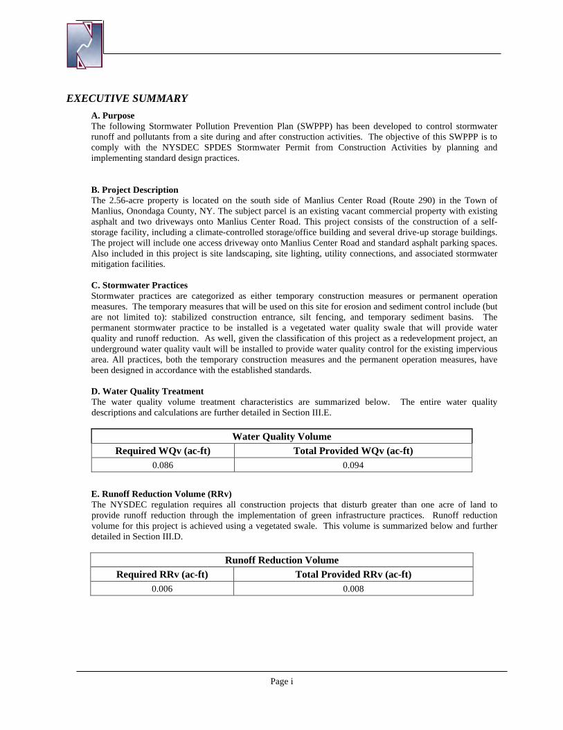
EXECUTIVE SUMMARY A. Purpose The following Stormwater Pollution Prevention Plan (SWPPP) has been developed to control stormwater runoff and pollutants from a site during and after construction activities. The objective of this SWPPP is to comply with the NYSDEC SPDES Stormwater Permit from Construction Activities by planning and implementing standard design practices. B. Project Description The 2.56-acre property is located on the south side of Manlius Center Road (Route 290) in the Town of Manlius, Onondaga County, NY. The subject parcel is an existing vacant commercial property with existing asphalt and two driveways onto Manlius Center Road. This project consists of the construction of a self-storage facility, including a climate-controlled storage/office building and several drive-up storage buildings. The project will include one access driveway onto Manlius Center Road and standard asphalt parking spaces. Also included in this project is site landscaping, site lighting, utility connections, and associated stormwater mitigation facilities. C. Stormwater Practices Stormwater practices are categorized as either temporary construction measures or permanent operation measures. The temporary measures that will be used on this site for erosion and sediment control include (but are not limited to): stabilized construction entrance, silt fencing, and temporary sediment basins. The permanent stormwater practice to be installed is a vegetated water quality swale that will provide water quality and runoff reduction. As well, given the classification of this project as a redevelopment project, an underground water quality vault will be installed to provide water quality control for the existing impervious area. All practices, both the temporary construction measures and the permanent operation measures, have been designed in accordance with the established standards. D. Water Quality Treatment The water quality volume treatment characteristics are summarized below. The entire water quality descriptions and calculations are further detailed in Section III.E.
Water Quality Volume Required WQv (ac-ft) Total Provided WQv (ac-ft)
0.086 0.094
E. Runoff Reduction Volume (RRv) The NYSDEC regulation requires all construction projects that disturb greater than one acre of land to provide runoff reduction through the implementation of green infrastructure practices. Runoff reduction volume for this project is achieved using a vegetated swale. This volume is summarized below and further detailed in Section III.D.
Runoff Reduction Volume Required RRv (ac-ft) Total Provided RRv (ac-ft)
0.006 0.008
Page ii
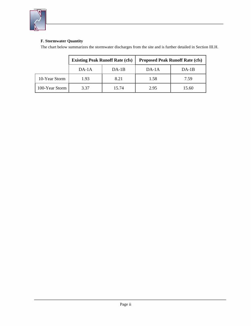
F. Stormwater Quantity The chart below summarizes the stormwater discharges from the site and is further detailed in Section III.H.
Existing Peak Runoff Rate (cfs) Proposed Peak Runoff Rate (cfs)
DA-1A DA-1B DA-1A DA-1B
10-Year Storm 1.93 8.21 1.58 7.59
100-Year Storm 3.37 15.74 2.95 15.60
Page iii
Table of Contents
Section I. SCOPE .............................................................................................................................................. 1
A. PURPOSE .......................................................................................................................................................1 B. SPDES GENERAL PERMIT GP-0-20-001 ....................................................................................................1 C. RESPONSIBILITIES OF THE OWNER........................................................................................................1 D. RESPONSIBILITIES OF THE CONTRACTOR ...........................................................................................1 E. NOTICE OF INTENT .....................................................................................................................................2 F. STORMWATER INSPECTIONS...................................................................................................................2 G. SWPPP MODIFICATIONS ............................................................................................................................3 H. FINAL STABILIZATION AND TERMINATION OF PERMIT COVERAGE ............................................3
Section II. SITE DESCRIPTION ....................................................................................................................... 4
A. PROJECT NAME AND LOCATION ............................................................................................................4 B. OWNER/OPERATOR NAME AND ADDRESS ...........................................................................................4 C. PROJECT DESCRIPTION .............................................................................................................................5 D. RECEIVING WATERS ..................................................................................................................................5 E. ENDANGERED OR THREATENED SPECIES ...........................................................................................6 F. FEDERAL AND STATE HISTORIC PRESERVATION ..............................................................................6
Section III. STORMWATER MANAGEMENT ................................................................................................. 7 A. METHODOLOGY ..........................................................................................................................................7
1. Hydrologic Conditions ...............................................................................................................7 2. Rainfall Information ..................................................................................................................7 3. Soil Information ....................................................................................................................... 10
B. EXISTING CONDITIONS ........................................................................................................................... 10 C. PROPOSED CONDITIONS ......................................................................................................................... 13 D. RUNOFF REDUCTION VOLUME (RRV) ................................................................................................. 16 E. WATER QUALITY VOLUME (WQv) & RUNOFF REDUCTION VOLUME (RRV) REQUIRED: ........ 17 F. WATER QUALITY VOLUME (WQV) & RUNOFF REDUCTION VOLUME (RRv) PROVIDED ........ 18 G. CHANNEL PROTECTION VOLUME (CPV) .............................................................................................. 21 H. PEAK FLOW MITIGATION (Qp10 and Qp100) ............................................................................................. 21
Section IV. CONTROLS ................................................................................................................................... 22 A. EROSION AND SEDIMENT CONTROLS ................................................................................................. 22
Section V. INSPECTION AND MAINTENANCE REQUIREMENTS .......................................................... 26
A. CONSTRUCTION MAINTENANCE/INSPECTION PROCEDURES ....................................................... 26 B. OPERATION MAINTENANCE AND INSPECTION PROCEDURES...................................................... 28
Section VI. MATERIALS MANAGEMENT PLAN ......................................................................................... 29 A. MATERIALS COVERED ............................................................................................................................ 29 B. MATERIAL MANAGEMENT PRACTICES .............................................................................................. 29
Section VII. SPILL PREVENTION AND RESPONSE PROCEDURES ........................................................... 31
Section VIII. CONTROL OF NON-STORMWATER DISCHARGES ............................................................... 32
Section IX. CERTIFICATION AND NOTIFICATION .................................................................................... 32
Page iv
List of Figures Figure 1: Site Location Map .......................................................................................................................................... 4 Figure 2: Proposed Site Aerial Image - Google Earth ................................................................................................... 5 Figure 3. Onondaga County GIS Wetland and Floodplain Mapper ............................................................................... 5 Figure 4: NYS DEC Environmental Resource Mapper ................................................................................................. 6 Figure 5: State Historic Preservation Office Map .......................................................................................................... 6 Figure 6: New York State 90% Rainfall Map ................................................................................................................ 8 Figure 7: New York State One-Year Design Storm Map .............................................................................................. 8 Figure 8: New York State 10-Year Design Storm Map ................................................................................................. 9 Figure 9: New York State 100-Year Design Storm Map ............................................................................................... 9 Figure 10: Project Site NRCS Soil Survey Map .......................................................................................................... 10 Figure 11: Existing HydroCAD Drainage Map ........................................................................................................... 11 Figure 12: Proposed HydroCAD Drainage Map ......................................................................................................... 14
List of Tables Table 1: Rainfall Information ........................................................................................................................................ 7 Table 2: Existing Drainage Area 1A Curve Number Calculation ................................................................................ 12 Table 3: Existing Drainage Area 1 Curve Number Calculation .................................................................................. 12 Table 4: Proposed Drainage Area DA-1A Curve Number Calculations ..................................................................... 15 Table 5: Proposed Drainage Area DA-1B Curve Number Calculations ...................................................................... 15 Table 4: Proposed Drainage Area DA-1C Curve Number Calculations ...................................................................... 15
List of Appendices
APPENDIX A: HYDRO CAD – EXISTING CONDITIONS APPENDIX B: HYDRO CAD – PROPOSED CONDITIONS APPENDIX C: SOIL DESCRIPTIONS APPENDIX D: VEGETATED SWALE AND DETENTION CHAMBER SYSTEM CONSTRUCTION AND
MAINTENANCE APPENDIX E: SWPPP FORMS APPENDIX F: EROSION & SEDIMENT CONTROL DETAILS AND STORMWATER MANAGEMENT PLAN
Page | 1
Section I. SCOPE
A. PURPOSE
Napierala Consulting, Professional Engineer, P.C., has prepared this Stormwater Pollution Prevention Plan (SWPPP) in compliance with the New York State Department of Environmental Conservation (NYSDEC) State Pollutant Discharge Elimination System (SPDES) Construction General Permit governing stormwater discharges during construction. The contractor’s participation and adherence to this plan is mandatory. Non-compliance with the plan is subject to various remedies including, without limitation, monetary set-offs, withholding payments, reimbursement for costs, expenses (including reasonable attorney’s fees), fines and civil penalties incurred and/or liquidated damages. This section provides a descriptive explanation of the Stormwater Pollution Prevention Plan and required contractor participation.
B. SPDES GENERAL PERMIT GP-0-20-001
Regulations enacted by the New York State Department of Environmental Conservation require permitting for the discharge of stormwater from construction activities on sites where an area of one acre or more of soil disturbance is proposed. To comply with these regulations, the developer of the site must request coverage under the NYSDEC SPDES General Permit for Stormwater Discharges from Construction Activity (GP-0-20-001). In order to obtain coverage under the General Permit, a Stormwater Pollution Prevention Plan (SWPPP) for the site must be prepared following the requirements of the New York State Stormwater Management Design Manual and the New York State Standards and Specifications for Erosion and Sediment Control. The NOI, the SWPPP, and any amendments to the SWPPP, as well as any reports required by the SPDES General Permit for Stormwater Discharges from Construction Activity, must also be submitted concurrently to the local governing body and any other authorized agency having jurisdiction or regulatory control over the construction project.
C. RESPONSIBILITIES OF THE OWNER
The owner/operator shall identify the contractor(s) and subcontractor(s) that will be responsible for installing, constructing, repairing, replacing, inspecting, and maintaining the erosion and sediment control practices included in the SWPPP. The owner/operator shall identify the contractor(s) and subcontractor(s) that will be responsible for constructing the post-construction stormwater management practices included in the SWPPP. The owner/operator shall have each of the contractors and subcontractors identify at least one person from their company that will be responsible for implementation of the SWPPP. The owner/operator shall ensure that at least one trained contractor is on site on a daily basis when soil disturbance activities are being performed. The owner/operator shall have a qualified inspector conduct site inspections.
D. RESPONSIBILITIES OF THE CONTRACTOR
The contractor shall manage the discharge of stormwater from the site in accordance with the NYSDEC SPDES General Permit for Stormwater Discharges from Construction Activity. The owner shall be responsible for conducting the stormwater management practices in accordance with the permit. The contractor shall be responsible for providing qualified inspectors to conduct the inspections required by the SWPPP. The contractor shall be responsible for any enforcement action taken or imposed by federal, state, or local agencies, including the cost of fines, construction delays, and remedial actions resulting from the contractor’s failure to comply with the permit provisions. It shall be the responsibility of the contractor to make any changes to the SWPPP necessary when the contractor or any of his subcontractors elects to use borrow or fill or material storage sites, either contiguous to or remote from the construction
Page | 2
site, when such sites are used solely for this construction site. Such sites are considered to be part of the construction site covered by the permit and this SWPPP. Off-site borrow, fill, or material storage sites which are used for multiple construction projects are not subject to this requirement, unless specifically required by state or local jurisdictional entity regulations. The contractor should consider this requirement in negotiating with earthwork subcontractors, since the choice of an off-site borrow, fill, or material storage site may impact their duty to implement, make changes to, and perform inspections required by the SWPPP for the site.
The SWPPP shall provide forms for both the general contractor and subcontractor(s) identifying the company name, business address and telephone number along with the responsible person for the contractor and all subcontractors’ who will implement the measures identified in the SWPPP. The general contractor shall sign the “General Contractor’s Certification” and all subcontractors shall sign the “Subcontractor’s Certification”, verifying they have been instructed on how to comply with and fully understand the requirements of the NYSDEC and SWPPP. This certification must be signed, by a fully qualified individual on behalf of each entity, prior to the beginning of any construction activities and shall be filed in the projects SWPPP. The SWPPP is meant to be a working document that shall be maintained at the site of the construction activities at all times throughout the project, shall be readily available upon request by the operator’s personnel or NYSDEC or any other agency with regulatory authority over storm water issues, and shall be kept on-site until the site complies with the Final Stabilization section of this document. A sign or other notice must be posted near the main entrance of the construction site which contains a completed NOI, the location of the SWPPP and the name and phone number of a contact person responsible for scheduling SWPPP viewing times, and any other state specific requirements.
E. NOTICE OF INTENT
The operator has petitioned the NYSDEC for the stormwater discharges during construction at this site to be covered by the NYSDEC SPDES General Permit for Stormwater Discharges from Construction Activity. A Notice of Intent (NOI) to be covered under this permit has been filed by the operator. The signatory on the NOI must sign all documents (i.e., inspection reports) associated with the SWPPP. If the signatory chooses not to sign all documents, he/she must designate a duly authorized representative to sign all relevant documents. This designation must be made in writing and be included in the SWPPP. The duly authorized representative may be either a named individual or any individual occupying a named position. Additionally, the written designation must be submitted to the NYSDEC.
F. STORMWATER INSPECTIONS
1. Inspection Procedures Inspections of the erosion control practices are required once every seven days by a qualified professional. All inspections will continue until the site complies with the final stabilization section of this document. Weekly Inspections must be conducted by a “Qualified Professional”. “Qualified Professional” means a person knowledgeable in the principles and practice of erosion and sediment controls, such as a licensed Professional Engineer (PE), Certified Professional in Erosion and Sediment Control (CPESC), or soil scientist. Each inspection must be followed up by a report documenting the inspector’s findings and request the required maintenance and/or repair for the erosion and sedimentation control measures. It is imperative that the contractor documents the inspection and maintenance of all erosion and sedimentation control measures as soon as possible after the inspection and/or maintenance have been completed. These records are used to prove that the required inspection and maintenance were performed. The records shall be placed in the SWPPP. In addition to inspection and maintenance reports, records should be kept of the construction activities that occur on the site. The operator shall post at the site, in a publicly-accessible location, a summary of the site inspection activities on a monthly basis. 2. Record Keeping The operator shall also prepare a written summary of its status with respect to compliance with this general permit at a minimum frequency of every three months during which coverage under the NYSDEC
Page | 3
SPDES General Permit for Stormwater Discharges from Construction Activity exists. The summary should address the status of achieving each component of the SWPPP. The reports shall be signed by the signatory of the NOI or a duly-authorized person and be retained at the construction site. The contractor shall retain copies of the SWPPP, all reports and data for a minimum of five (5) years after the project. The following list identifies the required inspection and maintenance documentation that must be maintained by the contractor under this SWPPP.
• Inspection Report • Stabilization Schedule • Implementation Schedule • Status Report
G. SWPPP MODIFICATIONS
The inspection report should also identify if any revisions to the SWPPP are warranted due to unexpected conditions. The SWPPP is meant to be a dynamic working guide that is to be kept current and amended whenever:
• The NYSDEC provides notification that the SWPPP does not comply with the minimum permit requirements.
• The design, construction, operation, or maintenance of the site changes in a way which significantly affects the potential for the discharge of pollutants or when the plan proves to be ineffective in eliminating or significantly minimizing pollutant discharges
• Within seven (7) calendar days of knowledge of a reportable release.
Any such changes to the SWPPP must be made in writing within seven (7) days of the date such modification or amendment is made. The contractor’s failure to monitor or report deficiencies to the operator will result in the contractor being liable for fines and construction delays resulting from any federal, state, or local agency enforcement action.
H. FINAL STABILIZATION AND TERMINATION OF PERMIT COVERAGE
A site can be considered stabilized when all soil disturbing activities have been completed and a uniform perennial vegetative cover with a density of 80% over the unpaved areas and areas not covered by permanent structures has been established or equivalent permanent stabilization measures have been established and the facility no longer discharges stormwater associated with construction activities, and a Notice of Termination (NOT) form has been filed by the operator(s) with the NYSDEC. Prior to filing of the Notice of Termination, the operator shall have the qualified professional perform a final site inspection. The qualified professional shall certify that the site has undergone final stabilization using either vegetative or structural stabilization methods and that all temporary erosion and sediment controls (such as silt fence) not needed for long-term erosion control have been removed. The filing of the NOT terminates coverage under the General Permit and terminates the contractor’s responsibility to implement the SWPPP, but the requirements of the SWPPP, including periodic inspections, must be continued until the NOT is filed. Upon achieving this milestone, the contractor shall also submit “Final Stabilization Certification/Termination Checklist”. Final payment and/or the release of any retainer will be withheld until all provisions of the SWPPP have been submitted, completed and accepted by the operator.
Page | 4
Section II. SITE DESCRIPTION
A. PROJECT NAME AND LOCATION
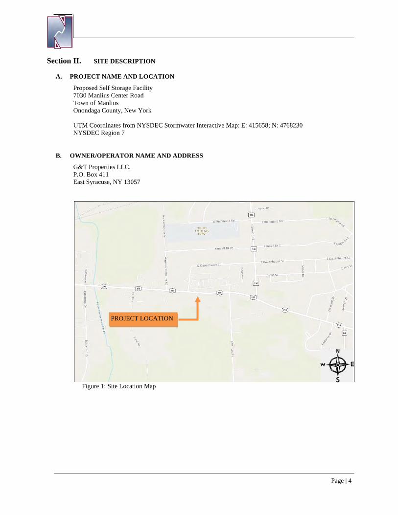
Proposed Self Storage Facility 7030 Manlius Center Road Town of Manlius Onondaga County, New York UTM Coordinates from NYSDEC Stormwater Interactive Map: E: 415658; N: 4768230 NYSDEC Region 7
B. OWNER/OPERATOR NAME AND ADDRESS
G&T Properties LLC. P.O. Box 411 East Syracuse, NY 13057
Figure 1: Site Location Map
PROJECT LOCATION
Page | 5
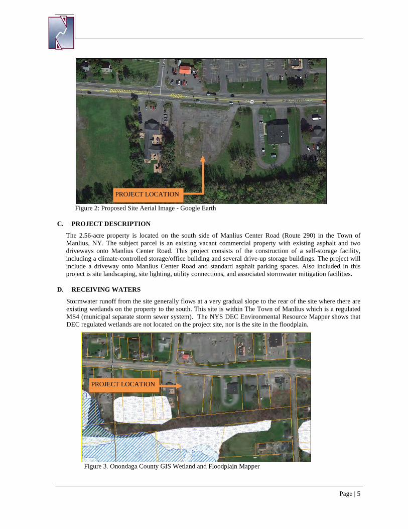
Figure 2: Proposed Site Aerial Image - Google Earth
C. PROJECT DESCRIPTION
The 2.56-acre property is located on the south side of Manlius Center Road (Route 290) in the Town of Manlius, NY. The subject parcel is an existing vacant commercial property with existing asphalt and two driveways onto Manlius Center Road. This project consists of the construction of a self-storage facility, including a climate-controlled storage/office building and several drive-up storage buildings. The project will include a driveway onto Manlius Center Road and standard asphalt parking spaces. Also included in this project is site landscaping, site lighting, utility connections, and associated stormwater mitigation facilities.
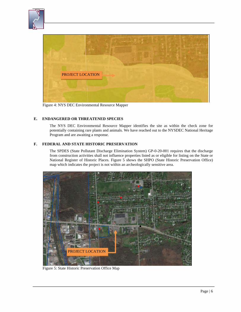
D. RECEIVING WATERS
Stormwater runoff from the site generally flows at a very gradual slope to the rear of the site where there are existing wetlands on the property to the south. This site is within The Town of Manlius which is a regulated MS4 (municipal separate storm sewer system). The NYS DEC Environmental Resource Mapper shows that DEC regulated wetlands are not located on the project site, nor is the site in the floodplain.
Figure 3. Onondaga County GIS Wetland and Floodplain Mapper
PROJECT LOCATION
PROJECT LOCATION
Page | 6
Figure 4: NYS DEC Environmental Resource Mapper
E. ENDANGERED OR THREATENED SPECIES
The NYS DEC Environmental Resource Mapper identifies the site as within the check zone for potentially containing rare plants and animals. We have reached out to the NYSDEC National Heritage Program and are awaiting a response.
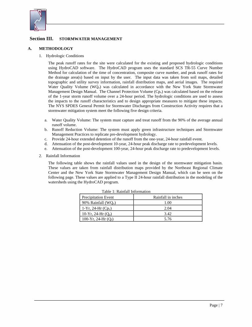
F. FEDERAL AND STATE HISTORIC PRESERVATION
The SPDES (State Pollutant Discharge Elimination System) GP-0-20-001 requires that the discharge from construction activities shall not influence properties listed as or eligible for listing on the State or National Register of Historic Places. Figure 5 shows the SHPO (State Historic Preservation Office) map which indicates the project is not within an archeologically sensitive area.
Figure 5: State Historic Preservation Office Map
PROJECT LOCATION
PROJECT LOCATION
Page | 7
Section III. STORMWATER MANAGEMENT
A. METHODOLOGY
1. Hydrologic Conditions
The peak runoff rates for the site were calculated for the existing and proposed hydrologic conditions using HydroCAD software. The HydroCAD program uses the standard SCS TR-55 Curve Number Method for calculation of the time of concentration, composite curve number, and peak runoff rates for the drainage area(s) based on input by the user. The input data was taken from soil maps, detailed topographic and utility survey information, rainfall distribution maps, and aerial images. The required Water Quality Volume (WQv) was calculated in accordance with the New York State Stormwater Management Design Manual. The Channel Protection Volume (Cpv) was calculated based on the release of the 1-year storm runoff volume over a 24-hour period. The hydrologic conditions are used to assess the impacts to the runoff characteristics and to design appropriate measures to mitigate these impacts. The NYS SPDES General Permit for Stormwater Discharges from Construction Activity requires that a stormwater mitigation system meet the following five design criteria.
a. Water Quality Volume: The system must capture and treat runoff from the 90% of the average annual runoff volume.
b. Runoff Reduction Volume: The system must apply green infrastructure techniques and Stormwater Management Practices to replicate pre-development hydrology.
c. Provide 24-hour extended detention of the runoff from the one-year, 24-hour rainfall event. d. Attenuation of the post-development 10-year, 24-hour peak discharge rate to predevelopment levels. e. Attenuation of the post-development 100-year, 24-hour peak discharge rate to predevelopment levels.
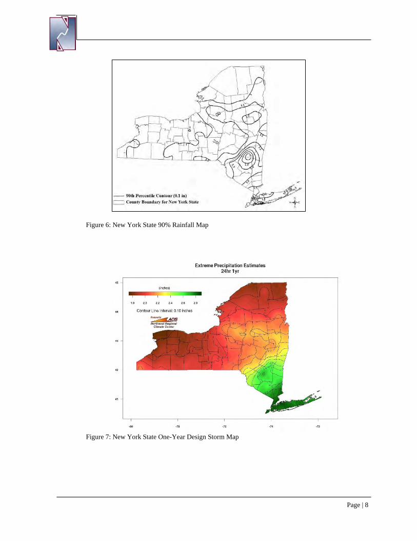
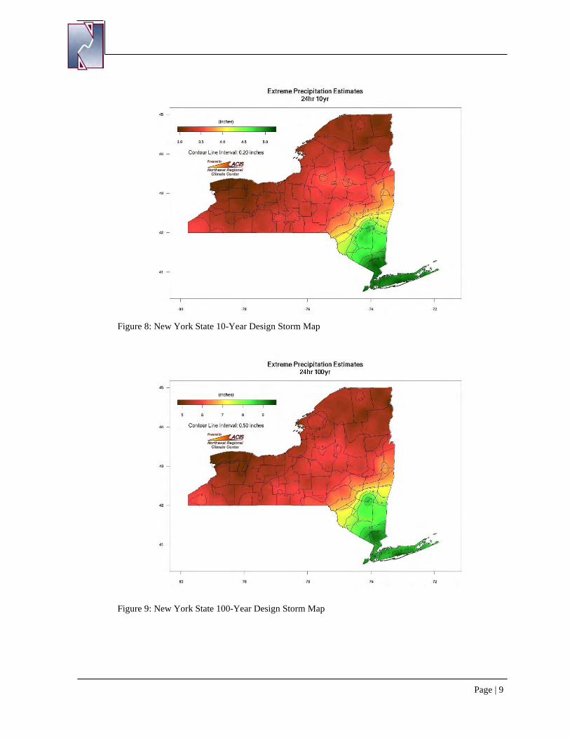
2. Rainfall Information
The following table shows the rainfall values used in the design of the stormwater mitigation basin. These values are taken from rainfall distribution maps provided by the Northeast Regional Climate Center and the New York State Stormwater Management Design Manual, which can be seen on the following page. These values are applied to a Type II 24-hour rainfall distribution in the modeling of the watersheds using the HydroCAD program.
Table 1: Rainfall Information Precipitation Event Rainfall in inches 90% Rainfall (WQv) 1.00 1-Yr, 24-Hr (Cpv) 2.04 10-Yr, 24-Hr (Qp) 3.42 100-Yr, 24-Hr (Qf) 5.76
Page | 8
Figure 6: New York State 90% Rainfall Map
Figure 7: New York State One-Year Design Storm Map
Page | 9
Figure 8: New York State 10-Year Design Storm Map
Figure 9: New York State 100-Year Design Storm Map
Page | 10
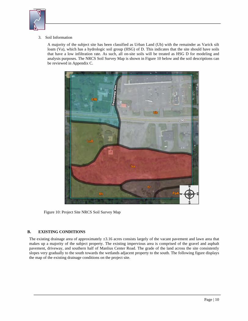
3. Soil Information
A majority of the subject site has been classified as Urban Land (Ub) with the remainder as Varick silt loam (Va), which has a hydrologic soil group (HSG) of D. This indicates that the site should have soils that have a low infiltration rate. As such, all on-site soils will be treated as HSG D for modeling and analysis purposes. The NRCS Soil Survey Map is shown in Figure 10 below and the soil descriptions can be reviewed in Appendix C.
Figure 10: Project Site NRCS Soil Survey Map
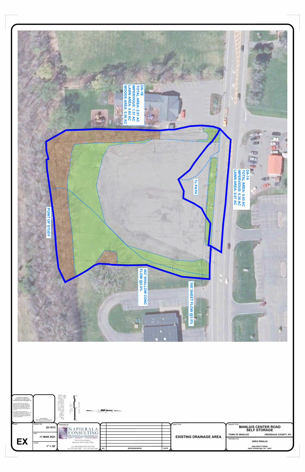
B. EXISTING CONDITIONS
The existing drainage area of approximately ±3.16 acres consists largely of the vacant pavement and lawn area that makes up a majority of the subject property. The existing impervious area is comprised of the gravel and asphalt pavement, driveway, and southern half of Manlius Center Road. The grade of the land across the site consistently slopes very gradually to the south towards the wetlands adjacent property to the south. The following figure displays the map of the existing drainage conditions on the project site.
100' SHEET FLO
W @
3.5%
362' SHA
LLOW
CO
NC
FLOW
@2.0%
DA
-1ATO
TAL A
REA
: 0.43 AC
IMPER
VIOU
S: 0.36 AC
LAW
N A
REA
: 0.07 AC
DA
-1BTO
TAL A
REA
: 2.91 AC
IMPER
VIOU
S: 1.51 AC
LAW
N A
REA
: 0.84 AC
WO
OD
S AR
EA: 0.56 A
C
POIN
T OF STU
DY
Tc PATH
PROJECT NO.
DATE
SCALE
SHEET
MATTHEW R. NAPIERALA, P.E.NYS REGISTRATION # 068733
PLAN SEAL BY:
PREPARED BY:
COPYRIGHT C 2021
NO. REVISION/ISSUE
SHEET TITLE:
DATE
PREPARED FOR:
PROJECT TITLE:
110 FAYETTE STREETMANLIUS, NEW YORK 13104
email: [email protected]: (315) 682-5580 FAX: (315) 682-5544
N A P I E R A L AC O N S U L T I N GPROFESSIONAL ENGINEER, P.C.SITE DESIGN ENGINEERING
IT IS A VIOLATION OF LAW FOR ANYPERSON, UNLESS ACTING UNDER THEDIRECTION OF A LICENSED ARCHITECT,PROFESSIONAL ENGINEER, LANDSCAPEARCHITECT, OR LAND SURVEYOR TOALTER ANY ITEM ON THIS DOCUMENT INANY WAY.
ANY LICENSEE WHO ALTERS THISDOCUMENT IS REQUIRED BY LAW TO AFFIXHIS OR HER SEAL AND THE NOTATION"ALTERED BY" FOLLOWED BY HIS OR HERSIGNATURE AND SPECIFIC DESCRIPTIONOF THE ALTERATIONS.
NAPIERALA CONSULTINGPROFESSIONAL ENGINEER, PC
MANLIUS CENTER ROADSELF STORAGE
TOWN OF MANLIUS ONONDAGA COUNTY, NY
GREG RINALDI
5990 DROTT DRIVEEAST SYRACUSE, NY 13057
EXISTING DRAINAGE AREA
20-1913
11 MAR 2021
1" = 30'EX

THIS PAGE INTENTIONALLY LEFT BLANK
Page | 12
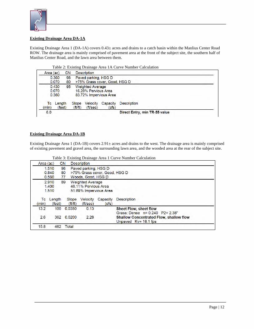
Existing Drainage Area DA-1A
Existing Drainage Area 1 (DA-1A) covers 0.43± acres and drains to a catch basin within the Manlius Center Road ROW. The drainage area is mainly comprised of pavement area at the front of the subject site, the southern half of Manlius Center Road, and the lawn area between them.
Table 2: Existing Drainage Area 1A Curve Number Calculation
Existing Drainage Area DA-1B
Existing Drainage Area 1 (DA-1B) covers 2.91± acres and drains to the west. The drainage area is mainly comprised of existing pavement and gravel area, the surrounding lawn area, and the wooded area at the rear of the subject site.
Table 3: Existing Drainage Area 1 Curve Number Calculation
Page | 13
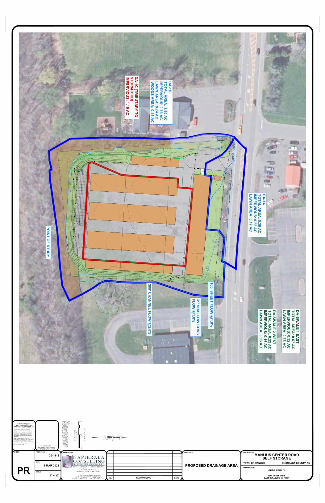
C. PROPOSED CONDITIONS
The 2.56-acre property is located on the south side of Manlius Center Road (Route 290) in the Town of Manlius, Onondaga County, NY. The subject parcel is an existing vacant commercial property with existing asphalt and two driveways onto Manlius Center Road. This project consists of the construction of a self-storage facility, including a climate-controlled storage/office building and several drive-up storage buildings. Approximately 0.35 acres of additional impervious area are proposed under the new development. The project will include one access driveway onto Manlius Center Road and standard asphalt parking spaces. Also included in this project is site landscaping, site lighting, utility connections, and associated stormwater mitigation facilities. The stormwater management system includes several management practices to capture, treat and control the release of runoff from the site. Runoff from the impervious areas, both rooftop and asphalt, will be directed to practices to provide runoff reduction, water quality treatment and water quantity storage. The following stormwater management practices will be constructed:
• Vegetated Swale: Vegetated swales are open drainage channel systems lined with grass and designed
to capture and divert stormwater runoff to a downstream point of collection or discharge. Vegetated swales temporarily store, infiltrate, and treat stormwater runoff from lower intensity storms while providing a path of conveyance for higher intensity storm events.
• Water Quality Unit (1): The water quality unit, considered an alternative stormwater management practice, uses a series of baffles, weirs, and oil catchment to improve water quality. The water quality unit removes pollutants such as phosphorous and suspended solids in order to improve the quality of the runoff before it is discharged. This unit will be located under paved area and its sizing calculations are included in Section F.
The map and narrative on the following pages summarize the hydrology of the proposed condition watershed.
31' SHA
LLOW
CO
NC
FLOW
@1.0%
309' CH
AN
NEL FLO
W @
2.0%
DA
-1ATO
TAL A
REA
: 0.39 AC
IMPER
VIOU
S: 0.22 AC
LAW
N A
REA
: 0.17 AC
DA
-SWA
LE 2 WEST
TOTA
L AR
EA: 0.22 A
CIM
PERVIO
US: 0.16 A
CLA
WN
AR
EA: 0.06 A
C
DA
-1BTO
TAL A
REA
: 1.85 AC
IMPER
VIOU
S: 0.76 AC
LAW
N A
REA
: 0.74 AC
WO
OD
S AR
EA: 0.43 A
C
POIN
T OF STU
DY
DA
-SWA
LE 1 EAST
TOTA
L AR
EA: 0.67 A
CIM
PERVIO
US: 0.32 A
CLA
WN
AR
EA: 0.35 A
C
DA
-1C (TR
IBU
TAR
Y TOSTO
RM
TECH
)IM
PERVIO
US: 1.10 A
C
100' SHEET FLO
W @
1.0%
PROJECT NO.
DATE
SCALE
SHEET
MATTHEW R. NAPIERALA, P.E.NYS REGISTRATION # 068733
PLAN SEAL BY:
PREPARED BY:
COPYRIGHT C 2021
NO. REVISION/ISSUE
SHEET TITLE:
DATE
PREPARED FOR:
PROJECT TITLE:
110 FAYETTE STREETMANLIUS, NEW YORK 13104
email: [email protected]: (315) 682-5580 FAX: (315) 682-5544
N A P I E R A L AC O N S U L T I N GPROFESSIONAL ENGINEER, P.C.SITE DESIGN ENGINEERING
IT IS A VIOLATION OF LAW FOR ANYPERSON, UNLESS ACTING UNDER THEDIRECTION OF A LICENSED ARCHITECT,PROFESSIONAL ENGINEER, LANDSCAPEARCHITECT, OR LAND SURVEYOR TOALTER ANY ITEM ON THIS DOCUMENT INANY WAY.
ANY LICENSEE WHO ALTERS THISDOCUMENT IS REQUIRED BY LAW TO AFFIXHIS OR HER SEAL AND THE NOTATION"ALTERED BY" FOLLOWED BY HIS OR HERSIGNATURE AND SPECIFIC DESCRIPTIONOF THE ALTERATIONS.
NAPIERALA CONSULTINGPROFESSIONAL ENGINEER, PC
MANLIUS CENTER ROADSELF STORAGE
TOWN OF MANLIUS ONONDAGA COUNTY, NY
GREG RINALDI
5990 DROTT DRIVEEAST SYRACUSE, NY 13057
PROPOSED DRAINAGE AREA
20-1913
11 MAR 2021
1" = 30'PR

THIS PAGE INTENTIONALLY LEFT BLANK
Page | 15
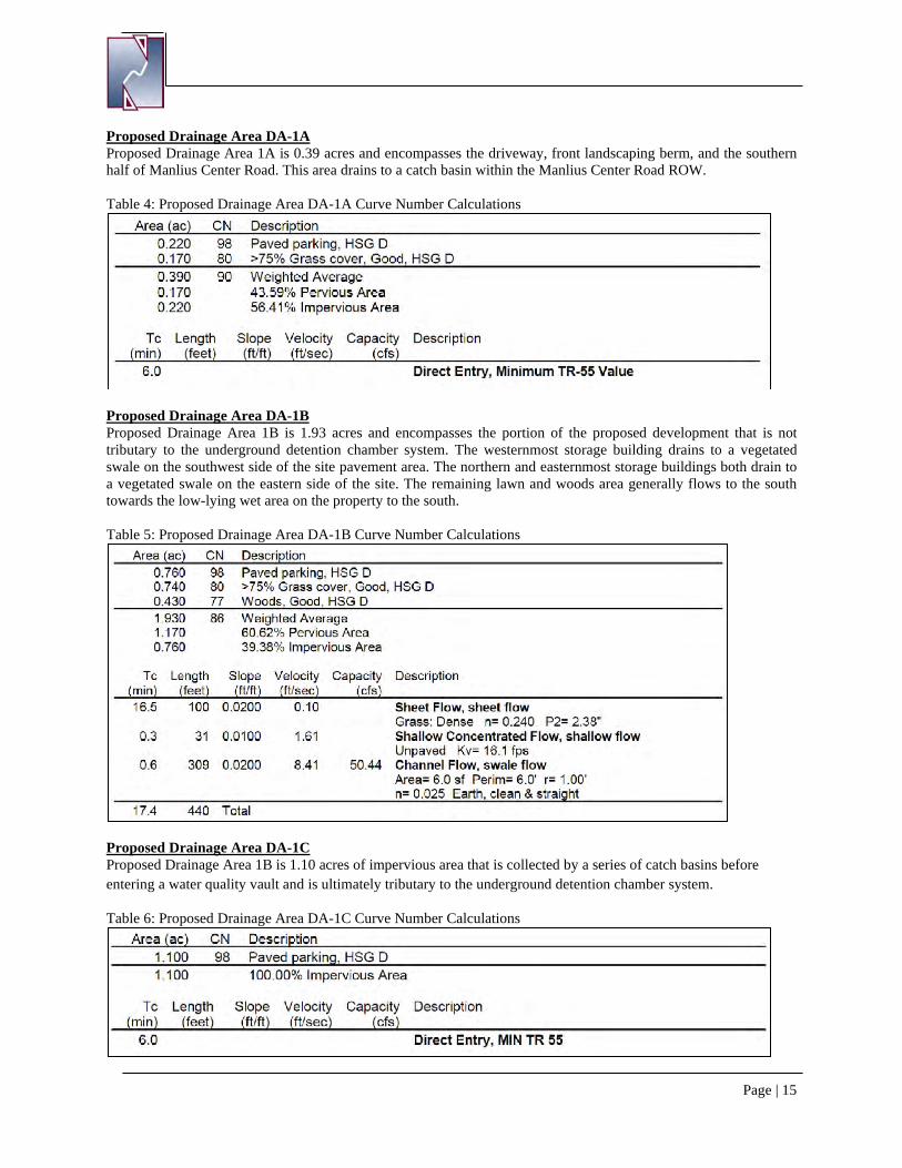
Proposed Drainage Area DA-1A Proposed Drainage Area 1A is 0.39 acres and encompasses the driveway, front landscaping berm, and the southern half of Manlius Center Road. This area drains to a catch basin within the Manlius Center Road ROW.
Table 4: Proposed Drainage Area DA-1A Curve Number Calculations
Proposed Drainage Area DA-1B Proposed Drainage Area 1B is 1.93 acres and encompasses the portion of the proposed development that is not tributary to the underground detention chamber system. The westernmost storage building drains to a vegetated swale on the southwest side of the site pavement area. The northern and easternmost storage buildings both drain to a vegetated swale on the eastern side of the site. The remaining lawn and woods area generally flows to the south towards the low-lying wet area on the property to the south.
Table 5: Proposed Drainage Area DA-1B Curve Number Calculations
Proposed Drainage Area DA-1C Proposed Drainage Area 1B is 1.10 acres of impervious area that is collected by a series of catch basins before entering a water quality vault and is ultimately tributary to the underground detention chamber system.
Table 6: Proposed Drainage Area DA-1C Curve Number Calculations
Page | 16
D. RUNOFF REDUCTION VOLUME (RRV)
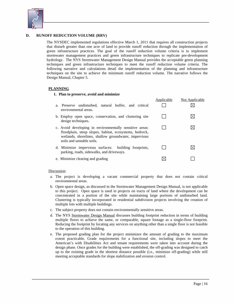
The NYSDEC implemented regulations effective March 1, 2011 that requires all construction projects that disturb greater than one acre of land to provide runoff reduction through the implementation of green infrastructure practices. The goal of the runoff reduction volume criteria is to implement stormwater management practices and green infrastructure techniques to replicate pre-development hydrology. The NYS Stormwater Management Design Manual provides the acceptable green planning techniques and green infrastructure techniques to meet the runoff reduction volume criteria. The following narrative and calculations detail the implementation of the planning and infrastructure techniques on the site to achieve the minimum runoff reduction volume. The narrative follows the Design Manual, Chapter 5. PLANNING
1. Plan to preserve, avoid and minimize Applicable Not Applicable a. Preserve undisturbed, natural buffer, and critical
environmental areas.
b. Employ open space, conservation, and clustering site design techniques.
c. Avoid developing in environmentally sensitive areas: floodplain, steep slopes, habitat, ecosystems, bedrock, wetlands, shorelines, shallow groundwater, impervious soils and unstable soils.
d. Minimize impervious surfaces: building footprints, parking, roads, sidewalks, and driveways.
e. Minimize clearing and grading
Discussion: a. The project is developing a vacant commercial property that does not contain critical
environmental areas. b. Open space design, as discussed in the Stormwater Management Design Manual, is not applicable
to this project. Open space is used in projects on tracts of land where the development can be concentrated in a portion of the site while maintaining large portions of undisturbed land. Clustering is typically incorporated in residential subdivision projects involving the creation of multiple lots with multiple buildings.
c. The subject property does not contain environmentally sensitive areas. d. The NYS Stormwater Design Manual discusses building footprint reduction in terms of building
multiple floors to achieve the same, or comparable, square footage as a single-floor footprint. Reducing the footprint by locating any services on anything other than a single floor is not feasible to the operation of this building.
e. The proposed grading plan for the project minimizes the amount of grading to the maximum extent practicable. Grade requirements for a functional site, including slopes to meet the American’s with Disabilities Act and tenant requirements were taken into account during the design phase. Once grades for the building were established, the off-grading was designed to catch up to the existing grade in the shortest distance possible (i.e., minimize off-grading) while still meeting acceptable standards for slope stabilization and erosion control.
Page | 17
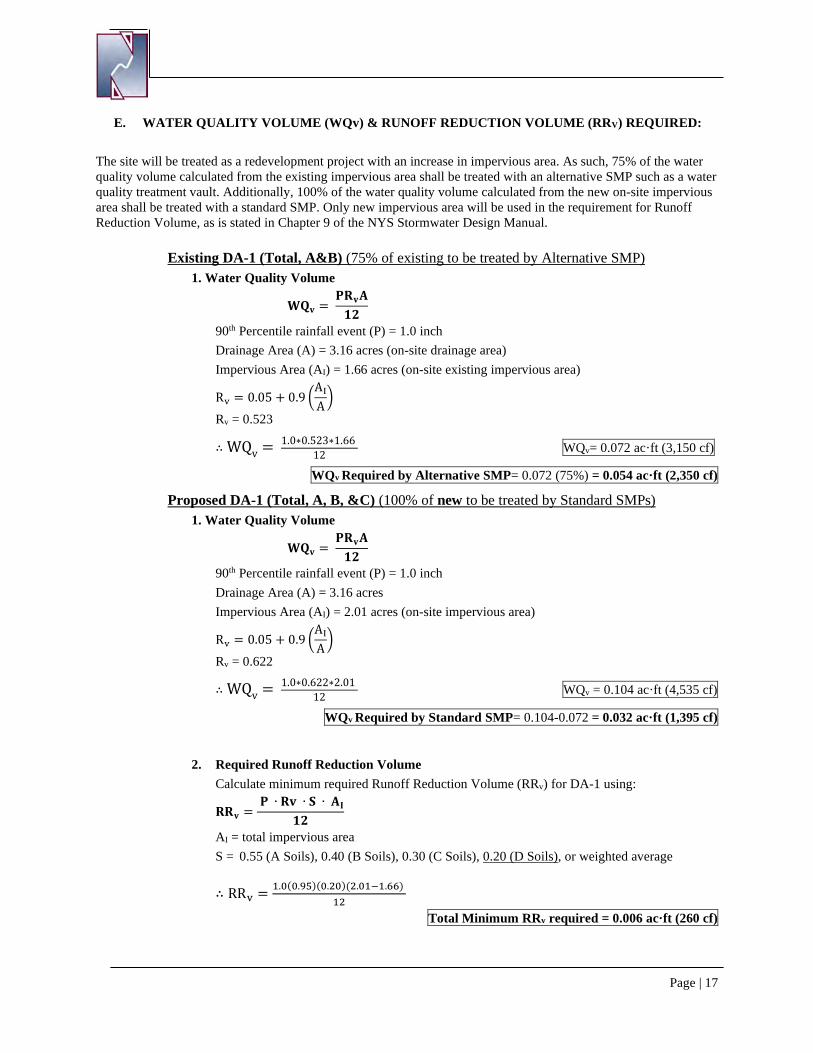
E. WATER QUALITY VOLUME (WQv) & RUNOFF REDUCTION VOLUME (RRV) REQUIRED:
The site will be treated as a redevelopment project with an increase in impervious area. As such, 75% of the water quality volume calculated from the existing impervious area shall be treated with an alternative SMP such as a water quality treatment vault. Additionally, 100% of the water quality volume calculated from the new on-site impervious area shall be treated with a standard SMP. Only new impervious area will be used in the requirement for Runoff Reduction Volume, as is stated in Chapter 9 of the NYS Stormwater Design Manual.
Existing DA-1 (Total, A&B) (75% of existing to be treated by Alternative SMP) 1. Water Quality Volume
𝐖𝐖𝐖𝐖𝐯𝐯 = 𝐏𝐏𝐑𝐑𝐯𝐯𝐀𝐀𝟏𝟏𝟏𝟏
90th Percentile rainfall event (P) = 1.0 inch Drainage Area (A) = 3.16 acres (on-site drainage area) Impervious Area (AI) = 1.66 acres (on-site existing impervious area)
Rv = 0.05 + 0.9 �AI
A�
Rv = 0.523
∴ WQv = 1.0∗0.523∗1.66 12 WQv= 0.072 ac·ft (3,150 cf)
WQv Required by Alternative SMP= 0.072 (75%) = 0.054 ac·ft (2,350 cf)
Proposed DA-1 (Total, A, B, &C) (100% of new to be treated by Standard SMPs) 1. Water Quality Volume
𝐖𝐖𝐖𝐖𝐯𝐯 = 𝐏𝐏𝐑𝐑𝐯𝐯𝐀𝐀𝟏𝟏𝟏𝟏
90th Percentile rainfall event (P) = 1.0 inch Drainage Area (A) = 3.16 acres Impervious Area (AI) = 2.01 acres (on-site impervious area)
Rv = 0.05 + 0.9 �AI
A�
Rv = 0.622
∴ WQv = 1.0∗0.622∗2.01 12 WQv = 0.104 ac·ft (4,535 cf)
WQv Required by Standard SMP= 0.104-0.072 = 0.032 ac·ft (1,395 cf)
2. Required Runoff Reduction Volume Calculate minimum required Runoff Reduction Volume (RRv) for DA-1 using:
𝐑𝐑𝐑𝐑𝐯𝐯 = 𝐏𝐏 ∙ 𝐑𝐑𝐯𝐯 ∙ 𝐒𝐒 ∙ 𝐀𝐀𝐈𝐈
𝟏𝟏𝟏𝟏
AI = total impervious area S = 0.55 (A Soils), 0.40 (B Soils), 0.30 (C Soils), 0.20 (D Soils), or weighted average
∴ RRv = 1.0(0.95)(0.20)(2.01−1.66) 12
Total Minimum RRv required = 0.006 ac·ft (260 cf)
Page | 18
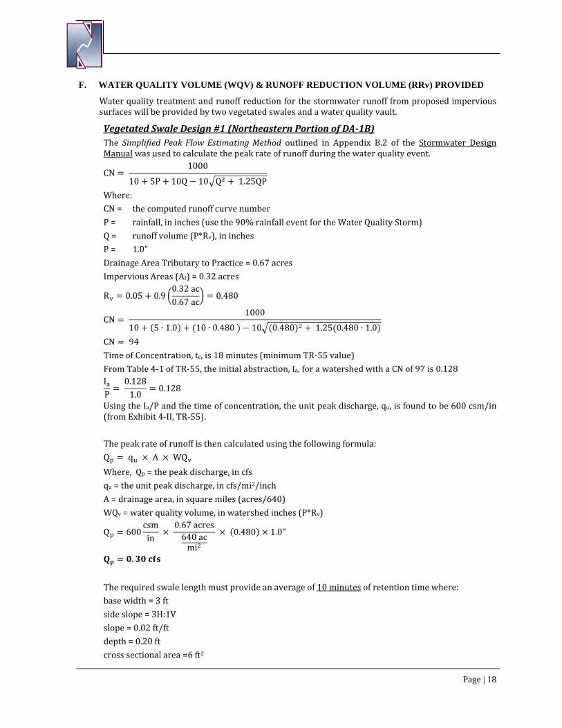
F. WATER QUALITY VOLUME (WQV) & RUNOFF REDUCTION VOLUME (RRv) PROVIDED
Water quality treatment and runoff reduction for the stormwater runoff from proposed impervious surfaces will be provided by two vegetated swales and a water quality vault.
Vegetated Swale Design #1 (Northeastern Portion of DA-1B) The Simplified Peak Flow Estimating Method outlined in Appendix B.2 of the Stormwater Design Manual was used to calculate the peak rate of runoff during the water quality event.
CN = 1000
10 + 5P + 10Q − 10�Q2 + 1.25QP
Where: CN = the computed runoff curve number P = rainfall, in inches (use the 90% rainfall event for the Water Quality Storm) Q = runoff volume (P*Rv), in inches P = 1.0” Drainage Area Tributary to Practice = 0.67 acres Impervious Areas (AI) = 0.32 acres
Rv = 0.05 + 0.9 �0.32 ac0.67 ac
� = 0.480
CN = 1000
10 + (5 ∙ 1.0) + (10 ∙ 0.480 ) − 10�(0.480)2 + 1.25(0.480 ∙ 1.0)
CN = 94 Time of Concentration, tc, is 18 minutes (minimum TR-55 value) From Table 4-1 of TR-55, the initial abstraction, Ia, for a watershed with a CN of 97 is 0.128 IaP
= 0.128
1.0= 0.128
Using the Ia/P and the time of concentration, the unit peak discharge, qu, is found to be 600 csm/in (from Exhibit 4-II, TR-55). The peak rate of runoff is then calculated using the following formula: Qp = qu × A × WQv Where, Qp = the peak discharge, in cfs qu = the unit peak discharge, in cfs/mi2/inch A = drainage area, in square miles (acres/640) WQv = water quality volume, in watershed inches (P*Rv)
Qp = 600csmin
× 0.67 acres
640 acmi2
× (0.480) × 1.0"
𝐖𝐖𝐩𝐩 = 𝟎𝟎.𝟑𝟑𝟎𝟎 𝐜𝐜𝐜𝐜𝐜𝐜 The required swale length must provide an average of 10 minutes of retention time where: base width = 3 ft side slope = 3H:1V slope = 0.02 ft/ft depth = 0.20 ft cross sectional area =6 ft2
Page | 19
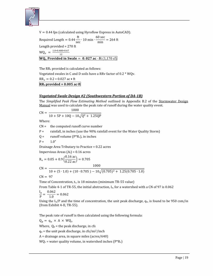
V = 0.44 fps (calculated using Hyroflow Express in AutoCAD).
Required Length = 0.44ft
sec∙ 10 min ∙
60 secmin
= 264 ft
Length provided = 270 ft
WQv = 1.0∗0.480∗0.67 12
𝐖𝐖𝐖𝐖𝐯𝐯 𝐏𝐏𝐏𝐏𝐏𝐏𝐯𝐯𝐏𝐏𝐏𝐏𝐏𝐏𝐏𝐏 𝐏𝐏𝐢𝐢 𝐒𝐒𝐒𝐒𝐒𝐒𝐒𝐒𝐏𝐏 = 𝟎𝟎.𝟎𝟎𝟏𝟏𝟎𝟎 𝐒𝐒𝐜𝐜 · 𝐜𝐜𝐟𝐟 (1,170 cf) The RRv provided is calculated as follows: Vegetated swales in C and D soils have a RRv factor of 0.2 * WQv. RRv = 0.2 ∗ 0.027 ac • ft RRv provided = 0.005 ac·ft
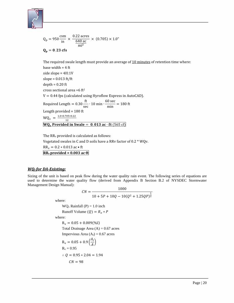
Vegetated Swale Design #2 (Southwestern Portion of DA-1B) The Simplified Peak Flow Estimating Method outlined in Appendix B.2 of the Stormwater Design Manual was used to calculate the peak rate of runoff during the water quality event.
CN = 1000
10 + 5P + 10Q − 10�Q2 + 1.25QP
Where: CN = the computed runoff curve number P = rainfall, in inches (use the 90% rainfall event for the Water Quality Storm) Q = runoff volume (P*Rv), in inches P = 1.0” Drainage Area Tributary to Practice = 0.22 acres Impervious Areas (AI) = 0.16 acres
Rv = 0.05 + 0.9 �0.16 ac0.22 ac
� = 0.705
CN = 1000
10 + (5 ∙ 1.0) + (10 ∙ 0.705 ) − 10�(0.705)2 + 1.25(0.705 ∙ 1.0)
CN = 97 Time of Concentration, tc, is 18 minutes (minimum TR-55 value) From Table 4-1 of TR-55, the initial abstraction, Ia, for a watershed with a CN of 97 is 0.062 IaP
= 0.062
1.0= 0.062
Using the Ia/P and the time of concentration, the unit peak discharge, qu, is found to be 950 csm/in (from Exhibit 4-II, TR-55). The peak rate of runoff is then calculated using the following formula: Qp = qu × A × WQv Where, Qp = the peak discharge, in cfs qu = the unit peak discharge, in cfs/mi2/inch A = drainage area, in square miles (acres/640) WQv = water quality volume, in watershed inches (P*Rv)
Page | 20
Qp = 950csmin
× 0.22 acres
640 acmi2
× (0.705) × 1.0"
𝐖𝐖𝐩𝐩 = 𝟎𝟎.𝟏𝟏𝟑𝟑 𝐜𝐜𝐜𝐜𝐜𝐜 The required swale length must provide an average of 10 minutes of retention time where: base width = 4 ft side slope = 4H:1V slope = 0.013 ft/ft depth = 0.20 ft cross sectional area =6 ft2
V = 0.44 fps (calculated using Hyroflow Express in AutoCAD).
Required Length = 0.30ft
sec∙ 10 min ∙
60 secmin
= 180 ft
Length provided = 180 ft
WQv = 1.0∗0.705∗0.22 12
𝐖𝐖𝐖𝐖𝐯𝐯 𝐏𝐏𝐏𝐏𝐏𝐏𝐯𝐯𝐏𝐏𝐏𝐏𝐏𝐏𝐏𝐏 𝐏𝐏𝐢𝐢 𝐒𝐒𝐒𝐒𝐒𝐒𝐒𝐒𝐏𝐏 = 𝟎𝟎.𝟎𝟎𝟏𝟏𝟑𝟑 𝐒𝐒𝐜𝐜 · 𝐜𝐜𝐟𝐟 (565 cf) The RRv provided is calculated as follows: Vegetated swales in C and D soils have a RRv factor of 0.2 * WQv. RRv = 0.2 ∗ 0.013 ac • ft RRv provided = 0.003 ac·ft
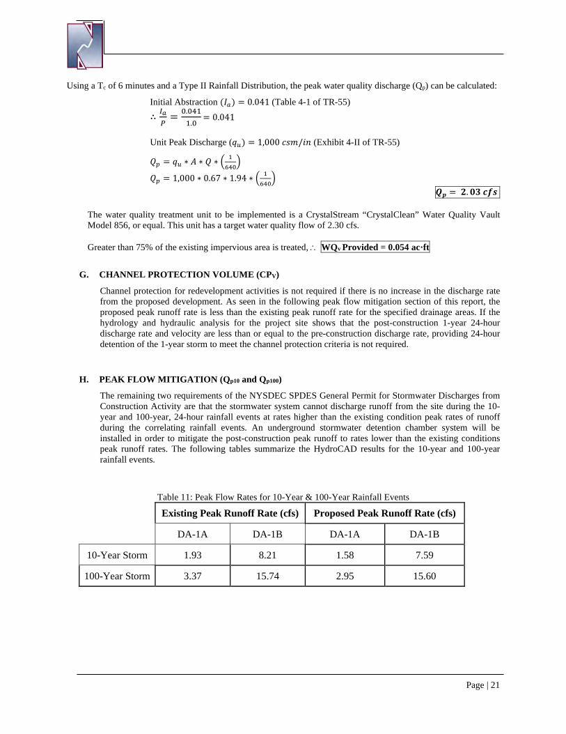
WQf for DA-Existing: Sizing of the unit is based on peak flow during the water quality rain event. The following series of equations are used to determine the water quality flow (derived from Appendix B Section B.2 of NYSDEC Stormwater Management Design Manual):
𝐶𝐶𝐶𝐶 =1000
10 + 5𝑃𝑃 + 10𝑄𝑄 − 10(𝑄𝑄2 + 1.25𝑄𝑄𝑃𝑃)12
where: WQv Rainfall (P) = 1.0 inch Runoff Volume (𝑄𝑄) = 𝑅𝑅𝑣𝑣 ∗ 𝑃𝑃
where: Rv = 0.05 + 0.009(%I) Total Drainage Area (A) = 0.67 acres Impervious Area (AI) = 0.67 acres
Rv = 0.05 + 0.9 �𝐴𝐴𝐼𝐼𝐴𝐴�
Rv = 0.95
∴ 𝑄𝑄 = 0.95 ∗ 2.04 = 1.94
𝐶𝐶𝐶𝐶 = 98
Page | 21
Using a Tc of 6 minutes and a Type II Rainfall Distribution, the peak water quality discharge (Qp) can be calculated:
Initial Abstraction (𝐼𝐼𝑎𝑎) = 0.041 (Table 4-1 of TR-55) ∴ 𝐼𝐼𝑎𝑎
𝑃𝑃= 0.041
1.0 = 0.041 Unit Peak Discharge (𝑞𝑞𝑢𝑢) = 1,000 𝑐𝑐𝑐𝑐𝑐𝑐/𝑖𝑖𝑖𝑖 (Exhibit 4-II of TR-55)
𝑄𝑄𝑝𝑝 = 𝑞𝑞𝑢𝑢 ∗ 𝐴𝐴 ∗ 𝑄𝑄 ∗ �1640�
𝑄𝑄𝑝𝑝 = 1,000 ∗ 0.67 ∗ 1.94 ∗ � 1640�
𝑸𝑸𝒑𝒑 = 𝟏𝟏.𝟎𝟎𝟑𝟑 𝒄𝒄𝒄𝒄𝒄𝒄
The water quality treatment unit to be implemented is a CrystalStream “CrystalClean” Water Quality Vault Model 856, or equal. This unit has a target water quality flow of 2.30 cfs. Greater than 75% of the existing impervious area is treated, ∴ WQv Provided = 0.054 ac·ft
G. CHANNEL PROTECTION VOLUME (CPV)
Channel protection for redevelopment activities is not required if there is no increase in the discharge rate from the proposed development. As seen in the following peak flow mitigation section of this report, the proposed peak runoff rate is less than the existing peak runoff rate for the specified drainage areas. If the hydrology and hydraulic analysis for the project site shows that the post-construction 1-year 24-hour discharge rate and velocity are less than or equal to the pre-construction discharge rate, providing 24-hour detention of the 1-year storm to meet the channel protection criteria is not required.
H. PEAK FLOW MITIGATION (Qp10 and Qp100)
The remaining two requirements of the NYSDEC SPDES General Permit for Stormwater Discharges from Construction Activity are that the stormwater system cannot discharge runoff from the site during the 10-year and 100-year, 24-hour rainfall events at rates higher than the existing condition peak rates of runoff during the correlating rainfall events. An underground stormwater detention chamber system will be installed in order to mitigate the post-construction peak runoff to rates lower than the existing conditions peak runoff rates. The following tables summarize the HydroCAD results for the 10-year and 100-year rainfall events.
Table 11: Peak Flow Rates for 10-Year & 100-Year Rainfall Events
Existing Peak Runoff Rate (cfs) Proposed Peak Runoff Rate (cfs)
DA-1A DA-1B DA-1A DA-1B
10-Year Storm 1.93 8.21 1.58 7.59
100-Year Storm 3.37 15.74 2.95 15.60
Page | 22
Section IV. CONTROLS
A. EROSION AND SEDIMENT CONTROLS
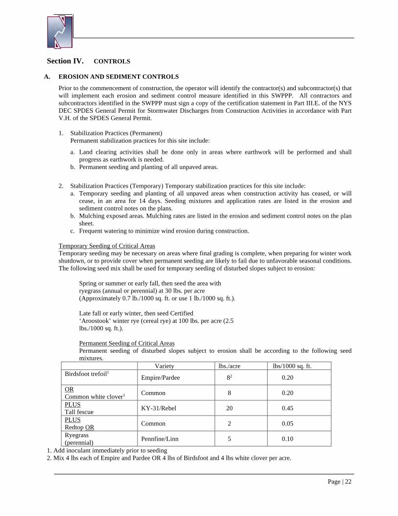
Prior to the commencement of construction, the operator will identify the contractor(s) and subcontractor(s) that will implement each erosion and sediment control measure identified in this SWPPP. All contractors and subcontractors identified in the SWPPP must sign a copy of the certification statement in Part III.E. of the NYS DEC SPDES General Permit for Stormwater Discharges from Construction Activities in accordance with Part V.H. of the SPDES General Permit. 1. Stabilization Practices (Permanent)
Permanent stabilization practices for this site include:
a. Land clearing activities shall be done only in areas where earthwork will be performed and shall progress as earthwork is needed.
b. Permanent seeding and planting of all unpaved areas.
2. Stabilization Practices (Temporary) Temporary stabilization practices for this site include: a. Temporary seeding and planting of all unpaved areas when construction activity has ceased, or will
cease, in an area for 14 days. Seeding mixtures and application rates are listed in the erosion and sediment control notes on the plans.
b. Mulching exposed areas. Mulching rates are listed in the erosion and sediment control notes on the plan sheet.
c. Frequent watering to minimize wind erosion during construction.
Temporary Seeding of Critical Areas Temporary seeding may be necessary on areas where final grading is complete, when preparing for winter work shutdown, or to provide cover when permanent seeding are likely to fail due to unfavorable seasonal conditions. The following seed mix shall be used for temporary seeding of disturbed slopes subject to erosion:
Spring or summer or early fall, then seed the area with ryegrass (annual or perennial) at 30 lbs. per acre (Approximately 0.7 lb./1000 sq. ft. or use 1 lb./1000 sq. ft.). Late fall or early winter, then seed Certified ‘Aroostook’ winter rye (cereal rye) at 100 lbs. per acre (2.5 lbs./1000 sq. ft.).
Permanent Seeding of Critical Areas Permanent seeding of disturbed slopes subject to erosion shall be according to the following seed mixtures.
Variety lbs./acre lbs/1000 sq. ft. Birdsfoot trefoil1 Empire/Pardee 82 0.20
OR Common white clover1 Common 8 0.20
PLUS Tall fescue KY-31/Rebel 20 0.45
PLUS Redtop OR Common 2 0.05
Ryegrass (perennial) Pennfine/Linn 5 0.10
1. Add inoculant immediately prior to seeding 2. Mix 4 lbs each of Empire and Pardee OR 4 lbs of Birdsfoot and 4 lbs white clover per acre.
Page | 23
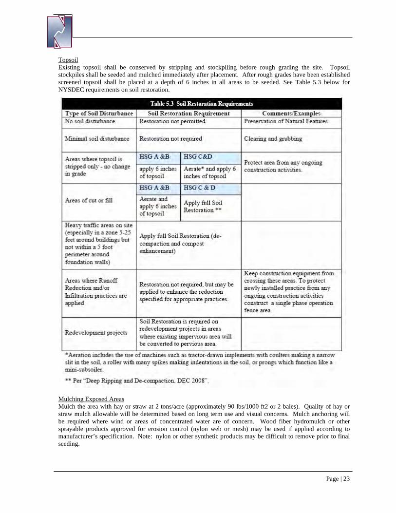
Topsoil Existing topsoil shall be conserved by stripping and stockpiling before rough grading the site. Topsoil stockpiles shall be seeded and mulched immediately after placement. After rough grades have been established screened topsoil shall be placed at a depth of 6 inches in all areas to be seeded. See Table 5.3 below for NYSDEC requirements on soil restoration.
Mulching Exposed Areas Mulch the area with hay or straw at 2 tons/acre (approximately 90 lbs/1000 ft2 or 2 bales). Quality of hay or straw mulch allowable will be determined based on long term use and visual concerns. Mulch anchoring will be required where wind or areas of concentrated water are of concern. Wood fiber hydromulch or other sprayable products approved for erosion control (nylon web or mesh) may be used if applied according to manufacturer’s specification. Note: nylon or other synthetic products may be difficult to remove prior to final seeding.
Page | 24
3. Structural Practices (Permanent)Permanent structural practices for this site include: a. Stone Rip-Rap reinforced outlet protection. Stone reinforced outlet protection will be provided at all
spillways and culvert outlets where velocities are sufficient to erode downstream areas, as indicated on the plans.
b. Land grading. Land grading is the reshaping of the existing land surface in accordance with a plan as determined by the engineering survey and layout. The purpose of a land grading specification is to provide erosion control and vegetative establishment on areas where the existing land is to be reshaped according to the plan.
4. Structural Practices (Temporary) Temporary structural practices for this site include:
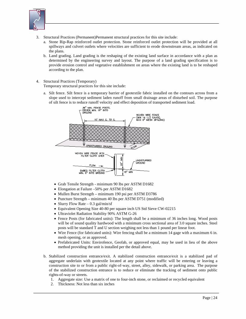
a. Silt fence. Silt fence is a temporary barrier of geotextile fabric installed on the contours across from a slope used to intercept sediment laden runoff from small drainage areas of disturbed soil. The purpose of silt fence is to reduce runoff velocity and effect deposition of transported sediment load.
• Grab Tensile Strength - minimum 90 lbs per ASTM D1682 • Elongation at Failure –50% per ASTM D1682 • Mullen Burst Strength – minimum 190 psi per ASTM D3786 • Puncture Strength – minimum 40 lbs per ASTM D751 (modified) • Slurry Flow Rate – 0.3 gal/min/sf • Equivalent Opening Size 40-80 per square inch US Std Sieve CW-02215 • Ultraviolet Radiation Stability 90% ASTM G-26 • Fence Posts (for fabricated units): The length shall be a minimum of 36 inches long. Wood posts
will be of sound quality hardwood with a minimum cross sectional area of 3.0 square inches. Steel posts will be standard T and U section weighing not less than 1 pound per linear foot.
• Wire Fence (for fabricated units): Wire fencing shall be a minimum 14 gage with a maximum 6 in. mesh opening, or as approved.
• Prefabricated Units: Envirofence, Geofab, or approved equal, may be used in lieu of the above method providing the unit is installed per the detail above.
b. Stabilized construction entrance/exit. A stabilized construction entrance/exit is a stabilized pad of
aggregate underlain with geotextile located at any point where traffic will be entering or leaving a construction site to or from a public right-of-way, street, alley, sidewalk, or parking area. The purpose of the stabilized construction entrance is to reduce or eliminate the tracking of sediment onto public rights-of-way or streets. 1. Aggregate size: Use a matrix of one to four-inch stone, or reclaimed or recycled equivalent 2. Thickness: Not less than six inches
Page | 25
3. Width: 24-foot minimum 4. Length: As required, but not less than 50 feet 5. Geotextile: To be placed over the entire area to be covered with aggregate. Piping of surface water
under entrance shall be provided as necessary.
c. Concrete washout area. A temporary excavated or above ground lined constructed pit where concrete truck mixers and equipment can be washed after their loads have been discharged to prevent highly alkaline runoff from entering storm drainage systems or leaching into the soil.
1. The washout facility is sized to contain solids, wash water and rainfall. The maximum size shall be eight feet by eight feet at the bottom and two feet deep. If excavated, then the side slopes shall be 2:1 (horizontal to vertical).
2. The facility shall be located a minimum of 100 feet from drainage swales, storm drain inlets, wetlands, streams, and other surface waters. Surface waters shall be prevented from entering the structure except got the access road. Appropriate access shall be provided with a gravel access road sloped down to the structure. Signs shall be placed to direct drivers to the facility after their load is discharged.
3. All washout facilities will be lined to prevent leaching of liquids into the ground. The liner shall be plastic sheeting with a minimum thickness of 10 mils with no holes or tears, and anchored beyond the top of the pit with an earthen berm, sand bags, stone, or other structural appurtenance except at the access point.
5. Sequence of Major Activities The contractor will be responsible for implementing the above listed erosion and sediment control practices. The contractor may designate these tasks to certain subcontractors as is seen fit, but the ultimate responsibility for implementing these controls and ensuring their proper function remains with the contractor. The order of activities shall be as follows:
a. Conduct a preconstruction meeting with all involved parties b. Delineate boundaries of disturbance as per the layout and grading plans c. Construct temporary construction entrance at the location on the erosion and sediment control plan d. Install silt fence in locations shown on the layout and grading plans e. Establish staging areas on the project site f. Construct temporary sediment trap for use during construction g. Remove topsoil, stockpile and stabilize h. Rough grade site including swales and provide temporary stabilization when idle for more than 7 days i. Building slabs and building construction j. Connect and install utilities k. Construct stormwater conveyance and underground detention chamber system. l. Compact gravel along driveways and parking areas m. Complete final grading of the site n. Restore all compacted soils in accordance with section 5.1.6 of the NYS Stormwater Design Manual o. Provide final stabilization and landscaping of new area p. Provide final stabilization of disturbed areas via seeding and mulching. q. Remove sediment trap and finalize grading of detention basin r. Provide final stabilization of detention basin area via seeding and mulching. s. Remove all temporary stabilization control practices
Disturbed areas of the site where construction activity has ceased for more than seven (7) days shall be temporarily seeded and mulched. The Erosion & Sediment Control plan is shown in Appendix F.
Page | 26
Section V. INSPECTION AND MAINTENANCE REQUIREMENTS
Best management practices, both construction and operational, must be inspected and maintained on a routine basis to ensure continued compliance with the NYS SPDES General Permit for Stormwater Discharges from Construction Activity. The contractor is responsible for inspecting the erosion and sediment control practices, the operator/owner is responsible for providing a qualified professional, as defined in the SPDES General Permit, to perform the required weekly inspections of the construction site from the time earth-disturbing activities begin until final stabilization is achieved and the Notice of Termination is filed. The contractor will obtain copies of all local and state regulations that are applicable to stormwater management, erosion control, and pollution minimization at this job site and will comply fully with such regulations. The contractor will submit written evidence of such compliance if requested by the operator or any agent of a regulatory body. The contractor will comply with all conditions of the NYSDEC SPDES General Permit for Stormwater Discharges from Construction Activity, including the conditions related to maintaining the SWPPP and evidence of compliance with the SWPPP at the job site and allowing regulatory personnel access to the job site and to records to determine compliance.
A. CONSTRUCTION MAINTENANCE/INSPECTION PROCEDURES
The operator shall maintain a record of all inspection reports in a site logbook. The logbook shall be maintained on site and be made available to the permitting authority upon request. Prior to the commencement of construction, the operator shall certify in the site logbook that the SWPPP, prepared in accordance with Part III.D. of the NYS DEC SPDES General Permit for Discharges from Construction Activities, meets all Federal, State and local erosion and sediment control requirements. The operator shall post at the site, in a publicly accessible location, a summary of the site inspection activities monthly. The following inspection and maintenance practices will be used to maintain erosion and sediment controls and stabilization measures.
1. Inspection and Maintenance Practices a. Inspections shall occur once every seven calendar days. b. At a minimum, the qualified inspector shall inspect all erosion and sediment control
practices to ensure integrity and effectiveness, all post-construction stormwater management practices under construction to ensure that they are constructed in conformance with the SWPPP, all areas of disturbance that have not achieved final stabilization, all points of discharge to natural surface water bodies located within or immediately adjacent to the property boundaries of the construction site, and all points of discharge from the construction site.
c. The qualified inspector shall prepare an inspection report subsequent to each and every inspection. At a minimum, the inspection report shall include and/or address the following:
i. Date and time of inspection; ii. Name and title of person(s) performing inspection;
iii. A description of the weather and soil conditions (e.g. dry, wet, saturated) at the time of the inspection;
iv. A description of the condition of the runoff at all points of discharge from the construction site. This shall include identification of any discharges of sediment from the construction site. Include discharges from conveyance systems (i.e. pipes, culverts, ditches, etc.) and overland flow;
v. A description of the condition of all natural surface water bodies located within, or immediately adjacent to, the property boundaries of the construction site which receive runoff from disturbed areas. This shall include identification of any discharges of sediment to the surface water body;
vi. Identification of all erosion and sediment control practices that need repair or maintenance;
vii. Identification of all erosion and sediment control practices that were not installed or are not functioning as designed and need to be reinstalled or replaced;
viii. Description and sketch of areas that are disturbed at the time of the inspection and areas that have been stabilized (temporarily and/or final) since the last inspection;
Page | 27
ix. Current phase of construction of all post-construction stormwater management practices and identification of all construction that is not in conformance with the SWPPP and technical standards;
x. Corrective action(s) that must be taken to install, repair, replace, or maintain erosion and sediment control practices; and to correct deficiencies identified with the construction of the post-construction stormwater management practice(s); and
xi. Digital photographs, with date stamp, that clearly show the condition of all practices that have been identified as needing corrective actions. The qualified inspector shall attach paper color copies of the digital photographs to the inspection report being maintained onsite within seven (7) calendar days of the date of the inspection. The qualified inspector shall also take digital photographs, with date stamp, that clearly show the condition of the practice(s) after the corrective action has been completed. The qualified inspector shall attach paper color copies of the digital photographs to the inspection report that documents the completion of the corrective action work within seven (7) calendar days of that inspection.
d. Within one business day of the completion of an inspection, the qualified inspector shall notify the owner or operator and appropriate contractor or subcontractor of any corrective actions that need to be taken. The contractor or subcontractor shall begin implementing the corrective actions within one business day of this notification and shall complete the corrective actions in a reasonable time frame.
e. All inspection reports shall be signed by the qualified inspector. The inspection reports shall be maintained on the site.
f. Erosion and Sediment Control Inspection/Maintenance i. Silt Fence: Silt fence shall be inspected for depth of sediment, tears, etc., to see if
the fabric is securely attached to the fence posts, and to see that the fence posts are securely in the ground. Built up sediment will be removed from silt fence when it has reached one-third the height of the fence.
ii. Stabilized Construction Entrance/Exit: The entrance shall be maintained in a condition which will prevent tracking of sediment onto public rights-of-way. This may require periodic top dressing with additional aggregate. All sediment spilled, dropped, or washed onto public rights-of-way must be removed immediately. When necessary, wheels must be cleaned to remove sediment prior to entrance onto public rights-of-way. When washing is required, it shall be done on an area stabilized with aggregate, which drains into an approved sediment-trapping device. All sediment shall be prevented from entering storm drains, ditches, or water courses.
iii. Seeding: Temporary and permanent seeding and all other stabilization measures will be inspected for bare spots, washouts, and healthy growth.
2. Inspection and Maintenance Report Forms • Once installation of any required or optional erosion control device or measure has been
implemented, at least twice every seven calendar days a Qualified Professional shall inspect each practice. The inspector shall use the forms found in this SWPPP to inventory and report the condition of each measure to assist in maintaining the erosion and sediment control measures in good working order.
• These report forms shall become an integral part of the SWPPP and shall be made readily accessible to governmental inspection officials, the operator’s engineer, and the operator for review upon request during visits to the project site. In addition, copies of the reports shall be provided to any of these persons upon requires, via mail or facsimile transmission. Inspection and maintenance report forms are to be maintained by the permittee for three years following the final stabilization of the site.
• The operator shall also prepare a written summary of its status with respect to compliance with the NYSDEC SPDES General Permit for Stormwater Discharges from Construction Activity at a minimum frequency of every three months during which coverage under the SPDES General Permit exists. The summary should address the status of achieving each
Page | 28
component of the SWPPP. The reports shall be signed by the signatory of the NOI or a duly authorized person and be retained at the construction site.
1. Other Record Keeping Requirements The contractor shall keep the following records related to construction activities at the site: • Dates when major grading activities occur and the areas which were graded. • Dates and details concerning the installation of structural controls. • Dates when construction activities cease in an area. • Dates when an area is stabilized, either temporarily or permanently. • Dates of rainfall and the amount of rainfall. • Dates and descriptions of the character and amount of any spills of hazardous materials. • Records of reports filed with regulatory agencies if reportable quantities of hazardous
materials are spilled.
B. OPERATION MAINTENANCE AND INSPECTION PROCEDURES
Long-term maintenance of the stormwater mitigation basins and swales will be the responsibility of the owner and/or the tenant. Maintenance and inspection check lists have been included in Appendix D. 1. Embankments and emergency spillways will be inspected annually and after major storm events. Items to
be inspected include: a. Vegetation and ground cover is adequate to prevent erosion. b. No embankment erosion has occurred. c. No animal burrows into embankments. d. No unauthorized planting. e. No cracking, bulging or sliding of dam. f. Emergency spillway is in good condition, free of silt buildup and debris. g. No leaks or seepage is occurring on downstream face. h. All slope protection and riprap is intact and no failure has occurred.
2. Grass lined swales shall be inspected and maintained as follows:
a. All channels are free of debris on monthly basis. b. No visible evidence of erosion. c. Mowing shall be performed as needed. Inspect to ensure minimum mowing depth has not been
exceeded. d. Dewatering of swales between storms. Inspect monthly or as necessary. e. Inspect swales for sediment deposition annually and clean, as necessary.
3. Underground stormwater detention chamber system is to be inspected and maintained as per the
manufacturers specifications.
Page | 29
Section VI. MATERIALS MANAGEMENT PLAN
A. MATERIALS COVERED
The following materials or substances are expected to be present onsite during construction:
Concrete/Additives/Wastes Cleaning Solvents Detergents Petroleum Based Products Paints/Solvents Pesticides Acids Solid and Construction Wastes Sanitary Wastes Soil Stabilization Additives
B. MATERIAL MANAGEMENT PRACTICES
The following are the material management practices that will be used to reduce the risk of spills or other accidental exposure of materials and substances to stormwater runoff. The job site superintendent will be responsible for ensuring that these procedures are followed.
1. Good Housekeeping The following good housekeeping practices will be followed onsite during the construction project.
a. An effort will be made to store only enough products required to do the job. b. All materials stored onsite will be stored in a neat, orderly manner and, if possible, under a roof or in a
containment area. At a minimum, all containers will be stored with their lids on when not in use. Drip pans shall be provided under all dispensers.
c. Products will be kept in their original containers with the original manufacturer’s label in legible condition.
d. Substances will not be mixed with one another unless recommended by the manufacturer. e. Whenever possible, all of a product will be used up before disposing of the container. f. Manufacturer’s recommendations for proper use and disposal will be followed. g. The job site superintendent will be responsible for daily inspections to ensure proper use and disposal
of materials.
2. Hazardous Products These practices will be used to reduce the risks associated with hazardous materials. Material Safety Data Sheets (MSDS’s) for each substance with hazardous properties that is used on the job site will be obtained and used for the proper management of potential wastes that may result from these products. An MSDS will be posted in the immediate area where such product is stored and/or used and another copy of each MSDS will be maintained in the SWPPP file at the job site construction trailer office. Each employee who must handle a substance with hazardous properties will be instructed on the use of MSDS sheets and the specific information in the applicable MSDS for the product he/she is using, particularly regarding spill control techniques.
a. Products will be kept in original containers with the original labels in legible condition. b. Original labels and material safety data sheets (MSDS’s) will be procured and used for each material. c. If surplus product must be disposed of, manufacturer’s or local/state/federal recommended methods for
proper disposal will be followed.
3. Hazardous Waste All hazardous waste materials will be disposed of by the contractor in the manner specified by local, state, and/or federal regulations and by the manufacturer of such products. Site personnel will be instructed in these practices by the job site superintendent, who will also be responsible for seeing that these practices are followed.
Page | 30
4. Product Specific Practices The following product specific practices will be followed on the job site.
a. Petroleum Products All onsite vehicles will be monitored for leaks and receive regular preventative maintenance to reduce the chance of leakage. Petroleum products will be stored in tightly sealed containers, which are clearly labeled. Any petroleum storage tanks used onsite will have a dike or berm containment structure constructed around it to contain any spills, which may occur. Drip pans shall be provided for all dispensers. Any asphalt substances used onsite will be applied per the manufacturer’s recommendations.
b. Fertilizers Due to the onsite public water supply that will be constructed as part of this project, the use of fertilizers is not allowed without the written authorization of the operator. Authorization will be based on the specific product’s possible contaminants and impacts to the groundwater.
c. Paints, Paint Solvents, and Cleaning Solvents All containers will be tightly sealed and stored when not in use. Excess paint and solvents will not be discharged to the storm sewer system but will be properly disposed of per manufacturer’s instructions or state and federal regulations.
5. Concrete Wastes Concrete trucks will be allowed to wash out or discharge surplus concrete or drum wash water on the site, but only in either (1) specifically designated area which has been prepared to prevent contact between the concrete and/or washout and stormwater which will be discharged from the site or (2) in locations where waste concrete can be poured into forms to make riprap or other useful concrete products.
The hardened residue from the concrete washout areas will be disposed of in the same manner as other non-hazardous construction waste materials or may be broken up and used on site as deemed appropriate by the contractor. The job site superintendent will be responsible for seeing that these procedures are followed.
All concrete washout areas will be in an area where the likelihood of the area contributing to storm water discharges is negligible. If required, additional BMPs must be implemented to prevent concrete wastes from contributing to storm water discharges.
6. Solid and Construction Wastes All waste materials will be collected and stored in a securely lidded metal dumpster rented from a local waste management company which must be a solid waste management company licensed to do business in New York State. The dumpster will comply with all local and state solid waste management regulations.
All trash and construction debris from the site will be deposited in the dumpster. The dumpster will be emptied a minimum of twice per week or more often if necessary, and the trash will be hauled to a landfill approved by New York State. No construction waste materials will be buried on site. All personnel will be instructed regarding the correct procedures for waste disposal.
All waste dumpsters and roll-off containers will be in an area where the likelihood of the containers contributing to storm water discharges is negligible. If required, additional BMPs must be implemented, such as sandbags around the base, to prevent wastes from contributing to storm water discharges.
7. Sanitary Wastes All sanitary waste will be collected from the portable units a minimum of three times per week by a licensed portable facility provider in complete compliance with local and state regulation.
All sanitary waste units will be in an area where the likelihood of the unit contributing to storm water discharges is negligible. If required, additional BMPs must be implemented, such as sandbags around the base, to prevent wastes from contributing to storm water discharges.
Page | 31
Section VII. SPILL PREVENTION AND RESPONSE PROCEDURES
The contractor will train all personnel in the proper handling and cleanup of spilled materials. No spilled hazardous materials or hazardous wastes will be allowed to come in contact with storm water discharges. If such contact occurs, the storm water discharge will be contained on site until appropriate measures in compliance with state and federal regulations are taken to dispose of such contaminated storm water. It shall be the responsibility of the job site superintendent to properly train all personnel in spill prevention and clean up procedures.
In order to minimize the potential for a spill of hazardous materials to come into contact with storm water, the following steps will be implemented:
1. All materials with hazardous properties (such as pesticides, petroleum products, fertilizers, detergents, construction chemicals, acids, paints, paint solvents, cleaning solvents, additives for soil stabilization, concrete curing compounds and additives, etc.) will be stored in a secure location, with their lids on, preferably under cover, when not in use.
2. The minimum practical quantity of all such materials will be kept on the job site. 3. A spill control and containment kit (containing, for example, absorbent materials, acid neutralizing
powder, brooms, dust pans, mops, rags, gloves, goggles, plastic and metal trash containers, etc.) will be provided at the storage site.
4. Manufacturer’s recommended methods for spill cleanup will be clearly posted and site personnel will be trained regarding these procedures and the location of the information and cleanup supplies.
In the event of a spill, the following procedures should be followed
1. All spills will be cleaned up immediately after discovery. 2. The spill area will be kept well ventilated and personnel will wear appropriate protective clothing to
prevent injury from contact with the hazardous substances. 3. The project manager and the Engineer of Record will be notified immediately.
Spills of toxic or hazardous materials will be reported to the appropriate federal, state, and/or local government agency, regardless of the size of the spill. Spills of amounts that exceed Reportable Quantities of certain substances specifically mentioned in federal regulations (40 CFR 110, 40 CFR 117, and 40 CFR 302) must be immediately reported to the NYSDEC 24-Hour Spill Hotline at 1-800-457-7362.
4. If the spill exceeds a Reportable Quantity, the SWPPP must be modified within seven (7) calendar days of knowledge of the discharge to provide a description of the release, the circumstances leading to the release, and the date of the release. The plans must identify measures to prevent the recurrence of such releases and to respond to such releases.
The job site superintendent will be the spill prevention and response coordinator. He will designate the individuals who will receive spill prevention and response training. These individuals will each become responsible for a particular phase of prevention and response. The names of these personnel will be posted in the material storage area and in the office trailer onsite.
Page | 32
Section VIII. CONTROL OF NON-STORMWATER DISCHARGES
Certain types of discharges are allowable under the NYS-DEC SPDES General Permit for Stormwater Discharges from Construction Activity, and it is the intent of this SWPPP to allow such discharges. These types of discharges will be allowed under the conditions that no pollutants will be allowed to come in contact with the water prior to or after its discharge. The control measures, which have been outlined previously in this SWPPP, will be strictly followed to ensure that no contamination of these non-stormwater discharges takes place. The following non-storm water discharges are allowed by the NYS-DEC and may occur at the job site:
1. Discharges from firefighting activities 2. Fire hydrant flushing 3. Waters to which cleansers or other components have not been added that are used to wash vehicles or
control dust 4. Routine external building wash down which does not use detergents 5. Pavement wash waters where spills or leaks of toxic or hazardous materials have not occurred (unless
all spilled material has been removed) and where detergents are not used 6. Air conditioning condensate 7. Springs 8. Foundation or footing drains where flows are not contaminated with process materials such as
solvents.
Section IX. CERTIFICATION AND NOTIFICATION
The New York State Department of Environmental Conservation requires that the operator and the contractor make certifications of knowledge of the contents of this SWPPP and agreement to follow the SWPPP. The terms of the General Permit also require that each contractor sign the SWPPP plan, thereby making them co-permittees and acknowledging their responsibility for certain operational aspects of the plan. These certifications should be signed before the contractor begins activities and should be filed with the site’s SWPPP at the jobsite.
APPENDIX A: HYDRO CAD – EXISTING CONDITIONS

[THIS PAGE IS LEFT INTENTIONALLY BLANK]
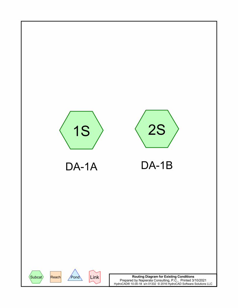
1S
DA-1A
2S
DA-1B
Routing Diagram for Existing ConditionsPrepared by Napierala Consulting, P.C., Printed 3/10/2021
HydroCAD® 10.00-18 s/n 01332 © 2016 HydroCAD Software Solutions LLC
Subcat Reach Pond Link
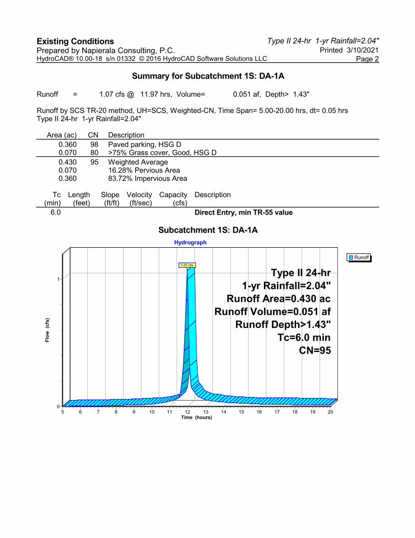
Type II 24-hr 1-yr Rainfall=2.04"Existing Conditions Printed 3/10/2021Prepared by Napierala Consulting, P.C.
Page 2HydroCAD® 10.00-18 s/n 01332 © 2016 HydroCAD Software Solutions LLC
Summary for Subcatchment 1S: DA-1A
Runoff = 1.07 cfs @ 11.97 hrs, Volume= 0.051 af, Depth> 1.43"
Runoff by SCS TR-20 method, UH=SCS, Weighted-CN, Time Span= 5.00-20.00 hrs, dt= 0.05 hrsType II 24-hr 1-yr Rainfall=2.04"
Area (ac) CN Description0.360 98 Paved parking, HSG D0.070 80 >75% Grass cover, Good, HSG D0.430 95 Weighted Average0.070 16.28% Pervious Area0.360 83.72% Impervious Area
Tc Length Slope Velocity Capacity Description(min) (feet) (ft/ft) (ft/sec) (cfs)
6.0 Direct Entry, min TR-55 value
Subcatchment 1S: DA-1A
Runoff
Hydrograph
Time (hours)201918171615141312111098765
Flo
w (
cfs)
1
0
Type II 24-hr1-yr Rainfall=2.04"
Runoff Area=0.430 acRunoff Volume=0.051 af
Runoff Depth>1.43"Tc=6.0 min
CN=95
1.07 cfs

Type II 24-hr 1-yr Rainfall=2.04"Existing Conditions Printed 3/10/2021Prepared by Napierala Consulting, P.C.
Page 3HydroCAD® 10.00-18 s/n 01332 © 2016 HydroCAD Software Solutions LLC
Summary for Subcatchment 2S: DA-1B
Runoff = 3.86 cfs @ 12.08 hrs, Volume= 0.236 af, Depth> 0.98"
Runoff by SCS TR-20 method, UH=SCS, Weighted-CN, Time Span= 5.00-20.00 hrs, dt= 0.05 hrsType II 24-hr 1-yr Rainfall=2.04"
Area (ac) CN Description1.510 98 Paved parking, HSG D0.840 80 >75% Grass cover, Good, HSG D0.560 77 Woods, Good, HSG D2.910 89 Weighted Average1.400 48.11% Pervious Area1.510 51.89% Impervious Area
Tc Length Slope Velocity Capacity Description(min) (feet) (ft/ft) (ft/sec) (cfs)13.2 100 0.0350 0.13 Sheet Flow, sheet flow
Grass: Dense n= 0.240 P2= 2.38"2.6 362 0.0200 2.28 Shallow Concentrated Flow, shallow flow
Unpaved Kv= 16.1 fps15.8 462 Total
Subcatchment 2S: DA-1B
Runoff
Hydrograph
Time (hours)201918171615141312111098765
Flo
w (
cfs)
4
3
2
1
0
Type II 24-hr1-yr Rainfall=2.04"
Runoff Area=2.910 acRunoff Volume=0.236 af
Runoff Depth>0.98"Flow Length=462'
Tc=15.8 minCN=89
3.86 cfs
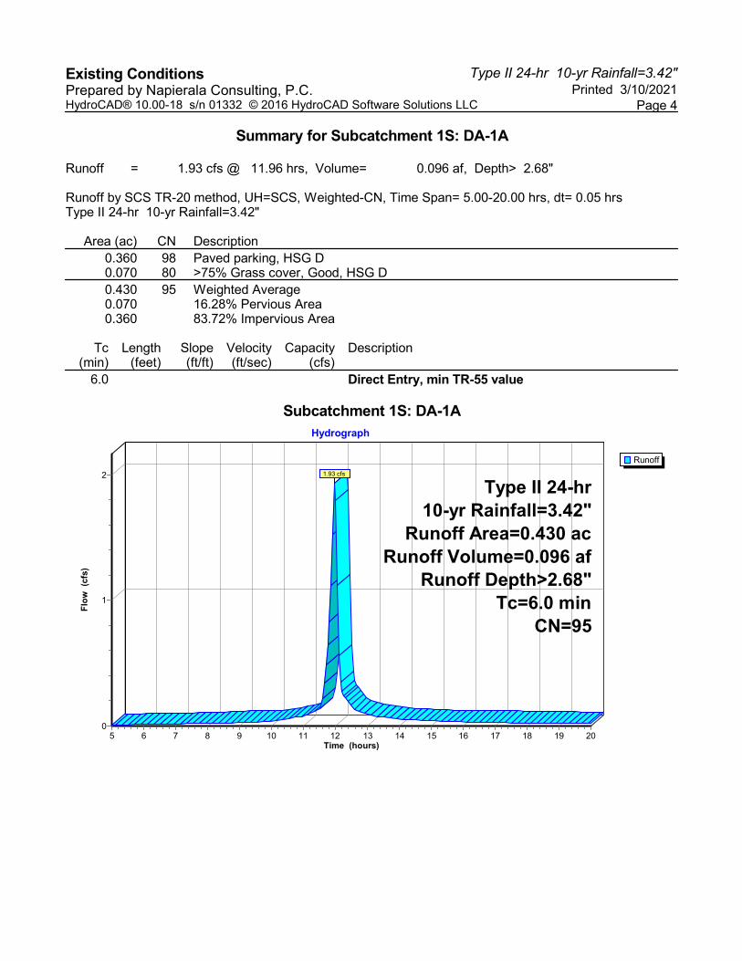
Type II 24-hr 10-yr Rainfall=3.42"Existing Conditions Printed 3/10/2021Prepared by Napierala Consulting, P.C.
Page 4HydroCAD® 10.00-18 s/n 01332 © 2016 HydroCAD Software Solutions LLC
Summary for Subcatchment 1S: DA-1A
Runoff = 1.93 cfs @ 11.96 hrs, Volume= 0.096 af, Depth> 2.68"
Runoff by SCS TR-20 method, UH=SCS, Weighted-CN, Time Span= 5.00-20.00 hrs, dt= 0.05 hrsType II 24-hr 10-yr Rainfall=3.42"
Area (ac) CN Description0.360 98 Paved parking, HSG D0.070 80 >75% Grass cover, Good, HSG D0.430 95 Weighted Average0.070 16.28% Pervious Area0.360 83.72% Impervious Area
Tc Length Slope Velocity Capacity Description(min) (feet) (ft/ft) (ft/sec) (cfs)
6.0 Direct Entry, min TR-55 value
Subcatchment 1S: DA-1A
Runoff
Hydrograph
Time (hours)201918171615141312111098765
Flo
w (
cfs)
2
1
0
Type II 24-hr10-yr Rainfall=3.42"
Runoff Area=0.430 acRunoff Volume=0.096 af
Runoff Depth>2.68"Tc=6.0 min
CN=95
1.93 cfs
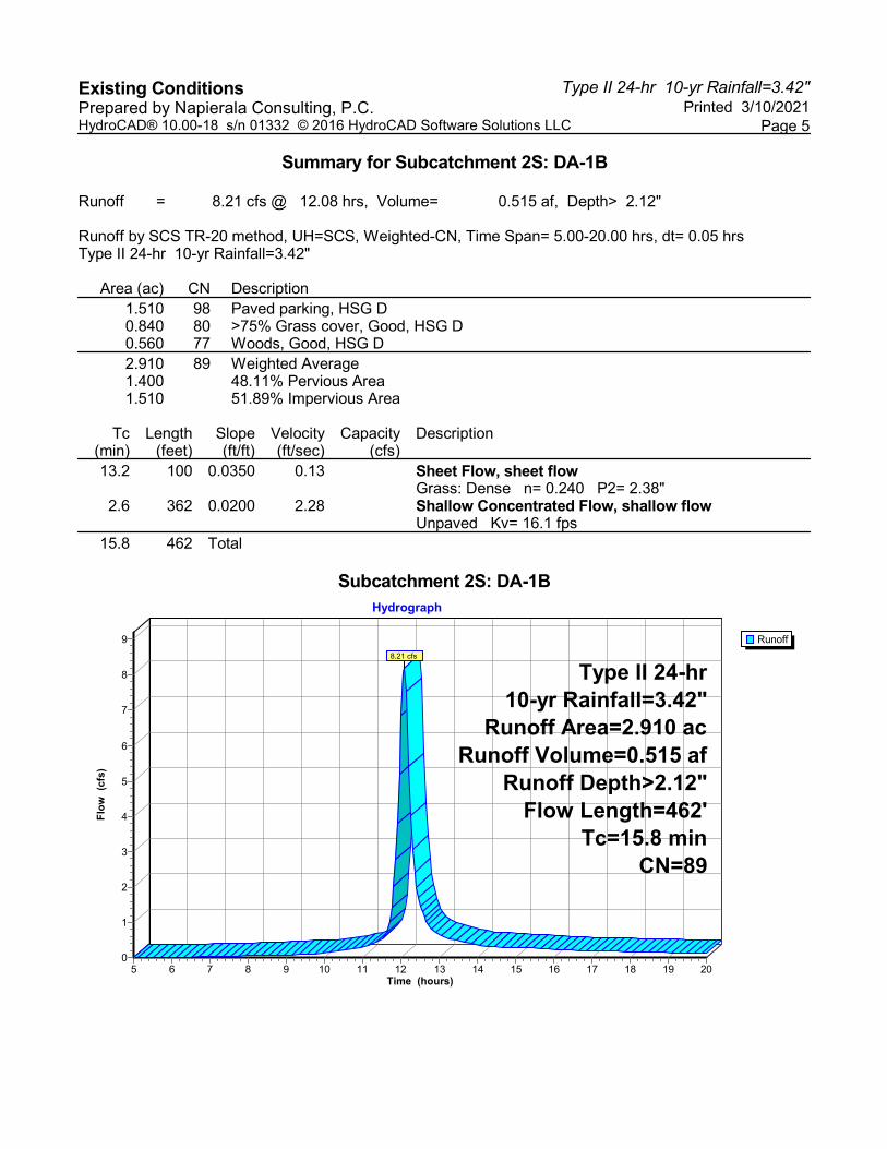
Type II 24-hr 10-yr Rainfall=3.42"Existing Conditions Printed 3/10/2021Prepared by Napierala Consulting, P.C.
Page 5HydroCAD® 10.00-18 s/n 01332 © 2016 HydroCAD Software Solutions LLC
Summary for Subcatchment 2S: DA-1B
Runoff = 8.21 cfs @ 12.08 hrs, Volume= 0.515 af, Depth> 2.12"
Runoff by SCS TR-20 method, UH=SCS, Weighted-CN, Time Span= 5.00-20.00 hrs, dt= 0.05 hrsType II 24-hr 10-yr Rainfall=3.42"
Area (ac) CN Description1.510 98 Paved parking, HSG D0.840 80 >75% Grass cover, Good, HSG D0.560 77 Woods, Good, HSG D2.910 89 Weighted Average1.400 48.11% Pervious Area1.510 51.89% Impervious Area
Tc Length Slope Velocity Capacity Description(min) (feet) (ft/ft) (ft/sec) (cfs)13.2 100 0.0350 0.13 Sheet Flow, sheet flow
Grass: Dense n= 0.240 P2= 2.38"2.6 362 0.0200 2.28 Shallow Concentrated Flow, shallow flow
Unpaved Kv= 16.1 fps15.8 462 Total
Subcatchment 2S: DA-1B
Runoff
Hydrograph
Time (hours)201918171615141312111098765
Flo
w (
cfs)
9
8
7
6
5
4
3
2
1
0
Type II 24-hr10-yr Rainfall=3.42"
Runoff Area=2.910 acRunoff Volume=0.515 af
Runoff Depth>2.12"Flow Length=462'
Tc=15.8 minCN=89
8.21 cfs
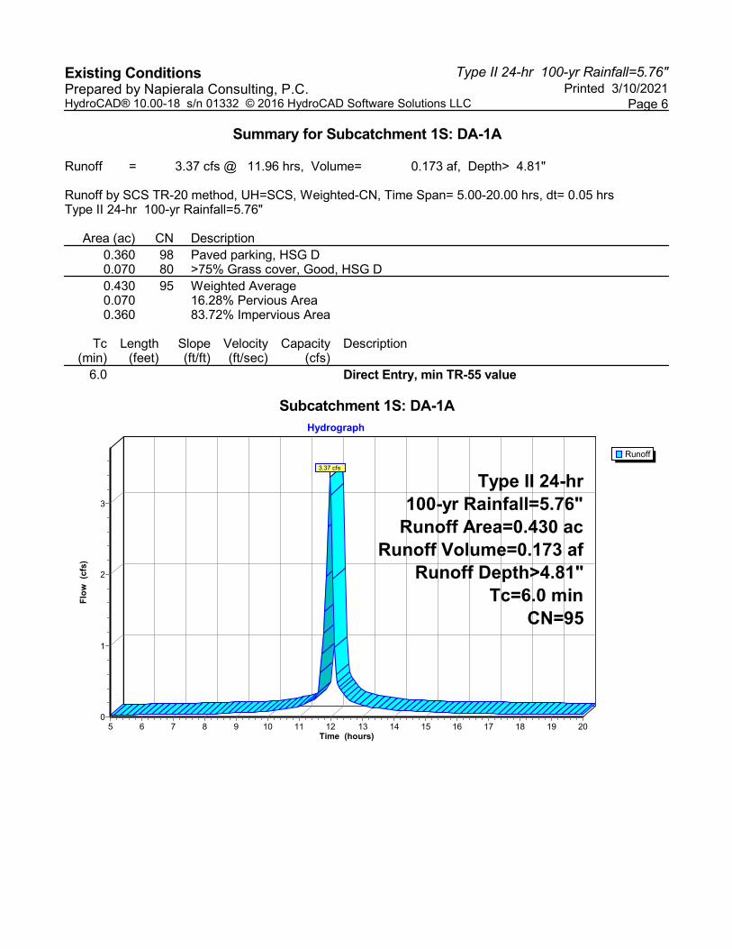
Type II 24-hr 100-yr Rainfall=5.76"Existing Conditions Printed 3/10/2021Prepared by Napierala Consulting, P.C.
Page 6HydroCAD® 10.00-18 s/n 01332 © 2016 HydroCAD Software Solutions LLC
Summary for Subcatchment 1S: DA-1A
Runoff = 3.37 cfs @ 11.96 hrs, Volume= 0.173 af, Depth> 4.81"
Runoff by SCS TR-20 method, UH=SCS, Weighted-CN, Time Span= 5.00-20.00 hrs, dt= 0.05 hrsType II 24-hr 100-yr Rainfall=5.76"
Area (ac) CN Description0.360 98 Paved parking, HSG D0.070 80 >75% Grass cover, Good, HSG D0.430 95 Weighted Average0.070 16.28% Pervious Area0.360 83.72% Impervious Area
Tc Length Slope Velocity Capacity Description(min) (feet) (ft/ft) (ft/sec) (cfs)
6.0 Direct Entry, min TR-55 value
Subcatchment 1S: DA-1A
Runoff
Hydrograph
Time (hours)201918171615141312111098765
Flo
w (
cfs)
3
2
1
0
Type II 24-hr100-yr Rainfall=5.76"
Runoff Area=0.430 acRunoff Volume=0.173 af
Runoff Depth>4.81"Tc=6.0 min
CN=95
3.37 cfs

Type II 24-hr 100-yr Rainfall=5.76"Existing Conditions Printed 3/10/2021Prepared by Napierala Consulting, P.C.
Page 7HydroCAD® 10.00-18 s/n 01332 © 2016 HydroCAD Software Solutions LLC
Summary for Subcatchment 2S: DA-1B
Runoff = 15.74 cfs @ 12.07 hrs, Volume= 1.022 af, Depth> 4.21"
Runoff by SCS TR-20 method, UH=SCS, Weighted-CN, Time Span= 5.00-20.00 hrs, dt= 0.05 hrsType II 24-hr 100-yr Rainfall=5.76"
Area (ac) CN Description1.510 98 Paved parking, HSG D0.840 80 >75% Grass cover, Good, HSG D0.560 77 Woods, Good, HSG D2.910 89 Weighted Average1.400 48.11% Pervious Area1.510 51.89% Impervious Area
Tc Length Slope Velocity Capacity Description(min) (feet) (ft/ft) (ft/sec) (cfs)13.2 100 0.0350 0.13 Sheet Flow, sheet flow
Grass: Dense n= 0.240 P2= 2.38"2.6 362 0.0200 2.28 Shallow Concentrated Flow, shallow flow
Unpaved Kv= 16.1 fps15.8 462 Total
Subcatchment 2S: DA-1B
Runoff
Hydrograph
Time (hours)201918171615141312111098765
Flo
w (
cfs)
17
16
15
14
13
12
11
10
9
8
7
6
5
4
3
2
1
0
Type II 24-hr100-yr Rainfall=5.76"
Runoff Area=2.910 acRunoff Volume=1.022 af
Runoff Depth>4.21"Flow Length=462'
Tc=15.8 minCN=89
15.74 cfs

[THIS PAGE IS LEFT INTENTIONALLY BLANK]
APPENDIX B: HYDRO CAD – PROPOSED CONDITIONS

[THIS PAGE IS LEFT INTENTIONALLY BLANK]
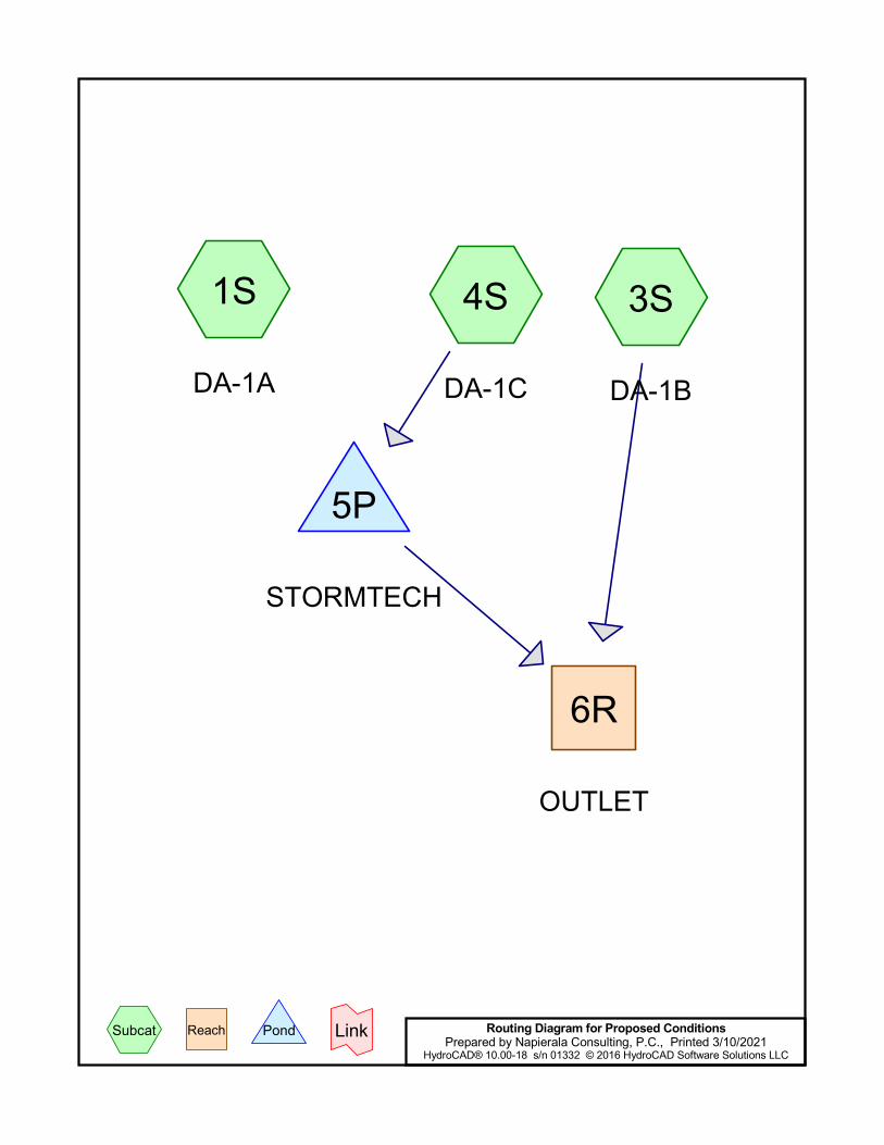
1S
DA-1A
3S
DA-1B
4S
DA-1C
6R
OUTLET
5P
STORMTECH
Routing Diagram for Proposed ConditionsPrepared by Napierala Consulting, P.C., Printed 3/10/2021
HydroCAD® 10.00-18 s/n 01332 © 2016 HydroCAD Software Solutions LLC
Subcat Reach Pond Link
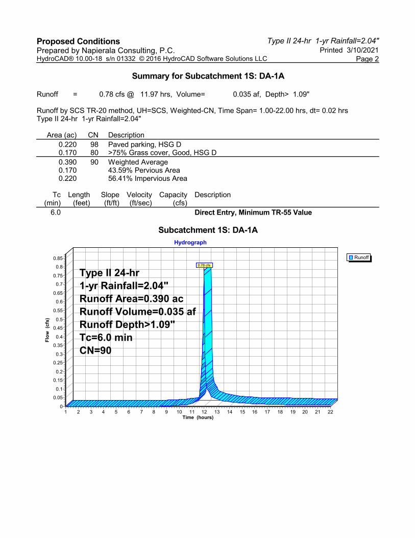
Type II 24-hr 1-yr Rainfall=2.04"Proposed Conditions Printed 3/10/2021Prepared by Napierala Consulting, P.C.
Page 2HydroCAD® 10.00-18 s/n 01332 © 2016 HydroCAD Software Solutions LLC
Summary for Subcatchment 1S: DA-1A
Runoff = 0.78 cfs @ 11.97 hrs, Volume= 0.035 af, Depth> 1.09"
Runoff by SCS TR-20 method, UH=SCS, Weighted-CN, Time Span= 1.00-22.00 hrs, dt= 0.02 hrsType II 24-hr 1-yr Rainfall=2.04"
Area (ac) CN Description0.220 98 Paved parking, HSG D0.170 80 >75% Grass cover, Good, HSG D0.390 90 Weighted Average0.170 43.59% Pervious Area0.220 56.41% Impervious Area
Tc Length Slope Velocity Capacity Description(min) (feet) (ft/ft) (ft/sec) (cfs)
6.0 Direct Entry, Minimum TR-55 Value
Subcatchment 1S: DA-1A
Runoff
Hydrograph
Time (hours)22212019181716151413121110987654321
Flo
w (
cfs)
0.85
0.8
0.75
0.7
0.65
0.6
0.55
0.5
0.45
0.4
0.35
0.3
0.25
0.2
0.15
0.1
0.05
0
Type II 24-hr1-yr Rainfall=2.04"Runoff Area=0.390 acRunoff Volume=0.035 afRunoff Depth>1.09"Tc=6.0 minCN=90
0.78 cfs
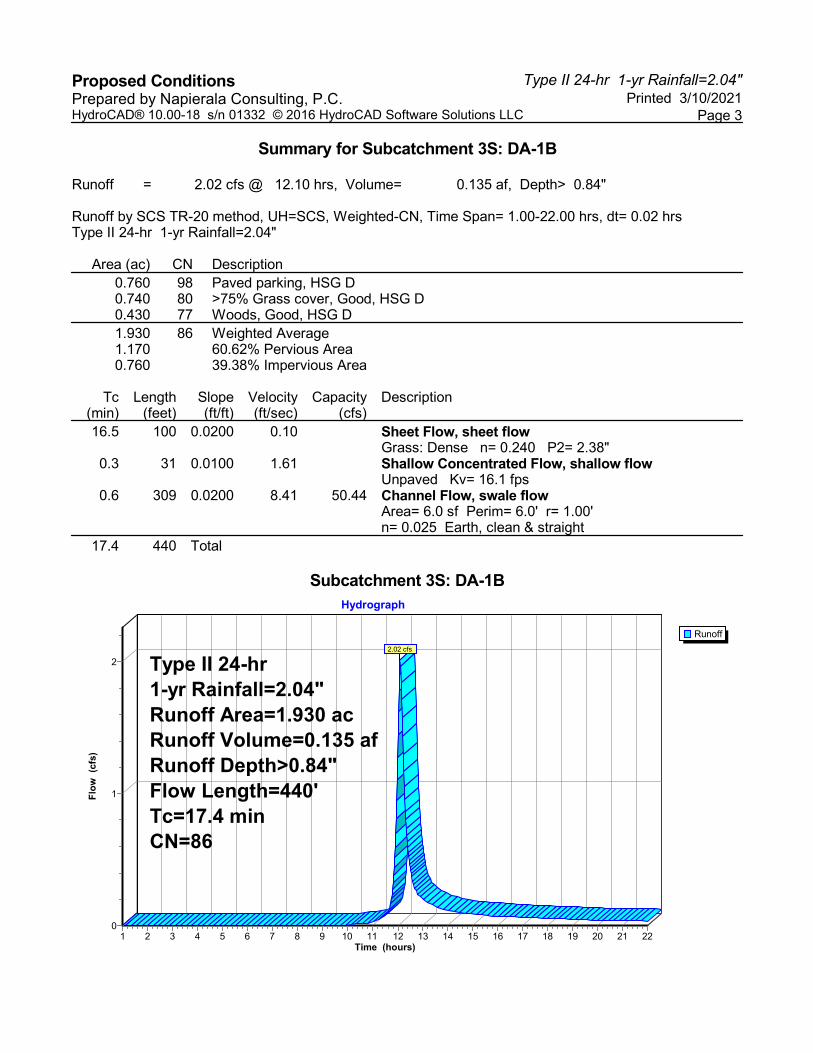
Type II 24-hr 1-yr Rainfall=2.04"Proposed Conditions Printed 3/10/2021Prepared by Napierala Consulting, P.C.
Page 3HydroCAD® 10.00-18 s/n 01332 © 2016 HydroCAD Software Solutions LLC
Summary for Subcatchment 3S: DA-1B
Runoff = 2.02 cfs @ 12.10 hrs, Volume= 0.135 af, Depth> 0.84"
Runoff by SCS TR-20 method, UH=SCS, Weighted-CN, Time Span= 1.00-22.00 hrs, dt= 0.02 hrsType II 24-hr 1-yr Rainfall=2.04"
Area (ac) CN Description0.760 98 Paved parking, HSG D0.740 80 >75% Grass cover, Good, HSG D0.430 77 Woods, Good, HSG D1.930 86 Weighted Average1.170 60.62% Pervious Area0.760 39.38% Impervious Area
Tc Length Slope Velocity Capacity Description(min) (feet) (ft/ft) (ft/sec) (cfs)16.5 100 0.0200 0.10 Sheet Flow, sheet flow
Grass: Dense n= 0.240 P2= 2.38"0.3 31 0.0100 1.61 Shallow Concentrated Flow, shallow flow
Unpaved Kv= 16.1 fps0.6 309 0.0200 8.41 50.44 Channel Flow, swale flow
Area= 6.0 sf Perim= 6.0' r= 1.00'n= 0.025 Earth, clean & straight
17.4 440 Total
Subcatchment 3S: DA-1B
Runoff
Hydrograph
Time (hours)22212019181716151413121110987654321
Flo
w (
cfs)
2
1
0
Type II 24-hr1-yr Rainfall=2.04"Runoff Area=1.930 acRunoff Volume=0.135 afRunoff Depth>0.84"Flow Length=440'Tc=17.4 minCN=86
2.02 cfs
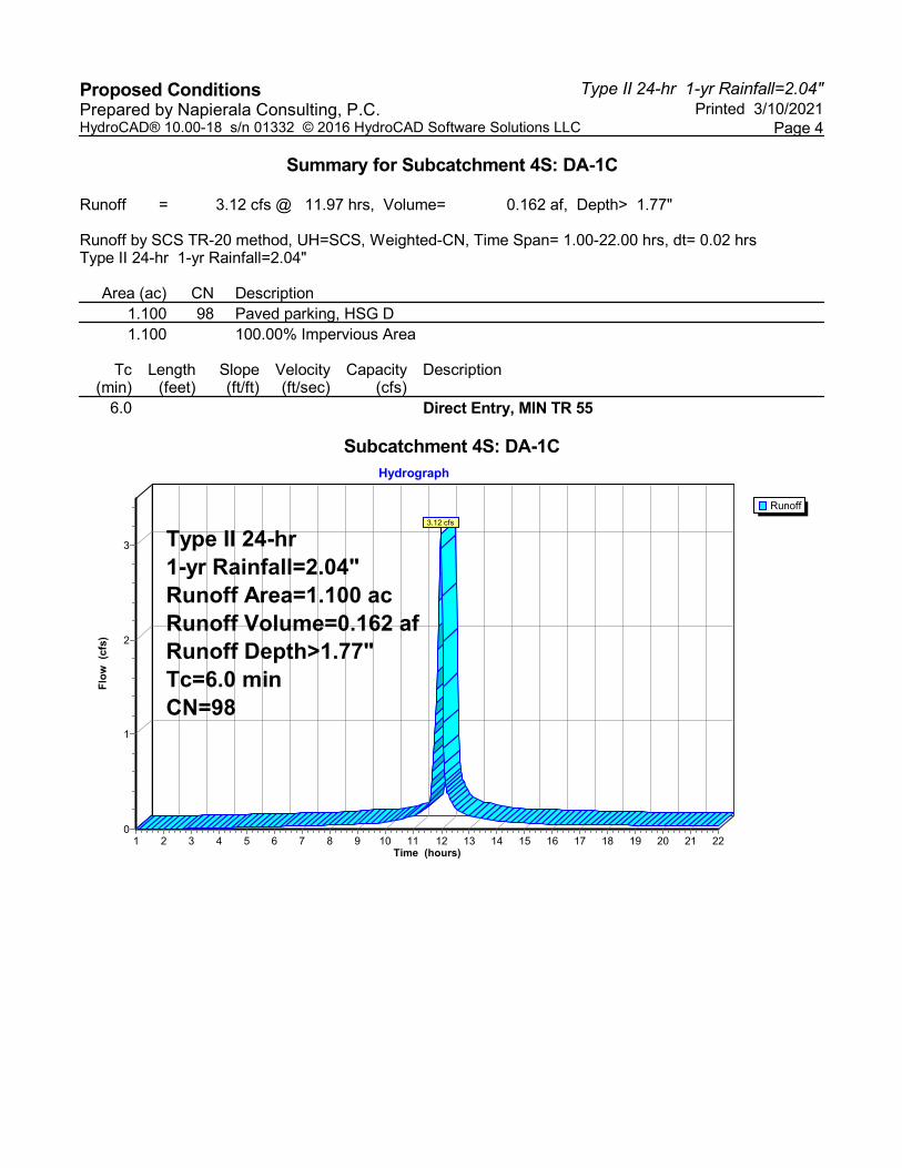
Type II 24-hr 1-yr Rainfall=2.04"Proposed Conditions Printed 3/10/2021Prepared by Napierala Consulting, P.C.
Page 4HydroCAD® 10.00-18 s/n 01332 © 2016 HydroCAD Software Solutions LLC
Summary for Subcatchment 4S: DA-1C
Runoff = 3.12 cfs @ 11.97 hrs, Volume= 0.162 af, Depth> 1.77"
Runoff by SCS TR-20 method, UH=SCS, Weighted-CN, Time Span= 1.00-22.00 hrs, dt= 0.02 hrsType II 24-hr 1-yr Rainfall=2.04"
Area (ac) CN Description1.100 98 Paved parking, HSG D1.100 100.00% Impervious Area
Tc Length Slope Velocity Capacity Description(min) (feet) (ft/ft) (ft/sec) (cfs)
6.0 Direct Entry, MIN TR 55
Subcatchment 4S: DA-1C
Runoff
Hydrograph
Time (hours)22212019181716151413121110987654321
Flo
w (
cfs)
3
2
1
0
Type II 24-hr1-yr Rainfall=2.04"Runoff Area=1.100 acRunoff Volume=0.162 afRunoff Depth>1.77"Tc=6.0 minCN=98
3.12 cfs

Type II 24-hr 1-yr Rainfall=2.04"Proposed Conditions Printed 3/10/2021Prepared by Napierala Consulting, P.C.
Page 5HydroCAD® 10.00-18 s/n 01332 © 2016 HydroCAD Software Solutions LLC
Summary for Reach 6R: OUTLET
Inflow Area = 3.030 ac, 61.39% Impervious, Inflow Depth > 1.17" for 1-yr eventInflow = 3.69 cfs @ 12.08 hrs, Volume= 0.296 afOutflow = 3.69 cfs @ 12.08 hrs, Volume= 0.296 af, Atten= 0%, Lag= 0.0 min
Routing by Stor-Ind+Trans method, Time Span= 1.00-22.00 hrs, dt= 0.02 hrs
Reach 6R: OUTLET
InflowOutflow
Hydrograph
Time (hours)22212019181716151413121110987654321
Flo
w (
cfs)
4
3
2
1
0
Inflow Area=3.030 ac3.69 cfs
3.69 cfs

Type II 24-hr 1-yr Rainfall=2.04"Proposed Conditions Printed 3/10/2021Prepared by Napierala Consulting, P.C.
Page 6HydroCAD® 10.00-18 s/n 01332 © 2016 HydroCAD Software Solutions LLC
Summary for Pond 5P: STORMTECH
Inflow Area = 1.100 ac,100.00% Impervious, Inflow Depth > 1.77" for 1-yr eventInflow = 3.12 cfs @ 11.97 hrs, Volume= 0.162 afOutflow = 1.75 cfs @ 12.05 hrs, Volume= 0.161 af, Atten= 44%, Lag= 5.0 minPrimary = 1.75 cfs @ 12.05 hrs, Volume= 0.161 af
Routing by Stor-Ind method, Time Span= 1.00-22.00 hrs, dt= 0.02 hrsPeak Elev= 427.43' @ 12.05 hrs Surf.Area= 0.067 ac Storage= 0.040 af
Plug-Flow detention time= 25.1 min calculated for 0.161 af (99% of inflow)Center-of-Mass det. time= 20.8 min ( 767.1 - 746.2 )
Volume Invert Avail.Storage Storage Description#1 426.40' 0.789 af 24.83'W x 117.58'L x 30.00'H Drainage Stone
2.011 af Overall - 0.038 af Embedded = 1.973 af x 40.0% Voids#2 426.90' 0.038 af ADS_StormTech RC-310 +Cap x 112 Inside #1
Effective Size= 28.9"W x 16.0"H => 2.07 sf x 7.12'L = 14.7 cfOverall Size= 34.0"W x 16.0"H x 7.56'L with 0.44' Overlap7 Rows of 16 Chambers
0.827 af Total Available Storage
Device Routing Invert Outlet Devices#1 Primary 426.40' 6.0" Round Underdrain Outlet
L= 8.0' CPP, projecting, no headwall, Ke= 0.900 Inlet / Outlet Invert= 426.40' / 426.20' S= 0.0250 '/' Cc= 0.900 n= 0.013 Corrugated PE, smooth interior, Flow Area= 0.20 sf
#2 Primary 426.70' 10.0" Round Outlet Pipe 1 L= 8.0' CPP, projecting, no headwall, Ke= 0.900 Inlet / Outlet Invert= 426.70' / 426.60' S= 0.0125 '/' Cc= 0.900 n= 0.013 Corrugated PE, smooth interior, Flow Area= 0.55 sf
#3 Primary 427.80' 12.0" Round Outlet Pipe 2 L= 8.0' CPP, projecting, no headwall, Ke= 0.900 Inlet / Outlet Invert= 427.80' / 427.70' S= 0.0125 '/' Cc= 0.900 n= 0.013 Corrugated PE, smooth interior, Flow Area= 0.79 sf
Primary OutFlow Max=1.74 cfs @ 12.05 hrs HW=427.42' (Free Discharge)1=Underdrain Outlet (Inlet Controls 0.66 cfs @ 3.34 fps)2=Outlet Pipe 1 (Barrel Controls 1.09 cfs @ 2.89 fps)3=Outlet Pipe 2 ( Controls 0.00 cfs)
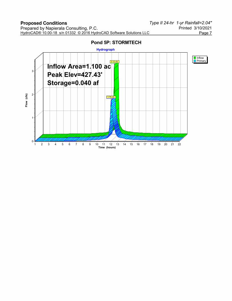
Type II 24-hr 1-yr Rainfall=2.04"Proposed Conditions Printed 3/10/2021Prepared by Napierala Consulting, P.C.
Page 7HydroCAD® 10.00-18 s/n 01332 © 2016 HydroCAD Software Solutions LLC
Pond 5P: STORMTECH
InflowPrimary
Hydrograph
Time (hours)22212019181716151413121110987654321
Flo
w (
cfs)
3
2
1
0
Inflow Area=1.100 acPeak Elev=427.43'Storage=0.040 af
3.12 cfs
1.75 cfs

Type II 24-hr 10-yr Rainfall=3.42"Proposed Conditions Printed 3/10/2021Prepared by Napierala Consulting, P.C.
Page 8HydroCAD® 10.00-18 s/n 01332 © 2016 HydroCAD Software Solutions LLC
Summary for Subcatchment 1S: DA-1A
Runoff = 1.58 cfs @ 11.97 hrs, Volume= 0.075 af, Depth> 2.30"
Runoff by SCS TR-20 method, UH=SCS, Weighted-CN, Time Span= 1.00-22.00 hrs, dt= 0.02 hrsType II 24-hr 10-yr Rainfall=3.42"
Area (ac) CN Description0.220 98 Paved parking, HSG D0.170 80 >75% Grass cover, Good, HSG D0.390 90 Weighted Average0.170 43.59% Pervious Area0.220 56.41% Impervious Area
Tc Length Slope Velocity Capacity Description(min) (feet) (ft/ft) (ft/sec) (cfs)
6.0 Direct Entry, Minimum TR-55 Value
Subcatchment 1S: DA-1A
Runoff
Hydrograph
Time (hours)22212019181716151413121110987654321
Flo
w (
cfs) 1
0
Type II 24-hr10-yr Rainfall=3.42"Runoff Area=0.390 acRunoff Volume=0.075 afRunoff Depth>2.30"Tc=6.0 minCN=90
1.58 cfs
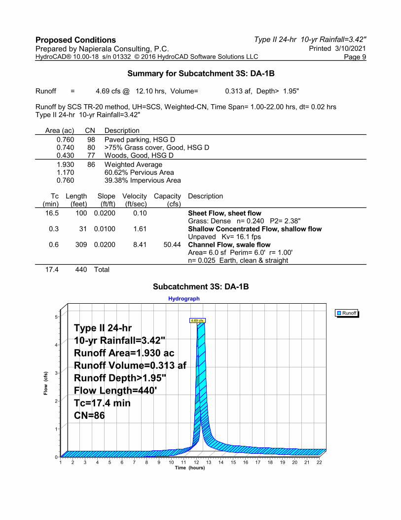
Type II 24-hr 10-yr Rainfall=3.42"Proposed Conditions Printed 3/10/2021Prepared by Napierala Consulting, P.C.
Page 9HydroCAD® 10.00-18 s/n 01332 © 2016 HydroCAD Software Solutions LLC
Summary for Subcatchment 3S: DA-1B
Runoff = 4.69 cfs @ 12.10 hrs, Volume= 0.313 af, Depth> 1.95"
Runoff by SCS TR-20 method, UH=SCS, Weighted-CN, Time Span= 1.00-22.00 hrs, dt= 0.02 hrsType II 24-hr 10-yr Rainfall=3.42"
Area (ac) CN Description0.760 98 Paved parking, HSG D0.740 80 >75% Grass cover, Good, HSG D0.430 77 Woods, Good, HSG D1.930 86 Weighted Average1.170 60.62% Pervious Area0.760 39.38% Impervious Area
Tc Length Slope Velocity Capacity Description(min) (feet) (ft/ft) (ft/sec) (cfs)16.5 100 0.0200 0.10 Sheet Flow, sheet flow
Grass: Dense n= 0.240 P2= 2.38"0.3 31 0.0100 1.61 Shallow Concentrated Flow, shallow flow
Unpaved Kv= 16.1 fps0.6 309 0.0200 8.41 50.44 Channel Flow, swale flow
Area= 6.0 sf Perim= 6.0' r= 1.00'n= 0.025 Earth, clean & straight
17.4 440 Total
Subcatchment 3S: DA-1B
Runoff
Hydrograph
Time (hours)22212019181716151413121110987654321
Flo
w (
cfs)
5
4
3
2
1
0
Type II 24-hr10-yr Rainfall=3.42"Runoff Area=1.930 acRunoff Volume=0.313 afRunoff Depth>1.95"Flow Length=440'Tc=17.4 minCN=86
4.69 cfs
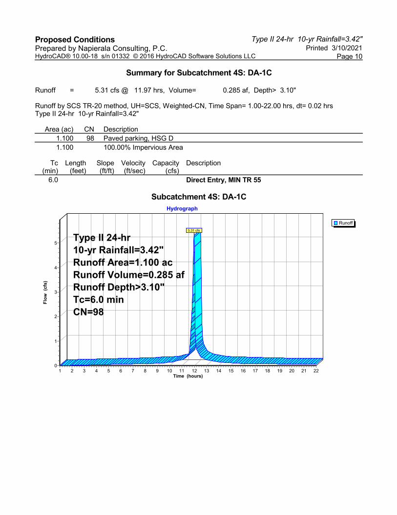
Type II 24-hr 10-yr Rainfall=3.42"Proposed Conditions Printed 3/10/2021Prepared by Napierala Consulting, P.C.
Page 10HydroCAD® 10.00-18 s/n 01332 © 2016 HydroCAD Software Solutions LLC
Summary for Subcatchment 4S: DA-1C
Runoff = 5.31 cfs @ 11.97 hrs, Volume= 0.285 af, Depth> 3.10"
Runoff by SCS TR-20 method, UH=SCS, Weighted-CN, Time Span= 1.00-22.00 hrs, dt= 0.02 hrsType II 24-hr 10-yr Rainfall=3.42"
Area (ac) CN Description1.100 98 Paved parking, HSG D1.100 100.00% Impervious Area
Tc Length Slope Velocity Capacity Description(min) (feet) (ft/ft) (ft/sec) (cfs)
6.0 Direct Entry, MIN TR 55
Subcatchment 4S: DA-1C
Runoff
Hydrograph
Time (hours)22212019181716151413121110987654321
Flo
w (
cfs)
5
4
3
2
1
0
Type II 24-hr10-yr Rainfall=3.42"Runoff Area=1.100 acRunoff Volume=0.285 afRunoff Depth>3.10"Tc=6.0 minCN=98
5.31 cfs
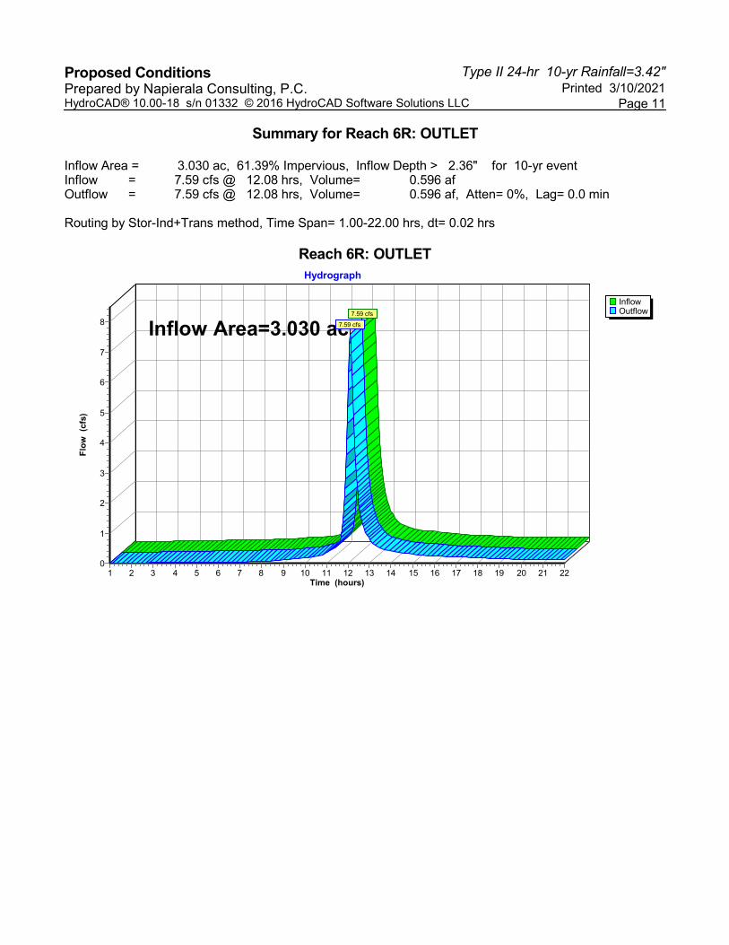
Type II 24-hr 10-yr Rainfall=3.42"Proposed Conditions Printed 3/10/2021Prepared by Napierala Consulting, P.C.
Page 11HydroCAD® 10.00-18 s/n 01332 © 2016 HydroCAD Software Solutions LLC
Summary for Reach 6R: OUTLET
Inflow Area = 3.030 ac, 61.39% Impervious, Inflow Depth > 2.36" for 10-yr eventInflow = 7.59 cfs @ 12.08 hrs, Volume= 0.596 afOutflow = 7.59 cfs @ 12.08 hrs, Volume= 0.596 af, Atten= 0%, Lag= 0.0 min
Routing by Stor-Ind+Trans method, Time Span= 1.00-22.00 hrs, dt= 0.02 hrs
Reach 6R: OUTLET
InflowOutflow
Hydrograph
Time (hours)22212019181716151413121110987654321
Flo
w (
cfs)
8
7
6
5
4
3
2
1
0
Inflow Area=3.030 ac7.59 cfs
7.59 cfs
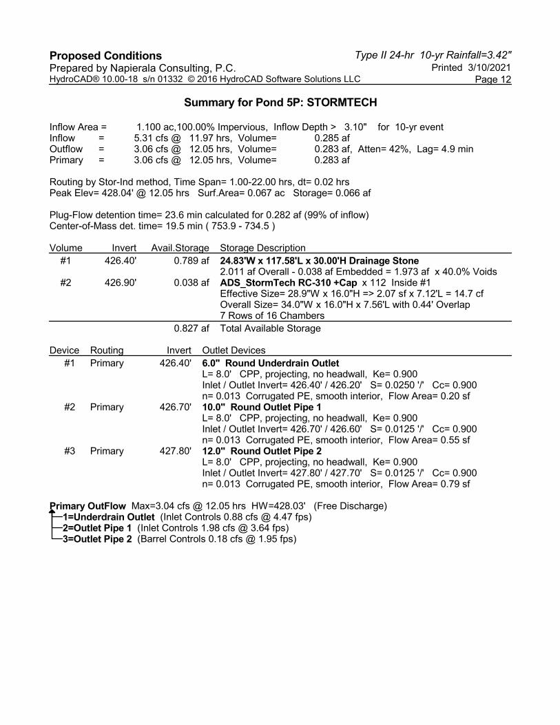
Type II 24-hr 10-yr Rainfall=3.42"Proposed Conditions Printed 3/10/2021Prepared by Napierala Consulting, P.C.
Page 12HydroCAD® 10.00-18 s/n 01332 © 2016 HydroCAD Software Solutions LLC
Summary for Pond 5P: STORMTECH
Inflow Area = 1.100 ac,100.00% Impervious, Inflow Depth > 3.10" for 10-yr eventInflow = 5.31 cfs @ 11.97 hrs, Volume= 0.285 afOutflow = 3.06 cfs @ 12.05 hrs, Volume= 0.283 af, Atten= 42%, Lag= 4.9 minPrimary = 3.06 cfs @ 12.05 hrs, Volume= 0.283 af
Routing by Stor-Ind method, Time Span= 1.00-22.00 hrs, dt= 0.02 hrsPeak Elev= 428.04' @ 12.05 hrs Surf.Area= 0.067 ac Storage= 0.066 af
Plug-Flow detention time= 23.6 min calculated for 0.282 af (99% of inflow)Center-of-Mass det. time= 19.5 min ( 753.9 - 734.5 )
Volume Invert Avail.Storage Storage Description#1 426.40' 0.789 af 24.83'W x 117.58'L x 30.00'H Drainage Stone
2.011 af Overall - 0.038 af Embedded = 1.973 af x 40.0% Voids#2 426.90' 0.038 af ADS_StormTech RC-310 +Cap x 112 Inside #1
Effective Size= 28.9"W x 16.0"H => 2.07 sf x 7.12'L = 14.7 cfOverall Size= 34.0"W x 16.0"H x 7.56'L with 0.44' Overlap7 Rows of 16 Chambers
0.827 af Total Available Storage
Device Routing Invert Outlet Devices#1 Primary 426.40' 6.0" Round Underdrain Outlet
L= 8.0' CPP, projecting, no headwall, Ke= 0.900 Inlet / Outlet Invert= 426.40' / 426.20' S= 0.0250 '/' Cc= 0.900 n= 0.013 Corrugated PE, smooth interior, Flow Area= 0.20 sf
#2 Primary 426.70' 10.0" Round Outlet Pipe 1 L= 8.0' CPP, projecting, no headwall, Ke= 0.900 Inlet / Outlet Invert= 426.70' / 426.60' S= 0.0125 '/' Cc= 0.900 n= 0.013 Corrugated PE, smooth interior, Flow Area= 0.55 sf
#3 Primary 427.80' 12.0" Round Outlet Pipe 2 L= 8.0' CPP, projecting, no headwall, Ke= 0.900 Inlet / Outlet Invert= 427.80' / 427.70' S= 0.0125 '/' Cc= 0.900 n= 0.013 Corrugated PE, smooth interior, Flow Area= 0.79 sf
Primary OutFlow Max=3.04 cfs @ 12.05 hrs HW=428.03' (Free Discharge)1=Underdrain Outlet (Inlet Controls 0.88 cfs @ 4.47 fps)2=Outlet Pipe 1 (Inlet Controls 1.98 cfs @ 3.64 fps)3=Outlet Pipe 2 (Barrel Controls 0.18 cfs @ 1.95 fps)
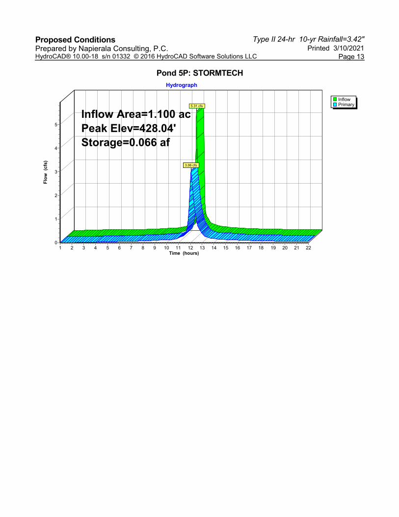
Type II 24-hr 10-yr Rainfall=3.42"Proposed Conditions Printed 3/10/2021Prepared by Napierala Consulting, P.C.
Page 13HydroCAD® 10.00-18 s/n 01332 © 2016 HydroCAD Software Solutions LLC
Pond 5P: STORMTECH
InflowPrimary
Hydrograph
Time (hours)22212019181716151413121110987654321
Flo
w (
cfs)
5
4
3
2
1
0
Inflow Area=1.100 acPeak Elev=428.04'Storage=0.066 af
5.31 cfs
3.06 cfs
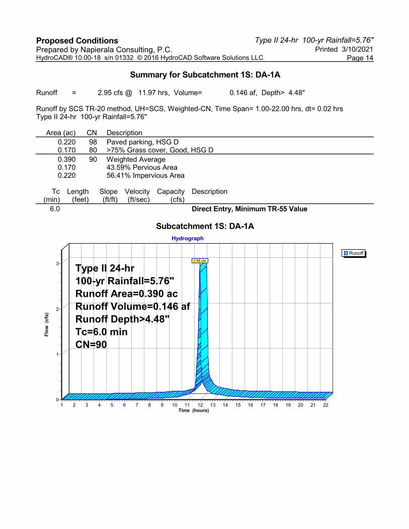
Type II 24-hr 100-yr Rainfall=5.76"Proposed Conditions Printed 3/10/2021Prepared by Napierala Consulting, P.C.
Page 14HydroCAD® 10.00-18 s/n 01332 © 2016 HydroCAD Software Solutions LLC
Summary for Subcatchment 1S: DA-1A
Runoff = 2.95 cfs @ 11.97 hrs, Volume= 0.146 af, Depth> 4.48"
Runoff by SCS TR-20 method, UH=SCS, Weighted-CN, Time Span= 1.00-22.00 hrs, dt= 0.02 hrsType II 24-hr 100-yr Rainfall=5.76"
Area (ac) CN Description0.220 98 Paved parking, HSG D0.170 80 >75% Grass cover, Good, HSG D0.390 90 Weighted Average0.170 43.59% Pervious Area0.220 56.41% Impervious Area
Tc Length Slope Velocity Capacity Description(min) (feet) (ft/ft) (ft/sec) (cfs)
6.0 Direct Entry, Minimum TR-55 Value
Subcatchment 1S: DA-1A
Runoff
Hydrograph
Time (hours)22212019181716151413121110987654321
Flo
w (
cfs)
3
2
1
0
Type II 24-hr100-yr Rainfall=5.76"Runoff Area=0.390 acRunoff Volume=0.146 afRunoff Depth>4.48"Tc=6.0 minCN=90
2.95 cfs
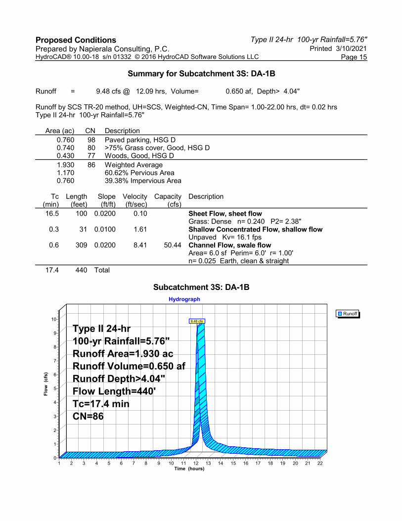
Type II 24-hr 100-yr Rainfall=5.76"Proposed Conditions Printed 3/10/2021Prepared by Napierala Consulting, P.C.
Page 15HydroCAD® 10.00-18 s/n 01332 © 2016 HydroCAD Software Solutions LLC
Summary for Subcatchment 3S: DA-1B
Runoff = 9.48 cfs @ 12.09 hrs, Volume= 0.650 af, Depth> 4.04"
Runoff by SCS TR-20 method, UH=SCS, Weighted-CN, Time Span= 1.00-22.00 hrs, dt= 0.02 hrsType II 24-hr 100-yr Rainfall=5.76"
Area (ac) CN Description0.760 98 Paved parking, HSG D0.740 80 >75% Grass cover, Good, HSG D0.430 77 Woods, Good, HSG D1.930 86 Weighted Average1.170 60.62% Pervious Area0.760 39.38% Impervious Area
Tc Length Slope Velocity Capacity Description(min) (feet) (ft/ft) (ft/sec) (cfs)16.5 100 0.0200 0.10 Sheet Flow, sheet flow
Grass: Dense n= 0.240 P2= 2.38"0.3 31 0.0100 1.61 Shallow Concentrated Flow, shallow flow
Unpaved Kv= 16.1 fps0.6 309 0.0200 8.41 50.44 Channel Flow, swale flow
Area= 6.0 sf Perim= 6.0' r= 1.00'n= 0.025 Earth, clean & straight
17.4 440 Total
Subcatchment 3S: DA-1B
Runoff
Hydrograph
Time (hours)22212019181716151413121110987654321
Flo
w (
cfs)
10
9
8
7
6
5
4
3
2
1
0
Type II 24-hr100-yr Rainfall=5.76"Runoff Area=1.930 acRunoff Volume=0.650 afRunoff Depth>4.04"Flow Length=440'Tc=17.4 minCN=86
9.48 cfs

Type II 24-hr 100-yr Rainfall=5.76"Proposed Conditions Printed 3/10/2021Prepared by Napierala Consulting, P.C.
Page 16HydroCAD® 10.00-18 s/n 01332 © 2016 HydroCAD Software Solutions LLC
Summary for Subcatchment 4S: DA-1C
Runoff = 9.00 cfs @ 11.97 hrs, Volume= 0.493 af, Depth> 5.38"
Runoff by SCS TR-20 method, UH=SCS, Weighted-CN, Time Span= 1.00-22.00 hrs, dt= 0.02 hrsType II 24-hr 100-yr Rainfall=5.76"
Area (ac) CN Description1.100 98 Paved parking, HSG D1.100 100.00% Impervious Area
Tc Length Slope Velocity Capacity Description(min) (feet) (ft/ft) (ft/sec) (cfs)
6.0 Direct Entry, MIN TR 55
Subcatchment 4S: DA-1C
Runoff
Hydrograph
Time (hours)22212019181716151413121110987654321
Flo
w (
cfs)
10
9
8
7
6
5
4
3
2
1
0
Type II 24-hr100-yr Rainfall=5.76"Runoff Area=1.100 acRunoff Volume=0.493 afRunoff Depth>5.38"Tc=6.0 minCN=98
9.00 cfs
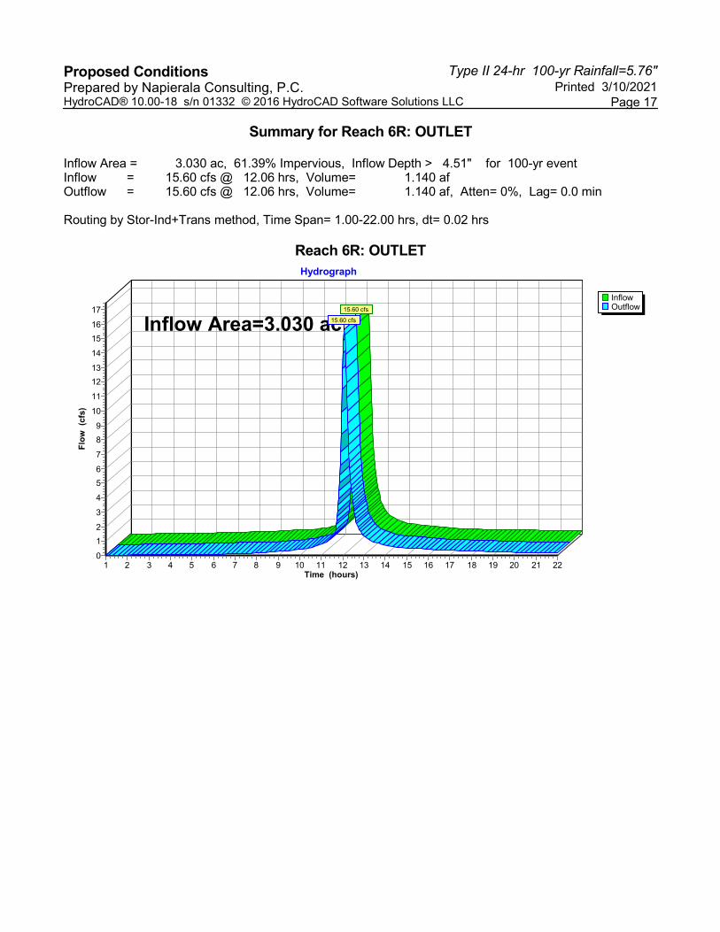
Type II 24-hr 100-yr Rainfall=5.76"Proposed Conditions Printed 3/10/2021Prepared by Napierala Consulting, P.C.
Page 17HydroCAD® 10.00-18 s/n 01332 © 2016 HydroCAD Software Solutions LLC
Summary for Reach 6R: OUTLET
Inflow Area = 3.030 ac, 61.39% Impervious, Inflow Depth > 4.51" for 100-yr eventInflow = 15.60 cfs @ 12.06 hrs, Volume= 1.140 afOutflow = 15.60 cfs @ 12.06 hrs, Volume= 1.140 af, Atten= 0%, Lag= 0.0 min
Routing by Stor-Ind+Trans method, Time Span= 1.00-22.00 hrs, dt= 0.02 hrs
Reach 6R: OUTLET
InflowOutflow
Hydrograph
Time (hours)22212019181716151413121110987654321
Flo
w (
cfs)
17
16
15
14
13
12
11
10
9
8
7
6
5
4
3
2
1
0
Inflow Area=3.030 ac15.60 cfs
15.60 cfs

Type II 24-hr 100-yr Rainfall=5.76"Proposed Conditions Printed 3/10/2021Prepared by Napierala Consulting, P.C.
Page 18HydroCAD® 10.00-18 s/n 01332 © 2016 HydroCAD Software Solutions LLC
Summary for Pond 5P: STORMTECH
Inflow Area = 1.100 ac,100.00% Impervious, Inflow Depth > 5.38" for 100-yr eventInflow = 9.00 cfs @ 11.97 hrs, Volume= 0.493 afOutflow = 6.75 cfs @ 12.02 hrs, Volume= 0.490 af, Atten= 25%, Lag= 3.5 minPrimary = 6.75 cfs @ 12.02 hrs, Volume= 0.490 af
Routing by Stor-Ind method, Time Span= 1.00-22.00 hrs, dt= 0.02 hrsPeak Elev= 429.10' @ 12.02 hrs Surf.Area= 0.067 ac Storage= 0.095 af
Plug-Flow detention time= 21.1 min calculated for 0.490 af (99% of inflow)Center-of-Mass det. time= 17.0 min ( 742.3 - 725.3 )
Volume Invert Avail.Storage Storage Description#1 426.40' 0.789 af 24.83'W x 117.58'L x 30.00'H Drainage Stone
2.011 af Overall - 0.038 af Embedded = 1.973 af x 40.0% Voids#2 426.90' 0.038 af ADS_StormTech RC-310 +Cap x 112 Inside #1
Effective Size= 28.9"W x 16.0"H => 2.07 sf x 7.12'L = 14.7 cfOverall Size= 34.0"W x 16.0"H x 7.56'L with 0.44' Overlap7 Rows of 16 Chambers
0.827 af Total Available Storage
Device Routing Invert Outlet Devices#1 Primary 426.40' 6.0" Round Underdrain Outlet
L= 8.0' CPP, projecting, no headwall, Ke= 0.900 Inlet / Outlet Invert= 426.40' / 426.20' S= 0.0250 '/' Cc= 0.900 n= 0.013 Corrugated PE, smooth interior, Flow Area= 0.20 sf
#2 Primary 426.70' 10.0" Round Outlet Pipe 1 L= 8.0' CPP, projecting, no headwall, Ke= 0.900 Inlet / Outlet Invert= 426.70' / 426.60' S= 0.0125 '/' Cc= 0.900 n= 0.013 Corrugated PE, smooth interior, Flow Area= 0.55 sf
#3 Primary 427.80' 12.0" Round Outlet Pipe 2 L= 8.0' CPP, projecting, no headwall, Ke= 0.900 Inlet / Outlet Invert= 427.80' / 427.70' S= 0.0125 '/' Cc= 0.900 n= 0.013 Corrugated PE, smooth interior, Flow Area= 0.79 sf
Primary OutFlow Max=6.73 cfs @ 12.02 hrs HW=429.09' (Free Discharge)1=Underdrain Outlet (Inlet Controls 1.17 cfs @ 5.94 fps)2=Outlet Pipe 1 (Inlet Controls 2.91 cfs @ 5.34 fps)3=Outlet Pipe 2 (Inlet Controls 2.65 cfs @ 3.38 fps)
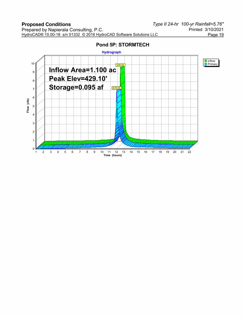
Type II 24-hr 100-yr Rainfall=5.76"Proposed Conditions Printed 3/10/2021Prepared by Napierala Consulting, P.C.
Page 19HydroCAD® 10.00-18 s/n 01332 © 2016 HydroCAD Software Solutions LLC
Pond 5P: STORMTECH
InflowPrimary
Hydrograph
Time (hours)22212019181716151413121110987654321
Flo
w (
cfs)
10
9
8
7
6
5
4
3
2
1
0
Inflow Area=1.100 acPeak Elev=429.10'Storage=0.095 af
9.00 cfs
6.75 cfs

[THIS PAGE IS LEFT INTENTIONALLY BLANK]
APPENDIX C: SOIL DESCRIPTIONS

[THIS PAGE IS LEFT INTENTIONALLY BLANK]
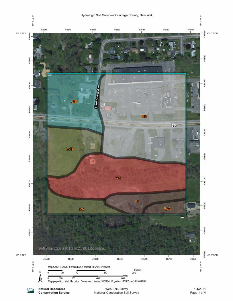
Hydrologic Soil Group—Onondaga County, New York
Natural ResourcesConservation Service
Web Soil SurveyNational Cooperative Soil Survey
1/4/2021Page 1 of 4
4768
000
4768
060
4768
120
4768
180
4768
240
4768
300
4768
360
4768
420
4768
480
4767
940
4768
000
4768
060
4768
120
4768
180
4768
240
4768
300
4768
360
4768
420
4768
480415480 415540 415600 415660 415720 415780 415840
415480 415540 415600 415660 415720 415780 415840
43° 3' 51'' N76
° 2
' 18'
' W43° 3' 51'' N
76° 1
' 59'
' W
43° 3' 34'' N
76° 2
' 18'' W
43° 3' 34'' N
76° 1
' 59'' W
N
Map projection: Web Mercator Corner coordinates: WGS84 Edge tics: UTM Zone 18N WGS840 100 200 400 600
Feet0 35 70 140 210
MetersMap Scale: 1:2,640 if printed on A portrait (8.5" x 11") sheet.
Soil Map may not be valid at this scale.
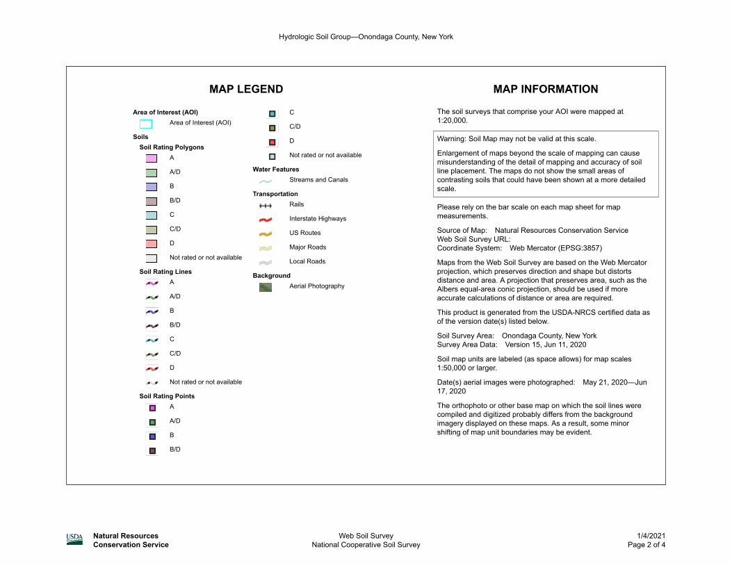
MAP LEGEND MAP INFORMATION
Area of Interest (AOI)Area of Interest (AOI)
SoilsSoil Rating Polygons
A
A/D
B
B/D
C
C/D
D
Not rated or not available
Soil Rating LinesA
A/D
B
B/D
C
C/D
D
Not rated or not available
Soil Rating PointsA
A/D
B
B/D
C
C/D
D
Not rated or not available
Water FeaturesStreams and Canals
TransportationRails
Interstate Highways
US Routes
Major Roads
Local Roads
BackgroundAerial Photography
The soil surveys that comprise your AOI were mapped at 1:20,000.
Warning: Soil Map may not be valid at this scale.
Enlargement of maps beyond the scale of mapping can cause misunderstanding of the detail of mapping and accuracy of soil line placement. The maps do not show the small areas of contrasting soils that could have been shown at a more detailed scale.
Please rely on the bar scale on each map sheet for map measurements.
Source of Map: Natural Resources Conservation ServiceWeb Soil Survey URL: Coordinate System: Web Mercator (EPSG:3857)
Maps from the Web Soil Survey are based on the Web Mercator projection, which preserves direction and shape but distorts distance and area. A projection that preserves area, such as the Albers equal-area conic projection, should be used if more accurate calculations of distance or area are required.
This product is generated from the USDA-NRCS certified data as of the version date(s) listed below.
Soil Survey Area: Onondaga County, New YorkSurvey Area Data: Version 15, Jun 11, 2020
Soil map units are labeled (as space allows) for map scales 1:50,000 or larger.
Date(s) aerial images were photographed: May 21, 2020—Jun 17, 2020
The orthophoto or other base map on which the soil lines were compiled and digitized probably differs from the background imagery displayed on these maps. As a result, some minor shifting of map unit boundaries may be evident.
Hydrologic Soil Group—Onondaga County, New York
Natural ResourcesConservation Service
Web Soil SurveyNational Cooperative Soil Survey
1/4/2021Page 2 of 4
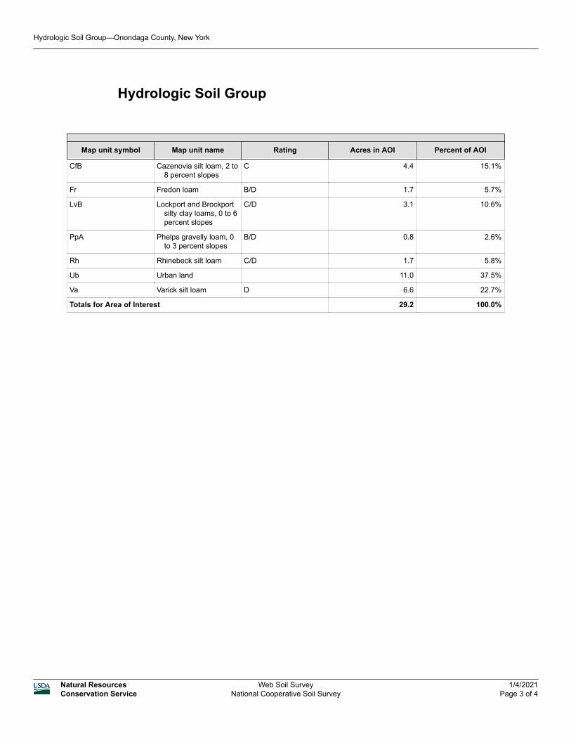
Hydrologic Soil Group
Map unit symbol Map unit name Rating Acres in AOI Percent of AOI
CfB Cazenovia silt loam, 2 to 8 percent slopes
C 4.4 15.1%
Fr Fredon loam B/D 1.7 5.7%
LvB Lockport and Brockport silty clay loams, 0 to 6 percent slopes
C/D 3.1 10.6%
PpA Phelps gravelly loam, 0 to 3 percent slopes
B/D 0.8 2.6%
Rh Rhinebeck silt loam C/D 1.7 5.8%
Ub Urban land 11.0 37.5%
Va Varick silt loam D 6.6 22.7%
Totals for Area of Interest 29.2 100.0%
Hydrologic Soil Group—Onondaga County, New York
Natural ResourcesConservation Service
Web Soil SurveyNational Cooperative Soil Survey
1/4/2021Page 3 of 4
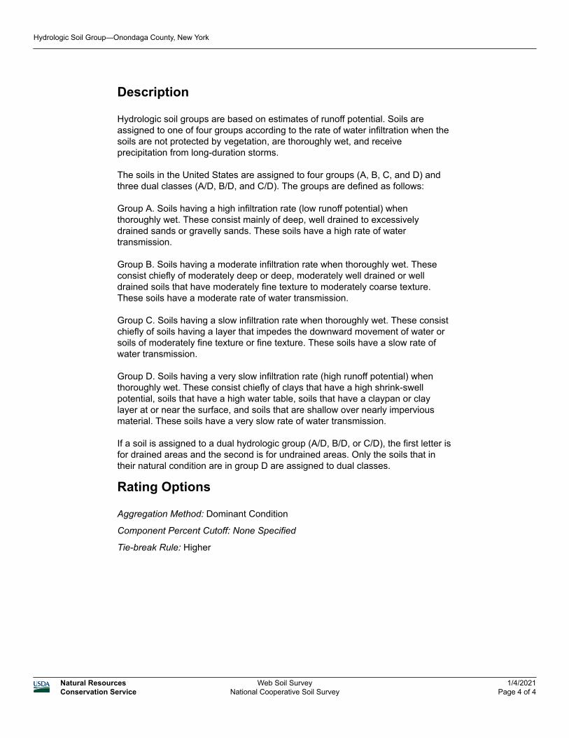
Description
Hydrologic soil groups are based on estimates of runoff potential. Soils are assigned to one of four groups according to the rate of water infiltration when the soils are not protected by vegetation, are thoroughly wet, and receive precipitation from long-duration storms.
The soils in the United States are assigned to four groups (A, B, C, and D) and three dual classes (A/D, B/D, and C/D). The groups are defined as follows:
Group A. Soils having a high infiltration rate (low runoff potential) when thoroughly wet. These consist mainly of deep, well drained to excessively drained sands or gravelly sands. These soils have a high rate of water transmission.
Group B. Soils having a moderate infiltration rate when thoroughly wet. These consist chiefly of moderately deep or deep, moderately well drained or well drained soils that have moderately fine texture to moderately coarse texture. These soils have a moderate rate of water transmission.
Group C. Soils having a slow infiltration rate when thoroughly wet. These consist chiefly of soils having a layer that impedes the downward movement of water or soils of moderately fine texture or fine texture. These soils have a slow rate of water transmission.
Group D. Soils having a very slow infiltration rate (high runoff potential) when thoroughly wet. These consist chiefly of clays that have a high shrink-swell potential, soils that have a high water table, soils that have a claypan or clay layer at or near the surface, and soils that are shallow over nearly impervious material. These soils have a very slow rate of water transmission.
If a soil is assigned to a dual hydrologic group (A/D, B/D, or C/D), the first letter is for drained areas and the second is for undrained areas. Only the soils that in their natural condition are in group D are assigned to dual classes.
Rating Options
Aggregation Method: Dominant Condition
Component Percent Cutoff: None Specified
Tie-break Rule: Higher
Hydrologic Soil Group—Onondaga County, New York
Natural ResourcesConservation Service
Web Soil SurveyNational Cooperative Soil Survey
1/4/2021Page 4 of 4
APPENDIX D: VEGETATED SWALE AND DETENTION CHAMBER SYSTEM CONSTRUCTION AND MAINTENANCE

[THIS PAGE IS LEFT INTENTIONALLY BLANK]
�����������
������ ���� ������������� �������������������������������������
������� � ������ ��� � �� � �������� �������
����������� ������������������������� ��������
�
��������� � �� ������� �
������ ��!� ��"#��$������ �� � ��� �����%�&�!�� &�!���$������
�� ������������� ��� ���� �
���������������������������
�� ���������� ����������� ����� ���� �
�
�� !�����" ���#��� $����" ���#�
�
�� ����� ������� ��#��� ������ %���#��������� �����
� �!����� ����� � � �!����� �&�%�� �
� �!������ �
�����$������� �!����� �
�
�����'�����
�(���� ��������� ���������� ���������� ���������� �����������&�
���"#�%��)*��+��$������ ��� ,�##��-.!������ ����
��
��� $� ������'�� ���������
����� ���#�( ��������������������#� �)�
�� ��#���#�������� ���#�� ��������� ������������������������������&�
�� *�������� ������� ������������'��������'���#��##����#���#��� �������������������������&�
�� ����� ����� �������������������� ����'�� +���� �#� ������� ����������������� ����+�� ����������������� ��� ��##���������������� ���������� ��������+���������#&�
�� ���� ,�
�� -���.�������������/�����������,��� ���� ����������������������� �#�#'�� ��� �� ����������� ���� ����&���+� �0�� �� � ��������������������
�
�
�� ���������� �������������'������'��#� �'�����'�� ������ ����� �����
�� %������� ����� ����������� �������������'�������'�#� �'����&�
�� ���� ,�
�
�� ������������� ��������'�� ����'������'�� ����� ������������
�� ���� �� �� ��� �+�#�������������� ����1���������+�� �����������#����������� ��+��� ����#������������ ������������+������2���� ���3� #���&�
�� " ����#+��������#������ ��#�
�� ��#���#������1��##���������� ���������������#�#&��� ���� ,�
�� -���.�������������/�����������,�" ��������#����������������������������#��������� �������� ������&������#�����+����#������� ������#��������� ����� ������(�&�&'�������#���� ���)&�
�����/�����
�(�� #����
���#���������������#�������� ������������������ ����� ��������&�
���"#�%��)*��+��$������ ��� ,�##��-.!������ ��
�� �������� �����������#���� �������������� ��'�� �������������'�� �#�� ���� ������� ���4��#��� ����&�������� ���+�����������������������������&�5�����6������������������������ ������+��� ���� �������������
��������&�
�� �������������������� ������� �����#�#�� ���(���������+������ ���������� ��������)&��� ������������������ ���������� ���������������������������
�����������&��� �������������������� ������ ����� ���#�'���#�
�������������������� �� �������������������� ��� �������&�
�� %��������+�� �������������'�������'�������'���#����� �#�� ��������������������������������� �������������#����������������� ����� �����������#��
������� &��� *� ���������#�#������'� ��������#��������#�#�� ������������� �����+�������������������� �#�����
���������� ��������� ����������&��� 7������������������ ����� ��� �+�������� ����� �����
�������� �.���� ���������&��� ���� ,�
�� -���.�������������/�����������,��������� ��������#���������2������������������������� �#�������������
���������� ������������&�
�
�� ����� �������������������� ��� �#������������ ����'��������'���#����� �� ������� ��� �����'�� ���� ������� ��#� ����������������������
��������&�
�� *� �������� �������� �����'����������������� �#�#��� ����#�����+� ����� �������(�&�&'� ��� �������)����� �������� ��� �� �����&� �����+'������ ���� ������
�����#���#� ����� ����� ������&��� �������������'� ����#������#�����+�������� ������
���� ���������������������#����� �������� ��� �� �����&������������������ �������+����
����������������� #�������� '����������+�������������������������#���������� ���� &�
�� ���� ,�
�� ������/�����������,��8 ������������� ��������������������������� �������������������������#��&�5���
������#��������+��������������#����#&�
�����0�����
�(����$���������82�������������� ��������� �������#���#��������&�
���"#�%��)*��+��$������ ��� ,�##��-.!������ ��
�� ���� �� ���������#�����'�� ��'�� ���'��� ����� �#�� ���� ���������������������������&�
�� ����������������������������� �� ���������#������� �� ��'����������+���������� �������� ����� ����#�������� �������+����������#�����������&�7������������������ ������ ������������ �.���� ���������&�
�� ��� ���������������� ����� �������������� ����� ��'�������������#�����������#��##����#���#��� ����� �.��������&�
�� %������� ���'������������#�� ��'���#����� ���#��� ��������� ����&��� ���������������#�����+���������#'������+����#������������#�����������������1�
�������� ��2�����������#����� ����� ��������#��� ���#�����������������������������������������#����� ������������������ �����&�
�� ���� ,�
�� -���.�������������/�����������,��#��������������������#��� �������9��������#������#����� ��/:;�� ��� ���������������� ����&�
�� 5������ ��������#����������������� ��������������� ����#������������������ ��&�
��
�
�� 5�� ������ ��������������������� ����������#��������&�<��� ��������������� ��������� ������������������ ��������������� ��������������&�
�� 5 +�������������� �#�#�� ���������������������'���#���������#���#������������������������������&�
�� �������� ������ ��� �'�+�����+�������������������+�������������'�������(�&�&'� ��� �������)'�� ����� ����� ���������������� �#�#�� ���&�
�� �������� ����������������#�������'�����������������#����� ������ �����.���� ������������ ������������ ������������ � �.���#���&�
�� -���.�������������/�����������,�5���� �������� ������� ������ ����������� �������9��������#������#�������������������������������� ����� ����#��������� �������������&�
�� -���.�������������/�����������,�5���� ������#������������������������#��+����������� '����������������� ������������������ �����(�&�&'�=��������>)�#�������������#� � ���#�� �����&�
�� <��� �#�����������������+�#�������������������������'��������#������� ������ ������ �������� ��#����������(�&�&'�?/���� ������ ������ �)&�5��������#���������������������=���������# ������&>�������#� ����� �����#�����+����� ��� ������� �&�
�� �������� ������������� �(6���������'��������#�� ���)'�� +��������������� ����� ����� ����������� ��������� ���������������1� �������2�������������������� ���'���#�����'�� ����� �#�� ����������+��������������������&�
�� ���� ,�
�� -���.�������������/�����������,�<��� ����#������� �������/:;��������������� ��� ���#�+��� ��� ������ ������ �&�5�����������+��������������#� �+���������� ������ �#�������������&�
�� <��� ����#�������#�������#������ ��� ���#�+��� ��� ������ ������ �&�������#������+����������#�� ������������������ ��� �+&�
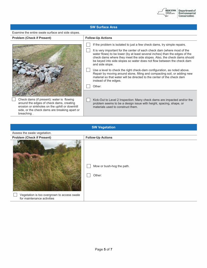
�����1�����
�(����$���������82�������������� ��������� �������#���#��������&�
���"#�%��)*��+��$������ ��� ,�##��-.!������ ���
��� ������#����(���� �����),���� ������������
� ���#������#�������������#���'�� �������� ������� �������������������������� �#���������#�'�� �����������#����� ��� ���������� ��� �� ��������&�
�� �������� ����������������#����6���������������#���'�� +�������� ���� �&�
�� �������� +����� ������� ���������� ���������������#���(�� ����������������� �����)���������� �(�+�������������� ���������)�����������#�����������������#������ �����+������������#��������&�!���'�����������#���������#������+�#��������#��������������� �#�����������������������������#�����#���#�������&�
�� ������������������������ ����������.#���������� �����'��������#������&�%���� ��+��������� ���#������'�����������#����������������'�� ��##����������� ��������������� ��������#� ����#������������� ��������������#���������#���������#���&�
�� ���� ,�
�� -���.�������������/�����������,����+�������#����� ���������#���#4� ������ ��������������������#����������������������'��������'������'�� ����� ��������#��������� ��������&�
�(�2�������� �!�������������������������&����"#�%��)*��+��$������ ��� ,�##��-.!������ ��
& ��� @�������������������� � ������������������
�� ������������������������
�� ���� �����.������������&���� ���� ,�
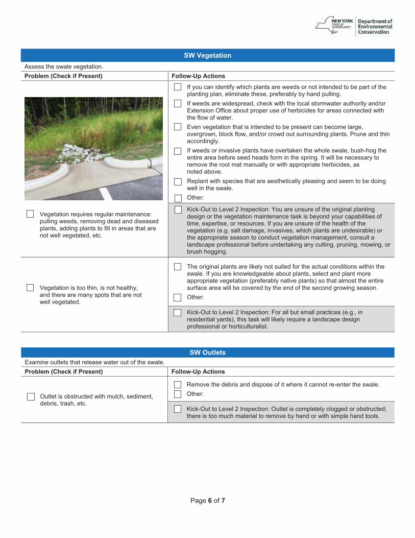
�����3�����
�(�2�������� �!�������������������������&����"#�%��)*��+��$������ ��� ,�##��-.!������ ��
���� @���������� �0�� ��� ����� ������������,�
����������#�'� ��������#��#���#�#������#�������'��##����������������������� ���������� ������������������#'����&�
�� ���+��������#�����+�������������� ����#��� ����������#�#��������� ����������������������'����������������'�� ��� ���+��+����#��������&�
�� �����#��� ���#��� ��#'������������������������ ���� ������ ��+���#4� �82���������������������� ��� ���������� ����#����� �� ������������#������������������� &�
�� 8����������������������������#�#�������� ������������������� ��'���� � ��'����������'���#4� �� �#������� ���#����������&�� ������#���������� #����+&�
�� �����#��� ������������������������� �������������������'�����.������������ ��� ������� �����#����#���� ����������� ���&������������������ +���� ���������� ���������������+�� �������� �� ������� ����#��'���������#������&�
�� %������������������������� ��������������+������������#������������#��������������������&�
�� ���� ,�
�� -���.�������������/�����������,�A���� ������ ���������� ����������������#������� ��������������������������������������+��#�+�� ���������������������'��2�� ����'�� � ���� ���&����+���� ������ ����������������������������������(�&�&������#�����'����������'�������������� ����#��� ����)�� �������� �� ������������������#�������������������������'��������������#������� ��������������� ����#� ���������+��������'�� �����'������'�� �� �����������&�
�� @���������������������'��������������+'����#���� ��� �����+������������� �������������������#&�
�� 5���� ��������������� �������+����������#��� ���������������#���������������������&����+���� �������#�������������������'����������#��������� ����� �� ����������������(� ��� ���+��������������)������������������������ ���� ������ �������������� �#��+�������#�������������#�� �����������&�
�� ���� ,�
�� -���.�������������/�����������,�*� ���������������� ��������(�&�&'���� ���#�������+� #�)'��������������������+� �0�� �������#������#������� ������������ ��� ������� �����&�
�(����#����82������������������� ���������� ����������������&����"#�%��)*��+��$������ ��� ,�##��-.!������ ��
�� �������������� ����#����������'���#�����'�#�� ��'�� ���'����&�
�� %����������#�� �����#�#��������������� ������������ �.���� ���������&��� ���� ,�
�� -���.�������������/�����������,��������������������+�������#�� ����� ����#1���� ������������������ ������� �������+����#�� ���������������#������&�

�����������
!##��������B����,� �
�
�
�������� ,��� � � � � � � � 7���,���� � � �
������������������������������.��4�� ���������������� ���#�������#�#� �������������������,�
�
)����$����)�%!#���� ��$�,�##��-.!������ �4�
=���� ��+��� ���+���������������.��4�� ����������������#�������#��������������������� �� ��#������������������(7!58)� ������������������#���#���+� �0�� �#�������������#�����������������������#�0�����+��� ����#&>��
�������� 4��� ��� ,�� � � � � � � 7���,�� � � � �
�
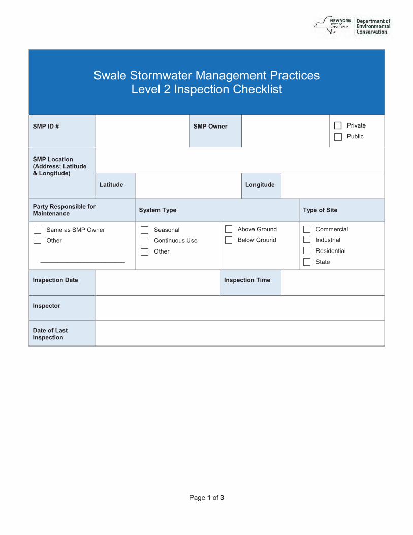
����������/
������ ���� ������������� ��������������/����������������������
������� � ������ ��� � �� � �������� �������
����������� ������������������������� ��������
�
��������� � �� ������� �
������ ��!� ��"#��$������ �� � ��� �����%�&�!�� &�!���$������
�� ������������� ��� ���� �
���������������������������
�� ���������� ����������� ����� ���� �
�
�� !�����" ���#��� $����" ���#�
�
�� ����� ������� ��#��� ������ %���#��������� �����
� �!����� ����� � � �!����� �&�%�� �
� �!������ �
�����$������� �!����� �
�
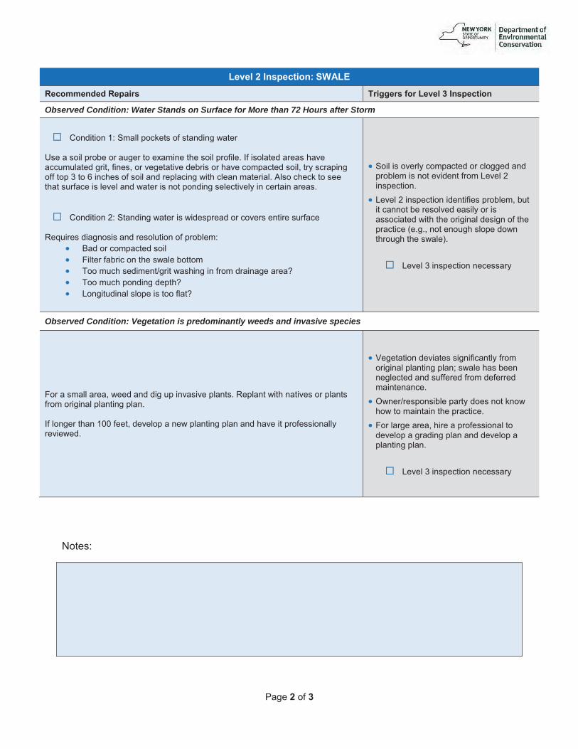
�����'����/
��5�#�'�� �!����� 4��(��6�
���%%� ���� �!������ &��������$�����5�#�/�� �!����� �
Observed Condition: Water Stands on Surface for More than 72 Hours after Storm
�� ���#�������,���������������������#������� �� ����������� ����� ����� �����2���������������� �����&�����������#�� �������������������#�� ��'������'�� ������������#�� ���� ��������������#�����'�� +��� ��������������9����C������������������#� ����������������������� ���&�!������������������������ ����������������#���� �����������#��������������+������ ������ ���&����� ���#������/,����#������� �����#��� ��#�� ����� ������ ���� �����
�%�0�� ���#�����������#� �������������� �����,�
�� $�#�� ���������#�������� *���� ���� ������������������������ 5����������#�����4� �������������� ���# �������� ��D��� 5�����������#����#����D��� �������#����������������������D�
������������ �+���������#�� �������#���#�� ����������������#����� ���������/�����������&�
��������/�������������#���������� �����'������������������ ������#������+�� �������������#���������� �������#�������������� �������(�&�&'������������������#����� �������������)&�
��� ������9������������������� +�
Observed Condition: Vegetation is predominantly weeds and invasive species
*� ���������� ��'���#���#�#���������������������&�%�������������������� ��������� ���� ��������������������&���������� �������EE�����'�#����������������������������#���������� �����������+� �����#&�
��@����������#��������������������+�� ���� ��������������������1�����������������������#���#������ �#�� ���#��� �#������������&�
����� 4 ������������� �+�#�������������������������������� ������&�
��*� ��� ���� ��'��� ����� ��������������#���������� �#�����������#�#����������������������&�
��� ������9������������������� +�
B����,� �

�����/����/
�
�
�������� ,��� � � � � � � � 7���,���� � � �
������������������������������.��4�� ���������������� ���#�������#�#� �������������������,�
�
)����$����)�%!#���� ��$�,�##��-.!������ �4�
=���� ��+��� ���+���������������.��4�� ����������������#�������#��������������������� �� ��#������������������(7!58)� ������������������#���#���+� �0�� �#�������������#�����������������������#�0�����+��� ����#&>��
�������� 4��� ��� ,�� � � � � � � 7���,�� � � � �
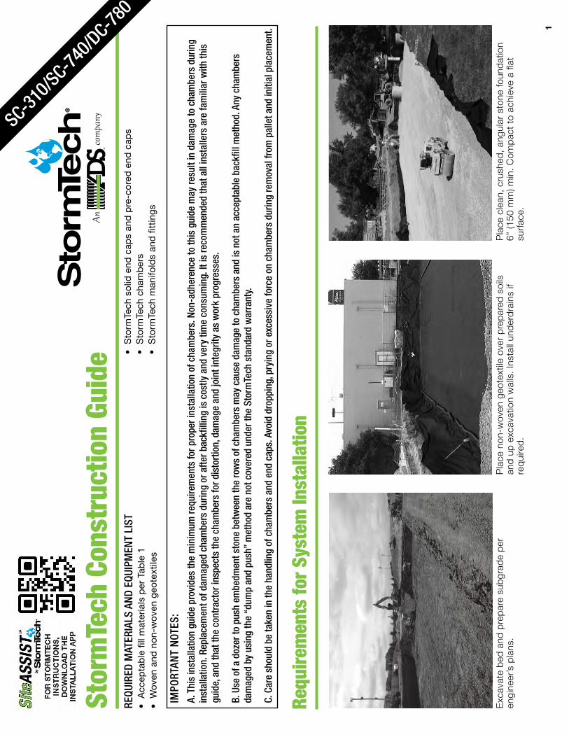
Initi
al A
ncho
ring
of C
ham
bers
– E
mbe
dmen
t Sto
ne
Back
fill o
f Cha
mbe
rs –
Em
bedm
ent S
tone
UN
EV
EN
BA
CK
FILL
Initi
al e
mb
edm
ent
shal
l be
spot
ted
alo
ng t
he c
ente
rline
of t
he c
ham
ber
eve
nly
anch
orin
g th
e lo
wer
por
tion
of t
he c
ham
ber
. Th
is is
bes
t ac
com
plis
hed
with
a
ston
e co
nvey
or o
r ex
cava
tor
reac
hing
alo
ng t
he r
ow.
than
12”
(300
mm
) bet
wee
n ad
jace
nt c
ham
ber
row
s or
bet
wee
n ch
amb
er
row
s an
d p
erim
eter
.
EV
EN
BA
CK
FILL
time.
wal
l.
888.
892.
2694
3
12" (
300
mm
)M
AX.
Man
ifold
, Sco
ur F
abric
and
Cha
mbe
r Ass
embl
y
geot
extil
e at
inle
t ro
ws
[min
. 12
.5 ft
(3.8
m)]
at
Isol
ator
® R
ow(s
).
row
with
inle
t p
ipes
. C
ontr
acto
r m
ay c
hoos
e to
and
leav
e en
ds
of r
ows
open
for
easy
insp
ectio
n
Atta
chin
g th
e En
d Ca
ps
Pref
abric
ated
End
Cap
s Is
olat
or R
ow
Lift
the
end
of t
he c
ham
ber
a fe
w in
ches
off
Stor
mTe
ch C
onst
ruct
ion
Guid
eRE
QUIR
ED M
ATER
IALS
AN
D EQ
UIPM
ENT
LIST
IMPO
RTAN
T N
OTES
:A.
Thi
s in
stal
latio
n gu
ide
prov
ides
the
min
imum
requ
irem
ents
for p
rope
r ins
talla
tion
of c
ham
bers
. Non
-adh
eren
ce to
this
gui
de m
ay re
sult
in d
amag
e to
cha
mbe
rs d
urin
g in
stal
latio
n. R
epla
cem
ent o
f dam
aged
cha
mbe
rs d
urin
g or
afte
r bac
kfill
ing
is c
ostly
and
ver
y tim
e co
nsum
ing.
It is
reco
mm
ende
d th
at a
ll in
stal
lers
are
fam
iliar
with
this
gu
ide,
and
that
the
cont
ract
or in
spec
ts th
e ch
ambe
rs fo
r dis
tort
ion,
dam
age
and
join
t int
egrit
y as
wor
k pr
ogre
sses
.
B. U
se o
f a d
ozer
to p
ush
embe
dmen
t sto
ne b
etw
een
the
row
s of
cha
mbe
rs m
ay c
ause
dam
age
to c
ham
bers
and
is n
ot a
n ac
cept
able
bac
kfill
met
hod.
Any
cha
mbe
rs
dam
aged
by
usin
g th
e “d
ump
and
push
” m
etho
d ar
e no
t cov
ered
und
er th
e St
orm
Tech
sta
ndar
d w
arra
nty.
C. C
are
shou
ld b
e ta
ken
in th
e ha
ndlin
g of
cha
mbe
rs a
nd e
nd c
aps.
Avo
id d
ropp
ing,
pry
ing
or e
xces
sive
forc
e on
cha
mbe
rs d
urin
g re
mov
al fr
om p
alle
t and
initi
al p
lace
men
t.
Requ
irem
ents
for S
yste
m In
stal
latio
n
engi
neer
’s p
lans
.
SC-310/S
C-740/D
C-780
1 2
An
com
pany
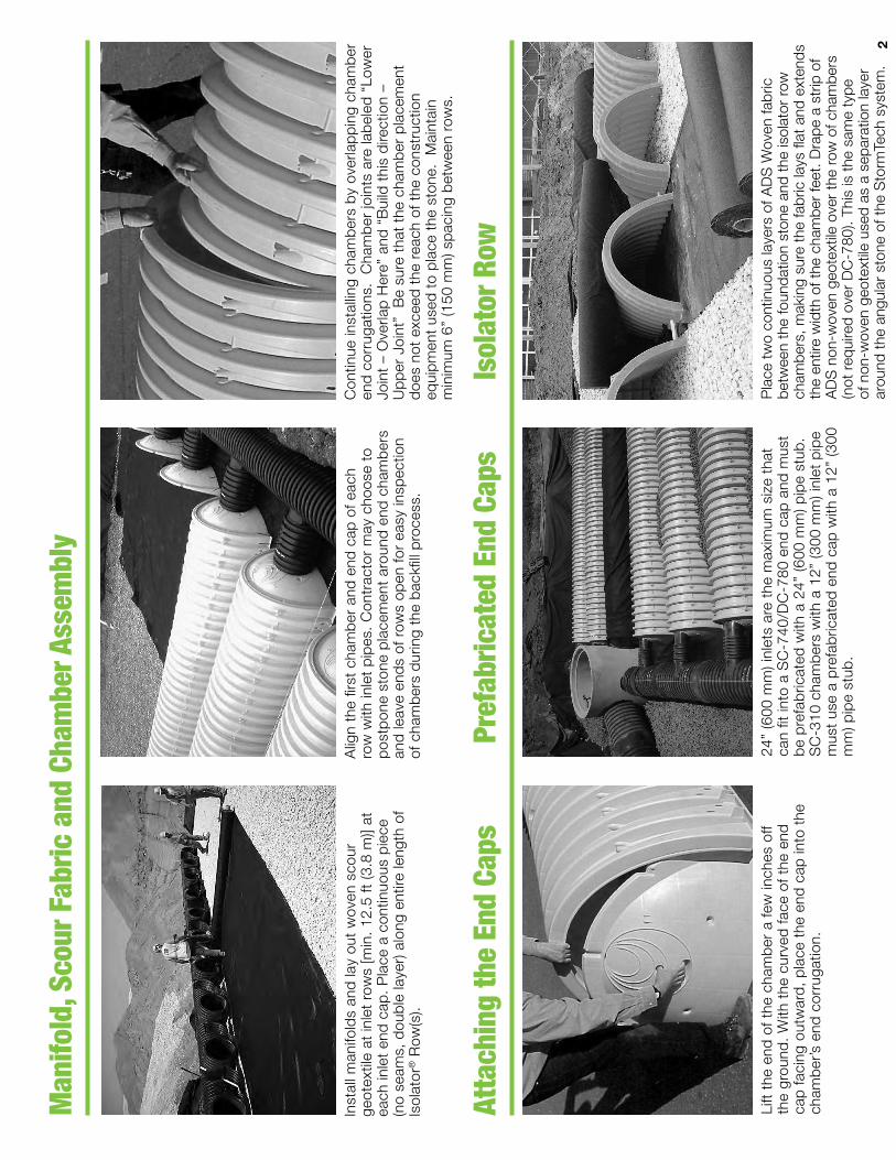
Initi
al A
ncho
ring
of C
ham
bers
– E
mbe
dmen
t Sto
ne
Back
fill o
f Cha
mbe
rs –
Em
bedm
ent S
tone
UN
EV
EN
BA
CK
FILL
Initi
al e
mb
edm
ent
shal
l be
spot
ted
alo
ng t
he c
ente
rline
of t
he c
ham
ber
eve
nly
anch
orin
g th
e lo
wer
por
tion
of t
he c
ham
ber
. Th
is is
bes
t ac
com
plis
hed
with
a
ston
e co
nvey
or o
r ex
cava
tor
reac
hing
alo
ng t
he r
ow.
than
12”
(300
mm
) bet
wee
n ad
jace
nt c
ham
ber
row
s or
bet
wee
n ch
amb
er
row
s an
d p
erim
eter
.
EV
EN
BA
CK
FILL
time.
wal
l.
888.
892.
2694
3
12" (
300
mm
)M
AX.
Man
ifold
, Sco
ur F
abric
and
Cha
mbe
r Ass
embl
y
geot
extil
e at
inle
t ro
ws
[min
. 12
.5 ft
(3.8
m)]
at
Isol
ator
® R
ow(s
).
row
with
inle
t p
ipes
. C
ontr
acto
r m
ay c
hoos
e to
and
leav
e en
ds
of r
ows
open
for
easy
insp
ectio
n
Atta
chin
g th
e En
d Ca
ps
Pref
abric
ated
End
Cap
s Is
olat
or R
ow
Lift
the
end
of t
he c
ham
ber
a fe
w in
ches
off
Stor
mTe
ch C
onst
ruct
ion
Guid
eRE
QUIR
ED M
ATER
IALS
AN
D EQ
UIPM
ENT
LIST
IMPO
RTAN
T N
OTES
:A.
Thi
s in
stal
latio
n gu
ide
prov
ides
the
min
imum
requ
irem
ents
for p
rope
r ins
talla
tion
of c
ham
bers
. Non
-adh
eren
ce to
this
gui
de m
ay re
sult
in d
amag
e to
cha
mbe
rs d
urin
g in
stal
latio
n. R
epla
cem
ent o
f dam
aged
cha
mbe
rs d
urin
g or
afte
r bac
kfill
ing
is c
ostly
and
ver
y tim
e co
nsum
ing.
It is
reco
mm
ende
d th
at a
ll in
stal
lers
are
fam
iliar
with
this
gu
ide,
and
that
the
cont
ract
or in
spec
ts th
e ch
ambe
rs fo
r dis
tort
ion,
dam
age
and
join
t int
egrit
y as
wor
k pr
ogre
sses
.
B. U
se o
f a d
ozer
to p
ush
embe
dmen
t sto
ne b
etw
een
the
row
s of
cha
mbe
rs m
ay c
ause
dam
age
to c
ham
bers
and
is n
ot a
n ac
cept
able
bac
kfill
met
hod.
Any
cha
mbe
rs
dam
aged
by
usin
g th
e “d
ump
and
push
” m
etho
d ar
e no
t cov
ered
und
er th
e St
orm
Tech
sta
ndar
d w
arra
nty.
C. C
are
shou
ld b
e ta
ken
in th
e ha
ndlin
g of
cha
mbe
rs a
nd e
nd c
aps.
Avo
id d
ropp
ing,
pry
ing
or e
xces
sive
forc
e on
cha
mbe
rs d
urin
g re
mov
al fr
om p
alle
t and
initi
al p
lace
men
t.
Requ
irem
ents
for S
yste
m In
stal
latio
n
engi
neer
’s p
lans
.
SC-310/S
C-740/D
C-780
1 2
An
com
pany
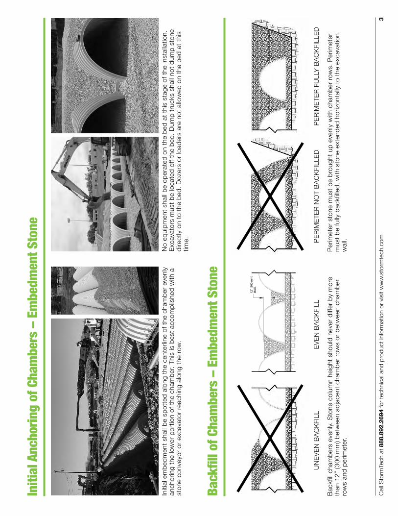
Initi
al A
ncho
ring
of C
ham
bers
– E
mbe
dmen
t Sto
ne
Back
fill o
f Cha
mbe
rs –
Em
bedm
ent S
tone
UN
EV
EN
BA
CK
FILL
Initi
al e
mb
edm
ent
shal
l be
spot
ted
alo
ng t
he c
ente
rline
of t
he c
ham
ber
eve
nly
anch
orin
g th
e lo
wer
por
tion
of t
he c
ham
ber
. Th
is is
bes
t ac
com
plis
hed
with
a
ston
e co
nvey
or o
r ex
cava
tor
reac
hing
alo
ng t
he r
ow.
than
12”
(300
mm
) bet
wee
n ad
jace
nt c
ham
ber
row
s or
bet
wee
n ch
amb
er
row
s an
d p
erim
eter
.
EV
EN
BA
CK
FILL
time.
wal
l.
888.
892.
2694
3
12" (
300
mm
)M
AX.
Man
ifold
, Sco
ur F
abric
and
Cha
mbe
r Ass
embl
y
geot
extil
e at
inle
t ro
ws
[min
. 12
.5 ft
(3.8
m)]
at
Isol
ator
® R
ow(s
).
row
with
inle
t p
ipes
. C
ontr
acto
r m
ay c
hoos
e to
and
leav
e en
ds
of r
ows
open
for
easy
insp
ectio
n
Atta
chin
g th
e En
d Ca
ps
Pref
abric
ated
End
Cap
s Is
olat
or R
ow
Lift
the
end
of t
he c
ham
ber
a fe
w in
ches
off
Stor
mTe
ch C
onst
ruct
ion
Guid
eRE
QUIR
ED M
ATER
IALS
AN
D EQ
UIPM
ENT
LIST
IMPO
RTAN
T N
OTES
:A.
Thi
s in
stal
latio
n gu
ide
prov
ides
the
min
imum
requ
irem
ents
for p
rope
r ins
talla
tion
of c
ham
bers
. Non
-adh
eren
ce to
this
gui
de m
ay re
sult
in d
amag
e to
cha
mbe
rs d
urin
g in
stal
latio
n. R
epla
cem
ent o
f dam
aged
cha
mbe
rs d
urin
g or
afte
r bac
kfill
ing
is c
ostly
and
ver
y tim
e co
nsum
ing.
It is
reco
mm
ende
d th
at a
ll in
stal
lers
are
fam
iliar
with
this
gu
ide,
and
that
the
cont
ract
or in
spec
ts th
e ch
ambe
rs fo
r dis
tort
ion,
dam
age
and
join
t int
egrit
y as
wor
k pr
ogre
sses
.
B. U
se o
f a d
ozer
to p
ush
embe
dmen
t sto
ne b
etw
een
the
row
s of
cha
mbe
rs m
ay c
ause
dam
age
to c
ham
bers
and
is n
ot a
n ac
cept
able
bac
kfill
met
hod.
Any
cha
mbe
rs
dam
aged
by
usin
g th
e “d
ump
and
push
” m
etho
d ar
e no
t cov
ered
und
er th
e St
orm
Tech
sta
ndar
d w
arra
nty.
C. C
are
shou
ld b
e ta
ken
in th
e ha
ndlin
g of
cha
mbe
rs a
nd e
nd c
aps.
Avo
id d
ropp
ing,
pry
ing
or e
xces
sive
forc
e on
cha
mbe
rs d
urin
g re
mov
al fr
om p
alle
t and
initi
al p
lace
men
t.
Requ
irem
ents
for S
yste
m In
stal
latio
n
engi
neer
’s p
lans
.
SC-310/S
C-740/D
C-780
1 2
An
com
pany
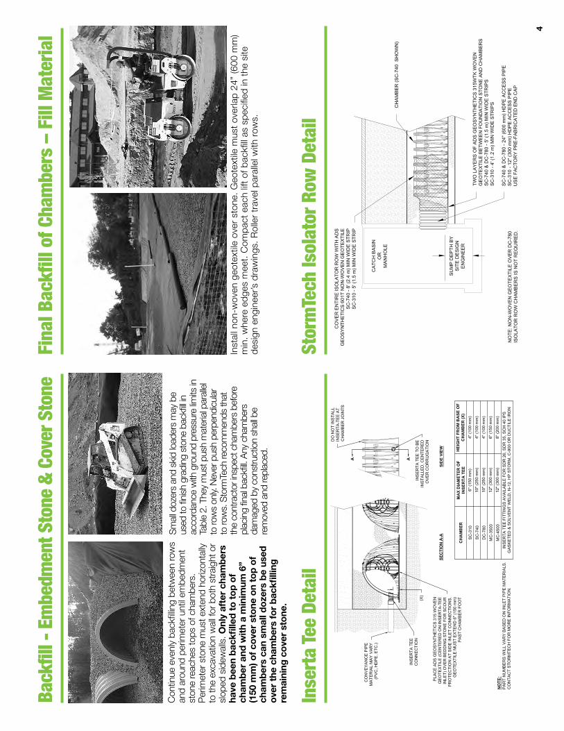
ADS
“Ter
ms
and
Cond
ition
s of
Sal
e” a
re a
vaila
ble
on th
e AD
S w
ebsi
te,
ww
w.ad
s-pi
pe.c
om. A
dvan
ced
Drai
nage
Sys
tem
s, th
e AD
S lo
go, a
nd th
e gr
een
strip
e ar
e re
gist
ered
trad
emar
ks o
f Adv
ance
d Dr
aina
ge S
yste
ms,
Inc.
Stor
mTe
ch® a
nd th
e Is
olat
or® R
ow a
re re
gist
ered
trad
emar
ks o
f Sto
rmTe
ch, I
nc#1
1010
07/
19 C
S
©20
19 A
dvan
ced
Drai
nage
Sys
tem
s, In
c.
NOTE
S:
1. 3
6” (9
00 m
m) o
f sta
biliz
ed c
over
mat
eria
ls o
ver t
he c
ham
bers
is
requ
ired
for f
ull d
ump
truc
k tr
avel
and
dum
ping
.
2. D
urin
g pa
ving
ope
ratio
ns, d
ump
truc
k ax
le lo
ads
on 1
8” (4
50
mm
) of c
over
may
be
nece
ssar
y. Pr
ecau
tions
sho
uld
be ta
ken
to
avoi
d ru
tting
of t
he ro
ad b
ase
laye
r, to
ens
ure
that
com
pact
ion
requ
irem
ents
hav
e be
en m
et, a
nd th
at a
min
imum
of 1
8” (4
50
mm
) of c
over
exi
sts
over
the
cham
bers
. Con
tact
Sto
rmTe
ch fo
r ad
ditio
nal g
uida
nce
on a
llow
able
axl
e lo
ads
durin
g pa
ving
.
3. G
roun
d pr
essu
re fo
r tra
ck d
ozer
s is
the
vehi
cle
oper
atin
g w
eigh
t di
vide
d by
tota
l gro
und
cont
act a
rea
for b
oth
trac
ks. E
xcav
ator
s w
ill e
xert
hig
her g
roun
d pr
essu
res
base
d on
load
ed b
ucke
t wei
ght
and
boom
ext
ensi
on.
4. M
ini-
exca
vato
rs (<
8,0
00lb
s/3,
628
kg) c
an b
e us
ed w
ith a
t lea
st
12”
(300
mm
) of s
tone
ove
r the
cha
mbe
rs a
nd a
re li
mite
d by
the
max
imum
gro
und
pres
sure
s in
Tab
le 2
bas
ed o
n a
full
buck
et a
t m
axim
um b
oom
ext
ensi
on.
5. S
tora
ge o
f mat
eria
ls s
uch
as c
onst
ruct
ion
mat
eria
ls, e
quip
men
t, sp
oils
, etc
. sho
uld
not b
e lo
cate
d ov
er th
e St
orm
Tech
sys
tem
. The
us
e of
equ
ipm
ent o
ver t
he S
torm
Tech
sys
tem
not
cov
ered
in T
able
2
(ex.
soi
l mix
ing
equi
pmen
t, cr
anes
, etc
) is
limite
d. P
leas
e co
ntac
t St
orm
Tech
for m
ore
info
rmat
ion.
6. A
llow
able
trac
k lo
ads
base
d on
veh
icle
trav
el o
nly.
Exca
vato
rs
3 fe
et (9
00 m
m) o
ver t
he e
ntire
bed
.
Mat
eria
l Lo
catio
n
Fill
Dept
h ov
er C
ham
bers
in
. [m
m]
Max
imum
Allo
wab
le W
heel
Loa
dsM
axim
um A
llow
able
Tra
ck L
oads
6M
axim
um A
llow
able
Rol
ler L
oads
Max
Axl
e Lo
ad
for T
ruck
s lb
s [k
N]
Max
Whe
el L
oad
for L
oade
rs
lbs
[kN]
Trac
k W
idth
in
. [m
m]
Max
Gro
und
Pres
sure
psf [
kPa]
Max
Dru
m W
eigh
t or
Dyn
amic
For
ce
lbs
[kN]
D F
inal
Fill
Mat
eria
l36
” [90
0]Co
mpa
cted
32,0
00 [1
42]
16,0
00 [7
1]12
” [30
5]18
” [45
7]24
” [61
0]30
” [76
2]36
” [91
4]
3420
[164
]23
50 [1
13]
1850
[89]
1510
[72]
1310
[63]
38,0
00 [1
69]
C I
nitia
l Fill
Mat
eria
l24
” [60
0]Co
mpa
cted
32,0
00 [1
42]
16,0
00 [7
1]12
” [30
5]18
” [45
7]24
” [61
0]30
” [76
2]36
” [91
4]
2480
[119
]17
70 [8
5]14
30 [6
8]12
10 [5
8]10
70 [5
1]
20,0
00 [8
9]
24” [
600]
Loos
e/Du
mpe
d32
,000
[142
]16
,000
[71]
12” [
305]
18” [
457]
24” [
610]
30” [
762]
36” [
914]
2245
[107
]16
25 [7
8]13
25 [6
3]11
35 [5
4]10
10 [4
8]
20,0
00 [8
9]Ro
ller g
ross
vehic
le we
ight n
ot to
exce
ed 1
2,00
0 lbs
. [53
kN]
18” [
450]
32,0
00 [1
42]
16,0
00 [7
1]12
” [30
5]18
” [45
7]24
” [61
0]30
” [76
2]36
” [91
4]
2010
[96]
1480
[71]
1220
[58]
1060
[51]
950
[45]
20,0
00 [8
9]Ro
ller g
ross
vehic
le we
ight n
ot to
exce
ed 1
2,00
0 lbs
. [53
kN]
B E
mbe
dmen
t
Sto
ne12
” [30
0]16
,000
[71]
NOT A
LLOW
ED12
” [30
5]18
” [45
7]24
” [61
0]30
” [76
2]36
” [91
4]
1540
[74]
1190
[57]
1010
[48]
910
[43]
840
[40]
20,0
00 [8
9]Ro
ller g
ross
vehic
le we
ight n
ot to
exce
ed 1
2,00
0 lbs
. [53
kN]
6” [1
50]
8,00
0 [3
5]NO
T ALL
OWED
12” [
305]
18” [
457]
24” [
610]
30” [
762]
36” [
914]
1070
[51]
900
[43]
800
[38]
760
[36]
720
[34]
NOT A
LLOW
ED
Mat
eria
l Lo
catio
nPl
acem
ent M
etho
ds/ R
estri
ctio
nsW
heel
Loa
d Re
stric
tions
Trac
k Lo
ad R
estri
ctio
nsRo
ller L
oad
Rest
rictio
ns
See
Tabl
e 2
for M
axim
um C
onst
ruct
ion
Load
s
D F
inal
Fill
Mat
eria
lA
varie
ty of
plac
emen
t met
hods
may
be
used
. All c
onstr
uctio
n loa
ds m
ust n
otex
ceed
the
max
imum
limits
in Ta
ble 2
.
36” (
900
mm
) mini
mum
cove
r req
uired
for d
ump
truck
s to
dum
p ov
erch
ambe
rs.
Doze
rs to
pus
h pa
ralle
l toro
ws u
ntil 3
6” (9
00m
m)
com
pace
d co
ver i
sre
ache
d.4
Rolle
r tra
vel p
arall
el to
rows
only
until
36” (
900
mm
)co
mpa
cted
cove
r is
reac
hed.
C In
itial
Fill
Mat
eria
lEx
cava
tor p
ositio
ned
off b
ed re
com
men
ded.
Small
exc
avat
or a
llowe
d ov
erch
ambe
rs. S
mall
doz
er a
llowe
d.
Asph
alt ca
n be
dum
ped
into
pave
r whe
n co
mpa
cted
pave
men
t sub
base
reac
hes
18” (
450
mm
) abo
ve to
p of
cham
bers
.
Small
LGP
trac
k doz
ers &
skid
loade
rs a
llowe
d to
gra
de co
ver
stone
with
at le
ast 6
” (15
0 m
m)
stone
und
er tr
acks
at a
ll tim
es.
Equip
men
t mus
t pus
h pa
ralle
lto
rows
at a
ll tim
es.
Use
dyna
mic
forc
e of
rolle
ron
ly af
ter c
ompa
cted
fillde
pth
reac
hes 1
2” (3
00 m
m)
over
cham
bers
. Roll
er tr
avel
para
llel to
cham
ber r
ows o
nly.
B E
mbe
dmen
t
Sto
neNo
equ
ipmen
t allo
wed
on b
are
cham
bers
.Us
e ex
cava
tor o
r sto
ne co
nvey
orpo
sition
ed o
ff be
d or
on
foun
datio
nsto
ne to
eve
nly fil
l aro
und
all ch
ambe
rsto
at le
ast t
he to
p of
cham
bers
.
No w
heel
loads
allo
wed.
Mat
erial
mus
t be
place
dou
tside
the
limits
of t
hech
ambe
r bed
.
No tr
acke
d eq
uipm
ent is
allow
ed o
n ch
ambe
rs u
ntil a
min.
6” (
150
mm
) cov
ersto
ne is
in p
lace.
No ro
llers
allo
wed.
A F
ound
atio
n
Sto
neNo
Sto
rmTe
ch re
strict
ions.
Cont
racto
r res
pons
ible
for a
ny co
nditio
ns o
r req
uirem
ents
by o
ther
s rela
tive
to su
bgra
de b
earin
gca
pacit
y, de
wate
ring
or p
rote
ction
of s
ubgr
ade.
Tabl
e 2
- M
axim
um A
llow
able
Con
stru
ctio
n Ve
hicl
e Lo
ads5
Tabl
e 3
- Pl
acem
ent M
etho
ds a
nd D
escr
iptio
ns
888.
892.
2694
6
NO
TES:
1.IN
SPEC
TIO
N P
OR
TS M
AY B
E C
ON
NEC
TED
TH
RO
UG
H A
NY
CH
AMBE
RC
OR
RU
GAT
ION
VAL
LEY.
2.AL
L SC
HED
ULE
40
FITT
ING
S TO
BE
SOLV
ENT
CEM
ENTE
D (4
" PVC
NO
TPR
OVI
DED
BY
ADS)
.
CO
NN
ECTI
ON
DET
AIL
NTS
8"(2
00 m
m)
4" (1
00 m
m)
SCH
ED 4
0 PV
CC
OU
PLIN
G
4" (1
00 m
m)
SCH
ED 4
0 PV
C
4" (1
00 m
m)
SCH
ED 4
0 PV
C
CO
RE
4.5"
(114
mm
) ØH
OLE
IN C
HAM
BER
(4.5
" HO
LE S
AW R
EQ'D
)
ANY
VALL
EYLO
CAT
ION
STO
RM
TEC
H C
HAM
BER
CO
NC
RET
E C
OLL
AR
PAVE
MEN
T
12" (
300
mm
) MIN
WID
TH
CO
NC
RET
E SL
AB6"
(150
mm
) MIN
TH
ICKN
ESS
4" P
VC IN
SPEC
TIO
N P
OR
T D
ETA
ILN
TS
8" N
YLO
PLAS
T IN
SPEC
TIO
N P
OR
TBO
DY
(PAR
T# 2
708A
G4I
PKIT
) OR
TRAF
FIC
RAT
ED B
OX
W/S
OLI
DLO
CKI
NG
CO
VER
CO
NC
RET
E C
OLL
AR N
OT
REQ
UIR
EDFO
R U
NPA
VED
APP
LIC
ATIO
NS
4" (1
00 m
m)
SCH
ED 4
0 PV
C
Mat
eria
l Loc
atio
nDe
scrip
tion
AASH
TO M
43
Desi
gnat
ion1
Com
pact
ion/
Dens
ity
Requ
irem
ent
D F
inal
Fill
: Fill
Mat
erial
for l
ayer
‘D’
starts
from
the
top
of th
e ‘C’
laye
r to
the
botto
m o
f flex
ible
pave
men
t or u
npav
ed
finish
ed g
rade
abo
ve. N
ote
that
the
pave
-m
ent s
ubba
se m
ay b
e pa
rt of
the ‘
D’ la
yer.
Any s
oil/ro
ck m
ater
ials,
nativ
e so
ils
or p
er e
ngine
er’s
plans
. Che
ck
plans
for p
avem
ent s
ubgr
ade
requ
irem
ents.
N/A
Prep
are
per s
ite d
esign
eng
ineer
’s pla
ns. P
aved
ins
talla
tions
may
hav
e str
ingen
t mat
erial
and
pre
para
-tio
n re
quire
men
ts.
C In
itial
Fill
: Fill
Mat
erial
for l
ayer
‘C’
starts
from
the
top
of th
e em
bedm
ent
stone
(‘B’
laye
r) to
18”
(450
mm
) abo
ve
the
top
of th
e ch
ambe
r. Not
e th
at p
ave-
men
t sub
base
may
be
part
of th
e ‘C’
laye
r.
Gran
ular w
ell-g
rade
d so
il/ag
greg
ate
mixt
ures
, <35
% fin
es
or p
roce
ssed
agg
rega
te. M
ost
pave
men
t sub
base
mat
erial
s can
be
use
d in
lieu
of th
is lay
er.
AASH
TO M
45A-
1, A
-2-4
, A-3
orAA
SHTO
M43
1
3, 3
57, 4
, 467
, 5, 5
6, 5
7, 6
, 67
, 68,
7, 7
8, 8
, 89,
9, 1
0
Begin
com
pacti
on a
fter m
in. 1
2” (3
00 m
m) o
f mat
e-ria
l ove
r the
cham
bers
is re
ache
d. Co
mpa
ct ad
dition
al lay
ers i
n 6”
(150
mm
) max
. lifts
to a
min.
95%
Pro
ctor
dens
ity fo
r well
-gra
ded
mat
erial
and
95%
relat
ive
dens
ity fo
r pro
cess
ed a
ggre
gate
mat
erial
s. Ro
ller
gros
s veh
icle
weigh
t not
to e
xcee
d 12
,000
lbs (
53
kN). D
ynam
ic fo
rce
not t
o ex
ceed
20,
000
lbs (8
9 kN
)
B E
mbe
dmen
t Sto
ne: E
mbe
dmen
t St
one
surro
undin
g ch
ambe
rs fr
om th
e fo
unda
tion
stone
to th
e ‘C’
laye
r abo
ve.
Clea
n, cr
ushe
d, an
gular
ston
eAA
SHTO
M43
1
3, 3
57, 4
, 467
, 5, 5
6, 5
7No
com
pacti
on re
quire
d.
A F
ound
atio
n St
one:
Fou
ndat
ion S
tone
be
low th
e ch
ambe
rs fr
om th
e su
bgra
de u
p to
the
foot
(bot
tom
) of t
he ch
ambe
r.
Clea
n, cr
ushe
d, an
gular
ston
e,AA
SHTO
M43
1
3, 3
57, 4
, 467
, 5, 5
6, 5
7Pl
ace
and
com
pact
in 6”
(150
mm
) lifts
usin
g tw
o fu
llco
vera
ges w
ith a
vibr
ator
y com
pacto
r.2, 3
Tabl
e 1-
Acc
epta
ble
Fill
Mat
eria
ls
Figu
re 1
- In
spec
tion
Port
Deta
il
PLEA
SE N
OTE:
1. T
he li
sted
AAS
HTO
desi
gnat
ions
are
for g
rada
tions
onl
y. Th
e st
one
mus
t als
o be
cle
an, c
rush
ed, a
ngul
ar. F
or
2. S
torm
Tech
com
pact
ion
requ
irem
ents
are
met
for ‘
A’ lo
catio
n m
ater
ials
whe
n pl
aced
and
com
pact
ed in
6”
(150
mm
) (m
ax) l
ifts
usin
g tw
o fu
ll co
vera
ges
with
a v
ibra
tory
com
pact
or.
3. de
sign
s, c
onta
ct S
torm
Tech
for c
ompa
ctio
n re
quire
men
ts.
Figu
re 2
- F
ill M
ater
ial L
ocat
ions
5
Back
fill -
Em
bedm
ent S
tone
& C
over
Sto
neFi
nal B
ackf
ill o
f Cha
mbe
rs –
Fill
Mat
eria
l
Stor
mTe
ch Is
olat
or R
ow D
etai
l
ston
e re
ache
s to
ps o
f cha
mbe
rs.
to th
e ex
cava
tion
wal
l for
bot
h st
raig
ht o
r sl
oped
sid
ewal
ls. O
nly
afte
r ch
amb
ers
desi
gn e
ngin
eer’s
dra
win
gs. R
olle
r tr
avel
par
alle
l with
row
s.
the
cont
ract
or in
spec
t cha
mbe
rs b
efor
e
rem
oved
and
repl
aced
.
4
Inse
rta
Tee
Deta
il
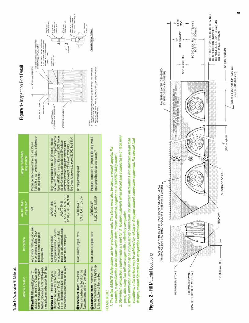
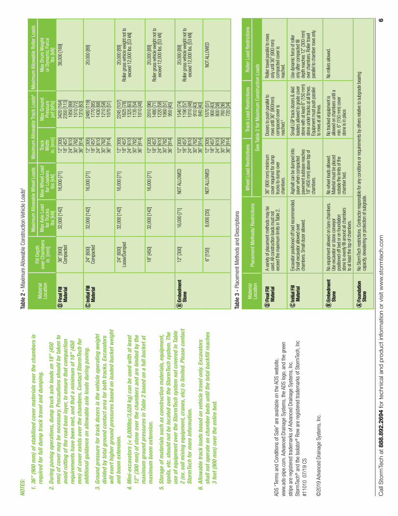

Call StormTech at 860.529.8188 or 888.892.2694 or visit our website at www.stormtech.com for technical and product information. 1
StormTech MC-3500 Chamber
SC-160LP, SC-310, SC-740 & DC-780 Design Manual
THE MOST ADVANCED NAME IN WATER MANAGEMENT SOLUTIONS ®
StormTech® Chamber Systems for Stormwater Management
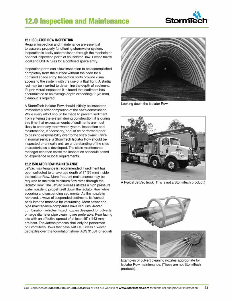
Call StormTech at 860.529.8188 or 888.892.2694 or visit our website at www.stormtech.com for technical and product information. 31
12.0 Inspection and Maintenance
Looking down the Isolator Row
A typical JetVac truck (This is not a StormTech product.)
Examples of culvert cleaning nozzles appropriate for Isolator Row maintenance. (These are not StormTech products).
12.1 ISOLATOR ROW INSPECTIONRegular inspection and maintenance are essential to assure a properly functioning stormwater system. Inspection is easily accomplished through the manhole or optional inspection ports of an Isolator Row. Please follow local and OSHA rules for a confined space entry.
Inspection ports can allow inspection to be accomplished completely from the surface without the need for a confined space entry. Inspection ports provide visual access to the system with the use of a flashlight. A stadia rod may be inserted to determine the depth of sediment. If upon visual inspection it is found that sediment has accumulated to an average depth exceeding 3” (76 mm), cleanout is required.
A StormTech Isolator Row should initially be inspected immediately after completion of the site’s construction. While every effort should be made to prevent sediment from entering the system during construction, it is during this time that excess amounts of sediments are most likely to enter any stormwater system. Inspection and maintenance, if necessary, should be performed prior to passing responsibility over to the site’s owner. Once in normal service, a StormTech Isolator Row should be inspected bi-annually until an understanding of the sites characteristics is developed. The site’s maintenance manager can then revise the inspection schedule based on experience or local requirements.
12.2 ISOLATOR ROW MAINTENANCEJetVac maintenance is recommended if sediment has been collected to an average depth of 3” (76 mm) inside the Isolator Row. More frequent maintenance may be required to maintain minimum flow rates through the Isolator Row. The JetVac process utilizes a high pressure water nozzle to propel itself down the Isolator Row while scouring and suspending sediments. As the nozzle is retrieved, a wave of suspended sediments is flushed back into the manhole for vacuuming. Most sewer and pipe maintenance companies have vacuum/ JetVac combination vehicles. Fixed nozzles designed for culverts or large diameter pipe cleaning are preferable. Rear facing jets with an effective spread of at least 45” (1143 mm) are best. The JetVac process shall only be performed on StormTech Rows that have AASHTO class 1 woven geotextile over the foundation stone (ADS 315ST or equal).
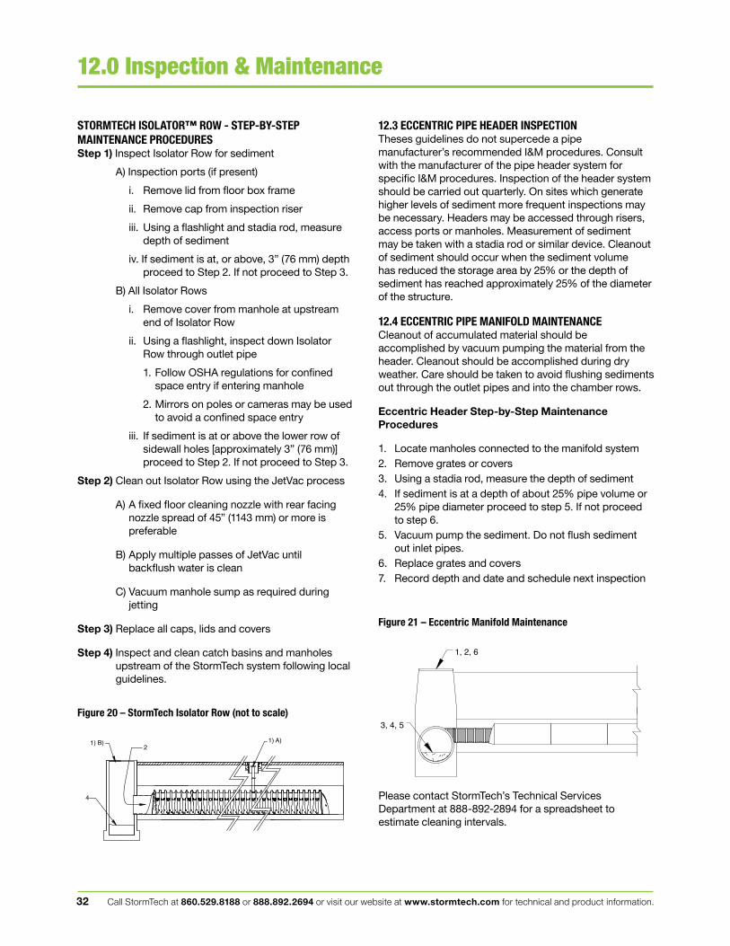
Call StormTech at 860.529.8188 or 888.892.2694 or visit our website at www.stormtech.com for technical and product information.32
12.0 Inspection & Maintenance
12.3 ECCENTRIC PIPE HEADER INSPECTIONTheses guidelines do not supercede a pipe manufacturer’s recommended I&M procedures. Consult with the manufacturer of the pipe header system for specific I&M procedures. Inspection of the header system should be carried out quarterly. On sites which generate higher levels of sediment more frequent inspections may be necessary. Headers may be accessed through risers, access ports or manholes. Measurement of sediment may be taken with a stadia rod or similar device. Cleanout of sediment should occur when the sediment volume has reduced the storage area by 25% or the depth of sediment has reached approximately 25% of the diameter of the structure.
12.4 ECCENTRIC PIPE MANIFOLD MAINTENANCECleanout of accumulated material should be accomplished by vacuum pumping the material from the header. Cleanout should be accomplished during dry weather. Care should be taken to avoid flushing sediments out through the outlet pipes and into the chamber rows.
Eccentric Header Step-by-Step Maintenance Procedures
1. Locate manholes connected to the manifold system2. Remove grates or covers3. Using a stadia rod, measure the depth of sediment4. If sediment is at a depth of about 25% pipe volume or
25% pipe diameter proceed to step 5. If not proceed to step 6.
5. Vacuum pump the sediment. Do not flush sediment out inlet pipes.
6. Replace grates and covers7. Record depth and date and schedule next inspection
STORMTECH ISOLATOR™ ROW - STEP-BY-STEPMAINTENANCE PROCEDURESStep 1) Inspect Isolator Row for sediment
A) Inspection ports (if present)
i. Remove lid from floor box frame
ii. Remove cap from inspection riser
iii. Using a flashlight and stadia rod, measure depth of sediment
iv. If sediment is at, or above, 3” (76 mm) depth proceed to Step 2. If not proceed to Step 3.
B) All Isolator Rows
i. Remove cover from manhole at upstream end of Isolator Row
ii. Using a flashlight, inspect down Isolator Row through outlet pipe
1. Follow OSHA regulations for confined space entry if entering manhole
2. Mirrors on poles or cameras may be used to avoid a confined space entry
iii. If sediment is at or above the lower row of sidewall holes [approximately 3” (76 mm)] proceed to Step 2. If not proceed to Step 3.
Step 2) Clean out Isolator Row using the JetVac process
A) A fixed floor cleaning nozzle with rear facing nozzle spread of 45” (1143 mm) or more is preferable
B) Apply multiple passes of JetVac until backflush water is clean
C) Vacuum manhole sump as required during jetting
Step 3) Replace all caps, lids and covers
Step 4) Inspect and clean catch basins and manholes upstream of the StormTech system following local guidelines.
Figure 20 – StormTech Isolator Row (not to scale)
Figure 21 – Eccentric Manifold Maintenance
4
21) B) 1) A)
1, 2, 6
3, 4, 5
Please contact StormTech’s Technical Services Department at 888-892-2894 for a spreadsheet to estimate cleaning intervals.
Call StormTech at 860.529.8188 or 888.892.2694 or visit our website at www.stormtech.com for technical and product information. 33
13.0 General Notes
1. StormTech (“StormTech”) requires installing contractors to use and understand StormTech’s latest Installation Instructions prior to beginning system installation.
2. Our Technical Services Department offers installation consultations to installing contractors. Contact our Technical Service Representatives at least 30 days prior to system installation to arrange a preinstallation consultation. Our representatives can then answer questions or address comments on the StormTech chamber system and inform the Installing contractor of the minimum installation requirements before beginning the system’s construction. Call 860-529-8188 to speak to a Technical Service Representative or visit www.stormtech.com to receive a copy of our Installation Instructions.
3. StormTech’s requirements for systems with pavement design (asphalt, concrete pavers, etc.): Minimum cover for the SC-740, DC-780 and SC-310 chambers is 18” (457 mm) not including pavement; Minimum cover for the SC-160LP chamber is 14” (350 mm); Maximum cover for the SC-740 and SC-310 chambers is 96” (2.4 m) including pavement design; Maximum cover for the SC-160LP chamber is 10’ (3.0 m); Maximum cover for the DC-780 chamber is 12’ (3.6 m) including pavement design. For installations that do not include pavement, where rutting from vehicles may occur, minimum required cover is 24” (610 mm), maximum cover is as stated above.
4. The contractor must report any discrepancies with the bearing capacity of the chamber foundation materials to the design engineer.
5. AASHTO M288 Class 2 non-woven geotextile (filter fabric) must be used as indicated in the project plans.
6. Stone placement between chamber rows and around perimeter must follow instructions as indicated in the most current version of StormTech’s Installation Instructions.
7. Backfilling over the chambers must follow requirements as indicated in the most current version of StormTech’s Installation Instructions.
8. The contractor must refer to StormTech’s Installation Instructions for a Table of Acceptable Vehicle Loads at various depths of cover. This information is also available at StormTech’s website: www.stormtech.com. The contractor is responsible for preventing vehicles that exceed StormTech’s requirements from traveling across or parking over the stormwater system. Temporary fencing, warning tape and appropriately located signs are commonly used to prevent unauthorized vehicles from entering sensitive construction areas.
9. The contractor must apply erosion and sediment control measures to protect the stormwater system during all phases of site construction per local codes and design engineer’s specifications.
10. STORMTECH PRODUCT WARRANTY IS LIMITED. Contact StormTech for warranty information.
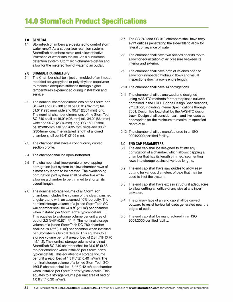
Call StormTech at 860.529.8188 or 888.892.2694 or visit our website at www.stormtech.com for technical and product information.34
14.0 StormTech Product Specifications
2.7 The SC-740 and SC-310 chambers shall have forty eight orifices penetrating the sidewalls to allow for lateral conveyance of water.
2.8 The chamber shall have two orifices near its top to allow for equalization of air pressure between its interior and exterior.
2.9 The chamber shall have both of its ends open to allow for unimpeded hydraulic flows and visual inspections down a row’s entire length.
2.10 The chamber shall have 14 corrugations.
2.11 The chamber shall be analyzed and designed using AASHTO methods for thermoplastic culverts contained in the LRFD Bridge Design Specifications, 2nd Edition, including Interim Specifications through 2001. Design live load shall be the AASHTO design truck. Design shall consider earth and live loads as appropriate for the minimum to maximum specified depth of fill.
2.12 The chamber shall be manufactured in an ISO 9001:2000 certified facility.
3.0 END CAP PARAMETERS3.1 The end cap shall be designed to fit into any
corrugation of a chamber, which allows: capping a chamber that has its length trimmed; segmenting rows into storage basins of various lengths.
3.2 The end cap shall have saw guides to allow easy cutting for various diameters of pipe that may be used to inlet the system.
3.3 The end cap shall have excess structural adequacies to allow cutting an orifice of any size at any invert elevation.
3.4 The primary face of an end cap shall be curved outward to resist horizontal loads generated near the edges of beds.
3.5 The end cap shall be manufactured in an ISO 9001:2000 certified facility.
1.0 GENERAL1.1 StormTech chambers are designed to control storm
water runoff. As a subsurface retention system, StormTech chambers retain and allow effective infiltration of water into the soil. As a subsurface detention system, StormTech chambers detain and allow for the metered flow of water to an outfall.
2.0 CHAMBER PARAMETERS2.1 The Chamber shall be injection molded of an impact
modified polypropylene or polyethylene copolymer to maintain adequate stiffness through higher temperatures experienced during installation and service.
2.2 The nominal chamber dimensions of the StormTech SC-740 and DC-780 shall be 30.0” (762 mm) tall, 51.0” (1295 mm) wide and 90.7” (2304 mm) long. The nominal chamber dimensions of the StormTech SC-310 shall be 16.0” (406 mm) tall, 34.0” (864 mm) wide and 90.7” (2304 mm) long. SC-160LP shall be 12”(305mm) tall, 25” (635 mm) wide and 90.7” (2304mm) long. The installed length of a joined chamber shall be 85.4” (2169 mm).
2.3 The chamber shall have a continuously curved section profile.
2.4 The chamber shall be open-bottomed.
2.5 The chamber shall incorporate an overlapping corrugation joint system to allow chamber rows of almost any length to be created. The overlapping corrugation joint system shall be effective while allowing a chamber to be trimmed to shorten its overall length.
2.6 The nominal storage volume of all StormTech chambers includes the volume of the clean, crushed, angular stone with an assumed 40% porosity. The nominal storage volume of a joined StormTech SC-740 chamber shall be 74.9 ft3 (2.1 m3) per chamber when installed per StormTech’s typical details. This equates to a storage volume per unit area of bed of 2.2 ft3/ft2 (0.67 m3/m2). The nominal storage volume of a joined StormTech DC-780 chamber shall be 78.4 ft3 (2.2 m3) per chamber when installed per StormTech’s typical details. This equates to a storage volume per unit area of bed of 2.3 ft3/ft2 (0.70 m3/m2). The nominal storage volume of a joined StormTech SC-310 chamber shall be 31.0 ft3 (0.88 m3) per chamber when installed per StormTech’s typical details. This equates to a storage volume per unit area of bed of 1.3 ft3/ft2 (0.40 m3/m2). The nominal storage volume of a joined StormTech SC-160LP chamber shall be 15 ft3 (0.42 m3) per chamber when installed per StormTech’s typical details. This equates to a storage volume per unit area of bed of 1.0 ft3/ft3 (0.30 m3/m3).
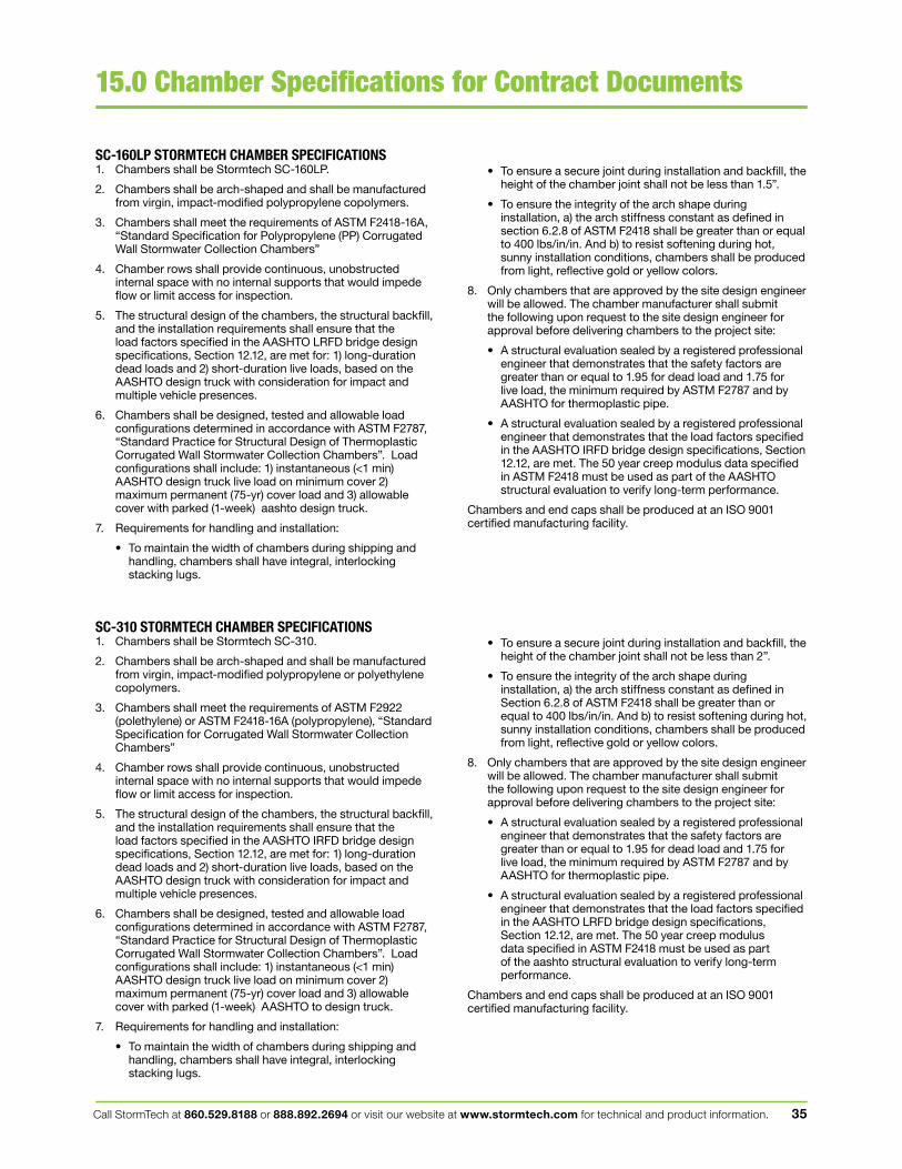
Call StormTech at 860.529.8188 or 888.892.2694 or visit our website at www.stormtech.com for technical and product information. 35
15.0 Chamber Specifications for Contract Documents
• To ensure a secure joint during installation and backfill, the height of the chamber joint shall not be less than 1.5”.
• To ensure the integrity of the arch shape during installation, a) the arch stiffness constant as defined in section 6.2.8 of ASTM F2418 shall be greater than or equal to 400 lbs/in/in. And b) to resist softening during hot, sunny installation conditions, chambers shall be produced from light, reflective gold or yellow colors.
8. Only chambers that are approved by the site design engineer will be allowed. The chamber manufacturer shall submit the following upon request to the site design engineer for approval before delivering chambers to the project site:
• A structural evaluation sealed by a registered professional engineer that demonstrates that the safety factors are greater than or equal to 1.95 for dead load and 1.75 for live load, the minimum required by ASTM F2787 and by AASHTO for thermoplastic pipe.
• A structural evaluation sealed by a registered professional engineer that demonstrates that the load factors specified in the AASHTO IRFD bridge design specifications, Section 12.12, are met. The 50 year creep modulus data specified in ASTM F2418 must be used as part of the AASHTO structural evaluation to verify long-term performance.
Chambers and end caps shall be produced at an ISO 9001 certified manufacturing facility.
• To ensure a secure joint during installation and backfill, the height of the chamber joint shall not be less than 2”.
• To ensure the integrity of the arch shape during installation, a) the arch stiffness constant as defined in Section 6.2.8 of ASTM F2418 shall be greater than or equal to 400 lbs/in/in. And b) to resist softening during hot, sunny installation conditions, chambers shall be produced from light, reflective gold or yellow colors.
8. Only chambers that are approved by the site design engineer will be allowed. The chamber manufacturer shall submit the following upon request to the site design engineer for approval before delivering chambers to the project site:
• A structural evaluation sealed by a registered professional engineer that demonstrates that the safety factors are greater than or equal to 1.95 for dead load and 1.75 for live load, the minimum required by ASTM F2787 and by AASHTO for thermoplastic pipe.
• A structural evaluation sealed by a registered professional engineer that demonstrates that the load factors specified in the AASHTO LRFD bridge design specifications, Section 12.12, are met. The 50 year creep modulus data specified in ASTM F2418 must be used as part of the aashto structural evaluation to verify long-term performance.
Chambers and end caps shall be produced at an ISO 9001 certified manufacturing facility.
SC-160LP STORMTECH CHAMBER SPECIFICATIONS1. Chambers shall be Stormtech SC-160LP.
2. Chambers shall be arch-shaped and shall be manufactured from virgin, impact-modified polypropylene copolymers.
3. Chambers shall meet the requirements of ASTM F2418-16A, “Standard Specification for Polypropylene (PP) Corrugated Wall Stormwater Collection Chambers”
4. Chamber rows shall provide continuous, unobstructed internal space with no internal supports that would impede flow or limit access for inspection.
5. The structural design of the chambers, the structural backfill, and the installation requirements shall ensure that the load factors specified in the AASHTO LRFD bridge design specifications, Section 12.12, are met for: 1) long-duration dead loads and 2) short-duration live loads, based on the AASHTO design truck with consideration for impact and multiple vehicle presences.
6. Chambers shall be designed, tested and allowable load configurations determined in accordance with ASTM F2787, “Standard Practice for Structural Design of Thermoplastic Corrugated Wall Stormwater Collection Chambers”. Load configurations shall include: 1) instantaneous (<1 min) AASHTO design truck live load on minimum cover 2) maximum permanent (75-yr) cover load and 3) allowable cover with parked (1-week) aashto design truck.
7. Requirements for handling and installation:
• To maintain the width of chambers during shipping and handling, chambers shall have integral, interlocking stacking lugs.
SC-310 STORMTECH CHAMBER SPECIFICATIONS1. Chambers shall be Stormtech SC-310.
2. Chambers shall be arch-shaped and shall be manufactured from virgin, impact-modified polypropylene or polyethylene copolymers.
3. Chambers shall meet the requirements of ASTM F2922 (polethylene) or ASTM F2418-16A (polypropylene), “Standard Specification for Corrugated Wall Stormwater Collection Chambers”
4. Chamber rows shall provide continuous, unobstructed internal space with no internal supports that would impede flow or limit access for inspection.
5. The structural design of the chambers, the structural backfill, and the installation requirements shall ensure that the load factors specified in the AASHTO IRFD bridge design specifications, Section 12.12, are met for: 1) long-duration dead loads and 2) short-duration live loads, based on the AASHTO design truck with consideration for impact and multiple vehicle presences.
6. Chambers shall be designed, tested and allowable load configurations determined in accordance with ASTM F2787, “Standard Practice for Structural Design of Thermoplastic Corrugated Wall Stormwater Collection Chambers”. Load configurations shall include: 1) instantaneous (<1 min) AASHTO design truck live load on minimum cover 2) maximum permanent (75-yr) cover load and 3) allowable cover with parked (1-week) AASHTO to design truck.
7. Requirements for handling and installation:
• To maintain the width of chambers during shipping and handling, chambers shall have integral, interlocking stacking lugs.
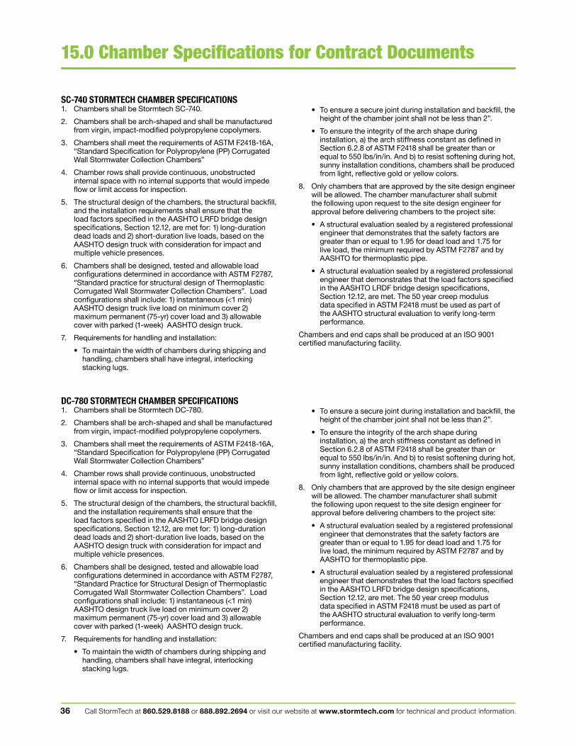
Call StormTech at 860.529.8188 or 888.892.2694 or visit our website at www.stormtech.com for technical and product information.36
15.0 Chamber Specifications for Contract Documents
• To ensure a secure joint during installation and backfill, the height of the chamber joint shall not be less than 2”.
• To ensure the integrity of the arch shape during installation, a) the arch stiffness constant as defined in Section 6.2.8 of ASTM F2418 shall be greater than or equal to 550 lbs/in/in. And b) to resist softening during hot, sunny installation conditions, chambers shall be produced from light, reflective gold or yellow colors.
8. Only chambers that are approved by the site design engineer will be allowed. The chamber manufacturer shall submit the following upon request to the site design engineer for approval before delivering chambers to the project site:
• A structural evaluation sealed by a registered professional engineer that demonstrates that the safety factors are greater than or equal to 1.95 for dead load and 1.75 for live load, the minimum required by ASTM F2787 and by AASHTO for thermoplastic pipe.
• A structural evaluation sealed by a registered professional engineer that demonstrates that the load factors specified in the AASHTO LRDF bridge design specifications, Section 12.12, are met. The 50 year creep modulus data specified in ASTM F2418 must be used as part of the AASHTO structural evaluation to verify long-term performance.
Chambers and end caps shall be produced at an ISO 9001 certified manufacturing facility.
• To ensure a secure joint during installation and backfill, the height of the chamber joint shall not be less than 2”.
• To ensure the integrity of the arch shape during installation, a) the arch stiffness constant as defined in Section 6.2.8 of ASTM F2418 shall be greater than or equal to 550 lbs/in/in. And b) to resist softening during hot, sunny installation conditions, chambers shall be produced from light, reflective gold or yellow colors.
8. Only chambers that are approved by the site design engineer will be allowed. The chamber manufacturer shall submit the following upon request to the site design engineer for approval before delivering chambers to the project site:
• A structural evaluation sealed by a registered professional engineer that demonstrates that the safety factors are greater than or equal to 1.95 for dead load and 1.75 for live load, the minimum required by ASTM F2787 and by AASHTO for thermoplastic pipe.
• A structural evaluation sealed by a registered professional engineer that demonstrates that the load factors specified in the AASHTO LRFD bridge design specifications, Section 12.12, are met. The 50 year creep modulus data specified in ASTM F2418 must be used as part of the AASHTO structural evaluation to verify long-term performance.
Chambers and end caps shall be produced at an ISO 9001 certified manufacturing facility.
SC-740 STORMTECH CHAMBER SPECIFICATIONS1. Chambers shall be Stormtech SC-740.
2. Chambers shall be arch-shaped and shall be manufactured from virgin, impact-modified polypropylene copolymers.
3. Chambers shall meet the requirements of ASTM F2418-16A, “Standard Specification for Polypropylene (PP) Corrugated Wall Stormwater Collection Chambers”
4. Chamber rows shall provide continuous, unobstructed internal space with no internal supports that would impede flow or limit access for inspection.
5. The structural design of the chambers, the structural backfill, and the installation requirements shall ensure that the load factors specified in the AASHTO LRFD bridge design specifications, Section 12.12, are met for: 1) long-duration dead loads and 2) short-duration live loads, based on the AASHTO design truck with consideration for impact and multiple vehicle presences.
6. Chambers shall be designed, tested and allowable load configurations determined in accordance with ASTM F2787, “Standard practice for structural design of Thermoplastic Corrugated Wall Stormwater Collection Chambers”. Load configurations shall include: 1) instantaneous (<1 min) AASHTO design truck live load on minimum cover 2) maximum permanent (75-yr) cover load and 3) allowable cover with parked (1-week) AASHTO design truck.
7. Requirements for handling and installation:
• To maintain the width of chambers during shipping and handling, chambers shall have integral, interlocking stacking lugs.
DC-780 STORMTECH CHAMBER SPECIFICATIONS1. Chambers shall be Stormtech DC-780.
2. Chambers shall be arch-shaped and shall be manufactured from virgin, impact-modified polypropylene copolymers.
3. Chambers shall meet the requirements of ASTM F2418-16A, “Standard Specification for Polypropylene (PP) Corrugated Wall Stormwater Collection Chambers”
4. Chamber rows shall provide continuous, unobstructed internal space with no internal supports that would impede flow or limit access for inspection.
5. The structural design of the chambers, the structural backfill, and the installation requirements shall ensure that the load factors specified in the AASHTO LRFD bridge design specifications, Section 12.12, are met for: 1) long-duration dead loads and 2) short-duration live loads, based on the AASHTO design truck with consideration for impact and multiple vehicle presences.
6. Chambers shall be designed, tested and allowable load configurations determined in accordance with ASTM F2787, “Standard Practice for Structural Design of Thermoplastic Corrugated Wall Stormwater Collection Chambers”. Load configurations shall include: 1) instantaneous (<1 min) AASHTO design truck live load on minimum cover 2) maximum permanent (75-yr) cover load and 3) allowable cover with parked (1-week) AASHTO design truck.
7. Requirements for handling and installation:
• To maintain the width of chambers during shipping and handling, chambers shall have integral, interlocking stacking lugs.

[THIS PAGE IS LEFT INTENTIONALLY BLANK]

APPENDIX E: SWPPP FORMS Notice of Intent
Notice of Termination Contractor Forms

[THIS PAGE IS LEFT INTENTIONALLY BLANK]
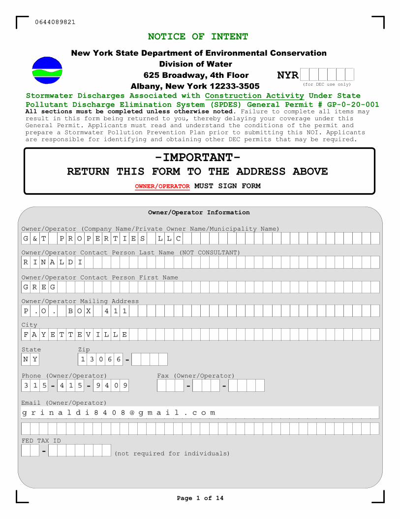
Fax (Owner/Operator)
- -
Page 1 of 14
New York State Department of Environmental ConservationDivision of Water
625 Broadway, 4th FloorAlbany, New York 12233-3505
NOTICE OF INTENT
-IMPORTANT-RETURN THIS FORM TO THE ADDRESS ABOVE
OWNER/OPERATOR MUST SIGN FORM
Stormwater Discharges Associated with Construction Activity Under StatePollutant Discharge Elimination System (SPDES) General Permit # GP-0- -00All sections must be completed unless otherwise noted. Failure to complete all items mayresult in this form being returned to you, thereby delaying your coverage under thisGeneral Permit. Applicants must read and understand the conditions of the permit andprepare a Stormwater Pollution Prevention Plan prior to submitting this NOI. Applicantsare responsible for identifying and obtaining other DEC permits that may be required.
Owner/Operator Information
Owner/Operator Contact Person Last Name (NOT CONSULTANT)
Owner/Operator Contact Person First Name
Owner/Operator Mailing Address
City
State Zip
-Phone (Owner/Operator)
- -
Email (Owner/Operator)
Owner/Operator (Company Name/Private Owner Name/Municipality Name)
NYR(for DEC use only)
FED TAX ID
- (not required for individuals)
0644089821
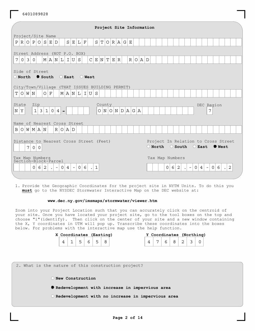
1. Provide the Geographic Coordinates for the project site in NYTM Units. To do this youmust go to the NYSDEC Stormwater Interactive Map on the DEC website at:
www.dec.ny.gov/imsmaps/stormwater/viewer.htm
Zoom into your Project Location such that you can accurately click on the centroid ofyour site. Once you have located your project site, go to the tool boxes on the top andchoose "i"(identify). Then click on the center of your site and a new window containingthe X, Y coordinates in UTM will pop up. Transcribe these coordinates into the boxesbelow. For problems with the interactive map use the help function.
X Coordinates (Easting) Y Coordinates (Northing)
Project Site Information
Project/Site Name
Street Address (NOT P.O. BOX)
City/Town/Village (THAT ISSUES BUILDING PERMIT)
State Zip
-County
Name of Nearest Cross Street
Distance to Nearest Cross Street (Feet) Project In Relation to Cross StreetNorth South East West
Page 2 of 14
2. What is the nature of this construction project?
New Construction
Redevelopment with increase in impervious area
Redevelopment with no increase in impervious area
Section-Block-ParcelTax Map Numbers
Side of StreetNorth South East West
DEC Region
Tax Map Numbers
6401089828
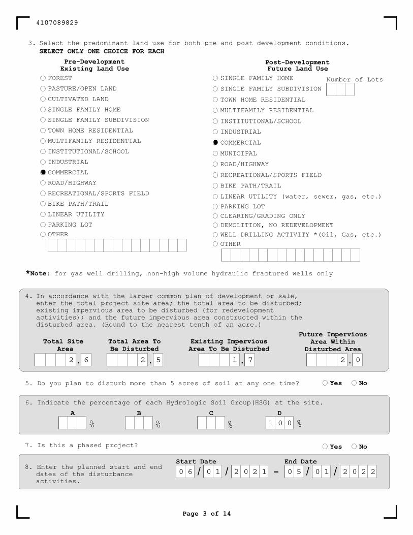
3. Select the predominant land use for both pre and post development conditions.SELECT ONLY ONE CHOICE FOR EACH
Page 3 of 14
Existing Land UseFOREST
PASTURE/OPEN LAND
CULTIVATED LAND
SINGLE FAMILY HOME
SINGLE FAMILY SUBDIVISION
TOWN HOME RESIDENTIAL
MULTIFAMILY RESIDENTIAL
INSTITUTIONAL/SCHOOL
INDUSTRIAL
COMMERCIAL
ROAD/HIGHWAY
RECREATIONAL/SPORTS FIELD
BIKE PATH/TRAIL
LINEAR UTILITY
PARKING LOT
OTHER
Future Land UseSINGLE FAMILY HOME
SINGLE FAMILY SUBDIVISION
TOWN HOME RESIDENTIAL
MULTIFAMILY RESIDENTIAL
INSTITUTIONAL/SCHOOL
INDUSTRIAL
COMMERCIAL
MUNICIPAL
ROAD/HIGHWAY
RECREATIONAL/SPORTS FIELD
BIKE PATH/TRAIL
LINEAR UTILITY (water, sewer, gas, etc.)
PARKING LOTCLEARING/GRADING ONLYDEMOLITION, NO REDEVELOPMENTWELL DRILLING ACTIVITY *(Oil, Gas, etc.)OTHER
Pre-Development Post-Development
4. In accordance with the larger common plan of development or sale,enter the total project site area; the total area to be disturbed;existing impervious area to be disturbed (for redevelopmentactivities); and the future impervious area constructed within thedisturbed area. (Round to the nearest tenth of an acre.)
Number of Lots
*Note: for gas well drilling, non-high volume hydraulic fractured wells only
Total SiteArea
.
Total Area ToBe Disturbed
.
Existing ImperviousArea To Be Disturbed
.
Future ImperviousArea Within
Disturbed Area
.
5. Do you plan to disturb more than 5 acres of soil at any one time? Yes No
6. Indicate the percentage of each Hydrologic Soil Group(HSG) at the site.
A B C D
% % % %
7. Is this a phased project? Yes No
8. Enter the planned start and enddates of the disturbanceactivities.
-Start Date
/ /End Date
/ /
4107089829
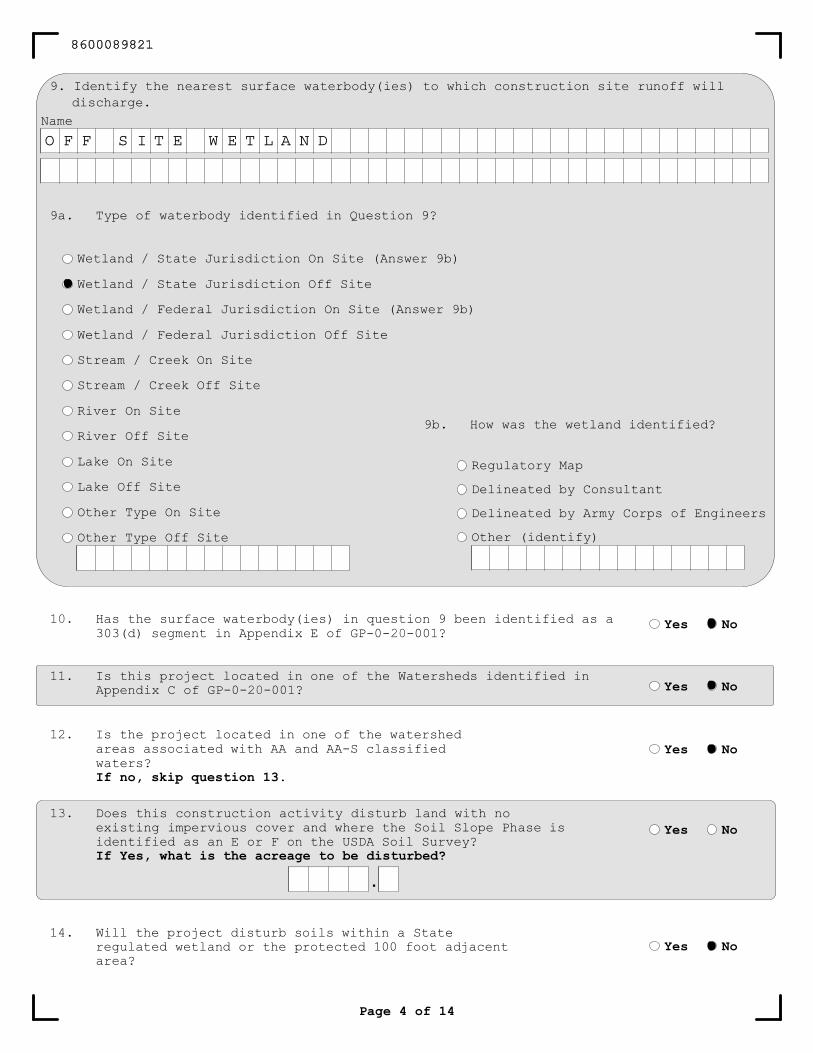
Page 4 of 14
Name
9. Identify the nearest surface waterbody(ies) to which construction site runoff willdischarge.
9a. Type of waterbody identified in Question 9?
Wetland / State Jurisdiction On Site (Answer 9b)
Wetland / State Jurisdiction Off Site
Wetland / Federal Jurisdiction On Site (Answer 9b)
Wetland / Federal Jurisdiction Off Site
Stream / Creek On Site
Stream / Creek Off Site
River On Site
River Off Site
Lake On Site
Lake Off Site
Other Type On Site
Other Type Off Site
9b. How was the wetland identified?
Regulatory Map
Delineated by Consultant
Delineated by Army Corps of Engineers
Other (identify)
Yes No
Yes No
Yes No
Has the surface waterbody(ies) in question 9 been identified as a303(d) segment in Appendix E of GP-0- -00 ?
Is this project located in one of the Watersheds identified inAppendix C of GP-0- -00 ?
Is the project located in one of the watershedareas associated with AA and AA-S classifiedwaters?If no, skip question 13.
Does this construction activity disturb land with noexisting impervious cover and where the Soil Slope Phase isidentified as an E or F on the USDA Soil Survey?If Yes, what is the acreage to be disturbed?
Yes No
.
14. Will the project disturb soils within a Stateregulated wetland or the protected 100 foot adjacentarea?
Yes No
8600089821
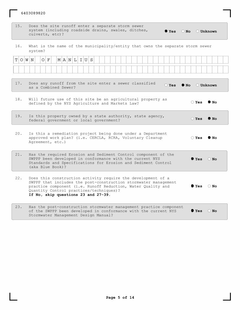
15. Does the site runoff enter a separate storm sewersystem (including roadside drains, swales, ditches,culverts, etc)?
16. What is the name of the municipality/entity that owns the separate storm sewersystem?
Yes No Unknown
17. Does any runoff from the site enter a sewer classifiedas a Combined Sewer? Yes No Unknown
21. Has the required Erosion and Sediment Control component of theSWPPP been developed in conformance with the current NYSStandards and Specifications for Erosion and Sediment Control(aka Blue Book)?
22. Does this construction activity require the development of aSWPPP that includes the post-construction stormwater managementpractice component (i.e. Runoff Reduction, Water Quality andQuantity Control practices/techniques)?If No, skip questions 23 and 27-39.
23. Has the post-construction stormwater management practice componentof the SWPPP been developed in conformance with the current NYSStormwater Management Design Manual?
Yes No
Yes No
Yes No
Page 5 of 14
18. Will future use of this site be an agricultural property asdefined by the NYS Agriculture and Markets Law? Yes No
Yes No20. Is this a remediation project being done under a Department
approved work plan? (i.e. CERCLA, RCRA, Voluntary CleanupAgreement, etc.)
Yes No19. Is this property owned by a state authority, state agency,
federal government or local government?
6403089820
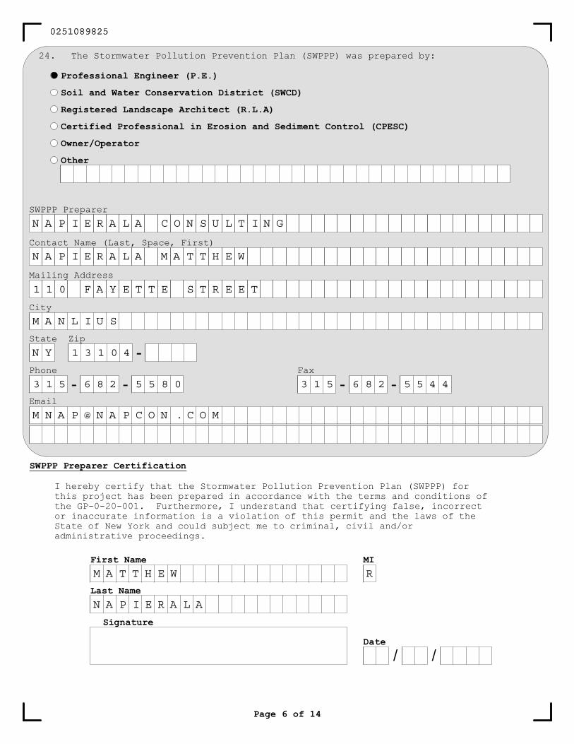
Page 6 of 14
SWPPP Preparer
Contact Name (Last, Space, First)
Mailing Address
City
State Zip
-Phone
- -Fax
Signature
Date
/ /
First Name
Last Name
MI
SWPPP Preparer Certification
24. The Stormwater Pollution Prevention Plan (SWPPP) was prepared by:
Professional Engineer (P.E.)
Soil and Water Conservation District (SWCD)
Registered Landscape Architect (R.L.A)
Certified Professional in Erosion and Sediment Control (CPESC)
Owner/Operator
Other
I hereby certify that the Stormwater Pollution Prevention Plan (SWPPP) forthis project has been prepared in accordance with the terms and conditions ofthe GP-0- -00 . Furthermore, I understand that certifying false, incorrector inaccurate information is a violation of this permit and the laws of theState of New York and could subject me to criminal, civil and/oradministrative proceedings.
0251089825
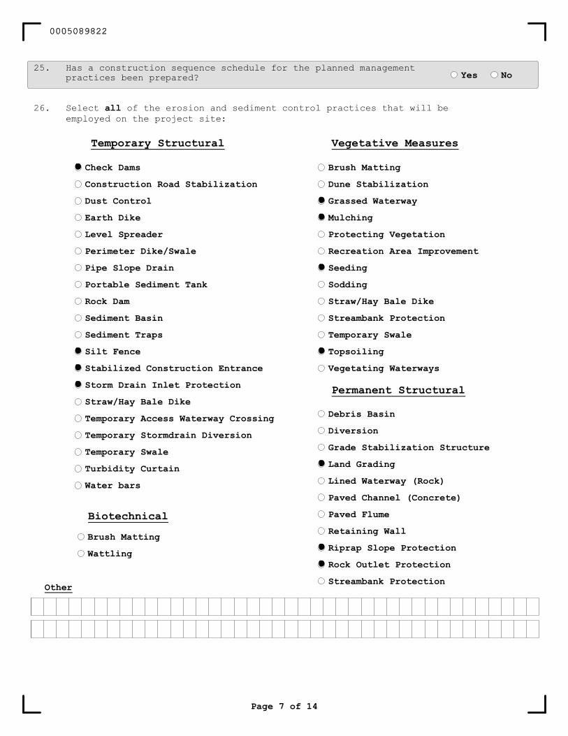
26. Select all of the erosion and sediment control practices that will beemployed on the project site:
Page 7 of 14
Biotechnical
Brush Matting
Wattling
Other
25. Has a construction sequence schedule for the planned managementpractices been prepared? Yes No
Brush Matting
Dune Stabilization
Grassed Waterway
Mulching
Protecting Vegetation
Recreation Area Improvement
Seeding
Sodding
Straw/Hay Bale Dike
Streambank Protection
Temporary Swale
Topsoiling
Vegetating Waterways
Vegetative Measures
Check Dams
Construction Road Stabilization
Dust Control
Earth Dike
Level Spreader
Perimeter Dike/Swale
Pipe Slope Drain
Portable Sediment Tank
Rock Dam
Sediment Basin
Sediment Traps
Silt Fence
Stabilized Construction Entrance
Storm Drain Inlet Protection
Straw/Hay Bale Dike
Temporary Access Waterway Crossing
Temporary Stormdrain Diversion
Temporary Swale
Turbidity Curtain
Water bars
Temporary Structural
Debris Basin
Diversion
Grade Stabilization Structure
Land Grading
Lined Waterway (Rock)
Paved Channel (Concrete)
Paved Flume
Retaining Wall
Riprap Slope Protection
Rock Outlet Protection
Streambank Protection
Permanent Structural
0005089822
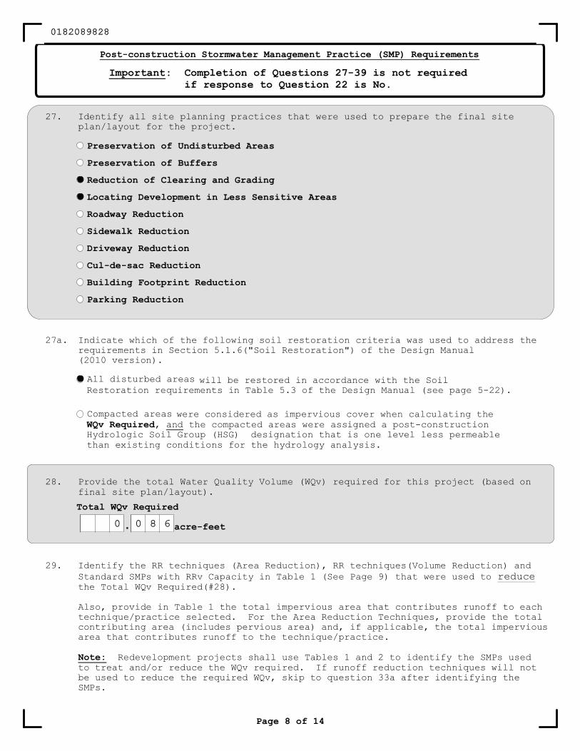
Page 8 of 14
Post-construction Stormwater Management Practice (SMP) Requirements
Important: Completion of Questions 27-39 is not requiredif response to Question 22 is No.
27. Identify all site planning practices that were used to prepare the final siteplan/layout for the project.
Preservation of Undisturbed Areas
Preservation of Buffers
Reduction of Clearing and Grading
Locating Development in Less Sensitive Areas
Roadway Reduction
Sidewalk Reduction
Driveway Reduction
Cul-de-sac Reduction
Building Footprint Reduction
Parking Reduction
28. Provide the total Water Quality Volume (WQv) required for this project (based onfinal site plan/layout).
Total WQv Required
. acre-feet
29. Identify the RR techniques (Area Reduction), RR techniques(Volume Reduction) andStandard SMPs with RRv Capacity in Table 1 (See Page 9) that were used to reducethe Total WQv Required(#28).
Also, provide in Table 1 the total impervious area that contributes runoff to eachtechnique/practice selected. For the Area Reduction Techniques, provide the totalcontributing area (includes pervious area) and, if applicable, the total imperviousarea that contributes runoff to the technique/practice.
Note: Redevelopment projects shall use Tables 1 and 2 to identify the SMPs usedto treat and/or reduce the WQv required. If runoff reduction techniques will notbe used to reduce the required WQv, skip to question 33a after identifying theSMPs.
27a. Indicate which of the following soil restoration criteria was used to address therequirements in Section 5.1.6("Soil Restoration") of the Design Manual(2010 version).
All disturbed areas
Compacted areas
will be restored in accordance with the SoilRestoration requirements in Table 5.3 of the Design Manual (see page 5-22).
were considered as impervious cover when calculating theWQv Required, and the compacted areas were assigned a post-constructionHydrologic Soil Group (HSG) designation that is one level less permeablethan existing conditions for the hydrology analysis.
0182089828
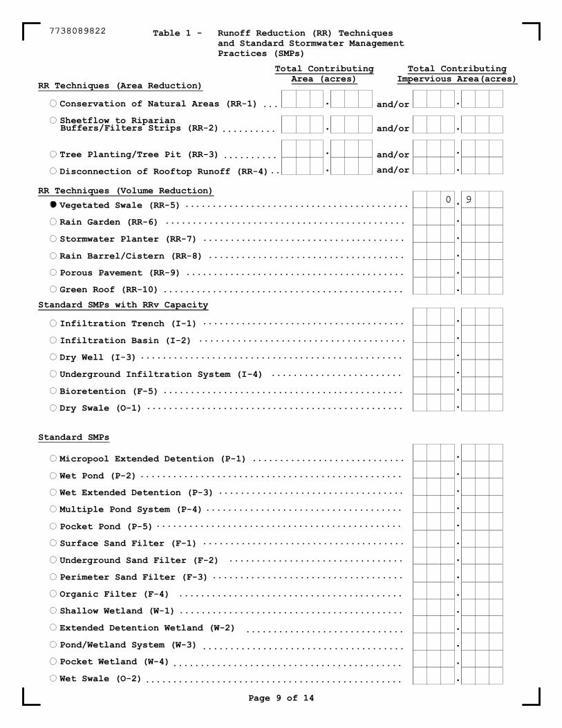
and/or
and/or
and/or
and/or
Conservation of Natural Areas (RR-1)
Sheetflow to Riparian
Tree Planting/Tree Pit (RR-3)
Disconnection of Rooftop Runoff (RR-4)
Vegetated Swale (RR-5)
Rain Garden (RR-6)
Stormwater Planter (RR-7)
Rain Barrel/Cistern (RR-8)
Porous Pavement (RR-9)
Green Roof (RR-10)
Infiltration Trench (I-1)
Infiltration Basin (I-2)
Dry Well (I-3)
Underground Infiltration System (I-4)
Bioretention (F-5)
Dry Swale (O-1)
Micropool Extended Detention (P-1)
Wet Pond (P-2)
Wet Extended Detention (P-3)
Multiple Pond System (P-4)
Pocket Pond (P-5)
Surface Sand Filter (F-1)
Underground Sand Filter (F-2)
Perimeter Sand Filter (F-3)
Organic Filter (F-4)
Shallow Wetland (W-1)
Extended Detention Wetland (W-2)
Pond/Wetland System (W-3)
Pocket Wetland (W-4)
Wet Swale (O-2)
.
.
.
.
.
.
.
.
.
.
.
.
.
.
............................
..................................
....................................
.............................................
.....................................
................................
...................................
.........................................
.........................................
.............................
.....................................
..........................................
...............................................
................................................
RR Techniques (Area Reduction)
Total ContributingImpervious Area(acres)
.
.
.
.
.
.
.
.
.
.
.
.
.
.
.
...
..........
..........
..
.........................................
............................................
.....................................
....................................
........................................
.....................................
......................................
................................................
........................
............................................
...............................................
Table 1 - Runoff Reduction (RR) Techniquesand Standard Stormwater ManagementPractices (SMPs)
RR Techniques (Volume Reduction)
Standard SMPs with RRv Capacity
Standard SMPs
Page 9 of 14
Total ContributingArea (acres)
.
.
.
.
Buffers/Filters Strips (RR-2)
.............................................
7738089822
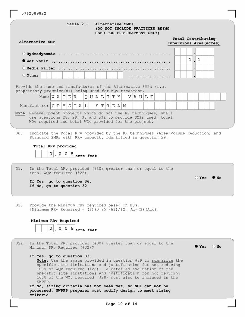
.
31. Is the Total RRv provided (#30) greater than or equal to thetotal WQv required (#28).
If Yes, go to question 36.If No, go to question 32.
Yes No
Total RRv provided
32. Provide the Minimum RRv required based on HSG.[Minimum RRv Required = (P)(0.95)(Ai)/12, Ai=(S)(Aic)]
Minimum RRv Required
. acre-feet
30. Indicate the Total RRv provided by the RR techniques (Area/Volume Reduction) andStandard SMPs with RRv capacity identified in question 29.
acre-feet
32a. Is the Total RRv provided (#30) greater than or equal to theMinimum RRv Required (#32)?
If Yes, go to question 33.Note: Use the space provided in question #39 to summarize thespecific site limitations and justification for not reducing100% of WQv required (#28). A detailed evaluation of thespecific site limitations and justification for not reducing100% of the WQv required (#28) must also be included in theSWPPP.
If No, sizing criteria has not been met, so NOI can not beprocessed. SWPPP preparer must modify design to meet sizingcriteria.
Yes No
Page 10 of 14
Hydrodynamic
Wet Vault
Media Filter
Other
Alternative SMP
.
.
.
.
...............................................
..................................................
...............................................
..................
Table 2 - Alternative SMPs(DO NOT INCLUDE PRACTICES BEINGUSED FOR PRETREATMENT ONLY)
Note: Redevelopment projects which do not use RR techniques, shalluse questions 28, 29, 33 and 33a to provide SMPs used, totalWQv required and total WQv provided for the project.
Total ContributingImpervious Area(acres)
Provide the name and manufacturer of the Alternative SMPs (i.e.proprietary practice(s)) being used for WQv treatment.
Name
Manufacturer
0762089822
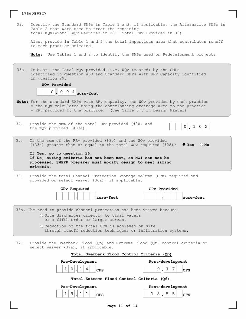
. acre-feet
CPv Provided
acre-feet.CPv Required
36. Provide the total Channel Protection Storage Volume (CPv) required andprovided or select waiver (36a), if applicable.
Page 11 of 14
35. Is the sum of the RRv provided (#30) and the WQv provided(#33a) greater than or equal to the total WQv required (#28)?
If Yes, go to question 36.If No, sizing criteria has not been met, so NOI can not beprocessed. SWPPP preparer must modify design to meet sizingcriteria.
.34. Provide the sum of the Total RRv provided (#30) and
the WQv provided (#33a).
Yes No
33a. Indicate the Total WQv provided (i.e. WQv treated) by the SMPsidentified in question #33 and Standard SMPs with RRv Capacity identifiedin question 29.
.WQv Provided
acre-feet
Note: For the standard SMPs with RRv capacity, the WQv provided by each practice= the WQv calculated using the contributing drainage area to the practice- RRv provided by the practice. (See Table 3.5 in Design Manual)
33. Identify the Standard SMPs in Table 1 and, if applicable, the Alternative SMPs inTable 2 that were used to treat the remainingtotal WQv(=Total WQv Required in 28 - Total RRv Provided in 30).
Also, provide in Table 1 and 2 the total impervious area that contributes runoffto each practice selected.
Note: Use Tables 1 and 2 to identify the SMPs used on Redevelopment projects.
Site discharges directly to tidal waters
Reduction of the total CPv is achieved on site
36a. The need to provide channel protection has been waived because:
or a fifth order or larger stream.
through runoff reduction techniques or infiltration systems.
. CFS CFS.Post-developmentPre-Development
Total Extreme Flood Control Criteria (Qf)
. CFS . CFS
Post-developmentPre-Development
Total Overbank Flood Control Criteria (Qp)
37. Provide the Overbank Flood (Qp) and Extreme Flood (Qf) control criteria orselect waiver (37a), if applicable.
1766089827
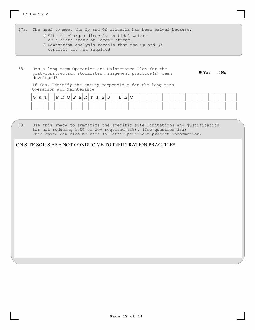
Page 12 of 14
39. Use this space to summarize the specific site limitations and justificationfor not reducing 100% of WQv required(#28). (See question 32a)This space can also be used for other pertinent project information.
38. Has a long term Operation and Maintenance Plan for thepost-construction stormwater management practice(s) beendeveloped?
If Yes, Identify the entity responsible for the long termOperation and Maintenance
Yes No
37a. The need to meet the Qp and Qf criteria has been waived because:
Site discharges directly to tidal waters
Downstream analysis reveals that the Qp and Qfcontrols are not required
or a fifth order or larger stream.
1310089822
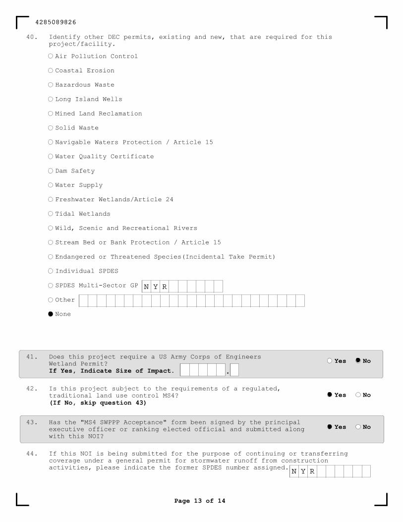
Air Pollution Control
Coastal Erosion
Hazardous Waste
Long Island Wells
Mined Land Reclamation
Solid Waste
Navigable Waters Protection / Article 15
Water Quality Certificate
Dam Safety
Water Supply
Freshwater Wetlands/Article 24
Tidal Wetlands
Wild, Scenic and Recreational Rivers
Stream Bed or Bank Protection / Article 15
Endangered or Threatened Species(Incidental Take Permit)
Individual SPDES
SPDES Multi-Sector GP
Other
None
44. If this NOI is being submitted for the purpose of continuing or transferringcoverage under a general permit for stormwater runoff from constructionactivities, please indicate the former SPDES number assigned.
42. Is this project subject to the requirements of a regulated,traditional land use control MS4?(If No, skip question 43)
Yes No
43. Has the "MS4 SWPPP Acceptance" form been signed by the principalexecutive officer or ranking elected official and submitted alongwith this NOI?
Yes No
41. Does this project require a US Army Corps of EngineersWetland Permit?If Yes, Indicate Size of Impact.
Yes No
.
Page 13 of 14
40. Identify other DEC permits, existing and new, that are required for thisproject/facility.
4285089826
Owner/Operator CertificationI have read or been advised of the permit conditions and believe that I understand them. I alsounderstand that, under the terms of the permit, there may be reporting requirements. I hereby certifythat this document and the corresponding documents were prepared under my direction or supervision. I amaware that there are significant penalties for submitting false information, including the possibility offine and imprisonment for knowing violations. I further understand that coverage under the general permitwill be identified in the acknowledgment that I will receive as a result of submitting this NOI and canbe as long as sixty (60) business days as provided for in the general permit. I also understand that, bysubmitting this NOI, I am acknowledging that the SWPPP has been developed and will be implemented as thefirst element of construction, and agreeing to comply with all the terms and conditions of the generalpermit for which this NOI is being submitted.
Owner/Operator Signature
Date
/ /
Print First Name
Print Last Name
MI
Page 14 of 14
3547089826

STORMWATER POLLUTION PREVENTION PLAN GENERAL CONTRACTOR’S CERTIFICATION
Construction Site:
STORMWATER POLLUTION PREVENTION PLAN
GENERAL CONTRACTOR'S CERTIFICATION:
“I hereby certify that I understand and agree to comply with the terms and conditions of the SWPPP and agree to implement any corrective actions identified by the qualified inspector during a site inspection. I also understand that the owner or operator must comply with the terms and conditions of the most current version of the New York State Pollutant Discharge Elimination System ("SPDES") general permit for stormwater discharges from construction activities and that it is unlawful for any person to cause or contribute to a violation of water quality standards. Furthermore, I understand that certifying false, incorrect or inaccurate information is a violation of the referenced permit and the laws of the State of New York and could subject me to criminal, civil and/or administrative proceedings."
Name: (Print)
Signature:
Title:
Company Name:
Address:
Telephone Number:
Date:
Scope of Services:

STORMWATER POLLUTION PREVENTION PLAN SUBCONTRACTOR’S CERTIFICATION
Construction Site:
STORMWATER POLLUTION PREVENTION PLAN
SUBCONTRACTOR'S CERTIFICATION: NYS-DEC SPDES General Permit Contractor’s Certification Statement
“I hereby certify that I understand and agree to comply with the terms and conditions of the SWPPP and agree to implement any corrective actions identified by the qualified inspector during a site inspection. I also understand that the owner or operator must comply with the terms and conditions of the most current version of the New York State Pollutant Discharge Elimination System ("SPDES") general permit for stormwater discharges from construction activities and that it is unlawful for any person to cause or contribute to a violation of water quality standards. Furthermore, I understand that certifying false, incorrect or inaccurate information is a violation of the referenced permit and the laws of the State of New York and could subject me to criminal, civil and/or administrative proceedings."
Name: (Print)
Signature:
Title:
Company Name:
Address:
Telephone Number:
Date:
Scope of Services:
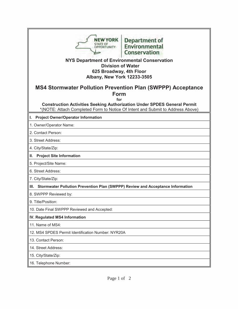
NYS Department of Environmental ConservationDivision of Water
625 Broadway, 4th FloorAlbany, New York 12233-3505
MS4 Stormwater Pollution Prevention Plan (SWPPP) Acceptance Form
forConstruction Activities Seeking Authorization Under SPDES General Permit
*(NOTE: Attach Completed Form to Notice Of Intent and Submit to Address Above)
I. Project Owner/Operator Information
1. Owner/Operator Name:
2. Contact Person:
3. Street Address:
4. City/State/Zip:
II. Project Site Information
5. Project/Site Name:
6. Street Address:
7. City/State/Zip:
III. Stormwater Pollution Prevention Plan (SWPPP) Review and Acceptance Information
8. SWPPP Reviewed by:
9. Title/Position:
10. Date Final SWPPP Reviewed and Accepted:
IV. Regulated MS4 Information
11. Name of MS4:
12. MS4 SPDES Permit Identification Number: NYR20A
13. Contact Person:
14. Street Address:
15. City/State/Zip:
16. Telephone Number:
Page 1 of 2
MS4 SWPPP Acceptance Form - continuedV. Certification Statement - MS4 Official (principal executive officer or ranking elected official) or Duly Authorized Representative
I hereby certify that the final Stormwater Pollution Prevention Plan (SWPPP) for the construction project identified in question 5 has been reviewed and meets the substantive requirements in the SPDES General Permit For Stormwater Discharges from Municipal Separate Storm Sewer Systems (MS4s).Note: The MS4, through the acceptance of the SWPPP, assumes no responsibility for the accuracy and adequacy of the design included in the SWPPP. In addition, review and acceptance of the SWPPP by the MS4 does not relieve the owner/operator or their SWPPP preparer of responsibility or liability for errors or omissions in the plan.
Printed Name:
Title/Position:
Signature:
Date:
VI. Additional Information
(NYS DEC - MS4 SWPPP Acceptance Form - January 2015)
Page 2 of 2
New York State Department of Environmental ConservationDivision of Water
625 Broadway, 4th FloorAlbany, New York 12233-3505
*(NOTE: Submit completed form to address above)*
NOTICE OF TERMINATION for Storm Water Discharges Authorizedunder the SPDES General Permit for Construction Activity
Please indicate your permit identification number: NYR ___ ___ ___ ___ ___ ___
I. Owner or Operator Information
1. Owner/Operator Name:
2. Street Address:
3. City/State/Zip:
4. Contact Person: 4a.Telephone:
4b. Contact Person E-Mail:
II. Project Site Information
5. Project/Site Name:
6. Street Address:
7. City/Zip:
8. County:
III. Reason for Termination
9a. Κ All disturbed areas have achieved final stabilization in accordance with the general permit and SWPPP. *Date final stabilization completed (month/year):
9b. Κ Permit coverage has been transferred to new owner/operator. Indicate new owner/operator’s permit identification number: NYR ___ ___ ___ ___ ___ ___
(Note: Permit coverage can not be terminated by owner identified in I.1. above until new owner/operator obtains coverage under the general permit)
9c. Κ Other (Explain on Page 2)
IV. Final Site Information:
10a. Did this construction activity require the development of a SWPPP that includes post-construction stormwater management practices? Κ yes Κ no ( If no, go to question 10f.)
10b. Have all post-construction stormwater management practices included in the final SWPPP been constructed? Κ yes Κ no (If no, explain on Page 2)
10c. Identify the entity responsible for long-term operation and maintenance of practice(s)?
Page 1 of 3
NOTICE OF TERMINATION for Storm Water Discharges Authorized under the SPDES General Permit for Construction Activity - continued
10d. Has the entity responsible for long-term operation and maintenance been given a copy of the operation and maintenance plan required by the general permit? Κ yes Κ no
10e. Indicate the method used to ensure long-term operation and maintenance of the post-construction stormwater management practice(s):
Κ Post-construction stormwater management practice(s) and any right-of-way(s) needed to maintain practice(s) have been deeded to the municipality.
Κ Executed maintenance agreement is in place with the municipality that will maintain the post-construction stormwater management practice(s).
Κ For post-construction stormwater management practices that are privately owned, a mechanism is in place that requires operation and maintenance of the practice(s) in accordance with the operation and maintenance plan, such as a deed covenant in the owner or operator’s deed of record.
Κ For post-construction stormwater management practices that are owned by a public or private institution (e.g. school, university or hospital), government agency or authority, or public utility; policy and procedures are in place that ensures operation and maintenance of the practice(s) in accordance with the operation and maintenance plan.
10f. Provide the total area of impervious surface (i.e. roof, pavement, concrete, gravel, etc.) constructed within the disturbance area? (acres)
11. Is this project subject to the requirements of a regulated, traditional land use control MS4? Κ yes � no
(If Yes, complete section VI - “MS4 Acceptance” statement
V. Additional Information/Explanation:(Use this section to answer questions 9c. and 10b., if applicable)
VI. MS4 Acceptance - MS4 Official (principal executive officer or ranking elected official) or Duly Authorized Representative (Note: Not required when 9b. is checked -transfer of coverage)
I have determined that it is acceptable for the owner or operator of the construction project identified in question 5 to submit the Notice of Termination at this time.
Printed Name:
Title/Position:
Signature: Date:
Page 2 of 3
NOTICE OF TERMINATION for Storm Water Discharges Authorized under the SPDES General Permit for Construction Activity - continued
VII. Qualified Inspector Certification - Final Stabilization:
I hereby certify that all disturbed areas have achieved final stabilization as defined in the current version of the general permit, and that all temporary, structural erosion and sediment control measures have been removed. Furthermore, I understand that certifying false, incorrect or inaccurate information is a violation of the referenced permit and the laws of the State of New York and could subject me to criminal, civil and/or administrative proceedings.
Printed Name:
Title/Position:
Signature: Date:
VIII. Qualified Inspector Certification - Post-construction Stormwater Management Practice(s):
I hereby certify that all post-construction stormwater management practices have been constructed in conformance with the SWPPP. Furthermore, I understand that certifying false, incorrect or inaccurate information is a violation of the referenced permit and the laws of the State of New York and could subject me to criminal, civil and/or administrative proceedings.
Printed Name:
Title/Position:
Signature: Date:
IX. Owner or Operator Certification
I hereby certify that this document was prepared by me or under my direction or supervision. My determination, based upon my inquiry of the person(s) who managed the construction activity, or those persons directly responsible for gathering the information, is that the information provided in this document is true, accurate and complete. Furthermore, I understand that certifying false, incorrect or inaccurate information is a violation of the referenced permit and the laws of the State of New York and could subject me to criminal, civil and/or administrative proceedings.
Printed Name:
Title/Position:
Signature: Date:
(NYS DEC Notice of Termination - January 2015)
Page 3 of 3

[THIS PAGE IS LEFT INTENTIONALLY BLANK]

APPENDIX F: EROSION & SEDIMENT CONTROL DETAILS AND STORMWATER
MANAGEMENT PLAN

[THIS PAGE IS LEFT INTENTIONALLY BLANK]
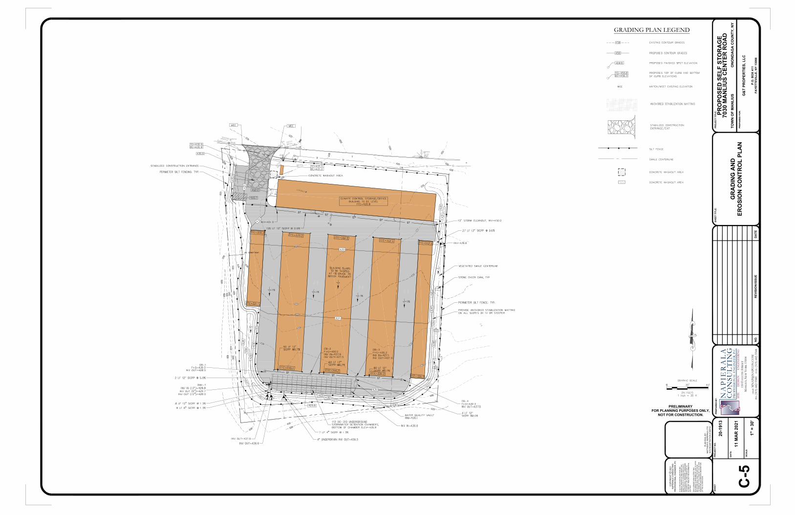
PRO
JEC
T N
O.
DA
TE
SCA
LE
SHEE
T
MAT
THEW
R. N
APIE
RAL
A, P
.E.
NYS
REG
ISTR
ATIO
N #
068
733
PLAN
SEA
L BY
:
PREP
AR
ED B
Y:
CO
PYR
IGH
T C
202
1
NO
.R
EVIS
ION
/ISSU
E
SHEE
T TI
TLE:
DA
TE
PREP
AR
ED F
OR
:
PRO
JEC
T TI
TLE:
110
FAY
ETT
E S
TRE
ET
MA
NLI
US,
NE
W Y
ORK
131
04
emai
l: M
NA
P@N
APC
ON
.CO
MPH
: (31
5) 6
82-5
580
FA
X: (
315)
682
-554
4
N A
P I
E R
A L
AC
O N
S U L
T I N
GPR
OFE
SSIO
NA
L E
NG
INE
ER,
P.C
.SI
TE
D
ESI
GN
EN
GIN
EE
RIN
G
IT IS
A V
IOLA
TIO
N O
F LA
W F
OR
AN
YPE
RSO
N, U
NLE
SS A
CTI
NG
UN
DER
TH
ED
IREC
TIO
N O
F A
LIC
ENSE
D A
RC
HIT
ECT,
PRO
FESS
ION
AL E
NG
INEE
R, L
AND
SCAP
EAR
CH
ITEC
T, O
R L
AND
SU
RVE
YOR
TO
ALTE
R A
NY
ITEM
ON
TH
IS D
OC
UM
ENT
INAN
Y W
AY.
ANY
LIC
ENSE
E W
HO
ALT
ERS
THIS
DO
CU
MEN
T IS
REQ
UIR
ED B
Y LA
W T
O A
FFIX
HIS
OR
HER
SEA
L AN
D T
HE
NO
TATI
ON
"ALT
ERED
BY"
FO
LLO
WED
BY
HIS
OR
HER
SIG
NAT
UR
E AN
D S
PEC
IFIC
DES
CR
IPTI
ON
OF
THE
ALTE
RAT
ION
S.
NAP
IER
ALA
CO
NSU
LTIN
GPR
OFE
SSIO
NAL
EN
GIN
EER
, PC
PRO
POSE
D S
ELF
STO
RA
GE
7030
MA
NLI
US
CEN
TER
RO
AD
TOW
N O
F M
AN
LIU
SO
NO
ND
AG
A C
OU
NTY
, NY
G&
T PR
OPE
RTI
ES, L
LC
P.O
. BO
X 41
1FA
YETT
EVIL
LE, N
Y 13
066
GR
AD
ING
AN
DER
OSI
ON
CO
NTR
OL
PLA
N
20-1
913
11 M
AR
202
1
1" =
30'
C-5
GRADING PLAN LEGEND
PRELIMINARYFOR PLANNING PURPOSES ONLY,
NOT FOR CONSTRUCTION.

THIS PAGE INTENTIONALLY LEFT BLANK
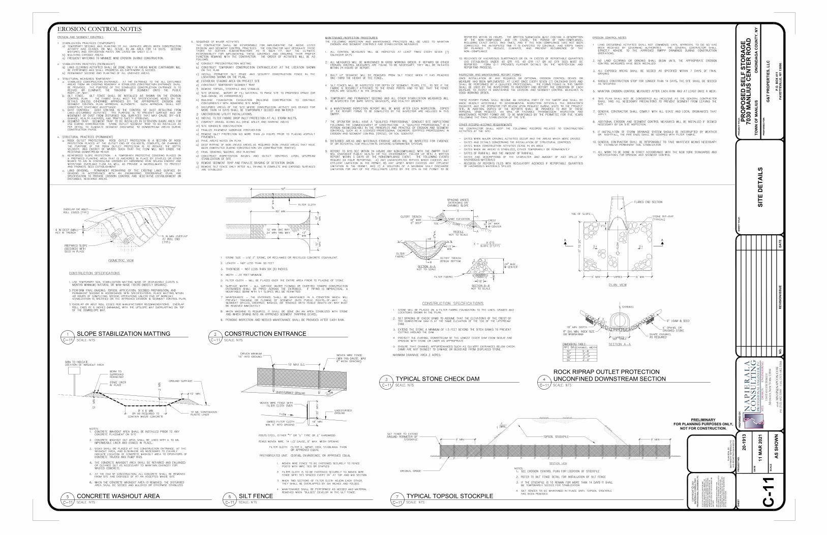
PRO
JEC
T N
O.
DA
TE
SCA
LE
SHEE
T
MAT
THEW
R. N
APIE
RAL
A, P
.E.
NYS
REG
ISTR
ATIO
N #
068
733
PLAN
SEA
L BY
:
PREP
AR
ED B
Y:
CO
PYR
IGH
T C
202
1
NO
.R
EVIS
ION
/ISSU
E
SHEE
T TI
TLE:
DA
TE
PREP
AR
ED F
OR
:
PRO
JEC
T TI
TLE:
110
FAY
ETT
E S
TRE
ET
MA
NLI
US,
NE
W Y
ORK
131
04
emai
l: M
NA
P@N
APC
ON
.CO
MPH
: (31
5) 6
82-5
580
FA
X: (
315)
682
-554
4
N A
P I
E R
A L
AC
O N
S U L
T I N
GPR
OFE
SSIO
NA
L E
NG
INE
ER,
P.C
.SI
TE
D
ESI
GN
EN
GIN
EE
RIN
G
IT IS
A V
IOLA
TIO
N O
F LA
W F
OR
AN
YPE
RSO
N, U
NLE
SS A
CTI
NG
UN
DER
TH
ED
IREC
TIO
N O
F A
LIC
ENSE
D A
RC
HIT
ECT,
PRO
FESS
ION
AL E
NG
INEE
R, L
AND
SCAP
EAR
CH
ITEC
T, O
R L
AND
SU
RVE
YOR
TO
ALTE
R A
NY
ITEM
ON
TH
IS D
OC
UM
ENT
INAN
Y W
AY.
ANY
LIC
ENSE
E W
HO
ALT
ERS
THIS
DO
CU
MEN
T IS
REQ
UIR
ED B
Y LA
W T
O A
FFIX
HIS
OR
HER
SEA
L AN
D T
HE
NO
TATI
ON
"ALT
ERED
BY"
FO
LLO
WED
BY
HIS
OR
HER
SIG
NAT
UR
E AN
D S
PEC
IFIC
DES
CR
IPTI
ON
OF
THE
ALTE
RAT
ION
S.
NAP
IER
ALA
CO
NSU
LTIN
GPR
OFE
SSIO
NAL
EN
GIN
EER
, PC
PRO
POSE
D S
ELF
STO
RA
GE
7030
MA
NLI
US
CEN
TER
RO
AD
TOW
N O
F M
AN
LIU
SO
NO
ND
AG
A C
OU
NTY
, NY
G&
T PR
OPE
RTI
ES, L
LC
P.O
. BO
X 41
1FA
YETT
EVIL
LE, N
Y 13
066
SITE
DET
AIL
S
20-1
913
11 M
AR
202
1
AS
SHO
WN
C-1
1
SILT FENCE
CONSTRUCTION ENTRANCE
EROSION CONTROL NOTES
CONCRETE WASHOUT AREA
SLOPE STABILIZATION MATTING
TYPICAL TOPSOIL STOCKPILE
ROCK RIPRAP OUTLET PROTECTIONUNCONFINED DOWNSTREAM SECTION
PRELIMINARYFOR PLANNING PURPOSES ONLY,
NOT FOR CONSTRUCTION.
TYPICAL STONE CHECK DAM

THIS PAGE INTENTIONALLY LEFT BLANK
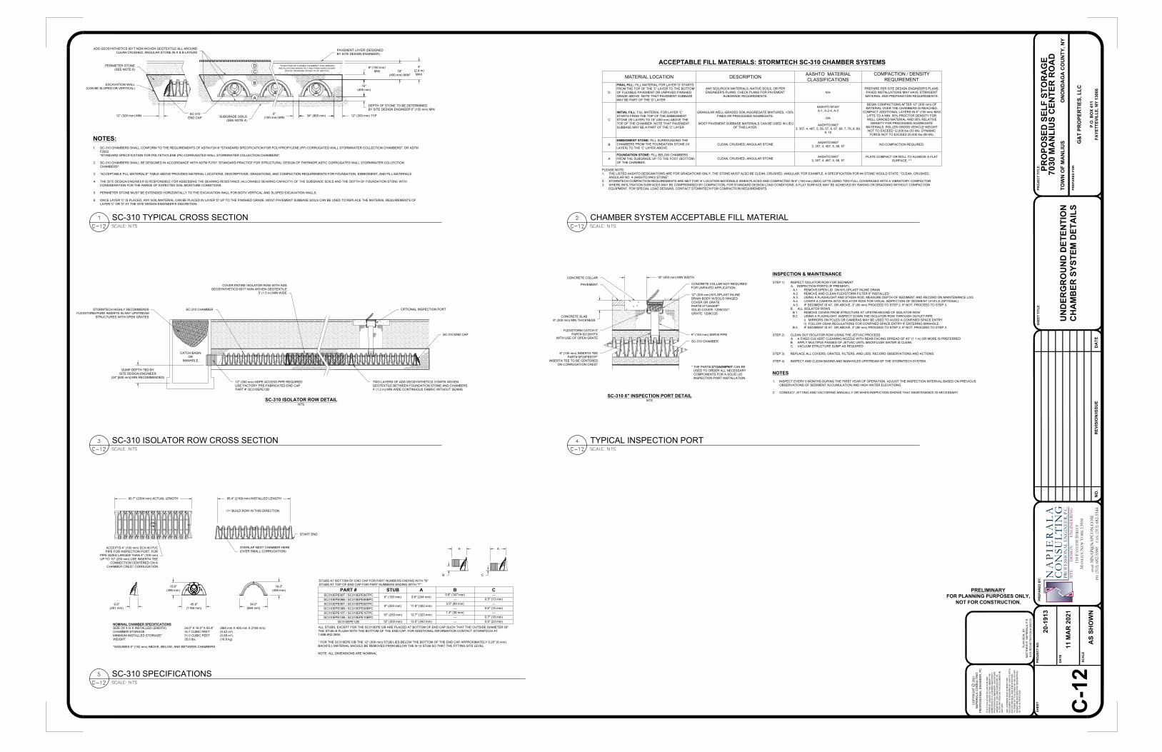
PRO
JEC
T N
O.
DA
TE
SCA
LE
SHEE
T
MAT
THEW
R. N
APIE
RAL
A, P
.E.
NYS
REG
ISTR
ATIO
N #
068
733
PLAN
SEA
L BY
:
PREP
AR
ED B
Y:
CO
PYR
IGH
T C
202
1
NO
.R
EVIS
ION
/ISSU
E
SHEE
T TI
TLE:
DA
TE
PREP
AR
ED F
OR
:
PRO
JEC
T TI
TLE:
110
FAY
ETT
E S
TRE
ET
MA
NLI
US,
NE
W Y
ORK
131
04
emai
l: M
NA
P@N
APC
ON
.CO
MPH
: (31
5) 6
82-5
580
FA
X: (
315)
682
-554
4
N A
P I
E R
A L
AC
O N
S U L
T I N
GPR
OFE
SSIO
NA
L E
NG
INE
ER,
P.C
.SI
TE
D
ESI
GN
EN
GIN
EE
RIN
G
IT IS
A V
IOLA
TIO
N O
F LA
W F
OR
AN
YPE
RSO
N, U
NLE
SS A
CTI
NG
UN
DER
TH
ED
IREC
TIO
N O
F A
LIC
ENSE
D A
RC
HIT
ECT,
PRO
FESS
ION
AL E
NG
INEE
R, L
AND
SCAP
EAR
CH
ITEC
T, O
R L
AND
SU
RVE
YOR
TO
ALTE
R A
NY
ITEM
ON
TH
IS D
OC
UM
ENT
INAN
Y W
AY.
ANY
LIC
ENSE
E W
HO
ALT
ERS
THIS
DO
CU
MEN
T IS
REQ
UIR
ED B
Y LA
W T
O A
FFIX
HIS
OR
HER
SEA
L AN
D T
HE
NO
TATI
ON
"ALT
ERED
BY"
FO
LLO
WED
BY
HIS
OR
HER
SIG
NAT
UR
E AN
D S
PEC
IFIC
DES
CR
IPTI
ON
OF
THE
ALTE
RAT
ION
S.
NAP
IER
ALA
CO
NSU
LTIN
GPR
OFE
SSIO
NAL
EN
GIN
EER
, PC
PRO
POSE
D S
ELF
STO
RA
GE
7030
MA
NLI
US
CEN
TER
RO
AD
TOW
N O
F M
AN
LIU
SO
NO
ND
AG
A C
OU
NTY
, NY
G&
T PR
OPE
RTI
ES, L
LC
P.O
. BO
X 41
1FA
YETT
EVIL
LE, N
Y 13
066
UN
DER
GR
OU
ND
DET
ENTI
ON
CH
AM
BER
SYS
TEM
DET
AIL
S
20-1
913
11 M
AR
202
1
AS
SHO
WN
C-1
2
PRELIMINARYFOR PLANNING PURPOSES ONLY,
NOT FOR CONSTRUCTION.
ACCEPTABLE FILL MATERIALS: STORMTECH SC-310 CHAMBER SYSTEMS
PLEASE NOTE:1. THE LISTED AASHTO DESIGNATIONS ARE FOR GRADATIONS ONLY. THE STONE MUST ALSO BE CLEAN, CRUSHED, ANGULAR. FOR EXAMPLE, A SPECIFICATION FOR #4 STONE WOULD STATE: "CLEAN, CRUSHED,
ANGULAR NO. 4 (AASHTO M43) STONE".2. STORMTECH COMPACTION REQUIREMENTS ARE MET FOR 'A' LOCATION MATERIALS WHEN PLACED AND COMPACTED IN 6" (150 mm) (MAX) LIFTS USING TWO FULL COVERAGES WITH A VIBRATORY COMPACTOR.3. WHERE INFILTRATION SURFACES MAY BE COMPROMISED BY COMPACTION, FOR STANDARD DESIGN LOAD CONDITIONS, A FLAT SURFACE MAY BE ACHIEVED BY RAKING OR DRAGGING WITHOUT COMPACTION
EQUIPMENT. FOR SPECIAL LOAD DESIGNS, CONTACT STORMTECH FOR COMPACTION REQUIREMENTS.
NOTES:1. SC-310 CHAMBERS SHALL CONFORM TO THE REQUIREMENTS OF ASTM F2418 "STANDARD SPECIFICATION FOR POLYPROPYLENE (PP) CORRUGATED WALL STORMWATER COLLECTION CHAMBERS", OR ASTM
F2922"STANDARD SPECIFICATION FOR POLYETHYLENE (PE) CORRUGATED WALL STORMWATER COLLECTION CHAMBERS".
2. SC-310 CHAMBERS SHALL BE DESIGNED IN ACCORDANCE WITH ASTM F2787 "STANDARD PRACTICE FOR STRUCTURAL DESIGN OF THERMOPLASTIC CORRUGATED WALL STORMWATER COLLECTIONCHAMBERS".
3. "ACCEPTABLE FILL MATERIALS" TABLE ABOVE PROVIDES MATERIAL LOCATIONS, DESCRIPTIONS, GRADATIONS, AND COMPACTION REQUIREMENTS FOR FOUNDATION, EMBEDMENT, AND FILL MATERIALS.
4. THE SITE DESIGN ENGINEER IS RESPONSIBLE FOR ASSESSING THE BEARING RESISTANCE (ALLOWABLE BEARING CAPACITY) OF THE SUBGRADE SOILS AND THE DEPTH OF FOUNDATION STONE WITHCONSIDERATION FOR THE RANGE OF EXPECTED SOIL MOISTURE CONDITIONS.
5. PERIMETER STONE MUST BE EXTENDED HORIZONTALLY TO THE EXCAVATION WALL FOR BOTH VERTICAL AND SLOPED EXCAVATION WALLS.
6. ONCE LAYER 'C' IS PLACED, ANY SOIL/MATERIAL CAN BE PLACED IN LAYER 'D' UP TO THE FINISHED GRADE. MOST PAVEMENT SUBBASE SOILS CAN BE USED TO REPLACE THE MATERIAL REQUIREMENTS OFLAYER 'C' OR 'D' AT THE SITE DESIGN ENGINEER'S DISCRETION.
MATERIAL LOCATION DESCRIPTION AASHTO MATERIALCLASSIFICATIONS
COMPACTION / DENSITYREQUIREMENT
D
FINAL FILL: FILL MATERIAL FOR LAYER 'D' STARTSFROM THE TOP OF THE 'C' LAYER TO THE BOTTOMOF FLEXIBLE PAVEMENT OR UNPAVED FINISHEDGRADE ABOVE. NOTE THAT PAVEMENT SUBBASEMAY BE PART OF THE 'D' LAYER
ANY SOIL/ROCK MATERIALS, NATIVE SOILS, OR PERENGINEER'S PLANS. CHECK PLANS FOR PAVEMENT
SUBGRADE REQUIREMENTS.N/A
PREPARE PER SITE DESIGN ENGINEER'S PLANS.PAVED INSTALLATIONS MAY HAVE STRINGENTMATERIAL AND PREPARATION REQUIREMENTS.
C
INITIAL FILL: FILL MATERIAL FOR LAYER 'C'STARTS FROM THE TOP OF THE EMBEDMENTSTONE ('B' LAYER) TO 18" (450 mm) ABOVE THETOP OF THE CHAMBER. NOTE THAT PAVEMENTSUBBASE MAY BE A PART OF THE 'C' LAYER.
GRANULAR WELL-GRADED SOIL/AGGREGATE MIXTURES, <35%FINES OR PROCESSED AGGREGATE.
MOST PAVEMENT SUBBASE MATERIALS CAN BE USED IN LIEUOF THIS LAYER.
AASHTO M145¹A-1, A-2-4, A-3
OR
AASHTO M43¹3, 357, 4, 467, 5, 56, 57, 6, 67, 68, 7, 78, 8, 89,
9, 10
BEGIN COMPACTIONS AFTER 12" (300 mm) OFMATERIAL OVER THE CHAMBERS IS REACHED.
COMPACT ADDITIONAL LAYERS IN 6" (150 mm) MAXLIFTS TO A MIN. 95% PROCTOR DENSITY FORWELL GRADED MATERIAL AND 95% RELATIVE
DENSITY FOR PROCESSED AGGREGATEMATERIALS. ROLLER GROSS VEHICLE WEIGHT
NOT TO EXCEED 12,000 lbs (53 kN). DYNAMICFORCE NOT TO EXCEED 20,000 lbs (89 kN).
BEMBEDMENT STONE: FILL SURROUNDING THECHAMBERS FROM THE FOUNDATION STONE ('A'LAYER) TO THE 'C' LAYER ABOVE.
CLEAN, CRUSHED, ANGULAR STONE AASHTO M43¹3, 357, 4, 467, 5, 56, 57 NO COMPACTION REQUIRED.
AFOUNDATION STONE: FILL BELOW CHAMBERSFROM THE SUBGRADE UP TO THE FOOT (BOTTOM)OF THE CHAMBER.
CLEAN, CRUSHED, ANGULAR STONE AASHTO M43¹3, 357, 4, 467, 5, 56, 57
PLATE COMPACT OR ROLL TO ACHIEVE A FLATSURFACE. ² ³
SUBGRADE SOILS(SEE NOTE 4)
PAVEMENT LAYER (DESIGNEDBY SITE DESIGN ENGINEER)
SC-310END CAP
DC
B
A
PERIMETER STONE(SEE NOTE 6) 18"
(450 mm) MIN*
8'(2.4 m)MAX
6" (150 mm)MIN
EXCAVATION WALL(CAN BE SLOPED OR VERTICAL)
12" (300 mm) MIN 12" (300 mm) TYP34" (865 mm)6"(150 mm) MIN
ADS GEOSYNTHETICS 601T NON-WOVEN GEOTEXTILE ALL AROUNDCLEAN CRUSHED, ANGULAR STONE IN A & B LAYERS
16"(405 mm)
DEPTH OF STONE TO BE DETERMINEDBY SITE DESIGN ENGINEER 6" (150 mm) MIN
*TO BOTTOM OF FLEXIBLE PAVEMENT. FOR UNPAVEDINSTALLATIONS WHERE RUTTING FROM VEHICLES MAY
OCCUR, INCREASE COVER TO 24" (600 mm).
PART # STUB A B CSC310EPE06T / SC310EPE06TPC 6" (150 mm) 9.6" (244 mm)
5.8" (147 mm) ---SC310EPE06B / SC310EPE06BPC --- 0.5" (13 mm)SC310EPE08T / SC310EPE08TPC 8" (200 mm) 11.9" (302 mm)
3.5" (89 mm) ---SC310EPE08B / SC310EPE08BPC --- 0.6" (15 mm)SC310EPE10T / SC310EPE10TPC 10" (250 mm) 12.7" (323 mm)
1.4" (36 mm) ---SC310EPE10B / SC310EPE10BPC --- 0.7" (18 mm)
SC310EPE12B 12" (300 mm) 13.5" (343 mm) --- 0.9" (23 mm)
ALL STUBS, EXCEPT FOR THE SC310EPE12B ARE PLACED AT BOTTOM OF END CAP SUCH THAT THE OUTSIDE DIAMETER OFTHE STUB IS FLUSH WITH THE BOTTOM OF THE END CAP. FOR ADDITIONAL INFORMATION CONTACT STORMTECH AT1-888-892-2694.
* FOR THE SC310EPE12B THE 12" (300 mm) STUB LIES BELOW THE BOTTOM OF THE END CAP APPROXIMATELY 0.25" (6 mm).BACKFILL MATERIAL SHOULD BE REMOVED FROM BELOW THE N-12 STUB SO THAT THE FITTING SITS LEVEL.
NOTE: ALL DIMENSIONS ARE NOMINAL
NOMINAL CHAMBER SPECIFICATIONSSIZE (W X H X INSTALLED LENGTH) 34.0" X 16.0" X 85.4" (864 mm X 406 mm X 2169 mm)CHAMBER STORAGE 14.7 CUBIC FEET (0.42 m³)MINIMUM INSTALLED STORAGE* 31.0 CUBIC FEET (0.88 m³)WEIGHT 35.0 lbs. (16.8 kg)
*ASSUMES 6" (152 mm) ABOVE, BELOW, AND BETWEEN CHAMBERS
STUBS AT BOTTOM OF END CAP FOR PART NUMBERS ENDING WITH "B"STUBS AT TOP OF END CAP FOR PART NUMBERS ENDING WITH "T"
34.0"(864 mm)
16.0"(406 mm)
90.7" (2304 mm) ACTUAL LENGTH 85.4" (2169 mm) INSTALLED LENGTH
ACCEPTS 4" (100 mm) SCH 40 PVCPIPE FOR INSPECTION PORT. FOR
PIPE SIZES LARGER THAN 4" (100 mm)UP TO 10" (250 mm) USE INSERTA TEE
CONNECTION CENTERED ON ACHAMBER CREST CORRUGATION
OVERLAP NEXT CHAMBER HERE(OVER SMALL CORRUGATION)
BUILD ROW IN THIS DIRECTION
START END
A A
B C
9.9"(251 mm)
45.9"(1166 mm)
15.6"(396 mm)
INSPECTION & MAINTENANCESTEP 1) INSPECT ISOLATOR ROW FOR SEDIMENT
A. INSPECTION PORTS (IF PRESENT)A.1. REMOVE/OPEN LID ON NYLOPLAST INLINE DRAINA.2. REMOVE AND CLEAN FLEXSTORM FILTER IF INSTALLEDA.3. USING A FLASHLIGHT AND STADIA ROD, MEASURE DEPTH OF SEDIMENT AND RECORD ON MAINTENANCE LOGA.4. LOWER A CAMERA INTO ISOLATOR ROW FOR VISUAL INSPECTION OF SEDIMENT LEVELS (OPTIONAL)A.5. IF SEDIMENT IS AT, OR ABOVE, 3" (80 mm) PROCEED TO STEP 2. IF NOT, PROCEED TO STEP 3.
B. ALL ISOLATOR ROWSB.1. REMOVE COVER FROM STRUCTURE AT UPSTREAM END OF ISOLATOR ROWB.2. USING A FLASHLIGHT, INSPECT DOWN THE ISOLATOR ROW THROUGH OUTLET PIPE
i) MIRRORS ON POLES OR CAMERAS MAY BE USED TO AVOID A CONFINED SPACE ENTRYii) FOLLOW OSHA REGULATIONS FOR CONFINED SPACE ENTRY IF ENTERING MANHOLE
B.3. IF SEDIMENT IS AT, OR ABOVE, 3" (80 mm) PROCEED TO STEP 2. IF NOT, PROCEED TO STEP 3.
STEP 2) CLEAN OUT ISOLATOR ROW USING THE JETVAC PROCESSA. A FIXED CULVERT CLEANING NOZZLE WITH REAR FACING SPREAD OF 45" (1.1 m) OR MORE IS PREFERREDB. APPLY MULTIPLE PASSES OF JETVAC UNTIL BACKFLUSH WATER IS CLEANC. VACUUM STRUCTURE SUMP AS REQUIRED
STEP 3) REPLACE ALL COVERS, GRATES, FILTERS, AND LIDS; RECORD OBSERVATIONS AND ACTIONS.
STEP 4) INSPECT AND CLEAN BASINS AND MANHOLES UPSTREAM OF THE STORMTECH SYSTEM.
NOTES1. INSPECT EVERY 6 MONTHS DURING THE FIRST YEAR OF OPERATION. ADJUST THE INSPECTION INTERVAL BASED ON PREVIOUS
OBSERVATIONS OF SEDIMENT ACCUMULATION AND HIGH WATER ELEVATIONS.
2. CONDUCT JETTING AND VACTORING ANNUALLY OR WHEN INSPECTION SHOWS THAT MAINTENANCE IS NECESSARY.
SUMP DEPTH TBD BYSITE DESIGN ENGINEER
(24" [600 mm] MIN RECOMMENDED)12" (300 mm) HDPE ACCESS PIPE REQUIREDUSE FACTORY PRE-FABRICATED END CAPPART #: SC310EPE12B
TWO LAYERS OF ADS GEOSYNTHETICS 315WTK WOVENGEOTEXTILE BETWEEN FOUNDATION STONE AND CHAMBERS4' (1.2 m) MIN WIDE CONTINUOUS FABRIC WITHOUT SEAMS
CATCH BASINOR
MANHOLE
SC-310 ISOLATOR ROW DETAILNTS
STORMTECH HIGHLY RECOMMENDSFLEXSTORM PURE INSERTS IN ANY UPSTREAM
STRUCTURES WITH OPEN GRATES
COVER ENTIRE ISOLATOR ROW WITH ADSGEOSYNTHETICS 601T NON-WOVEN GEOTEXTILE
5' (1.5 m) MIN WIDE
SC-310 CHAMBER
SC-310 END CAP
OPTIONAL INSPECTION PORT
SC-310 6" INSPECTION PORT DETAILNTS
SC-310 CHAMBER
FLEXSTORM CATCH ITPART# 6212NYFX
WITH USE OF OPEN GRATE
6" (150 mm) INSERTA TEEPART# 6P26FBSTIP*
INSERTA TEE TO BE CENTEREDON CORRUGATION CREST
6" (150 mm) SDR35 PIPE
CONCRETE COLLAR
12" (300 mm) NYLOPLAST INLINEDRAIN BODY W/SOLID HINGEDCOVER OR GRATEPART# 2712AG6IP*SOLID COVER: 1299CGC*GRATE: 1299CGS
18" (450 mm) MIN WIDTH
CONCRETE SLAB8" (200 mm) MIN THICKNESS
PAVEMENT CONCRETE COLLAR NOT REQUIREDFOR UNPAVED APPLICATION
* THE PART# 2712AG6IPKIT CAN BEUSED TO ORDER ALL NECESSARYCOMPONENTS FOR A SOLID LIDINSPECTION PORT INSTALLATION
SC-310 TYPICAL CROSS SECTION CHAMBER SYSTEM ACCEPTABLE FILL MATERIAL
SC-310 ISOLATOR ROW CROSS SECTION TYPICAL INSPECTION PORT
SC-310 SPECIFICATIONS

THIS PAGE INTENTIONALLY LEFT BLANK


