Embed Size (px)
Citation preview

Santa Clara UniversityScholar Commons
Civil Engineering Senior Theses Engineering Senior Theses
6-15-2014
Straw bale seismic design capacities 2Beth AvonSanta Clara Univeristy
Brittnie SwartchickSanta Clara Univeristy
Follow this and additional works at: https://scholarcommons.scu.edu/ceng_senior
Part of the Civil and Environmental Engineering Commons
This Thesis is brought to you for free and open access by the Engineering Senior Theses at Scholar Commons. It has been accepted for inclusion in CivilEngineering Senior Theses by an authorized administrator of Scholar Commons. For more information, please contact [email protected].
Recommended CitationAvon, Beth and Swartchick, Brittnie, "Straw bale seismic design capacities 2" (2014). Civil Engineering Senior Theses. 38.https://scholarcommons.scu.edu/ceng_senior/38

SANTA CLARA UNIVERSITY
Department of Civil Engineering
I hereby recommend that the SENIOR DESIGN PROJECT REPORT
prepared under my supervision by
BETH AVON &
BRITTNIE SWARTCHICK
entitled
STRAW BALE SEISMIC DESIGN CAP A CITIES 2
be accepted in partial fulfillment of the requirements for the degree of
BACHELOR OF SCIENCE IN CIVIL ENGINEERING
Advisor (..(tS/11
Datd
c, /rr/1 ~ Department Chair Date

STRAW BALE SEISMIC DESIGN CAPACITIES 2
by
BETH AVON
&
BRITTNIE SWARTCHICK
SENIOR DESIGN PROJECT REPORT
submitted to
the Department of Civil Engineering
of
SANTA CLARA UNIVERSITY
in partial fulfillment of the requirements for the degree of
Bachelor of Science in Civil Engineering
Santa Clara, California
Spring 2014

i
ACKNOWLDEGEMENTS
We would like to thank everyone who made this project possible especially
Our project advisors for their guidance:
Dr. Mark Aschheim
Our industry advisors for their advice and support:
Members of the FEMA P695 Peer Review Group
And all of our contacts at the California Straw Bale Association for their support and guidance
throughout the project.
ii
STRAW BALE SEISMIC DESIGN CAPACITIES
Beth Avon and Brittnie Swartchick
Department of Civil Engineering
Santa Clara University, Spring 2014
ABSTRACT
Straw bale is a sustainable building material that repurposes agricultural waste for use in the
structural system of buildings. This material will be used as a component in the lateral force
resisting systems of walls, especially helpful in the California seismic environment and under
heavy wind loads. The four main components of a post-and-beam method straw bale wall are
timber framing, straw bales, wire mesh, and plaster. This report will focus on the design of the
exterior plaster and the design of “workhorse” and “strong” walls for simple construction and
areas of higher seismic activity, respectively. Our test results will be used to validate straw bale
as a viable structural material for future building code development.

iii
TABLE OF CONTENTS ACKNOWLDEGEMENTS .................................................................................................................................. i
ABSTRACT ...................................................................................................................................................... ii
LIST OF FIGURES ............................................................................................................................................ v
LIST OF TABLES ............................................................................................................................................. vi
INTRODUCTION ............................................................................................................................................. 1
STRAW BALE AS A CONSTRUCTION MATERIAL ............................................................................................. 2
PLASTER MIX DESIGN .................................................................................................................................... 4
Design Goals .............................................................................................................................................. 4
Design Materials – Plaster Mix ................................................................................................................. 4
Cement-Lime Plaster Mix Design Code Considerations ............................................................................ 6
Mix Design Iterations ................................................................................................................................ 6
Final Plaster Determination ...................................................................................................................... 9
WALL DESIGN .............................................................................................................................................. 11
Overview ................................................................................................................................................. 11
Preliminary Design Methodology ........................................................................................................... 12
“Workhorse” Wall Design ....................................................................................................................... 14
Description .......................................................................................................................................... 14
Calculations ......................................................................................................................................... 17
“Strong” Wall Design............................................................................................................................... 18
Description .......................................................................................................................................... 18
Calculations ......................................................................................................................................... 22
NEXT STEPS ................................................................................................................................................. 23
ETHICAL ANALYSIS OF STRAW BALE MATERIAL USE ................................................................................... 23
Straw Bale as a Solution for Engineer’s Challenges ................................................................................ 24
Economic Advantages to Straw Bale Construction ................................................................................. 24
Embodied Energy of Straw and Comparative Construction Materials ................................................... 24
Global Warming and Benefits of Straw Bale Construction ..................................................................... 25
American Society of Civil Engineer’s Views on Sustainable Building ...................................................... 25
Analyzing Risk .......................................................................................................................................... 26
Dangers of Building with Straw Bale....................................................................................................... 26
Concerns of Building with Straw Bale ..................................................................................................... 26

iv
Other Environmental Considerations ..................................................................................................... 27
Verifying Quality in Our Research and Design ........................................................................................ 27
Straw Bale as a Solution .......................................................................................................................... 27
WORKS CITED .............................................................................................................................................. 28
APPENDIX A: PLASTER MIX DESIGN REFERENCES ...................................................................................... A1
APPENDIX B: BUDGET FOR PROJECT SCOPE .............................................................................................. B1
APPENDIX C : PLASTER MIX DESIGN SAMPLE DESCRIPTIONS AND STRENGTHS ......................................... C1
APPENDIX D: TEAMWORK PHILOSOPHY .....................................................................................................D1

v
LIST OF FIGURES
Figure 1: Straw Bale Dimensions and Orientation..………………………………………………2
Figure 2: Basic Wall Dimensions and Components……………………………………………..11
Figure 3: 4 Materials Used to Build a Straw Bale Wall (Post and Beam Method)……………...12
Figure 4: Workhorse Wall Elevation...…………………………………………………………..14
Figure 5: Workhorse Wall Section………………………………………………………………15
Figure 6: Workhorse Wall Boundary Connection Detail…..……………………………………16
Figure 7: Strong Wall Elevation…………………………………………………………………18
Figure 8: Plywood vs. Reinforced Concrete Shear Load Transfer Diagram.........…………...….19
Figure 9: Strong Wall Section………………………………………………………………..….20
Figure 10: Strong Wall Connection Detail………..……………………………………………..21

vi
LIST OF TABLES
Table 1: Post and Beam Method Materials and Their Structural Purpose..……………………….3
Table 2: Plaster Strengths Varying Sand Proportions………………………………………….….6
Table 3: Plaster Strengths Varying Curing Methods (Lime)……………………………………...7
Table 4: Plaster Strengths Varying Curing Methods (Water)……………………………………..7
Table 5: Plaster Strengths Varying Sand Grain Size……………………………………………...8
Table 6: Final Plaster Mix Design………………………………………………………………...9
Table 7: Final Plaster Mix Strengths……………………………………………………………...9
Table 8: Workhorse Wall Material Quantities.……………….………………………………….17
Table 9: Workhorse Wall Failure Mode Calculation Summary…………………………………18
Table 10: Strong Wall Material Quantities………………….…………………………………...22
Table 11: Strong Wall Failure Mode Calculation Summary..…………………………………...23
Table A1: ASTMC926-06…………………………………………...…………………….……A1
Table A2: ASTMC 897………………………………………………………………………….A2
Table A3: Cemex #1/20 and 30 Mesh Sieve Test Results…………...………………………….A3
Table A4: Quail Hollow #2 Plaster Sand Sieve Test Results…………………………………...A3
Table B1: Budget for Project Scope……………………………………………………………..B1
Table C1: 2x2 Plaster Compressive Strength Test Results……………………………………...C1
Table C2: Cylinder Plaster Compressive Strength Test Results………………………………...C2
Table D1: CUREE-Caltech Protocol Testing Method…………………………………………..D1
Table E1: Plywood And Concrete Shear Wall Forces to Foundation…………………………...E1

1
INTRODUCTION
Finding a Use for Waste Rice Straw
Straw bales come from agricultural waste, a byproduct of the food that we consume. As a
waste product, the material has little to no use beyond littering stable grounds. This material was
previously burned, increasing air pollution. The passing of the California Rice Straw Burning
Reduction Act of 1991 required farmers to start looking into alternative ways of disposing of rice
straw in the Sacramento Valley, specifically. As a result, rice straw bales were considered as a
sustainable structural building material.
Early Feasibility Tests are Promising
Straw bale construction uses an alternative building material in a building’s structural
system that is both functional and sustainable. Tests were conducted in 2003 that provided the
basic material information for straw bale construction; these tests indicated that straw bale is a
viable construction material. To develop building code provisions to include structural
applications in seismic environments, further testing is required. This research and wall design
will be conducted under the guidance of not only our faculty advisory, but also the FEMA P695
Peer Review Group that will ensure that our tests will be compliant with introducing new
materials into the building code. Through a series of three coordinated senior design projects, we
will gather enough data to create a basis for code incorporation.
How the Current Work fits into the Bigger Picture
Our research will be an extension of the research done at the University of Illinois in
2003 that began the work resulting in the adoption of qualitative data for straw bale into the 2015
International Residential Code appendix. We will introduce new structural applications of straw
bale that will include construction techniques to begin the process for straw bale construction’s
incorporation into the International Building Code. This research project will include the origin
for a holistic wall design that can deliver dependable strength and a ductile failure mode. The
project scope for the Straw Bale Seismic Design Capacities 2 team includes the design of
cement-lime based plaster used on the exterior of the wall, the design of the 8-foot “workhorse”
wall that is easy to construct, and the design of the 8-foot “strong” wall that is designed to take
larger loads per foot length. Testing of these walls will not be included in this work scope.

2
STRAW BALE AS A CONSTRUCTION MATERIAL
Straw Bale as More than a Convenient Solution
Using straw bale in construction addresses a larger issue: what farmers are supposed to
do with the straw that is produced from their rice and grain crops. Not only is straw bale a
healthy, insulating, sound-dampening, safe, and earth-friendly product, but it is very structurally
sound in seismic environments. The geometry of the straw bales used in the design of shear walls
using the post and beam method came from the dimensions provided by the specific supplier.
These dimensions can be found in figure 1; these dimensions exhibit a very thick base as
compared to its length.
Straw Bale’s Geometry Affects Material Properties
The width to height ratio of a bale causes them to have a small moment of inertia. This
allows them to resist greater rotations in order to perform well under the lateral loads from
earthquakes and wind. We are proposing that structural straw bale walls be constructed using the
post and beam method explored in the 2003 University of Illinois study. Straw bale construction
involves four basic materials:
Straw Bale
Figure 1 – The straw bale orientation within the wall will be an 18” thickness and a 16” height. The standard bale
dimension is a 4’ length and may be reduced for smaller wall dimensions or a more efficient bale configuration.

3
Timber Framing
Wire Mesh
Plaster
The purposes and goals of each material are outlined in Table 1.
Material Structural Purpose
Straw Bale Provides rigidity and structural backing for the
structure
Acts as infill to provide the
Timber Framing Provides the shape of the structure
Dissipates the gravity loads applied to the structure
Wire Mesh Provides ductility during lateral loading
Maintains wall thickness and
Plaster
Indicates visible failure of walls in case of emergency
Binds together mesh and straw bale to engage all
components
Table 1 – The summary of the 4 main structural materials used in the post and beam framing method includes the
main structural role that the individual material plays for the wall.

4
PLASTER MIX DESIGN
Design Goals
Plaster is the outermost layer of the straw bale wall. This element creates the finishing
touches for the final wall, the component that the non-technical users will appreciate the most.
Beyond the aesthetics of the plaster finish, the plaster mix design is intended to do the following:
act as a binder for the mesh to the straw bales,
visually indicate failure before the mesh yields, and
add a desired strength of less than 1,200 psi to the structure.
Plaster Design for Straw Bale Walls
Lateral load-resisting straw bale walls require the plaster component to help maintain the
structural integrity of the wall, without being the main load-resisting material. The mesh is
designed to be stronger than the plaster, creating a core capable of resisting greater deformations
in a seismic event. After more research has been conducted to bring straw bale construction into
the building code, the minimum standards for plaster design in straw bale walls will be set. By
achieving these code minimum standards in design, contractors or home builders will find it
easier to comply with city and state requirements to build a seismically stable, and earth-friendly
home.
Design Materials – Plaster Mix
The four ingredients used to create the straw bale wall plaster layer are: cement, lime,
sand, and water. In order to select the appropriate mix design for testing considerations, it was
important to determine which proportions of each ingredient would provide the desired behavior.
Portland Cement in the Plaster Mix
Basic plaster mix designs are most commonly made up of cement, sand, and water. Type
I Portland cement is utilized as our primary binding material because of its reliability as all-
purpose cement. Because building code design is intended to have easy-to-find ingredients, it is
important to use a material that is readily available everywhere. Any substitutions for a change in
environment are only expected to help the plaster mix to perform better in its new environment.

5
Portland cement type I develops almost full strength at a consistent rate of 28 days of
curing. A typical Portland cement mix design produces an average strength of approximately
4,000 psi. Because the design goals require a maximum of 1,200 psi strength at 28 days, an
additional binder material, lime, is added to reduce the expected strength to a value close to the
desired strength.
Lime in the Plaster Mix
Most often, lime is added to a mix design as a plasticizer in order to improve workability.
Lime is included as a binder in these mix designs in order to create a more sustainable plaster.
Slaked lime, for instance, has a 20-percent lower embodied energy than cement as it is produced
at a lower temperature. Type S lime is also added to the plaster mix design to weaken the mix;
average lime sand plaster has an average strength of approximately 400 psi. In weakening the
design strength of the plaster, there will be a greater assurance that the plaster will fail before the
mesh. This behavior not only provides a visual indication of the building strength to alert
occupants of the building failure, but as the plaster breaks away from the wire mesh, it allows the
mesh to yield as it provides a ductile failure.
Aggregate in the Plaster Mix
Like a typical concrete mix, aggregate will be used to provide the strength of the plaster.
Several sand grain mixes will be used to determine the best plaster mix design for the walls. It is
expected that the larger grains will produce stronger samples with less workability, while the
smaller grains will produce weaker samples with greater workability. The final mix design will
achieve a balance between the desired strength and workability.
Water in the Plaster Mix
The amount of water used in each mix design varies. While a larger quantity of water
does increase the workability, making the plaster easier to apply to the structure’s exterior, it can
also significantly decrease the strength of the sample. This final amount is not regulated by codes
and will be adjusted as needed in mix designs to determine the best balance between strength and
workability.

6
Cement-Lime Plaster Mix Design Code Considerations
Two ASTM provisions are used to guide the plaster mix design process:
ASTM C 926: Application of Portland Cement-Based Plasters
ASTM C 897: Aggregate for Job-Mixed Portland Cement-Based Plasters
A Closer Look at ASTM C926
ASTM section C926 Table 3 lists the requirements for mixing Portland Cement-based
plasters. The requirements by volume are 1 cement: 0 to ¾ lime: 2 ½ to 4 sand per volume of
cementitious material. These ranges were used in the mix design to determine the most effective
ratio for the plaster mix design. This full table is listed in Appendix A Table A1.
A Closer Look at ASTM C897
ASTM section C897 describes the sieve test percent passing requirements for Portland
cement-based plaster sand mix designs. The sand chosen for use with the final wall specimens
will follow these grading requirements. This full table is listed in Appendix A Table A2.
Mix Design Iterations
The first set of mix designs were all made with a coarse sand mix that was readily
available in the lab. This sand is typically used as fine aggregate in concrete mixes, and has
much larger grains than are typically used in wall plastering. The first design mixes focused on
varying sand content within the ranges specified in ASTM section C926. These ratios and test
results are shown in Table 2. Three 2” cube specimens were made to test mix designs 1-2, 1-3,
and 1-4.
Mix
Name Sand
Cement:Lime:Sand
(by part) Cured
Cure
Time
Max
Average
Load
(pounds)
Average
(psi) COV
Viable
Option
1-2 Coarse 1 : 0.75 : 4.375 Air 7 3059 765 5% Yes
1-3 Coarse 1 : 0.75 : 4.5 Air 7 2874 719 9% No
1-4 Coarse 1 : 0.75 : 5.25 Air 7 2198 550 12% Yes
Table 2 – The first mix design iterations with initial mixes 1-2, 1-3, and 1-4 varied the proportions of
sand by volume in the mix designs.

7
Mix 1-3 was immediately eliminated from further testing due to its lack of workability.
Testing was continued with mix designs 1-2 and 1-4, using different curing methods and curing
time intervals.
Evaluating how Curing Environments Effects the Strength of the Plaster
ASTM C192 introduces the use of lime-saturated water baths to cure the concrete more
slowly, but at a higher final strength. Mixes 1-2 and 1-4 were introduced to two curing
environments: (1) lime and (2) water baths. These values are shown below in Table 3 and Table
4. The results for mixes 1-2 and 1-4 using these curing methods are listed as mixes 2-2 and 2-4,
respectively.
Mix
Name Sand
Cement:Lime:Sand
(by part) Cured
Cure
Time
Max Load
Average
(pounds)
Average
(PSI) COV
Viable
Option
2-2 Coarse 1 : 0.75 : 4.375 Lime 7 6318 1580 20% Yes
2-2 Coarse 1 : 0.75 : 4.375 Lime 41 10000+ 2500+ --- Yes
2-4 Coarse 1 : 0.75 : 5.25 Lime 7 4104 1030 16% No
2-4 Coarse 1 : 0.75 : 5.25 Lime 41 4568 1140 36% No
Mix
Name Sand
Cement:Lime:Sand
(by part) Cured
Cure
Time
Max Load
Average
(pounds)
Average
(PSI) COV
Viable
Option
2-2 Coarse 1 : 0.75 : 4.375 Water 7 3147 790 36% No
2-4 Coarse 1 : 0.75 : 5.25 Water 7 2468 620 27% No
Analysis of the Water-Cured Samples
Water curing was instantly eliminated due to low strengths of less than 1,000 psi and high
coefficients of variance (COV). When producing mixes 2-2 and 2-4, it was understood that both
designs had low workability that needed to be corrected by adding more water to the mix.
Table 3 – The second set of mix design iterations varied the curing methods. This table shows the
results for the lime-cured samples at 7-days and 41-days(past the time of fully-developed strength).
+ Values over 10,000 pounds and were not able to be read by testing machine, therefore the value
reported for mix 2-2 lime-cured for 41 days is not the true maximum load, but the maximum load
that could be recorded with the load cell.
Table 4 – The second set of mix design iterations varied the curing methods. Below are the results for
the water-cured samples.

8
Because water also decreases the strength of the mix design, mix 2-2 was continued to ideally
decrease the strength from 1579.5 psi to below the 1200 psi goal.
Analysis of the Lime-Cured Samples
The samples cured in a lime water bath were significantly stronger than the water-cured
samples. On average, these samples had lower COV values of 16-20% (compared to the water
cured samples of 27-36%), indicating that more consistent strengths can be obtained with the
lime-curing technique, rather than water. As compared to the air-cured samples listed in Table 2,
however, the lime-cured samples nearly triple the COV from the air-cured samples of 5-12%.
Moving forward, the samples were cured using lime or air curing techniques in order to receive
more consistent results.
Evaluating how Aggregate Size Affects the Strength and Workability of the Plaster
Mix 2-2 was utilized with finer sands that conform to ASTM standard C897 to increase
the workability of the mixture. CEMEX sand size #1/20 was used with the same mix proportions
by volume as mix 2-2. The sand grain size distribution can be found in Appendix A Table A3.
The results from this mix design can be seen in Table 5.
These values are much weaker than the coarse sand grains that had been used in the
earlier mix design iterations. Mix design 2-2.1, with a finer sand grain distribution, obtained an
average failure stress of less than 600 psi for a 7-day cure, while coarse aggregate lime-cured
samples reached average strengths of 1,500 psi. This can be attributed to the quantity of water in
the mixture; the amount was consistent with that of the coarse-grained mixes, intended to
increase workability, however the smaller aggregate did not bind together as well as the larger
aggregate. With the smaller void spaces in between sand particles filled with water in the mix
Mix
Name Sand
Cement:Lime:Sand
(by part) Cured
Cure
Time
Max Load
Average
(pounds)
Average
(PSI) COV
Viable
Option
2-2.1 #1/20 1:0.75:4.375 Lime 7 2353 590 12% Yes
2-2.1 #1/20 1:0.75:4.375 Air 7 1858 465 3% Yes
Table 5 – Another mix design iteration was made with a finer sand grain distribution using CEMEX #1/20
sand mix design to conform to ASTM C897 aggregate size distributions.

9
and less friction between sand grains, the workability was much greater than necessary. This led
the mix samples being weak and brittle when tested. Because this mix was weak, fragile, and too
workable for the desired application, the final mix design was approached using a sand grain size
with better strength and reliability.
Final Plaster Determination
The final mix design used for the wall specimens utilized a mix ratio by volume of 1 part
cement to 0.75 parts lime to 5.25 parts sand. (These values correspond with the ASTM ratios as 3
parts sand per cementitious material.)The amount of water in the applied mix was approximately
9-11% water by weight, varying based on the desired workability of the mix. The values used in
one batch of plaster by weight can be found in Table 6.
Material Volume
Weight per
Batch (lb)
Percentage of Mix
by Weight
Type 1 Portland Cement 1 13.3 11%
Type S Hydrated Lime 0.75 4.9 13%
#2 Plaster Sand 5.25 76.4 65%
Water As needed 11.1-12.8 9-11%
The strengths of the final mix design made with the above proportions are located in Table 7.
This final mix design used mix proportions and a sand grain size that were accepted by
ASTM standards C926 and C897 as required for mix design proportions and sand grain size
distributions for cement-lime plasters. The air-cured samples were weaker than the lime-cured
samples and much closer to our goal of a strength of 1,200 psi. The water proportions (listed in
table 6) allows the first layer applied to have a smaller amount of water for a workable, but not
Sand Cement:Lime:Sand Cured
Max Load
Average
(pounds)
Average
(PSI) COV
#2 Plaster Sand 1 : 0.75 : 5.25 Lime 10984 2746 10%
#2 Plaster Sand 1 : 0.75 : 5.25 Air 6930 1732 15%
Table 6 – The final plaster mix values by weight and percentage weight per batch. These values were used throughout the plaster mixes
applied to the final wall specimens, with percentages of water varying due to workability.
Table 7 – The final plaster mix strengths in both the lime and air-cured environments. These samples were cured for over the standard
28-days with the intention of curing the samples around the same time that the full scale walls were tested.

10
entirely liquid mix. The second layer has a greater proportion of water in order to adhere to the
first layer of plaster without drying out too quickly. The success of the mix will ultimately be
measured by its behavior as an integral part of the straw bale wall structure.

11
WALL DESIGN
Overview
The wall design by Straw Bale Seismic Design Capacities 2 entails the design and
detailing of two 8-foot long walls of standard dimensions. The standard dimensions of the walls
are 8-foot length by 8-foot height. Both walls are designed for the 18” thickness of two-string
rice straw bales. Refer to Figure 2 for the basic detailing of the two walls.
The timber framing acts as the wall boundaries and is used to take the gravity loads
experienced by the building. The straw bales, as the wall infill, provide thermal, acoustic, and
rigidity properties based on the thickness of the bales. Wire mesh sizes were selected based on
their strength and ductility properties, in addition to their behavior when combined with the
cement-lime based plaster. This plaster is used as a binder to join the mesh to the straw bale; it is
also used to indicate high stresses in the wall that visually represent the beginnings of material
failure. These elements are used to complete the wall and give it the smooth appearance that
owners desire.
Figure 2 – This picture indicates the basic 8’ long wall elevation based on the timber framing used to define the wall dimensions.
This image also indicates the 8’ length that both the “workhorse” and “strong” wall will be designed for and the common detailing
that was used for both walls.

12
In order to ensure that the walls can be tested in similar conditions to the ones in the
finished structure, 5/8” diameter anchor bolts are used to fasten the 4x4 sill to the ½” steel
bearing plate at the base; this steel bearing plate simulates the concrete or steel foundation that
the straw bale wall is resting on. The 2x4 blocking and 15/32” plywood provide an evenly-
supported structure on which to apply the loads for testing. Figure 3 illustrates the locations of
the basic wall components in relation to the other materials in the finished wall construction.
Note: As indicated in figure 3, the wall specimens used for testing will be constructed with only
one side completed with the mesh-plaster detailing. Only one side of the wall is detailed in order
to take the full load that the wall demands; these walls are intended to prove that both sides of
the wall can be plastered if additional strength is needed within the given wall length. The side of
the wall with the mesh reinforcement and plaster layer will be referred to as the “strong side” of
the wall samples.
Preliminary Design Methodology
The design of the workhorse and strong walls are intended to encourage ductile failure
modes, so the four materials indicated in figure 3 must work together. In order to design the
walls for basic structural code, it is important to determine the appropriate design constraints to
Figure 3 – This picture indicates the basic configuration of the 4 types of materials used in the straw bale post and beam method. This
includes the timber framing, straw bale core, mesh (detailing and type differ for the two walls), and the plaster exterior layer.

13
evaluate the goals of the structural design. As in all structural design, it is important to design the
structure to have a strength capacity that is much higher than the applied load, or demand. The
desired failure mode is a flexural failure within the wall, not at the boundary or connection
conditions. This failure mode provides a very ductile failure that is safer for building occupants
in the event of an earthquake.
The loads applied to the walls include the dead loads imposed by the material weights,
where the weights of the mesh and timber framing were considered negligible compared to the
weights of the plaster and straw bales. The live loads were calculated as the applied loads
provided by the test fixture as a simulated earthquake.
For the calculations, it was determined that the only materials that will be absorbing the
lateral loads would be the cement-lime plaster and the steel mesh, while the straw bales would be
absorbing gravity loads and adding rigidity to the mesh-plaster structure. The nominal shear
strength of the wall, Vn, based on these material properties was calculated using equation 1:
Vn = Vc + Vs (1)
where Vc is the shear based on the plaster shear capacity and Vs is the shear based on the total
steel mesh capacity. These values are compared to the shear based on the moment resulting from
the applied load and material dimensions, Vmp. This shear is calculated using equation 2:
𝑉𝑚𝑝 = (𝑀𝑏 +𝑀𝑡)/ℎ (2)
where Mb is the moment resultant in the base of the calculated wall segment, Mt is the moment
resultant at the top of the wall segment, and h is the effective height of the wall.
The ratio of Vmp to Vn is calculated for each wall design to determine the governing
failure mode. A Vmp/Vn ratio of greater than 1 indicates a shear failure while a ratio less than 1
indicates a desired flexural failure.
Note: the material property data from the mesh types specified for the “workhorse” and
“strong” walls was determined by the Straw Bale Seismic Design Capacities 1 team and was
provided to the Straw Bale Seismic Design Capacities 2 team to design the full scale walls.
These values are used in the following design calculations.
14
“Workhorse” Wall Design
Description
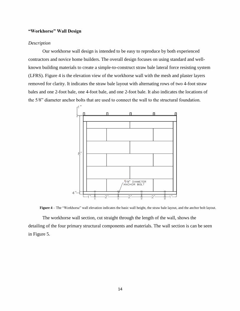
Our workhorse wall design is intended to be easy to reproduce by both experienced
contractors and novice home builders. The overall design focuses on using standard and well-
known building materials to create a simple-to-construct straw bale lateral force resisting system
(LFRS). Figure 4 is the elevation view of the workhorse wall with the mesh and plaster layers
removed for clarity. It indicates the straw bale layout with alternating rows of two 4-foot straw
bales and one 2-foot bale, one 4-foot bale, and one 2-foot bale. It also indicates the locations of
the 5/8” diameter anchor bolts that are used to connect the wall to the structural foundation.
The workhorse wall section, cut straight through the length of the wall, shows the
detailing of the four primary structural components and materials. The wall section is can be seen
in Figure 5.
Figure 4 – The “Workhorse” wall elevation indicates the basic wall height, the straw bale layout, and the anchor bolt layout.

15
The 8-foot long 4x8 top plate is connected to two 4x4 posts at 96-inch height using hand
driven nails. These pieces are attached to the 8-foot long 4x4 sill plate that will rest on the
foundation of the structure. These connections are made with 0.162” diameter nails. The mesh
and plaster layers are attached to this framing on only one side of the wall. This was done
intentionally to provide a basic understanding of the wall strength when only one side provides
the strength required of the entire wall. Should the opposite side also be plastered, then the
strength is expected to be approximately doubled. Figure 6 describes the detailed connections
made to the boundary conditions of the “workhorse” wall for the mesh and plaster connections
on the strong side of the wall.
Figure 5 – The “Workhorse” wall section indicates the material layout and connections made to create the material structure.

16
Two layers of asphalt-saturated building paper are stapled to each of the boundary timber
framing members. One 6” wide section of expanded metal lath is attached to the top and bottom
timber framing pieces with structural grade staples. A 8-foot long by 8-foot tall layer of 2”x4”,
14 gauge mesh is attached to both the top and bottom beams by diagonal staples at mesh weld
intersections. An additional 10-inch band of the 14 ga. 2”x4” is offset at the base of the wall and
attached to the wall with diagonal staples at mesh weld connections.
Cement-lime based plaster is finally added to the exterior of the mesh. The plaster is
applied in 2 coats (the scratch and brown coats) to create approximately a 7/8-inch thick
moisture barrier, and to bind the other building materials together. The final wall is left to cure
for a minimum of 28 days, so that the plaster can achieve its full strength. A list of the building
elements required for the 8-foot long workhorse wall can be seen in Table 8.
Figure 6 – The “Workhorse” wall boundary condition detail provides the detailing requirements for the layers added to form the mesh
and plaster layers that deliver the ductile behavior of the wall.

17
Building Element Material Quantity
Timber Framing
Posts 4x4 (2) @ 96” length
Top Beam 4x8 (1) @ 96” length
Sill 4x4 (1) @ 96” length
Wall Infill Straw Bale 12 for (1) 8’x8’ wall
Wire Mesh 2x4, 14 gauge 8’ x 8’ plus extra slack
Connections
Mesh to Timber
Framing
16 ga. 7/16” crown
1-3/4” leg electro
galvanized staples
(1) Per mesh loop
@ 2” (96”L)
Post to Beam 3” length 0.162”
diameter nails
(1) per side of post
(8 total per post)
Wall to Foundation 5/8” anchor bolt (1) @ 24” o.c.
(4 total)
Exterior Surface Binder Cement-Lime
Plaster
5.5 Cubic Feet
(96”x99”x1”)
Calculations
This wall design was calculated to have an effective height, h, of 7.17 feet based on the
reduced height from the additional 10-inch band of mesh applied to the base boundary. The
nominal shear (calculated using equation 1) based on the expected strength of 1200 psi plaster
and the 2”x4” 14 gauge mesh was calculated to be 13.4 kips (approximately 13,400 lbs --- 1 kip
is 1000 lbs), with a shear due to applied moment, Vmp (calculated using equation 2), of 5 kips.
The Vmp/Vn ratio is calculated to be 0.39, which is much less than 1, indicating that a flexural
failure is expected in this wall. This flexural failure is expected to correspond to a shear loading
of approximately 5 kips. These values are summarized in Table 9.
Table 8 – These base material quantities used for the “workhorse” wall are the rough material estimates made to construct an 8’ long
wall with simpler nailed or stapled connections for construction.

18
Plan Length, Li 8.00 feet
Height, h 7.17 feet
Vn = Vc + Vs 13.4 kips
Vmp 5 kips
Vmp/Vn 0.39
Failure mode (assumed) Flexure Governs
Shear corresponding to failure 5 kips
“Strong” Wall Design
Description
The purpose of our “strong” wall was to create a wall that was appropriately detailed to
achieve the necessary strength for heavy seismic regions. This detail was expected to be
extremely useful for shorter lengths or wall openings like windows and doors; the detailing is
expected to resist more shear loads than the workhorse wall per unit length, and distribute the
loads around the openings. It is intentionally designed for the experienced professional to
construct as the detailing requirements are much greater than for the “workhorse” wall. This
includes establishing a stronger and more ductile behavior for the mesh-plaster interaction. The
“strong” wall can be seen in Figure 7.
Table 9 – The values were used to determine the expected failure mode of the workhorse wall.

19
The strong wall design mechanically differs from the workhorse design in the final
specimen’s detailing. The strong wall is attached to the foundation using a Simpson Strong Tie
hold down in addition to 5/8” diameter anchor bolts. This detail is intended to provide the extra
protection from shear uplift forces on the foundation. The straw bale shear walls have both
timber framing and a concrete-like plaster coating. Because a plywood shear wall and a
reinforced concrete shear wall transfer the loads to the foundation differently, a hold down was
added to only one side of the wall. Figure 8 illustrates the load transfer of shear loads applied to a
plywood shear wall and a concrete shear wall.
Figure 7 – The “strong” wall elevation indicates the basic wall height, the straw bale layout, and the anchor bolt layout. The main
difference between the workhorse and strong wall elevations is the Simpson Strong Tie hold down located on the left side of the wall.

20
This allows us to determine whether the wall behaves most like a plywood shear wall,
where the load is transferred around the boundaries of the structure and into the foundation
through a hold down; or a reinforced concrete shear wall, where the load is distributed along the
length of the member and then straight into the foundation through the base connection design.
Figure 9 expands on the differences between the workhorse and strong wall with a section view
of the wall.
Figure 8 – These diagrams illustrate the ways that loads are transferred from the wall into the foundations for plywood shear
walls versus reinforced concrete shear walls. The single holddown in the “strong” wall is intended to help illustrated which
behavior is prevalent in the straw bale walls constructed using the post and beam method.
Figure 9 – The “strong” wall section indicates only the differences in the cross section between the workhorse and strong walls. These
differences include the header, the post to beam connections, and the mesh layers.

21
In addition to the extra foundation requirements, this “strong” wall has a 4x10 top beam
(as opposed to the 4x8 of the “workhorse” wall) to better take the gravity and shear loads that are
present. The timber framing elements (post and beams) are connected using Simpson Strong Tie
ACE4 post to beam connections with six 16d nails. The mesh types and layers also differ and are
more clearly detailed in Figure 10.
The asphalt building paper is first attached to the timber framing. A double layer of wire
mesh is used in the design, with the initial layer of 2x2 wire stucco mesh stapled to the timber
framing. The stucco mesh is overlapped by the W1.4 wire mesh attached to the wall by looping
the ends of the wires 180-degrees around the 9/16”diameter 3” long hot-dipped galvanized
(HDG) lag screws installed at each of the mesh intersections. These provide extra resistance to
weld failure, increasing the strength in the boundaries and pushing the failure towards the center
of the wall height. Once attached, the cement-lime plaster is added in 2 layers to form the 7/8”
desired thickness for testing. A general list of the materials used in the construction of the 8-foot
long strong wall can be seen in Table 10.
Figure 10 – The “strong” wall boundary condition detail provides the detailing requirements at the base and top boundary locations.
This design differs from the workhorse wall primarily by mesh types and fasteners.

22
Building Element Material Quantity
Timber Framing
Posts 4x4 (2) @ 96”
Top Beam 4x10 (1) @ 96”
Sill 4x4 (1) @ 96”
Wall Infill Straw Bale 12 for (1) 8’x8’ wall
Wire Mesh
W1.4 Mesh (10 ga.) 8’ x 8’ plus extra slack
for 180-degree loops
2x2 Wire stucco
mesh (paperback)
8’ x 8’
Connections
Mesh to Timber
Framing
5/16”d x 3” HDG
lag screws
(1) Per W1.4 mesh
loop
@ 2” (96”L)
16 ga. 7/16” crown
1-3/4” leg electro
galvanized staples
(1) Per 2x2 stucco
mesh weld intersection
@ 2” (96”L)
Post to Beam Simpson ACE4 w/
(6) 16d nails
(1) per post to beam
connection (2 total)
Wall to Foundation 5/8” anchor bolts (1) @ 24” o.c.
(4 total)
Simson HDU2-
SDS25 Hold-Down
(1) at left side
Exterior Surface Binder Cement-Lime
Plaster
5.5 Cubic Feet
(96”x99”x1”)
Calculations
The shear strength of the 8-foot strong wall was calculated assuming a 7.73-foot height
based on the W1.4 mesh layer and lag screws providing extra strength at the boundaries in order
to move the failure away from the base or top plates. The shear strength of the steel mesh, Vs,
was calculated with the use of a composite mesh strength based on the total volume of 2x2 wire
stucco mesh and W1.4 mesh that contributes to the reinforcing ratio of the plaster. Equation 1
was used to calculate the nominal shear, Vn, based on the steel and plaster material properties of
approximately 30.2 kips. As with the workhorse wall, the shear based on the applied moment
was calculated using equation 2. This resulting shear, Vmp was calculated to be around 23 kips.
The Vmp/Vn ratio was 0.76 based on the Vn and Vmp values being much closer than the workhorse
wall. Because 0.76 can be very easily rounded up to 1 and the material properties of the wall are
Table 10 – The base material quantities used for the “strong” wall.

23
still being understood, it is not yet possible to state definitively whether the wall will fail in either
flexure or shear. For this reason, the failure mode is assumed to be mixed: either flexural or shear
failure are assumed to occur based on the given loading condition. Table 11 is a summary of
these values.
Plan Length, Li 8.00 feet
Height, h 7.73 feet
Vn = Vc + Vs 30.2 kips
Vmp 23 kips
Vmp/Vn 0.76
Failure mode (assumed) Mixed
Shear corresponding to failure 23 kips
NEXT STEPS
The walls are constructed and are awaiting testing; these tests are outside of the current
scope. Their behavior under cyclic loading will be recorded both quantitatively and qualitatively
in order to refine the wall design and detailing for the straw bale post and beam method. It is
expected that flexural failure will occur and the qualitative behavior will be analyzed to improve
the wall’s structural response in events of high seismic activity.
Refer to the completed thesis by Straw Bale Seismic Design Capacities 3 to learn more
about the design of shorter lengths of straw bale wall segments and the additional detailing
required for walls with windows or doors.
ETHICAL ANALYSIS OF STRAW BALE MATERIAL USE
Straw bale construction employs an alternative material for structural design for lateral
loads (i.e. earthquake and wind loads). Several ethical concerns come into play when introducing
a new material to the construction industry, especially when there are current building methods
that have been around for hundreds, if not thousands, of years. It is also important to note that
Table 11 – The values were used to determine the expected failure mode of the workhorse wall.

24
straw and plaster have been used as building materials for generations; we are just trying to set a
standard so structures can be safely and easily designed and built for areas of high seismicity.
Straw Bale as a Solution for Engineer’s Challenges
The majority of the problems that civil engineers face, deal with overpopulation,
diminishing resources, and/or climate change. Our collaboration with the two other senior design
groups will incorporate the design of the structural components of a simple straw bale building
for the California seismic environment. Our ultimate goal is to introduce straw bale into the
California Building Code, however we recognize that our efforts will just be the beginning of
design iterations to eventually reach this end goal. With the introduction of straw bale into the
California Building Code, we can find solutions to help positively impact these areas.
Economic Advantages to Straw Bale Construction
The population in the US grows approximately 0.7-0.8% each year, adding
approximately 2.1 million people each year to the over 300 million people currently residing in
the United States. This population increase demands an equivalent increase in housing
development. Straw bale can accommodate this need as each bale costs approximately $3.50,
which is far less than traditional construction materials. The material is also very readily
available; as the waste product of barley, oats, rice, rye, and wheat, straw bale is readily
produced and discarded. For the purposes of our project we focused on rice straw bales. By
repurposing the material, there is less waste deposited in landfills and more affordable housing to
accommodate the growing population.
Embodied Energy of Straw and Comparative Construction Materials
With diminishing resources in the United States, the demands of steel, concrete, and
lumber on the environment is increasingly devastating. Straw bale, as a natural biomaterial, that
requires less energy in the manufacturing process than typical building materials. The embodied
energy (energy required for the manufacture of the material) of straw bale is approximately 0.91
MJ/mg, compared to 20.10 MJ/mg, 1.11MJ/mg, and 10.00 MJ/mg of steel, concrete, and timber,
respectively. These demands cannot be taken lightly. Straw bale fulfills a need without requiring
much energy for production. Because straw bale is a waste product and is used in its raw form,

25
very little energy is used to bring the material up to industry standards. The material is readily
available for use as the food industry is already financing the agriculture that produces this
structural material.
Global Warming and Benefits of Straw Bale Construction
Global warming has been a growing concern as scientists have realized that the carbon
dioxide emissions that we create in our developed world are actually collecting in the
atmosphere, trapping the sun’s heat and increasing temperatures worldwide. Straw bales are
biomaterials that sequester, or take in, carbon dioxide from the surrounding air. This material
should be in greater demand to have a more profound impact on the environment. The use of this
material can slow global warming efforts by taking in more carbon than it produces while being
used as a structural material.
American Society of Civil Engineer’s Views on Sustainable Building
As engineers and members of the American Society of Civil Engineers (ASCE), we look
to make decisions that will benefit the environment and also encourage the use of natural
materials. Our project aligns with the first fundamental canon of ASCE:
Engineers shall hold paramount the safety, health, and welfare of the public and shall
strive to comply with the principles of sustainable development in the performance of
their professional duties.
In line with this fundamental canon, ASCE defines sustainable development as: “the
process of applying natural, human, and economic resources to enhance the safety, welfare, and
quality of life for all of society while maintaining the availability of the remaining natural
resources.” As we repurpose this waste material, we use the already overproduced waste product
to create a structure that is safe under high seismic activity, healthy as a natural and minimally-
processed material, and encourages the advancement of building techniques to accommodate
renewable building materials. In our journey to become professional engineers, we accepted a
project that would further our understanding of current building methods and expand on them to
create a sustainable and reliable alternative building material. Creating the building codes for
easier implementation in design makes this method a more affordable and approachable building
method.
26
Analyzing Risk
For as beneficial as this material is to the environment, there are still many risks involved
with the use of a natural building material. As engineers, we need to analyze these risks in terms
of the end users and those who may be remotely affected by the use of straw bales in building
construction.
Dangers of Building with Straw Bale
In construction projects, the final products are large and often dangerous elements until
secured. Straw bale creates an additional safety concern as the bales themselves can cause
allergies for the builders. Our project employs rice straw bales, and rice straw, in particular, has a
very high silica content. When homebuilders are constructing the straw bale structure, it is
important that proper precautions are taken to avoid the inhalation of high quantities of this
silica-rich material. After the plaster has been applied, the bales are no longer openly exposed to
the air, and straw bale dust inhalation is severely reduced. When constructing exterior walls, this
inhalation risk is minimized due to the large amount of air flow. Throughout our construction
process we found that using simple dust masks helped allergies greatly.
Concerns of Building with Straw Bale
As straw bale construction is relatively new to the construction industry, it is important
that workers understand how to design and construct the straw bale buildings to industry
standards. With few experts in this field, it is important that information be readily available and
utilized properly in order to employ straw bales as the primary lateral force resisting elements. It
must also be noted that the use of straw bale as a building element will remain a voluntary
decision as specified by the owner or architect and understood by the structural designer.
Additionally, construction for these buildings is highly weather dependent; because the straw
bales cannot be exposed to moisture due to the risk of mold causing the eventual degradation of
the structure, it is important to keep the bales dry throughout the construction process until each
element has been provided a water barrier by the plaster.

27
Other Environmental Considerations
It is also important to consider the environment for which the building is being designed.
While the greatest risk is on the person with the greatest financial investment, there is still a
concern with the people who are in the surrounding area, especially during construction. Because
straw contains many allergens and can be a very labor intensive and messy project, it is
important to be aware of the effects that this material can have on the public and to exercise care
to ensure that the straw bale waste is disposed of in a clean and contained manner. However,
there is large risk working on any construction site, and as straw bale becomes a more viable
building material people will understand how to better work with it.
Verifying Quality in Our Research and Design
Throughout the design process, our small scale and full scale specimen designs have been
reviewed by external sources to the project. Peer reviewers from the FEMA P695 Peer Review
group have been evaluating our material testing and design, in addition to validating our research
findings. Several members of the group also worked on the initial straw bale material testing to
prove that this is a safe and viable building material. During our construction process, several
volunteers from the California Straw Bale Association (CASBA) were able to lend their
expertise in material construction, ensuring that our test specimens will be constructed with the
quality expected in the field. Additionally we had assistance from several professional natural
earth plasterers to help ensure a quality binding between the straw and the wire mesh. These
forms of quality control will help to develop future quality assurance practices for industry
standards.
Straw Bale as a Solution
Overall, straw bale seismic design is beneficial to the world and can solve many of the
problems that civil engineers face in the design and construction processes. Our goal is to create
building code provisions that allow California, especially, to take a step towards a more
sustainable and ethically sound future.

28
WORKS CITED
American Society for Testing and Materials. Philadelphia, Penn.: Society, n.d. Print.
"Climate Basics." Global Warming. Natural Resources Defense Council, n.d. Web. 3 Dec. 2013.
"Code of Ethics." Code of Ethics. American Society of Civil Engineers, n.d. Web. Sept. 2010.
"Earthquake and Seismic Resistance Is a Major Advantage of Topsider's Prefab Home Designs."
Seismic & Earthquake Resistant Homes. Topsider Homes, 2012. Web. 9 Jan. 2014.
"Ellensburg Straw Bale Construction Workshop." Straw Bale Construction Workshop for
Ellensburg Barn Raising and Wall Building Class. Celebrate Big, Oct. 2007. Web. 14
Mar. 2014.
"Embodied Energy." GreenSpec. Srccreative.net, n.d. Web. 4 Dec. 2013.
"Graniterock: Technical Note: Quail Hollow #2 Plaster Sand." Graniterock: Technical Note:
Quail Hollow #2 Plaster Sand. N.p., n.d. Web. 02 Jan. 2014.
<http://www.graniterock.com/technical_notes/140_quail_hollow_2_plaster_sand.html>.
King, Bruce, and Mark Aschheim. Design of Straw Bale Buildings: The State of the Art. San
Rafael, CA: Green Building, 2006. Print.
"LAPIS LUSTRE SAND GRADING PARAMETERS Cumulative Percent Passing US
Sieves." Cemexusa.com. CEMEX Technical Services, 8 Nov. 2010. Web. Mar. 2014.
<http://www.cemexusa.com/ProductsServices/files/MaterialGrading.pdf>.
Morison, Andrew. "We Have a National Straw Bale Building Code!" Strawbalecom RSS.
Strawbale Innovations LLC, 4 Oct. 2013. Web. 14 Dec. 2013.
Portland Cement Association. Portland Cement Plaster/Stucco Manual. N.p.: Portland Cement
Association, 2003. Print.
"Straw Bale Codes Updates | California Straw Building Association." Straw Bale Codes Updates
| California Straw Building Association. N.p., Oct. 2013. Web. 7 Nov. 2013.
Wing, Nick. "Census: U.S. Population Growing Again, But At Lowest Level Since Great
Depression." The Huffington Post. TheHuffingtonPost.com, 20 Dec. 2012. Web. 4 Dec.
2013.

A1
APPENDIX A: PLASTER MIX DESIGN REFERENCES
U.S.
Standard
Sieve
Size
Percent Retained (by weight)
Natural Sand
Manufactured
Sand
max min max min
No. 4 0 0 0 0
No. 8 10 0 10 0
No. 16 40 10 40 10
No. 30 65 30 65 30
No. 50 90 70 80 60
No. 100 100 95 90 75
No. 200 100 97 100 90
Cementitious Materials Volume of Aggregate per
Sum of Separate Volumes of
Cementitious Materials Plaster
Mix
Symbols
Portland Cement
or Blended
Cement
Plastic
Cement
Masonry
Cement Lime
N M or S 1st Coat 2nd Coat
C 1 … … … 0 - 3/4 2 1/2-4 3-5
CL 1 … … … 3/4 - 1 1/2 2 1/2-4 3-5
M … … 1 … … 2 1/2-4 3-5
CM 1 … 1 … … 2 1/2-4 3-5
MS … … … 1 … 2 1/2-4 3-5
P … 1 … … … 2 1/2-4 3-5
CP 1 1 … … … 2 1/2-4 3-5
Table A1 – ASTM C 926-06 Table 3 listing the different plaster mix designs possible within ASTM standards.
The chosen design is from plaster mix CL.
Table A2 – ASTM C 897 sieve test requirements to for acceptable sands to be used for cement-lime based plaster.

A2
Nominal Sieve Size #1/20 30 Mesh
US mm 20x40 30x70
#4 4.75 100±0 100±0
#8 2.36 100±0 100±0
#12 1.7 100±0 100±0
#16 1.18 100±0 100±0
#20 0.850 88±8 100±0
#30 0.600 18±11 95±5
#40 0.425 1±1 73±23
#50 0.300 0 25±11
#70 0.212 0 3±2
#100 0.150 0 1±1
Sieve Size ASTM Spec. No. C-897 Quail Hollow #2 Plaster Sand
3⁄8″ 100 100
No. 4 (4.75 mm) 100 100
No. 8 (2.36 mm) 90–100 100
No. 16 (1.18 mm) 60–90 87.7
No. 30 (600 um) 35–70 55.1
No. 50 (300 um) 10–30 28.9
No. 100 (150 um) 0–5 2.1
No. 200 0 0.6
Table A4 – These are the ASTM C 897 sieve test requirements and the final plaster mix design sand gradation results, indicating that the
material complies with ASTM standards for cement-lime plaster. (Graniterock)
Table A3 – These are the sieve test grading that the CEMEX #1/20 and 30 Mesh samples are graded under used in mix designs 2.2-1, 3.1,
3.2, and 4.2. These aggregate mixes were not used due to failing to meet the ASTM C897 standards listed in Table A2. (CEMEX Testing
Services)

B1
APPENDIX B: BUDGET FOR PROJECT SCOPE
Each Required Total
Straw Bale Walls
Wire $ 160.00 per 3'X100' roll 1 3'X100' rolls $ 160.00
Rice Straw Bale $ 3.50 per bale 40 bales $ 140.00
Wood Framing $ 8.00 per 8-foot
section
10 8-foot sections $ 80.00
Cement Stucco
sand $ 6.00 per bag 30 bags $ 180.00
cement $ 10.00 per bag 8 bags $ 80.00
slaked lime $ 50.00 per bag 15 bags $ 750.00
Testing Platform
Lumber $ 15.00
per 6 foot section
8 6-foot section $ 120.00
Simpson Strong Tie $ 10.00 per hanger 10 hangers $ 100.00
Sum $ 1,610.00
Tax (9.25%) $ 148.93
Contingency (15%) $ 241.50
TOTAL $ 2,000.43
Table B1 – Project budget for plaster design, workhorse wall construction, and strong wall construction

C1
APPENDIX C : PLASTER MIX DESIGN SAMPLE DESCRIPTIONS AND STRENGTHS
Date Mixed Mix
Name Sand Specimen C:L:S Comments Cured
Cure
Time
Max Load
Average
(pounds)
Compressive
Strength
(PSI)
COV
11/7/2013 1 Coarse 2X2 0.5:0.5:3 1 part = 2.5"X6"X3" Air 7 2137 534 13%
11/7/2013 1 Coarse 2X2 0.5:0.5:3 1 part = 2.5"X6"X3" Air 70 1767 441 24%
11/7/2013 2 Coarse 2X2 0.6:0.4:3 1 part = 2.5"X6"X3" Air 7 3135 783 6%
11/7/2013 2 Coarse 2X2 0.6:0.4:3 1 part = 2.5"X6"X3" Air 70 4035 1008 7%
11/7/2013 3 Coarse 2X2 0.7:0.3:3 1 part = 2.5"X6"X3" Air 7 1941 485 8%
11/7/2013 3 Coarse 2X2 0.7:0.3:3 1 part = 2.5"X6"X3" Air 70 2533 633 18%
11/19/2013 1-1 Coarse 2X2 1:0.5:3.75 Middle proportion Lime Normal Sand Air 7 3027 756 6%
11/19/2013 1-2 Coarse 2X2 1:0.75:4.375 High proportion Lime normal amount
Sand Air 7 3059 764 5%
11/19/2013 1-3 Coarse 2X2 1:0.75:4.5 Middle proportion Lime High amount
Sand Air 7 2874 718 9%
11/19/2013 1-4 Coarse 2X2 1:0.75:5.25 High proportion Lime High amount
Sand Air 7 2198 549 12%
11/19/2013 1-5 Coarse 2X2 1:1:5.5 Extreme Air 7 2839 709 13%
11/19/2013 1-6 Coarse 2X2 1:0.75:2.625 High Proportion Lime Low Proportion
Sand Air 7 3153 788 4%
12/6/2013 2-2 Coarse 2X2 1:0.75:4.375 1 part = 2.5"X6"X3" 652 grams of
water Lime 7 6318 1579 20%
12/6/2013 2-2 Coarse 2X2 1:0.75:4.375 1 part = 2.5"X6"X3" 652 grams of
water Lime 41 >2500 PSI
12/6/2013 2-2 Coarse 2X2 1:0.75:4.375 1 part = 2.5"X6"X3" 652 grams of
water Water 7 3147 786 36%
12/6/2013 2-4 Coarse 2X2 1:0.75:5.25 1 part = 2.5"X6"X3" 626.4 grams of
water Lime 7 4104 1026 16%
12/6/2013 2-4 Coarse 2X2 1:0.75:5.25 1 part = 2.5"X6"X3" 626.4 grams of
water Lime 41 4568 1142 36%
12/6/2013 2-4 Coarse 2X2 1:0.75:5.25 1 part = 2.5"X6"X3" 626.4 grams of
water Water 7 2468 617 27%
1/16/2014 2-2.1 1/20 2X2 1:0.75:4.375 1 part = 2.5"X6"X3" 2.5 lb of water Lime 7 2353 588 12%
1/16/2014 2-2.1 1/20 2X2 1:0.75:4.375 1 part = 2.5"X6"X3" 2.5 lb of water Air 7 1858 464 3%
Table C1 – These are the 2” cube plaster sample mix design iterations arranged in order of trial number and dates mixed. The final mix design is not included.

C2
Date
Mixed
Mix
Name Sand Specimen C:L:S Comments Cured
Cure
Time
Max Load
Average
(pounds)
Compressive
Strength
(PSI)
COV
2/2/2014 2-2.2 Coarse Cylinder 1:0.75:4.375 1 part =
2.5"X6"X3" Air 7 15596 1242 8%
2/2/2014 2-2.2 Coarse Cylinder 1:0.75:4.375 1 part =
2.5"X6"X3" Air 28 7840 156
2/3/2014 2-2 .2 Coarse Cylinder 1:0.75:4.375 1 part =
2.5"X6"X3" Lime 7 4288 341 61%
2/3/2014 2-2 .2 Coarse Cylinder 1:0.75:4.375 1 part =
2.5"X6"X3" Lime 28 7968 634 18%
2/9/2014 3-1 1/20 Cylinder 1:0.75:7 1 part =
2.5"X6"X3" Air 7 3189 254 18%
2/9/2014 3-1 1/20 Cylinder 1:0.75:7 1 part =
2.5"X6"X3" Lime 7 2823 225 19%
2/17/2014 3-2 1/20 Cylinder 1:0.75:5 1 part =
2.5"X6"X3" Air 7 12848 1023 4%
2/17/2014 3-2 1/20 Cylinder 1:0.75:5 1 part =
2.5"X6"X3" Lime 7 10358 825 15%
2/17/2014 4-2 30 mesh Cylinder 1:0.75:5 1 part =
2.5"X6"X3" Air 7 7839 624 12%
2/17/2014 4-2 30 mesh Cylinder 1:0.75:5 1 part =
2.5"X6"X3" Lime 7 5846 465 6%
Table C2 – These are the 4” diameter , 8” long cylinder plaster sample mix design iterations in order of trial number and dates mixed. The final mix design is not included.

D1
APPENDIX D: TEAMWORK PHILOSOPHY
We believe that it is important to solve this environmental problem with ethics in the
forefront of our minds. Together, the Straw Bale Seismic Design Capacities 2 team members
established a code of ethics for incorporating our work together with previous research done by
our advisor for our final project. We will:
treat each other’s ideas with respect, understanding the delicacy of
the brainstorming process,
take great care to express the previous work done on straw bale
construction in a manner that gives the researchers and designers
full credit,
work cooperatively and respectfully with the other groups doing
projects on straw bale construction, making sure that they receive
the proper credit for the information that they have provided,
treat our advisor, faculty, professionals, and other students with
respect, taking their suggestions and input into consideration but
ultimately remembering that it is our senior design project so the
final decisions, hardships and work are our responsibility
represent Santa Clara University well when working with industry
professionals and code specialists making sure we enter meetings
prepared to the best of our abilities, treat them with the respect
they deserve and be grateful for their time and assistance.
Ethical Obligations to Our Sponsors, School and Selves
Regardless of the situation, we will not misrepresent any of our findings, nor will we take
any credit for work that is not ours. If a sponsor, faculty member, or other student requests this of
us, we will walk away from the situation. We take pride that the project is ours and we will not
be pushed into representing anything in a way that s not accurate. If we end up in an ethically
challenging situation, we will speak openly about our concerns. If we cannot agree on the
ethically correct action, we will seek guidance from Santa Clara University’s Markkula Center
for Applied Ethics.

D2
Ethical Obligations in Designing the Building Code
After researching the ethical obligations of our senior design process, the main ethical
concern we have is making sure that we accurately record our process and represent our results.
We understand that the work that we are doing will likely be adopted into the California Building
Code, so we must accurately portray the process and results. It is our moral obligation as future
engineers to ensure detailed reports of the systems. This will allow us to influence the
incorporation of straw bale building design for more widespread use of this agricultural
byproduct in construction.
Ethical obligations to Represent Data Accurately
We recognize that it is more important to show truthful results than it is to manipulate the
data so that the project appears to be a success. We acknowledge that this representation must be
accessible to future straw bale construction users. We will guarantee the safety of users by
providing fully representative descriptions of our work and detailed construction techniques.
Ethical obligations to Contributing Research
Previous research has been done regarding straw bale construction, a large part of which
was done by our advisor, Dr. Mark Aschheim. This research is an invaluable resource for us and
we will treat is as such as we acknowledge what findings were ours, and what findings were
provided to us. We will do this by clearly citing information and data that we did not generate, as
well as, verifying with Dr. Aschheim that the work that we have done is original.


![[Murray Hollis] Practical Straw Bale Building(Bookos org)](https://img.pdfslide.net/doc/110x75/631325a15cba183dbf06f7fb/murray-hollis-practical-straw-bale-buildingbookos-org.jpg)


