Embed Size (px)
Citation preview
Composite Beams
When solving the problems for Section 6.2, assume that thecomponent parts of the beams are securely bonded byadhesives or connected by fasteners. Also, be sure to use thegeneral theory for composite beams described in Sect. 6.2.
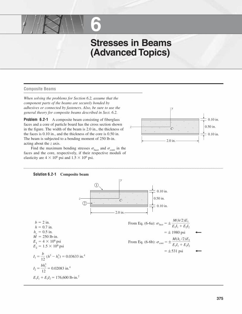
Problem 6.2-1 A composite beam consisting of fiberglassfaces and a core of particle board has the cross section shownin the figure. The width of the beam is 2.0 in., the thickness ofthe faces is 0.10 in., and the thickness of the core is 0.50 in.The beam is subjected to a bending moment of 250 lb-in.acting about the z axis.
Find the maximum bending stresses �face and �core in thefaces and the core, respectively, if their respective moduli ofelasticity are 4 � 106 psi and 1.5 � 106 psi.
Solution 6.2-1 Composite beam
6Stresses in Beams(Advanced Topics)
375
z
y
C 0.50 in.
0.10 in.
0.10 in.
2.0 in.
b � 2 in.h � 0.7 in.
hc � 0.5 in.M � 250 lb-in.E1 � 4 � 106 psiE2 � 1.5 � 106 psi
E1I1 � E2I2 � 176,600 lb-in.2
I2 �bh3
c
12� 0.02083 in.4
I1 �b
12 (h3 � hc
3) � 0.03633 in.4
From Eq. (6-6a):
From Eq. (6-6b):
� ; 531 psi
score � ; M(hc �2)E2
E1I1 � E2I2
� ; 1980 psi
sface � ; M(h�2)E1
E1I1 � E2I2
z
y
C 0.50 in.
0.10 in.
0.10 in.
2.0 in.
2
1
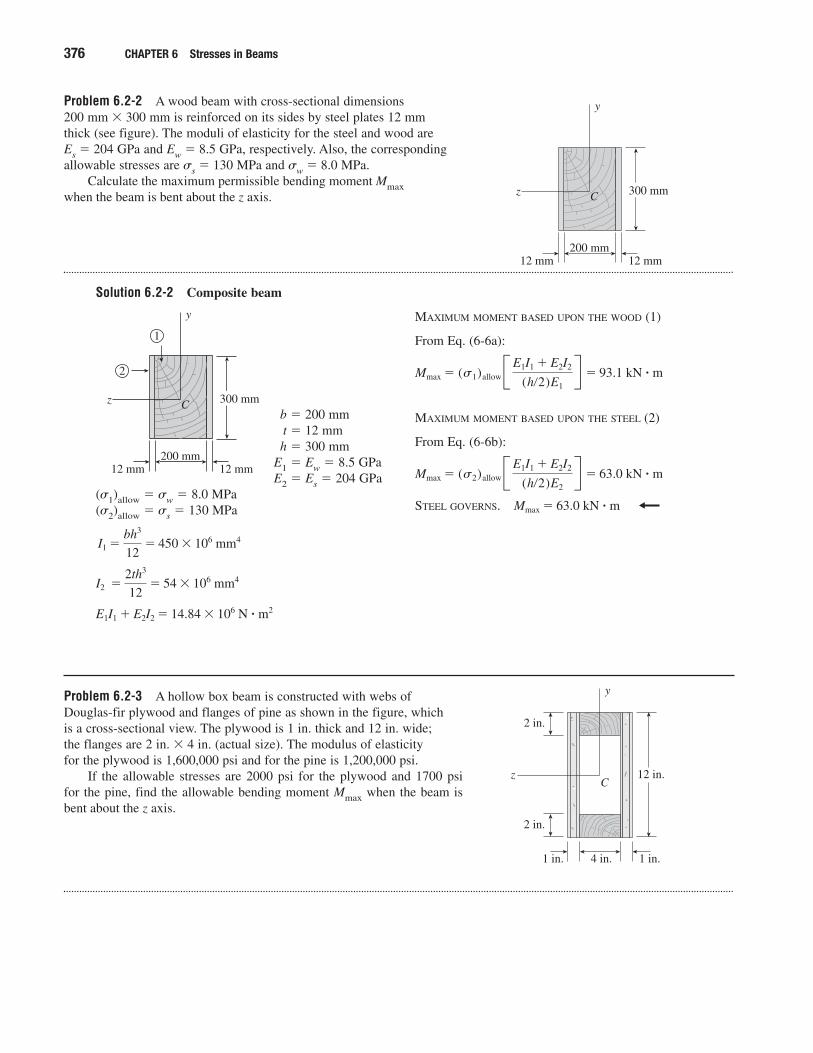
Problem 6.2-2 A wood beam with cross-sectional dimensions 200 mm � 300 mm is reinforced on its sides by steel plates 12 mm thick (see figure). The moduli of elasticity for the steel and wood are Es � 204 GPa and Ew � 8.5 GPa, respectively. Also, the correspondingallowable stresses are �s � 130 MPa and �w � 8.0 MPa.
Calculate the maximum permissible bending moment Mmaxwhen the beam is bent about the z axis.
Solution 6.2-2 Composite beam
376 CHAPTER 6 Stresses in Beams
z
y
C
200 mm12 mm12 mm
300 mm
b � 200 mmt � 12 mmh � 300 mm
E1 � Ew � 8.5 GPaE2 � Es � 204 GPa
(�1)allow � �w � 8.0 MPa(�2)allow � �s � 130 MPa
E1I1 � E2I2 � 14.84 � 106 N � m2
I2 �2th3
12� 54 � 106 mm4
I1 �bh3
12� 450 � 106 mm4
MAXIMUM MOMENT BASED UPON THE WOOD (1)
From Eq. (6-6a):
MAXIMUM MOMENT BASED UPON THE STEEL (2)
From Eq. (6-6b):
STEEL GOVERNS. Mmax � 63.0 kN � m
Mmax � (s2)allowB E1I1 � E2I2
(h�2)E2R � 63.0 kN � m
Mmax � (s1)allowB E1I1 � E2I2
(h�2)E1R � 93.1 kN � m
z
y
C
200 mm12 mm12 mm
300 mm
2
1
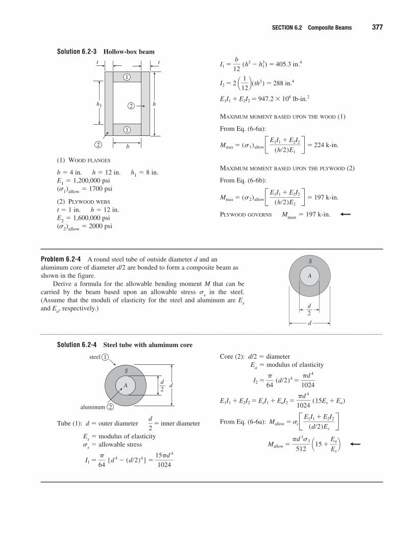
Problem 6.2-3 A hollow box beam is constructed with webs ofDouglas-fir plywood and flanges of pine as shown in the figure, which is a cross-sectional view. The plywood is 1 in. thick and 12 in. wide; the flanges are 2 in. � 4 in. (actual size). The modulus of elasticity for the plywood is 1,600,000 psi and for the pine is 1,200,000 psi.
If the allowable stresses are 2000 psi for the plywood and 1700 psi for the pine, find the allowable bending moment Mmax when the beam isbent about the z axis.
z
y
C
2 in.
2 in.
1 in. 1 in.4 in.
12 in.
SECTION 6.2 Composite Beams 377
(1) WOOD FLANGES
b � 4 in. h � 12 in. h1 � 8 in.E1 � 1,200,000 psi(�1)allow � 1700 psi
(2) PLYWOOD WEBS
t � 1 in. h � 12 in.E2 � 1,600,000 psi(�2)allow � 2000 psi
t t
b
hh1 2
2
1
1
MAXIMUM MOMENT BASED UPON THE WOOD (1)
From Eq. (6-6a):
MAXIMUM MOMENT BASED UPON THE PLYWOOD (2)
From Eq. (6-6b):
PLYWOOD GOVERNS Mmax � 197 k-in.
Mmax � (s2)allowB E1I1 � E2I2
(h�2)E2R � 197 k-in.
Mmax � (s1)allowB E1I1 � E2I2
(h�2)E1R � 224 k-in.
E1I1 � E2I2 � 947.2 � 106 lb-in.2
I2 � 2 ¢ 1
12≤(th3) � 288 in.4
I1 �b
12 (h3 � h1
3) � 405.3 in.4
Problem 6.2-4 A round steel tube of outside diameter d and analuminum core of diameter d/2 are bonded to form a composite beam asshown in the figure.
Derive a formula for the allowable bending moment M that can becarried by the beam based upon an allowable stress �s in the steel.(Assume that the moduli of elasticity for the steel and aluminum are Esand Ea, respectively.)
Solution 6.2-4 Steel tube with aluminum core
d
S
A
d2—
Tube (1): d � outer diameter
Es � modulus of elasticity�s � allowable stress
I1 ��
64 [d 4 � (d�2)4] �
15�d 4
1024
d
2� inner diameter
d
S
Ad2—
2
1steel
aluminum
Core (2): d/2 � diameterEa � modulus of elasticity
From Eq. (6-6a):
Mallow ��d 3s3
512 ¢15 �
Ea
Es
≤
Mallow �ssB E1I1 � E2I2
(d�2)Es
RE1I1 � E2I2 � EsI1 � EaI2 �
�d 4
1024 (15Es � Ea)
I2 ��
64 (d�2)4 �
�d 4
1024
Solution 6.2-3 Hollow-box beam
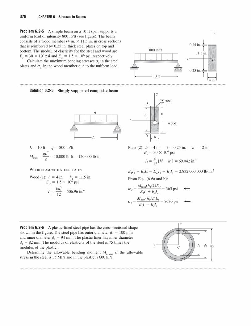
Problem 6.2-5 A simple beam on a 10 ft span supports auniform load of intensity 800 lb/ft (see figure). The beamconsists of a wood member (4 in. � 11.5 in. in cross section) that is reinforced by 0.25 in. thick steel plates on top and bottom. The moduli of elasticity for the steel and wood are Es � 30 � 106 psi and Ew � 1.5 � 106 psi, respectively.
Calculate the maximum bending stresses �s in the steelplates and �w in the wood member due to the uniform load.
Solution 6.2-5 Simply supported composite beam
378 CHAPTER 6 Stresses in Beams
10 ft
800 lb/ft11.5 in.
0.25 in.
4 in.
0.25 in.
z
y
C
L � 10 ft q � 800 lb/ft
WOOD BEAM WITH STEEL PLATES
Wood (1): b � 4 in. h1 � 11.5 in.Ew � 1.5 � 106 psi
I1 �bh3
1
12� 506.96 in.4
Mmax �qL2
8� 10,000 lb-ft � 120,000 lb-in.
Plate (2): b � 4 in. t � 0.25 in. h � 12 in.Es � 30 � 106 psi
E1I1 � E2I2 � EwI1 � EsI2 � 2,832,000,000 lb-in.2
From Eqs. (6-6a and b):
ss �Mmax(h1�2)Es
E1I1 � E2I2� 7630 psi
sw �Mmax(h1�2)Ew
E1I1 � E2I2� 365 psi
I2 �b
12[h3 � h3
1 ] � 69.042 in.4
L
qh1
h
t
t
b
z
y
steel
wood
2
1
Problem 6.2-6 A plastic-lined steel pipe has the cross-sectional shapeshown in the figure. The steel pipe has outer diameter d3 � 100 mm and inner diameter d2 � 94 mm. The plastic liner has inner diameter d1 � 82 mm. The modulus of elasticity of the steel is 75 times themodulus of the plastic.
Determine the allowable bending moment Mallow if the allowablestress in the steel is 35 MPa and in the plastic is 600 kPa.
z
y
C d1 d2 d3
SECTION 6.2 Composite Beams 379
(1) Pipe: ds � 100 mm d2 � 94 mmEs � E1 � modulus of elasticity
(�1)allow � 35 MPa
(2) Liner: d2 � 94 mm d1 � 32 mmEp � E2 � modulus of elasticity
(�2)allow � 600 kPaE1 � 75E2 E1/E2 � 75
I2 ��
64 (d 2
4 � d 14) � 1.613 � 10�6 m4
I1 ��
64 (d 3
4 � d 24) � 1.076 � 10�6 m4
z
y
C d1 d2 d3
2
1steel
plastic
MAXIMUM MOMENT BASED UPON THE STEEL (1)
From Eq. (6-6a):
MAXIMUM MOMENT BASED UPON THE PLASTIC (2)
From Eq. (6-6b):
STEEL GOVERNS Mallow � 768 N � m
� (s2)allowB (E1�E2)I1 � I2
(d2�2)R � 1051 N � m
Mmax � (s2)allowB E1I1 � E2I2
(d2 �2)E2R
� (s1)allow
(E1�E2)I1 � I2
(ds�2)(E1�E2)� 768 N � m
Mmax � (s1)allowB E1I1 � E2I2
(d3 �2)E1R
Solution 6.2-6 Steel pipe with plastic liner
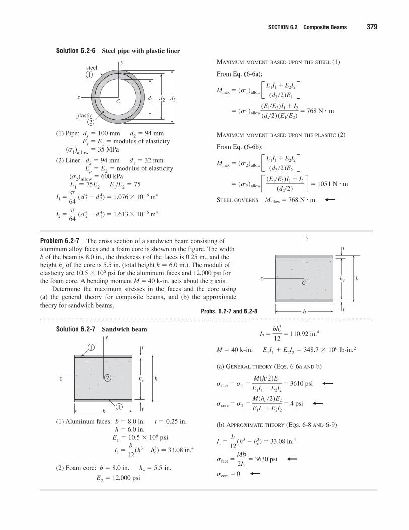
Problem 6.2-7 The cross section of a sandwich beam consisting ofaluminum alloy faces and a foam core is shown in the figure. The widthb of the beam is 8.0 in., the thickness t of the faces is 0.25 in., and theheight hc of the core is 5.5 in. (total height h � 6.0 in.). The moduli ofelasticity are 10.5 � 106 psi for the aluminum faces and 12,000 psi forthe foam core. A bending moment M � 40 k-in. acts about the z axis.
Determine the maximum stresses in the faces and the core using (a) the general theory for composite beams, and (b) the approximatetheory for sandwich beams.
Solution 6.2-7 Sandwich beam
t
t
z
y
Chc h
b
(1) Aluminum faces: b � 8.0 in. t � 0.25 in.h � 6.0 in.
E1 � 10.5 � 106 psi
(2) Foam core: b � 8.0 in. hc � 5.5 in.
E2 � 12,000 psi
I1 �b
12(h3 � h3
c) � 33.08 in.4
t
t
z
y
hc h
b
2
1
1
M � 40 k-in. E1I1 � E2I2 � 348.7 � 106 lb-in.2
(a) GENERAL THEORY (EQS. 6-6a AND b)
(b) APPROXIMATE THEORY (EQS. 6-8 AND 6-9)
score � 0
sface �Mb
2I1� 3630 psi
I1 �b
12(h3 � h3
c) � 33.08 in.4
score �s2 �M(hc �2)E2
E1I1 � E2I2� 4 psi
sface �s1 �M(h�2)E1
E1I1 � E2I2� 3610 psi
I2 �bh3
c
12� 110.92 in.4
Probs. 6.2-7 and 6.2-8
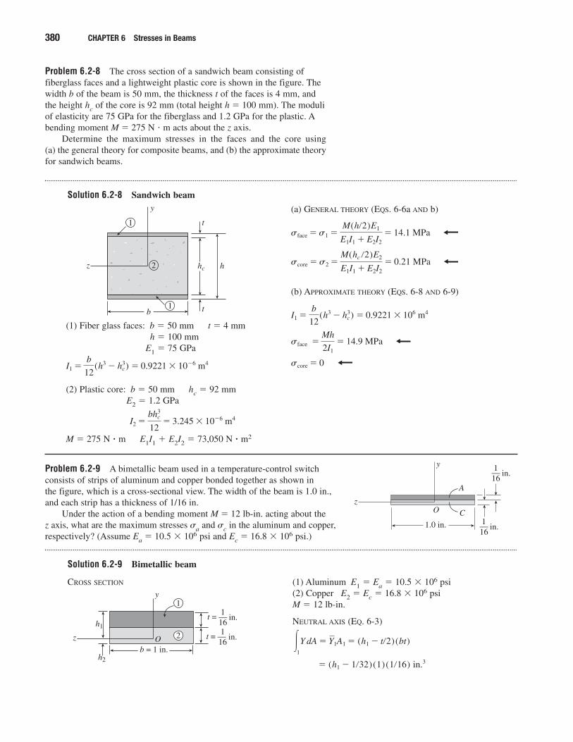
Problem 6.2-8 The cross section of a sandwich beam consisting offiberglass faces and a lightweight plastic core is shown in the figure. Thewidth b of the beam is 50 mm, the thickness t of the faces is 4 mm, andthe height hc of the core is 92 mm (total height h � 100 mm). The moduliof elasticity are 75 GPa for the fiberglass and 1.2 GPa for the plastic. Abending moment M � 275 N � m acts about the z axis.
Determine the maximum stresses in the faces and the core using (a) the general theory for composite beams, and (b) the approximate theoryfor sandwich beams.
Solution 6.2-8 Sandwich beam
380 CHAPTER 6 Stresses in Beams
(1) Fiber glass faces: b � 50 mm t � 4 mmh � 100 mm
E1 � 75 GPa
(2) Plastic core: b � 50 mm hc � 92 mmE2 � 1.2 GPa
M � 275 N � m E1I1 � E2I2 � 73,050 N � m2
I2 �bh3
c
12� 3.245 � 10�6 m4
I1 �b
12(h3 � h3
c) � 0.9221 � 10�6 m4
t
t
z
y
hc h
b
2
1
1
(a) GENERAL THEORY (EQS. 6-6a AND b)
(b) APPROXIMATE THEORY (EQS. 6-8 AND 6-9)
score � 0
sface �Mh
2I1� 14.9 MPa
I1 �b
12(h3 � h3
c) � 0.9221 � 106 m4
score �s2 �M(hc �2)E2
E1I1 � E2I2� 0.21 MPa
sface �s1 �M(h�2)E1
E1I1 � E2I2� 14.1 MPa
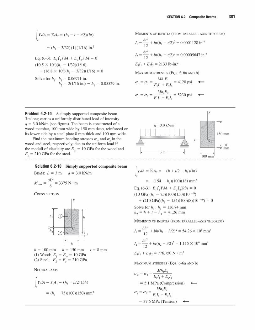
Problem 6.2-9 A bimetallic beam used in a temperature-control switchconsists of strips of aluminum and copper bonded together as shown in the figure, which is a cross-sectional view. The width of the beam is 1.0 in.,and each strip has a thickness of 1/16 in.
Under the action of a bending moment M � 12 lb-in. acting about the z axis, what are the maximum stresses �a and �c in the aluminum and copper,respectively? (Assume Ea � 10.5 � 106 psi and Ec � 16.8 � 106 psi.)
Solution 6.2-9 Bimetallic beam
1.0 in. in.
z
y
O C
A
116—
in.116—
CROSS SECTION
b = 1 in.
z
y
O in.116
t = —
in.116
t = —h1
h2
2
1
(1) Aluminum E1 � Ea � 10.5 � 106 psi(2) Copper E2 � Ec � 16.8 � 106 psiM � 12 lb-in.
NEUTRAL AXIS (EQ. 6-3)
� (h1 � 1�32)(1)(1�16) in.3
�1
Y dA � Y1A1 � (h1 � t�2)(bt)
Problem 6.2-10 A simply supported composite beam 3 m long carries a uniformly distributed load of intensity q � 3.0 kN/m (see figure). The beam is constructed of a wood member, 100 mm wide by 150 mm deep, reinforced onits lower side by a steel plate 8 mm thick and 100 mm wide.
Find the maximum bending stresses �w and �s in thewood and steel, respectively, due to the uniform load if the moduli of elasticity are Ew � 10 GPa for the wood and Es � 210 GPa for the steel.
Solution 6.2-10 Simply supported composite beam
SECTION 6.2 Composite Beams 381
Eq. (6-3): E1�1YdA � E2�2YdA � 0
(10.5 � 106)(h1 � 1/32)(1/16)
� (16.8 � 106)(h1 � 3/32)(1/16) � 0
Solve for h1: h1 � 0.06971 in.h2 � 2(1/16 in.) � h1 � 0.05529 in.
� (h1 � 3�32)(1)(1�16) in.3
�2
Y dA � Y2A2 � (h1 � t � t�2)(bt) MOMENTS OF INERTIA (FROM PARALLEL-AXIS THEOREM)
MAXIMUM STRESSES (EQS. 6-6a AND b)
sc �s2 �Mh2E2
E1I1 � E2I2� 5230 psi
sa �s1 �Mh1E1
E1I1 � E2I2� 4120 psi
E1I1 � E2I2 � 2133 lb-in.2
I2 �bt 3
12� bt(h2 � t�2)2 � 0.00005647 in.4
I1 �bt 3
12� bt(h1 � t�2)2 � 0.0001128 in.4
3 m
q = 3.0 kN/m
150 mm
8mm
100 mm
z
y
O
BEAM: L � 3 m q � 3.0 kN/m
CROSS SECTION
b � 100 mm h � 150 mm t � 8 mm(1) Wood: E1 � Ew � 10 GPa(2) Steel: E2 � Es � 210 GPa
NEUTRAL AXIS
� (h1 � 75)(100)(150) mm3
�1
Y dA � Y1A1 � (h1 � h�2)(bh)
h
b
h1
h2
z
y
O2
1
t
Mmax �qL2
8� 3375 N � m � �(154 � h1)(100)(18) mm3
Eq. (6-3): E1�1YdA � E2�2YdA � 0
(10 GPa)(h1 � 75)(100)(150)(10 �9)
� (210 GPa)(h1 � 154)(100)(8)(10 �9) � 0
Solve for h1: h1 � 116.74 mmh2 � h � t � h1 � 41.26 mm
MOMENTS OF INERTIA (FROM PARALLEL-AXIS THEOREM)
MAXIMUM STRESSES (EQS. 6-6a AND b)
� 5.1 MPa (Compression)
� 37.6 MPa (Tension)
ss �s2 �Mh2E2
E1I1 � E2I2
sw �s1 �Mh1E1
E1I1 � E2I2
E1I1 � E2I2 � 776,750 N � m2
I2 �bt 2
12� bt(h2 � t�2)2 � 1.115 � 106 mm4
I1 �bh 3
12� bh(h1 � h�2)2 � 54.26 � 106 mm4
�2
y dA � Y2A2 � �(h � t�2 � h1) (bt)
Transformed-Section Method
When solving the problems for Section 6.3, assume that the componentparts of the beams are securely bonded by adhesives or connected by fasteners. Also, be sure to use the transformed-section method in thesolutions.
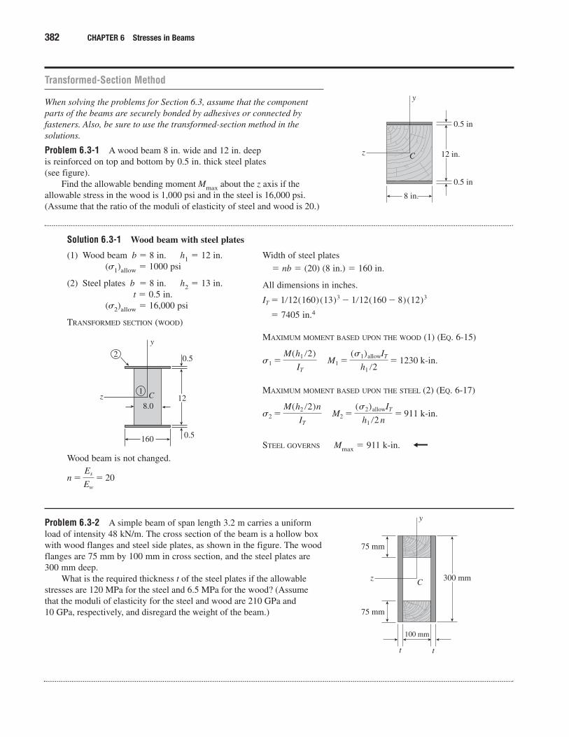
Problem 6.3-1 A wood beam 8 in. wide and 12 in. deep is reinforced on top and bottom by 0.5 in. thick steel plates (see figure).
Find the allowable bending moment Mmax about the z axis if theallowable stress in the wood is 1,000 psi and in the steel is 16,000 psi.(Assume that the ratio of the moduli of elasticity of steel and wood is 20.)
Solution 6.3-1 Wood beam with steel plates
382 CHAPTER 6 Stresses in Beams
12 in.
0.5 in
0.5 in
8 in.
y
z C
(1) Wood beam b � 8 in. h1 � 12 in.(�1)allow � 1000 psi
(2) Steel plates b � 8 in. h2 � 13 in.t � 0.5 in.
(�2)allow � 16,000 psi
TRANSFORMED SECTION (WOOD)
Wood beam is not changed.
n �Es
Ew
� 20
12
0.5
0.5
160
y
z C
2
1
8.0
Width of steel plates
� nb � (20) (8 in.) � 160 in.
All dimensions in inches.
� 7405 in.4
MAXIMUM MOMENT BASED UPON THE WOOD (1) (EQ. 6-15)
MAXIMUM MOMENT BASED UPON THE STEEL (2) (EQ. 6-17)
STEEL GOVERNS Mmax � 911 k-in.
s2 �M(h2 �2)n
IT
M2 �(s2)allowIT
h1 �2 n� 911 k-in.
s1 �M(h1 �2)
IT
M1 �(s1)allowIT
h1 �2� 1230 k-in.
IT � 1�12(160)(13)3 � 1�12(160 � 8)(12)3
Problem 6.3-2 A simple beam of span length 3.2 m carries a uniformload of intensity 48 kN/m. The cross section of the beam is a hollow boxwith wood flanges and steel side plates, as shown in the figure. The woodflanges are 75 mm by 100 mm in cross section, and the steel plates are300 mm deep.
What is the required thickness t of the steel plates if the allowablestresses are 120 MPa for the steel and 6.5 MPa for the wood? (Assumethat the moduli of elasticity for the steel and wood are 210 GPa and 10 GPa, respectively, and disregard the weight of the beam.)
300 mm
75 mm
75 mm
100 mm
t t
z
y
C
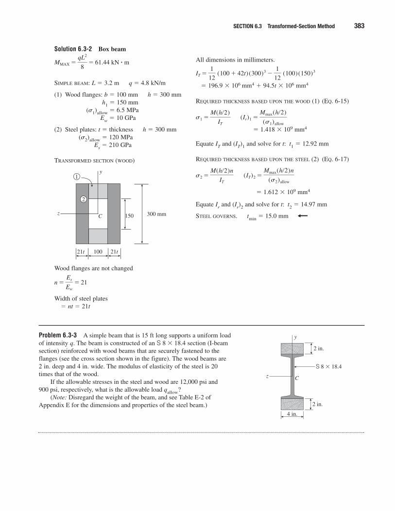
Solution 6.3-2 Box beam
SECTION 6.3 Transformed-Section Method 383
SIMPLE BEAM: L � 3.2 m q � 4.8 kN/m
(1) Wood flanges: b � 100 mm h � 300 mmh1 � 150 mm
(�1)allow � 6.5 MPaEw � 10 GPa
(2) Steel plates: t � thickness h � 300 mm(�2)allow � 120 MPa
Es � 210 GPa
TRANSFORMED SECTION (WOOD)
Wood flanges are not changed
Width of steel plates� nt � 21t
n �Es
Ew
� 21
300 mm
100
z
y
C 150
21t 21t
2
1
MMAX �qL2
8� 61.44 kN � m All dimensions in millimeters.
� 196.9 � 106 mm4 � 94.5t � 106 mm4
REQUIRED THICKNESS BASED UPON THE WOOD (1) (EQ. 6-15)
� 1.418 � 109 mm4
Equate IT and (IT)1 and solve for t: t1 � 12.92 mm
REQUIRED THICKNESS BASED UPON THE STEEL (2) (EQ. 6-17)
� 1.612 � 109 mm4
Equate Ir and (Ir)2 and solve for t: t2 � 14.97 mm
STEEL GOVERNS. tmin � 15.0 mm
(IT)2 �Mmax(h�2)n
(s2)allows2 �
M(h�2)n
IT
(Ir)1 �Mmax(h�2)
(s1)allows1 �
M(h�2)
IT
IT �1
12 (100 � 42t)(300)3 �
1
12 (100)(150)3
Problem 6.3-3 A simple beam that is 15 ft long supports a uniform loadof intensity q. The beam is constructed of an S 8 � 18.4 section (I-beamsection) reinforced with wood beams that are securely fastened to theflanges (see the cross section shown in the figure). The wood beams are2 in. deep and 4 in. wide. The modulus of elasticity of the steel is 20times that of the wood.
If the allowable stresses in the steel and wood are 12,000 psi and 900 psi, respectively, what is the allowable load qallow?
(Note: Disregard the weight of the beam, and see Table E-2 ofAppendix E for the dimensions and properties of the steel beam.)
S 8 � 18.4
z
y
C
2 in.
4 in.
2 in.
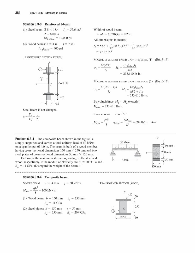
Solution 6.3-3 Reinforced I-beam
384 CHAPTER 6 Stresses in Beams
(1) Steel beam: S 8 � 18.4 I1 � 57.6 in.4
d � 8.00 in.(�1)allow � 12,000 psi
(2) Wood beams: b � 4 in. t � 2 in.
(�2)allow � 900 psi
TRANSFORMED SECTION (STEEL)
Steel beam is not changed.
n �Ew
Es
�1
20
z C
t = 2
0.2
t = 2
2
1
d = 8.00
y
Width of wood beams
� nb � (1/20)(4) � 0.2 in.
All dimensions in inches.
� 77.87 in.4
MAXIMUM MOMENT BASED UPON THE STEEL (1) (EQ. 6-15)
� 233,610 lb-in.
MAXIMUM MOMENT BASED UPON THE WOOD (2) (EQ. 6-17)
� 233,610 lb-in.
By coincidence, M1 � M2 (exactly)
Mmax � 233,610 lb-in.
SIMPLE BEAM L � 15 ft
qallow �8Mmax
L2 � 692 lb�ftMmax �qL2
8
M2 �(s2)allowIT
(d�2 � t)ns2 �
M(d�2 � t)n
IT
M1 �(s1)allowIT
d�2s1 �
M(d�2)
IT
IT � 57.6 �1
12 (0.2)(12)3 �
1
12 (0.2)(8)3
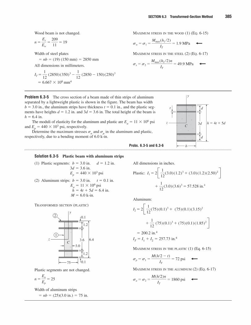
Problem 6.3-4 The composite beam shown in the figure is simply supported and carries a total uniform load of 50 kN/m on a span length of 4.0 m. The beam is built of a wood member having cross-sectional dimensions 150 mm � 250 mm and two steel plates of cross-sectional dimensions 50 mm � 150 mm.
Determine the maximum stresses �s and �w in the steel and wood, respectively, if the moduli of elasticity are Es � 209 GPa and Ew � 11 GPa. (Disregard the weight of the beam.)
Solution 6.3-4 Composite beam
4.0 m
50 kN/m
z
y
C250 mm
150 mm
50 mm
50 mm
SIMPLE BEAM: L � 4.0 m q � 50 kN/m
(1) Wood beam: b � 150 mm h1 � 250 mm
Ew � 11 GPa
(2) Steel plates: b � 150 mm t � 50 mmh2 � 350 mm Es � 209 GPa
Mmax �qL2
8� 100 kN � m
TRANSFORMED SECTION (WOOD)
z
y
C250
2850 50
502
1
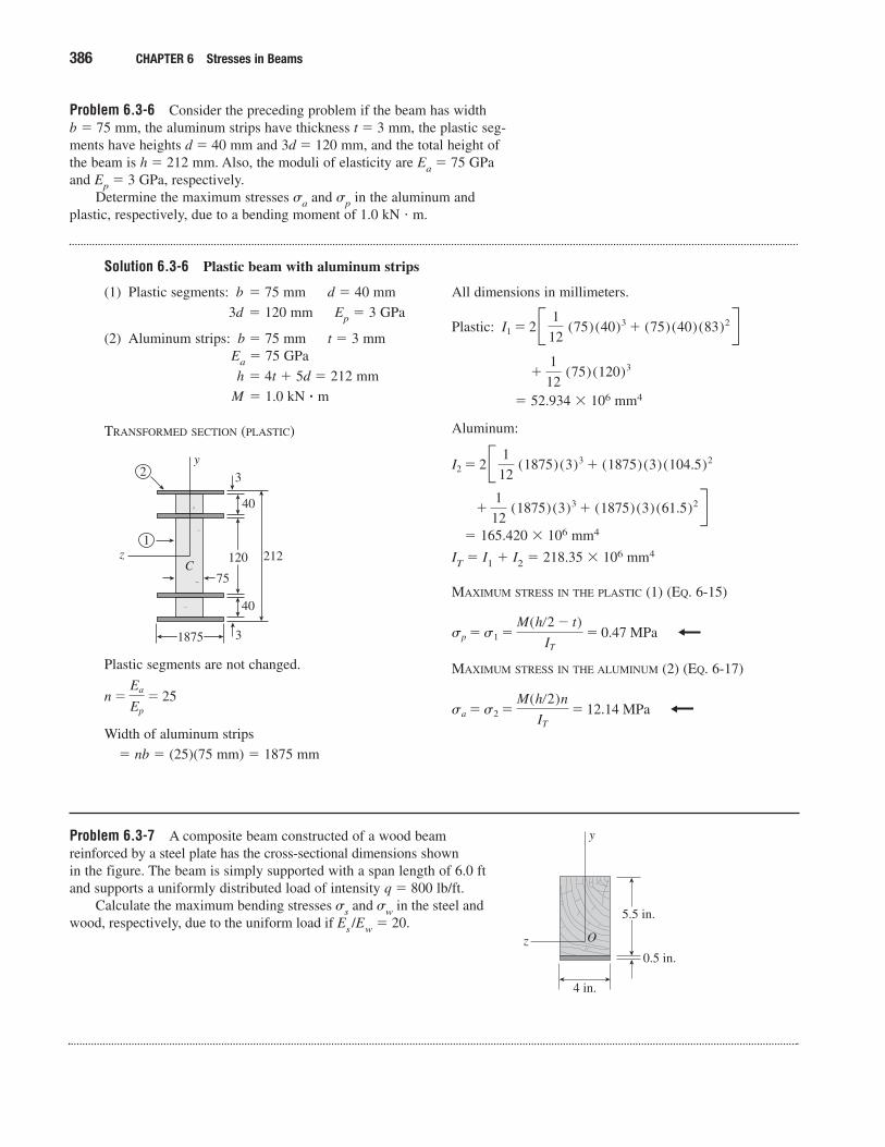
Problem 6.3-5 The cross section of a beam made of thin strips of aluminumseparated by a lightweight plastic is shown in the figure. The beam has width b � 3.0 in., the aluminum strips have thickness t � 0.1 in., and the plastic seg-ments have heights d � 1.2 in. and 3d � 3.6 in. The total height of the beam ish � 6.4 in.
The moduli of elasticity for the aluminum and plastic are Ea � 11 � 106 psiand Ep � 440 � 103 psi, respectively.
Determine the maximum stresses �a and �p in the aluminum and plastic,respectively, due to a bending moment of 6.0 k-in.
Solution 6.3-5 Plastic beam with aluminum strips
SECTION 6.3 Transformed-Section Method 385
Wood beam is not changed.
Width of steel plates
� nb � (19) (150 mm) � 2850 mm
All dimensions in millimeters.
� 6.667 � 108 mm4
IT �1
12 (2850)(350)3 �
1
12 (2850 � 150)(250)3
n �Es
Ew
�209
11� 19
MAXIMUM STRESS IN THE WOOD (1) (EQ. 6-15)
MAXIMUM STRESS IN THE STEEL (2) (EQ. 6-17)
ss �s2 �Mmax(h2 �2)n
IT
� 49.9 MPa
sw �s1 �Mmax(h1 �2)
IT
� 1.9 MPa
z
y
C
t d
d
h � 4t � 5d
b
3d
(1) Plastic segments: b � 3.0 in. d � 1.2 in.3d � 3.6 in.Ep � 440 � 103 psi
(2) Aluminum strips: b � 3.0 in. t � 0.1 in.Ea � 11 � 106 psih � 4t � 5d � 6.4 in.
M � 6.0 k-in.
TRANSFORMED SECTION (PLASTIC)
Plastic segments are not changed.
Width of aluminum strips
� nb � (25)(3.0 in.) � 75 in.
n �Ea
Ep
� 25
z
y
C
1.2
1.2
6.4
75
3.6
2
1
0.1
0.1
3.0
All dimensions in inches.
Plastic:
Aluminum:
� 200.2 in.4
IT � I1 � I2 � 257.73 in.4
MAXIMUM STRESS IN THE PLASTIC (1) (Eq. 6-15)
MAXIMUM STRESS IN THE ALUMINUM (2) (EQ. 6-17)
sa �s2 �M(h�2)n
IT
� 1860 psi
sp �s1 �M(h�2 � t)
IT
� 72 psi
�1
12 (75)(0.1)3 � (75)(0.1)(1.85)2R
I2 � 2B 1
12(75)(0.1)3 � (75)(0.1)(3.15)2
�1
12(3.0)(3.6)3 � 57.528 in.4
I1 � 2B 1
12(3.0)(1.2)3 � (3.0)(1.2)(2.50)2R
Probs. 6.3-5 and 6.3-6
Problem 6.3-6 Consider the preceding problem if the beam has widthb � 75 mm, the aluminum strips have thickness t � 3 mm, the plastic seg-ments have heights d � 40 mm and 3d � 120 mm, and the total height ofthe beam is h � 212 mm. Also, the moduli of elasticity are Ea � 75 GPaand Ep � 3 GPa, respectively.
Determine the maximum stresses �a and �p in the aluminum andplastic, respectively, due to a bending moment of 1.0 kN � m.
Solution 6.3-6 Plastic beam with aluminum strips
386 CHAPTER 6 Stresses in Beams
(1) Plastic segments: b � 75 mm d � 40 mm
3d � 120 mm Ep � 3 GPa
(2) Aluminum strips: b � 75 mm t � 3 mmEa � 75 GPa
h � 4t � 5d � 212 mm
M � 1.0 kN � m
TRANSFORMED SECTION (PLASTIC)
Plastic segments are not changed.
Width of aluminum strips
� nb � (25)(75 mm) � 1875 mm
n �Ea
Ep
� 25
z
y
C
40
40
212
1875
120
2
1
3
3
75
All dimensions in millimeters.
Plastic:
� 52.934 � 106 mm4
Aluminum:
� 165.420 � 106 mm4
IT � I1 � I2 � 218.35 � 106 mm4
MAXIMUM STRESS IN THE PLASTIC (1) (EQ. 6-15)
MAXIMUM STRESS IN THE ALUMINUM (2) (EQ. 6-17)
sa �s2 �M(h�2)n
IT
� 12.14 MPa
sp �s1 �M(h�2 � t)
IT
� 0.47 MPa
�1
12 (1875)(3)3 � (1875)(3)(61.5)2R
I2 � 2B 1
12 (1875)(3)3 � (1875)(3)(104.5)2
�1
12 (75)(120)3
I1 � 2B 1
12 (75)(40)3 � (75)(40)(83)2R
Problem 6.3-7 A composite beam constructed of a wood beamreinforced by a steel plate has the cross-sectional dimensions shown in the figure. The beam is simply supported with a span length of 6.0 ftand supports a uniformly distributed load of intensity q � 800 lb/ft.
Calculate the maximum bending stresses �s and �w in the steel andwood, respectively, due to the uniform load if Es /Ew � 20.
5.5 in.
4 in.
0.5 in.z
y
O
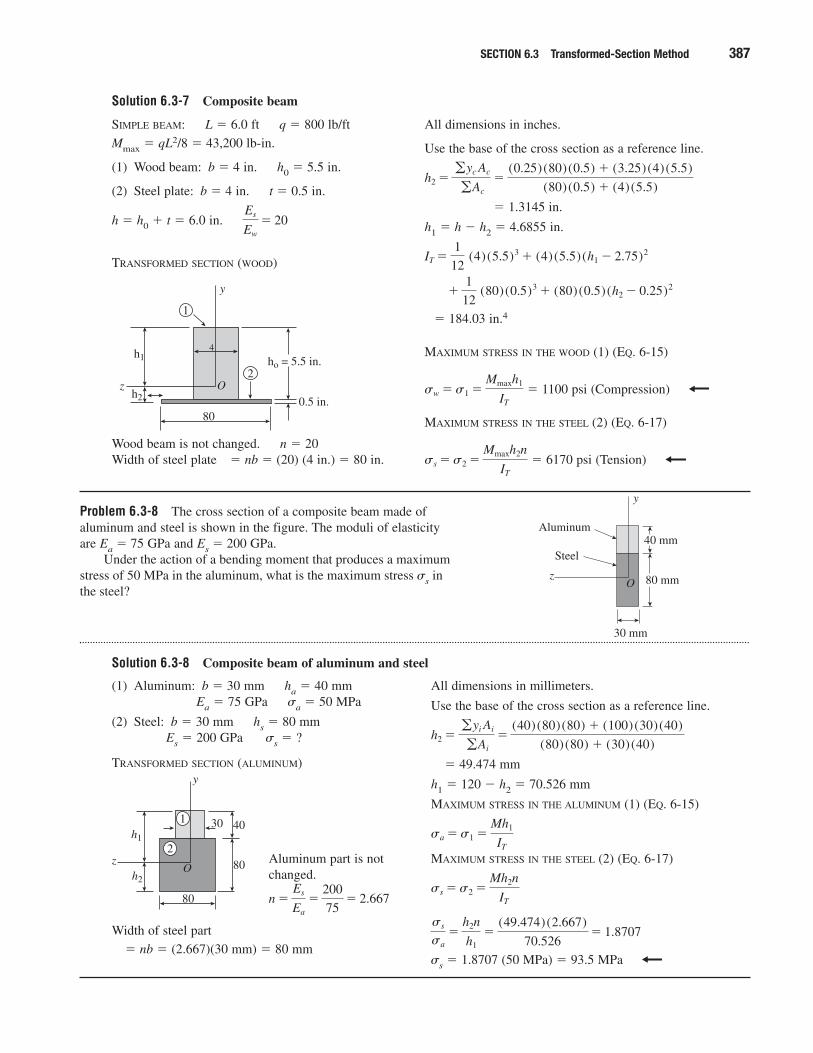
Solution 6.3-7 Composite beam
SECTION 6.3 Transformed-Section Method 387
SIMPLE BEAM: L � 6.0 ft q � 800 lb/ft
Mmax � qL2/8 � 43,200 lb-in.
(1) Wood beam: b � 4 in. h0 � 5.5 in.
(2) Steel plate: b � 4 in. t � 0.5 in.
h � h0 � t � 6.0 in.
TRANSFORMED SECTION (WOOD)
Wood beam is not changed. n � 20Width of steel plate � nb � (20) (4 in.) � 80 in.
ho = 5.5 in.h1
h2
800.5 in.
z
y
O2
1
4
Es
Ew
� 20
All dimensions in inches.
Use the base of the cross section as a reference line.
� 1.3145 in.
h1 � h � h2 � 4.6855 in.
� 184.03 in.4
MAXIMUM STRESS IN THE WOOD (1) (EQ. 6-15)
� 1100 psi (Compression)
MAXIMUM STRESS IN THE STEEL (2) (EQ. 6-17)
� 6170 psi (Tension)ss �s2 �Mmaxh2n
IT
sw �s1 �Mmaxh1
IT
�1
12 (80)(0.5)3 � (80)(0.5)(h2 � 0.25)2
IT �1
12 (4)(5.5)3 � (4)(5.5)(h1 � 2.75)2
h2 �gyc Ac
gAc
�(0.25)(80)(0.5) � (3.25)(4)(5.5)
(80)(0.5) � (4)(5.5)
Problem 6.3-8 The cross section of a composite beam made ofaluminum and steel is shown in the figure. The moduli of elasticity are Ea � 75 GPa and Es � 200 GPa.
Under the action of a bending moment that produces a maximumstress of 50 MPa in the aluminum, what is the maximum stress �s in the steel?
Solution 6.3-8 Composite beam of aluminum and steel
40 mm
30 mm
80 mm
Aluminum
Steel
z
y
O
(1) Aluminum: b � 30 mm ha � 40 mmEa � 75 GPa �a � 50 MPa
(2) Steel: b � 30 mm hs � 80 mmEs � 200 GPa �s � ?
TRANSFORMED SECTION (ALUMINUM)
Aluminum part is notchanged.
Width of steel part
� nb � (2.667)(30 mm) � 80 mm
n �Es
Ea
�200
75� 2.667
All dimensions in millimeters.
Use the base of the cross section as a reference line.
� 49.474 mm
h1 � 120 � h2 � 70.526 mm
MAXIMUM STRESS IN THE ALUMINUM (1) (EQ. 6-15)
MAXIMUM STRESS IN THE STEEL (2) (EQ. 6-17)
�s � 1.8707 (50 MPa) � 93.5 MPa
ss
sa�
h2n
h1�
(49.474)(2.667)
70.526� 1.8707
ss �s2 �Mh2n
IT
sa �s1 �Mh1
IT
h2 �gyi Ai
gAi
�(40)(80)(80) � (100)(30)(40)
(80)(80) � (30)(40)
40
80
80 z
y
O
30
2
1h1
h2
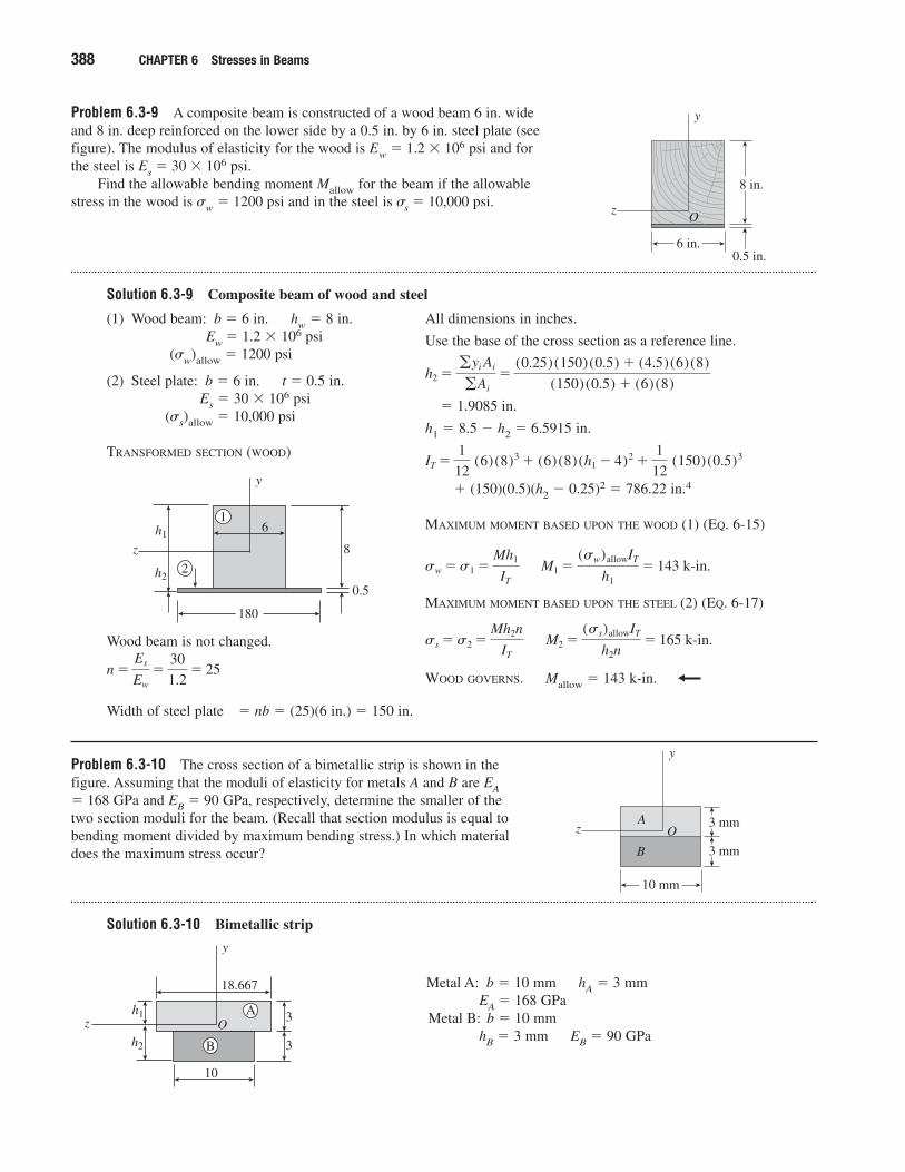
Problem 6.3-9 A composite beam is constructed of a wood beam 6 in. wideand 8 in. deep reinforced on the lower side by a 0.5 in. by 6 in. steel plate (seefigure). The modulus of elasticity for the wood is Ew � 1.2 � 106 psi and forthe steel is Es � 30 � 106 psi.
Find the allowable bending moment Mallow for the beam if the allowablestress in the wood is �w � 1200 psi and in the steel is �s � 10,000 psi.
Solution 6.3-9 Composite beam of wood and steel
388 CHAPTER 6 Stresses in Beams
z
y
O
8 in.
6 in.0.5 in.
(1) Wood beam: b � 6 in. hw � 8 in.Ew � 1.2 � 106 psi
(�w)allow � 1200 psi
(2) Steel plate: b � 6 in. t � 0.5 in.Es � 30 � 106 psi
(�s)allow � 10,000 psi
TRANSFORMED SECTION (WOOD)
Wood beam is not changed.
Width of steel plate � nb � (25)(6 in.) � 150 in.
n �Es
Ew
�30
1.2� 25
z
y
8
180
0.5
2
16h1
h2
All dimensions in inches.
Use the base of the cross section as a reference line.
� 1.9085 in.
h1 � 8.5 � h2 � 6.5915 in.
� (150)(0.5)(h2 � 0.25)2 � 786.22 in.4
MAXIMUM MOMENT BASED UPON THE WOOD (1) (EQ. 6-15)
MAXIMUM MOMENT BASED UPON THE STEEL (2) (EQ. 6-17)
WOOD GOVERNS. Mallow � 143 k-in.
M2 �(ss)allowIT
h2n� 165 k-in.ss �s2 �
Mh2n
IT
M1 �(sw)allowIT
h1� 143 k-in.sw �s1 �
Mh1
IT
IT �1
12 (6)(8)3 � (6)(8)(h1 � 4)2 �
1
12 (150)(0.5)3
h2 �gyi Ai
gAi
�(0.25)(150)(0.5) � (4.5)(6)(8)
(150)(0.5) � (6)(8)
Problem 6.3-10 The cross section of a bimetallic strip is shown in thefigure. Assuming that the moduli of elasticity for metals A and B are EA� 168 GPa and EB � 90 GPa, respectively, determine the smaller of thetwo section moduli for the beam. (Recall that section modulus is equal tobending moment divided by maximum bending stress.) In which materialdoes the maximum stress occur?
Solution 6.3-10 Bimetallic strip
3 mm
10 mm
3 mm
z
y
OA
B
3
10
18.667
3
z
y
OA
B
h1
h2
Metal A: b � 10 mm hA � 3 mmEA � 168 GPa
Metal B: b � 10 mmhB � 3 mm EB � 90 GPa
SECTION 6.3 Transformed-Section Method 389
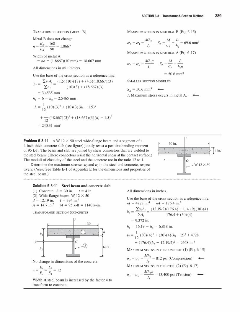
Problem 6.3-11 A W 12 � 50 steel wide-flange beam and a segment of a 4-inch thick concrete slab (see figure) jointly resist a positive bending moment of 95 k-ft. The beam and slab are joined by shear connectors that are welded tothe steel beam. (These connectors resist the horizontal shear at the contact surface.)The moduli of elasticity of the steel and the concrete are in the ratio 12 to 1.
Determine the maximum stresses �s and �c in the steel and concrete, respec-tively. (Note: See Table E-1 of Appendix E for the dimensions and properties ofthe steel beam.)
Solution 6.3-11 Steel beam and concrete slab
z
y
O
30 in.
4 in.
W 12 � 50
(1) Concrete: b � 30 in. t � 4 in.(2) Wide-flange beam: W 12 � 50d � 12.19 in. I � 394 in.4
A � 14.7 in.2 M � 95 k-ft � 1140 k-in.
TRANSFORMED SECTION (CONCRETE)
No change in dimensions of the concrete.
Width at steel beam is increased by the factor n totransform to concrete.
n �Es
Ec
�E2
E1� 12
z
y
O
30
4
2
1
12.19
h1
h2
All dimensions in inches.
Use the base of the cross section as a reference line.nI � 4728 in.4 nA � 176.4 in.2
� 9.372 in.
h1 � 16.19 � h2 � 6.818 in.
� (176.4)(h2 � 12.19/2)2 � 9568 in.4
MAXIMUM STRESS IN THE CONCRETE (1) (EQ. 6-15)
MAXIMUM STRESS IN THE STEEL (2) (EQ. 6-17)
ss �s2 �Mh2 n
IT
� 13,400 psi (Tension)
sc �s1 �Mh1
IT
� 812 psi (Compression)
IT �1
12 (30)(4)3 � (30)(4)(h1 � 2)2 � 4728
h2 �gyi Ai
gAi
�(12.19�2)(176.4) � (14.19)(30)(4)
176.4 � (30)(4)
TRANSFORMED SECTION (METAL B)
Metal B does not change.
Width of metal A� nb � (1.8667)(10 mm) � 18.667 mm
All dimensions in millimeters.
Use the base of the cross section as a reference line.
� 3.4535 mm
h1 � 6 � h2 � 2.5465 mm
� 240.31 mm4
�1
12 (18.667)(3)3 � (18.667)(3)(h1 � 1.5)2
Ir �1
12 (10)(3)3 � (10)(3)(h2 � 1.5)2
h2 �gyi Ai
gAi
�(1.5)(10)(13) � (4.5)(18.667)(3)
(10)(3) � (18.667)(3)
n �EA
EB
�168
90� 1.8667
MAXIMUM STRESS IN MATERIAL B (EQ. 6-15)
MAXIMUM STRESS IN MATERIAL A (EQ. 6-17)
� 50.6 mm3
SMALLER SECTION MODULUS
SA � 50.6 mm3
� Maximum stress occurs in metal A.
SA �MsA
�Ir
h1nsA �s2 �
Mh1n
IT
SB �MsB
�IT
h2� 69.6 mm3sB �s1 �
Mh2
Ir
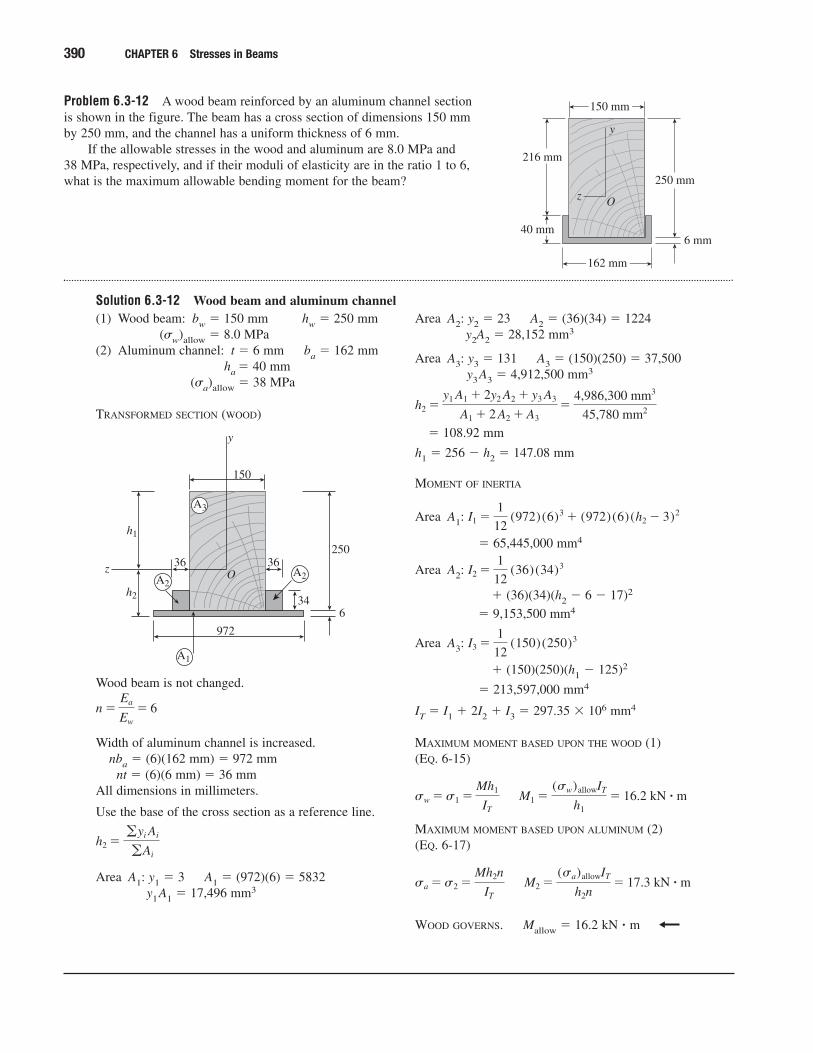
Problem 6.3-12 A wood beam reinforced by an aluminum channel sectionis shown in the figure. The beam has a cross section of dimensions 150 mmby 250 mm, and the channel has a uniform thickness of 6 mm.
If the allowable stresses in the wood and aluminum are 8.0 MPa and 38 MPa, respectively, and if their moduli of elasticity are in the ratio 1 to 6,what is the maximum allowable bending moment for the beam?
Solution 6.3-12 Wood beam and aluminum channel
390 CHAPTER 6 Stresses in Beams
z
y
O
250 mm
216 mm
40 mm6 mm
150 mm
162 mm
(1) Wood beam: bw � 150 mm hw � 250 mm(�w)allow � 8.0 MPa
(2) Aluminum channel: t � 6 mm ba � 162 mmha � 40 mm
(�a)allow � 38 MPa
TRANSFORMED SECTION (WOOD)
Wood beam is not changed.
Width of aluminum channel is increased.nba � (6)(162 mm) � 972 mm
nt � (6)(6 mm) � 36 mmAll dimensions in millimeters.
Use the base of the cross section as a reference line.
Area A1: y1 � 3 A1 � (972)(6) � 5832y1A1 � 17,496 mm3
h2 �gyi Ai
gAi
n �Ea
Ew
� 6
z
y
O
250
h1
h2
6
150
972
A1
A2A2
A3
36 36
34
Area A2: y2 � 23 A2 � (36)(34) � 1224y2A2 � 28,152 mm3
Area A3: y3 � 131 A3 � (150)(250) � 37,500y3A3 � 4,912,500 mm3
� 108.92 mm
h1 � 256 � h2 � 147.08 mm
MOMENT OF INERTIA
Area A1:
� 65,445,000 mm4
Area A2:
� (36)(34)(h2 � 6 � 17)2
� 9,153,500 mm4
Area A3:
� (150)(250)(h1 � 125)2
� 213,597,000 mm4
IT � I1 � 2I2 � I3 � 297.35 � 106 mm4
MAXIMUM MOMENT BASED UPON THE WOOD (1) (EQ. 6-15)
MAXIMUM MOMENT BASED UPON ALUMINUM (2)(EQ. 6-17)
WOOD GOVERNS. Mallow � 16.2 kN � m
M2 �(sa)allowIT
h2n� 17.3 kN � ˇmsa �s2 �
Mh2n
IT
M1 �(sw)allowIT
h1� 16.2 kN � ˇmsw �s1 �
Mh1
IT
I3 �1
12 (150)(250)3
I2 �1
12 (36)(34)3
I1 �1
12 (972)(6)3 � (972)(6)(h2 � 3)2
h2 �y1 A1 � 2y2 A2 � y3 A3
A1 � 2 A2 � A3�
4,986,300 mm3
45,780 mm2
Beams with Inclined Loads
When solving the problems for Section 6.4, be sure to draw a sketch of thecross section showing the orientation of the neutral axis and the locationsof the points where the stresses are being found.
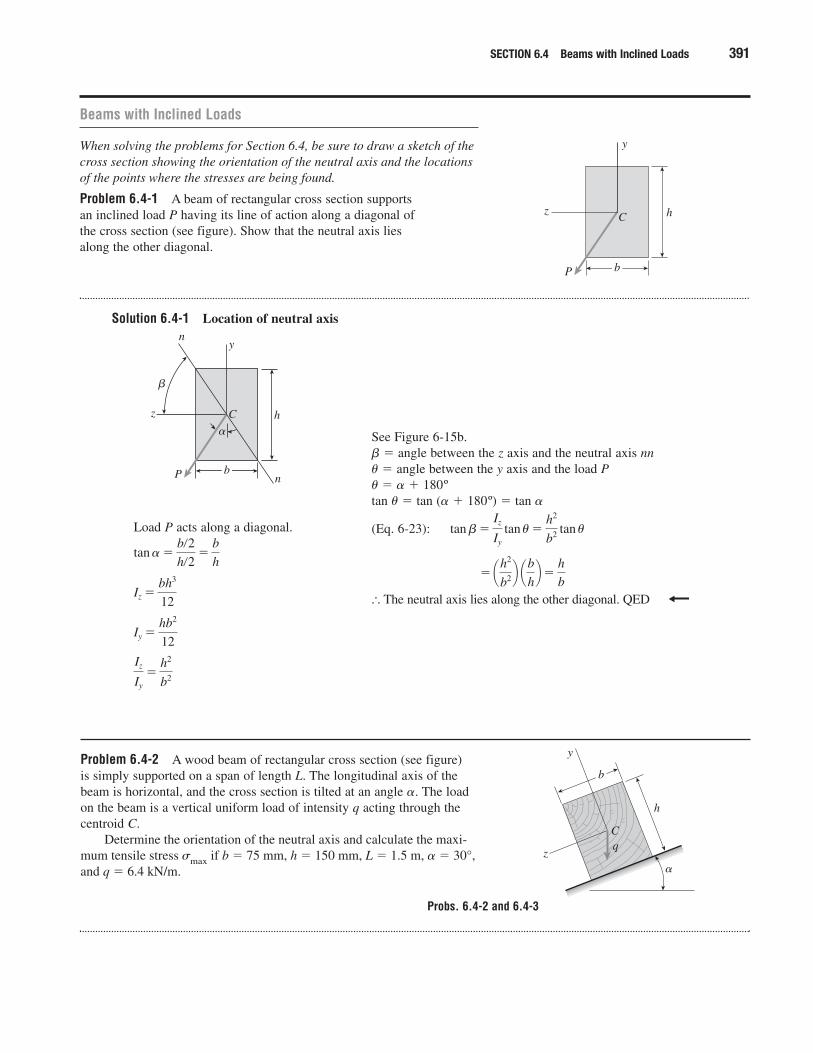
Problem 6.4-1 A beam of rectangular cross section supportsan inclined load P having its line of action along a diagonal ofthe cross section (see figure). Show that the neutral axis liesalong the other diagonal.
Solution 6.4-1 Location of neutral axis
SECTION 6.4 Beams with Inclined Loads 391
b
z
y
C
P
h
Load P acts along a diagonal.
Iz
Iy
�h2
b2
Iy �hb2
12
Iz �bh3
12
tan � �b�2h�2
�b
h
See Figure 6-15b.� � angle between the z axis and the neutral axis nn� � angle between the y axis and the load P� � � � 180ºtan � � tan (� � 180º) � tan �
(Eq. 6-23):
� The neutral axis lies along the other diagonal. QED
� ¢h2
b2≤ ¢bh≤�h
b
tan b�Iz
Iy
tan u�h2
b2 tan u
b
z
y
C
P
h
n
n
�
�
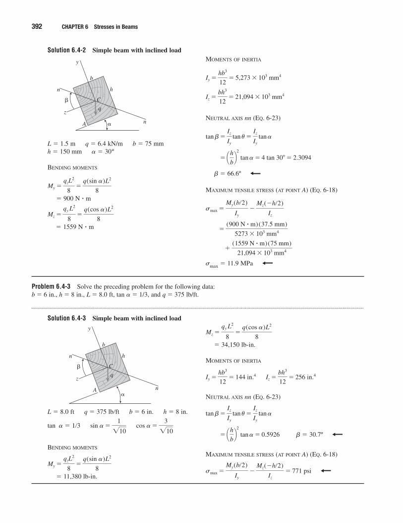
Problem 6.4-2 A wood beam of rectangular cross section (see figure) is simply supported on a span of length L. The longitudinal axis of thebeam is horizontal, and the cross section is tilted at an angle �. The loadon the beam is a vertical uniform load of intensity q acting through thecentroid C.
Determine the orientation of the neutral axis and calculate the maxi-mum tensile stress �max if b � 75 mm, h � 150 mm, L � 1.5 m, � � 30°,and q � 6.4 kN/m.
C
z
y
q
h
b
�
Probs. 6.4-2 and 6.4-3
Solution 6.4-2 Simple beam with inclined load
392 CHAPTER 6 Stresses in Beams
L � 1.5 m q � 6.4 kN/m b � 75 mmh � 150 mm � � 30º
BENDING MOMENTS
� 900 N � m
� 1559 N � m
Mz �qy L2
8�
q(cos �)L2
8
My �qzL
2
8�
q(sin �)L2
8
MOMENTS OF INERTIA
NEUTRAL AXIS nn (EQ. 6-23)
� � 66.6º
MAXIMUM TENSILE STRESS (AT POINT A) (EQ. 6-18)
�max � 11.9 MPa
�(1559 N � ˇm)(75 mm)
21,094 � 103 mm4
�(900 N � ˇm)(37.5 mm)
5273 � 103 mm4
smax �My(b�2)
Iy
�Mz(�h�2)
Iz
� ¢hb≤
2
tan � � 4 tan 30� � 2.3094
tan b�Iz
Iy
tan u�Iz
Iy
tan �
Iz �bh3
12� 21,094 � 103 mm4
Iy �hb3
12� 5,273 � 103 mm4
C
z
y
q
h
b
� n
n
�
A
Problem 6.4-3 Solve the preceding problem for the following data: b � 6 in., h � 8 in., L � 8.0 ft, tan � � 1/3, and q � 375 lb/ft.
Solution 6.4-3 Simple beam with inclined load
L � 8.0 ft q � 375 lb�ft b � 6 in. h � 8 in.
tan � � 1�3
BENDING MOMENTS
� 11,380 lb-in.
My �qzL
2
8�
q(sin �)L2
8
cos � �3
�10sin � �
1
�10
C
z
y
q
h
b
�n
n
�
A
� 34,150 lb-in.
MOMENTS OF INERTIA
NEUTRAL AXIS nn (EQ. 6-23)
� � 30.7º
MAXIMUM TENSILE STRESS (AT POINT A) (EQ. 6-18)
smax �My(b�2)
Iy
�Mz(�h�2)
Iz
� 771 psi
� ¢hb≤
2
tan � � 0.5926
tan b�Iz
Iy
tan u�Iz
Iy
tan �
Iz �bh3
12� 256 in.4Iy �
hb3
12� 144 in.4
Mz �qy L2
8�
q(cos �)L2
8
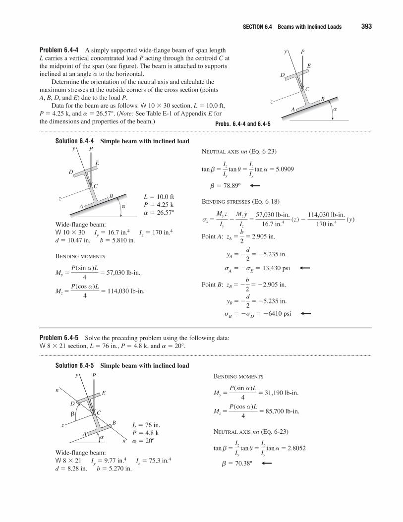
Problem 6.4-4 A simply supported wide-flange beam of span length L carries a vertical concentrated load P acting through the centroid C atthe midpoint of the span (see figure). The beam is attached to supportsinclined at an angle � to the horizontal.
Determine the orientation of the neutral axis and calculate the maximum stresses at the outside corners of the cross section (points A, B, D, and E) due to the load P.
Data for the beam are as follows: W 10 � 30 section, L � 10.0 ft, P � 4.25 k, and � � 26.57°. (Note: See Table E-1 of Appendix E for the dimensions and properties of the beam.)
Solution 6.4-4 Simple beam with inclined load
SECTION 6.4 Beams with Inclined Loads 393
z
y
C
A
D
P
E
B
�
L � 10.0 ftP � 4.25 k� � 26.57º
Wide-flange beam:W 10 � 30 Iy � 16.7 in.4 Iz � 170 in.4
d � 10.47 in. b � 5.810 in.
BENDING MOMENTS
Mz �P(cos �)L
4� 114,030 lb-in.
My �P(sin �)L
4� 57,030 lb-in.
NEUTRAL AXIS nn (EQ. 6-23)
� � 78.89º
BENDING STRESSES (EQ. 6-18)
Point A:
�A � ��E � 13,430 psi
Point B:
�B � ��D � �6410 psi
yB � �d
2� �5.235 in.
zB � �b
2� �2.905 in.
yA � �d
2� �5.235 in.
zA �b
2� 2.905 in.
�114,030 lb-in.
170 in.4 (y)sx �
My z
Iy
�Mz y
Iz
�57,030 lb-in.
16.7 in.4 (z)
tan b�Iz
Iy
tan u�Iz
Iy
tan � � 5.0909
Problem 6.4-5 Solve the preceding problem using the following data: W 8 � 21 section, L � 76 in., P � 4.8 k, and � � 20°.
Solution 6.4-5 Simple beam with inclined load
L � 76 in.P � 4.8 k� � 20º
Wide-flange beam:W 8 � 21 Iy � 9.77 in.4 Iz � 75.3 in.4
d � 8.28 in. b � 5.270 in.
BENDING MOMENTS
NEUTRAL AXIS nn (EQ. 6-23)
� � 70.38º
tan b�Iz
Iy
tan u�Iz
Iy
tan � � 2.8052
Mz �P(cos �)L
4� 85,700 lb-in.
My �P(sin �)L
4� 31,190 lb-in.
z
y
C
A
D
P
E
B
�
z
y
C
A
D
P
E
B
�n
n
�
Probs. 6.4-4 and 6.4-5
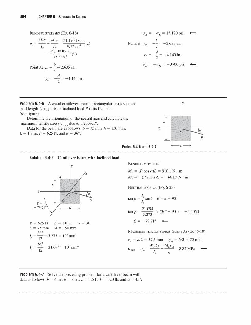
Problem 6.4-6 A wood cantilever beam of rectangular cross sectionand length L supports an inclined load P at its free end
(see figure). Determine the orientation of the neutral axis and calculate the
maximum tensile stress �max due to the load P.Data for the beam are as follows: b � 75 mm, h � 150 mm,
L � 1.8 m, P � 625 N, and � � 36°.
Solution 6.4-6 Cantilever beam with inclined load
394 CHAPTER 6 Stresses in Beams
BENDING STRESSES (EQ. 6-18)
Point A:
yA � �d
2� �4.140 in.
zA �b
2� 2.635 in.
�85,700 lb-in.
75.3 in.4 (y)
sx �My z
Iy
�Mz y
Iz
�31,190 lb-in.
9.77 in.4 (z)
�A � ��E � 13,120 psi
Point B:
�B � ��D � �3700 psi
yB � �d
2� �4.140 in.
zB � �b
2� �2.635 in.
z
y
C
P
b
h
�
P � 625 N L � 1.8 m � � 36ºb � 75 mm h � 150 mm
Ia �bh3
12� 21.094 � 106 mm4
Iy �bh3
12� 5.273 � 106 mm4
z
y
C
P
b
h
�
n
n � = 79.71�
A
BENDING MOMENTS
My � (P cos �)L � 910.1 N � m
Mz � �(P sin �)L � �661.3 N � m
NEUTRAL AXIS nn (EQ. 6-23)
� � �79.71º
MAXIMUM TENSILE STRESS (POINT A) (EQ. 6-18)
zA � b�2 � 37.5 mm yA � h�2 � 75 mm
smax �sA �My z A
Iy
�Mz y A
Iz
� 8.82 MPa
tan b�21.094
5.273 tan(36� � 90�) � �5.5060
tan b�Iz
Iy
tan u�u� � � 90�
Problem 6.4-7 Solve the preceding problem for a cantilever beam withdata as follows: b � 4 in., h � 8 in., L � 7.5 ft, P � 320 lb, and � � 45°.
Probs. 6.4-6 and 6.4-7
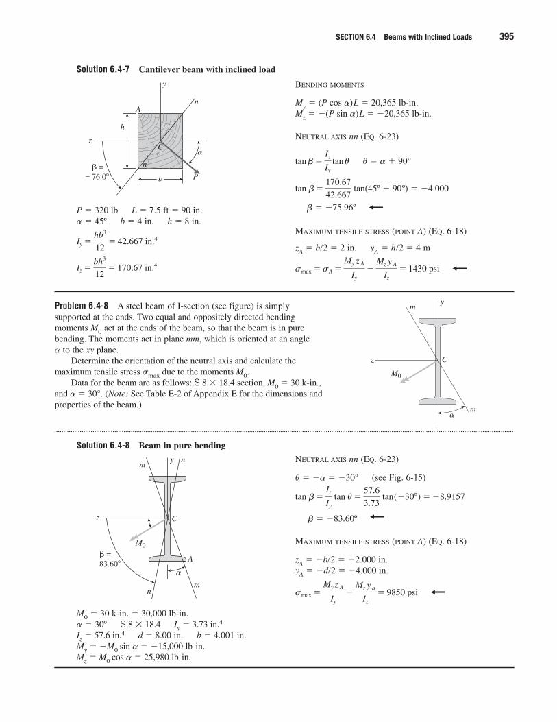
Solution 6.4-7 Cantilever beam with inclined load
SECTION 6.4 Beams with Inclined Loads 395
P � 320 lb L � 7.5 ft � 90 in.� � 45º b � 4 in. h � 8 in.
Iz �bh3
12� 170.67 in.4
Iy �hb3
12� 42.667 in.4
z
y
C
Pb
h
�
n
n � = 76.0�
A
BENDING MOMENTS
My � (P cos �)L � 20,365 lb-in.Mz � �(P sin �)L � �20,365 lb-in.
NEUTRAL AXIS nn (EQ. 6-23)
� � � � 90º
tan(45º � 90º) � �4.000
� � �75.96º
MAXIMUM TENSILE STRESS (POINT A) (EQ. 6-18)
zA � b�2 � 2 in. yA � h�2 � 4 m
smax �sA �My z A
Iy
�Mz y A
Iz
� 1430 psi
tan b�170.67
42.667
tan b�Iz
Iy
tan u
Problem 6.4-8 A steel beam of I-section (see figure) is simplysupported at the ends. Two equal and oppositely directed bendingmoments M0 act at the ends of the beam, so that the beam is in purebending. The moments act in plane mm, which is oriented at an angle � to the xy plane.
Determine the orientation of the neutral axis and calculate themaximum tensile stress �max due to the moments M0.
Data for the beam are as follows: S 8 � 18.4 section, M0 � 30 k-in.,and � � 30°. (Note: See Table E-2 of Appendix E for the dimensions andproperties of the beam.)
Solution 6.4-8 Beam in pure bending
z
y
C
M0
m
m�
M0 � 30 k-in. � 30,000 lb-in.� � 30º S 8 � 18.4 Iy � 3.73 in.4
Iz � 57.6 in.4 d � 8.00 in. b � 4.001 in.My � �M0 sin � � �15,000 lb-in.Mz � M0 cos � � 25,980 lb-in.
NEUTRAL AXIS nn (EQ. 6-23)
� � �� � �30º (see Fig. 6-15)
� � �83.60º
MAXIMUM TENSILE STRESS (POINT A) (EQ. 6-18)
zA � �b�2 � �2.000 in.yA � �d�2 � �4.000 in.
smax �My z A
Iy
�Mz y a
Iz
� 9850 psi
tan b�Iz
Iy
tan u�57.6
3.73 tan(�30�) � �8.9157
z
y
C
M0
m
m
�
n
n
A� =83.60�
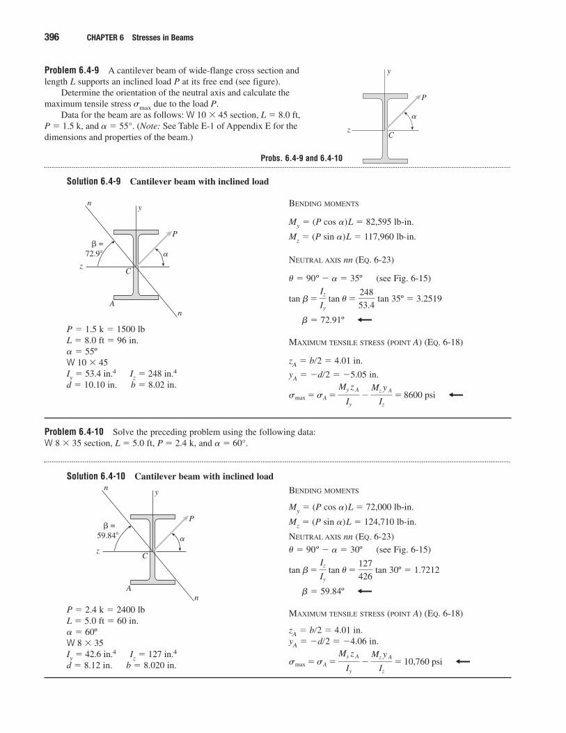
Problem 6.4-9 A cantilever beam of wide-flange cross section andlength L supports an inclined load P at its free end (see figure).
Determine the orientation of the neutral axis and calculate themaximum tensile stress �max due to the load P.
Data for the beam are as follows: W 10 � 45 section, L � 8.0 ft, P � 1.5 k, and � � 55°. (Note: See Table E-1 of Appendix E for thedimensions and properties of the beam.)
Solution 6.4-9 Cantilever beam with inclined load
396 CHAPTER 6 Stresses in Beams
z
y
C
P
�
P � 1.5 k � 1500 lbL � 8.0 ft � 96 in.� � 55ºW 10 � 45Iy � 53.4 in.4 Iz � 248 in.4
d � 10.10 in. b � 8.02 in.
z
y
C
P
�
n
n
A
� = 72.9�
BENDING MOMENTS
My � (P cos �)L � 82,595 lb-in.
Mz � (P sin �)L � 117,960 lb-in.
NEUTRAL AXIS nn (EQ. 6-23)
� � 90º � � � 35º (see Fig. 6-15)
tan 35º � 3.2519
� � 72.91º
MAXIMUM TENSILE STRESS (POINT A) (EQ. 6-18)
zA � b�2 � 4.01 in.
yA � �d�2 � �5.05 in.
smax �sA �My z A
Iy
�Mz y A
Iz
� 8600 psi
tan b�Iz
Iy
tan u�248
53.4
Problem 6.4-10 Solve the preceding problem using the following data:W 8 � 35 section, L � 5.0 ft, P � 2.4 k, and � � 60°.
Solution 6.4-10 Cantilever beam with inclined load
P � 2.4 k � 2400 lbL � 5.0 ft � 60 in.� � 60ºW 8 � 35Iy � 42.6 in.4 Iz � 127 in.4
d � 8.12 in. b � 8.020 in.
z
y
C
P
�
n
n
A
� = 59.84�
BENDING MOMENTS
My � (P cos �)L � 72,000 lb-in.
Mz � (P sin �)L � 124,710 lb-in.
NEUTRAL AXIS nn (EQ. 6-23)
� � 90º � � � 30º (see Fig. 6-15)
tan 30º � 1.7212
� � 59.84º
MAXIMUM TENSILE STRESS (POINT A) (EQ. 6-18)
zA � b�2 � 4.01 in.yA � �d�2 � �4.06 in.
smax �sA �My z A
Iy
�Mz y A
Iz
� 10,760 psi
tan b�Iz
Iy
tan u�127
426
Probs. 6.4-9 and 6.4-10
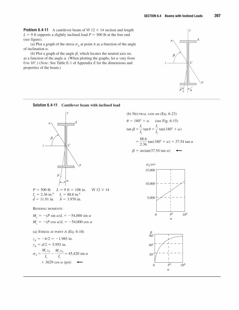
Problem 6.4-11 A cantilever beam of W 12 � 14 section and length L � 9 ft supports a slightly inclined load P � 500 lb at the free end (see figure).
(a) Plot a graph of the stress �A at point A as a function of the angle of inclination �.
(b) Plot a graph of the angle �, which locates the neutral axis nn, as a function of the angle �. (When plotting the graphs, let � vary from 0 to 10°.) (Note: See Table E-1 of Appendix E for the dimensions andproperties of the beam.)
Solution 6.4-11 Cantilever beam with inclined load
SECTION 6.4 Beams with Inclined Loads 397
y
z
n
n
A
C
P �
�
P � 500 lb L � 9 ft � 108 in. W 12 � 14Iy � 2.36 in.4 Iz � 88.6 in.4
d � 11.91 in. b � 3.970 in.
BENDING MOMENTS
My � �(P sin �)L � �54,000 sin �
Mz � �(P cos �)L � �54,000 cos �
(a) STRESS AT POINT A (EQ. 6-18)
zA � �b�2 � �1.985 in.
yA � d�2 � 5.955 in.
� 3629 cos � (psi)
sA �My zA
Iy
�Mz yA
Iz
� 45,420 sin �
y
z
n
n
A
C
P
�
�
(b) NEUTRAL AXIS nn (EQ. 6-23)
� � 180º � � (see Fig. 6-15)
� � arctan(37.54 tan �)
�88.6
2.36 tan(180� � �) � 37.54 tan �
tan b�Iz
Iy
tan u�Iz
Iy
tan(180� � �)
15,000
10,000
5,000
0 50 100
�
�A (psi)
90�
60�
30�
0 50 100
�
�
Bending of Unsymmetric Beams
When solving the problems for Section 6.5, be sure to draw a sketch of thecross section showing the orientation of the neutral axis and the locationsof the points where the stresses are being found.
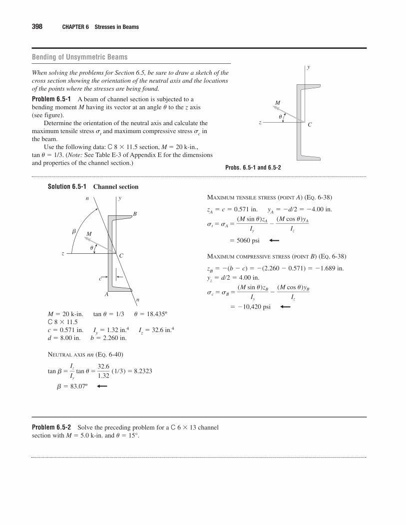
Problem 6.5-1 A beam of channel section is subjected to abending moment M having its vector at an angle � to the z axis(see figure).
Determine the orientation of the neutral axis and calculate the maximum tensile stress �t and maximum compressive stress �c in the beam.
Use the following data: C 8 � 11.5 section, M � 20 k-in., tan � � 1/3. (Note: See Table E-3 of Appendix E for the dimensions and properties of the channel section.)
Solution 6.5-1 Channel section
398 CHAPTER 6 Stresses in Beams
z
y
C
M
�
M � 20 k-in. tan � � 1�3 � � 18.435ºC 8 � 11.5c � 0.571 in. Iy � 1.32 in.4 Iz � 32.6 in.4
d � 8.00 in. b � 2.260 in.
NEUTRAL AXIS nn (EQ. 6-40)
� � 83.07º
tan b�Iz
Iy
tan u�32.6
1.32 (1�3) � 8.2323
z
y
C
M
�
A
n
n
�
c
B
MAXIMUM TENSILE STRESS (POINT A) (EQ. 6-38)
zA � c � 0.571 in. yA � �d�2 � �4.00 in.
� 5060 psi
MAXIMUM COMPRESSIVE STRESS (POINT B) (EQ. 6-38)
zB � �(b � c) � �(2.260 � 0.571) � �1.689 in.
yz � d�2 � 4.00 in.
� �10,420 psi
sc �sB �(M sin u)zB
Iy
�(M cos u)yB
Iz
st �sA �(M sin u)zA
Iy
�(M cos u)yA
Iz
Problem 6.5-2 Solve the preceding problem for a C 6 � 13 channelsection with M � 5.0 k-in. and � � 15°.
Probs. 6.5-1 and 6.5-2
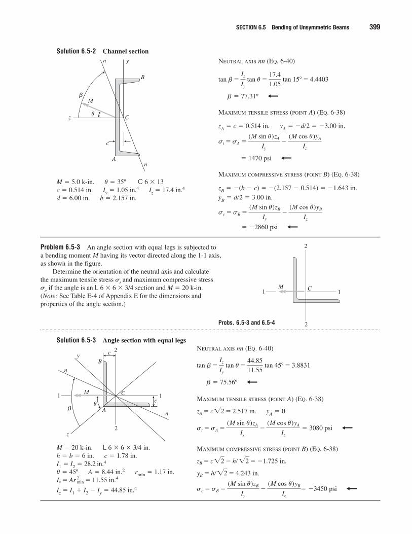
Solution 6.5-2 Channel section
SECTION 6.5 Bending of Unsymmetric Beams 399
M � 5.0 k-in. � � 35º C 6 � 13c � 0.514 in. Iy � 1.05 in.4 Iz � 17.4 in.4
d � 6.00 in. b � 2.157 in.
z
y
C
M
�
A
n
n
�
c
B
NEUTRAL AXIS nn (EQ. 6-40)
� � 77.31º
MAXIMUM TENSILE STRESS (POINT A) (EQ. 6-38)
zA � c � 0.514 in. yA � �d�2 � �3.00 in.
� 1470 psi
MAXIMUM COMPRESSIVE STRESS (POINT B) (EQ. 6-38)
zB � �(b � c) � �(2.157 � 0.514) � �1.643 in.
yB � d�2 � 3.00 in.
� �2860 psi
sc �sB �(M sin u)zB
Iy
�(M cos u)yB
Iz
st �sA �(M sin u)zA
Iy
�(M cos u)yA
Iz
tan b�Iz
Iy
tan u�17.4
1.05 tan 15� � 4.4403
Problem 6.5-3 An angle section with equal legs is subjected to a bending moment M having its vector directed along the 1-1 axis, as shown in the figure.
Determine the orientation of the neutral axis and calculate the maximum tensile stress �t and maximum compressive stress �c if the angle is an L 6 � 6 � 3/4 section and M � 20 k-in. (Note: See Table E-4 of Appendix E for the dimensions and properties of the angle section.)
Solution 6.5-3 Angle section with equal legs
2
2
C1 1M
M � 20 k-in. L 6 � 6 � 3�4 in.h � b � 6 in. c � 1.78 in.I1 � I2 � 28.2 in.4
� � 45º A � 8.44 in.2 rmin � 1.17 in.
Iz � I1 � I2 � Iy � 44.85 in.4Iy � Ar 2min � 11.55 in.4
2
2
C1 1M
n
n
y
z
c
c
A�
�
B
NEUTRAL AXIS nn (EQ. 6-40)
� � 75.56º
MAXIMUM TENSILE STRESS (POINT A) (EQ. 6-38)
yA � 0
� 3080 psi
MAXIMUM COMPRESSIVE STRESS (POINT B) (EQ. 6-38)
� �3450 psisc �sB �(M sin u)zB
Iy
�(M cos u)yB
Iz
yB � h� �2 � 4.243 in.
zB � c�2 � h� �2 � �1.725 in.
st �sA �(M sin u)zA
Iy
�(M cos u)yA
Iz
zA � c�2 � 2.517 in.
tan b�Iz
Iy
tan u�44.85
11.55 tan 45� � 3.8831
Probs. 6.5-3 and 6.5-4
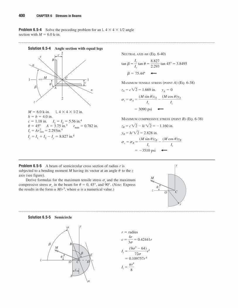
Problem 6.5-4 Solve the preceding problem for an L 4 � 4 � 1/2 anglesection with M � 6.0 k-in.
Solution 6.5-4 Angle section with equal legs
400 CHAPTER 6 Stresses in Beams
M � 6.0 k-in. L 4 � 4 � 1�2 in.h � b � 4.0 in.c � 1.18 in. I1 � I2 � 5.56 in.4
� � 45º A � 3.75 in.2 rmin � 0.782 in.
Iz � I1 � I2 � Iy � 8.827 in.4Iy � Ar 2min � 2.293in.4
2
2
C1 1M
n
n
y
z
c
c
A�
�
B
NEUTRAL AXIS nn (EQ. 6-40)
� � 75.44º
MAXIMUM TENSILE STRESS (POINT A) (EQ. 6-38)
yA � 0
� 3090 psi
MAXIMUM COMPRESSIVE STRESS (POINT B) (EQ. 6-38)
� �3510 psi
sc �sB �(M sin u)zB
Iy
�(M cos u)yB
Iz
yB � h� �2 � 2.828 in.
zB � c�2 � h� �2 � �1.160 in.
st �sA �(M sin u)zA
Iy
�(M cos u)yA
Iz
zA � c�2 � 1.669 in.
tan b�Iz
Iy
tan u�8.827
2.293 tan 45� � 3.8495
Problem 6.5-5 A beam of semicircular cross section of radius r issubjected to a bending moment M having its vector at an angle � to the zaxis (see figure).
Derive formulas for the maximum tensile stress �t and the maximumcompressive stress �c in the beam for � � 0, 45°, and 90°. (Note: Expressthe results in the form � M/r3, where � is a numerical value.)
Solution 6.5-5 Semicircle
r
Oz
y
C
M
�
r � radius
� 0.109757r 4
Iz ��r4
8
Iy �(9s2 � 64)
72sr4
c �4r
3s� 0.42441r
Oz
y
C
M
�
�
�
n
n
B
A
D
E
c
Shear Stresses in Wide-Flange Beams
When solving the problems for Section 6.8, assume that the cross sectionsare thin-walled. Use centerline dimensions for all calculations and derivations, unless otherwise specified
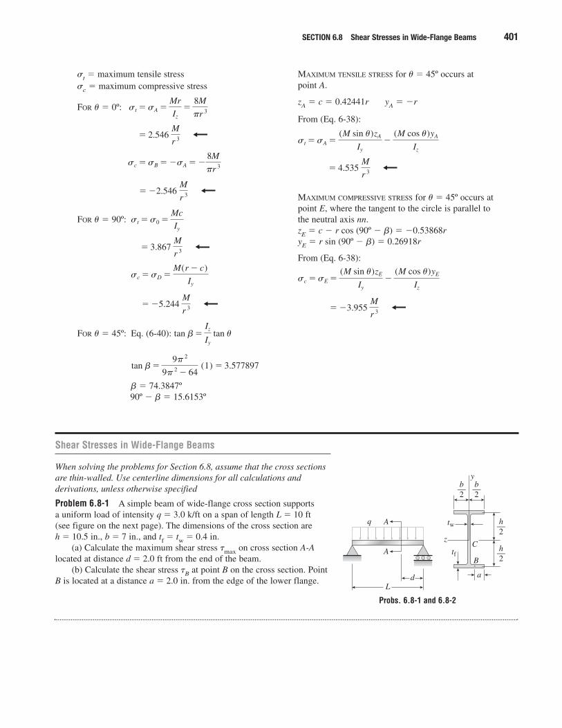
Problem 6.8-1 A simple beam of wide-flange cross section supports a uniform load of intensity q � 3.0 k/ft on a span of length L � 10 ft (see figure on the next page). The dimensions of the cross section are h � 10.5 in., b � 7 in., and tf � tw � 0.4 in.
(a) Calculate the maximum shear stress �max on cross section A-Alocated at distance d � 2.0 ft from the end of the beam.
(b) Calculate the shear stress �B at point B on the cross section. PointB is located at a distance a � 2.0 in. from the edge of the lower flange.
SECTION 6.8 Shear Stresses in Wide-Flange Beams 401
�t � maximum tensile stress�c � maximum compressive stress
FOR � � 0º:
FOR � � 90º:
FOR � � 45º: Eq. (6-40):
� � 74.3847º90º � � � 15.6153º
tan b�9� 2
9� 2 � 64 (1) � 3.577897
tan b�Iz
Iy
tan u
� �5.244 M
r 3
sc �sD �M(r � c)
Iy
� 3.867 M
r 3
st �s0 �Mc
Iy
� �2.546 M
r 3
sc �sB � �sA � �8M
�r 3
� 2.546 M
r 3
st �sA �Mr
Iz
�8M
�r 3
MAXIMUM TENSILE STRESS for � � 45º occurs at point A.
zA � c � 0.42441r yA � �r
From (Eq. 6-38):
MAXIMUM COMPRESSIVE STRESS for � � 45º occurs atpoint E, where the tangent to the circle is parallel tothe neutral axis nn.zE � c � r cos (90º � �) � �0.53868ryE � r sin (90º � �) � 0.26918r
From (Eq. 6-38):
� �3.955 M
r 3
sc �sE �(M sin u)zE
Iy
�(M cos u)yE
Iz
� 4.535 M
r 3
st �sA �(M sin u)zA
Iy
�(M cos u)yA
Iz
A
A
L
q
d a
z
y
C
Btf
tw
b2—b
2—
h2—
h2—
Probs. 6.8-1 and 6.8-2
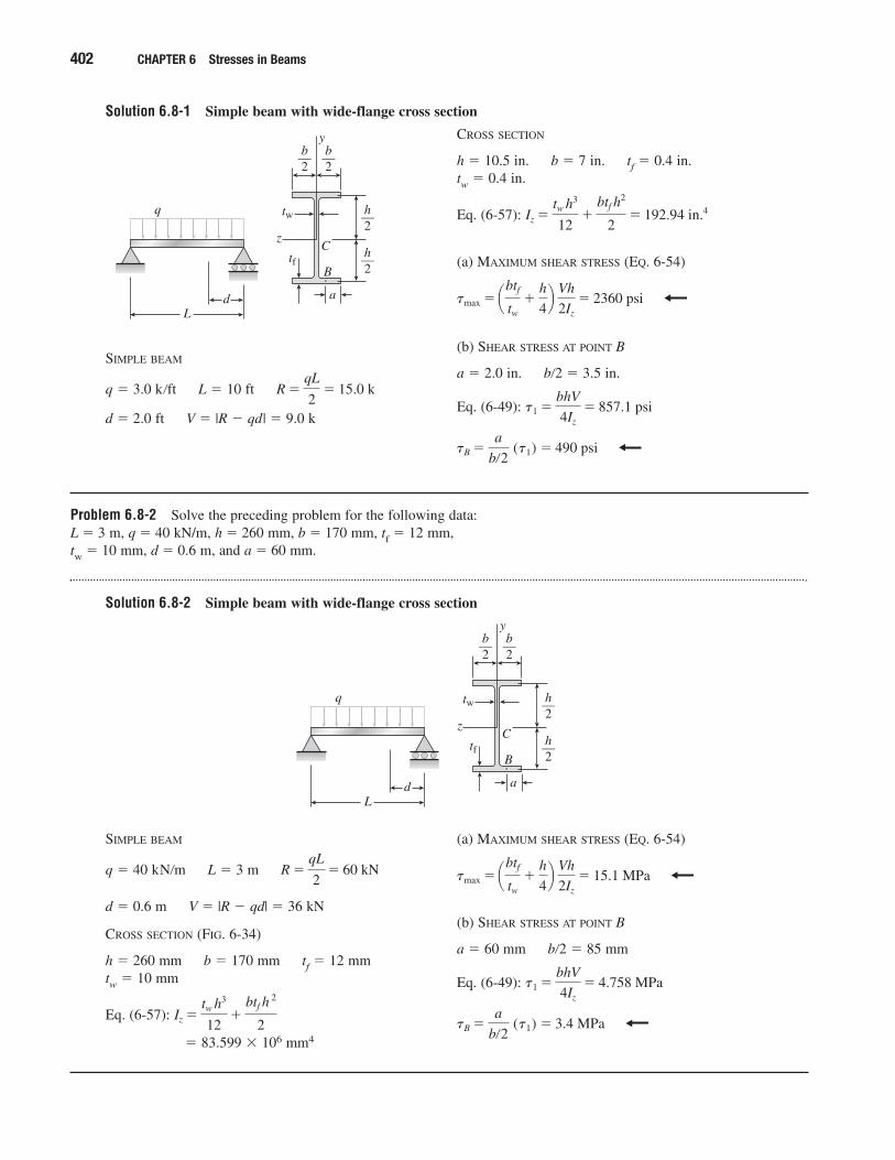
Solution 6.8-1 Simple beam with wide-flange cross section
402 CHAPTER 6 Stresses in Beams
SIMPLE BEAM
q � 3.0 k�ft L � 10 ft
d � 2.0 ft V � |R � qd| � 9.0 k
R �qL
2� 15.0 k
L
q
d a
z
y
C
Btf
tw
b2—b
2—
h2—
h2—
CROSS SECTION
h � 10.5 in. b � 7 in. tf � 0.4 in.tw � 0.4 in.
Eq. (6-57):
(a) MAXIMUM SHEAR STRESS (EQ. 6-54)
(b) SHEAR STRESS AT POINT B
a � 2.0 in. b�2 � 3.5 in.
Eq. (6-49):
tB �a
b�2 (t1) � 490 psi
t1 �bhV
4Iz
� 857.1 psi
tmax � ¢btf
tw
�h
4≤ Vh
2Iz
� 2360 psi
Iz �tw h3
12�
btf h2
2� 192.94 in.4
Problem 6.8-2 Solve the preceding problem for the following data: L � 3 m, q � 40 kN/m, h � 260 mm, b � 170 mm, tf � 12 mm, tw � 10 mm, d � 0.6 m, and a � 60 mm.
Solution 6.8-2 Simple beam with wide-flange cross section
SIMPLE BEAM
q � 40 kN�m L � 3 m
d � 0.6 m V � |R � qd| � 36 kN
CROSS SECTION (FIG. 6-34)
h � 260 mm b � 170 mm tf � 12 mmtw � 10 mm
Eq. (6-57):
� 83.599 � 106 mm4
Iz �tw h3
12�
btf h 2
2
R �qL
2� 60 kN
(a) MAXIMUM SHEAR STRESS (EQ. 6-54)
(b) SHEAR STRESS AT POINT B
a � 60 mm b�2 � 85 mm
Eq. (6-49):
tB �a
b�2 (t1) � 3.4 MPa
t1 �bhV
4Iz
� 4.758 MPa
tmax � ¢btf
tw
�h
4≤ Vh
2Iz
� 15.1 MPa
L
q
d a
z
y
C
Btf
tw
b2—b
2—
h2—
h2—
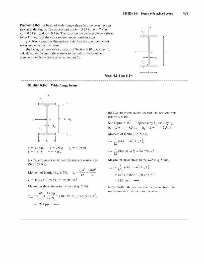
Problem 6.8-3 A beam of wide-flange shape has the cross sectionshown in the figure. The dimensions are b � 5.25 in., h � 7.9 in., tw � 0.25 in., and tf � 0.4 in. The loads on the beam produce a shearforce V � 6.0 k at the cross section under consideration.
(a) Using centerline dimensions, calculate the maximum shear stress in the web of the beam.
(b) Using the more exact analysis of Section 5.10 in Chapter 5, calculate the maximum shear stress in the web of the beam and compare it with the stress obtained in part (a).
Solution 6.8-3 Wide-flange beam
SECTION 6.8 Beams with Inclined Loads 403
b � 5.25 in. h � 7.9 in. tw � 0.25 in.tf � 0.4 in. V � 6.0 k
(a) CALCULATIONS BASED ON CENTERLINE DIMENSIONS
(SECTION 6.8)
Moment of inertia (Eq. 6-59):
Iz � 10.272 � 65.531 � 75.803 in.4
Maximum shear stress in the web (Eq. 6-54):
� 3244 psi
tmax � ¢btf
tw
�h
4≤ Vh
2Iz
� (10.375 in.) (312.65 lb�in.3)
Iz �tw h
3
12�
btf h2
2
(b) CALCULATIONS BASED ON MORE EXACT ANALYSIS
(SECTION 5.10)
See Figure 5-38. Replace h by h2 and t by tw.
h2 � h � tf � 8.3 in. h1 � h � tf � 7.5 in.
Moment of inertia (Eq. 5-47):
Maximum shear stress in the web (Eq. 5-48a):
� (40.336 lb/in.5)(80.422 in.3)
� 3244 psi
NOTE: Within the accuracy of the calculations, themaximum shear stresses are the same.
tmax �V
8Itw
(bh 22 � bh 1
2 � twh 12)
I �1
12 (892.51 in.4) � 74.376 in.4
I �1
12 (bh 2
3 � bh 13 � twh 1
3)
b
hz
y
C
tf
tf
tw
b
h1 h h2z
y
C
tf
tf
tw
Probs. 6.8-3 and 6.8-4
Problem 6.8-4 Solve the preceding problem for the following data: b � 145 mm, h � 250 mm, tw � 8.0 mm, tf � 14.0 mm, and V � 30 kN.
Solution 6.8-4 Wide-flange beam
404 CHAPTER 6 Stresses in Beams
b � 145 mmh � 250 mm
tw � 8.0 mmtf � 14.0 mm
V � 30 kN
(a) CALCULATIONS BASED ON CENTERLINE DIMENSIONS
(SECTION 6.8)
Moment of inertia (Eq. 6-57):
Iz � 10.417 � 106 mm4 � 63.438 � 106 mm4
� 73.855 � 106 mm4
Maximum shear stress in the web (Eq. 6-54):
� (316.25 mm) (0.050775 N/mm3)
� 16.06 MPa
tmax � ¢btf
tw
�h
4≤ Vh
2Iz
Iz �tw h
3
12�
btf h2
2
(b) CALCULATIONS BASED ON MORE EXACT ANALYSIS
(SECTION 5.10)
See Figure 5-38. Replace h by h2 and t by tw.
h2 � h � tf � 264 mm h1 � h � tf � 236 mm
Moment of inertia (Eq. 5-47):
Maximum shear stress in the web (Eq. 5-48a):
� (6.4864 � 10�6 N/mm5)(2.4756 � 106 mm2)
� 16.06 MPa
NOTE: Within the accuracy of the calculations, themaximum shear stresses are the same.
tmax �V
8Itw
(bh 22 � bh 1
2 � twh 12)
I �1
12 (867.20 � 106 mm4) � 72.267 � 106 mm4
I �1
12 (bh 2
3 � bh 13 � twh 1
2)
b
h1 h h2z
y
C
tf
tf
tw
Shear Centers of Thin-Walled Open Sections
When locating the shear centers in the problems for Section 6.9, assumethat the cross sections are thin-walled and use centerline dimensions forall calculations and derivations.
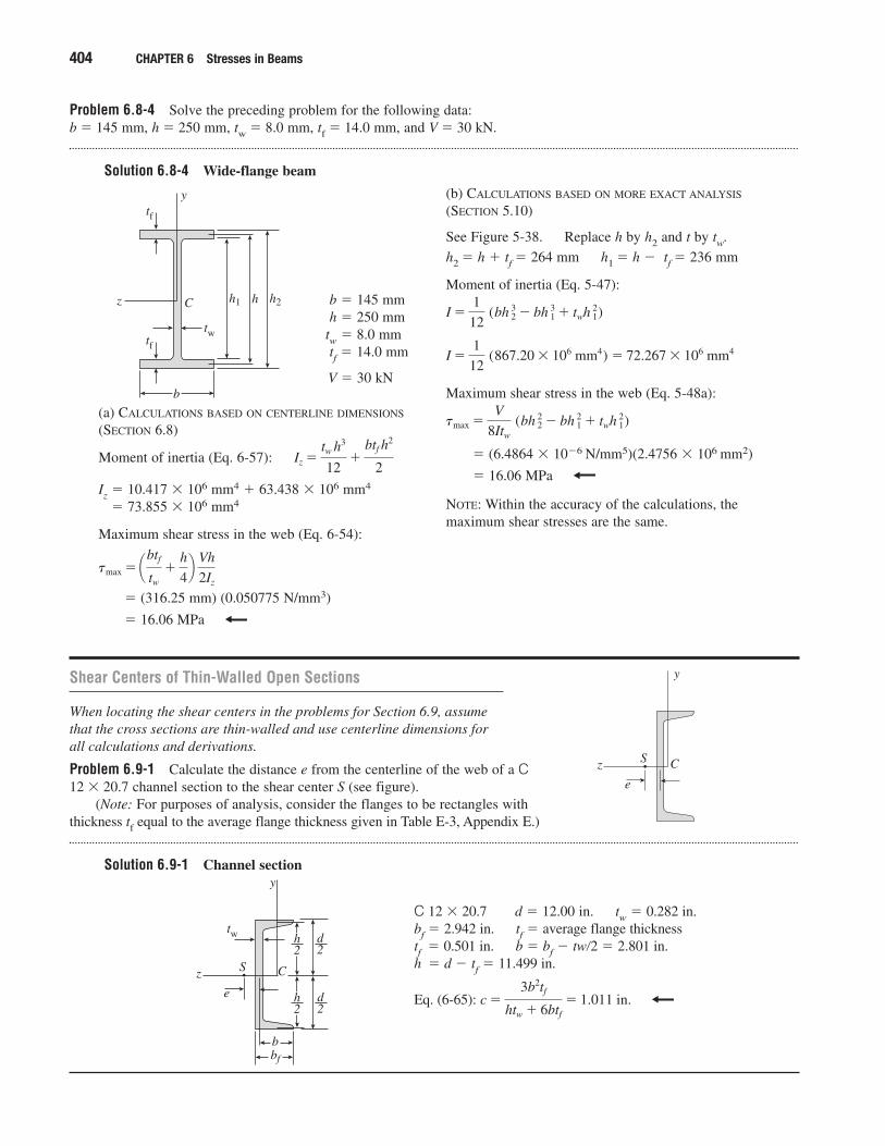
Problem 6.9-1 Calculate the distance e from the centerline of the web of a C12 � 20.7 channel section to the shear center S (see figure).
(Note: For purposes of analysis, consider the flanges to be rectangles withthickness tf equal to the average flange thickness given in Table E-3, Appendix E.)
Solution 6.9-1 Channel section
z
y
CS
e
C 12 � 20.7 d � 12.00 in. tw � 0.282 in.bf � 2.942 in. tf � average flange thicknesstf � 0.501 in. b � bf � tw�2 � 2.801 in.h � d � tf � 11.499 in.
Eq. (6-65): c �3b2tf
htw � 6btf
� 1.011 in.
z
y
CS
e
tw
bf
b
d2
d2
h2
h2
SECTION 6.9 Shear Centers of Thin-Walled Open Sections 405
Problem 6.9-2 Calculate the distance e from the centerline of the web of a C 8 � 18.75 channel section to the shear center S (see figure).
(Note: For purposes of analysis, consider the flanges to be rectangles with thickness tf equal to the average flange thickness given in Table E-3, Appendix E.)
Solution 6.9-2 Channel section
z
y
CS
e
tw
bf
b
d2
d2
h2
h2
C 8 � 18.75 d � 8.00 in. tw � 0.487 in.bf � 2.527 in. tf � average flange thicknesstf � 0.390 in. b � bf � tw/2 � 2.284 in.h � d � tf � 7.610 in.
Eq. (6-65): c �3b2tf
htw � 6btf
� 0.674 in.
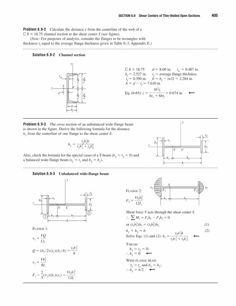
Problem 6.9-3 The cross section of an unbalanced wide-flange beam is shown in the figure. Derive the following formula for the distance h1 from the centerline of one flange to the shear center S:
h1 �
Also, check the formula for the special cases of a T-beam (b2 � t2 � 0) anda balanced wide-flange beam (t2 � t1 and b2 � b1).
Solution 6.9-3 Unbalanced wide-flange beam
t2b32h
��t1b3
1 � t2b32
z
y
CS
t2t1b1
h1 h2
b2
h
FLANGE 1:
F1 �2
3(t1) (b1) (t1) �
Vt1b 13
12Iz
t1 �Vb1
2
8Iz
Q � (b1 �2)(t1) (b1 �4) �t1b 1
2
8
t1 �VQ
Izt1
z
y
CS
t2t1b1
h1 h2
b2
h1
2
FLANGE 2:
Shear force V acts through the shear center S.
�
or (1)
h1 � h2 � h (2)
Solve Eqs. (1) and (2):
T-BEAM
b2 � t2 � 0;� h1 � 0
WIDE-FLANGE BEAM
t2 � t1 and b2 � b1;� h1 � h�2
h1 �t2b 2
3h
t1b 13 � t2b 2
3
(t1b13)h1 � (t2b2
3)h2
aMs � F1h1 � F2h2 � 0
F2 �Vt2b2
3
12Iz
S�2�1
h1 h2
F1 F2
406 CHAPTER 6 Stresses in Beams
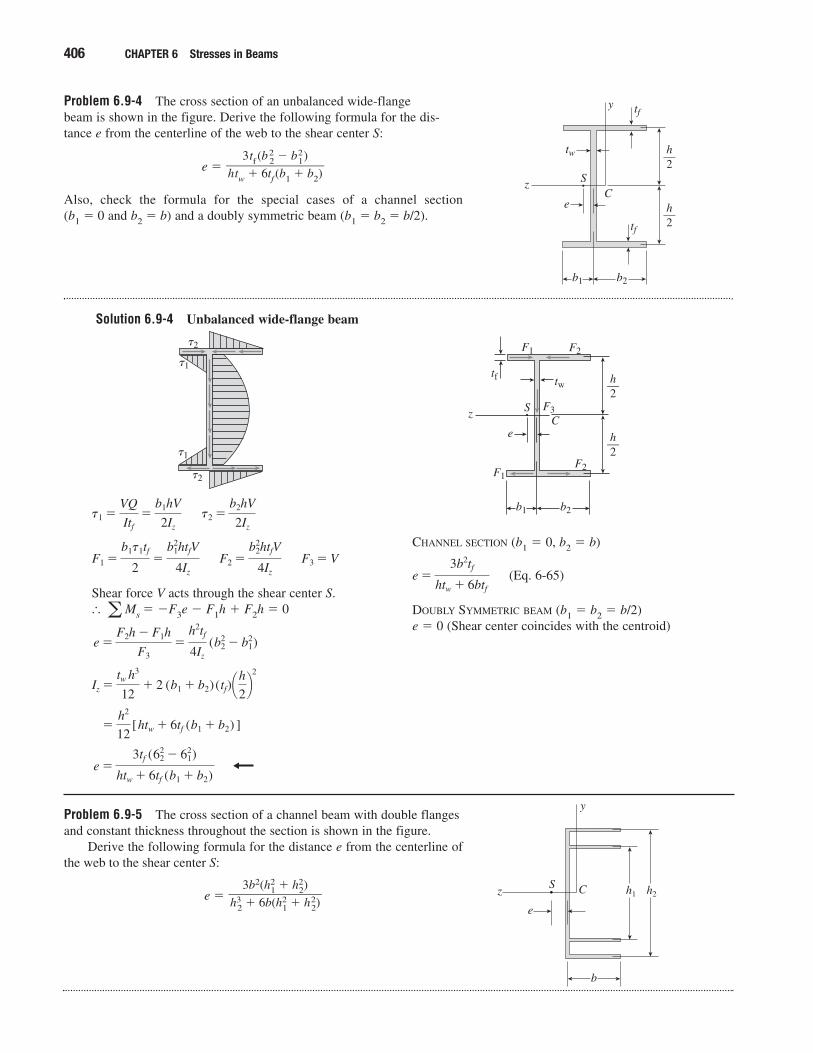
Problem 6.9-4 The cross section of an unbalanced wide-flange beam is shown in the figure. Derive the following formula for the dis-tance e from the centerline of the web to the shear center S:
e �
Also, check the formula for the special cases of a channel section (b1 � 0 and b2 � b) and a doubly symmetric beam (b1 � b2 � b/2).
Solution 6.9-4 Unbalanced wide-flange beam
3tf (b22 � b2
1)��htw � 6tf (b1 � b2)
z
y
CS
tf
tf
tw
b1 b2
e
h2—
h2—
Shear force V acts through the shear center S.� Ms � �F3e � F1h � F2h � 0
e �3tf (62
2 � 621)
htw � 6tf (b1 � b2)
�h2
12[htw � 6tf (b1 � b2) ]
Iz �tw h
3
12� 2 (b1 � b2) (tf)¢h2≤
2
e �F2h � F1h
F3�
h2tf
4Iz
(b22 � b2
1)
a
F3 � VF2 �b2
2htfV
4Iz
F1 �b1t1tf
2�
b21htfV
4Iz
t2 �b2hV
2Iz
t1 �VQ
Itf
�b1hV
2Iz
CHANNEL SECTION (b1 � 0, b2 � b)
(Eq. 6-65)
DOUBLY SYMMETRIC BEAM (b1 � b2 � b/2)e � 0 (Shear center coincides with the centroid)
e �3b2tf
htw � 6btf
�2
�2
�1
�1
z S
tf tw
b1 b2
e
h2—
h2—
F2
F2
F3
F1
F1
C
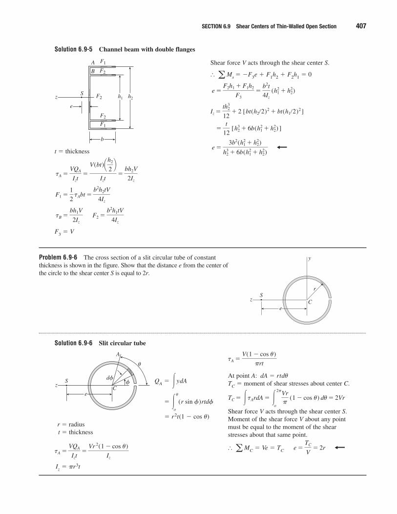
Problem 6.9-5 The cross section of a channel beam with double flangesand constant thickness throughout the section is shown in the figure.
Derive the following formula for the distance e from the centerline ofthe web to the shear center S:
e �3b2(h2
1 � h22)
��h3
2 � 6b(h21 � h2
2)z
y
h2h1CS
e
b
Solution 6.9-5 Channel beam with double flanges
SECTION 6.9 Shear Centers of Thin-Walled Open Section 407
t � thickness
F3 � V
F2 �b2h1tV
4Iz
tB �bh1V
2Iz
F1 �1
2 tAbt �
b2h2tV
4Iz
tA �VQA
Izt�
V(bt)¢h2
2≤
Izt�
bh2V
2Iz
z h2h1F2S
e
b
F1
F1
F2
F2
B
A Shear force V acts through the shear center S.
� Ms � �F3e � F1h2 � F2h1 � 0
e �3b2(h2
1 � h22)
h32 � 6b(h2
1 � h22)
�t
12 [h3
2 � 6b(h21 � h2
2) ]
Iz �th3
2
12� 2 [bt(h2�2)2 � bt(h1�2)2]
e �F2h1 � F1h2
F3�
b2t
4Iz
(h12 � h2
2)
a
Problem 6.9-6 The cross section of a slit circular tube of constantthickness is shown in the figure. Show that the distance e from the center ofthe circle to the shear center S is equal to 2r.
Solution 6.9-6 Slit circular tube
z
e
r
y
CS
QA � ydA
� r2t(1 � cos �)r � radiust � thickness
Iz � �r3t
tA �VQA
Izt�
Vr 2(1 � cos u)
Iz
� �u
o
(r sin f)rtdf
� At point A: dA � rtd�TC � moment of shear stresses about center C.
Shear force V acts through the shear center S.Moment of the shear force V about any pointmust be equal to the moment of the shearstresses about that same point.
� MC � Ve � TC e �TC
V� 2ra
TC � �tArdA � �2�
o
Vr�
(1 � cos u) du� 2Vr
tA �V(1 � cos u)
�rt
z
eC
S
A
d��
�
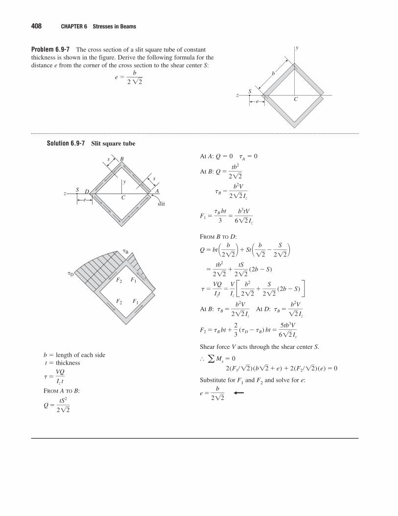
Problem 6.9-7 The cross section of a slit square tube of constantthickness is shown in the figure. Derive the following formula for thedistance e from the corner of the cross section to the shear center S:
e � �2 �
b
2��
Solution 6.9-7 Slit square tube
408 CHAPTER 6 Stresses in Beams
ze
y
CS
b
b � length of each sidet � thickness
FROM A TO B:
Q �tS2
212
t�VQ
Iz t
At A: Q � 0 �A � 0
At B:
FROM B TO D:
At B: At D:
Shear force V acts through the shear center S.
� Ms � 0
Substitute for F1 and F2 and solve for e:
e �b
212
2(F1�12)(b12 � e) � 2(F2�12)(e) � 0a
F2 � tB bt �2
3 (tD � tB) bt �
5tb3V
612 Iz
tB �b2V12 Iz
tB �b2V
212 Iz
t�VQ
Izt�
V
Iz
B b2
212�
S
212 (2b � S) R
�tb2
212�
tS
212 (2b � S)
Q � bt ¢ b
212≤� St ¢ b12
�S
212≤
F1 �tB bt
3�
b3tV
612 Iz
tB �b2V
212 Iz
Q �tb2
212
ze
y
CS
s
s
A
slit
D
B
F2
F2 F1
F1
�B
�D
SECTION 6.9 Shear Centers of Thin-Walled Open Section 409
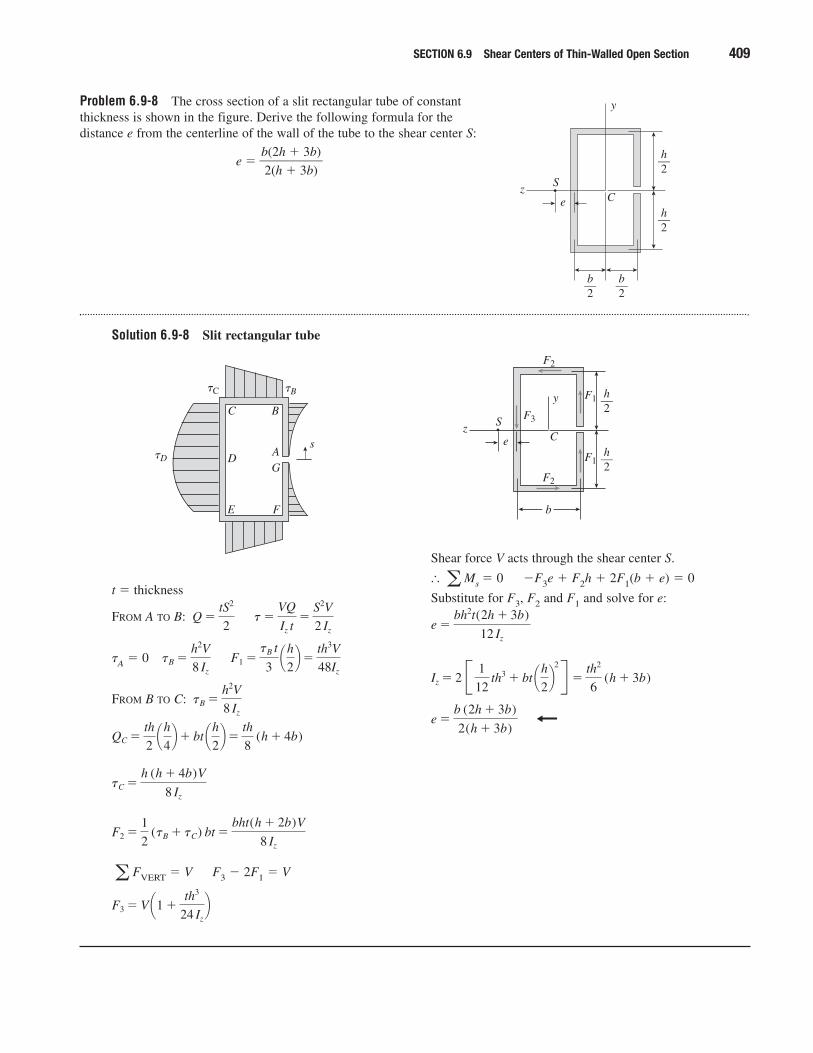
Problem 6.9-8 The cross section of a slit rectangular tube of constantthickness is shown in the figure. Derive the following formula for thedistance e from the centerline of the wall of the tube to the shear center S:
e � �b
2
(
(
2
h
h
�
�
3
3
b
b
)
)�
Solution 6.9-8 Slit rectangular tube
z
y
CS
e
h2—
h2—
b2— b
2—
t � thickness
FROM A TO B:
�A � 0
FROM B TO C:
FVERT � V F3 � 2F1 � V
F3 � V ¢1 �th3
24 Iz
≤a
F2 �1
2 (tB � tC) bt �
bht(h � 2b)V
8 Iz
tC �h (h � 4b)V
8 Iz
QC �th
2 ¢h
4≤� bt ¢h
2≤�
th
8 (h � 4b)
tB �h2V
8 Iz
F1 �tB t
3 ¢h
2≤�
th3V
48Iz
tB �h2V
8 Iz
t�VQ
Iz t�
S2V
2 Iz
Q �tS2
2
Shear force V acts through the shear center S.
� Ms � 0 �F3e � F2h � 2F1(b � e) � 0
Substitute for F3, F2 and F1 and solve for e:
e �b (2h � 3b)
2(h � 3b)
Iz � 2 B 1
12 th3 � bt ¢h
2≤
2R �th2
6 (h � 3b)
e �bh2t(2h � 3b)
12 Iz
a
C B
DAG
E F
�D
�B�C
sz
y
CS
e
h2—
h2—
F3
F2
F2
F1
F1
b
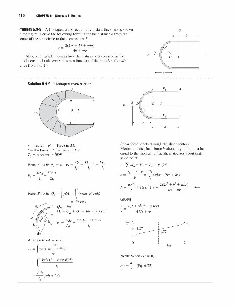
Problem 6.9-9 A U-shaped cross section of constant thickness is shownin the figure. Derive the following formula for the distance e from thecenter of the semicircle to the shear center S:
e ��2(2r2
4�
b �
b2
�
�
r�br)
�
Also, plot a graph showing how the distance e (expressed as thenondimensional ratio e/r) varies as a function of the ratio b/r. (Let b/rrange from 0 to 2.)
Solution 6.9-9 U-shaped cross section
410 CHAPTER 6 Stresses in Beams
z
r
e
b
y
CS
O
r � radius F1 � force in AEt � thickness F2 � force in EFT0 � moment in BDE
FROM A TO B: �A � 0
FROM B TO E:
� r2t sin �QB � btrQe � QB � Q1 � btr � r2t sin �
At angle �: dA � rtd�
�Vr 3t
Iz
(�b � 2r)
� ��
0
Vr 3t (b � r sin u)du
Iz
T0 � �trdA � ��
b
tr 2tdu
te �VQB
Iz t�
Vr (b � r sin u)
Iz
Q1 � �ydA � �u
0
(r cos f) rtdf
F1 �bttB
2�
Vb2rt
2Iz
tB �VQ
Iz t�
V(btr)
Iz t�
Vbr
Iz
Shear force V acts through the shear center S.Moment of the shear force V about any point must beequal to the moment of the shear stresses about thatsame point.
� M0 � Ve � T0 � F1(2r)
GRAPH
NOTE: When b/r � 0,
(Eq. 6-73)e�r �4�
1.27
3
2
1
0
��er
1.72
2.20
2b/r
er
�2(2 � b2�r2 � � b�r)
4 b�r � �
e �2(2r2 � b2 � �br)
4b � �rIz �
�r 3t
2� 2(btr 2)
e �T0 � 2F1r
V�
r 2t
Iz
(�br � 2r 2 � b2)
a
D
B
CO�D
�B
A
E F
z
e
CS O
b
F1
F2
To
E
A
F
D
B
D
B
O
d
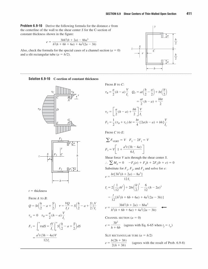
Problem 6.9-10 Derive the following formula for the distance e fromthe centerline of the wall to the shear center S for the C-section ofconstant thickness shown in the figure:
e �
Also, check the formula for the special cases of a channel section (a � 0)and a slit rectangular tube (a � h/2).
Solution 6.9-10 C-section of constant thickness
3bh2(b � 2a) � 8ba3����h2(h � 6b � 6a) � 4a2(2a � 3h)
SECTION 6.9 Shear Centers of Thin-Walled Open Section 411
z
e
b
a
a
y
CS
h2—
h2—
C B
D
A
GE F
�D
�B�Cs
z
y
CSe
F3
F2
F2
F1
F1
b
h
a
a
t � thickness
FROM A TO B:
�A � 0
�a2t (3h � 4a)V
12 Iz
F1 � �a
0
ttdS �tV
Iz�
a
0
S ¢h2
� a �S
2≤ dS
tB �a
2 (h � a)
V
Iz
t�VQ
Iz t� S ¢h
2� a �
S
2≤
V
Iz
Q � St ¢h2
� a �S
2≤
FROM B TO C:
FROM C TO E:
FVERT � V F3 � 2F1 � V
Shear force V acts through the shear center S.
� MS � 0 �F3(e) � F2h � 2F1(b � e) � 0
Substitute for F1, F2, and F3 and solve for e:
CHANNEL SECTION (a � 0)
(agrees with Eq. 6-65 when tf � tw)
SLIT RECTANGULAR TUBE (a � h�2)
(agrees with the result of Prob. 6.9-8)e �b(2h � 3b)
2(h � 3b)
e �3b2
h � 6b
e �3bh2(b � 2a) � 8ba3
h2(h � 6b � 6a) � 4a2(2a � 3h)
�t
12[h2(h � 6b � 6a) � 4a2(2a � 3h) ]
Iz � 2 ¢ 1
12 th3≤� 2bt ¢h
2≤
2
�6
12 (h � 2a)3
e �bt[3h2(b � 2a) � 8a3 ]
12 Iz
a
F3 � VB1 �a2t (3h � 4a)
6 Iz
Ra
F2 �1
2 (tB � tC) bt �
bt
4 [2a(h � a) � bh ]
V
Iz
tC � B a
2 (h � a) �
bh
2R
V
Iz
�at
2 (h � a) �
bht
2
QC � at ¢h2
�a
2≤� bt ¢h
2≤tB �
a
2 (h � a)
V
Iz
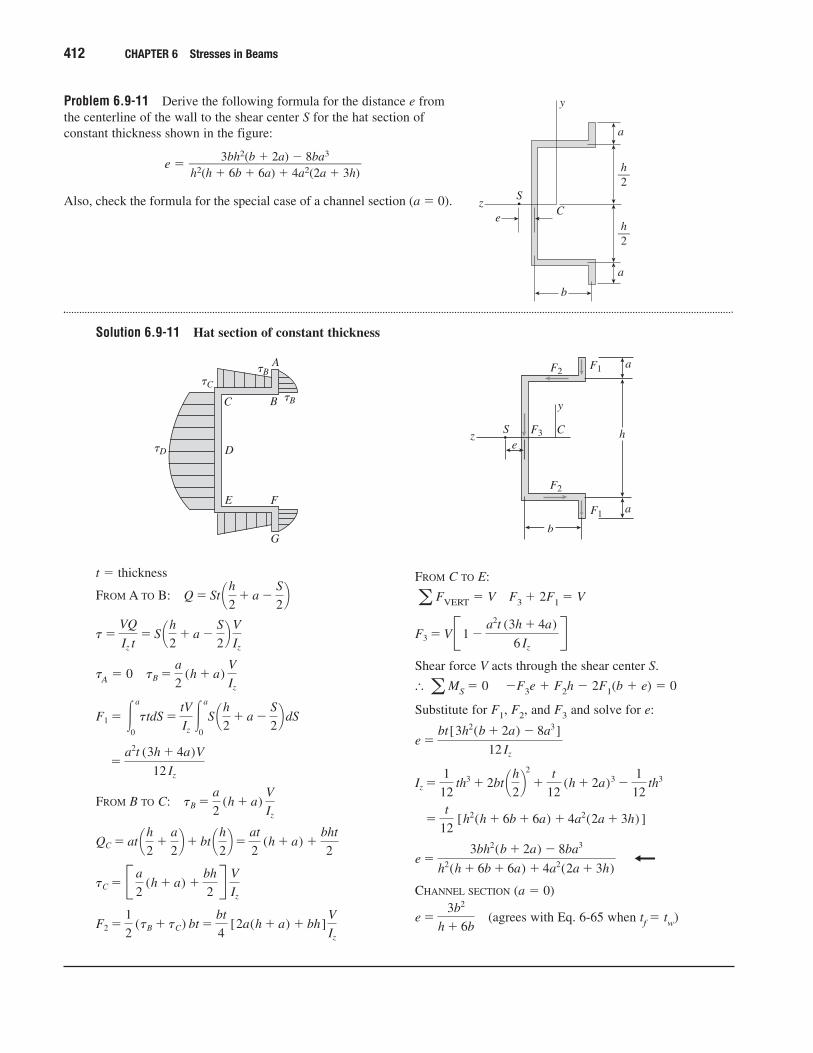
Problem 6.9-11 Derive the following formula for the distance e fromthe centerline of the wall to the shear center S for the hat section ofconstant thickness shown in the figure:
e �
Also, check the formula for the special case of a channel section (a � 0).
Solution 6.9-11 Hat section of constant thickness
3bh2(b � 2a) � 8ba3����h2(h � 6b � 6a) � 4a2(2a � 3h)
412 CHAPTER 6 Stresses in Beams
z
a
a
b
y
CS
e
h2—
h2—
�C
�B
�B
�D
C B
A
D
E F
G
z
y
CSe
F3
F2
F2
F1
F1
b
h
a
a
t � thickness
FROM A TO B:
�A � 0
FROM B TO C:
F2 �1
2 (tB � tC) bt �
bt
4 [2a(h � a) � bh ]
V
Iz
tC � B a
2 (h � a) �
bh
2R
V
Iz
QC � at ¢h2
�a
2≤� bt ¢h
2≤�
at
2 (h � a) �
bht
2
tB �a
2 (h � a)
V
Iz
�a2t (3h � 4a)V
12 Iz
F1 � �a
0
ttdS �tV
Iz�
a
0
S ¢h2
� a �S
2≤ dS
tB �a
2 (h � a)
V
Iz
t�VQ
Iz t� S ¢h
2� a �
S
2≤
V
Iz
Q � St ¢h2
� a �S
2≤
FROM C TO E:
FVERT � V F3 � 2F1 � V
Shear force V acts through the shear center S.
� MS � 0 �F3e � F2h � 2F1(b � e) � 0
Substitute for F1, F2, and F3 and solve for e:
CHANNEL SECTION (a � 0)
(agrees with Eq. 6-65 when tf � tw)e �3b2
h � 6b
e �3bh2(b � 2a) � 8ba3
h2(h � 6b � 6a) � 4a2(2a � 3h)
�t
12 [h2(h � 6b � 6a) � 4a2(2a � 3h) ]
Iz �1
12 th3 � 2bt ¢h
2≤
2
�t
12 (h � 2a)3 �
1
12 th3
e �bt[3h2(b � 2a) � 8a3 ]
12 Iz
a
F3 � VB1 �a2t (3h � 4a)
6 Iz
Ra
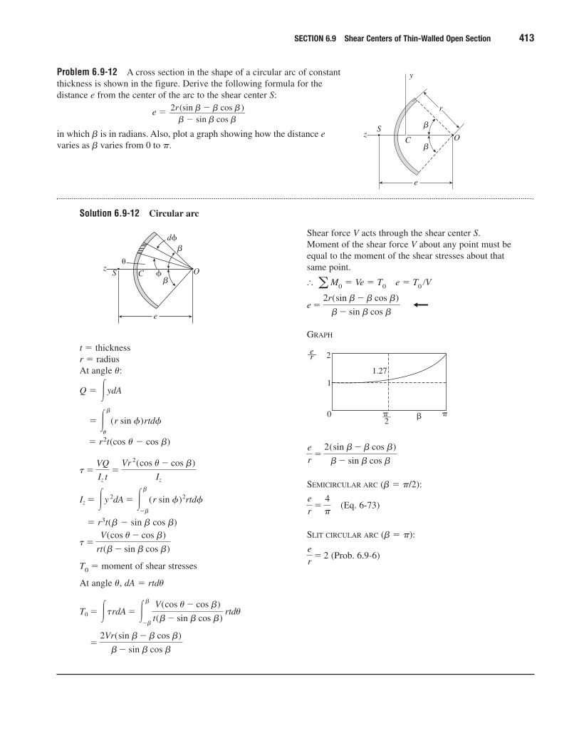
Problem 6.9-12 A cross section in the shape of a circular arc of constantthickness is shown in the figure. Derive the following formula for thedistance e from the center of the arc to the shear center S:
e �
in which � is in radians. Also, plot a graph showing how the distance evaries as � varies from 0 to �.
Solution 6.9-12 Circular arc
2r(sin � � � cos �)���
� � sin � cos �
SECTION 6.9 Shear Centers of Thin-Walled Open Section 413
z
e
y
r
CS
O
�
�
t � thicknessr � radiusAt angle �:
Q � ydA
� r2t(cos � � cos �)
� r3t(� � sin � cos �)
T0 � moment of shear stresses
At angle �, dA � rtd�
�2Vr(sin b� b cos b)
b� sin b cos b
T0 � �trdA � �b
�b
V(cos u� cos b)
t(b� sin b cos b) rtdu
t�V(cos u� cos b)
rt(b� sin b cos b)
Iz � �y 2dA � �b
�b
(r sin f)2rtdf
t�VQ
Iz t�
Vr 2(cos u� cos b)
Iz
� �b
u
(r sin f)rtdf
�
z
e
d
CS O�
�
Shear force V acts through the shear center S.Moment of the shear force V about any point must beequal to the moment of the shear stresses about thatsame point.
� M0 � Ve � T0 e � T0 �V
GRAPH
SEMICIRCULAR ARC (� � �/2):
(Eq. 6-73)
SLIT CIRCULAR ARC (� � �):
(Prob. 6.9-6)er
� 2
er
�4�
er
�2(sin b� b cos b)
b� sin b cos b
�� 2
���
1.27
0
1
2��er
e �2r(sin b� b cos b)
b� sin b cos b
a
Elastoplastic Bending
The problems for Section 6.10 are to be solved using the assumption thatthe material is elastoplastic with yield stress �Y.
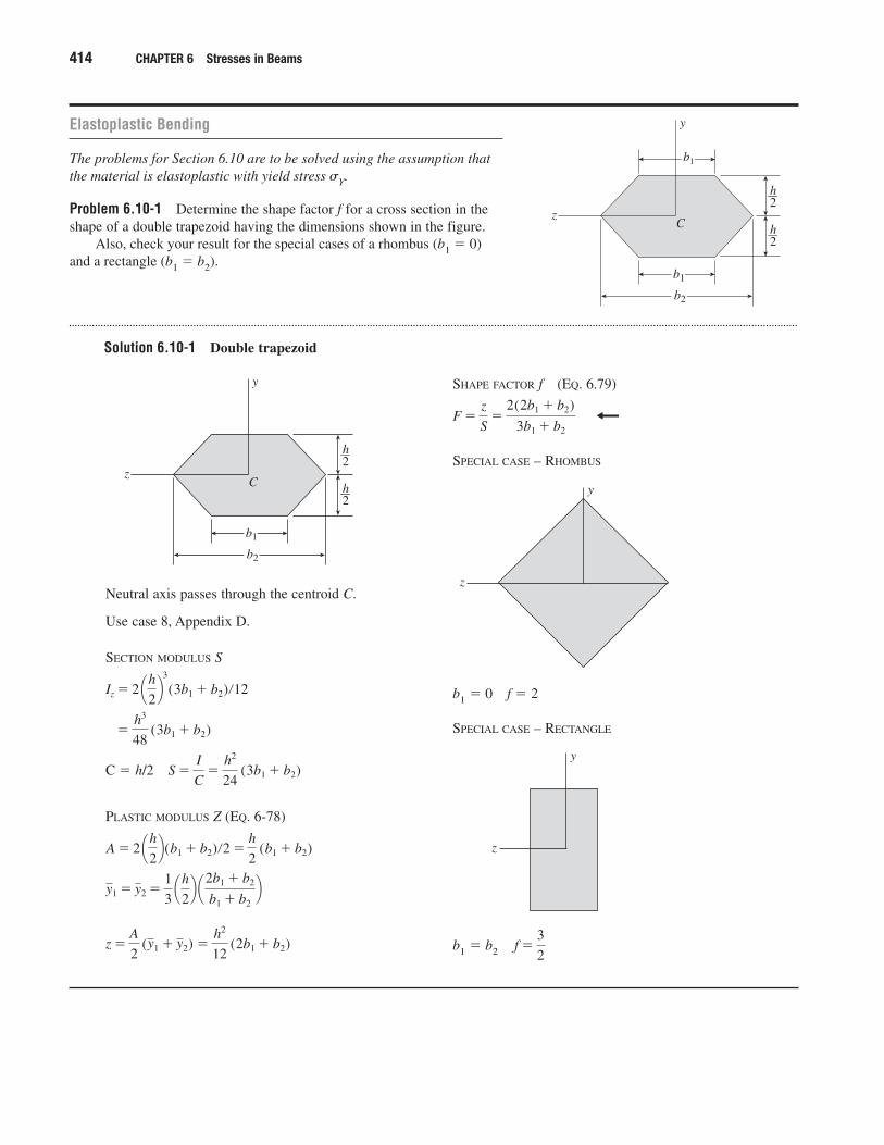
Problem 6.10-1 Determine the shape factor f for a cross section in the shape of a double trapezoid having the dimensions shown in the figure.
Also, check your result for the special cases of a rhombus (b1 � 0)and a rectangle (b1 � b2).
Solution 6.10-1 Double trapezoid
414 CHAPTER 6 Stresses in Beams
z
y
h2—
h2—
C
b2
b1
b1
Neutral axis passes through the centroid C.
Use case 8, Appendix D.
SECTION MODULUS S
C � h/2
PLASTIC MODULUS Z (EQ. 6-78)
z �A
2 (y1 � y2) �
h2
12 (2b1 � b2)
y1 � y2 �1
3 ¢h
2≤ ¢2b1 � b2
b1 � b2≤
A � 2 ¢h2≤(b1 � b2)�2 �
h
2 (b1 � b2)
S �I
C�
h2
24 (3b1 � b2)
�h3
48 (3b1 � b2)
Iz � 2 ¢h2≤
3
(3b1 � b2)�12
z
y
h2—
h2—
C
b2
b1
SHAPE FACTOR f (EQ. 6.79)
SPECIAL CASE – RHOMBUS
b1 � 0 f � 2
SPECIAL CASE – RECTANGLE
b1 � b2 f �3
2
z
y
z
y
F �z
S�
2(2b1 � b2)
3b1 � b2
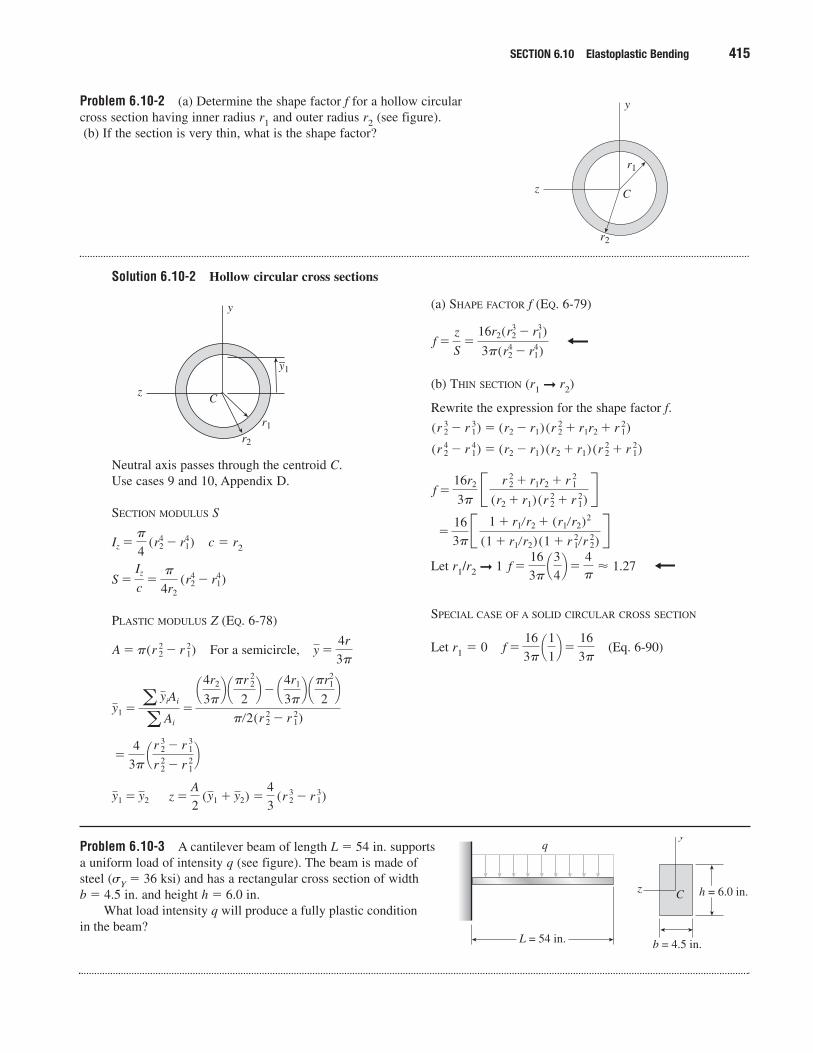
Problem 6.10-2 (a) Determine the shape factor f for a hollow circularcross section having inner radius r1 and outer radius r2 (see figure).(b) If the section is very thin, what is the shape factor?
Solution 6.10-2 Hollow circular cross sections
SECTION 6.10 Elastoplastic Bending 415
z
y
C
r1
r2
Neutral axis passes through the centroid C.Use cases 9 and 10, Appendix D.
SECTION MODULUS S
c � r2
PLASTIC MODULUS Z (EQ. 6-78)
For a semicircle,
z �A
2 (y1 � y2) �
4
3 (r 32 � r 31)y1 � y2
�4
3� ¢r 32 � r 31
r 22 � r 21≤
y1 �a yiAi
a Ai
�
¢4r2
3�≤ ¢�r 22
2≤� ¢4r1
3�≤ ¢�r2
1
2≤
��2(r 22 � r 21)
y �4r
3�A � �(r 22 � r 21)
S �Iz
c�
�
4r2 (r2
4 � r14)
Iz ��
4 (r4
2 � r41)
z
y
C
r1
r2
y1�
(a) SHAPE FACTOR f (EQ. 6-79)
(b) THIN SECTION (r1 ➞ r2)
Rewrite the expression for the shape factor f.
Let r1/r2 ➞ 1
SPECIAL CASE OF A SOLID CIRCULAR CROSS SECTION
Let r1 � 0 (Eq. 6-90)f �16
3� ¢1
1≤�
16
3�
f �16
3� ¢3
4≤�
4�
� 1.27
�16
3�B 1 � r1�r2 � (r1�r2)2
(1 � r1�r2) (1 � r 21�r 22)R
f �16r2
3� B r 22 � r1r2 � r 21
(r2 � r1) (r 22 � r 21)R
(r 42 � r 41) � (r2 � r1) (r2 � r1) (r 22 � r 21)
(r 32 � r 31) � (r2 � r1) (r 22 � r1r2 � r 21)
f �z
S�
16r2(r32 � r3
1)
3�(r42 � r4
1)
Problem 6.10-3 A cantilever beam of length L � 54 in. supports a uniform load of intensity q (see figure). The beam is made of steel (�Y � 36 ksi) and has a rectangular cross section of width b � 4.5 in. and height h � 6.0 in.
What load intensity q will produce a fully plastic condition in the beam?
L = 54 in.
q
z
y
C h = 6.0 in.
b = 4.5 in.
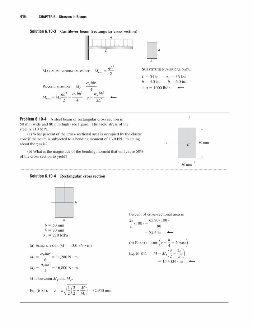
Solution 6.10-3 Cantilever beam (rectangular cross section)
416 CHAPTER 6 Stresses in Beams
MAXIMUM BENDING MOMENT:
PLASTIC MOMENT:
Mmax � MP
qL2
2�sy bh2
4� q �
sy bh2
2L2
MP �sy bh2
4
Mmax �qL2
2SUBSTITUTE NUMERICAL DATA:
L � 54 in. �Y � 36 ksib � 4.5 in. h � 6.0 in.
� q � 1000 lb/in.
L
q
h
b
Problem 6.10-4 A steel beam of rectangular cross section is 50 mm wide and 80 mm high (see figure). The yield stress of the steel is 210 MPa.
(a) What percent of the cross-sectional area is occupied by the elasticcore if the beam is subjected to a bending moment of 13.0 kN m actingabout the z axis?
(b) What is the magnitude of the bending moment that will cause 50%of the cross section to yield?
Solution 6.10-4 Rectangular cross section
z
y
C
50 mm
80 mm
b � 50 mmh � 80 mm
�Y � 210 MPa
(a) ELASTIC CORE (M � 13.0 kN � m)
M is between MY and MP.
Eq. (6-85): e � hB1
2 ¢3
2�
M
My
≤� 32.950 mm
MP �sY bh2
4� 16,800 N � ˇm
MY �sY bh2
6� 11,200 N � ˇm
b
h
Percent of cross-sectional area is
� 82.4 %
(b) ELASTIC CORE
Eq. (6-84):
� 15.4 kN � m
M � MY ¢32
�2e2
h2 ≤¢e �
h
4� 20 ≤
2e
h (100) �
65.90 (100)
80
MM
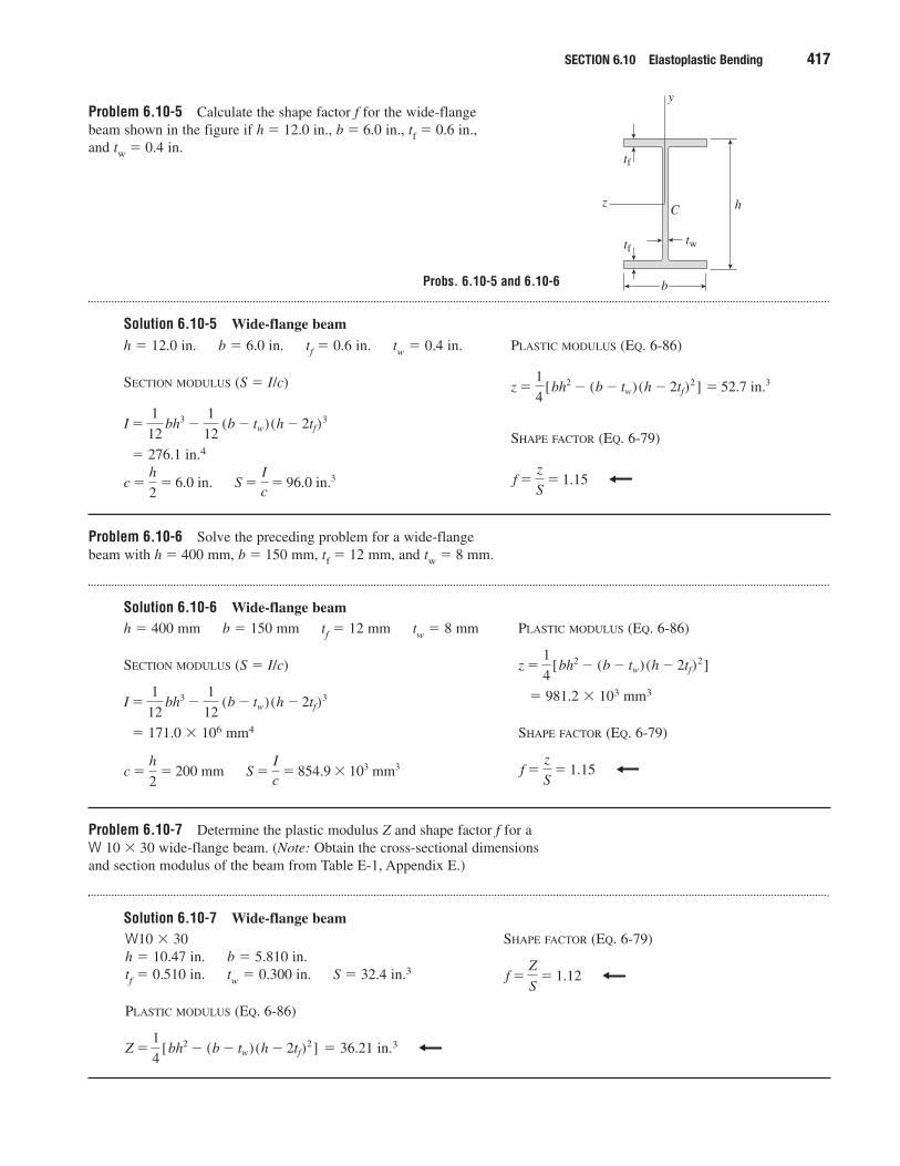
Problem 6.10-5 Calculate the shape factor f for the wide-flange beam shown in the figure if h � 12.0 in., b � 6.0 in., tf � 0.6 in., and tw � 0.4 in.
Solution 6.10-5 Wide-flange beam
SECTION 6.10 Elastoplastic Bending 417
z
y
C
tf
tftw
h
b
h � 12.0 in. b � 6.0 in. tf � 0.6 in. tw � 0.4 in.
SECTION MODULUS (S � I/c)
� 276.1 in.4
S �Ic
� 96.0 in.3c �h
2� 6.0 in.
I �1
12 bh3 �
1
12 (b � tw)(h � 2tf)
3
PLASTIC MODULUS (EQ. 6-86)
SHAPE FACTOR (EQ. 6-79)
f �z
S� 1.15
z �1
4[bh2 � (b � tw)(h � 2tf)
2 ] � 52.7 in.3
Problem 6.10-6 Solve the preceding problem for a wide-flange beam with h � 400 mm, b � 150 mm, tf � 12 mm, and tw � 8 mm.
Solution 6.10-6 Wide-flange beamh � 400 mm b � 150 mm tf � 12 mm tw � 8 mm
SECTION MODULUS (S � I/c)
� 171.0 � 106 mm4
S �Ic
� 854.9 � 103 mm3c �h
2� 200 mm
I �1
12 bh3 �
1
12 (b � tw)(h � 2tf)
3
PLASTIC MODULUS (EQ. 6-86)
� 981.2 � 103 mm3
SHAPE FACTOR (EQ. 6-79)
f �z
S� 1.15
z �1
4[bh2 � (b � tw)(h � 2tf)
2 ]
Problem 6.10-7 Determine the plastic modulus Z and shape factor f for a W 10 � 30 wide-flange beam. (Note: Obtain the cross-sectional dimensions and section modulus of the beam from Table E-1, Appendix E.)
Solution 6.10-7 Wide-flange beamW10 � 30h � 10.47 in. b � 5.810 in.tf � 0.510 in. tw � 0.300 in. S � 32.4 in.3
PLASTIC MODULUS (EQ. 6-86)
� 36.21 in.3Z �1
4[bh2 � (b � tw)(h � 2tf)
2 ]
SHAPE FACTOR (EQ. 6-79)
f �Z
S� 1.12
Probs. 6.10-5 and 6.10-6
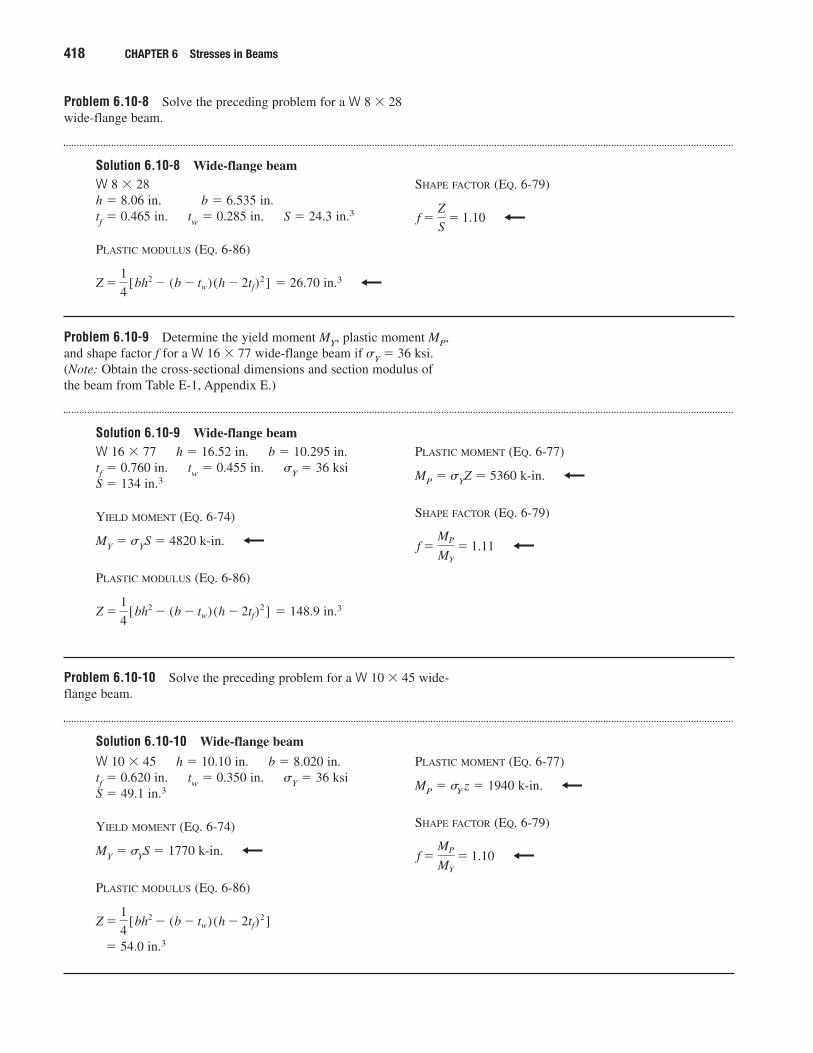
Problem 6.10-8 Solve the preceding problem for a W 8 � 28 wide-flange beam.
Solution 6.10-8 Wide-flange beam
418 CHAPTER 6 Stresses in Beams
W 8 � 28h � 8.06 in. b � 6.535 in.tf � 0.465 in. tw � 0.285 in. S � 24.3 in.3
PLASTIC MODULUS (EQ. 6-86)
� 26.70 in.3Z �1
4[bh2 � (b � tw)(h � 2tf)
2 ]
SHAPE FACTOR (EQ. 6-79)
f �Z
S� 1.10
Problem 6.10-9 Determine the yield moment MY, plastic moment MP,and shape factor f for a W 16 � 77 wide-flange beam if �Y � 36 ksi.(Note: Obtain the cross-sectional dimensions and section modulus of the beam from Table E-1, Appendix E.)
Solution 6.10-9 Wide-flange beamW 16 � 77 h � 16.52 in. b � 10.295 in.tf � 0.760 in. tw � 0.455 in. �Y � 36 ksiS � 134 in.3
YIELD MOMENT (EQ. 6-74)
MY � �YS � 4820 k-in.
PLASTIC MODULUS (EQ. 6-86)
� 148.9 in.3Z �1
4[bh2 � (b � tw)(h � 2tf)
2 ]
PLASTIC MOMENT (EQ. 6-77)
MP � �YZ � 5360 k-in.
SHAPE FACTOR (EQ. 6-79)
f �MP
MY
� 1.11
Problem 6.10-10 Solve the preceding problem for a W 10 � 45 wide-flange beam.
Solution 6.10-10 Wide-flange beam
W 10 � 45 h � 10.10 in. b � 8.020 in.tf � 0.620 in. tw � 0.350 in. �Y � 36 ksiS � 49.1 in.3
YIELD MOMENT (EQ. 6-74)
MY � �YS � 1770 k-in.
PLASTIC MODULUS (EQ. 6-86)
� 54.0 in.3
Z �1
4[bh2 � (b � tw)(h � 2tf)
2 ]
PLASTIC MOMENT (EQ. 6-77)
MP � �Y z � 1940 k-in.
SHAPE FACTOR (EQ. 6-79)
f �MP
MY
� 1.10
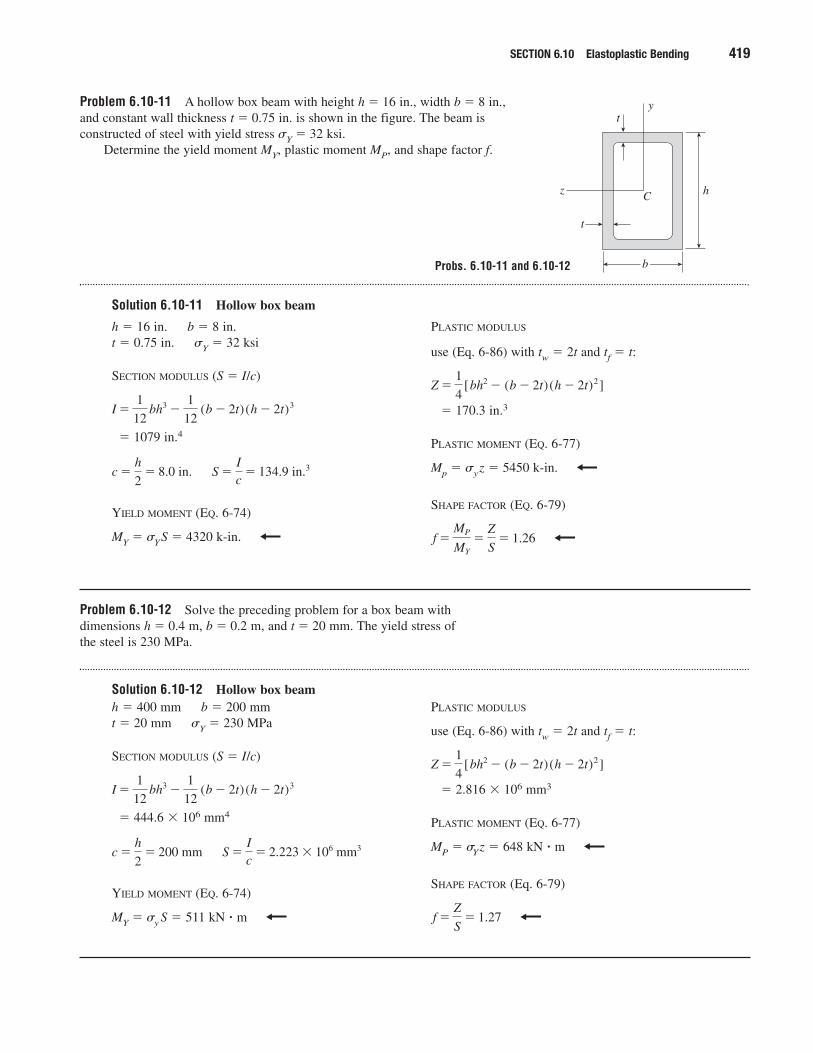
Problem 6.10-11 A hollow box beam with height h � 16 in., width b � 8 in.,and constant wall thickness t � 0.75 in. is shown in the figure. The beam isconstructed of steel with yield stress �Y � 32 ksi.
Determine the yield moment MY, plastic moment MP, and shape factor f.
Solution 6.10-11 Hollow box beam
SECTION 6.10 Elastoplastic Bending 419
z
y
C
t
t
h
b
h � 16 in. b � 8 in.t � 0.75 in. �Y � 32 ksi
SECTION MODULUS (S � I/c)
� 1079 in.4
YIELD MOMENT (EQ. 6-74)
MY � �YS � 4320 k-in.
S �Ic
� 134.9 in.3c �h
2� 8.0 in.
I �1
12 bh3 �
1
12 (b � 2t)(h � 2t)3
PLASTIC MODULUS
use (Eq. 6-86) with tw � 2t and tf � t:
� 170.3 in.3
PLASTIC MOMENT (EQ. 6-77)
Mp � �yz � 5450 k-in.
SHAPE FACTOR (EQ. 6-79)
f �MP
MY
�Z
S� 1.26
Z �1
4[bh2 � (b � 2t)(h � 2t)2 ]
Problem 6.10-12 Solve the preceding problem for a box beam withdimensions h � 0.4 m, b � 0.2 m, and t � 20 mm. The yield stress of the steel is 230 MPa.
Solution 6.10-12 Hollow box beamh � 400 mm b � 200 mmt � 20 mm �Y � 230 MPa
SECTION MODULUS (S � I/c)
� 444.6 � 106 mm4
YIELD MOMENT (EQ. 6-74)
MY � �y S � 511 kN � m
S �Ic
� 2.223 � 106 mm3c �h
2� 200 mm
I �1
12 bh3 �
1
12 (b � 2t)(h � 2t)3
PLASTIC MODULUS
use (Eq. 6-86) with tw � 2t and tf � t:
� 2.816 � 106 mm3
PLASTIC MOMENT (EQ. 6-77)
MP � �Yz � 648 kN � m
SHAPE FACTOR (Eq. 6-79)
f �Z
S� 1.27
Z �1
4[bh2 � (b � 2t)(h � 2t)2 ]
Probs. 6.10-11 and 6.10-12
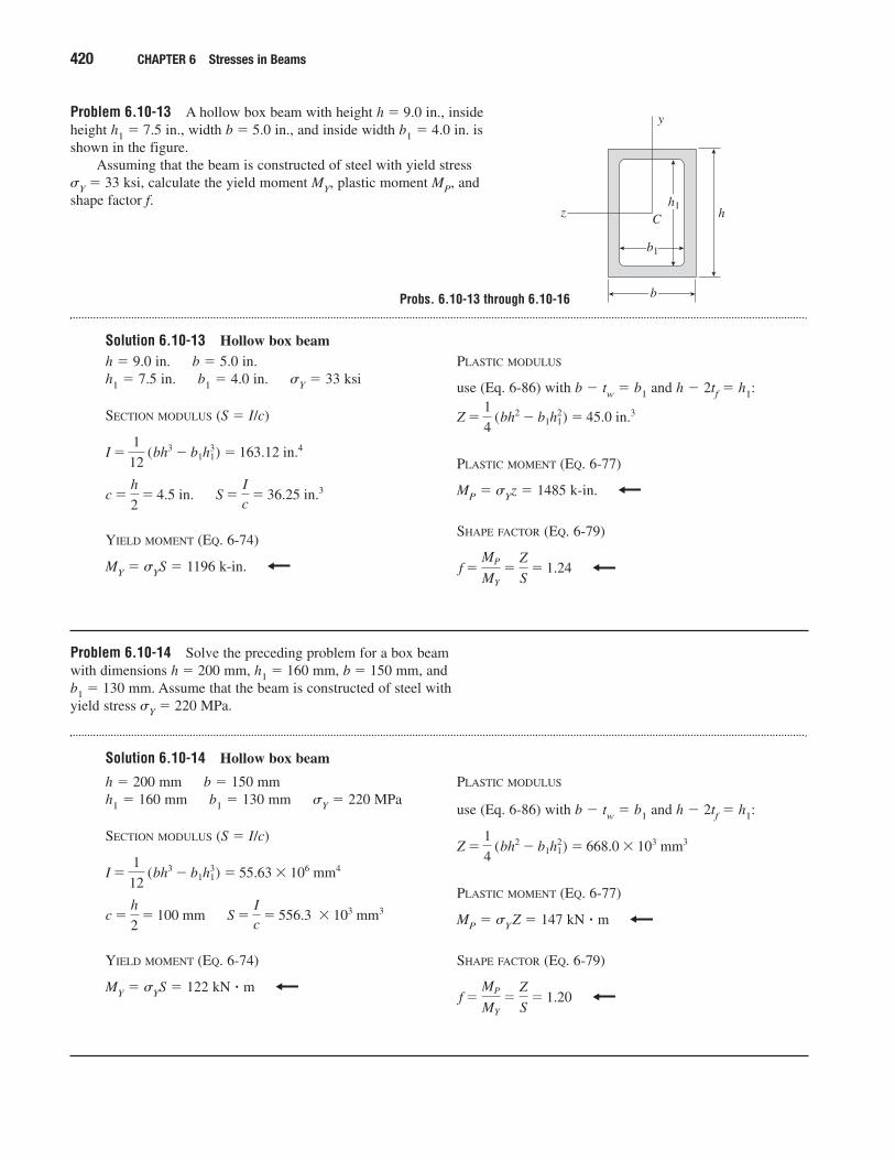
Problem 6.10-13 A hollow box beam with height h � 9.0 in., insideheight h1 � 7.5 in., width b � 5.0 in., and inside width b1 � 4.0 in. isshown in the figure.
Assuming that the beam is constructed of steel with yield stress �Y � 33 ksi, calculate the yield moment MY, plastic moment MP, andshape factor f.
Solution 6.10-13 Hollow box beam
420 CHAPTER 6 Stresses in Beams
z
y
C hh1
b1
b
h � 9.0 in. b � 5.0 in.h1 � 7.5 in. b1 � 4.0 in. �Y � 33 ksi
SECTION MODULUS (S � I/c)
YIELD MOMENT (EQ. 6-74)
MY � �YS � 1196 k-in.
S �Ic
� 36.25 in.3c �h
2� 4.5 in.
I �1
12 (bh3 � b1h1
3) � 163.12 in.4
PLASTIC MODULUS
use (Eq. 6-86) with b � tw � b1 and h � 2tf � h1:
PLASTIC MOMENT (EQ. 6-77)
MP � �Yz � 1485 k-in.
SHAPE FACTOR (EQ. 6-79)
f �MP
MY
�Z
S� 1.24
Z �1
4 (bh2 � b1h1
2) � 45.0 in.3
Problem 6.10-14 Solve the preceding problem for a box beam with dimensions h � 200 mm, h1 � 160 mm, b � 150 mm, and b1 � 130 mm. Assume that the beam is constructed of steel with yield stress �Y � 220 MPa.
Solution 6.10-14 Hollow box beam
h � 200 mm b � 150 mmh1 � 160 mm b1 � 130 mm �Y � 220 MPa
SECTION MODULUS (S � I/c)
YIELD MOMENT (EQ. 6-74)
MY � �YS � 122 kN � m
S �Ic
� 556.3 � 103 mm3c �h
2� 100 mm
I �1
12 (bh3 � b1h1
3) � 55.63 � 106 mm4
PLASTIC MODULUS
use (Eq. 6-86) with b � tw � b1 and h � 2tf � h1:
PLASTIC MOMENT (EQ. 6-77)
MP � �YZ � 147 kN � m
SHAPE FACTOR (EQ. 6-79)
f �MP
MY
�Z
S� 1.20
Z �1
4 (bh2 � b1h1
2) � 668.0 � 103 mm3
Probs. 6.10-13 through 6.10-16
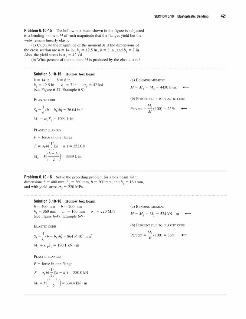
Problem 6.10-15 The hollow box beam shown in the figure is subjectedto a bending moment M of such magnitude that the flanges yield but thewebs remain linearly elastic.
(a) Calculate the magnitude of the moment M if the dimensions ofthe cross section are h � 14 in., h1 � 12.5 in., b � 8 in., and b1 � 7 in.Also, the yield stress is �Y � 42 ksi.
(b) What percent of the moment M is produced by the elastic core?
Solution 6.10-15 Hollow box beam
SECTION 6.10 Elastoplastic Bending 421
h � 14 in. b � 8 in.h1 � 12.5 in. b1 � 7 in. �Y � 42 ksi(see Figure 6-47, Example 6-9)
ELASTIC CORE
M1 � �Y S1 � 1094 k-in.
PLASTIC FLANGES
F � force in one flange
M2 � F ¢h � h1
2≤� 3339 k-in.
F �sY b ¢12≤(h � h1) � 252.0 k
S1 �1
6 (b � b1)h2
1 � 26.04 in.3
(a) BENDING MOMENT
M � M1 � M2 � 4430 k-in.
(b) PERCENT DUE TO ELASTIC CORE
Percent �M1
M (100) � 25%
Problem 6.10-16 Solve the preceding problem for a box beam withdimensions h � 400 mm, h1 � 360 mm, b � 200 mm, and b1 � 160 mm,and with yield stress �Y � 220 MPa.
Solution 6.10-16 Hollow box beamh � 400 mm b � 200 mmh1 � 360 mm b1 � 160 mm �Y � 220 MPa(see Figure 6-47, Example 6-9)
ELASTIC CORE
M1 � �YS1 � 190.1 kN � m
PLASTIC FLANGES
F � force in one flange
M2 � F ¢h � h1
2≤� 334.4 kN � ˇm
F �sY b ¢12≤(h � h1) � 880.0 kN
S1 �1
6 (b � b1)h2
1 � 864 � 103 mm3
(a) BENDING MOMENT
M � M1 � M2 � 524 kN � m
(b) PERCENT DUE TO ELASTIC CORE
Percent �M1
M (100) � 36%
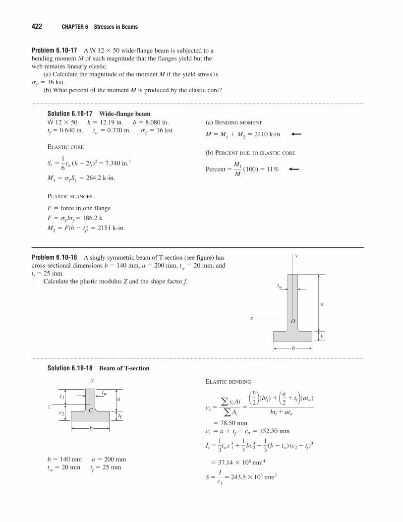
Problem 6.10-17 A W 12 � 50 wide-flange beam is subjected to abending moment M of such magnitude that the flanges yield but the web remains linearly elastic.
(a) Calculate the magnitude of the moment M if the yield stress is �Y � 36 ksi.
(b) What percent of the moment M is produced by the elastic core?
Solution 6.10-17 Wide-flange beam
422 CHAPTER 6 Stresses in Beams
W 12 � 50 h � 12.19 in. b � 8.080 in.tf � 0.640 in. tw � 0.370 in. �Y � 36 ksi
ELASTIC CORE
M1 � �YS1 � 264.2 k-in.
PLASTIC FLANGES
F � force in one flange
F � �Ybtf � 186.2 k
M2 � F(h � tf) � 2151 k-in.
S1 �1
6 tw (h � 2tf)
2 � 7.340 in.3
(a) BENDING MOMENT
M � M1 � M2 � 2410 k-in.
(b) PERCENT DUE TO ELASTIC CORE
Percent �M1
M (100) � 11%
Problem 6.10-18 A singly symmetric beam of T-section (see figure) hascross-sectional dimensions b � 140 mm, a � 200 mm, tw � 20 mm, andtf � 25 mm.
Calculate the plastic modulus Z and the shape factor f.
Solution 6.10-18 Beam of T-section
tf
tw
z
y
O
a
b
b � 140 mm a � 200 mmtw � 20 mm tf � 25 mm
tf
tw
z
y
C
a
b
c1
c2
ELASTIC BENDING
� 78.50 mmc1 � a � tf � c2 � 152.50 mm
� 37.14 � 106 mm4
S �Ic1
� 243.5 � 103 mm3
Iz �1
3tw c 1
3 �1
3 bc 2
3 �1
3(b � tw)(c2 � tf)
3
c2 �a yi Ai
a Ai
�
¢ tf
2≤(btf) � ¢a
2� tf≤(atw)
btf � atw
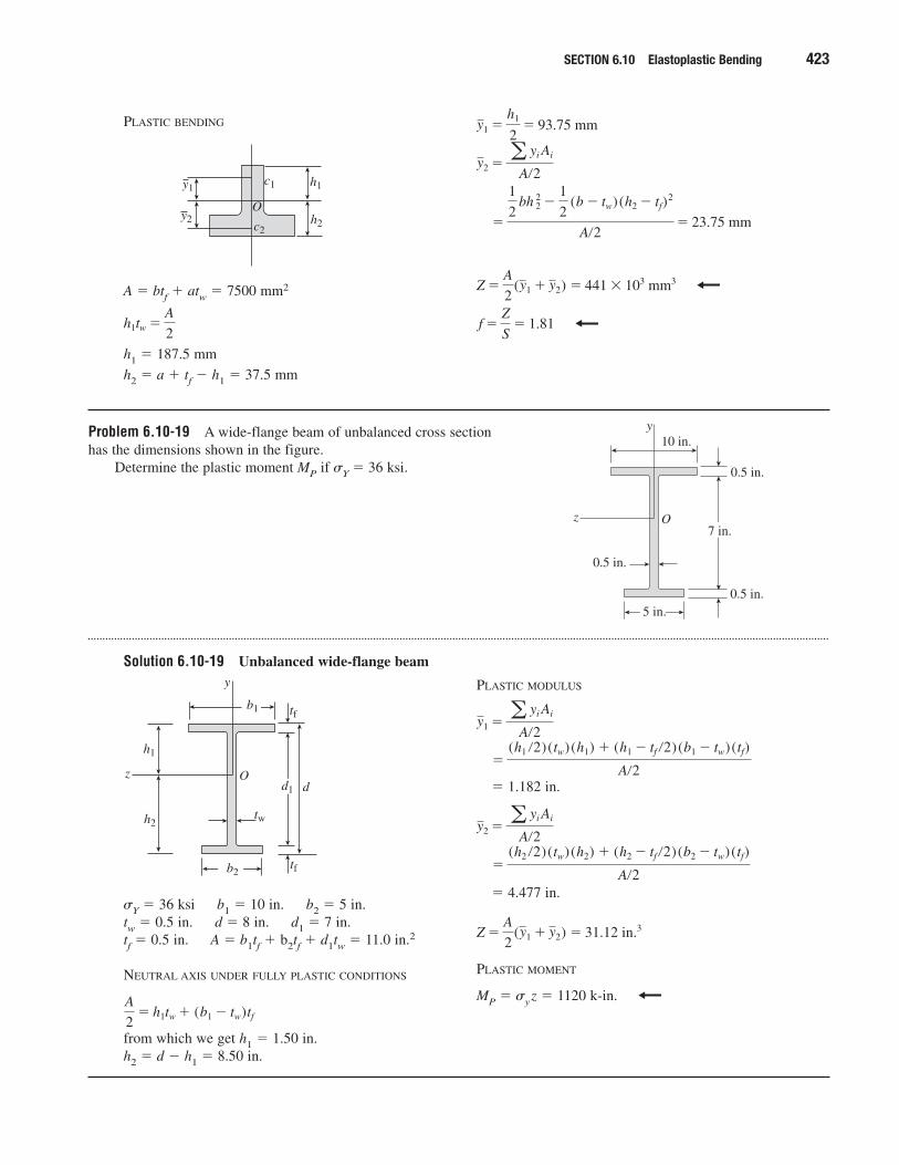
Problem 6.10-19 A wide-flange beam of unbalanced cross section has the dimensions shown in the figure.
Determine the plastic moment MP if �Y � 36 ksi.
Solution 6.10-19 Unbalanced wide-flange beam
SECTION 6.10 Elastoplastic Bending 423
PLASTIC BENDING
A � btf � atw � 7500 mm2
h1 � 187.5 mm
h2 � a � tf � h1 � 37.5 mm
h1tw �A
2
h2
O
h1c1y1
c2y2
f �Z
S� 1.81
Z �A
2(y1 � y2) � 441 � 103 mm3
�
1
2 bh 2
2 �1
2 (b � tw)(h2 � tf)
2
A�2� 23.75 mm
y2 �a yi Ai
A�2
y1 �h1
2� 93.75 mm
z
y10 in.
0.5 in.
0.5 in.
0.5 in.
O7 in.
5 in.
�Y � 36 ksi b1 � 10 in. b2 � 5 in.tw � 0.5 in. d � 8 in. d1 � 7 in.tf � 0.5 in. A � b1tf � b2tf � d1tw � 11.0 in.2
NEUTRAL AXIS UNDER FULLY PLASTIC CONDITIONS
from which we get h1 � 1.50 in.h2 � d � h1 � 8.50 in.
A
2� h1tw � (b1 � tw)tf
z
y
tw
tf
tf
Od1 d
b2
b1
h2
h1
PLASTIC MODULUS
� 1.182 in.
� 4.477 in.
PLASTIC MOMENT
MP � �yz � 1120 k-in.
Z �A
2(y1 � y2) � 31.12 in.3
�(h2 �2)(tw)(h2) � (h2 � tf �2)(b2 � tw)(tf)
A�2
y2 �a yi Ai
A�2
�(h1 �2)(tw)(h1) � (h1 � tf �2)(b1 � tw)(tf)
A�2
y1 �a yi Ai
A�2
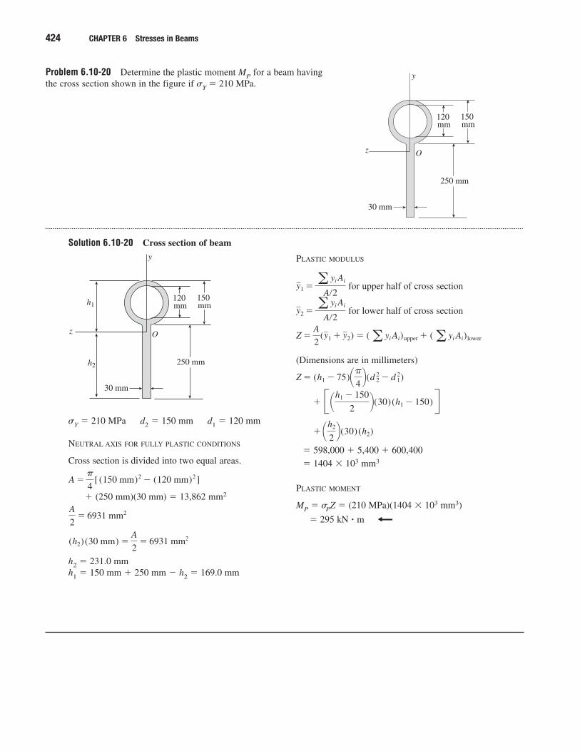
Problem 6.10-20 Determine the plastic moment MP for a beam havingthe cross section shown in the figure if �Y � 210 MPa.
Solution 6.10-20 Cross section of beam
424 CHAPTER 6 Stresses in Beams
z
y
O
30 mm
120 mm
150 mm
250 mm
�Y � 210 MPa d2 � 150 mm d1 � 120 mm
NEUTRAL AXIS FOR FULLY PLASTIC CONDITIONS
Cross section is divided into two equal areas.
� (250 mm)(30 mm) � 13,862 mm2
h2 � 231.0 mmh1 � 150 mm � 250 mm � h2 � 169.0 mm
(h2) (30 mm) �A
2� 6931 mm2
A
2� 6931 mm2
A ��
4[ (150 mm)2 � (120 mm)2]
z
y
O
30 mm
120 mm
150 mm
250 mmh2
h1
PLASTIC MODULUS
for upper half of cross section
for lower half of cross section
(Dimensions are in millimeters)
� 598,000 � 5,400 � 600,400
� 1404 � 103 mm3
PLASTIC MOMENT
MP � �PZ � (210 MPa)(1404 � 103 mm3)
� 295 kN � m
� ¢h2
2≤(30)(h2)
� B ¢h1 � 150
2≤(30)(h1 � 150) R
Z � (h1 � 75)¢�4≤(d 2
2 � d 12)
Z �A
2(y1 � y2) � (a yi Ai)upper � (a yi Ai)lower
y2 �a yi Ai
A�2
y1 �a yi Ai
A�2