Embed Size (px)
Citation preview
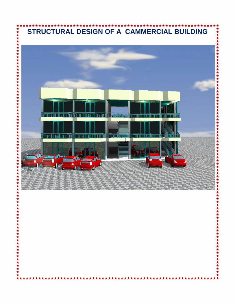
STRUCTURAL DESIGN OF A CAMMERCIAL BUILDING
Page 2 of 29
Location: GISENYI /RUBAVU
Plot No:567
Owner: Mr. Shona RUBERWA
Designed by:Eng .Pacifique B. MUMENYI
Date:Jan 2018
Approved by:
Page 1 of 29CONTENTSCONTENTS................................................................................................................................................ 10. INTRODUCTION .................................................................................................................................. 21. NOTATIONS.......................................................................................................................................... 32. ASSUMPTIONS..................................................................................................................................... 43. LAYOUT OF OVERALL PLAN [STRUCTURAL ARRANGEMENT] ............................................. 64. CALCULATION AND DESIGN OF SLABS: ...................................................................................... 76. CALCULATION AND DESIGN OF COLUMN ................................................................................ 197. CALCULATION AND DESIGN OF FOUNDATIONS ..................................................................... 238. CALCULATION AND DESIGN OF STAIRS.................................................................................... 26
Page 2 of 290. INTRODUCTIONThe aim of design is the achievement of an acceptable probability that structures being designed will
perform satisfactorily during their intended life. With an appropriate degree of safety, they should
sustain all the loads and deformations of normal construction and use and have adequate durability and
resistance to the effects of misuse and fire.
Once the building form and structural arrangement have been finalized the design problem consists of
the following:
1. Idealization of the structure into load bearing frames and elements for analysis and design2. Estimation of loads3. Analysis to determine the maximum moments, thrusts and shears for design4. Design of sections and reinforcement arrangements for slabs, beams, columns and walls using the
results from 35. Production of arrangement and detail drawings and bar schedules
Thisstructural design process has been carried out under use of BS8110 design code of practice.
Especially, computations have been made by use of BS 8110 based spreadsheets; publication produced
by the Reinforced Concrete Council (RCC) as part of its project 'Spreadsheets for concrete design to BS
8110 and EC2'.
Page 3 of 29
1. NOTATIONSThe symbolic notation used in this project is in accordance with the BS code of practice. Other symbols
not defined here, have been defined alongside the particular place where they have been applied.
A: cross section area
Asmin: minimum required reinforcement section
B : width of foundation footing, Beam
b: width reinforced concrete section
bf: width of flange in a beam
bw : width of web of a flanged a beam
C : cover
d : effective depth of tensile reinforcement
H : depth of foundation
fcu: characteristic yield strength of concreteat 28 days
fy: characteristic yield strength of steel
GK: dead load
h: overall depth of a concrete section
hf: thickness of flange in a T-beam
L : span length
lx : short-span length
ly: long-span length
M : bending moment
p: perimeter
qadm: bearing pressure
Qk: imposed load
S: spacing of shear reinforcement
V: shear force in concrete section
Øt: shear reinforcement diameter
Ø: reinforcementdiameter
B.S: British standard
C.P: Code of Practice
RC: Reinforced concrete
m.f: modification factor
`
Page 4 of 292. ASSUMPTIONSDesign standards used
Design standard used to determine section of steel bars of different structural elements of concerned
building are BS 8110
UnitiesVolumetric load: kN/m3
Surface load: kN/m2
Linear load: kN/m
Point load: kN
Dead loads
Roof structure: 1.5kN/m2
Reinforced concrete: 25kN/m3
Wall Finishes: 22kN/m2
Masonry in burnt bricks: 20kN/m3
Coating in cement mortar: 20kN/m3
Plinth 22kNm2
Masonry in cement blocks: 13.5kN/m3
Slab finishes 2kN/m2
Imposed load or live load
Residential house building: 1.5kN/m2
Cover conditions
Slabs, beams and columns [mild condition]: 30mm
Foundation pads [moderate condition]: 40mm
Soil characteristics
Page 5 of 29
Sandy-gravel subsoil of unit weight: 18kN/m3
Allowable bearing pressure: 240kN/ m2
Mix proportions [BS 5328-2]
Mix ratio: 350 kg/ m3
Elasticity limit for construction materials
Strength of reinforcement:
Hot rolled mild steel: 250 N/mm2
High yield steel : 460 N/mm2
Concrete ƒck: 30N/mm2
Partial safety magnification factors
For dead load: 1.4
For live load: 1.6
Basic span-effective depth ration: 26
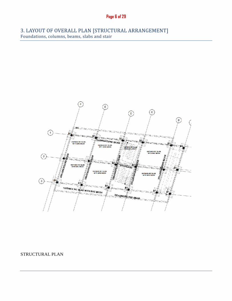
Page 6 of 293. LAYOUT OF OVERALL PLAN [STRUCTURAL ARRANGEMENT]Foundations, columns, beams, slabs and stair
STRUCTURAL PLAN
Page 7 of 29
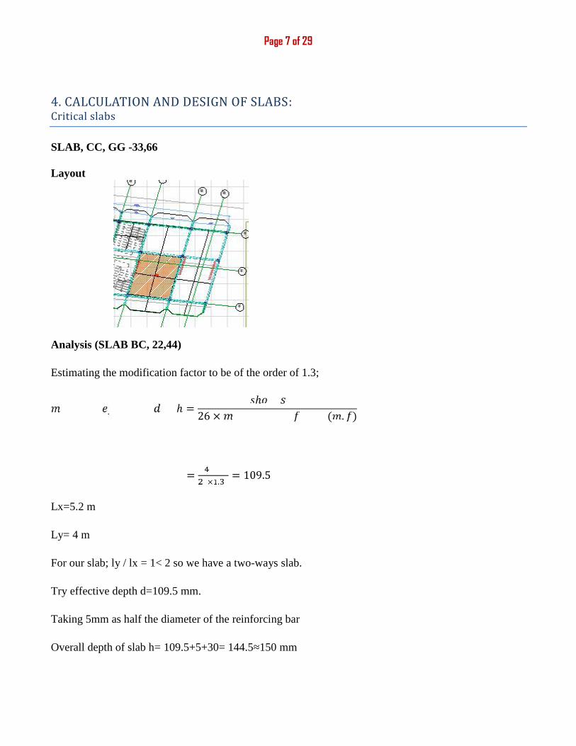
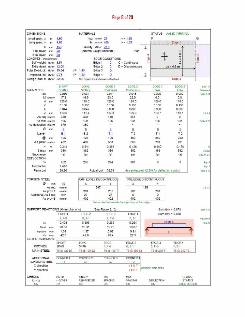
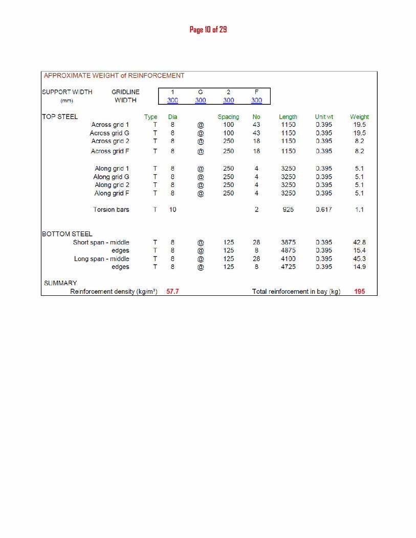
4. CALCULATION AND DESIGN OF SLABS:Critical slabsSLAB, CC, GG -33,66
Layout
Analysis (SLAB BC, 22,44)
Estimating the modification factor to be of the order of 1.3;
ℎ = ℎ26 × ( . )= × . = 109.5
Lx=5.2 m
Ly= 4 m
For our slab; ly / lx = 1< 2 so we have a two-ways slab.
Try effective depth d=109.5 mm.
Taking 5mm as half the diameter of the reinforcing bar
Overall depth of slab h= 109.5+5+30= 144.5≈150 mm

Page 8 of 29
Self weight of slab= 0.15×25= 3.75kN/m2
Total dead load= finishing + self weight = 2+ 3.75 = 5.75 kN/m2
Imposed load= 1.5kN/m2 forresidential building
Ultimate design load=1.4×5.75 +1.6×1.5=10.45 kN/m2
Page 9 of 29
Page 10 of 29
Page 11 of 29
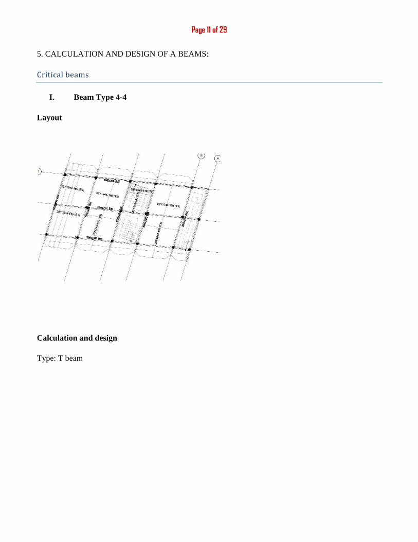
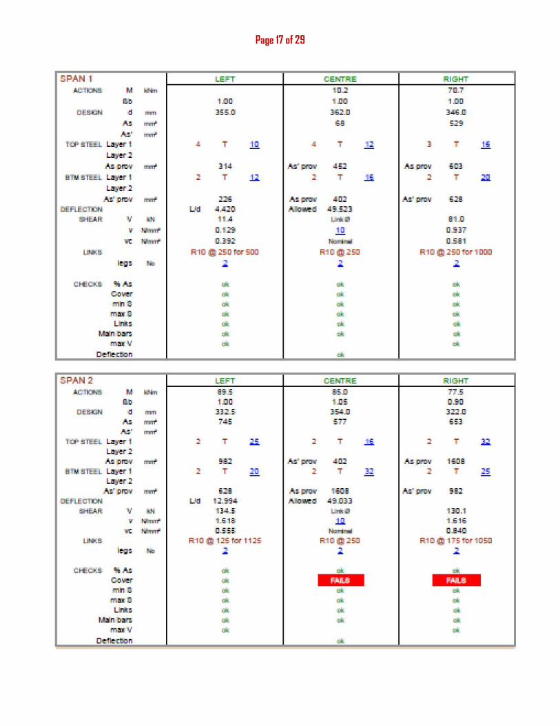
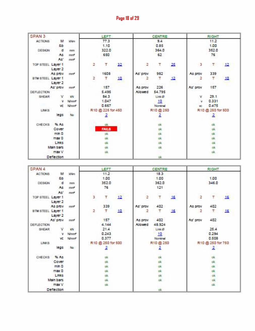
5. CALCULATION AND DESIGN OF A BEAMS:Critical beamsI. Beam Type 4-4
Layout
Calculation and design
Type: T beam
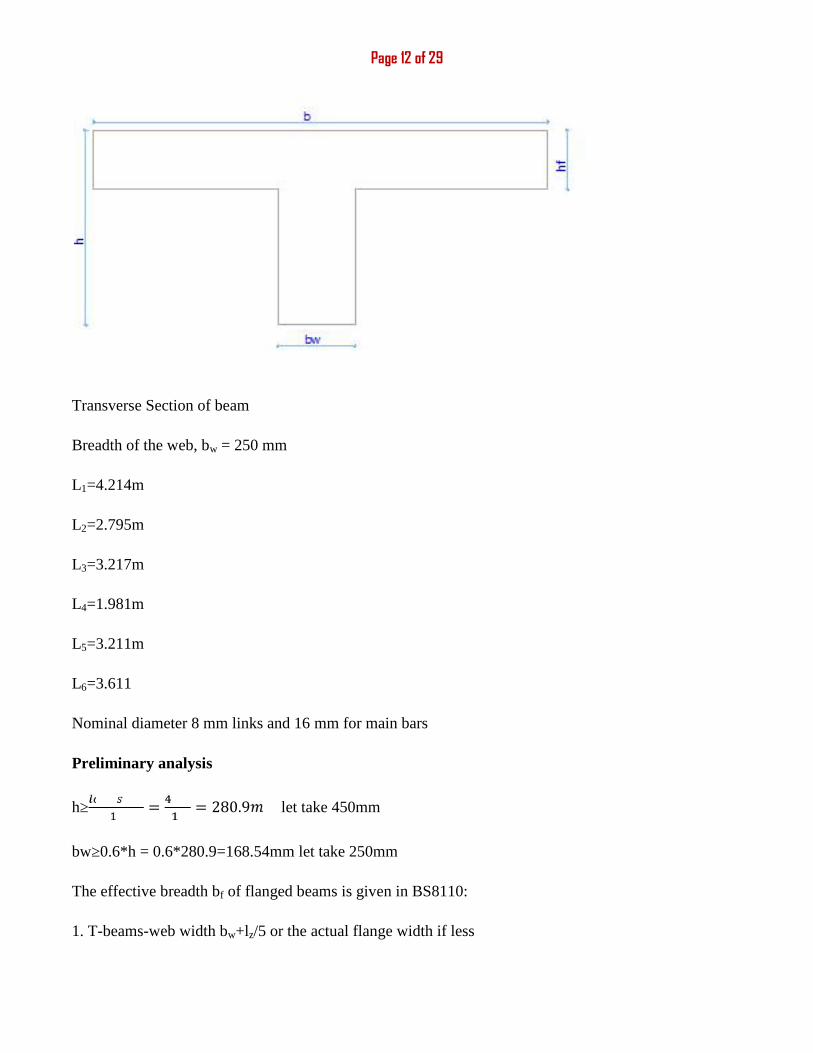
Page 12 of 29
Transverse Section of beam
Breadth of the web, bw = 250 mm
L1=4.214m
L2=2.795m
L3=3.217m
L4=1.981m
L5=3.211m
L6=3.611
Nominal diameter 8 mm links and 16 mm for main bars
Preliminary analysis
h≥ = = 280.9 let take 450mm
bw≥0.6*h = 0.6*280.9=168.54mm let take 250mm
The effective breadth bf of flanged beams is given in BS8110:
1. T-beams-web width bw+lz/5 or the actual flange width if less
Page 13 of 29
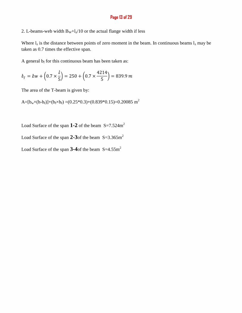
2. L-beams-web width BW+lz/10 or the actual flange width if less
Where lz is the distance between points of zero moment in the beam. In continuous beams lz may betaken as 0.7 times the effective span.
A general bf for this continuous beam has been taken as:
= + 0.7 × 5 = 250 + 0.7 × 42145 = 839.9The area of the T-beam is given by:
A=[bw×(h-hf)]+(bf×hf) =(0.25*0.3)+(0.839*0.15)=0.20085 m2
Load Surface of the span 1-2 of the beam S=7.524m2
Load Surface of the span 2-3of the beam S=3.365m2
Load Surface of the span 3-4of the beam S=4.55m2
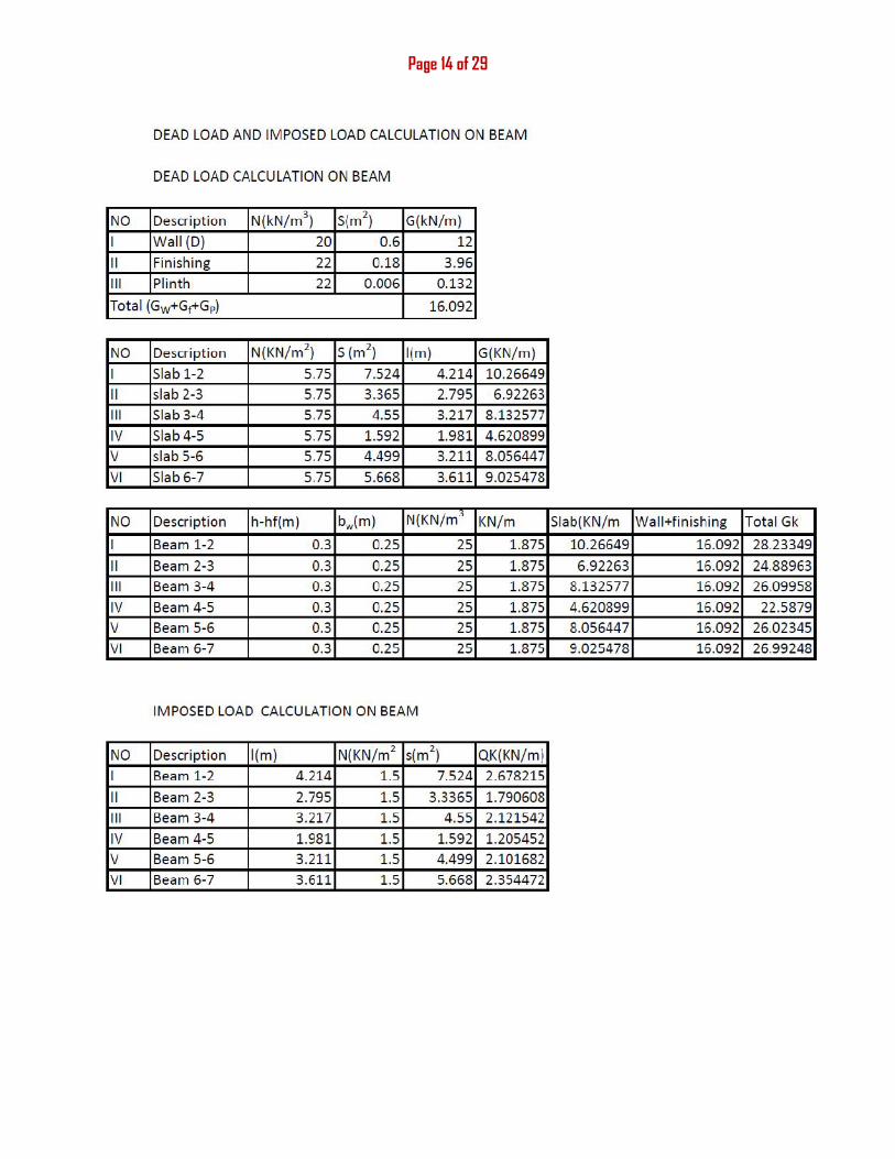
Page 14 of 29
Page 15 of 29
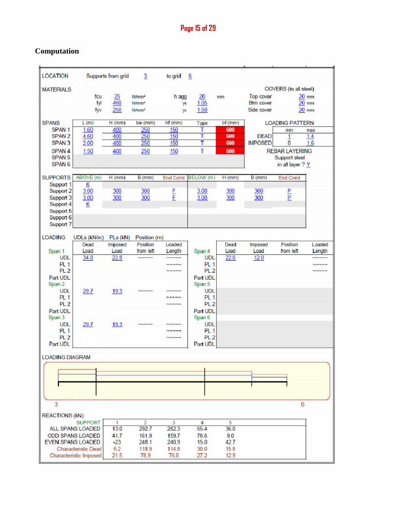
Computation
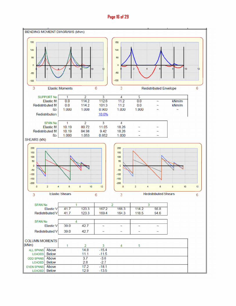
Page 16 of 29
Page 17 of 29
Page 18 of 29
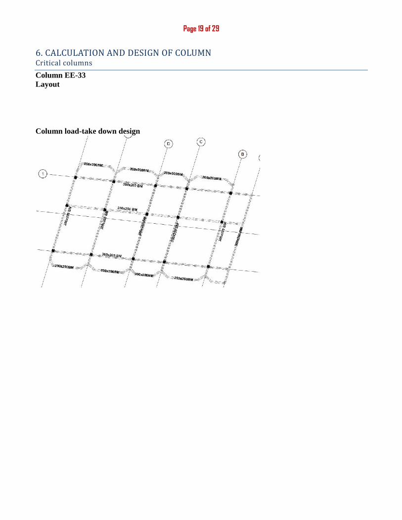
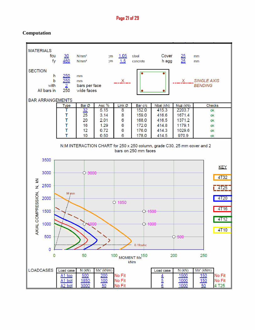
Page 19 of 296. CALCULATION AND DESIGN OF COLUMNCritical columnsColumn EE-33Layout
Column load-take down design
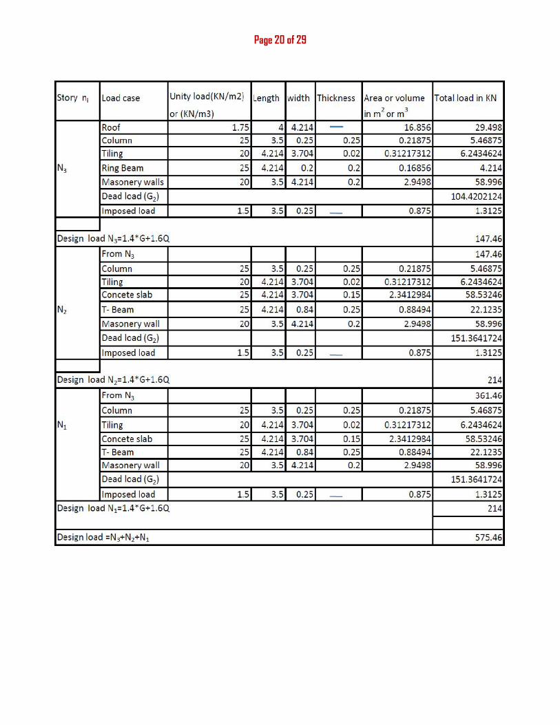
Page 20 of 29
Page 21 of 29
Computation
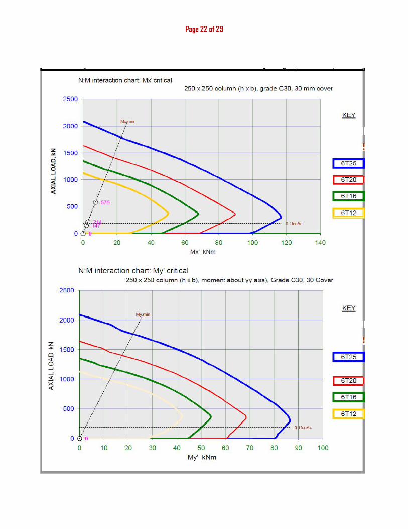
Page 22 of 29
Page 23 of 29
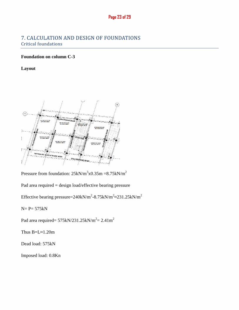
7. CALCULATION AND DESIGN OF FOUNDATIONSCritical foundationsFoundation on column C-3
Layout
Bearing pressure =240kN/m2
Use nominal cover=40mm (cover against blinding)
H=350mm
Pressure from foundation: 25kN/m3x0.35m =8.75kN/m2
Pad area required = design load/effective bearing pressure
Effective bearing pressure=240kN/m2-8.75kN/m2≈231.25kN/m2
N= P= 575kN
Pad area required= 575kN/231.25kN/m2= 2.41m2
Thus B=L≈1.20m
Dead load: 575kN
Imposed load: 0.8Kn

Page 24 of 29
Computation
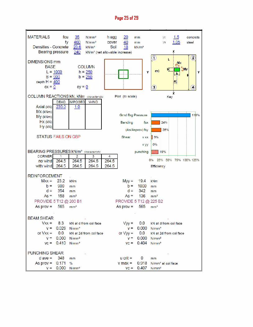
Page 25 of 29
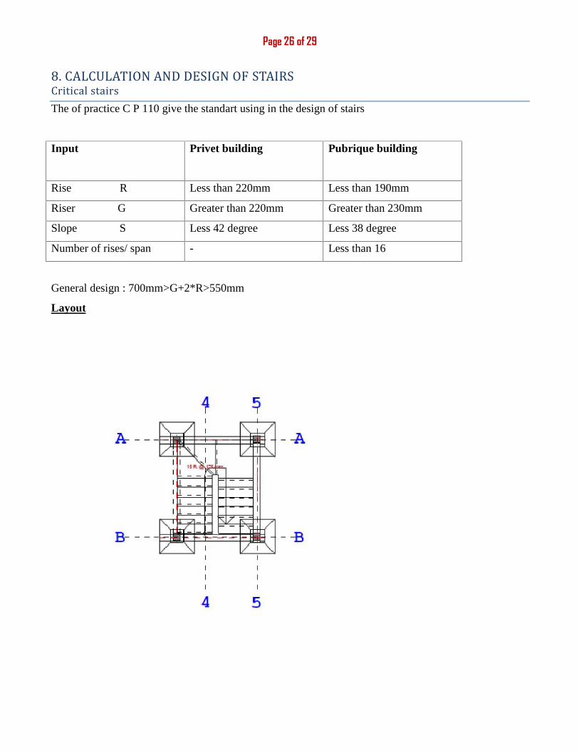
Page 26 of 298. CALCULATION AND DESIGN OF STAIRSCritical stairsThe of practice C P 110 give the standart using in the design of stairs
Input Privet building Pubrique building
Rise R Less than 220mm Less than 190mm
Riser G Greater than 220mm Greater than 230mm
Slope S Less 42 degree Less 38 degree
Number of rises/ span - Less than 16
General design : 700mm>G+2*R>550mm
Layout
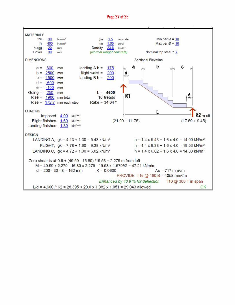
Page 27 of 29


