Embed Size (px)
Citation preview
Operating Instructions
Studer Vista XDigital Mixing System, SW V5.3
0. Safety/Conformity Information1. Introduction, Operating Features2. Desk Operation3. Parameter Description4. Graphical Controller (GC) Operation5. AutoTouch+ Dynamic Automation6. SessionConfigurationToolforInfinityCore7. DAW Control8. RELINK – Resource Linking9. Vista FX10. Application Notes, Update Info11. InfinityCore

Disclaimer
The information in this document has been carefully checked and is believed to be accurate at the time of publica-tion. However, no responsibility is taken by us for inaccuracies, errors, or omissions, nor is any liability assumed for any loss or damage resulting either directly or indirectly from use of the information contained within it.
Prepared and edited by Copyright by Studer Professional Audio GmbHStuder Professional Audio GmbH Technical DocumentationRiedthofstrasse 214CH-8105 Regensdorf - Switzerlandhttp://www.studer.ch Subject to change
Studer is a registered trade mark of Studer Professional Audio GmbH, Regensdorf
Order no. 5073888-01
I
For Your Own Safety and to Avoid Invalidation of the Warranty Please Read This Section Carefully
• Readtheseinstructions. • Keeptheseinstructions. • Heedallwarnings. • Followallinstructions. • Donotusethisapparatusnearwater. • Cleanonlywithadrycloth. • Donotblockanyventilationopenings.Install inaccordancewiththe
manufacturer'sinstructions. • Donot installnearanyheatsourcessuchasradiators,heatregisters,
stoves,orotherapparatus(includingamplifiers)thatproduceheat. • Donotdefeatthesafetypurposeofapolarisedorgroundingtypeplug.A
polarisedplughastwobladeswithonewiderthantheother.Agroundingtypeplughastwobladesandathirdgroundingprong.Thewidebladeorthethirdprongareprovidedforyoursafety.Iftheprovidedplugdoesnotfitintoyouroutlet,consultanelectricianforreplacementoftheobsoleteoutlet
• Protectthepowercordfrombeingwalkedonorpinchedparticularlyatplugs,conveniencereceptaclesandthepointwheretheyexitfromtheapparatus.
• Onlyuseattachments/accessoriesspecifiedbythemanufacturer. • Useonlywiththecart,stand,tripod,bracketortablespecifiedbythe
manufacturer,orsoldwiththeapparatus.Whenacartisused,usecau-tionwhenmovingthecart/apparatuscombinationtoavoidinjuryfromtip-over.
• Referallservicingtoqualifiedservicepersonnel.Servicingisrequiredwhentheapparatushasbeendamagedinanyway,suchaspower-supplycordorplugisdamaged,liquidhasbeenspilledorobjectsfallenintotheapparatus,theapparatushasbeenexposedtorainormoisture,doesnotoperatenormally,orhasbeendropped.
Note: It is recommended thatallmaintenanceandserviceon theproductshouldbecarriedoutbyStuderoritsauthorisedagents.Studercannotacceptanyliabilitywhatsoeverforanylossordamagecausedbyservice,maintenanceorrepairbyunauthorisedpersonnel.
• WARNING:Toreducetheriskoffireorelectricshock,donotexposethisapparatustorainormoisture.Donotexposetheapparatustodrippingorsplashinganddonotplaceobjectsfilledwithliquids,suchasvases,ontheapparatus.
• Nonakedflamesources,suchaslightedcandles,shouldbeplacedontheapparatus.
• Ventilationshouldnotbeimpededbycoveringtheventilationopeningswithitemssuchasnewspapers,tablecloths,curtainsetc.
Warning: Donotusethisapparatusinverydustyatmospheres,orinatmospherescontainingflammablegasesorchemicals.
• THISAPPARATUSMUSTBEEARTHED.Undernocircumstancesshouldthesafetyearthbedisconnectedfromthemainslead.
Safety Information
II
• Themainssupplydisconnectdeviceisthemainsplug.Itmustremainaccessiblesoastobereadilyoperablewhentheapparatusisinuse.
• Ifanypartofthemainscordsetisdamaged,thecompletecordsetshouldbereplaced.Thefollowinginformationisforreferenceonly.Thewiresinthemainsleadarecolouredinaccordancewiththefollowingcode:
• ProtectiveEarth (Ground):Green/Yellow (US:GreenorGreen/Yellow)
• Neutral:Blue(US:White) • Live(Hot):Brown(US:Black)
Asthecoloursofthewiresinthemainsleadmaynotcorrespondwiththecolouredmarkingsidentifyingtheterminalsinyourplug,proceedasfollows:
• ThewirewhichiscolouredGreenandYellowmustbeconnectedtotheterminalintheplugwhichismarkedwiththeletterEorbytheearthsymbol.
• ThewirewhichiscolouredBluemustbeconnectedtotheterminalintheplugwhichismarkedwiththeletterN
• ThewirewhichiscolouredBrownmustbeconnectedtotheterminalintheplugwhichismarkedwiththeletterL
Ensurethatthesecolourcodesarefollowedcarefullyintheeventoftheplugbeingchanged
• Thisunit is capableofoperatingoverarangeofmainsvoltages,asmarkedontherearpanel.
Note: This equipment has been tested and found to comply with the limits for a Class A digital device, pursuant to Part 15 of the FCC Rules. These limits are designed to provide reasonable protection against harmful interference when the equipment is operated in a commercial environment. This equipment gen-erates, uses and can radiate radio frequency energy and, if not installed and used in accordance with the instruction manual, may cause harmful interfer-ence to radio communications. Operation of this equipment in a residential area is likely to cause harmful interference in which case the user will be required to correct the interference at his own expense.
This Class A digital apparatus meets the requirements of the Canadian Interference-Causing Equipment Regulations.
Cet appareil numérique de la Classe A respecte toutes les exigences du Règle-ment sur le matériel brouilleur du Canada.
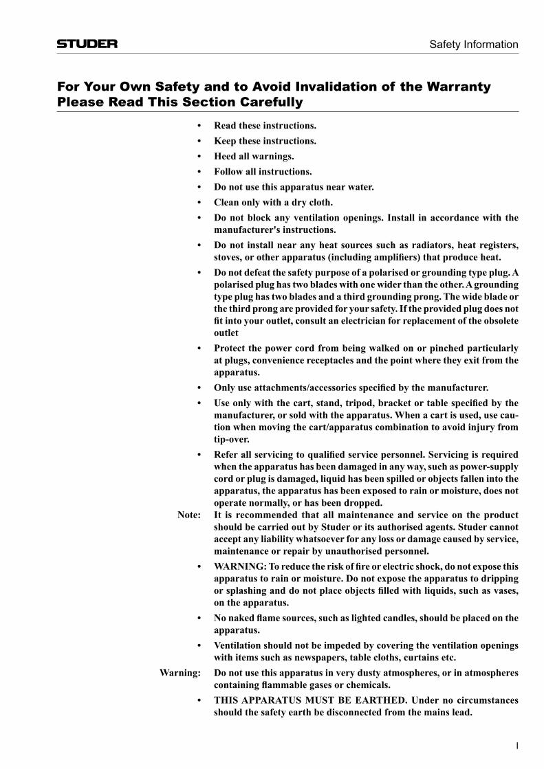
WorkingSafelyWithSound Although your new console will not make any noise until you feed it signals, it has the capability to produce sounds that, when monitored through a moni-tor system or headphones can damage hearing over time.The table below is taken from the Occupational Safety & Health Administration directive on occupational noise exposure (1926.52):
PermissibleNoiseExposure: Duration per day [h] Sound level [dBA, slow response] 8 906 924 953 972 100
1.5 1021 105
0.5 110<0.25 115
Safety Information
!
III
Conforming to this directive will minimise the risk of hearing damage caused by long listening periods. A simple rule to follow is: The longer you listen, the lower the average volume should be. Please take care when working with your audio system – if you are manipulating controls which you don’t understand (which we all do when we are learning), make sure your monitoring level is turned down. Remember that your ears are the most important tool of your trade. Look after them, and they will look after you. Most importantly: Don’t be afraid to experiment to find out how each parameter affects the sound; this will extend your creativity and help you to get the best results.
A1 Safety Symbol Guide
For your own safety and to avoid invalidation of the warranty, all text marked with these symbols should be read carefully.
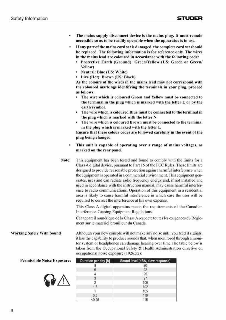
To reduce the risk of electric shock, do not remove covers. No user-serviceable parts inside. Refer servicing to qualified service personnel (i.e., persons having appropriate technical training and experience necessary to be aware of hazards to which they are exposed in performing a repair action, and of measures to minimize the danger of themselves).
The lightning flash with arrowhead symbol is intended to alert the user to the presence of un-insulated “dangerous voltage” within the product’s enclosure that may be of sufficient magnitude to constitute a risk of electric shock to persons.
The exclamation point within an equilateral triangle is intended to alert the user to the presence of important operating and maintenance (servicing) instructions in the literature accompanying the appliance.
Headphones safety warnings contain important information and useful tips on headphone outputs and monitoring levels.
Assemblies or sub-assemblies of this product can contain opto-electronic devices. As long as these devices comply with Class I of laser or LED prod-ucts according to EN 60825-1:1994, they will not be expressly marked on the product. If a special design should be covered by a higher class of this standard, the device concerned will be marked directly on the assembly or sub-assembly in accordance with the above standard.
A2 First Aid
InCaseofElectricShock: Separate the person as quickly as possible from the electric power source: • By switching the equipment off, • By unplugging or disconnecting the mains cable, or • By pushing the person away from the power source, using dry insulating
material (such as wood or plastic). • After having suffered an electric shock, always consult a doctor.Warning! Do not touch the person or his clothing before the power is turned off,
otherwise you stand the risk of suffering an electric shock as well!
IfthePersonisUnconscious: • Lay the person down • Turn him to one side • Check the pulse • Reanimate the person if respiration is poor • Call for a doctor immed iately.
CAUTIONRISK OF ELECTRIC SHOCK
DO NOT OPEN
ACHTUNGGEFAHR: ELEKTRISCHER SCHLAG
NICHT ÖFFNEN
ATTENTIONRISQUE DE CHOC ELECTRIQUE
NE PAS OUVRIR
!
CLASS 1LASER PRODUCT
CLASS 1LED PRODUCT
!
Safety Information
IV
B General Installation Instructions Please consider besides these general instructions also any product-specific
instructions in the “Installation” chapter of this manual.
B1 Unpacking
Check the equipment for any transport damage. If the unit is mechanically damaged, if liquids have been spilled or if objects have fallen into the unit, it must not be connected to the AC power outlet, or it must be immediately disconnected by unplugging the power cable. Repair must only be performed by trained personnel in accordance with the applicable regulations.
B2 Installation Site
Install the unit in a place where the following conditions are met: • The temperature and the relative humidity of the environment must be
within the specified limits during operation of the unit. Relevant values are the ones at the air inlets of the unit (refer to Appendix 1).
• Condensation must be avoided. If the unit is installed in a location with large variation of ambient temperature (e.g. in an OB-van), appropriate precautions must be taken before and after operation (refer to Appendix 1).
• Unobstructed air flow is essential for proper operation. Air vents of the unit are a functional part of the design and must not be blocked in any way during operation (e.g. by objects placed upon them, placement of the unit on a soft surface, or installation of the unit within a rack or piece of furniture).
• The unit must not be heated up by external sources of heat radiation (sun-light, spotlights).
B3 Earthing and Power Supply
Earthing of units with mains supply (class I equipment) is performed via the protective earth (PE) conductor integrated in the mains cable. Units with battery operation (< 60 V, class III equipment) must be earthed separately.
Earthing the unit is one of the measures for protection against electrical shock hazard (dangerous body currents). Hazardous voltage may not only be caused by a defective power supply insulation, but may also be introduced by the connected audio or control cables.
If the unit is installed with one or several external connections, its earthing must be provided during operation as well as while the unit is not operated. If the earthing connection can be interrupted, for example, by unplugging the mains plug of an external power supply unit, an additional, permanent earthing connection must be installed using the provided earth terminal.
Avoid ground loops (hum loops) by keeping the loop surface as small as possible (by consequently guiding the earth conductors in a narrow, parallel way), and reduce the noise current flowing through the loop by inserting an additional impedance (common-mode choke).
Installation
V
Installation / EMC
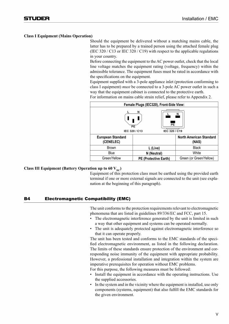
ClassIEquipment(MainsOperation) Should the equipment be delivered without a matching mains cable, the
latter has to be prepared by a trained person using the attached female plug (IEC 320 / C13 or IEC 320 / C19) with respect to the applicable regulations in your country.
Before connecting the equipment to the AC power outlet, check that the local line voltage matches the equipment rating (voltage, frequency) within the ad missible tolerance. The equipment fuses must be rated in accordance with the specifications on the equipment.
Equipment supplied with a 3-pole appliance inlet (protection conforming to class I equip ment) must be connect ed to a 3-pole AC power outlet in such a way that the equipment ca binet is connected to the protective earth.
For information on mains cable strain relief, please refer to Appendix 2.
Female Plugs (IEC320), Front-Side View:
European Standard (CENELEC)
North American Standard(NAS)
Brown L (Live) BlackBlue N (Neutral) White
Green/Yellow PE (Protective Earth) Green (or Green/Yellow)
ClassIIIEquipment(BatteryOperationupto60VDC) Equipment of this protection class must be earthed using the provided earth
terminal if one or more external signals are connected to the unit (see expla-nation at the beginning of this paragraph).
B4 Electromagnetic Compatibility (EMC)
The unit conforms to the protection requirements relevant to electromagnetic phenomena that are listed in guidelines 89/336/EC and FCC, part 15.
• The electromagnetic interference generated by the unit is limited in such a way that other equipment and systems can be operated normally.
• The unit is adequately protected against electromagnetic interference so that it can operate properly.
The unit has been tested and conforms to the EMC standards of the speci-fied electromagnetic environment, as listed in the following declaration. The limits of these standards ensure protection of the environment and cor-responding noise immunity of the equipment with appropriate probability. However, a professional installation and integration within the system are imperative prerequisites for operation without EMC problems.
For this purpose, the following measures must be followed: • Install the equipment in accordance with the operating instructions. Use
the supplied accessories. • In the system and in the vicinity where the equipment is installed, use only
components (systems, equipment) that also fulfill the EMC standards for the given environment.
PE
L N
IEC 320 / C19IEC 320 / C13PE
L N
VI
• Use a system grounding concept that satisfies the safety requirements (class I equipment must be connected with a protective ground conduc-tor) and that also takes into consideration the EMC require ments. When deciding between radial, surface, or combined grounding, the advantages and disadvantages should be carefully evaluated in each case.
• Use shielded cables where shielding is specified. The connection of the shield to the corresponding connector terminal or housing should have a large surface and be corrosion-proof. Please note that a cable shield con-nected only single-ended can act as a transmitting or receiving antenna within the corresponding frequency range.
• Avoid ground loops or reduce their adverse effects by keeping the loop surface as small as possible, and reduce the noise current flowing through the loop by inserting an additional impedance (e.g. common-mode choke).
• Reduce electrostatic discharge (ESD) of persons by installing an appropri-ate floor covering (e.g. a carpet with permanent electrostatic filaments) and by keeping the relative humidity above 30%. Further measures (e.g. con-ducting floor) are usually unnecessary and only effective if used together with corresponding personal equipment.
• When using equipment with touch-sensitive operator controls, please take care that the surrounding building structure allows for sufficient capacitive coupling of the operator. This coupling can be improved by an additional, conducting surface in the operator’s area, connected to the equipment housing (e.g. metal foil underneath the floor covering, carpet with conduc-tive backing).
C Maintenance All air vents and openings for operating elements (faders, rotary knobs) must
be checked on a regular basis, and cleaned in case of dust accumulation. For cleaning, a soft paint-brush or a vacuum cleaner is recommended.
Cleaning the surfaces of the unit is performed with a soft, dry cloth or a soft brush.
Persistent contamination can be treated with a cloth that is slightly humidified with a mild cleaning solution, such as dishwashing detergent.
For cleaning display windows, commercially available computer/TV screen cleaners are suited. Use only a slightly damp (never wet) cloth.
Never use any solvents for cleaning the exterior of the unit! Liquids must never be sprayed or poured on directly!
For equipment-specific maintenance information please refer to the corre-sponding chapter in the operating and service manuals.
D Electrostatic Discharge during Maintenance and RepairCaution: Observe the precautions for handling devices sensitive to electrostatic dis-
charge! Many semiconductor components are sensitive to electrostatic discharge
(ESD). The lifespan of assemblies contain ing such components can be dras-tically reduced by improper handling during maintenance and repair. Please observe the following rules when handling ESD sensitive components:
• ESD sensitive components should only be stored and transported in the packing material specifically provided for this purpose.
EMC / Maintenance / ESD
VII
ESD / Repair
• When performing a repair by replacing complete assemblies, the removed assembly must be sent back to the supplier in the same packing material in which the replacement assembly was shipped. If this should not be the case, any claim for a possible refund will be null and void.
• Unpacked ESD sensitive components should only be handled in ESD protected areas (EPA, e.g. area for field service, repair or service bench) and only be touched by persons wearing a wristlet connected to the ground potential of the repair or service bench by a series resistor. The equipment to be repaired or serviced as well as all tools and electrically semi-conducting work, storage, and floor mats should also be connected to this ground potential.
• The terminals of ESD sensitive components must not come in uncontrolled contact with electro statically chargeable or metallic surfaces (voltage puncture, discharge shock hazard).
• To prevent the components from undefined transient stress and possible damage due to inadmissible voltages or compensation currents, electrical connections should only be established or separated when the equipment is switched off and after any capacitor charges have decayed.
E Repair By removing housing parts or shields, energized parts may be exposed. For
this reason the following precautions must be observed: • Maintenance may only be performed by trained personnel in accordance
with the applicable regulations. • The equipment must be switched off and disconnected from the AC power
outlet before any housing parts are removed. • Even if the equipment is disconnected from the power outlet, parts with
hazardous charges (e.g. capacitors, picture tubes) must not be touched until they have been properly discharged. Do not touch hot components (power semi con ductors, heat sinks, etc.) before they have cooled off.
• If maintenance is performed on a unit that is open ed while being switched on, no un-insulated circuit compon ents and metallic semiconductor hous-ings must be touched, neither with bare hands nor with un- insulated tools.
Certain components pose additional hazards: • Explosion hazard from lithium batteries, electrolytic capacitors and power
semiconductors (Observe the component’s polarity. Do not short battery terminals. Replace batteries only by the same type).
• Implosion hazard from evacuated display units. • Radiation hazard from laser units (non-ionizing), picture tubes (ionizing). • Caustic effect of display units (LCD) and components containing liquid
electrolyte. Such components should only be handled by trained personnel who are prop-
erly protected (e.g. protection glasses, gloves).
VIII
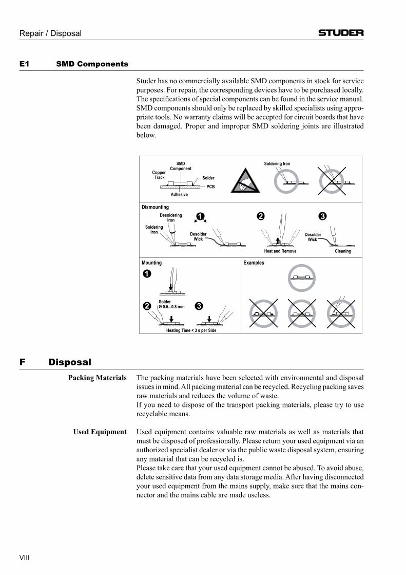
E1 SMD Components
Studer has no commercially available SMD components in stock for service purposes. For repair, the corresponding devices have to be purchased locally. The specifications of special components can be found in the service manual.
SMD components should only be replaced by skilled specialists using appro-priate tools. No warranty claims will be accepted for circuit boards that have been damaged. Proper and improper SMD soldering joints are illustrated below.
F Disposal PackingMaterials The packing materials have been selected with environmental and disposal
issues in mind. All packing material can be recycled. Recycling packing saves raw materials and reduces the volume of waste.
If you need to dispose of the transport packing materials, please try to use recyclable means.
UsedEquipment Used equipment contains valuable raw materials as well as materials that must be disposed of professionally. Please return your used equipment via an authorized specialist dealer or via the public waste disposal system, ensuring any material that can be recycled is.
Please take care that your used equipment cannot be abused. To avoid abuse, delete sensitive data from any data storage media. After having disconnected your used equipment from the mains supply, make sure that the mains con-nector and the mains cable are made useless.
Repair / Disposal
Dismounting
Mounting Examples
Solder
SMDComponent
CopperTrack
Adhesive
Soldering Iron
DesolderingIron
DesolderWick
Heat and Remove Cleaning
SolderØ 0.5...0.8 mm
Heating Time < 3 s per Side
SolderingIron Desolder
Wick
PCB
321
32
1
IX
G Declarations of ConformityG1 Class A Equipment - FCC Notice
This equipment has been tested and found to comply with the limits for a Class A digital device, pursuant to Part 15 of the FCC Rules. These limits are designed to provide a reasonable protection against harmful interfer-ence when the equipment is operated in a commercial environment. This equipment generates, uses, and can radiate radio frequency energy and, if not installed and used in accordance with the instruction manual, may cause harmful interference to radio com munications. Operation of this equipment in a residential area is likely to cause harmful interference, in which case the user will be required to correct the interference at his own expense.
This Class A digital apparatus meets the requirements of the Canadian Interference-Causing Equipment Regulations.
Cet appareil numérique de la Classe A respecte toutes les exigences du Règle-ment sur le matériel brouilleur du Canada.
Caution: Any changes or modifications not expressly approved by the manufacturer could void the user’s authority to operate the equipment. Also refer to relevant information in this manual.
G2 CE Declaration of Conformity
We, StuderProfessionalAudioGmbH, CH-8105Regensdorf, declare under our sole responsibility that the product StuderVistaX,DigitalMixingSystem (startingwithserialno.1001), to which this declaration relates, according to following regulations of EU
directives and amendments are in conformity with the following standards or normative documents:
Conformity to be declared here
Conformity
X
Appendix 1: Air Temperature and HumidityGeneral
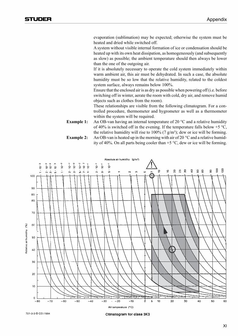
Normal operation of the unit or system is warranted under the ambient condi-tions defined by EN 60721-3-3, set IE32, value 3K3.
This standard consists of an extensive catalogue of parameters, the most important of which are: ambient temperature +5...+40 °C, relative humidity 5...85% (i.e., no formation of condensation or ice); absolute humidity 1...25 g/m³; rate of temperature change < 0.5 °C/min. These parameters are dealt with in the following paragraphs.
Under these conditions the unit or system starts and works without any prob-lem. Beyond these specifications, possible problems are described below.
Ambient Temperature
Units and systems by Studer are generally designed for an ambient tempera-ture range (i.e. temperature of the incoming air) of +5 °C to +40 °C. When rack mounting the units, the intended air flow and herewith adequate cooling must be provided. The following facts must be considered:
• The admissible ambient temperature range for operation of the semicon-ductor components is 0 °C to +70 °C (commercial temperature range for operation).
• The air flow through the installation must provide that the outgoing air is always cooler than 70 °C.
• Average heat increase of the cooling air shall be about 20 K, allowing for an additional maximum 10 K increase at the hot components.
• In order to dissipate 1 kW with this admissible average heat increase, an air flow of 2.65 m³/min is required.
Example: A rack dissipating P = 800 W requires an air flow of 0.8 * 2.65 m³/min which corresponds to 2.12 m³/min.
• If the cooling function of the installation must be monitored (e.g. for fan failure or illumination with spot lamps), the outgoing air temperature must be measured directly above the modules at several places within the rack. The trigger temperature of the sensors should be 65 °C to 70 °C.
Frost and Dew
The unsealed system parts (connector areas and semiconductor pins) allow for a minute formation of ice or frost. However, formation of dew visible to the naked eye will already lead to malfunctions. In practice, reliable opera-tion can be expected in a temperature range above –15 °C, if the following general rule is considered for putting the cold system into operation:
If the air within the system is cooled down, the relative humidity rises. If it reaches 100%, condensation will arise, usually in the boundary layer between the air and a cooler surface, together with formation of ice or dew at sensi-tive areas of the system (contacts, IC pins, etc.). Once internal condensation occurs, trouble-free operation cannot be guaranteed, independent of tempera-ture.
Before putting into operation, the system must be checked for internal for-mation of condensation or ice. Only with a minute formation of ice, direct
Appendix
XI
evaporation (sublimation) may be expected; otherwise the system must be heated and dried while switched off.
A system without visible internal formation of ice or condensation should be heated up with its own heat dissipation, as homogeneously (and subsequently as slow) as possible; the ambient temperature should then always be lower than the one of the outgoing air.
If it is absolutely necessary to operate the cold system immediately within warm ambient air, this air must be dehydrated. In such a case, the absolute humidity must be so low that the relative humidity, related to the coldest system surface, always remains below 100%.
Ensure that the enclosed air is as dry as possible when powering off (i.e. before switching off in winter, aerate the room with cold, dry air, and remove humid objects such as clothes from the room).
These relationships are visible from the following climatogram. For a con-trolled procedure, thermometer and hygrometer as well as a thermometer within the system will be required.
Example1: An OB-van having an internal temperature of 20 °C and a relative humidity of 40% is switched off in the evening. If the temperature falls below +5 °C, the relative humidity will rise to 100% (7 g/m³); dew or ice will be forming.
Example2: An OB-van is heated up in the morning with air of 20 °C and a relative humid-ity of 40%. On all parts being cooler than +5 °C, dew or ice will be forming.
Appendix
XII
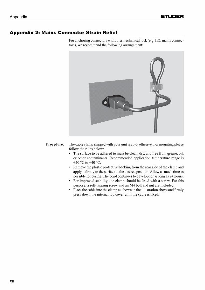
Appendix 2: Mains Connector Strain Relief For anchoring connectors without a mechanical lock (e.g. IEC mains connec-
tors), we recommend the following arrangement:
Procedure: The cable clamp shipped with your unit is auto-adhesive. For mounting please follow the rules below:
• The surface to be adhered to must be clean, dry, and free from grease, oil, or other contaminants. Recommended application temperature range is +20 °C to +40 °C.
• Remove the plastic protective backing from the rear side of the clamp and apply it firmly to the surface at the desired position. Allow as much time as possible for curing. The bond continues to develop for as long as 24 hours.
• For improved stability, the clamp should be fixed with a screw. For this purpose, a self-tapping screw and an M4 bolt and nut are included.
• Place the cable into the clamp as shown in the illustration above and firmly press down the internal top cover until the cable is fixed.
Appendix
XIII
Appendix
Appendix 3: Software License Use of the software is subject to the Studer Professional Audio Software
License Agreement set forth below. Using the software indicates your accep-tance of this license agreement. If you do not accept these license terms, you are not authorized to use this software.
Under the condition and within the scope of the following Terms and Con-ditions, Studer Professional Audio GmbH (hereinafter “Studer”) grants the right to use programs developed by Studer as well as those of third parties which have been installed by Studer on or within its products. References to the license programs shall be references to the newest release of a license program installed at the Customer’s site.
Programs Covered by the Agreement
LicenseProgramsofStuder The following Terms and Conditions grant the right to use all programs of Studer that are part of the System and/or its options at the time of its delivery to the Customer, as well as the installation software on the original data disk and the accompanying documentation (“License Material”). In this Agree-ment the word “Programs” shall have the meaning of programs and data written in machine code.
Using the software indicates your acceptance of this license agreement. If you do not accept these license terms, you are not authorized to use this software.
ProgramsofThirdParties Programs of third parties are all programs which constitute part of the System and/or its options at the time of delivery to the Customer but have not been developed by Studer. The following conditions are applicable to programs of third parties:
• The right to use third parties’ programs is governed by the License Agree-ment attached hereto (if applicable), which is an integral part of this Agreement. The Customer shall sign any and all License Agreements for all further programs of third parties installed on the system. The Customer shall be deemed to have received all License Agreements upon delivery of the system and/or its options.
• Studer shall accept no responsibility or liability for, and gives no warran-ties (express or implied) as to the programs of third parties. The Customer waives any and all claims versus Studer for any consequential damages, which might occur due to defects of these programs.
Right of Use
Principle Studer grants the Customer the non-exclusive right to use the License Ma-terial in one copy on the system and/or its options as laid down by the Sales Agreement concluded between the parties and all Terms and Conditions which shall be deemed to form and be read and construed as part of the Sales Agreement. This right is assignable according to the “Assignability” paragraph hereinafter.
CustomizedConfigurations The Customer is not entitled to alter or develop further the License Material except within the expressly permitted configuration possibilities given by the software installed on the system or elsewhere. All altered programs, includ-ing but not limited to the products altered within the permitted configuration possibilities, are covered by this License Agreement.
XIV
ReverseEngineering Reverse engineering is only permitted with the express consent of Studer. The consent of Studer can be obtained but is not limited to the case in which the interface software can not be provided by Studer. In any case Studer has to be informed immediately upon complete or partial reverse engineering.
CopyingtheLicenseMaterial The Customer is entitled to make one copy of all or parts of the License Material as is necessary for the use according to this Agreement, namely for backup purposes. The Customer shall apply the copyright of Studer found on the License Material onto all copies made by him. Records shall be kept by the Customer regarding the amount of copies made and their place of keeping. The responsibility for the original program and all copies made lies with the Customer. Studer is entitled to check these records on first request. Copies not needed anymore have to be destroyed immediately.
DisclosureofLicenseMaterial The License Material is a business secret of Studer. The Customer shall not hand out or in any way give access to parts of or the complete License Material to third parties nor to publish any part of the License Material without prior written consent of Studer. The Customer shall protect the License Material and any copies made according to the paragraph above by appropriate defense measures against unauthorized access. This obligation of non-disclosure is a perpetual obligation.
Third parties are entitled to have access to the License Material if they use the License Material at the Customer’s site in compliance with this Agreement.
Under no circumstance are third parties entitled to have access to the instal-lation software on the original data media. The Customer shall safeguard the original data media accordingly.
Assignability The rights granted to the Customer according to this License Agreement shall only be assignable to a third party together with the transfer of the system and/or its options and after the prior written consent of Studer.
Rights to License Material
With the exception of the right of use granted by this License Agreement all proprietary rights to the License Material, especially the ownership and the intellectual property rights (such as but not limited to patents and copyright) remain with Studer even if alterations, customized changes or amendments have been made to the License Material.
Studer’s proprietary rights are acknowledged by the Customer. The Customer shall undertake no infringements and make no claims of any patent, registered design, copyright, trade mark or trade name, or other intellectual property right.
Warranty, Disclaimer, and Liability
For all issues not covered herewithin, refer to the “General Terms and Condi-tions of Sales and Delivery” being part of the sales contract.
Appendix
Vista X Digital Mixing System
Introduction 1-1Document generated : 12.07.16 SW V5.3
CHAPTER 1
1 Introduction ........................................................................................................................................................................ 3
1.1 Operating Features ...................................................................................................................................................... 31.1.1 Vistonics™ ............................................................................................................................................................. 41.1.2 Momentary/Latching Keys .............................................................................................................................. 71.1.3 Ganging ................................................................................................................................................................. 81.1.4 Copy/Paste............................................................................................................................................................. 91.1.5 Scrolling .............................................................................................................................................................. 101.1.6 FaderGlow™ ....................................................................................................................................................... 121.1.7 TFT Level Meters .............................................................................................................................................. 13
1.2 The Graphical Controller (GC) ................................................................................................................................. 141.2.1 GC Screen Examples........................................................................................................................................... 15
1.3 Channels, Routing, and Buses .................................................................................................................................. 18
1.4 Processing Blocks ..................................................................................................................................................... 19
1.5 Monitoring and Communication ............................................................................................................................... 19
1.6 Automation ............................................................................................................................................................... 21
1.7 Input Channel Block Diagrams................................................................................................................................. 22

Vista X Digital Mixing System
1-2 Introduction Document generated : 12.07.16SW V5.3
Vista X Digital Mixing System
Introduction 1-3Document generated : 12.07.16 SW V5.3
1 InTRoduCTIon
1.1 operating Features
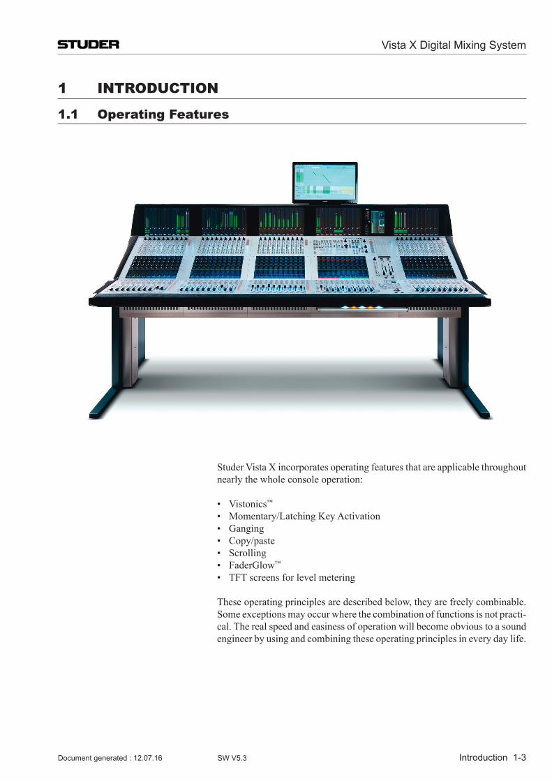
Studer Vista X incorporates operating features that are applicable throughout nearly the whole console operation:
• Vistonics™
• Momentary/LatchingKeyActivation • Ganging • Copy/paste • Scrolling • FaderGlow™
• TFTscreensforlevelmetering
These operating principles are described below, they are freely combinable. Some exceptions may occur where the combination of functions is not practi-cal. The real speed and easiness of operation will become obvious to a sound engineer by using and combining these operating principles in every day life.
Vista X Digital Mixing System
1-4 Introduction Document generated : 12.07.16SW V5.3
1.1.1 Vistonics™
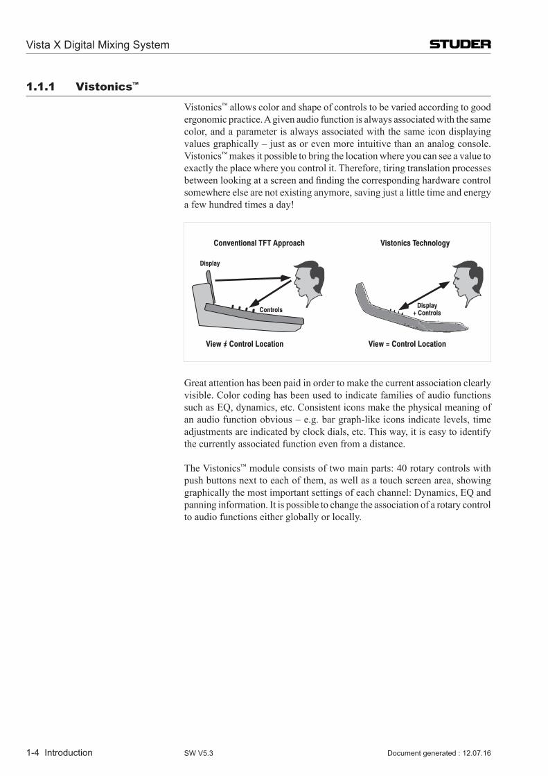
Vistonics™ allows color and shape of controls to be varied according to good ergonomic practice. A given audio function is always associated with the same color, and a parameter is always associated with the same icon displaying values graphically – just as or even more intuitive than an analog console. Vistonics™ makes it possible to bring the location where you can see a value to exactly the place where you control it. Therefore, tiring translation processes betweenlookingatascreenandfindingthecorrespondinghardwarecontrolsomewhere else are not existing anymore, saving just a little time and energy a few hundred times a day!
View = Control Location View = Control Location
Display+ Controls
Conventional TFT Approach Vistonics Technology
Controls
Display
/
Great attention has been paid in order to make the current association clearly visible. Color coding has been used to indicate families of audio functions such as EQ, dynamics, etc. Consistent icons make the physical meaning of an audio function obvious – e.g. bar graph-like icons indicate levels, time adjustments are indicated by clock dials, etc. This way, it is easy to identify the currently associated function even from a distance.
The Vistonics™ module consists of two main parts: 40 rotary controls with push buttons next to each of them, as well as a touch screen area, showing graphically the most important settings of each channel: Dynamics, EQ and panning information. It is possible to change the association of a rotary control to audio functions either globally or locally.
Vista X Digital Mixing System
Introduction 1-5Document generated : 12.07.16 SW V5.3
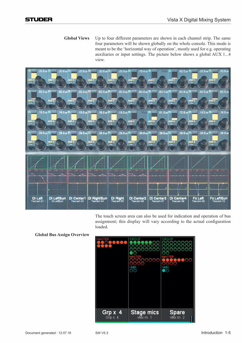
Global Views Up to four different parameters are shown in each channel strip. The same four parameters will be shown globally on the whole console. This mode is meant to be the ‘horizontal way of operation’, mostly used for e.g. operating auxiliaries or input settings. The picture below shows a global AUX 1...4 view.
The touch screen area can also be used for indication and operation of bus assignment; thisdisplaywill varyaccording to theactual configurationloaded.
Global Bus Assign Overview
Vista X Digital Mixing System
1-6 Introduction Document generated : 12.07.16SW V5.3
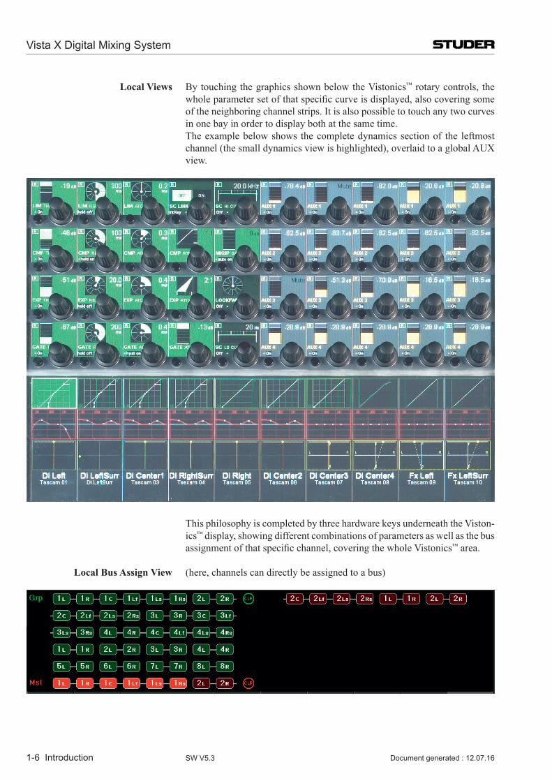
Local Views By touching the graphics shown below the Vistonics™ rotary controls, the wholeparametersetofthatspecificcurveisdisplayed,alsocoveringsomeof the neighboring channel strips. It is also possible to touch any two curves in one bay in order to display both at the same time.
The example below shows the complete dynamics section of the leftmost channel (the small dynamics view is highlighted), overlaid to a global AUX view.
This philosophy is completed by three hardware keys underneath the Viston-ics™ display, showing different combinations of parameters as well as the bus assignmentofthatspecificchannel,coveringthewholeVistonics™ area.
Local Bus Assign View (here, channels can directly be assigned to a bus)
Vista X Digital Mixing System
Introduction 1-7Document generated : 12.07.16 SW V5.3
1.1.2 Momentary/Latching Keys
A lot of key presses during console operation are repetitive in order to com-pare settings or to make quick checks for monitoring purposes. The Studer Vista console has reduced the amount of needed key presses tremendously by incorporating a special logic for these cases: The Studer Vista control surface distinguishes long and short key presses and reacts differently in both cases: Pressing and holding a key will automatically reverse its activation upon release of the key – this is, however, applied only where appropriate. All keys featuring momentary/latching activation are labeled with a symbol throughout this manual.
For example, holding down a MUTE key for one second will automatically un-mute the signal again upon release. Further examples are ON/OFF switching ofaudiofunctions(EQ,filters,dynamics),PFL/SOLOaswellasmostofthemonitoring functions: soloing different loudspeakers, muting loudspeakers, selecting alternate loudspeaker sets, etc. Keeping a monitoring source key or loudspeaker set key pressed will automatically go back to the previous selec-tion upon key release. If you want a switch to be activated continuously, just press the key and release it immediately, without holding.
This automatism also works on view changes: Pressing and holding an EQ graphic will make all its parameters accessible for as long as the graphic on the screen is being touched. However, it will disappear immediately when the graphic is untouched. The same thing is possible for global view changes: Quick checks of bus assignments or auxiliary levels are as fast as never before.
This philosophy has also the advantage of not having to remember the last settings or views. The console remembers it automatically.
Note The threshold time for the momentary/latching distinction is adjustable in the Graphical Controller’s ‘Vista Desk Settings’ screen.
Vista X Digital Mixing System
1-8 Introduction Document generated : 12.07.16SW V5.3
1.1.3 Ganging
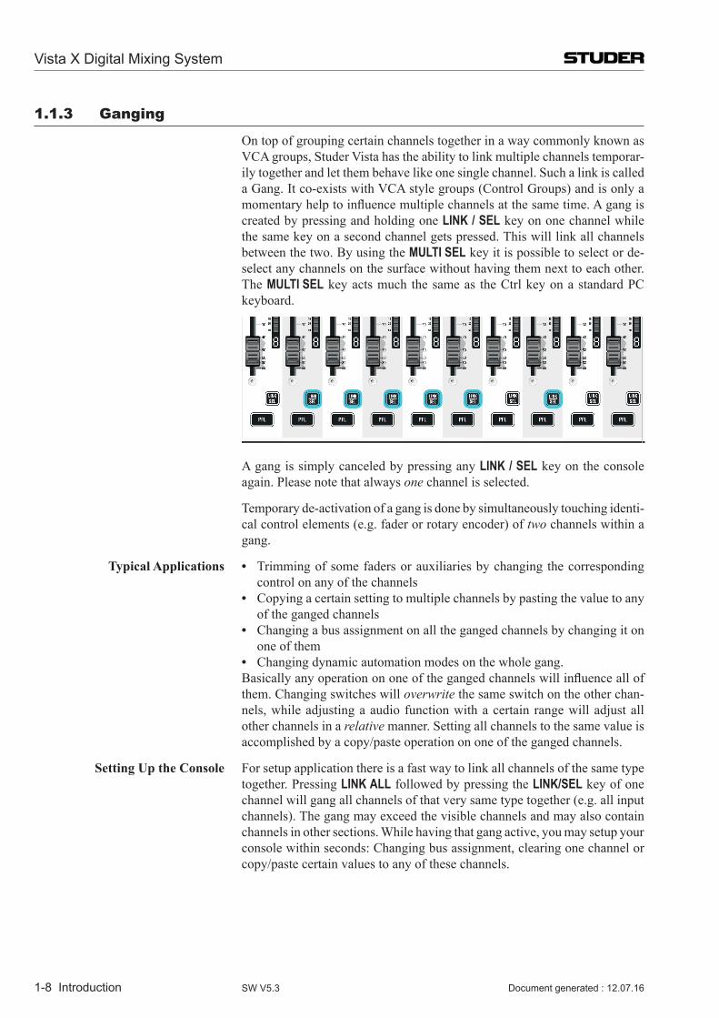
On top of grouping certain channels together in a way commonly known as VCA groups, Studer Vista has the ability to link multiple channels temporar-ily together and let them behave like one single channel. Such a link is called a Gang. It co-exists with VCA style groups (Control Groups) and is only a momentaryhelptoinfluencemultiplechannelsatthesametime.Agangiscreated by pressing and holding one LINK / SEL key on one channel while the same key on a second channel gets pressed. This will link all channels between the two. By using the MULTI SEL key it is possible to select or de-select any channels on the surface without having them next to each other. The MULTI SEL key acts much the same as the Ctrl key on a standard PC keyboard.
A gang is simply canceled by pressing any LINK / SEL key on the console again. Please note that always one channel is selected.
Temporary de-activation of a gang is done by simultaneously touching identi-cal control elements (e.g. fader or rotary encoder) of two channels within a gang.
TypicalApplications • Trimming of some faders or auxiliaries by changing the corresponding control on any of the channels
• Copying a certain setting to multiple channels by pasting the value to any of the ganged channels
• Changing a bus assignment on all the ganged channels by changing it on one of them
• Changing dynamic automation modes on the whole gang. Basicallyanyoperationononeofthegangedchannelswillinfluenceallof
them. Changing switches will overwrite the same switch on the other chan-nels, while adjusting a audio function with a certain range will adjust all other channels in a relative manner. Setting all channels to the same value is accomplished by a copy/paste operation on one of the ganged channels.
Setting Up the Console For setup application there is a fast way to link all channels of the same type together. Pressing LINK ALL followed by pressing the LINK/SEL key of one channel will gang all channels of that very same type together (e.g. all input channels). The gang may exceed the visible channels and may also contain channels in other sections. While having that gang active, you may setup your console within seconds: Changing bus assignment, clearing one channel or copy/paste certain values to any of these channels.
Vista X Digital Mixing System
Introduction 1-9Document generated : 12.07.16 SW V5.3
1.1.4 Copy/Paste
Copying certain audio settings across the console is made very fast and easy: Each channel strip hosts copy/paste keys dedicated to a certain audio func-tion, as EQ, dynamics, etc. Pressing one of these keys will make it fully lit, while all possible destination channels (channels that also have this same audio function) will show up half-lit. Selecting anyone of them will paste the value into that channel. It is possible to paste a value to multiple channels with the help of the MULTI SEL key or by creating a gang. However, there is a shortcut to paste a value to multiple channels located next to each other: Press and hold the (Copy/Paste)keyofthefirstchannelwhilepressingthe (Copy/Paste) key on the last channel. This will paste the value to all channels in between.
There is also a special A (Copy/Paste All) key to copy a whole channel including bus assignment, as well as a (Undo/Redo) key to undo the last paste or clear function on each channel separately. Pressing this key after an undo operation again will redo the last copy.
Note The (Undo/Redo) key can be used momentarily (long press) in order to compare settings on a channel:
1 Press the (Copy/Paste) key twice in order to ‘memorize’ the current setting (i.e., by pasting it to itself)
2 Adjust the audio function to an alternative setting 3 Press (Undo/Redo) multiple times (either short or long) in order to
compare the two settings.
Half-Lit Keys Whenevertheconsoleiswaitingforakeypressinordertofinishafunction,it will illuminate all possible keys by half. This is a guide for the user – so hecanselectoneofthesekeys,orreversethefunctionbypressingthefirst(fully lit) key again. A timeout applies if none of the half-lit keys are pressed within a given time frame. Timeout duration is adjustable in the “Vista Desk Settings” menu on the GC.
Examples: (Copy/Paste) > (Copy/Paste), LINK ALL > LINK/SEL, Setup of control groups, etc.
Vista X Digital Mixing System
1-10 Introduction Document generated : 12.07.16SW V5.3
1.1.5 Scrolling
Most Vista installations will have more channels available in the DSP core than there are physical faders on the console surface. Most manufacturers deal with that fact by introducing ‘layers’. The console surface can be switched in order to show the different layers, all of which making all DSP channels availabletotheuser.TheVistaoperatingphilosophyhasmodifiedthiscon-cept: Rather than thinking of layers sitting on top of each other, we think of the layers being arranged on a horizontal line. The ‘Layer’ is now called ‘Section’. The six sections are next to each other on an imaginary horizontal line, as indicated by the ‘Section Navigator’ keys in the control bay.
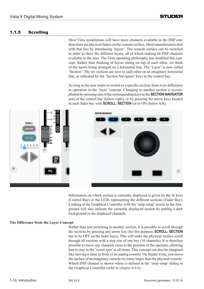
Aslongastheuserwantstoswitchtoaspecificsection,thereisnodifferencein operation to the ‘layer’ concept. Changing to another section is accom-plished by pressing one of the corresponding keys in the SEcTIoN NAvIgATor area of the control bay (below right), or by pressing the arrow keys located in each fader bay with ScroLL: SEcTIoN set to ON (below left).
Information on which section is currently displayed is given by the lit keys (Control Bay) or the LEDs representing the different sections (Fader Bay). Looking at the Graphical Controller with the ‘strip setup’ screen in the fore-ground will also indicate the currently displayed section by putting a dark background to the displayed channels.
The Difference from the Layer Concept Rather than just switching to another section, it is possible to scroll through
the sections by pressing any arrow key (for this purpose, ScroLL: SEcTIoN has to be OFF on the fader bays). This will make the physical surface scroll through all sections with a step size of one bay (10 channels). It is therefore possible to move any channels close to the position of the operator, allowing him to stay in the ‘sweet spot’ at all times. This concept can also be imagined like moving a chair in front of an analog console. On Studer Vista, you move the surface of an imaginary console six times larger than the physical console. WhichDSPchannelisshownwhereisdefinedinthe‘stripsetup’dialoginthe Graphical Controller (refer to chapter 4.4.6).
Vista X Digital Mixing System
Introduction 1-11Document generated : 12.07.16 SW V5.3
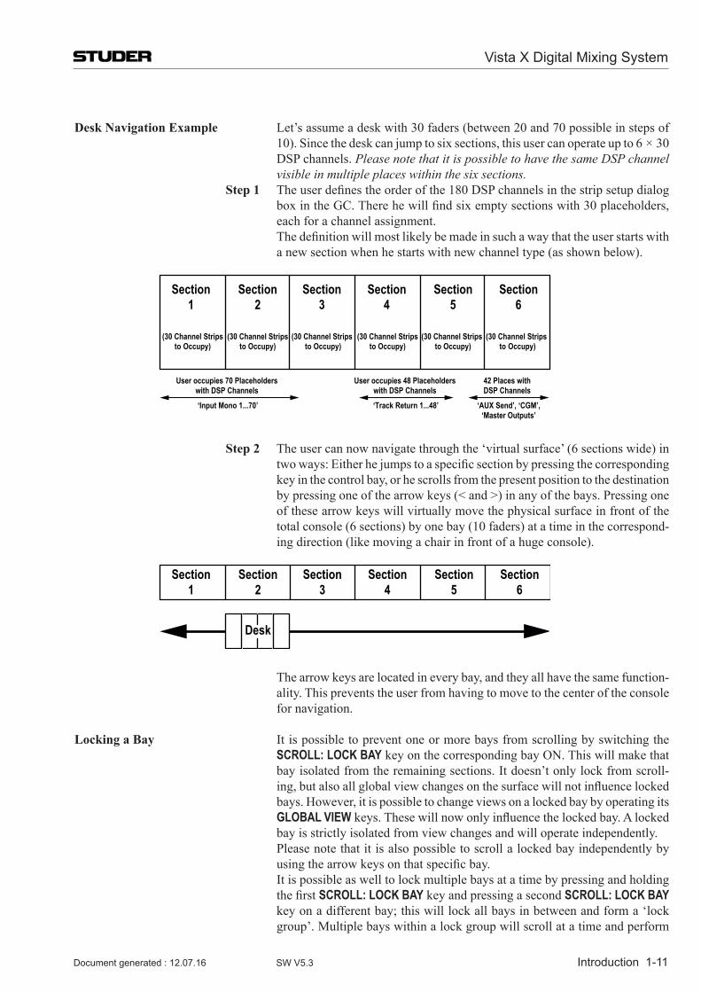
Desk Navigation Example Let’s assume a desk with 30 faders (between 20 and 70 possible in steps of 10). Since the desk can jump to six sections, this user can operate up to 6 × 30 DSP channels. Please note that it is possible to have the same DSP channel visible in multiple places within the six sections.
Step 1 Theuserdefinestheorderofthe180DSPchannelsinthestripsetupdialogboxintheGC.Therehewillfindsixemptysectionswith30placeholders,each for a channel assignment.
Thedefinitionwillmostlikelybemadeinsuchawaythattheuserstartswitha new section when he starts with new channel type (as shown below).
Section1
(30 Channel Stripsto Occupy)
Section2
Section3
Section4
Section5
Section6
(30 Channel Stripsto Occupy)
(30 Channel Stripsto Occupy)
(30 Channel Stripsto Occupy)
(30 Channel Stripsto Occupy)
(30 Channel Stripsto Occupy)
User occupies 70 Placeholders with DSP Channels
‘Input Mono 1...70’
User occupies 48 Placeholders with DSP Channels
‘Track Return 1...48’
42 Places with DSP Channels
‘AUX Send’, ‘CGM’,‘Master Outputs’
Step 2 The user can now navigate through the ‘virtual surface’ (6 sections wide) in twoways:Eitherhejumpstoaspecificsectionbypressingthecorrespondingkey in the control bay, or he scrolls from the present position to the destination by pressing one of the arrow keys (< and >) in any of the bays. Pressing one of these arrow keys will virtually move the physical surface in front of the total console (6 sections) by one bay (10 faders) at a time in the correspond-ing direction (like moving a chair in front of a huge console).
Section1
Section2
Section3
Section4
Section5
Section6
Desk
The arrow keys are located in every bay, and they all have the same function-ality. This prevents the user from having to move to the center of the console for navigation.
Locking a Bay It is possible to prevent one or more bays from scrolling by switching the ScroLL: LocK BAY key on the corresponding bay ON. This will make that bay isolated from the remaining sections. It doesn’t only lock from scroll-ing,butalsoallglobalviewchangesonthesurfacewillnotinfluencelockedbays. However, it is possible to change views on a locked bay by operating its gLoBAL vIEWkeys.Thesewillnowonlyinfluencethelockedbay.Alockedbay is strictly isolated from view changes and will operate independently.
Please note that it is also possible to scroll a locked bay independently by usingthearrowkeysonthatspecificbay.
It is possible as well to lock multiple bays at a time by pressing and holding thefirstScroLL: LocK BAY key and pressing a second ScroLL: LocK BAY key on a different bay; this will lock all bays in between and form a ‘lock group’. Multiple bays within a lock group will scroll at a time and perform
Vista X Digital Mixing System
1-12 Introduction Document generated : 12.07.16SW V5.3
common global view changes. In this way it is easy to split the desk for two-operator use.
Scrolling a Locked Bay by One Section When both the ScroLL: SEcTIoN and the ScroLL: LocK BAY keys are ON
on a fader bay, this is a special case. When pressing one of the arrow keys on thatspecificbay,thedisplayofchannelswilljumpbyexactlyonesection.This function becomes very obvious when looking at the dark background indication on the Graphical Controller. This operation mode might be useful for operators who want to change to a different section with a locked bay.
1.1.6 FaderGlow™
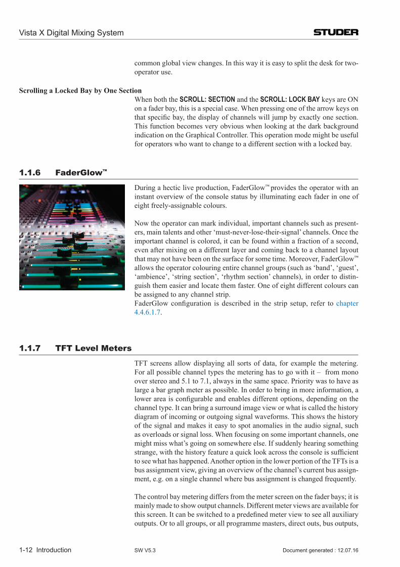
During a hectic live production, FaderGlow™ provides the operator with an instant overview of the console status by illuminating each fader in one of eight freely-assignable colours.
Now the operator can mark individual, important channels such as present-ers, main talents and other ‘must-never-lose-their-signal’ channels. Once the important channel is colored, it can be found within a fraction of a second, even after mixing on a different layer and coming back to a channel layout that may not have been on the surface for some time. Moreover, FaderGlow™
allows the operator colouring entire channel groups (such as ‘band’, ‘guest’, ‘ambience’, ‘string section’, ‘rhythm section’ channels), in order to distin-guish them easier and locate them faster. One of eight different colours can be assigned to any channel strip.
FaderGlowconfiguration isdescribed in the strip setup, refer tochapter 4.4.6.1.7.
1.1.7 TFT Level Meters
TFT screens allow displaying all sorts of data, for example the metering. For all possible channel types the metering has to go with it – from mono over stereo and 5.1 to 7.1, always in the same space. Priority was to have as large a bar graph meter as possible. In order to bring in more information, a lowerareaisconfigurableandenablesdifferentoptions,dependingonthechannel type. It can bring a surround image view or what is called the history diagram of incoming or outgoing signal waveforms. This shows the history of the signal and makes it easy to spot anomalies in the audio signal, such as overloads or signal loss. When focusing on some important channels, one might miss what’s going on somewhere else. If suddenly hearing something strange,withthehistoryfeatureaquicklookacrosstheconsoleissufficientto see what has happened. Another option in the lower portion of the TFTs is a bus assignment view, giving an overview of the channel’s current bus assign-ment, e.g. on a single channel where bus assignment is changed frequently.
The control bay metering differs from the meter screen on the fader bays; it is mainly made to show output channels. Different meter views are available for thisscreen.Itcanbeswitchedtoapredefinedmeterviewtoseeallauxiliaryoutputs. Or to all groups, or all programme masters, direct outs, bus outputs,
Vista X Digital Mixing System
Introduction 1-13Document generated : 12.07.16 SW V5.3
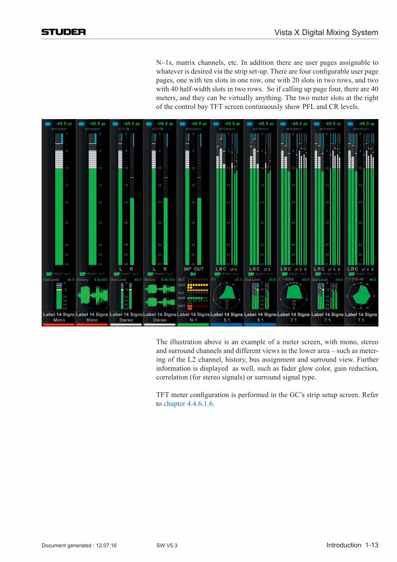
N–1s, matrix channels, etc. In addition there are user pages assignable to whateverisdesiredviathestripset-up.Therearefourconfigurableuserpagepages, one with ten slots in one row, one with 20 slots in two rows, and two with 40 half-width slots in two rows. So if calling up page four, there are 40 meters, and they can be virtually anything. The two meter slots at the right of the control bay TFT screen continuously show PFL and CR levels.
The illustration above is an example of a meter screen, with mono, stereo and surround channels and different views in the lower area – such as meter-ing of the L2 channel, history, bus assignment and surround view. Further information is displayed as well, such as fader glow color, gain reduction, correlation (for stereo signals) or surround signal type.
TFTmeterconfigurationisperformedintheGC’sstripsetupscreen.Referto chapter 4.4.6.1.6.
Vista X Digital Mixing System
1-14 Introduction Document generated : 12.07.16SW V5.3
1.2 The Graphical Controller (GC) An important feature of the Vista Digital Mixing System is the Graphical
Controller, also referred to as ‘GC’. The Graphical Controller program is used for operating all mixing console functions that extend console’s functionality.
Specifically,theGraphicalController’sextendedfunctionsinclude: • Generalandchannel-specificroutercontrol(definingtheorderofprocess-
ing elements, e.g. EQ or dynamics libraries, within a channel) • Recallandmanagementofsnapshotsandcuepoints • Savingofdeskclipboards • AssignmentoftheDSPchannelstothefaderstrips • Tonegeneratorandmeteringcontrol • Controlgroupandlinkagecontrol • ProductionandTitlemanagement • Systemadministration
Various display windows and dialog boxes logically group the individual functions. Visual elements are optimized for simple and intuitive operation.
With the help of an easy-to-understand General Patch page, the setup of routercrosspointsisdramaticallysimplified,evenforlargemixingconsoleconfigurations.ViaaSnapshotwindow,allmixingconsoleparameterscanbestored and recalled using mouse clicks. Some of the most important functions are also available as dedicated keys on Vista’s control bay.
Theconceptofoverallsystemconfigurabilityhasbeenalsoadoptedwithinthe Graphical Controller application. Since most functions are arranged in overlapping windows of changeable sizes, users can set up their work envi-ronmenttosuittheirspecificrequirementsforeachrecordingorproductionsession. These settings can be saved and recalled at any time, allowing for fast and application-oriented operation of the Vista system.
Vista X Digital Mixing System
Introduction 1-15Document generated : 12.07.16 SW V5.3
1.2.1 GC Screen Examples
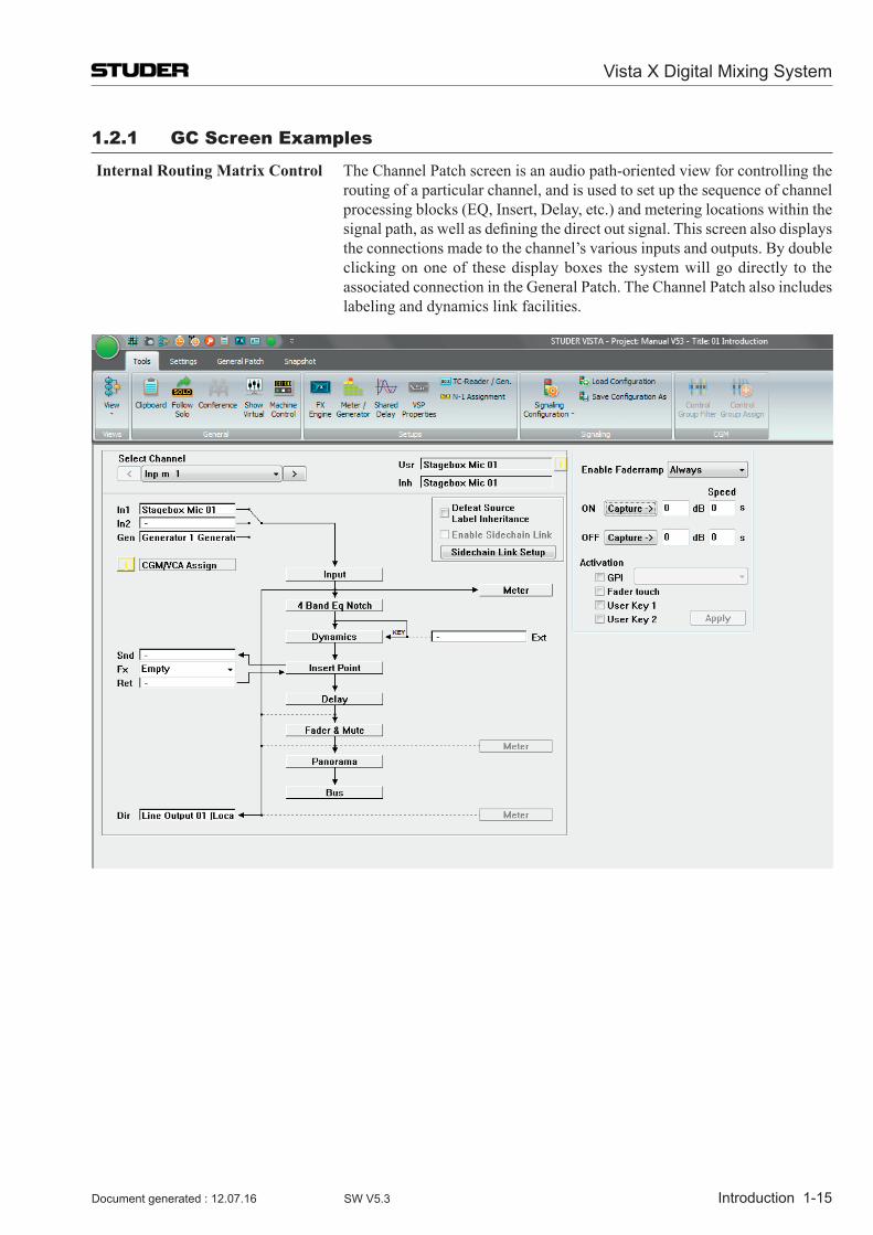
Internal Routing Matrix Control The Channel Patch screen is an audio path-oriented view for controlling the routing of a particular channel, and is used to set up the sequence of channel processing blocks (EQ, Insert, Delay, etc.) and metering locations within the signalpath,aswellasdefiningthedirectoutsignal.Thisscreenalsodisplaysthe connections made to the channel’s various inputs and outputs. By double clicking on one of these display boxes the system will go directly to the associated connection in the General Patch. The Channel Patch also includes labeling and dynamics link facilities.
Vista X Digital Mixing System
1-16 Introduction Document generated : 12.07.16SW V5.3
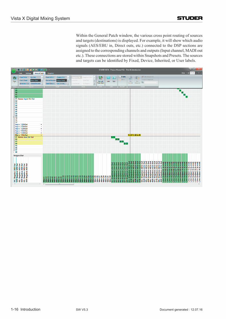
Within the General Patch window, the various cross point routing of sources and targets (destinations) is displayed. For example, it will show which audio signals (AES/EBU in, Direct outs, etc.) connected to the DSP sections are assigned to the corresponding channels and outputs (Input channel, MADI out etc.). These connections are stored within Snapshots and Presets. The sources andtargetscanbeidentifiedbyFixed,Device,Inherited,orUserlabels.
Vista X Digital Mixing System
Introduction 1-17Document generated : 12.07.16 SW V5.3
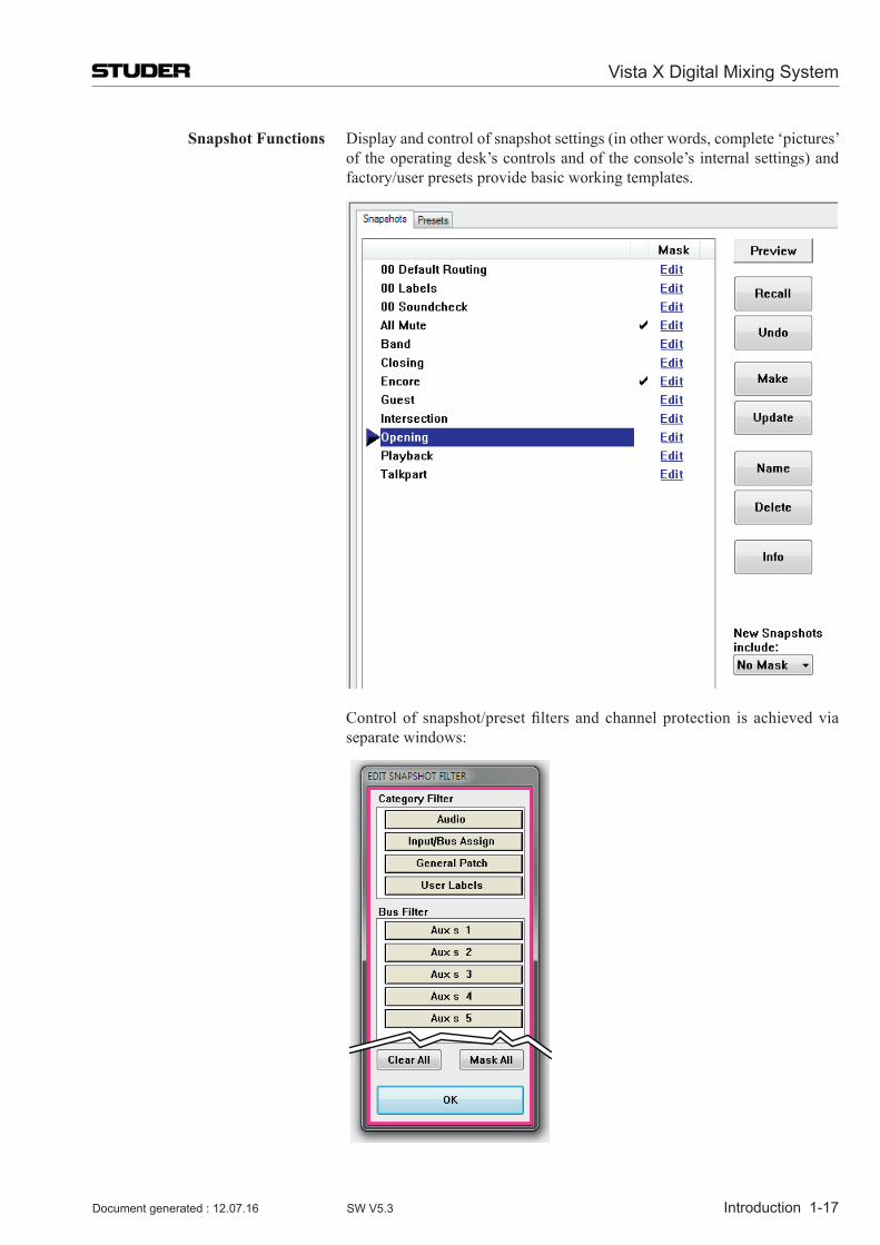
Snapshot Functions Display and control of snapshot settings (in other words, complete ‘pictures’ of the operating desk’s controls and of the console’s internal settings) and factory/user presets provide basic working templates.
Controlof snapshot/presetfilters andchannelprotection is achievedviaseparate windows:
Vista X Digital Mixing System
1-18 Introduction Document generated : 12.07.16SW V5.3
1.3 Channels, Routing, and Buses Processingblocks,suchasequalizer,dynamics,delay,etc.,canbeconfigured
for all channel types.
Input Channels Vista’s digital routing matrix is located between the console’s physical inputs and the actual DSP channels. This topology means that the physical analog and digital inputs can be assigned to any console channel via the General Patch page on the Graphical Controller. The patch setup forms part of each individual snapshot, and can be saved, updated and recalled within the Snap-shot/Preset system.
Output Channels This also applies to the outputs. On the General Patch page, each channel’s output can be selected and sent to any analog or digital output destination.
Auxiliaries ThenumberofstereoormonoAUXsendsisfullyconfigurable.Theuserscan establish the number and type of AUX sends they would like to use. The AUX master channel can be equipped with the same selection of processing blocks such as equalizer, dynamics, delay, and more.
Clean-Feeds/Mix-Minus (N–1/N–X) Clean-Feeds/Mix-Minus or N–1/N–X buses can be set up in stereo or mono, andareconfigurableinnumber.
Multi-track and Group Routing Fullmulti-trackandgrouproutingcanbeconfigured.
Solo Modes Each channel features a Solo and a PFL Switch. Depending upon the mode selected within the Control Bay the SOLO key is active as SOLO or Solo-In-Place. Clearing these buttons can be achieved by opening the corresponding fader in case ‘PFL BC’ (Broadcast) is active. A very handy PFL/Solo Reset is provided to disengage any solos regardless of where they are engaged on the console. This eliminates the need to ‘search’ for solos with large console configurations.Akeytodefinecertainchannelstobesafefrombeingmutedin ‘Solo-In-Place’ mode is also provided. This set will be stored with each title.
Vista X Digital Mixing System
Introduction 1-19Document generated : 12.07.16 SW V5.3
1.4 Processing Blocks Equalizer Four fully parametric bands are provided on the Vista. Each band, which
can be switched in and out independently, extends from 20 Hz to 20 kHz, with a ±18 dB gain range. The EQ features a psycho-acoustically corrected frequency response for high frequencies, similar to well-known analog EQ designs. The two mid-bands can be switched between constant-Q and constant-range modes. The high and low frequency bands can be switched to shelvingmode.AsecondEQtypeisavailable(definedintheConfigurationTool),whichfeaturesanadditionalNotchfilter.
Since SW V4.8 an additional, 30-band BSS graphic EQ is available; its set-tings may be indicated and adjusted by 30 of the desk faders very simply. If required,boththeparametricandthegraphicEQmaybeconfiguredwithinthe same DSP channel.
Filter Low-cutandhigh-cutfiltersareprovided,withcutofffrequenciesthatare
variable between 20 Hz and 20 kHz, and slope selections of 12, 18, or 24 dB/octave.
Inaddition,ananaloglow-cutfilterwithacutofffrequencyof75Hzandaslopeof12dB/octaveisavailableintheD21mMic/Linepreamplifier.
Dynamics The Vista standard dynamics processing consists of four parts: Limiter, Compressor, Expander, and Gate. To avoid pumping and modulation, the dynamics processing sections feature
high sampling rate transient detection. Distortion artifacts are minim ized through selectable, program-dependent attack and release times. The Vista’s dynamics feature a side-chain input that can be used with or without HP/LPfilters.Aunique‘lookforward’functionisalsofeatured.Ifdesired,thisallows the entire transient portion of a waveform to be affected when using the limiter/compressor or to be passed when the expander/gate is used.
Sometimes the dynamics processing can be utilized in a more pronounced way, i.e., as an effect itself. For this purpose the ‘vintage dynamics’ was cre-ated.Itistargetedtobeflexibleenoughfordifferenttypesofsoundcolorationincluding extreme and unusual settings, but does not feature a dedicated limiter.
Selection between the standard or vintage dynamics section can be made per inputchannelduringconfigurationoftheconsole.
Soft Clip In addition, a soft clip function can be activated in the D21m Mic/Line pre-amplifier.
1.5 Monitoring and Communication Monitoring The Control Room (CR) monitoring section provides control of up to three
different speaker systems (two multi-channel and one two-channel stereo) and 32 source selectors. All internal digital sources can be assigned to any of the source selector keys. A headphone socket is also supplied for use within the control room.
TheStudioMonitorisconfigurableinthesamewayastheCRmonitorsec-tion. Two stereo loudspeaker pairs are supported.
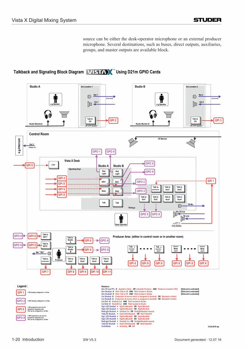
Talkback An extensive talkback system is implemented within the Vista. The talkback
Vista X Digital Mixing System
1-20 Introduction Document generated : 12.07.16SW V5.3
source can be either the desk-operator microphone or an external producer microphone. Several destin ations, such as buses, direct outputs, auxiliaries, groups, and master outputs are available block.
Control Room
Studio A
Talk to CR
Ret 1
Ext 1
Studio MonitorA
TB only
PFL/TB Out
CR Monitor
Signaling Keys
Talk to Aux1
Talk to Aux2
Talk to Aux3
Talk to Aux4
Talk to Aux1
Talk to Aux2
Talk to Ext1
Talk to Ext2
Talk to Aux3
Talk to Aux4
Talk topreselected
Talk topreselected
Talk to Studio
B
e.g.Speaker
GPI 2
GPI 4
GPI 5 GPO 3
GPO 2 GPI 1
Foot Switch
GPI 7 GPI 8 GPI 9 GPI 10 GPI 11
e.g.In
terc
om
Ext 3
(Line level) (Line level)
(always on)
Vista X Desk
Mic "TB2"
TB Mic
GPO 1
Ext Location 1
Producer
( to PFL Speaker)
Studio B
Talk to CR
Ret 2
Ext 2
Studio Monitor BGPI 3
Ext Location 2
( to PFL Speaker)
Talk to Studio
A GPI 6
GPI XTalk toChanOut
Grp01
Talk to ChanOut
Grp N
Channel MuteGrp01
ChannelMuteGrp N
Talk to EXT1
Talk to EXT2GPI13
GPI12
GPI X GPI X GPI X GPI XGPI XGPI X
LiveGPI X
GPO 4
GPO X
GPO X
GPI X
GPI X
GPO X
GPO X
e.g.Speaker
GPO 6
GPO X
TB Keys
GPO 5
Legend :
GPI 1
GPO 2
GPI X
= GPI already configured in .ini files
= GPO already configured in .ini files
= GPI prepared to use, but not assigned to signaling card. This can be configured in .ini files
GPO X= GPO prepared to use, but not assigned to signaling card. This can be configured in .ini files
Desk Operator
GPO X
Producer Area (either in control room or in another room)
Studio A Studio BRed Light
SIG1
SIG2
Talk
Red Light
SIG1
SIG2
Talk
12.04.2016 wp
Talkback and Signaling Block Diagram Using D21m GPIO Cards
Relations :Dim CR and PFL if: Anytalk in Desk OR ( )Anytalk Producer AND Producer located in CR [DimLock is activated]Dim StudioA if: Ret1 Talk to CR AND Ret1 located in Studio [DimLock is activated]Dim StudioB if: Ret2 Talk to CR AND Ret2 located in Studio [DimLock is activated]Cut StudioA if: (Faderstart of source which is assigned to StudioA) OR (StudioA is OnAir)Cut StudioB if: (Faderstart of source which is assigned to StudioB) OR (StudioB is OnAir)Cut Ext1 if: StudioA Cut AND Ret1 located in StudioCut Ext2 if: StudioB Cut AND Ret2 located in StudioSig1 LED StudioA = Sig1OutStudioA OR Sig1InStudioASig2 LED StudioA = Sig2OutStudioA OR Sig2InStudioARedLight StudioA = StudioA Cut OR RedlightStudioA manualTalkLED StudioA = DeskTalktoStudioA OR Ret1TalktoCRSig1 LED StudioB = Sig1OutStudioB OR Sig1InStudioBSig2 LED StudioB = Sig2OutStudioB OR Sig2InStudioBRedLight StudioB = StudioB Cut OR RedlightStudioB manualTalkLED StudioB = DeskTalktoStudioB OR Ret2TalktoCROnAirMode = OnAirKey OR GPI
Vista X Digital Mixing System
Introduction 1-21Document generated : 12.07.16 SW V5.3
Eachchannelisfittedwithatalkbackkeythatactivatestalkbacktothedirectoutput of the corresponding channel and, if the channel is an N–1 owner, to the N–1 output.
For details see the talkback and signaling block diagram below.
1.6 AutomationStatic Automation Snapshots An unlimited number of snapshots can be captured, stored, and recalled
for each Project Title. All control parameters of the console are stored in the snapshots. When a snapshot is recalled, the console typically requires 120 ms to fully reset itself. Snapshots recalls can be done with snapshot filtersactive,protectingcertainconsoleparametersfrombeingchangedbythe recall. Extensive editing functions allow modifying snapshots after or during a live show. Besides absolute protection of certain parameters it is possible to trim parameters relative to their stored values rather then letting themtotallyunmodified.Recallingapresethowever,willignoreanysnapshotfilterswhichmaybeactiveandbringtheconsoleintoadefinedaudiostate.
Copy & Paste Clipboard The Vista System supports copy and paste of some or all channel settings to one or more other channels. This ability streamlines the set-up of the console when an operator is starting from scratch with a new layout. However, if starting from a clean slate is desired, clearing all or some of the parameters is possible as well.
Dynamic Automation Each audio parameter of the Vista mixing console can be stored and recalled dynamically against timecode information.
Such enormous versatility can be accompanied, of course, by a certain op-eration complexity. For this reason, most operator controls capable of being automated are touch-sensitive.
Please refer to chapter 5 for a complete description.
(Parameters of Lexicon FX currently are an exception - they can only be stored and recalled in static snapshots).
Vista X Digital Mixing System
1-22 Introduction Document generated : 12.07.16SW V5.3
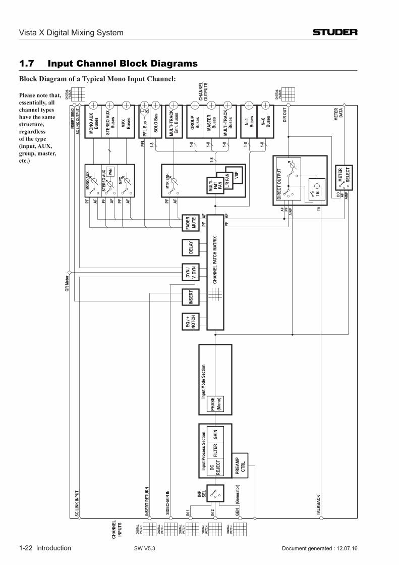
1.7 Input Channel Block diagramsBlock Diagram of a Typical Mono Input Channel:
Please note that,essentially, all channel types have the same structure, regardless of the type (input, AUX, group, master, etc.)
VSP
L/R
PAN
TALK
BACK
PREA
MPCT
RL
EQ / +
NOTC
HIN
SERT
PHAS
E(M
ono)
IN 1
IN 2
GEN
(Ge
nera
tor)
INSE
RT R
ETUR
N
INP
SEL
CHAN
NEL
INPU
TS
GR M
eter
SC L
INK
INPU
T
Inpu
t Mod
e Sec
tion
FILT
ERDC
REJE
CTGA
IN
Inpu
t Pro
cess
Sec
tion
SIDE
CHAI
N IN
DIGI
TAL
PATC
H
DIGI
TAL
PATC
H
DIGI
TAL
PATC
H
DIGI
TAL
PATC
H
DIGI
TAL
PATC
H
DYN
/V.
DYN
FADE
RMU
TEDE
LAY
PFAF
CHAN
NEL
PATC
H MA
TRIX
PFAF
PATC
HDI
GITA
L
DIGI
TAL
PATC
H
MULT
I-TRA
CKBu
ses
MULT
I-TRA
CKEn
h. B
uses
DIR
OUT
AF PFAI
NP TB
DIRE
CT O
UTPU
T
TB
METE
RSE
LECT
DO AF AINP
METE
RDA
TA
N–X
Buse
s
N–1
Buse
s
PFL
1-8 1-8
1-8
1-8
1-8
1-8
1-8
STER
EO A
UXBu
ses
GROU
PBu
ses
MAST
ERBu
ses
MONO
AUX
Buse
s
MPX
Buse
s
INSE
RT S
END
CHA
NNEL
OUTP
UTS
PFL
Bus
SOLO
Bus
SC L
INK
OUTP
UT L R
PAN
PF AF PF AFPF AF
MONO
AUX
MPX
PF AF
MTR
ENH.
STER
EO A
UX
MULT
I-FM
TPA
N
Vista X Digital Mixing System
Introduction 1-23Document generated : 12.07.16 SW V5.3
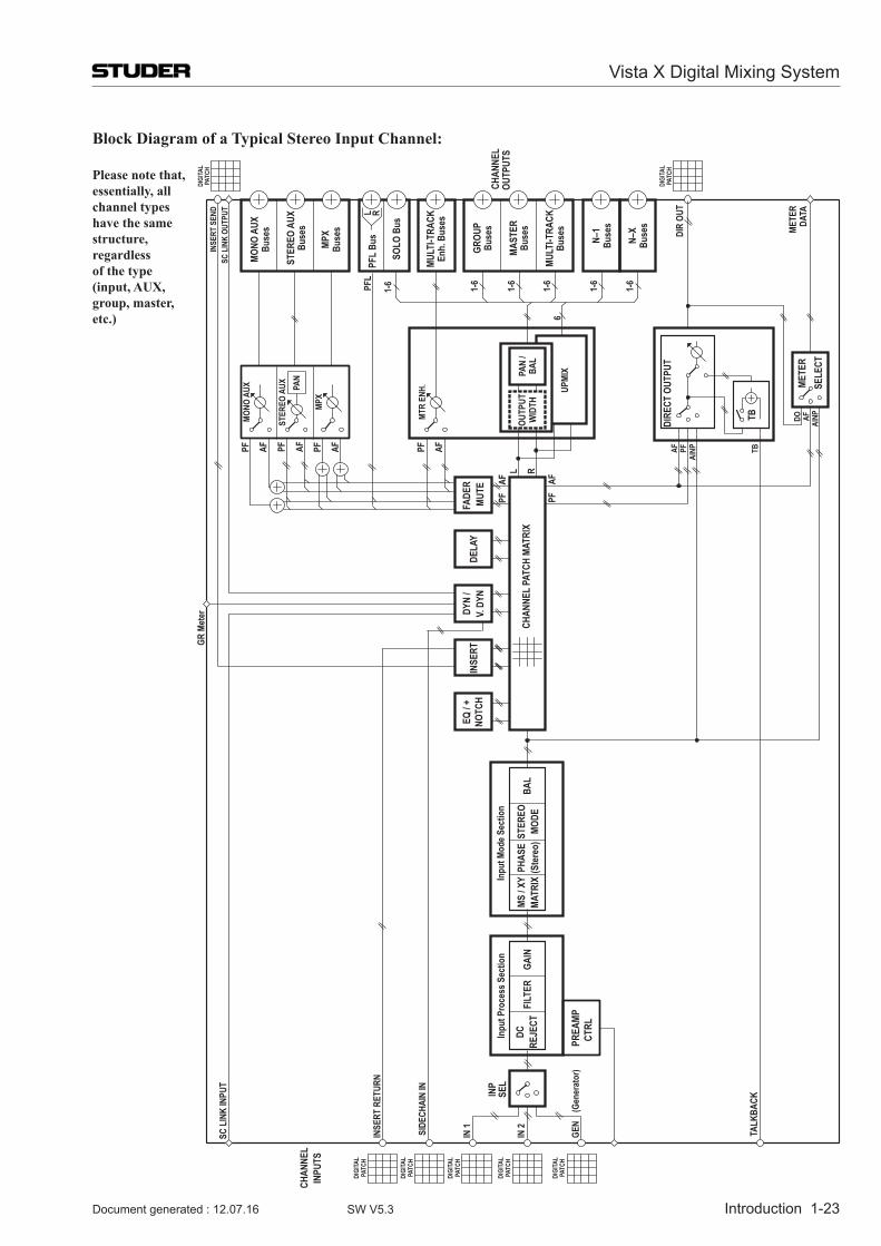
Block Diagram of a Typical Stereo Input Channel:
Please note that,essentially, all channel types have the same structure, regardless of the type (input, AUX, group, master, etc.)
TALK
BACK
PREA
MPCT
RL
EQ / +
NOTC
HIN
SERT
MS / X
YPH
ASE
MATR
IX(S
tere
o)ST
EREO
BAL
MODE
IN 1
IN 2
GEN
(Ge
nera
tor)
INSE
RT R
ETUR
N
INP
SEL
CHAN
NEL
INPU
TS
GR M
eter
SC L
INK
INPU
T
Inpu
t Mod
e Sec
tion
FILT
ERDC
REJE
CTGA
IN
Inpu
t Pro
cess
Sec
tion
SIDE
CHAI
N IN
DIGI
TAL
PATC
H
DIGI
TAL
PATC
H
DIGI
TAL
PATC
H
DIGI
TAL
PATC
H
DIGI
TAL
PATC
H
DYN
/V.
DYN
FADE
RMU
TEDE
LAY
PFAF
CHAN
NEL
PATC
H MA
TRIX
PFAF
PATC
HDI
GITA
L
DIGI
TAL
PATC
H
L R
MULT
I-TRA
CKBu
ses
MULT
I-TRA
CKEn
h. B
uses
DIR
OUT
AF PFAI
NP TB
DIRE
CT O
UTPU
T
TB
METE
RSE
LECT
DO AF AINP
METE
RDA
TA
N–X
Buse
s
N–1
Buse
s
PFL
1-6
61-
6
1-6
1-6
1-6
1-6
STER
EO A
UXBu
ses
GROU
PBu
ses
MAST
ERBu
ses
MONO
AUX
Buse
s
MPX
Buse
s
INSE
RT S
END
CHA
NNEL
OUTP
UTS
PFL
Bus
SOLO
Bus
SC L
INK
OUTP
UT L R
PAN
PF AF PF AFPF AF
MONO
AUX
MPX
PF AF
MTR
ENH.
STER
EO A
UX
PAN
/BA
L
UPMI
X
OUTP
UTW
IDTH
Vista X Digital Mixing System
1-24 Introduction Document generated : 12.07.16SW V5.3
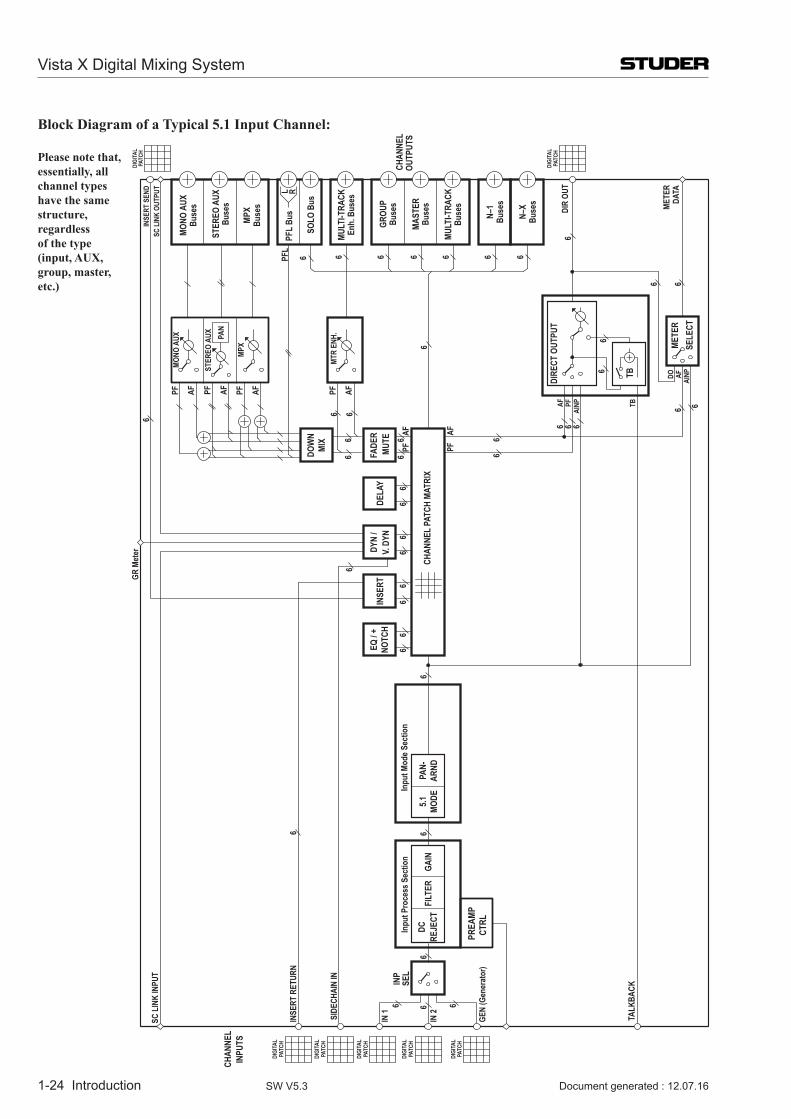
Block Diagram of a Typical 5.1 Input Channel:
Please note that,essentially, all channel types have the same structure, regardless of the type (input, AUX, group, master, etc.)
TALK
BACK
PREA
MPCT
RL
EQ / +
NOTC
HIN
SERT
5.1 MODE
PAN-
ARND
IN 1
IN 2
GEN
(Gen
erat
or)
INSE
RT R
ETUR
N
INP
SEL
CHAN
NEL
INPU
TS
GR M
eter
SC L
INK
INPU
T
Inpu
t Mod
e Sec
tion
FILT
ERDC
REJE
CTGA
IN
Inpu
t Pro
cess
Sec
tion
SIDE
CHAI
N IN
DIGI
TAL
PATC
H
DIGI
TAL
PATC
H
DIGI
TAL
PATC
H
DIGI
TAL
PATC
H
DIGI
TAL
PATC
H
DYN
/V.
DYN
FADE
R
DOW
NMI
X
MUTE
DELA
Y
PFAF
CHAN
NEL
PATC
H MA
TRIX
PFAF
PATC
HDI
GITA
L
DIGI
TAL
PATC
H
MULT
I-TRA
CKBu
ses
MULT
I-TRA
CKEn
h. B
uses
DIR
OUT
AF PFAI
NP TB
DIRE
CT O
UTPU
T
TB
METE
RSE
LECT
DO AF AINP
METE
RDA
TA
N–X
Buse
s
N–1
Buse
s
PFL
66
6
66
66
66
66
6
6
66
6
66
66
66
6 6
6 66
666
66
6
6
6 6
6
6666 6 6
STER
EO A
UXBu
ses
GROU
PBu
ses
MAST
ERBu
ses
MONO
AUX
Buse
s
MPX
Buse
s
INSE
RT S
END
CHA
NNEL
OUTP
UTS
PFL
Bus
SOLO
Bus
SC L
INK
OUTP
UT L R
PAN
PF AF PF AFPF AF
MONO
AUX
MPX
PF AF
MTR
ENH.
STER
EO A
UX
Desk Operation 2-1
Chapter 2
2 Desk Operation .................................................................................................................................................32.1 Fader Bay Overview ...........................................................................................................................................4
2.2 Fader Bay Details ...............................................................................................................................................42.2.1 Area 1 – Channel Metering .................................................................................................................................. 52.2.2 Area 2 – Channel Control ..................................................................................................................................... 52.2.3 Area 3a – Channel Control .................................................................................................................................... 62.2.4 Area 3b – Faders ................................................................................................................................................... 8
2.2.4.1 Channel LED Meters ...............................................................................................................................................102.2.4.2 Two-Layer mode ......................................................................................................................................................10
2.2.5 Area 4 – Vistonics™ ........................................................................................................................................... 122.2.6 Areas 5a, 5b – Channel Selection ....................................................................................................................... 152.2.7 Area 6 – Desk Scrolling ...................................................................................................................................... 16
2.3 Control Bay Overview ......................................................................................................................................17
2.4 Control Bay Details ..........................................................................................................................................182.4.1 Area 1 – System Power On/Off .......................................................................................................................... 182.4.2 Areas 1 and 2 – Control Bay Metering .............................................................................................................. 20
2.4.2.1 Loudness Metering ...................................................................................................................................................212.4.3 Area 3 – Machine Control Panel (Optional) ....................................................................................................... 222.4.4 Area 4 – Monitoring Source Selector.................................................................................................................. 242.4.5 Area 5 – CR (Control Room) Monitoring .......................................................................................................... 252.4.6 Area 6 – Studio Monitoring ............................................................................................................................... 272.4.7 Area 7 – Talkback / Headphones Control ........................................................................................................... 282.4.8 Area 8 – Dynamic Automation / Static Automation ........................................................................................... 302.4.9 Area 9 – Mute Group / Control Group / Conference Setup ............................................................................... 342.4.10 Area 10 – Control Bay Vistonics™..................................................................................................................... 352.4.11 Area 11 – Control Bay Faders ............................................................................................................................. 38
2.4.11.1 SpillZone ..................................................................................................................................................................402.4.11.2 Follow Solo ..............................................................................................................................................................43
2.4.12 Area 12 – Grand Master Faders .......................................................................................................................... 452.4.12.1 Stereo Channel Fader Unfold on Grand Masters .....................................................................................................46
2.4.13 Area 13 – Joystick .............................................................................................................................................. 482.4.14 Area 14 – Mute Groups ....................................................................................................................................... 492.4.15 Area 15 – Keyboard / Trackball / Graphical Controller ..................................................................................... 512.4.16 Area 16 – Section Navigator .............................................................................................................................. 522.4.17 Area 17 – Fader Page Selector ............................................................................................................................ 522.4.18 Area 18 – Cue List Keys ..................................................................................................................................... 532.4.19 Area 19 – Option/Spare Keys ............................................................................................................................. 54
2.5 Console Illumination ........................................................................................................................................54
2.6 Metering ............................................................................................................................................................55
2.7 FaderGlow ........................................................................................................................................................57
2.8 Virtual Vista ......................................................................................................................................................582.8.1 Screen Layout...................................................................................................................................................... 602.8.2 Fader Bay View ................................................................................................................................................... 612.8.3 Control Bay View ................................................................................................................................................ 62
Vista X Digital Mixing System
Document generated: 12.07.16 SW V5.3
2-2 Desk Operation
2.8.4 GC View .............................................................................................................................................................. 64
2.9 Desk Redundancy Handling - by Vista Supervisor ..........................................................................................65
Vista X Digital Mixing System
Document generated: 12.07.16SW V5.3
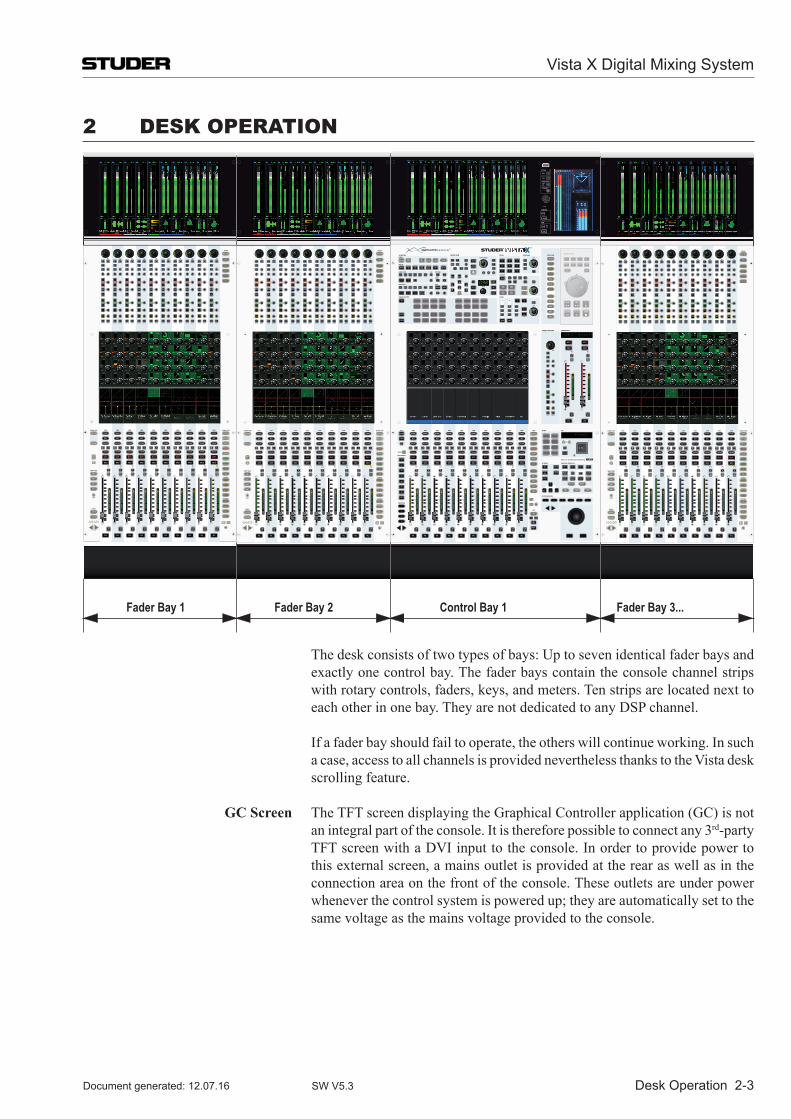
Desk Operation 2-3
2 Desk OperatiOn
Fader Bay 1 Fader Bay 2 Control Bay 1 Fader Bay 3...
The desk consists of two types of bays: Up to seven identical fader bays and exactly one control bay. The fader bays contain the console channel strips with rotary controls, faders, keys, and meters. Ten strips are located next to each other in one bay. They are not dedicated to any DSP channel.
If a fader bay should fail to operate, the others will continue working. In such a case, access to all channels is provided nevertheless thanks to the Vista desk scrolling feature.
GC Screen The TFT screen displaying the Graphical Controller application (GC) is not an integral part of the console. It is therefore possible to connect any 3rd-party TFT screen with a DVI input to the console. In order to provide power to this external screen, a mains outlet is provided at the rear as well as in the connection area on the front of the console. These outlets are under power whenever the control system is powered up; they are automatically set to the same voltage as the mains voltage provided to the console.
Vista X Digital Mixing System
Document generated: 12.07.16 SW V5.3
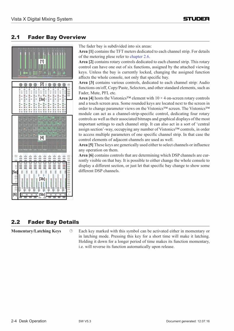
2-4 Desk Operation
2.1 Fader Bay Overview
[2]
[3a]
[4]
[3b][5a]
[6]
[1]
[5b]
The fader bay is subdivided into six areas: Area [1] contains the TFT meters dedicated to each channel strip. For details
of the metering plese refer to chapter 2.6. Area [2] contains rotary controls dedicated to each channel strip. This rotary
control can have one out of six functions, assigned by the attached viewing keys. Unless the bay is currently locked, changing the assigned function affects the whole console, not only that specific bay.
Area [3] contains various controls, dedicated to each channel strip: Audio functions on/off, Copy/Paste, Selectors, and other standard elements, such as Fader, Mute, PFL etc.
Area [4] hosts the Vistonics™ element with 10 × 4 on-screen rotary controls and a touch screen area. Some rounded keys are located next to the screen in order to change parameter views on the Vistonics™ screen. The Vistonics™ module can act as a channel-strip-specific control, dedicating four rotary controls as well as their associated bitmaps and graphical displays of the most important settings to each channel strip. It can also act in a sort of ‘central assign section’-way, occupying any number of Vistonics™ controls, in order to access multiple parameters of one specific channel strip. In that case the control elements of adjacent channels are used as well.
Area [5] These keys are generically used either to select channels or influence any operation on them.
Area [6] contains controls that are determining which DSP channels are cur-rently visible on that bay. It is possible to either change the whole console to display a different section, or just let that specific bay change to show some different DSP channels.
2.2 Fader Bay DetailsMomentary/Latching Keys Each key marked with this symbol can be activated either in momentary or
in latching mode. Pressing this key for a short time will make it latching. Holding it down for a longer period of time makes its function momentary, i.e. will reverse its function automatically upon release.
Vista X Digital Mixing System
Document generated: 12.07.16SW V5.3
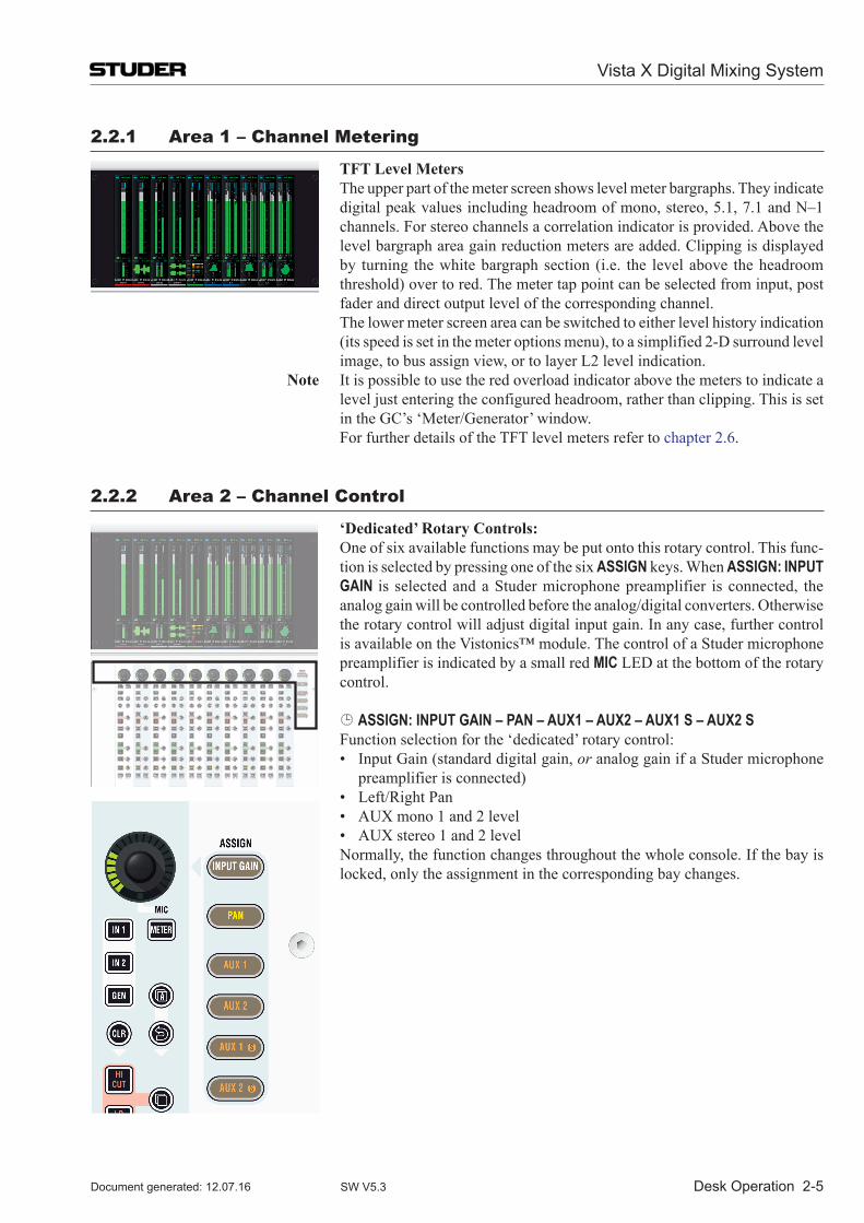
Desk Operation 2-5
2.2.1 area 1 – Channel Metering
TFT Level Meters The upper part of the meter screen shows level meter bargraphs. They indicate
digital peak values including headroom of mono, stereo, 5.1, 7.1 and N–1 channels. For stereo channels a correlation indicator is provided. Above the level bargraph area gain reduction meters are added. Clipping is displayed by turning the white bargraph section (i.e. the level above the headroom threshold) over to red. The meter tap point can be selected from input, post fader and direct output level of the corresponding channel.
The lower meter screen area can be switched to either level history indication (its speed is set in the meter options menu), to a simplified 2-D surround level image, to bus assign view, or to layer L2 level indication.
Note It is possible to use the red overload indicator above the meters to indicate a level just entering the configured headroom, rather than clipping. This is set in the GC’s ‘Meter/Generator’ window.
For further details of the TFT level meters refer to chapter 2.6.
2.2.2 area 2 – Channel Control
‘Dedicated’ Rotary Controls: One of six available functions may be put onto this rotary control. This func-
tion is selected by pressing one of the six ASSIGN keys. When ASSIGN: INPUT GAIN is selected and a Studer microphone preamplifier is connected, the analog gain will be controlled before the analog/digital converters. Otherwise the rotary control will adjust digital input gain. In any case, further control is available on the Vistonics™ module. The control of a Studer microphone preamplifier is indicated by a small red MIC LED at the bottom of the rotary control.
ASSIGN: INPUT GAIN – PAN – AUX1 – AUX2 – AUX1 S – AUX2 S Function selection for the ‘dedicated’ rotary control: • InputGain(standarddigitalgain,or analog gain if a Studer microphone
preamplifier is connected) • Left/RightPan • AUXmono1and2level • AUXstereo1and2level Normally, the function changes throughout the whole console. If the bay is
locked, only the assignment in the corresponding bay changes.
Vista X Digital Mixing System
Document generated: 12.07.16 SW V5.3
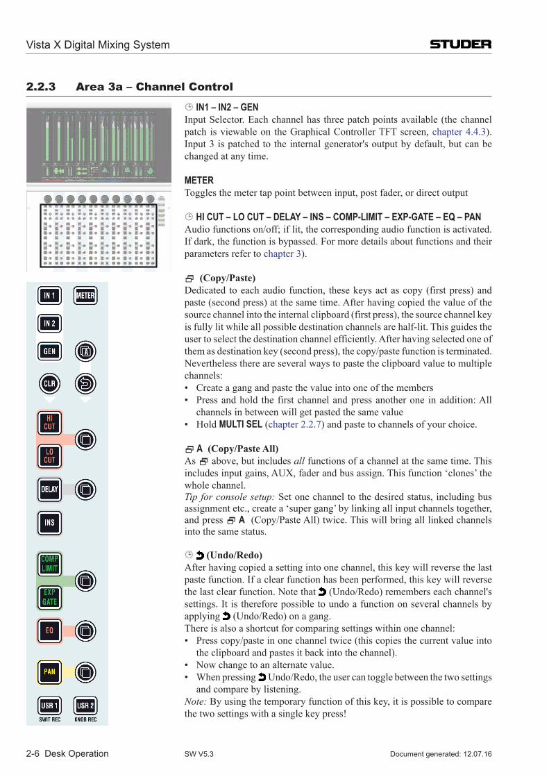
2-6 Desk Operation
2.2.3 area 3a – Channel Control
IN1 – IN2 – GEN Input Selector. Each channel has three patch points available (the channel
patch is viewable on the Graphical Controller TFT screen, chapter 4.4.3). Input 3 is patched to the internal generator's output by default, but can be changed at any time.
METER Toggles the meter tap point between input, post fader, or direct output
HI CUT – LO CUT – DELAY – INS – COMP-LIMIT – EXP-GATE – EQ – PAN Audio functions on/off; if lit, the corresponding audio function is activated.
If dark, the function is bypassed. For more details about functions and their parameters refer to chapter 3).
(Copy/Paste) Dedicated to each audio function, these keys act as copy (first press) and
paste (second press) at the same time. After having copied the value of the source channel into the internal clipboard (first press), the source channel key is fully lit while all possible destination channels are half-lit. This guides the user to select the destination channel efficiently. After having selected one of them as destination key (second press), the copy/paste function is terminated. Nevertheless there are several ways to paste the clipboard value to multiple channels:
• Createagangandpastethevalueintooneofthemembers • Pressandhold the firstchannelandpressanotherone inaddition:All
channels in between will get pasted the same value • HoldMULTI SEL (chapter 2.2.7) and paste to channels of your choice. A (Copy/Paste All) As above, but includes all functions of a channel at the same time. This
includesinputgains,AUX,faderandbusassign.Thisfunction‘clones’thewhole channel.
Tip for console setup: Set one channel to the desired status, including bus assignment etc., create a ‘super gang’ by linking all input channels together, and press A (Copy/Paste All) twice. This will bring all linked channels into the same status.
(Undo/Redo) After having copied a setting into one channel, this key will reverse the last
paste function. If a clear function has been performed, this key will reverse the last clear function. Note that (Undo/Redo) remembers each channel's settings. It is therefore possible to undo a function on several channels by applying (Undo/Redo) on a gang.
There is also a shortcut for comparing settings within one channel: • Presscopy/pasteinonechanneltwice(thiscopiesthecurrentvalueinto
the clipboard and pastes it back into the channel). • Nowchangetoanalternatevalue. • Whenpressing Undo/Redo, the user can toggle between the two settings
and compare by listening. Note: By using the temporary function of this key, it is possible to compare
the two settings with a single key press!
Vista X Digital Mixing System
Document generated: 12.07.16SW V5.3
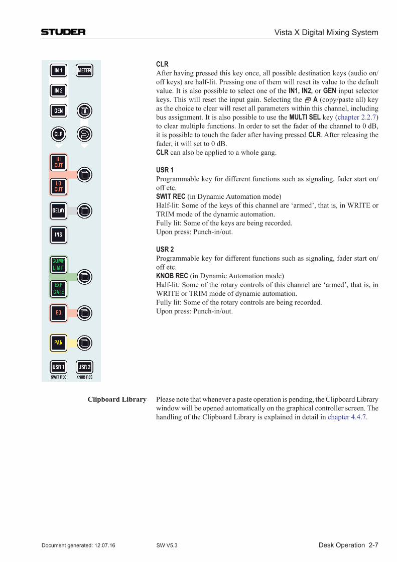
Desk Operation 2-7
CLR After having pressed this key once, all possible destination keys (audio on/
off keys) are half-lit. Pressing one of them will reset its value to the default value. It is also possible to select one of the IN1, IN2, or GEN input selector keys. This will reset the input gain. Selecting the A (copy/paste all) key as the choice to clear will reset all parameters within this channel, including bus assignment. It is also possible to use the MULTI SEL key (chapter 2.2.7) to clear multiple functions. In order to set the fader of the channel to 0 dB, it is possible to touch the fader after having pressed CLR. After releasing the fader, it will set to 0 dB.
CLR can also be applied to a whole gang.
USR 1 Programmable key for different functions such as signaling, fader start on/
off etc. SWIT REC (in Dynamic Automation mode) Half-lit: Some of the keys of this channel are ‘armed’, that is, in WRITE or
TRIM mode of the dynamic automation. Fully lit: Some of the keys are being recorded. Upon press: Punch-in/out. USR 2 Programmable key for different functions such as signaling, fader start on/
off etc. KNOB REC (in Dynamic Automation mode) Half-lit: Some of the rotary controls of this channel are ‘armed’, that is, in
WRITE or TRIM mode of dynamic automation. Fully lit: Some of the rotary controls are being recorded. Upon press: Punch-in/out.
Clipboard Library Please note that whenever a paste operation is pending, the Clipboard Library window will be opened automatically on the graphical controller screen. The handling of the Clipboard Library is explained in detail in chapter 4.4.7.
Vista X Digital Mixing System
Document generated: 12.07.16 SW V5.3
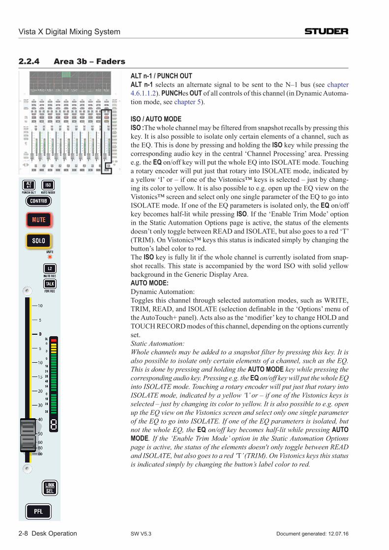
2-8 Desk Operation
2.2.4 area 3b – Faders
ALT n-1 / PUNCH OUT ALT n-1 selects an alternate signal to be sent to the N–1 bus (see chapter
4.6.1.1.2). PUNCHes OUT of all controls of this channel (in Dynamic Automa-tion mode, see chapter 5).
ISO / AUTO MODE ISO :The whole channel may be filtered from snapshot recalls by pressing this
key. It is also possible to isolate only certain elements of a channel, such as the EQ. This is done by pressing and holding the ISO key while pressing the corresponding audio key in the central ‘Channel Processing’ area. Pressing e.g. the EQ on/off key will put the whole EQ into ISOLATE mode. Touching a rotary encoder will put just that rotary into ISOLATE mode, indicated by a yellow ‘I’ or – if one of the Vistonics™ keys is selected – just by chang-ing its color to yellow. It is also possible to e.g. open up the EQ view on the Vistonics™ screen and select only one single parameter of the EQ to go into ISOLATE mode. If one of the EQ parameters is isolated only, the EQ on/off key becomes half-lit while pressing ISO. If the ‘Enable Trim Mode’ option in the Static Automation Options page is active, the status of the elements doesn’t only toggle between READ and ISOLATE, but also goes to a red ‘T’ (TRIM). On Vistonics™ keys this status is indicated simply by changing the button’s label color to red.
The ISO key is fully lit if the whole channel is currently isolated from snap-shot recalls. This state is accompanied by the word ISO with solid yellow background in the Generic Display Area.
AUTO MODE: Dynamic Automation: Toggles this channel through selected automation modes, such as WRITE,
TRIM, READ, and ISOLATE (selection definable in the ‘Options’ menu of the AutoTouch+ panel). Acts also as the ‘modifier’ key to change HOLD and TOUCH RECORD modes of this channel, depending on the options currently set.
Static Automation: Whole channels may be added to a snapshot filter by pressing this key. It is
also possible to isolate only certain elements of a channel, such as the EQ. This is done by pressing and holding the AUTO MODE key while pressing the corresponding audio key. Pressing e.g. the EQ on/off key will put the whole EQ into ISOLATE mode. Touching a rotary encoder will put just that rotary into ISOLATE mode, indicated by a yellow ‘I’ or – if one of the Vistonics keys is selected – just by changing its color to yellow. It is also possible to e.g. open up the EQ view on the Vistonics screen and select only one single parameter of the EQ to go into ISOLATE. If one of the EQ parameters is isolated, but not the whole EQ, the EQ on/off key becomes half-lit while pressing AUTO MODE. If the ‘Enable Trim Mode’ option in the Static Automation Options page is active, the status of the elements doesn't only toggle between READ and ISOLATE, but also goes to a red ‘T’ (TRIM). On Vistonics keys this status is indicated simply by changing the button’s label color to red.
Vista X Digital Mixing System
Document generated: 12.07.16SW V5.3
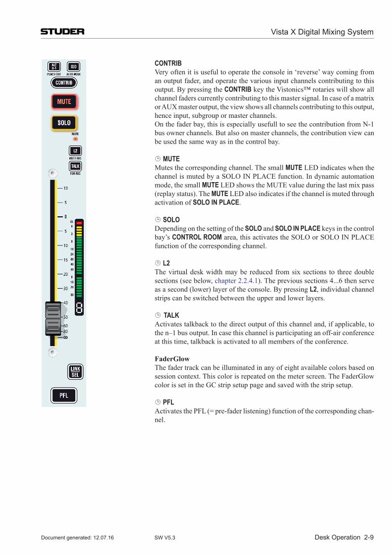
Desk Operation 2-9
CONTRIB Very often it is useful to operate the console in ‘reverse’ way coming from
an output fader, and operate the various input channels contributing to this output. By pressing the CONTRIB key the Vistonics™ rotaries will show all channel faders currently contributing to this master signal. In case of a matrix orAUXmasteroutput,theviewshowsallchannelscontributingtothisoutput,hence input, subgroup or master channels.
On the fader bay, this is especially usefull to see the contribution from N-1 bus owner channels. But also on master channels, the contribution view can be used the same way as in the control bay.
MUTE Mutes the corresponding channel. The small MUTE LED indicates when the
channel is muted by a SOLO IN PLACE function. In dynamic automation mode, the small MUTE LED shows the MUTE value during the last mix pass (replay status). The MUTE LED also indicates if the channel is muted through activation of SOLO IN PLACE.
SOLO Depending on the setting of the SOLO and SOLO IN PLACE keys in the control
bay’s CONTROL ROOM area, this activates the SOLO or SOLO IN PLACE function of the corresponding channel.
L2 The virtual desk width may be reduced from six sections to three double
sections (see below, chapter 2.2.4.1). The previous sections 4...6 then serve as a second (lower) layer of the console. By pressing L2, individual channel strips can be switched between the upper and lower layers.
TALK Activates talkback to the direct output of this channel and, if applicable, to
the n–1 bus output. In case this channel is participating an off-air conference at this time, talkback is activated to all members of the conference.
FaderGlow The fader track can be illuminated in any of eight available colors based on
session context. This color is repeated on the meter screen. The FaderGlow color is set in the GC strip setup page and saved with the strip setup.
PFL Activates the PFL (= pre-fader listening) function of the corresponding chan-
nel.
Vista X Digital Mixing System
Document generated: 12.07.16 SW V5.3
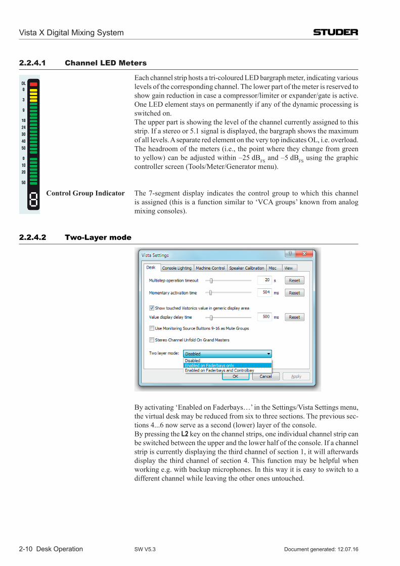
2-10 Desk Operation
2.2.4.1 Channel LeD Meters
Each channel strip hosts a tri-coloured LED bargraph meter, indicating various levels of the corresponding channel. The lower part of the meter is reserved to show gain reduction in case a compressor/limiter or expander/gate is active. One LED element stays on permanently if any of the dynamic processing is switched on.
The upper part is showing the level of the channel currently assigned to this strip. If a stereo or 5.1 signal is displayed, the bargraph shows the maximum of all levels. A separate red element on the very top indicates OL, i.e. overload. The headroom of the meters (i.e., the point where they change from green to yellow) can be adjusted within –25 dBFS and –5 dBFS using the graphic controller screen (Tools/Meter/Generator menu).
Control Group Indicator The 7-segment display indicates the control group to which this channel is assigned (this is a function similar to ‘VCA groups’ known from analog mixing consoles).
2.2.4.2 two-Layer mode
By activating ‘Enabled on Faderbays…’ in the Settings/Vista Settings menu, the virtual desk may be reduced from six to three sections. The previous sec-tions 4...6 now serve as a second (lower) layer of the console.
By pressing the L2 key on the channel strips, one individual channel strip can be switched between the upper and the lower half of the console. If a channel strip is currently displaying the third channel of section 1, it will afterwards display the third channel of section 4. This function may be helpful when working e.g. with backup microphones. In this way it is easy to switch to a different channel while leaving the other ones untouched.
Vista X Digital Mixing System
Document generated: 12.07.16SW V5.3
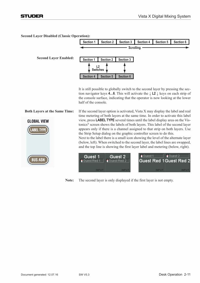
Desk Operation 2-11
Second Layer Disabled (Classic Operation):
Section 2Section 1 Section 3Scrolling
Section 4 Section 5 Section 6
Second Layer Enabled: Section 2Section 1
L2Switches
Section 3
Section 4 Section 5 Section 6Scrolling
It is still possible to globally switch to the second layer by pressing the sec-tion navigator keys 4…6. This will activate the ↓ L2 ↓ keys on each strip of the console surface, indicating that the operator is now looking at the lower half of the console.
Both Layers at the Same Time: Ifthesecondlayeroptionisactivated,VistaXmaydisplaythelabelandreal time metering of both layers at the same time. In order to activate this label
view, press LABEL TYPE several times until the label display area on the Vis-tonics® screen shows the labels of both layers. This label of the second layer appears only if there is a channel assigned to that strip on both layers. Use the Strip Setup dialog on the graphic controller screen to do this.
Next to the label there is a small icon showing the level of the alternate layer (below, left). When switched to the second layer, the label lines are swapped, and the top line is showing the first layer label and metering (below, right).
Note: The second layer is only displayed if the first layer is not empty.
Vista X Digital Mixing System
Document generated: 12.07.16 SW V5.3
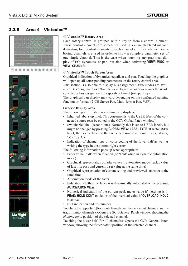
2-12 Desk Operation
2.2.5 area 4 – Vistonics™
Vistonics™ Rotary Area Each rotary control is grouped with a key to form a control element.
These control elements are sometimes used in a channel-related manner, dedicating four control elements to each channel strip; sometimes, neigh-boring channels are used in order to show a complete parameter set of one single channel. This is the case when touching any graphical dis-play of EQ, dynamics, or pan, but also when activating VIEW: MISC or VIEW: CHANNEL.
Vistonics™ Touch Screen Area Graphical indication of dynamics, equalizer and pan. Touching the graphics
will open up all corresponding parameters on the rotary control area. This section is also able to display bus assignment. Two modes are avail-
able: Bus assignment as a ‘bubble view’ to give an overview over the whole console, or bus assignment of a specific channel (one per bay).
The graphical pan display may vary depending on the configured panning function or format. (2-CH Stereo Pan, Multi-format Pan, VSP).
Generic Display Area The following information is continuously displayed: • Inheritedlabel(topline).ThiscorrespondstotheUSERlabelofthecon-
nected source (can be edited in the GC’s Global Patch window). • Switchablelabel(secondline).NormallythisissettoUSERlabels,but
might be changed by pressing GLOBAL VIEW: LABEL TYPE. If set to USER label, the device label of the connected source is being displayed (e.g. ‘Mic1, StA’).
• Indicationofchanneltypebycolorcodingofthelowerhalfaswellaswriting the type in the bottom right corner.
The following information pops up when appropriate: • FadervalueindBwhentouched(or‘held’whenindynamicautomation
mode) • Graphicalrepresentationoffadervaluesinautomationmode(replayvalue
of last mix pass and currently set value at the same time) • Graphicalrepresentationofcurrentsettingandpreviewedsnapshotatthe
same time. • Automationmodeofthefader. • Indicationwhetherthefaderwasdynamicallyautomatedwhilepressing
AUTOMATION VIEW. • Numerical indicationof thecurrentpeakmetervalue ifmetering is in
PEAK: HOLD CONT mode, or of the overload value if OVERLOAD: HOLD is active.
• N–1 indication and bus number. Touching the upper half (for input channels, multi-track input channels, multi-
track monitor channels): Opens the GC’s General Patch window, showing the channel input position of the selected channel..
Touching the lower half (for all channels): Opens the GC’s General Patch window, showing the direct output position of the selected channel.
Vista X Digital Mixing System
Document generated: 12.07.16SW V5.3
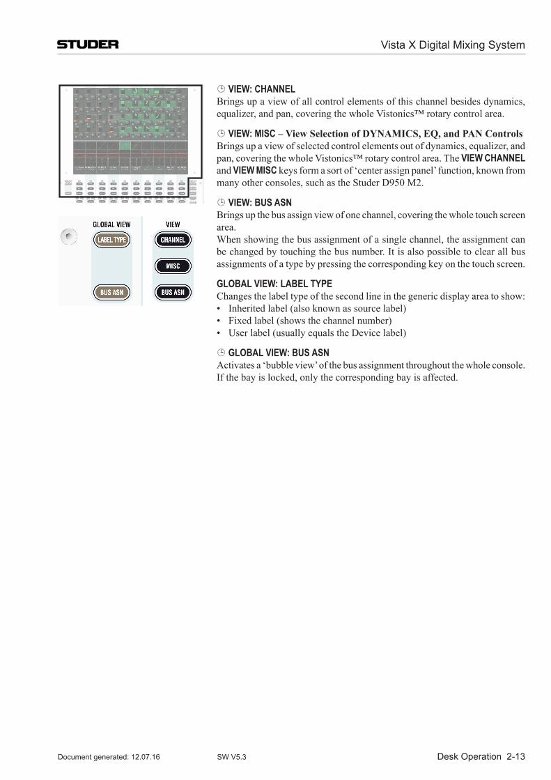
Desk Operation 2-13
VIEW: CHANNEL Brings up a view of all control elements of this channel besides dynamics,
equalizer, and pan, covering the whole Vistonics™ rotary control area.
VIEW: MISC – View Selection of DYNAMICS, EQ, and PAN Controls Brings up a view of selected control elements out of dynamics, equalizer, and
pan, covering the whole Vistonics™ rotary control area. The VIEW CHANNEL and VIEW MISC keys form a sort of ‘center assign panel’ function, known from many other consoles, such as the Studer D950 M2.
VIEW: BUS ASN Brings up the bus assign view of one channel, covering the whole touch screen
area. When showing the bus assignment of a single channel, the assignment can
be changed by touching the bus number. It is also possible to clear all bus assignments of a type by pressing the corresponding key on the touch screen.
GLOBAL VIEW: LABEL TYPE Changes the label type of the second line in the generic display area to show: • Inheritedlabel(alsoknownassourcelabel) • Fixedlabel(showsthechannelnumber) • Userlabel(usuallyequalstheDevicelabel)
GLOBAL VIEW: BUS ASN Activates a ‘bubble view’ of the bus assignment throughout the whole console.
If the bay is locked, only the corresponding bay is affected.
Vista X Digital Mixing System
Document generated: 12.07.16 SW V5.3
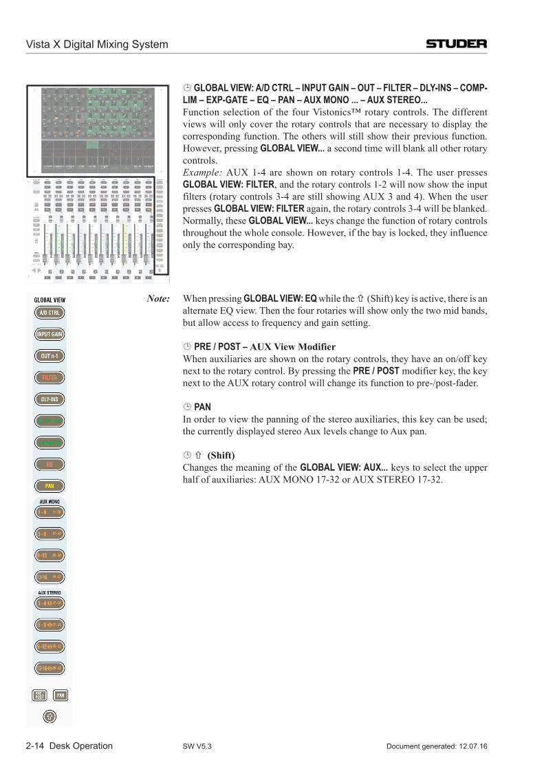
2-14 Desk Operation
GLOBAL VIEW: A/D CTRL – INPUT GAIN – OUT – FILTER – DLY-INS – COMP-LIM – EXP-GATE – EQ – PAN – AUX MONO ... – AUX STEREO...
Function selection of the four Vistonics™ rotary controls. The different views will only cover the rotary controls that are necessary to display the corresponding function. The others will still show their previous function. However, pressing GLOBAL VIEW... a second time will blank all other rotary controls.
Example: AUX1-4are shownon rotarycontrols1-4.TheuserpressesGLOBAL VIEW: FILTER, and the rotary controls 1-2 will now show the input filters(rotarycontrols3-4arestillshowingAUX3and4).Whentheuserpresses GLOBAL VIEW: FILTER again, the rotary controls 3-4 will be blanked.
Normally, these GLOBAL VIEW... keys change the function of rotary controls throughout the whole console. However, if the bay is locked, they influence only the corresponding bay.
Note: When pressing GLOBAL VIEW: EQ while the (Shift) key is active, there is an alternate EQ view. Then the four rotaries will show only the two mid bands, but allow access to frequency and gain setting.
PRE / POST – AUX View Modifier When auxiliaries are shown on the rotary controls, they have an on/off key
next to the rotary control. By pressing the PRE / POST modifier key, the key nexttotheAUXrotarycontrolwillchangeitsfunctiontopre-/post-fader.
PAN In order to view the panning of the stereo auxiliaries, this key can be used;
the currently displayed stereo Aux levels change to Aux pan.
(Shift) Changes the meaning of the GLOBAL VIEW: AUX... keys to select the upper
halfofauxiliaries:AUXMONO17-32orAUXSTEREO17-32.
Vista X Digital Mixing System
Document generated: 12.07.16SW V5.3
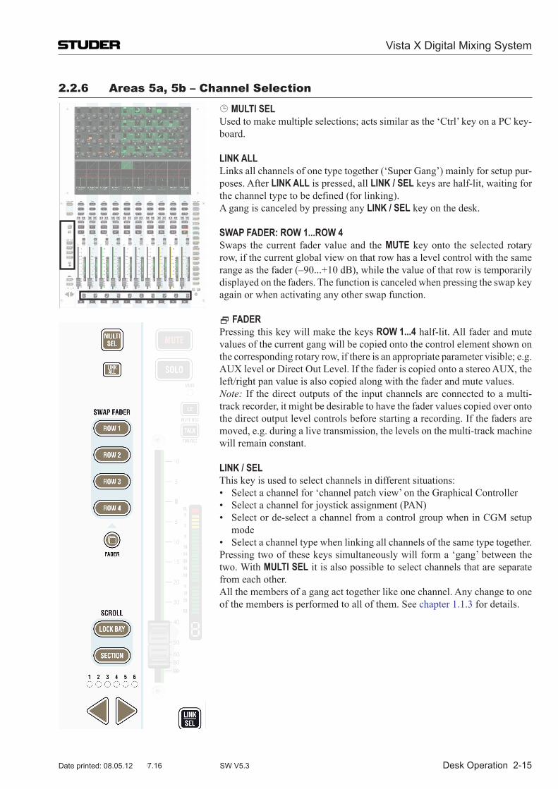
Desk Operation 2-15
2.2.6 areas 5a, 5b – Channel selection
MULTI SEL Used to make multiple selections; acts similar as the ‘Ctrl’ key on a PC key-
board.
LINK ALL Links all channels of one type together (‘Super Gang’) mainly for setup pur-
poses. After LINK ALL is pressed, all LINK / SEL keys are half-lit, waiting for the channel type to be defined (for linking).
A gang is canceled by pressing any LINK / SEL key on the desk.
SWAP FADER: ROW 1...ROW 4 Swaps the current fader value and the MUTE key onto the selected rotary
row, if the current global view on that row has a level control with the same range as the fader (–90...+10 dB), while the value of that row is temporarily displayed on the faders. The function is canceled when pressing the swap key again or when activating any other swap function.
FADER Pressing this key will make the keys ROW 1...4 half-lit. All fader and mute
values of the current gang will be copied onto the control element shown on the corresponding rotary row, if there is an appropriate parameter visible; e.g. AUXlevelorDirectOutLevel.IfthefaderiscopiedontoastereoAUX,theleft/right pan value is also copied along with the fader and mute values.
Note: If the direct outputs of the input channels are connected to a multi-track recorder, it might be desirable to have the fader values copied over onto the direct output level controls before starting a recording. If the faders are moved, e.g. during a live transmission, the levels on the multi-track machine will remain constant.
LINK / SEL This key is used to select channels in different situations: • Selectachannelfor‘channelpatchview’ontheGraphicalController • Selectachannelforjoystickassignment(PAN) • Selectorde-selectachannelfromacontrolgroupwheninCGMsetup
mode • Selectachanneltypewhenlinkingallchannelsofthesametypetogether. Pressing two of these keys simultaneously will form a ‘gang’ between the
two. With MULTI SEL it is also possible to select channels that are separate from each other.
All the members of a gang act together like one channel. Any change to one of the members is performed to all of them. See chapter 1.1.3 for details.
Vista X Digital Mixing System
Document generated: 12.07.16 SW V5.3Date printed: 08.05.12
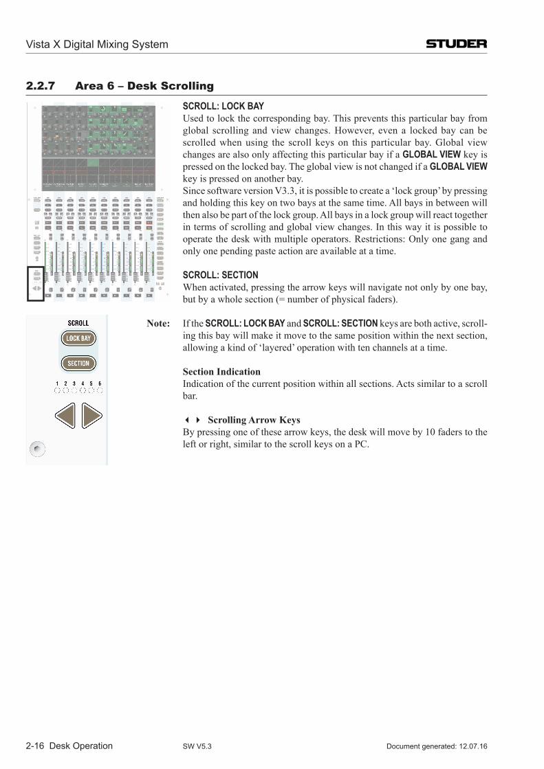
2-16 Desk Operation
2.2.7 area 6 – Desk scrolling
SCROLL: LOCK BAY Used to lock the corresponding bay. This prevents this particular bay from
global scrolling and view changes. However, even a locked bay can be scrolled when using the scroll keys on this particular bay. Global view changes are also only affecting this particular bay if a GLOBAL VIEW key is pressed on the locked bay. The global view is not changed if a GLOBAL VIEW key is pressed on another bay.
Since software version V3.3, it is possible to create a ‘lock group’ by pressing and holding this key on two bays at the same time. All bays in between will then also be part of the lock group. All bays in a lock group will react together in terms of scrolling and global view changes. In this way it is possible to operate the desk with multiple operators. Restrictions: Only one gang and only one pending paste action are available at a time.
SCROLL: SECTION When activated, pressing the arrow keys will navigate not only by one bay,
but by a whole section (= number of physical faders).
Note: If the SCROLL: LOCK BAY and SCROLL: SECTION keys are both active, scroll-ing this bay will make it move to the same position within the next section, allowing a kind of ‘layered’ operation with ten channels at a time.
Section Indication Indication of the current position within all sections. Acts similar to a scroll
bar.
Scrolling Arrow Keys By pressing one of these arrow keys, the desk will move by 10 faders to the
left or right, similar to the scroll keys on a PC.
Vista X Digital Mixing System
Document generated: 12.07.16SW V5.3
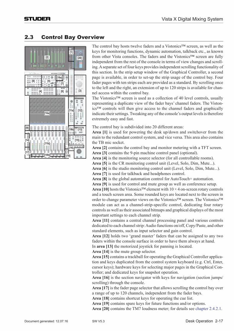
Desk Operation 2-17
2.3 Control Bay Overview
[10a]
[11b]
[18][17]
[14]
[9]
[2][1]
[8]
[4]
[5][7]
[19a]
[6] [3]
[20]
[11a] [12]
[19b]
[16]
[15]
[13]
[10b]
The control bay hosts twelve faders and a Vistonics™ screen, as well as the keys for monitoring functions, dynamic automation, talkback etc., as known from other Vista consoles. The faders and the Vistonics™ screen are fully independent from the rest of the console in terms of view changes and scroll-ing. A separate set of four keys provides independent scrolling functionality of this section. In the strip setup window of the Graphical Controller, a second page is available, in order to set-up the strip usage of the control bay. Four fader pages with ten strips each are provided as a standard. By scrolling once to the left and the right, an extension of up to 120 strips is available for chan-nel access within the control bay.
The Vistonics™ screen is used as a collection of 40 level controls, usually representing a duplicate view of the fader bays’ channel faders. The Viston-ics™ controls will then give access to the channel faders and graphically indicate their settings. Tweaking any of the console’s output levels is therefore extremely easy and fast.
The control bay is subdivided into 20 different areas: Area [1] is used for powering the desk up/down and switchover from the
main to the redundant control system, and vice versa. This area also contains the TB mic socket.
Area [2] contains the control bay and monitor metering with a TFT screen. Area [3] contains the 9-pin machine control panel (optional). Area [4] is the monitoring source selector (for all controllable rooms). Area [5] is the CR monitoring control unit (Level, Solo, Dim, Mute...). Area [6] is the studio monitoring control unit (Level, Solo, Dim, Mute...). Area [7] is used for talkback and headphones control. Area [8] is the global automation control for AutoTouch+ automation. Area [9] is used for control and mute group as well as conference setup. Area [10] hosts the Vistonics™ element with 10 × 4 on-screen rotary controls
and a touch screen area. Some rounded keys are located next to the screen in order to change parameter views on the Vistonics™ screen. The Vistonics™ module can act as a channel-strip-specific control, dedicating four rotary controls as well as their associated bitmaps and graphical displays of the most important settings to each channel strip.
Area [11] contains a central channel processing panel and various controls dedicated to each channel strip: Audio functions on/off, Copy/Paste, and other standard elements, such as input selector and gain control.
Area [12] holds two ‘grand master’ faders that can be assigned to any two faders within the console surface in order to have them always at hand.
In area [13] the motorized joystick for panning is located. Area [14] is the mute group selector. Area [15] contains a trackball for operating the Graphical Controller applica-
tion and keys duplicated from the control system keyboard (e.g. Ctrl, Enter, cursor keys); hardware keys for selecting major pages in the Graphical Con-troller; and dedicated keys for snapshot operation.
Area [16] is the section navigator with keys for navigation (section jumps/scrolling) through the console.
Area [17] is the fader page selector that allows scrolling the control bay over a range of up to 120 channels, independent from the fader bays.
Area [18] contains shortcut keys for operating the cue list. Area [19] contains spare keys for future functions and/or options. Area [20] contains the TM7 loudness meter; for details see chapter 2.4.2.1.
Vista X Digital Mixing System
Document generated: 12.07.16 SW V5.3
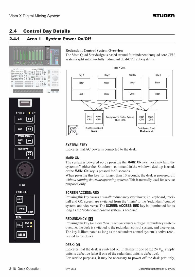
2-18 Desk Operation
2.4 Control Bay Details2.4.1 area 1 – system power On/Off
Redundant Control System Overview The Vista Quad Star design is based around four independentquad core CPU
systems split into two fully redundant dual-CPU sub-systems.
Dual System BoardMain
Desk CPU
Meter CPU
Dual System BoardRedundant
Desk CPU
Meter CPU
Two symmetric Control Systems(Quad CPU)
Meter
Desk
Bay 1
Meter
Desk
Bay 2
Meter
Desk
CtrlBay
Meter
Desk
Bay 3
Vista X Desk
SYSTEM: STBY Indicates that AC power is connected to the desk.
MAIN: ON The system is powered up by pressing the MAIN: ON key. For switching the
system off, either the ‘Shutdown’ command in the windows desktop is used, or the MAIN: ON key is pressed for 3 seconds.
When pressing this key for longer than 10 seconds, the desk is powered off without shutting down the operating systems. This is normally used for service purposes only.
SCREEN ACCESS: RED Pressing this key causes a ‘small’ redundancy switchover, i.e. keyboard, track-
ball and GC screen are switched from the ‘main’ to the ‘redundant’ control system, and vice versa. The SCREEN ACCESS: RED key is illuminated for as long as the ‘redundant’ control system is accessed.
REDUNDANCY: Pressing this key for more than 3 seconds causes a ‘large’ redundancy switch-
over, i.e. the desk is switched to the redundant control system, and vice versa. The key is illuminated as long as the redundant control system is active (con-nected to the desk).
DESK: ON Indicates that the desk is switched on. It flashes if one of the 24 VDC supply
units is defective (also if one of the redundant units is defective). For service purposes, it may be necessary to power off the desk part only,
Vista X Digital Mixing System
Document generated: 12.07.16SW V5.3
Desk Operation 2-19
while the control systems remain on. This can be accomplished by pressing this key for several seconds. Another short press will power on the desk again. A warning message will be displayed, and the GC will be restarted.
Powering off the desk also powers off the monitoring outputs as well a the RTW meter.
XLR Socket TheXLRsocketinthisareacanbeusedforplugginginagoosenecktalkback
microphone. The CAL trimmer potentiometer accessible through a small hole below allows matching the input gain to the microphone in use.
USB Port USB port for plugging any USB compliant USB device, such as a memory
stick, in order to backup data of the console. It is possible to backup individual productions from within the Vista application software – or make backup an image of the whole system using the installed special software. See chapter 4.5.3 for more details about how to make image backups and how to restore them onto a console.
Vista X Digital Mixing System
Document generated: 12.07.16 SW V5.3
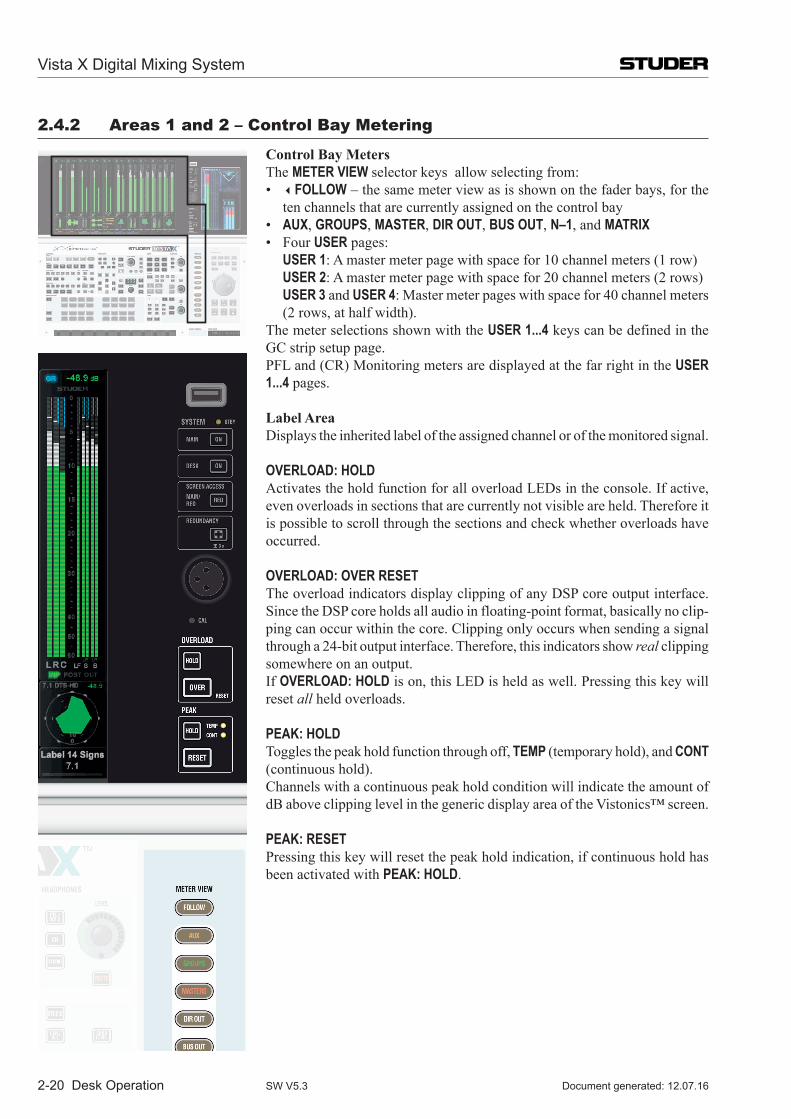
2-20 Desk Operation
2.4.2 areas 1 and 2 – Control Bay Metering
Control Bay Meters The METER VIEW selector keys allow selecting from: • FOLLOW – the same meter view as is shown on the fader bays, for the
ten channels that are currently assigned on the control bay • AUX, GROUPS, MASTER, DIR OUT, BUS OUT, N–1, and MATRIX • FourUSER pages: USER 1: A master meter page with space for 10 channel meters (1 row) USER 2: A master meter page with space for 20 channel meters (2 rows) USER 3 and USER 4: Master meter pages with space for 40 channel meters
(2 rows, at half width). The meter selections shown with the USER 1...4 keys can be defined in the
GC strip setup page. PFL and (CR) Monitoring meters are displayed at the far right in the USER
1...4 pages.
Label Area Displays the inherited label of the assigned channel or of the monitored signal.
OVERLOAD: HOLD Activates the hold function for all overload LEDs in the console. If active,
even overloads in sections that are currently not visible are held. Therefore it is possible to scroll through the sections and check whether overloads have occurred.
OVERLOAD: OVER RESET The overload indicators display clipping of any DSP core output interface.
Since the DSP core holds all audio in floating-point format, basically no clip-ping can occur within the core. Clipping only occurs when sending a signal through a 24-bit output interface. Therefore, this indicators show real clipping somewhere on an output.
If OVERLOAD: HOLD is on, this LED is held as well. Pressing this key will reset all held overloads.
PEAK: HOLD Toggles the peak hold function through off, TEMP (temporary hold), and CONT
(continuous hold). Channels with a continuous peak hold condition will indicate the amount of
dB above clipping level in the generic display area of the Vistonics™ screen.
PEAK: RESET Pressing this key will reset the peak hold indication, if continuous hold has
been activated with PEAK: HOLD.
Vista X Digital Mixing System
Document generated: 12.07.16SW V5.3
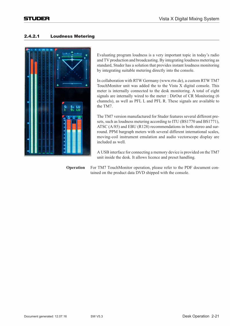
Desk Operation 2-21
2.4.2.1 Loudness Metering
Evaluating program loudness is a very important topic in today’s radio and TV production and broadcasting. By integrating loudness metering as standard, Studer has a solution that provides instant loudness monitoring by integrating suitable metering directly into the console.
In collaboration with RTW Germany (www.rtw.de), a custom RTW TM7 TouchMonitorunitwasadded the to theVistaXdigitalconsole.Thismeter is internally connected to the desk monitoring. A total of eight signals are internally wired to the meter : DirOut of CR Monitoring (6 channels), as well as PFL L and PFL R. These signals are available to the TM7.
The TM7 version manufactured for Studer features several different pre-sets, such as loudness metering according to ITU (BS1770 and BS1771), ATSC (A/85) and EBU (R128) recommendations in both stereo and sur-round. PPM bargraph meters with several different international scales, moving-coil instrument emulation and audio vectorscope display are included as well.
A USB interface for connecting a memory device is provided on the TM7 unit inside the desk. It allows licence and preset handling.
Operation For TM7 TouchMonitor operation, please refer to the PDF document con-tained on the product data DVD shipped with the console.
Vista X Digital Mixing System
Document generated: 12.07.16 SW V5.3
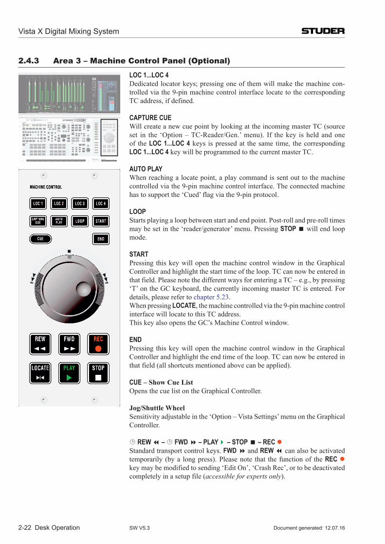
2-22 Desk Operation
2.4.3 area 3 – Machine Control panel (Optional)
LOC 1...LOC 4 Dedicated locator keys; pressing one of them will make the machine con-
trolled via the 9-pin machine control interface locate to the corresponding TC address, if defined.
CAPTURE CUE Will create a new cue point by looking at the incoming master TC (source
set in the ‘Option – TC-Reader/Gen.’ menu). If the key is held and one of the LOC 1...LOC 4 keys is pressed at the same time, the corresponding LOC 1...LOC 4 key will be programmed to the current master TC.
AUTO PLAY When reaching a locate point, a play command is sent out to the machine
controlled via the 9-pin machine control interface. The connected machine has to support the ‘Cued’ flag via the 9-pin protocol.
LOOP Starts playing a loop between start and end point. Post-roll and pre-roll times
may be set in the ‘reader/generator’ menu. Pressing STOP will end loop mode.
START Pressing this key will open the machine control window in the Graphical
Controller and highlight the start time of the loop. TC can now be entered in that field. Please note the different ways for entering a TC – e.g., by pressing ‘T’ on the GC keyboard, the currently incoming master TC is entered. For details, please refer to chapter 5.23.
When pressing LOCATE, the machine controlled via the 9-pin machine control interface will locate to this TC address.
This key also opens the GC’s Machine Control window.
END Pressing this key will open the machine control window in the Graphical
Controller and highlight the end time of the loop. TC can now be entered in that field (all shortcuts mentioned above can be applied).
CUE – Show Cue List Opens the cue list on the Graphical Controller.
Jog/Shuttle Wheel Sensitivity adjustable in the ‘Option – Vista Settings’ menu on the Graphical
Controller.
REW – FWD – PLAY – STOP – REC Standard transport control keys. FWD and REW can also be activated
temporarily (by a long press). Please note that the function of the REC key may be modified to sending ‘Edit On’, ‘Crash Rec’, or to be deactivated completely in a setup file (accessible for experts only).
Vista X Digital Mixing System
Document generated: 12.07.16SW V5.3
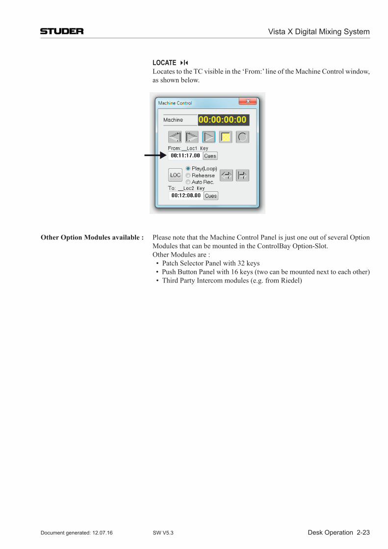
Desk Operation 2-23
LOCATE I Locates to the TC visible in the ‘From:’ line of the Machine Control window,
as shown below.
Other Option Modules available : Please note that the Machine Control Panel is just one out of several Option Modules that can be mounted in the ControlBay Option-Slot.
Other Modules are : •Patch Selector Panel with 32 keys •Push Button Panel with 16 keys (two can be mounted next to each other) •ThirdPartyIntercommodules(e.g.fromRiedel)
Vista X Digital Mixing System
Document generated: 12.07.16 SW V5.3
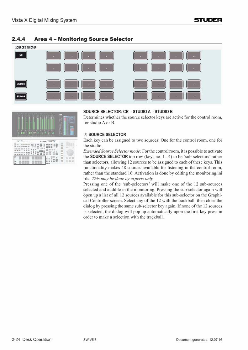
2-24 Desk Operation
2.4.4 area 4 – Monitoring source selector
SOURCE SELECTOR: CR – STUDIO A – STUDIO B Determines whether the source selector keys are active for the control room,
for studio A or B. SOURCE SELECTOR Each key can be assigned to two sources: One for the control room, one for
the studio. Extended Source Selector mode: For the control room, it is possible to activate
the SOURCE SELECTOR top row (keys no. 1...4) to be ‘sub-selectors’ rather than selectors, allowing 12 sources to be assigned to each of these keys. This functionality makes 48 sources available for listening in the control room, rather than the standard 16. Activation is done by editing the monitoring.ini file. This may be done by experts only.
Pressing one of the ‘sub-selectors’ will make one of the 12 sub-sources selected and audible in the monitoring. Pressing the sub-selector again will open up a list of all 12 sources available for this sub-selector on the Graphi-cal Controller screen. Select any of the 12 with the trackball, then close the dialog by pressing the same sub-selector key again. If none of the 12 sources is selected, the dialog will pop up automatically upon the first key press in order to make a selection with the trackball.
Vista X Digital Mixing System
Document generated: 12.07.16SW V5.3
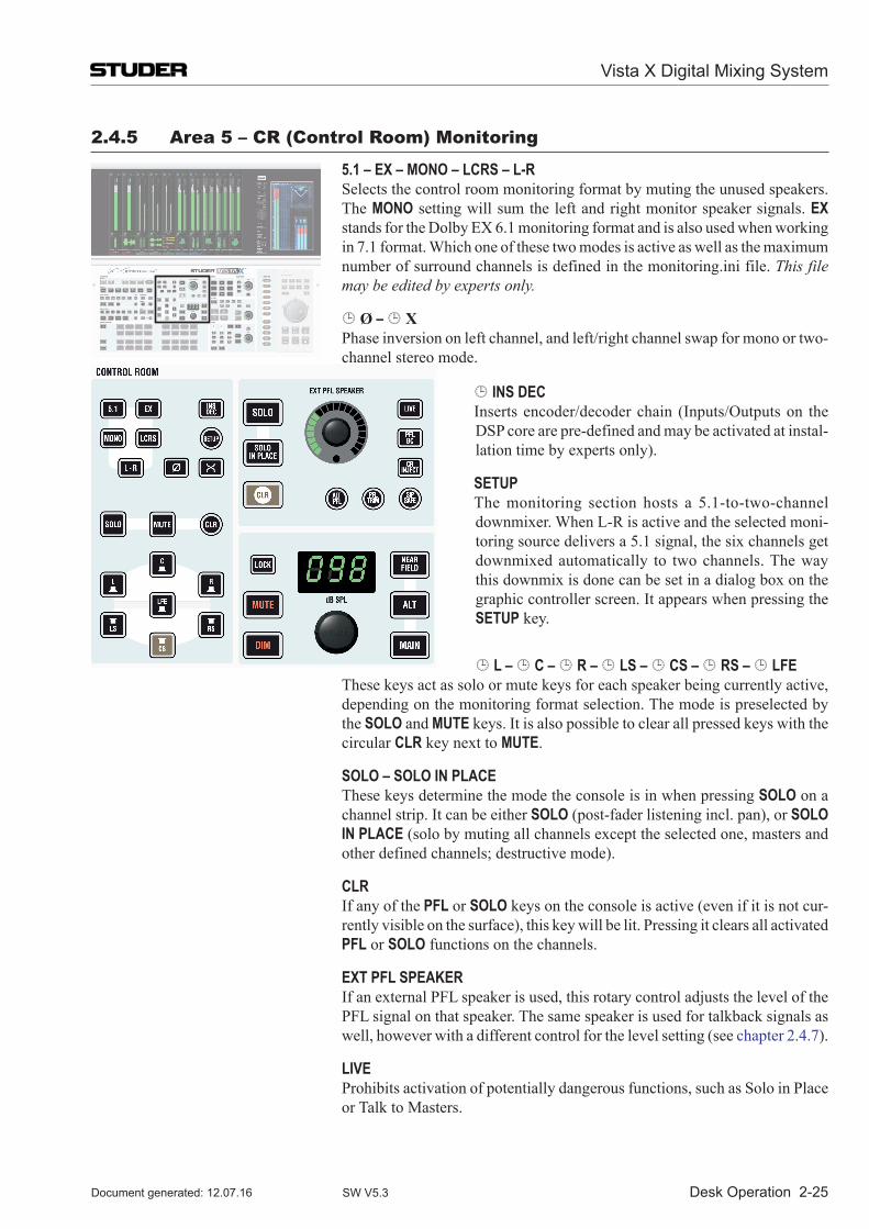
Desk Operation 2-25
2.4.5 area 5 – Cr (Control room) Monitoring
5.1 – EX – MONO – LCRS – L-R Selects the control room monitoring format by muting the unused speakers.
The MONO setting will sum the left and right monitor speaker signals. EX standsfortheDolbyEX6.1monitoringformatandisalsousedwhenworkingin 7.1 format. Which one of these two modes is active as well as the maximum number of surround channels is defined in the monitoring.ini file. This file may be edited by experts only.
Ø – X Phase inversion on left channel, and left/right channel swap for mono or two-
channel stereo mode.
INS DEC Inserts encoder/decoder chain (Inputs/Outputs on the
DSP core are pre-defined and may be activated at instal-lation time by experts only).
SETUP The monitoring section hosts a 5.1-to-two-channel
downmixer. When L-R is active and the selected moni-toring source delivers a 5.1 signal, the six channels get downmixed automatically to two channels. The way this downmix is done can be set in a dialog box on the graphic controller screen. It appears when pressing the SETUP key.
L – C – R – LS – CS – RS – LFE These keys act as solo or mute keys for each speaker being currently active,
depending on the monitoring format selection. The mode is preselected by the SOLO and MUTE keys. It is also possible to clear all pressed keys with the circular CLR key next to MUTE.
SOLO – SOLO IN PLACE These keys determine the mode the console is in when pressing SOLO on a
channel strip. It can be either SOLO (post-fader listening incl. pan), or SOLO IN PLACE (solo by muting all channels except the selected one, masters and other defined channels; destructive mode).
CLR If any of the PFL or SOLO keys on the console is active (even if it is not cur-
rently visible on the surface), this key will be lit. Pressing it clears all activated PFL or SOLO functions on the channels.
EXT PFL SPEAKER If an external PFL speaker is used, this rotary control adjusts the level of the
PFL signal on that speaker. The same speaker is used for talkback signals as well, however with a different control for the level setting (see chapter 2.4.7).
LIVE Prohibits activation of potentially dangerous functions, such as Solo in Place
or Talk to Masters.
Vista X Digital Mixing System
Document generated: 12.07.16 SW V5.3
2-26 Desk Operation
PFL BC (PFL broadcast mode) activates a mode where PFL/SOLO on a channel is
automatically canceled whenever the channel fader is open.
CR INJECT If active: PFL/SOLO signals will be audible in the control room speakers as
soon as any PLF/SOLO function is activated.
SIP SAFE Pressing this key enters setup mode for editing the channels that should be
safe from muting when activating SOLO IN PLACE on any other channel; by default, all master channels are safe from muting when SOLO IN PLACE is active. It may be desirable to protect effect returns from muting by adding them to the group of safe channels. When in SIP SAFE setup mode, it is pos-sible to select or de-select individual channels on the desk by pressing their LINK / SEL key. Pressing SIP SAFE again will cancel edit mode and activate the selected SIP protection. The information on which channels should be protected is saved in each title, and therefore may vary from title to title.
Note As a standard, the MULTISEL key is active when entering SIP SAFE setup mode. Thus it is possible to select or de-select any channels to be safe from muting. However, for clearing all currently selected and safe channels (including master channels), the MULTISEL key may be de-activated. When pressing any LINK / SEL key of a channel, all others will be de-selected.
PFL TRIM Pressing this key allows adjusting the solo offset level applied in the moni-
toring, whenever PFL is active. The offset level is displayed in place of the control room level. Turn the CR level knob for solo offset level adjustment.
ALT PFL Alternate PFL bus (2nd PFL); setup is done by pressing the ALT PFL key and
then selecting the channels that are to be assigned to the alternate PFL bus with the LINK/SEL keys. The ALT PFL key needs to pressed again to clear the setup mode (ALT PFL key dark).
LOCK Locks the control room level and prohibits it from being changed by accident.
MUTE – DIM – dB SPL Muting and dimming of the control room speakers, and setting their level.
DIM level may be adjusted in the monitoring.ini file (by experts only).
NEAR FIELD – ALT – MAIN Selection of three speaker sets: MAIN and ALT may be multi-channel surround
systems, NEAR FIELD is a two-channel stereo system. Note The GC allows level calibration of the different speaker sets as well as trim-
ming the individual speakers within each set.
Vista X Digital Mixing System
Document generated: 12.07.16SW V5.3
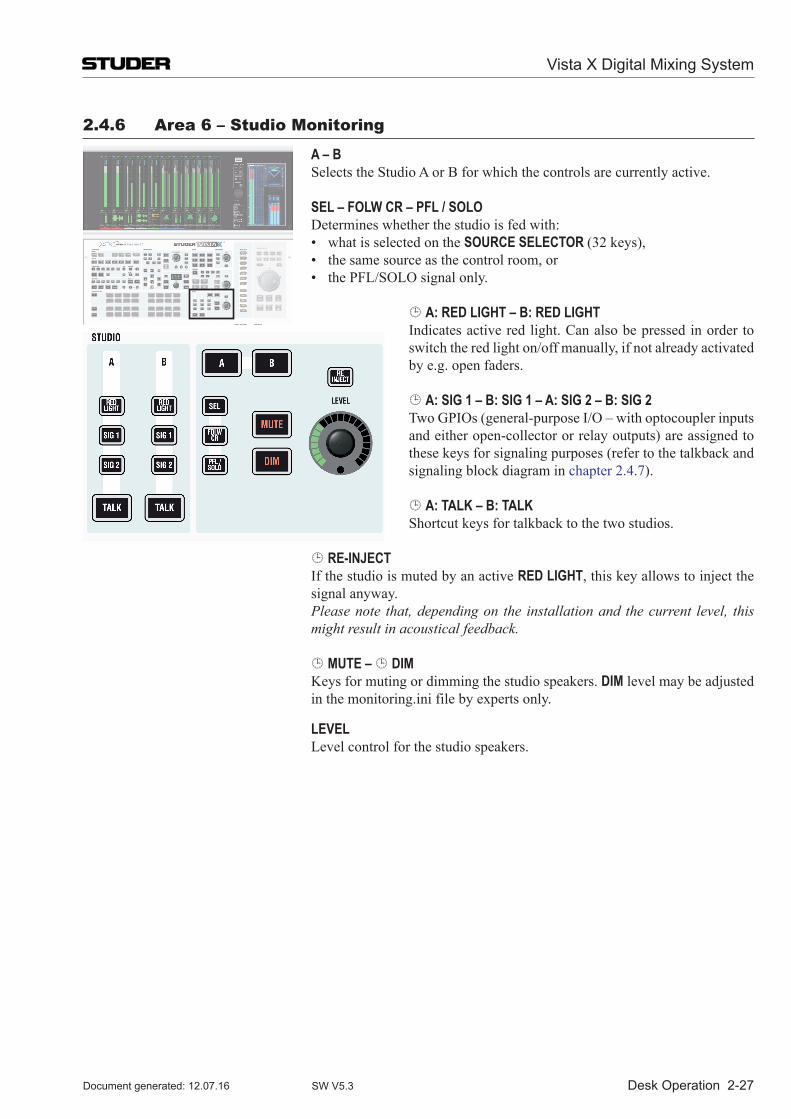
Desk Operation 2-27
2.4.6 area 6 – studio Monitoring
A – B Selects the Studio A or B for which the controls are currently active.
SEL – FOLW CR – PFL / SOLO Determines whether the studio is fed with: • whatisselectedontheSOURCE SELECTOR (32 keys), • thesamesourceasthecontrolroom,or • thePFL/SOLOsignalonly.
A: RED LIGHT – B: RED LIGHT Indicates active red light. Can also be pressed in order to
switch the red light on/off manually, if not already activated by e.g. open faders.
A: SIG 1 – B: SIG 1 – A: SIG 2 – B: SIG 2 Two GPIOs (general-purpose I/O – with optocoupler inputs
and either open-collector or relay outputs) are assigned to these keys for signaling purposes (refer to the talkback and signaling block diagram in chapter 2.4.7).
A: TALK – B: TALK Shortcut keys for talkback to the two studios.
RE-INJECT If the studio is muted by an active RED LIGHT, this key allows to inject the
signal anyway. Please note that, depending on the installation and the current level, this
might result in acoustical feedback.
MUTE – DIM Keys for muting or dimming the studio speakers. DIM level may be adjusted
in the monitoring.ini file by experts only.
LEVEL Level control for the studio speakers.
Vista X Digital Mixing System
Document generated: 12.07.16 SW V5.3
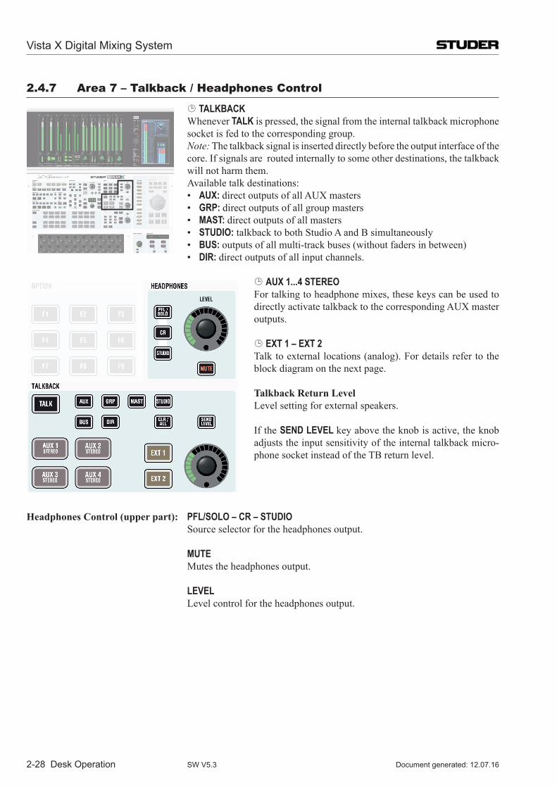
2-28 Desk Operation
2.4.7 area 7 – talkback / headphones Control
TALKBACK Whenever TALK is pressed, the signal from the internal talkback microphone
socket is fed to the corresponding group. Note: The talkback signal is inserted directly before the output interface of the
core. If signals are routed internally to some other destinations, the talkback will not harm them.
Available talk destinations: • AUX: directoutputsofallAUXmasters • GRP: direct outputs of all group masters • MAST: direct outputs of all masters • STUDIO: talkback to both Studio A and B simultaneously • BUS: outputs of all multi-track buses (without faders in between) • DIR: direct outputs of all input channels.
AUX 1...4 STEREOFor talking to headphone mixes, these keys can be used to directlyactivatetalkbacktothecorrespondingAUXmasteroutputs.
EXT 1 – EXT 2Talk to external locations (analog). For details refer to the block diagram on the next page.
Talkback Return Level Level setting for external speakers.
If the SEND LEVEL key above the knob is active, the knob adjusts the input sensitivity of the internal talkback micro-phone socket instead of the TB return level.
Headphones Control (upper part): PFL/SOLO – CR – STUDIO Source selector for the headphones output.
MUTE Mutes the headphones output.
LEVEL Level control for the headphones output.
Vista X Digital Mixing System
Document generated: 12.07.16SW V5.3
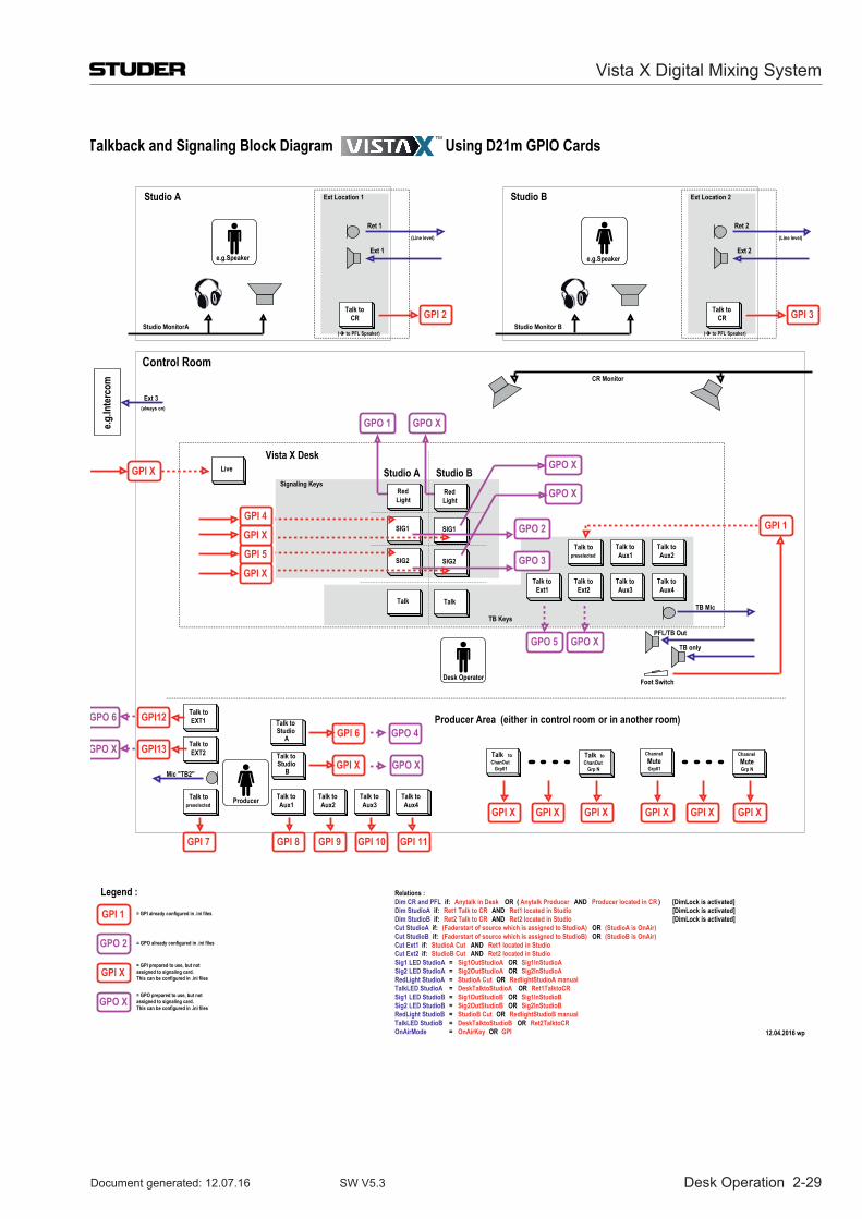
Desk Operation 2-29
Control Room
Studio A
Talk to CR
Ret 1
Ext 1
Studio MonitorA
TB only
PFL/TB Out
CR Monitor
Signaling Keys
Talk to Aux1
Talk to Aux2
Talk to Aux3
Talk to Aux4
Talk to Aux1
Talk to Aux2
Talk to Ext1
Talk to Ext2
Talk to Aux3
Talk to Aux4
Talk topreselected
Talk topreselected
Talk to Studio
B
e.g.Speaker
GPI 2
GPI 4
GPI 5 GPO 3
GPO 2 GPI 1
Foot Switch
GPI 7 GPI 8 GPI 9 GPI 10 GPI 11
e.g.In
terc
om
Ext 3
(Line level) (Line level)
(always on)
Vista X Desk
Mic "TB2"
TB Mic
GPO 1
Ext Location 1
Producer
( to PFL Speaker)
Studio B
Talk to CR
Ret 2
Ext 2
Studio Monitor BGPI 3
Ext Location 2
( to PFL Speaker)
Talk to Studio
A GPI 6
GPI XTalk toChanOut
Grp01
Talk to ChanOut
Grp N
Channel MuteGrp01
ChannelMuteGrp N
Talk to EXT1
Talk to EXT2GPI13
GPI12
GPI X GPI X GPI X GPI XGPI XGPI X
LiveGPI X
GPO 4
GPO X
GPO X
GPI X
GPI X
GPO X
GPO X
e.g.Speaker
GPO 6
GPO X
TB Keys
GPO 5
Legend :
GPI 1
GPO 2
GPI X
= GPI already configured in .ini files
= GPO already configured in .ini files
= GPI prepared to use, but not assigned to signaling card. This can be configured in .ini files
GPO X= GPO prepared to use, but not assigned to signaling card. This can be configured in .ini files
Desk Operator
GPO X
Producer Area (either in control room or in another room)
Studio A Studio BRed Light
SIG1
SIG2
Talk
Red Light
SIG1
SIG2
Talk
12.04.2016 wp
Talkback and Signaling Block Diagram Using D21m GPIO Cards
Relations :Dim CR and PFL if: Anytalk in Desk OR ( )Anytalk Producer AND Producer located in CR [DimLock is activated]Dim StudioA if: Ret1 Talk to CR AND Ret1 located in Studio [DimLock is activated]Dim StudioB if: Ret2 Talk to CR AND Ret2 located in Studio [DimLock is activated]Cut StudioA if: (Faderstart of source which is assigned to StudioA) OR (StudioA is OnAir)Cut StudioB if: (Faderstart of source which is assigned to StudioB) OR (StudioB is OnAir)Cut Ext1 if: StudioA Cut AND Ret1 located in StudioCut Ext2 if: StudioB Cut AND Ret2 located in StudioSig1 LED StudioA = Sig1OutStudioA OR Sig1InStudioASig2 LED StudioA = Sig2OutStudioA OR Sig2InStudioARedLight StudioA = StudioA Cut OR RedlightStudioA manualTalkLED StudioA = DeskTalktoStudioA OR Ret1TalktoCRSig1 LED StudioB = Sig1OutStudioB OR Sig1InStudioBSig2 LED StudioB = Sig2OutStudioB OR Sig2InStudioBRedLight StudioB = StudioB Cut OR RedlightStudioB manualTalkLED StudioB = DeskTalktoStudioB OR Ret2TalktoCROnAirMode = OnAirKey OR GPI
Vista X Digital Mixing System
Document generated: 12.07.16 SW V5.3
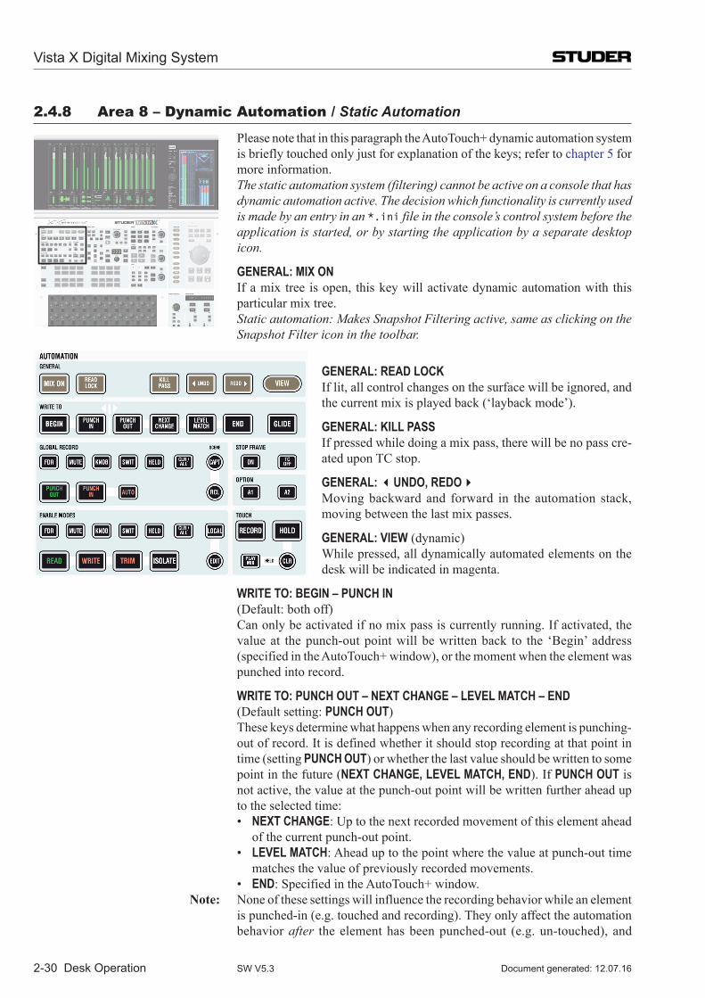
2-30 Desk Operation
2.4.8 area 8 – Dynamic automation / Static Automation
Please note that in this paragraph the AutoTouch+ dynamic automation system is briefly touched only just for explanation of the keys; refer to chapter 5 for more information.
The static automation system (filtering) cannot be active on a console that has dynamic automation active. The decision which functionality is currently used is made by an entry in an *.ini file in the console’s control system before the application is started, or by starting the application by a separate desktop icon.
GENERAL: MIX ON If a mix tree is open, this key will activate dynamic automation with this
particular mix tree. Static automation: Makes Snapshot Filtering active, same as clicking on the
Snapshot Filter icon in the toolbar.
GENERAL: READ LOCK If lit, all control changes on the surface will be ignored, and
the current mix is played back (‘layback mode’).
GENERAL: KILL PASS If pressed while doing a mix pass, there will be no pass cre-
ated upon TC stop.
GENERAL: UNDO, REDO Moving backward and forward in the automation stack,
moving between the last mix passes.
GENERAL: VIEW (dynamic) While pressed, all dynamically automated elements on the
desk will be indicated in magenta.
WRITE TO: BEGIN – PUNCH IN (Default: both off) Can only be activated if no mix pass is currently running. If activated, the
value at the punch-out point will be written back to the ‘Begin’ address (specified in the AutoTouch+ window), or the moment when the element was punched into record.
WRITE TO: PUNCH OUT – NEXT CHANGE – LEVEL MATCH – END (Default setting: PUNCH OUT) These keys determine what happens when any recording element is punching-
out of record. It is defined whether it should stop recording at that point in time (setting PUNCH OUT) or whether the last value should be written to some point in the future (NEXT CHANGE, LEVEL MATCH, END). If PUNCH OUT is not active, the value at the punch-out point will be written further ahead up to the selected time:
• NEXT CHANGE: Up to the next recorded movement of this element ahead of the current punch-out point.
• LEVEL MATCH: Ahead up to the point where the value at punch-out time matches the value of previously recorded movements.
• END: Specified in the AutoTouch+ window. Note: None of these settings will influence the recording behavior while an element
is punched-in (e.g. touched and recording). They only affect the automation behavior after the element has been punched-out (e.g. un-touched), and
Vista X Digital Mixing System
Document generated: 12.07.16SW V5.3
Desk Operation 2-31
therefore make it stay in record further into the future. Option settings in the AutoTouch+ window may determine whether the
‘Begin’ and ‘End’ settings are cleared automatically when the mix pass is finished, in order to prevent erasing valuable automation data.
GLIDE Determines whether a fade back to the previous value will be applied at the end
point of writing, or whether it should be a jump. Glide time can be adjusted in the AutoTouch+ window.
Static Automation: Activates/deactivates global snapshot cross-fading.
GLOBAL RECORD: FDR – MUTE – KNOB – SWIT – HELD Pre-selector keys for global punch-in (fader, mutes, knobs, switches, all held
objects); if corresponding elements are in TRIM or WRITE mode, they may be punched into record by pressing PUNCH IN. Only pre-selected keys/elements will be punched-in.
GLOBAL RECORD: CLR / ALL This key will either clear all active GLOBAL RECORD pre-selector keys (if
some of them are already lit), or select them all (if all were dark before). Shortcut: In order to punch-in or out all armed elements, press and hold CLR
/ ALL, then press PUNCH IN or PUNCH OUT.
GLOBAL RECORD: PUNCH IN – PUNCH OUT Punches-in or out all elements selected with one of the GLOBAL RECORD
pre-selector keys. Punches-in or out all armed elements, if pressed together with CLR / ALL.
GLOBAL RECORD: SCENE: CAPT – RCL • SCENE: CAPT saves all elements that are currently recording together with
their current values into a special clipboard. The RCL key is lit if a setting is saved.
• SCENE: RCL recalls the values of the saved elements and punches them directly into record, if they are armed and TOUCH RECORD is active. If TOUCH RECORD is not active, the elements are only recalled (audition mode).
Note: Normally only one scene is saved at a time in the clipboard. However, by hold-ing down the Shift key of the keyboard, it is possible to address a second clipboard. Shift + CAPT will therefore save the values into this second clipboard, while Shift + RCL recalls the values from the second clipboard.
STOP FRAME: ON Instead of starting and stopping a mix pass automatically by detecting the TC
play speed, the user can deactivate this automatism, and start and stop a mix pass manually. When this key is lit, the mix pass is started regardless of the TC speed. It is now possible to record movements in slow motion.
Note: The AutoTouch+ Dynamic Automation will not record backwards. If a TC address is read, the values are already written to this point. See STOP FRAME: TC OFF for ‘correction mode’.
STOP FRAME: TC OFF In order to look for a certain time code address and being able to jog/shuttle
without writing automation data too far ahead, this key will inhibit the auto-mation from looking at TC addresses until deactivated again.
Vista X Digital Mixing System
Document generated: 12.07.16 SW V5.3
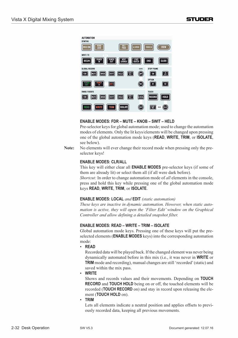
2-32 Desk Operation
ENABLE MODES: FDR – MUTE – KNOB – SWIT – HELD Pre-selector keys for global automation mode; used to change the automation
modes of elements. Only the lit keys/elements will be changed upon pressing one of the global automation mode keys (READ, WRITE, TRIM, or ISOLATE, see below).
Note: No elements will ever change their record mode when pressing only the pre-selector keys!
ENABLE MODES: CLR/ALL This key will either clear all ENABLE MODES pre-selector keys (if some of
them are already lit) or select them all (if all were dark before). Shortcut: In order to change automation mode of all elements in the console,
press and hold this key while pressing one of the global automation mode keys READ, WRITE, TRIM, or ISOLATE.
ENABLE MODES: LOCAL and EDIT (static automation) These keys are inactive in dynamic automation. However, when static auto-
mation is active, they will open the ‘Filter Edit’ window on the Graphical Controller and allow defining a detailed snapshot filter.
ENABLE MODES: READ – WRITE – TRIM – ISOLATE Global automation mode keys. Pressing one of these keys will put the pre-
selected elements (ENABLE MODES keys) into the corresponding automation mode:
• READ Recorded data will be played back. If the changed element was never being
dynamically automated before in this mix (i.e., it was never in WRITE or TRIM mode and recording), manual changes are still ‘recorded’ (static) and saved within the mix pass.
• WRITE Shows and records values and their movements. Depending on TOUCH
RECORD and TOUCH HOLD being on or off, the touched elements will be recorded (TOUCH RECORD on) and stay in record upon releasing the ele-ment (TOUCH HOLD on).
• TRIM Lets all elements indicate a neutral position and applies offsets to previ-
ously recorded data, keeping all previous movements.
Vista X Digital Mixing System
Document generated: 12.07.16SW V5.3
Desk Operation 2-33
• ISOLATE No changes to elements will be saved. Also no playback of dynamic or
static changes will occur. Static Automation: Pre-selected elements may be put into READ (not fil-
tered), ISOLATE (filtered) or TRIM mode (relative corrections applied for all following snapshot recalls, if activated in the Options page).
TOUCH: RECORD If on, an element in WRITE or TRIM will start recording as soon as it is
touched. If off, settings can be auditioned without recording them. However, in conjunction with TOUCH HOLD on, elements can be left in an auditioned value and punched-in at anytime afterwards, using PUNCH IN with an active GLOBAL RECORD: HELD pre-selector key.
TOUCH: HOLD Determines whether an element should detect when the user releases it (‘un-
touch’), or whether only touch is registered and un-touch is ignored. The indi-cation of held elements is as if they were touched (e.g., the dB value visible in the Vistonics™ generic display area when a fader is held, or underlined value display in the Vistonics™ Rotary Control Area (chapter 2.2.6).
Note: The AutoTouch+ Dynamic Automation is only looking at the current setting of this key at the moment when an element is untouched (the moment when it is released with the finger). It is therefore possible to touch any ele-ment, set the TOUCH HOLD key and then release the element. At the next touch, the TOUCH HOLD key may be altered. Therefore it is possible to have some elements held, while others are actually moving back to the original value.
TOUCH: HELD: PLAY MIX If this key is active, the AutoTouch+ Dynamic Automation will always play
the recorded mix data and therefore make any audition mode inactive.
TOUCH: HELD: CLR Clears the ‘hold’ status of all objects being currently in ‘hold’ mode.
Vista X Digital Mixing System
Document generated: 12.07.16 SW V5.3
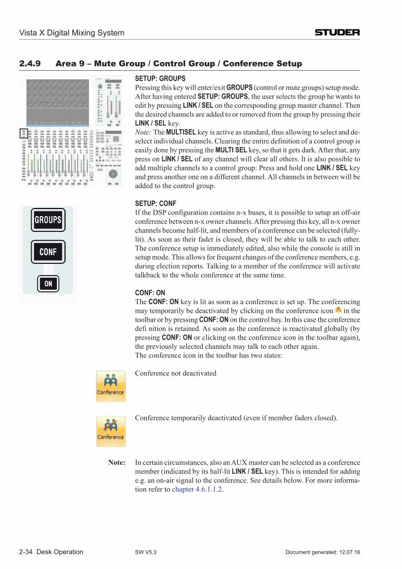
2-34 Desk Operation
2.4.9 area 9 – Mute Group / Control Group / Conference setup
SETUP: GROUPS Pressing this key will enter/exit GROUPS (control or mute groups) setup mode.
After having entered SETUP: GROUPS, the user selects the group he wants to edit by pressing LINK / SEL on the corresponding group master channel. Then the desired channels are added to or removed from the group by pressing their LINK / SEL key.
Note: The MULTISEL key is active as standard, thus allowing to select and de-select individual channels. Clearing the entire definition of a control group is easily done by pressing the MULTI SEL key, so that it gets dark. After that, any press on LINK / SEL of any channel will clear all others. It is also possible to add multiple channels to a control group: Press and hold one LINK / SEL key and press another one on a different channel. All channels in between will be added to the control group.
SETUP: CONF If the DSP configuration contains n-x buses, it is possible to setup an off-air
conference between n-x owner channels. After pressing this key, all n-x owner channels become half-lit, and members of a conference can be selected (fully-lit). As soon as their fader is closed, they will be able to talk to each other. The conference setup is immediately edited, also while the console is still in setup mode. This allows for frequent changes of the conference members, e.g. during election reports. Talking to a member of the conference will activate talkback to the whole conference at the same time.
CONF: ON The CONF: ON key is lit as soon as a conference is set up. The conferencing
may temporarily be deactivated by clicking on the conference icon in the toolbar or by pressing CONF: ON on the control bay. In this case the conference defi nition is retained. As soon as the conference is reactivated globally (by pressing CONF: ON or clicking on the conference icon in the toolbar again), the previously selected channels may talk to each other again.
The conference icon in the toolbar has two states: Conference not deactivated
Conference temporarily deactivated (even if member faders closed).
Note: Incertaincircumstances,alsoanAUXmastercanbeselectedasaconferencemember (indicated by its half-lit LINK / SEL key). This is intended for adding e.g. an on-air signal to the conference. See details below. For more informa-tion refer to chapter 4.6.1.1.2.
Vista X Digital Mixing System
Document generated: 12.07.16SW V5.3
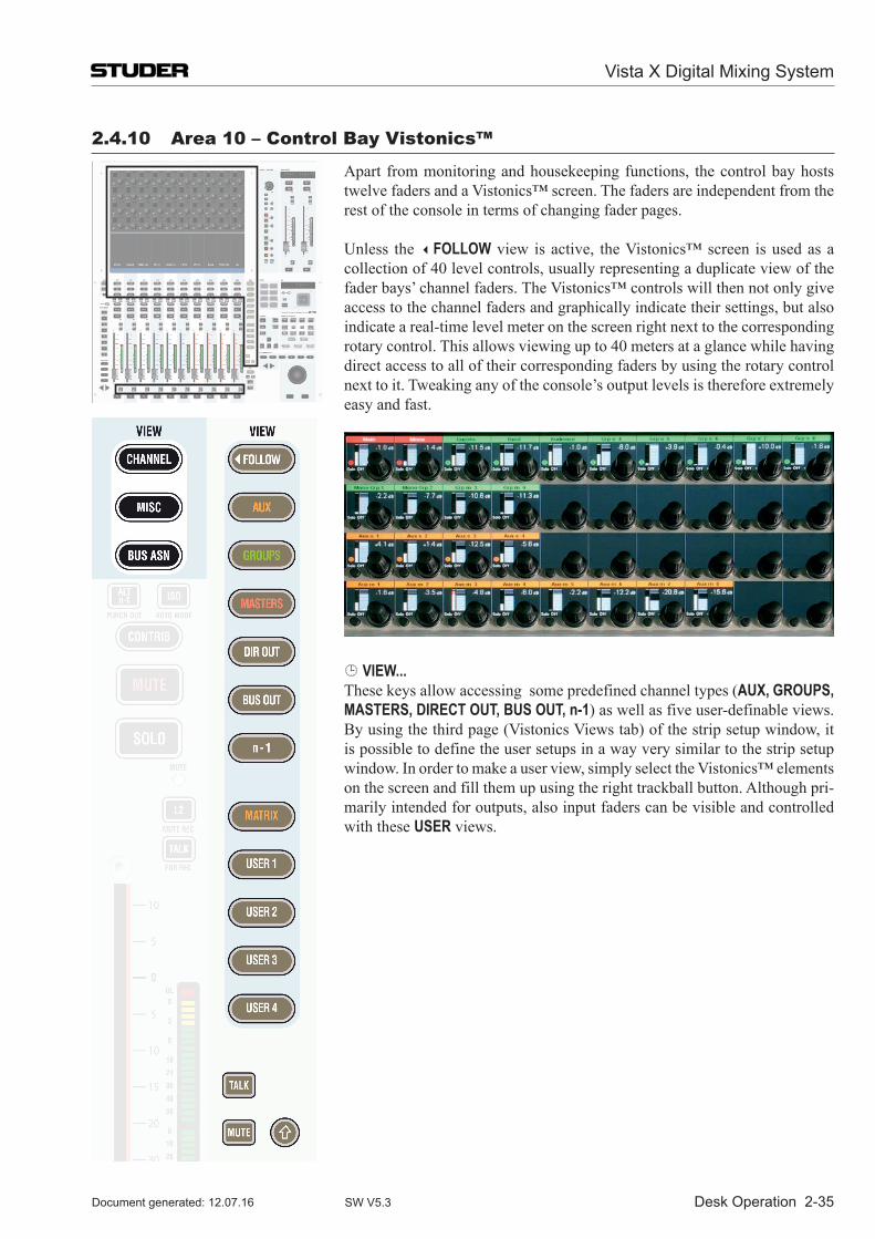
Desk Operation 2-35
2.4.10 area 10 – Control Bay Vistonics™
Apart from monitoring and housekeeping functions, the control bay hosts twelve faders and a Vistonics™ screen. The faders are independent from the rest of the console in terms of changing fader pages.
Unless the FOLLOW view is active, the Vistonics™ screen is used as a collection of 40 level controls, usually representing a duplicate view of the fader bays’ channel faders. The Vistonics™ controls will then not only give access to the channel faders and graphically indicate their settings, but also indicate a real-time level meter on the screen right next to the corresponding rotary control. This allows viewing up to 40 meters at a glance while having direct access to all of their corresponding faders by using the rotary control next to it. Tweaking any of the console’s output levels is therefore extremely easy and fast.
VIEW... These keys allow accessing some predefined channel types (AUX, GROUPS,
MASTERS, DIRECT OUT, BUS OUT, n-1) as well as five user-definable views. By using the third page (Vistonics Views tab) of the strip setup window, it is possible to define the user setups in a way very similar to the strip setup window. In order to make a user view, simply select the Vistonics™ elements on the screen and fill them up using the right trackball button. Although pri-marily intended for outputs, also input faders can be visible and controlled with these USER views.
Vista X Digital Mixing System
Document generated: 12.07.16 SW V5.3
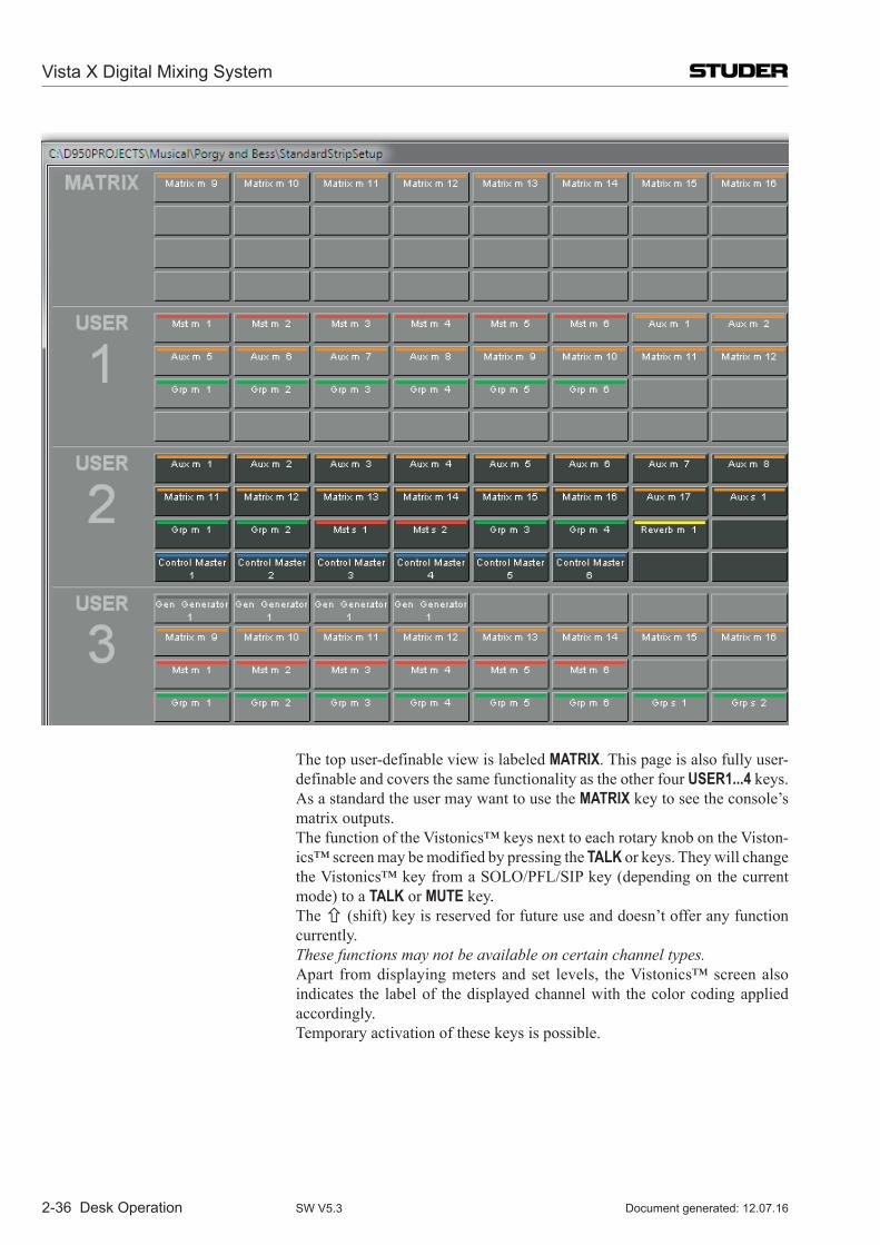
2-36 Desk Operation
The top user-definable view is labeled MATRIX. This page is also fully user-
definable and covers the same functionality as the other four USER1...4 keys. As a standard the user may want to use the MATRIX key to see the console’s matrix outputs.
The function of the Vistonics™ keys next to each rotary knob on the Viston-ics™ screen may be modified by pressing the TALK or keys. They will change the Vistonics™ key from a SOLO/PFL/SIP key (depending on the current mode) to a TALK or MUTE key.
The (shift) key is reserved for future use and doesn’t offer any function currently.
These functions may not be available on certain channel types. Apart from displaying meters and set levels, the Vistonics™ screen also
indicates the label of the displayed channel with the color coding applied accordingly.
Temporary activation of these keys is possible.
Vista X Digital Mixing System
Document generated: 12.07.16SW V5.3
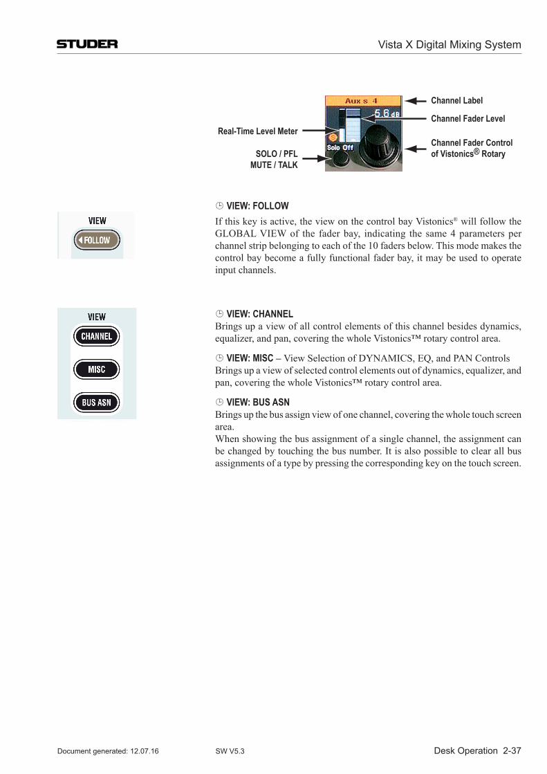
Desk Operation 2-37
Channel Label
Channel Fader LevelReal-Time Level Meter
SOLO / PFLMUTE / TALK
Channel Fader Controlof Vistonics® Rotary
VIEW: FOLLOW If this key is active, the view on the control bay Vistonics® will follow the
GLOBAL VIEW of the fader bay, indicating the same 4 parameters per channel strip belonging to each of the 10 faders below. This mode makes the control bay become a fully functional fader bay, it may be used to operate input channels.
VIEW: CHANNEL Brings up a view of all control elements of this channel besides dynamics,
equalizer, and pan, covering the whole Vistonics™ rotary control area.
VIEW: MISC – View Selection of DYNAMICS, EQ, and PAN Controls Brings up a view of selected control elements out of dynamics, equalizer, and
pan, covering the whole Vistonics™ rotary control area.
VIEW: BUS ASN Brings up the bus assign view of one channel, covering the whole touch screen
area. When showing the bus assignment of a single channel, the assignment can
be changed by touching the bus number. It is also possible to clear all bus assignments of a type by pressing the corresponding key on the touch screen.
Vista X Digital Mixing System
Document generated: 12.07.16 SW V5.3
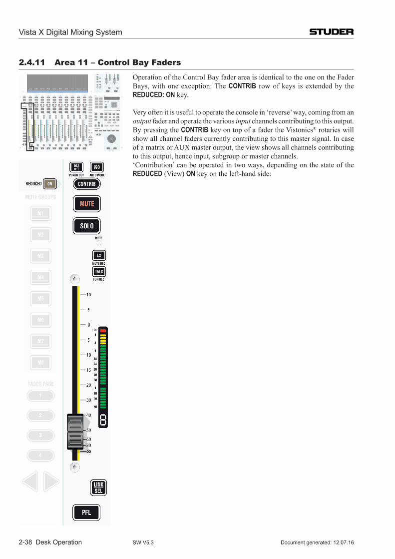
2-38 Desk Operation
2.4.11 area 11 – Control Bay Faders
Operation of the Control Bay fader area is identical to the one on the Fader Bays, with one exception: The CONTRIB row of keys is extended by the REDUCED: ON key.
Very often it is useful to operate the console in ‘reverse’ way, coming from an output fader and operate the various input channels contributing to this output. By pressing the CONTRIB key on top of a fader the Vistonics® rotaries will show all channel faders currently contributing to this master signal. In case ofamatrixorAUXmasteroutput,theviewshowsallchannelscontributingto this output, hence input, subgroup or master channels.
‘Contribution’ can be operated in two ways, depending on the state of the REDUCED (View) ON key on the left-hand side:
Vista X Digital Mixing System
Document generated: 12.07.16SW V5.3
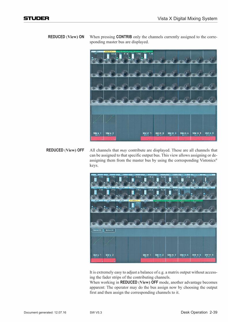
Desk Operation 2-39
REDUCED (View) ON When pressing CONTRIB only the channels currently assigned to the corre-sponding master bus are displayed.
REDUCED (View) OFF All channels that may contribute are displayed. These are all channels that can be assigned to that specific output bus. This view allows assigning or de-assigning them from the master bus by using the corresponding Vistonics® keys.
It is extremely easy to adjust a balance of e.g. a matrix output without access-ing the fader strips of the contributing channels.
When working in REDUCED (View) OFF mode, another advantage becomes apparent: The operator may do the bus assign now by choosing the output first and then assign the corresponding channels to it.
Vista X Digital Mixing System
Document generated: 12.07.16 SW V5.3
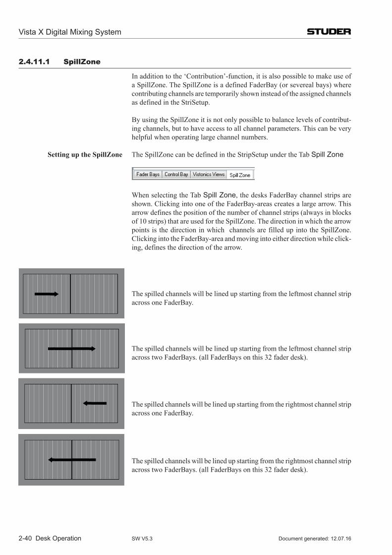
2-40 Desk Operation
2.4.11.1 spillZone
In addition to the ‘Contribution’-function, it is also possible to make use of a SpillZone. The SpillZone is a defined FaderBay (or severeal bays) where contributing channels are temporarily shown instead of the assigned channels as defined in the StriSetup.
By using the SpillZone it is not only possible to balance levels of contribut-ing channels, but to have access to all channel parameters. This can be very helpful when operating large channel numbers.
Setting up the SpillZone The SpillZone can be defined in the StripSetup under the Tab Spill Zone
When selecting the Tab Spill Zone, the desks FaderBay channel strips are shown. Clicking into one of the FaderBay-areas creates a large arrow. This arrow defines the position of the number of channel strips (always in blocks of 10 strips) that are used for the SpillZone. The direction in which the arrow points is the direction in which channels are filled up into the SpillZone. Clicking into the FaderBay-area and moving into either direction while click-ing, defines the direction of the arrow.
The spilled channels will be lined up starting from the leftmost channel strip across one FaderBay.
The spilled channels will be lined up starting from the leftmost channel strip across two FaderBays. (all FaderBays on this 32 fader desk).
The spilled channels will be lined up starting from the rightmost channel strip across one FaderBay.
The spilled channels will be lined up starting from the rightmost channel strip across two FaderBays. (all FaderBays on this 32 fader desk).
Vista X Digital Mixing System
Document generated: 12.07.16SW V5.3
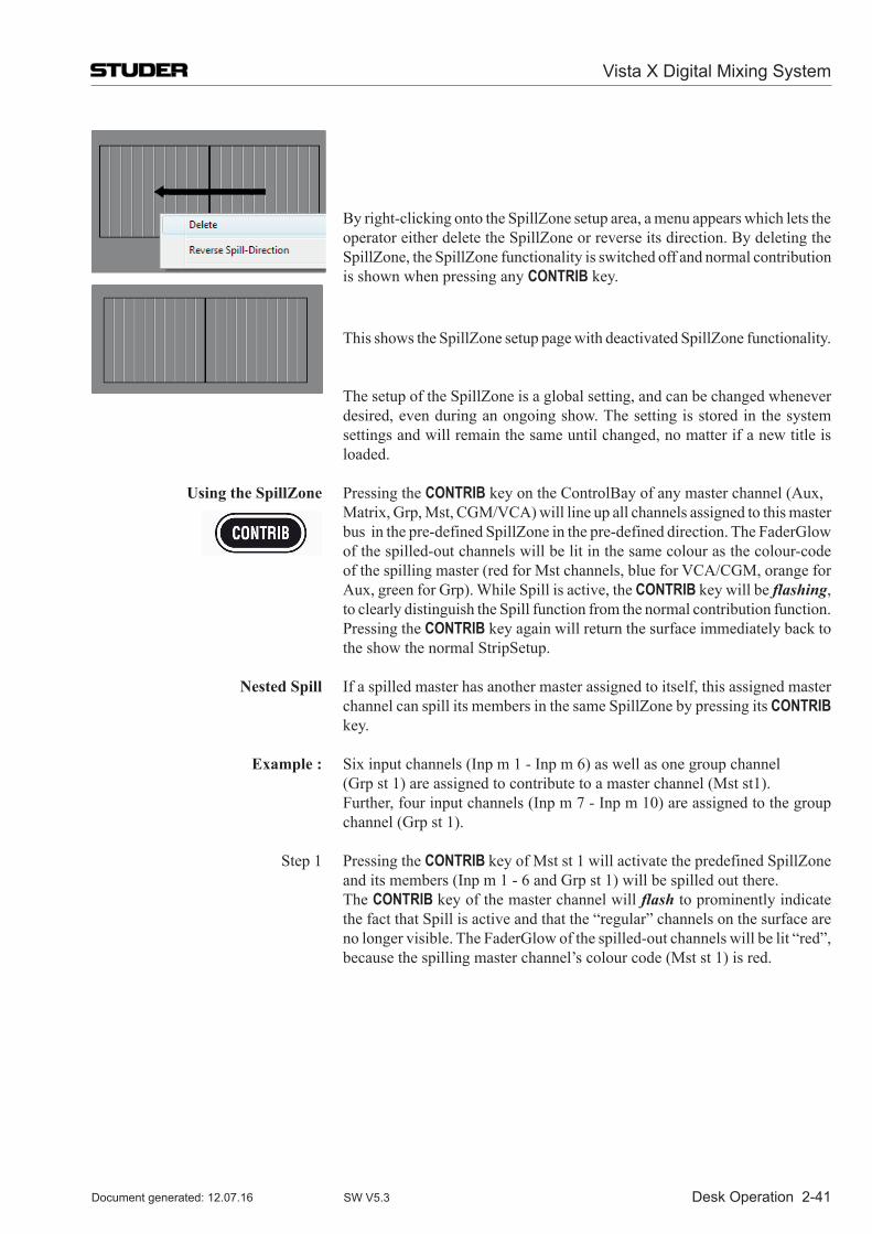
Desk Operation 2-41
By right-clicking onto the SpillZone setup area, a menu appears which lets the operator either delete the SpillZone or reverse its direction. By deleting the SpillZone, the SpillZone functionality is switched off and normal contribution is shown when pressing any CONTRIB key.
This shows the SpillZone setup page with deactivated SpillZone functionality.
The setup of the SpillZone is a global setting, and can be changed whenever desired, even during an ongoing show. The setting is stored in the system settings and will remain the same until changed, no matter if a new title is loaded.
Using the SpillZone Pressing the CONTRIB key on the ControlBay of any master channel (Aux, Matrix, Grp, Mst, CGM/VCA) will line up all channels assigned to this master
bus in the pre-defined SpillZone in the pre-defined direction. The FaderGlow of the spilled-out channels will be lit in the same colour as the colour-code of the spilling master (red for Mst channels, blue for VCA/CGM, orange for Aux, green for Grp). While Spill is active, the CONTRIB key will be flashing, to clearly distinguish the Spill function from the normal contribution function.Pressing the CONTRIB key again will return the surface immediately back to the show the normal StripSetup.
Nested Spill If a spilled master has another master assigned to itself, this assigned master channel can spill its members in the same SpillZone by pressing its CONTRIB key.
Example : Six input channels (Inp m 1 - Inp m 6) as well as one group channel (Grp st 1) are assigned to contribute to a master channel (Mst st1). Further, four input channels (Inp m 7 - Inp m 10) are assigned to the group
channel (Grp st 1).
Step 1 Pressing the CONTRIB key of Mst st 1 will activate the predefined SpillZone and its members (Inp m 1 - 6 and Grp st 1) will be spilled out there.
The CONTRIB key of the master channel will flash to prominently indicate the fact that Spill is active and that the “regular” channels on the surface are no longer visible. The FaderGlow of the spilled-out channels will be lit “red”, because the spilling master channel’s colour code (Mst st 1) is red.
Vista X Digital Mixing System
Document generated: 12.07.16 SW V5.3
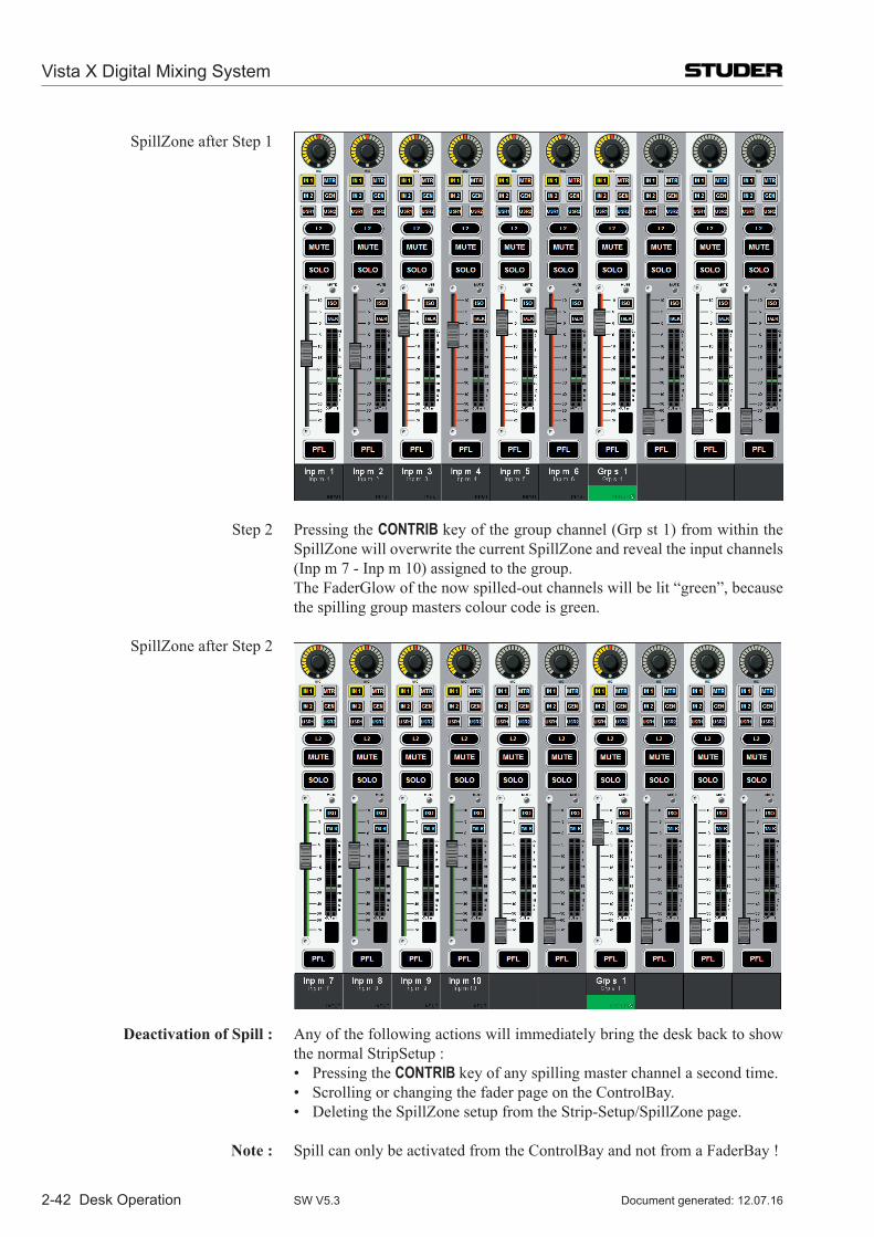
2-42 Desk Operation
SpillZone after Step 1
Step 2 Pressing the CONTRIB key of the group channel (Grp st 1) from within the SpillZone will overwrite the current SpillZone and reveal the input channels (Inp m 7 - Inp m 10) assigned to the group.
The FaderGlow of the now spilled-out channels will be lit “green”, because the spilling group masters colour code is green.
SpillZone after Step 2
Deactivation of Spill : Any of the following actions will immediately bring the desk back to show the normal StripSetup :
• PressingtheCONTRIB key of any spilling master channel a second time. • ScrollingorchangingthefaderpageontheControlBay. • DeletingtheSpillZonesetupfromtheStrip-Setup/SpillZonepage.
Note : Spill can only be activated from the ControlBay and not from a FaderBay !
Vista X Digital Mixing System
Document generated: 12.07.16SW V5.3
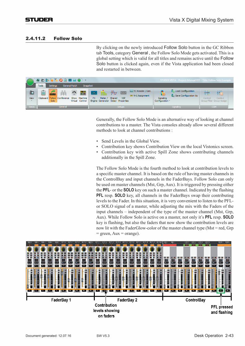
Desk Operation 2-43
2.4.11.2 Follow solo
By clicking on the newly introduced Follow Solo button in the GC Ribbon tab Tools, category General , the Follow Solo Mode gets activated. This is a global setting which is valid for all titles and remains active until the Follow Solo button is clicked again, even if the Vista application had been closed and restarted in between.
Generally, the Follow Solo Mode is an alternative way of looking at channel contributions to a master. The Vista consoles already allow several different methods to look at channel contributions :
• SendLevelsintheGlobalView. • ContributionkeyshowsContributionViewonthelocalVistonicsscreen. • ContributionkeywithactiveSpillZone showscontributingchannels
additionally in the Spill Zone.
The Follow Solo Mode is the fourth method to look at contribution levels to a specific master channel. It is based on the rule of having master channels in the ControlBay and input channels in the FaderBays. Follow Solo can only be used on master channels (Mst, Grp, Aux). It is triggered by pressing either the PFL- or the SOLO key on such a master channel. Indicated by the flashing PFL resp. SOLO key, all channels in the FaderBays swap their contributing levels to the Fader. In this situation, it is very convenient to listen to the PFL- or SOLO signal of a master, while adjusting the mix with the Faders of the input channels – independent of the type of the master channel (Mst, Grp, Aux). While Follow Solo is active on a master, not only it’s PFL resp. SOLO key is flashing, but also the faders that now show the contribution levels are now lit with the FaderGlow-color of the master channel type (Mst = red, Grp = green, Aux = orange).
Vista X Digital Mixing System
Document generated: 12.07.16 SW V5.3
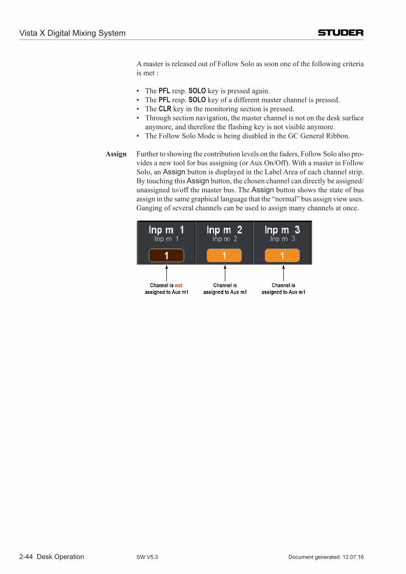
2-44 Desk Operation
A master is released out of Follow Solo as soon one of the following criteria is met :
• ThePFL resp. SOLO key is pressed again. • ThePFL resp. SOLO key of a different master channel is pressed. • TheCLR key in the monitoring section is pressed. • Throughsectionnavigation,themasterchannelisnotonthedesksurface
anymore, and therefore the flashing key is not visible anymore. • TheFollowSoloModeisbeingdisabledintheGCGeneralRibbon.
Assign Further to showing the contribution levels on the faders, Follow Solo also pro-vides a new tool for bus assigning (or Aux On/Off). With a master in Follow Solo, an Assign button is displayed in the Label Area of each channel strip. By touching this Assign button, the chosen channel can directly be assigned/unassigned to/off the master bus. The Assign button shows the state of bus assign in the same graphical language that the “normal” bus assign view uses. Ganging of several channels can be used to assign many channels at once.
Vista X Digital Mixing System
Document generated: 12.07.16SW V5.3
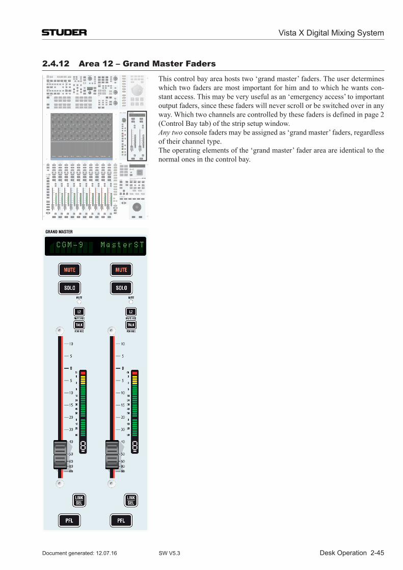
Desk Operation 2-45
2.4.12 area 12 – Grand Master Faders
This control bay area hosts two ‘grand master’ faders. The user determines which two faders are most important for him and to which he wants con-stant access. This may be very useful as an ‘emergency access’ to important output faders, since these faders will never scroll or be switched over in any way. Which two channels are controlled by these faders is defined in page 2 (Control Bay tab) of the strip setup window.
Any two console faders may be assigned as ‘grand master’ faders, regardless of their channel type.
The operating elements of the ‘grand master’ fader area are identical to the normal ones in the control bay.
Vista X Digital Mixing System
Document generated: 12.07.16 SW V5.3
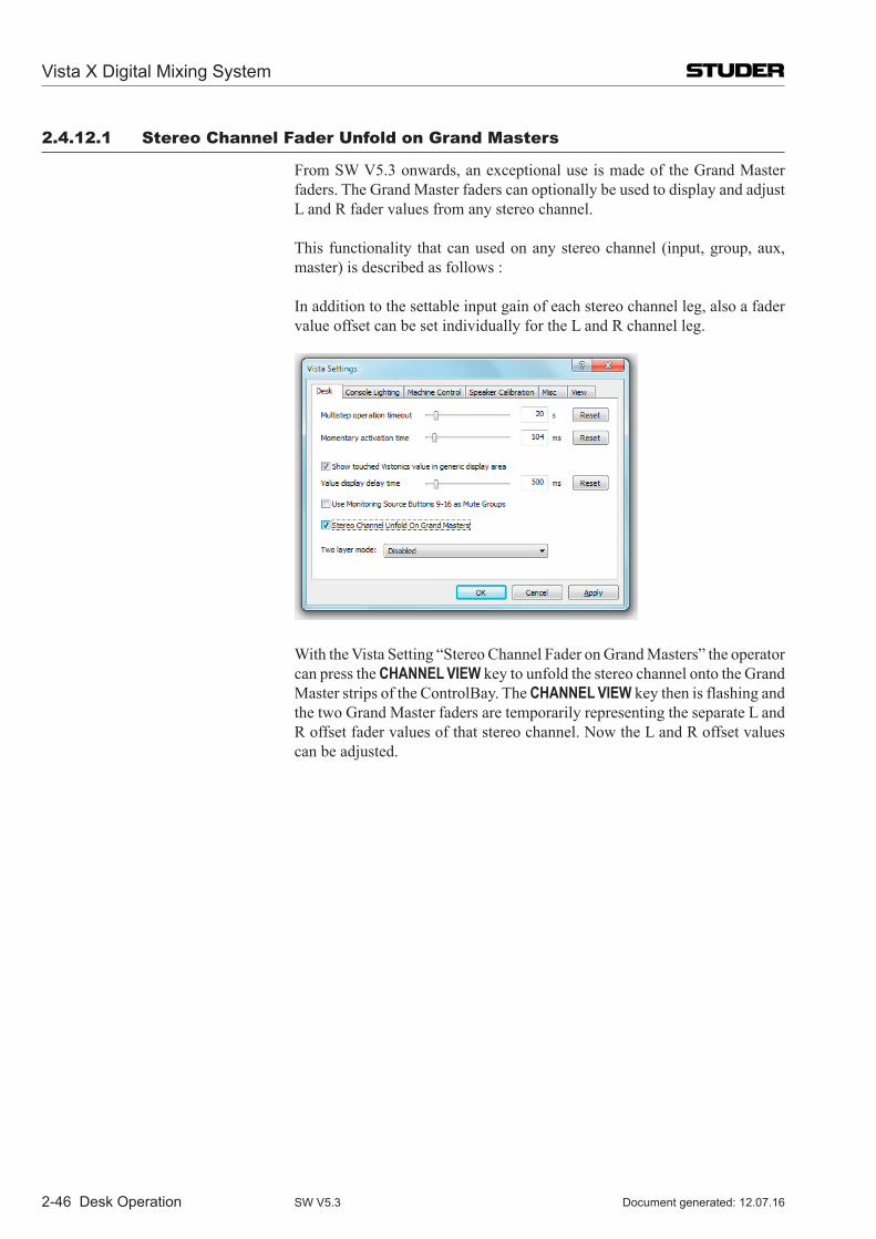
2-46 Desk Operation
2.4.12.1 stereo Channel Fader Unfold on Grand Masters
From SW V5.3 onwards, an exceptional use is made of the Grand Master faders. The Grand Master faders can optionally be used to display and adjust L and R fader values from any stereo channel.
This functionality that can used on any stereo channel (input, group, aux, master) is described as follows :
In addition to the settable input gain of each stereo channel leg, also a fader value offset can be set individually for the L and R channel leg.
With the Vista Setting “Stereo Channel Fader on Grand Masters” the operator can press the CHANNEL VIEW key to unfold the stereo channel onto the Grand Master strips of the ControlBay. The CHANNEL VIEW key then is flashing and the two Grand Master faders are temporarily representing the separate L and R offset fader values of that stereo channel. Now the L and R offset values can be adjusted.
Vista X Digital Mixing System
Document generated: 12.07.16SW V5.3
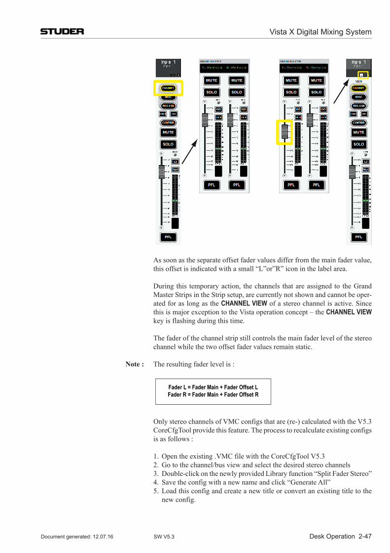
Desk Operation 2-47
As soon as the separate offset fader values differ from the main fader value,
this offset is indicated with a small “L”or”R” icon in the label area.
During this temporary action, the channels that are assigned to the Grand Master Strips in the Strip setup, are currently not shown and cannot be oper-ated for as long as the CHANNEL VIEW of a stereo channel is active. Since this is major exception to the Vista operation concept – the CHANNEL VIEW key is flashing during this time.
The fader of the channel strip still controls the main fader level of the stereo channel while the two offset fader values remain static.
Note : The resulting fader level is :
Fader L = Fader Main + Fader Offset LFader R = Fader Main + Fader Offset R
Only stereo channels of VMC configs that are (re-) calculated with the V5.3 CoreCfgTool provide this feature. The process to recalculate existing configs is as follows :
1. Open the existing .VMC file with the CoreCfgTool V5.3 2. Go to the channel/bus view and select the desired stereo channels 3. Double-click on the newly provided Library function “Split Fader Stereo” 4. Save the config with a new name and click “Generate All” 5. Load this config and create a new title or convert an existing title to the
new config.
Vista X Digital Mixing System
Document generated: 12.07.16 SW V5.3
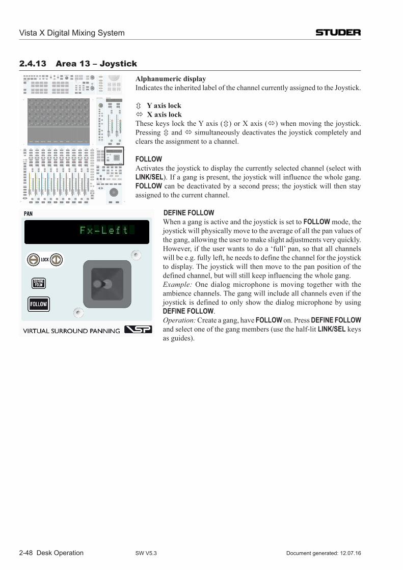
2-48 Desk Operation
2.4.13 area 13 – Joystick
Alphanumeric display Indicates the inherited label of the channel currently assigned to the Joystick.
Y axis lock X axis lock These keys lock the Y axis ()orXaxis() when moving the joystick.
Pressing and simultaneously deactivates the joystick completely and clears the assignment to a channel.
FOLLOW Activates the joystick to display the currently selected channel (select with
LINK/SEL). If a gang is present, the joystick will influence the whole gang. FOLLOW can be deactivated by a second press; the joystick will then stay assigned to the current channel.
DEFINE FOLLOW When a gang is active and the joystick is set to FOLLOW mode, the
joystick will physically move to the average of all the pan values of the gang, allowing the user to make slight adjustments very quickly. However, if the user wants to do a ‘full’ pan, so that all channels will be e.g. fully left, he needs to define the channel for the joystick to display. The joystick will then move to the pan position of the defined channel, but will still keep influencing the whole gang.
Example: One dialog microphone is moving together with the ambience channels. The gang will include all channels even if the joystick is defined to only show the dialog microphone by using DEFINE FOLLOW.
Operation: Create a gang, have FOLLOW on. Press DEFINE FOLLOW and select one of the gang members (use the half-lit LINK/SEL keys as guides).
Vista X Digital Mixing System
Document generated: 12.07.16SW V5.3
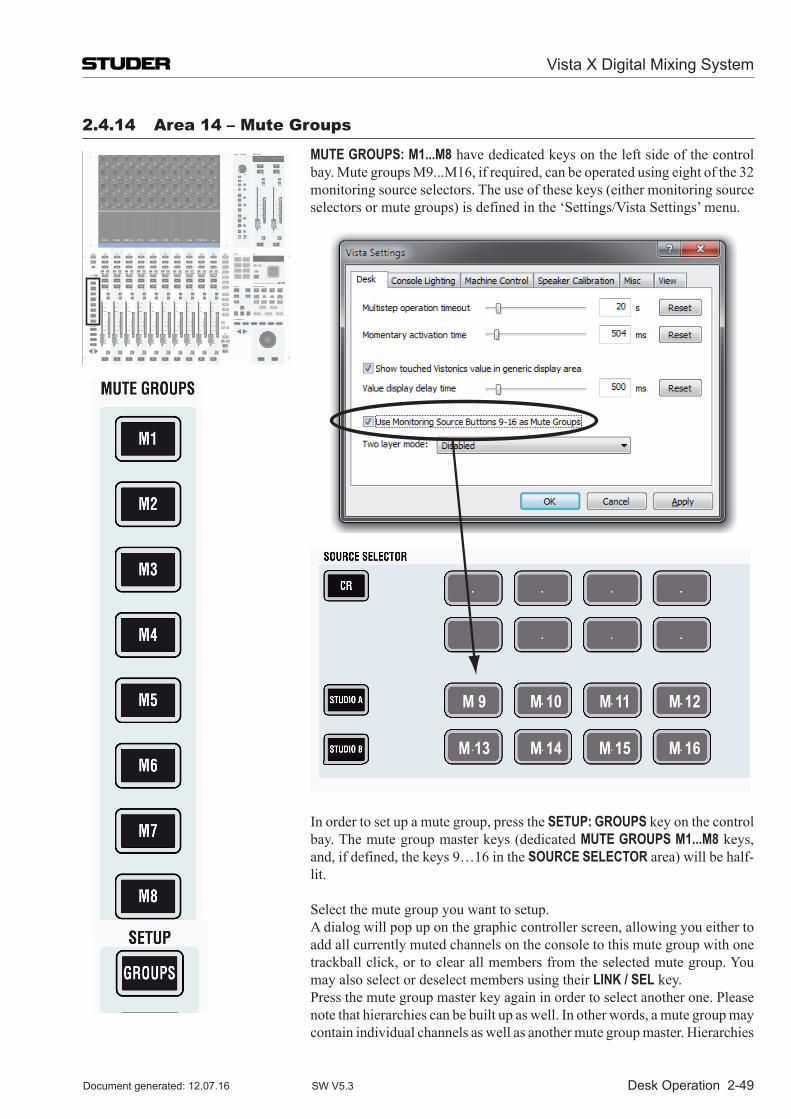
Desk Operation 2-49
2.4.14 area 14 – Mute Groups
MUTE GROUPS: M1...M8 have dedicated keys on the left side of the control bay. Mute groups M9...M16, if required, can be operated using eight of the 32 monitoring source selectors. The use of these keys (either monitoring source selectors or mute groups) is defined in the ‘Settings/Vista Settings’ menu.
M 9
M 13
M 10
M 14
M 11
M 15
M 12
M 16
In order to set up a mute group, press the SETUP: GROUPS key on the control bay. The mute group master keys (dedicated MUTE GROUPS M1...M8 keys, and, if defined, the keys 9…16 in the SOURCE SELECTOR area) will be half-lit.
Select the mute group you want to setup. A dialog will pop up on the graphic controller screen, allowing you either to
add all currently muted channels on the console to this mute group with one trackball click, or to clear all members from the selected mute group. You may also select or deselect members using their LINK / SEL key.
Press the mute group master key again in order to select another one. Please note that hierarchies can be built up as well. In other words, a mute group may contain individual channels as well as another mute group master. Hierarchies
Vista X Digital Mixing System
Document generated: 12.07.16 SW V5.3
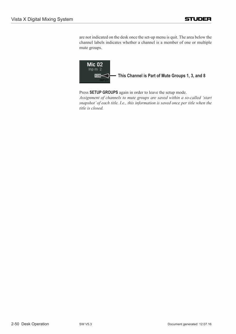
2-50 Desk Operation
are not indicated on the desk once the set-up menu is quit. The area below the channel labels indicates whether a channel is a member of one or multiple mute groups.
This Channel is Part of Mute Groups 1, 3, and 8
Press SETUP GROUPS again in order to leave the setup mode. Assignment of channels to mute groups are saved within a so-called ‘start
snapshot’ of each title. I.e., this information is saved once per title when the title is closed.
Vista X Digital Mixing System
Document generated: 12.07.16SW V5.3
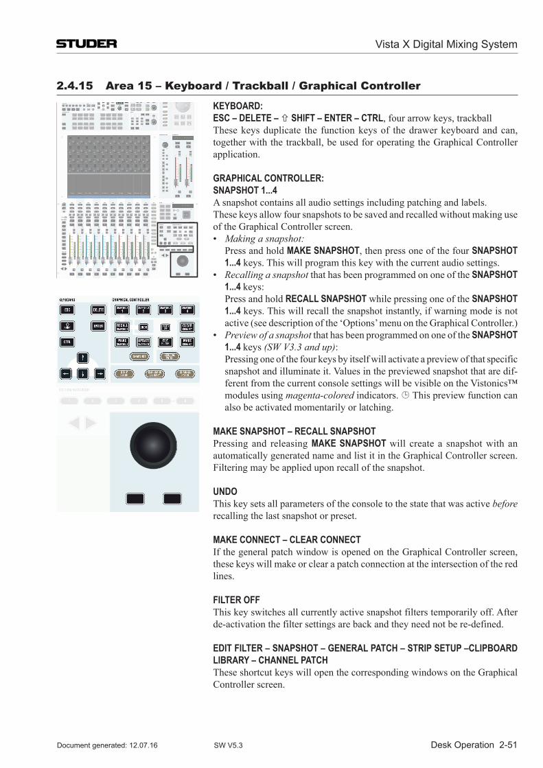
Desk Operation 2-51
2.4.15 area 15 – keyboard / trackball / Graphical Controller
KEYBOARD: ESC – DELETE – SHIFT – ENTER – CTRL, four arrow keys, trackball These keys duplicate the function keys of the drawer keyboard and can,
together with the trackball, be used for operating the Graphical Controller application.
GRAPHICAL CONTROLLER: SNAPSHOT 1...4 A snapshot contains all audio settings including patching and labels. These keys allow four snapshots to be saved and recalled without making use
of the Graphical Controller screen. • Making a snapshot: Press and hold MAKE SNAPSHOT, then press one of the four SNAPSHOT
1...4 keys. This will program this key with the current audio settings. • Recalling a snapshot that has been programmed on one of the SNAPSHOT
1...4 keys: Press and hold RECALL SNAPSHOT while pressing one of the SNAPSHOT
1...4 keys. This will recall the snapshot instantly, if warning mode is not active (see description of the ‘Options’ menu on the Graphical Controller.)
• Preview of a snapshot that has been programmed on one of the SNAPSHOT 1...4 keys (SW V3.3 and up):
Pressing one of the four keys by itself will activate a preview of that specific snapshot and illuminate it. Values in the previewed snapshot that are dif-ferent from the current console settings will be visible on the Vistonics™ modules using magenta-colored indicators. This preview function can also be activated momentarily or latching.
MAKE SNAPSHOT – RECALL SNAPSHOT Pressing and releasing MAKE SNAPSHOT will create a snapshot with an
automatically generated name and list it in the Graphical Controller screen. Filtering may be applied upon recall of the snapshot.
UNDO This key sets all parameters of the console to the state that was active before
recalling the last snapshot or preset.
MAKE CONNECT – CLEAR CONNECT If the general patch window is opened on the Graphical Controller screen,
these keys will make or clear a patch connection at the intersection of the red lines.
FILTER OFF This key switches all currently active snapshot filters temporarily off. After
de-activation the filter settings are back and they need not be re-defined.
EDIT FILTER – SNAPSHOT – GENERAL PATCH – STRIP SETUP –CLIPBOARD LIBRARY – CHANNEL PATCH
These shortcut keys will open the corresponding windows on the Graphical Controller screen.
Vista X Digital Mixing System
Document generated: 12.07.16 SW V5.3
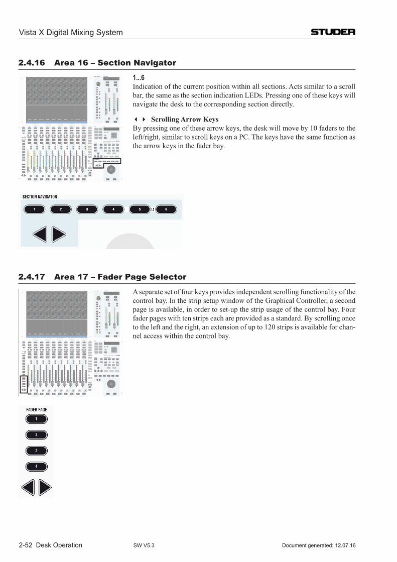
2-52 Desk Operation
2.4.16 area 16 – section navigator
1...6 Indication of the current position within all sections. Acts similar to a scroll
bar, the same as the section indication LEDs. Pressing one of these keys will navigate the desk to the corresponding section directly.
Scrolling Arrow Keys By pressing one of these arrow keys, the desk will move by 10 faders to the
left/right, similar to scroll keys on a PC. The keys have the same function as the arrow keys in the fader bay.
2.4.17 area 17 – Fader page selector
A separate set of four keys provides independent scrolling functionality of the control bay. In the strip setup window of the Graphical Controller, a second page is available, in order to set-up the strip usage of the control bay. Four fader pages with ten strips each are provided as a standard. By scrolling once to the left and the right, an extension of up to 120 strips is available for chan-nel access within the control bay.
Vista X Digital Mixing System
Document generated: 12.07.16SW V5.3
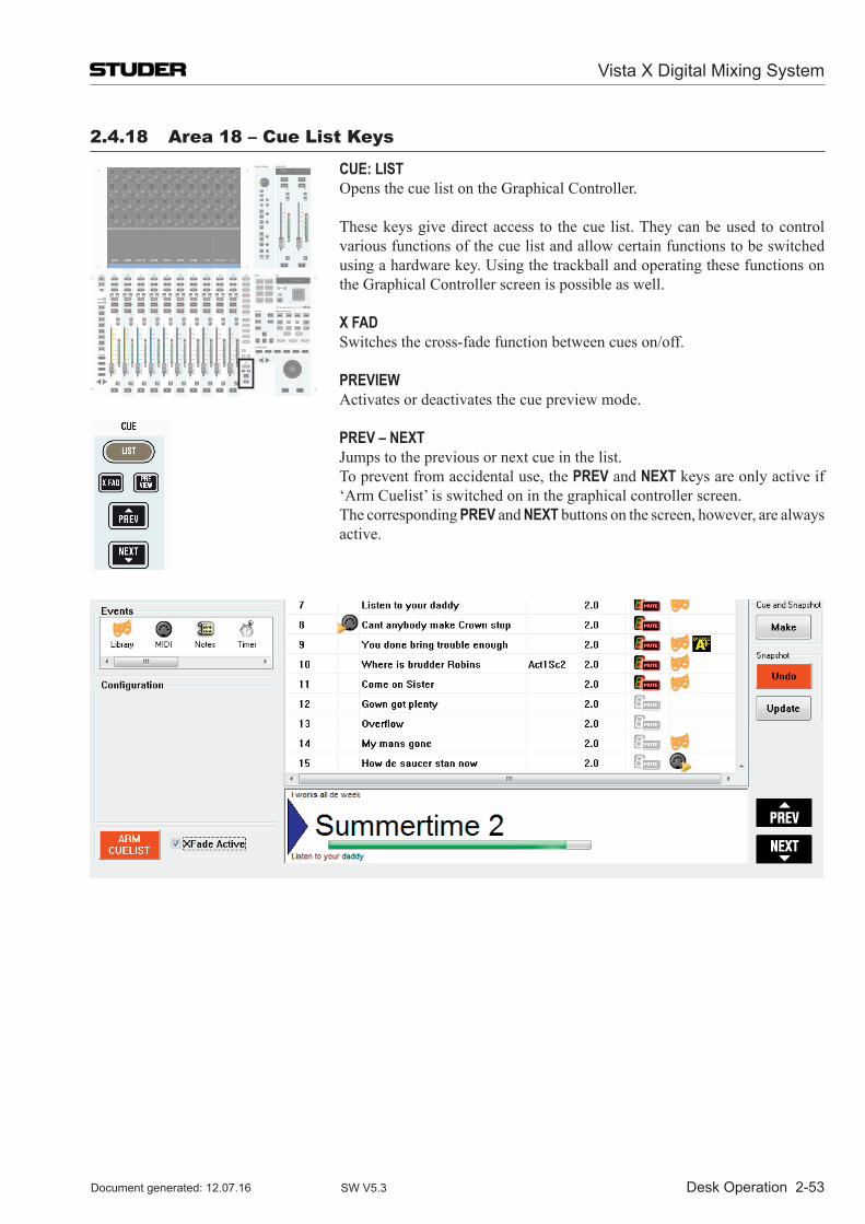
Desk Operation 2-53
2.4.18 area 18 – Cue List keys
CUE: LIST Opens the cue list on the Graphical Controller.
These keys give direct access to the cue list. They can be used to control various functions of the cue list and allow certain functions to be switched using a hardware key. Using the trackball and operating these functions on the Graphical Controller screen is possible as well.
X FAD Switches the cross-fade function between cues on/off.
PREVIEW Activates or deactivates the cue preview mode. PREV – NEXT Jumps to the previous or next cue in the list. To prevent from accidental use, the PREV and NEXT keys are only active if
‘Arm Cuelist’ is switched on in the graphical controller screen. The corresponding PREV and NEXT buttons on the screen, however, are always
active.
Vista X Digital Mixing System
Document generated: 12.07.16 SW V5.3
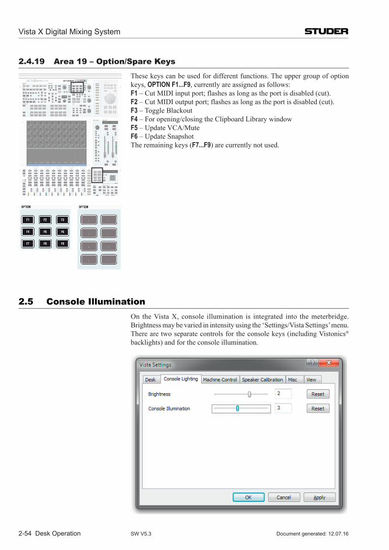
2-54 Desk Operation
2.4.19 area 19 – Option/spare keys
These keys can be used for different functions. The upper group of option keys, OPTION F1...F9, currently are assigned as follows:
F1 – Cut MIDI input port; flashes as long as the port is disabled (cut). F2 – Cut MIDI output port; flashes as long as the port is disabled (cut). F3 – Toggle Blackout F4 – For opening/closing the Clipboard Library window F5 – Update VCA/Mute F6 – Update Snapshot The remaining keys (F7...F9) are currently not used.
2.5 Console illumination On theVistaX, console illumination is integrated into themeterbridge.
Brightness may be varied in intensity using the ‘Settings/Vista Settings’ menu. There are two separate controls for the console keys (including Vistonics® backlights) and for the console illumination.
Vista X Digital Mixing System
Document generated: 12.07.16SW V5.3
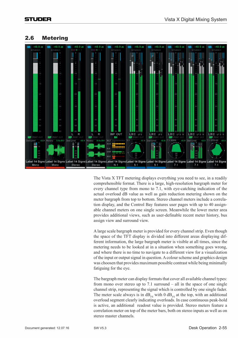
Desk Operation 2-55
2.6 Metering
TheVistaXTFTmeteringdisplayseverythingyouneedtosee,inareadilycomprehensible format. There is a large, high-resolution bargraph meter for every channel type from mono to 7.1, with eye-catching indication of the actual overload dB value as well as gain reduction metering shown on the meter bargraph from top to bottom. Stereo channel meters include a correla-tion display, and the Control Bay features user pages with up to 40 assign-able channel meters on one single screen. Meanwhile the lower meter area provides additional views, such as user-definable recent meter history, bus assign view and surround view.
A large scale bargraph meter is provided for every channel strip. Even though the space of the TFT display is divided into different areas displaying dif-ferent information, the large bargraph meter is visible at all times, since the metering needs to be looked at in a situation when something goes wrong, and where there is no time to navigate to a different view for a visualization of the input or output signal in question. A colour scheme and graphics design was choosen that provides maximum possible contrast while being minimally fatiguing for the eye.
The bargraph meter can display formats that cover all available channel types: from mono over stereo up to 7.1 surround – all in the space of one single channel strip, representing the signal which is controlled by one single fader. The meter scale always is in dBFS with 0 dBFS at the top, with an additional overload segment clearly indicating overloads. In case continuous peak-hold is active, an additional readout value is provided. Stereo meters feature a correlation meter on top of the meter bars, both on stereo inputs as well as on stereo master channels.
Vista X Digital Mixing System
Document generated: 12.07.16 SW V5.3
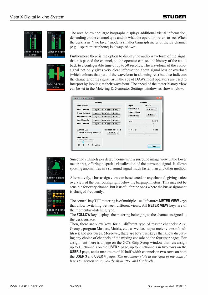
2-56 Desk Operation
The area below the large bargraphs displays additional visual information, depending on the channel type and on what the operator prefers to see. When the desk is in ‘two layer’ mode, a smaller bargraph meter of the L2 channel (e.g. a spare microphone) is always shown.
Furthermore there is the option to display the audio waveform of the signal that has passed the channel, so the operator can see the history of the audio back to a configurable time of up to 50 seconds. The waveform of the audio-signal not only gives very clear information about signal loss or overload (which colours that part of the waveform in alarming red) but also indicates the character of the signal, as in the age of DAWs most operators are used to interpret by looking at their waveform. The speed of the meter history view can be set in the Metering & Generator Settings window, as shown below.
Surround channels per default come with a surround image view in the lower meter area, offering a spatial visualization of the surround signal. It allows spotting anomalities in a surround signal much faster than any other method.
Alternatively, a bus assign view can be selected on any channel, giving a nice overview of the bus routing right below the bargraph meters. This may not be sensible for every channel but is useful for the ones where the bus assignment is changed frequently.
The control bay TFT metering is of multiple use. It features METER VIEW keys that allow switching between different views. All METER VIEW keys are of the momentary/latching type.
The FOLLOW key displays the metering belonging to the channel assigned to the desk surface.
Then, there are view keys for all different type of master channels: Aux, Groups, program Masters, Matrix, etc., as well as output meter views of mul-titrack and n-x buses. Moreover, there are four user keys that allow display-ing any choice of channels of the mixing console on the four user pages. For assignment there is a page on the GC’s Strip Setup window that lets assign up to 10 channels on the USER 1 page, up to 20 channels in two rows on the USER 2 page, and a maximum of 40 half-width channels in two rows on both the USER 3 and USER 4 pages. The two meter slots at the right of the control bay TFT screen continuously show PFL and CR levels.
Vista X Digital Mixing System
Document generated: 12.07.16SW V5.3
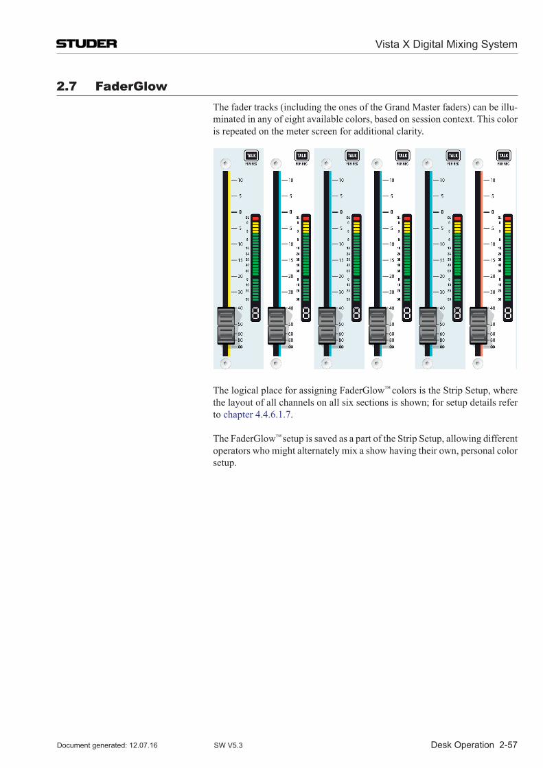
Desk Operation 2-57
2.7 FaderGlow The fader tracks (including the ones of the Grand Master faders) can be illu-
minated in any of eight available colors, based on session context. This color is repeated on the meter screen for additional clarity.
The logical place for assigning FaderGlow™ colors is the Strip Setup, where the layout of all channels on all six sections is shown; for setup details refer to chapter 4.4.6.1.7.
The FaderGlow™ setup is saved as a part of the Strip Setup, allowing different operators who might alternately mix a show having their own, personal color setup.
Vista X Digital Mixing System
Document generated: 12.07.16 SW V5.3
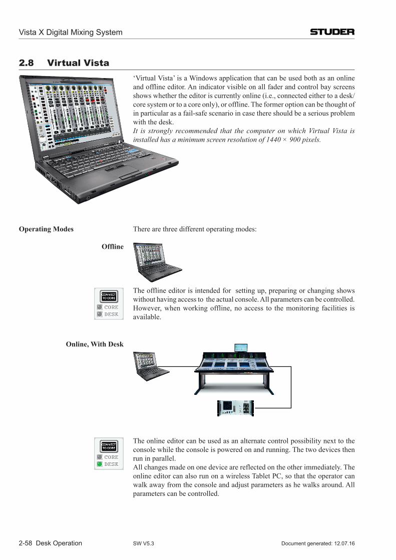
2-58 Desk Operation
2.8 Virtual Vista ‘Virtual Vista’ is a Windows application that can be used both as an online
and offline editor. An indicator visible on all fader and control bay screens shows whether the editor is currently online (i.e., connected either to a desk/core system or to a core only), or offline. The former option can be thought of in particular as a fail-safe scenario in case there should be a serious problem with the desk.
It is strongly recommended that the computer on which Virtual Vista is installed has a minimum screen resolution of 1440 × 900 pixels.
Operating Modes There are three different operating modes:
Offline
The offline editor is intended for setting up, preparing or changing shows without having access to the actual console. All parameters can be controlled. However, when working offline, no access to the monitoring facilities is available.
Online, With Desk
The online editor can be used as an alternate control possibility next to the console while the console is powered on and running. The two devices then run in parallel.
All changes made on one device are reflected on the other immediately. The online editor can also run on a wireless Tablet PC, so that the operator can walk away from the console and adjust parameters as he walks around. All parameters can be controlled.
Vista X Digital Mixing System
Document generated: 12.07.16SW V5.3
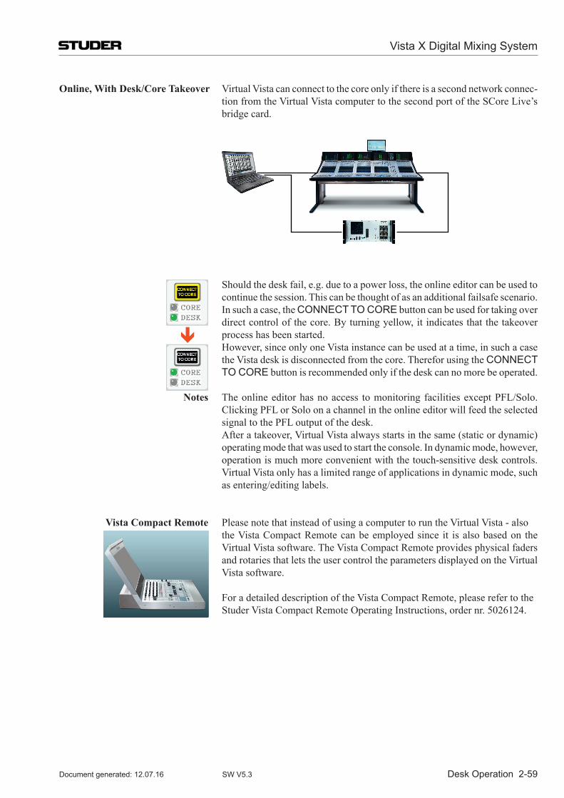
Desk Operation 2-59
Online, With Desk/Core Takeover Virtual Vista can connect to the core only if there is a second network connec-tion from the Virtual Vista computer to the second port of the SCore Live’s bridge card.
Should the desk fail, e.g. due to a power loss, the online editor can be used to continue the session. This can be thought of as an additional failsafe scenario.
In such a case, the CONNECT TO CORE button can be used for taking over direct control of the core. By turning yellow, it indicates that the takeover process has been started.
However, since only one Vista instance can be used at a time, in such a case the Vista desk is disconnected from the core. Therefor using the CONNECT TO CORE button is recommended only if the desk can no more be operated.
Notes The online editor has no access to monitoring facilities except PFL/Solo. Clicking PFL or Solo on a channel in the online editor will feed the selected signal to the PFL output of the desk.
After a takeover, Virtual Vista always starts in the same (static or dynamic) operating mode that was used to start the console. In dynamic mode, however, operation is much more convenient with the touch-sensitive desk controls. Virtual Vista only has a limited range of applications in dynamic mode, such as entering/editing labels.
Vista Compact Remote Please note that instead of using a computer to run the Virtual Vista - also the Vista Compact Remote can be employed since it is also based on the
Virtual Vista software. The Vista Compact Remote provides physical faders and rotaries that lets the user control the parameters displayed on the Virtual Vista software.
For a detailed description of the Vista Compact Remote, please refer to the Studer Vista Compact Remote Operating Instructions, order nr. 5026124.
Vista X Digital Mixing System
Document generated: 12.07.16 SW V5.3
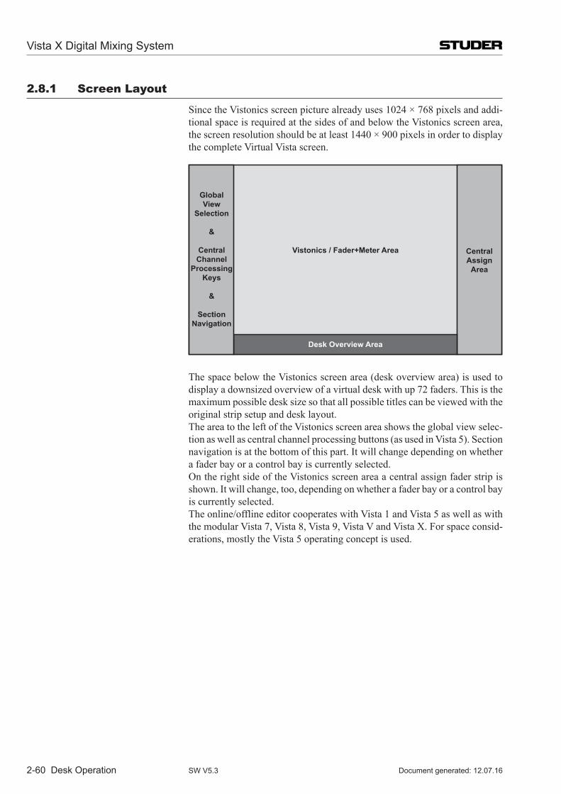
2-60 Desk Operation
2.8.1 screen Layout
Since the Vistonics screen picture already uses 1024 × 768 pixels and addi-tional space is required at the sides of and below the Vistonics screen area, the screen resolution should be at least 1440 × 900 pixels in order to display the complete Virtual Vista screen.
GlobalView
Selection
&
CentralChannel
ProcessingKeys
&
SectionNavigation
CentralAssignArea
Vistonics / Fader+Meter Area
Desk Overview Area
The space below the Vistonics screen area (desk overview area) is used to display a downsized overview of a virtual desk with up 72 faders. This is the maximum possible desk size so that all possible titles can be viewed with the original strip setup and desk layout.
The area to the left of the Vistonics screen area shows the global view selec-tion as well as central channel processing buttons (as used in Vista 5). Section navigation is at the bottom of this part. It will change depending on whether a fader bay or a control bay is currently selected.
On the right side of the Vistonics screen area a central assign fader strip is shown. It will change, too, depending on whether a fader bay or a control bay is currently selected.
The online/offline editor cooperates with Vista 1 and Vista 5 as well as with themodularVista7,Vista8,Vista9,VistaVandVistaX.Forspaceconsid-erations, mostly the Vista 5 operating concept is used.
Vista X Digital Mixing System
Document generated: 12.07.16SW V5.3
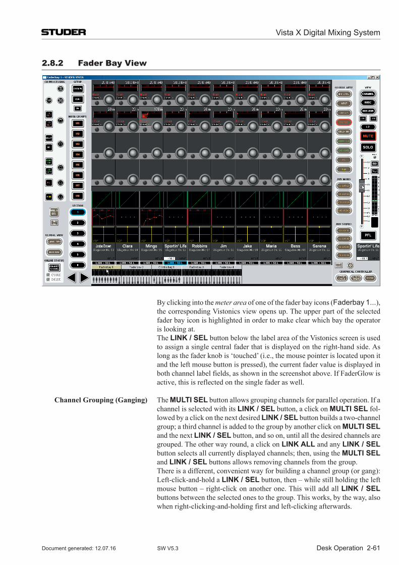
Desk Operation 2-61
2.8.2 Fader Bay View
By clicking into the meter area of one of the fader bay icons (Faderbay 1...), the corresponding Vistonics view opens up. The upper part of the selected fader bay icon is highlighted in order to make clear which bay the operator is looking at.
The LINK / SEL button below the label area of the Vistonics screen is used to assign a single central fader that is displayed on the right-hand side. As long as the fader knob is ‘touched’ (i.e., the mouse pointer is located upon it and the left mouse button is pressed), the current fader value is displayed in both channel label fields, as shown in the screenshot above. If FaderGlow is active, this is reflected on the single fader as well.
Channel Grouping (Ganging) The MULTI SEL button allows grouping channels for parallel operation. If a channel is selected with its LINK / SEL button, a click on MULTI SEL fol-lowed by a click on the next desired LINK / SEL button builds a two-channel group; a third channel is added to the group by another click on MULTI SEL and the next LINK / SEL button, and so on, until all the desired channels are grouped. The other way round, a click on LINK ALL and any LINK / SEL button selects all currently displayed channels; then, using the MULTI SEL and LINK / SEL buttons allows removing channels from the group.
There is a different, convenient way for building a channel group (or gang): Left-click-and-hold a LINK / SEL button, then – while still holding the left mouse button – right-click on another one. This will add all LINK / SEL buttons between the selected ones to the group. This works, by the way, also when right-clicking-and-holding first and left-clicking afterwards.
Vista X Digital Mixing System
Document generated: 12.07.16 SW V5.3
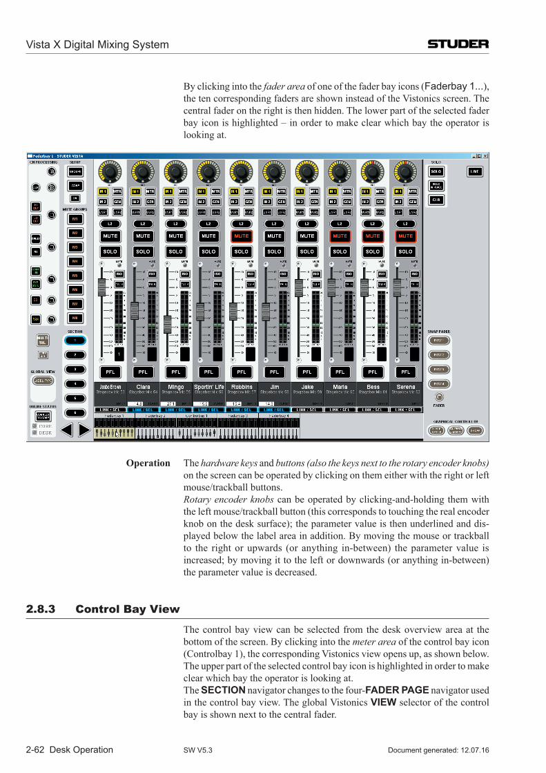
2-62 Desk Operation
By clicking into the fader area of one of the fader bay icons (Faderbay 1...), the ten corresponding faders are shown instead of the Vistonics screen. The central fader on the right is then hidden. The lower part of the selected fader bay icon is highlighted – in order to make clear which bay the operator is looking at.
Operation The hardware keys and buttons (also the keys next to the rotary encoder knobs) on the screen can be operated by clicking on them either with the right or left mouse/trackball buttons.
Rotary encoder knobs can be operated by clicking-and-holding them with the left mouse/trackball button (this corresponds to touching the real encoder knob on the desk surface); the parameter value is then underlined and dis-played below the label area in addition. By moving the mouse or trackball to the right or upwards (or anything in-between) the parameter value is increased; by moving it to the left or downwards (or anything in-between) the parameter value is decreased.
2.8.3 Control Bay View
The control bay view can be selected from the desk overview area at the bottom of the screen. By clicking into the meter area of the control bay icon (Controlbay 1), the corresponding Vistonics view opens up, as shown below. The upper part of the selected control bay icon is highlighted in order to make clear which bay the operator is looking at.
The SECTION navigator changes to the four-FADER PAGE navigator used in the control bay view. The global Vistonics VIEW selector of the control bay is shown next to the central fader.
Vista X Digital Mixing System
Document generated: 12.07.16SW V5.3
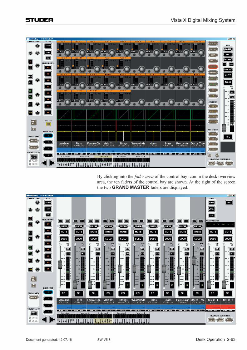
Desk Operation 2-63
By clicking into the fader area of the control bay icon in the desk overview area, the ten faders of the control bay are shown. At the right of the screen the two GRAND MASTER faders are displayed.
Vista X Digital Mixing System
Document generated: 12.07.16 SW V5.3
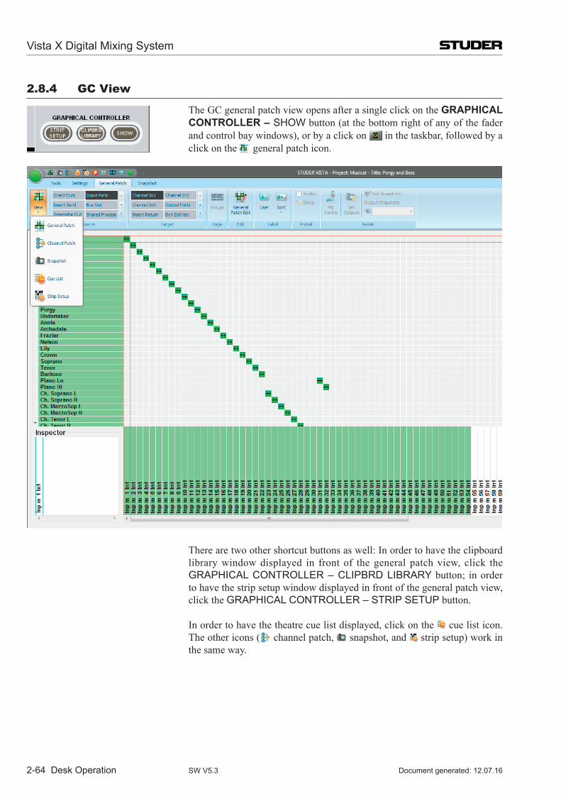
2-64 Desk Operation
2.8.4 GC View
The GC general patch view opens after a single click on the GRAPHICAL CONTROLLER – SHOW button (at the bottom right of any of the fader and control bay windows), or by a click on in the taskbar, followed by a click on the general patch icon.
There are two other shortcut buttons as well: In order to have the clipboard library window displayed in front of the general patch view, click the GRAPHICAL CONTROLLER – CLIPBRD LIBRARY button; in order to have the strip setup window displayed in front of the general patch view, click the GRAPHICAL CONTROLLER – STRIP SETUP button.
In order to have the theatre cue list displayed, click on the cue list icon. The other icons ( channel patch, snapshot, and strip setup) work in the same way.
Vista X Digital Mixing System
Document generated: 12.07.16SW V5.3
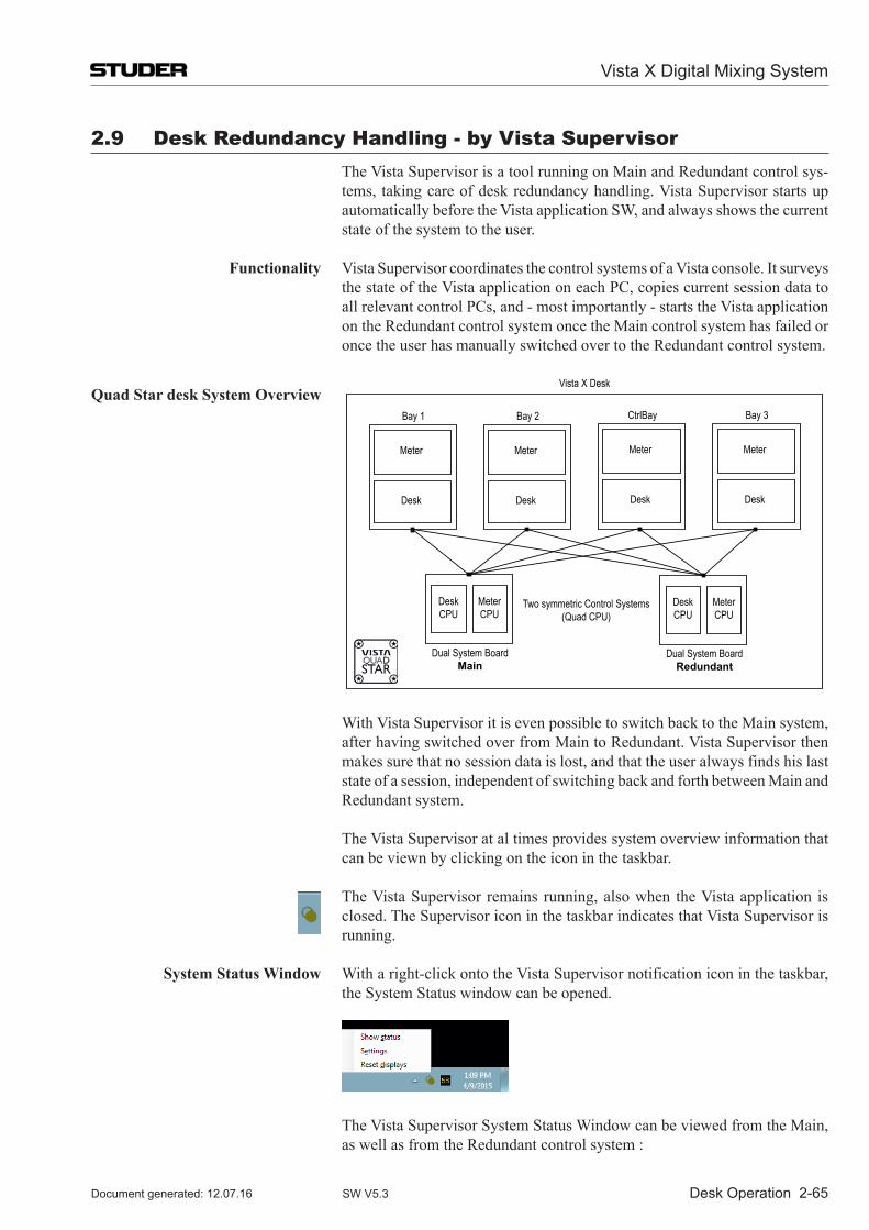
Desk Operation 2-65
2.9 Desk redundancy handling - by Vista supervisor The Vista Supervisor is a tool running on Main and Redundant control sys-
tems, taking care of desk redundancy handling. Vista Supervisor starts up automatically before the Vista application SW, and always shows the current state of the system to the user.
Functionality Vista Supervisor coordinates the control systems of a Vista console. It surveys the state of the Vista application on each PC, copies current session data to all relevant control PCs, and - most importantly - starts the Vista application on the Redundant control system once the Main control system has failed or once the user has manually switched over to the Redundant control system.
Quad Star desk System Overview
Dual System BoardMain
Desk CPU
Meter CPU
Dual System BoardRedundant
Desk CPU
Meter CPU
Two symmetric Control Systems(Quad CPU)
Meter
Desk
Bay 1
Meter
Desk
Bay 2
Meter
Desk
CtrlBay
Meter
Desk
Bay 3
Vista X Desk
With Vista Supervisor it is even possible to switch back to the Main system, after having switched over from Main to Redundant. Vista Supervisor then makes sure that no session data is lost, and that the user always finds his last state of a session, independent of switching back and forth between Main and Redundant system.
The Vista Supervisor at al times provides system overview information that can be viewn by clicking on the icon in the taskbar.
The Vista Supervisor remains running, also when the Vista application is closed. The Supervisor icon in the taskbar indicates that Vista Supervisor is running.
System Status Window With a right-click onto the Vista Supervisor notification icon in the taskbar, the System Status window can be opened.
The Vista Supervisor System Status Window can be viewed from the Main, as well as from the Redundant control system :
Vista X Digital Mixing System
Document generated: 12.07.16 SW V5.3
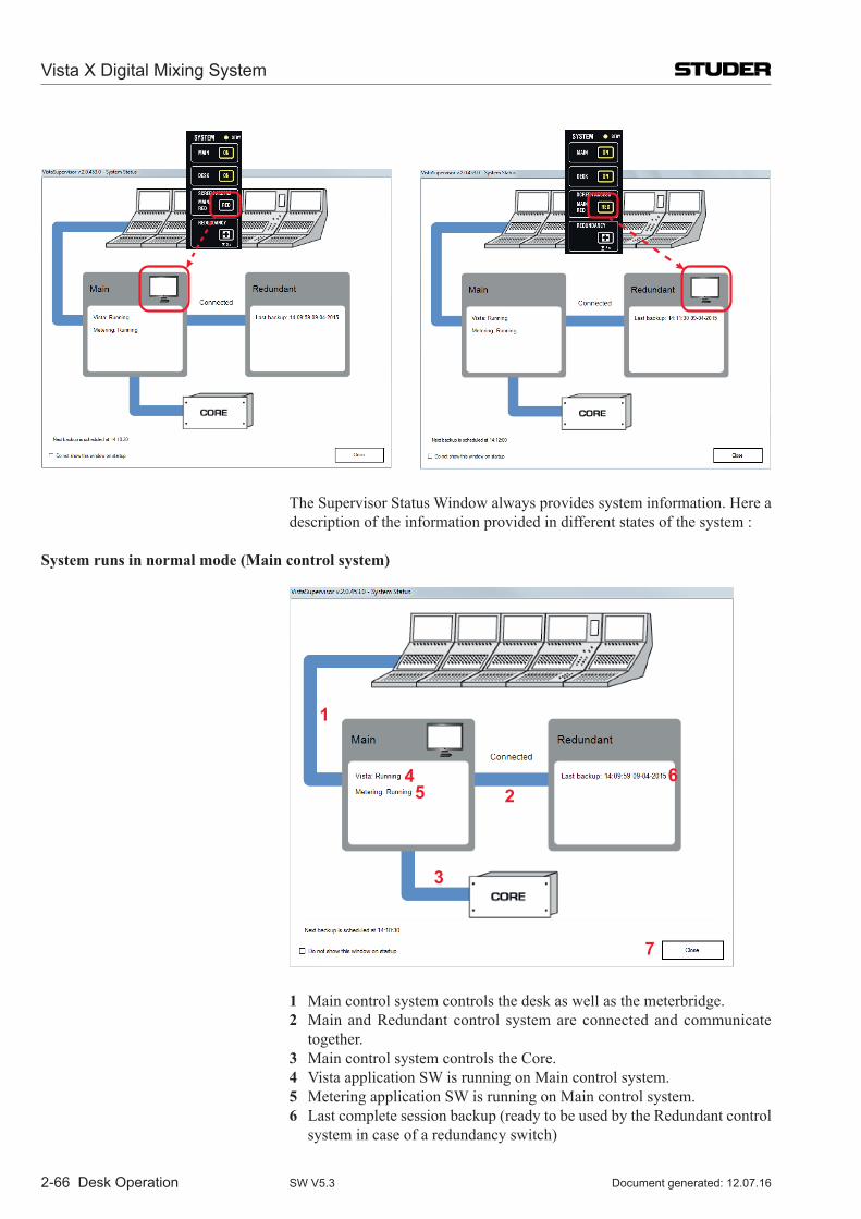
2-66 Desk Operation
The Supervisor Status Window always provides system information. Here a
description of the information provided in different states of the system :
System runs in normal mode (Main control system)
1
2
3
45
6
7
1 Main control system controls the desk as well as the meterbridge. 2 Main and Redundant control system are connected and communicate
together. 3 Main control system controls the Core. 4 Vista application SW is running on Main control system. 5 Metering application SW is running on Main control system. 6 Last complete session backup (ready to be used by the Redundant control
system in case of a redundancy switch)
Vista X Digital Mixing System
Document generated: 12.07.16SW V5.3
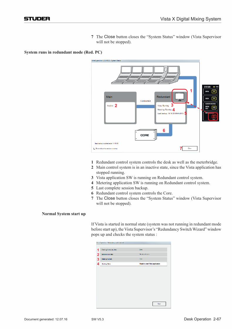
Desk Operation 2-67
7 The Close button closes the “System Status” window (Vista Supervisor will not be stopped).
System runs in redundant mode (Red. PC)
1
2 34
5
6
7
1 Redundant control system controls the desk as well as the meterbridge. 2 Main control system is in an inactive state, since the Vista application has
stopped running. 3 Vista application SW is running on Redundant control system. 4 Metering application SW is running on Redundant control system. 5 Last complete session backup. 6 Redundant control system controls the Core. 7 The Close button closes the “System Status” window (Vista Supervisor
will not be stopped).
Normal System start up
If Vista is started in normal state (system was not running in redundant mode before start up), the Vista Supervisor’s “Redundancy Switch Wizard” window pops up and checks the system status :
1234
Vista X Digital Mixing System
Document generated: 12.07.16 SW V5.3
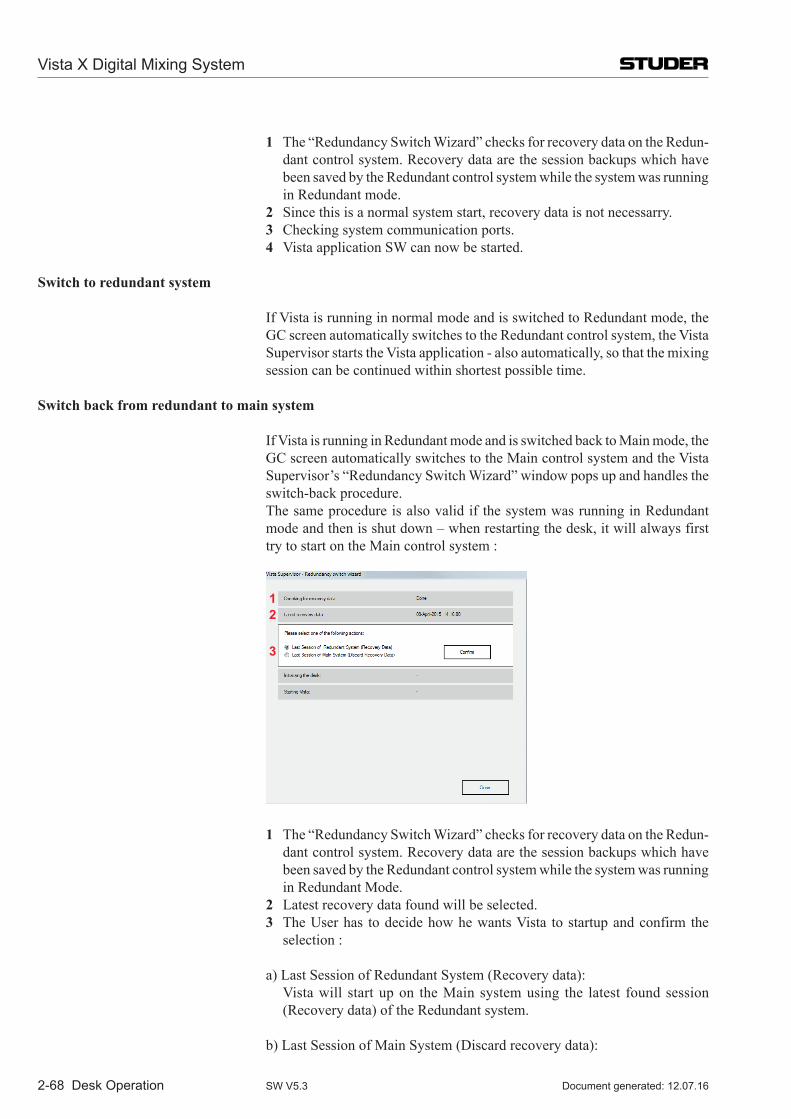
2-68 Desk Operation
1 The “Redundancy Switch Wizard” checks for recovery data on the Redun-dant control system. Recovery data are the session backups which have been saved by the Redundant control system while the system was running in Redundant mode.
2 Since this is a normal system start, recovery data is not necessarry. 3 Checking system communication ports. 4 Vista application SW can now be started.
Switch to redundant system
If Vista is running in normal mode and is switched to Redundant mode, the GC screen automatically switches to the Redundant control system, the Vista Supervisor starts the Vista application - also automatically, so that the mixing session can be continued within shortest possible time.
Switch back from redundant to main system
If Vista is running in Redundant mode and is switched back to Main mode, the GC screen automatically switches to the Main control system and the Vista Supervisor’s “Redundancy Switch Wizard” window pops up and handles the switch-back procedure.
The same procedure is also valid if the system was running in Redundant mode and then is shut down – when restarting the desk, it will always first try to start on the Main control system :
12
3
1 The “Redundancy Switch Wizard” checks for recovery data on the Redun-dant control system. Recovery data are the session backups which have been saved by the Redundant control system while the system was running in Redundant Mode.
2 Latest recovery data found will be selected. 3 The User has to decide how he wants Vista to startup and confirm the
selection :
a) Last Session of Redundant System (Recovery data): Vista will start up on the Main system using the latest found session
(Recovery data) of the Redundant system.
b) Last Session of Main System (Discard recovery data):
Vista X Digital Mixing System
Document generated: 12.07.16SW V5.3
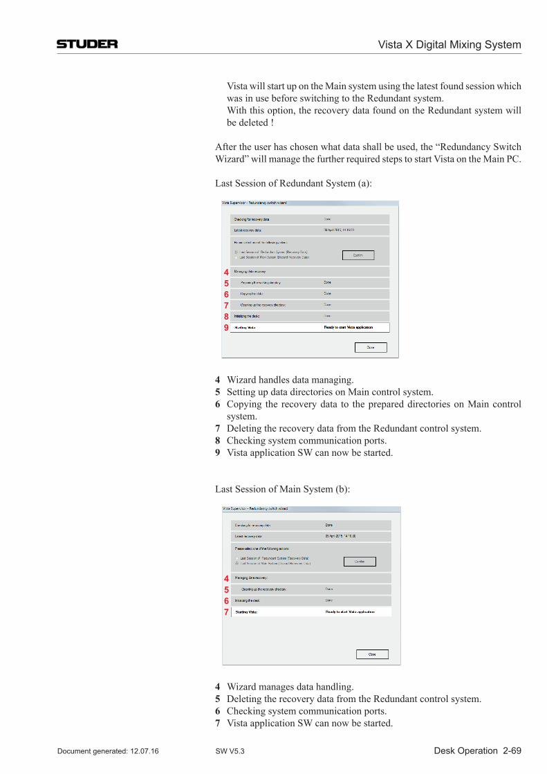
Desk Operation 2-69
Vista will start up on the Main system using the latest found session which was in use before switching to the Redundant system.
With this option, the recovery data found on the Redundant system will be deleted !
After the user has chosen what data shall be used, the “Redundancy Switch Wizard” will manage the further required steps to start Vista on the Main PC.
Last Session of Redundant System (a):
456789
4 Wizard handles data managing. 5 Setting up data directories on Main control system. 6 Copying the recovery data to the prepared directories on Main control
system. 7 Deleting the recovery data from the Redundant control system. 8 Checking system communication ports. 9 Vista application SW can now be started.
Last Session of Main System (b):
4567
4 Wizard manages data handling. 5 Deleting the recovery data from the Redundant control system. 6 Checking system communication ports. 7 Vista application SW can now be started.
Vista X Digital Mixing System
Document generated: 12.07.16 SW V5.3
Vista X Digital Mixing System
Parameters 3-1Document generated: 12.07.16 SW V5.3
CHAPTER 3
3 Parameter Description ....................................................................................................................................................... 3
3.1 Introduction ................................................................................................................................................................. 3
3.2 View Change ............................................................................................................................................................... 33.2.1 Global View Change ............................................................................................................................................. 33.2.2 Channel-Related View Change ............................................................................................................................. 4
3.3 Global Views ............................................................................................................................................................... 53.3.1 Input Parameters.................................................................................................................................................... 53.3.2 Pre-Amp Remote Parameters ................................................................................................................................ 83.3.3 Direct, Multi-Track and N–1 Output Parameters ................................................................................................ 103.3.4 Mono AUX Parameters ....................................................................................................................................... 113.3.5 Stereo AUX Parameters ...................................................................................................................................... 123.3.6 Filter Parameters ................................................................................................................................................. 133.3.7 Delay and Insert Parameters................................................................................................................................ 143.3.8 Dynamics Parameters .......................................................................................................................................... 16
3.3.8.1 Compressor / Limiter Parameters ................................................................................................................... 163.3.8.2 Expander / Gate Parameters ........................................................................................................................... 18
3.3.9 EQ Parameters ..................................................................................................................................................... 203.3.10 Panning Parameters ............................................................................................................................................. 213.3.11 5.1 Surround Input Channels............................................................................................................................... 223.3.12 Global Bus Assignment View ............................................................................................................................. 233.3.13 Generic and Label Display Area ......................................................................................................................... 24
3.4 Channel-Related Views ............................................................................................................................................. 253.4.1 EQ / Filter Parameters ......................................................................................................................................... 25
3.4.1.1 Parametric EQ................................................................................................................................................. 253.4.1.2 Graphic EQ ..................................................................................................................................................... 26
3.4.2 Dynamics Parameters .......................................................................................................................................... 283.4.2.1 Standard Dynamics ......................................................................................................................................... 283.4.2.2 Standard Dynamics for 5.1 Surround Channels ............................................................................................. 323.4.2.3 Vintage Dynamics ........................................................................................................................................... 34
3.4.3 Panning Parameters ............................................................................................................................................. 363.4.3.1 Amplitude Panning Parameters ...................................................................................................................... 383.4.3.2 Upmix Panner Parameters (for Stereo Channels only) ................................................................................... 403.4.3.3 Multi-Format Panning Parameters.................................................................................................................. 413.4.3.4 VSP Panning Parameters ................................................................................................................................ 433.4.3.5 Panning Parameters for 5.1 Surround Channels ............................................................................................. 453.4.3.6 Microphone Simulation Tool (MST) – User Pan Mode ................................................................................. 47
3.4.4 VistaMix (VMX) ................................................................................................................................................. 503.4.5 Channel View in general ..................................................................................................................................... 543.4.6 Channel View - Stereo Channel .......................................................................................................................... 553.4.7 General 5.1 Surround Channel View................................................................................................................... 573.4.8 Misc View (Miscellaneous Parameters) ............................................................................................................. 613.4.9 Bus Assignment View ......................................................................................................................................... 62

Vista X Digital Mixing System
3-2 Parameters Document generated: 12.07.16SW V5.3
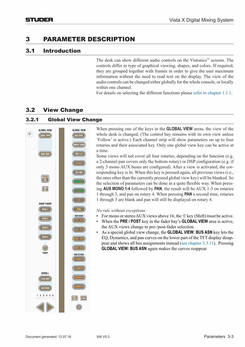
Vista X Digital Mixing System
Parameters 3-3Document generated: 12.07.16 SW V5.3
3 PARAmETER DEsCRiPTion
3.1 introduction The desk can show different audio controls on the Vistonics™ screens. The
controls differ in type of graphical viewing, shapes, and colors. If required, they are grouped together with frames in order to give the user maximum information without the need to read text on the display. The view of the audio controls can be changed either globally for the whole console, or locally within one channel.
For details on selecting the different functions please refer to chapter 1.1.1.
3.2 View Change3.2.1 Global View Change
When pressing one of the keys in the GLOBAL VIEW areas, the view of the whole desk is changed. (The control bay remains with its own view unless ‘Follow’ is active.) Each channel strip will show parameters on up to four rotaries and their associated key. Only one global view key can be active at a time.
Some views will not cover all four rotaries, depending on the function (e.g. a 2-channel pan covers only the bottom rotary) or DSP configuration (e.g. if only 3 mono AUX buses are configured). After a view is activated, the cor-responding key is lit. When this key is pressed again, all previous views (i.e., the ones other than the currently pressed global view key) will be blanked. So the selection of parameters can be done in a quite flexible way. When press-ing AUX MONO 1-4 followed by PAN, the result will be AUX 1-3 on rotaries 1 through 3, and pan on rotary 4. When pressing PAN a second time, rotaries 1 through 3 are blank and pan will still be displayed on rotary 4.
No rule without exceptions: • For mono or stereo AUX views above 16, the key (Shift) must be active. • When the PRE / POST key in the fader bay’s GLOBAL VIEW area is active,
the AUX views change to pre-/post-fader selection. • As a special global view change, the GLOBAL VIEW: BUS ASN key lets the
EQ, Dynamics, and pan curves on the lower part of the TFT display disap-pear and shows all bus assignments instead (see chapter 3.3.11). Pressing GLOBAL VIEW: BUS ASN again makes the curves reappear.
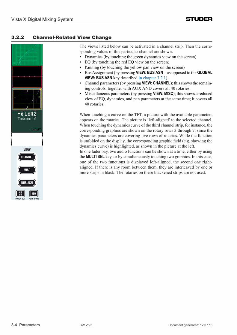
Vista X Digital Mixing System
3-4 Parameters Document generated: 12.07.16SW V5.3
3.2.2 Channel-Related View Change
The views listed below can be activated in a channel strip. Then the corre-sponding values of this particular channel are shown.
• Dynamics (by touching the green dynamics view on the screen) • EQ (by touching the red EQ view on the screen) • Panning (by touching the yellow pan view on the screen) • Bus Assignment (by pressing VIEW: BUS ASN – as opposed to the GLOBAL
VIEW: BUS ASN key described in chapter 3.2.1). • Channel parameters (by pressing VIEW: CHANNEL); this shows the remain-
ing controls, together with AUX AND covers all 40 rotaries. • Miscellaneous parameters (by pressing VIEW: MISC); this shows a reduced
view of EQ, dynamics, and pan parameters at the same time; it covers all 40 rotaries.
When touching a curve on the TFT, a picture with the available parameters appears on the rotaries. The picture is ‘left-aligned’ to the selected channel. When touching the dynamics curve of the third channel strip, for instance, the corresponding graphics are shown on the rotary rows 3 through 7, since the dynamics parameters are covering five rows of rotaries. While the function is unfolded on the display, the corresponding graphic field (e.g. showing the dynamics curve) is highlighted, as shown in the picture at the left.
In one fader bay, two audio functions can be shown at a time, either by using the MULTI SEL key, or by simultaneously touching two graphics. In this case, one of the two functions is displayed left-aligned, the second one right-aligned. If there is any room between them, they are interleaved by one or more strips in black. The rotaries on these blackened strips are not used.
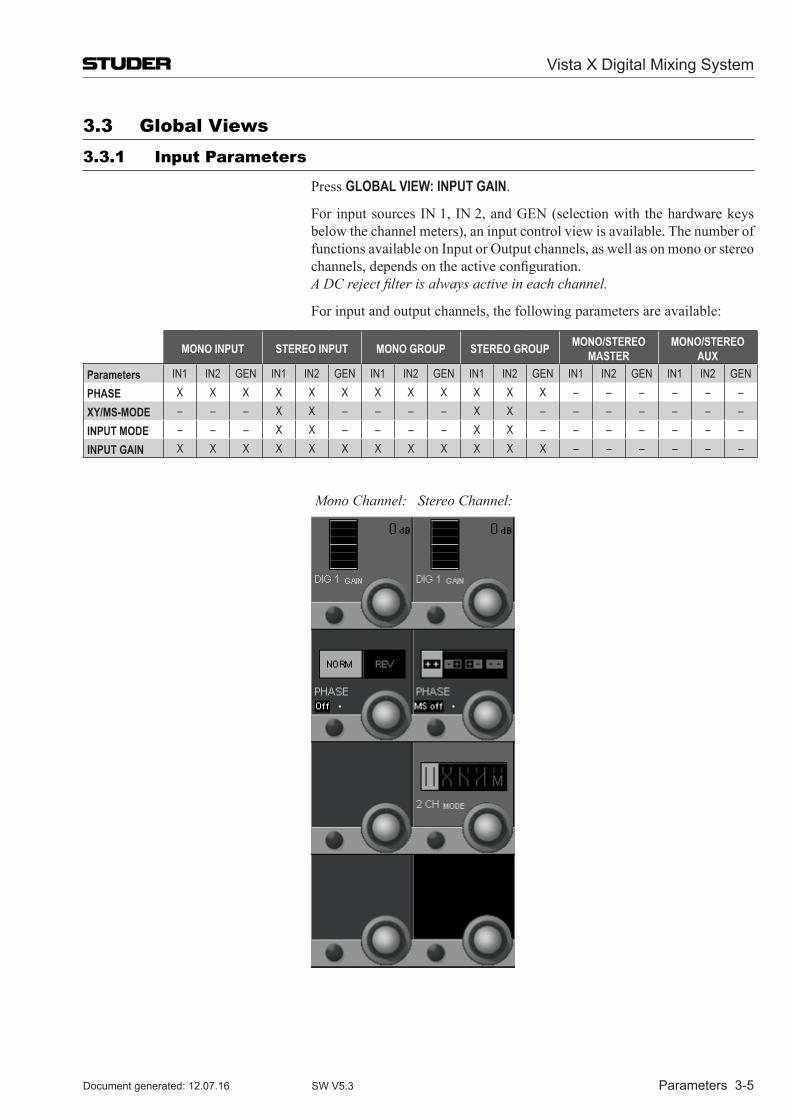
Vista X Digital Mixing System
Parameters 3-5Document generated: 12.07.16 SW V5.3
3.3 Global Views3.3.1 input Parameters
Press GLOBAL VIEW: INPUT GAIN.
For input sources IN 1, IN 2, and GEN (selection with the hardware keys below the channel meters), an input control view is available. The number of functions available on Input or Output channels, as well as on mono or stereo channels, depends on the active configuration.
A DC reject filter is always active in each channel.
For input and output channels, the following parameters are available:
MONO INPUT STEREO INPUT MONO GROUP STEREO GROUP MONO/STEREOMASTER
MONO/STEREO AUX
Parameters IN1 IN2 GEN IN1 IN2 GEN IN1 IN2 GEN IN1 IN2 GEN IN1 IN2 GEN IN1 IN2 GENPHASE X X X X X X X X X X X X – – – – – –XY/MS-MODE – – – X X – – – – X X – – – – – – –INPUT MODE – – – X X – – – – X X – – – – – – –INPUT GAIN X X X X X X X X X X X X – – – – – –
Mono Channel: Stereo Channel:
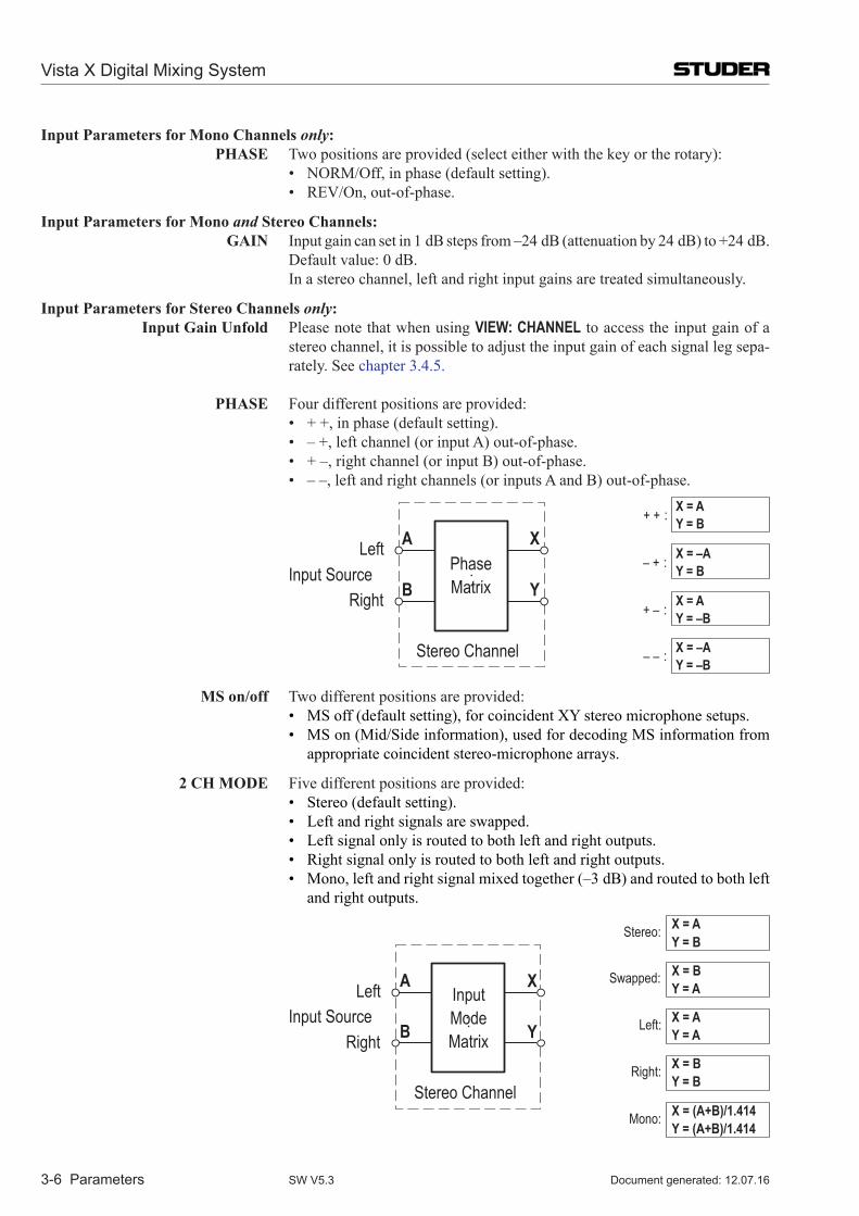
Vista X Digital Mixing System
3-6 Parameters Document generated: 12.07.16SW V5.3
Input Parameters for Mono Channels only: Phase Two positions are provided (select either with the key or the rotary): • NORM/Off, in phase (default setting). • REV/On, out-of-phase.
Input Parameters for Mono and stereo Channels: GaIn Input gain can set in 1 dB steps from –24 dB (attenuation by 24 dB) to +24 dB.
Default value: 0 dB. In a stereo channel, left and right input gains are treated si multaneously.
Input Parameters for stereo Channels only: Input Gain Unfold Please note that when using VIEW: CHANNEL to access the input gain of a
stereo channel, it is possible to adjust the input gain of each signal leg sepa-rately. See chapter 3.4.5.
Phase Four different positions are provided: • + +, in phase (default setting). • – +, left channel (or input A) out-of-phase. • + –, right channel (or input B) out-of-phase. • – –, left and right channels (or inputs A and B) out-of-phase.
Left
Right
PhaseMatrix
Stereo Channel
A
B
X
YInput Source
X = AY = B+ + :
X = –AY = –B
X = AY = –B
X = –AY = B– + :
+ – :
– – :
Ms on/off Two different positions are provided: • MS off (default setting), for coincident XY stereo microphone setups. • MS on (Mid/Side information), used for decoding MS information from
appropriate coincident stereo-microphone arrays.
2 Ch MoDe Five different positions are provided: • Stereo (default setting). • Left and right signals are swapped. • Left signal only is routed to both left and right outputs. • Right signal only is routed to both left and right outputs. • Mono, left and right signal mixed together (–3 dB) and routed to both left
and right outputs.
Left
Right
Input ModeMatrix
Stereo Channel
A
B
X
YInput Source
Stereo: X = AY = B
Mono:
Left:
Right:
Swapped:
X = (A+B)/1.414Y = (A+B)/1.414
X = AY = A
X = BY = B
X = BY = A
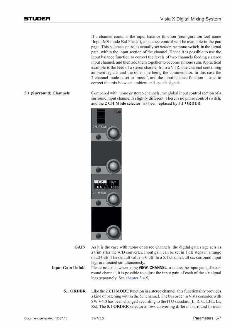
Vista X Digital Mixing System
Parameters 3-7Document generated: 12.07.16 SW V5.3
If a channel contains the input balance function (configuration tool name ‘Input MS mode Bal Phase’), a balance control will be available in the pan page. This balance control is actually set before the mono switch in the signal path, within the input section of the channel. Hence it is possible to use the input balance function to correct the levels of two channels feeding a stereo input channel, and then add them together to become a mono sum. A practical example is the feed of a stereo channel from a VTR, one channel containing ambient signals and the other one being the commentator. In this case the 2-channel mode is set to ‘mono’, and the input balance function is used to correct the mix between ambient and speech signals.
5.1 (surround) Channels Compared with mono or stereo channels, the global input control section of a surround input channel is slightly different: There is no phase control switch, and the 2 Ch Mode selector has been replaced by 5.1 oRDeR.
GaIn As it is the case with mono or stereo channels, the digital gain stage acts as a trim after the A/D converter. Input gain can be set in 1 dB steps in a range of ±24 dB. The default value is 0 dB. In a 5.1 channel, all six surround input legs are treated simultaneously.
Input Gain Unfold Please note that when using VIEW: CHANNEL to access the input gain of a sur-round channel, it is possible to adjust the input gain of each of the six signal legs separately. See chapter 3.4.5.
5.1 oRDeR Like the 2 Ch MoDe function in a stereo channel, this functionality provides a kind of patching within the 5.1 channel. The bus order in Vista consoles with SW V4.0 has been changed according to the ITU standard (L, R, C, LFE, Ls, Rs). The 5.1 oRDeR selector allows converting different surround formats
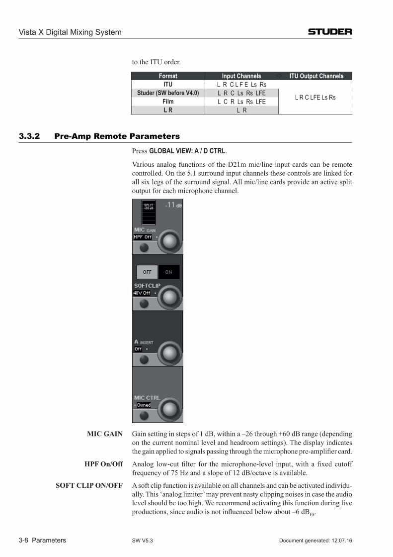
Vista X Digital Mixing System
3-8 Parameters Document generated: 12.07.16SW V5.3
to the ITU order.
Format Input Channels ITU Output ChannelsITU L R C L F E Ls Rs
L R C LFE Ls RsStuder (SW before V4.0) L R C Ls Rs LFEFilm L C R Ls Rs LFEL R L R
3.3.2 Pre-Amp Remote Parameters
Press GLOBAL VIEW: A / D CTRL.
Various analog functions of the D21m mic/line input cards can be remote controlled. On the 5.1 surround input channels these controls are linked for all six legs of the surround signal. All mic/line cards provide an active split output for each microphone channel.
MIC GaIn Gain setting in steps of 1 dB, within a –26 through +60 dB range (depending on the current nominal level and headroom settings). The display indicates the gain applied to signals passing through the microphone pre-amplifier card.
hPF on/off Analog low-cut filter for the microphone-level input, with a fixed cutoff frequency of 75 Hz and a slope of 12 dB/octave is available.
soFT CLIP on/oFF A soft clip function is available on all channels and can be activated individu-ally. This ‘analog limiter’ may prevent nasty clipping noises in case the audio level should be too high. We recommend activating this function during live productions, since audio is not influenced below about –6 dBFS.
Vista X Digital Mixing System
Parameters 3-9Document generated: 12.07.16 SW V5.3
48 V on/off Toggles phantom power on/off for the microphone input.
a InseRT on/off (Not supported by transformer-balanced microphone pre-amplifier cards A949.0447). An analog insert point is made available by inserting an optional analog insert card. Its send output is always active at line level, and the return path may be activated by the corresponding switch on the console.
MIC CTRL Free/other/owned Toggle switch for remote control of the analog mic/line input parameters. In case of I/O sharing operation this switch is also used for the mic takeover procedure (refer to chapter 8.3).
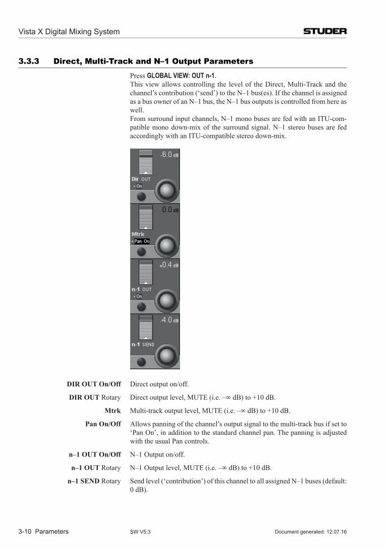
Vista X Digital Mixing System
3-10 Parameters Document generated: 12.07.16SW V5.3
3.3.3 Direct, multi-Track and n–1 output Parameters
Press GLOBAL VIEW: OUT n-1. This view allows controlling the level of the Direct, Multi-Track and the
channel’s contribution (‘send’) to the N–1 bus(es). If the channel is assigned as a bus owner of an N–1 bus, the N–1 bus outputs is controlled from here as well.
From surround input channels, N–1 mono buses are fed with an ITU-com-patible mono down-mix of the surround signal. N–1 stereo buses are fed accordingly with an ITU-compatible stereo down-mix.
DIR oUT on/off Direct output on/off.
DIR oUT Rotary Direct output level, MUTE (i.e. –∞ dB) to +10 dB.
Mtrk Multi-track output level, MUTE (i.e. –∞ dB) to +10 dB.
Pan on/off Allows panning of the channel’s output signal to the multi-track bus if set to ‘Pan On’, in addition to the standard channel pan. The panning is adjusted with the usual Pan controls.
n–1 oUT on/off N–1 Output on/off.
n–1 oUT Rotary N–1 Output level, MUTE (i.e. –∞ dB) to +10 dB.
n–1 senD Rotary Send level (‘contribution’) of this channel to all assigned N–1 buses (default: 0 dB).
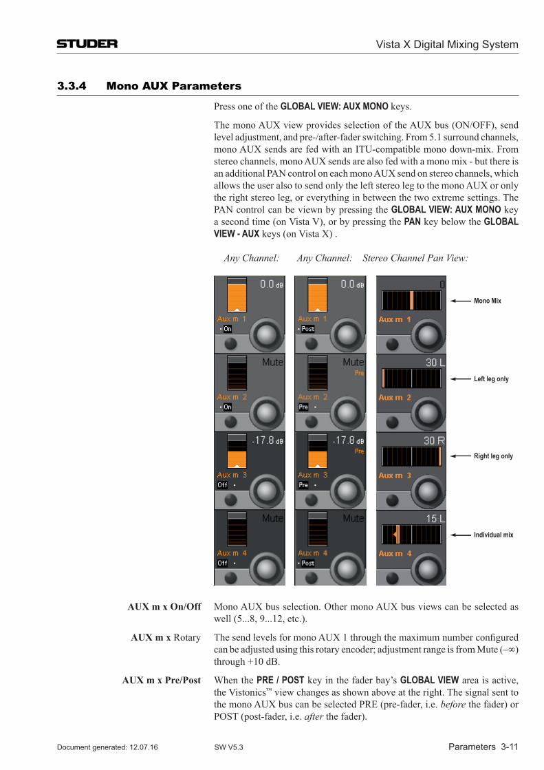
Vista X Digital Mixing System
Parameters 3-11Document generated: 12.07.16 SW V5.3
3.3.4 mono AUX Parameters
Press one of the GLOBAL VIEW: AUX MONO keys.
The mono AUX view provides selection of the AUX bus (ON/OFF), send level adjustment, and pre-/after-fader switching. From 5.1 surround channels, mono AUX sends are fed with an ITU-compatible mono down-mix. From stereo channels, mono AUX sends are also fed with a mono mix - but there is an additional PAN control on each mono AUX send on stereo channels, which allows the user also to send only the left stereo leg to the mono AUX or only the right stereo leg, or everything in between the two extreme settings. The PAN control can be viewn by pressing the GLOBAL VIEW: AUX MONO key a second time (on Vista V), or by pressing the PAN key below the GLOBAL VIEW - AUX keys (on Vista X) .
Any Channel: Any Channel: Stereo Channel Pan View:
Mono Mix
Left leg only
Right leg only
Individual mix
aUX m x on/off Mono AUX bus selection. Other mono AUX bus views can be selected as well (5...8, 9...12, etc.).
aUX m x Rotary The send levels for mono AUX 1 through the maximum number configured can be adjusted using this rotary encoder; adjustment range is from Mute (–∞) through +10 dB.
aUX m x Pre/Post When the PRE / POST key in the fader bay’s GLOBAL VIEW area is active, the Vistonics™ view changes as shown above at the right. The signal sent to the mono AUX bus can be selected PRE (pre-fader, i.e. before the fader) or POST (post-fader, i.e. after the fader).
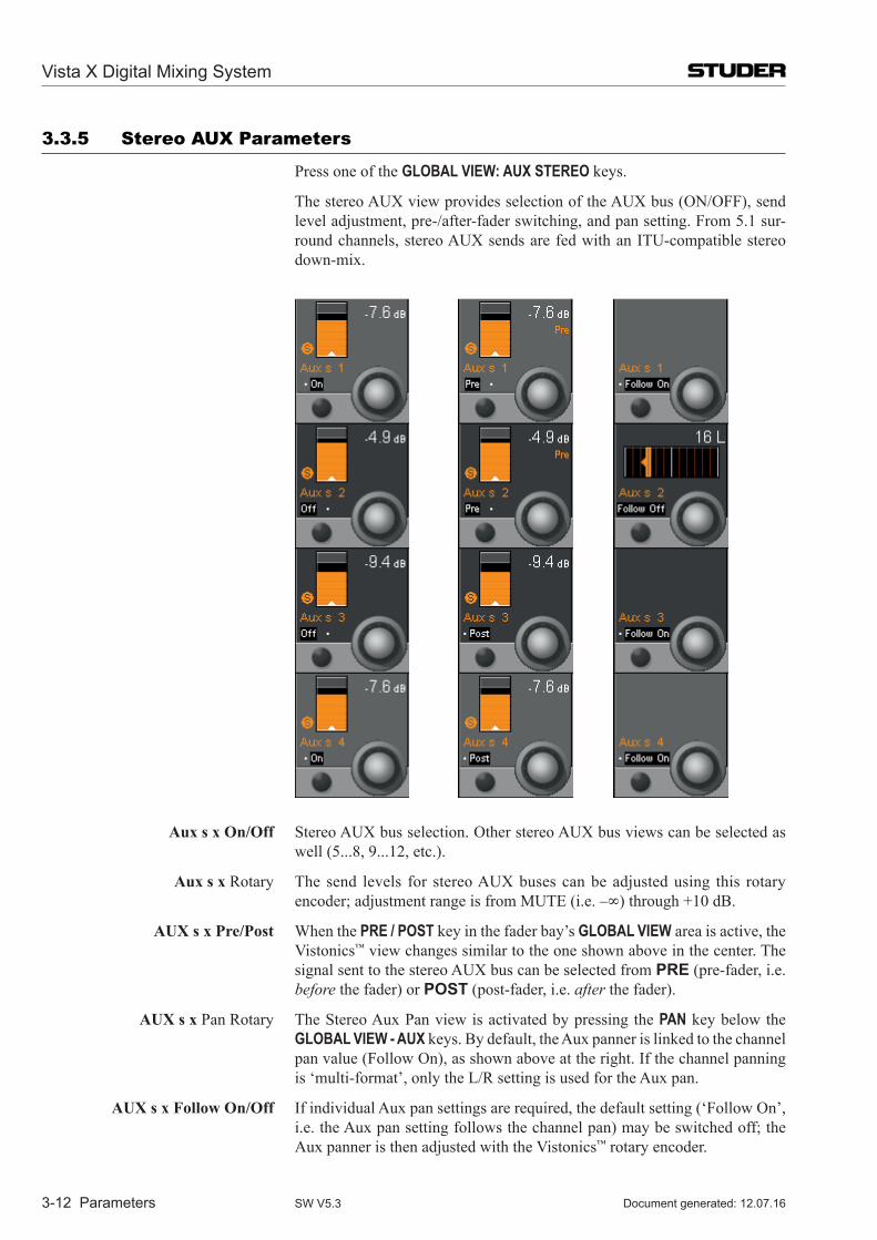
Vista X Digital Mixing System
3-12 Parameters Document generated: 12.07.16SW V5.3
3.3.5 stereo AUX Parameters
Press one of the GLOBAL VIEW: AUX STEREO keys.
The stereo AUX view provides selection of the AUX bus (ON/OFF), send level adjustment, pre-/after-fader switching, and pan setting. From 5.1 sur-round channels, stereo AUX sends are fed with an ITU-compatible stereo down-mix.
aux s x on/off Stereo AUX bus selection. Other stereo AUX bus views can be selected as well (5...8, 9...12, etc.).
aux s x Rotary The send levels for stereo AUX buses can be adjusted using this rotary encoder; adjustment range is from MUTE (i.e. –∞) through +10 dB.
aUX s x Pre/Post When the PRE / POST key in the fader bay’s GLOBAL VIEW area is active, the Vistonics™ view changes similar to the one shown above in the center. The signal sent to the stereo AUX bus can be selected from PRE (pre-fader, i.e. before the fader) or POST (post-fader, i.e. after the fader).
aUX s x Pan Rotary The Stereo Aux Pan view is activated by pressing the PAN key below the GLOBAL VIEW - AUX keys. By default, the Aux panner is linked to the channel pan value (Follow On), as shown above at the right. If the channel panning is ‘multi-format’, only the L/R setting is used for the Aux pan.
aUX s x Follow on/off If individual Aux pan settings are required, the default setting (‘Follow On’, i.e. the Aux pan setting follows the channel pan) may be switched off; the Aux panner is then adjusted with the Vistonics™ rotary encoder.
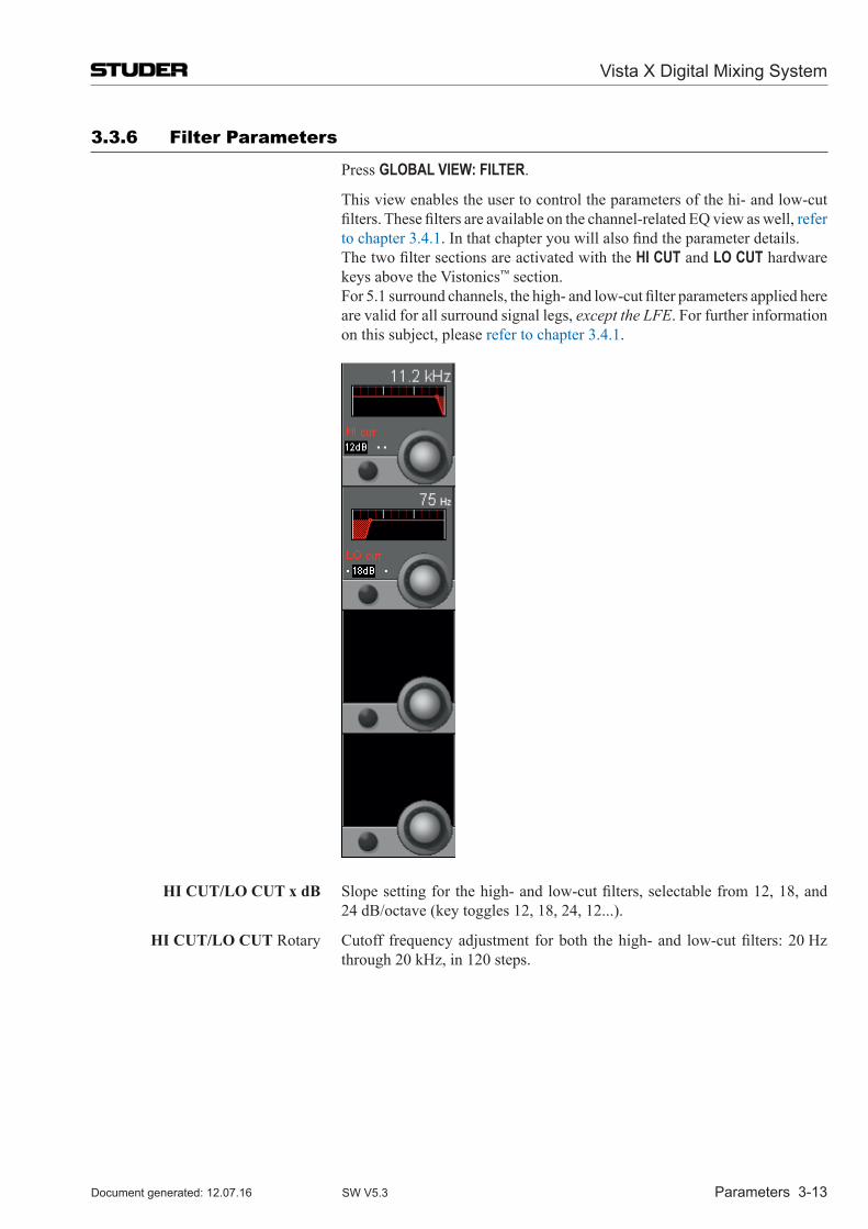
Vista X Digital Mixing System
Parameters 3-13Document generated: 12.07.16 SW V5.3
3.3.6 Filter Parameters
Press GLOBAL VIEW: FILTER.
This view enables the user to control the parameters of the hi- and low-cut filters. These filters are available on the channel-related EQ view as well, refer to chapter 3.4.1. In that chapter you will also find the parameter details.
The two filter sections are activated with the HI CUT and LO CUT hardware keys above the Vistonics™ section.
For 5.1 surround channels, the high- and low-cut filter parameters applied here are valid for all surround signal legs, except the LFE. For further information on this subject, please refer to chapter 3.4.1.
hI CUT/Lo CUT x dB Slope setting for the high- and low-cut filters, selectable from 12, 18, and 24 dB/octave (key toggles 12, 18, 24, 12...).
hI CUT/Lo CUT Rotary Cutoff frequency adjustment for both the high- and low-cut filters: 20 Hz through 20 kHz, in 120 steps.
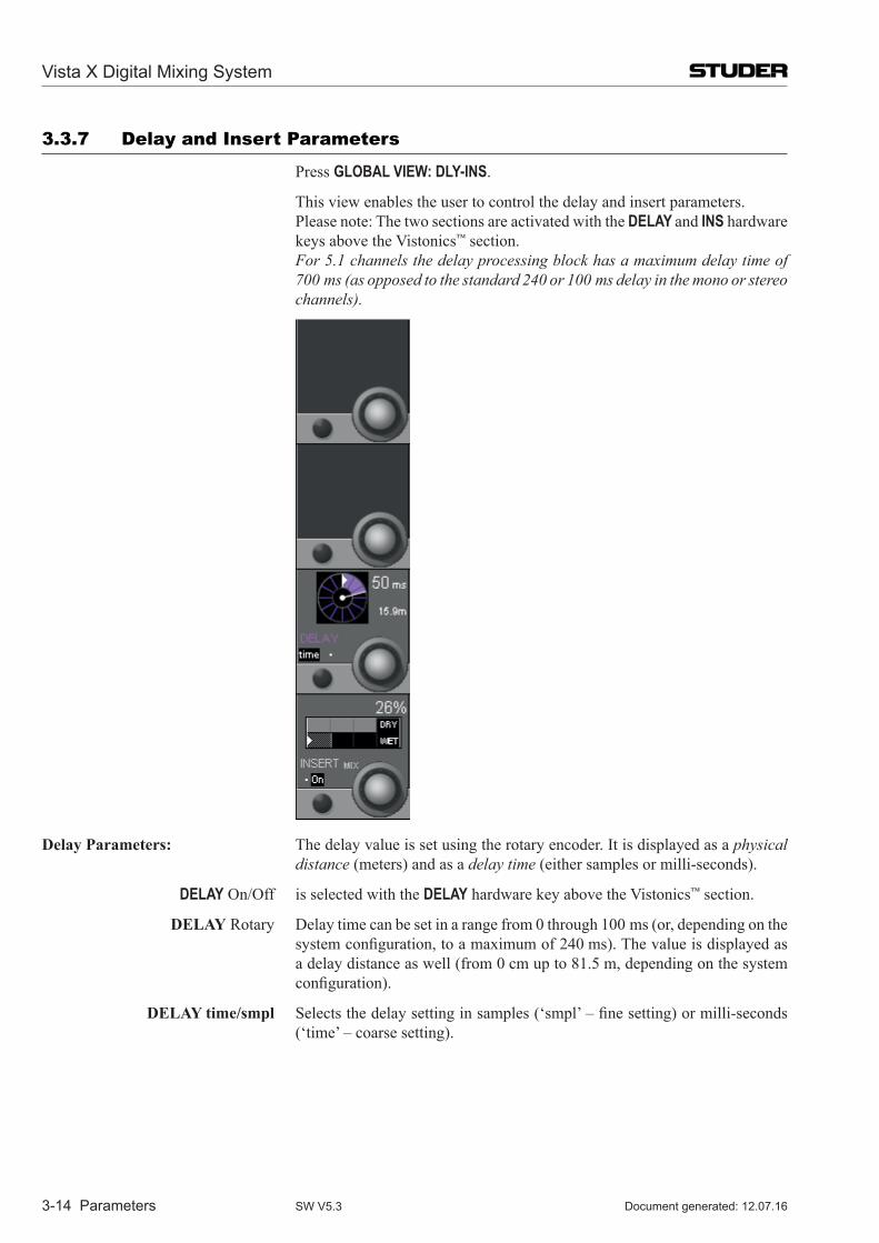
Vista X Digital Mixing System
3-14 Parameters Document generated: 12.07.16SW V5.3
3.3.7 Delay and insert Parameters
Press GLOBAL VIEW: DLY-INS.
This view enables the user to control the delay and insert parameters. Please note: The two sections are activated with the DELAY and INS hardware
keys above the Vistonics™ section. For 5.1 channels the delay processing block has a maximum delay time of
700 ms (as opposed to the standard 240 or 100 ms delay in the mono or stereo channels).
Delay Parameters: The delay value is set using the rotary encoder. It is displayed as a physical distance (meters) and as a delay time (either samples or milli-seconds).
DELAY On/Off is selected with the DELAY hardware key above the Vistonics™ section.
DeLaY Rotary Delay time can be set in a range from 0 through 100 ms (or, depending on the system configuration, to a maximum of 240 ms). The value is displayed as a delay distance as well (from 0 cm up to 81.5 m, depending on the system configuration).
DeLaY time/smpl Selects the delay setting in samples (‘smpl’ – fine setting) or milli-seconds (‘time’ – coarse setting).
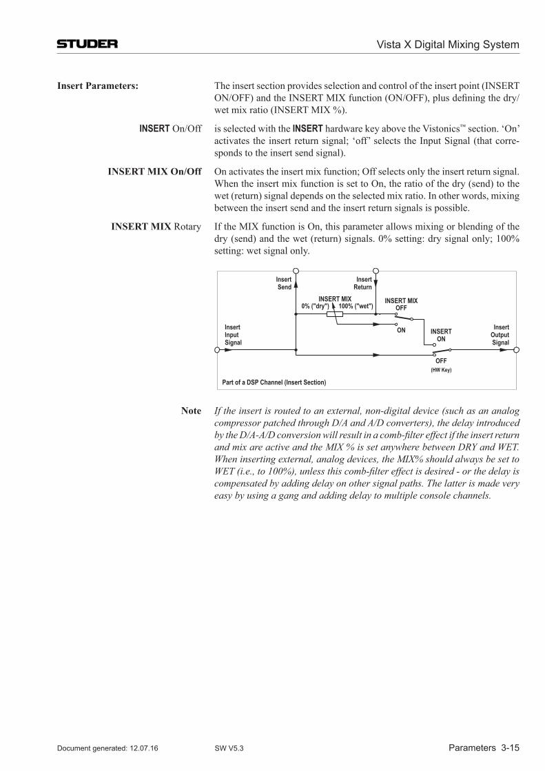
Vista X Digital Mixing System
Parameters 3-15Document generated: 12.07.16 SW V5.3
Insert Parameters: The insert section provides selection and control of the insert point (INSERT ON/OFF) and the INSERT MIX function (ON/OFF), plus defining the dry/wet mix ratio (INSERT MIX %).
INSERT On/Off is selected with the INSERT hardware key above the Vistonics™ section. ‘On’ activates the insert return signal; ‘off’ selects the Input Signal (that corre-sponds to the insert send signal).
InseRT MIX on/off On activates the insert mix function; Off selects only the insert return signal. When the insert mix function is set to On, the ratio of the dry (send) to the
wet (return) signal depends on the selected mix ratio. In other words, mixing between the insert send and the insert return signals is possible.
InseRT MIX Rotary If the MIX function is On, this parameter allows mixing or blending of the dry (send) and the wet (return) signals. 0% setting: dry signal only; 100% setting: wet signal only.
INSERT MIX0% ("dry") 100% ("wet")
INSERT MIXOFF
ON INSERTON
OFF
InsertInputSignal
InsertOutputSignal
InsertSend
InsertReturn
Part of a DSP Channel (Insert Section)
(HW Key)
note If the insert is routed to an external, non-digital device (such as an analog compressor patched through D/A and A/D converters), the delay introduced by the D/A-A/D conversion will result in a comb-filter effect if the insert return and mix are active and the MIX % is set anywhere between DRY and WET. When inserting external, analog devices, the MIX% should always be set to WET (i.e., to 100%), unless this comb-filter effect is desired - or the delay is compensated by adding delay on other signal paths. The latter is made very easy by using a gang and adding delay to multiple console channels.
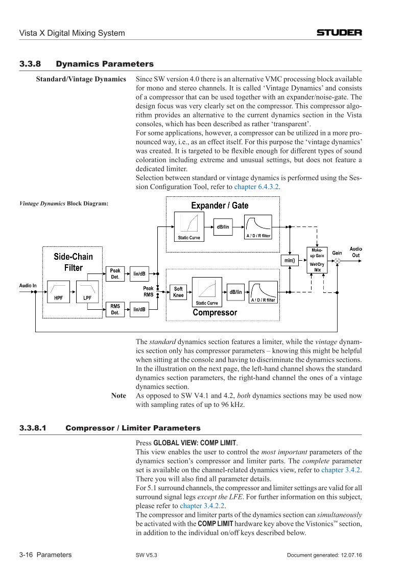
Vista X Digital Mixing System
3-16 Parameters Document generated: 12.07.16SW V5.3
3.3.8 Dynamics Parameters
standard/Vintage Dynamics Since SW version 4.0 there is an alternative VMC processing block available for mono and stereo channels. It is called ‘Vintage Dynamics’ and consists of a compressor that can be used together with an expander/noise-gate. The design focus was very clearly set on the compressor. This compressor algo-rithm provides an alternative to the current dynamics section in the Vista consoles, which has been described as rather ‘transparent’.
For some applications, however, a compressor can be utilized in a more pro-nounced way, i.e., as an effect itself. For this purpose the ‘vintage dynamics’ was created. It is targeted to be flexible enough for different types of sound coloration including extreme and unusual settings, but does not feature a dedicated limiter.
Selection between standard or vintage dynamics is performed using the Ses-sion Configuration Tool, refer to chapter 6.4.3.2.
Vintage Dynamics Block Diagram:
The standard dynamics section features a limiter, while the vintage dynam-ics section only has compressor parameters – knowing this might be helpful when sitting at the console and having to discriminate the dynamics sections.
In the illustration on the next page, the left-hand channel shows the standard dynamics section parameters, the right-hand channel the ones of a vintage dynamics section.
note As opposed to SW V4.1 and 4.2, both dynamics sections may be used now with sampling rates of up to 96 kHz.
3.3.8.1 Compressor / Limiter Parameters
Press GLOBAL VIEW: COMP LIMIT. This view enables the user to control the most important parameters of the
dynamics section’s compressor and limiter parts. The complete parameter set is available on the channel-related dynamics view, refer to chapter 3.4.2. There you will also find all parameter details.
For 5.1 surround channels, the compressor and limiter settings are valid for all surround signal legs except the LFE. For further information on this subject, please refer to chapter 3.4.2.2.
The compressor and limiter parts of the dynamics section can simultaneously be activated with the COMP LIMIT hardware key above the Vistonics™ section, in addition to the individual on/off keys described below.
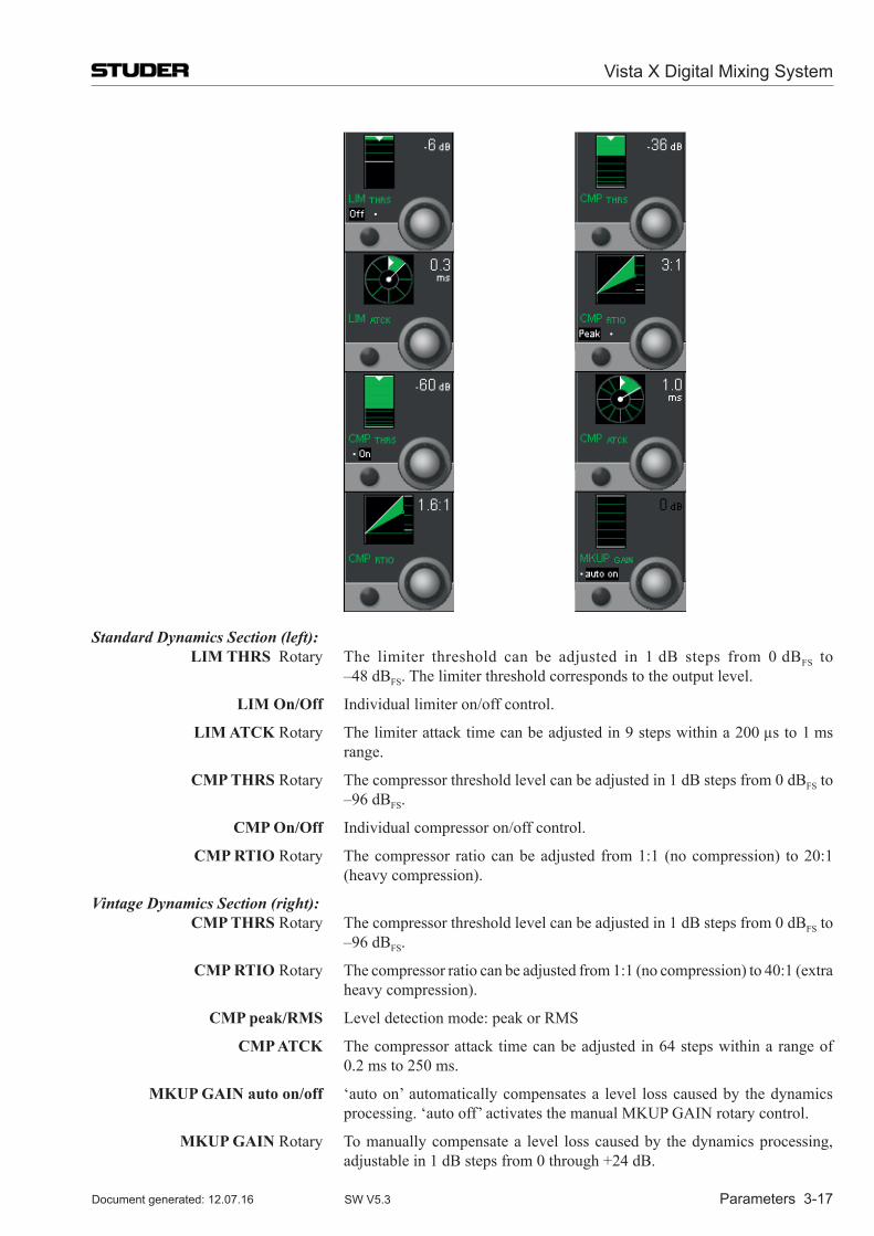
Vista X Digital Mixing System
Parameters 3-17Document generated: 12.07.16 SW V5.3
Standard Dynamics Section (left): LIM ThRs Rotary The limiter threshold can be adjusted in 1 dB steps from 0 dBFS to
–48 dBFS. The limiter threshold corresponds to the output level.
LIM on/off Individual limiter on/off control.
LIM aTCK Rotary The limiter attack time can be adjusted in 9 steps within a 200 µs to 1 ms range.
CMP ThRs Rotary The compressor threshold level can be adjusted in 1 dB steps from 0 dBFS to –96 dBFS.
CMP on/off Individual compressor on/off control.
CMP RTIo Rotary The compressor ratio can be adjusted from 1:1 (no com pression) to 20:1 (heavy compression).
Vintage Dynamics Section (right): CMP ThRs Rotary The compressor threshold level can be adjusted in 1 dB steps from 0 dBFS to
–96 dBFS.
CMP RTIo Rotary The compressor ratio can be adjusted from 1:1 (no com pression) to 40:1 (extra heavy compression).
CMP peak/RMs Level detection mode: peak or RMS
CMP aTCK The compressor attack time can be adjusted in 64 steps within a range of 0.2 ms to 250 ms.
MKUP GaIn auto on/off ‘auto on’ automatically compensates a level loss caused by the dynamics processing. ‘auto off’ activates the manual MKUP GAIN rotary control.
MKUP GaIn Rotary To manually compensate a level loss caused by the dynamics processing, adjustable in 1 dB steps from 0 through +24 dB.
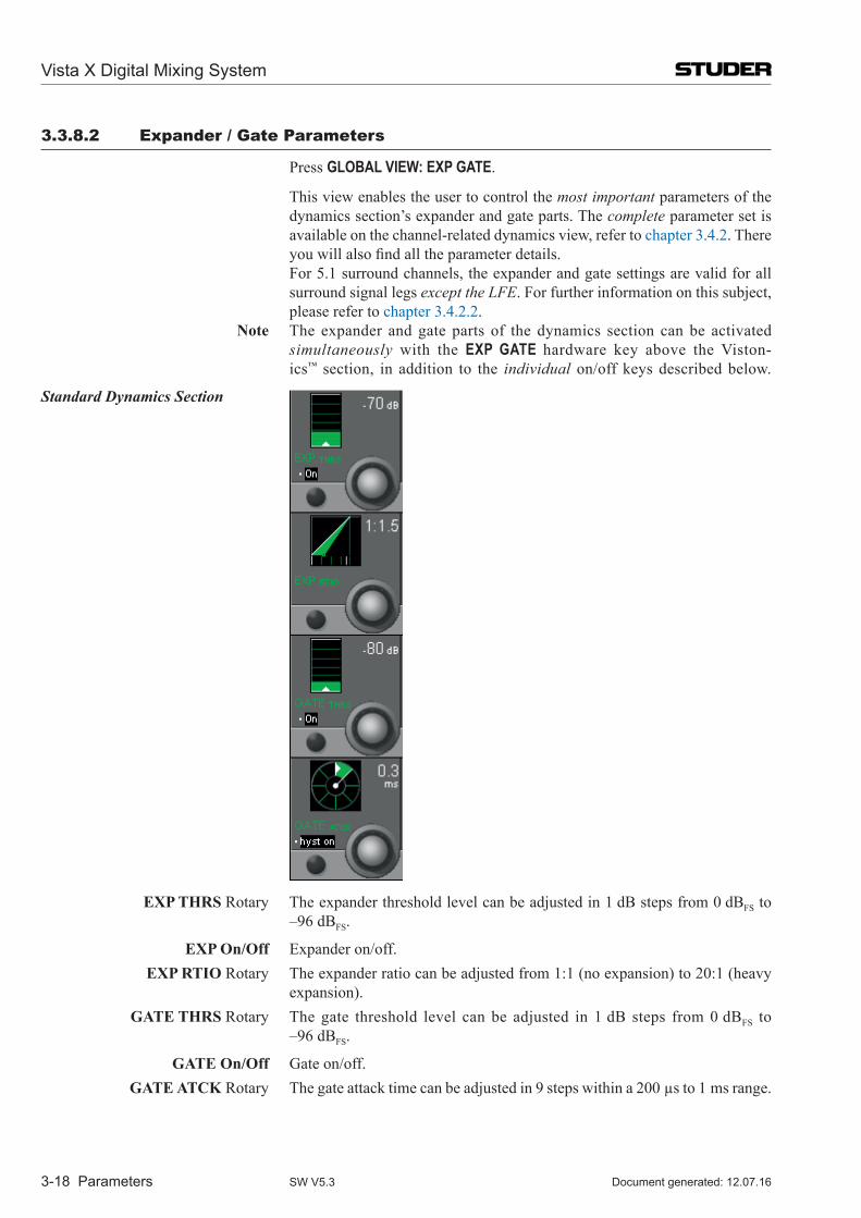
Vista X Digital Mixing System
3-18 Parameters Document generated: 12.07.16SW V5.3
3.3.8.2 Expander / Gate Parameters
Press GLOBAL VIEW: EXP GATE.
This view enables the user to control the most important parameters of the dynamics section’s expander and gate parts. The complete parameter set is available on the channel-related dynamics view, refer to chapter 3.4.2. There you will also find all the parameter details.
For 5.1 surround channels, the expander and gate settings are valid for all surround signal legs except the LFE. For further information on this subject, please refer to chapter 3.4.2.2.
note The expander and gate parts of the dynamics section can be activated simultaneously with the EXP GATE hardware key above the Viston-ics™ section, in addition to the individual on/off keys described below.
Standard Dynamics Section
eXP ThRs Rotary The expander threshold level can be adjusted in 1 dB steps from 0 dBFS to –96 dBFS.
eXP on/off Expander on/off. eXP RTIo Rotary The expander ratio can be adjusted from 1:1 (no expansion) to 20:1 (heavy
expansion). GaTe ThRs Rotary The gate threshold level can be adjusted in 1 dB steps from 0 dBFS to
–96 dBFS.
GaTe on/off Gate on/off. GaTe aTCK Rotary The gate attack time can be adjusted in 9 steps within a 200 µs to 1 ms range.
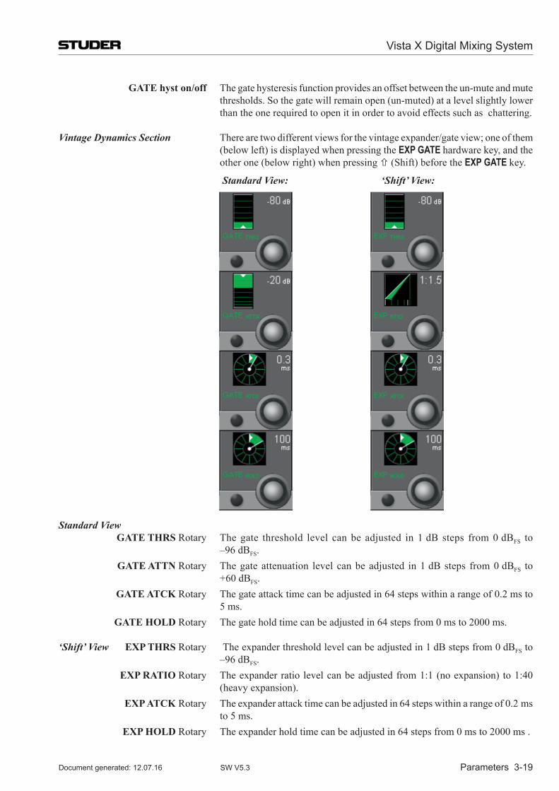
Vista X Digital Mixing System
Parameters 3-19Document generated: 12.07.16 SW V5.3
GaTe hyst on/off The gate hysteresis function provides an offset between the un-mute and mute thresholds. So the gate will remain open (un-muted) at a level slightly lower than the one required to open it in order to avoid effects such as chattering.
Vintage Dynamics Section There are two different views for the vintage expander/gate view; one of them (below left) is displayed when pressing the EXP GATE hardware key, and the other one (below right) when pressing (Shift) before the EXP GATE key.
Standard View: ‘Shift’ View:
Standard View GaTe ThRs Rotary The gate threshold level can be adjusted in 1 dB steps from 0 dBFS to
–96 dBFS. GaTe aTTn Rotary The gate attenuation level can be adjusted in 1 dB steps from 0 dBFS to
+60 dBFS. GaTe aTCK Rotary The gate attack time can be adjusted in 64 steps within a range of 0.2 ms to
5 ms. GaTe hoLD Rotary The gate hold time can be adjusted in 64 steps from 0 ms to 2000 ms.
‘Shift’ View eXP ThRs Rotary The expander threshold level can be adjusted in 1 dB steps from 0 dBFS to –96 dBFS.
eXP RaTIo Rotary The expander ratio level can be adjusted from 1:1 (no expansion) to 1:40 (heavy expansion).
eXP aTCK Rotary The expander attack time can be adjusted in 64 steps within a range of 0.2 ms to 5 ms.
eXP hoLD Rotary The expander hold time can be adjusted in 64 steps from 0 ms to 2000 ms .
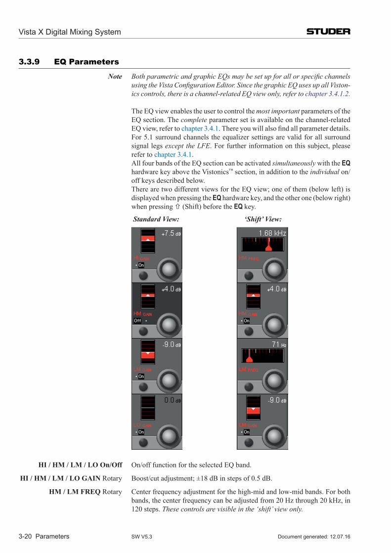
Vista X Digital Mixing System
3-20 Parameters Document generated: 12.07.16SW V5.3
3.3.9 EQ Parameters
Note Both parametric and graphic EQs may be set up for all or specific channels using the Vista Configuration Editor. Since the graphic EQ uses up all Viston-ics controls, there is a channel-related EQ view only, refer to chapter 3.4.1.2.
The EQ view enables the user to control the most important parameters of the
EQ section. The complete parameter set is available on the channel-related EQ view, refer to chapter 3.4.1. There you will also find all parameter details.
For 5.1 surround channels the equalizer settings are valid for all surround signal legs except the LFE. For further information on this subject, please refer to chapter 3.4.1.
All four bands of the EQ section can be activated simultaneously with the EQ hardware key above the Vistonics™ section, in addition to the individual on/off keys described below.
There are two different views for the EQ view; one of them (below left) is displayed when pressing the EQ hardware key, and the other one (below right) when pressing (Shift) before the EQ key.
Standard View: ‘Shift’ View:
hI / hM / LM / Lo on/off On/off function for the selected EQ band.
hI / hM / LM / Lo GaIn Rotary Boost/cut adjustment; ±18 dB in steps of 0.5 dB.
hM / LM FReq Rotary Center frequency adjustment for the high-mid and low-mid bands. For both bands, the center frequency can be adjusted from 20 Hz through 20 kHz, in 120 steps. These controls are visible in the ‘shift’ view only.
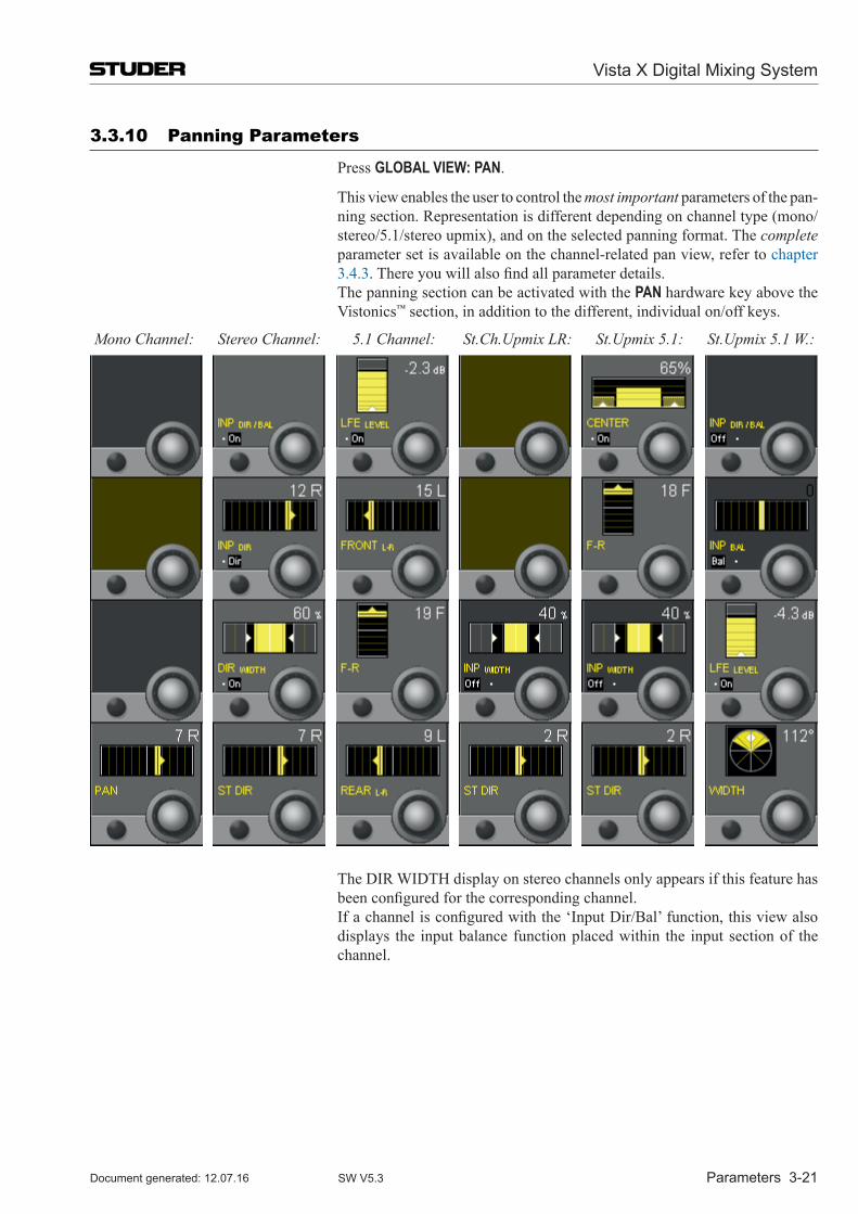
Vista X Digital Mixing System
Parameters 3-21Document generated: 12.07.16 SW V5.3
3.3.10 Panning Parameters
Press GLOBAL VIEW: PAN.
This view enables the user to control the most important parameters of the pan-ning section. Representation is different depending on channel type (mono/ stereo/5.1/stereo upmix), and on the selected panning format. The complete parameter set is available on the channel-related pan view, refer to chapter 3.4.3. There you will also find all parameter details.
The panning section can be activated with the PAN hardware key above the Vistonics™ section, in addition to the different, individual on/off keys.
Mono Channel: Stereo Channel: 5.1 Channel: St.Ch.Upmix LR: St.Upmix 5.1: St.Upmix 5.1 W.:
The DIR WIDTH display on stereo channels only appears if this feature has been configured for the corresponding channel.
If a channel is configured with the ‘Input Dir/Bal’ function, this view also displays the input balance function placed within the input section of the channel.
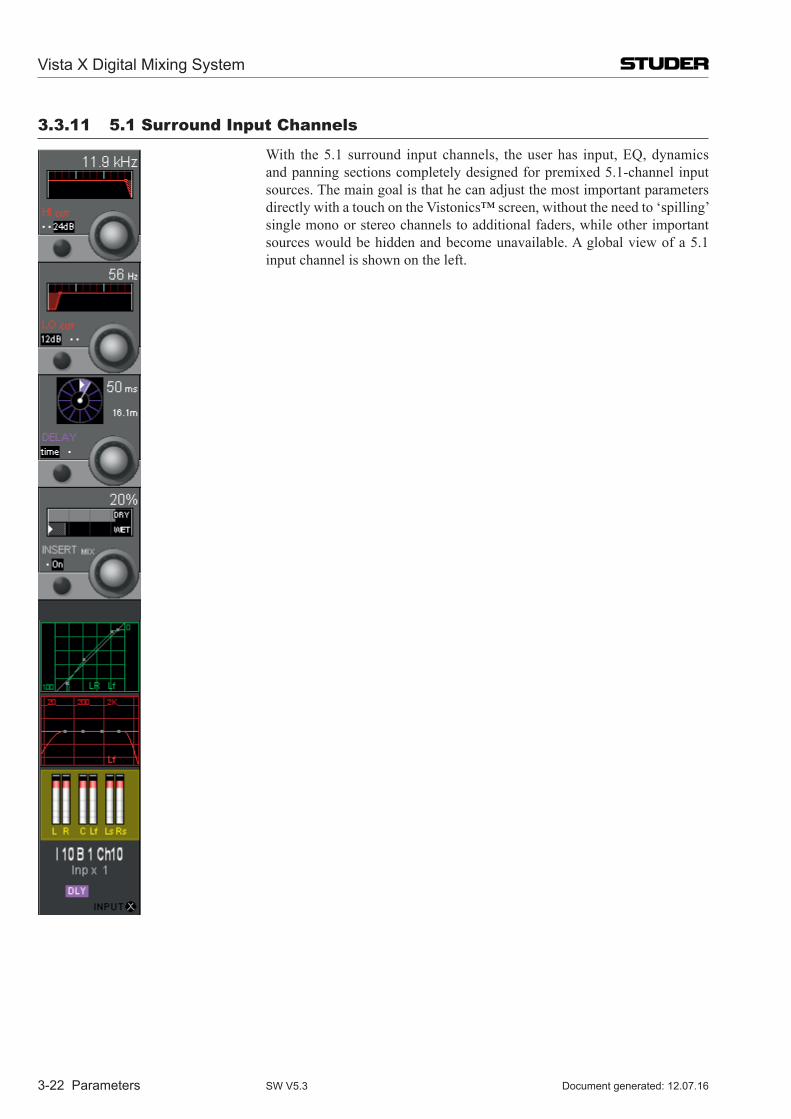
Vista X Digital Mixing System
3-22 Parameters Document generated: 12.07.16SW V5.3
3.3.11 5.1 surround input Channels
With the 5.1 surround input channels, the user has input, EQ, dynamics and panning sections completely designed for premixed 5.1-channel input sources. The main goal is that he can adjust the most important parameters directly with a touch on the Vistonics™ screen, without the need to ‘spilling’ single mono or stereo channels to additional faders, while other important sources would be hidden and become unavailable. A global view of a 5.1 input channel is shown on the left.
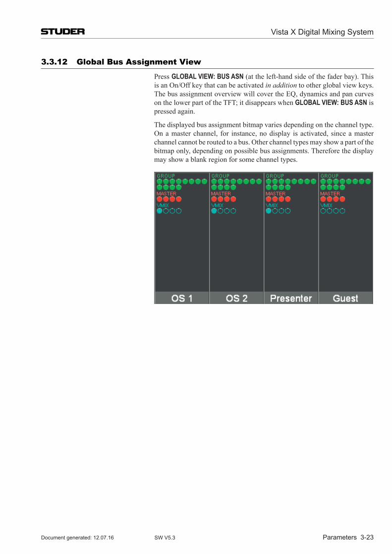
Vista X Digital Mixing System
Parameters 3-23Document generated: 12.07.16 SW V5.3
3.3.12 Global Bus Assignment View
Press GLOBAL VIEW: BUS ASN (at the left-hand side of the fader bay). This is an On/Off key that can be activated in addition to other global view keys. The bus assignment overview will cover the EQ, dynamics and pan curves on the lower part of the TFT; it disappears when GLOBAL VIEW: BUS ASN is pressed again.
The displayed bus assignment bitmap varies depending on the channel type. On a master channel, for instance, no display is activated, since a master channel cannot be routed to a bus. Other channel types may show a part of the bitmap only, depending on possible bus assignments. Therefore the display may show a blank region for some channel types.
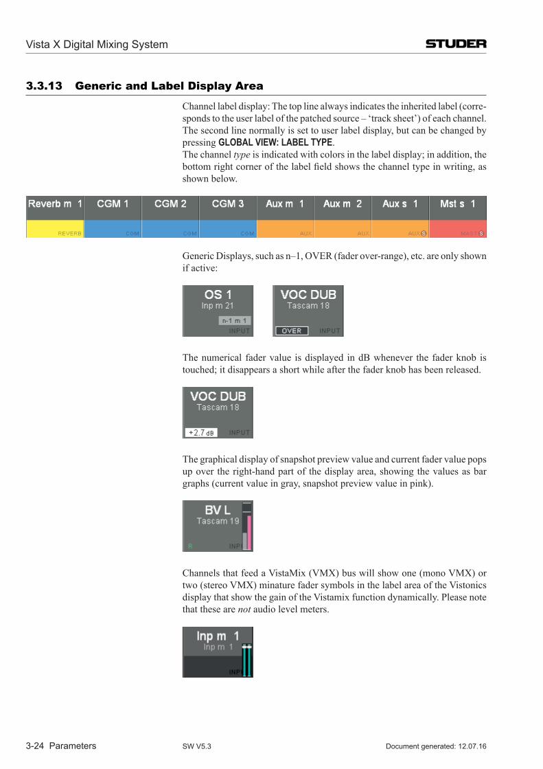
Vista X Digital Mixing System
3-24 Parameters Document generated: 12.07.16SW V5.3
3.3.13 Generic and Label Display Area
Channel label display: The top line always indicates the inherited label (corre-sponds to the user label of the patched source – ‘track sheet’) of each channel. The second line normally is set to user label display, but can be changed by pressing GLOBAL VIEW: LABEL TYPE.
The channel type is indicated with colors in the label display; in addition, the bottom right corner of the label field shows the channel type in writing, as shown below.
Generic Displays, such as n–1, OVER (fader over-range), etc. are only shown if active:
The numerical fader value is displayed in dB whenever the fader knob is touched; it disappears a short while after the fader knob has been released.
The graphical display of snapshot preview value and current fader value pops up over the right-hand part of the display area, showing the values as bar graphs (current value in gray, snapshot preview value in pink).
Channels that feed a VistaMix (VMX) bus will show one (mono VMX) or two (stereo VMX) minature fader symbols in the label area of the Vistonics display that show the gain of the Vistamix function dynamically. Please note that these are not audio level meters.
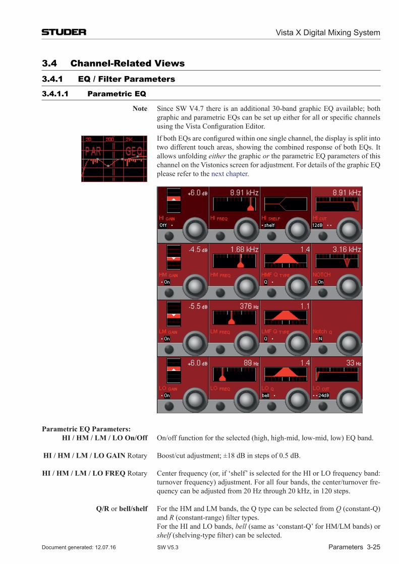
Vista X Digital Mixing System
Parameters 3-25Document generated: 12.07.16 SW V5.3
3.4 Channel-Related Views3.4.1 EQ / Filter Parameters
3.4.1.1 Parametric EQ
note Since SW V4.7 there is an additional 30-band graphic EQ available; both graphic and parametric EQs can be set up either for all or specific channels using the Vista Configuration Editor.
If both EQs are configured within one single channel, the display is split into two different touch areas, showing the combined response of both EQs. It allows unfolding either the graphic or the parametric EQ parameters of this channel on the Vistonics screen for adjustment. For details of the graphic EQ please refer to the next chapter.
Parametric eq Parameters: hI / hM / LM / Lo on/off On/off function for the selected (high, high-mid, low-mid, low) EQ band.
hI / hM / LM / Lo GaIn Rotary Boost/cut adjustment; ±18 dB in steps of 0.5 dB.
hI / hM / LM / Lo FReq Rotary Center frequency (or, if ‘shelf’ is selected for the HI or LO frequency band: turnover frequency) adjustment. For all four bands, the center/turnover fre-quency can be adjusted from 20 Hz through 20 kHz, in 120 steps.
q/R or bell/shelf For the HM and LM bands, the Q type can be selected from Q (constant-Q) and R (constant-range) filter types.
For the HI and LO bands, bell (same as ‘constant-Q’ for HM/LM bands) or shelf (shelving-type filter) can be selected.
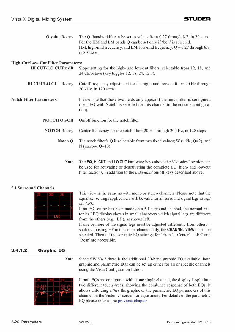
Vista X Digital Mixing System
3-26 Parameters Document generated: 12.07.16SW V5.3
q value Rotary The Q (bandwidth) can be set to values from 0.27 through 8.7, in 30 steps. For the HM and LM bands Q can be set only if ‘bell’ is selected.
HM, high-mid frequency, and LM, low-mid frequency: Q = 0.27 through 8.7, in 30 steps.
high-Cut/Low-Cut Filter Parameters: hI CUT/Lo CUT x dB Slope setting for the high- and low-cut filters, selectable from 12, 18, and
24 dB/octave (key toggles 12, 18, 24, 12...).
hI CUT/Lo CUT Rotary Cutoff frequency adjustment for the high- and low-cut filter: 20 Hz through 20 kHz, in 120 steps.
notch Filter Parameters: Please note that these two fields only appear if the notch filter is configured (i.e., ‘EQ with Notch’ is selected for this channel in the console configura-tion).
noTCh on/off On/off function for the notch filter.
noTCh Rotary Center frequency for the notch filter: 20 Hz through 20 kHz, in 120 steps.
notch q The notch filter’s Q is selectable from two fixed values; W (wide, Q=2), and N (narrow, Q=10).
note The EQ, HI CUT and LO CUT hardware keys above the Vistonics™ section can be used for activating or deactivating the complete EQ, high- and low-cut filter sections, in addition to the individual on/off keys described above.
5.1 surround Channels This view is the same as with mono or stereo channels. Please note that the
equalizer settings applied here will be valid for all surround signal legs except the LFE.
If an EQ setting has been made on a 5.1 surround channel, the normal Vis-tonics™ EQ display shows in small characters which signal legs are different from the others (e.g. ‘Lf’), as shown left.
If one or more of the signal legs must be adjusted differently from others – such as boosting HF in the center channel only, the CHANNEL VIEW has to be selected. Then all the separate EQ settings for ‘Front’, ‘Center’, ‘LFE’ and ‘Rear’ are accessible.
3.4.1.2 Graphic EQ
note Since SW V4.7 there is the additional 30-band graphic EQ available; both graphic and parametric EQs can be set up either for all or specific channels using the Vista Configuration Editor.
If both EQs are configured within one single channel, the display is split into two different touch areas, showing the combined response of both EQs. It allows unfolding either the graphic or the parametric EQ parameters of this channel on the Vistonics screen for adjustment. For details of the parametric EQ please refer to the previous chapter.
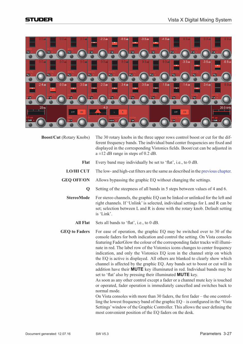
Vista X Digital Mixing System
Parameters 3-27Document generated: 12.07.16 SW V5.3
Boost/Cut (Rotary Knobs) The 30 rotary knobs in the three upper rows control boost or cut for the dif-ferent frequency bands. The individual band center frequencies are fixed and displayed in the corresponding Vistonics fields. Boost/cut can be adjusted in a ±12 dB range in steps of 0.2 dB.
Flat Every band may individually be set to ‘flat’, i.e., to 0 dB.
Lo/hI CUT The low- and high-cut filters are the same as described in the previous chapter.
Geq oFF/on Allows bypassing the graphic EQ without changing the settings.
q Setting of the steepness of all bands in 5 steps between values of 4 and 6.
stereoMode For stereo channels, the graphic EQ can be linked or unlinked for the left and right channels. If ‘Unlink’ is selected, individual settings for L and R can be set; selection between L and R is done with the rotary knob. Default setting is ‘Link’.
all Flat Sets all bands to ‘flat’, i.e., to 0 dB.
Geq to Faders For ease of operation, the graphic EQ may be switched over to 30 of the console faders for both indication and control the setting. On Vista consoles featuring FaderGlow the colour of the corresponding fader tracks will illumi-nate in red. The label row of the Vistonics icons changes to center frequency indication, and only the Vistonics EQ icon in the channel strip on which the EQ is active is displayed. All others are blanked to clearly show which channel is affected by the graphic EQ. Any bands set to boost or cut will in addition have their MUTE key illuminated in red. Individual bands may be set to ‘flat’ also by pressing their illuminated MUTE key.
As soon as any other control except a fader or a channel mute key is touched or operated, fader operation is immediately cancelled and switches back to normal mode.
On Vista consoles with more than 30 faders, the first fader – the one control-ling the lowest frequency band of the graphic EQ – is configured in the ‘Vista Settings’ window of the Graphic Controller. This allows the user defining the most convenient position of the EQ faders on the desk.
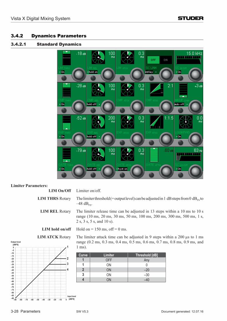
Vista X Digital Mixing System
3-28 Parameters Document generated: 12.07.16SW V5.3
3.4.2 Dynamics Parameters
3.4.2.1 standard Dynamics
Limiter Parameters: LIM on/off Limiter on/off.
LIM ThRs Rotary The limiter threshold (= output level) can be adjusted in 1 dB steps from 0 dBFS to –48 dBFS.
LIM ReL Rotary The limiter release time can be adjusted in 13 steps within a 10 ms to 10 s range (10 ms, 20 ms, 30 ms, 50 ms, 100 ms, 200 ms, 300 ms, 500 ms, 1 s, 2 s, 3 s, 5 s, and 10 s).
LIM hold on/off Hold on = 150 ms, off = 0 ms.
LIM aTCK Rotary The limiter attack time can be adjusted in 9 steps within a 200 µs to 1 ms
0–5
–10–15–20–25–30–35–40–45–50–55–60–65–70–75–80–85–90 –10–20–30–40–50–60–70–80–90 0
Input level [dBFS]
Output level [dBFS]
1
2
4
3
range (0.2 ms, 0.3 ms, 0.4 ms, 0.5 ms, 0.6 ms, 0.7 ms, 0.8 ms, 0.9 ms, and 1 ms).
Curve Limiter Threshold [dB]1 OFF Any1 ON 02 ON –203 ON –304 ON –40
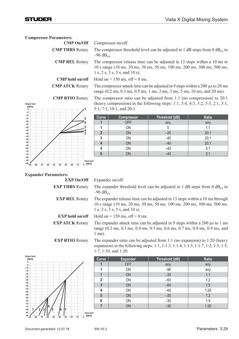
Vista X Digital Mixing System
Parameters 3-29Document generated: 12.07.16 SW V5.3
Compressor Parameters: CMP on/off Compressor on/off. CMP ThRs Rotary The compressor threshold level can be adjusted in 1 dB steps from 0 dBFS to
–96 dBFS. CMP ReL Rotary The compressor release time can be adjusted in 13 steps within a 10 ms to
10 s range (10 ms, 20 ms, 30 ms, 50 ms, 100 ms, 200 ms, 300 ms, 500 ms, 1 s, 2 s, 3 s, 5 s, and 10 s).
CMP hold on/off Hold on = 150 ms, off = 0 ms. CMP aTCK Rotary The compressor attack time can be adjusted in 9 steps within a 200 µs to 20 ms
range (0.2 ms, 0.3 ms, 0.5 ms, 1 ms, 2 ms, 3 ms, 5 ms, 10 ms, and 20 ms). CMP RTIo Rotary The compressor ratio can be adjusted from 1:1 (no com pression) to 20:1
0–5
–10–15–20–25–30–35–40–45–50–55–60–65–70–75–80–85–90 –10–20–30–40–50–60–70–80–90 0
Input level [dBFS]
Output level [dBFS]
1
26543
(heavy compression) in the following steps: 1:1, 5:4, 4:3, 3:2, 5:3, 2:1, 3:1, 5:1, 7:1, 10:1, and 20:1.
Curve Compressor Threshold [dB] Ratio1 OFF any any1 ON 0 1:12 ON –20 20:13 ON –40 20:14 ON –40 20:15 ON –40 5:16 ON –40 2:1
expander Parameters: eXP on/off Expander on/off. eXP ThRs Rotary The expander threshold level can be adjusted in 1 dB steps from 0 dBFS to
–96 dBFS. eXP ReL Rotary The expander release time can be adjusted in 13 steps within a 10 ms through
10 s range (10 ms, 20 ms, 30 ms, 50 ms, 100 ms, 200 ms, 300 ms, 500 ms, 1 s, 2 s, 3 s, 5 s, and 10 s).
eXP hold on/off Hold on = 150 ms, off = 0 ms. eXP aTCK Rotary The expander attack time can be adjusted in 9 steps within a 200 µs to 1 ms
range (0.2 ms, 0.3 ms, 0.4 ms, 0.5 ms, 0.6 ms, 0.7 ms, 0.8 ms, 0.9 ms, and 1 ms).
eXP RTIo Rotary The expander ratio can be adjusted from 1:1 (no expansion) to 1:20 (heavy expansion) in the following steps: 1:1, 1:1.3, 1:1.4, 1:1.5, 1:1.7, 1:2, 1:3, 1:5, 1:7, 1:10, and 1:20.
0–5
–10–15–20–25–30–35–40–45–50–55–60–65–70–75–80–85–90 –10–20–30–40–50–60–70–80–90 0
Input level [dBFS]
Output level [dBFS]
2 34
5 6 71
Curve Expander Threshold [dB] Ratio1 OFF any any1 ON –96 any1 ON –30 1:12 ON –60 1:23 ON –60 1:54 ON –60 1:205 ON –30 1:26 ON –30 1:57 ON –30 1:20
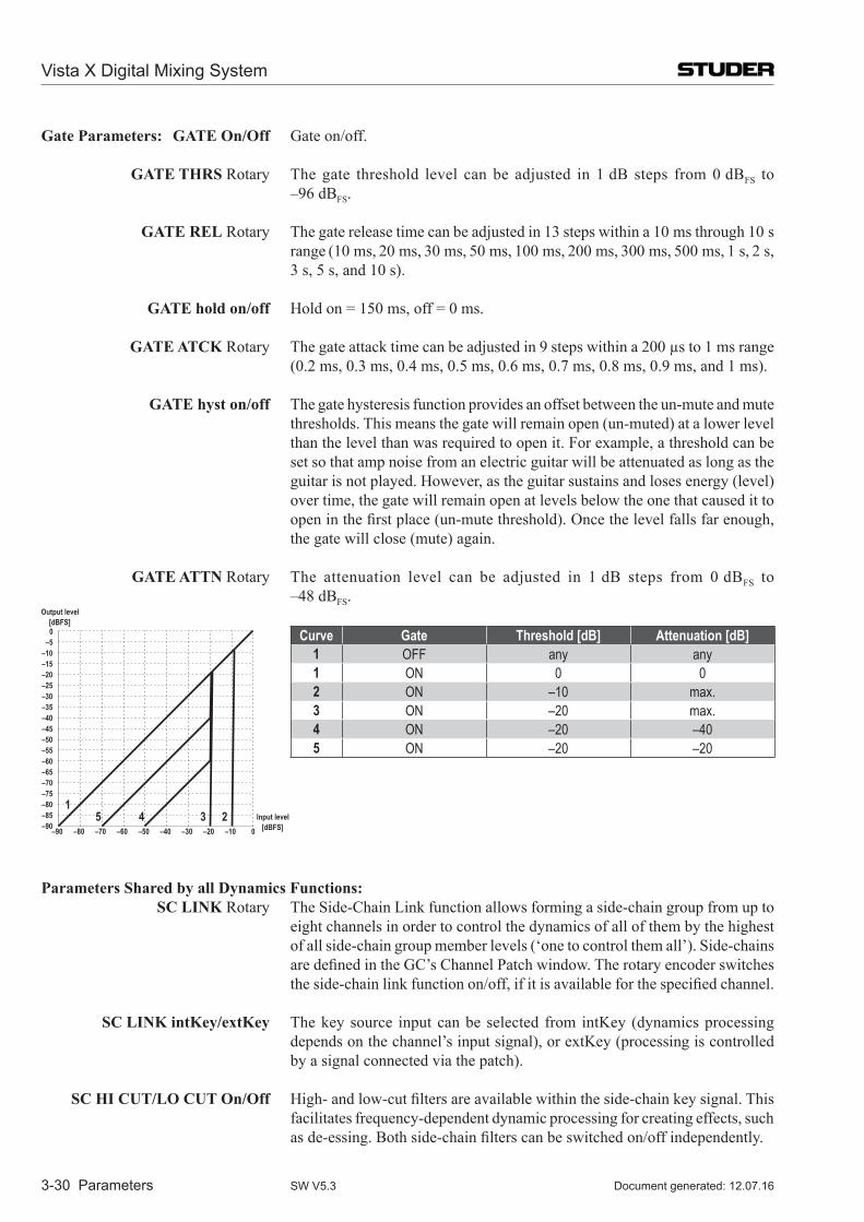
Vista X Digital Mixing System
3-30 Parameters Document generated: 12.07.16SW V5.3
Gate Parameters: GaTe on/off Gate on/off.
GaTe ThRs Rotary The gate threshold level can be adjusted in 1 dB steps from 0 dBFS to –96 dBFS.
GaTe ReL Rotary The gate release time can be adjusted in 13 steps within a 10 ms through 10 s range (10 ms, 20 ms, 30 ms, 50 ms, 100 ms, 200 ms, 300 ms, 500 ms, 1 s, 2 s, 3 s, 5 s, and 10 s).
GaTe hold on/off Hold on = 150 ms, off = 0 ms.
GaTe aTCK Rotary The gate attack time can be adjusted in 9 steps within a 200 µs to 1 ms range (0.2 ms, 0.3 ms, 0.4 ms, 0.5 ms, 0.6 ms, 0.7 ms, 0.8 ms, 0.9 ms, and 1 ms).
GaTe hyst on/off The gate hysteresis function provides an offset between the un-mute and mute thresholds. This means the gate will remain open (un-muted) at a lower level than the level than was required to open it. For example, a threshold can be set so that amp noise from an electric guitar will be attenuated as long as the guitar is not played. However, as the guitar sustains and loses energy (level) over time, the gate will remain open at levels below the one that caused it to open in the first place (un-mute threshold). Once the level falls far enough, the gate will close (mute) again.
GaTe aTTn Rotary The attenuation level can be adjusted in 1 dB steps from 0 dBFS to –48 dBFS.
0–5
–10–15–20–25–30–35–40–45–50–55–60–65–70–75–80–85–90 –10–20–30–40–50–60–70–80–90 0
Input level [dBFS]
Output level [dBFS]
23451
Curve Gate Threshold [dB] Attenuation [dB]1 OFF any any1 ON 0 02 ON –10 max.3 ON –20 max.4 ON –20 –405 ON –20 –20
Parameters shared by all Dynamics Functions: sC LInK Rotary The Side-Chain Link function allows forming a side-chain group from up to
eight channels in order to control the dynamics of all of them by the highest of all side-chain group member levels (‘one to control them all’). Side-chains are defined in the GC’s Channel Patch window. The rotary encoder switches the side-chain link function on/off, if it is available for the specified channel.
sC LInK intKey/extKey The key source input can be selected from intKey (dynamics pro cessing depends on the channel’s input signal), or extKey (processing is controlled by a signal connected via the patch).
sC hI CUT/Lo CUT on/off High- and low-cut filters are available within the side-chain key signal. This facilitates frequency-dependent dynamic processing for creating effects, such as de-essing. Both side-chain filters can be switched on/off independently.
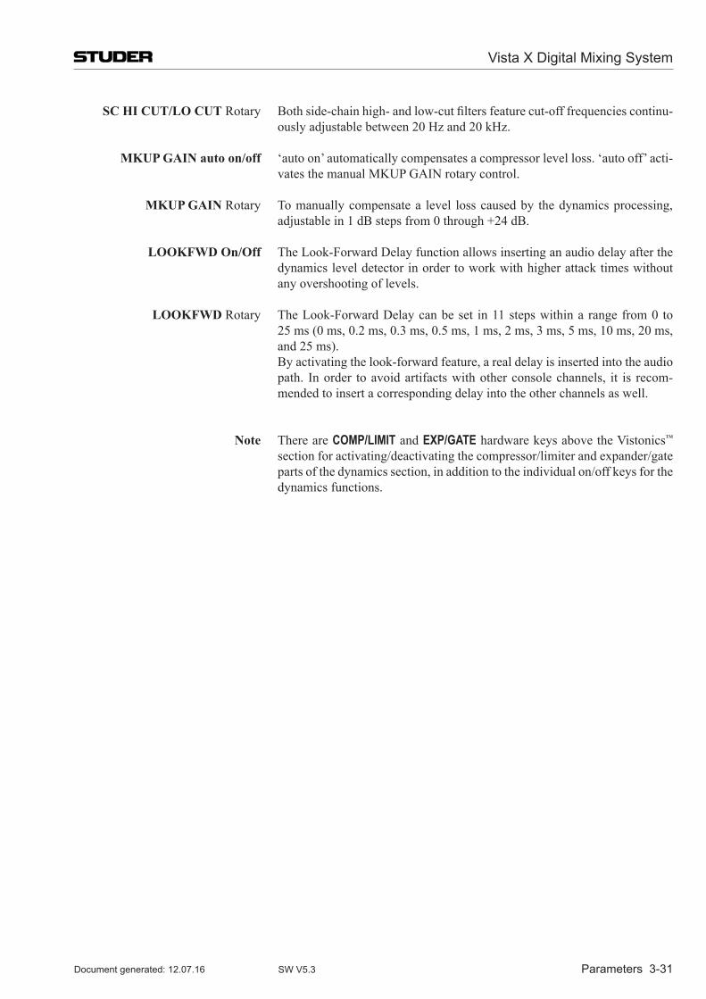
Vista X Digital Mixing System
Parameters 3-31Document generated: 12.07.16 SW V5.3
sC hI CUT/Lo CUT Rotary Both side-chain high- and low-cut filters feature cut-off frequencies continu-ously adjustable between 20 Hz and 20 kHz.
MKUP GaIn auto on/off ‘auto on’ automatically compensates a compressor level loss. ‘auto off’ acti-vates the manual MKUP GAIN rotary control.
MKUP GaIn Rotary To manually compensate a level loss caused by the dynamics processing, adjustable in 1 dB steps from 0 through +24 dB.
LooKFWD on/off The Look-Forward Delay function allows inserting an audio delay after the dynamics level detector in order to work with higher attack times without any overshooting of levels.
LooKFWD Rotary The Look-Forward Delay can be set in 11 steps within a range from 0 to 25 ms (0 ms, 0.2 ms, 0.3 ms, 0.5 ms, 1 ms, 2 ms, 3 ms, 5 ms, 10 ms, 20 ms, and 25 ms).
By activating the look-forward feature, a real delay is inserted into the audio path. In order to avoid artifacts with other console channels, it is recom-mended to insert a corresponding delay into the other channels as well.
note There are COMP/LIMIT and EXP/GATE hardware keys above the Vistonics™ section for activating/deactivating the compressor/limiter and expander/gate parts of the dynamics section, in addition to the individual on/off keys for the dynamics functions.
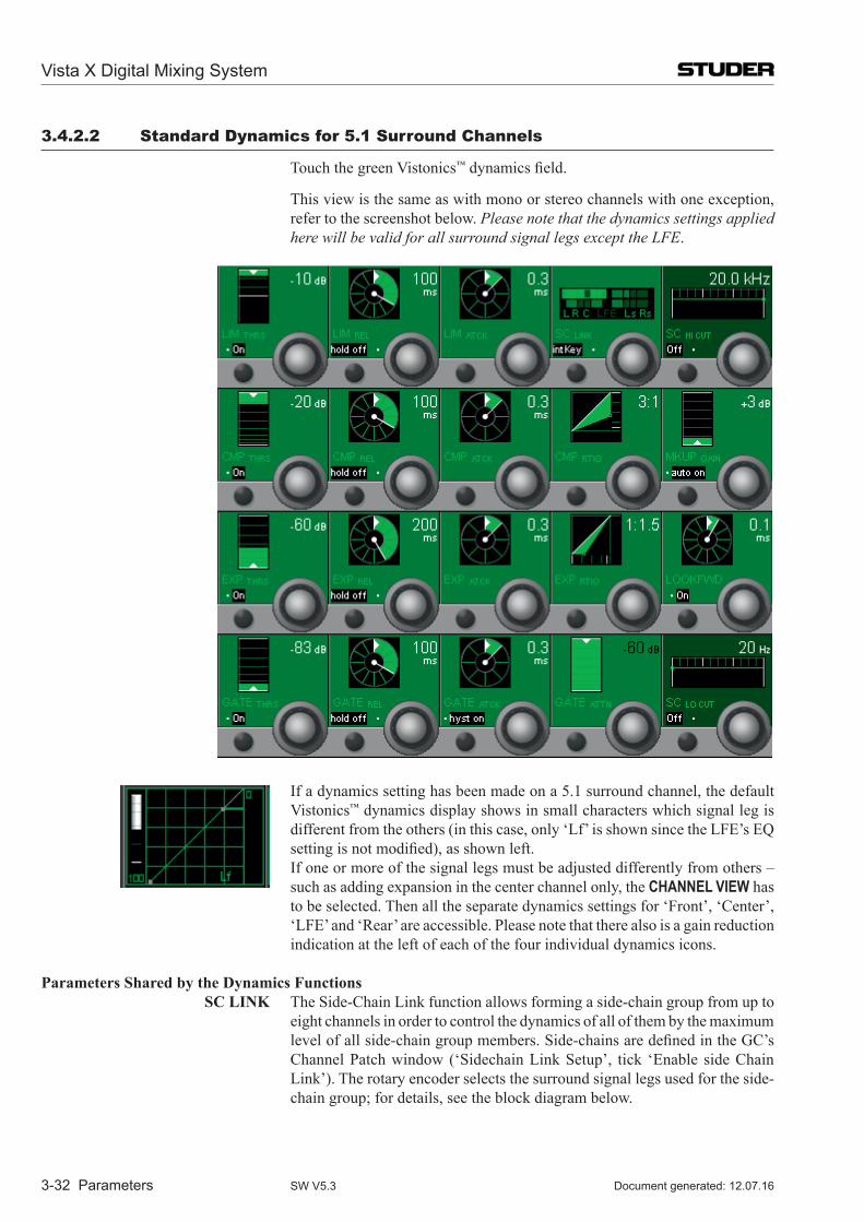
Vista X Digital Mixing System
3-32 Parameters Document generated: 12.07.16SW V5.3
3.4.2.2 standard Dynamics for 5.1 surround Channels
Touch the green Vistonics™ dynamics field.
This view is the same as with mono or stereo channels with one exception, refer to the screenshot below. Please note that the dynamics settings applied here will be valid for all surround signal legs except the LFE.
If a dynamics setting has been made on a 5.1 surround channel, the default Vistonics™ dynamics display shows in small characters which signal leg is different from the others (in this case, only ‘Lf’ is shown since the LFE’s EQ setting is not modified), as shown left.
If one or more of the signal legs must be adjusted differently from others – such as adding expansion in the center channel only, the CHANNEL VIEW has to be selected. Then all the separate dynamics settings for ‘Front’, ‘Center’, ‘LFE’ and ‘Rear’ are accessible. Please note that there also is a gain reduction indication at the left of each of the four individual dynamics icons.
Parameters shared by the Dynamics Functions sC LInK The Side-Chain Link function allows forming a side-chain group from up to
eight channels in order to control the dynamics of all of them by the maximum level of all side-chain group members. Side-chains are defined in the GC’s Channel Patch window (‘Sidechain Link Setup’, tick ‘Enable side Chain Link’). The rotary encoder selects the surround signal legs used for the side-chain group; for details, see the block diagram below.
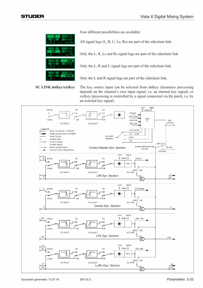
Vista X Digital Mixing System
Parameters 3-33Document generated: 12.07.16 SW V5.3
Four different possibilities are available:
All signal legs (L, R, C, Ls, Rs) are part of the sidechain link.
Only the L, R, Ls and Rs signal legs are part of the sidechain link.
Only the L, R and C signal legs are part of the sidechain link.
Only the L and R signal legs are part of the sidechain link.
sC LInK intKey/extKey The key source input can be selected from intKey (dynamics pro cessing depends on the channel’s own input signal, i.e. an internal key signal), or extKey (processing is controlled by a signal connected via the patch, i.e. by an external key signal).
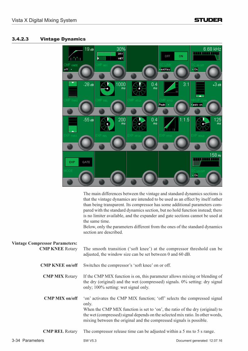
Vista X Digital Mixing System
3-34 Parameters Document generated: 12.07.16SW V5.3
3.4.2.3 Vintage Dynamics
The main differences between the vintage and standard dynamics sections is that the vintage dynamics are intended to be used as an effect by itself rather than being transparent. Its compressor has some additional parameters com-pared with the standard dynamics section, but no hold function instead; there is no limiter available, and the expander and gate sections cannot be used at the same time.
Below, only the parameters different from the ones of the standard dynamics section are described.
Vintage Compressor Parameters: CMP Knee Rotary The smooth transition (‘soft knee’) at the compressor threshold can be
adjusted, the window size can be set between 0 and 60 dB.
CMP Knee on/off Switches the compressor’s ‘soft knee’ on or off.
CMP MIX Rotary If the CMP MIX function is on, this parameter allows mixing or blending of the dry (original) and the wet (compressed) signals. 0% setting: dry signal only; 100% setting: wet signal only.
CMP MIX on/off ‘on’ activates the CMP MIX function; ‘off’ selects the compressed signal only.
When the CMP MIX function is set to ‘on’, the ratio of the dry (original) to the wet (compressed) signal depends on the selected mix ratio. In other words, mixing between the original and the compressed signals is possible.
CMP ReL Rotary The compressor release time can be adjusted within a 5 ms to 5 s range.
Vista X Digital Mixing System
Parameters 3-35Document generated: 12.07.16 SW V5.3
CMP aTCK Rotary The compressor attack time can be adjusted in steps within a 200 µs through 250 ms range.
CMP RTIo Rotary The compressor ratio can be adjusted from 1:1 (no com pression) through 40:1 (very heavy compression).
eXP / GaTe MoDe Rotary Used for selecting either the expander or the gate function for the vintage dynamics section. The threshold, release, attack and hold parameters of expander and gate are adjusted in common; they cannot be set individually.
eXP / GaTe ReL Rotary The expander/gate release time can be adjusted within a 5 ms through 5 s range.
eXP / GaTe aTCK Rotary The expander / gate attack time can be adjusted within a 0.5 through 5 ms range.
eXP RTIo Rotary The expander ratio can be adjusted from 1:1 (no expansion) through 1:40 (very heavy expansion).
eXP / GaTe hold Rotary The expander / gate hold time can be adjusted within a 0 through 2 s range.
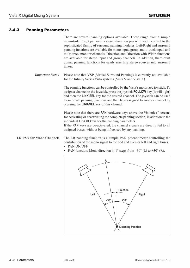
Vista X Digital Mixing System
3-36 Parameters Document generated: 12.07.16SW V5.3
3.4.3 Panning Parameters
There are several panning options available. These range from a simple mono-to-left/right pan over a stereo direction pan with width control to the sophisticated family of surround panning modules. Left/Right and surround panning functions are available for mono input, group, multi-track input, and multi-track monitor channels. Direction and Direction with Width functions are available for stereo input and group channels. In addition, there exist upmix panning functions for easily inserting stereo sources into surround mixes.
Important Note : Please note that VSP (Virtual Surround Panning) is currently not available for the Infinity Series Vista systems (Vista V and Vista X).
The panning functions can be controlled by the Vista’s motorized joystick. To assign a channel to the joystick, press the joystick FOLLOW key (it will light) and then the LINK/SEL key for the desired channel. The joystick can be used to automate panning functions and then be reassigned to another channel by pressing the LINK/SEL key of this channel.
Please note that there are PAN hardware keys above the Vistonics™ screens for activating or deactivating the complete panning section, in addition to the individual On/Off keys for the panning parameters.
If the PAN keys are de-activated, the channel signals are directly fed to all assigned buses, without being influenced by any panning.
LR Pan for Mono Channels The LR panning function is a simple PAN pot entio meter controlling the contribution of the mono signal to the odd and even or left and right buses.
• PAN ON/OFF • PAN function: Mono direction in 1° steps from –30° (L) to +30° (R).
–30°
Direction
+30°
Left Right
Listening Position
A
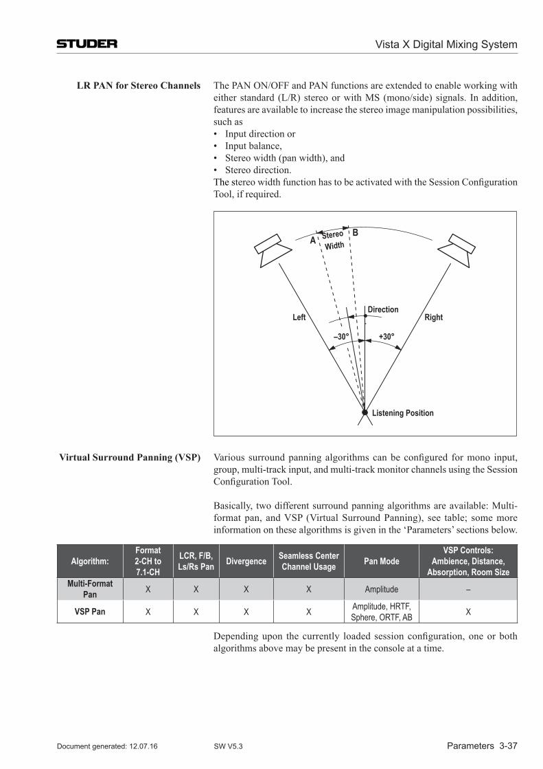
Vista X Digital Mixing System
Parameters 3-37Document generated: 12.07.16 SW V5.3
LR Pan for stereo Channels The PAN ON/OFF and PAN functions are extended to enable working with either standard (L/R) stereo or with MS (mono/side) signals. In addition, features are available to increase the stereo image manipulation possibilities, such as
• Input direction or • Input balance, • Stereo width (pan width), and • Stereo direction. The stereo width function has to be activated with the Session Configuration
Tool, if required.
AB
Left Right
Listening Position
Direction
StereoWidth
+30°–30°
Virtual surround Panning (VsP) Various surround panning algorithms can be configured for mono input, group, multi-track input, and multi-track monitor channels using the Session Configuration Tool.
Basically, two different surround panning algorithms are available: Multi-format pan, and VSP (Virtual Surround Panning), see table; some more information on these algorithms is given in the ‘Parameters’ sections below.
Algorithm:Format 2-CH to 7.1-CH
LCR, F/B,Ls/Rs Pan Divergence Seamless Center
Channel Usage Pan ModeVSP Controls:
Ambience, Distance, Absorption, Room Size
Multi-Format Pan X X X X Amplitude –
VSP Pan X X X X Amplitude, HRTF, Sphere, ORTF, AB X
Depending upon the currently loaded session configuration, one or both algorithms above may be present in the console at a time.
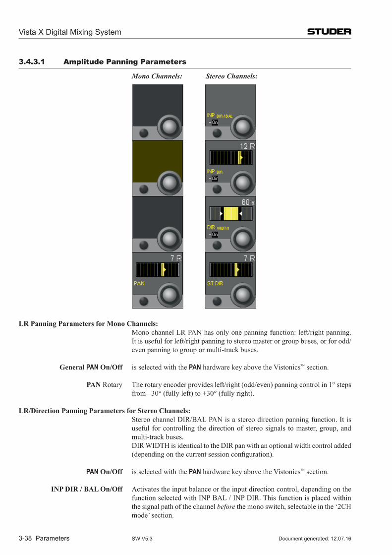
Vista X Digital Mixing System
3-38 Parameters Document generated: 12.07.16SW V5.3
3.4.3.1 Amplitude Panning Parameters
Mono Channels: Stereo Channels:
LR Panning Parameters for Mono Channels: Mono channel LR PAN has only one panning function: left/right panning.
It is useful for left/right panning to stereo master or group buses, or for odd/even panning to group or multi-track buses.
General PAN on/off is selected with the PAN hardware key above the Vistonics™ section.
Pan Rotary The rotary encoder provides left/right (odd/even) panning control in 1° steps from –30° (fully left) to +30° (fully right).
LR/Direction Panning Parameters for stereo Channels: Stereo channel DIR/BAL PAN is a stereo direction panning function. It is
useful for controlling the direction of stereo signals to master, group, and multi-track buses.
DIR WIDTH is identical to the DIR pan with an optional width control added (depending on the current session configuration).
PAN on/off is selected with the PAN hardware key above the Vistonics™ section.
InP DIR / BaL on/off Activates the input balance or the input direction control, depending on the function selected with INP BAL / INP DIR. This function is placed within the signal path of the channel before the mono switch, selectable in the ‘2CH mode’ section.
Vista X Digital Mixing System
Parameters 3-39Document generated: 12.07.16 SW V5.3
InP DIR / BaL Selection from two input functions: INP BAL or INP DIR.
InP DIR / InP BaL Rotary The INP DIR function is used to control the direction of a stereo input signal. Turning the rotary encoder shifts the input direction in 1° steps from –30° (left) to +30° (right).
The INP BAL function is used to control the balance of a stereo input signal. Turning the rotary encoder to the left attenuates the right channel from 0 to –∞ dB while the left channel remains at full input level, and vice versa.
DIR WIDTh on/off Optional, only if the width function is configured. Switches the DIR WIDTH function on/off.
DIR WIDTh Rotary Optional, only if the width function is configured. The DIR WIDTH parameter is used to control the width of the stereo signal.
It is only functional if there is a difference between the left and right input channels, or if IBAL or IDIR has been used to create an offset between the channels. The ST DIR control directs the position of the stereo signal, while the DIR WIDTH control determines the width or stereo spread either side of that position. DIR WIDTH operates over a range from 0% (mono) to 200% (‘super stereo’).
sT DIR Rotary Left/right (or odd/even) panning control for a stereo output signal in 1° steps from –30° (fully left) to +30° (fully right).
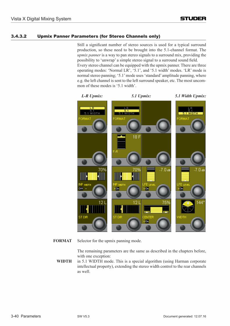
Vista X Digital Mixing System
3-40 Parameters Document generated: 12.07.16SW V5.3
3.4.3.2 Upmix Panner Parameters (for stereo Channels only)
Still a significant number of stereo sources is used for a typical surround production, so these need to be brought into the 5.1-channel format. The upmix panner is a way to pan stereo signals to a surround mix, providing the possibility to ‘unwrap’ a simple stereo signal to a surround sound field.
Every stereo channel can be equipped with the upmix panner. There are three operating modes: ‘Normal LR’, ‘5.1’, and ‘5.1 width’ modes. ‘LR’ mode is normal stereo panning; ‘5.1’ mode uses ‘standard’ amplitude panning, where e.g. the left channel is sent to the left surround speaker, etc. The most uncom-mon of these modes is ‘5.1 width’.
L-R Upmix: 5.1 Upmix: 5.1 Width Upmix:
FoRMaT Selector for the upmix panning mode.
The remaining parameters are the same as described in the chapters before, with one exception:
WIDTh in 5.1 WIDTH mode. This is a special algorithm (using Harman corporate intellectual property), extending the stereo width control to the rear channels as well.
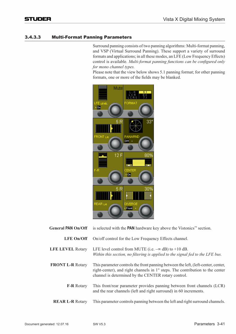
Vista X Digital Mixing System
Parameters 3-41Document generated: 12.07.16 SW V5.3
3.4.3.3 multi-Format Panning Parameters
Surround panning consists of two panning algorithms: Multi-format panning, and VSP (Virtual Surround Panning). These support a variety of surround formats and applications; in all these modes, an LFE (Low Frequency Effects) control is available. Multi-format panning functions can be configured only for mono channel types.
Please note that the view below shows 5.1 panning format; for other panning formats, one or more of the fields may be blanked.
General PAN on/off is selected with the PAN hardware key above the Vistonics™ section.
LFe on/off On/off control for the Low Frequency Effects channel.
LFe LeVeL Rotary LFE level control from MUTE (i.e. –∞ dB) to +10 dB. Within this section, no filtering is applied to the signal fed to the LFE bus.
FRonT L-R Rotary This parameter controls the front panning between the left, (left-center, center, right-center), and right channels in 1° steps. The contribution to the center channel is determined by the CENTER rotary control.
F-R Rotary This front/rear parameter provides panning between front channels (LCR) and the rear channels (left and right surround) in 60 increments.
ReaR L-R Rotary This parameter controls panning between the left and right surround channels.
Vista X Digital Mixing System
3-42 Parameters Document generated: 12.07.16SW V5.3
FoRMaT Rotary This serves as the format selector in all multi-format panning modes. The fol-lowing selections are possible: L-R, LCR, LCRS, 5.1, EX, and 7.1. Depend-ing on this selection, the actually required parameters are displayed.
PanaRnD on/off This key activates the unique Pan-Around function. If active, the FRONT L-R, F-R and REAR L-R controls become inactive.
PanaRnD Rotary This is a single-knob function that provides an easy-to-use pan setting around all selected loudspeakers (depending on format) in a circular fashion. If active, the FRONT L-R, F-R and REAR L-R controls become inactive.
CenTeR on/off On/off selector for center channel use.
CenTeR Rotary Center channel percentage control; 0% = no center channel use (phantom center), 100% = center channel fully active.
DIVeRGe off/Front/all Divergence mode selector. The divergence function can be applied to panning between all channels or the front channels only. The key toggles between off, front and all.
DIVeRGe Rotary The divergence function is used to bleed portions of sound from the panned output to the other speakers. For example, if the divergence is active and set to 100%, the LR control will act as a traditional L/R pan pot (assuming there is no center channel contribution). Panning to full left will result in full attenuation of the right channel. If the divergence is then set to 50%, one half of the left channel signal strength will be bled into the right channel (with-out effecting the left channel). With the divergence control set to 1%, equal signal will be fed to both channels and the LR pan pot will have no effect. Divergence values are as follows: 1%, 2%, 3%, 4%, 5%, 10%, 15%, 20%, 25%, 30%, 35%, 40%, 45%, 50%, 60%, 70%, 80%, 90%, 100%. Careful use of this control may have the effect of increasing the size of the mix ‘sweet spot’, particularly for large auditoria. Misuse of this control may result in essentially mono panning.
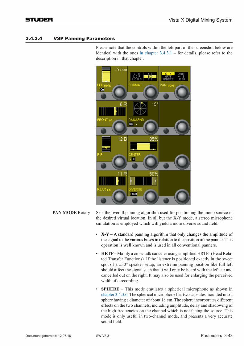
Vista X Digital Mixing System
Parameters 3-43Document generated: 12.07.16 SW V5.3
3.4.3.4 VsP Panning Parameters
Please note that the controls within the left part of the screenshot below are identical with the ones in chapter 3.4.3.1 – for details, please refer to the description in that chapter.
Pan MoDe Rotary Sets the overall panning algorithm used for positioning the mono source in the desired virtual location. In all but the X-Y mode, a stereo microphone simulation is employed which will yield a more diverse sound field.
• X-Y – A standard panning algorithm that only changes the amplitude of the signal to the various buses in relation to the position of the panner. This operation is well known and is used in all conventional panners.
• hRTF – Mainly a cross-talk canceler using simplified HRTFs (Head Rela-ted Transfer Functions). If the listener is positioned exactly in the sweet spot of a ±30° speaker setup, an extreme panning position like full left should affect the signal such that it will only be heard with the left ear and cancelled out on the right. It may also be used for enlarging the perceived width of a recording.
• sPheRe – This mode emulates a spherical microphone as shown in chapter 3.4.3.6. The spherical microphone has two capsules mounted into a sphere having a diameter of about 18 cm. The sphere incorporates different effects on the two channels, including amplitude, delay and shadowing of the high frequencies on the channel which is not facing the source. This mode is only useful in two-channel mode, and presents a very accurate sound field.
Vista X Digital Mixing System
3-44 Parameters Document generated: 12.07.16SW V5.3
• oRTF – An idealized version of the common cardioid microphone setup according to angles and distances used for stereo miking. A more accurate sound field is created through the manipulation of both amplitude and time differences.
• a-B – An idealized version of the common setup using omni-directional microphones. With this mode the sound stage is perceived as large, and is useful for solo instruments, audience, and choir. The positioning of the source is only established by changes in time delays.
• UseR – When this mode is selected, the panning algorithms are establis-hed from the Microphone User Settings interface provided under the main Option menu in the system Graphical Controller. The settings made affect the relationship between amplitude and time differences, determined by the settings of the imaginary microphones. For details, see chapter 3.4.3.6.
Important Note : Please note that VSP (Virtual Surround Panning) is currently not available for the Infinity Series Vista systems (Vista V and Vista X).
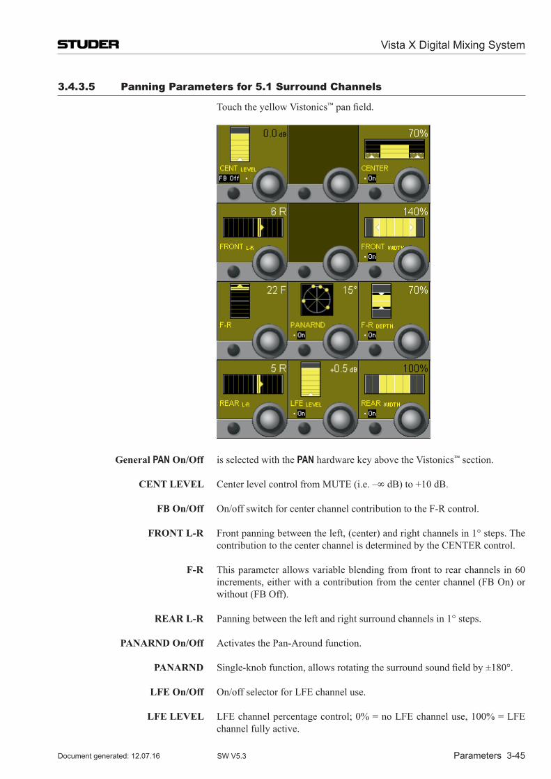
Vista X Digital Mixing System
Parameters 3-45Document generated: 12.07.16 SW V5.3
3.4.3.5 Panning Parameters for 5.1 surround Channels
Touch the yellow Vistonics™ pan field.
General PAN on/off is selected with the PAN hardware key above the Vistonics™ section.
CenT LeVeL Center level control from MUTE (i.e. –∞ dB) to +10 dB.
FB on/off On/off switch for center channel contribution to the F-R control.
FRonT L-R Front panning between the left, (center) and right channels in 1° steps. The contribution to the center channel is determined by the CENTER control.
F-R This parameter allows variable blending from front to rear channels in 60 increments, either with a contribution from the center channel (FB On) or without (FB Off).
ReaR L-R Panning between the left and right surround channels in 1° steps.
PanaRnD on/off Activates the Pan-Around function.
PanaRnD Single-knob function, allows rotating the surround sound field by ±180°.
LFe on/off On/off selector for LFE channel use.
LFe LeVeL LFE channel percentage control; 0% = no LFE channel use, 100% = LFE channel fully active.
Vista X Digital Mixing System
3-46 Parameters Document generated: 12.07.16SW V5.3
CenTeR on/off On/off selector for center channel use.
CenTeR Center channel percentage control; 0% = no center channel use (phantom center), 100% = center channel fully active.
FRonT WIDTh on/off Switches the FRONT WIDTH function on/off.
FRonT WIDTh The FRONT WIDTH parameter is used to control the width of the front signal. It is only functional if there is a difference between the left and right input channels. FRONT WIDTH operates over a range from 0% (mono) to 200% (‘super stereo’).
F/R DePTh on/off Switches the F/R DEPTH function on/off.
F/R DePTh The F/R DEPTH parameter is used to control the depth of the surround space. It is only functional if there is a difference between the front and the rear input channels. F/R DEPTH operates over a range from 0% (zero depth) to 200% (‘super depth’).
ReaR WIDTh on/off Switches the REAR WIDTH function on/off.
ReaR WIDTh The REAR WIDTH parameter is used to control the width of the rear signal. It is only functional if there is a difference between the left and right input channels. REAR WIDTH operates over a range from 0% (mono) to 200% (‘super stereo’).
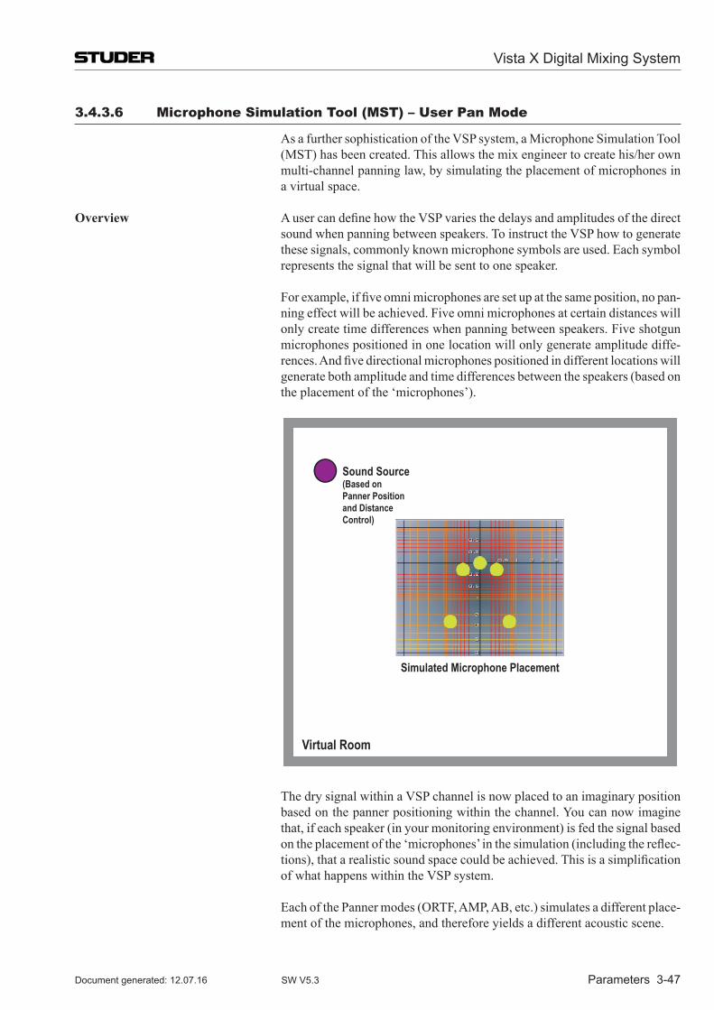
Vista X Digital Mixing System
Parameters 3-47Document generated: 12.07.16 SW V5.3
3.4.3.6 microphone simulation Tool (msT) – User Pan mode
As a further sophistication of the VSP system, a Microphone Simulation Tool (MST) has been created. This allows the mix engineer to create his/her own multi-channel panning law, by simulating the placement of microphones in a virtual space.
overview A user can define how the VSP varies the delays and amplitudes of the direct sound when panning between speakers. To instruct the VSP how to generate these signals, commonly known microphone symbols are used. Each symbol represents the signal that will be sent to one speaker.
For example, if five omni microphones are set up at the same position, no pan-ning effect will be achieved. Five omni microphones at certain distances will only create time differences when panning between speakers. Five shotgun microphones positioned in one location will only generate amplitude diffe-rences. And five directional microphones positioned in different locations will generate both amplitude and time differences between the speakers (based on the placement of the ‘microphones’).
Sound Source(Based onPanner Positionand DistanceControl)
Simulated Microphone Placement
Virtual Room
The dry signal within a VSP channel is now placed to an imaginary position based on the panner positioning within the channel. You can now imagine that, if each speaker (in your monitoring environment) is fed the signal based on the placement of the ‘microphones’ in the simulation (including the reflec-tions), that a realistic sound space could be achieved. This is a simplification of what happens within the VSP system.
Each of the Panner modes (ORTF, AMP, AB, etc.) simulates a different place-ment of the microphones, and therefore yields a different acoustic scene.
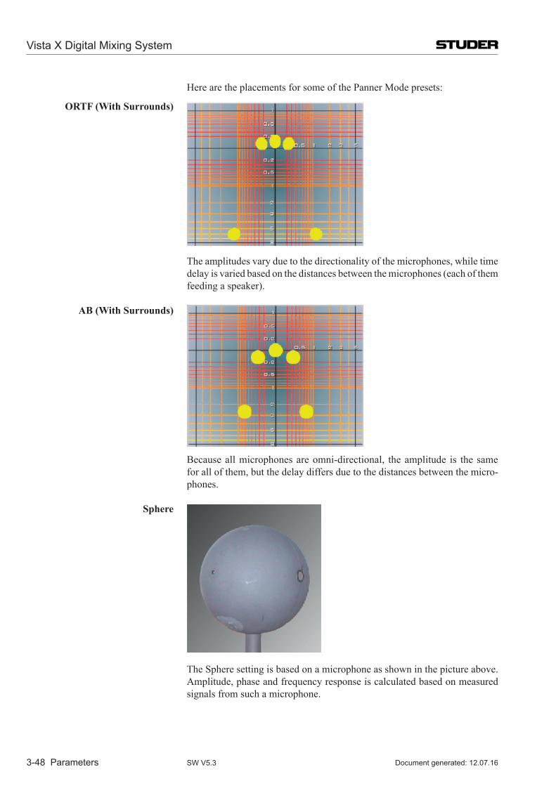
Vista X Digital Mixing System
3-48 Parameters Document generated: 12.07.16SW V5.3
Here are the placements for some of the Panner Mode presets:
oRTF (With surrounds)
The amplitudes vary due to the directionality of the microphones, while time delay is varied based on the distances between the microphones (each of them feeding a speaker).
aB (With surrounds)
Because all microphones are omni-directional, the amplitude is the same for all of them, but the delay differs due to the distances between the micro-phones.
sphere
The Sphere setting is based on a microphone as shown in the picture above. Amplitude, phase and frequency response is calculated based on measured signals from such a microphone.
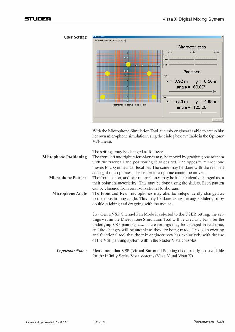
Vista X Digital Mixing System
Parameters 3-49Document generated: 12.07.16 SW V5.3
User setting
With the Microphone Simulation Tool, the mix engineer is able to set up his/her own microphone simulation using the dialog box available in the Options/VSP menu.
The settings may be changed as follows: Microphone Positioning The front left and right microphones may be moved by grabbing one of them
with the trackball and positioning it as desired. The opposite microphone moves to a symmetrical location. The same may be done with the rear left and right microphones. The center microphone cannot be moved.
Microphone Pattern The front, center, and rear microphones may be independently changed as to their polar characteristics. This may be done using the sliders. Each pattern can be changed from omni-directional to shotgun.
Microphone angle The Front and Rear microphones may also be independently changed as to their positioning angle. This may be done using the angle sliders, or by double-clicking and dragging with the mouse.
So when a VSP Channel Pan Mode is selected to the USER setting, the set-tings within the Microphone Simulation Tool will be used as a basis for the underlying VSP panning law. These settings may be changed in real time, and the changes will be audible as they are being made. This is an exciting and functional tool that the mix engineer now has exclusively with the use of the VSP panning system within the Studer Vista consoles.
Important Note : Please note that VSP (Virtual Surround Panning) is currently not available for the Infinity Series Vista systems (Vista V and Vista X).
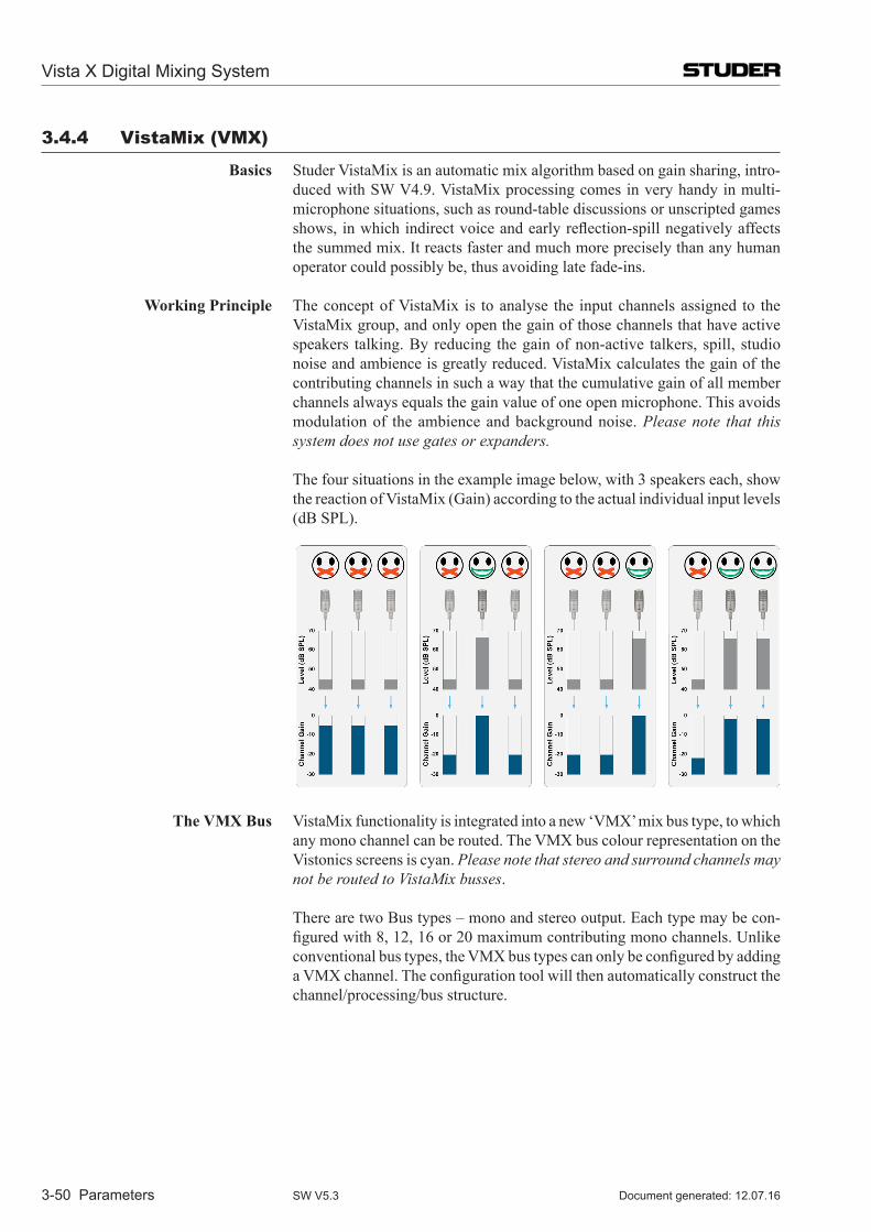
Vista X Digital Mixing System
3-50 Parameters Document generated: 12.07.16SW V5.3
3.4.4 Vistamix (VmX)
Basics Studer VistaMix is an automatic mix algorithm based on gain sharing, intro-duced with SW V4.9. VistaMix processing comes in very handy in multi-microphone situations, such as round-table discussions or unscripted games shows, in which indirect voice and early reflection-spill negatively affects the summed mix. It reacts faster and much more precisely than any human operator could possibly be, thus avoiding late fade-ins.
Working Principle The concept of VistaMix is to analyse the input channels assigned to the VistaMix group, and only open the gain of those channels that have active speakers talking. By reducing the gain of non-active talkers, spill, studio noise and ambience is greatly reduced. VistaMix calculates the gain of the contributing channels in such a way that the cumulative gain of all member channels always equals the gain value of one open microphone. This avoids modulation of the ambience and background noise. Please note that this system does not use gates or expanders.
The four situations in the example image below, with 3 speakers each, show the reaction of VistaMix (Gain) according to the actual individual input levels (dB SPL).
The VMX Bus VistaMix functionality is integrated into a new ‘VMX’ mix bus type, to which any mono channel can be routed. The VMX bus colour representation on the Vistonics screens is cyan. Please note that stereo and surround channels may not be routed to VistaMix busses.
There are two Bus types – mono and stereo output. Each type may be con-figured with 8, 12, 16 or 20 maximum contributing mono channels. Unlike conventional bus types, the VMX bus types can only be configured by adding a VMX channel. The configuration tool will then automatically construct the channel/processing/bus structure.
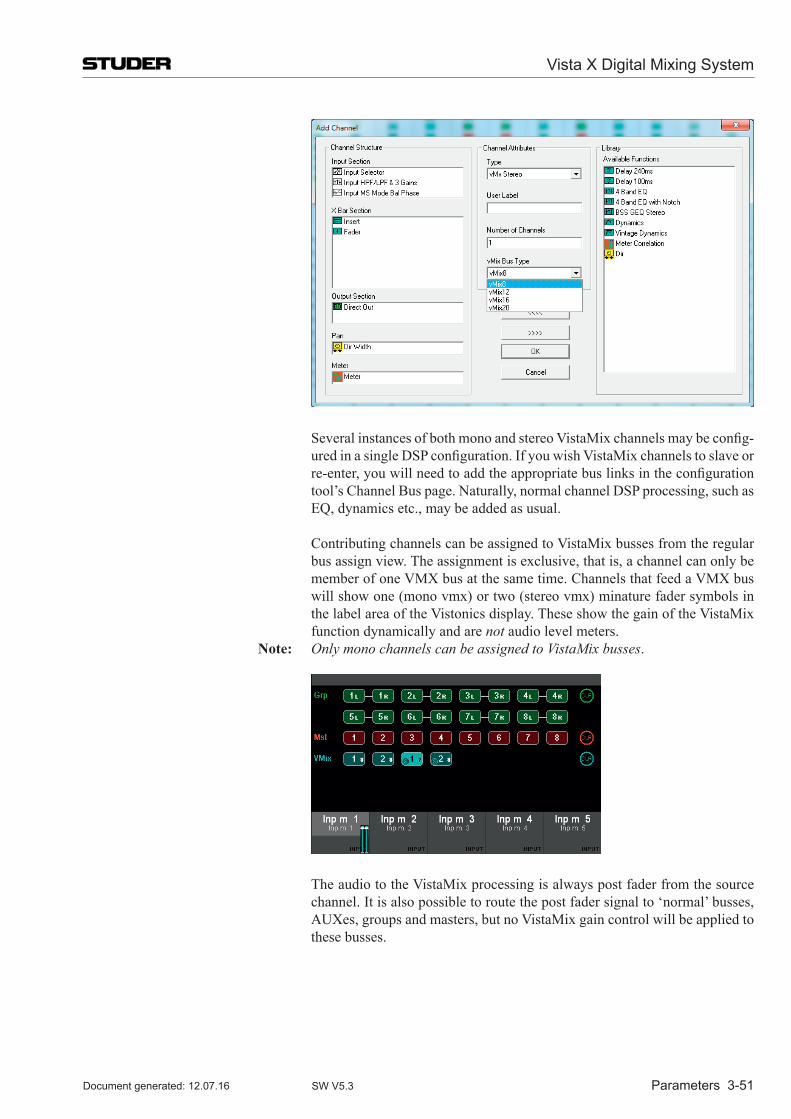
Vista X Digital Mixing System
Parameters 3-51Document generated: 12.07.16 SW V5.3
Several instances of both mono and stereo VistaMix channels may be config-ured in a single DSP configuration. If you wish VistaMix channels to slave or re-enter, you will need to add the appropriate bus links in the configuration tool’s Channel Bus page. Naturally, normal channel DSP processing, such as EQ, dynamics etc., may be added as usual.
Contributing channels can be assigned to VistaMix busses from the regular bus assign view. The assignment is exclusive, that is, a channel can only be member of one VMX bus at the same time. Channels that feed a VMX bus will show one (mono vmx) or two (stereo vmx) minature fader symbols in the label area of the Vistonics display. These show the gain of the VistaMix function dynamically and are not audio level meters.
note: Only mono channels can be assigned to VistaMix busses.
The audio to the VistaMix processing is always post fader from the source channel. It is also possible to route the post fader signal to ‘normal’ busses, AUXes, groups and masters, but no VistaMix gain control will be applied to these busses.
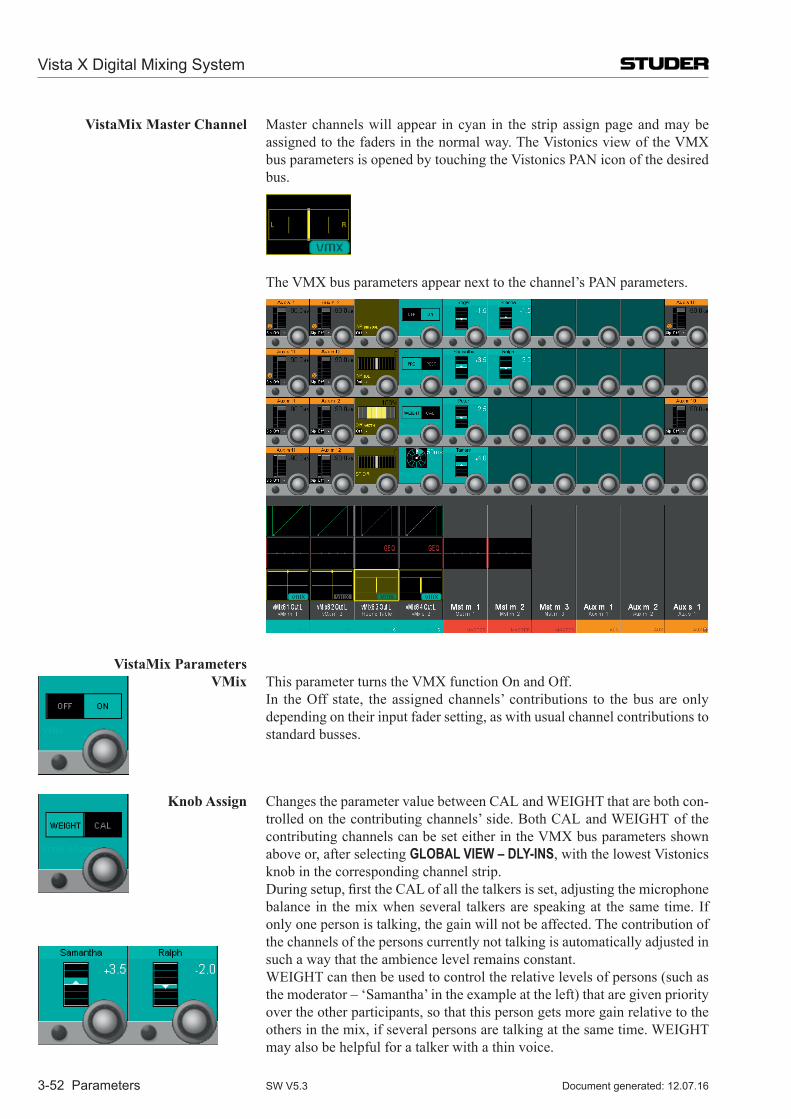
Vista X Digital Mixing System
3-52 Parameters Document generated: 12.07.16SW V5.3
VistaMix Master Channel Master channels will appear in cyan in the strip assign page and may be assigned to the faders in the normal way. The Vistonics view of the VMX bus parameters is opened by touching the Vistonics PAN icon of the desired bus.
The VMX bus parameters appear next to the channel’s PAN parameters.
VistaMix Parameters
VMix This parameter turns the VMX function On and Off. In the Off state, the assigned channels’ contributions to the bus are only
depending on their input fader setting, as with usual channel contributions to standard busses.
Knob assign Changes the parameter value between CAL and WEIGHT that are both con-trolled on the contributing channels’ side. Both CAL and WEIGHT of the contributing channels can be set either in the VMX bus parameters shown above or, after selecting GLOBAL VIEW – DLY-INS, with the lowest Vistonics knob in the corresponding channel strip.
During setup, first the CAL of all the talkers is set, adjusting the microphone balance in the mix when several talkers are speaking at the same time. If only one person is talking, the gain will not be affected. The contribution of
the channels of the persons currently not talking is automatically adjusted in such a way that the ambience level remains constant.
WEIGHT can then be used to control the relative levels of persons (such as the moderator – ‘Samantha’ in the example at the left) that are given priority over the other participants, so that this person gets more gain relative to the others in the mix, if several persons are talking at the same time. WEIGHT may also be helpful for a talker with a thin voice.
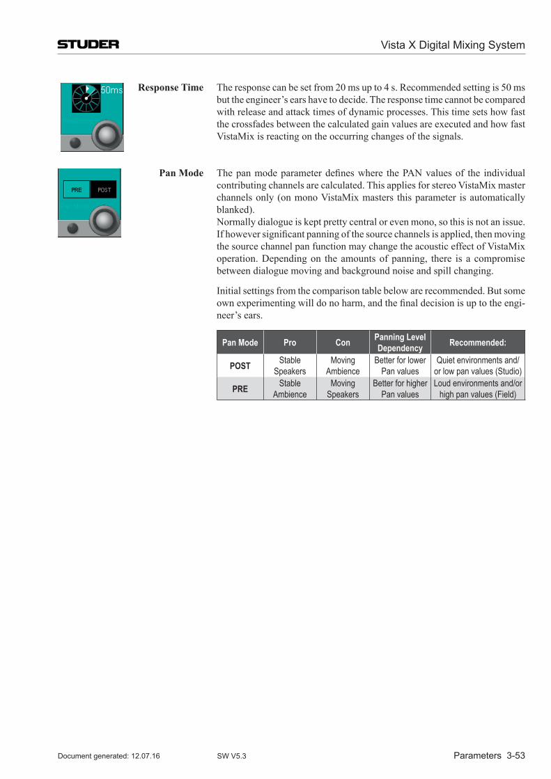
Vista X Digital Mixing System
Parameters 3-53Document generated: 12.07.16 SW V5.3
Response Time The response can be set from 20 ms up to 4 s. Recommended setting is 50 ms but the engineer’s ears have to decide. The response time cannot be compared with release and attack times of dynamic processes. This time sets how fast the crossfades between the calculated gain values are executed and how fast VistaMix is reacting on the occurring changes of the signals.
Pan Mode The pan mode parameter defines where the PAN values of the individual contributing channels are calculated. This applies for stereo VistaMix master channels only (on mono VistaMix masters this parameter is automatically blanked).
Normally dialogue is kept pretty central or even mono, so this is not an issue. If however significant panning of the source channels is applied, then moving the source channel pan function may change the acoustic effect of VistaMix operation. Depending on the amounts of panning, there is a compromise between dialogue moving and background noise and spill changing.
Initial settings from the comparison table below are recommended. But some own experimenting will do no harm, and the final decision is up to the engi-neer’s ears.
Pan Mode Pro Con Panning Level Dependency Recommended:
POST Stable Speakers
Moving Ambience
Better for lower Pan values
Quiet environments and/or low pan values (Studio)
PRE Stable Ambience
Moving Speakers
Better for higher Pan values
Loud environments and/or high pan values (Field)
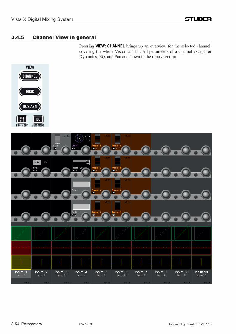
Vista X Digital Mixing System
3-54 Parameters Document generated: 12.07.16SW V5.3
3.4.5 Channel View in general
Pressing VIEW: CHANNEL brings up an overview for the selected channel, covering the whole Vistonics TFT. All parameters of a channel except for Dynamics, EQ, and Pan are shown in the rotary section.
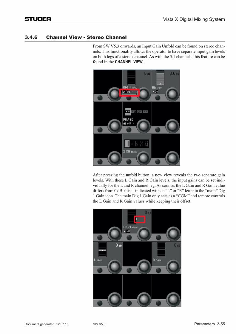
Vista X Digital Mixing System
Parameters 3-55Document generated: 12.07.16 SW V5.3
3.4.6 Channel View - stereo Channel
From SW V5.3 onwards, an Input Gain Unfold can be found on stereo chan-nels. This functionality allows the operator to have separate input gain levels on both legs of a stereo channel. As with the 5.1 channels, this feature can be found in the CHANNEL VIEW.
After pressing the unfold button, a new view reveals the two separate gain levels. With these L Gain and R Gain levels, the input gains can be set indi-vidually for the L and R channel leg. As soon as the L Gain and R Gain value differs from 0 dB, this is indicated with an “L” or “R” letter in the “main” Dig 1 Gain icon. The main Dig 1 Gain only acts as a “CGM” and remote controls the L Gain and R Gain values while keeping their offset.
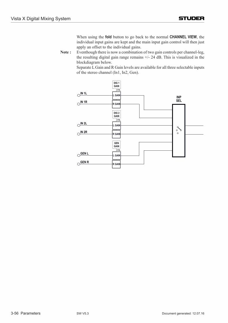
Vista X Digital Mixing System
3-56 Parameters Document generated: 12.07.16SW V5.3
When using the fold button to go back to the normal CHANNEL VIEW, the individual input gains are kept and the main input gain control will then just apply an offset to the individual gains.
note : Eventhough there is now a combination of two gain controls per channel-leg, the resulting digital gain range remains +/- 24 dB. This is visualized in the blockdiagram below.
Separate L Gain and R Gain levels are available for all three selectable inputs of the stereo channel (In1, In2, Gen).
INPSEL
IN 1L
IN 1R
L GAIN
R GAIN
IN 2L
IN 2R
L GAIN
R GAIN
GEN L
GEN R
L GAIN
R GAIN
DIG 1GAIN
CTRL
DIG 2GAIN
CTRL
GENGAIN
CTRL
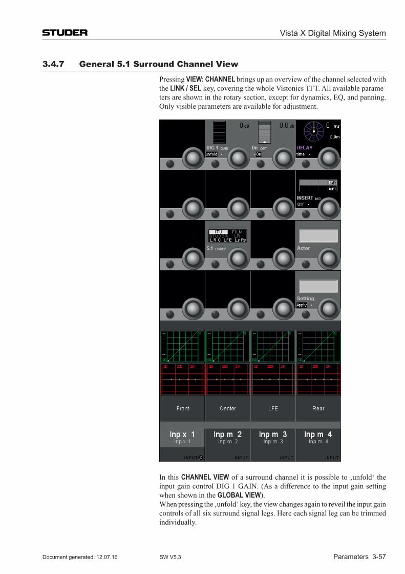
Vista X Digital Mixing System
Parameters 3-57Document generated: 12.07.16 SW V5.3
3.4.7 General 5.1 surround Channel View
Pressing VIEW: CHANNEL brings up an overview of the channel selected with the LINK / SEL key, covering the whole Vistonics TFT. All available parame-ters are shown in the rotary section, except for dynamics, EQ, and panning. Only visible parameters are available for adjustment.
In this CHANNEL VIEW of a surround channel it is possible to ‚unfold‘ the input gain control DIG 1 GAIN. (As a difference to the input gain setting when shown in the GLOBAL VIEW).
When pressing the ‚unfold‘ key, the view changes again to reveil the input gain controls of all six surround signal legs. Here each signal leg can be trimmed individually.
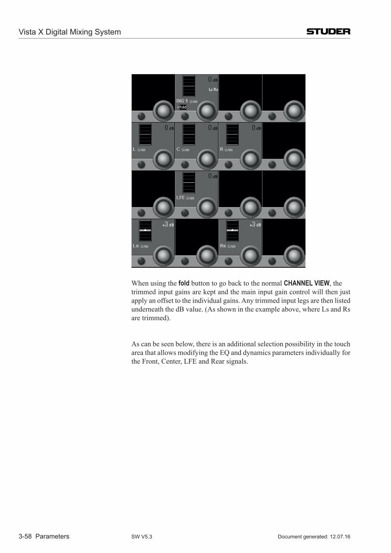
Vista X Digital Mixing System
3-58 Parameters Document generated: 12.07.16SW V5.3
When using the fold button to go back to the normal CHANNEL VIEW, the trimmed input gains are kept and the main input gain control will then just
apply an offset to the individual gains. Any trimmed input legs are then listed underneath the dB value. (As shown in the example above, where Ls and Rs are trimmed).
As can be seen below, there is an additional selection possibility in the touch area that allows modifying the EQ and dynamics parameters individually for the Front, Center, LFE and Rear signals.
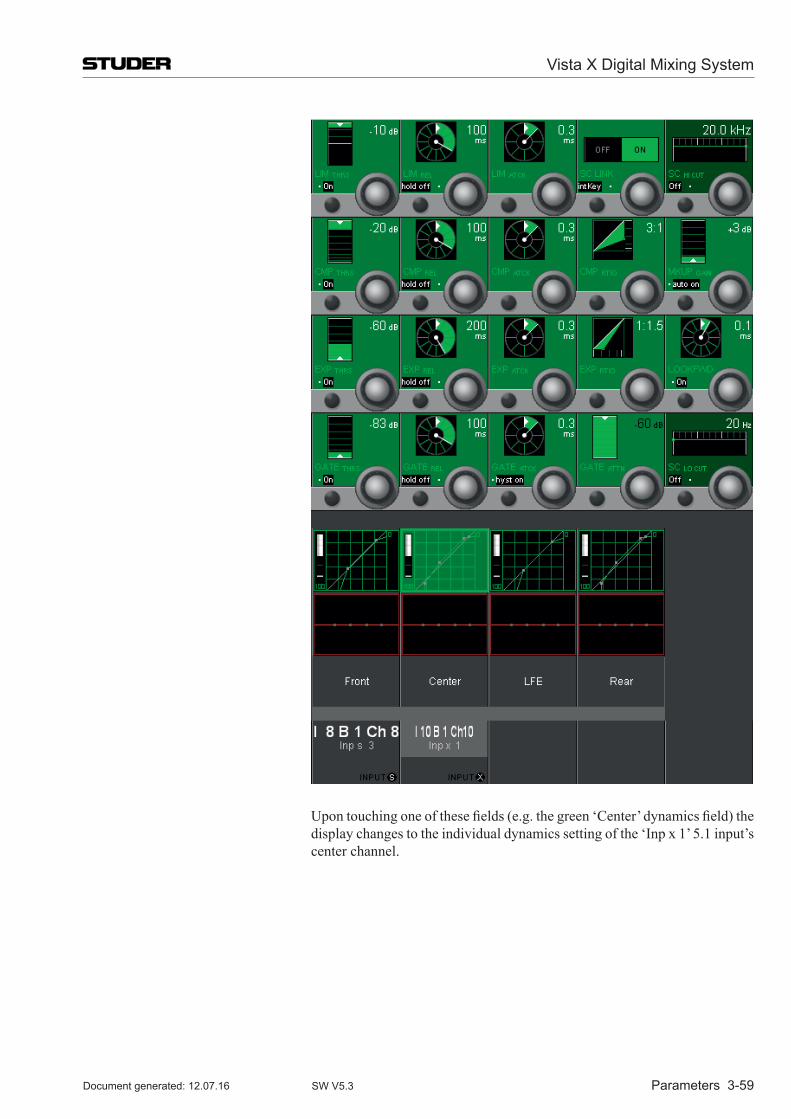
Vista X Digital Mixing System
Parameters 3-59Document generated: 12.07.16 SW V5.3
Upon touching one of these fields (e.g. the green ‘Center’ dynamics field) the display changes to the individual dynamics setting of the ‘Inp x 1’ 5.1 input’s center channel.
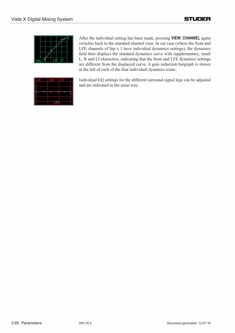
Vista X Digital Mixing System
3-60 Parameters Document generated: 12.07.16SW V5.3
After the individual setting has been made, pressing VIEW: CHANNEL again switches back to the standard channel view. In our case (where the front and LFE channels of Inp x 1 have individual dynamics settings), the dynamics field then displays the standard dynamics curve with supplementary, small L, R and Lf characters, indicating that the front and LFE dynamics settings are different from the displayed curve. A gain reduction bargraph is shown at the left of each of the four individual dynamics icons.
Individual EQ settings for the different surround signal legs can be adjusted and are indicated in the same way.
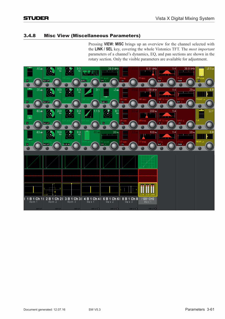
Vista X Digital Mixing System
Parameters 3-61Document generated: 12.07.16 SW V5.3
3.4.8 misc View (miscellaneous Parameters)
Pressing VIEW: MISC brings up an overview for the channel selected with the LINK / SEL key, covering the whole Vistonics TFT. The most important parameters of a channel’s dynamics, EQ, and pan sections are shown in the rotary section. Only the visible parameters are available for adjustment.
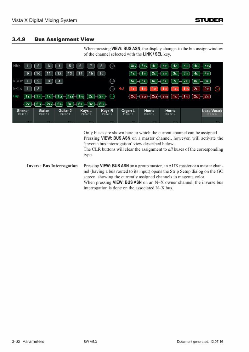
Vista X Digital Mixing System
3-62 Parameters Document generated: 12.07.16SW V5.3
3.4.9 Bus Assignment View
When pressing VIEW: BUS ASN, the display changes to the bus assign window of the channel selected with the LINK / SEL key.
Only buses are shown here to which the current channel can be assigned. Pressing VIEW: BUS ASN on a master channel, however, will activate the
‘inverse bus interrogation’ view described below. The CLR buttons will clear the assignment to all buses of the corresponding
type.
Inverse Bus Interrogation Pressing VIEW: BUS ASN on a group master, an AUX master or a master chan-nel (having a bus routed to its input) opens the Strip Setup dialog on the GC screen, showing the currently assigned channels in magenta color.
When pressing VIEW: BUS ASN on an N–X owner channel, the inverse bus interrogation is done on the associated N–X bus.
Vista X Digital Mixing System
GC Operation 4-1Document generated: 12.07.16 SW V5.3
CHAPTER 4
4 Graphical Controller Operation ......................................................................................................................54.1 Introduction ........................................................................................................................................................5
4.2 The GC Screen ....................................................................................................................................................74.2.1 The View Button ................................................................................................................................................... 84.2.2 The Quick Access Bar ........................................................................................................................................... 84.2.3 The Ribbon Style Selector .................................................................................................................................... 9
4.3 Graphical Controller Basics ..............................................................................................................................104.3.1 Sources and Targets ............................................................................................................................................. 104.3.2 The Session Configuration .................................................................................................................................. 104.3.3 Labels .................................................................................................................................................................. 11
4.4 First Level: Main GC Pages .............................................................................................................................134.4.1 Working with Multiple Pages .............................................................................................................................. 144.4.2 The General Patch ............................................................................................................................................... 14
4.4.2.1 General Patch Navigation ........................................................................................................................................164.4.2.1.1 Navigating the Sources/Targets List ............................................................................................................................164.4.2.1.2 Other Navigation Methods ...........................................................................................................................................174.4.2.1.3 What Patch Groups are There? ....................................................................................................................................18
4.4.2.2 How to Deal with the Analog Interfacing? ..............................................................................................................194.4.2.3 Digital Input/Output Subclasses ...............................................................................................................................194.4.2.4 Making and Clearing the Cross-Points ....................................................................................................................204.4.2.5 Editing the User Labels in the General Patch ..........................................................................................................23
4.4.2.5.1 Sorting Options ............................................................................................................................................................244.4.2.5.2 View the Different Label Types ...................................................................................................................................24
4.4.2.6 Working with Labels ................................................................................................................................................254.4.2.6.1 Automatic Label Propagation ......................................................................................................................................26
4.4.2.7 What are Device Labels? .........................................................................................................................................274.4.2.8 How to Activate the Device Label Functionality .....................................................................................................284.4.2.9 Where are the Device Labels Saved? .......................................................................................................................284.4.2.10 How to Create or Overwrite a Device Label ............................................................................................................284.4.2.11 How to Edit an Existing Device Label .....................................................................................................................284.4.2.12 Background Information ..........................................................................................................................................284.4.2.13 Automatic Generation of Intelligent Fixed Labels...................................................................................................29
4.4.3 Channel Patch...................................................................................................................................................... 314.4.3.1 Using the Channel Patch for Patching Audio ...........................................................................................................324.4.3.2 Setting the Order of DSP Processing Blocks ...........................................................................................................334.4.3.3 On-screen Toggles for Input Selector and Dynamics Key Selector .........................................................................334.4.3.4 Editing the Channel User Labels .............................................................................................................................334.4.3.5 Set the Metering and Direct Out Source Point .........................................................................................................344.4.3.6 Switch off the Label Inheritance ..............................................................................................................................344.4.3.7 Setup & Activate the Dynamics Sidechain Link ......................................................................................................354.4.3.8 Fader Ramp Control (‘Audio Follows Video’) ........................................................................................................37
Vista X Digital Mixing System
4-2 GC Operation Document generated: 12.07.16SW V5.3
4.4.4 Snapshot Page ..................................................................................................................................................... 394.4.4.1 Snapshots .................................................................................................................................................................404.4.4.2 Multiple Snapshots ...................................................................................................................................................434.4.4.3 Snapshot Crossfading ...............................................................................................................................................454.4.4.4 Additional Snapshot Functionality ..........................................................................................................................464.4.4.5 Partial Snapshots .....................................................................................................................................................474.4.4.6 Typical Applications .................................................................................................................................................494.4.4.7 Snapshot Filtering (Static Automation) ....................................................................................................................504.4.4.8 Presets ......................................................................................................................................................................524.4.4.9 Default Settings ........................................................................................................................................................534.4.4.10 Files and Backup ......................................................................................................................................................534.4.4.11 Recall Confirm .........................................................................................................................................................544.4.4.12 Option: Snapshot Automation ..................................................................................................................................54
4.4.5 Cue List / Theatre Cue List ................................................................................................................................. 554.4.5.1 ‘Standard’ Cue List ..................................................................................................................................................554.4.5.2 Theatre Cue List .......................................................................................................................................................58
4.4.5.2.1 Cross-Fading Between Cues ........................................................................................................................................594.4.5.2.2 Organizing Events ........................................................................................................................................................604.4.5.2.3 Updating Snapshots ......................................................................................................................................................604.4.5.2.4 BlackOut ......................................................................................................................................................................604.4.5.2.5 Arm CueList .................................................................................................................................................................604.4.5.2.6 XFade Active ................................................................................................................................................................614.4.5.2.7 Preview .........................................................................................................................................................................614.4.5.2.8 MIDI Show Control Device .........................................................................................................................................614.4.5.2.9 MIDI Port Deactivation................................................................................................................................................614.4.5.2.10 Event Types ..................................................................................................................................................................624.4.5.2.11 VCA / Channel Mute Mode .........................................................................................................................................694.4.5.2.12 Isolate Labels and VCA Assignment ............................................................................................................................694.4.5.2.13 Mute Groups.................................................................................................................................................................704.4.5.2.14 Hard Mute ....................................................................................................................................................................704.4.5.2.15 Cue List Options Menu ................................................................................................................................................72
4.4.5.3 Theatre Workflow Tutorial .......................................................................................................................................734.4.5.3.1 Console Setup ..............................................................................................................................................................744.4.5.3.2 Building Cues ...............................................................................................................................................................754.4.5.3.3 Rehearsal Phase ............................................................................................................................................................784.4.5.3.4 Shows ...........................................................................................................................................................................81
4.4.6 Strip Setup ........................................................................................................................................................... 844.4.6.1 How to Use the Strip Setup ......................................................................................................................................86
4.4.6.1.1 Assigning a Single DSP Channel to a Single Channel Strip ........................................................................................864.4.6.1.2 Assigning Multiple Channels in one Single Action .....................................................................................................864.4.6.1.3 Moving Already Assigned DSP Channels to Other Channel Strips .............................................................................874.4.6.1.4 Useful Information .......................................................................................................................................................884.4.6.1.5 Labels in Strip Setup ....................................................................................................................................................884.4.6.1.6 Metering .......................................................................................................................................................................894.4.6.1.7 FaderGlow ....................................................................................................................................................................91
4.4.7 Clipboard Libraries ............................................................................................................................................. 924.4.7.1 Clipboard Library Window ......................................................................................................................................934.4.7.2 Paste into Clipboard Library ....................................................................................................................................934.4.7.3 Copy from Clipboard Library ..................................................................................................................................934.4.7.4 Rename/Delete a Clipboard Library File .................................................................................................................944.4.7.5 Clear the Display ......................................................................................................................................................944.4.7.6 Update a Clipboard File ...........................................................................................................................................944.4.7.7 Storage Format .........................................................................................................................................................944.4.7.8 Import a Clipboard File from Another Library ........................................................................................................954.4.7.9 Where are Clipboard Libraries Saved? ....................................................................................................................95
Vista X Digital Mixing System
GC Operation 4-3Document generated: 12.07.16 SW V5.3
4.5 Second Level: The Application Menu ..............................................................................................................964.5.1 Titles and Projects .............................................................................................................................................. 964.5.2 Save ................................................................................................................................................................... 1014.5.3 Make/Restore Backup ....................................................................................................................................... 1014.5.4 Import ................................................................................................................................................................ 1024.5.5 Export ................................................................................................................................................................ 1024.5.6 Load DSP Configuration ................................................................................................................................... 1034.5.7 Surveyor ............................................................................................................................................................ 1044.5.8 Dynamic-Mode ................................................................................................................................................. 1044.5.9 Log In (as System Administrator) ..................................................................................................................... 1044.5.10 About ................................................................................................................................................................. 1044.5.11 Exit Vista Application ....................................................................................................................................... 105
4.6 Third Level: Tools and Settings Ribbon Tabs.................................................................................................1064.6.1 The Tools Ribbon Tab ....................................................................................................................................... 106
4.6.1.1 General ...................................................................................................................................................................1064.6.1.1.1 Clipboard ....................................................................................................................................................................1064.6.1.1.2 Follow Solo ................................................................................................................................................................1064.6.1.1.3 Offline Conference .....................................................................................................................................................1064.6.1.1.4 Show Virtual ...............................................................................................................................................................1094.6.1.1.5 Machine Control.........................................................................................................................................................109
4.6.1.2 Setups .....................................................................................................................................................................1104.6.1.2.1 FX Engine ..................................................................................................................................................................1104.6.1.2.2 Meter/Generator .........................................................................................................................................................1104.6.1.2.3 Shared Delay ..............................................................................................................................................................1114.6.1.2.4 VSP Properties ...........................................................................................................................................................1124.6.1.2.5 TC-Reader/Generator .................................................................................................................................................1124.6.1.2.6 N-1 Assignment ..........................................................................................................................................................112
4.6.1.3 Signaling ................................................................................................................................................................1154.6.1.3.1 Load Signaling Configuration ....................................................................................................................................1204.6.1.3.2 Save Signaling Configuration As ...............................................................................................................................121
4.6.1.4 CGM .......................................................................................................................................................................1214.6.1.4.1 Control Group Basics .................................................................................................................................................1214.6.1.4.2 Control Group Setup ..................................................................................................................................................1224.6.1.4.3 Control Group Filter ...................................................................................................................................................1234.6.1.4.4 Control Group Assignment ........................................................................................................................................1244.6.1.4.5 Hierarchical CGMs ....................................................................................................................................................125
4.6.2 The Settings Ribbon Tab ................................................................................................................................... 1264.6.2.1 System ....................................................................................................................................................................126
4.6.2.1.1 Vista Settings ..............................................................................................................................................................1264.6.2.1.2 Downmix Settings ......................................................................................................................................................1294.6.2.1.3 Sampling Rate ............................................................................................................................................................1294.6.2.1.4 EQ/Dyn View .............................................................................................................................................................1304.6.2.1.5 VCA Style Control Groups (‘Motors Off’) ................................................................................................................131
4.6.2.2 Preferences .............................................................................................................................................................1334.6.2.2.1 Load............................................................................................................................................................................1334.6.2.2.2 Save ............................................................................................................................................................................133
Vista X Digital Mixing System
4-4 GC Operation Document generated: 12.07.16SW V5.3
4.7 Fourth Level: SysAdmin functions .................................................................................................................1344.7.1 Tools: Control Group Assign ............................................................................................................................ 1354.7.2 Settings: Show VMC Tree ................................................................................................................................ 1354.7.3 Settings: FX HiQnet Audio ............................................................................................................................... 1354.7.4 Settings: Ember Control .................................................................................................................................... 1354.7.5 Settings: Reduced Function Set ........................................................................................................................ 1374.7.6 Settings: General Patch Edit.............................................................................................................................. 1374.7.7 Settings: Edit Monitoring Files ......................................................................................................................... 1414.7.8 Settings: Enable Monitoring Setup-Mode ......................................................................................................... 1434.7.9 Settings: Reinitialize Monitoring ...................................................................................................................... 1434.7.10 Settings : Device Labels (Save and Apply) ....................................................................................................... 1444.7.11 Settings: Use DeviceLabels............................................................................................................................... 1444.7.12 Settings: Overwrite Channel User Label........................................................................................................... 1444.7.13 Settings: Configure ExernalRouter I/O ............................................................................................................. 1444.7.14 Settings: Connection Setup ............................................................................................................................... 1444.7.15 Settings: Regenerate Intelligent Fix Labels ...................................................................................................... 1444.7.16 General Patch: Enable Pro-Bel Setup ............................................................................................................... 1454.7.17 General Patch: Pro-Bel Setup............................................................................................................................ 145
4.7.17.1 3rd-Party Control of Console Patch (Native Pro-Bel P-02/08 Support) .................................................................1454.7.17.1.1 Pro-Bel P-08 support ..................................................................................................................................................1484.7.17.1.2 Exclude Certain Patch Targets from Being Changed by Snapshots ..........................................................................1494.7.17.1.3 Label Import from 3rd-Party Systems .........................................................................................................................1494.7.17.1.4 Support of External Monitoring Source Selector Panels ...........................................................................................151
4.7.18 Snapshot: Output Snapshot Isolation ................................................................................................................ 152
4.8 Fifth Level: The Surveyor ..............................................................................................................................153
Vista X Digital Mixing System
GC Operation 4-5Document generated: 12.07.16 SW V5.3
4 GRAPHiCAl ConTRollER oPERATion
4.1 introduction The graphical controller (GC) is an essential part of the Vista system’s opera-
tion, because it enables the user to utilize all of its enhanced functions, such as the snapshots, book-keeping and much more. It is also the place where the operating software is started and shut down – becoming, in fact, the console’s main operations center.
All the operating software – consisting of a large number of individual files needed for proper operation of the console – is saved on the Control PC’s hard disk. Even if there are hundreds of configuration, snapshot, and related files saved here from previous Vista sessions, the user basically needs to start only one application program: D950SYSTEM.EXE.
The D950SYSTEM.EXE is represented by the Studer Vista shortcut icon on the GC monitor screen:
Depending on the desired operating mode (static, i.e. with snapshot automa-tion, or dynamic, i.e. with the AutoTouch+ dynamic automation), use the appropriate icon.
If Virtual Vista (see chapter 2.11) should be used for controlling the core in parallel with the console, it always starts in the same static or dynamic mode in which the console was started. In dynamic mode, however, opera-tion is much more convenient with the touch-sensitive desk controls. For the dynamic mode, Virtual Vista only has a limited range of applications, such as entering/editing labels.
The Vista software runs under Windows. All files used by Vista and all files produced by the user (snapshots, mixes, etc.) are fully compatible with the Windows standard. This means that they can be copied to other compatible media, using the Make Backup utility and standard Windows tools and pro-cedures. Long file names (more than eight characters) are supported.
One of the advantages of using standard Windows techniques is that the majority of users will already be familiar with operating a PC-based system. Because all screen and trackball procedures are derived from the Windows operating systems, please refer to the appropriate manuals if you are not familiar with using them.
Operation of the graphical controller is also fully Windows-compatible. Text strings, files, or even pictures can be copied from one location to the other using the Windows clipboard principle and keyboard shortcuts: Ctrl + c will copy to, and Ctrl + v will paste from the clipboard. This technique can be used, for example, to enter repetitive labels into the user labels, or for copying mixes from one title to another.
Vista X Digital Mixing System
4-6 GC Operation Document generated: 12.07.16SW V5.3
Full use is made of the Windows-standard, context-sensitive menus that can be accessed by the right trackball button. The same is valid for conventional double-click techniques. The Tab, PgUp/Dn, and arrow keys behave according to standard Windows operation.
The graphical controller’s screen colors, screen sizes, individual window positions and sizes, certain font sizes etc., are also part of the Windows Screen Properties, and can be adjusted there.
Because the graphical controller’s user interface can be configured to suit the individual needs of specific users, all the graphics shown in this operating instructions manual may differ slightly from what you will see on the GC display of your Vista digital console.
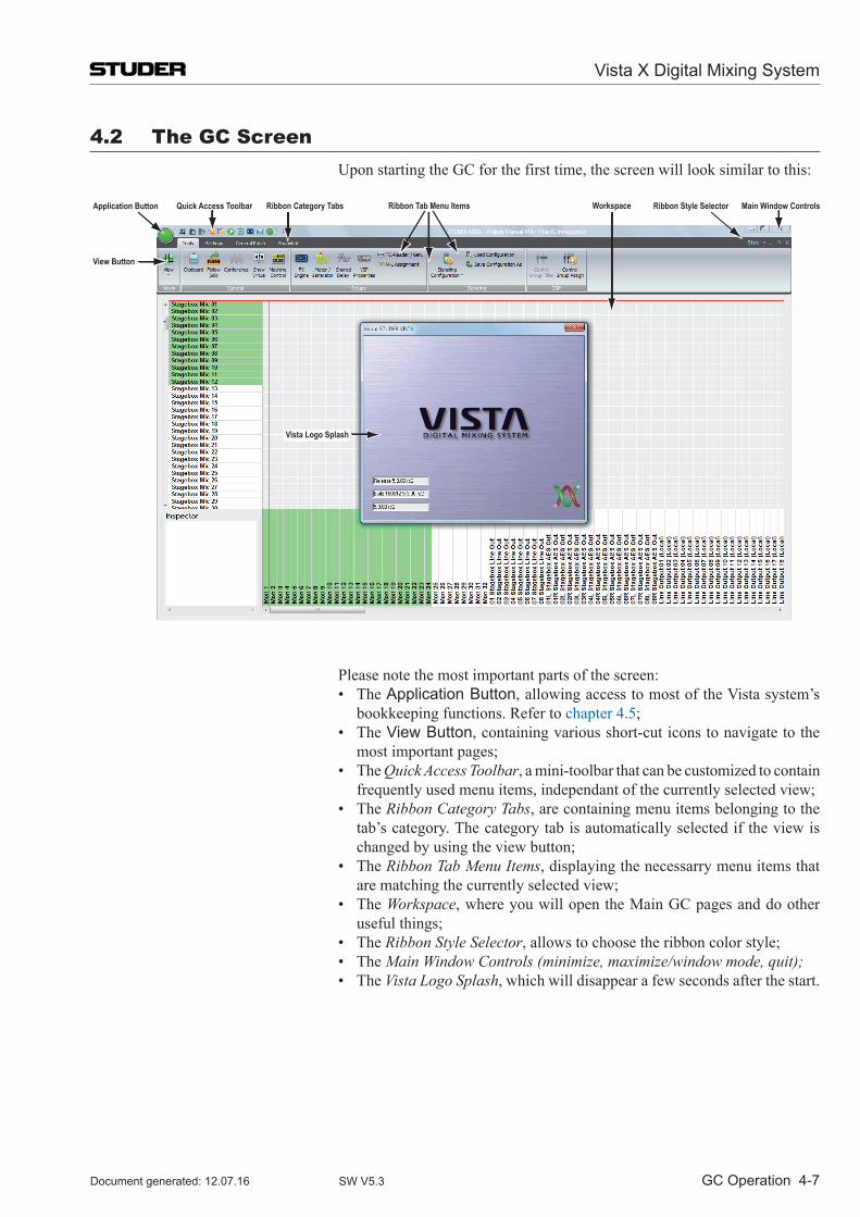
Vista X Digital Mixing System
GC Operation 4-7Document generated: 12.07.16 SW V5.3
4.2 The GC Screen Upon starting the GC for the first time, the screen will look similar to this:
Ribbon Style SelectorWorkspaceRibbon Tab Menu ItemsRibbon Category TabsQuick Access ToolbarApplication Button
View Button
Main Window Controls
Vista Logo Splash
Please note the most important parts of the screen: • TheApplication Button, allowing access to most of the Vista system’s
bookkeeping functions. Refer to chapter 4.5; • TheView Button, containing various short-cut icons to navigate to the
most important pages; • TheQuick Access Toolbar, a mini-toolbar that can be customized to contain
frequently used menu items, independant of the currently selected view; • TheRibbon Category Tabs, are containing menu items belonging to the
tab’s category. The category tab is automatically selected if the view is changed by using the view button;
• TheRibbon Tab Menu Items, displaying the necessarry menu items that are matching the currently selected view;
• TheWorkspace, where you will open the Main GC pages and do other useful things;
• TheRibbon Style Selector, allows to choose the ribbon color style; • TheMain Window Controls (minimize, maximize/window mode, quit); • TheVista Logo Splash, which will disappear a few seconds after the start.
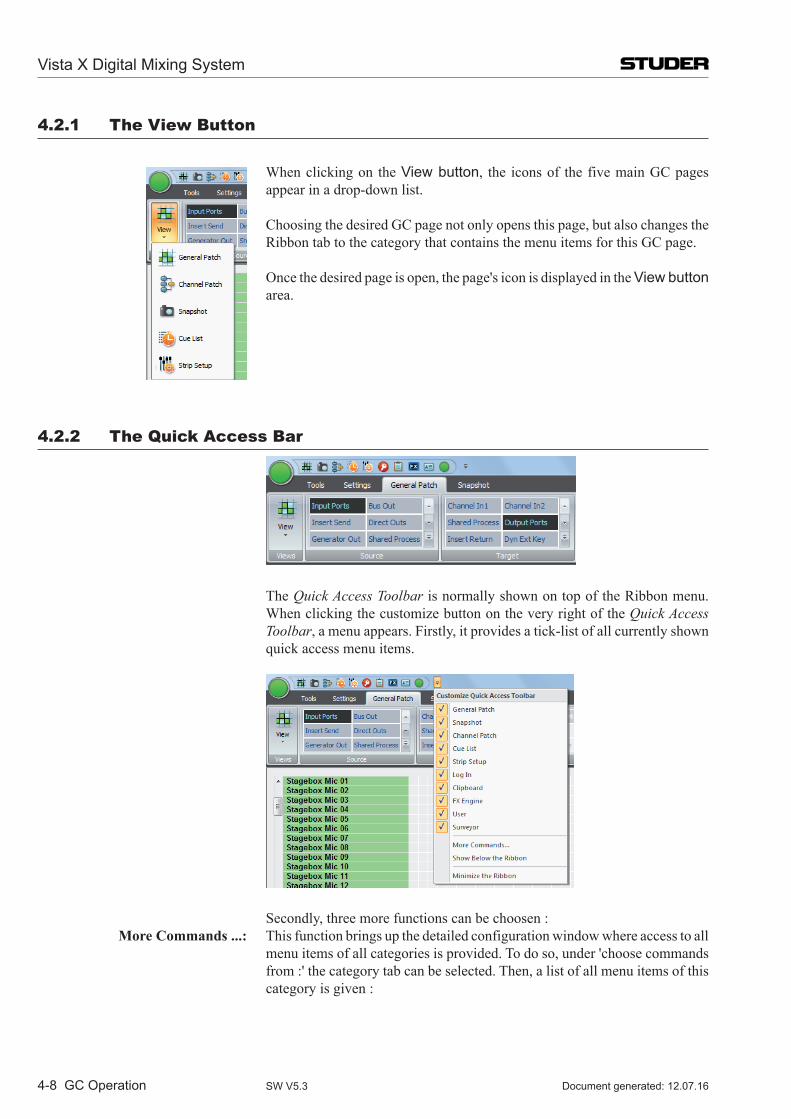
Vista X Digital Mixing System
4-8 GC Operation Document generated: 12.07.16SW V5.3
4.2.1 The View Button
When clicking on the View button, the icons of the five main GC pages appear in a drop-down list.
Choosing the desired GC page not only opens this page, but also changes the Ribbon tab to the category that contains the menu items for this GC page.
Once the desired page is open, the page's icon is displayed in the View button area.
4.2.2 The Quick Access Bar
The Quick Access Toolbar is normally shown on top of the Ribbon menu. When clicking the customize button on the very right of the Quick Access Toolbar, a menu appears. Firstly, it provides a tick-list of all currently shown quick access menu items.
Secondly, three more functions can be choosen : More Commands ...: This function brings up the detailed configuration window where access to all
menu items of all categories is provided. To do so, under 'choose commands from :' the category tab can be selected. Then, a list of all menu items of this category is given :
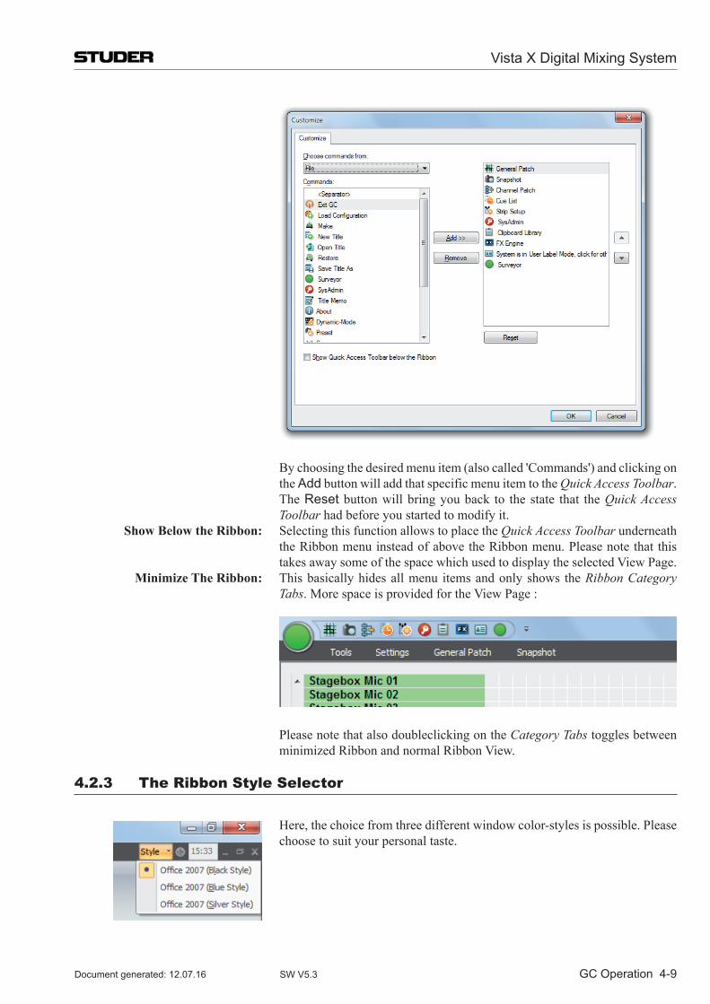
Vista X Digital Mixing System
GC Operation 4-9Document generated: 12.07.16 SW V5.3
By choosing the desired menu item (also called 'Commands') and clicking on the Add button will add that specific menu item to the Quick Access Toolbar.
The Reset button will bring you back to the state that the Quick Access Toolbar had before you started to modify it.
Show Below the Ribbon: Selecting this function allows to place the Quick Access Toolbar underneath the Ribbon menu instead of above the Ribbon menu. Please note that this takes away some of the space which used to display the selected View Page.
Minimize The Ribbon: This basically hides all menu items and only shows the Ribbon Category Tabs. More space is provided for the View Page :
Please note that also doubleclicking on the Category Tabs toggles between minimized Ribbon and normal Ribbon View.
4.2.3 The Ribbon Style Selector
Here, the choice from three different window color-styles is possible. Please choose to suit your personal taste.
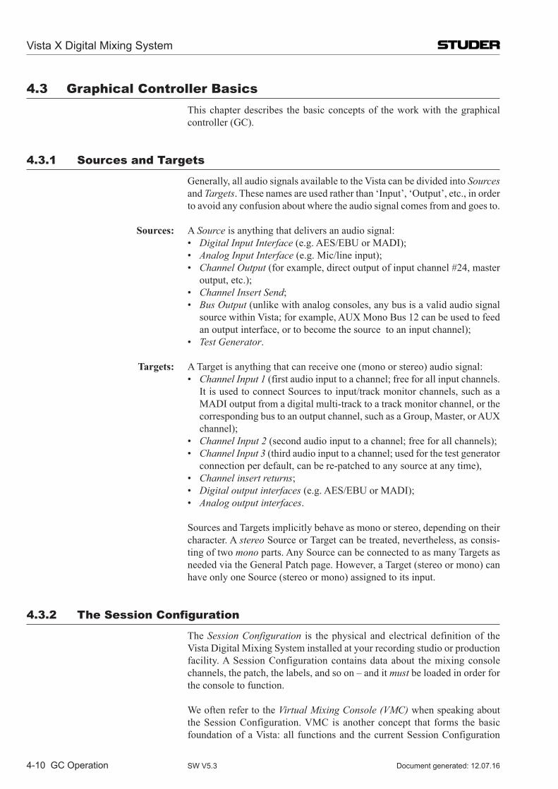
Vista X Digital Mixing System
4-10 GC Operation Document generated: 12.07.16SW V5.3
4.3 Graphical Controller Basics This chapter describes the basic concepts of the work with the graphical
controller (GC).
4.3.1 Sources and Targets
Generally, all audio signals available to the Vista can be divided into Sources and Targets. These names are used rather than ‘Input’, ‘Out put’, etc., in order to avoid any confusion about where the audio signal comes from and goes to.
Sources: A Source is anything that delivers an audio signal: • Digital Input Interface (e.g. AES/EBU or MADI); • Analog Input Interface (e.g. Mic/line input); • Channel Output (for example, direct output of input channel #24, master
output, etc.); • Channel Insert Send; • Bus Output (unlike with analog consoles, any bus is a valid audio signal
source within Vista; for example, AUX Mono Bus 12 can be used to feed an output interface, or to become the source to an input channel);
• Test Generator.
Targets: A Target is anything that can receive one (mono or stereo) audio signal: • Channel Input 1 (first audio input to a channel; free for all input channels.
It is used to connect Sources to input/track monitor channels, such as a MADI output from a digital multi-track to a track monitor channel, or the corresponding bus to an output channel, such as a Group, Master, or AUX channel);
• Channel Input 2 (second audio input to a channel; free for all channels); • Channel Input 3 (third audio input to a channel; used for the test generator
connection per default, can be re-patched to any source at any time), • Channel insert returns; • Digital output interfaces (e.g. AES/EBU or MADI); • Analog output interfaces.
Sources and Targets implicitly behave as mono or stereo, depending on their character. A stereo Source or Target can be treated, nevertheless, as consis-ting of two mono parts. Any Source can be connect ed to as many Targets as needed via the General Patch page. However, a Target (stereo or mono) can have only one Source (stereo or mono) assigned to its input.
4.3.2 The Session Configuration
The Session Configuration is the physical and electrical definition of the Vista Digital Mixing System installed at your recording studio or production facility. A Session Configuration contains data about the mixing console channels, the patch, the labels, and so on – and it must be loaded in order for the console to function.
We often refer to the Virtual Mixing Console (VMC) when speaking about the Session Configuration. VMC is another concept that forms the basic foundation of a Vista: all functions and the current Session Configuration
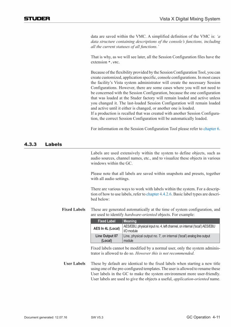
Vista X Digital Mixing System
GC Operation 4-11Document generated: 12.07.16 SW V5.3
data are saved within the VMC. A simplified definition of the VMC is: ‘a data structure containing descriptions of the console’s functions, including all the current statuses of all functions.’
That is why, as we will see later, all the Session Configuration files have the extension *.vmc.
Because of the flexibility provided by the Session Configuration Tool, you can create customized, application specific, console configurations. In most cases the facility’s Vista system administrator will create the necessary Session Configurations. However, there are some cases where you will not need to be concerned with the Session Configuration, because the one configuration that was loaded at the Studer factory will remain loaded and active unless you changed it. The last-loaded Session Configuration will remain loaded and active until it either is changed, or another one is loaded.
If a production is recalled that was created with another Session Configura-tion, the correct Session Configuration will be automatically loaded.
For information on the Session Configuration Tool please refer to chapter 6.
4.3.3 labels
Labels are used extensively within the system to define objects, such as audio sources, channel names, etc., and to visualize these objects in various windows within the GC.
Please note that all labels are saved within snapshots and presets, together with all audio settings.
There are various ways to work with labels within the system. For a descrip-tion of how to use labels, refer to chapter 4.4.2.6. Basic label types are descri-bed below:
Fixed Labels These are generated automatically at the time of system configuration, and are used to identify hardware-oriented objects. For example:
Fixed Label Meaning
AES In 4L (Local) AES/EBU, physical input no. 4, left channel, on internal (‘local’) AES/EBU I/O module
Line Output 07 (Local)
Line, physical output no. 7, on internal (‘local’) analog line output module
Fixed labels cannot be modified by a normal user, only the system adminis-trator is allowed to do so. However this is not recommended.
User Labels These by default are identical to the fixed labels when starting a new title using one of the pre-configured templates. The user is allowed to rename these User labels in the GC to make the system environment more user-friendly. User labels are used to give the objects a useful, application-oriented name.
Vista X Digital Mixing System
4-12 GC Operation Document generated: 12.07.16SW V5.3
For example:Fixed Label User Label Meaning
AES In 4L (Local) DAT 1 DAT Player 1, coming in via AES/EBU, physical input no. 4, left channel, on internal (‘local’) AES/EBU I/O module
Line Output 07 (Local) Foldback 1
Line, physical output no. 7, on internal (‘local’) analog line output module, is the foldback Send 1 to the Studio Floor
Inherited (or Device) Labels Inherited labels are used primarily to identify the Source Signal that is con-nected to the Channel Strip, rather than the user label of the Channel. In this way, as soon as the signal is connected to a channel’s input, the channel strip display inherits the Label from the actual Source.
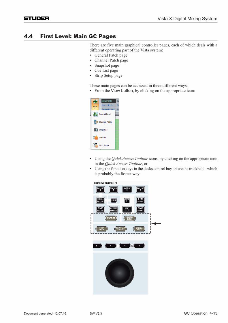
Vista X Digital Mixing System
GC Operation 4-13Document generated: 12.07.16 SW V5.3
4.4 First level: Main GC Pages There are five main graphical controller pages, each of which deals with a
different operating part of the Vista system: • GeneralPatchpage • ChannelPatchpage • Snapshotpage • CueListpage • StripSetuppage
These main pages can be accessed in three different ways: • FromtheView button, by clicking on the appropriate icon:
• UsingtheQuick Access Toolbar icons, by clicking on the appropriate icon in the Quick Access Toolbar, or
• Usingthefunctionkeysinthedeskscontrolbayabovethetrackball–whichis probably the fastest way:
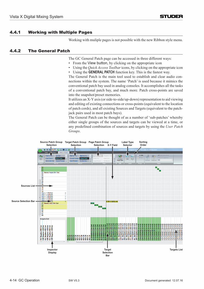
Vista X Digital Mixing System
4-14 GC Operation Document generated: 12.07.16SW V5.3
4.4.1 Working with Multiple Pages
Working with muliple pages is not possible with the new Ribbon style menu.
4.4.2 The General Patch
The GC General Patch page can be accessed in three different ways: • FromtheView button, by clicking on the appropriate icon • UsingtheQuick Access Toolbar icons, by clicking on the appropriate icon • UsingtheGENERAL PATCH function key. This is the fastest way. The General Patch is the main tool used to establish and clear audio con-
nections within the system. The name ‘Patch’ is used because it mimics the conventional patch bay used in analog consoles. It accomplishes all the tasks of a conventional patch bay, and much more. Patch cross-points are saved into the snapshot/preset memories.
It utilizes an X-Y axis (or side-to-side/up-down) representation to aid viewing and editing of existing connections or cross-points (equivalent to the location of patch cords), and all existing Sources and Targets (equivalent to the patch-jack pairs used in most patch bays).
The General Patch can be thought of as a number of ‘sub-patches’ whereby either single groups of the sources and targets can be viewed at a time, or any predefined combination of sources and targets by using the User Patch Groups.
X-Y Field
Sources List
TargetSelection
Bar
InspectorDisplay
Targets List
Target Patch Group Selection
Source Patch Group Selection
Source Selection Bar
Label TypeSelector
Page Patch Group Selection
SortingOrder
Vista X Digital Mixing System
GC Operation 4-15Document generated: 12.07.16 SW V5.3
The General Patch consists of: • ATargetslist(thelowerhorizontal,orxaxis),equivalenttothelowerjack
row in a patch bay • ASourceslist(theleft-handverticaloryaxis),equivalenttotheupper
jack row in a patch bay • TheX-Yfield,wherethecross-pointiconsenableinterrogationandediting
of cross-point connections • TheSource-andTargetPatchGroupselection • ThePagePatchGroupselection(navigatesboth,Source-andTargetlists) • TheSource-andTargetselectionbar,whichallowschoosingacrosspoint • ViewingselectionswhichallowsortingoftheSourcesandTargetsLists
by label type • TheFixed/UserLabeldisplaysfortheselectedSource/Target • TheInspectorDisplay.
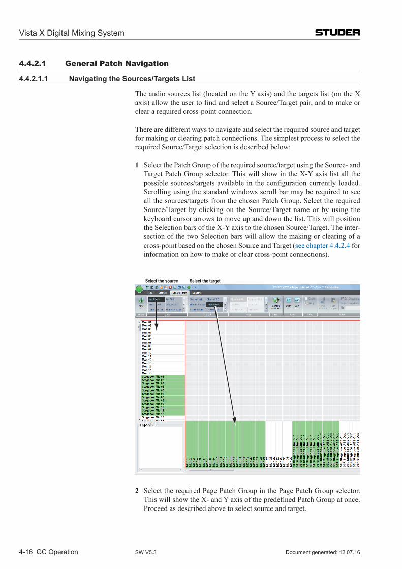
Vista X Digital Mixing System
4-16 GC Operation Document generated: 12.07.16SW V5.3
4.4.2.1 General Patch navigation
4.4.2.1.1 Navigating the Sources/Targets List
The audio sources list (located on the Y axis) and the targets list (on the X axis) allow the user to find and select a Source/Target pair, and to make or clear a required cross-point connection.
There are different ways to navigate and select the required source and target for making or clearing patch connections. The simplest process to select the required Source/Target selection is described below:
1 Select the Patch Group of the required source/target using the Source- and Target Patch Group selector. This will show in the X-Y axis list all the possible sources/targets available in the configuration currently loaded. Scrolling using the standard windows scroll bar may be required to see all the sources/targets from the chosen Patch Group. Select the required Source/Target by clicking on the Source/Target name or by using the keyboard cursor arrows to move up and down the list. This will position the Selection bars of the X-Y axis to the chosen Source/Target. The inter-section of the two Selection bars will allow the making or clearing of a cross-point based on the chosen Source and Target (see chapter 4.4.2.4 for information on how to make or clear cross-point connections).
Select the targetSelect the source
2 Select the required Page Patch Group in the Page Patch Group selector. This will show the X- and Y axis of the predefined Patch Group at once. Proceed as described above to select source and target.
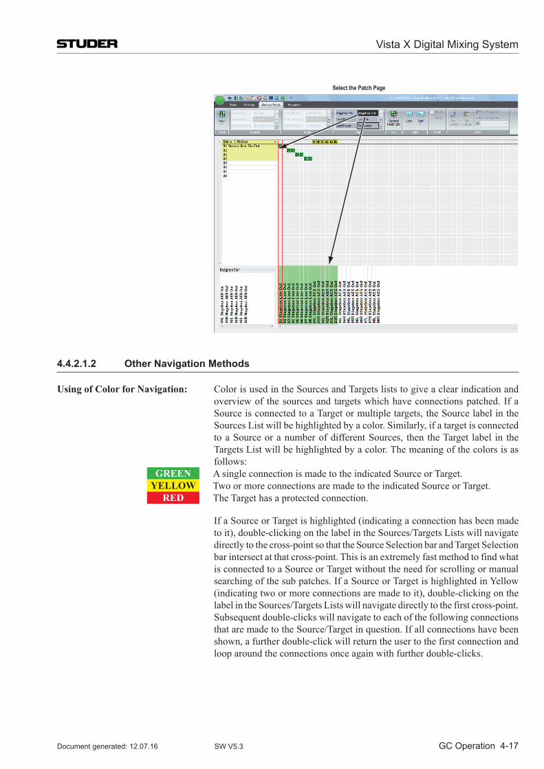
Vista X Digital Mixing System
GC Operation 4-17Document generated: 12.07.16 SW V5.3
Select the Patch Page
4.4.2.1.2 Other Navigation Methods
Using of Color for Navigation: Color is used in the Sources and Targets lists to give a clear indication and overview of the sources and targets which have connections patched. If a Source is connected to a Target or multiple targets, the Source label in the Sources List will be highlighted by a color. Similarly, if a target is connected to a Source or a number of different Sources, then the Target label in the Targets List will be highlighted by a color. The meaning of the colors is as follows:
GREEN A single connection is made to the indicated Source or Target.YELLOW Two or more connections are made to the indicated Source or Target.
RED The Target has a protected connection.
If a Source or Target is highlighted (indicating a connection has been made to it), double-clicking on the label in the Sources/Targets Lists will navigate directly to the cross-point so that the Source Selection bar and Target Selection bar intersect at that cross-point. This is an extremely fast method to find what is connected to a Source or Target without the need for scrolling or manual searching of the sub patches. If a Source or Target is highlighted in Yellow (indicating two or more connections are made to it), double-clicking on the label in the Sources/Targets Lists will navigate directly to the first cross-point. Subsequent double-clicks will navigate to each of the following connections that are made to the Source/Target in question. If all connections have been shown, a further double-click will return the user to the first connection and loop around the connections once again with further double-clicks.
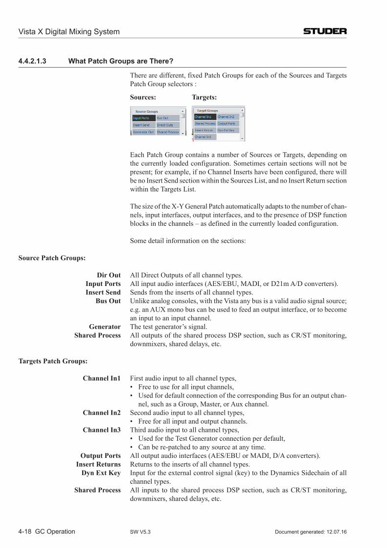
Vista X Digital Mixing System
4-18 GC Operation Document generated: 12.07.16SW V5.3
4.4.2.1.3 What Patch Groups are There?
There are different, fixed Patch Groups for each of the Sources and Targets Patch Group selectors :
Sources: Targets:
Each Patch Group contains a number of Sources or Targets, depending on the currently loaded configuration. Sometimes certain sections will not be present; for example, if no Channel Inserts have been configured, there will be no Insert Send section within the Sources List, and no Insert Return section within the Targets List.
The size of the X-Y General Patch automatically adapts to the number of chan-nels, input interfaces, output interfaces, and to the presence of DSP function blocks in the channels – as defined in the currently loaded configuration.
Some detail information on the sections:
Source Patch Groups:
Dir Out All Direct Outputs of all channel types. Input Ports All input audio interfaces (AES/EBU, MADI, or D21m A/D converters). Insert Send Sends from the inserts of all channel types. Bus Out Unlike analog consoles, with the Vista any bus is a valid audio signal source;
e.g. an AUX mono bus can be used to feed an output interface, or to become an input to an input channel.
Generator The test generator’s signal. Shared Process All outputs of the shared process DSP section, such as CR/ST monitoring,
downmixers, shared delays, etc.
Targets Patch Groups: Channel In1 First audio input to all channel types, • Freetouseforallinputchannels, • UsedfordefaultconnectionofthecorrespondingBusforanoutputchan-
nel, such as a Group, Master, or Aux channel. Channel In2 Second audio input to all channel types, • Freeforallinputandoutputchannels. Channel In3 Third audio input to all channel types, • UsedfortheTestGeneratorconnectionperdefault, • Canbere-patchedtoanysourceatanytime. Output Ports All output audio interfaces (AES/EBU or MADI, D/A converters). Insert Returns Returns to the inserts of all channel types. Dyn Ext Key Input for the external control signal (key) to the Dynamics Sidechain of all
channel types. Shared Process All inputs to the shared process DSP section, such as CR/ST monitoring,
downmixers, shared delays, etc.
Vista X Digital Mixing System
GC Operation 4-19Document generated: 12.07.16 SW V5.3
4.4.2.2 How to Deal with the Analog interfacing?
There is no difference between analog and digital interfacing. The respective D21m I/O card incorporates the A/D or D/A converters and provides digital signals to- and from the system.
4.4.2.3 Digital input/output Subclasses
Subclasses are not used with the new General Patch page aymore.
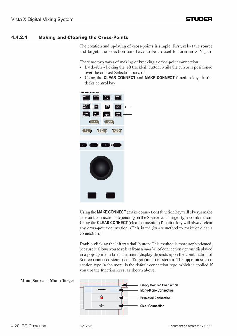
Vista X Digital Mixing System
4-20 GC Operation Document generated: 12.07.16SW V5.3
4.4.2.4 Making and Clearing the Cross-Points
The creation and updating of cross-points is simple. First, select the source and target; the selection bars have to be crossed to form an X-Y pair.
There are two ways of making or breaking a cross-point connection: • Bydouble-clickingthelefttrackballbutton,whilethecursorispositioned
over the crossed Selection bars, or • Using theCLEAR CONNECT and MAKE CONNECT function keys in the
desks control bay:
Using the MAKE CONNECT (make connection) function key will always make a default connection, depending on the Source- and Target-type combin ation. Using the CLEAR CONNECT (clear connection) function key will always clear any cross-point connection. (This is the fastest method to make or clear a connection.)
Double-clicking the left trackball button: This method is more sophisticated, because it allows you to select from a number of connection options displayed in a pop-up menu box. The menu display depends upon the combination of Source (mono or stereo) and Target (mono or stereo). The uppermost con-nection type in the menu is the default connection type, which is applied if you use the function keys, as shown above.
Mono Source – Mono Target Empty Box: No ConnectionMono-Mono Connection
Protected Connection
Clear Connection
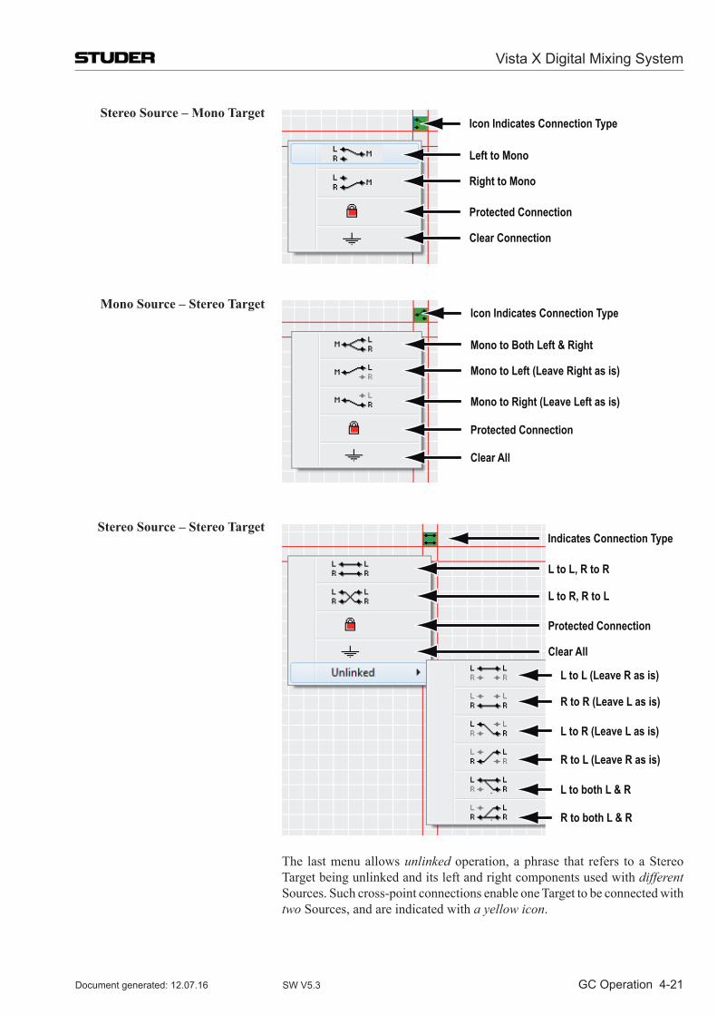
Vista X Digital Mixing System
GC Operation 4-21Document generated: 12.07.16 SW V5.3
Stereo Source – Mono Target Icon Indicates Connection Type
Left to Mono
Right to Mono
Protected Connection
Clear Connection
Mono Source – Stereo Target Icon Indicates Connection Type
Mono to Both Left & Right
Mono to Left (Leave Right as is)
Mono to Right (Leave Left as is)
Protected Connection
Clear All
Stereo Source – Stereo Target Indicates Connection Type
L to L, R to R
L to R, R to L
Protected Connection
L to R (Leave L as is)
L to L (Leave R as is)
R to R (Leave L as is)
R to L (Leave R as is)
L to both L & R
R to both L & R
Clear All
The last menu allows unlinked operation, a phrase that refers to a Stereo Target being unlinked and its left and right components used with different Sources. Such cross-point connections enable one Target to be connected with two Sources, and are indicated with a yellow icon.
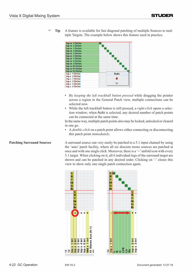
Vista X Digital Mixing System
4-22 GC Operation Document generated: 12.07.16SW V5.3
Tip A feature is available for fast diagonal patching of multiple Sources to mul-tiple Targets. The example below shows this feature used in practice.
• Bykeeping the left trackball button pressed while dragging the pointer across a region in the General Patch view, multiple connections can be selected now.
• Whilethelefttrackballbuttonisstillpressed,aright-click opens a selec-tion window; when Auto is selected, any desired number of patch points can be connected at the same time.
In the same way, multiple patch points also may be locked, unlocked or cleared in one go.
• Adouble-click on a patch point allows either connecting or disconnecting this patch point immediately.
Patching Surround Sources A surround source can very easily be patched to a 5.1 input channel by using the ‘auto’ patch facility, where all six discrete mono sources are patched at once and with one single click. Moreover, there is a ‘+’ unfold icon with every 5.1 target. When clicking on it, all 6 individual legs of the surround target are shown and can be patched in any desired order. Clicking on ‘-’ closes this view to show only one single patch connection again.
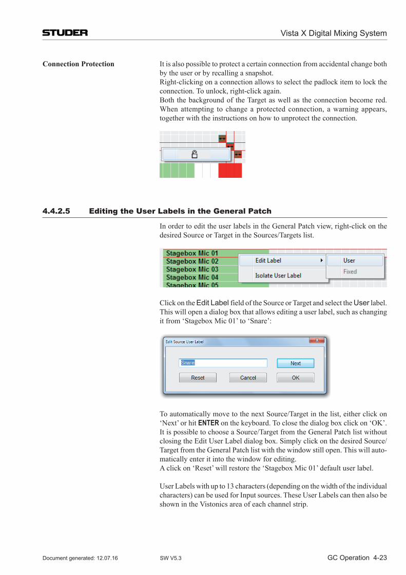
Vista X Digital Mixing System
GC Operation 4-23Document generated: 12.07.16 SW V5.3
Connection Protection It is also possible to protect a certain connection from accidental change both by the user or by recalling a snapshot.
Right-clicking on a connection allows to select the padlock item to lock the connection. To unlock, right-click again.
Both the background of the Target as well as the connection become red. When attempting to change a protected connection, a warning appears, together with the instructions on how to unprotect the connection.
4.4.2.5 Editing the User labels in the General Patch
In order to edit the user labels in the General Patch view, right-click on the desired Source or Target in the Sources/Targets list.
Click on the Edit Label field of the Source or Target and select the User label. This will open a dialog box that allows editing a user label, such as changing it from ‘Stagebox Mic 01’ to ‘Snare’:
To automatically move to the next Source/Target in the list, either click on ‘Next’ or hit ENTER on the keyboard. To close the dialog box click on ‘OK’. It is possible to choose a Source/Target from the General Patch list without closing the Edit User Label dialog box. Simply click on the desired Source/Target from the General Patch list with the window still open. This will auto-matically enter it into the window for editing.
A click on ‘Reset’ will restore the ‘Stagebox Mic 01’ default user label.
User Labels with up to 13 characters (depending on the width of the individual characters) can be used for Input sources. These User Labels can then also be shown in the Vistonics area of each channel strip.
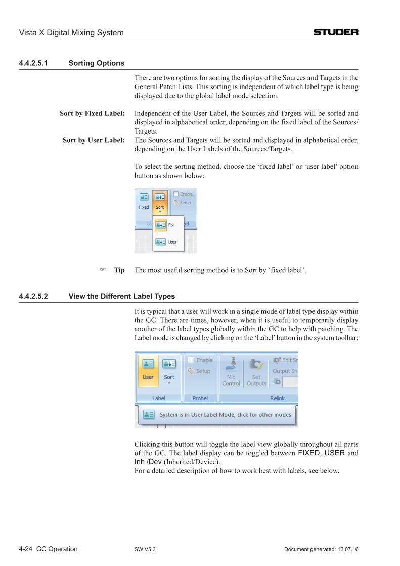
Vista X Digital Mixing System
4-24 GC Operation Document generated: 12.07.16SW V5.3
4.4.2.5.1 Sorting Options
There are two options for sorting the display of the Sources and Targets in the General Patch Lists. This sorting is independent of which label type is being displayed due to the global label mode selection.
Sort by Fixed Label: Independent of the User Label, the Sources and Targets will be sorted and displayed in alphabetical order, depending on the fixed label of the Sources/Targets.
Sort by User Label: The Sources and Targets will be sorted and displayed in alphabetical order, depending on the User Labels of the Sources/Targets.
To select the sorting method, choose the ‘fixed label’ or ‘user label’ option button as shown below:
Tip The most useful sorting method is to Sort by ‘fixed label’.
4.4.2.5.2 View the Different Label Types
It is typical that a user will work in a single mode of label type display within the GC. There are times, however, when it is useful to temporarily display another of the label types globally within the GC to help with patching. The Label mode is changed by clicking on the ‘Label’ button in the system toolbar:
Clicking this button will toggle the label view globally throughout all parts of the GC. The label display can be toggled between FIXED, USER and Inh /Dev (Inherited/Device).
For a detailed description of how to work best with labels, see below.
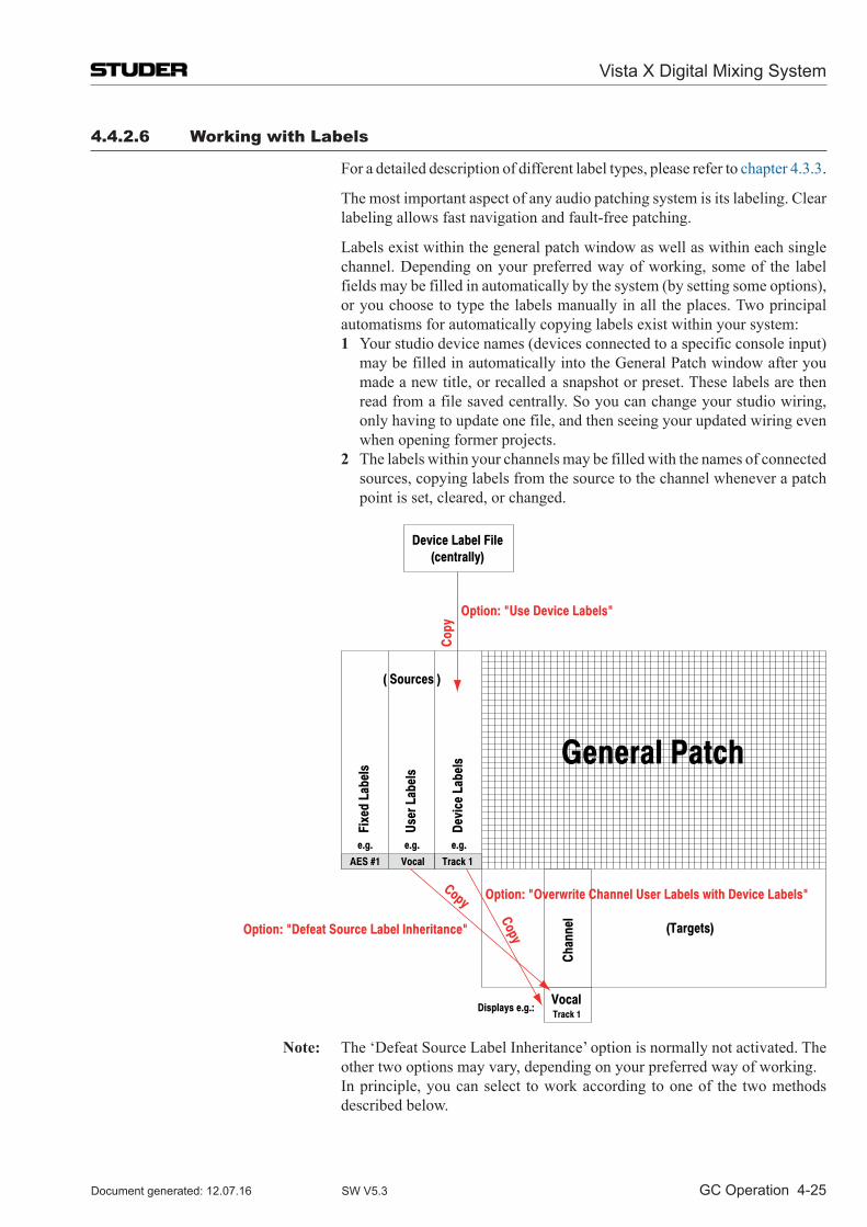
Vista X Digital Mixing System
GC Operation 4-25Document generated: 12.07.16 SW V5.3
4.4.2.6 Working with labels
For a detailed description of different label types, please refer to chapter 4.3.3.
The most important aspect of any audio patching system is its labeling. Clear labeling allows fast navigation and fault-free patching.
Labels exist within the general patch window as well as within each single channel. Depending on your preferred way of working, some of the label fields may be filled in automatically by the system (by setting some options), or you choose to type the labels manually in all the places. Two principal automatisms for automatically copying labels exist within your system:
1 Your studio device names (devices connected to a specific console input) may be filled in automatically into the General Patch window after you made a new title, or recalled a snapshot or preset. These labels are then read from a file saved centrally. So you can change your studio wiring, only having to update one file, and then seeing your updated wiring even when opening former projects.
2 The labels within your channels may be filled with the names of connected sources, copying labels from the source to the channel whenever a patch point is set, cleared, or changed.
User
Lab
els
Devi
ce L
abel
s
Fixe
d La
bels
(Targets)
AES #1 Vocal Track 1
e.g. e.g. e.g.
( Sources )
Chan
nel
VocalTrack 1
Displays e.g.:
Device Label File(centrally)
General Patch
Copy
Copy
Copy
Option: "Use Device Labels"
Option: "Defeat Source Label Inheritance"
Option: "Overwrite Channel User Labels with Device Labels"
Note: The ‘Defeat Source Label Inheritance’ option is normally not activated. The other two options may vary, depending on your preferred way of working.
In principle, you can select to work according to one of the two methods described below.
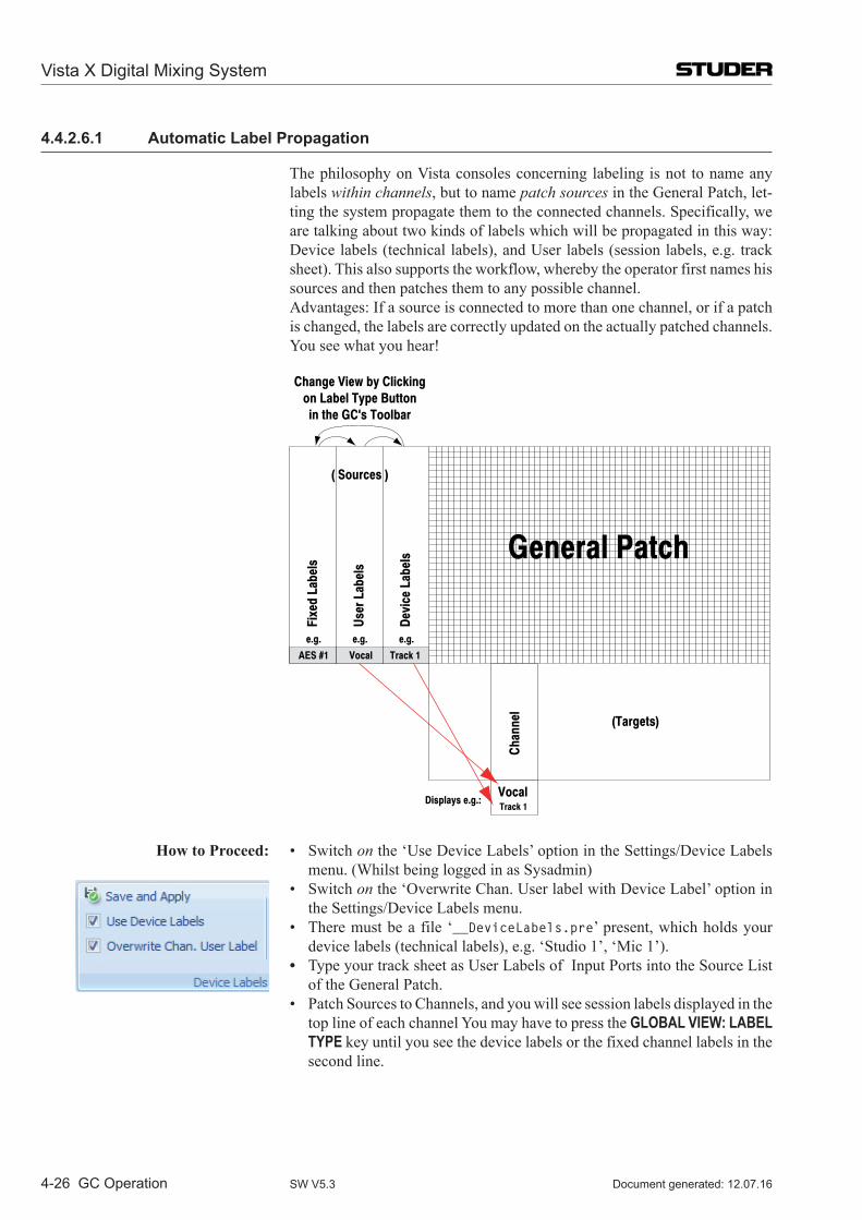
Vista X Digital Mixing System
4-26 GC Operation Document generated: 12.07.16SW V5.3
4.4.2.6.1 Automatic Label Propagation
The philosophy on Vista consoles concerning labeling is not to name any labels within channels, but to name patch sources in the General Patch, let-ting the system propagate them to the connected channels. Specifically, we are talking about two kinds of labels which will be propagated in this way: Device labels (technical labels), and User labels (session labels, e.g. track sheet). This also supports the workflow, whereby the operator first names his sources and then patches them to any possible channel.
Advantages: If a source is connected to more than one channel, or if a patch is changed, the labels are correctly updated on the actually patched channels. You see what you hear!
User
Lab
els
Devi
ce L
abel
s
Fixe
d La
bels
(Targets)
AES #1 Vocal Track 1
e.g. e.g. e.g.
( Sources )
Change View by Clickingon Label Type Buttonin the GC's Toolbar
Chan
nel
VocalTrack 1
Displays e.g.:
General Patch
How to Proceed: • Switchon the ‘Use Device Labels’ option in the Settings/Device Labels menu. (Whilst being logged in as Sysadmin)
• Switchon the ‘Overwrite Chan. User label with Device Label’ option in the Settings/Device Labels menu.
• Theremustbeafile‘__DeviceLabels.pre’ present, which holds your device labels (technical labels), e.g. ‘Studio 1’, ‘Mic 1’).
• Type your track sheet as User Labels of Input Ports into the Source List of the General Patch.
• PatchSourcestoChannels,andyouwillseesessionlabelsdisplayedinthetop line of each channel You may have to press the GLOBAL VIEW: LABEL TYPE key until you see the device labels or the fixed channel labels in the second line.
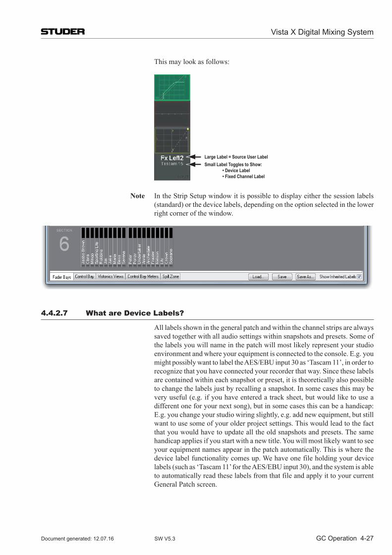
Vista X Digital Mixing System
GC Operation 4-27Document generated: 12.07.16 SW V5.3
This may look as follows:
Large Label = Source User LabelSmall Label Toggles to Show: • Device Label • Fixed Channel Label
Note In the Strip Setup window it is possible to display either the session labels (standard) or the device labels, depending on the option selected in the lower right corner of the window.
4.4.2.7 What are Device labels?
All labels shown in the general patch and within the channel strips are always saved together with all audio settings within snapshots and presets. Some of the labels you will name in the patch will most likely represent your studio environment and where your equipment is connected to the console. E.g. you might possibly want to label the AES/EBU input 30 as ‘Tascam 11’, in order to recognize that you have connected your recorder that way. Since these labels are contained within each snapshot or preset, it is theoretically also possible to change the labels just by recalling a snapshot. In some cases this may be very useful (e.g. if you have entered a track sheet, but would like to use a different one for your next song), but in some cases this can be a handicap: E.g. you change your studio wiring slightly, e.g. add new equipment, but still want to use some of your older project settings. This would lead to the fact that you would have to update all the old snapshots and presets. The same handicap applies if you start with a new title. You will most likely want to see your equipment names appear in the patch automatically. This is where the device label functionality comes up. We have one file holding your device labels (such as ‘Tascam 11’ for the AES/EBU input 30), and the system is able to automatically read these labels from that file and apply it to your current General Patch screen.
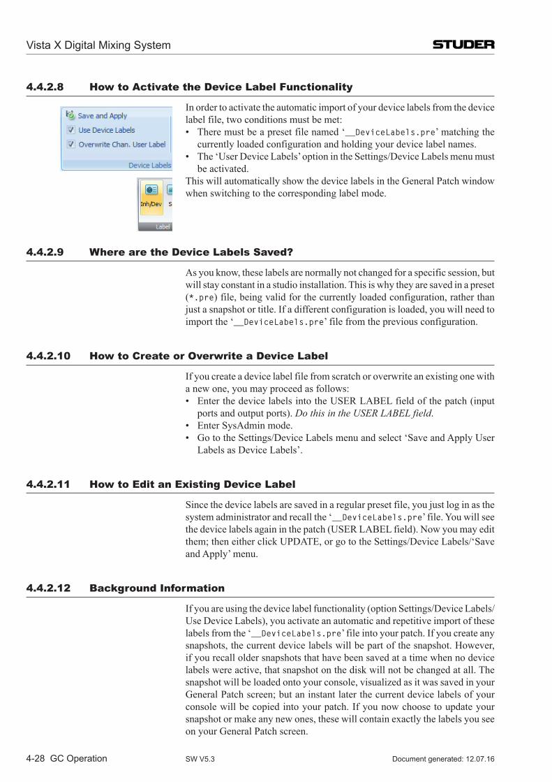
Vista X Digital Mixing System
4-28 GC Operation Document generated: 12.07.16SW V5.3
4.4.2.8 How to Activate the Device label Functionality
In order to activate the automatic import of your device labels from the device label file, two conditions must be met:
• Theremustbeapresetfilenamed‘__DeviceLabels.pre’ matching the currently loaded configuration and holding your device label names.
• The‘UserDeviceLabels’optionintheSettings/DeviceLabelsmenumustbe activated.
This will automatically show the device labels in the General Patch window when switching to the corresponding label mode.
4.4.2.9 Where are the Device labels Saved?
As you know, these labels are normally not changed for a specific session, but will stay constant in a studio installation. This is why they are saved in a preset (*.pre) file, being valid for the currently loaded configuration, rather than just a snapshot or title. If a different configuration is loaded, you will need to import the ‘__DeviceLabels.pre’ file from the previous configuration.
4.4.2.10 How to Create or overwrite a Device label
If you create a device label file from scratch or overwrite an existing one with a new one, you may proceed as follows:
• EnterthedevicelabelsintotheUSERLABELfieldofthepatch(inputports and output ports). Do this in the USER LABEL field.
• EnterSysAdminmode. • GototheSettings/DeviceLabelsmenuandselect‘SaveandApplyUser
Labels as Device Labels’.
4.4.2.11 How to Edit an Existing Device label
Since the device labels are saved in a regular preset file, you just log in as the system administrator and recall the ‘__DeviceLabels.pre’ file. You will see the device labels again in the patch (USER LABEL field). Now you may edit them; then either click UPDATE, or go to the Settings/Device Labels/‘Save and Apply’ menu.
4.4.2.12 Background information
If you are using the device label functionality (option Settings/Device Labels/Use Device Labels), you activate an automatic and repetitive import of these labels from the ‘__DeviceLabels.pre’ file into your patch. If you create any snapshots, the current device labels will be part of the snapshot. However, if you recall older snapshots that have been saved at a time when no device labels were active, that snapshot on the disk will not be changed at all. The snapshot will be loaded onto your console, visualized as it was saved in your General Patch screen; but an instant later the current device labels of your console will be copied into your patch. If you now choose to update your snapshot or make any new ones, these will contain exactly the labels you see on your General Patch screen.
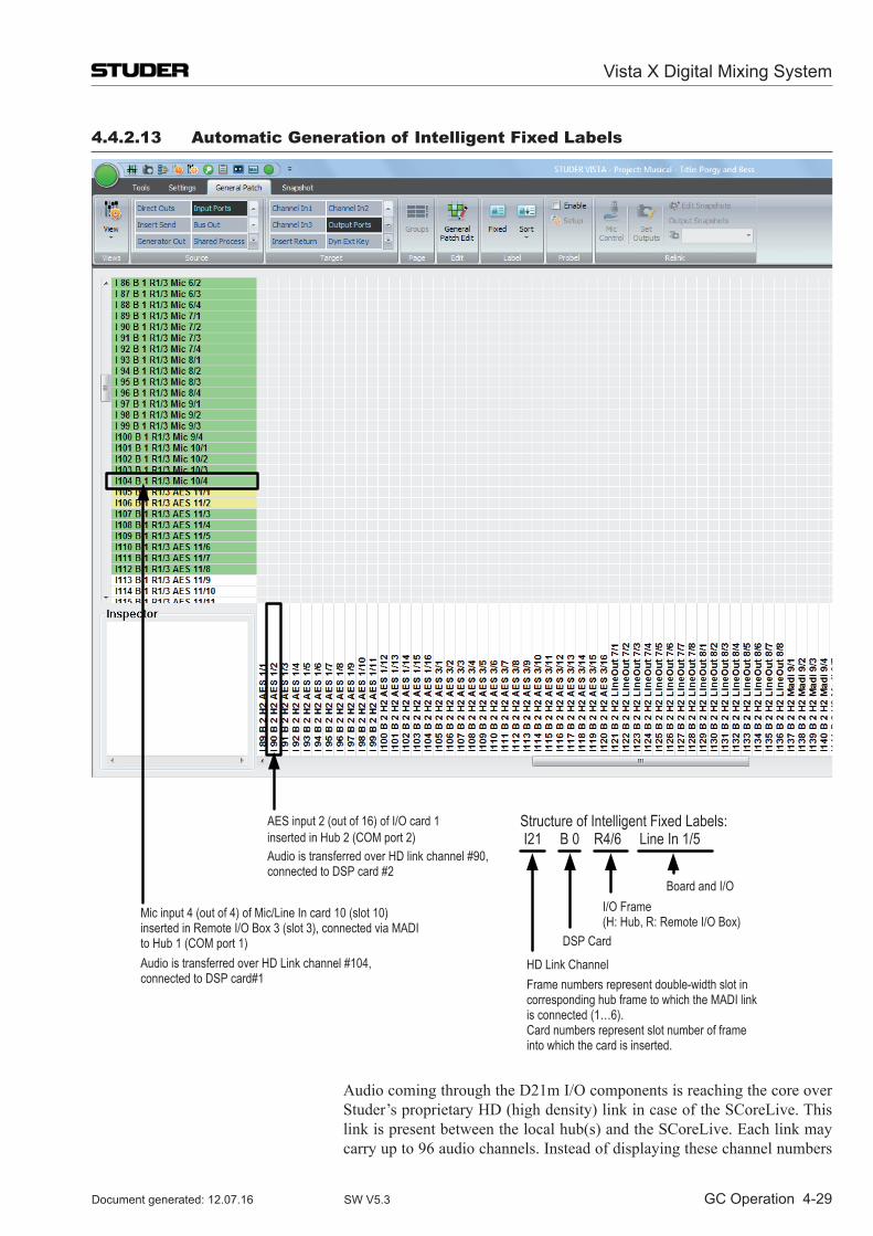
Vista X Digital Mixing System
GC Operation 4-29Document generated: 12.07.16 SW V5.3
4.4.2.13 Automatic Generation of intelligent Fixed labels
AES input 2 (out of 16) of I/O card 1 inserted in Hub 2 (COM port 2) Audio is transferred over HD link channel #90, connected to DSP card #2
Mic input 4 (out of 4) of Mic/Line In card 10 (slot 10) inserted in Remote I/O Box 3 (slot 3), connected via MADI to Hub 1 (COM port 1) Audio is transferred over HD Link channel #104, connected to DSP card#1
Structure of Intelligent Fixed Labels: I21 B 0 R4/6 Line In 1/5
Board and I/OI/O Frame (H: Hub, R: Remote I/O Box)
DSP Card
HD Link Channel Frame numbers represent double-width slot in corresponding hub frame to which the MADI link is connected (1…6). Card numbers represent slot number of frame into which the card is inserted.
Audio coming through the D21m I/O components is reaching the core over Studer’s proprietary HD (high density) link in case of the SCoreLive. This link is present between the local hub(s) and the SCoreLive. Each link may carry up to 96 audio channels. Instead of displaying these channel numbers
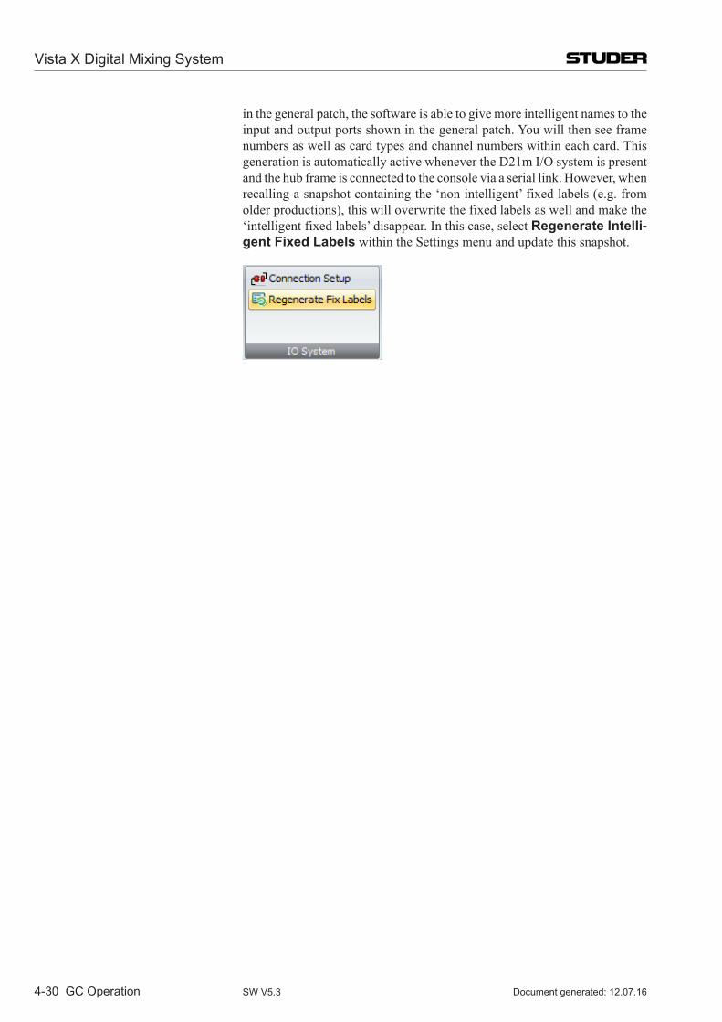
Vista X Digital Mixing System
4-30 GC Operation Document generated: 12.07.16SW V5.3
in the general patch, the software is able to give more intelligent names to the input and output ports shown in the general patch. You will then see frame numbers as well as card types and channel numbers within each card. This generation is automatically active whenever the D21m I/O system is present and the hub frame is connected to the console via a serial link. However, when recalling a snapshot containing the ‘non intelligent’ fixed labels (e.g. from older productions), this will overwrite the fixed labels as well and make the ‘intelligent fixed labels’ disappear. In this case, select Regenerate Intelli-gent Fixed Labels within the Settings menu and update this snapshot.
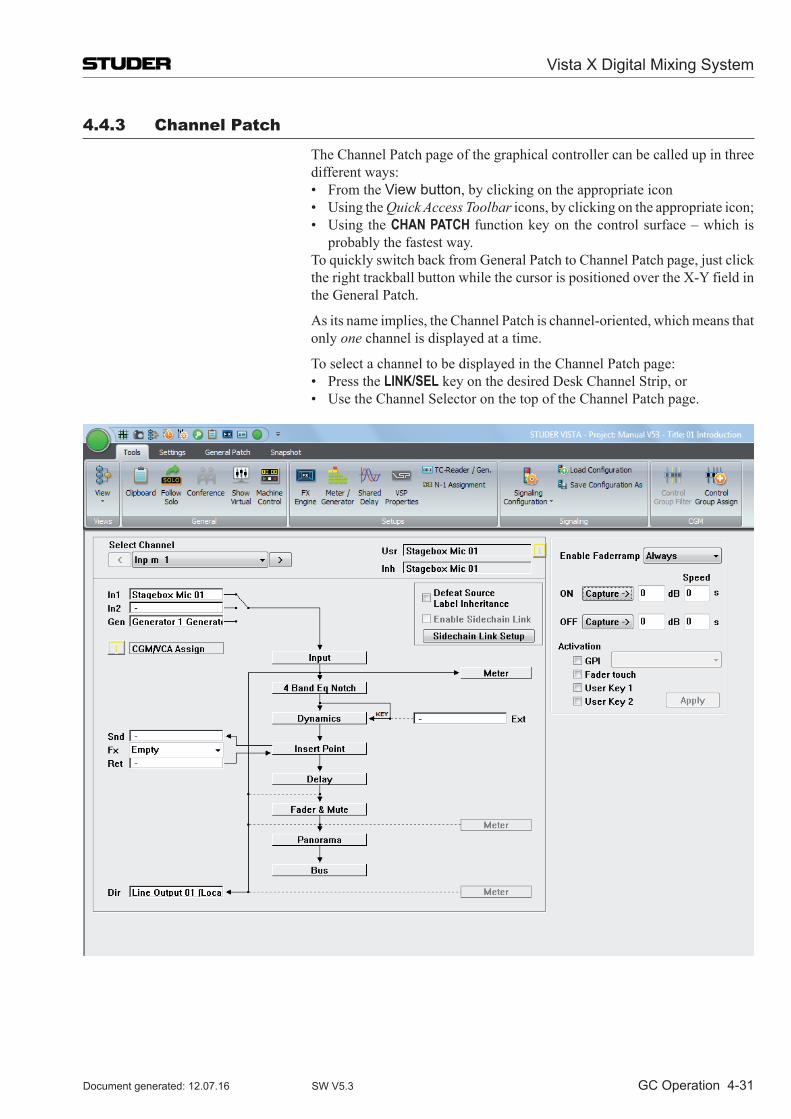
Vista X Digital Mixing System
GC Operation 4-31Document generated: 12.07.16 SW V5.3
4.4.3 Channel Patch
The Channel Patch page of the graphical controller can be called up in three different ways:
• FromtheView button, by clicking on the appropriate icon • UsingtheQuick Access Toolbar icons, by clicking on the appropriate icon; • Using theCHAN PATCH function key on the control surface – which is
probably the fastest way. To quickly switch back from General Patch to Channel Patch page, just click
the right trackball button while the cursor is positioned over the X-Y field in the General Patch.
As its name implies, the Channel Patch is channel-oriented, which means that only one channel is displayed at a time.
To select a channel to be displayed in the Channel Patch page: • PresstheLINK/SEL key on the desired Desk Channel Strip, or • UsetheChannelSelectoronthetopoftheChannelPatchpage.
Vista X Digital Mixing System
4-32 GC Operation Document generated: 12.07.16SW V5.3
Essentially, the Channel Patch provides a block diagram of the selected chan-nel’s audio path. All channel types can be selected. From the Channel Patch, you can:
• ViewGeneralPatchconnectionstoandfromtheselectedchannel; • Directlyaccessthechannel’spatchpointsintheGeneralPatch; • Viewchannel’sDSPprocessingblocks; • Set theorderofDSPprocessingblocks in theselectedchannel’saudio
path; • Togglethree-wayinputselectoroftheselectedchannel; • Toggleselectedchannel’stwo-wayDynamicskeyselector; • Viewandeditselectedchannel’s Desk Labels; • Switchoffselectedchannel’s Label Inheritance function; • SettheMeteringsourcepointintheselectedchannel’saudiopath; • SettheDirectOutputsourcepointintheselectedchannel’saudiopath; • SetuptheSidechainLinks; • ActivatetheSidechainLinkfortheselectedchannel.
4.4.3.1 Using the Channel Patch for Patching Audio
The Channel Patch page displays the following channel-oriented patch items of the selected channel for viewing:
In1 The first audio input; In2 The second audio input; Gen (In3) The third audio input; Snd The Insert Send; Ret The Insert Return; Ext The key signal to Dynamics Block; Dir The Direct Out. These labels will be displayed according to the current Label Mode. To edit
the patch connection, just double-click the left trackball button while the cursor is positioned on a connection. This will toggle over to the General Patch page, allowing actions to be performed. The connection you pointed at will be pre-selected automatically.
Examples for channel Im1 (Input Mono 1): Double-click on In1 field • togglestoGeneralPatch • pre-selects Target Im 1 Input m 1 In1 • now only select a Source and patch it. Double-click on Dir field • togglestoGeneralPatch • pre-selects Source Im 1 Input m 1 DirOut • now only select a Target and patch it. Obviously, if the connection you selected is a Source (Snd, Dir), you will
only have to select a Target in the General Patch. If the connection is a Target (In1, In2, Gen, Ret, Ext), you will only have to select a Source.
All patch cross-points are saved with snapshots and presets.
Tip To quickly toggle the display from Channel Patch to General Patch page, just click the right trackball button while the cursor is positioned anywhere in the Channel Patch page.
To quickly switch back from General Patch to Channel Patch page, just click the right trackball button while the cursor is positioned over the X-Y field in the General Patch.
Vista X Digital Mixing System
GC Operation 4-33Document generated: 12.07.16 SW V5.3
4.4.3.2 Setting the order of DSP Processing Blocks
The following processing blocks (if available in the currently selected con-figuration) can be placed individually at different locations along the Audio Path of the channels:
• EQ; • InsertPoint; • Dynamics(Compressor/Limiter/Expander/Gate/Sidechain); • Delay; • Fader&ON/OFF Mute.
The actual order of the system blocks is user-modifiable, and can be changed at any time. The order is saved with snapshots and presets.
To change the system-block order, use the familiar drag-and-drop technique: • Clickontheselectedblocks,andholddownthetrackballbutton; • Availablepositionsinthesignalpathareshownasareversed embossed
graphic; • Dragtheselectedblocktotherequiredpositioninthesignalpath; • Iftheblockcanbeinsertedatthatlocation,theblocknamewillturnred; • Releasethebuttonandtheselectedblockwillbeinsertedintothenew
location.
4.4.3.3 on-screen Toggles for input Selector and Dynamics Key Selector
Input Selector To toggle the three-way input selector (In1, In2, Gen), click on the switch icon that corresponds to the location at which you want the selector to point. The Desk Input Selector keys will follow the changes, and display the correct source.
Dynamics Key Selector To toggle the two-way input selector (Int, Ext), click on the switch icon that corresponds to the location at which you want the selector to point.
The selector settings are saved within snapshots.
4.4.3.4 Editing the Channel User labels
Double-click on the user label field (Usr) to open the Edit window. Proceed to edit and/or change the Desk Label using the same techniques used in the General Patch.
Vista X Digital Mixing System
4-34 GC Operation Document generated: 12.07.16SW V5.3
4.4.3.5 Set the Metering and Direct out Source Point
Set Metering Source Point: To set the Metering Source point in the selected channel’s audio path, click on one of the three Meter boxes. The channel meter will now be sourced from the selected point in the signal path.
Available points in the signal path are: • AfterInputBlock; • AfterFader&Mute; • AfterDirectOutlevelcontrol. The Meter Source point is saved within snapshots and presets.
Note: There will only be two Meter Source points if Direct Outputs have not been configured for the selected channel.
To set the Metering Source points for more channels at a time, use the Tools/Meter/Generator menu (refer to chapter 4.6.1.2.2).
Set Direct Output source Point: If a Direct Output is included in a channel’s configuration, it can be fed from one of three points in the audio path. To set the Direct Output source point, click on one of the three ‘wires’ connected to the Dir Box (the current con-nection will be shown solid, while the two possible connections are displayed as dotted lines).
The Direct Out will now be fed from the selected point in the signal path.
Available points in the signal path are: • AfterInputBlock; • PreFader&Mute; • AfterFader&Mute. The selected Direct Output source points are saved within snapshots and
presets.
Tip If you have changed the order of the processing blocks, note that the Meter and Direct Out source points will move together with the processing blocks to which they are attached (except the Input Block, which cannot be moved).
4.4.3.6 Switch off the label inheritance
The Desk Label displays will show Source Labels (from the General Patch) if the console is set to Inherited Label mode and if a source is patched in to the channel. If you wish to remain in Inherited Mode, but do not wish to see Source Labels for certain channels, check the Defeat Source Label Inheritance box. The Desk Label display will now show the name of the channel rather than the Source Label, assuming the user label on the Channel Patch has not been changed from the default. If the user label has been changed on the Channel Patch screen, the Desk Labels will display this user label when the Defeat Source Label Inheritance box has been checked. user labels entered on the Channel Patch screen are saved with snapshots and presets.
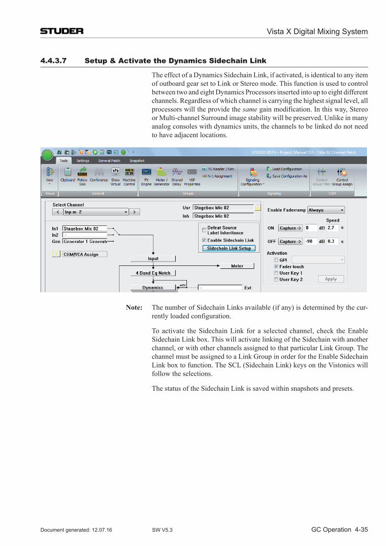
Vista X Digital Mixing System
GC Operation 4-35Document generated: 12.07.16 SW V5.3
4.4.3.7 Setup & Activate the Dynamics Sidechain link
The effect of a Dynamics Sidechain Link, if activated, is identical to any item of outboard gear set to Link or Stereo mode. This function is used to control between two and eight Dynamics Processors inserted into up to eight different channels. Regard less of which channel is carrying the highest signal level, all processors will the provide the same gain modification. In this way, Stereo or Multi-channel Surround image stability will be preserved. Unlike in many analog consoles with dynamics units, the channels to be linked do not need to have adjacent locations.
Note: The number of Sidechain Links available (if any) is determined by the cur-rently loaded configuration.
To activate the Sidechain Link for a selected channel, check the Enable Sidechain Link box. This will activate linking of the Sidechain with another channel, or with other channels assigned to that particular Link Group. The channel must be assigned to a Link Group in order for the Enable Sidechain Link box to function. The SCL (Sidechain Link) keys on the Vistonics will follow the selections.
The status of the Sidechain Link is saved within snapshots and presets.
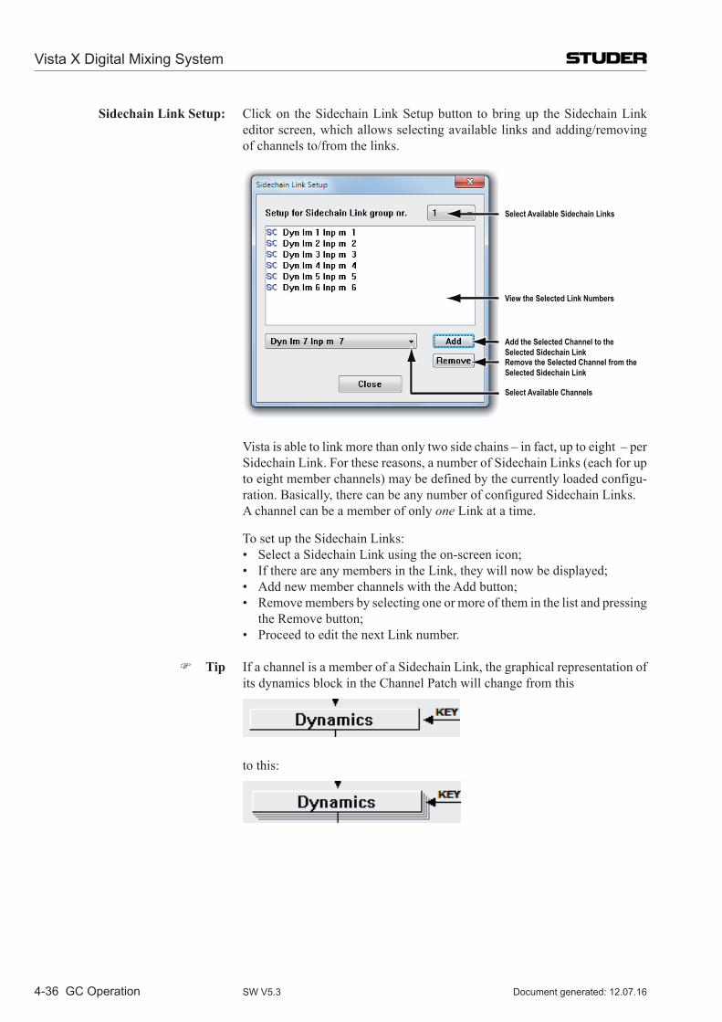
Vista X Digital Mixing System
4-36 GC Operation Document generated: 12.07.16SW V5.3
Sidechain Link Setup: Click on the Sidechain Link Setup button to bring up the Sidechain Link editor screen, which allows selecting available links and adding/removing of channels to/from the links.
Select Available Sidechain Links
View the Selected Link Numbers
Add the Selected Channel to theSelected Sidechain Link
Select Available Channels
Remove the Selected Channel from theSelected Sidechain Link
Vista is able to link more than only two side chains – in fact, up to eight – per Sidechain Link. For these reasons, a number of Sidechain Links (each for up to eight member channels) may be defined by the currently loaded configu-ration. Basically, there can be any number of configured Side chain Links.
A channel can be a member of only one Link at a time.
To set up the Sidechain Links: • SelectaSidechainLinkusingtheon-screenicon; • IfthereareanymembersintheLink,theywillnowbedisplayed; • AddnewmemberchannelswiththeAddbutton; • Removemembersbyselectingoneormoreoftheminthelistandpressing
the Remove button; • ProceedtoeditthenextLinknumber.
Tip If a channel is a member of a Sidechain Link, the graphical representation of its dynamics block in the Channel Patch will change from this
to this:
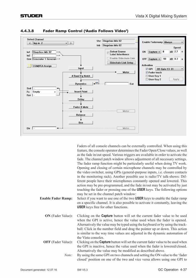
Vista X Digital Mixing System
GC Operation 4-37Document generated: 12.07.16 SW V5.3
4.4.3.8 Fader Ramp Control (‘Audio Follows Video’)
Faders of all console channels can be externally controlled. When using this feature, the console operator determines the Fader Open/Close values, as well as the fade in/out speed. Various triggers are available in order to activate the fade. The channel patch window allows adjustment of all necessary settings.
The fader ramp function might be particularly useful when doing TV work. Opening and closing of certain microphone channels may be controlled by the video switcher, using GPIs (general-purpose inputs, i.e. closure contacts in the monitoring rack). Another possible use is radio/TV talk-shows: Dif-ferent people have their microphones constantly opened and lowered. This action may be pre-programmed, and the fade in/out may be activated by just touching the fader or pressing one of the USER keys. The following options may be set in the channel patch window:
Enable Fader Ramp: Select if you want to use one of the two USER keys to enable the fader ramp on a specific channel. It is also possible to activate it constantly, leaving the USER keys free for other functions.
ON (Fader Value): Clicking on the Capture button will set the current fader value to be used when the GPI is active, hence the value used when the fader is opened. Alternatively the value may be typed using the keyboard or by using the track-ball: Click in the number field and drag the pointer up or down. This action is similar to the way time values are adjusted in the dynamic automation of the Vista consoles.
OFF (Fader Value): Clicking on the Capture button will set the current fader value to be used when the GPI is inactive, hence the value used when the fader is lowered/closed. Alternatively the value may be modified as described above.
Note: By using the same GPI on two channels and setting the ON value to the ‘fader closed’ position on one of the two and vice versa allows using one GPI to
Vista X Digital Mixing System
4-38 GC Operation Document generated: 12.07.16SW V5.3
control opening and closing of different channels at the same time. Speed ON: Determines the time used for fading in the corresponding channel. Speed OFF: Determines the time used for fading out the corresponding channel. Activation: The fade actions may be activated by different events. Several events may
be enabled at the same time. The fade will take place whenever one of the activated events is detected:
GPI: Select one of the general-purpose inputs available on the console for trigger-ing the fade.
Fader Touch: Touch-and-release the fader in order to activate the fade. Note: If the fader is moved while being touched, no automatic fade is being exe-
cuted. This prevents from accidental fading. User Key 1/2: The fade is activated when pressing the corresponding USER 1 or USER 2 key
on each channel. Note: In case adjusted values should constantly jump back to their previous values,
check that the C:\D950System\Sig...ini file is not write protected.
Vista X Digital Mixing System
GC Operation 4-39Document generated: 12.07.16 SW V5.3
4.4.4 Snapshot Page
The snapshot page of the graphical controller can be called up in three different ways:
• FromtheView button, by clicking on the appropriate icon • UsingtheQuick Access Toolbar icons, by clicking on the appropriate icon; • UsingtheSNAPSHOT function key on the console – which is probably the
fastest way.
The snapshot page deals with snapshot and preset management. Snapshots and presets are extremely helpful when working with a digital console as they contain the static values for all console parameters. The difference between snapshots and presets is simple: While snapshots can be edited freely, presets are accessible for editing in system administration mode only (refer to chapter 4.7).
Snapshots are saved within titles, and presets are provided with configura-tions. Because of this, snapshots are readily available only while using the title in which they were created. On the other hand, all presets that were created for a particular configuration are available in any title that uses that configuration. This allows presets to be used as templates (based upon that configuration), while snapshots are specific to individual projects or sessions.
Another difference between snapshots and presets is that any filtering mecha-nism is active for snapshots only, but not for presets. This means that after having recalled a preset, the user can always be sure to have all audio settings of this preset applied.
Using the Import facility from the Application menu, it is possible to use snapshots and presets from other titles and configurations, refer to chapter 4.5.4.
Because it is possible to save an unlimited number of snapshots, Vista ope-rators will probably find themselves using them more and more every day.
A snapshot or preset will save: • Allaudiosettings:Faderlevels,auxiliarysettings,dynamics,delays,input
selectors, etc. • Orderofchannelprocessingblocks; • Directoutputandmetersourcepoints; • Busassignments; • Alllabels; • Allpatchcross-pointconnections; • Channelandotherlinks; • N–1/mix-minusassignments.
Tip Snapshots and presets always save every control and switch setting for the entire console. The choice of recalling every setting to every control is up to the operator. A sophisticated filtering system is available in order to keep certain settings even when recalling a snapshot.
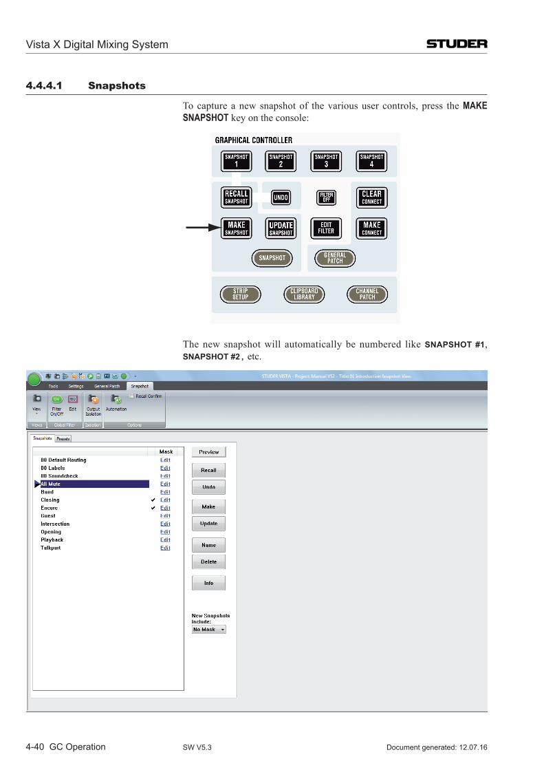
Vista X Digital Mixing System
4-40 GC Operation Document generated: 12.07.16SW V5.3
4.4.4.1 Snapshots
To capture a new snapshot of the various user controls, press the MAKE SNAPSHOT key on the console:
The new snapshot will automatically be numbered like SNAPSHOT #1, SNAPSHOT #2, etc.
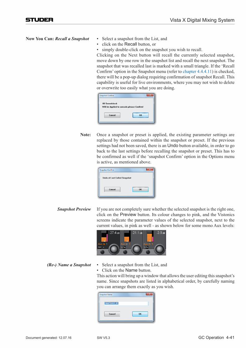
Vista X Digital Mixing System
GC Operation 4-41Document generated: 12.07.16 SW V5.3
Now You Can: Recall a Snapshot • SelectasnapshotfromtheList,and • clickontheRecall button, or • simplydouble-clickonthesnapshotyouwishtorecall. Clicking on the Next button will recall the currently selected snapshot,
move down by one row in the snapshot list and recall the next snapshot. The snapshot that was recalled last is marked with a small triangle. If the ‘Recall Confirm’ option in the Snapshot menu (refer to chapter 4.4.4.11) is checked, there will be a pop-up dialog requiring confirmation of snapshot Recall. This capability is useful for live environments, where you may not wish to delete or overwrite too easily what you are doing.
Note: Once a snapshot or preset is applied, the existing parameter settings are replaced by those contained within the snapshot or preset. If the previous settings had not been saved, there is an Undo button available, in order to go back to the last settings before recalling the snapshot or preset. This has to be confirmed as well if the ‘snapshot Confirm’ option in the Options menu is active, as mentioned above.
Snapshot Preview If you are not completely sure whether the selected snapshot is the right one, click on the Preview button. Its colour changes to pink, and the Vistonics screens indicate the parameter values of the selected snapshot, next to the current values, in pink as well - as shown below for some mono Aux levels:
(Re-) Name a Snapshot • SelectasnapshotfromtheList,and • ClickontheName button. This action will bring up a window that allows the user editing this snapshot’s
name. Since snapshots are listed in alphabetical order, by carefully naming you can arrange them exactly as you wish.
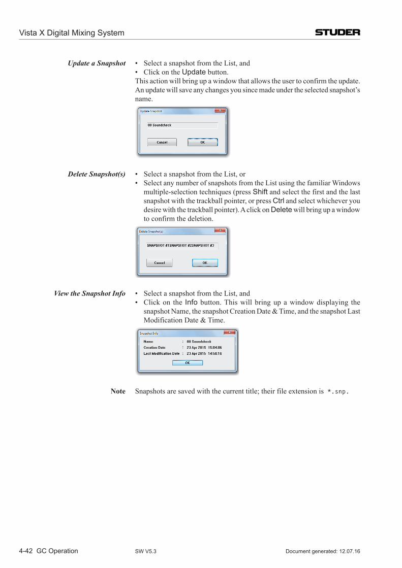
Vista X Digital Mixing System
4-42 GC Operation Document generated: 12.07.16SW V5.3
Update a Snapshot • SelectasnapshotfromtheList,and • ClickontheUpdate button. This action will bring up a window that allows the user to confirm the update.
An update will save any changes you since made under the selected snapshot’s name.
Delete Snapshot(s) • SelectasnapshotfromtheList,or • SelectanynumberofsnapshotsfromtheListusingthefamiliarWindows
multiple-selection techniques (press Shift and select the first and the last snapshot with the trackball pointer, or press Ctrl and select whichever you desire with the trackball pointer). A click on Delete will bring up a window to confirm the deletion.
View the Snapshot Info • SelectasnapshotfromtheList,and • Clickon the Info button. This will bring up a window displaying the
snapshot Name, the snapshot Creation Date & Time, and the snapshot Last Modification Date & Time.
Note Snapshots are saved with the current title; their file extension is *.snp.
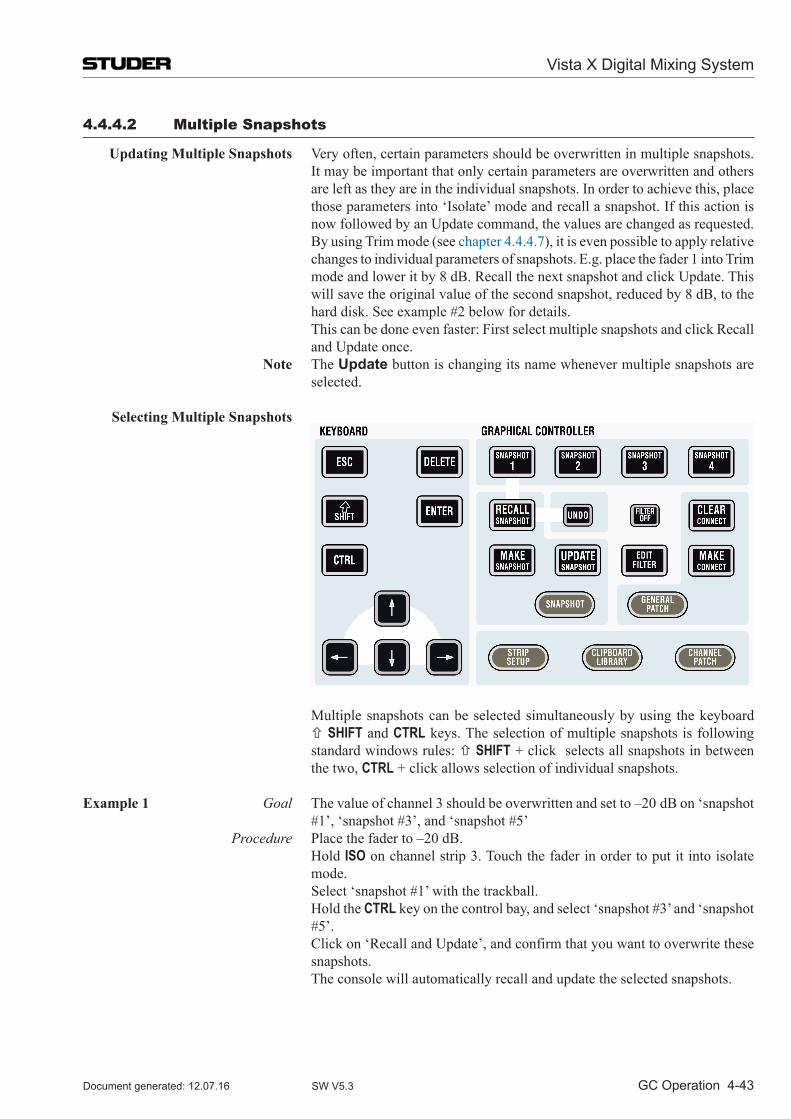
Vista X Digital Mixing System
GC Operation 4-43Document generated: 12.07.16 SW V5.3
4.4.4.2 Multiple Snapshots
Updating Multiple Snapshots Very often, certain parameters should be overwritten in multiple snapshots. It may be important that only certain parameters are overwritten and others are left as they are in the individual snapshots. In order to achieve this, place those parameters into ‘Isolate’ mode and recall a snapshot. If this action is now followed by an Update command, the values are changed as requested.
By using Trim mode (see chapter 4.4.4.7), it is even possible to apply relative changes to individual parameters of snapshots. E.g. place the fader 1 into Trim mode and lower it by 8 dB. Recall the next snapshot and click Update. This will save the original value of the second snapshot, reduced by 8 dB, to the hard disk. See example #2 below for details.
This can be done even faster: First select multiple snapshots and click Recall and Update once.
Note The Update button is changing its name whenever multiple snapshots are selected.
Selecting Multiple Snapshots
Multiple snapshots can be selected simultaneously by using the keyboard SHIFT and CTRL keys. The selection of multiple snapshots is following standard windows rules: SHIFT + click selects all snapshots in between the two, CTRL + click allows selection of individual snapshots.
Example 1 Goal The value of channel 3 should be overwritten and set to –20 dB on ‘snapshot #1’, ‘snapshot #3’, and ‘snapshot #5’
Procedure Place the fader to –20 dB. Hold ISO on channel strip 3. Touch the fader in order to put it into isolate
mode. Select ‘snapshot #1’ with the trackball. Hold the CTRL key on the control bay, and select ‘snapshot #3’ and ‘snapshot
#5’. Click on ‘Recall and Update’, and confirm that you want to overwrite these
snapshots. The console will automatically recall and update the selected snapshots.
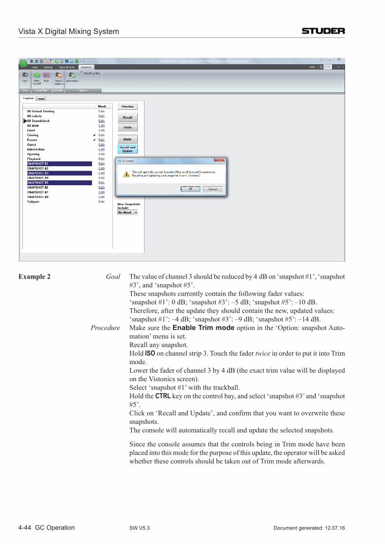
Vista X Digital Mixing System
4-44 GC Operation Document generated: 12.07.16SW V5.3
Example 2 Goal The value of channel 3 should be reduced by 4 dB on ‘snapshot #1’, ‘snapshot #3’, and ‘snapshot #5’.
These snapshots currently contain the following fader values: ‘snapshot #1’: 0 dB; ‘snapshot #3’: –5 dB; ‘snapshot #5’: –10 dB. Therefore, after the update they should contain the new, updated values: ‘snapshot #1’: –4 dB; ‘snapshot #3’: –9 dB; ‘snapshot #5’: –14 dB. Procedure Make sure the Enable Trim mode option in the ‘Option: snapshot Auto-
mation’ menu is set. Recall any snapshot. Hold ISO on channel strip 3. Touch the fader twice in order to put it into Trim
mode. Lower the fader of channel 3 by 4 dB (the exact trim value will be displayed
on the Vistonics screen). Select ‘snapshot #1’ with the trackball. Hold the CTRL key on the control bay, and select ‘snapshot #3’ and ‘snapshot
#5’. Click on ‘Recall and Update’, and confirm that you want to overwrite these
snapshots. The console will automatically recall and update the selected snapshots.
Since the console assumes that the controls being in Trim mode have been placed into this mode for the purpose of this update, the operator will be asked whether these controls should be taken out of Trim mode afterwards.
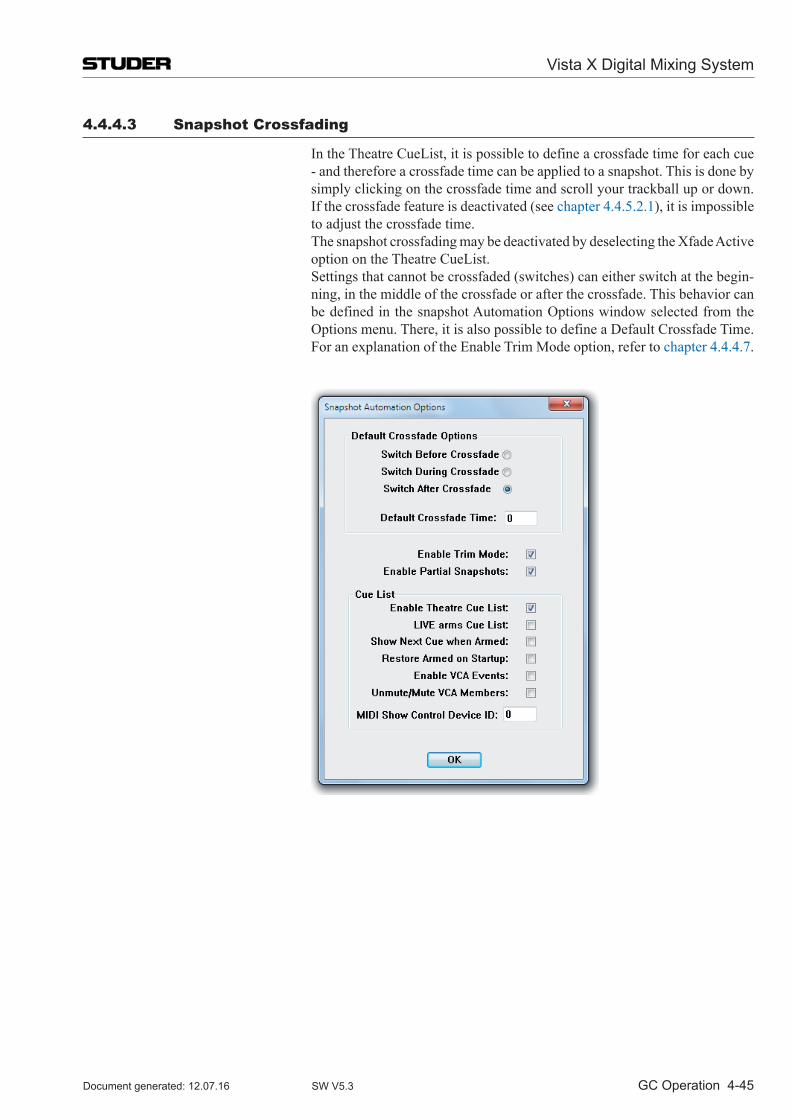
Vista X Digital Mixing System
GC Operation 4-45Document generated: 12.07.16 SW V5.3
4.4.4.3 Snapshot Crossfading
In the Theatre CueList, it is possible to define a crossfade time for each cue - and therefore a crossfade time can be applied to a snapshot. This is done by simply clicking on the crossfade time and scroll your trackball up or down. If the crossfade feature is deactivated (see chapter 4.4.5.2.1), it is impossible to adjust the crossfade time.
The snapshot crossfading may be deactivated by deselecting the Xfade Active option on the Theatre CueList.
Settings that cannot be crossfaded (switches) can either switch at the begin-ning, in the middle of the crossfade or after the crossfade. This behavior can be defined in the snapshot Automation Options window selected from the Options menu. There, it is also possible to define a Default Crossfade Time.
For an explanation of the Enable Trim Mode option, refer to chapter 4.4.4.7.
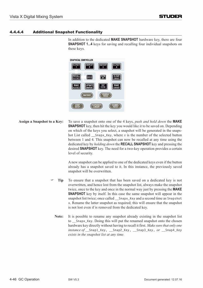
Vista X Digital Mixing System
4-46 GC Operation Document generated: 12.07.16SW V5.3
4.4.4.4 Additional Snapshot Functionality
In addition to the dedicated MAKE SNAPSHOT hardware key, there are four SNAPSHOT 1...4 keys for saving and recalling four individual snapshots on these keys.
Assign a Snapshot to a Key: To save a snapshot onto one of the 4 keys, push and hold down the MAKE SNAPSHOT key, then hit the key you would like it to be saved on. Depending on which of the keys you select, a snapshot will be generated in the snaps-hot List called __Snapx_Key, where x is the number of the selected button between 1 and 4. This snapshot can now be recalled at any time using the dedicated key by holding down the RECALL SNAPSHOT key and pressing the desired SNAPSHOT key. The need for a two-key operation provides a certain level of security.
A new snapshot can be applied to one of the dedicated keys even if the button already has a snapshot saved to it. In this instance, the previously saved snapshot will be overwritten.
Tip To ensure that a snapshot that has been saved on a dedicated key is not overwritten, and hence lost from the snapshot list, always make the snapshot twice, once to the key and once in the normal way just by pressing the MAKE SNAPSHOT key by itself. In this case the same snapshot will appear in the snapshot list twice; once called __Snapx_Key and a second time as Snapshot x. Rename the latter snapshot as required; this will ensure that the snapshot is not lost even if is removed from the dedicated key.
Note: It is possible to rename any snapshot already existing in the snapshot list to __Snapx_Key. Doing this will put the renamed snapshot onto the chosen hardware key directly without having to recall it first. Make sure that only one instance of __Snap1_Key, __Snap2_Key, __Snap3_Key, or __Snap4_Key exists in the snapshot list at any time.
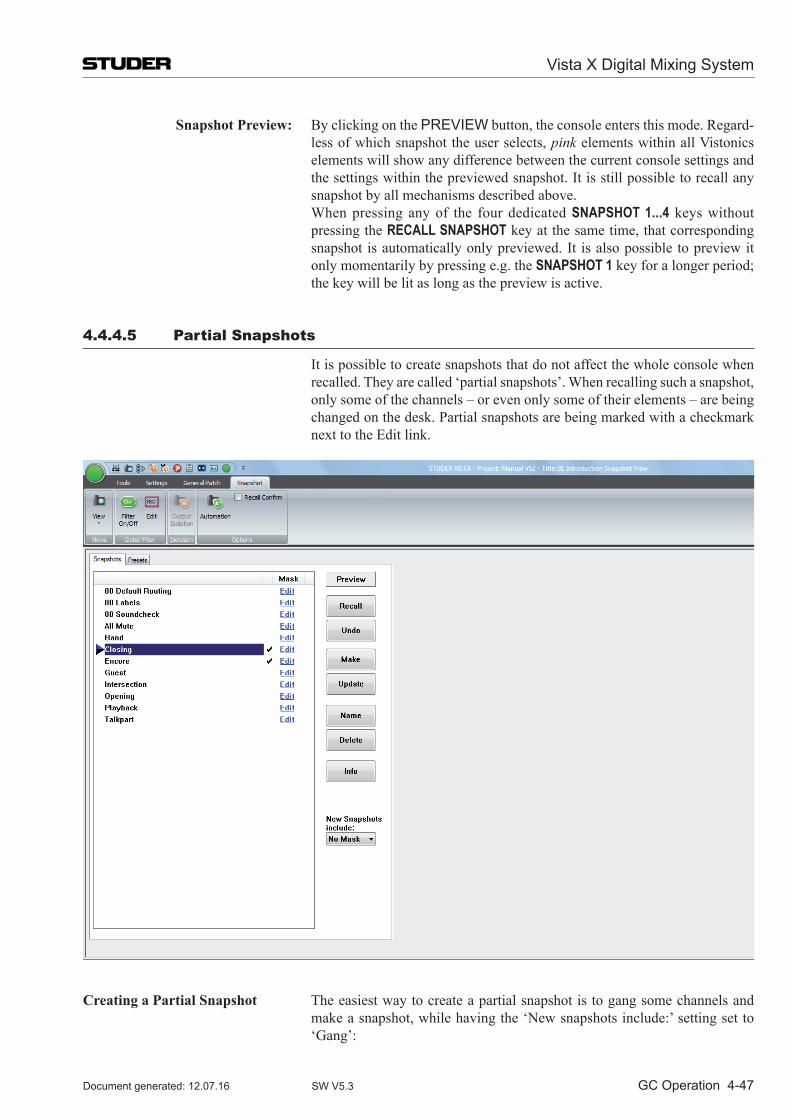
Vista X Digital Mixing System
GC Operation 4-47Document generated: 12.07.16 SW V5.3
Snapshot Preview: By clicking on the PREVIEW button, the console enters this mode. Regard-less of which snapshot the user selects, pink elements within all Vistonics elements will show any difference between the current console settings and the settings within the previewed snapshot. It is still possible to recall any snapshot by all mechanisms described above.
When pressing any of the four dedicated SNAPSHOT 1...4 keys without pressing the RECALL SNAPSHOT key at the same time, that corresponding snapshot is automatically only previewed. It is also possible to preview it only momentarily by pressing e.g. the SNAPSHOT 1 key for a longer period; the key will be lit as long as the preview is active.
4.4.4.5 Partial Snapshots
It is possible to create snapshots that do not affect the whole console when recalled. They are called ‘partial snapshots’. When recalling such a snapshot, only some of the channels – or even only some of their elements – are being changed on the desk. Partial snapshots are being marked with a checkmark next to the Edit link.
Creating a Partial Snapshot The easiest way to create a partial snapshot is to gang some channels and make a snapshot, while having the ‘New snapshots include:’ setting set to ‘Gang’:
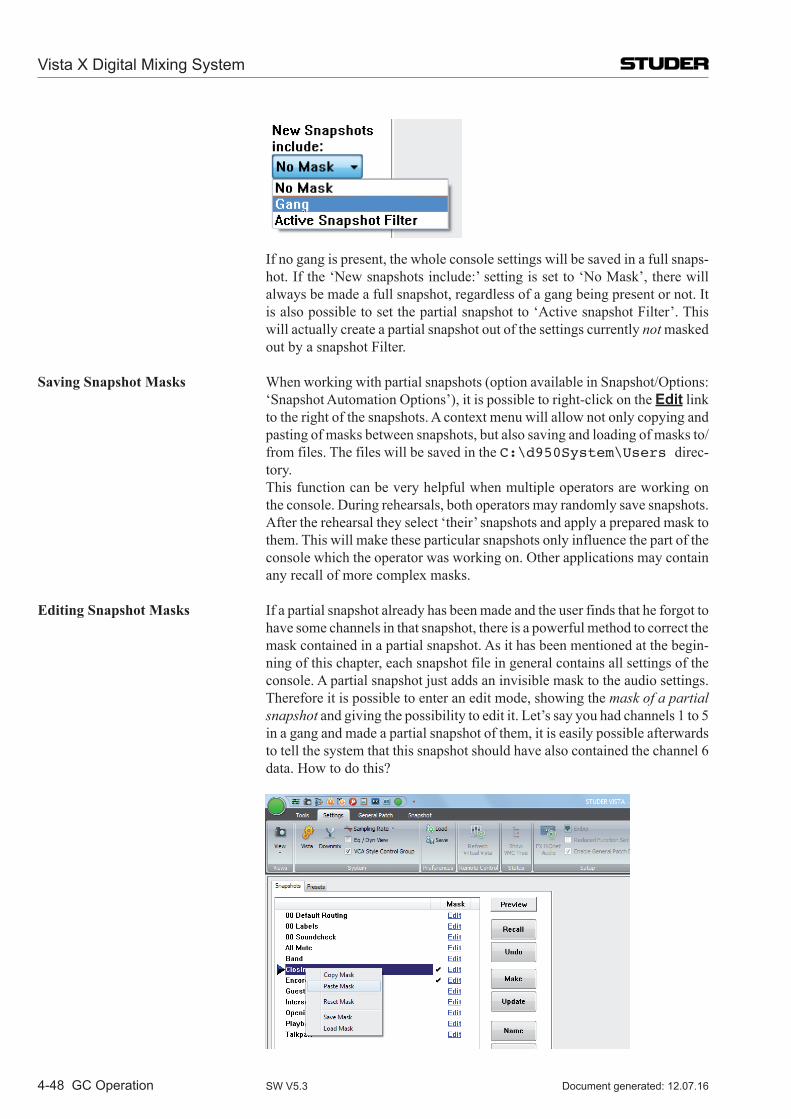
Vista X Digital Mixing System
4-48 GC Operation Document generated: 12.07.16SW V5.3
If no gang is present, the whole console settings will be saved in a full snaps-hot. If the ‘New snapshots include:’ setting is set to ‘No Mask’, there will always be made a full snapshot, regardless of a gang being present or not. It is also possible to set the partial snapshot to ‘Active snapshot Filter’. This will actually create a partial snapshot out of the settings currently not masked out by a snapshot Filter.
Saving Snapshot Masks When working with partial snapshots (option available in Snapshot/Options: ‘Snapshot Automation Options’), it is possible to right-click on the Edit link to the right of the snapshots. A context menu will allow not only copying and pasting of masks between snapshots, but also saving and loading of masks to/from files. The files will be saved in the C:\d950System\Users direc-tory.
This function can be very helpful when multiple operators are working on the console. During rehearsals, both operators may randomly save snapshots. After the rehearsal they select ‘their’ snapshots and apply a prepared mask to them. This will make these particular snapshots only influence the part of the console which the operator was working on. Other applications may contain any recall of more complex masks.
Editing Snapshot Masks If a partial snapshot already has been made and the user finds that he forgot to have some channels in that snapshot, there is a powerful method to correct the mask contained in a partial snapshot. As it has been mentioned at the begin-ning of this chapter, each snapshot file in general contains all settings of the console. A partial snapshot just adds an invisible mask to the audio settings. Therefore it is possible to enter an edit mode, showing the mask of a partial snapshot and giving the possibility to edit it. Let’s say you had channels 1 to 5 in a gang and made a partial snapshot of them, it is easily possible afterwards to tell the system that this snapshot should have also contained the channel 6 data. How to do this?
Vista X Digital Mixing System
GC Operation 4-49Document generated: 12.07.16 SW V5.3
Next to each snapshot there is an Edit link at the very right of the snapshot list. By clicking this button, you will put the console into the ‘partial snapshot filter edit’ mode. Then you will see the same edit dialog box on the screen as when editing the snapshot filter. Also the desk doesn’t show your audio set-tings anymore, but the mask defining the focus of that partial snapshot. You may now press ISO on one or more channels, create a gang, and add multiple channels to the partial snapshot, or touch and press any other control. The same mechanism will apply as when editing the snapshot filter. Upon clicking the Edit link again, you leave the edit mode, and the console is back to display normal audio settings.
When you are not in the edit mode of the partial snapshots mask, you are also able to copy and paste masks across from one snapshot to one or multiple others. Simply right-click on the Edit link of a snapshot mask and use the standard windows commands.
4.4.4.6 Typical Applications
Isolate one or more channels from being changed by upcoming snapshot recalls: Press ISO on the corresponding channels. The user may create a gang first in
order to isolate multiple channels at a time.
Isolate just the EQ of one or more channels from being changed by upcoming snapshot recalls: Press and hold ISO in order to enter the edit snapshot filter mode, indicated
by magenta-colored frames within all Vistonics elements of this channel. All LEDs will now display their isolation status but not the audio. E.g. if the EQ button is lit at this time, the EQ is isolated. In order to change the isolation status, press the corresponding key, touch the fader or knob while still holding the ISO key. The word ‘ISOLATE’ will now show up in the generic display area, indicating that some element is currently isolated. You may also use a gang in order to isolate one element of multiple channels.
De-Activate the whole snapshot filtering mechanism on the console Press FILTER OFF on the Control Bay, or click on the snapshot filter icon in
the toolbar to de-activate the snapshot filtering while keeping its definition for later use.
Create Snapshots, that contain only some of the channels, but not the whole console Set the ‘New snapshot includes:’ option to ‘Gang’. Whenever a gang is
present, only the gang will be ‘part of the snapshot’. If there is no gang, the whole console is affected by the recall of freshly created snapshots. A snaps-hot not affecting the whole channel is graphically marked by a checkmark ().
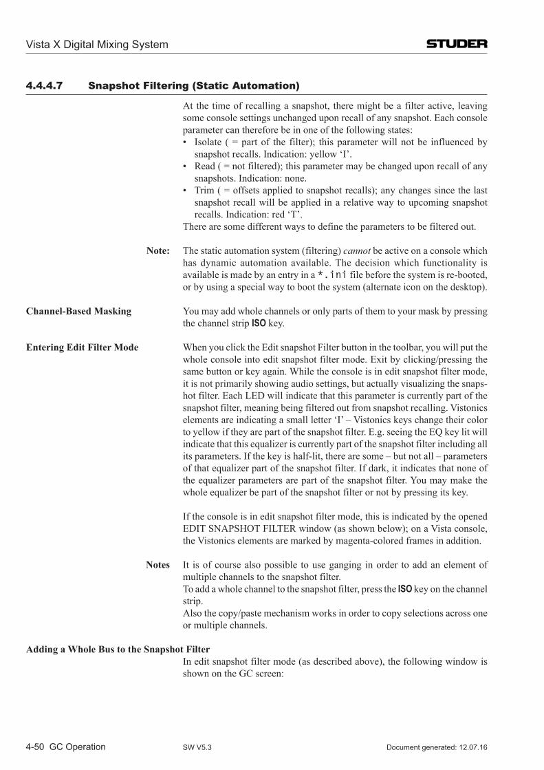
Vista X Digital Mixing System
4-50 GC Operation Document generated: 12.07.16SW V5.3
4.4.4.7 Snapshot Filtering (Static Automation)
At the time of recalling a snapshot, there might be a filter active, leaving some console settings unchanged upon recall of any snapshot. Each console parameter can therefore be in one of the following states:
• Isolate (=partof the filter); thisparameterwillnotbe influencedbysnapshot recalls. Indication: yellow ‘I’.
• Read(=notfiltered);thisparametermaybechangeduponrecallofanysnapshots. Indication: none.
• Trim(=offsetsappliedtosnapshotrecalls);anychangessincethelastsnapshot recall will be applied in a relative way to upcoming snapshot recalls. Indication: red ‘T’.
There are some different ways to define the parameters to be filtered out.
Note: The static automation system (filtering) cannot be active on a console which has dynamic automation available. The decision which functionality is available is made by an entry in a *.ini file before the system is re-booted, or by using a special way to boot the system (alternate icon on the desktop).
Channel-Based Masking You may add whole channels or only parts of them to your mask by pressing the channel strip ISO key.
Entering Edit Filter Mode When you click the Edit snapshot Filter button in the toolbar, you will put the whole console into edit snapshot filter mode. Exit by clicking/pressing the same button or key again. While the console is in edit snapshot filter mode, it is not primarily showing audio settings, but actually visualizing the snaps-hot filter. Each LED will indicate that this parameter is currently part of the snapshot filter, meaning being filtered out from snapshot recalling. Vistonics elements are indicating a small letter ‘I’ – Vistonics keys change their color to yellow if they are part of the snapshot filter. E.g. seeing the EQ key lit will indicate that this equalizer is currently part of the snapshot filter including all its parameters. If the key is half-lit, there are some – but not all – parameters of that equalizer part of the snapshot filter. If dark, it indicates that none of the equalizer parameters are part of the snapshot filter. You may make the whole equalizer be part of the snapshot filter or not by pressing its key.
If the console is in edit snapshot filter mode, this is indicated by the opened EDIT SNAPSHOT FILTER window (as shown below); on a Vista console, the Vistonics elements are marked by magenta-colored frames in addition.
Notes It is of course also possible to use ganging in order to add an element of multiple channels to the snapshot filter.
To add a whole channel to the snapshot filter, press the ISO key on the channel strip.
Also the copy/paste mechanism works in order to copy selections across one or multiple channels.
Adding a Whole Bus to the Snapshot Filter In edit snapshot filter mode (as described above), the following window is
shown on the GC screen:
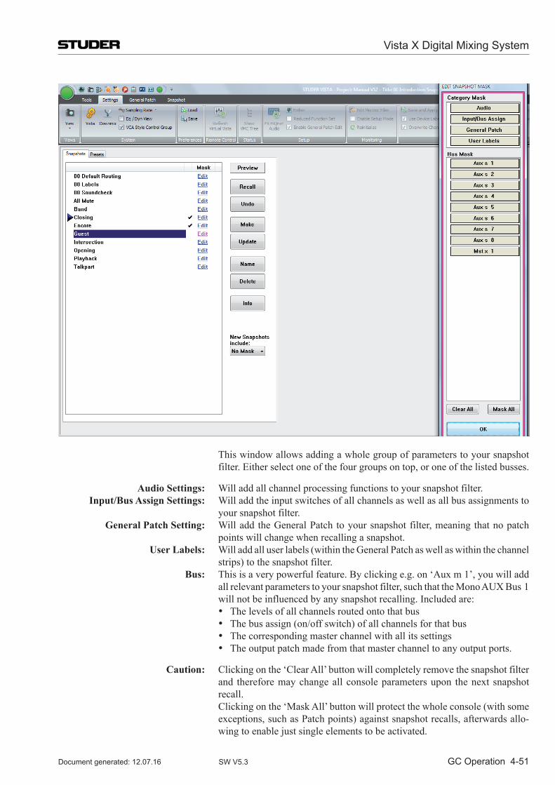
Vista X Digital Mixing System
GC Operation 4-51Document generated: 12.07.16 SW V5.3
This window allows adding a whole group of parameters to your snapshot filter. Either select one of the four groups on top, or one of the listed busses.
Audio Settings: Will add all channel processing functions to your snapshot filter. Input/Bus Assign Settings: Will add the input switches of all channels as well as all bus assignments to
your snapshot filter. General Patch Setting: Will add the General Patch to your snapshot filter, meaning that no patch
points will change when recalling a snapshot. User Labels: Will add all user labels (within the General Patch as well as within the channel
strips) to the snapshot filter. Bus: This is a very powerful feature. By clicking e.g. on ‘Aux m 1’, you will add
all relevant parameters to your snapshot filter, such that the Mono AUX Bus 1 will not be influenced by any snapshot recalling. Included are:
• The levels of all channels routed onto that bus • The bus assign (on/off switch) of all channels for that bus • The corresponding master channel with all its settings • The output patch made from that master channel to any output ports.
Caution: Clicking on the ‘Clear All’ button will completely remove the snapshot filter and therefore may change all console parameters upon the next snapshot recall.
Clicking on the ‘Mask All’ button will protect the whole console (with some exceptions, such as Patch points) against snapshot recalls, afterwards allo-wing to enable just single elements to be activated.
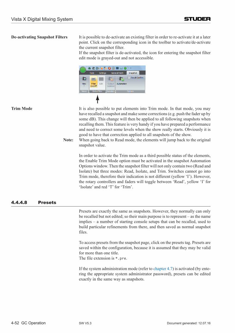
Vista X Digital Mixing System
4-52 GC Operation Document generated: 12.07.16SW V5.3
De-activating Snapshot Filters It is possible to de-activate an existing filter in order to re-activate it at a later point. Click on the corresponding icon in the toolbar to activate/de-activate the current snapshot filter.
If the snapshot filter is de-activated, the icon for entering the snapshot filter edit mode is grayed-out and not accessible.
Trim Mode It is also possible to put elements into Trim mode. In that mode, you may
have recalled a snapshot and make some corrections (e.g. push the fader up by some dB). This change will then be applied to all following snapshots when recalling them. This feature is very handy if you have prepared a performance and need to correct some levels when the show really starts. Obviously it is good to have that correction applied to all snapshots of the show.
Note: When going back to Read mode, the elements will jump back to the original snapshot value.
In order to activate the Trim mode as a third possible status of the elements, the Enable Trim Mode option must be activated in the snapshot Automation Options window. Then the snapshot filter will not only contain two (Read and Isolate) but three modes: Read, Isolate, and Trim. Switches cannot go into Trim mode, therefore their indication is not different (yellow ‘I’). However, the rotary controllers and faders will toggle between ‘Read’, yellow ‘I’ for ‘Isolate’ and red ‘T’ for ‘Trim’.
4.4.4.8 Presets
Presets are exactly the same as snapshots. However, they normally can only be recalled but not edited; so their main purpose is to represent – as the name implies – a number of starting console setups that can be recalled, used to build particular refinements from there, and then saved as normal snapshot files.
To access presets from the snapshot page, click on the presets tag. Presets are saved within the configuration, because it is assumed that they may be valid for more than one title.
The file extension is *.pre.
If the system administration mode (refer to chapter 4.7) is activated (by ente-ring the appropriate system administrator password), presets can be edited exactly in the same way as snapshots.
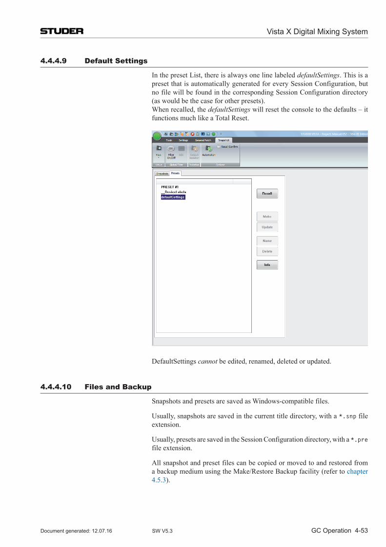
Vista X Digital Mixing System
GC Operation 4-53Document generated: 12.07.16 SW V5.3
4.4.4.9 Default Settings
In the preset List, there is always one line labeled defaultSettings. This is a preset that is automatically generated for every Session Configuration, but no file will be found in the corresponding Session Configuration directory (as would be the case for other presets).
When recalled, the defaultSettings will reset the console to the defaults – it functions much like a Total Reset.
DefaultSettings cannot be edited, renamed, deleted or updated.
4.4.4.10 Files and Backup
Snapshots and presets are saved as Windows-compatible files.
Usually, snapshots are saved in the current title directory, with a *.snp file extension.
Usually, presets are saved in the Session Configuration directory, with a *.pre file extension.
All snapshot and preset files can be copied or moved to and restored from a backup medium using the Make/Restore Backup facility (refer to chapter 4.5.3).
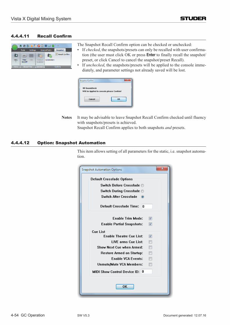
Vista X Digital Mixing System
4-54 GC Operation Document generated: 12.07.16SW V5.3
4.4.4.11 Recall Confirm
The Snapshot Recall Confirm option can be checked or unchecked: • Ifchecked, the snapshots/presets can only be recalled with user confirma-
tion (the user must click OK or press Enter to finally recall the snapshot/preset, or click Cancel to cancel the snapshot/preset Recall).
• Ifunchecked, the snapshots/presets will be applied to the console imme-diately, and parameter settings not already saved will be lost.
Notes It may be advisable to leave Snapshot Recall Confirm checked until fluency with snapshots/presets is achieved.
Snapshot Recall Confirm applies to both snapshots and presets.
4.4.4.12 option: Snapshot Automation
This item allows setting of all parameters for the static, i.e. snapshot automa-tion.
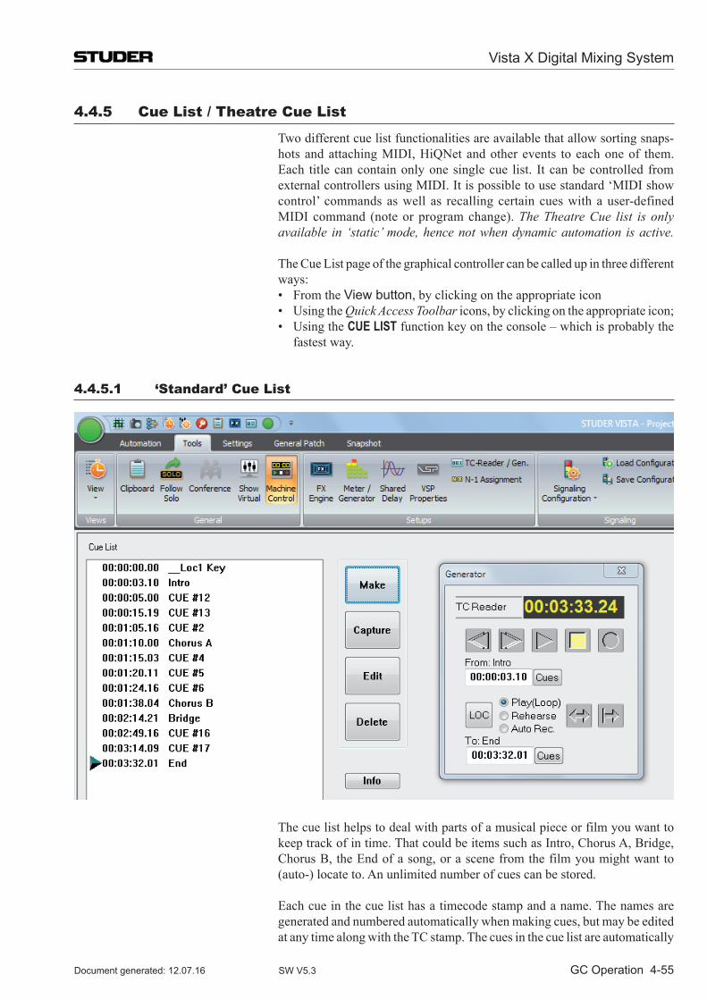
Vista X Digital Mixing System
GC Operation 4-55Document generated: 12.07.16 SW V5.3
4.4.5 Cue list / Theatre Cue list
Two different cue list functionalities are available that allow sorting snaps-hots and attaching MIDI, HiQNet and other events to each one of them. Each title can contain only one single cue list. It can be controlled from external controllers using MIDI. It is possible to use standard ‘MIDI show control’ commands as well as recalling certain cues with a user-defined MIDI command (note or program change). The Theatre Cue list is only available in ‘static’ mode, hence not when dynamic automation is active.
The Cue List page of the graphical controller can be called up in three different ways:
• FromtheView button, by clicking on the appropriate icon • UsingtheQuick Access Toolbar icons, by clicking on the appropriate icon; • UsingtheCUE LIST function key on the console – which is probably the
fastest way.
4.4.5.1 ‘Standard’ Cue list
The cue list helps to deal with parts of a musical piece or film you want to keep track of in time. That could be items such as Intro, Chorus A, Bridge, Chorus B, the End of a song, or a scene from the film you might want to (auto-) locate to. An unlimited number of cues can be stored.
Each cue in the cue list has a timecode stamp and a name. The names are generated and numbered automatically when making cues, but may be edited at any time along with the TC stamp. The cues in the cue list are automatically
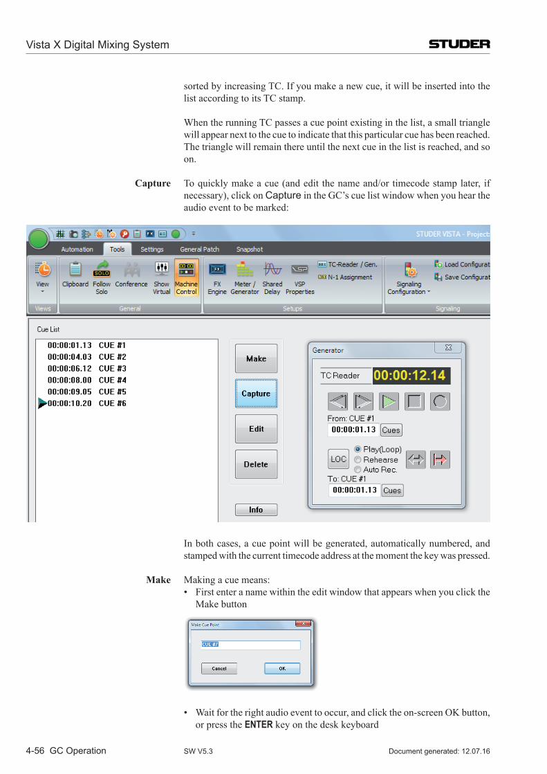
Vista X Digital Mixing System
4-56 GC Operation Document generated: 12.07.16SW V5.3
sorted by increasing TC. If you make a new cue, it will be inserted into the list according to its TC stamp.
When the running TC passes a cue point existing in the list, a small triangle will appear next to the cue to indicate that this particular cue has been reached. The triangle will remain there until the next cue in the list is reached, and so on.
Capture To quickly make a cue (and edit the name and/or timecode stamp later, if necessary), click on Capture in the GC’s cue list window when you hear the audio event to be marked:
In both cases, a cue point will be generated, automatically numbered, and stamped with the current timecode address at the moment the key was pressed.
Make Making a cue means: • Firstenteranamewithintheeditwindowthatappearswhenyouclickthe
Make button
• Waitfortherightaudioeventtooccur,andclicktheon-screenOK button, or press the ENTER key on the desk keyboard
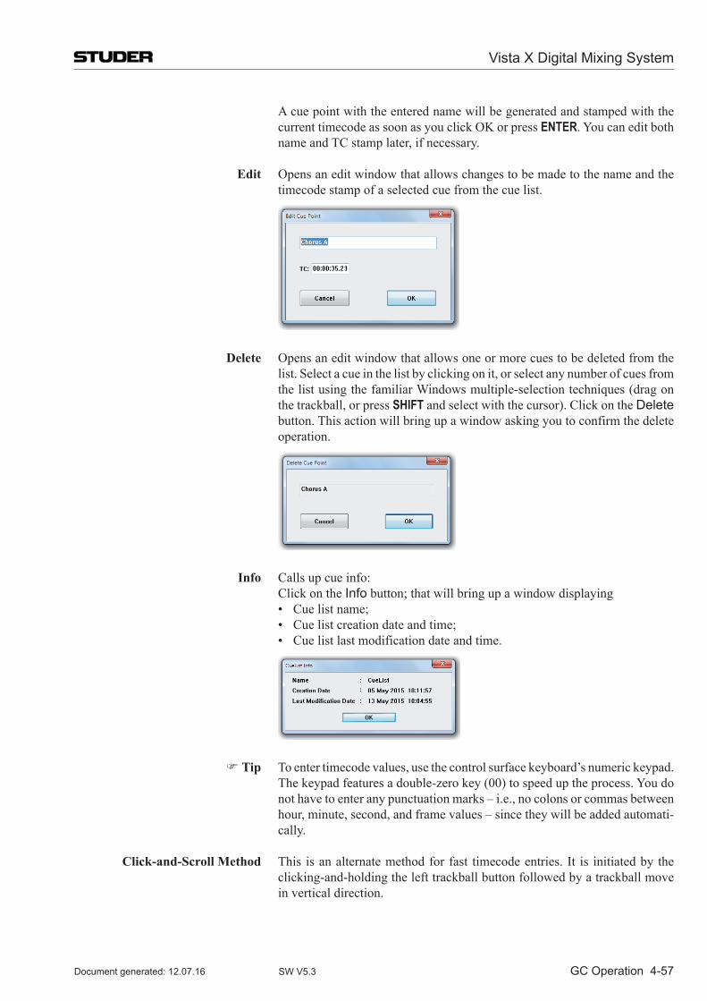
Vista X Digital Mixing System
GC Operation 4-57Document generated: 12.07.16 SW V5.3
A cue point with the entered name will be generated and stamped with the current timecode as soon as you click OK or press ENTER. You can edit both name and TC stamp later, if necessary.
Edit Opens an edit window that allows changes to be made to the name and the timecode stamp of a selected cue from the cue list.
Delete Opens an edit window that allows one or more cues to be deleted from the list. Select a cue in the list by clicking on it, or select any number of cues from the list using the familiar Windows multiple-selection techniques (drag on the trackball, or press SHIFT and select with the cursor). Click on the Delete button. This action will bring up a window asking you to confirm the delete operation.
Info Calls up cue info: Click on the Info button; that will bring up a window displaying • Cuelistname; • Cuelistcreationdateandtime; • Cuelistlastmodificationdateandtime.
Tip To enter timecode values, use the control surface keyboard’s numeric keypad. The keypad features a double-zero key (00) to speed up the process. You do not have to enter any punctuation marks – i.e., no colons or commas between hour, minute, second, and frame values – since they will be added automati-cally.
Click-and-Scroll Method This is an alternate method for fast timecode entries. It is initiated by the clicking-and-holding the left trackball button followed by a trackball move in vertical direction.
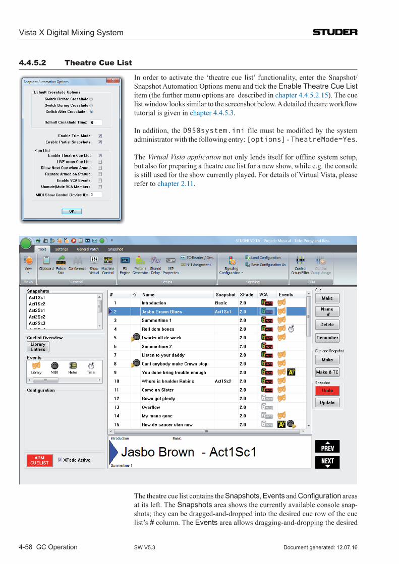
Vista X Digital Mixing System
4-58 GC Operation Document generated: 12.07.16SW V5.3
4.4.5.2 Theatre Cue list
In order to activate the ‘theatre cue list’ functionality, enter the Snapshot/Snapshot Automation Options menu and tick the Enable Theatre Cue List item (the further menu options are described in chapter 4.4.5.2.15). The cue list window looks similar to the screenshot below. A detailed theatre workflow tutorial is given in chapter 4.4.5.3.
In addition, the D950system.ini file must be modified by the system administrator with the following entry: [options] - TheatreMode=Yes.
The Virtual Vista application not only lends itself for offline system setup, but also for preparing a theatre cue list for a new show, while e.g. the console is still used for the show currently played. For details of Virtual Vista, please refer to chapter 2.11.
The theatre cue list contains the Snapshots, Events and Configuration areas at its left. The Snapshots area shows the currently available console snap-shots; they can be dragged-and-dropped into the desired cue row of the cue list’s # column. The Events area allows dragging-and-dropping the desired
Vista X Digital Mixing System
GC Operation 4-59Document generated: 12.07.16 SW V5.3
events into the cue list’s Events column. If one of the events is selected, the Configuration area shows the settings and options useful for the current event.
A click on the Library Entries button opens the cue actor overview window that gives a comprehensive overview of all library events.
At the bottom of the theatre cue list window, the name of the current cue (and snapshot, if appropriate) is indicated in large characters so that it may be clearly read even from a certain distance. The last and the next cue’s names are displayed as well at the upper or lower border of this indication field in small characters. Any desired cue from the list can be recalled either by double-clicking on its name or by using the PREV or NEXT buttons.
The buttons at the right-hand edge of the theatre cue list: Cue Name and Number The Name # button is used for entering/editing a name for the currently
selected cue, and for manually editing its number. Make a New Cue Make inserts a new cue below the one currently selected. Its number is gen-
erated automatically. If the selected cue is, e.g., #14, the new cue’s number will be #14.5, and its name will be Cue 14.5; a next one will be #14.75, etc.
Renumber Cues After having edited the theatre cue list by making new or deleting cues, the Renumber button allows renumbering a selection of cues. In order to renum-ber the complete list, simply select all cues before.
Make Cue and Snapshot The Cue and Snapshot - Make button allows generating a cue, together with a snapshot of the whole console, in one go; the new cue is named according to the rule given above, and its name will be ‘SNAPSHOT #x’.
With Snapshot Update, the snapshot of the selected cue is updated with the current console settings; this can be undone using Snapshot Undo.
4.4.5.2.1 Cross-Fading Between Cues
Each cue displays a value for the cross-fade time when activating this cue. To modify the cross-fade time, point to the digits, hold the left trackball button, and scroll up or down. Alternatively, enter the number using the numerical keypad.
When clicking on the cross-fade time once, options for the behavior of switches during cross-fades become visible in the left part of the window (Options Area). For each cue it can be defined whether the switches should change their state before, in the middle, or after the cross-fade – while the other parameters are changing seamlessly.
Within a cue, a partial snapshot may be recalled, influencing only certain parts of the console. If a larger cross-fade time is applied to this and the next cue is recalled before the last cross-fade has been finished, there will be two cross-fades happening at the same time, possibly with different cross-fade times. Only if the two cues change the same parameters, the first cross-fade will stop and the second one is applied from this point onwards.
Example Given: All Faders are set to 0 dB. Cue #1 contains a partial snapshot, setting faders 1…10 to –20 dB, cross-fade
time 10 s. Cue #2 contains a partial snapshot, setting faders 11…20 to –40 dB, cross-
fade time 1 s. Procedure: Recall Cue #1, e.g. by double-clicking on its name. Faders 1…10 will start
moving down slowly. Five seconds later, Cue #2 is recalled. Faders 11…20 will start moving down.
Vista X Digital Mixing System
4-60 GC Operation Document generated: 12.07.16SW V5.3
After six seconds, faders 11…20 have finished their cross-fade and are set to –40 dB.
After ten seconds faders 1…10 also have finished their cross-fade and are set to –20 dB.
4.4.5.2.2 Organizing Events
It is possible to move events from one cue to a different one by using drag-and-drop. Also, snapshots may be moved between cues using drag-and-drop. In this way, snapshots can be replaced or exchanged within cues.
4.4.5.2.3 Updating Snapshots
The snapshot names displayed in the cue list are only referring to the corre-sponding snapshot contained in the snapshot list. It is therefore possible to use the same snapshot in multiple cues, possibly using different cross-fade times. When updating a snapshot, the cues containing it will automatically use the updated snapshot.
Note Snapshots can be updated from within the cue list window; right-click on the snapshot within the snapshot list in the top left corner in order to get different options, such as Make, Update, Name, etc.
Alternatively a button has been introduced which allows updating a snapshot directly out of the cue list window (not shown in illustrations above.)
MIDI MIDI note and program changes can be used both as sources for firing a cue, or as events to be sent out of the console upon recalling a cue. In order to attach a MIDI command as a cue trigger, drag-and-drop the MIDI icon to the left side of the cue name. If a MIDI command should be sent out upon cue recall, drag-and-drop the MIDI icon to the right side of the cue. Multiple events may be added to the right side of a cue.
4.4.5.2.4 BlackOut
It is possible to make the whole console surface go dark. This function is useful in case complete darkness is required, e.g. in a theatre environment. This function also includes the optional console illumination. It can only be activated if the cue list is armed. The console lights come back on again either by the next BlackOut event (Parameter: OFF) or by pressing F3 in the control bay.
4.4.5.2.5 Arm CueList
To avoid undesired influence by external devices, the cue list inputs may be armed or disarmed. If not armed, the BlackOut function, the MIDI IN events, and the NEXT and PREVIOUS keys in the control bay are disabled.
It is possible to set the default value of the ARM CUELIST button by using the Snapshot/Snapshot Automation Options menu.
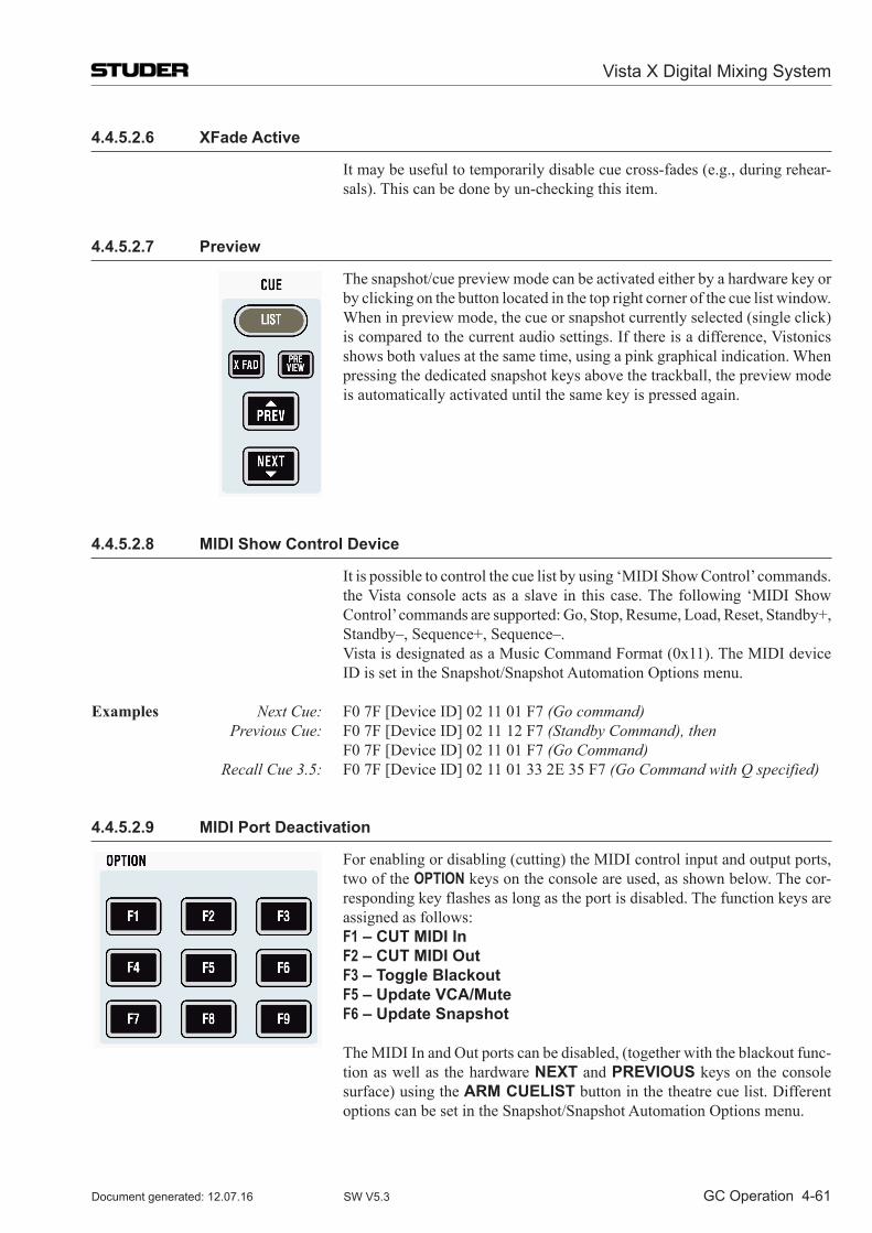
Vista X Digital Mixing System
GC Operation 4-61Document generated: 12.07.16 SW V5.3
4.4.5.2.6 XFade Active
It may be useful to temporarily disable cue cross-fades (e.g., during rehear-sals). This can be done by un-checking this item.
4.4.5.2.7 Preview
The snapshot/cue preview mode can be activated either by a hardware key or by clicking on the button located in the top right corner of the cue list window. When in preview mode, the cue or snapshot currently selected (single click) is compared to the current audio settings. If there is a difference, Vistonics shows both values at the same time, using a pink graphical indication. When pressing the dedicated snapshot keys above the trackball, the preview mode is automatically activated until the same key is pressed again.
4.4.5.2.8 MIDI Show Control Device
It is possible to control the cue list by using ‘MIDI Show Control’ commands. the Vista console acts as a slave in this case. The following ‘MIDI Show Control’ commands are supported: Go, Stop, Resume, Load, Reset, Standby+, Standby–, Sequence+, Sequence–.
Vista is designated as a Music Command Format (0x11). The MIDI device ID is set in the Snapshot/Snapshot Automation Options menu.
Examples Next Cue: F0 7F [Device ID] 02 11 01 F7 (Go command) Previous Cue: F0 7F [Device ID] 02 11 12 F7 (Standby Command), then F0 7F [Device ID] 02 11 01 F7 (Go Command) Recall Cue 3.5: F0 7F [Device ID] 02 11 01 33 2E 35 F7 (Go Command with Q specified)
4.4.5.2.9 MIDI Port Deactivation
For enabling or disabling (cutting) the MIDI control input and output ports, two of the OPTION keys on the console are used, as shown below. The cor-responding key flashes as long as the port is disabled. The function keys are assigned as follows:
F1 – CUT MIDI In F2 – CUT MIDI Out F3 – Toggle Blackout F5 – Update VCA/Mute F6 – Update Snapshot
The MIDI In and Out ports can be disabled, (together with the blackout func-tion as well as the hardware NEXT and PREVIOUS keys on the console surface) using the ARM CUELIST button in the theatre cue list. Different options can be set in the Snapshot/Snapshot Automation Options menu.
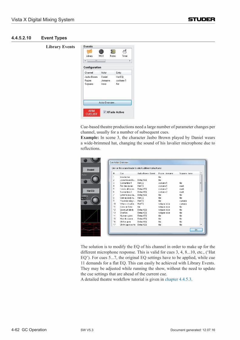
Vista X Digital Mixing System
4-62 GC Operation Document generated: 12.07.16SW V5.3
4.4.5.2.10 Event Types
Library Events
Cue-based theatre productions need a large number of parameter changes per channel, usually for a number of subsequent cues.
Example: In scene 3, the character Jasbo Brown played by Daniel wears a wide-brimmed hat, changing the sound of his lavalier microphone due to reflections.
The solution is to modify the EQ of his channel in order to make up for the different microphone response. This is valid for cues 3, 4, 8...10, etc., (‘Hat EQ’). For cues 5...7, the original EQ settings have to be applied, while cue 11 demands for a flat EQ. This can easily be achieved with Library Events. They may be adjusted while running the show, without the need to update the cue settings that are ahead of the current cue.
A detailed theatre workflow tutorial is given in chapter 4.4.5.3.
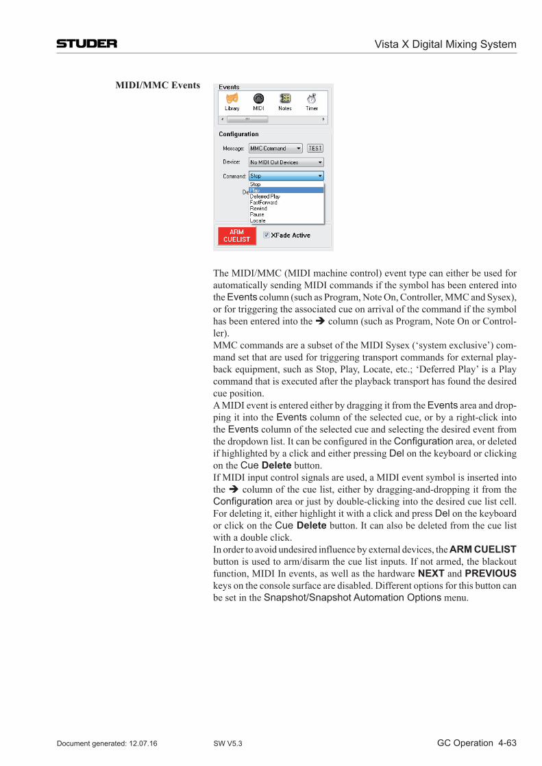
Vista X Digital Mixing System
GC Operation 4-63Document generated: 12.07.16 SW V5.3
MIDI/MMC Events
The MIDI/MMC (MIDI machine control) event type can either be used for automatically sending MIDI commands if the symbol has been entered into the Events column (such as Program, Note On, Controller, MMC and Sysex), or for triggering the associated cue on arrival of the command if the symbol has been entered into the column (such as Program, Note On or Control-ler).
MMC commands are a subset of the MIDI Sysex (‘system exclusive’) com-mand set that are used for triggering transport commands for external play-back equipment, such as Stop, Play, Locate, etc.; ‘Deferred Play’ is a Play command that is executed after the playback transport has found the desired cue position.
A MIDI event is entered either by dragging it from the Events area and drop-ping it into the Events column of the selected cue, or by a right-click into the Events column of the selected cue and selecting the desired event from the dropdown list. It can be configured in the Configuration area, or deleted if highlighted by a click and either pressing Del on the keyboard or clicking on the Cue Delete button.
If MIDI input control signals are used, a MIDI event symbol is inserted into the column of the cue list, either by dragging-and-dropping it from the Configuration area or just by double-clicking into the desired cue list cell. For deleting it, either highlight it with a click and press Del on the keyboard or click on the Cue Delete button. It can also be deleted from the cue list with a double click.
In order to avoid undesired influence by external devices, the ARM CUELIST button is used to arm/disarm the cue list inputs. If not armed, the blackout function, MIDI In events, as well as the hardware NEXT and PREVIOUS keys on the console surface are disabled. Different options for this button can be set in the Snapshot/Snapshot Automation Options menu.
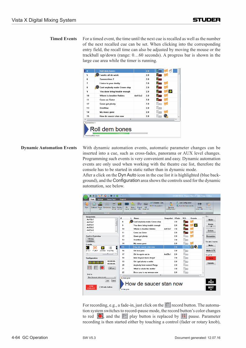
Vista X Digital Mixing System
4-64 GC Operation Document generated: 12.07.16SW V5.3
Timed Events For a timed event, the time until the next cue is recalled as well as the number of the next recalled cue can be set. When clicking into the corresponding entry field, the recall time can also be adjusted by moving the mouse or the trackball up/down (range: 0…60 seconds). A progress bar is shown in the large cue area while the timer is running.
Dynamic Automation Events With dynamic automation events, automatic parameter changes can be inserted into a cue, such as cross-fades, panorama or AUX level changes. Programming such events is very convenient and easy. Dynamic automation events are only used when working with the theatre cue list, therefore the console has to be started in static rather than in dynamic mode.
After a click on the Dyn Auto icon in the cue list it is highlighted (blue back-ground), and the Configuration area shows the controls used for the dynamic automation, see below.
For recording, e.g., a fade-in, just click on the record button. The automa-tion system switches to record-pause mode, the record button’s color changes to red , and the play button is replaced by pause. Parameter recording is then started either by touching a control (fader or rotary knob),
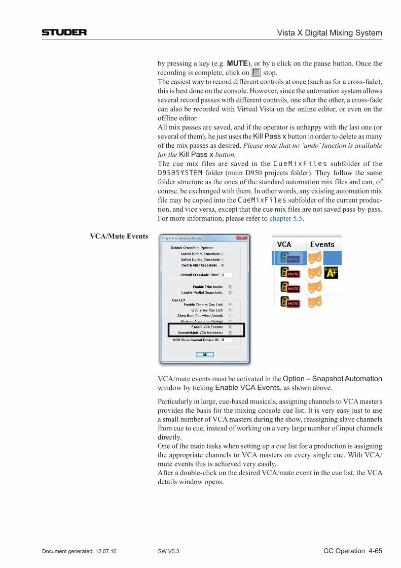
Vista X Digital Mixing System
GC Operation 4-65Document generated: 12.07.16 SW V5.3
by pressing a key (e.g. MUTE), or by a click on the pause button. Once the recording is complete, click on stop.
The easiest way to record different controls at once (such as for a cross-fade), this is best done on the console. However, since the automation system allows several record passes with different controls, one after the other, a cross-fade can also be recorded with Virtual Vista on the online editor, or even on the offline editor.
All mix passes are saved, and if the operator is unhappy with the last one (or several of them), he just uses the Kill Pass x button in order to delete as many of the mix passes as desired. Please note that no ‘undo’ function is available for the Kill Pass x button.
The cue mix files are saved in the CueMixFiles subfolder of the D950SYSTEM folder (main D950 projects folder). They follow the same folder structure as the ones of the standard automation mix files and can, of course, be exchanged with them. In other words, any existing automation mix file may be copied into the CueMixFiles subfolder of the current produc-tion, and vice versa, except that the cue mix files are not saved pass-by-pass. For more information, please refer to chapter 5.5.
VCA/Mute Events
VCA/mute events must be activated in the Option – Snapshot Automation window by ticking Enable VCA Events, as shown above.
Particularly in large, cue-based musicals, assigning channels to VCA masters provides the basis for the mixing console cue list. It is very easy just to use a small number of VCA masters during the show, reassigning slave channels from cue to cue, instead of working on a very large number of input channels directly.
One of the main tasks when setting up a cue list for a production is assigning the appropriate channels to VCA masters on every single cue. With VCA/mute events this is achieved very easily.
After a double-click on the desired VCA/mute event in the cue list, the VCA details window opens.
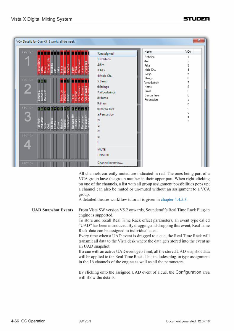
Vista X Digital Mixing System
4-66 GC Operation Document generated: 12.07.16SW V5.3
All channels currently muted are indicated in red. The ones being part of a VCA group have the group number in their upper part. When right-clicking on one of the channels, a list with all group assignment possibilities pops up; a channel can also be muted or un-muted without an assignment to a VCA group.
A detailed theatre workflow tutorial is given in chapter 4.4.5.3.
UAD Snapshot Events From Vista SW version V5.2 onwards, Soundcraft’s Real Time Rack Plug-in engine is supported.
To store and recall Real Time Rack effect parameters, an event type called “UAD” has been introduced. By dragging and dropping this event, Real Time Rack-data can be assigned to individual cues.
Every time when a UAD event is dragged to a cue, the Real Time Rack will transmit all data to the Vista desk where the data gets stored into the event as an UAD snapshot.
If a cue with an active UAD event gets fired, all the stored UAD snapshot data will be applied to the Real Time Rack. This includes plug-in type assignment in the 16 channels of the engine as well as all the parameters.
By clicking onto the assigned UAD event of a cue, the Configuration area will show the details.
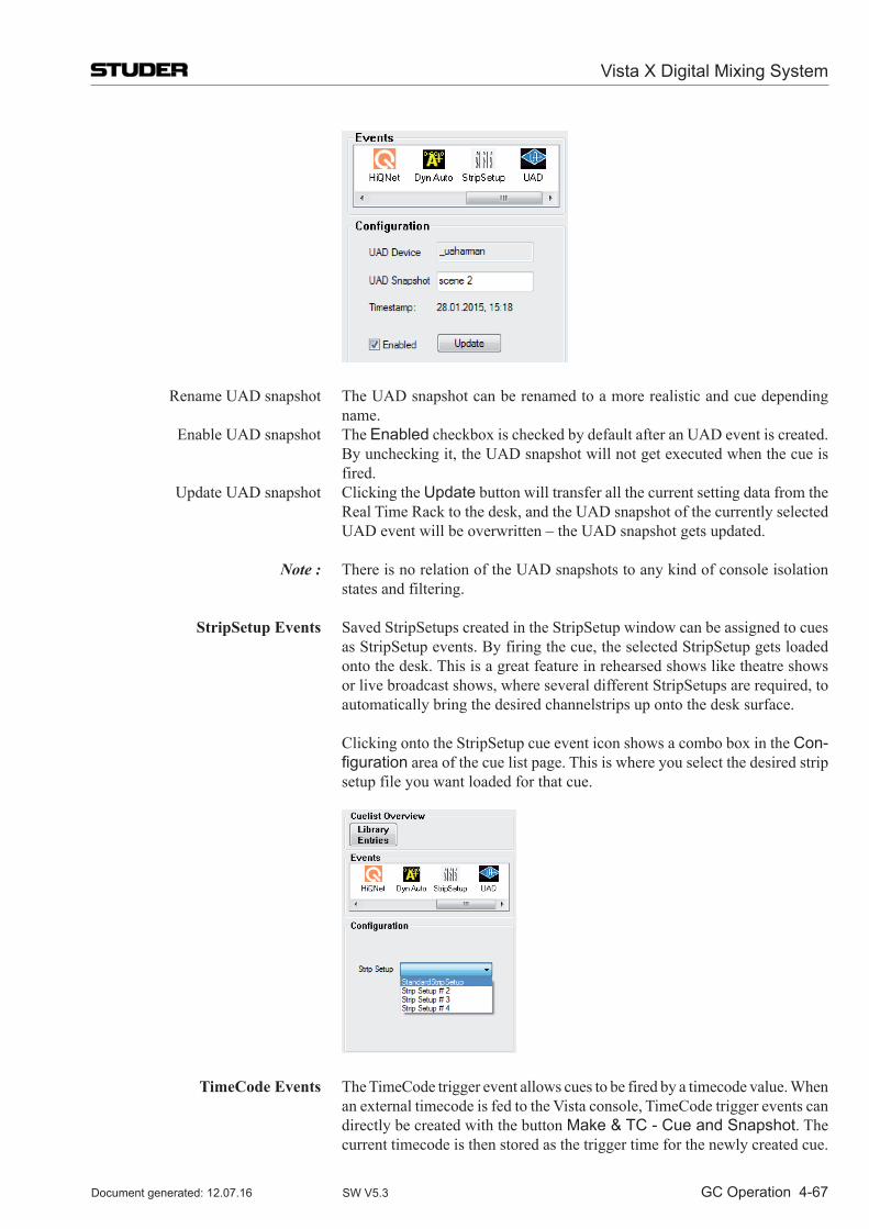
Vista X Digital Mixing System
GC Operation 4-67Document generated: 12.07.16 SW V5.3
Rename UAD snapshot The UAD snapshot can be renamed to a more realistic and cue depending name.
Enable UAD snapshot The Enabled checkbox is checked by default after an UAD event is created. By unchecking it, the UAD snapshot will not get executed when the cue is fired.
Update UAD snapshot Clicking the Update button will transfer all the current setting data from the Real Time Rack to the desk, and the UAD snapshot of the currently selected UAD event will be overwritten – the UAD snapshot gets updated.
Note : There is no relation of the UAD snapshots to any kind of console isolation states and filtering.
StripSetup Events Saved StripSetups created in the StripSetup window can be assigned to cues as StripSetup events. By firing the cue, the selected StripSetup gets loaded onto the desk. This is a great feature in rehearsed shows like theatre shows or live broadcast shows, where several different StripSetups are required, to automatically bring the desired channelstrips up onto the desk surface.
Clicking onto the StripSetup cue event icon shows a combo box in the Con-figuration area of the cue list page. This is where you select the desired strip setup file you want loaded for that cue.
TimeCode Events The TimeCode trigger event allows cues to be fired by a timecode value. When an external timecode is fed to the Vista console, TimeCode trigger events can directly be created with the button Make & TC - Cue and Snapshot. The current timecode is then stored as the trigger time for the newly created cue.
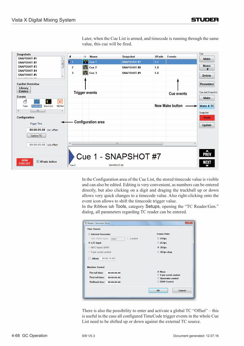
Vista X Digital Mixing System
4-68 GC Operation Document generated: 12.07.16SW V5.3
Later, when the Cue List is armed, and timecode is running through the same value, this cue will be fired.
Configuration area
Trigger events Cue events
New Make button
In the Configuration area of the Cue List, the stored timecode value is visible and can also be edited. Editing is very convenient, as numbers can be entered directly, but also clicking on a digit and draging the trackball up or down allows very quick changes to a timecode value. Also right-clicking onto the event icon allows to shift the timecode trigger value.
In the Ribbon tab Tools, category Setups, opening the “TC Reader/Gen.” dialog, all parameters regarding TC reader can be entered.
There is also the possibility to enter and activate a global TC “Offset” – this is useful in the case all configured TimeCode trigger events in the whole Cue List need to be shifted up or down against the external TC source.
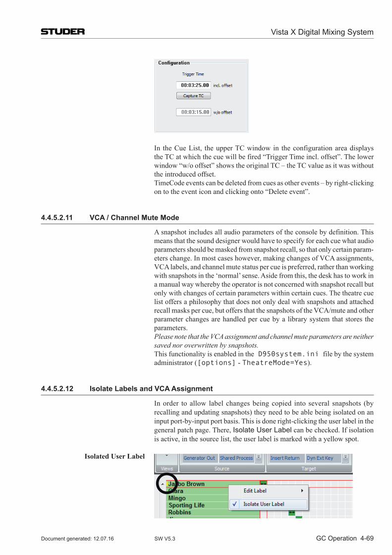
Vista X Digital Mixing System
GC Operation 4-69Document generated: 12.07.16 SW V5.3
In the Cue List, the upper TC window in the configuration area displays
the TC at which the cue will be fired “Trigger Time incl. offset”. The lower window “w/o offset” shows the original TC – the TC value as it was without the introduced offset.
TimeCode events can be deleted from cues as other events – by right-clicking on to the event icon and clicking onto “Delete event”.
4.4.5.2.11 VCA / Channel Mute Mode
A snapshot includes all audio parameters of the console by definition. This means that the sound designer would have to specify for each cue what audio parameters should be masked from snapshot recall, so that only certain param-eters change. In most cases however, making changes of VCA assignments, VCA labels, and channel mute status per cue is preferred, rather than working with snapshots in the ‘normal’ sense. Aside from this, the desk has to work in a manual way whereby the operator is not concerned with snapshot recall but only with changes of certain parameters within certain cues. The theatre cue list offers a philosophy that does not only deal with snapshots and attached recall masks per cue, but offers that the snapshots of the VCA/mute and other parameter changes are handled per cue by a library system that stores the parameters.
Please note that the VCA assignment and channel mute parameters are neither saved nor overwritten by snapshots.
This functionality is enabled in the D950system.ini file by the system administrator ([options] - TheatreMode=Yes).
4.4.5.2.12 Isolate Labels and VCA Assignment
In order to allow label changes being copied into several snapshots (by recalling and updating snapshots) they need to be able being isolated on an input port-by-input port basis. This is done right-clicking the user label in the general patch page. There, Isolate User Label can be checked. If isolation is active, in the source list, the user label is marked with a yellow spot.
Isolated User Label
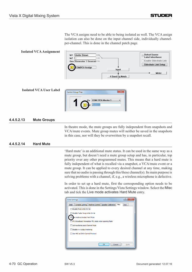
Vista X Digital Mixing System
4-70 GC Operation Document generated: 12.07.16SW V5.3
The VCA assigns need to be able to being isolated as well. The VCA assign isolation can also be done on the input channel side, individually channel-per-channel. This is done in the channel patch page.
Isolated VCA Assignment
Isolated VCA User Label
4.4.5.2.13 Mute Groups
In theatre mode, the mute groups are fully independent from snapshots and VCA/mute events. Mute group mutes will neither be saved in the snapshots in this case, nor will they be overwritten by a snapshot recall.
4.4.5.2.14 Hard Mute
‘Hard mute’ is an additional mute status. It can be used in the same way as a mute group, but doesn’t need a mute group setup and has, in particular, top priority over any other programmed mutes. This means that a hard mute is fully independent of what is recalled via a snapshot, a VCA/mute event or a mute group. It can be applied to every desired channel at any time, making sure that no audio is passing through this/these channel(s). Its main purpose is solving problems with a channel, if, e.g., a wireless microphone is defective.
In order to set up a hard mute, first the corresponding option needs to be activated. This is done in the Settings/Vista Settings window. Select the Misc tab and tick the Live mode activates Hard Mute entry.

Vista X Digital Mixing System
GC Operation 4-71Document generated: 12.07.16 SW V5.3
A click on the LIVE button (or pressing the small LIVE key in the desk’s CONTROL ROOM monitor section) followed by a channel MUTE button acti-vates a hard mute of this channel, regardless whether this channel is currently muted or not. If a channel is hard-muted, a indicator appears in the Vistonics label area, and the MUTE button is illuminated.
If a hard mute is applied to a channel that already has a ‘soft mute’ caused either by the system (via a snapshot or a VCA/mute event) or manually with the MUTE button, this is indicated by illuminating the MUTE button together with the small MUTE LED, as shown below.
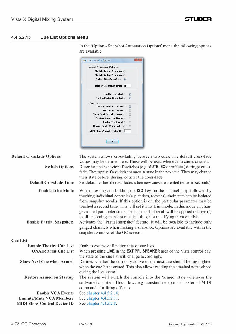
Vista X Digital Mixing System
4-72 GC Operation Document generated: 12.07.16SW V5.3
4.4.5.2.15 Cue List Options Menu
In the ‘Option - Snapshot Automation Options’ menu the following options are available:
Default Crossfade Options The system allows cross-fading between two cues. The default cross-fade values may be defined here. These will be used whenever a cue is created.
Switch Options Describes the behavior of switches (e.g. MUTE, EQ on/off etc.) during a cross-fade. They apply if a switch changes its state in the next cue. They may change their state before, during, or after the cross-fade.
Default Crossfade Time Set default value of cross-fades when new cues are created (enter in seconds).
Enable Trim Mode When pressing-and-holding the ISO key on the channel strip followed by touching individual controls (e.g. faders, rotaries), their state can be isolated from snapshot recalls. If this option is on, the particular parameter may be touched a second time. This will set it into Trim mode. In this mode all chan-ges to that parameter since the last snapshot recall will be applied relative (!) to all upcoming snapshot recalls – thus, not modifying them on disk.
Enable Partial Snapshots Activates the ‘Partial snapshot’ feature. It will be possible to include only ganged channels when making a snapshot. Options are available within the snapshot window of the GC screen.
Cue List Enable Theatre Cue List Enables extensive functionality of cue lists. ONAIR arms Cue List When pressing LIVE in the EXT PFL SPEAKER area of the Vista control bay,
the state of the cue list will change accordingly. Show Next Cue when Armed Defines whether the currently active or the next cue should be highlighted
when the cue list is armed. This also allows reading the attached notes ahead during the live event.
Restore Armed on Startup The system will switch the console into the ‘armed’ state whenever the software is started. This allows e.g. constant reception of external MIDI commands for firing off cues.
Enable VCA Events See chapter 4.4.5.2.10. Unmute/Mute VCA Members See chapter 4.4.5.2.11. MIDI Show Control Device ID See chapter 4.4.5.2.8.
Vista X Digital Mixing System
GC Operation 4-73Document generated: 12.07.16 SW V5.3
4.4.5.3 Theatre Workflow Tutorial
In general, a cue-based production usually has a workflow similar to the fol-lowing scenario:
1. Console Setup The channels are labeled, patch connections are made, etc.2. Building Cues With the help of the script, the cues are created and named. VCAs are labeled and channels are assigned to VCAs. Mutes are made (per cue).3. Rehearsal Phase This is the first time that the cast is involved. No orchestra yet, just a piano.
Mic gains and EQs are set, but only in a hurry, since rehearsals go fast (through all cues).
With more rehearsals, the mic gain and EQ settings get refined. Cues need to be added.4. Dress Rehearsal Phase This is the first time that the orchestra/band is involved. These channels can
now be setup (gain, EQ, monitor mix). Now with dresses, props and orchestra, vocals sound different; mic gains and
EQs need to be refined.5. Preview Rehearsal Phase This is the first time that an audience is involved. Things sound different again
since the audience modifies the acoustics of the venue. Fader levels, gains and EQs need to be adapted.6. Shows During the show, the console operator reads the script, goes from cue to cue
and rides VCA master levels. Usually there is no time available for changing parameters apart from the VCA levels.
Basically, the channel settings don’t change anymore, but it may happen anyway (almost every show) that an actor or a musician of the orchestra needs to be replaced due to sickness or other reasons.
This means that channel settings such as mic gain, EQ and dynamics need to be adapted to the current understudy actor; this is, however, only required for the corresponding input channels.
Glossary: Character / Role The name or term of the character or role in the script, such as Romeo, Julia, etc. It is very important to understand that one input channel of the console should always be fed with the mic signal of one certain character/role through-out the whole play.
Actor Name of the person who is playing a specific character/role. Understudy Actor who replaces the main actor in case of sickness, different shifts, etc. Cast The ensemble/company, i.e. all (or several) actors or all actors of a play.
Conventions for the Workflow Suggested Below: • Aninputchanneloftheconsoleisequaltoacharacteroftheplay. E.g.Inpm1=Romeo;Inpm2=Julia,etc. • WhentheroleofRomeoisplayedbyanactorcalledJohnSmith,anactor
for Romeo’s role (Inp m1) needs to be created whose name is John Smith. • Lateron,anunderstudyactorcanbecreatedasacopyofJohnSmithbut
with the actual understudy’s name.
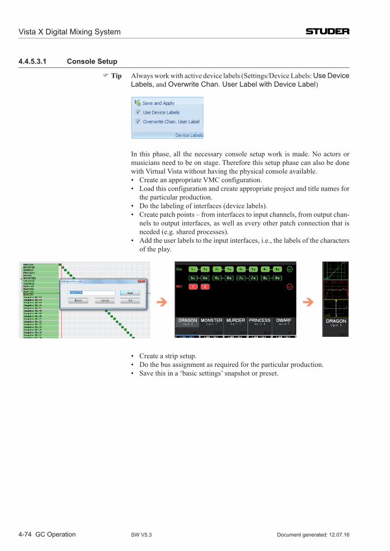
Vista X Digital Mixing System
4-74 GC Operation Document generated: 12.07.16SW V5.3
4.4.5.3.1 Console Setup
Tip Always work with active device labels (Settings/Device Labels: Use Device Labels, and Overwrite Chan. User Label with Device Label)
In this phase, all the necessary console setup work is made. No actors or musicians need to be on stage. Therefore this setup phase can also be done with Virtual Vista without having the physical console available.
• CreateanappropriateVMCconfiguration. • Loadthisconfigurationandcreateappropriateprojectandtitlenamesfor the particular production. • Dothelabelingofinterfaces(devicelabels). • Createpatchpoints–frominterfacestoinputchannels,fromoutputchan-
nels to output interfaces, as well as every other patch connection that is needed (e.g. shared processes).
• Addtheuserlabelstotheinputinterfaces,i.e.,thelabelsofthecharactersof the play.
• Createastripsetup. • Dothebusassignmentasrequiredfortheparticularproduction. • Savethisina‘basicsettings’snapshotorpreset.
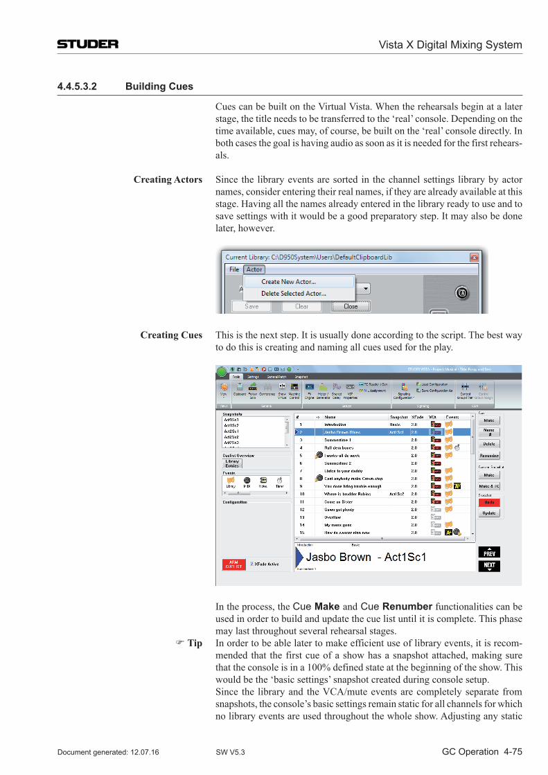
Vista X Digital Mixing System
GC Operation 4-75Document generated: 12.07.16 SW V5.3
4.4.5.3.2 Building Cues
Cues can be built on the Virtual Vista. When the rehearsals begin at a later stage, the title needs to be transferred to the ‘real’ console. Depending on the time available, cues may, of course, be built on the ‘real’ console directly. In both cases the goal is having audio as soon as it is needed for the first rehears-als.
Creating Actors Since the library events are sorted in the channel settings library by actor names, consider entering their real names, if they are already available at this stage. Having all the names already entered in the library ready to use and to save settings with it would be a good preparatory step. It may also be done later, however.
Creating Cues This is the next step. It is usually done according to the script. The best way to do this is creating and naming all cues used for the play.
In the process, the Cue Make and Cue Renumber functionalities can be used in order to build and update the cue list until it is complete. This phase may last throughout several rehearsal stages.
Tip In order to be able later to make efficient use of library events, it is recom-mended that the first cue of a show has a snapshot attached, making sure that the console is in a 100% defined state at the beginning of the show. This would be the ‘basic settings’ snapshot created during console setup.
Since the library and the VCA/mute events are completely separate from snapshots, the console’s basic settings remain static for all channels for which no library events are used throughout the whole show. Adjusting any static
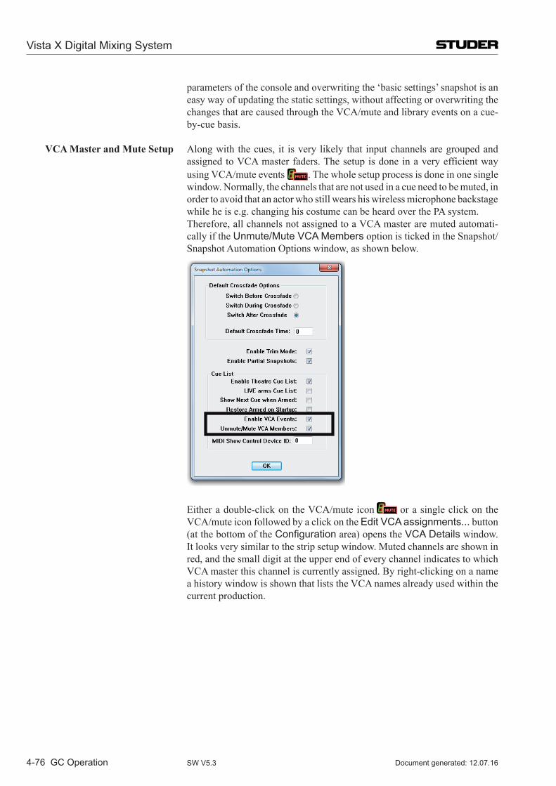
Vista X Digital Mixing System
4-76 GC Operation Document generated: 12.07.16SW V5.3
parameters of the console and overwriting the ‘basic settings’ snapshot is an easy way of updating the static settings, without affecting or overwriting the changes that are caused through the VCA/mute and library events on a cue-by-cue basis.
VCA Master and Mute Setup Along with the cues, it is very likely that input channels are grouped and assigned to VCA master faders. The setup is done in a very efficient way using VCA/mute events . The whole setup process is done in one single window. Normally, the channels that are not used in a cue need to be muted, in order to avoid that an actor who still wears his wireless microphone backstage while he is e.g. changing his costume can be heard over the PA system.
Therefore, all channels not assigned to a VCA master are muted automati-cally if the Unmute/Mute VCA Members option is ticked in the Snapshot/Snapshot Automation Options window, as shown below.
Either a double-click on the VCA/mute icon or a single click on the VCA/mute icon followed by a click on the Edit VCA assignments... button (at the bottom of the Configuration area) opens the VCA Details window. It looks very similar to the strip setup window. Muted channels are shown in red, and the small digit at the upper end of every channel indicates to which VCA master this channel is currently assigned. By right-clicking on a name a history window is shown that lists the VCA names already used within the current production.
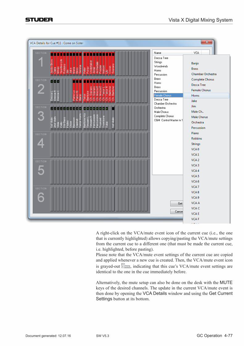
Vista X Digital Mixing System
GC Operation 4-77Document generated: 12.07.16 SW V5.3
A right-click on the VCA/mute event icon of the current cue (i.e., the one that is currently highlighted) allows copying/pasting the VCA/mute settings from the current cue to a different one (that must be made the current cue, i.e. highlighted, before pasting).
Please note that the VCA/mute event settings of the current cue are copied and applied whenever a new cue is created. Then, the VCA/mute event icon is grayed-out , indicating that this cue’s VCA/mute event settings are identical to the one in the cue immediately before.
Alternatively, the mute setup can also be done on the desk with the MUTE keys of the desired channels. The update in the current VCA/mute event is then done by opening the VCA Details window and using the Get Current Settings button at its bottom.
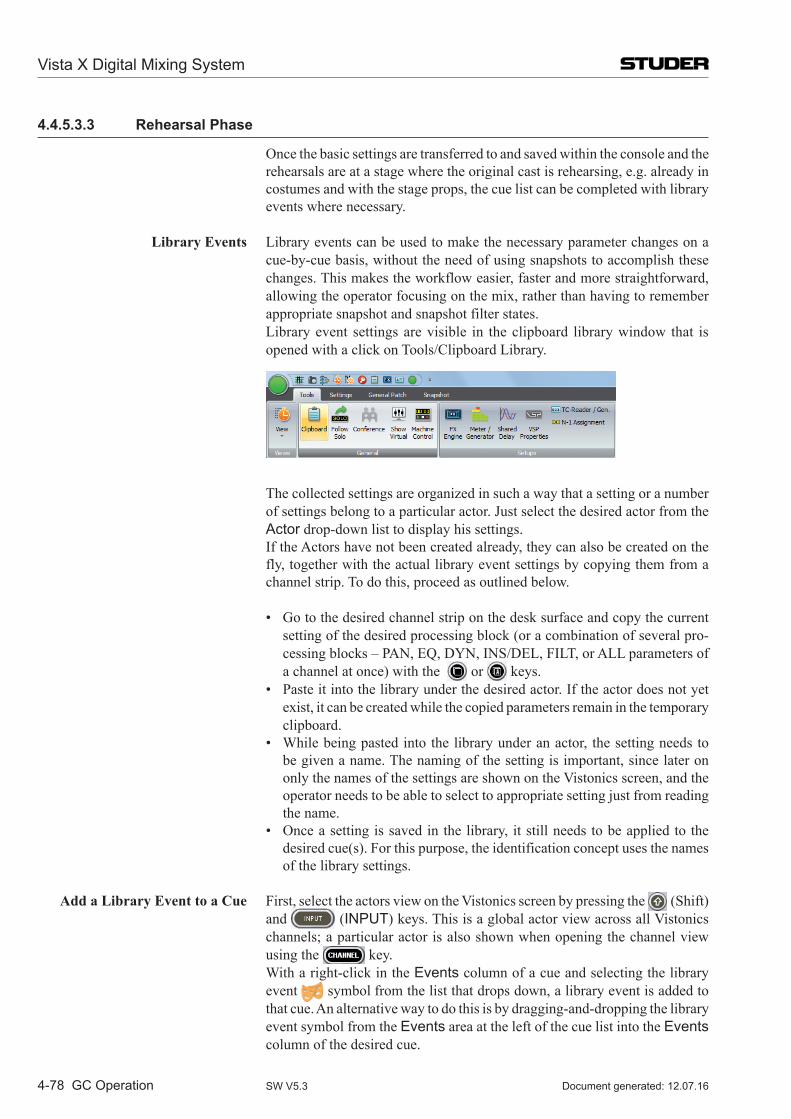
Vista X Digital Mixing System
4-78 GC Operation Document generated: 12.07.16SW V5.3
4.4.5.3.3 Rehearsal Phase
Once the basic settings are transferred to and saved within the console and the rehearsals are at a stage where the original cast is rehearsing, e.g. already in costumes and with the stage props, the cue list can be completed with library events where necessary.
Library Events Library events can be used to make the necessary parameter changes on a cue-by-cue basis, without the need of using snapshots to accomplish these changes. This makes the workflow easier, faster and more straightforward, allowing the operator focusing on the mix, rather than having to remember appropriate snapshot and snapshot filter states.
Library event settings are visible in the clipboard library window that is opened with a click on Tools/Clipboard Library.
The collected settings are organized in such a way that a setting or a number of settings belong to a particular actor. Just select the desired actor from the Actor drop-down list to display his settings.
If the Actors have not been created already, they can also be created on the fly, together with the actual library event settings by copying them from a channel strip. To do this, proceed as outlined below.
• Gotothedesiredchannelstriponthedesksurfaceandcopythecurrentsetting of the desired processing block (or a combination of several pro-cessing blocks – PAN, EQ, DYN, INS/DEL, FILT, or ALL parameters of a channel at once) with the or keys.
• Pasteitintothelibraryunderthedesiredactor.Iftheactordoesnotyetexist, it can be created while the copied parameters remain in the temporary clipboard.
• Whilebeingpastedintothelibraryunderanactor, thesettingneedstobe given a name. The naming of the setting is important, since later on only the names of the settings are shown on the Vistonics screen, and the operator needs to be able to select to appropriate setting just from reading the name.
• Onceasettingissavedinthelibrary, itstillneedstobeappliedtothedesired cue(s). For this purpose, the identification concept uses the names of the library settings.
Add a Library Event to a Cue First, select the actors view on the Vistonics screen by pressing the (Shift) and (INPUT) keys. This is a global actor view across all Vistonics channels; a particular actor is also shown when opening the channel view using the key.
With a right-click in the Events column of a cue and selecting the library event symbol from the list that drops down, a library event is added to that cue. An alternative way to do this is by dragging-and-dropping the library event symbol from the Events area at the left of the cue list into the Events column of the desired cue.
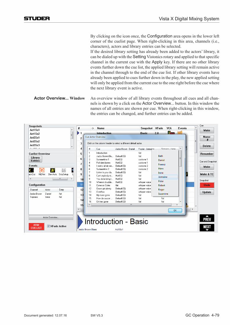
Vista X Digital Mixing System
GC Operation 4-79Document generated: 12.07.16 SW V5.3
By clicking on the icon once, the Configuration area opens in the lower left corner of the cuelist page. When right-clicking in this area, channels (i.e., characters), actors and library entries can be selected.
If the desired library setting has already been added to the actors’ library, it can be dialed up with the Setting Vistonics rotary and applied to that specific channel in the current cue with the Apply key. If there are no other library events further down the cue list, the applied library setting will remain active in the channel through to the end of the cue list. If other library events have already been applied to cues further down in the play, the new applied setting will only be applied from the current cue to the one right before the cue where the next library event is active.
Actor Overview... Window An overview window of all library events throughout all cues and all chan-nels is shown by a click on the Actor Overview... button. In this window the names of all entries are shown per cue. When right-clicking in this window, the entries can be changed, and further entries can be added.
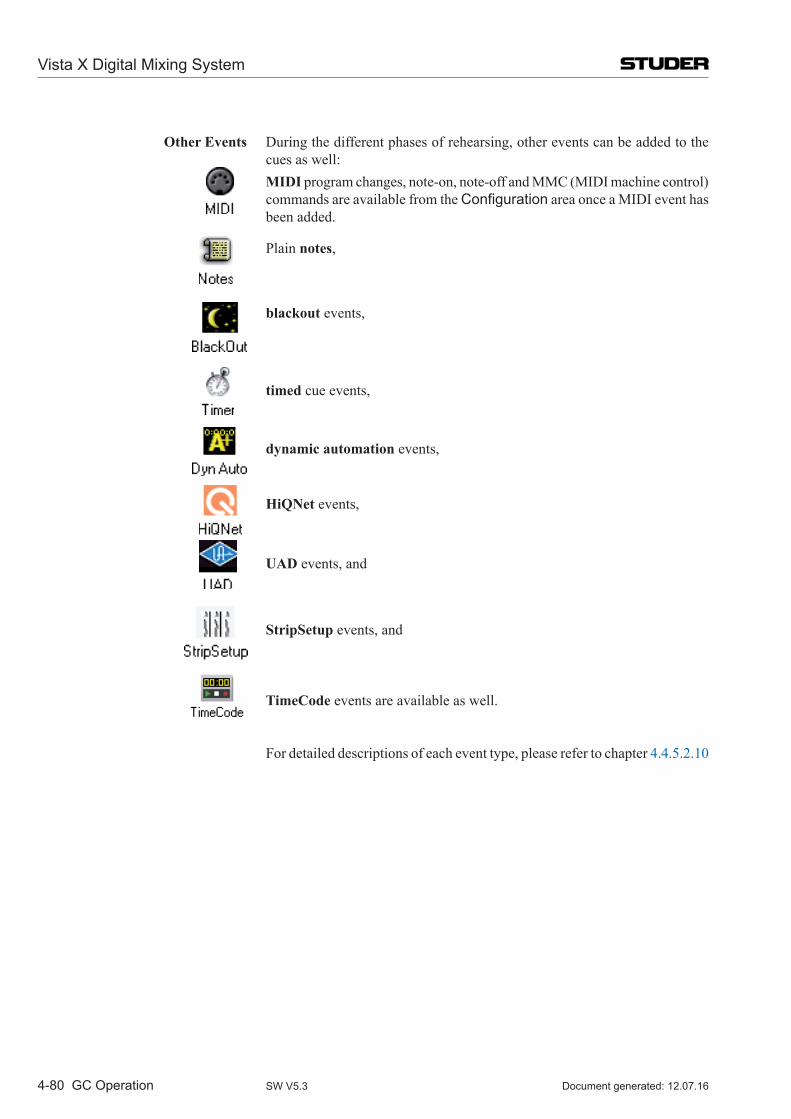
Vista X Digital Mixing System
4-80 GC Operation Document generated: 12.07.16SW V5.3
Other Events During the different phases of rehearsing, other events can be added to the cues as well:
MIDI program changes, note-on, note-off and MMC (MIDI machine control) commands are available from the Configuration area once a MIDI event has been added.
Plain notes,
blackout events,
timed cue events,
dynamic automation events,
HiQNet events,
UAD events, and
StripSetup events, and
TimeCode events are available as well.
For detailed descriptions of each event type, please refer to chapter 4.4.5.2.10
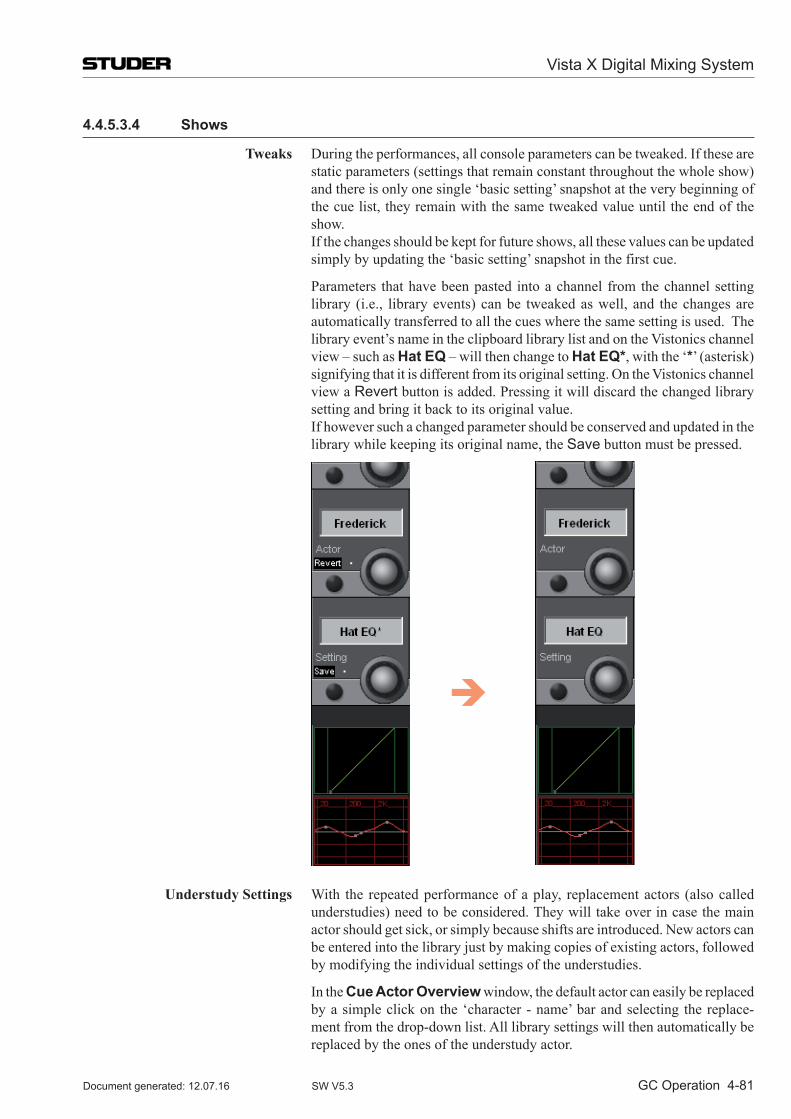
Vista X Digital Mixing System
GC Operation 4-81Document generated: 12.07.16 SW V5.3
4.4.5.3.4 Shows
Tweaks During the performances, all console parameters can be tweaked. If these are static parameters (settings that remain constant throughout the whole show) and there is only one single ‘basic setting’ snapshot at the very beginning of the cue list, they remain with the same tweaked value until the end of the show.
If the changes should be kept for future shows, all these values can be updated simply by updating the ‘basic setting’ snapshot in the first cue.
Parameters that have been pasted into a channel from the channel setting library (i.e., library events) can be tweaked as well, and the changes are automatically transferred to all the cues where the same setting is used. The library event’s name in the clipboard library list and on the Vistonics channel view – such as Hat EQ – will then change to Hat EQ*, with the ‘*’ (asterisk) signifying that it is different from its original setting. On the Vistonics channel view a Revert button is added. Pressing it will discard the changed library setting and bring it back to its original value.
If however such a changed parameter should be conserved and updated in the library while keeping its original name, the Save button must be pressed.
Understudy Settings With the repeated performance of a play, replacement actors (also called understudies) need to be considered. They will take over in case the main actor should get sick, or simply because shifts are introduced. New actors can be entered into the library just by making copies of existing actors, followed by modifying the individual settings of the understudies.
In the Cue Actor Overview window, the default actor can easily be replaced by a simple click on the ‘character - name’ bar and selecting the replace-ment from the drop-down list. All library settings will then automatically be replaced by the ones of the understudy actor.
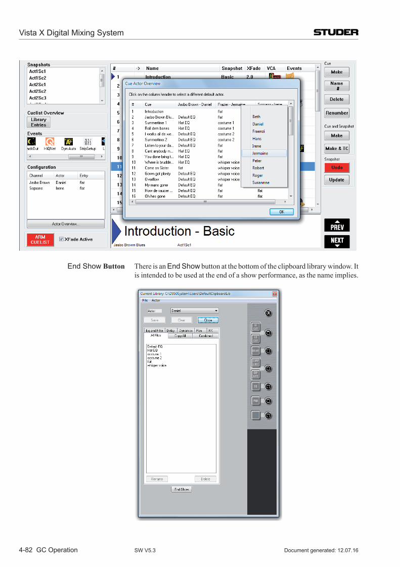
Vista X Digital Mixing System
4-82 GC Operation Document generated: 12.07.16SW V5.3
End Show Button There is an End Show button at the bottom of the clipboard library window. It is intended to be used at the end of a show performance, as the name implies.
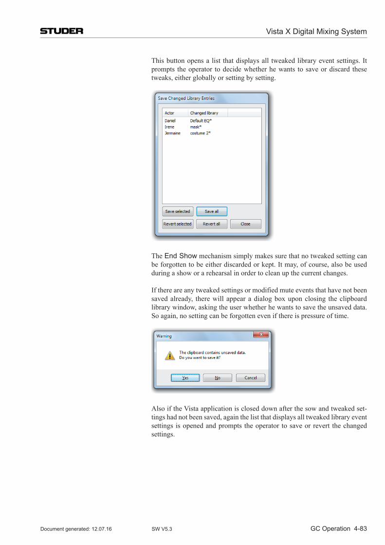
Vista X Digital Mixing System
GC Operation 4-83Document generated: 12.07.16 SW V5.3
This button opens a list that displays all tweaked library event settings. It prompts the operator to decide whether he wants to save or discard these tweaks, either globally or setting by setting.
The End Show mechanism simply makes sure that no tweaked setting can be forgotten to be either discarded or kept. It may, of course, also be used during a show or a rehearsal in order to clean up the current changes.
If there are any tweaked settings or modified mute events that have not been saved already, there will appear a dialog box upon closing the clipboard library window, asking the user whether he wants to save the unsaved data. So again, no setting can be forgotten even if there is pressure of time.
Also if the Vista application is closed down after the sow and tweaked set-tings had not been saved, again the list that displays all tweaked library event settings is opened and prompts the operator to save or revert the changed settings.
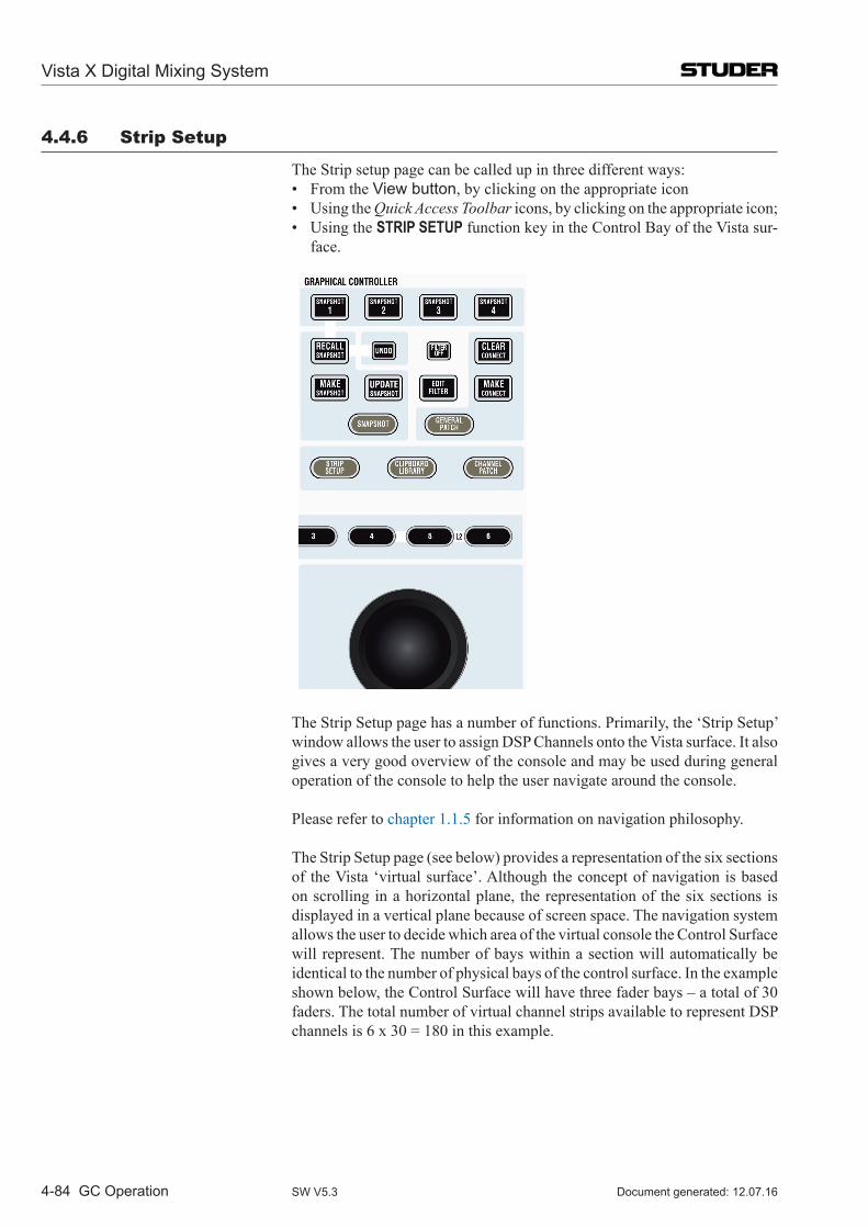
Vista X Digital Mixing System
4-84 GC Operation Document generated: 12.07.16SW V5.3
4.4.6 Strip Setup
The Strip setup page can be called up in three different ways: • FromtheView button, by clicking on the appropriate icon • UsingtheQuick Access Toolbar icons, by clicking on the appropriate icon; • UsingtheSTRIP SETUP function key in the Control Bay of the Vista sur-
face.
The Strip Setup page has a number of functions. Primarily, the ‘Strip Setup’ window allows the user to assign DSP Channels onto the Vista surface. It also gives a very good overview of the console and may be used during general operation of the console to help the user navigate around the console.
Please refer to chapter 1.1.5 for information on navigation philosophy.
The Strip Setup page (see below) provides a representation of the six sections of the Vista ‘virtual surface’. Although the concept of navigation is based on scrolling in a horizontal plane, the representation of the six sections is displayed in a vertical plane because of screen space. The navigation system allows the user to decide which area of the virtual console the Control Surface will represent. The number of bays within a section will automatically be identical to the number of physical bays of the control surface. In the example shown below, the Control Surface will have three fader bays – a total of 30 faders. The total number of virtual channel strips available to represent DSP channelsis6x30=180inthisexample.
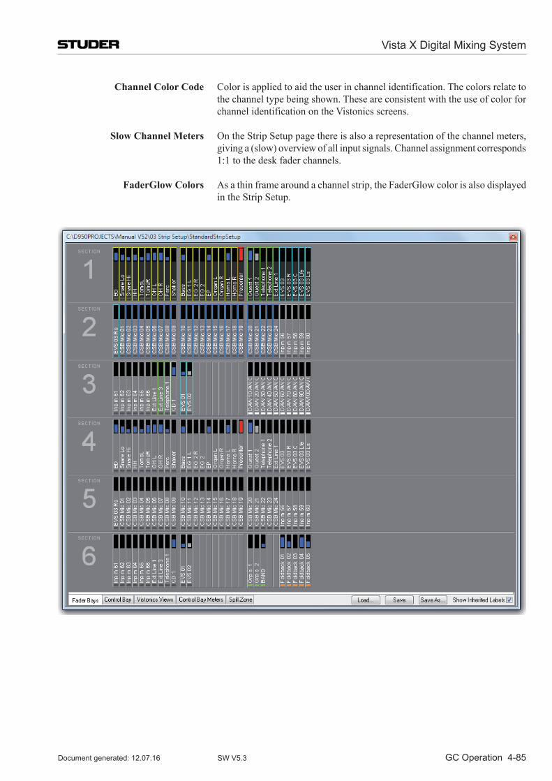
Vista X Digital Mixing System
GC Operation 4-85Document generated: 12.07.16 SW V5.3
Channel Color Code Color is applied to aid the user in channel identification. The colors relate to the channel type being shown. These are consistent with the use of color for channel identification on the Vistonics screens.
Slow Channel Meters On the Strip Setup page there is also a representation of the channel meters, giving a (slow) overview of all input signals. Channel assignment corresponds 1:1 to the desk fader channels.
FaderGlow Colors As a thin frame around a channel strip, the FaderGlow color is also displayed in the Strip Setup.
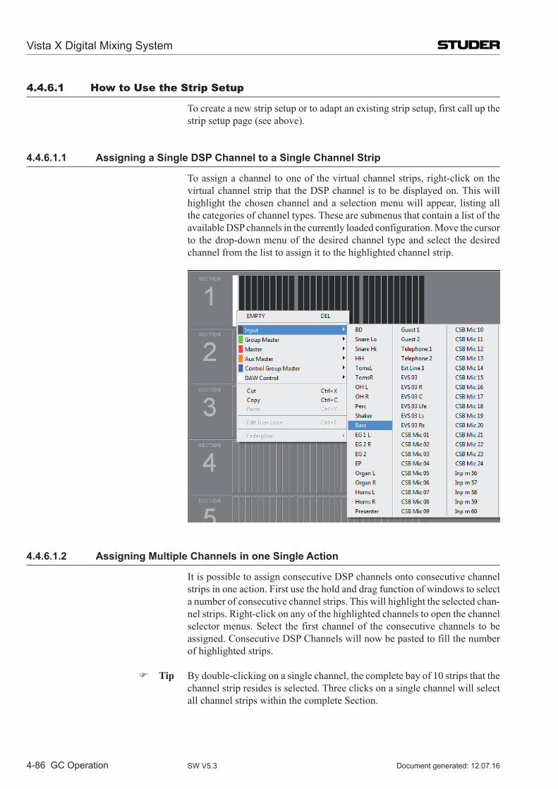
Vista X Digital Mixing System
4-86 GC Operation Document generated: 12.07.16SW V5.3
4.4.6.1 How to Use the Strip Setup
To create a new strip setup or to adapt an existing strip setup, first call up the strip setup page (see above).
4.4.6.1.1 Assigning a Single DSP Channel to a Single Channel Strip
To assign a channel to one of the virtual channel strips, right-click on the virtual channel strip that the DSP channel is to be displayed on. This will highlight the chosen channel and a selection menu will appear, listing all the categories of channel types. These are submenus that contain a list of the available DSP channels in the currently loaded configuration. Move the cursor to the drop-down menu of the desired channel type and select the desired channel from the list to assign it to the highlighted channel strip.
4.4.6.1.2 Assigning Multiple Channels in one Single Action
It is possible to assign consecutive DSP channels onto consecutive channel strips in one action. First use the hold and drag function of windows to select a number of consecutive channel strips. This will highlight the selected chan-nel strips. Right-click on any of the highlighted channels to open the channel selector menus. Select the first channel of the consecutive channels to be assigned. Consecutive DSP Channels will now be pasted to fill the number of highlighted strips.
Tip By double-clicking on a single channel, the complete bay of 10 strips that the channel strip resides is selected. Three clicks on a single channel will select all channel strips within the complete Section.
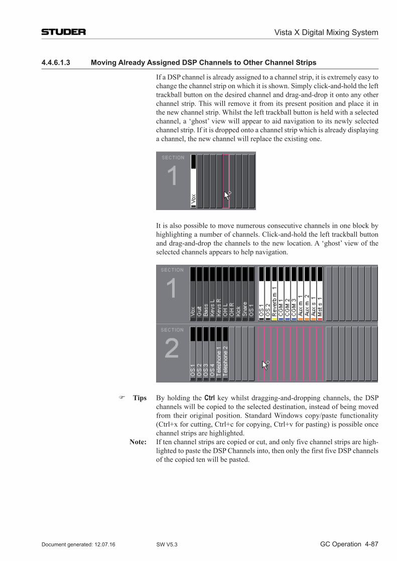
Vista X Digital Mixing System
GC Operation 4-87Document generated: 12.07.16 SW V5.3
4.4.6.1.3 Moving Already Assigned DSP Channels to Other Channel Strips
If a DSP channel is already assigned to a channel strip, it is extremely easy to change the channel strip on which it is shown. Simply click-and-hold the left trackball button on the desired channel and drag-and-drop it onto any other channel strip. This will remove it from its present position and place it in the new channel strip. Whilst the left trackball button is held with a selected channel, a ‘ghost’ view will appear to aid navigation to its newly selected channel strip. If it is dropped onto a channel strip which is already displaying a channel, the new channel will replace the existing one.
It is also possible to move numerous consecutive channels in one block by highlighting a number of channels. Click-and-hold the left trackball button and drag-and-drop the channels to the new location. A ‘ghost’ view of the selected channels appears to help navigation.
Tips By holding the Ctrl key whilst dragging-and-dropping channels, the DSP channels will be copied to the selected destination, instead of being moved from their original position. Standard Windows copy/paste functionality (Ctrl+x for cutting, Ctrl+c for copying, Ctrl+v for pasting) is possible once channel strips are highlighted.
Note: If ten channel strips are copied or cut, and only five channel strips are high-lighted to paste the DSP Channels into, then only the first five DSP channels of the copied ten will be pasted.
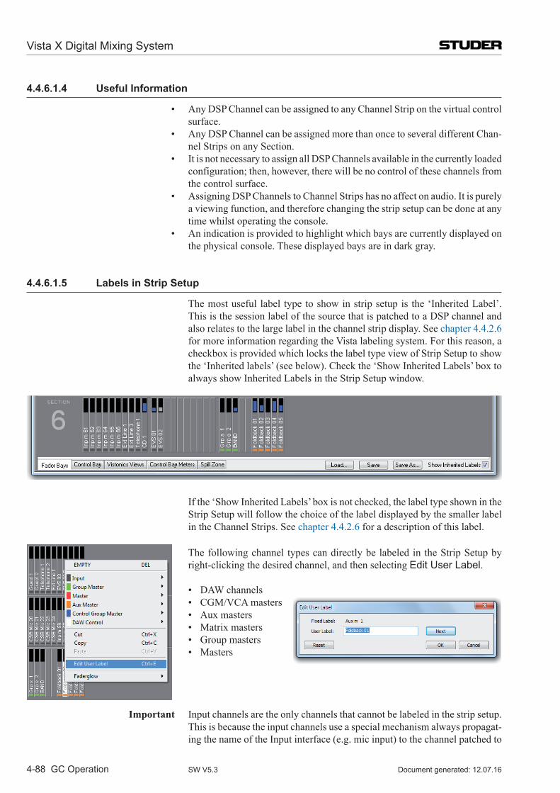
Vista X Digital Mixing System
4-88 GC Operation Document generated: 12.07.16SW V5.3
4.4.6.1.4 Useful Information
• AnyDSPChannelcanbeassignedtoanyChannelStriponthevirtualcontrolsurface.
• AnyDSPChannelcanbeassignedmorethanoncetoseveraldifferentChan-nel Strips on any Section.
• ItisnotnecessarytoassignallDSPChannelsavailableinthecurrentlyloadedconfiguration; then, however, there will be no control of these channels from the control surface.
• AssigningDSPChannelstoChannelStripshasnoaffectonaudio.Itispurelya viewing function, and therefore changing the strip setup can be done at any time whilst operating the console.
• Anindicationisprovidedtohighlightwhichbaysarecurrentlydisplayedonthe physical console. These displayed bays are in dark gray.
4.4.6.1.5 Labels in Strip Setup
The most useful label type to show in strip setup is the ‘Inherited Label’. This is the session label of the source that is patched to a DSP channel and also relates to the large label in the channel strip display. See chapter 4.4.2.6 for more information regarding the Vista labeling system. For this reason, a checkbox is provided which locks the label type view of Strip Setup to show the ‘Inherited labels’ (see below). Check the ‘Show Inherited Labels’ box to always show Inherited Labels in the Strip Setup window.
If the ‘Show Inherited Labels’ box is not checked, the label type shown in the Strip Setup will follow the choice of the label displayed by the smaller label in the Channel Strips. See chapter 4.4.2.6 for a description of this label.
The following channel types can directly be labeled in the Strip Setup by
right-clicking the desired channel, and then selecting Edit User Label.
• DAWchannels • CGM/VCAmasters • Auxmasters • Matrixmasters • Groupmasters • Masters
Important Input channels are the only channels that cannot be labeled in the strip setup. This is because the input channels use a special mechanism always propagat-ing the name of the Input interface (e.g. mic input) to the channel patched to
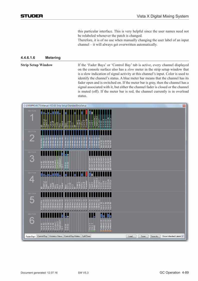
Vista X Digital Mixing System
GC Operation 4-89Document generated: 12.07.16 SW V5.3
this particular interface. This is very helpful since the user names need not be relabeled whenever the patch is changed.
Therefore, it is of no use when manually changing the user label of an input channel – it will always get overwritten automatically.
4.4.6.1.6 Metering
Strip Setup Window If the ‘Fader Bays’ or ‘Control Bay’ tab is active, every channel displayed on the console surface also has a slow meter in the strip setup window that is a slow indication of signal activity at this channel’s input. Color is used to identify the channel’s status. A blue meter bar means that the channel has its fader open and is switched on. If the meter bar is gray, then the channel has a signal associated with it, but either the channel fader is closed or the channel is muted (off). If the meter bar is red, the channel currently is in overload status.
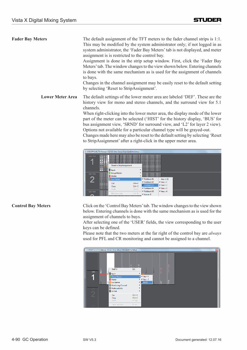
Vista X Digital Mixing System
4-90 GC Operation Document generated: 12.07.16SW V5.3
Fader Bay Meters The default assignment of the TFT meters to the fader channel strips is 1:1. This may be modified by the system administrator only; if not logged in as system administrator, the ‘Fader Bay Meters’ tab is not displayed, and meter assignment is is restricted to the control bay.
Assignment is done in the strip setup window. First, click the ‘Fader Bay Meters’ tab. The window changes to the view shown below. Entering channels is done with the same mechanism as is used for the assignment of channels to bays.
Changes in the channel assignment may be easily reset to the default setting by selecting ‘Reset to StripAssignment’.
Lower Meter Area The default settings of the lower meter area are labeled ‘DEF’. These are the history view for mono and stereo channels, and the surround view for 5.1 channels.
When right-clicking into the lower meter area, the display mode of the lower part of the meter can be selected (‘HIST’ for the history display, ‘BUS’ for bus assignment view, ‘SRND’ for surround view, and ‘L2’ for layer 2 view). Options not available for a particular channel type will be grayed-out.
Changes made here may also be reset to the default setting by selecting ‘Reset to StripAssignment’ after a right-click in the upper meter area.
Control Bay Meters Click on the ‘Control Bay Meters’ tab. The window changes to the view shown below. Entering channels is done with the same mechanism as is used for the assignment of channels to bays.
After selecting one of the ‘USER’ fields, the view corresponding to the user keys can be defined.
Please note that the two meters at the far right of the control bay are always used for PFL and CR monitoring and cannot be assigned to a channel.
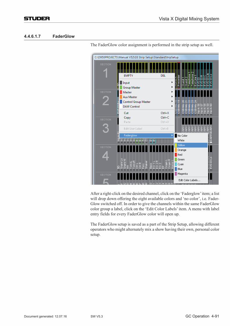
Vista X Digital Mixing System
GC Operation 4-91Document generated: 12.07.16 SW V5.3
4.4.6.1.7 FaderGlow
The FaderGlow color assignment is performed in the strip setup as well.
After a right-click on the desired channel, click on the ‘Faderglow’ item; a list will drop down offering the eight available colors and ‘no color’, i.e. Fader-Glow switched off. In order to give the channels within the same FaderGlow color group a label, click on the ‘Edit Color Labels’ item. A menu with label entry fields for every FaderGlow color will open up.
The FaderGlow setup is saved as a part of the Strip Setup, allowing different operators who might alternately mix a show having their own, personal color setup.
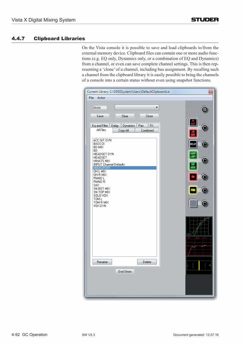
Vista X Digital Mixing System
4-92 GC Operation Document generated: 12.07.16SW V5.3
4.4.7 Clipboard libraries
On the Vista console it is possible to save and load clipboards to/from the external memory device. Clipboard files can contain one or more audio func-tions (e.g. EQ only, Dynamics only, or a combination of EQ and Dynamics) from a channel, or even can save complete channel settings. This is then rep-resenting a ‘clone’ of a channel, including bus assignment. By recalling such a channel from the clipboard library it is easily possible to bring the channels of a console into a certain status without even using snapshot functions.
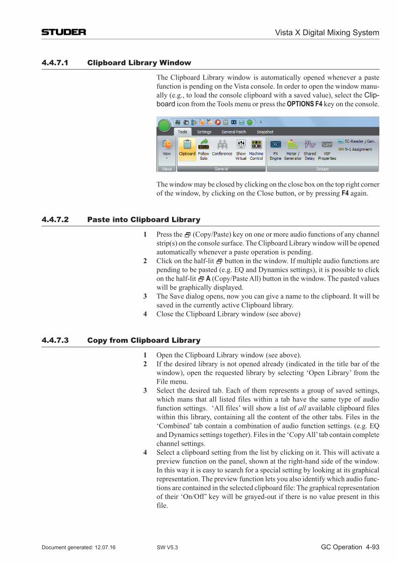
Vista X Digital Mixing System
GC Operation 4-93Document generated: 12.07.16 SW V5.3
4.4.7.1 Clipboard library Window
The Clipboard Library window is automatically opened whenever a paste function is pending on the Vista console. In order to open the window manu-ally (e.g., to load the console clipboard with a saved value), select the Clip-board icon from the Tools menu or press the OPTIONS F4 key on the console.
The window may be closed by clicking on the close box on the top right corner of the window, by clicking on the Close button, or by pressing F4 again.
4.4.7.2 Paste into Clipboard library
1 Press the (Copy/Paste) key on one or more audio functions of any channel strip(s) on the console surface. The Clipboard Library window will be opened automatically whenever a paste operation is pending.
2 Click on the half-lit button in the window. If multiple audio functions are pending to be pasted (e.g. EQ and Dynamics settings), it is possible to click on the half-lit A (Copy/Paste All) button in the window. The pasted values will be graphically displayed.
3 The Save dialog opens, now you can give a name to the clipboard. It will be saved in the currently active Clipboard library.
4 Close the Clipboard Library window (see above)
4.4.7.3 Copy from Clipboard library
1 Open the Clipboard Library window (see above). 2 If the desired library is not opened already (indicated in the title bar of the
window), open the requested library by selecting ‘Open Library’ from the File menu.
3 Select the desired tab. Each of them represents a group of saved settings, which mans that all listed files within a tab have the same type of audio function settings. ‘All files’ will show a list of all available clipboard files within this library, containing all the content of the other tabs. Files in the ‘Combined’ tab contain a combination of audio function settings. (e.g. EQ and Dynamics settings together). Files in the ‘Copy All’ tab contain complete channel settings.
4 Select a clipboard setting from the list by clicking on it. This will activate a preview function on the panel, shown at the right-hand side of the window. In this way it is easy to search for a special setting by looking at its graphical representation. The preview function lets you also identify which audio func-tions are contained in the selected clipboard file: The graphical representation of their ‘On/Off’ key will be grayed-out if there is no value present in this file.
Vista X Digital Mixing System
4-94 GC Operation Document generated: 12.07.16SW V5.3
5 Click on the (Copy/Paste) button of the desired function in order to activate copying. The button will light, and all possible destination keys on the console surface will be half-lit. Shortcut: A double-click on the clipboard name in the list will activate copying of all contained audio values within that particular file directly.
6 Paste the value into one or more channels of the console, using the standard functionality. If the clipboard contained multiple audio settings, such as EQ and Dynamics, they may be pasted together by pressing the A (Copy/Paste All) key of the destination channel.
4.4.7.4 Rename/Delete a Clipboard library File
1 Open the Clipboard Library window (see above). 2 Select the file you want to change or delete by clicking on it. Click on the
‘Rename’ or ‘Delete’ button of the Clipboard Library window in order to execute the desired action.
3 Close the Clipboard Library window (see above).
4.4.7.5 Clear the Display
By clicking on the ‘Clear’ button, the previewed settings are cleared, and no graphical indication is shown on the right-hand side of the window.
4.4.7.6 Update a Clipboard File
To combine, for instance, the current dynamics settings of a channel with the EQ settings that are already in the library, and to save them as one new set into the library, proceed as follows:
1 Open the Clipboard Library window (see above). 2 Select the desired, already saved EQ setting by clicking on it once. The EQ
settings will be displayed graphically on the right-hand side of the window. 3 Press the (Copy/Paste) key in the dynamics section of the source channel
on the console. 4 Click on the half-lit (Copy/Paste) button in the dynamics section of the
window. 5 Both EQ and dynamics values will now be displayed on the right-hand side
of the window. 6 The Save dialog opens. Once saved, the new, combined set will now be dis-
played within the ‘Combined’ tab. 7 Close the Clipboard Library window (see above).
4.4.7.7 Storage Format
Each clipboard is saved in a file with a .cpy extension. Multiple .cpy files form a library. A .cpy file may contain only one audio function (e.g. EQ settings) or a combination of any audio functions of a channel (e.g. EQ and Dynamics settings).
Vista X Digital Mixing System
GC Operation 4-95Document generated: 12.07.16 SW V5.3
4.4.7.8 import a Clipboard File from Another library
1 Select ‘Import Clipboard’ from the file menu. 2 Navigate to the desired library. 3 Open the desired .cpy file. It will automatically appear and be saved within
the library currently active.
4.4.7.9 Where are Clipboard libraries Saved?
If you don’t want to maintain multiple libraries on your console, you never have to change or define a name; just start directly, using the library func-tionality. The system will then use a library called DefaultClipboardLib.
If there are multiple libraries, you may select ‘Open Library’ from the file menu of the clipboard window in order to select another library to work with. It is also possible to save the whole library under a different name or to save it to a portable storage device such as a USB memory stick by selecting ‘Save Library’ in this file menu. Selecting ‘New Library’ in the file menu creates a new, empty library.
In technical terms, a library is a subdirectory of the C:\D950System\Users directory, it may also be located within any other user subdirectory. Selecting ‘New User’ creates a new user directory containing an empty Library called ClipboardLib.
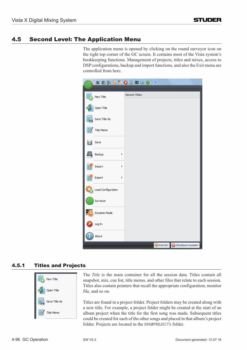
Vista X Digital Mixing System
4-96 GC Operation Document generated: 12.07.16SW V5.3
4.5 Second level: The Application Menu The application menu is opened by clicking on the round surveyor icon on
the right top corner of the GC screen. It contains most of the Vista system’s bookkeeping functions. Management of projects, titles and mixes, access to DSP configurations, backup and import functions, and also the Exit menu are controlled from here.
4.5.1 Titles and Projects
The Title is the main container for all the session data. Titles contain all snapshot, mix, cue list, title memo, and other files that relate to each session. Titles also contain pointers that recall the appropriate configuration, monitor file, and so on.
Titles are found in a project folder. Project folders may be created along with a new title. For example, a project folder might be created at the start of an album project when the title for the first song was made. Subsequent titles could be created for each of the other songs and placed in that album’s project folder. Projects are located in the D950PROJECTS folder.
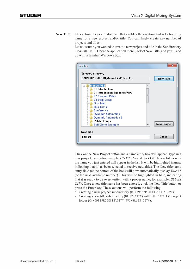
Vista X Digital Mixing System
GC Operation 4-97Document generated: 12.07.16 SW V5.3
New Title This action opens a dialog box that enables the creation and selection of a name for a new project and/or title. You can freely create any number of projects and titles.
Let us assume you wanted to create a new project and title in the Subdirectory D950PROJECTS. Open the application menu , select New Title, and you’ll end up with a familiar Windows box:
Click on the New Project button and a name entry box will appear. Type in a new project name – for example, CITy TV1 – and click OK. A new folder with the name you just entered will appear in the list. It will be highlighted in gray, indicating that it has been selected to receive new titles. The New title name entry field (at the bottom of the box) will now automatically display Title #1 (or the next available number). This will be highlighted in blue, indicating that it is ready to be over-written with a proper name, for example, BLUES CITy. Once a new title name has been entered, click the New Title button or press the Enter key. These actions will perform the following:
• Creatinganewprojectsubdirectory(C:\D950PROJECTS\CiTY TV1); • Creatinganewtitlesubdirectory(BLUES CiTY) within the CiTY TV1 project
folder (C:\D950PROJECTS\CiTY TV1\BLUES CiTY);
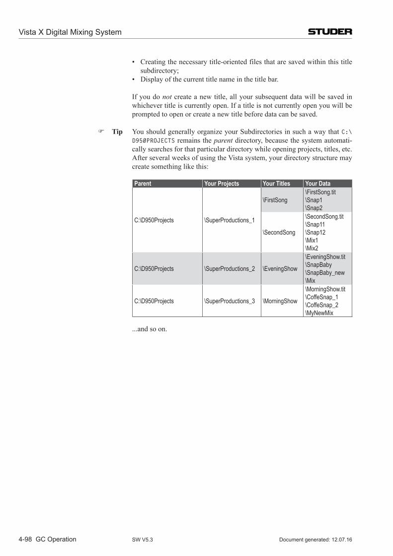
Vista X Digital Mixing System
4-98 GC Operation Document generated: 12.07.16SW V5.3
• Creatingthenecessarytitle-orientedfilesthataresavedwithinthistitlesubdirectory;
• Displayofthecurrenttitlenameinthetitlebar.
If you do not create a new title, all your subsequent data will be saved in whichever title is currently open. If a title is not currently open you will be prompted to open or create a new title before data can be saved.
Tip You should generally organize your Subdirectories in such a way that C:\D950PROJECTS remains the parent directory, because the system automati-cally searches for that particular directory while opening projects, titles, etc. After several weeks of using the Vista system, your directory structure may create something like this:
Parent Your Projects Your Titles Your Data
C:\D950Projects \SuperProductions_1
\FirstSong\FirstSong.tit\Snap1\Snap2
\SecondSong
\SecondSong.tit\Snap11\Snap12\Mix1\Mix2
C:\D950Projects \SuperProductions_2 \EveningShow
\EveningShow.tit\SnapBaby\SnapBaby_new\Mix
C:\D950Projects \SuperProductions_3 \MorningShow
\MorningShow.tit\CoffeSnap_1\CoffeSnap_2\MyNewMix
...and so on.

Vista X Digital Mixing System
GC Operation 4-99Document generated: 12.07.16 SW V5.3
Open Title This action opens the list of project folders from the D950PROJECTS directory. This enables the selection and opening of an existing title from a selected folder. Titles can also be deleted from this menu item.
To open an existing title, first double-click on the desired project subdirectory, an action that will move you into its Subdirectory:
The desired title can now be opened by double-clicking on the title folder or by highlighting it and clicking the Open button. This action will perform the following:
• Makethenewtitlethecurrent title, making available all snapshots, mixes, etc;
• Indicatethecurrenttitlenameinthetitlebar.
A title can be deleted by highlighting a title’s name (while in Open Title) and clicking on the Delete button. You will be asked to confirm this action. You cannot directly delete a project folder using this technique. However, if you delete the last title from within a project folder, you will be notified that the empty folder will be automatically deleted.
Note Titles are color-coded according to the status of the DSP configuration that was in use during their creation. Black, blue, and red title names indicate the following:
Black The DSP configuration needed for this title is currently loaded; Blue The DSP configuration needed for this title is not currently loaded.
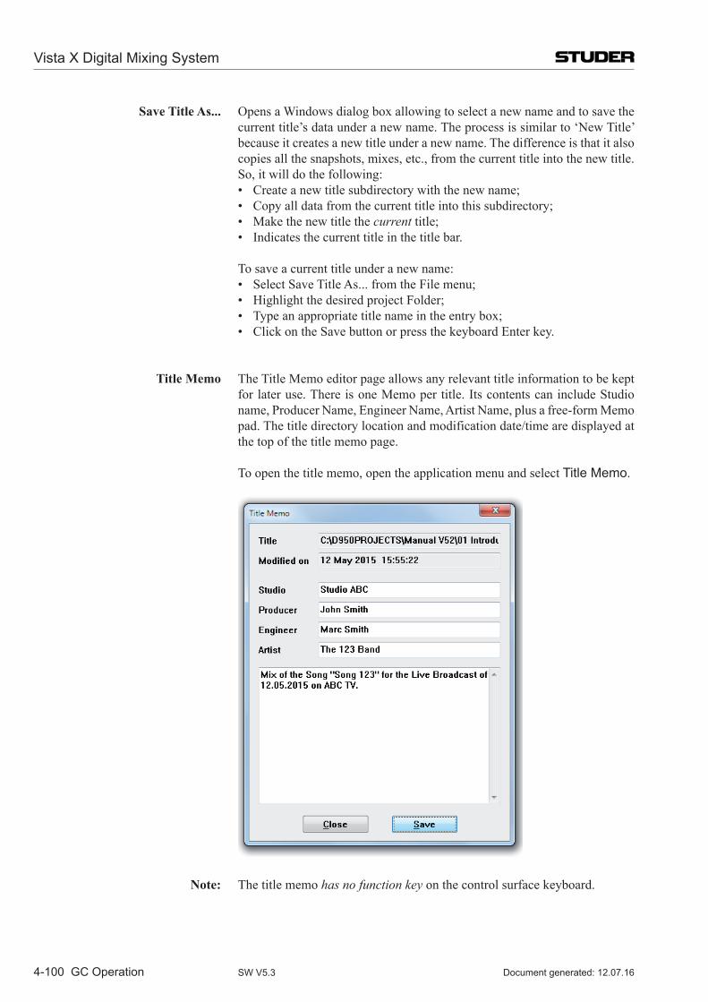
Vista X Digital Mixing System
4-100 GC Operation Document generated: 12.07.16SW V5.3
Save Title As... Opens a Windows dialog box allowing to select a new name and to save the current title’s data under a new name. The process is similar to ‘New Title’ because it creates a new title under a new name. The difference is that it also copies all the snapshots, mixes, etc., from the current title into the new title. So, it will do the following:
• Createanewtitlesubdirectorywiththenewname; • Copyalldatafromthecurrenttitleintothissubdirectory; • Makethenewtitlethecurrent title; • Indicatesthecurrenttitleinthetitlebar.
To save a current title under a new name: • SelectSaveTitleAs...fromtheFilemenu; • HighlightthedesiredprojectFolder; • Typeanappropriatetitlenameintheentrybox; • ClickontheSavebuttonorpressthekeyboardEnterkey.
Title Memo The Title Memo editor page allows any relevant title information to be kept for later use. There is one Memo per title. Its contents can include Studio name, Producer Name, Engineer Name, Artist Name, plus a free-form Memo pad. The title directory location and modification date/time are displayed at the top of the title memo page.
To open the title memo, open the application menu and select Title Memo.
Note: The title memo has no function key on the control surface keyboard.
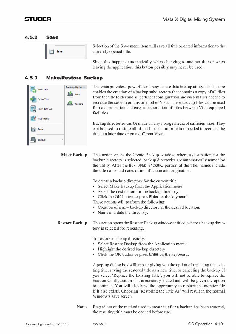
Vista X Digital Mixing System
GC Operation 4-101Document generated: 12.07.16 SW V5.3
4.5.2 Save
Selection of the Save menu item will save all title oriented information to the currently opened title.
Since this happens automatically when changing to another title or when leaving the application, this button possibly may never be used.
4.5.3 Make/Restore Backup
The Vista provides a powerful and easy-to-use data backup utility. This fea ture enables the creation of a backup subdirectory that contains a copy of all files from the title folder and all pertinent configuration and system files needed to recreate the session on this or another Vista. These backup files can be used for data protection and easy transportation of titles between Vista equipped facilities.
Backup directories can be made on any storage media of sufficient size. They can be used to restore all of the files and information needed to recreate the title at a later date or on a different Vista.
Make Backup This action opens the Create Backup window, where a destination for the backup directory is selected. backup directories are automatically named by the utility. After the BCK_D950_BaCKUP… portion of the title, names include the title name and dates of modification and origination.
To create a backup directory for the current title: • SelectMakeBackupfromtheApplicationmenu; • Selectthedestinationforthebackupdirectory; • ClicktheOKbuttonorpressEnter on the keyboard These actions will perform the following: • Creationofanewbackupdirectoryatthedesiredlocation; • Nameanddatethedirectory.
Restore Backup This action opens the Restore Backup window entitled, where a backup direc-tory is selected for reloading.
To restore a backup directory: • SelectRestoreBackupfromtheApplicationmenu; • Highlightthedesiredbackupdirectory; • ClicktheOKbuttonorpressEnter on the keyboard;
A pop-up dialog box will appear giving you the option of replacing the exis-ting title, saving the restored title as a new title, or canceling the backup. If you select ‘Replace the Existing Title’, you will not be able to replace the Session Configuration if it is currently loaded and will be given the option to continue. You will also have the opportunity to replace the monitor file if it also exists. Choosing ‘Restoring the Title As’ will result in the normal Window’s save screen.
Notes Regardless of the method used to create it, after a backup has been restored,
the resulting title must be opened before use.
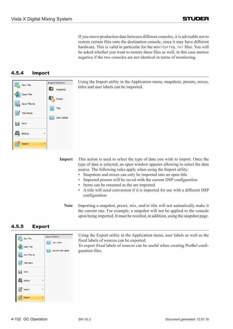
Vista X Digital Mixing System
4-102 GC Operation Document generated: 12.07.16SW V5.3
If you move production data between different consoles, it is advisable not to restore certain files onto the destination console, since it may have different hardware. This is valid in particular for the monitoring.ini files. You will be asked whether you want to restore these files as well; in this case answer negative if the two consoles are not identical in terms of monitoring.
4.5.4 import
Using the Import utility in the Application menu, snapshots, presets, mixes, titles and user labels can be imported.
Import This action is used to select the type of data you wish to import. Once the type of data is selected, an open window appears allowing to select the data source. The following rules apply when using the Import utility:
• Snapshotsandmixescanonlybeimportedintoanopentitle • ImportedpresetswillbesavedwiththecurrentDSPconfiguration • Itemscanberenamedastheareimported • AtitlewillneedconversionifitisimportedforusewithadifferentDSP
configuration
Note Importing a snapshot, preset, mix, and/or title will not autmatically make it the current one. For example, a snapshot will not be applied to the console upon being imported. It must be recalled, in addition, using the snapshot page.
4.5.5 Export
Using the Export utility in the Application menu, user labels as well as the fixed labels of sources can be exported.
To export fixed labels of sources can be useful when creating ProBel confi-guration files.
Vista X Digital Mixing System
GC Operation 4-103Document generated: 12.07.16 SW V5.3
4.5.6 load DSP Configuration
If there is more than one DSP configuration on your Vista system, you may need to access this menu item in order to load a different configuration. Since titles will automatically open the correct DSP configuration (if its not already loaded), using the Load Configuration menu item is only necessary when loading a configuration without opening a Title. Regardless of how a configuration is recalled, this process takes 20 to 30 seconds to complete, and mutes the console during loading.
Note: Keep in mind that all Titles contain pointers that enable the loading of the proper DSP configuration and other appropriate files. If the Title’s DSP configuration is different from the one that is currently loaded, you will be asked to either confirm the loading of the correct configuration or to convert the Title for use with the current one. Therefore, during routine operation, it is not necessary to use the Load Configuration menu unless the user has created or modified a DSP configuration during that session. Typically, the Load Configuration menu item should only be used by the facility’s System Administrator or by advanced users.
DSP configuration subdirectories reside in the C:\D950SYSTEMBD subdirec-tory. These subdirectories contain the following files:
• VirtualMixingConsole(VMC)files:Thesefiles(with*.vmc extensions) are created by the Session Configuration Tool. They contain all the Con-figuration data needed for the Session Configuration Tool to create a core file;
• Corefiles:Thesefiles(with*.cor extensions) are created by the Session Configuration Tool. They contain the actual code used by the DSP core (SCoreLive);
• Xmlfiles:TheXmlConfigurationandVmcMappingInformation-files(with *.xml extensions) are created by the Session Configuration Tool. They contain the actual definition of the processing used by the DSP core (Infinity Core). Also the file MixercloudPaths.txt belongs to this category of files used by the Infinity Core;
• Presetfiles:Thesefiles(ifanyexist)arecreatedwithinTitlesbutaresavedwith DSP configurations so they can be used with any Title that uses a particular configuration. Preset files have .pre extensions.
Load Configuration: This action opens a dialog box that allows the selection and opening of an existing Session Configuration. A list of available Session Configurations for selection will be displayed.
Tip You should generally organize your DSP configurations in such a way that C:\D950SYSTEMDB remains the parent directory, because the system automatically searches for that directory during opening of a Title or Session Configuration.
To load a configuration, double-click on it, or highlight it and click the Open button. This will do the following:
• Mutetheconsole’saudiopaths(includingthemonitoringsection); • LoadtheappropriateVMCdata(corefile)intothesystem,andchecktheir
validity; • ErasetheoldSessionConfigurationDSPsoftwarefromtheFlashEPROM
in the DSP Core, and load the new DSP software; • Reloadthecontrolsurfacedesk(theChannelStripswillgoblankforafew
moments);
Vista X Digital Mixing System
4-104 GC Operation Document generated: 12.07.16SW V5.3
• LoadtheappropriateMonitorConfigurationfile; • ActivatethelastusedpreferencesbelongingtothenewlyloadedSession
Configuration.
Notes: When a cnfiguration is loaded via the Load Configuration menu, the currently open Title will be closed; no new Title will be opened. Before any data can be saved using the newly loaded configuration, an existing Title must be opened or a new one must be created.
If a DSP configuration is displayed in red this means that this configuration has not been compiled properly by the Session Configuration Tool. Either run the tool again or delete this configuration.
4.5.7 Surveyor
Clicking the Surveyor menu item opens up the Surveyor window which show the current state of the system. Please see chapter 4.8 for a complete description.
The same Surveyor window is also opened when double-clicking on the Application menu Surveyor icon.
4.5.8 Dynamic-Mode
This menu item closes the Vista application, and restarts it with the same title, but in the Dynamic Automation mode.
This operation mode then provides functionality for dynamic automation of console elements against timecode.
Please note that in dynamic automation mode, the static snapshot automation functionality is not available.
4.5.9 log in (as System Administrator)
Lets the operator log in as System Administrator by entering a password (if defined at all). All greyed out SysAdmin menu items then become accessible.
Once logged in, this menu item automatically becomes the Log Out function, which allows to leave the System Administrator mode again.
Refer to chapter 4.7 (system administration menu) for more details.
4.5.10 About
When selected, this menu item displays information pertaining to that specific Vista installation. This includes the software Release Number (version) and the Build Number.
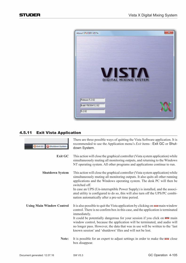
Vista X Digital Mixing System
GC Operation 4-105Document generated: 12.07.16 SW V5.3
4.5.11 Exit Vista Application
There are three possible ways of quitting the Vista Software application. It is recommended to use the Application menu’s Exit items : Exit GC or Shut-down System.
Exit GC This action will close the graphical controller (Vista system application) while simultaneously muting all monitoring outputs, and returning to the Windows NT operating system. All other programs and applications continue to run.
Shutdown System This action will close the graphical controller (Vista system application) while simultaneously muting all monitoring outputs. It also quits all other running applications and the Windows operating system. The desk PC will then be switched off.
In case an UPS (Un-interruptible Power Supply) is installed, and the associ-ated utility is configured to do so, this will also turn off the UPS/PC combi-nation automatically after a pre-set time period.
Using Main Window Control It is also possible to quit the Vista application by clicking on main window control. There is no confirm box in this case, and the appli cation is terminated immediately.
It could be potentially dangerous for your session if you click on main window control, because the application will be terminat ed, and audio will no longer pass. However, the data that was in use will be written to the ‘last known session’ and ‘shutdown’ files and will not be lost.
Note: It is possible for an expert to adjust settings in order to make the close box disappear.
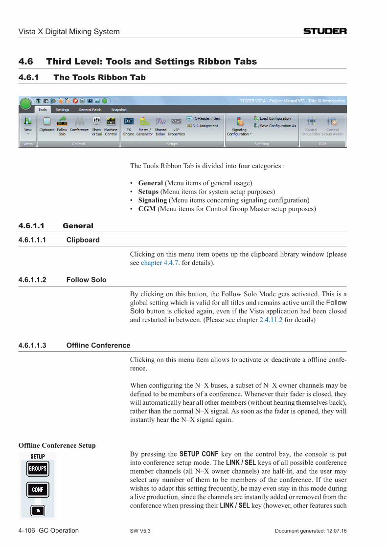
Vista X Digital Mixing System
4-106 GC Operation Document generated: 12.07.16SW V5.3
4.6 Third level: Tools and Settings Ribbon Tabs
4.6.1 The Tools Ribbon Tab
The Tools Ribbon Tab is divided into four categories :
• General (Menu items of general usage) • Setups (Menu items for system setup purposes) • Signaling (Menu items concerning signaling configuration) • CGM (Menu items for Control Group Master setup purposes)
4.6.1.1 General
4.6.1.1.1 Clipboard
Clicking on this menu item opens up the clipboard library window (please see chapter 4.4.7. for details).
4.6.1.1.2 Follow Solo
By clicking on this button, the Follow Solo Mode gets activated. This is a global setting which is valid for all titles and remains active until the Follow Solo button is clicked again, even if the Vista application had been closed and restarted in between. (Please see chapter 2.4.11.2 for details)
4.6.1.1.3 Offline Conference
Clicking on this menu item allows to activate or deactivate a offline confe-rence.
When configuring the N–X buses, a subset of N–X owner channels may be defined to be members of a conference. Whenever their fader is closed, they will automatically hear all other members (without hearing themselves back), rather than the normal N–X signal. As soon as the fader is opened, they will instantly hear the N–X signal again.
Offline Conference Setup By pressing the SETUP CONF key on the control bay, the console is put
into conference setup mode. The LINK / SEL keys of all possible conference member channels (all N–X owner channels) are half-lit, and the user may select any number of them to be members of the conference. If the user wishes to adapt this setting frequently, he may even stay in this mode during a live production, since the channels are instantly added or removed from the conference when pressing their LINK / SEL key (however, other features such
Vista X Digital Mixing System
GC Operation 4-107Document generated: 12.07.16 SW V5.3
as ganging will not be available while in setup mode). All the channels currently defined as conference members are marked in the
strip setup window.
The conference icon in the Tools tab has (only two) states:
Grayed out : No conference active nor defined
Grayed out : Conference active (if member faders closed)
Grayed out, crossed out : Conference defined, but temporarily deactivated (even if member faders closed).
Note: In certain circumstances, also an aux master can be selected as a conference member (indicated by its half-lit LINK / SEL key). This is intended for adding e.g. an on-air signal to the conference. See details below.
Talk to the Conference When pressing the TALK key on a channel which is currently conferencing,
the talk function is automatically activated on all members of the conference at the same time.
Temporary Conference Deactivation The conferencing may temporarily be deactivated by clicking on the confe-
rence icon in the toolbar or the CONF ON key. In this case the conference definition is retained. As soon as the conference is reactivated globally (by pressing CONF ON or clicking on the conference icon in the toolbar again), the previously selected channels may talk to each other again. Temporary activation of the CONF ON key is possible as well.
Conference Level While in conference mode, the N–X send level of the channel conferencing
may be adjusted. This level will then be used as a conference send level only. When opening the fader, the level previously set returns. In other words, the system remembers two level settings; one of them is active when conferen-cing, the other one is activated in normal N–X mode.
Monitoring the Conference Using the MPX Bus Within the new Configuration Editor software, the MPX bus type has been
added. This bus only exists once within a configuration (similar to a PFL bus) and is used to monitor the conference. It is a mono bus. Any channel currently conferencing is automatically assigned to the MPX bus, and the MPX bus output may be monitored using a source selector key. Since the MPX bus output is a normal bus output, it can also be patched to any console output. This allows, for example, feeding this signal to a small loudspeaker for constantly playing back the conference signal.
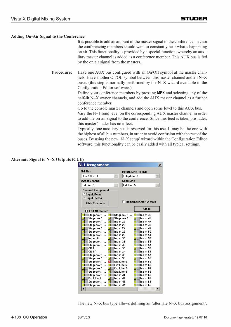
Vista X Digital Mixing System
4-108 GC Operation Document generated: 12.07.16SW V5.3
Adding On-Air Signal to the Conference It is possible to add an amount of the master signal to the conference, in case
the conferencing members should want to constantly hear what’s happening on air. This functionality is provided by a special function, whereby an auxi-liary master channel is added as a conference member. This AUX bus is fed by the on air signal from the masters.
Procedure: Have one AUX bus configured with an On/Off symbol at the master chan-nels. Have another On/Off symbol between this master channel and all N–X buses (this step is normally performed by the N–X wizard available in the Configuration Editor software.)
Define your conference members by pressing MPX and selecting any of the half-lit N–X owner channels, and add the AUX master channel as a further conference member.
Go to the console master channels and open some level to this AUX bus. Vary the N–1 send level on the corresponding AUX master channel in order
to add the on-air signal to the conference. Since this feed is taken pre-fader, this master’s fader has no effect.
Typically, one auxiliary bus is reserved for this use. It may be the one with the highest of all bus numbers, in order to avoid confusion with the rest of the buses. By using the new ‘N–X setup’ wizard within the Configuration Editor software, this functionality can be easily added with all typical settings.
Alternate Signal to N–X Outputs (CUE)
The new N–X bus type allows defining an ‘alternate N–X bus assignment’.
Vista X Digital Mixing System
GC Operation 4-109Document generated: 12.07.16 SW V5.3
It is possible to select any console channel (or multiples) to be the alternate N–X output signal. This signal is activated by the ALT n-1 key on the channel strip. This can be done only if the owner channel’s fader is closed.
If you don’t want to use normal console channels to be the alternate signal, feel free to configure simple input channels not used otherwise during the production. Such a channel can be the ‘alternate cue signal’ source for all N–X buses – or you can define a different alternate source for each N–X bus separately.
Set-up an ‘alternate N–X signal’ for a specific N–X bus: • Open the ‘Option:N–1Assignment’menu in theGraphicalController
screen • SelecttheN–Xbusyouwanttodefinethealternatesignalfor • ChecktheEdit Alt. Source checkbox • Selectanychannel(ormultiple)tobethealternatesignalsourceforthe
selected N–X bus (their pre-fader signal will be used that can be weighted with the ‘N–1 send level’ to form the alternate signal for this N–X bus).
Note To avoid having to repeat this process too often, such a setup may be saved in a snapshot or preset to be used at any time by all operators.
Option to bring back ALT N–X status upon closing fader. Option active (): The signal will switch back to ALT N–X upon closing
the fader again, in case it was active before opening. This allows e.g. feeding an off-air signal to the outside lines while there are not on air (e.g. output signal from on-air console including commercials). Result: When the fader is opened, the outside lines get the normal N–X signal; when closed they are switched to the off-air signal.
Option inactive (original behavior): If the ALT N-X key (i.e. USR 1 or USR 2 key defined above) was active and the fader was opened, the return signal would automatically switch to normal N–X. After the fader is closed again, the signal would stay on N–X.
4.6.1.1.4 Show Virtual
When using the Virtual Vista application, this item brings up the virtual desk window and provides access to faders and other desk controls. The GC screen is then moved to the background. (This icon is greyed out when working on a console).
4.6.1.1.5 Machine Control
This menu item brings up the Machine Control window. In case the desk is not equipped with a hardware transport control panel, this software panel allows to do transport control, e.g. for playback devices connected via Sony P2 transport control interface, or also for transport control of a DAW via DAW-control.
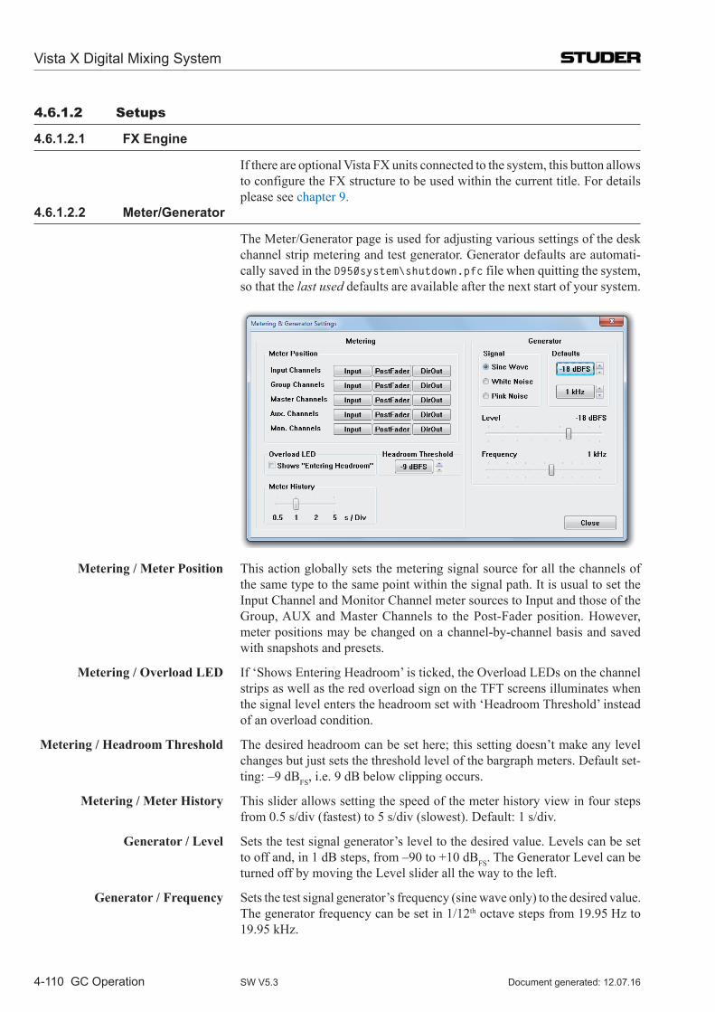
Vista X Digital Mixing System
4-110 GC Operation Document generated: 12.07.16SW V5.3
4.6.1.2 Setups
4.6.1.2.1 FX Engine
If there are optional Vista FX units connected to the system, this button allows to configure the FX structure to be used within the current title. For details please see chapter 9.
4.6.1.2.2 Meter/Generator
The Meter/Generator page is used for adjusting various settings of the desk channel strip metering and test generator. Generator defaults are automati-cally saved in the D950system\shutdown.pfc file when quitting the system, so that the last used defaults are available after the next start of your system.
Metering / Meter Position This action globally sets the metering signal source for all the channels of the same type to the same point within the signal path. It is usual to set the Input Channel and Monitor Channel meter sources to Input and those of the Group, AUX and Master Channels to the Post-Fader position. However, meter positions may be changed on a channel-by-channel basis and saved with snapshots and presets.
Metering / Overload LED If ‘Shows Entering Headroom’ is ticked, the Overload LEDs on the channel strips as well as the red overload sign on the TFT screens illuminates when the signal level enters the headroom set with ‘Headroom Threshold’ instead of an overload condition.
Metering / Headroom Threshold The desired headroom can be set here; this setting doesn’t make any level changes but just sets the threshold level of the bargraph meters. Default set-ting: –9 dBFS, i.e. 9 dB below clipping occurs.
Metering / Meter History This slider allows setting the speed of the meter history view in four steps from 0.5 s/div (fastest) to 5 s/div (slowest). Default: 1 s/div.
Generator / Level Sets the test signal generator’s level to the desired value. Levels can be set to off and, in 1 dB steps, from –90 to +10 dBFS. The Generator Level can be turned off by moving the Level slider all the way to the left.
Generator / Frequency Sets the test signal generator’s frequency (sine wave only) to the desired value. The generator frequency can be set in 1/12th octave steps from 19.95 Hz to 19.95 kHz.
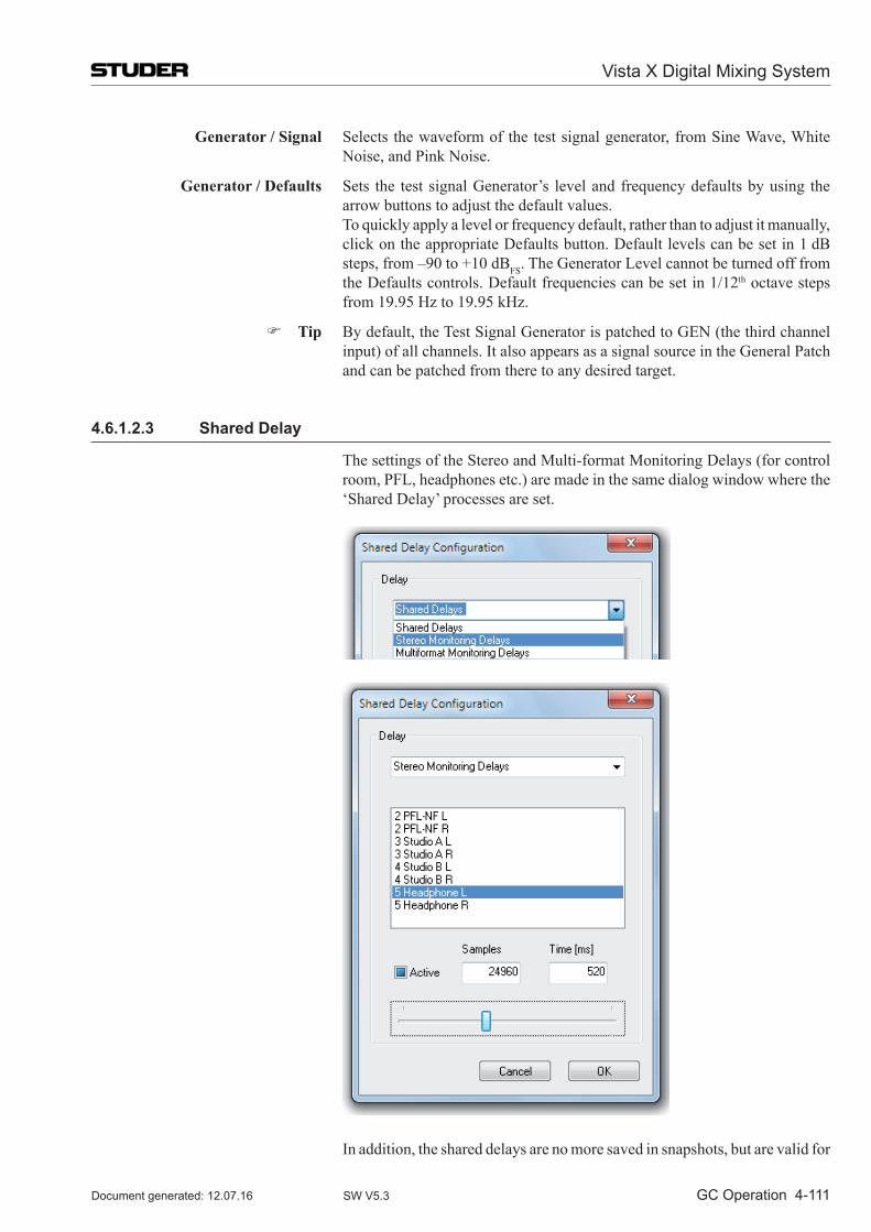
Vista X Digital Mixing System
GC Operation 4-111Document generated: 12.07.16 SW V5.3
Generator / Signal Selects the waveform of the test signal generator, from Sine Wave, White Noise, and Pink Noise.
Generator / Defaults Sets the test signal Generator’s level and frequency defaults by using the arrow buttons to adjust the default values.
To quickly apply a level or frequency default, rather than to adjust it manually, click on the appropri ate Defaults button. Default levels can be set in 1 dB steps, from –90 to +10 dBFS. The Generator Level cannot be turned off from the Defaults controls. Default frequencies can be set in 1/12th octave steps from 19.95 Hz to 19.95 kHz.
Tip By default, the Test Signal Generator is patched to GEN (the third channel input) of all channels. It also appears as a signal source in the General Patch and can be patched from there to any desired target.
4.6.1.2.3 Shared Delay
The settings of the Stereo and Multi-format Monitoring Delays (for control room, PFL, headphones etc.) are made in the same dialog window where the ‘Shared Delay’ processes are set.
In addition, the shared delays are no more saved in snapshots, but are valid for
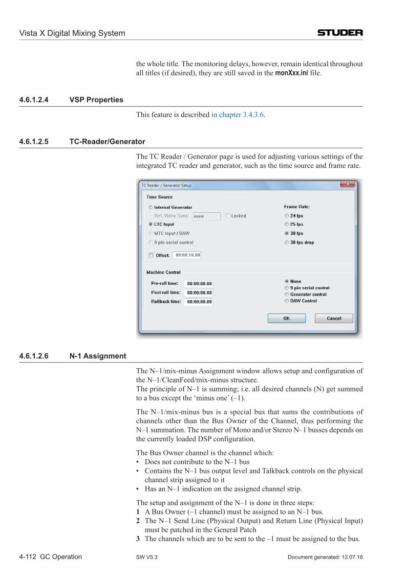
Vista X Digital Mixing System
4-112 GC Operation Document generated: 12.07.16SW V5.3
the whole title. The monitoring delays, however, remain identical throughout all titles (if desired), they are still saved in the monXxx.ini file.
4.6.1.2.4 VSP Properties
This feature is described in chapter 3.4.3.6.
4.6.1.2.5 TC-Reader/Generator
The TC Reader / Generator page is used for adjusting various settings of the integrated TC reader and generator, such as the time source and frame rate.
4.6.1.2.6 N-1 Assignment
The N–1/mix-minus Assignment window allows setup and configuration of the N–1/CleanFeed/mix-minus structure.
The principle of N–1 is summing; i.e. all desired channels (N) get summed to a bus except the ‘minus one’ (–1).
The N–1/mix-minus bus is a special bus that sums the contributions of channels other than the Bus Owner of the Channel, thus performing the N–1 summation. The number of Mono and/or Stereo N–1 busses depends on the currently loaded DSP configuration.
The Bus Owner channel is the channel which: • DoesnotcontributetotheN–1bus • ContainstheN–1busoutputlevelandTalkbackcontrolsonthephysical
channel strip assigned to it • HasanN–1indicationontheassignedchannelstrip.
The setup and assignment of the N–1 is done in three steps: 1 A Bus Owner (–1 channel) must be assigned to an N–1 bus. 2 The N–1 Send Line (Physical Output) and Return Line (Physical Input)
must be patched in the General Patch 3 The channels which are to be sent to the –1 must be assigned to the bus.
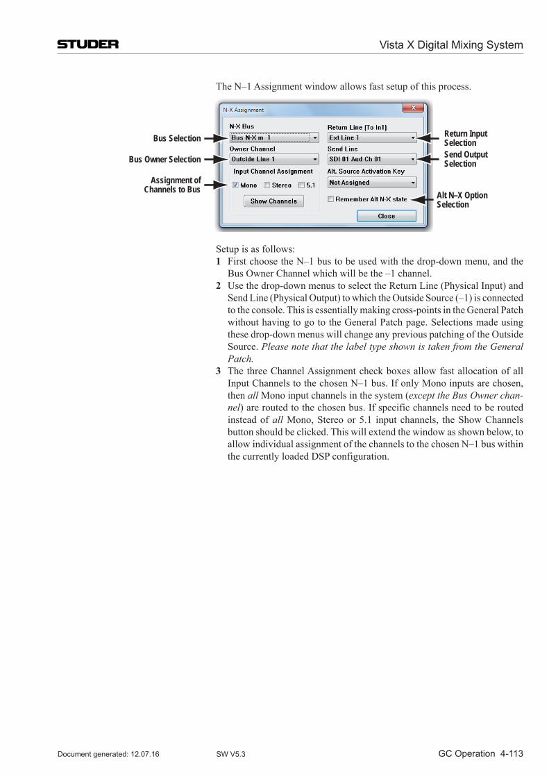
Vista X Digital Mixing System
GC Operation 4-113Document generated: 12.07.16 SW V5.3
The N–1 Assignment window allows fast setup of this process.
Bus Selection
Assignment ofChannels to Bus
Bus Owner Selection
Return InputSelectionSend OutputSelection
Alt N–X OptionSelection
Setup is as follows: 1 First choose the N–1 bus to be used with the drop-down menu, and the
Bus Owner Channel which will be the –1 channel. 2 Use the drop-down menus to select the Return Line (Physical Input) and
Send Line (Physical Output) to which the Outside Source (–1) is connected to the console. This is essentially making cross-points in the General Patch without having to go to the General Patch page. Selections made using these drop-down menus will change any previous patching of the Outside Source. Please note that the label type shown is taken from the General Patch.
3 The three Channel Assignment check boxes allow fast allocation of all Input Channels to the chosen N–1 bus. If only Mono inputs are chosen, then all Mono input channels in the system (except the Bus Owner chan-nel) are routed to the chosen bus. If specific channels need to be routed instead of all Mono, Stereo or 5.1 input channels, the Show Channels button should be clicked. This will extend the window as shown below, to allow individual assignment of the channels to the chosen N–1 bus within the currently loaded DSP configuration.
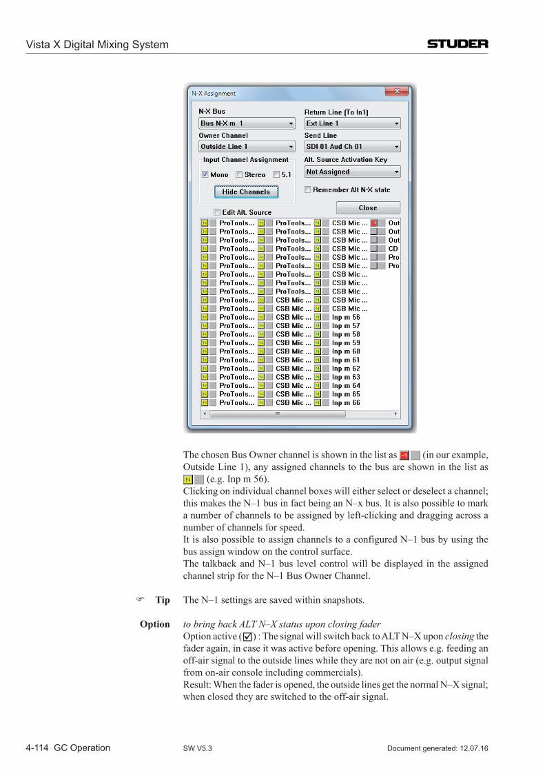
Vista X Digital Mixing System
4-114 GC Operation Document generated: 12.07.16SW V5.3
The chosen Bus Owner channel is shown in the list as (in our example, Outside Line 1), any assigned channels to the bus are shown in the list as
(e.g. Inp m 56). Clicking on individual channel boxes will either select or deselect a channel;
this makes the N–1 bus in fact being an N–x bus. It is also possible to mark a number of channels to be assigned by left-clicking and dragging across a number of channels for speed.
It is also possible to assign channels to a configured N–1 bus by using the bus assign window on the control surface.
The talkback and N–1 bus level control will be displayed in the assigned channel strip for the N–1 Bus Owner Channel.
Tip The N–1 settings are saved within snapshots.
Option to bring back ALT N–X status upon closing fader Option active () : The signal will switch back to ALT N–X upon closing the
fader again, in case it was active before opening. This allows e.g. feeding an off-air signal to the outside lines while they are not on air (e.g. output signal from on-air console including commercials).
Result: When the fader is opened, the outside lines get the normal N–X signal; when closed they are switched to the off-air signal.
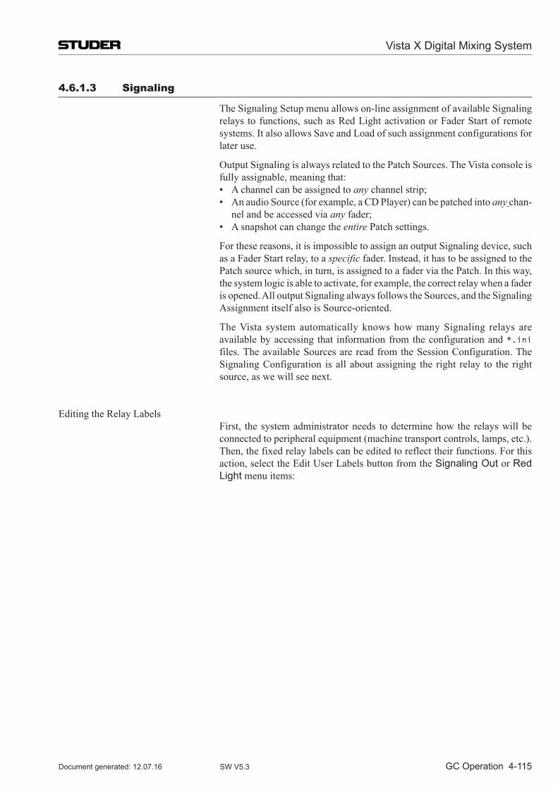
Vista X Digital Mixing System
GC Operation 4-115Document generated: 12.07.16 SW V5.3
4.6.1.3 Signaling
The Signaling Setup menu allows on-line assignment of available Signaling relays to functions, such as Red Light activation or Fader Start of remote systems. It also allows Save and Load of such assignment configurations for later use.
Output Signaling is always related to the Patch Sources. The Vista console is fully assignable, meaning that:
• Achannelcanbeassignedtoany channel strip; • AnaudioSource(forexample,aCDPlayer)canbepatchedintoany chan-
nel and be accessed via any fader; • Asnapshotcanchangetheentire Patch settings.
For these reasons, it is impossible to assign an output Signaling device, such as a Fader Start relay, to a specific fader. Instead, it has to be assigned to the Patch source which, in turn, is assigned to a fader via the Patch. In this way, the system logic is able to activate, for example, the correct relay when a fader is opened. All output Signaling always follows the Sources, and the Signaling Assignment itself also is Source-oriented.
The Vista system auto matically knows how many Signaling relays are available by accessing that information from the configuration and *.ini files. The available Sources are read from the Session Configuration. The Signaling Configuration is all about assigning the right relay to the right source, as we will see next.
Editing the Relay Labels First, the system administrator needs to determine how the relays will be
connected to peripheral equipment (machine transport controls, lamps, etc.). Then, the fixed relay labels can be edited to reflect their functions. For this action, select the Edit User Labels button from the Signaling Out or Red Light menu items:
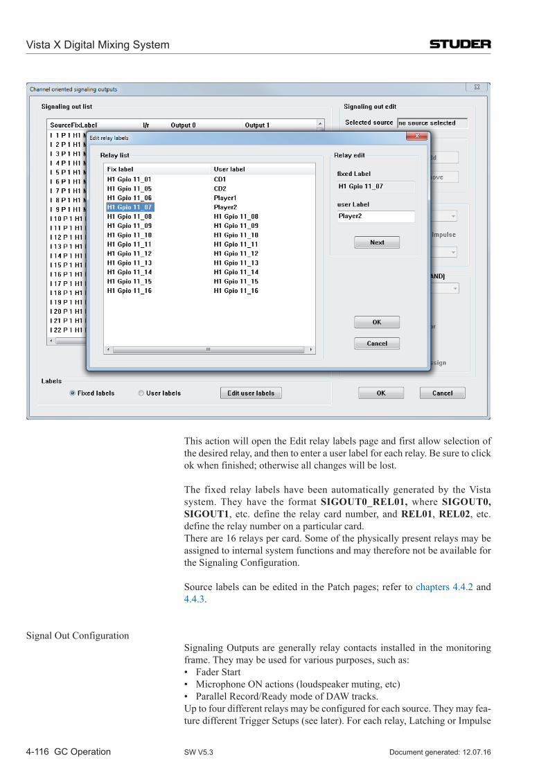
Vista X Digital Mixing System
4-116 GC Operation Document generated: 12.07.16SW V5.3
This action will open the Edit relay labels page and first allow selection of the desired relay, and then to enter a user label for each relay. Be sure to click ok when finished; otherwise all changes will be lost.
The fixed relay labels have been automatically generated by the Vista system. They have the format SIGOUT0_REL01, where SIGOUT0, SIGOUT1, etc. define the relay card number, and REL01, REL02, etc. define the relay number on a particular card.
There are 16 relays per card. Some of the physically present relays may be assigned to internal system functions and may therefore not be available for the Signaling Configuration.
Source labels can be edited in the Patch pages; refer to chapters 4.4.2 and 4.4.3.
Signal Out Configuration Signaling Outputs are generally relay contacts installed in the monitoring
frame. They may be used for various purposes, such as: • FaderStart • MicrophoneONactions(loudspeakermuting,etc) • ParallelRecord/ReadymodeofDAWtracks. Up to four different relays may be configured for each source. They may fea-
ture different Trigger Setups (see later). For each relay, Latching or Impulse
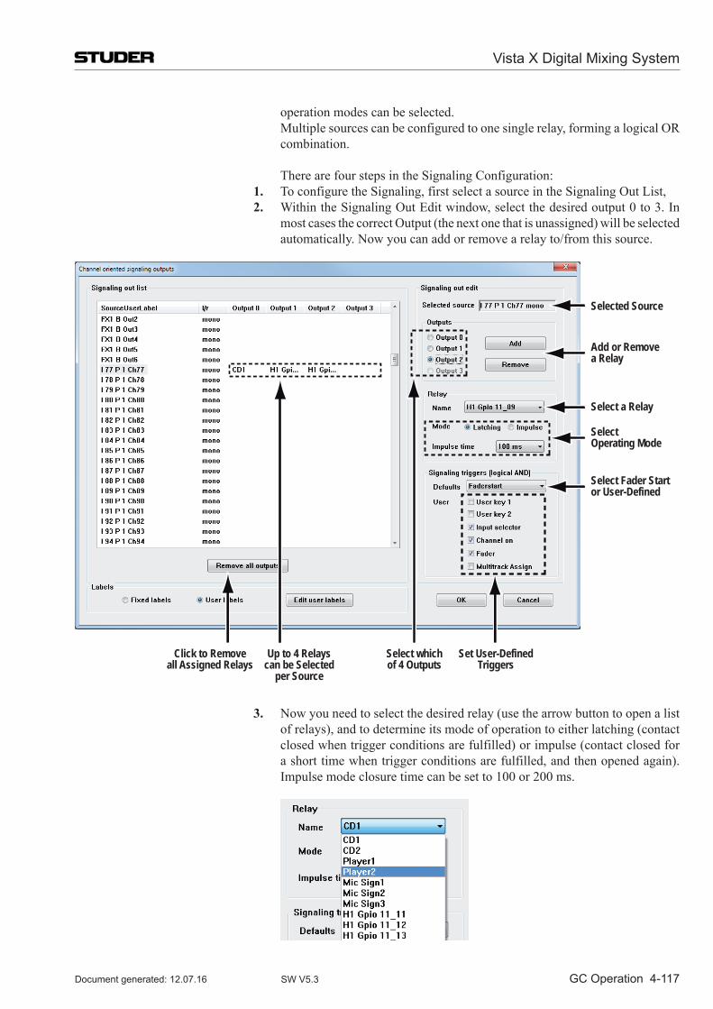
Vista X Digital Mixing System
GC Operation 4-117Document generated: 12.07.16 SW V5.3
operation modes can be selected. Multiple sources can be configured to one single relay, forming a logical OR
combination.
There are four steps in the Signaling Configuration: 1. To configure the Signaling, first select a source in the Signaling Out List, 2. Within the Signaling Out Edit window, select the desired output 0 to 3. In
most cases the correct Output (the next one that is unassigned) will be selected automatically. Now you can add or remove a relay to/from this source.
Selected Source
Add or Removea Relay
Select a Relay
SelectOperating Mode
Select Fader Startor User-Defined
Click to Removeall Assigned Relays
Select whichof 4 Outputs
Set User-DefinedTriggers
Up to 4 Relayscan be Selected
per Source
3. Now you need to select the desired relay (use the arrow button to open a list of relays), and to determine its mode of operation to either latching (contact closed when trigger conditions are fulfilled) or impulse (contact closed for a short time when trigger conditions are fulfilled, and then opened again). Impulse mode closure time can be set to 100 or 200 ms.
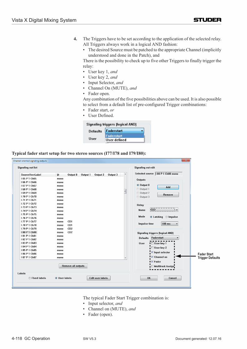
Vista X Digital Mixing System
4-118 GC Operation Document generated: 12.07.16SW V5.3
4. The Triggers have to be set according to the application of the selected relay. All Triggers always work in a logical AND fashion:
• ThedesiredSourcemustbepatchedtotheappropriateChannel(implicitlyunderstood and done in the Patch), and
There is the possibility to check up to five other Triggers to finally trigger the relay:
• Userkey1,and • Userkey2,and • InputSelector,and • ChannelOn(MUTE),and • Faderopen. Any combination of the five possibilities above can be used. It is also possible
to select from a default list of pre-configured Trigger combinations: • Faderstart,or • UserDefined.
Typical fader start setup for two stereo sources (I77/I78 and I79/I80):
Fader StartTrigger Defaults
The typical Fader Start Trigger combination is: • Inputselector,and • Channelon(MUTE),and • Fader(open).
Vista X Digital Mixing System
GC Operation 4-119Document generated: 12.07.16 SW V5.3
You can also remove all assigned relays from the list by clicking on the Remove all outputs button.
Tip For a typical stereo source, such as a CD player, the same relay should be configured for both the left and the right signal part, as shown in the example above for I77/I78 (relay cd1) and I79/I80 (relay cd2). This action ensures that the CD player will start even if it is connected to two Mono Input Channels, and only one of the faders is opened.
Red Light Configuration Generally, Red Light Outputs are relays installed within the monitoring
frame. Only one relay is normally used for the global Red Light Signaling, but several relays can be configured independently if more than one Studio exists.
The Trigger conditions for a Red Light relay to be activated are fixed to the following:
• ASourceconfiguredforRedLightispatchedtoaChannel,and • TheInputChannelInputSelectorissettotheaboveSource,and • TheInputChannelFaderisopen,and • TheInputChannelON(MUTE)isopen,and • TheInputChannelisroutedtoatleastoneMasterBus,and • TheMasterChannelInputSelectorissettotheaboveSource,and • TheMasterChannelFaderisopen,and • TheMasterChannelON(MUTE)isopen.
In other words, the audio signal has a fully open path from the Source to the Master Channel output. If an Input Channel is routed to a group only, then the Group has to be routed to a Master, etc., to fulfill the Trigger conditions.
Multiple sources are usually configured to one single relay – they form a logi-cal OR. For instance, all Mic Inputs from the same room would be configured to the same Red Light relay.
There are four steps in the Red Light Configuration: 1. To configure the Red Light, first select a source in the Red Light List; 2. You can then add or remove a relay to/from this source in the Red Light Edit
window.
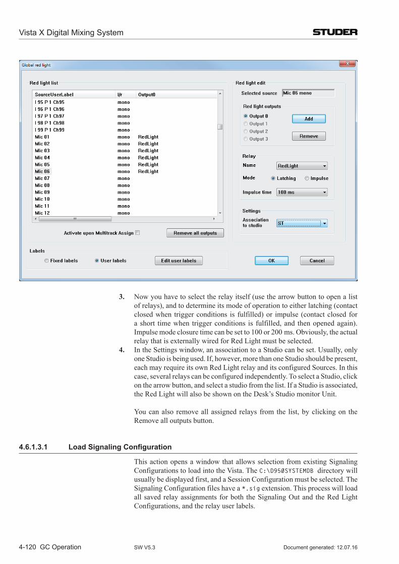
Vista X Digital Mixing System
4-120 GC Operation Document generated: 12.07.16SW V5.3
3. Now you have to select the relay itself (use the arrow button to open a list of relays), and to determine its mode of operation to either latching (contact closed when trigger conditions is fulfilled) or impulse (contact closed for a short time when trigger conditions is fulfilled, and then opened again). Impulse mode closure time can be set to 100 or 200 ms. Obviously, the actual relay that is externally wired for Red Light must be selected.
4. In the Settings window, an association to a Studio can be set. Usually, only one Studio is being used. If, however, more than one Studio should be present, each may require its own Red Light relay and its configured Sources. In this case, several relays can be configured independently. To select a Studio, click on the arrow button, and select a studio from the list. If a Studio is associated, the Red Light will also be shown on the Desk’s Studio monitor Unit.
You can also remove all assigned relays from the list, by clicking on the Remove all outputs button.
4.6.1.3.1 Load Signaling Configuration
This action opens a window that allows selection from existing Signaling Configurations to load into the Vista. The C:\D950SYSTEMDB directory will usually be displayed first, and a Session Configuration must be selected. The Signaling Con figuration files have a *.sig extension. This process will load all saved relay assignments for both the Signaling Out and the Red Light Con fig urations, and the relay user labels.
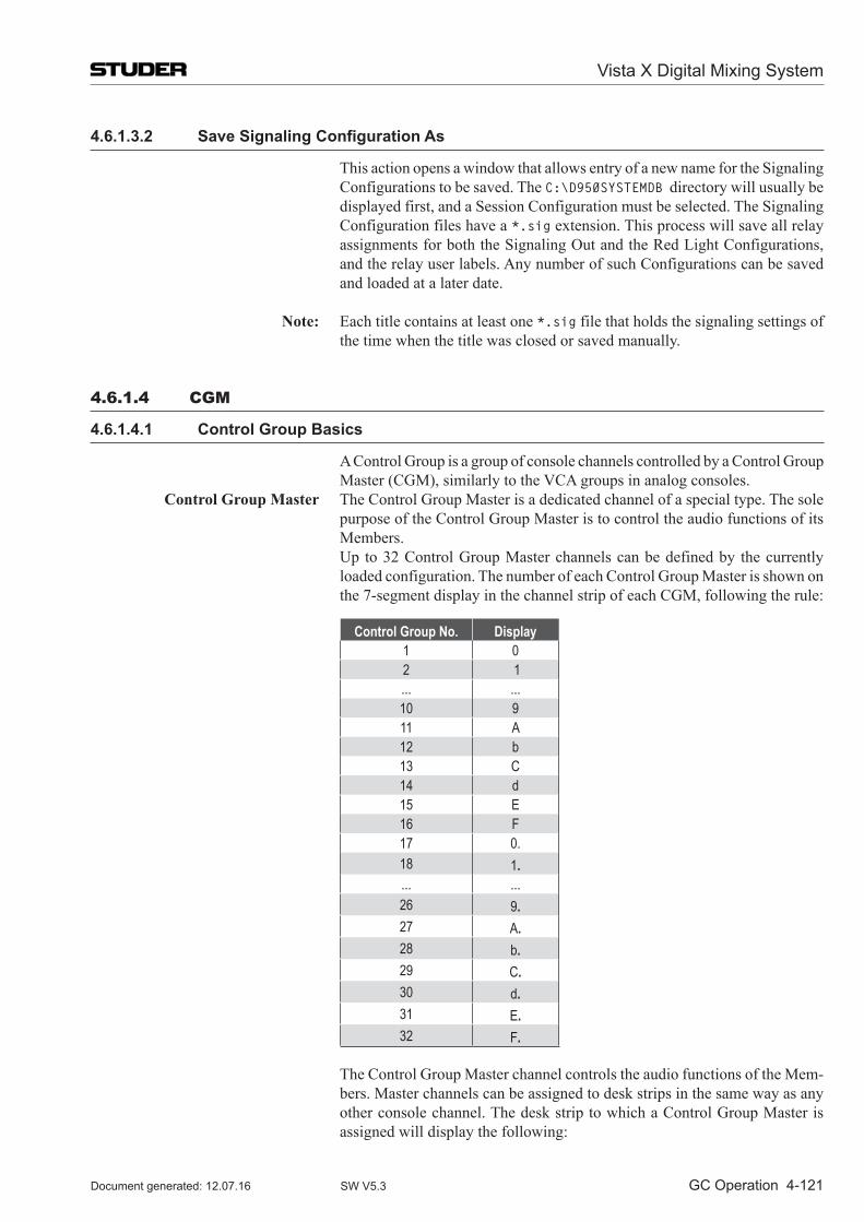
Vista X Digital Mixing System
GC Operation 4-121Document generated: 12.07.16 SW V5.3
4.6.1.3.2 Save Signaling Configuration As
This action opens a window that allows entry of a new name for the Signaling Configurations to be saved. The C:\D950SYSTEMDB directory will usually be displayed first, and a Session Configuration must be selected. The Signaling Con fig uration files have a *.sig extension. This process will save all relay assign ments for both the Signaling Out and the Red Light Con fig urations, and the relay user labels. Any number of such Configurations can be saved and loaded at a later date.
Note: Each title contains at least one *.sig file that holds the signaling settings of the time when the title was closed or saved manually.
4.6.1.4 CGM
4.6.1.4.1 Control Group Basics
A Control Group is a group of console channels controlled by a Control Group Master (CGM), similarly to the VCA groups in analog consoles.
Control Group Master The Control Group Master is a dedicated channel of a special type. The sole purpose of the Control Group Master is to control the audio functions of its Members.
Up to 32 Control Group Master channels can be defined by the currently loaded configuration. The number of each Control Group Master is shown on the 7-segment display in the channel strip of each CGM, following the rule:
Control Group No. Display1 02 1... ...10 911 A12 b13 C14 d15 E16 F17 0.18 1.... ...26 9.27 A.28 b.29 C.30 d.31 E.32 F.
The Control Group Master channel controls the audio functions of the Mem-bers. Master channels can be assigned to desk strips in the same way as any other console channel. The desk strip to which a Control Group Master is assigned will display the following:
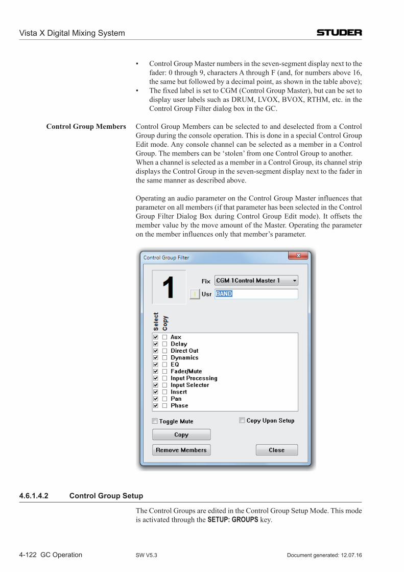
Vista X Digital Mixing System
4-122 GC Operation Document generated: 12.07.16SW V5.3
• ControlGroupMasternumbersintheseven-segmentdisplaynexttothefader: 0 through 9, characters A through F (and, for numbers above 16, the same but followed by a decimal point, as shown in the table above);
• ThefixedlabelissettoCGM(ControlGroupMaster),butcanbesettodisplay user labels such as DRUM, LVOX, BVOX, RTHM, etc. in the Control Group Filter dialog box in the GC.
Control Group Members Control Group Members can be selected to and deselected from a Control Group during the console operation. This is done in a special Control Group Edit mode. Any console channel can be selected as a member in a Control Group. The members can be ‘stolen’ from one Control Group to another.
When a channel is selected as a member in a Control Group, its channel strip displays the Control Group in the seven-segment display next to the fader in the same manner as described above.
Operating an audio parameter on the Control Group Master influences that parameter on all members (if that parameter has been selected in the Control Group Filter Dialog Box during Control Group Edit mode). It offsets the member value by the move amount of the Master. Operating the parameter on the member influences only that member’s parameter.
4.6.1.4.2 Control Group Setup
The Control Groups are edited in the Control Group Setup Mode. This mode is activated through the SETUP: GROUPS key.
Vista X Digital Mixing System
GC Operation 4-123Document generated: 12.07.16 SW V5.3
On first press, the SETUP: GROUPS key is lit to show that an activity has been started but not yet finished. All LINK/SEL keys of Control Group Master chan-nels are half-lit. Pressing one of these enables setting up the corresponding Control Group. The LINK/SEL keys of the Control Group members are lit, the ones of non-members are half-lit. The graphical controller automatically activates the Control Group Filter dialog (see above) for the selected Control Group.
When a Control Group is selected for editing, member channels can be added or removed from the Control Group by using their LINK/SEL keys. If the MULTI SEL key is deactivated, all members are cleared upon pressing any LINK/SEL key, similar to creating a gang. During editing, the Control Group is not active, i.e. the setting of the Control Group Master can be changed without influencing the members. This can be used to adjust the offset between the Master and the Members if required.
Editing a control group can be terminated either by pressing the LINK/SEL key of the master, or by exiting setup mode by pressing the SETUP: GROUPS key in the control bay. If you now want to proceed with editing of another control group, first deselect (using the LINK/SEL key) the Control Group Master you have just finished with, and then select the new one that you wish to edit.
4.6.1.4.3 Control Group Filter
When Control Group Editing is activated, the graphical controller automati-cally activates the Control Group Filter dialog box for the selected Control Group (see screenshot on the previous page).
In the Control Group Filter dialog, the user can define functions to be grouped or not. To group the desired function, the appropriate Select checkbox must be checked. If Select is unchecked, the functions’ control can be moved freely without influencing the members. Normally, when the members are grouped, their local values of Fader/Mute are left untouched when the group is formed – they are grouped in a relative way. If absolute grouping is desired, values can be copied from the master to the members:
• BycheckingtheCopyEnablecheckboxandclickingonCopy; • BycompletingtheeditingofagroupwhiletheCopyUponSetupcheckbox
is checked. There is also a context menu available, called up by right-clicking within the
edit dialog: • IfthecursorisplacedovertheSelectitems,themenuallowstocheckor
clear all select boxes; • IfthecursorisplacedovertheCopycolumn,themenuallowstocheck
and clear all copy parameters; • andifitisplacedoverawhitespace,itdoesboth.
Vista X Digital Mixing System
4-124 GC Operation Document generated: 12.07.16SW V5.3
Note: The Control Group Filter dialog box can also be started by clicking on the Control Group Filter item on the Options menu of the graphical controller. Clicking on the Close button does not terminate the Desk editing mode.
Absolute/Relative Faders are implicitly controlled in a relative way. This means that all the members will remain in relative positions to each other when the Master Fader (or other control) is moved. The member Faders can be forced to match the Master Fader using the Copy function in the Control Group Filter dialog, see above.
Muting can be controlled in absolute and relative mode. The relative (Toggle) mo de for the Mutes can be selected by the user in the Group Filter dialog. If selected, the Mutes can be set to On or Off on the members and will be toggled when the Master Mute is used. If Toggle is not selected, all Mutes on the members will be forced to the same status as the Master Mute the next time the Master Mute is used, regardless of their original status.
Member Behavior When a new member is added to a Control Group, it keeps its values until a change is made in the Control Group Master. At that moment, the change is transferred to all members. When a member is separated from a Control Group it keeps its current setting which includes the Master offset(s) that have been applied along the way. Member values can be changed locally at any time, without affecting the status of the other members or of the Control Group Master.
Over-Range All controls can have an over-range. The over-range condition can occur if
the Member Fader has reached its top or bottom position while the Master Fader is still moving. During over-range, the relative levels of the members are kept intact, even if the Fader (and the audio level) can not move anymore.
Over-range can be positive or negative. The maximum value of over-range can be twice the normal working range of the Fader (100 dB) in both up and down directions.
The over-range of a Member can be zeroed easily. Simply move the Fader of a Member in over-range by a bit, and the over-range will be zeroed.
Note: This will, however, clear the initial relative level of that particular Member with respect to the other Members.
Snapshots Control Groups are part of the snapshot. Their data comprise three parts: • MembersofaControlGroup(whichchannelsareMembersinaControl
Group); • ControlGroupsettings(filterandCopysettings); • ParametervaluesoftheControlGroupMasters.
4.6.1.4.4 Control Group Assignment
A Control Group Assignment dialog window can be started from the SysAd-min (system administration) menu in the graphical controller. This window allows to view the members for a selected Control Group and to edit the members by clicking or dragging them graphically on the screen. Selection of the control group to be edited is not synchronized with the Desk selection – so two different control groups can be viewed at a time.
The Control Group Assignment window serves a similar function as the SETUP: GROUPS key on the control surface, except assignments are made via software, and the Control Group Filter window does not open.
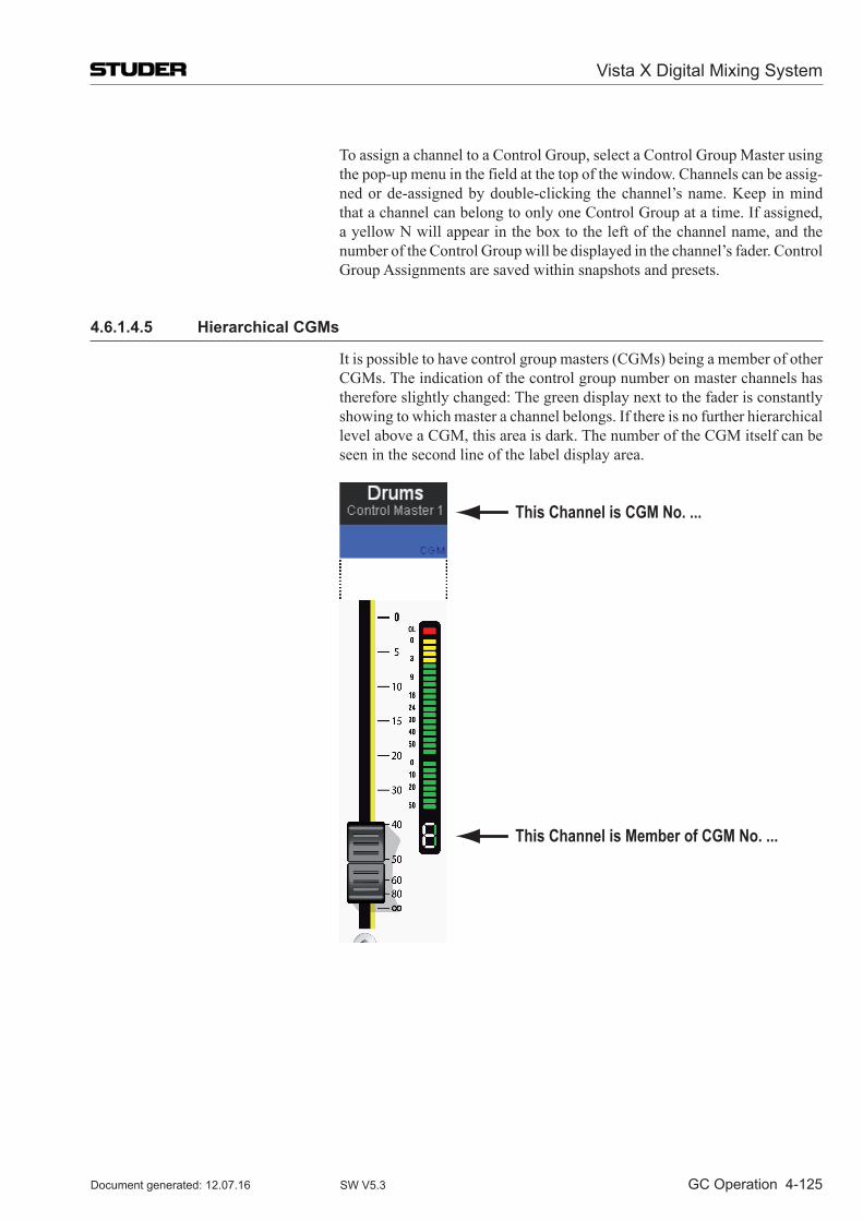
Vista X Digital Mixing System
GC Operation 4-125Document generated: 12.07.16 SW V5.3
To assign a channel to a Control Group, select a Control Group Master using the pop-up menu in the field at the top of the window. Channels can be assig-ned or de-assigned by double-clicking the channel’s name. Keep in mind that a channel can belong to only one Control Group at a time. If assigned, a yellow N will appear in the box to the left of the channel name, and the number of the Control Group will be displayed in the channel’s fader. Control Group Assignments are saved within snapshots and presets.
4.6.1.4.5 Hierarchical CGMs
It is possible to have control group masters (CGMs) being a member of other CGMs. The indication of the control group number on master channels has therefore slightly changed: The green display next to the fader is constantly showing to which master a channel belongs. If there is no further hierarchical level above a CGM, this area is dark. The number of the CGM itself can be seen in the second line of the label display area.
This Channel is CGM No. ...
This Channel is Member of CGM No. ...
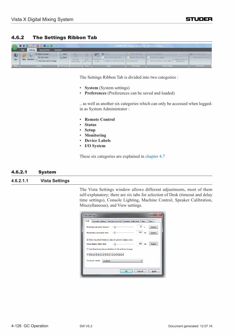
Vista X Digital Mixing System
4-126 GC Operation Document generated: 12.07.16SW V5.3
4.6.2 The Settings Ribbon Tab
The Settings Ribbon Tab is divided into two categories :
• System (System settings) • Preferences (Preferences can be saved and loaded)
.. as well as another six categories which can only be accessed when logged- in as System Administrator :
• Remote Control • Status • Setup • Monitoring • Device Labels • I/O System
These six categories are explained in chapter 4.7
4.6.2.1 System
4.6.2.1.1 Vista Settings
The Vista Settings window allows different adjustments, most of them self-explanatory; there are six tabs for selection of Desk (timeout and delay time settings), Console Lighting, Machine Control, Speaker Calibration, Misc(ellaneous), and View settings.
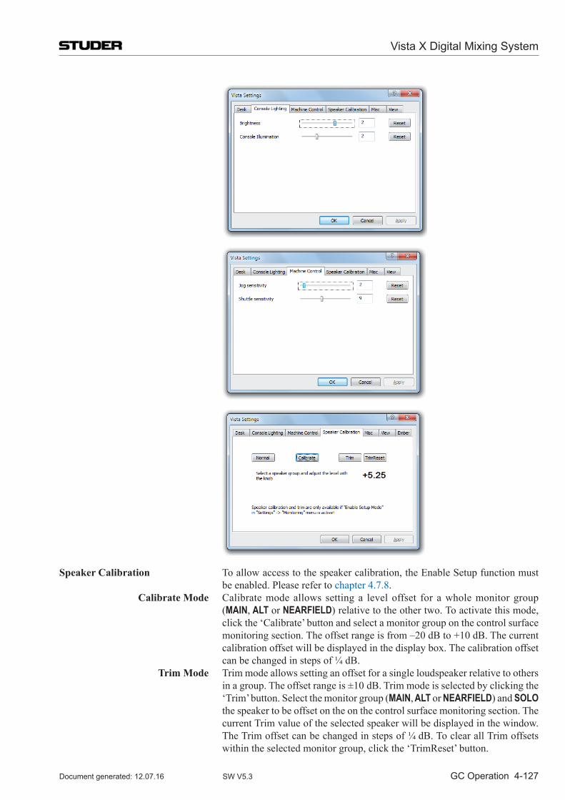
Vista X Digital Mixing System
GC Operation 4-127Document generated: 12.07.16 SW V5.3
Speaker Calibration To allow access to the speaker calibration, the Enable Setup function must be enabled. Please refer to chapter 4.7.8.
Calibrate Mode Calibrate mode allows setting a level offset for a whole monitor group (MAIN, ALT or NEARFIELD) relative to the other two. To activate this mode, click the ‘Calibrate’ button and select a monitor group on the control surface monitoring section. The offset range is from –20 dB to +10 dB. The current calibration offset will be displayed in the display box. The calibration offset can be changed in steps of ¼ dB.
Trim Mode Trim mode allows setting an offset for a single loudspeaker relative to others in a group. The offset range is ±10 dB. Trim mode is selected by clicking the ‘Trim’ button. Select the monitor group (MAIN, ALT or NEARFIELD) and SOLO the speaker to be offset on the on the control surface monitoring section. The current Trim value of the selected speaker will be displayed in the window. The Trim offset can be changed in steps of ¼ dB. To clear all Trim offsets within the selected monitor group, click the ‘TrimReset’ button.
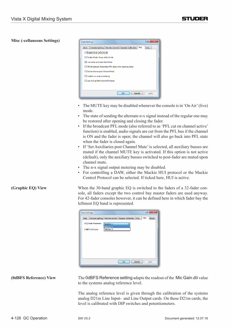
Vista X Digital Mixing System
4-128 GC Operation Document generated: 12.07.16SW V5.3
Misc (-cellaneous Settings)
• TheMUTEkeymaybedisabledwhenevertheconsoleisin‘OnAir’(live)mode.
• Thestateofsendingthealternaten-xsignalinsteadoftheregularonemaybe restored after opening and closing the fader.
• IfthebroadcastPFLmode(alsoreferredtoas‘PFLcutonchannelactive’function) is enabled, audio signals are cut from the PFL bus if the channel is ON and the fader is open; the channel will also go back into PFL state when the fader is closed again.
• If‘SetAuxiliariespostChannelMute’isselected,allauxiliarybussesaremuted if the channel MUTE key is activated. If this option is not active (default), only the auxiliary busses switched to post-fader are muted upon channel mute.
• Then-xsignaloutputmeteringmaybedisabled. • ForcontrollingaDAW,either theMackieHUIprotocolor theMackie
Control Protocol can be selected. If ticked here, HUI is active.
(Graphic EQ) View When the 30-band graphic EQ is switched to the faders of a 32-fader con-sole, all faders except the two control bay master faders are used anyway. For 42-fader consoles however, it can be defined here in which fader bay the leftmost EQ band is represented.
(0dBFS Reference) View The 0dBFS Reference setting adapts the readout of the Mic Gain dB value to the systems analog reference level.
The analog reference level is given through the calibration of the systems analog D21m Line Input- and Line Output cards. On these D21m cards, the level is calibrated with DIP switches and potentiometers.
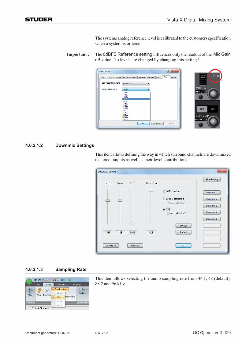
Vista X Digital Mixing System
GC Operation 4-129Document generated: 12.07.16 SW V5.3
The systems analog reference level is calibrated to the customers specification when a system is ordered.
Important : The 0dBFS Reference setting influences only the readout of the Mic Gain dB value. No levels are changed by changing this setting !
4.6.2.1.2 Downmix Settings
This item allows defining the way in which surround channels are downmixed to stereo outputs as well as their level contributions.
4.6.2.1.3 Sampling Rate
This item allows selecting the audio sampling rate from 44.1, 48 (default), 88.2 and 96 kHz.
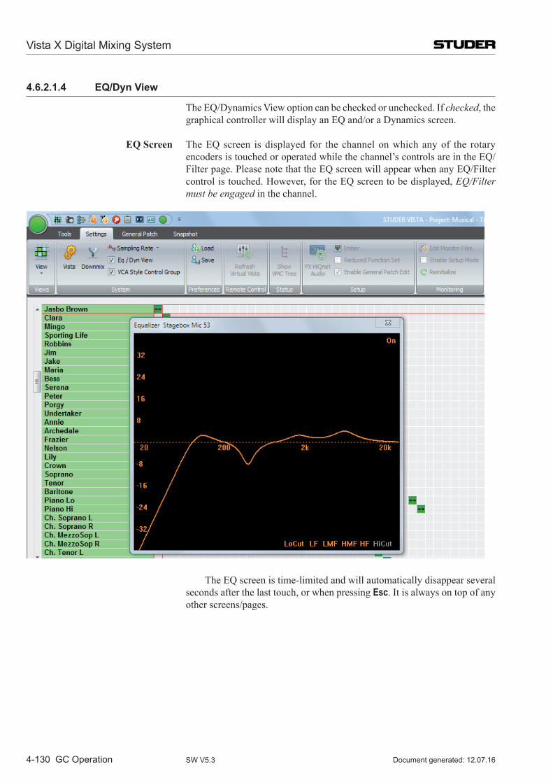
Vista X Digital Mixing System
4-130 GC Operation Document generated: 12.07.16SW V5.3
4.6.2.1.4 EQ/Dyn View
The EQ/Dynamics View option can be checked or unchecked. If checked, the graphical controller will display an EQ and/or a Dynamics screen.
EQ Screen The EQ screen is displayed for the channel on which any of the rotary encoders is touched or operated while the channel’s controls are in the EQ/Filter page. Please note that the EQ screen will appear when any EQ/Filter control is touched. However, for the EQ screen to be displayed, EQ/Filter must be engaged in the channel.
The EQ screen is time-limited and will automatically disappear several seconds after the last touch, or when pressing Esc. It is always on top of any other screens/pages.
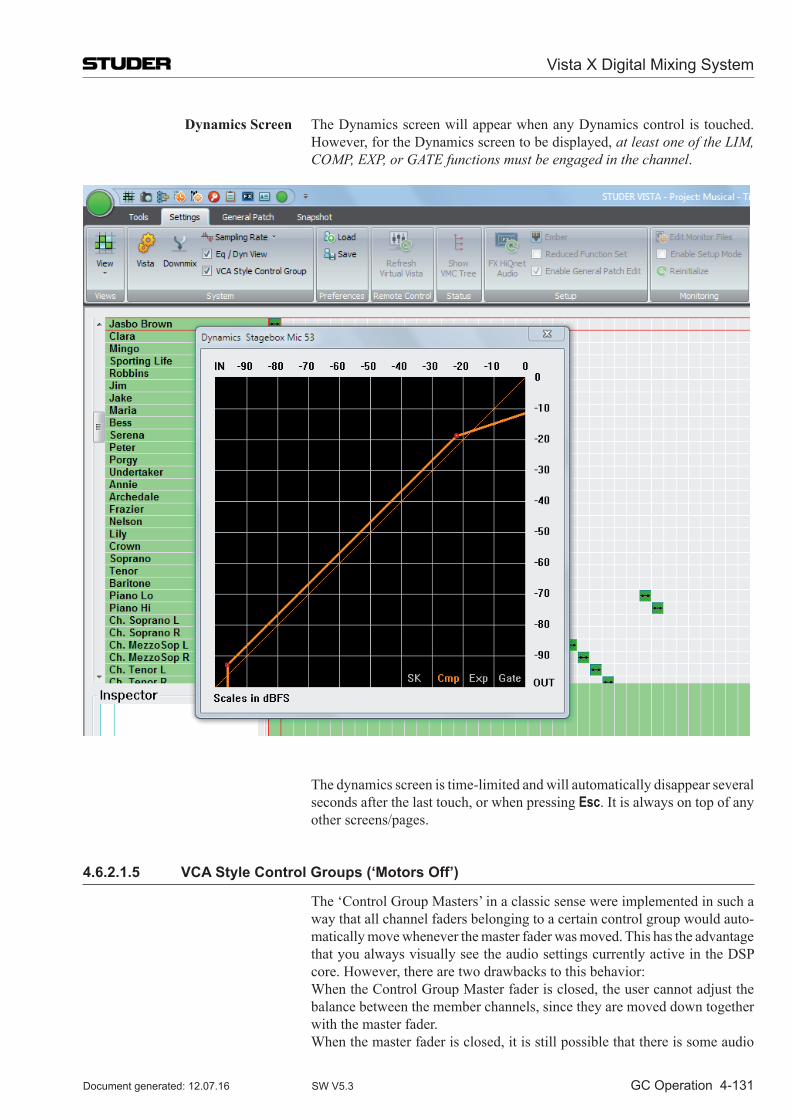
Vista X Digital Mixing System
GC Operation 4-131Document generated: 12.07.16 SW V5.3
Dynamics Screen The Dynamics screen will appear when any Dynamics control is touched. However, for the Dynamics screen to be displayed, at least one of the LIM, COMP, EXP, or GATE functions must be engaged in the channel.
The dynamics screen is time-limited and will automatically disappear several seconds after the last touch, or when pressing Esc. It is always on top of any other screens/pages.
4.6.2.1.5 VCA Style Control Groups (‘Motors Off’)
The ‘Control Group Masters’ in a classic sense were implemented in such a way that all channel faders belonging to a certain control group would auto-matically move whenever the master fader was moved. This has the advantage that you always visually see the audio settings currently active in the DSP core. However, there are two drawbacks to this behavior:
When the Control Group Master fader is closed, the user cannot adjust the balance between the member channels, since they are moved down together with the master fader.
When the master fader is closed, it is still possible that there is some audio
Vista X Digital Mixing System
4-132 GC Operation Document generated: 12.07.16SW V5.3
passing through some of the member channels, since their fader is not com-pletely closed.
With software release 3.4, there is now an alternative way of how the control group master channels can work, that is very similar to the VCA groups of an analog mixing console. Sometimes, this new behavior is also called ‘motors off’. In this mode, the value set on the control group master channels (as seen on their scale) is added to or subtracted from all member channels, and the resulting (audio) level is set in the DSP core. The faders of the member channels don’t move up/down, and so it is possible to have the master fader closed but still to correct the balance between the member faders. In addition, the user can be sure that whenever the master channel is closed, no audio can be heard from the member channels. Since the fader of a member channel doesn’t represent the real audio value anymore, the digits below the label display are indicating the real audio value.
Notes If ‘VCA style’ operation is active, you may see member channels change their fader values as soon as they are added to a control group. This is the case if the master channel is already set to a value different from 0 dB at the moment when a new slave channel is added to the group. This behavior is by intention, in order not to have any audio changing when adding or subtracting member channels from a control group. Example: You have set a microphone channel to –15 dB, and you add it to a ‘VCA’ group the master channel of which is already set to –10 dB. In the moment the microphone channel is added to that group, the user will see the microphone fader jump up to –5 dB. This results in no audio change, as requested.
The VCA style Control Groups option can be found in the Option menu of the graphical controller screen.
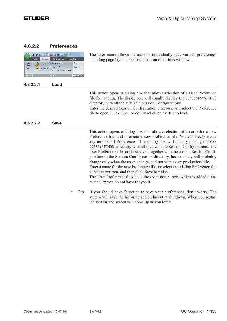
Vista X Digital Mixing System
GC Operation 4-133Document generated: 12.07.16 SW V5.3
4.6.2.2 Preferences
The User menu allows the users to individually save various prefer ences including page layout, size, and position of various windows.
4.6.2.2.1 Load
This action opens a dialog box that allows selection of a User Preference file for loading. The dialog box will usually display the C:\D950SYSTEMDB directory with all the available Session Configurations.
Enter the desired Session Configuration directory, and select the Preference file to open. Click Open or double-click on the file to load.
4.6.2.2.2 Save
This action opens a dialog box that allows selection of a name for a new Preference file, and to create a new Preference file. You can freely create any number of Preferences. The dialog box will usually display the C:\D950SYSTEMDB directory with all the available Session Con figurations. The User Preference files are best saved together with the current Session Confi-guration in the Session Configuration directory, because they will probably change only when the users change, and not with every production/title.
Enter a name for the new Preference file, or select an existing Preference file to be overwritten, and then click Save to finish.
The User Preference files have the extension *.pfc, which is added auto-matically; you do not have to type it.
Tip If you should have forgotten to save your preferences, don’t worry. The system will save the last-used screen layout at shutdown. When you restart the system, the screen will come up as you left it.
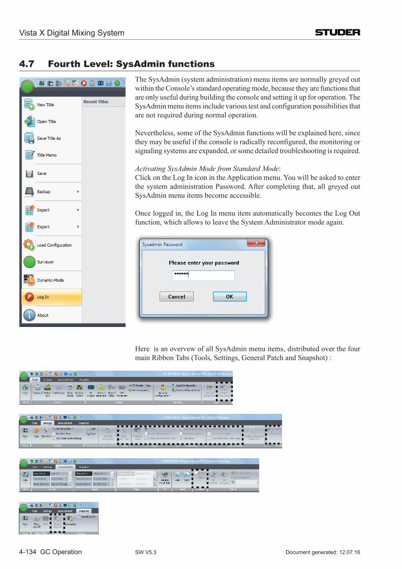
Vista X Digital Mixing System
4-134 GC Operation Document generated: 12.07.16SW V5.3
4.7 Fourth level: SysAdmin functions The SysAdmin (system administration) menu items are normally greyed out
within the Console’s standard operating mode, because they are functions that are only useful during building the console and setting it up for operation. The SysAdmin menu items include various test and configuration possibilities that are not required during normal operation.
Nevertheless, some of the SysAdmin functions will be explained here, since they may be useful if the console is radically reconfigured, the monitoring or signaling systems are expanded, or some detailed troubleshooting is required.
Activating SysAdmin Mode from Standard Mode: Click on the Log In icon in the Application menu. You will be asked to enter
the system administration Password. After completing that, all greyed out SysAdmin menu items become accessible.
Once logged in, the Log In menu item automatically becomes the Log Out function, which allows to leave the System Administrator mode again.
Here is an overvew of all SysAdmin menu items, distributed over the four main Ribbon Tabs (Tools, Settings, General Patch and Snapshot) :
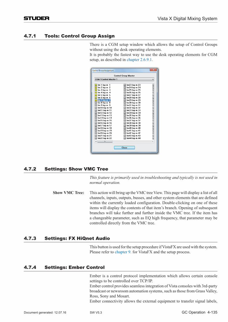
Vista X Digital Mixing System
GC Operation 4-135Document generated: 12.07.16 SW V5.3
4.7.1 Tools: Control Group Assign
There is a CGM setup window which allows the setup of Control Groups without using the desk operating elements.
It is probably the fastest way to use the desk operating elements for CGM setup, as described in chapter 2.6.9.1.
4.7.2 Settings: Show VMC Tree
This feature is primarily used in troubleshooting and typically is not used in normal operation.
Show VMC Tree: This action will bring up the VMC tree View. This page will display a list of all channels, inputs, outputs, busses, and other system elements that are defined within the currently loaded configuration. Double-clicking on one of these items will display the contents of that item’s branch. Opening of subsequent branches will take further and further inside the VMC tree. If the item has a changeable parameter, such as EQ high frequency, that parameter may be controlled directly from the VMC tree.
4.7.3 Settings: FX HiQnet Audio
This button is used for the setup procedure if VistaFX are used with the system. Please refer to chapter 9. for VistaFX and the setup process.
4.7.4 Settings: Ember Control
Ember is a control protocol implementation which allows certain console settings to be controlled over TCP/IP.
Ember control provides seamless integration of Vista consoles with 3rd-party broadcast or newsroom automation systems, such as those from Grass Valley, Ross, Sony and Mosart.
Ember connectivity allows the external equipment to transfer signal labels,
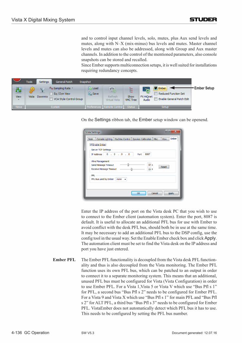
Vista X Digital Mixing System
4-136 GC Operation Document generated: 12.07.16SW V5.3
and to control input channel levels, solo, mutes, plus Aux send levels and mutes, along with N–X (mix-minus) bus levels and mutes. Master channel levels and mutes can also be addressed, along with Group and Aux master channels. In addition to the control of the mentioned parameters, also console snapshots can be stored and recalled.
Since Ember supports multiconnection setups, it is well suited for installations requiring redundancy concepts.
Ember Setup
On the Settings ribbon tab, the Ember setup window can be openend.
Enter the IP address of the port on the Vista desk PC that you wish to use to connect to the Ember client (automation system). Enter the port, 8087 is default. It is useful to allocate an additional PFL bus for use with Ember to avoid conflict with the desk PFL bus, should both be in use at the same time. It may be necessary to add an additional PFL bus to the DSP config, use the config tool in the usual way. Set the Enable Ember check box and click Apply. The automation client must be set to find the Vista desk on the IP address and port you have just entered.
Ember PFL The Ember PFL functionality is decoupled from the Vista desk PFL function-ality and thus is also decoupled from the Vista monitoring. The Ember PFL function uses its own PFL bus, which can be patched to an output in order to connect it to a separate monitoring system. This means that an additional, unused PFL bus must be configured for Vista (Vista Configuration) in order to use Ember PFL. For a Vista 1,Vista 5 or Vista V which use “Bus Pfl s 1” for PFL, a second bus “Bus Pfl s 2” needs to be configured for Ember PFL. For a Vista 9 and Vista X which use “Bus Pfl s 1” for main PFL and “Bus Pfl s 2” for ALT PFL, a third bus “Bus Pfl s 3” needs to be configured for Ember PFL. VistaEmber does not automatically detect which PFL bus it has to use. This needs to be configured by setting the PFL bus number.
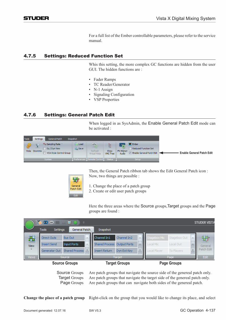
Vista X Digital Mixing System
GC Operation 4-137Document generated: 12.07.16 SW V5.3
For a full list of the Ember controllable parameters, please refer to the service manual.
4.7.5 Settings: Reduced Function Set
Whis this setting, the more complex GC functions are hidden from the user GUI. The hidden functions are :
• FaderRamps • TCReader/Generator • N-1Assign • SignalingConfiguration • VSPProperties
4.7.6 Settings: General Patch Edit
When logged in as SysAdmin, the Enable General Patch Edit mode can be activated :
Enable General Patch Edit
Then, the General Patch ribbon tab shows the Edit General Patch icon : Now, two things are possible :
1. Change the place of a patch group 2. Create or edit user patch groups
Here the three areas where the Source groups,Target groups and the Page groups are found :
Source Groups Target Groups Page Groups
Source Groups Are patch groups that navigate the source side of the genereal patch only. Target Groups Are patch groups that navigate the target side of the genereal patch only. Page Groups Are patch groups that can navigate both sides of the genereal patch.
Change the place of a patch group Right-click on the group that you would like to change its place, and select
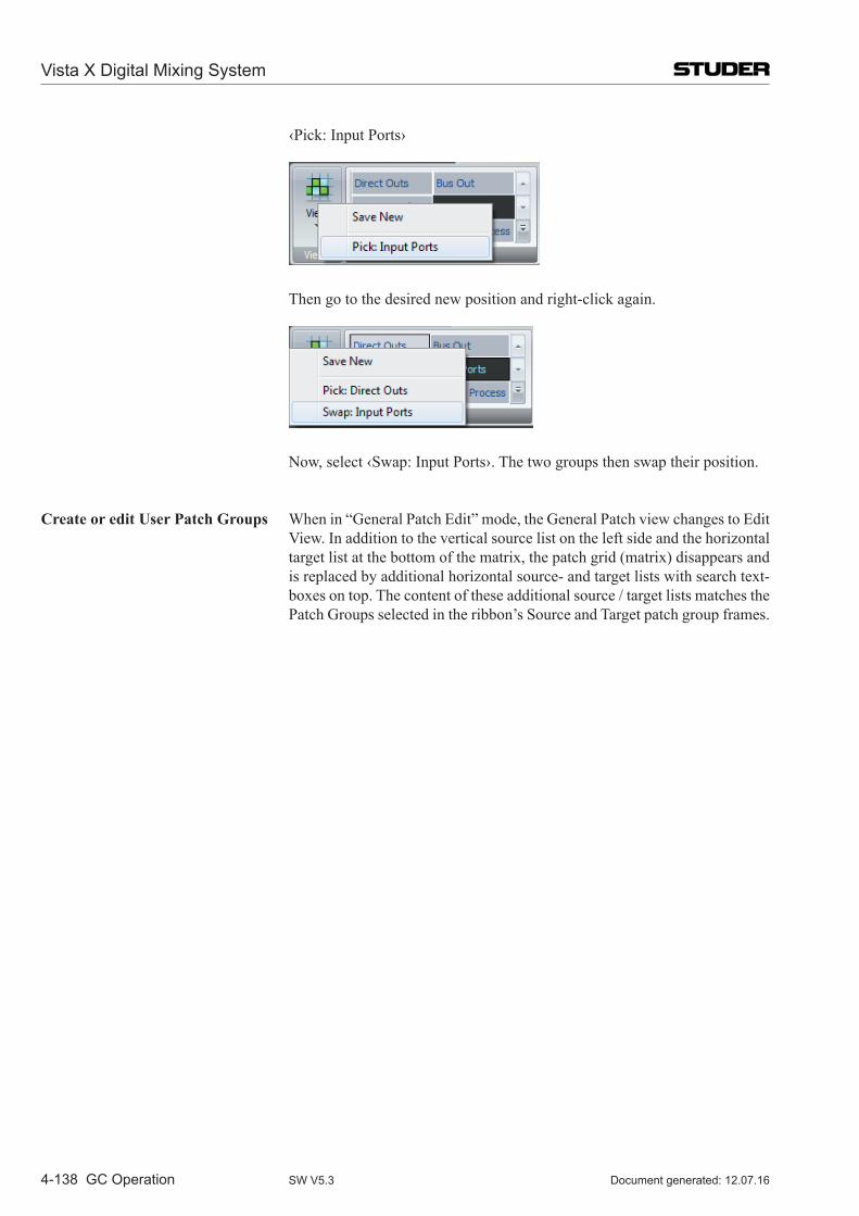
Vista X Digital Mixing System
4-138 GC Operation Document generated: 12.07.16SW V5.3
‹Pick: Input Ports›
Then go to the desired new position and right-click again.
Now, select ‹Swap: Input Ports›. The two groups then swap their position.
Create or edit User Patch Groups When in “General Patch Edit” mode, the General Patch view changes to Edit View. In addition to the vertical source list on the left side and the horizontal target list at the bottom of the matrix, the patch grid (matrix) disappears and is replaced by additional horizontal source- and target lists with search text-boxes on top. The content of these additional source / target lists matches the Patch Groups selected in the ribbon’s Source and Target patch group frames.
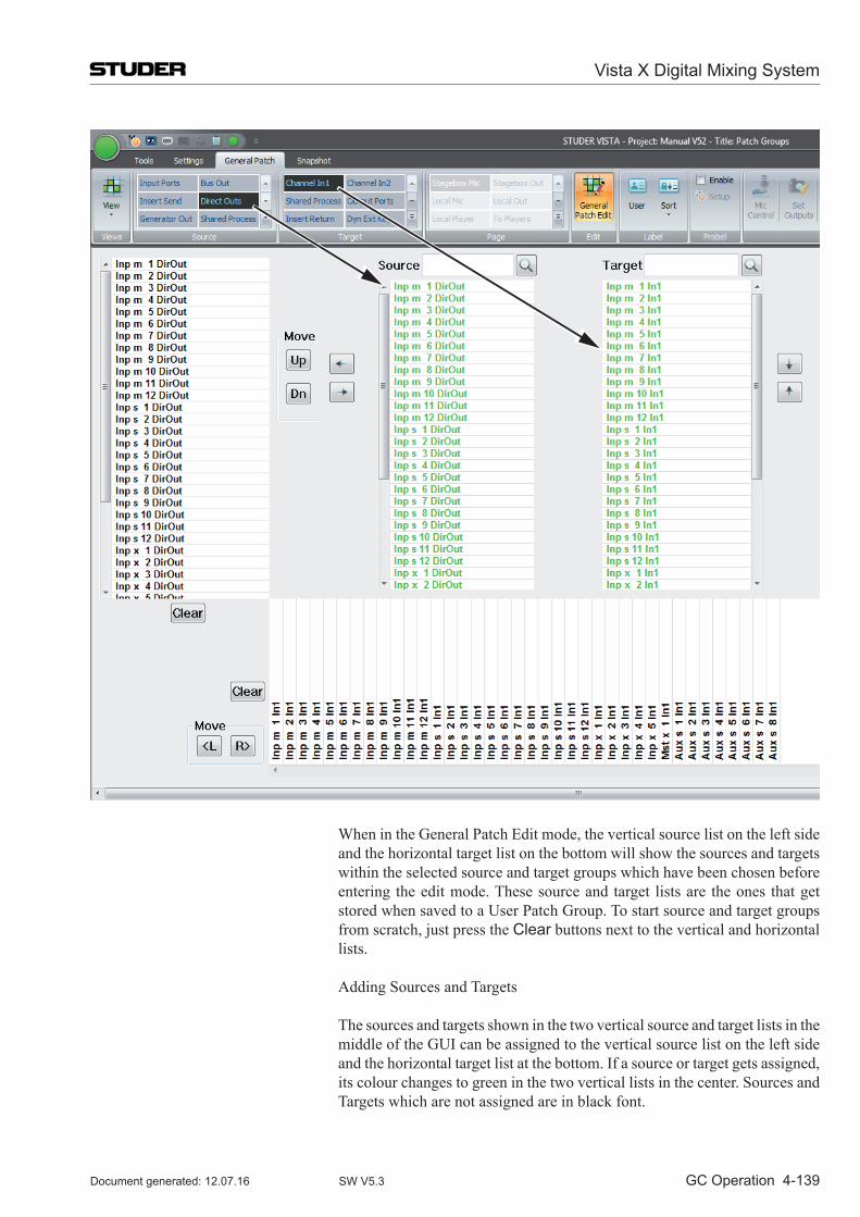
Vista X Digital Mixing System
GC Operation 4-139Document generated: 12.07.16 SW V5.3
When in the General Patch Edit mode, the vertical source list on the left side and the horizontal target list on the bottom will show the sources and targets within the selected source and target groups which have been chosen before entering the edit mode. These source and target lists are the ones that get stored when saved to a User Patch Group. To start source and target groups from scratch, just press the Clear buttons next to the vertical and horizontal lists.
Adding Sources and Targets
The sources and targets shown in the two vertical source and target lists in the middle of the GUI can be assigned to the vertical source list on the left side and the horizontal target list at the bottom. If a source or target gets assigned, its colour changes to green in the two vertical lists in the center. Sources and Targets which are not assigned are in black font.

Vista X Digital Mixing System
4-140 GC Operation Document generated: 12.07.16SW V5.3
Assign a source or target to the list by double-clicking it. Deassign them by
double-clicking on them in the list on the left and bottom. Multiple sources and targets can also be assigned and de-assigned by selecting several items (using Shift or Ctrl on the keyboard) at once and then using the arrow keys on the GUI.
It is possible to mix different source and target types within the Patch Group you are creating. For example, it is possible to create a source list that contains some Bus Outs, some Direct Outs etc.
In Edit mode, you can simply select another source or target Patch Group and add channels from these to the list which you are editing.
By using the Move Up / Move Down buttons, it is possible to change the source / target order of appearance in your edited /created Patch Group.
Save an edited / created User Patch Group
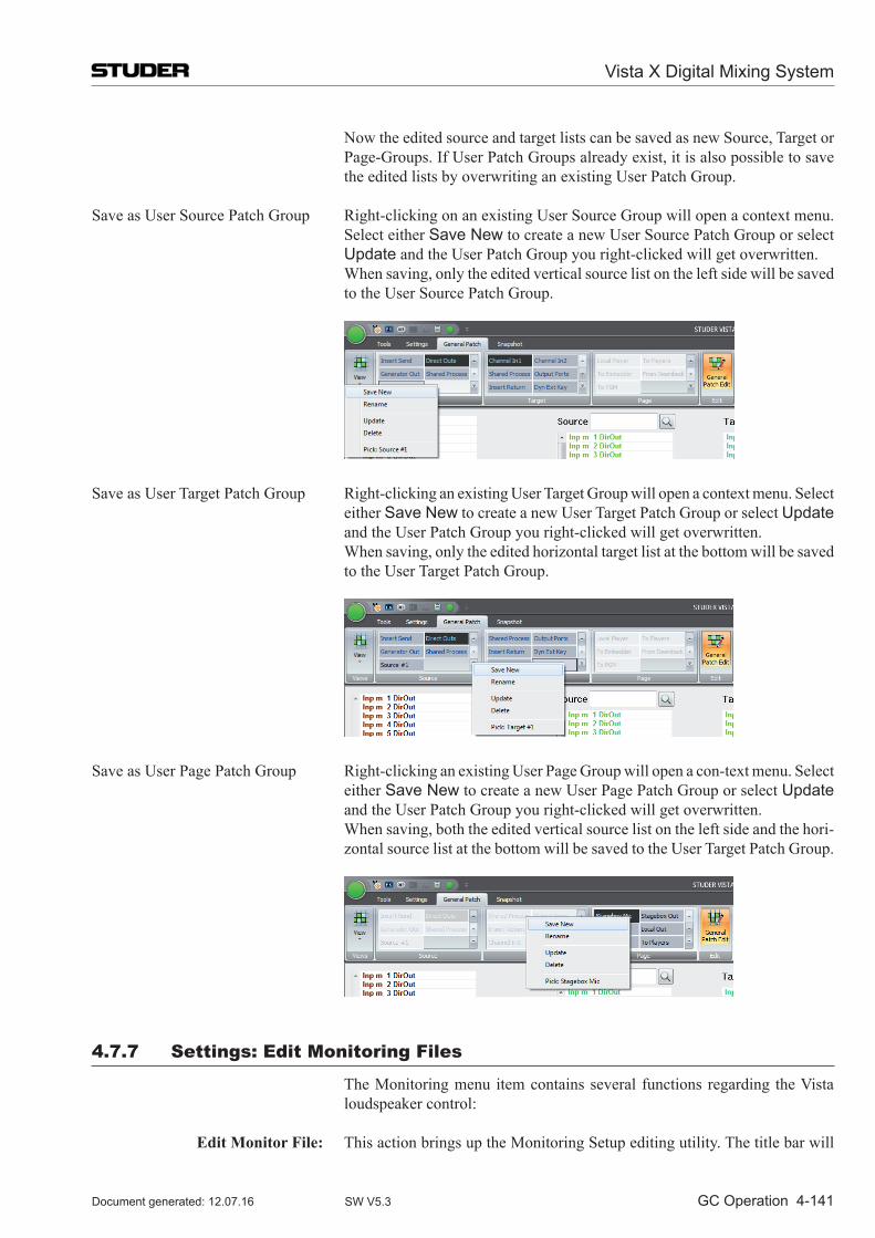
Vista X Digital Mixing System
GC Operation 4-141Document generated: 12.07.16 SW V5.3
Now the edited source and target lists can be saved as new Source, Target or Page-Groups. If User Patch Groups already exist, it is also possible to save the edited lists by overwriting an existing User Patch Group.
Save as User Source Patch Group Right-clicking on an existing User Source Group will open a context menu. Select either Save New to create a new User Source Patch Group or select Update and the User Patch Group you right-clicked will get overwritten.
When saving, only the edited vertical source list on the left side will be saved to the User Source Patch Group.
Save as User Target Patch Group Right-clicking an existing User Target Group will open a context menu. Select either Save New to create a new User Target Patch Group or select Update and the User Patch Group you right-clicked will get overwritten.
When saving, only the edited horizontal target list at the bottom will be saved to the User Target Patch Group.
Save as User Page Patch Group Right-clicking an existing User Page Group will open a con-text menu. Select either Save New to create a new User Page Patch Group or select Update and the User Patch Group you right-clicked will get overwritten.
When saving, both the edited vertical source list on the left side and the hori-zontal source list at the bottom will be saved to the User Target Patch Group.
4.7.7 Settings: Edit Monitoring Files
The Monitoring menu item contains several functions regarding the Vista loudspeaker control:
Edit Monitor File: This action brings up the Monitoring Setup editing utility. The title bar will
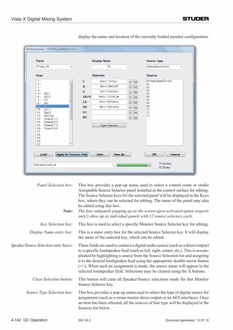
Vista X Digital Mixing System
4-142 GC Operation Document generated: 12.07.16SW V5.3
display the name and location of the currently loaded monitor configuration.
Panel Selection box: This box provides a pop-up menu used to select a control room or studio Assignable Source Selector panel installed in the control surface for editing. The Source Selector keys for the selected panel will be displayed in the Keys box, where they can be selected for editing. The name of the panel may also be edited using this box.
Note: The four subpanels popping up on the screen upon activated option (experts only!) show up as individual panels with 12 source selectors each.
Key Selection box: This box is used to select a specific Monitor Source Selector key for editing.
Display Name entry box: This is a name entry box for the selected Source Selector key. It will display the name of the selected key, which can be edited.
Speaker/Source Selection entry boxes: These fields are used to connect a digital audio source (such as a direct output) to a specific loudspeaker feed (such as left, right, center, etc.). This is accom-plished by highlighting a source from the Source Selection list and assigning it to the desired loudspeaker feed using the appropriate double-arrow button (<<). When such an assignment is made, the source name will appear in the selected loudspeaker field. Selections may be cleared using the X buttons.
Clear Selection button: This button will clear all Speaker/Source selections made for that Monitor Source Selector key.
Source Type Selection box: This box provides a pop-up menu used to select the type of digital source for assignment (such as a mono master direct output or an AES interface). Once an item has been selected, all the sources of that type will be displayed in the Sources list below.
Vista X Digital Mixing System
GC Operation 4-143Document generated: 12.07.16 SW V5.3
Source Selection box: This box displays a list of digital sources of a specific type that are available for assignment to loudspeaker feeds.
Load button: This button brings up a familiar Windows box from which an existing monitor configuration file can be loaded.
Apply button: This button applies the current monitor configuration file to the Vista. This is handy when testing a recently edited file or recalling a previously saved file.
Save and Save As... buttons: The Save button allows a previously saved monitor configuration file to be updated after editing. The Save As... button allows a new file to be named and created.
OK and Cancel buttons: The OK button accepts the current monitor setup and closes the window. Cli-cking OK does not apply or save the monitor configuration file. The Cancel button exits the monitor setup screen.
Monitor File Name entry box: This field is used to enter a name for a new monitor Configuration.
Application Progress indicator: This meter displays the progress of the loading of the monitor configuration file when it is applied to the console.
Applied and Saved Status boxes: These boxes display the status of the current monitor configuration file. If checked, the current file is applied to the console and/or saved.
To create a new monitor configuration file: • FirstopentheMonitoringSetuputilityfromtheMonitorsectionofthe
SysAdmin menu. • SelectthedesiredAssignableSourceSelectorpanelandkey,usingthelists
on the left. • Selectasourcetypeandsourcefromthelistsontheright. • Highlighttheselectedsourceandclickonthedouble-arrow(<<)button
next to the desired loudspeaker feed in the Selection boxes. The source name will appear in the selected location. Once a key is selected, its name may be changed using the Display Name field.
• Repeatthesestepstocompletethenecessaryassignments.Oncefinished,the new file can be saved and applied to the console.
Please note that the edited file must be applied to the console before it takes effect.
Existing monitor configuration files can be edited by recalling them with the Load button and using the procedures described above.
4.7.8 Settings: Enable Monitoring Setup-Mode
To allow access to the speaker calibration, the Enable Setup function must be enabled. Please refer to chapter 4.6.2.1.1.
4.7.9 Settings: Reinitialize Monitoring
This action will reinitialize the monitor system and reload the last used moni-tor configuration file. The monitors will mute during this operation.
Vista X Digital Mixing System
4-144 GC Operation Document generated: 12.07.16SW V5.3
4.7.10 Settings : Device labels (Save and Apply)
This menu item lets you set-up the console for use with Device Labels. It is used for setup only ! For a detailed description, please refer to chapter 4.4.2.6
4.7.11 Settings: Use Devicelabels
This option must be checked for using the console with Device Labels. It must be checked (active) for proper Device Labels functionality. For a detailed description, please refer to chapter 4.4.2.8.
4.7.12 Settings: overwrite Channel User label
This option must be checked for using the console with Device Labels. It must be checked (active) for proper Device Labels functionality. For a detailed description, please refer to chapter 4.4.2.8.
4.7.13 Settings: Configure ExernalRouter i/o
This opens a dialog window for External Router I/O Configuration - but only in the case if external router control is enabled on the system.
4.7.14 Settings: Connection Setup
If this button is pressed, the D23m/D21m I/O system will be reinitialized. This button is not used in normal operating mode, only when changes in the I/O system have happened, this button can be used for trouble shooting.
4.7.15 Settings: Regenerate intelligent Fix labels
Audio coming through the D21m I/O components is reaching the core over Studer’s proprietary HD (high density) link in case of the SCoreLive. This link is present between the local hub(s) and the SCoreLive. Each link may carry up to 96 audio channels. Instead of displaying these channel numbers in the general patch, the software is able to give more intelligent names to the input and output ports shown in the general patch. You will then see frame numbers as well as card types and channel numbers within each card. This generation is automatically active whenever the D21m I/O system is present and the hub frame is connected to the console via a serial link. However, when recalling a snapshot containing the ‘non intelligent’ fixed labels (e.g. from older productions), this will overwrite the fixed labels as well and make the ‘intelligent fixed labels’ disappear. In this case, select Regenerate Intelli-gent Fixed Labels and update this snapshot.
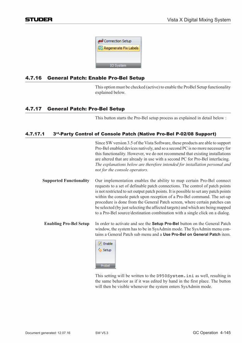
Vista X Digital Mixing System
GC Operation 4-145Document generated: 12.07.16 SW V5.3
4.7.16 General Patch: Enable Pro-Bel Setup
This option must be checked (active) to enable the ProBel Setup functionality explained below.
4.7.17 General Patch: Pro-Bel Setup
This button starts the Pro-Bel setup process as explained in detail below :
4.7.17.1 3rd-Party Control of Console Patch (native Pro-Bel P-02/08 Support)
Since SW version 3.5 of the Vista Software, these products are able to support Pro-Bel enabled devices natively, and so a second PC is no more necessary for this functionality. However, we do not recommend that existing installations are altered that are already in use with a second PC for Pro-Bel interfacing.
The explanations below are therefore intended for installation personal and not for the console operators.
Supported Functionality Our implementation enables the ability to map certain Pro-Bel connect requests to a set of definable patch connections. The control of patch points is not restricted to set output patch points. It is possible to set any patch points within the console patch upon reception of a Pro-Bel command. The set-up procedure is done from the General Patch screen, where certain patches can be selected (by just selecting the affected targets) and which are being mapped to a Pro-Bel source/destination combination with a single click on a dialog.
Enabling Pro-Bel Setup In order to activate and see the Setup Pro-Bel button on the General Patch window, the system has to be in SysAdmin mode. The SysAdmin menu con-tains a General Patch sub menu and a Use Pro-Bel on General Patch item.
This setting will be written to the D950System.ini as well, resulting in the same behavior as if it was edited by hand in the first place. The button will then be visible whenever the system enters SysAdmin mode.
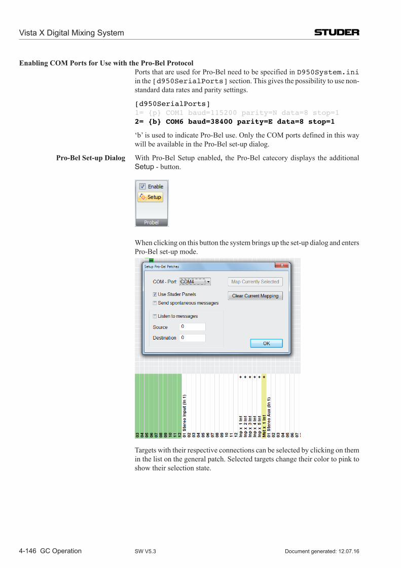
Vista X Digital Mixing System
4-146 GC Operation Document generated: 12.07.16SW V5.3
Enabling COM Ports for Use with the Pro-Bel Protocol Ports that are used for Pro-Bel need to be specified in D950System.ini
in the [d950SerialPorts] section. This gives the possibility to use non-standard data rates and parity settings.
[d950SerialPorts]1= {p} COM1 baud=115200 parity=N data=8 stop=12= {b} COM6 baud=38400 parity=E data=8 stop=1
‘b’ is used to indicate Pro-Bel use. Only the COM ports defined in this way will be available in the Pro-Bel set-up dialog.
Pro-Bel Set-up Dialog With Pro-Bel Setup enabled, the Pro-Bel catecory displays the additional Setup - button.
When clicking on this button the system brings up the set-up dialog and enters
Pro-Bel set-up mode.
Targets with their respective connections can be selected by clicking on them in the list on the general patch. Selected targets change their color to pink to show their selection state.
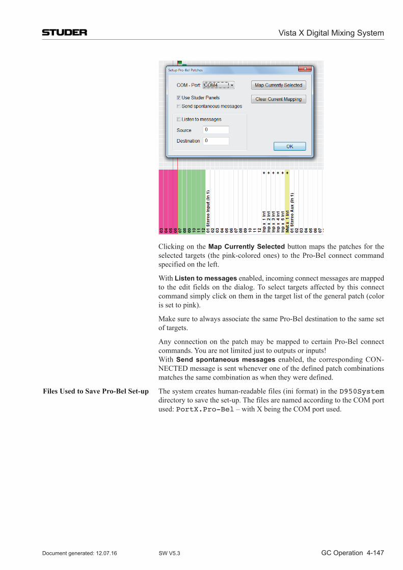
Vista X Digital Mixing System
GC Operation 4-147Document generated: 12.07.16 SW V5.3
Clicking on the Map Currently Selected button maps the patches for the selected targets (the pink-colored ones) to the Pro-Bel connect command specified on the left.
With Listen to messages enabled, incoming connect messages are mapped to the edit fields on the dialog. To select targets affected by this connect command simply click on them in the target list of the general patch (color is set to pink).
Make sure to always associate the same Pro-Bel destination to the same set of targets.
Any connection on the patch may be mapped to certain Pro-Bel connect commands. You are not limited just to outputs or inputs!
With Send spontaneous messages enabled, the corresponding CON -NECTED message is sent whenever one of the defined patch combinations matches the same combination as when they were defined.
Files Used to Save Pro-Bel Set-up The system creates human-readable files (ini format) in the D950System directory to save the set-up. The files are named according to the COM port used: PortX.Pro-Bel – with X being the COM port used.
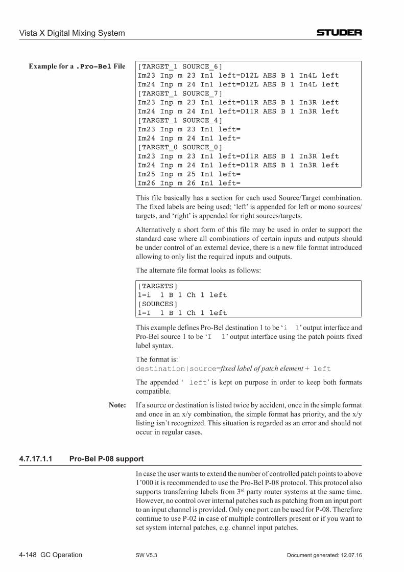
Vista X Digital Mixing System
4-148 GC Operation Document generated: 12.07.16SW V5.3
Example for a .Pro-Bel File [TARGET_1 SOURCE_6]Im23 Inp m 23 In1 left=D12L AES B 1 In4L leftIm24 Inp m 24 In1 left=D12L AES B 1 In4L left[TARGET_1 SOURCE_7]Im23 Inp m 23 In1 left=D11R AES B 1 In3R leftIm24 Inp m 24 In1 left=D11R AES B 1 In3R left[TARGET_1 SOURCE_4]Im23 Inp m 23 In1 left=Im24 Inp m 24 In1 left=[TARGET_0 SOURCE_0]Im23 Inp m 23 In1 left=D11R AES B 1 In3R leftIm24 Inp m 24 In1 left=D11R AES B 1 In3R leftIm25 Inp m 25 In1 left=Im26 Inp m 26 In1 left=
This file basically has a section for each used Source/Target combination. The fixed labels are being used; ‘left’ is appended for left or mono sources/targets, and ‘right’ is appended for right sources/targets.
Alternatively a short form of this file may be used in order to support the standard case where all combinations of certain inputs and outputs should be under control of an external device, there is a new file format introduced allowing to only list the required inputs and outputs.
The alternate file format looks as follows:
[TARGETS]1=i 1 B 1 Ch 1 left[SOURCES]1=I 1 B 1 Ch 1 left
This example defines Pro-Bel destination 1 to be ‘i 1’ output interface and Pro-Bel source 1 to be ‘I 1’ output interface using the patch points fixed label syntax.
The format is: destination|source=fixed label of patch element + left
The appended ‘ left’ is kept on purpose in order to keep both formats compatible.
Note: If a source or destination is listed twice by accident, once in the simple format and once in an x/y combination, the simple format has priority, and the x/y listing isn’t recognized. This situation is regarded as an error and should not occur in regular cases.
4.7.17.1.1 Pro-Bel P-08 support
In case the user wants to extend the number of controlled patch points to above 1’000 it is recommended to use the Pro-Bel P-08 protocol. This protocol also supports transferring labels from 3rd party router systems at the same time. However, no control over internal patches such as patching from an input port to an input channel is provided. Only one port can be used for P-08. Therefore continue to use P-02 in case of multiple controllers present or if you want to set system internal patches, e.g. channel input patches.
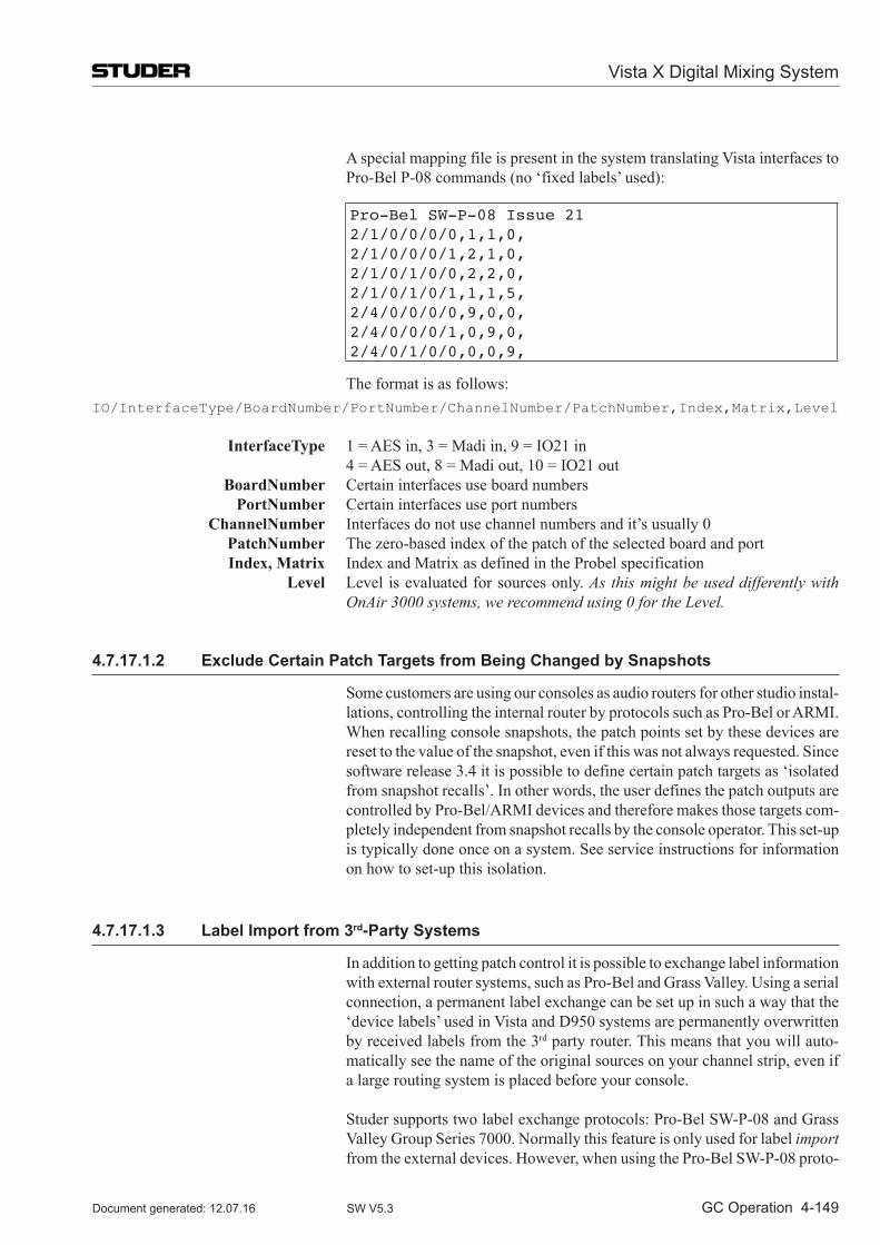
Vista X Digital Mixing System
GC Operation 4-149Document generated: 12.07.16 SW V5.3
A special mapping file is present in the system translating Vista interfaces to Pro-Bel P-08 commands (no ‘fixed labels’ used):
Pro-Bel SW-P-08 Issue 212/1/0/0/0/0,1,1,0,2/1/0/0/0/1,2,1,0,2/1/0/1/0/0,2,2,0,2/1/0/1/0/1,1,1,5,2/4/0/0/0/0,9,0,0,2/4/0/0/0/1,0,9,0,2/4/0/1/0/0,0,0,9,
The format is as follows:IO/InterfaceType/BoardNumber/PortNumber/ChannelNumber/PatchNumber,Index,Matrix,Level
InterfaceType 1=AESin,3=Madiin,9=IO21in 4=AESout,8=Madiout,10=IO21out BoardNumber Certain interfaces use board numbers PortNumber Certain interfaces use port numbers ChannelNumber Interfaces do not use channel numbers and it’s usually 0 PatchNumber The zero-based index of the patch of the selected board and port Index, Matrix Index and Matrix as defined in the Probel specification Level Level is evaluated for sources only. As this might be used differently with
OnAir 3000 systems, we recommend using 0 for the Level.
4.7.17.1.2 Exclude Certain Patch Targets from Being Changed by Snapshots
Some customers are using our consoles as audio routers for other studio instal-lations, controlling the internal router by protocols such as Pro-Bel or ARMI. When recalling console snapshots, the patch points set by these devices are reset to the value of the snapshot, even if this was not always requested. Since software release 3.4 it is possible to define certain patch targets as ‘isolated from snapshot recalls’. In other words, the user defines the patch outputs are controlled by Pro-Bel/ARMI devices and therefore makes those targets com-pletely independent from snapshot recalls by the console operator. This set-up is typically done once on a system. See service instructions for information on how to set-up this isolation.
4.7.17.1.3 Label Import from 3rd-Party Systems
In addition to getting patch control it is possible to exchange label information with external router systems, such as Pro-Bel and Grass Valley. Using a serial connection, a permanent label exchange can be set up in such a way that the ‘device labels’ used in Vista and D950 systems are permanently overwritten by received labels from the 3rd party router. This means that you will auto-matically see the name of the original sources on your channel strip, even if a large routing system is placed before your console.
Studer supports two label exchange protocols: Pro-Bel SW-P-08 and Grass Valley Group Series 7000. Normally this feature is only used for label import from the external devices. However, when using the Pro-Bel SW-P-08 proto-
Vista X Digital Mixing System
4-150 GC Operation Document generated: 12.07.16SW V5.3
col, also export of output interface labels is supported. It is therefore possible to connect two Vistas together and get the labels automatically from one Vista transferred to the second.
Note: The Pro-Bel P-08 interface also allows patch control and not only transfer of labels.
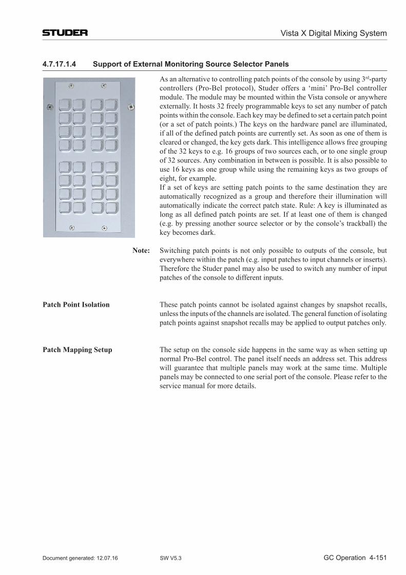
Vista X Digital Mixing System
GC Operation 4-151Document generated: 12.07.16 SW V5.3
4.7.17.1.4 Support of External Monitoring Source Selector Panels
As an alternative to controlling patch points of the console by using 3rd-party controllers (Pro-Bel protocol), Studer offers a ‘mini’ Pro-Bel controller module. The module may be mounted within the Vista console or anywhere externally. It hosts 32 freely programmable keys to set any number of patch points within the console. Each key may be defined to set a certain patch point (or a set of patch points.) The keys on the hardware panel are illuminated, if all of the defined patch points are currently set. As soon as one of them is cleared or changed, the key gets dark. This intelligence allows free grouping of the 32 keys to e.g. 16 groups of two sources each, or to one single group of 32 sources. Any combination in between is possible. It is also possible to use 16 keys as one group while using the remaining keys as two groups of eight, for example.
If a set of keys are setting patch points to the same destination they are automatically recognized as a group and therefore their illumination will automatically indicate the correct patch state. Rule: A key is illuminated as long as all defined patch points are set. If at least one of them is changed (e.g. by pressing another source selector or by the console’s trackball) the key becomes dark.
Note: Switching patch points is not only possible to outputs of the console, but everywhere within the patch (e.g. input patches to input channels or inserts). Therefore the Studer panel may also be used to switch any number of input patches of the console to different inputs.
Patch Point Isolation These patch points cannot be isolated against changes by snapshot recalls, unless the inputs of the channels are isolated. The general function of isolating patch points against snapshot recalls may be applied to output patches only.
Patch Mapping Setup The setup on the console side happens in the same way as when setting up normal Pro-Bel control. The panel itself needs an address set. This address will guarantee that multiple panels may work at the same time. Multiple panels may be connected to one serial port of the console. Please refer to the service manual for more details.
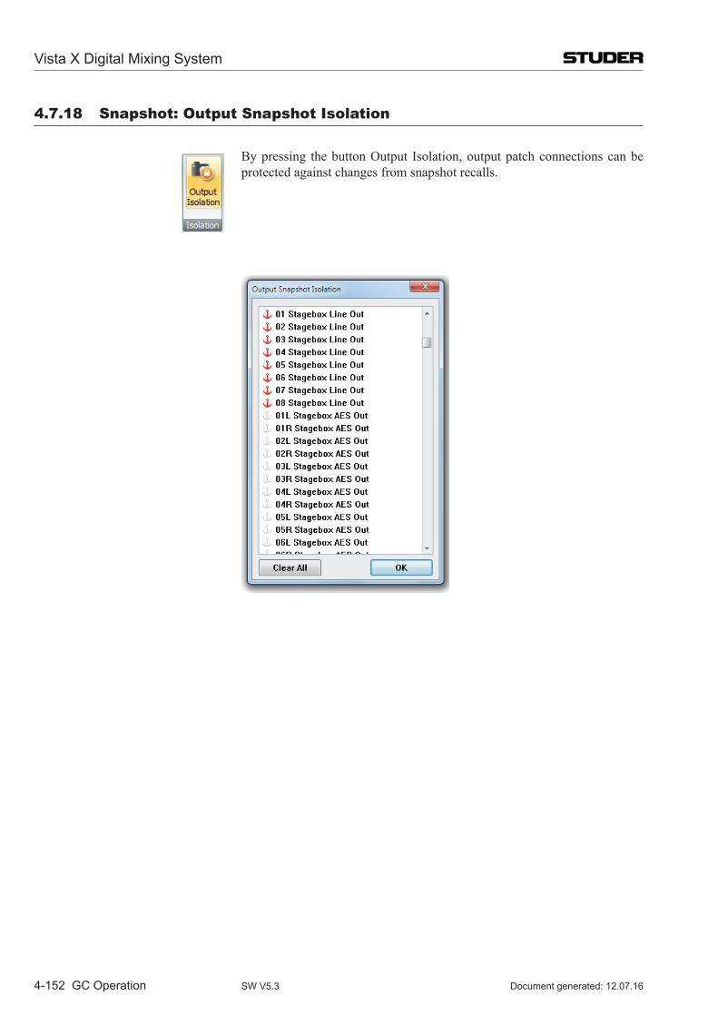
Vista X Digital Mixing System
4-152 GC Operation Document generated: 12.07.16SW V5.3
4.7.18 Snapshot: output Snapshot isolation
By pressing the button Output Isolation, output patch connections can be protected against changes from snapshot recalls.
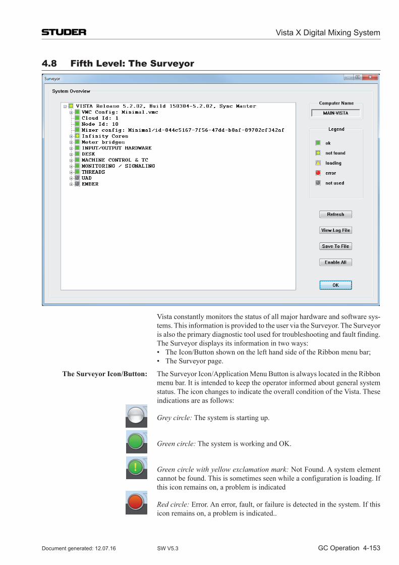
Vista X Digital Mixing System
GC Operation 4-153Document generated: 12.07.16 SW V5.3
4.8 Fifth level: The Surveyor
Vista constantly monitors the status of all major hardware and software sys-tems. This information is provided to the user via the Surveyor. The Surveyor is also the primary diagnostic tool used for troubleshooting and fault finding.
The Surveyor displays its information in two ways: • TheIcon/ButtonshownonthelefthandsideoftheRibbonmenubar; • TheSurveyorpage.
The Surveyor Icon/Button: The Surveyor Icon/Application Menu Button is always located in the Ribbon menu bar. It is intended to keep the operator informed about general system status. The icon changes to indicate the overall condition of the Vista. These indications are as follows:
Grey circle: The system is starting up.
Green circle: The system is working and OK.
Green circle with yellow exclamation mark: Not Found. A system element cannot be found. This is sometimes seen while a configuration is loading. If this icon remains on, a problem is indicated
Red circle: Error. An error, fault, or failure is detected in the system. If this icon remains on, a problem is indicated..
Vista X Digital Mixing System
4-154 GC Operation Document generated: 12.07.16SW V5.3
Surveyor Page: The Surveyor page may be opened from the SysAdmin menu or by clicking on the Surveyor button. The main window contains all the major system elements displayed as a directory tree. The status icon at the start of each directory indicates the general status of its contents. These icons utilize the same indication system as the Surveyor button (see above).
Green square: OK. This system element operates normally;
Green square with yellow diamond: Not Found. A system element cannot be found. This is sometimes seen while a configuration is loading. If this icon remains on, a problem is indicated.
Tip Sometimes an element cannot be found simply because it has not been switched on.
yellow triangle: Loading. This system element is booting (info in the status bar);
Red circle: Error. An error, fault, or failure is detected in this system element.
Grey circle: Not Used. A system element is defined but is not in use.
If all elements display the OK icon (green square), the system will operate normally. If any of the directories display the Error icon, it can be opened to determine which of its contents has a problem. Since some system elements have many subsystems, several nested subdirectories might be contained within the main directories. As with the typical Windows directory system, directories that contain subdirectories have a ‘+’ symbol on the left of the status icons. To open these directories either click on the ‘+’ symbol or double-click the directory name or status icon. It might be necessary to open several directories to find the specific element that is having a problem.
Surveyor Tools: The Surveyor features several tools to enhance its operation. These are avail-able as buttons on the Surveyor page:
• Refresh: Real-time updates of system element icons are not provided when the Surveyor page is open. If a fault is corrected during troubleshooting, the system must be re-interrogated before the Surveyor page will display the result. Clicking the Refresh button will survey the entire system and display the current the status of all elements.
• View Log File: This tool allows the Vista log files to be viewed from within the Surveyor.
• Save Log File: This button saves the current Vista log file. • Enable All: It is possible to tell the Surveyor to ignore some problems by
right-clicking on one of the red symbols. This will make the main symbol in the task bar remain green, even if there is an error reported in some sub-area. ‘Enable All’ clears these exceptions and makes the Surveyor work as usual. Inactivated sub-areas are always re-activated upon system startup for safety reasons.
• OK: Clicking this button will close the Surveyor page.
Surveyor Information: When it is initially opened, the Surveyor displays some information without the need to open any directories or subdirectories:
• Computer Name: This field displays the name of the PC that is being used to control the Vista system;
Vista X Digital Mixing System
GC Operation 4-155Document generated: 12.07.16 SW V5.3
• Vista System: This is the main directory in the Surveyor, which contains all of the other system element subdirectories. It’s name displays the Vista software Application Release number (version) and the Build number. This directory will always be open to show the primary system element subdirectories (and their status) when the Surveyor is opened;
• VMC Session Config: This item displays the currently loaded Session Configuration file in a directory name format, such as: C:\D950SY STEM\VMC directory name\VMC name.vmc.
Tip Other current system files (such as monitor files) may be found in the Sur-veyor, but will be nested within subdirectories.
Vista X Digital Mixing System
AutoTouch+ 5-1Document generated: 12.07.16 SW V5.3
CHAPTER 5
5 Auto Touch+ Dynamic Automation ................................................................................................................................... 5
5.1 Getting Started Quickly ............................................................................................................................................. 55.1.1 Basics .................................................................................................................................................................... 55.1.2 The AutoTouch+ Automation Panel ...................................................................................................................... 65.1.3 Automation Keys on the Channel Strips ............................................................................................................... 85.1.4 Mix Passes ............................................................................................................................................................. 95.1.5 Write Zones ......................................................................................................................................................... 105.1.6 How to… ............................................................................................................................................................ 11
5.2 The Details ................................................................................................................................................................ 135.2.1 About this Chapter .............................................................................................................................................. 135.2.2 Features ............................................................................................................................................................... 145.2.3 Operational Philosophy ....................................................................................................................................... 16
5.3 Essential Concepts .................................................................................................................................................... 185.3.1 Static and Dynamic Objects ................................................................................................................................ 18
5.3.1.1 Static Objects .................................................................................................................................................. 185.3.1.2 Dynamic Objects ............................................................................................................................................ 205.3.1.3 Mix Snapshot .................................................................................................................................................. 21
5.3.2 Touch & Un-Touch Events .................................................................................................................................. 22
5.4 File Management ...................................................................................................................................................... 235.4.1 Mix Tree .............................................................................................................................................................. 24
5.4.1.1 Passes in the Mix Tree .................................................................................................................................... 255.4.1.2 Active Pass ..................................................................................................................................................... 275.4.1.3 Mix Tree Display Modes ................................................................................................................................ 275.4.1.4 Mix Tree Click Functions ............................................................................................................................... 30
5.4.2 Creating a New Mix ............................................................................................................................................ 325.4.3 Loading an Existing Mix ..................................................................................................................................... 33
5.5 Mix Pass .................................................................................................................................................................... 345.5.1 Mix Pass Stack .................................................................................................................................................... 35
5.5.1.1 Mix Comparison ............................................................................................................................................. 365.5.1.2 Undo/Redo ...................................................................................................................................................... 365.5.1.3 Kill Pass .......................................................................................................................................................... 38
5.6 Control Modes .......................................................................................................................................................... 395.6.1 Read..................................................................................................................................................................... 405.6.2 Write .................................................................................................................................................................... 415.6.3 Trim ..................................................................................................................................................................... 425.6.4 Isolate .................................................................................................................................................................. 455.6.5 Control Mode Entry ............................................................................................................................................ 46
5.6.5.1 Global Mode Entry ......................................................................................................................................... 465.6.5.2 Mode Entry ..................................................................................................................................................... 48
5.6.6 Control Mode Indicators ..................................................................................................................................... 49
5.7 Touch and Hold ......................................................................................................................................................... 525.7.1 Touch and Un-Touch ........................................................................................................................................... 525.7.2 Touch Record ...................................................................................................................................................... 545.7.3 Touch Hold .......................................................................................................................................................... 555.7.4 Touch Record + Touch Hold ............................................................................................................................... 565.7.5 Held Controls ...................................................................................................................................................... 57
5.7.5.1 Held Plays Mix ............................................................................................................................................... 585.7.6 Auto Mode Key Function.................................................................................................................................... 59
5.7.6.1 Modified Un-touch Inverts ............................................................................................................................. 605.7.6.1.1 OptionModifiedUn-TouchInverts<TouchRecord> ..................................................................................................605.7.6.1.2 OptionModifiedUn-TouchInverts<TouchHold> .....................................................................................................61
Vista X Digital Mixing System
5-2 AutoTouch+ Document generated: 12.07.16SW V5.3
5.8 Global Record ........................................................................................................................................................... 645.8.1 Preselectors ......................................................................................................................................................... 645.8.2 Manual Punch-In/-Out ........................................................................................................................................ 655.8.3 Write Zone ........................................................................................................................................................... 655.8.4 Auto Punch-In/Out .............................................................................................................................................. 685.8.5 Auto GPI In/Out .................................................................................................................................................. 68
5.9 Data Transition Behavior .......................................................................................................................................... 695.9.1 Write To: .............................................................................................................................................................. 695.9.2 Extend Back To: .................................................................................................................................................. 735.9.3 Glide .................................................................................................................................................................... 75
5.10 Switch Automation ................................................................................................................................................... 785.10.1 Switch Classifications ......................................................................................................................................... 785.10.2 Switch Control Modes......................................................................................................................................... 805.10.3 Switch Operation ................................................................................................................................................. 81
5.10.3.1 Press and Release............................................................................................................................................ 825.10.3.2 Press and Hold ................................................................................................................................................ 835.10.3.3 Modified Press Function ................................................................................................................................. 84
5.11 Graphical Controller Automation ............................................................................................................................. 855.11.1 General Patch ...................................................................................................................................................... 855.11.2 Channel Patch...................................................................................................................................................... 87
5.12 Other Automated Functions ...................................................................................................................................... 905.12.1 Bus Assignments ................................................................................................................................................. 905.12.2 Snapshots/Presets ................................................................................................................................................ 915.12.3 GC Menu Items ................................................................................................................................................... 92
5.13 Mix Protection .......................................................................................................................................................... 945.13.1 Protection Sets ..................................................................................................................................................... 95
5.13.1.1 Creating Protection Sets ................................................................................................................................. 955.13.1.2 Saving Protection Sets .................................................................................................................................... 975.13.1.3 Loading Protection Sets .................................................................................................................................. 98
5.13.2 Applying Mix Protection..................................................................................................................................... 995.13.3 Removing Protection ......................................................................................................................................... 1005.13.4 Isolate via Protection ......................................................................................................................................... 101
5.14 Miscellaneous Controls/Modes............................................................................................................................... 1025.14.1 Mix On .............................................................................................................................................................. 1025.14.2 View Dynamic ................................................................................................................................................... 1025.14.3 View Alt ............................................................................................................................................................ 1025.14.4 Function Keys ................................................................................................................................................... 1025.14.5 Scene Capture/Recall ........................................................................................................................................ 103
5.15 Special Operating Modes ........................................................................................................................................ 1045.15.1 Stop Frame Automation .................................................................................................................................... 1045.15.2 Read Lock ......................................................................................................................................................... 106
Vista X Digital Mixing System
AutoTouch+ 5-3Document generated: 12.07.16 SW V5.3
5.16 Offline Mix Editing ................................................................................................................................................ 1075.16.1 Event List Editing ............................................................................................................................................. 1075.16.2 OFLA Editing .................................................................................................................................................... 112
5.16.2.1 Object Picker ................................................................................................................................................ 1155.16.2.2 Channel Selector Panel ................................................................................................................................. 1165.16.2.3 Object Selector Panel.................................................................................................................................... 1175.16.2.4 Channel/Object Tree Display Area ............................................................................................................... 1195.16.2.5 Function Controls ......................................................................................................................................... 121
5.16.3 Mix Controls ..................................................................................................................................................... 1225.16.3.1 Active Mix .................................................................................................................................................... 1225.16.3.2 Spread Source Mix ....................................................................................................................................... 1245.16.3.3 Merge Mix .................................................................................................................................................... 1255.16.3.4 Update Snap Source Mix ............................................................................................................................. 127
5.16.4 Timecode Controls ............................................................................................................................................ 1285.16.4.1 General Information ..................................................................................................................................... 1285.16.4.2 Editing Timecode Entries ............................................................................................................................. 1285.16.4.3 Timecode Entry Controls .............................................................................................................................. 1305.16.4.4 Locking Timecode Fields ............................................................................................................................. 131
5.16.5 Selected Objects Display................................................................................................................................... 1335.16.6 Edit Types .......................................................................................................................................................... 1345.16.7 Offline Editing Tutorial ..................................................................................................................................... 135
5.17 User Files ................................................................................................................................................................ 136
5.18 AutoTouch+ Panel Survey ...................................................................................................................................... 139
5.19 Desk Automation Controls...................................................................................................................................... 142
5.20 Auto Touch Plus Window ....................................................................................................................................... 145
5.21 Mix Options ............................................................................................................................................................ 1495.21.1 Saving/Loading Mix Options ............................................................................................................................ 1505.21.2 Control Mode Options....................................................................................................................................... 1535.21.3 Glide .................................................................................................................................................................. 1545.21.4 Hold ................................................................................................................................................................... 1565.21.5 Master Panel ...................................................................................................................................................... 1575.21.6 End Of Pass ....................................................................................................................................................... 1595.21.7 Miscellaneous .................................................................................................................................................... 160
5.22 GC Automation Menu ............................................................................................................................................. 161
5.23 Hot Keys ................................................................................................................................................................ 162
Vista X Digital Mixing System
5-4 AutoTouch+ Document generated: 12.07.16SW V5.3
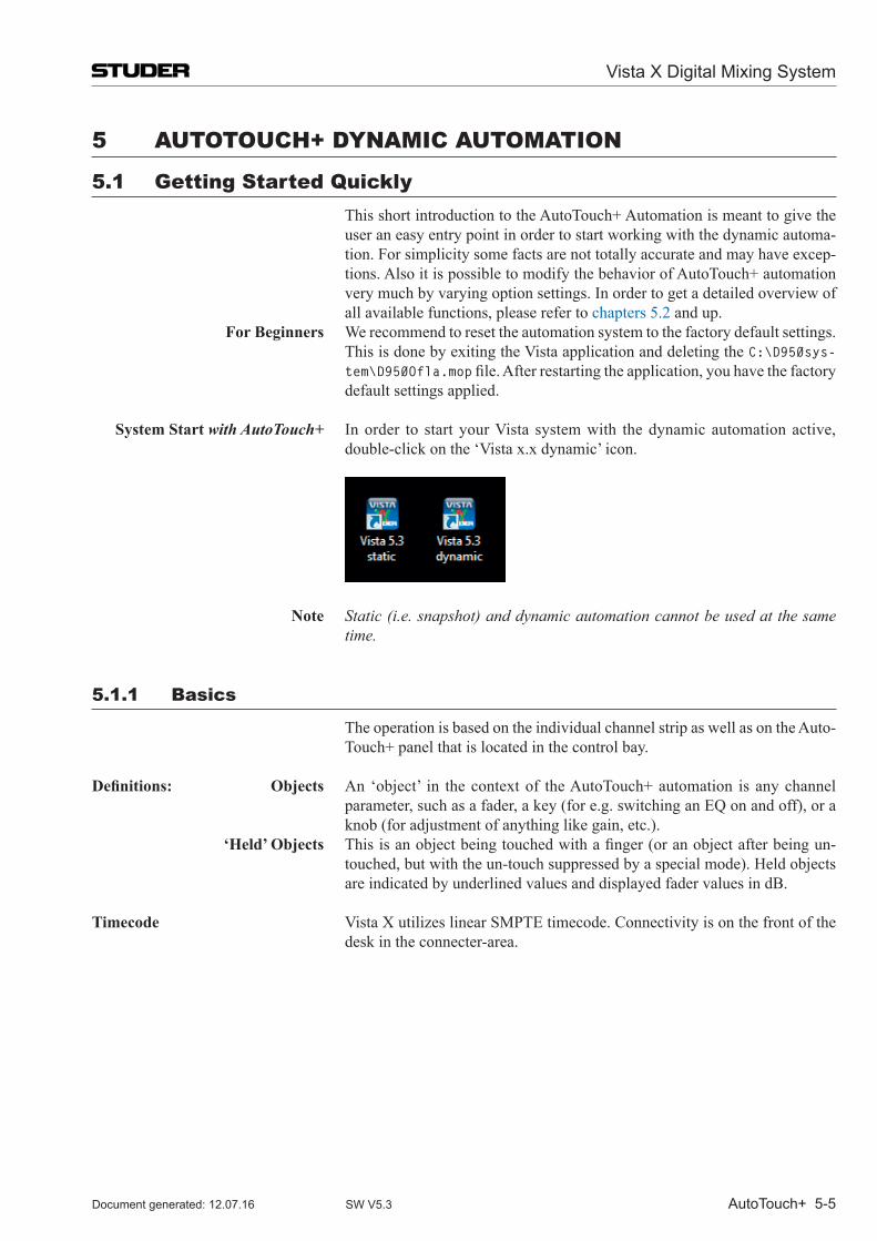
Vista X Digital Mixing System
AutoTouch+ 5-5Document generated: 12.07.16 SW V5.3
5 AuTo TouCH+ DynAmiC AuTomATion
5.1 Getting Started Quickly This short introduction to the Auto Touch+ Automation is meant to give the
user an easy entry point in order to start working with the dynamic automa-tion. For simplicity some facts are not totally accurate and may have excep-tions. Also it is possible to modify the behavior of Auto Touch+ automation very much by varying option settings. In order to get a detailed overview of all available functions, please refer to chapters 5.2 and up.
For Beginners We recommend to reset the automation system to the factory default settings. This is done by exiting the Vista application and deleting the C:\D950sys-tem\D950Ofla.mopfile.Afterrestartingtheapplication,youhavethefactorydefault settings applied.
System Start with AutoTouch+ In order to start your Vista system with the dynamic automation active, double-click on the ‘Vista x.x dynamic’ icon.
Note Static (i.e. snapshot) and dynamic automation cannot be used at the same time.
5.1.1 Basics
The operation is based on the individual channel strip as well as on the Auto-Touch+ panel that is located in the control bay.
Definitions: Objects An ‘object’ in the context of the Auto Touch+ automation is any channel parameter, such as a fader, a key (for e.g. switching an EQ on and off), or a knob (for adjustment of anything like gain, etc.).
‘Held’ Objects Thisisanobjectbeingtouchedwithafinger(oranobjectafterbeingun-touched, but with the un-touch suppressed by a special mode). Held objects are indicated by underlined values and displayed fader values in dB.
Timecode Vista X utilizes linear SMPTE timecode. Connectivity is on the front of the desk in the connecter-area.
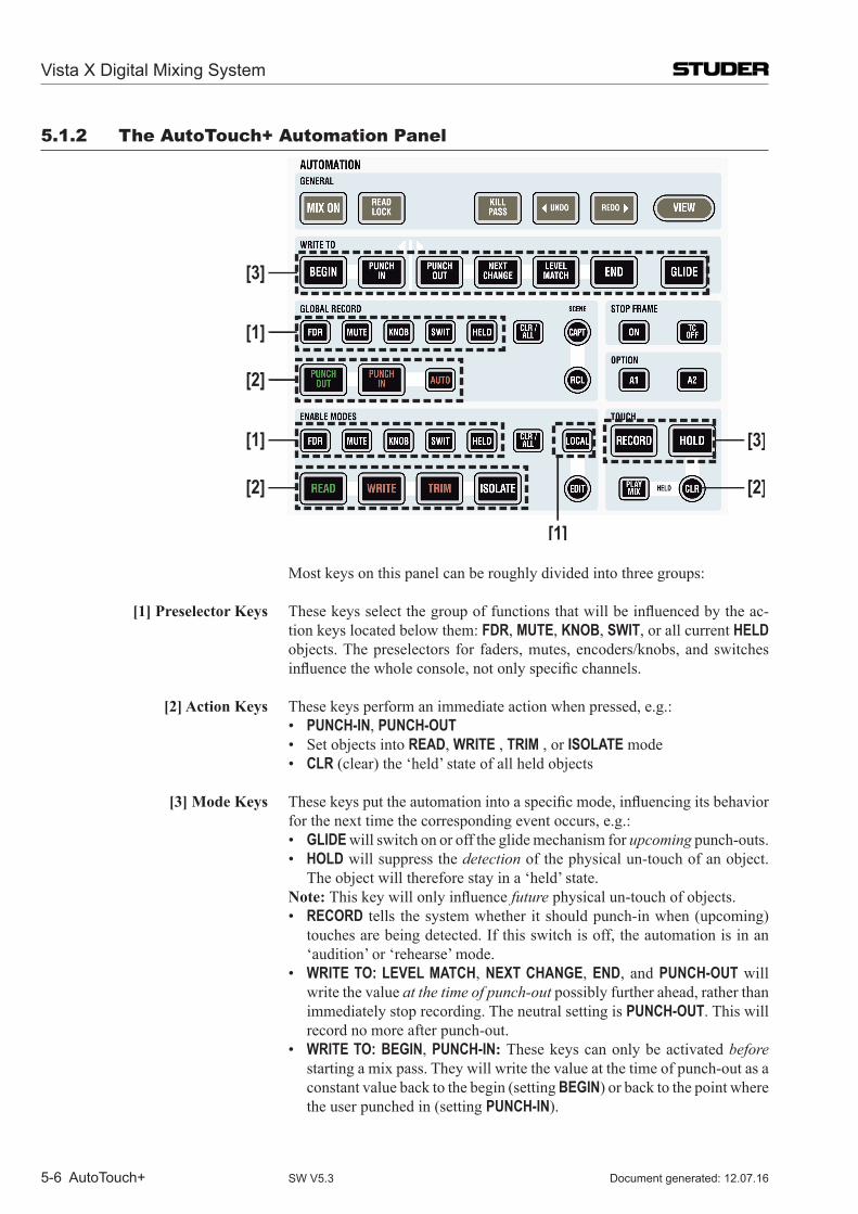
Vista X Digital Mixing System
5-6 AutoTouch+ Document generated: 12.07.16SW V5.3
5.1.2 The AutoTouch+ Automation Panel
[3]
[1]
[2]
[1]
[2] [2]
[1]
[3]
Most keys on this panel can be roughly divided into three groups:
[1] Preselector Keys Thesekeysselectthegroupoffunctionsthatwillbeinfluencedbytheac-tion keys located below them: FDR, MUTE, KNOB, SWIT, or all current HELD objects. The preselectors for faders, mutes, encoders/knobs, and switches influencethewholeconsole,notonlyspecificchannels.
[2] Action Keys These keys perform an immediate action when pressed, e.g.: • PUNCH-IN, PUNCH-OUT • SetobjectsintoREAD, WRITE , TRIM , or ISOLATE mode • CLR (clear) the ‘held’ state of all held objects
[3] Mode Keys Thesekeysputtheautomationintoaspecificmode,influencingitsbehaviorfor the next time the corresponding event occurs, e.g.:
• GLIDE will switch on or off the glide mechanism for upcoming punch-outs. • HOLD will suppress the detection of the physical un-touch of an object.
The object will therefore stay in a ‘held’ state. Note: Thiskeywillonlyinfluencefuture physical un-touch of objects. • RECORD tells the system whether it should punch-in when (upcoming)
touches are being detected. If this switch is off, the automation is in an ‘audition’ or ‘rehearse’ mode.
• WRITE TO: LEVEL MATCH, NEXT CHANGE, END, and PUNCH-OUT will write the value at the time of punch-out possibly further ahead, rather than immediately stop recording. The neutral setting is PUNCH-OUT. This will record no more after punch-out.
• WRITE TO: BEGIN, PUNCH-IN: These keys can only be activated before starting a mix pass. They will write the value at the time of punch-out as a constant value back to the begin (setting BEGIN) or back to the point where the user punched in (setting PUNCH-IN).
Vista X Digital Mixing System
AutoTouch+ 5-7Document generated: 12.07.16 SW V5.3
Examples In WRITE mode: 1. Correcting a constant value throughout a mix (WRITE TO: BEGIN) 2. Inamusicmix,whenasoloisplayed:Forfindingavaluewhilelistening
andapplyingthefinalvaluetothewholepassage(WRITE TO: PUNCH-IN).
In TRIM mode: 1. Trim an object back to the beginning of a mix while keeping its movements
(WRITE TO: BEGIN) 2. Trim an object by a constant value between punch-in and punch-out point,
while keeping the movements (WRITE TO: PUNCH-IN).
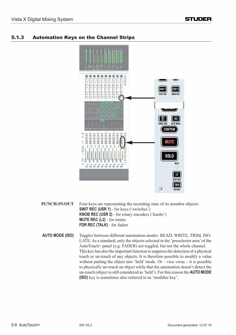
Vista X Digital Mixing System
5-8 AutoTouch+ Document generated: 12.07.16SW V5.3
5.1.3 Automation Keys on the Channel Strips
PUNCH-IN/OUT Four keys are representing the recording state of its member objects: SWIT REC (USR 1) - for keys (‘switches’) KNOB REC (USR 2) - for rotary encoders (‘knobs’) MUTE REC (L2) - for mutes FDR REC (TALK) - for faders
AUTO MODE (ISO) Toggles between different automation modes: READ, WRITE, TRIM, ISO-LATE. As a standard, only the objects selected in the ‘preselector area’ of the Auto Touch+ panel (e.g. FADER) are toggled, but not the whole channel.
This key has also the important function to suppress the detection of a physical touch or un-touch of any objects. It is therefore possible to modify a value without putting the object into ‘held’ mode. Or – vice versa – it is possible to physically un-touch an object while that the automation doesn’t detect the un-touch (object is still considered as ‘held’). For this reason the AUTO MODE (ISO)keyissometimesalsoreferredtoas‘modifierkey’.
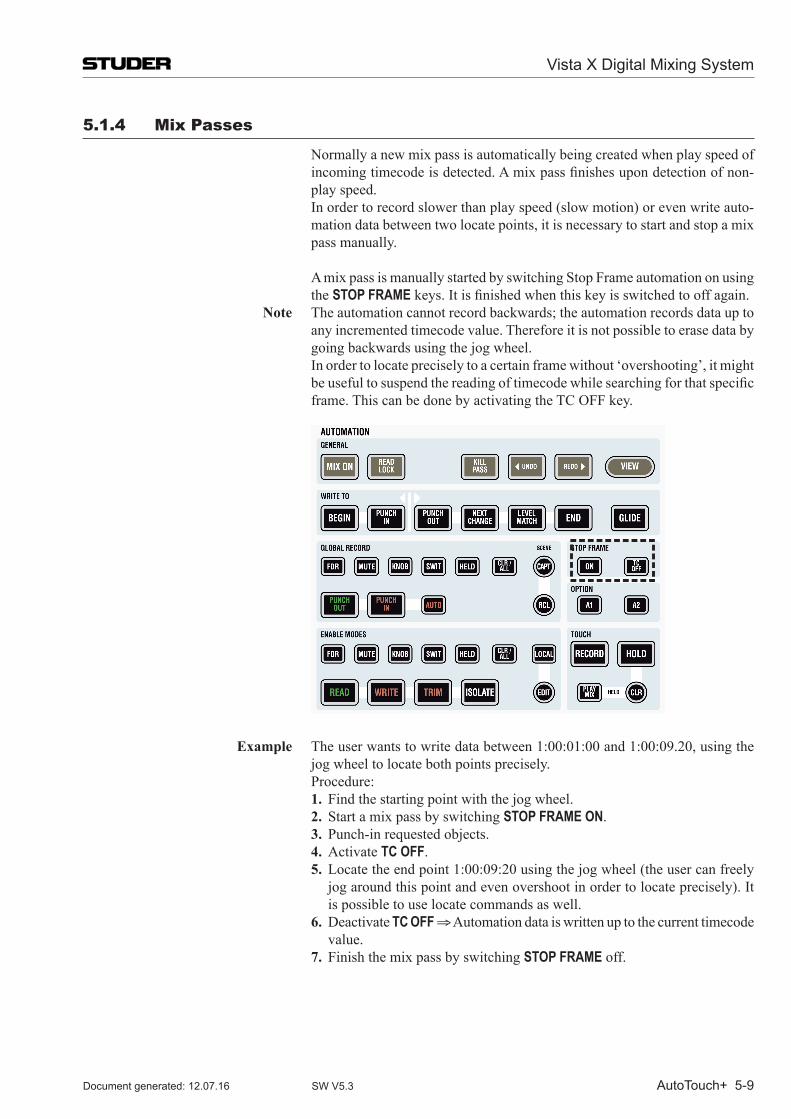
Vista X Digital Mixing System
AutoTouch+ 5-9Document generated: 12.07.16 SW V5.3
5.1.4 mix Passes
Normally a new mix pass is automatically being created when play speed of incomingtimecodeisdetected.Amixpassfinishesupondetectionofnon-play speed.
In order to record slower than play speed (slow motion) or even write auto-mation data between two locate points, it is necessary to start and stop a mix pass manually.
A mix pass is manually started by switching Stop Frame automation on using the STOP FRAMEkeys.Itisfinishedwhenthiskeyisswitchedtooffagain.
Note The automation cannot record backwards; the automation records data up to any incremented timecode value. Therefore it is not possible to erase data by going backwards using the jog wheel.
In order to locate precisely to a certain frame without ‘overshooting’, it might beusefultosuspendthereadingoftimecodewhilesearchingforthatspecificframe. This can be done by activating the TC OFF key.
Example The user wants to write data between 1:00:01:00 and 1:00:09.20, using the jog wheel to locate both points precisely.
Procedure: 1. Find the starting point with the jog wheel. 2. Start a mix pass by switching STOP FRAME ON. 3. Punch-in requested objects. 4. Activate TC OFF. 5. Locate the end point 1:00:09:20 using the jog wheel (the user can freely
jog around this point and even overshoot in order to locate precisely). It is possible to use locate commands as well.
6. Deactivate TC OFF ⇒ Automation data is written up to the current timecode value.
7. Finish the mix pass by switching STOP FRAME off.
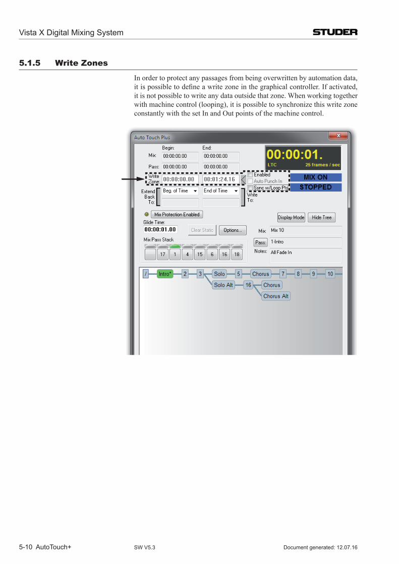
Vista X Digital Mixing System
5-10 AutoTouch+ Document generated: 12.07.16SW V5.3
5.1.5 Write Zones
In order to protect any passages from being overwritten by automation data, itispossibletodefineawritezoneinthegraphicalcontroller.Ifactivated,it is not possible to write any data outside that zone. When working together with machine control (looping), it is possible to synchronize this write zone constantly with the set In and Out points of the machine control.
Vista X Digital Mixing System
AutoTouch+ 5-11Document generated: 12.07.16 SW V5.3
5.1.6 How to…
...put the whole console into write mode? Activate preselector keys FDR REC, MUTE, KNOB, SWIT (or press the ALL/
CLR key) and press automation mode WRITE (make sure you have TOUCH RECORD active in order to record any changes against timecode).
...put all faders into write mode? Select FDR REC as preselector and press WRITE underneath in order to put all faders into write mode (make sure you have TOUCH RECORD active in order to record any changes against timecode).
<Option> There is an optional setting (see menu ‘Automation Options…’, ‘Control Modes’, ‘Mode Enable sets non-selected to READ’, also refer to chapter 5.21.2) which determines whether the non-selected functions (e.g. MUTE, KNOB, SWIT) will change their state to READ or whether they don’t change their automation state when putting the faders into WRITE.
...put a group of faders into write mode? Select FDR REC as preselector (section ENABLE MODES) and create a gang of
the channels that should change their automation mode to Write. Then toggle through the automation modes by pressing the AUTO MODE key on any of the linked channels several times, until the automation state indication on the TFT says ‘W’ (make sure you have TOUCH RECORD active in order to record any changes against timecode).
...use ‘Rehearse’ mode? Basically you just have to switch off the RECORD key. This will prevent all upcoming touches from switching into recording. To rehearse some settings, you will normally have HOLD on, since you want your settings to stay when you physically un-touch an object. In this way you will see all objects you changed in order to rehearse some alternate settings indicating ‘held’ state, either by underlined values (Vistonics module) or in the fader case by the displayed dB values. You can now stop the tape, rewind, and all objects will stay ‘held’. Now you activate the HOLD key from the preselectors of the section GLOBAL RECORD (PUNCH-IN / PUNCH-OUT) and play the tape again. When you press the PUNCH-IN or PUNCH-OUT key, you will now put all your rehearsed objects in and out of recording.
Note If objects are moved in rehearse mode, you will always hear what you see. However, if you want to switch over and hear the underlying original mix, simply activate the PLAY MIX key.
...correct a mix pass and let the automation take over whenever the level matches? Select WRITE TO…: LEVEL MATCH. Please note that these WRITE TO… keys
will only affect automated objects after they are punched out. This is to pre-vent unwanted punch-outs while you are still touching an object and doing corrections. In order to move e.g. a fader manually over the point of level matchandmakeitpunch-outuponlevelmatch,youneedtopunch-outfirstand afterwards touch the fader again ‘without the automation detecting the touch’. This means you will have to hold down the AUTO MODEmodifierkeywhen touching the fader again. Now you can move the fader towards the point of expected level match. As soon as this level is reached, this fader will stop recording.
There is also an alternate way of suppressing the detection of the touch: Switch TOUCH RECORD off and then touch the fader, followed by a manual movement over the point of matching levels.
Vista X Digital Mixing System
5-12 AutoTouch+ Document generated: 12.07.16SW V5.3
...activate a glide on one channel while another one shouldn’t glide back? As stated above, GLIDE isamodekeyanddoesonly influenceupcoming
punch-outs. You can switch this key while mixing. E.g.: GLIDE is off and you punch-out channel 8. It will punch-out without
gliding. Then you switch GLIDE on and punch-out channel 9. Since GLIDE mode is now activated, channel 9 will punch-out and glide back to the value of the last mix pass.
...keep an object in ‘held’ mode while another one should not be held? Therearetwoeasywaysforthis.Thefirstoneissimilartoactivatingand
deactivating GLIDE: Switch HOLD on and physically un-touch an object – it will stay ‘held’. Change the HOLD state to off, and the next time you physi-cally un-touch an object it will also come out of ‘held’ state.
A second way is to hold down the AUTO MODEmodifierkeywhilereleasingan object. This will invert the HOLDstateforthatspecificevent.
Note Thebehaviorofthemodifierkeycanbedefinedintheautomationoptions(Misc,ModifiedUn-touchInverts)whetherTOUCH RECORD or TOUCH HOLD willbemodified.
...make an object louder for the entire mix while keeping its movements? In the WRITE TO section, activate EXTEND BACK TO / WRITE TO BEGIN and
WRITE TO END. Select TRIM mode for the desired objects (section ENABLE MODES / CONTROL
MODES, use preselectors). Start a mix pass and move the desired objects by the amount you want them to be corrected.
In this case the movements of the objects will be kept, only the ‘offset’ will be written to the new mix pass.
Note When TRIM mode for faders is selected, the faders will jump to the 0 dB position and therefore indicate the correction level rather than the real fader values.
The real values will still be displayed in the touch-screen area. On rotary controls, Vista will display the amount of corrections in digits while display-ing the real values graphically.
...erase all movements of an objects on the entire mix? Or, how to...
...turn a ‘dynamic object’ back into a ‘static object’ again? In the WRITE TO section, activate EXTEND BACK TO / WRITE TO BEGIN and
WRITE TO END. Select RECORD mode for the desired objects (section ENABLE MODES / CON-
TROL MODES, use preselectors). Start a mix pass and set the desired objects to the value you want to have for the entire mix. This will write the level at the time of punch-out to the time between END and BEGIN.
Note The exact meaning of END and BEGINcanbedefinedonthegraphicalcontrol-ler screen, but defaults to ‘begin of mix’ and ‘end of mix’.
Vista X Digital Mixing System
AutoTouch+ 5-13Document generated: 12.07.16 SW V5.3
5.2 The Details Welcome to the Auto Touch+ dynamic automation system for Studer Vista
digital mixing consoles. For Vista users, Auto Touch+ provides a powerful and comprehensiveautomationsystemthatiseasyandefficienttouse.Alluserswillfindtheflexibilitytoworkinthewaymostappropriateforthetaskathandwithoutoverlycomplicatedprocedures.Userswillalsofindthepowertoefficientlycreateandfine-tunetheoptimalmix.
AutoTouch+allowsanycontroldefinedwithinaVMCfiletobeautomated.This includes faders, encoders, switches, and bus assignments. Connections made within the new and improved General Patch, audio oriented objects in the Channel Patch, and select Graphical Controller (GC) menu items may also be automated.
5.2.1 About this Chapter
Assumptions This chapter is designed to explain the operation of the Studer Auto Touch+ dynamic automation system. It will prepare the reader for basic to advanced operation of the system. It assumes the user will have basic familiarity and operationalproficiencywith theVistaconsoles.Thefullunderstandingofmany of the terms and concepts depends on this familiarity. Refer to the Console Operation chapters of this manual as necessary.
Redundant Information In several chapters information is repeated. This is to accommodate those who will use this document as a reference, only going to the chapter(s) in which help is needed. Redundant chapters will become obvious to those who will read this document as a text, and may be skipped as desired.
Disclaimer The information provided in this chapter is as accurate as possible at the time ofitscreation.Minordifferencemaybepresentinthefinalreleaseversionand in subsequent releases.
This chapter is designed to provide information for both new as well as long-time Vista users. Basic information is sometimes presented and is not intended to offend advanced users.
Vista X Digital Mixing System
5-14 AutoTouch+ Document generated: 12.07.16SW V5.3
5.2.2 Features
There is an impressive array of new features built into Auto Touch+. A sum-mary of these features follows.
New Mix Management AutomationMixfilesaremanagedviatheMixTreeSystem(MTS).TheMTSwill work in conjunction with the expanded Mix Pass Stack (8 Mix Passes). Each and every Mix Pass will be automatically saved and archived within the Mix Tree. Multiple Mix Trees can be created within a Title. Any previous mix can become the Active Pass (or Read Mix Pass) for a subsequent Record Mix Pass. The MTS is maintained between sessions, so that when a mix is recalled days or weeks later, the entire Mix Tree will be available to the new session. The Mix Tree may also be hidden so that all mix management can be done within the Mix Pass Stack. At any time the Mix Tree may be made fully visible again. Mix Passes may be named and comments may be added. A full mix link history is maintained.
Static Objects Whenamixisfirstcreated(whenaMixTreeisfirstopened)allautomatablecontrols are Static Objects. Static objects act just like manual controls except thattheirfinalsettingisrememberedbytheautomation.AllcontrolsremainStatic until a Dynamic move is recorded.
Anyswitch,faderorrotarycontrol(automationobjects)maybeclassifiedas a Static object. They may be adjusted at any time during the mix process without needing to put them into a WRITE or RECORD automation mode (similar to mixing on an analog console). The value of all static objects is maintainedonapass-by-passbasis.This simplifies the ‘tweaking’of thehundreds of controls within a mix session that must be adjusted, but will never change at timecode locations. Should a Dynamic move be required for a Static object, the move can be simply written into the mix, and the object is transformed automatically into a Dynamic automation object. This simple and effective system will greatly enhance the mix process and dramatically improvemixefficiency.
Independent Automation Modes Different channels may be in different automation Control Modes. For example some channels may be in WRITE while others may be in TRIM. In addition, different controls (objects) within channels may be in different modes. For example the fader may be in TRIM, while the mute is in WRITE, and the rotaries are in READ. Any combination is possible.
Touch Record Function Touch Record allows an enabled control to enter RECORD when touched. With Touch Record turned off, a control be auditioned before it is punched-in to Record. With Touch Record engaged touching a Held enabled control will permit an intentional ‘jump level’ punch-ins if the Audition value is different from the Read Mix value.
Touch Hold Function With Touch Hold engaged, the setting of a touched control will be maintained when it is released. If Touch Record was enabled before the control was touched, it will stay in RECORD upon release. Touch Hold can function for faders, rotaries, and switches and can work in READ, WRITE, and TRIM modes.
Held Plays Mix This feature allows the read mix to be heard, even though one or more ob-jects are being held in an audition state awaiting a punch-in. This allows true
Vista X Digital Mixing System
AutoTouch+ 5-15Document generated: 12.07.16 SW V5.3
emulation of the resultant mix, while the mix pass is being run.
Mix Pass Control FullflexibilityisallowedforhowanewMixPassautomaticallymergeswiththe Active Pass Read Mix data. The setting of a control when it is punched out may be written to the punch-out point; the next data change in the read mix; when a level match occurs (auto-takeover); or the end of the mix, the endoftime(23:59:59:2x),orafixedcuepoint.Inaddition,thesettingatthepunch-out point may be extended back to the punch-in point, the beginning ofthemix,thebeginningoftime(00:00:00.00),ofafixedcuepoint.
Enhanced Glide Control When the Glide function is active, every transition between the Read Mix data and the new pass will Glide from one to the other according to the current glide time. In addition, some Glide transitions may be optionally set to ‘back time’ the Glide so that they are completed at the desired edit point, rather than startedthere.Also,specificGlidetransitionsmaybesuppressedwhileothersare allowed.
Scene Capture Anyspecificsetofcontrols, their settings,andautomationmodescanbesaved in the Scene buffer. This allows the exact settings of those controls to be punched into the mix at a later time when the scene occurs again.
Read Lock This forces the automation system to playback the current Active Mix and ignore any and all key and control changes. This ensures a perfect audition playbackorlaybacktothefinalmasterrecordmachine.
Real Time Switch Editing Switch data may be edited in real time allowing the movement of the in-point and or the out-point, as well as adding or deleting Mutes and Ins or Outs.
Event List Editor Allautomationeventsmaybeedited(moved,copied,ordeleted)offlineusingthe Event List Editor.
Full Offline Editing The OFLA application is integrated in Auto Touch+. Mix data comprising theentiremix,oranyspecifiedobjectsforanyspecifiedtimerangemaybechanged, merged, or copied with other mixes or itself.
Protection Any set of controls may be placed in a protected status. Protected controls playback their recorded moves, but are prevented from being enabled for Write or Trim operations. This is useful for protecting channels or controls that have already been written, while working on other aspects of the mix.
Write Zone AWriteZonemaybespecifiedsothatnodatacanbewrittenoutsidethetimerangespecified.Thisisusefulforworkingonaspecificsceneorsectionwhileprotecting the rest of the mix from accidentally writing into it. This will also facilitate the automatic punch-out (with or without glide) at the end of the Write Zone.
Auto-Punch When Auto-Punch is active the system will automatically punch Write En-abled controls into RECORD at the beginning of the Write Zone.
Stop Frame Automation TheStopFrameautomationfeaturemakesitpossibletowritespecificcontrolvalues between timecode locations. The user can stop timecode playback at a specificlocation,setanynumberofcontrolstodesiredvalues,andmovetothe next location forward in time where values may again be adjusted. The initially set values will be recorded between the timecode locations.
Vista X Digital Mixing System
5-16 AutoTouch+ Document generated: 12.07.16SW V5.3
5.2.3 operational Philosophy
The automation system follows the paradigm that there is audio under each control. It is as if this were a conventional analog moving fader system, in which case the fader position always represents the audio level. This is re-ferred to as WYSIWYH (‘What You See Is What You Hear’). However, in order to enhance the operation of the system, this rule is broken from time to time. Those cases will be noted and they are the exception. The general rule is WYSIWYH.
Formula Based System In order to make a very powerful system that is also easy to understand, the system is based on a set of consistent Rules that pertain to the behavior of each mode or function. It is the consistency of these Rules, that allow the system to be simple to understand, yet very deep and powerful.
TotheseRules,ConditionsandOptionsmaybeimposedthatfurtherdefinethe behavior of the basic modes or functions. It is these Conditions and Op-tionsthataddextrafacilityandflexibilitytothesystem.
Optionsessentially‘fine-tune’thefunctionalityoroperationofspecificareasof the system.
The combination of Rules, Conditions, and Options allows the user to start using the system in a basic and easy to use manner. As familiarity increases (and based on the needs of the production), more complex operations may be carried out by applying the appropriate Conditions and/or Options. The systemalsoprovidesextremeflexibility sooperationmaybeessentially‘customized’ to the task at hand and/or the working style of the user. The net resultisapowerfulandflexibleautomationsystem,thatiseasytouse,butcan address even the most complex needs of any production.
Rules Rulesdefinethebasicbehaviorofacontrol,afunctionorafeature.ThebasicRules are simple and straightforward. In the simplest form, these Rules will dictate the basic functionality of the system. In this regard, Rules mostly ap-ply to the basic modes of operation, but it should be noted that all aspects of the system have their own set of rules.
InsomecasestheRuleswillbebrokenormodified,andtheexactfunctionwill be determined by a given set of Conditions and Options.
Conditions Conditionsfurtherdefinethebehavior(s)ofacontrol,function,orfeature.They are imposed by the selection of combinations of modes/features and in some cases by way in which controls are operated. Conditions may be influencedbytheselectedsetofOptions.
Options Optionsapplyoperationalorfunctionaldetailstospecificareasofthesystem.Optionsfurtherdefinethebehavioroftheassociatedmode,control,feature,orfunction.Insomecases,Optionsmayinfluencethesystemindependentlyof the Rules and Conditions being applied. Options are set by selecting the appropriate tab on the Mix Options page. They are indicated throughout this document within brackets, i.e. <Option>.
Operational Formula The essential aspect to understanding the system is the following formula: Rules + Conditions + Options = Exact Function Thekeytoefficientoperationisknowledgeofthisformulaandtheelements
Vista X Digital Mixing System
AutoTouch+ 5-17Document generated: 12.07.16 SW V5.3
within. Rules provide the basis of operation and functionality, Conditions furtherdefinebehaviors,andOptionsprovidespecificparameterstothevari-ous elements being used.
In some instances (such as Switch and GC automation), the operation of the controlwillalsoinfluenceitsfunctionality.However,inthemajorityofcasesthe formula above will apply.
Document Note When appropriate, this document will organize information with the opera-tional formula in mind.
Functional Formula Three basic areas should be kept in mind when conducting most Auto Touch+ operations:
• SelectedControlMode:Basicoperatingmodes(READ,WRITE,TRIM,and ISOLATE). Refer to chapter 5.6.
• SelectedTouchandHoldFunctions:Determinetheeffectsoftouchingatouch-sensitive control or operating a switch. Refer to chapter 5.7.
• Transitionofdata:Howthedatatransitionsbetweenpreviouslyrecordeddata and newly recorded data. Refer to chapter 5.9.
If these areas are considered, especially when learning the system, logical and predicted results will routine.
Vista X Digital Mixing System
5-18 AutoTouch+ Document generated: 12.07.16SW V5.3
5.3 Essential Concepts In addition to the various Rules, Conditions, and Options, there is a small set
of ‘essential concepts’ that must be understood when operating Auto Touch+. An explanation of these concepts follows.
5.3.1 Static and Dynamic objects
One of the primary tenants of the Auto Touch+ system is the concept of StaticandDynamiccontrols.Bydefinition,thevalueofaStaticcontrolisremembered by the system, but does not change during the course of a Mix Pass.DynamiccontrolsaredefinedbyhavingoneormorechangesrecordedatspecifictimecodelocationswithinaMixPass.
Note The terms ‘objects’ and ‘controls’ may be used interchangeably.
5.3.1.1 Static objects
The addition of Static (objects) controls allows mixes to be created in much the same way as mixes would be made on an analog console with fader/mute automation, but with the power to automate any audio control as needed (not just faders and mutes). Once set to the desired values, the vast majority of controls will not need to be automated. However during the course of a mix, the engineer may need to periodically adjust the settings of these controls (such as ‘tweaking’ an EQ). As with an analog console, the new values will be applied with the expectation that settings will be retained from Mix Pass to Mix Pass. In Auto Touch+, Static controls will perform in this manner and allows the user to work in a very familiar and intuitive fashion.
Static Objects AStaticobjectisdefinedasanyautomatablecontrolthathasnodynamicchanges recorded within the Mix Pass. Therefore, Static objects retain one value throughout a Mix Pass. Any switch, fader, rotary control and some GC items(automationobjects)maybeclassifiedasa‘Staticobject.’Staticobjectsactjustlikemanualcontrolsexceptthattheirfinalsettingisrememberedbythe automation. They may be adjusted at any time during the mix process without needing to put them into a WRITE or RECORD automation mode or needing to update the Mix Snapshot. The value of all Static objects is main-tainedonapass-by-passbasis.Thissimplifiesthe‘tweaking’ofthehundredsof controls within a mix session that must be adjusted, but will never move against timecode.
All objects are Static until a dynamic move is recorded. Should a dynamic move be required for a static object, the move can be simply written into the mix, and the object is transformed automatically into a Dynamic automation object.
Note If a control is put into Isolate, it’s static value will not change. If changed while in Isolate, the control’s current value will be heard, but its Static value will not be updated in subsequent Mix Passes.
Changing Static Values Whenanewmix(MixTree)isfirstopened,theStaticvalueforeverycontrolisstoredinthefirstMixPass.ThestoredStaticvalueswillbethecurrent
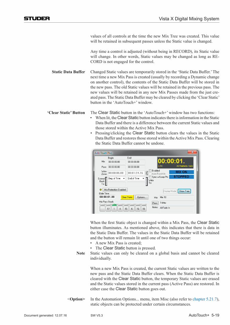
Vista X Digital Mixing System
AutoTouch+ 5-19Document generated: 12.07.16 SW V5.3
values of all controls at the time the new Mix Tree was created. This value will be retained in subsequent passes unless the Static value is changed.
Any time a control is adjusted (without being in RECORD), its Static value will change. In other words, Static values may be changed as long as RE-CORD is not engaged for the control.
Static Data Buffer Changed Static values are temporarily stored in the ‘Static Data Buffer.’ The next time a new Mix Pass is created (usually by recording a Dynamic change on another control), the contents of the Static Data Buffer will be stored in the new pass. The old Static values will be retained in the previous pass. The new values will be retained in any new Mix Passes made from the just cre-ated pass. The Static Data Buffer may be cleared by clicking the ‘Clear Static’ button in the ‘Auto Touch+’ window.
‘Clear Static’ Button The Clear Static button in the ‘Auto Touch+’ window has two functions: • Whenlit,theClear Static button indicates there is information in the Static
Data Buffer and there is a difference between the current Static values and those stored within the Active Mix Pass.
• Pressing/clickingtheClear Static button clears the values in the Static Data Buffer and restores those stored within the Active Mix Pass. Clearing the Static Data Buffer cannot be undone.
WhenthefirstStaticobjectischangedwithinaMixPass,theClear Static button illuminates. As mentioned above, this indicates that there is data in the Static Data Buffer. The values in the Static Data Buffer will be retained and the button will remain lit until one of two things occur:
• AnewMixPassiscreated; • TheClear Static button is pressed.
Note Static values can only be cleared on a global basis and cannot be cleared individually.
When a new Mix Pass is created, the current Static values are written to the new pass and the Static Data Buffer clears. When the Static Data Buffer is cleared with the Clear Static button, the temporary Static values are erased and the Static values stored in the current pass (Active Pass) are restored. In either case the Clear Static button goes out.
<Option> In the Automation Options... menu, item Misc (also refer to chapter 5.21.7),
static objects can be protected under certain circumstances.
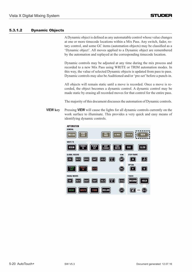
Vista X Digital Mixing System
5-20 AutoTouch+ Document generated: 12.07.16SW V5.3
5.3.1.2 Dynamic objects
ADynamicobjectisdefinedasanyautomatablecontrolwhosevaluechangesat one or more timecode locations within a Mix Pass. Any switch, fader, ro-tarycontrol,andsomeGCitems(automationobjects)maybeclassifiedasa‘Dynamic object’. All moves applied to a Dynamic object are remembered by the automation and replayed at the corresponding timecode location.
Dynamic controls may be adjusted at any time during the mix process and recorded to a new Mix Pass using WRITE or TRIM automation modes. In this way, the value of selected Dynamic objects is updated from pass to pass. Dynamic controls may also be Auditioned and/or ‘pre-set’ before a punch-in.
All objects will remain static until a move is recorded. Once a move is re-corded, the object becomes a dynamic control. A dynamic control may be made static by erasing all recorded moves for that control for the entire pass.
The majority of this document discusses the automation of Dynamic controls.
VIEW key Pressing VIEW will cause the lights for all dynamic controls currently on the work surface to illuminate. This provides a very quick and easy means of identifying dynamic controls.
Vista X Digital Mixing System
AutoTouch+ 5-21Document generated: 12.07.16 SW V5.3
5.3.1.3 mix Snapshot
The Mix Snapshot contains two types of data: • ThevaluesforStaticobjects. • TheinitialvaluesforDynamicobjectsfromthebeginningoftheMixPass
uptothefirstrecordedchange.
EveryMixPasshasaMixSnapshot.WhenaMixTreeisfirstopened,aMixPass is created that contains a Mix Snapshot with a Static value for each control. The Static value stored in the Mix Snapshot is the current value of thecontrolatthetimetheMixTreewasfirstopened.Asamixprogressesthefollowing operations occur:
• ChangestoStaticvaluesarewrittendirectlytotheMixSnapshoteachtimea new Mix Pass is created.
• ChangesmadetoDynamicobjectsarewrittentotimestamps(timecodelocations) within the Mix Pass.
When changes are made to Static Objects, the Mix Snapshot is automatically updated when the next Mix Pass is generated.
The Mix Snapshot for Dynamic objects may be updated in two ways: • Usingthe‘ExtendBackToBegin’MixPassfunction.Thevalueofthe
control at the time of a punch-out will be written back to the beginning of the Mix Pass (essentially updating the Mix Snapshot).
• Performinga‘UpdateMixSnap’editusingtheOFLAofflinemixeditor. In normal V3.0 operation, use of the Mix Snapshot is mostly transparent to
the user and there is no need for manual updates.
Vista X Digital Mixing System
5-22 AutoTouch+ Document generated: 12.07.16SW V5.3
5.3.2 Touch & un-Touch Events
Another crucial, but easy to understand concept is that of Touch and Un-touch. Auto Touch+ is a very tactile system and relies on physical actions for efficientoperation.Fadersandencodersaretouch-sensitiveandcanbemadeto respond in different ways depending on the mode and operation being performed. Switches and automatable GC items are not sensitive to physical touch, but their actuation can generate similar messages as faders and encod-ers.
Touch Events The physical touching of a fader or encoder produces a ‘Touch Event.’ Ac-tuating an automatable switch or GC item may also generate a Touch Event, depending on the current mode.
Un-touch Events The physical release of a fader or encoder produces an ‘Un-touch Event.’ Automatable switches and GC items may also generate an Un-touch Event, depending on the current mode.
Events and Auto Touch+ In most cases, Events come in Touch and Un-touch pairs…that is a Touch followed by an Un-touch. An example would be touching a fader, moving itforashortperiodoftime,andthenreleasingit.Whenthefaderwasfirsttouched, a Touch Event will be sent and when released an Un-touch will be sent. Auto Touch+ will either use both Events, ignore both Events, or suppress one or the other. Details of how these events are used and the operations this makes possible are discussed throughout this document.
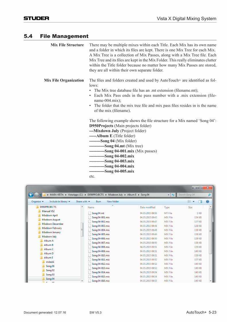
Vista X Digital Mixing System
AutoTouch+ 5-23Document generated: 12.07.16 SW V5.3
5.4 File management Mix File Structure There may be multiple mixes within each Title. Each Mix has its own name
andafolderinwhichitsfilesarekept.ThereisoneMixTreeforeachMix. AMixTreeisacollectionofMixPasses,alongwithaMixTreefile.Each
MixTreeanditsfilesarekeptintheMixFolder.Thisreallyeliminatesclutterwithin the Title folder because no matter how many Mix Passes are stored, they are all within their own separate folder.
Mix File Organization ThefilesandfolderscreatedandusedbyAutoTouch+areidentifiedasfol-lows:
• TheMixtreedatabasefilehasan.mtextension(filename.mt); • EachMixPass ends in thepassnumberwith a .mixextension (file-
name-004.mix); • Thefolderthatthemixtreefileandmixpassfilesresidesinisthename
ofthemix(filename).
ThefollowingexampleshowsthefilestructureforaMixnamed‘Song04’: D950Projects (Main projects folder) ---Mixdown July (Project folder) -----Album E (Title folder) --------Song 04 (Mix folder) -----------Song 04.mt (Mix tree) -----------Song 04-001.mix (Mix passes) -----------Song 04-002.mix -----------Song 04-003.mix -----------Song 04-004.mix -----------Song 04-005.mix etc.
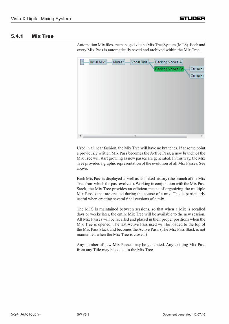
Vista X Digital Mixing System
5-24 AutoTouch+ Document generated: 12.07.16SW V5.3
5.4.1 mix Tree
AutomationMixfilesaremanagedviatheMixTreeSystem(MTS).Eachandevery Mix Pass is automatically saved and archived within the Mix Tree.
Used in a linear fashion, the Mix Tree will have no branches. If at some point a previously written Mix Pass becomes the Active Pass, a new branch of the Mix Tree will start growing as new passes are generated. In this way, the Mix Tree provides a graphic representation of the evolution of all Mix Passes. See above.
Each Mix Pass is displayed as well as its linked history (the branch of the Mix Tree from which the pass evolved). Working in conjunction with the Mix Pass Stack,theMixTreeprovidesanefficientmeansoforganizingthemultipleMix Passes that are created during the course of a mix. This is particularly usefulwhencreatingseveralfinalversionsofamix.
The MTS is maintained between sessions, so that when a Mix is recalled days or weeks later, the entire Mix Tree will be available to the new session. All Mix Passes will be recalled and placed in their proper positions when the Mix Tree is opened. The last Active Pass used will be loaded to the top of the Mix Pass Stack and becomes the Active Pass. (The Mix Pass Stack is not maintained when the Mix Tree is closed.)
Any number of new Mix Passes may be generated. Any existing Mix Pass from any Title may be added to the Mix Tree.
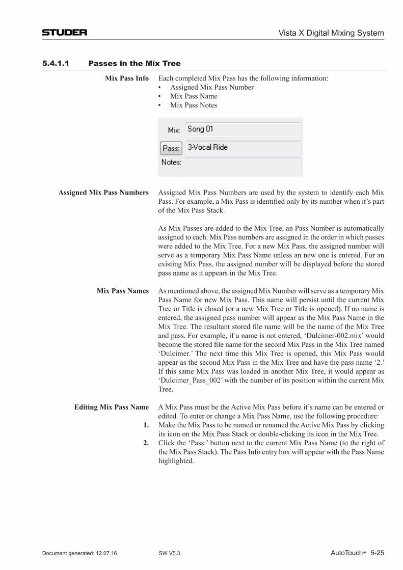
Vista X Digital Mixing System
AutoTouch+ 5-25Document generated: 12.07.16 SW V5.3
5.4.1.1 Passes in the mix Tree
Mix Pass Info Each completed Mix Pass has the following information: • AssignedMixPassNumber • MixPassName • MixPassNotes
Assigned Mix Pass Numbers Assigned Mix Pass Numbers are used by the system to identify each Mix Pass.Forexample,aMixPassisidentifiedonlybyitsnumberwhenit’spartof the Mix Pass Stack.
As Mix Passes are added to the Mix Tree, an Pass Number is automatically assigned to each. Mix Pass numbers are assigned in the order in which passes were added to the Mix Tree. For a new Mix Pass, the assigned number will serve as a temporary Mix Pass Name unless an new one is entered. For an existing Mix Pass, the assigned number will be displayed before the stored pass name as it appears in the Mix Tree.
Mix Pass Names As mentioned above, the assigned Mix Number will serve as a temporary Mix Pass Name for new Mix Pass. This name will persist until the current Mix Tree or Title is closed (or a new Mix Tree or Title is opened). If no name is entered, the assigned pass number will appear as the Mix Pass Name in the MixTree.TheresultantstoredfilenamewillbethenameoftheMixTreeand pass. For example, if a name is not entered, ‘Dulcimer-002.mix’ would becomethestoredfilenameforthesecondMixPassintheMixTreenamed‘Dulcimer.’ The next time this Mix Tree is opened, this Mix Pass would appear as the second Mix Pass in the Mix Tree and have the pass name ‘2.’ If this same Mix Pass was loaded in another Mix Tree, it would appear as ‘Dulcimer_Pass_002’ with the number of its position within the current Mix Tree.
Editing Mix Pass Name A Mix Pass must be the Active Mix Pass before it’s name can be entered or
edited. To enter or change a Mix Pass Name, use the following procedure: 1. Make the Mix Pass to be named or renamed the Active Mix Pass by clicking
its icon on the Mix Pass Stack or double-clicking its icon in the Mix Tree. 2. Click the ‘Pass:’ button next to the current Mix Pass Name (to the right of
the Mix Pass Stack). The Pass Info entry box will appear with the Pass Name highlighted.
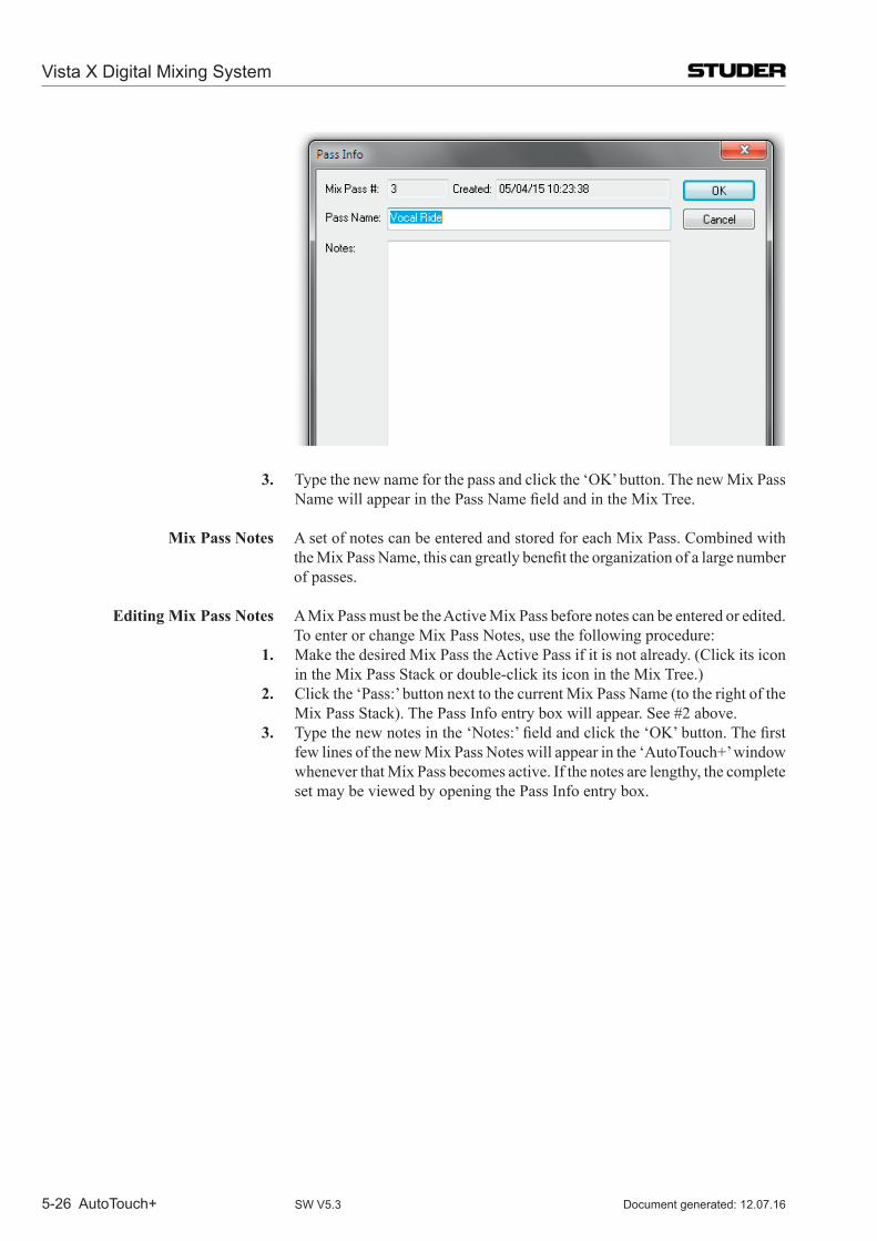
Vista X Digital Mixing System
5-26 AutoTouch+ Document generated: 12.07.16SW V5.3
3. Type the new name for the pass and click the ‘OK’ button. The new Mix Pass NamewillappearinthePassNamefieldandintheMixTree.
Mix Pass Notes A set of notes can be entered and stored for each Mix Pass. Combined with theMixPassName,thiscangreatlybenefittheorganizationofalargenumberof passes.
Editing Mix Pass Notes A Mix Pass must be the Active Mix Pass before notes can be entered or edited. To enter or change Mix Pass Notes, use the following procedure:
1. Make the desired Mix Pass the Active Pass if it is not already. (Click its icon in the Mix Pass Stack or double-click its icon in the Mix Tree.)
2. Click the ‘Pass:’ button next to the current Mix Pass Name (to the right of the Mix Pass Stack). The Pass Info entry box will appear. See #2 above.
3. Typethenewnotesinthe‘Notes:’fieldandclickthe‘OK’button.Thefirstfew lines of the new Mix Pass Notes will appear in the ‘Auto Touch+’ window whenever that Mix Pass becomes active. If the notes are lengthy, the complete set may be viewed by opening the Pass Info entry box.
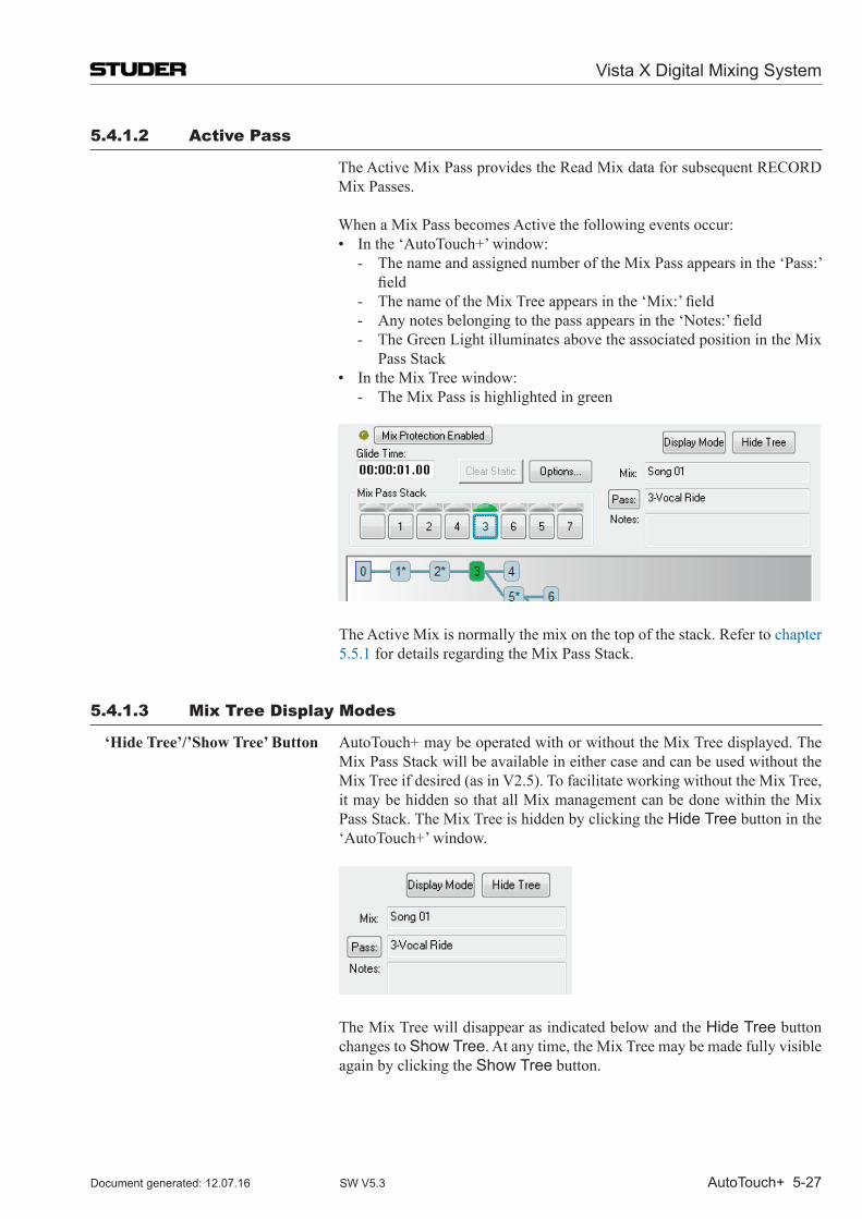
Vista X Digital Mixing System
AutoTouch+ 5-27Document generated: 12.07.16 SW V5.3
5.4.1.2 Active Pass
The Active Mix Pass provides the Read Mix data for subsequent RECORD Mix Passes.
When a Mix Pass becomes Active the following events occur: • Inthe‘AutoTouch+’window: - The name and assigned number of the Mix Pass appears in the ‘Pass:’
field - ThenameoftheMixTreeappearsinthe‘Mix:’field - Anynotesbelongingtothepassappearsinthe‘Notes:’field - The Green Light illuminates above the associated position in the Mix
Pass Stack • IntheMixTreewindow: - The Mix Pass is highlighted in green
The Active Mix is normally the mix on the top of the stack. Refer to chapter 5.5.1 for details regarding the Mix Pass Stack.
5.4.1.3 mix Tree Display modes
‘Hide Tree’/’Show Tree’ Button Auto Touch+ may be operated with or without the Mix Tree displayed. The Mix Pass Stack will be available in either case and can be used without the Mix Tree if desired (as in V2.5). To facilitate working without the Mix Tree, it may be hidden so that all Mix management can be done within the Mix Pass Stack. The Mix Tree is hidden by clicking the Hide Tree button in the ‘Auto Touch+’ window.
The Mix Tree will disappear as indicated below and the Hide Tree button changes to Show Tree. At any time, the Mix Tree may be made fully visible again by clicking the Show Tree button.
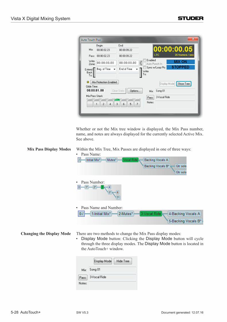
Vista X Digital Mixing System
5-28 AutoTouch+ Document generated: 12.07.16SW V5.3
Whether or not the Mix tree window is displayed, the Mix Pass number, name, and notes are always displayed for the currently selected Active Mix. See above.
Mix Pass Display Modes Within the Mix Tree, Mix Passes are displayed in one of three ways: • PassName:
• PassNumber:
• PassNameandNumber:
Changing the Display Mode There are two methods to change the Mix Pass display modes: • Display Mode button: Clicking the Display Mode button will cycle
through the three display modes. The Display Mode button is located in the Auto Touch+ window.
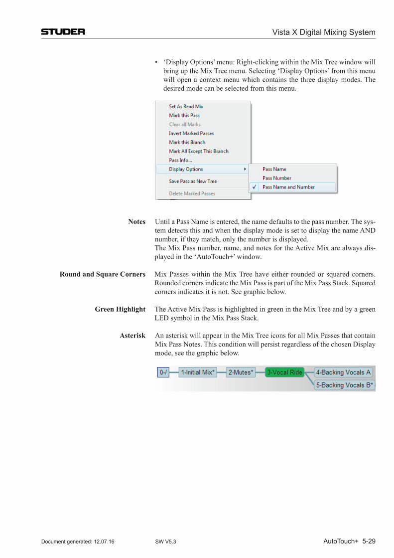
Vista X Digital Mixing System
AutoTouch+ 5-29Document generated: 12.07.16 SW V5.3
• ‘DisplayOptions’menu:Right-clickingwithintheMixTreewindowwillbring up the Mix Tree menu. Selecting ‘Display Options’ from this menu will open a context menu which contains the three display modes. The desired mode can be selected from this menu.
Notes Until a Pass Name is entered, the name defaults to the pass number. The sys-tem detects this and when the display mode is set to display the name AND number, if they match, only the number is displayed.
The Mix Pass number, name, and notes for the Active Mix are always dis-played in the ‘Auto Touch+’ window.
Round and Square Corners Mix Passes within the Mix Tree have either rounded or squared corners. Rounded corners indicate the Mix Pass is part of the Mix Pass Stack. Squared corners indicates it is not. See graphic below.
Green Highlight The Active Mix Pass is highlighted in green in the Mix Tree and by a green LED symbol in the Mix Pass Stack.
Asterisk An asterisk will appear in the Mix Tree icons for all Mix Passes that contain Mix Pass Notes. This condition will persist regardless of the chosen Display mode, see the graphic below.
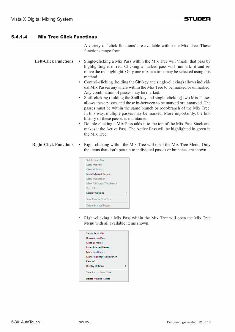
Vista X Digital Mixing System
5-30 AutoTouch+ Document generated: 12.07.16SW V5.3
5.4.1.4 mix Tree Click Functions
A variety of ‘click functions’ are available within the Mix Tree. These functions range from
Left-Click Functions • Single-clickingaMixPasswithintheMixTreewill‘mark’thatpassbyhighlighting it in red. Clicking a marked pass will ‘unmark’ it and re-move the red highlight. Only one mix at a time may be selected using this method.
• Control-clicking(holdingtheCtrl key and single-clicking) allows individ-ual Mix Passes anywhere within the Mix Tree to be marked or unmarked. Any combination of passes may be marked.
• Shift-clicking(holdingtheShift key and single-clicking) two Mix Passes allows these passes and those in-between to be marked or unmarked. The passes must be within the same branch or root-branch of the Mix Tree. In this way, multiple passes may be marked. More importantly, the link history of these passes is maintained.
• Double-clickingaMixPassaddsittothetopoftheMixPassStackandmakes it the Active Pass. The Active Pass will be highlighted in green in the Mix Tree.
Right-Click Functions • Right-clickingwithintheMixTreewillopentheMixTreeMenu.Onlythe items that don’t pertain to individual passes or branches are shown.
• Right-clickingaMixPasswithintheMixTreewillopentheMixTreeMenu with all available items shown.
Vista X Digital Mixing System
AutoTouch+ 5-31Document generated: 12.07.16 SW V5.3
The Mix Tree menu items function as follows: • SetAsReadMix:MakestheselectedMixPasstheActivePass(thisisthe
same as double-clicking a Mix Pass in the Mix Tree) • UnmarkThisPass:UnmarkstheselectedMixPass • ClearsAllMarks:UnmarksallmarkedMixPasses(alwaysavailablewhen
any passes are marked) • InvertMarkedPasses:ReverseswhichMixPassesaremarkedandwhich
are unmarked. (always available) • MarkThisBranch:TheselectedMixPassandallsubsequentpassesmade
from this pass will be marked • MarkAllExceptThisBranch:Allbranchesexcepttheoneinwhichthe
selected Mix Pass is a member will be marked. Selecting a Mix Pass in the middle of a branch will prevent any member of that branch from being marked whether they were made before or after the selected pass. All other branches will be marked.
• PassInfo…:OpensthePassInfoentryboxfortheselectedMixPass.Theselected pass does not need to be the Active Pass in order to open the Pass Info entry box in this way.
• DisplayOptions:OpensthecontextmenuforMixTreeDisplaymodes.Name, Number, and Name & Number may be selected. (always available)
• SavePassAsNewTree:CreatesanewMixTreewiththeselectedMixPassloadedasthefirstpass.ThisfunctionisonlyavailablefortheActivePass. The newly created Mix Tree will not automatically open, but may be opened as needed.
• DeleteMarkedPasses:Anymarkedpasseswillbedeleted.Becausethisaction is not undoable, the user will be prompted to verify this action.
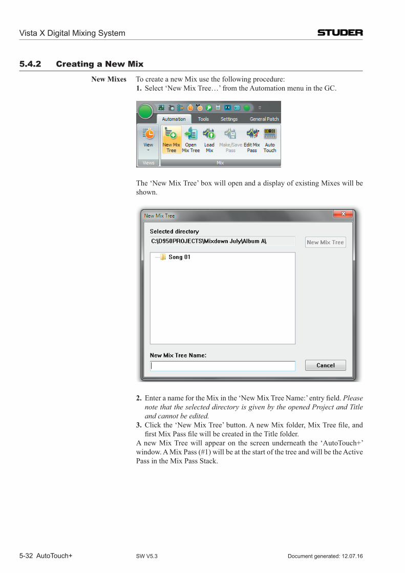
Vista X Digital Mixing System
5-32 AutoTouch+ Document generated: 12.07.16SW V5.3
5.4.2 Creating a new mix
New Mixes To create a new Mix use the following procedure: 1. Select ‘New Mix Tree…’ from the Automation menu in the GC.
The ‘New Mix Tree’ box will open and a display of existing Mixes will be shown.
2. EnteranamefortheMixinthe‘NewMixTreeName:’entryfield.Please note that the selected directory is given by the opened Project and Title and cannot be edited.
3. Clickthe‘NewMixTree’button.AnewMixfolder,MixTreefile,andfirstMixPassfilewillbecreatedintheTitlefolder.
A new Mix Tree will appear on the screen underneath the ‘Auto Touch+’ window. A Mix Pass (#1) will be at the start of the tree and will be the Active Pass in the Mix Pass Stack.
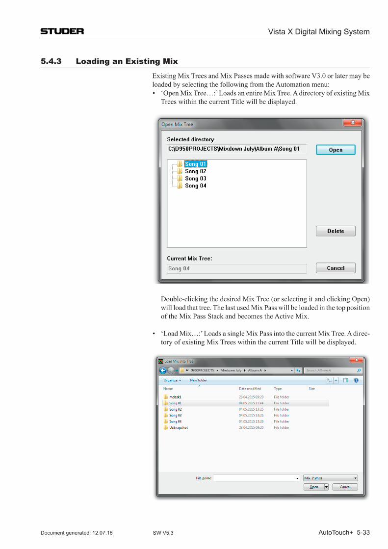
Vista X Digital Mixing System
AutoTouch+ 5-33Document generated: 12.07.16 SW V5.3
5.4.3 Loading an Existing mix
Existing Mix Trees and Mix Passes made with software V3.0 or later may be loaded by selecting the following from the Automation menu:
• ‘OpenMixTree…:’LoadsanentireMixTree.AdirectoryofexistingMixTrees within the current Title will be displayed.
Double-clicking the desired Mix Tree (or selecting it and clicking Open) will load that tree. The last used Mix Pass will be loaded in the top position of the Mix Pass Stack and becomes the Active Mix.
• ‘LoadMix…:’LoadsasingleMixPassintothecurrentMixTree.Adirec-
tory of existing Mix Trees within the current Title will be displayed.
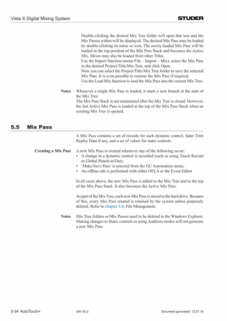
Vista X Digital Mixing System
5-34 AutoTouch+ Document generated: 12.07.16SW V5.3
Double-clicking the desired Mix Tree folder will open that tree and the Mix Passes within will be displayed. The desired Mix Pass may be loaded by double-clicking its name or icon. The newly loaded Mix Pass will be loaded in the top position of the Mix Pass Stack and becomes the Active Mix. Mixes may also be loaded from other Titles.
Use the Import function (menu File – Import – Mix), select the Mix Pass in the desired Project/Title/Mix Tree, and click Open.
Now you can select the Project/Title/Mix Tree folder to save the selected Mix Pass. It is even possible to rename the Mix Pass if required.
Use the Load Mix function to load the Mix Pass into the current Mix Tree.
Notes Whenever a single Mix Pass is loaded, it starts a new branch at the start of the Mix Tree.
The Mix Pass Stack is not maintained after the Mix Tree is closed. However, the last Active Mix Pass is loaded at the top of the Mix Pass Stack when an existing Mix Tree is opened.
5.5 mix Pass A Mix Pass contains a set of records for each dynamic control, fader Trim
Replay Data if any, and a set of values for static controls.
Creating a Mix Pass A new Mix Pass is created whenever any of the following occur: • Achangeinadynamiccontrolisrecorded(suchasusingTouchRecord
or Global Punch-in/Out); • ‘Make/SavePass’isselectedfromtheGCAutomationmenu; • AnofflineeditisperformedwitheitherOFLAortheEventEditor
In all cases above, the new Mix Pass is added to the Mix Tree and to the top of the Mix Pass Stack. It also becomes the Active Mix Pass.
As part of the Mix Tree, each new Mix Pass is stored to the hard drive. Because of this, every Mix Pass created is retained by the system unless purposely deleted. Refer to chapter 5.4, File Management.
Notes Mix Tree folders or Mix Passes need to be deleted in the Windows Explorer. Making changes to Static controls or using Audition modes will not generate
a new Mix Pass.
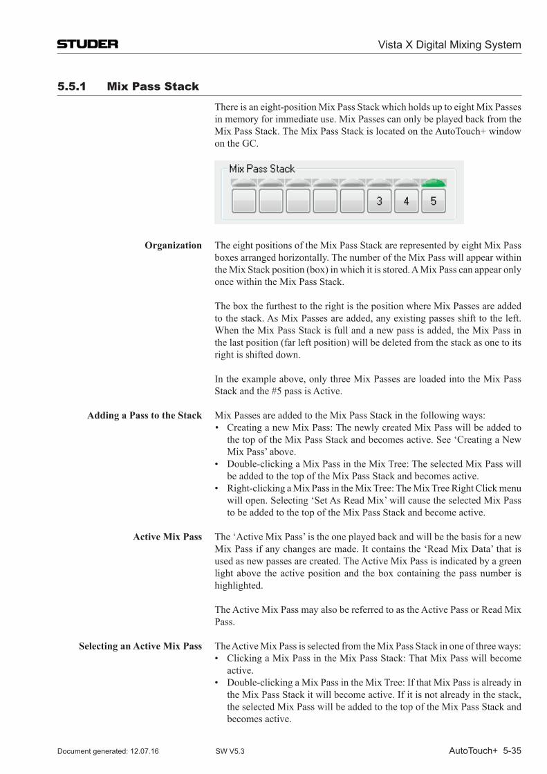
Vista X Digital Mixing System
AutoTouch+ 5-35Document generated: 12.07.16 SW V5.3
5.5.1 mix Pass Stack
There is an eight-position Mix Pass Stack which holds up to eight Mix Passes in memory for immediate use. Mix Passes can only be played back from the Mix Pass Stack. The Mix Pass Stack is located on the Auto Touch+ window on the GC.
Organization The eight positions of the Mix Pass Stack are represented by eight Mix Pass boxes arranged horizontally. The number of the Mix Pass will appear within the Mix Stack position (box) in which it is stored. A Mix Pass can appear only once within the Mix Pass Stack.
The box the furthest to the right is the position where Mix Passes are added to the stack. As Mix Passes are added, any existing passes shift to the left. When the Mix Pass Stack is full and a new pass is added, the Mix Pass in the last position (far left position) will be deleted from the stack as one to its right is shifted down.
In the example above, only three Mix Passes are loaded into the Mix Pass Stack and the #5 pass is Active.
Adding a Pass to the Stack Mix Passes are added to the Mix Pass Stack in the following ways: • CreatinganewMixPass:ThenewlycreatedMixPasswillbeaddedto
the top of the Mix Pass Stack and becomes active. See ‘Creating a New Mix Pass’ above.
• Double-clickingaMixPassintheMixTree:TheselectedMixPasswillbe added to the top of the Mix Pass Stack and becomes active.
• Right-clickingaMixPassintheMixTree:TheMixTreeRightClickmenuwill open. Selecting ‘Set As Read Mix’ will cause the selected Mix Pass to be added to the top of the Mix Pass Stack and become active.
Active Mix Pass The ‘Active Mix Pass’ is the one played back and will be the basis for a new
Mix Pass if any changes are made. It contains the ‘Read Mix Data’ that is used as new passes are created. The Active Mix Pass is indicated by a green light above the active position and the box containing the pass number is highlighted.
The Active Mix Pass may also be referred to as the Active Pass or Read Mix Pass.
Selecting an Active Mix Pass The Active Mix Pass is selected from the Mix Pass Stack in one of three ways: • ClickingaMixPassintheMixPassStack:ThatMixPasswillbecome
active. • Double-clickingaMixPassintheMixTree:IfthatMixPassisalreadyin
the Mix Pass Stack it will become active. If it is not already in the stack, the selected Mix Pass will be added to the top of the Mix Pass Stack and becomes active.
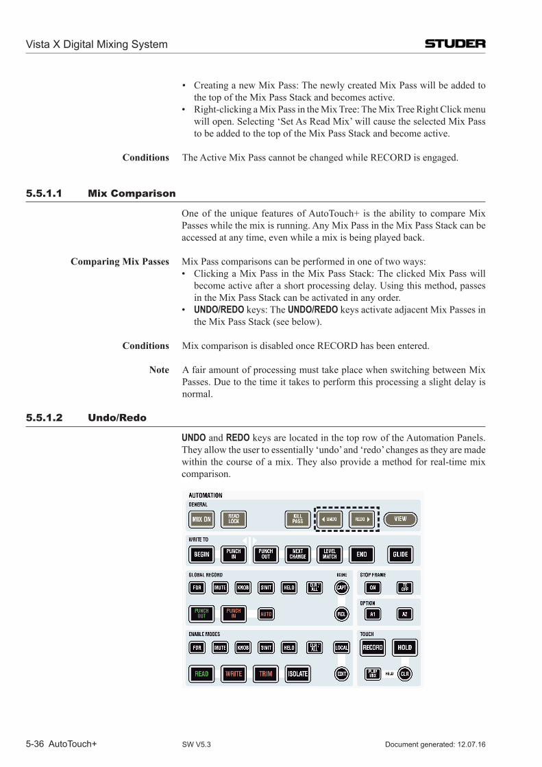
Vista X Digital Mixing System
5-36 AutoTouch+ Document generated: 12.07.16SW V5.3
• CreatinganewMixPass:ThenewlycreatedMixPasswillbeaddedtothe top of the Mix Pass Stack and becomes active.
• Right-clickingaMixPassintheMixTree:TheMixTreeRightClickmenuwill open. Selecting ‘Set As Read Mix’ will cause the selected Mix Pass to be added to the top of the Mix Pass Stack and become active.
Conditions The Active Mix Pass cannot be changed while RECORD is engaged.
5.5.1.1 mix Comparison
One of the unique features of Auto Touch+ is the ability to compare Mix Passes while the mix is running. Any Mix Pass in the Mix Pass Stack can be accessed at any time, even while a mix is being played back.
Comparing Mix Passes Mix Pass comparisons can be performed in one of two ways: • ClickingaMixPassintheMixPassStack:TheclickedMixPasswill
become active after a short processing delay. Using this method, passes in the Mix Pass Stack can be activated in any order.
• UNDO/REDO keys: The UNDO/REDO keys activate adjacent Mix Passes in the Mix Pass Stack (see below).
Conditions Mix comparison is disabled once RECORD has been entered.
Note A fair amount of processing must take place when switching between Mix Passes. Due to the time it takes to perform this processing a slight delay is normal.
5.5.1.2 undo/Redo
UNDO and REDO keys are located in the top row of the Automation Panels. They allow the user to essentially ‘undo’ and ‘redo’ changes as they are made within the course of a mix. They also provide a method for real-time mix comparison.
Vista X Digital Mixing System
AutoTouch+ 5-37Document generated: 12.07.16 SW V5.3
Using these keys activates adjacent Mix Passes within the Mix Pass Stack with UNDO moving backward through the stack and REDO moving forward.
Note The UNDO and REDO keys move consecutively through the Mix Pass Stack. The order of passes heard while using the UNDO and REDO keys may not necessarily be in numeric order, depending on the order in which passes were added to the stack.
UNDO / REDO The precise functions of the UNDO and REDO keys are as follows: • UNDO: Pressing the UNDO key will activate the most previous Mix Pass
in the Mix Pass Stack from the currently active position. In other words, pressing UNDO will allows the previous adjacent Mix Pass to be activated.
• REDO: Pressing the REDO key will activate the next Mix Pass in the Mix Pass Stack from the currently active position. In other words, pressing REDO will allows the next adjacent Mix Pass to be activated.
Consecutive presses of either key will continue through the Mix Pass Stack in the direction the key indicates (UNDO = backward or to the left, REDO = forwardortotheright).IfthefirstpassintheMixPassStackistheActivePass, the system provides eight levels of undo/redo.
Conditions UNDO and REDO are disabled once RECORD has been entered.
Notes Since all Mix Passes are stored in the Mix Tree, it is always possible to retrieve any Mix Pass at anytime. However, passes must be in the Mix Pass Stack to be played. In addition, the UNDO / REDO keys do not apply to the Mix Tree and activate only the passes in the Mix Pass Stack.
The UNDO / REDO keys only allow activation of adjacent passes within the Mix Pass Stack. The order of passes may or may not follow the branches of the Mix Tree. This is depending on the order in which Mix Passes were added to the Mix Pass Stack.
Using UNDO / REDO • DiscardinganUndesiredPass:IfanewMixPasswasjustcompleted,thenew pass will be at the top of the stack and will become active. If it contains unsuccessful moves, going back to the previous pass is as easy as pressing UNDO. When UNDO is pressed, the previous Mix Pass will become active and therefore the basis for the next new pass. In this regard, consecutive presses of UNDO will allow the user to ‘back up’ to a Mix Pass that provides a suitable point from which to restart.
• Real-timeMixComparison:PressingUNDO / REDO while a Mix Pass is being replayed, adjacent passes in the Mix Pass Stack may be compared in real-time.
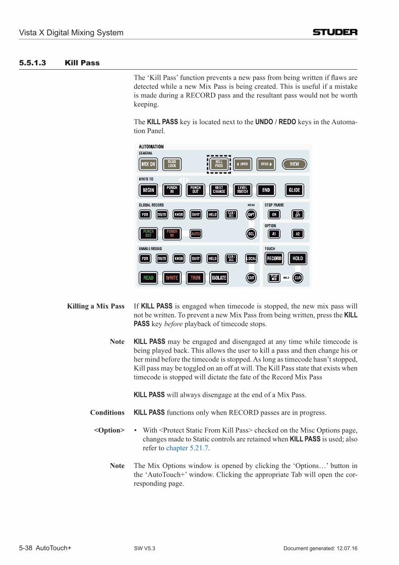
Vista X Digital Mixing System
5-38 AutoTouch+ Document generated: 12.07.16SW V5.3
5.5.1.3 Kill Pass
The‘KillPass’functionpreventsanewpassfrombeingwrittenifflawsaredetected while a new Mix Pass is being created. This is useful if a mistake is made during a RECORD pass and the resultant pass would not be worth keeping.
The KILL PASS key is located next to the UNDO / REDO keys in the Automa-tion Panel.
Killing a Mix Pass If KILL PASS is engaged when timecode is stopped, the new mix pass will not be written. To prevent a new Mix Pass from being written, press the KILL PASS key before playback of timecode stops.
Note KILL PASS may be engaged and disengaged at any time while timecode is being played back. This allows the user to kill a pass and then change his or her mind before the timecode is stopped. As long as timecode hasn’t stopped, Kill pass may be toggled on an off at will. The Kill Pass state that exists when timecode is stopped will dictate the fate of the Record Mix Pass
KILL PASS will always disengage at the end of a Mix Pass. Conditions KILL PASS functions only when RECORD passes are in progress.
<Option> • With<ProtectStaticFromKillPass>checkedontheMiscOptionspage,changes made to Static controls are retained when KILL PASS is used; also refer to chapter 5.21.7.
Note The Mix Options window is opened by clicking the ‘Options…’ button in the ‘Auto Touch+’ window. Clicking the appropriate Tab will open the cor-responding page.
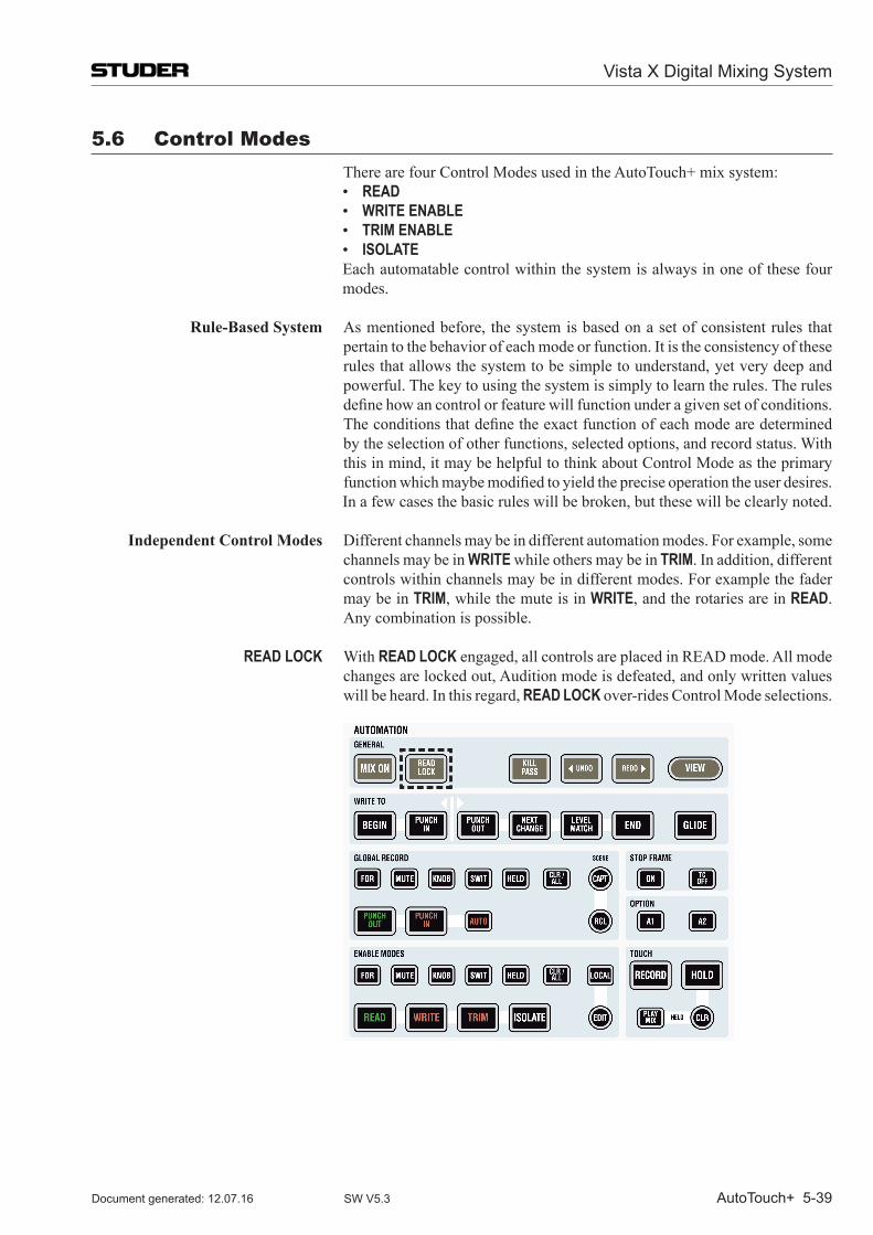
Vista X Digital Mixing System
AutoTouch+ 5-39Document generated: 12.07.16 SW V5.3
5.6 Control modes There are four Control Modes used in the Auto Touch+ mix system: • READ • WRITE ENABLE • TRIM ENABLE • ISOLATE
Each automatable control within the system is always in one of these four modes.
Rule-Based System As mentioned before, the system is based on a set of consistent rules that pertain to the behavior of each mode or function. It is the consistency of these rules that allows the system to be simple to understand, yet very deep and powerful. The key to using the system is simply to learn the rules. The rules definehowancontrolorfeaturewillfunctionunderagivensetofconditions.
Theconditionsthatdefinetheexactfunctionofeachmodearedeterminedby the selection of other functions, selected options, and record status. With this in mind, it may be helpful to think about Control Mode as the primary functionwhichmaybemodifiedtoyieldthepreciseoperationtheuserdesires.
In a few cases the basic rules will be broken, but these will be clearly noted.
Independent Control Modes Different channels may be in different automation modes. For example, some channels may be in WRITE while others may be in TRIM. In addition, different controls within channels may be in different modes. For example the fader may be in TRIM, while the mute is in WRITE, and the rotaries are in READ. Any combination is possible.
READ LOCK With READ LOCK engaged, all controls are placed in READ mode. All mode changes are locked out, Audition mode is defeated, and only written values will be heard. In this regard, READ LOCK over-rides Control Mode selections.
Vista X Digital Mixing System
5-40 AutoTouch+ Document generated: 12.07.16SW V5.3
Note In describing the behavior of each Control Mode it is assumed that the MIX ON function is active and timecode is running. If MIX ON is not active then all controls behave as if there were in ISOLATE mode.
Document Note The next several chapters will provide a set of basic rules for each Control Mode.Asetofconditionsandoptionsthatfurtherdefinethemode’sopera-tion will also be provided. The most pertinent conditions and options for each mode will be discussed, but it would be impractical to list every permutation. Some system conditions and options will be discussed as stand alone elements and their effects upon other areas will be noted.
5.6.1 Read
READ is the data replay mode of the system. Controls in READ mode will playback changes written in the Mix Pass.
READ Rules Record Off: • REPLAY:Thecontrolplaysbackthemixdatatotimecode.
- Static controls will be set to the value stored within the Mix Pass. (Static values are not timecode stamped.)
- Dynamic controls will be set to their stored values and subsequent changes will be replayed.
• AUDITION:Ifthecontrolismovedorpreventedfromfollowingwrittenchanges,theaudiochangestoreflectthe‘audition’level.- When released the control will snap back to its written value- A new Mix Pass is not generated when controls are auditioned.
Record On: • AcontrolinREAD cannot be placed into record.
Conditions • Iftouched,thecontrolwillenterAUDITIONforthedurationofthetouch.When released (un-touched) the control snaps back to its written value.
• WithTOUCH HOLD engaged, the control will enter AUDITION when touched and holds the audition value when released (un-touched).
<Option> • With<ReadSafe>checkedontheMisc.Optionspage,AUDITIONmodeis defeated for controls in READ and only written values will be heard.
Static Controls Changes may be made to Static controls while Auto Touch+ is in READ (or any other mode). Changes to Static values are temporarily stored in a global memory buffer (Static Buffer). If a new Mix Pass isn’t written, changes to Static controls will be retained in the buffer over time. For example, a section of a song might be looped while adjustments to EQ, Pans, and other controls are made. Changes to these Static controls will accumulate in the Static buffer until a new Mix Pass is generated or the Static Buffer is cleared. The values in the Static Buffer will saved as part of the next Mix Pass created.
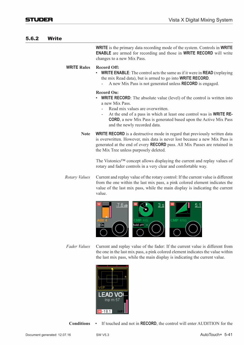
Vista X Digital Mixing System
AutoTouch+ 5-41Document generated: 12.07.16 SW V5.3
5.6.2 Write
WRITE is the primary data recording mode of the system. Controls in WRITE ENABLE are armed for recording and those in WRITE RECORD will write changes to a new Mix Pass.
WRITE Rules Record Off: • WRITE ENABLE: The control acts the same as if it were in READ (replaying
the mix Read data), but is armed to go into WRITE RECORD.- A new Mix Pass is not generated unless RECORD is engaged.
Record On: • WRITE RECORD: The absolute value (level) of the control is written into
a new Mix Pass. - Read mix values are overwritten.- At the end of a pass in which at least one control was in WRITE RE-
CORD, a new Mix Pass is generated based upon the Active Mix Pass and the newly recorded data.
Note WRITE RECORD is a destructive mode in regard that previously written data is overwritten. However, mix data is never lost because a new Mix Pass is generated at the end of every RECORD pass. All Mix Passes are retained in the Mix Tree unless purposely deleted.
The Vistonics™ concept allows displaying the current and replay values of rotary and fader controls in a very clear and comfortable way.
Rotary Values Current and replay value of the rotary control: If the current value is different from the one within the last mix pass, a pink colored element indicates the value of the last mix pass, while the main display is indicating the current value.
Fader Values Current and replay value of the fader: If the current value is different from the one in the last mix pass, a pink colored element indicates the value within the last mix pass, while the main display is indicating the current value.
Conditions • IftouchedandnotinRECORD, the control will enter AUDITION for the
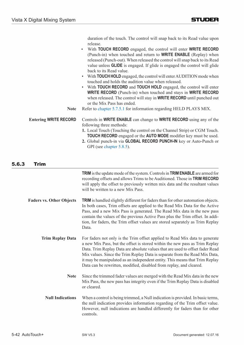
Vista X Digital Mixing System
5-42 AutoTouch+ Document generated: 12.07.16SW V5.3
duration of the touch. The control will snap back to its Read value upon release.
• WithTOUCH RECORD engaged, the control will enter WRITE RECORD (Punch-in) when touched and return to WRITE ENABLE (Replay) when released (Punch-out). When released the control will snap back to its Read value unless GLIDE is engaged. If glide is engaged the control will glide back to its Read value.
• WithTOUCH HOLD engaged, the control will enter AUDITION mode when touched and holds the audition value when released.
• WithTOUCH RECORD and TOUCH HOLD engaged, the control will enter WRITE RECORD (Punch-in) when touched and stays in WRITE RECORD when released. The control will stay in WRITE RECORD until punched out or the Mix Pass has ended.
Note Refer to chapter 5.7.5.1 for information regarding HELD PLAYS MIX.
Entering WRITE RECORD Controls in WRITE ENABLE can change to WRITE RECORD using any of the following three methods:
1. Local Touch (Touching the control on the Channel Strip) or CGM Touch. TOUCH RECORD engaged or the AUTO MODE modifierkeymustbeused.
2. Global punch-in via GLOBAL RECORD PUNCH-IN key or Auto-Punch or GPI (see chapter 5.8.5).
5.6.3 Trim
TRIM is the update mode of the system. Controls in TRIM ENABLE are armed for recording offsets and allows Trims to be Auditioned. Those in TRIM RECORD will apply the offset to previously written mix data and the resultant values will be written to a new Mix Pass.
Faders vs. Other Objects TRIM is handled slightly different for faders than for other automation objects. In both cases, Trim offsets are applied to the Read Mix Data for the Active Pass, and a new Mix Pass is generated. The Read Mix data in the new pass contain the values of the previous Active Pass plus the Trim offset. In addi-tion, for faders, the Trim offset values are stored separately as Trim Replay Data.
Trim Replay Data For faders not only is the Trim offset applied to Read Mix data to generate a new Mix Pass, but the offset is stored within the new pass as Trim Replay Data. Trim Replay Data are absolute values that are used to offset fader Read Mix values. Since the Trim Replay Data is separate from the Read Mix Data, it may be manipulated as an independent entity. This means that Trim Replay Datacanberewritten,modified,disabledfromreplay,andcleared.
Note Since the trimmed fader values are merged with the Read Mix data in the new Mix Pass, the new pass has integrity even if the Trim Replay Data is disabled or cleared.
Null Indications When a control is being trimmed, a Null indication is provided. In basic terms, the null indication provides information regarding of the Trim offset value. However, null indications are handled differently for faders than for other controls.
Vista X Digital Mixing System
AutoTouch+ 5-43Document generated: 12.07.16 SW V5.3
Faders ThefirsttimeafaderisplacedinTRIM,thenullpointis0dBandthefaderwill snap to this position. It should be noted that the fader is showing the null value rather than the Read Mix values and in this case it is 0 dB. As the pass is played, the changes in the Read Mix values will be heard with a 0 dB offset and the fader will not move. When the fader is moved from 0 dB, an offset equivalent to the amount of the move will be applied to the Read Mix data and the net result will be heard.
The offset is displayed by a pink bar (replay value) and a gray bar (current value).
When a recorded Trim is played back with TRIM enabled, the fader will move to indicate the Trim offset from 0 dB. If the value of the Trim Replay Data is recorded at –3 dB and then moves to –5 dB, the fader will move –3 dB and then to –5 dB at the appropriate time. The underlying Read Mix data will be heard with the Trim offset applied. The Trim Replay Data may be updated using TRIM RECORD techniques, thus allowing Trims to be modified.
It should be noted that faders in TRIM do not follow the WYSIWYH (What You See is What You Hear) paradigm. The recorded moves plus Trim offsets will be heard, but only the Trim Replay values will be shown by the fader.
Encoders Any time an encoder is placed in TRIM, the null point will be 0 dB and the encoder will ‘auto-null’ to this value. Since there is no Trim Replay Data for encoders, the null value can show only the offset of Read Mix values from 0 dB. The null point for encoders is always a 0 dB offset from the Read Mix value.
Whenever an encoder is put in TRIM, a 0 dB offset will be used. When a recorded Trim is played back with TRIM enabled, the encoder will move to indicate the Trim offset from 0 dB. As the pass is played, the changes in the Read Mix values will be heard with a 0 dB offset and the encoder will not move. When the encoder is moved from 0 dB, an offset equivalent to the amount of the move will be applied to the Read Mix data and the net result will be heard.
The pink-colored bar or dot (replay value) is used to match the current value to the replay value.
TRIM Rules Record Off: • TRIMENABLE:ThecontrolisarmedtogointoTRIMRECORD. Faders move to their Trim Replay values and both the Read Mix Data and
Trim Replay Data are replayed. The Read Mix values plus the Trim offset will be heard. Any changes made to the Trim value (+/- from the nominal Trim Replay value), will offset the Trim Replay value by that amount. The firsttimeTRIMENABLEisused,faderswilldisplayanominalTrimvalueof 0 dB. Since the default offset value is 0 dB, the Read Mix Data will be heard unaltered if the control is not moved. While Read Mix data will be heard, it will not be indicated by the fader’s position.
Encoders display a nominal Trim value. The nominal value will vary de-pending on the control (i.e. 0 dB for levels/gains, center for stereo panner, etc.). Read Mix Data (Written changes plus any previous Trims) is played back. Any changes made to the Trim value (+/- from the nominal Trim value), will offset the Read Mix values by that amount.
Vista X Digital Mixing System
5-44 AutoTouch+ Document generated: 12.07.16SW V5.3
The Read Mix (replay value) is roughly indicated by a pink-colored ele-ment.- If the control is moved while in TRIM ENABLE (no Touch modes
engaged), the Trim value will be AUDITIONED. The Trim values will offset the Read Mix Data and the net result will be heard. In other words,ifthecontrolismoved,theaudioreflectsthesumoftheReadMix Data plus the offset from the nominal Trim value of the control. So, if the Read Mix Data had a moving value, you will hear that same moving value, except it will be offset by the amount that the control has been moved from the nominal trim value.
- If changes to Trim values have been previously written, faders in TRIM will normally replay the Read Mix Data (which incorporates the previous Trim values) and the Trim Replay values will be shown on the faders and null indicators. Other controls will replay the Read Mix Data (which incorporates the previous Trim values). Changes to Trim values will be displayed by the control.
Record On: • TRIMRECORD:EverythingisthesameaswithRecordOff,exceptthat
the Trim values are written into a new Mix Pass. For all controls, the Trim offset is combined with the Read Mix data in the new pass. The Trim Re-playdataisalsomodifiedforfaders.- Previous Trim values are updated (modifying a trim).- At the end of a pass in which at least one control was in TRIM RE-
CORD, a new Mix Pass is generated that contains the previous Mix Pass Read data plus the Trim offset. For faders, the newly recorded Trim Replay Data is generated as well.
Note TRIM RECORD is a destructive mode in regard that previously written Trim data is updated. However, Trim data is never lost because a new Mix Pass is created at the end of every Trim RECORD pass. All Mix Passes are retained in the Mix Tree unless purposely deleted.
Conditions • IftouchedandnotinRECORD,thecontrolwillenterTRIMAUDITIONfor the duration of the touch. The control will snap back to its Trim value upon release.
• WithTOUCHRECORDengaged,thecontrolwillenterTRIMRECORD(Punch-in) when touched and return to TRIM ENABLE (Replay) when released (Punch-out). When released the control will snap back to its Trim value unless GLIDE is engaged. If glide is engaged the control will glide back to its Trim value.
• WithTOUCHHOLDengaged,thecontrolwillenterTRIMAUDITIONmode when touched and holds the audition value when released.
• WithTOUCHRECORDandTOUCHHOLDengaged,thecontrolwillenter TRIM RECORD (Punch-in) when touched and stays in TRIM RECORD when released. The control will stay in TRIM RECORD until punched out or the Mix Pass has ended.
<Option> • With<DisableTrimReplay>checkedontheMiscOptionspage,theoffsetof fader Read Mix Data using Trim Replay Data is defeated and untrimmed audio is heard (also refer to chapter 5.21.7).
Vista X Digital Mixing System
AutoTouch+ 5-45Document generated: 12.07.16 SW V5.3
Automation Menu • Selecting‘ClearTRIMReplayData’fromtheAutomationmenuintheGC deletes the fader Trim Replay Data and creates a new Mix Pass with 0 dB recorded as the new Trim Replay value.
Entering TRIM RECORD Controls in TRIM ENABLE can change to TRIM RECORD using any of the
following 3 methods:1. Local Touch (Touching the control on the Channel Strip) or CGM
Touch. TOUCH RECORD engaged or the AUTO MODE modifierkeymust be used.
2. Local punch-in using the Channel Strip STAT (record punch) key.3. Global punch-in via Global Record PUNCH-IN key, or Auto-Punch,
or GPI (refer to chapter 5.8.5).
5.6.4 isolate
ISOLATE is the system’s manual mode. Controls in ISOLATE neither re-sponds to or creates new mix data. In other words, the control is essentially removed from the automation system is becomes strictly a manual control.
Note A control in ISOLATE mode differs from a Static control in regard that changes in an Isolated control’s position are not written to Mix Passes. Like-wise, Static values are not applied to Isolated controls.
ISOLATE Rules Record Off: • ISOLATE:Thecontrolactslikeamanualcontrolandisunaffectedbyany
previously written Read and Trim Replay data.- The audio follows the control position
Record On: • AcontrolinISOLATEcannotbeplacedintorecord.
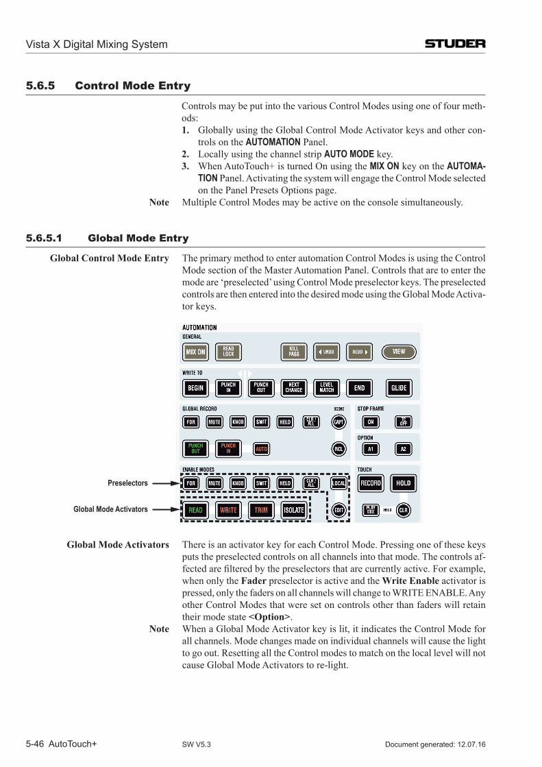
Vista X Digital Mixing System
5-46 AutoTouch+ Document generated: 12.07.16SW V5.3
5.6.5 Control mode Entry
Controls may be put into the various Control Modes using one of four meth-ods:1. Globally using the Global Control Mode Activator keys and other con-
trols on the AUTOMATION Panel. 2. Locally using the channel strip AUTO MODE key.3. When Auto Touch+ is turned On using the MIX ON key on the AUTOMA-
TION Panel. Activating the system will engage the Control Mode selected on the Panel Presets Options page.
Note Multiple Control Modes may be active on the console simultaneously.
5.6.5.1 Global mode Entry
Global Control Mode Entry The primary method to enter automation Control Modes is using the Control Mode section of the Master Automation Panel. Controls that are to enter the mode are ‘preselected’ using Control Mode preselector keys. The preselected controls are then entered into the desired mode using the Global Mode Activa-tor keys.
Preselectors
Global Mode Activators
Global Mode Activators There is an activator key for each Control Mode. Pressing one of these keys puts the preselected controls on all channels into that mode. The controls af-fectedarefilteredbythepreselectorsthatarecurrentlyactive.Forexample,when only the Fader preselector is active and the Write Enable activator is pressed, only the faders on all channels will change to WRITE ENABLE. Any other Control Modes that were set on controls other than faders will retain their mode state <Option>.
Note When a Global Mode Activator key is lit, it indicates the Control Mode for all channels. Mode changes made on individual channels will cause the light to go out. Resetting all the Control modes to match on the local level will not cause Global Mode Activators to re-light.
Vista X Digital Mixing System
AutoTouch+ 5-47Document generated: 12.07.16 SW V5.3
Preselectors Control Mode preselectors determine which controls are selected when a new Control Mode is activated. Multiple preselectors may be active at a time. Any and all combinations are allowed. Preselectors will illuminate when activated.
ThefollowingdescribesthecontrolclassificationsasdefinedbytheControlMode preselectors:
• FDR REC (Fader): The fader of all channel types • MUTE (Mute): The Mute of all channel types • KNOB (Encoders): All continuous controller type encoders (knobs or
rotaries). This does not include knobs that control ‘selectors’ such as pan format, or phase inversion (for example).
• SWIT (Switches): All switches (keys) and selectors (keys and knobs) • HELD (Held Controls): All controls that are currently in a ‘Held’ status
(this could be any combination of faders, mutes, switches, and encoders); refer to chapter 5.7.3, Touch Hold.
• LOCAL, LOCAL EDIT, LOCAL CLR: Not implemented. Note If no preselectors are active, then no controls will be put into the mode of the
pressed Mode Activator.
Clear/All • CLR / ALL: Permits the changing of all of the preselectors at once. This key functions as follows:
- If one or more preselectors are active, then pressing CLR / ALL clears all of the preselectors.
- If no preselectors are active, then all preselectors become active.- Holding CLR / ALL and pressing a Control Mode activator will bypass
the preselector and select all controls. This is very handy as follows. If the user wants to set only the fader to a Con-
trol Mode and some preselectors are active, it is not necessary to manually disengage each of the currently lit selections. Pressing CLR / ALL followed by FDR REC, will clear all active preselectors and then select fader. This will saveseveralkeystrokesandimproveefficiency.
Another Shortcut IftheuserwishestosetallofthecontrolsintoaspecificControlModethefollowing method may be used. Rather than pressing CLR / ALL until all the preselectors are active, just hold down CLR / ALL and press the Global Mode Activator for the desired Control Mode. All control types will be set into that mode and the preselectors will remain in the state that they were.
Other Control Mode Entries Control Modes may entered as part of other automation operations. These operations are as follows:
• TurningAutomationon for theFirstTime:ControlModesareenteredbased upon the options selected on the Panel Presets Options page. See Options below.
• SettingtheMixStatustoon:ControlModesareenteredbasedupontheoptions selected on the Control Mode Options page. See Options below.
• RecallingaScene:ControlsthathavebeenstoredwithintheSceneBufferare set to WRITE ENABLE and come back in a Held state. The stored values are also reset upon recall.
• EngagingREAD LOCK: All controls are placed in READ mode. All mode changes are locked out, AUDITION mode is defeated, and only written values will be heard.
Vista X Digital Mixing System
5-48 AutoTouch+ Document generated: 12.07.16SW V5.3
<Option> • <WhenMixStatusisSettoon>(alsorefertochapter 5.21.2): Radio but-tons on the Control Modes Options page allow the selection of one of the followingoptionstotakeeffectwhenMixStatusissettoon(afterthefirsttimeAutoTouchhasbeenturnedonforthefirsttime):- <MaintainObjectModes>:When theMIX ON key on the Automa-
tion Panel is turned off, all controls are isolated from automation and operateasmanualcontrols.With<MaintainObjectModes>selected,knowledge of the Control Mode for each control is maintained. When the system is turned back on, the Control Mode of all controls is re-stored.
- <SetAlltoRead>:TurningtheMIX ON key on, after having turned it off, will set all controls to READ.
- <SetpreselectorObjectstoWRITE>:Anycontrolsthatareselectedin the Global Control Modes preselector will be set to WRITE. All others will be set to READ.
- <SetpreselectorObjectstoTRIM>:Anycontrolsthatareselectedinthe Global Control Modes preselector will be set to TRIM. All others will be set to READ.
• With<ModeEnablesetsnon-selectedtoREAD>checkedontheControlModes Options page, all controls not preselected are placed in READ when a new Control Mode is enabled. In other words, only the controls that have been preselected will enter the new mode and all others change to READ.
• <WhenLoadingaPreset>:RadiobuttonsonthePanelPresetOptionspageallow the selection of one of the following options to take effect when a Panel Preset is loaded:- <MaintainObjectModes>:LoadingaPanelPresetwillnotchange
the control modes of any of the controls in the console. Current modes will be retained.
- <SetAll toRead>:LoadingaPanelPresetwill setallcontrols toREAD.
- <ApplyStoredControlMode>:TheControlModesandpreselectorsstored within the recalled Preset will be applied.
5.6.5.2 mode Entry
Local Control Mode Entry Refer to chapter 5.6.5.2 Global Control Mode Entry Global Control Mode entry is made as described above. However it should
be noted that the Global Mode Activators are located in the ‘Enable Modes’ section of the Vista automation panel.
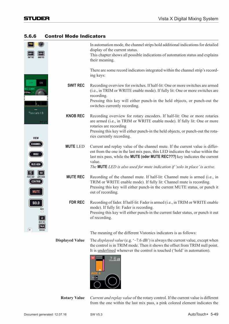
Vista X Digital Mixing System
AutoTouch+ 5-49Document generated: 12.07.16 SW V5.3
5.6.6 Control mode indicators
In automation mode, the channel strips hold additional indications for detailed display of the current status.
This chapter shows all possible indications of automation status and explains their meaning.
There are some record indicators integrated within the channel strip’s record-ing keys:
SWIT REC Recording overview for switches. If half-lit: One or more switches are armed (i.e., in TRIM or WRITE enable mode). If fully lit: One or more switches are recording.
Pressing this key will either punch-in the held objects, or punch-out the switches currently recording.
KNOB REC Recording overview for rotary encoders. If half-lit: One or more rotaries are armed (i.e., in TRIM or WRITE enable mode). If fully lit: One or more rotaries are recording
Pressing this key will either punch-in the held objects, or punch-out the rota-ries currently recording.
MUTE LED Current and replay value of the channel mute. If the current value is differ-ent from the one in the last mix pass, this LED indicates the value within the last mix pass, while the MUTE (oder MUTE REC???) key indicates the current value.
The MUTE LED is also used for mute indication if ‘solo in place’ is active.
MUTE REC Recording of the channel mute. If half-lit: Channel mute is armed (i.e., in TRIM or WRITE enable mode). If fully lit: Channel mute is recording.
Pressing this key will either punch-in the current MUTE status, or punch it out of recording.
FDR REC Recording of fader. If half-lit: Fader is armed (i.e., in TRIM or WRITE enable mode). If fully lit: Fader is recording.
Pressing this key will either punch-in the current fader status, or punch it out of recording.
The meaning of the different Vistonics indicators is as follows:
Displayed Value The displayed value (e.g. ‘–7.6 dB’) is always the current value, except when the control is in TRIM mode. Then it shows the offset from TRIM null point.
It is underlined whenever the control is touched (‘hold’ in automation).
Rotary Value Current and replay value of the rotary control. If the current value is different from the one within the last mix pass, a pink colored element indicates the
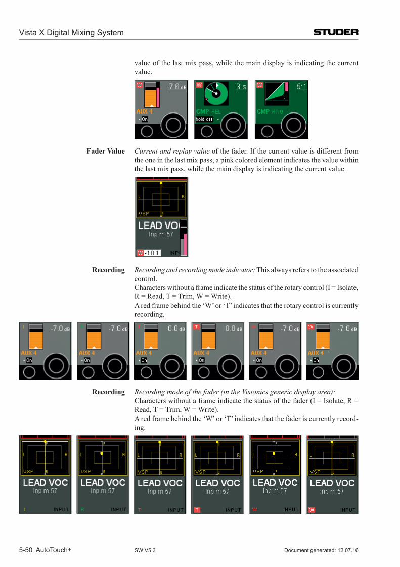
Vista X Digital Mixing System
5-50 AutoTouch+ Document generated: 12.07.16SW V5.3
value of the last mix pass, while the main display is indicating the current value.
Fader Value Current and replay value of the fader. If the current value is different from the one in the last mix pass, a pink colored element indicates the value within the last mix pass, while the main display is indicating the current value.
Recording Recording and recording mode indicator: This always refers to the associated control.
Characters without a frame indicate the status of the rotary control (I = Isolate, R = Read, T = Trim, W = Write).
A red frame behind the ‘W’ or ‘T’ indicates that the rotary control is currently recording.
Recording Recording mode of the fader (in the Vistonics generic display area): Characters without a frame indicate the status of the fader (I = Isolate, R =
Read, T = Trim, W = Write). A red frame behind the ‘W’ or ‘T’ indicates that the fader is currently record-
ing.
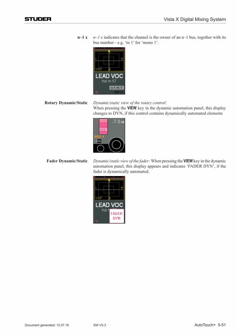
Vista X Digital Mixing System
AutoTouch+ 5-51Document generated: 12.07.16 SW V5.3
n–1 x n–1 x indicates that the channel is the owner of an n–1 bus, together with its bus number - e.g. ‘m 1’ for ‘mono 1’.
Rotary Dynamic/Static Dynamic/static view of the rotary control: When pressing the VIEW key in the dynamic automation panel, this display
changes to DYN, if this control contains dynamically automated elements
Fader Dynamic/Static Dynamic/static view of the fader: When pressing the VIEW key in the dynamic automation panel, this display appears and indicates ‘FADER DYN’, if the fader is dynamically automated.
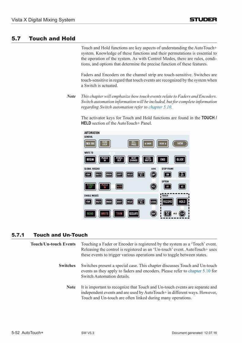
Vista X Digital Mixing System
5-52 AutoTouch+ Document generated: 12.07.16SW V5.3
5.7 Touch and Hold Touch and Hold functions are key aspects of understanding the Auto Touch+
system. Knowledge of these functions and their permutations is essential to the operation of the system. As with Control Modes, there are rules, condi-tions, and options that determine the precise function of these features.
Faders and Encoders on the channel strip are touch-sensitive. Switches are touch-sensitive in regard that touch events are recognized by the system when a Switch is actuated.
Note This chapter will emphasize how touch events relate to Faders and Encoders. Switch automation information will be included, but for complete information regarding Switch automation refer to chapter 5.10.
The activator keys for Touch and Hold functions are found in the TOUCH / HELD section of the AutoTouch+ Panel.
5.7.1 Touch and un-Touch
Touch/Un-touch Events Touching a Fader or Encoder is registered by the system as a ‘Touch’ event. Releasing the control is registered as an ‘Un-touch’ event. Auto Touch+ uses these events to trigger various operations and to toggle between states.
Switches Switches present a special case. This chapter discusses Touch and Un-touch events as they apply to faders and encoders. Please refer to chapter 5.10 for Switch Automation details.
Note It is important to recognize that Touch and Un-touch events are separate and independent events and are used by Auto Touch+ in different ways. However, Touch and Un-touch are often linked during many operations.
Vista X Digital Mixing System
AutoTouch+ 5-53Document generated: 12.07.16 SW V5.3
Examples of possible operations that can be triggered by Touch and Un-touch events:
• Touch- Enter the enabled mode for that control (i.e. Audition)- Punch-in that control (i.e. Enable to Record)
• Un-touch- Exit the enabled mode for that control (i.e. Audition)- Punch-out that control (i.e. Record to Enable)
Touch-sensitivity is always active on the work surface, even if TOUCH RE-CORD and/or TOUCH HOLD are not active. It should also be noted that when necessary,TouchandUn-toucheventscanbesuppressedtofacilitatespecificfunctionality.
Basic Touch/Un-touch Events Touch/Un-touch events can be registered without TOUCH RECORD or TOUCH
HOLD engaged. These events perform the following functions when dynamic controls are in the Control Modes indicated:
• READ:Touch/Un-touchwilltogglethecontrolinandoutofAUDITION.The control will change from READ to AUDITION when touched and will snap back to recorded values (READ) when released.
• WRITEENABLE:Touch/Un-touchwilltogglethecontrolinandoutofAUDITION
• TRIMENABLE:Touch/Un-touchwill togglethecontrol inandoutofTRIM AUDITION
• ISOLATE:Touch/Un-toucheventsofIsolatedcontrolsarenotrecognizedby Auto Touch+.
<Option> • With<ReadSafe>checkedontheMiscOptionspage,AUDITIONmodeis defeated for controls in READ and only Read Mix values will be heard (also refer to chapter 5.21.7).
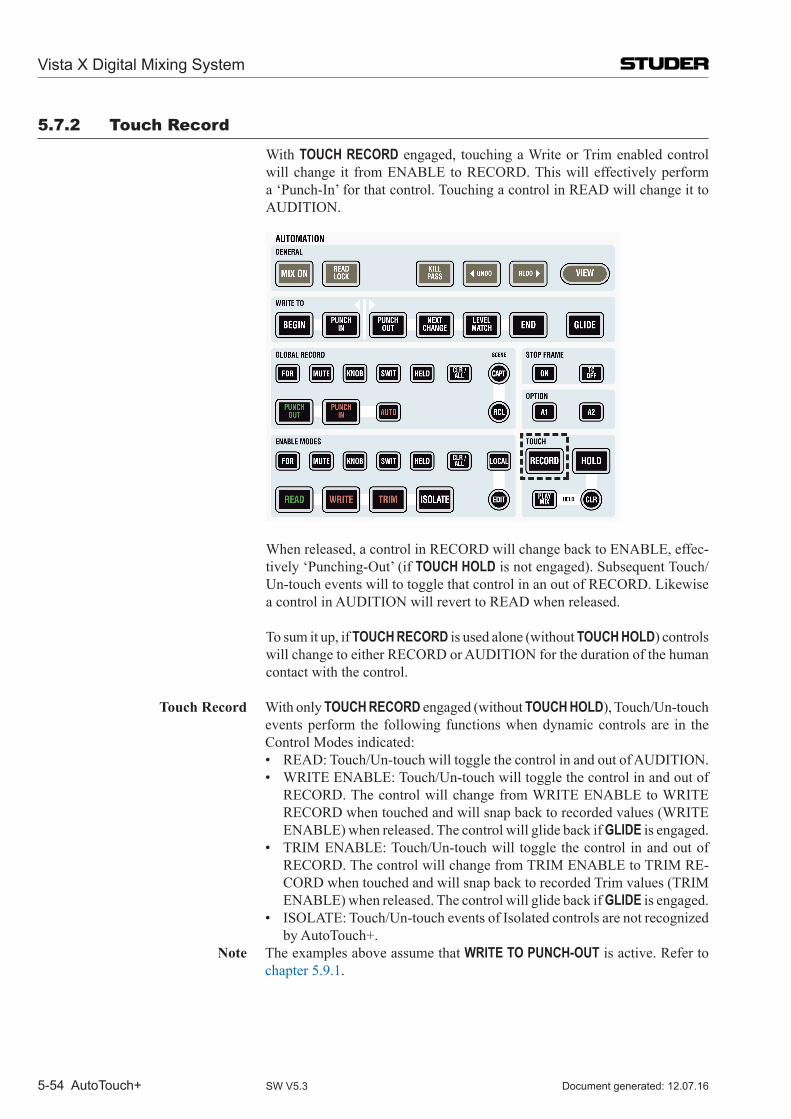
Vista X Digital Mixing System
5-54 AutoTouch+ Document generated: 12.07.16SW V5.3
5.7.2 Touch Record
With TOUCH RECORD engaged, touching a Write or Trim enabled control will change it from ENABLE to RECORD. This will effectively perform a ‘Punch-In’ for that control. Touching a control in READ will change it to AUDITION.
When released, a control in RECORD will change back to ENABLE, effec-tively ‘Punching-Out’ (if TOUCH HOLD is not engaged). Subsequent Touch/Un-touch events will to toggle that control in an out of RECORD. Likewise a control in AUDITION will revert to READ when released.
To sum it up, if TOUCH RECORD is used alone (without TOUCH HOLD) controls will change to either RECORD or AUDITION for the duration of the human contact with the control.
Touch Record With only TOUCH RECORD engaged (without TOUCH HOLD), Touch/Un-touch events perform the following functions when dynamic controls are in the Control Modes indicated:
• READ:Touch/Un-touchwilltogglethecontrolinandoutofAUDITION. • WRITEENABLE:Touch/Un-touchwilltogglethecontrolinandoutof
RECORD. The control will change from WRITE ENABLE to WRITE RECORD when touched and will snap back to recorded values (WRITE ENABLE) when released. The control will glide back if GLIDE is engaged.
• TRIMENABLE:Touch/Un-touchwill togglethecontrol inandoutofRECORD. The control will change from TRIM ENABLE to TRIM RE-CORD when touched and will snap back to recorded Trim values (TRIM ENABLE) when released. The control will glide back if GLIDE is engaged.
• ISOLATE:Touch/Un-toucheventsofIsolatedcontrolsarenotrecognizedby Auto Touch+.
Note The examples above assume that WRITE TO PUNCH-OUT is active. Refer to chapter 5.9.1.
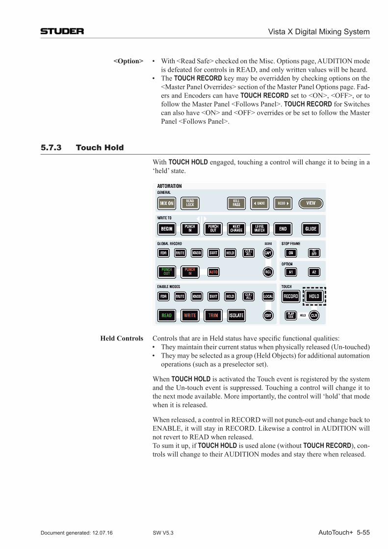
Vista X Digital Mixing System
AutoTouch+ 5-55Document generated: 12.07.16 SW V5.3
<Option> • With<ReadSafe>checkedontheMisc.Optionspage,AUDITIONmodeis defeated for controls in READ, and only written values will be heard.
• TheTOUCH RECORD key may be overridden by checking options on the <MasterPanelOverrides>sectionoftheMasterPanelOptionspage.Fad-ers and Encoders can have TOUCH RECORDsetto<ON>,<OFF>,ortofollowtheMasterPanel<FollowsPanel>.TOUCH RECORD for Switches canalsohave<ON>and<OFF>overridesorbesettofollowtheMasterPanel<FollowsPanel>.
5.7.3 Touch Hold
With TOUCH HOLD engaged, touching a control will change it to being in a ‘held’ state.
Held Controls ControlsthatareinHeldstatushavespecificfunctionalqualities: • Theymaintaintheircurrentstatuswhenphysicallyreleased(Un-touched) • Theymaybeselectedasagroup(HeldObjects)foradditionalautomation
operations (such as a preselector set).
When TOUCH HOLD is activated the Touch event is registered by the system and the Un-touch event is suppressed. Touching a control will change it to the next mode available. More importantly, the control will ‘hold’ that mode when it is released.
When released, a control in RECORD will not punch-out and change back to ENABLE, it will stay in RECORD. Likewise a control in AUDITION will not revert to READ when released.
To sum it up, if TOUCH HOLD is used alone (without TOUCH RECORD), con-trols will change to their AUDITION modes and stay there when released.
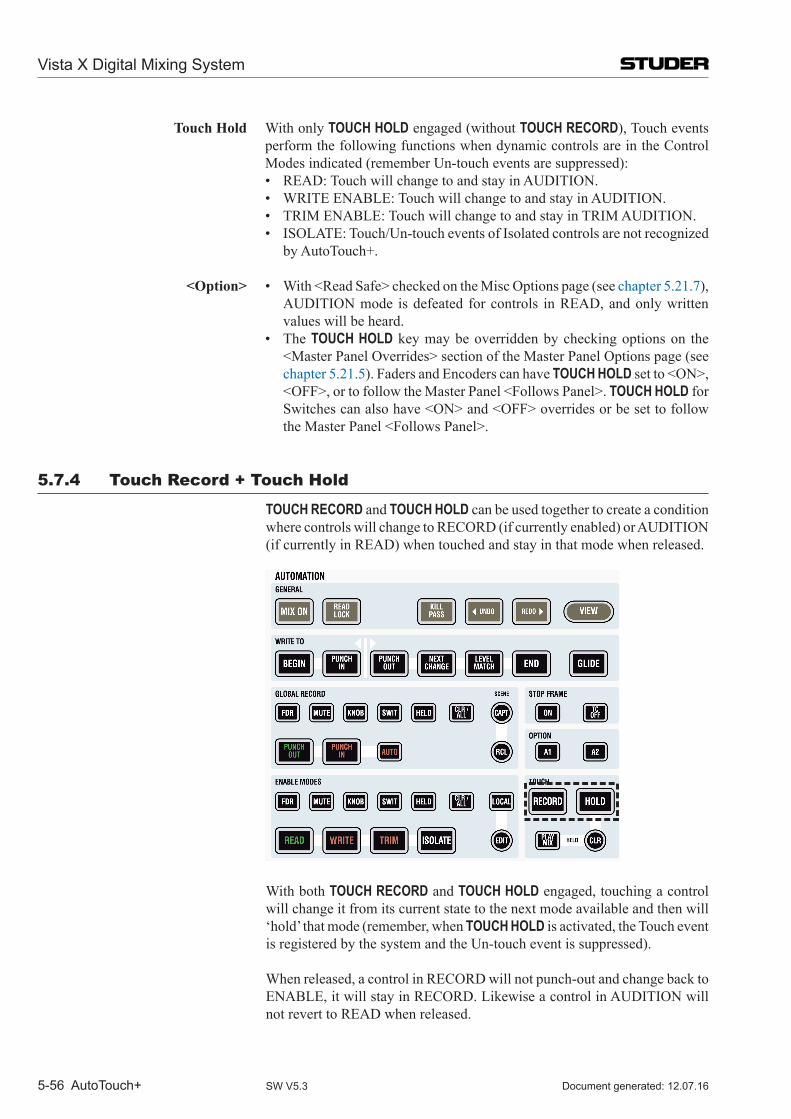
Vista X Digital Mixing System
5-56 AutoTouch+ Document generated: 12.07.16SW V5.3
Touch Hold With only TOUCH HOLD engaged (without TOUCH RECORD), Touch events perform the following functions when dynamic controls are in the Control Modes indicated (remember Un-touch events are suppressed):
• READ:TouchwillchangetoandstayinAUDITION. • WRITEENABLE:TouchwillchangetoandstayinAUDITION. • TRIMENABLE:TouchwillchangetoandstayinTRIMAUDITION. • ISOLATE:Touch/Un-toucheventsofIsolatedcontrolsarenotrecognized
by Auto Touch+. <Option> • With<ReadSafe>checkedontheMiscOptionspage(seechapter 5.21.7),
AUDITION mode is defeated for controls in READ, and only written values will be heard.
• TheTOUCH HOLD key may be overridden by checking options on the <MasterPanelOverrides>sectionoftheMasterPanelOptionspage(seechapter 5.21.5). Faders and Encoders can have TOUCH HOLDsetto<ON>,<OFF>,ortofollowtheMasterPanel<FollowsPanel>.TOUCH HOLD for Switchescanalsohave<ON>and<OFF>overridesorbesettofollowtheMasterPanel<FollowsPanel>.
5.7.4 Touch Record + Touch Hold
TOUCH RECORD and TOUCH HOLD can be used together to create a condition where controls will change to RECORD (if currently enabled) or AUDITION (if currently in READ) when touched and stay in that mode when released.
With both TOUCH RECORD and TOUCH HOLD engaged, touching a control will change it from its current state to the next mode available and then will ‘hold’ that mode (remember, when TOUCH HOLD is activated, the Touch event is registered by the system and the Un-touch event is suppressed).
When released, a control in RECORD will not punch-out and change back to ENABLE, it will stay in RECORD. Likewise a control in AUDITION will not revert to READ when released.
Vista X Digital Mixing System
AutoTouch+ 5-57Document generated: 12.07.16 SW V5.3
Touch Record + Touch Hold With both TOUCH RECORD and TOUCH HOLD engaged, Touch events perform the following functions when dynamic controls are in the Control Modes indicated (remember Un-touch events are suppressed):
• READ:TouchwillchangetoandstayinAUDITION. • WRITEENABLE:TouchwillchangethecontrolfromWRITEENABLE
to WRITE RECORD and stay in WRITE RECORD when released. • TRIMENABLE:TouchwillchangethecontrolfromTRIMENABLEto
TRIM RECORD and stay in TRIM RECORD when released. • ISOLATE:Touch/Un-toucheventsofIsolatedcontrolsarenotrecognized
by Auto Touch+. <Option> • With<ReadSafe>checkedontheMiscOptionspage(seechapter 5.21.7),
AUDITION mode is defeated for controls in READ, and only written values will be heard.
• TheMasterPanelTOUCH RECORD and TOUCH HOLD keys may be over-riddenbycheckingoptionsonthe<MasterPanelOverrides>sectionofthe Master Panel Options page (see chapter 5.21.5). Faders and Encoders can have TOUCH RECORD and TOUCH HOLDsetto<ON>,<OFF>,ortofollowtheMasterPanel<FollowsPanel>.TOUCH RECORD and TOUCH HOLDforSwitchescanalsohave<ON>and<OFF>overridesorbesettofollowtheMasterPanel<FollowsPanel>
• TheUn-touchfunctionofeitherTOUCH RECORD or TOUCH HOLD may be changed by using the AUTO MODE modifierkey.Fordetails,refertochapter 5.7.6.
5.7.5 Held Controls
A control that is touched with TOUCH HOLD engaged becomes a ‘held’ con-trol. Held controls are also known as ‘Held Objects.’ Controls that are held notonlystayintheirTouchedmodewhenreleased,theyareidentifiedbythesystem as being held.
Held Controls Buffer As controls are placed into a held status, they are added to a list of controls stored in the ‘Held Controls Buffer.’ The CLR HELD key in the HELD section of the AutoTouch+ Panel will light if one or more control is held.
TheHeldControls list isusedasafilter for theHELD preselectors in the Control Modes and Global Record sections of the Automation Panel.
Clearing Held Controls Clear Held Controls Buffer: Pressing the CLR HELD key will take all Held controls out of Hold. It will also clear the list of controls in the Held Controls Buffer.
Clear Held Controls Modes: Controls may be taken out of hold in the follow-ing ways:
• WhenTOUCH HOLD is turned OFF <Option> • UponPunch-Out<Option> • AttheendofaMixPass<Option> <Option> • With<WhenTouchHoldTurnedOff>checkedinthe<ClearHeldOb-
jects>sectionoftheHoldOptionspage(alsorefertochapter 5.21.4), all held controls are cleared when TOUCH HOLD is turned Off.
• With<UponPunch-Out>checkedinthe<ClearHeldObjects>sectionofthe Hold Options page, any Held control is cleared upon punch-out.
• With<HeldObjects>checkedinthe<EndofPassClears>sectionoftheEnd of Pass Options page, all held controls are cleared at the end of each Mix Pass.
Vista X Digital Mixing System
5-58 AutoTouch+ Document generated: 12.07.16SW V5.3
Note The TOUCH HOLD key on the AutoTouch+ Panel may be overridden by check-ingoptionson the<MasterPanelOverrides>sectionof theMasterPanelOptions page (also refer to chapter 5.21.5). Faders/Encoders and Switches can have TOUCH HOLDsetto<ON>asandefaultoption.Whenusingthisoption, care should be taken not inadvertently place controls into Hold.
5.7.5.1 Held Plays mix
When the HELD PLAYS MIX key is engaged, all Held controls play their Read Mix data when not in RECORD, but the controls can be set to different physi-cal positions.
The Read Mix data is heard, even though one or more controls are being held in AUDITION. This allows a held control to be pre-positioned while awaiting a punch-in. The result is true emulation of the resultant mix, while the Mix Pass is being run.
<Option> • With<DisabledWhileTouched>checkedinthe<HeldPlaysMix>sectionof the Hold Options page (also refer to chapter 5.21.4) and HELD PLAYS MIX engaged, all held controls that are touched will change to AUDITION for the duration of the touch. The AUDITION value will be heard while the control is being touched. Upon release held controls revert to playing the Read mix. This is useful when pre-positioning the control before the punch. This ‘TOUCH AUDITION’ mode allows the Punch-In value to be determined by touching and moving the control to the desired position and releasing it to return to hearing the Read mix. The control retains its AUDITION value awaiting Punch-In while the Read mix is heard.
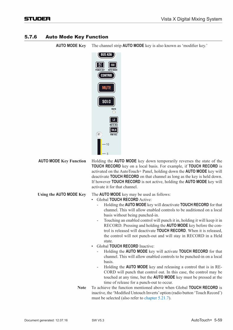
Vista X Digital Mixing System
AutoTouch+ 5-59Document generated: 12.07.16 SW V5.3
5.7.6 Auto mode Key Function
AUTO MODE Key The channel strip AUTO MODEkeyisalsoknownas‘modifierkey.’
AUTO MODE Key Function Holding the AUTO MODE key down temporarily reverses the state of the TOUCH RECORD key on a local basis. For example, if TOUCH RECORD is activated on the AutoTouch+ Panel, holding down the AUTO MODE key will deactivate TOUCH RECORD on that channel as long as the key is held down. If however TOUCH RECORD is not active, holding the AUTO MODE key will activate it for that channel.
Using the AUTO MODE Key The AUTO MODE key may be used as follows: • GlobalTOUCH RECORD Active:
- Holding the AUTO MODE key will deactivate TOUCH RECORD for that channel. This will allow enabled controls to be auditioned on a local basis without being punched-in.
- Touching an enabled control will punch it in, holding it will keep it in RECORD. Pressing and holding the AUTO MODE key before the con-trol is released will deactivate TOUCH RECORD. When it is released, the control will not punch-out and will stay in RECORD in a Held state.
• GlobalTOUCH RECORD Inactive:- Holding the AUTO MODE key will activate TOUCH RECORD for that
channel. This will allow enabled controls to be punched-in on a local basis.
- Holding the AUTO MODE key and releasing a control that is in RE-CORD will punch that control out. In this case, the control may be touched at any time, but the AUTO MODE key must be pressed at the time of release for a punch-out to occur.
Note To achieve the function mentioned above when Global TOUCH RECORD is inactive,the‘ModifiedUntouchInverts’option(radiobutton‘TouchRecord’)must be selected (also refer to chapter 5.21.7).
Vista X Digital Mixing System
5-60 AutoTouch+ Document generated: 12.07.16SW V5.3
5.7.6.1 modified un-touch inverts
As an option, TOUCH RECORD or TOUCH HELDmayhave theirmodifiedUn-touch function inverted. In other words, if the AUTO MODE key is held down when a control is Un-touched (released) the normal Un-touch function of Touch Record or Touch Hold will be reversed.
Either Touch Record or Touch Hold may be selected for Un-touch inversion, but not both.
<Option> • Either theTOUCH HELD or TOUCH RECORD function may be selected forModifiedUn-touchInversionwhentheAUTO MODE key is held. This selectionismadebyclickingthedesiredradiobuttoninthe<ModifiedUn-touchInverts>sectionoftheMiscOptionspage(alsorefertochapter 5.21.7).
5.7.6.1.1 Option Modified Un-Touch Inverts <Touch Record>
Both Global TOUCH RECORD and Global TOUCH HELD inactive: 1a Holding the AUTO MODE key when an enabled control is touched, will punch
that control in RECORD. As long as the AUTO MODE key is held down, a touched control will be in RECORD. Un-touching the control will return the status from RECORD to ENABLE.
1b If the control is touched and the AUTO MODE key is released before the con-trol is physically un-touched, the control will remain in RECORD even if the control is physically un-touched.
Even if the control remains in RECORD, the un-touch information is sup-pressed.
1c A control being in RECORD can be punched out by holding the AUTO MODE key, and touching and un-touching the control while the AUTO MODE key is being pressed. The control changes from RECORD to ENABLE when the control is physically un-touched.
Global TOUCH RECORD active, Global TOUCH HELD inactive: 2a While pressing the AUTO MODE key, touching of a control that is in ENABLE
mode will not punch it into RECORD. 2b Touching the control (causing it to change from ENABLE to RECORD) and
pressing the AUTO MODE key while still touching the control, then releasing the control while still pressing the AUTO MODE key will cause the control to remain in RECORD and HELD status.
Global TOUCH RECORD inactive, Global TOUCH HELD active: 3a Keep the AUTO MODE key pressed. Touching and untouching a control in
ENABLE mode will punch the control in and out of RECORD. Please note that the control is in HELD status, regardless whether it is in RECORD or not.
3b Keep the AUTO MODE key pressed and touch a control that is currently in ENABLE mode. Keep the control touched and release the AUTO MODE key. The control will remain in RECORD.
3c A control being in RECORD mode can be punched out by keeping the AUTO MODE key pressed, then touching and un-touching the control. At the moment the control is released, it punches out of RECORD but remains in HELD status.
Vista X Digital Mixing System
AutoTouch+ 5-61Document generated: 12.07.16 SW V5.3
Both Global TOUCH RECORD and Global TOUCH HELD active: 4a While keeping the AUTO MODE key pressed, touching a control in ENABLE
mode will not PUNCH-INto RECORD. The control will remain in HELD status.
4b A control being in RECORD status can be punched out by keeping the AUTO MODE key pressed, then touching and un-touching the control. At the moment the control is released, it punches out of RECORD while remaining in HELD status.
5.7.6.1.2 Option Modified Un-Touch Inverts <Touch Hold>
Both Global TOUCH RECORD and TOUCH HELD inactive: 5a While keeping the AUTO MODE key pressed, touching a control in ENABLE
mode will switch it to RECORD and HELD status. When releasing the control it will remain in RECORD and TOUCHED.
Global TOUCH RECORD active, TOUCH HELD inactive: 6a While keeping the AUTO MODE key pressed, touching a control in ENABLE
mode will switch it to HELD but not to RECORD status, if the control is released before the AUTO MODE key.
6b While keeping a control in ENABLE mode touched, press the AUTO MODE key. Then release the control before releasing the AUTO MODE key, causing the control to switch to RECORD and HELD status.
Global TOUCH RECORD inactive, TOUCH HELD active: 7a While keeping the AUTO MODE key pressed, touching a control in ENABLE
mode will switch it to RECORD but not to HELD mode, if the control is released before the AUTO MODE key.
Both Global TOUCH RECORD and TOUCH HELD active: 8a While keeping the AUTO MODE key pressed, touching a control in ENABLE
mode will not punch the control into RECORD. When releasing the control while the AUTO MODE key is still pressed, the control will not jump back to the replay value.
8b A control being in RECORD can be punched-out by pressing the AUTO MODE key, then touching the control and releasing it while the AUTO MODE key is still pressed. At the same time the control’s HELD status is cleared.
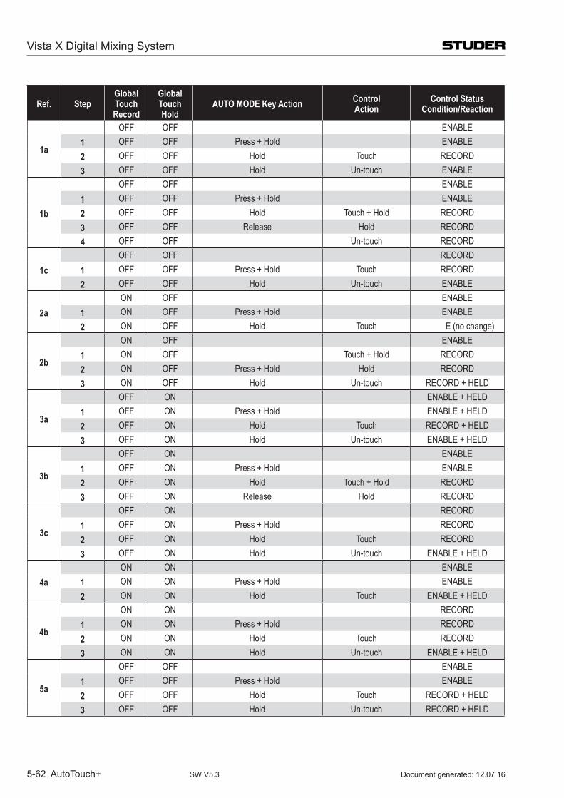
Vista X Digital Mixing System
5-62 AutoTouch+ Document generated: 12.07.16SW V5.3
Ref. StepGlobal Touch Record
Global Touch Hold
AUTO MODE Key Action ControlAction
Control StatusCondition/Reaction
1a
off off ENABLE1 off off Press + Hold ENABLE2 off off Hold Touch RECoRD3 off off Hold Un-touch ENABLE
1b
off off ENABLE1 off off Press + Hold ENABLE2 off off Hold Touch + Hold RECoRD3 off off Release Hold RECoRD4 off off Un-touch RECoRD
1coff off RECoRD
1 off off Press + Hold Touch RECoRD2 off off Hold Un-touch ENABLE
2aoN off ENABLE
1 oN off Press + Hold ENABLE2 oN off Hold Touch E (no change)
2b
oN off ENABLE1 oN off Touch + Hold RECoRD2 oN off Press + Hold Hold RECoRD3 oN off Hold Un-touch RECoRD + HELD
3a
off oN ENABLE + HELD1 off oN Press + Hold ENABLE + HELD2 off oN Hold Touch RECoRD + HELD3 off oN Hold Un-touch ENABLE + HELD
3b
off oN ENABLE1 off oN Press + Hold ENABLE2 off oN Hold Touch + Hold RECoRD3 off oN Release Hold RECoRD
3c
off oN RECoRD1 off oN Press + Hold RECoRD2 off oN Hold Touch RECoRD3 off oN Hold Un-touch ENABLE + HELD
4aoN oN ENABLE
1 oN oN Press + Hold ENABLE2 oN oN Hold Touch ENABLE + HELD
4b
oN oN RECoRD1 oN oN Press + Hold RECoRD2 oN oN Hold Touch RECoRD3 oN oN Hold Un-touch ENABLE + HELD
5a
off off ENABLE1 off off Press + Hold ENABLE2 off off Hold Touch RECoRD + HELD3 off off Hold Un-touch RECoRD + HELD
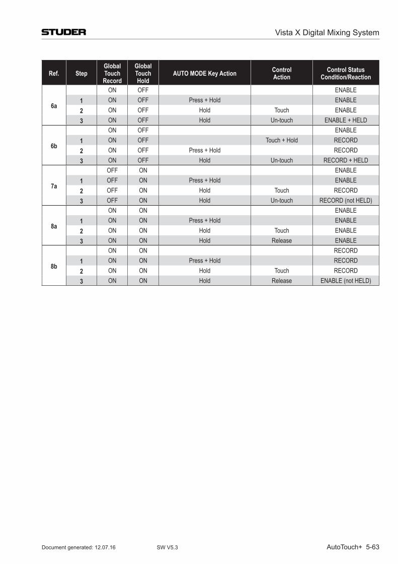
Vista X Digital Mixing System
AutoTouch+ 5-63Document generated: 12.07.16 SW V5.3
Ref. StepGlobal Touch Record
Global Touch Hold
AUTO MODE Key Action ControlAction
Control StatusCondition/Reaction
6a
oN off ENABLE1 oN off Press + Hold ENABLE2 oN off Hold Touch ENABLE3 oN off Hold Un-touch ENABLE + HELD
6b
oN off ENABLE1 oN off Touch + Hold RECoRD2 oN off Press + Hold RECoRD3 oN off Hold Un-touch RECoRD + HELD
7a
off oN ENABLE1 off oN Press + Hold ENABLE2 off oN Hold Touch RECoRD3 off oN Hold Un-touch RECoRD (not HELD)
8a
oN oN ENABLE1 oN oN Press + Hold ENABLE2 oN oN Hold Touch ENABLE3 oN oN Hold Release ENABLE
8b
oN oN RECoRD1 oN oN Press + Hold RECoRD2 oN oN Hold Touch RECoRD3 oN oN Hold Release ENABLE (not HELD)
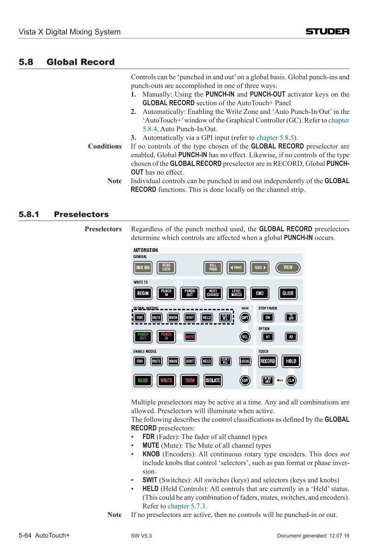
Vista X Digital Mixing System
5-64 AutoTouch+ Document generated: 12.07.16SW V5.3
5.8 Global Record Controls can be ‘punched in and out’ on a global basis. Global punch-ins and
punch-outs are accomplished in one of three ways:1. Manually: Using the PUNCH-IN and PUNCH-OUT activator keys on the
GLOBAL RECORD section of the AutoTouch+ Panel2. Automatically: Enabling the Write Zone and ‘Auto Punch-In/Out’ in the
‘Auto Touch+’ window of the Graphical Controller (GC). Refer to chapter 5.8.4, Auto Punch-In/Out.
3. Automatically via a GPI input (refer to chapter 5.8.5). Conditions If no controls of the type chosen of the GLOBAL RECORD preselector are
enabled, Global PUNCH-IN has no effect. Likewise, if no controls of the type chosen of the GLOBAL RECORD preselector are in RECORD, Global PUNCH-OUT has no effect.
Note Individual controls can be punched in and out independently of the GLOBAL RECORD functions. This is done locally on the channel strip.
5.8.1 Preselectors
Preselectors Regardless of the punch method used, the GLOBAL RECORD preselectors determine which controls are affected when a global PUNCH-IN occurs.
Multiple preselectors may be active at a time. Any and all combinations are allowed. Preselectors will illuminate when active.
ThefollowingdescribesthecontrolclassificationsasdefinedbytheGLOBAL RECORD preselectors:
• FDR (Fader): The fader of all channel types • MUTE (Mute): The Mute of all channel types • KNOB (Encoders): All continuous rotary type encoders. This does not
include knobs that control ‘selectors’, such as pan format or phase inver-sion.
• SWIT (Switches): All switches (keys) and selectors (keys and knobs) • HELD (Held Controls): All controls that are currently in a ‘Held’ status.
(This could be any combination of faders, mutes, switches, and encoders). Refer to chapter 5.7.3.
Note If no preselectors are active, then no controls will be punched-in or out.
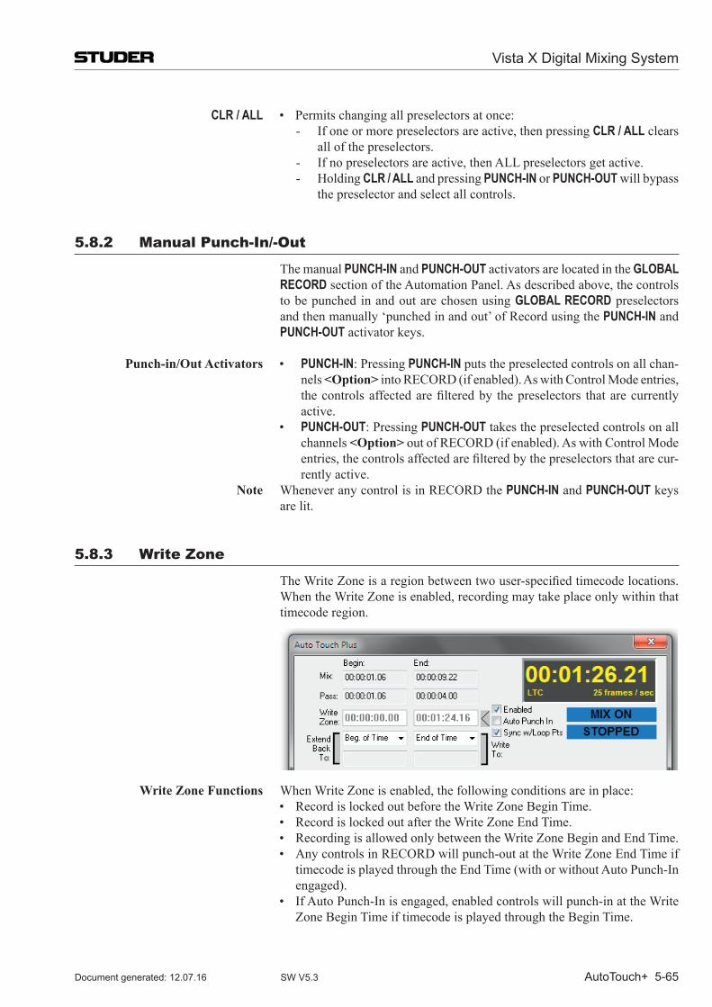
Vista X Digital Mixing System
AutoTouch+ 5-65Document generated: 12.07.16 SW V5.3
CLR / ALL • Permitschangingallpreselectorsatonce:- If one or more preselectors are active, then pressing CLR / ALL clears
all of the preselectors.- If no preselectors are active, then ALL preselectors get active.- Holding CLR / ALL and pressing PUNCH-IN or PUNCH-OUT will bypass
the preselector and select all controls.
5.8.2 manual Punch-in/-out
The manual PUNCH-IN and PUNCH-OUT activators are located in the GLOBAL RECORD section of the Automation Panel. As described above, the controls to be punched in and out are chosen using GLOBAL RECORD preselectors and then manually ‘punched in and out’ of Record using the PUNCH-IN and PUNCH-OUT activator keys.
Punch-in/Out Activators • PUNCH-IN: Pressing PUNCH-IN puts the preselected controls on all chan-
nels <Option> into RECORD (if enabled). As with Control Mode entries, thecontrolsaffectedarefilteredby thepreselectors thatarecurrentlyactive.
• PUNCH-OUT: Pressing PUNCH-OUT takes the preselected controls on all channels <Option> out of RECORD (if enabled). As with Control Mode entries,thecontrolsaffectedarefilteredbythepreselectorsthatarecur-rently active.
Note Whenever any control is in RECORD the PUNCH-IN and PUNCH-OUT keys are lit.
5.8.3 Write Zone
TheWriteZoneisaregionbetweentwouser-specifiedtimecodelocations.When the Write Zone is enabled, recording may take place only within that timecode region.
Write Zone Functions When Write Zone is enabled, the following conditions are in place: • RecordislockedoutbeforetheWriteZoneBeginTime. • RecordislockedoutaftertheWriteZoneEndTime. • RecordingisallowedonlybetweentheWriteZoneBeginandEndTime. • AnycontrolsinRECORDwillpunch-outattheWriteZoneEndTimeif
timecode is played through the End Time (with or without Auto Punch-In engaged).
• IfAutoPunch-Inisengaged,enabledcontrolswillpunch-inattheWriteZone Begin Time if timecode is played through the Begin Time.
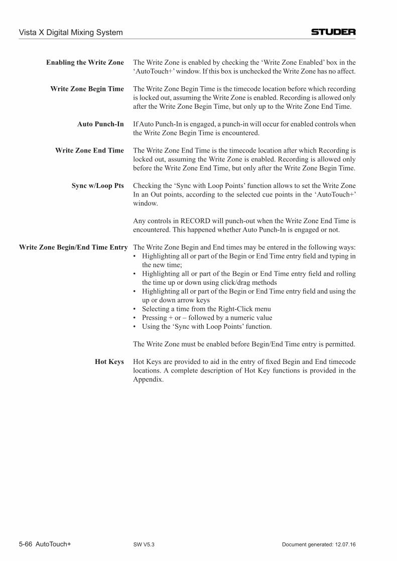
Vista X Digital Mixing System
5-66 AutoTouch+ Document generated: 12.07.16SW V5.3
Enabling the Write Zone The Write Zone is enabled by checking the ‘Write Zone Enabled’ box in the ‘Auto Touch+’ window. If this box is unchecked the Write Zone has no affect.
Write Zone Begin Time The Write Zone Begin Time is the timecode location before which recording is locked out, assuming the Write Zone is enabled. Recording is allowed only after the Write Zone Begin Time, but only up to the Write Zone End Time.
Auto Punch-In If Auto Punch-In is engaged, a punch-in will occur for enabled controls when the Write Zone Begin Time is encountered.
Write Zone End Time The Write Zone End Time is the timecode location after which Recording is locked out, assuming the Write Zone is enabled. Recording is allowed only before the Write Zone End Time, but only after the Write Zone Begin Time.
Sync w/Loop Pts Checking the ‘Sync with Loop Points’ function allows to set the Write Zone In an Out points, according to the selected cue points in the ‘Auto Touch+’ window.
Any controls in RECORD will punch-out when the Write Zone End Time is encountered. This happened whether Auto Punch-In is engaged or not.
Write Zone Begin/End Time Entry The Write Zone Begin and End times may be entered in the following ways: • HighlightingallorpartoftheBeginorEndTimeentryfieldandtypingin
the new time; • HighlightingallorpartoftheBeginorEndTimeentryfieldandrolling
the time up or down using click/drag methods • HighlightingallorpartoftheBeginorEndTimeentryfieldandusingthe
up or down arrow keys • SelectingatimefromtheRight-Clickmenu • Pressing+or–followedbyanumericvalue • Usingthe‘SyncwithLoopPoints’function.
The Write Zone must be enabled before Begin/End Time entry is permitted.
Hot Keys HotKeysareprovidedtoaidintheentryoffixedBeginandEndtimecodelocations. A complete description of Hot Key functions is provided in the Appendix.
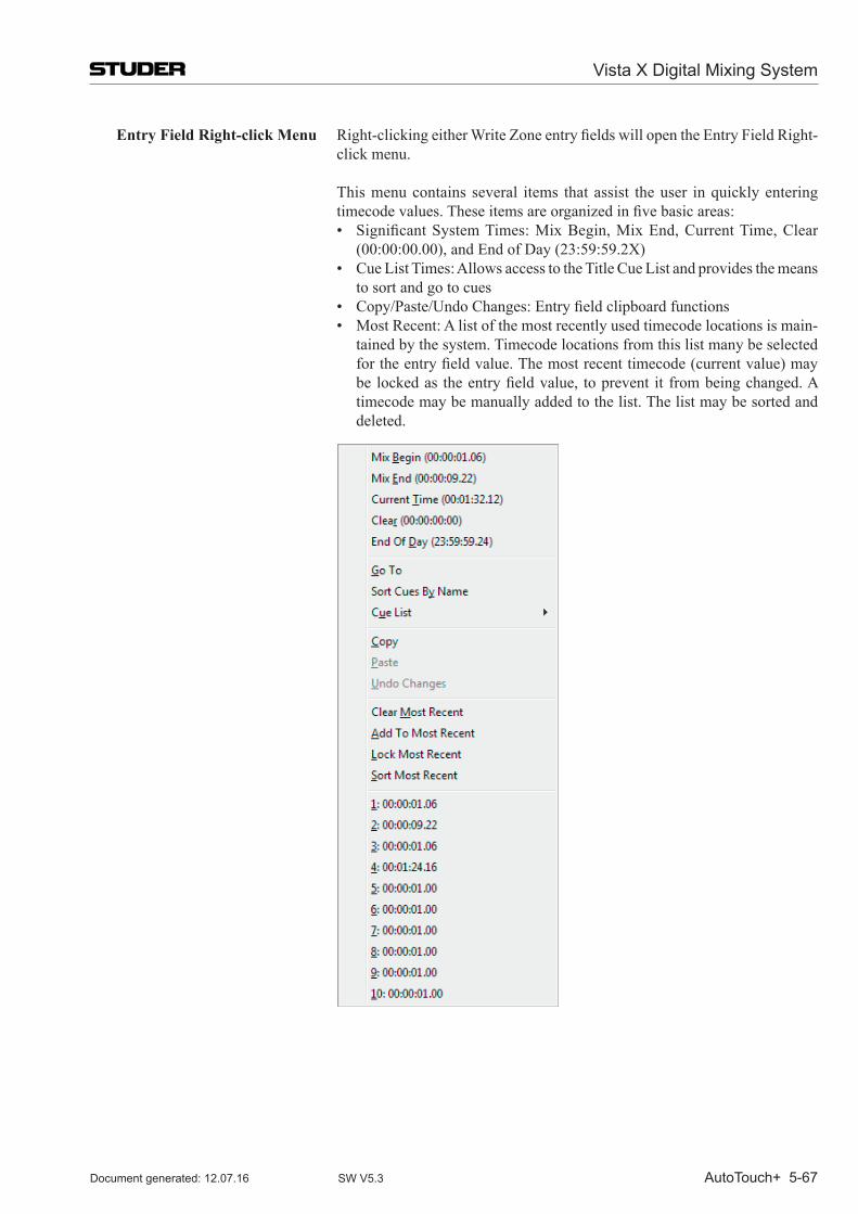
Vista X Digital Mixing System
AutoTouch+ 5-67Document generated: 12.07.16 SW V5.3
Entry Field Right-click Menu Right-clickingeitherWriteZoneentryfieldswillopentheEntryFieldRight-click menu.
This menu contains several items that assist the user in quickly entering timecodevalues.Theseitemsareorganizedinfivebasicareas:
• SignificantSystemTimes:MixBegin,MixEnd,CurrentTime,Clear(00:00:00.00), and End of Day (23:59:59.2X)
• CueListTimes:AllowsaccesstotheTitleCueListandprovidesthemeansto sort and go to cues
• Copy/Paste/UndoChanges:Entryfieldclipboardfunctions • MostRecent:Alistofthemostrecentlyusedtimecodelocationsismain-
tained by the system. Timecode locations from this list many be selected fortheentryfieldvalue.Themostrecenttimecode(currentvalue)maybe lockedas theentryfieldvalue, toprevent it frombeingchanged.Atimecode may be manually added to the list. The list may be sorted and deleted.
Vista X Digital Mixing System
5-68 AutoTouch+ Document generated: 12.07.16SW V5.3
5.8.4 Auto Punch-in/out
Automatic punch-in/punch-out is controlled via the Auto Touch+ window of the GC.
Write Zone To set up an Auto Punch-in/Out, a ‘Write Zone’ with a ‘Begin’ and ‘End’ timemustfirstbeestablished.ThesewillbetheInandOutpointfortheAutoPunch-in. The times displayed were the last In and Out times used by the system. Direct entry of Begin and End times is possible once the Write Zone is enabled. Refer to chapter 5.8.3 for details.
Auto Punch-in ToactivatetheAutoPunch-infeature,theWriteZonemustfirstbeenabled,whichisdonebycheckingthe‘Enable’boxnexttotheEndtimefield.Oncethe Write Zone is enabled, it is then possible to enable the Auto Punch-in facility. This is accomplished by checking the ‘Auto PUNCH-IN’ box located below the Write Zone Enable box.
Performing the Punch Once Auto Punch-In is enabled and the desired controls are enabled, play back timecode (media). During the pre-roll before the Begin Time, the affected controls will act as if in RECORD ENABLE, but will not punch-in until the Write Zone Begin time.
At the Begin time, the system will automatically punch-in and the any enabled controls will change to RECORD. Recording will continue until the End time is reached, where the controls are automatically punched out.
Notes It is possible to punch-out any individual control at any time within the Write Zone using the AUTO MODE key. Global punch-outs may also take place be-fore the end of the Write zone. It is not possible to punch-in before the Begin time or after the End time when the Write Zone is enabled.
Glide functions may be used with Auto Punch-In/Out. Since changes to the Read Mix are prohibited after the Write Zone End time, the Backtime Glide function must be used if Auto Punch-out is used.
5.8.5 Auto GPi in/out
Global Punch-Ins and Punch-Outs can also be done via the GPI input. This will basically make the Punch-In and Punch-Out key available to external systems or external keys.
If such functionality is required, the Signaling.inifileneedstobeadaptedaccordingly. Please contact Studer Service & Support to do the necessary changesinthatfile.
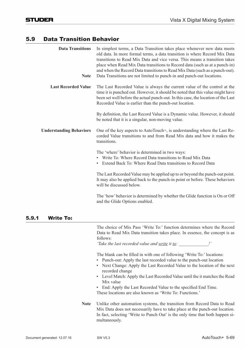
Vista X Digital Mixing System
AutoTouch+ 5-69Document generated: 12.07.16 SW V5.3
5.9 Data Transition Behavior Data Transitions In simplest terms, a Data Transition takes place whenever new data meets
old data. In more formal terms, a data transition is where Record Mix Data transitions to Read Mix Data and vice versa. This means a transition takes place when Read Mix Data transitions to Record data (such as at a punch-in) and when the Record Data transitions to Read Mix Data (such as a punch-out).
Note Data Transitions are not limited to punch-in and punch-out locations.
Last Recorded Value The Last Recorded Value is always the current value of the control at the time it is punched out. However, it should be noted that this value might have been set well before the actual punch-out. In this case, the location of the Last Recorded Value is earlier than the punch-out location.
Bydefinition,theLastRecordValueisaDynamicvalue.However,itshouldbe noted that it is a singular, non-moving value.
Understanding Behaviors One of the key aspects to Auto Touch+, is understanding where the Last Re-corded Value transitions to and from Read Mix data and how it makes the transitions.
The ‘where’ behavior is determined in two ways: • WriteTo:WhereRecordDatatransitionstoReadMixData • ExtendBackTo:WhereReadDatatransitionstoRecordData
The Last Recorded Value may be applied up to or beyond the punch-out point. It may also be applied back to the punch-in point or before. These behaviors will be discussed below.
The ‘how’ behavior is determined by whether the Glide function is On or Off
and the Glide Options enabled.
5.9.1 Write To:
The choice of Mix Pass ‘Write To:’ function determines where the Record Data to Read Mix Data transition takes place. In essence, the concept is as follows:
‘Take the last recorded value and write it to: _____________!’
Theblankcanbefilledinwithoneoffollowing‘WriteTo:’locations: • Punch-out:Applythelastrecordedvaluetothepunch-outlocation • NextChange:ApplytheLastRecordedValuetothelocationofthenext
recorded change • LevelMatch:ApplytheLastRecordedValueuntiltheitmatchestheRead
Mix value • End:ApplytheLastRecordedValuetothespecifiedEndTime. These locations are also known as ‘Write To: Functions.’
Note Unlike other automation systems, the transition from Record Data to Read Mix Data does not necessarily have to take place at the punch-out location. In fact, selecting ‘Write to Punch Out’ is the only time that both happen si-multaneously.
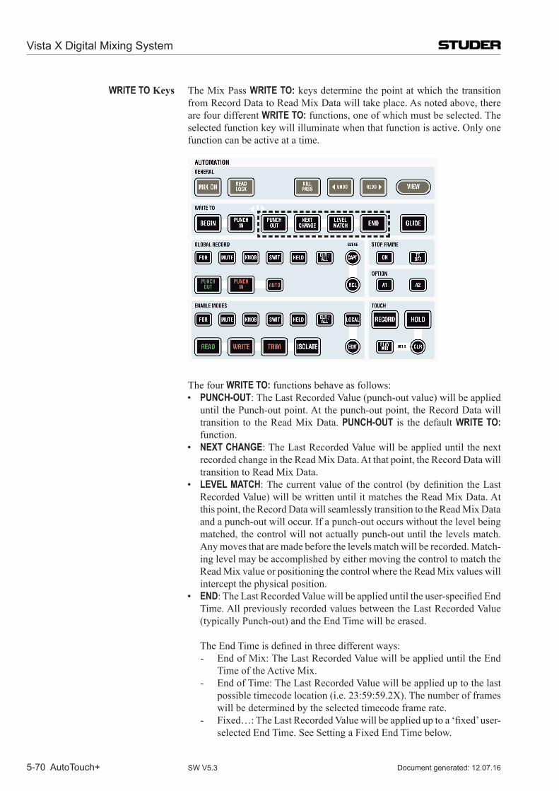
Vista X Digital Mixing System
5-70 AutoTouch+ Document generated: 12.07.16SW V5.3
WRITE TO Keys The Mix Pass WRITE TO: keys determine the point at which the transition from Record Data to Read Mix Data will take place. As noted above, there are four different WRITE TO: functions, one of which must be selected. The selected function key will illuminate when that function is active. Only one function can be active at a time.
The four WRITE TO: functions behave as follows: • PUNCH-OUT: The Last Recorded Value (punch-out value) will be applied
until the Punch-out point. At the punch-out point, the Record Data will transition to the Read Mix Data. PUNCH-OUT is the default WRITE TO: function.
• NEXT CHANGE: The Last Recorded Value will be applied until the next recorded change in the Read Mix Data. At that point, the Record Data will transition to Read Mix Data.
• LEVEL MATCH:Thecurrentvalueof thecontrol(bydefinitiontheLastRecorded Value) will be written until it matches the Read Mix Data. At this point, the Record Data will seamlessly transition to the Read Mix Data and a punch-out will occur. If a punch-out occurs without the level being matched, the control will not actually punch-out until the levels match. Any moves that are made before the levels match will be recorded. Match-ing level may be accomplished by either moving the control to match the Read Mix value or positioning the control where the Read Mix values will intercept the physical position.
• END:TheLastRecordedValuewillbeapplieduntiltheuser-specifiedEndTime. All previously recorded values between the Last Recorded Value (typically Punch-out) and the End Time will be erased.
TheEndTimeisdefinedinthreedifferentways:- End of Mix: The Last Recorded Value will be applied until the End
Time of the Active Mix. - End of Time: The Last Recorded Value will be applied up to the last
possible timecode location (i.e. 23:59:59.2X). The number of frames will be determined by the selected timecode frame rate.
- Fixed…:TheLastRecordedValuewillbeapplieduptoa‘fixed’user-selected End Time. See Setting a Fixed End Time below.
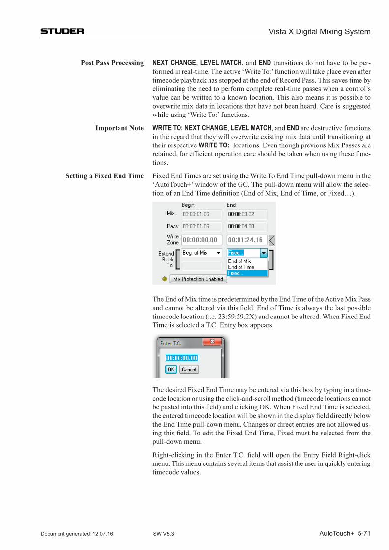
Vista X Digital Mixing System
AutoTouch+ 5-71Document generated: 12.07.16 SW V5.3
Post Pass Processing NEXT CHANGE, LEVEL MATCH, and END transitions do not have to be per-formed in real-time. The active ‘Write To:’ function will take place even after timecode playback has stopped at the end of Record Pass. This saves time by eliminating the need to perform complete real-time passes when a control’s value can be written to a known location. This also means it is possible to overwrite mix data in locations that have not been heard. Care is suggested while using ‘Write To:’ functions.
Important Note WRITE TO: NEXT CHANGE, LEVEL MATCH, and END are destructive functions in the regard that they will overwrite existing mix data until transitioning at their respective WRITE TO: locations. Even though previous Mix Passes are retained,forefficientoperationcareshouldbetakenwhenusingthesefunc-tions.
Setting a Fixed End Time Fixed End Times are set using the Write To End Time pull-down menu in the ‘Auto Touch+’ window of the GC. The pull-down menu will allow the selec-tionofanEndTimedefinition(EndofMix,EndofTime,orFixed…).
The End of Mix time is predetermined by the End Time of the Active Mix Pass andcannotbealteredviathisfield.EndofTimeisalwaysthelastpossibletimecode location (i.e. 23:59:59.2X) and cannot be altered. When Fixed End Time is selected a T.C. Entry box appears.
The desired Fixed End Time may be entered via this box by typing in a time-code location or using the click-and-scroll method (timecode locations cannot bepastedintothisfield)andclickingOK.WhenFixedEndTimeisselected,theenteredtimecodelocationwillbeshowninthedisplayfielddirectlybelowthe End Time pull-down menu. Changes or direct entries are not allowed us-ingthisfield.ToedittheFixedEndTime,Fixedmustbeselectedfromthepull-down menu.
Right-clickingintheEnterT.C.fieldwillopentheEntryFieldRight-clickmenu. This menu contains several items that assist the user in quickly entering timecode values.
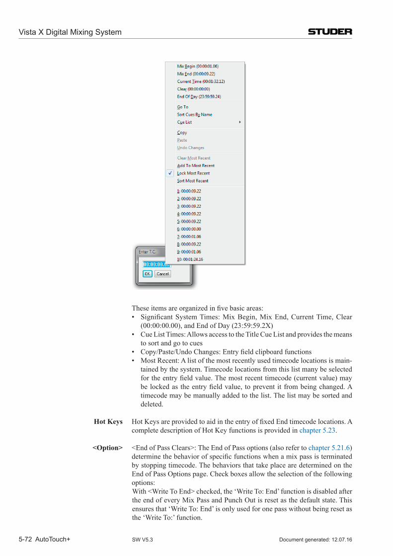
Vista X Digital Mixing System
5-72 AutoTouch+ Document generated: 12.07.16SW V5.3
Theseitemsareorganizedinfivebasicareas: • SignificantSystemTimes:MixBegin,MixEnd,CurrentTime,Clear
(00:00:00.00), and End of Day (23:59:59.2X) • CueListTimes:AllowsaccesstotheTitleCueListandprovidesthemeans
to sort and go to cues • Copy/Paste/UndoChanges:Entryfieldclipboardfunctions • MostRecent:Alistofthemostrecentlyusedtimecodelocationsismain-
tained by the system. Timecode locations from this list many be selected fortheentryfieldvalue.Themostrecenttimecode(currentvalue)maybe lockedas theentryfieldvalue, toprevent it frombeingchanged.Atimecode may be manually added to the list. The list may be sorted and deleted.
Hot Keys HotKeysareprovidedtoaidintheentryoffixedEndtimecodelocations.Acomplete description of Hot Key functions is provided in chapter 5.23.
<Option> <EndofPassClears>:TheEndofPassoptions(alsorefertochapter 5.21.6) determinethebehaviorofspecificfunctionswhenamixpassisterminatedby stopping timecode. The behaviors that take place are determined on the End of Pass Options page. Check boxes allow the selection of the following options:
With<WriteToEnd>checked,the‘WriteTo:End’functionisdisabledafterthe end of every Mix Pass and Punch Out is reset as the default state. This ensures that ‘Write To: End’ is only used for one pass without being reset as the ‘Write To:’ function.
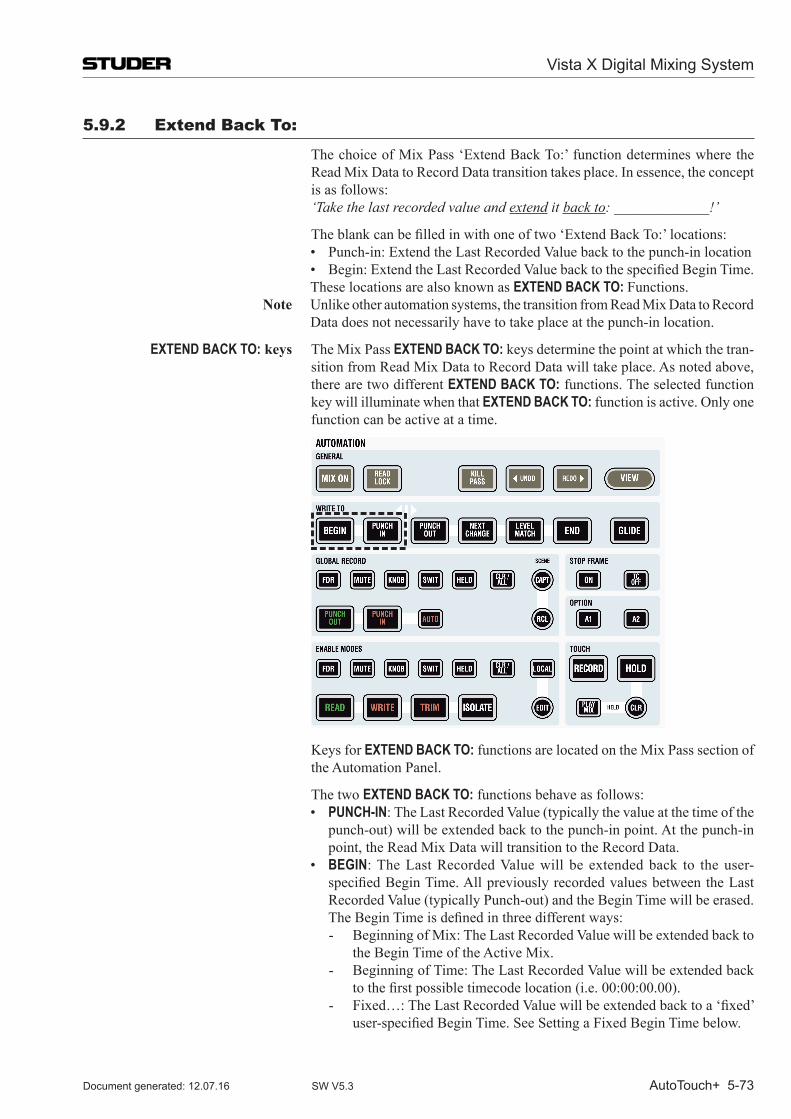
Vista X Digital Mixing System
AutoTouch+ 5-73Document generated: 12.07.16 SW V5.3
5.9.2 Extend Back To:
The choice of Mix Pass ‘Extend Back To:’ function determines where the Read Mix Data to Record Data transition takes place. In essence, the concept is as follows:
‘Take the last recorded value and extend it back to: _____________!’
Theblankcanbefilledinwithoneoftwo‘ExtendBackTo:’locations: • Punch-in:ExtendtheLastRecordedValuebacktothepunch-inlocation • Begin:ExtendtheLastRecordedValuebacktothespecifiedBeginTime. These locations are also known as EXTEND BACK TO: Functions.
Note Unlike other automation systems, the transition from Read Mix Data to Record Data does not necessarily have to take place at the punch-in location.
EXTEND BACK TO: keys The Mix Pass EXTEND BACK TO: keys determine the point at which the tran-sition from Read Mix Data to Record Data will take place. As noted above, there are two different EXTEND BACK TO: functions. The selected function key will illuminate when that EXTEND BACK TO: function is active. Only one function can be active at a time.
Keys for EXTEND BACK TO: functions are located on the Mix Pass section of the Automation Panel.
The two EXTEND BACK TO: functions behave as follows: • PUNCH-IN: The Last Recorded Value (typically the value at the time of the
punch-out) will be extended back to the punch-in point. At the punch-in point, the Read Mix Data will transition to the Record Data.
• BEGIN: The Last Recorded Value will be extended back to the user-specifiedBeginTime.AllpreviouslyrecordedvaluesbetweentheLastRecorded Value (typically Punch-out) and the Begin Time will be erased.
TheBeginTimeisdefinedinthreedifferentways:- Beginning of Mix: The Last Recorded Value will be extended back to
the Begin Time of the Active Mix. - Beginning of Time: The Last Recorded Value will be extended back
tothefirstpossibletimecodelocation(i.e.00:00:00.00).- Fixed…:TheLastRecordedValuewillbeextendedbacktoa‘fixed’
user-specifiedBeginTime.SeeSettingaFixedBeginTimebelow.
Vista X Digital Mixing System
5-74 AutoTouch+ Document generated: 12.07.16SW V5.3
Post Pass Processing Bydefinition,EXTEND BACK TO: transitions are performed as a post pass process. This also means it is possible to overwrite mix data in locations that have not been heard. Care is suggested while using EXTEND BACK TO: func-tions.
Important Note EXTEND BACK TO: PUNCH-IN and BEGIN are destructive functions in the
regard that they will overwrite existing mix data back to their respective EXTEND BACK TO: locations. Even though previous Mix Passes are retained, forefficientoperationcareshouldbetakenwhenusingthesefunctions.
Setting a Fixed Begin Time Fixed Begin Times are set using the methods employed to setting Fixed End Times. Refer to ‘Setting a Fixed End Time’ in chapter 5.9.1 above.
Hot Keys HotKeysareprovidedtoaidintheentryoffixedBegintimecodelocations.A complete description of Hot Key functions is provided in the Appendix.
<Option> • <EndofPassClears>:TheEndofPassoptions(refertochapter 5.21.6) determinethebehaviorofspecificfunctionswhenamixpassisterminatedby stopping timecode. The behaviors that take place are determined on the End of Pass Options page. Check boxes allow the selection of the follow-ing options:- With<ExtendBackToBegin>checked,the‘ExtendBackTo:Begin’
function is disabled after the end of every Mix Pass. This ensures that ‘Extend Back To: Begin’ is only used for one pass without being reset.
- With<ExtendBackToPUNCH-IN>checked,the‘ExtendBackTo:PUNCH-IN’ function is disabled after the end of every Mix Pass. This ensures that ‘Extend Back To: Begin’ is only used for one pass without being reset.
• With<ExtendBackToPUNCH-INSelectsWritetoPunchOut>checkedon the Master Panel Options page (refer to chapter 5.21.5), ‘Write To: Punch Out’ is automatically selected when ‘Extend Back To: PUNCH-IN’ is selected. This is convenient since these functions are often used together, especially when Auditioning a level and then using that level between punch-in and punch-out locations.
• TheMasterPanelEXTEND BACK TO: PUNCH-IN and BEGIN keys may be overriddenbycheckingoptionsonthe<MasterPanelOverrides>sectionof the Master Panel Options page. Faders and Encoders can have EXTEND BACK TO: PUNCH-IN and/or BEGIN setto<OFF>ortofollowtheMasterPanel<FollowsPanel>.EXTEND BACK TO: PUNCH-IN and/or BEGIN for Switchescanalsobesetto<OFF>orbesettofollowtheMasterPanel<FollowsPanel>.
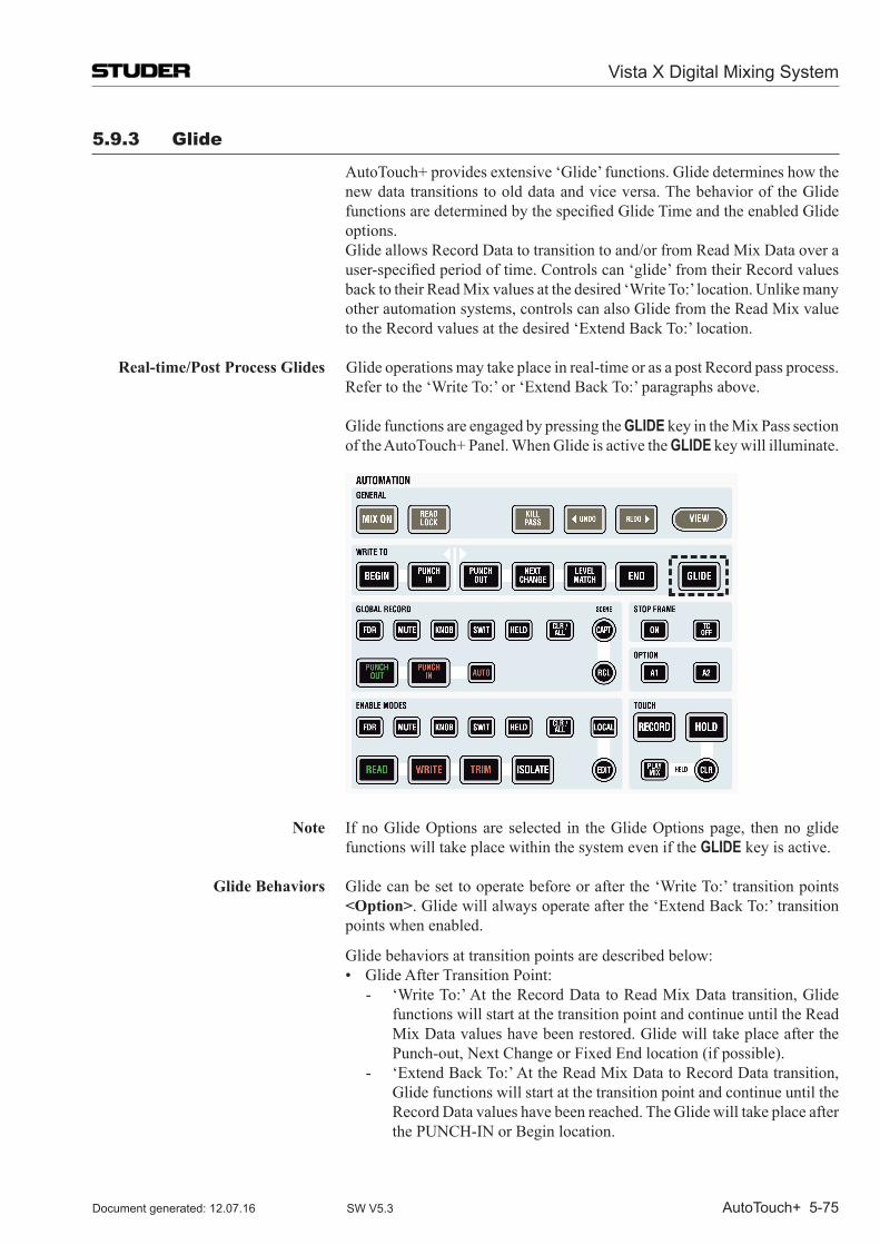
Vista X Digital Mixing System
AutoTouch+ 5-75Document generated: 12.07.16 SW V5.3
5.9.3 Glide
Auto Touch+ provides extensive ‘Glide’ functions. Glide determines how the new data transitions to old data and vice versa. The behavior of the Glide functionsaredeterminedbythespecifiedGlideTimeandtheenabledGlideoptions.
Glide allows Record Data to transition to and/or from Read Mix Data over a user-specifiedperiodoftime.Controlscan‘glide’fromtheirRecordvaluesback to their Read Mix values at the desired ‘Write To:’ location. Unlike many other automation systems, controls can also Glide from the Read Mix value to the Record values at the desired ‘Extend Back To:’ location.
Real-time/Post Process Glides Glide operations may take place in real-time or as a post Record pass process. Refer to the ‘Write To:’ or ‘Extend Back To:’ paragraphs above.
Glide functions are engaged by pressing the GLIDE key in the Mix Pass section of the AutoTouch+ Panel. When Glide is active the GLIDE key will illuminate.
Note If no Glide Options are selected in the Glide Options page, then no glide functions will take place within the system even if the GLIDE key is active.
Glide Behaviors Glide can be set to operate before or after the ‘Write To:’ transition points <Option>. Glide will always operate after the ‘Extend Back To:’ transition points when enabled.
Glide behaviors at transition points are described below: • GlideAfterTransitionPoint:
- ‘Write To:’ At the Record Data to Read Mix Data transition, Glide functions will start at the transition point and continue until the Read Mix Data values have been restored. Glide will take place after the Punch-out, Next Change or Fixed End location (if possible).
- ‘Extend Back To:’ At the Read Mix Data to Record Data transition, Glide functions will start at the transition point and continue until the Record Data values have been reached. The Glide will take place after the PUNCH-IN or Begin location.
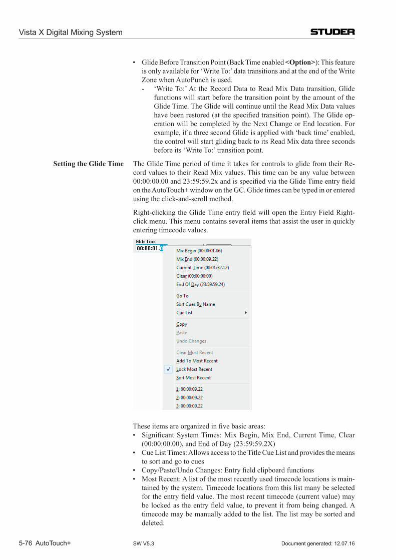
Vista X Digital Mixing System
5-76 AutoTouch+ Document generated: 12.07.16SW V5.3
• GlideBeforeTransitionPoint(BackTimeenabled<Option>): This feature is only available for ‘Write To:’ data transitions and at the end of the Write Zone when AutoPunch is used.- ‘Write To:’ At the Record Data to Read Mix Data transition, Glide
functions will start before the transition point by the amount of the Glide Time. The Glide will continue until the Read Mix Data values havebeenrestored(atthespecifiedtransitionpoint).TheGlideop-eration will be completed by the Next Change or End location. For example, if a three second Glide is applied with ‘back time’ enabled, the control will start gliding back to its Read Mix data three seconds before its ‘Write To:’ transition point.
Setting the Glide Time The Glide Time period of time it takes for controls to glide from their Re-cord values to their Read Mix values. This time can be any value between 00:00:00.00and23:59:59.2xandisspecifiedviatheGlideTimeentryfieldon the Auto Touch+ window on the GC. Glide times can be typed in or entered using the click-and-scroll method.
Right-clickingtheGlideTimeentryfieldwillopentheEntryFieldRight-click menu. This menu contains several items that assist the user in quickly entering timecode values.
Theseitemsareorganizedinfivebasicareas: • SignificantSystemTimes:MixBegin,MixEnd,CurrentTime,Clear
(00:00:00.00), and End of Day (23:59:59.2X) • CueListTimes:AllowsaccesstotheTitleCueListandprovidesthemeans
to sort and go to cues • Copy/Paste/UndoChanges:Entryfieldclipboardfunctions • MostRecent:Alistofthemostrecentlyusedtimecodelocationsismain-
tained by the system. Timecode locations from this list many be selected fortheentryfieldvalue.Themostrecenttimecode(currentvalue)maybe lockedas theentryfieldvalue, toprevent it frombeingchanged.Atimecode may be manually added to the list. The list may be sorted and deleted.
Vista X Digital Mixing System
AutoTouch+ 5-77Document generated: 12.07.16 SW V5.3
Hot Keys Hot Keys are provided to aid in the entry of glide times. A complete descrip-tion of Hot Key functions is provided in the Appendix.
<Option> Glide can be applied to all transition points used within the system. The af-fected points are selected by checking the options on the Glide Options page (also refer to chapter 5.21.3).
<ApplyGlidetothefollowingtransitionpointswhenGlideisON:> • <WriteTo:>Glidewillbeappliedtothefollowing‘WriteTo:’transition
points:- <PunchOut>- <NextChange>- <End>- <WriteZoneEnd(AutoPunchOut)>
• <ExtendBackTo:>Glidewillbeappliedtothefollowing‘ExtendBackTo:’ transition points:- <Begin>- <PUNCH-IN>
• <BackTimeGlide(EndandWriteZoneEndOnly)>:Glidewill‘backtime’from the transition point. The Glide will start before the transition point by theamountoftheGlideTime.TheGlidewillfinishatthetransitionpoint.This feature does not apply to ‘Extend Back To:’ transition points.
Vista X Digital Mixing System
5-78 AutoTouch+ Document generated: 12.07.16SW V5.3
5.10 Switch Automation SwitchautomationusingAutoTouch+isbotheasytouseandflexibleenough
to facilitate numerous functions and modes of operation.
Real-time Switch Editing The location of switch state changes may be edited in real-time. Adding or deleting switch events may also be easily accomplished.
In general, the following types of switch events may be created and edited: • MuteOn/Off:TurnsthechannelMuteonandoff • ProcessIn/Out:Engagesanddisengagestheconfiguredprocesses • ProcessControlSwitches:Performsswitchfunctionswithinconfigured
processes Note Channel Mute operates within Auto Touch+ as a switch, but since it has its own
Status key some Mute functions are performed differently as other switches. These differences in operation will be noted where needed.
Other system controls that are seen by Auto Touch+ as ‘switches’ but have alternative means of control. These controls are discussed in detail elsewhere in this document, but warrant mention here:
• Selectors:Choosing the routingofaudiooraudioprocessor functions(Channel Input Selector or Filter Slope for example). See below.
• GeneralPatchConnections:MakingorbreakingGeneralPatchConnec-tions. Refer to chapter 5.11.1, General Patch.
• ChannelPatchDirectOutTap:Changing the location fromwhere thechannel Direct Output is derived. Refer to chapter 5.11.2, Channel Patch.
• ChannelPatchMeterTap:ChangingthelocationfromwherethechannelMeter feed is derived. Refer to chapter 5.11.2, Channel Patch.
• ChannelPatchProcessorOrder:Changingthelocationofprocessorblockswithin the channel. Refer to chapter 5.11.2, Channel Patch.
<Option> • With<ReadSafe>checkedontheMiscOptionspage(refertochapter 5.21.7), AUDITION mode is defeated for controls in READ and only Read Mix values will be heard.
5.10.1 Switch Classifications
Themultipleswitcheson thechannelstripcanbedefinedasbeingeitherVMCorientedorcontroloriented.Theclassificationof theswitches (andothercontrols)isdeterminedbywhetherornottheyaredefinedinVMCfile.IftheyarenotdefinedbytheVMC,theyarecontrolorientedbydefault.
• VMC-orientedcontrols: Bydefinition,theobjects(controlsinthiscase)that appear in the VMC are audio oriented. These objects directly affect the audio and/or its routing.
• Control-orientedcontrols:Bydefinition,thesecontrolshaveanoperationalorientation and do not directly affect audio. These controls perform system oriented functions.
Vista X Digital Mixing System
AutoTouch+ 5-79Document generated: 12.07.16 SW V5.3
VMC Switches VMC oriented switches can be automated using Auto Touch+. These switches are as follows:
- Mute: Channel Mute - Encoder Parameter Switches: The switch associated with each of the
four channel strip rotary encoders. - Rotary Selectors: This also includes rotary encoders that are used as
Selectors. (See Selectors below)- Processor Block In/Out Switches: HI CUT, LO CUT, DELAY, INS, COMP-
LIMIT, EXP-GATE, EQ, PAN- Auxiliary In/Out Switches: AUX MONO 1..., AUX STEREO 1...- Input Selector Switches (See Selectors below): IN 1, IN 2, GEN
Control Switches Switches that are control-oriented are outside the Auto Touch+ system and therefore cannot be automated. Switches outside of the control of Auto Touch+ are as follows:
- LINK / SEL Key: Channel Select key - PFL/SOLO Key - Automation Switches: AUTO, SWIT REC, KNOB REC, MUTE REC,
FDR REC- Layer Switches: L1 and L2- Clipboard Control Switches: CLR, (Copy/Paste), A (Copy/Paste
All)- TALK - User Keys: USR 1, USR 2
Selectors Selectors are a special group of controls that typically use the encoder knobs as a means of physical control, but function as ‘switches’ within Auto Touch+. This differs from switches that operate as ‘toggles’, alternating between two states only.
Selectors perform one of two functions: • AudioRouting:InputSelector,DirectOuttaplocation,Metertaplocation,
Processor Block Order, etc. • ProcessorParameterSelector:InputFunction,FilterSlope,etc.
Selectors may be assigned to switches, knobs, or to the Channel Patch for a means of control. However, they may only be preselected using the SWIT preselectors.
Notes The Channel Input Selector is a special case in regard that it has a key for each input on the channel strip. However, these keys function collectively as a Selector. The input may also be selected from the Channel Patch.
Vista X Digital Mixing System
5-80 AutoTouch+ Document generated: 12.07.16SW V5.3
5.10.2 Switch Control modes
Since switches and selectors are not continuous controllers like faders or encoders, Control Modes affect switches in a unique manner.
Switch operations will perform the following functions when dynamic switches are in the Control Modes indicated:
READ The Read Mix data will determine the switch state. AUDITION mode is
available. • PressandReleaseActuation:
- Without Touch Hold engaged, Switch Press will toggle the switch state and put the switch in Audition. The switch state will toggle back at the next recorded change of state.
- With Touch Hold engaged, Switch Press will toggle the switch state and put the switch in Audition in a Held state. The switch will hold its alternate state and stay in Audition until Held controls are cleared.
• PressandHoldActuation:- Switch Press will toggle the switch state and put the switch in Audi-
tion. The switch will exit Audition when released. If its state does not match the Read Mix state, it will toggle to match upon release.
WRITE While in RECORD previously written switch states will be overwritten.
WRITE AUDITION mode is available. • PressandReleaseActuation:
- Without Touch Record or Touch Hold engaged, Switch Press will toggle the switch state and put the switch in Audition. The switch state will toggle back at the next recorded change of state.
- With Touch Hold engaged, Switch Press will toggle the switch state and put the switch in Audition in a Held state. The switch will stay in Audition until Held controls are cleared.
- With Touch Record engaged, Switch Press will toggle the switch state and punch the switch into RECORD. The switch will hold its alternate state and stay in RECORD until Held controls are cleared.
• PressandHoldActuation:- Without Touch Record, Switch Press will toggle the switch state
and put the switch in Audition. The switch will exit Audition when released. If its state does not match the Read Mix state, it will toggle to match upon release.
Vista X Digital Mixing System
AutoTouch+ 5-81Document generated: 12.07.16 SW V5.3
- With Touch Record engaged, Switch Press will toggle the switch state and punch the switch into RECORD. The switch will punch-out when released. If its state does not match the Read Mix state, it will toggle to match upon release.
TRIM While in TRIM previously written switch states may be edited. TRIM AUDI-TION mode is available.
• PressandReleaseActuation:- Without Touch Record engaged, Switch Press will toggle the switch
state and put the switch in Audition. The switch state will toggle back at the next recorded change of state.
- With Touch Record engaged, Switch Press will toggle the switch state and punch the switch into RECORD. The switch will hold its alternate state and stay in RECORD until the next recorded change of state. The switch state will toggle to its Read Mix state and will punch-out at the next recorded change of state.
• PressandHoldActuation:- Using Press and Hold actuation on Trim Enabled switches yields the
same results as if the switches were Write Enabled. The Trim of a switch cannot persist past the next recorded change of state for
that switch.
ISOLATE State changes of Isolated switches are not recognized by Auto Touch+.
Note All Mix Pass ‘Write To:’ and ‘Extend Back To:’ conditions apply as appropri-ate.
5.10.3 Switch operation
Switches and Touch-sensitivity Switches are not ‘touch-sensitive’ in the same regard as faders or encoders. Merephysicalcontactwithaswitchisnotsufficientenoughtoberegisteredby the system. For switches to have an effect within the system, they must be pressed.
Unlike faders and encoders (knobs) switches are ‘touch-sensitive’ only when engaged and disengaged. Because of this, and the toggle function of most switches (all switches except Selectors), the automation of switch functions differs from faders and encoders. The differences are operational mostly in nature and will be described in this chapter.
Switch Functions Pressing a switch performs two basic functions: • AudioFunction:Theswitchstateistoggledtoitsalternateposition. • AutomationFunctions:
- Switch Press- Switch Release
Under normal circumstances, a Switch Press produces a Touch event. How-ever, unlike faders and encoders, switches do not produce a Un-touch event when they are released. The Switch Press audio toggle (switch state toggle) event may be suppressed by holding down the AUTO MODE modifierkeywhenthe switch is actuated.
Vista X Digital Mixing System
5-82 AutoTouch+ Document generated: 12.07.16SW V5.3
Auto Touch+ recognizes Switch Press and Switch Release as separate and independent events. The Touch event produced by a Switch Press serves a separate from the Switch Press itself. This system allows the user to determine what will take place when a key is pressed and also when it is released.
This independence allows switches to take on different behaviors depending on which functions Switch Press and Switch Release are allowed to perform. The result is the ability for switches to operate in different modes depending on the needs of the user.
Switch Operating Modes Switches may operated using the following modes: • PressandRelease:MomentaryPressandRelease;Pressingthekeyand
immediately releasing it. • PressandHold:Pressingandholdingthekeydownbeyondapredeter-
mined time threshold. • ModifiedPressFunction:HoldingtheAUTO MODE key will suppress the
audio toggle function, but produces the Touch event when a key is pressed. This mode allows the switch to be punched-in without toggling its state.
Eachofthesefunctionsaredescribedbelow.TheModifiedPressFunctionmay be used with either Press and Release or Press and Hold operations.
Document Note The next three chapters make the assumption that the switches actuated are in the proper enabled Control Mode as operations are carried out.
5.10.3.1 Press and Release
PressandReleaseisdefinedasusingswitchesinamomentarymanner.Toperform a Press and Release operation, press a work surface key and imme-diately release it. The key is not held down any longer than it takes to toggle the switch state.
Press and Release operations perform the following functions: • SwitchPress:
- Toggles the switch state- Produces a Touch event
• SwitchRelease:- An Un-touch event is not produced.
With Press and Release operations, switches toggle to their alternate state when pressed and then hold that state until one of several conditions is met. The behaviors that occur as the result of a Press and Release switch operation is dependent on the switch’s Control Mode and whether Touch Record and/or Touch Record is engaged. Refer to chapter 5.10.2.
Note If a switch is held down too long, it will change to Press and Hold operation. The length of time a switch may be held down is determined by the Switch Press and Hold Threshold in the D950desk.inifileintheD950System folder.
Vista X Digital Mixing System
AutoTouch+ 5-83Document generated: 12.07.16 SW V5.3
5.10.3.2 Press and Hold
PressandHoldisdefinedasusingswitchesinatemporarilysustainedmanner.To perform a Press and Hold operation, press a switch and hold it down for a period of time before releasing it. Auto Touch+ senses how long the key is down and its mode of operation changes if it is held down longer than a speci-fiedperiodoftime(typically500msorso).Thefunctionbecomessimilartotouchingafader,keepingafingeronit,andthenreleasingitlater.
Press and Hold operations perform the following functions: • SwitchPress:
- Toggles the switch state- Produces a Touch event
• SwitchRelease:- Punch-out
With Press and Hold operations, switches toggle to their alternate state when pressed and then hold that state as long as the key is held down. When the switch is released, it may or may not toggle depending on the state recorded in the Read Mix Data at the time of release.
If Touch Record is engaged, the switch will punch-in as well as toggle its alternate state when it is pressed. The switch will stay in that state and in RECORD as long as the switch is held down. Upon release, the switch will punch-out. It may or may not toggle states depending on the state recorded in the Read Mix Data at the time of release. The change of state may Written or Trimmed depending on the selected Control Mode.
The behaviors that occur as the result of a Press and Hold switch operation is dependent on the switch’s Control Mode and whether Touch Record and/or Touch Record is engaged. Refer to chapter 5.10.2, Switch Control Modes.
Press and Hold Threshold Whenever a work surface key is pressed, Auto Touch+ monitors the duration
the key is held down. If the time a key is held down is longer than the Switch Press and Hold Threshold value, Press and Hold becomes active. If the hold duration is less than the threshold time the Press and Release functions are maintained.
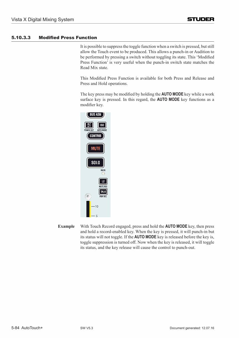
Vista X Digital Mixing System
5-84 AutoTouch+ Document generated: 12.07.16SW V5.3
5.10.3.3 modified Press Function
It is possible to suppress the toggle function when a switch is pressed, but still allow the Touch event to be produced. This allows a punch-in or Audition to beperformedbypressingaswitchwithouttogglingitsstate.This‘ModifiedPress Function’ is very useful when the punch-in switch state matches the Read Mix state.
ThisModifiedPressFunction isavailableforbothPressandReleaseandPress and Hold operations.
ThekeypressmaybemodifiedbyholdingtheAUTO MODE key while a work surface key is pressed. In this regard, the AUTO MODE key functions as a modifierkey.
Example With Touch Record engaged, press and hold the AUTO MODE key, then press and hold a record-enabled key. When the key is pressed, it will punch-in but its status will not toggle. If the AUTO MODE key is released before the key is, toggle suppression is turned off. Now when the key is released, it will toggle its status, and the key release will cause the control to punch-out.
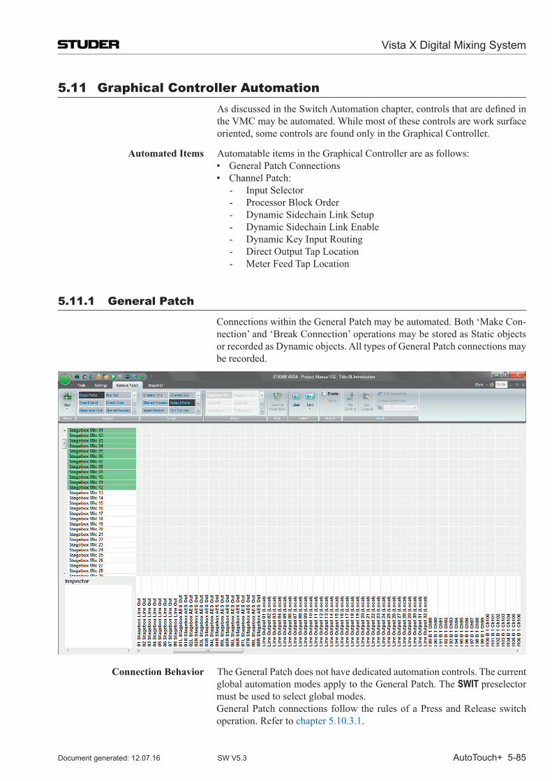
Vista X Digital Mixing System
AutoTouch+ 5-85Document generated: 12.07.16 SW V5.3
5.11 Graphical Controller Automation AsdiscussedintheSwitchAutomationchapter,controlsthataredefinedin
the VMC may be automated. While most of these controls are work surface oriented, some controls are found only in the Graphical Controller.
Automated Items Automatable items in the Graphical Controller are as follows: • GeneralPatchConnections • ChannelPatch:
- Input Selector- Processor Block Order- Dynamic Sidechain Link Setup- Dynamic Sidechain Link Enable- Dynamic Key Input Routing- Direct Output Tap Location- Meter Feed Tap Location
5.11.1 General Patch
Connections within the General Patch may be automated. Both ‘Make Con-nection’ and ‘Break Connection’ operations may be stored as Static objects or recorded as Dynamic objects. All types of General Patch connections may be recorded.
Connection Behavior The General Patch does not have dedicated automation controls. The current global automation modes apply to the General Patch. The SWIT preselector must be used to select global modes.
General Patch connections follow the rules of a Press and Release switch operation. Refer to chapter 5.10.3.1.
Vista X Digital Mixing System
5-86 AutoTouch+ Document generated: 12.07.16SW V5.3
As with any control, changes to General Patch connections may be Audi-tioned.
Record a General Patch Change To automate a connection in the General Patch, use the following procedure:1. Select the desired global Control Mode. Write will overwrite previous
changes, both location and connection type. 2. Select TOUCH RECORD.3. Select the desired ‘Write To:’ and ‘Extend Back To:’ functions. 4. Open the General Patch if it is not already open.5. Select the connection point to be automated (single click at the desired
location).6. Make/break the desired connection as follows:
• Tomakeasimplemono-to-monoconnection,presstheMAKE CON-NECT function key above the trackball. (Double-clicking the connec-tion location will bring up the connection menu where a mono-to-mono connection may be made.)
• Tomakeacomplexconnection (mono-to-stereo, stereo-to-stereo,stereo-to-mono), double-clicking the connection location will bring up the connection menu where the desired connection may be made.
• Tobreakanyconnection,press theBREAK CONNECT function key above the trackball. (Double-clicking the connection location will bring up the connection menu where a connection may be broken.)
7. Upon the selection of the desired connection type, Auto Touch+ will punch-in. Following the rules for Press and Hold, the new connection state will persist until the ‘Write To:’ conditions are met or a Global Punch-out occurs.
8. When timecode is stopped, a new Mix Pass will be generated.
Note Like any other object within Auto Touch+, all General Patch connection points are Static objects until a change state is recorded in the system. Therefore, General Patch connections may be updated in the same manner as any other Static control.
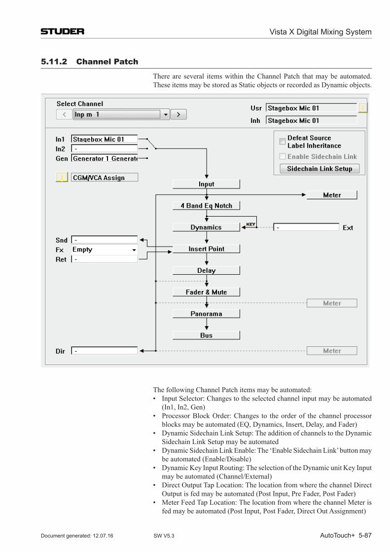
Vista X Digital Mixing System
AutoTouch+ 5-87Document generated: 12.07.16 SW V5.3
5.11.2 Channel Patch
There are several items within the Channel Patch that may be automated. These items may be stored as Static objects or recorded as Dynamic objects.
The following Channel Patch items may be automated: • InputSelector:Changestotheselectedchannelinputmaybeautomated
(In1, In2, Gen) • ProcessorBlockOrder:Changes to theorderof thechannelprocessor
blocks may be automated (EQ, Dynamics, Insert, Delay, and Fader) • DynamicSidechainLinkSetup:TheadditionofchannelstotheDynamic
Sidechain Link Setup may be automated • DynamicSidechainLinkEnable:The‘EnableSidechainLink’buttonmay
be automated (Enable/Disable) • DynamicKeyInputRouting:TheselectionoftheDynamicunitKeyInput
may be automated (Channel/External) • DirectOutputTapLocation:ThelocationfromwherethechannelDirect
Output is fed may be automated (Post Input, Pre Fader, Post Fader) • MeterFeedTapLocation:ThelocationfromwherethechannelMeteris
fed may be automated (Post Input, Post Fader, Direct Out Assignment)
Vista X Digital Mixing System
5-88 AutoTouch+ Document generated: 12.07.16SW V5.3
Notes Like any other object within Auto Touch+, all Channel Patch items are Static objects until a change state is recorded in the system. Therefore, Channel Patch items may be updated in the same manner as any other Static control.
The following Channel Patch items have switches on the channel strip that duplicate the Channel Patch functions:
• InputSelector • DynamicSidechainLinkEnable • DynamicKeyInputRouting
The channel Meter location can be set globally using the controls in the ‘Meter/Generator’ item in the GC Options menu (not the Auto Touch+ Options selector).
Item Behavior The Channel Patch does not have dedicated automation controls. The current
global automation modes apply to the Channel Patch.
The following Channel Patch items operate as Selectors: • InputSelector • ProcessorBlockOrder
• DynamicKeyInputRouting • DirectOutputTapLocation • MeterFeedTapLocation
The SW (SWIT) preselectors are used to select global modes.
Press and Release Selectors Some Channel Patch Selectors operate as Press and Release switches and therefore follow Press and Release switch operation rules. Refer to chapter 5.10.3.1.
The following Channel Patch items operate as Press and Release Selectors: • InputSelector
• DynamicKeyInputRouting • MeterFeedTapLocation
Note The channel Input Selector may be operated via the Channel Patch or by us-ing the keys on the channel strip. Since input selection is controlled with a Selector, Press and Hold operations are not possible.
One Shot Selectors Other Channel Patch Selectors operate as ‘One Shot’ switches. One Shot
selectors operate as true momentary switches. The user has no control over the duration of the held down state and release is immediate. A One Shot op-eration produces both a Touch and a Un-touch event. In TOUCH RECORD, when a One Shot switch is operated, punch-in and punch-out is almost im-mediate. Under normal circumstances this could produce an audible glitch, depending on the operation being completed. However, functions assigned to One Shot Selectors will persist in their changed state after punch-out. All Mix Pass ‘Write To:’ and ‘Extend Back To:’ conditions apply, except ‘Write To : Punch Out.’
The following Channel Patch items operate as One Shot Selectors: • ProcessorBlockOrder
• DirectOutputTapLocation These items follow the rules for One Shot Selectors as described above.
Vista X Digital Mixing System
AutoTouch+ 5-89Document generated: 12.07.16 SW V5.3
Channel Patch Operations Channel Patch items are operated as follows: • InputSelector:PlacethecursoronorneartheInputSelectoricon.Each
trackball click will cycle the selector through the inputs. A Touch event will be produced for each click.
• ProcessorBlockOrder:Clickandholdtheprocessorblocktobemoved,drag it to the new location, and release the trackball button (click and drag). A Touch event will be produced when the trackball is released.
• DynamicSidechainLinkSetup:ClickingSidechainLinkSetupwillopenthe Sidechain Link window where channels may be added to the available Sidechain Links. A Touch event will be produced when the ‘ADD’ button is clicked.
• DynamicSidechainLinkEnable:ClickingtheCheckBoxwilltoggletheswitch state. A Touch event will be produced when the box is checked or unchecked.
• DynamicKeyInputRouting:Theroutewiththesolidlineisthecurrentstate. Clicking the dashed line will select that route and a Touch event will be produced.
• DirectOutputTapLocation:Theroutewiththesolidlineisthecurrentstate. Clicking the dashed line will select that route and a Touch event will be produced.
• MeterFeedTapLocation:Clickingthealternatelocation(showngrayed-out) will select that location and a Touch event will be produced.
Channel Patch Switches Two Channel Patch items operate as toggle Switches: • DynamicSidechainLinkSetup • DynamicSidechainLinkEnable
From the Channel Patch, these switches follow the rules of Press and Release switch operations. However, if these functions are accessed via the channel strip keys, they may use either Press and Release or Press and Hold opera-tions. Press and Hold functions are not available via the GC.
As with any control, changes to Channel Patch items may Auditioned.
Record a Channel Patch Change To automate an item in the Channel Patch, use the following procedure:1. Select the desired global Control Mode. Write will overwrite previous
changes, both location and connection type. 2. Select TOUCH RECORD.3. Select the desired ‘Write To:’ and ‘Extend Back To:’ functions. 4. Open the Channel Patch if it is not already open.5. Perform the desired operation within the Channel Patch.6. At the time the desired operation is performed, Auto Touch+ will punch-
in. The new item state will persist until the ‘Write To:’ conditions are met or a Global Punch-out occurs.
7. When timecode is stopped, a new Mix Pass will be generated.
Vista X Digital Mixing System
5-90 AutoTouch+ Document generated: 12.07.16SW V5.3
5.12 other Automated Functions There are several ancillary functions that may be automated. These functions
are described below.
5.12.1 Bus Assignments
Bus Assignments may be automated. Both ‘assignment’ and ‘de-assign ment’ operations may be stored as Static objects or recorded as Dynamic objects.
Bus Assignments follow the rules of a Press and Release or Press and Hold switch operation. Refer to chapter 5.10. All Mix Pass ‘Write To:’ and ‘Extend Back To:’ conditions apply, except ‘Write To : Punch Out.’
As with any control, changes to Bus Assignments may Auditioned.
Record a Bus Assignment To automate a Bus Assignment, use the following procedure:1. Select the desired global Control Mode. Write will overwrite previous
changes, both location and connection type. 2. Select TOUCH RECORD.3. Select the desired ‘Write To:’ function. 4. Activate BUS ASN in the Touch Screen Area below the Vistonics™ sec-
tion.5. Press the desired bus number to make the assignment.6. Press and Release or Press and Hold switch rules will apply depending
on how the switch is operated.7. When timecode is stopped, a new Mix Pass will be generated.
Note Like any other object within Auto Touch+, all Bus Assignments are Static objects until a change state is recorded in the system. Therefore, Bus Assign-ments may be updated in the same manner as any other Static control.
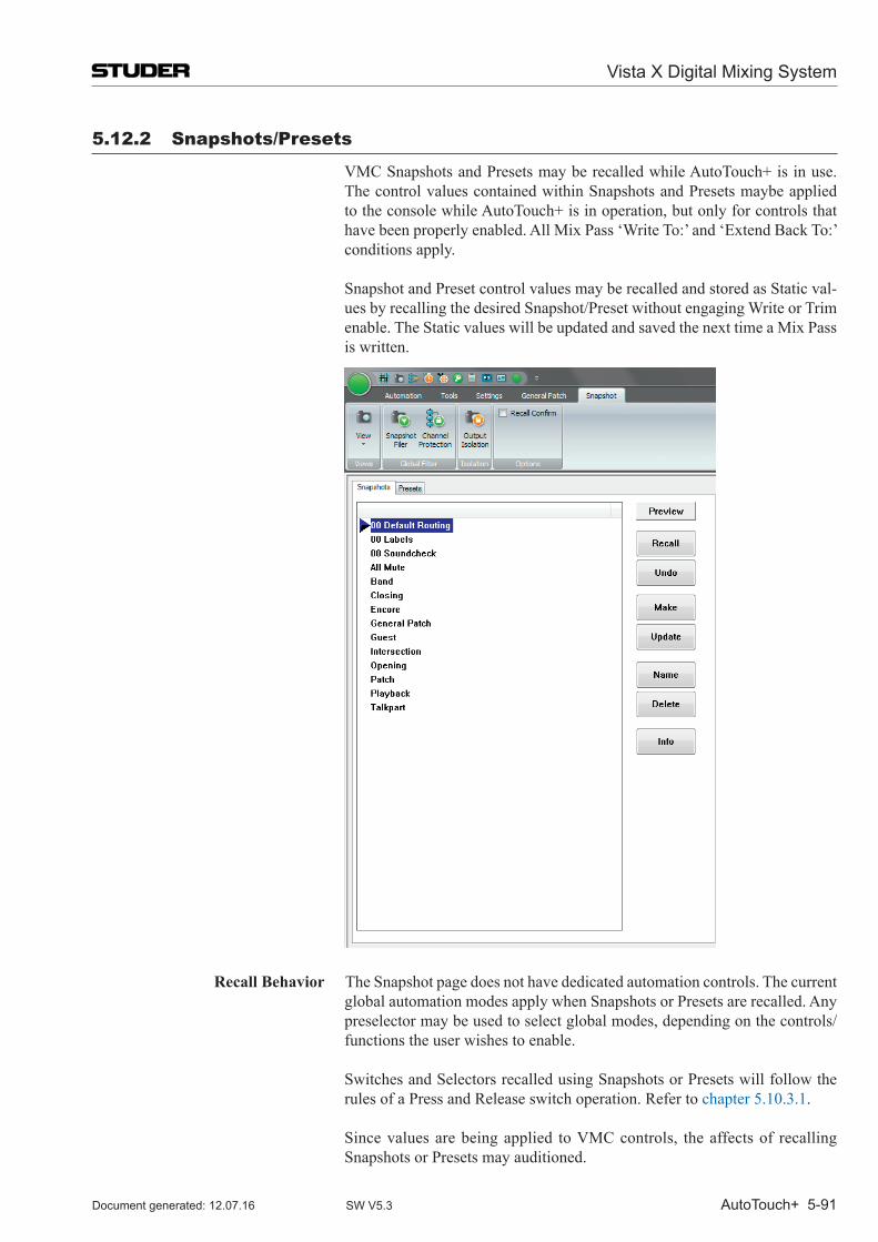
Vista X Digital Mixing System
AutoTouch+ 5-91Document generated: 12.07.16 SW V5.3
5.12.2 Snapshots/Presets
VMC Snapshots and Presets may be recalled while Auto Touch+ is in use. The control values contained within Snapshots and Presets maybe applied to the console while Auto Touch+ is in operation, but only for controls that have been properly enabled. All Mix Pass ‘Write To:’ and ‘Extend Back To:’ conditions apply.
Snapshot and Preset control values may be recalled and stored as Static val-ues by recalling the desired Snapshot/Preset without engaging Write or Trim enable. The Static values will be updated and saved the next time a Mix Pass is written.
Recall Behavior The Snapshot page does not have dedicated automation controls. The current global automation modes apply when Snapshots or Presets are recalled. Any preselector may be used to select global modes, depending on the controls/functions the user wishes to enable.
Switches and Selectors recalled using Snapshots or Presets will follow the rules of a Press and Release switch operation. Refer to chapter 5.10.3.1.
Since values are being applied to VMC controls, the affects of recalling Snapshots or Presets may auditioned.
Vista X Digital Mixing System
5-92 AutoTouch+ Document generated: 12.07.16SW V5.3
Record Recalled VMC Values To record Snapshot or Preset values to controls, use the following procedure:1. Select the desired global Control Mode. 2. Select TOUCH RECORD.3. Select the desired ‘Write To:’ function (Trim will default to ‘Next
Change’).4. Open the Snapshot page in the GC if it is not already open.5. Recall the desired Snapshot or Preset.6. Global conditions will apply to the controls that were enabled.7. When timecode is stopped, a new Mix Pass will be generated.
Note Recalling the channel strip clipboard has the same affect as recalling a Snapshot or Preset, except values are only applied on one channel at a time. Recording recalled clipboard values may be done as described above.
5.12.3 GC menu items
Some operational GC menu items may be automated. During normal opera-tion, these items are found in the GC Option menu. However, since all VMC objects are available in the ShowVMCTree menu (in the SysAdmin menu), these menu items may be automated as well.
Automatable Option Menu Items The following Option menu items contain automatable controls: • Meter/Generator:GlobalchannelMeterlocationsandGeneratorparam-
eters may be automated. Changes made to these items will produce Touch/Un-touch events.
• N–1Assignments:N–1Assignmentsmayautomated.Changesmadetothese assignments will produce Touch/Un-touch events.
• ControlGroupFilter:ChangesmadewithineachControlGroupmaybeautomated. Changes made within a Control Group will produce Touch/Un-touch events.
• VSPMicrophonesandReverb:ChangesmadeReverbBusAssignmentsand Microphone Characteristics (polar pattern and placement) may be automated. Changes made within the VSP Microphones and Reverb menu items will produce Touch/Un-touch events.
Menu Item Behavior The GC menus do not have dedicated automation controls. The current global automation modes apply to the automatable GC menu items. For an Option menu item use either the SW (SWIT) or ENC (KNOB) preselectors to select global modes, depending on item to be automated. For ‘ShowVMCTree’ items, any preselector may be used, depending on the controls/functions the user wishes to enable.
Menu item switches and selectors will follow the rules of a Press and Release switch operation, refer to chapter 5.10.3.1. All Mix Pass ‘Write To:’ and ‘Ex-tend Back To:’ conditions apply.
As with any control, changes to menu items may be auditioned.
Vista X Digital Mixing System
AutoTouch+ 5-93Document generated: 12.07.16 SW V5.3
Record a Menu Item Change To automate a menu item, use the following procedure:1. Select the desired global Control Mode. Write will overwrite previous
changes, both location and connection type. Trim will allow the locations of changes to be moved without changing connection types.
2. Select TOUCH RECORD.3. Select the desired ‘Write To:’ function. 4. Open the appropriate GC menu and select the desired item.5. Perform desired operations to be automated.6. At the time the desired operation is performed, Auto Touch+ will punch-
in. The new item state will persist until the ‘Write To:’ conditions are met or a Global Punch-out occurs. (trimmed status will persist until the Next Change by default.)
7. Upon punch-out a new Mix Pass will be created.
Note Like any other object within Auto Touch+, menu items are Static objects until a change state is recorded in the system. Therefore, menu items may be updated in the same manner as any other Static control.
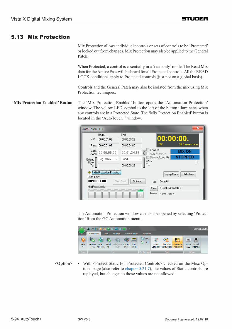
Vista X Digital Mixing System
5-94 AutoTouch+ Document generated: 12.07.16SW V5.3
5.13 mix Protection Mix Protection allows individual controls or sets of controls to be ‘Protected’
or locked out from changes. Mix Protection may also be applied to the General Patch.
When Protected, a control is essentially in a ‘read only’ mode. The Read Mix data for the Active Pass will be heard for all Protected controls. All the READ LOCK conditions apply to Protected controls (just not on a global basis).
Controls and the General Patch may also be isolated from the mix using Mix Protection techniques.
‘Mix Protection Enabled’ Button The ‘Mix Protection Enabled’ button opens the ‘Automation Protection’ window. The yellow LED symbol to the left of the button illuminates when any controls are in a Protected State. The ‘Mix Protection Enabled’ button is located in the ‘Auto Touch+’ window.
The Automation Protection window can also be opened by selecting ‘Protec-tion’ from the GC Automation menu.
<Option> • With<ProtectStaticForProtectedControls>checkedontheMiscOp-tions page (also refer to chapter 5.21.7), the values of Static controls are replayed, but changes to those values are not allowed.
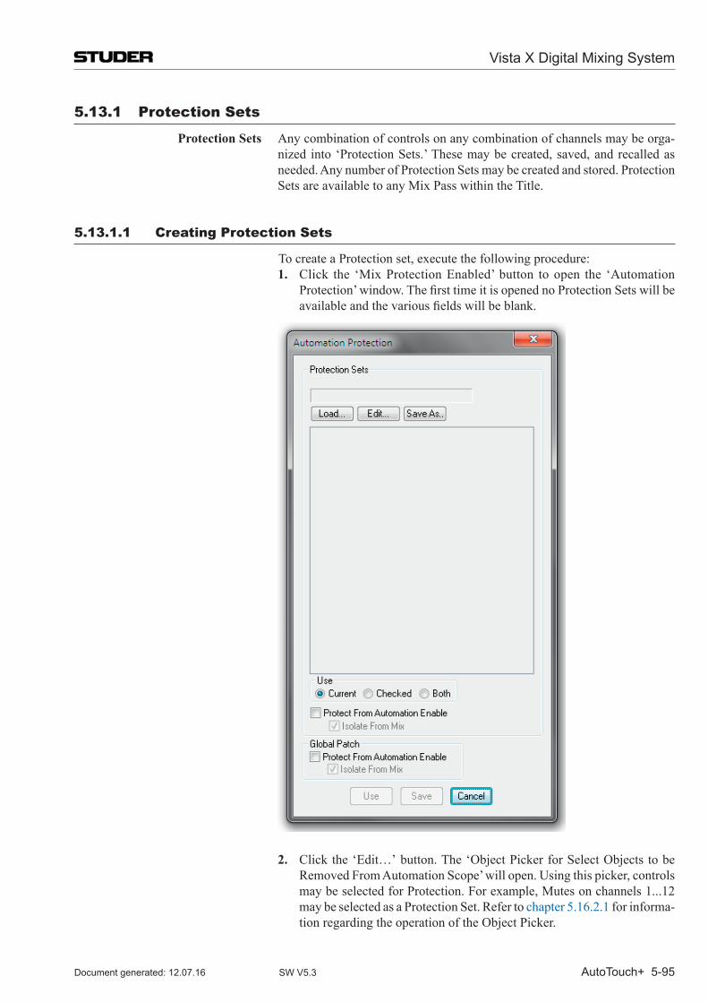
Vista X Digital Mixing System
AutoTouch+ 5-95Document generated: 12.07.16 SW V5.3
5.13.1 Protection Sets
Protection Sets Any combination of controls on any combination of channels may be orga-nized into ‘Protection Sets.’ These may be created, saved, and recalled as needed. Any number of Protection Sets may be created and stored. Protection Sets are available to any Mix Pass within the Title.
5.13.1.1 Creating Protection Sets
To create a Protection set, execute the following procedure:1. Click the ‘Mix Protection Enabled’ button to open the ‘Automation
Protection’window.ThefirsttimeitisopenednoProtectionSetswillbeavailableandthevariousfieldswillbeblank.
2. Click the ‘Edit…’ button. The ‘Object Picker for Select Objects to be Removed From Automation Scope’ will open. Using this picker, controls may be selected for Protection. For example, Mutes on channels 1...12 may be selected as a Protection Set. Refer to chapter 5.16.2.1 for informa-tion regarding the operation of the Object Picker.
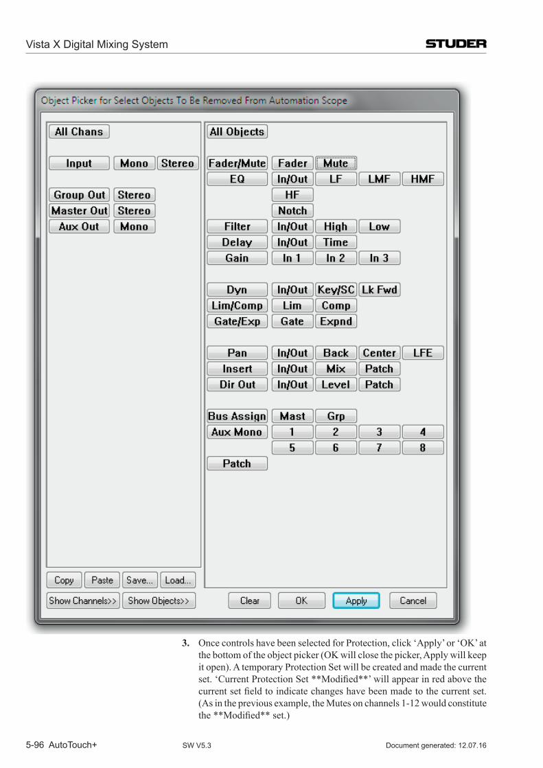
Vista X Digital Mixing System
5-96 AutoTouch+ Document generated: 12.07.16SW V5.3
3. Once controls have been selected for Protection, click ‘Apply’ or ‘OK’ at the bottom of the object picker (OK will close the picker, Apply will keep it open). A temporary Protection Set will be created and made the current set.‘CurrentProtectionSet**Modified**’willappearinredabovethecurrentsetfieldtoindicatechangeshavebeenmadetothecurrentset.(As in the previous example, the Mutes on channels 1-12 would constitute the**Modified**set.)
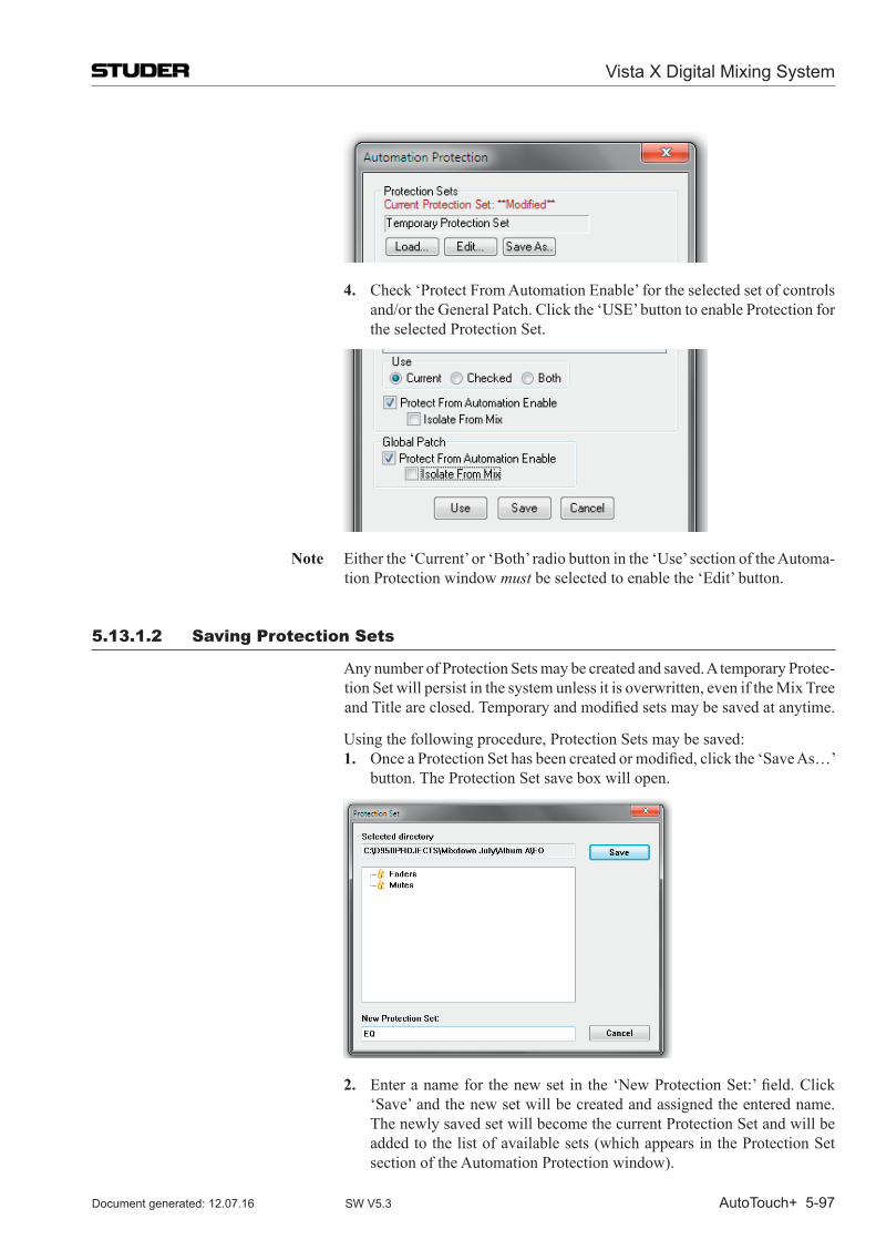
Vista X Digital Mixing System
AutoTouch+ 5-97Document generated: 12.07.16 SW V5.3
4. Check ‘Protect From Automation Enable’ for the selected set of controls and/or the General Patch. Click the ‘USE’ button to enable Protection for the selected Protection Set.
Note Either the ‘Current’ or ‘Both’ radio button in the ‘Use’ section of the Automa-tion Protection window must be selected to enable the ‘Edit’ button.
5.13.1.2 Saving Protection Sets
Any number of Protection Sets may be created and saved. A temporary Protec-tion Set will persist in the system unless it is overwritten, even if the Mix Tree andTitleareclosed.Temporaryandmodifiedsetsmaybesavedatanytime.
Using the following procedure, Protection Sets may be saved:1. OnceaProtectionSethasbeencreatedormodified,clickthe‘SaveAs…’
button. The Protection Set save box will open.
2. Enteranameforthenewset inthe‘NewProtectionSet:’field.Click‘Save’ and the new set will be created and assigned the entered name. The newly saved set will become the current Protection Set and will be added to the list of available sets (which appears in the Protection Set section of the Automation Protection window).
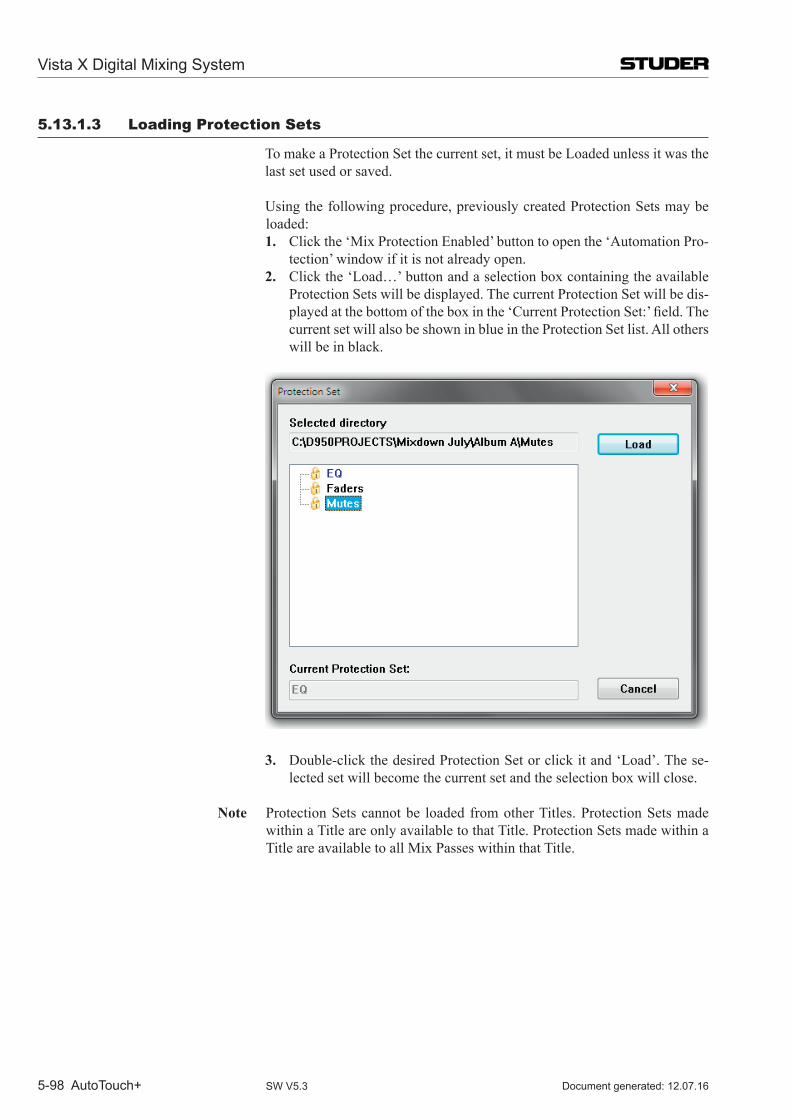
Vista X Digital Mixing System
5-98 AutoTouch+ Document generated: 12.07.16SW V5.3
5.13.1.3 Loading Protection Sets
To make a Protection Set the current set, it must be Loaded unless it was the last set used or saved.
Using the following procedure, previously created Protection Sets may be loaded:1. Click the ‘Mix Protection Enabled’ button to open the ‘Automation Pro-
tection’ window if it is not already open.2. Click the ‘Load…’ button and a selection box containing the available
Protection Sets will be displayed. The current Protection Set will be dis-playedatthebottomoftheboxinthe‘CurrentProtectionSet:’field.Thecurrent set will also be shown in blue in the Protection Set list. All others will be in black.
3. Double-click the desired Protection Set or click it and ‘Load’. The se-lected set will become the current set and the selection box will close.
Note Protection Sets cannot be loaded from other Titles. Protection Sets made within a Title are only available to that Title. Protection Sets made within a Title are available to all Mix Passes within that Title.
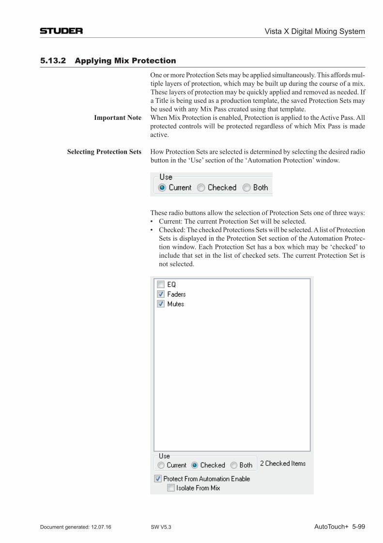
Vista X Digital Mixing System
AutoTouch+ 5-99Document generated: 12.07.16 SW V5.3
5.13.2 Applying mix Protection
One or more Protection Sets may be applied simultaneously. This affords mul-tiple layers of protection, which may be built up during the course of a mix. These layers of protection may be quickly applied and removed as needed. If a Title is being used as a production template, the saved Protection Sets may be used with any Mix Pass created using that template.
Important Note When Mix Protection is enabled, Protection is applied to the Active Pass. All protected controls will be protected regardless of which Mix Pass is made active.
Selecting Protection Sets How Protection Sets are selected is determined by selecting the desired radio button in the ‘Use’ section of the ‘Automation Protection’ window.
These radio buttons allow the selection of Protection Sets one of three ways: • Current:ThecurrentProtectionSetwillbeselected.
• Checked:ThecheckedProtectionsSetswillbeselected.AlistofProtectionSets is displayed in the Protection Set section of the Automation Protec-tion window. Each Protection Set has a box which may be ‘checked’ to include that set in the list of checked sets. The current Protection Set is not selected.
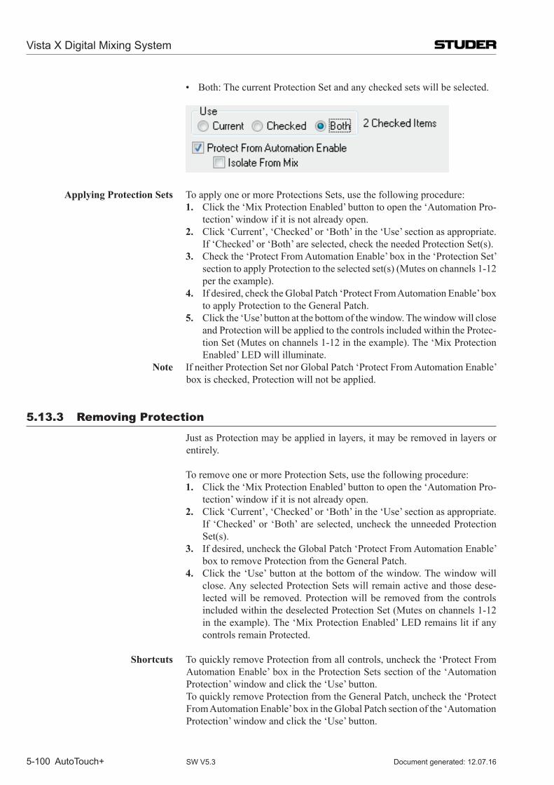
Vista X Digital Mixing System
5-100 AutoTouch+ Document generated: 12.07.16SW V5.3
• Both:ThecurrentProtectionSetandanycheckedsetswillbeselected.
Applying Protection Sets To apply one or more Protections Sets, use the following procedure:1. Click the ‘Mix Protection Enabled’ button to open the ‘Automation Pro-
tection’ window if it is not already open.2. Click ‘Current’, ‘Checked’ or ‘Both’ in the ‘Use’ section as appropriate.
If ‘Checked’ or ‘Both’ are selected, check the needed Protection Set(s). 3. Check the ‘Protect From Automation Enable’ box in the ‘Protection Set’
section to apply Protection to the selected set(s) (Mutes on channels 1-12 per the example).
4. If desired, check the Global Patch ‘Protect From Automation Enable’ box to apply Protection to the General Patch.
5. Click the ‘Use’ button at the bottom of the window. The window will close and Protection will be applied to the controls included within the Protec-tion Set (Mutes on channels 1-12 in the example). The ‘Mix Protection Enabled’ LED will illuminate.
Note If neither Protection Set nor Global Patch ‘Protect From Automation Enable’ box is checked, Protection will not be applied.
5.13.3 Removing Protection
Just as Protection may be applied in layers, it may be removed in layers or entirely.
To remove one or more Protection Sets, use the following procedure:1. Click the ‘Mix Protection Enabled’ button to open the ‘Automation Pro-
tection’ window if it is not already open.2. Click ‘Current’, ‘Checked’ or ‘Both’ in the ‘Use’ section as appropriate.
If ‘Checked’ or ‘Both’ are selected, uncheck the unneeded Protection Set(s).
3. If desired, uncheck the Global Patch ‘Protect From Automation Enable’ box to remove Protection from the General Patch.
4. Click the ‘Use’ button at the bottom of the window. The window will close. Any selected Protection Sets will remain active and those dese-lected will be removed. Protection will be removed from the controls included within the deselected Protection Set (Mutes on channels 1-12 in the example). The ‘Mix Protection Enabled’ LED remains lit if any controls remain Protected.
Shortcuts To quickly remove Protection from all controls, uncheck the ‘Protect From Automation Enable’ box in the Protection Sets section of the ‘Automation Protection’ window and click the ‘Use’ button.
To quickly remove Protection from the General Patch, uncheck the ‘Protect From Automation Enable’ box in the Global Patch section of the ‘Automation Protection’ window and click the ‘Use’ button.
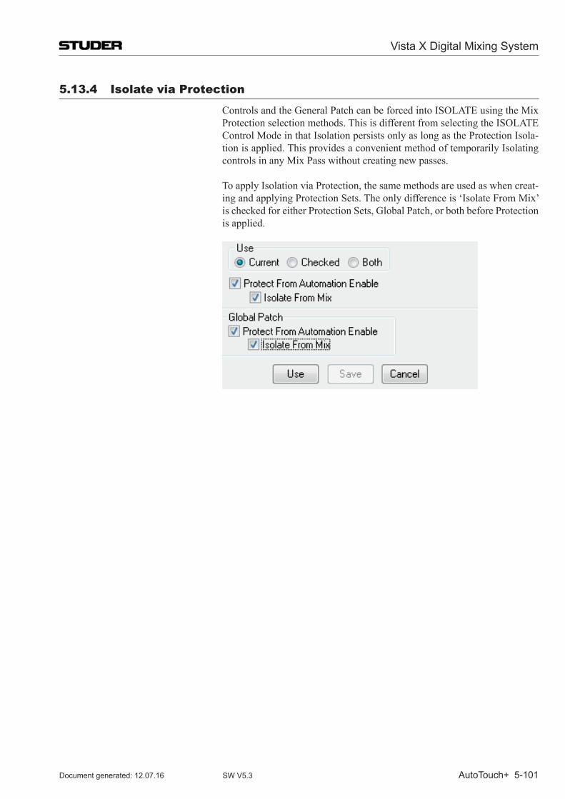
Vista X Digital Mixing System
AutoTouch+ 5-101Document generated: 12.07.16 SW V5.3
5.13.4 isolate via Protection
Controls and the General Patch can be forced into ISOLATE using the Mix Protection selection methods. This is different from selecting the ISOLATE Control Mode in that Isolation persists only as long as the Protection Isola-tion is applied. This provides a convenient method of temporarily Isolating controls in any Mix Pass without creating new passes.
To apply Isolation via Protection, the same methods are used as when creat-ing and applying Protection Sets. The only difference is ‘Isolate From Mix’ is checked for either Protection Sets, Global Patch, or both before Protection is applied.
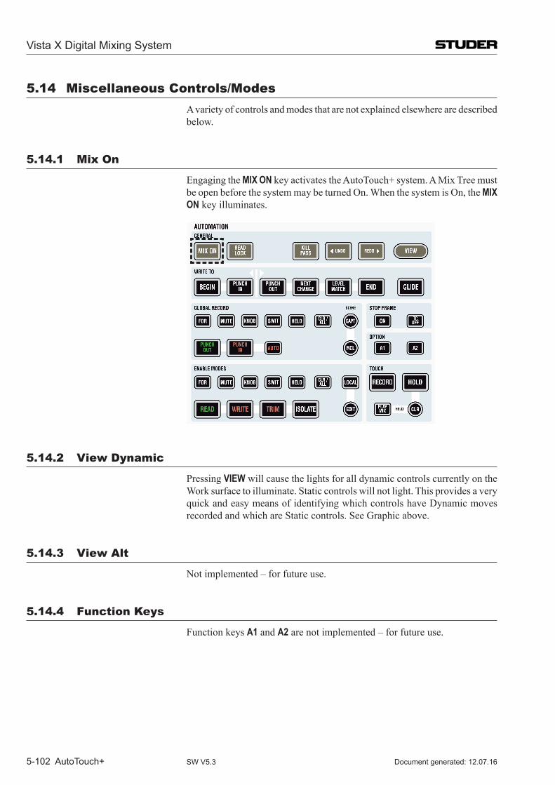
Vista X Digital Mixing System
5-102 AutoTouch+ Document generated: 12.07.16SW V5.3
5.14 miscellaneous Controls/modes A variety of controls and modes that are not explained elsewhere are described
below.
5.14.1 mix on
Engaging the MIX ON key activates the Auto Touch+ system. A Mix Tree must be open before the system may be turned On. When the system is On, the MIX ON key illuminates.
5.14.2 View Dynamic
Pressing VIEW will cause the lights for all dynamic controls currently on the Work surface to illuminate. Static controls will not light. This provides a very quick and easy means of identifying which controls have Dynamic moves recorded and which are Static controls. See Graphic above.
5.14.3 View Alt
Not implemented – for future use.
5.14.4 Function Keys
Function keys A1 and A2 are not implemented – for future use.
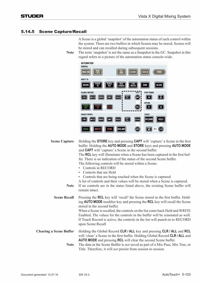
Vista X Digital Mixing System
AutoTouch+ 5-103Document generated: 12.07.16 SW V5.3
5.14.5 Scene Capture/Recall
A Scene is a global ‘snapshot’ of the automation status of each control within the system. There are two buffers in which Scenes may be stored. Scenes will be stored and can recalled during subsequent sessions.
Note The term ‘snapshot’ is not the same as a Snapshot in the GC. Snapshot in this regard refers to a picture of the automation status console-wide.
Scene Capture Holding the STORE key and pressing CAPTwill‘capture’aSceneinthefirstbuffer. Holding the AUTO MODE and STORE keys and pressing AUTO MODE and CAPT will ‘capture’ a Scene in the second buffer.
The RCLkeywillilluminatewhenaScenehasbeencapturedinthefirstbuf-fer. There is no indication of the status of the second Scene buffer.
The following controls will be stored within a Scene: • ControlsinRECORD • ControlsthatareHeld • ControlsthatarebeingtouchedwhentheSceneiscaptured A list of controls and their values will be stored when a Scene is captured. Note If no controls are in the states listed above, the existing Scene buffer will
remain intact.
Scene Recall Pressing the RCLkeywill‘recall’theScenestoredinthefirstbuffer.Hold-ing AUTO MODE modifierkey and pressing the RCL key will recall the Scene stored in the second buffer.
When a Scene is recalled, the controls on the list come back Held and WRITE Enabled. The values for the controls in the buffer will be reinstated as well. If Touch Record is active, the controls in the list will punch-in to RECORD upon Scene Recall
Clearing a Scene Buffer Holding the Global Record CLR / ALL key and pressing CLR / ALL and RCL will‘clear’aSceneinthefirstbuffer.HoldingGlobalRecordCLR / ALL and AUTO MODE and pressing RCL will clear the second Scene buffer.
Note The data in the Scene Buffer is not saved as part of a Mix Pass, Mix Tree, or Title. Therefore, it will not persist from session to session.
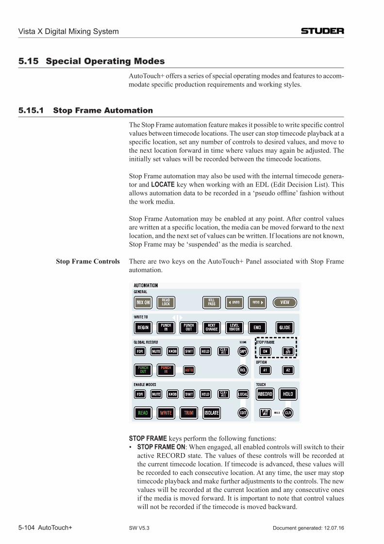
Vista X Digital Mixing System
5-104 AutoTouch+ Document generated: 12.07.16SW V5.3
5.15 Special operating modes Auto Touch+ offers a series of special operating modes and features to accom-
modatespecificproductionrequirementsandworkingstyles.
5.15.1 Stop Frame Automation
TheStopFrameautomationfeaturemakesitpossibletowritespecificcontrolvalues between timecode locations. The user can stop timecode playback at a specificlocation,setanynumberofcontrolstodesiredvalues,andmovetothe next location forward in time where values may again be adjusted. The initially set values will be recorded between the timecode locations.
Stop Frame automation may also be used with the internal timecode genera-tor and LOCATE key when working with an EDL (Edit Decision List). This allowsautomationdatatoberecordedina‘pseudooffline’fashionwithoutthe work media.
Stop Frame Automation may be enabled at any point. After control values arewrittenataspecificlocation,themediacanbemovedforwardtothenextlocation, and the next set of values can be written. If locations are not known, Stop Frame may be ‘suspended’ as the media is searched.
Stop Frame Controls There are two keys on the AutoTouch+ Panel associated with Stop Frame automation.
STOP FRAME keys perform the following functions: • STOP FRAME ON: When engaged, all enabled controls will switch to their
active RECORD state. The values of these controls will be recorded at the current timecode location. If timecode is advanced, these values will be recorded to each consecutive location. At any time, the user may stop timecode playback and make further adjustments to the controls. The new values will be recorded at the current location and any consecutive ones if the media is moved forward. It is important to note that control values will not be recorded if the timecode is moved backward.
Vista X Digital Mixing System
AutoTouch+ 5-105Document generated: 12.07.16 SW V5.3
• STOP FRAME TC OFF: When engaged, Stop Frame recording is suspended. This allows timecode to be moved backward or forward so a the next timecode location may be found. No control values will be written while STOP FRAME TC OFF is engaged.
Using Stop Frame Automation The procedures for using Stop Frame Automation are as follows:1. Select WRITE ENABLE or TRIM ENABLE and the desired preselector(s).2. Engage TOUCH RECORD so that touched, enabled controls change to
RECORD. Also engage TOUCH HOLD so controls won’t snap back to previously written values when un-touched.
3. Move the media forward and stop media at a desired timecode location. 4. Enable Stop Frame by pressing the STOP FRAME ON key, if it is not al-
ready on. The STOP FRAME ON key will illuminate and record status will change to ‘Ready.’
5. Adjust enabled controls to the desired values while sitting at that location. Any touched control will enter RECORD and its value can be set. The finalvalueforeachcontrolwillberecordedatthatlocationandeveryconsecutive timecode location played into the system. This is typically to the next Stop Frame location, but transitions will be applied according to the chosen ‘Write To:’ function.
6. Pressing the STOP FRAME TC OFF key will release Stop Frame from timecode. This allows the media to searched forward and backward in ordertofindthenexttimecodelocation.
7. Once values have been recorded at all desired locations, turn Stop Frame off, by disengaging the STOP FRAME ON key. A new Mix Pass will be created and added to the Mix Tree and Mix Pass Stack.
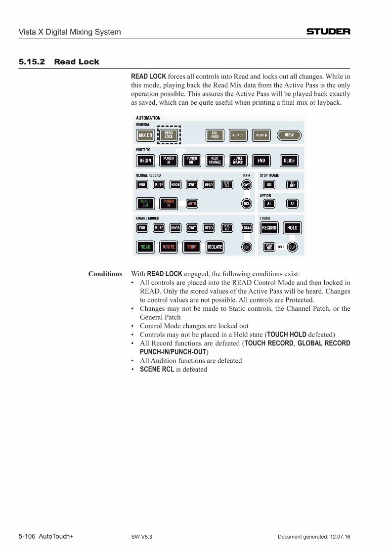
Vista X Digital Mixing System
5-106 AutoTouch+ Document generated: 12.07.16SW V5.3
5.15.2 Read Lock
READ LOCK forces all controls into Read and locks out all changes. While in this mode, playing back the Read Mix data from the Active Pass is the only operation possible. This assures the Active Pass will be played back exactly assaved,whichcanbequiteusefulwhenprintingafinalmixorlayback.
Conditions With READ LOCK engaged, the following conditions exist: • AllcontrolsareplacedintotheREADControlModeandthenlockedin
READ. Only the stored values of the Active Pass will be heard. Changes to control values are not possible. All controls are Protected.
• ChangesmaynotbemadetoStaticcontrols,theChannelPatch,ortheGeneral Patch
• ControlModechangesarelockedout • ControlsmaynotbeplacedinaHeldstate(TOUCH HOLD defeated) • AllRecordfunctionsaredefeated(TOUCH RECORD, GLOBAL RECORD
PUNCH-IN/PUNCH-OUT) • AllAuditionfunctionsaredefeated • SCENE RCL is defeated
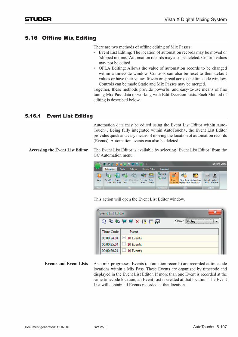
Vista X Digital Mixing System
AutoTouch+ 5-107Document generated: 12.07.16 SW V5.3
5.16 offline mix Editing TherearetwomethodsofofflineeditingofMixPasses:
• EventListEditing:Thelocationofautomationrecordsmaybemovedor‘slipped in time.’ Automation records may also be deleted. Control values may not be edited.
• OFLAEditing:Allows thevalueofautomationrecords tobechangedwithin a timecode window. Controls can also be reset to their default values or have their values frozen or spread across the timecode window. Controls can be made Static and Mix Passes may be merged.
Together, thesemethodsprovidepowerfulandeasy-to-usemeansoffinetuning Mix Pass data or working with Edit Decision Lists. Each Method of editing is described below.
5.16.1 Event List Editing
Automation data may be edited using the Event List Editor within Auto-Touch+. Being fully integrated within Auto Touch+, the Event List Editor provides quick and easy means of moving the location of automation records (Events). Automation events can also be deleted.
Accessing the Event List Editor The Event List Editor is available by selecting ‘Event List Editor’ from the GC Automation menu.
This action will open the Event List Editor window.
Events and Event Lists As a mix progresses, Events (automation records) are recorded at timecode locations within a Mix Pass. These Events are organized by timecode and displayed in the Event List Editor. If more than one Event is recorded at the same timecode location, an Event List is created at that location. The Event List will contain all Events recorded at that location.
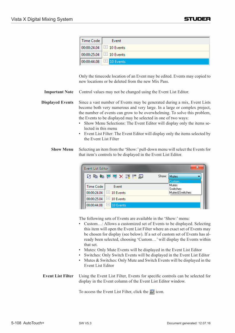
Vista X Digital Mixing System
5-108 AutoTouch+ Document generated: 12.07.16SW V5.3
Only the timecode location of an Event may be edited. Events may copied to new locations or be deleted from the new Mix Pass.
Important Note Control values may not be changed using the Event List Editor.
Displayed Events Since a vast number of Events may be generated during a mix, Event Lists become both very numerous and very large. In a large or complex project, the number of events can grow to be overwhelming. To solve this problem, the Events to be displayed may be selected in one of two ways:
• ShowMenuSelections:TheEventEditorwilldisplayonlytheitemsse-lected in this menu
• EventListFilter:TheEventEditorwilldisplayonlytheitemsselectedbythe Event List Filter
Show Menu Selecting an item from the ‘Show:’ pull-down menu will select the Events for
that item’s controls to be displayed in the Event List Editor.
The following sets of Events are available in the ‘Show:’ menu: • Custom…:AllowsacustomizedsetofEventstobedisplayed.Selecting
this item will open the Event List Filter where an exact set of Events may be chosen for display (see below). If a set of custom set of Events has al-ready been selected, choosing ‘Custom…’ will display the Events within that set.
• Mutes:OnlyMuteEventswillbedisplayedintheEventListEditor • Switches:OnlySwitchEventswillbedisplayedintheEventListEditor • Mutes&Switches:OnlyMuteandSwitchEventswillbedisplayedinthe
Event List Editor
Event List Filter UsingtheEventListFilter,Eventsforspecificcontrolscanbeselectedfordisplay in the Event column of the Event List Editor window.
To access the Event List Filter, click the icon.
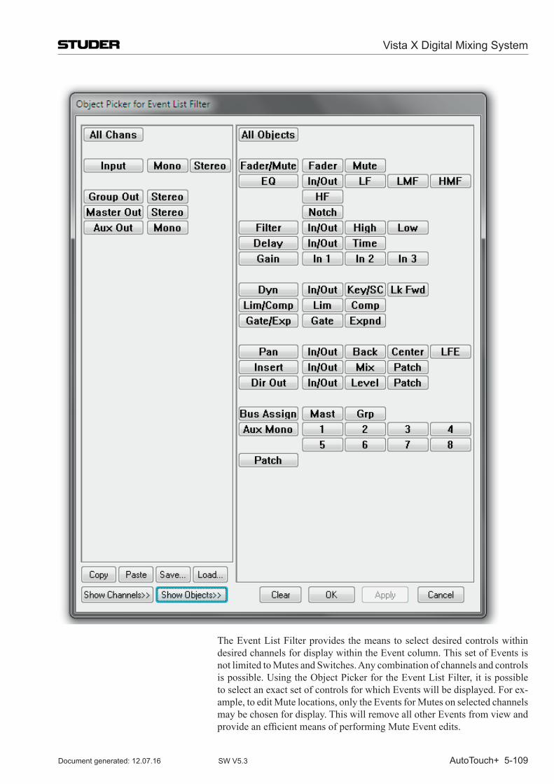
Vista X Digital Mixing System
AutoTouch+ 5-109Document generated: 12.07.16 SW V5.3
The Event List Filter provides the means to select desired controls within desired channels for display within the Event column. This set of Events is not limited to Mutes and Switches. Any combination of channels and controls is possible. Using the Object Picker for the Event List Filter, it is possible to select an exact set of controls for which Events will be displayed. For ex-ample, to edit Mute locations, only the Events for Mutes on selected channels may be chosen for display. This will remove all other Events from view and provideanefficientmeansofperformingMuteEventedits.
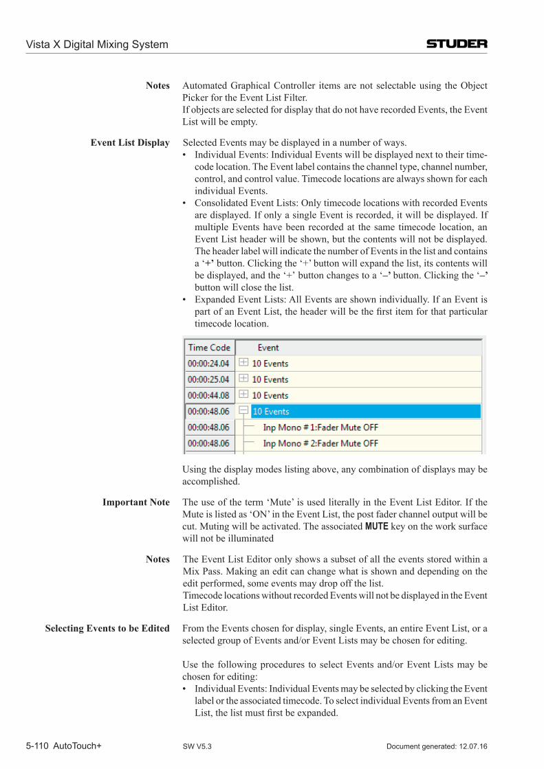
Vista X Digital Mixing System
5-110 AutoTouch+ Document generated: 12.07.16SW V5.3
Notes Automated Graphical Controller items are not selectable using the Object Picker for the Event List Filter.
If objects are selected for display that do not have recorded Events, the Event List will be empty.
Event List Display Selected Events may be displayed in a number of ways. • IndividualEvents:IndividualEventswillbedisplayednexttotheirtime-
code location. The Event label contains the channel type, channel number, control, and control value. Timecode locations are always shown for each individual Events.
• ConsolidatedEventLists:OnlytimecodelocationswithrecordedEventsare displayed. If only a single Event is recorded, it will be displayed. If multiple Events have been recorded at the same timecode location, an Event List header will be shown, but the contents will not be displayed. The header label will indicate the number of Events in the list and contains a ‘+’ button. Clicking the ‘+’ button will expand the list, its contents will be displayed, and the ‘+’ button changes to a ‘–’ button. Clicking the ‘–’ button will close the list.
• ExpandedEventLists:AllEventsareshownindividually.IfanEventispartofanEventList,theheaderwillbethefirstitemforthatparticulartimecode location.
Using the display modes listing above, any combination of displays may be accomplished.
Important Note The use of the term ‘Mute’ is used literally in the Event List Editor. If the Mute is listed as ‘ON’ in the Event List, the post fader channel output will be cut. Muting will be activated. The associated MUTE key on the work surface will not be illuminated
Notes The Event List Editor only shows a subset of all the events stored within a Mix Pass. Making an edit can change what is shown and depending on the edit performed, some events may drop off the list.
Timecode locations without recorded Events will not be displayed in the Event List Editor.
Selecting Events to be Edited From the Events chosen for display, single Events, an entire Event List, or a selected group of Events and/or Event Lists may be chosen for editing.
Use the following procedures to select Events and/or Event Lists may be chosen for editing:
• IndividualEvents:IndividualEventsmaybeselectedbyclickingtheEventlabel or the associated timecode. To select individual Events from an Event List,thelistmustfirstbeexpanded.
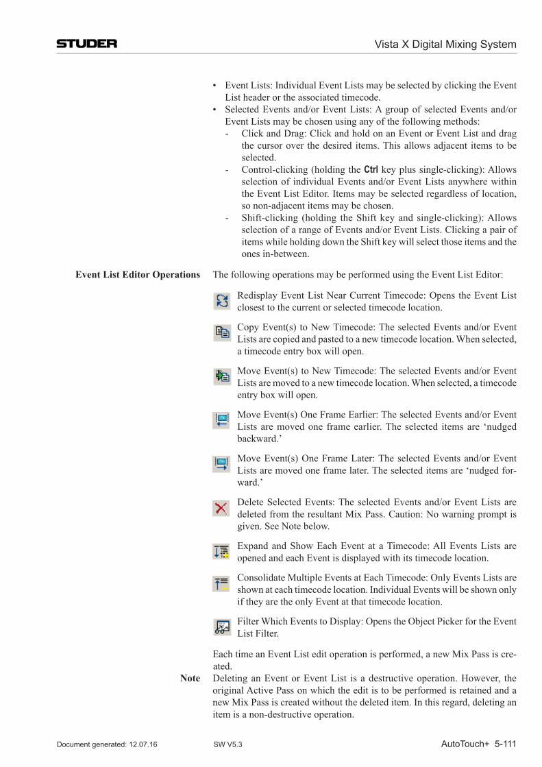
Vista X Digital Mixing System
AutoTouch+ 5-111Document generated: 12.07.16 SW V5.3
• EventLists:IndividualEventListsmaybeselectedbyclickingtheEventList header or the associated timecode.
• SelectedEventsand/orEventLists:AgroupofselectedEventsand/orEvent Lists may be chosen using any of the following methods:- Click and Drag: Click and hold on an Event or Event List and drag
the cursor over the desired items. This allows adjacent items to be selected.
- Control-clicking (holding the Ctrl key plus single-clicking): Allows selection of individual Events and/or Event Lists anywhere within the Event List Editor. Items may be selected regardless of location, so non-adjacent items may be chosen.
- Shift-clicking (holding the Shift key and single-clicking): Allows selection of a range of Events and/or Event Lists. Clicking a pair of items while holding down the Shift key will select those items and the ones in-between.
Event List Editor Operations The following operations may be performed using the Event List Editor:
Redisplay Event List Near Current Timecode: Opens the Event List closest to the current or selected timecode location.
Copy Event(s) to New Timecode: The selected Events and/or Event Lists are copied and pasted to a new timecode location. When selected, a timecode entry box will open.
Move Event(s) to New Timecode: The selected Events and/or Event Lists are moved to a new timecode location. When selected, a timecode entry box will open.
Move Event(s) One Frame Earlier: The selected Events and/or Event Lists are moved one frame earlier. The selected items are ‘nudged backward.’
Move Event(s) One Frame Later: The selected Events and/or Event Lists are moved one frame later. The selected items are ‘nudged for-ward.’
Delete Selected Events: The selected Events and/or Event Lists are deleted from the resultant Mix Pass. Caution: No warning prompt is given. See Note below.
Expand and Show Each Event at a Timecode: All Events Lists are opened and each Event is displayed with its timecode location.
Consolidate Multiple Events at Each Timecode: Only Events Lists are shown at each timecode location. Individual Events will be shown only if they are the only Event at that timecode location.
Filter Which Events to Display: Opens the Object Picker for the Event List Filter.
Each time an Event List edit operation is performed, a new Mix Pass is cre-ated.
Note Deleting an Event or Event List is a destructive operation. However, the original Active Pass on which the edit is to be performed is retained and a new Mix Pass is created without the deleted item. In this regard, deleting an item is a non-destructive operation.
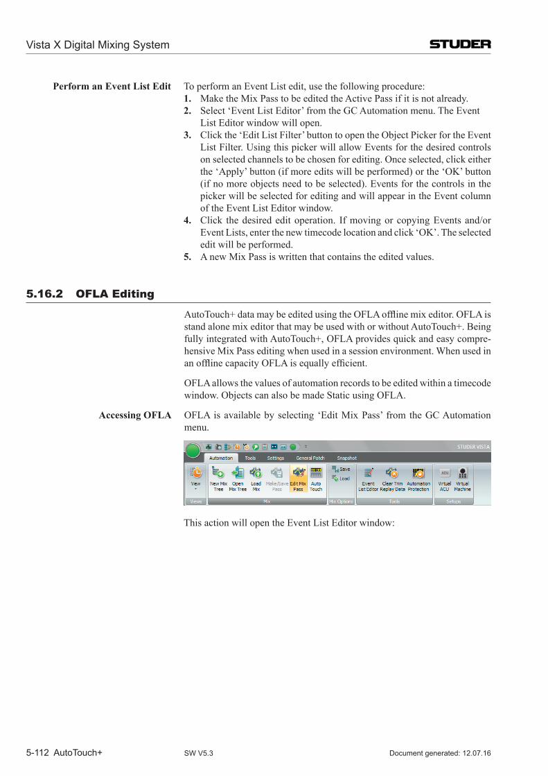
Vista X Digital Mixing System
5-112 AutoTouch+ Document generated: 12.07.16SW V5.3
Perform an Event List Edit To perform an Event List edit, use the following procedure:1. Make the Mix Pass to be edited the Active Pass if it is not already.2. Select ‘Event List Editor’ from the GC Automation menu. The Event
List Editor window will open.3. Click the ‘Edit List Filter’ button to open the Object Picker for the Event
List Filter. Using this picker will allow Events for the desired controls on selected channels to be chosen for editing. Once selected, click either the ‘Apply’ button (if more edits will be performed) or the ‘OK’ button (if no more objects need to be selected). Events for the controls in the picker will be selected for editing and will appear in the Event column of the Event List Editor window.
4. Click the desired edit operation. If moving or copying Events and/or Event Lists, enter the new timecode location and click ‘OK’. The selected edit will be performed.
5. A new Mix Pass is written that contains the edited values.
5.16.2 oFLA Editing
AutoTouch+datamaybeeditedusingtheOFLAofflinemixeditor.OFLAisstand alone mix editor that may be used with or without Auto Touch+. Being fully integrated with Auto Touch+, OFLA provides quick and easy compre-hensive Mix Pass editing when used in a session environment. When used in anofflinecapacityOFLAisequallyefficient.
OFLA allows the values of automation records to be edited within a timecode window. Objects can also be made Static using OFLA.
Accessing OFLA OFLA is available by selecting ‘Edit Mix Pass’ from the GC Automation menu.
This action will open the Event List Editor window:
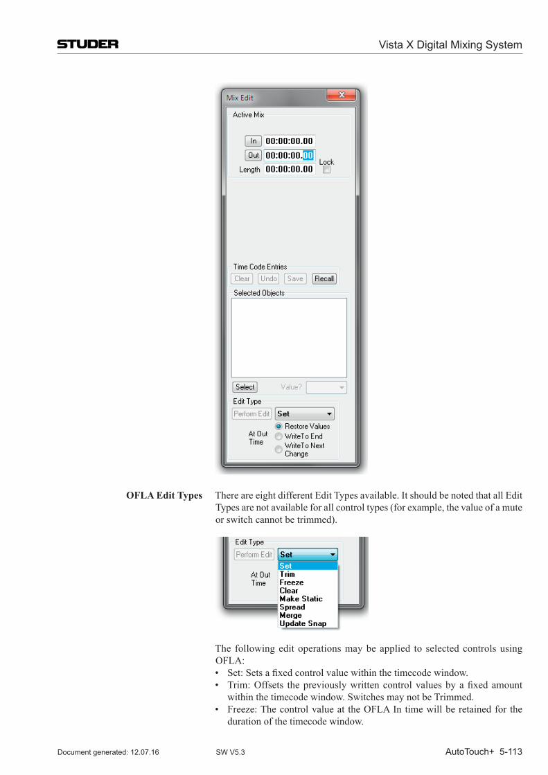
Vista X Digital Mixing System
AutoTouch+ 5-113Document generated: 12.07.16 SW V5.3
OFLA Edit Types There are eight different Edit Types available. It should be noted that all Edit Types are not available for all control types (for example, the value of a mute or switch cannot be trimmed).
The following edit operations may be applied to selected controls using OFLA:
• Set:Setsafixedcontrolvaluewithinthetimecodewindow. • Trim:Offsets thepreviouslywrittencontrolvaluesbyafixedamount
within the timecode window. Switches may not be Trimmed. • Freeze:Thecontrolvalueat theOFLAIntimewillberetainedfor the
duration of the timecode window.
Vista X Digital Mixing System
5-114 AutoTouch+ Document generated: 12.07.16SW V5.3
• Clear:Controlswillberesettotheirdefaultvalueswithinthetimecodewindow.
• MakeStatic:ControlswillbemadeStatic.Allautomationrecordsotherthan the Static value will be erased for the entire Mix Pass.
• Spread:Controlvaluesataspecificpointinasourcemix(ActiveorMixTree) may be applied throughout the timecode window.
• Merge:Controlvaluesatimecodewindowwithinasourcemix(ActiveorMix Tree) may be applied throughout the timecode window.
• UpdateSnap:UpdatestheMixSnapshot.ThisappliesthecurrentcontrolvaluesfromthebeginningoftheMixPasstothefirstrecordedrecord.
Each time an OFLA edit is performed, a new Mix Pass created.
Edit a Mix Pass with OFLA To edit a Mix Pass with OFLA, use the following procedure:1. Make the Mix Pass to be edited the Active Pass if it is not already.2. Select ‘Edit Mix Pass’ from the GC Automation menu. The basic Edit
Mix window will open.3. Click the ‘Select’ button to open the Object Picker for Edit Object Selec-
tor. Using this picker will allow the desired controls on selected channels to be chosen for editing. Once selected, click either the ‘Apply’ button (if more edits will be performed) or the ‘OK’ button (if no more objects need to be selected). The controls in the picker will be selected for editing and will appear in the Selected Objects section of the Edit Mix window.
4. Select the Edit Type from the ‘Edit Type’ pull-down menu. 5. Enter the new control value if necessary (depending on Edit Type).6. Enter the Spread Source Mix or Merge Mix if Spread or Merge edit types
are used. The Mix Passes in the current Mix Tree are available.7. Enter the timecode locations for edit In and Out points if necessary (de-
pending on Edit Type).8. Click on the appropriate radio button to select the ‘At Out Time’ function.
These functions mostly mirror the ‘Write To’ functions found in Auto-Touch+, but have some difference. See below.
9. Click ‘Perform Edit’ to perform the edit. A new Mix Pass is written that contains the edited values.
Note Automated Graphical Controller items are not selectable using the Object Picker for Edit Object Selector.
At Out Time Functions The select ‘At Out Time’ function will determine how the edit data transitions back to Read Mix data.
At Out Time selections function as follows: • RestoreValues:Thisistheequivalentto‘WriteTo:Punch-Out’.ReadMix
control values will be restored at the OFLA Out Time. Glide functions are not available.
• Write toEnd:This is theequivalent to ‘WriteTo:End’except theeditcontrolvalueswillbewrittentotheendoftheMixPass.Touseafixedend time select Restore Values as the At Out Time function. ‘Write To: End Of Time’ is not available.
• WritetoNextChange:Thisistheequivalentto‘WriteTo:NextChange’.Read Mix control values will be restored when the next record is encoun-tered. Glide functions are not available.
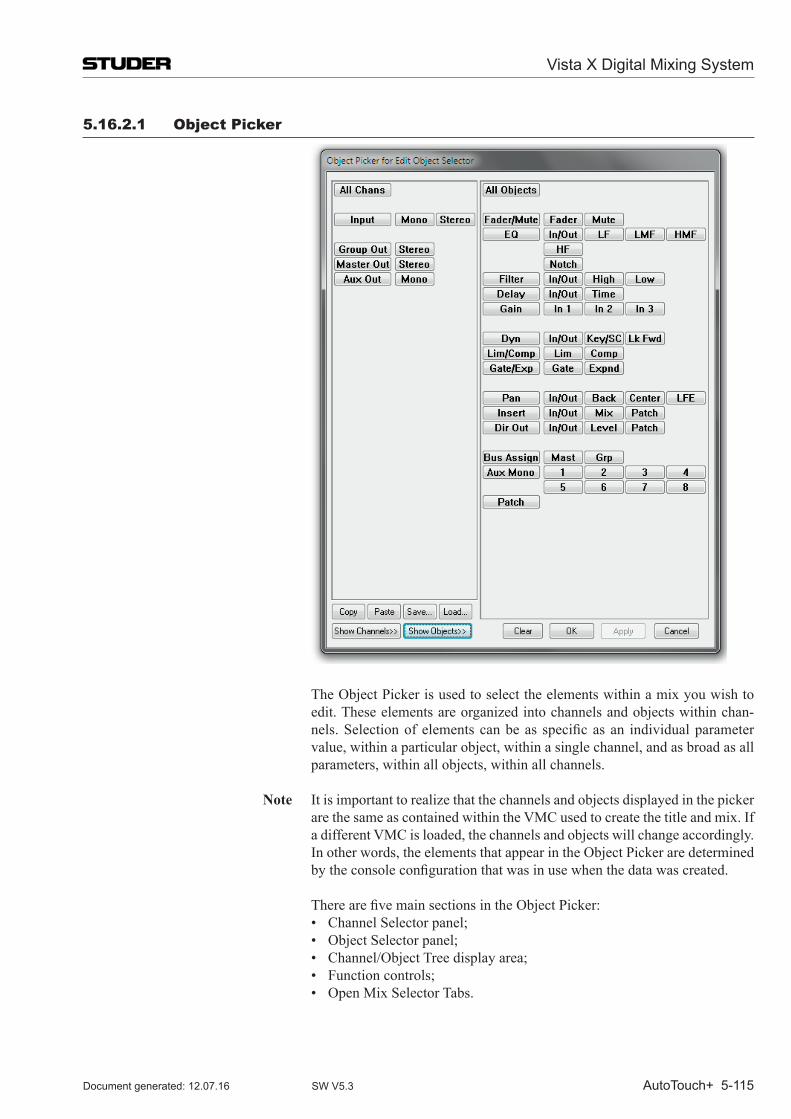
Vista X Digital Mixing System
AutoTouch+ 5-115Document generated: 12.07.16 SW V5.3
5.16.2.1 object Picker
The Object Picker is used to select the elements within a mix you wish to edit. These elements are organized into channels and objects within chan-nels.Selectionofelementscanbeas specificasan individualparametervalue, within a particular object, within a single channel, and as broad as all parameters, within all objects, within all channels.
Note It is important to realize that the channels and objects displayed in the picker are the same as contained within the VMC used to create the title and mix. If a different VMC is loaded, the channels and objects will change accordingly. In other words, the elements that appear in the Object Picker are determined bytheconsoleconfigurationthatwasinusewhenthedatawascreated.
TherearefivemainsectionsintheObjectPicker: • ChannelSelectorpanel; • ObjectSelectorpanel; • Channel/ObjectTreedisplayarea; • Functioncontrols; • OpenMixSelectorTabs.
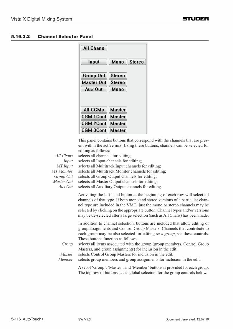
Vista X Digital Mixing System
5-116 AutoTouch+ Document generated: 12.07.16SW V5.3
5.16.2.2 Channel Selector Panel
This panel contains buttons that correspond with the channels that are pres-ent within the active mix. Using these buttons, channels can be selected for editing as follows:
All Chans selects all channels for editing; Input selects all Input channels for editing; MT Input selects all Multitrack Input channels for editing; MT Monitor selects all Multitrack Monitor channels for editing; Group Out selects all Group Output channels for editing; Master Out selects all Master Output channels for editing; Aux Out selects all Auxiliary Output channels for editing.
Activating the left-hand button at the beginning of each row will select all channels of that type. If both mono and stereo versions of a particular chan-nel type are included in the VMC, just the mono or stereo channels may be selected by clicking on the appropriate button. Channel types and/or versions may be de-selected after a large selection (such as All Chans) has been made.
In addition to channel selection, buttons are included that allow editing of group assignments and Control Group Masters. Channels that contribute to each group may be also selected for editing as a group, via these controls. These buttons function as follows:
Group selects all items associated with the group (group members, Control Group Masters, and group assignments) for inclusion in the edit;
Master selects Control Group Masters for inclusion in the edit; Member selects group members and group assignments for inclusion in the edit.
A set of ‘Group’, ‘Master’, and ‘Member’ buttons is provided for each group. The top row of buttons act as global selectors for the group controls below.
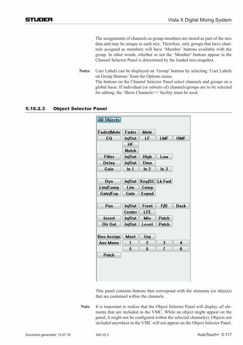
Vista X Digital Mixing System
AutoTouch+ 5-117Document generated: 12.07.16 SW V5.3
The assignments of channels as group members are stored as part of the mix data and may be unique to each mix. Therefore, only groups that have chan-nels assigned as members will have ‘Member’ buttons available with the group. In other words, whether or not the ‘Member’ buttons appear in the Channel Selector Panel is determined by the loaded mix/snapshot.
Notes User Labels can be displayed on ‘Group’ buttons by selecting ‘User Labels on Group Buttons’ from the Options menu.
The buttons on the Channel Selector Panel select channels and groups on a global basis. If individual (or subsets of) channels/groups are to be selected forediting,the‘ShowChannels>>’facilitymustbeused.
5.16.2.3 object Selector Panel
This panel contains buttons that correspond with the elements (or objects) that are contained within the channels.
Note It is important to realize that the Object Selector Panel will display all ele-ments that are included in the VMC. While an object might appear on the panel,itmightnotbeconfiguredwithintheselectedchannel(s).Objectsnotincluded anywhere in the VMC will not appear on the Object Selector Panel.
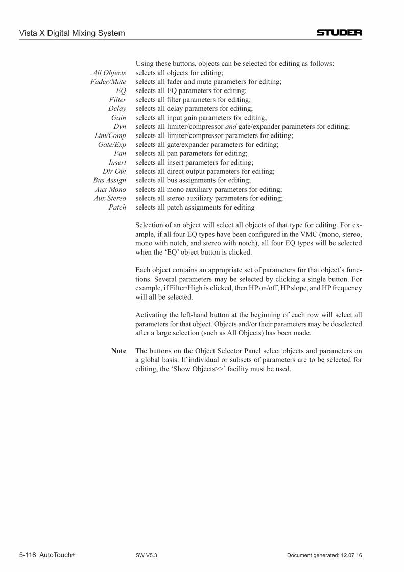
Vista X Digital Mixing System
5-118 AutoTouch+ Document generated: 12.07.16SW V5.3
Using these buttons, objects can be selected for editing as follows: All Objects selects all objects for editing; Fader/Mute selects all fader and mute parameters for editing; EQ selects all EQ parameters for editing; Filter selectsallfilterparametersforediting; Delay selects all delay parameters for editing; Gain selects all input gain parameters for editing; Dyn selects all limiter/compressor and gate/expander parameters for editing; Lim/Comp selects all limiter/compressor parameters for editing; Gate/Exp selects all gate/expander parameters for editing; Pan selects all pan parameters for editing; Insert selects all insert parameters for editing; Dir Out selects all direct output parameters for editing; Bus Assign selects all bus assignments for editing; Aux Mono selects all mono auxiliary parameters for editing; Aux Stereo selects all stereo auxiliary parameters for editing; Patch selects all patch assignments for editing
Selection of an object will select all objects of that type for editing. For ex-ample,ifallfourEQtypeshavebeenconfiguredintheVMC(mono,stereo,mono with notch, and stereo with notch), all four EQ types will be selected when the ‘EQ’ object button is clicked.
Each object contains an appropriate set of parameters for that object’s func-tions. Several parameters may be selected by clicking a single button. For example, if Filter/High is clicked, then HP on/off, HP slope, and HP frequency will all be selected.
Activating the left-hand button at the beginning of each row will select all parameters for that object. Objects and/or their parameters may be de selected after a large selection (such as All Objects) has been made.
Note The buttons on the Object Selector Panel select objects and parameters on a global basis. If individual or subsets of parameters are to be selected for editing,the‘ShowObjects>>’facilitymustbeused.
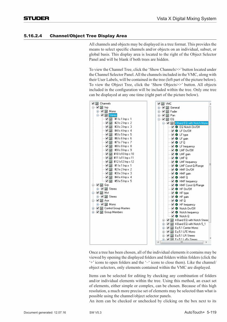
Vista X Digital Mixing System
AutoTouch+ 5-119Document generated: 12.07.16 SW V5.3
5.16.2.4 Channel/object Tree Display Area
All channels and objects may be displayed in a tree format. This provides the meanstoselectspecificchannelsand/orobjectsonanindividual,subset,orglobal basis. This display area is located to the right of the Object Selector Panel and will be blank if both trees are hidden.
ToviewtheChannelTree,clickthe‘ShowChannels>>’buttonlocatedunderthe Channel Selector Panel. All the channels included in the VMC, along with their User Labels, will be contained in the tree (left part of the picture below).
Toview theObjectTree,click the ‘ShowObjects>>’button.Allobjectsincludedintheconfigurationwillbeincludedwithinthetree.Onlyonetreecan be displayed at any one time (right part of the picture below).
Once a tree has been chosen, all of the individual elements it contains may be viewed by opening the displayed folders and folders within folders (click the ‘+’ icons to open folders and the ‘–‘ icons to close them). Like the channel/object selectors, only elements contained within the VMC are displayed.
Items can be selected for editing by checking any combination of folders and/or individual elements within the tree. Using this method, an exact set of elements, either simple or complex, can be chosen. Because of this high resolution, a much more precise set of elements may be selected than what is possible using the channel/object selector panels.
An item can be checked or unchecked by clicking on the box next to its
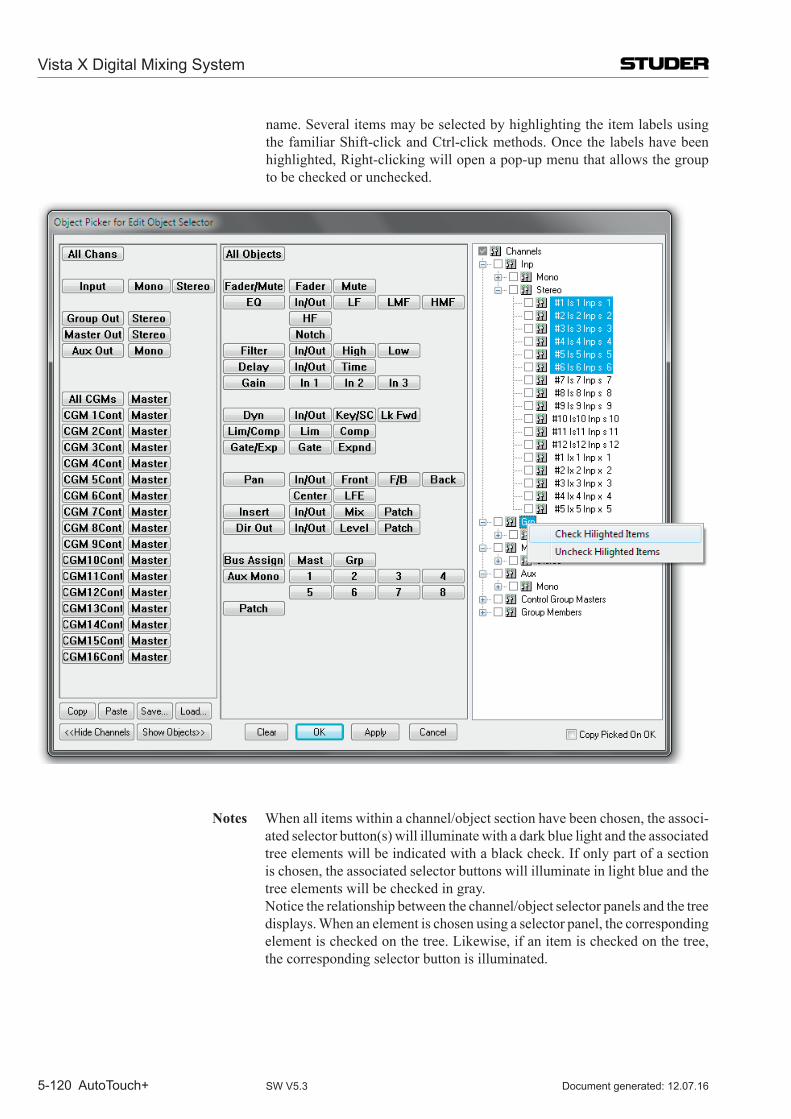
Vista X Digital Mixing System
5-120 AutoTouch+ Document generated: 12.07.16SW V5.3
name. Several items may be selected by highlighting the item labels using the familiar Shift-click and Ctrl-click methods. Once the labels have been highlighted, Right-clicking will open a pop-up menu that allows the group to be checked or unchecked.
Notes When all items within a channel/object section have been chosen, the associ-ated selector button(s) will illuminate with a dark blue light and the associated tree elements will be indicated with a black check. If only part of a section is chosen, the associated selector buttons will illuminate in light blue and the tree elements will be checked in gray.
Notice the relationship between the channel/object selector panels and the tree displays. When an element is chosen using a selector panel, the corresponding element is checked on the tree. Likewise, if an item is checked on the tree, the corresponding selector button is illuminated.
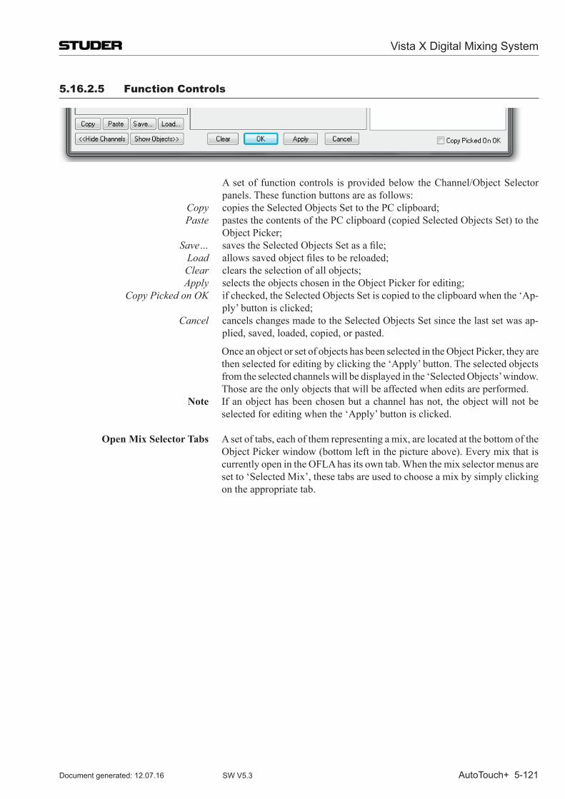
Vista X Digital Mixing System
AutoTouch+ 5-121Document generated: 12.07.16 SW V5.3
5.16.2.5 Function Controls
A set of function controls is provided below the Channel/Object Selector panels. These function buttons are as follows:
Copy copies the Selected Objects Set to the PC clipboard; Paste pastes the contents of the PC clipboard (copied Selected Objects Set) to the
Object Picker; Save… savestheSelectedObjectsSetasafile; Load allowssavedobjectfilestobereloaded; Clear clears the selection of all objects; Apply selects the objects chosen in the Object Picker for editing; Copy Picked on OK if checked, the Selected Objects Set is copied to the clipboard when the ‘Ap-
ply’ button is clicked; Cancel cancels changes made to the Selected Objects Set since the last set was ap-
plied, saved, loaded, copied, or pasted.
Once an object or set of objects has been selected in the Object Picker, they are then selected for editing by clicking the ‘Apply’ button. The selected objects from the selected channels will be displayed in the ‘Selected Objects’ window. Those are the only objects that will be affected when edits are performed.
Note If an object has been chosen but a channel has not, the object will not be selected for editing when the ‘Apply’ button is clicked.
Open Mix Selector Tabs A set of tabs, each of them representing a mix, are located at the bottom of the Object Picker window (bottom left in the picture above). Every mix that is currently open in the OFLA has its own tab. When the mix selector menus are set to ‘Selected Mix’, these tabs are used to choose a mix by simply clicking on the appropriate tab.
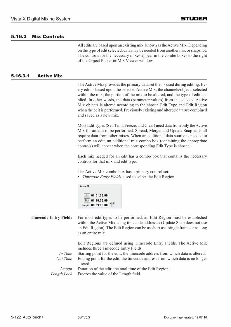
Vista X Digital Mixing System
5-122 AutoTouch+ Document generated: 12.07.16SW V5.3
5.16.3 mix Controls
All edits are based upon an existing mix, known as the Active Mix. Depending on the type of edit selected, data may be needed from another mix or snapshot. The controls for the necessary mixes appear in the combo boxes to the right of the Object Picker or Mix Viewer window.
5.16.3.1 Active mix
The Active Mix provides the primary data set that is used during editing. Ev-ery edit is based upon the selected Active Mix, the channels/objects selected within the mix, the portion of the mix to be altered, and the type of edit ap-plied. In other words, the data (parameter values) from the selected Active Mix objects is altered according to the chosen Edit Type and Edit Region when the edit is performed. Previously existing and altered data are combined and saved as a new mix.
Most Edit Types (Set, Trim, Freeze, and Clear) need data from only the Active Mix for an edit to be performed. Spread, Merge, and Update Snap edits all require data from other mixes. When an additional data source is needed to perform an edit, an additional mix combo box (containing the appropriate controls) will appear when the corresponding Edit Type is chosen.
Each mix needed for an edit has a combo box that contains the necessary controls for that mix and edit type.
The Active Mix combo box has a primary control set: • Timecode Entry Fields, used to select the Edit Region.
Timecode Entry Fields For most edit types to be performed, an Edit Region must be established within the Active Mix using timecode addresses (Update Snap does not use an Edit Region). The Edit Region can be as short as a single frame or as long as an entire mix.
EditRegionsaredefinedusingTimecodeEntryFields.TheActiveMixincludes three Timecode Entry Fields:
In Time Starting point for the edit; the timecode address from which data is altered; Out Time Ending point for the edit; the timecode address from which data is no longer
altered; Length Duration of the edit; the total time of the Edit Region; Length Lock FreezesthevalueoftheLengthfield.
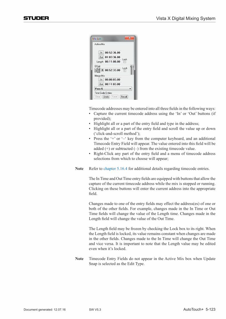
Vista X Digital Mixing System
AutoTouch+ 5-123Document generated: 12.07.16 SW V5.3
Timecodeaddressesmaybeenteredintoallthreefieldsinthefollowingways: • Capturethecurrenttimecodeaddressusingthe‘In’or‘Out’buttons(if
provided); • Highlightallorapartoftheentryfieldandtypeintheaddress; • Highlightallorapartoftheentryfieldandscrollthevalueupordown
(‘click-and-scroll method’); • Pressthe‘+’or‘–‘keyfromthecomputerkeyboard,andanadditional
TimecodeEntryFieldwillappear.Thevalueenteredintothisfieldwillbeadded (+) or subtracted (–) from the existing timecode value.
• Right-Clickanypartoftheentryfieldandamenuoftimecodeaddressselections from which to choose will appear;
Note Refer to chapter 5.16.4 for additional details regarding timecode entries. TheInTimeandOutTimeentryfieldsareequippedwithbuttonsthatallowthe
capture of the current timecode address while the mix is stopped or running. Clicking on these buttons will enter the current address into the appropriate field.
Changesmadetooneoftheentryfieldsmayeffecttheaddress(es)ofoneorbothoftheotherfields.Forexample,changesmadeintheInTimeorOutTimefieldswillchangethevalueoftheLengthtime.ChangesmadeintheLengthfieldwillchangethevalueoftheOutTime.
TheLengthfieldmaybefrozenbycheckingtheLockboxtoitsright.WhentheLengthfieldislocked,itsvalueremainsconstantwhenchangesaremadeintheotherfields.ChangesmadetotheInTimewillchangetheOutTimeand vice versa. It is important to note that the Length value may be edited even when it’s locked.
Note Timecode Entry Fields do not appear in the Active Mix box when Update Snap is selected as the Edit Type.
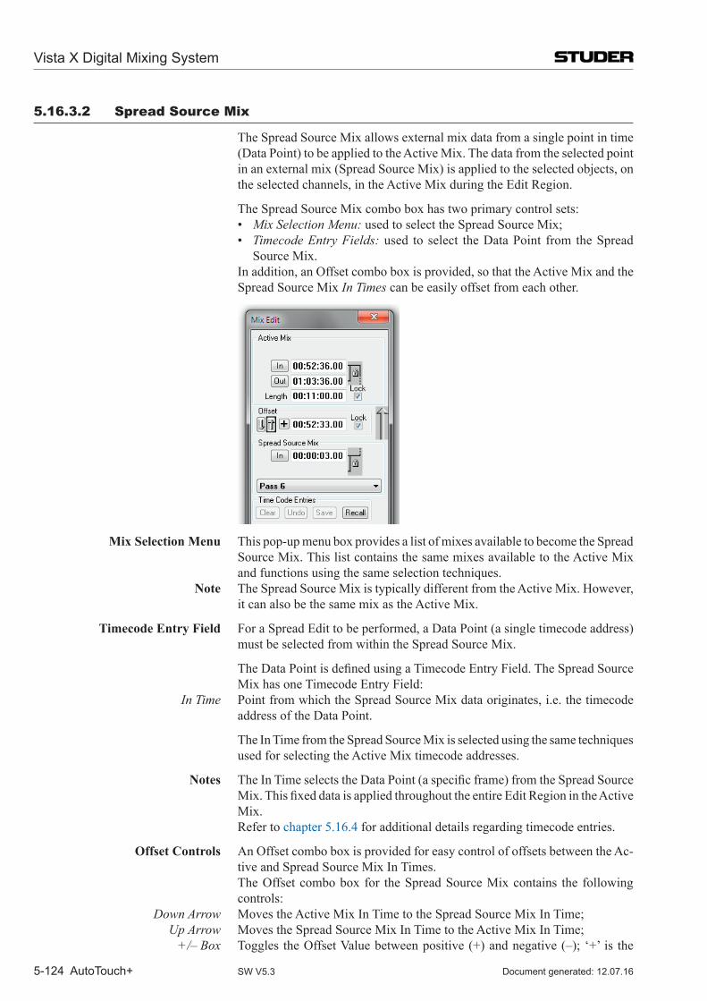
Vista X Digital Mixing System
5-124 AutoTouch+ Document generated: 12.07.16SW V5.3
5.16.3.2 Spread Source mix
The Spread Source Mix allows external mix data from a single point in time (Data Point) to be applied to the Active Mix. The data from the selected point in an external mix (Spread Source Mix) is applied to the selected objects, on the selected channels, in the Active Mix during the Edit Region.
The Spread Source Mix combo box has two primary control sets: • Mix Selection Menu: used to select the Spread Source Mix; • Timecode Entry Fields: used to select the Data Point from the Spread
Source Mix. In addition, an Offset combo box is provided, so that the Active Mix and the
Spread Source Mix In Times can be easily offset from each other.
Mix Selection Menu This pop-up menu box provides a list of mixes available to become the Spread
Source Mix. This list contains the same mixes available to the Active Mix and functions using the same selection techniques.
Note The Spread Source Mix is typically different from the Active Mix. However, it can also be the same mix as the Active Mix.
Timecode Entry Field For a Spread Edit to be performed, a Data Point (a single timecode address) must be selected from within the Spread Source Mix.
TheDataPointisdefinedusingaTimecodeEntryField.TheSpreadSourceMix has one Timecode Entry Field:
In Time Point from which the Spread Source Mix data originates, i.e. the timecode address of the Data Point.
The In Time from the Spread Source Mix is selected using the same techniques used for selecting the Active Mix timecode addresses.
Notes TheInTimeselectstheDataPoint(aspecificframe)fromtheSpreadSourceMix.ThisfixeddataisappliedthroughouttheentireEditRegionintheActiveMix.
Refer to chapter 5.16.4 for additional details regarding timecode entries.
Offset Controls An Offset combo box is provided for easy control of offsets between the Ac-tive and Spread Source Mix In Times.
The Offset combo box for the Spread Source Mix contains the following controls:
Down Arrow Moves the Active Mix In Time to the Spread Source Mix In Time; Up Arrow Moves the Spread Source Mix In Time to the Active Mix In Time; +/– Box Toggles the Offset Value between positive (+) and negative (–); ‘+’ is the
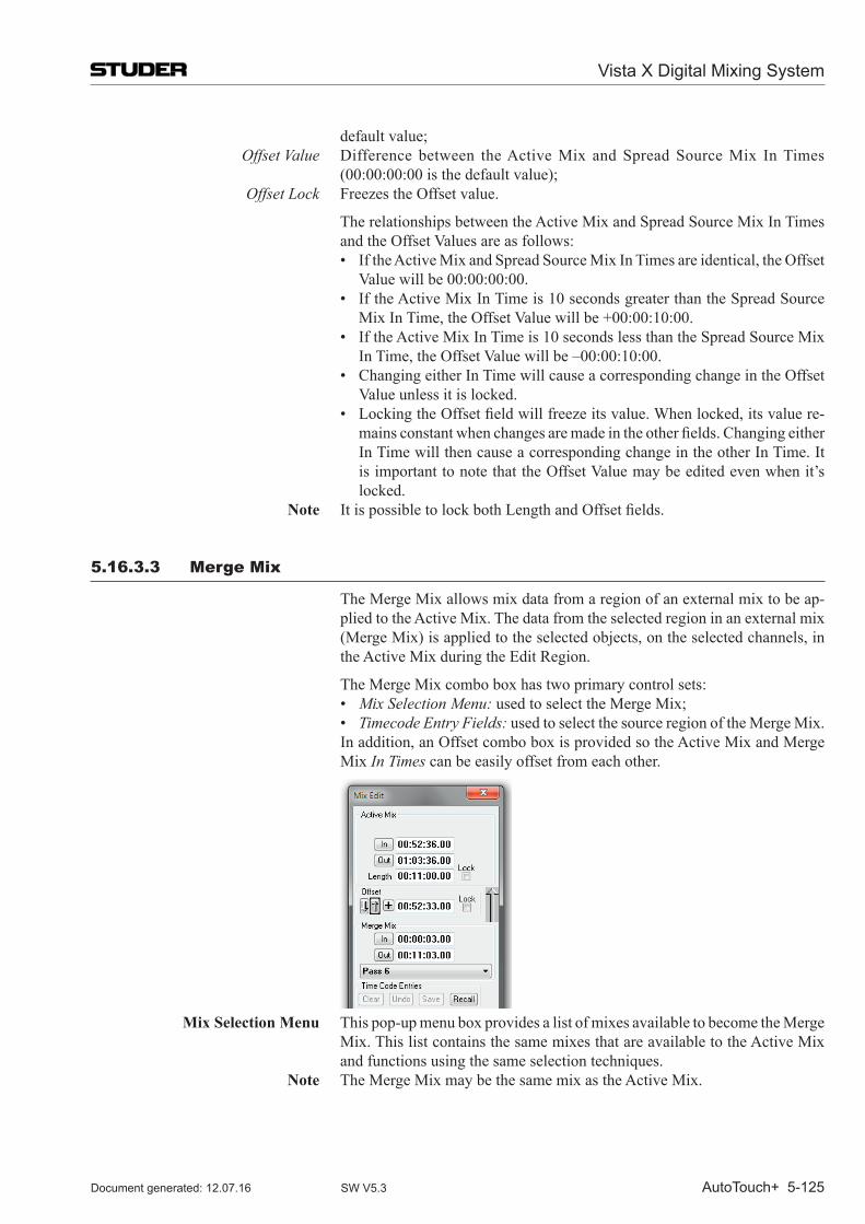
Vista X Digital Mixing System
AutoTouch+ 5-125Document generated: 12.07.16 SW V5.3
default value; Offset Value Difference between the Active Mix and Spread Source Mix In Times
(00:00:00:00 is the default value); Offset Lock Freezes the Offset value.
The relationships between the Active Mix and Spread Source Mix In Times and the Offset Values are as follows:
• IftheActiveMixandSpreadSourceMixInTimesareidentical,theOffsetValue will be 00:00:00:00.
• IftheActiveMixInTimeis10secondsgreaterthantheSpreadSourceMix In Time, the Offset Value will be +00:00:10:00.
• IftheActiveMixInTimeis10secondslessthantheSpreadSourceMixIn Time, the Offset Value will be –00:00:10:00.
• ChangingeitherInTimewillcauseacorrespondingchangeintheOffsetValue unless it is locked.
• LockingtheOffsetfieldwillfreezeitsvalue.Whenlocked,itsvaluere-mainsconstantwhenchangesaremadeintheotherfields.ChangingeitherIn Time will then cause a corresponding change in the other In Time. It is important to note that the Offset Value may be edited even when it’s locked.
Note ItispossibletolockbothLengthandOffsetfields.
5.16.3.3 merge mix
The Merge Mix allows mix data from a region of an external mix to be ap-plied to the Active Mix. The data from the selected region in an external mix (Merge Mix) is applied to the selected objects, on the selected channels, in the Active Mix during the Edit Region.
The Merge Mix combo box has two primary control sets: • Mix Selection Menu: used to select the Merge Mix; • Timecode Entry Fields: used to select the source region of the Merge Mix. In addition, an Offset combo box is provided so the Active Mix and Merge
Mix In Times can be easily offset from each other.
Mix Selection Menu This pop-up menu box provides a list of mixes available to become the Merge
Mix. This list contains the same mixes that are available to the Active Mix and functions using the same selection techniques.
Note The Merge Mix may be the same mix as the Active Mix.
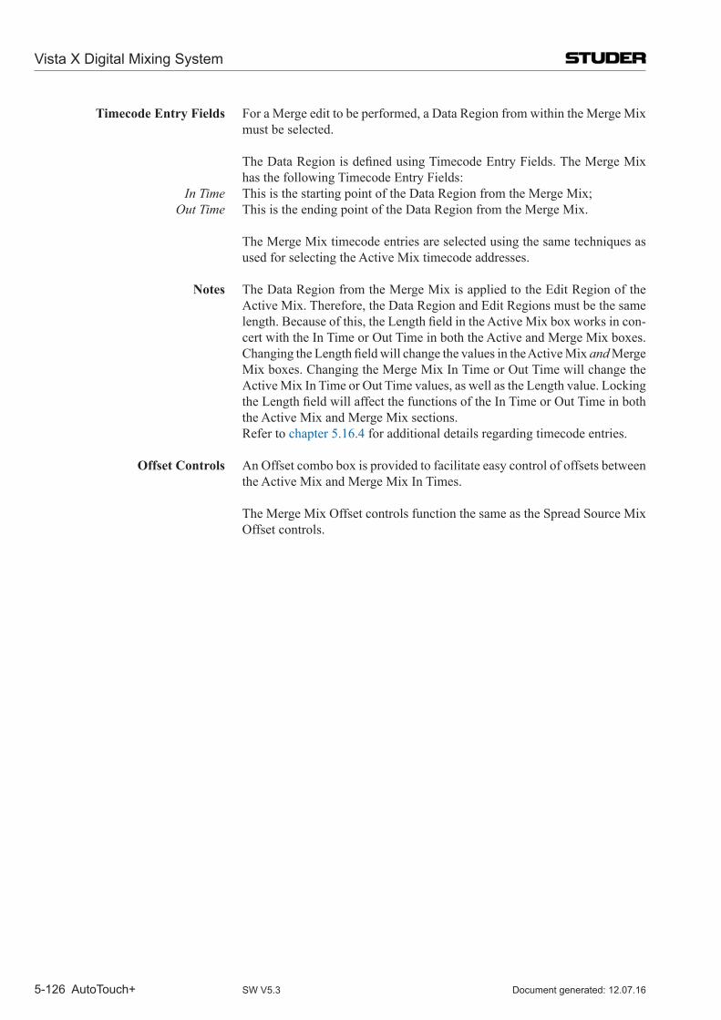
Vista X Digital Mixing System
5-126 AutoTouch+ Document generated: 12.07.16SW V5.3
Timecode Entry Fields For a Merge edit to be performed, a Data Region from within the Merge Mix must be selected.
TheDataRegionisdefinedusingTimecodeEntryFields.TheMergeMixhas the following Timecode Entry Fields:
In Time This is the starting point of the Data Region from the Merge Mix; Out Time This is the ending point of the Data Region from the Merge Mix.
The Merge Mix timecode entries are selected using the same techniques as used for selecting the Active Mix timecode addresses.
Notes The Data Region from the Merge Mix is applied to the Edit Region of the
Active Mix. Therefore, the Data Region and Edit Regions must be the same length.Becauseofthis,theLengthfieldintheActiveMixboxworksincon-cert with the In Time or Out Time in both the Active and Merge Mix boxes. ChangingtheLengthfieldwillchangethevaluesintheActiveMixand Merge Mix boxes. Changing the Merge Mix In Time or Out Time will change the Active Mix In Time or Out Time values, as well as the Length value. Locking theLengthfieldwillaffectthefunctionsoftheInTimeorOutTimeinboththe Active Mix and Merge Mix sections.
Refer to chapter 5.16.4 for additional details regarding timecode entries.
Offset Controls An Offset combo box is provided to facilitate easy control of offsets between the Active Mix and Merge Mix In Times.
The Merge Mix Offset controls function the same as the Spread Source Mix
Offset controls.
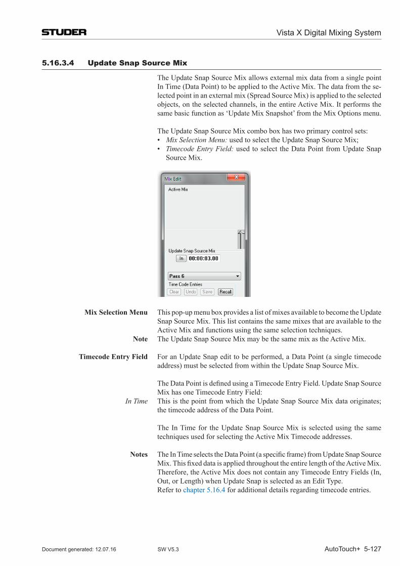
Vista X Digital Mixing System
AutoTouch+ 5-127Document generated: 12.07.16 SW V5.3
5.16.3.4 update Snap Source mix
The Update Snap Source Mix allows external mix data from a single point In Time (Data Point) to be applied to the Active Mix. The data from the se-lected point in an external mix (Spread Source Mix) is applied to the selected objects, on the selected channels, in the entire Active Mix. It performs the same basic function as ‘Update Mix Snapshot’ from the Mix Options menu.
The Update Snap Source Mix combo box has two primary control sets: • Mix Selection Menu: used to select the Update Snap Source Mix; • Timecode Entry Field: used to select the Data Point from Update Snap
Source Mix.
Mix Selection Menu This pop-up menu box provides a list of mixes available to become the Update Snap Source Mix. This list contains the same mixes that are available to the Active Mix and functions using the same selection techniques.
Note The Update Snap Source Mix may be the same mix as the Active Mix.
Timecode Entry Field For an Update Snap edit to be performed, a Data Point (a single timecode address) must be selected from within the Update Snap Source Mix.
TheDataPointisdefinedusingaTimecodeEntryField.UpdateSnapSourceMix has one Timecode Entry Field:
In Time This is the point from which the Update Snap Source Mix data originates; the timecode address of the Data Point.
The In Time for the Update Snap Source Mix is selected using the same techniques used for selecting the Active Mix Timecode addresses.
Notes TheInTimeselectstheDataPoint(aspecificframe)fromUpdateSnapSource
Mix.ThisfixeddataisappliedthroughouttheentirelengthoftheActiveMix.Therefore, the Active Mix does not contain any Timecode Entry Fields (In, Out, or Length) when Update Snap is selected as an Edit Type.
Refer to chapter 5.16.4 for additional details regarding timecode entries.
Vista X Digital Mixing System
5-128 AutoTouch+ Document generated: 12.07.16SW V5.3
5.16.4 Timecode Controls
5.16.4.1 General information
All timecode values are expressed as positive numbers and are limited by the number of timecode addresses available. Times cannot be less than 00:00:00:00orgreaterthan23:59:59:29(in30non-drop).OnlyOffsetfieldscan have both positive and negative time values.
TimecodeEntryFieldsareinteractive.Changesmadetoanentryfieldmayeffectotherfields’values.Forexample,changesmadetotheInTimeorOutTimefieldsintheActiveor Merge Mix boxes will change the value of the Lengthtime.ChangesmadeintheLengthfieldwillchangethevalueoftheOut Time of both the Active and Merge Mixes. Changes made to the Offset fieldmayeffectInTimes,andsoon.
It is possible for the In Time and Out Time to be equal in value. When using the click/drag method of timecode entry, it is possible to scroll the Out Time downward until it matches the In Time. In that event, the Length time will be 00:00:00:00. Additional reduction of the Out Time value will also reduce the In Time value. Returning the Out Time to its original value will increase the In Time until it matches its original value.
The current system timecode is displayed in the upper right-hand corner of the OFLA screen when the Mix Viewer is enabled.
5.16.4.2 Editing Timecode Entries
Timecode Entry Fields AvarietyofTimecodeEntryFieldsareprovidedforthedefinitionandcontrolof Edit Regions, Data Regions, Data Points, and Offsets.
Timecode Entry Fields function as follows: In Time The starting point for an Edit Region (Active Mix), the starting point for a
Data Region (Merge Mix), or the timecode address for a Data Point (Spread Source Mix or Update Snap Source Mix);
Out Time The ending point for an Edit Region (Active Mix) or a Data Region (Merge Mix);
Length The duration of the edit; the total time of the Edit Region; Offset The difference between In Times of the Active Mix and Spread Source or
Merge Mixes.
The‘InTime’and‘OutTime’entryfieldsareequippedwithbuttonsthatallowthe capture of the current timecode address while the mix is stopped or run-ning. Clicking on these buttons (‘In’ or ‘Out’) will enter the current address intotheappropriatefield.
Timecodeaddressesmaybeenteredintoanyfieldusingthefollowingmeth-ods:
Timecode Capture Capture the current timecode address by clicking the ‘In’ or ‘Out’ buttons (if provided); at the point the ‘In’ or ‘Out’ button is clicked, the current timecode addressisenteredintothecorrespondingfield;Timecodeaddressescanbecaptured when the mix is running or stopped.
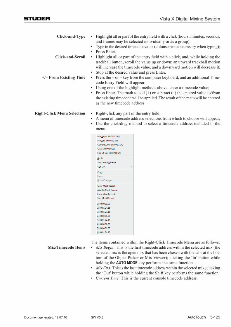
Vista X Digital Mixing System
AutoTouch+ 5-129Document generated: 12.07.16 SW V5.3
Click-and-Type • Highlightallorpartoftheentryfieldwithaclick(hours,minutes,seconds,and frames may be selected individually or as a group);
• Typeinthedesiredtimecodevalue(colonsarenotnecessarywhentyping); • PressEnter. Click-and-Scroll • Highlightallorpartoftheentryfieldwithaclick,and,whileholdingthe
trackball button, scroll the value up or down; an upward trackball motion will increase the timecode value, and a downward motion will decrease it;
• StopatthedesiredvalueandpressEnter. +/– From Existing Time • Pressthe+or–keyfromthecomputerkeyboard,andanadditionalTime-
code Entry Field will appear; • Usingoneofthehighlightmethodsabove,enteratimecodevalue; • PressEnter.Themathtoadd(+)orsubtract(–)theenteredvalueto/from
the existing timecode will be applied. The result of the math will be entered as the new timecode address.
Right-Click Menu Selection • Right-clickanypartoftheentryfield; • Amenuoftimecodeaddressselectionsfromwhichtochoosewillappear; • Usetheclick/dragmethodtoselecta timecodeaddressincludedinthe
menu.
The items contained within the Right-Click Timecode Menu are as follows: Mix/Timecode Items • Mix Begin:Thisisthefirsttimecodeaddresswithintheselectedmix(the
selected mix is the open mix that has been chosen with the tabs at the bot-tom of the Object Picker or Mix Viewer); clicking the ‘In’ button while holding the AUTO MODE key performs the same function.
• Mix End: This is the last timecode address within the selected mix; clicking the ‘Out’ button while holding the Shift key performs the same function.
• Current Time: This is the current console timecode address.
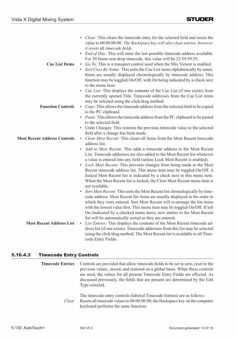
Vista X Digital Mixing System
5-130 AutoTouch+ Document generated: 12.07.16SW V5.3
• Clear:Thisclearsthetimecodeentryfortheselectedfieldandresetsthevalue to 00:00:00:00. The Backspace key will also clear entries, however, it resets all timecode fields.
• End of Day: This will enter the last possible timecode address available. For 30 frame non-drop timecode, this value will be 23:59:59:29.
Cue List Items • Go To: This is a transport control used when the Mix Viewer is enabled. • Sort Cues By Name: This sorts the Cue List items alphabetically by name.
Items are usually displayed chronologically by timecode address. This function may be toggled On/Off, with On being indicated by a check next to the menu item.
• Cue List: This displays the contents of the Cue List (if one exists) from the currently opened Title. Timecode addresses from the Cue List items may be selected using the click/drag method.
Function Controls • Copy:Thisallowsthetimecodeaddressfromtheselectedfieldtobecopiedto the PC clipboard.
• Paste: This allows the timecode address from the PC clipboard to be pasted totheselectedfield.
• UndoChanges:Thisrestorestheprevioustimecodevaluetotheselectedfieldafterachangehasbeenmade.
Most Recent Address Controls • Clear Most Recent: This clears all items from the Most Recent timecode address list.
• Add to Most Recent: This adds a timecode address to the Most Recent List. Timecode addresses are also added to the Most Recent list whenever avalueisenteredintoanyfield(unlessLockMostRecentisenabled).
• Lock Most Recent: This prevents changes from being made to the Most Recent timecode address list. This menu item may be toggled On/Off. A locked Most Recent list is indicated by a check next to this menu item. When the Most Recent list is locked, the Clear Most Recent menu item is not available.
• Sort Most Recent: This sorts the Most Recent list chronologically by time-code address. Most Recent list items are usually displayed in the order in which they were entered. Sort Most Recent will re-arrange the list items withthelowestvaluefirst.ThismenuitemmaybetoggledOn/Off.IfleftOn (indicated by a checked menu item), new entries to the Most Recent list will be automatically sorted as they are entered.
Most Recent Address List • List Entries: This displays the contents of the Most Recent timecode ad-dress list (if one exists). Timecode addresses from this list may be selected using the click/drag method. The Most Recent list is available to all Time-code Entry Fields.
5.16.4.3 Timecode Entry Controls
Timecode Entries Controlsareprovidedthatallowtimecodefieldstobesettozero,resettotheprevious values, stored, and restored on a global basis. When these controls are used, the values for all present Timecode Entry Fields are effected. As discussedpreviously,thefieldsthatarepresentaredeterminedbytheEditType selected.
The timecode entry controls (labeled Timecode Entries) are as follows: Clear Resets all timecode values to 00:00:00:00; the Backspace key on the computer
keyboard performs the same function;
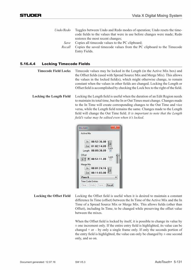
Vista X Digital Mixing System
AutoTouch+ 5-131Document generated: 12.07.16 SW V5.3
Undo/Redo Toggles between Undo and Redo modes of operation; Undo resets the time-codefieldstothevaluesthatwereinusebeforechangesweremade;Redorestores the most recent changes;
Save Copies all timecode values to the PC clipboard; Recall Copies the saved timecode values from the PC clipboard to the Timecode
Entry Fields.
5.16.4.4 Locking Timecode Fields
Timecode Field Locks Timecode values may be locked in the Length (in the Active Mix box) and theOffsetfields(usedwithSpreadSourceMixandMergeMix).Thisallowsthevaluesinthelockedfield(s),whichmightotherwisechange,toremainconstantwhenthevaluesinotherfieldsarechanged.LockingtheLengthorOffsetfieldisaccomplishedbycheckingtheLockboxtotherightofthefield.
Locking the Length Field LockingtheLengthfieldisusefulwhenthedurationofanEditRegionneedsto maintain its total time, but the In or Out Times must change. Changes made to the In Time will create corresponding changes to the Out Time and vice versa,whiletheLengthfieldremainsthesame.ChangesmadetotheLengthfieldwillchangetheOutTimefield.It is important to note that the Length field’s value may be edited even when it’s locked.
Locking the Offset Field LockingtheOffsetfieldisusefulwhenitisdesiredtomaintainaconstantdifference In Time (offset) between the In Time of the Active Mix and the In TimeofaSpreadSourceMixorMergeMix.Thisallowsfields(otherthanOffset), including In Time, to be changed while preserving the offset value between the mixes.
WhentheOffsetfieldislockedbyitself,itispossibletochangeitsvalueby±oneincrementonly.Iftheentireentryfieldishighlighted,itsvaluecanbechanged + or – by only a single frame only. If only the seconds portion of theentryfieldishighlighted,thevaluecanonlybechangedby±onesecondonly, and so on.
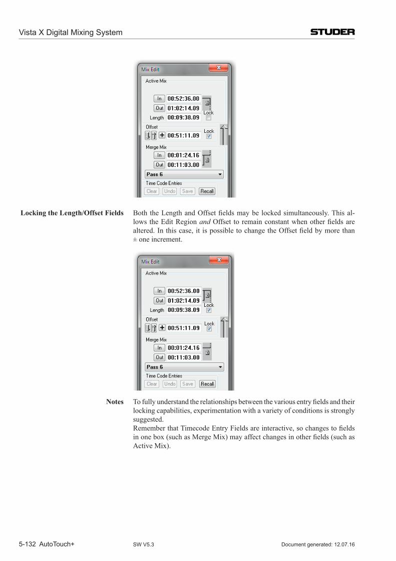
Vista X Digital Mixing System
5-132 AutoTouch+ Document generated: 12.07.16SW V5.3
Locking the Length/Offset Fields Both theLengthandOffsetfieldsmaybe lockedsimultaneously.Thisal-lows the Edit Region andOffset toremainconstantwhenotherfieldsarealtered.Inthiscase,it ispossibletochangetheOffsetfieldbymorethan ± one increment.
Notes Tofullyunderstandtherelationshipsbetweenthevariousentryfieldsandtheirlocking capabilities, experimentation with a variety of conditions is strongly suggested.
RememberthatTimecodeEntryFieldsareinteractive,sochangestofieldsinonebox(suchasMergeMix)mayaffectchangesinotherfields(suchasActive Mix).
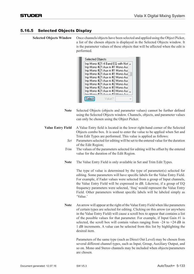
Vista X Digital Mixing System
AutoTouch+ 5-133Document generated: 12.07.16 SW V5.3
5.16.5 Selected objects Display
Selected Objects Window Once channels/objects have been selected and applied using the Object Picker, a list of the chosen objects is displayed in the Selected Objects window. It is the parameter values of these objects that will be affected when the edit is performed.
Note Selected Objects (objectsandparametervalues)cannotbefurtherdefinedusing the Selected Objects window. Channels, objects, and parameter values can only be chosen using the Object Picker.
Value Entry Field AValueEntryfieldislocatedinthelowerright-handcorneroftheSelectedObjects combo box. It is used to enter the value to be applied when Set and Trim Edit Types are performed. This value is applied as follows:
Set Parameters selected for editing will be set to the entered value for the duration of the Edit Region;
Trim The values of the parameters selected for editing will be offset by the entered value for the duration of the Edit Region.
Note The Value Entry Field is only available in Set and Trim Edit Types.
The type of value is determined by the type of parameter(s) selected for editing.SomeparameterswillhavespecificlabelsfortheValueEntryField.For example, if Fader values were selected from a group of Input channels, the Value Entry Field will be expressed in dB. Likewise, if a group of EQ frequency parameters were selected, ‘freq’ would represent the Value Entry Field.Otherparameterswithout specific labelswillbe labeledsimplyas‘Value.’
Note An arrow will appear at the right of the Value Entry Field when like parameters of certain types are selected for editing. Clicking on this arrow (or anywhere in the Value Entry Field) will cause a scroll box to appear that contains a list of the possible values for that parameter. For example, if Input Gain #1 is selected, the scroll box will contain values ranging from –24 to +24 dB in 1 dB increments. A value can be selected from this list by highlighting the desired item.
Parameters of the same type (such as Direct Out Level) may be chosen from several different channel types, such as Input, Group, Auxiliary Output, and so on. Mono and Stereo channels may be included when objects/parameters are chosen.
Vista X Digital Mixing System
5-134 AutoTouch+ Document generated: 12.07.16SW V5.3
Parameters of similar type may be selected from similar types of objects. For example, ON/OFF parameters may be selected from Filters, EQ, Dynamics, Delay, and other objects that contain ON/OFF switches. However, parameters that are dissimilar may not be chosen for Set and Trim Edit Types.
Note When incompatible parameters are selected (such as Fader level and Mute), Set and Trim Edit Types are not functional and values cannot be entered. This is indicated by a ‘Grayed Out’ Value Entry Field.
5.16.6 Edit Types
General Information In order to provide power and versatility, OFLA offers seven distinct Edit Types.Eachprovidesaneditfunctiondesignedtoperformaspecifictask.
Edit Types can be chosen by clicking the arrow at the end of the display. A list of Edit Types will be displayed. Clicking one of the Edit Types will select it for use. Edit Types can also be selected using click-drag method in the Edit Type window.
Edit Types are as follows: Set Parameters selected for editing will be set to the entered value for the duration
of the Edit Region; Trim Data for the parameters selected for editing will be offset by the entered value
for the duration of the Edit Region; Freeze Data for the parameters selected for editing will be frozen at the In Time for
the duration of the Edit Region; Clear Data from the VMC Defaults will be applied to the parameters selected for
editing for the duration of the Edit Region; Spread Data from a single point in an external mix will be applied to the parameters
selected for editing for the duration of the Edit Region; Merge Data from a region of an external mix will be applied to the parameters se-
lected for editing for the duration of the Edit Region; Update Snap Data from a single point in an external mix will be applied to the parameters
selected for editing for the entire mix. This is a function corresponding to ‘Update Mix Snapshot’ in the System Mix Options menu.
At Out Time Controls are provided that determine what happens to the data (for the pa-rameters selected for editing) that exists after the Edit Region. These radio buttons are contained in the ‘At Out Time’ section of the Edit Type combo box. Only one of these options may be selected.
The functions of these controls are as follows: Restore Values The data from the Active Mix that exists after the Edit Region is retained. Write To End The data from the last frame of the Edit Region is written to the end of the
mix. Write To Next Change The data from the last frame of the Edit Region is written for each selected
parameter until there is an original value change for that parameter in the Active Mix.
Vista X Digital Mixing System
AutoTouch+ 5-135Document generated: 12.07.16 SW V5.3
5.16.7 offline Editing Tutorial
Select Objects 1. Click the ‘SELECT’ button on the AutoTouch+ page in the GC. 2. Using the Object Picker, click the channel buttons to choose groups of
channels for editing. 3. Using the Object Picker, click the object buttons to choose groups of objects
for editing. 4. Click ‘Apply’ to select objects for editing. OR 1. Clickthe‘ShowChannels>>’button. 2. Check items in the Channel Tree to choose individual or groups of chan-
nels for editing. 3. Clickthe‘ShowObjects>>’button. 4. Check items in the Object Tree to choose individual or groups of objects
for editing. 5. Click ‘Apply’ to select objects for editing.
Set an Edit Region 1. Click the ‘In’ button in the Active Mix box or enter a timecode address manually.
2. Click the ‘Out’ button in the Active Mix box or enter a timecode address manually.
3. Further manipulate the Edit Region as necessary.
Select an Edit Type 1. Using the Edit Type Menu, select the desired edit function. 2. Enter Set or Trim values if using those functions. 3. Enter the necessary timecode values as required by the selected Edit Type. 4. Click on the desired ‘At Out Time’ option.
Perform Edit 1. Click ‘Perform Edit’ to complete the process. 2. Repeat as needed.
After Editing In the mix pass tree, a new Mix Pass will be created after each ‘Perform Edit’ function.
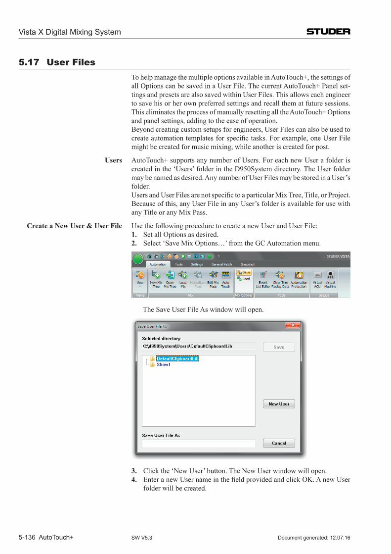
Vista X Digital Mixing System
5-136 AutoTouch+ Document generated: 12.07.16SW V5.3
5.17 user Files To help manage the multiple options available in Auto Touch+, the settings of
all Options can be saved in a User File. The current Auto Touch+ Panel set-tings and presets are also saved within User Files. This allows each engineer to save his or her own preferred settings and recall them at future sessions. This eliminates the process of manually resetting all the Auto Touch+ Options and panel settings, adding to the ease of operation.
Beyond creating custom setups for engineers, User Files can also be used to createautomationtemplatesforspecifictasks.Forexample,oneUserFilemight be created for music mixing, while another is created for post.
Users Auto Touch+ supports any number of Users. For each new User a folder is created in the ‘Users’ folder in the D950System directory. The User folder may be named as desired. Any number of User Files may be stored in a User’s folder.
UsersandUserFilesarenotspecifictoaparticularMixTree,Title,orProject.Because of this, any User File in any User’s folder is available for use with any Title or any Mix Pass.
Create a New User & User File Use the following procedure to create a new User and User File:1. Set all Options as desired.2. Select ‘Save Mix Options…’ from the GC Automation menu.
The Save User File As window will open.
3. Click the ‘New User’ button. The New User window will open. 4. EnteranewUsernameinthefieldprovidedandclickOK.AnewUser
folder will be created.
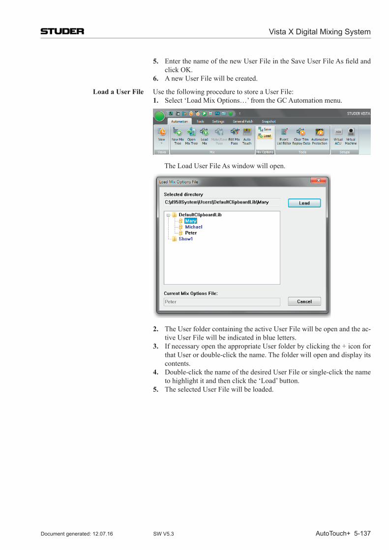
Vista X Digital Mixing System
AutoTouch+ 5-137Document generated: 12.07.16 SW V5.3
5. EnterthenameofthenewUserFileintheSaveUserFileAsfieldandclick OK.
6. A new User File will be created.
Load a User File Use the following procedure to store a User File:1. Select ‘Load Mix Options…’ from the GC Automation menu.
The Load User File As window will open.
2. The User folder containing the active User File will be open and the ac-tive User File will be indicated in blue letters.
3. If necessary open the appropriate User folder by clicking the + icon for that User or double-click the name. The folder will open and display its contents.
4. Double-click the name of the desired User File or single-click the name to highlight it and then click the ‘Load’ button.
5. The selected User File will be loaded.
Vista X Digital Mixing System
5-138 AutoTouch+ Document generated: 12.07.16SW V5.3
Update a User File Use the following procedure to update an existing User File:1. Make changes to Options as desired.2. Select ‘Save Mix Options…’ from the GC Automation menu. The Save
User File As window will open.3. Either double-click the active User File (in blue letters) or enter the same
UsernameinthefieldprovidedandclickOK.Adialogboxwillindicateafilewiththesamenamealreadyexistsandwillaskifyouwishtoreplaceit.
4. Click YES and the chosen User File will be updated.
Delete a User or User File Users and User Files may be deleted by removing them from the Users folder in the D950System directory.
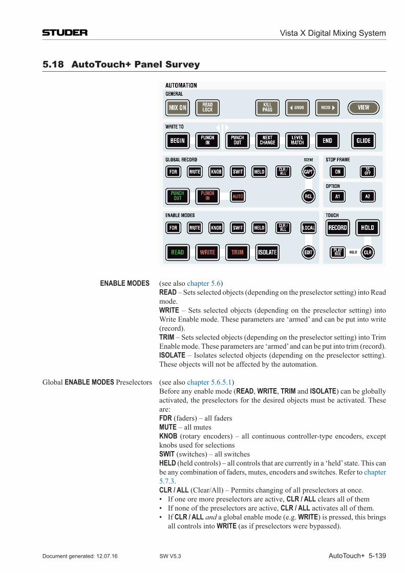
Vista X Digital Mixing System
AutoTouch+ 5-139Document generated: 12.07.16 SW V5.3
5.18 AutoTouch+ Panel Survey
ENABLE MODES (see also chapter 5.6) READ – Sets selected objects (depending on the preselector setting) into Read
mode. WRITE – Sets selected objects (depending on the preselector setting) into
Write Enable mode. These parameters are ‘armed’ and can be put into write (record).
TRIM – Sets selected objects (depending on the preselector setting) into Trim Enable mode. These parameters are ‘armed’ and can be put into trim (record).
ISOLATE – Isolates selected objects (depending on the preselector setting). These objects will not be affected by the automation.
Global ENABLE MODES Preselectors (see also chapter 5.6.5.1) Before any enable mode (READ, WRITE, TRIM and ISOLATE) can be globally
activated, the preselectors for the desired objects must be activated. These are:
FDR (faders) – all faders MUTE – all mutes KNOB (rotary encoders) – all continuous controller-type encoders, except
knobs used for selections SWIT (switches) – all switches HELD (held controls) – all controls that are currently in a ‘held’ state. This can
be any combination of faders, mutes, encoders and switches. Refer to chapter 5.7.3.
CLR / ALL (Clear/All) – Permits changing of all preselectors at once. • Ifoneoremorepreselectorsareactive,CLR / ALL clears all of them • Ifnoneofthepreselectorsareactive,CLR / ALL activates all of them. • IfCLR / ALL and a global enable mode (e.g. WRITE) is pressed, this brings
all controls into WRITE (as if preselectors were bypassed).
Vista X Digital Mixing System
5-140 AutoTouch+ Document generated: 12.07.16SW V5.3
TOUCH / HELD (see also chapters 5.7.1 through 5.7.4) TOUCH RECORD – If activated, touching a write or trim enabled control ele-
ment (e.g. fader) will put it into record. TOUCH HOLD – If activated, touching and releasing a control element (e.g.
fader) will simulate a touch and hold the object even if the control has been released.
HELD PLAY MIX – When this key is engaged (see also chapter 5.7.5.1), all held controls play back their Read Mix data if not in RECORD, but the controls can be set to different physical positions.
The Read Mix data is heard, even though one or more controls are being held. This allows a held control to be pre-positioned while awaiting a punch-in. The result is true emulation of the resulting mix while the Mix Pass is running.
HELD CLR – Pressing this key will take all held controls out of hold. It will also clear the list of controls in the held controls buffer.
GLOBAL RECORD (see also chapter 5.8) PUNCH-IN – Write or Trim enabled controls are put into record (depending
on the GLOBAL RECORD preselector setting). PUNCH-OUT – Control elements currently in record are punched out (depend-
ing on the GLOBAL RECORD preselector setting).
GLOBAL RECORD Preselectors (see also chapter 5.8.1) Before globally any control can be punched in or out (Record, Play), the
preselectors for the desired objects must be activated. These are: FDR (faders) – all faders MUTE – all mutes KNOB (rotary encoders) – all continuous controller-type encoders, except
knobs used for selections SWIT (switches) – all switches HELD (held controls) – all controls that are currently in a ‘held’ state. This can
be any combination of faders, mutes, encoders and switches. Refer to chapter 5.7.3.
CLR / ALL (Clear/All) – Permits changing of all preselectors at once. • Ifoneoremorepreselectorsareactive,CLR / ALL clears all of them • Ifnoneofthepreselectorsareactive,CLR / ALL activates all of them. • IfCLR / ALL and a global record command (PUNCH-IN or PUNCH-OUT) is
pressed, this will affect all controls (as if preselectors were bypassed).
(Mix Pass) WRITE TO (see also chapter 5.9.1) PUNCH-OUT – The automation system stays in record until Punch-out is per-
formed. LEVEL MATCH, NEXT CHANGE, END will write the value at the time of punch-
out further ahead, rather than immediately stop recording. The neutral default setting is PUNCH-OUT. This will record no more after punch-out.
NEXT CHANGE – The last recorded data will be applied until the next recorded change in the Read Mix data. At that point the automation will transition from record data to read mix data.
LEVEL MATCH – The last recorded value will be written until it matches the read mix data.
END – TheLastRecordedValuewillbeapplieduntiltheuser-specifiedEndTime. All previously recorded values between the Last Recorded Value (typi-cally Punch-out) and the End Time will be erased.
PUNCH-IN – Extend the Last Recorded Value back to the punch-in location. BEGIN – ExtendtheLastRecordedValuebacktothespecifiedBeginTime.
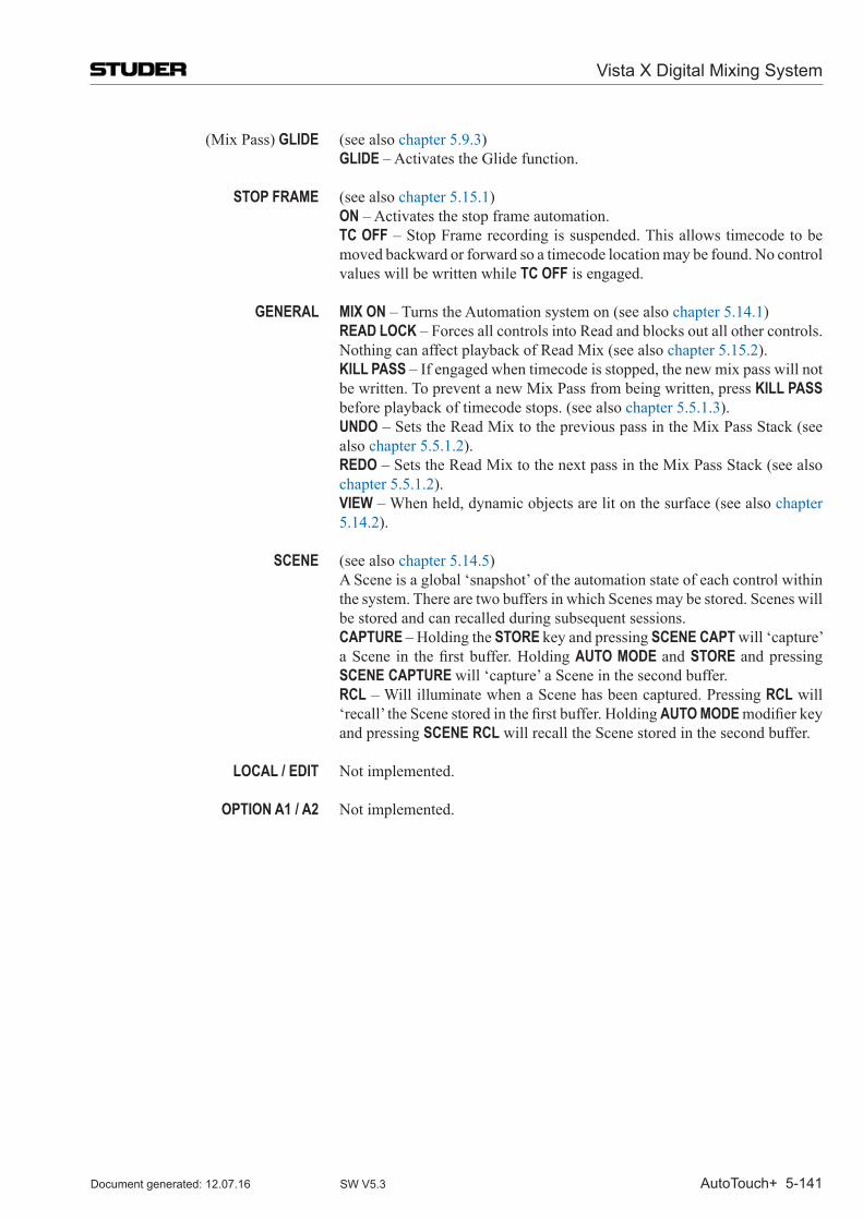
Vista X Digital Mixing System
AutoTouch+ 5-141Document generated: 12.07.16 SW V5.3
(Mix Pass) GLIDE (see also chapter 5.9.3) GLIDE – Activates the Glide function.
STOP FRAME (see also chapter 5.15.1) ON – Activates the stop frame automation. TC OFF – Stop Frame recording is suspended. This allows timecode to be
moved backward or forward so a timecode location may be found. No control values will be written while TC OFF is engaged.
GENERAL MIX ON – Turns the Automation system on (see also chapter 5.14.1) READ LOCK – Forces all controls into Read and blocks out all other controls.
Nothing can affect playback of Read Mix (see also chapter 5.15.2). KILL PASS – If engaged when timecode is stopped, the new mix pass will not
be written. To prevent a new Mix Pass from being written, press KILL PASS before playback of timecode stops. (see also chapter 5.5.1.3).
UNDO – Sets the Read Mix to the previous pass in the Mix Pass Stack (see also chapter 5.5.1.2).
REDO – Sets the Read Mix to the next pass in the Mix Pass Stack (see also chapter 5.5.1.2).
VIEW – When held, dynamic objects are lit on the surface (see also chapter 5.14.2).
SCENE (see also chapter 5.14.5) A Scene is a global ‘snapshot’ of the automation state of each control within
the system. There are two buffers in which Scenes may be stored. Scenes will be stored and can recalled during subsequent sessions.
CAPTURE – Holding the STORE key and pressing SCENE CAPT will ‘capture’ aScene in thefirstbuffer.HoldingAUTO MODE and STORE and pressing SCENE CAPTURE will ‘capture’ a Scene in the second buffer.
RCL – Will illuminate when a Scene has been captured. Pressing RCL will ‘recall’theScenestoredinthefirstbuffer.HoldingAUTO MODE modifierkeyand pressing SCENE RCL will recall the Scene stored in the second buffer.
LOCAL / EDIT Not implemented.
OPTION A1 / A2 Not implemented.
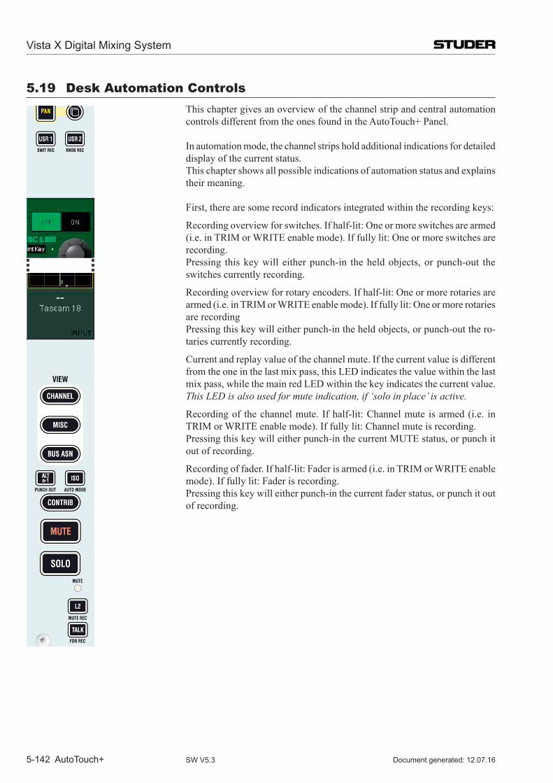
Vista X Digital Mixing System
5-142 AutoTouch+ Document generated: 12.07.16SW V5.3
5.19 Desk Automation Controls This chapter gives an overview of the channel strip and central automation
controls different from the ones found in the AutoTouch+ Panel.
In automation mode, the channel strips hold additional indications for detailed display of the current status.
This chapter shows all possible indications of automation status and explains their meaning.
First, there are some record indicators integrated within the recording keys:
Recording overview for switches. If half-lit: One or more switches are armed (i.e. in TRIM or WRITE enable mode). If fully lit: One or more switches are recording.
Pressing this key will either punch-in the held objects, or punch-out the switches currently recording.
Recording overview for rotary encoders. If half-lit: One or more rotaries are armed (i.e. in TRIM or WRITE enable mode). If fully lit: One or more rotaries are recording
Pressing this key will either punch-in the held objects, or punch-out the ro-taries currently recording.
Current and replay value of the channel mute. If the current value is different from the one in the last mix pass, this LED indicates the value within the last mix pass, while the main red LED within the key indicates the current value.
This LED is also used for mute indication, if ‘solo in place’ is active.
Recording of the channel mute. If half-lit: Channel mute is armed (i.e. in TRIM or WRITE enable mode). If fully lit: Channel mute is recording.
Pressing this key will either punch-in the current MUTE status, or punch it out of recording.
Recording of fader. If half-lit: Fader is armed (i.e. in TRIM or WRITE enable mode). If fully lit: Fader is recording.
Pressing this key will either punch-in the current fader status, or punch it out of recording.
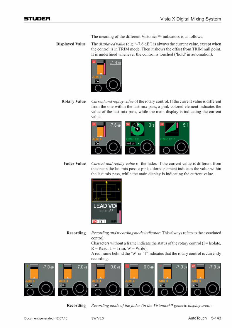
Vista X Digital Mixing System
AutoTouch+ 5-143Document generated: 12.07.16 SW V5.3
The meaning of the different Vistonics™ indicators is as follows:
Displayed Value The displayed value (e.g. ‘–7.6 dB’) is always the current value, except when the control is in TRIM mode. Then it shows the offset from TRIM null point.
It is underlined whenever the control is touched (‘hold’ in automation).
Rotary Value Current and replay value of the rotary control. If the current value is different from the one within the last mix pass, a pink-colored element indicates the value of the last mix pass, while the main display is indicating the current value.
Fader Value Current and replay value of the fader. If the current value is different from the one in the last mix pass, a pink colored element indicates the value within the last mix pass, while the main display is indicating the current value.
Recording Recording and recording mode indicator: This always refers to the associated control.
Characters without a frame indicate the status of the rotary control (I = Isolate, R = Read, T = Trim, W = Write).
A red frame behind the ‘W’ or ‘T’ indicates that the rotary control is currently recording.
Recording Recording mode of the fader (in the Vistonics™ generic display area):
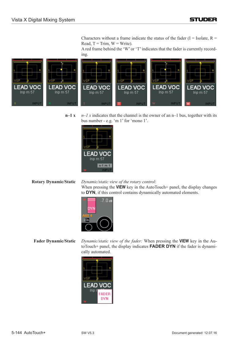
Vista X Digital Mixing System
5-144 AutoTouch+ Document generated: 12.07.16SW V5.3
Characters without a frame indicate the status of the fader (I = Isolate, R = Read, T = Trim, W = Write).
A red frame behind the ‘W’ or ‘T’ indicates that the fader is currently record-ing.
n–1 x n–1 x indicates that the channel is the owner of an n–1 bus, together with its bus number - e.g. ‘m 1’ for ‘mono 1’.
Rotary Dynamic/Static Dynamic/static view of the rotary control: When pressing the VIEW key in the AutoTouch+ panel, the display changes
to DYN, if this control contains dynamically automated elements.
Fader Dynamic/Static Dynamic/static view of the fader: When pressing the VIEW key in the Au-toTouch+ panel, the display indicates FADER DYN if the fader is dynami-cally automated.
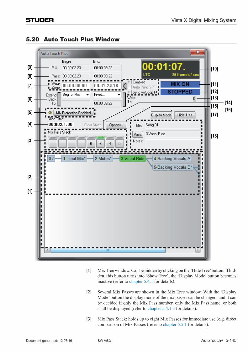
Vista X Digital Mixing System
AutoTouch+ 5-145Document generated: 12.07.16 SW V5.3
5.20 Auto Touch Plus Window
[1]
[2]
[3]
[4]
[5]
[6]
[7]
[8]
[9] [10]
[11] [12] [13] [15]
[17]
[18]
[14][16]
[1] Mix Tree window. Can be hidden by clicking on the ‘Hide Tree’ button. If hid-den, this button turns into ‘Show Tree’, the ‘Display Mode’ button becomes inactive (refer to chapter 5.4.1 for details).
[2] Several Mix Passes are shown in the Mix Tree window. With the ‘Display Mode’ button the display mode of the mix passes can be changed, and it can be decided if only the Mix Pass number, only the Mix Pass name, or both shall be displayed (refer to chapter 5.4.1.3 for details).
[3] Mix Pass Stack; holds up to eight Mix Passes for immediate use (e.g. direct comparison of Mix Passes (refer to chapter 5.5.1 for details).
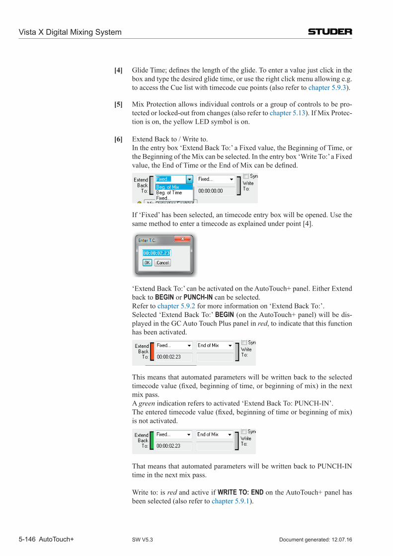
Vista X Digital Mixing System
5-146 AutoTouch+ Document generated: 12.07.16SW V5.3
[4] GlideTime;definesthelengthoftheglide.Toenteravaluejustclickinthebox and type the desired glide time, or use the right click menu allowing e.g. to access the Cue list with timecode cue points (also refer to chapter 5.9.3).
[5] Mix Protection allows individual controls or a group of controls to be pro-tected or locked-out from changes (also refer to chapter 5.13). If Mix Protec-tion is on, the yellow LED symbol is on.
[6] Extend Back to / Write to. In the entry box ‘Extend Back To:’ a Fixed value, the Beginning of Time, or
the Beginning of the Mix can be selected. In the entry box ‘Write To:’ a Fixed value,theEndofTimeortheEndofMixcanbedefined.
If ‘Fixed’ has been selected, an timecode entry box will be opened. Use the same method to enter a timecode as explained under point [4].
‘Extend Back To:’ can be activated on the AutoTouch+ panel. Either Extend back to BEGIN or PUNCH-IN can be selected.
Refer to chapter 5.9.2 for more information on ‘Extend Back To:’. Selected ‘Extend Back To:’ BEGIN (on the AutoTouch+ panel) will be dis-
played in the GC Auto Touch Plus panel in red, to indicate that this function has been activated.
This means that automated parameters will be written back to the selected timecodevalue(fixed,beginningoftime,orbeginningofmix)inthenextmix pass.
A green indication refers to activated ‘Extend Back To: PUNCH-IN’. Theenteredtimecodevalue(fixed,beginningoftimeorbeginningofmix)
is not activated.
That means that automated parameters will be written back to PUNCH-IN time in the next mix pass.
Write to: is red and active if WRITE TO: END on the AutoTouch+ panel has been selected (also refer to chapter 5.9.1).
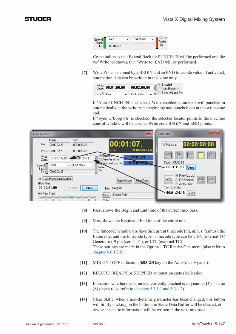
Vista X Digital Mixing System
AutoTouch+ 5-147Document generated: 12.07.16 SW V5.3
Green indicates that Extend Back to: PUNCH-IN will be performed and the red Write to: shows, that ‘Write to: END will be performed.
[7] WriteZoneisdefinedbyaBEGINandanENDtimecodevalue.Ifactivated,automation data can be written in this zone only.
If ‘Auto PUNCH-IN’ is checked, Write enabled parameters will punched in automatically at the write zone beginning and punched out at the write zone end.
If ‘Sync w/Loop Pts’ is checked, the selected locator points in the machine control window will be used as Write zone BEGIN and END points.
[8] Pass; shows the Begin and End time of the current mix pass.
[9] Mix; shows the Begin and End time of the entire mix.
[10] The timecode window displays the current timecode (hh, min, s, frames), the frame rate, and the timecode type. Timecode type can be GEN (internal TC Generator), 9 pin (serial TC), or LTC (external TC).
These settings are made in the Option – TC Reader/Gen menu (also refer to chapter 4.6.1.2.5).
[11] MIX ON / OFF indication (MIX ON key on the AutoTouch+ panel).
[12] RECORD, READY or STOPPED automation status indication.
[13] Indication whether the parameter currently touched is a dynamic (D) or static (S) object (also refer to chapters 5.3.1.1 and 5.3.1.2).
[14] Clear Static; when a non-dynamic parameter has been changed, this button will lit. By clicking on the button the Static Data Buffer will be cleared, oth-erwise the static information will be written in the next mix pass.
Vista X Digital Mixing System
5-148 AutoTouch+ Document generated: 12.07.16SW V5.3
[15] Options...; (only activated if MIX is ON) Click on the this button to access the Mix Options (also refer to chapter 5.21).
[16] Display Mode; mix pass display mode selection: it can be decided whether only Mix Pass number, only Mix Pass name or both shall be displayed (also refer to chapter 5.4.1.3 for details).
[17] Hide Tree or Show Tree; will hide or show the Mix Tree window.
[18] Mix Pass information; to activate the PASS INFO dialog box. A name and notes can be entered for the selected Mix Pass (also refer to chapter 5.4.1.3).
Mix: Shows the Mix Tree Name Pass: Shows the name of the mix pass and allows to enter the PASS INFO
dialog box Notes: Shows the notes.
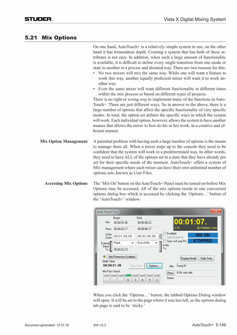
Vista X Digital Mixing System
AutoTouch+ 5-149Document generated: 12.07.16 SW V5.3
5.21 mix options On one hand, Auto Touch+ is a relatively simple system to use, on the other
hand it has tremendous depth. Creating a system that has both of these at-tributes is not easy. In addition, when such a large amount of functionality isavailable,itisdifficulttodefineeverysingletransitionfromonemodeorstate to another in a precise and dictated way. There are two reasons for this:
• Notwomixerswillmixthesameway.Whileonewillwantafeaturetoworkthisway,anotherequallyproficientmixerwillwantittoworkan-other way.
• Eventhesamemixerwillwantdifferentfunctionalityatdifferenttimeswithin the mix process or based on different types of projects.
There is no right or wrong way to implement many of the functions in Auto-Touch+. There are just different ways. So in answer to the above, there is a largenumberofoptionsthataffectthespecificfunctionalityofveryspecificmodes.Intotal,theoptionsetdefinesthespecificwaysinwhichthesystemwill work. Each individual option, however, allows the system to have another nuance that allows the mixer to best do his or her work, in a creative and ef-ficientmanner.
Mix Option Management A potential problem with having such a large number of options is the means to manage them all. When a mixer steps up to the console they need to be confidentthatthesystemwillworkinapredeterminedway.Inotherwords,they need to have ALL of the options set to a state that they have already pre setfortheirspecificneedsofthemoment.AutoTouch+offersasystemofMix management where each mixer can have their own unlimited number of options sets, known as User Files.
Accessing Mix Options The ‘Mix On’ button on the AutoTouch+ Panel must be turned on before Mix Options may be accessed. All of the mix options reside in one convenient options dialog box which is accessed by clicking the ‘Options…’ button of the ‘Auto Touch+’ window.
When you click the ‘Options…’ button, the tabbed Options Dialog window will open. It will be set to the page where it was last left, so the options dialog tab page is said to be ‘sticky.’
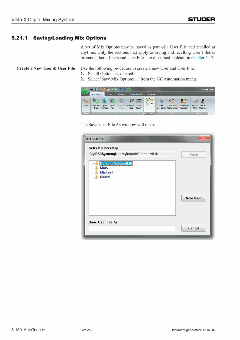
Vista X Digital Mixing System
5-150 AutoTouch+ Document generated: 12.07.16SW V5.3
5.21.1 Saving/Loading mix options
A set of Mix Options may be saved as part of a User File and recalled at anytime. Only the sections that apply to saving and recalling User Files is presented here. Users and User Files are discussed in detail in chapter 5.17.
Create a New User & User File Use the following procedure to create a new User and User File:1. Set all Options as desired.2. Select ‘Save Mix Options…’ from the GC Automation menu.
The Save User File As window will open.
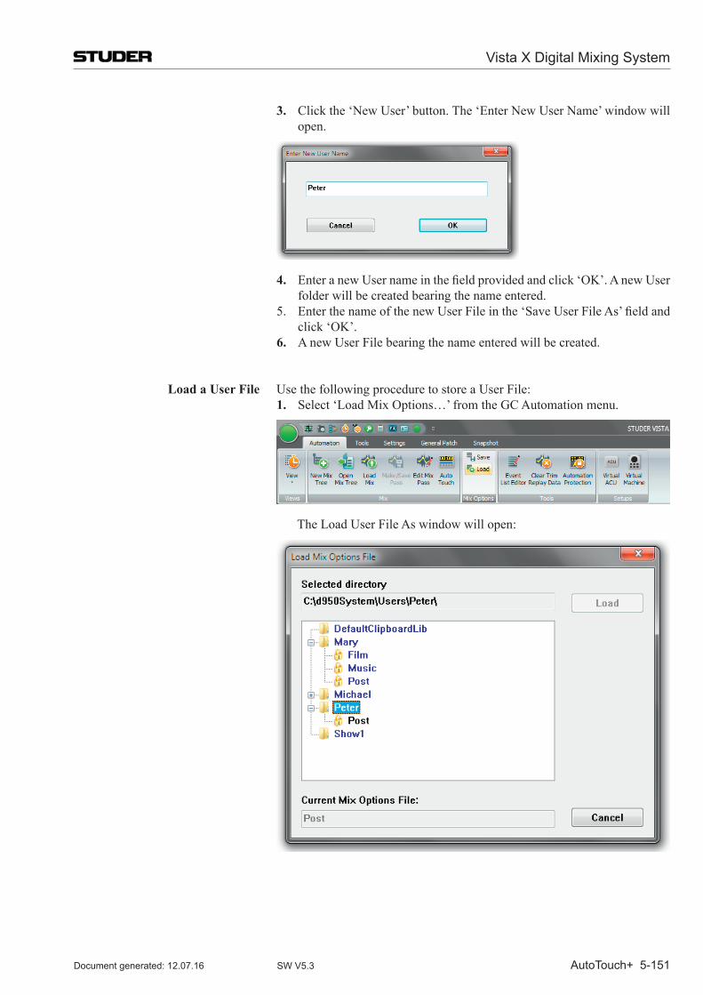
Vista X Digital Mixing System
AutoTouch+ 5-151Document generated: 12.07.16 SW V5.3
3. Click the ‘New User’ button. The ‘Enter New User Name’ window will open.
4. EnteranewUsernameinthefieldprovidedandclick‘OK’.AnewUserfolder will be created bearing the name entered.
5. EnterthenameofthenewUserFileinthe‘SaveUserFileAs’fieldandclick ‘OK’.
6. A new User File bearing the name entered will be created.
Load a User File Use the following procedure to store a User File:1. Select ‘Load Mix Options…’ from the GC Automation menu.
The Load User File As window will open:
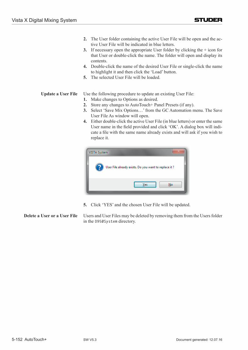
Vista X Digital Mixing System
5-152 AutoTouch+ Document generated: 12.07.16SW V5.3
2. The User folder containing the active User File will be open and the ac-tive User File will be indicated in blue letters.
3. If necessary open the appropriate User folder by clicking the + icon for that User or double-click the name. The folder will open and display its contents.
4. Double-click the name of the desired User File or single-click the name to highlight it and then click the ‘Load’ button.
5. The selected User File will be loaded.
Update a User File Use the following procedure to update an existing User File:1. Make changes to Options as desired.2. Store any changes to AutoTouch+ Panel Presets (if any).3. Select ‘Save Mix Options…’ from the GC Automation menu. The Save
User File As window will open.4. Either double-click the active User File (in blue letters) or enter the same
Usernameinthefieldprovidedandclick‘OK’.Adialogboxwillindi-cateafilewiththesamenamealreadyexistsandwillaskifyouwishtoreplace it.
5. Click ‘YES’ and the chosen User File will be updated.
Delete a User or a User File Users and User Files may be deleted by removing them from the Users folder in the D950System directory.
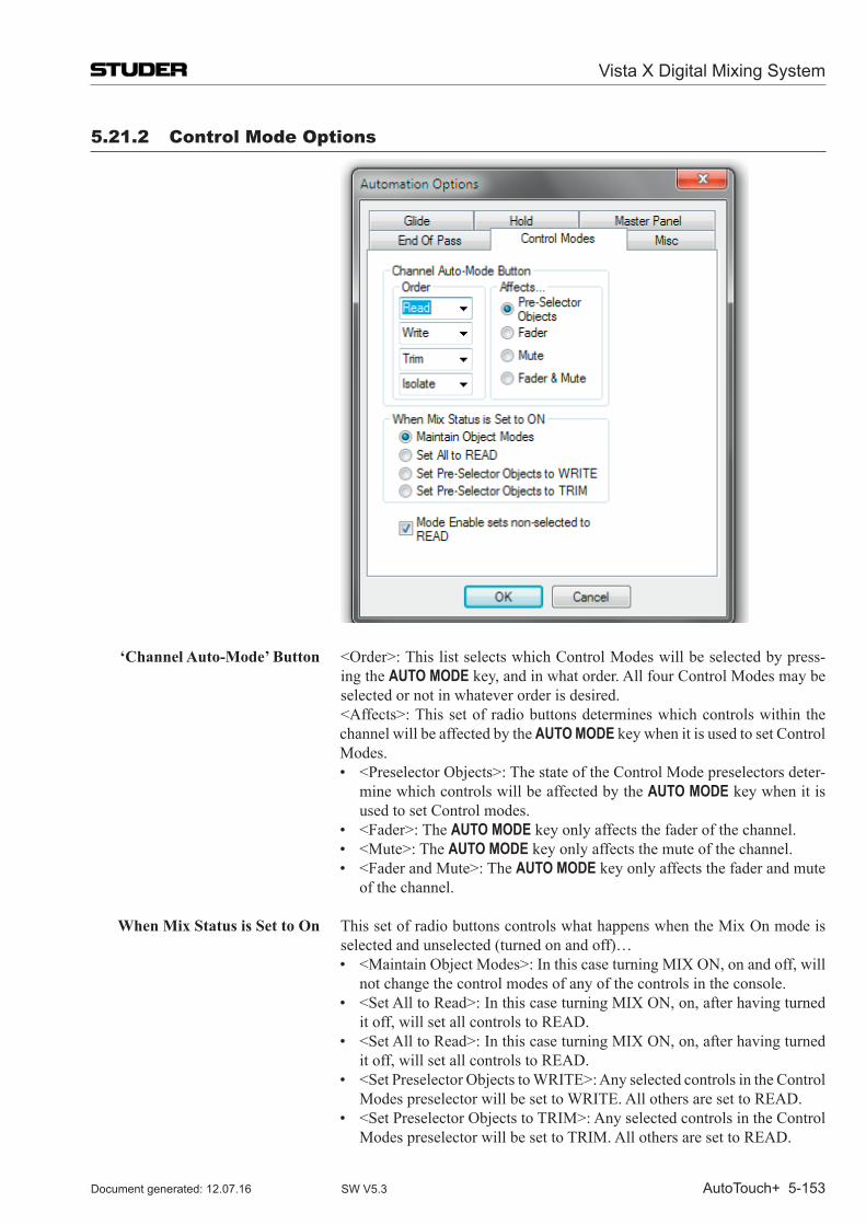
Vista X Digital Mixing System
AutoTouch+ 5-153Document generated: 12.07.16 SW V5.3
5.21.2 Control mode options
‘Channel Auto-Mode’ Button <Order>:ThislistselectswhichControlModeswillbeselectedbypress-ing the AUTO MODE key, and in what order. All four Control Modes may be selected or not in whatever order is desired.
<Affects>:Thissetofradiobuttonsdetermineswhichcontrolswithinthechannel will be affected by the AUTO MODE key when it is used to set Control Modes.
• <PreselectorObjects>:ThestateoftheControlModepreselectorsdeter-mine which controls will be affected by the AUTO MODE key when it is used to set Control modes.
• <Fader>:TheAUTO MODE key only affects the fader of the channel. • <Mute>:TheAUTO MODE key only affects the mute of the channel. • <FaderandMute>:TheAUTO MODE key only affects the fader and mute
of the channel.
When Mix Status is Set to On This set of radio buttons controls what happens when the Mix On mode is selected and unselected (turned on and off)…
• <MaintainObjectModes>:InthiscaseturningMIXON,onandoff,willnot change the control modes of any of the controls in the console.
• <SetAlltoRead>:InthiscaseturningMIXON,on,afterhavingturnedit off, will set all controls to READ.
• <SetAlltoRead>:InthiscaseturningMIXON,on,afterhavingturnedit off, will set all controls to READ.
• <SetPreselectorObjectstoWRITE>:AnyselectedcontrolsintheControlModes preselector will be set to WRITE. All others are set to READ.
• <SetPreselectorObjectstoTRIM>:AnyselectedcontrolsintheControlModes preselector will be set to TRIM. All others are set to READ.
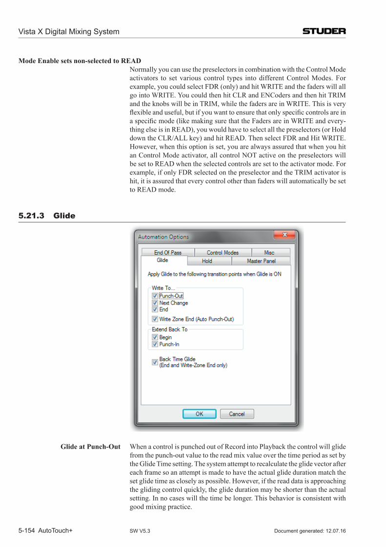
Vista X Digital Mixing System
5-154 AutoTouch+ Document generated: 12.07.16SW V5.3
Mode Enable sets non-selected to READ Normally you can use the preselectors in combination with the Control Mode
activators to set various control types into different Control Modes. For example, you could select FDR (only) and hit WRITE and the faders will all go into WRITE. You could then hit CLR and ENCoders and then hit TRIM and the knobs will be in TRIM, while the faders are in WRITE. This is very flexibleanduseful,butifyouwanttoensurethatonlyspecificcontrolsareinaspecificmode(likemakingsurethattheFadersareinWRITEandevery-thing else is in READ), you would have to select all the preselectors (or Hold down the CLR/ALL key) and hit READ. Then select FDR and Hit WRITE. However, when this option is set, you are always assured that when you hit an Control Mode activator, all control NOT active on the preselectors will be set to READ when the selected controls are set to the activator mode. For example, if only FDR selected on the preselector and the TRIM activator is hit, it is assured that every control other than faders will automatically be set to READ mode.
5.21.3 Glide
Glide at Punch-Out When a control is punched out of Record into Playback the control will glide from the punch-out value to the read mix value over the time period as set by the Glide Time setting. The system attempt to recalculate the glide vector after each frame so an attempt is made to have the actual glide duration match the set glide time as closely as possible. However, if the read data is approaching the gliding control quickly, the glide duration may be shorter than the actual setting. In no cases will the time be longer. This behavior is consistent with good mixing practice.
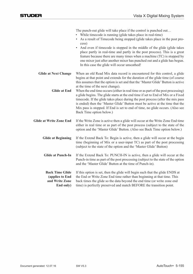
Vista X Digital Mixing System
AutoTouch+ 5-155Document generated: 12.07.16 SW V5.3
The punch-out glide will take place if the control is punched out… • Whiletimecodeisrunning(glidetakesplaceinreal-time) • AsaresultofTimecodebeingstopped(glidetakesplaceinthepostpro-
cess) • Andeveniftimecodeisstoppedinthemiddleoftheglide(glidetakes
place partly in real-time and partly in the post process). This is a great feature because there are many times when a machine (TC) is stopped by one mixer just after another mixer has punched out and a glide has begun. In this case the glide will occur unscathed!
Glide at Next Change When an old Read Mix data record is encountered for this control, a glide begins at that point and extends for the duration of the glide time (of course this assumes that the option is set and that the ‘Master Glide’ Button is active at the time of the next change).
Glide at End When the end time occurs (either in real time or as part of the post processing) a glide begins. The glide starts at the end time if set to End of Mix or a Fixed timecode. If the glide takes place during the post process (after the mix pass is ended) then the ‘Master Glide’ Button must be active at the time that the Mix pass is stopped. If End is set to end of time, no glide occurs. (Also see Back Time option below.)
Glide at Write Zone End If the Write Zone is active then a glide will occur at the Write Zone End time either in real time or as part of the post process (subject to the state of the option and the ‘Master Glide’ Button. (Also see Back Time option below.)
Glide at Beginning If the Extend Back To: Begin is active, then a glide will occur at the begin time (beginning of Mix or a user-input TC) as part of the post processing (subject to the state of the option and the ‘Master Glide’ Button)
Glide at Punch-In If the Extend Back To: PUNCH-IN is active, then a glide will occur at the Punch-in time as part of the post processing (subject to the state of the option and the ‘Master Glide’ Button at the time of Punch-in).
Back Time Glide If this option is set, then the glide will begin such that the glide ENDS at (applies to End the End or Write Zone End time rather than beginning at that time. This and Write Zone back times the glide so the data beyond the end time (or write zone end End only) time) is perfectly preserved and match BEFORE the transition point.
Vista X Digital Mixing System
5-156 AutoTouch+ Document generated: 12.07.16SW V5.3
5.21.4 Hold
Held Plays Mix <DisableWhileTouched>:WhenHELD PLAYS MIX on the AutoTouch+ Panel is active channels that are Held, do not ‘play’ their held auditioned values, but play the Read Mix values instead. When this option is set, touching a control at this time disables this feature and allows a new audition (punch) value to be established by being able to listen to the Audition audio. If this option is unchecked, the Held Plays Mix function is not over-ridden and the Read Mix continues to be heard.
Clear Held Objects <WhenTouchHoldTurnedOff>:TOUCH HOLD (on the AutoTouch+ Panel) may be turned on and off during the course of a Mix pass. This options affects whether Held controls are cleared of their ‘held’ status when The Touch Hold mode is changed from On (active) to Off. If the option is not selected, then changing the state of Touch Hold will have no effect on Held controls.
<UponPunchOut>:TouchHoldisusedforavarietyofpurposes.Sometimea write value needs to be held (so that un-touching the control while Touch Record is engaged does not punch it out of record), just until the control is punched out of record. At that point the control would return to playing back the Read Mix. With this option set, that is how the behavior would work. However, sometimes you will want to punch-in to that same held value later in the mix pass, even after you have punched out for this section of the mix. By deselecting this option the behavior will allow for this operation. The held value will remain until it is cancelled by other means. The new Mix Pass will, of course, not be affected.
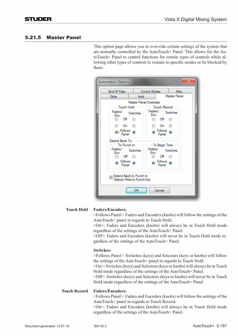
Vista X Digital Mixing System
AutoTouch+ 5-157Document generated: 12.07.16 SW V5.3
5.21.5 master Panel
This option page allows you to over-ride certain settings of the system that are normally controlled by the AutoTouch+ Panel. This allows for the Au-toTouch+ Panel to control functions for certain types of controls while al-lowingothertypesofcontrolstoremaininspecificmodesorbeblockedbythem.
Touch Hold Faders/Encoders: <FollowsPanel>:FadersandEncoders(knobs)willfollowthesettingsofthe
AutoTouch+ panel in regards to Touch Hold. <On>:FadersandEncoders (knobs)willalwaysbe inTouchHoldmode
regardless of the settings of the AutoTouch+ Panel. <Off>:FadersandEncoders(knobs)willneverbeinTouchHoldmodere-
gardless of the settings of the AutoTouch+ Panel.
Switches: <FollowsPanel>:Switches(keys)andSelectors(keysorknobs)willfollow
the settings of the AutoTouch+ panel in regards to Touch Hold. <On>:Switches(keys)andSelectors(keysorknobs)willalwaysbeinTouch
Hold mode regardless of the settings of the AutoTouch+ Panel. <Off>:Switches(keys)andSelectors(keysorknobs)willneverbeinTouch
Hold mode regardless of the settings of the AutoTouch+ Panel.
Touch Record Faders/Encoders: <FollowsPanel>:FadersandEncoders(knobs)willfollowthesettingsofthe
AutoTouch+ panel in regards to Touch Record. <On>:FadersandEncoders (knobs)willalwaysbe inTouchHoldmode
regardless of the settings of the AutoTouch+ Panel.
Vista X Digital Mixing System
5-158 AutoTouch+ Document generated: 12.07.16SW V5.3
<Off>:FadersandEncoders(knobs)willneverbeinTouchHoldmodere-gardless of the settings of the AutoTouch+ Panel.
Switches <FollowsPanel>:Switches(keys)andSelectors(keysorknobs)willfollowthe settings of the AutoTouch+ panel in regards to Touch Record.
<On>:Switches(keys)andSelectors(keysorknobs)willalwaysbeinTouchHold mode regardless of the settings of the AutoTouch+ Panel.
<Off>:Switches(keys)andSelectors(keysorknobs)willneverbeinTouchHold mode regardless of the settings of the AutoTouch+ Panel.
Extend Back To Begin Time Faders/Encoders: <FollowsPanel>:FadersandEncoders(knobs)willfollowthesettingsofthe
AutoTouch+ panel in regards to Extend Back To Begin Time. <Off>:FadersandEncoders(knobs)willbeblockedfromenteringExtend
Back To Begin Time regardless of the settings of the AutoTouch+ Panel.
Switches: <FollowsPanel>:Switches(keys)andSelectors(keysorknobs)willfollow
the settings of the AutoTouch+ panel in regards to Extend Back To Begin Time.
<Off>:Switches(keys)andSelectors(keysorknobs)willbeblockedfromentering Extend Back To Begin Time regardless of the settings of the Au-toTouch+ Panel.
Extend Back To Punch-In Faders/Encoders: <FollowsPanel>:FadersandEncoders(knobs)willfollowthesettingsofthe
AutoTouch+ panel in regards to Extend Back To Punch-In. <Off>:FadersandEncoders(knobs)willbeblockedfromenteringExtend
Back To Punch-In regardless of the settings of the AutoTouch+ Panel.
Switches: <FollowsPanel>:Switches(keys)andSelectors(keysorknobs)willfollow
the settings of the AutoTouch+ panel in regards to Extend Back To Punch-In. <Off>:Switches(keys)andSelectors(keysorknobs)willbeblockedfrom
entering Extend Back To Punch-In regardless of the settings of the Auto-Touch+ Panel.
Extend Back To Punch-In Selects Inmanycasesitisdesirabletoauditionalevelandhavethatfinaldeter-Write to Punch-out mined level be written from the punch-in to the punch-out time. This is some-
times referred to as writing to a region. In Auto Touch+ this is accomplished by setting both the Extend Back To: Punch-In as well as Write To: Punch Out. Because this combination is selected so often, this options automatically selects Write To: Punch-Out whenever Extend Back To: Punch-In is selected. It is simply a convenience and ensure that when you wish to write to a punch-in/out region it is set properly. If you wish to set Extend Back to Punch-In with a different Write To selection you can simple select a different Write To selection after Extend Back to Punch-In has been selected (or do not set this option).
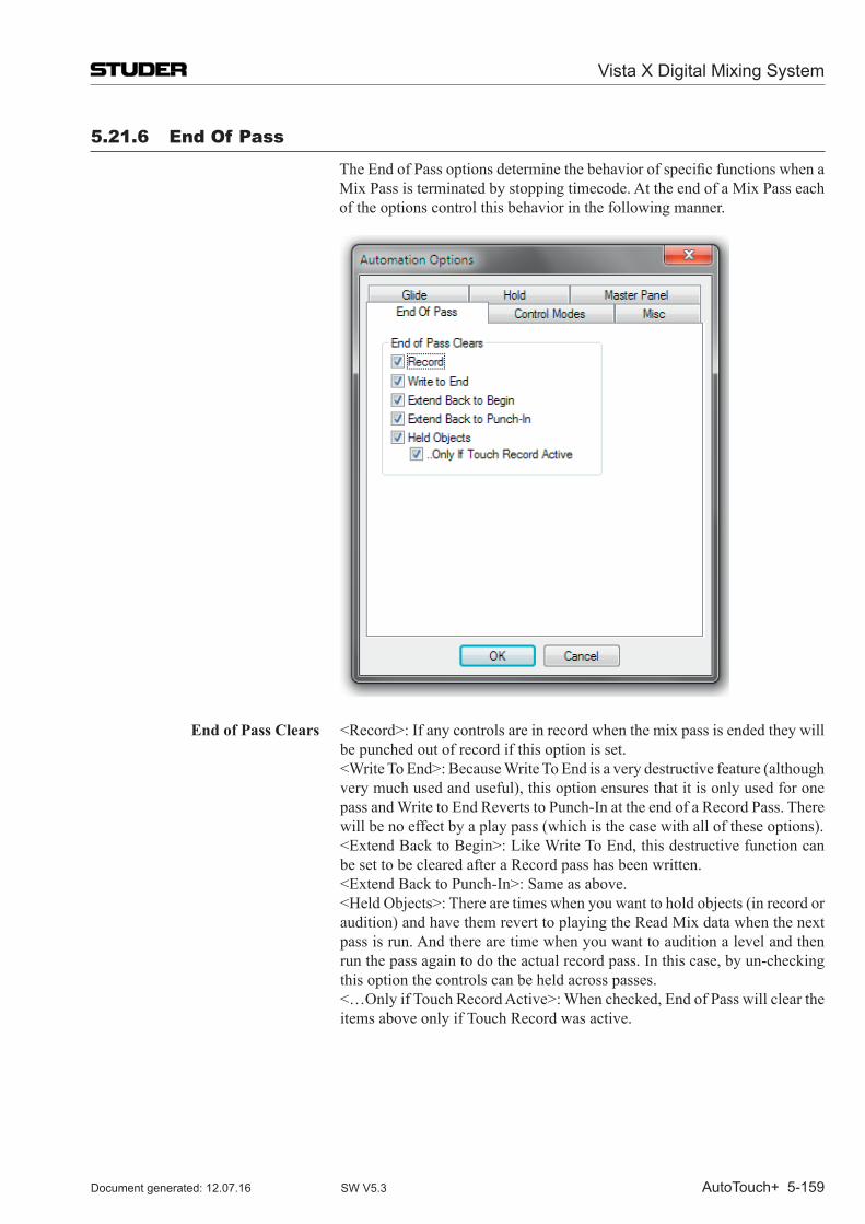
Vista X Digital Mixing System
AutoTouch+ 5-159Document generated: 12.07.16 SW V5.3
5.21.6 End of Pass
TheEndofPassoptionsdeterminethebehaviorofspecificfunctionswhenaMix Pass is terminated by stopping timecode. At the end of a Mix Pass each of the options control this behavior in the following manner.
End of Pass Clears <Record>:Ifanycontrolsareinrecordwhenthemixpassisendedtheywillbe punched out of record if this option is set.
<WriteToEnd>:BecauseWriteToEndisaverydestructivefeature(althoughvery much used and useful), this option ensures that it is only used for one pass and Write to End Reverts to Punch-In at the end of a Record Pass. There will be no effect by a play pass (which is the case with all of these options).
<ExtendBacktoBegin>:LikeWriteToEnd,thisdestructivefunctioncanbe set to be cleared after a Record pass has been written.
<ExtendBacktoPunch-In>:Sameasabove. <HeldObjects>:Therearetimeswhenyouwanttoholdobjects(inrecordor
audition) and have them revert to playing the Read Mix data when the next pass is run. And there are time when you want to audition a level and then run the pass again to do the actual record pass. In this case, by un-checking this option the controls can be held across passes.
<…OnlyifTouchRecordActive>:Whenchecked,EndofPasswillcleartheitems above only if Touch Record was active.
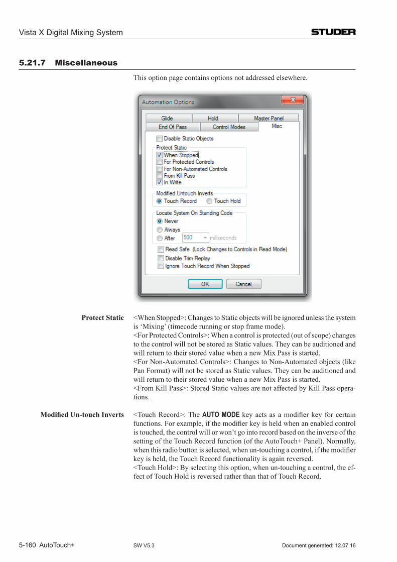
Vista X Digital Mixing System
5-160 AutoTouch+ Document generated: 12.07.16SW V5.3
5.21.7 miscellaneous
This option page contains options not addressed elsewhere.
Protect Static <WhenStopped>:ChangestoStaticobjectswillbeignoredunlessthesystemis ‘Mixing’ (timecode running or stop frame mode).
<ForProtectedControls>:Whenacontrolisprotected(outofscope)changesto the control will not be stored as Static values. They can be auditioned and will return to their stored value when a new Mix Pass is started.
<ForNon-AutomatedControls>:ChangestoNon-Automatedobjects(likePan Format) will not be stored as Static values. They can be auditioned and will return to their stored value when a new Mix Pass is started.
<FromKillPass>:StoredStaticvaluesarenotaffectedbyKillPassopera-tions.
Modified Un-touch Inverts <TouchRecord>:TheAUTO MODE keyactsasamodifierkeyforcertainfunctions.Forexample,ifthemodifierkeyisheldwhenanenabledcontrolis touched, the control will or won’t go into record based on the inverse of the setting of the Touch Record function (of the Auto Touch+ Panel). Normally, whenthisradiobuttonisselected,whenun-touchingacontrol,ifthemodifierkey is held, the Touch Record functionality is again reversed.
<TouchHold>:Byselectingthisoption,whenun-touchingacontrol,theef-fect of Touch Hold is reversed rather than that of Touch Record.
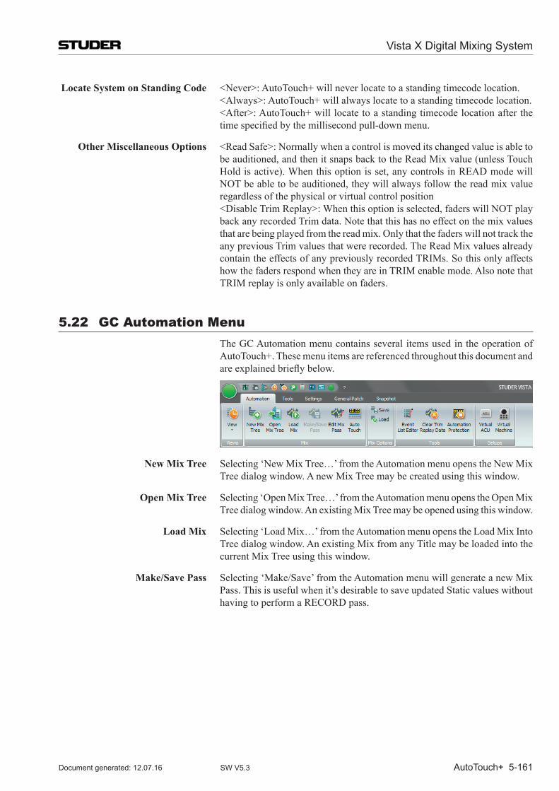
Vista X Digital Mixing System
AutoTouch+ 5-161Document generated: 12.07.16 SW V5.3
Locate System on Standing Code <Never>:AutoTouch+willneverlocatetoastandingtimecodelocation. <Always>:AutoTouch+willalwayslocatetoastandingtimecodelocation. <After>:AutoTouch+willlocatetoastandingtimecodelocationafterthe
timespecifiedbythemillisecondpull-downmenu.
Other Miscellaneous Options <ReadSafe>:Normallywhenacontrolismoveditschangedvalueisabletobe auditioned, and then it snaps back to the Read Mix value (unless Touch Hold is active). When this option is set, any controls in READ mode will NOT be able to be auditioned, they will always follow the read mix value regardless of the physical or virtual control position
<DisableTrimReplay>:Whenthisoptionisselected,faderswillNOTplayback any recorded Trim data. Note that this has no effect on the mix values that are being played from the read mix. Only that the faders will not track the any previous Trim values that were recorded. The Read Mix values already contain the effects of any previously recorded TRIMs. So this only affects how the faders respond when they are in TRIM enable mode. Also note that TRIM replay is only available on faders.
5.22 GC Automation menu The GC Automation menu contains several items used in the operation of
Auto Touch+. These menu items are referenced throughout this document and areexplainedbrieflybelow.
New Mix Tree Selecting ‘New Mix Tree…’ from the Automation menu opens the New Mix Tree dialog window. A new Mix Tree may be created using this window.
Open Mix Tree Selecting ‘Open Mix Tree…’ from the Automation menu opens the Open Mix Tree dialog window. An existing Mix Tree may be opened using this window.
Load Mix Selecting ‘Load Mix…’ from the Automation menu opens the Load Mix Into Tree dialog window. An existing Mix from any Title may be loaded into the current Mix Tree using this window.
Make/Save Pass Selecting ‘Make/Save’ from the Automation menu will generate a new Mix Pass. This is useful when it’s desirable to save updated Static values without having to perform a RECORD pass.
Vista X Digital Mixing System
5-162 AutoTouch+ Document generated: 12.07.16SW V5.3
Edit Mix Pass Selecting‘EditMixPass’fromtheAutomationmenuopenstheOFLAofflinemix editor. The Active Mix Pass control values and locations may be edited.
Event List Editor Selecting‘EventListEditor’fromtheAutomationmenuopenstheofflineEvent List Editor. The locations of the Active Mix Pass control changes may be edited.
Clear Trim Replay Data Selecting ‘Clear Trim Replay Data’ clears the Trim Replay Data for the Active Mix Pass.
Save Mix Options Selecting ‘Save Mix Options’ from the Automation menu opens the Save User File As dialog window. A new User and or User File may be created using this window. User Files contain Mix Options and Auto Touch+ Panel Presets.
Load Mix Options Selecting ‘Load Mix Options’ from the Automation menu opens the Load Mix Options File dialog window. Any existing User File may be loaded using this window. User Files contain Mix Options and Auto Touch+ Panel Presets.
Protection Selecting ‘Protection…’ from the Automation menu opens the Automation Protect control window. Protection may be applied to any set of controls using this window.
5.23 Hot Keys AutoTouch+ software supports a variety of ‘Hot Keys’ (shortcut keys) that
improveefficiencywhenoperatingthesystem.TheseHotKeysassistinthemanagement of timecode entry and information.
Note This chapter assumes that the appropriate window or entry box is active. Appropriatefieldsorsectionsoffieldsarehighlighted,and/orthecursorisplaced appropriately.
Hot Key Functions Hot Key functions are described in the table on the next page.
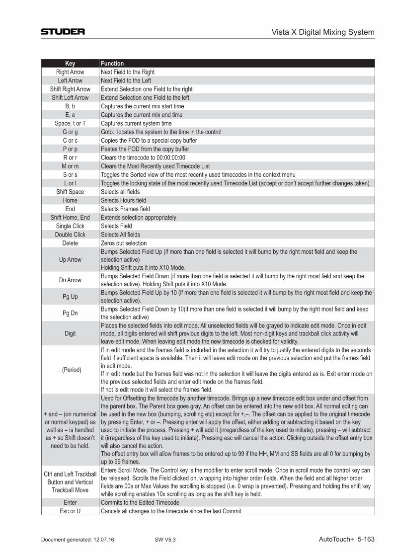
Vista X Digital Mixing System
AutoTouch+ 5-163Document generated: 12.07.16 SW V5.3
Key FunctionRight Arrow Next field to the RightLeft Arrow Next field to the Left
Shift Right Arrow Extend Selection one field to the rightShift Left Arrow Extend Selection one field to the left
B, b Captures the current mix start timeE, e Captures the current mix end time
Space, t or T Captures current system timeG or g Goto.. locates the system to the time in the controlC or c Copies the foD to a special copy bufferP or p Pastes the foD from the copy bufferR or r Clears the timecode to 00:00:00:00
M or m Clears the Most Recently used Timecode ListS or s Toggles the Sorted view of the most recently used timecodes in the context menuL or l Toggles the locking state of the most recently used Timecode List (accept or don’t accept further changes taken)
Shift Space Selects all fieldsHome Selects Hours fieldEnd Selects Frames field
Shift Home, End Extends selection appropriatelySingle Click Selects fieldDouble Click Selects All fields
Delete Zeros out selection
Up ArrowBumps Selected Field Up (if more than one field is selected it will bump by the right most field and keep the selection active)Holding Shift puts it into X10 Mode.
Dn Arrow Bumps Selected Field Down (if more than one field is selected it will bump by the right most field and keep the selection active). Holding Shift puts it into X10 Mode.
Pg Up Bumps Selected Field Up by 10 (if more than one field is selected it will bump by the right most field and keep the selection active).
Pg Dn Bumps Selected Field Down by 10(if more than one field is selected it will bump by the right most field and keep the selection active)
DigitPlaces the selected fields into edit mode. All unselected fields will be grayed to indicate edit mode. Once in edit mode, all digits entered will shift previous digits to the left. Most non-digit keys and trackball click activity will leave edit mode. When leaving edit mode the new timecode is checked for validity.
. (Period)
If in edit mode and the frames field is included in the selection it will try to justify the entered digits to the seconds field if sufficient space is available. Then it will leave edit mode on the previous selection and put the frames field in edit mode.If in edit mode but the frames field was not in the selection it will leave the digits entered as is. Exit enter mode on the previous selected fields and enter edit mode on the frames field.If not is edit mode it will select the frames field.
+ and – (on numerical or normal keypad) as well as = is handled as + so Shift doesn’t
need to be held.
Used for offsetting the timecode by another timecode. Brings up a new timecode edit box under and offset from the parent box. The Parent box goes gray. An offset can be entered into the new edit box. All normal editing can be used in the new box (bumping, scrolling etc) except for +,–. The offset can be applied to the original timecode by pressing Enter, + or –. Pressing enter will apply the offset, either adding or subtracting it based on the key used to initiate the process. Pressing + will add it (irregardless of the key used to initiate), pressing – will subtract it (irregardless of the key used to initiate). Pressing esc will cancel the action. Clicking outside the offset entry box will also cancel the action.The offset entry box will allow frames to be entered up to 99 if the HH, MM and SS fields are all 0 for bumping by up to 99 frames.
Ctrl and Left Trackball Button and Vertical
Trackball Move
Enters Scroll Mode. The Control key is the modifier to enter scroll mode. Once in scroll mode the control key can be released. Scrolls the Field clicked on, wrapping into higher order fields. When the field and all higher order fields are 00s or Max Values the scrolling is stopped (i.e. 0 wrap is prevented). Pressing and holding the shift key while scrolling enables 10x scrolling as long as the shift key is held.
Enter Commits to the Edited TimecodeEsc or U Cancels all changes to the timecode since the last Commit
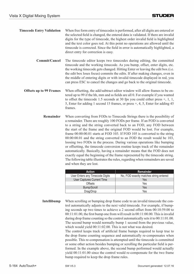
Vista X Digital Mixing System
5-164 AutoTouch+ Document generated: 12.07.16SW V5.3
Timecode Entry Validation When free form entry of timecodes is performed, after all digits are entered or theselectedfieldischanged,theentereddataisvalidated.Ifthereareinvaliddigitsforthetypeoftimecode,thehighestorderinvalidfieldishighlightedand the text color goes red. At this point no operations are allowed until the timecodeiscorrected.Sincethefieldinerrorisautomaticallyhighlighted,adirect entry for correction is easy.
Commit/Cancel The timecode editor keeps two timecodes during editing, the committed timecode and the working timecode. As you bump, offset, enter digits, etc. the working timecode gets changed. Hitting Enter or leaving the edit box (i.e. the edit box loses focus) commits the edits. If after making changes, even in the middle of entering digits or with invalid timecode displayed in red, you can press ESC to cancel the changes and go back to the original timecode.
Offsets up to 99 Frames When offsetting, the add/subtract editor window will allow frames to be en-teredupto99ifthehh,mmandssfieldsareall0.Forexampleifyouwantedto offset the timecode 1.5 seconds at 30 fps you could either press +, 1, 1, 5, Enter for adding 1 second 15 frames, or press +, 4, 5, Enter for adding 45 frames.
Remainder When converting from FODs to Timecode Strings there is the possibility of a remainder. There are roughly 100 FODs per frame. If an FOD is converted to a string and the string converted back to an FOD, any FOD between the start of the frame and the original FOD would be lost. For example, frame 00:00:00.01 starts at FOD 103. If FOD 105 is converted to the string 00:00:00.01 and the string converted to an FOD the result would be 103, loosing two FODs in the process. During various operations like bumping or offsetting, the timecode conversion routine keeps track of the remainder automatically. Basically, having a remainder means that the FOD does not exactly equal the beginning of the frame represented by the timecode string. The following table illustrates the rules, regarding when remainders are saved and when they are lost.
Action RemainderUser Enters any Timecode Digits No, foD exactly matches string entered
User Captures Current Time Yesoffsets Yes
Bump/Scroll YesDrag/Drop Yes
Intellibump When scrolling or bumping drop frame code to an invalid timecode the con-trol automatically adjusts to the next valid timecode. For example, if bump-ing seconds up two times to achieve a 2 second offset from 00:10:59.00 to 00:11:01.00,thefirstbumponefromwillresultin00:11:00.00.Thisisinvalidduring drop frame counting so the control automatically sets it to 00:11:01.00. The second bump would normally bump 1 second from the previous value, which would yield 00:11:02.00. This is not what was desired.
Thecontrolkeeps trackofartificialframebumpsrequiredtokeeptrue tothe drop frame counting sequence and automatically re-compensates when possible. This re-compensation is attempted until the timecode is committed orsomeotheractionbesidesbumpingorscrollingtheparticularfieldisper-formed. In the example above, the second bump performed would actually yield 00:11:01.00 since the control would re-compensate for the two frame bump required to keep the drop frame rules.
CHAPTER 6
6 Session Configuration Tool for Infinity Cores ...............................................................................................36.1 Installation ..........................................................................................................................................................3
6.1.1 Where to Install ..................................................................................................................................................... 46.1.2 How to Install ........................................................................................................................................................ 46.1.3 Infinity Core or SCoreLive ?................................................................................................................................. 4
6.2 Introduction ........................................................................................................................................................56.2.1 Features & Benefits ............................................................................................................................................... 56.2.2 Virtual Mixing Console (VMC) Concept .............................................................................................................. 76.2.3 The Practical Side ................................................................................................................................................. 8
6.2.3.1 Data Compatibility .....................................................................................................................................................96.3 The Fast Lane – Try it! .....................................................................................................................................11
6.3.1 Do Your Own – Use Existing or Start from Scratch? ......................................................................................... 116.3.1.1 Use an Existing VMC ..............................................................................................................................................116.3.1.2 Start from Scratch ....................................................................................................................................................11
6.3.2 Generate the Vista Configuration Files ............................................................................................................... 126.3.2.1 Does my Console Have Enough Power? .................................................................................................................16
6.3.3 Generate the Core File ........................................................................................................................................ 186.3.4 Transfer the Files to the Console ......................................................................................................................... 20
6.4 Detailed Tutorial ...............................................................................................................................................216.4.1 Set Your own Workspace .................................................................................................................................... 216.4.2 Sampling Rate ..................................................................................................................................................... 226.4.3 Channel/Bus Page ............................................................................................................................................... 22
6.4.3.1 Add / Edit Channels .................................................................................................................................................236.4.3.2 Function Library ......................................................................................................................................................256.4.3.3 Add / Edit Buses ......................................................................................................................................................266.4.3.4 Special Configuration Function: Stems ...................................................................................................................29
6.4.4 Interface Page ...................................................................................................................................................... 306.4.5 Core Page ............................................................................................................................................................ 326.4.6 Shared Functions Page ........................................................................................................................................ 336.4.7 Session Configuration Toolbar and Menus ......................................................................................................... 34
6.4.7.1 Toolbar .....................................................................................................................................................................346.4.7.2 File Menu .................................................................................................................................................................346.4.7.3 View Menu ...............................................................................................................................................................346.4.7.4 VMC Tree View .......................................................................................................................................................356.4.7.5 Generate Menu .........................................................................................................................................................366.4.7.6 Window Menu ..........................................................................................................................................................36
6.5 Maintenance ......................................................................................................................................................376.5.1 Managing the Files – Which File is Where? ....................................................................................................... 376.5.2 CoreCfgTool.ini .................................................................................................................................................. 37
6.5.2.1 Content of the Core Knowledge File .......................................................................................................................376.5.3 Troubleshooting .................................................................................................................................................. 38
6.5.3.1 Errors and Warnings During Generate Process / In Log File ...................................................................................38
Vista X Digital Mixing System
Session Configuration 6-1Document generated: 12.07.16 SW V5.3
Vista X Digital Mixing System
6-2 Session Configuration Document generated: 12.07.16SW V5.3
6 SESSion ConfiguRATion Tool foR infiniTy CoRES The Studer Infinity Series Mixing Systems may be easily reconfigured using
the Session Configuration Tool. Whereas the ability for reconfiguration is a great feature of the Studer Vista, it is important for an operator to fully under-stand the Session Configuration Tool and its functions. There is no safeguard functionality to prevent someone from configuring a console without e.g. the summing buses – and in such a case, the console may not function properly.
Functions, features, and appearance of the Session Configuration Tool may be changed by modifying the software. For this reason the operation of the tool and its parts as described in this manual may be slightly different from your version.
6.1 installation Note A good level of understanding PC basics is assumed for this installation. You
may need to copy files between various media and create subdirectories.
Environment The Session Configuration Tool will run under Microsoft Windows XP, Win-dows Vista or Windows 7 environments.
Minimum Requirements The Session Configuration Tool requires the following minimum environment to run properly:
• Windows XP/SP2 • Intel Pentium processor (x86 compatible), 1 GHz or faster • 512 MB RAM, 2 GB available harddisk space
Vista X Digital Mixing System
Session Configuration 6-3Document generated: 12.07.16 SW V5.3
6.1.1 Where to install
The Session Configuration Tool is already preinstalled on your Infinity Series Vista console.
We recommend a second installation on a PC different than the Vista control PC. On such an offline PC, Session Configurations can be genereted whilst the Vista console is used for mixing.
6.1.2 How to install
Installing from a Compressed File Normally, when the Session Configuration Tool is provided in compressed form, you will start by copying the file (usually called VistaX_verscfg.zip, while ‘vers’ refers to the current version number of the SW release) into the target directory and then running the self-extracting file. This will decompress the original files and create the necessary directories for you.
You need to extract the original files into a root directory of a drive (C, D, E, ...) on your PC.
Create a Shortcut: Usually the fastest way to use a program is to create a so-called Shortcut on the Windows Desktop. To create a Shortcut for the Session Configuration Tool, please click on the file ‘CoreCfgTool.exe’ in the Windows Explorer, then use the right trackball button and drag the file to the desktop. Now you are ready to run the Configuration Tool for the first time.
6.1.3 infinity Core or SCorelive ?
The Session Configuration Tool for the Infinity Core actually is the very same Session Configuration Tool as used for the SCoreLive (starting from SW 5.2.00). Whether it is used for the SCoreLive or for the Infinity Core is decided by some entries in the CoreCfgTool.ini file.
There are two templates of the .ini files in the folder C:\CoreCfgTool :
•CoreCfgTool.sCore •CoreCfgTool.ini
CoreCfgTool.sCore è This file must be renamed to .ini when used with SCoreLive systems. CoreCfgTool.ini è This file is ready to be used with the Infinity Core systems.
To doublecheck whether the correct version of the file is active, the file can be opened with a text editor and the entry ‘CoreType= ’ can be verified.
Important All the following information in this chapter of the Operating Instructions is refering to the Infinity Core only !
Vista X Digital Mixing System
6-4 Session Configuration Document generated: 12.07.16SW V5.3
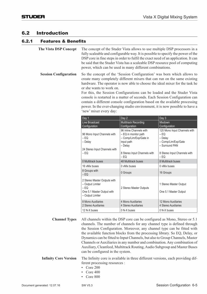
6.2 introduction6.2.1 features & Benefits
The Vista DSP Concept The concept of the Studer Vista allows to use multiple DSP processors in a fully scaleable and configurable way. It is possible to specify the power of the DSP core in fine steps in order to fulfil the exact need of an application. It can be said that the Studer Vista has a scaleable DSP resource pool of computing power, which can be used in many different combinations.
Session Configuration So the concept of the ‘Session Configuration’ was born which allows to create many completely different mixers that can run on the same existing hardware. The operator is now able to choose the ideal mixer for the task he or she wants to work on.
For this, the Session Configurations can be loaded and the Studer Vista console is restarted in a matter of seconds. Each Session Configuration can contain a different console configuration based on the available processing power. In the ever-changing studio environment, it is now possible to have a ‘new’ mixer every day:
Day 1 Day 2 Day 3Live Broadcast Configuration
Multitrack Recording Configuration
Mixdown Configuration
96 Mono Input Channels with– EQ– Delay
24 Stereo Input Channels with– EQ
96 Inline Channels with– EQ in monitor path– Comp/Lim/Exp/Gate in input path– Delay
8 Stereo Input Channels with– EQ
120 Mono Input Channels with– EQ– Delay– Comp/Lim/Exp/Gate– Surround PAN
8 Stereo Input Channels with– EQ
0 Multitrack buses 48 Multitrack buses 8 Multitrack buses16 vMix buses 0 vMix buses 0 vMix buses8 Groups with – EQ 0 Groups 16 Groups
2 Stereo Master Outputs with – Output Limiter– EQOne 5.1 Master Output with– Output Limiter
2 Stereo Master Outputs1 Stereo Master Output
One 5.1 Master Output
8 Mono Auxiliaries2 Stereo Auxiliaries
4 Mono Auxiliaries4 Stereo Auxiliaries
12 Mono Auxiliaries4 Stereo Auxiliaries
12 N-X buses 0 N-X buses 0 N-X buses
Channel Types All channels within the DSP core can be configured as Mono, Stereo or 5.1 channels. The number of channels for any channel type is defined through the Session Configuration. Moreover, any channel type can be fitted with the available function blocks from the processing library. So EQ, Delay, or Dynamics can be fitted to Input Channels, but also to Group Channels, Master Channels or Auxiliaries in any number and combination. Any combination of Auxiliary, Cleanfeed, Multitrack Routing, Audio Subgroup and Master Buses can be configured in the system.
Infinity Core Version The Infinity core is available in three different versions, each providing dif-ferent processing resources :
• Core200 • Core400 • Core800
Vista X Digital Mixing System
Session Configuration 6-5Document generated: 12.07.16 SW V5.3
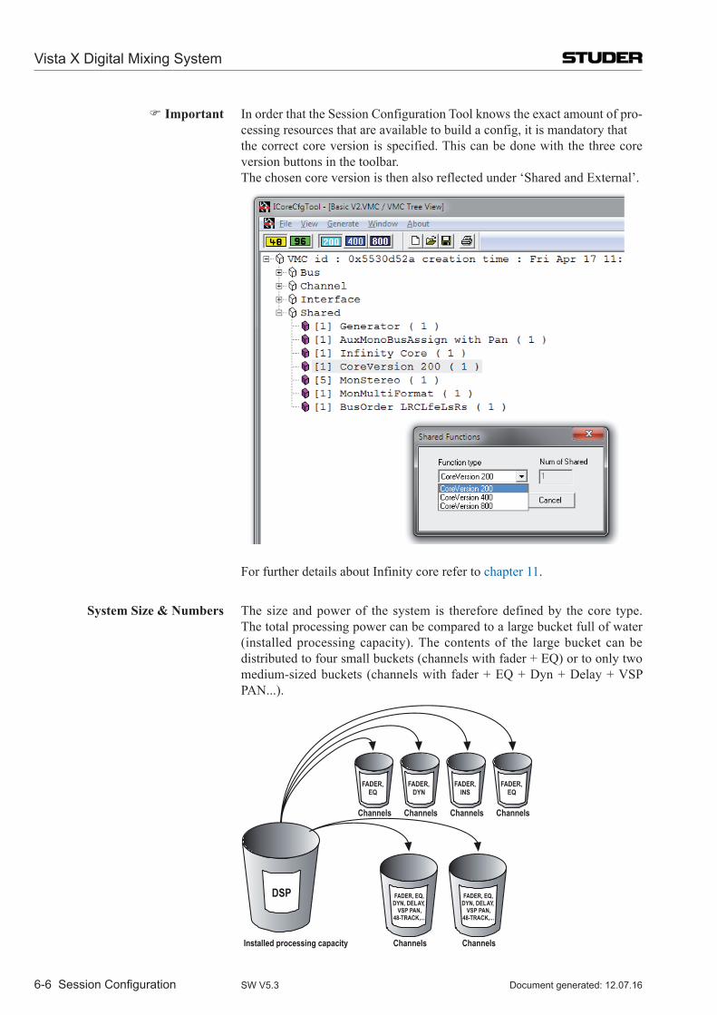
Important In order that the Session Configuration Tool knows the exact amount of pro-cessing resources that are available to build a config, it is mandatory that
the correct core version is specified. This can be done with the three core version buttons in the toolbar.
The chosen core version is then also reflected under ‘Shared and External’.
For further details about Infinity core refer to chapter 11.
System Size & Numbers The size and power of the system is therefore defined by the core type. The total processing power can be compared to a large bucket full of water (installed processing capacity). The contents of the large bucket can be distributed to four small buckets (channels with fader + EQ) or to only two medium-sized buckets (channels with fader + EQ + Dyn + Delay + VSP PAN...).
Channels Channels Channels Channels
Channels Channels
DSP FADER, EQ,DYN, DELAY,
VSP PAN,48-TRACK,...
FADER, EQ,DYN, DELAY,
VSP PAN,48-TRACK,...
FADER, DYN
FADER, INS
FADER, EQ
FADER, EQ
Installed processing capacity
Vista X Digital Mixing System
6-6 Session Configuration Document generated: 12.07.16SW V5.3
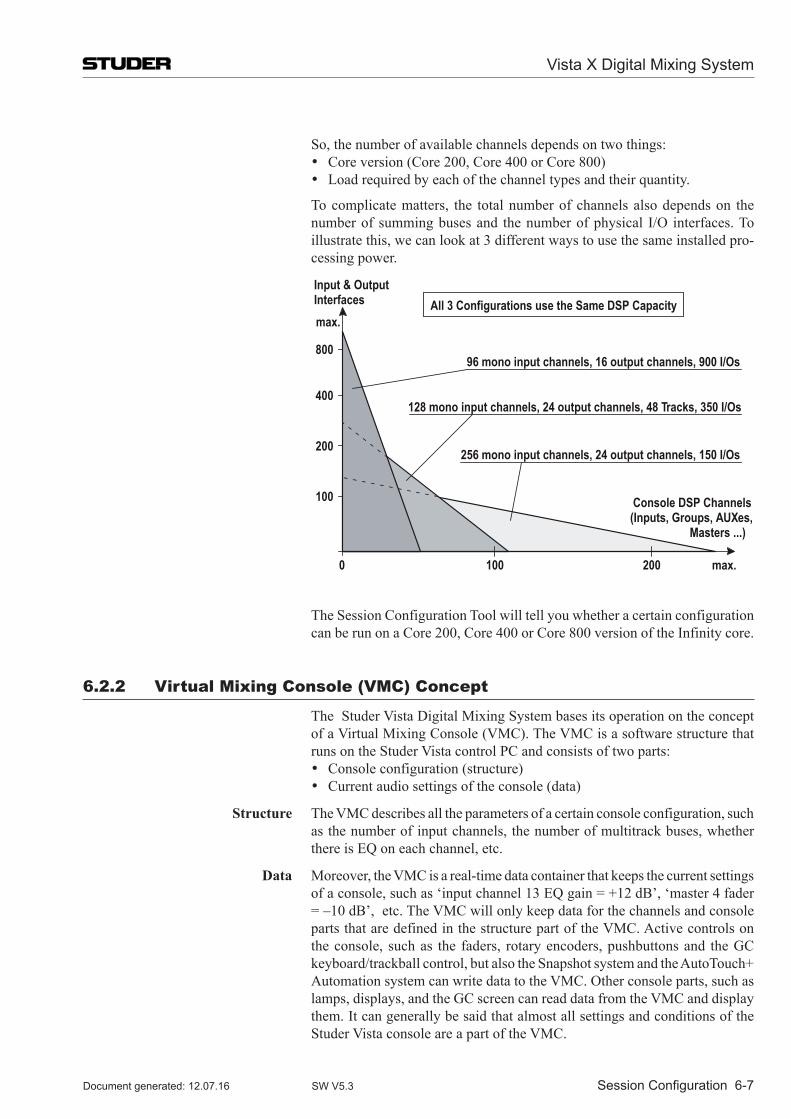
So, the number of available channels depends on two things:• Core version (Core 200, Core 400 or Core 800)• Load required by each of the channel types and their quantity.
To complicate matters, the total number of channels also depends on the number of summing buses and the number of physical I/O interfaces. To illustrate this, we can look at 3 different ways to use the same installed pro-cessing power.
Input & Output Interfaces
Console DSP Channels (Inputs, Groups, AUXes,
Masters ...)
100
200
400
800
002001
max.
256 mono input channels, 24 output channels, 150 I/Os
128 mono input channels, 24 output channels, 48 Tracks, 350 I/Os
96 mono input channels, 16 output channels, 900 I/Os
All 3 Configurations use the Same DSP Capacity
0 max.
The Session Configuration Tool will tell you whether a certain configuration
can be run on a Core 200, Core 400 or Core 800 version of the Infinity core.
6.2.2 Virtual Mixing Console (VMC) Concept
The Studer Vista Digital Mixing System bases its operation on the concept of a Virtual Mixing Console (VMC). The VMC is a software structure that runs on the Studer Vista control PC and consists of two parts:• Console configuration (structure)• Current audio settings of the console (data)
Structure The VMC describes all the parameters of a certain console configuration, such as the number of input channels, the number of multitrack buses, whether there is EQ on each channel, etc.
Data Moreover, the VMC is a real-time data container that keeps the current settings of a console, such as ‘input channel 13 EQ gain = +12 dB’, ‘master 4 fader = –10 dB’, etc. The VMC will only keep data for the channels and console parts that are defined in the structure part of the VMC. Active controls on the console, such as the faders, rotary encoders, pushbuttons and the GC keyboard/trackball control, but also the Snapshot system and the AutoTouch+ Automation system can write data to the VMC. Other console parts, such as lamps, displays, and the GC screen can read data from the VMC and display them. It can generally be said that almost all settings and conditions of the Studer Vista console are a part of the VMC.
Vista X Digital Mixing System
Session Configuration 6-7Document generated: 12.07.16 SW V5.3
Make and Edit a Configuration The Session Configuration Tool can be used to make a new configuration, or to edit an existing one. This is the first part of the process of preparing a VMC for the Studer Vista console. That part is done off-line, even if the Configuration Tool is running on the Studer Vista Control PC. The results of this part are:
• A‘meta’VMCfile(*.vmc) – the definition of the console structure • aXMLconfigurationfile(*.xml) – file that tells the DSP core what to do • aMixercloudPathsfile(*.txt) – a list of all parameters • aVmcMappingInformationfile(*.xml) – a mapping file • Configurationknowledgefile(*.ckf) – stores other configuration relevant
information.
Use a Configuration When we operate the Studer Vista console, we speak of ‘loading a configura-tion’. This means loading the ‘meta’ VMC file to the memory of the Studer Vista Control PC. This process will remove the current file from the Studer Vista memory and load a different one. The Studer Vista Control software will then, based on information contained in the new files, run a VMC that corresponds to the information from the ‘meta’ VMC file. It will also remove the current processing xml file, replacing it with a new one, thus activating a new VMC. Now the Studer Vista is ready to work with the new Session Configuration.
There can only be one VMC that is active on the Studer Vista console at any one time, but there can be multiple VMCs configured and saved for later use.
6.2.3 The Practical Side
The purpose of the Session Configuration Tool is to allow creating and modi-fying ‘meta’ VMC files and generating the xml files from the information contained in the ‘meta’ VMC file. We call this process ‘making a Session Configuration’. There are always five files that are the result of making a Session Configuration:
• the‘meta’VMCfilecalledMyConfig.vmc • theprocessingxmlfilecalledMyConfig.xml • theMixercloudPathsfilecalledMyConfig-MixercloudPaths.txt • theVmcMappingInformationfilecalled MyConfig-VmcMappingInformation.xml • theconfigurationknowledgefilecalledMyConfig.ckf
The name ‘MyConfig’ stands for any name selected by the user. The endings ‘.vmc’, ‘.xml’ and ‘.ckf’ are mandatory. They are automatically created by the Tool and do not have to be typed.
It is mandatory to keep all Session Configurations in the Windows folder C:\D950SYSTEMDB, because both the Session Configuration Tool and the Studer Vista System software are set to search in this folder automatically. The Configuration Tool will automatically create a subdirectory (folder) within C:\D950SYSTEMDB, with the same name as the Session Configuration, so the folder structure may look similar to this:
Vista X Digital Mixing System
6-8 Session Configuration Document generated: 12.07.16SW V5.3
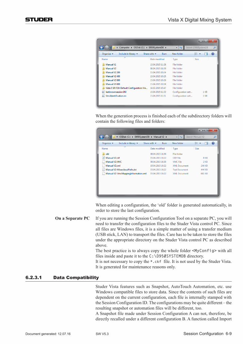
When the generation process is finished each of the subdirectory folders will contain the following files and folders:
When editing a configuration, the ‘old’ folder is generated automatically, in order to store the last configuration.
On a Separate PC If you are running the Session Configuration Tool on a separate PC, you will need to transfer the configuration files to the Studer Vista control PC. Since all files are Windows files, it is a simple matter of using a transfer medium (USB stick, LAN) to transport the files. Care has to be taken to store the files under the appropriate directory on the Studer Vista control PC as described above.
The best practice is to always copy the whole folder <MyConfig> with all files inside and paste it to the C:\D950SYSTEMDB directory.
It is not necessary to copy the *.ckf file. It is not used by the Studer Vista. It is generated for maintenance reasons only.
6.2.3.1 Data Compatibility
Studer Vista features such as Snapshot, AutoTouch Automation, etc. use Windows compatible files to store data. Since the contents of such files are dependent on the current configuration, each file is internally stamped with the Session Configuration ID. The configurations may be quite different – the resulting snapshot or automation files will be different, too.
A Snapshot file made under Session Configuration A can not, therefore, be directly recalled under a different configuration B. A function called Import
Vista X Digital Mixing System
Session Configuration 6-9Document generated: 12.07.16 SW V5.3
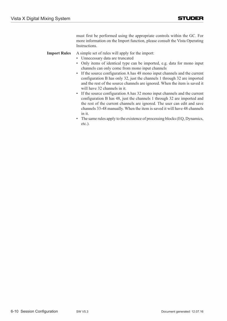
must first be performed using the appropriate controls within the GC. For more information on the Import function, please consult the Vista Operating Instructions.
Import Rules A simple set of rules will apply for the import: • Unnecessarydataaretruncated • Only itemsof identical typecanbe imported,e.g.dataformonoinput
channels can only come from mono input channels • IfthesourceconfigurationAhas48monoinputchannelsandthecurrent
configuration B has only 32, just the channels 1 through 32 are imported and the rest of the source channels are ignored. When the item is saved it will have 32 channels in it.
• IfthesourceconfigurationAhas32monoinputchannelsandthecurrentconfiguration B has 48, just the channels 1 through 32 are imported and the rest of the current channels are ignored. The user can edit and save channels 33-48 manually. When the item is saved it will have 48 channels in it.
• Thesamerulesapplytotheexistenceofprocessingblocks(EQ,Dynamics,etc.).
Vista X Digital Mixing System
6-10 Session Configuration Document generated: 12.07.16SW V5.3
6.3 The fast lane – Try it!6.3.1 Do your own – use Existing or Start from Scratch?
6.3.1.1 use an Existing VMC
Usually the changes that need to be made to a configuration are small. Adding two more AUXes or replacing the mono input channels by stereo input chan-nels may be two examples of such small changes. In such cases, an existing *.vmc file can be loaded and modified. For the first try you can use the *.vmc file that was delivered with your console as a starting point.
The *.vmc files can be treated in a similar way as word processing documents. They can be opened, saved, saved under a different name, moved and deleted.
Tip Please be careful to first save the file under a different name in order to keep the Studer Vista basic configuration intact! Use the Save As item in the File menu.
Modifying the *.vmc file that had been delivered with your console is the simplest way to create a configuration that will run properly on your existing Studer Vista console. On your console, there are several things that can not simply be changed by editing the configuration:
• AllexternalI/Owiring • Monitoringwiringandmonitoringconfiguration • Signaling(faderstart,...)wiringandconfiguration
It is not very likely that you will be changing any of the above all the time – that is why you will want to use the existing configuration as a starting point for your work, without having to think of configuring the right I/O every time.
Tip It could be that you want to change the sampling rate of an existing configura-tion. Just hit the according button on the toolbar, and you are done.
The Configuration Tool will prompt you about functions which are not sup-ported under the selected sample frequency. It says, that they are not sup-ported and therefore will be removed automatically.
Note : Currently for the Infinity core, only the sample frequency 48 kHz is available.
6.3.1.2 Start from Scratch
It is sometimes handy to find out which Core version (Core 200, Core 400 or Core 800) would be needed for a certain configuration. You can always configure the mixing console of any description by starting with an empty (New) *.vmc file. For this, you will use the File/New menu. The approach of starting from scratch will be useful if you do not have to modify an existing console, but are really starting a new project.
The first thing you need to do is selecting the sample frequency. The default value is 48 kHz. The buttons on the toolbar show the selected value.
Tip If you want the new configuration to really run on your existing console, you need to be careful to think of all the elements of a configuration – channel numbers and types, summing buses, I/O configuration, shared functions, etc. Otherwise your new configuration may not be able to be loaded properly on an existing console.
Vista X Digital Mixing System
Session Configuration 6-11Document generated: 12.07.16 SW V5.3
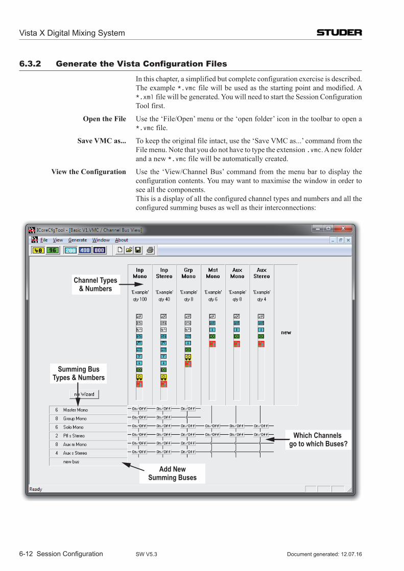
6.3.2 generate the Vista Configuration files
In this chapter, a simplified but complete configuration exercise is described. The example *.vmc file will be used as the starting point and modified. A *.xml file will be generated. You will need to start the Session Configuration Tool first.
Open the File Use the ‘File/Open’ menu or the ‘open folder’ icon in the toolbar to open a *.vmc file.
Save VMC as... To keep the original file intact, use the ‘Save VMC as...’ command from the File menu. Note that you do not have to type the extension .vmc. A new folder and a new *.vmc file will be automatically created.
View the Configuration Use the ‘View/Channel Bus’ command from the menu bar to display the configuration contents. You may want to maximise the window in order to see all the components.
This is a display of all the configured channel types and numbers and all the configured summing buses as well as their interconnections:
Channel Types& Numbers
Which Channels go to which Buses?
Add NewSumming Buses
Summing BusTypes & Numbers
Vista X Digital Mixing System
6-12 Session Configuration Document generated: 12.07.16SW V5.3
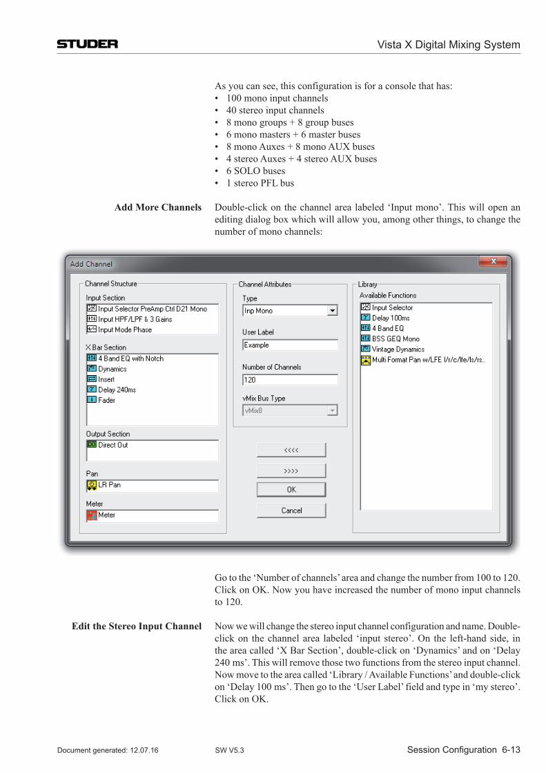
As you can see, this configuration is for a console that has: • 100monoinputchannels • 40stereoinputchannels • 8monogroups+8groupbuses • 6monomasters+6masterbuses • 8monoAuxes+8monoAUXbuses • 4stereoAuxes+4stereoAUXbuses • 6SOLObuses • 1stereoPFLbus
Add More Channels Double-click on the channel area labeled ‘Input mono’. This will open an editing dialog box which will allow you, among other things, to change the number of mono channels:
Go to the ‘Number of channels’ area and change the number from 100 to 120. Click on OK. Now you have increased the number of mono input channels to 120.
Edit the Stereo Input Channel Now we will change the stereo input channel configuration and name. Double-click on the channel area labeled ‘input stereo’. On the left-hand side, in the area called ‘X Bar Section’, double-click on ‘Dynamics’ and on ‘Delay 240 ms’. This will remove those two functions from the stereo input channel. Now move to the area called ‘Library / Available Functions’ and double-click on ‘Delay 100 ms’. Then go to the ‘User Label’ field and type in ‘my stereo’. Click on OK.
Vista X Digital Mixing System
Session Configuration 6-13Document generated: 12.07.16 SW V5.3
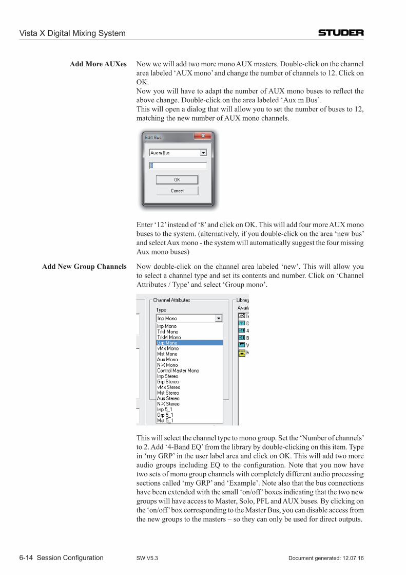
Add More AUXes Now we will add two more mono AUX masters. Double-click on the channel area labeled ‘AUX mono’ and change the number of channels to 12. Click on OK.
Now you will have to adapt the number of AUX mono buses to reflect the above change. Double-click on the area labeled ‘Aux m Bus’.
This will open a dialog that will allow you to set the number of buses to 12, matching the new number of AUX mono channels.
Enter ‘12’ instead of ‘8’ and click on OK. This will add four more AUX mono buses to the system. (alternatively, if you double-click on the area ‘new bus’ and select Aux mono - the system will automatically suggest the four missing Aux mono buses)
Add New Group Channels Now double-click on the channel area labeled ‘new’. This will allow you to select a channel type and set its contents and number. Click on ‘Channel Attributes / Type’ and select ‘Group mono’.
This will select the channel type to mono group. Set the ‘Number of channels’ to 2. Add ‘4-Band EQ’ from the library by double-clicking on this item. Type in ‘my GRP’ in the user label area and click on OK. This will add two more audio groups including EQ to the configuration. Note that you now have two sets of mono group channels with completely different audio processing sections called ‘my GRP’ and ‘Example’. Note also that the bus connections have been extended with the small ‘on/off’ boxes indicating that the two new groups will have access to Master, Solo, PFL and AUX buses. By clicking on the ‘on/off’ box corresponding to the Master Bus, you can disable access from the new groups to the masters – so they can only be used for direct outputs.
Vista X Digital Mixing System
6-14 Session Configuration Document generated: 12.07.16SW V5.3
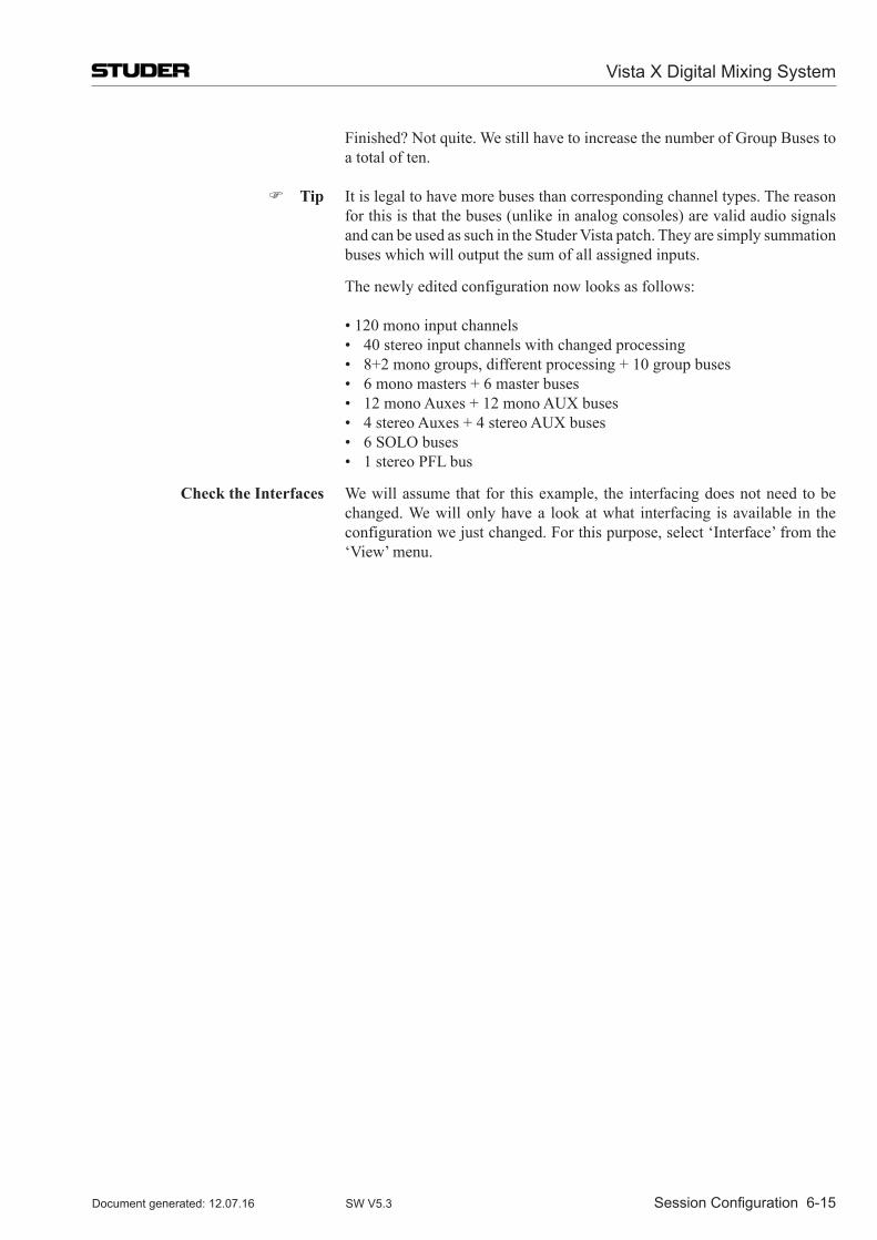
Finished? Not quite. We still have to increase the number of Group Buses to a total of ten.
Tip It is legal to have more buses than corresponding channel types. The reason for this is that the buses (unlike in analog consoles) are valid audio signals and can be used as such in the Studer Vista patch. They are simply summation buses which will output the sum of all assigned inputs.
The newly edited configuration now looks as follows:
•120monoinputchannels • 40stereoinputchannelswithchangedprocessing • 8+2monogroups,differentprocessing+10groupbuses • 6monomasters+6masterbuses • 12monoAuxes+12monoAUXbuses • 4stereoAuxes+4stereoAUXbuses • 6SOLObuses • 1stereoPFLbus
Check the Interfaces We will assume that for this example, the interfacing does not need to be changed. We will only have a look at what interfacing is available in the configuration we just changed. For this purpose, select ‘Interface’ from the ‘View’ menu.
Vista X Digital Mixing System
Session Configuration 6-15Document generated: 12.07.16 SW V5.3
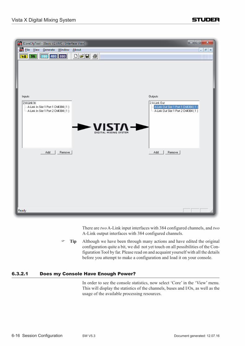
There are two A-Link input interfaces with 384 configured channels, and two A-Link output interfaces with 384 configured channels.
Tip Although we have been through many actions and have edited the original configuration quite a bit, we did not yet touch on all possibilities of the Con-figuration Tool by far. Please read on and acquaint yourself with all the details before you attempt to make a configuration and load it on your console.
6.3.2.1 Does my Console Have Enough Power?
In order to see the console statistics, now select ‘Core’ in the ‘View’ menu. This will display the statistics of the channels, buses and I/Os, as well as the usage of the available processing resources.
Vista X Digital Mixing System
6-16 Session Configuration Document generated: 12.07.16SW V5.3
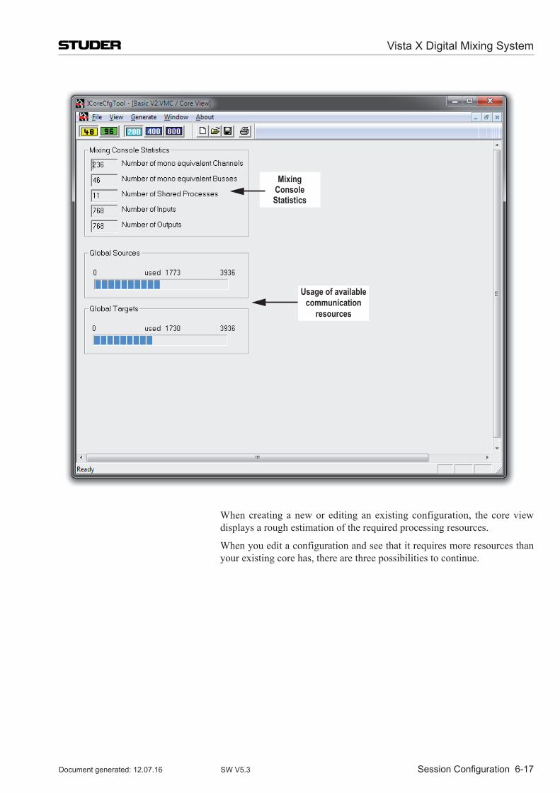
MixingConsoleStatistics
Usage of available communication
resources
When creating a new or editing an existing configuration, the core view displays a rough estimation of the required processing resources.
When you edit a configuration and see that it requires more resources than your existing core has, there are three possibilities to continue.
Vista X Digital Mixing System
Session Configuration 6-17Document generated: 12.07.16 SW V5.3
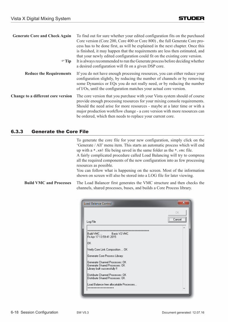
Generate Core and Check Again To find out for sure whether your edited configuration fits on the purchased Core version (Core 200, Core 400 or Core 800) , the full Generate Core pro-cess has to be done first, as will be explained in the next chapter. Once this is finished, it may happen that the requirements are less then estimated, and that your newly edited configuration could fit on the existing core version.
Tip It is always recommended to run the Generate process before deciding whether a desired configuration will fit on a given DSP core.
Reduce the Requirements If you do not have enough processing resources, you can either reduce your configuration slightly, by reducing the number of channels or by removing some Dynamics or EQs you do not really need, or by reducing the number of I/Os, until the configuration matches your actual core version.
Change to a different core version The core version that you purchase with your Vista system should of course provide enough processing resources for your mixing console requirements. Should the need arise for more resources - maybe at a later time or with a major production workflow change - a core version with more resources can be ordered, which then needs to replace your current core.
6.3.3 generate the Core file
To generate the core file for your new configuration, simply click on the ‘Generate / All’ menu item. This starts an automatic process which will end up with a *.xml file being saved in the same folder as the *.vmc file.
A fairly complicated procedure called Load Balancing will try to compress all the required components of the new configuration into as few processing resources as possible.
You can follow what is happening on the screen. Most of the information shown on screen will also be stored into a LOG file for later viewing.
Build VMC and Processes The Load Balancer first generates the VMC structure and then checks the channels, shared processes, buses, and builds a Core Process library.
Vista X Digital Mixing System
6-18 Session Configuration Document generated: 12.07.16SW V5.3
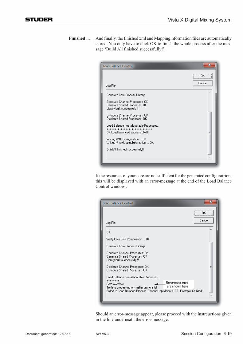
Finished ... And finally, the finished xml and Mappinginformation files are automatically stored. You only have to click OK to finish the whole process after the mes-sage ‘Build All finished successfully!’.
If the resources of your core are not sufficient for the generated configuratrion,
this will be displayed with an error-message at the end of the Load Balance Control window :
Error-messages are shown here
Should an error-message appear, please proceed with the instrcuctions given in the line underneath the error-message.
Vista X Digital Mixing System
Session Configuration 6-19Document generated: 12.07.16 SW V5.3
6.3.4 Transfer the files to the Console
The processing xml file and the ‘meta’ VMC files are now ready to be used on a Vista console.
On the Studer Vista System If you are running the Session Configuration Tool on the Vista desk, there is nothing more you need to do in order to load a configuration. Simply switch to the Vista application (i.e., the GC) and load a new configuration from the GC File menu.
On a Separate PC If you are running the Session Configuration Tool on a separate PC, you will need to transfer the configuration files to the Studer Vista control PC. Since all files are Windows files, it is a simple matter of using a transfer medium (USB stick, LAN) to transport the files. Care has to be taken to store the files under the appropriate directory on the Studer Vista control PC as described above.
The best practice is to always copy the whole folder <MyConfig> with all files inside and paste it to the C:\D950SYSTEMDB directory.
It is not necessary to copy the *.ckf file. It is not used by the Studer Vista. It is generated for maintenance reasons only.
Vista X Digital Mixing System
6-20 Session Configuration Document generated: 12.07.16SW V5.3
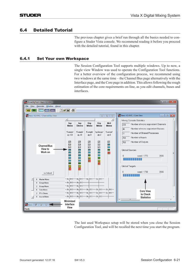
6.4 Detailed Tutorial The previous chapter gives a brief run through all the basics needed to con-
figure a Studer Vista console. We recommend reading it before you proceed with the detailed tutorial, found in this chapter.
6.4.1 Set your own Workspace
The Session Configuration Tool supports multiple windows. Up to now, a single view Window was used to operate the Configuration Tool functions. For a better overview of the configuration process, we recommend using two windows at the same time – the Channel/Bus page alternatively with the Interface page, and the Core page in addition. This allows following the rough estimation of the core requirements on-line, as you edit channels, buses and interfaces.
Channel/BusView to Work on
MinimizedInterface
View
Core View to CheckStatistics
The last used Workspace setup will be stored when you close the Session Configuration Tool, and will be recalled the next time you start the program.
Vista X Digital Mixing System
Session Configuration 6-21Document generated: 12.07.16 SW V5.3
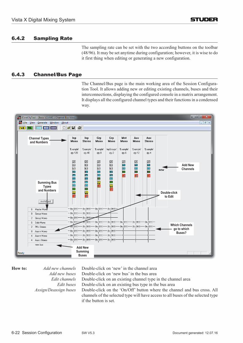
6.4.2 Sampling Rate
The sampling rate can be set with the two according buttons on the toolbar (48/96). It may be set anytime during configuration; however, it is wise to do it first thing when editing or generating a new configuration.
6.4.3 Channel/Bus Page
The Channel/Bus page is the main working area of the Session Configura-tion Tool. It allows adding new or editing existing channels, buses and their interconnections, displaying the configured console in a matrix arrangement. It displays all the configured channel types and their functions in a condensed way.
Channel Typesand Numbers
Add NewChannels
Double-clickto Edit
Which Channelsgo to which
Buses?
Add NewSumming
Buses
Summing BusTypes
and Numbers
How to: Add new channels Double-click on ‘new’ in the channel area Add new buses Double-click on ‘new bus’ in the bus area Edit channels Double-click on an existing channel type in the channel area Edit buses Double-click on an existing bus type in the bus area Assign/Deassign buses Double-click on the ‘On/Off’ button where the channel and bus cross. All
channels of the selected type will have access to all buses of the selected type if the button is set.
Vista X Digital Mixing System
6-22 Session Configuration Document generated: 12.07.16SW V5.3
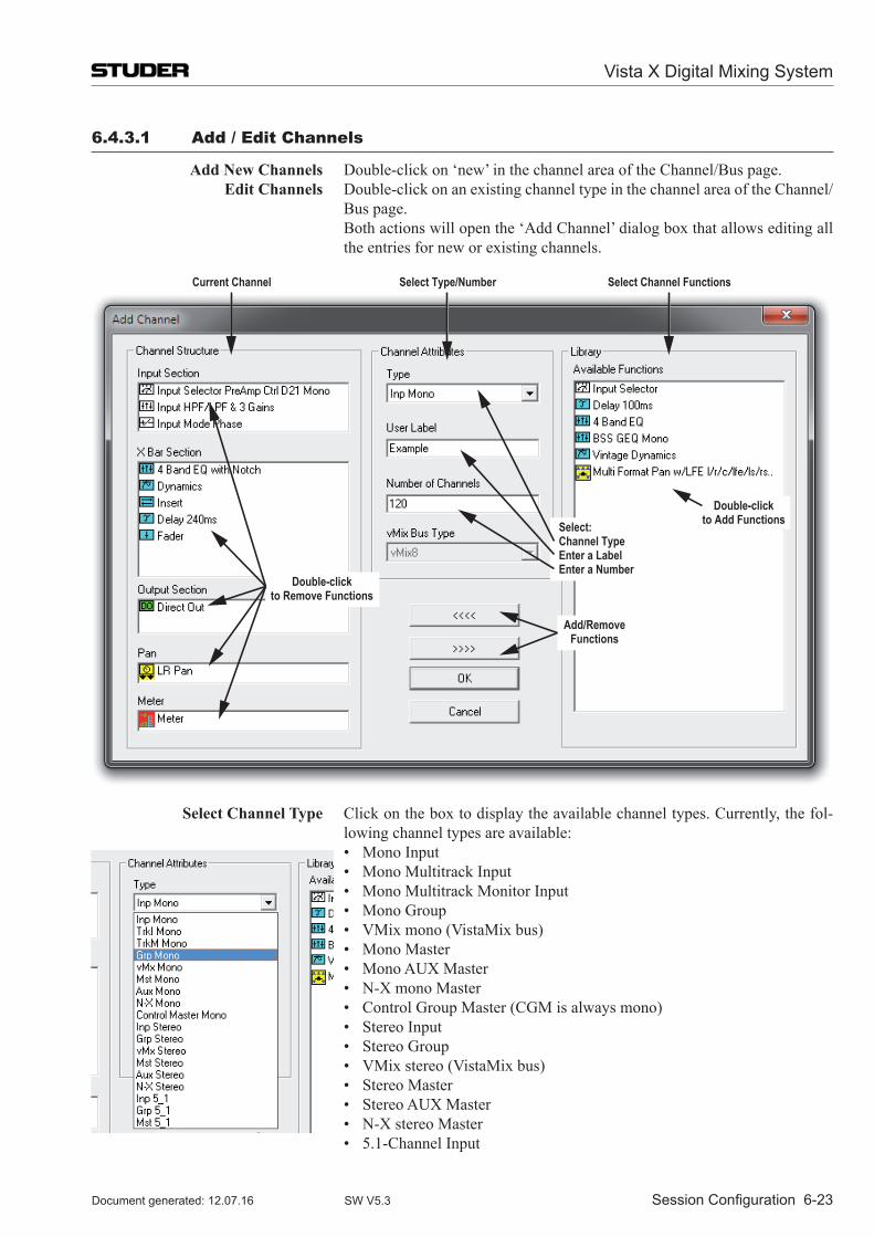
6.4.3.1 Add / Edit Channels
Add New Channels Double-click on ‘new’ in the channel area of the Channel/Bus page. Edit Channels Double-click on an existing channel type in the channel area of the Channel/
Bus page. Both actions will open the ‘Add Channel’ dialog box that allows editing all
the entries for new or existing channels.
Double-clickto Add Functions
Double-clickto Remove Functions
Select:Channel TypeEnter a LabelEnter a Number
Current Channel Select Type/Number Select Channel Functions
Add/RemoveFunctions
Select Channel Type Click on the box to display the available channel types. Currently, the fol-lowing channel types are available:
• MonoInput • MonoMultitrackInput • MonoMultitrackMonitorInput • MonoGroup • VMixmono(VistaMixbus) • MonoMaster • MonoAUXMaster • N-XmonoMaster • ControlGroupMaster(CGMisalwaysmono) • StereoInput • StereoGroup • VMixstereo(VistaMixbus) • StereoMaster • StereoAUXMaster • N-XstereoMaster • 5.1-ChannelInput
Vista X Digital Mixing System
Session Configuration 6-23Document generated: 12.07.16 SW V5.3
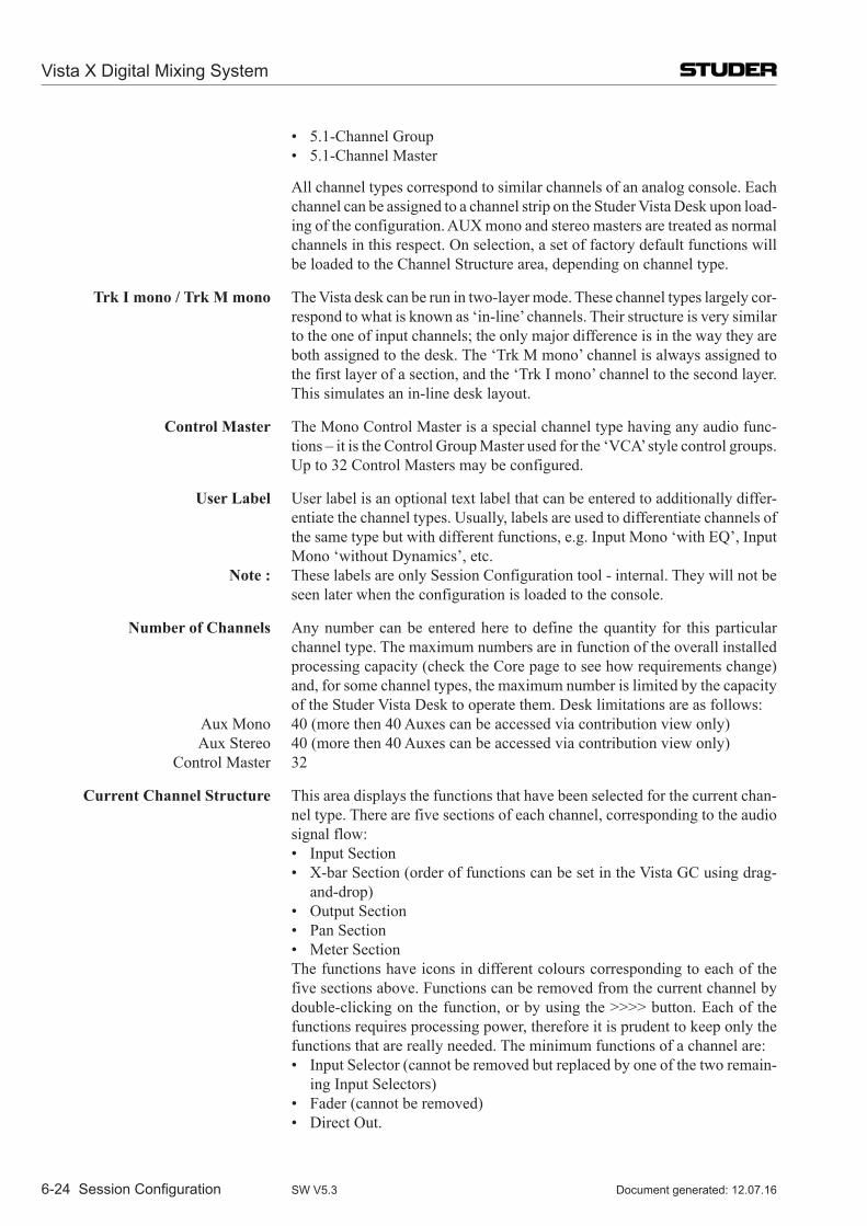
• 5.1-ChannelGroup • 5.1-ChannelMaster
All channel types correspond to similar channels of an analog console. Each channel can be assigned to a channel strip on the Studer Vista Desk upon load-ing of the configuration. AUX mono and stereo masters are treated as normal channels in this respect. On selection, a set of factory default functions will be loaded to the Channel Structure area, depending on channel type.
Trk I mono / Trk M mono The Vista desk can be run in two-layer mode. These channel types largely cor-respond to what is known as ‘in-line’ channels. Their structure is very similar to the one of input channels; the only major difference is in the way they are both assigned to the desk. The ‘Trk M mono’ channel is always assigned to the first layer of a section, and the ‘Trk I mono’ channel to the second layer. This simulates an in-line desk layout.
Control Master The Mono Control Master is a special channel type having any audio func-tions – it is the Control Group Master used for the ‘VCA’ style control groups. Up to 32 Control Masters may be configured.
User Label User label is an optional text label that can be entered to additionally differ-entiate the channel types. Usually, labels are used to differentiate channels of the same type but with different functions, e.g. Input Mono ‘with EQ’, Input Mono ‘without Dynamics’, etc.
Note : These labels are only Session Configuration tool - internal. They will not be seen later when the configuration is loaded to the console.
Number of Channels Any number can be entered here to define the quantity for this particular channel type. The maximum numbers are in function of the overall installed processing capacity (check the Core page to see how requirements change) and, for some channel types, the maximum number is limited by the capacity of the Studer Vista Desk to operate them. Desk limitations are as follows:
Aux Mono 40 (more then 40 Auxes can be accessed via contribution view only) Aux Stereo 40 (more then 40 Auxes can be accessed via contribution view only) Control Master 32
Current Channel Structure This area displays the functions that have been selected for the current chan-nel type. There are five sections of each channel, corresponding to the audio signal flow:
• InputSection • X-barSection(orderoffunctionscanbesetintheVistaGCusingdrag-
and-drop) • OutputSection • PanSection • MeterSection The functions have icons in different colours corresponding to each of the
five sections above. Functions can be removed from the current channel by double-clicking on the function, or by using the >>>> button. Each of the functions requires processing power, therefore it is prudent to keep only the functions that are really needed. The minimum functions of a channel are:
• InputSelector(cannotberemovedbutreplacedbyoneofthetworemain-ing Input Selectors)
• Fader(cannotberemoved) • DirectOut.
Vista X Digital Mixing System
6-24 Session Configuration Document generated: 12.07.16SW V5.3
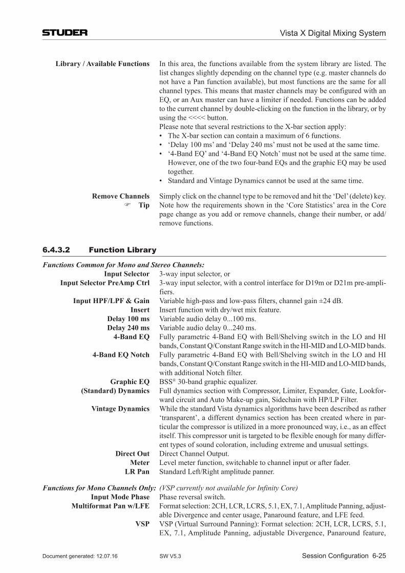
Library / Available Functions In this area, the functions available from the system library are listed. The list changes slightly depending on the channel type (e.g. master channels do not have a Pan function available), but most functions are the same for all channel types. This means that master channels may be configured with an EQ, or an Aux master can have a limiter if needed. Functions can be added to the current channel by double-clicking on the function in the library, or by using the <<<< button.
Please note that several restrictions to the X-bar section apply: • TheX-barsectioncancontainamaximumof6functions. • ‘Delay100ms’and‘Delay240ms’mustnotbeusedatthesametime. • ‘4-BandEQ’and‘4-BandEQNotch’mustnotbeusedatthesametime.
However, one of the two four-band EQs and the graphic EQ may be used together.
• StandardandVintageDynamicscannotbeusedatthesametime.
Remove Channels Simply click on the channel type to be removed and hit the ‘Del’ (delete) key. Tip Note how the requirements shown in the ‘Core Statistics’ area in the Core
page change as you add or remove channels, change their number, or add/remove functions.
6.4.3.2 function library
Functions Common for Mono and Stereo Channels: Input Selector 3-way input selector, or Input Selector PreAmp Ctrl 3-way input selector, with a control interface for D19m or D21m pre-ampli-
fiers. Input HPF/LPF & Gain Variable high-pass and low-pass filters, channel gain ±24 dB. Insert Insert function with dry/wet mix feature. Delay 100 ms VariabIe audio delay 0...100 ms. Delay 240 ms VariabIe audio delay 0...240 ms. 4-Band EQ Fully parametric 4-Band EQ with Bell/Shelving switch in the LO and HI
bands, Constant Q/Constant Range switch in the HI-MID and LO-MID bands. 4-Band EQ Notch Fully parametric 4-Band EQ with Bell/Shelving switch in the LO and HI
bands, Constant Q/Constant Range switch in the HI-MID and LO-MID bands, with additional Notch filter.
Graphic EQ BSS® 30-band graphic equalizer. (Standard) Dynamics Full dynamics section with Compressor, Limiter, Expander, Gate, Lookfor-
ward circuit and Auto Make-up gain, Sidechain with HP/LP Filter. Vintage Dynamics While the standard Vista dynamics algorithms have been described as rather
‘transparent’, a different dynamics section has been created where in par-ticular the compressor is utilized in a more pronounced way, i.e., as an effect itself. This compressor unit is targeted to be flexible enough for many differ-ent types of sound coloration, including extreme and unusual settings.
Direct Out Direct Channel Output. Meter Level meter function, switchable to channel input or after fader. LR Pan Standard Left/Right amplitude panner.
Functions for Mono Channels Only: (VSP currently not available for Infinity Core) Input Mode Phase Phase reversal switch. Multiformat Pan w/LFE Format selection: 2CH, LCR, LCRS, 5.1, EX, 7.1, Amplitude Panning, adjust-
able Divergence and center usage, Panaround feature, and LFE feed. VSP VSP (Virtual Surround Panning): Format selection: 2CH, LCR, LCRS, 5.1,
EX, 7.1, Amplitude Panning, adjustable Divergence, Panaround feature,
Vista X Digital Mixing System
Session Configuration 6-25Document generated: 12.07.16 SW V5.3
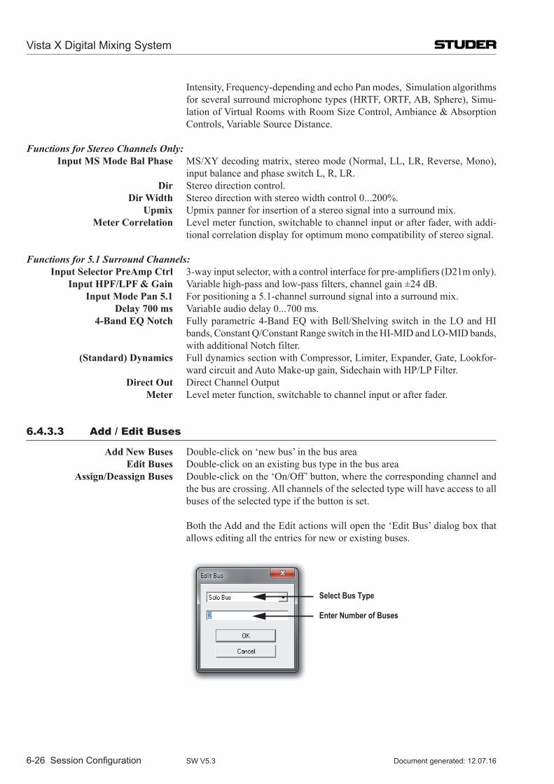
Intensity, Frequency-depending and echo Pan modes, Simulation algorithms for several surround microphone types (HRTF, ORTF, AB, Sphere), Simu-lation of Virtual Rooms with Room Size Control, Ambiance & Absorption Controls, Variable Source Distance.
Functions for Stereo Channels Only: Input MS Mode Bal Phase MS/XY decoding matrix, stereo mode (Normal, LL, LR, Reverse, Mono),
input balance and phase switch L, R, LR. Dir Stereo direction control. Dir Width Stereo direction with stereo width control 0...200%. Upmix Upmix panner for insertion of a stereo signal into a surround mix. Meter Correlation Level meter function, switchable to channel input or after fader, with addi-
tional correlation display for optimum mono compatibility of stereo signal.
Functions for 5.1 Surround Channels: Input Selector PreAmp Ctrl 3-way input selector, with a control interface for pre-amplifiers (D21m only). Input HPF/LPF & Gain Variable high-pass and low-pass filters, channel gain ±24 dB. Input Mode Pan 5.1 For positioning a 5.1-channel surround signal into a surround mix. Delay 700 ms VariabIe audio delay 0...700 ms. 4-Band EQ Notch Fully parametric 4-Band EQ with Bell/Shelving switch in the LO and HI
bands, Constant Q/Constant Range switch in the HI-MID and LO-MID bands, with additional Notch filter.
(Standard) Dynamics Full dynamics section with Compressor, Limiter, Expander, Gate, Lookfor-ward circuit and Auto Make-up gain, Sidechain with HP/LP Filter.
Direct Out Direct Channel Output Meter Level meter function, switchable to channel input or after fader.
6.4.3.3 Add / Edit Buses
Add New Buses Double-click on ‘new bus’ in the bus area Edit Buses Double-click on an existing bus type in the bus area Assign/Deassign Buses Double-click on the ‘On/Off’ button, where the corresponding channel and
the bus are crossing. All channels of the selected type will have access to all buses of the selected type if the button is set.
Both the Add and the Edit actions will open the ‘Edit Bus’ dialog box that allows editing all the entries for new or existing buses.
Select Bus Type
Enter Number of Buses
Vista X Digital Mixing System
6-26 Session Configuration Document generated: 12.07.16SW V5.3
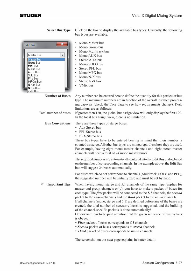
Select Bus Type Click on the box to display the available bus types. Currently, the following bus types are available:
• MonoMasterbus • MonoGroupbus • MonoMultitrackbus • MonoAUXbus • StereoAUXbus • MonoSOLObus • StereoPFLbus • MonoMPXbus • MonoN-Xbus • StereoN-Xbus • VMixbus
Number of Buses Any number can be entered here to define the quantity for this particular bus type. The maximum numbers are in function of the overall installed process-ing capacity (check the Core page to see how requirements change). Desk limitations are as follows:
Total number of buses If greater then 120, the global bus assign view will only display the first 120. In the local bus assign view, there is no limitation.
Bus Conventions There are three types of stereo buses: • Aux Stereo bus • PFL Stereo bus • N–X Stereo bus These bus types have to be entered bearing in mind that their number is
counted as stereo. All other bus types are mono, regardless how they are used. For example, having eight mono master channels and eight stereo master channels will need a total of 24 mono master buses.
The required numbers are automatically entered into the Edit Bus dialog based on the number of corresponding channels. In the example above, the Edit Bus box will suggest 24 buses automatically.
For buses which do not correspond to channels (Multitrack, SOLO and PFL), the suggested number will be initially zero and must be set by hand.
Important Tips When having mono, stereo and 5.1 channels of the same type (applies for master and group channels only), you have to make a packet of buses for each type. The first packet will be connected to the 5.1 channels, the second packet to the stereo channels and the third packet to the mono channels.
If all channels (mono, stereo and 5.1) are defined before any of the buses are created, the total number of necesarry buses is suggested, and the building of the channel-specific packets is done automatically!
Otherwise it has to be paid attention that the given sequence of bus packets is obeyed :
•First packet of buses corresponds to 5.1 channels •Second packet of buses corresponds to stereo channels •Third packet of buses corresponds to mono channels The screenshot on the next page explains in better detail :
Vista X Digital Mixing System
Session Configuration 6-27Document generated: 12.07.16 SW V5.3
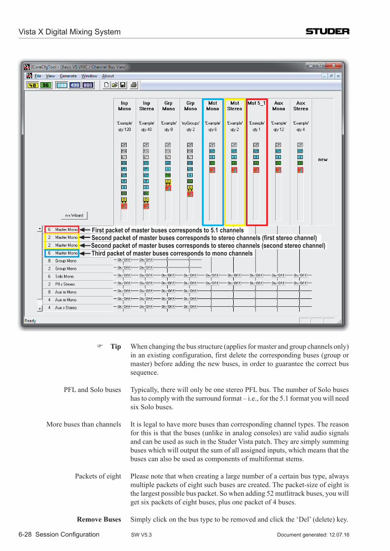
Third packet of master buses corresponds to mono channels
First packet of master buses corresponds to 5.1 channelsSecond packet of master buses corresponds to stereo channels (first stereo channel)Second packet of master buses corresponds to stereo channels (second stereo channel)
Tip When changing the bus structure (applies for master and group channels only) in an existing configuration, first delete the corresponding buses (group or master) before adding the new buses, in order to guarantee the correct bus sequence.
PFL and Solo buses Typically, there will only be one stereo PFL bus. The number of Solo buses has to comply with the surround format – i.e., for the 5.1 format you will need six Solo buses.
More buses than channels It is legal to have more buses than corresponding channel types. The reason for this is that the buses (unlike in analog consoles) are valid audio signals and can be used as such in the Studer Vista patch. They are simply summing buses which will output the sum of all assigned inputs, which means that the buses can also be used as components of multiformat stems.
Packets of eight Please note that when creating a large number of a certain bus type, always multiple packets of eight such buses are created. The packet-size of eight is the largest possible bus packet. So when adding 52 mutlitrack buses, you will get six packets of eight buses, plus one packet of 4 buses.
Remove Buses Simply click on the bus type to be removed and click the ‘Del’ (delete) key.
Vista X Digital Mixing System
6-28 Session Configuration Document generated: 12.07.16SW V5.3
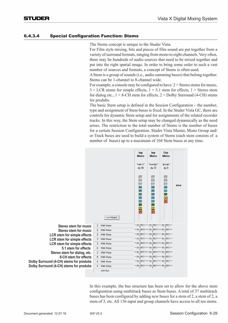
6.4.3.4 Special Configuration function: Stems
The Stems concept is unique to the Studer Vista. For Film style mixing, bits and pieces of film sound are put together from a
variety of surround formats, ranging from mono to eight channels. Very often, there may be hundreds of audio sources that need to be mixed together and put into the right spatial image. In order to bring some order to such a vast number of sources and formats, a concept of Stems is often used.
A Stem is a group of sounds (i.e., audio summing buses) that belong together. Stems can be 1-channel to 8-channel wide.
For example, a console may be configured to have: 2 × Stereo stems for music, 3 × LCR stems for simple effects, 1 × 5.1 stem for effects, 1 × Stereo stem for dialog etc., 1 × 8-CH stem for effects, 2 × Dolby Surround (4-CH) stems for predubs.
The basic Stem setup is defined in the Session Configuration – the number, type and assignment of Stem buses is fixed. In the Studer Vista GC, there are controls for dynamic Stem setup and for assignments of the related recorder tracks. In this way, the Stem setup may be changed dynamically as the need arises. The restriction to the total number of Stems is the number of buses for a certain Session Configuration. Studer Vista Master, Mono Group and/or Track buses are used to build a system of Stems (each stem consists of a number of buses) up to a maximum of 104 Stem buses at any time.
Stereo stem for musicStereo stem for music
LCR stem for simple effectsLCR stem for simple effectsLCR stem for simple effects
5.1 stem for effects Stereo stem for dialog, etc.
8-CH stem for effectsDolby Surround (4-CH) stems for predubsDolby Surround (4-CH) stems for predubs
In this example, the bus structure has been set to allow for the above stem configuration using multitrack buses as Stem buses. A total of 37 multitrack buses has been configured by adding new buses for a stem of 2, a stem of 2, a stem of 3, etc. All 136 input and group channels have access to all ten stems.
Vista X Digital Mixing System
Session Configuration 6-29Document generated: 12.07.16 SW V5.3
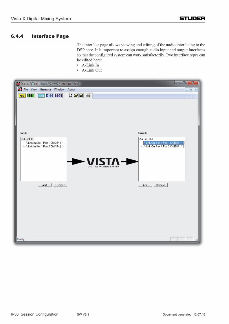
6.4.4 interface Page
The interface page allows viewing and editing of the audio interfacing to the DSP core. It is important to assign enough audio input and output interfaces so that the configured system can work satisfactorily. Two interface types can be edited here:
• A-LinkIn • A-LinkOut
Vista X Digital Mixing System
6-30 Session Configuration Document generated: 12.07.16SW V5.3
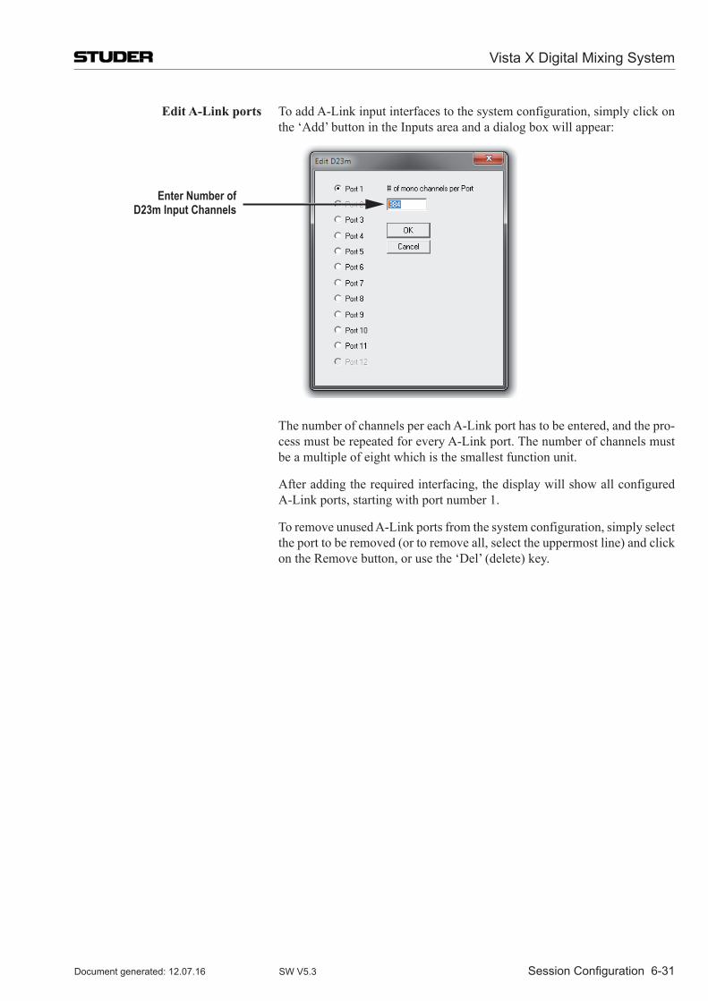
Edit A-Link ports To add A-Link input interfaces to the system configuration, simply click on the ‘Add’ button in the Inputs area and a dialog box will appear:
Enter Number ofD23m Input Channels
The number of channels per each A-Link port has to be entered, and the pro-cess must be repeated for every A-Link port. The number of channels must be a multiple of eight which is the smallest function unit.
After adding the required interfacing, the display will show all configured A-Link ports, starting with port number 1.
To remove unused A-Link ports from the system configuration, simply select the port to be removed (or to remove all, select the uppermost line) and click on the Remove button, or use the ‘Del’ (delete) key.
Vista X Digital Mixing System
Session Configuration 6-31Document generated: 12.07.16 SW V5.3
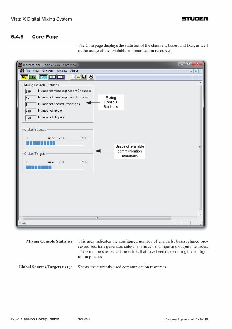
6.4.5 Core Page
The Core page displays the statistics of the channels, buses, and I/Os, as well as the usage of the available communication resources.
MixingConsoleStatistics
Usage of available communication
resources
Mixing Console Statistics This area indicates the configured number of channels, buses, shared pro-cesses (test tone generator, side-chain links), and input and output interfaces. These numbers reflect all the entries that have been made during the configu-ration process.
Global Sources/Targets usage Shows the currently used communication resources.
Vista X Digital Mixing System
6-32 Session Configuration Document generated: 12.07.16SW V5.3
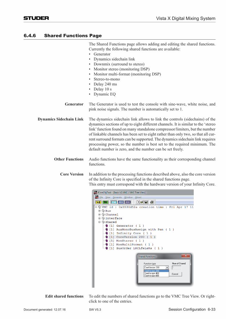
6.4.6 Shared functions Page
The Shared Functions page allows adding and editing the shared functions. Currently the following shared functions are available:
• Generator • Dynamicssidechainlink • Downmix(surroundtostereo) • Monitorstereo(monitoringDSP) • Monitormulti-format(monitoringDSP) • Stereo-to-mono • Delay240ms • Delay10s • DynamicEQ Generator The Generator is used to test the console with sine-wave, white noise, and
pink noise signals. The number is automatically set to 1.
Dynamics Sidechain Link The dynamics sidechain link allows to link the controls (sidechains) of the dynamics sections of up to eight different channels. It is similar to the ‘stereo link’ function found on many standalone compressor/limiters, but the number of linkable channels has been set to eight rather than only two, so that all cur-rent surround formats can be supported. The dynamics sidechain link requires processing power, so the number is best set to the required minimum. The default number is zero, and the number can be set freely.
Other Functions Audio functions have the same functionality as their corresponding channel functions.
Core Version In addition to the processing functions described above, also the core version of the Infinity Core is specified in the shared functions page.
This entry must correspond with the hardware version of your Infinity Core.
Edit shared functions To edit the numbers of shared functions go to the VMC Tree View. Or right-click to one of the entries.
Vista X Digital Mixing System
Session Configuration 6-33Document generated: 12.07.16 SW V5.3
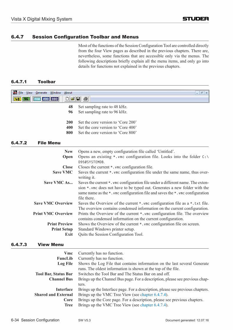
6.4.7 Session Configuration Toolbar and Menus
Most of the functions of the Session Configuration Tool are controlled directly from the four View pages as described in the previous chapters. There are, nevertheless, some functions that are accessible only via the menus. The following descriptions briefly explain all the menu items, and only go into details for functions not explained in the previous chapters.
6.4.7.1 Toolbar
48 Set sampling rate to 48 kHz. 96 Set sampling rate to 96 kHz.
200 Set the core version to ‘Core 200’ 400 Set the core version to ‘Core 400’ 800 Set the core version to ‘Core 800’
6.4.7.2 file Menu
New Opens a new, empty configuration file called ‘Untitled’. Open Opens an existing *.vmc configuration file. Looks into the folder C:\
D950SYSTEMDB. Close Closes the current *.vmc configuration file. Save VMC Saves the current *.vmc configuration file under the same name, thus over-
writing it. Save VMC As... Saves the current *.vmc configuration file under a different name. The exten-
sion *.vmc does not have to be typed out. Generates a new folder with the same name as the *.vmc configuration file and saves the *.vmc configuration file there.
Save VMC Overview Saves the Overview of the current *.vmc configuration file as a *.txt file. The overview contains condensed information on the current configuration.
Print VMC Overview Prints the Overview of the current *.vmc configuration file. The overview contains condensed information on the current configuration.
Print Preview Shows the Overview of the current *.vmc configuration file on screen. Print Setup Standard Windows printer setup. Exit Quits the Session Configuration Tool.
6.4.7.3 View Menu
Vmc Currently has no function. FuncLib Currently has no function. Log File Shows the Log File that contains information on the last several Generate
runs. The oldest information is shown at the top of the file. Tool Bar, Status Bar Switches the Tool Bar and The Status Bar on and off. Channel Bus Brings up the Channel Bus page. For a description, please see previous chap-
ters. Interface Brings up the Interface page. For a description, please see previous chapters. Shared and External Brings up the VMC Tree View (see chapter 6.4.7.4). Core Brings up the Core page. For a description, please see previous chapters. Tree Brings up the VMC Tree View (see chapter 6.4.7.4).
Vista X Digital Mixing System
6-34 Session Configuration Document generated: 12.07.16SW V5.3
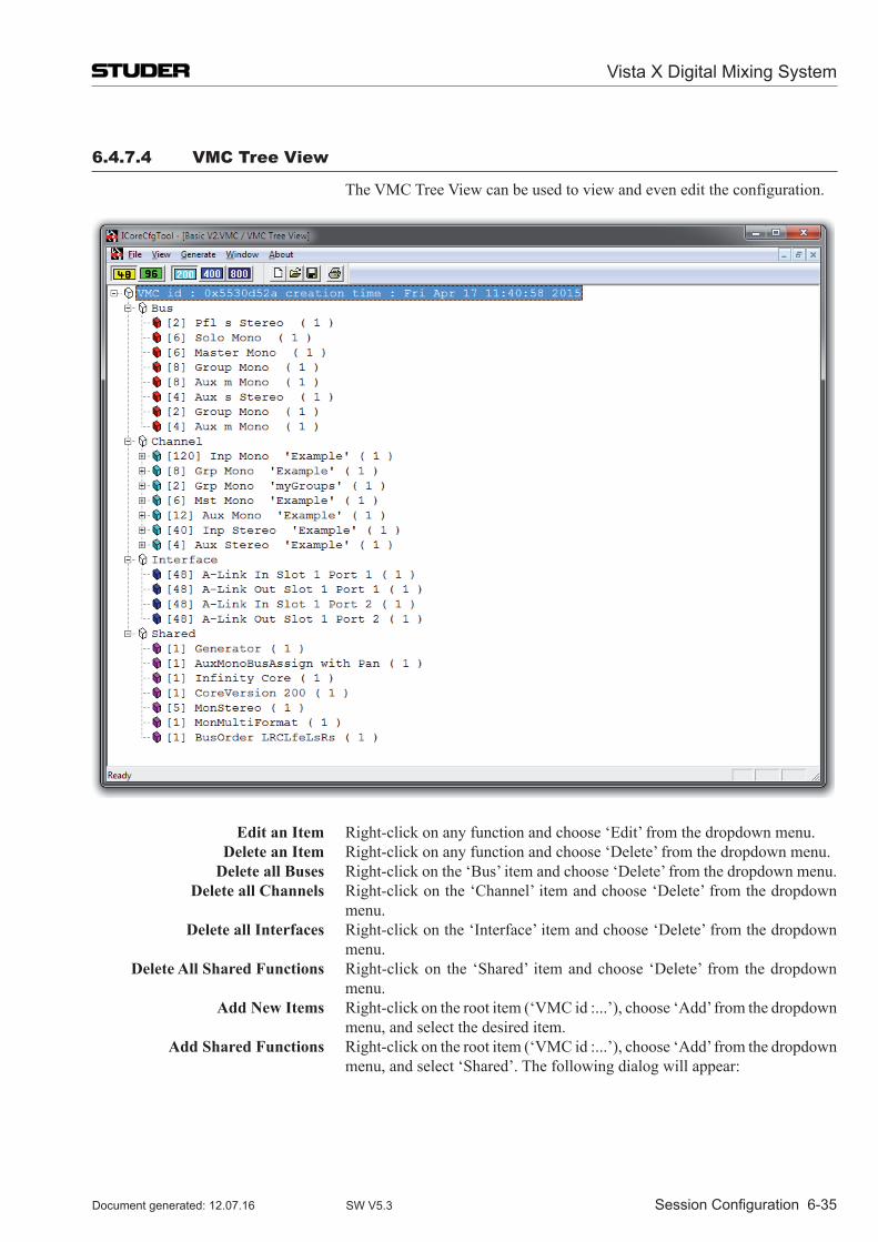
6.4.7.4 VMC Tree View
The VMC Tree View can be used to view and even edit the configuration.
Edit an Item Right-click on any function and choose ‘Edit’ from the dropdown menu. Delete an Item Right-click on any function and choose ‘Delete’ from the dropdown menu. Delete all Buses Right-click on the ‘Bus’ item and choose ‘Delete’ from the dropdown menu. Delete all Channels Right-click on the ‘Channel’ item and choose ‘Delete’ from the dropdown
menu. Delete all Interfaces Right-click on the ‘Interface’ item and choose ‘Delete’ from the dropdown
menu. Delete All Shared Functions Right-click on the ‘Shared’ item and choose ‘Delete’ from the dropdown
menu. Add New Items Right-click on the root item (‘VMC id :...’), choose ‘Add’ from the dropdown
menu, and select the desired item. Add Shared Functions Right-click on the root item (‘VMC id :...’), choose ‘Add’ from the dropdown
menu, and select ‘Shared’. The following dialog will appear:
Vista X Digital Mixing System
Session Configuration 6-35Document generated: 12.07.16 SW V5.3
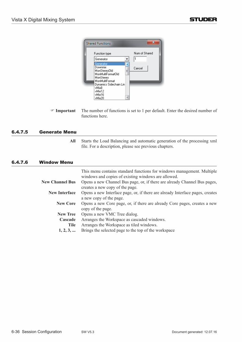
Important The number of functions is set to 1 per default. Enter the desired number of functions here.
6.4.7.5 generate Menu
All Starts the Load Balancing and automatic generation of the processing xml file. For a description, please see previous chapters.
6.4.7.6 Window Menu
This menu contains standard functions for windows management. Multiple windows and copies of existing windows are allowed.
New Channel Bus Opens a new Channel Bus page, or, if there are already Channel Bus pages, creates a new copy of the page.
New Interface Opens a new Interface page, or, if there are already Interface pages, creates a new copy of the page.
New Core Opens a new Core page, or, if there are already Core pages, creates a new copy of the page.
New Tree Opens a new VMC Tree dialog. Cascade Arranges the Workspace as cascaded windows. Tile Arranges the Workspace as tiled windows. 1, 2, 3, ... Brings the selected page to the top of the workspace
Vista X Digital Mixing System
6-36 Session Configuration Document generated: 12.07.16SW V5.3
6.5 Maintenance6.5.1 Managing the files – Which file is Where?
Any Session Configuration starts with five files:
• the‘meta’VMCfilecalledMyConfig.vmc • theprocessingxmlfilecalledMyConfig.xml • theMixercloudPathsfilecalledMyConfig-MixercloudPaths.txt • theVmcMappingInformationfilecalled MyConfig-VmcMappingInformation.xml • theconfigurationknowledgefilecalledMyConfig.ckf
They are stored in a subfolder (with the name of the configuration) of the Session Configuration folders on the Studer Vista PC.
6.5.2 CoreCfgTool.ini
The C:\CoreCfgTool directory contains the CoreCfgTool.ini file. This file tells the Configuration Tool where to look for various components and what the basic settings are.
The Session Configuration Tool for the Infinity Core actually is the very same Session Configuration Tool as used for the SCoreLive (starting from SW 5.2.00). Whether it is used for the SCoreLive or for the Infinity Core is decided by the CoreCfgTool.ini file.
There are two templates of the .ini files in the folder C:\CoreCfgTool :
•CoreCfgTool.sCore •CoreCfgTool.ini
CoreCfgTool.sCore è This file must be renamed to .ini when used with SCoreLive systems. CoreCfgTool.ini è This file is ready to be used with the Infinity Core systems.
To doublecheck whether the correct version of the file is active, the file can be opened with a text editor and the entry ‘CoreType= ’ can be verified.
6.5.2.1 Content of the Core Knowledge file
The Core Knowledge file offers the following information on a Configuration.
VMC ID Identification of the VMC used to ensure that the *.vmc and *.xml files match. Sampling Rate 48 kHz or 96 kHz Tasks Shows the task (channels, buses….) of the configuration. CoreCfgTool.ini A copy of the *.ini file used to generate the configuration.
Vista X Digital Mixing System
Session Configuration 6-37Document generated: 12.07.16 SW V5.3
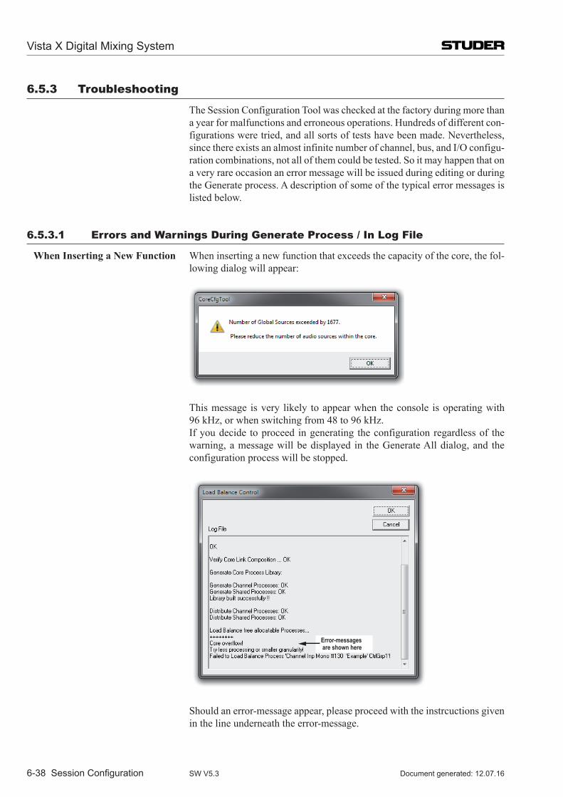
6.5.3 Troubleshooting
The Session Configuration Tool was checked at the factory during more than a year for malfunctions and erroneous operations. Hundreds of different con-figurations were tried, and all sorts of tests have been made. Nevertheless, since there exists an almost infinite number of channel, bus, and I/O configu-ration combinations, not all of them could be tested. So it may happen that on a very rare occasion an error message will be issued during editing or during the Generate process. A description of some of the typical error messages is listed below.
6.5.3.1 Errors and Warnings During generate Process / in log file
When Inserting a New Function When inserting a new function that exceeds the capacity of the core, the fol-lowing dialog will appear:
This message is very likely to appear when the console is operating with 96 kHz, or when switching from 48 to 96 kHz.
If you decide to proceed in generating the configuration regardless of the warning, a message will be displayed in the Generate All dialog, and the configuration process will be stopped.
Error-messages are shown here
Should an error-message appear, please proceed with the instrcuctions given in the line underneath the error-message.
Vista X Digital Mixing System
6-38 Session Configuration Document generated: 12.07.16SW V5.3
Vista X Digital Mixing System
DAW Control 7-1Document generated: 12.07.16 SW V5.3
CHAPTER 7
7 DAW Control .....................................................................................................................................................37.1 Basics ..................................................................................................................................................................3
7.2 Vista Settings ......................................................................................................................................................6
7.3 DAW Settings .....................................................................................................................................................8
7.4 Connect the Sessions ..........................................................................................................................................9
7.5 Control Keys in Channel Strip ..........................................................................................................................11

Vista X Digital Mixing System
7-2 DAW Control Document generated: 12.07.16SW V5.3
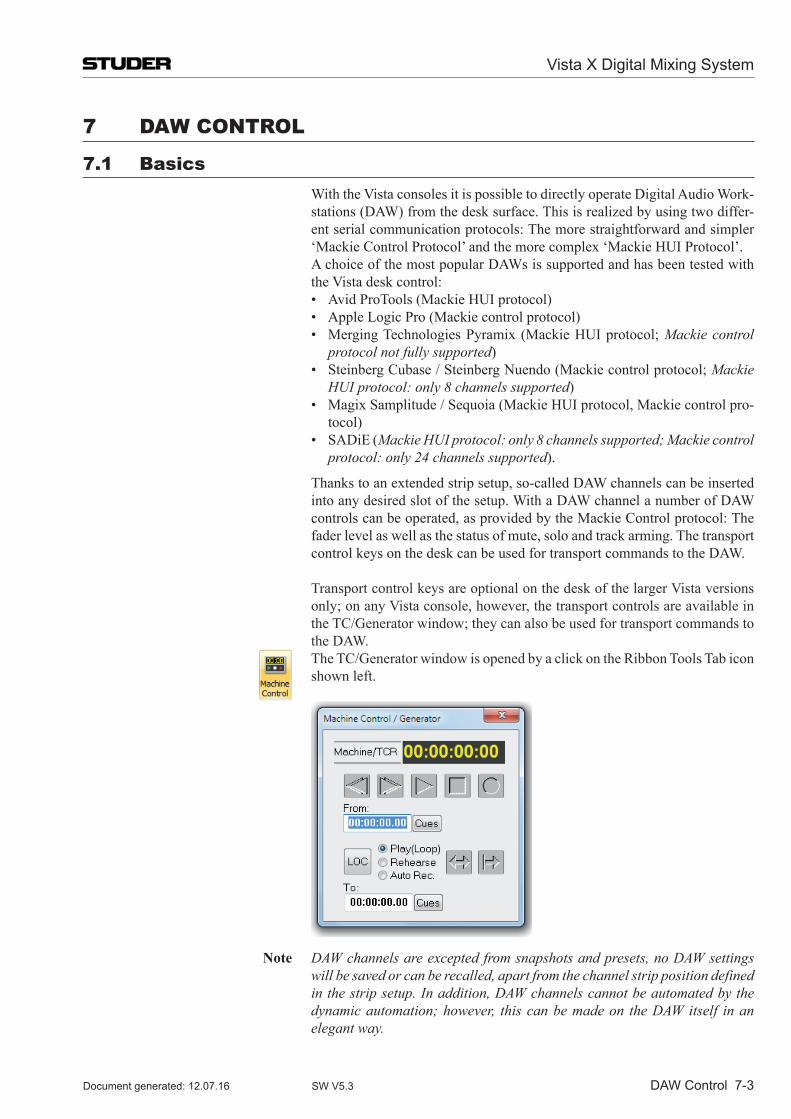
Vista X Digital Mixing System
DAW Control 7-3Document generated: 12.07.16 SW V5.3
7 DAW ConTRol
7.1 Basics With the Vista consoles it is possible to directly operate Digital Audio Work-
stations (DAW) from the desk surface. This is realized by using two differ-ent serial communication protocols: The more straightforward and simpler ‘Mackie Control Protocol’ and the more complex ‘Mackie HUI Protocol’.
A choice of the most popular DAWs is supported and has been tested with the Vista desk control:
• AvidProTools(MackieHUIprotocol) • AppleLogicPro(Mackiecontrolprotocol) • MergingTechnologiesPyramix (MackieHUIprotocol;Mackie control
protocol not fully supported) • SteinbergCubase/SteinbergNuendo(Mackiecontrolprotocol;Mackie
HUI protocol: only 8 channels supported) • MagixSamplitude/Sequoia(MackieHUIprotocol,Mackiecontrolpro-
tocol) • SADiE(Mackie HUI protocol: only 8 channels supported; Mackie control
protocol: only 24 channels supported).
Thankstoanextendedstripsetup,so-calledDAWchannelscanbeinsertedinto any desired slot of the setup. With a DAW channel a number of DAW controlscanbeoperated,asprovidedbytheMackieControlprotocol:Thefaderlevelaswellasthestatusofmute,soloandtrackarming.Thetransportcontrol keys on the desk can be used for transport commands to the DAW.
TransportcontrolkeysareoptionalonthedeskofthelargerVistaversionsonly;onanyVistaconsole,however,thetransportcontrolsareavailableintheTC/Generatorwindow;theycanalsobeusedfortransportcommandstothe DAW.
TheTC/GeneratorwindowisopenedbyaclickontheRibbonToolsTabiconshown left.
Note DAW channels are excepted from snapshots and presets, no DAW settings will be saved or can be recalled, apart from the channel strip position defined in the strip setup. In addition, DAW channels cannot be automated by the dynamic automation; however, this can be made on the DAW itself in an elegant way.
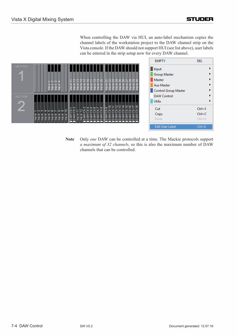
Vista X Digital Mixing System
7-4 DAW Control Document generated: 12.07.16SW V5.3
Whencontrolling theDAWviaHUI,anauto-labelmechanismcopies thechannel labels of the workstation project to the DAW channel strip on the Vistaconsole.IftheDAWshouldnotsupportHUI(seelistabove),userlabelscanbeenteredinthestripsetupnowforeveryDAWchannel.
Note Only one DAW can be controlled at a time. The Mackie protocols support a maximum of 32 channels,sothisisalsothemaximumnumberofDAWchannels that can be controlled.
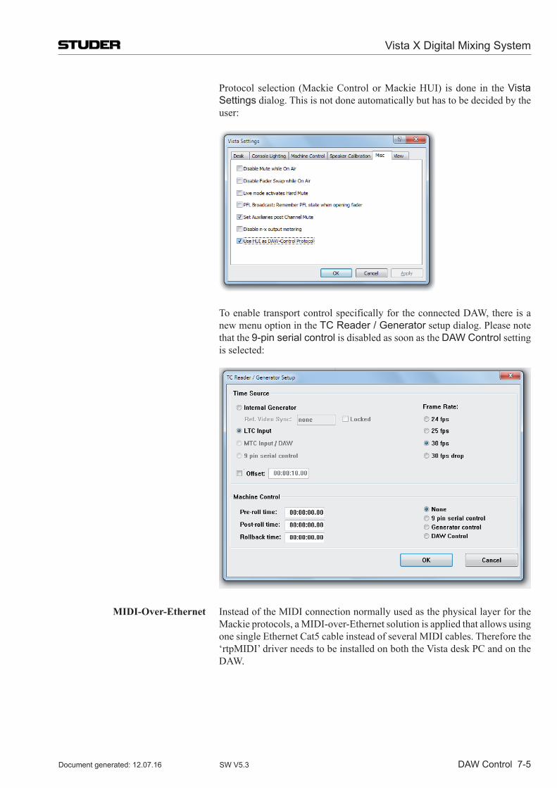
Vista X Digital Mixing System
DAW Control 7-5Document generated: 12.07.16 SW V5.3
Protocol selection (Mackie Control or Mackie HUI) is done in the Vista Settings dialog. This is not done automatically but has to be decided by the user:
ToenabletransportcontrolspecificallyfortheconnectedDAW,thereisanew menu option in the TC Reader / Generator setup dialog. Please note that the 9-pin serial control is disabled as soon as the DAW Control setting is selected:
MIDI-Over-Ethernet Instead of the MIDI connection normally used as the physical layer for the Mackieprotocols,aMIDI-over-EthernetsolutionisappliedthatallowsusingonesingleEthernetCat5cableinsteadofseveralMIDIcables.Thereforethe‘rtpMIDI’driverneedstobeinstalledonboththeVistadeskPCandontheDAW.
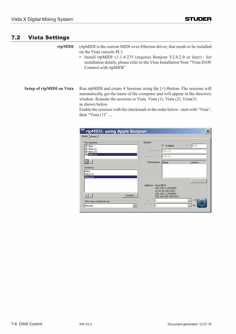
Vista X Digital Mixing System
7-6 DAW Control Document generated: 12.07.16SW V5.3
7.2 Vista Settings rtpMIDI (rtpMIDIisthecurrentMIDI-over-Ethernetdriver,thatneedstobeinstalled
on the Vista console PC) • Install rtpMIDIv1.1.4.235 (requiresBonjourV2.0.2.0or later) - for
installationdetails,pleaserefertotheVistaInstallationNote“VistaDAWComtrol with rtpMIDI”
Setup of rtpMIDI on Vista RunrtpMIDIandcreate4Sessionsusingthe[+]-Button.Thesessionswillautomatically get the name of the computer and will appear in the directory window.RenamethesessionstoVista,Vista(1),Vista(2),Vista(3)
as shown below. Enablethesessionswiththecheckmarkintheorderbelow-startwith“Vista”,
then“Vista(1)”....
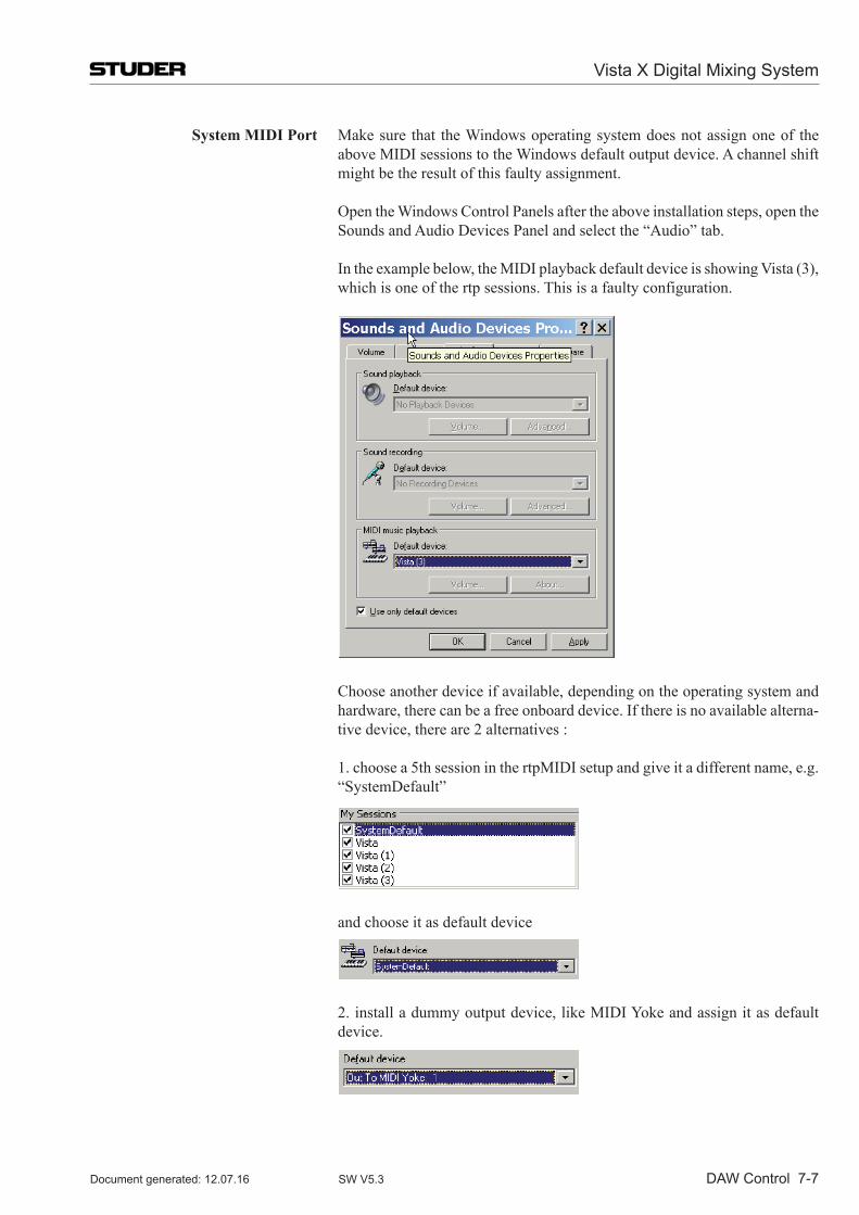
Vista X Digital Mixing System
DAW Control 7-7Document generated: 12.07.16 SW V5.3
System MIDI Port Make sure that the Windows operating system does not assign one of the aboveMIDIsessionstotheWindowsdefaultoutputdevice.Achannelshiftmight be the result of this faulty assignment.
OpentheWindowsControlPanelsaftertheaboveinstallationsteps,opentheSoundsandAudioDevicesPanelandselectthe“Audio”tab.
Intheexamplebelow,theMIDIplaybackdefaultdeviceisshowingVista(3),which is one of the rtp sessions. This is a faulty configuration.
Chooseanotherdeviceifavailable,dependingontheoperatingsystemand
hardware,therecanbeafreeonboarddevice.Ifthereisnoavailablealterna-tivedevice,thereare2alternatives:
1.choosea5thsessioninthertpMIDIsetupandgiveitadifferentname,e.g.“SystemDefault”
andchooseitasdefaultdevice
2.installadummyoutputdevice,likeMIDIYokeandassignitasdefault
device.
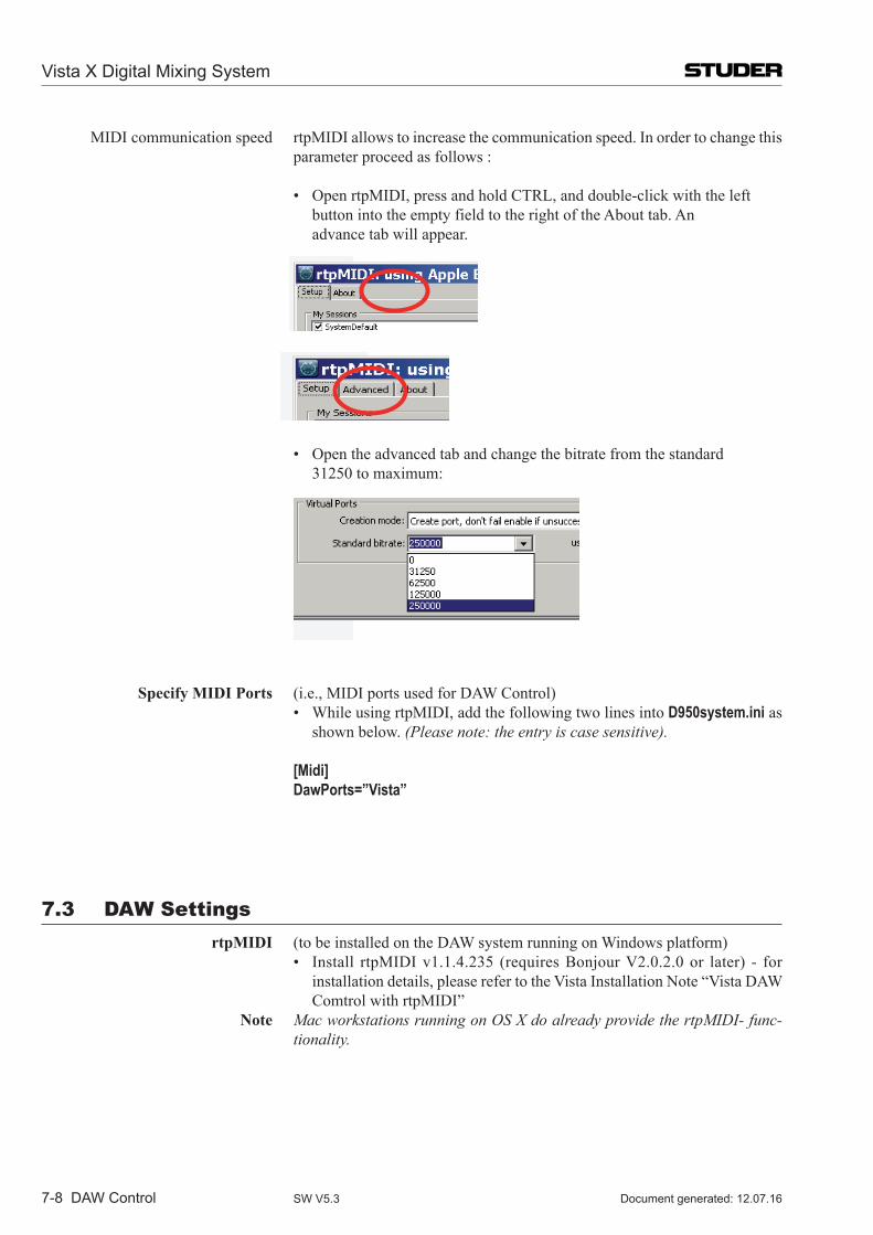
Vista X Digital Mixing System
7-8 DAW Control Document generated: 12.07.16SW V5.3
MIDI communication speed rtpMIDI allows to increase the communication speed. In order to change this parameter proceed as follows :
• OpenrtpMIDI,pressandholdCTRL,anddouble-clickwiththeleft button into the empty field to the right of the About tab. An advancetabwillappear.
• Opentheadvancedtabandchangethebitratefromthestandard 31250tomaximum:
Specify MIDI Ports (i.e.,MIDIportsusedforDAWControl) • WhileusingrtpMIDI,addthefollowingtwolinesintoD950system.ini as
shown below. (Please note: the entry is case sensitive).
[Midi] DawPorts=”Vista”
7.3 DAW Settings rtpMIDI (to be installed on the DAW system running on Windows platform) • Install rtpMIDIv1.1.4.235 (requiresBonjourV2.0.2.0or later) - for
installationdetails,pleaserefertotheVistaInstallationNote“VistaDAWComtrol with rtpMIDI”
Note Mac workstations running on OS X do already provide the rtpMIDI- func-tionality.
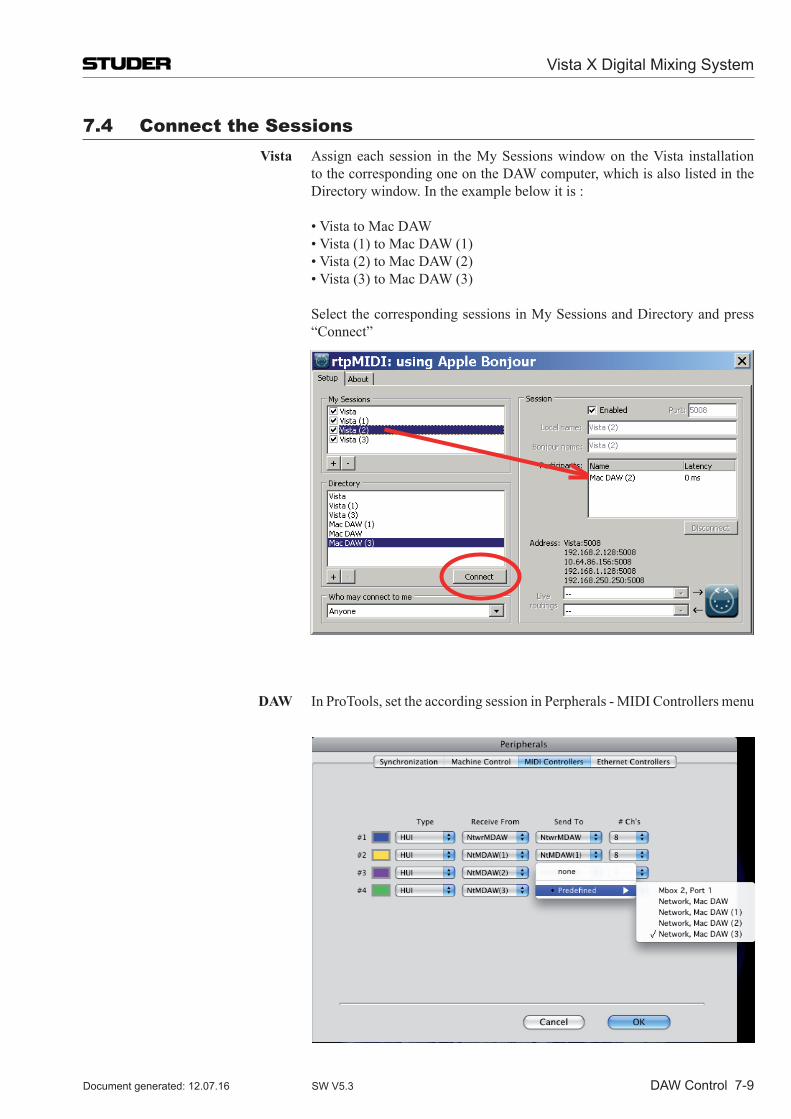
Vista X Digital Mixing System
DAW Control 7-9Document generated: 12.07.16 SW V5.3
7.4 Connect the Sessions Vista Assign each session in the My Sessions window on the Vista installation
tothecorrespondingoneontheDAWcomputer,whichisalsolistedintheDirectory window. In the example below it is :
•VistatoMacDAW •Vista(1)toMacDAW(1) •Vista(2)toMacDAW(2) •Vista(3)toMacDAW(3)
Select the corresponding sessions in My Sessions and Directory and press “Connect”
DAW InProTools,settheaccordingsessioninPerpherals-MIDIControllersmenu
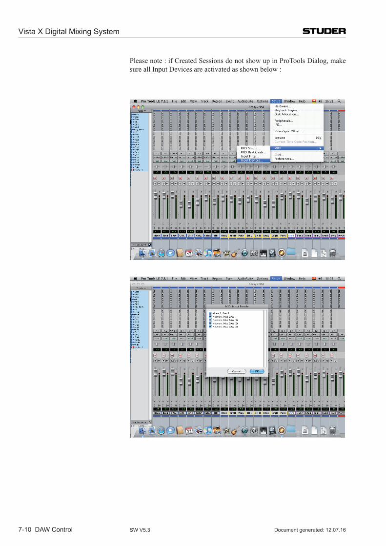
Vista X Digital Mixing System
7-10 DAW Control Document generated: 12.07.16SW V5.3
Pleasenote:ifCreatedSessionsdonotshowupinProToolsDialog,makesureallInputDevicesareactivatedasshownbelow:
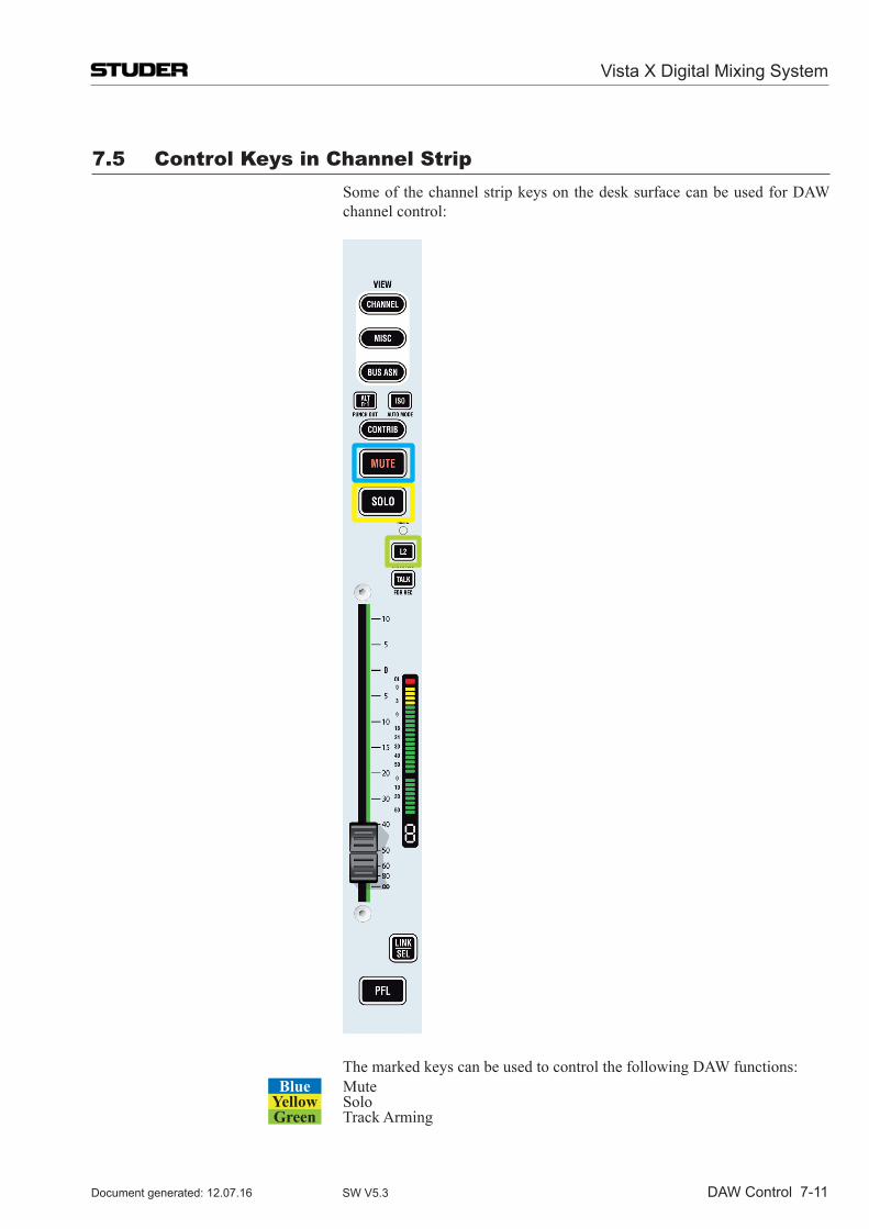
Vista X Digital Mixing System
DAW Control 7-11Document generated: 12.07.16 SW V5.3
7.5 Control Keys in Channel Strip Some of the channel strip keys on the desk surface can be used for DAW
channel control:
The marked keys can be used to control the following DAW functions:Blue Mute
Yellow SoloGreen Track Arming
Vista X Digital Mixing System
RELINK 8-1Document generated: 12.07.16 SW V5.3
CHAPTER 8
8 RELINK (Resource Linking) ...........................................................................................................................38.1 Input Patching .....................................................................................................................................................3
8.2 Output Patching ..................................................................................................................................................4
8.3 Mic Take-Over Procedure ...................................................................................................................................6
8.4 Vista Restrictions ................................................................................................................................................9
8.5 Technical Details ..............................................................................................................................................108.5.1 Vista I/O Sharing Setup ....................................................................................................................................... 108.5.2 Restricting Shared I/O ......................................................................................................................................... 148.5.3 Configuration Changes........................................................................................................................................ 148.5.4 Container.ini ........................................................................................................................................................ 158.5.5 D950System.ini ................................................................................................................................................... 168.5.6 Tie Line Management ......................................................................................................................................... 168.5.7 Control Network.................................................................................................................................................. 17
8.5.7.1 Vista X in general .....................................................................................................................................................178.5.7.2 Vista X ......................................................................................................................................................................18
8.5.8 IP Addresses ........................................................................................................................................................ 188.5.9 Audio Sync for all Systems ................................................................................................................................ 18
8.6 Messages from Other Systems .........................................................................................................................19
8.7 Labels from Other Systems ..............................................................................................................................19
8.8 Locked Patch Points .........................................................................................................................................19
8.9 Stereo and Surround Sources ............................................................................................................................19
Vista X Digital Mixing System
8-2 RELINK Document generated:12.07.16SW V5.3
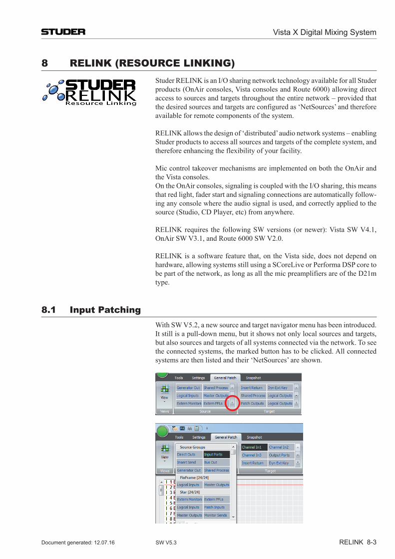
Vista X Digital Mixing System
RELINK 8-3Document generated: 12.07.16 SW V5.3
8 RELINK (REsouRCE LINKINg) Studer RELINK is an I/O sharing network technology available for all Studer
products (OnAir consoles, Vista consoles and Route 6000) allowing direct access to sources and targets throughout the entire network – provided that the desired sources and targets are configured as ‘NetSources’ and therefore available for remote components of the system.
RELINK allows the design of ‘distributed’ audio network systems – enabling Studer products to access all sources and targets of the complete system, and therefore enhancing the flexibility of your facility.
Mic control takeover mechanisms are implemented on both the OnAir and the Vista consoles.
On the OnAir consoles, signaling is coupled with the I/O sharing, this means that red light, fader start and signaling connections are automatically follow-ing any console where the audio signal is used, and correctly applied to the source (Studio, CD Player, etc) from anywhere.
RELINK requires the following SW versions (or newer): Vista SW V4.1, OnAir SW V3.1, and Route 6000 SW V2.0.
RELINK is a software feature that, on the Vista side, does not depend on hardware, allowing systems still using a SCoreLive or Performa DSP core to be part of the network, as long as all the mic preamplifiers are of the D21m type.
8.1 Input Patching With SW V5.2, a new source and target navigator menu has been in trod uced.
It still is a pull-down menu, but it shows not only local sources and targets, but also sources and targets of all systems connected via the network. To see the connected systems, the marked button has to be clicked. All connected systems are then listed and their ‘NetSources’ are shown.
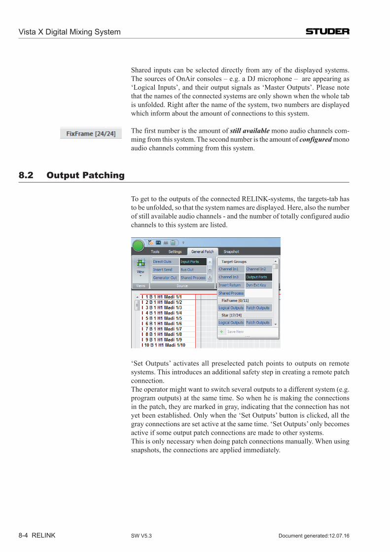
Vista X Digital Mixing System
8-4 RELINK Document generated:12.07.16SW V5.3
Shared inputs can be selected directly from any of the displayed systems. The sources of OnAir consoles – e.g. a DJ microphone – are appearing as ‘Logical Inputs’, and their output signals as ‘Master Outputs’. Please note that the names of the connected systems are only shown when the whole tab is unfolded. Right after the name of the system, two numbers are displayed which inform about the amount of connections to this system.
The first number is the amount of still available mono audio channels com-ming from this system. The second number is the amount of configured mono audio channels comming from this system.
8.2 output Patching
To get to the outputs of the connected RELINK-systems, the targets-tab has to be unfolded, so that the system names are displayed. Here, also the number of still available audio channels - and the number of totally configured audio channels to this system are listed.
‘Set Outputs’ activates all preselected patch points to outputs on remote systems. This introduces an additional safety step in creating a remote patch connection.
The operator might want to switch several outputs to a different system (e.g. program outputs) at the same time. So when he is making the connections in the patch, they are marked in gray, indicating that the connection has not yet been established. Only when the ‘Set Outputs’ button is clicked, all the gray connections are set active at the same time. ‘Set Outputs’ only becomes active if some output patch connections are made to other systems.
This is only necessary when doing patch connections manually. When using snapshots, the connections are applied immediately.
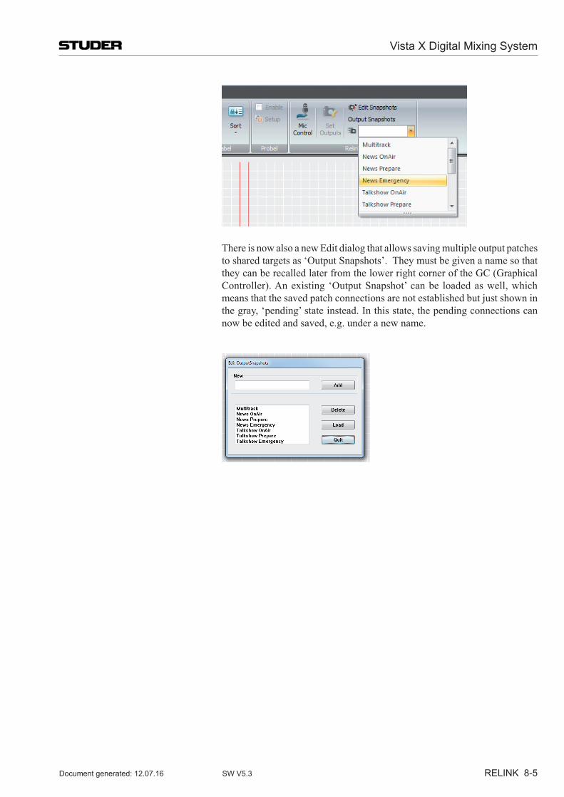
Vista X Digital Mixing System
RELINK 8-5Document generated: 12.07.16 SW V5.3
There is now also a new Edit dialog that allows saving multiple output patches to shared targets as ‘Output Snapshots’. They must be given a name so that they can be recalled later from the lower right corner of the GC (Graphical Controller). An existing ‘Output Snapshot’ can be loaded as well, which means that the saved patch connections are not established but just shown in the gray, ‘pending’ state instead. In this state, the pending connections can now be edited and saved, e.g. under a new name.
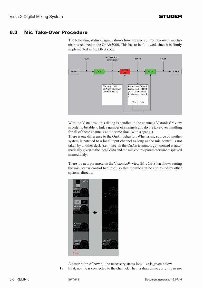
Vista X Digital Mixing System
8-6 RELINK Document generated:12.07.16SW V5.3
8.3 Mic Take-over Procedure The following status diagram shows how the mic control take-over mecha-
nism is realized in the OnAir3000. This has to be followed, since it is firmly implemented in the DNet code.
With the Vista desk, this dialog is handled in the channels Vistonics™ view in order to be able to link a number of channels and do the take-over handling for all of these channels at the same time (with a ‘gang’).
There is one difference to the OnAir behavior: When a mic source of another system is patched to a local input channel as long as the mic control is not taken by another desk (i.e., ‘free’ in the OnAir terminology), control is auto-matically given to the local Vista and the mic control parameters are displayed immediately.
There is a new parameter in the Vistonics™ view (Mic Ctrl) that allows setting the mic access control to ‘Free’, so that the mic can be controlled by other systems directly.
A description of how all the necessary states look like is given below. 1a First, no mic is connected to the channel. Then, a shared mic currently in use
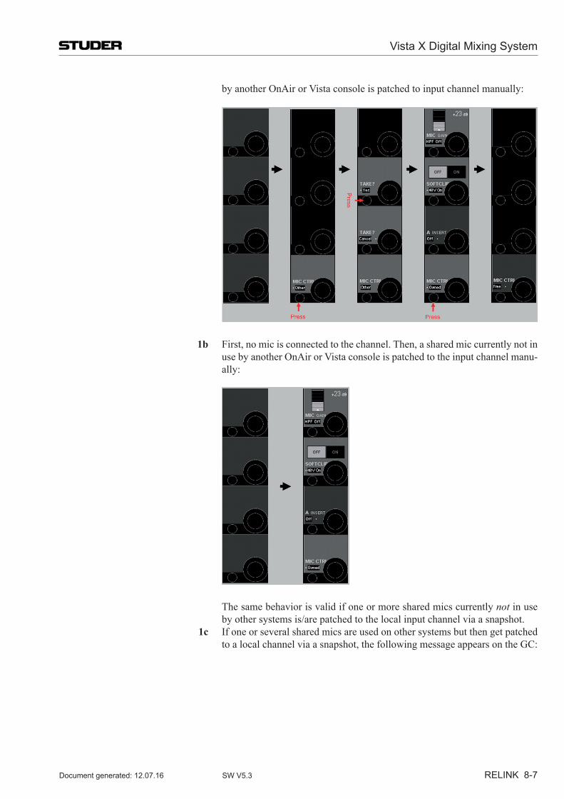
Vista X Digital Mixing System
RELINK 8-7Document generated: 12.07.16 SW V5.3
by another OnAir or Vista console is patched to input channel manually:
1b First, no mic is connected to the channel. Then, a shared mic currently not in use by another OnAir or Vista console is patched to the input channel manu-ally:
The same behavior is valid if one or more shared mics currently not in use by other systems is/are patched to the local input channel via a snapshot.
1c If one or several shared mics are used on other systems but then get patched to a local channel via a snapshot, the following message appears on the GC:
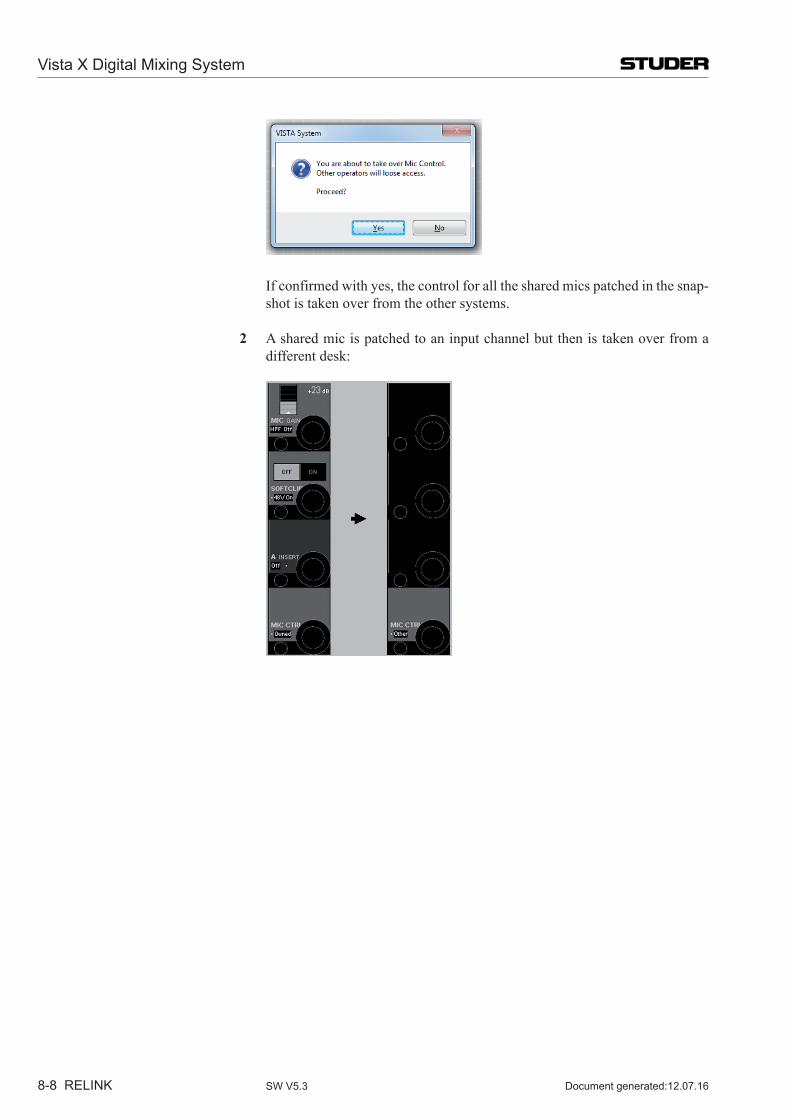
Vista X Digital Mixing System
8-8 RELINK Document generated:12.07.16SW V5.3
If confirmed with yes, the control for all the shared mics patched in the snap-shot is taken over from the other systems.
2 A shared mic is patched to an input channel but then is taken over from a
different desk:
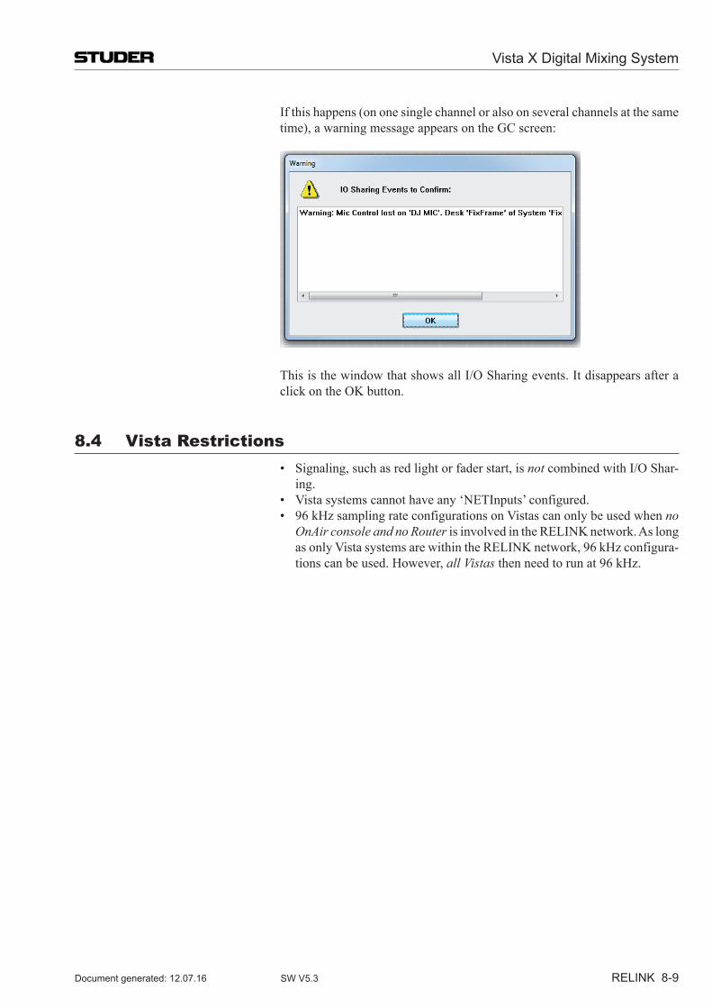
Vista X Digital Mixing System
RELINK 8-9Document generated: 12.07.16 SW V5.3
If this happens (on one single channel or also on several channels at the same time), a warning message appears on the GC screen:
This is the window that shows all I/O Sharing events. It disappears after a click on the OK button.
8.4 Vista Restrictions • Signaling,suchasredlightorfaderstart,isnot combined with I/O Shar-
ing. • Vistasystemscannothaveany‘NETInputs’configured. • 96kHzsamplingrateconfigurationsonVistascanonlybeusedwhenno
OnAir console and no Router is involved in the RELINK network. As long as only Vista systems are within the RELINK network, 96 kHz configura-tions can be used. However, all Vistas then need to run at 96 kHz.
Vista X Digital Mixing System
8-10 RELINK Document generated:12.07.16SW V5.3
8.5 Technical Details8.5.1 Vista I/o sharing setup
ConfigTool for DNet Applications For configuring the tie lines necessary for I/O Sharing on the Vista system, we use the ConfigTool for DNet Applications known from the OnAir product range. This program now needs to be installed on the Vista’s control computer (C:\Release ConfigTool\ConfigTool.exe). In the same folder there needs to be a file named container.ini with setup information for this DNet ConfigTool. Here is an example of the DNet ConfigTool container.ini file:
############################################################################ container.ini: Necessary for initialization of each container (.exe)## Digital Mixing Console: VISTA# Studer Professional Audio GmbH, Regensdorf, Switzerland## Last modification : Sep, 1st 2006# Compatible with OATreeLib : V2.1# Author : SIA## Rules:# ======# - always leave one blank before and after the ‹=› (e.g. systemid=1 NO!)# - never change the left expression# - the right expression of systemid, containerid, systemname# and containername MUST be defined# ##########################################################################
# The systemid identifies the mixing console system to which this container# belongs to. The systemid is a unique number within a network.# The serial number must be in the range 1...255
systemid = 36 this needs to be a unique number
# The systemname identifies the mixing console system in a readable way# and must be unique within a company resp. network. It is recommended# not to use more than 8 characters due to visualization aspects.# «Undefined» is not allowed!
systemname = «ConfigTool» the name of the system
Vista X Digital Mixing System
RELINK 8-11Document generated: 12.07.16 SW V5.3
# The containerid identifies this container # and must be unique within the mixing console system# This id is fixed to ‹10› (CORE) for all VISTA desks
containerid = 20 ‚20’ is always standing when the container.ini is belonging to a configtool
# The containername identifies this container in a readable way# and must be unique within the mixing console system. It is recommended# not to use more than 8 characters due to visualization aspects.# «Undefined» is not allowed!
containername = «Config» the name of the container
# Multicast# -----------# If you use IGMP multicasts instead of broadcasts in your network,# you have to uncomment the lines below. It is possible that a # container is member of one or more than one multicast groups.## NOTE: For an optimal performance, make sure that all network resources# (Switches, Routers...) support IGMP.## NOTE: To avoid IP conflicts, check the available addresses for# multicast groups (www.iana.org). Use preferable addresses from the# local scope (239.255.0.0/16) described in RFC 2365.## NOTE: If the multicast should reach computers beyond the local subnet# Set MulticastTimeToLive > 1 (1 is default)
# MulticastGroup = 239.255.0.1# MulticastGroup = 239.255.0.2# MulticastGroup = 239.255.0.3# MulticastTimeToLive = 10
# Multiple Network Adapters# ---------------------------------# When more than one network adapter is enabled on the computer, the MAC Address has to be specified## MAC = 00-1A-A0-B9-F9-88
Note: There needs to be a second container.ini file on the Vista’s control computer – the one which is belonging to the mixing console application.
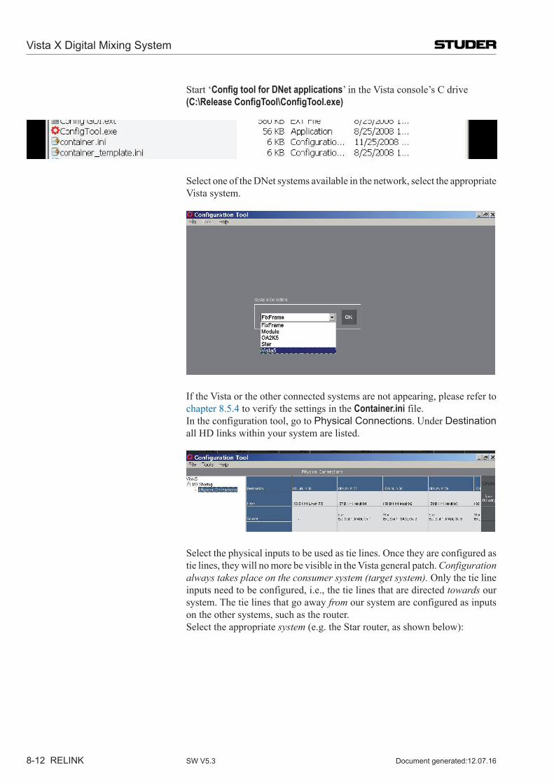
Vista X Digital Mixing System
8-12 RELINK Document generated:12.07.16SW V5.3
Start ‘Config tool for DNet applications’ in the Vista console’s C drive (C:\Release ConfigTool\ConfigTool.exe)
Select one of the DNet systems available in the network, select the appropriate Vista system.
If the Vista or the other connected systems are not appearing, please refer to chapter 8.5.4 to verify the settings in the Container.ini file.
In the configuration tool, go to Physical Connections. Under Destination all HD links within your system are listed.
Select the physical inputs to be used as tie lines. Once they are configured as tie lines, they will no more be visible in the Vista general patch. Configuration always takes place on the consumer system (target system). Only the tie line inputs need to be configured, i.e., the tie lines that are directed towards our system. The tie lines that go away from our system are configured as inputs on the other systems, such as the router.
Select the appropriate system (e.g. the Star router, as shown below):
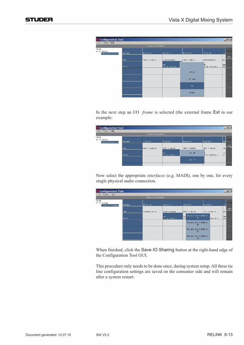
Vista X Digital Mixing System
RELINK 8-13Document generated: 12.07.16 SW V5.3
In the next step an I/O frame is selected (the external frame Ext in our example:
Now select the appropriate interfaces (e.g. MADI), one by one, for every single physical audio connection.
When finished, click the Save IO Sharing button at the right-hand edge of the Configuration Tool GUI.
This procedure only needs to be done once, during system setup. All these tie line configuration settings are saved on the consumer side and will remain after a system restart.
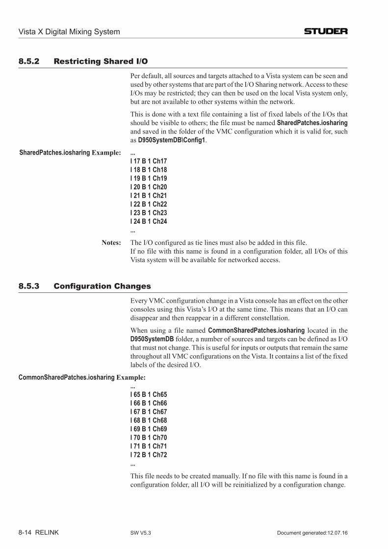
Vista X Digital Mixing System
8-14 RELINK Document generated:12.07.16SW V5.3
8.5.2 Restricting shared I/o
Per default, all sources and targets attached to a Vista system can be seen and used by other systems that are part of the I/O Sharing network. Access to these I/Os may be restricted; they can then be used on the local Vista system only, but are not available to other systems within the network.
This is done with a text file containing a list of fixed labels of the I/Os that should be visible to others; the file must be named SharedPatches.iosharing and saved in the folder of the VMC configuration which it is valid for, such as D950SystemDB\Config1.
SharedPatches.iosharing Example: ... I 17 B 1 Ch17 I 18 B 1 Ch18 I 19 B 1 Ch19 I 20 B 1 Ch20 I 21 B 1 Ch21 I 22 B 1 Ch22 I 23 B 1 Ch23 I 24 B 1 Ch24 ... Notes: The I/O configured as tie lines must also be added in this file. If no file with this name is found in a configuration folder, all I/Os of this
Vista system will be available for networked access.
8.5.3 Configuration Changes
Every VMC configuration change in a Vista console has an effect on the other consoles using this Vista’s I/O at the same time. This means that an I/O can disappear and then reappear in a different constellation.
When using a file named CommonSharedPatches.iosharing located in the D950SystemDB folder, a number of sources and targets can be defined as I/O that must not change. This is useful for inputs or outputs that remain the same throughout all VMC configurations on the Vista. It contains a list of the fixed labels of the desired I/O.
CommonSharedPatches.iosharing Example: ... I 65 B 1 Ch65 I 66 B 1 Ch66 I 67 B 1 Ch67 I 68 B 1 Ch68 I 69 B 1 Ch69 I 70 B 1 Ch70 I 71 B 1 Ch71 I 72 B 1 Ch72 ... This file needs to be created manually. If no file with this name is found in a
configuration folder, all I/O will be reinitialized by a configuration change.
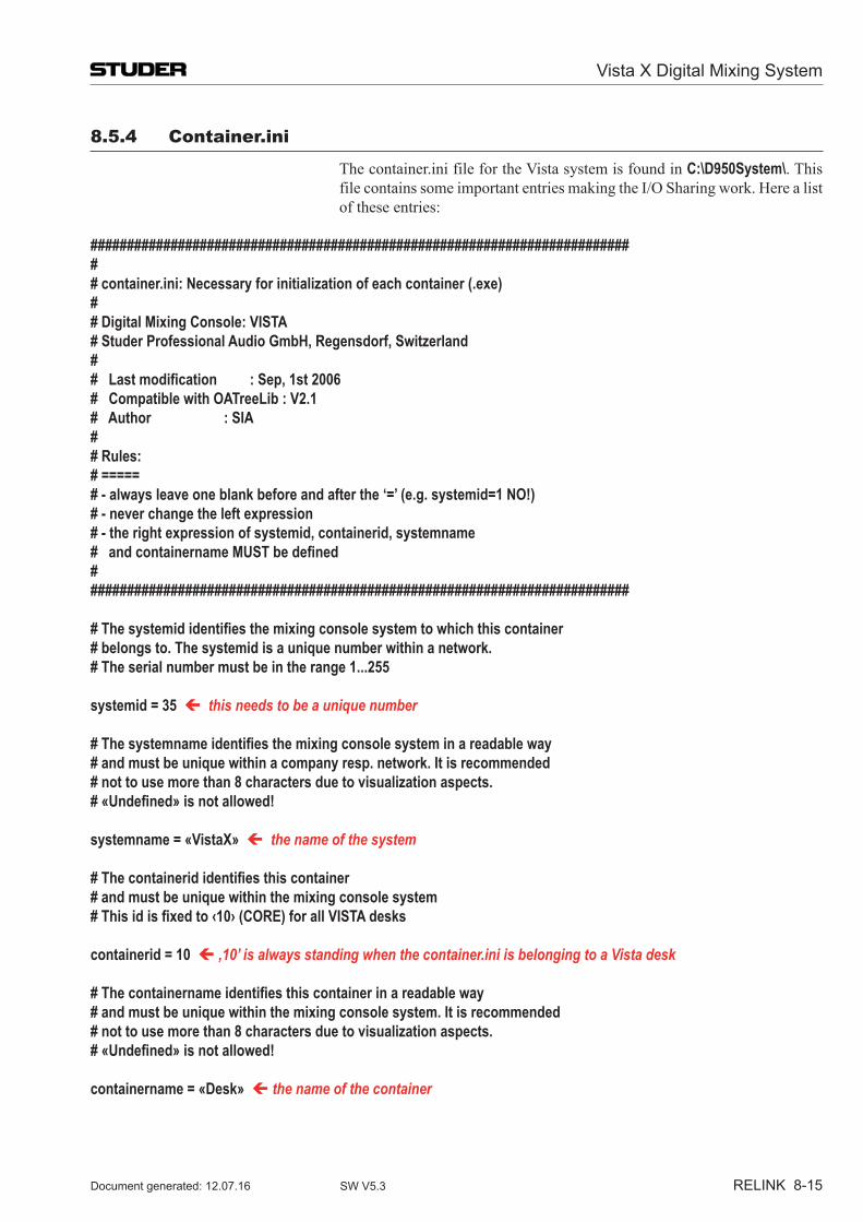
Vista X Digital Mixing System
RELINK 8-15Document generated: 12.07.16 SW V5.3
8.5.4 Container.ini
The container.ini file for the Vista system is found in C:\D950System\. This file contains some important entries making the I/O Sharing work. Here a list of these entries:
############################################################################ container.ini: Necessary for initialization of each container (.exe)## Digital Mixing Console: VISTA# Studer Professional Audio GmbH, Regensdorf, Switzerland## Last modification : Sep, 1st 2006# Compatible with OATreeLib : V2.1# Author : SIA## Rules:# =====# - always leave one blank before and after the ‘=’ (e.g. systemid=1 NO!)# - never change the left expression# - the right expression of systemid, containerid, systemname# and containername MUST be defined###########################################################################
# The systemid identifies the mixing console system to which this container# belongs to. The systemid is a unique number within a network.# The serial number must be in the range 1...255
systemid = 35 this needs to be a unique number
# The systemname identifies the mixing console system in a readable way# and must be unique within a company resp. network. It is recommended# not to use more than 8 characters due to visualization aspects.# «Undefined» is not allowed!
systemname = «VistaX» the name of the system
# The containerid identifies this container # and must be unique within the mixing console system# This id is fixed to ‹10› (CORE) for all VISTA desks
containerid = 10 ‚10’ is always standing when the container.ini is belonging to a Vista desk
# The containername identifies this container in a readable way# and must be unique within the mixing console system. It is recommended# not to use more than 8 characters due to visualization aspects.# «Undefined» is not allowed!
containername = «Desk» the name of the container
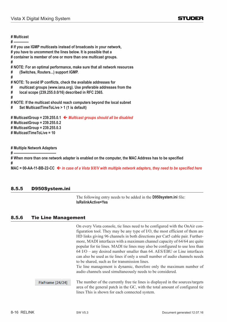
Vista X Digital Mixing System
8-16 RELINK Document generated:12.07.16SW V5.3
# Multicast# -------------# If you use IGMP multicasts instead of broadcasts in your network,# you have to uncomment the lines below. It is possible that a # container is member of one or more than one multicast groups.## NOTE: For an optimal performance, make sure that all network resources# (Switches, Routers...) support IGMP.## NOTE: To avoid IP conflicts, check the available addresses for# multicast groups (www.iana.org). Use preferable addresses from the# local scope (239.255.0.0/16) described in RFC 2365.## NOTE: If the multicast should reach computers beyond the local subnet# Set MulticastTimeToLive > 1 (1 is default)
# MulticastGroup = 239.255.0.1 Multicast groups should all be disabled# MulticastGroup = 239.255.0.2# MulticastGroup = 239.255.0.3# MulticastTimeToLive = 10
# Multiple Network Adapters# -------------------------------------# When more than one network adapter is enabled on the computer, the MAC Address has to be specified#MAC = 00-AA-11-BB-22-CC in case of a Vista 9/X/V with multiple network adapters, they need to be specified here
8.5.5 D950system.ini
The following entry needs to be added in the D950system.ini file: IsRelinkActive=Yes
8.5.6 Tie Line Management
On every Vista console, tie lines need to be configured with the OnAir con-figuration tool. They may be any type of I/O, the most efficient of them are HD links giving 96 channels in both directions per Cat5 cable pair. Further-more, MADI interfaces with a maximum channel capacity of 64/64 are quite popular for tie lines. MADI tie lines may also be configured to use less than 64 I/O – any desired number smaller than 64. AES/EBU or Line interfaces can also be used as tie lines if only a small number of audio channels needs to be shared, such as for transmission lines.
Tie line management is dynamic, therefore only the maximum number of audio channels used simultaneously needs to be considered.
The number of the currently free tie lines is displayed in the sources/targets area of the general patch in the GC, with the total amount of configured tie lines This is shown for each connected system.
Vista X Digital Mixing System
RELINK 8-17Document generated: 12.07.16 SW V5.3
8.5.7 Control Network
All systems that need to be part of the I/O Sharing network need to be inter-connected via Ethernet. On the Vista side, it is always the desk that needs to be networked.
•Vista desk networked (Ethernet) •Tie lines between cores (MADI, AES, or HD Links) •DNET technology from OnAir product range •Setup with the OnAir configuration tool also on the Vista side.
8.5.7.1 Vista X in general
Vista X is by default equipped with several network ports. There is a specific «Relink» Ethernet port which must be used to network the console to the Relink system. Normally, the Relink Ethernet port is connected to an Ether-net switch, where all other Relink devices are connected as well. In case the Relink network only consist of two Vista X consoles, also a X-over network cable between both Relink Ethernet ports of the two consoles could be used instead of an Ethernet switch.
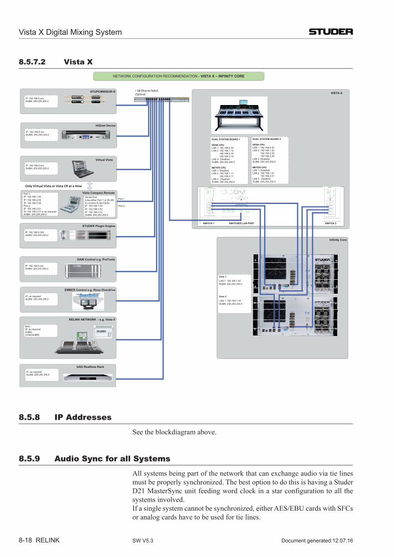
Vista X Digital Mixing System
8-18 RELINK Document generated:12.07.16SW V5.3
8.5.7.2 Vista X
VISTA X
SCore Live
BRIDGE 1
IP Port 1 192.168.1.60IP Port 2 192.168.2.60SUBN: 255.255.255.0
NETWORK CONFIGURATION RECOMMENDATION - VISTA X – INFINITY CORE
IP: 192.168.5.xxxSUBN: 255.255.255.0
HiQnet Device
IP: 192.168.5.xxxSUBN: 255.255.255.0
DAW Control e.g. ProTools
IP: 192.168.5.xxxSUBN: 255.255.255.0
STUDER Plugin Engine
IP: 192.168.5.200SUBN: 255.255.255.0
Infinity Core
Core 1
Core 2
STUPCM96SUR-D
Virtual Vista
1 GB Ethernet Switch(Optional)
Vista Compact Remote
Only Virtual Vista or Vista CR at a time
RELINK NETWORK - e.g. Vista 5
MAC :IP: as requiredSUBN:CONTAINER:
EMBER Control e.g. Ross Overdrive
IP: as requiredSUBN: 255.255.255.0
Port 1:IP: 192.168.1.50IP: 192.168.2.50IP: 192.168.3.50Port 2:IP: 192.168.2.51IP: 192.168.5.51 or as required SUBN: 255.255.255.0
Port 1
Port 2
IP: 192.168.5.xxxSUBN: 255.255.255.0
WLAN Port(Use either Port 1 or WLANto connect to the Desk)IP: 192.168.1.52IP: 192.168.2.52IP: 192.168.3.52SUBN: 255.255.255.0
DUAL SYSTEM BOARD 1
DESK CPULAN 1: 192.168.5.30LAN 2: 192.168.1.10
192.168.2.10192.168.3.10
LAN 3: DisabledSUBN: 255.255.255.0
METER CPULAN 1: DisabledLAN 2: 192.168.1.11
192.168.2.11LAN 3: DisabledSUBN: 255.255.255.0
DUAL SYSTEM BOARD 2
DESK CPULAN 1: 192.168.5.30LAN 2: 192.168.1.20
192.168.2.20192.168.3.20
LAN 3: DisabledSUBN: 255.255.255.0
METER CPULAN 1: DisabledLAN 2: 192.168.1.21
192.168.2.21LAN 3: DisabledSUBN: 255.255.255.0
LAN 1: 192.168.1.42SUBN: 255.255.255.0
LAN 1: 192.168.1.43SUBN: 255.255.255.0
UAD Realtime RackIP: as requiredSUBN: 255.255.255.0
SWITCH 1 SWITCH 2SWITCHED LAN PORT
8.5.8 IP Addresses
See the blockdiagram above.
8.5.9 Audio sync for all systems
All systems being part of the network that can exchange audio via tie lines must be properly synchronized. The best option to do this is having a Studer D21 MasterSync unit feeding word clock in a star configuration to all the systems involved.
If a single system cannot be synchronized, either AES/EBU cards with SFCs or analog cards have to be used for tie lines.
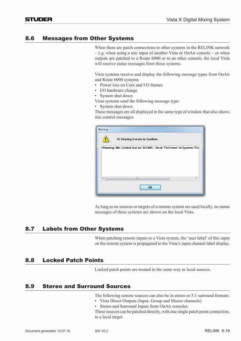
Vista X Digital Mixing System
RELINK 8-19Document generated: 12.07.16 SW V5.3
8.6 Messages from other systems When there are patch connections to other systems in the RELINK network
– e.g. when using a mic input of another Vista or OnAir console – or when outputs are patched to a Route 6000 or to an other console, the local Vista will receive status messages from these systems.
Vista systems receive and display the following message types from OnAir and Route 6000 systems:
• PowerlossonCoreandI/O frames • I/Ohardwarechange • Systemshutdown Vista systems send the following message type: • Systemshutdown These messages are all displayed in the same type of window that also shows
mic control messages:
As long as no sources or targets of a remote system are used locally, no status messages of these systems are shown on the local Vista.
8.7 Labels from other systems When patching remote inputs to a Vista system, the ‘user label’ of this input
on the remote system is propagated to the Vista’s input channel label display.
8.8 Locked Patch Points Locked patch points are treated in the same way as local sources.
8.9 stereo and surround sources The following remote sources can also be in stereo or 5.1 surround formats: • VistaDirectOutputs(Input,GroupandMasterchannels) • StereoandSurroundInputsfromOnAirconsoles. These sources can be patched directly, with one single patch point connection,
to a local target.
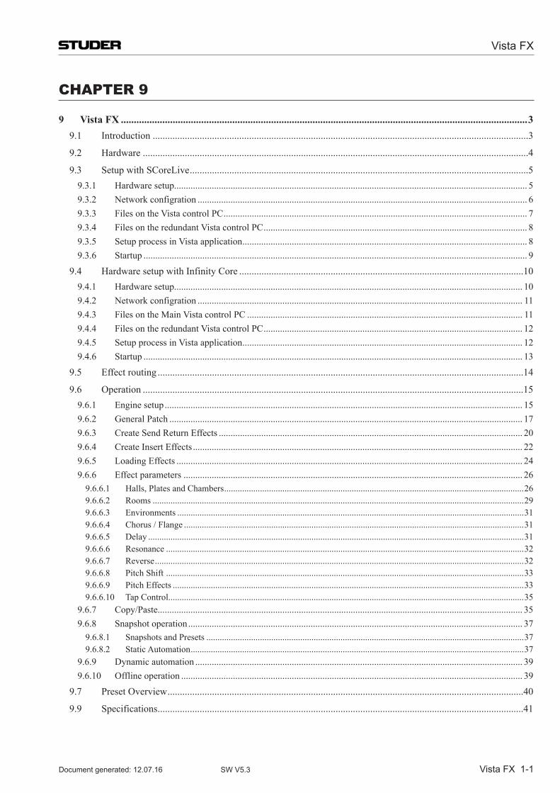
Vista FX
Vista FX 1-1Document generated: 12.07.16 SW V5.3
Chapter 9
9 Vista FX .............................................................................................................................................................39.1 Introduction ........................................................................................................................................................3
9.2 Hardware ............................................................................................................................................................4
9.3 Setup with SCoreLive .........................................................................................................................................59.3.1 Hardware setup...................................................................................................................................................... 59.3.2 Network configration ............................................................................................................................................ 69.3.3 Files on the Vista control PC ................................................................................................................................. 79.3.4 Files on the redundant Vista control PC ................................................................................................................ 89.3.5 Setup process in Vista application ......................................................................................................................... 89.3.6 Startup ................................................................................................................................................................... 9
9.4 Hardware setup with Infinity Core ...................................................................................................................109.4.1 Hardware setup.................................................................................................................................................... 109.4.2 Network configration .......................................................................................................................................... 119.4.3 Files on the Main Vista control PC ..................................................................................................................... 119.4.4 Files on the redundant Vista control PC .............................................................................................................. 129.4.5 Setup process in Vista application ....................................................................................................................... 129.4.6 Startup ................................................................................................................................................................. 13
9.5 Effect routing ....................................................................................................................................................14
9.6 Operation ..........................................................................................................................................................159.6.1 Engine setup ........................................................................................................................................................ 159.6.2 General Patch ...................................................................................................................................................... 179.6.3 Create Send Return Effects ................................................................................................................................. 209.6.4 Create Insert Effects ............................................................................................................................................ 229.6.5 Loading Effects ................................................................................................................................................... 249.6.6 Effect parameters ................................................................................................................................................ 26
9.6.6.1 Halls, Plates and Chambers ......................................................................................................................................269.6.6.2 Rooms ......................................................................................................................................................................299.6.6.3 Environments ...........................................................................................................................................................319.6.6.4 Chorus / Flange ........................................................................................................................................................319.6.6.5 Delay ........................................................................................................................................................................319.6.6.6 Resonance ................................................................................................................................................................329.6.6.7 Reverse .....................................................................................................................................................................329.6.6.8 Pitch Shift ................................................................................................................................................................339.6.6.9 Pitch Effects .............................................................................................................................................................339.6.6.10 Tap Control...............................................................................................................................................................35
9.6.7 Copy/Paste........................................................................................................................................................... 359.6.8 Snapshot operation .............................................................................................................................................. 37
9.6.8.1 Snapshots and Presets ..............................................................................................................................................379.6.8.2 Static Automation .....................................................................................................................................................37
9.6.9 Dynamic automation ........................................................................................................................................... 399.6.10 Offline operation ................................................................................................................................................. 39
9.7 Preset Overview ................................................................................................................................................40
9.9 Specifications ....................................................................................................................................................41
Vista FX
1-2 Vista FX Document generated: 12.07.16SW V5.3
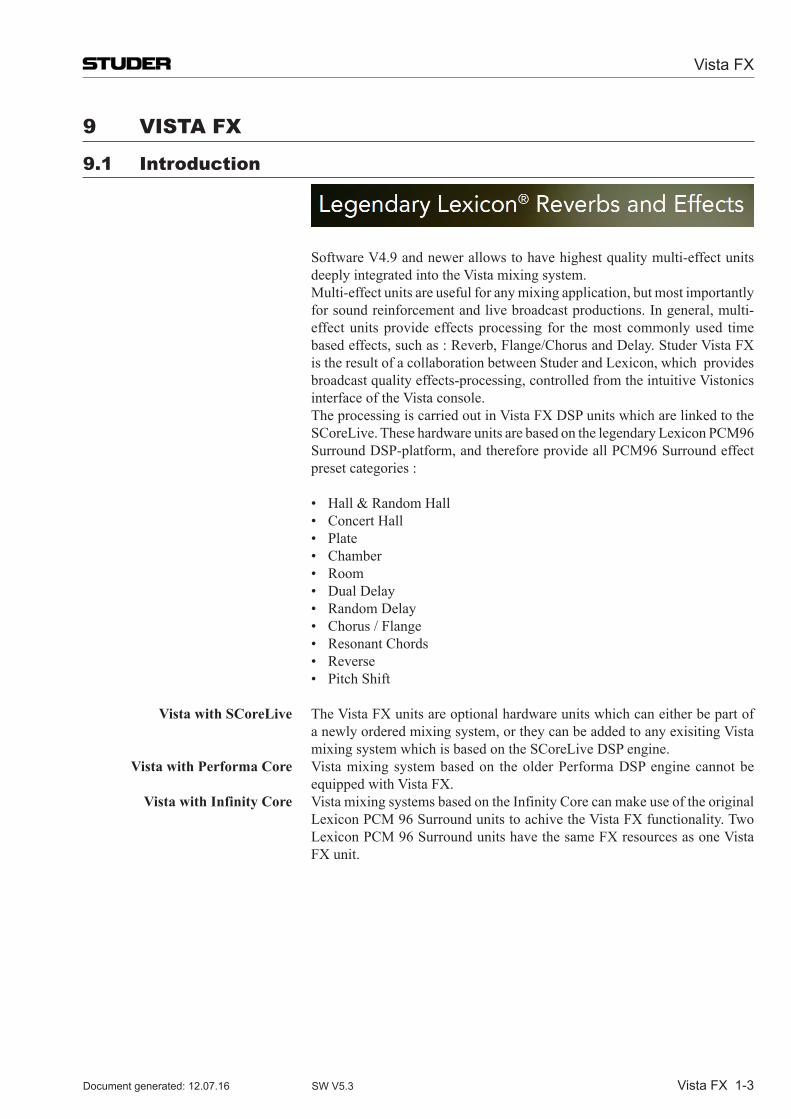
Vista FX
Vista FX 1-3Document generated: 12.07.16 SW V5.3
9 Vista FX
9.1 introduction
Software V4.9 and newer allows to have highest quality multi-effect units deeply integrated into the Vista mixing system.
Multi-effect units are useful for any mixing application, but most importantly for sound reinforcement and live broadcast productions. In general, multi-effect units provide effects processing for the most commonly used time based effects, such as : Reverb, Flange/Chorus and Delay. Studer Vista FX is the result of a collaboration between Studer and Lexicon, which provides broadcast quality effects-processing, controlled from the intuitive Vistonics interface of the Vista console.
The processing is carried out in Vista FX DSP units which are linked to the SCoreLive. These hardware units are based on the legendary Lexicon PCM96 Surround DSP-platform, and therefore provide all PCM96 Surround effect preset categories :
• Hall&RandomHall • ConcertHall • Plate • Chamber • Room • DualDelay • RandomDelay • Chorus/Flange • ResonantChords • Reverse • PitchShift
Vista with SCoreLive The Vista FX units are optional hardware units which can either be part of a newly ordered mixing system, or they can be added to any exisiting Vista mixing system which is based on the SCoreLive DSP engine.
Vista with Performa Core Vista mixing system based on the older Performa DSP engine cannot be equipped with Vista FX.
Vista with Infinity Core Vista mixing systems based on the Infinity Core can make use of the original Lexicon PCM 96 Surround units to achive the Vista FX functionality. Two Lexicon PCM 96 Surround units have the same FX resources as one Vista FX unit.
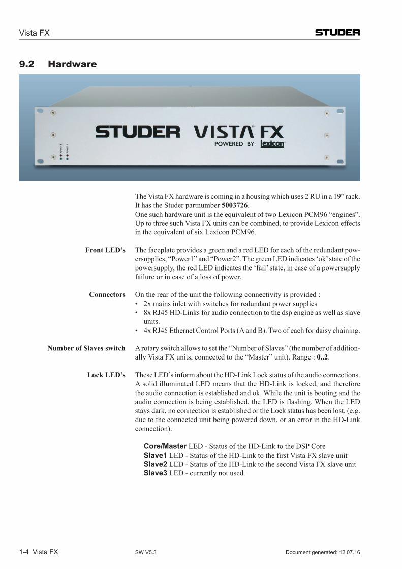
Vista FX
1-4 Vista FX Document generated: 12.07.16SW V5.3
9.2 hardware
The Vista FX hardware is coming in a housing which uses 2 RU in a 19” rack. It has the Studer partnumber 5003726. One such hardware unit is the equivalent of two Lexicon PCM96 “engines”.
Up to three such Vista FX units can be combined, to provide Lexicon effects in the equivalent of six Lexicon PCM96.
Front LED’s The faceplate provides a green and a red LED for each of the redundant pow-ersupplies, “Power1” and “Power2”. The green LED indicates ‘ok’ state of the powersupply, the red LED indicates the ‘fail’ state, in case of a powersupply failure or in case of a loss of power.
Connectors On the rear of the unit the following connectivity is provided : • 2xmainsinletwithswitchesforredundantpowersupplies • 8xRJ45HD-Linksforaudioconnectiontothedspengineaswellasslave
units. • 4xRJ45EthernetControlPorts(AandB).Twoofeachfordaisychaining.
Number of Slaves switch Arotaryswitchallowstosetthe“NumberofSlaves”(thenumberofaddition-allyVistaFXunits,connectedtothe“Master”unit).Range:0..2.
Lock LED’s These LED’s inform about the HD-Link Lock status of the audio connections. A solid illuminated LED means that the HD-Link is locked, and therefore the audio connection is established and ok. While the unit is booting and the audio connection is being established, the LED is flashing. When the LED staysdark,noconnectionisestablishedortheLockstatushasbeenlost.(e.g.due to the connected unit being powered down, or an error in the HD-Link connection).
Core/Master LED - Status of the HD-Link to the DSP Core Slave1 LED - Status of the HD-Link to the first Vista FX slave unit Slave2 LED - Status of the HD-Link to the second Vista FX slave unit Slave3 LED - currently not used.
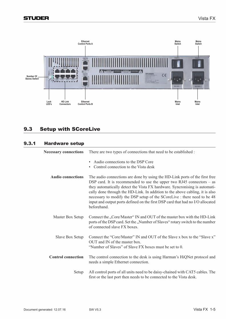
Vista FX
Vista FX 1-5Document generated: 12.07.16 SW V5.3
MainsSwitch
MainsSwitch
MainsInlet
Number Of Slaves Switch
MainsInlet
LockLED’s
HD LinkConnectors
EthernetControl Ports B
EthernetControl Ports A
9.3 setup with sCoreLive
9.3.1 hardware setup
Necessary connections There are two types of connections that need to be established :
• AudioconnectionstotheDSPCore • ControlconnectiontotheVistadesk
Audio connections The audio connections are done by using the HD-Link ports of the first free DSPcard. It is recommended touse theupper twoRJ45connectors–asthey automatically detect the Vista FX hardware. Syncronising is automati-cally done through the HD-Link. In addition to the above cabling, it is also necessary to modify the DSP setup of the SCoreLive : there need to be 48 input and output ports defined on the first DSP card that had no I/O allocated beforehand.
MasterBoxSetup Connectthe„Core/Master“INandOUTofthemasterboxwiththeHD-LinkportsoftheDSPcard.Setthe„NumberofSlaves“rotaryswitchtothenumberof connected slave FX boxes.
SlaveBoxSetup Connectthe“Core/Master”INandOUToftheSlavexboxtothe“Slavex”OUT and IN of the master box.
“Number of Slaves” of Slave FX boxes must be set to 0.
Control connection The control connection to the desk is using Harman’s HiQNet protocol and needs a simple Ethernet connection.
Setup All control ports of all units need to be daisy-chained with CAT5 cables. The first or the last port then needs to be connected to the Vista desk.
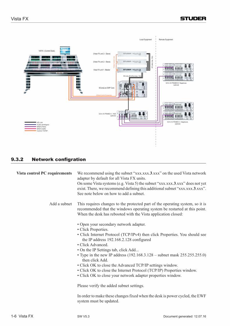
Vista FX
1-6 Vista FX Document generated: 12.07.16SW V5.3
0 1 2 3 422.07.2014 wp
SYSTEM BLOCK DIAGRAM Vista FX
SCoreLive DSP Core
D21m I/O FRAMES A / HUB(optional)
VISTA (Control Desk)
D21m I/O FRAMES B / Stageboxes(optional)
HD Links 48 In/Out (max. 10m)
D21m I/O FRAMES C / Stageboxes(optional)
(Vista FX unit 3 - Slave)
(Vista FX unit 2 - Slave)
Vista FX unit 1- Master
Audio (analogue)MADI (Fibre)MADI (Cat5)Control TCP/IP
HD Link
HiQnet Control Connection
HiQn
et Co
ntrol
Links
HD Li
nks (
max.
10m)
Local Equipment Remote Equipment
9.3.2 Network configration
Vista control PC requirements We recommend using the subnet “xxx.xxx.3.xxx” on the used Vista network adapter by default for all Vista FX units.
OnsomeVistasystems(e.g.Vista5)thesubnet“xxx.xxx.3.xxx” does not yet exist. There, we recommend defining this additional subnet “xxx.xxx.3.xxx”. See note below on how to add a subnet.
Add a subnet This requires changes to the protected part of the operating system, so it is
recommended that the windows operating system be restarted at this point.When the desk has rebooted with the Vista application closed:
•Openyoursecondarynetworkadapter. •ClickProperties. •ClickInternetProtocol(TCP/IPv4)thenclickProperties.Youshouldsee
the IP address 192.168.2.128 configured •ClickAdvanced. •OntheIPSettingstab,clickAdd... •TypeinthenewIPaddress(192.168.3.128–subnetmask255.255.255.0)
then click Add. •ClickOKtoclosetheAdvancedTCP/IPsettingswindow. •ClickOKtoclosetheInternetProtocol(TCP/IP)Propertieswindow. •ClickOKtocloseyournetworkadapterpropertieswindow.
Please verify the added subnet settings.
In order to make these changes fixed when the desk is power cycled, the EWF system must be updated.
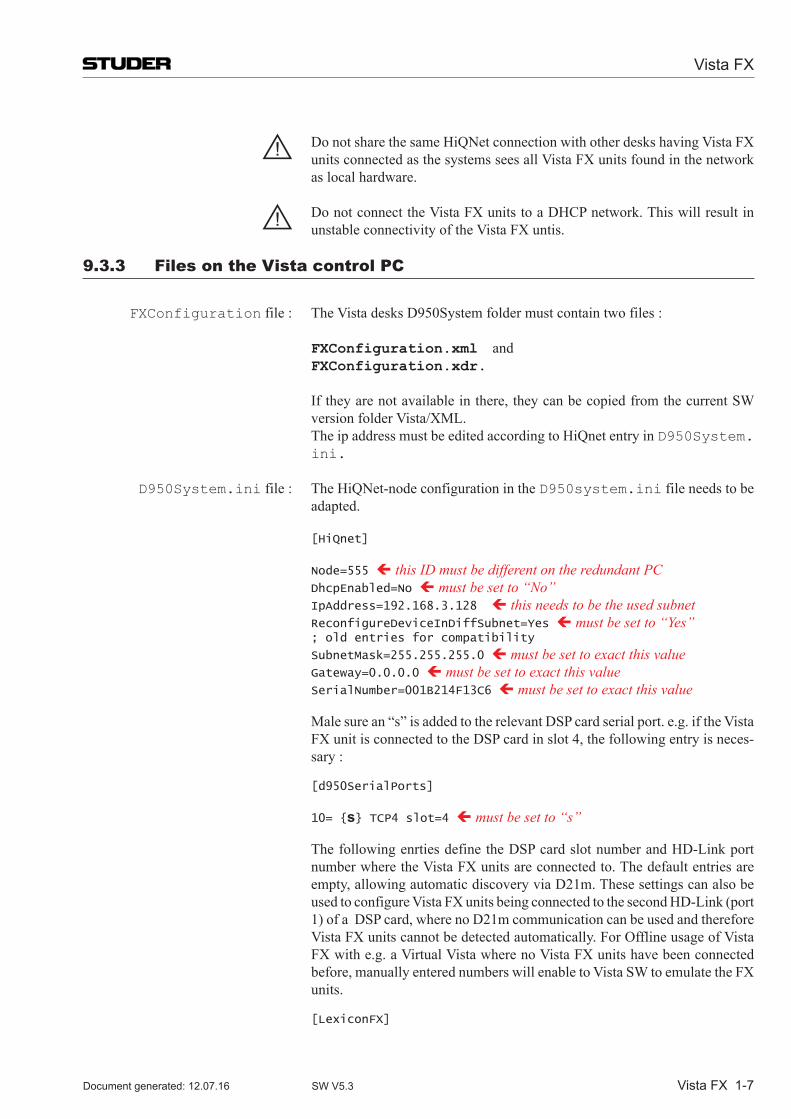
Vista FX
Vista FX 1-7Document generated: 12.07.16 SW V5.3
! Do not share the same HiQNet connection with other desks having Vista FX units connected as the systems sees all Vista FX units found in the network as local hardware.
! Do not connect the Vista FX units to a DHCP network. This will result in unstable connectivity of the Vista FX untis.
9.3.3 Files on the Vista control pC
FXConfiguration file : The Vista desks D950System folder must contain two files :
FXConfiguration.xml and FXConfiguration.xdr.
If they are not available in there, they can be copied from the current SW version folder Vista/XML.
The ip address must be edited according to HiQnet entry in D950System.ini.
D950System.ini file : The HiQNet-node configuration in the D950system.ini file needs to be adapted.
[HiQnet]
Node=555 ç this ID must be different on the redundant PC DhcpEnabled=No ç must be set to “No” IpAddress=192.168.3.128 ç this needs to be the used subnet ReconfigureDeviceInDiffSubnet=Yes ç must be set to “Yes” ; old entries for compatibility
SubnetMask=255.255.255.0 ç must be set to exact this value Gateway=0.0.0.0 ç must be set to exact this value SerialNumber=001B214F13C6 ç must be set to exact this value
Male sure an “s” is added to the relevant DSP card serial port. e.g. if the Vista FX unit is connected to the DSP card in slot 4, the following entry is neces-sary :
[d950SerialPorts]
10= {s} TCP4 slot=4 ç must be set to “s”
The following enrties define the DSP card slot number and HD-Link port number where the Vista FX units are connected to. The default entries are empty, allowing automatic discovery via D21m. These settings can also be usedtoconfigureVistaFXunitsbeingconnectedtothesecondHD-Link(port1)ofaDSPcard,wherenoD21mcommunicationcanbeusedandthereforeVista FX units cannot be detected automatically. For Offline usage of Vista FX with e.g. a Virtual Vista where no Vista FX units have been connected before, manually entered numbers will enable to Vista SW to emulate the FX units.
[LexiconFX]
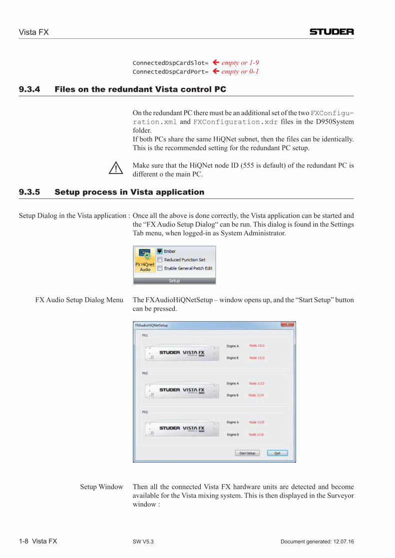
Vista FX
1-8 Vista FX Document generated: 12.07.16SW V5.3
ConnectedDspCardSlot= ç empty or 1-9 ConnectedDspCardPort= ç empty or 0-1
9.3.4 Files on the redundant Vista control pC
On the redundant PC there must be an additional set of the two FXConfigu-ration.xml and FXConfiguration.xdr files in the D950System folder.
If both PCs share the same HiQNet subnet, then the files can be identically. This is the recommended setting for the redundant PC setup.
! MakesurethattheHiQNetnodeID(555isdefault)oftheredundantPCisdifferent o the main PC.
9.3.5 setup process in Vista application
Setup Dialog in the Vista application : Once all the above is done correctly, the Vista application can be started and the “FX Audio Setup Dialog“ can be run. This dialog is found in the Settings Tab menu, when logged-in as System Administrator.
FXAudioSetupDialogMenu TheFXAudioHiQNetSetup–windowopensup,andthe“StartSetup”buttoncan be pressed.
Setup Window Then all the connected Vista FX hardware units are detected and become
available for the Vista mixing system. This is then displayed in the Surveyor window :
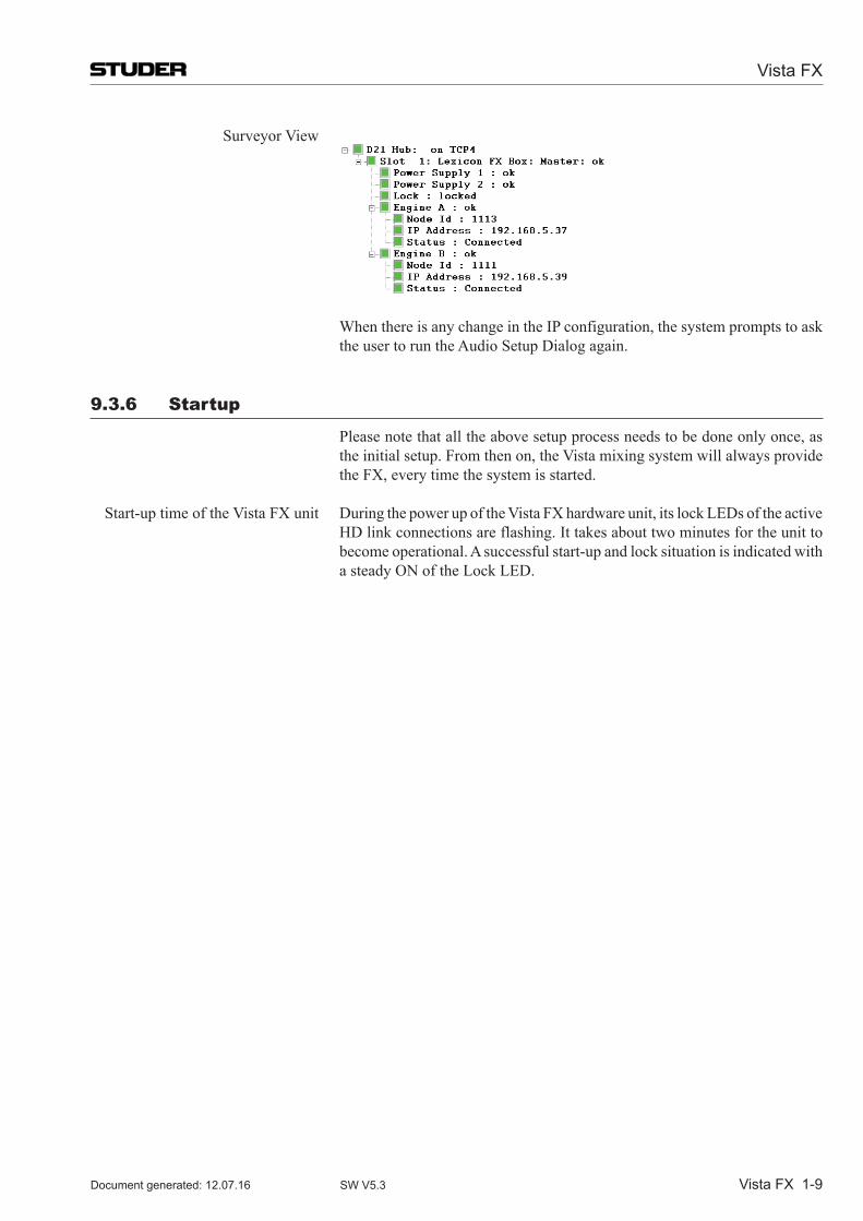
Vista FX
Vista FX 1-9Document generated: 12.07.16 SW V5.3
Surveyor View
When there is any change in the IP configuration, the system prompts to ask the user to run the Audio Setup Dialog again.
9.3.6 startup
Please note that all the above setup process needs to be done only once, as the initial setup. From then on, the Vista mixing system will always provide the FX, every time the system is started.
Start-up time of the Vista FX unit During the power up of the Vista FX hardware unit, its lock LEDs of the active HD link connections are flashing. It takes about two minutes for the unit to become operational. A successful start-up and lock situation is indicated with a steady ON of the Lock LED.
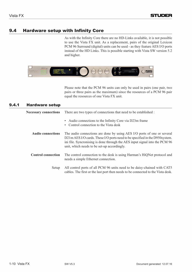
Vista FX
1-10 Vista FX Document generated: 12.07.16SW V5.3
9.4 hardware setup with infinity Core As with the Infinity Core there are no HD-Links available, it is not possible
to use the Vista FX unit. As a replacement, pairs of the original Lexicon PCM96Surround(digital)unitscanbeused-astheyfeatureAESI/Oportsinstead of the HD Links. This is possible starting with Vista SW version 5.2 and higher.
PleasenotethatthePCM96unitscanonlybeusedinpairs(onepair,two
pairsorthreepairsasthemaximum)sincetheresourcesofaPCM96pairequal the resources of one Vista FX unit.
9.4.1 hardware setup
Necessary connections There are two types of connections that need to be established :
• AudioconnectionstotheInfinityCoreviaD23mframe • ControlconnectiontotheVistadesk
Audio connections The audio connections are done by using AES I/O ports of one or several D21m AES I/O cards. These I/O ports need to be specified in the D950system.ini file. Syncronising is done through the AES input signal into the PCM 96 unit, which needs to be set-up accordingly.
Control connection The control connection to the desk is using Harman’s HiQNet protocol and needs a simple Ethernet connection.
Setup All control ports of all PCM 96 units need to be daisy-chained with CAT5 cables. The first or the last port then needs to be connected to the Vista desk.
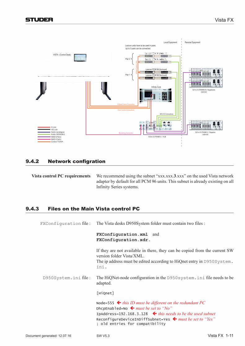
Vista FX
Vista FX 1-11Document generated: 12.07.16 SW V5.3
Lexicon PCM 96 Surround
Lexicon PCM 96 Surround
0 1 2 3 429.09.2014 wp
SYSTEM BLOCK DIAGRAM Vista FX
Infinity Core
D23m I/O FRAME A / HUB
VISTA (Control Desk)
D21m I/O FRAMES B / Stageboxes(optional)
AES I/O Connections
D21m I/O FRAME C / Stagebox(optional)
MADI (Fibre)MADI (Cat5)Control TCP/IP
HiQnet Control Connection
HiQn
et Co
ntrol
Links
Local Equipment Remote Equipment
Core Control Connections
Monitoring ConnectionAudio (AES/EBU)Audio (analogue)HD LinkA Link
Pair 1
Pair 2
Lexicon units have to be used in pairs. Up to 3 pairs can be connected.
9.4.2 Network configration
Vista control PC requirements We recommend using the subnet “xxx.xxx.3.xxx” on the used Vista network adapter by default for all PCM 96 units. This subnet is already existing on all Infinity Series systems.
9.4.3 Files on the Main Vista control pC
FXConfiguration file : The Vista desks D950System folder must contain two files :
FXConfiguration.xml and FXConfiguration.xdr.
If they are not available in there, they can be copied from the current SW version folder Vista/XML.
The ip address must be edited according to HiQnet entry in D950System.ini.
D950System.ini file : The HiQNet-node configuration in the D950system.ini file needs to be adapted.
[HiQnet]
Node=555 ç this ID must be different on the redundant PC DhcpEnabled=No ç must be set to “No” IpAddress=192.168.3.128 ç this needs to be the used subnet ReconfigureDeviceInDiffSubnet=Yes ç must be set to “Yes” ; old entries for compatibility
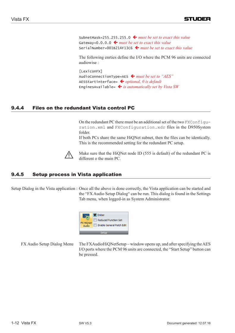
Vista FX
1-12 Vista FX Document generated: 12.07.16SW V5.3
SubnetMask=255.255.255.0 ç must be set to exact this value Gateway=0.0.0.0 ç must be set to exact this value SerialNumber=001B214F13C6 ç must be set to exact this value
The following enrties define the I/O where the PCM 96 units are connected audiowise :
[LexiconFX]
AudioConnectionType=AES ç must be set to “AES” AESStartinterface= ç optional, 0 is default EnginesAvailable= ç is automatically set by Vista SW
9.4.4 Files on the redundant Vista control pC
On the redundant PC there must be an additional set of the two FXConfigu-ration.xml and FXConfiguration.xdr files in the D950System folder.
If both PCs share the same HiQNet subnet, then the files can be identically. This is the recommended setting for the redundant PC setup.
! MakesurethattheHiQNetnodeID(555isdefault)oftheredundantPCisdifferent o the main PC.
9.4.5 setup process in Vista application
Setup Dialog in the Vista application : Once all the above is done correctly, the Vista application can be started and the “FX Audio Setup Dialog“ can be run. This dialog is found in the Settings Tab menu, when logged-in as System Administrator.
FXAudioSetupDialogMenu TheFXAudioHiQNetSetup–windowopensup,andafterspecifyingtheAESI/O ports where the PCM 96 units are connected, the “Start Setup” button can be pressed.
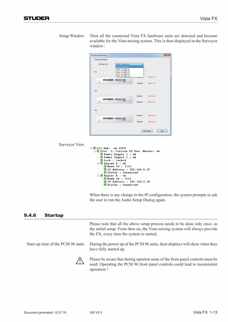
Vista FX
Vista FX 1-13Document generated: 12.07.16 SW V5.3
Setup Window Then all the connected Vista FX hardware units are detected and become available for the Vista mixing system. This is then displayed in the Surveyor window :
Surveyor View
When there is any change in the IP configuration, the system prompts to ask the user to run the Audio Setup Dialog again.
9.4.6 startup
Please note that all the above setup process needs to be done only once, as the initial setup. From then on, the Vista mixing system will always provide the FX, every time the system is started.
Start-up time of the PCM 96 units During the power up of the PCM 96 units, their dsiplays will show when they have fully started up.
! Please be aware that during opration none of the front panel controls must be used. Operating the PCM 96 front panel controls could lead to inconsistent operation !
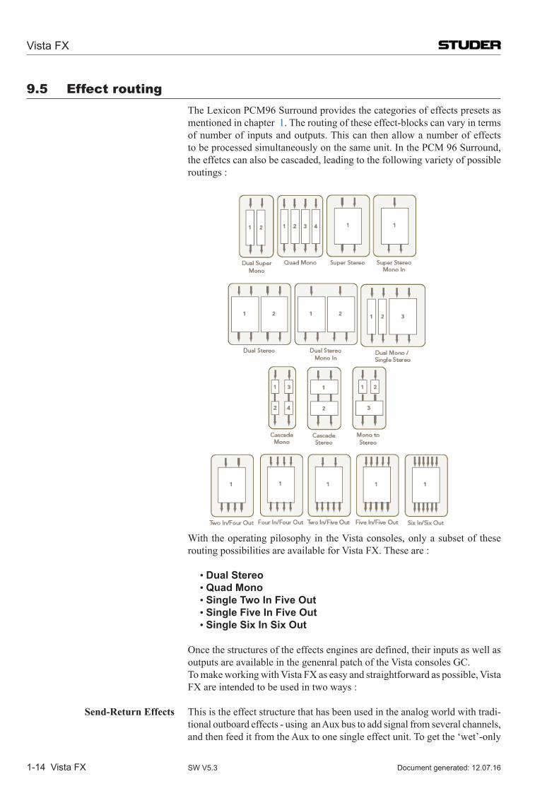
Vista FX
1-14 Vista FX Document generated: 12.07.16SW V5.3
9.5 effect routing The Lexicon PCM96 Surround provides the categories of effects presets as
mentioned in chapter 1. The routing of these effect-blocks can vary in terms of number of inputs and outputs. This can then allow a number of effects to be processed simultaneously on the same unit. In the PCM 96 Surround, the effetcs can also be cascaded, leading to the following variety of possible routings :
With the operating pilosophy in the Vista consoles, only a subset of these
routing possibilities are available for Vista FX. These are : •Dual Stereo •Quad Mono •Single Two In Five Out •Single Five In Five Out •Single Six In Six Out
Once the structures of the effects engines are defined, their inputs as well as outputs are available in the genenral patch of the Vista consoles GC.
To make working with Vista FX as easy and straightforward as possible, Vista FX are intended to be used in two ways :
Send-Return Effects This is the effect structure that has been used in the analog world with tradi-tional outboard effects - using an Aux bus to add signal from several channels, and then feed it from the Aux to one single effect unit. To get the ‘wet’-only
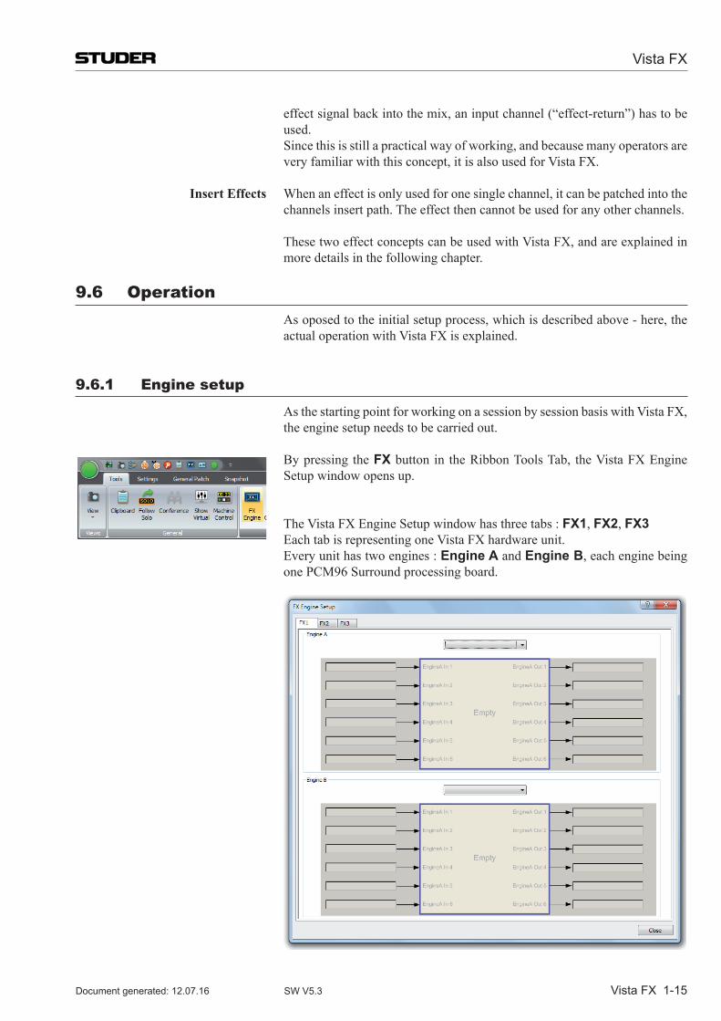
Vista FX
Vista FX 1-15Document generated: 12.07.16 SW V5.3
effectsignalbackintothemix,aninputchannel(“effect-return”)hastobeused.
Since this is still a practical way of working, and because many operators are very familiar with this concept, it is also used for Vista FX.
Insert Effects When an effect is only used for one single channel, it can be patched into the channels insert path. The effect then cannot be used for any other channels.
These two effect concepts can be used with Vista FX, and are explained in more details in the following chapter.
9.6 Operation As oposed to the initial setup process, which is described above - here, the
actual operation with Vista FX is explained.
9.6.1 engine setup
As the starting point for working on a session by session basis with Vista FX, the engine setup needs to be carried out.
Bypressing theFX button in the Ribbon Tools Tab, the Vista FX Engine Setup window opens up.
The Vista FX Engine Setup window has three tabs : FX1, FX2, FX3 Each tab is representing one Vista FX hardware unit. Every unit has two engines : Engine A and Engine B, each engine being
one PCM96 Surround processing board.
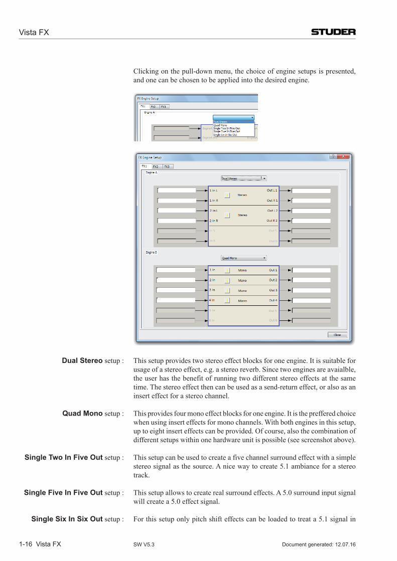
Vista FX
1-16 Vista FX Document generated: 12.07.16SW V5.3
Clicking on the pull-down menu, the choice of engine setups is presented, and one can be chosen to be applied into the desired engine.
Dual Stereo setup : This setup provides two stereo effect blocks for one engine. It is suitable for
usage of a stereo effect, e.g. a stereo reverb. Since two engines are avaialble, the user has the benefit of running two different stereo effects at the same time. The stereo effect then can be used as a send-return effect, or also as an insert effect for a stereo channel.
Quad Mono setup : This provides four mono effect blocks for one engine. It is the preffered choice when using insert effects for mono channels. With both engines in this setup, up to eight insert effects can be provided. Of course, also the combination of differentsetupswithinonehardwareunitispossible(seescreenshotabove).
Single Two In Five Out setup : This setup can be used to create a five channel surround effect with a simple stereo signal as the source. A nice way to create 5.1 ambiance for a stereo track.
Single Five In Five Out setup : This setup allows to create real surround effects. A 5.0 surround input signal will create a 5.0 effect signal.
Single Six In Six Out setup : For this setup only pitch shift effects can be loaded to treat a 5.1 signal in
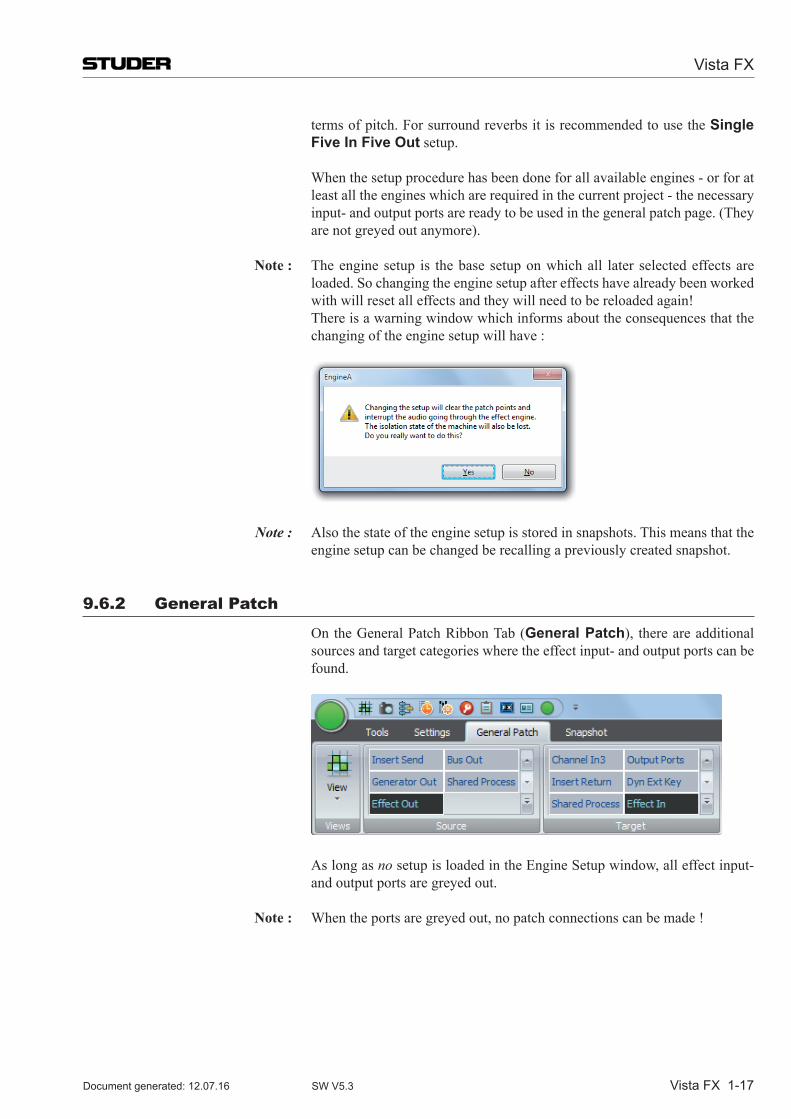
Vista FX
Vista FX 1-17Document generated: 12.07.16 SW V5.3
terms of pitch. For surround reverbs it is recommended to use the Single Five In Five Out setup.
When the setup procedure has been done for all available engines - or for at least all the engines which are required in the current project - the necessary input-andoutputportsarereadytobeusedinthegeneralpatchpage.(Theyarenotgreyedoutanymore).
Note : The engine setup is the base setup on which all later selected effects are loaded. So changing the engine setup after effects have already been worked with will reset all effects and they will need to be reloaded again!
There is a warning window which informs about the consequences that the changing of the engine setup will have :
Note : Also the state of the engine setup is stored in snapshots. This means that the engine setup can be changed be recalling a previously created snapshot.
9.6.2 General patch
OntheGeneralPatchRibbonTab(General Patch), thereareadditionalsources and target categories where the effect input- and output ports can be found.
As long as no setup is loaded in the Engine Setup window, all effect input- and output ports are greyed out.
Note : When the ports are greyed out, no patch connections can be made !
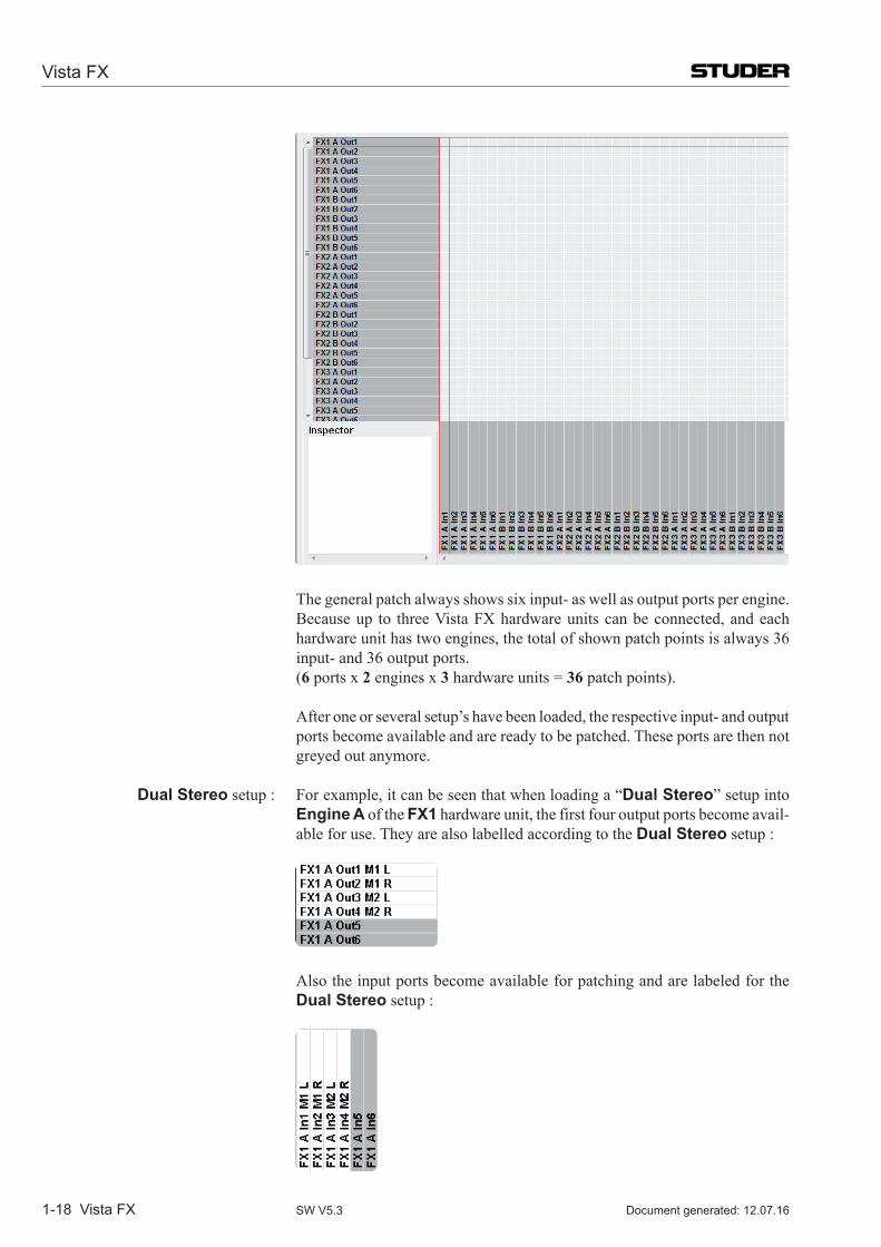
Vista FX
1-18 Vista FX Document generated: 12.07.16SW V5.3
The general patch always shows six input- as well as output ports per engine. Becauseup to threeVistaFXhardwareunitscanbeconnected,andeachhardware unit has two engines, the total of shown patch points is always 36 input- and 36 output ports.
(6 ports x 2 engines x 3 hardware units = 36patchpoints).
After one or several setup’s have been loaded, the respective input- and output ports become available and are ready to be patched. These ports are then not greyed out anymore.
Dual Stereo setup : For example, it can be seen that when loading a “Dual Stereo” setup into Engine A of the FX1 hardware unit, the first four output ports become avail-able for use. They are also labelled according to the Dual Stereo setup :
Also the input ports become available for patching and are labeled for the Dual Stereo setup :
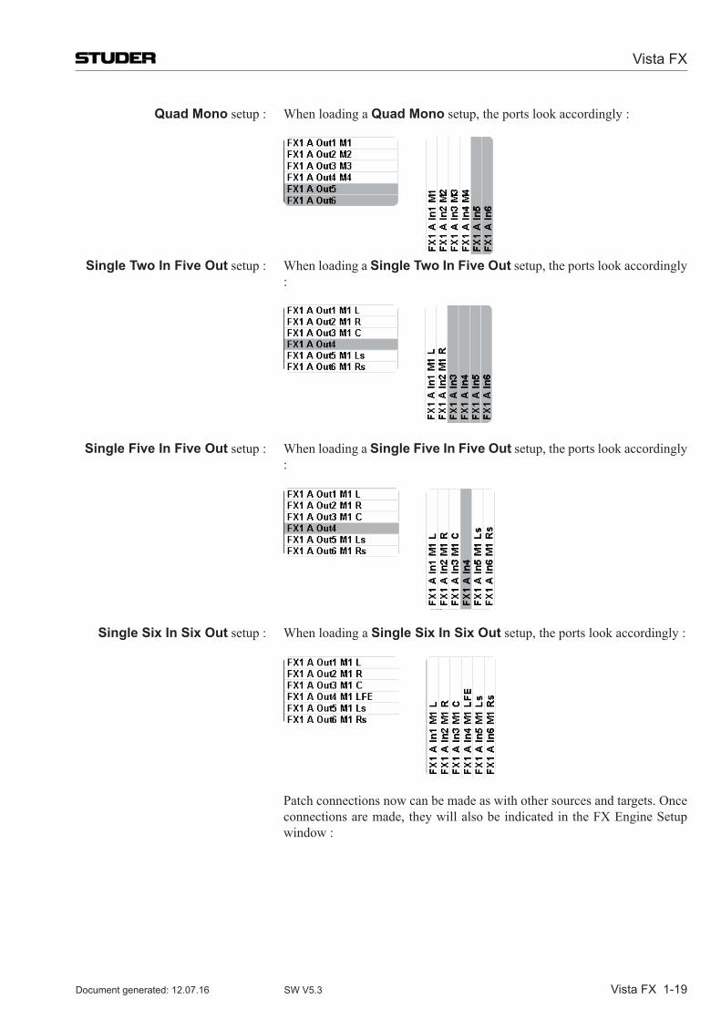
Vista FX
Vista FX 1-19Document generated: 12.07.16 SW V5.3
Quad Mono setup : When loading a Quad Mono setup, the ports look accordingly :
Single Two In Five Out setup : When loading a Single Two In Five Out setup, the ports look accordingly :
Single Five In Five Out setup : When loading a Single Five In Five Out setup, the ports look accordingly :
Single Six In Six Out setup : When loading a Single Six In Six Out setup, the ports look accordingly :
Patch connections now can be made as with other sources and targets. Once connections are made, they will also be indicated in the FX Engine Setup window :
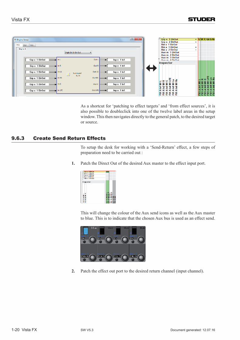
Vista FX
1-20 Vista FX Document generated: 12.07.16SW V5.3
As a shortcut for ‘patching to effect targets’ and ‘from effect sources’, it is
also possible to doubleclick into one of the twelve label areas in the setup window. This then navigates directly to the general patch, to the desired target or source.
9.6.3 Create send return effects
To setup the desk for working with a ‘Send-Return’ effect, a few steps of preparation need to be carried out :
1. Patch the Direct Out of the desired Aux master to the effect input port.
This will change the colour of the Aux send icons as well as the Aux master to blue. This is to indicate that the chosen Aux bus is used as an effect send.
2. Patchtheeffectoutporttothedesiredreturnchannel(inputchannel).
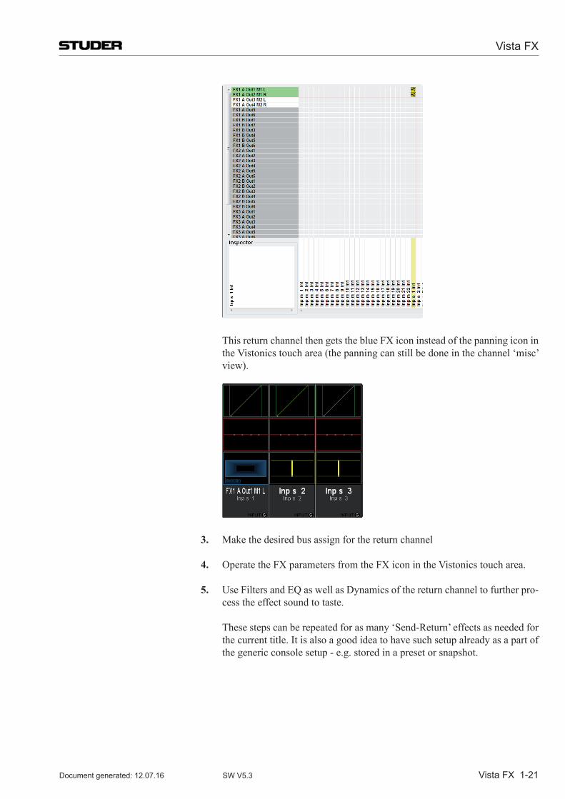
Vista FX
Vista FX 1-21Document generated: 12.07.16 SW V5.3
This return channel then gets the blue FX icon instead of the panning icon in theVistonicstoucharea(thepanningcanstillbedoneinthechannel‘misc’view).
3. Make the desired bus assign for the return channel
4. Operate the FX parameters from the FX icon in the Vistonics touch area.
5. Use Filters and EQ as well as Dynamics of the return channel to further pro-cess the effect sound to taste.
These steps can be repeated for as many ‘Send-Return’ effects as needed for the current title. It is also a good idea to have such setup already as a part of the generic console setup - e.g. stored in a preset or snapshot.
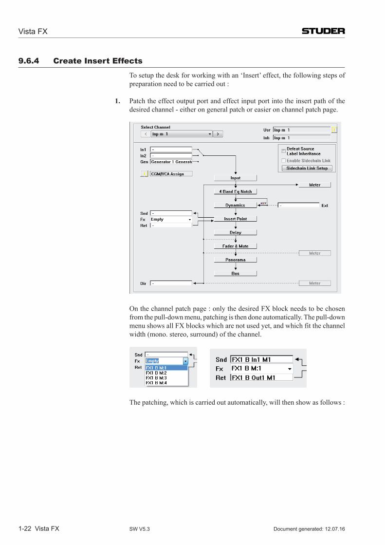
Vista FX
1-22 Vista FX Document generated: 12.07.16SW V5.3
9.6.4 Create insert effects
To setup the desk for working with an ‘Insert’ effect, the following steps of preparation need to be carried out :
1. Patch the effect output port and effect input port into the insert path of the desired channel - either on general patch or easier on channel patch page.
On the channel patch page : only the desired FX block needs to be chosen from the pull-down menu, patching is then done automatically. The pull-down menu shows all FX blocks which are not used yet, and which fit the channel width(mono.stereo,surround)ofthechannel.
The patching, which is carried out automatically, will then show as follows :
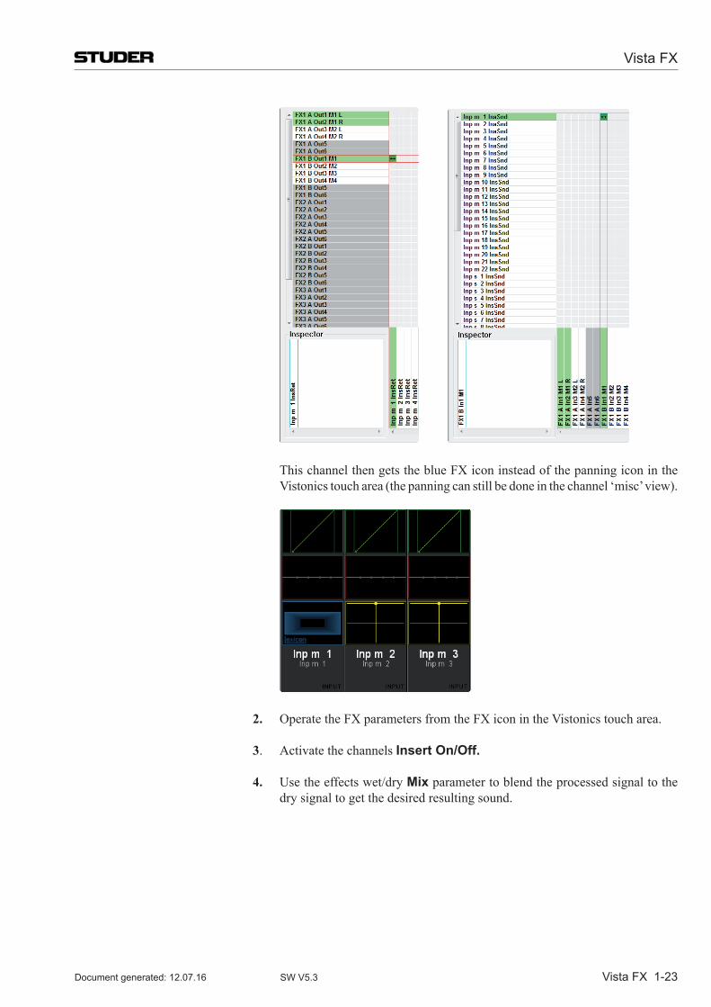
Vista FX
Vista FX 1-23Document generated: 12.07.16 SW V5.3
This channel then gets the blue FX icon instead of the panning icon in the Vistonicstoucharea(thepanningcanstillbedoneinthechannel‘misc’view).
2. Operate the FX parameters from the FX icon in the Vistonics touch area.
3. Activate the channels Insert On/Off.
4. Use the effects wet/dry Mix parameter to blend the processed signal to the dry signal to get the desired resulting sound.
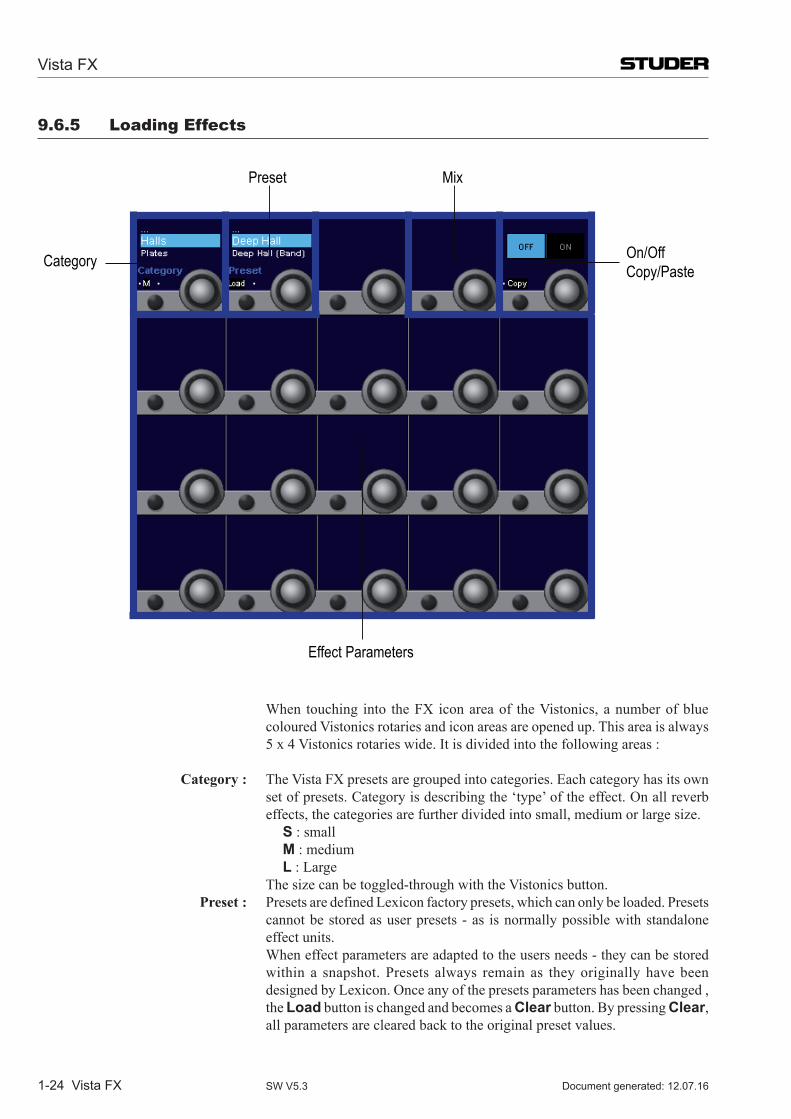
Vista FX
1-24 Vista FX Document generated: 12.07.16SW V5.3
9.6.5 Loading effects
Category
Preset Mix
On/OffCopy/Paste
Effect Parameters
When touching into the FX icon area of the Vistonics, a number of blue coloured Vistonics rotaries and icon areas are opened up. This area is always 5 x 4 Vistonics rotaries wide. It is divided into the following areas :
Category : The Vista FX presets are grouped into categories. Each category has its own set of presets. Category is describing the ‘type’ of the effect. On all reverb effects, the categories are further divided into small, medium or large size.
S : small M : medium L : Large The size can be toggled-through with the Vistonics button. Preset : Presets are defined Lexicon factory presets, which can only be loaded. Presets
cannot be stored as user presets - as is normally possible with standalone effect units.
When effect parameters are adapted to the users needs - they can be stored within a snapshot. Presets always remain as they originally have been designed by Lexicon. Once any of the presets parameters has been changed , the Load button is changed and becomes a Clearbutton.BypressingClear, all parameters are cleared back to the original preset values.
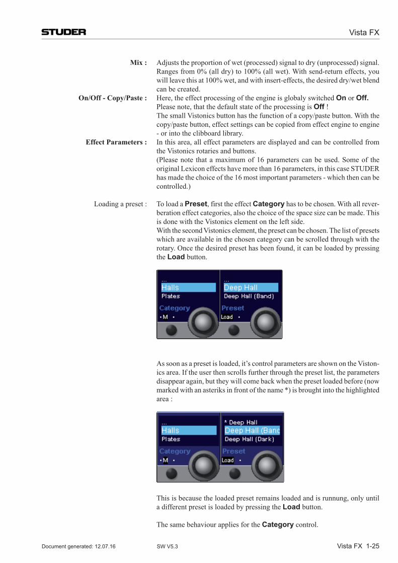
Vista FX
Vista FX 1-25Document generated: 12.07.16 SW V5.3
Mix : Adjuststheproportionofwet(processed)signaltodry(unprocessed)signal.Rangesfrom0%(alldry)to100%(allwet).Withsend-returneffects,youwill leave this at 100% wet, and with insert-effects, the desired dry/wet blend can be created.
On/Off - Copy/Paste : Here, the effect processing of the engine is globaly switched On or Off. Please note, that the default state of the processing is Off ! The small Vistonics button has the function of a copy/paste button. With the
copy/paste button, effect settings can be copied from effect engine to engine - or into the clibboard library.
Effect Parameters : In this area, all effect parameters are displayed and can be controlled from the Vistonics rotaries and buttons.
(Pleasenote thatamaximumof16parameterscanbeused.Someof theoriginal Lexicon effects have more than 16 parameters, in this case STUDER has made the choice of the 16 most important parameters - which then can be controlled.)
Loading a preset : To load a Preset, first the effect Category has to be chosen. With all rever-beration effect categories, also the choice of the space size can be made. This is done with the Vistonics element on the left side.
With the second Vistonics element, the preset can be chosen. The list of presets which are available in the chosen category can be scrolled through with the rotary. Once the desired preset has been found, it can be loaded by pressing the Load button.
As soon as a preset is loaded, it’s control parameters are shown on the Viston-ics area. If the user then scrolls further through the preset list, the parameters disappearagain,buttheywillcomebackwhenthepresetloadedbefore(nowmarkedwithanasteriksinfrontofthename*)isbroughtintothehighlightedarea :
This is because the loaded preset remains loaded and is runnung, only until
a different preset is loaded by pressing the Load button.
The same behaviour applies for the Category control.
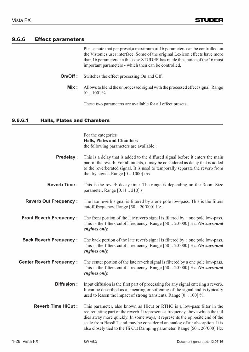
Vista FX
1-26 Vista FX Document generated: 12.07.16SW V5.3
9.6.6 effect parameters
Please note that per preset,a maximum of 16 parameters can be controlled on the Vistonics user interface. Some of the original Lexicon effects have more than 16 parameters, in this case STUDER has made the choice of the 16 most important parameters - which then can be controlled.
On/Off : Switches the effect processing On and Off.
Mix : Allows to blend the unprocessed signal with the processed effect signal. Range [0 .. 100] %
These two parameters are available for all effect presets.
9.6.6.1 halls, plates and Chambers
For the categories Halls, Plates and Chambers the following parameters are available :
Predelay : This is a delay that is added to the diffused signal before it enters the main part of the reverb. For all intents, it may be considered as delay that is added to the reverberated signal. It is used to temporally separate the reverb from the dry signal. Range [0 .. 1000] ms.
Reverb Time : This is the reverb decay time. The range is depending on the Room Size parameter. Range [0.11 .. 210] s.
Reverb Out Frequency : The late reverb signal is filtered by a one pole low-pass. This is the filters cutoff frequency. Range [50 .. 20’000] Hz.
Front Reverb Frequency : The front portion of the late reverb signal is filtered by a one pole low-pass. This is the filters cutoff frequency. Range [50 .. 20’000] Hz. On surround engines only.
Back Reverb Frequency : The back portion of the late reverb signal is filtered by a one pole low-pass. This is the filters cutoff frequency. Range [50 .. 20’000] Hz. On surround engines only.
Center Reverb Frequency : The center portion of the late reverb signal is filtered by a one pole low-pass. This is the filters cutoff frequency. Range [50 .. 20’000] Hz. On surround engines only.
Diffusion : Input diffusion is the first part of processing for any signal entering a reverb. It can be described as a smearing or softening of the signal and is typically used to lessen the impact of strong transients. Range [0 .. 100] %.
Reverb Time HiCut : This parameter, also known as Hicut or RTHC is a low-pass filter in the recirculating part of the reverb. It represents a frequency above which the tail dies away more quickly. In some ways, it represents the opposite end of the scalefromBassRT,andmaybeconsideredananalogofairabsorption.Itisalso closely tied to the Hi Cut Damping parameter. Range [50 .. 20’000] Hz.
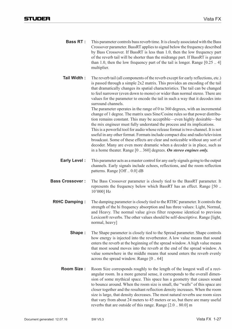
Vista FX
Vista FX 1-27Document generated: 12.07.16 SW V5.3
Bass RT : Thisparametercontrolsbassreverbtime.ItiscloselyassociatedwiththeBassCrossoverparameter.BassRTappliestosignalbelowthefrequencydescribedbyBassCrossover.IfBassRTislessthan1.0,thenthelowfrequencypartofthereverbtailwillbeshorterthanthemidrangepart.IfBassRTisgreaterthan 1.0, then the low frequency part of the tail is longer. Range [0.25 .. 4] multiplier.
Tail Width : Thereverbtail(allcomponentsofthereverbexceptforearlyreflections,etc.)is passed through a simple 2x2 matrix. This provides an encoding of the tail that dramatically changes its spatial characteristics. The tail can be changed tofeelnarrower(evendowntomono)orwiderthannormalstereo.Therearevalues for the parameter to encode the tail in such a way that it decodes into surround channels.
The parameter operates in the range of 0 to 360 degrees, with an incremental change of 1 degree. The matrix uses Sine/Cosine rules so that power distribu-tion remains constant. This may be acceptible—even highly desirable—but the mix engineer must fully understand the process and its implications.
This is a powerful tool for audio whose release format is two-channel. It is not useful in any other format. Formats include compact disc and radio/television broadcast. Some of these effects are clear and noticeable without any sort of decoder. Many are even more dramatic when a decoder is in place, such as in a home theater. Range [0 .. 360] degrees. On stereo engines only.
Early Level : This parameter acts as a master control for any early signals going to the output channels. Early signals include echoes, reflections, and the room reflection patterns.Range[Off..0.0]dB
Bass Crossover : TheBassCrossoverparameter isclosely tied to theBassRTparameter. Itrepresents thefrequencybelowwhichBassRThasaneffect.Range[50 ..10’000] Hz
RtHC Damping : The damping parameter is closely tied to the RTHC parameter. It controls the strength of the hi frequency absorption and has three values: Light, Normal, and Heavy. The normal value gives filter response identical to previous Lexicon® reverbs. The other values should be self-descriptive. Range [light, normal, heavy]
Shape : The Shape parameter is closely tied to the Spread parameter. Shape controls how energy is injected into the reverberator. A low value means that sound enters the reverb at the beginning of the spread window. A high value means that most sound moves into the reverb at the end of the spread window. A value somewhere in the middle means that sound enters the reverb evenly across the spread window. Range [0 .. 64]
Room Size : Room Size corresponds roughly to the length of the longest wall of a rect-angular room. In a more general sense, it corresponds to the overall dimen-sion of some mythical space. This space has a geometry that causes sound to bounce around. When the room size is small, the “walls” of this space are closer together and the resultant reflection density increases. When the room size is large, that density decreases. The most natural reverbs use room sizes that vary from about 24 meters to 45 meters or so, but there are many useful reverbs that are outside of this range. Range [2.0 .. 80.0] m
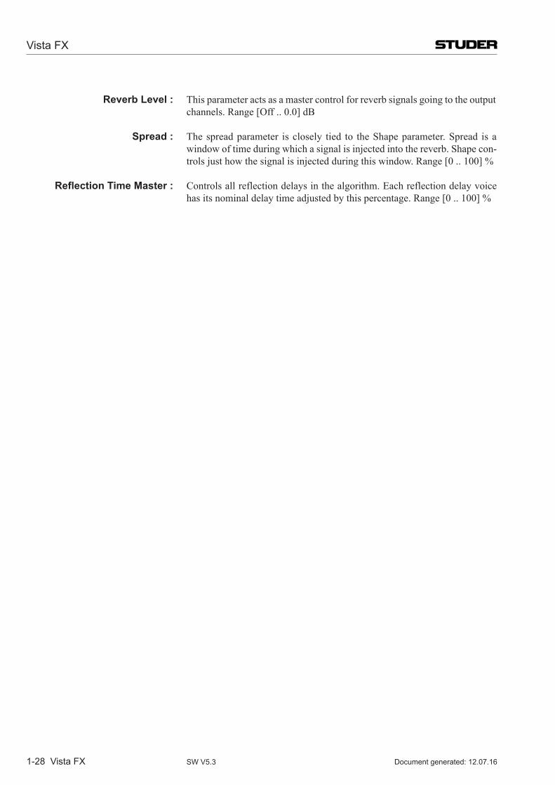
Vista FX
1-28 Vista FX Document generated: 12.07.16SW V5.3
Reverb Level : This parameter acts as a master control for reverb signals going to the output channels.Range[Off..0.0]dB
Spread : The spread parameter is closely tied to the Shape parameter. Spread is a window of time during which a signal is injected into the reverb. Shape con-trols just how the signal is injected during this window. Range [0 .. 100] %
Reflection Time Master : Controls all reflection delays in the algorithm. Each reflection delay voice has its nominal delay time adjusted by this percentage. Range [0 .. 100] %
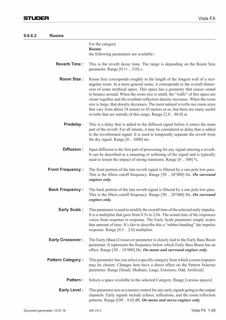
Vista FX
Vista FX 1-29Document generated: 12.07.16 SW V5.3
9.6.6.2 Rooms
For the category Rooms the following parameters are available :
Reverb Time : This is the reverb decay time. The range is depending on the Room Size parameter. Range [0.11 .. 210] s.
Room Size : Room Size corresponds roughly to the length of the longest wall of a rect-angular room. In a more general sense, it corresponds to the overall dimen-sion of some mythical space. This space has a geometry that causes sound to bounce around. When the room size is small, the “walls” of this space are closer together and the resultant reflection density increases. When the room size is large, that density decreases. The most natural reverbs use room sizes that vary from about 24 meters to 45 meters or so, but there are many useful reverbs that are outside of this range. Range [2.0 .. 80.0] m
Predelay : This is a delay that is added to the diffused signal before it enters the main part of the reverb. For all intents, it may be considered as delay that is added to the reverberated signal. It is used to temporally separate the reverb from the dry signal. Range [0 .. 1000] ms.
Diffusion : Input diffusion is the first part of processing for any signal entering a reverb.
It can be described as a smearing or softening of the signal and is typically used to lessen the impact of strong transients. Range [0 .. 100] %.
Front Frequency : The front portion of the late reverb signal is filtered by a one pole low-pass. This is the filters cutoff frequency. Range [50 .. 20’000] Hz. On surround engines only.
Back Frequency : The back portion of the late reverb signal is filtered by a one pole low-pass. This is the filters cutoff frequency. Range [50 .. 20’000] Hz. On surround engines only.
Early Scale : This parameter is used to modify the overall time of the selected early impulse. It is a multiplier that goes from 0.5x to 2.0x. The actual time of the responses varies from response to response. The Early Scale parameter simply scales that amount of time. It’s fair to describe this a “rubber-banding” the impulse response. Range [0.5 .. 2.0] multiplier.
Early Crossover : TheEarly(Bass)CrossoverparameteriscloselytiedtotheEarlyBassBoostparameter.ItrepresentsthefrequencybelowwhichEarlyBassBoosthasaneffect. Range [50 .. 10’000] Hz. On mono and surround engines only.
Pattern Category : This parameter lets you select a specific category from which a room response may be chosen. Changes here have a direct effect on the Pattern Selector parameter. Range [Small, Medium, Large, Exteriors, Odd, Artificial]
Pattern : Selects a space available in the selected Category. Range [various spaces]
Early Level : This parameter acts as a master control for any early signals going to the output channels. Early signals include echoes, reflections, and the room reflection patterns.Range[Off..0.0]dB.On mono and stereo engines only.
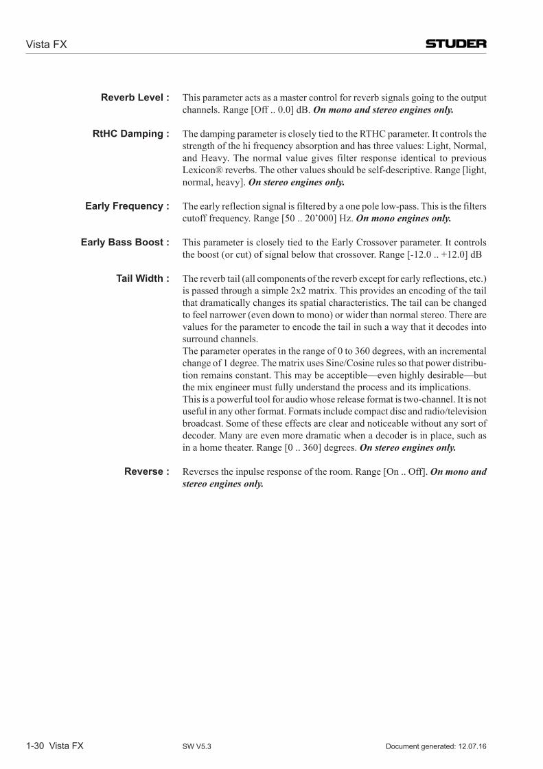
Vista FX
1-30 Vista FX Document generated: 12.07.16SW V5.3
Reverb Level : This parameter acts as a master control for reverb signals going to the output channels.Range[Off..0.0]dB.On mono and stereo engines only.
RtHC Damping : The damping parameter is closely tied to the RTHC parameter. It controls the strength of the hi frequency absorption and has three values: Light, Normal, and Heavy. The normal value gives filter response identical to previous Lexicon® reverbs. The other values should be self-descriptive. Range [light, normal, heavy]. On stereo engines only.
Early Frequency : The early reflection signal is filtered by a one pole low-pass. This is the filters cutoff frequency. Range [50 .. 20’000] Hz. On mono engines only.
Early Bass Boost : This parameter is closely tied to the Early Crossover parameter. It controls theboost(orcut)ofsignalbelowthatcrossover.Range[-12.0..+12.0]dB
Tail Width : Thereverbtail(allcomponentsofthereverbexceptforearlyreflections,etc.)is passed through a simple 2x2 matrix. This provides an encoding of the tail that dramatically changes its spatial characteristics. The tail can be changed tofeelnarrower(evendowntomono)orwiderthannormalstereo.Therearevalues for the parameter to encode the tail in such a way that it decodes into surround channels.
The parameter operates in the range of 0 to 360 degrees, with an incremental change of 1 degree. The matrix uses Sine/Cosine rules so that power distribu-tion remains constant. This may be acceptible—even highly desirable—but the mix engineer must fully understand the process and its implications.
This is a powerful tool for audio whose release format is two-channel. It is not useful in any other format. Formats include compact disc and radio/television broadcast. Some of these effects are clear and noticeable without any sort of decoder. Many are even more dramatic when a decoder is in place, such as in a home theater. Range [0 .. 360] degrees. On stereo engines only.
Reverse : Reverses the inpulse response of the room. Range [On .. Off]. On mono and stereo engines only.
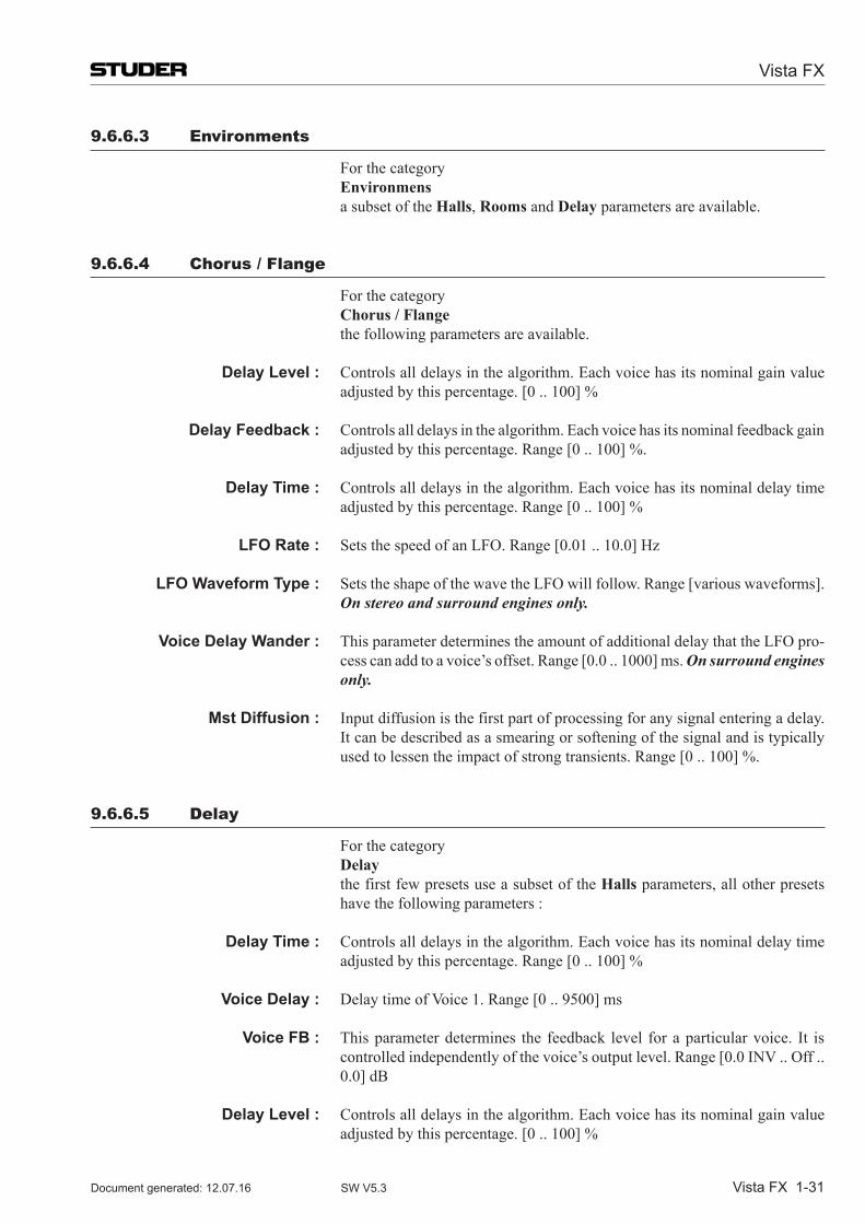
Vista FX
Vista FX 1-31Document generated: 12.07.16 SW V5.3
9.6.6.3 environments
For the category Environmens a subset of the Halls, Rooms and Delay parameters are available.
9.6.6.4 Chorus / Flange
For the category Chorus / Flange the following parameters are available.
Delay Level : Controls all delays in the algorithm. Each voice has its nominal gain value adjusted by this percentage. [0 .. 100] %
Delay Feedback : Controls all delays in the algorithm. Each voice has its nominal feedback gain adjusted by this percentage. Range [0 .. 100] %.
Delay Time : Controls all delays in the algorithm. Each voice has its nominal delay time adjusted by this percentage. Range [0 .. 100] %
LFO Rate : Sets the speed of an LFO. Range [0.01 .. 10.0] Hz
LFO Waveform Type : Sets the shape of the wave the LFO will follow. Range [various waveforms]. On stereo and surround engines only.
Voice Delay Wander : This parameter determines the amount of additional delay that the LFO pro-cess can add to a voice’s offset. Range [0.0 .. 1000] ms. On surround engines only.
Mst Diffusion : Input diffusion is the first part of processing for any signal entering a delay. It can be described as a smearing or softening of the signal and is typically used to lessen the impact of strong transients. Range [0 .. 100] %.
9.6.6.5 Delay
For the category Delay the first few presets use a subset of the Halls parameters, all other presets
have the following parameters :
Delay Time : Controls all delays in the algorithm. Each voice has its nominal delay time adjusted by this percentage. Range [0 .. 100] %
Voice Delay : Delay time of Voice 1. Range [0 .. 9500] ms
Voice FB : This parameter determines the feedback level for a particular voice. It is controlled independently of the voice’s output level. Range [0.0 INV .. Off .. 0.0]dB
Delay Level : Controls all delays in the algorithm. Each voice has its nominal gain value adjusted by this percentage. [0 .. 100] %
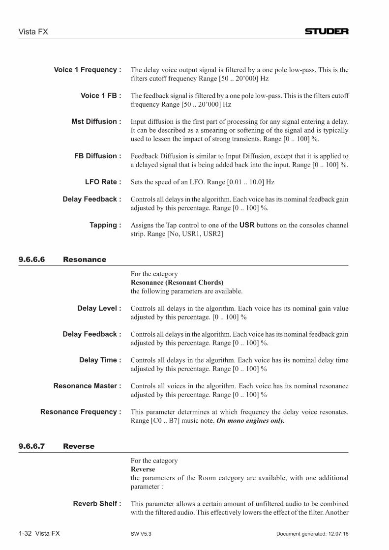
Vista FX
1-32 Vista FX Document generated: 12.07.16SW V5.3
Voice 1 Frequency : The delay voice output signal is filtered by a one pole low-pass. This is the filters cutoff frequency Range [50 .. 20’000] Hz
Voice 1 FB : The feedback signal is filtered by a one pole low-pass. This is the filters cutoff frequency Range [50 .. 20’000] Hz
Mst Diffusion : Input diffusion is the first part of processing for any signal entering a delay. It can be described as a smearing or softening of the signal and is typically used to lessen the impact of strong transients. Range [0 .. 100] %.
FB Diffusion : Feedback Diffusion is similar to Input Diffusion, except that it is applied to a delayed signal that is being added back into the input. Range [0 .. 100] %.
LFO Rate : Sets the speed of an LFO. Range [0.01 .. 10.0] Hz
Delay Feedback : Controls all delays in the algorithm. Each voice has its nominal feedback gain adjusted by this percentage. Range [0 .. 100] %.
Tapping : Assigns the Tap control to one of the USR buttons on the consoles channel strip. Range [No, USR1, USR2]
9.6.6.6 resonance
For the category Resonance (Resonant Chords) the following parameters are available.
Delay Level : Controls all delays in the algorithm. Each voice has its nominal gain value adjusted by this percentage. [0 .. 100] %
Delay Feedback : Controls all delays in the algorithm. Each voice has its nominal feedback gain adjusted by this percentage. Range [0 .. 100] %.
Delay Time : Controls all delays in the algorithm. Each voice has its nominal delay time adjusted by this percentage. Range [0 .. 100] %
Resonance Master : Controls all voices in the algorithm. Each voice has its nominal resonance adjusted by this percentage. Range [0 .. 100] %
Resonance Frequency : This parameter determines at which frequency the delay voice resonates. Range[C0..B7]musicnote.On mono engines only.
9.6.6.7 reverse
For the category Reverse the parameters of the Room category are available, with one additional
parameter :
Reverb Shelf : This parameter allows a certain amount of unfiltered audio to be combined with the filtered audio. This effectively lowers the effect of the filter. Another
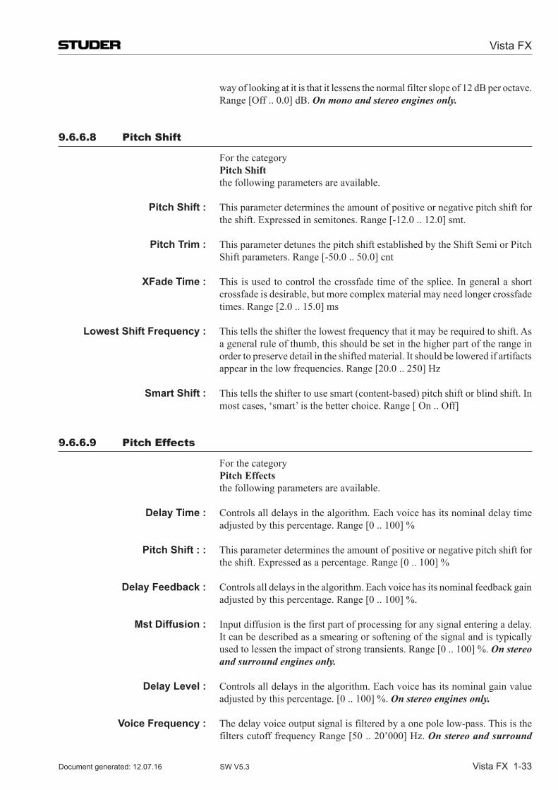
Vista FX
Vista FX 1-33Document generated: 12.07.16 SW V5.3
wayoflookingatitisthatitlessensthenormalfilterslopeof12dBperoctave.Range[Off..0.0]dB.On mono and stereo engines only.
9.6.6.8 pitch shift
For the category Pitch Shift the following parameters are available. Pitch Shift : This parameter determines the amount of positive or negative pitch shift for
the shift. Expressed in semitones. Range [-12.0 .. 12.0] smt.
Pitch Trim : This parameter detunes the pitch shift established by the Shift Semi or Pitch Shift parameters. Range [-50.0 .. 50.0] cnt
XFade Time : This is used to control the crossfade time of the splice. In general a short crossfade is desirable, but more complex material may need longer crossfade times. Range [2.0 .. 15.0] ms
Lowest Shift Frequency : This tells the shifter the lowest frequency that it may be required to shift. As a general rule of thumb, this should be set in the higher part of the range in order to preserve detail in the shifted material. It should be lowered if artifacts appear in the low frequencies. Range [20.0 .. 250] Hz
Smart Shift : Thistellstheshiftertousesmart(content-based)pitchshiftorblindshift.Inmost cases, ‘smart’ is the better choice. Range [ On .. Off]
9.6.6.9 pitch effects
For the category Pitch Effects the following parameters are available. Delay Time : Controls all delays in the algorithm. Each voice has its nominal delay time
adjusted by this percentage. Range [0 .. 100] %
Pitch Shift : : This parameter determines the amount of positive or negative pitch shift for the shift. Expressed as a percentage. Range [0 .. 100] %
Delay Feedback : Controls all delays in the algorithm. Each voice has its nominal feedback gain adjusted by this percentage. Range [0 .. 100] %.
Mst Diffusion : Input diffusion is the first part of processing for any signal entering a delay. It can be described as a smearing or softening of the signal and is typically used to lessen the impact of strong transients. Range [0 .. 100] %. On stereo and surround engines only.
Delay Level : Controls all delays in the algorithm. Each voice has its nominal gain value adjusted by this percentage. [0 .. 100] %. On stereo engines only.
Voice Frequency : The delay voice output signal is filtered by a one pole low-pass. This is the filters cutoff frequency Range [50 .. 20’000] Hz. On stereo and surround
Vista FX
1-34 Vista FX Document generated: 12.07.16SW V5.3
engines only.
FB Diffusion : Feedback Diffusion is similar to Input Diffusion, except that it is applied to a delayed signal that is being added back into the input. Range [0 .. 100] %. On surround engines only.
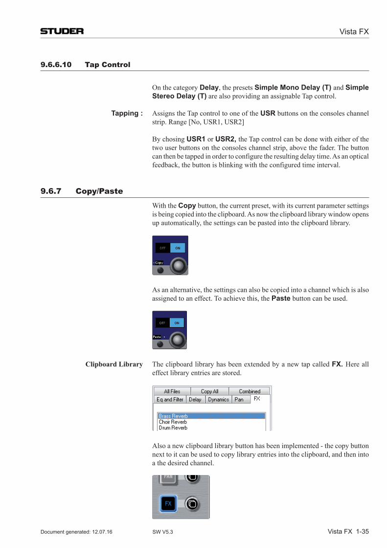
Vista FX
Vista FX 1-35Document generated: 12.07.16 SW V5.3
9.6.6.10 tap Control
On the category Delay, the presets Simple Mono Delay (T) and Simple
Stereo Delay (T) are also providing an assignable Tap control.
Tapping : Assigns the Tap control to one of the USR buttons on the consoles channel strip. Range [No, USR1, USR2]
BychosingUSR1 or USR2, the Tap control can be done with either of the two user buttons on the consoles channel strip, above the fader. The button can then be tapped in order to configure the resulting delay time. As an optical feedback, the button is blinking with the configured time interval.
9.6.7 Copy/paste
With the Copy button, the current preset, with its current parameter settings is being copied into the clipboard. As now the clipboard library window opens up automatically, the settings can be pasted into the clipboard library.
As an alternative, the settings can also be copied into a channel which is also assigned to an effect. To achieve this, the Paste button can be used.
Clipboard Library The clipboard library has been extended by a new tap called FX. Here all effect library entries are stored.
Also a new clipboard library button has been implemented - the copy button next to it can be used to copy library entries into the clipboard, and then into a the desired channel.
Vista FX
1-36 Vista FX Document generated: 12.07.16SW V5.3
Note : Effectsettingscanonlybecopiedwithinthesameenginesetupformat(mono,stereo,surround)!
The paste function will only be carried out when the target channel has the same engine format as the source channel, or the setting stored in the clip-board library.
If the format is not matching, the settings are not pasted into the target chan-nel. No error message is displayed - the system will just be ready for a new copy/paste operation.
Vista FX
Vista FX 1-37Document generated: 12.07.16 SW V5.3
9.6.8 snapshot operation
9.6.8.1 snapshots and presets
All necesarry settings to recreate any use of Vista FX can be stored is snap-shots. In more detail, the following data is stored within each snapshot or system preset :
* the engine setup * patching of the effect input- and output ports * choice of preset * effect parameter settings of the current state
Note : The recalling of a snapshot or a preset can change the Vista FX engine setup if this snapshot had been previously stored with a different engine setup.
In such a case where the engine setup is changed by a snapshot, unsaved effect parameter settings can then be overwritten.
Therefore it is important to keep in mind that the engine setup is of great importance and should be set-up correctly at the start of a session and prefer-rably not be changed anymore.
(Ofcourse-asnapshotrecallundo operation would bring back the unsaved settingsifasnapshothadbeenrecalledbyerror.)
Important : Manually changing the engine setup when the engine is in use, displays a warning window. When performing the same change via a snapshot recall - no warninig window is displayed !
9.6.8.2 static automation
Global Snapshot filter With the global snapshot filter, effect parameters can be isolated as any other audio parameter in the system. This is done by editing the global snapshot filter, and then touching any of the to be isolated parameter controls. Please note that the isolation of Category and Preset parameters is always linked.
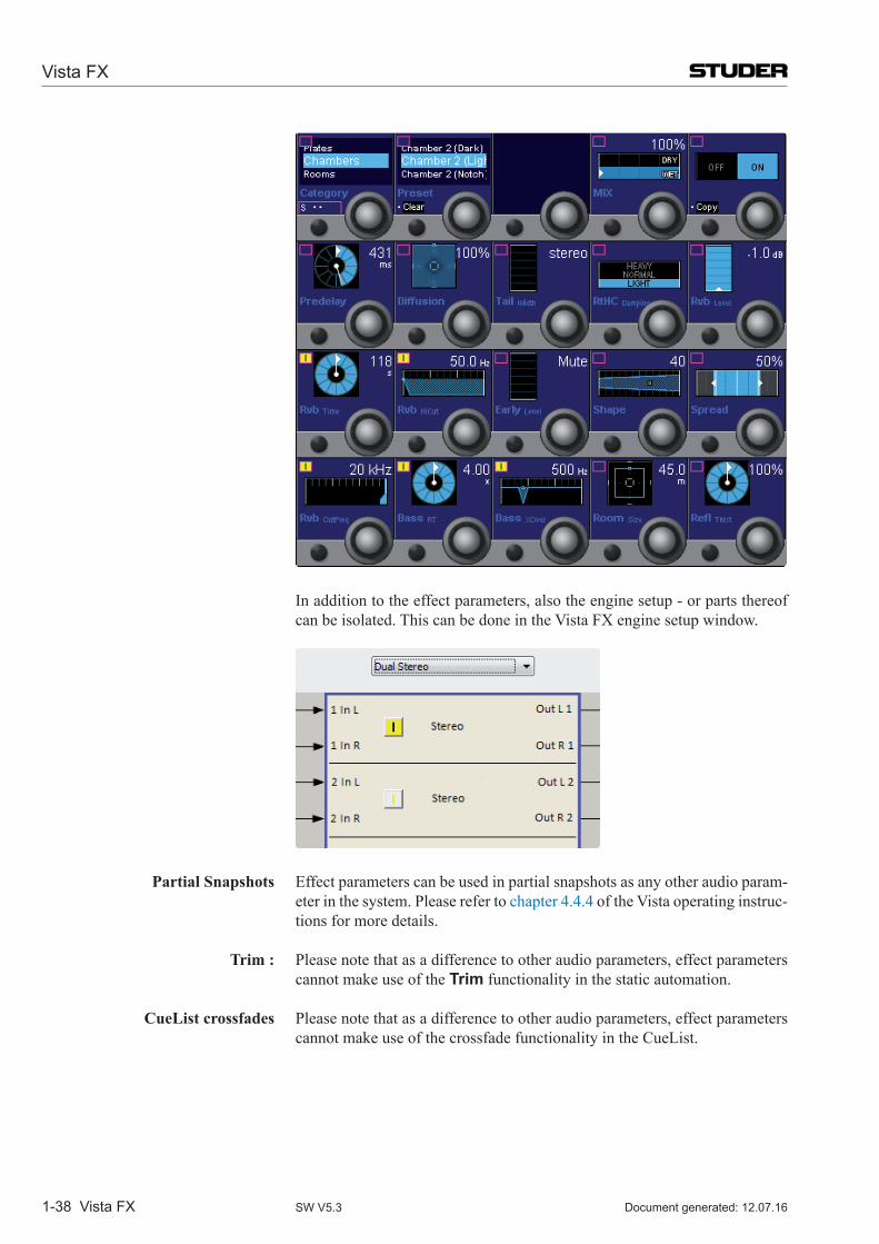
Vista FX
1-38 Vista FX Document generated: 12.07.16SW V5.3
In addition to the effect parameters, also the engine setup - or parts thereof can be isolated. This can be done in the Vista FX engine setup window.
Partial Snapshots Effect parameters can be used in partial snapshots as any other audio param-eter in the system. Please refer to chapter 4.4.4 of the Vista operating instruc-tions for more details.
Trim : Please note that as a difference to other audio parameters, effect parameters cannot make use of the Trim functionality in the static automation.
CueList crossfades Please note that as a difference to other audio parameters, effect parameters cannot make use of the crossfade functionality in the CueList.
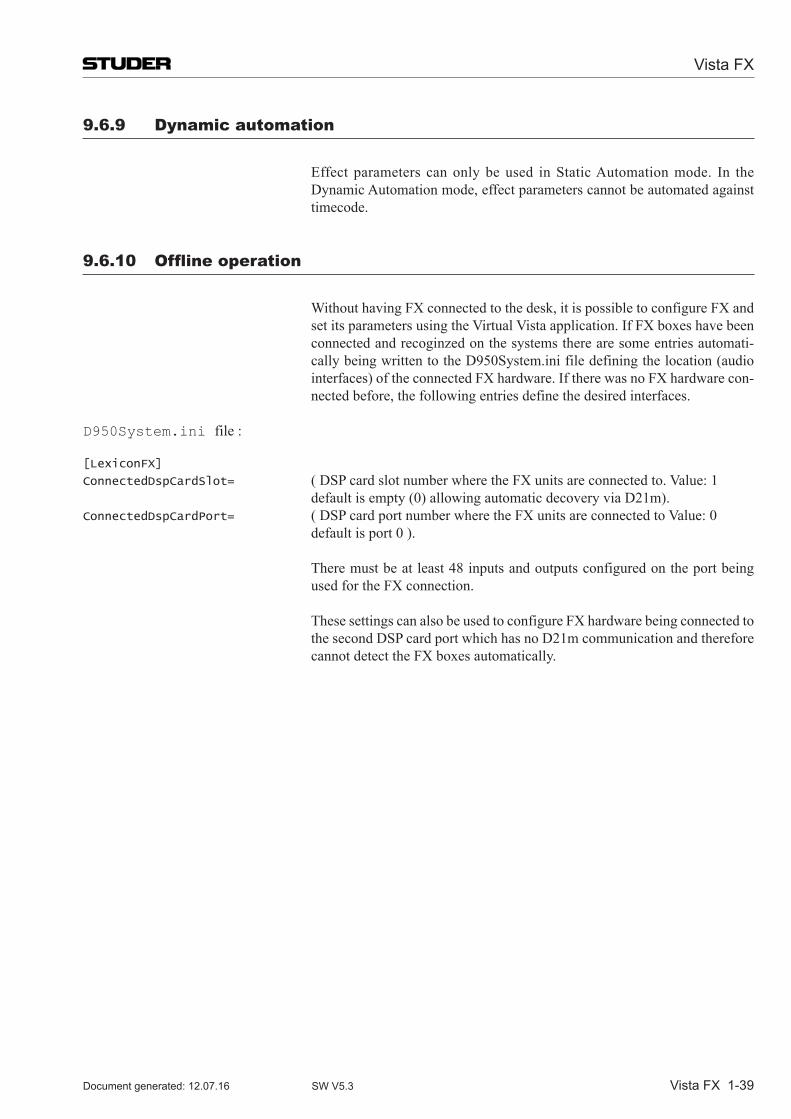
Vista FX
Vista FX 1-39Document generated: 12.07.16 SW V5.3
9.6.9 Dynamic automation
Effect parameters can only be used in Static Automation mode. In the Dynamic Automation mode, effect parameters cannot be automated against timecode.
9.6.10 Offline operation
Without having FX connected to the desk, it is possible to configure FX and set its parameters using the Virtual Vista application. If FX boxes have been connected and recoginzed on the systems there are some entries automati-callybeingwrittentotheD950System.inifiledefiningthelocation(audiointerfaces)oftheconnectedFXhardware.IftherewasnoFXhardwarecon-nected before, the following entries define the desired interfaces.
D950System.ini file : [LexiconFX]
ConnectedDspCardSlot= (DSPcardslotnumberwheretheFXunitsareconnectedto.Value:1 defaultisempty(0)allowingautomaticdecoveryviaD21m).ConnectedDspCardPort= (DSPcardportnumberwheretheFXunitsareconnectedtoValue:0 defaultisport0).
There must be at least 48 inputs and outputs configured on the port being used for the FX connection.
These settings can also be used to configure FX hardware being connected to the second DSP card port which has no D21m communication and therefore cannot detect the FX boxes automatically.
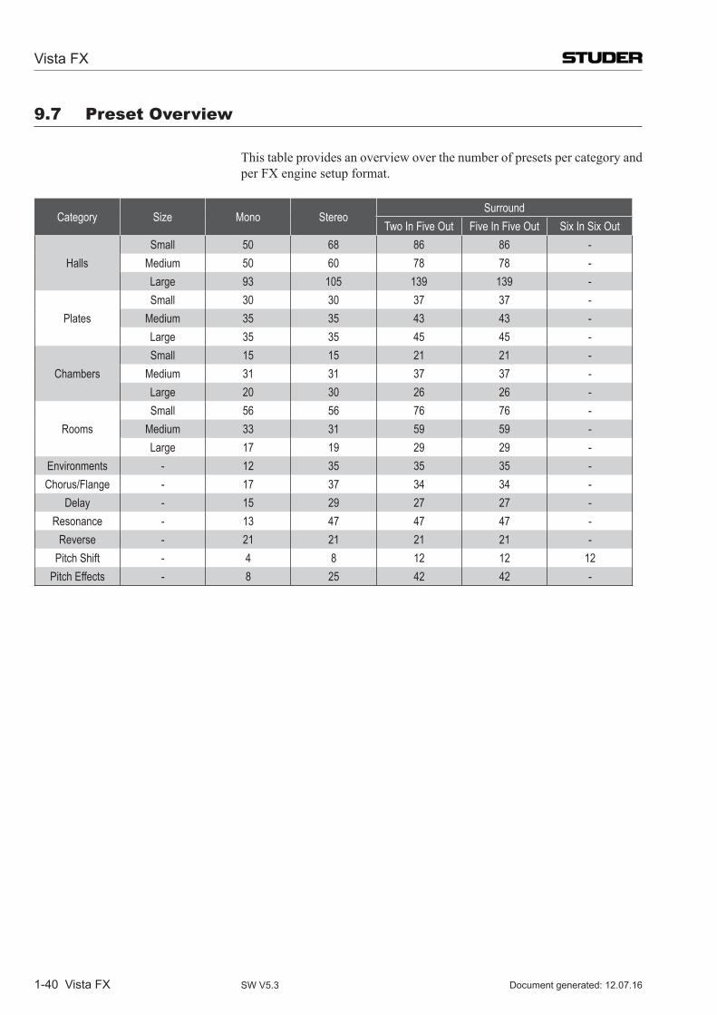
Vista FX
1-40 Vista FX Document generated: 12.07.16SW V5.3
9.7 preset Overview
This table provides an overview over the number of presets per category and per FX engine setup format.
Category Size Mono StereoSurround
Two In Five Out Five In Five Out Six In Six Out
HallsSmall 50 68 86 86 -
Medium 50 60 78 78 -Large 93 105 139 139 -
PlatesSmall 30 30 37 37 -
Medium 35 35 43 43 -Large 35 35 45 45 -
ChambersSmall 15 15 21 21 -
Medium 31 31 37 37 -Large 20 30 26 26 -
RoomsSmall 56 56 76 76 -
Medium 33 31 59 59 -Large 17 19 29 29 -
Environments - 12 35 35 35 -Chorus/Flange - 17 37 34 34 -
Delay - 15 29 27 27 -Resonance - 13 47 47 47 -
Reverse - 21 21 21 21 -Pitch Shift - 4 8 12 12 12
Pitch Effects - 8 25 42 42 -
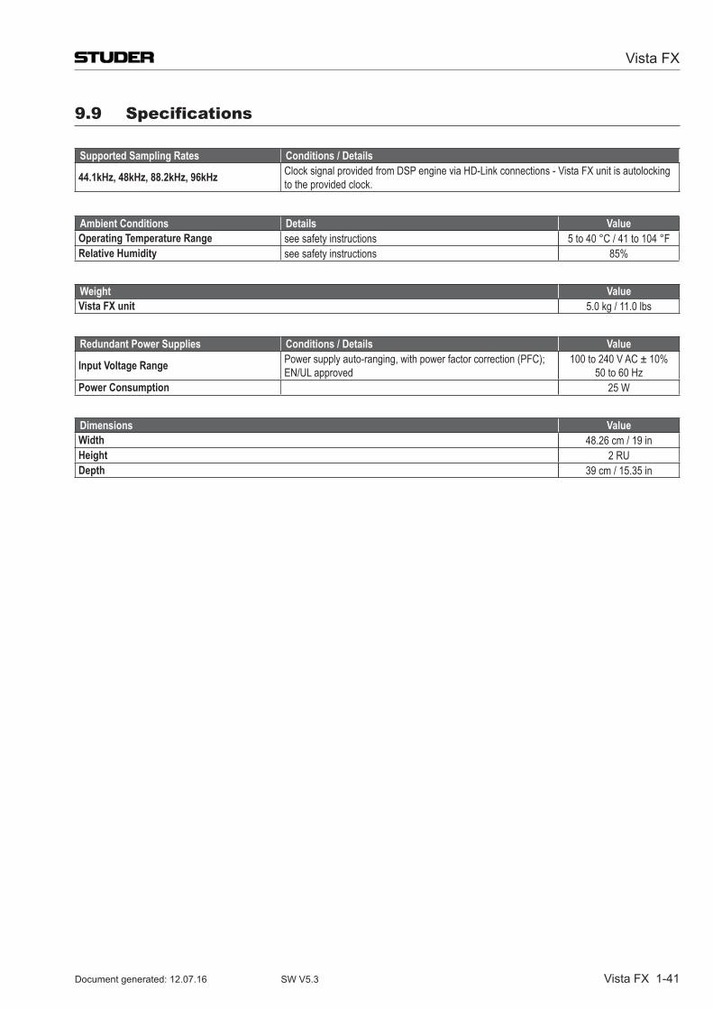
Vista FX
Vista FX 1-41Document generated: 12.07.16 SW V5.3
9.9 specifications
Supported Sampling Rates Conditions / Details
44.1kHz, 48kHz, 88.2kHz, 96kHz Clock signal provided from DSP engine via HD-Link connections - Vista FX unit is autolocking to the provided clock.
Ambient Conditions Details ValueOperating Temperature Range see safety instructions 5 to 40 °C / 41 to 104 °FRelative Humidity see safety instructions 85%
Weight ValueVista FX unit 5.0 kg / 11.0 lbs
Redundant Power Supplies Conditions / Details Value
Input Voltage Range Power supply auto-ranging, with power factor correction (PFC); EN/UL approved
100 to 240 V AC ± 10%50 to 60 Hz
Power Consumption 25 W
Dimensions ValueWidth 48.26 cm / 19 inHeight 2 RUDepth 39 cm / 15.35 in
Chapter 10: appliCation notes / Update info
Application Note 1: Matrix Buses – Panning in a PA Environment ...................................................................................... 3
Application Note 2: TV Gallery ‘Pre-Hear’ .............................................................................................................................. 4
Vista X Digital Mixing System
Applications / Update Info 10-1Document generated: 12.07.16 SW V5.3
Vista X Digital Mixing System
10-2 Applications / Update Info Document generated: 12.07.16SW V5.3
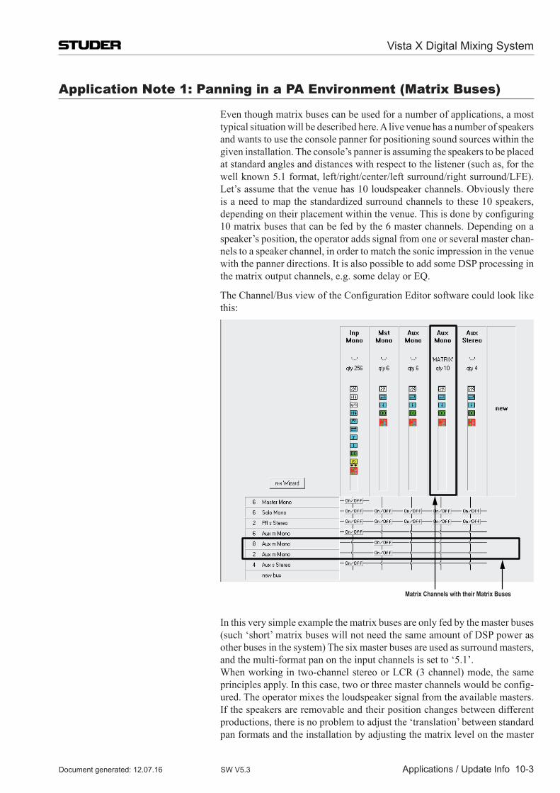
application note 1: panning in a pa environment (Matrix Buses)
Even though matrix buses can be used for a number of applications, a most typical situation will be described here. A live venue has a number of speakers and wants to use the console panner for positioning sound sources within the given installation. The console’s panner is assuming the speakers to be placed at standard angles and distances with respect to the listener (such as, for the well known 5.1 format, left/right/center/left surround/right surround/LFE). Let’s assume that the venue has 10 loudspeaker channels. Obviously there is a need to map the standardized surround channels to these 10 speakers, depending on their placement within the venue. This is done by configuring 10 matrix buses that can be fed by the 6 master channels. Depending on a speaker’s position, the operator adds signal from one or several master chan-nels to a speaker channel, in order to match the sonic impression in the venue with the panner directions. It is also possible to add some DSP processing in the matrix output channels, e.g. some delay or EQ.
The Channel/Bus view of the Configuration Editor software could look like this:
Matrix Channels with their Matrix Buses
In this very simple example the matrix buses are only fed by the master buses (such ‘short’ matrix buses will not need the same amount of DSP power as other buses in the system) The six master buses are used as surround masters, and the multi-format pan on the input channels is set to ‘5.1’.
When working in two-channel stereo or LCR (3 channel) mode, the same principles apply. In this case, two or three master channels would be config-ured. The operator mixes the loudspeaker signal from the available masters. If the speakers are removable and their position changes between different productions, there is no problem to adjust the ‘translation’ between standard pan formats and the installation by adjusting the matrix level on the master
Vista X Digital Mixing System
Applications / Update Info 10-3Document generated: 12.07.16 SW V5.3
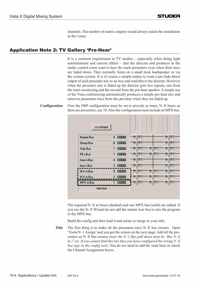
channels. The number of matrix outputs would always match the installation in the venue.
application note 2: tV Gallery ‘pre-hear’
It is a common requirement in TV studios – especially when doing light entertainment and current affairs – that the director and producer in the studio control room want to hear the main presenters even when their mics are faded down. They normally listen on a small desk loudspeaker or via the comms system. It is of course a simple matter to route a pre-fade direct output of each presenter mic to an Aux and send this to the director. However when the presenter mic is faded up the director gets two signals, one from the main monitoring and the second from the pre-hear speaker. A simple use of the Vista conferencing automatically produces a simple pre-hear mix and removes presenters mics from this pre-hear when they are faded up.
Configuration First the DSP configuration must be set to provide as many N–X buses as there are presenters, say 10. Also the configuration must include an MPX bus.
The required N–X m buses (dashed) and one MPX bus (solid) are added. If you use the N–X Wizard do not add the master Aux bus to mix the program to the MPX bus.
Build the config and then load it and create or merge to your title.
Title The first thing is to make all the presenters mics N–X bus owners. Open ‘Tools/N–1 Assign’ and you get the screen on the next page. Add all the pre-senters as N–X bus owners (note the N–1 Bus pull down must be ‘Bus N–X m 1’ etc. If you cannot find this bus then you have configured the wrong N–X bus type in the config tool). You do not need to add the send lines or check the Channel Assignment boxes.
Vista X Digital Mixing System
10-4 Applications / Update Info Document generated: 12.07.16SW V5.3
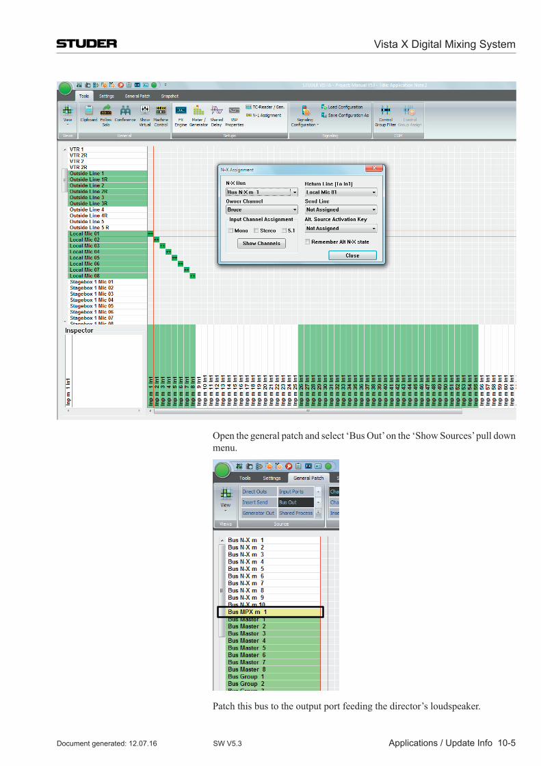
Open the general patch and select ‘Bus Out’ on the ‘Show Sources’ pull down menu.
Patch this bus to the output port feeding the director’s loudspeaker.
Vista X Digital Mixing System
Applications / Update Info 10-5Document generated: 12.07.16 SW V5.3
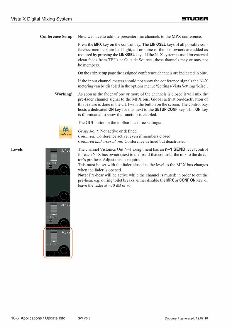
Conference Setup Now we have to add the presenter mic channels to the MPX conference.
Press the MPX key on the control bay. The LINK/SEL keys of all possible con-ference members are half light, all or some of the bus owners are added as required by pressing the LINK/SEL keys. If the N–X system is used for external clean feeds from TBUs or Outside Sources; these thannels may or may not be members.
On the strip setup page the assigned conference channels are indicated in blue.
If the input channel meters should not show the conference signals the N–X metering can be disabled in the options menu: ‘Settings/Vista Settings/Misc’.
Working! As soon as the fader of one or more of the channels is closed it will mix the pre-fader channel signal to the MPX bus. Global activation/deactivation of this feature is done in the GUI with the button on the screen. The control bay hosts a dedicated ON key for this next to the SETUP CONF key. This ON key is illuminated to show the function is enabled.
The GUI button in the toolbar has three settings:
Grayed-out: Not active or defined. Coloured: Conference active, even if members closed. Coloured and crossed out: Conference defined but deactivated.
Levels The channel Vistonics Out N–1 assignment has an n–1 send level control for each N–X bus owner (next to the front) that controls the mix to the direc-tor’s pre-hear. Adjust this as required.
This must be set with the fader closed as the level to the MPX bus changes when the fader is opened.
Note: Pre-hear will be active while the channel is muted; in order to cut the pre-hear, e.g. during toilet breaks, either disable the MPX or CONF ON key, or leave the fader at –70 dB or so.
Vista X Digital Mixing System
10-6 Applications / Update Info Document generated: 12.07.16SW V5.3
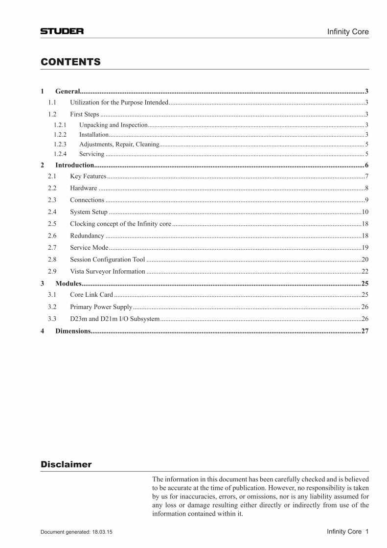
Infinity Core
Infinity Core 1Document generated: 18.03.15
Disclaimer The information in this document has been carefully checked and is believed
to be accurate at the time of publication. However, no responsibility is taken by us for inaccuracies, errors, or omissions, nor is any liability assumed for any loss or damage resulting either directly or indirectly from use of the information contained within it.
CONTENTS
1 General...............................................................................................................................................................31.1 Utilization for the Purpose Intended ...................................................................................................................3
1.2 First Steps ...........................................................................................................................................................31.2.1 Unpacking and Inspection ..................................................................................................................................... 31.2.2 Installation ............................................................................................................................................................. 31.2.3 Adjustments, Repair, Cleaning .............................................................................................................................. 51.2.4 Servicing ............................................................................................................................................................... 5
2 Introduction .......................................................................................................................................................62.1 Key Features .......................................................................................................................................................7
2.2 Hardware ............................................................................................................................................................8
2.3 Connections ........................................................................................................................................................9
2.4 System Setup ....................................................................................................................................................10
2.5 Clocking concept of the Infinity core ...............................................................................................................18
2.6 Redundancy ......................................................................................................................................................18
2.7 Service Mode ....................................................................................................................................................19
2.8 Session Configuration Tool ..............................................................................................................................20
2.9 Vista Surveyor Information ..............................................................................................................................22
3 Modules ............................................................................................................................................................253.1 Core Link Card .................................................................................................................................................25
3.2 Primary Power Supply ..................................................................................................................................... 26
3.3 D23m and D21m I/O Subsystem ......................................................................................................................26
4 Dimensions.......................................................................................................................................................27
Infinity Core
2 Infinity Core Document generated: 18.03.15
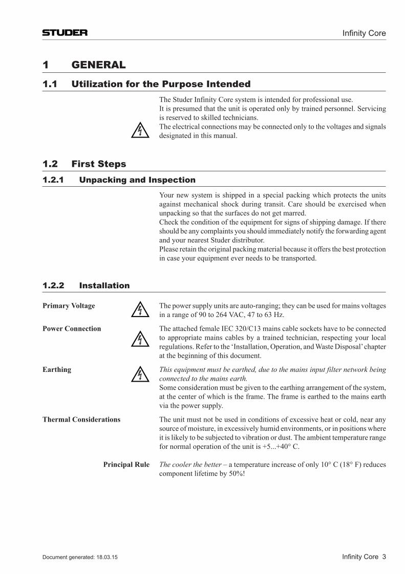
Infinity Core
Infinity Core 3Document generated: 18.03.15
1 GENEral
1.1 Utilization for the Purpose Intended The Studer Infinity Core system is intended for professional use. It is presumed that the unit is operated only by trained personnel. Servicing
is reserved to skilled technicians. The electrical connections may be connected only to the voltages and signals
designated in this manual.
1.2 First Steps1.2.1 Unpacking and Inspection
Your new system is shipped in a special packing which protects the units against mechanical shock during transit. Care should be exercised when unpacking so that the surfaces do not get marred.
Check the condition of the equipment for signs of shipping damage. If there should be any complaints you should immediately notify the forwarding agent and your nearest Studer distributor.
Please retain the original packing material because it offers the best protection in case your equipment ever needs to be transported.
1.2.2 Installation
Primary Voltage The power supply units are auto-ranging; they can be used for mains voltages in a range of 90 to 264 VAC, 47 to 63 Hz.
Power Connection The attached female IEC 320/C13 mains cable sockets have to be connected to appropriate mains cables by a trained technician, respecting your local regulations. Refer to the ‘Installation, Operation, and Waste Disposal’ chapter at the beginning of this document.
Earthing This equipment must be earthed, due to the mains input filter network be ing connected to the mains earth.
Some consideration must be given to the earthing arrangement of the sy stem, at the center of which is the frame. The frame is earthed to the mains earth via the power supply.
Thermal Considerations The unit must not be used in conditions of excessive heat or cold, near any source of moisture, in excessively humid environments, or in positions where it is likely to be subjected to vibration or dust. The ambient temperature range for normal operation of the unit is +5...+40° C.
Principal Rule The cooler the better – a temperature increase of only 10° C (18° F) reduces component lifetime by 50%!

Infinity Core
4 Infinity Core Document generated: 18.03.15
Heat dissipation The following table lists the required heat dissipation which is depending on the type of the Infinity Core ( Core 200, Core 400, Core 800 ) :
Infinity Core Type Required Heat Dissipation
Core 200 140 WCore 400 250 WCore 800 350 W
If the unit is mounted in a climatised rack, please note that air intake must be at the front and air outlet at the rear of the rack.
If two Infinity Cores are mounted on top of each other, there is no space required between the two units.
If two Infinity Cores are mounted on top of each other, it is recommended to mount an air deflector panel on the very top of the two units. This air deflector panel then directs the hot air to the rear of the rack.
Single Infinity CoreNo Air Deflector Unit needed
Rear
Air
Front
AirAir Infinity Core
Dual Infinity Core1 Air Deflector Unit on top
Rear Front
AirInfinity Core
AirInfinity Core
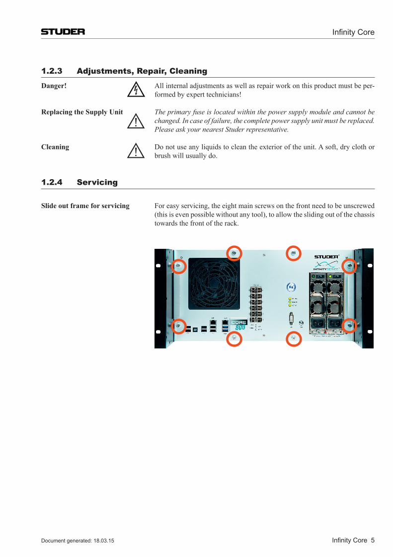
Infinity Core
Infinity Core 5Document generated: 18.03.15
1.2.3 adjustments, repair, Cleaning
Danger! All internal adjustments as well as repair work on this product must be per-formed by expert technicians!
Replacing the Supply Unit The primary fuse is located within the power supply module and cannot be changed. In case of failure, the complete power supply unit must be replaced. Please ask your nearest Studer representative.
Cleaning Do not use any liquids to clean the exterior of the unit. A soft, dry cloth or brush will usually do.
1.2.4 Servicing
Slide out frame for servicing For easy servicing, the eight main screws on the front need to be unscrewed (this is even possible without any tool), to allow the sliding out of the chassis towards the front of the rack.
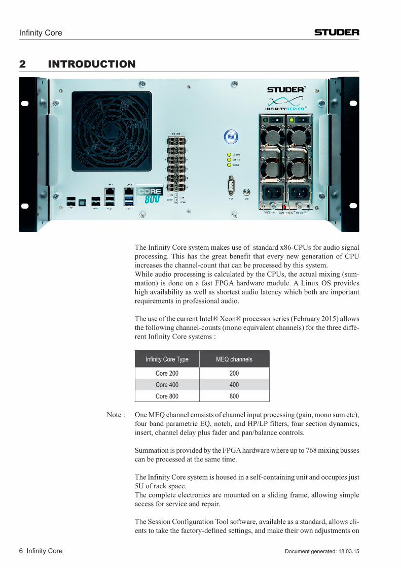
Infinity Core
6 Infinity Core Document generated: 18.03.15
2 INTrODUCTION
The Infinity Core system makes use of standard x86-CPUs for audio signal processing. This has the great benefit that every new generation of CPU increases the channel-count that can be processed by this system.
While audio processing is calculated by the CPUs, the actual mixing (sum-mation) is done on a fast FPGA hardware module. A Linux OS provides high availability as well as shortest audio latency which both are important requirements in professional audio.
The use of the current Intel® Xeon® processor series (February 2015) allows the following channel-counts (mono equivalent channels) for the three diffe-rent Infinity Core systems :
Infinity Core Type MEQ channels
Core 200 200Core 400 400Core 800 800
Note : One MEQ channel consists of channel input processing (gain, mono sum etc), four band parametric EQ, notch, and HP/LP filters, four section dynamics, insert, channel delay plus fader and pan/balance controls.
Summation is provided by the FPGA hardware where up to 768 mixing busses can be processed at the same time.
The Infinity Core system is housed in a self-containing unit and occupies just 5U of rack space.
The complete electronics are mounted on a sliding frame, allowing simple access for service and repair.
The Session Configuration Tool software, available as a standard, allows cli-ents to take the factory-defined settings, and make their own adjustments on
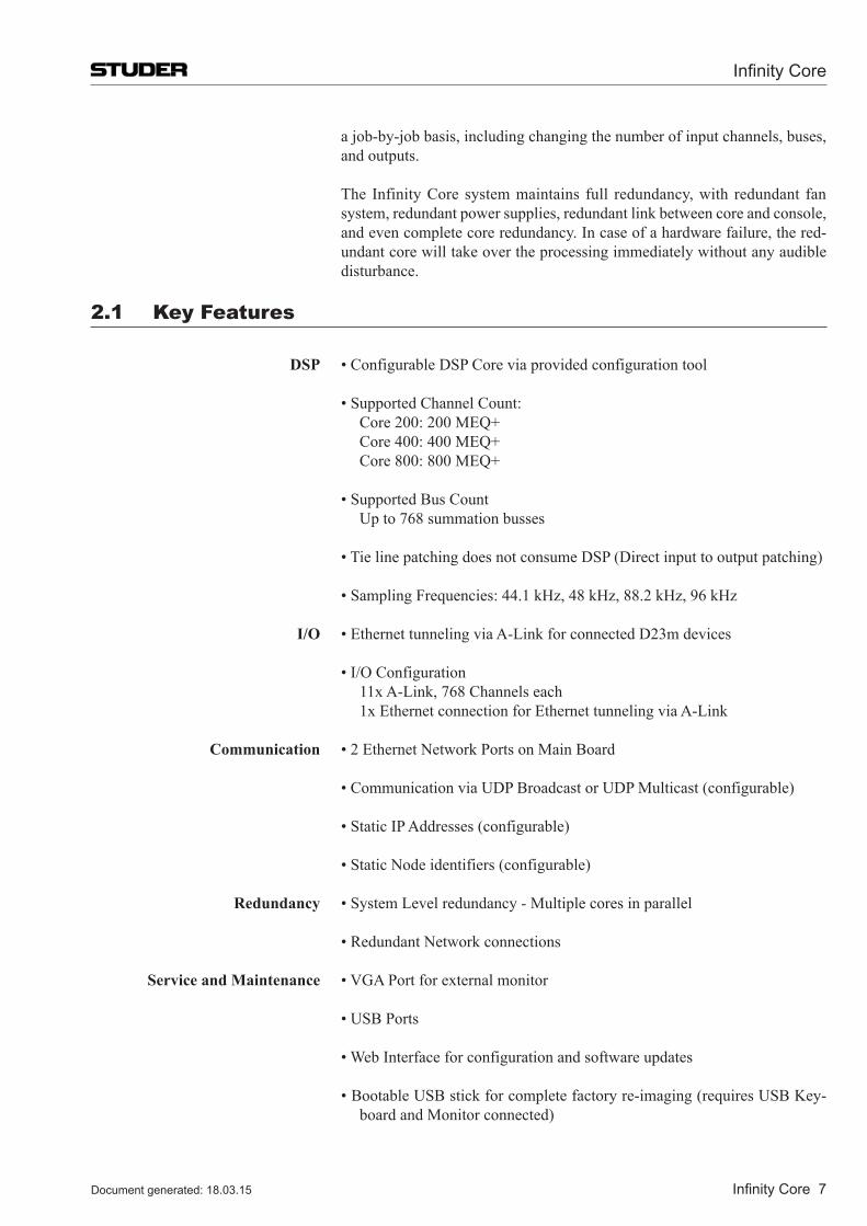
Infinity Core
Infinity Core 7Document generated: 18.03.15
a job-by-job basis, including changing the number of input channels, buses, and outputs.
The Infinity Core system maintains full redundancy, with redundant fan system, redundant power supplies, redundant link between core and console, and even complete core redundancy. In case of a hardware failure, the red-undant core will take over the processing immediately without any audible disturbance.
2.1 Key Features
DSP •ConfigurableDSPCoreviaprovidedconfigurationtool
•SupportedChannelCount: Core 200: 200 MEQ+ Core 400: 400 MEQ+ Core 800: 800 MEQ+
•SupportedBusCount Up to 768 summation busses
•TielinepatchingdoesnotconsumeDSP(Directinputtooutputpatching)
•SamplingFrequencies:44.1kHz,48kHz,88.2kHz,96kHz
I/O •EthernettunnelingviaA-LinkforconnectedD23mdevices
•I/OConfiguration 11x A-Link, 768 Channels each 1x Ethernet connection for Ethernet tunneling via A-Link
Communication •2EthernetNetworkPortsonMainBoard
•CommunicationviaUDPBroadcastorUDPMulticast(configurable)
•StaticIPAddresses(configurable)
•StaticNodeidentifiers(configurable)
Redundancy •SystemLevelredundancy-Multiplecoresinparallel
•RedundantNetworkconnections
Service and Maintenance •VGAPortforexternalmonitor
•USBPorts
•WebInterfaceforconfigurationandsoftwareupdates
•BootableUSBstickforcompletefactoryre-imaging(requiresUSBKey-board and Monitor connected)
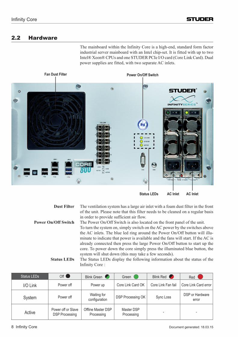
Infinity Core
8 Infinity Core Document generated: 18.03.15
2.2 Hardware The mainboard within the Infinity Core is a high-end, standard form factor
industrial server mainboard with an Intel chip-set. It is fitted with up to two Intel® Xeon® CPUs and one STUDER PCIe I/O card (Core Link Card). Dual power supplies are fitted, with two separate AC inlets.
Status LEDs
Fan Dust Filter Power On/Off Switch
AC Inlet AC Inlet
Dust Filter The ventilation system has a large air inlet with a foam dust filter in the front of the unit. Please note that this filter needs to be cleaned on a regular basis in order to provide sufficient air flow.
Power On/Off Switch The Power On/Off Switch is also located on the front panel of the unit. To turn the system on, simply switch on the AC power by the switches above
the AC inlets. The blue led ring around the Power On/Off button will illu-minate to indicate that power is available and the fans will start. If the AC is already connected then press the large Power On/Off button to start up the core. To power down the core simply press the illuminated blue button, the system will shut down (this may take a few seconds).
Status LEDs The Status LEDs display the following information about the status of the Infinity Core :
Status LEDs Off Blink Green Green Blink Red Red
I/O Link Power off Power up Core Link Card OK Core Link Fan fail Core Link Card error
System Power off Waiting for configuration DSP Processing OK Sync Loss DSP or Hardware
error
Active Power off or Slave DSP Processing
Offline Master DSP Processing
Master DSP Processing - -
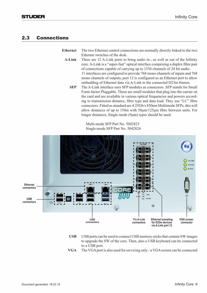
Infinity Core
Infinity Core 9Document generated: 18.03.15
2.3 Connections
Ethernet The two Ethernet control connections are normally directly linked to the two Ethernet switches of the desk.
A-Link There are 12 A-Link ports to bring audio in-, as well as out of the Infinity core. A-Link is a “super-fast” optical interface comprising a duplex fibre pair of connections capable of carrying up to 1536 channels of 24 bit audio.
11 interfaces are configured to provide 768 mono channels of inputs and 768 mono channels of outputs, port 12 is configured as an Ethernet port to allow embedding of Ethernet data via A-Link to the connected D23m frames.
SFP The A-Link interface uses SFP modules as connectors. SFP stands for Small Form-factor Pluggable. These are small modules that plug into the carrier on the card and are available in various optical frequencies and powers accord-ing to transmission distance, fibre type and data load. They use “LC” fibre connectors. Fitted as standard are 4.25Gb/s 850nm Multimode SFPs, this will allowdistancesofupto150mwith50μm/125μmfibrebetweenunits.Forlongerdistances,Singlemode(9μm)typesshouldbeused.
Multi-mode SFP Part No. 5042823 Single-mode SFP Part No. 5042824
11x A-Linkconnectors
VGA screen connector
Ethernetconnectors
USBconnectors
USBconnectors
Ethernet tunnelingfor D23m devicesvia A-Link port 12
USB USBportscanbeusedtoconnectUSBmemorysticksthatcontainSWimagestoupgradetheSWofthecore.Then,alsoaUSBkeyboardcanbeconnectedtoaUSBport.
VGA The VGA port is also used for servicing only - a VGA screen can be connected
Infinity Core
10 Infinity Core Document generated: 18.03.15
2.4 System Setup
General terms
Node Id Each element (desk, core, D23m I/O frames) in the mixing console system is connected via Ethernet. The so called “Node Id” is used to identify each element uniquely so the software can communicate correctly. Thus each Node Id must be unique.
Cloud Id It is often the case that several consoles will be connected together via Ethernet for resource sharing (such as Studer’s Relink). It is therefore necessary that each element must also have a second Id to allow each element to know which mixing system it is a part of; each Vista desk must know which Infinity Core (or Cores) is processing its audio. This second Id is known as the “Cloud Id” and must be set uniquely for each system.
There are two different parts of the network which have the same Id :
•Mixercloud The network part on which desk and cores communicate.
•IOCloud The network part on which desk and I/O frames communicate.
Eventhough the Cloud Id’s of the Mixercloud and the IOCloud are the same on one mixing system, the communication is kept separate between deks-core and desk-IO by using different Portnumbers and different UDP Multicast groups. This is what differntiates the Mixercloud from the IOCloud.
Numbering Rules The Node Id is normally used as the last byte of the elements IP-address.
Network configuration With a new ordered Vista Mixing System these settings are already configured correctly. The diagram on the next page shows a complete overview of the network configuration of a multi Vista system.
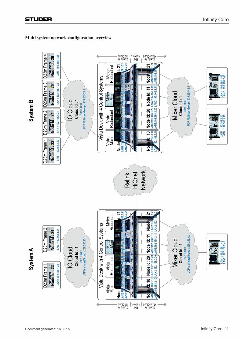
Infinity Core
Infinity Core 11Document generated: 18.03.15
Multi system network configuration overview
Node
ID :
42Inf
inity
Core
LAN1
: 19
2.168
.1.42
LAN2
: 19
2.168
.2.42
Node
Id :
23D2
3m F
rame
1
LAN
: 192
.168.1
.23No
de Id
: 24
D23m
Fra
me 2
LAN
: 192
.168.1
.24
Syst
em A
Syst
em B
Vista
-Ma
inVi
sta
Redu
ndan
tMe
ter
Redu
ndan
tMe
ter
Main
Vista
Des
k with
4 Co
ntrol
Syste
ms
Node
Id: 1
0LA
N2:1
92.16
8.1.10
LAN2
:192
.168.2
.10
Node
Id: 1
0LA
N2:1
92.16
8.1.10
LAN2
:192
.168.2
.10
LAN1
:192
.168.5
.30
Node
Id: 2
0LA
N2:1
92.16
8.1.20
LAN2
:192
.168.2
.20
Node
Id: 2
0LA
N2:1
92.16
8.1.20
LAN2
:192
.168.2
.20
LAN1
:192
.168.5
.30
Node
Id: 1
1LA
N2:1
92.16
8.1.11
LAN2
:192
.168.2
.11
Node
Id: 1
1LA
N2:1
92.16
8.1.11
LAN2
:192
.168.2
.11
LAN1
:192
.168.5
.30
Node
Id: 2
1LA
N2:1
92.16
8.1.21
LAN2
:192
.168.2
.21
Node
Id: 2
1LA
N2:1
92.16
8.1.21
LAN2
:192
.168.2
.21
LAN1
:192
.168.5
.30
IO C
loud
Clou
d Id
: 1
Port
: 300
1UD
P Mu
ltica
stGr
oup
: 239
.255.2
3.1
Mixe
r Clou
dCl
oud
Id :
1Po
rt : 3
000
UDP
Multi
cast
Grou
p : 2
39.25
5.42.1
Config for IO Cloud
Config for Mixer Cloud
Ext.Network
Vista
-Ma
inVi
sta
Redu
ndan
tMe
ter
Redu
ndan
tMe
ter
Main
Node
Id :
23D2
3m F
rame
1
LAN
: 192
.168.1
.23
Vista
Des
k with
4 Co
ntrol
Syste
ms
Node
Id :
24D2
3m F
rame
2
LAN
: 192
.168.1
.24
Node
Id: 1
0LA
N2:1
92.16
8.1.10
LAN2
:192
.168.2
.10
Node
Id: 1
0LA
N2:1
92.16
8.1.10
LAN2
:192
.168.2
.10
LAN1
:192
.168.5
.30
Node
Id: 2
0LA
N2:1
92.16
8.1.20
LAN2
:192
.168.2
.20
Node
Id: 2
0LA
N2:1
92.16
8.1.20
LAN2
:192
.168.2
.20
LAN1
:192
.168.5
.30
Node
Id: 1
1LA
N2:1
92.16
8.1.11
LAN2
:192
.168.2
.11
Node
Id: 1
1LA
N2:1
92.16
8.1.11
LAN2
:192
.168.2
.11
LAN1
:192
.168.5
.30
Node
Id: 2
1LA
N2:1
92.16
8.1.21
LAN2
:192
.168.2
.21
Node
Id: 2
1LA
N2:1
92.16
8.1.21
LAN2
:192
.168.2
.21
LAN1
:192
.168.5
.30
IO C
loud
Clou
d Id
: 1
Port
: 300
1UD
P Mu
ltica
stGr
oup
: 239
.255.2
3.1
Node
ID :
42Inf
inity
Core
Main
LAN1
: 19
2.168
.1.42
LAN2
: 19
2.168
.2.42Mixe
r Clou
dCl
oud
Id :
1Po
rt : 3
000
UDP
Multi
cast
Grou
p : 2
39.25
5.42.1
Config for IO Cloud
Config for Mixer Cloud
Ext.Network
Node
Id :
25D2
3m F
rame
3
LAN
: 192
.168.1
.25No
de Id
: 26
D23m
Fra
me 4
LAN
: 192
.168.1
.26
Node
ID :
43Inf
inity
Core
Red
.
LAN1
: 19
2.168
.1.43
LAN2
: 19
2.168
.2.43
Relin
k Hi
Qnet
Netw
ork
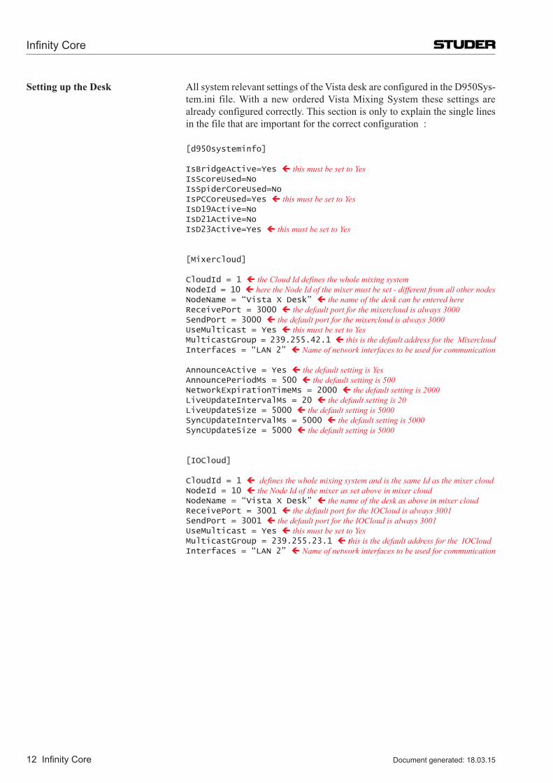
Infinity Core
12 Infinity Core Document generated: 18.03.15
Setting up the Desk All system relevant settings of the Vista desk are configured in the D950Sys-tem.ini file. With a new ordered Vista Mixing System these settings are already configured correctly. This section is only to explain the single lines in the file that are important for the correct configuration :
[d950systeminfo]
IsBridgeActive=Yes ç this must be set to Yes IsScoreUsed=No IsSpiderCoreUsed=No IsPCCoreUsed=Yes ç this must be set to Yes IsD19Active=No IsD21Active=No IsD23Active=Yes ç this must be set to Yes
[Mixercloud]
CloudId = 1 ç the Cloud Id defines the whole mixing system NodeId = 10 ç here the Node Id of the mixer must be set - different from all other nodes NodeName = “Vista X Desk” ç the name of the desk can be entered here ReceivePort = 3000 ç the default port for the mixercloud is always 3000 SendPort = 3000 ç the default port for the mixercloud is always 3000 UseMulticast = Yes ç this must be set to Yes MulticastGroup = 239.255.42.1 ç this is the default address for the Mixercloud Interfaces = “LAN 2” ç Name of network interfaces to be used for communication
AnnounceActive = Yes ç the default setting is Yes AnnouncePeriodMs = 500 ç the default setting is 500 NetworkExpirationTimeMs = 2000 ç the default setting is 2000 LiveUpdateIntervalMs = 20 ç the default setting is 20 LiveUpdateSize = 5000 ç the default setting is 5000 SyncUpdateIntervalMs = 5000 ç the default setting is 5000 SyncUpdateSize = 5000 ç the default setting is 5000
[IOCloud]
CloudId = 1 ç defines the whole mixing system and is the same Id as the mixer cloud NodeId = 10 ç the Node Id of the mixer as set above in mixer cloud NodeName = “Vista X Desk” ç the name of the desk as above in mixer cloud ReceivePort = 3001 ç the default port for the IOCloud is always 3001 SendPort = 3001 ç the default port for the IOCloud is always 3001 UseMulticast = Yes ç this must be set to Yes MulticastGroup = 239.255.23.1 ç this is the default address for the IOCloud Interfaces = “LAN 2” ç Name of network interfaces to be used for communication
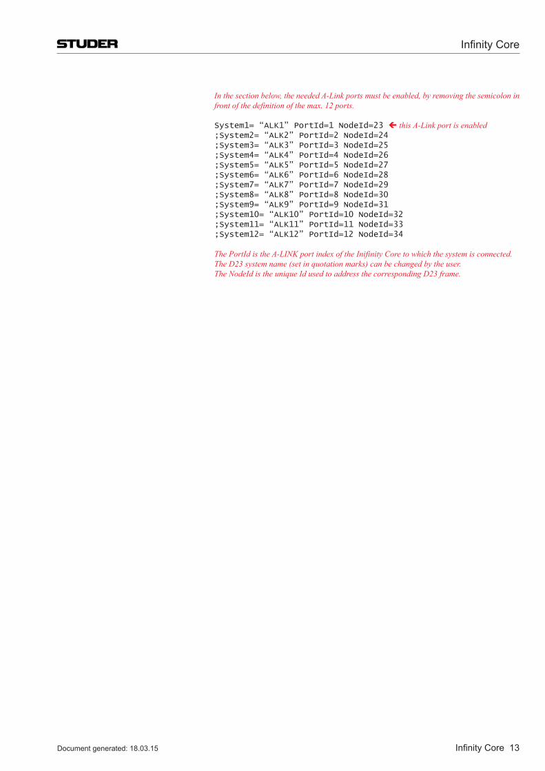
Infinity Core
Infinity Core 13Document generated: 18.03.15
In the section below, the needed A-Link ports must be enabled, by removing the semicolon in front of the definition of the max. 12 ports.
System1= “ALK1” PortId=1 NodeId=23 ç this A-Link port is enabled ;System2= “ALK2” PortId=2 NodeId=24 ;System3= “ALK3” PortId=3 NodeId=25 ;System4= “ALK4” PortId=4 NodeId=26 ;System5= “ALK5” PortId=5 NodeId=27 ;System6= “ALK6” PortId=6 NodeId=28 ;System7= “ALK7” PortId=7 NodeId=29 ;System8= “ALK8” PortId=8 NodeId=30 ;System9= “ALK9” PortId=9 NodeId=31 ;System10= “ALK10” PortId=10 NodeId=32 ;System11= “ALK11” PortId=11 NodeId=33 ;System12= “ALK12” PortId=12 NodeId=34
The PortId is the A-LINK port index of the Inifinity Core to which the system is connected. The D23 system name (set in quotation marks) can be changed by the user. The NodeId is the unique Id used to address the corresponding D23 frame.
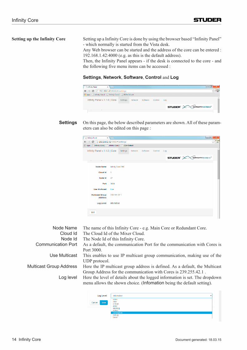
Infinity Core
14 Infinity Core Document generated: 18.03.15
Setting up the Infinity Core Setting up a Infinity Core is done by using the browser based “Infinity Panel” - which normally is started from the Vista desk.
Any Web browser can be started and the address of the core can be entered : 192.168.1.42:4000 (e.g. as this is the default address).
Then, the Infinity Panel appears - if the desk is connected to the core - and the following five menu items can be accessed :
Settings, Network, Software, Control and Log
Settings On this page, the below described parameters are shown. All of these param-eters can also be edited on this page :
Node Name The name of this Infinity Core - e.g. Main Core or Redundant Core. Cloud Id The Cloud Id of the Mixer Cloud. Node Id The Node Id of this Infinity Core. Communication Port As a default, the communication Port for the communication with Cores is
Port 3000. Use Multicast This enables to use IP multicast group communication, making use of the
UDP protocol. Multicast Group Address Here the IP multicast group address is defined. As a default, the Multicast
Group Address for the communication with Cores is 239.255.42.1 . Log level Here the level of details about the logged information is set. The dropdown
menu allows the shown choice. (Infomation being the default setting).
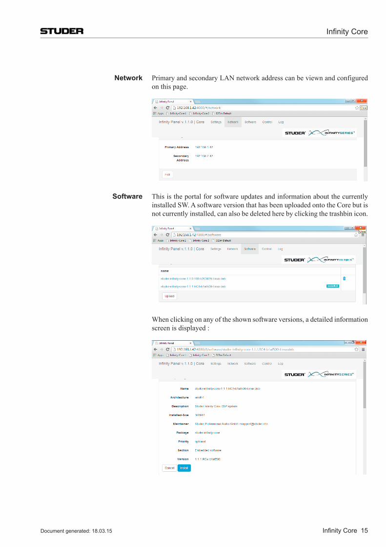
Infinity Core
Infinity Core 15Document generated: 18.03.15
Network Primary and secondary LAN network address can be viewn and configured on this page.
Software This is the portal for software updates and information about the currently installed SW. A software version that has been uploaded onto the Core but is not currently installed, can also be deleted here by clicking the trashbin icon.
When clicking on any of the shown software versions, a detailed information screen is displayed :
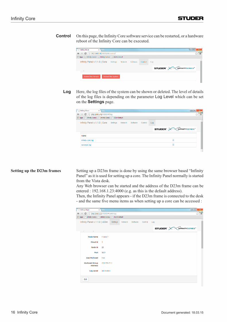
Infinity Core
16 Infinity Core Document generated: 18.03.15
Control On this page, the Infinity Core software service can be restarted, or a hardware reboot of the Infinity Core can be executed.
Log Here, the log files of the system can be shown or deleted. The level of details of the log files is depending on the parameter Log Level which can be set on the Settings page.
Setting up the D23m frames Setting up a D23m frame is done by using the same browser based “Infinity Panel” as it is used for setting up a core. The Infinity Panel normally is started from the Vista desk.
Any Web browser can be started and the address of the D23m frame can be entered : 192.168.1.23:4000 (e.g. as this is the default address).
Then, the Infinity Panel appears - if the D23m frame is connected to the desk - and the same five menu items as when setting up a core can be accessed :
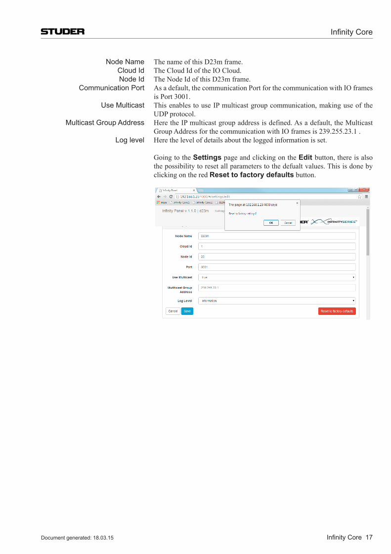
Infinity Core
Infinity Core 17Document generated: 18.03.15
Node Name The name of this D23m frame. Cloud Id The Cloud Id of the IO Cloud. Node Id The Node Id of this D23m frame. Communication Port As a default, the communication Port for the communication with IO frames
is Port 3001. Use Multicast This enables to use IP multicast group communication, making use of the
UDP protocol. Multicast Group Address Here the IP multicast group address is defined. As a default, the Multicast
Group Address for the communication with IO frames is 239.255.23.1 . Log level Here the level of details about the logged information is set.
Going to the Settings page and clicking on the Edit button, there is also the possibility to reset all parameters to the defualt values. This is done by clicking on the red Reset to factory defaults button.
Infinity Core
18 Infinity Core Document generated: 18.03.15
2.5 Clocking concept of the Infinity core The Sync source of the Infinity core is always provided by a D23m frame.
The Sync signal of the D23m system is etiher internally generated by one of the D23m frames, or an external sync signal is connected to one of the D23m frames. The sync signal is then transmitted to the core via A-Link. All other frames will be synced from the core via their audio interface (MADI or A-Link).
The D23m system is able to connect to external sync sources to be synchro-nised. Following sync sources can be used:
•Video •WordClock •AES/EBU •A-Link(mainorredundant) For Video 50 Hz, 59.94 Hz, and 60 Hz are supported. For all other sync sources
48 kHz, 96 kHz, 44.1 kHz and 88.2 kHz are supported.
An automatic process is employed to ‘look’ for the best possible sync source. This process has the following rules :
1. External Clocks have higher priorities then internal clocks. 2. The priorities of the external sync signals are in this order : 1.Videoreference,2.Wordclock,3.AES/EBU4.A-Link 3. The lowest A-Link portnumber (on the core) has the highest priority. 4. Once a switchover to a different sync source has occured, the system
will automatically switch back to the original source, as soon as this sync signal is restored.
If the D23m system consists of multiple frames and a redundant Infinity core
system, the above process provides an audio clock redundancy. If the D23m frame which is the sync source, fails, the system will switch over to the next possible D23m frame that can be the sync master.
2.6 redundancy The redundancy concept of the Infinity Core closely interacts with the redun-
dancy of the D23m I/O system :
The D23m host card (A-Link HD card) offers two A-Link ports, main and redundant with automatic switching - the D23m frame switches automatically to the redundant connection, in case the main connection fails.
A-Link Quality of Service Every A-Link carries its Qualtiy of Service indication, which is depending on the state of the source that generates the A-Link signal.
Looking at this QoS, the D23m system can decide to switch from the main A-Link to the redundant A-Link signal.
QoS is taking into account the following criterias of the source that generates the A-Link signal :
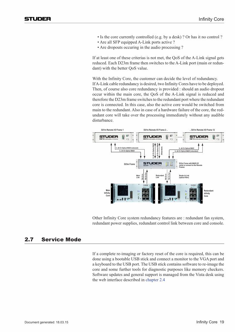
Infinity Core
Infinity Core 19Document generated: 18.03.15
•Isthecorecurrentlycontrolled(e.g.byadesk)?Orhasitnocontrol? •AreallSFPequippedA-Linkportsactive? •Aredropoutsoccuringintheaudioprocessing?
If at least one of these criterias is not met, the QoS of the A-Link signal gets reduced. Each D23m frame then switches to the A-Link port (main or redun-dant) with the better QoS value.
With the Infinity Core, the customer can decide the level of redundancy. If A-Link cable redundancy is desired, two Infinity Cores have to be deployed. Then, of course also core redundancy is provided : should an audio dropout
occur within the main core, the QoS of the A-Link signal is reduced and therefore the D23m frame switches to the redundant port where the redundant core is connected. In this case, also the active core would be switched from main to the redundant. Also in case of a hardware failure of the core, the red-undant core will take over the processing immediately without any audible disturbance.
D21m Remote I/O Frame 2 ..
0...64
Ch
Optic
al MA
DI
0...64
Ch
Optic
al MA
DI
(Red
unda
nt)
D23m Frame
MainInfinity
Core
768 C
h In
768 C
h Ou
t
Studer A-Link(optical fibre)
Main Link
D23m Frame with MADI I/Ocards to connect to the RemoteFrames
D21m Remote I/O Frame 1 .. D21m Remote I/O Frame 12
0...64 Ch Optical MADI 0...64 Ch Optical MADI (redundant)
0...64 Ch Optical MADI (redunant) 0...64 Ch Optical MADI
Redundant InfinityCore
768 C
h In
768 C
h Ou
t
Redundant Link
Other Infinity Core system redundancy features are : redundant fan system, redundant power supplies, redundant control link between core and console.
2.7 Service Mode
If a complete re-imaging or factory reset of the core is required, this can be doneusingabootableUSBstickandconnectamonitortotheVGAportandakeyboardtotheUSBport.TheUSBstickcontainssoftwaretore-imagethecore and some further tools for diagnostic purposes like memory checkers. Software updates and general support is managed from the Vista desk using the web interface described in chapter 2.4
Infinity Core
20 Infinity Core Document generated: 18.03.15
2.8 Session Configuration Tool
The Infinity Core uses almost the same concept of user configurable channel/bus structures (Session Configurations) as the SCoreLive.
In this chapter, the most obvious and most important differences to the Ses-sion Configuration Tool of the SCoreLive are explained.
Differences to the Session Configuration Tool of the SCoreLive
The Session Configuration Tool of the Infininty Core is not generating DSP program code - as needed for the SCoreLive - but it is generating a number of “simple” .xml files.
Out of this fact, two major advantages evolve :
1. No licence is required for the compiling process 2. To generate a Session Configuration takes only very little time The resulting files of a compiled Session Configuration (“Generate All”) are
three new files :
•theXMLConfiguration:Configname.xml •theMixerCloudpaths:Configname-MixercloudPaths.txt •theVMCMappinginformation:Configname-VmcMappinginformation.xml
Setup The Session Configuration Tool for the Infinity Core actually is the very same Session Configuration Tool as used for the SCoreLive (starting from SW 5.2.00). Whether it is used for the SCoreLive or for the Infinity Core is decided by the CoreConfigTool.ini file.
There are two templates of the .ini files in the folder C:\CoreCfgTool :
•CoreConfigTool.sCore •CoreConfigTool.ini
CoreConfigTool.sCore è This file must be renamed to .ini when used with SCoreLive systems. CoreConfigTool.ini è This file is ready to be used with the Infinity Core systems.
To doublecheck whether the correct version of the file is active, the file can be opened with a text editor and the entry ‘CoreType= ’ can be verified.
When the Session Configuration Tool is set-up for the Infinity Core, it can be started with C:\CoreCfgTool\CoreCfgTool.exe.or with the shortcut on the desktop refering to this file.
Then name of the Session Configuration Tool then is “ICoreCfgTool” - which is shown on he very top of the program window - and the GUI of the tool looks as shown below.
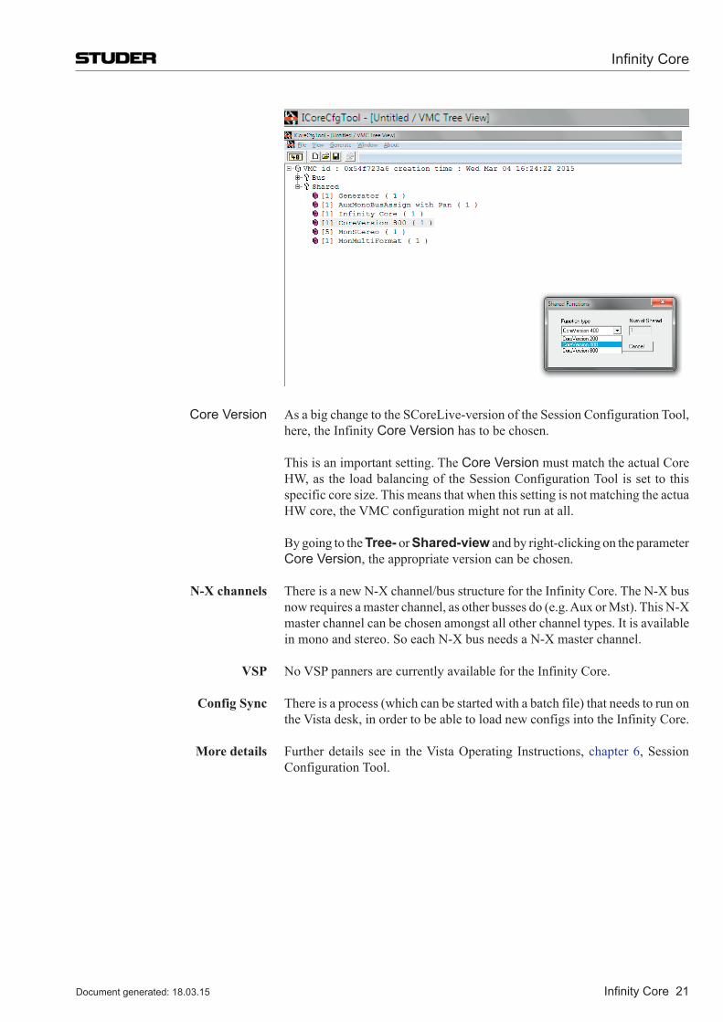
Infinity Core
Infinity Core 21Document generated: 18.03.15
Core Version As a big change to the SCoreLive-version of the Session Configuration Tool,
here, the Infinity Core Version has to be chosen.
This is an important setting. The Core Version must match the actual Core HW, as the load balancing of the Session Configuration Tool is set to this specific core size. This means that when this setting is not matching the actua HW core, the VMC configuration might not run at all.
BygoingtotheTree- or Shared-view and by right-clicking on the parameter Core Version, the appropriate version can be chosen.
N-X channels There is a new N-X channel/bus structure for the Infinity Core. The N-X bus now requires a master channel, as other busses do (e.g. Aux or Mst). This N-X master channel can be chosen amongst all other channel types. It is available in mono and stereo. So each N-X bus needs a N-X master channel.
VSP No VSP panners are currently available for the Infinity Core.
Config Sync There is a process (which can be started with a batch file) that needs to run on the Vista desk, in order to be able to load new configs into the Infinity Core.
More details Further details see in the Vista Operating Instructions, chapter 6, Session Configuration Tool.
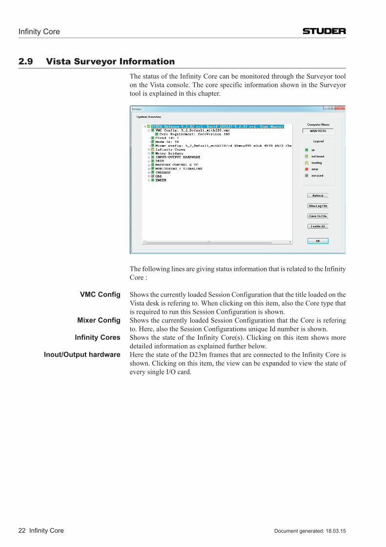
Infinity Core
22 Infinity Core Document generated: 18.03.15
2.9 Vista Surveyor Information The status of the Infinity Core can be monitored through the Surveyor tool
on the Vista console. The core specific information shown in the Surveyor tool is explained in this chapter.
The following lines are giving status information that is related to the Infinity
Core :
VMC Config Shows the currently loaded Session Configuration that the title loaded on the Vista desk is refering to. When clicking on this item, also the Core type that is required to run this Session Configuration is shown.
Mixer Config Shows the currently loaded Session Configuration that the Core is refering to. Here, also the Session Configurations unique Id number is shown.
Infinity Cores Shows the state of the Infinity Core(s). Clicking on this item shows more detailed information as explained further below.
Inout/Output hardware Here the state of the D23m frames that are connected to the Infinity Core is shown. Clicking on this item, the view can be expanded to view the state of every single I/O card.
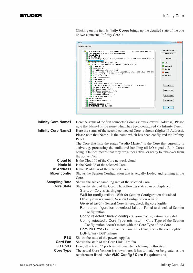
Infinity Core
Infinity Core 23Document generated: 18.03.15
Clicking on the item Infinity Cores brings up the detailed state of the one or two connected Infinity Cores :
Infinity Core Name1 Here the status of the first connected Core is shown (lower IP Address). Please note that Name1 is the name which has been configured via Infinity Panel.
Infinity Core Name2 Here the status of the second connected Core is shown (higher IP Address). Please note that Name1 is the name which has been configured via Infinity Panel.
The Core that lists the status “Audio Master” is the Core that currently is activee.g.processing theaudioandhandlingall I/Osignals.BothCoresbeing “Online” means that they are either active, or ready to take-over from the active Core.
Cloud Id Is the Cloud Id of the Core network cloud Node Id Is the Node Id of the selected Core IP Address Is the IP address of the selected Core Mixer config Shows the Session Configuration that is actually loaded and running in the
Core. Sampling Rate Shows the active sampling rate of the selected Core. Core State Shows the state of the Core. The following states can be displayed : Startup - Core is starting up Wait for configuration - Wait for Session Configuration download Ok - System is running, Session Configuration is valid General Error - General Core failure, check the core logfile Remote configuration download failed - Failed to download Session
Configuration Config rejected : Invalid config - Session Configuration is invalid Config rejected : Core Type mismatch - Core Type of the Session
Configuration doesn’t match with the Core Type of the Core Corelink Error - Failure on the Core Link Card, check the core logfile DSP Error - DSP failiure PSU Shows the state of the power supplies. Card Fan Shows the state of the Core Link Card fan. I/O Ports Here, all active I/O ports are shown when clicking on this item. Core Type The actual Core Version is shown here. It has to match or be greater as the
requirement listed under VMC Config / Core Requirement.
Infinity Core
24 Infinity Core Document generated: 18.03.15
CPU Type Shows the physical CPU type and specifications. Software Version The version of the currently active software of the Core is listed here. Hardware type Shows the hardware type of the fitted Core Link Card. Hardware revision Shows the revision of the fitted Core Link Card. Gateware type Shows the type of the gateware running on the fitted Core Link Card Gateware Version Shows the gateware version of the fitted Core Link Card. Plugin Catalog Shows a list of all available processing plugins, also each plugins version
number is listed.
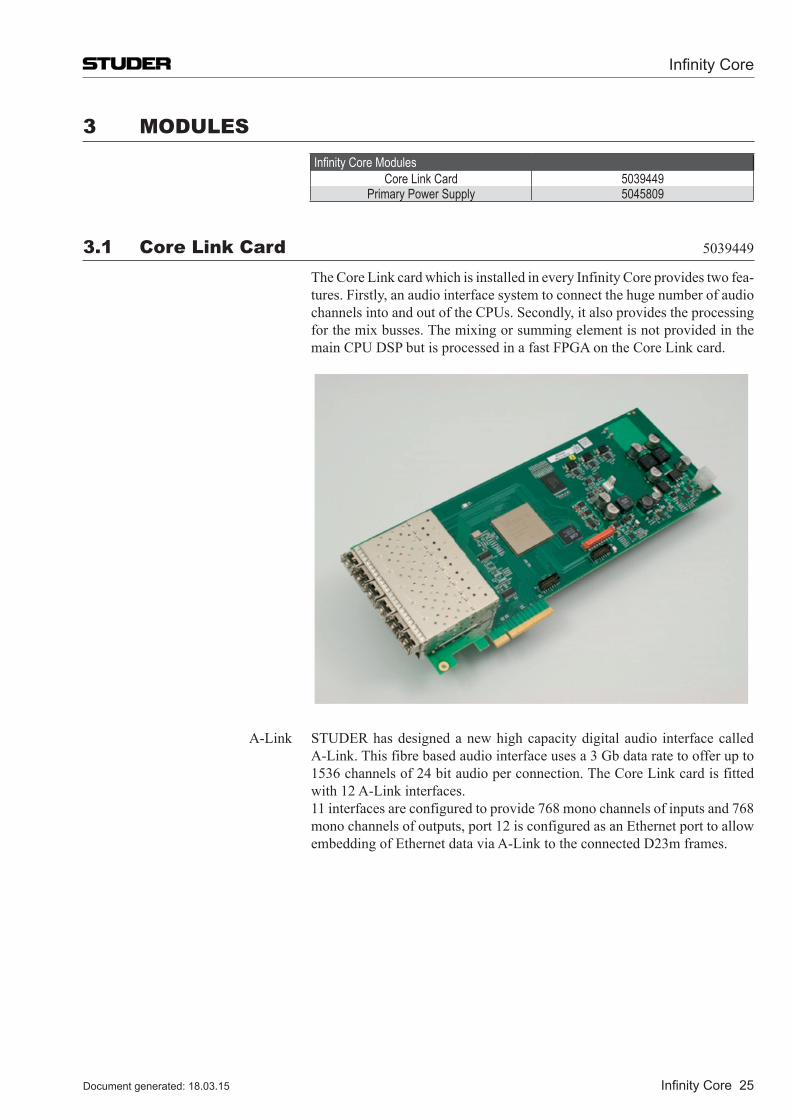
Infinity Core
Infinity Core 25Document generated: 18.03.15
3 MODUlESInfinity Core Modules
Core Link Card 5039449Primary Power Supply 5045809
3.1 Core link Card 5039449
The Core Link card which is installed in every Infinity Core provides two fea-tures. Firstly, an audio interface system to connect the huge number of audio channels into and out of the CPUs. Secondly, it also provides the processing for the mix busses. The mixing or summing element is not provided in the main CPU DSP but is processed in a fast FPGA on the Core Link card.
A-Link STUDER has designed a new high capacity digital audio interface called A-Link. This fibre based audio interface uses a 3 Gb data rate to offer up to 1536 channels of 24 bit audio per connection. The Core Link card is fitted with 12 A-Link interfaces.
11 interfaces are configured to provide 768 mono channels of inputs and 768 mono channels of outputs, port 12 is configured as an Ethernet port to allow embedding of Ethernet data via A-Link to the connected D23m frames.
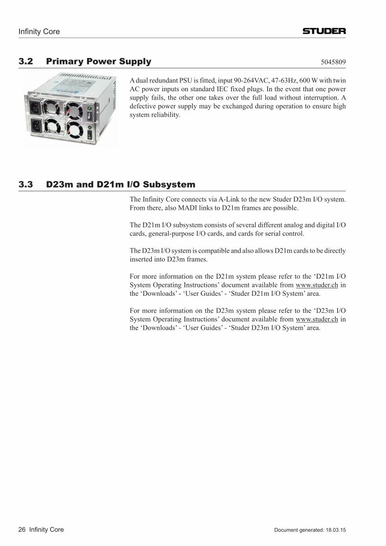
Infinity Core
26 Infinity Core Document generated: 18.03.15
3.2 Primary Power Supply 5045809
A dual redundant PSU is fitted, input 90-264VAC, 47-63Hz, 600 W with twin AC power inputs on standard IEC fixed plugs. In the event that one power supply fails, the other one takes over the full load without interruption. A defective power supply may be exchanged during operation to ensure high system reliability.
3.3 D23m and D21m I/O Subsystem The Infinity Core connects via A-Link to the new Studer D23m I/O system.
From there, also MADI links to D21m frames are possible.
The D21m I/O subsystem consists of several different analog and digital I/O cards, general-purpose I/O cards, and cards for serial control.
The D23m I/O system is compatible and also allows D21m cards to be directly inserted into D23m frames.
For more information on the D21m system please refer to the ‘D21m I/O System Operating Instructions’ document available from www.studer.ch in the ‘Downloads’ - ‘User Guides’ - ‘Studer D21m I/O System’ area.
For more information on the D23m system please refer to the ‘D23m I/O System Operating Instructions’ document available from www.studer.ch in the ‘Downloads’ - ‘User Guides’ - ‘Studer D23m I/O System’ area.
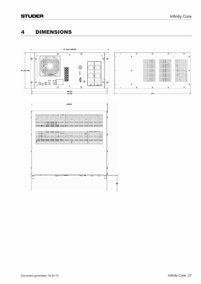
Infinity Core
Infinity Core 27Document generated: 18.03.15
4 DIMENSIONS


