Embed Size (px)
Citation preview

JJMIE Volume 4, Number 1, Jan. 2010
ISSN 1995-6665 Pages 49 - 54
Jordan Journal of Mechanical and Industrial Engineering
Study and Control of a Power Electronic Cascade using Photovoltaic Cell-Multilevel Inverter
Dalila Beriber a Abdelaziz Talha a Farid Bouchafaaa Mohamed Seghir Boucheritb
a Laboratoire d’Instrumentation, F.E.I, Université des Sciences et de la Technologie Houari Boumediene, Alger, ALGÉRIE
b Laboratoire de Commande des Processus, École Nationale Polyechnique, Alger, ALGÉRIE
Abstract
In this paper, we study the performances of the cascade of the photovoltaic cell with the multilevel neutral point clamped (NPC) voltage source inverter (VSI). In the first part, we remind the model of the double stator induction motors (DSIM). Then, we develop knowledge and control models of this inverter using the connection functions of the semi-conductors. After that, we propose a PWM strategy to control this converter. In this part, the inverter is fed by constant input DC voltages. In the last part, we study the performances of the constituted by two photovoltaic cells – two three-level NPC VSI - DSIM. The results obtained confirm the good performances of the proposed cascade.
ll rights reserved
Keywords: Multilevel inverter; Generator Cells; Photovoltaic; Control; DSIM.
1. Introduction *
Nowadays, the main energy supplier of the worldwide economy is fossil fuel. This, however has led to many problems such as global warming and air pollution. Therefore, with regard to the worldwide trend of green energy, solar power technology has become one of the most promising energy resources. The number of PV installations has had an exponential growth [1]. One of the most important types of PV installation is the grid connected inverter configurations. These grid connected PV systems can be categorized from two viewpoints: PV cell and inverter configurations. The PV cell arrangements fall into four broad groups: centralized technology, string technology, multi-string technology and AC-module and AC-cell technologies [2].
All approaches have advantages and disadvantages [2], [3]; and will compromise various attributes such as harmonic generation, complexity, efficiency, flexibility, reliability, safety, modularity and cost. However, for residential PV installations, the most suitable configuration seems to be the string or multistring technologies where one or more strings of PV cells are connected to a single inverter. Using this type of configuration, there will be no losses associated with the string diodes compared to centralized technology. Moreover, independent Maximum Power Point Tracking (MPPT) is possible for all strings which might be installed in different sizes and orientations.
Corresponding Author. [email protected]
This also increases the overall efficiency under special circumstances like partial shadowing.
There are different approaches to implement string and multi-string topologies. Usually, these modules consist of a solar array and a DC to DC converter controlled by a MPPT algorithm. Afterwards, the outputs of the DC/DC converters build up a DC voltage which is then converted to AC by means of an inverter [4]. The other possibility is to use multilevel. PV systems categorized by different PV cell configurations and inverter types topologies which are able to generate better output quality, while operating at lower switching frequency. This implies lower switching dissipation and higher efficiency. Moreover, this topology utilizes switches with lower breakdown voltage; therefore, it can be used in higher power applications at lower cost. It is worth mentioning that although the number of switches in this approach is higher than other two level topologies, for a sufficient high number of levels, the output filter can be avoided which means less weight, cost and space.
On the other hand, even with the same size of filter at the output, the switching frequency can be decreased which means higher efficiency. In general, a greater number of switches in multilevel converters can be justified since the semiconductor cost decreases at a much greater rate than the filter components cost. This project the total cost of multilevel converters to be comparable or even lower than that of two-level converters.
This paper presents the performances of the cascade of the photovoltaic cells with the multilevel NPC inverter.
Simulation results obtained confirm the good performance of the proposed cascade.
© 2010 International Conference and Exhibition on Green Energy & Sustainability for Arid Regions & Mediterranean Countries A

© 2010 Jordan Journal of Mechanical and Industrial Engineering. All rights reserved - Volume 4, Number 1 (ISSN 1995-6665)
50
2. Model of the DSIM
The model of the double stator induction machines
(DSIM) is given in figure1 [5], [6].
Figure 1. DSIM schema
Park model of the DSIM, with P pairs of poles, is
defined by the following equations system [7], [8]:
The electromagnetic torque is given by the following
expression:
The model of the DSIM in the Park frame is given by
figure2.
Figure 2. Representation of DSIM in the Park frame
3. Modelling of Three Level NPC VSI
3.1. The three-level NPC VSI structure The three-level NPC VSI is constituted by three arms and two DC voltage sources [9], [10]. Every arm has four bi-directional switches in series and two diodes (Figure3) [7].
rdrq
rqrrq
rqrd
rdrrd
sdsq
sqssq
sqsd
sdssd
sdsq
sqssq
sqsd
sdssd
dt
dirV
dt
dirV
dt
dirV
dt
dirV
dt
dirV
dt
dirV
φωφ
φωφ
ωφφ
ωφφ
ωφφ
ωφφ
gl
gl
22
222
22
222
11
111
11
111
Figure 3. The three-level NPC inverter
2121 sdsdrqsqsqrdrm
mem iiii
LL
LpC

© 2010 Jordan Journal of Mechanical and Industrial Engineering. All rights reserved - Volume 4, Number 1 (ISSN 1995-6665)
51
3.2. Knowledge model
F indicates the opened or
We define two a half arm connection function ith:
number
trol law which lets an optimal control of this inverter is:
switch Tks. We define th
associated respectively to the upper and lower
tively to the
aracteristic lets us to extrapolate the str
n as follow
The current id0 is defined by the following relatio
4. PWM Strategy of the Five Level NPC VSI
ector mo
n index m is defined as a ratio between the cy p and the reference voltage frequency f:
ate r is the ratio between the magnitude V eference voltage and three times of the ’
:
voltage of the inverter
The switch connection function ks
closed state of the switch TDks.
bkmF w
k : arm
For an arm k of the three-phase three-level NPC,
several complementary laws controls are possible. The con
Where BKs represents the gate control of the e half arm connection function
bi1F and F b
i0half arms. Where i is arm number (i=1, 2, 3).
The output voltages of the inverter relamiddle point M are defined as follows:
This system shows that the three-level can be considered as two two-level voltage source inverters in series. This ch
ategies used The input currents of the inverter are give
n:
The inverter is controlled by the space vdulation strategy which uses two bipolar carriers.
This strategy is characterized by two parameters [8], [11]: - The modulatiocarrier frequen f
- The modulation r
m of the rs magnitude: carrier
Upm
Figure4 shows the signals of this strategy.
Figure 4. Space vector modulation strategy
Figure 5. Simple voltage of the inverter and its spectrum
Figure 6 The adjusting characteristic of the output
arm halfupper for the 1
arm halflower for the 0m
14 KK
BB
BB
23 KK
3433302423201413
3031CM
3302201102d
213210 ddd
323131222121121111 ;;FFF
FFF
FFF
FFF
FFF
FFFb
b
b
b
b
b
10
220
10
121
11
Cb
b
b
Cb
b
b
BM
AM
U
F
F
F
U
F
F
F
V
V
V
3312211111
iFiFiFi
iFiFiFibbb
bbbd
iiiiii
f
f pm
pmUmr
V
Fundamentalmagnitude
(P.U)
0.6
0.8
1
Harmonics rate
0
0.2
0.4
0 0.3 0.6 0.9 1.2 1.5
r
1
.2

© 2010 Jordan Journal of Mechanical and Industrial Engineering. All rights reserved - Volume 4, Number 1 (ISSN 1995-6665)
52
For even value m, ut voltages
s of the outp present
, only y famfirst
The h
Fig
VSI - DSIM
ntil now, we have supposed the input DC voltages of the
basically a p−n semiconductor junction that directly converts light energy into electricity. Since the invention of solar cells, several models have been proposed to describe its function and behavior under different weather conditions (light and temperature) [12]. In this paper, we present the model with one exponential
fig
Figure 10. Power–voltage Characteristic PV
symmetry relatively to the quarter of the period. Then odd harmonics exist. These harmonics gather bilies centred around frequencies multiple of 4mf. The
family centred around frequency 2mf is the most important in view of its magnitude (Figure5). The modulation rate r lets linear adjusting of fundamental magnitude from to (Figure6).
armonics r eases (Figure6). 0r
ate decreas15,1max r
es when r incr
ure 7. Two photovoltaic generator-filter-two three-level NPC
VSI-DSIM cascade
5. Cascade of two Photovoltaic Generator – two Three-Level NPC
U three-level NPC VSI constants. In this part, the authors
study a generation input DC voltage technique. For this, we propose a cascade constituted by two photovoltaic generator-two three-level NPC VSI which feeds a DSIM (Figure7).
5.1. Modelling of Photovoltaic Generator The building block of the PV array is the solar cell,
which is
(diode) [13], [14]. The equivalent circuit is shown inure8.
Figure 8. Electrical Scheme of a photovoltaic cell with one diode
To simulate a PV array, a PV simulation model whichwas obtained using Matlab/Simulink, was used based on the following equation:
gshms R ,
where I is the PV array output current (A); V the PV
array output voltage (V); Iph is the photocurrent depends on the solar radiation and the cell temperature; Is is the cell reverse saturation current varies with temperature; Rs is the series resistance; Rsh is the shunt resistance, q is the charge of electron = 1.602.10 C; K is the Boltzmanns constant K=1.381.10-23 J/K; A is the pn junction ideality factor; T is the cell temperature (K) and g is the gap.
In our case, we have used photovoltaic generator MSX-83 composed by 36 cells in en series. The characteristics of a PV cell of changes in current and power based on the
d 10(for a
19
voltage of the PV cell is shown in figures 9 antemperature T=25° and light E=1000W/m2).
Figure 9. Current–voltage Characteristic PV
ggsgggsggsgphg
IRV
TAkN
IRVqIII ,,
,, ]1[exp
© 2010 Jordan Journal of Mechanical and Industrial Engineering. All rights reserved - Volume 4, Number 1 (ISSN 1995-6665)
53
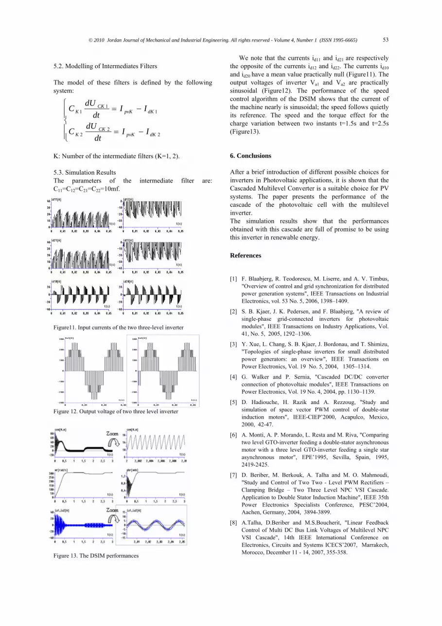
5.2. Modelling of Intermediates Filters
following
lter are
M performances
m of the DSIM shows that the current of
tants t=1.5s and t=2.5s
. Conclusions
hoice for PV
that the performances
bus,
K. Pedersen, and F. Blaabjerg, "A review of
of single-phase inverters for small distributed
"Study and
r asynchronous
, M. Berkouk, A. Talha and M. O. Mahmoudi,
any, 2004, 3894-3899.
S’2007, Marrakech,
The model of these filters is defined by the system:
K: Number of the intermediate filters (K=1, 2).
5.3. Simulation Results The parameters of the intermediate fiC11=C12=C21=C22=10mf.
gorith
igure13).
:
Af
obt
[1]
"Ov
Figure11. Input currents of the two three-level inverter
Figure 12. Output voltage of two three level inverter
Figure 13. The DSI
We note that the currents id11 and id21 are respectively the opposite of the currents id12 and id22. The currents id10 and id20 have a mean value practically null (Figure11). The output voltages of inverter Va1 and Va2 are practically sinusoidal (Figure12). The performance of the speed control al
22
2
11
1
dKpvKCK
K
dKpvKCK
K
IIdt
dUC
IIdt
dUC the machine nearly is sinusoidal; the speed follows quietly
its reference. The speed and the torque effect for the charge variation between two ins(F
6
ter a brief introduction of different possible choices for inverters in Photovoltaic applications, it is shown that the Cascaded Multilevel Converter is a suitable csystems. The paper presents the performance of the cascade of the photovoltaic cell with the multilevel inverter. The simulation results show
ained with this cascade are full of promise to be using this inverter in renewable energy.
References
F. Blaabjerg, R. Teodorescu, M. Liserre, and A. V. Timerview of control and grid synchronization for distributed
power generation systems", IEEE Transactions on Industrial Electronics, vol. 53 No. 5, 2006, 1398–1409.
[2] S. B. Kjaer, J.single-phase grid-connected inverters for photovoltaic modules", IEEE Transactions on Industry Applications, Vol. 41, No. 5, 2005, 1292–1306.
[3] Y. Xue, L. Chang, S. B. Kjaer, J. Bordonau, and T. Shimizu, "Topologies power generators: an overview", IEEE Transactions on Power Electronics, Vol. 19 No. 5, 2004, 1305–1314.
[4] G. Walker and P. Sernia, "Cascaded DC/DC converter connection of photovoltaic modules", IEEE Transactions on Power Electronics, Vol. 19 No. 4, 2004, pp. 1130–1139.
[5] D. Hadiouche, H. Razik and A. Rezzoug,simulation of space vector PWM control of double-star induction motors", IEEE-CIEP’2000, Acapulco, Mexico, 2000, 42-47.
[6] A. Monti, A. P. Morando, L. Resta and M. Riva, "Comparing two level GTO-inverter feeding a double-statomotor with a three level GTO-inverter feeding a single star asynchronous motor", EPE’1995, Sevilla, Spain, 1995, 2419-2425.
[7] D. Beriber"Study and Control of Two Two - Level PWM Rectifiers – Clamping Bridge – Two Three Level NPC VSI Cascade. Application to Double Stator Induction Machine", IEEE 35th Power Electronics Specialists Conference, PESC’2004, Aachen, Germ
[8] A.Talha, D.Beriber and M.S.Boucherit, "Linear Feedback Control of Multi DC Bus Link Voltages of Multilevel NPC VSI Cascade", 14th IEEE International Conference on Electronics, Circuits and Systems ICECMorocco, December 11 - 14, 2007, 355-358.

© 2010 Jordan Journal of Mechanical and Industrial Engineering. All rights reserved - Volume 4, Number 1 (ISSN 1995-6665)
54
s, controls, and applications", IEEE
alez, and J. Balcells, "Interfacing renewable energy ng a three-level inverter", IEEE
ransactions on Industrial Electronics, Vol. 53, No. 5, 2006,
[11] T.G. Habelter, "Multilevel M methods at Low Modulation indices", in Proceedings
Electronics Conference and , 1999, 1032-1039.
[13] B.Multon and al, "Analysis and Experimental Validation of Various Photovoltaic System Models", 7th International ELECTRIMACS’2002 Congress, Montréal, Canada, 2002, 1-6.
[14 E. Massada, "Power Converter for Renewable and Distributed Sources", 9th International Conference on Power Electronics and Motion Controls, EPE-PEMC’2000, Kosice, Slovak Republic, 2000.
[9] J. Rodriguez, J. Lai, and F. Peng, "Multilevel inverters: A survey of topologieTransactions on Industrial Electronics, Vol. 49, No. 4, 2002, 724–738.
[10] S. Alepuz, S. Busquets-Monge, J. Bordonau, J. Gago, D. Gonz
[12]
sources to the utility grid usiT1504–1511.
L.M. Tolbert, F.Z. Peng and PWof 1999 Applied Powerexposition (APEC)
M. Bayegan, "Power electronic technologies for distributed Power", Keynote paper, 9th European conference on Power Electronics and Applications, EPE 01, 27th August 2001, Graz, Austria, 2001.
]


