Embed Size (px)
Citation preview
This article appeared in a journal published by Elsevier. The attachedcopy is furnished to the author for internal non-commercial researchand education use, including for instruction at the authors institution
and sharing with colleagues.
Other uses, including reproduction and distribution, or selling orlicensing copies, or posting to personal, institutional or third party
websites are prohibited.
In most cases authors are permitted to post their version of thearticle (e.g. in Word or Tex form) to their personal website orinstitutional repository. Authors requiring further information
regarding Elsevier’s archiving and manuscript policies areencouraged to visit:
http://www.elsevier.com/copyright
Author's personal copy
Journal of Alloys and Compounds 480 (2009) 596–602
Contents lists available at ScienceDirect
Journal of Alloys and Compounds
journa l homepage: www.e lsev ier .com/ locate / ja l l com
Study of ac impedance spectroscopy of Al doped MnFe2−2xAl2xO4
Khalid Mujasam Batooa,∗, Shalendra Kumarb, Chan Gyan Leeb, Alimuddina
a Department of Applied Physics, Aligarh Muslim University, Aligarh 202002, Indiab School of Nano and Advanced Materials Engineering, Changwon National University, Changwon, South Korea
a r t i c l e i n f o
Article history:Received 30 September 2008Received in revised form 30 January 2009Accepted 30 January 2009Available online 10 February 2009
PACS:75.50.Gg74.25.Nf
Keywords:FerritesImpedance spectroscopy
a b s t r a c t
We have reported electrical properties of Al doped MnFe2O4 ferrite using ac impedance spectroscopyas a function of frequency (42 Hz to 5 MHz) at different temperatures (300–473 K). XRD analysis showsthat all the compositions are single phase cubic spinel in structure. The complex impedance analysishas been used to separate the grain and grain boundary resistance of MnFe2−2xAl2xO4. From the analysisof impedance spectra it is found that the real (Z′), and imaginary (Z′′) part of the impedance decreasewith increasing frequency and both are found to decrease with Al doping up to 20%, and thereafter, theseincrease with further increasing the Al concentration. Experimental results have been fitted with twoparallel RC equivalent circuits in series.
© 2009 Elsevier B.V. All rights reserved.
1. Introduction
Spinel ferrites are an important class of magnetic materials,which have attracted a lot of attention of scientific communitybecause of their excellent combination of good electrical and mag-netic properties [1]. In general, the cation distribution in spinellattice has the form: (D1−xMx)[DxM2−x]O−2
4, where D and M aredivalent and trivalent ions respectively, and x is called the degree ofinversion. The round and square brackets denote the cations locatedat the center of tetrahedral lattice of oxygen (A) and those at octa-hedral (B) lattice respectively. The high electrical resistivity andconsequently low eddy currents and dielectric losses make themvery important material for technological and industrial applica-tions. These materials have wide range of applications in microwavedevices, computer memories, transformers, magnetic recordingsand switches [2]. The electrical properties of these materials havebeen the subject of continuous investigation, which depend uponthe preparation conditions, amount of doping element and prepa-ration time etc.
It is well known that impedance spectroscopy is an impor-tant method to study the electrical properties of ferrites, sinceimpedance of the grains can be separated from other impedancesources, such as impedance of electrodes and grain boundaries. Oneof the important factors, which influences the impedance proper-ties of ferrites, is micro-structural effect. Two semi-circles are often
∗ Corresponding author. Tel.: +91 9897810509; fax: +91 571 2700042.E-mail address: [email protected] (K.M. Batoo).
obtained in Cole–Cole plot, when the grain boundary resistanceis larger than that of grain. The distributions of relaxation times,which result in deviation from ideal semi-circles, are attributed tovarious factors, such as disorder in the samples, and inhomogeneityin microstructures [3–6].
Tsonos et al. [7] studied the microstructure of cement mortarsthrough dielectric parameters variation by using the com-plex impedance spectroscopy technique. They reported that theimpedance analysis of the prepared samples revealed the existenceof two short range relaxation mechanisms of conductivity. Theysuggested that the low frequency relaxation is related to the closedcapillary pores and the high frequency relaxation to the C–S–Hgel pores. Nobre et al. [8] studied the electrical properties of theZn7Sb2O12 using impedance spectroscopy. They reported that thebulk resistance curve of Zn antimoniate as a function of temper-ature, exhibits thermostat behaviour with negative temperaturecoefficient. In addition, the bulk conductivity follows the Arrheniuslaw with two linear branches of different slopes positioned arounda region of transition temperature.
There are many studies on the impedance properties of differ-ent ferrite materials reported in the literature. Amador et al. [9]studied the effect of grain size distribution on Cole–Cole plots ofNi–Zn ferrites. They reported that the decrease in resistivity occurswith increasing grain size. They also reported that as the width ofgrain size distribution increases, the semi-circles exhibit a defor-mation and become unresolved. Sivakumar et al. [10] reportedthe electrical and magnetic properties of the chemically derivednanocrystalline Co ferrite. They reported that due to the smallergrain size of prepared samples (Co ferrite), the conduction mech-
0925-8388/$ – see front matter © 2009 Elsevier B.V. All rights reserved.doi:10.1016/j.jallcom.2009.01.137
Author's personal copy
K.M. Batoo et al. / Journal of Alloys and Compounds 480 (2009) 596–602 597
anism takes place predominantly through the grain boundary andhence a single semi-circle is observed in the complex impedanceplot. Similar results have been reported by us in our earlier paper[11], where we have reported that the impedance of grain boundaryhas increased with Al doping. we have also reported in Cd dopedCoFe2O4 materials [12], that capacitive and resistive properties ofthe materials decreased up to 20% of Cd doping, and thereafter,these properties increased with further Cd doping. Bo Wang etal. [13] use the impedance spectroscopy technique to study themicro-structural dielectric constant of copper-substituted Ni–Znferrites. They reported that the small liquid-like particles werefound filling the grain boundaries of prepared samples, whichhave lower dielectric constant and dielectric loss. Ponpandian etal. [14] studied the electrical conductivity and dielectric behaviourof nanocrystalline NiFe2O4 spinel. They reported that the sampleswith smaller grain size show only one semi-circle correspondingto grain boundary conduction, while samples of larger size showtwo semi-circles corresponding to both grain and grain bound-ary conduction mechanism. Ahmed et al. [15] studied the effectof cation concentration on the relaxation phenomena of Co–Znferrites. They reported that the maximum of the relaxation time(�), calculated from the Cole–Cole plots corresponds to the criticalconcentration, x = 0.6.
In the present work, the electrical properties of Al dopedMnFe2O4 ferrites have been investigated by impedance spec-troscopy. It is preferable to plot the complex impedance orconductivity for characterizing our ferrite materials when deal-ing with charge carrier systems. The impedance spectroscopy orac conductivity technique enables us to evaluate and separate outthe contributions to overall electrical properties due to variouscomponents such as grain, and grain boundary or polarization phe-nomenon in a material, in the frequency or time domains. Here, theprinciple of analysis is based on the fact that ac response of a sam-ple to sinusoidal electrical signal, and subsequent calculation of theresulting transfer (impedance) with respect to the frequency of theapplied signal. The aim of this work is to study the bulk and interfacephenomena over a wide range of frequencies and at selected tem-peratures in order to get information about the relaxation times,and relaxation amplitudes of various processes present in the sys-tem, when a small perturbation signal is sent to the system over awide range of frequencies. It is worth to note that various physicalparameters and characteristic properties that influence the perfor-mance of a ferrite material can be obtained from the analysis ofcomplex impedance spectra.
2. Experimental
Polycrystalline spinel ferrites with chemical formula MnFe2−2xAl2xO4
(0 ≤ x ≤ 0.5) were prepared by conventional solid state reaction technique.High purity ‘AR’ grade oxides, iron oxide (Fe2O3), aluminum oxide (Al2O3) andmanganese oxide (MnO2) were mixed together according to their chemical weights.The mixture of each composition was ground to a very fine powder, and calcinatedat 1273 K for 12 h. The pre-calcinated powders were again ground and sintered at1523 K for 24 h. Finally, the samples were ground to fine powder, pressed into diskshaped pellets, and sintered at 1573 K for 24 h. At the end of each heat treatmentthe samples were allowed to cool slowly to room temperature at a rate of 274 K/min[16]. Silver paste coating was applied on the opposite faces of pellets, in orderto make parallel plate capacitor geometry and the ferrite material as dielectricmedium. The complex impedance measurements were carried out using theLCR HI-Tester (HIOKI 3532-50) as a function of frequency (42 Hz to 5 MHz), andtemperature (300 K–473 K).
3. Result and discussion
3.1. X-ray analysis
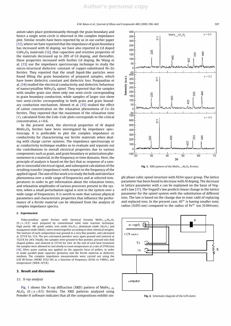
Fig. 1 shows the X-ray diffraction (XRD) pattern of MnFe2−2xAlxO4 (0 ≤ x ≤ 0.5) ferrites. The XRD patterns analyzed usingPowder-X software indicates that all the compositions exhibit sin-
Fig. 1. XRD pattern of the MnFe2−xAlxO4 ferrites.
gle phase cubic spinel structure with Fd3m space group. The latticeparameter has been found to decrease with Al doping. The decreasein lattice parameter with x can be explained on the basis of Veg-ard’s law [17]. The Vegard’s law predicts linear change in the latticeparameter for the spinel system with the substitution of differentions. The law is based on the change due to ionic radii of replacingand replaced ions. In the present case, Al3+ is having smaller ionicradius (0.051 nm) compared to the radius of Fe3+ ion (0.064 nm).
Fig. 2. Schematic diagram of the LCR meter.
Author's personal copy
598 K.M. Batoo et al. / Journal of Alloys and Compounds 480 (2009) 596–602
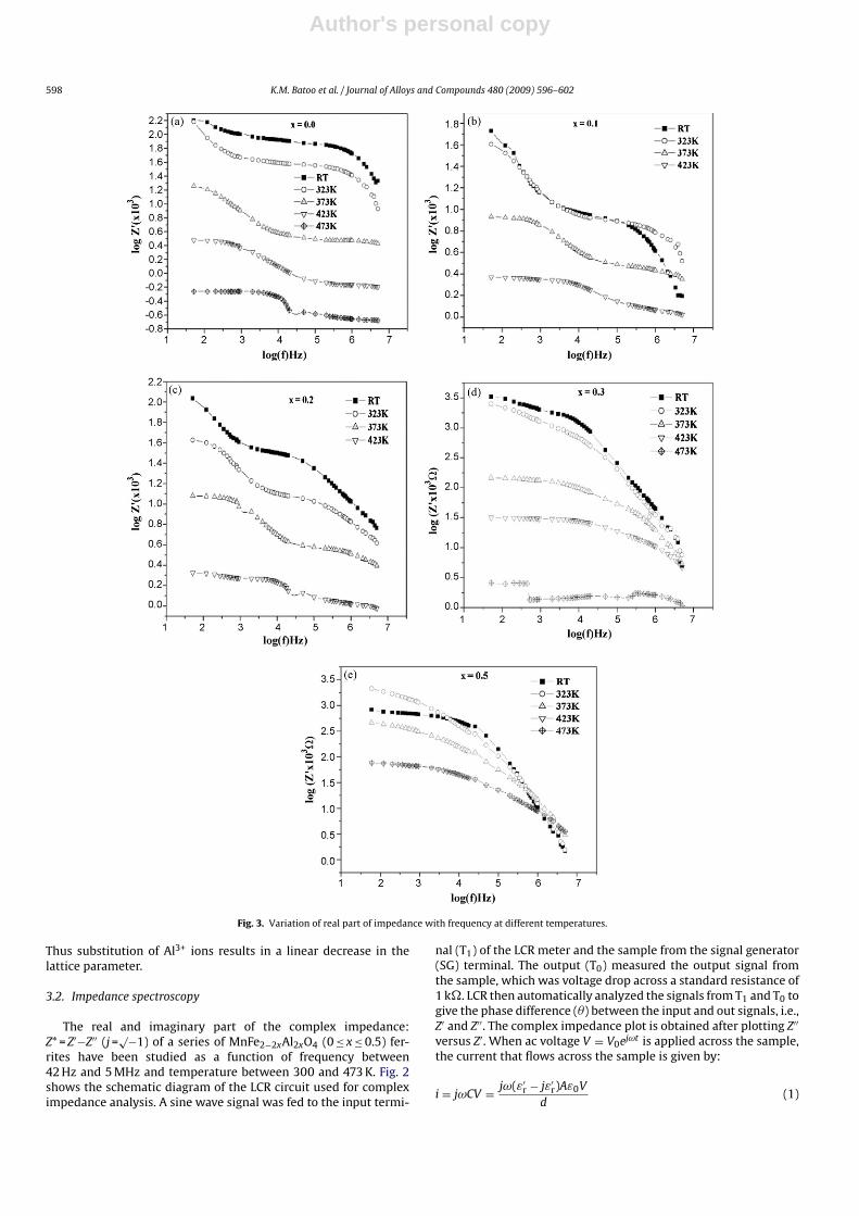
Fig. 3. Variation of real part of impedance with frequency at different temperatures.
Thus substitution of Al3+ ions results in a linear decrease in thelattice parameter.
3.2. Impedance spectroscopy
The real and imaginary part of the complex impedance:Z* = Z′−Z′′ (j =
√−1) of a series of MnFe2−2xAl2xO4 (0 ≤ x ≤ 0.5) fer-rites have been studied as a function of frequency between42 Hz and 5 MHz and temperature between 300 and 473 K. Fig. 2shows the schematic diagram of the LCR circuit used for compleximpedance analysis. A sine wave signal was fed to the input termi-
nal (T1) of the LCR meter and the sample from the signal generator(SG) terminal. The output (T0) measured the output signal fromthe sample, which was voltage drop across a standard resistance of1 k�. LCR then automatically analyzed the signals from T1 and T0 togive the phase difference (�) between the input and out signals, i.e.,Z′ and Z′′. The complex impedance plot is obtained after plotting Z′′
versus Z′. When ac voltage V = V0ejωt is applied across the sample,the current that flows across the sample is given by:
i = jωCV = jω(ε′r − jε′
r)Aε0V
d(1)
Author's personal copy
K.M. Batoo et al. / Journal of Alloys and Compounds 480 (2009) 596–602 599
where C is the capacitance of the parallel plate capacitor withthe ferrite material as the dielectric and ε0 is permittivity of freespace.
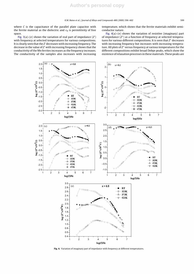
Fig. 3(a)–(e) shows the variation of real part of impedance (Z′)with frequency at selected temperatures for various compositions.It is clearly seen that the Z′ decreases with increasing frequency. Thedecrease in the value of Z′ with increasing frequency shows that theconductivity of the Mn ferrites increases as the frequency increases.The conductivity of the samples also increases with increasing
temperature, which shows that the ferrite materials exhibit semi-conductor nature.
Fig. 4(a)–(e) shows the variation of resistive (imaginary) partof impedance (Z′′) as a function of frequency at selected tempera-tures for various different compositions. It is seen that Z′′ decreaseswith increasing frequency but increases with increasing tempera-ture. All plots of Z′′ versus frequency at various temperatures for thedifferent compositions exhibit broad Debye peaks, which show theexistence of relaxation processes in these materials. These peaks are
Fig. 4. Variation of imaginary part of impedance with frequency at different temperatures.
Author's personal copy
600 K.M. Batoo et al. / Journal of Alloys and Compounds 480 (2009) 596–602
Fig. 5. Complex impedance for the composition x = 0.0, at selected temperatures.
shifted towards higher temperature by increasing frequency from42 Hz to 5 MHz. There are three generic relaxation dispersion situa-tions, which may occur for solids while discussing Z′ as a function offrequency: conductive system associated charge carriers, dielectricdispersion usually arising from dipole rotation of lattice entities andthe presence of both types of dispersion within measured frequencyrange. Three different dipolar relaxation processes and an intrin-sic conductivity contribution may be involved in this case [18]. Thevalue of Z′′ maxima decreases with temperature for all the composi-tions, which indicate the increasing loss in the resistive property ofthe sample. Such behaviour is expected due to the presence of spacecharge polarization in the materials [19]. The occurrence of relax-ation peaks in the real and imaginary part of complex impedanceat low frequencies with temperature may be due to the existenceof the space–charge relaxation at low frequencies, which is relatedto the charge carriers in association with the oxygen vacancies. Theconductivity is dominated by the short range hopping of charge car-riers at low temperature. In order to form space charge polarization,few oxygen vacancies are trapped at the electrode interface, whichare due to the high mobility of oxygen vacancies in the Al dopedMn ferrites, where they can move easily, when externally appliedelectric field is turned on, resulting in a little space charge effect atlow temperatures. In contrast, at high temperatures, more oxygendefects are activated, and they are accumulated at the electrodeinterfaces and grain boundaries resulting in a strong space chargerelaxation [20,21].
The impedance spectroscopy helps in the separation of grain andgrain boundary because each of them has different relaxation times,
Fig. 6. Complex impedance for the composition x = 0.2, at selected temperatures.
Fig. 7. Complex impedance for the composition x = 0.4, at selected temperatures.
Author's personal copy
K.M. Batoo et al. / Journal of Alloys and Compounds 480 (2009) 596–602 601
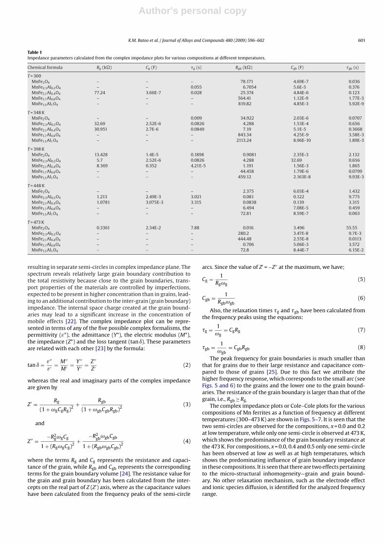
Table 1Impedance parameters calculated from the complex impedance plots for various compositions at different temperatures.
Chemical formula Rg (k�) Cg (F) �g (s) Rgb (k�) Cgb (F) �gb (s)
T = 300MnFe2O4 – – – 78.171 4.69E-7 0.036MnFe2.3Al0.2O4 – – 0.055 6.7054 5.6E-5 0.376MnFe2.1Al0.4O4 77.24 3.66E-7 0.028 25.374 4.84E-6 0.123MnFe1.7Al0.8O4 – – – 564.41 1.12E-9 1.77E-3MnFe1.5Al1O4 – – – 819.82 4.85E-3 5.92E-9
T = 348 KMnFe2O4 – – 0.009 34.922 2.03E-6 0.0707MnFe2.3Al0.2O4 32.69 2.52E-6 0.0826 4.288 1.53E-4 0.656MnFe2.1Al0.4O4 30.951 2.7E-6 0.0849 7.19 5.1E-5 0.3668MnFe1.7Al0.8O4 – – – 843.34 4.25E-9 3.58E-3MnFe1.5Al1O4 – – – 2113.24 8.96E-10 1.89E-3
T = 398 KMnFe2O4 13.428 1.4E-5 0.1898 0.9081 2.35E-3 2.132MnFe2.3Al0.2O4 5.7 2.52E-6 0.0826 4.288 32.69 0.656MnFe2.1Al0.4O4 8.369 0.352 4.21E-5 1.191 1.56E-3 1.865MnFe1.7Al0.8O4 – – – 44.458 1.79E-6 0.0799MnFe1.5Al1O4 – – – 459.12 2.163E-8 9.93E-3
T = 448 KMnFe2O4 – – – 2.375 6.03E-4 1.432MnFe2.3Al0.2O4 1.213 2.49E-3 3.021 0.081 0.122 9.775MnFe2.1Al0.4O4 1.0781 3.075E-3 3.315 0.0838 0.139 3.315MnFe1.7Al0.8O4 – – – 6.494 7.08E-5 0.459MnFe1.5Al1O4 – – – 72.81 8.59E-7 0.063
T = 473 KMnFe2O4 0.3361 2.34E-2 7.88 0.016 3.496 55.55MnFe2.3Al0.2O4 – – – 280.2 3.47E-8 9.7E-3MnFe2.1Al0.4O4 – – – 444.48 2.55E-8 0.0113MnFe1.7Al0.8O4 – – – 0.706 5.06E-3 3.572MnFe1.5Al1O4 – – – 72.8 8.44E-7 6.15E-2
resulting in separate semi-circles in complex impedance plane. Thespectrum reveals relatively large grain boundary contribution tothe total resistivity because close to the grain boundaries, trans-port properties of the materials are controlled by imperfections,expected to be present in higher concentration than in grains, lead-ing to an additional contribution to the inter-grain (grain boundary)impedance. The internal space charge created at the grain bound-aries may lead to a significant increase in the concentration ofmobile effects [22]. The complex impedance plot can be repre-sented in terms of any of the five possible complex formalisms, thepermittivity (ε*), the admittance (Y*), the electric modulus (M*),the impedance (Z*) and the loss tangent (tan ı). These parametersare related with each other [23] by the formula:
tan ı = ε′′
ε′ = M′′
M′ = Y ′′
Y ′ = Z ′′
Z ′ (2)
whereas the real and imaginary parts of the complex impedanceare given by
Z ′ = Rg
(1 + ωgCgRg)2+ Rgb
(1 + ωgbCgbRgb)2(3)
and
Z ′′ = −R2gωgCg
1 + (RgωgCg)2+
−R2gbωgbCgb
1 + (RgbωgbCgb)2(4)
where the terms Rg and Cg represents the resistance and capaci-tance of the grain, while Rgb and Cgb represents the correspondingterms for the grain boundary volume [24]. The resistance value forthe grain and grain boundary has been calculated from the inter-cepts on the real part of Z (Z′) axis, where as the capacitance valueshave been calculated from the frequency peaks of the semi-circle
arcs. Since the value of Z′ = −Z′′ at the maximum, we have;
Cg = 1Rgωg
(5)
Cgb = 1Rgbωgb
(6)
Also, the relaxation times �g and �gb have been calculated fromthe frequency peaks using the equations:
�g = 1ωg
= CgRg (7)
�gb = 1ωgb
= CgbRgb (8)
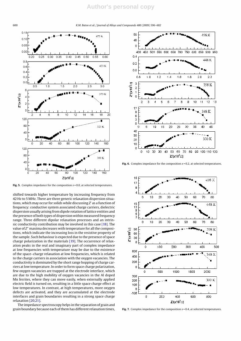
The peak frequency for grain boundaries is much smaller thanthat for grains due to their large resistance and capacitance com-pared to those of grains [25]. Due to this fact we attribute thehigher frequency response, which corresponds to the small arc (seeFigs. 5 and 6) to the grains and the lower one to the grain bound-aries. The resistance of the grain boundary is larger than that of thegrain, i.e., Rgb ≥ Rg.
The complex impedance plots or Cole–Cole plots for the variouscompositions of Mn ferrites as a function of frequency at differenttemperatures (300–473 K) are shown in Figs. 5–7. It is seen that thetwo semi-circles are observed for the compositions, x = 0.0 and 0.2at low temperature, while only one semi-circle is observed at 473 K,which shows the predominance of the grain boundary resistance atthe 473 K. For compositions, x = 0.0, 0.4 and 0.5 only one semi-circlehas been observed at low as well as at high temperatures, whichshows the predominating influence of grain boundary impedancein these compositions. It is seen that there are two effects pertainingto the micro-structural inhomogeneity—grain and grain bound-ary. No other relaxation mechanism, such as the electrode effectand ionic species diffusion, is identified for the analyzed frequencyrange.
Author's personal copy
602 K.M. Batoo et al. / Journal of Alloys and Compounds 480 (2009) 596–602
Fig. 8. Proposed circuit for the analysis of impedance spectroscopy data.
Different electrical parameters calculated from the compleximpedance plots for the various compositions at selected temper-atures are shown in Table 1. It is observed that the grain boundaryresistance decreases up to 448 K, thereafter it increases with fur-ther increasing the temperature. The capacitance of grain boundaryis found to increase with increasing temperature, which means thepolarizability increases with the increasing temperature. For all thesamples the capacitance of the grain boundary (Cgb) is higher thanthat of the grain (Cg), which is explained on the basis that the capac-itance is inversely proportional to the thickness of the media. Thevalue of Cg and Cgb are found to be maximum, which means Aldoped Mn ferrites are having greater polarizability. The lower valueof total resistance Rg and Rgb for the composition, x = 0.2, indicatesthat the phenomena of electron hopping mechanism is promotedin this composition, which is a sole mechanism for the processof conduction and polarizability. The value of the grain boundaryresistance is found to be larger than the resistance of the grain, inaddition, the semi-circle arc is found distorted at higher tempera-ture, which is attributed to the fact that the atomic arrangement atthe grain boundary is disordered, giving enhancement in electronscattering process. The higher value of grain boundary impedancecan be because of the fact that the Fe2+ ion species decrease in theregion [26].
For the analysis of the experimental results, it is assumed thatthe material consists of piled up crystalline plates, as a microstruc-ture formed by parallel conducting plates (grains) separated byresistive plate boundaries (grain boundaries). Therefore, the imag-inary part of the impedance (Z′′) is plotted against the real part ofthe impedance (Z′). Two semi-circles are obtained. Each semi-circlearc corresponds to resister–capacitor RC phase. The semi-circle atlow frequency side corresponds to the grain boundary, while thesemi-circle at higher frequency side corresponds to the grain. Suchan interpretation is indeed very helpful to represent the sample byan electrical circuit as a combination of resistors and capacitors asshown in Fig. 8, and analytically explained by Eqs. (3) and (4). Suchinterpretations have also been given earlier [27–29] for amorphouschalcogenides. The representation of sample through an electricalanalog circuit is very helpful in representing the electrical featuresof the sample [26]. In this circuit, a resistance represents a conduc-tive path and a given resistor in a circuit might account for the bulkconductivity of the sample. Also the capacitances will be generallyassociated with space charge polarization regions.
4. Conclusion
We have successfully synthesized single phase polycrystallineMnFe2−2xAl2xO4, using solid state reaction technique. The real and
imaginary parts of the impedance have been found to decreaseby increasing the temperature, which shows the conductivity ofMn ferrite increases with the temperature, confirming the semi-conductor behaviour of the system. Two semi-circles have beenobserved for the compositions, x = 0.1 and 0.2 at low temperature,while only one semi-circle has been observed at 473 K, which showsthe predominance of the grain boundary resistance at 473 K. Forcompositions, x = 0.0, 0.4 and 0.5 only one semi-circle has beenobserved at low as well as at high temperature, which is due tothe large contribution by the grain boundaries in these composi-tions. The values of Rg and Rgb are minimum for the composition,x = 0.2, which shows that the ac conductivity of the composition isvery high. The analysis of the complex impedance data shows thatthe capacitive and reactive properties of the materials are mainlyattributed due to the processes which are associated with the grainand grain boundary.
Acknowledgements
One of the authors K.M. Batoo is thankful to I.U.A.C, New Delhi,India, for financial support though UFUP project. Authors S.K. andC.G. Lee acknowledge Korea Research Foundation (Grant KRF-2008-005-J02703) for the financial support.
References
[1] N.S. Gajbhiye, G. Balaji, S. Bhattacharyya, M. Ghafari, Hyp. Int. 156/157 (2004)57.
[2] J. Smith, H.P.J. Winjin, Ferrites, Philips, Eindhoven, 1959.[3] J.T.S. Irvine, D.C. Sinclair, A.R. West, Adv. Mater. 3 (2004) 132–138.[4] H.F. Cheng, J. Appl. Phys. 56 (1984) 1831–1837.[5] S.C. Byeon, K.S. Hong, J.G. Park, W.N. Kang, J. Appl. Phys. 81 (1997) 7835–7841.[6] D. Arcos, M. Vazquer, R. Valezuela, M. Vallet-Regi, J. Mater. Res. 14 (1999)
861–865.[7] C. Tsonos, I. Stavrakas, C. Anastasiadis, A. Kyriazopoulos, A. Kanapitsas, D. Tri-
antis, J. Phys. Chem. Sol., doi:10.1016/j.jpcs.2008.12.015.[8] M.A. dE Lima Nobre, S. Lanfredi, J. Mater. Res. 2 (2003) 151–155.[9] M.P. Gutierrez-Amador, R. Valenzuela, Mater. Res. Soc. Symp. Proc. (2002) 699.
[10] N. SivaKumar, A. Narayanasamy, K. Shinoda, C.N. Chinnasamy, B. Jeyadevan, J.M.Greneche, J. Appl. Phys. 102 (2007) 013916.
[11] K.M. Batoo, et al., Curr. Appl. Phys. (2008), doi:10.1016/j.cap.2008.08.001.[12] A.M.M. Farea, S. Kumar, K.M. Batoo, A. Yousef, C.G. Lee, Alimuddin, J. Alloys
Compd. 464 (2008) 361–369.[13] H. Bo Wang, J.H. Liu, W.F. Li, J. Bo Wang, L. Wang, L.J. Song, S.J. Yuan, F.S. Li, J.
Alloys Compd. 461 (2008) 373–377.[14] N. Ponpandian, P. Balaya, A. Narayanasamy, J. Phys. Cond. Mater 14 (2002)
3221–3237.[15] M.A. Ahmed, K.A. Darwish, H. Mikhail, M. Mounir, E.H. El-khawas, Phys. Scripta
(1997) 750–755.[16] S. Kumar, R. Kumar, S.K. Sharma, V.R. Reddy, A. Benerjee, Alimuddin, Solid. Stat.
Comm. 12 (2007) 706–709.[17] C.G. Whinfrey, D.W. Eckort, A. Tauber, J. Am. Chem. Soc. 82 (1960) 2695.[18] S. Dutta, R.N.P. Choudhary, P.K. Sinha, Phys. Stat. Sol. (a) 202 (2005) 1172–1181.[19] H. Groothues, F. Kremer, P.G. Schouten, J.M. Warman, Adv. Mater. 7 (1995) 283.[20] S. Dutta, P.K. Sinha, R.N. Choudhary, J. Appl. Phys. 96 (2004) 1607.[21] I.W. Kim, C.W. Ahn., J.S. Kim, T.K. Song, J.S. Lee, Appl. Phys. Lett. 80 (2002) 4006.[22] A.R. James, S. Balaji, S.B. Krupanidhi, Mater. Sci. Eng. B 64 (1999) 149.[23] J.R. Macdonald, Impedance Spectroscopy, Wiley, New York, 1987.[24] G.S. Surravanshi, C.N. Jadhav, S.A. Patil, S.R. Sawan, J. Less-Comm. Meter. (1991)
168–169.[25] D. Arcos, M. Vazqez, R. Valenzuela, M. Vallet-Regi, J. Mater. Res. 3 (1999) 861.[26] A.K. Joncher, Relaxations in Solids, Chelsa dielectric Press, London, 1983.[27] S. Gautam, N. Goyal, J. Ovon. Res. (2007) 111–118.[28] S. Gautam, A. Thakur, S.K. Tripathi, N. Goyal, J. Non-Cryst. Solids 353 (2007)
1315–1321.[29] R. Rizwan, T.R. Krishna, A.R. James, P. Sarah, Cryst. Res. Technol. 42 (2007)
699–706.

![Synthesis and characterizations of water-based ferrofluids of substituted ferrites [Fe 1− x B x Fe 2O 4, B=Mn, Co ( x=0–1)] for biomedical applications](https://img.pdfslide.net/doc/110x75/631704efd16b3722ff0d2943/synthesis-and-characterizations-of-water-based-ferrofluids-of-substituted-ferrites.jpg)


