Embed Size (px)
Citation preview
SUBSTITUTION OF NATURAL GAS BY COKE OVEN GAS
FOR EXISTING SPONGE IRON PLANT
At Salav, Dist. Raigad, Maharashtra
Project Report
Welspun Maxsteel Ltd. Mumbai
June 2014

Welspun Maxsteel Limited
Maharashtra Substitution of Natural Gas by Coke Oven Gas for Existing Sponge Iron Plant
Project Report
CONTENTS
Chapter No. Title Page Nos.
From To
01 Introduction 1-1 1-3
02 Major Technological Facilities 2-1 2-14
03 Raw Materials & Finished Products 3-1 3-4
04 Proposed Site 4-1 4-3
05 Services, Utilities & Manpower Requirement 5-1 5-4
06 Environmental Management 6-1 6-2
07 Project Implementation 7-1 7-1
08 Block Capital Cost 8-1 8-1
DRAWINGS
Sl. No. Description Drawing No.
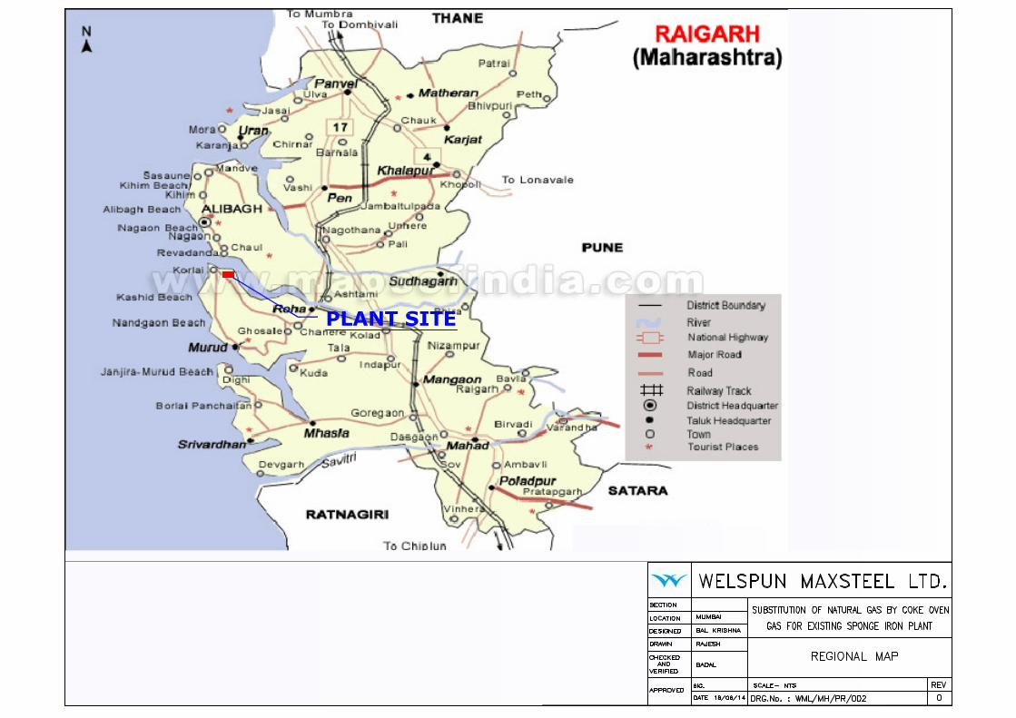
01 Location Map WML/MH/PR/001
02 Regional Map WML/MH/PR/002
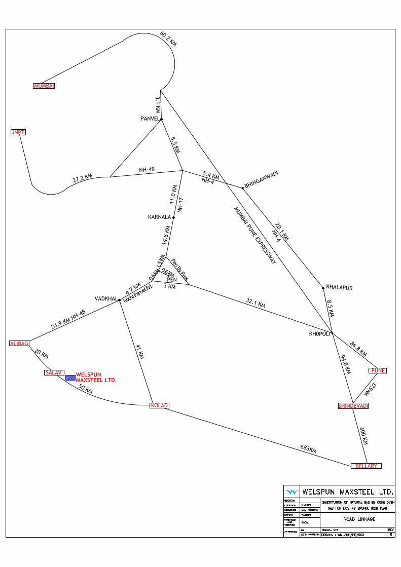
03 Road Linkage WML/MH/PR/003
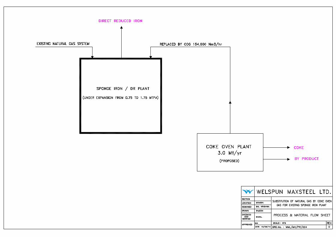
04 Process Flow Sheet WML/MH/PR/004
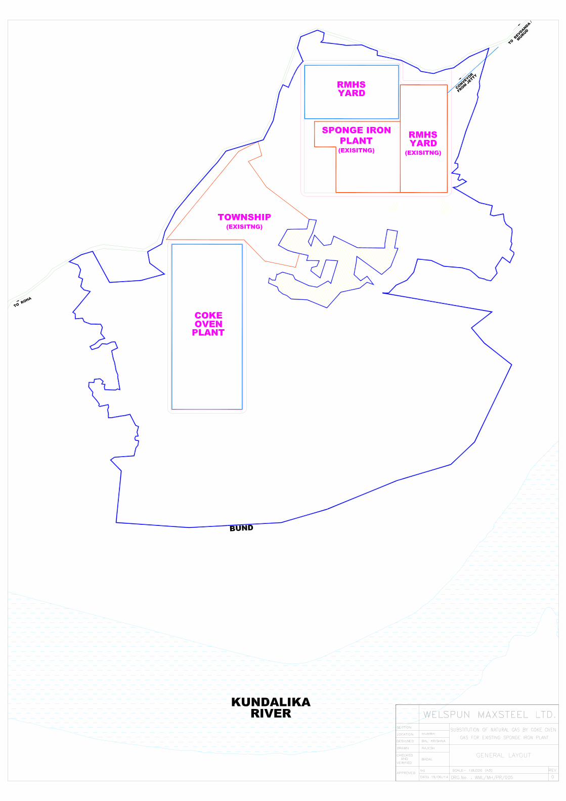
05 General Layout WML/MH/PR/005
06 Implementation Schedule WML/MH/PR/006
Welspun Maxsteel Limited
Maharashtra Substitution of Natural Gas by Coke Oven Gas for Existing Sponge Iron Plant
Project Report
1-1
01 Introduction
01.01 Preamble
The US$ 3.5 billion Welspun Group is one of India’s fastest
growing conglomerates having registered a CAGR of 30% over the
last decade. It has a presence across five business verticals --
Pipes, Plates & Coils; Home Textiles; Steel; Infrastructure; and
Energy. In the first two verticals, it is a fully integrated player.
Welspun is also among the recognised world leaders in the fields
of Line Pipes and Home Textiles. The Group has a strong foothold
in more than 50 Countries, employs over 24,000 people and has
as many as 100,000 shareholders.
The Group has business dealings with companies across the
globe, including a number of marquee clients, covering most of
the Fortune 100 companies in the Oil & Gas and Retail sectors.
Among the group’s subsidiaries is Welspun USA, Welspun Tubular
LLC, Welspun Middle East and Welspun UK.
In the Line Pipe sector, Welspun has to its credit some of the
most prestigious projects including the world’s deepest pipeline
project in the Gulf of Mexico, heaviest pipeline project in the
Persian Gulf, highest LNG pipeline project in Peru and longest
pipeline project from Canada to the US.
Welspun Maxsteel Ltd. was formed on 22nd May, 2009 after
Welspun Steel Ltd. completed the acquisition of Vikram Ispat, the
Sponge Iron division Business of Grasim Industries Ltd. The
facility was set up with design capacity of 0.75 million tons of
Sponge Iron in the form of HBI (Hot Briquetted Iron).
Welspun Maxsteel Limited
Maharashtra Substitution of Natural Gas by Coke Oven Gas for Existing Sponge Iron Plant
Project Report
1-2
Welspun Maxsteel Ltd. takes pride in being the first and the only
one of its kind in the world to produce both HBI and DRI (Direct
Reduced Iron) from the same Reactor" using state of the art
technology “HYL III” from HYLSA of MEXICO and engineering
expertise of Davy Dravo of USA.
Welspun Power and Steel Ltd. signed a MOU with Government of
Maharashtra on 18th August 2009 to invest Rs. 6000 crores for
setting up an Integrated Steel Plant along with a 660 MW Captive
power plant through a Special Purpose Vehicle viz. Welspun
Maxsteel Ltd. at Salav, Taluka Murud, Dist. Raigad falling in C
zone under the package Scheme of Incentives (PSI) 2007 and to
provide direct and indirect employment to 5000 persons in
conformity with the state government’s policy regarding
employment of local persons.
The plant is based on usage of natural gas based process to
produce Sponge Iron. The availability of Natural Gas is becoming
very scarce in India & the prices are also increasing. It is
apprehended that it may no longer be viable to operate this plant
with Natural Gas leading to closure of the plant and loss of
employment of people. Welspun takes pride in serving the
community and hence it is proposed to substitute the Natural Gas
by Coke Oven Gas for producing Sponge Iron from the plant. This
technology is now being developed in steel plants and is becoming
viable for usage in production of Sponge Iron.
Welspun Maxsteel Limited (WML) intends to install a recovery type
coke oven plant for the generation of required Gas for the
production of Sponge Iron. The by-products like coke, benzol,
Welspun Maxsteel Limited
Maharashtra Substitution of Natural Gas by Coke Oven Gas for Existing Sponge Iron Plant
Project Report
1-3
sulphur, BTX shall be recovered and disposed off suitably in the
market.
For this purpose, it is proposed to install a 3 million tons per
annum coke oven plant which will generate about 154,000 Nm3/hr
of coke oven gas having total energy 662 Gcal/hr. Out of 662
Gcal/hr energy about 40% (265 Gcal/hr) would be used internally
in the coke oven plant for battery heating & ammonia cracking
and remaining 60% (397 Gcal/hr) would be used for production of
Sponge Iron/DRI.
MoEF GOI has already granted Environmental Clearance
after following the due processes including Public Hearing
for expanding the plant from 0.75 MTPA to 1.75 MTPA,
with integrated facility of Pellet Plant (4 MTPA), Steel
Plant (1.5 MTPA), Captive Power Plant (330 MW) at
Village Salav, P.O. Revdanda, District Raigad, Maharashtra
vide MOEF letter No. F.No.J-11011/183/2008-IA.II (I)
dated 27th January 2011.
Since this application is for substitution of Natural Gas by
Coke Oven Gas only, it is requested that fresh public
hearing may not be mandated.
The capital investment for the proposed gas generation coke oven
plant will be about Rs. 3000 crores.
The project has been envisaged keeping in view the substitution
of scarce & inconsistently available Natural Gas by Coke Oven gas.
The proposed plant shall have positive impact on socio-economic
development of the area along with further employment of people
by expanding the plant operation.
Welspun Maxsteel Limited
Maharashtra Substitution of Natural Gas by Coke Oven Gas for Existing Sponge Iron Plant
Project Report
2-1
02 Major Technological Facilities 02.01 General
The project envisages installation of a 3.0 Mt/yr coke oven plant
to generate 154,000 Nm3/hr of coke oven gas along with coke and
by-products at Salav village in Raigad district of Maharashtra. The
process flow sheet and general layout of proposed project is
shown in Drg. No. WML/MH/PR/004 & WML/MH/PR/005
respectively.
02.02 Process Chemistry
The Sponge Iron/DRI process converts iron oxide lump ore,
pellets, or pellet/lump mixtures into highly metalized Iron in the
form of direct reduced iron which is an ideal feed material for high
quality steel making.
02.02.01 Iron Oxide Reduction
Most naturally occurring iron oxide has the chemical composition
of haematite, Fe2O3 and contains about 30 percent oxygen by
weight. In this process, the chemically bonded oxygen in the iron
ore is removed by high temperature reduction reactions with CO
and H2 to produce metallic Fe. The CO2 and H2O are byproducts
produced by the iron ore reduction reactions. The overall
reduction reactions are :
Fe2O3 + 3H2 = 2Fe + 3H2O
Fe2O3 + 3CO = 2Fe + 3CO2

Welspun Maxsteel Limited
Maharashtra Substitution of Natural Gas by Coke Oven Gas for Existing Sponge Iron Plant
Project Report
2-2
An important property of the reduction gas is the reductant
/Oxidant ratio or “gas quality”. The gas quality is a measure of
potential for the gas to reduce iron oxide. The gas quality is
defined as the ratio of reductants to oxidants contained in the gas :
Gas quality = reductant / oxidant ratio
= (%H2 + %CO) / (%H2O + %CO2)
It is found that the optimum gas quality for hot reducing gas
entering the shaft furnace should be 9 or higher. Also, to obtain
essentially complete reduction, the quality of the spent reducing
gas exiting the shaft furnace should be at least 2.
Another important property of the reducing gas is the H2/CO ratio.
Control of the H2/CO ratio results in thermally balanced reduction
reactions since reduction with CO is exothermic, and reduction
with H2 is endothermic. That is, the heat required by the H2
reaction is balanced by the heat supplied by the CO reaction. So,
proper reduction temperatures are easily maintained.
The incoming COG (Coke Oven Gas) contains the reductant (CO
and H2) source of the reduction reactions in the shaft furnace.
Besides containing the reductants, COG also contains
approximately 25% CH4. In order to eliminate the impurities in the
COG and reform CH4 into additional reductants, the COG is
injected into the Thermal Reactor System (TRS) to create a
syngas which contains approximately 1% CH4.
Spent reducing gas exiting the shaft furnace is cleaned,
compressed, mixed with the TRS syngas system and cooled in the
process gas aftercooler to remove excess heat and water vapour.
Welspun Maxsteel Limited
Maharashtra Substitution of Natural Gas by Coke Oven Gas for Existing Sponge Iron Plant
Project Report
2-3
The gas stream, called rich process gas continues on to the CO2
removal system which strips the CO2 and H2S. The gas exiting the
CO2 removal system is called the lean process gas. The lean gas
and the bypass stream of the TRS syngas are mixed together and
sent to the feed gas mist eliminator for mist removal to achieve
minimum H2S levels to inhibit metal dusting. With this, the
majority of the sulphur compounds in the syngas is stripped in the
CO2 removal system and is not absorbed by DRI. The feed gas
stream from the feed gas mist eliminator contains 3-4% CH4. CH4
content in the reducing gas stream is an important control
parameter in this process. After heating in the reducing gas
heater, a small amount of O2 is added in the reducing gas stream
inducing a exothermic reaction to obtain the proper energy for the
reactions in the furnace.
The specific reducing gas consumption and gas quality also affect
the DRI metallization. The degree of metallization is a
quantitative means of determining the amount of O2 removed
from the iron oxide during the reduction reactions.
% Metallization = (% Metallic Fe / % Total Fe) x 100
The plant production capacity is based on the degree of
metallization and is about 93 - 94%.
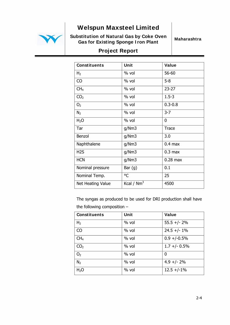
The clean Coke oven gas proposed to be used in the production of
DRI plant shall have the below composition –
Welspun Maxsteel Limited
Maharashtra Substitution of Natural Gas by Coke Oven Gas for Existing Sponge Iron Plant
Project Report
2-4
Constituents Unit Value
H2 % vol 56-60
CO % vol 5-8
CH4 % vol 23-27
CO2 % vol 1.5-3
O2 % vol 0.3-0.8
N2 % vol 3-7
H2O % vol 0
Tar g/Nm3 Trace
Benzol g/Nm3 3.0
Naphthalene g/Nm3 0.4 max
H2S g/Nm3 0.3 max
HCN g/Nm3 0.28 max
Nominal pressure Bar (g) 0.1
Nominal Temp. °C 25
Net Heating Value Kcal / Nm3 4500
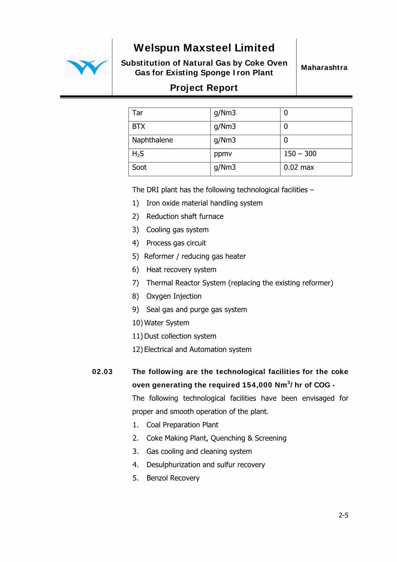
The syngas as produced to be used for DRI production shall have
the following composition –
Constituents Unit Value
H2 % vol 55.5 +/- 2%
CO % vol 24.5 +/- 1%
CH4 % vol 0.9 +/-0.5%
CO2 % vol 1.7 +/- 0.5%
O2 % vol 0
N2 % vol 4.9 +/- 2%
H2O % vol 12.5 +/-1%
Welspun Maxsteel Limited
Maharashtra Substitution of Natural Gas by Coke Oven Gas for Existing Sponge Iron Plant
Project Report
2-5
Tar g/Nm3 0
BTX g/Nm3 0
Naphthalene g/Nm3 0
H2S ppmv 150 – 300
Soot g/Nm3 0.02 max
The DRI plant has the following technological facilities –
1) Iron oxide material handling system
2) Reduction shaft furnace
3) Cooling gas system
4) Process gas circuit
5) Reformer / reducing gas heater
6) Heat recovery system
7) Thermal Reactor System (replacing the existing reformer)
8) Oxygen Injection
9) Seal gas and purge gas system
10) Water System
11) Dust collection system
12) Electrical and Automation system
02.03 The following are the technological facilities for the coke
oven generating the required 154,000 Nm3/hr of COG -
The following technological facilities have been envisaged for
proper and smooth operation of the plant.
1. Coal Preparation Plant
2. Coke Making Plant, Quenching & Screening
3. Gas cooling and cleaning system
4. Desulphurization and sulfur recovery
5. Benzol Recovery
Welspun Maxsteel Limited
Maharashtra Substitution of Natural Gas by Coke Oven Gas for Existing Sponge Iron Plant
Project Report
2-6
6. Ammonia scrubbing and distillation
7. Ammonia cracking unit
8. De-dusting
9. Gas holder & Booster station
10. Effluent treatment plant
02.04 Coal Preparation Plant
The coal preparation plant has been envisaged to cater to a daily
average wet coal through put of about 11900 t/day.
The coking coals from the overseas sources will be imported and
will be transported upto the captive jetty by barges. The coals
unloaded at the jetty will be transferred to plant coal storage yard
by belt conveying systems.
Coal storage yard at the coke oven plant has been envisaged for
storage of incoming coking coals. Coal received through conveyor
will transfer the coal to a stacker cum reclaimer machine for
forming stock piles according to the grades of coal. Different
grades of coal will be stored separately. Transfer of coking coal to
the stockpiles will be done by a rail mounted wheel-on-boom
stacker cum reclaimer. The stacking operation, if necessary, can
be performed in all three shift to match the coal receipt pattern at
the plant site.
The coal preparation unit will consist of coal crushing and
blending facilities.
Reclaimed coals of size ≤ 80 mm from the storage yard will be
crushed to < 3 mm not less than 80 %, in the primary crusher,
Welspun Maxsteel Limited
Maharashtra Substitution of Natural Gas by Coke Oven Gas for Existing Sponge Iron Plant
Project Report
2-7
delivered to the coal silos, one variety at a time, through a system
of conveyors. 12 Nos. bins with each capacity of 1000 tons and 4
Nos. coal surge bins with each capacity of 1000 tons will be
provided near the storage yard for storing of different types of
coals. Each constituent of the blend will be drawn in requisite
proportion from different bunkers to the secondary coal crushing
station.
In the secondary crushing station, blended coal will be crushed to
90% below 3 mm in reversible compact jump hammer crushers.
Coals after crushing will be conveyed to the mixer for full mixing
of different coals in order to ensure the complete mixing of each
type of blended coal to enhance the coke quality.
After the mixing section the coal blend is fed to coal blend
bunkers. Each concrete bunker has capacity to sustain 8 hours of
operation of coke oven batteries. Proportioning of coal blend from
both bunkers is performed by continuous action proportioning
devices. The adjustment for the preset capacity and capacity
control of the proportioning devices is performed by the coal
handling plant operator from the control room.
Downstream of the coal blend bunkers, there are conveyor
systems for coal blend supply to the stamping machine.
02.05 Coke Making Plant
4x62 nos. of stamp charged recovery type coke ovens will be
constructed with a total annual dry coke production, of around
3,000,000 tonnes.

Welspun Maxsteel Limited
Maharashtra Substitution of Natural Gas by Coke Oven Gas for Existing Sponge Iron Plant
Project Report
2-8
Coal from the coal preparation workshop is conveyed to the coal
stamping machine through the belt conveyor. The coal delivered
by the conveyors is sent from the feeding system of Stamping
Charging Pushing (SCP) machine into the coal hopper which is
located on the SCP machine. The coal is then delivered into
stamping box via plate type feeders, and stamped by the
stamping machines into coal cake. The stamped coal cake is
charged into the coking chamber from the coal side. The coal cake
is carbonized at a certain temperature, and after ~24 hours coke
is pushed into the bucket car by coke pusher via the coke guiding
gate. The bucket car then takes the hot coke to CDQ for dry
quenching. Afterwards the cooled coke will be discharged into belt
conveyor which goes to the coke screening system. In case of wet
quenching, the coke will be taken by the coke quenching car to
the coke-cooling wharf wherein it is discharged by the coke
scraper onto the belt conveyor and then taken to the coke
handling system.
The raw coke oven gas produced during carbonization goes
through the top of coking chamber, the ascending pipe, and the
bridge pipe, to the gas collecting main. The gas is cooled by
spraying liquor ammonia at ~78 under ~0.3MPa pressure at the
bridge pipe and gas collector, so that it is cooled from ~700 to
~84 ; then, it is sucked through the suction elbow and suction
pipe to the condensing/blowing unit. The tar and ammonia
condensed in the gas collecting main flow via the tar box and
suction main to the condensing/blowing unit.
Welspun Maxsteel Limited
Maharashtra Substitution of Natural Gas by Coke Oven Gas for Existing Sponge Iron Plant
Project Report
2-9
The heating gas (mixture of coke oven gas and blast furnace gas)
is sent through the external pipe to the coke oven. The combined
gas goes into the regeneration chamber and at the same time the
air goes into regeneration chamber via waste gas shut-on-off
device for air. After being pre-heated, the gas combined with air
goes into the vertical flue of combustion chamber. The flame is
elongated by the circulation of partial waste gas which makes the
heating in the top more even. The standard heating temperature
is 1300~1320 .
The waste gas, after combustion, goes runs through the top of
the vertical flue and then into the vertical flue with downward air
flow, via the regeneration chamber for partial heat recovery and
finally is discharged into the atmosphere from the chimney.
During coal charging, the possibly collapsed coal cake at the coal
side will be cleaned into the belt conveyor located under the
operation platform, and then delivered into the coal bin for
storage and transported by vehicles.
The fumes and dust which is produced during coal charging will
go via the gas transfer car into the adjacent coking chamber. The
dust collecting hood as well as gas collecting main will be set up
above the oven door on the coal side, which will capture the fume
dust escaping from the oven door during the coal charging and
send them into the ground de-dusting station. The fume and dust
generated from coke pushing will be guided via the coke guiding
car and dust collecting main into the ground de-dusting station for
treatment and discharging.

Welspun Maxsteel Limited
Maharashtra Substitution of Natural Gas by Coke Oven Gas for Existing Sponge Iron Plant
Project Report
2-10
The major structural dimensions and process indexes of the coke
oven are given below:
(1) The major structural dimensions of coke oven are as follows:
Total length of coking chamber: 17000 mm
Effective length of coking chamber: 16140 mm
Total height of coking chamber: 6300 mm
Effective height of coking chamber 5900 mm
Average width of coking chamber: 525 mm
Center distance of coking chamber: 1450 mm
Taper of coking chamber: 30 mm
Center distance of vertical flue: 480 mm
Number of vertical flues: 34
Thickness of combustion chamber wall: 100mm
(2) Major technical indexes of coking process:
Number of coke oven ports: 4×62 ovens
Dimensions of coal cake: L×W×H 16150/15950×480×5900 mm
Density of coal cake (Dry) 1.00 t/m3
Dry coal capacity of coking chamber 45.45 t
Cycle time of coke oven 24 hr
Yield ratio of dry CO gas 315 Nm3/t (dry coal)
Annual consumption of dry coal 4,285,000 t
Annual yield of dry coke 3,000,000 t
Temperature of raw coke oven gas from gas collector:~84°C
Pressure of raw coke oven gas from gas collector: 80~120Pa
02.06 Gas cooling and cleaning system
The section includes coal gas condensing, cooling, and pressurized
convey, separation, storage and convey of tar, ammonia, and tar
Welspun Maxsteel Limited
Maharashtra Substitution of Natural Gas by Coke Oven Gas for Existing Sponge Iron Plant
Project Report
2-11
slag, precipitation of tar fog drops and naphthalene in coal gas,
and cleaning of tail gas.
The mixture of tar, ammonia, and coal gas from coking section
enters into the gas-liquid separators at about 80°C, where the tar
and ammonia are separated from the coal gas. The raw coal gas
enters into the transverse pipe PGCs where coal gas is cooled.
The cooled coal gas enters into the electro tar precipitators to
precipitate tar fog drops and naphthalene from the coal gas; after
electric tar precipitation, the coal gas enters into the centrifugal
exhauster and is pressurized, and then sent to the
desulphurization section.
02.07 Desulphurization and sulfur recovery
Coke oven gas (at 45 ) coming from condensing-blowing section
first enters final cooling tower. The gas in final cooling tower is in
counter-current contact with the circulating cooling water sprayed
from the tower top and is cooled to 23 , then enters H2S
washing tower to remove H2S. The cooling water flowing out from
bottom of final cooling tower is pumped to the final cooling water
heat-exchanger and cooled to 210C and enters final cooling tower
for circulating and spray.
The cooled gas is cleaned of most of the H2S by passing through
the H2S washing tower with ammonia water. The clean gas is
discharged from the top of H2S washing tower and enters the
bottom of ammonia washing tower for ammonia removing.
Welspun Maxsteel Limited
Maharashtra Substitution of Natural Gas by Coke Oven Gas for Existing Sponge Iron Plant
Project Report
2-12
The gas entering from the bottom of the ammonia washing tower
is cleaned out of the ammonia and some hydrogen sulfide with
semi rich ammonia water from second ammonia washing tower.
The gas is then discharged from the top of the first ammonia
washing tower and then enters alkaline washing section at the
bottom of the second ammonia washing tower. At the alkaline
washing section, the gas is washed by NaOH solution to remove
most of the H2S.
The distilled Coke Oven gas is led from top of the de-acidification
tower to Claus Furnace for sulfur recovery.
The ammonia from ammonia distilling tower, enters ammonia
cracking furnace where it is cracked into N2 and H2.
About 1100 high temperature tail gas produced from ammonia
decomposition furnace is cooled to 300 though waste heat
boiler and 0.5MPa (G) steam is produced, and then the tail gas
passes through the boiler water per-heater again and cracker gas
cooler to be cooled to 80 .
The high temperature process gas discharged from bottom of
Claus Furnace is cooled through waste heat boiler, and the heat
recovered from the waste heat boiler is used to produce the
0.7MPa saturated steam. The process gas existing the waste heat
boiler still has H2S and SO2, and then conversion reaction is
carried out further in Claus Furnace. This process consists of
reactor with two sections and after each section of the reactor
there is set up the sulfur condenser and molten sulfur catcher. The
molten sulfur flows into the molten sulfur sealing tank and then

Welspun Maxsteel Limited
Maharashtra Substitution of Natural Gas by Coke Oven Gas for Existing Sponge Iron Plant
Project Report
2-13
into the molten sulfur storage tank. The tail gas is directed to the
chimney.
The molten sulfur stored in sulfur pool is pumped regularly with
submerged pump to sulfur slicer and cooled, formed and packed.
02.08 Benzol Recovery
This unit recovers Benzol from the coke oven gas. It includes two
section viz. benzol scrubbing and benzol recovery.
Benzol scrubbing uses scrubbing oil (either wash oil or Solar oil) to
absorb the benzol in the coke oven gas, and afterward the gas is
sent to the consumers. After benzol scrubbing, the benzol
contents in gas reduces to 2~5 g/Nm3.
The Benzol Recovery Plant will consists of three sections -
1. Cooling section
2. Benzol scrubbing
3. Benzol recovery
Benzol Hydro-Refining Unit
Benzol-hydro-refining unit will utilize the crude benzol as raw
material and remove the harmful impurities such as hydrocarbon,
hydrogen sulfide, ammonia and water etc containing the sulfur,
nitrogen, oxygen through chemical and physic methods, in order
to get high pure benzene, toluene, xylene.
The following are the process unit steps –
1. Deoctaniser
2. Hydrogenation
3. Stabiliser
4. Deheptaniser

Welspun Maxsteel Limited
Maharashtra Substitution of Natural Gas by Coke Oven Gas for Existing Sponge Iron Plant
Project Report
2-14
5. Recycle gas treating
6. Absorption section
7. Aromatic extraction
8. Aromatic Post fractionation
9. Hydrogen production unit
02.09 De-dusting system
“U” type gas transferring is arranged with high pressure ammonia
liquid spraying for the charging de-dusting, and the ground de-
dusing station is arranged for de-dusting purpose.
02.10 Gas holder & Booster station
The gas holder in this section is a 50000 m3 dry gas holder for gas
buffering and storage; the gas is boostered with Roots blowers.
The main purpose of the section is to even out the fluctuations in
production of gas and uneven gas consumption. The gas stored in
the gas holder is also used as a buffer to handle short-time
operation break-downs.

Welspun Maxsteel Limited
Maharashtra Substitution of Natural Gas by Coke Oven Gas for Existing Sponge Iron Plant
Project Report
3-1
03 Raw Materials & Finished Products 03.01 Raw Materials
The coke making facilities are planned to generate 154,000
Nm3/hr of coke oven gas to be used for Sponge Iron/DRI
production along with by-products viz 3,000,000 tonnes of gross
coke per year & chemicals. It is proposed to use 100% imported
coal, of different qualities and blend it suitably.
The proposed coke oven plant is designed based on use of low
ash imported coal in the coal blend to produce about 3,000,000
tonnes of gross coke per year. For the purpose of this report
following blend composition has been assumed by the technology
supplier
Coal Blend
- Coking coal - 70%
- Semi-soft coal - 10%
- Medium coal - 20%
The net and dry annual requirements of various raw materials and
their sources are given in table-03.01 for 3.0 Mtpa Coke Oven
Plant.
Table-03.01
Annual raw material (net and dry basis) Requirements:
Sl. No. Raw material Unit Quantity t/yr
Source
1 Imported Coking Coal t/yr 4,285,000 Imported
2 42% NaOH t/yr 6,272 Local

Welspun Maxsteel Limited
Maharashtra Substitution of Natural Gas by Coke Oven Gas for Existing Sponge Iron Plant
Project Report
3-2
3. Ni Catalyst m3/3-yr 90 Local
4. Wash Oil t/yr 3079 Local
03.01.01 Coal Availability of low ash coking coal of desired quality in this country
is limited. Hence, it has been envisaged that total requirement of
metallurgical coal 4,285,000 t/yr for the proposed coke oven plant
will be met through imports, as given in Table 03.02 and 03.03..
Table-03.02
Tentative quality of imported coal blend:
Sl. No. Quality parameters Unit Value 1 Size mm 0 to 50 2 Ash % 9.0 – 9.5 (max.) 3 VM % 24 to 26 4 Moisture % 8 to 10 5 Sulphur % 1.2 (max.) 6 Phosphorous % 0.06 (max.) 7 Grey king coke type - G 5 (min.) 8 Crucible swelling No. 6.5 (min.) 9 Mean max. reflectance (R0 max) - 1.10 to 1.30 10 Gieseler fluidity ddpm 600-2000
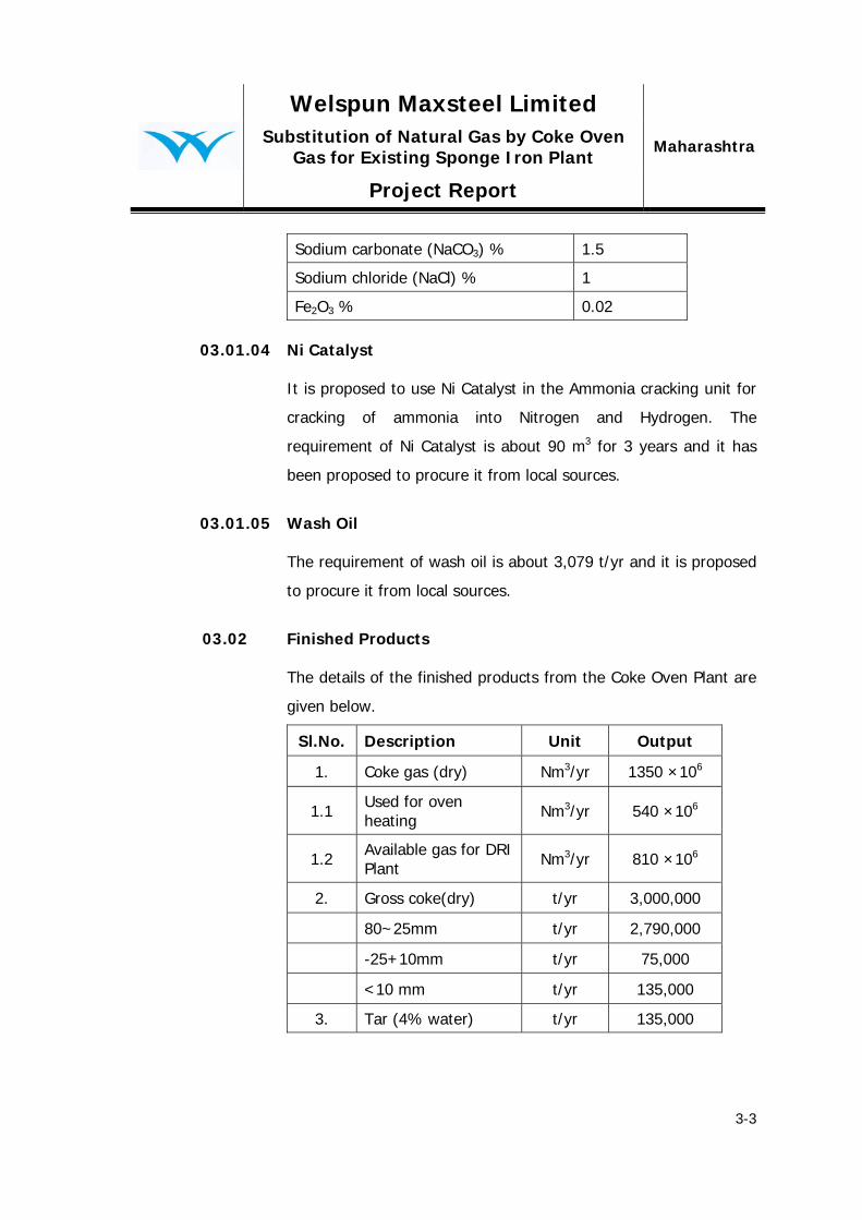
03.01.02 Sodium Hydroxide (NaOH)
It is proposed to use Sodium Hydroxide (42% NaOH) alkali
solution in the ammonia distillation tower. The requirement of
Sodium Hydroxide is about 6,272 t/yr. The typical quality is given
below :
Description Value
Sodium hydroxide (NaOH) % 42
Welspun Maxsteel Limited
Maharashtra Substitution of Natural Gas by Coke Oven Gas for Existing Sponge Iron Plant
Project Report
3-3
Sodium carbonate (NaCO3) % 1.5
Sodium chloride (NaCl) % 1
Fe2O3 % 0.02
03.01.04 Ni Catalyst It is proposed to use Ni Catalyst in the Ammonia cracking unit for
cracking of ammonia into Nitrogen and Hydrogen. The
requirement of Ni Catalyst is about 90 m3 for 3 years and it has
been proposed to procure it from local sources.
03.01.05 Wash Oil
The requirement of wash oil is about 3,079 t/yr and it is proposed
to procure it from local sources.
03.02 Finished Products The details of the finished products from the Coke Oven Plant are
given below.
Sl.No. Description Unit Output
1. Coke gas (dry) Nm3/yr 1350 ×106
1.1 Used for oven heating Nm3/yr 540 ×106
1.2 Available gas for DRI Plant Nm3/yr 810 ×106
2. Gross coke(dry) t/yr 3,000,000
80~25mm t/yr 2,790,000
-25+10mm t/yr 75,000
<10 mm t/yr 135,000
3. Tar (4% water) t/yr 135,000

Welspun Maxsteel Limited
Maharashtra Substitution of Natural Gas by Coke Oven Gas for Existing Sponge Iron Plant
Project Report
3-4
Sl.No. Description Unit Output
4. Sulphur t/yr 9,200
5. Crude Benzol t/yr 42,000
6. Benzene t/yr 29,500
7. Toluene t/yr 5,500
8. Xylene t/yr 1,500
9. Raffinates t/yr 5,500
03.02.01 Product Quality
Cleaned Coke Oven gas
Impurities Unit Quantity
Ammonia g/Nm3 0.05
Hydrogen sulphide g/Nm3 0.5
HCN g/Nm3 0.3
Benzol g/Nm3 2-5
Naphthalene g/Nm3 0.2
tar g/Nm3 0.01
Coke
Coke specifications (Tentative)
Sl. No. Quality parameters Value 1 Ash 12 % (max.) 2 VM 1.0 % (max.) 3 M10 8.0 (max.) 4 CSR 64 (min.) 5 Moisture 4 % (max.)

Welspun Maxsteel Limited
Maharashtra Substitution of Natural Gas by Coke Oven Gas for Existing Sponge Iron Plant
Project Report
4-1
04 Proposed Site
04.01 Site Location The 3.0 Mtpa Coke Oven Plant is proposed to be set up within the
existing sponge iron plant of M/s Welspun Maxsteel Ltd. The
existing sponge iron plant is situated in Salav village of Raigad
district in the state of Maharashtra. The site is at a distance of 150
km from Mumbai, and about 45 km from Roha by Road. The
location map and the regional map of the proposed site have been
shown in the drawing no. WML/MH/PR/001 and drawing no.
WML/MH/PR/002 respectively.
The indicative coordinates of the proposed site are given below:
Latitudes : 18°31’1” - 18°32’2.5” N Longitudes : 72°56’39” - 72°57’54” E
04.02 Area Requirement
04.02.01 General
The area requirement for the proposed plant has been estimated
based on the following factors:
Area requirements of individual technological and service
facilities
Smooth and uninterrupted flow of incoming and outgoing materials with minimum counterflow for different technological facilities.
Logistics in location of technological units as well as services
facilities.
Safety requirements and statutory provisions.

Welspun Maxsteel Limited
Maharashtra Substitution of Natural Gas by Coke Oven Gas for Existing Sponge Iron Plant
Project Report
4-2
Adequate green belt all around the plant.
Optimum lead for service lines.
Maximum utilization of the land.
Logistic approach in location of technological units as well as services with assumption that area is flat.
Space for storage of incoming coking coal of three varieties.
04.02.02 Estimated area
The area requirement for the proposed plant has been minimized
since the infrastructure and auxiliary facilities are already existing.
Special attention has been made to provide connectivity to the
existing facilities viz. utilities, raw material corridors, finished
product corridors etc.
The total area required is estimated to be approximately 80 acres.
04.03 Proposed Site
The company already has land in its possession for its existing
sponge iron plant complex. The proposed coke oven plant is
proposed to be setup within the existing area and no additional
land is to be acquired.
04.04 Logistics
The total coking coal required for the coke Oven Complex are
imported and would be handled by the existing port.
04.04.01 Road
The National Highway NH-17 (Mumbai-Goa) passes on the east
side about 50 km from the plant. State Highway also passes on

Welspun Maxsteel Limited
Maharashtra Substitution of Natural Gas by Coke Oven Gas for Existing Sponge Iron Plant
Project Report
4-3
the west side of the plant. The Mumbai city is located at about
150 km on the North-West side of the plant.
The Road linkage of the proposed site is shown in Drg. No.
WML/MH/PR/003.
04.04.02 Railways
The nearest railway station Roha is about 50 km from the plant
site and is located in the east on the Konkan Railway Mumbai -
Mangalore main line. Rail linkage from plant site has to be
strengthen.
04.04.04 Air Connectivity
The nearest Mumbai airport is 150 km away from site connected
through major road. The proposed Navi Mumbai International
airport is 90 km away from plant site.
04.05 Water
The make up water requirement for the proposed plant
generating 154,000 Nm3/hr gas at 3 million tons per year coke
production level, as estimated, will be about 690 cum/hour (16.5
MLD).
04.06 Power
The estimated power requirement of the coke oven plant will be
about 45 MW.
Welspun Maxsteel Limited
Maharashtra Substitution of Natural Gas by Coke Oven Gas for Existing Sponge Iron Plant
Project Report
5-1
05 Services, Utilities and Manpower Requirement 05.01 General
The estimated power requirement of the recovery type coke oven
plant will be about 45 MW and will be sourced from captive
sources. The nearest grid of Maharashtra State Electricity Board
may be utilised in case of short fall.
05.02 Power
The estimated power requirement is about 45 MW.
05.03 Water System
The fresh water requirement for the proposed coke oven project
shall be about 690 m3/hr (16.5 MLD).
Water supply is classified into domestic water supply system,
production and fire fighting water supply system, multi-use water
system and circulating water system.
05.04 Compressed Air Station
A captive compressed air station would be established for the
proposed plant.
05.05 Plant Automation
The controlling system is proposed to be of distributed controlling
type. The system generally is based on EIC integrated structure in
which the PLC and DCS is taken as controlling core functioning
with data collecting, procedure controlling, process controlling,
parameter indicating, over-limit alarming, equipment running
status display, data storage, production data printout, which
Welspun Maxsteel Limited
Maharashtra Substitution of Natural Gas by Coke Oven Gas for Existing Sponge Iron Plant
Project Report
5-2
combines production management with process control thus
constitute a safe, high efficient and opened controlling system.
One PLC is additionally arranged for pressure regulating of gas
collecting main, while the PLC each for coke oven machinery
control, oven machinery auto-positioning system, hydraulic
exchange system and ground de-dusting station is supplied
together the mechanical equipment. Level 1 system adopts Client-
Based network structure and provides the interfacing provision
with Level 2 system in the future.
05.06 Communication System
Telephone system will be provided for communication inside as
well as outside the plant. Telephone system shall comprise one
Electronics Private Automation Branch Exchange (EPABX) of
required line capacity and associated cable network along with
Press-to-talk system, CCTV, VHF wireless system as required.
05.07 Repair And Maintenance Facilities
The existing sponge iron plant repair and maintenance facilities
will take care of routine repair and periodical maintenance work of
the coke oven plant. Major repairing works involving machining,
fabrication and assembly of heavy and critical jobs of specialized
nature are envisaged to be contracted to outside agencies.
05.08 Warehouse
A existing central warehouse will keep spares of equipment, hard-
wares and consumables of the proposed coke oven project.
Welspun Maxsteel Limited
Maharashtra Substitution of Natural Gas by Coke Oven Gas for Existing Sponge Iron Plant
Project Report
5-3
For storing various refractories, separate buildings have been
envisaged. Refractories will be received in pallets and in bags.
05.09 Ancillary Facilities
Necessary ancillary facilities such as administrative building,
canteen, car park, cycle and scooter stand, first-aid station etc.
shall be provided based on the manpower requirement for the
plant.
05.10 Drainage And Sewerage System
Open type drain has been envisaged for the plant storm water
drainage. The drains will be laid generally by the side of the
roads. Storm water run-off, collected through arterial and trunk
drain, will be discharged suitably for minimum pollution.
Plant drainage
This drainage system is classified into domestic & Production
drainage system and production clean sewage drainage system.
The effluent from the sewage treatment plant will be utilized for
the development and maintenance of greenery.
05.11 Roads
Adequate plant road system will be provided. The road system will
be integrated with the existing roads.
05.12 Manpower Requirement
The proposed plant will not only require management and
executive manpower but also, skilled, semi-skilled, unskilled and
Welspun Maxsteel Limited
Maharashtra Substitution of Natural Gas by Coke Oven Gas for Existing Sponge Iron Plant
Project Report
5-4
clerical manpower. However, a number of jobs like major repair
and maintenance, cleaning, transportation and loading/unloading
of bulk materials, etc. will be done by engaging out side agencies.
The total manpower requirement is estimated at 450 persons.
Welspun Maxsteel Limited
Maharashtra Substitution of Natural Gas by Coke Oven Gas for Existing Sponge Iron Plant
Project Report
6-1
06 Environmental Management
06.01 The proposed plant would result in air, water and land pollution of
varying nature and degree. This chapter briefly outlines the nature
and sources of pollution and also suggests broad environmental
protection measures to be adopted for limiting pollution within
permissible levels.
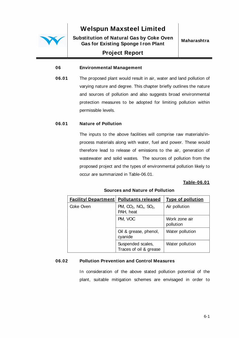
06.01 Nature of Pollution
The inputs to the above facilities will comprise raw materials/in-
process materials along with water, fuel and power. These would
therefore lead to release of emissions to the air, generation of
wastewater and solid wastes. The sources of pollution from the
proposed project and the types of environmental pollution likely to
occur are summarized in Table-06.01.
Table-06.01
Sources and Nature of Pollution
Facility/Department Pollutants released Type of pollution
Coke Oven PM, CO2, NOx, SO2, PAH, heat
Air pollution
PM, VOC Work zone air pollution
Oil & grease, phenol, cyanide
Water pollution
Suspended scales, Traces of oil & grease
Water pollution
06.02 Pollution Prevention and Control Measures
In consideration of the above stated pollution potential of the
plant, suitable mitigation schemes are envisaged in order to
Welspun Maxsteel Limited
Maharashtra Substitution of Natural Gas by Coke Oven Gas for Existing Sponge Iron Plant
Project Report
6-2
control environmental pollution within the permissible norms and
keep the environment fairly clean.
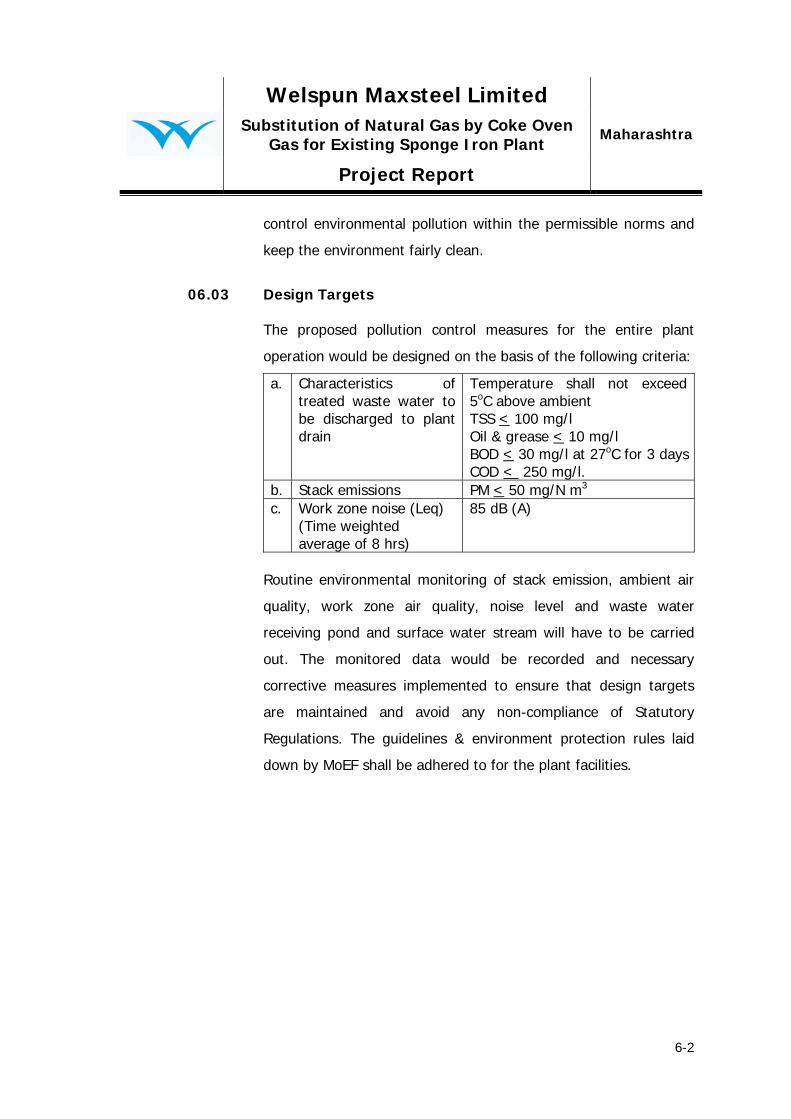
06.03 Design Targets
The proposed pollution control measures for the entire plant
operation would be designed on the basis of the following criteria:
a. Characteristics of treated waste water to be discharged to plant drain
Temperature shall not exceed 5oC above ambient TSS < 100 mg/l Oil & grease < 10 mg/l BOD < 30 mg/l at 27oC for 3 daysCOD < 250 mg/l.
b. Stack emissions PM < 50 mg/N m3 c. Work zone noise (Leq)
(Time weighted average of 8 hrs)
85 dB (A)
Routine environmental monitoring of stack emission, ambient air
quality, work zone air quality, noise level and waste water
receiving pond and surface water stream will have to be carried
out. The monitored data would be recorded and necessary
corrective measures implemented to ensure that design targets
are maintained and avoid any non-compliance of Statutory
Regulations. The guidelines & environment protection rules laid
down by MoEF shall be adhered to for the plant facilities.

Welspun Maxsteel Limited
Maharashtra Substitution of Natural Gas by Coke Oven Gas for Existing Sponge Iron Plant
Project Report
7-1
07 Project Implementation 07.01 General
Implementation of a modern Coke Oven Plant which generates
coke oven gas is a challenging task and calls for meticulous
planning, scheduling and monitoring to realize the project goals in
budgeted time frame. The time schedule for installation of Coke
Oven Plant will depend to a large extent upon completion of pre-
project activities; methodology adopted in procurement of plant &
equipment, engineering, construction and erection activities at
site. The extent of import component of plant & equipment,
availability of infrastructural facilities at site as well as efficient
project management and monitoring also play an important role in
determining the time frame requirement for the project.
07.02 Schedule
The implementation schedule for installation of the proposed Plant
is indicated in the form of bar chart in the drawing no.
WML/MH/PR/006. The overall schedule shows that from the date
of start of the project (Zero date), the first pushing of the coke
oven plant will be commissioned in 22 months and the
commissioning of By-Product plant will be in 25 months. The
schedule as presented is based upon conventional project
implementation logics for coke oven plant, preliminary vendor
information available and in-house analysis.
07.03 Zero Date
The date of start of project activities has been assumed as “zero
date” for installation of the proposed plant.

Welspun Maxsteel Limited
Maharashtra Substitution of Natural Gas by Coke Oven Gas for Existing Sponge Iron Plant
Project Report
8-1
08 Block Capital Cost
The estimated block capital cost outlay for the project is about Rs.
3,000 crores.

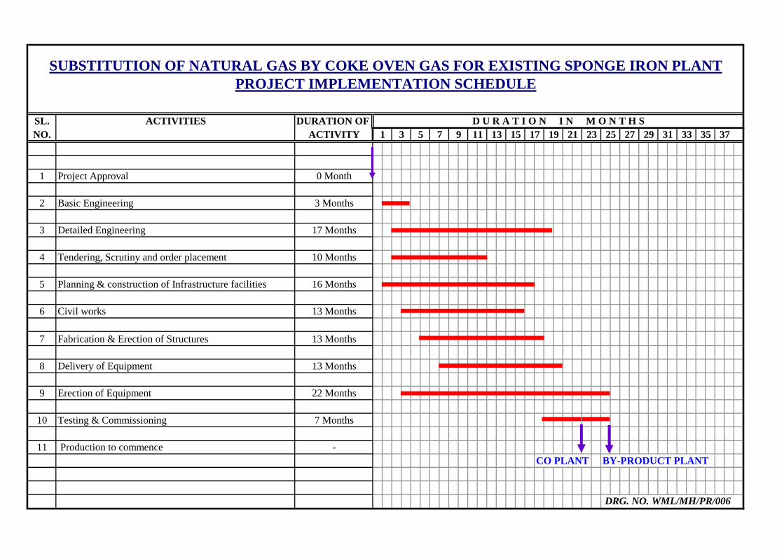
SL. ACTIVITIES DURATION OF NO. ACTIVITY
1 Project Approval 0 Month
2 Basic Engineering 3 Months
3 Detailed Engineering 17 Months
4 Tendering, Scrutiny and order placement 10 Months
5 Planning & construction of Infrastructure facilities 16 Months
6 Civil works 13 Months
7 Fabrication & Erection of Structures 13 Months
8 Delivery of Equipment 13 Months
9 Erection of Equipment 22 Months
10 Testing & Commissioning 7 Months
11 Production to commence -CO PLANT BY-PRODUCT PLANT
3 5 7 27 3723
SUBSTITUTION OF NATURAL GAS BY COKE OVEN GAS FOR EXISTING SPONGE IRON PLANTPROJECT IMPLEMENTATION SCHEDULE
D U R A T I O N I N M O N T H S33 35251 319 11
DRG. NO. WML/MH/PR/006
13 15 2917 19 21


