Embed Size (px)
Citation preview

1
CHAPTER 1
INTRODUCTION
1.1 GENERAL
Shell structures find application in many fields of engineering, notably civil,
mechanical and aeronautical disciplines. In the past 100 years, considerable effort
has been expended on the development of rigorous theories both general and
specialist-to describe the behavior of shells in the elastic range as realistically as
possible.
1.2 BEHAVIOUR OF SHELL
1.2.1 Membrane Behaviour of Shell
The membrane behavior of shell structures refers to the general state of stress
in a shell element that consists of in-plane normal and shear stress resultants which
transfer loads to the supports. In thin shells, the component of stress normal to the
shell surface is negligible in comparison to the other internal stress components and
therefore neglected in classical thin shell theories. The initial curvature of shell
surface enables shell to carry even load perpendicular to the surface by in-plane
stresses only.
The carrying of load only by in-plane extensional stresses is closely related to
the way in which membranes carry their load. Because of the flexural rigidity is
much smaller than the extensional rigidity, a membrane under external load mainly
produces in-plane stresses. In case of shells, the external load also causes stretching
or contraction of the shell as a membrane, without producing significant bending or
local curvature changes. Hence, there is referred to the membrane behavior of shells,
described by the membrane theory.

2
Carrying the load by in-plane membranes stresses is far more efficient than
the mechanism of bending which is often seen by other structural elements such as
beams. Consequently, it is possible to construct very thin shell structures. Thin shell
structures are unable to resist significant bending moments and, therefore, their
design must allow and aim for a predominant membrane state. Bending stresses
eventually arise when the membrane stress field is insufficient to satisfy specific
equilibrium or deflection requirements.
1.2.2 Bending Behaviour
In regions where the membrane solution is not sufficient for describing the
equilibrium and deformations requirements, bending moments arise to compensate
for the shortcoming of the membrane behavior. For example at the supports, by local
concentrated (thin shell structures are exceptionally suited to carrying distributed
loads, however, they are unsuited to carrying concentrated loads) or a sudden change
in geometry the membrane state is distributed causing bending action. Bending
moments only compensate the membrane solution and do not carry loads. Hence
there is often referred to compatibility moments. Due to their compensating
character, bending moments are confined to a small region; the major part of the
shell still behaves as a true membrane. It is the salient feature of shells and that is
responsible for the most profound and efficient structural performance.
The performance for membrane action arises as a consequence of being thin.
In thicker shell the preference is not so notorious and eventually it may reverse.
Shells can be categorization into membrane-dominated, bending-dominated, and
mixed shell problems. The category can be made more specific by considering the
asymptotic behavior of shells.
1.2.3 Material Effect
Reinforced concrete shells have complicated nonlinear material behavior with
strong influence on the structural behavior. Significant tensile stresses in the shell
will cause cracking and with that weakening of cross-section. Micro-cracking at the
surface is caused by the evaporation of water. Due to high amount of surface exposed

3
the micro-cracking in the shell surface may exceed the allowable value. Furthermore,
creep of concrete will cause flattening of the shell surface, resulting in less curvature
and possible bending stresses to occur. Additionally shrinkage may lead to unwanted
residual stresses.
1.3 CLASSIFICATION OF SHELL SURFACES
The spatially curved surface of shell structures can be classified in several
ways. For shell structures it is convenient to make a classification according to
Gaussian curvature. The Gaussian curvature of a three dimensional surface is the
product of principal curvatures, which are defined as the maximum and minimum
curvature of a certain surface. The principal curvatures can be found by intersecting
shell by an infinite number of planes normal to the shell surface at an arbitrary point
and determining the two planes for which the secant with the surface has a maximum
curvature and a minimum curvature. The principal curvatures are, by definition,
orthogonal to each other. The product of the principal curvatures is either positive,
zero or negative. Classification in Gaussian curvature therefore means a
classification in surfaces with positive Gaussian curvature (synclastic), zero Gaussian
curvature (monoclastic) or negative Gaussian curvature (anticlastic).
1.3.1 Synclastic
The Gaussian curvature of synclastic shell is positive and both principal
curvatures have the same sign. A synclastic surface is a non-developable. A shell is
either developable or non-developable. If it is possible to develop a surface it can, in
contrast with non-developable surfaces, be changed into a plane form without cutting
or stretching the middle surface. Therefore, surface which are non-developable are
stronger .An example of a synclastic structure is the dome. Synclastic surface carry
their load by meridional and circumferential in-plane stresses. Except for elpar
(hemisphere sliced to a square base shape) which carries forces with in-plane shear.
1.3.2 Monoclastic
An example of a developable surface is a monoclastic surface. The Gaussian
curvature of monoclastic surface equals zero. Zero Gaussian curvature refers also to

4
structures with zero curvature in both directions, as plates; however, these structures
are named as zeroclastic. Monoclastic shells do have curvature in one direction but
zero in the orthogonal direction. An example of monoclastic surfaces are cylindrical
shells such as barrel vaults. Cylindrical shells, probably the most used form of
concrete shells, are widely used to cover e.g. airplane hangars or train stations. The
membrane behavior of cylindrical shells loaded perpendicular to their surface
consists of an interaction of two behavioural components such as beam action and
arch action. Whether the cylindrical shell has mostly the beam action or the arch
action depends on the shell geometry and the edge conditions. Long cylindrical shells
resting on end supports act like simply supported beams.
1.3.3 Anticlastic
A surface with negative Gaussian curvature is called anticlastic and is, like
synclastic surfaces, non-developable. The two principal curvatures have opposite
signs, which make the product negative. The characteristic feature of having a
positive curvature in one direction and a negative curvature in the perpendicular
direction makes the shell act as a combination of a compression and tension arch
when loaded perpendicular to its surface . Example of anticlastic shell are the
hyperbolic paraboloid (hypar) shells of Felix Candela. The hyper carries forces with
in-plane shear like elpar shells.
1.4 TERMINOLOGY
Asymmetrical Cylindrical Shells- Cylindrical shells which are asymmetrical about
the crown.
Chord Width – The chord width is the horizontal projection of the arc of the
cylindrical shell.
Continuous Cylindrical Shells – Cylindrical shells which are longitudinally
continuous over the traverses.
Cylindrical Shells – Shells in which either the directrix or generatrix is a straight
line.

5
Edge Member – A member provided at the edge of a shell.
End Frames or Traverses – End frames or traverses are structures provided to
support and preserve the geometry of the shell.
Folded Plates - Folded plates consist of a series of thin plates, usually rectangular,
joined monolithically along their common edges and supported on diaphragms. They
are also known as hipped plates.
Generatrix,Directrix – A curve which moves parallel to itself over a stationary
curve generates a surface. The moving curve is called the generatrix and the
stationary curve the diectrix. One of them may be straight line.
Junction Member – The common edge member at the junction of two adjacent
shell.
Multiple Cylindrical Shells – A series of parallel cylindrical shell which are
transversely continuous.
North-Light Shells – Cylindrical shells with two springing at different levels and
having provisions for north-light glazing.
Radius – Radius at any point of the shell in one of the two principal directions.
Rise – The vertical distance between the apex of the curve representing the center
line of the shell and the lower most springing.
Ruled Surfaces – Surfaces which can be generated entirely by straight lines. The
surface is said to be ‘singly ruled’ if at every point, a single straight line can be ruled
and ‘doubly ruled’ if at every point, two straight lines can be ruled. Cylindrical
shells, conical shells and conoids are examples of singly ruled surfaces; hyperbolic
paraboloids and hyperboloids of revolution of one sheet are examples of doubly
ruled surfaces.
Semi-Central Angle – Half the angle subtended by the arc of a symmetrical circular
shell at the center.

6
Shells – Thin shells are those in which the radius to thickness ratio should not be
more than 20.
Shells of Translation – Shells which are obtained when the plane of the generatrix
and the directory are at right angles. Examples are cylindrical shells, elliptic
paraboloids, hyperbolic paraboloids.
Shells of Revolution – Shells which are obtained when a plane curve is rotated about
the axis of symmetry. Examples are segmental domes, cones, paraboloids of
revolution, hyperboloids of revolution, etc.
1.5 OBJECTIVE
(i) To model the cylindrical shells with and without GFRP and determine the
ultimate load carrying capacity and deflection .
1.6 SCOPE
(i) To study the behavior of cylindrical shell when it is subjected to
compressive load on in plan and in plane surfaces.
(ii) To find the ultimate load carrying capacity of the cylindrical shells for
various heights ,with and without GFRP.
(iii) To study the deflection characteristics with respect to various height of the
cylindrical concrete shells with and without GFRP.
7
CHAPTER 2
LITERATURE REVIEW
2.1 GENERAL
The previous work on thin cylindrical shells are studied and most of the
literatures are analytical. Some of the literature reviews are collected and they are
listed below.
2.2 LITERATURES
Chryssanthopoulos, et al. (1995), There are number of difficulties in
calculating design buckling loads for shells based only on numerical analysis. In
many cases there is lack of experimental data. These papers has concentrated on
presenting methods for estimating knockdown factors based on probabilistic
imperfection modelling and finite element analysis.
Venkata Narayana Yenugula, et al. (2013), The linear and nonlinear
buckling of composite cylindrical shell were performed using generalized finite
element program ANSYS. The cylindrical shell specimens were manufactured using
filament winding machine and these samples were tested under compressive loads.
The experimental results were compared with general purpose finite element
program. Limited point loads evaluated for geometric imperfection magnitudes
shows an excellent agreement with experimental results which clearly indicates the
confidence gained on the numerical results presented.
Zingoni,et al. (2013), They have been investigated the buckling behaviour of
vertical concrete arch dams which are curved in plan. A number of significant
observations were made. The actual mathematical shape of the arch does not have
significant effect on the buckling strength. But other geometric properties (such as
shell thickness t, rise ratio h/a and aspect ratio b/a) have a far greater effect. The
buckling pressures are seen to decrease sharply with increasing relative depth (i.e.

8
aspect ratio) of the arch dam, the rate of decrease becoming slower as b/a gets larger.
The shell rise ratio has a particularly strong influence on the buckling strength of the
dam and therefore it can be used as a tool for enhancing the buckling strength of an
arch of given dimensions without having to increase the shell thickness, thus saving
on the volume of material used in the construction.
Diederik Veenendaal, et al. (2014), The field of fabric formwork represents
over a century of exciting inventions and discoveries, yet provides many
opportunities still. A historical overview of flexibility formed shell structures and
prototypes, often hypars, has been presented, many of which were constructed with
comparable goals to the present work. The solution has been developed to allow
large-span formworks with little or no falsework and enable a wider range of
anticlastic shapes than those possible through traditional means. The first proto type
presented here is the first cable-net and second is fabric formwork. It is clear that
much work needs to be done for the further development of this construction. Future
work will focus on improving the optimization procedure and tackling the challenges
associated with scaling up the construction method.
Rigoberto Burgueno, et al. (2014), The buckling of cylindrical shells has
long been regarded as an undesirable phenomenon, but increasing interests on the
development of active and controllable structures open new opportunities to utilize
such unstable behaviour. In this paper, approaches for modifying and controlling the
elastic response of axially compressed laminated composite cylindrical shells in the
far post buckling regime are presented and evaluated. Three methods are explored (i)
varying ply orientation and laminate stacking sequence (ii) introducing patterned
material stiffness distributions (iii) providing internal lateral constraints.
Experimental data and numerical results show that the static and kinematic response
of unstable mode branch switching during post buckling response can be modified
and potentially tailored.
2.3 SUMMARY OF REVIEW OF LITERATURE
Knockdown factor can be determined based on imperfection modelling and
finite element analysis. The linear and non-linear buckling of composite cylindrical
shell were performed by analytical and compared with experimental results. The

9
comparative study of cable net and fabric formwork of hyperbolic shell structure that
needs further development of this construction.
2.4 NEED FOR THE RESEARCH
The underground structure need to withstand in buckling behaviour using
different composite material with concrete. To avoid the sudden collapse, GFRP will
be used as reinforcement in thin cylindrical shell. And need to compare with normal
reinforcement as well as GFRP.
10
CHAPTER 3
MATERIALS AND METHODOLOGY
3.1 MATERIALS
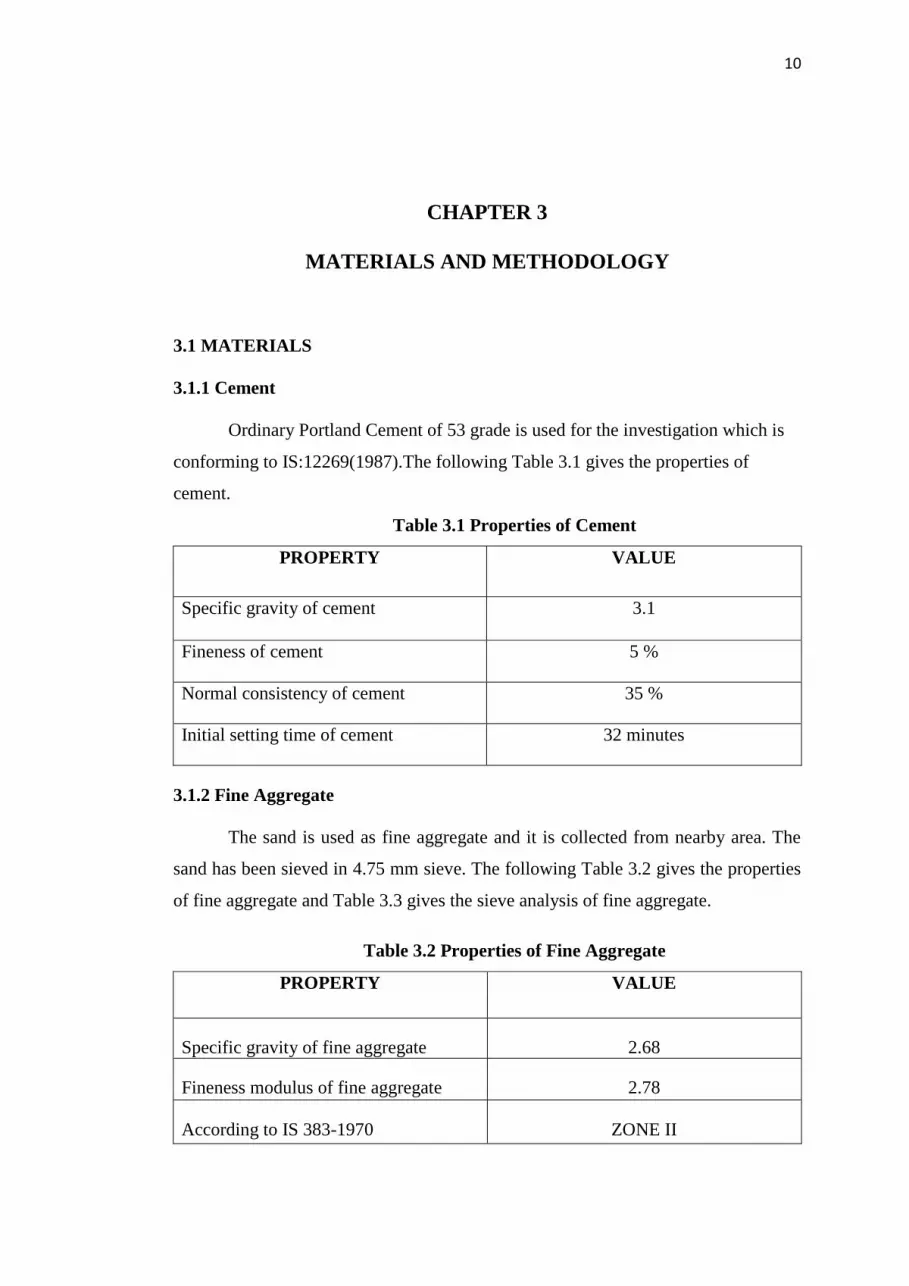
3.1.1 Cement
Ordinary Portland Cement of 53 grade is used for the investigation which is
conforming to IS:12269(1987).The following Table 3.1 gives the properties of
cement.
Table 3.1 Properties of Cement
PROPERTY VALUE
Specific gravity of cement 3.1
Fineness of cement 5 %
Normal consistency of cement 35 %
Initial setting time of cement 32 minutes
3.1.2 Fine Aggregate
The sand is used as fine aggregate and it is collected from nearby area. The
sand has been sieved in 4.75 mm sieve. The following Table 3.2 gives the properties
of fine aggregate and Table 3.3 gives the sieve analysis of fine aggregate.
Table 3.2 Properties of Fine Aggregate
PROPERTY VALUE
Specific gravity of fine aggregate 2.68
Fineness modulus of fine aggregate 2.78
According to IS 383-1970 ZONE II
11
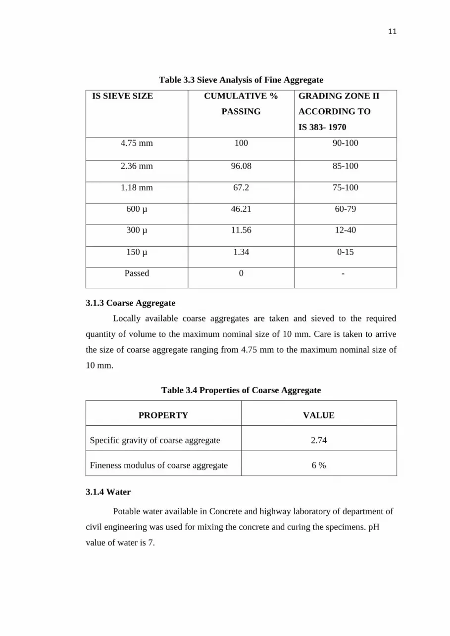
Table 3.3 Sieve Analysis of Fine Aggregate
IS SIEVE SIZE CUMULATIVE %
PASSING
GRADING ZONE II
ACCORDING TO
IS 383- 1970
4.75 mm 100 90-100
2.36 mm 96.08 85-100
1.18 mm 67.2 75-100
600 µ 46.21 60-79
300 µ 11.56 12-40
150 µ 1.34 0-15
Passed 0 -
3.1.3 Coarse Aggregate
Locally available coarse aggregates are taken and sieved to the required
quantity of volume to the maximum nominal size of 10 mm. Care is taken to arrive
the size of coarse aggregate ranging from 4.75 mm to the maximum nominal size of
10 mm.
Table 3.4 Properties of Coarse Aggregate
PROPERTY VALUE
Specific gravity of coarse aggregate 2.74
Fineness modulus of coarse aggregate 6 %
3.1.4 Water
Potable water available in Concrete and highway laboratory of department of
civil engineering was used for mixing the concrete and curing the specimens. pH
value of water is 7.

12
3.2 METHODOLOGY
The following Fig. 3.1 shows the methodology.
Review of Literature
Preliminary test of material
Mix Design
Preliminary Test on hardened concrete
Creating different size of mould
Casting of thin cylindrical shell
With and without GFRP
Testing the shell specimens
Comparing the Result
Fig 3.1 Methodology

13
CHAPTER 4
EXPERIMENTAL WORK AND TEST RESULTS
4.1 SPECIMEN DETAILS
4.1.1 Cube Specimens
Cube of size 100 × 100 × 100 mm is used for making conventional concrete
Specimens.
4.1.2 Cylinder Specimens
Cylinders of 100 mm in diameter and 200 mm in height is used for making
conventional concrete Specimens.
4.1.3 Cylindrical Shell Trial Specimens
Cylinders shell is having outer diameter of 160 mm and inner diameter of
90mm, so the shell is having 30 mm thickness. The following Fig.4.1 has shown the
testing of cylindrical shell.
Fig 4.1 Trial Specimen of Cylindrical shell

14
4.1.4 Mix Proportion
Design of mix proportion is given in Appendix A. The proportion of each
ingredient of concrete used are,
(i) Cement = 557 kg/m3
(ii) Water = 250 lit/m3
(iii) Fine Aggregate = 1058.94 kg/m3
(iv) Coarse Aggregate = 418.28 kg/m3
(v) Water Cement Ratio = 0.45
Mix proportion - C : F A : C A
1 : 1.9 : 0.76
4.2 SPECIMEN TESTS
4.2.1 Compression test
Concrete is primarily meant to withstand compressive stresses. Cubes are
casted and cured for 7 days and for 28 days. After curing, compressive strength is
tested in a Compression Testing Machine (CTM) according to IS 14858:2000. The
compressive strength of concrete are given in Table 4.2.
Compression Strength of concrete = Load applied on the cube specimen …(4.1)
Cross Section area of the cube
Table 4.1 Compressive Strength of Conventional concrete
DURATION COMPRESSIVE STRENGTH
( N/mm2)
7 days 23.1
28 days 30.1
4.2.2 Young’s Modulus Test
Initially it is assumed that concrete is elastic, isotropic, homogeneous and it
conforms to Hook’s law. Actually none of these assumptions are strictly true and
concrete is not a perfectly elastic material. Concrete deforms when load is applied

15
but this deformation does not follow any simple rule. The deformation depends upon
the magnitude of the load, the rate at which the load is applied and the elapsed time
after which the observation is made.
4.2.3 Cylindrical Shell Specimens
Cylinders shell is having outer diameter of 300 mm and inner diameter of 240
mm, so the shell is having 30 mm thickness and height of 200mm, 400mm, 600mm.
The following Fig. 4.2 shows the specimen of cylindrical shell.
Fig. 4.2 Specimen after casting and demoulding
4.2.4 Axial Compression Test on Cylindrical Shell
Axial compression on cylindrical shell is same as loading the cylinder axially
on top and bottom of shell. A deflectometer is placed to take the deflection of
cylindrical shell. Two steel rings are attached at top and bottom of the specimens.
Strain gauges are attached on four sides of specimen to measure the lateral deflection
using strain indicator. The Fig. 4.3 shows the testing of specimen.
Fig. 4.3 Testing of Specimens

16
4.2.5 Specimen Details of Cylindrical Shell
The following Table 4.2 shows the specimen details of cylindrical specimens.
Table 4.2 Specimen Details of cylindrical shell
SPECIMEN
DETAILS
HEIGHT
(mm)
DIAMETER
(mm)
THICKNESS
(mm)
Specimen 1 200 300 30
Specimen 2 400 300 30
Specimen 3 600 300 30

17
CHAPTER 5
RESULTS AND DISCUSSION
5.1 YOUNG’S MODULUS
The modulus of elasticity is determined by subjecting a cylinder specimen to
uniaxial compression and measuring the deformations by means of dial gauges fixed
between certain gauge length. Dial gauge reading divided by gauge length would
give the strain and load applied divided by area of cross-section would give the
stress. A series of readings were taken and the stress-strain relationship was
established.
After 28 days of curing, the cylinders are tested in a Compression Testing
Machine (CTM). The following equation is given by the following equation(5.1)
Modulus of Elasticity = Linear Stress ………..(5.1)
Linear Strain
The following Fig. 5.1, Fig. 5.2, Fig. 5.3 and Fig. 5.4 shows the stress vs
strain graph for various cylindrical specimens.
Fig. 5.1 Stress vs Strain for Specimen 1 at 7 days

18
Fig. 5.2 Stress vs Strain for Specimen 2 at 7 days
The size of the aggregate used for making the cylinder is 4.75 mm. Because
of that smaller size of aggregate, it was effected in the linear strain. So the Young’s
modulus for 7 days resulted as 17207 MPa and 15901 MPa.
Fig. 5.3 Stress vs Strain for Specimen 1 at 28 days
Fig. 5.4 Stress vs Strain for Specimen 2 at 28 days

19
Table 5.1 Young’s Modulus of Conventional concrete
DURATION Young’s modulus (N/mm2)
SPECIMEN 1 SPECIMEN 2
7 days 17207 15901
28 days 20167 22329
The above Table 5.1 shows the young’s modulus of concrete for 7 days and
28 days. Since the young’s modulus is directly proportional compressive strength, as
the strength increase, E value is also increased. Young’s modulus of 28 days is 0.85
times increased from 7 days value.
5.2 AXIAL COMPRESSION TEST ON TRAIL CYLINDRICAL SHELLS
Axial compression on cylindrical shell is same as loading the cylinder axially
on top and bottom of shell. A deflectometer is placed to take the deflection of
cylindrical shell. The means of applying the load shall provide for the load to be
applied either with the specimen in direct contact with the machine platens, or
spacing blocks, or with auxiliary platens interposed between each machine platen, or
spacing block, and the specimen. The following Fig. 5.5 and Fig. 5.6 shows the load
vs deflection graph for various specimens.
Fig. 5.5 Load vs Deflection for Trail Specimen 1
The above Fig. 5.5 shows the load vs deflection curve of cylindrical shell
specimen 1 of size 160 mm in outer diameter and 30 mm thickness with height 300
mm. The ultimate load carrying capacity of this specimen is 190 kN. During the

20
ultimate load crack was formed and sudden failure of concrete was observed at one
edge.
Fig. 5.6 Load vs Deflection for Trail Specimen 2
The above Fig. 5.6 shows the load vs deflection curve of cylindrical shell
specimen 2 of size 160 mm in outer diameter and 30 mm thickness with height
600mm. The ultimate load carrying capacity of this specimen is 220 kN. During the
ultimate the crack was formed and sudden failure of concrete was observed at one
edge and the reinforcement was buckled.
5.3 AXIAL COMPRESSION TEST ON CYLINDRICAL SHELL SPECIMENS
Axial compression on cylindrical shell is same as loading the cylinder axially
on top and bottom of shell. A deflectometer is placed to take the deflection of
cylindrical shell. Two steel rings are attached at top and bottom of the specimens to
avoid the direct contacts of machine platens with specimen. Strain gauges are
attached on four sides of specimen to measure the longitudinal deflection. The
following Fig. 5.7, Fig. 5.8 and Fig. 5.9 shows the load vs deflection graph for
various specimens.
Fig. 5.7 Load vs Deflection for Specimen 1

21
The above Fig. 5.7 shows the load vs deflection curve of cylindrical shell
specimen 1 of size 300 mm in outer diameter and 30 mm thickness with height
200 mm. The ultimate load carrying capacity of this specimen is 650 kN and 350 kN.
During the ultimate load crack was formed throughout the height of specimen in
without GFRP specimen and there is crushing of concrete at one end and the
specimen was buckled at center. There is no crack present outside the GFRP while
using it.
Fig. 5.8 Load vs Deflection for Specimen 2
. The above Fig. 5.8 shows the load vs deflection curve of cylindrical shell
specimen 2 of size 300 mm in outer diameter and 30mm thickness with height
400 mm. The ultimate load carrying capacity of this specimen is 300 kN and 320 kN.
During the ultimate load crack was formed from top end and extended to some
distance. Spalling of concrete was observed in the specimens of without GFRP and
buckling of specimen at above the center on one side and there is no crack outside
the GFRP.
Fig. 5.9 Load vs Deflection for Specimen 3
22
The above Fig. 5.9 shows the load vs deflection curve of cylindrical shell
specimen 3 of size 300 mm in outer diameter and 30mm thickness with height
600 mm. The ultimate load carrying capacity of this specimen is 420 kN and 520 kN.
During the ultimate load crack was formed from top end to bottom and was observed
of in without GFRP and there is damage in GFRP at bottom of specimen. There
was no crack outside the GFRP.
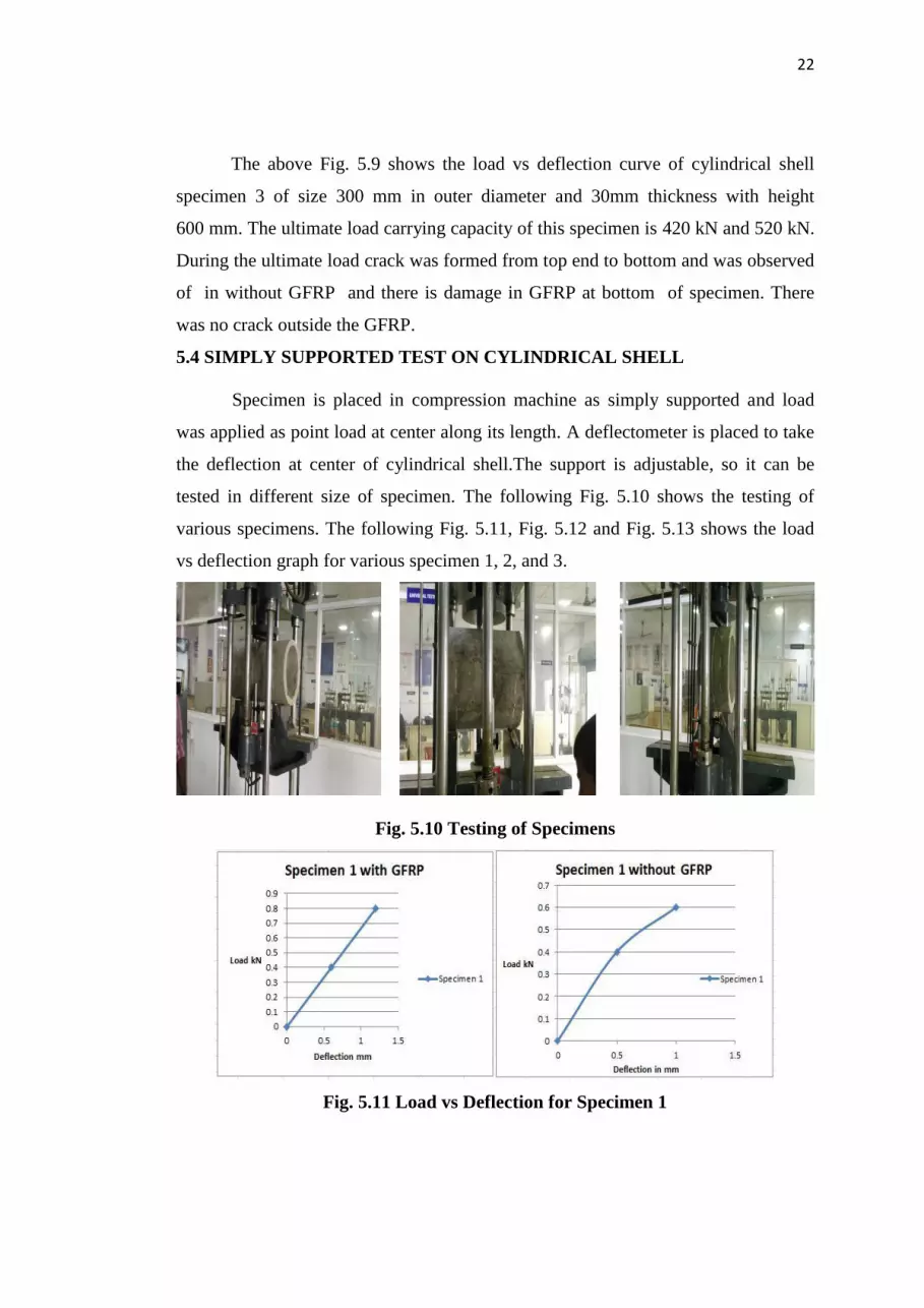
5.4 SIMPLY SUPPORTED TEST ON CYLINDRICAL SHELL
Specimen is placed in compression machine as simply supported and load
was applied as point load at center along its length. A deflectometer is placed to take
the deflection at center of cylindrical shell.The support is adjustable, so it can be
tested in different size of specimen. The following Fig. 5.10 shows the testing of
various specimens. The following Fig. 5.11, Fig. 5.12 and Fig. 5.13 shows the load
vs deflection graph for various specimen 1, 2, and 3.
Fig. 5.10 Testing of Specimens
Fig. 5.11 Load vs Deflection for Specimen 1
23
The above Fig. 5.11 shows the load vs deflection curve of cylindrical shell
specimen 1 of size 300 mm in outer diameter and 30 mm thickness with height
200 mm. The ultimate load carrying capacity of this specimen is 0.6 kN without
GFRP and 1.2 kN with GFRP. During the ultimate load crack was formed
throughout the length of specimen in without GFRP and there was crack and no
sudden failure while using GFRP .
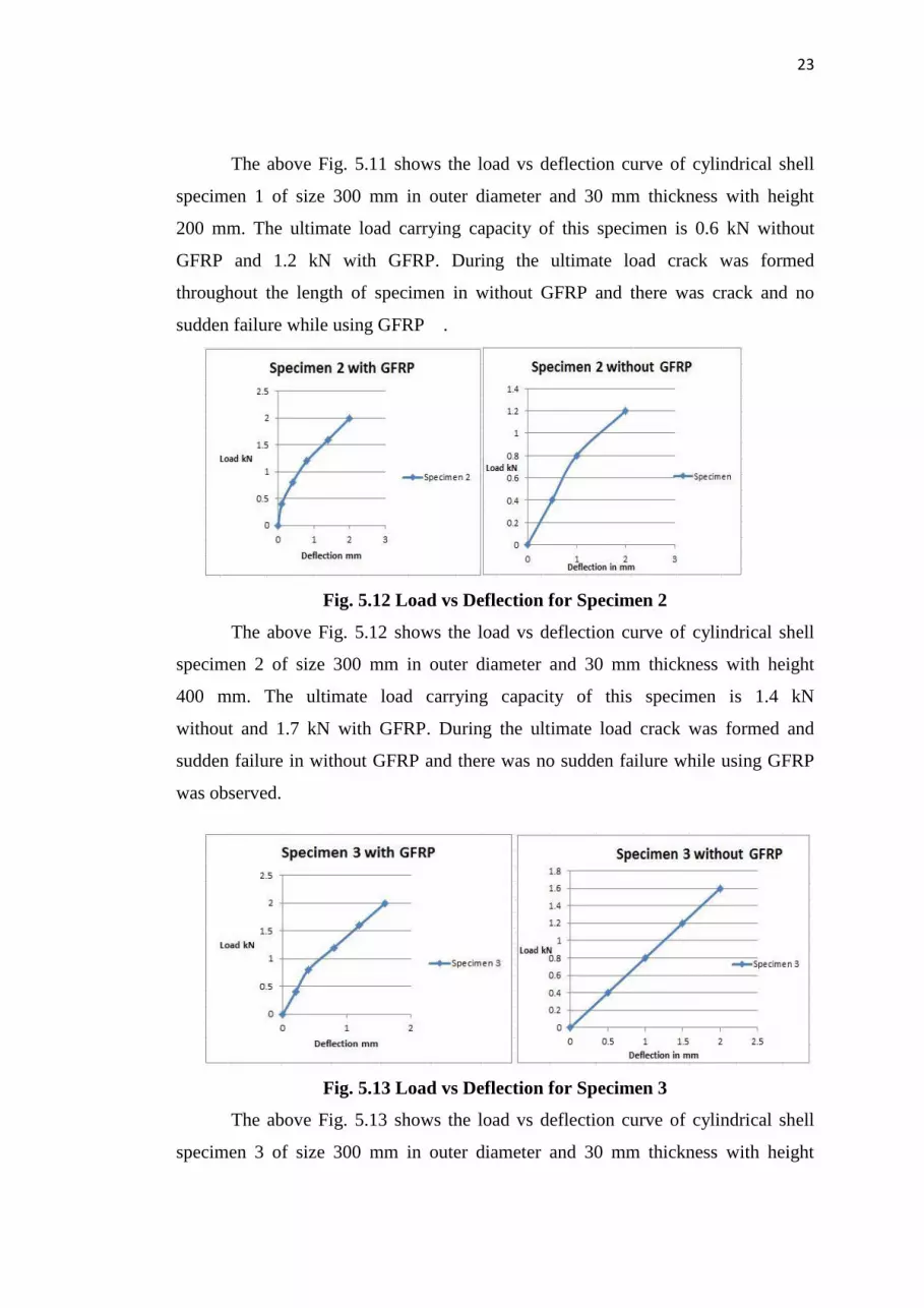
Fig. 5.12 Load vs Deflection for Specimen 2
The above Fig. 5.12 shows the load vs deflection curve of cylindrical shell
specimen 2 of size 300 mm in outer diameter and 30 mm thickness with height
400 mm. The ultimate load carrying capacity of this specimen is 1.4 kN
without and 1.7 kN with GFRP. During the ultimate load crack was formed and
sudden failure in without GFRP and there was no sudden failure while using GFRP
was observed.
Fig. 5.13 Load vs Deflection for Specimen 3
The above Fig. 5.13 shows the load vs deflection curve of cylindrical shell
specimen 3 of size 300 mm in outer diameter and 30 mm thickness with height

24
600 mm. The ultimate load carrying capacity of this specimen is 1.6 kN
without GFRP and 2.4 kN with GFRP. During the ultimate load crack was formed
and sudden failure in the specimen of without GFRP and there was no sudden failure
while using GFRP was observed. The Table 5.2 shows the maximum deflection of
axial compression test.
Table 5.2 Deflection of axial compression test of specimens
MAXIMUM
DEFLECTION(mm)
EXPERIMENTAL
VALUE
THEORITICAL
VALUE
WITHOUT
GFRP
WITH
GFRP
WITHOUT
GFRP
WITH
GFRP
Specimen 1 3.975 5.838 1.28 2.37
Specimen 2 3.432 4.368 1.09 1.6
Specimen 3 6.201 8.919 1.53 1.9
The above Table 5.1 shows the maximum deflection of experimental value as
3.975 mm and theoretical value is 1.28 mm of deflection. The theoretical deflection
is decreased to 3.1 times of experimental , because when the specimen is subjected to
axial compression, it behave like hollow cylinder rather than shell. The Table 5.2
shows the maximum deflection of axial compression test.
Table 5.3 Ultimate load of axial compression test of specimens
ULTIMATE LOAD
(kN)
WITHOUT GFRP WITH GFRP
Specimen 1 350 650
Specimen 2 300 440
Specimen 3 420 520
The ultimate load carrying capacity is increased by 33% when GFRP is used.
The bonding between the GFRP and concrete gives the good results. The Table 5.4
shows the maximum deflection of simply supported point load test.
25
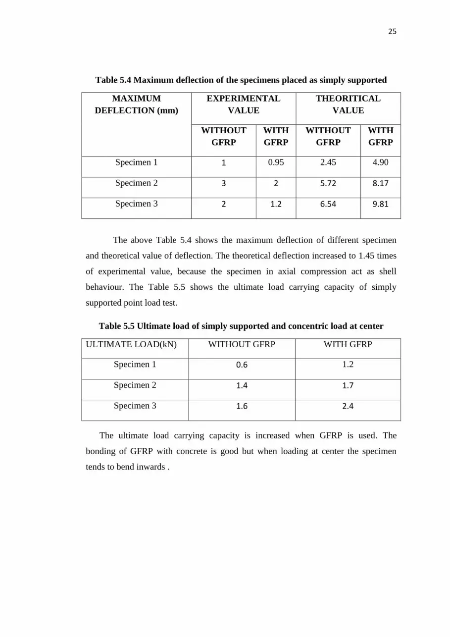
Table 5.4 Maximum deflection of the specimens placed as simply supported
MAXIMUM
DEFLECTION (mm)
EXPERIMENTAL
VALUE
THEORITICAL
VALUE
WITHOUT
GFRP
WITH
GFRP
WITHOUT
GFRP
WITH
GFRP
Specimen 1 1 0.95 2.45 4.90
Specimen 2 3 2 5.72 8.17
Specimen 3 2 1.2 6.54 9.81
The above Table 5.4 shows the maximum deflection of different specimen
and theoretical value of deflection. The theoretical deflection increased to 1.45 times
of experimental value, because the specimen in axial compression act as shell
behaviour. The Table 5.5 shows the ultimate load carrying capacity of simply
supported point load test.
Table 5.5 Ultimate load of simply supported and concentric load at center
ULTIMATE LOAD(kN) WITHOUT GFRP WITH GFRP
Specimen 1 0.6 1.2
Specimen 2 1.4 1.7
Specimen 3 1.6 2.4
The ultimate load carrying capacity is increased when GFRP is used. The
bonding of GFRP with concrete is good but when loading at center the specimen
tends to bend inwards .

26
CHAPTER 6
CONCLUSION
6.1 GENERAL
From both axial compression and simply supported test the results
were concluded and they are given below. The future scope of the project also given.
6.1 CONCLUSION
(i) In axial compression test the ultimate load carrying capacity is 300 kN
without GFRP and 440 kN with GFRP, the load has been increased
by 46.67% .
(ii) Deflection in axial compression is increased to the maximum by 0.46
times, when using the GFRP.
(iii) In axial compression test the experimental value is 3.975 mm and in
theoretical value is 1.28 mm, theoretical value is reduced 0.67 times
than experimental value. This is due to specimen behaves like a
cylinder not like a shell.
(iv) In simply supported the ultimate load carrying capacity is 1.4 kN
without GFRP and 1.7 kN with GFRP. Because of using GFRP the
load has been increased 0.2 times.
(v) Deflection in simply support test is decreased 0.67 times eventhough
if the GFRP is used.
(vi) In simply supported test, the deflection by experiment value is 1 mm
and in the theoretical value is 2.45 mm. Deflection is increased for
theoretical value is 0.40 times then experimental value. This is due to
the specimen acted as a cylindrical shell.

27
6.3 FUTURE SCOPE
(i) In the forthcoming researches, it is better to reduce the thickness of
shell, so that the behaviour will be purely like thin shell.
(ii) Different types of boundary conditions can be applied on cylindrical
shells.
(iii) Either the GFRP can be wrapped inside or both sides of cylindrical
shells.
(iv) By above steps and changing the parameters the characteristics of
cylindrical shell can be analysed.

28
APPENDIX A
MIX DESIGN AS PER ACI 211.1
Target mean strength = fmin +ks
= 30 + 1.64 x 4
= 36.56 MPa
From Table A1.5.3.4(a) of ACI 211.1
Water/cement ratio =0.45
From Table A1.5.3.3 of ACI 211.1
Water for given slump = 250.69/.45 = 557.09 kg/m3
From Table A1.5.3.6 of ACI 211.1
Volume of coarse aggregate = 0.2614 x 1600
= 418.28 kg/m3
From Table A1.5.3.7 of ACI 211.1
For 5mm aggregate = 2285 kg/m3
Weight of Fine aggregate =2285-(250.69+557.09+418.28)
=1058.94 kg/m3
Absolute volume of all ingredients
Cement = 557.09 x 1000 = 179.92 x 103 cm
3
3.1
Water = 250.69 x 1000 = 250.69 x 103 cm
3
1
Coarse aggregate = 418.28 x 1000 = 152.65 x 103 cm
3
2.74
583.09 x 103 cm
3
Absolute volume of fine aggregate =1000-583.09
= 416.96 x 2.68
= 1117.45 kg/m3

29
Estimated Quantities of materials per cubic meter of concrete
Cement = 557.09 kg
Fine aggregate = 1117.45 kg
Coarse aggregate = 418.28 kg
W/C = 0.45
Mix Proportion - Cement : F.A : C.A
1 : 1.9 : 0.76

30
APPENDIX B
MAXIMUM DEFLECTION
Wmax= P
8×β4×D
Where, β4= 3×(1-µ
2)
a2 ×h
2
Thickness, h = 30 mm
Internal Radius, a = 120 mm
Poisson’s ratio µ = 0.3
Internal Diameter D = 240 mm
β4= (3×(1-0.3
2))
1202×30
2
β = 0.5
(i) Specimen 1
Load = 588.6 N
Wmax = 588.6
8×0.53×240
= 2.45 mm.
(ii) Specimen 2
Load = 1569.6 N
Wmax = 1569.6
8×0.53×240
= 6.54 mm.
(iii) Specimen 3
Load = 1373.4 N
Wmax = 1373.4
8×0.53×240
= 5.72 mm.

31
REFERENCES
Chryssanthopoulos et al. (1995), ‘Stochastic imperfection modelling in shell
buckling studies’, Thin-Walled Structures,Vol.23, pp.179-200.
Diederik Veenendal et al. (2010), ‘Design process for prototype concrete shells using
a hybrid cable-net and fabric formwork’, Engineering Structures,Vol.75, pp.39-50.
Rigoberto Burgueno et al. (2014), ‘Tailoring the elastic postbuckling response of
thin-walled cylindrical composite shells under axial compression’, Thin-Walled
Structures,Vol.84, pp.14-25.
Venkata Narayana Yenugula et al. (2013), ‘Experimental investigation on buckling
of GFRP cylindrical shells subjected to axial compression’,IOSR-JMCE e-
ISSN:2278, Vol.9, pp 20-25.
Zingoni et al. (2013), ‘Buckling strength of thin-shell concrete arch dams’, Thin-
Walled Structures,Vol.64, pp.94-102.
ACI 211.1.(1991), ‘Standard Practice for selecting Proportions for Normal,
Heavyweight ,and Mass Concrete’, American concrete institute.
IS:2210 (1988), ‘Indian Standard for Design of concrete shell structures and folded
plates’, Bureau of Indian Standards, New Delhi.
Alphose Zingoni.(1997), ‘Shell Structures in Civil and Mechanical Engineering’,
University of Zimbabwe, Harare.
M.S.Shetty.(2006), ‘Concrete technology- theory and practice’, S Chand and
Company Ltd, New Delhi, India.


