Embed Size (px)
Citation preview
AUG 1 7 198?Docket Nos. 50-280
and 50-281
Mr. R. H. Leasburg Vice President - Nuclear Operations Virginia Electric and Powet'-Company Post Office Box 26666 Richmond, Virginia 23261
Dear Mr. Leasburg:
DISTRIBUTION Dockets DBrinkman NRC PDR Gray L PDR NSIC ORB#1 Rdg DEisenhut OELD IE-2 ACRS-1 0 CParrish DNei ghbors LEngle TBarnhart-8 LSchneider OPA RDiggs ASLAB
The Commission has issued the enclosed Amendment No. 79 to Facility Operating License No. DPR-32 and Amendment No. 80 to Facility Operating License No. DPR-37 for the Surry Power Station, Unit Nos. 1 and 2, respectively. The amendments consistsof changes to the Technical Specifications in response to your application transmitted by letter dated September 20, 1978, as supplemented April 28, 1981, May 24, 1982 and July 7, 1982.
These amendments revise the Technical Specifications to incorporate revised inservice surveillance requirements for snubbers, both mechanical and hydraulic.
Copies of the Safety Evaluation and the Notice of Issuance are also encloged.
Sincer•1.y,
ftseph D. Neighbors, Project Manager Operating Reactors Branch #1 Division of Licensing
Fnclosures: I. Amendment No. 79 to DPR-32 2. Amendment No. 80 to DPR-37 3. Safety Evaluation 4. Notice of Issuance
.. . .. . " .... .................... . . . . .
SURNAMELI CParrish \1DNeig~1 ~ors: •s LEngle I• IllIIG•L.IlI~ - "R ....... C? a ..r..s...... d s..... •"...." .... .E .l... .......... .' ......... .. .,/ I /•2.h s.... ........:• LI! gL . "r *• t. ... O .' . ... .• :. ..... .. ............
S 8209200004 8208 17 ............
NR( PDR ADOCK 05000280 OFFICIAL RECORD COPY P PDR
ol..W A flJ .....
USGPO: 1981-335-960
.Mr. R. H. Leasburg 'Virginia Electric and Power Company
cc: Mr. Michael W. Maupin Hunton and Williams Post Office Box 1535 Richmond, Virginia 23213
Mr. J. L. Wilson, Manager P. 0. Box 315 Surry, Virginia 23883
Swem Library College of William and Williamsburg, Virginia
Mary 23185
Mr. J. H. Ferguson Executive Vice President - Power Virginia Electric and Power Company Post Office Box 26666 Richmond, Virginia 23261
James P. O'Reilly Regional Administrator - Region II U. S. Nuclear Regulatory Commission 101 Marietta Street, Suite 3100 Atlanta, Georgia 30303
Donald J. Burke, Resident Inspector Surry Power Station U. S. Nuclear Regulatory Commission Post Office Box 166 Route 1 Surry, Virginia 23883
Mr. Sherlock Holmes, Chairman Board of Supervisors of Surry County Surry County Courthouse, Virginia 23683
Commonwealth of Virginia Council on the Environment 903 Ninth Street Office Building Richmond, Virginia 23219
Attorney General 1101 East Broad Street Richmond, Virginia 23219
Mr. James R. Wittine Commonwealth of Virginia State Corporation Commission Post Office Box 1197 Richmond, Virginia 23209
Regional Radiation Representative EPA Region III Curtis Building - 6th Floor 6th and Walnut Streets Philadelphia, Pennsylvania 19106
"�0 UNITED STATES
0 NUCLEAR REGULATORY COMMISSION I .WASHINGTON, D. C. 20555
VIRGINIA ELECTRIC AND POWER COMPANY
DOCKET NO. 50-280
SURRY POWER STATION, UNIT NO. 1
AMENDMENT TO FACILITY OPERATING LICENSE
Amendment No.79
License No. DPR-32
1. The Nuclear Regulatory Commission (the Commission) has found that:
A. The application for amendment by Virginia Electric and Power
Company (the licensee) dated September 20, 1978, as supplemented
April 28, 1981, May 24, 1982 and July 7, 1982, complies with
the standards and requirements of the Atomic Energy Act of
1954, as amended (the Act) and the Commission's rules and
regulations set forth in 10 CFR Chapter I;
B. The facility will operate in conformity with the application,
the provisions of the Act, and the rules and regulations of
the Commission;
C. There is reasonable assurance (i) that the activities authorized
by this amendment can be conducted without endangering the health
and safety of the public, and (ii) that such activities will be
conducted in compliance with the Commission's regulations;
D. The issuance of this amendment will not be inimical to the common
defense and security or to the health and safety of the public; and
E. The issuance of this amendment is in accordance with 10 CFR Part
51 of the Commission's regulations and all applicable requirements have been satisfied.
8209200006 820817 PDR ADOCK 05000280 P PDR
-2-
2. Accordingly, the license is amended by changes to the Technical Specifications as indicated in the attachment to this license amendment, and paragraph 3.B of Facility Operating License No. DPR-32 is hereby amended to read as follows:
B. Technical Specifications
The Technical Specifications contained in Appendix A, as revised through Amendment No. 7 9 , are hereby incorporated in the license. The licensee shall operate the facility in accordance with the Technical Specifications.
3. This license amendment is effective as of the date of its issuance.
R THE NUCLEA REGULATORY COMMISSION
'Opeeratin ga, f Reactors I nch #1
Division of Licensin
Attachment: Changes to the Technical
Speci fications
Date of Issuance: August 17, 1982
0 UNITED STATES NUCLEAR REGULATORY COMMISSION
WASHINGTON, D. C. 20555
VIRGINIA ELECTRIC AND POWER COMPANY
DOCKET NO. 50-281
SURRY POWER STATION, UNIT NO. 2
AMENDMENT TO FACILITY OPERATING LICENSE
Amendment No. 80 License No. DPR-37
1. The Nuclear Regulatory Commission (the Commission) has found that:
A. The application for amendment by Virginia Electric and Power Company (the licensee) dated September 20, 1978, as supplemented April 28, 1981, May 24, 1982 and July 7, 1982, complies with the standards and requirements of the Atomic Energy Act of 1954, as amended (the Act) and the Commission's rules and regulations set forth in 10 CFR Chapter I;
B. The facility will operate in conformity with the application, the provisions of the Act, and the rules and regulations of the Commission;
C. There is reasonable assurance (i) that the activities authorized by this amendment can be-conducted without endangering the health and safety of the public, and (ii) that such activities will be conducted in compliance with the Commission's regulations;
D. The issuance of this amendment will not be inimical to the common defense and security or to the health and safety of the public; and
E. The issuance of this amendment is in accordance with 10 CFR Part 51 of the Commission's regulations and all applicable requirements have been satisfied,
-2-
2. Accordingly, the license 4s Specifications as indicated amendment, and paragraph 3.B No. DPR-37 is hereby amended
amended by changes to the Technical in the attachment to this license of Facility Operating License to read as follows:
B. Technical Specifications
The Technical Specifications rontained in Appendix A, as revised through Amendment No. 80 , are hereby incorporated in the license. The licensee shall operate the facility in accordance with the Technical Specifications.
3. This license amendment is effective as of the date of its issuance.
THE NUCLFAR.REGULATORY COMMISSION
#1
Attachment: Changes to the Technical
Specifications
Date of Issuance: August 17, 1982
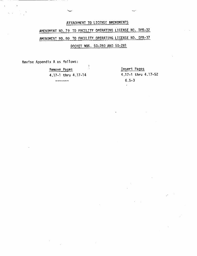
ATTACHMENT TO LICENSE AMENDMENTS
AMENDMENT NO. 79 TO FACILITY OPERATING LICENSE NO. DPR-32
AMENDMENT NO. 80 TO FACILITY OPERATING LICENSE NO. DPR-37
DOCKET NaS. 50-280 AND 50-281
Revise Appendix A as follows:
Remove Pages
4.17-1 thru 4.17-14
Insert Pages 4.17-1 thru 4.17-52
6.5-3
TS 4.17-1
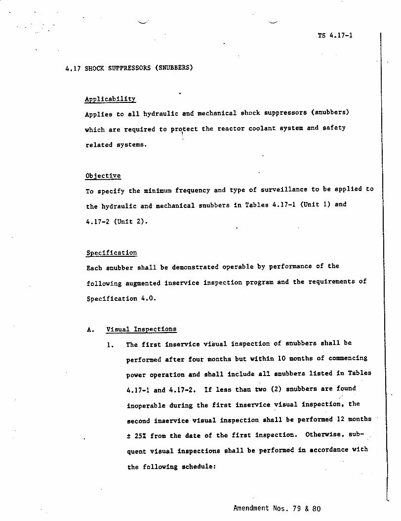
4.17 SHOCK SUPPRESSORS (SNUBBERS)
Applicability
Applies to all hydraulic and mechanical shock suppressors (snubbers)
which are required to pro!tect the reactor coolant system and safety
related systems.
Objective
To specify the minimum frequency and type of surveillance to be applied to
the hydraulic and mechanical snubbers in Tables 4.17-1 (Unit 1) and
4.17-2 (Unit 2).
Specification
Each snubber shall be demonstrated operable by performance of the
following augmented inservice inspection program and the requirements of
Specification 4.0.
A. Visual Inspections
1. The first inservice visual inspection of snubbers shall be
performed after four months but within 10 months of commencing
power operation and shall include all snubbers listed in Tables
4.17-1 and 4.17-2. If less than two (2) snubbers are found
inoperable during the first inservice visual inspection, the
second inservice visual inspection shall be performed 12 months
t 25% from the date of the first inspection. Otherwise, sub
quent visual inspections shall be performed in accordance with
the following schedule:
Amendment Nos. 79 & 80
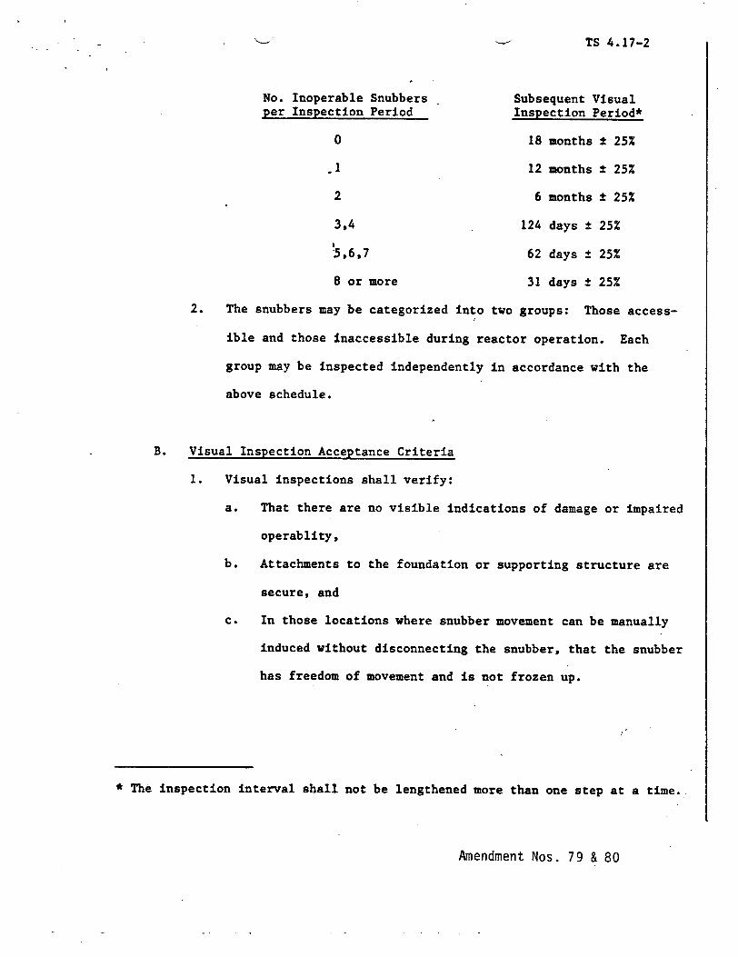
TS 4.17-2
No. Inoperable Snubbers Subsequent Visual per Inspection Period Inspection Period*
0 18 months ± 25%
.1 12 months ± 25%
2 6 months ± 25%
3,4 124 days ± 25%
!5.6,7 62 days ± 25%
8 or more 31 days ± 25%
2. The snubbers may be categorized into two groups: Those access
ible and those inaccessible during reactor operation. Each
group may be inspected independently in accordance with the
above schedule.
B. Visual Inspection Acceptance Criteria
1. Visual inspections shall verify:
a. That there are no visible indications of damage or impaired
operablity,
b. Attachments to the foundation or supporting structure are
secure, and
c. In those locations where snubber movement can be manually
induced without disconnecting the snubber, that the snubber
has freedom of movement and is not frozen up.
* The inspection interval shall not be lengthened more than one step at a time.
Amendment Nos. 79 & 80
TS 4.17-3
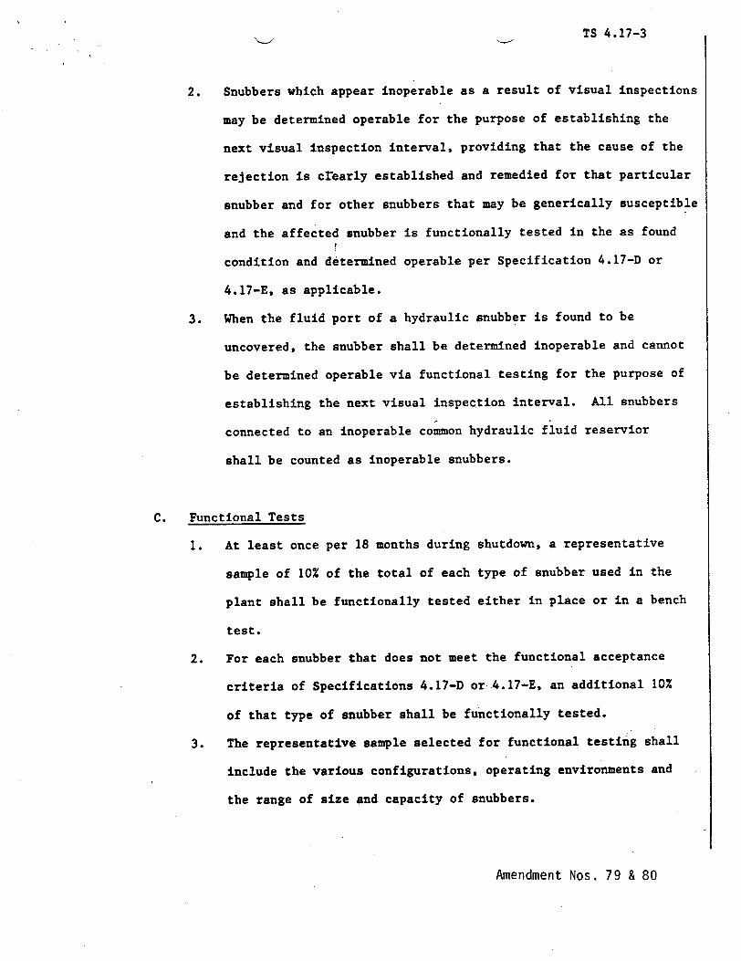
2. Snubbers which appear inoperable as a result of visual inspections
may be determined operable for the purpose of establishing the
next visual inspection interval, providing that the cause of the
rejection is crearly established and remedied for that particular
snubber and for other snubbers that may be generically susceptible
and the affected snubber is functionally tested in the as found
condition and determined operable per Specification 4.17-D or
4.17-E, as applicable.
3. When the fluid port of a hydraulic snubber is found to be
uncovered, the snubber shall be determined inoperable and cannot
be determined operable via functional testing for the purpose of
establishing the next visual inspection interval. All snubbers
connected to an inoperable common hydraulic fluid reservior
shall be counted as inoperable snubbers.
C. Functional Tests
1. At least once per 18 months during shutdown, a representative
sample of 10% of the total of each type of snubber used in the
plant shall be functionally tested either in place or in a bench
test.
2. For each snubber that does not meet the functional acceptance
criteria of Specifications 4.17-D or .4.17-E, an additional 10Z
of that type of snubber shall be functionally tested.
3. The representative sample selected for functional testing shall
include the various configurations, operating environments and
the range of size and capacity of snubbers.
Amendment Nos. 79 & 80
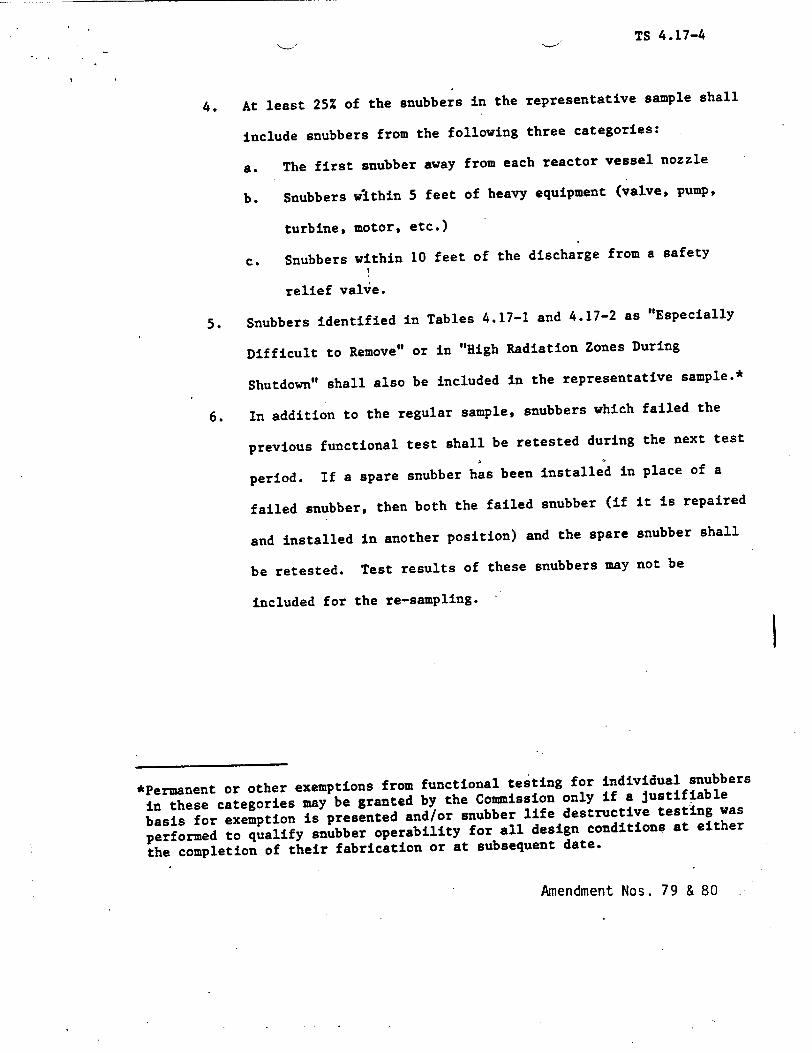
TS 4.17-4
4. At least 25Z of the snubbers in the representative sample shall
include snubbers from the following three categories:
a. The first snubber away from each reactor vessel nozzle
b. Snubbers within 5 feet of heavy equipment (valve, pump,
turbine, motor, etc.)
c. Snubbers within 10 feet of the discharge from a safety
relief valve.
5. Snubbers identified in Tables 4.17-1 and 4.17-2 as "Especially
Difficult to Remove" or in "High Radiation Zones During
Shutdown" shall also be included in the representative sample.*
6. In addition to the regular sample, snubbers which failed the
previous functional test shall be retested during the next test
period. If a spare snubber has been installed in place of a
failed snubber, then both the failed snubber (if it is repaired
and installed in another position) and the spare snubber shall
be retested. Test results of these snubbers may not be
included for the re-sampling.
*Permanent or other exemptions from functional testing for individual snubbers
in these categories may be granted by the Commission only if a justifiable
basis for exemption is presented and/or snubber life destructive testing was
performed to qualify snubber operability for all design conditions at either
the completion of their fabrication or at subsequent date.
Amendment Nos. 79 & 80

TS 4.17-5
7. If any snubber selected for functional testing either fails to
lockup or fails to move, i.e., frozen in place, the cause will be
evaluated and if caused by manufacturer or design deficiency all
snubbers of the same design subject to the same defect shall be
functionally tested. This testing requirement shall be indepen
dent of the requirements stated above for snubbers not meeting
the functional test acceptance criteria.
8. For the snubber(s) found inoperable, an engineering evaluation
shall be performed on the components which are supported by
snubber(s). The purpose of this engineering evaluation shall
be to determine if the components supported by the snubber(s)
were adversely affected by the inoperability of the snubber(s)
in order to ensure that the supported component remains capable
of meeting the designed service.
D. Hydraulic Snubbers Functional Test Acceptance Criteria
1. The hydraulic snubber functional test shall verify that:
a. Activity (restraining action) is achieved within the
specified range of velocity or acceleration in both tension
and compression.
b. Snubber bleed, or. release rate, where required, is within
the specified range in compression and tension. For snubbers
specifically required to not displace under continuous load,
the ability of the snubber to withstand load without displace
ment shall be verified.
Amendment Nos. 79 & 80
TS 4.17-6
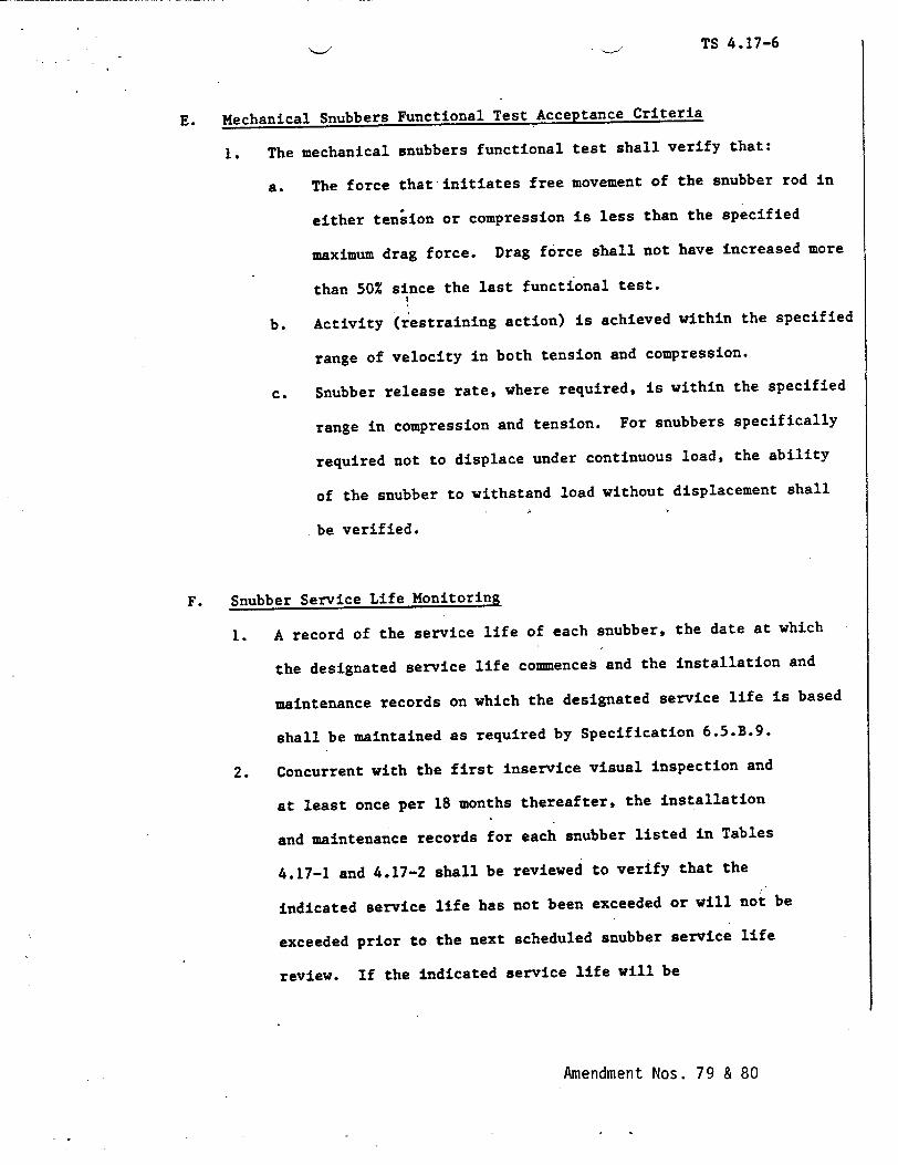
E. Mechanical Snubbers Functional Test Acceptance Criteria
1. The mechanical snubbers functional test shall verify that:
a. The force that initiates free movement of the snubber rod in
either tension or compression is less than the specified
maximum drag force. Drag force shall not have increased more
than 50Z since the last functional test.
b. Activity (restraining action) is achieved within the specified
range of velocity in both tension and compression.
c. Snubber release rate, where required, is within the specified
range in compression and tension. For snubbers specifically
required not to displace under continuous load, the ability
of the snubber to withstand load without displacement shall
be verified.
F. Snubber Service Life Monitoring
1. A record of the service life of each snubber, the date at which
the designated service life commences and the installation and
maintenance records on which the designated service life is based
shall be maintained as required by Specification 6.5.B.9.
2. Concurrent with the first inservice visual inspection and
at least once per 18 months thereafter, the installation
and maintenance records for each snubber listed in Tables
4.17-1 and 4.17-2 shall be reviewed to verify that the
indicated service life has not been exceeded or will not be
exceeded prior to the next scheduled snubber service life
review. If the indicated service life will be
Amendment Nos. 79 & 80
TS 4.17-7
exceeded prior to the next'scheduled snubber service life review,
the snubber service life shall be reevaluated or the snubber
shall be replaced or reconditioned so as to extend its service
life beyond the date of the next scheduled service life review.
This reevaluation, replacement or reconditioning shall be
indicated in the records.
Bases
All snubbers are required operable to ensure that the structural integri
ty of the reactor coolant system and all other safety-related systems is
maintained during and following a seismic or other event initiating
dynamic loads. Snubbers excluded from this inspection program are those
installed on nonsafety-related systems and then only if their failure or
failure of the system on which they are installed would have no adverse
effect on any safety-related system.
The visual inspection frequency is based upon maintaining a constant
level of snubber protection to systems. Therefore, the required inspec
tion interval varies inversely with the observed snubber failures and is
determined by the number of inoperable snubbers found during an inspec
tion. Inspections performed before that interval has elapsed may be used
as a new reference point to determine the next inspection. However, the
results of such early inspections performed before the original required
time interval has elapsed (nominal time less 25Z) may not be used to
lengthen the required inspection interval. Any inspection whose results
require a shorter inspection interval will override the previous schedule.
Amendment Nos. 79 & 80
TS 4.17-8
When the cause of the rejection of a snubber is clearly established and
remedied for that snubber and for any other snubbers that may be gener
ically susceptible, and verified by inservice functional testing, that
snubber may be exempted from being counted as inoperable. Generically
susceptible snubbers are those which are of a specific make or model
and have the same design ýfeatures directly related to rejection of the
snubber by visual inspection, or are similarly located or exposed to the
same environmental conditions such as temperature, radiation, and vibra
tion.
When a snubber is found inoperable, an engineering evaluation is per
formed, in addition to the determination of the snubber mode of failure,
in order to determine if any safety-related component or system has been
adversely affected by the inoperability of the snubber. The engineering
evaluation shall determine whether or not the snubber mode of failure has
imparted a significant effect or degradation on the supported component
or system.
To provide assurance of snubber functional relaibility, a representative
sample of the installed snubbers will be functionally tested during plant
shutdowns at 18 month intervals. Functional testing is to be in
accordance with ASME Section XI 1980ed. Subsection IWF. Observed
failures of these sample snubbers shall require functional testing of
additional units.
Hydraulic snubbers and mechanical snubbers may each be treated as a
different entity for the above surveillance programs.
Amendment Nos. 79 & 80
TS 4.17-9
The service life of a snubber is evaluated via manufacturer input and
information through consideration of the snubber service conditions and
associated installation and maintenance records (newly installed snubber,
seal replaced, spring replaced, in high radiation area, in high tempera
ture area, etc. . . . ). The requirement to monitor the snubber service
life is included to ensure that the snubbers periodically undergo a
performance evaluation in'view of their age and operating conditions.
These records will provide statistical bases for future consideration of
snubber service life. The requirements for the maintenance of records
and the snubber service life review are not intended to affect plant
operation.
Amendment Nos. 79 & 80
TS 4.17-10
LEGEND
Accessibility Category
A - Accessible
I - Inaccessible
Radiation Category
H High radiation area only during periods of reactor operation. In
acceptable radiation work area during period of reactor shutdown.
N - Acceptable radiation work area during periods of reactor operation
and shutdown.
Removal Category
D - Expecially difficult to remove
R - Can be removed
*Snubbers may be added to and deleted from safety related systems without prior
License Amendment to Tables 4.17-1 and 4.17-2 provided that a revision
to Tables 4.17-1 and 4.17-2 included in the next License Amendment request.
**Modifications to the "Radiation Category" column due to changes in high
radiation areas may be made without prior License Amendment provided that a
revision to Tables 4.17-1, 4.17-2, is included with the next License
Amendment request.
Amendment Nos. 79 & 80
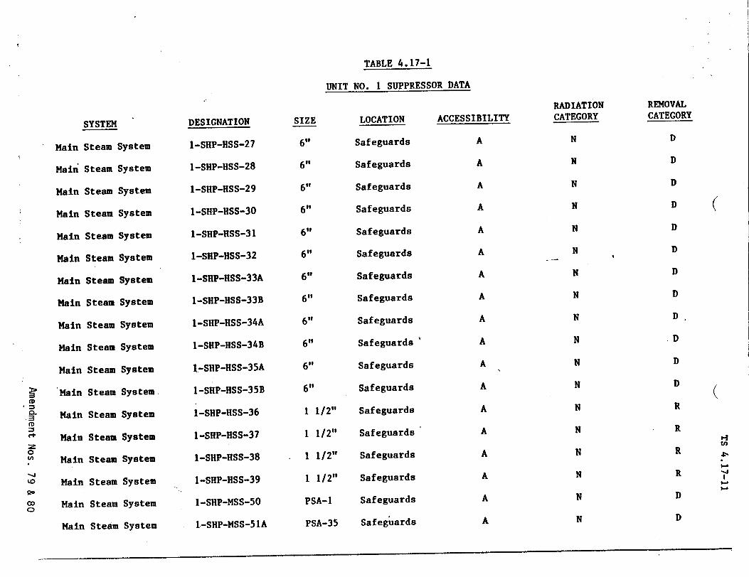
TABLE 4.17-1
UNIT NO. I SUPPRESSOR DATA
SYSTEM
Main Steam System I.-SHP-MSS-51A
Main
Main
Main
Main
Main
Main
Main
Main
Main
Main
Main
Main
Main
Main
Main
Main
Main
Steam
Steam
Steam
Steam
Steam
Steam
Steam
Steam
Steam
Steam
Steam
Steam
Steam
Steam
Steam
Steam
Steam
System
System
System
System
System
System
System
System
System
System
System
System
System
System
System
I System
I System
PSA-35 Safeguards A
DESIGNATION
I-SHP-HSS-27
I-SHP-HSS-28
I-SHP-HSS-29
1-SHP-HSS-30
1-SHP-HSS-31
1-SHP-HSS-32
I-SHP-HSS-33A
I-SHP-HSS-33B
1-SHP-HSS-34A
I-SHP-HSS-34B
1-SHP-HSS-35A
I-SHP-HSS-35B
1-SHP-HSS-36
I-SHP-HSS-37
I-SHP-HSS-38
1-SHP-HSS-39
1-SHP-MSS-50
SIZE
6"
6"
6"
6"
6"
6"
6"
6"
6"
6"
6"
6"
1 112"
1 1/2"
1 1/2"
1 1/2"
PSA-1
LOCATION
Safeguards
Safeguards
Safeguards
Safeguards
Safeguards
Safeguards
Safeguards
Safeguards
Safeguards
Safeguards
Safeguards
Safeguards
Safeguards
Safeguards
Safeguards
Safeguards
Safeguards
ACCESSIBILITY
A
A
A
A
A
A
A
A
A
A
A
A
A
A
A
A
A
RADIATION CATEGORY
N
N
N
N
N
N
N
N
N
N
N
N
N
N
N
N
N
N
REMOVAL CATEGORY
D
D
D
D
D
D
D
D
D
.D
D
D
R
R
R
R
D
D
(
(
'.4 U)
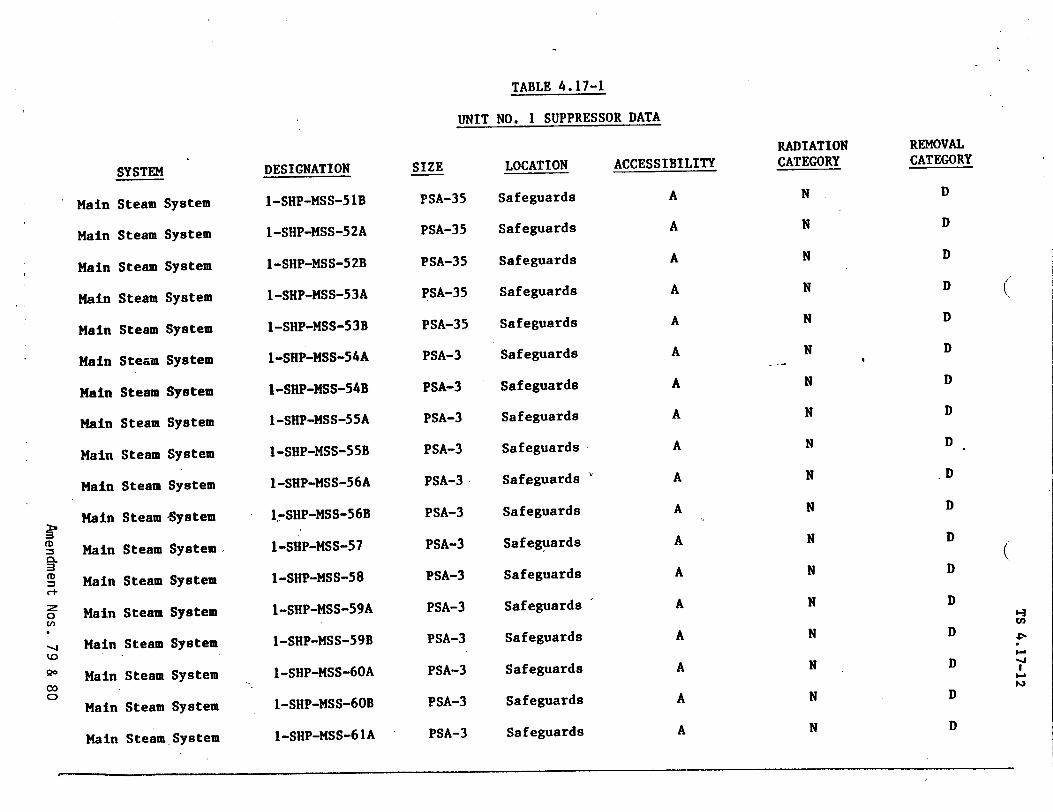
TABLE 4.17-1
UNIT NO. 1 SUPPRESSOR DATA
SYSTEM
Main
Main
Main
Main
Steam
Steam
Steam
Steam
Steam
Steam
Steam
Steam
Steam
Steam
Steam
Steam
Steam
Steam
Steam
Steam
Steav
Stear
System
System
System
System
System
System
System
System
System
System
ISystem
System
System
System
System
a System
SSystem
.System
DESIGNATION
1-SHP-MSS-51B
I-SHP-MSS-52A
I-SHP-MSS-52B
I-SHP-MSS-53A
1-SHP-MSS-53B
1-SHP-MSS-54A
I-SHP-MSS-54B
I-SHP-MSS-55A
I-SHP-MSS-55B
I-SHP-MSS-56A
I.-SHP-MSS-56B
I-SHP-MSS-57
1-SHP-MSS-58
I-SHP-MSS-59A
I-SHP-MSS-59B
1-SHP-MSS-60A
I-SHP-MSS-60B
I-SHP-MSS-61A
SIZE
PSA-35
PSA-35
PSA-35
PSA-35
PSA-35
PSA-3
PSA-3
PSA-3
PSA-3
PSA-3
PSA-3
PSA-3
PSA-3
PSA-3
PSA-3
PSA-3
PSA-3
PSA-3
LOCATION
Safeguards
Safeguards
Safeguards
Safeguards
Safeguards
Safeguards
Safeguards
Safeguards
Safeguards
Safeguards
Safeguards
Safeguards
Safeguards
Safeguards
Safeguards
Safeguards
Safeguards
Safeguards
ACCESSIBILITY
A
A
A
A
A
A
A
A
A
A
A
A
A
A
A
A
A
A
Main
Main
Main
Main
Main
Main
Main
Main
Main
Main
Main
Main
Mair
Mait
RADIATION CATEGORY
N
N
N
N
N
N
N
N
N
N
N
N
N
N
N
N
N
N
20
Cl)
*--1
00 co
REMOVAL CATEGORY
D
D
D
D
D
D
D
D
D
D
D
D
D
D
D
D
D
D
(
0-3
I-
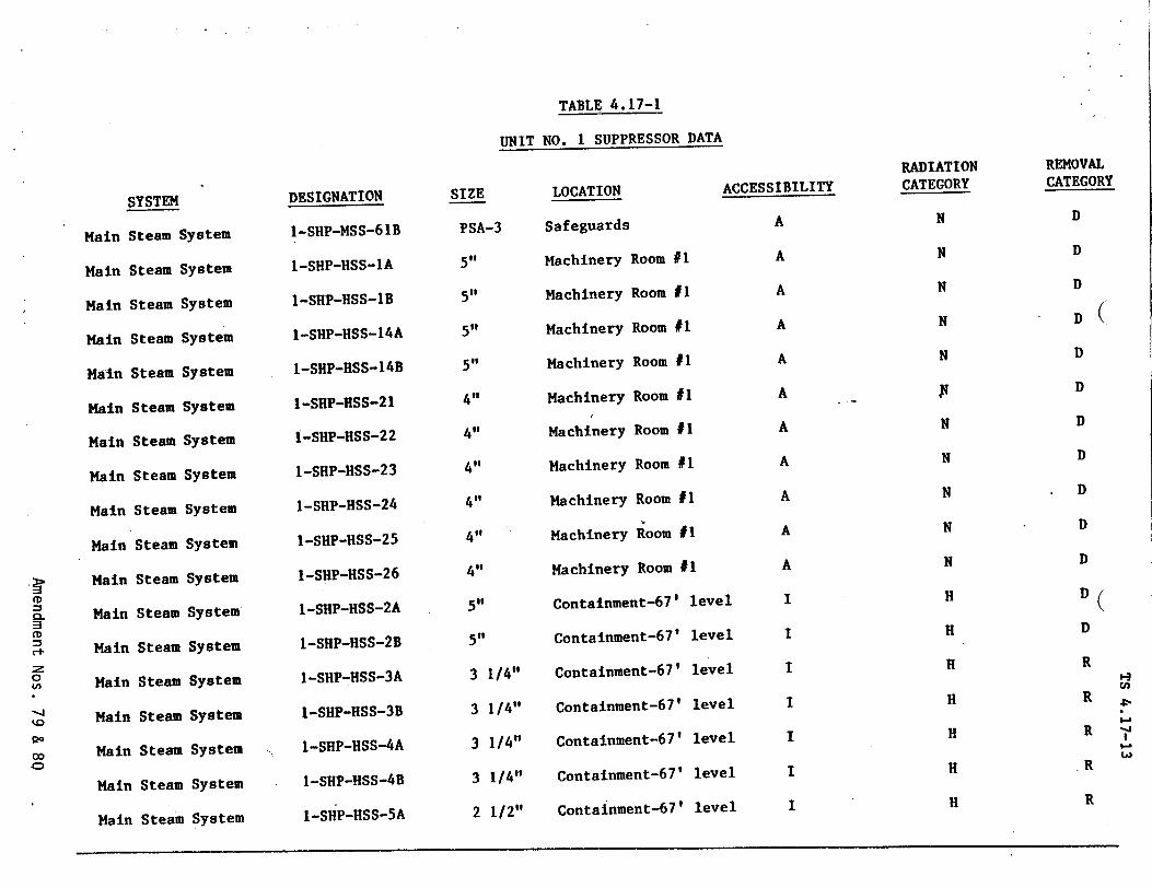
TABLE 4.17-1
UNIT NO. 1 SUPPRESSOR DATA
SYSTEM
Main Steam System 1-SHP-HSS-5A
SIZE
Main S
Main .€
Main I
Main
Main
Main
Main
Main
Main
Main
Main
Main
Main
Main
Main
Main
Main
LOCATION
team
;team
team
;team
Steam
Steam
Steam
Steam
Steam
Steam
Steam
Stear
Steat
Steat
Steat
Steaw
Steal
ACCESSIBILITY
System
System
System
System
System
System
System
System
System
System
n System
a System
m System
m System
m System
m System
m System
2 1/2" Containment-67' level I
DESIGNATION
I-SHP-MSS-61B
I-SHP-HSS-IA
1-SHP-HSS-1B
1-SHP-HSS-14A
1-SHP-HSS-14B
I-SHP-HSS-21
1-SHP-HSS-22
I-SHP-HSS-23
I-SHP-HSS-24
I-SHP-HSS-25
I-SHP-HSS-26
1-SHP-HSS-2A
1-SHP-HSS-2B
1-SHP-HSS-3A
I-SHP-HSS-3B
1-SHP-HSS-4A
I-SHP-HSS-4B
PSA-3
5',
5,,
5,,
5,,
4,,
4"
4,,
4,,
4"
4,,
51@
5,,
3 1/4"
3 1/4"
3 1/4"
3 1/4"
Safeguards
Machinery Room #1
Machinery Room #1
Machinery Room #1
Machinery Room #1
Machinery Room #1
Machinery Room #1
Machinery Room #1
Machinery Room #1
Machinery Room #1
Machinery Room #1
Containment-671 level
Containment-67' level
Containment-67' level
Containment-67' level
Containment-67' level
Containment-671 level
A
A
A
A
A
A
A
A
A
A
A
I
I
I
I
I
RADIATION CATEGORY
N
N
N
N
N
N
N
N
N
N
H
H
H
H
H
H
H
REMOVAL CATEGORY
D
D
D
D(
D
D
D
D
D
D
D
D
R
R
R
R
.R
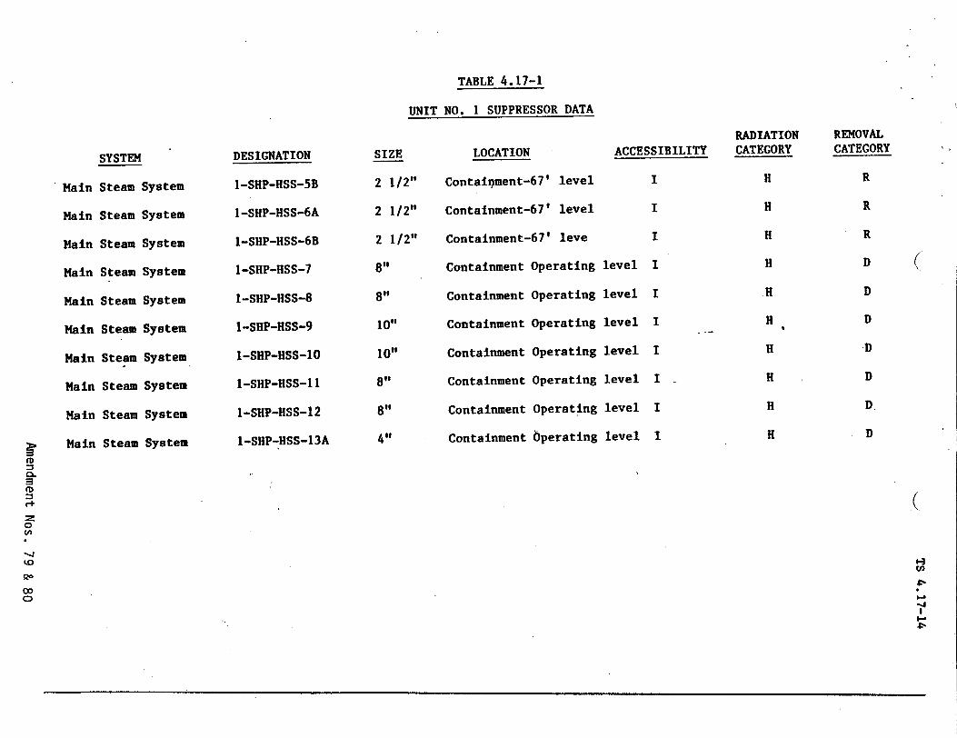
TABLE 4.17-1
UNIT NO. 1 SUPPRESSOR DATA
SYSTEM
Main Steam System
Main Steam System
Main Steam System
Main Steam System
Main Steam System
Main Steam System
Main Steam System
Main Steam System
Main Steam System
Main Steam System
DESIGNATION
I-SHP-HSS-5B
1-SHP-HSS-6A
I-SHP-HSS-6B
1-SHP-HSS-7
I-SHP-HSS-8
I-SHP-HSS-9
1-SHP-HSS-1O
1-SHP-HSS-11
1-SHP-HSS-12
I-SHP-HSS-13A
SIZE
2 1/2"
2 1/2"
2 1/2"
8"
8"
10"
10"
8"
8"
4"
LOCATION
Contaitnment-67' level
Containment-67' level
Containment-67' leve
Containment Operating
Containment Operating
Containment Operating
Containment Operating
Containment Operating
Containment Operating
Containment 6perating
ACCESSIBILITY
I
I
I
level I
level I
level I
level I
level I
level I
level I
RADIATION CATEGORY
H
H
H
H
.H
H
H
H
H
H
REMOVAL CATEGORY
R
R
R
D
D
D
.D
D
D.
D
C
(
-4
4-Ji
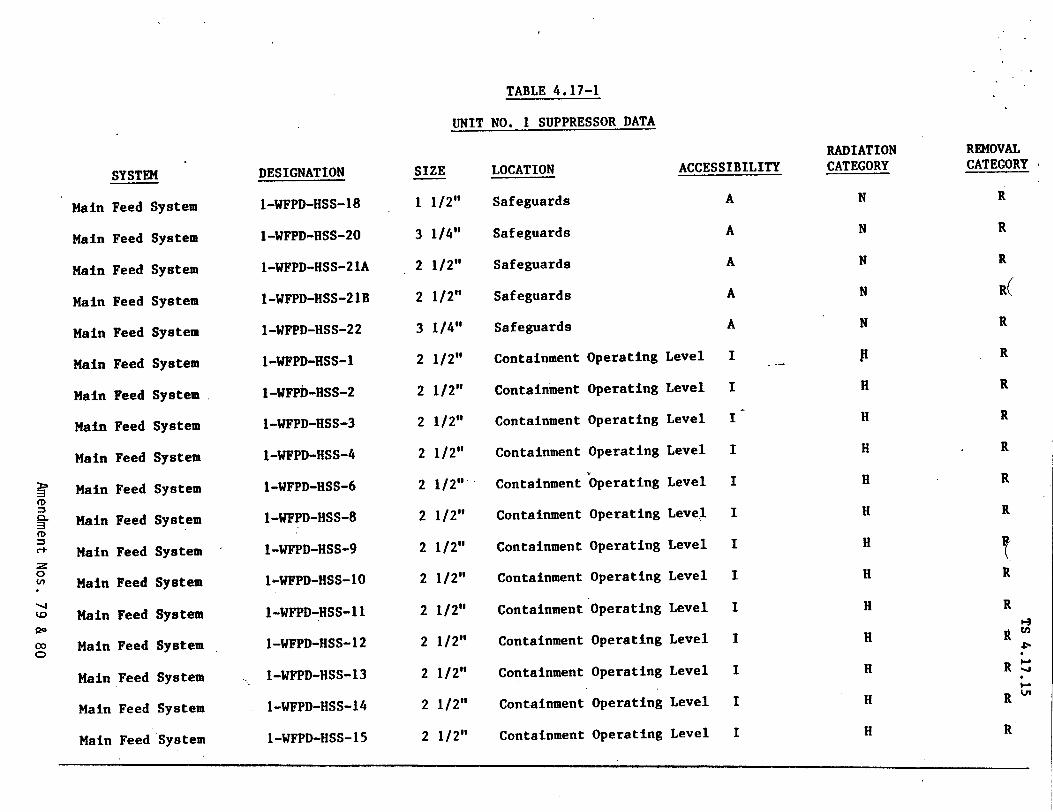
TABLE 4.17-1
UNIT NO. I SUPPRESSOR DATA
SYSTEM
Main Feed System
Main Feed System
Main Feed System
Main Feed System
Main Feed System
Main Feed System
Main Feed System
Main Feed System
Main Feed System
Main Feed System
Main Feed System
Main Feed System
Main Feed System
Main Feed System
Main Feed System
Main Feed System
Main Feed System
Main Feed System
DESIGNATION
I-WFPD-HSS-18
I-WFPD-HSS-20
I-WFPD-HSS-21A
1-WFPD-HSS-21B
1-WFPD-HSS-22
I-WFPD-HSS-1
1-WFPD-HSS-2
I-WFPD-HSS-3
I-WFPD-HSS-4
1-WFPD-HSS-6
1-WFPD-HSS-8
I-WFPD-HSS-9
1-WFPD-HSS-10
I-WFPD-HSS-11
I-WFPD-HSS-12
1-WFPD-HSS-13
I-WFPD-HSS-14
1-WFPD-HSS-15
SIZE
1 1/2"
3 1/4"
2 1/2"
2 1/2"
3 1/4"
2 1/2"
2 1/2"
2 1/2"
2 1/2"
2 1/2"
2 1/2"
2 1/2"
2 1/2"
2 1/2"
2 1/2"
2 1/2"
2 1/2"
2 1/2"
LOCATION
Safeguards
Safeguards
Safeguards
Safeguards
Safeguards
Containment
Containment
Containment
Containment
Containment
Containment
Containment
Containment
Containment
Containment
Containment
Containment
Containment
Operating
Operating
Operating
Operating
Operating
Operating
Operating
Operating
Operating
Operating
Operating
Operating
Operating
ACCESSIBILITY
A
A
A
A
A
evel I
evel I
evel I
evel I
evel I
evel I
evel I
.evel I
*evel I
evel I
Level I
Level I
evel I
L.
L
L
L
L
L
L
L
I
I
L
I
I
C.
0
14
co
CO •0
CO
RADIATION CATEGORY
N
N
N
N
N
P
H
H
H
H
H
H
H
H
H
H
H
H
REMOVAL CATEGORY
R
R
R
R(
R
R
R
R
R
R
R
R
R 0-3
4-.
RV
R
R
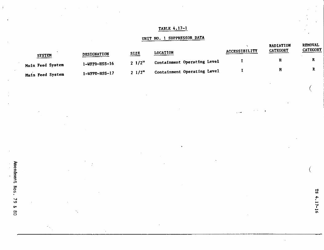
TABLE 4.17-1
UNIT NO. I SUPPRESSOR DATA
SYSTEM
Main Feed System
Main Feed System
DESIGNATION
I-WFPD-HSS-16
I-WFPD-HSS-17
SIZE
2 1/2"
2 1/2"
LOCATION
Containment Operating Level
Containment Operating Level
ACCESSIBILITY
I
I
(
CD
SCD
z 0
0
CD
RADIATION CATEGORY
H
H
REMOVAL CATEGORY
R
R
(
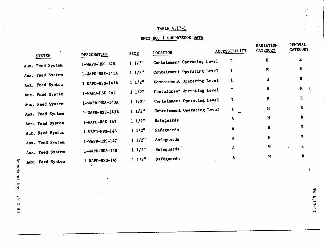
TABLE 4.17-1
UNIT NO. 1 SUPPRESSOR DATA
Aux. Feed System
SYSTEMSIZEDESIGNATION
I-WAPD-HSS-140
1-WAPD-HSS-141A
1-WAPD-HSS-141B
I-WAPD-HSS-142
1-WAPD-HSS-143A
I-WAPD-HSS-143B
I-WAPD-HSS-145
1-WAPD-HSS-146
I-WAPD-HSS-147
1-WAPD-HSS-148
I-WAPD-HSS-149
LOCATION
Containment
Containment
Containment
Containment
Containment
Containment
Safeguards
Safeguards
Safeguards
Safeguards
Operating
Operating
Operating
Operating
Operating
Operating
Leve
Lev
Levi
Levi
Lev
Lev
ACCESSIBILITY
el I
el I
el I
el I
el I
el I
A
A
1 1/2"
1 1/2"
1 1/2"
1 1/2"
1 1/2"
1 1/2"
1 1/2"
1 1/2"
1 1/2"
1 1/2"
1 1/2" Safeguards
Aux.
Aux.
Aux.
Aux.
Aux.
Aux.
Aux.
Aux.
Aux.
Aux.
Feed
Feed
Feed
Feed
Feed
Feed
Feed
Feed
Feed
Feed
System
System
System
System
System
System
System
System
I System
SSystem
A
A
A
RADIATION CATEGORY
H
H
H
H
H
H
N
N
N
N
N
REMOVAL CATEGORY
R
R
R
R
R
R
R
R
R
R
R
(
Cr,
0
-4
o0 CD
(
Hn
t-.1
"-J
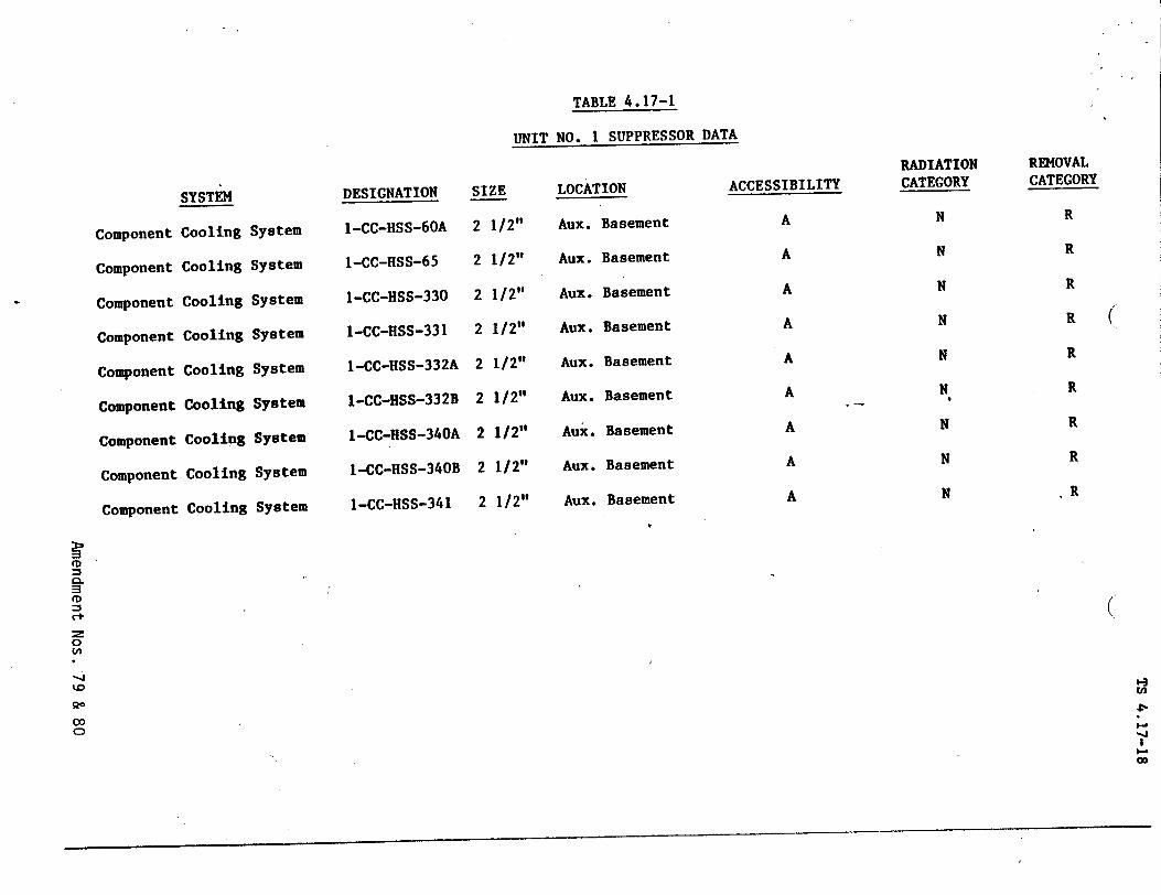
TABLE 4.17-1
UNIT NO. 1 SUPPRESSOR DATA
SYSTEM
Component Cooling System
Component Cooling System
Component Cooling System
Component Cooling System
Component Cooling System
Component Cooling System
Component Cooling System
Component Cooling System
Component Cooling System
DESIGNATION
I-CC-HSS-60A
1-CC-HSS-65
I-CC-HSS-330
1-CC-HSS-331
I-CC-HSS-332A
I-CC-HSS-332B
I-CC-HSS-340A
1-CC-HSS-340B
I-CC-HSS-341
SIZE
2 1/2"
2 1/2"
2 1/2"
2 1/2"
2 1/2"
2 1/2"
2 1/2"
2 1/2"
2 1/2"
LOCATION
Aux. Basement
Aux. Basement
Aux. Basement
Aux. Basement
Aux. Basement
Aux. Basement
Aux. Basement
Aux. Basement
Aux. Basement
ACCESSIBILITY
A
A
A
A
A
A
A
A
A
RADIATION CATEGORY
N
N
N
N
N
N
N
N
N
REMOVAL CATEGORY
R
R
R
R
R
R
R
R
R
CD
Ct
$.0 U,
00 CD
(
(
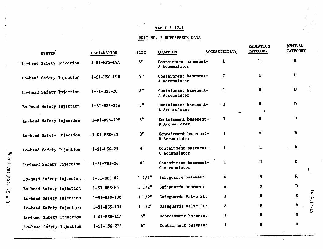
SYSTEM
Lo-head Safety Injection
Lo-head Safety Injection
Lo-head Safety Injection
Lo-head Safety Injection
Lo-head Safety Injection
Lo-head Safety Injection
Lo-head Safety Injection
Lo-head Safety Injection
Lo-head
Lo-head
Lo-head
Lo-head
Lo-head
Lo-head
Safety
Safety
Safety
Safety
Safety
Safety
Injection
Injection
Injection
Injection
Injection
Injection
DESIGNATION
I-SI-HSS-19A
I-SI-HSS-19B
I-SI-HSS-20
I-SI-HSS-22A
1-SI-HSS-22B
1-SI-HSS-23
I-SI-HSS-25
- 1-S$1-HSS-26
1-Sl-HSS-84
I-S1-HSS-85
1-S1-HSS-00
1-S1-HSS-101
I-SI-HSS-21A
1-SI-HSS-21B
TABLE 4.17-1
UNIT NO. 1 SUPPRESSOR DATA
SIZE LOCATION AC
5" Containment basementA Accumulator
5" Containment basementA Accumulator
8" Containment basementA Accumulator
5" Containment basementB Accumulator
5" Containment basementB Accumulator
8" Containment basementB Accumulator
8" Containment basementC Accumulator
8" Containment basementC Accumulator
1 1/2" Safeguards basement
1 1/2" Safeguards basement
1 1/2" Safeguards Valve Pit
1 1/2" Safeguards Valve Pit
4" Containment basement
4" Containment basement
CESSIBILITY
I
I
I
I
I
I
I
I
A
A
A
A
I
I
RADIATION CATEGORY
H
H
H
H
H
H
H
H
N
N
N
N
H
H
REMOVAL CATEGORY
D
D
D (
D
D
D
D
D
R
R
R
R
D
D
(
'-3
-J
'0
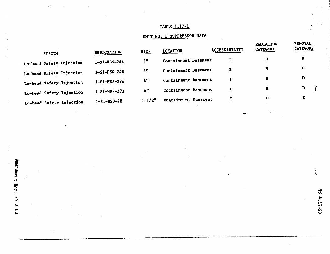
TABLE 4.17-1
UNIT NO. I SUPPRESSOR.DATA
SYSTEM
Lo-head Safety
Lo-head Safety
Lo-head Safety
Lo-head Safety
Lo-head Safety
DESIGNATION
I-SI-HSS-24A
I-SI-HSS-24B
I-SI-HSS-27A
1-SI-HSS-27B
I-SI-HSS-28
SIZE
4,l
41,
4"
41,
1 1/2"
LOCATION
Containment
Containment
Containment
Containment
Containment
ACCESSIBILITY
Basement I
Basement I
Basement I
Basement I
Basement I
Inj ect ion
Injection
Injection
Injection
Injection
RADIATION CATEGORY
H
H
H
H
H
REMOVAL CATEGORY
D
D
D
D (
R
CD
C+
o-,
0
"-4
20 C)
-J
O
v
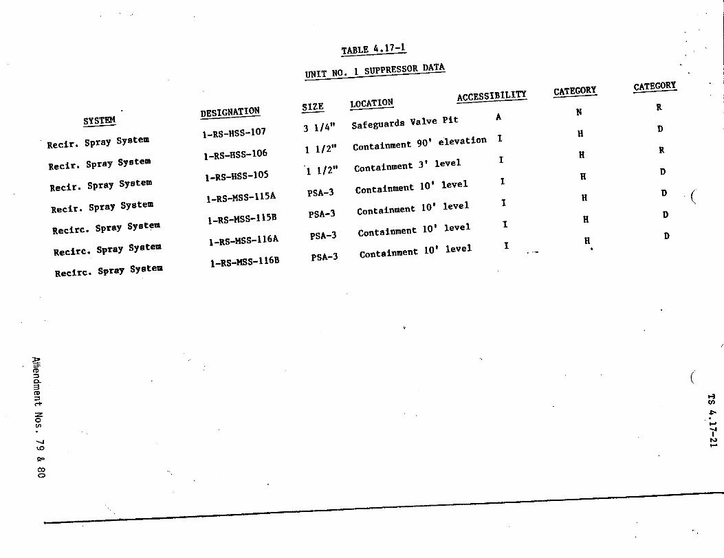
TABLE 4.17-1
UNIT NO. I SUPPRESSOR DATA
SYSTEM
Recir. Spray System
Recir. Spray System
Recir. Spray System
Recir. Spray System
Recirc. Spray System
Recirc. Spray System
Recirc. Spray System
DESIGNATION I-RS-HSS-1
0 7
I-RS-HSS-106
1-RS-HSS-105
I_RS-MSS-115 A
I-RS-MSS-115B
I-RS-MSS-1 16A
I_RS-MSS-116B
SIZE 3 1/4"
1 1/2"
"1 1/2"
PSA-3
PSA-3
PSA-3
PSA-3
LOCATION ACCESSIBILITY
Safeguards Valve Pit A
Containment 90' elevation I
Containment 3' level I
Containment I0' level
Containment 10' level
Containment i0' level
Containment i0' level
CATEGORY
N
H
H
H
H
H
H
CATEGORY
R
D
R
D
D
D
D
C+
0
Cl,
2-'
0 U,
-4
CD
(
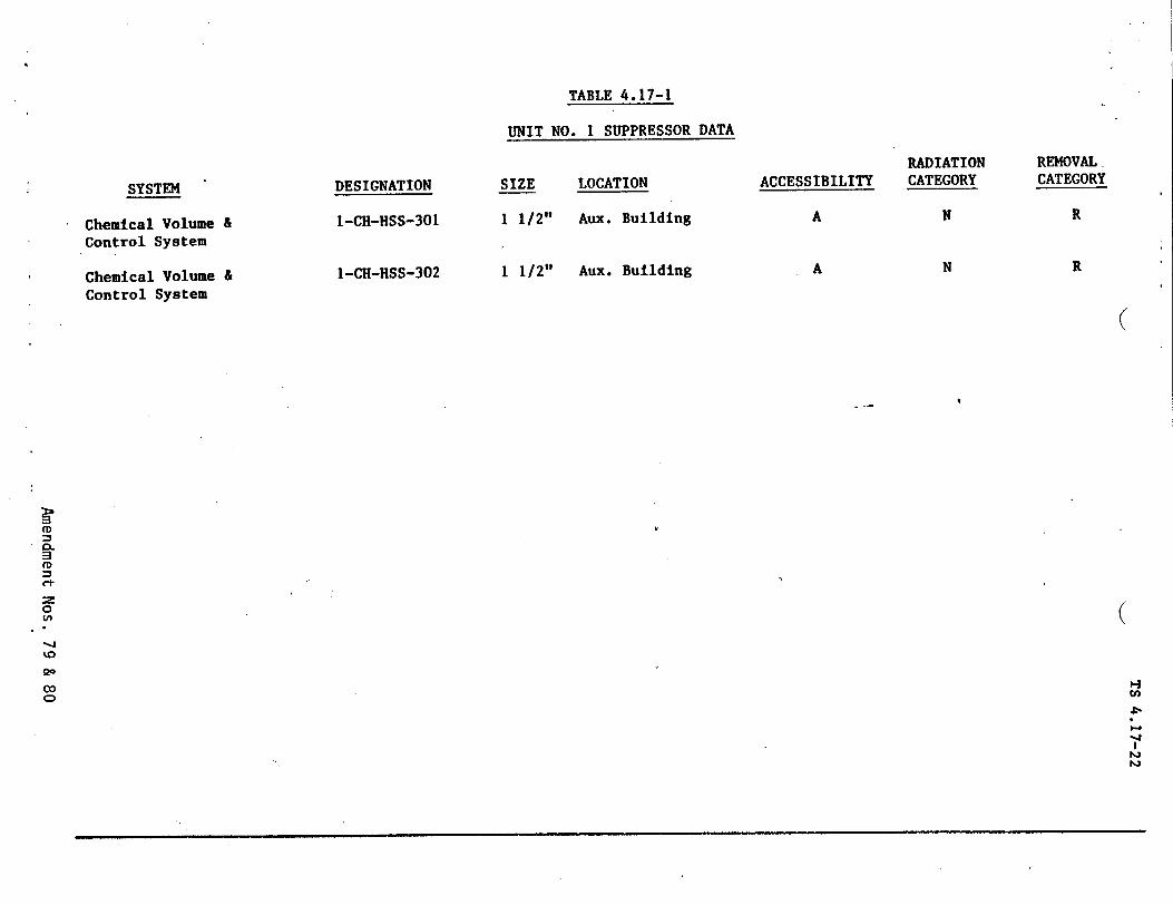
SYSTEM
Chemical Volume & Control System
Chemical Volume & Control System
DESIGNATION
1-CH-HSS-301
I-CH-HSS-302
TABLE 4.17-1
UNIT NO. I SUPPRESSOR DATA
SIZE LOCATION
1 1/2" Aux. Building
1 1/2" Aux. Building
ACCESSIBILITY
A
A
RADIATION CATEGORY
N
N
REMOVAL. CATEGORY
R
R
(
C+
0
00
Cý
"H4
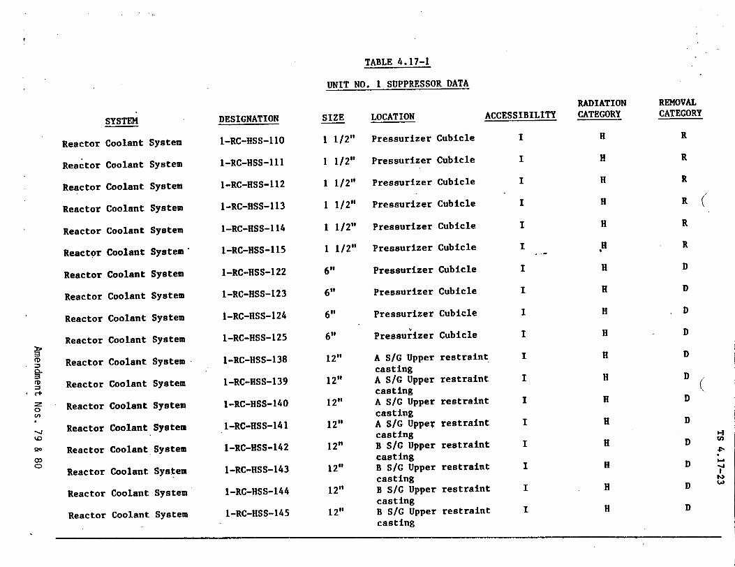
TABLE 4.17-1
UNIT NO. I SUPPRESSOR DATA
SYSTEM
Reactor Coolant System
DESIGNATION
1-RC-HSS-110
I-RC-HSS-111
I-RC-HSS-112
I-RC-HSS-113
1-RC-HSS-114
I-RC-HSS-115
I-RC-HSS-122
1-RC-HSS-123
I-RC-HSS-124
I-RC-HSS-125
I-RC-HSS-138
1-RC-HSS-139
I-RC-HSS-140
1-RC-HSS-141
1-RC-HSS-142
I-RC-HSS-143
I-RC-HSS-144
1-RC-HSS-145
SIZE
1 1/2"
1 1/2"
1 1/2"
1 1/2"
1 1/2"
1 1/2"
6"
6"
6"
6"
12"
12"
12"
12"
12"9
12"
12"
12"
Reactor (
Reactor
Reactor
Reactor 4
Reactor
Reactor
Reactor
Reactor
Reactor
Reactor
Reactor
Reactor
Reactor
Reactor
Reactor
Reactor
Reactor
'oolant
Coolant
Coolant
Coolant
Coolant
Coolant
Coolant
Coolant
Coolant
Coolant
Coolant
Coolant
Coolant
Coolant
Coolant
Coolant
Coolant
System
System
System
System
System'
System
System
System
System
System
System
System
System
System
System
System
System
LOCATION
Pressurizer
Pressurizer
Pressurizer
Pressurizer
Pressurizer
Pressurizer
Pressurizer
Pressurizer
Pressurizer
Pressurizer
A S/G Upper casting A S/G Upper casting A S/G Upper casting A S/C Upper casting B S/G Upper casting B S/C Upper casting B S/G Upper casting B S/G Upper casting
ACCESSIBILITY
Cubicle I
Cubicle I
Cubicle I
Cubicle I
Cubicle I
Cubicle I
Cubicle I
Cubicle I
Cubicle I
Cubicle I
restraint I
restraint I
restraint I
restraint I
restraint I
*restraint I
restraint I
* restraint I
0D ?t
(n
o c)
RADIATION CATEGORY
H
H
H
H
H
H
H
H
H
H
H
H
H
H
H
H
H
H
REMOVAL CATEGORY
R
R
R
R
R
R
D
D
D
D
D
D
D
D
D
D D
D
'-I
-4
'-a
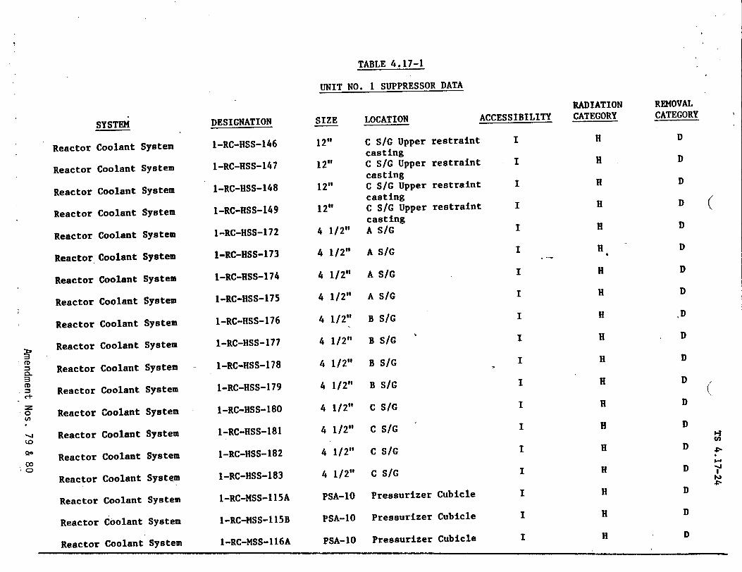
TABLE 4.17-1
UNIT NO. I SUPPRESSOR DATA
Reactor C
Reactor (
Reactor C
Reactor C
Reactor
Reactor.4
Reactor
Reactor
Reactor
Reactor
Reactor
Reactor
o Reactor
Reactor
Reactor
Reactor
Reactor
Reactor Coolant System
Reactor Coolant System
SYSTEMSIZE LOCATION
:oolant
•oolant
Coolant
oolant
Coolant
Coolant
Coolant
Coolant
Coolant
Coolant
Coolant
Coolant
Coolant
Coolant
Coolant
Coolant
Coolant
ystem
System
System
System
System
System
System
System
System
System
System
System
System
System
System
System
System
ACCESSIBILITYDESIGNATION
I-RC-HSS-146
1-RC-HSS-147
1-RC-HSS-148
1-RC-HSS-149
I-RC-HSS-172
I-RC-HSS-173
I-RC-HSS-174
1-RC-HSS-175
1-RC-HSS-176
1-RC-HSS-177
1-RC-HSS-178
I-RC-HSS-179
I-RC-HSS-180
1-RC-HSS-181
I-RC-HSS-182
1-RC-HSS-183
I-RC-MSS-115A
1-RC-MSS-1 15B
12"
12"
12"
12"
4 1/2"
4 1/2"
4 1/2"
4 1/2"
4 1/2"
4 1/2"
4 1/2"
4 1/2"
4 1/2"
4 1/2"
4 1/2"
4 1/2"
PSA-10
PSA-1O
C S/G Upper restraint casting C SIG Upper restraint casting C S/G Upper restraint casting C S/G Upper restraint casting A S/G
A SiG
A SiG
A S/G
B S/G
B SIC
B SiG
B S/G
C SiC
C S/G
C S/G
C SiC
Pressurizer Cubicle
Pressurizer Cubicle
I
I
I
I
I
I
I
I
I
I
I
I
I
I
I
I
I
I
I H1-RC-MSS-116A PSA-1O Pressurizer Cubicle
RADIATION CATEGORY
H
H
H
H
H
H
H
H
H
H
H
H
H
H
H
H
H
H
REMOVAL CATEGORY
D
D
D
D
D
D
D
D
*D
D
D
D
D
D
D
D
D
D
9-.3 Cn
4•
D
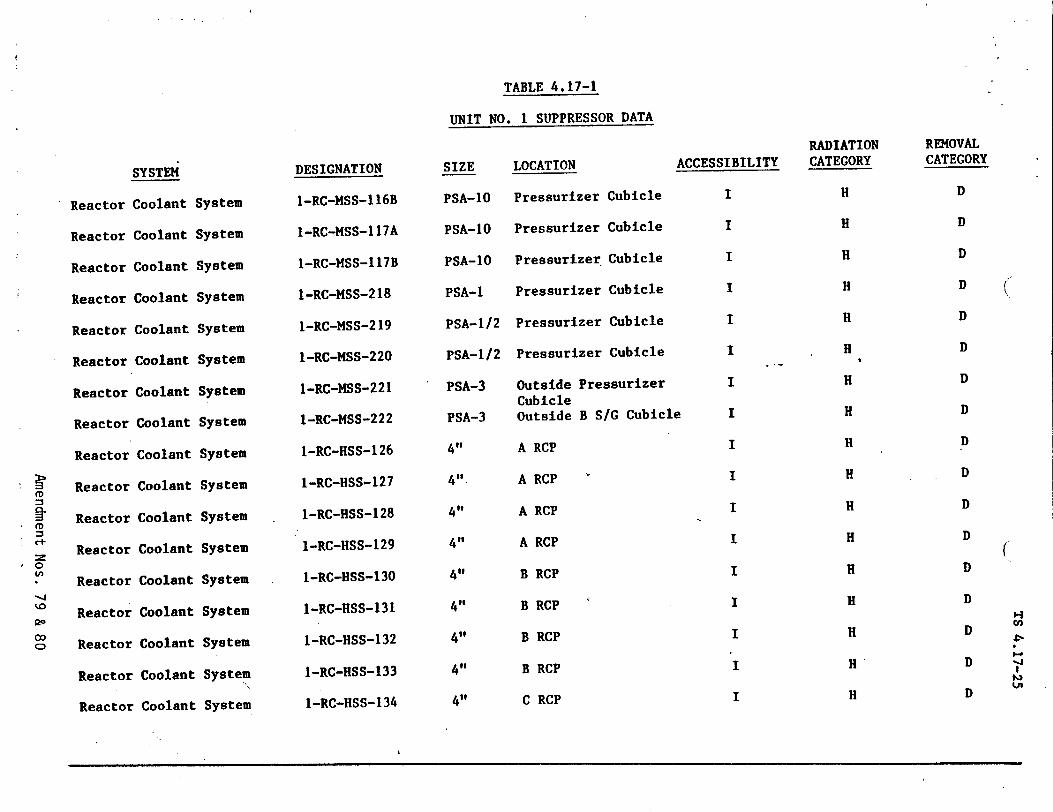
TABLE 4.17-1
UNIT NO. I SUPPRESSOR DATA
SYSTEM
Reactor Coolant System
Reactor Coolant System
Reactor Coolant System
Reactor Coolant System
Reactor Coolant System
Reactor Coolant System
Reactor Coolant System
Reactor Coolant System
Reactor Coolant System
Reactor Coolant System
Reactor Coolant System
Reactor Coolant System
Reactor Coolant System
Reactor Coolant System
Reactor Coolant System
Reactor Coolant System
Reactor Coolant System
DESIGNATION
1-RC-MSS-116B
1-RC-MSS-117A
1-RC-MSS-117B
1-RC-MSS-218
1-RC-MSS-219
I-RC-MSS-220
1-RC-MSS-221
I-RC-MSS-222
1-RC-HSS-126
I-RC-HSS-127
I-RC-HSS-128
1-RC-HSS-129
1-RC-HSS-130
1-RC-HSS-131
1-RC-HSS-132
I-RC-HSS-133
I-RC-HSS-134
SIZE
PSA-1O
PSA-1O
PSA-1O
PSA-1
PSA-1/2
PSA-1/2
PSA-3
PSA-3
4,,
4,,
4,,
4,,
4,,
4@@
4,,
4"
4,,
LOCATION
Pressurizer Cubicle
Pressurizer Cubicle
Pressurizer Cubicle
Pressurizer Cubicle
Pressurizer Cubicle
Pressurizer Cubicle
Outside Pressurizer Cubicle Outside B S/G Cubicle
A RCP
A RCP
A RCP
A RCP
B RCP
B RCP
B RCP
B RCP
C RCP
ACCESSIBILITY
I
I
I
I
I
I
I
I
I
I
I
I
I
I
I
I
I
RADIATION CATEGORY
H
H
H
H
H
H
H
H
H
H
H
H
H
H
H
H
H
REMOVAL CATEGORY
D
D
D
D
D
D
D
D
D
D
D
D
D
D
D
D
D
-J
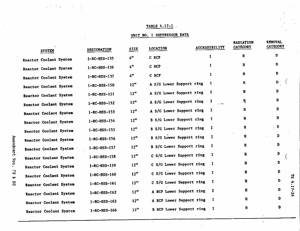
TABLE 4.17-1
UNIT NO. 1 SUPPRESSOR DATA
SYSTEMSIZE LOCATION
Reactor (
Reactor
Reactor (
Reactor I
Reactor
Reactor
Reactor
Reactor
Reactor
Reactor
Reactor
Reactor
Reactor
Reactor
Reactor
Reactor
Reactor
C RCPoolant
oolant
Coolant
Coolant
Coolant
Coolant
Coolant
Coolant
Coolant
Coolant
Coolant
Coolant
Coolant
Coolant
Coolant
Coolant
Coolant
ystem
Systemr
System
System
System
System
System
System
System
System
System
System
System
System
System
System
System
ILower Support
DESIGNATION
I-RC-HSS-135
1-RC-HSS-136
1-RC-HSS-137
I-RC-HSS-150
I-RC-HSS-151
1-RC-HSS-152
1-RC-HSS-153
1-RC-HSS-154
1-RC-HSS-155
1-RC-HSS-156
I-RC-HSS-157
1-RC-HSS-158
I-RC-HSS-159
I-RC-HSS-160
1-RC-HSS-161
1-RC-HSS-162
I-RC-HSS-163
4"
4,'
4"
12"
12"
12"
12"
12"
12"
12"
12"
12"
12"
12"
12"
12"
12"
ACCESSIBILITY
I
I
I
ring I
C
C
A
A
A
A
B
B
B
B
C
C
C
C
A
A
RCP
RCP
S/G
S/G
S/G
S/G
S/G
S/G
SIC
S/G
S/C
S/C
S/C
S/G
RCP
RCP
I1-RC-HSS-166 12" B RCP Lower Support ring
Lower
Lower
Lower
Lower
Lower
Lower
Lower
Lower
Lower
Lower
Lower
Lower
Lower
Support
Support
Support
Support
Support
Support
Support
Support
Support
Support
Support
Support
Support
ring
ring
ring
ring
ring
ring
ring
ring
ring
ring
ring
ring
ring
I
I
I
I
I
I
I
I
I
I
I
I
I
CD
0
"-4
co en
RADIATION CATEGORY
H
H
H
H
H
H
H
H
H
H
H
H
H
H
H
H
REMOVAL CATEGORY
D
D
D
D
D
D
D
D
D
D
D
D
D
D
D
D
D
H DReactor Coolant System
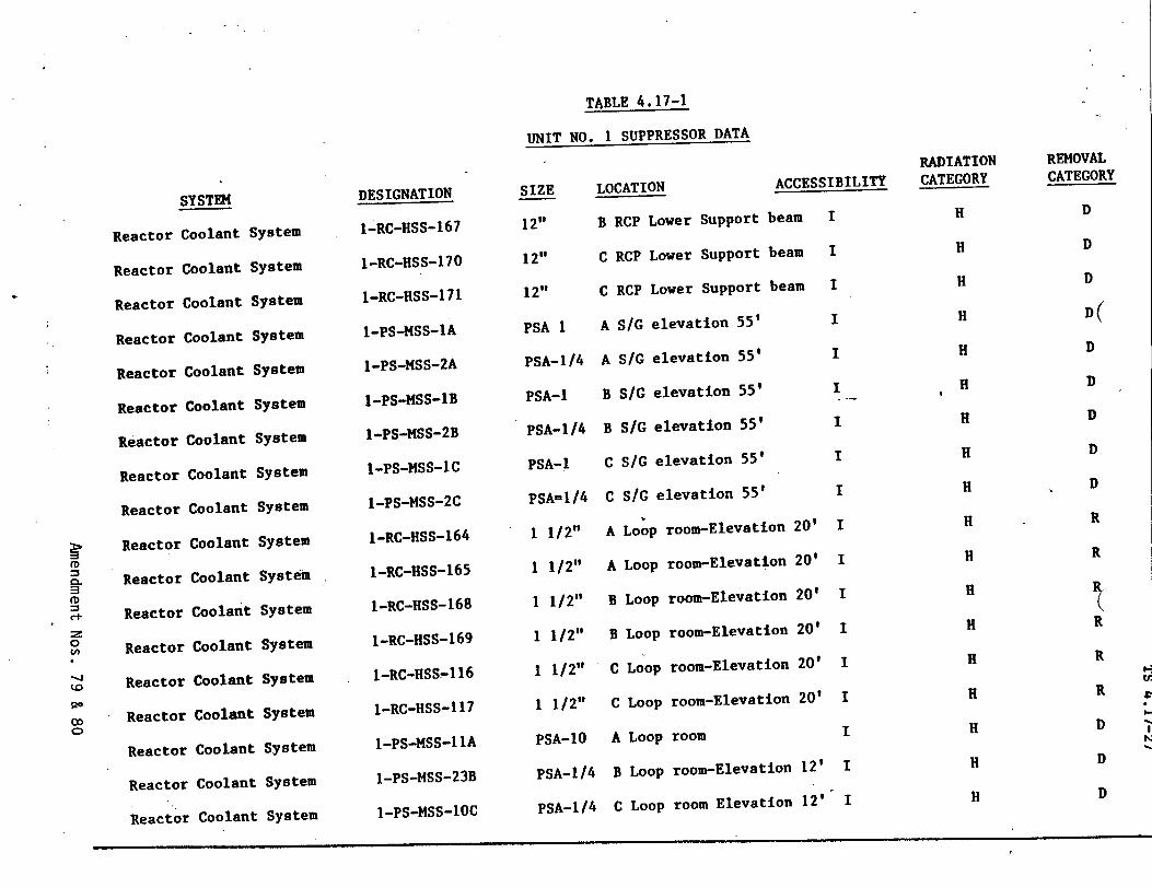
TABLE 4.17-1
UNIT NO. 1 SUPPRESSOR DATA
Reactor Coolant System
Reactor Coolant System
Reactor Coolant System
Reactor Coolant System
Reactor Coolant System
Reactor Coolant System
Reactor Coolant System
Reactor Coolant System
Reactor Coolant System
Reactor Coolant System
Reactor Coolant System
Reactor Coolant System
Reactor Coolant System
Reactor Coolant System
Reactor Coolant System
Reactor Coolant System
Reactor Coolant System
Reactor Coolant System
SYSTEMSIZE LOCATION
DESIGNATION
1-RC-HSS-167
1-RC-HSS-170
1-RC-HSS-171
1-PS-MSS-1A
I-PS-MSS-2A
I-PS-MSS-B
1-PS-MSS-2B
I-PS-MSS-LC
I-PS-MSS-2C
1-RC-HSS-164
I-RC-HSS-165
I-RC-HSS-168
I-RC-HSS-169
1-RC-HSS-116
1-RC-HSS-117
1-PS-MSS-11A
1-PS-MSS-23B
1-PS-MSS-1OC
ACCESSIBILITY
B RCP Lower Support beam12"
12"
12"
PSA 1
PSA-1/4
PSA-1
PSA-1 /4
PSA-1
PSA-I/4
1 1/2"
1 1/2"
1 1/2"
1 1/2"
1 1/2"
1 1/2"
PSA-10
PSA-1/4
C
C
A
A
B
B
C
C
A
A
B
(
RCP Lower Support beam
RCP Lower Support beam
S/G elevation 55'
S/G elevation 55'
S/G elevation 55'
S/G elevation 55'
S/G elevation 55'
S/G elevation 55'
Loop room-Elevation 20'
Loop room-Elevation 20'
Loop room-Elevation 20'
Loop room-Elevation 20'
Loop room-Elevation 20'
3 Loop room-Elevation 20'
k Loop room
B Loop room-Elevation 12'
0.
14 z
to
00
Cn
Co
I
I
I
I
I
I
I
I
I
I
I
I
I
I
I
I
I
RADIATION CATEGORY
H
H
H
H
H
H H
H
H
H
H
H
H
H
H
H
H
H
REMOVAL CATEGORY
D
D
D
D(
D
D
D
D
D
R
R
R
R R
D
D
D
PSA-1/4 C Loop room Elevation 12'
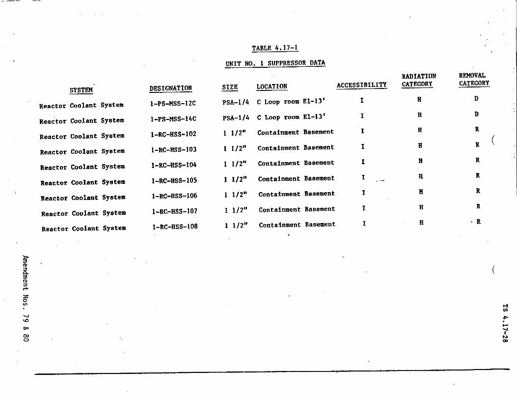
TABLE 4.17-1
UNIT NO. 1 SUPPRESSOR DATA
DESIGNATION
I-PS-MSS-12C
1-PS-mSS-14C
1-RC-HSS-102
1-RC-HSS-103
I-RC-HSS-104
1-RC-HSS-105
I-RC-HSS-106
1-RC-HSS-107
1-RC-HSS-108
SIZE
PSA-1/4
PSA-1/4
1 1/2"
1 1/2"
1 1/2"
1 1/2"
1 1/2"
1 1/2"
1 1/2"
LOCATION
C Loop room
C Loop room
Containment
Containment
Containment
Containment
Containment
Containment
Containment
El-13'
El-13'
Basement
Basement
Basement
Basement
Basement
Basement
Basement
ACCESSIBILITY
I
I
I
I
I
I
I
I
I
((D
C+.
0 U,
co o
SYSTEM
Coolant
Coolant
Coolant
Coolant
Coolant
Coolant
Coolant
Coolant
Coolant
Reactor
Reactor
Reactor
Reactor
Reactor
Reactor
Reactor
Reactor
Reactor
System
System
System
System
System
System
System
System
System
RADIATION CATEGORY
H
H
H
H
H
H
H
H
H
REMOVAL CATEGORY
D
D
R
R
R
R
R
R
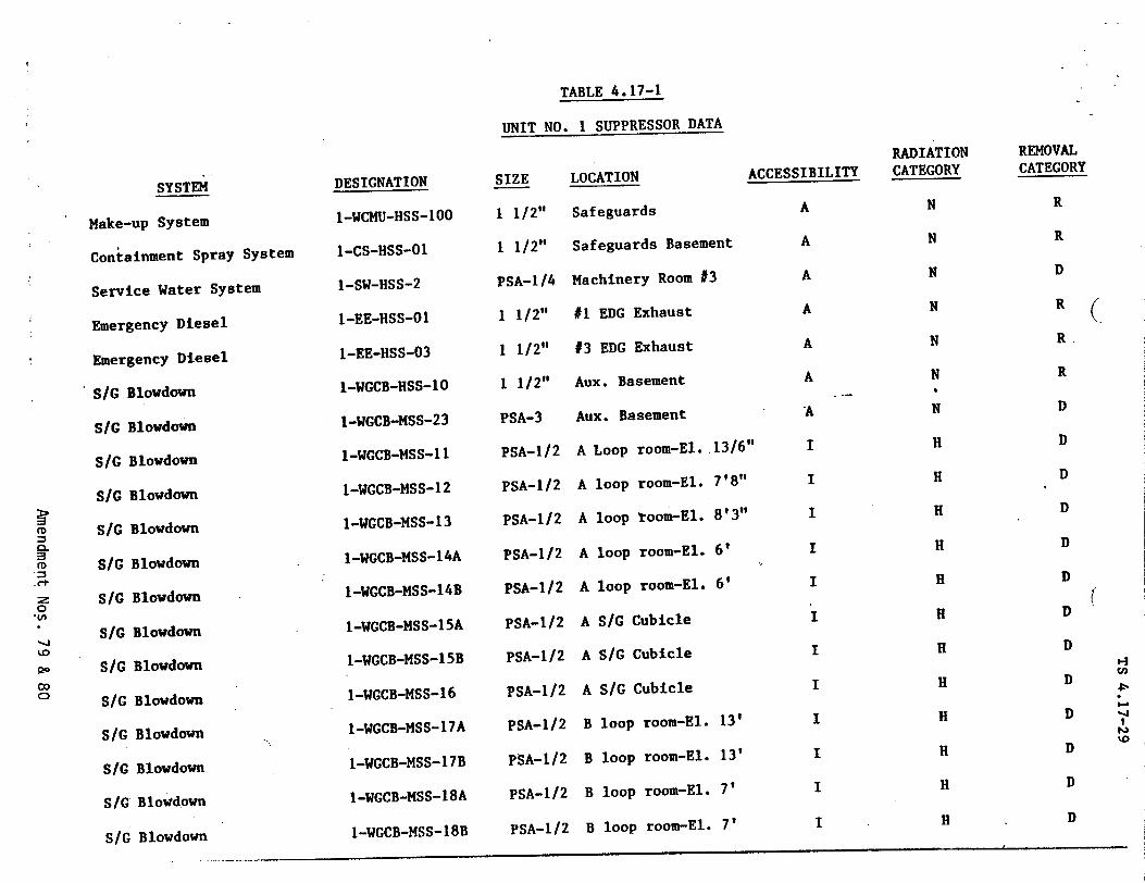
TABLE 4.17-1
UNIT NO. 1 SUPPRESSOR DATA
SYSTEM
Make-up System
Containment Spray System
Service Water System
Emergency Diesel
Emergency Diesel
S/G Blowdown
S/G Blowdown
S/G Blowdown
S/G Blowdown
S/G Blowdown
S/G Blowdown
S/G Blowdown
S/G Blowdown
S/G Blowdown
S/G Blowdown
S/G Blowdown
S/G Blowdown
S/G Blowdown
S/G Blowdown
DESIGNATION
I-WCMU-HSS-100
1-CS-HSS-01
1-SW-HSS-2
I-EE-HSS-O1
I-EE-HSS-03
1-WGCB-HSS-10
1-WGCB-MSS-23
I-WGCB-MSS-11
I-WGCB-MSS-12
I-WGCB-MSS-13
1-WGCB-MSS-14A
I-WGCB-MSS-14B
1-WGCB-MSS-15A
1-WGCB-MSS-15B
I-WGCB-MSS-16
1-WGCB-MSS-17A
1-WGCB-MSS-17B
I-WGCB-MSS-18A
I-WGCB-MSS-18B
SIZE LOCATION ACCESSIBILITY
1 1/2" Safeguards A
1 1/2" Safeguards Basement A
PSA-1/4 Machinery Room #3 A
1 1/2" #1 EDG Exhaust A
1 1/2" #3 EDG Exhaust A
1 1/2" Aux. Basement A
PSA-3 Aux. Basement -A
PSA-1/2 A Loop room-El. 13/6" I
PSA-1/2 A loop room-El. 7'8" I
PSA-1/2 A loop toom-El. 8'3" I
PSA-1/2 A loop room-El. 6' I
PSA-1/2 A loop room-El. 6' I
PSA-1/2 A S/G Cubicle
PSA-1/2 A S/G Cubicle I
PSA-1/2 A S/G Cubicle I
PSA-1/2 B loop room-El. 13' I
PSA-1/2 B loop room-El. 13' I
PSA-1/2 B loop room-El. 7' I
PSA-1/2 B loop room-El. 7' I
CL =q
r1
"::z
0
-.1
00
RADIATION CATEGORY
N
N
N
N
N
N
N
H
H
H
H
H
H
H
H
H
H
H
H
REMOVAL CATEGORY
R
R
D
R
R
R
D
D
D
D
D
D
D
D
D
D
D
D
D
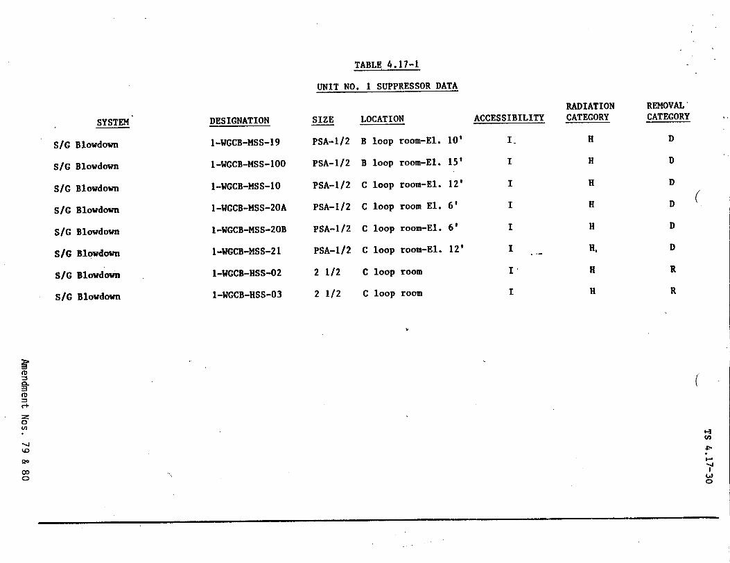
TABLE 4.17-1
UNIT NO. I SUPPRESSOR DATA
SYSTEM
Blowdown
Blowdown
Blowdown
Blowdown
Blowdown
Blowdown
Blowdown
Blowdown
DESIGNATION
I-WGCB-MSS-19
I-WGCB-MSS-100
1-WGCB-MSS-10
I-WGCB-MSS-20A
1-WGCB-MSS-20B
1-WGCB-MSS-21
1-WGCB-HSS-02
1-WGCB-HSS-03
SIZE
PSA-1/2
PSA-1/2
PSA-1/2
PSA-1/2
PSA-1/2
PSA-1/2
2 1/2
2 1/2
LOCATION
B loop room-El.
B loop room-El.
C loop room-El.
C loop room El.
C loop room-El.
C loop room-El.
C loop room
C loop room
10'
15'
12'
6'
6'
12'
ACCESSIBILITY
I
I
I
I
I
I
I,
I
sic
S/G
SiG
SIG
S/G
SI/
S/G
S/G
RADIATION CATEGORY
H
H
H
H
H
H.
H
H
REMOVAL* CATEGORY
D
D
D
D
D
D
R
R
(
(
1-3
-.1
0
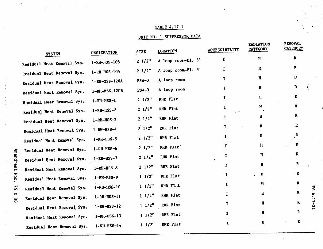
TABLE 4.17-1
UNIT NO. I SUPPRESSOR DATA
Residual H
Residual H
Residual H
Residual H
Residual H
Residual I
Residual I
Residual l
Residual
Residual
Residual
Residual
Residual
Residual
Residual
Residual
Residual
Residual
SYSTEM
eat Removal
eat Removal
eat Removal
[eat Removal
Removal
Removal
Removal
Removal
Removal
Removal
Removal
Removal
* Removal
SRemoval
* Removal
t Removal
S
S
S
IC
eat
leat
teat
Heat
Heat
Heat
Heat
Heat
Heat
Heat
Heat
Heat
Heat
Heat
YB.
ys.
'ys.
5ys.
'ys.
ysB.
Sys.
Sys.
Sys.
Sys.
Sys.
Sys.
Sys.
Sys.
Sys.
Sys.
DESIGNATION
I-RH-HSS-103
I-RH-HSS-104
I-RH-MSS-120A
1-RH-MSS-120B
I-RH-HSS-1
1-RH-HSS-2
1-RH-HSS-3
1-RH-HSS-4
I-RH-HSS-5
I-RH-HSS-6
1-RH-HSS-7
I-RH-HSS-8
I-RH-HSS-9
I-RH-HSS-10
1-RH-HSS-11
I-RH-HSS-12
i-RH-HSS-13
I-RH-HSS-14
1
I
1/2"
1/2"
SIZE
2 1/2"
2 1/2"
PSA-3
PSA-3
2 1/2"
2 1/2"
2 1/2"
2 1/2"
2 1/2"
2 1/2"
2 1/2"
2 1/2"
1 1/2"
1 1/2"
1 1/2"
1 1/2"
LOCATION
A loop room-El. 3'
A loop room-El. 3'
A loop room
A loop room
RHR Flat
RHR Flat
RHR Flat
RHR Flat
RHR Flat
RHR Flat'
RHR Flat
RHR Flat
RHR Flat
RHR Flat'
RHR Flat
RHR Flat
RHR Flat
RHR Flat
ACCESSIBILITY I
I
I
I
I
I
I
I
I
I
I
I
I
I
I
I
IRemoval Sys.
Removal Sys.
CD
0.
00
Cý
RADIATION CATEGORY
H
H
H
H
H
H
H
H
H
H
H
H
H
H
H
H
H
H
REMOVAL CATEGORY
R
R
D
D
R
R
R
R
R
R
R
R
R
R
R
R
R
R
(
14
-,=
t
t
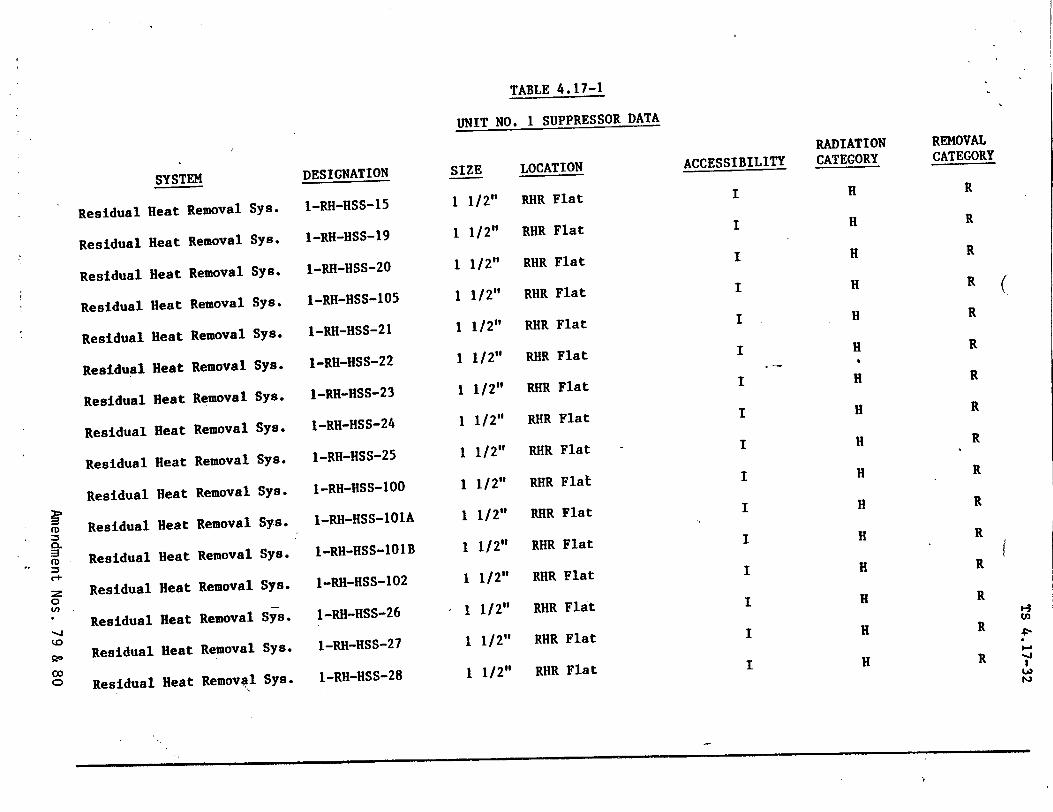
TABLE 4.17-1
UNIT NO. 1 SUPPRESSOR DATA
SYSTEM
Residual Heat Removal Sys.
Residual Heat Removal Sys.
Residual Heat Removal Sys.
Residual Heat Removal Sys.
Residual Heat Removal Sys.
Residual Heat Removal Sys.
Residual Heat Removal Sys.
Residual Heat Removal Sys*
Residual Heat Removal Sys*
Residual Heat Removal Sys.
Residual Heat Removal Sys.
Residual Heat Removal Sys.
Residual Heat Removal Sys.
Residual Heat Removal Sys.
Residual Heat Removal Sys.
Residual Heat Removal Sys.
DESIGNATION
I-RH-HSS-15
I-RH-HSS-19
1-RH-HSS-20
I-RH-HSS-105
I-RH-HSS-21
1-RH-HSS-22
I-RH-HSS-23
I-RH-HSS-24
I-RH-HSS-25
I-RH-HSS-100
I-RH-HSS-101A
I-RH-HSS-1O1B
I-RH-HSS-102
1-RH-HSS-26
1-RH-HSS-27
1-RH-HSS-28
SIZE
1 1/2"
1 1/2"
1 1/2"
1 1/2"
1 1/2"
1 1/2"
1 1/2"
1 1/2"
1 1/2"
1 1/2"
1 1/2"
1 1/2"
1 1/2"
1 1/2"
1 1/2"
1 1/2"
LOCATION
RHR Flat
RHR Flat
RHR Flat
RHR Flat
RHR Flat
RHR Flat
RHR Flat
RHR Flat
RHR Flat
RHR Flat
RHR Flat
RHR Flat
RHR Flat
RHR Flat
RHR Flat
RHR Flat
ACCESSIBILITY I
I
I
I
I
I
I
I
I
I
I
I
I
I
I
I
RADIATION CATEGORY
H
H
H
H
H
H H
H
H
H
H
H
H
H
H
H
REMOVAL CATEGORY
R
R
R
R
R
R
R
R
R
R
R
R
R
R
R
R
tD
0D
o.
0
go
0,
00
CD
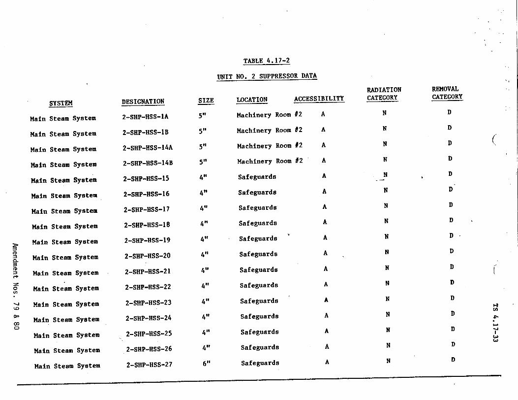
SYSTEM
Main Steam System
Main Steam System
Main Steam System
Main Steam System
Main Steam System
Main Steam System
Main Steam System
Main Steam System
Main Steam System
Main Steam System
Main Steam System
Main Steam System
Main Steam System
Main Steam System
Main Steam System
Main Steam System
Main Steam System
DESIGNATION
2-SHP-HSS-lA
2-SHP-HSS-1B
2-SHP-HSS-14A
2-SHP-HSS-14B
2-SHP-HSS-15
2-SHP-HSS-16
2-SHP-HSS-17
2-SHP-HSS-18
2-SHP-HSS-19
2-SHP-HSS-20
2-SHP-HSS-21
2-SHP-HSS-22
2-SHP-HSS-23
2-SHP-HSS-24
2-SHP-HSS-25
2-SHP-HSS-26
2-SHP-HSS-27
SIZE
5,,
50,
5,,
5,,
4,,
4,,
4"
4,,
4,,
4,,
4"
4,,
4"
4"
4,,
41,
61'
TABLE 4.17-2
UNIT NO. 2 SUPPRESSOR DATA
LOCATION ACCESSIBILITY
Machinery Room #2 A
Machinery Room #2 A
Machinery Room #2 A
Machinery Room #2 A
Safeguards A
Safeguards A
Safeguards A
Safeguards A
Safeguards A
Safeguards A
Safeguards A
Safeguards A
Safeguards A
Safeguards A
Safeguards A
Safeguards A
Safeguards A
RADIATION CATEGORY
N
N
N
N
N
N
N
N
N
N
N
N
N
N
N
N
N
REMOVAL CATEGORY
D
D
D
D
D
D
D
D
D
D
D
D
D
D
D
D
D
(
i-J
Ia (a)
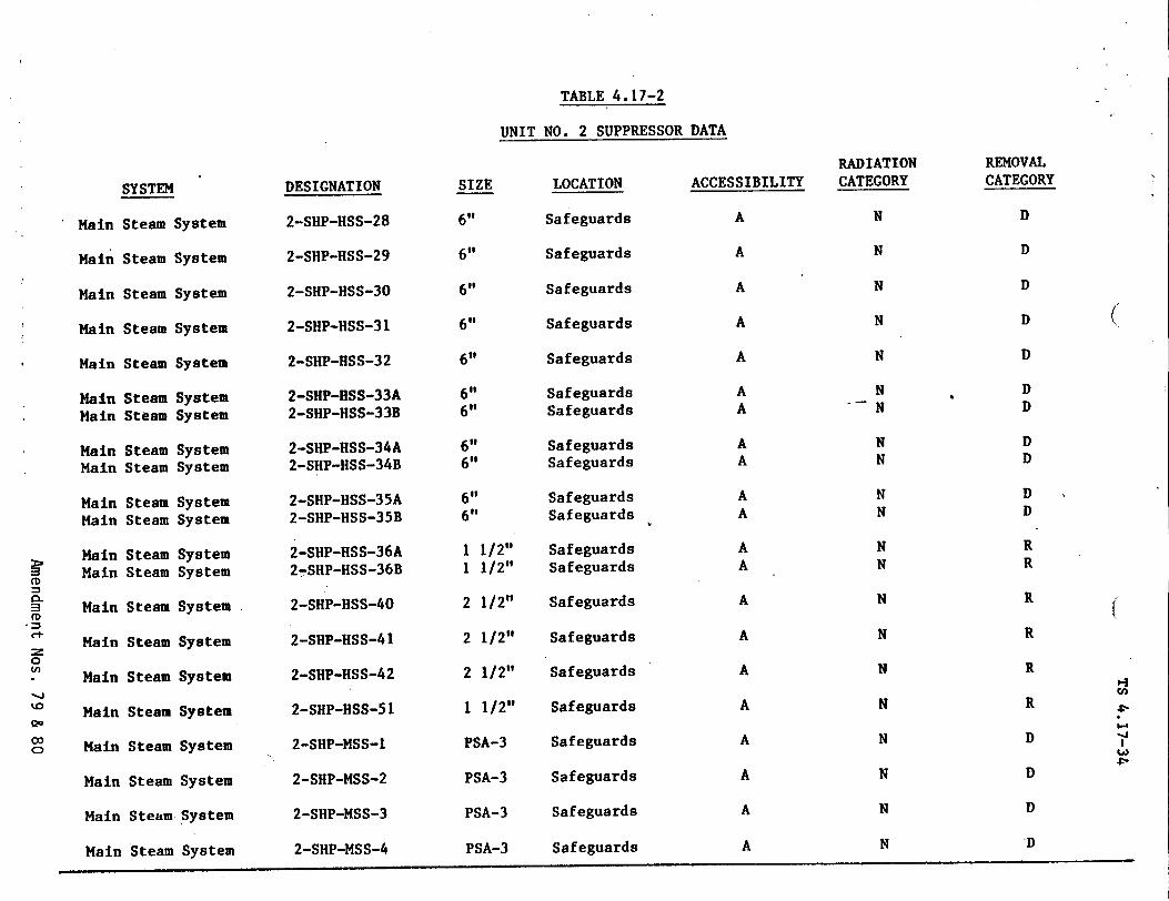
TABLE 4.17-2
UNIT NO. 2 SUPPRESSOR DATA
SYSTEM
Main Steam System
Main Steam System
Main Steam System
Main Steam System
Main Steam System
Main Steam System Main Steam System
Main Steam System Main Steam System
Main Steam System Main Steam System
Main Steam System Main Steam System
= Main Steam System
Main Steam System
0
r Main Steam System
to Main Steam System
co
Main Steam System
Main Steam System
Main Steam System Main Steam System
DESIGNATION
2-SHP-HSS-28
2-SHP-HSS-29
2-SHP-HSS-30
2-SHP-HSS-31
2-SHP-HSS-32
2-SHP-HSS-33A 2-SHP-HSS-33B
2-SHP-HSS-34A 2-SHP-HSS-34B
2-SHP-HSS-35A 2-SHP-HSS-35B
2-SHP-HSS-36A 27SHP-HSS-36B
2-SHP-HSS-40
2-SHP-HSS-41
2-SHP-HSS-42
2-SHP-HSS-51
2-SHP-MSS-1
2-SHP-MSS-2
2-SHP-MSS-3
2-SHP-MSS-4
SIZE
6"1
6"
6"
6"
6"
6" 6"
6" 6"
6"
6"
1 1/2"
1 1/2"
2 1/2"
2 1/2"
2 1/2"
1 1/2"
PSA-3
PSA-3
PSA-3
PSA-3
LOCATION
Safeguards
Safeguards
Safeguards
Safeguards
Safeguards
Safeguards
Safeguards
Safeguards
Safeguards
Safeguards
Safeguards
Safeguards
Safeguards
Safeguards
Safeguards
Safeguards
Safeguards
Safeguards
Safeguards
Safeguards
Safeguards
ACCESSIBILITY
A
A
A
A
A
A
A
A
A
A
A
A
A
A
A
A
A
A
A
A
A
RADIATION CATEGORY
REMOVAL CATEGORY
(
N
N
N
N
N
N "N
N N
N N
N
N
N
N
N
N
N
N
N
N
r.
'-3 Cl)
-J
w
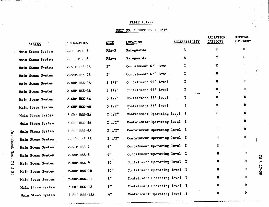
TABLE 4.17-2
UNIT NO. 2 SUPPRESSOR DATA
SYSTEM
Main Steam System
Main' Steam System
Main Steam System
Main Steam System
Main Steam System
Main Steam System
Main Steam System
Main Steam System
Main Steam System
Main Steam System
Main Steam System
Main Steam System
Main Steam System
Main Steam System
Main Steam System
Main Steam System
Main Steam System
Main Steam System
DESIGNATION
2-SHP-MSS-5
2-SHP-MSS-6
2-SHP-HSS-2A
2-SHP-HSS-2B
2-SHP-HSS-3A
2-SHP-HSS-3B
2-SHP-HSS-4A
2-SHP-HSS-4B
2-SHP-HSS-5A
2-SHP-HSS-SB
2-SHP-HSS-6A
2-SHP-HSS-6B
2-SHP-HSS-7
2-SHP-HSS-8
2-SHP-HSS-9
2-SHP-HSS-10
2-SHP-HSS-11
2-SHP-HSS-12
SIZE
PSA-3
PSA-4
5',
55"
3 1/2"
3 1/2"
3 1/2"
3 1/2"
2 1/2"
2 1/2"
2 1/2"
2 1/2"
6"
6"
logo
10"
8"
8"
LOCATION
Safeguards
Safeguards
Containment 67' leve
Containment 67' level
Containment 55' level
Containment 55' level
Containment 55' level
Containment 55' level
Containment Operating
ContainmentýOperating
Containment Operating
Containment Operating
Containment Operating
Containment'Operating
Containment Operating
Containment Operating
Containment Operating
Containment Operating
ACCESSIBILITY
A
A
I
I
I
I
I
I
level I
level I
level I
level I
level I
level I
level I
level I
level I
level I
H DMain Steam System 2-SHP-HSS-13A
CL
CD
0
UD.
20
CD
RADIATION CATEGORY
N
N
H
H
H
H
H
H
H
H
H
H
H
H
H
H
H
H
REMOVAL CATEGORY
D
D
D
D
R
R
R
R
R
R
R
R
D
D
D
D
D
D
(
(
'-3 cn
I-.
La) La'
Containment Operating level .14"
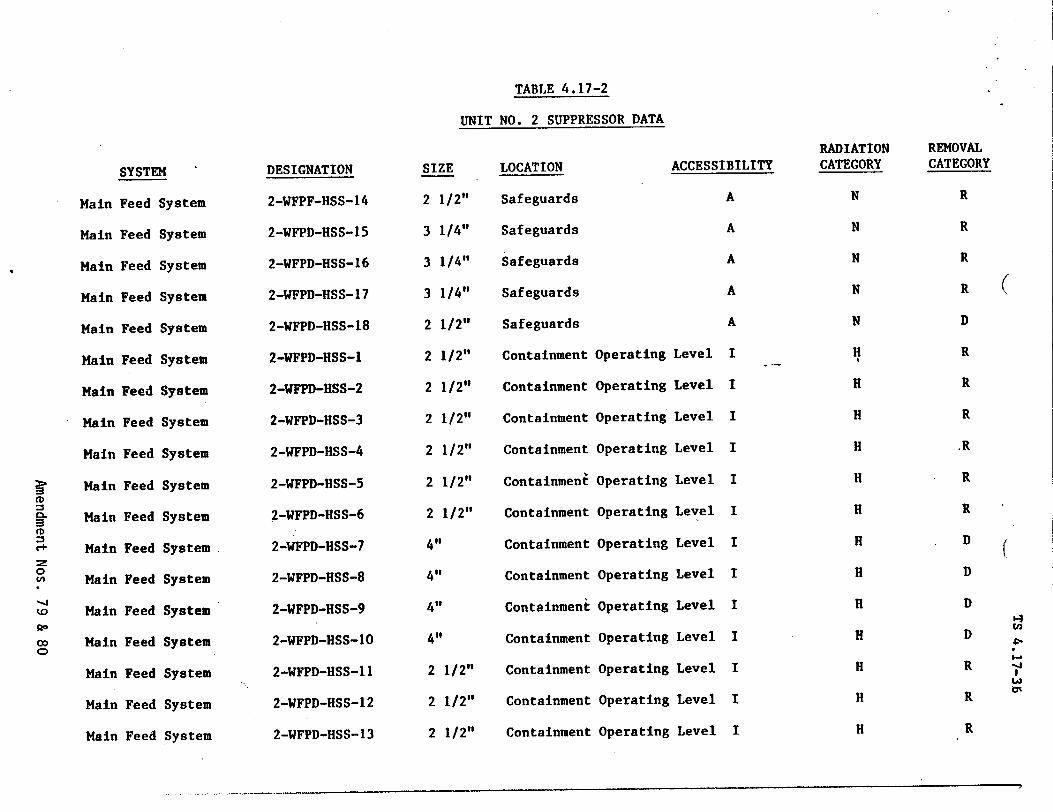
TABLE 4.17-2
UNIT NO. 2 SUPPRESSOR DATA
SYSTEM SIZE
Main
Main
Main
Main
Main
Main
Main
Main
Main
Main
Main
Main
Ma in
Main
Main
Main
Main
Main
Feed
Feed
Feed
Feed
Feed
Feed
Feed
Feed
Feed
Feed
Feed
Feed
Feed
Feed
Feed
Feed
Feed
Feed
System
System
System
System
System
System
System
System
System
System
System
System
System
System
System
System
System
.System
DESIGNATION
2-WFPF-HSS-14
2-WFPD-HSS-15
2-WFPD-HSS-16
2-WFPD-HSS-17
2-WFPD-HSS-18
2-WFPD-HSS-1
2-WFPD-HSS-2
2-WFPD-HSS-3
2-WFPD-HSS-4
2-WFPD-HSS-5
2-WFPD-HSS-6
2-WFPD-HSS-7
2-WFPD-HSS-8
2-WFPD-HSS-9
2-WFPD-HSS-10
2-WFPD-HSS-11
2-WFPD-HSS-12
2-WFPD-HSS-13
21
31
31
31
2 1
21
2
2
2
2
2
4"
4"
4"
4"
2
2
2
1/2"
1/2"
1/2"
/2"
/4"
/14"
.14"
I12"
I12"
/2"
1/2"
1/2" 1 /2"
LOCATION
Safeguards
Safeguards
Safeguards
Safeguards
Safeguards
Containment
Containment
Containment
Containment
Containment
Containment
Containment
Containment
Containment
Containment
Containment
Containment
Containment
ACCESSIBILITY
A
A
A
A
A
Operating Level I
Operating Level I
Operating Level I
Operating Level I
Operating Level I
Operating Level I
Operating Level I
Operating Level I
Operating Level I
Operating Level I
Operating Level I
Operating Level I
Operating Level I
CD
2:z 0
kD
co C)
RADIATION CATEGORY
N
N
N
N
N
H
H
H
H
H
H
H
H
H
H
H
H
H
REMOVAL CATEGORY
R
R
R
R
D
R
R
R
.R
R
R
D
D
D
D
R
R
R
I-;
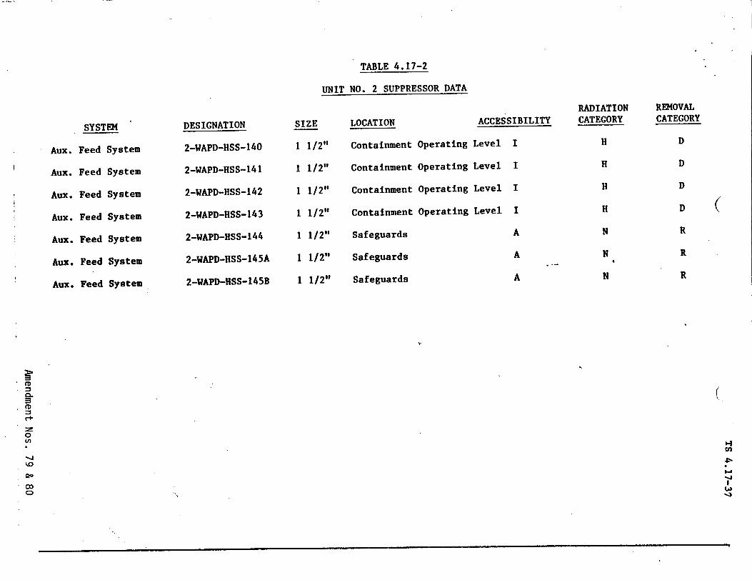
TABLE 4.17-2
UNIT NO. 2 SUPPRESSOR DATA
Aux.
Aux.
Aux.
Aux.
Aux.
Aux.
Aux.
SYSTEM
Feed System
Feed System
Feed System
Feed System
Feed System
Feed System
Feed System
DESIGNATION
2-WAPD-HSS-140
2-WAPD-HSS-141
2-WAPD-HSS-142
2-WAPD-HSS-143
2-WAPD-HSS-144
2-WAPD-HSS-145A
2-WAPD-HSS-145B
SIZE
1 1/2"
1 1/2"
1 1/2"
1 1/2"
1 1/2"
1 1/2"
1 1/2"
LOCATION ACCESSIBILITY
Containment Operating Level I
Containment Operating Level I
Containment Operating Level I
Containment Operating Level I
Safeguards A
Safeguards A
Safeguards A
RADIATION CATEGORY
H
H
H
H
N
N
N
REMOVAL CATEGORY
D
D
D
D
R
R
R
(
(
'-I
I-i -J
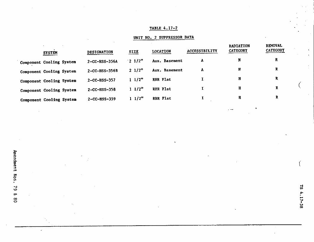
TABLE 4.17-2
UNIT NO. 2 SUPPRESSOR DATA
SYSTEM
Component Cooling System
Component Cooling System
Component Cooling System
Component Cooling System
Component Cooling System
DESIGNATION
2-CC-HSS-356A
2-CC-HSS-356B
2-CC-HSS-357
2-CC-HSS-358
2-CC-HSS-359
SIZE
12 1/2"
2 1/2"
1 1/2"
1 1/2"
1 1/2"
LOCATION
Aux. Basement
Aux. Basement
RIR Flat
RHR Flat
RHR Flat
ACCESSIBILITY
A
A
I
I
I
REMOVAL CATEGORY
.R
RADIATION CATEGORY
N
N
H
H
H
R
R
R
R
(
C+ 0.
00
C1
In
"0-' 0o
I.;
I-J wO
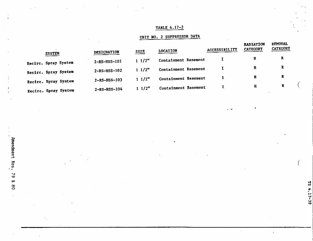
TABLE 4.17-2
UNIT NO. 2 SUPPRESSOR DATA
SYSTEM
Recirc. Spray System
Recirc. Spray System
Recirc. Spray System
Recirc. Spray System
DESIGNATION
2-RS-HSS-101
2-RS-HSS-102
2-RS-HSS-103
2-RS-HSS-104
SIZE
1 1/2"
1 1/2"
1 1/2"
1 1/2"
LOCATION
Containment Basement
Containment Basement
Containment Basement
Containment Basement
RADIATION ACCESSIBILITY CATEGORY
I H
I H
I H
I H
REMOVAL CATEGORY
R
R
R
R (
CL
C+ :z
0
co
0 Cl
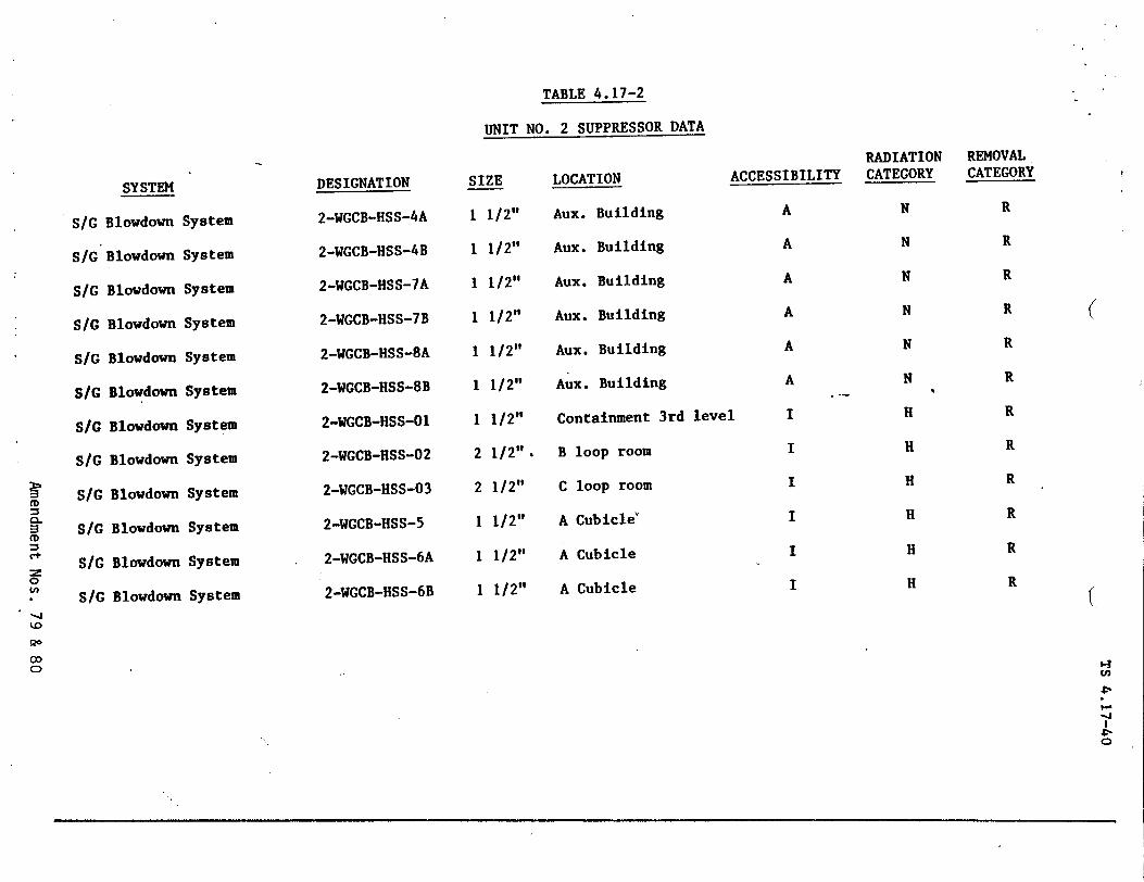
TABLE 4.17-2
UNIT NO. 2 SUPPRESSOR DATA
SI/
SIG
SIG
SIG
SlG
SlG
SlG
SlG
* s/c
S/G
(D
CD
SSIG
0
r S/G
SYSTEM
Blowdown
Blowdown
Blowdown
Blowdown
Blowdown
Blowdown
Blowdown
Blowdown
Blowdown
Blowdown
Blowdown
Blowdown
DESIGNATION
2-WGCB-HSS-4A
2-WGCB-HSS-4B
2-WGCB-HSS-7A
2-WGCB-HSS-7B
2-WGCB-HSS-8A
2-WGCB-HSS-8B
2-WGCB-HSS-O1
2-WGCB-HSS-02
2-WGCB-HSS-03
2-WGCB-HSS-5
2-WGCB-HSS-6A
2-WGCB-HSS-6B
SIZE
1 1/2"
1 1/2"
1 1/2"
1 1/2"
1 1/2"
1 1/2"
1 1/2"
2 1/2"
2 1/2"
1 1/2"
1 1/2"
1 1/2"
LOCATION A
Aux. Building
Aux. Building
Aux. Building
Aux. Building
Aux. Building
Aux. Building
Containment 3rd level
B loop room
C loop room
A Cubicle'
A Cubicle
A Cubicle
RADIATION .CCESSIBILITY CATEGORY
A N
A NSystem
System
System
System
System
System
System
System
System
System
System
System
N
N
N
N
H
H
H
H
H
H
A
A
A
A
I
I
I
I
I
I
REMOVAL CATEGORY
R
R
R
R
R
R
R
R
R
R
R
R
1�
4
Ca -J
0
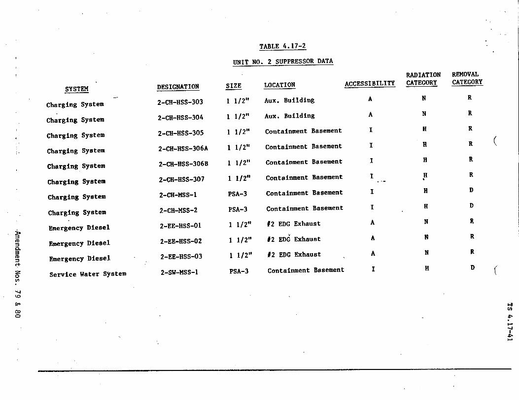
TABLE 4.17-2
UNIT NO. 2 SUPPRESSOR DATA
SYSTEM
Charging System
Charging System
Charging System
Charging System
Charging System
Charging System
Charging System
Charging System
Emergency Diesel
Emergency Diesel
Emergency Diesel
Service Water System
DESIGNATION
2-CH-HSS-303
2-CH-HSS-304
2-CH-HSS-305
2-CH-HSS-306A
2-CH-HSS-306B
2-CH-HSS-307
2-CH-MSS-1
2-CH-MSS-2
2-EE-HSS-O1
2-EE-HSS-02
2-EE-HSS-03
2-SW-MSS-I
SIZE
1 1/2"
1 1/2"
1 1/2"
1 1/2"
1 1/2"
1 1/2"1
PSA-3
PSA-3
1 1/2"
1 1/2"
1 1/2"
PSA-3
LOCATION ACCESSIBILITY
Aux. Building A
Aux. Building A
Containment Basement I
Containment Basement I
Containment Basement I
Containment Basement I
Containment Basement I
Containment Basement I
#2 EDG Exhaust A
#2 EDG Exhaust A
#2 EDG Exhaust A
Containment Basement I
RADIATION CATEGORY
N
N
H
H
H
H
H
H
N
N
N
H
REMOVAL CATEGORY
R
R
R
R
R
R
D
D
R
R
R
D
(
(
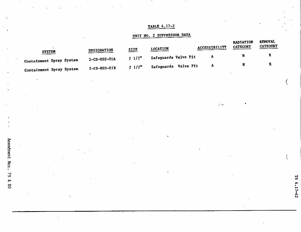
TABLE 4.17-2
UNIT NO. 2 SUPPRESSOR DATA
SYSTEM
Containment Spray System
Containment Spray System
DESIGNATION
2-CS-HSS-O1A
2-CS-HSS-01B
SIZE
2 1/2"
2 1/2"
LOCATION ACCESSIBILITY
Safeguards Valve Pit A
Safeguards Valve Pit A
RADIATION REMOVAL CATEGORY CATEGORY
N R
N R
(
k.
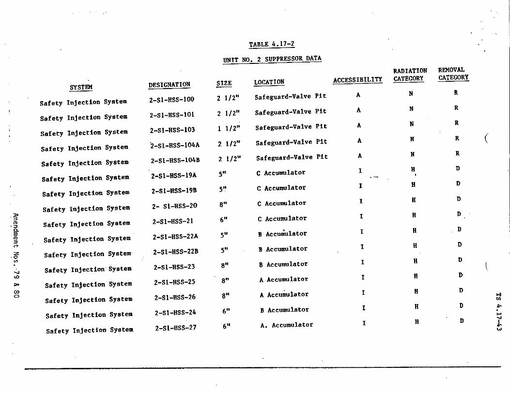
TABLE 4.17-2
UNIT NO. 2 SUPPRESSOR DATA
Safety
Safety
Safety
Safety
Safety
Safety
Safety
Safety
Safety
Safety
Safety
Safety
Safety
Safety
Safeet
Safet
SYSTEM
Injection S
Injection S
Injection S
Injection S
Injection
Injection
Injection
Injection
Injection
Injection
Injection
Injection'
y Injection
F Injection
y Injection
y Injection
ystem
.ystem
ystem
;ystem
ystem
System
System
System
System
System
System
System
System
System
System
System
DESIGNATION
2-SI-HSS-100
2-Sl-HSS-101
2-Sl-HSS-103
2-S1-HSS-1O4A
2-S1-HSS-104B
2-SI-HSS-19A
2-SI-HSS-19B
2- S1-HSS-20
2-SI-HSS-21
2-SI-HSS-22A
2-SI-HSS-22B
2-SJ-HSS-23
2-Sl-HSS-25
2-SI-HSS-26
2-SI-HSS-24
2-S1-HSS-27
SIZE
2 1/2"
2 1/2"
1 1/2"
2 1/2"
2 1/2"
5"
5"
8"
6"
5"
5"
8"
8"
8"
6"
6"
LOCATION
Safeguard-Valve Pit
Safeguard-Valve Pit
Safeguard-Valve Pit
Safeguard-Valve Pit
Safeguard-Valve Pit
C Accumulator
C Accumulator
C Accumulator
C Accumulator
B Accumulator
B Accumulator
B Accumulator
A Accumulator
A Accumulator
B Accumulator
A. Accumulator
RADIATION ACCESSIBILITY CATEGORY
A N
A N
A N
A N
A N
I H
I H
I H
I H
I H
I H
I H
I H
I H
I H
I H
REMOVAL CATEGORY
R
R
R
R
R
D
D
D
D
D
D
D
D
D
D
D
(
'-I
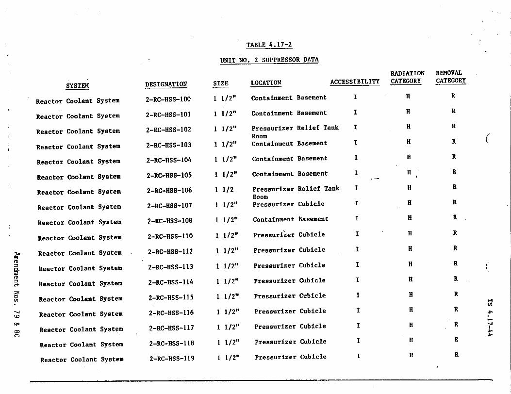
TABLE 4.17-2
UNIT NO. 2 SUPPRESSOR DATA
SYSTEM SIZE
Reactor
Reactor
Reactor
Reactor
Reactor
Reactor
Reactor
Reactor
Reactor
Reactor
Reactor
Reactor
Reactor
Reactor
Reactor
Reactor
Reactor
Reactol
Coolant
Coolant
Coolant
Coolant
Coolant
Coolant
Coolant
Coolant
Coolant
Coolant
Coolant
Coolant
Coolant
Coolant
Coolant
Coolant
r Coolant
r Coolant
System
System
System
System
System
System
System
System
System
System
System
System
System
System
System
System
System
System
DESIGNATION
2-RC-HSS-100
2-RC-HSS-101
2-RC-HSS-102
2-RC-HSS-103
2-RC-HSS-104
2-RC-HSS-105
2-RC-HSS-106
2-RC-HSS-107
2-RC-HSS-108
2-RC-HSS-110
2-RC-HSS-112
2-RC-HSS-113
2-RC-HSS-114
2-RC-HSS-115
2-RC-HSS-116
2-RC-HSS-117
2-RC-HSS-118
2-RC-HSS-119
1 1/2"
1 1/2"
1 1/2"
1 1/2"
1 1/2"
1 1/2"
1 1/2
1 1/2"
1 1/2"
1 1/2"
1 1/2"
1 1/2"
1 1/2"
1 1/2"
1 1/2"
1 1/2"
1 1/2"
1 1/2"
LOCATION
Containment
Containment
Pressurizer Room Containment
Containment
Containment
Pressurizer Room Pressurizer
Containment
Pressurizer
Pressurizer
Pressurizer
Pressurizer
Pressurizer
Pressurizer
Pressurizer
Pressurizei
Pressurizei
ACCESSIBILITY
Basement I
Basement I
Relief Tank I
Basement I
Basement I
Basement I
Relief Tank I
Cubicle I
Basement I
Cubicle I
Cubicle I
Cubicle I
Cubicle I
* Cubicle I
* Cubicle I
* Cubicle I
Cubicle I
Cubicle I
C
RADIATION CATEGORY
H
H
H
H
H
H
H
H
H
H
H
H
H
H
H
H
H
H
REMOVAL CATEGORY
R
R
R
R
R
R
R
R
R
R
R
R
R
R
R
R
1-1
R
R
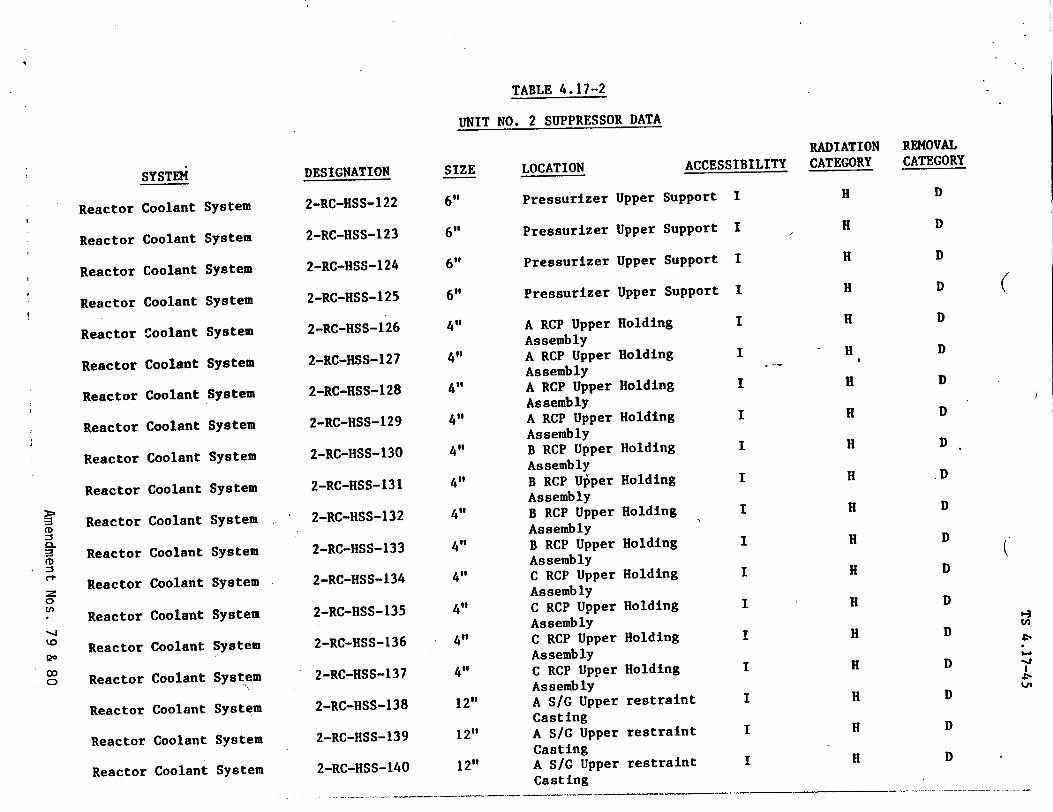
TABLE 4.17-2
UNIT NO. 2 SUPPRESSOR DATA
Reactor
Reactor
Reactor
Reactor
Reactor
Reactor
Reactor
Reactor
Reactor
Reactor
Reactor
Reacto0
Reactor
Reactor
Reactor
Reactol
Reacto
Coolant S
Coolant f
Coolant
Coolant
Coolant
Coolant
Coolant
Coolant
Coolant
Coolant
Coolant
r Coolant
r Coolant
r Coolant
r Coolant
r Coolant
r Coolant
Reactor Coolant System
Reactor Coolant System
SYSTEM
lystem
;ystem
ystem
;ystem
System
System
System
System
System
System
System
System
System
System
System
System
System
DESIGNATION
2-RC-HSS-122
2-RC-HSS-123
2-RC-HSS-124
2-RC-HSS-125
2-RC-HSS-126
2-RC-HSS-127
2-RC-HSS-128
2-RC-HSS-129
2-RC-HSS-130
2-RC-HSS-131
2-RC-HSS-132
2-RC-HSS-133
2-RC-HSS-134
2-RC-HSS-135
2-RC-HSS-136
2-RC-HSS-137
2-RC-HSS-138
2-RC-HSS-139
2-RC-HSS-140
SIZE
6"
6"
6"
6"
4"1
4"
4"
4"
4"
4"'
4"
4"
4"
4"
4"
4"
12"
12"
12"
RADIATION LOCATION ACCESSIBILITY CATEGORY
Pressurizer Upper Support I H
Pressurizer Upper Support I H
Pressurizer Upper Support I H
Pressurizer Upper Support I H
A RCP Upper Holding I H
Assembly
A RCP Upper Holding I H
Assembly A RCP Upper Holding I H
Assembly A RCP Upper Holding I H
Assembly B RCP Upper Holding I H
Assembly
B RCP Upper Holding I H
Assembly
B RCP Upper Holding I H
Assembly B RCP Upper Holding I H
Assembly C RCP Upper Holding I H
Assembly C RCP Upper Holding I H
Assembly C RCP Upper Holding I H
Assembly C RCP Upper Holding I H
Assembly A S/G Upper restraint I H
Casting A S/G Upper restraint I H
Casting A S/G Upper restraint I H
Casting
REMOVAL CATEGORY
D
D
D
D
D
D
D
D
D
.D
D
D
D
D
D
D
D
D
D
(
(
I
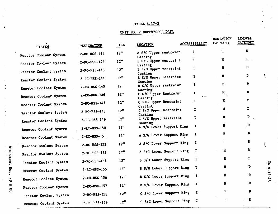
TABLE 4.17-2
UNIT NO. 2 SUPPRESSOR DATA
Reactor
Reactor
Reactor
Reactor
Reactor
Reactor
Reactor
Reactor
Reactor
Reactor
Reactor
Reactor
Reactor
Reactol
Reactoi
Reactol
Reactor Coolant
Reactor Coolant System
Reactor Coolant System
SYSTEM
Coolant S
Coolant S
Coolant I
Coolant
Coolant
Coolant
Coolant
Coolant
Coolant
Coolant
Coolant
Coolant
Coolant
r Coolant
r Coolant
r Coolant
•ystem
;ystem
ystem
System
System
System
System
System
System
System
System
System
System
System
System
System
System
DESIGNATION
2-RC-HSS-141
2-RC-HSS-142
2-RC-HSS-143
2-RC-HSS-144
2-RC-HSS-145
2-RC-HSS-146
2-RC-HSS-1 4 7
2-RC-HSS-14 8
2-RC-HSS-149
2-RC-HSS-150
2-RC-HSS-151
2-RC-HSS-152
2-RC-HSS-153
2-RC-HSS-154
2-RC-HSS-155
2-RC-HSS-156
2-RC-HSS-157
2-RC-HSS-158
SIZE
12"
12"
12"
12"
12"
12"
12"
12"
12"
12"
12"
12"
12"
12"
12"
12"
12"
12"
estrailn
restrain
restrain
RADIATION REMOVAL ACCESSIBILITY CATEGORY CATEGOR!
t I H D
t I H D
t I H D
LOCATION
A S/G Upper 1 Casting B S/G Upper Casting B S/G Upper Casting B S/G Upper Casting B S/G Upper Casting C S/G Upper Casting C SIG Upper Casting C S/G Upper Casting C S/G Upper Casting A S/G Lower
A S/G Lower
A SIG Lower
A S/G Lower
B S/G Lower
B S/G Lower
B S/G Lower
Support
Support
Ring
Ring
2-RC-HSS-159 12" C S/G Lower Support Ring
I
I
I
I
I
I
I
I
I
I
I
I
I
I
I
I
H
H
H
H
H
H
H
H
H
H
H
H
H
H
H
H
restraint
restraint
Restraint
Restraint
Restraint
Restraint
Support Ring
Support Ring
Support Ring
Support Ring
Support Ring
Support Ring
Support Ring
B
C
S/G Lower
S/G Lower
(
C', 0
00
"0, 0D
D
D
D
D
D
D
D
D
D
D
D
D
D
D
D
D
H-I
",I-I
0'
Y
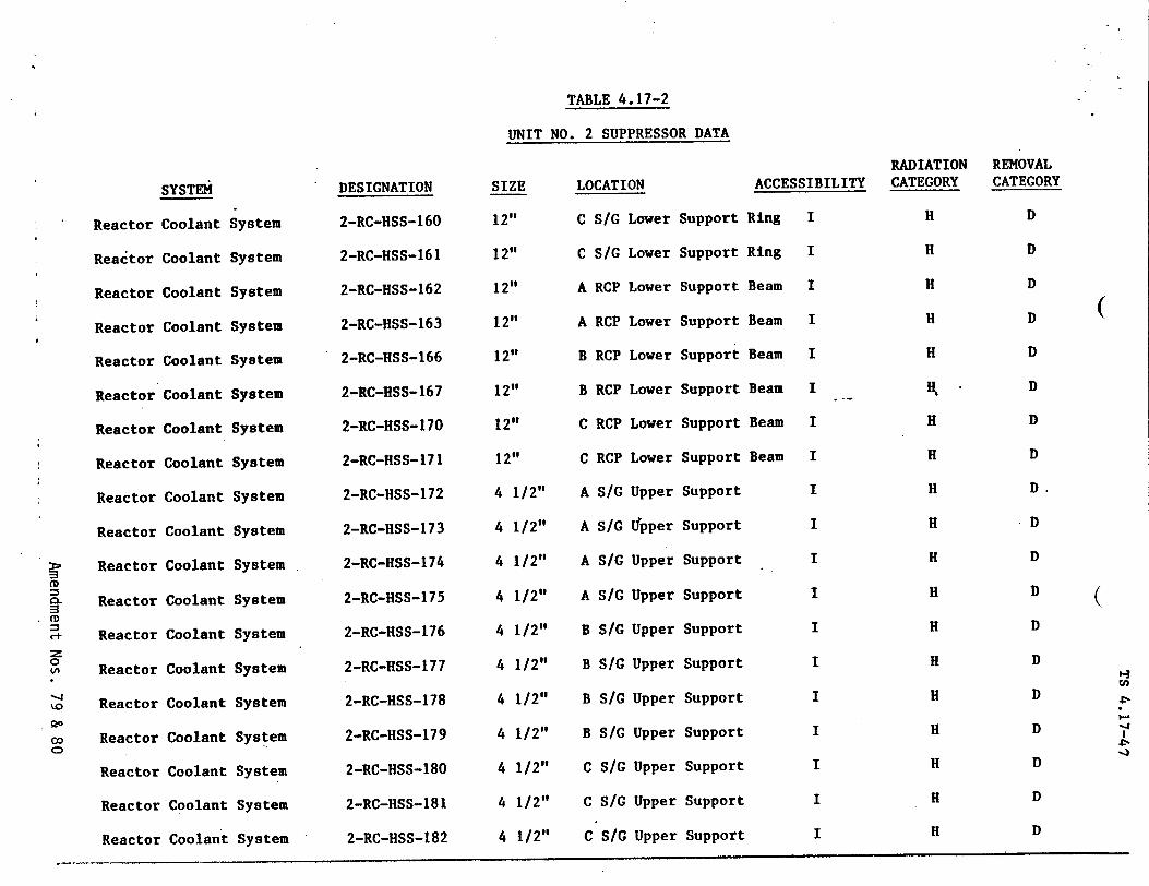
TABLE 4.17-2
UNIT NO. 2 SUPPRESSOR DATA
Reactor I
Reactor I
Reactor I
Reactor
Reactor
Reactor
Reactor
* Reactor
Reactor
Reactor
Reactor
CL Reactor (CD
C Reactor :z 0 ( Reactor
SReactor
c Reactor 0
Reactor
Reactor
Reactor
SYSTE1
Coolant
Coolant
Coolant
Coolant
Coolant
Coolant
Coolant
Coolant
Coolant
Coolant
Coolant
Coolant
Coolant
Coolant
Coolant
Coolant
Coolant
Coolant
Coolant
LOCATION
C S/G LowerSystem
System
System
System
System
System
System
System
System
System
System
System
System
System
System
System
System
System
System
DESIGNATION
2-RC-HSS-160
2-RC-HSS-161
2-RC-HSS-162
2-RC-HSS-163
2-RC-HSS-166
2-RC-HSS-167
2-RC-HSS-170
2-RC-HSS-171
2-RC-HSS-172
2-RC-HSS-173
2-RC-HSS-174
2-RC-HSS-175
2-RC-HSS-176
2-RC-HSS-177
2-RC-HSS-178
2-RC-HSS-179
2-RC-HSS-180
2-RC-HSS-181
2-RC-HSS-182
Support
SIZE
12"
12"
12"
12"
12"
12"
12"
12"
4 1/2"
4 1/2"
4 1/2"
4 1/2"
4 1/2"
4 1/2"
4 1/2"
4 1/2"
4 1/2"
4 1/2"
4 1/2"
C
A
A
B
B
C
C
A
A
A
A
B
B
B
B
C
C
C
SIG
RCP
RCP
RCP
RCP
RCP
RCP
SIG
SIG
SIC
SIC
SIC
SIG
SIG
S/G
S/G
SiG
SiG
Lower Support
Lower Support
Lower Support
Lower Support
Lower Support
Lower Support
Lower Support
Upper Support
TJpper Support
Upper Support
Upper Support
Upper Support
Upper Support
Upper Support
Upper Support
Upper Support
Upper Support
Upper Support
ACCESSIBILITY
Ring I
Ring I
Beam I
Beam I
Beam I
Beam I
Beam I
Beam I
I
I
I
I
I
I
I
I
I
I
I
RADIATION CATEGORY
H
H
H
H
H
H
H
H
H
H
H
H
H
H
H
H
H
H
H
REMOVAL CATEGORY
D
D
D
D
D
D
D
D
D.
D
D
D
D
D
D
D
D
D
D
(
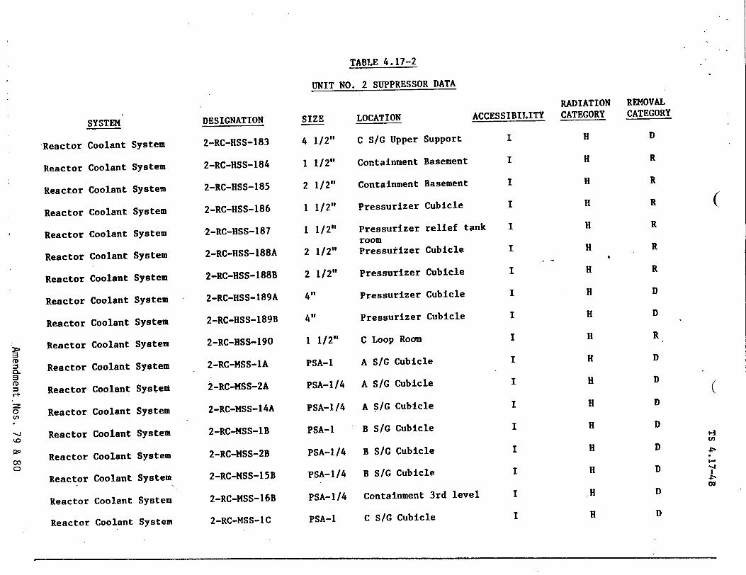
TABLE 4.17-2
UNIT NO. 2 SUPPRESSOR DATA
Reactor Coolant System
SYSTEM
Reactor Coolant System 2-RC-MSS-IC
Reactor
Reactor
Reactor
Reactor
Reactor
Reactor
Reactor
Reactor
Reactor
Reactor
Reactor
Reactor
Reactor
Reactor
Reactor
Reactor
;oolant
Coolant
Coolant
Coolant
Coolant
Coolant
Coolant
Coolant
Coolant
Coolant
Coolant
Coolant
Coolant
Coolant
Coolant
Coolant
PSA-1 C S/G Cubicle
System
System
System
System
System
System
System
System
System
System
System
System
System
System
System
System
DESIGNATION
2-RC-HSS-183
2-RC-HSS-184
2-RC-HSS-185
2-RC-HSS-186
-2-RC-HSS-187
2-RC-HSS-188A
2-RC-HSS-188B
2-RC-HSS-189A
2-RC-HSS-189B
2-RC-HSS-190
2-RC-MSS-1A
2-RC-MSS-2A
2-RC-MSS-14A
2-RC-MSS-IB
2-RC-MSS-2B
2-RC-MSS-15B
2-RC-MSS-16B
SIZE
4 1/2"
1 1/2"
2 1/2"
1 1/2"
1 1/2"
2 1/2"
2 1/2"
4"
4"'
1 1/2"
PSA-1
PSA-1/4
PSA-1/4
PSA-1
PSA-1 /4
PSA-1/4
PSA-1/4
LOCATION AL
C S/G Upper Support
Containment Basement
Containment Basement
Pressurizer Cubicle
Pressurizer relief tan room Pressurizer Cubicle
Pressurizer Cubicle
Pressurizer Cubicle
Pressurizer Cubicle
C Loop Room
A S/G Cubicle
A S/G Cubicle
A S/G Cubicle
B SIG Cubicle
B SIG Cubicle
B S/G Cubicle
Containment 3rd level
i
RADIATION XCESSIBILITY CATEGORY
I H
I H
I H
I H
k I H
I H
I H
I H
I H
I H
I H
I H
I H
I H
I H
I H
I H
I H
REMOVAL CATEGORY
D
R
R
R
R
R
R
D
D
R
D
D
D
D
D
D
D
D
In
4,
co
(
(
b
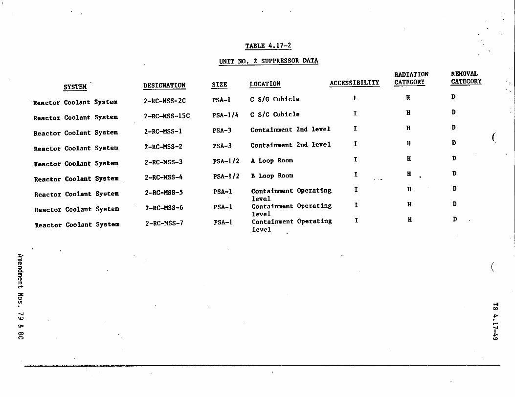
TABLE 4.17-2
UNIT NO. 2 SUPPRESSOR DATA
DESIGNATION
2-RC-MSS-2C
2-RC-MSS-15C
2-RC-MSS-1
2-RC-MSS-2
2-RC-MSS-3
2-RC-MSS-4
2-RC-MSS-5
2-RC-MSS-6
2-RC-MSS-7
SIZE
PSA-1
PSA-1/4
PSA-3
PSA-3
PSA-1/2
PSA-1/2
PSA-1
PSA-1
PSA-1
LOCATION ACCESSIBILITY
C S/G Cubicle I
C S/G Cubicle I
Containment 2nd level I
Containment 2nd level I
A Loop Room I
B Loop Room I
Containment Operating I level Containment Operating I level Containment Operating I level
SYSTEM
Coolant
Coolant
Coolant
Coolant
Coolant
Coolant
Coolant
Coolant
Coolant
Reactor
Reactor
Reactor
Reactor
Reactor
Reactor
Reactor
Reactor
Reactor
System
System
System
System
System
System
System
System
System
RADIATION CATEGORY
H
H
H
H
H
H
H
H H
REMOVAL CATEGORY
D
D
D
D
D
D
D
D
D
(
ir CD
Co
0
00
(
,-.
4%0
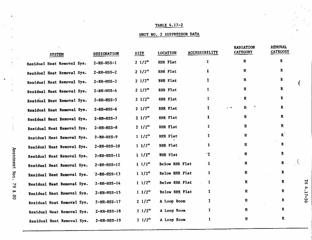
TABLE 4.17-2
UNIT NO. 2 SUPPRESSOR DATA
SYSTEM
Residual Heat Removal Sys.
Residual
Residual
Residual
Residual
Residual
Residual
Residual
Residual
Residual
R d
Residual
C+ 0 Residual
O Residual ko
go Residual
Residual 00
Residual
Residual
Heat
Heat
Heat
Heat
Heat
Heat
Heat
Heat
Heat
Heat
Heat
Heat
Heat
Heat
Heat
Heat
Removal
Removal
Removal
Removal
Removal
Removal
Removal
Removal
Removal
Removal
Removal
Removal
Removal
Removal
Removal
Removal
Sys;
Sys.
Sys.
Sys.
Sys.
Sys.
Sys.
Sys.
Sys.
Sys.:
Sys.
Sys.
Sys.
Sys.
Sys.
Sys.
DESIGNATION
2-RH-HSS-1
2-RH-HSS-2
2-RH-HSS-3
2-RH-HSS-4
2-RH-HSS-5
2-RH-HSS-6
2-RH-HSS-7
2-RH-HSS-8
2-RH-HSS-9
2-RH-HSS-10
2-RH-HSS-11
2-RH-HSS-12
2-RH-HSS-13
2-RH-HSS-14
2-RH-HSS-15
2-RH-HSS-17
2-RH-HSS-18
SIZE
2 1/2"
2 1/2"
2 1/2"
2 1/2"
2 1/2"
2 1/2"
2 1/2"
2 1/2"
1 1/2"
1 1/2"
1 1/2"
1 1/2"
1 1/2"
1 1/2"
1 1/2"
2 1/2"
2 1/2"
LOCATION ACCESSIBILITY
RHR Flat
RHR Flat
RHR Flat
RHR Flat
RHR Flat
RHR Flat
RHR Flat
RHR Flat
RHR Flat
RHR Flat
RHR Flat
Below RHR Flat
Below RHR Flat
Below RHR Flat
Below RHR Flat
A Loop Room
A Loop Room
RADIATION CATEGORY
H
H
H
H
H
H
H
H
H
H
H
H
H
H
H
H
H
H
REMOVAL CATEGORY
R
R
R
R
R
R
R
R
R
R
R
R
R
R
R
R
R
(
(
2-RH-HSS-19 2 1/2" A Loop Room RIResidual Heat Removal Sys.
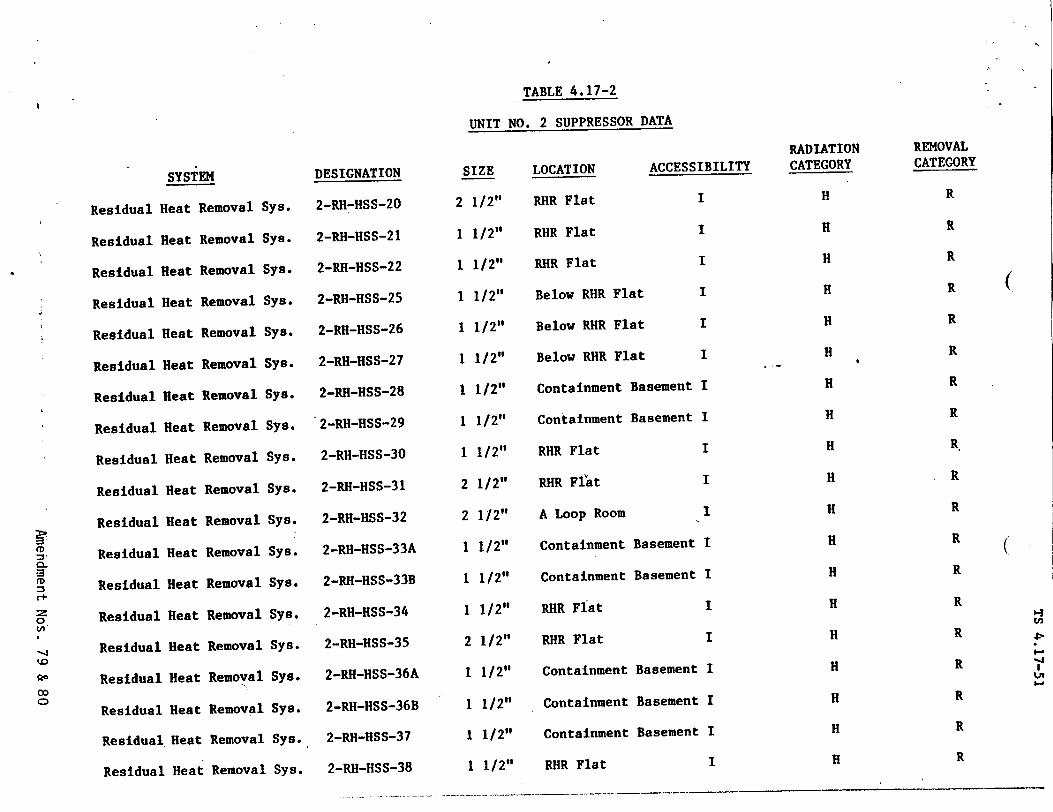
TABLE 4.17-2
UNIT NO. 2 SUPPRESSOR DATA
SYSTEM
Residual Heat Removal Sys.
Residual I
Residual I
Residual I
Residual
Residual I
Residual !
Residual !
Residual
Residual
Residual
Residual CL
(D =3 Residual Cedu z Residual
SResidual 0 Residual
Ro Residual
Residual
leat
leat
leat
leat
Heat
Heat
Heat
Heat
Heat
Heat
Heat
Heat
Heat
Heat
Heat
Heat
Heat
Removal S
Removal S
Removal f
Removal
Removal
Removal
Removal
Removal
Removal
Removal
Removal
Removal
Removal
Removal
t Removal
t Removal
t Removal
;ys.
•ys.
;ys.
Sys.
;ys.
Sys.
Sys.
Sys.
Sys.
Sys.
Sys.
Sys.
Sys.
Sys.
Sys.
Sys.
Residual Heat Removal Sys.
DESIGNATION
2-RH-HSS-20
2-RH-HSS-21I
2-RH-HSS-22
2-RH-HSS-25
2-RH-HSS-26
2-RH-HSS-27
2-RH-HSS-28
2-RH-HSS-29
2-RH-HSS-30
2-RH-HSS-31
2-RH-HSS-32
2-RH-HSS-33A
2-RII-HSS-33B
2-RH-HSS-34
2-RH-HSS-35
2-RH-HSS-36A
2-RH-HSS-36B
2-RH-HSS-37
2-RH-HSS-38
SIZE
2 1/2"
1 1/2"
1 1/2"
1 1/2"
1 1/2"
1 1/2"
1 1/2"
1 1/2"
1 1/2"
2 1/2"
2 1/2"
1 1/2"
1 1/2"
1 1/2"
2 1/2"
1 1/2"
1 1/2"
1 1/2"
1 1/2"
LOCATION ACCESS:
RHR Flat
RHR Flat
RHR Flat
Below RHR Flat
Below RHR Flat
Below RHR Flat
Containment Basement
Containment Basement
RHR Flat
RHR FlAt
A Loop Room
Containment Basement
Cnntainment Basement
RHR Flat
RHR Flat
Containment Basement
Containment Basement
Containment Basement
RHR Flat
I
1
]
]
[BIL ITYn
I
I
I
I
I
I
I
I
I
I
I
I
I
I
RADIATION CATEGORY
H
H
H
H
H
H
H
H
H
H
H
H
H
H
H
H
H
H
H
REMOVAL CATEGORY
R
R
R
R
R
R
R
R
R
R
R
R
R
R
R
R
R
R
R
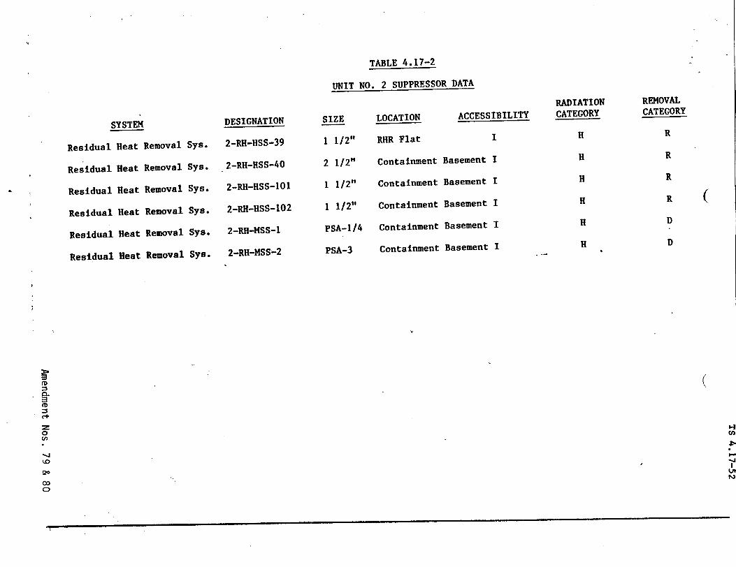
TABLE 4.17-2
UNIT NO. 2 SUPPRESSOR DATA
SYSTEM
Residual Heat
Residual Heat
Residual Heat
Residual Heat
Residual Heat
Residual Heat
Removal Sys.
Removal Sys.
Removal Sys.
Removal Sys.
Removal Sys.
Removal Sys.
DESIGNATION
2-RH-HSS-39
2-RH-HSS-40
2-RH-HSS-101
2-RH-HSS-102
2-RH-MSS-1
2-RH-MSS-2
SIZE
1 1/2"
2 1/2"
1 1/2"
1 1/2"
PSA-1/4
PSA-3
LOCATION
RHR Flat
Containment
Containment
Containment
Containment
Containment
ACCESSIBILITY
I
Basement I
Basement I
Basement I
Basement I
Basement I
RADIATION CATEGORY
H
H
H
H
H
H
REMOVAL CATEGORY
R
R
R
R
D
D
ir (D
0 -4 'fl
0
CD
(
(.
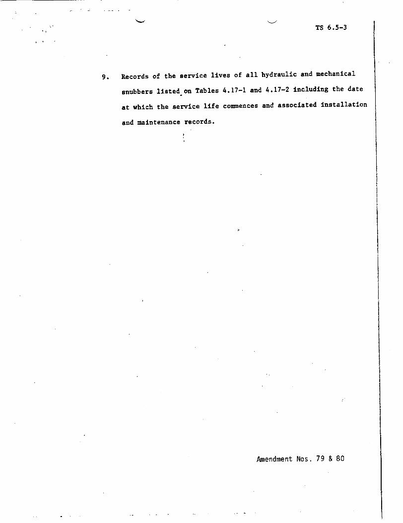
TS 6.5-3
9. Records of the service lives of all hydraulic and mechanical
snubbers listed on Tables 4.17-1 and 4.17-2 including the date
at which the service life commences and associated installation
and maintenance records.
Amendment Nos. 79 & 80
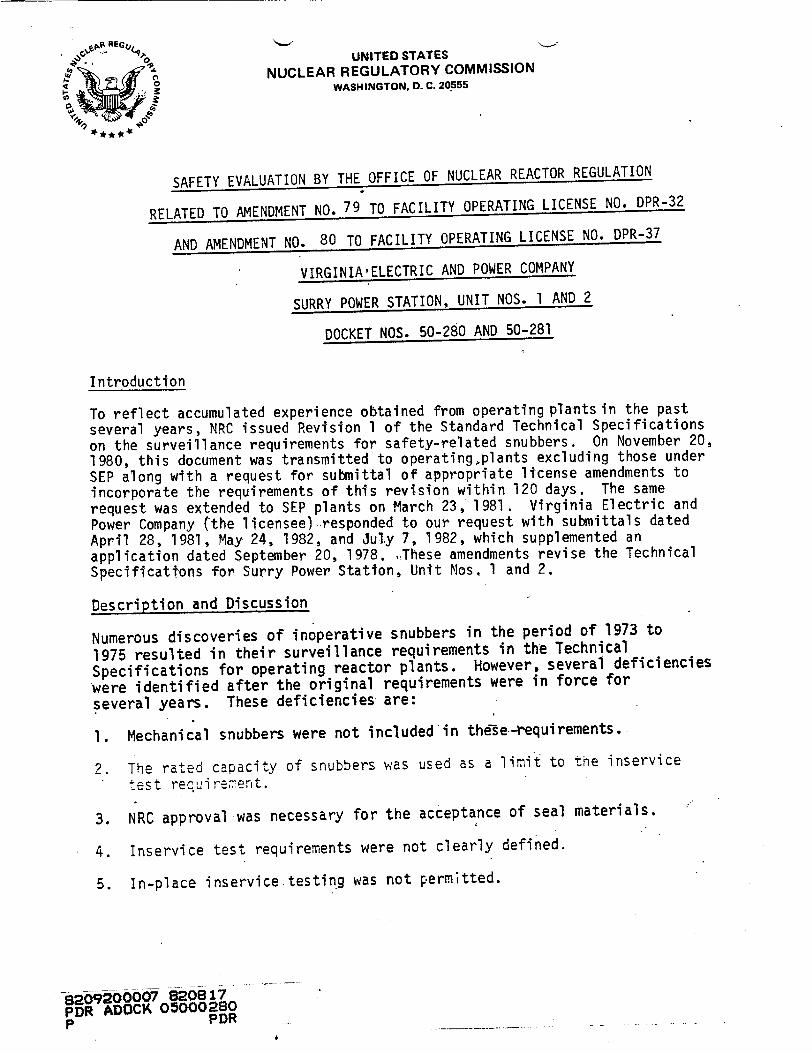
0" UNITED STATES
SO, NUCLEAR REGULATORY COMMISSION 49 o WASHINGTON, D. C. 20555
SAFETY EVALUATION BY THE OFFICE OF NUCLEAR REACTOR REGULATION
RELATED TO AMENDMENT NO. 79 TO FACILITY OPERATING LICENSE NO. DPR-32
AND AMENDMENT NO. 80 TO FACILITY OPERATING LICENSE NO. DPR-37
VIRGINIA'ELECTRIC AND POWER COMPANY
SURRY POWER STATION, UNIT NOS. 1 AND 2
DOCKET NOS. 50-280 AND 50-281
Introduction
To reflect accumulated experience obtained from operating plants in the past
several years, NRC issued Revision 1 of the Standard Technical Specifications
on the surveillance requirements for safety-related snubbers. On November 20,
1980, this document was transmitted to operating.plants excluding those under
SEP along with a request for submittal of appropriate license amendments to
incorporate the requirements of this revision within 120 days. The same
request was extended to SEP plants on March 23, 1981. Virginia Electric and
Power Company (the licensee) responded to our request with submittals dated
April 28, 1981, May 24, 1982, and July 7, 1982, which supplemented an
application dated September 20, 1978. These amendments revise the Technical
Specifications for Surry Power Station, Unit Nos. 1 and 2.
Description and Discussion
Numerous discoveries of inoperative snubbers in the period of 1973 to
1975 resulted in their surveillance requirements in the Technical
Specifications for operating reactor plants. However, several deficiencies
were identified after the original requirements were in force for
several years. These deficiencies are:
1. Mechanical snubbers were not included in the-se---requirements.
2. The rated capacity of snubbers was used as a limit to the inservice
test reuirmenFLt.
3. NRC approval was necessary for the acceptance of seal materials.
4. Inservice test requirements were not clearly defined.
5. In-place inservice.testing was not perm;tted.
820o9200007 8320817 PDR ADOCK 035000280 p PDR
-2-
Since mechanical snubbers were not subject to any surveillance requirements, some licensees and permit holders believed that mechanical snubbers were preferred by NRC. Many plants used mechanical snubbers as original equipment and many others requested to replace their hydraulic snubbers with mechanical ones to simplify or avoid a inservice surveillance program. This is directly contradictory to NRC's intention, where for an unsurveyed mechanical snubber, the most likely failure is permanent lock-up. This failure mode can be harmful to the system during normal plant operations.
During the period of 1973-1975, when the first hydraulic snubber surveillance requirements in the Technical Specifications were drafted, a compromise was made to -limit the testing of snubbers to those with rated capacity of not more than 50,000 lbs. This is because of the available capacity of the test equipment and the requirement to test some parameters at the snubber rated load. Since then, greater equipment capacity and better understanding of parametric correlation both developed. To maintain this arbitrary 50,000 lb. limit could mean an unnecessary compromise on plant safety.
The original hydraulic snubber problem started -from leaking seals. Most seal materials of the 1973 vintage could not withstand the temperature and irradiation environments. Ethylene propylene was the first material that could offer a reasonable service life for those seals. In order to discourage the use of unproven material for those seals, the words "NRC approved material" were used in the Technical Specifications. Staff members were asked to approve different seal materials on many occasions. Consequently, since the basis for the approval was not defined, the development of better seal materials by the industry was actually discouraged.
The not-well-defined acceptance criteria in. the earlier version of the testing requirements resulted in non-uniform interpretations and implementation. Acceptance Criteria were set individually at widely different ranges. Since the rationale of adopting a specific acceptance criteria was not clear, I&E inspectors found it'impbssible to make any necessary corrections. In some cases, snubbers were tested without reference to acceptance criteria.
Testing of snubbers was usually accomplished by removiihg snubbers from their installed positions, mounting them on a testing rig, conducting the test, removing them from rig, and reinstalling them to the working position. Many snubbe'rs were damaged in the removing and reinstallation process. This defeated the purpose for conducting tests. Since methods and equipment have been developed to conduct in-place tests on snubbers, taking advantage of these developments could result in minimizing the damage to snubbers caused by removal and reinstallation plus time and cost savings' to the plants.
1-
-3
From these short-comings it was concluded that the snubber surveillance
requirements for the Technical Specifications should be revised.:
The revised surveillance requirements correct these deficiencies in
the following manner:
1. Mechanical snubbers are now included in the surveillance program.
2. No arbitrary srwbber capacity is used as a limit to the inservice
test requiremenrs.
3. Seal material no longer requires NRC approval. A monitoring
program shall be implemented to assure that snubbers are functioning
within their service life.
4. Clearly defined inservice test requirements for snubbers shall be
impl emented.
5. In-place inservice testing shall be permitted.
The licensee has responded in the following manner:
1. Mechanical snubbers have been included in the surveillance program.
2. The arbitrary 50 KIP limit has been removed from inservice test requirements.
3. A service record will be kept for all snubbers.
4. Quantitive testing procedures will be used.
5. The use of in-place testing as an alternative method to bench test for
the surveillance of snubbers has been proposed.
The proposed license amendment submitted by the licensee for operating license
DPR-32 and DPR-37 for Surry Nuclear Plant Units 1 and 2 has incorporated the
necessary requirements in Revision I of the Standard Technical Specifications
for the surveillance of safety-related snubbers and is therefore, acceptable.
Some changes were madeto the proposed Technical Specifications with the licensee's concurrence,
- 4-
Environmental Consideration
We have determined that the amendments do not authorize a change in effluent types or total amounts nor an increase in power level and
will not result in any significant environmental impact. Having made
this determination, we have further concluded that the amendments involve an action which is insignificant from the standpoint of
environmental impact and, pursuant to 10 CFR §51.5(d)(4), that an
environmental impact statement or negative declaration and environmental impact appraisal need not be prepared in connection with the issuance of these amendments.
Conclusion
We have concluded, based on the considerations discussed above, that:
(1) because the amendments do not involve a significant increase in
the probability or consequences of an accident previously evaluated,
do not create the possibility of an accident of a type different from
any evaluated previously, and do not involve a significant reduction
in a margin of safety, the amendments do not involve a significant
hazards consideration, (2) there is reasonable assurance that the health
and safety of the public will not be endangered by operation in the
proposed manner, and (3) such activities will be conducted in compliance
with the Commission's regulations and the issuance of the amendments will
not be inimical to the common defense and security or to the health and
safety of the public.
Pate: August 17, 1982
Principal Contributors: Leon Fngle Horace Shaw Don Neighbors
7590-01
UNITED STATES NUCLEAR REGULATORY COMMISSION
DOCKET NOS. 50-280 AND 50-281
VIRGINIA ELECTRIC AND POWER COMPANY
NOTICE OF ISSUANCE OF AMENDMENTS TO FACILITY OPERATING LICENSES
The U. S. Nuclear Regulatory Commission (the Commission) has issued
Amendment No. 79 to Facility Operating License No. DPR-32 and Amendment
No. 80 to Facility Operating License No. DPR-37 issued to Virginia Electric
and Power Company (the licensee), which revised Technical Specification for
operation of the Surry Power Station, Unit Nos. 1 and 2, respectively, (the
facilities), located in Surry County, Virgina. The amendments are effective
as of the date of issuance.
The amendments revise the Technical Specifications to incorporate
revised inservice surveillance requirements for snubbers, both mechanical
and hydraulic,
The application for the amendments complies with the standards and
requirements of the Atomic Energy Act of 1954, as amended (the Act), and
the Commission's rules and regulations. The Commission has made appropriate
findings as required by the Act and the Commission's rules and regulations
in 10 CFR Chapter I, which are set forth in the license amendments. Prior
public notice of these amendments was not required since these amendments
do not involve a significant hazards consideration.
The Commission has determined that the issuance of these amendments will
not result in any significant environmental impact and that pursuant to
10 CFR §51.5(d)(4) an environmental impact statement or negative declaration
and environmental impact appraisal need not be prepared in connection with /
the issuance of these amendments.
8209200604 -820617 PDR ADOCK 05000280 P PDR .
7590-01
-2
For further details with respect to this action, see (1) the application
for amendments dated September 20,,1978, as supplemented April 28, 1981,
May 24, 1982, and July 7, 1982, (2) Amendment Nos. 79 and 80 to License Nos.
DPR-32 and DPR-37, and (3) the Commission's related Safety Evaluation.
All of these items are available for public inspection at the Commission's
Public Document Room, 1717 H Street, N.W., Washington, D.C. and at the Swem
Library, College of William and Mary, Williamsburg, Virginia 23185. A
copy of items (2) and (3) may be obtained upon request addressed to the
U. S. Nuclear Regulatory Commission, Washington, D.C. 20555, Attention:
Director, Division of Licensing.
Dated at Bethesda, Maryland, this 17th day O'f August, 1982.
FOR, ET~ NNIL E~-LT COMMISSION
Steen A. Varga, Chi f Operating Reactors Br h #1 Division of Licensing


![JIA 79 (1953) [0001]-[0050]](https://img.pdfslide.net/doc/110x75/6319ef3a1a1adcf65a0ede04/jia-79-1953-0001-0050.jpg)


![No. 2 [79]/2021 - cssas](https://img.pdfslide.net/doc/110x75/6338525dae2b409ac00ba2b4/no-2-792021-cssas.jpg)


