Embed Size (px)
Citation preview


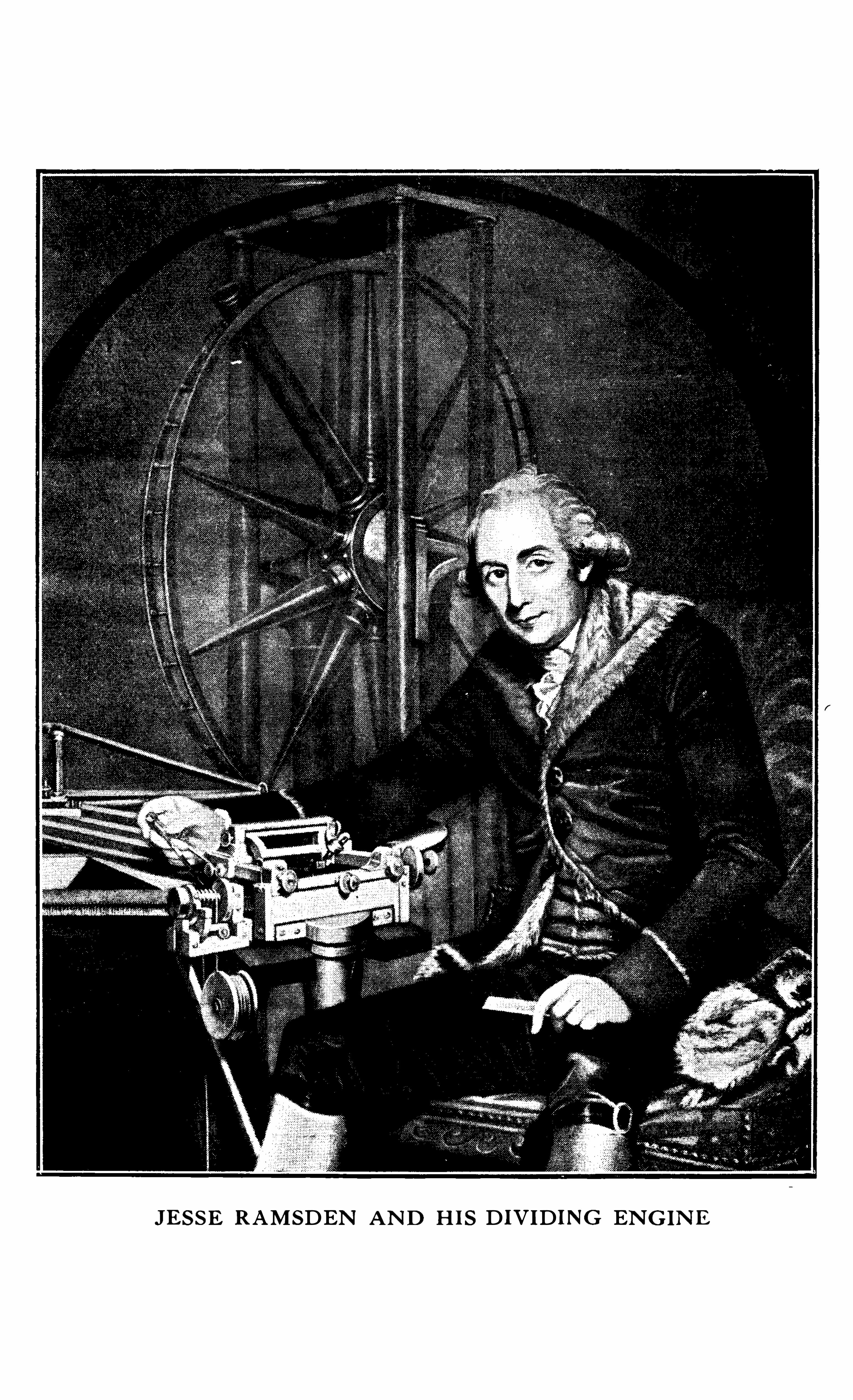
JESSE RAMSDEN AND H IS DIVIDING ENGINE
SURVEY ING
INSTRUMENTSTHEIR DESIGN , CONSTRUCTION ,
TEST ING 83 ADJUSTMENT
MR . M . ABRAHAM
,
7
With 2 3 8 I l lu strat ions
“ V D 3 N
o
iREGENT HOU S E , FITZROY SQ""DON,
V '
Copyr ight

CONTENTS
CHAPTER I
fiINTRODUCTION . Improvements in the design of surveying instruments Work done by inferior instruments Importance of
accuracy.
CHAPTER II
MANUFACTURE AND CARE OF SURVEYING INSTRUMENTS . Choice of in
struments —Minimum weight which can be carried in variouscountries—Surveys made with simple instruments— Importanceof transit theodolite—Reduction in weight of instruments—Sizesof telescopes—Metals used in the construction of instrumentsLubrication—Finish of instruments .
CHAPTER III
OPTICS OF SURVEYING INSTRUMENTS . Achromatic lens—Acuteness of vision—Optical qualities required in telescope—Largefield of view desirable Resolving power MagnificationBrightness of the fi eld—Size of telescope required—Focusing fordistance and for elimination of parallax— Advantages of the
internal focusing lens—Variation of the collimation lines—Eyepieces—Object glasses—Centering of object glasses—DiaphragmsFitting of spider webs Illumination of webs Readers
Reading micrometers—Estimating microscope—Construction of
micrometers—Adjustment of micrometer magnifi cation—Mini
mum focusing distance—Short focus attachment—Parallel platemicrometer Anallatic telescopes Stadia readings Inclinedsights—Bar subtense method—Eyepiece micrometer .
CHAPTER IV
SPIRIT LEVELS . Sensitivity of spirit levels—Machine grinding of levels—Cleanliness of the interior—Liquids used- Variation in the
length of bubble—Chambered bubbles—Damping of bubblesValue of the level divisions—Methods ofmounting levels—Leveltube grinding machine—Circular levels—hi ethods of readingthe bubble—Level triers—Radius of bubbles .
69 3 03
v i CONTENTS
CHAPTER V
GRADUATION OF INSTRUMENTS . Work done by Graham S issonBird—Roemer—Hooke—Duc de ChauneS—Ramsden—Ramsden ’s engine—Andrew Ross ’s engine—Accuracy of dividingConstruction of a dividing engine—Cutting the teeth—Compensating apparatus—Elimination of errors—Speed of dividingMaterials for divided circles—Thickness of lines—Various formsof vernier —Method of inlaying silver—Figuring of verniersWorm and wheel in place of vernier—Method of calculatingvernier values .
CHAPTER VI
TRANSIT THEODOLITE. Self-checking instruments—Sizes of theodo
lites—Tacheometers—Centesimal dividing—Horizontal axisDouble taper axes—Independent axes—Parallel axes—Positionof plumb bob—Adjustment of the vertical axis—Foot screwsFour-screw system—Three-screw system—Two-screw systemLocking plate—Railway transit theodolites—Clamps and tangent screws Defects of various forms of clamps Floatingclamping arm—Floating tangent screw—Tripod stand—Ball andsocket joint—Gradienter screw—Direct-reading tacheome terCasella ’s double-reading micrometer theodolite—Electric lighting for theodolite—Effect of side illumination on the dividingHeyde ’s micrometer Adjustment of transit theodolitesCollimating apparatus for adjusting theodolites—Errors of collimation—General performance of the instrument—Field of Viewof theodolite telescopes—Theodolites with eccentric te lescopes .
CHAPTER VII
LEVELLING INSTRUMENTS . The ideal instrument - Dumpy levelY level—Adjustment of the dumpy level— Adjustment of theY level—Four-screw Y level— Casella ’s precise tilting levelLevels with tilting screws—American pattern precise levelBuilder ’s levelling outfi t .
CHAPTER VIII
S IMPLE SURVEYING INSTRUMENTS . Abney level—Tables for u se withAbney level—Optical square -Brunton Pearse ’s mine transit
-Clinometer levels—Verschoyle ’
s pocke t transit—Hanging levelPrismatic compasses Pocket altazimuth Trocheameter
Perambulators —Pedometers .
CONTENTS Vii
CHAPTER IX
LEVELLING STAVES . Self-reading staff—S taff with inverted fi guresTar‘ge t levelling staff— Precise levelling staff Foot platesCircular spirit levels for levelling staves—Ranging poles .
CHAPTER "
PHOTOGRAPHIC SURVEYING . Advantages of the photographic methodof surveying—Main diffi culties which affect the subject—BridgesLee photo-theodolite—Canadian surveying camera—Method Of
adjusting surveying cameras—Pictures taken at an angle to the
horizon—S tereo-photographic system—Measurement . of baselines—S tereo-comparator—Vivian Thompson ’s stereo plotterVon Orel
’
s automatic plotter—Drawing of contours—Speed of
plotting by intersection and by stereo method—Aerial photography—Photographs on inclined plates .
CHAPTER XI
INVESTIGATION OF THE UPPER ATMOSPHERE. Pilot balloons—Ballonssondes—Dines ’s apparatus— Recording theodolite—Kite me teorgraph—Cloud attachment—Method Of observing with a pair oftheodolites—Method of Observing with a single theodolite .
CHAPTER XII
GEODETIC SURVEYING . Objects of geodetic surveying—Minor surveys—Situation Of control points—Base line measurements—Rigidbar me thod—Ice bar apparatus— Invar tapes and wires—S teeltapes and wires—Length of tapes—Accuracy required—Supporting and stretching apparatus—Corrections required for heightabove sea level
,sag and temperature—Qualities Of invar—Reel
for invar tapes —Annealing of tapes Tape thermometersTriangulation— Lengths of the sides Of triangles—Theodolitesused for primary triangulation—Size Of theodolites—Casella’sten-inch double-reading micrometer theodolite —Secondary andtertiary triangulations
,accuracy of Levelling—Precise levelling
Accuracy required—Levels run along railways—Time requiredand results obtained on large surveys—Levelling by theodolite .
CHAPTER XIIITOPOGRAPHY . Contour lines—Prismatic compass survey—Chain and
level survey—Types of steel band chains—Diffi cu lties of planetable survey—Alidades for plane tables—Potter ’s alidadeTrough compasses .
viii CONTENTS
CHAPTER XIV
ASTRONOMICAL WORK . Determination of time by sextant—Variousforms of astronomical transit instruments—Chronographs
,drum
type—Governors for chronographs—Electrically driven tapechronograph Impersonal micrometer Adjustment Of transitinstruments Latitude Horrebow-Talcott method Zenithtelescope—Adjustment of Zenith telescope—Obtaining the valueof micrometer divisions—Zenith tube—Latitude variation discovered by Chandler—Longitude—Longitude by chronometerand the u se of telegraph wires—Photographic method—Azimuth
-Azimuth marks—Heliotropes—Eyepiece micrometer method-Circumpolar star method—Forms of targets used .
CHAPTER XVPRISMATIC ASTROLABE. Description of Claude 8c Driencourt
’
s method—The accuracy to be expected—Prismatic astrolabe attachmentfor micrometer theodolite—Adjustment of the instrumentBall 85 Knox Shaw’s star list—Weld Arnold ’s Star list—Improvements in astrolabe by T . Y . Baker .
CHAPTER XVIGRAVITY . Rates of pendulums—Errors introduced into the apparatus
by Vibration—Michelson ’s interferometer—Radius of the Sphere—Clarke ’s ellipsoid—Determination of gravity at sea—Form of
the earth .
CHAPTER XVIIMEASUREMENT OF MAGNETIC DECLINATION . Horizontal intensity
Dip—Kewdip circlewAdju stment of the dip circle—Method ofusing the instrument—Observations at sea—Dip inductorsGoolden ’3 portable dip circle Magnetometers—Magnetic declination—Collimator magnet—Horizontal component measurement—Vibration experiment Torsion head Plumb bobsDeflection magnets Inertia bar Schuster dip inductorShaxby
’
s inductor magnetometer .
CHAPTER XVIIISE"TANT . Hadley’s sextant—Hooke and Newton sextant—Improve
ments by Ramsden—Advantages of the sextant—Sextant mirrors—Britannia sextant—Method of holding index and horizon mirrot s—Qualities required in dark glasses—Me thod of centeringcircles when dividing—Qualities of shades—Endless tangentscrew—Appleyard
’
s sextant—Booth ’s bubble sextant—Baker airsextant—Box sextant—Adjustment of sextants—Artifi cial horizons—Roof pattern—Casella’s pattern—Glass plate horizon .
CONTENTS
CHAPTER XIX
WIRELESS TIME S IGNALS FOR THE DETERMINATION OF LONGITUDE.
Atmospherics—Ordinary time Signals—Rhythmic time SignalsMethod of transmitting time signals—Spark system—Method ofreception of time signals—Methods of recording time signalsList of high power stations transmitting signals—Equipmentrequired .
CHAPTER XX
MINE SURVEYING . Theodolite used—Auxiliary telescopes for theodolites—Precise plumbing —Optical plumbing—Plumbing in deepmines Two-wire apparatus Three-wire apparatus Mineplumbing device .
CHAPTER XXI
ERRORS IN THE MEASUREMENT OF ANGLES . Instrumental errorsObserver ’s errors—Errors of eccentricity—Taking the mean of
two or more verniers—Probable error of readings- Eliminationof centering error—Inconsistent readings—Necessity for stability when setting up the instrument—Accuracy of placementrequired—Errors in the reading of bubbles .
CHAPTER XXII
BAROMETERS AND HYPSOMETERS . Mercury barometers—Aneroid barometers—Fortin type barometers—Mountain barometer—Calibration of aneroids necessary—Compensation for temperaturelag—Advantages and disadvantages of aneroids—Apparatus fortesting and comparing aneroid barometers— Hypsometers~Accu racy
'
of hypsometers .

CHAPTER I
INTRODUCTION
TRUST I may be pardoned for the infliction on the publicof another volume on mathematical instruments . Myexcuse is that a study of the books generally found in the
hands of students and scientific workers has left me with the
impression that the information contained in them is,in the
majority Of cases , antiquated and incomplete , and that theillustrations are e ither copied from older works
,or extracted
from the ou t-Of-date catalogues of manufacturers . While the
general principles upon which the designs of modern surveyinginstruments are based have not changed appreciably in recentyears , great improvements in detail have been introduced bymost of ou r progressive manufacturers . Although it is truethat these improvements have been mainly in the direction of
simplifying the apparatus , cutting down the weight , making theinstruments easier to u se , and increasing the accuracy Of theirperformance
,at the same time certain types of apparatus have
been so modified that newmethods have been deve loped bythe users in order to take full advantage of these improvements .
Newmaterials have been introduced , enabling manufacturersto incorporate in their designs improvements which have com
pletely changed the Older methods Of procedure . For example ,the commercial production of invar has enabled surveyors to u se
geodetic methods Of base line measurements for such minorsurveys as city and town planning schemes . Howimportantthis has become will be realised when considering the surveyOf underground work in a city such as London , with its complexsystem of railway tunnels , water mains and sewerage schemes .
For surveys of this nature,measurements of angles and distances
must be carried ou t to the greatest accuracy which it is possibleto Obtain , and only those instruments which are capable of
giving results of a very high order may be employed .
While it may be admitted that of the surveys made twentyor thirty years ago many Show up remarkably well , the resultswere Obtained at an enormous expense Of time and money bytaking the means of repeated readings on whatwe should now
2 SURVEYING INSTRUMENTS
consider inferior and cumbersome instruments . Repeatedreadings on inaccurate instruments may give accurate resultsthere is no certainty and little likelihood , however , that theywill . The accuracy required to-day necessitates the employment of highly Skilled Observerswho are , or ought to be , highlypaid . It is therefore of paramount importance that the workshould be carried ou t in the Shortest possible time and that theresults Should be undeniably correct within the prescribed limits ,Accuracy is the first consideration to-day
,and in designing
instruments , this point must never be allowed to recede into thebackground . Although convenience in handling , speed , pobility , etc . , are of great importance , and although every finisheddesign must be more or less of a compromise , accuracy andpermanence of adjustment are the points upon which no latitudeis permiss ible . It has been found desirable tovolume a number of instruments , the design of which has notchanged for many years . The reason for this lack of modifi ca
tion is not because these particular instruments are perfect ,but probably because the demand has not been suffi cientlygreat to make it commercially worth while to modify them .
I have endeavoured to describe and illustrate only those instruments the u se of which is general , and to exclude examples ofmany appliances which , while interesting in themse lves , havenot , or are not likely to , become part of the equipment of thesurveyor or explorer . No .attempt has been made to treat sub
jects such as optics in a general way , or to include materialwhich can be found in the usual text books . An endeavour ,however , has been made to accentuate points of special interestto surveyors:for example , in the section dealing with the lenssystem used on instruments no mention has been made Of thevarious aberrations , etc . , which are of interest to the users Ofphotographic lenses , but stress has , on the other hand , beenlaid on the special points such as resolving power and magn ifi cation upon which surveyors r
ely .
My thanks are du e to Mr Rowland Miall for his kindly he lp ,to Messrs Cooke , Troughton and Simms , for the loan of variousblocks for the illustrations
, to Mr C . Green ,who produced thedrawings for the diagrams , and to Miss M . L . Ackerman forthe transcription of the MS .
CHAPTER I I
General Observ ations on the
MANUFACTURE AND CARE OF
SURVEYING INSTRUMENTS
HE choice Of instruments to be carried by a survey partywill depend on many circumstances , and a careful studyof all the conditions before coming to a decision is
advisable,and will amply repay both thosewho have to supply
the outfit and thosewho are to do the fie ld work . For ex
ploration work , where the cost of transport and porterageespecially over rough mountainous regions is very high , it is ofthe greatest importance to see that weight is reduced to the
utmost,and in certain cases it is necessary that mere bulk shall
be avoided . Local conditions should be taken into consideration whenever possible , and where the outfit has to be carriedby native porters , the equipment should be so divided thateach bearer will have the maximum weight which it has beenfound by experience he can carry without undue fatigue overthe particular terrain in which the party has to travel and work .
As an indication of the difference which is to be found indifferent countries , an Indian native can be relied upon to carry40 lbs . for twelve hours per day . In Peru 35 lbs . is about themaximum , and in Tropical Africa 50 lbs . In Canada and the
where the instruments are carried by white men , 65 lbs .
on level ground is considered a good load per man , and inheavy or hilly ground 30 lbs . is about his limit . Pack mulescan carry about one-third their own weight . The total weightof the outfit will
, of course , depend on the degree of accuracyto which the survey is to be made . This point is generallysettled first , and then a suitable equipment designed to fulfil
4 SURVEYING INSTRUMENTS
the conditions within the limits decided upon . Many explorershave made wonderfully accurate maps of previously unknownterritories with such simple equipment as prismatic compassesand aneroid barometers
,but for any serious survey , it is now
considered essential to carry a theodolite which is , withoutdoubt
,the most generally useful instrument for this kind of
work . With it , angles in altitude and in azimuth , compassbearings , leve ls , distances and astronomical observations forlatitude and longitude can be taken with the greatest ease , andto any order of accuracy required . The instrument
,moreover ,
is easily adjusted without subsidiary apparatus,and can be
relied upon to remain in adjustment even when subjected to
treatment which would render alternative instruments use less .
Theodolites we ighing fi v e or six pounds can nowbe Obtainedwhich can be relied upon to give results accurate to within afewseconds of arc . It is not surprising , therefore ,
that thisinstrument has become SO deservedly popular with surveyors .
The tr an s it theodol i te may be considered the most importantOf all the appliances used by surveyors and in consequencemore thought has been given to its design and therefore moreimprovements in its details have been effected than in the caseOf any other single instrument of this kind . Specializedsurveying instruments can , of course
,do the work for which
they have been designed in either a better or more expeditiousfashion
,but the theodolite can do the work of all of them with
more or less perfect results , whereas the Special instrumentscan only do their own jobs perfectly , and the other jobs not at all .
A possib le exception to this is , however , the s extant . Thisinstrument which has remained practically unchanged for fiftyyears
,is
,in spite of its many serious drawbacks , a wonderfully
conceived and extraordinarily effi cient instrument . The factthat it can be operated without a stand makes its u se essentialon board Ship , where the theodolite would Of course be useless .
Some years ago ,magnetic compasses of very elaborate design
were much in favour . Their u se has nowpractically ceased ,the work formerly done by them being nowcarried ou t by thetheodolite . M ining dials
,circumferentors and instruments of
this description have also given place to the leve l and the theodolite just as the watch has superseded the sundial and astrolabe .
GENERAL OBSERVATIONS 5
Reduction of We ight
In order to reduce the dead weight of instruments,man
factu rers have , in recent years , taken advantage of the mlight alloys nowcommercially procurable . The prodof these alloys has been studied very extensive ly , owing to the
demand which has arisen for them in connection with automobile and aircraft construction , with the result that instrument makers have nowa wide choice of excellent materialswhich they have been quick to take advantage of. Great care ,must
,however , be exercised in the u se Of these materials , and
up to the present no light alloy has been found whi ch is suitablefor the working centres and faces . In this connexion , it mustbe mentioned that the perfection to which ball bearings are nowconstructed makes it possible in some instances to design the
working parts so that u se may be made of these bearings not
only to allow the parts to turn more easily , but in certain cases toreduce the total weight to be moved . It is along these lines thatdesigners are nowtravelling , and it is only by attentionof this nature , that instruments have arrived at their prfection . Although the saving ofweight , as has been pois generally Of great importance , in certain cases , actual weightis , on the contrary
,desirable . For example , in a theodolite
which is to be used in a city or in any position where the transport problem is not Vital , the stability given to an instrumentconstructed from material of high specific gravity is of greatadvantage . When this additional weight is so disposed that thecentre of gravity Of the whole apparatus is lowered , the differencein steadiness is most marked . The modern tendency in the
design of theodolites and leve ls is to keep as much Of the weightas possible in the lower and stationary parts , and to concentrateon lightening the upper or moving parts . The weight of theupper parts of a theodolite depends largely on the s ize of telescopeemployed . It is therefore desirable to keep this importantpart as Small as possible , and to this end , perfection of the lenssystem must be sought after by every means . A s tudy of
modern instruments will illustrate this point very clearly , andit will be found that theodolites and levels with long , smalldiameter te lescopes have been quite superseded by those of
short focus and large aperture . A modern level with an object
6 SURVEYING INSTRUMENTS
glass of 1 0 inch focus will give better results than any of the
old-fashioned Y leve ls many of which had telescopes as longas 2 2 inches .
The pr incipa l meta l s used in the manufacture of surveying instruments are gun-metal , containing 88 parts copper to2 parts tin , and bell metal which is an alloy containing rathermore tin , generally about I 6% to I SO/0 . The castings shouldbe made from Virgin metal and as many instruments are fittedwith , or contain a magnetic compass , great care must be takento see that no ferrous material is used in the construction or
allowed to get into the castings . Nicke l silver,an alloy of
copper7OO/O and nicke l is used for many of the small partssuch as foot and tangent screws , pinions and springs . Ye llowbrass , which often contains a percentage of lead
,is nownever
used for any part . In certain types of levels and theodolites ,steel is employed for the centres and other working parts , andin the rustless form is an excellent material for this purpose .
ItS great advantage , apart from its strength , lies in the factthat when it is hardened , it can very easily be ground andpolished to a degree of perfection impossible with the softermetals
,and that the wearing qualities are so remarkably good .
When an instrument leaves the maker ’s hands , it is generallyin adjustment ; it always looks very beautifully finished andpolished , showing that he has spent a great deal of time andtaken great pains to make it perfect . He is therefore muchdisappointed when , if it is returned to him for repair , he seesthe shocking state in which it arrives and the evidence of the
rough treatment it has received at the hands of its owner .
Accidents will happen to instruments , many of them unavoid
able . The bulk of repairs , however , are not necessitated byaccidental happenings , but by wilful misuse . Screws are
overturned , parts left for years without Oil , or clogged up withlubricants only suitable for the axles of carts , or the instrumenthas been placed wrongly 1n its case and the lid then forced down .
A good instrument (unless accidentally damaged) , should neverneed repair ; it will never wear ou t , and should only need tobe replaced when it becomes ou t-of-date . Lubrication shouldbe carefully attended to , only the finest watch Oil should be usedfor working parts , and then only the merest trace . Superfluou s
CHAPTER I I I
THE OPTICS OF SURVEYING
INSTRUMENTS
HE measurement of angles by optical means was acomparatively inexact science until the invention byMOOR HALL in 172 4 and by DOLLOND independently
in 1757of the achromatic Objective . This brilliantly conceivedimprovement put in the hands of scientists a weapon whichenabled them to solve many diffi cult problems . Except perhaps for the interior focusing system of PORRO , referred to
later , no improvement so remarkable has since been made .
The resolving power of ou r modern optical systems has , of
course , been constantly improved , until to-day it probablyapproaches the point where the personal errors in observationof the setting of contact between reference marks and objectsmagnified by the telescope put a period to the accuracy ultimately obtainable .
Instrument constructors have constantly been improvingtheir products
,and although the accuracy may possibly be
increased still further , it is finally limited by the physiologicaldeficiencies of the eye . HELMHOLTZ has shown that the unaidedeye is capable of resolving objects only if the angle subtendedby them approaches 90 seconds of arc . Other observers haveput the value as lowas 50 seconds . In any case , it is necessaryto realize that the acuteness of human Vision is limited , and thatbefore deciding to carry ou t measurements to any given degreeof accuracy
,it is important to determine if the means to hand are
suitable . Instrument makers in the past neglected to take thesefactors into consideration in their designs , so thatwe Often findapparatus Offered with circles and verniers marked to read say1 0 seconds of arc , the optical parts of which are only capable
THE OPTICS OF SURVEYING INSTRUMENTS 9
of be ing used to perhaps 30 seconds with any degree of certainty .
We have seen instruments fitted with spirit bubbles sensitiveto I O seconds , with verniers to set them only capable of beingread to double that figure . The same fault is also found inthe re lative powers of the telescope and circle readings with theconsequence that one instrument may Often have double the
weight of another giving exactly the same result .
The majority of instruments used by surveyors require to beportable , and comparatively light in weight , but as stadiamethods of measuring distances and astronomical observationson second or third magnitude stars are Often employed , it ise ssential that the optical qualities of the te lescopes Should be of
the highest , in View of the limit placed on their dimensions bythe nature Of the instruments themselves . The optical designshould therefore be directed towards perfection in the specialpoints of interest to the surveyor , and all other considerations ,which do not directly affect the final results , should be treatedwhere necessary as of relative ly small importance . It may beuseful here to define the essential requirements and those of
s econdary importance . In the first place , a surveying telescopeis always employed to bring the image of a mark , such as a staror staff , into its line of collimation
,this image being then
examined under magnification by the eyep iece . AS this line of
collimation is always in the centre of the field , it follows that theresolving power of the te lescope is Of greatest importance atthis point , and if better resolution in the centre can be obtainedat the expense of Slight distortion at the margin , it is desirableto effect a compromise of this nature . A large field of View isalways desirable , as otherwise some diffi culty is experienced ingetting the object into the field . The brightness of the fie ldis important owing , amongst other things , to the fact that it isOften necessary to work in failing light towards the end Of the
day , so that good light-gathering power enables the surveyor toget in more sights in his working day . A correct value of
magnification for each particular kind of job is important but ,as will be seen later , the most essential characteristic which thetelescope ought to have , is good resolving power . All thev arious defects of aberration and chromatism which wouldbe undesirable in a look-ou t telescope or a pair of field glasses
I O SURVEYING INSTRUMENTS
are of no great interest to the surveyor unless they affect theresolving power of his instrument . The r e s olving power maybe defined as the magnitude ofthe assistance which is given to theunaided Vision to distinguish small Objects . In order to com
pare te lescopes for resolving power , it is useful to fix some unitof resolution and this may conveniently be taken as the resolution of unaided Vision Of a person having normal Sight . The
resolving power of the telescope will then be the ratio of the sizeof an object which he can distinctly see with the help of the
telescope to that which he can see with the unaided eye . For
examp le , if the resolving power of the telescope is 10 ,then an
object I O times as small can be distinguished with it as thatwhich can be distinguished by the naked eye . | The actualresult which an individual will Obtain with any particulartelescope will depend Of course on his acuity of vision so thatin order to determine the distance atwhich he will be able toread a graduated rod with a telescope of known resolving power
,
it will be necessary to multip ly his observations by a constantwhich he himself will first have to determine by taking a seriesof Observations . Taking the mean result of a number of
observers looking with the naked eye at a graduated scalep laced at various distances , it has been found that they caneasily distinguish and count the divisions when standingtimes the spacing of the graduations distant from it . Thisfigure of I in holds good down to distances of about 2 0feet . At shorter ranges , errors du e to the quality of the illumination and to diffraction effects render the determinationsunreliable . These short ranges are not , however , importantin the case under discussion . The resolving power of the nakedeye having been chosen as unity Of resolution , if (1: size of the
division of the rod and D its distance,and R 2 resolution ,
then if given the distance and the spacing of the divisions on thestaff the resolution required of the telescope is
Given the resolution and the size of the graduation the distance at which the graduations can be clearly determined will
THE OPTICS OF SURVEYING INSTRUMENTS I I
be D 2 000dR, and the Size of the smallest divis ion whichcan be seen on a staff is given by
Dd
2 000R
The surveyor can by this method determine for himself theresolution of the telescope and can calculate the best distanceat which to place his rod for the most economical result . Inworks and laboratories , a different method is adopted , owingto the necessity of dealing with large numbers of instrumentsOf varying qualities under invariable conditions . The procedureis generally as follows —A diaphragm of thin metal 18 perforatedwith sets Of holes the spacing of which decreases ln geometricalprogression , the Size of the largest set depending on the distanceat which it is to be used . This diaphragm is then fixed at oneend of a tunnel made of wood or sheet metal , the length of
which is 2 000 times the spacing of the largest hole . When the
diaphragm is strongly and evenly illuminated , the largest setOf dots should then be distinguishable by the naked eye , and
may therefore be called R I as the resolving power Of the nakedeye is unity . It is then only necessary to point the telescopeto the diaphragm and , by noting the number of the set whichis only just distinguishable the resolution can at once be found .
The difference in resolution between the centre and edges Ofthe object glass can be determined at the same time , and anidea of the aberrations present in the system may be arrived atby noting the appearance of the dots as the telescope is rackedin and ou t of focus .
Magn ification
magnification of a telescopeeffective diameter of O .G.
diameter of exit pup ilDE
MDE
Then
F focal length of O .G.
'
PI focal length Of eyepiece
1 2 SURVEYING INSTRUMENTS
The simplest way to find the magnification is to measureD and E , the latter by placing a small microscope having ascale of known value in the focus of its eyep iece , close to the
ocular Of the telescope . The b r ightnes s of the fi e ld variesinversely as the square of the magnification and directly as thesquare of the clear aperture .
Thus if B brightness of field
D effective diameter
M magnification
2
Then B1
1
34,To obtain the absolute value of B this expression must be
adjusted by a constant depending on the construction of
the telescope . As the exit pupi l varies‘
in the same waythe brightness also bears the same proportion to this exitpupil . The brightness of the field of the telescope beingproportional to E , if this is larger than the full aperture of the
eye , nothing is gained in brightness or resolution . If, however ,it is smaller than the pupil of the eye , the full resolving powerof the eye is not effectively employed , and therefore the resolution of the telescope is less than the theoretical value
‘
deduced
from its dimensions . A study of the magnification is of greatimportance to the surveyor , not only because Of the effect onthe resolution but also on account of the aspect of the image .
Given two telescopes of equal resolution , one of large and one
of small magnification, the former will give a small field and
the appearance of the graduation of the staff will be large , butowing to the lack of light the webs cannot be set any betterthan they can on the larger instrument which has a very brightfield with small but very clear and sharp divisions . Again ,with the small
,high magnification telescope , the diffi culty in
pointing it on to the object is greater and it is more affectedby vibrations . On the other hand , being smaller , it is lessaffected by the wind , moves more easily and is altogether moredesirab le from a mechanical point of View . As mentionedpreviously , the size of telescope to be used depends largely
THE OPTICS OF SURVEYING INSTRUMENTS 1 3
on the conditions under which it is to be employed ,bu t generally
speaking , the instrument with a comparatively small te lescopeand having fairly high magnification is
,in spite Of its draw
backs from a pure ly optical View,a rather better all-round tool
,
because of its stability and portability and the ease with whichit can be set up and transported . The opinions of surveyorsdiffer a great deal on the subject of magnification , and there isno doubt that it is largely a question of what they have beenaccustomed to , but as a general indication of the preference of
the majority , it may be taken that for measuring angles to anaccuracy of 2 0 inches to 30 inches , a 5-inch theodolite with a telescope having a magnification of about 2 0 to 2 2 in conjunctionwith an object glass of I % inch clear aperture which will give areso lution Of about 2 0 will give exce llent results and a wellbalanced , suffi ciently portable instrument with a fie ld brightenough for u se even in ou r winter climate . In leve ls , as theirbulk is somewhat less
,we can afford to u se a larger object
glass in the telescope . Its focal length can also be made slightlylonger
,thus allowing the same magnification with a lower
power ocular . This has the advantage that it is easier to getcorrect focus free from parallax and that the brightness of thefield is much i ncreased . For ordinary levelling operations atelescope of 10 inch focus , 1 -2 inch Object glass , and a power oftwenty will be found amply suffi cient ; for the most precise workthere is no necessity to go beyond 1 2 inch focus with a 1 -3 inchObject glass and a power of 2 8 . This Size of telescope willbe found quite comfortable to work with , and there is no pointin going further , as the limit of accuracy will be determinedrather by the setting of the bubble and the measurements onthe ground than by the telescope itself . For stadia work , of
course,the larger the telescope the better ; the only question
to be considered is the relative cost Of the final results . Withregard to the actual construction of the mechanical details of
the telescope , there are several points to be borne in mind whenconsidering the design
,the most important of which are as
follows
It should be capable Of being easily and accurate ly focusedfor distance and for elimination of parallax . It should be freefrom collimation error at any focus . It should be water-tight
14 SURVEYING INSTRUMENTS
and where possible , well-balanced about its axis of rotation .
The webs or reference marks at the focus should be easilyremovable for cleaning or adjusting , and should be so arrangedthat they can be replaced without undue disturbance of the
line of collimation . Formerly , telescopes were adjusted forfocus by varying the distance between the Object glass and thewebs e ither by racking ou t one or other or both of these parts .
This system had several defects , which in badly-made instruments were serious . (I ) The balance Of the telescope wasaltered , owing to the difference in total length when focusedfor different distances . (2 ) When racked ou t for short distancesa certain amount of overhang was unavoidable
,with the result
that the lack of support for the overhung part allowed it to droop ,
thus introducing an error Of collimation . (3) Itwas difficultto keep the tube water-tight . (4) It was only possible to secureanallatism by the u se Of additional lenses , which , from theirnature , caused a large loss of light and magnifying power , andwhat was more serious , introduced another source of possibleerror into the line of collimation . It cannot be too stronglyemphasized , that a surveying instrument is merely an apparatusbuilt round a line of collimation and exists only for the purposeof s etting,
that line in any desired direction , and then measuringits setting . The introduction therefore of any device or partwhich is liable to deflect the line from its correct position mustbe carefully guarded against . Levels and theodolites have beendesigned from time to time in which prisms and mirrors havebeen utilised for the purpose of Shortening the instrument orbringing the line of collimation into a more convenient positionfor examination . Hitherto , little success has attended thesepraiseworthy and often ingenious efforts , because of the difficultyof securing permanance of the adjustments . In modern surveyingtelescopes , the u se of a movable internal lens for focusing
( isnowuniversal , and fulfils most of the conditions just laid down .
It is true that an internal lens introduces something in the lineof collimation which may possibly disturb it
,but as has been
Shown by several writers , the probable error is negligible .
The following argument has been translated by permission froman article in Zeitschrz
'
ft fu’
r Instrumentenkunde of 1909, whichwill make tli is point quite clear .
16 SURVEYING INSTRUMENTS
ordinary type , where the object glass or the diaphragm is movedto adjust the focus , the whole of the error du e to lateral displacement would be chargeable to the result .
It is evident that as the power Of the negative lens f becomesless , so does the error x , but on the other hand , the distancethrough which it has to be moved to get down to short focusbecomes greater . As , however , the S lides upon which the tubecarrying the movable lens can be machined very perfectly , noappreciable error need be feared from this source . When theline Of collimation is the most important feature of the instru
ment it is obviously of advantage to fit a negative lens of lowpower . When , however , the instrument is to be used fortacheometrical purposes , the more powerful lens is preferable ,owing to the fact that the smaller motion necessary for focusinghas less effect on the position of the anallatic point to whichthe measurements are referred . Tests with telescopes con
structed with internal lenses Show that for distances over 100 ft . ,
the errors in the stadia measurements are negligible , and as alldistances up to 1 00 ft . are usually measured by tape or chaininstead of by stadia , the corrections to b e applied to the readingsare only of theoretical interest . Should the surveyor everrequire to make stadia measurements at short distances , and of
very high accuracy , it is a Simp le matter to test the telescope on
various measured distances , and to make a table or curveshowing the corrections to be app lied . Most makers of thesetelescopes give the value of a constant which , when added to thefigure found by the webs , will correct for all distances aboveabout 30 ft . , to within two or three inches and certainly to
within a smaller error than that du e to the reading of the staff,
under even the best conditions . Mr E . Wilfrid Taylor hasdescribed (Trans . ,
Opt . Soc . , ""V, No . a perfectly anallatic
internally focusing te lescope , which does away with the necessityof adding a constant to the readings . As , however , two morelenses are employed in this design , it would seem that thisdisadvantage , and the additional complication and loss of lightintroduced would hardly compensate for the
‘
slight amountof labour involved in applying the necessary corrections whenusing a telescope Of the more usual and more simple pattern .
THE OPTICS OF SURVEYING INSTRUMENTS 17
However , from a theoretical point of View , the design is mostinteresting and for certain laboratory purposes would probablybe of great value .
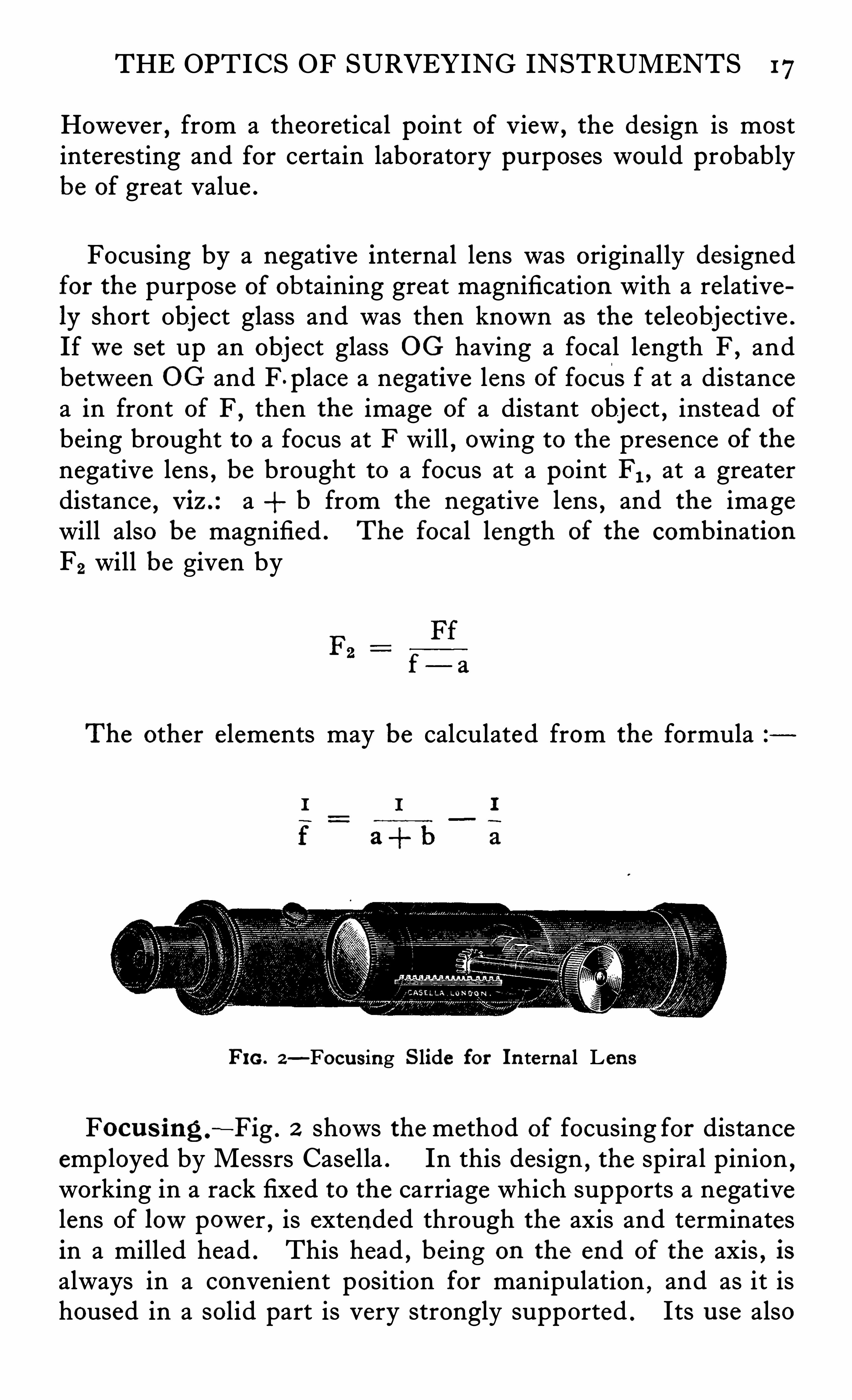
Focusing by a negative internal lens was originally designedfor the purpose of obtaining great magnification with a relatively short Object glass and was then known as the teleobjective .
Ifwe set up an object glass OG having a focal length F , andbetween OG and F place a negative lens of focus f at a distancea in front of F
,then the image of a distant object , instead of
being brought to a focus at F will , owing to the presence of the
negative lens , be brought to a focus at a point PI , at a greaterdistance , Viz .:a b from the negative lens , and the imagewill also be magnified . The focal length of the combinationF2 will be given by
f— a
The other e lements may be calculated from the formula
FIG. 2—Focusing S lide for In ternal Len s
Focu s ing .
—Fig . 2 shows the method of focusing for distanceemployed by Messrs Casella . In this design
,the spiral pinion
,
working in a rack fixed to the carriage which supports a negativelens Of lowpower
,is extended through the axis and terminates
in a milled head . This head , being on the end of the axis,is
always in a convenient position for manipulation , and as it ishoused in a solid part is very strongly supported . Its u se also
18 SURVEYING INSTRUMENTS
does not disturb the setting of the telescope to the same extentas in the usual design in which the milled head is fixed to thetube .
Fig . I 19shows an excellent design for the movable slide carrying the internal lens , due to Messrs T . Cooke 8:Sons . Inthis case the carriage runs on a 3
-point skid which gives thesmooth and straight run for the lens necessary to fulfil one of
the conditions laid down .
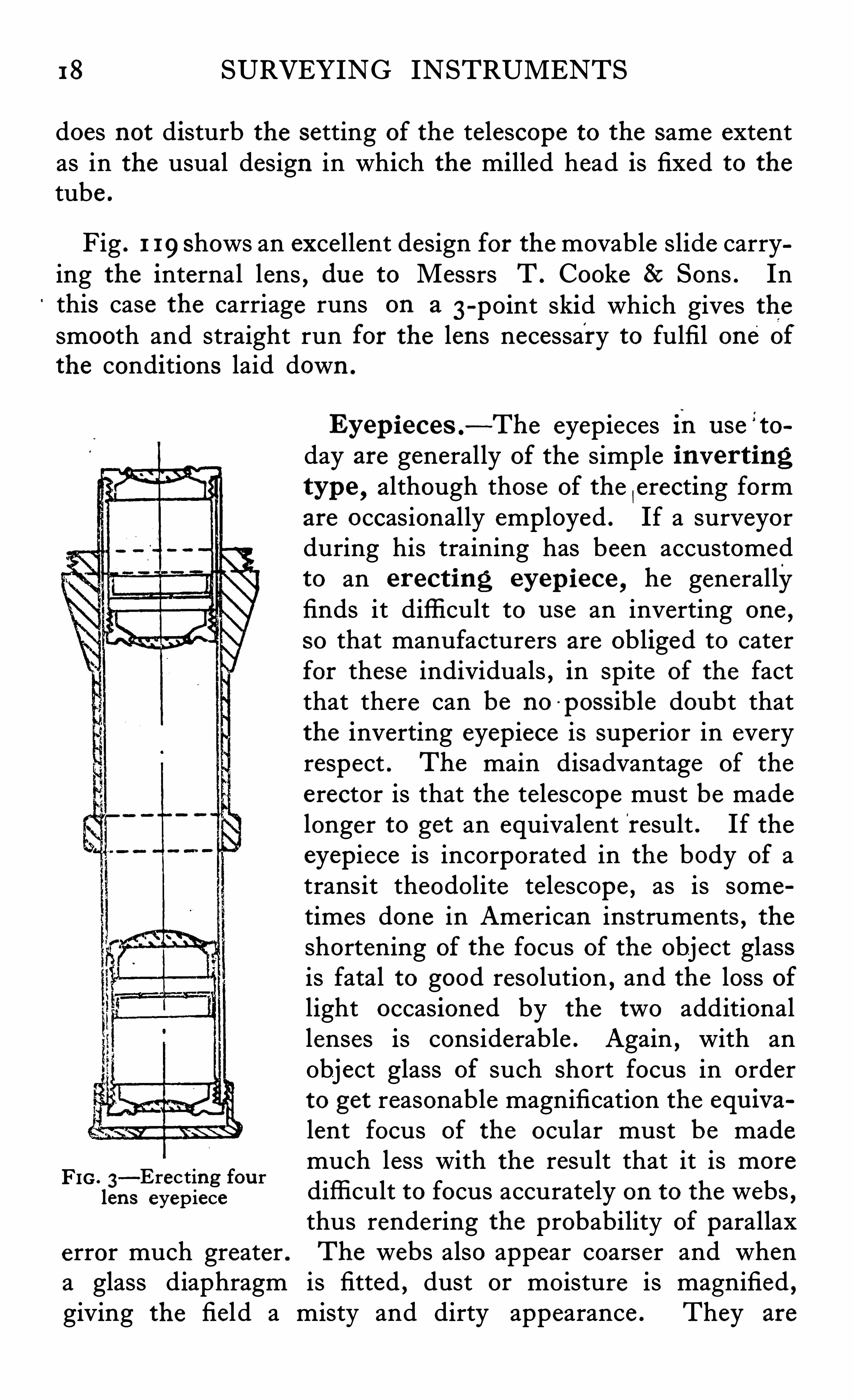
FIG . 3—Erecting fou rlens eyepiece
error much greater .
Eyepieces .—The eyepieces in u se
’to
day are generally of the simple inver tingtyp e , although those of the
|erecting form
are occasionally employed . If a surveyorduring his training has been accustomedto an erect ing eyep iece , he generallyfinds it diffi cult to u se an inverting one ,
so that manufacturers are obliged to caterfor these individuals
,in spite of the fact
that there can be no'
possible doubt thatthe inverting eyepiece is superior in everyrespect . The main disadvantage of the
erector is that the telescope must be madelonger to get an equivalent result . If theeyepiece is incorporated in the body of atransit theodolite telescope , as is sometimes done in American instruments , theshortening of the focus of the object glassis fatal to good resolution , and the loss oflight occasioned by the two additionallenses is considerable . Again , with anObject glass of such short focus in orderto get reasonable magnification the equ ivalent focus of the ocular must be mademuch less with the result that it is morediffi cult to focus accurate ly on to the webs ,thus rendering the probability of parallaxThe webs also appear coarser and when
a glass diaphragm is fitted , dust or moisture is magnified ,giving the field a misty and dirty appearance . They are
THE OPTICS OF SURVEYING INSTRUMENTS 19
convenient , however , when used in conjunction with a prism to
examine stars towards the zenith , and for that reason an illustration of the form generally employed is shown in Fig . 3 . The
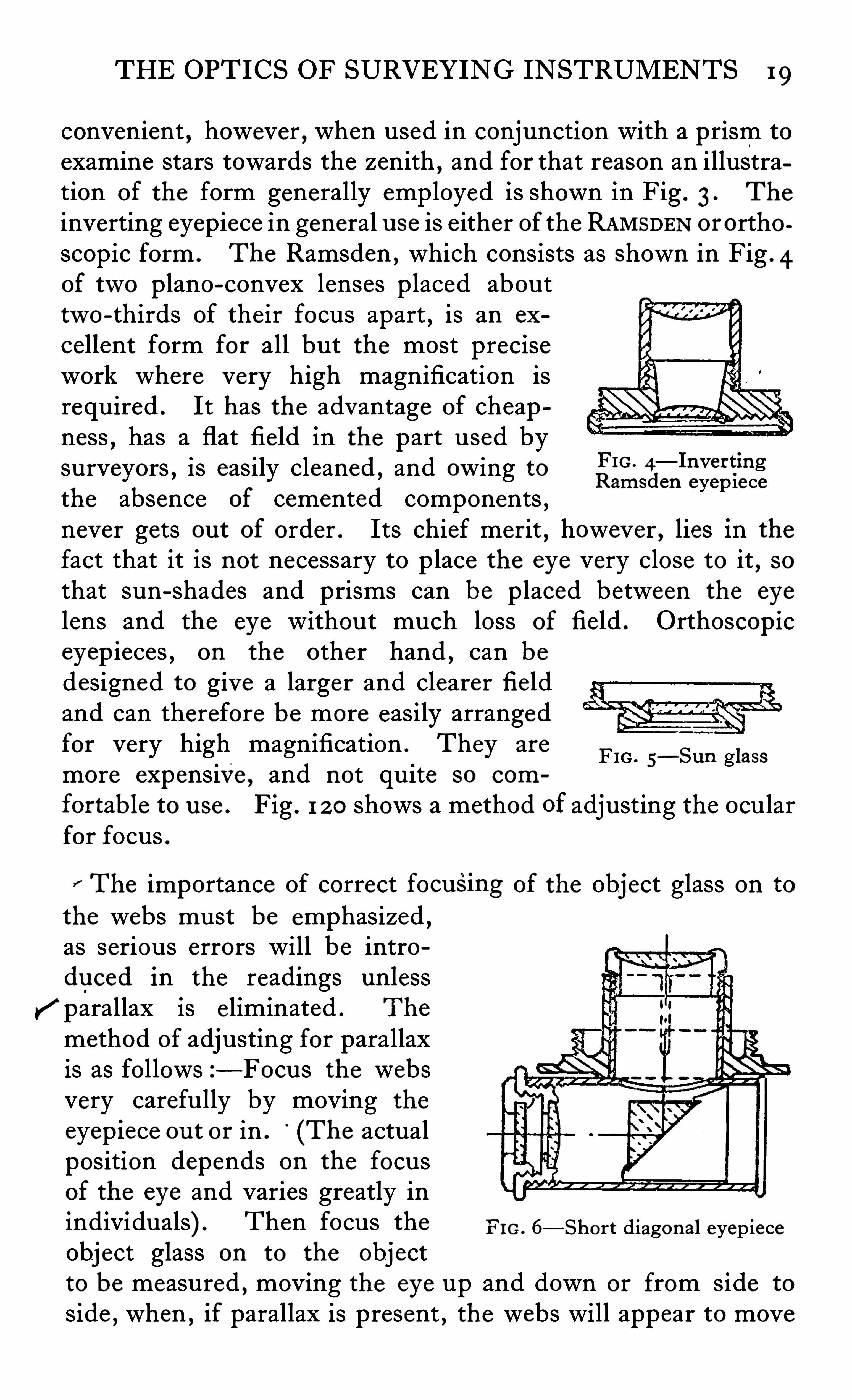
inverting eyepiece in general u se is e ither of the RAMSDEN ororthoscopic form . The Ramsden , which consists as Shown in Fig . 4of two plano-convex lenses placed abouttwo-thirds of the ir focus apart , is an ex
cellent form for all but the most precisework where very high magnification isrequired . It has the advantage of cheapness
,has a flat field in the part used by
surveyors , is easily cleaned , and owing to fi—‘ Inv ef fing
ams en eyep iecethe absence of cemented components ,never gets ou t of order . Its chief merit , however , lies in the
fact that it is not necessary to place the eye very close to it , sothat sun-shades and prisms can be placed between the eye
lens and the eye without much loss of field . Orthoscop iceyepieces , on the other hand , can bedesigned to give a larger and clearer fieldand can therefore be more easily arrangedfor very high magnification . They are
more expensive , and not quite SO com
fortable to u se . Fig . 1 2 0 shows a method of adjusting the ocularfor focus .
FIG . 5—Sun glass
The importance of correct focu smg of the Object glass on to
the webs must be emphasized ,as serious errors will be introdu ced in the readings unlessparallax is e liminated . The
method of adjusting for parallaxis as fol lows z— Focus the websvery carefully by moving the
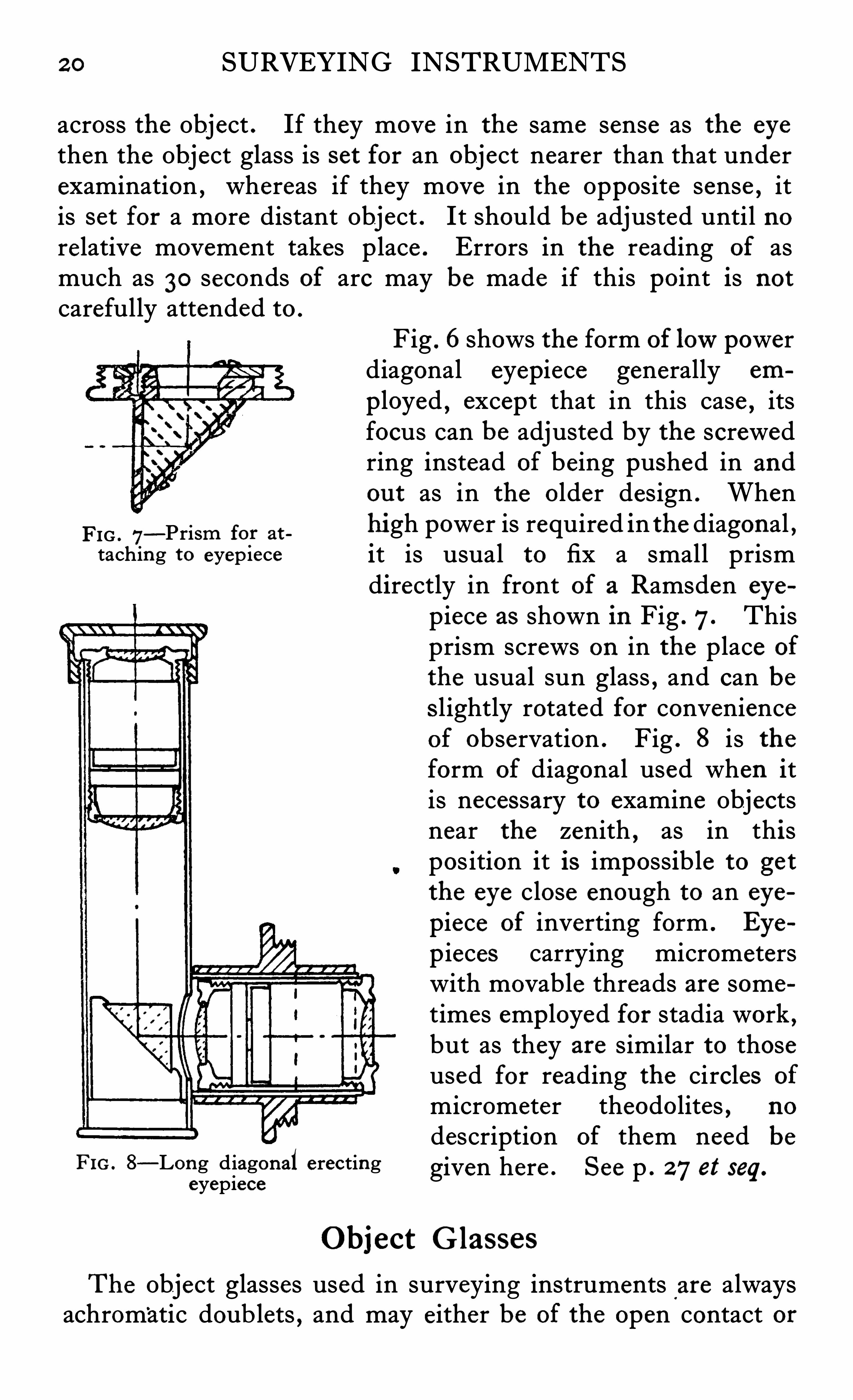
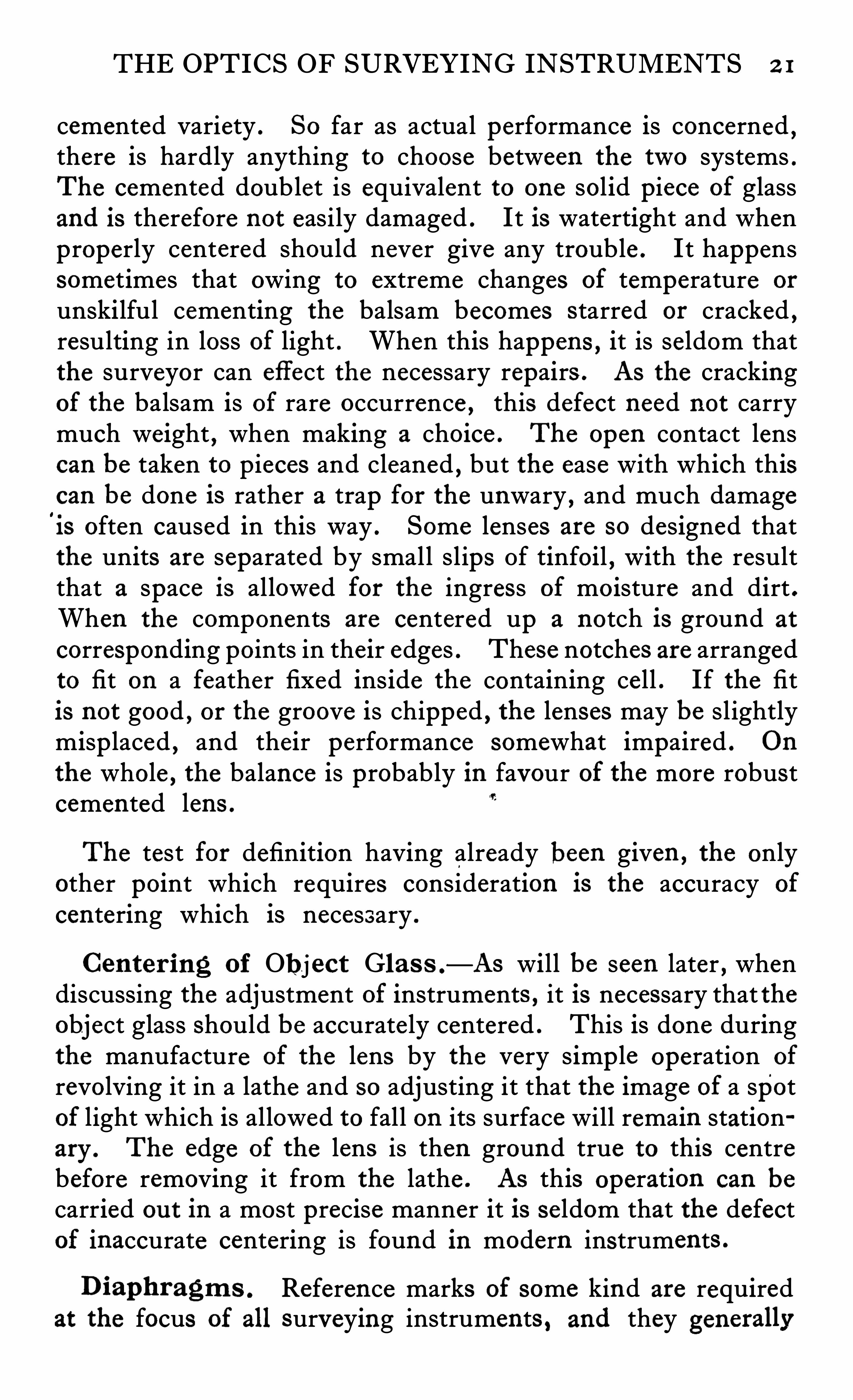
eyepiece ou t or in . (The actualposition depends on the focusof the eye and varies greatly inindividuals) . Then focus the Fro . 6—Short diagon al eyepieceObject glass on to the objectto be measured , moving the eye up and down or from side to
side , when ,if parallax is present , the webs will appear to move
2 0 SURVEYING INSTRUMENTS
across the Object . If they move in the same sense as the eye
then the Object glass is set for an object nearer than that underexamination , whereas if they move in the Opposite sense , itis set for a more distant Object . It should be adjusted until norelative movement takes place . Errors in the reading of asmuch as 30 seconds of arc may be made if this point is not
carefully attended to .
FIG . 7—Prism for at
taching to eyep iece
FIG. 8—Long diagonaleyepiece
Object Glasses
The Object glasses used in surveying instruments are alwaysachromatic doub lets , and may either be of the open contact or
Fig . 6shows the form of lowpowerdiagonal eyepiece generally em
p loyed , except that in this case,its
focus can be adjusted by the screwedring instead of being pushed in and
ou t as in the older design . Whenhi gh power is required in the diagonal ,it is usual to fix a small prismdirectly in front of a Ramsden eye
erecting
piece as shown in Fig . 7. Thisprism screws on in the place of
the usual sun glass,and can be
Slightly rotated for convenienceof observation . Fig . 8 is theform of diagonal used when itis necessary to examine Objectsnear the zenith , as in thispos ition it is impossible to getthe eye close enough to an eye
piece of inverting form . Eye
p ieces carrying micrometerswith movable threads are sometimes employed for stadia work ,but as they are similar to thoseused for reading the circles of
micrometer theodolites , no
description of them need be
given here . See p . 27et seq.
THE OPTICS OF SURVEYING INSTRUMENTS 2 1
cemented variety . So far as actual performance is concerned ,there is hardly anything to choose between the two systems .The cemented doublet is equivalent to one solid piece of glassand is therefore not easily damaged . It is watertight and whenproperly centered should never give any trouble . It happenssometimes that owing to extreme changes of temperature or
unskilful cementing the balsam becomes starred or cracked ,resulting in loss of light . When this happens
,it is seldom that
the surveyor can effect the necessary repairs . As the crackingof the balsam is of rare occurrence , this defect need not carrymuch weight , when making a choice . The open contact lenscan be taken to pieces and cleaned , but the ease with which thiscan be done is rather a trap for the unwary , and much damage18 often caused in this way . Some lenses are so designed thatthe units are separated by small slips Of tinfoil , with the resultthat a space is allowed for the ingress of moisture and dirt .When the components are centered up a notch is ground at
corresponding points in their edges . These notches are arrangedto fit on a feather fixed ins ide the containing cell . If the fitis not good , or the groove is chipped , the lenses may be slightlymisp laced , and their performance somewhat impaired . On
the whole , the balance is probably in favour of the more robustcemen ted lens .
The test for definition having already been given ,the only
other point which requires consideration is the accuracy of
centering which is necessary .
Center ing of Obj ect Glas s .—As will be seen later , when
discussing the adjustment of instruments , it is necessary that theobject glass Should be accurate ly centered . This is done duringthe manufacture of the lens by the very simp le operation of
revolving it in a lathe and so adjusting it that the image of a spotof light which is allowed to fall on its surface will remain stationary . The edge of the lens is then ground true to this centrebefore removing it from the lathe . AS this operation can be
carried ou t in a most precise manner it is se ldom that the defectof inaccurate centering is found in modern instruments .
Diaphragm s . Reference marks of some kind are requiredat the focus of all surveying instruments , and they generallv
2 2 SURVEYING INSTRUMENTS
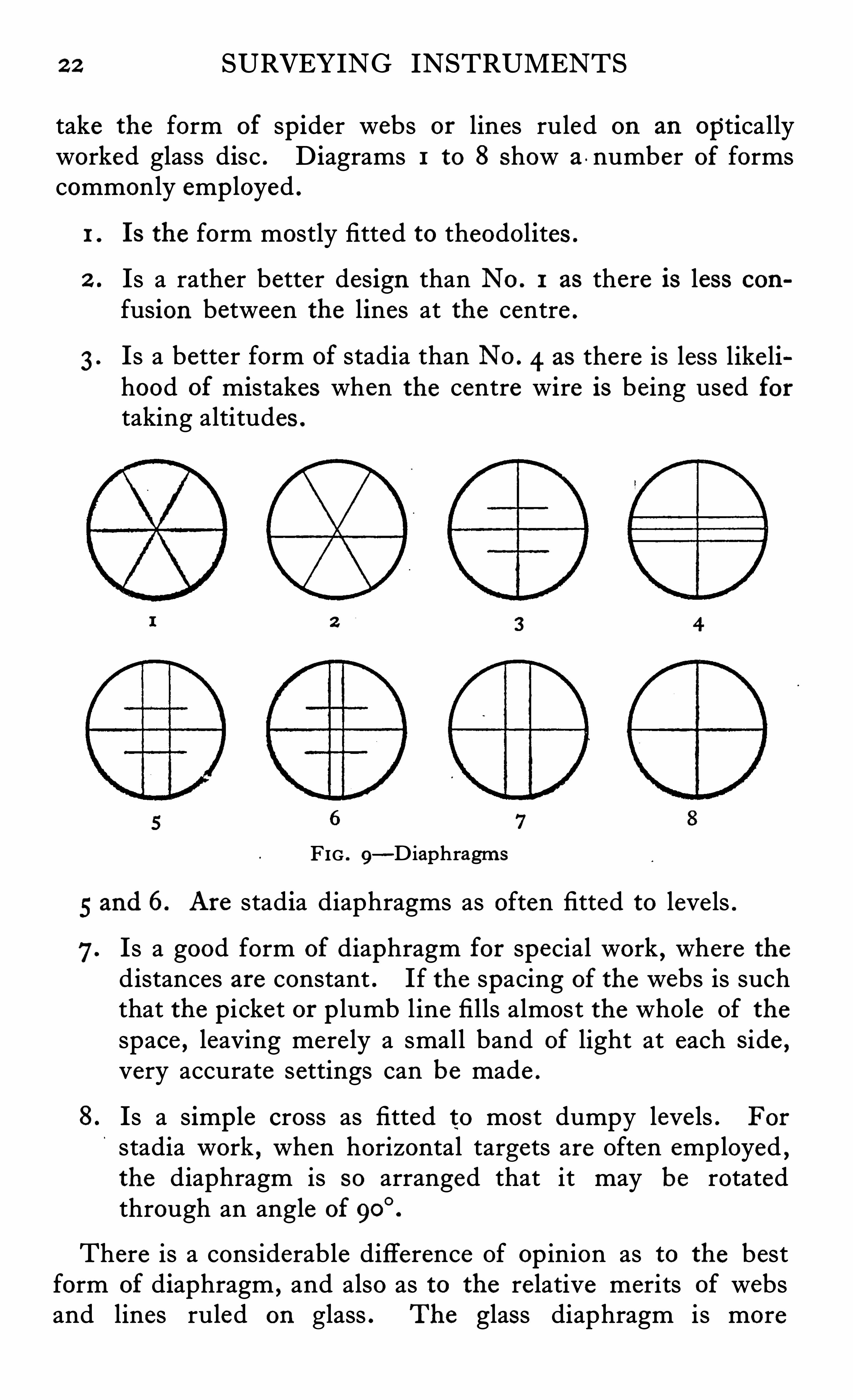
take the form of spider webs or lines ruled on an opticallyworked glass disc . D iagrams 1 to 8 Show a -number of formscommonly emp loyed .
1 . Is the form mostly fitted to theodolites .
2 . Is a rather better design than No . 1 as there is less con
fusion between the lines at the centre .
3 . Is a better form of stadia than No . 4 as there is less like lihood of mistakes when the centre wire is being used fortaking altitudes .
FIG . 9—D iaphragms
5 and 6. Are stadia diaphragms as often fitted to leve ls .
7. Is a good form of diaphragm for special work , where thedistances are constant . If the spacing of the webs is suchthat the picket or p lumb line fills almost the whole Of thespace , leaving mere ly a small band of light at each Side ,very accurate settings can be made .
8. Is a simp le cross as fitted to most dumpy leve ls . For
stadia work , when horizontal targets are Often employed ,the diaphragm is so arranged that it may be rotatedthrough an angle of
There is a considerable difference Of op inion as to the bestform of diaphragm ,
and also as to the re lative merits of websand lines ruled on glass . The glass diaphragm is more
2 4 SURVEYING INSTRUMENTS
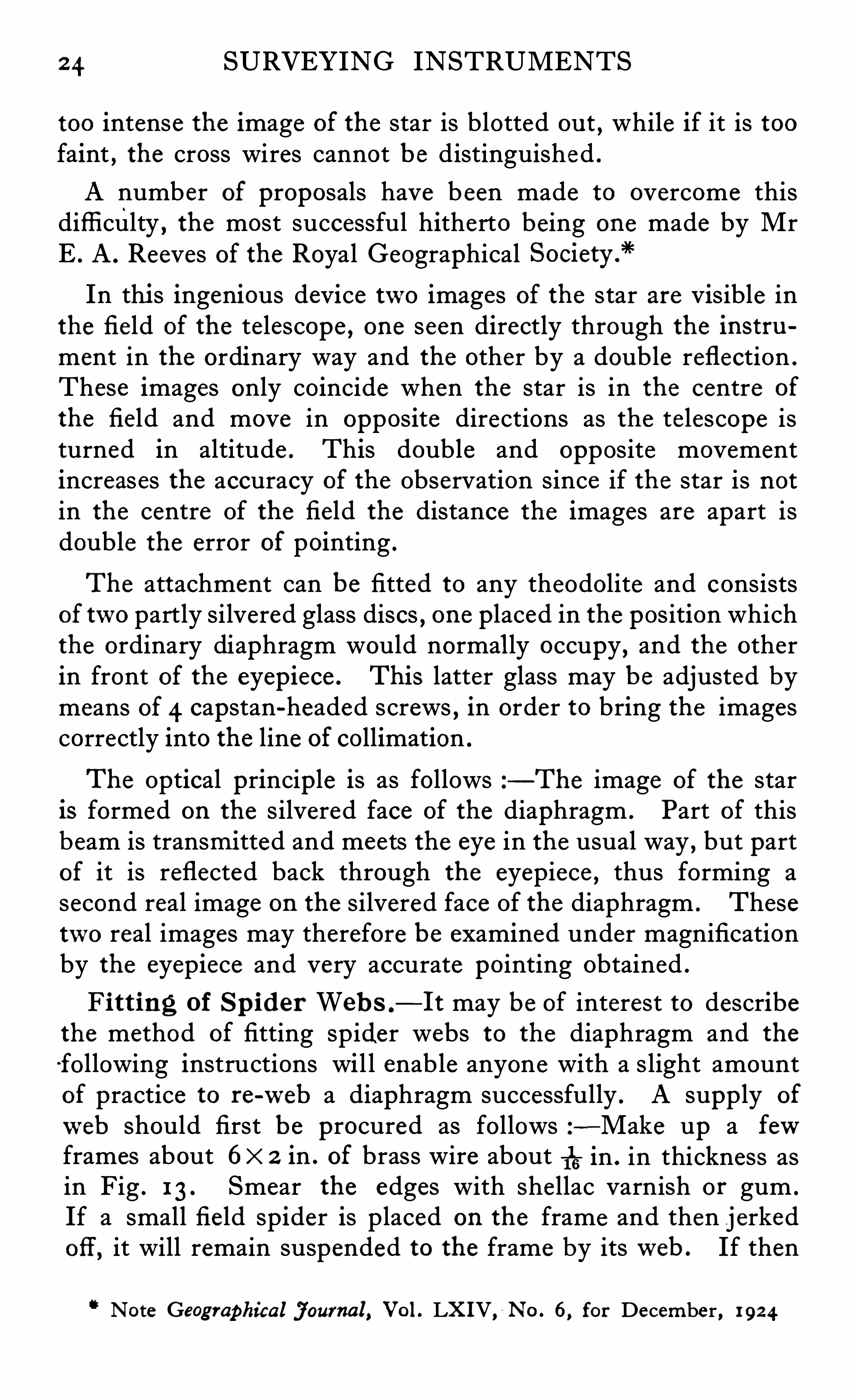
too intense the image of the star is blotted ou t, while if it is too
faint,the cross wires cannot be distinguished .
A number of proposals have b een made to overcome thisdiffi culty , the most successful hitherto being one made by MrE . A . Reeves of the Royal GeographicalIn thi s ingenious device two images of the star are Visible in
the fie ld of the telescope , one seen directly through the instrument in the ordinary way and the other by a double reflection .
These images only coincide when the star is in the centre of
the field and move in opposite directions as the telescope isturned in altitude . This double and opposite movementincreases the accuracy of the Observation since if the star is notin the centre Of the field the distance the images are apart isdouble the error of pointing .
The attachment can be fitted to any theodolite and consistsof two partly silvered glass discs , one placed in the position whichthe ordinary diaphragm would normal ly occupy
,and the other
in front of the eyepiece . This latter glass may be adjusted bymeans of 4 capstan-headed screws , in order to bring the imagescorrectly into the line of collimation .
The Optical principle is as follows —The image of the staris formed on the silvered face of the diaphragm . Part of thisbeam is transmi tted and meets the eye in the usual way , but partof it is reflected back through the eyepiece , thus forming asecond real image on the silvered face Of the diaphragm . Thesetwo real images may therefore be examined under magnificationby the eyepiece and very accurate pointing obtained .
Fi tting of Sp ider Web s .
— I t may be of interest to describethe method of fitting spider webs to the diaphragm and the
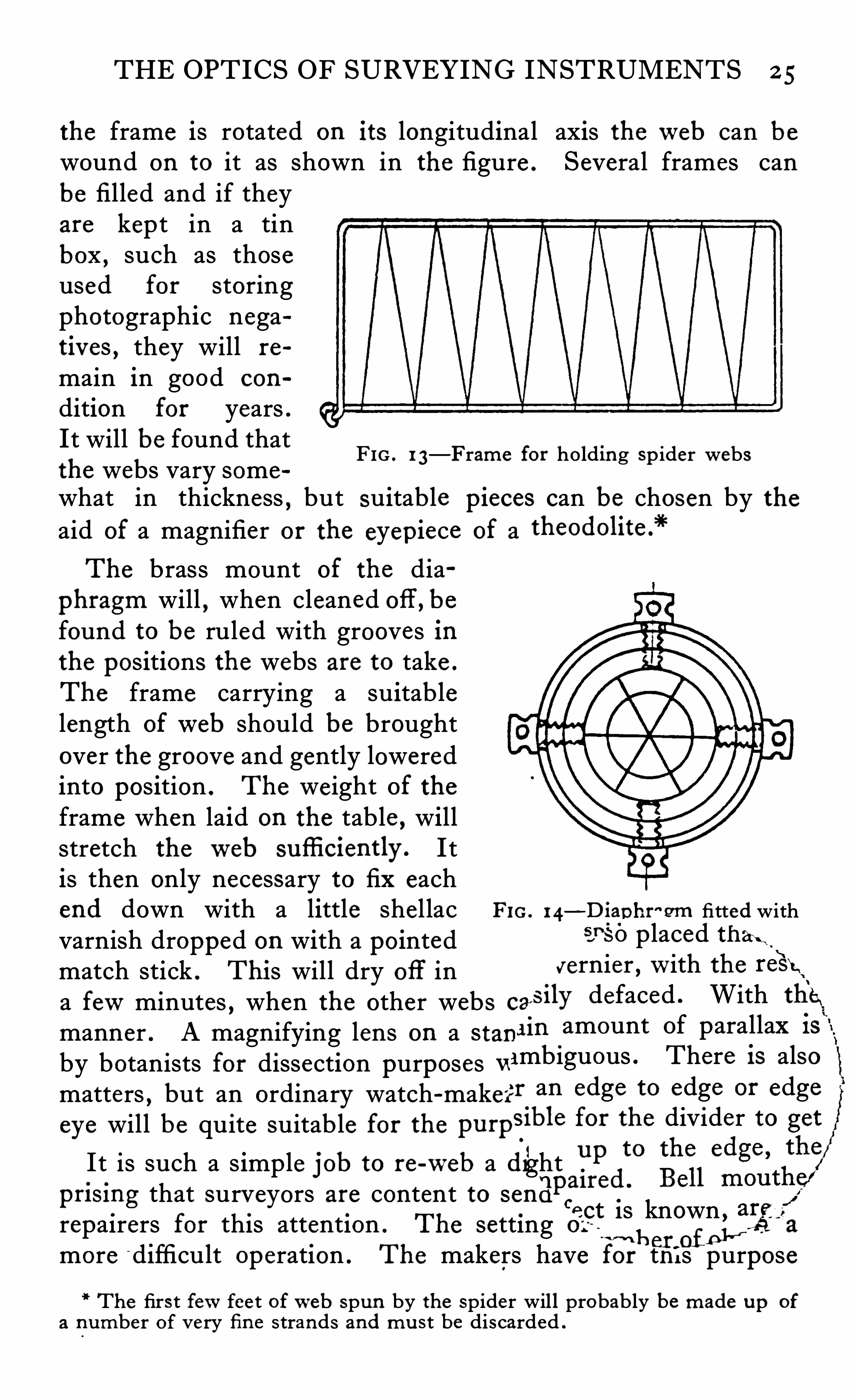
f ollowing instructions wi l l enable anyone with a slight amountof practice to re-web a diaphragm successfully . A supply ofweb should first be procured as follows —Make up a fewframes about 6"2 in . of brass wire about fi in . in thickness asin Fig . 1 3 . Smear the edges with she llac varnish or gum .
If a small field spider is placed on the frame and then j erkedoff
, it will remain suspended to the frame by itsweb . If then
Note Geographica l yaw-m l , Vol . L"IV,
- NO . 6, for Decembe r , 192 4
THE OPTICS OF SURVEYING INSTRUMENTS 2 5
the frame is rotated on its longitudinal axis theweb can bewound on to it as shown in the figure . Several frames canbe filled and if theyare kept in a tinbox , such as thoseused for storingphotographic negativ es , they will re
main in good con
dition for years .
It will be found thatthe webs vary some
what in thickness,but suitable pieces can be chosen by the
aid of a magnifier or the eyep iece of a
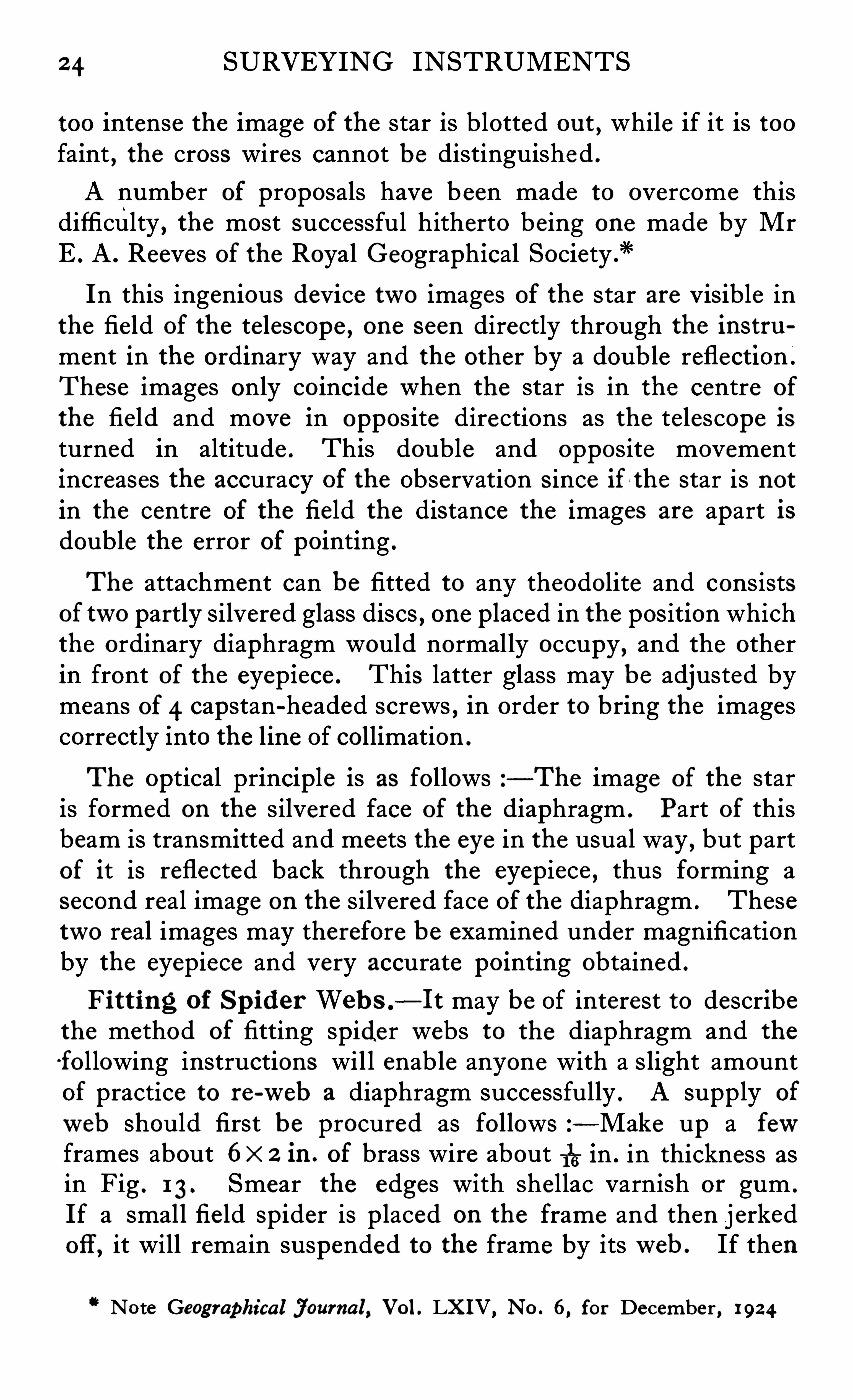
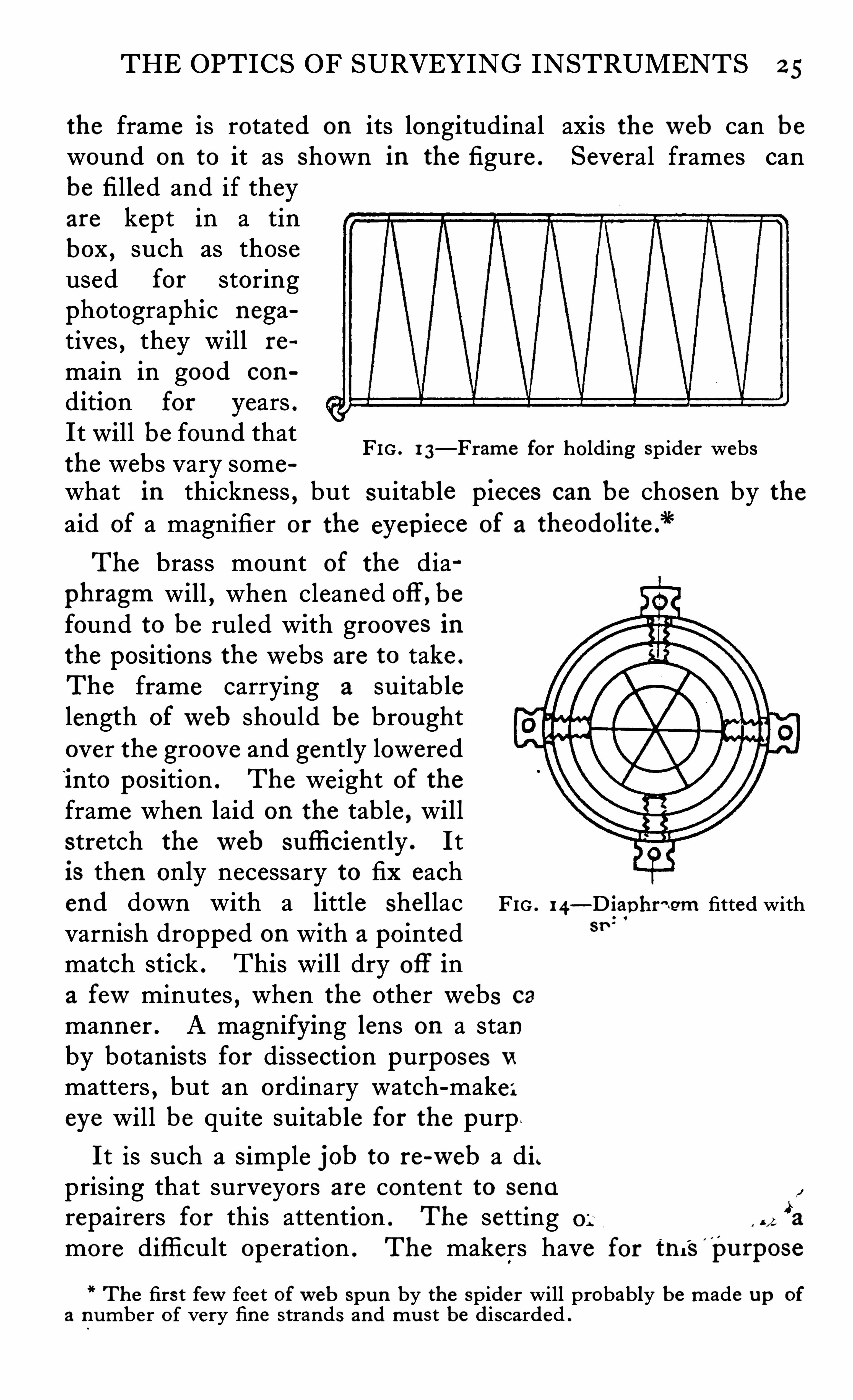
The brass mount of the dia
phragm will , when cleaned off , befound to be ruled with grooves inthe positions the webs are to take .
The frame carrying a suitablelength ofweb should be broughtover the groove and gently loweredinto position . The weight of theframe when laid on the table , willstretch theweb sufli ciently . I tis then only necessary to fix eachend down with a little shel lac Fro . 14
—Diap hr"Qm fitted with
varnish dropped on with a pointed SJ‘SO placed thax t
,
‘
match stick . Thi s will dry Off in vernier , W ith the
a fewminutes , when the other webs caSily defaced . With the"
manner . A magnifying lens on a stani in amount Of parallax 13
by botanists for dissection purposes “ ambiguous . There 15 also
matters , but an ordinary watch-maker” an edge to edge or edge
eye will be quite suitable for the pu rpSible for the divider to get
I t is such a s imple job to re-web a (fight PP to the e
apai re
pri smg that surveyors are content to senCa ct is known , agarepairers for this attention . The setting o.
~wh en of p l"more difficult operation . The makers have for th i s purpose
FIG . I 3—Frame for ho lding sp ider webs
The firs t fewfeet ofweb spun by the spider will probably be made Up Of
a number Of very fi n e s trands and mu st be discarded .
2 4 SURVEYING INSTRUMENTS
too intense the image of the star is blotted ou t , while if it is toofaint
, the cross wires cannot be distinguished .
A number of proposals have been made to overcome thisdifficulty , the most successful hitherto being one made by MrE . A . Reeves of the Royal Geographical Society .
"
In this ingenious device two images of the star are Visible inthe fie ld of the telescope , one seen directly through the instrument in the ordinary way and the other by a double reflection .
These images only coincide when the star is in the centre of
the field and move in opposite directions as the telescope isturned in altitude . This double and opposite movementincreases the accuracy of the Observation Since if l the star is notin the centre of the field the distance the images are apart isdouble the error of pointing .
The attachment can be fitted to any theodolite and consistsof two partly silvered glass discs , one placed in the position whichthe ordinary diaphragm would normally occupy
,and the other
in front of the eyepiece . This latter glass may be adjusted bymeans of 4 capstan-headed screws , in order to bring the imagescorrectly into the line Of collimation .
The optical principle is as follows —The image of the staris formed on the silvered face of the diaphragm . Part of thisbeam is transmitted and meets the eye in the usual way , but partof it is reflected back through the eyepiece , thus forming asecond real image on the silvered face of the diaphragm . Thesetwo real images may therefore be examined under magnificationby the eyepiece and very accurate pointing obtained .
Fi tting of Sp ider Web s .
—I t may be Of interest to describethe method of fitting spider webs to the diaphragm and the
f ol lowing instructions wil l enable anyone with a slight amountof practice to re-web a diaphragm successfully . A supply ofweb should first be procured as follows —Make up a fewframes about 6x 2 in . of brass wire about 115 in . in thickness asin Fig . 1 3 . Smear the edges with shellac varnish or gum .
If a small fie ld spider is placed on the frame and then jerkedOff, it will remain suspended to the frame by itsweb . If then
Note Geographica l j ourna l , Vol . L"IV, No . 6, for Decembe r , 192 4
THE OPTICS OF SURVEYING INSTRUMENTS 2 5
the frame is rotated on its longitudinal axis theweb can bewound on to it as Shown in the figure . Several frames canbe filled and if theyare kept in a tinbox , such as thoseused for storingphotographic negatiy es , they will re
main in good con
dition for years .It will be found thatthe webs vary somewhat in thickness , but suitable p ieces can be chosen by theaid of a magnifier or the eyep iece of a theodolitefi“
The brass mount of the dia
phragm will , when cleaned off , befound to be ruled with grooves inthe positions the webs are to take .
The frame carrying a suitablelength ofweb should be broughtover the groove and gently loweredinto position . The weight of theframe when laid on the table , willstretch theweb suffi ciently . Itis then only necessary to fix eachend down with a little she llac FIG . 14
—Dtap hr~ .gm fitted withvarnish dropped on with a pointed 8”
match stick . This will dry off ina fewminutes , when the other webs ca
manner . A magnifying lens on a stanby botanists for dissection purposes Vt
matters , but an ordinary watch-make ;eye will be quite suitable for the purp .
FIG . 1 3—Frame for holding sp ider webs
It is such a simple job to re-web a di.prising that surveyors are content to send
repairers for this attention . The setting ’a
more diffi cult operation . The makers have for tni
’
s'
pu rpose
The firs t fewfee t ofweb spun by the spider will probably be made up of
a number Of very fi ne strands and mu s t be discarded .
26 SURVEYING INSTRUMENTS
a tool which traverses theweb a known distance , by means of ascrew , and then lowers it into place . I t is also necessary of
course , to have a micrometer eyepiece which fits into the theodolite in order to measure the value of the interval to give the reading required . As , however ,web stadia diaphragms are se ldomused , the surveyor will not Often be required to fit them himself.
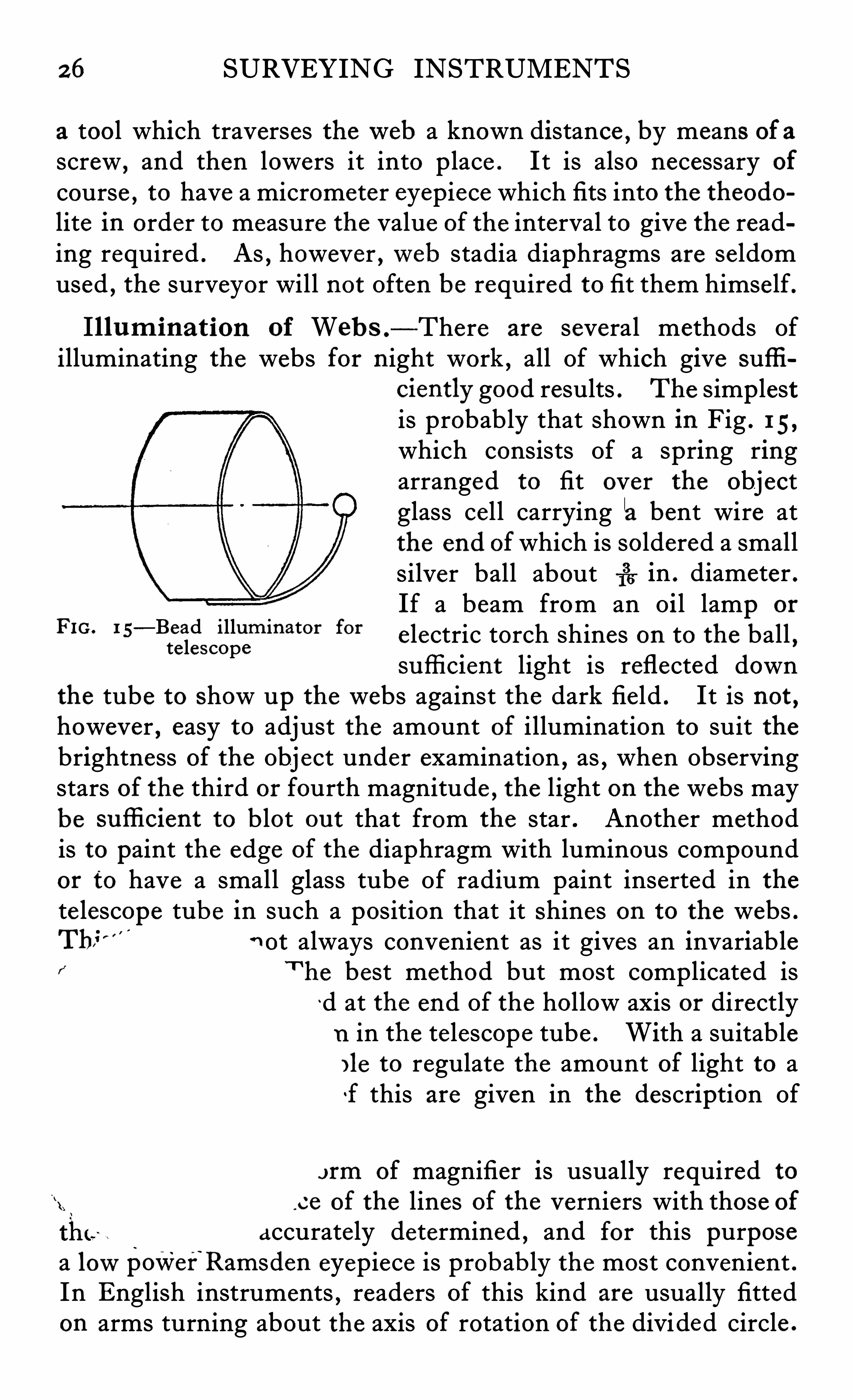
Il lum ina t ion of Web s .
-There are several methods Ofilluminating the webs for n ight work
,all Of which give suffi
ciently good results . The simp lestis probably that shown in Fig . I 5,
which consists Of a spring ringarranged to fit over the objectglass cel l carrying a bent wire atthe end ofwhich is soldered a smallsilver ball about 1
33 in . diameter .
If a beam from an Oi l lamp or
e lectric torch shines on to the ball ,sufli cient light is reflected down
the tube to Show up the webs against the dark field . It is not ,however , easy to adjust the amount of i llumination to suit thebrightness of the Obj ect under examination , as , when Observingstars of the third or fourth magnitude
,the light on the webs may
be sufli cient to blot ou t that from the star . Another methodis to paint the edge of the diaphragm with luminous compoundor to have a small glass tube Of radium paint inserted in thete lescope tube in such a position that it Shines on to the webs .Th" n ot always convenient as it gives an invariablef’ T he best method but most complicated is
‘d at the end Of the hollow axis or directlyn in the te lescope tube . With a suitableI le to regulate the amount of light to af this are given in the description Of
FIG. 1 5—Bead illum inator forte lescope
e of magnifier is usually required to
ce of the lines of the verniers with those ofaccurately determined , and for this purpose
a lowpower’
Ramsden eyepiece is probab ly the most convenient .In English instruments
,readers of this kind are usually fitted
on arms turning about the axis of rotation of the divided circle .
THE OPTICS OF SURVEYING INSTRUMENTS 27
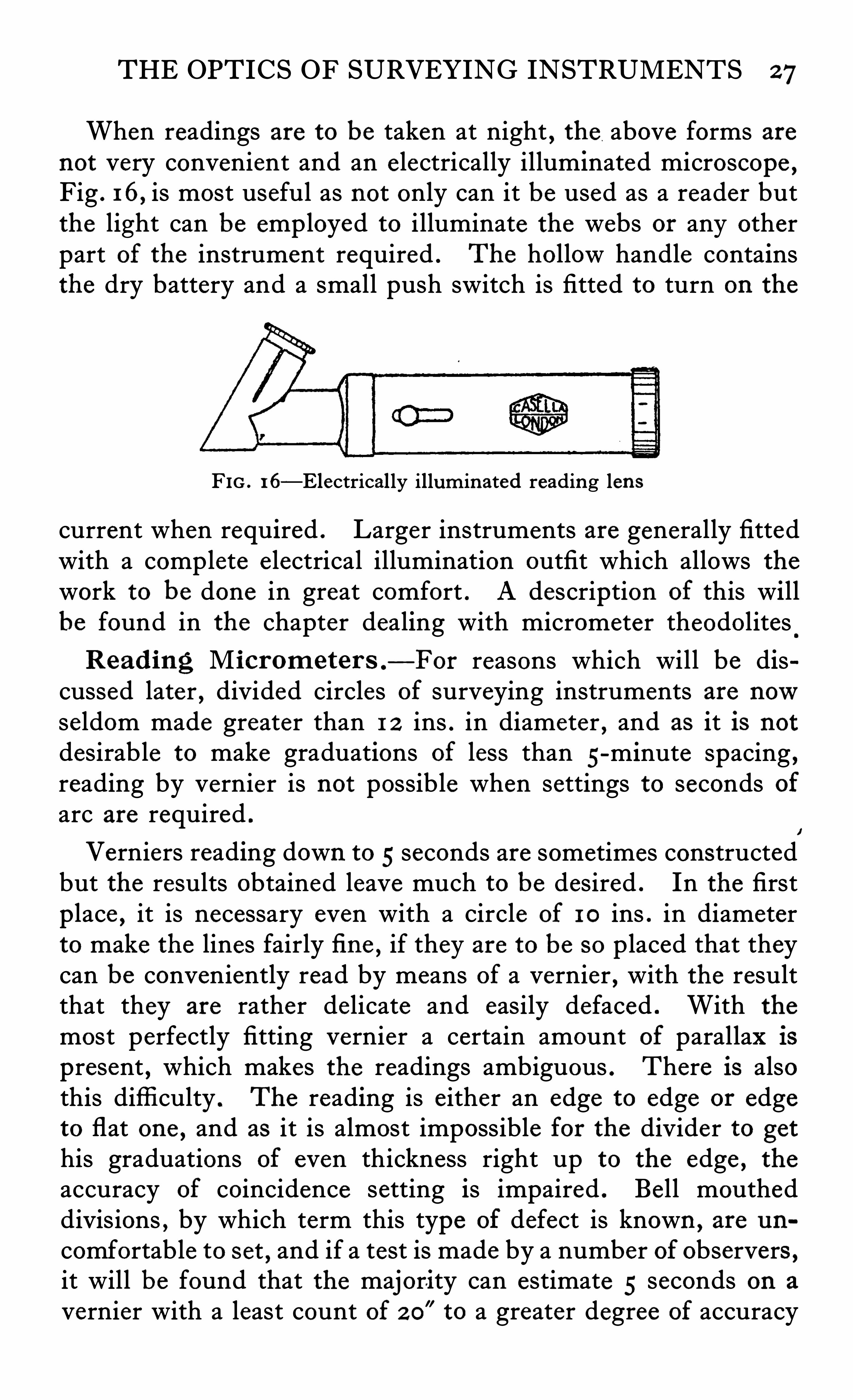
When readings are to be taken at night , the above forms arenot very convenient and an e lectrically illuminated microscope ,Fig . 16, is most useful as not only can it be used as a reader butthe light can be employed to i lluminate the webs or any otherpart of the instrument required . The hollow handle containsthe dry battery and a small push switch is fitted to turn on the
FIG . 16—Electrically illuminated reading len s
current when required . Larger instruments are generally fittedwith a complete e lectrical illumination outfit which allows thework to be done in great comfort . A description of this willbe found in the chapter dealing with micrometer theodolites
Read ing M icrom eter s .
—For reasons which will be discussed later
,divided circles of surveying instruments are now
seldom made greater than 1 2 ins . in diameter,and as it is not
desirable to make graduations of less than 5-minute spacing ,reading by vernier is not possible when settings to seconds ofarc are required .
Verniers reading down to 5 seconds are sometimes constructedbut the results obtained leave much to be desired . In the firstp lace , it is necessary even with a Circle of I O ins . in diameterto make the lines fairly fi ne
,if they are to be so placed that they
can be conveniently read by means of a vernier , with the resultthat they are rather delicate and easily defaced . With the
most perfectly fitting vernier a certain amount of parallax ispresent , which makes the readings ambiguous . There is alsothis diffi culty . The reading is either an edge to edge or edgeto flat one , and as it is almost impossible for the divider to gethis graduations of even thickness right up to the edge , theaccuracy of coincidence setting is impaired . Bell moutheddivisions , by which term this type of defect is known , are un
comfortable to set,and if a test is made by a number of observers ,
it will be found that the majori ty can estimate 5 seconds on a
vernier with a least count of 2 0” to a greater degree of accuracy
2 8 SURVEYING INSTRUMENTS
than they can read a direct 5 second vernier . The power of theeye , even in untrained observers , to estimate halves , quartersand tenths is remarkable . For these reasons , there has beenconsiderable deve lopment in the design of theodolites in whichthe readings are made by either mechanical or optical micrometers . Formerly , instruments of this description were con
fined to those of comparatively large s ize , and although theywere sometimes fitted to those having Circles of 6inches diameterand smaller , they were , owing to the relatively small demand
,
merely adaptions of vernier instruments with the micrometersfitted on in the manner which the constructor found most convenient for himse lf. The resultwas , as might be expectedfrom any built-up apparatus of this nature , unsatisfactory ,both from a mechanical and optical point of view
'
. In recentdesigns , the problem haS
' been studied as a whole and suitablearrangements evolved to meet the necessary requirements
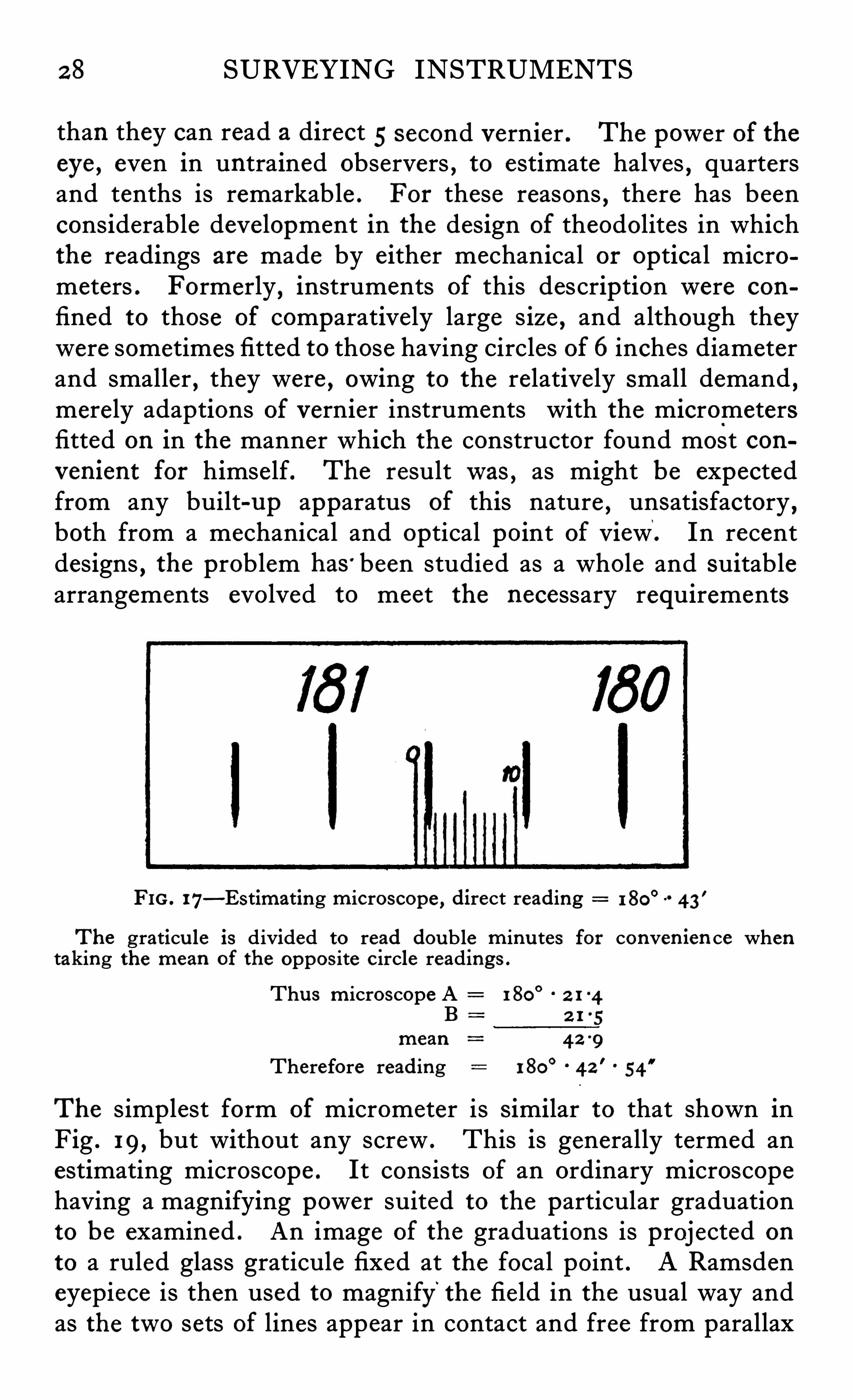
FIG . I7—Estimating microscope , direct reading 180°
43'
The graticu le is divided to read doub le m inu tes for conven ien ce whentaking the mean of the oppos ite C ircle readings .
Thu s m icroscope A 1 80°
2 1 4Bmean 4 2 9
Therefore reading 1 80°
4 2'
54”
The simplest form of micrometer is Similar to that shown inFig . 19, but without any screw . This is generally termed anestimating microscope . It consists of an ordinary microscopehaving a magnifying power suited to the particular graduationto be examined . An image of the graduations is projected on
to a ruled glass graticule fixed at the focal point . A Ramsdeneyepiece is then used to magnify the field in the usual way andas the two sets of lines appear in contact and free from parallax
30 SURVEYING INSTRUMENTS
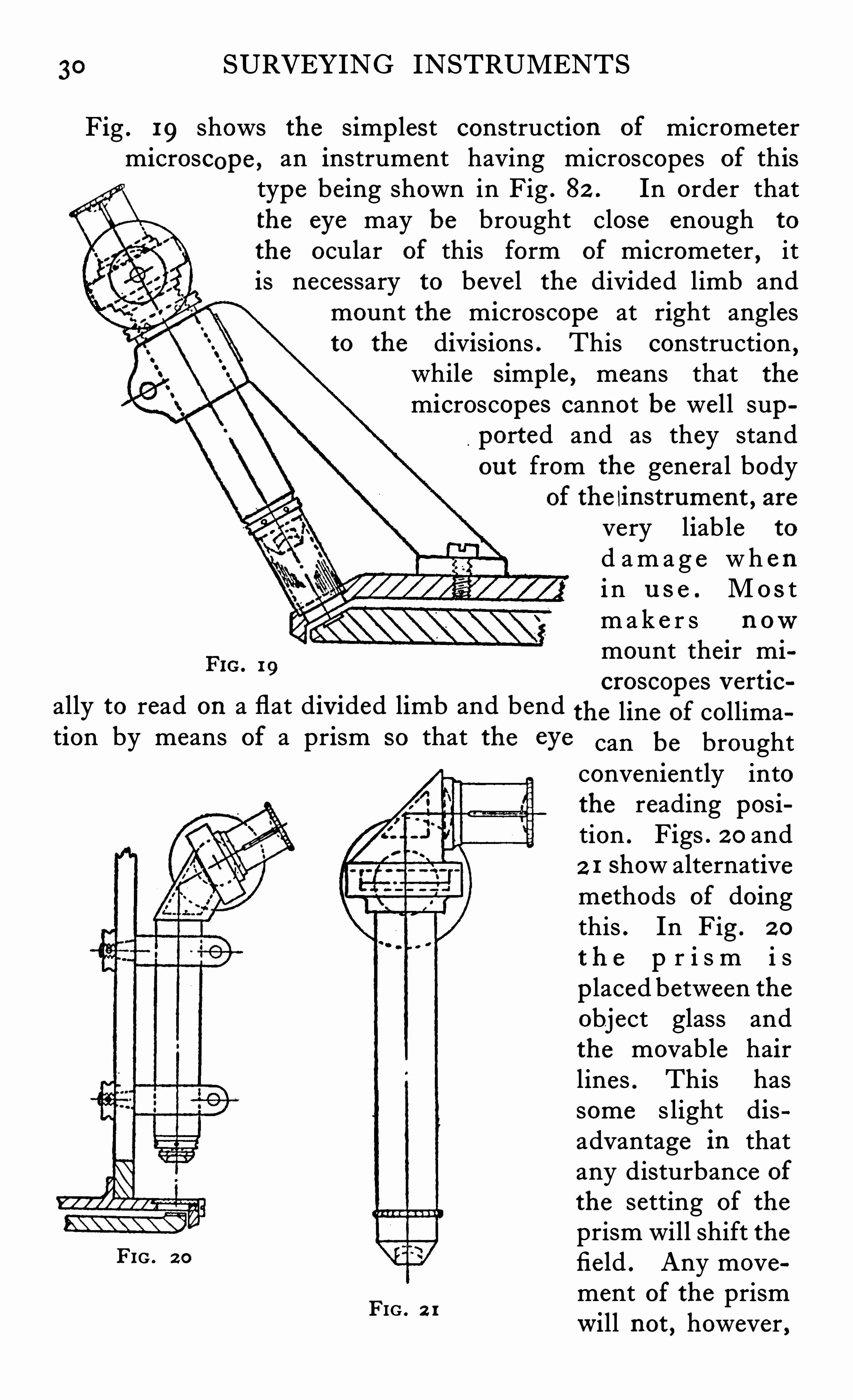
Fig . 19 shows the simp lest construction of micrometermicroscope , an instrument having microscopes of this
type being shown in Fig . 82 . In order thatthe eye may be brought close enough to
the ocular of this form of micrometer , itis necessary to bevel the divided limb and
mount the microscope at right anglesto the divisions . This construction ,
while Simp le , means that the
microscopes cannot be wel l supported and as they standou t from the general body
of the |instrument , are
very liable to
d am a g e wh e nin u s e . M o s tm a k e r s n owmount their micrOSCOpes v ertic
ally to read on a flat divided limb and bend the line of collimation by means of a prism so that the eye can be brought
conveniently intothe reading position . Figs . 2 0 and2 1 Show alternativemethods of doingthis . In Fig . 2 0
t h e p r i s m i sp laced between theobject glass andthe movable hairlines . This hassome s light disadvantage in thatany disturbance of
the setting of the
prism will shift theFIG 2 ° fie ld . Any move
ment of the prismFIG . 2 1
Will not , however ,
THE OPTICS OF SURVEYING INSTRUMENTS 3 1
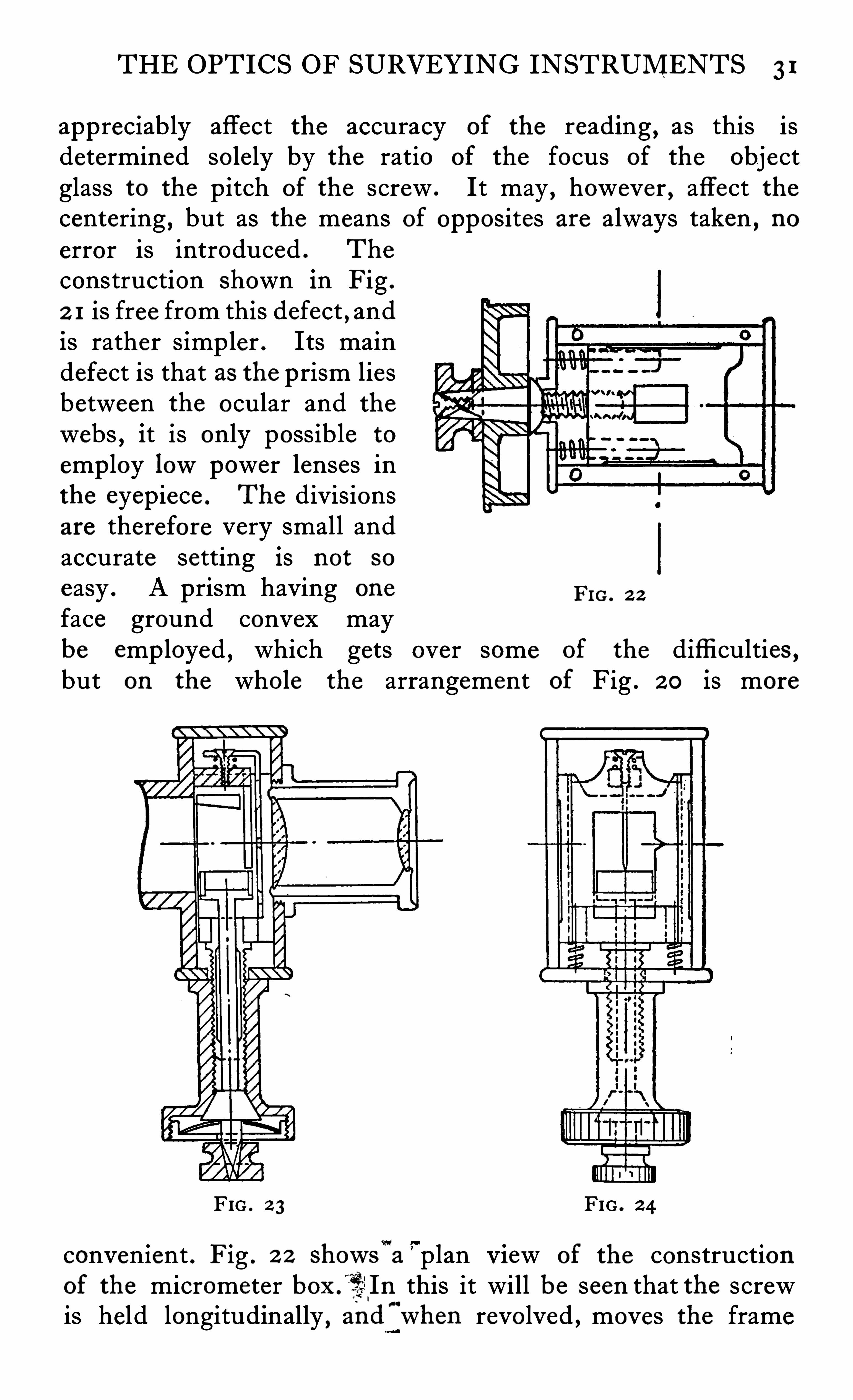
appreciably affect the accuracy of the reading , as this isdetermined solely by the ratio of the focus of the objectglass to the pitch of the screw . It may , however , affect thecentering , but as the means of opposites are always taken , noerror is introduced . The
construction Shown in Fig .
2 1 is free from this defect , andis rather simpler . Its maindefect is that as the prism liesbetween the ocular and the
webs , it is only possible to
employ lowpower lenses inthe eyepiece . The divisionsare therefore very small andaccurate setting is not so
easy . A prism having one Fro . 2 2
face ground convex maybe emp loyed , which gets over some of the diffi culties ,but on the whole the arrangement of Fig . 2 0 is more
FIG . 2 3 FIG . 2 4
convenient . Fig . 2 2 showswa plan View of the constructionof the micrometer boxf'
iié 'In this it will be seen that the screwis held longitudinally
, andflwhen revolved , moves the frame
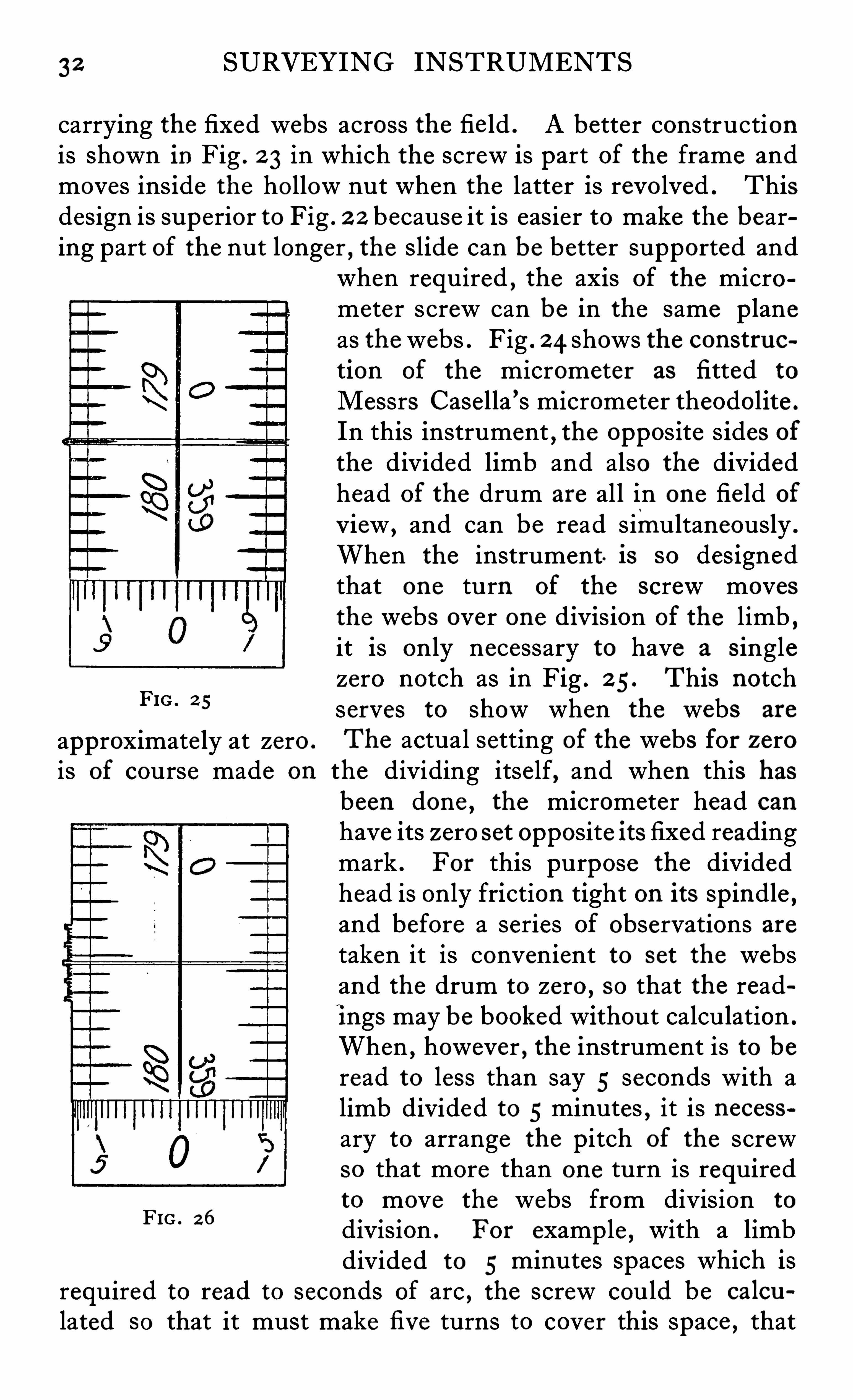
32 SURVEYING INSTRUMENTS
carrying the fixed webs across the fie ld . A better constructionis shown in Fig . 2 3 in which the screw is part of the frame andmoves inside the hollow nut when the latter is revolved . Thisdesign is superior to Fig . 2 2 because it is easier to make the bearing part of the nut longer , the slide can be better supported and
FIG . 2 5
approximate ly at zero .
when required , the axis of the micrometer screw can be in the same p laneas the webs . Fig . 2 4 shows the construction of the micrometer as fitted to
Messrs Casella ’s micrometer theodolite .
In this instrument,the opposite s ides of
the divided limb and also the dividedhead of the drum are all in one fie ld of
View , and can be read simultaneously .
When the instrument is so des ignedthat one turn of the screw movesthe webs over one divis ion of the limb ,it is only necessary to have a s inglezero notch as in Fig . 2 5. This notchserves to show when the webs are
The actual setting of the webs for zerois of course made on the dividing itself, and when this has
FIG . 26
been done , the micrometer head can
have its zero set opposite its fixed readingmark . For this purpose the dividedhead is only friction tight on its spindle ,and before a series of observations aretaken it is convenient to set the websand the drum to zero ,
so that the readi ngs may be booked without calculation .
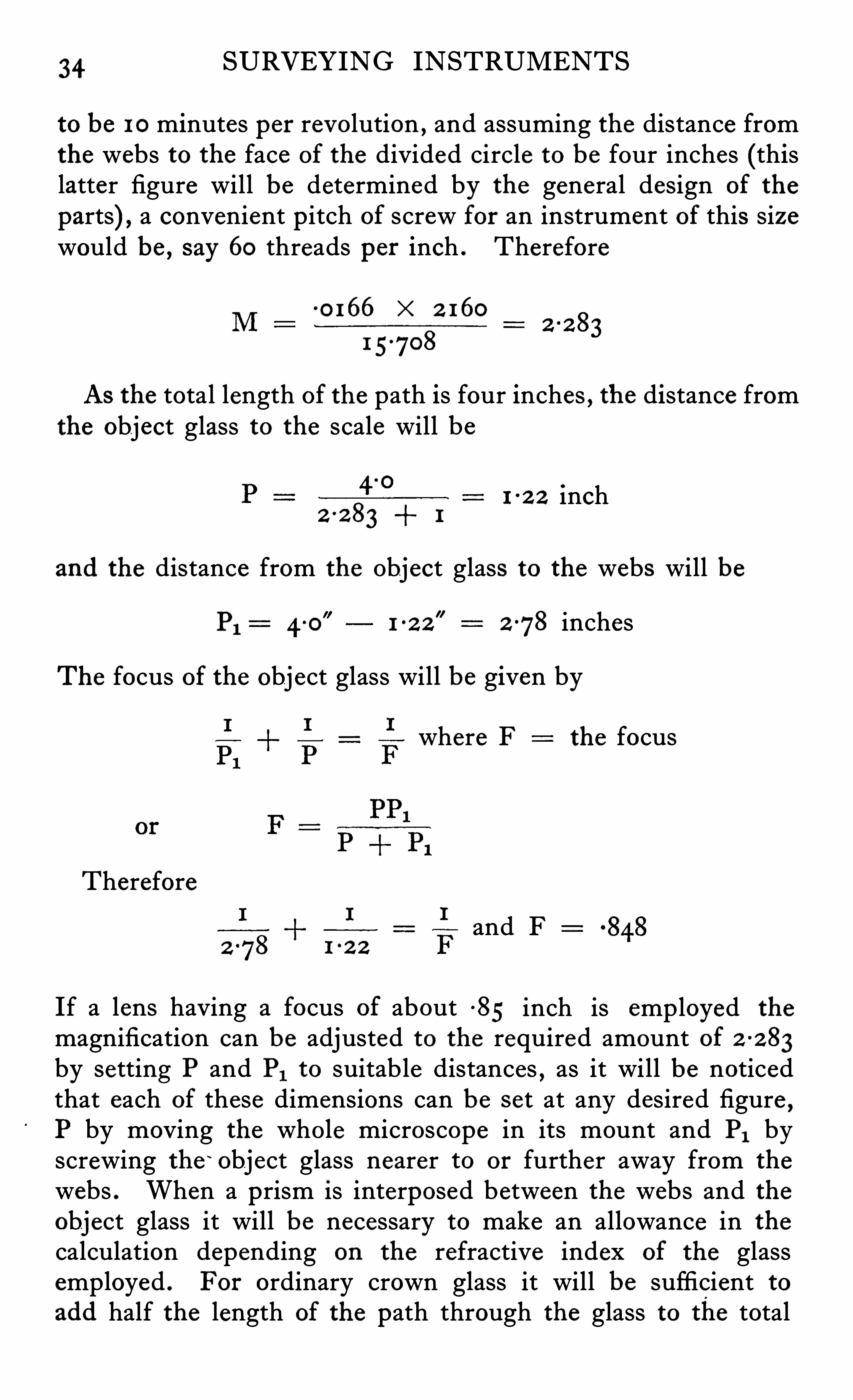
When , however , the instrument is to beread to less than say 5 seconds with alimb divided to 5 minutes , it is necessary to arrange the pitch of the screwso that more than one turn is requiredto move the webs from division to
division . For example , with a limbdivided to 5 minutes spaces which is
required to read to seconds of arc , the screw could be calcu
lated so that it must make fi ve turns to cover this space , that
THE OPTICS OF SURVEYING INSTRUMENTS 33
is , a screw having a pitch equal to one minute . If then the
drum is divided into 60 parts , each part will be equal to one
second , i .e . , , 5 turns "60 divisions 300 secs . 5 mins .It is therefore necessary in this case to be able to count thenumber of whole turns and parts of a turn
, the parts of aturn being of course counted on the drum . In order to
count the whole turn a comb , Fig . 26, is placed as close to thewebs as possible , so that it is in the focus of, and magnified by ,the eyep iece . This comb is of exactly the same pitch as thescrew ,
and is made by cutting a screw thread on a rod of brasson the lathe upon which the micrometer screw was made , andthen milling it down to a thin flat section from which the
combs can be cut .
Adjustment of M icrometer Magn ification
In a fi v e inch circle divided into spaces of 10 minutes the distance between the division lines will be
77-00727inch
2 160
and in a Six inch circle ~00873 inch . As it would be i ncon
v enient to cut a screw having a p itch exactly equal to or anys imple proportion of the spacing of the circle , it is necessaryto arrange the microscope in such a way that its initial magn ifi ca
tion may be suitably adjusted . The micrometer screw therefor is cut to any convenient p itch , say , 50 , 60 or 1 00 threads perinch and an object glass of suitable focus is employed in such aposition that the image of the divisions which it projects on to
the webs will be equal to , or 5 or 1 0 times as large as , the pitch ,the proportion depending on the reading required and the
number of spaces into which each degree is divided . If Mthe magnification , p the pitch of the screw ,
(1 the
diameter of the circle at the reading point and G the numberof spaces into which the whole circle is divided then
p G
7r d
Taking the practical example of a fi ve inch diameter circledivided into ten minute spaces , the reading in the micrometer
34 SURVEYING INSTRUMENTS
to be 10 minutes per revolution , and assuming the distance fromthe webs to the face of the divided circle to be four inches (thislatter figure will be determined by the general design of the
parts) , a convenient p itch of screw for an instrument of this sizewould be , say 60 threads per inch . Therefore
0 166 " 2 160
1 5-708
As the total length of the path is four inches , the distance fromthe object glass to the scale will be
2 2 83 1
1 2 2 inch
and the distance from the Object glass to the webs will be
PI : 4 0 278 inches
The focus of the object glass will be given by
where F the focus
Therefore
and F1 2 2
If a lens having a focus of about -85 inch is employed the
magnification can be adjusted to the required amount of 2 2 83by setting P and P1 to suitable distances , as it will be noticedthat each of these dimensions can be s et at any desired figure
,
P by moving the whole microscope in its mount and P, byscrewing the ‘
object glass nearer to or further away from the
webs . When a prism is interposed between the webs and theobject glass it will be necessary to make an allowance in the
calculation depending on the refractive index of the glassemployed . For ordinary crown glass it will be sufficient toadd half the length of the path through the glass to the total
THE OPTICS OF SURVEYING INSTRUMENTS 35
distance . For examp le , if the path through glass is 5 inch ,the distance assumed in above case as 4 inches would be increasedto 4
-2 5 inches for the purpose of the calculation . The actualmeasured distance would of course be only
4 inches . If the distance P1 is permanently fixed
,the magnification will always
be correct for the circle to which itwasadjusted
, as it has been shown by severalwriters that the expans ion of the brass tubedue to increase in temperature nearly balau ces the alteration in focus from the same
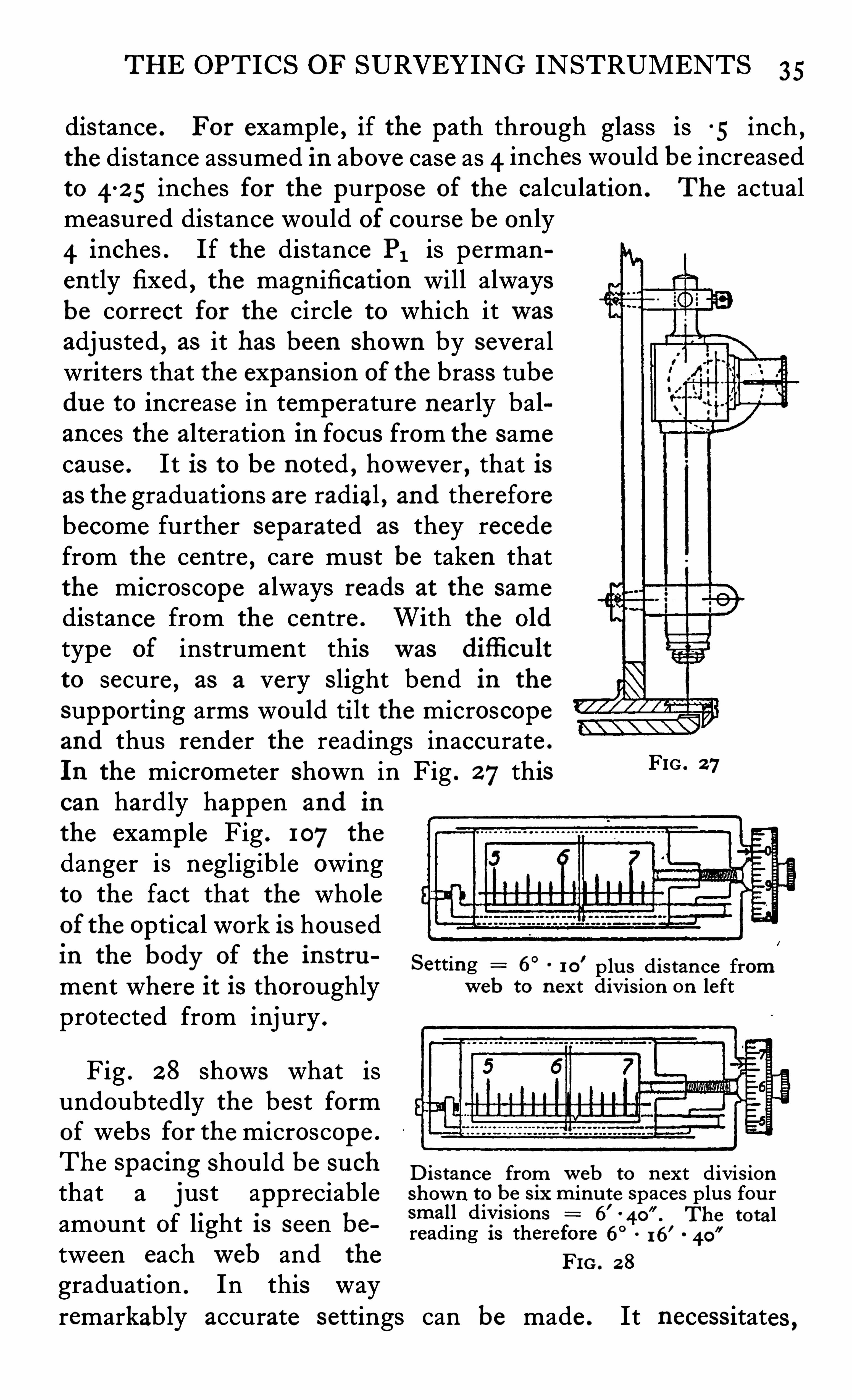
cause . It is to be noted , however , that isas the graduations are radial , and thereforebecome further separated as they recedefrom the centre , care must be taken thatthe microscope always reads at the samedistance from the centre . With the old
type of instrument thiswas difli cu lt
to secure , as a very Slight bend in the
supporting arms would tilt the microscopeand thus render the readings inaccurate .
In the micrometer shown in Fig . 27thiscan hardly happen and in
the examp le Fig . 107 the
danger is negligible owingto the fact that the wholeof the optical work is housedIn the bOdy
.
of the lnStru ‘
Setting 6°
1 0' p lu s dis tan ce from
ment where 11; IS thoroughly web to n ext divis ion on leftprotected from injury .
FIG . 27
Fig . 2 8 shows what isundoubtedly the best formof webs for the microscope .
The Spacmg Should be 3 11011 Dis tance fromweb to n ext divis ionthat a j ust appreciable shown to be s ix m inu te spaces plu s fou r
small divis ion s 6’
The totalamount of light 18 seen be reading is therefore 6° 16’
tween eachweb and the Fm , 2 3
graduation . In this wayremarkably accurate settings can be made . It necess itates
,
36 SURVEYING INSTRUMENTS
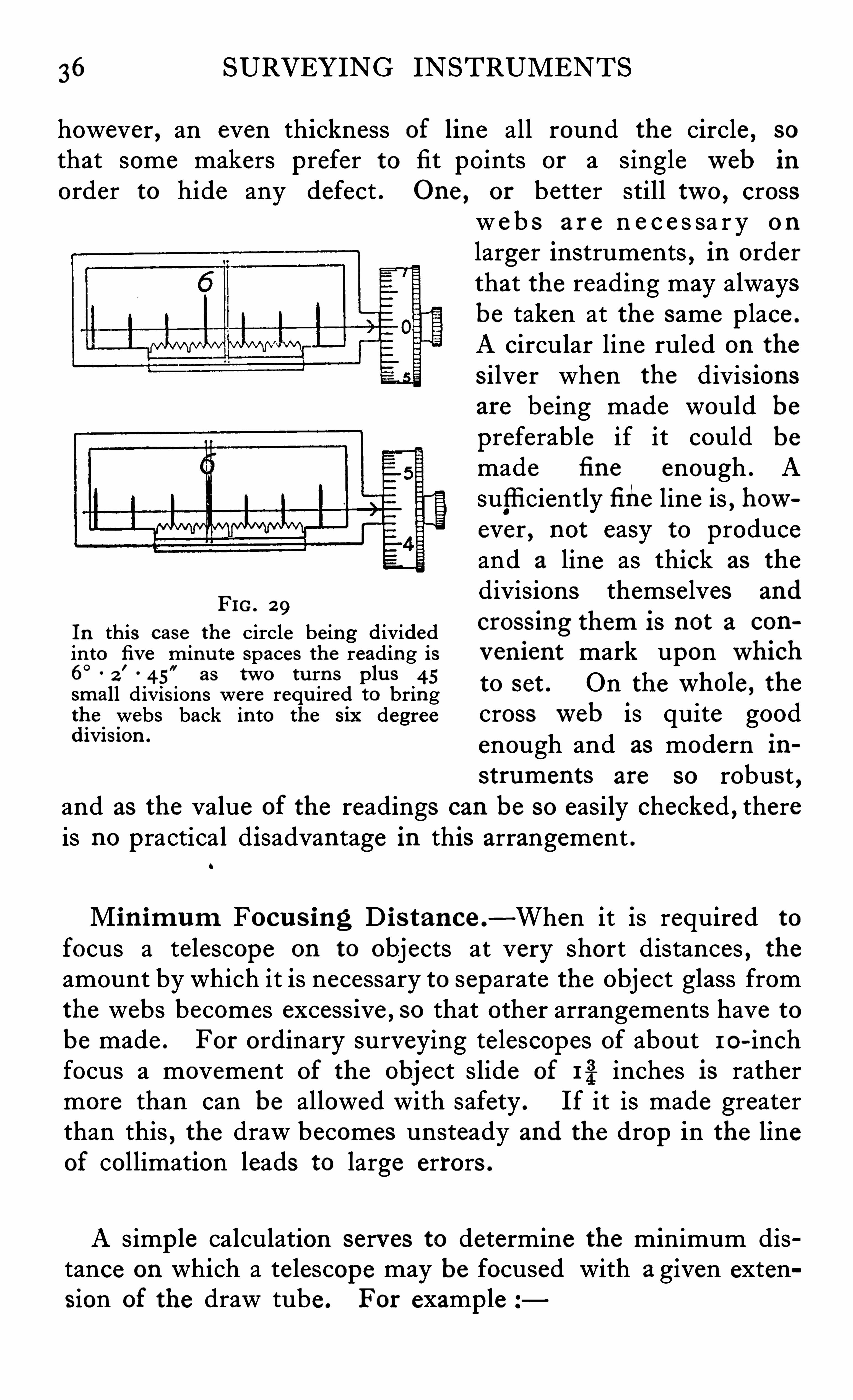
however , an even thickness of line all round the circle , so
that some makers prefer to fit points or a singleweb in
order to hide any defect . One , or better still two , crossw e b s a r e n e c e s sa r y o n
larger instruments , in orderthat the reading may alwaysbe taken at the same p lace .
A circular line ruled on the
Silver when the divisionsare being made would bepreferable if it could be
made fi ne enough . Asuffi ciently fi he line is , however , not easy to produceand a line as thick as the
Fdivisions themselves and
1G. 2 9
In this case the circle being divided cros.
s lng them 18 nOt a C911
in to fi v e m inu te spaces the reading is v en i ent mark upon Wt h6°
2'
45”
as two tu rn s plu s 45small divis ion s were requ ired to bring to set . On the “ 711013 , the
the .
webs back in to the s ix degree crossweb is quite gooddm swn ‘
enough and as modern instruments are so robust ,
and as the value of the readings can be so easily checked , thereis no practical disadvantage in this arrangement .
o
Min imum Focu s ing D i s tance .-When it is required to
focus a telescope on to objects at very short distances , theamount by which it is necessary to separate the object glass fromthe webs becomes excessive , so that other arrangements have tobe made . For ordinary surveying telescopes of about I O-inchfocus a movement of the object slide of r-g inches is rathermore than can be allowed with safety . If it is made greaterthan this , the draw becomes unsteady and the drop in the lineof collimation leads to large errors .
A simp le calculation serves to determine the minimum distance on which a telescope may be focused with a given extension of the draw tube . For examp le
38 SURVEYING INSTRUMENTS
the instrument is to be emp loyed around buildings or underground , it is often necessary to sight on to marks as close as 3or 4 feet . To enable this to be done , it is usual to fix temporarilya long focus Single lens in front of and working in conjunctionwith the
“ usual object glass . It is mounted in a tube , whichfits over the cel l of the object glass and is positioned by a slotand pin which prevents the tube turning on the cell . Sometimesthree adjusting screws are fitted in order to allow for the centeringof this auxiliary lens , but it is more usual for the maker to arrangethat the comb ination is in adjustment when pushed home on
the cell . The error of collimation can be checked by stretchinga line along the ground from the centre of the instrument andby Sighting on to a p lumb line . The error o
'n such short
distances is , however , not likely to be serious .
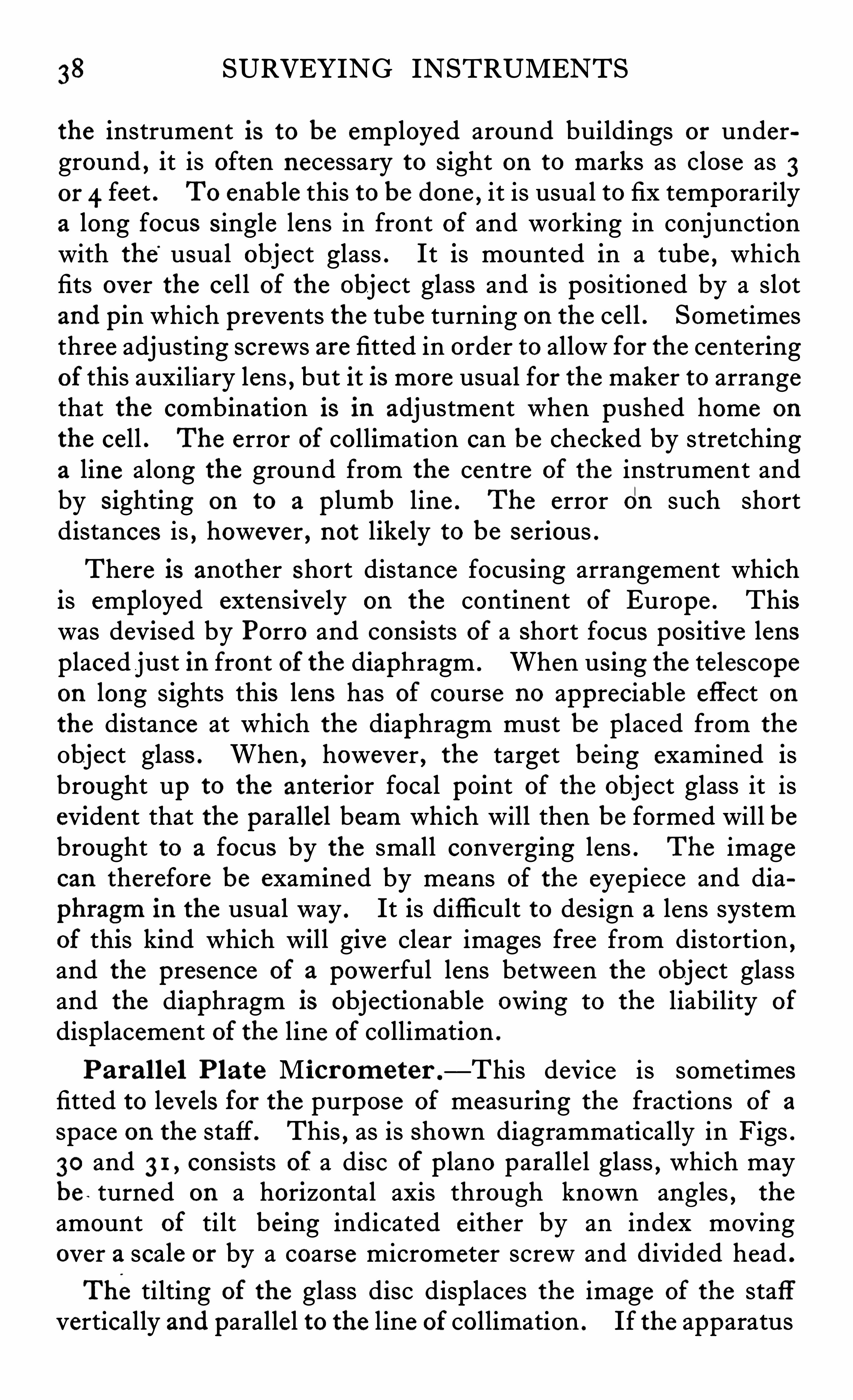
There is another short distance focusing arrangement whichis employed extensively on the continent of Europe . Thiswas devised by Porro and consists of a Short focus pos itive lensplaced just in front of the diaphragm . When using the te lescopeon long s ights this lens has of course no appreciable effect onthe distance at which the diaphragm must be placed from the
Object glass . When , however , the target being examined isbrought up to the anterior focal point of the object glass it isevident that the parallel beam which will then be formed will bebrought to a focus by the small converging lens . The imagecan therefore be examined by means of the eyepiece and dia
phragm in the usual way . It is diffi cult to design a lens systemof this kind which will give clear images free from distortion ,and the presence of a powerful lens between the object glassand the diaphragm is objectionable owing to the liability of
displacement of the line of collimation .
Paral lel Plate M icrometer .
—This device is sometimesfitted to levels for the purpose of measuring the fractions of a
space on the staff. This , as is Shown diagrammatically in Figs .30 and 3 1 , consists of a disc of p lano paralle l glass , which maybe turned on a horizontal axis through known angles , the
amount of tilt being indicated either by an index movingover a scale or by a coarse micrometer screw and divided head .
Thetilting of the glass disc disp laces the image of the staffvertically and parallel to the line of collimation . If the apparatus
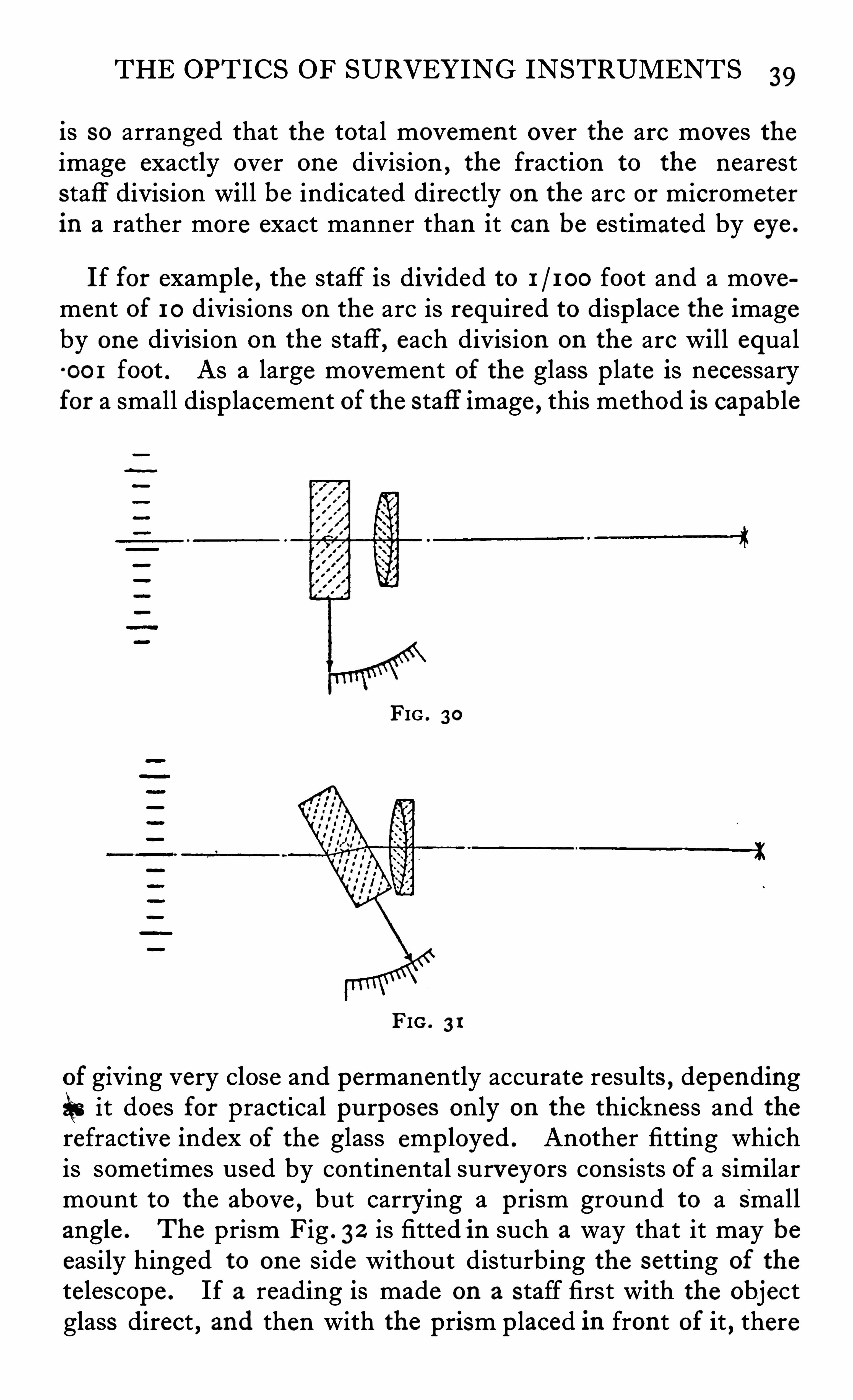
THE OPTICS OF SURVEYING INSTRUMENTS 39
is so arranged that the total movement over the arc moves theimage exactly over one division , the fraction to the neareststaff division will be indicated directly on the arc or micrometerin a rather more exact manner than it can be estimated by eye .
If for examp le , the staff is divided to foot and a movement of 10 divisions on the arc is required to disp lace the imageby one division on the staff , each division on the arc will equal0 0 1 foot . As a large movement of the glass p late is necessaryfor a small disp lacement of the staff image , this method is capable
FIG . 30
FIG . 3 1
of giving very close and permanently accurate results , dependingit does for practical purposes only on the thickness and the
refractive index of the glass employed . Another fitting whichis sometimes used by continental surveyors consists of a similarmount to the above , but carrying a prism ground to a Smallangle . The prism Fig . 32 is fitted in such a way that it may beeasily hinged to one side without disturbing the setting of the
telescope . If a reading is made on a staff first with the objectglass direct , and then with the prism p laced in front of it , there
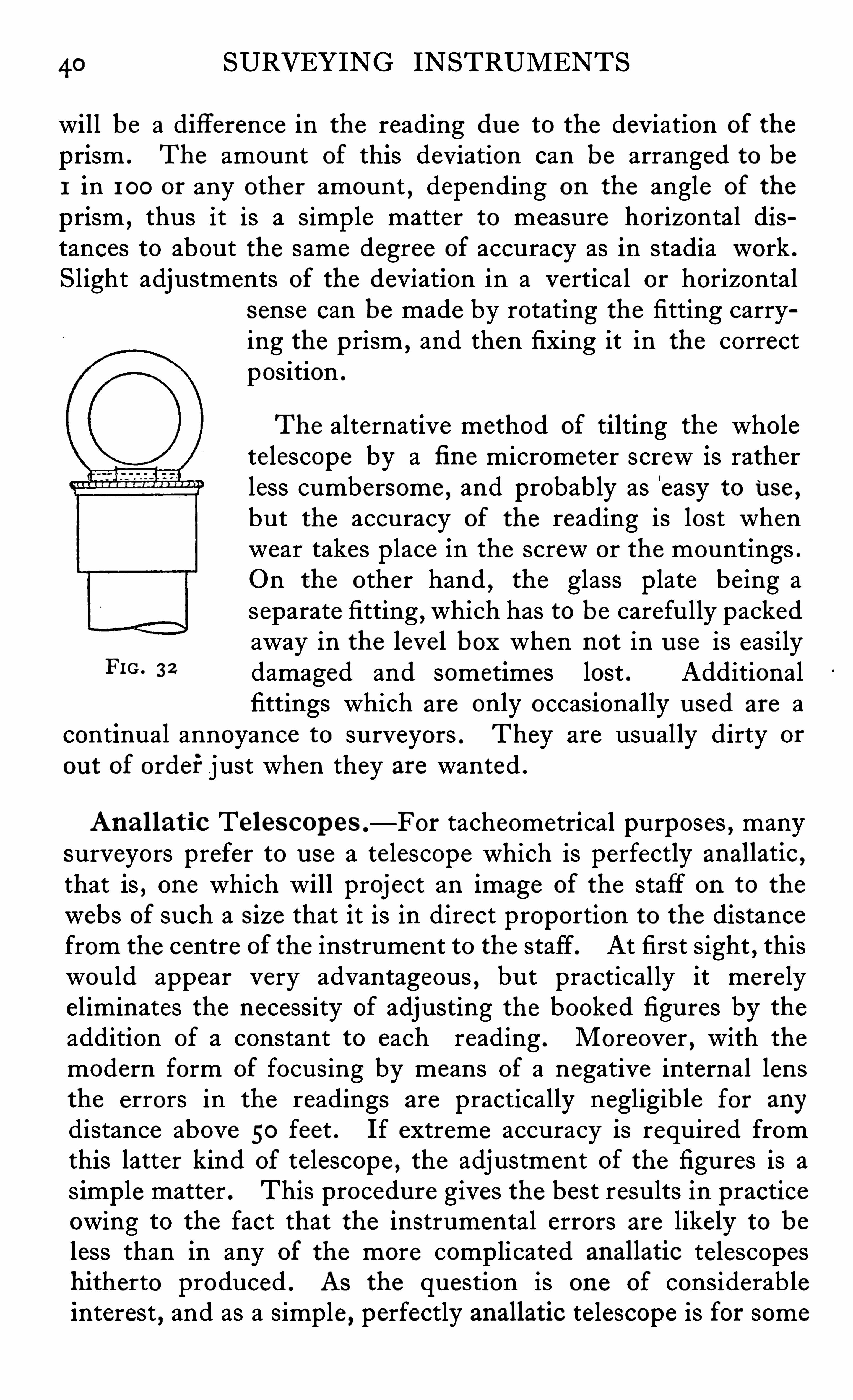
40 SURVEYING INSTRUMENTS
will be a difference in the reading due to the deviation of the
prism . The amount of this deviation can be arranged to beI in 1 00 or any other amount , depending on the angle of the
prism,thus it is a simple matter to measure horizontal dis
tances to about the same degree of accuracy as in stadia work .
Slight adjustments of the deviation in a vertical or horizontalsense can be made by rotating the fitting carrying the prism ,
and then fixing it in the correctposition .
The alternative method of tilting the wholetelescope by a fi ne micrometer screw is ratherless cumbersome
,and probably as '
easy to Use ,
but the accuracy of the reading is lost whenwear takes p lace in the screw or the mountings .
On the other hand , the glass p late be ing aseparate fitting , which has to be carefully packedaway in the leve l box when not in u se is easily
FIG 3 2 damaged and sometimes lost . Additionalfittings which are only occasionally used are a
continual annoyance to surveyors . They are usually dirty or
ou t of ordei‘ just when they are wanted .
Ana l lat ic Teles cop es .
—For tacheometrical purposes , manysurveyors prefer to u se a te lescope which is perfectly anallatic ,
that is , one which will proj ect an image of the staff on to the
webs of such a Size that it is in direct proportion to the distancefrom the centre of the instrument to the staff. At first sight , thiswould appear very advantageous , but practically it mere lyeliminates the necessity of adjusting the booked figures by theaddition of a constant to each reading . Moreover , with the
modern form of focusing by means of a negative internal lensthe errors in the readings are practically negligible for anydistance above 50 feet . If extreme accuracy is required fromthis latter kind of telescope , the adjustment of the figures is asimple matter . This procedure gives the best results in practiceowing to the fact that the instrumental errors are likely to beless than in any of the more comp licated anallatic telescopeshi therto produced . AS the question is one of considerab leinterest , and as a simple , perfectly anallatic telescope is for some
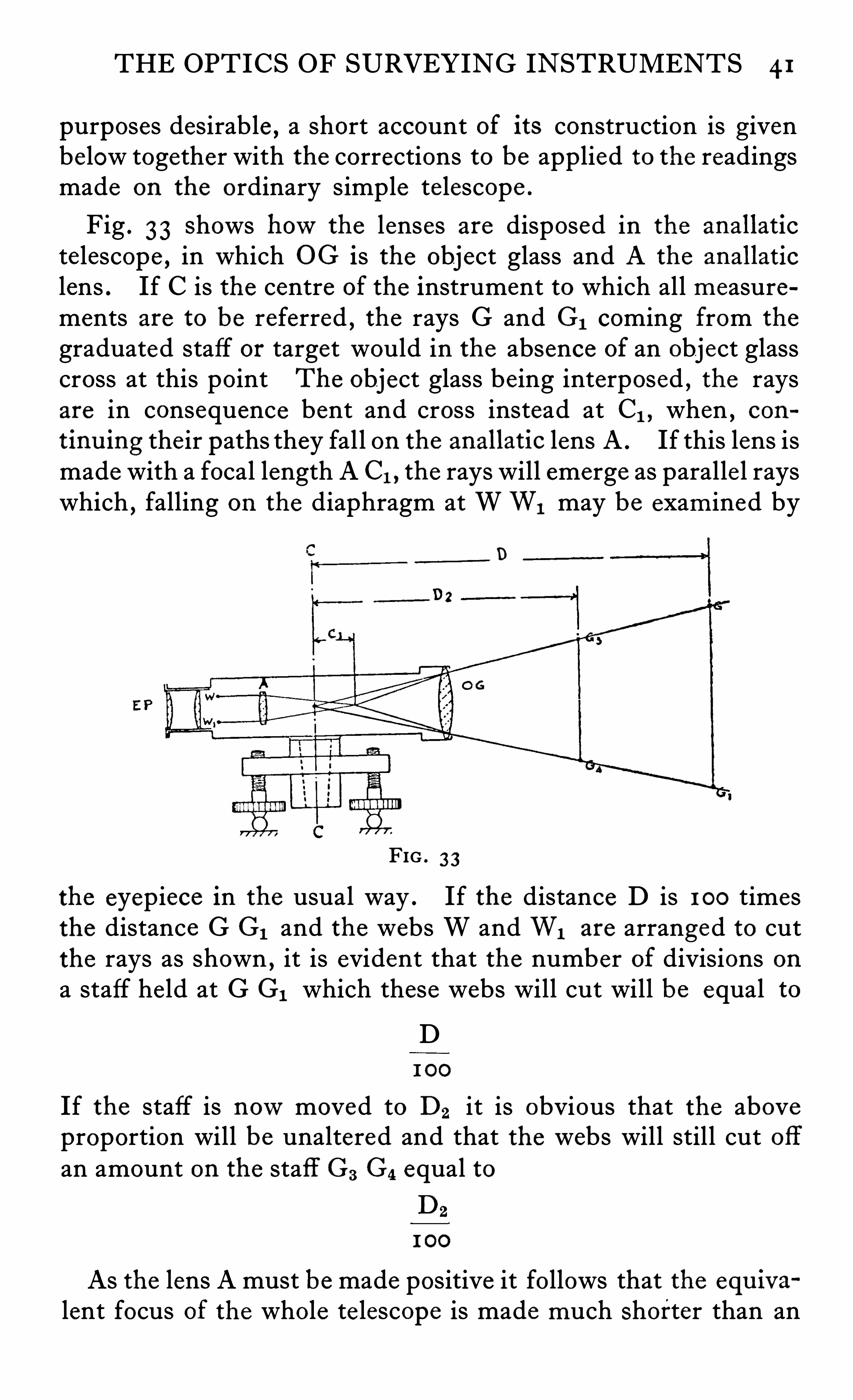
THE OPTICS OF SURVEYING INSTRUMENTS 4 1
purposes desirable , a short account of its construction is givenbelow together with the corrections to be applied to the readingsmade on the ordinary simple telescope .
Fig . 33 Shows howthe lenses are disposed in the anallatic
telescope , in which 0G is the object glass and A the anallatic
lens . If C is the centre of the instrument to which all measurements are to be referred
,the rays G and G1 coming from the
graduated staff or target would in the absence of an object glasscross at this point The object glass being interposed , the raysare in consequence bent and cross instead at C1 , when , con
t inu ing their paths they fall on the anallatic lens A . If this lens ismade with a focal length A C1 , the rays will emerge as paralle l rayswhich , falling on the diaphragm at WW1 may be exam ined by
D
FIG . 3 3
the eyepiece in the usual way . If the distance D is 1 00 timesthe distance G G1 and the webs W and W1 are arranged to cutthe rays as shown , it is evident that the number of divisions ona staff held at G G1 which these webs will cut will be equal to
D1 00
If the staff is nowmoved to D2 it is obvious that the aboveproportion will be unaltered and that the webs will still cut offan amount on the staff G3 G4 equal to
D2
1 00
As the lens A must be made positive it follows that the equ iva
lent focus Of the whole te lescope is made much Shorter than an
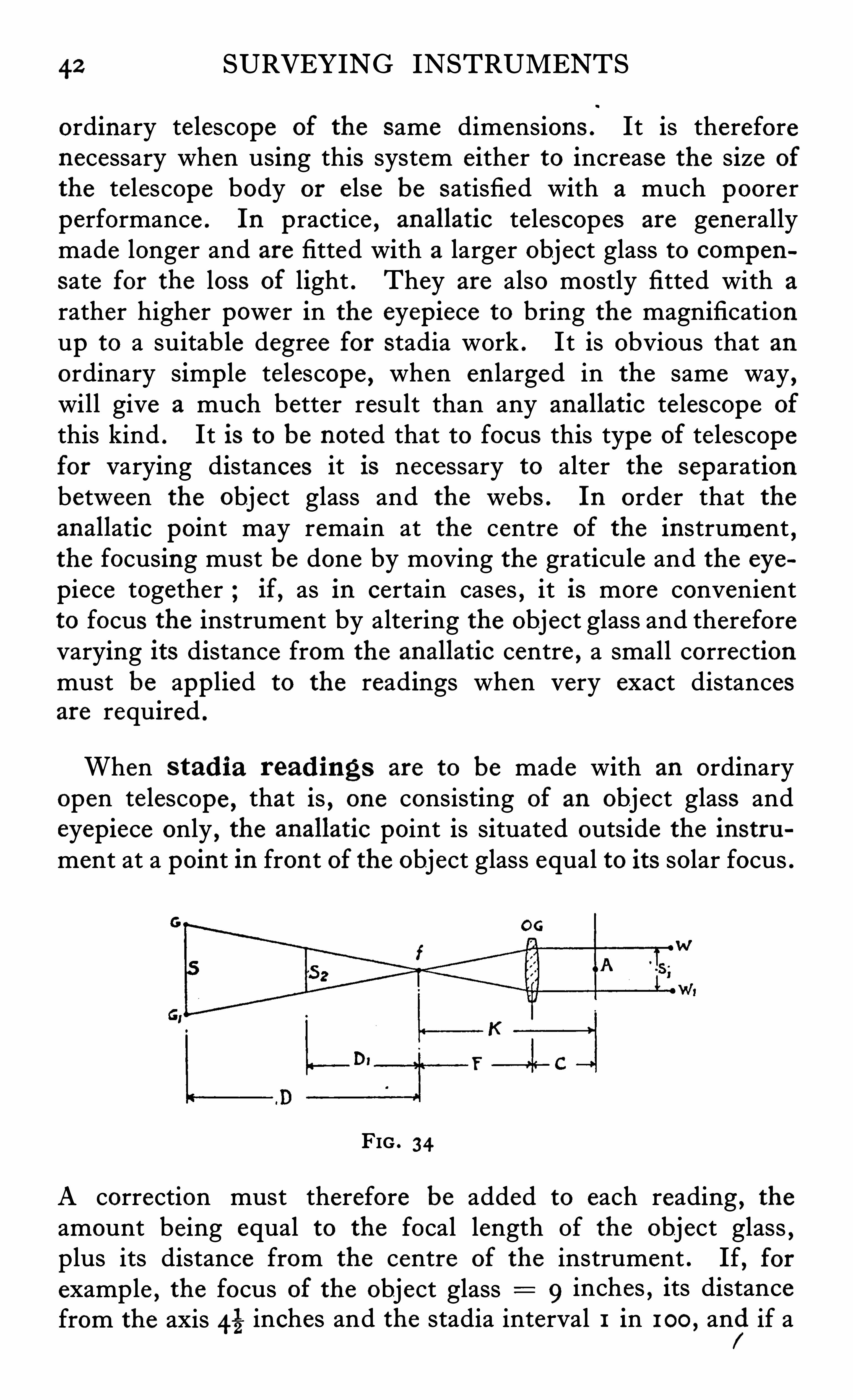
42 SURVEYING INSTRUMENTS
ordinary telescope of the same dimensions . It is thereforenecessary when using this system either to increase the size of
the telescope body or else be satisfied with a much poorerperformance . In practice , anallatic telescopes are generallymade longer and are fitted with a larger object glass to compen
sate for the loss of light . They are also mostly fitted with a
rather higher power in the eyepiece to bring the magnificationup to a suitable degree for stadia work . I t is obvious that anordinary simp le telescope , when en larged in the same way
,
will give a much better result than any anallatic te lescope of
this kind . It is to be noted that to focus this type of telescopefor varying distances it is necessary to alter the separationbetween the object glass and the webs . In order that theanallatic point may remain at the centre of the instrument
,
the focusing must be done by moving the graticule and the eye
piece together ; if, as in certain cases , it is more convenientto focus the instrument by altering the object glass and thereforevarying its distance from the anallatic centre , a small correctionmust be app lied to the readings when very exact distancesare required .
When s tad ia read ings are to be made with an ordinaryopen telescope , that is , one consisting of an object glass andeyepiece only , the anallatic point is situated outside the instrument at a point in front of the object glass equal to its solar focus .
FIG . 34
A correction must therefore be added to each reading , theamount being equal to the focal length Of the object glass ,plus its distance from the centre of the instrument . If, forexample , the focus of the object glass 9 inches , its distancefrom the axis 43 inches and the stadia interval 1 in 100 , anfi
i if a
THE OPTICS OF SURVEYING INSTRUMENTS 43
space of two feet were cut on the staff , then the distance from the
"c entre of the instrument to the staff would be
2 00 feet ,a foot 2 0 1%feet
The preceding diagram , Fig . 34 will make this point clear .If WW1 are the webs in the telescope , A the axis upon whichit turns p laced at a distance C from the object glass , F the focallength of the Obj ect glass and G G1 the staff,,
then light falling onthe webs W W, would be brought to a focus by the glassat f and continuing would cut the staff at G C 1
Let S distance G G1
and SI : distance WW1
S 81
D F
F S81
If the dimensions F and 81 are s o chosen that81 1 SF D
and D 1 00 8
If therefore the webs cut off 1 foot on the staff the distance Dwill be equal to 1 00 feet and the distance of the s taff from the
centre of the instrument wi l l be D (F C) D, K .
If nowthe staff is moved to Sz it is evident that the proportions are unaltered and that the required distance will be D1 K .
If the te lescope is arranged to focus by moving the webs andeyepiece , K will be a constant , but if on the other hand thefocusing is performed as usua l by moving the object glass itwill then be necessary to add an additional amount equal tothe distance which the object glass had to be moved from the
position it took when focused for paralle l rays . As the amountof movement required is very small for distances above 100 feet ,this correction is for most work negligible .
The exact amount may be found by the method shown on
page 37
44 SURVEYING INSTRUMENTS
In practice it is usual to determine the stadia interval , d , byactual experiment over measured distances of 2 00 or 300 feet ,
‘
these distances being measured from a point in front of the
centre of the instrument equal to K . The distance for anordinary telescope is then
D ds K
and for an anallatic t elescopeD ds
Inclined Sights
As it is seldom that the stadia readings can be made on a rod
held at the same leve l as the instrument , it is necessary to applyvarious corrections to allow for the angle to which the telescopemust be tilted when the staff is at some cons iderable e levationor depress ion . There are three methods of holding the staffwhen taking inclined s ights .
(a) With staff vertical .
(b) With staff inclined so as to be at right angles to the line of
sight on the middle wire .
(0) With s taff horizontal .
Those made with the staff he ld in a vertical position are mostemp loyed as it is diffi cult for the rodman to hold it at thecorrect angle when using the method (b) and when the staff ishorizontal as in (c) some form of supporting stand is essential .
The horizontal position gives the best results but becauseof the necessity of transporting some form of fairly stable andtherefore comparatively heavy stand is only employed wherelong sights are required . When the staff is held in a verticalposition as in (a) and if a is the angle which a line joining thecentral wire to the s tafl makes with the horizontal , then the
horizontal distance D ds .cos2a K cos a .
I t is therefore necessary to note the angle a on the centralwire when reading the staff . The height from the pivots of the
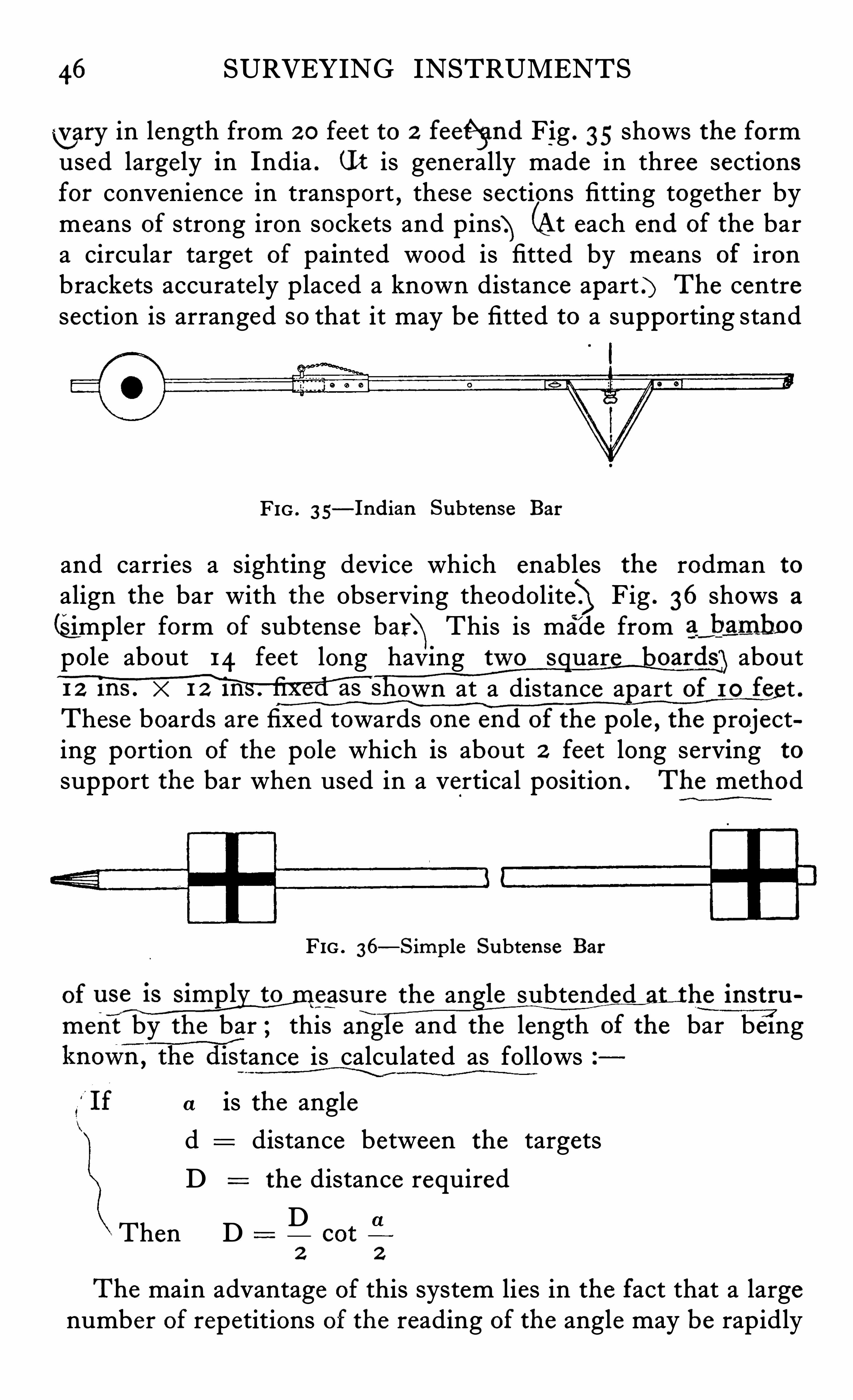
46 SURVEYING INSTRUMENTSwary in length from 2 0 feet to 2 feeé gnd Fig . 35 shows the formused large ly in India . (I t is generally made in three sectionsfor convenience in transport , these sections fitting together bymeans of strong iron sockets and pins} (At each end of the bara circular target of painted wood is fitted by means of ironbrackets accurate ly placed a known distance apart .) The centresection is arranged so that it may be fitted to a supporting stand
FIG . 3 5—Indian Subtense Bar
and carries a sighting device which enables the rodman to
align the bar with the Observing theodolite} Fig . 36 shows a
(Simpler form of subtense bar\This is made from ag hamboopole about 14 feet long hay ing two S uar oards aboutM s own at a distance a art of I O fe t .These boards are fixed towards one end of the pole , the projecting portion of the pole which is about 2 feet long serving to
support the bar when used in a vertical position . The method
FIG . 36—Simple Subten se Bar
of USW Q SM C the an le subtended he instru
menf by the bar ; this z1n e and the length of the bar beingance is calculated as follows
is the anglea
d distance between the targets
D the distance required
D2 2
Then D
The main advantage of this system lies in the fact that a largenumber of repetitions of the reading of the angle may be rapidly
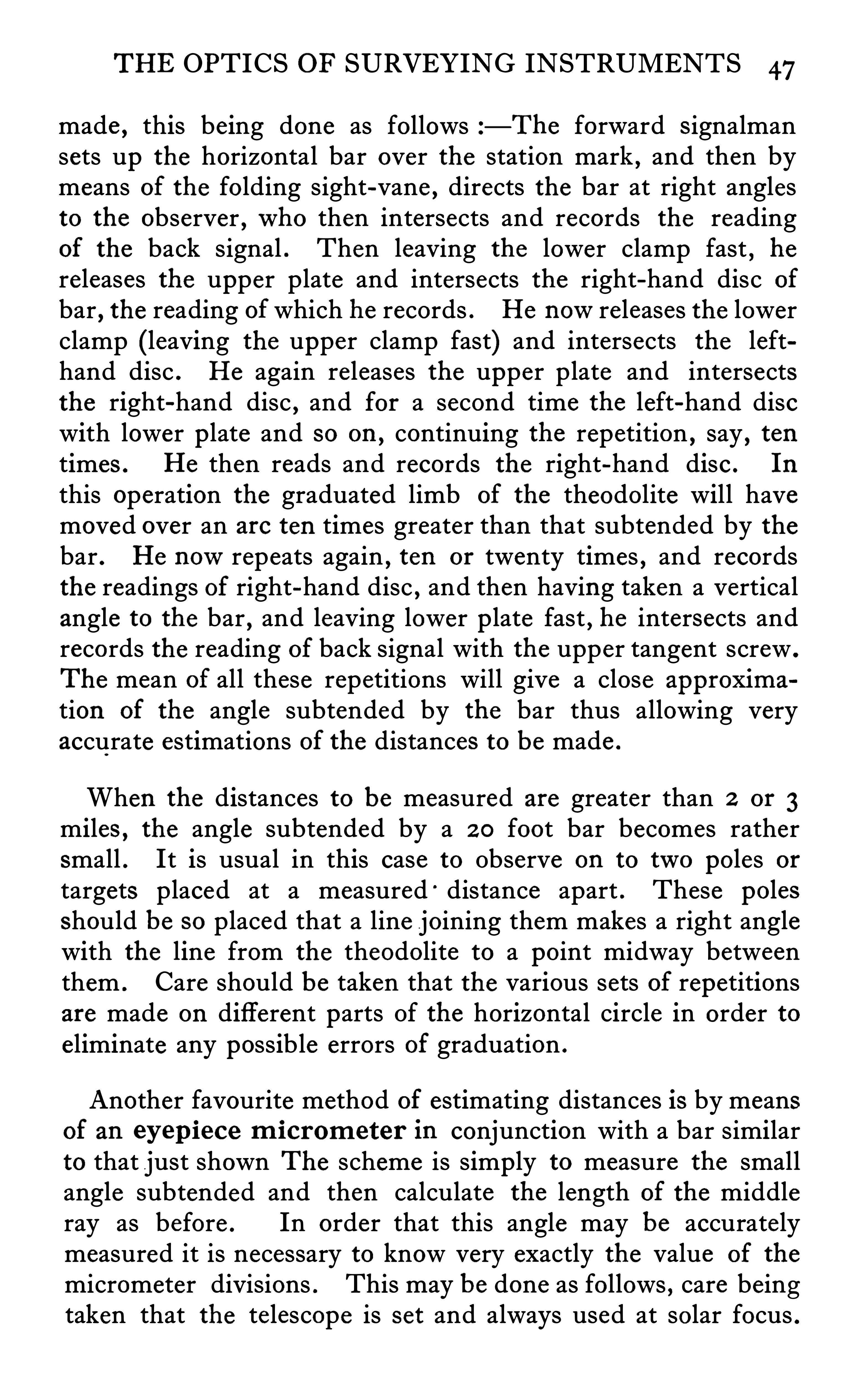
THE OPTICS OF SURVEYING INSTRUMENTS 47
made , this being done as follows —The forward Signalmansets up the horizontal bar over the station mark , and then bymeans of the folding sight-vane , directs the bar at right anglesto the observer ,who then intersects and records the readingof the back signal . Then leaving the lower clamp fast
,he
releases the upper plate and intersects the right-hand disc of
bar , the reading ofwhich he records . He nowreleases the lowerclamp (leaving the upper clamp fast) and intersects the lefthand disc . He again releases the upper plate and intersectsthe right-hand disc , and for a second time the left-hand discwith lower p late and so on ,
continuing the repetition , say , tentimes . He then reads and records the right-hand disc . In
this operation the graduated limb of the theodolite will havemoved over an are ten times greater than that subtended by thebar . He nowrepeats again
,ten or twenty times , and records
the readings of right-hand disc,and then having taken a vertical
angle to the bar , and leaving lower p late fast , he intersects andrecords the reading of back signal with the upper tangent screw .
The mean of all these repetitions will give a close approxima
tion of the angle subtended by the bar thus allowing veryaccurate estimations of the distances to be made .
When the distances to be measured are greater than 2 or 3miles , the angle subtended by a 2 0 foot bar becomes rathersmall . It is usual in this case to Observe on to two poles or
targets placed at a measured “ distance apart . These polesshould be so placed that a line joining them makes a right anglewith the line from the theodolite to a point midway betweenthem . Care should be taken that the various sets of repetitionsare made on different parts Of the horizontal circle in order toeliminate any possible errors of graduation .
Another favourite method of estimating distances is by meansof an eyep iece m icrom eter in conjunction with a bar similarto that just shown The scheme is simply to measure the smallangle subtended and then calculate the length of the middleray as before . In order that this angle may be accuratelymeasured it is necessary to know very exactly the value of the
micrometer divisions . This may be done as follows , care beingtaken that the te lescope is set and always used at solar focus .
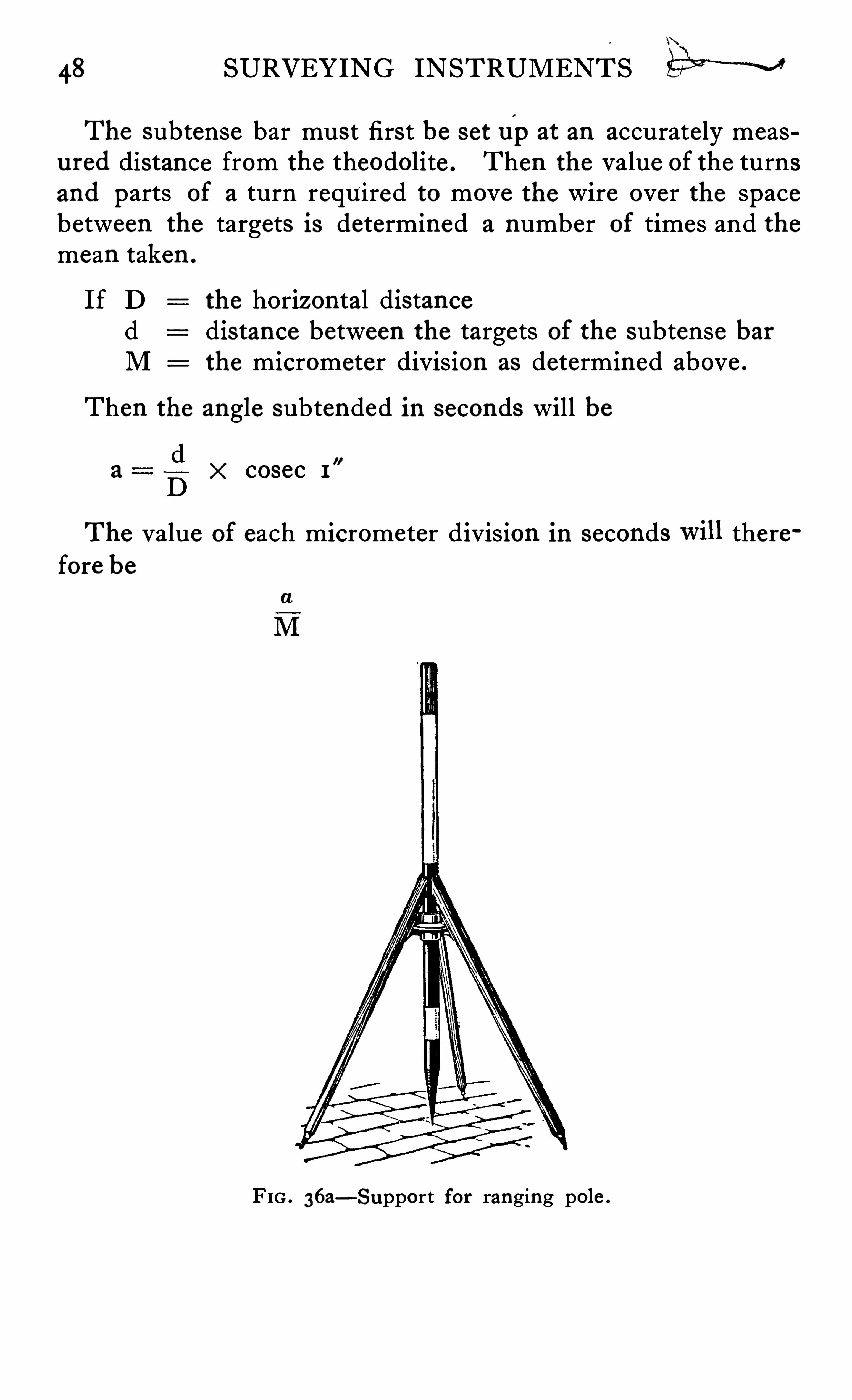
48 SURVEYING INSTRUMENTS M
The subtense bar must first be set upat an accurately measured distance from the theodolite . Then the value of the turnsand parts of a turn required to move the wire over the spacebetween the targets is determined a number of times and themean taken .
If D the horizontal distanced distance between the targets of the subtense barM the micrometer division as determined above .
Then the angle subtended in seconds will be
dD
The value of each micrometer division in seconds therefore be
cosec 1
FIG . 36a—Support for ranging pole .
CHAPTER IV
SPIRIT LEVELS
S surveying operations generally consist of taking anglesand distances which require to be referred to the
horizontal , the means for assuring horizontality mustbe efli cient and accurate . The invention of the spirit leve ltube was one of the most important discoveries in the historyof surveying . Before this event crude water levels and clinometers were the only means by which the horizontal could bedetermined . The level bubble put at once a newweapon intothe hands of the surveyor , and enabled full u se to be made of
the te lescope as a sighting instrument . It is difli cu lt to conceivea more simple and perfect device and the sensitiveness to whichit can be made is truly amazing . Recently , Mr Sears of the
National Physical Laboratory , has successfully made u se of the
leve l bubble in hiswonderfu l measuring machines , some of
which are capable of appreciating differences of a millionth of
an inch and as on many surveying Operations the final accuracydepends on the exactness of the setting of the bubbles of the
instruments , the subject is one which merits a great deal moreattention than is usually given to it . Formerly , leve l makerssimply picked ou t pieces of glass tube which happened to comeou t slightly curved in the manufacture . These were filledwith spirit and the ends sealed up . Very soon , however ,greater accuracywas demanded , and makers developed methodsof grinding the interior of the glass tubes to definite radii ,and were thus able to deliver levels to any degree of sensitiveness desired . It is usual to specify that bubbles should movedefinite amounts when tilted through definite angles , and the
art has arrived at such perfection that to make a bubble whichwill run inch for each 1 second of tilt is not a diffi cultmatter .
50 SURVEYING INSTRUMENTS
A perfect level should have the following characteristics .
It should be made of a glass which will not deteriorate with theelapse of time . Its bubble should move equal amounts forequal tilts . It must not be sluggish and it should not Show any
signs of creep ing . The tube should preferably have a barrelshaped interior . If not , it Should be so ground that nearly halfits circumference in cross section is circular , as if this is not done ,there will be errors of run when it is slightly rotated om
'
itslongitudinal axis . As during the mounting and indeed duringu se on the instrument it sometimes happens that slight disp lacement from the proper position occurs , it will be seen thatattention to this detail i s of great importance . Machine groundlevels nowadays are often barrel-shaped , and are , therefore , tobe preferred to those ground by hand
, as by the latter process , itIS diffi cult to ensure that the tubes are truly circular at anycross section . English-made lead glass is a very perfect materialfor the level makers ’ purpose , as it does not deteriorate with age ,as do soda glass and many of the continental varieties . Leadglass is also brilliant
,hard and stable , and is not easily deformed
under the influence of variation of temperature or the s lightunavoidable strain du e to the mounting . If the air space is tomove equal amounts for equal angles of tilt , the tube must beground to a true radius and this can only be ensured by machinegrinding . There will of course be a falling off in accuracy at
the ends Of the run due to the distortion introduced whensealing off , so that all else being equal , the longer the bubbletube the better from the point of View of evenness of run . The
sensitivity of the leve l for run depends on the radius of curvature ,and to a slight extent on the character of the ground surfaceand the material with which it is filled .
The cleanliness of the interior is also of importance as it isev identj hat any foreign substance on the ground surface whichI s not‘misciblewith the filling liquid would impair the readings .For example , a slight trace of grease in a tube filled withwater would cause the air space to behave in an erratic manner .The purity of the liquid with which the level tube is filled is ofthe first importance , not only for the above reason , but also toprevent any change taking place in the course of time . Duringthe manufacture of the level , it is not easy to avoid contamination
SPIRIT LEVELS 51
of the ground surface by grease,and it is diffi cult to remove the
last traces of it . A liquid which easily disso lves grease is , itwould seem ,
the most desirable one to employ , and in fact ,practical experience has proved this to be the case . The chiefliquids used are alcohol , ether , chloroform ,
benzene and some
times xylene . For the cheapest levels with bent tubes,such as
are fitted to bricklayer ’s spirit levels , methylated spirit is used ,but for surveying levels
,the value of the liquid is so small
compared with the other costs that it need not be taken intoconsideration . The most universally used liquid is nowpetroleum ether , distilled at about 50
°C . which , owing to its
lowsurface tension and viscosity , is a very suitable one for the
purpose . A well-made leve l filled with this liquid is about asperfect a p iece of apparatus as can we ll be imagined , except forone defect , which is , unfortunately , common to all liquid filledleve ls , and that is the effect which change of temperature hason its performance . A rise of temperature wil l cause the liquidand glass to expand and the air bubble to contract , thus increasingthe internal pressure Slightly . It is unlikely with the level asusually manufactured , that any alteration in radius or formtakes p lace , so that the only effect which needs to be consideredis that which differences in the length of the bubble will haveon its performance . In the first place
,the variations in the
length of the bubble might be so great that the leve l would failto be of service . For example , if the length of bubble is madesuitable for u se at a temperature of 20°C its u se in Polar regionswould be impossible , as the bubble might easily be as long asthe tube , while under the trop ical sun it might almost disappear ,so that special arrangements have to be made for these extremecases . The usual plan is to have a small chamber fastened V
‘ inside at one end of the main tube . By tilting the level , moreor less air can be trapped in i this
~
chamber , so that the actual
kbubble length can be adjusted . The most important effect
1.r”
;which the length of the bubble has on its performance is thef{m g The longer the bubble the greater the number oftimes it will oscillate when disturbed from zero before coming torest , and owing to the greater amount of control it will returnmore exactly to the zero position . For very exact work , therefore
,long bubb les in long tubes are to be preferred
,but on the
other hand they are very diffi cult to set and the length of time
SURVEYING INSTRUMENTS
necessary to adjust an instrument fitted with them becomesexcessive . When the bubble becomes SO short that its movements are almost dead beat , it is found that it does not alwaystake up the same position , but creeps about in a Slow and un
certain manner . The mobility of the bubble is also affectedto some extent by the diameter of the containing tube , bythe character of the ground surface and by the liquid emp loyed .
Manufacturers have found by practical experience the dimen
sions and qualities which give the best all-round results .
Mr Watts of London has devised an ingenious level which isso constructed that the bubble remains constant in length undervarying temperatures . This is arrived at by giving the groundsurface an elliptical section instead of the usual circular form ,
the bubble apparently expanding laterally instead of longitudinally . Everything e lse being ,
equ al , it would be advan
tageou s for ordinary levelling operations to have a bubble whichneeds to be examined at one end only
,but as any rotation of the
tube on its longitudinal axis would render the indications unreliable , this form does not fulfil the condition laid down fora perfect leve l and it is diffi cult to see howit could be used forprecise work .
Va lue of Level D ivi s ion s .—Levels are generally specified
by the distance of run given per second of tilt . For examp le
Let R radius of bubble tube in feet , and
T distance of travel of bubble in inches for a tiltof one second of arc .
Then R 17188 "T
For a travel of 1 /2 0th inch per second , the radius will therefore
171882 0
859 4 feet .
For a 5-inch theodolite which might have a bubble run of
I /2 0th inch per 10 seconds of tilt the radius would thereforebe 86feet .
It is to be noted that very small irregularities in the groundcurve may lead to large errors in the readings . This is especially
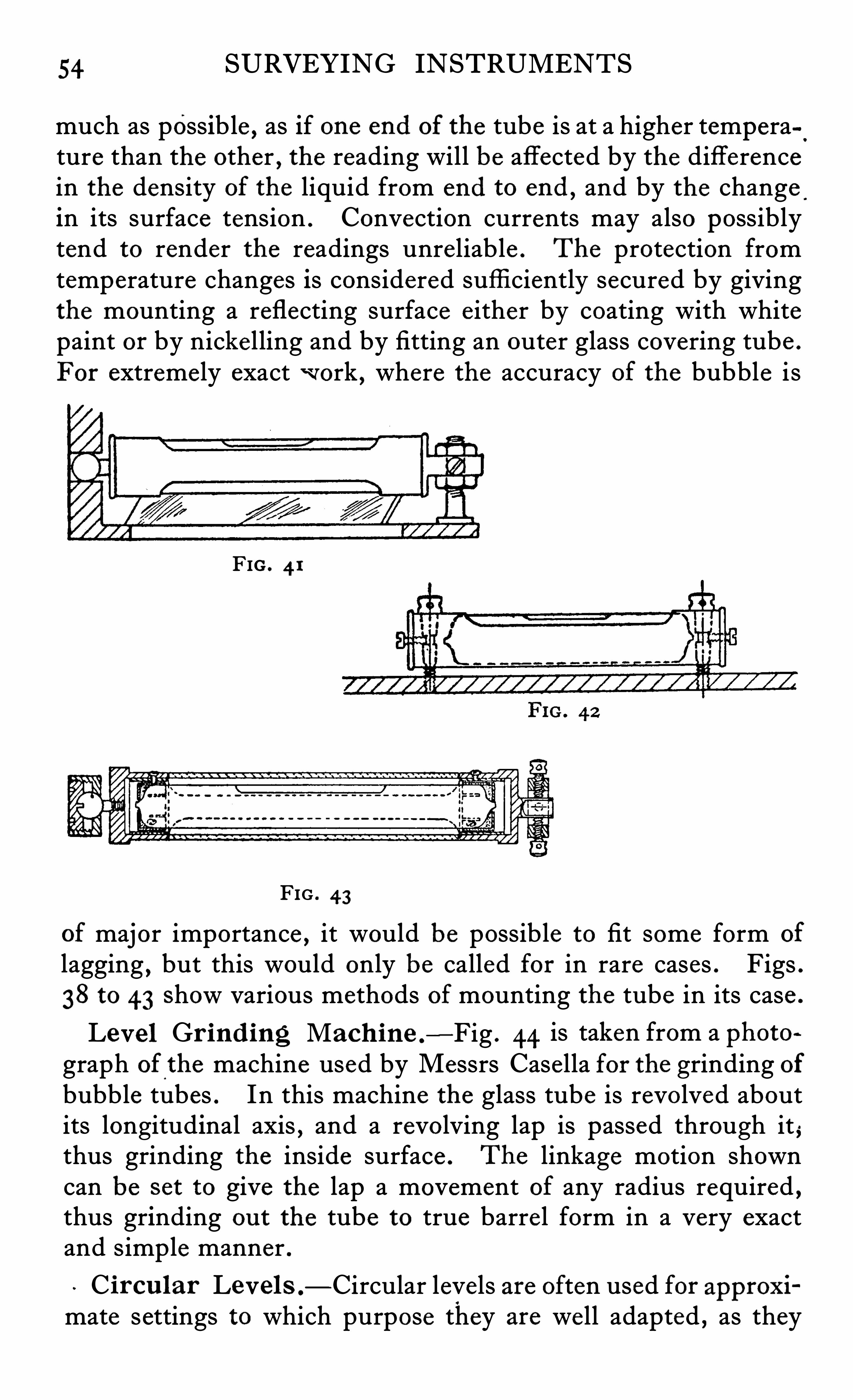
54 SURVEYING INSTRUMENTS
much as possible , as if one end of the tube is at a higher temperature than the other
,the reading will be affected by the difference
in the density of the liquid from end to end ,and by the change
.
in its surface tension . Convection currents may also possiblytend to render the readings unreliable . The protection fromtemperature changes is considered suffi ciently secured by givingthe mounting a reflecting surface e ither by coating with whitepaint or by nicke lling and by fitting an outer glass covering tube .
For extreme ly exactwork , where the accuracy of the bubble i s
FIG . 4 1
FIG . 4 3
of major importance , it would be possible to fit some form of
lagging,but this would only be called for in rare cases . Figs .
38 to 43 Show various methods of mounting the tube in its case .
Leve l Gr ind ing Mach ine .
—Fig . 44 is taken from a photo a
graph of the machine used by Messrs Case lla for the grinding ofbubble tubes . In this machine the glass tube is revolved aboutits longitudinal axis
,and a revolving lap is passed through it ,
thus grinding the inside surface . The linkage motion showncan be s et to give the lap a movement of any radius required ,thus grinding ou t the tube to true barre l form in a very exactand simple manner .
Ci rcu lar Level s .
— Circular levels are often used for approximate settings to which purpose they are we ll adapted , as they
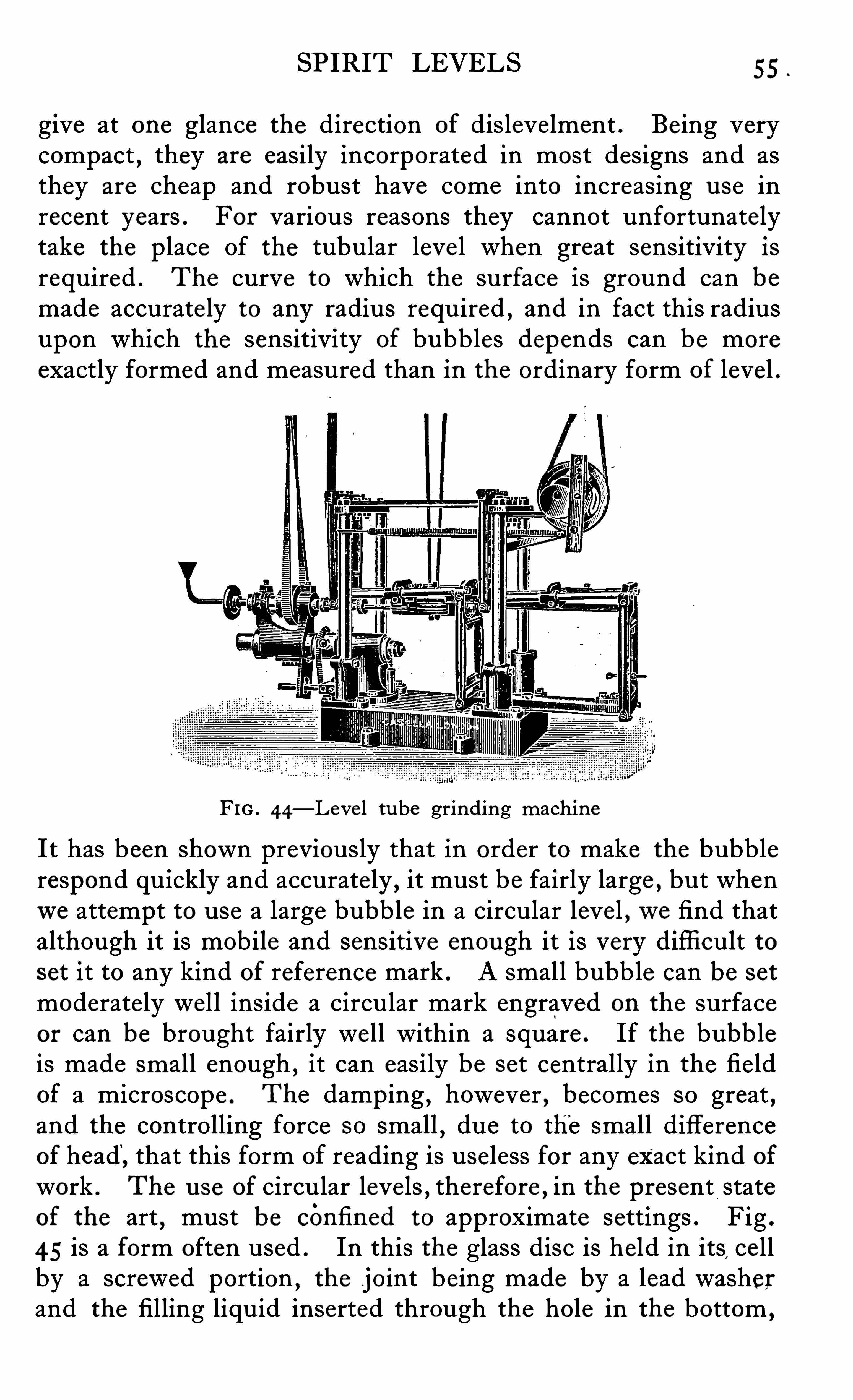
SPIRIT LEVELS 55
give at one glance the direction of dislevelment . Being verycompact , they are easily incorporated in most designs and asthey are cheap and robust have come into increasing u se inrecent years . For various reasons they cannot unfortunatelytake the place Of the tubular leve l when great sensitivity isrequired . The curve to which the surface is ground can bemade accurate ly to any radius required , and in fact this radiusupon which the sensitivity of bubb les depends can be moreexactly formed and measured than in the ordinary form of level .
FIG . 44—Leve l tube grinding machine
It has been shown previously that in order to make the bubblerespond quickly and accurate ly
,it must be fairly large , but whenwe attempt to u se a large bubble in a circular leve l ,we find that
although it is mobile and sensitive enough it is very difficult toset it to any kind of reference mark . A small bubb le can be set
moderate ly well inside a circular mark engraved on the surfaceor can be brought fairly well within a square . If the bubbleis made small enough , it can easily be set centrally in the fie ldof a microscope . The damping
,however , becomes so great ,
and the controlling force so small,du e to the small difference
of head“
, that this form of reading is useless for any exact kind ofwork . The u se of circular leve ls
,therefore , in the present state
of the art , must be cOnfi ned to approximate settings . Fig .
45 is a form often used . In this the glass disc is held in its,ce ll
by a screwed portion,the joint be ing made by a lead washer
and the filling liquid inserted through the hole in the bottom ,
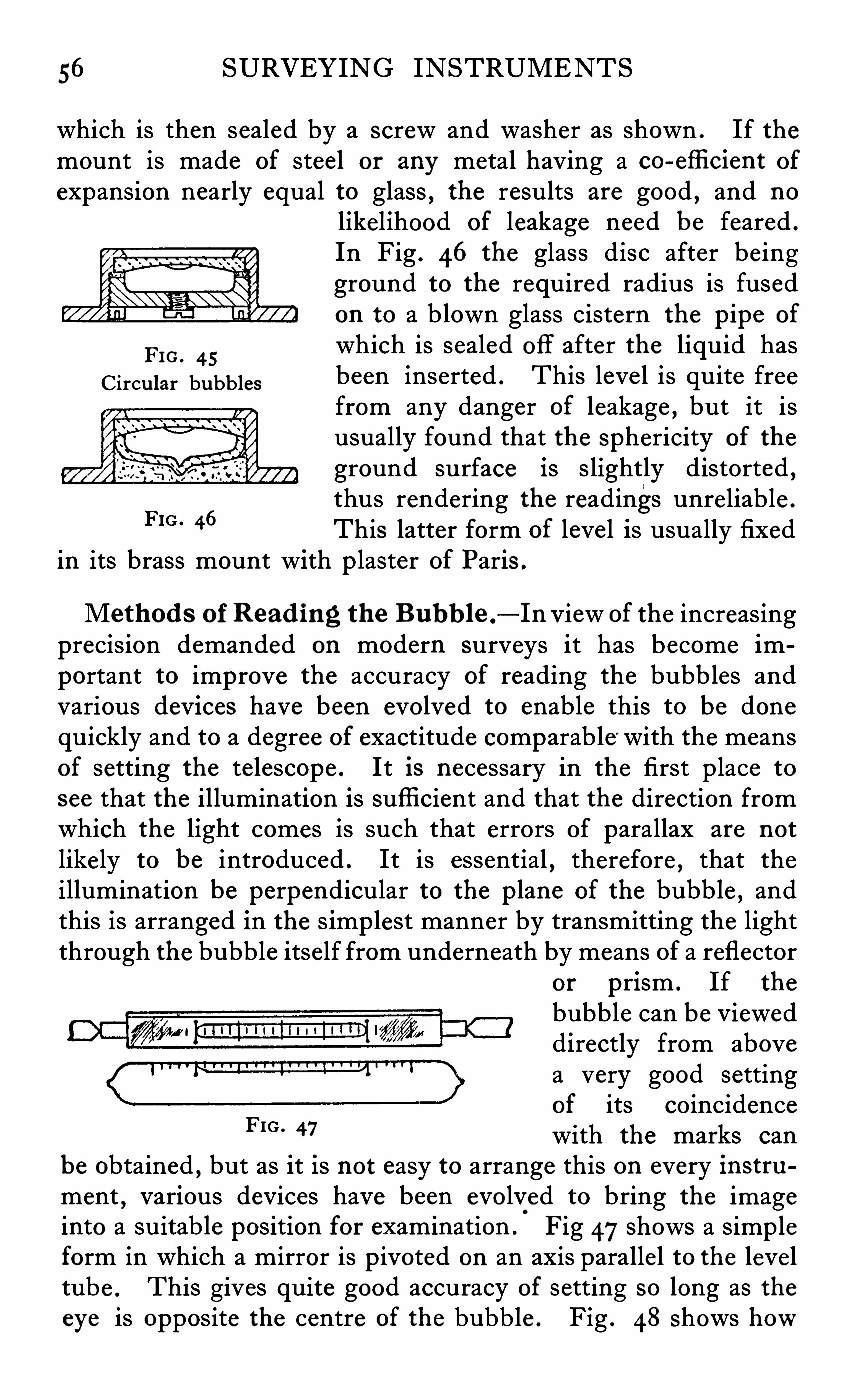
56 SURVEYING INSTRUMENTS
which is then sealed by a screw and washer as shown . If themount is made of steel or any metal having a co-effi cient of
expansion nearly equal to glass , the results are good , and no
likelihood of leakage need be feared .
In Fig . 46 the glass disc after beingground to the required radius is fusedon to a blown glass cistern the p ipe of
FIG. 45which is sealed off after the liquid has
Circu lar bubbles been inserted . This level is quite freefrom any danger of leakage , but it isusually found that the Sphericity of the
ground surface is slightly distorted ,thus rendering the readings unre liable .
This latter form of level is usually fixedin its brass mount with p laster of Paris .
FIG . 46
Method s of Read ing the B ubb le .
~—In View of the increasingprecision demanded on modern surveys it has become important to improve the accuracy of reading the bubbles andvarious devices have been evolved to enable this to be donequickly and to a degree of exactitude comparable “ with the meansof setting the telescope . It is necessary in the first place to
See that the illumination is sufficient and that the direction fromwhich the light comes is such that errors of parallax are not
likely to be introduced . It is essential , therefore , that theillumination be perpendicular to the p lane of the bubble , andthis is arranged in the s imp lest manner by transmitting the lightthrough the bubble itself from underneath by means of a reflector
or prism . If the
bubble can be Vieweddirectly from abovea very good settingof its coincidencewith the marks can
be obtained , but as it is not easy to arrange this on every instrument , various devices have been evolved to bring the imageinto a suitab le position for examination . Fig 47shows a simpleform in which a mirror is p ivoted on an axis paralle l to the leve ltube . This gives quite good accuracy of setting so long as theeye is opposite the centre of the bubb le . Fig . 48 Shows how
FIG . 47
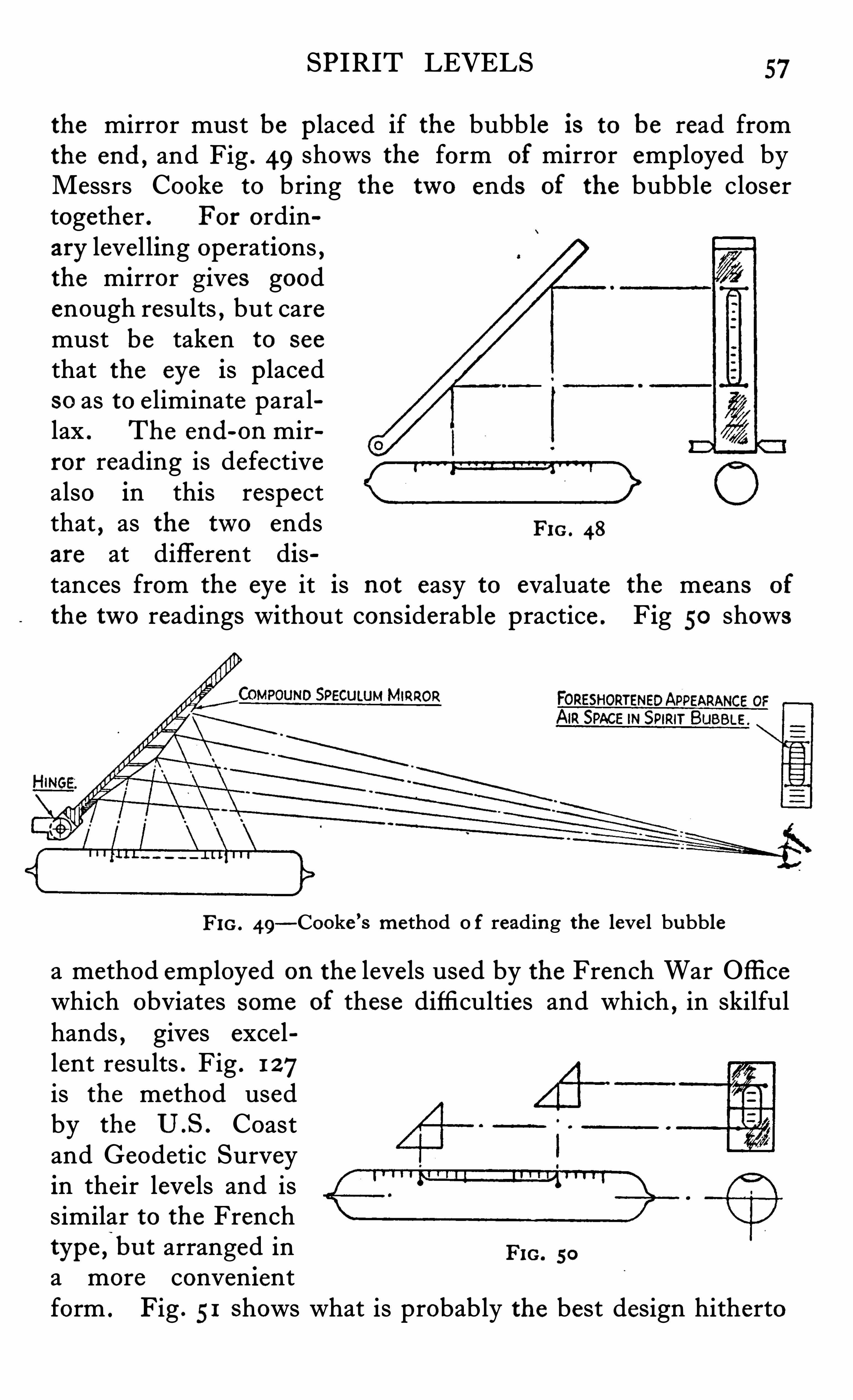
SPIRIT LEVELS 57
the mirror must be p laced if the bubble is to be read fromthe end , and Fig . 49 shows the form of mirror employed byMessrs Cooke to bring the two ends of the bubble closertogether . For ordinary leve lling operations ,the mirror gives goodenough results , but caremust be taken to see
that the eye is p lacedso as to e liminate parallax . The end-on mirror reading is defectivealso in this respectthat , as the two ends FIG. 48
are at different distances from the eye it is not easy to evaluate the means of
the two readings without cons iderable practice . Fig 50 shows
RROR
FIG. 49—Cooke ’s method o f reading the leve l bubble
a method employed on the levels used by the French War Offi cewhich obviates some of these difficulties and which , in skilfulhands , gives exce llent results . Fig . 1 27is the method usedby the U .S . Coastand Geodetic Surveyin their leve ls and issimilar to the Frenchtype ,
‘
bu t arranged in FIG. 50
a more convenientform . Fig . 51 Shows what is probably the best design hitherto
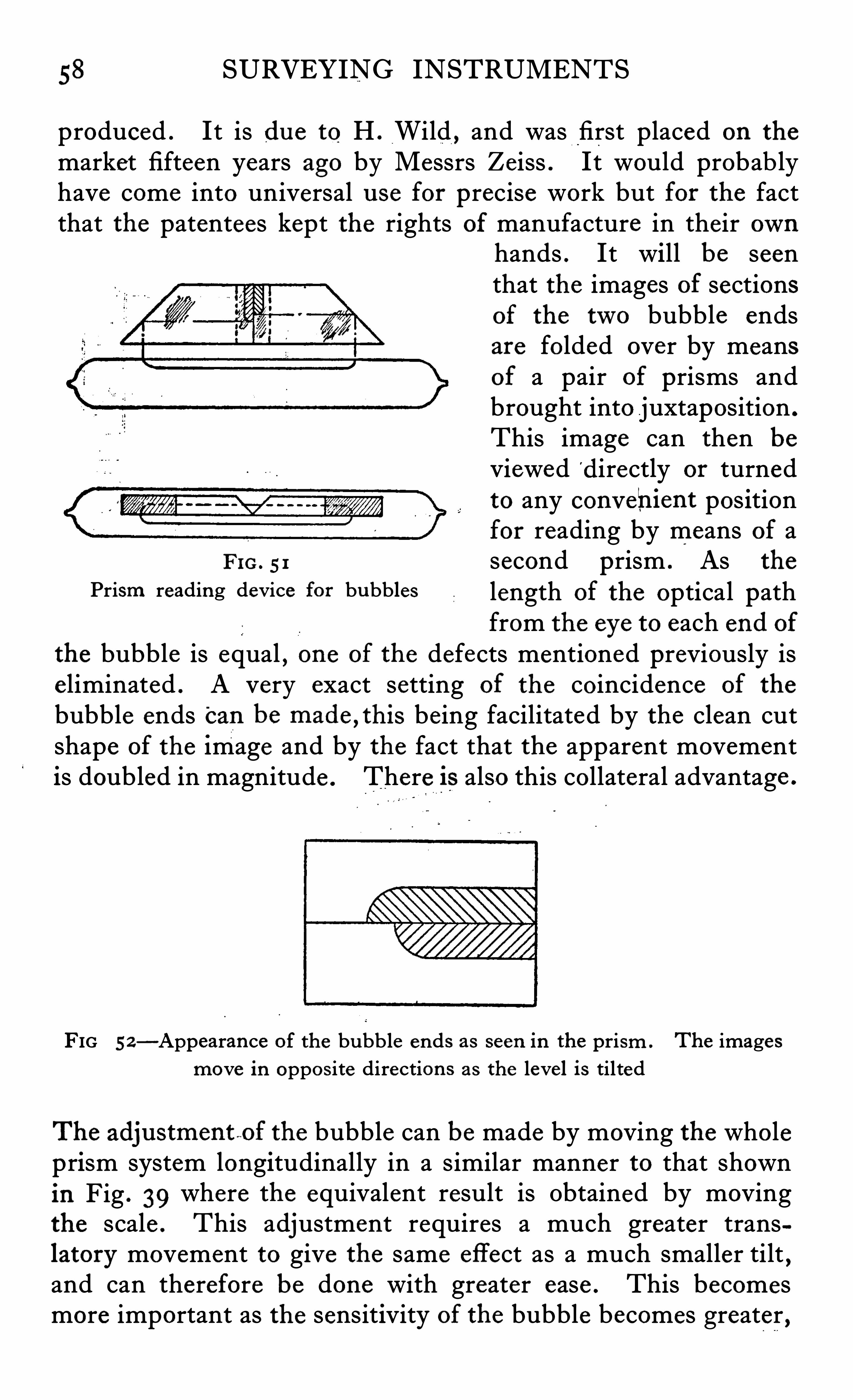
58 SURVEYING INSTRUMENTS
produced . It is du e to H . Wild , and was first placed on the
market fifteen years ago by Messrs Zeiss . It would probab lyhave come into universal u se for precise work but for the factthat the patentees kept the rights of manufacture in their own
hands . It will be seenthat the images of sectionsof the two bubble endsare folded over by meansof a pair of prisms andbrought into juxtaposition .
This image can then beViewed d irectly or turnedto any conv ehient positionfor reading by means of a
FIG. 5 1 second prism . As the
Prism reading device for bu bbles length of the optical pathfrom the eye to each end of
the bubble is equal , one of the defects mentioned previously ise liminated . A very exact setting of the coincidence of the
bubble ends Can be made,this being facilitated by the clean cut
shape of the image and by the fact that the apparent movementis doubled in magnitude . There is also this collateral advantage .
FIG 52—Appearance of the bubble ends as seen in the prism . The images
move in Oppos ite direction s as the level is tilted
The adju stment fi of the bubble can be made by moving the wholeprism system longitudinally in a similar manner to that shownin Fig . 39 where the equivalent result is Obtained by movingthe scale . This adjustment requires a much greater translatory movement to give the same effect as a much smaller tilt
,
and can therefore be done with greater ease . This becomesmore important as the sensitivity of the bubble becomes greater ,
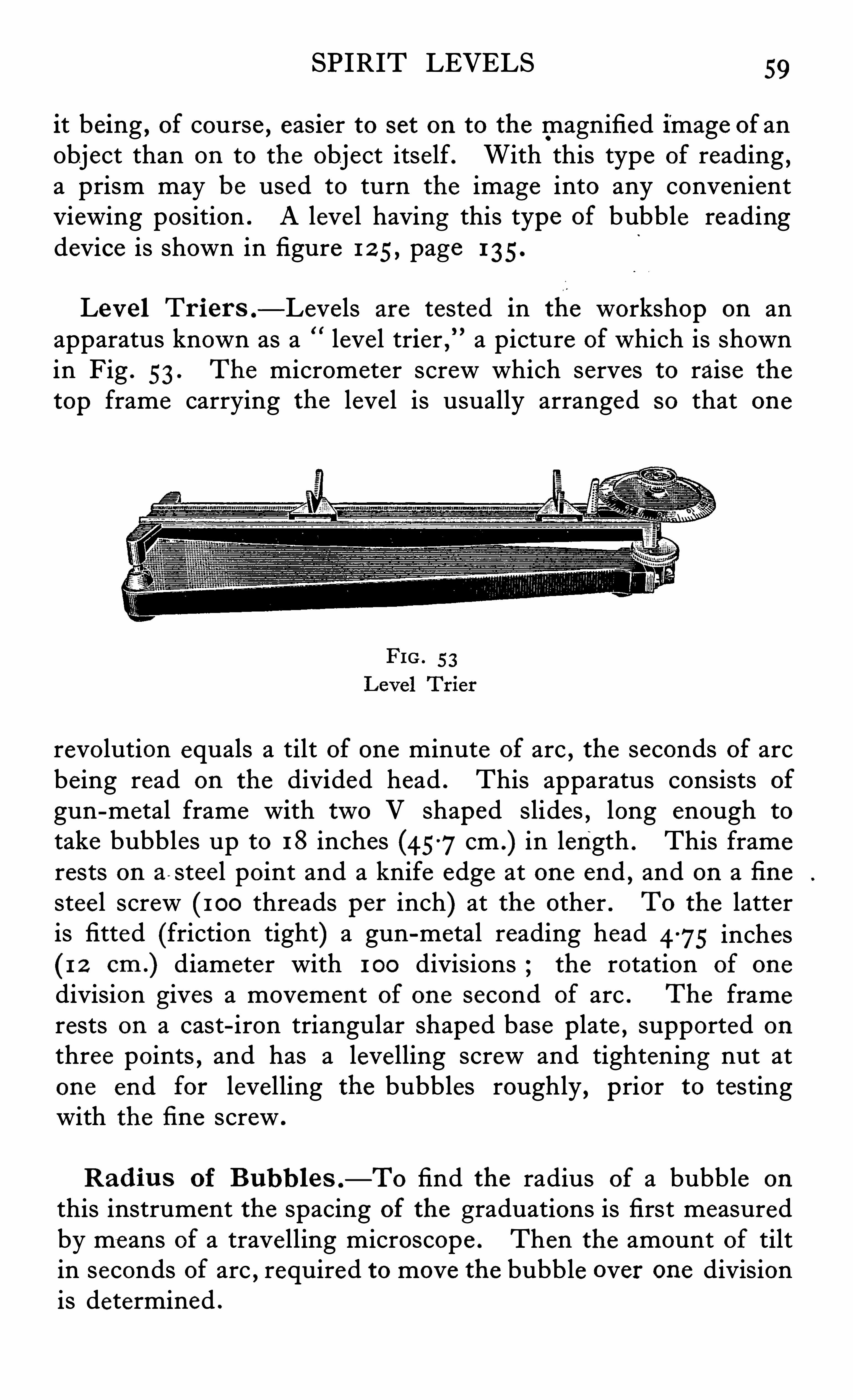
SPIRIT LEVELS 59
it being , of course , easier to set on to the magnified image of anObject than on to the object itself. With this type of reading ,a prism may be used to turn the image into any convenientviewing position . A leve l having this type of bubble readingdevice is shown in figure 1 2 5, page 1 35.
Level Tr ier s .
— Levels are tested in the workshop on anapparatus known as a leve l trier
,
” a picture of which is shownin Fig . 53 . The micrometer screw which serves to raise the
top frame carrying the level is usually arranged so that one
revo lution equals a tilt of one minute of arc , the seconds of arcbeing read on the divided head . This apparatus consists of
gun-metal frame with two V shaped slides , long enough to
take bubbles up to 18 inches (45-7cm .) in length . This framerests on a - stee l point and a knife edge at one end ,
and on a fi nestee l screw (1 00 threads per inch) at the other . To the latteris fitted (friction tight) a gun-metal reading head 4-75 inches
(1 2 cm .) diameter with 1 00 divisions ; the rotation of one
division gives a movement of one second of arc . The framerests on a cast-iron triangular shaped base plate , supported on
three points , and has a levelling screw and tightening nut atone end for levelling the bubbles roughly , prior to testingwith the fi ne screw .
Rad iu s of B ubb les .—To find the radius of a bubble on
this instrument the spacing of the graduations is first measuredby me ans of a travelling microscope . Then the amount of tiltin seconds of arc , required to move the bubble over one divisionis determined .
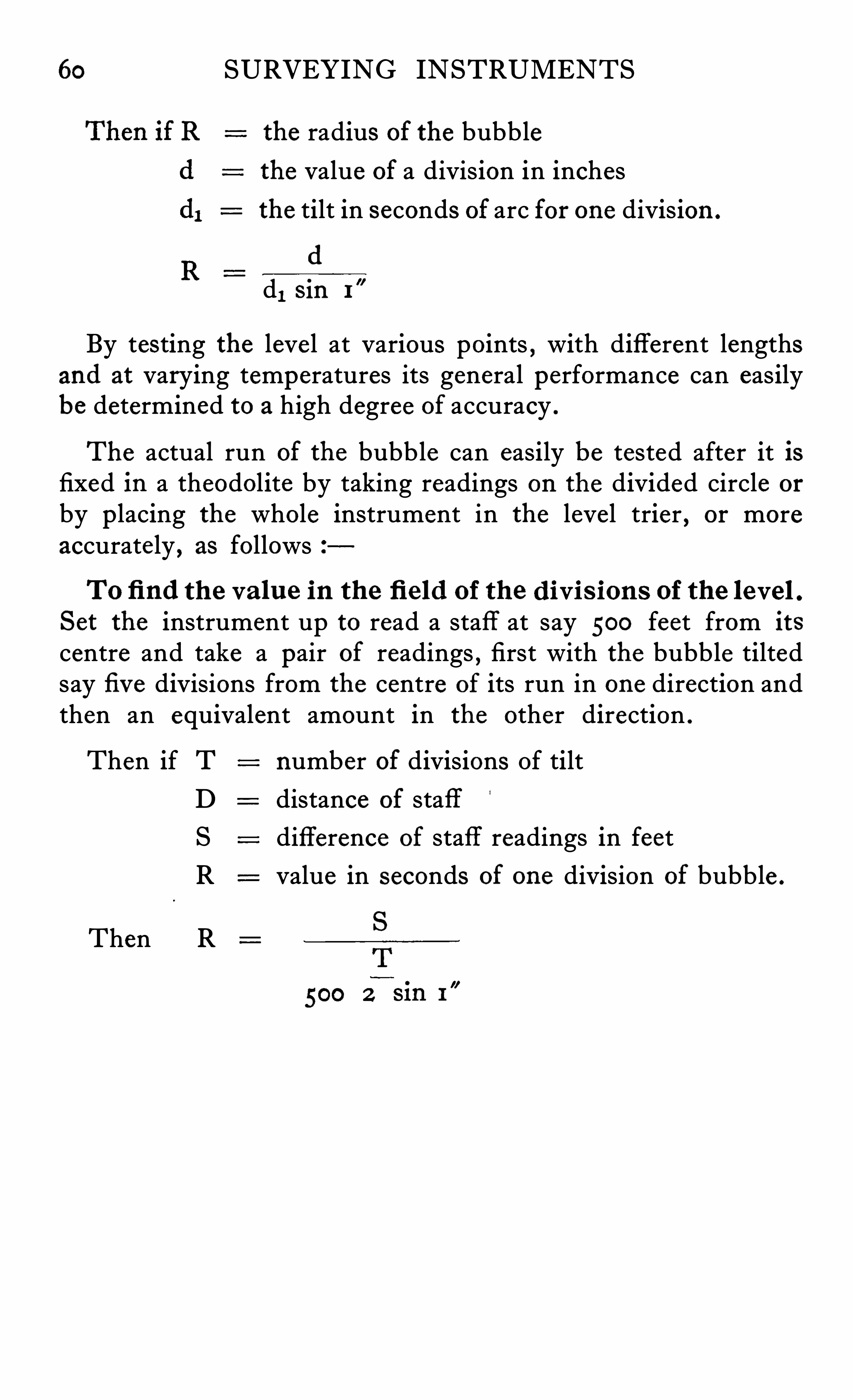
60 SURVEYING INSTRUMENTS
the radius of the bubblethe value of a division in inchesthe tilt in seconds of arc for one division .
(1
d, Sin 1
By testing the leve l at various points , with different lengthsand at varying temperatures its general performance can easilybe determined to a high degree of accuracy .
The actual run of the bubble can easily be tested after it isfixed in a theodolite by taking readings on the divided circle or
by p lacing the whole instrument in the level trier , or moreaccurately , as follows
To fi nd th e va lu e in the fi e ld of the d ivi s ion s of the level .Set the instrument up to read a staff at say 500 feet from its
centre and take a pair of readings , first with the bubble tiltedsay fi v e divisions from the centre of its run in one direction andthen an equivalent amount in the other direction .
Then if T number of divisions Of tiltD distance of staff
S difference of staff readings in feetR value in seconds of one division of bubble .
Then R
62 SURVEYING INSTRUMENTS
used beam compasses ; but by computing the chords of the
arcs he laid down the division 85-2 0 , and then by continualbisection was able to comp lete his divisions .
ROEMER,about this time divided quadrants by the following
method ; he set a pair of compasses to approximately the
smallest space required , and stepped this fixed distance alongthe whole of his arc .
5
The total length of the arc was disregarded,
the number of divisions being converted into degrees , minutesand seconds , by a table calculated specially for each instrument . This mode of dividingwas soon found to be unreliable
,
as owing to the porous nature of the metal , and to the fact thatthe dots could never be placed exactly on the circumferentialline , the errors were too irregular to permit of correction , histable being calculated on the assumption that the whole of the
arc was evenly divided .
HOOKE,about the same period , invented an endless screw
system of dividing but this , although nowthe recognisedmethod , was at that time a failure , owing to the fact that su fficiently accurate work in the mechanical details of the apparatuswas unattainable .
In the middle of the 18th century , the DUC DE CHAULNESmade a remarkable improvement , which has turned ou t to be
the foundation of ou r present-day method of examining , andcomputing
,the errors in divided circles . The procedure was
shortly as follows
Two microscopes were fixed to read diametrical ly oppositepoints on the circle which was to be graduated and these werefocused on to two slips of brass , each carrying a finely engravedline and fixed temporarily at the edge of the circle . The circlewas then moved through and the necessary adjustmentsmade to the brass s lips and microscopes , until the oppositedivisions were again bisected by the spider lines in the microscopes . A cutting frame having been fixed to the stand carryingthe circle , it was then only necessary to cut the divisions in theirproper positions , under control of the microscopes , and by continu al trial of bi and tri-sections in the whole of the circle , itwas possible with sufficient care to fill in the sub-divisions in amost precise manner . Once having obtained an accurate
THE GRADUATION OF INSTRUMENTS 63
master circle , itwas a comparative ly simp le matter to makecopies of it by this method and in fact until quite recent years ,this was the only means available to most of the continentaldividers for the production of circles on astronomical instruments
RAMSDEN . In the years round about 1765, Jesse Ramsden ,a clever mechanician of London , was dividing circles of a
quality notably superior in accuracy and finish to any hithertoproduced . His method , however , although capable of givingvery exce llent results , was too tedious and difficult , except to a
man of his outstanding skill , patience and ability . He firstdivided his circles as precisely as possible by beam compasses .
Then , after ascertaining the errors of spacing by means of themicroscopes , he corrected them by pressing over the dots ,backwards or forwards
,by a steel point he ld in the hand . The
demand for circles divided by Ramsden became so great that hes et his mind on the problem of turning them ou t by whatweshould nowterm methods of mass production .
”The result
was the invention and construction of his automatic dividingengine . This wonderful machine functioned so perfectly thatthe production of accurately divided circles became a matterof comparative ease
,and in consequence the strides made in the
output of astronomical and surveying instruments at this periodwere remarkable . The efforts of Ramsden also led to extraordinary improvements in the cutting of wheels for clocks andwatches and his name , in consequence , stands ou t as a landmark in the progress of mechanical achievement . It was du elarge ly to his efforts , and to those of his co-workers at thisperiod , that England became pre-eminent in the manufacture of
precision apparatus , a position which she has never sincerelinquished . It may be stated , without fear of contradiction ,that in the output of instruments of the first order of accuracy ,England to-day holds the premier position of all nations . The
circles produced on the dividing engines housed in her workshops are unsurpassed and her mechanicians , inspired by thetradition of hundreds of years Of successful effort and progress ,are to-day turning ou t apparatus which
,in design and accuracy of
manufacture , convenience in u se , and beauty of finish , takesecond p lace to none .
64 SURVEYING INSTRUMENTS
RAMSDEN ’
S ENGINE consisted of a wheel of bronze cut on itsperiphery with teeth , into which a steel worm engaged .
This was given an intermittent motion by a ratchet and whee l ,the cutting of the division taking p lace while the wormwas atrest , the cutter return ing , ready to make the next stroke , duringthe time the toothed wheel , carrying the circle to be graduated ,was moving round over the des ired interval .It was soon found that however accurately the teeth of the
wheel were cut in the first p lace , a certain amount of wear tookplace , and that the resultant d ividing showed errors of relativelylarge magnitude . Constructors then increased the diameterof their circles , and also the number of teeth cut on theirperiphery but , although this procedure minimised the errorsdu e to wear , other diffi culties soon became apparent . In con
sequence , ANDREW ROSS , in 1830 ,devised a machine on an
entirely newprinciple . The regulation of the motion of his
circular p late was the reverse of the endless screw of Ramsden ,which acts by driving . In the engine of Ross
, the plate , containing 48 adjustable steel abutments on its periphery ,was turnedby a gut band and weight , and was stopped very precisely at
every division by the contact of plane and spherical surfaces Ofhardened stee l . AS the circle was under no influence duringthe time the division was being cut , except that of a constantweight keeping the stee l surfaces in contact , very accurate workwas capable of being done on this machine . Moreover , as thestee l surfaces were fitted with a screw adjustment , it was foundthat contact could be made to within one quarter of a second of
arc , and the whole machine regulated from time to time , in sucha way
,that work of the very highest accuracy could be guaran
teed . The area of contact , upon which the permanence of
adjustment depended ,was necessarily small , so that constantattention had to be paid to the wear of the stee l surfaces , ifwork of extreme precision was required from the machine .
During the next 50 years , various machines were constructedin Europe and America , nearly all modifications of .Ramsden ’sengine .
Recently designed engines fo llow the Ramsden principle , butthey are constructed with circles of large diameter , the teethare cut in the first place with the most scrupulous accuracy ,
THE GRADUATION OF INSTRUMENTS 65
and fitted with hardened and ground steel worms , opticallyfinished on the angles of the threads . Such is the precision of
the modern tools brought to bear on this work , that the wheeland worm ,
when lapped together , will function with a maximumerror in the intervals of the divisions of less than one second of
arc . For the final regulation of the engine , trial divisions aremade with the machine in this stage , and tables of errors compu ted
—these tables being used to regulate the compensatingapparatus with which all the best modern machines are nowfitted . This Simple and very efficient device works on a similarprinciple to that used on measuring machines and the leadscrews of precision lathes . The method is as follows .
Round the periphery of the whee l a thin stee l p late is fixed ,and engaging with its edge is a lever which , when it is raisedor lowered , gives a corresponding lead or retardation to the
worm . It is then only necessary to cut the edge of this steelplate to the curves shown by the table of errors in order toremove the small residual discrepancies from the teeth . In thisway , not only can the machine be regulated to within the
probable errors of observation , but also it can be kept up to
this standard during the whole of its life .
It is diffi cult for the mind to realise the meaning of an accuracyof one-tenth of one second of are , but a numerical examplewill serve to give some indication of the minute spacing thisdenotes on say the 5-inch circles of a theodolite . Imagine a circlefour miles in diameter , with two straight lines starting at thecentre and diverging at an angle of 1 0 degrees . At the edgeof the circle they will be feet 8-74 inches apart increasethis divergence by 1 / 1 0th second and they will then befeet 8-80 1 3 inches apart , a difference of 3 061 3 inch . Thisdifference would amount on a 5-inch circle to -00000 1 2 inch .
To put it another way,a line drawn round the equator would
come back within ten feet of the starting point .
Dividing machines are generally housed in a specially con
structed room kept at a constant temperature . They are
arranged in such a way that when the circles to be divided are
66 SURVEYING INSTRUMENTS
fixed in place , the driving motor is started , and the cuttingproceeds automatically , stopping itself when the last divisionhas been completed .
Div id ing Eng ine
A description of the methods employed on the constructionof a dividing engine recently completed in Messrs Casella ’sworks is here given , as it differs somewhat in detail from otherpublished accounts . In the first place , the revolving table ,centre , and stand were made and the necessary apparatus forcutting the divisions mounted up in place . On the top surface ,near the edge , bands of silver had been inlaid in l the usualway ,and then a light ou t was taken over the top face and the edge ,where the teeth were to be formed while the table was revolvingon its own centre . Care had to be taken in this and subsequentOperations to see that all parts of the table were at an eventemperature , and that the foundation upon which the machinewas bolted was free from Vibration due to adjacent machineryand to heavy vehicles running on the roads in the Vicinity . To
this end , the important parts of the work were carried ou t afterthe usual working hours , and sometimes through the night ,careful control being kept of the temperature of the engine room .
The next operation was to clamp an accurately divided circleof half degrees (made on another machine , the accuracy of whichwas known to within two seconds of arc) , to the table and tofix four micrometer microscopes to read its 72 0 divisions .
This circle was carefully centered on the table from marks madeat the time the dividing was done , the centering being also .
checked on the divisions themselves . The cutting frame wasthen mounted over the silver on the main table and adjustedto give a truly radial division . The whole of the 72 0 divisionswere .then copied from the divided circle on to the table , underthe contro l of the microscopes , allowance being made at thisstage for the inaccuracies known to be in the circle being copied .
The microscopes were then fixed over the divisions just madeand a thorough examination of the errors was undertaken andtables made of them . This was a most laborious and trying operation , and one which would only be undertaken by a confirmedOptimist or one with patience and determination different
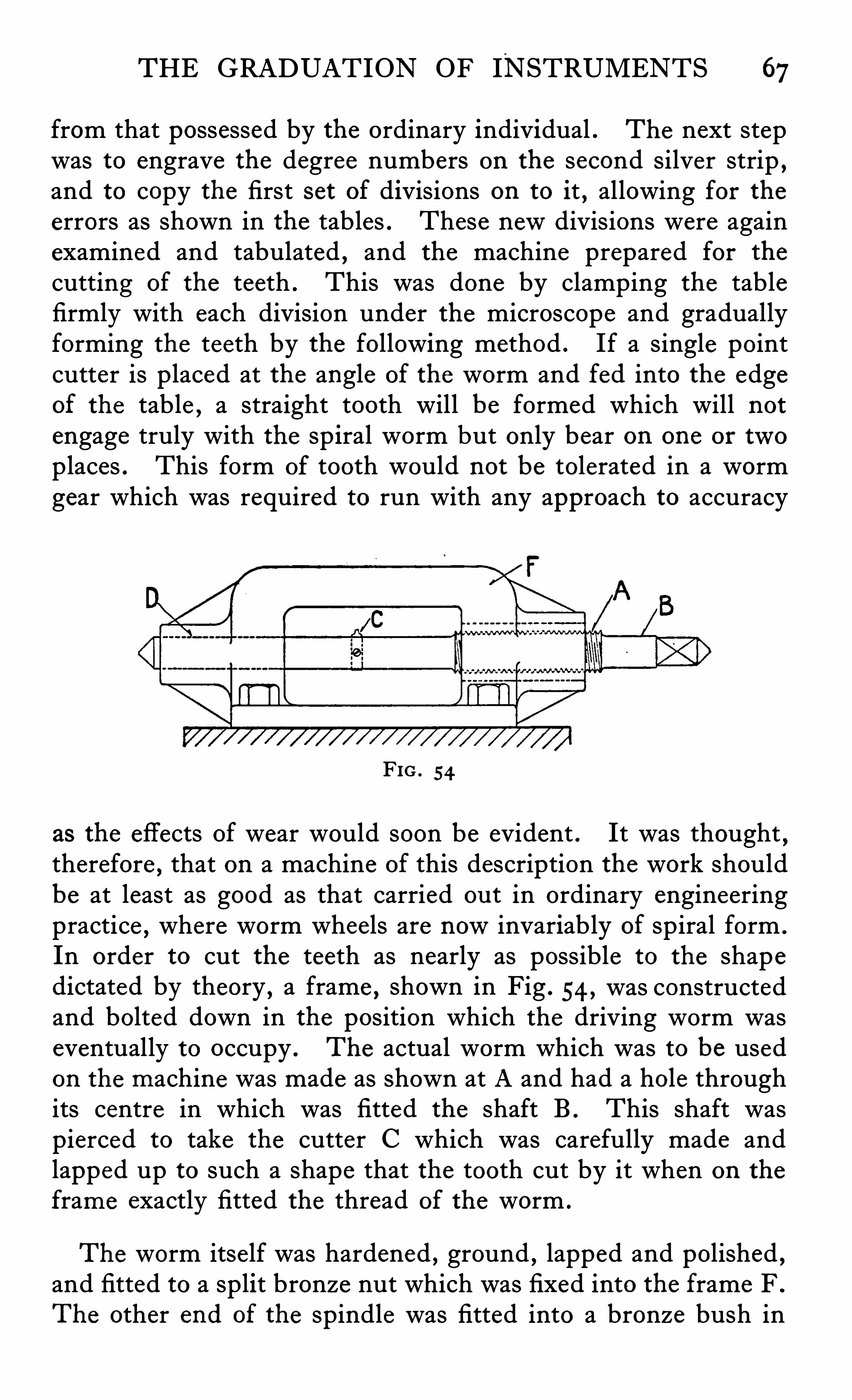
THE GRADUATION OF INSTRUMENTS 67
from that possessed by the ordinary individual . The next stepwas to engrave the degree numbers on the second Silver strip ,and to copy the first set of divisions on to it , allowing for theerrors as shown in the tables . These newdivisions were againexamined and tabulated , and the machine prepared for the
cutting of the teeth . This was done by clamping the tablefirmly with each division under the microscope and graduallyforming the teeth by the following method . If a single pointcutter is placed at the angle of the worm and fed into the edgeof the table , a straight tooth will be formed which will notengage truly with the sp iral worm but only bear on one or twoplaces . This form of tooth would not be tolerated in a wormgear which was required to run with any approach to accuracy
FIG . 54
as the effects of wear would soon be evident . It was thought,
therefore , that on a machine of this description the work shouldbe at least as good as that carried ou t in ordinary engineeringpractice , where worm wheels are nowinvariably of spiral form .
In order to cut the teeth as nearly as possible to the shapedictated by theory , a frame , shown in Fig . 54 , was constructedand bolted down in the position which the driving worm waseventually to occupy . The actual worm which was to be usedon the machine was made as shown at A and had a hole throughits centre in which was fitted the shaft B . This shaft waspierced to take the cutter C which was carefully made andlapped up to such a shape that the tooth cut by it when on the
frame exactly fitted the thread of the worm .
The worm itse lf was hardened , ground , lapped and polished ,and fitted to a split bronze nut which was fixed into the frame F .
The other end of the spindle was fitted into a bronze bush in
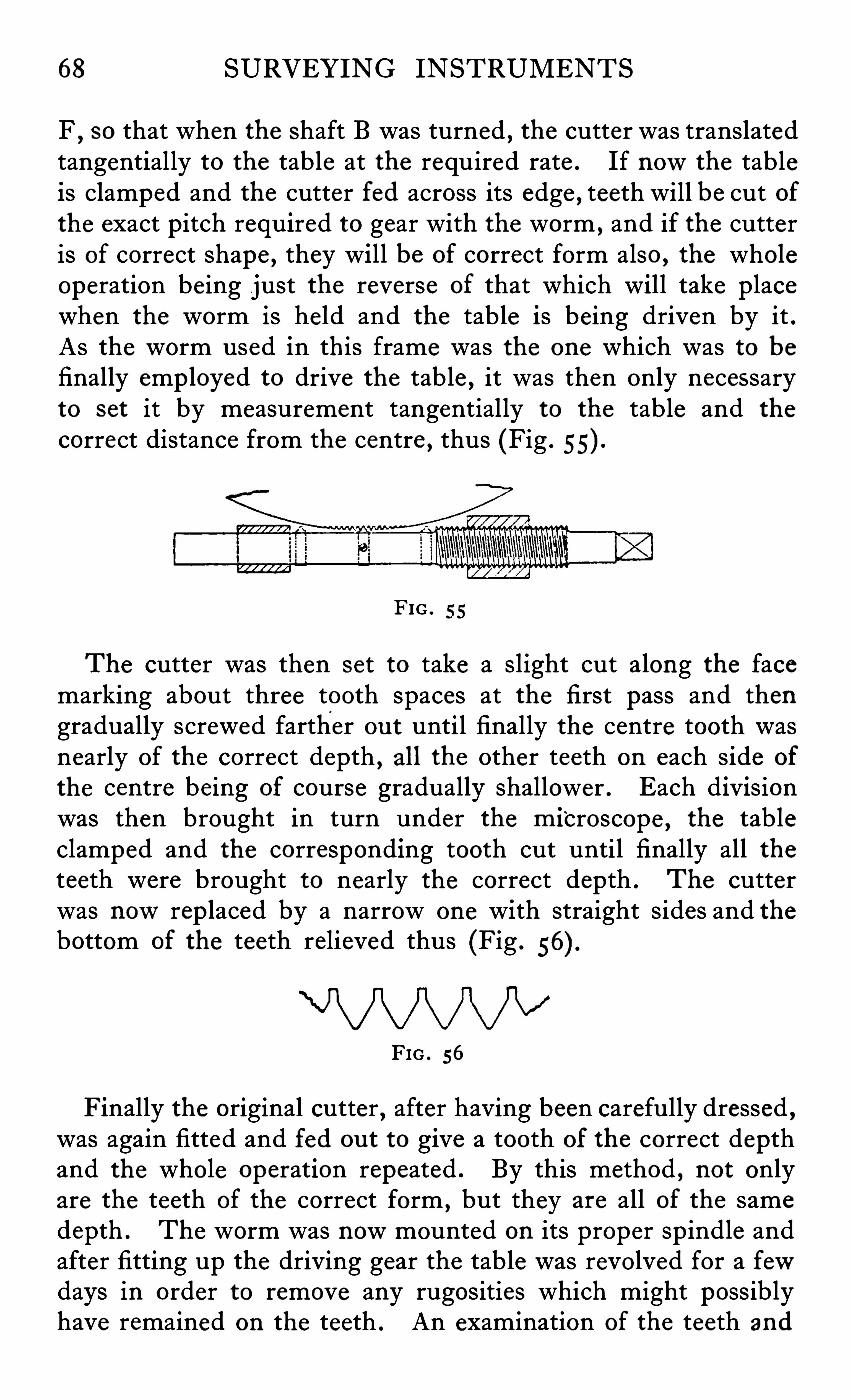
68 SURVEYING INSTRUMENTS
F,so that when the Shaft B was turned , the cutter was translated
tangentially to the table at the required rate . If nowthe tableis clamped and the cutter fed across its edge , teeth will be cut ofthe exact pitch required to gear with the worm , and if the cutteris of correct shape , they will be of correct form also , the wholeoperation being just the reverse of that which will take placewhen the worm is held and the table is being driven by it .As the worm used in this frame was the one which was to befinally emp loyed to drive the table , it was then only necessaryto set it by measurement tangentially to the table and the
correct distance from the centre , thus (Fig .
FIG . 55
The cutter was then set to take a slight cut along the facemarking about three tooth spaces at the first pass and thengradually screwed farther ou t until finally the centre tooth wasnearly of the correct depth , all the other teeth on each side of
the centre being of course gradually shallower . Each divisionwas then brought in turn under the microscope
,the table
clamped and the corresponding tooth cut until finally all theteeth were brought to nearly the correct depth . The cutterwas nowrep laced by a narrow one with straight sides and thebottom of the teeth relieved thus (Fig .
FIG . 56
Finally the original cutter,after having been carefully dressed ,
was again fitted and fed ou t to give a tooth of the correct depthand the whole operation repeated . By this method , not onlyare the teeth of the correct form ,
but they are all of the samedepth . The worm was nowmounted on its proper spindle andafter fitting up the driving gear the table was revolved for a fewdays in order to remove any rugosities which might possiblyhave remained on the teeth . An examination of the teeth and
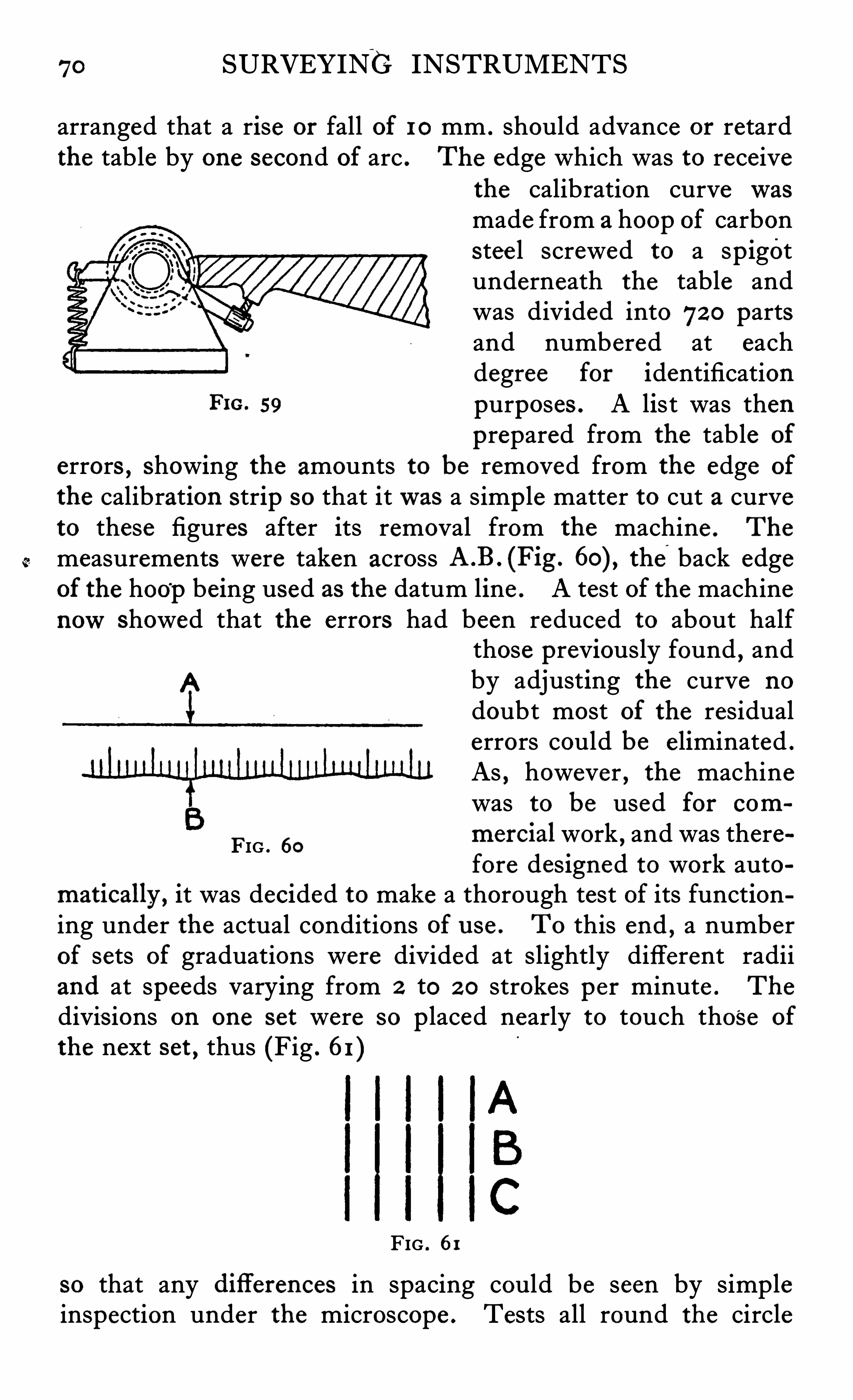
70 SURVEYING INSTRUMENTS
arranged that a rise or fall of 10 mm . should advance or retardthe table by one second of arc . The edge which was to receive
the calibration curvewasmade from a hoop of carbonstee l screwed to a spigotunderneath the table andwas divided into 72 0 partsand numbered at eachdegree for identification
FIG. 59 purposes . A list was thenprepared from the table of
errors , Showing the amounts to be removed from the edge of
the calibration strip so that itwas a simp le matter to cut a curveto these figures after its removal from the machine . The
measurements were taken across the,
back edgeof the hoop being used as the datum line . A test of the machinenowshowed that the errors had been reduced to about half
those previously found , andby adjusting the curve no
doubt most of the residualerrors could be e liminated .
As , however , the machinewas to be used for com
mercial work , and was therefore designed to work auto
matically , it was decided to make a thorough test of its functioning under the actual conditions of u se . To this end ,
a numberof sets of graduations were divided at slightly different radiiand at speeds varying from 2 to 2 0 strokes per minute . The
divis ions on one set were so p laced nearly to touch those of
the next set , thus (Fig . 61 )
FIG . 60
FIG . 61
so that any diflerences in spacing could be seen by simpleinspection under the microscope . Tests all round the circle
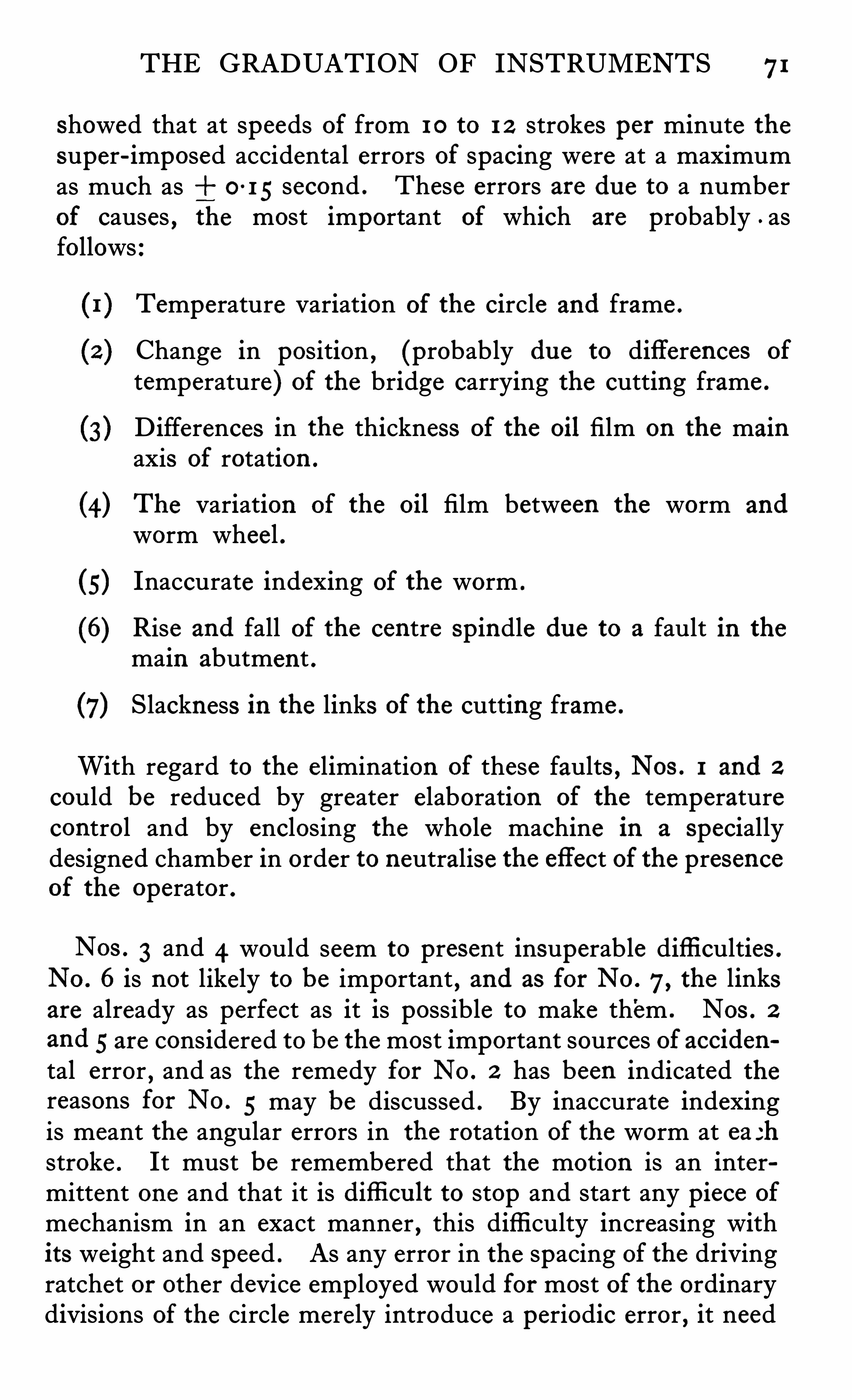
THE GRADUATION OF INSTRUMENTS 71
showed that at speeds of from 10 to 1 2 strokes per minute thesuper-imposed accidental errors of spacing were at a maximumas much as 0-15 second . These errors are du e to a numberof causes , the most important of which are probably . asfollows
Temperature variation of the circle and frame .
Change in position, (probably du e to differences of
temperature) of the bridge carrying the cutting frame .
D ifferences in the thickness of the oil film on the mainaxis of rotation .
(4) The variation of the oil film between the worm and
worm wheel .
(5) Inaccurate indexing of the worm .
(6) Rise and fall of the centre spindle du e to a fault in the
main abutment .
(7) Slackness in the links of the cutting frame .
With regard to the elimination of these faults , Nos . 1 and 2
could be reduced by greater elaboration of the temperaturecontrol and by enclosing the whole machine in a speciallydesigned chamber in order to neutralise the effect of the presenceof the operator .
N03 . 3 and 4 would seem to present insuperable diffi culties .
No . 6 is not likely to be important , and as for No . 7, the linksare already as perfect as it is possible to make them . NOS . 2
and 5 are considered to be the most important sources of accidental error , and as the remedy for No . 2 has been indicated thereasons for No . 5 may be discussed . By inaccurate indexingis meant the angular errors in the rotation of the worm at ea 3hstroke . It must be remembered that the motion is an intermittent one and that it is difli cu lt to stop and start any piece of
mechanism in an exact manner , this diffi culty increasing withits weight and Speed . As any error in the spacing of the drivingratchet or other device employed would for most of the ordinarydivisions of the circle merely introduce a periodic error , it need
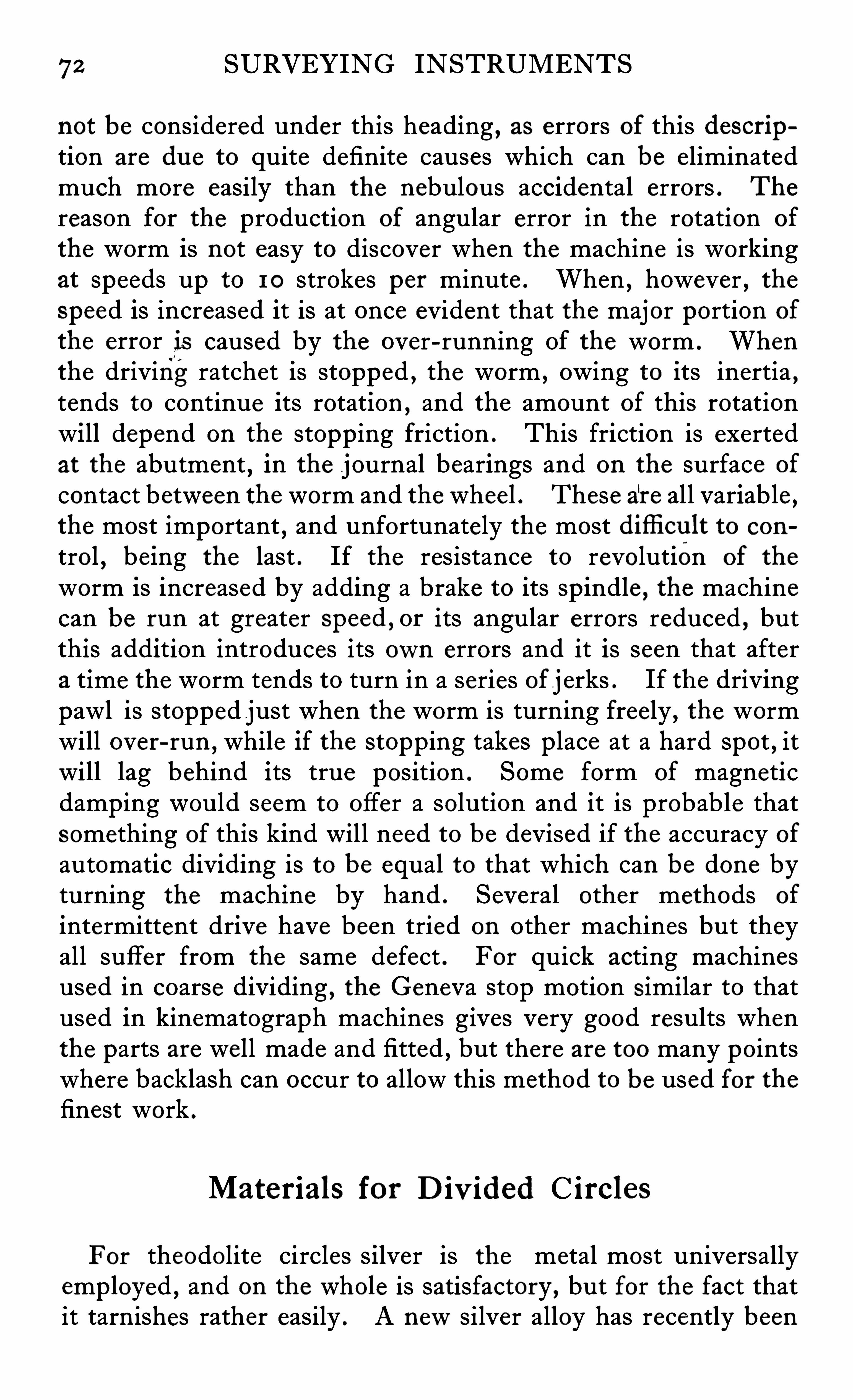
72 SURVEYING INSTRUMENTS
not be considered under this heading , as errors of this description are du e to quite definite causes which can be eliminatedmuch more easily than the nebulous accidental errors . The
reason for the production of angular error in the rotation of
the worm is not easy to discover when the machine is workingat speeds up to 1 0 strokes per minute . When , however , thespeed is increased it is at once evident that the major portion of
the error is caused by the over-running of the worm . Whenthe driving ratchet is stopped , the worm , owing to its inertia ,tends to continue its rotation ,
and the amount of this rotationwill depend on the stopping friction . This friction is exertedat the abutment
,in the journal bearings and on the surface of
contact between the worm and the wheel . These are all variable ,the most important
,and unfortunately the most difli cu lt to con
trol , being the last . If the resistance to revolution of the
worm is increased by adding a brake to its spindle , the machinecan be run at greater speed , or its angular errors reduced , butthis addition introduces its own errors and it is seen that aftera time the worm tends to turn in a series of j erks . If the drivingpawl is stopped just when the worm is turning freely , the wormwill over-run
,while if the stopping takes p lace at a hard spot , it
will lag behind its true position . Some form of magneticdamping would seem to offer a solution and it is probable thatsomething of this kind will need to be devised if the accuracy ofautomatic dividing is to be equal to that which can be done byturning the machine by hand . Several other methods of
intermittent drive have been tried on other machines but theyall suffer from the same defect . For quick acting machinesused in coarse dividing
,the Geneva stop motion Similar to that
used in kinematograph machines gives very good results whenthe parts are well made and fitted , but there are too many pointswhere backlash can occur to allow this method to be used for thefinest work .
Materials for D iv ided C ircles
For theodolite circles silver is the metal most universallyemployed , and on the whole is satisfactory , but for the fact thatit tarnishes rather easily . A newsilver alloy has recently been
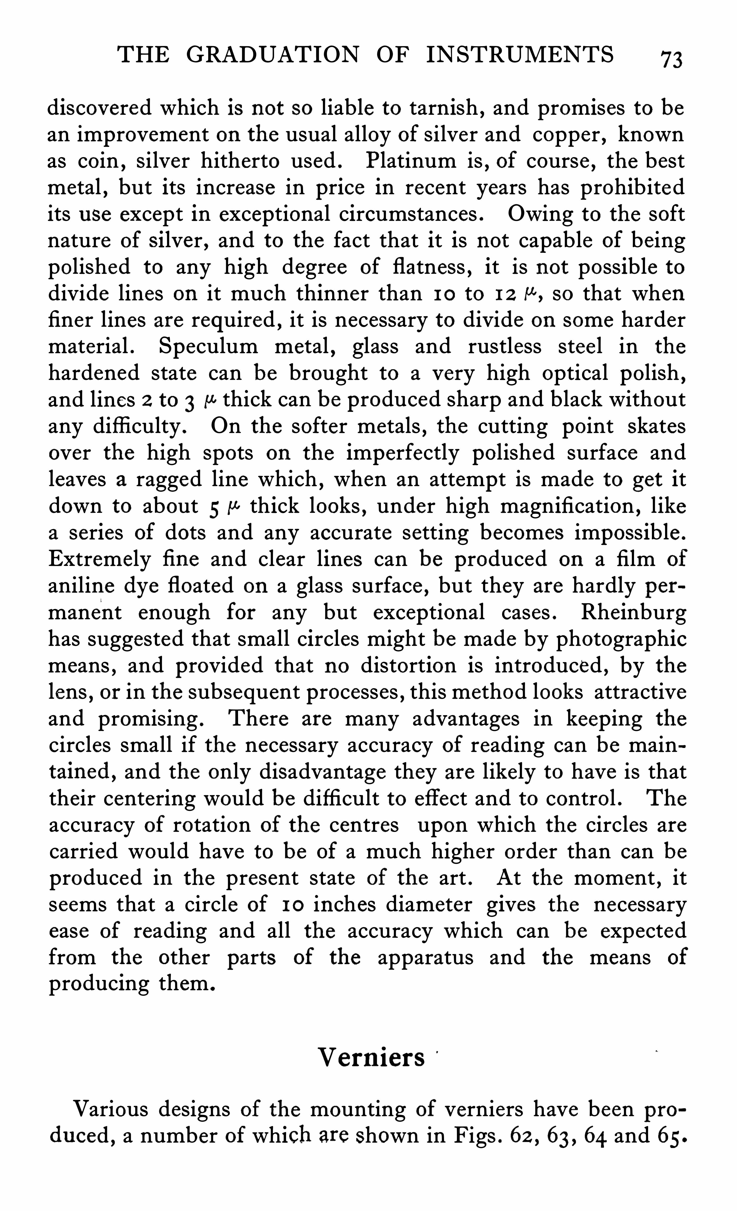
THE GRADUATION OF INSTRUMENTS 73
discovered which is not so liable to tarnish , and promises to bean improvement on the usual alloy of silver and copper , knownas coin , Silver hitherto used . Platinum is , of course , the bestmetal , but its increase in price in recent years has prohibitedits u se except in exceptional circumstances . Owing to the softnature of Silver , and to the fact that it is not capable of beingpolished to any high degree of flatness , it is not possible todivide lines on it much thinner than 1 0 to 1 2 M, so that whenfiner lines are required , it is necessary to divide on some hardermaterial . Speculum metal , glass and rustless stee l in the
hardened state can be brought to a very high optical polish ,and lines 2 to 3 {a thick can be produced sharp and black withoutany difficulty . On the softer metals , the cutting point Skatesover the high spots on the imperfectly polished surface andleaves a ragged line which , when an attempt is made to get itdown to about 5 11 thick looks , under high magnification , likea series of dots and any accurate setting becomes impossible .
Extremely fi ne and clear lines can be produced on a film of
aniline dye floated on a glass surface , but they are hardly permanent enough for any but exceptional cases . Rheinburghas suggested that small circles might be made by photographicmeans , and provided that no distortion is introduced , by thelens
,or in the subsequent processes , this method looks attractive
and promising . There are many advantages in keeping the
circles small if the necessary accuracy of reading can be maintained , and the only disadvantage they are likely to have is thattheir centering would be difficult to effect and to control . The
accuracy of rotation of the centres upon which the circles arecarried would have to be of a much higher order than can beproduced in the present state of the art . At the moment , itseems that a circle of 10 inches diameter gives the necessaryease of reading and all the accuracy which can be expectedfrom the other parts of the apparatus and the means of
producing them .
Vern iers
Various designs of the mounting of verniers have been produced
, a number of which are shown in Figs . 62 , 63 , 64 and 65
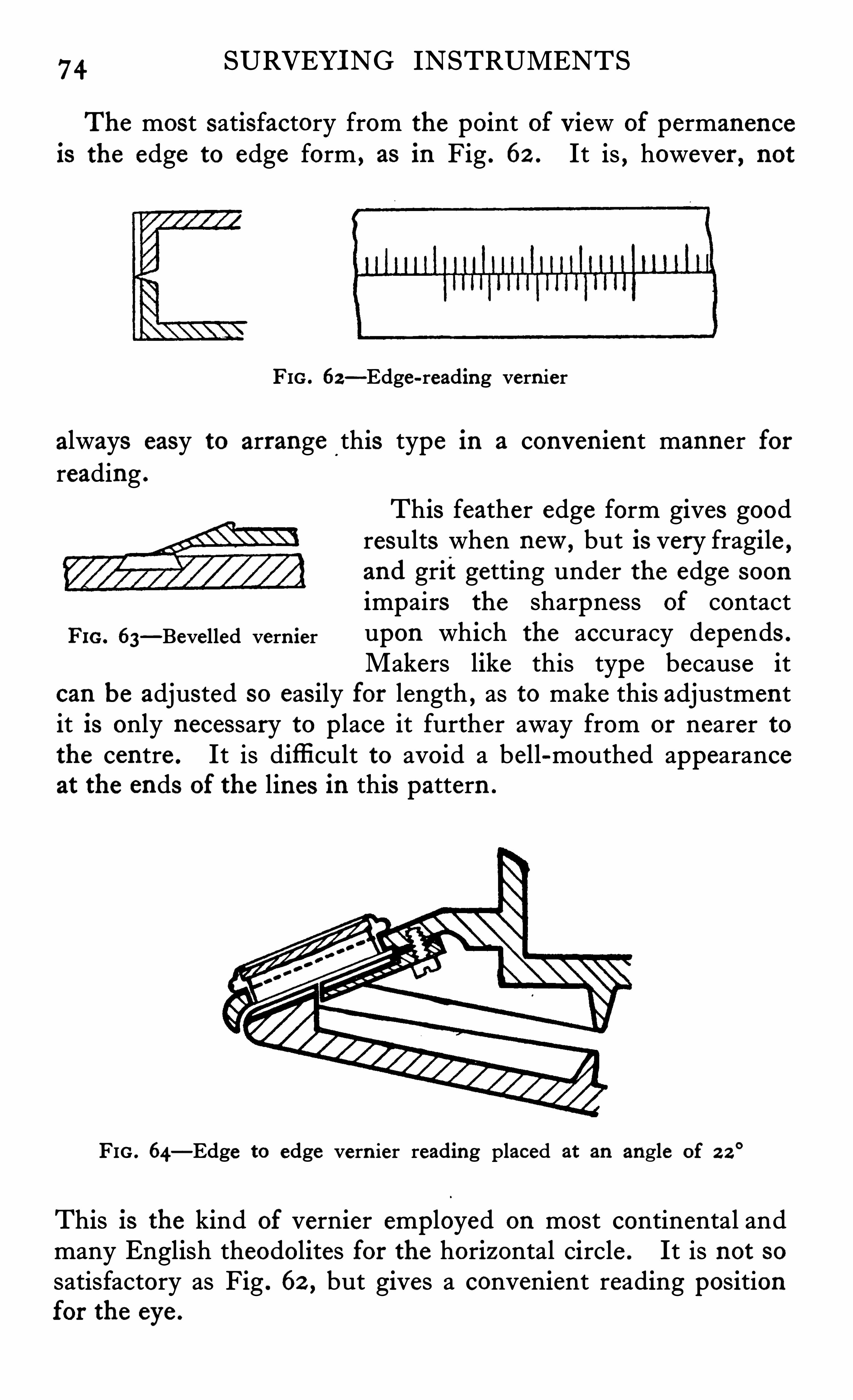
74 SURVEYING INSTRUMENTS
The most satisfactory from the point of view of permanenceis the edge to edge form , as in Fig . 62 . It is , however , not
FIG . 62—Edge-reading vern ier
always easy to arrange this type in a convenient manner forreading .
This feather edge form gives goodresults when new, but is very fragile ,and grit getting under the edge soon
impairs the sharpness of contactFm. 63
—Bevelled vern ier upon which the accuracy depends .
Makers like this type because itcan be adjusted so easily for length , as to make this adjustmentit is only necessary to p lace it further away from or nearer tothe centre . It is diffi cult to avoid a bell-mouthed appearanceat the ends of the lines in this pattern .
FIG . 64—Edge to edge vern ier reading placed at an angle of 2 2
°
This is the kind of vernier employed on most continental andmany English theodolites for the horizontal circle . It is not sosatisfactory as Fig . 62 , but gives a convenient reading positionfor the eye .
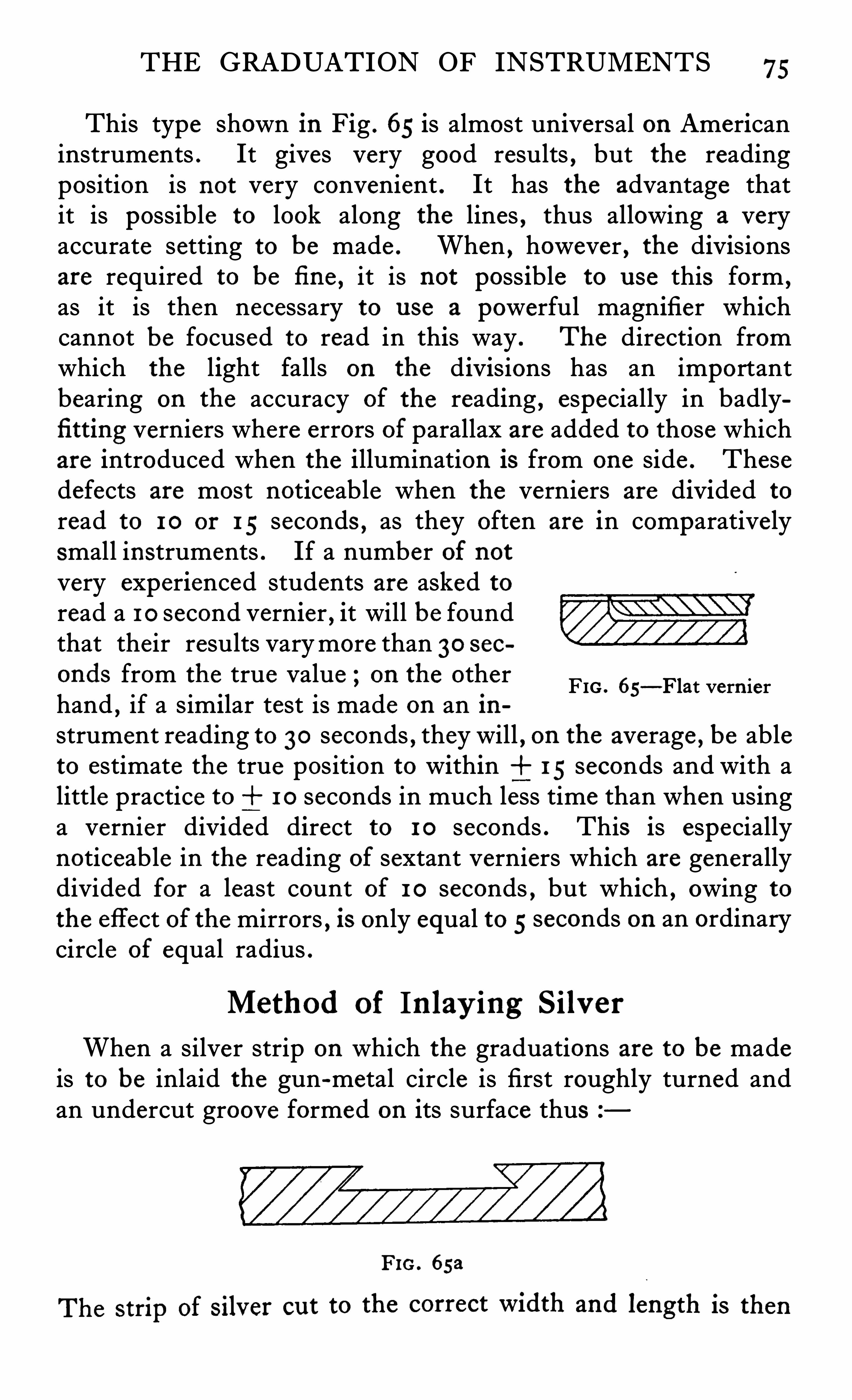
THE GRADUATION OF INSTRUMENTS 75
This type shown in Fig . 65 is almost universal on Americaninstruments . It gives very good results , but the readingposition is not very convenient . It has the advantage thatit is possible to look along the lines , thus allowing a veryaccurate setting to be made . When , however , the divisionsare required to be fi ne , it is not possible to u se this form ,
as it is then necessary to u se a powerful magnifier whichcannot be focused to read in this way . The direction fromwhich the light falls on the divisions has an importantbearing on the accuracy of the reading , especially in badlyfi tting verniers where errors of parallax are added to those whichare introduced when the illumination is from one side . Thesedefects are most noticeable when the verniers are divided to
read to 10 or 15 seconds , as they often are in comparativelysmall instruments . If a number of notvery experienced students are asked toread a 10 second vernier , it will be foundthat their results varymore than 30 seconds from the true value ; on the otherhand , if a similar test is made on an instrument reading to 30 seconds , they will , on the average , be ableto estimate the true position to within 15 seconds and with alittle practice to 1 0 seconds in much less time than when usinga vernier divided direct to 1 0 seconds . This is especiallynoticeable in the reading of sextant verniers which are generallydivided for a least count of 1 0 seconds , but which , owing tothe effect of the mirrors , is only equal to 5 seconds on an ordinarycircle of equal radius .
FIG . 65—Flat vern ier
Method of In lay ing S ilv er
When a silver strip on which the graduations are to be madeis to be inlaid the gun-metal circle is first roughly turned andan undercut groove formed on its surface thus
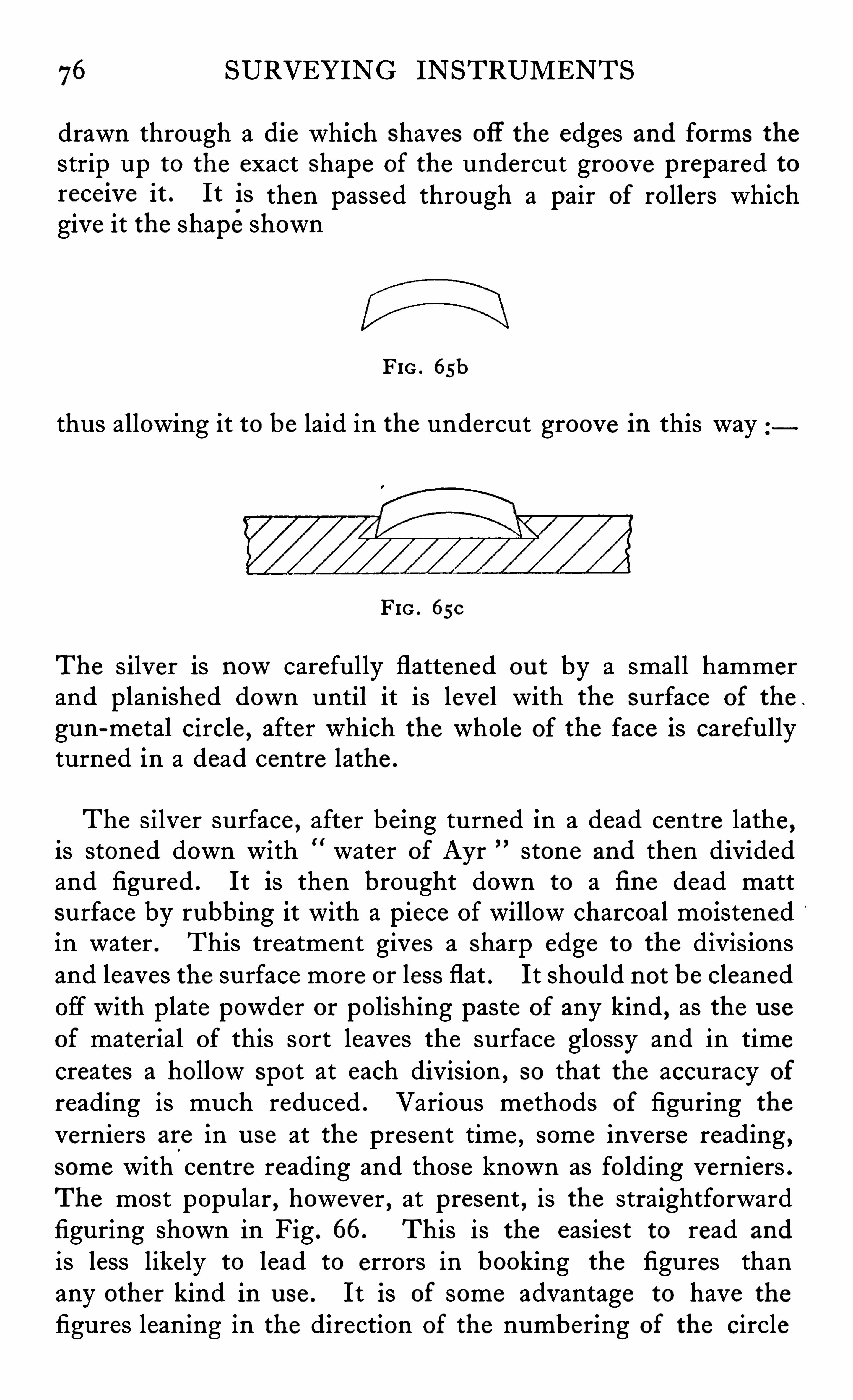
76 SURVEYING INSTRUMENTS
drawn through a die which Shaves off the edges and forms thestrip up to the exact Shape of the undercut groove prepared toreceive it . It is then passed through a pair of rollers whichgive it the shape shown
FIG . osh
thus allowing it to be laid in the undercut groove in this way
FIG . 650
The s ilver is nowcarefully flattened ou t by a small hammerand planished down until it is level with the surface of the .
gun-metal circle , after which the whole of the face is carefullyturned in a dead centre lathe .
The silver surface , after being turned in a dead centre lathe ,is stoned down with water of Ayr stone and then dividedand figured . It is then brought down to a fi ne dead mattsurface by rubbing it with a piece of willow charcoal moistenedin water . This treatment gives a Sharp edge to the divisionsand leaves the surface more or less flat . It should not be cleanedOff with plate powder or polishing paste of any kind , as the u se
of material of this sort leaves the surface glossy and in timecreates a hollow Spot at each division , so that the accuracy of
reading is much reduced . Various methods of figuring the
verniers are in u se at the present time , some inverse reading ,some with centre reading and those known as folding verniers .The most popular , however , at present , is the straightforwardfiguring shown in Fig . 66. This is the easiest to read and
is less likely to lead to errors in booking the figures thanany other kind in u se . It is of some advantage to have the
figures leaning in the direction of the numbering of the circle
78 SURVEYING INSTRUMENTS
observer gets used to it , is very convenient and s imple , and oncehe has been accustomed to reading and booking in this way , heis not liable to make mistakes . On the other hand , the presenceof two zeros in the field is confusing , and an observer not
accustomed to a vernier of this sort , would probably u se the zeroof the vernier as the zero of the instrument . Sometimes thecentre division of the vernier is used as the zero and certainadvantages are claimed for this position . It is , however , largelya matter of taste , and surveyors generally choose the form theyhave been taught to read during their training . There is no
doubt that the reading of verniers accurately and quickly is a
serious stumbling block to many , so that any design which woulds implify the matter would be welcomed .
Some continental theodolite makers have introduced instruments the reading of which is done by a micrometer headattached to a worm which engages with teeth cut all round thecircle . This arrangement gives a very Simp le and clear reading ,but has the great disadvantage that it is subject to wear . Moreover , to give the same accuracy as a vernier , the teeth on the circlemust be as truly p laced as are those of the engine used fordividing the circle . This is of course commercially impossible ,and is a point Often forgotten by designers of instruments whenthey suggest the worm and whee l or the micrometer screw as analternative to the divided circle .
Once the circle is truly divided and p laced on the instrument,
the graduations themse lves are not subject to any wear whichwould render them inaccurate ; they therefore remain alwaysa true reproduction of the engine upon which they were made .
For this reason ,we must look to newmethods of reading thecircle for improvements in accuracy . The present tendencylies in the direction of optical micrometers , the details of whichhave been discussed in another chapter .
Method of Calcu lating the Vern ier Values
It is usual to arrange the vernier so that its length is dividedinto one more space than an equal length on the limb .
THE GRADUATION OF INSTRUMENTS 79
the spaces on the vern ier1 the spaces on the limbthe value of the limb divisionsthe value of the vernier divisions .
Then na (n I ) a
And 3 1
n
And a al
Thus if the vernier is divided into 60 parts and the limb tosingle degrees
60
60
the expression a a, is therefore the least count of the vernierand in that case is equal to 1 minute or in other words 1 /60thof a degree .
-59)
To make a reading it is therefore only necessary to note firstat which space the zero falls and then to look along the vernierand note which line on the vernier coincides with that on the
limb . Let it coincide at p divisions from the zero , then the
fraction of a limb space , Viz . , a al " p will be the value of
the reading which must be added to the amount read oppositethe zero of the vernier . For example , if the zero of the vernierwas at 52 ° plus an amount x , and if the 15th line of the verniercoincided with a line on the limb , then the reading requiredwould be x .
and x al ) p15
or x60
I
The reading would therefore be 52°
15
When it is required to construct a vernier for a given least count,
then to find 11, the number of spaces into which the vern ier
must be divided ,
80 SURVEYING INSTRUMENTS
If, for examp le , a limb is divided into 5 minute spaces 300
seconds and a least count of 5 seconds is required , then
11300
605
and the number of spaces on the limb covered by the vernierwill be 11 1 59.
The verniers Should be examined at various positions on the
limb when , if all is correct , the first and last divisions of thevernier wil l coincide with the limb divisions . If, however ,coincidence occurs short of or beyond the last division by an
amount equal to y divis ions the vernier is too long or too
short by y (a al ) . Call this amount z ,then (n
and a — a1 a +n II
On a correct vernier the value of the reading x (a
p_Z_becomes
11
a (P11)
When the vern ier is too short by the amount z the correctionto the reading is z
Z
11
For example , take a limb which is divided into 1 0 minutespaces and having a vernier with a least count of 10 seconds .Then the number of divisions on the vernier will be 60 covering59 on the limb . If it is found that the vernier is too short byz 5 seconds then an addition to every reading of the amount
Z—l~ p,
n
must be made . If p 2 4 that is , if coincidence takes place atthe 2 4th division of the vernier , then
5 1 2 0
60 60
In other words in the above case every minute read on the
vernier must be increased by -5 second or every second by
°
5
6
and when it is too long by z is p
2 4 " 2 seconds .
second .
CHAPTER VI ‘
THE TRANSIT THEODOLITE
transit theodolite is the king of surveying instruments and deservedly so , as it is from the user ’s pointof View the most useful weapon at his command , and ,
moreover , is so easily adjusted and tested without auxiliaryapparatus that its accuracy can always be re lied upon . It maybe termed a self-checking instrument and differs in this respectfrom most other industrial p ieces of apparatus such as thermometers
,weights , measures or sextants , all of which require
to be checked periodically against standards of their own classif their readings are to be relied upon . The theodolite , on the
other hand,contains within itself the means of checking and
adjusting all its parts,and if in actual u se any fault deve lops , it
is generally shown up at once , so that the matter can be adjustedand no fear need be entertained of accumulating a mass of
inaccurate data as would happen in the case of such an instrument as a thermometer or measure of length which had becomeincorrect .
Theodolites are made in various s izes , designated by the
diameter of the graduated circles , these sizes ranging from 3inches up to 1 2 inches , the latter being the largest nowused forgeneral surveying work . Tacheometers are merely theodolites ,the telescopes of which are adapted for the measurement of
distances as well as for the more ordinary purpose of laying ou tor measuring angles in altitude and azimuth , SO that no sp ecialdescription need be made here as the only difference consistsin the optical work of the telescope , mention of which has beenmade in a previous chapter . Tacheometers are , however ,often divided centesimally instead of sexagesimally in order tosimplify the subsequent calculations . The main feature of the
transit theodolite is that it contains a telescope which can not
82 SURVEYING INSTRUMENTS
only be turned through any angle in a horizontal plane , but canalso be rotated through any angle in a vertical plane . The
spindles upon which the instrument turns are known as thehorizontal and vertical axes . Writers of textbooks generallyrefer to the axis upon which the horizontal circle turns as the
vertical axis because it normally stands in a vertical position .
Surveyors and instrument makers call this the hor izonta l
a x i s , and the axis about which the telescope turns , and to
which the vertical circle is fixed , the ver t ica l a x i s . This isobviously the most correct nomenclature for these parts , andin order to avoid confusion when describ ing the instrumentthe horizontal axes are to be understood as those upon whichthe whole upper part turns in azimuth
,and the vertical axis as
that upon which the telescope revolves . The horizontal axis ismostly a double one , that upon which the alidade and plateturns being called the inner centre while that upon whichthe circle is fixed is known as the ou ter centre . The s ock et
is the portion in or on which these axes turn . The p late is thehorizontal table to which the verniers and the standard whichcarries the telescope is fixed and the divided circle is oftenreferred to as the l imb . As the ultimate accuracy of the theodolite depends on the perfection with which these centres or axesare designed and made , a description of the various formsexisting at present is given herewith .
Hor izonta l Axi s . Fig . 68 shows the usual type of axisfitted to theodolites up to 6 inches . The inner axis is made of
phosphor bronze or bell metal and the outer axis and socket ofgun-metal . These centres are first roughed ou t in an ordinarylathe or automatic and then Very carefully finished on a deadcentre lathe . The female portions are bored ou t and thenfinished with a taper reamer to exactly the same angle as thecentres . After being allowed some time to season they are
ground together with oil stone dust and then lapped up by handuntil a perfect fit is secured . In recent years the perfectionto which modern tools can be made allows these centres to beso machined that they can be fitted together perfectly withoutthe u se of any abrasive . This is an obvious advantage , as thereis thus no fear of minute pieces of abrasive being left in the
pores of the metal . Great skill is required in the manufacture
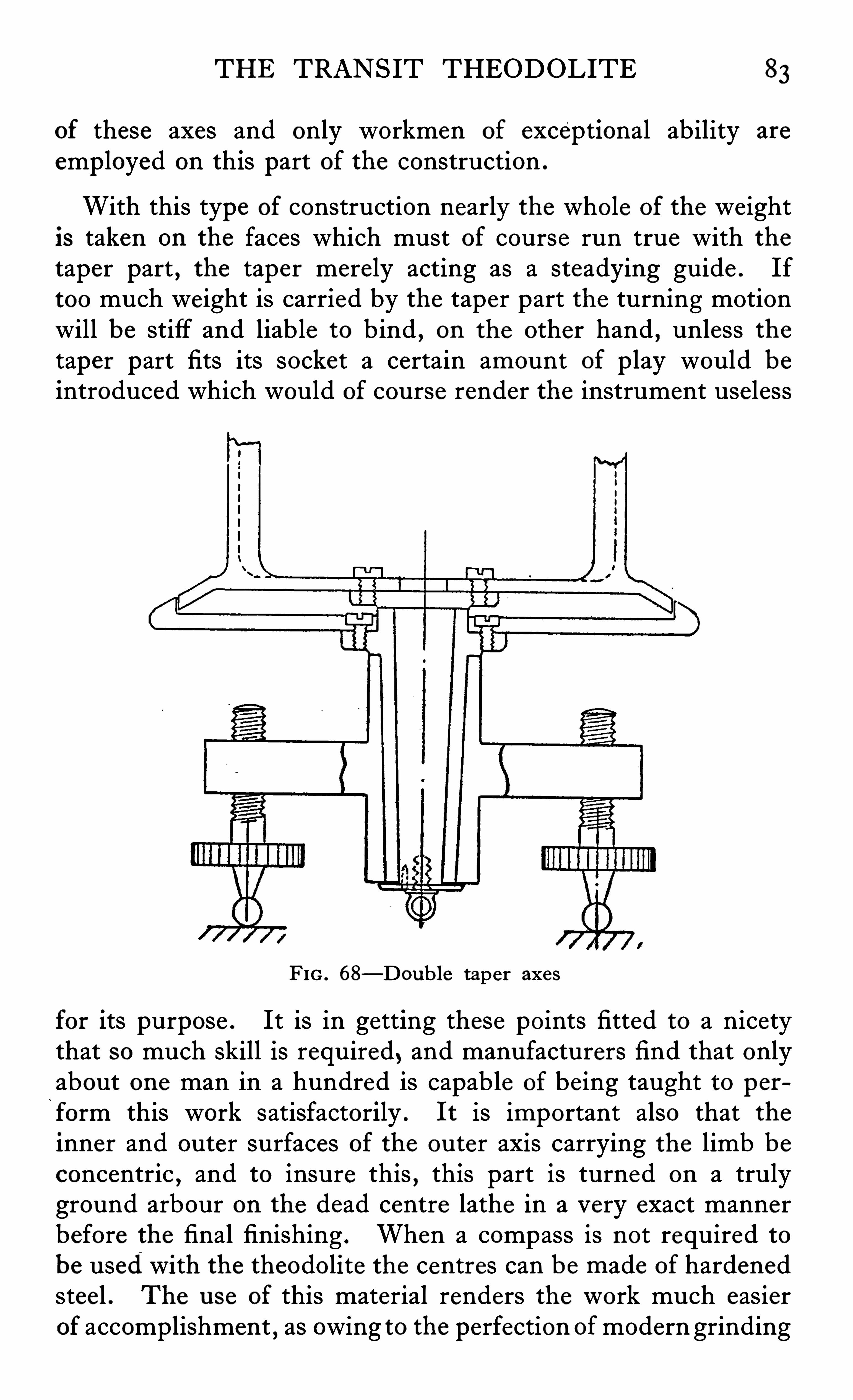
THE TRANSIT THEODOLITE 83
of these axes and only workmen of exceptional ability are
employed on this part of the construction .
With this type of construction nearly the whole of the weightis taken on the faces which must of course run true with thetaper part , the taper merely acting as a steadying guide . Iftoo much weight is carried by the taper part the turning motionwill be stiff and liable to bind , on the other hand , unless thetaper part fits its socket a certain amount of play would beintroduced which would of course render the instrument useless
FIG . 68—D0ub le taper axes
for its purpose . It is in getting these points fitted to a nicetythat so much skill is required , and manufacturers find that onlyabout one man in a hundred is capable of be ing taught to perform this work satisfactorily . It is important also that theinner and outer surfaces of the outer axis carrying the limb beconcentric , and to insure this , this part is turned on a trulyground arbour on the dead centre lathe in a very exact mannerbefore the final finishing . When a compass is not required tobe used with the theodolite the centres can be made of hardenedsteel . The use of this material renders the work much easierof accomplishment , as owing to the perfection ofmodern grinding
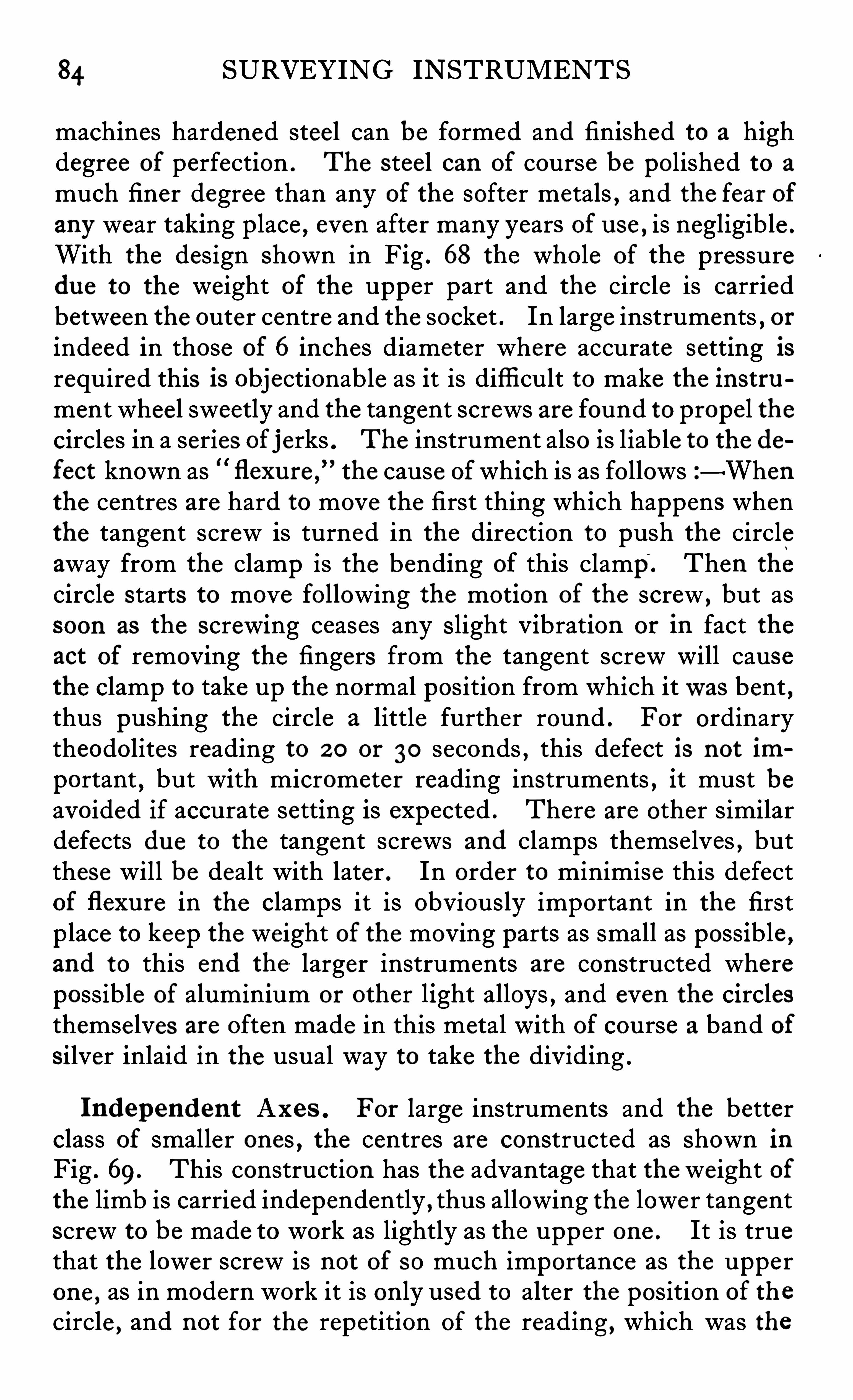
84 SURVEYING INSTRUMENTS
machines hardened steel can be formed and finished to a highdegree of perfection . The steel can of course be polished to a
much finer degree than any of the softer metals , and the fear ofany wear taking place , even after many years of u se , is negligible .
With the design Shown in Fig . 68 the whole of the pressuredue to the weight of the upper part and the circle is carriedbetween the outer centre and the socket . In large instruments , orindeed in those of 6 inches diameter where accurate setting isrequired this is objectionable as it is diffi cult to make the instrument whee l sweetly and the tangent screws are found to propel thecircles in a series of j erks . The instrument also is liable to the defect known as flexure ,
”the cause ofwhich is as follows—When
the centres are hard to move the first thing which happens whenthe tangent screw is turned in the direction to push the circleaway from the clamp is the bending of this clamp. Then the
circle starts to move following the motion of the screw , but assoon as the screwing ceases any Slight Vibration or in fact theact of removing the fingers from the tangent screw will causethe clamp to take up the normal position from which itwas bent ,thus pushing the circle a little further round . For ordinarytheodolites reading to 2 0 or 30 seconds , this defect is not im
portant , but with micrometer reading instruments , it must beavoided if accurate setting is expected . There are other similardefects du e to the tangent screws and clamps themse lves , butthese will be dealt with later . In order to minimise this defectof flexu re in the clamps it is obviously important in the firstplace to keep the weight of the moving parts as small as possible ,and to this end the larger instruments are constructed wherepossible of aluminium or other light alloys , and even the circlesthemselves are often made in this metal with of course a band ofsilver inlaid in the usual way to take the dividing .
Independent Axes . For large instruments and the betterclass of smaller ones , the centres are constructed as Shown inFig . 69. This construction has the advantage that the weight ofthe limb is carried independently , thus allowing the lower tangentscrew to be made to work as lightly as the upper one . It is truethat the lower screw is not of so much importance as the uppe rone , as in modern work it is only used to alter the position of thecircle , and not for the repetition of the reading , which was the
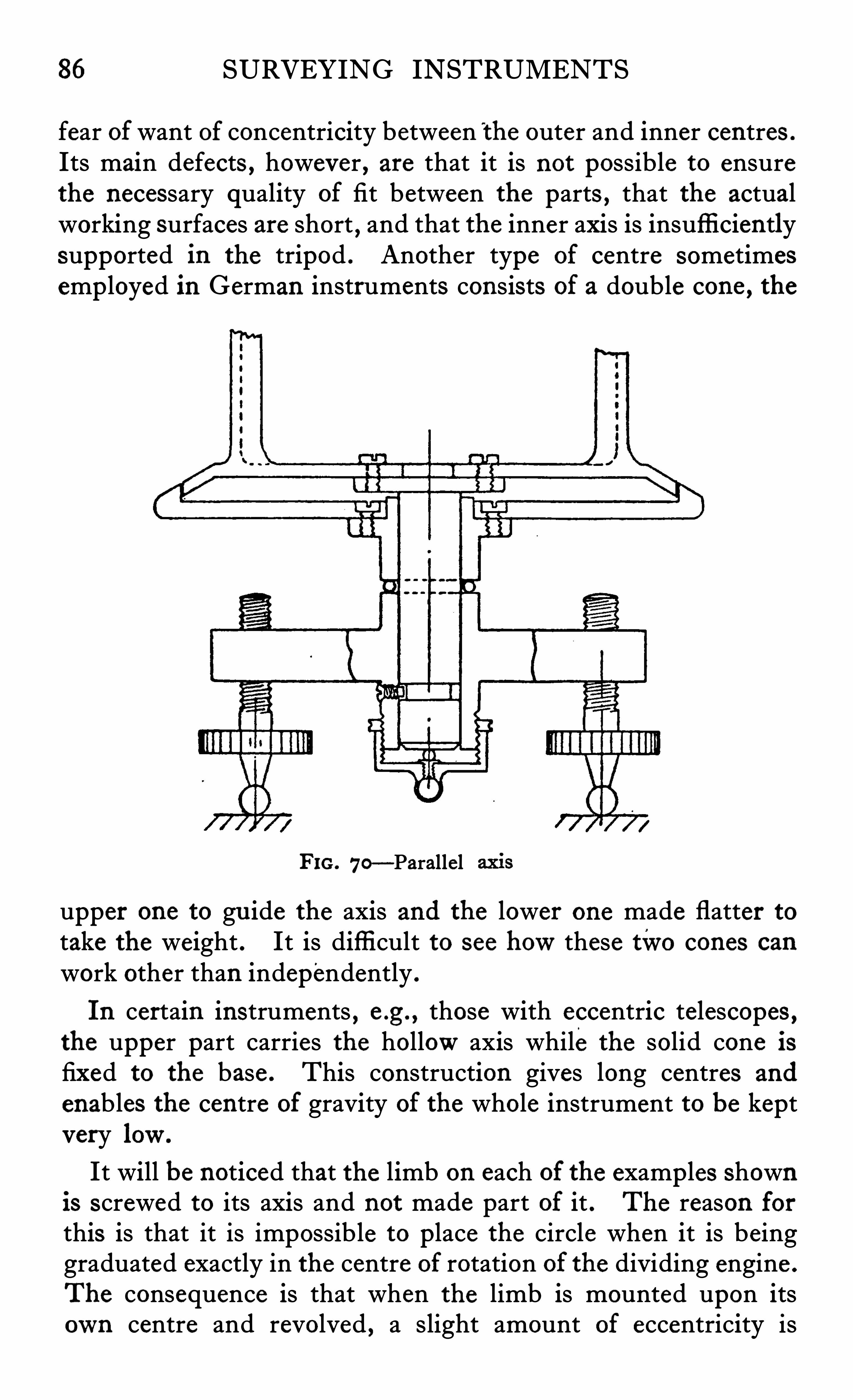
86 SURVEYING INSTRUMENTS
fear ofwant of concentricity between the outer and inner centres .
Its main defects , however , are that it is not possible to ensurethe necessary quality of fit between the parts , that the actualworking surfaces are short
,and that the inner axis is insuffi ciently
supported in the tripod . Another type of centre sometimesemp loyed in German instruments consists of a double cone , the
FIG. 70—Parallel
upper one to gu ide the axis and the lower one made flatter totake the weight . It is diffi cult to see howthese two cones can
work other than independently .
In certain instruments , e .g . , those with eccentric telescopes ,the upper part carries the hollowaxis while the solid cone isfixed to the base . This construction gives long centres and
enables the centre of gravity of the whole instrument to be keptvery low.It will be noticed that the limb on each of the examples shown
is screwed to its axis and not made part of it . The reason forthis is that it is impossible to place the circle when it is beinggraduated exactly in the centre of rotation of the dividing engine .
The consequence is that when the limb is mounted upon itsown centre and revolved , a slight amount of eccentricity is
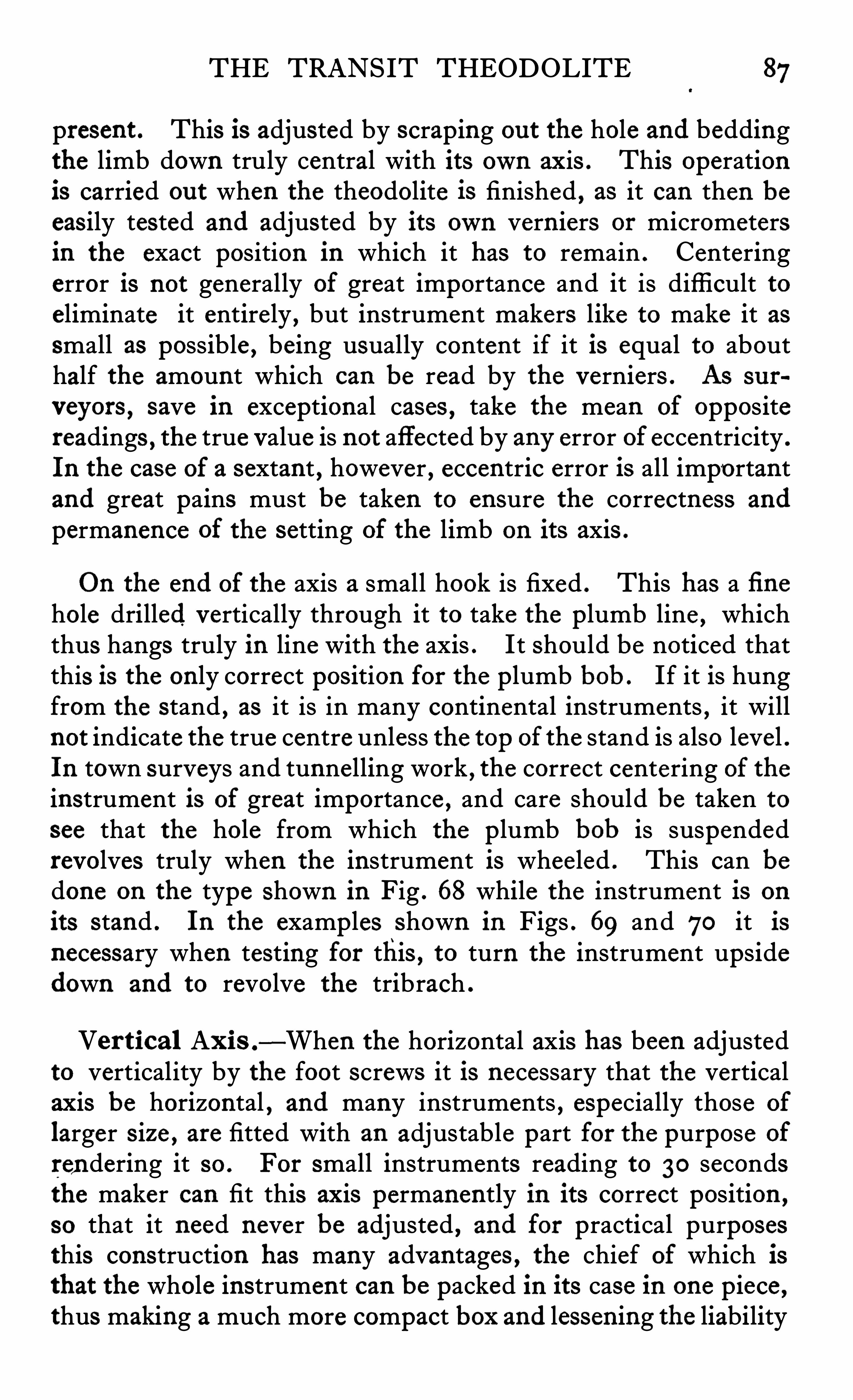
THE TRANSIT THEODOLITE 87
present . This is adjusted by scraping ou t the hole and beddingthe limb down truly central with its own axis . This operationis carried ou t when the theodolite is finished , as it can then beeasily tested and adjusted by its own vern iers or micrometersin the exact position in which it has to remain . Centeringerror is not generally of great importance and it is diffi cult toeliminate it entirely , but instrument makers like to make it assmall as possible , being usually content if it is equal to abouthalf the amount which can be read by the verniers . As su r
veyors , save in exceptional cases , take the mean of oppositereadings , the true value is not affected by any error of eccentricity .
In the case of a sextant , however , eccentric error is all importantand great pains must be taken to ensure the correctness and
permanence of the setting of the limb on its axis .
On the end of the axis a small hook is fixed . This has a fi nehole drilled vertically through it to take the plumb line , whichthus hangs truly in line with the axis . It Should be noticed thatthis is the only correct pos ition for the plumb bob . If it is hungfrom the stand , as it is in many continental instruments , it willnot indicate the true centre unless the top of the stand is also level .In town surveys and tunnelling work , the correct centering of theinstrument is of great importance , and care should be taken tosee that the hole from which the p lumb bob is suspendedrevolves truly when the instrument is whee led . This can bedone on the type shown in Fig . 68 while the instrument is on
its stand . In the examples shown in Figs . 69 and 70 it isnecessary when testing for this , to turn the instrument upsidedown and to revolve the tribrach .
Ver tical Ax i s .—When the horizontal axis has been adjusted
to verticality by the foot screws it is necessary that the verticalaxis be horizontal , and many instruments , especially those of
larger Size , are fitted with an adjustable part for the purpose of
rendering it so . For small instruments reading to 30 secondsthe maker can fit this axis permanently in its correct position ,
so that it need never be adjusted , and for practical purposesthis construction has many advantages , the chief of which isthat the whole instrument can be packed in its case in one piece ,thus making a much more compact box and lessening the liability
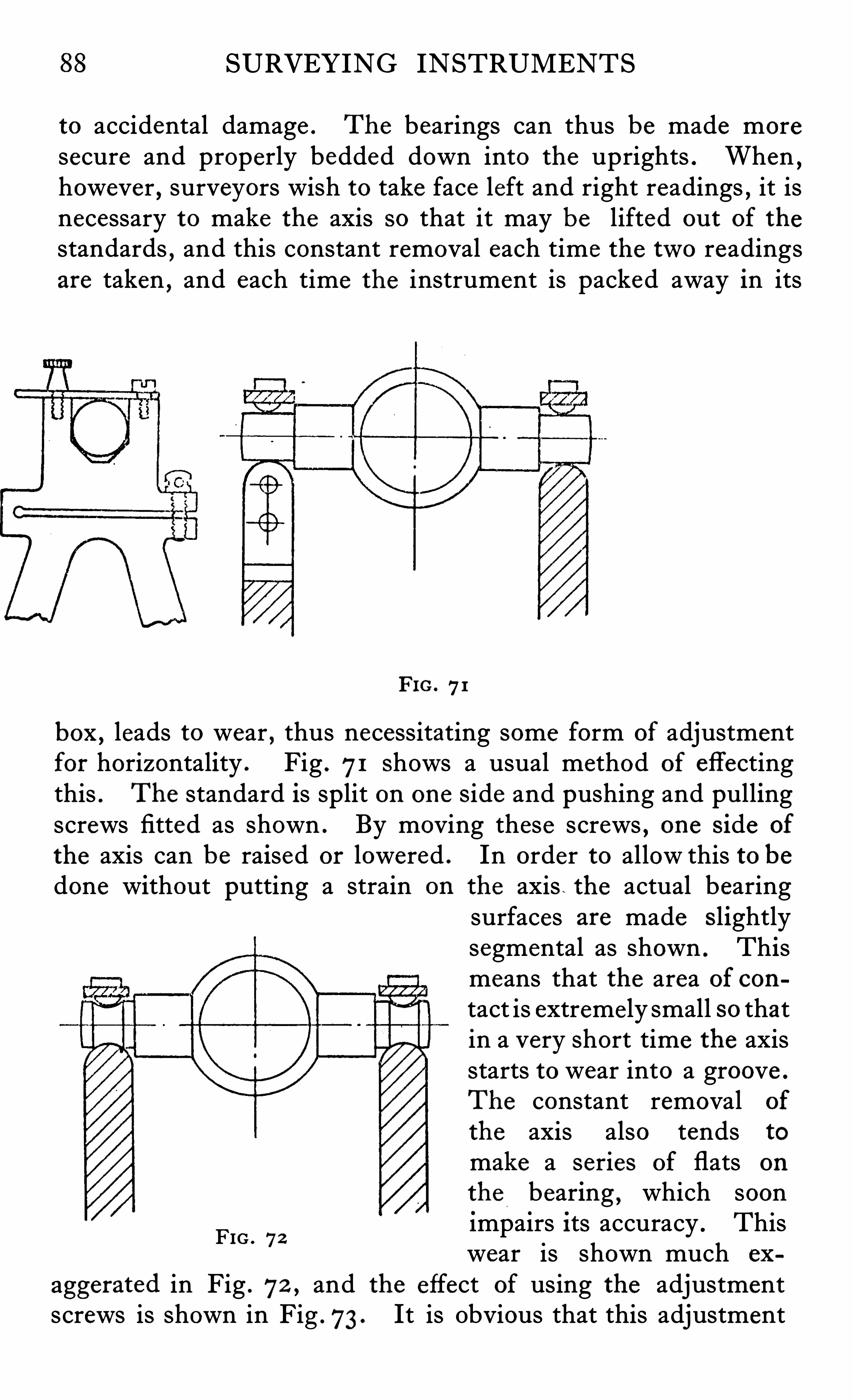
SURVEYING INSTRUMENTS
to accidental damage . The bearings can thus be made moresecure and properly bedded down into the uprights . When
,
however,surveyors wish to take face left and right readings , it is
necessary to make the axis so that it may be lifted ou t of the
standards,and this constant removal each time the two readings
are taken , and each time the instrument is packed away in its
FIG. 71
box ,leads to wear , thus necessitating some form of adjustment
for horizontality . Fig . 71 Shows a usual method of effectingthis . The standard is split on one Side and pushing and pullingscrews fitted as shown . By moving these screws , one Side of
the axis can be raised or lowered . In order to allow this to bedone without putting a strain on the axis . the actual bearing
surfaces are made s lightlysegmental as shown . Thismeans that the area of contact is extremely small so thatin a very short time the axisstarts to wear into a groove .
The constant removal of
the axis also tends to
make a series of flats on
the bearing , which soonimpairs Its accuracy . Thiswear is shown much ex
aggerated in Fig . 72 ,and the effect of using the adjustment
screws is shown in Fig .73 . It is Obvious that this adjustment
FIG . 72
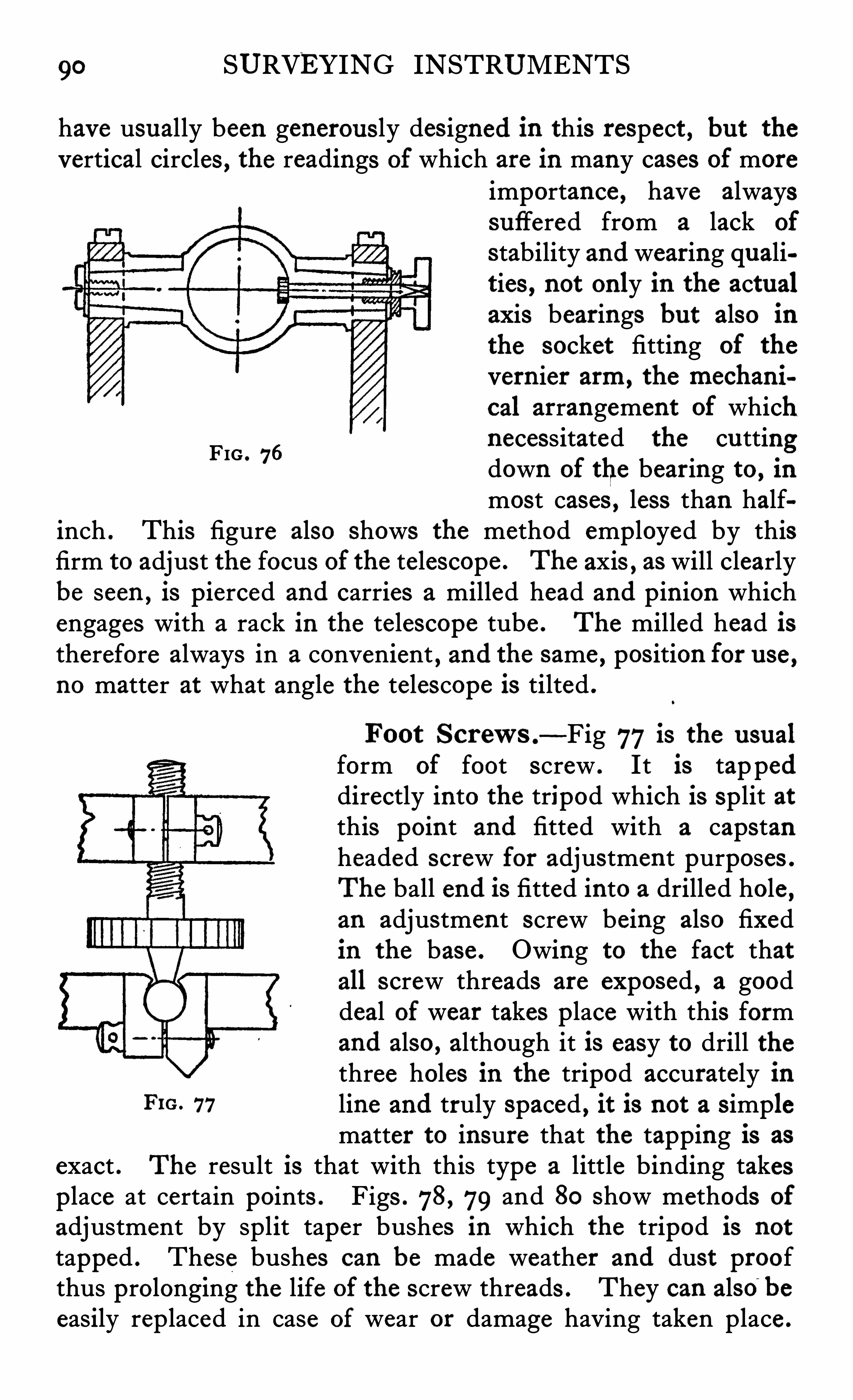
90 SURVEYING INSTRUMENTS
have usually been generous ly des igned in this respect , bu t thevertical circles , the readings of which are in many cases of more
importance , have alwayssuffered from a lack of
stability and wearing qualities , not only in the actualaxis bearings but also inthe socket fitting of the
vernier arm, the mechani
cal arrangement of whichnecessitated the cu ttingdown of the bearing to , in
most cases , less than halfinch . This figure also shows the method employed by thisfirm to adjust the focus of the telescope . The axis , as will clearlybe seen , is pierced and carries a milled head and pinion whichengages with a rack in the telescope tube . The milled head istherefore always in a convenient , and the same , pos ition for u se ,no matter at what angle the telescope is tilted .
FIG . 76
Foot Screws .—Fig 77is the u sual
form of foot screw . It is tappeddirectly into the tripod which is sp lit atthis point and fitted with a capstanheaded screw for adjustment purposes .
The ball end is fitted into a drilled hole ,an adjustment screw being also fixedin the base . Owing to the fact thatall screw threads are exposed , a gooddeal of wear takes place with this formand also , although it is easy to drill thethree holes in the tripod accurately in
FIG. 77 line and truly spaced , it is not a s implematter to insure that the tapping is as
exact . The result is that with this type a little binding takesplace at certain points . Figs . 78, 79 and 80 Show methods of
adjustment by split taper bushes in which the tripod is not
tapped . These bushes can be made weather and dust proofthus prolonging the life of the screw threads . They can also
~
be
easily replaced in case of wear or damage having taken place .
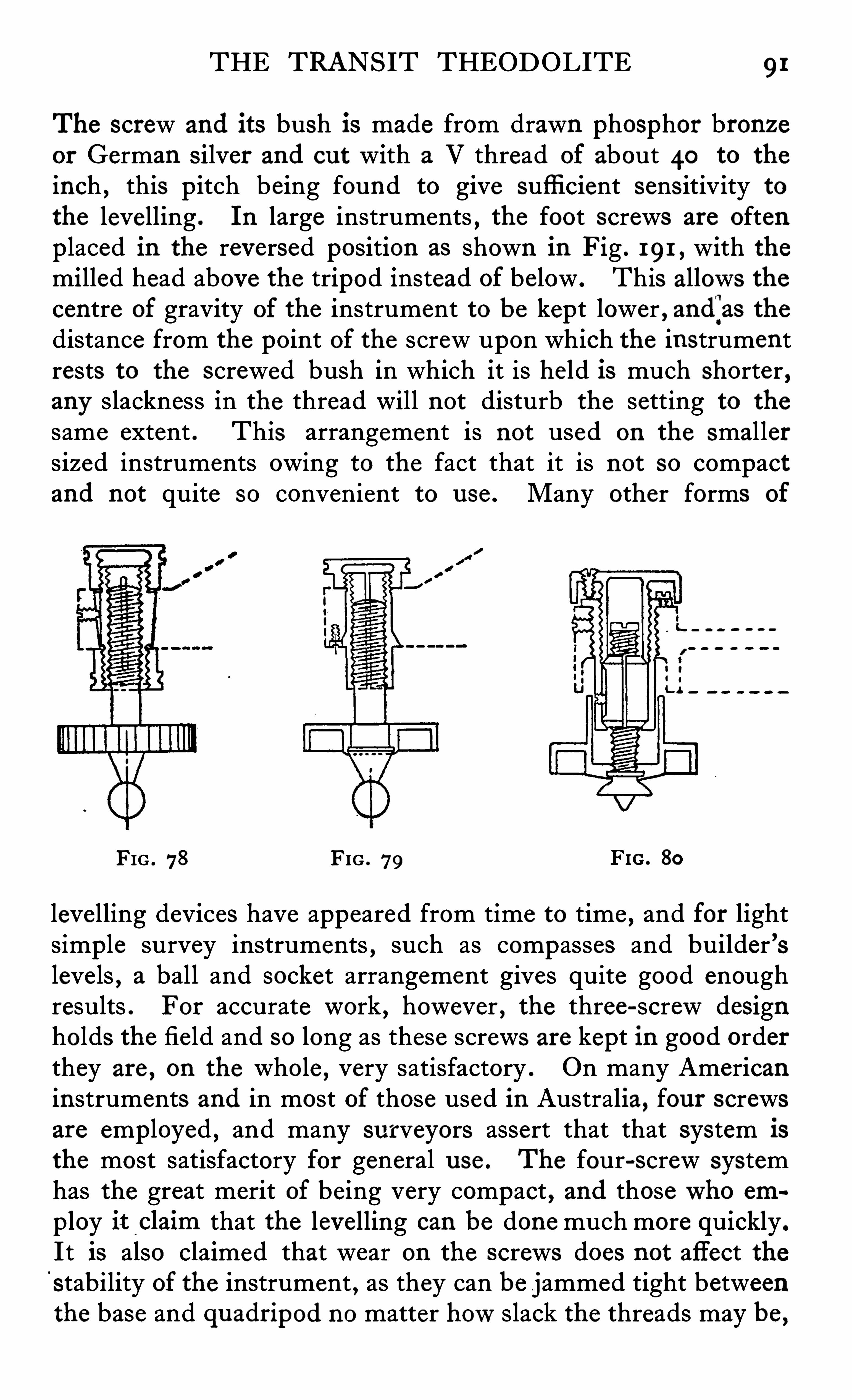
THE TRANSIT THEODOLITE 91
The screw and its bush is made from drawn phosphor bronzeor German s ilver and cu t with a V thread of about 40 to the
inch , this pitch being found to give suffi cient sens itivity to
the levelling . In large instruments , the foot screws are oftenp laced in the reversed position as shown in Fig . 191 , with themilled head above the tripod instead of below . This allows thecentre of gravity of the instrument to be kept lower , and
'
jas thedistance from the point of the screw upon which the instrumentrests to the screwed bush in which it is held is much Shorter ,any slackness in the thread will not disturb the setting to the
same extent . This arrangement is not used on the smal lersized instruments owing to the fact that it is not so compactand not quite so convenient to u se . Many other forms of
FIG . 78 FIG . 79 FIG . 80
levelling devices have appeared from time to time , and for lightsimple survey instruments , such as compasses and builder ’sleve ls , a ball and socket arrangement gives quite good enoughresults . For accurate work , however , the three-screw designholds the field and so long as these screws are kept in good orderthey are , on the whole
,very satisfactory . On many American
instruments and in most of those used in Australia, four screwsare employed , and many surveyors assert that that system is
the most satisfactory for general u se . The four-screw systemhas the great merit of being very compact , and thosewho em
ploy it_claim that the levelling can be done much more quickly .
It is also claimed that wear on the screws does not affect thestability of the instrument , as they can be jammed tight betweenthe base and qu adripod no matter howslack the threads may be ,
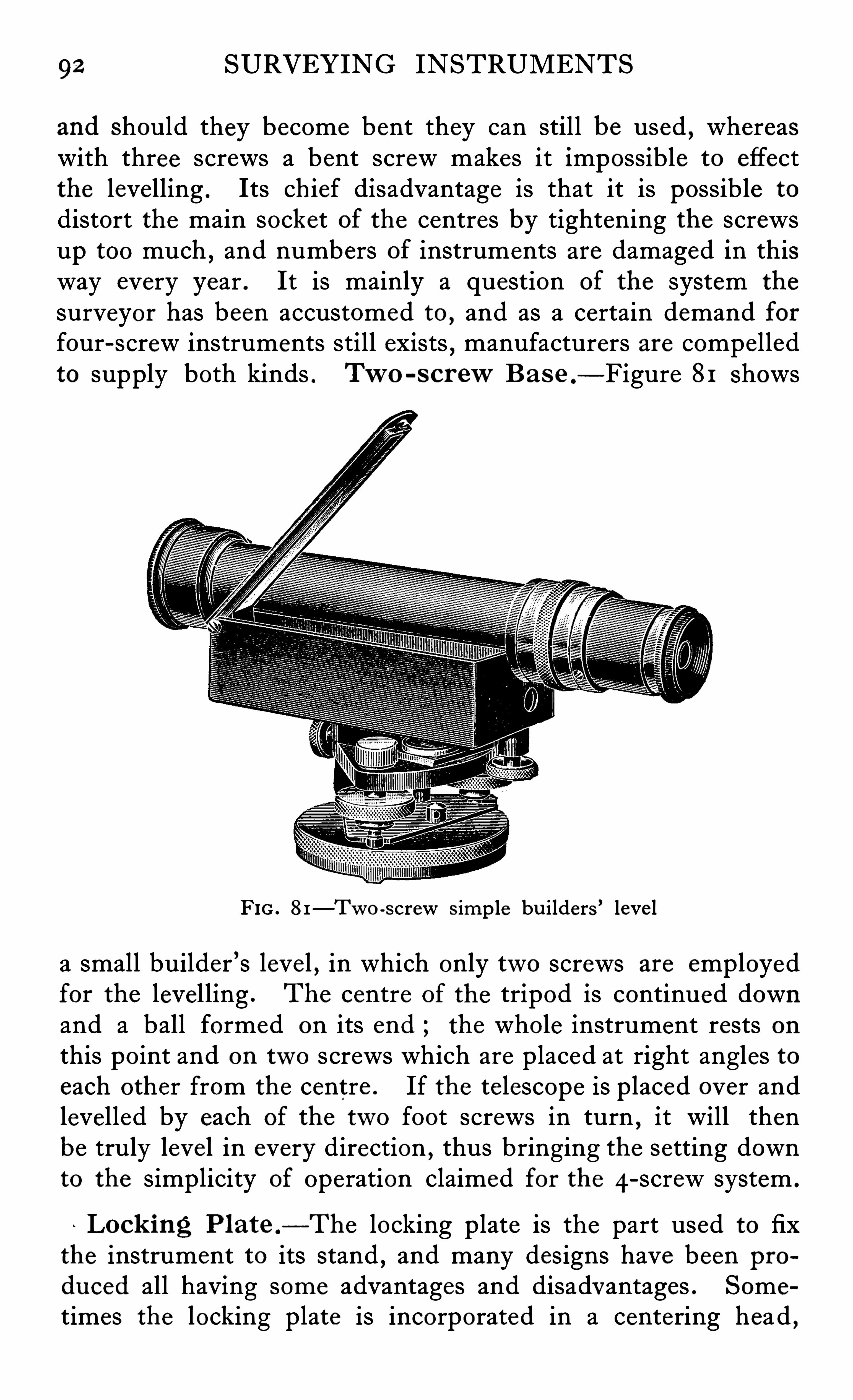
92 SURVEYING INSTRUMENTS
and should they become bent they can still be used , whereaswith three screws a bent screw makes it impossible to effectthe levelling . Its chief disadvantage is that it is possible to
distort the main socket of the centres by tightening the screwsup too much
,and numbers of instruments are damaged in this
way every year . It is mainly a question of the system the
surveyor has been accustomed to,and as a certain demand for
four-screw instruments still exists,manufacturers are compelled
to supply both kinds . TW O -s cr ewB a s e — Figure 81 Shows
FIG . 81—Two -screw Simp le bu ilders ’ leve l
a small builder ’s level , in which only two screws are employedfor the level ling . The centre of the tripod is continued downand a ball formed on its end the whole instrument rests onthis point and on two screws which are placed at right angles toeach other from the centre . If the te lescope is placed over andlevelled by each of the two foot screws in turn
,it will then
be truly level in every direction , thus bringing the setting downto the simplicity of operation claimed for the 4-screw system .
Lock ing Plate —The locking plate is the part used to fixthe instrument to its stand , and many designs have been produ ced all having some advantages and disadv antages . Some
times the locking plate is incorporated in a centering head ,
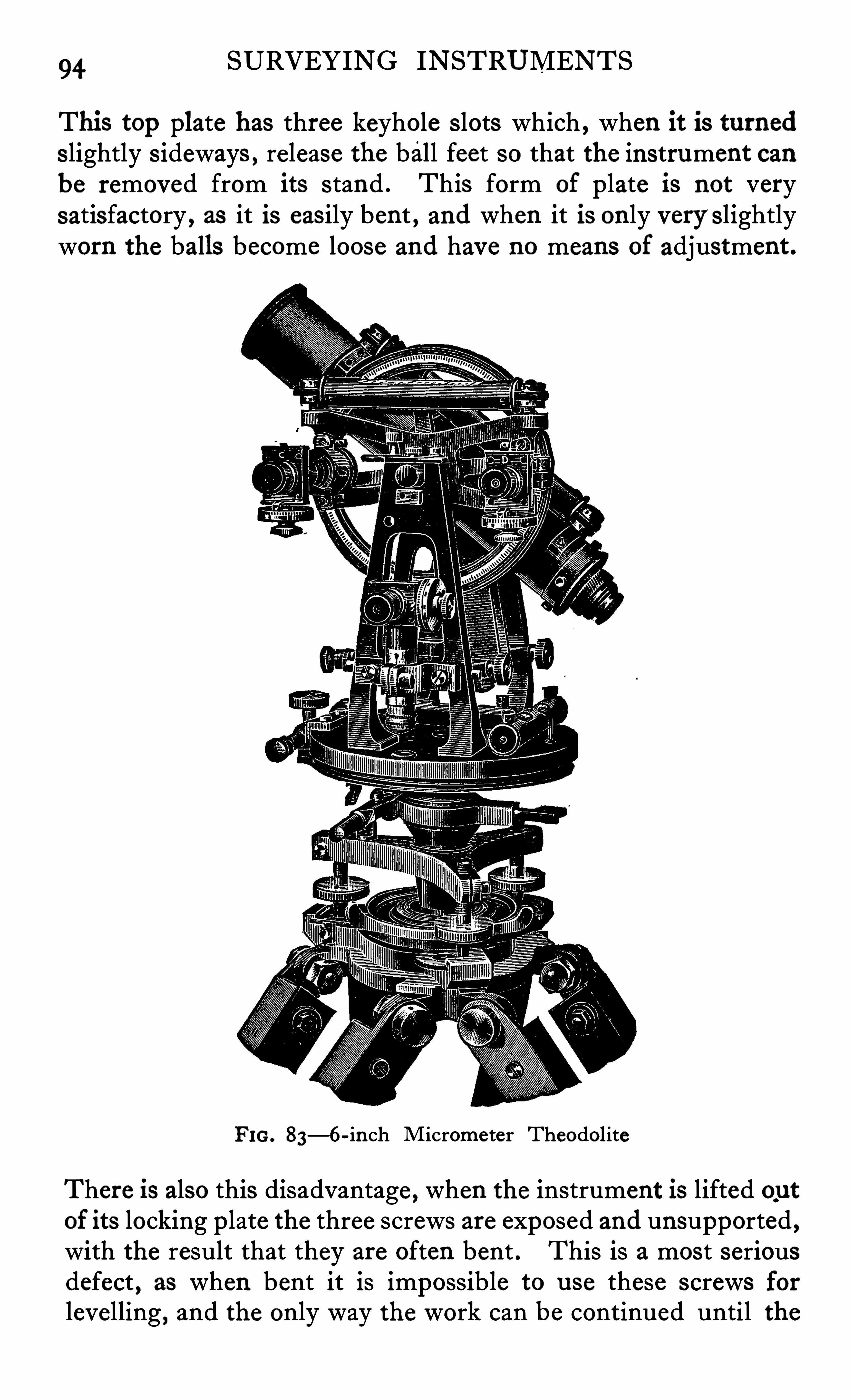
94 SURVEYING INSTRUMENTS
This top plate has three keyhole s lots which , when it is turneds lightly s ideways , release the ball feet so that the instrument canbe removed from its stand . This form of plate is not verysatisfactory , as it is easily bent , and when it is only very s lightlyworn the balls become loose and have no means of adjustment .
FIG. 83—6-inch Micrometer Theodolite
There is also this disadvantage , when the instrument is lifted outof its locking plate the three screws are exposed and unsupported ,with the result that they are often bent . This is a most seriousdefect , as when bent it is impossible to u se these screws forlevelling , and the only way the work can be continued until the
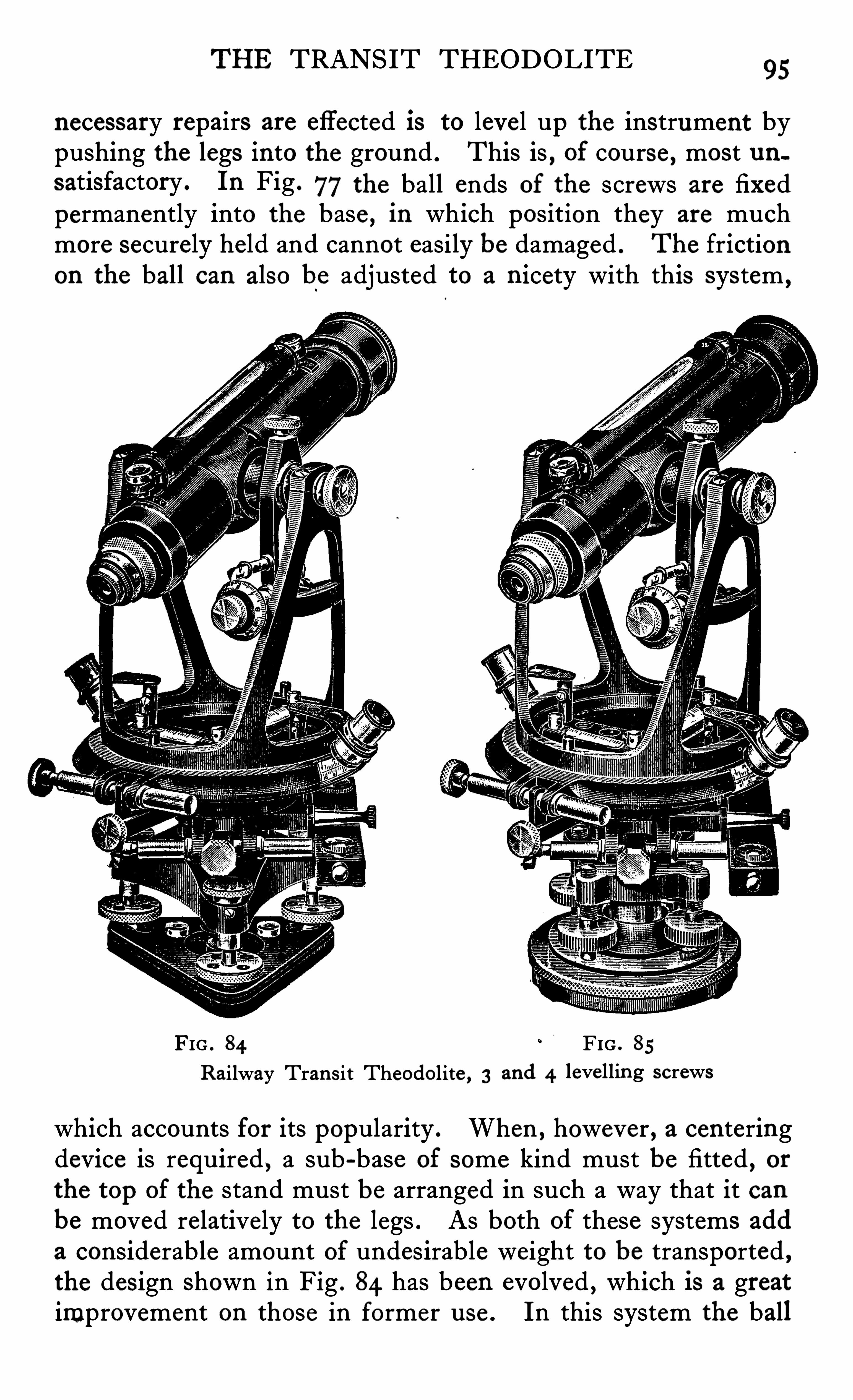
THE TRANSIT THEODOLITE95
necessary repairs are effected is to level up the instrument bypushing the legs into the ground . This is
, of course , most nusatisfactory . In Fig . 77the ball ends of the screws are fixedpermanently into the base , in which position they are muchmore securely held and cannot easily be damaged . The frictionon the ball can also be adjusted to a nicety with this system ,
FIG . 84 FIG . 85
Railway Tran s it Theodolite , 3 and 4 levelling screws
which accounts for its popularity . When , however , a centeringdevice is required , a sub-base of some kind must be fitted , orthe top of the stand must be arranged in such a way that it canbe moved relatively to the legs . As both of these systems add
a considerable amount of undesirable weight to be transported ,the design Shown in Fig . 84 has been evolved , which is a greatimprovement on those in former u se . In this system the ball
96 SURVEYING INSTRUMENTS
feet are held down on to a base having hole , Slot and plane seatsprepared to receive them . Between the two plates a triangularpiece of metal
,having a screwed hole in its centre , can slide
about . The top of the stand , which has a large hole in its centre ,is quite plain , so that the whole instrument can be placed on
it in any position desired . A threaded tubular piece is thenpassed through the hole in the stand and screwed into the socketof the triangular plate , thus tightening the instrument downsecurely on to its stand . If this screw is slackened slightly ,the whole instrument can Slide in any direction over the top of
the stand , and can thus be accurately centered over the mark onthe ground . With this system ,
the screws can be adjusted forsmoothness of working and to take up wear , and as they
’
s it in a
geometrical seat are free from any possible binding . Thereis also the incidental advantage that it is much easier to placethe instrument directly on the stand and then fix it with the
central screw,than to hold up the whole instrument and screw
it on to the stand by revolving the lower part . The fact thatthe stand has mere ly a ho le instead of an exposed screw threadis of manifest advantage . In practice the protecting cap forthe stand head screw is often lost
,with the result that this thread
becomes damaged to such an extent that it is impossible to
screw the base of the instrument on to it . As a rule , the standsare treated much more roughly than the instruments themselves ,so that it is of advantage to keep them as simple as possible , andto arrange that all the working parts
,such as the centering device ,
etc ., should be part of the instrument itself, so that it can be
packed away in the case where it is less liable to accidental damage .
Clamp s and Tangent Scr ews .
— In order to obtain the
slow motion necessary for the fi ne settings required in theodolites , Some form of clamp and tangent screw must be used , andmany designs for these have appeared from time to time . Inthe o lder forms , it was usual to arrange that a pair of flat platescould be clamped by a screw on to the edge of the circle , thisclamp being moved by a screw of fi ne pitch anchored to somefixed part of the instrument . This design had many unsatis
factory features , and is only nowused in exceptional circumstances . In all modern designs the clamping takes place on
the centres themselves or on concentric rings fixed to the circles .
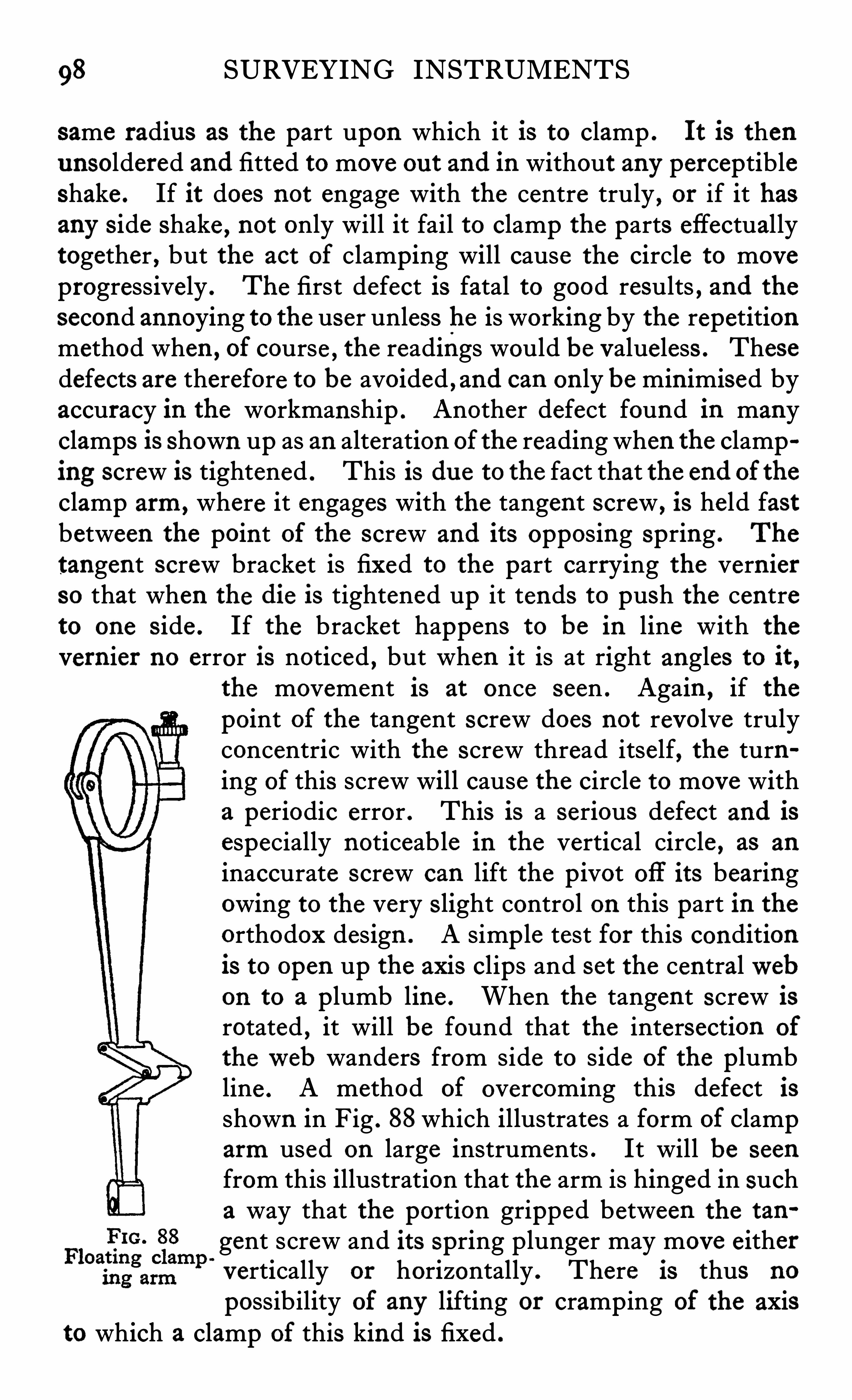
98 SURVEYING INSTRUMENTS
same radius as the part upon which it is to clamp . It is thenunsoldered and fitted to move ou t and in without any perceptibleShake . If it does not engage with the centre truly , or if it hasany s ide Shake , not only will it fail to clamp the parts effectuallytogether , but the act of clamping will cause the circle to moveprogressively . The first defect is fatal to good results , and thesecond annoying to the user unless he is working by the repetitionmethod when , of course , the readings would be valueless . Thesedefects are therefore to be avoided , and can on ly be minimised byaccuracy in the workmanship . Another defect found in manyclamps is Shown up as an alteration of the reading when the clamping screw is tightened . This is due to the fact that the end of theclamp arm, where it engages with the tangent screw ,
is held fastbetween the point of the screw and its opposing spring . The
tangent screw bracket is fixed to the part carrying the vern ierso that when the die is tightened up it tends to push the centreto one s ide . If the bracket happens to be in line with the
vernier no error is noticed , but when it is at right angles to it ,the movement is at once seen . Again , if thepoint of the tangent screw does not revolve trulyconcentric with the screw thread itself, the turning of this screw will cause the circle to move witha periodic error . This is a serious defect and isespecially noticeable in the vertical circle , as an
inaccurate screw can lift the pivot Off its bearingowing to the very Slight control on this part in theorthodox design . A simp le test for this conditionis to open up the axis clips and set the centralwebon to a plumb line . When the tangent screw isrotated , it will be found that the intersection of
theweb wanders from side to side of the plumbline . A method of overcoming this defect isshown in Fig . 88which illustrates a form of Clamparm used on large instruments . It will be seen
from this illustration that the arm is hinged in sucha way that the portion gripped between the tan
gent screw and its Spring plunger may move eithervertically or horizontally . There is thus no
possibility of any lifting or cramp ing of the axisto which a clamp of this kind i s fixed .
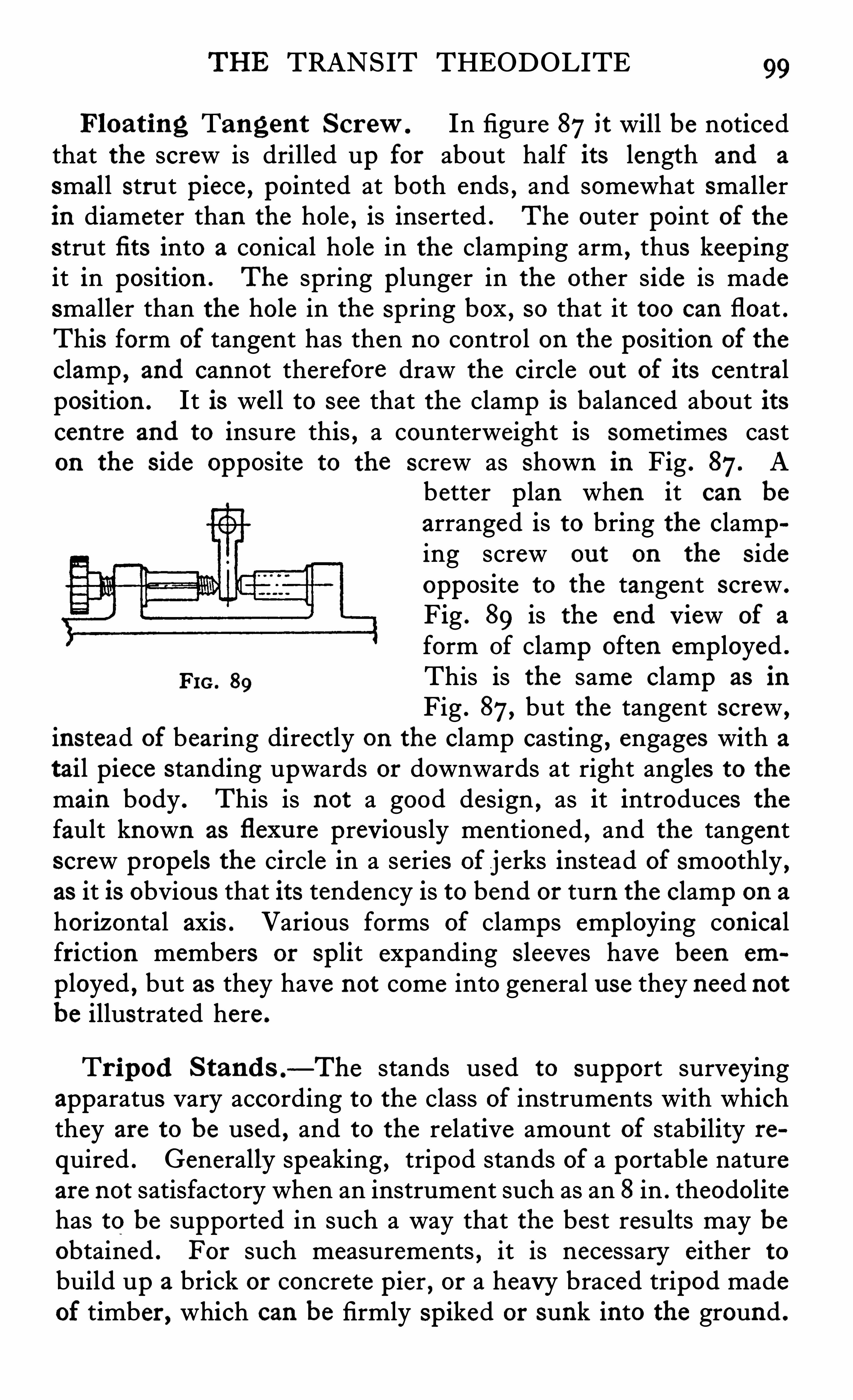
THE TRANSIT THEODOLITE 99
Float ing Tangent Scr ew. In figure 87it will be noticedthat the screw is drilled up for about half its length and a
small strut piece , pointed at both ends , and somewhat smallerin diameter than the hole , is inserted . The outer point of thestrut fi ts into a conical hole in the clamping arm , thus keep ingit in position . The spring plunger in the other side is madesmaller than the hole in the Spring box , so that it too can float .This form of tangent has then no control on the position of the
clamp, and cannot therefore draw the circle ou t of its central
position . It is well to see that the clamp is balanced about itscentre and to insure this , a counterweight is sometimes caston the s ide opposite to the screw as Shown in Fig . 87. A
better p lan when it can be
arranged is to bring the clamping screw ou t on the s ideopposite to the tangent screw .
Fig . 89 is the end View of a
form Of clamp often employed .
Fm , 39 This is the same clamp as in
Fig . 87, but the tangent screw ,
instead of bearing directly on the clamp casting , engages with a
tail piece standing upwards or downwards at right angles to themain body . This is not a good design , as it introduces thefault known as flexu re previously mentioned , and the tangentscrew propels the circle in a series of jerks instead of smoothly ,as it is obvious that its tendency is to bend or turn the clamp on a
horizontal axis . Various forms of clamps employing conicalfriction members or split expanding Sleeves have been em
ployed , but as they have not come into general u se they need notbe illustrated here .
Tr ipod Stand s .—The stands used to support surveying
apparatus vary according to the class of instruments with whichthey are to be used , and to the relative amount of stability re
quired . Generally speaking , tripod stands of a portable natureare not satisfactory when an instrument such as an 8 in . theodolitehas to be supported in such a way that the best results may beobtained . For such measurements , it is necessary either tobuild up a brick or concrete pier , or a heavy braced tripod madeof timber , which can be firmly spiked or sunk into the ground .
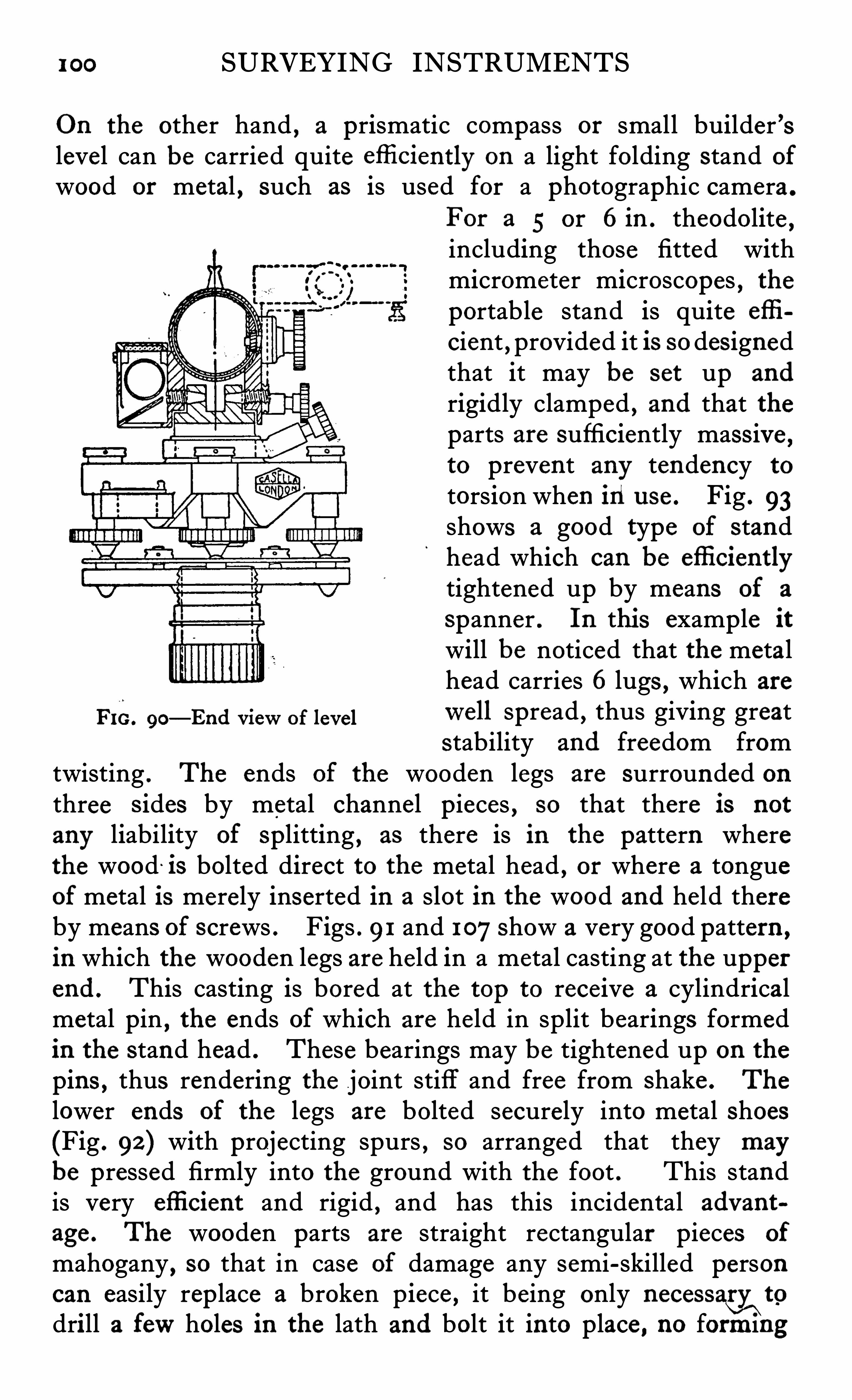
1 00 SURVEYING INSTRUMENTS
On the other hand , a prismatic compass or small builder ’slevel can be carried quite efli ciently on a light folding stand of
wood or metal , such as is used for a photographic camera .
For a 5 or 6in . theodolite ,including those fitted withmicrometer microscopes , theportable stand is quite efli
cient , provided it is so des ignedthat it may be set up and
rigidly clamped , and that theparts are sufficiently mass ive ,to prevent any tendency to
torsion when in u se . Fig . 93shows a good type of standhead which can be efli cientlytightened up by means of a
spanner . In thi s example itwill be noticed that the metalhead carries 6 lugs , which are
of wen spread , thus giving greatstability and freedom from
twisting . The ends of the wooden legs are surrounded onthree s ides by metal channel pieces , so that there is not
any liability of splitting , as there is in the pattern wherethe wood is bolted direct to the metal head , or where a tongueof metal is merely inserted in a slot in the wood and held thereby means of screws . Figs . 91 and 107Show a very good pattern ,
in which the wooden legs are held in a metal casting at the upperend . This casting is bored at the top to receive a cylindricalmetal pin
, the ends of which are held in split bearings formedin the stand head . These bearings may be tightened up on thepins , thus rendering the joint stiff and free from Shake . The
lower ends of the legs are bolted securely into metal shoes(Fig . 92 ) with projecting spurs , SO arranged that they maybe pressed firmly into the ground with the foot . This standis very efli cient and rigid , and has this incidental advant
age . The wooden parts are straight rectangular pieces of
mahogany , so that in case of damage any semi-skilled personcan easily rep lace a broken p iece , it being only necessa{y\
to
drill a fewholes in the lath and bolt it into place , no forming
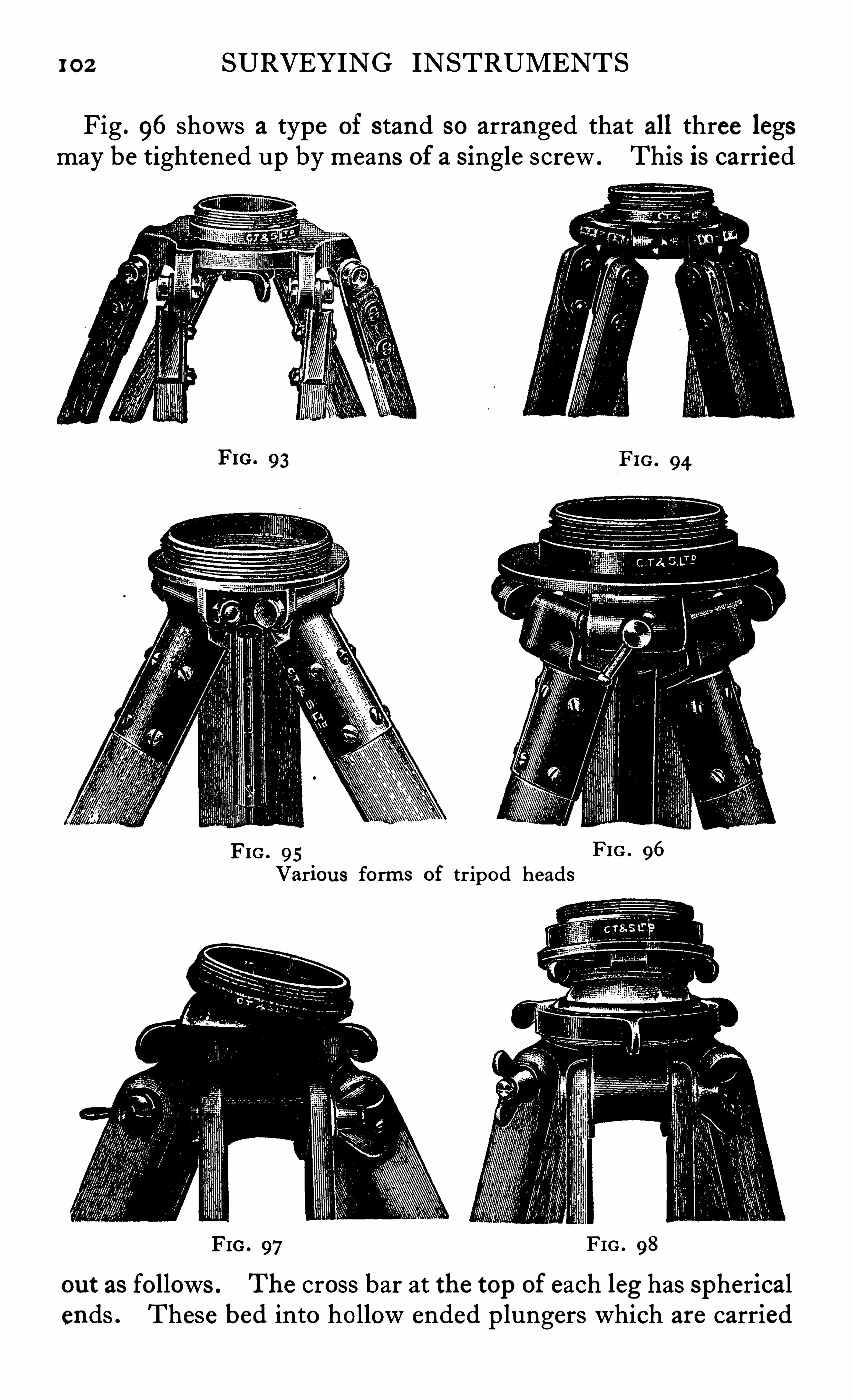
102 SURVEYING INSTRUMENTS
Fig . 96 shows a type of stand so arranged that all three legsmay be tightened up by means of a s ingle screw . This is carried
FIG . 93
FIG . 95 FIG . 96
Variou s forms of tripod heads
FIG . 97 FIG . 98
out as follows . The cross bar at the top of each leg has sphericalends . These bed into hollow ended plungers which are carried
THE TRANSIT THEODOLITE 103
in the metal head . One of these plungers is split in the centreso that when a pointed screw,
shown on the front of the head ,is screwed up , these p lungers are forced apart , thus pushingtheir hollow ends tightly against the spherical heads on the legs .
This is a very conven ient style of stand , its main defect beingthat the wearing surfaces are so small that constant adjustmentis necessary . Fig . 176shows a folding stand extensively used forplane table work . These stands , when well made , are fairlystable and sufficiently good for such work as exp loring , etc . ,
where portability is of primary importance . As there are so
many joints to work loose , and as there is no efficient means of
taking up wear , this type cannot be used for first class work .
The stand head is sometimes fitted with a ball and socketdevice for quickly levelling the instrument , an examp le of whichis shown in Fig . 97, while Fig . 98 Shows a Similar stand butwith a sliding top for centering the theodolite . These balland socket arrangements are very useful when it is necessaryto set up the instrument on uneven ground or on the side of a
hill . When much work is being done in precipitous country ,surveyors often carry stands with one or more legs made to
s lide . These stands cannot be made quite so rigid as the morestraightforward variety and Should on ly be used in cases of
necess ity . The old s tyle of round stand , Fig . 95, is nowseldom made . It is not very rigid and is rather heavier thanthose of the framed kind . Another defect of that type of standis that the spread of the lug which fastens the wood to the headcannot be made very wide , thus reducing the resistance totors ion .
Gradienter ScrewFigs . 84 and 85 Show a 5 in . theodolite to the telescope of
which is fitted a micrometer for measuring distances or determin ing grades , known as a gradienter screw . This device ismuch used in America and in the hands of careful operators iscapable of giving good results . It is merely an ordinary tangentscrew fitted with a large head divided into 50 parts and an indexdivided to read the number of turns and parts of a turn taken .
The pitch of the screw and its distance from the axis.
is so
arranged that the cross hair of the te lescope moves over 1 100th
104 SURVEYING INSTRUMENTS
foot space on a staff placed 1 00 feet distant from the centre of
the instrument when the screw is moved over one division on
the head . One complete revo lution of the screw will thereforemove theweb over 0 5 foot in 1 00 feet . To set a grade forrailway or drainage purposes it is only necessary , after levellingup carefully and setting the head to zero , to set the requiredgrade up or down by turning the screw through the correctnumber of divisions . Any point cut by the line of collimationwill then be on the grade required . It is only necessary to fi ndthe number of divisions which theweb moves over the staffwhen the screw is turned through one or more revolutions todetermine at once the distance . For example , if two revolutionsof the screw moved the cross line over 2 -326 feet on the staff ,the distance would be 2 32
-6feet from the s taff to the centre of
the instrument . A pole with a target at each end , say 10 feetapart , is often used instead of a staff, as longer ranges can betaken by this means . The distance is therefore
length of target" 100
When the staff or target is at a different level from the instrumentthe readings will require to be reduced to horizontal distance ,and tables may be obtained for this purpose . The sameprinciple may also be applied to the horizontal circle in thiscase the target is , of course , supported horizontally . In eithercase , it is necessary to see that the staff or target is presentedcorrectly to the instrument , and for this purpose a small telescopeis sometimes fitted to the target , to enable the operator to set itat right angles to the line of collimation . For a vertically heldstaff it is usual to set it correct by a plumb bob or spirit level ,but some operators prefer to have it he ld at right angles to theline of View . When working on slopes and holding the
staff Vertical the line of sight will be inclined to the staff so
that if D the distance and d the intercept of the staff forone turn Of the screw and a the angle to the bottom readingfrom the horizontal , then for this line D F: d (1 00 cos a Sin aand the horizontal distance between the instrument and the
staff d (100 cosza g sin
2a) .
When using fixed targets the spacing of which is d if v
1 06 SURVEYING INSTRUMENTS
The main disadvantage of the gradienter screw is that theinstrument has to be handled between the two readings . Th issometimes leads to errors which
,unless the observations are
repeated , are not easily discovered . For this reason ,probably
,
the more direct stadia method is gaining in popularity for distance measurements , although it is not of course so convenientfor laying ou t or finding gradients . As the methods of stadiameasurement have been treated in many text books , no furthermention of this system need be made , except to state that theold objection to the filming of the glass surface upon which thelines are ruled , is no longer valid , as in all modern instrumentsthe diaphragm in its cell can be instantly removed from the
telescope for cleaning purposes , and replaced without any fearof disturbing the line of collimation . The subtense bar methodof measuring distance is much used by military engineers . In
this system a bar about 1 0 feet long , having targets at each end ,
is supported horizontally , and its intercept measured eitherby repetition on the horizontal circle of a theodolite or bymeans of a micrometer in the eyepiece of the telescope , and
where a large amount of this kind of work has to be carried ou t ,special instruments are used . These instruments are madewith very powerful telescopes as lowas possible in centre of
gravity , as great stability is desirable .
Casella’
s
Double Read ing M icrometer Theodol ite
This instrument has recently been designed for u se bygeodetic and exploration parties , where accuracy and speed of
working is desired . One of the most serious faults in micrometer instruments hitherto produced , has been the delicacyof the mounting of the microscopes , and their consequentliability to damage or derangement , and although , as pointed ou tin a previous chapter , many improvements have been made tothese details , still most designs leave much to be desired . The
greatest drawback to the micrometer instrument is the numberof times it has to be handled after the telescope has been s et
on the object,as it is necessary to read the four micrometers
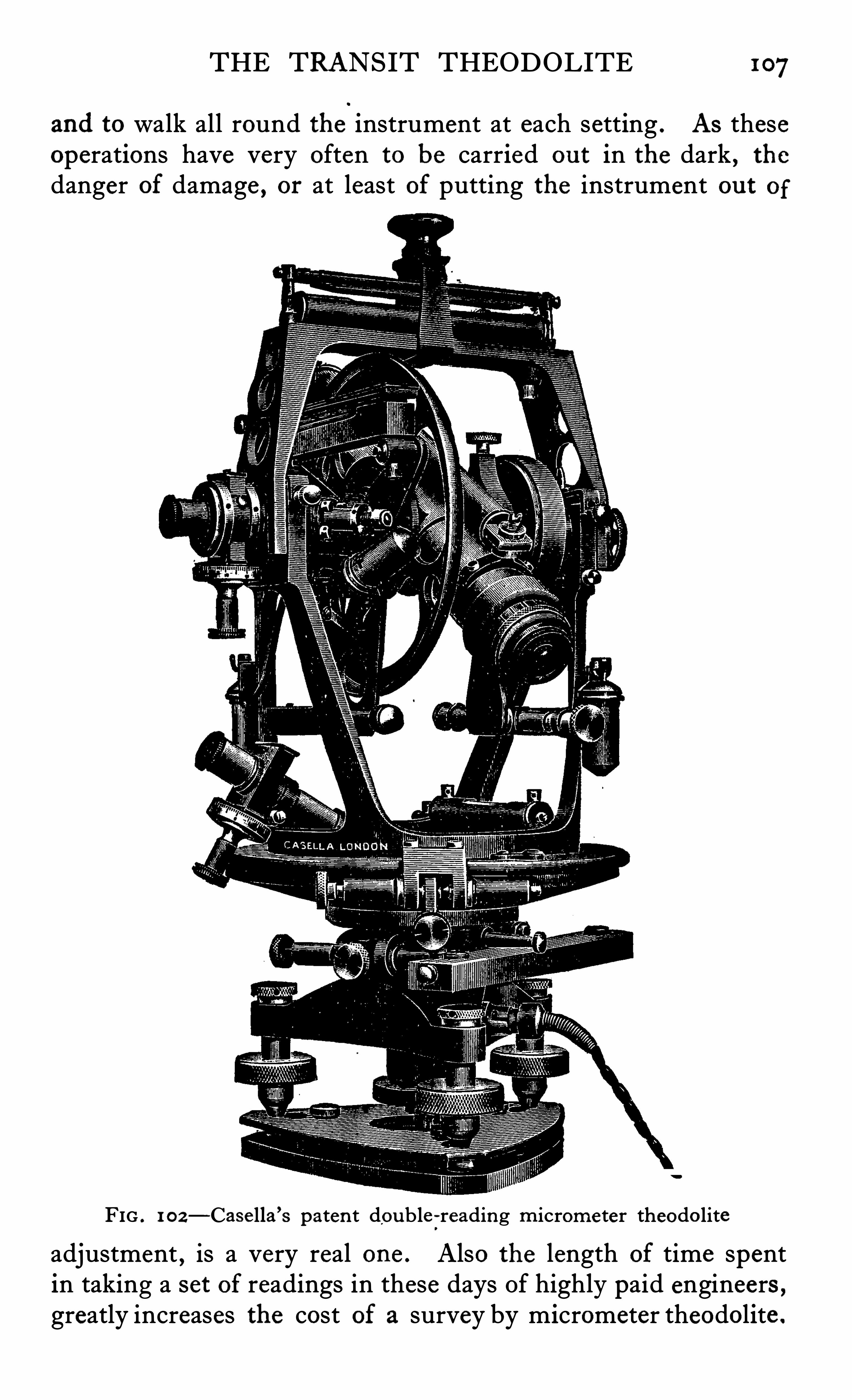
THE TRANSIT THEODOLITE 107
and to walk all round the instrument at each setting . AS theseoperations have very often to be carried ou t in the dark , thedanger of damage , or at least of putting the instrument ou t of
FIG . 1 0 2—Case lla ’s paten t double -reading micrometer theodo liteadjustment , is a very real one . Also the length of time spentin taking a set of readings in these days Of highly paid engineers ,greatly increases the cost of a survey by micrometer theodolite .
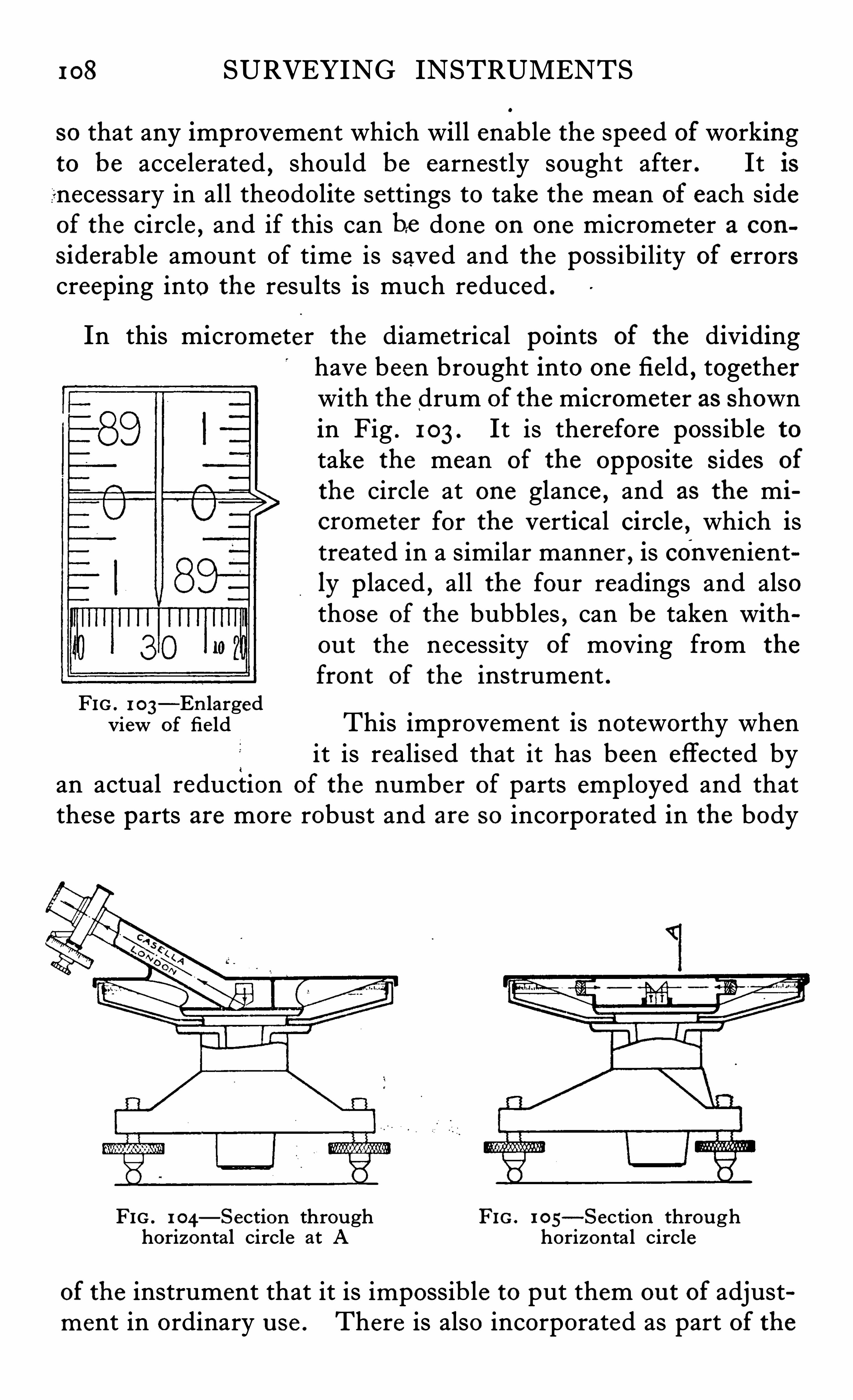
1 08 SURVEYING INSTRUMENTS
so that any improvement which will enable the speed of workingto be acce lerated , should be earnestly sought after . It isnecessary in all theodolite settings to take the mean of each sideof the circle , and if this can be done on one micrometer a con
s iderable amount Of time is saved and the possibility of errorscreeping into the results is much reduced .
In this micrometer the diametrical points of the dividinghave been brought into one field , togetherwith the drum of the micrometer as shownin Fig . 1 03 . It is therefore possible to
take the mean of the opposite s ides of
the circle at one glance , and as the micrometer for the vertical circle , which istreated in a similar manner , is conveniently p laced , all the four readings and alsothose of the bubbles , can be taken withou t the necessity of moving from the
front of the instrument .FIG . 1 03
—En largedview of fie ld This improvement is noteworthy when
it is realised that it has been effected byan actual reduction of the number of parts employed and thatthese parts are more robust and are so incorporated in the body
FIG . 1 04—Section throu gh FIG. 1 05
—Section throughhorizon tal circle at A horizon tal circle
of the instrument that it is impossib le to put them ou t of adjustment in ordinary u se . There is also incorporated as part Of the
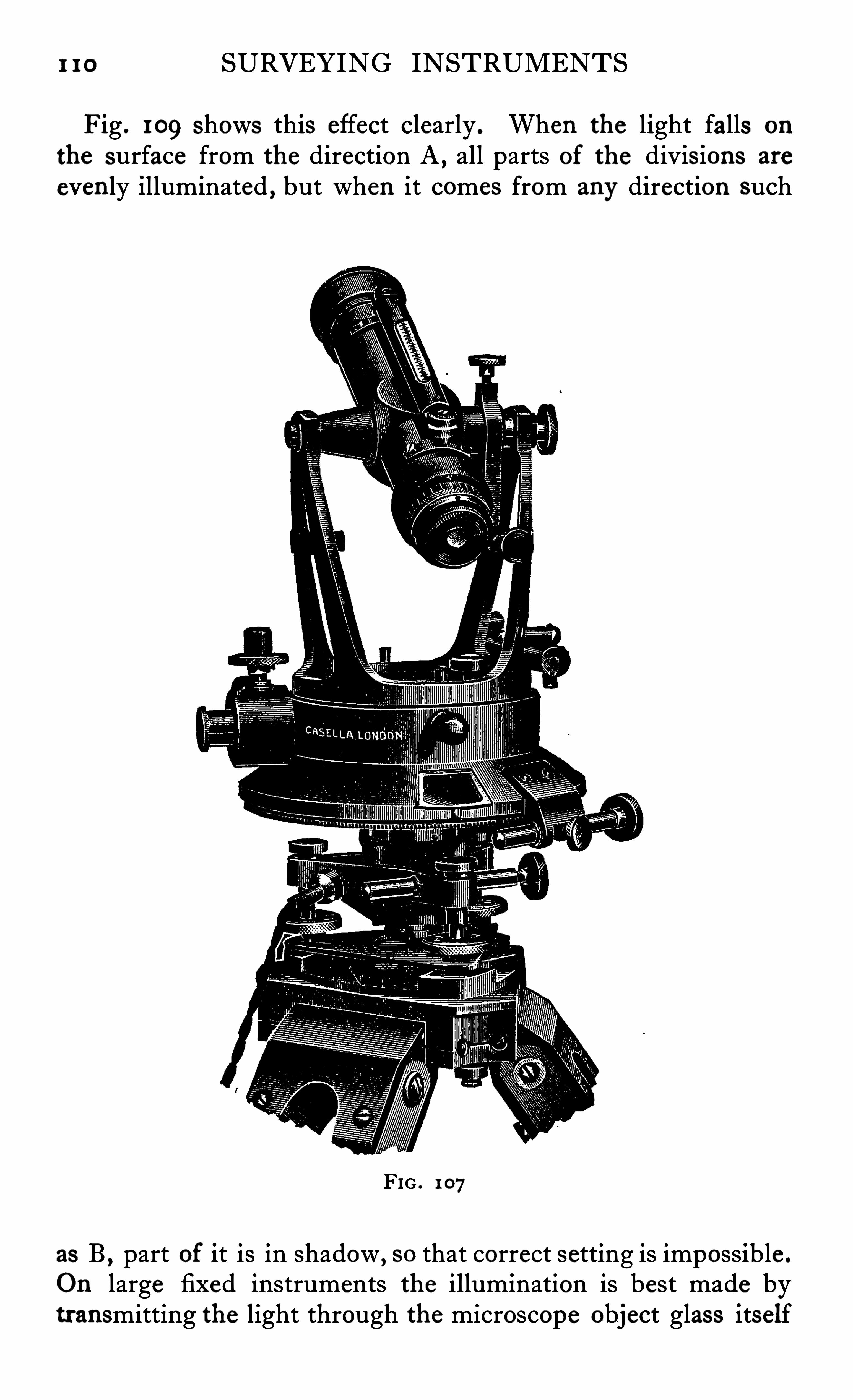
I 10 SURVEYING INSTRUMENTS
Fig . 109 shows this effect clearly . When the light falls on
the surface from the direction A , all parts of the divis ions are
evenly illuminated , but when it comes from any direction such
FIG . 1 07
as B , part of it is in shadow , so that correct setting is impossible .
On large fixed instruments the illumination is best made bytransmitting the light through the microscope object glass itself
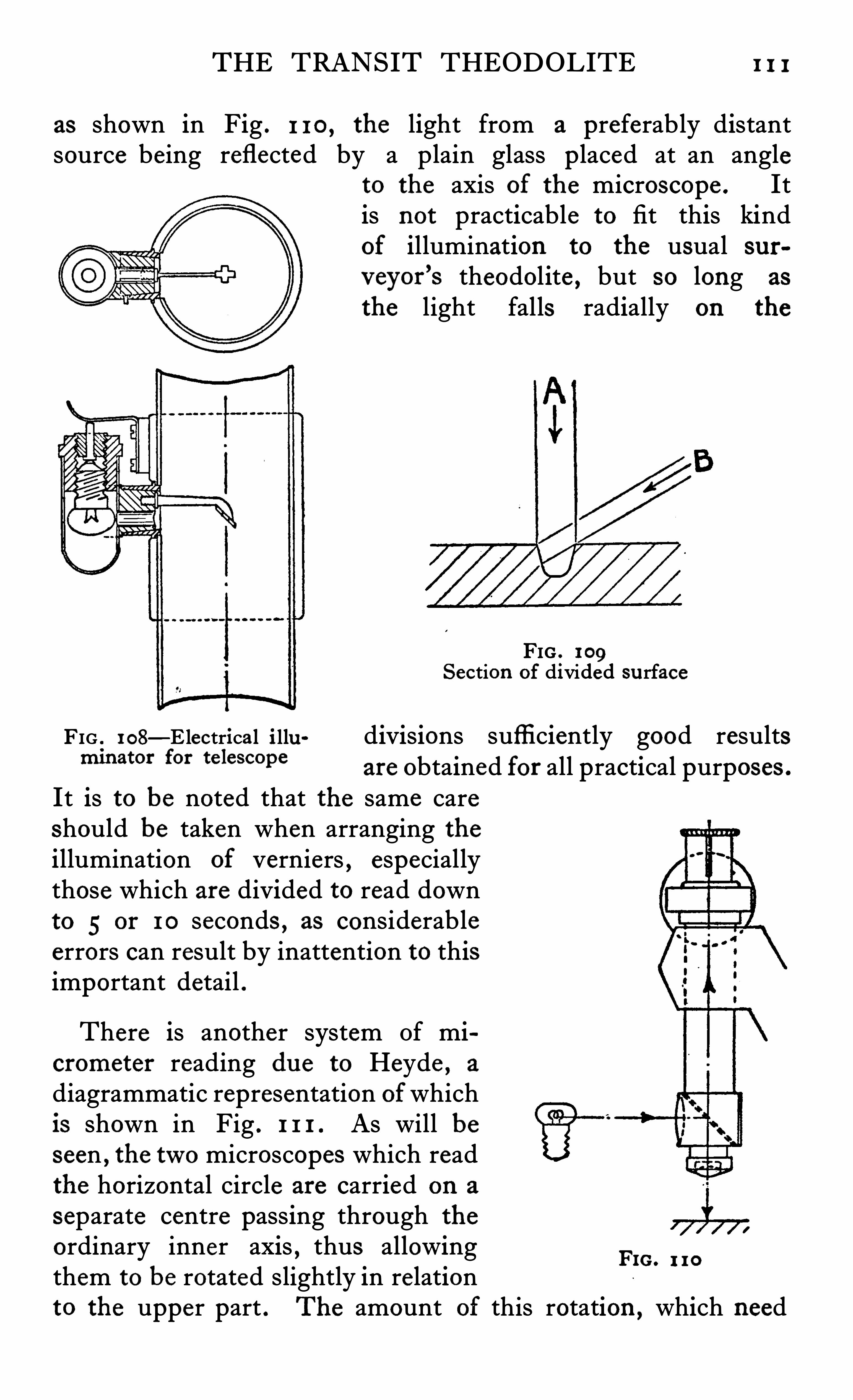
THE TRANSIT THEODOLITE 1 1 1
as shown in Fig . 1 1 0 , the light from a preferably distantsource being reflected by a plain glass p laced at an angle
to the axis of the microscope . Itis not practicable to fit this kindof illumination to the usual sur
v eyor’
s theodolite , but so long as
the light falls radially on the
FIG . 109Section of divided su rface
FIG 1 08—E lectrica l i llu divisions sufficiently good resultsm at“ for te lescope
are obtained for all practical purposes .
It is to be noted that the same careshould be taken when arranging theillumination of verniers , especiallythose which are divided to read downto 5 or 1 0 seconds , as considerableerrors can result by inattention to thisimportant detail .
There is another system Of micrometer reading due to Heyde , a
diagrammatic representation ofwhichis shown in Fig . 1 1 1 . As will beseen , the two microscopes which readthe horizontal circle are carried on a
separate centre passing through the
ordinary inner axis,thus allowing
them to be rotated slightly in relationto the upper part . The amount of this rotation ,
which need
FIG. 1 1 0
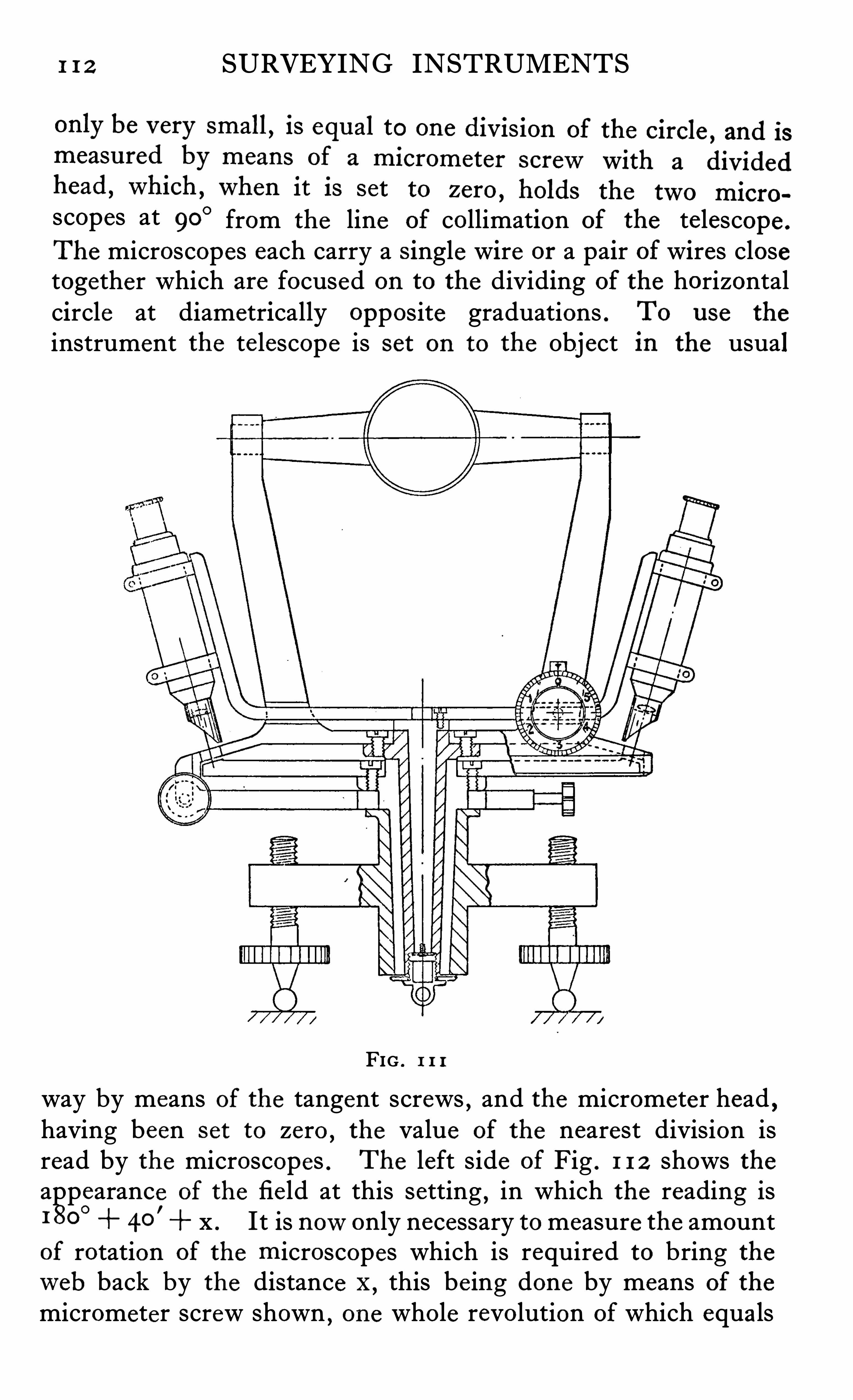
1 1 2 SURVEYING INSTRUMENTS
scopes at 90° from the line of collimation of the telescope .
The microscopes each carry a Single wire or a pair of wires closetogether which are focused on to the dividing of the horizontalcircle at diametrically opposite graduations . To u se the
instrument the telescope is set on to the Object in the usual
FIG . 1 1 1
way by means of the tangent screws,and the micrometer head
,
having been s et to zero , the value of the nearest division isread by the microscopes . The left side of Fig . 1 1 2 shows theappearance Of the fie ld at this setting
,in which the reading is
1 80°
40'
x . It is nowonly necessary to measure the amountof rotation of the microscopes which is required to bring theweb back by the distance "
,this be ing done by means of the
micrometer screw shown , one whole revolution of which equals
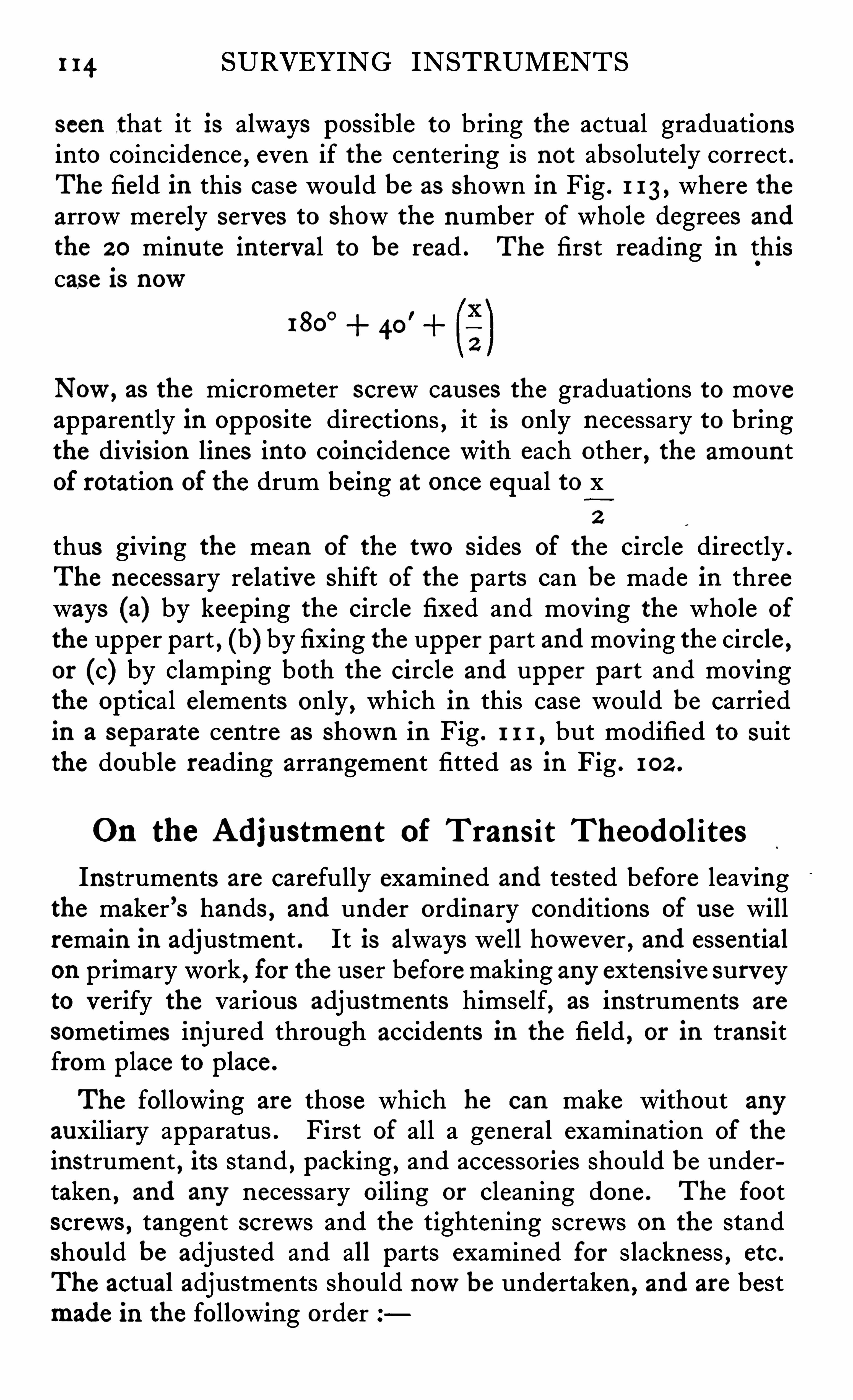
1 14 SURVEYING INSTRUMENTS
seen that it is always possible to bring the actual graduationsinto coincidence , even if the centering is not absolutely correct .The field in this case would be as shown in Fig . 1 1 3 , where thearrow merely serves to Show the number of whole degrees and
the 2 0 minute interval to be read . The first reading in thiscase is now
180°
40’
Now, as the micrometer screw causes the graduations to moveapparently in oppos ite directions , it is only necessary to bringthe division lines into coincidence with each other , the amountof rotation of the drum being at once equal to x
2
thus giving the mean of the two s ides of the circle directly .
The necessary relative shift of the parts can be made in threeways (a) by keeping the circle fixed and moving the whole of
the upper part , (b) by fixing the upper part and moving the circle ,or (c) by clamping both the circle and upper part and movingthe optical elements only , which in this case would be carriedin a separate centre as shown in Fig . 1 1 1 , but modified to suitthe double reading arrangement fitted as in Fig . 1 02 .
On the Adjustment of Trans it Theodolites
Instruments are carefully examined and tested before leavingthe maker ’s hands , and under ordinary conditions of u se willremain in adjustment . It is always well however , and essentialon primary work , for the user beforemaking any extens ive surveyto verify the various adjustments himself, as instruments are
sometimes injured through accidents in the field , or in transitfrom p lace to place .
The following are those which he can make without anyauxiliary apparatus . First of all a general examination of the
instrument , its stand , packing , and accessories should be undertaken , and any necessary oiling or cleaning done . The footscrews , tangent screws and the tightening screws on the standshou ld be adjusted and all parts examined for slackness , etc .
The actual adjustments should nowbe undertaken , and are bestmade in the following order
THE TRANSIT THEODOLITE 1 15
(I ) To Adju s t the Level s on the Hor izontal Vern ierPlate . Set up the instrument on solid ground with the legsfirmly planted and all clamps tight . Release the lower clampingscrew and set the long plate level paralle l with a pair of the footscrews . Bring this bubble to the centre of its run and turn the
instrument in azimuth 180 degrees . If the bubble does not
keep in the centre of its run , adjust for half the error by thecapstan head screws at the end of bubble tube and for the otherhalf by means of the foot screws , repeating this operation ,
ifnecessary , until the bubble remains in the middle of its run
while the instrument is revolved through 360 degrees .
(2 ) To Adju s t the Trans it Ax i s to the Hor izontal . (a) Ifthe instrument is provided with a stride level , erect this on topof the axis (reversing it in order to examine its own adjustmentand correcting if necessary) and if the bubble does not comecorrectly to the centre of its run , raise or lower the axis by theOppos ing screws just under the Y of the standard . The bubbleshou ld nowremain in the centre of its run when the instrumentis revolved in azimuth through 360 degrees . (b) If no s tridelevel is supplied with the instrument , focus the telescope (beingcareful to eliminate parallax) on a small well-defi ned point at acons iderable elevation and some distance from the instrument ,bringing the cross wires to cut the point exactly . Then depressthe telescope as much as poss ible and p lace a mark exactly at thepoint of intersection of the cross wires . Turn the telescope180 degrees in azimuth
,trans it it and bring the cross wires to
bear on the first point . On again depressing the telescope , ifthe wires cut the lower mark the axis is horizontal , but if not ,one s ide of the axis must be raised or lowered , as before , tocorrect half the error . Repeat these operations until theadjustment is correct .
(3) To Adju s t the Line of Col l imat ion at Right Anglesto the Trans i t Axi s . (a) If the theodolite is one in which thetransit axis is not removable from the standards , it is necessary toproceed as follows —The instrument being level and the horizontal verniers reading 180 degrees and 360 degrees , direct the intersection of the webs on any small , well-defi ned object by meansof the lower tangent screw ,
unclamp the horizontal vernier plateand turn the instrument through exactly 180 degrees in azimuth
I 16 SURVEYING INSTRUMENTS
and clamp there . Nowtransit the telescope and if the verticalweb does not cut the same point , correct for half the error bymeans of the small opposing screws just in front of the eyepieceand the other half by the lower tangent screw . Repeat untilthis adjustment is perfect . (b) If the transit axis is removable ,direct the intersection of the te lescope webs on any small , clearlydefined object
,by means of the lower tangent screw . Open
back the clips of the Y ’s and reverse the trans it axis in its bearings ; release the clamp of the vertical circle and transit thetelescope . If the verticalweb does not cut the same point asbefore , correct for half the error by means of the small opposingscrews in front of the eyepiece , and for the other half by thelower tangent screw . Repeat the observation and divide the
error again until the adjustment is correct .
(4) To Adju s t the Level on the Vern ier Arm . The
instrument being still level , bring the bubble on the vernier armto the middle of its run by means of the clip screws and thenset the zero of the vertical circle exactly to zero on the verniers
,
and clamp . Take the reading of the horizontalweb on a levellings taff at a considerable distance . Nowrevolve the instrumentthrough I 80 degrees in azimuth and transit the telescope . Adjustthe verniers to read zero on the vertical circle and then takeanother reading of the staff. If it is not exactly the same as inthe first Observation , correct half the error by the clip screws ,repeating if necessary until both readings are alike . The bubb leon the vernier arm should nowbe brought to the middle of itsrun by means of its capstan headed screws . All bubbles Shouldnowremain in the middle of their runs when the instrument isturned through a complete revolution .
In the workshops of manufacturers the actual tests carriedou t are rather different from those required by the surveyor ,and the adjustments are also made in a much more convenientand accurate manner by means of testing apparatus speciallyconstructed for the purpose . In the first place , the maker musttest all the pivots and bearing surfaces , adjusting screws , slides ,etc . , to see that they are correctly formed , and that they functionaccurate ly in the way it is intended they Should
,a rough indica
tion of the work requ ired‘
being as follows
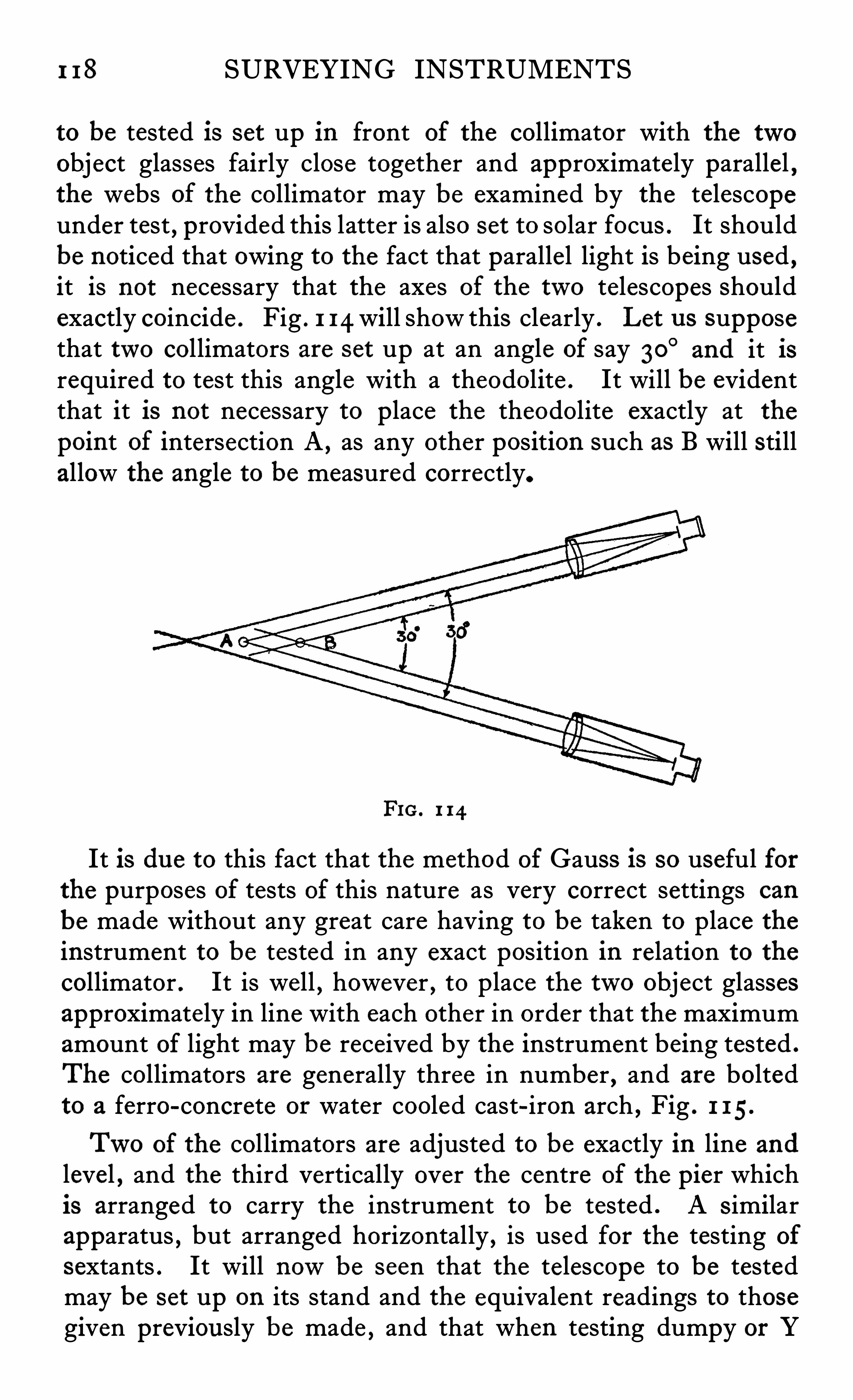
1 18 SURVEYING INSTRUMENTS
to be tested is set up in front of the collimator with the twoobject glasses fairly close together and approximately parallel
,
the webs of the collimator may be examined by the telescopeunder test , provided this latter is also set to solar focus . It shouldbe noticed that owing to the fact that parallel light is being used ,it is not necessary that the axes of the two telescopes Shouldexactly coincide . Fig . 1 14 will show this clearly . Let u s supposethat two collimators are set up at an angle of say 30
°and it is
required to test this angle with a theodolite . It will be evidentthat it is not necessary to place the theodolite exactly at thepoint of intersection A ,
as any other position such as B will stillallow the angle to be measured correctly.
FIG. 1 14
It is due to this fact that the method of Gauss is so useful forthe purposes of tests of this nature as very correct settings can
be made without any great care having to be taken to place theinstrument to be tested in any exact position in relation to thecollimator . It is well , however , to place the two object glassesapproximately in line with each other in order that the maximumamount of light may be received by the instrument being tested .
The collimators are generally three in number , and are boltedto a ferro-concrete or water cooled cast-iron arch , Fig . 1 15.
Two of the collimators are adjusted to be exactly in line and
level , and the third vertically over the centre of the pier whichis arranged to carry the instrument to be tested . A s imilarapparatus , but arranged horizontally , is used for the testing of
sextants . It will nowbe seen that the telescope to be testedmay be set up on its stand and the equivalent readings to thosegiven previously be made , and that when testing dumpy or Y
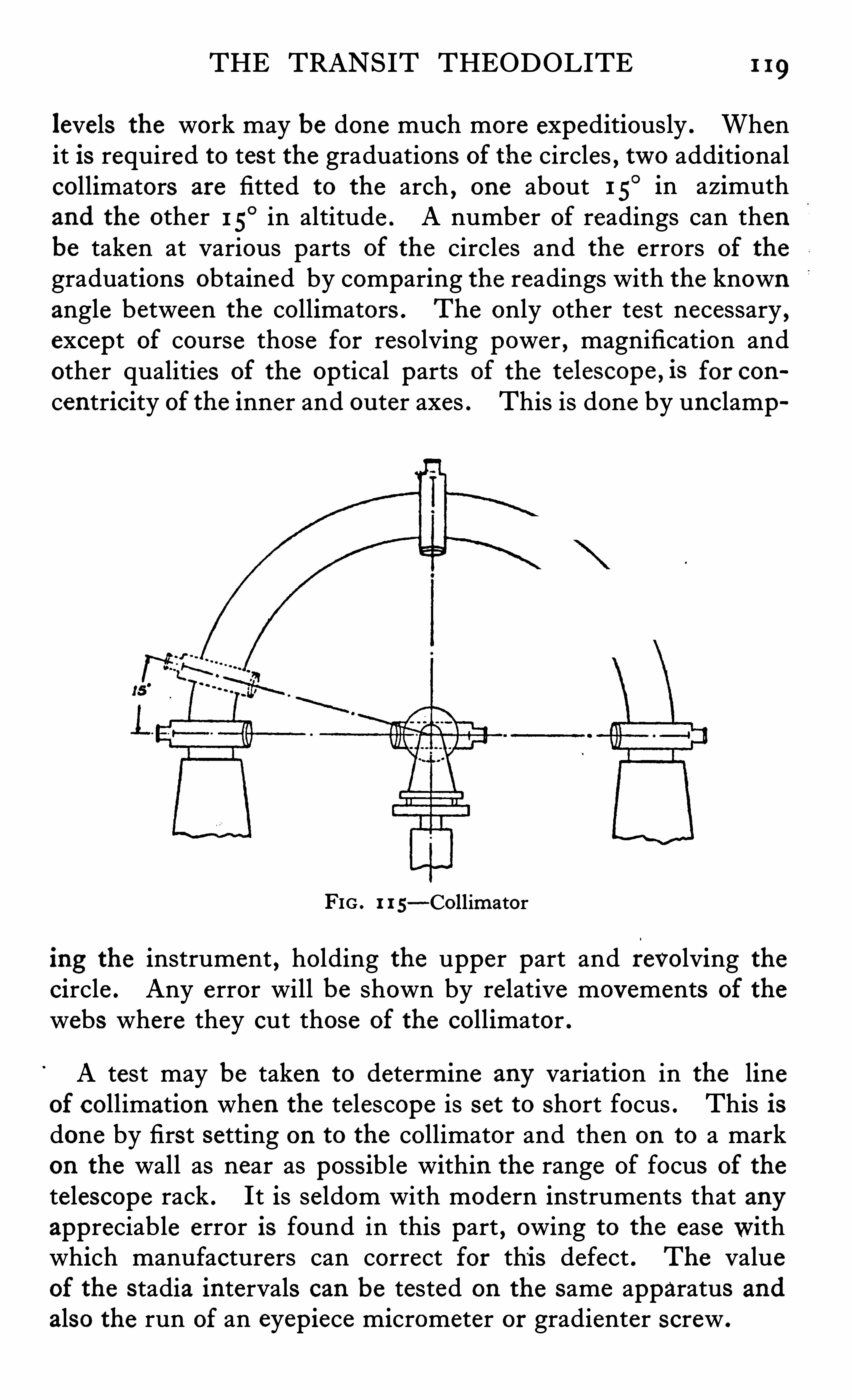
THE TRANSIT THEODOLITE 1 19
levels the work may be done much more expeditiously . Whenit is required to test the graduations of the circles , two additionalcollimators are fitted to the arch , one about 1 5
° in azimuthand the other 15
° in altitude . A number of readings can thenbe taken at various parts of the circles and the errors of the
graduations obtained by comparing the readings with the knownangle between the collimators . The only other test necessary ,except of course those for resolving power , magnification andother qualities of the optical parts of the telescope , is for con
centricity of the inner and outer axes . This is done by unclamp
FIG . 1 1 5—Collimator
ing the instrument , holding the upper part and revolving thecircle . Any error will be shown by relative movements of the
webs where they cut those of the collimator .
A test may be taken to determine any variation in the lineof collimation when the telescope is set to short focus . This isdone by first setting on to the collimator and then on to a markon the wall as near as possible within the range of focus of the
telescope rack . It is seldom with modern instruments that anyappreciable error is found in this part , owing to the easewithwhich manufacturers can correct for thi s defect . The valueof the stadia intervals can be tested on the same apparatus andalso the run of an eyepiece micrometer or gradienter screw .
1 2 0 SURVEYING INSTRUMENTS
When it is desired to find the amount of collimation errorby means of fixed collimators
,it is convenient to have one of
these fitted with a ‘micrometer in its eyepiece . If the righthand collimator as shown in the illustration Fig . 1 1 5 is fitted inthis way the procedure is as follows .
The instrument which is already in good adjustment is setup and leve lled and the te lescope webs directed to cut the websof the left collimator exactly . It is then transited and the error
(a) measured by means of the micrometer in the right handcollimator .
The plate is nowunclamped , revolved through 180 degreesand the telescope clamped and set by means of the tangent screwon the left collimator . It is again transited and the error (b)measured as before .
The error of collimation will then be
b - a
4
If the telescope is nowreversed in its Y ’s and a similar s et
of readings c and d made the error will be
d — c
4
If the m icrometerweb in the collimator is nowset tob a
4
and the thread in the te lescope brought into coincidence with itthe instrument will be in perfect collimation adjustment .
This test also shows whether the pivots on which the telescopeturns are in error . If they are perfect the correspondingreadings in each set will be alike ,
i .e . ,a C and b d
,and the
mean of the pairs in each set will be zero .
In practice errors of collimation , provided they are not verylarge , are complete ly compensated by face right and leftreadings . An endeavour should , however , be made to keepthem as small as possib le . Likewise ,
small errors du e to non
horizontality of the te lescope pivots can be e liminated , but
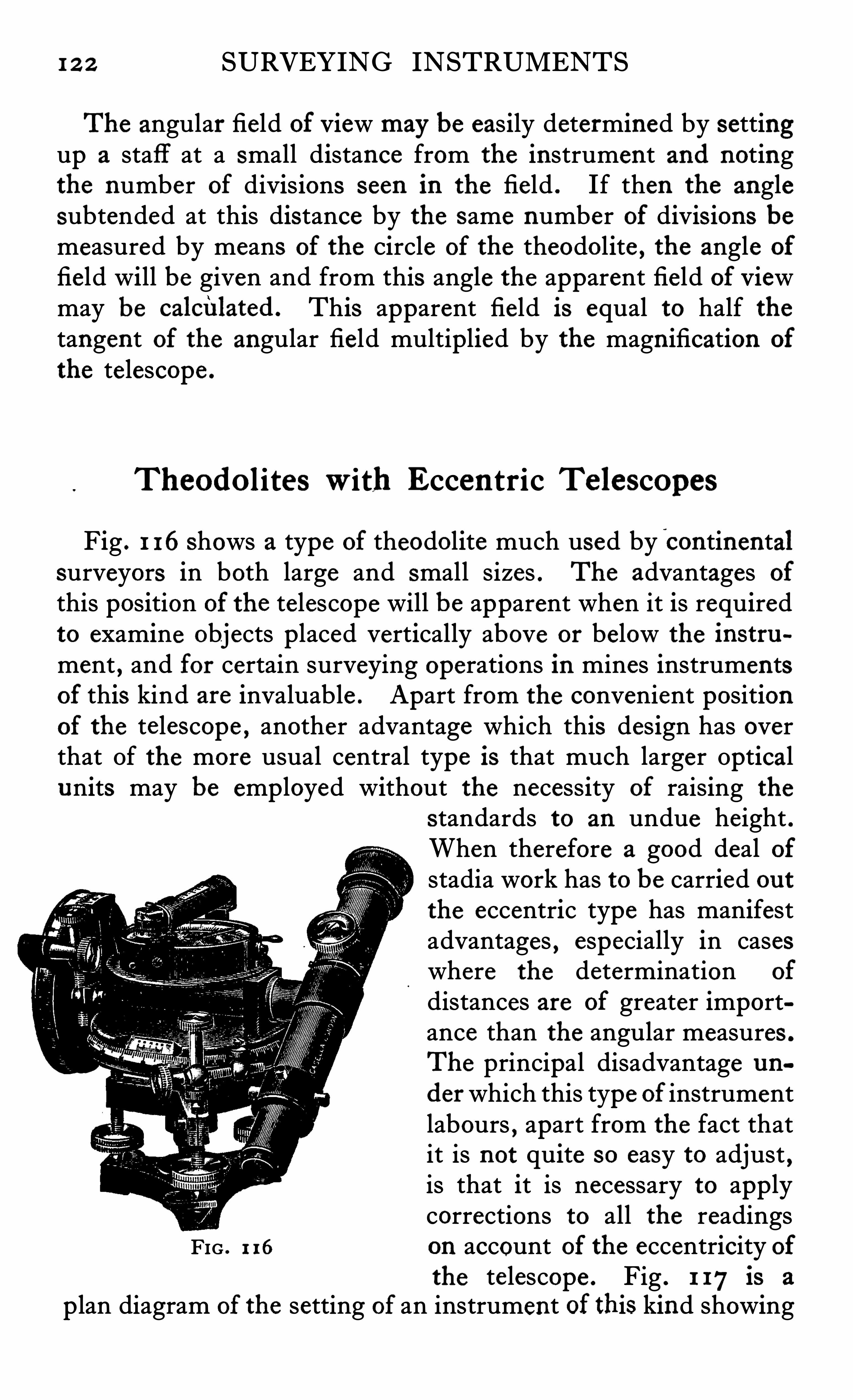
1 2 2 SURVEYING INSTRUMENTS
The angular field of View may be easily determined by settingup a staff at a small distance from the instrument and notingthe number of divisions seen in the field . If then the anglesubtended at this distance by the same number of divis ions bemeasured by means of the Circle of the theodolite , the angle of
field will be given and from this angle the apparent field of Viewmay be calciIlated . This apparent field is equal to half thetangent of the angular field multiplied by the magnification of
the telescope .
Theodo liteswith Eccen tric Te lescopes
Fig . 1 16shows a type of theodolite much used by continentalsurveyors in both large and small sizes . The advantages of
this position of the telescope will be apparent when it is requiredto examine objects placed vertically above or below the instru
ment , and for certain surveying operations in mines instrumentsof this kind are invaluable . Apart from the convenient positionof the telescope , another advantage which this design has overthat Of the more usual central type is that much larger Opticalunits may be employed without the necessity of raising the
standards to an undue height .When therefore a good deal ofstadia work has to be carried ou tthe eccentric type has manifestadvantages , especially in caseswhere the determination of
distances are of greater importance than the angular measures .
The principal disadvantage un
derwhich this type of instrumentlabours , apart from the fact thatit is not quite so easy to adjust ,is that it is necessary to applycorrections to all the readings
FIG . 1 16 on account of the eccentricity ofthe telescope . Fig . I 17 is a
p lan diagram of the setting of an instrument of this kind showing
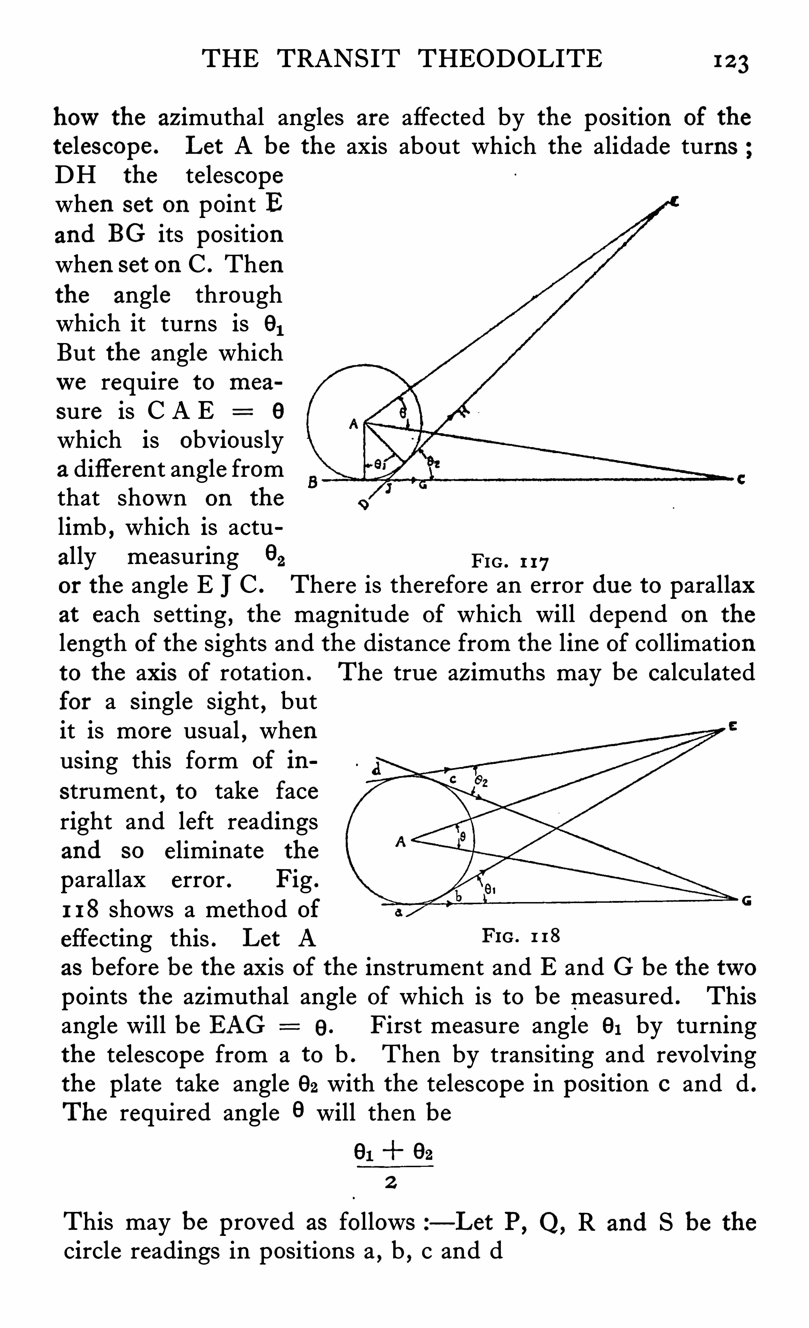
THE TRANSIT THEODOLITE 1 2 3
howthe azimuthal angles are affected by the pos ition of the
telescope . Let A be the axis about which the alidade turnsDH the telescopewhen set on point Band BG its positionwhen set on C . Thenthe angle throughwhich it turns is 91But the angle whichwe require to mea
sure is C A E 6
which is obviouslya different angle fromthat shown on the
limb , which is actually measuring 9
2 FIG . 1 17or the angle E JC . There is therefore an error du e to parallaxat each setting , the magnitude of which will depend on the
length of the sights and the distance from the line of collimationto the axis of rotation . The true azimuths may be calculatedfor a Single sight , butit is more usual , whenusing this form of in
strument , to take faceright and left readingsand so eliminate the
parallax error . Fig .
1 1 8 shows a method of
effecting this . Let A FIG. 1 18
as before be the axis of the instrument and E and G be the twopoints the azimuthal angle of which is to be measured . Thisangle will be BAG 9. First measure angle 9, by turningthe telescope from a to b . Then by transiting and revolvingthe plate take angle 92 with the telescope in position 0 and d .
The required angle 9 will then be
2
This may be proved as follows —Let P, Q, R and S be the
circle readings in positions a , b , c and d
1 2 4 SURVEYING INSTRUMENTS
And readings T and V those at AG and AE
Then 9 V T
Q Q ~ P
S R
And since GA bisects cGa
And Since EA b isects dEb
Then T
And V
ThereforeO + S P + R
2 2
It will be obvious that modifications must be made in the usualprocedure when adjusting the telescope on an instrument of
this kind,and that the labour involved in taking the angles is
much greater than that required with the more usual typehavi ng a central telescope . The extra work necessary whencomputing the angles is also a serious drawback to this system ,
which is probably the reason why it is not more extensively used .
When being used , however , for astronomical work , the errorsof parallax have less weight , and for quite small instrumentssuch as is shown in Fig . 1 16 these errors are not important , astheodolites of this Size are mostly used on compass surveys
, the
results being plotted in such a way that the errors are eliminated .
CHAPTER VI I
LEVELLING INSTRUMENTS
EVELLINGoperations are almost of as much importance asthose carried ou t with the theodolite , and much thoughthas been given to the subject of the design of suitable
instruments for this purpose . The surveyor ’s level has arrived atsuch perfection that it is only in minor detai ls that it is likely to bemodified in the near future . It performs its work so wellthat the ultimate accuracy depends on the stab ility of the benchmarks , the positions of which may vary owing to the movements of the earth ’s crust
,rather than on the instrument itself.
Improvements will no doubt be introduced , and are , in fact ,constantly being produced , to render the instrument morecompact , quicker to set up and to read . Endeavours are beingmade to arrange matters so that the personal errors of the
observers qualify the results to a less and less extent . In spiteof what has been written above , the ideal instrument has , however , not yet been produced , and in fact those in u se or contemplated at present , are far from ideal from the user ’s pointxofView . The present procedure is as follows z—An instrument isset up to read a distant staff. It is leve lled by means of a spiritbubble which serves to set the line of collimation of the telescopeat a true tangent to the earth ’s surface . The image of the staffis then examined in co-incidence with the webs marking thisline of collimation
,and the mean of several readings gives the
true level . This means that the indication of the bubble uponwhichwe are relying has to be transferred to another part of theapparatus beforewe can make u se of it , with the result thaterrors are likely to be introduced during this operation .
The ideal ins trument would be one which would projectinto the field of the telescope a picture of the two ends of thebubble superimposed on the image of the staff and in such a
LEVELLING INSTRUMENTS 1 27
form that their relative positions could be accurately determined ,thus enabling true level to be read at once on the graduationsof the staff. Some instrument maker or man of science wil l nodoubt produce a practical design of this nature , but at presentno such instrument is available , so thatwe must be content inthe meantime to improve the existing apparatus in such a waythat errors in the transferring process are eliminated as far aspossible , that the setting and reading of the bubble is rendereds imple , and that the relative position of the bubble and the lineof collimation shall be as invariable as it is possible to make it .There are two main types of levels in u se at the present timeA
, the dumpy and B , the Y level . Various modifications ofeach of these types are produced , but recent design has tendedin the direction of improving the dumpy leve l in an endeavourto obtain the results which the Y level is intended to give , butin a Simpler and more exact manner . For ordinary levellingoperations when known bench marks are being connected up ,the dumpy leve l is the most popular and deservedly so , as it isa very robust instrument which, if well-made and adjusted , maybe relied upon to give consistently accurate results within itslimits . Its adjustment in the workshop by means of a propercollimator is quickly and easily made
,but for a surveyor in the
field , the method which will be given later is rather laborious ,and requires some skill and care to effect properly . For thisreason many users nowprefer other instruments which are
either self-checking or which can be readily adjusted from a
s ingle station even for purposes for which the dumpy patternwas formerly considered the most satisfactory type . Up to
about ten years ago , levelling was done by setting the instrumentup to revolve truly level in azimuth about its axis and thentaking the back and fore sights
,thus relying on the accuracy of
fit of this main axis . Since then leve ls having an e levating screwarranged to tilt the telescope and therefore the line of collimationthrough a small angle have been revived and bid fair to beuniversally used in the future . The reason for this revivalseems to be that more attention has been given to the design of
reading devices to facilitate the setting of the bubble at themoment of reading the levelling staff. This method has beenfound much quicker in u se and more accurate in its final resultsthan the older one of setting the axis truly vertical in which the
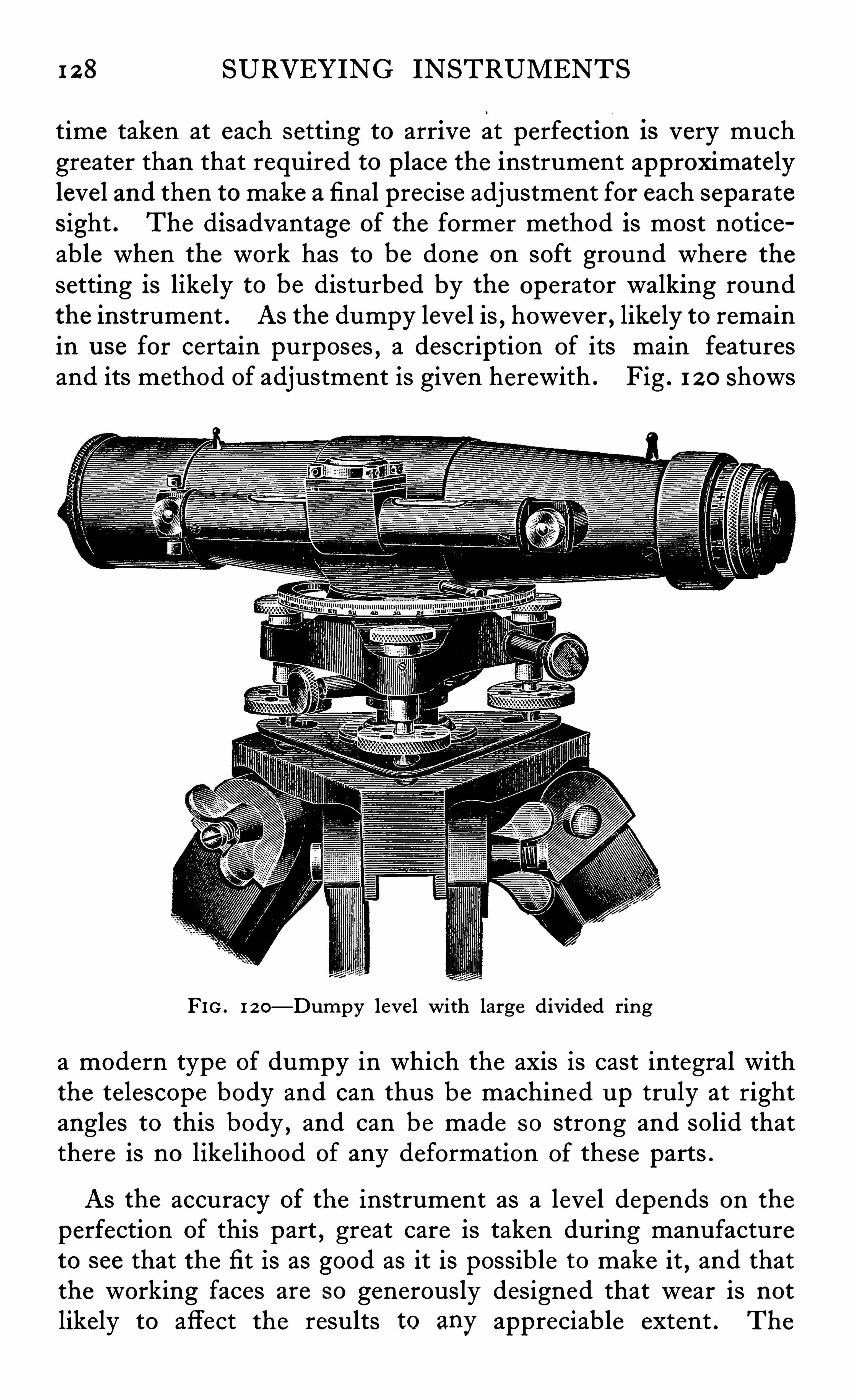
1 2 8 SURVEYING INSTRUMENTS
time taken at each setting to arrive at perfection 18 very muchgreater than that required to place the instrument approximatelylevel and then to make a final precise adjustment for each separateSight . The disadvantage of the former method is most noticeable when the work has to be done on soft ground where the
setting is likely to be disturbed by the operator walking roundthe instrument . As the dumpy leve l is , however , likely to remainin u se for certain purposes , a description of its main featuresand its method of adjustment is given herewith . Fig . 1 2 0 Shows
FIG . 1 2 0—Dumpy leve l with large divided ring
a modern type of dumpy in which the axis is cast integral withthe telescope body and can thus be machined up truly at rightangles to this body , and can be made s o strong and solid thatthere is no like lihood of any deformation of these parts .
As the accuracy Of the instrument as a leve l depends on the
perfection of this part , great care is taken during manufactureto see that the fit is as good as it is possib le to make it
,and that
the working faces are so generously designed that wear is notlikely to affect the results to any appreciable extent . The
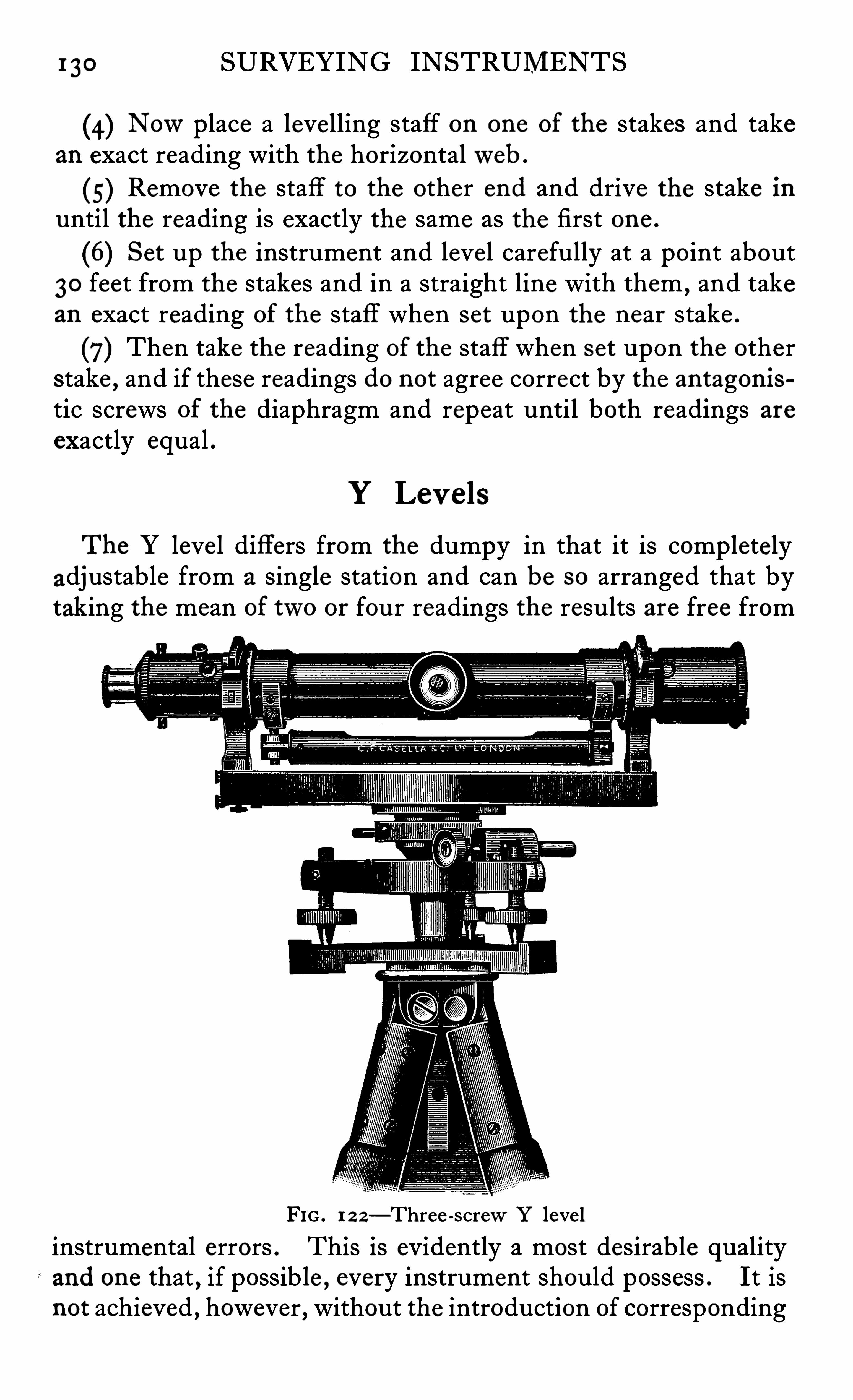
1 30 SURVEYING INSTRUMENTS
(4) Nowplace a levelling staff on one of the stakes and takean exact reading with the horizontalweb .
5) Remove the staff to the other end and drive the stake inuntil the reading is exactly the same as the first one .
(6) Set up the instrument and leve l carefully at a point about30 feet from the stakes and in a straight line with them ,
and takean exact reading of the staff when set upon the near stake .
(7) Then take the reading of the staff when set upon the otherstake , and if these readings do not agree correct by the antagon istic screws of the diaphragm and repeat until both readings areexactly equal .
Y Lev els
The Y level differs from the dumpy in that it is completelyadjustable from a single station and can be so arranged that bytaking the mean of two or four readings the results are free from
FIG . 1 2 2—Three -screwY leve linstrumental errors . This is evidently a most desirable qualityand one that , if possible , every instrument should possess . It isnot achieved , however , without the introduction of corresponding
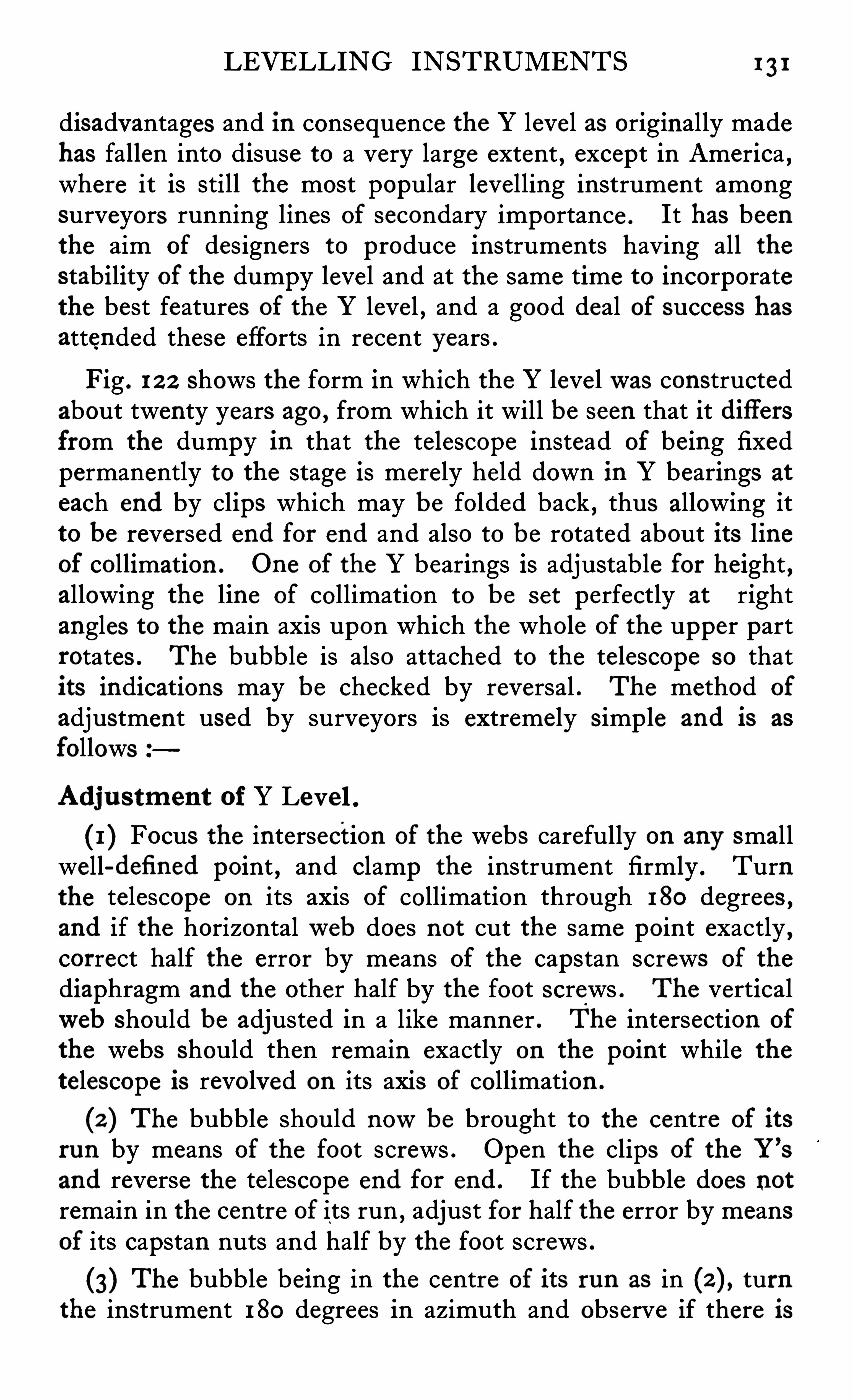
LEVELLING INSTRUMENTS 1 3 1
disadvantages and in consequence the Y level as originally madehas fallen into disuse to a very large extent , except in America ,where it is still the most popular levelling instrument amongsurveyors running lines of secondary importance . It has beenthe aim of designers to produce instruments having all thestability of the dumpy level and at the same time to incorporatethe best features of the Y level , and a good deal of success hasattended these efforts in recent years .
Fig . 1 2 2 shows the form in which the Y levelwas constructedabout twenty years ago , from which it will be seen that it diflersfrom the dumpy in that the telescope instead of being fixedpermanently to the stage is merely he ld down in Y bearings at
each end by clips which may be folded back , thus allowing itto be reversed end for end and also to be rotated about its lineof collimation . One of the Y bearings is adjustable for height ,allowing the line of collimation to be set perfectly at rightangles to the main axis upon which the whole of the upper partrotates . The bubble is also attached to the telescope so thatits indications may be checked by reversal . The method of
adjustment used by surveyors is extremely simp le and is as
follows
Adju s tment of Y Level .
(1 ) Focus the intersection of the webs carefully on any smallwell-defi ned point , and clamp the instrument firmly . Turnthe telescope on its axis of collimation through 180 degrees ,and if the horizontalweb does not cut the same point exactly ,correct half the error by means of the capstan screws of the
diaphragm and the other half by the foot Screws . The verticalweb should be adjusted in a like manner . The intersection of
the webs should then remain exactly on the point while the
telescope is revolved on its axis of collimation .
(2 ) The bubble should nowbe brought to the centre of its
run by means of the foot screws . Open the clips of the Y’
s
and reverse the telescope end for end . If the bubble does notremain in the centre of its run , adjust for half the error by meansof its capstan nuts and half by the foot screws .
(3) The bubble being in the centre of its run as in turnthe instrument 180 degrees in azimuth and observe if there is
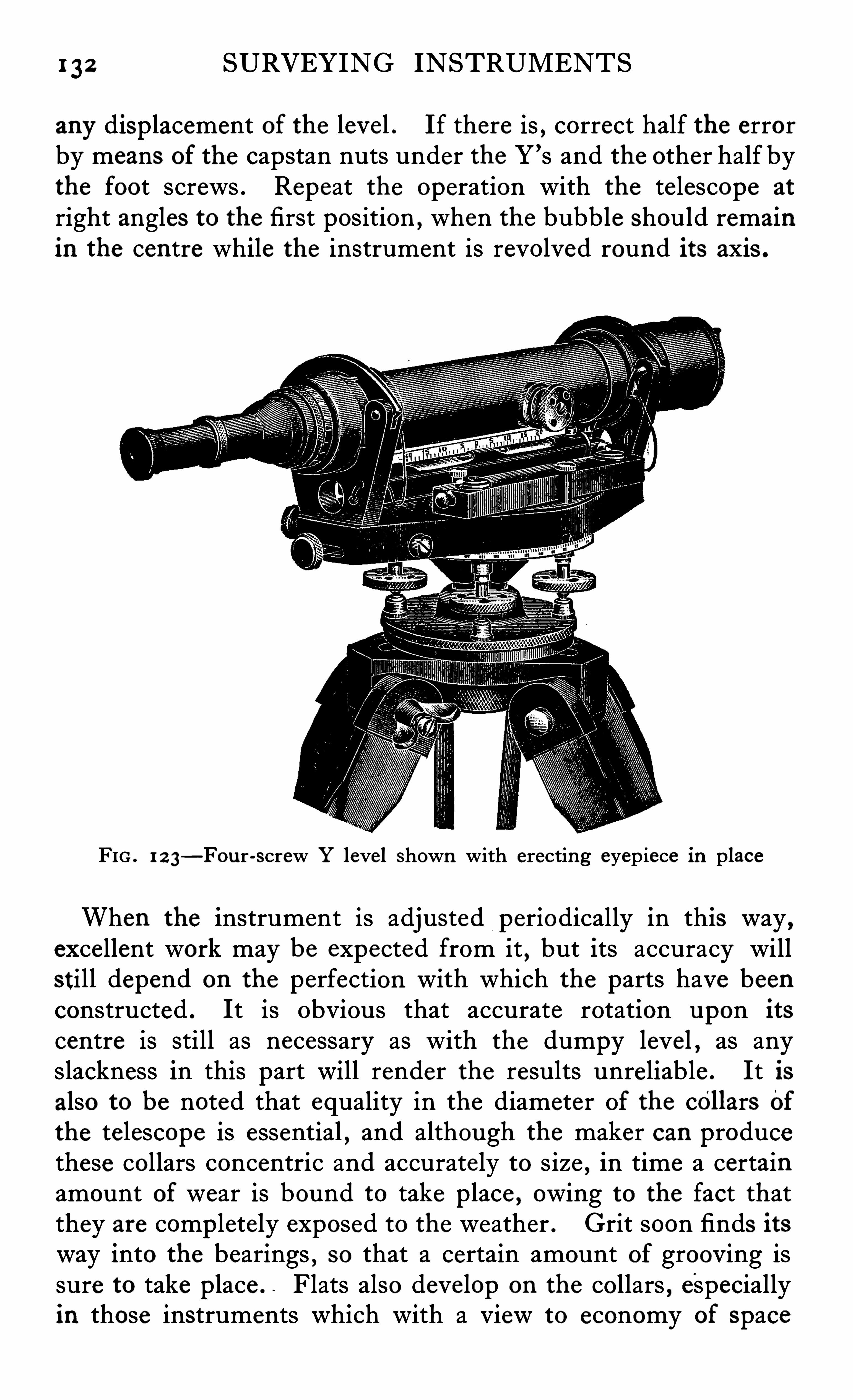
1 32 SURVEYING INSTRUMENTS
any displacement of the level . If there is , correct half the errorby means of the capstan nuts under the Y ’s and the other half bythe foot screws . Repeat the operation with the telescope at
right angles to the first position , when the bubble should remainin the centre while the instrument is revolved round its axis .
FIG . 1 2 3—Fou r-screw Y level shown with erecting eyepiece in place
When the instrument is adjusted periodically in this way ,excellent work may be expected from it , but its accuracy willstill depend on the perfection with which the parts have beenconstructed . It is obvious that accurate rotation upon its
centre is still as necessary as with the dumpy level , as anyslackness in this part will render the results unreliable . It isalso to be noted that equality in the diameter of the c011ars Ofthe telescope is essential
,and although the maker can produce
these collars concentric and accurate ly to size , in time a certainamount of wear is bound to take place , owing to the fact thatthey are completely exposed to the weather . Grit soon finds itsway into the bearings
, so that a certain amount of grooving issure to take place . . Flats also develop on the collars , especiallyin those instruments which with a view to economy of space
134 SURVEYING ' INSTRUMENTS
may be considered negligible , even for the most precise work .
Any residual errors which there may be are in addition not of
importance for precise work as when levelling of the greatestaccuracy is required , the practice is to make the sights of equallength so that these errors tend to cancel ou t in the final results .
ENLARGEDVIEW
THROUGHEYEPIECE
FIG . 1 2 4—Totally enclo sed precise tilting leve l with prismatic bubble
reading device which brings the image of the bubble in to the fie ld of the
main te lescope .
Lev elswith T i lting ScrewsFig . 1 2 4 shows a sectional e levation and Fig . 1 2 5 an outs ide
View of Casel la ’s precise level with micrometer screw whichserves to tilt the whole telescope and its attached bubble about ahorizontal axis carried near the centre of the telescope . Thislevel is fitted with the prism reading device shown on page 58»All the Optical work is enclosed and hermetically sealed in the
body of the instrument , an optical device in the eyepieceallowing the image of the ends of the bubble to be examinedand brought into co-incidence by means of the tilting screw .
A good deal of thought has been expended on the improvements
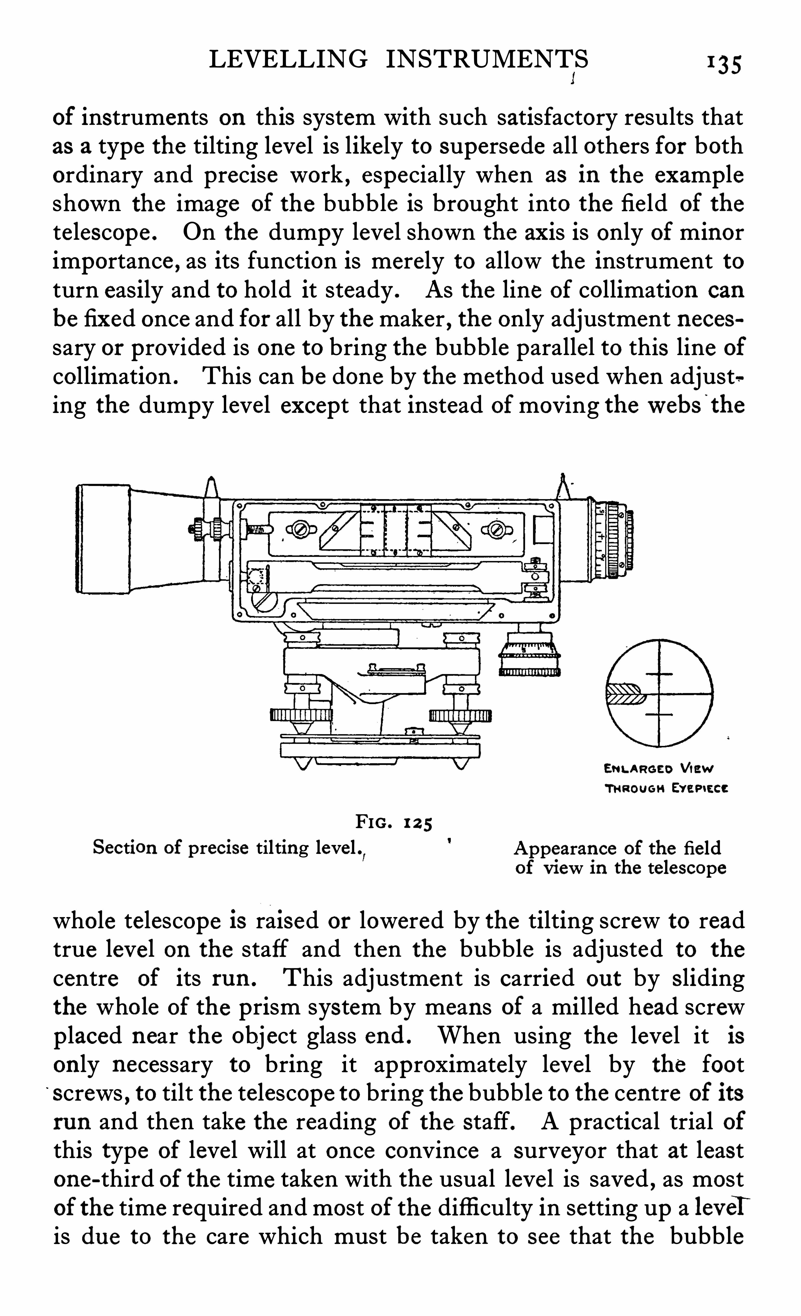
LEVELLING INSTRUMENTS F35
of instruments on this system with such satisfactory results thatas a type the tilting level is likely to supersede all others for bothordinary and precise work , especially when as in the exampleshown the image of the bubble is brought into the fie ld of the
telescope . On the dumpy level shown the axis is only of minorimportance , as its function is merely to allow the instrument toturn easily and to hold it steady . As the line of collimation can
be fixed once and for all by the maker , the only adjustment necessary or provided is one to bring the bubble parallel to this line of
collimation . This can be done by the method used when adjusting the dumpy level except that instead ofmoving thewebs ’
the
ENLARGED ViewTHROUGH Evap tecc
FIG . 1 2 5
Section of precise tilting level”
Appearance of the fieldof View in the telescope
whole telescope l s raised or lowered by the tilting screw to readtrue level on the staff and then the bubble is adjusted to the
centre of its run . This adjustment is carried ou t by s lidingthe who le of the prism system by means of a milled head screwp laced near the obj ect glass end . When using the level it ison ly necessary to bring it approximately leve l by the footscrews , to tilt the telescope to bring the bubble to the centre of its
run and then take the reading of the staff. A practical trial ofthis type of level will at once convince a surveyor that at leastone-third of the time taken with the usual level is saved , as mostof the time required and most of the difficulty in setting up a leveTis du e to the care which must be taken to see that the bubble
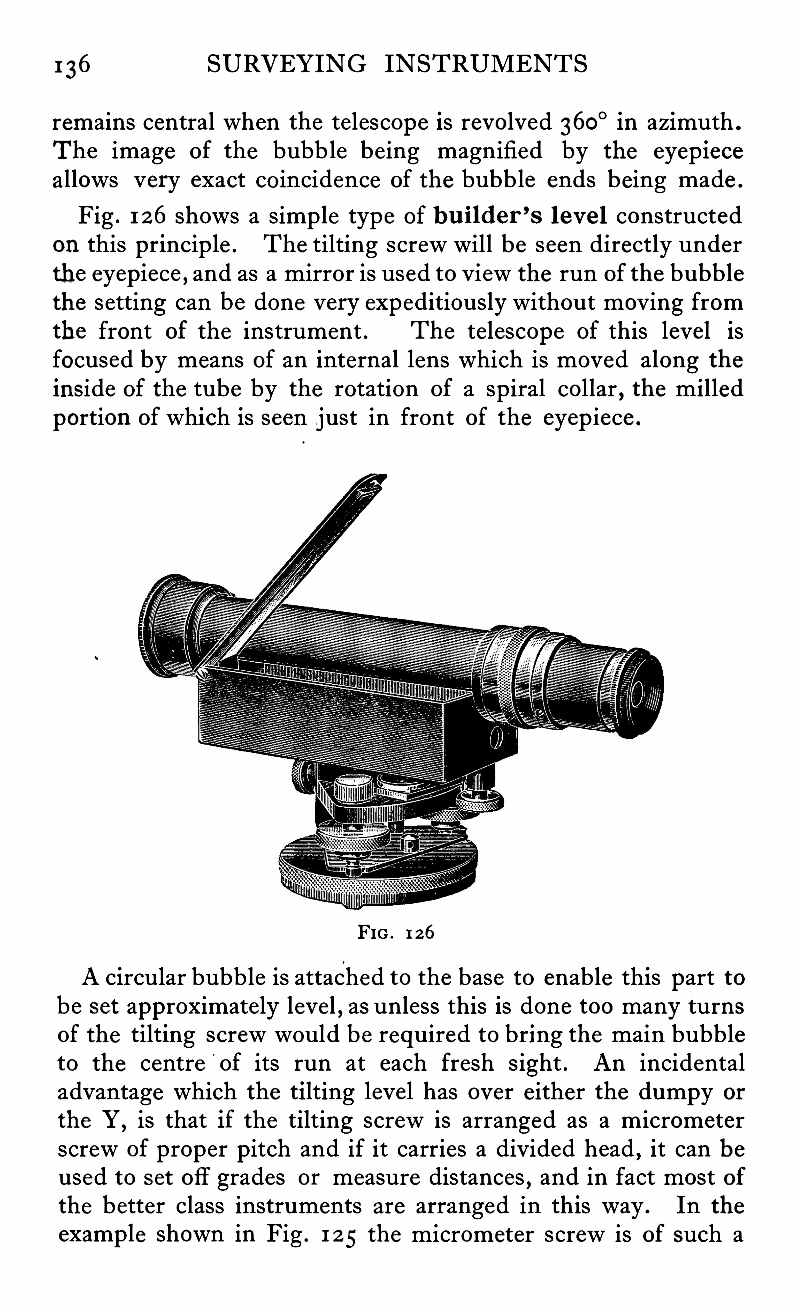
1 36 SURVEYING INSTRUMENTS
remains central when the telescope is revolved 360° in azimuth .
The image of the bubble being magnified by the eyepieceallows very exact coincidence Of the bubble ends being made .
Fig . 1 26Shows a simple type of bu i lder ’s leve l constructed
on this princip le . The tilting screw will be seen directly underthe eyepiece , and as a mirror is used to View the run of the bubblethe setting can be done very expeditiously without moving fromthe front of the instrument . The telescope of this level isfocused by means of an internal lens which is moved along theinside of the tube by the rotation of a spiral collar , the milledportion of which is seen just in front of the eyep iece .
FIG . 1 26
A circular bubble is attached to the base to enable this part tobe set approximately level , as unless this is done too many turnsof the tilting screw would be required to bring the main bubbleto the centre
'
of its run at each fresh sight . An incidentaladvantage which the tilting level has over either the dumpy or
the Y,is that if the tilting screw is arranged as a micrometer
screw of proper pitch and if it carries a divided head , it can beused to set off grades or measure distances , and in fact most ofthe better class instruments are arranged in this way . In theexample shown in Fig . 1 2 5 the micrometer screw is of such a
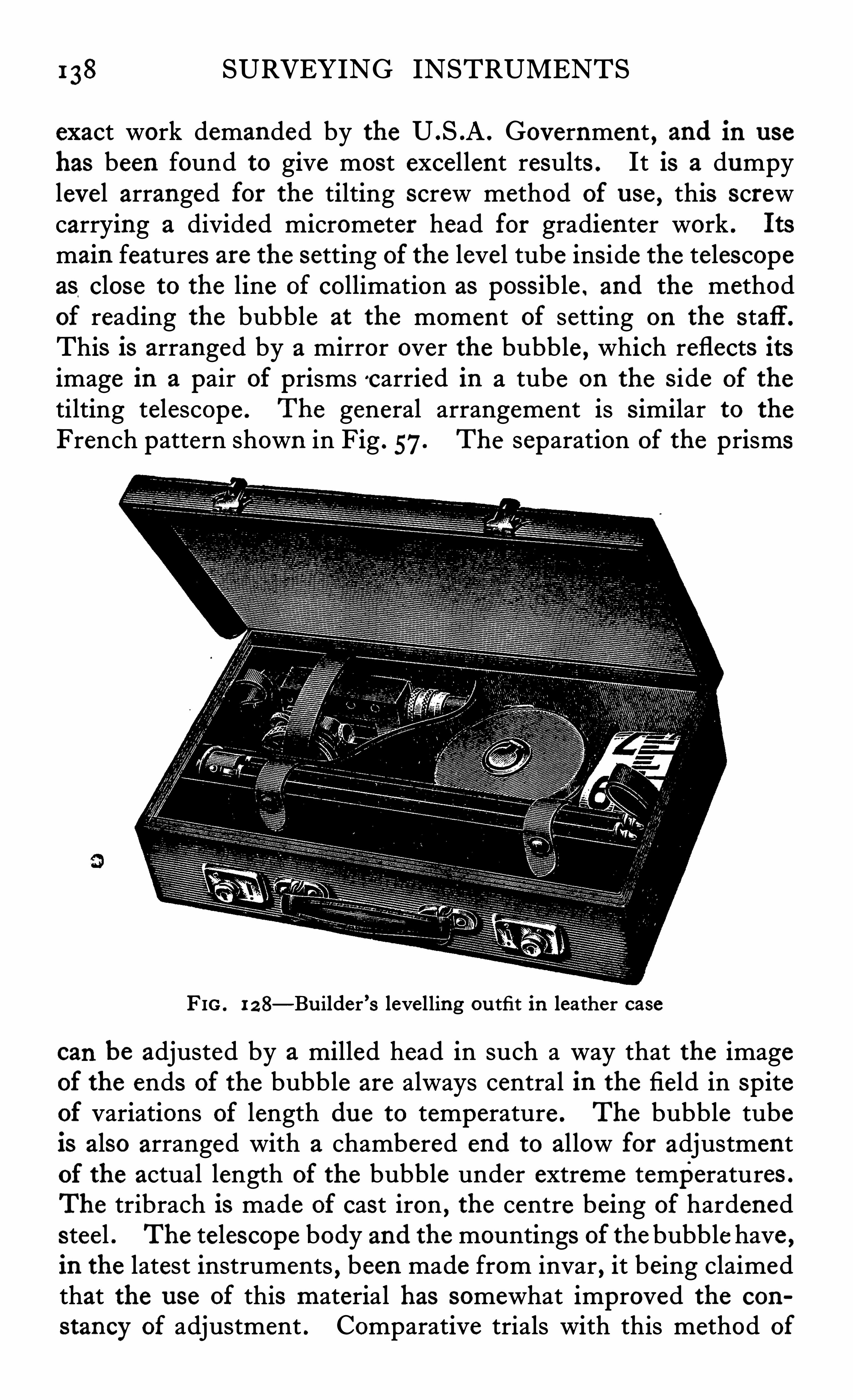
1 38 SURVEYING INSTRUMENTS
exact work demanded by the U .S .A . Government , and in use
has been found to give most excellent results . It is a dumpylevel arranged for the tilting screw method of u se , this screwcarrying a divided micrometer head for gradienter work . Its
main features are the setting of the level tube ins ide the telescopeas close to the line of collimation as possible . and the methodof reading the bubble at the moment of setting on the s taff .
This is arranged by a mirror over the bubble , which reflects itsimage in a pair of prisms c arried in a tube on the s ide of the
tilting telescope . The general arrangement is s imilar to the
French pattern shown in Fig . 57. The separation of the prisms
FIG . 1 2 8—Bu ilder ’s levelling ou tfit in leather case
can be adjusted by a milled head in such a way that the imageof the ends of the bubble are always central in the field in spiteof variations of length du e to temperature . The bubble tubeis also arranged with a chambered end to allow for adjustmentof the actual length of the bubble under extreme temperatures .
The tribrach is made of cast iron , the centre being of hardenedsteel . The telescope body and the mountings of the bubble have ,in the latest instruments , been made from invar , it being claimedthat the u se of this material has somewhat improved the con
stancy of adjustment . Comparative trials with this method of
LEVELLING INSTRUMENTS 139
bubble reading and that shown in Fig . 58 have been made withthe result that while equal accuracywas obtained , the latter formproved rather easier and quicker to set . It will be noticed thatthe central form of holding down screw has been used in thisinstrument . As this arrangement or some modification of itis undoubtedly the best method of fixing a surveying instrumentto its stand
,it is surprising that it is not more generally employed .
The method used for the adjustment of this leve l by the U .S .
Coast and Geodetic Survey , is as follows
Two staves are placed about 1 00 metres apart and the levelis set up about I o .metres from one of them . Sights are nowtaken first on to the far staff and then on to the near one and thefigu re booked . The instrument is nowmoved to within 1 0
metres of the far staff and another pair of sights taken . (Thetwo instrument stations are between the two staff points) .The staff readings must be taken with the bubble in the middleof its run . The required constant C to be determined
,namely
the ratio of the required 'correction to any staff reading to the
corresponding subtended interval is
(Sum of near staff readings) (Sum of distant staff readings)(Sum of distant staff intervals) (Sum of near staff intervals)
The total correction for curvature and refraction must beapplied to the sum of the distant rod readings before using it inthis formula . The level should only be adjusted if C exceeds-0 10 . This adjustment must be made by moving the level vialand not by moving the reticule .
The value of the stadia interval is found as follows
The object glass is first set to solar focus by pointing it on toa distant object and the distance from the centre of the objectglass to the cross wires measured . This gives the focal lengthof the object glass F .
The distance from the object glass to the centre of the axis isthen measured giving the figure C .
The instrument is nowset up in accordance with the formulagiven (see page 42 ,Anallatic Telescopes) in the following wayFrom a point directly under the axis of the instrument as
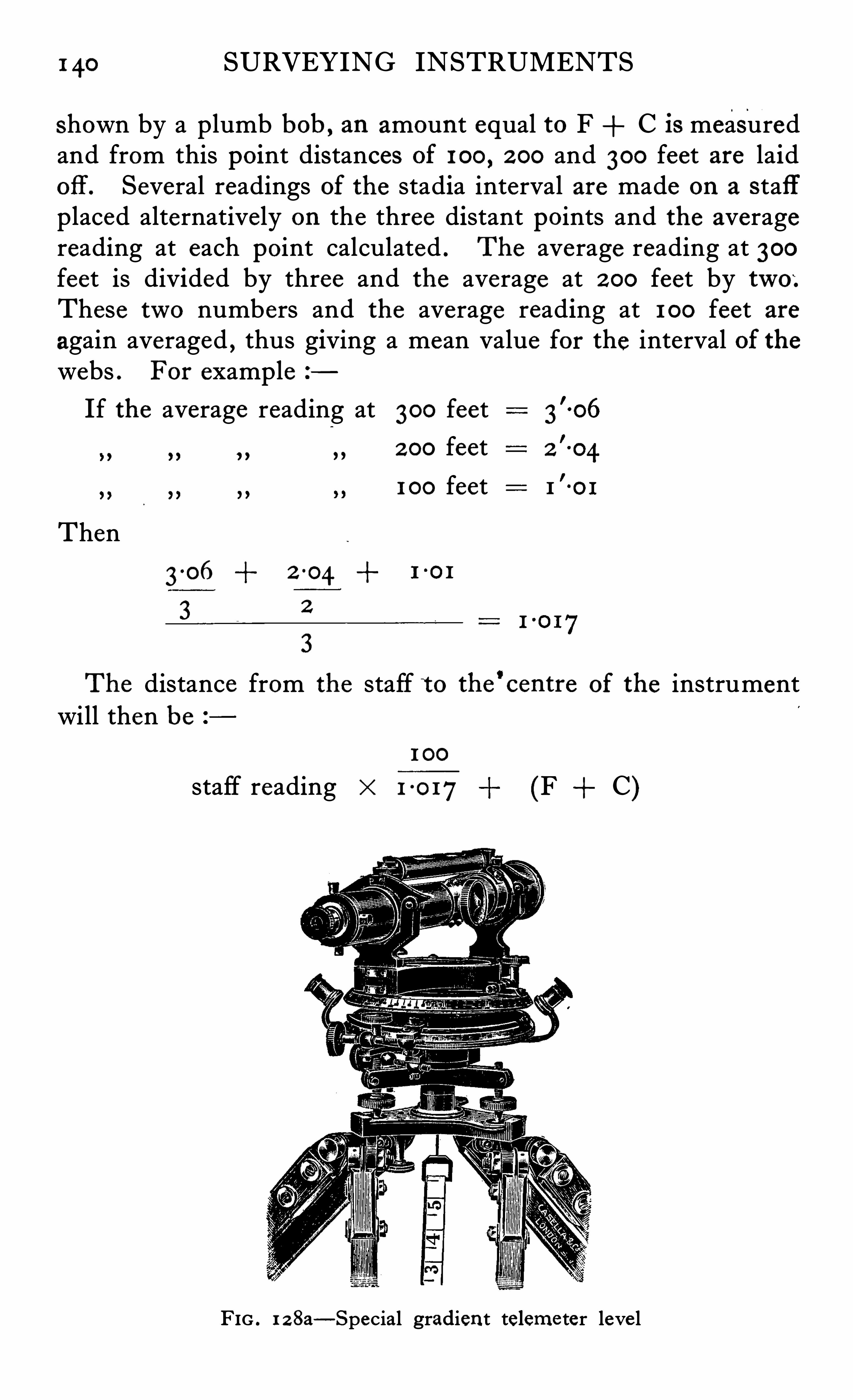
1 40 SURVEYING INSTRUMENTS
shown by a plumb bob , an amount equal to F C is measuredand from this point distances of 100
, 2 00 and 300 feet are laidoff . Several readings of the stadia interval are made on a staffplaced alternatively on the three distant points and the averagereading at each point calculated . The average reading at 300feet is divided by three and the average at 2 00 feet by two;These two numbers and the average reading at 1 00 feet areagain averaged , thus giving a mean value for the interval of thewebs . For example
If the average reading at 300 feet
2 00 feet
1 00 feet
Then
3 0 6 2 -04 1-0 1
3 2
3
The distance from the staff t o the'
centre of the instrumentwill then be
1 00
staff reading " 1 0 17 (F C)
FIG . 1 z8a—Special gradient teleme ter leve l
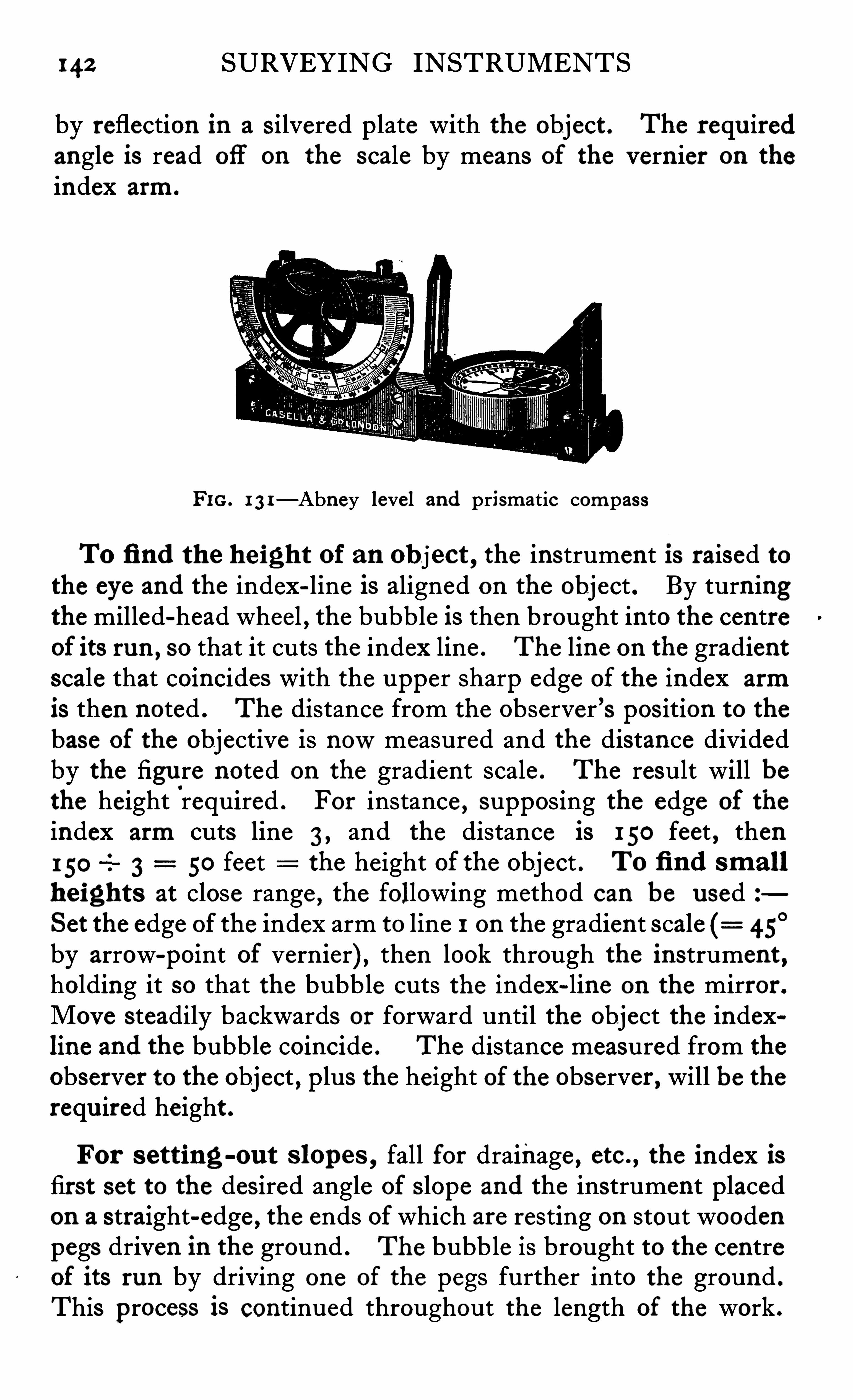
142 SURVEYING INSTRUMENTS
by reflection in a s ilvered p late with the object . The requ iredangle is read off on the scale by means of the vern ier on the
index arm.
FIG. 1 3 1—Abney level and prismatic compass
To fi nd the height of an object,the instrument l s raised to
the eye and the index-line is aligned on the object . By turningthe milled-head wheel , the bubble is then brought into the centreof its run ,
so that it cuts the index line . The line on the gradientscale that coincides with the upper sharp edge of the index arm
is then noted . The distance from the observer ’s pos ition to thebase of the objective is nowmeasured and the distance dividedby the figure noted on the gradient scale . The result will bethe height
'
required . For instance , supposing the edge of the
index arm cuts line 3 , and the distance is 150 feet , then150
-I 3 50 feet the height of the object . To fi nd small
heights at close range,the following method can be used
Set the edge of the index arm to line I on the gradient scale 45°
by arrow-point of vernier) , then look through the instrument ,holding it so that the bubble cuts the index-line on the mirror .
Move steadily backwards or forward until the object the indexline and the bubble coincide . The distance measured from the
observer to the object , plus the height of the observer , will be therequ ired height .
For s etting-ou t s lopes , fall for drainage , etc . , the index isfirst set to the des ired angle of s lope and the instrument placedon a straight-edge , the ends of which are resting on stout woodenpegs driven in the ground . The bubble is brought to the centreof its run by driving one of the pegs further into the ground .
This process is continued throughout the length of the work .
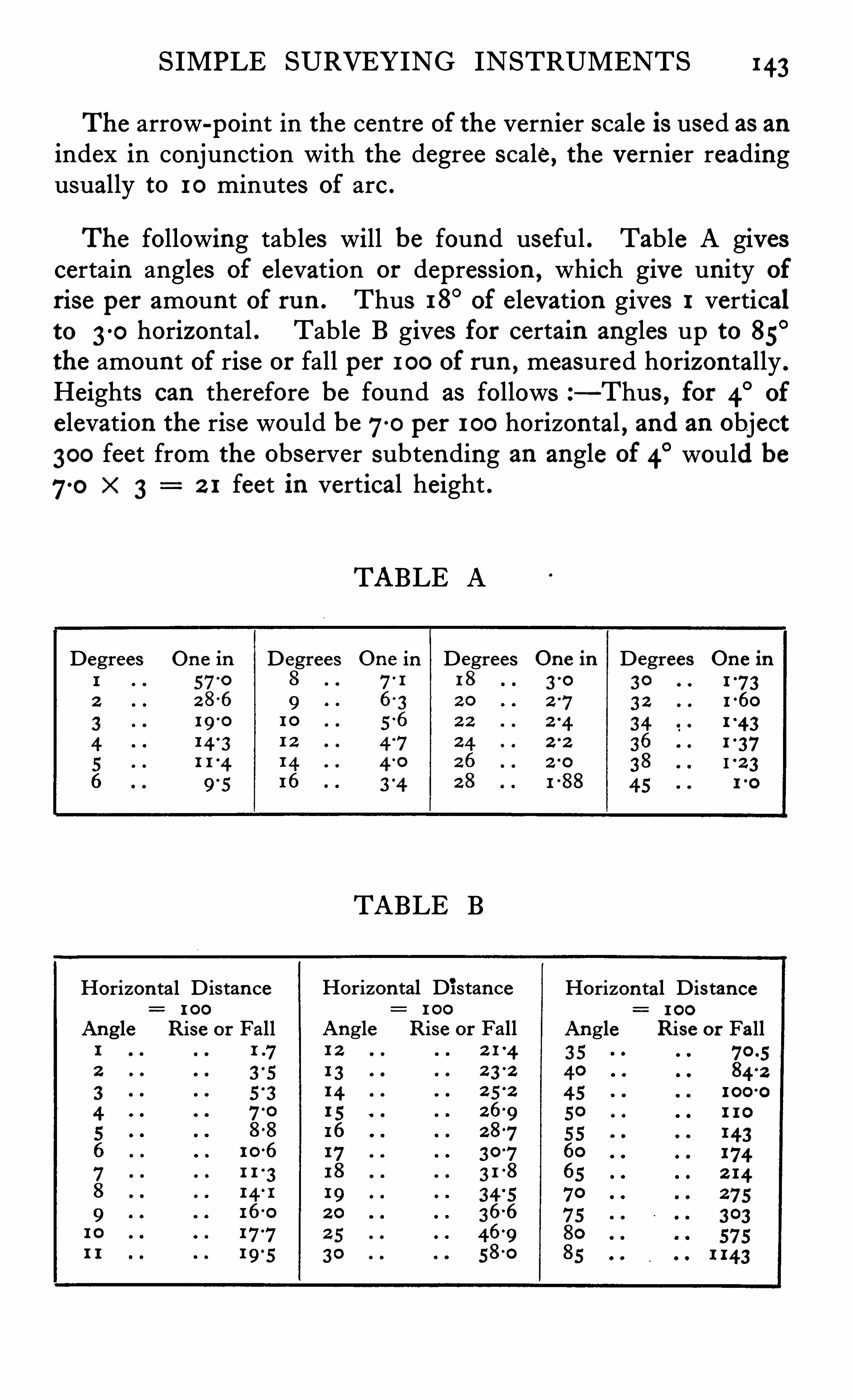
SIMPLE SURVEYING INSTRUMENTS 143
The arrow-point in the centre of the vernier scale is used as anindex in conjunction with the degree scale, the vernier readingusually to 10 minutes of arc .
The following tables will be found useful . Table A givescertain angles of elevation or depress ion , which give unity of
rise per amount of run . Thus 18°of elevation gives 1 vertical
to 3-0 horizontal . Table B gives for certain angles up to 85°
the amount of rise or fall per 1 00 of ru n , measured horizontally .
Heights can therefore be found as follows —Thus , for 4° of
elevation the rise would be70 per 1 00 horizontal , and an object300 feet from the observer subtending an angle of 4
° would be
70 "3 2 1 feet in vertical height .
TABLE A
Degrees One in Degrees One in Degrees On e in Degrees On e in
57-0 71 1 8 30
2 8-6 3 2
341 4 31 1 4 I 2 3
TABLE B
Horizon tal Distance Horizontal Dis tance1 00
Angle Rise or Fall Angle Rise or Fall84
-2
I OO‘O
Horizon tal Distance1 00
Angle Rise or Fall1 2 2 1 41 3 2 3
-2
14 2 52
1 5 2692 873073 1 8
4 566
469
58-0
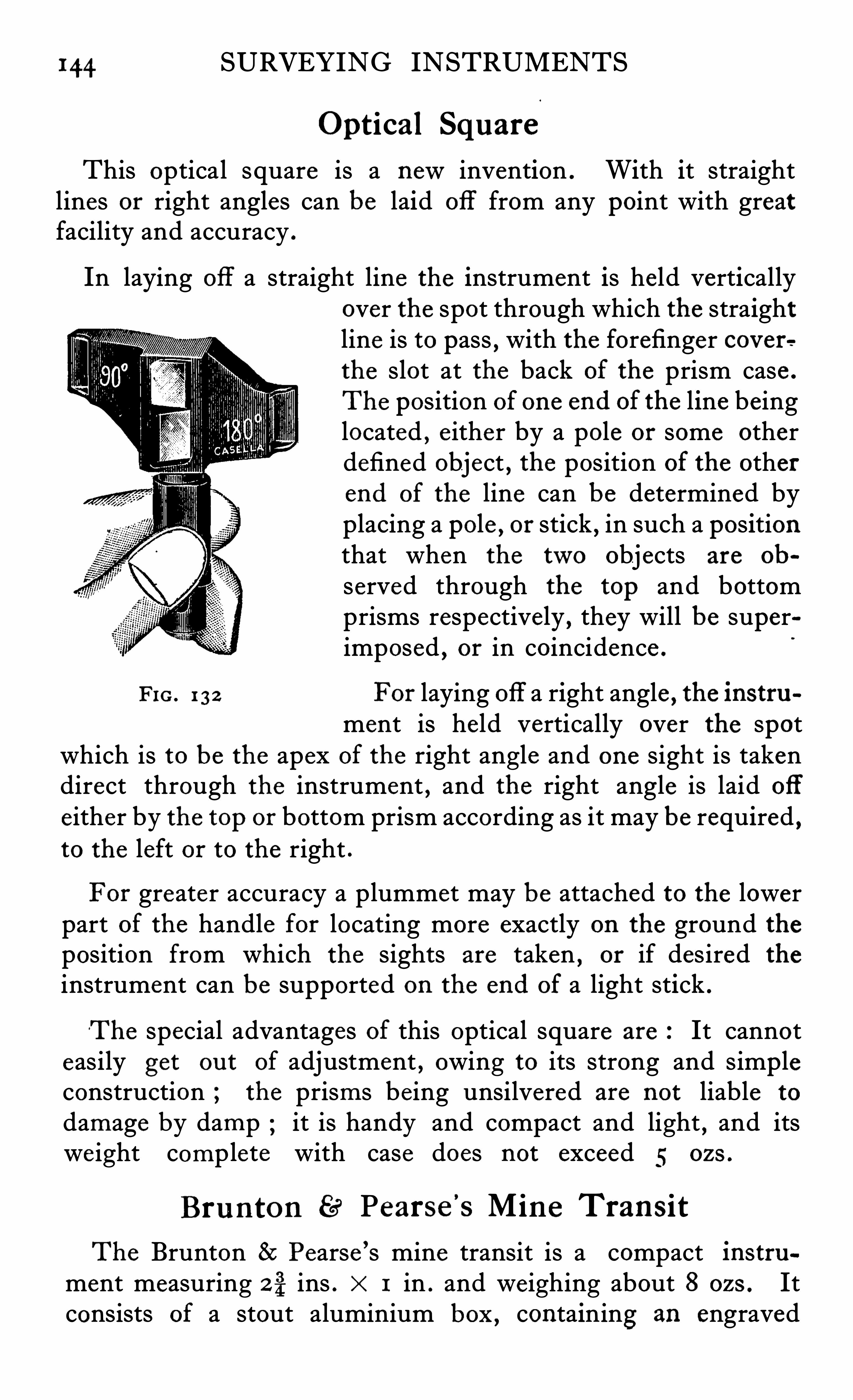
144 SURVEYING INSTRUMENTS
Optical Square
This optical square is a newinvention . With it straightlines or right angles can be laid off from any point with greatfacility and accuracy .
In laying off a straight line the instrument is held verticallyover the spot through which the straightline is to pass
,with the forefinger cov er e
the slot at the back of the prism case .
The position of one end of the line beinglocated
,e ither by a pole or some other
defined object , the position of the otherend of the line can be determined byplacing a pole
,or stick
,in such a position
that when the two objects are ob
served through the top and bottomprisms respectively , they will be superimposed , or in coincidence .
Fro . 1 3 2 For laying off a right angle , the instrument is held vertically over the spot
which is to be the apex of the right angle and one sight is takendirect through the instrument , and the right angle is laid off
either by the top or bottom prism according as it may be required ,to the left or to the right .
For greater accuracy a plummet may be attached to the lowerpart of the handle for locating more exactly on the ground theposition from which the sights are taken , or if desired the
instrument can be supported on the end of a light stick .
‘The special advantages of this optical square are It cannoteasily get ou t of adjustment , owing to its strong and simpleconstruction ; the prisms being unsilvered are not liable to
damage by damp it is handy and compact and light , and itsweight complete with case does not exceed 5 ozs .
Bru n ton 89° Pearse’
s M in e Trans it
The Brunton 8c Pearse ’s mine transit is a compact instrument measuring 2%ins . x 1 in . and weighing about 8 ozs . Itconsists of a stout aluminium box , containing an engraved
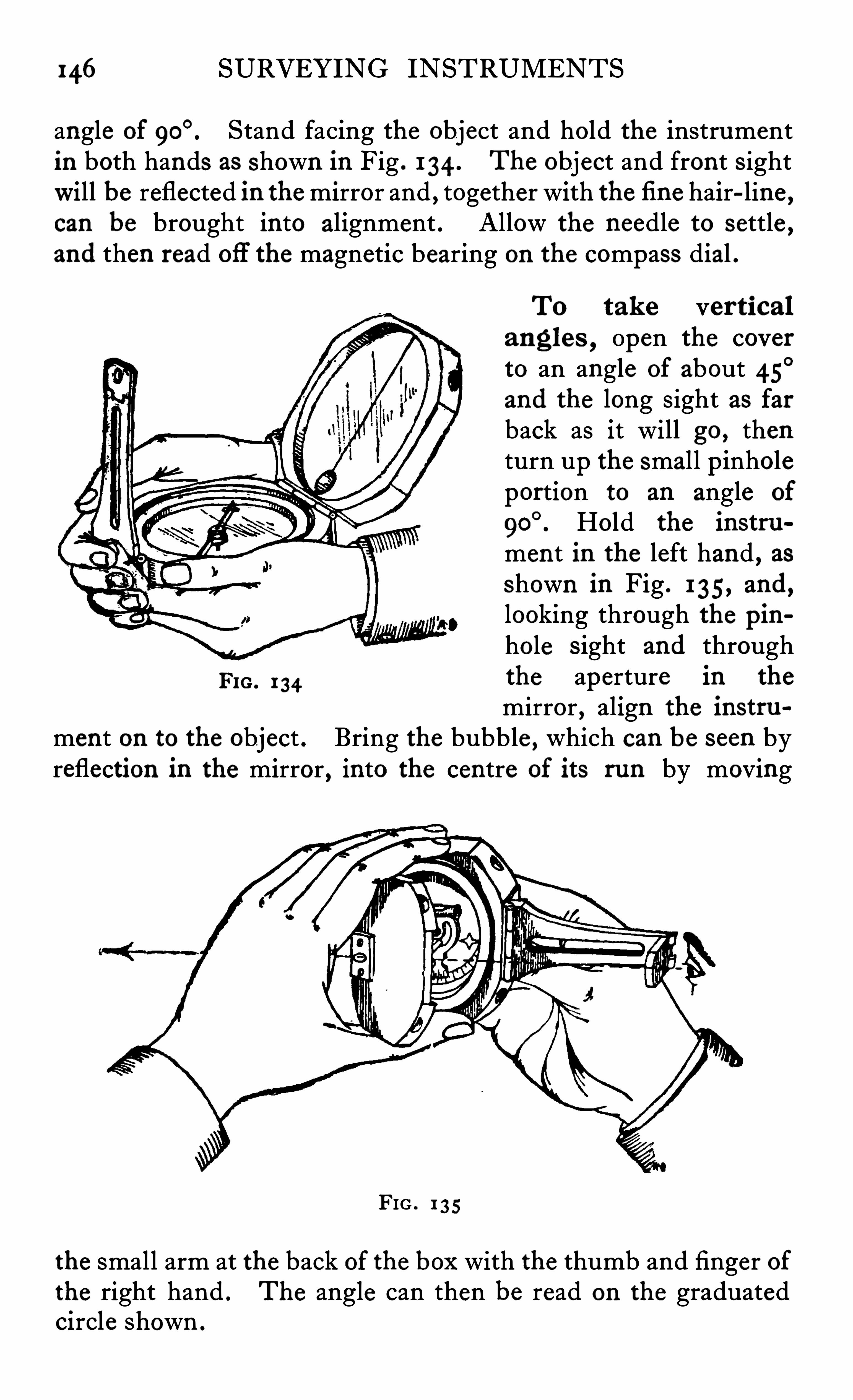
146 SURVEYING INSTRUMENTS
angle of Stand facing the object and hold the instrumentin both hands as shown in Fig . 1 34 . The object and front s ightWill be reflected in the mirror and , together with the fi ne hair-line ,can be brought into alignment . Allow the needle to settle ,and then read ofl
'
the magnetic bearing on the compass dial .
To tak e verticalangles , Open the coverto an angle of about 45
°
and the long sight as farback as it will go , thenturn up the small pinholeportion to an angle of
Hold the instru
ment in the left hand , asshown in Fig . 1 35, and,looking through the pinhole s ight and through
Pro . 1 34the aperture in the
mirror , align the instru
ment on to the object . Bring the bubble , which can be seen byreflection in the mirror
,into the centre of its run by moving
FIG . 1 35
the small arm at the back of the box with the thumb and finger ofthe right hand . The angle can then be read on the graduatedcircle shown .
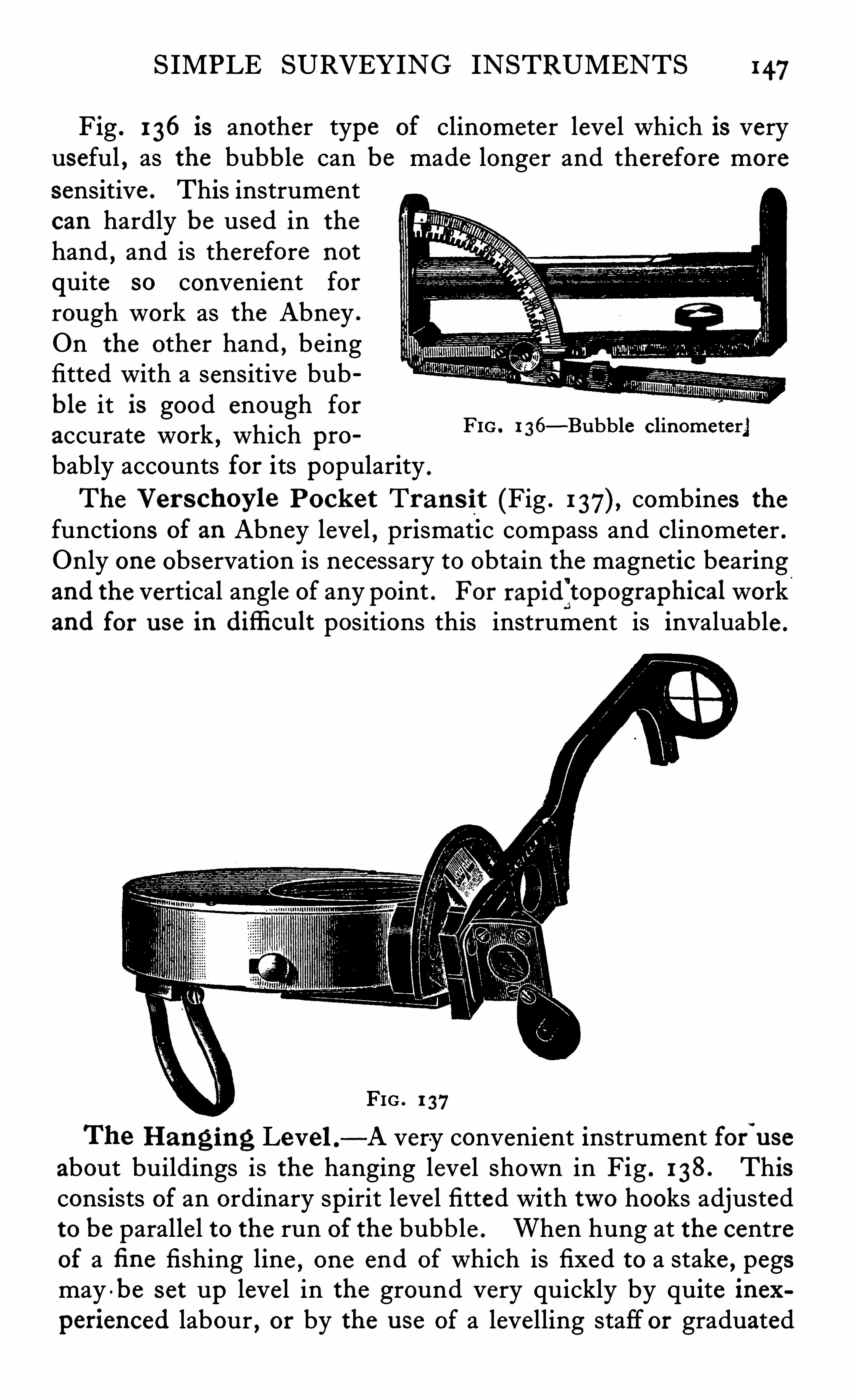
SIMPLE SURVEYING INSTRUMENTS 147
Fig. 136 is another type of clinometer leve l which is very
useful , as the bubble can be made longer and therefore more
sensitive . This instrumentcan hardly be used in the
hand,and is therefore not
quite so convenient for
rough work as the Abney .
On the other hand , be ingfitted with a sensitive bubble it is good enough foraccurate work , which probably accounts for its popularity .
The Ver s choy le Pock et Tran s it (Fig . combines thefunctions of an Abney level , prismatic compass and clinometer .Only one observation is necessary to obtain the magnetic bearingand the vertical angle of any point . For rapidZtopographical workand for u se in difli cu lt positions this instrument is invaluable .
FIG . 1 36—Bubble clinometer"
FIG . 1 37
Hanging Level . -A very convenient instrument forwu se
about buildings is the hanging level shown in Fig . 1 38. Thisconsists of an ordinary spirit leve l fitted with two hooks adjustedto be parallel to the run of the bubb le . When hung at the centreof a fi ne fishing line
,one end of which is fixed to a stake , pegs
may -be set up level in the ground very quickly by quite inexperienced labour , or by the u se of a levelling staff or graduated
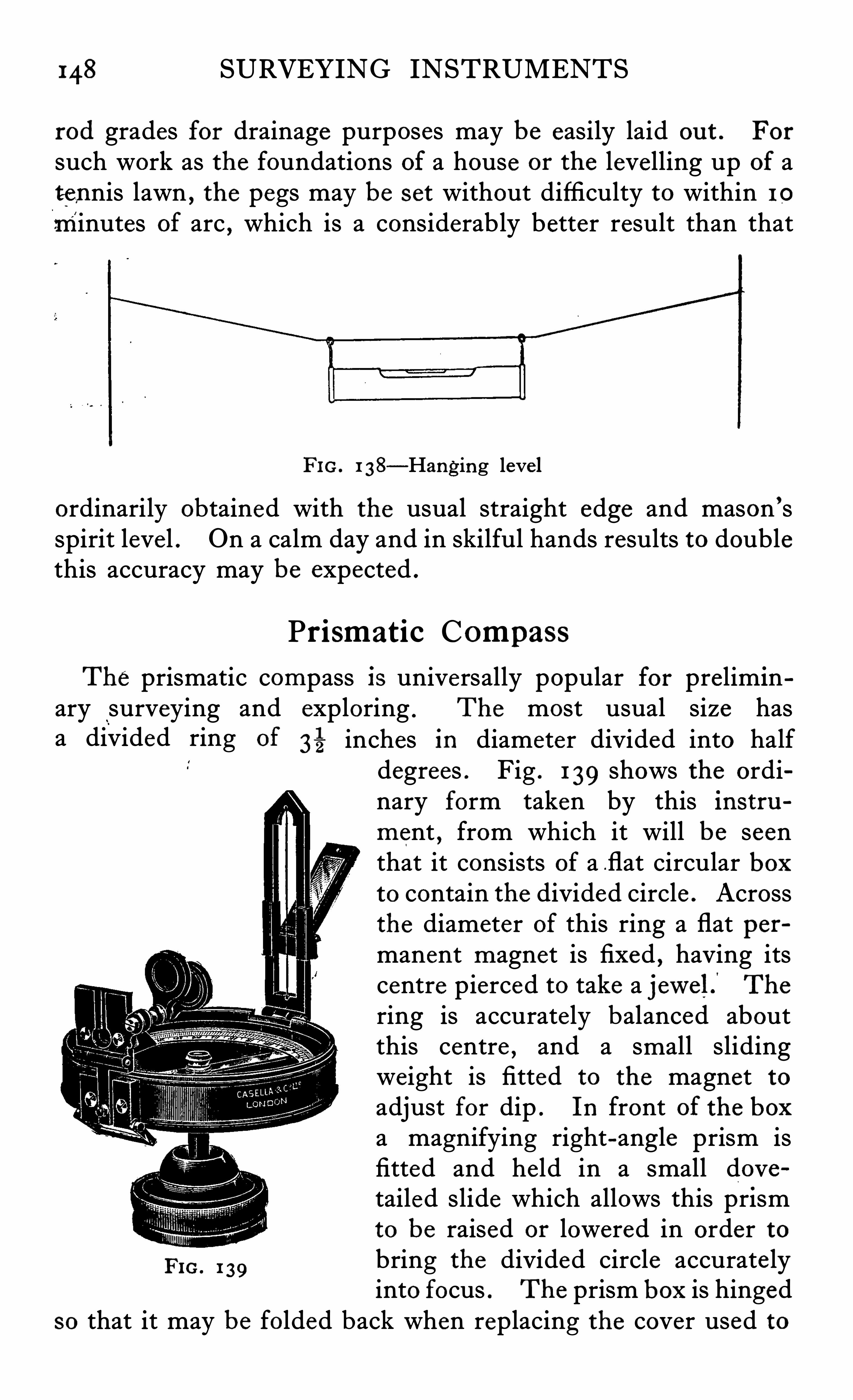
148 SURVEYING INSTRUMENTS
rod grades for drainage purposes may be easily laid ou t . For
such work as the foundations of a house or the levelling up of atennis lawn , the pegs may be set without difficulty to within 10
minutes of arc , which is a considerably better result than that
FIG. 1 38—Hanging leve l
ordinarily obtained with the usual straight edge and mason ’sspirit leve l . On a calm day and in skilful hands results to doublethis accuracy may be expected .
Prismatic CompassThe prismatic compass is universally popular for prelimin
ary surveying and exploring . The most usual size hasa divided ring of 3
—5 inches in diameter divided into halfdegrees . Fig . 1 39 shows the ordinary form taken by this instrument
,from which it will be seen
that it consists of a flat circular boxto contain the divided circle . Acrossthe diameter of this ring a flat permanent magnet is fixed , having itscentre pierced to take a jewelf Thering is accurate ly balanced aboutthis centre , and a small slidingweight is fitted to the magnet toadjust for dip . In front of the boxa magnifying right-angle prism isfitted and he ld in a small dovetailed slide which allows this prismto be raised or lowered in order to
Fro . 1 39bring the divided circle accurate lyinto focus . The prism box is hinged
so that it may be folded back when replacing the cover used to
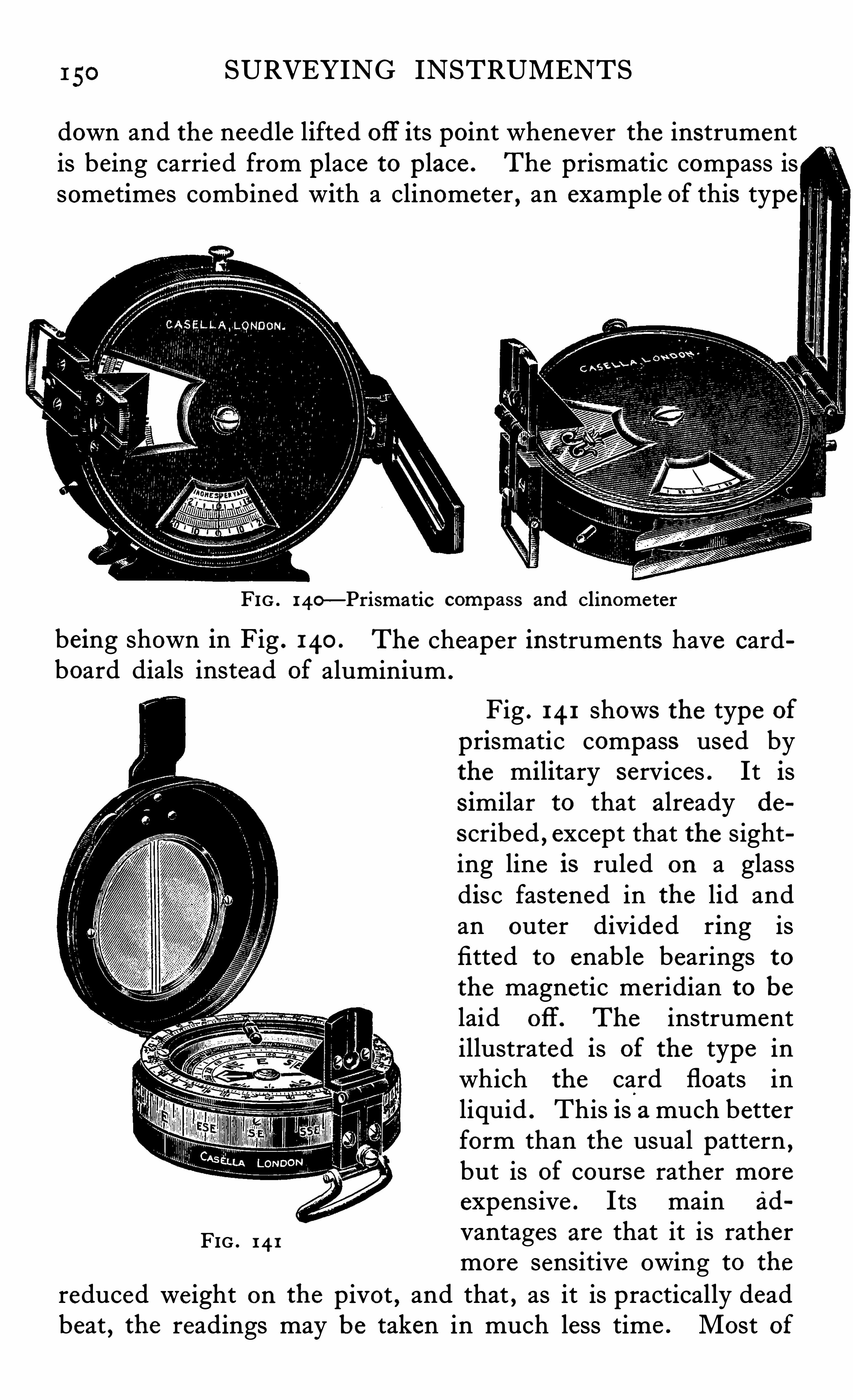
SURVEYING INSTRUMENTS
down and the needle lifted off its point whenever the instrumentis being carried from place to place . The prismatic compass issometimes combined with a clinometer , an example of this type
FIG . 140—Prismatic compass and clinometer
being shown in Fig . 140 .
board dials instead
FIG . 14 1
The cheaper instruments have cardaluminium .
Fig . 14 1 shows the type of
prismatic compass used bythe military services . It iss imilar to that already de
s cribed , except that the sighting line is ruled on a glassdisc fastened in the lid andan outer divided ring isfitted to enable bearings tothe magnetic meridian to belaid off . The instrumentillustrated is of the type inwhich the card floats inliquid . This is a much betterform than the usual pattern ,but is of course rather moreexpensive . Its main ad
vantages are that it is rathermore sensitive owing to the
reduced weight on the pivot , and that , as it is practically deadbeat , the readings may be taken in much less time . Most of
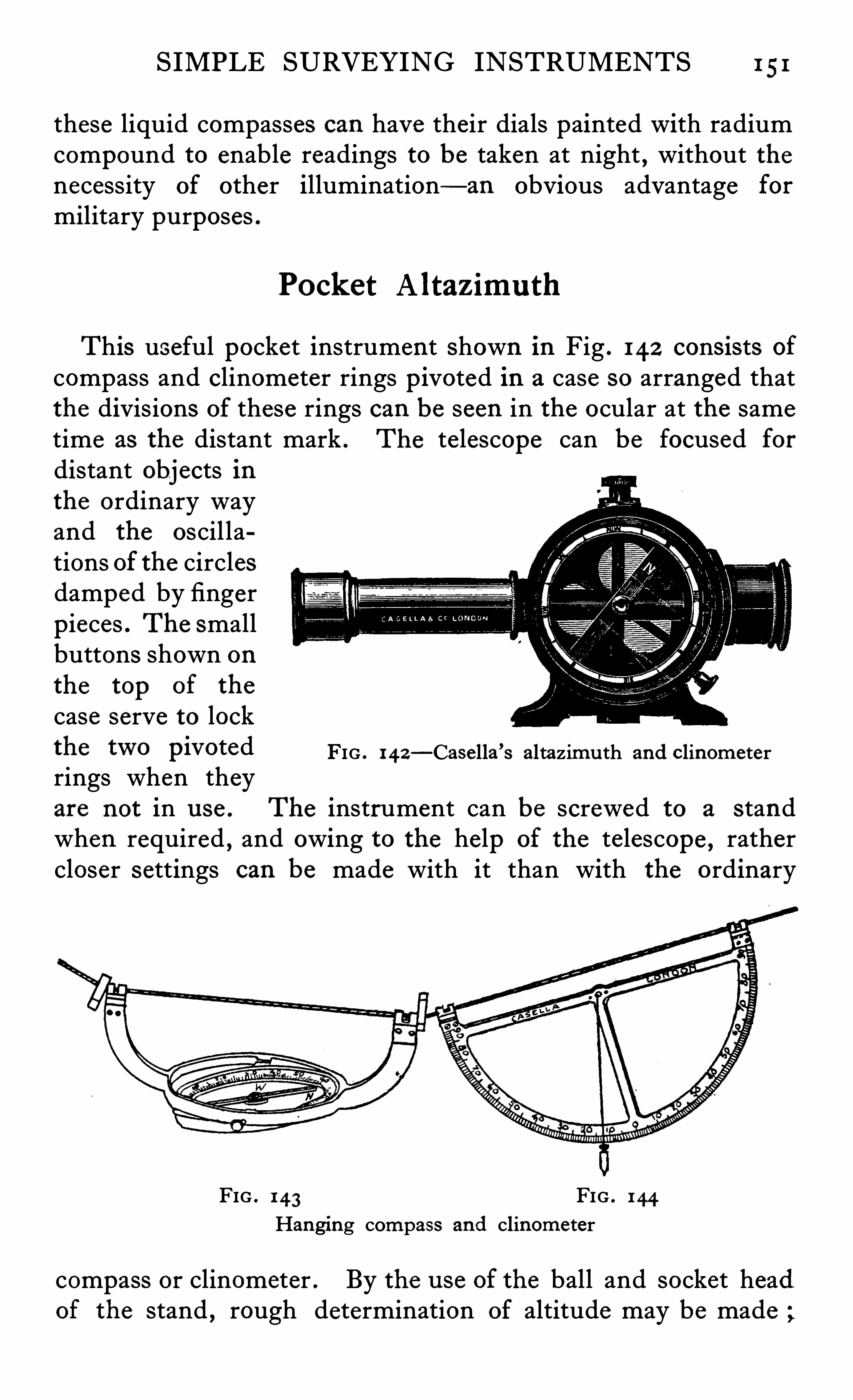
SIMPLE SURVEYING INSTRUMENTS 1 51
these liquid compasses can have their dials painted with radiumcompound to enable readings to be taken at night , without thenecessity of other illumination— an obvious advantage for
military purposes .
Pocket A ltaz imu th
This useful pocket instrument shown in Fig . 142 consists of
compass and clinometer rings pivoted in a case so arranged thatthe divisions of these rings can be seen in the ocular at the sametime as the distant mark . The telescope can be focused fordistant objects inthe ordinary wayand the oscil lations of the circlesdamped by fingerpieces . The smallbuttons shown onthe top of the
case serve to lockthe two Pivoted FIG . 142
—Casella ’s altazimu th and clinometerrings when theyare not in u se . The instrument can be screwed to a s tandwhen required , and owing to the help of the telescope , rathercloser settings can be made with it than with the ordinary
FIG . 143 FIG . 144
Hanging compass and clinometer
compass or clinometer . By the use of the ball and socket headof the stand , rough determination of altitude may be made ;
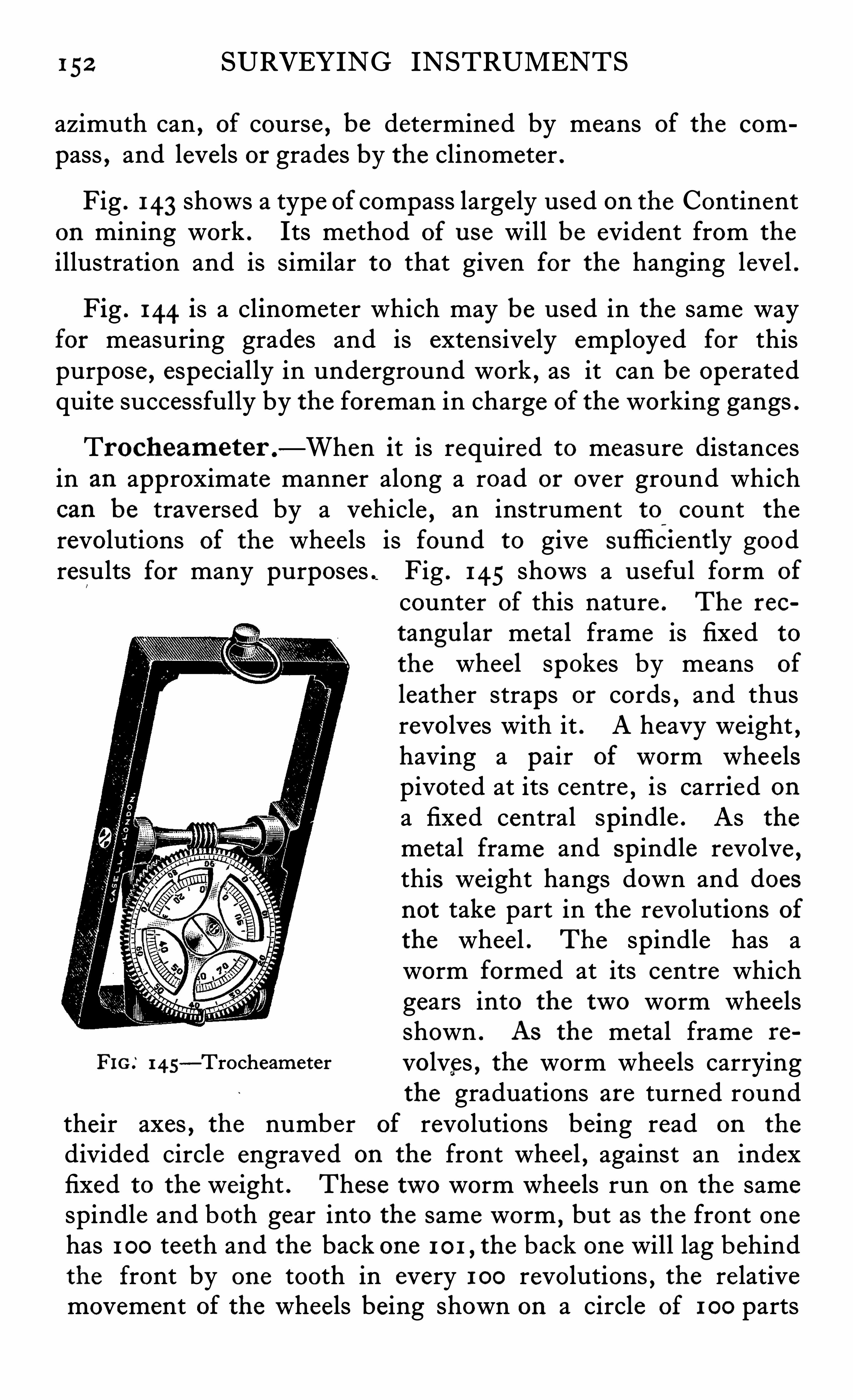
152 SURVEYING INSTRUMENTS
azimuth can,of course , be determined by means of the com
pass,and levels or grades by the clinometer .
Fig . 143 shows a type of compass large ly used on the Continenton mining work . Its method of use will be evident from the
illustration and is similar to that given for the hanging leve l .
Fig . 144 is a clinometer which may be used in the same wayfor measuring grades and is extensive ly employed for thispurpose , especially in underground work , as it can be operatedquite successfully by the foreman in charge of the working gangs .
Trocheameter .—When it is required to measure distances
in an approximate manner along a road or over ground whichcan be traversed by a vehicle , an instrument to count the
revolutions of the wheels is found to give sufliciently goodresults for many purposes . Fig . 145 shows a useful form of
counter of this nature . The rec
tangu lar metal frame is fixed to
the wheel spokes by means of
leather straps or cords , and thusrevolves with it . A heavy weight ,having a pair of worm whee lspivoted at its centre
,i s carried on
a fixed central spindle . As the
metal frame and spindle revolve ,this weight hangs down and doesnot take part in the revolutions of
the whee l . The spindle has aworm formed at its centre whichgears into the two worm wheelsshown . As the metal frame re
FIG.
‘
I 4S- Trocheameter volves , the worm whee ls carrying
the graduations are turned roundtheir axes , the number of revolutions being read on the
divided circle engraved on the front whee l , against an indexfixed to the weight . These two worm whee ls run on the samespindle and both gear into the same worm , but as the front onehas 1 00 teeth and the back one 1 0 1 , the back one will lag behindthe front by one tooth in every 1 00 revolutions , the re lativemovement of the wheels being shown on a circle of 1 00 parts
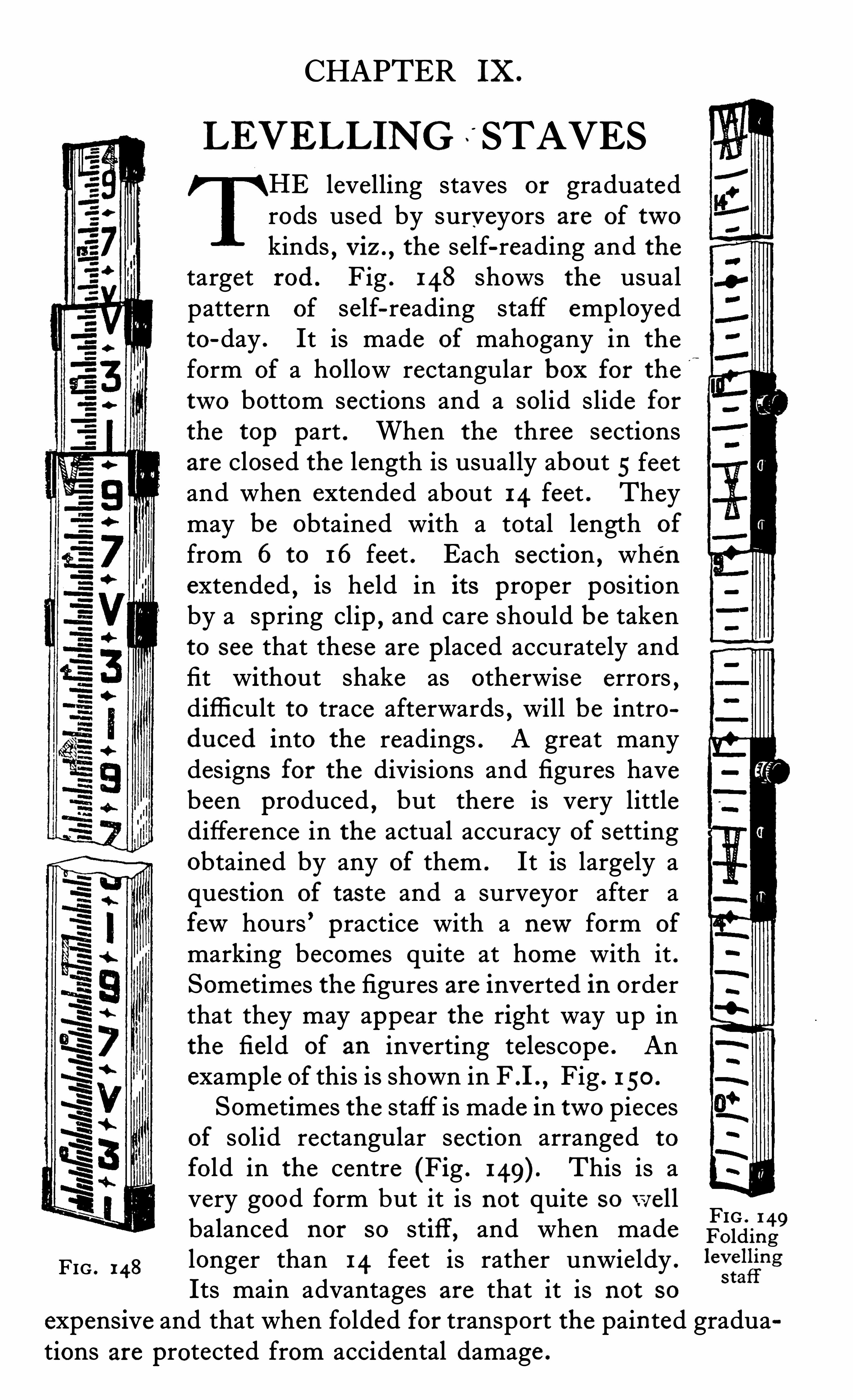
CHAPTER Ix .
LEVELLING STAVES
E levelling staves or graduatedrods used by surveyors are of twokinds , v iz . ,
the self-reading and thetarget rod . Fig . 148 shows the usualpattern of self-reading staff employedto-day . It is made of mahogany in the
form of a hollow rectangular box for thetwo bottom sections and a solid slide forthe top part . When the three sectionsare closed the length is usually about 5 feetand when extended about 14 feet . Theymay be obtained with a total length of
from 6 to 16 feet . Each section , whenextended , is held in its proper positionby a spring clip
,and care should be taken
to see that these are placed accurately andfit without shake as otherwise errors ,difficult to trace afterwards , will be introduced into the readings . A great manydesigns for the divisions and figures havebeen produced
,but there is very little
difference in the actual accuracy of settingobtained by any of them . It is largely aquestion of tas te and a surveyor after afewhours ’ practice with a newform of
marking becomes quite at home with it .Sometimes the figures are inverted in orderthat they may appear the right way up inthe field of an inverting telescope . Anexample of this is shown in F .I . , Fig . 1 50 .
Sometimes the staff is made in two piecesof solid rectangular section arranged to
fo ld in the centre (Fig . This is avery good form but it is not quite sowell FIG . 1 49balanced nor so stiff, and when made Folding
FIG . 148longer than 14 feet is rather unwieldy .
le
zfggng
Its main advantages are that it is not so
expensive and that when folded for transport the painted graduations are protected from accidental damage .
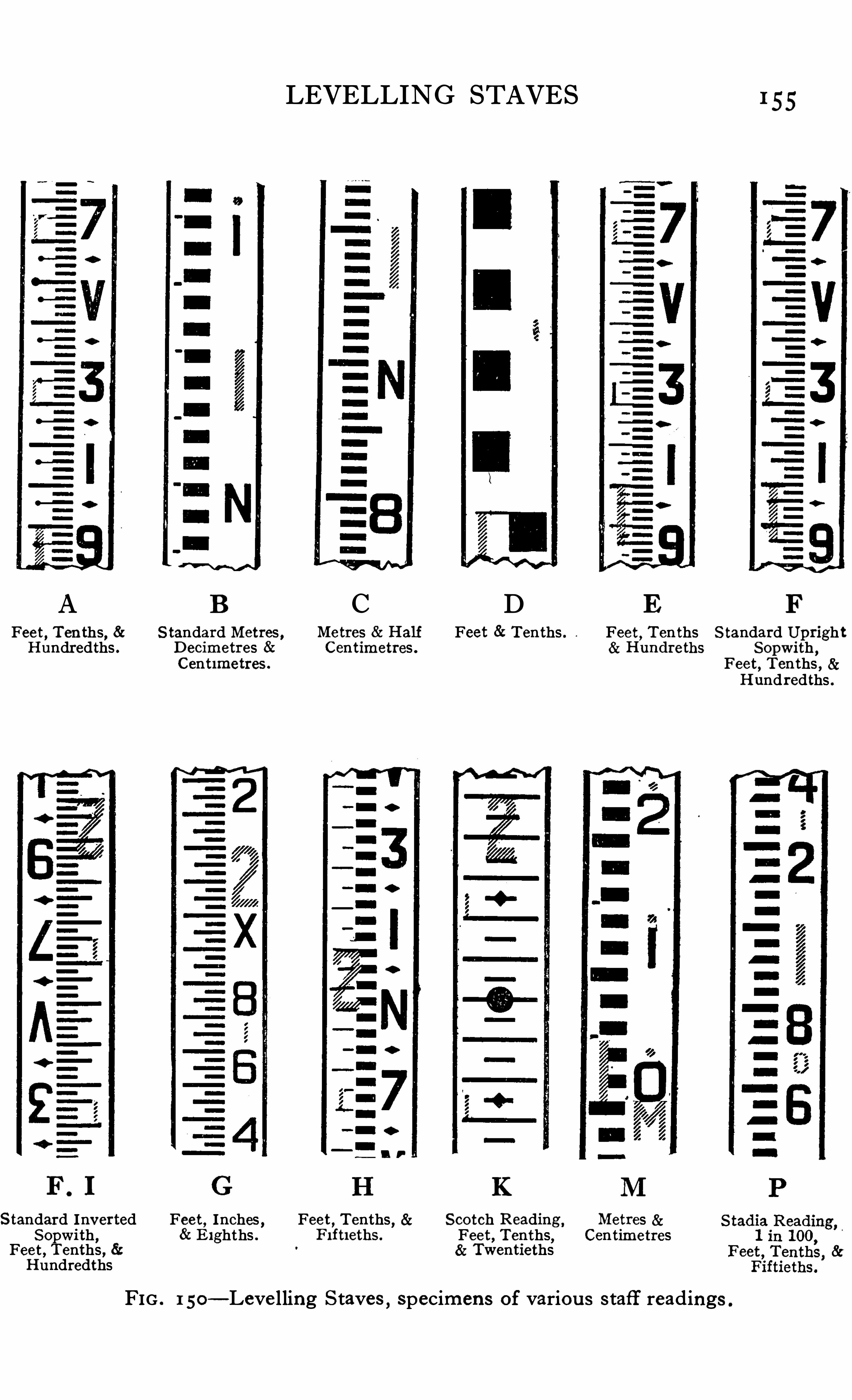
LEVELLING STAVES 1 55
A B C D E FFeet , Ten ths, 8: S tandard Metres , Me tres Half Feet Tenths . Feet
,Tenths S tandard Upright
Hundredths . Decimetres Centimetres . Hundreths Sopwith ,Cent imetres . Feet
,Tenths ,
Hundredths .
n r
Standard Inv erted Feet , Inches , Feet,Tenths
, Scotch Reading ,Metres
Sopwi th , E ighths . Fi ftleths . Feet , Tenths, CentimetresFeet , Tenths , 8: TwentiethsHundredths
FIG . 1 50—Leve lling Staves
,specimens of variou s s taff readings .
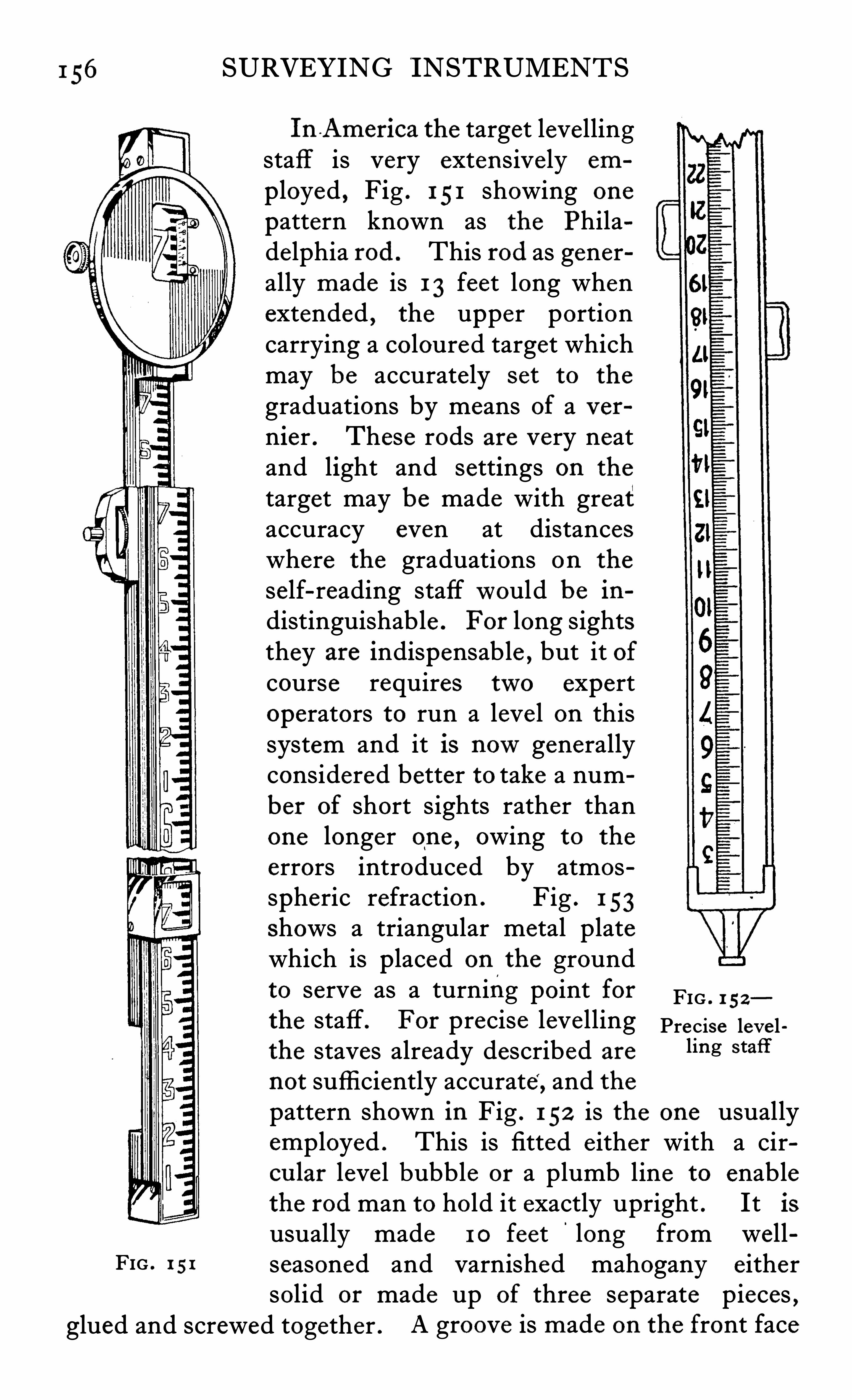
1 56
FIG . 1 51
glued and screwed together .
SURVEYING INSTRUMENTS
In America the target levellingstaff is very extensively em
p loyed , Fig . 1 51 showing one
pattern known as the Philadelphia rod . This rod as generally made is 1 3 feet long whenextended , the upper portioncarrying a coloured target whichmay be accurately set to the
graduations by means of a v ernier . These rods are very neatand light and settings on the
target may be made with greataccuracy even at distanceswhere the graduations on the
self-reading staffwould be indistinguishable . For long sightsthey are indispensable ,
but it ofcourse requires two expertoperators to run a leve l on thissystem and it is nowgenerallyconsidered better to take a number of short sights rather thanone longer one
,owing to the
errors introduced by atmosspheric refraction . Fig . 1 53shows a triangular metal platewhich is placed on the groundto serve as a turning point forthe staff. For precise levellingthe staves already described are
not sufficiently accurate, and the
FIG . 1 52
Precise leve lling staff
pattern shown in Fig . 1 52 is the one usuallyemployed . This is fitted e ither with a circu lar leve l bubble or a plumb line to enablethe rod man to hold it exactly upright . It isusually made 1 0 feet
'
long from wellseasoned and varnished mahogany eithersolid or made up of three separate pieces ,
A groove is made on the front face
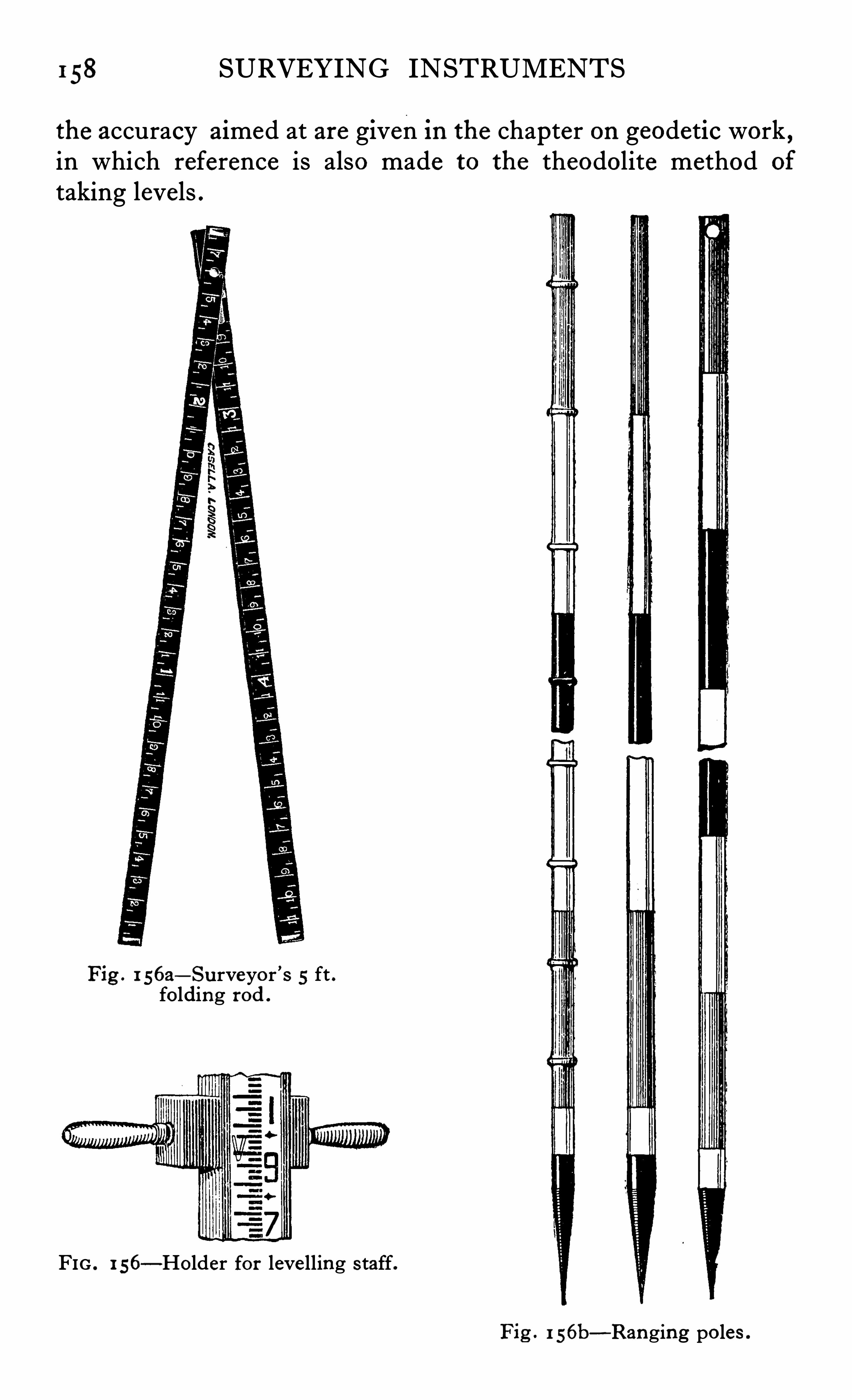
158 SURVEYING INSTRUMENTS
the accuracy aimed at are given In the chapter on geodetic work ,in which reference is also made to the theodolite method of
taking levels .
Fig . 1 s6a—Su rveyor ’s 5 ft .folding rod .
FIG . 1 56—Holder for leve lling s taff.
Fig . 1 56b—Ranging po les .
CHAPTER X .
PHOTOGRAPHIC SURVEYING
HOTOGRAMMETRY may be defined as that branch of
technical applied science which is concerned with the
determination of the forms and dimensions of objects fromphotographic pictures of those objects . A photograph which isfree from optical or mechanical distortion is in truth a perspective pure and simple , and all the laws and principles of per
spectiv e are applicable to the interpretation of such photographs .
For the correct interpretation and u se of perspectives formeasuring purposes it is necessary not only that they should betrue geometrically
,butwe must know or ascertain by some
means a number of particulars concerning each perspective .
Especially is it necessary to know
(1 ) The position of the spot from which the perspectivewasobtained (station) .
(2 ) The picture plane .
(3) The orientation of the View .
(4) The trace of the principal plane .
5) The trace of the horizon plane .
(6) The principal point (intersection of) (3) . and
(7) The length of the distance line , which in the case of aphotograph is the working focal length of the lens .
Various instruments have been specially designed to give truephotographic perspectives always in a vertical plane and atconstant distances and furnished with specially designedmechanism inside the camera for recording on the negative allor nearly all the information necessary for interpreting the
picture .
The practical advantages which result from having the
necessary data for interpretation recorded on the face of the
160 SURVEYING INSTRUMENTS
picture instead of in separate note-books , are very great . Risksof error and confusion are very much reduced . Much tim e issaved both in the field and in the ofli ce . Plotting operationsare rendered more easy , certain , and accurate , and the p ictureswill be more valuable as permanent records for future reference ,
The theory and the methods of photogrammetric measurement are not at all new. They were fully expounded more thanforty years ago by C01. Lau ssedat , Directeur da Conserva toiredes Arts at Mé tz
'
ers , Paris . Also from time to time there havebeen many photographic surveys made in many differentcountries over limited areas and with excellent results
,but it
has been reserved for the Canadian surveyors under the guidanceof the late Mr E . Deville , Surveyor-General , to demonstrateon a very large scale , and finally and conclusive ly that for hillyand mountainous districts the photographic method is superiorto all others . It has been proved to be very much quicker andcheaper than any other known method and more convenientand at least as accurate .
"
Some of the special advantages of the photographic methodmay be epitomised as follows
(1 ) It is often possible to obtain photographic p ictures of
places for surveying purposes which it would be quite impossible to survey by any more ordinary means , e .g .:—(a) Inmany exposed mountainous regions where the weather isgenerally unsettled and uncertain with only occasional fi neperiods ; or when so much time is of necessity consumed intravelling to and returning from a surveying station that it isimpossib le to spend much time at the station . (b) For militarypurposes in an enemy country . (c) When a traveller is com
pelled by circumstances to traverse unknown country at a rapidpace ; and speaking generally wherever and whenever it ispossible to obtain occasional clear views from spots visited ,but not possible to stay for any length of time at those spots orto revisit them . In all such cases the photographic method isthe best because it is the only effective one .
Deville has shown that in Canada the cos t of a photographic sufv ey byme thods heretofore in u se is con s iderably les s than on e -third of th e cos t of aplane table su rvey .
I 62 SURVEYING INSTRUMENTS
The difficulties under the first head may be further subdivided under two heads as follows(a) Those of a purely photographic nature .
(b) Those incidental to the choice of suitable stations .
The purely technical difficulties under (a) may be conqueredby a preliminary training on the part of the personswho are
concerned in producing the photographic p ictures . Clear ,well-defi ned pictures and , therefore , properly exposed plates ,are essential to success , so that great care must be taken in theactual manipulation of the camera at the stations
,as otherwise
much valuable time may be lost if any of them have to be re
occupied . The difli cu lties under (b) can only be conqueredby experience on the part of the surveyor in charge of the
operations,and the choice of stations
,and the proper orientation
of the camera must be skilfully carried ou t if the actual work ofconstructing the map in the ofli ce is to be done expeditiously .
The actual number of pictures which should be taken fromeach station will vary with the character of the country beingsurveyed , and from the point of view of economy , this numbermust be reduced to the utmost . When known triangulationpoints can be included in the picture , the stations must be so
chosen that as many of these points as possible may be observedfrom each station and that the same points may be photographedfrom at least two ,
or better still,three stations . The problems
met with are similar to those which the surveyor encountersin any other form of t0pographic work , but more forethoughtis generally required owing to the fact that the results are not
immediately obtainable as they are , for example , in planetabling
,and that mistakes are therefore not easily rectified .
The greatest diffi culties , however , are those under The
construction of the maps from the photographs entails a greatamount of labour and requires considerable practice , and thosecharged with this work , being office men and not generallyfamiliar with the country be ing mapped , have to rely on the
pictures for all their information . This is a great handicap ,and unless the photographs are technically perfect and properlyidentified by records of the ir orientation , etc . , the constructionof the map becomes extremely difli cu lt , if not impossib le . The
various methods used in the plotting of the maps , are very fully
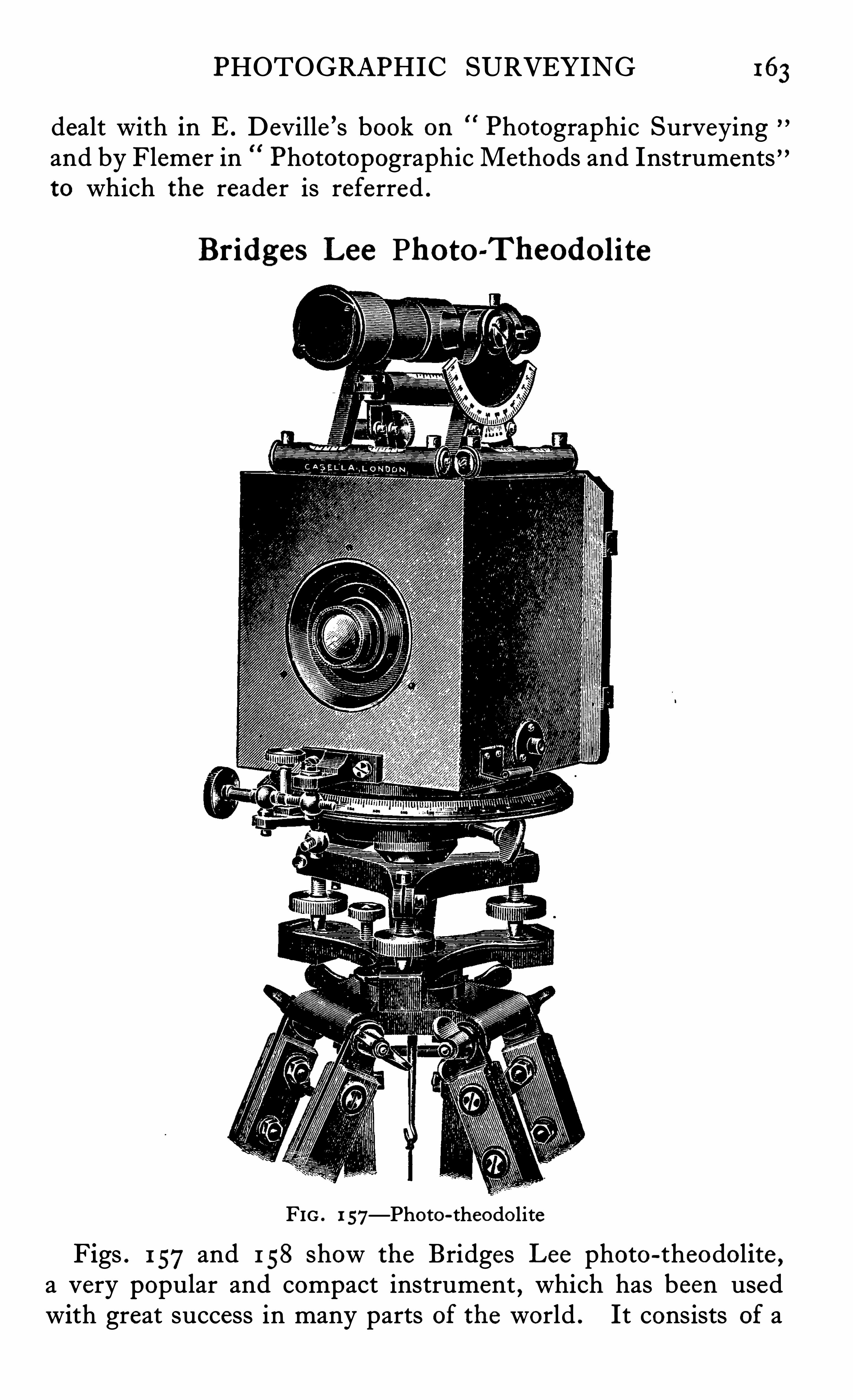
PHOTOGRAPHIC SURVEYING 163
dealt with in E . Deville ’s book on Photographic Surveyingand by Flemer in Phototopographic Methods and Instrumentsto which the reader is referred .
Bridges Lee Photo-Theodo lite
FIG . 1 57—Phot0-theodoliteFigs . 1 57and 1 58 show the Bridges Lee photo-theodolite ,
a very popular and compact instrument,which has been used
with great success in many parts of the world . It consists of a
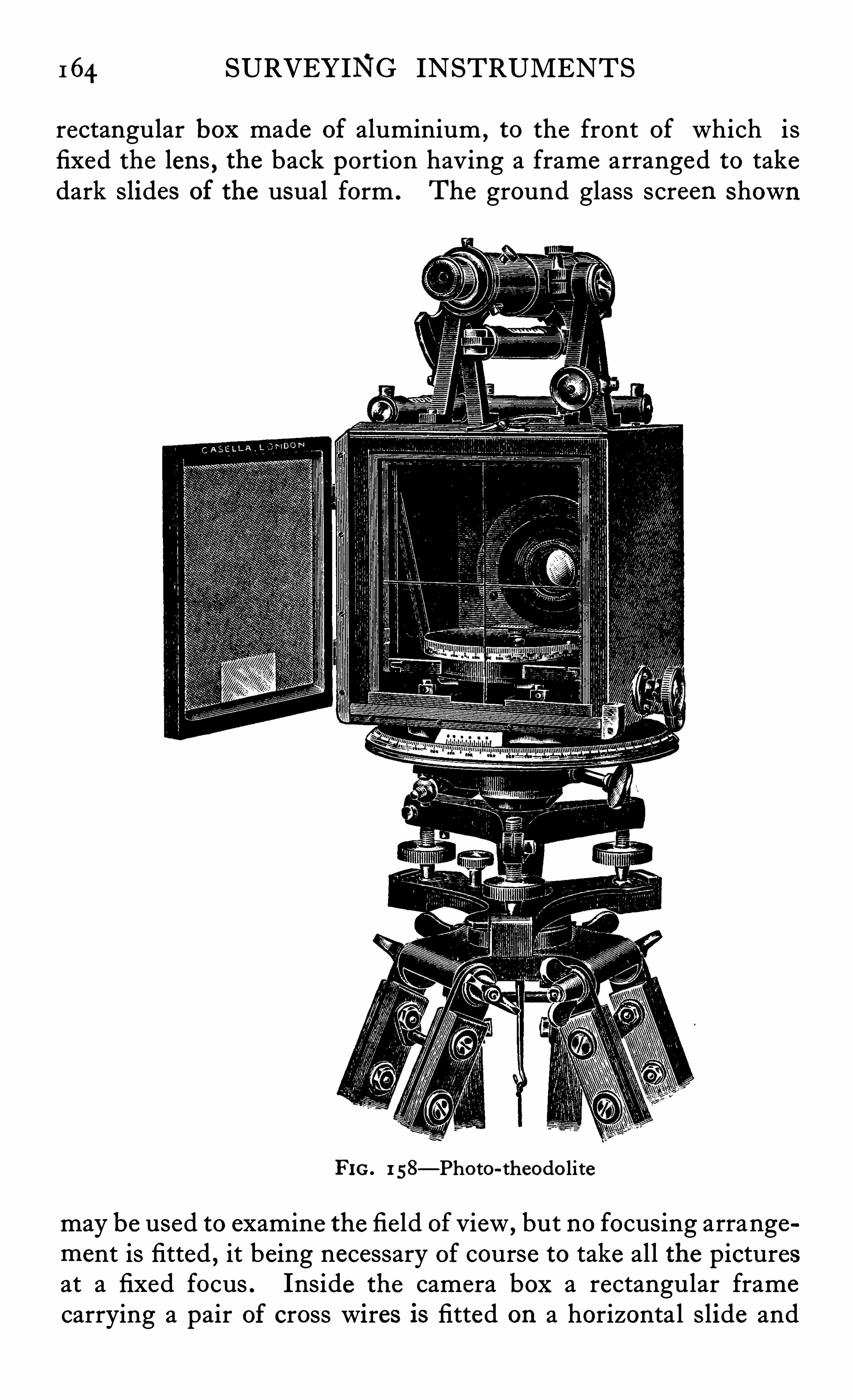
I 64 SURVEYING INSTRUMENTS
rectangular box made of aluminium , to the front of which isfixed the lens , the back portion having a frame arranged to takedark slides of the usual form . The ground glass screen shown
FIG. 1 58—Photo-theodo lite
may be used to examine the field of view , but no focusing arrangement is fitted , it being necessary of course to take all the picturesat a fixed focus . Inside the camera box a rectangular framecarrying a pair of cross wires is fitted on a horizontal slide and
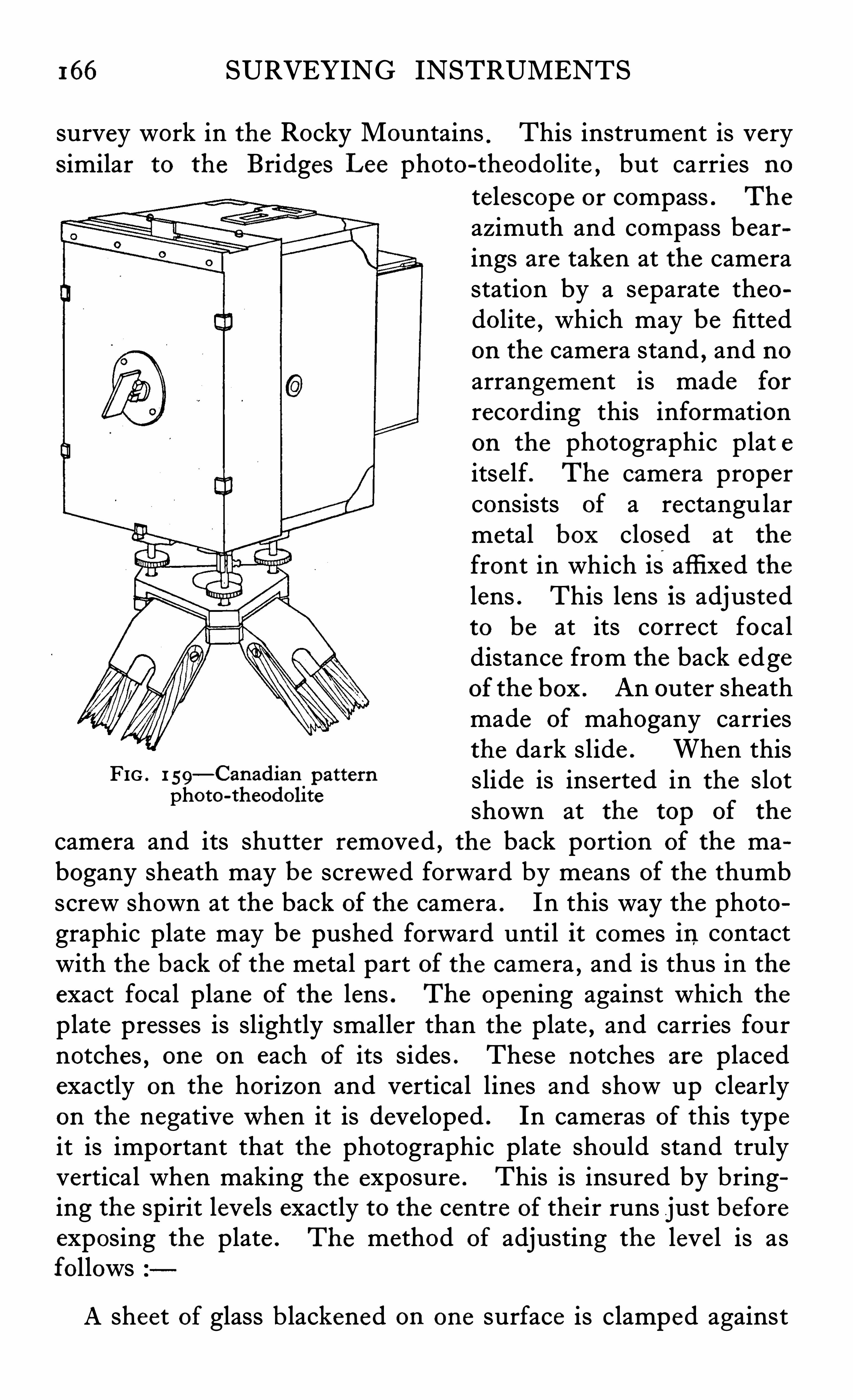
166 SURVEYING INSTRUMENTS
survey work in the Rocky Mountains.This instrument is very
s imilar to the Bridges Lee photo-theodolite ,but carries no
telescope or compass . The
azimuth and compass bearings are taken at the camerastation by a separate theodolite , which may be fittedon the camera stand
,and no
arrangement is made for
recording this informationon the photographic plat eitself. The camera properconsists of a rectangu larmetal box closed at the
front in which is affixed thelens . This lens is adjustedto be at its correct focaldistance from the back edgeof the box . An outer sheathmade of mahogany carriesthe dark slide . When this
FIG ' 1 59—canadian
.Pattem slide is inserted in the slotphoto-theodohte
shown at the top of the
camera and its shutter removed , the back portion of the mabogany sheath may be screwed forward by means of the thumbscrew shown at the back of the camera . In this way the photographic plate may be pushed forward until it comes in contactwith the back of the metal part of the camera , and is thus in theexact focal plane of the lens . The opening against which theplate presses is slightly smaller than the plate ,
and carries fournotches , one on each of its sides . These notches are placedexactly on the horizon and vertical lines and show up clearlyon the negative when it is developed . In cameras of this typeit is important that the photographic plate should stand trulyvertical when making the exposure . This is insured by bringing the spirit leve ls exactly to the centre of the ir runs just beforeexposing the plate . The method of adjusting the leve l is asfollows
A sheet of glass b lackened on one surface is clamped against
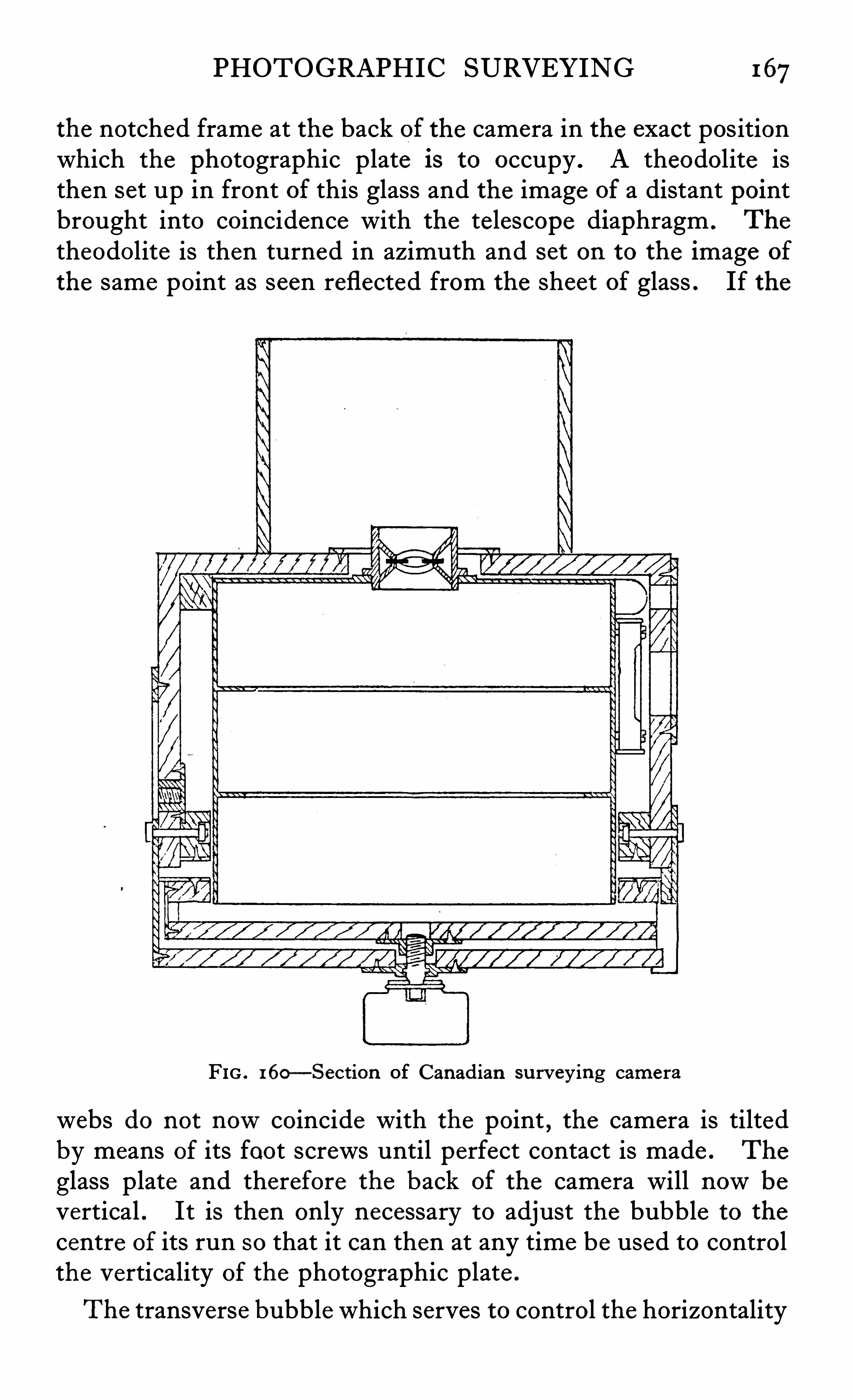
PHOTOGRAPHIC SURVEYING 167
the notched frame at the back of the camera in the exact positionwhich the photographic plate 18 to occupy . A theodolite isthen set up in front of this glass and the image of a distant pointbrought into coincidence with the telescope diaphragm . The
theodolite is then turned in azimuth and s et on to the image of
the same point as seen reflected from the sheet of glass . If the
FIG . 160—Section of Canadian su rveying camera
webs do not nowcoincide with the point , the camera is tiltedby means of its foot screws until perfect contact is made . The
glass plate and therefore the back of the camera will nowbevertical . It is then only necessary to adjust the bubble to the
centre of its run so that it can then at any time be used to controlthe verticality of the photographic plate .
The transverse bubble which serves to control the horizontality
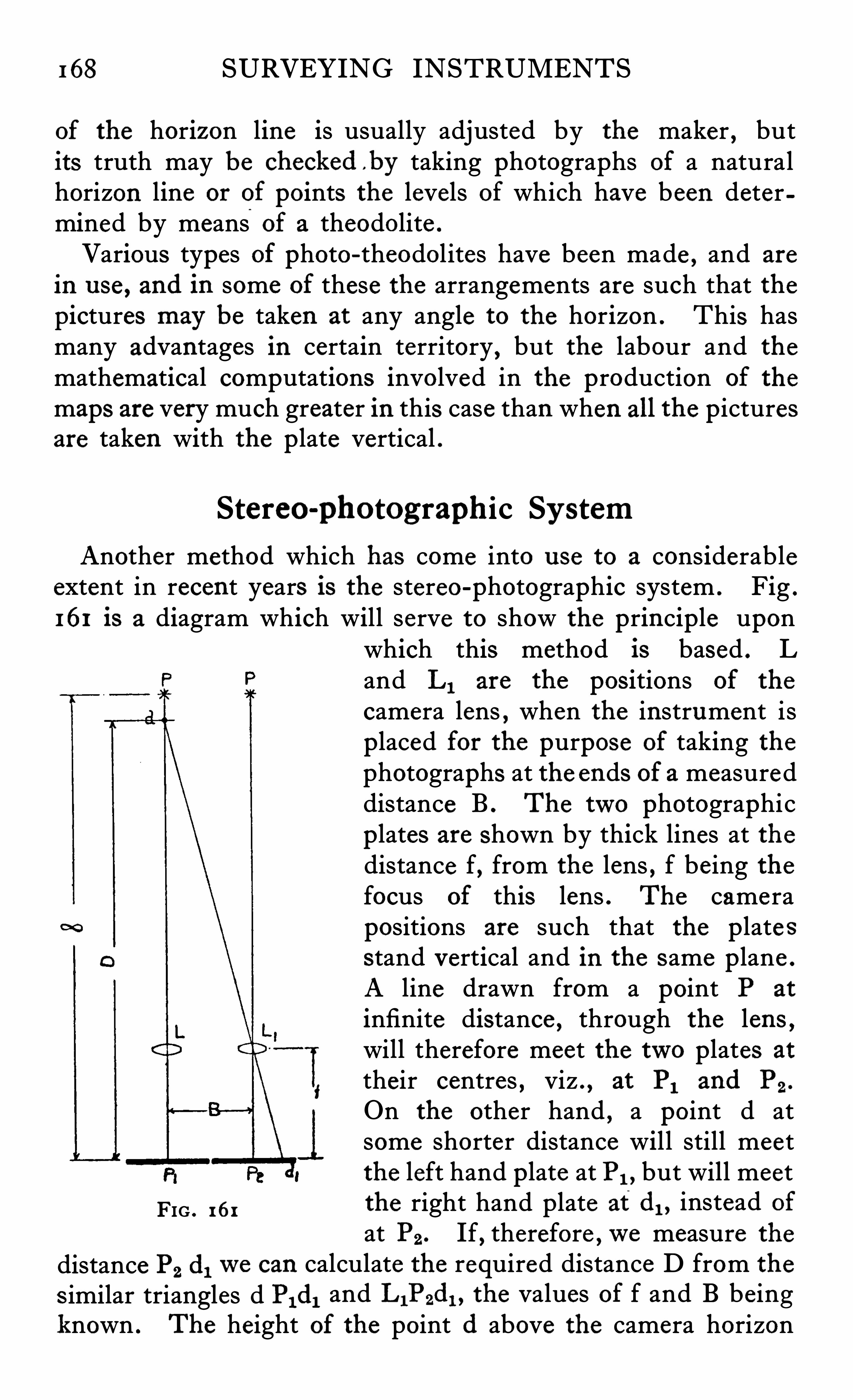
168 SURVEYING INSTRUMENTS
of the horizon line is usually adjusted by the maker , butits truth may be checked b y taking photographs of a naturalhorizon line or of points the levels of which have been determined by means
'
of a theodolite .
Various types of photo-theodol ites have been made , and are
in use , and in some of these the arrangements are such that thepictures may be taken at any angle to the horizon . This hasmany advantages in certain territory , but the labour and the
mathematical computations involved in the production of the
maps are very much greater in this case than when all the p icturesare taken with the p late vertical .
Stereo-photographic Sy stem
Another method which has come into use to a considerableextent in recent years is the stereo-photographic system . Fig .
161 is a diagram which will serve to show the principle uponwhich this method is based . Land L I are the pos itions of the
camera lens , when the instrument isplaced for the purpose of taking thephotographs at the ends of a measureddistance B . The two photographicplates are shown by thick lines at thedistance f, from the lens , f being thefocus of this lens . The camerapositions are such that the p late sstand vertical and in the same p lane .
A line drawn from a point P at
infinite distance , through the lens ,will therefore meet the two plates at
their centres , viz . , at PI and P2 .
On the other hand , a point d atsome shorter distance wil l still meetthe left hand plate at PI , but will meet
FIG . 161 the right hand plate at d l , instead of
at P2 . If, therefore ,we measure the
distance P2 dlwe can calculate the required distance D from the
s imilar triangles d Pl dl and L1P2d1 , the values of f and B beingknown . The height of the point (1 above the camera horizon
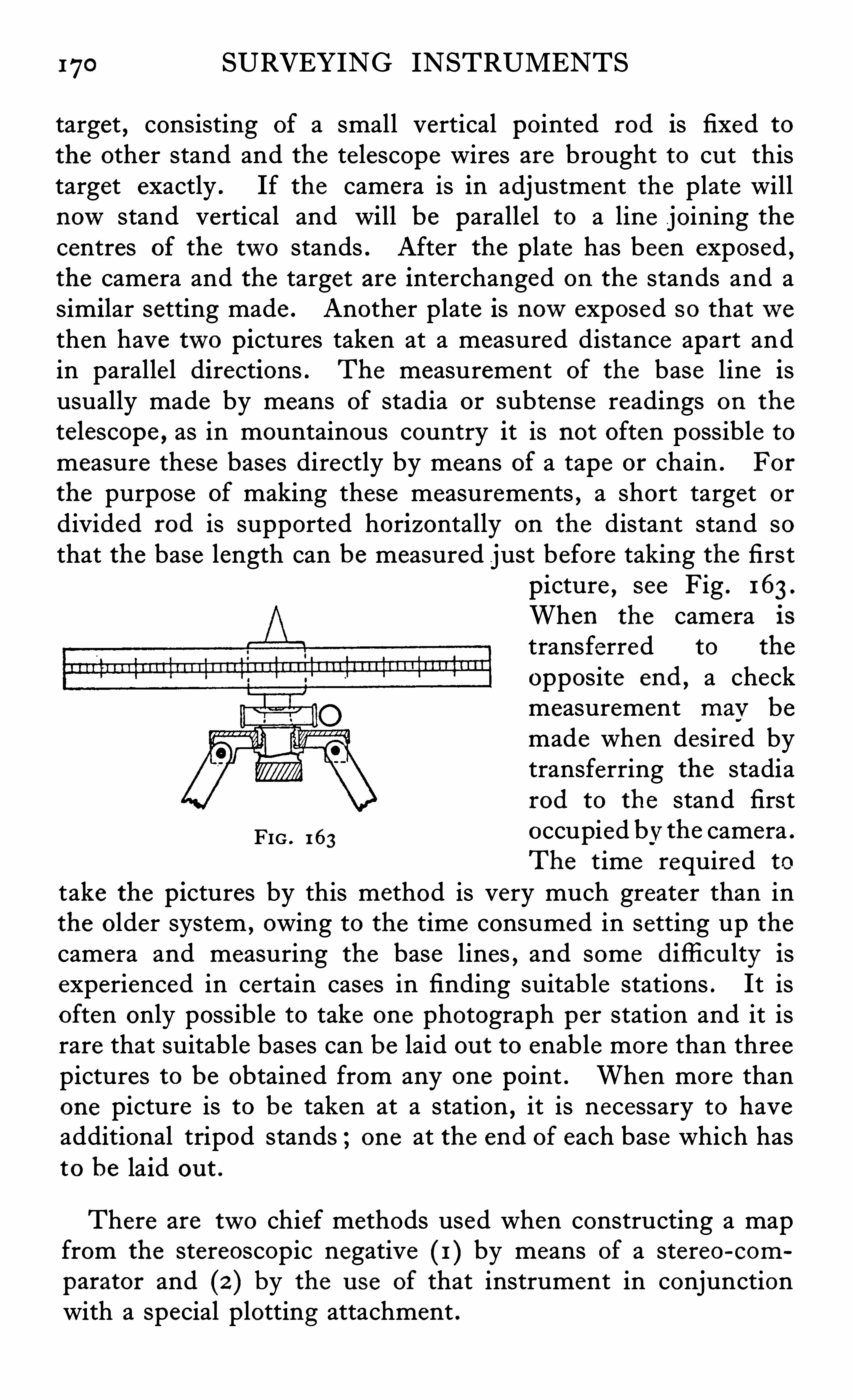
170 SURVEYING INSTRUMENTS
target , consisting of a small vertical pointed rod is fixed tothe other stand and the te lescope wires are brought to cut thistarget exactly . If the camera is in adjustment the plate willnowstand vertical and will be parallel to a line joining thecentres of the two stands . After the plate has been exposed ,the camera and the target are interchanged on the stands and asimilar setting made . Another plate is nowexposed so thatwethen have two pictures taken at a measured distance apart andin parallel directions . The measurement of the base line isusually made by means of stadia or subtense readings on the
telescope , as in mountainous country it is not often possible tomeasure these bases directly by means of a tape or chain . For
the purpose of making these measurements , a short target ordivided rod is supported horizontally on the distant stand so
that the base length can be measured just before taking the firstpicture , see Fig . 163 .
When the camera is
transferred to the
opposite end , a checkmeasurement may be
made when desired bytransferring the stadiarod to the stand first
FIG . 163occupied bv the camera .
The time required to
take the pictures by this method is very much greater than inthe older system , owing to the time consumed in setting up thecamera and measuring the base lines , and some difli cu lty is
experienced in certain cases in finding suitab le stations . It isoften only possible to take one photograph per station and it israre that suitable bases can be laid ou t to enable more than threepictures to be obtained from any one point . When more thanone picture is to be taken at a station , it is necessary to haveadditional tripod stands ; one at the end of each base which hasto be laid ou t .
There are two chief methods used when constructing a mapfrom the stereoscopic negative (1 ) by means of a stereo-com
parator and (2 ) by the u se of that instrument in conjunctionwith a special plotting attachment .
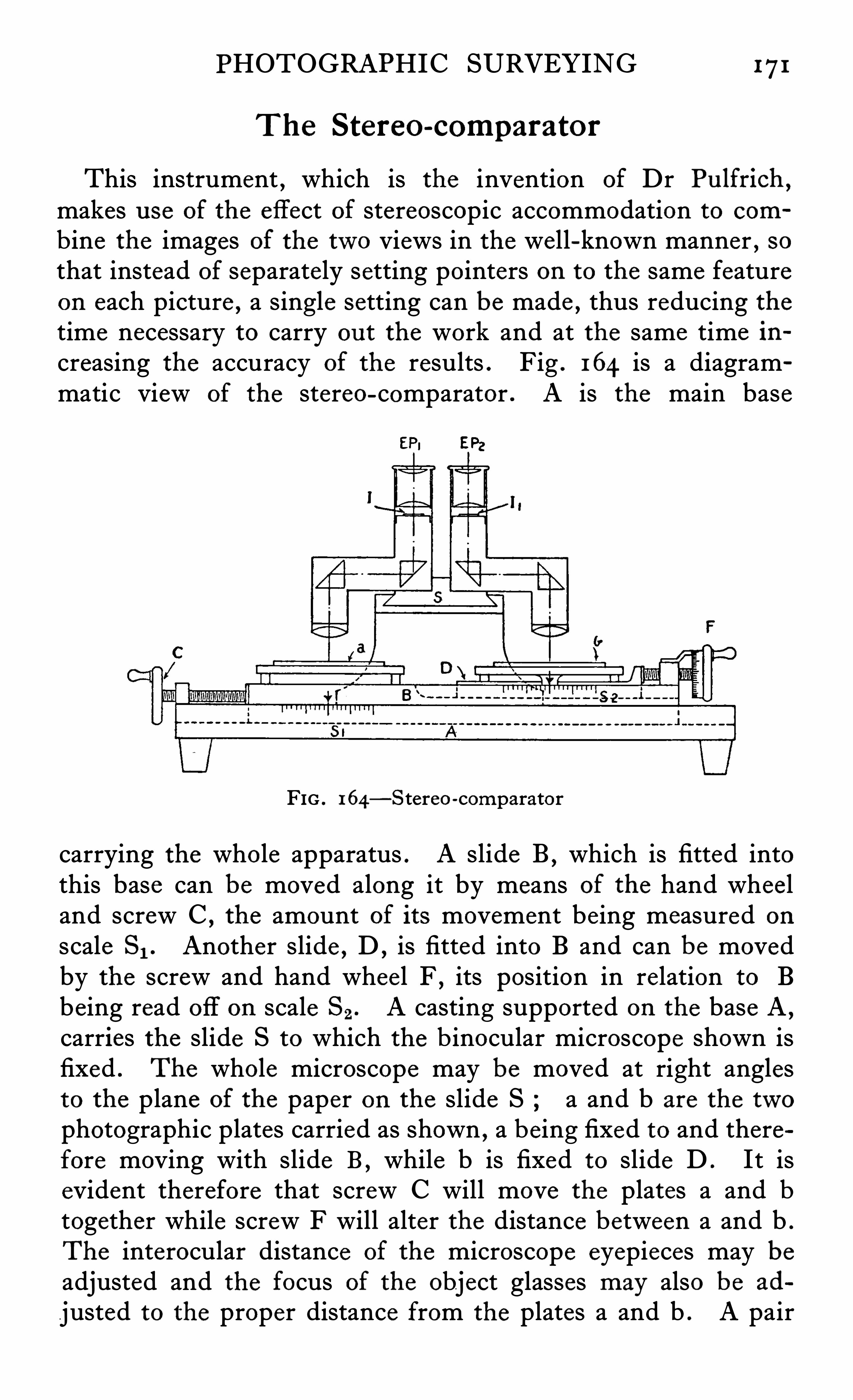
PHOTOGRAPHIC SURVEYING 171
The Stereo-comparator
This instrument , which is the invention of Dr Pu lfrich ,
makes u se of the effect of stereoscopic accommodation to com
bine the images of the two views in the well-known manner , sothat instead of separately setting pointers on to the same featureon each picture , a single setting can be made , thus reducing thetime necessary to carry ou t the work and at the same time in
creasing the accuracy of the results . Fig . 164 is a diagrammatic view of the stereo-comparator . A is the main base
FIG . 164—Stereo-comparator
carrying the whole apparatus . A slide B , which is fitted intothis base can be moved along it by means of the hand wheeland screw C ,
the amount of its movement being measured on
scale S1 . Another slide , D , is fitted into B and can be movedby the screw and hand whee l F , its position in relation to Bbeing read off on scale Sz. A casting supported on the base A ,
carries the slide S to which the b inocular microscope shown isfixed . The whole microscope may be moved at right anglesto the plane of the paper on the slide S a and b are the twophotographic plates carried as shown , a being fixed to and therefore moving with slide B , while b is fixed to slide D . It isevident therefore that screw C will move the plates a and btogether while screw F will alter the distance between a and b .
The interocular distance of the microscope eyepieces may beadjusted and the focus of the object glasses may also be ad
justed to the proper distance from the plates a and b . A pair
172 SURVEYING INSTRUMENTS
of indices I and 11 are placed in the mutual focus of the objectglasses and the eyepieces , the appearance of these in the fie ldwhen viewed together being shown in Fig . 165. The scale SI
is called the azimuth scale 8 2 the parallaxscale and a scale attached to slide S , theheight scale . The method of using the
apparatus is as follows
The object glasses are first set by the
operator to correct focus and each eyepieceadjusted to its index in order to e liminate
Fm . 165parallax in the usual way . The eyepiecesare then set at the interocular distance of
the observer thus combining the indices I and I l , stereoscopicallyto form a single image . The screw C is nowmoved Until whenusing the left eye only the principal line impressed on the leftpicture coincides with the index I . A similar adjustment ismade on the right picture using the right eye only . On lookingthrough the microscope the indices will be combined and willappear to be suspended over an object at infinite distance . Ifthe plate b is nowmoved by means of the screw F , it will bepossible to bring the index gradually nearer until it appears tobe suspended over any object desired . The amount of movement necessary to effect this will be shown on the scale , Sz, andis evidently equal to the parallax of the point ranged upon .
As the focal length of the camera lens is fixed , and as the lengthof the stereo base between the two camera positions is known ,the graduations of the scale can be converted directly into termsof horizontal distance by the application of a suitable constant .The objects as seen by the microscope will stand ou t in sharprelief, owing to the exaggerated effect given by the long stereoscopic base which was used when taking the pictures , so that theindex may be set very easily and accurately on to the selectedpoints . Any number of points may be measured in this way ,and points of equal height may also be determined
,thus allow
ing contour lines to be readily obtained . When a sufficientnumber of points have been tabulated , the map may be con
structed with much greater ease and accuracy than in the oldermethod of intersections
,where at least three measurements must
be made to fix any one point as against one pointing only in the
174 SURVEYING INSTRUMENTS
above or be low the horizontal and to follow this height across thevarious points at the same altitude on the picture .
A full description of Von Or el ’ s s tereo -au tograph has beenpublished in Mitterlingen A. u G. 191 1 , to which the reader isreferred for further details .
The main advantage which the stereo-plotter has over themethod of plotting by intersection is the greater speed withwhich the work can be done . By Deville ’s method of intersections , the plotting of 1 00 points takes about a week , whereaswith the stereo-plotter it is claimed that this number can easilybe accomplished in an hour , and by the Stereo-autograph inprobably half that time .
Another advantage which the stereoscopic method has overthat used formerly is that the identification of similar points inthe various pictures is rendered much easier owing to the factthat exaggerated relief effects are obtained and that the pointsare examined under magnification and can therefore be set
very exactly by means of the micrometer screws . There is nodoubt however , that the plotting part of the apparatus is theweakest link in the chain and that full advantage cannot betaken of the exactness of the setting which may be made underthe microscope .
All these photogrammetric schemes fail when the countryto be surveyed is flat and wooded , but when the region to bemapped is rugged or mountainous the stereo method in con
junction with a suitable plotter is undoubtedly superior to allothers
,both in accuracy and speed . Since the advent of the
aeroplane and airship great strides have been made in aerialphotography , and a number of surveys have been made withexcellent results by means of photographs taken in this way .
The chief difli cu lty to be encountered is the determination of theangle which the plate made to the horizontal at the time the
photograph was taken . When the plate is paralle l to the
ground , the resulting photograph is rather mosaic-like , andcan only serve as a rough guide for such purposes as militaryoperations . Owing also to the height Of the camera and the
consequent fore-shortening , it is impossib le to arrive at thealtitude of the various points above the general leve l , andtherefore contours cannot be determined .
PHOTOGRAPHIC SURVEYING 175
Photograph s on Incl ined P1ates .—To obviate this difli
culty,proposals have been made to take the pictures on plates
inclined at an angle to the horizon . If some method could bedevised to measure and record this angle at the time the photograph is being taken , the subsequent work in plotting wouldbecome easier and more exact . Up to the present no designhas been produced which is altogether satisfactory , but no
doubt some scheme will shortly be evolved , as the subject isone which is receiving a good deal of attention at the presenttime . When the photographs are taken on inclined plates , thecarrying ou t of the necessary computations Is very laborious andvarious methods have been proposed , all having for their objectthe simplification of this work . One scheme is to set up the
picture in a camera in front of a special theodolite which is usedin the same manner as if it were placed on the camera station .
Another is to re-photograph the picture in such a way that itis brought back to the vertical . Hugershoft 8c Cranz haverecently constructed an apparatus on which plotting may bedone directly from the actual stereoscopic negatives taken froman airship . It must be confessed that the subject is one whichbristles with difficulties , both mechanical and mathematical ,but its fascination and its possibilities are so great that developments in the direction of the simp lification and precision of the
apparatus are sure to take place in the near future .
The best books on the subject to which those requiring fullerdetails are referred are
Photographic Surveying , Deville .
Phototopographic Methods , Flemer .Mapping from Air Photographs
,
” McLeod .
Applications de la Photographie Aerienne , Rou ssilhe .
CHAPTER "I
Apparatu s for the
INVESTIGATION OF THE UPPER
ATMOSPHERE
URING the last fewyears great attention has been paidto the study of the upper air and to the conditions ofwind , temperature and humidity which are found there .
The remarkable extension of aviation has made it more thanever necessary to pay close attention to the air currents overthe surface of the earth , and modern military requirementsinclude , even on the battlefield , a meteorological s taff andapparatus for assisting them in predicting wind and weatherconditions for various purposes .
The meteorological conditions of the upper air are studiedeither by means of rubber balloons filled with hydrogen or bymeans of kites . The balloon may be comparatively large , aboutone metre in diameter , in which case it will carry small instruments recording the temperature and barometric pressure atvarious heights
,or a smaller balloon may be used , not carrying
any instruments,whose path in the air is fol lowed by a theo
dolite self-recording or otherwise . The former are usuallycalled p i lot b a l loon s and the latter b a l lon s -sondes .
”
The recording instruments carried on the balloons have to bemade extreme ly small and light
,for the balloon ascends until
the air becomes so rarefied that it bursts , and the ske leton , withthe instruments , fall to the ground . As the records have to
be’ obtained from the instruments , after they have fallen , it isvery important that these should not be damaged . Owing tothe extremely ingenious design of Mr W . H . Dines , Fthese instruments are made so light that they fall comparativelyslowly to the ground
,the burst balloon acting as a parachute ,
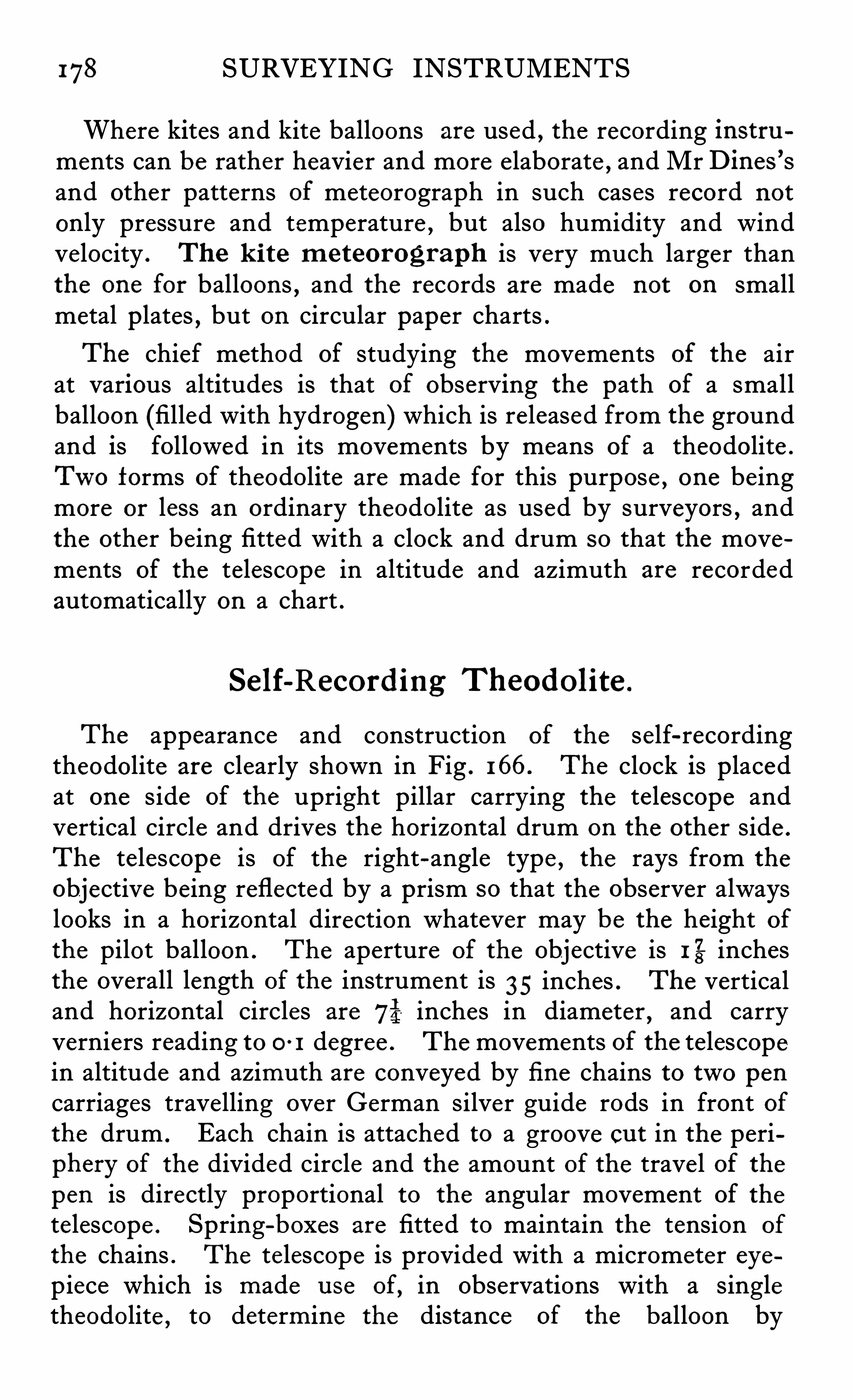
178 SURVEYING INSTRUMENTS
Where kites and kite balloons are used , the recording instruments can be rather heavier and more e laborate , and Mr Dines
’
s
and other patterns of meteorograph in such cases record not
only pressure and temperature , but also humidity and windvelocity . The k i te m eteorograph is very much larger thanthe one for balloons , and the records are made not on smallmetal plates , but on circular paper charts .
The chief method of studying the movements of the airat various altitudes is that of observing the path of a smallballoon (filled with hydrogen) which is released from the groundand is followed in its movements by means of a theodolite .
Two forms of theodolite are made for this purpose , one beingmore or less an ordinary theodolite as used by surveyors , andthe other being fitted with a clock and drum so that the movements of the telescope in altitude and azimuth are recordedautomatically on a chart .
Self-Record ing Theodolite .
The appearance and construction of the self-recordingtheodolite are clearly shown in Fig . 166. The clock is placedat one side of the upright pillar carrying the telescope andvertical circle and drives the horizontal drum on the other side .
The telescope is of the right-angle type , the rays from the
objective being reflected by a prism so that the observer alwayslooks in a horizontal direction whatever may be the height ofthe pilot balloon . The aperture of the objective is 1%inchesthe overall length of the instrument is 35 inches . The verticaland horizontal circles are 751 inches in diameter , and carryverniers reading to 0 1 degree . The movements of the telescopein altitude and azimuth are conveyed by fi ne chains to two pencarriages travelling over German silver guide rods in front ofthe drum . Each chain is attached to a groove cu t in the periphery of the divided circle and the amount of the trave l of thepen is directly proportional to the angular movement of thetelescope . Spring-boxes are fitted to maintain the tension of
the chains . The te lescope is provided with a micrometer eyepiece which is made u se of, in observations with a singletheodolite , to determine the distance of the balloon by
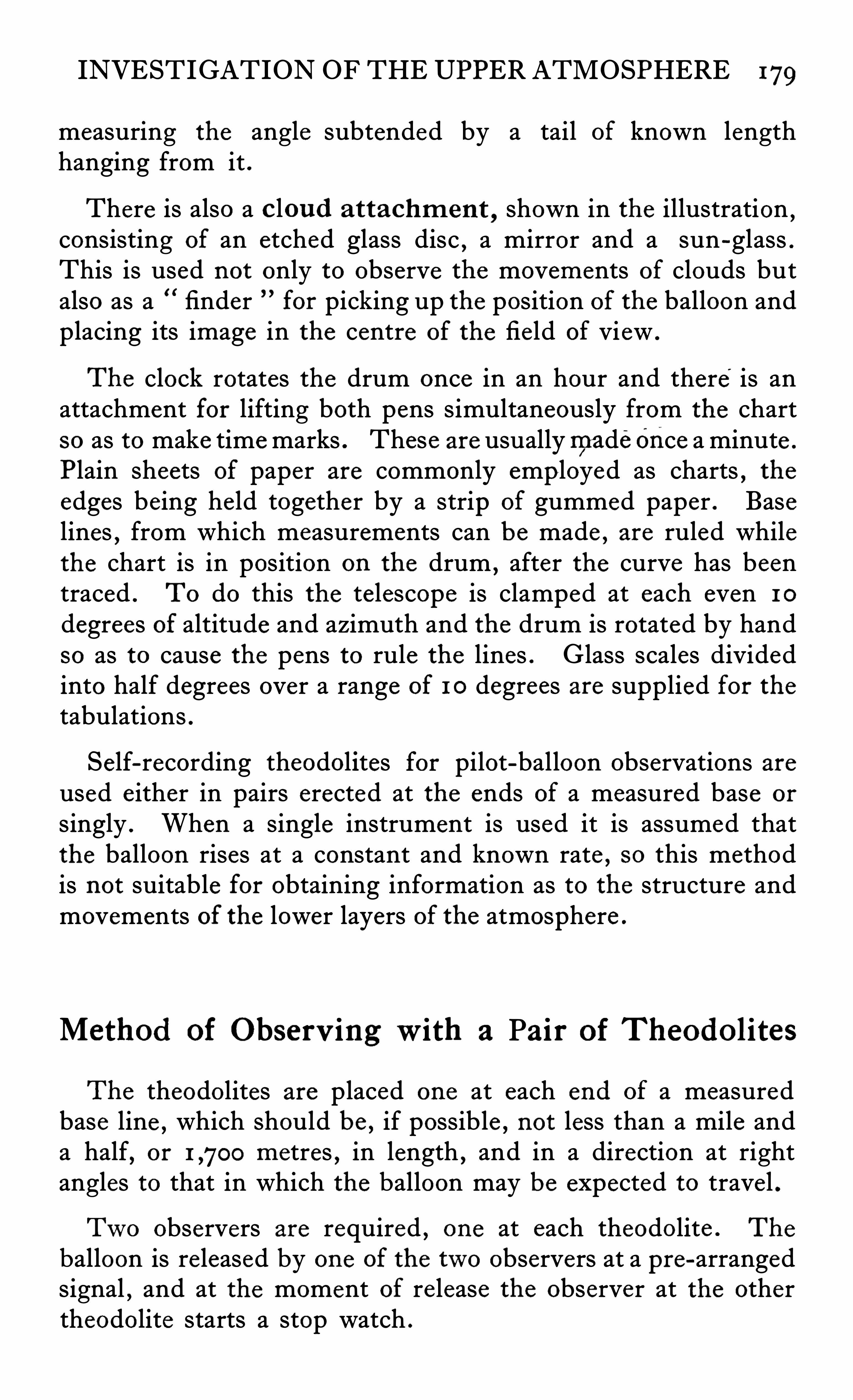
INVESTIGATION OF THE UPPER ATMOSPHERE 179
measuring the angle subtended by a tail of known lengthhanging from it .
There is also a c lou d a ttachm ent,shown in the illustration
,
consisting of an etched glass disc,a mirror and a sun-glass .
This is used not only to observe the movements of clouds butalso as a finder for picking up the position of the balloon andplacing its image in the centre of the field of view .
The clock rotates the drum once in an hour and there is anattachment for lifting both pens simultaneously from the chartso as to make timemarks . These are usuallymadeonce a minute .
Plain sheets of paper are commonly employed as charts , theedges being he ld together by a strip of gummed paper . Baselines
,from which measurements can be made , are ruled while
the chart is in position on the drum,after the curve has been
traced . To do this the telescope is clamped at each even 1 0
degrees of altitude and azimuth and the drum is rotated by handso as to cause the pens to rule the lines . Glass scales dividedinto half degrees over a range of 1 0 degrees are supplied for thetabulations .
Self-recording theodolites for pilot-balloon observations areused either in pairs erected at the ends of a measured base or
singly . When a single instrument is used it is assumed thatthe balloon rises at a constant and known rate , so this methodis not suitable for obtaining information as to the structure andmovements of the lower layers of the atmosphere .
Method of Observ ingwith a Pair of Theodolites
The theodolites are placed one at each end of a measuredbase line ,
which should be , if possible ,not less than a mile and
a half,or metres , in length , and in a direction at right
angles to that in which the balloon may be expected to trave l .
Two observers are required , one at each theodolite . The
balloon is re leased by one of the two observers at a pre-arrangedsignal
,and at the moment of release the observer at the other
theodolite starts a stop watch .
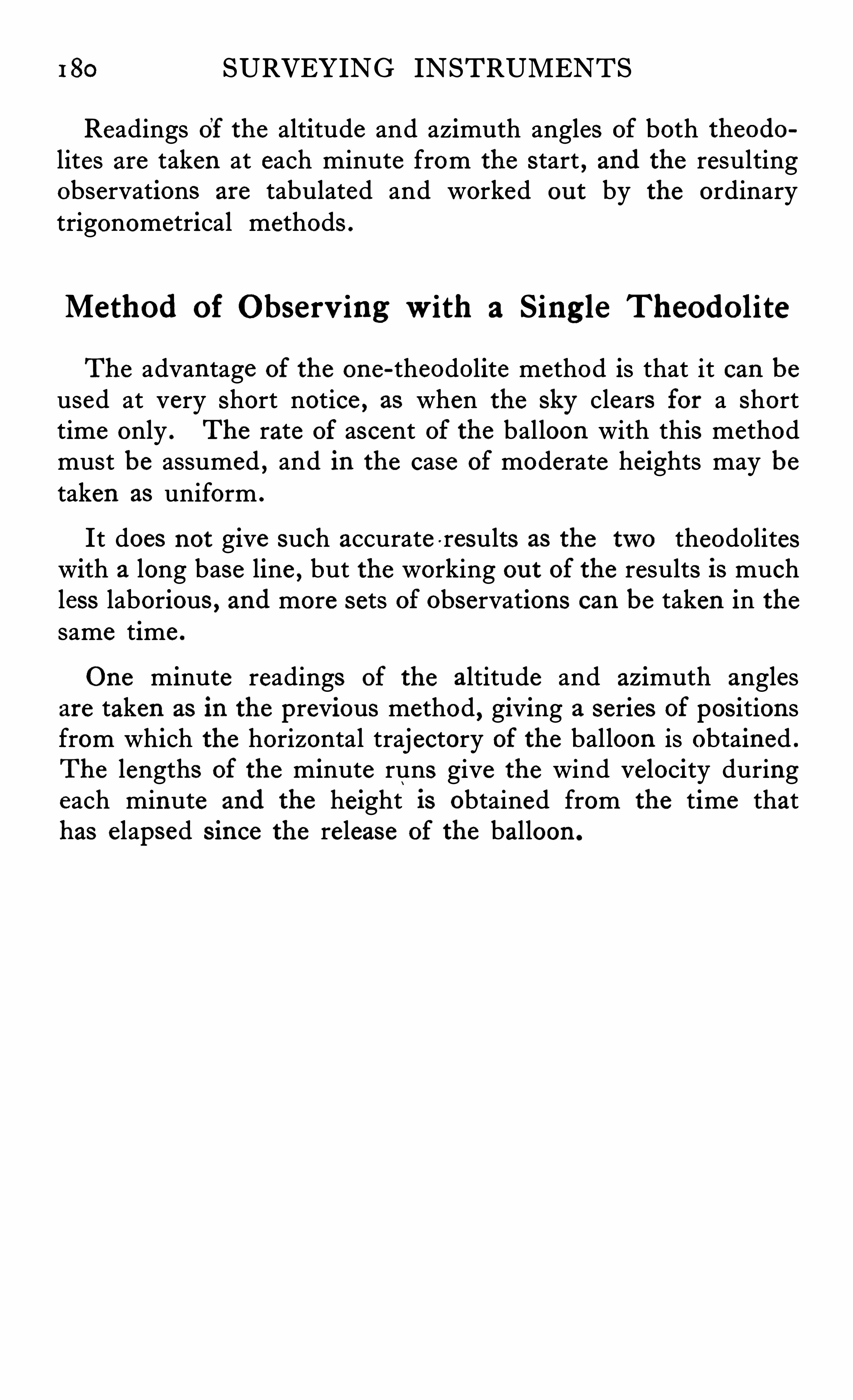
180 SURVEYING INSTRUMENTS
Readings of the altitude and azimuth angles of both theodolites are taken at each minute from the start , and the resultingobservations are tabulated and worked ou t by the ordinarytrigonometrical methods .
Method of Observ ingwith a Sing le Theodolite
The advantage of the one-theodolite method is that it can beused at very short notice , as when the sky clears for a shorttime only . The rate of ascent of the balloon with this methodmust be assumed , and in the case of moderate heights may betaken as uniform .
It does not give such accurate -results as the two theodoliteswith a long base line , but the working ou t of the results is muchless laborious , and more sets of observations can be taken in thesame time .
One minute readings of the altitude and azimuth anglesare taken as in the previous method , giving a series of positionsfrom which the horizontal trajectory of the balloon is obtained .
The lengths of the minute runs give the wind velocity duringeach minute and the height is obtained from the time thathas elapsed s ince the release of the balloon .
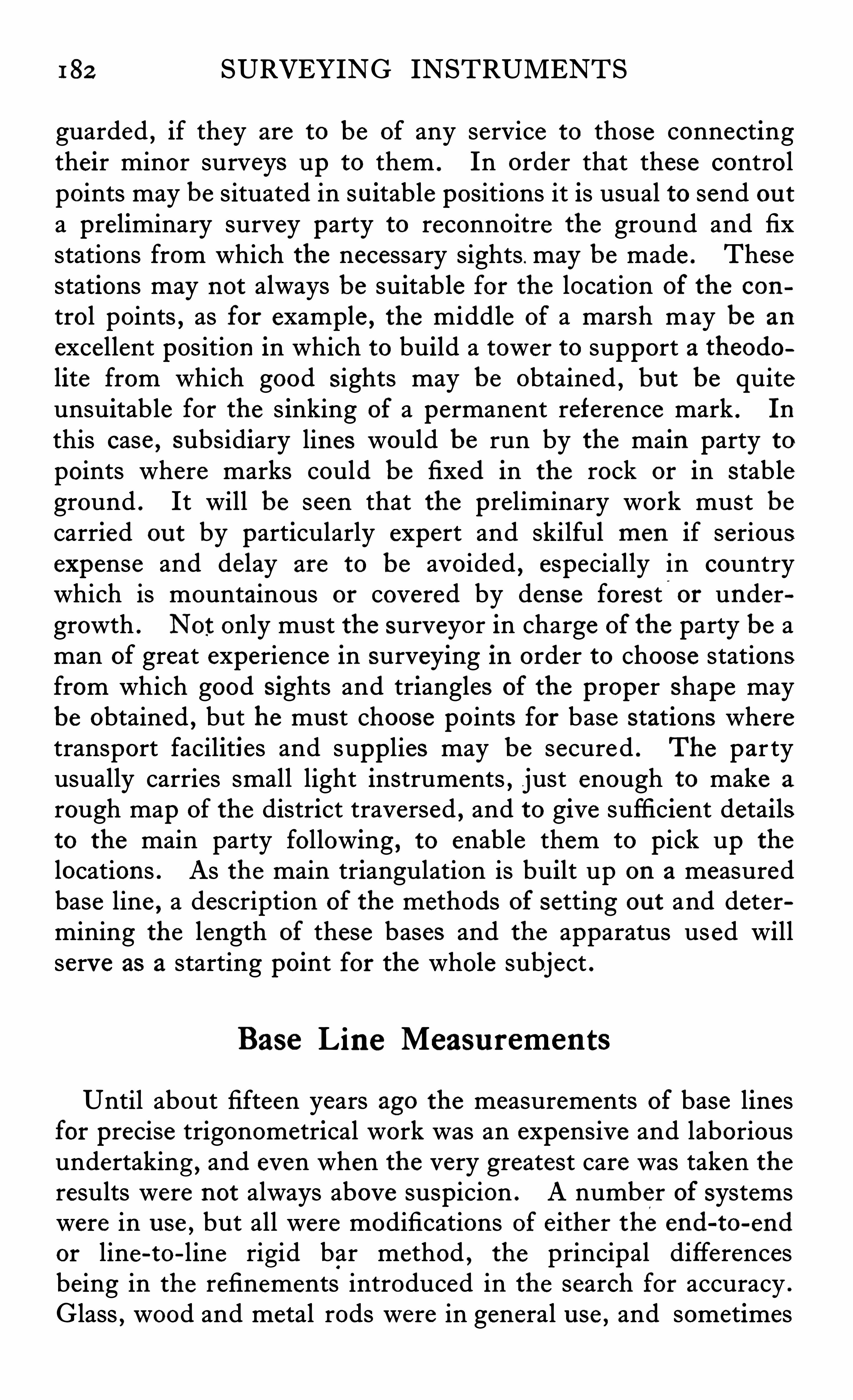
182 SURVEYING INSTRUMENTS
guarded , if they are to be of any service to those connectingtheir minor surveys up to them . In order that these controlpoints may be situated in suitable positions it is usual to send ou ta preliminary survey party to reconnoitre the ground and fixstations from which the necessary sights . may be made . Thesestations may not always be suitable for the location of the con
trol points,as for example , the middle of a marsh may be an
excellent position in which to build a tower to support a theodolite from which good s ights may be obtained
,bu t be quite
unsuitable for the s inking of a permanent reference mark . In
this case, subsidiary lines would be run by the main party to
points where marks could be fixed in the rock or in stableground . It will be seen that the preliminary work must becarried ou t by particularly expert and skilful men if seriousexpense and delay are to be avoided , especially in countrywhich is mountainous or covered by dense forest
,
or undergrowth . Not only must the surveyor in charge of the party be aman of great experience in surveying in order to choose stationsfrom which good s ights and triangles of the proper shape maybe obtained , but he must choose points for base stations wheretransport facilities and supplies may be secured . The par tyusually carries small light instruments , just enough to make a
rough map of the district traversed , and to give sufficient detailsto the main party following , to enable them to pick up the
locations . As the main triangulation is built up on a measuredbase line , a description of the methods of setting ou t and determining the length of these bases and the apparatus used willserve as a starting point for the whole subject .
Base Line Measu remen ts
Until about fifteen years ago the measurements of base linesfor precise trigonometrical work was an expensive and laboriousundertaking , and even when the very greatest care was taken theresults were not always above suspicion . A number of systemswere in u se , but all were modifications of e ither the end-to-end
or line-to-line rigid bar method , the principal differencesbeing in the refinements introduced in the search for accuracy .
Glass , wood and metal rods were in general u se , and sometimes
GEODETIc SURVEYING 183
the rods were made compound , in an attempt to keep the
length constant under varying conditions of temperature .
Many ingenious devices were employed to adjust the contactbetween the end abutments or to bring the engraved lines intocoincidence but in spite of the most elaborate precautions , thefinal results were not up to the standard demanded and easilyobtainable in other portions of the survey . In America ,apparatus was used in which the bars were immersed in meltingice , but the cost of these elaborations proved prohibitive , al
though the results were certainly of a very high order of accuracy .
The introduction of invar has changed all this , and to-day baselines are measured with the greatest ease and at a comparativ ely small expense by either a small expert party or else bythe ordinary surveying party as a part of their routine work .
Indeed , so Simple has the operation become that , accuratelines quite up to geodetic standard are regularly measured bytraverse parties , and on city surveys , where modern conditionsdemand results of a very high class , owing to the high value of
the land and the complications of the network system of sewersand other underground work . Invar
,which is an alloy of
iron and 36% nickel , has a coefficient of expansion of about°0000002 3 per degree Fahr . , the figure for steel be ing-0000064 p
i
er degree Fahr . Invar can be obtained either inthe form of wire or rol led ou t flat into tape . The latter form isthe more generally used forthe reason that it takes up less space ,is easier to wind on to the ree l and is not so easily kinked .
Should it become kinked , the fault is more readily discoveredthan in the wire . On the other hand , the wire is not so su scep
tible to disturbance by the wind,but as in any case it is not
desirable to measure a base line in the presence of wind , thelatter defect is not of importance . Recent redeterminationsof bases by means of invar tapes , the original measurements ofwhich had been made by rigid bars , have shown differences ofas much as 1 in As the probable error aimed at andusually obtained by means of the invar tape is one part in amillion ,"it is not likely that the rigid bar will be used in thefuture for any base measurement . In fact
, ordinary steel
In the measu remen t of the Stan ton base by the U .S . Governmen t theprobable error on a length of over metreswas 1 mm . ,
whichworks ou t at 1 part 111
184 SURVEYING INSTRUMENTS
tapes had been used quite successfully for base measurementbefore the discovery of invar
,and provided the work was
carried ou t at night or on cloudy days,under stable tem
perature conditions , the results as to accuracy comparedvery favourably with those obtained by the ordinary barmethod with of course an enormous saving in the cost of theoperation . The tapes are generally 50 metres in length , al
though sometimes those of 1 00 metres are employed . The
50 metre tape is easier and quicker to handle , and experiencehas proved that on the whole this length is the most economical
,
especially when the work has to be carried ou t on rough or
sloping ground . It is usual for each party to carry two or
three tapes which are used to check each other and each milesection is measured twice , once with each working tape , thethird being kept as a standard . The two results must agreeto less than
V d where d the distance
Sometimes all three tapes are used in combination , each tapefor one-third of the distance .
Many designs of supporting and stretching apparatus are inu se , some of them being quite elaborate . The best type to
employ largely depends on the nature of the terrain over whichthe measurement is being made , but as suitable country canusually be chosen , the apparatus need not be very elaborate .
When it is necessary to work over rocky ground , short tripodstands are useful , as they may be quickly set up and are easilytransported , but if the work is to be done quickly , and this isgenerally essential , a large number of stands will be required ,owing to the desirab ility of placing them in position ahead of
the measuring party . In the U .S .A . the method always em
ployed is as shown in Fig . 167. A number of stakes oftimber are driven firmly into the ground at 50 metre intervals ,with one intermediate supporting stake . These are set andtheir leve ls taken by a gang ahead of the measuring party , or
if the weather is windy or unfavourable , the stakes are firstset and then the measurements carried out on calm days . Onthe top of each terminal stake a piece of zinc or Copper is nailed ,
186 SURVEYING INSTRUMENTS
Then the required correction will be
(c) For Incl inat ion .
Let 1: length of that part of the base which is inclineda angle of inclination
Then the correction required wi ll be cos a)
Or approximately
If I the measured length in feeth the difference in level in feet between the two ends
of 1
Then the reduced length
h2
L = 12 1
Thus if the distance 1, measured on the s lope is 2 5 feet andthe difference in height is 2 feet , then the horizontal distance
5
4
; 0 8 2 4-92 feet .
When long tapes are being used and no intermediate sup
ports are possible , it is necessary to apply a correction for sagun less the tape has been standardised while hanging in a naturalcatenary . This correction for sag is approximately found as
follows
length of tape in feetthe applied tension in lbs .
w the weight of the tape in lbs .
then the correction to be applied is2
W12 4t
2
2and on an Incline a the sagwrll vary as cos a .
GEODETIC SURVEYING 187
(d) Temperatu re Cor r ection . IfT0 is the temperature at which the tape is standardTI the observed temperature of the tape at which
the measurement was madee the co-effi cient of expansion of the tape1 the length of the tape
Then the correction to be applied will be given by
(Tl— TO) "e
Formulae have been devised to give a more exact correctionfor sag , but it must be remembered that the accuracy to whicha base may be measured with an invar tape using the simplemethod already described is really higher than is actuallyrequired , owing to the fact that the probable errors introducedin the expansion of the triangles and in the astronomic determination are very much greater . If, however , the tape has beenstandardised while lying on a flat surface , the corrections forsag become important . The introduction of invar is du e to
the researches made by Dr Ch . Ed . Guillaume at the International Bureau of Weights and Measures at Sevres . It maybe procured in three qualities as follows
(a) With a coefficient of expansion less than 08 micronsper metre per degree Centigrade .
(b) With a coeffi cient between -8 and 16 microns .
(c) With a coeffi cient between 1 -6and 2 5 microns .
Invar of quality (b) is the kind usually employed for baseline tapes and wires .
It has been found that slight molecular changes take placein invar with the result that a gradual growth is shown aftera fewyears . An alloy containing of nickel has been foundto be free from this defect , but its coefficient of expans ion isgreater , being about 8 microns per metre per degree centigrade .
Invar is superior to stee l from the point of view of freedomfrom liability to oxidation but it is , of course , much softerand more easily bent . It is
,however , quite strong enough for
the purpose under consideration , as it will seldom be subjectedto a greater pull than 30 lbs . Invar is easily corroded by acid
,
so that care must be taken that the tapes are not exposed tothis substance , and that the oil used on them is free from acid
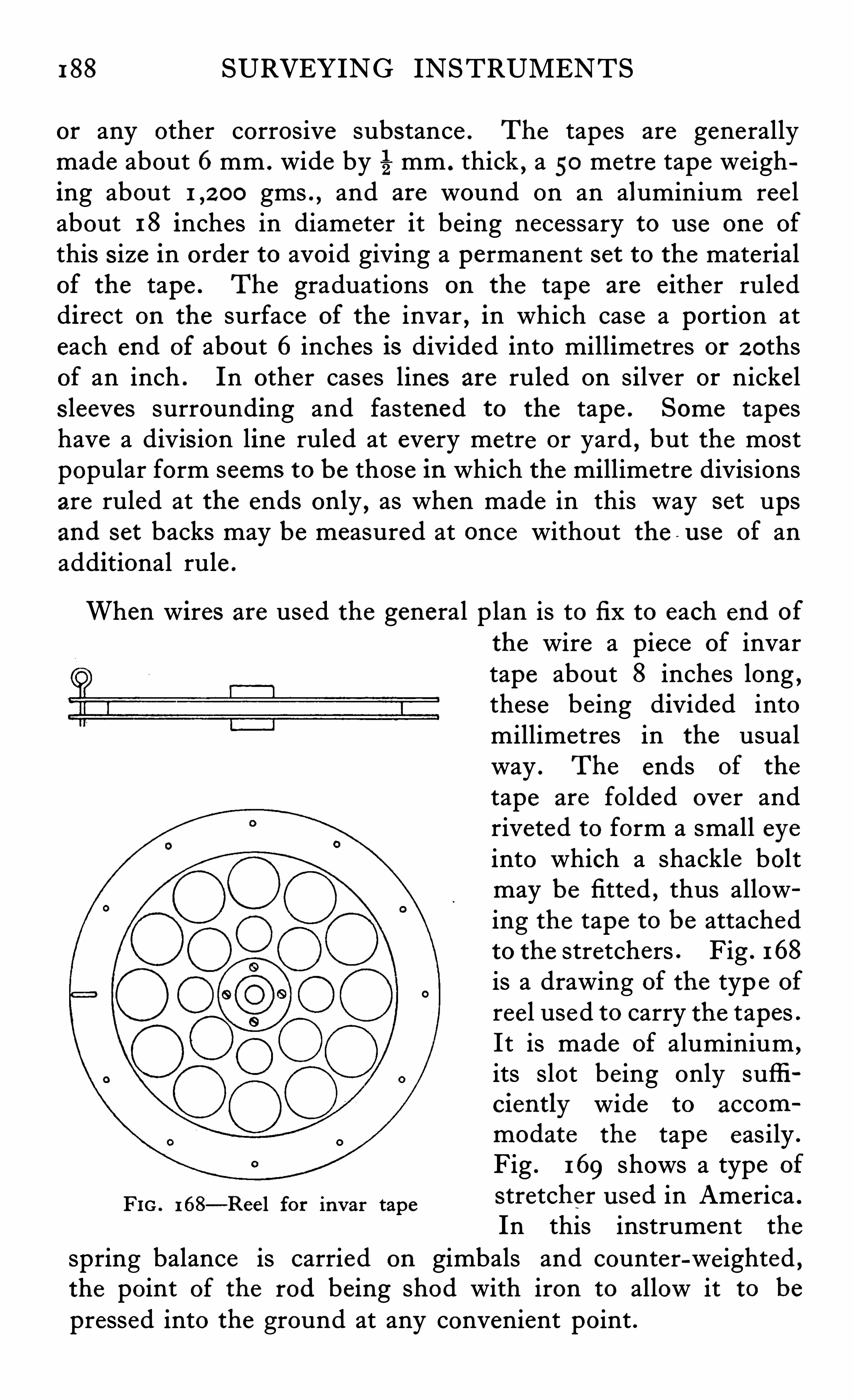
188 SURVEYING INSTRUMENTS
or any other corrosive substance . The tapes are generallymade about 6mm . wide by 5mm . thick , a 50 metre tape weighing about gms . , and are wound on an aluminium ree labout 18 inches in diameter it being necessary to u se one of
this s ize in order to avoid giving a permanent set to the materialof the tape . The graduations on the tape are either ruleddirect on the surface of the invar , in which case a portion ateach end of about 6 inches is divided into millimetres or 2 0thsof an inch . In other cases lines are ruled on silver or nickels leeves surrounding and fastened to the tape . Some tapeshave a divis ion line ruled at every metre or yard
,but the most
popular form seems to be those in which the millimetre divisionsare ruled at the ends only , as when made in this way set upsand set backs may be measured at once without the - u se of anadditional rule .
When wires are used the general plan is to fi x to each end of
the wire a piece of invartape about 8 inches long ,these being divided intomillimetres in the usualway . The ends of the
tape are folded over andriveted to form a small eyeinto which a shackle boltmay be fitted , thus allowing the tape to be attachedto the stretchers . Fig . 168
is a drawing of the typ e of
reel used to carry the tapes .
It is made of aluminium ,
its slot being only sufficiently wide to accom
modate the tape easily .
Fig . 169 shows a type of
FIG . 168—Ree l for invar tape Stretcher u sed in America °
In this instrument the
spring balance is carried on gimbals and counter-we ighted ,the point of the rod being shod with iron to allow it to be
pressed into the ground at any convenient point .
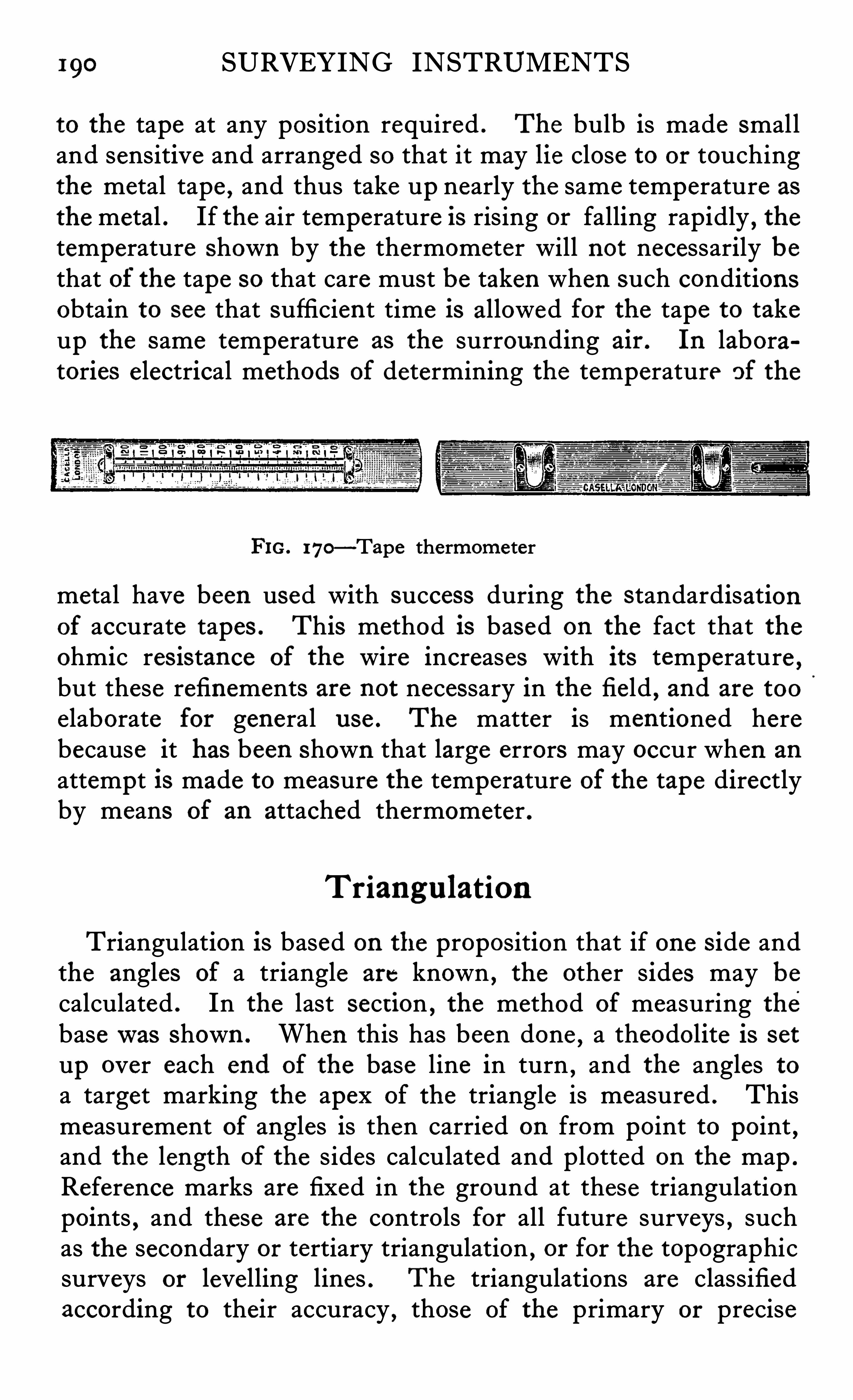
190 SURVEYING INSTRUMENTS
to the tape at any position required . The bulb is made smalland sensitive and arranged so that it may lie close to or touchingthe metal tape , and thus take up nearly the same temperature as
the metal . If the air temperature is rising or falling rapidly , thetemperature shown by the thermometer will not necessarily bethat of the tape so that care must be taken when such conditionsobtain to see that sufficient time is allowed for the tape to takeup the same temperature as the surrounding air . In laboratories electrical methods of determining the temperature of the
FIG. 170—Tape thermometer
metal have been used with success during the standardisationof accurate tapes . This method is based on the fact that theohmic res istance of the wire increases with its temperature ,but these refinements are not necessary in the field
, and are too
elaborate for general use . The matter is mentioned herebecause it has been shown that large errors may occur when an
attempt is made to measure the temperature of the tape directlyby means of an attached thermometer .
Triangu lation
Triangulation is based on the proposition that if one s ide andthe angles of a triangle are known , the other sides may becalculated . In the last sect ion , the method of measuring thebasewas shown . When this has been done
,a theodolite is set
up over each end of the base line in turn,and the angles to
a target marking the apex of the triangle is measured . Thismeasurement of angles is then carried on from point to point
,
and the length of the sides calculated and plotted on the map .
Reference marks are fixed in the ground at these triangulationpoints , and these are the controls for all future surveys , suchas the secondary or tertiary triangulation
,or for the topographic
surveys or levelling lines . The triangulations are classifiedaccording to their accuracy , those of the primary or precise
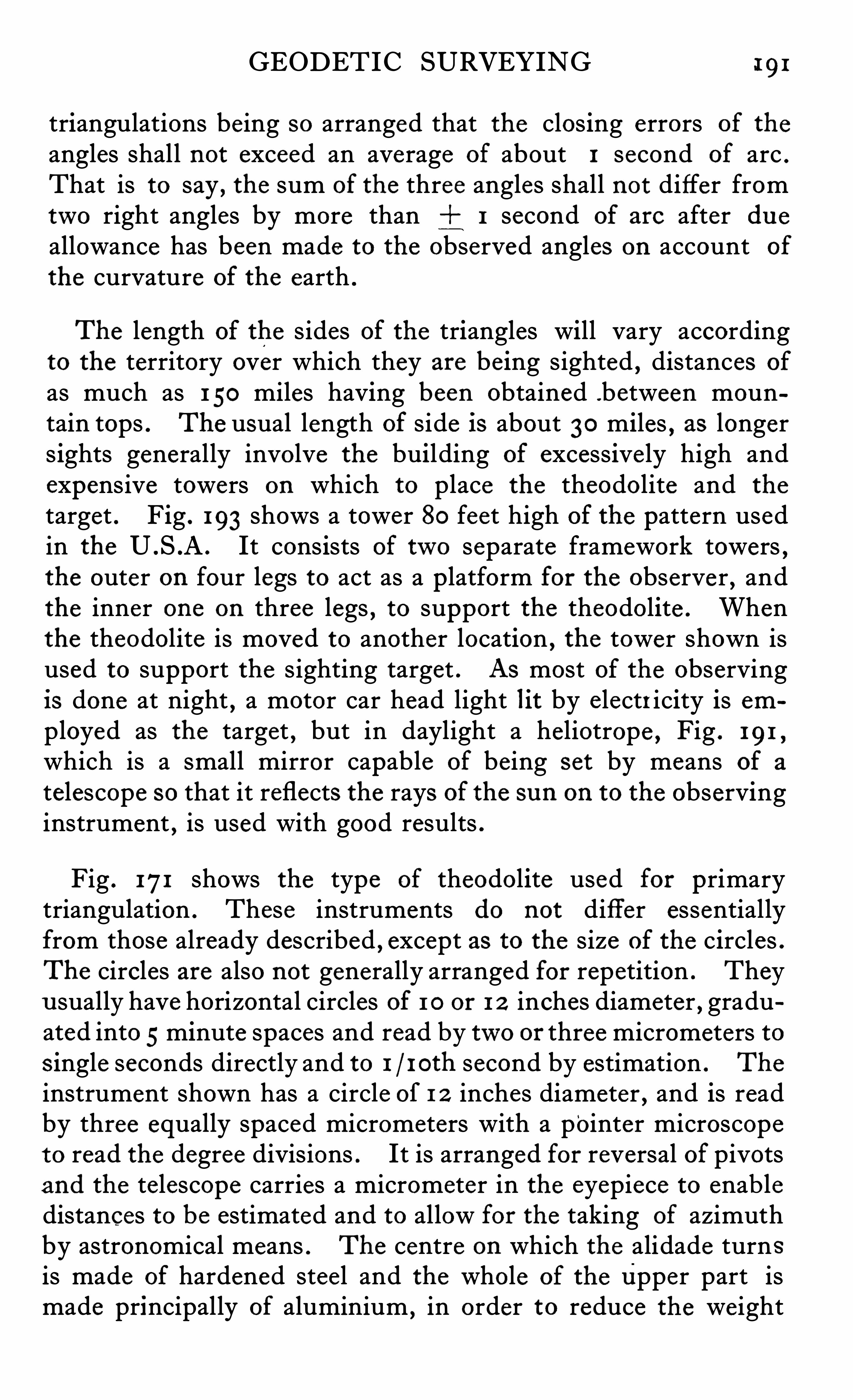
GEODETIC SURVEYING 191
triangulations being so arranged that the closing errors of the
angles shall not exceed an average of about 1 second of arc .
That is to say,the sum of the three angles shall not differ from
two right angles by more than 1 second of are after du eallowance has been made to the observed angles on account of
the curvature of the earth .
The length of the sides of the triangles will vary accordingto the territory over which they are being sighted , distances of
as much as 1 50 miles having been obtained .between mountain tops . The usual length of side is about 30 miles , as longers ights generally involve the building of excessive ly high andexpensive towers on which to place the theodolite and the
target . Fig . 193 shows a tower 80 feet high of the pattern usedin the U .S .A . It consists of two separate framework towers ,the outer on four legs to act as a platform for the observer , andthe inner one on three legs , to support the theodolite . Whenthe theodolite is moved to another location , the tower shown isused to support the sighting target . As most of the observingis done at night , a motor car head light lit by electricity is employed as the target , but in daylight a heliotrope , Fig . 191 ,
which is a small mirror capable of being set by means of a
telescope so that it reflects the rays of the sun on to the observinginstrument , is used with good results .
Fig . 171 shows the type of theodolite used for primarytriangulation . These instruments do not differ essentiallyfrom those already described , except as to the size of the circles .The circles are also not generally arranged for repetition . Theyu sually have horizontal circles of 1 0 or 1 2 inches diameter , graduated into 5minute spaces and read by two or three micrometers tos ingle seconds directly and to 1 1 0th second by estimation . The
instrument shown has a circle of 1 2 inches diameter , and is readby three equally spaced micrometers with a pointer microscopeto read the degree divisions . It is arranged for reversal of pivotsand the telescope carries a micrometer in the eyepiece to enab ledistances to be estimated and to allow for the taking of azimuthby astronomical means . The centre on which the alidade turnsis made of hardened stee l and the whole of the Upper part ismade principally of aluminium
,in order to reduce the weight
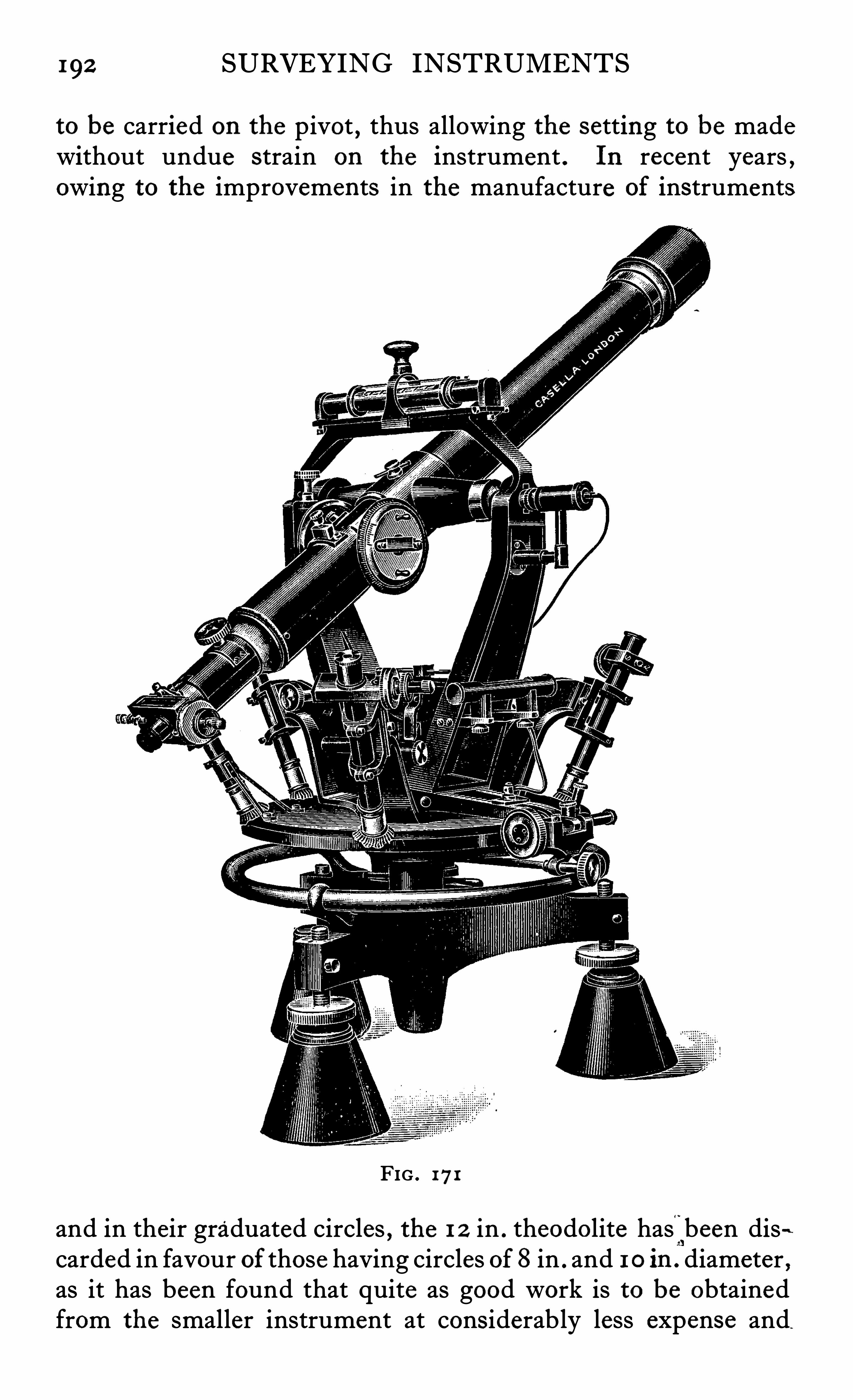
192 SURVEYING INSTRUMENTS
to be carried on the pivot , thus allowing the setting to be madewithout undue strain on the instrument . In recent years ,owing to the improvements in the manufacture of instruments
FIG . 171
and in their graduated circles , the 1 2 in . theodolite has'
been dis-Lcarded in favour of those having circles of 8 in . and 1 0 in . diameter ,as it has been found that quite as good work is to be obtainedfrom the smaller instrument at cons iderably less expense and
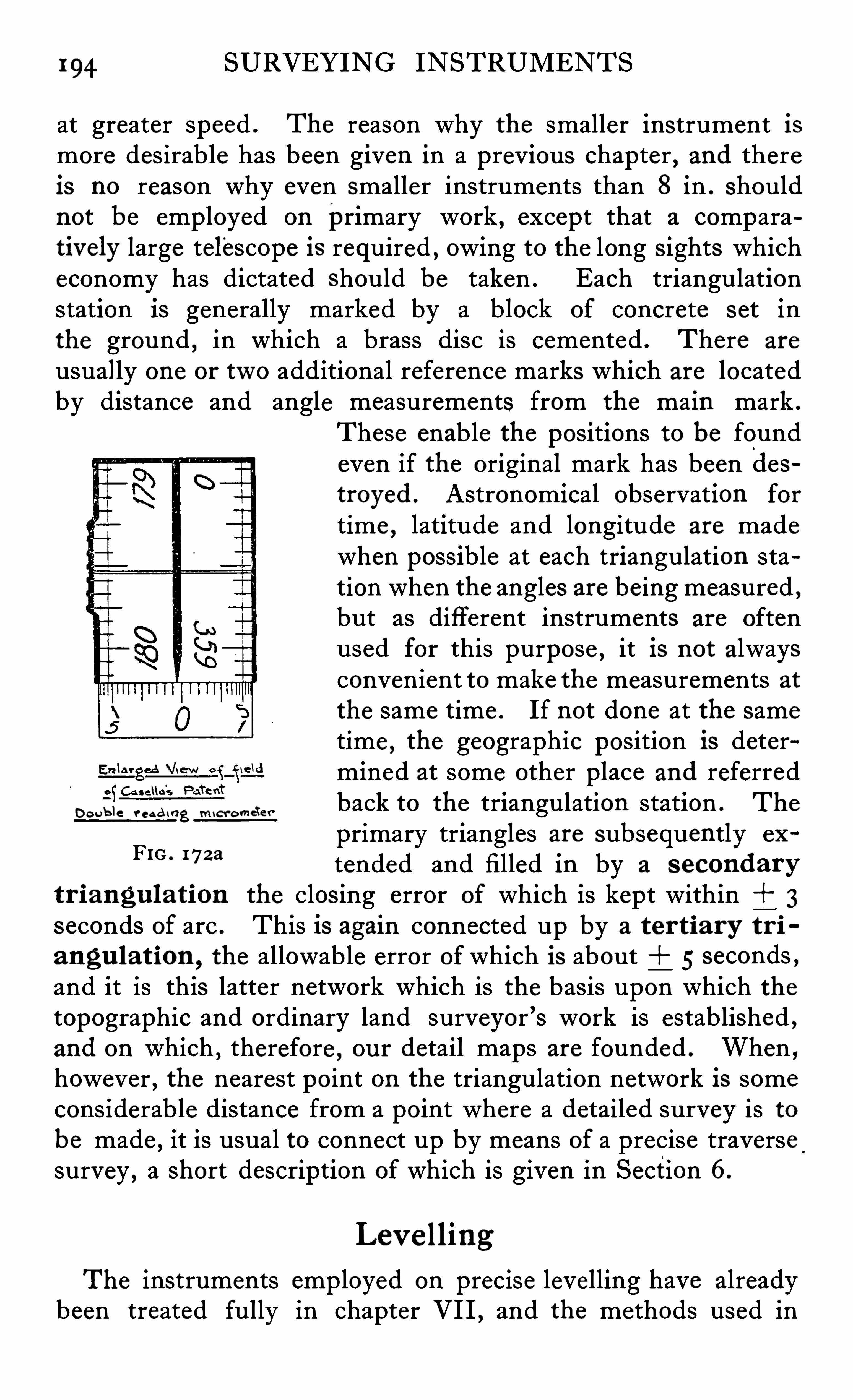
194 SURVEYING INSTRUMENTS
at greater speed . The reason why the smaller instrument ismore desirable has been given in a previous chapter , and thereis no reason why even smaller instruments than 8 in . shouldnot be employed on primary work , except that a comparativ ely large telescope is required , owing to the long s ights whicheconomy has dictated should be taken . Each triangulationstation is generally marked by a block of concrete s et inthe ground , in which a brass disc is cemented . There are
usually one or two additional reference marks which are locatedby distance and angle measurements from the main mark .
These enable the positions to be foundeven if the original mark has been destroyed . Astronomical observation for
time , latitude and longitude are madewhen possible at each triangulation station when the angles are being measured ,but as different instruments are oftenused for this purpose , it is not alwaysconvenient to make the measurements atthe same time . If not done at the sametime , the geographic position is determined at some other place and referredback to the triangulation station . The
primary triangles are subsequently ex
tended and filled in by a s econdary
tr i angu lation the clos ing error of which is kept within 3
s econds of arc . This is again connected up by a ter tiary tr i
angu lat ion ,the allowable error of which is about i 5 seconds ,
and it is this latter network which is the basis upon which thetopographic and ordinary land surveyor ’s work is established ,and on which
,therefore , ou r detail maps are founded . When ,
however , the nearest point on the triangulation network is someconsiderable distance from a point where a detailed survey is tobe made , it is usual to connect up by means of a precise traversesurvey , a short description of which is given in Section 6.
Do u b le r c e d i ng M i cr omete r
FIG . 17za
Lev e lling
The instruments employed on precise levelling have alreadybeen treated fully in chapter VI I , and the methods used in
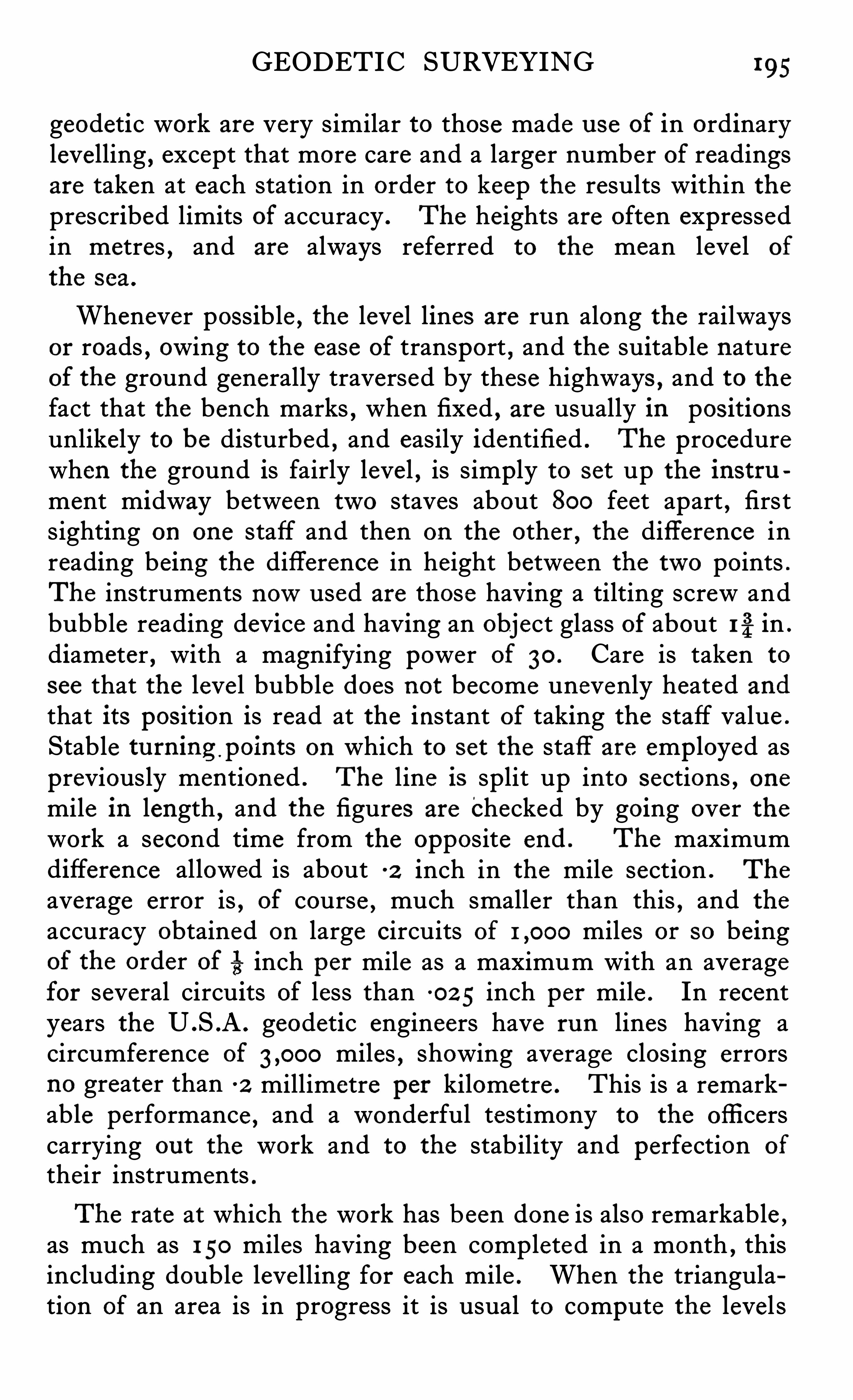
GEODETIC SURVEYING 195
geodetic work are very similar to those made u se of in ordinarylevelling , except that more care and a larger number of readingsare taken at each station in order to keep the results within theprescribed limits of accuracy . The heights are often expressedin metres , and are always referred to the mean leve l of
the s ea .
Whenever possible , the level lines are run along the railwaysor roads , owing to the ease of transport , and the suitable natureof the ground generally traversed by these highways , and to thefact that the bench marks , when fixed , are usually in pos itionsunlikely to be disturbed , and easily identified . The procedurewhen the ground is fairly level , is simply to set up the instrument midway between two staves about 800 feet apart , firstsighting on one staff and then on the other
,the difference in
reading being the difference in height between the two points .
The instruments nowused are those having a tilting screw andbubble reading device and having an object glass of about 1%in .
diameter , with a magnifying power of 30 . Care is taken to
see that the leve l bubble does not become unevenly heated and
that its pos ition is read at the instant of taking the staff value .
Stable tu rning points on which to set the staff are emp loyed aspreviously mentioned . The line is split up into sections , onemile in length , and the figures are checked by going over thework a second time from the opposite end . The maximumdifference allowed is about -2 inch in the mile section . The
average error is , of course , much smaller than this , and the
accuracy obtained on large circuits of miles or so beingof the order of 513 inch per mile as a maximum with an averagefor several circuits of less than 0 2 5 inch per mile . In recentyears the U .S .A . geodetic engineers have run lines having acircumference of miles , showing average closing errorsno greater than -2 millimetre per kilometre . This is a remarkable performance , and a wonderful testimony to the officerscarrying ou t the work and to the stability and perfection of
their instruments .
The rate at which the work has been done is also remarkable ,
as much as 1 50 miles having been completed in a month , thisincluding double levelling for each mile . When the triangulation of an area is in progress it is usual to compute the level s
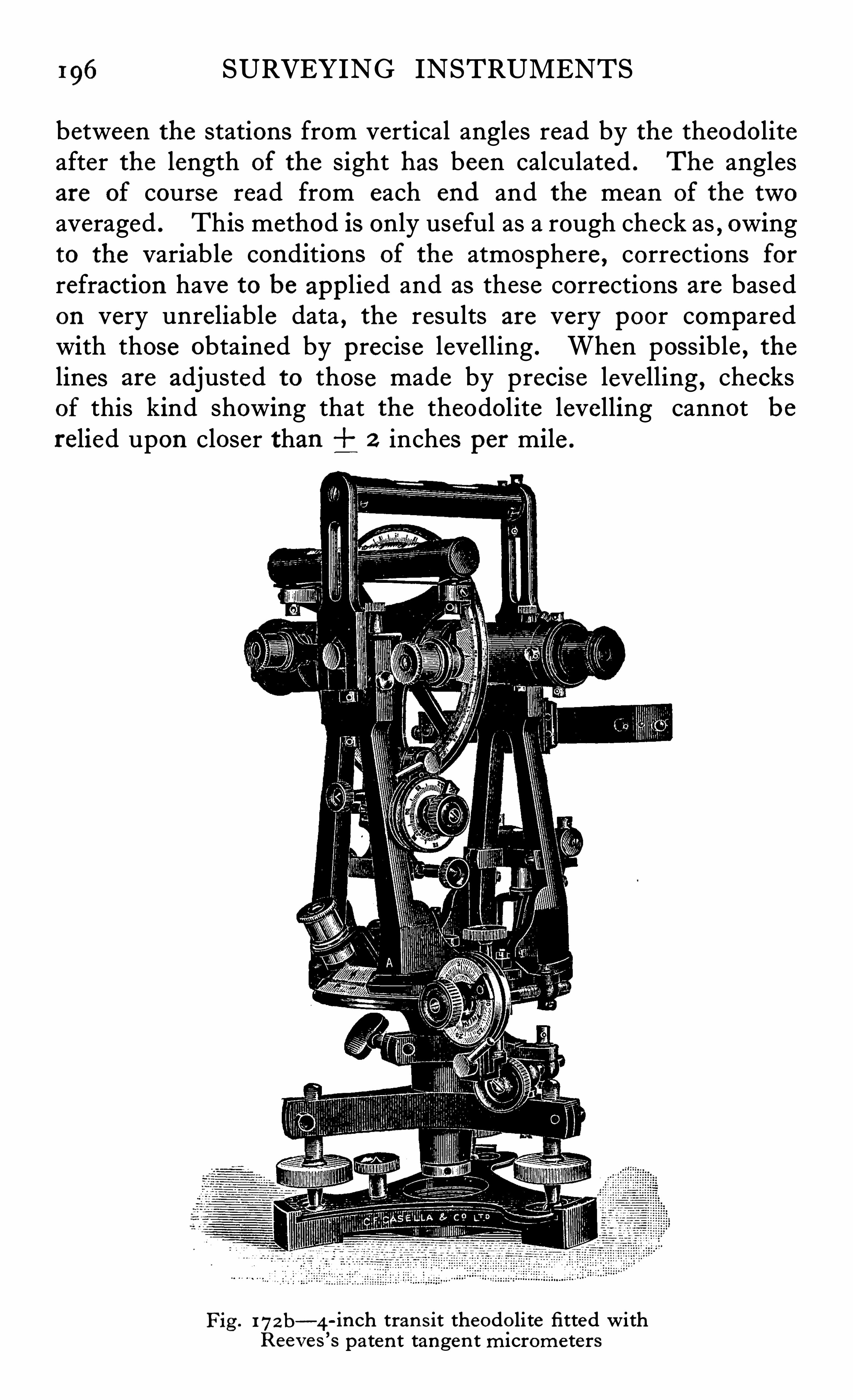
196 SURVEYING INSTRUMENTS
between the stations from vertical angles read by the theodoliteafter the length of the sight has been calculated . The anglesare of course read from each end and the mean of the twoaveraged . This method is only useful as a rough check as , owingto the variable conditions of the atmosphere , corrections forrefraction have to be applied and as these corrections are basedon very unreliable data , the results are very poor comparedwith those obtained by precise levelling . When possible , thelines are adjusted to those made by precise levelling , checksof this kind showing that the theodolite levelling cannot berelied upon closer than 2 inches per mile .
Fig . 17zb—4 -inch tran s it theodo lite fitted withReev es
’
s paten t tangen t microme ters
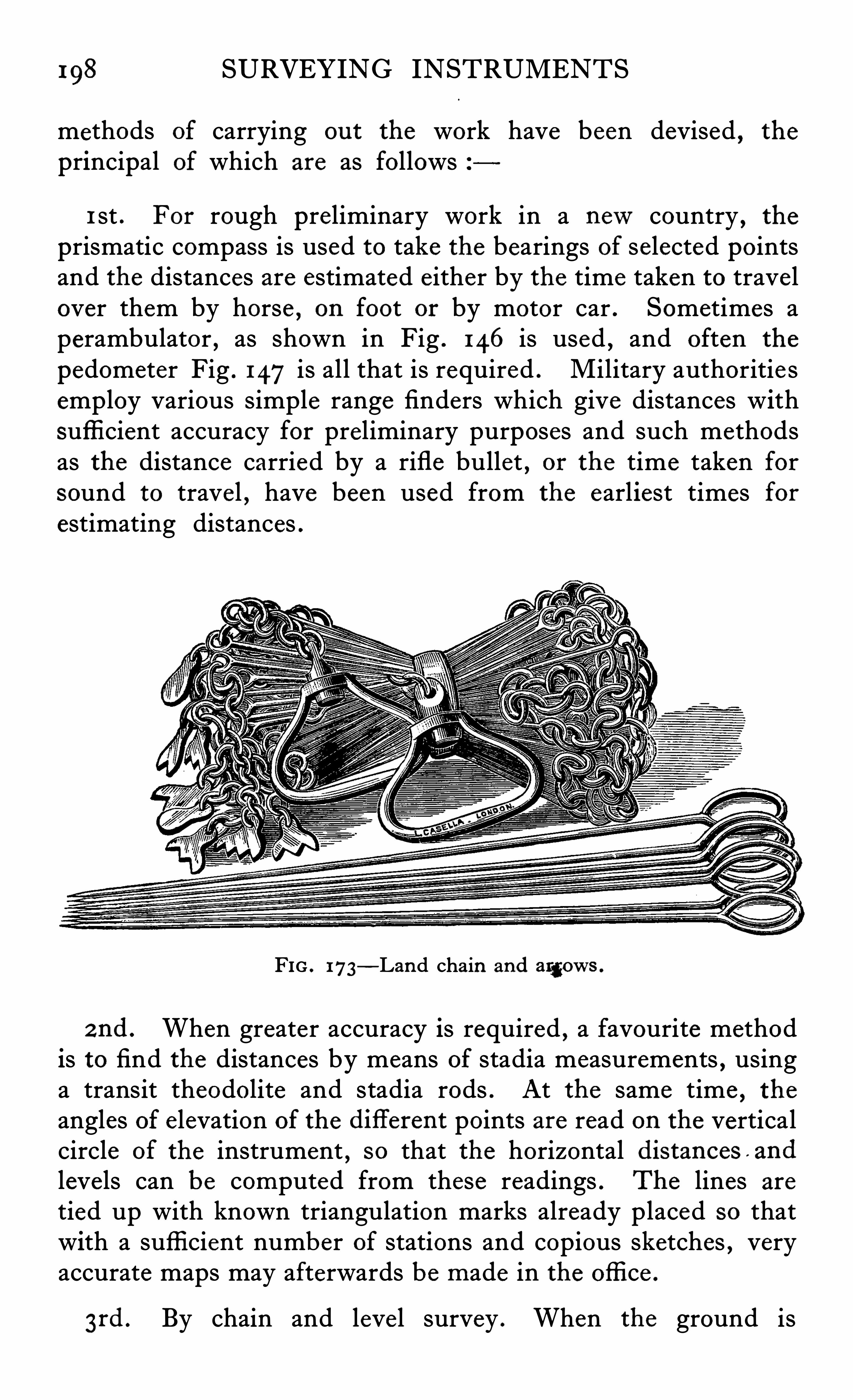
198 SURVEYING INSTRUMENTS
methods of carrying ou t the work have been devised , the
principal of which are as follows
1 st . For rough preliminary work in a newcountry , the
prismatic compass is used to take the bearings of selected pointsand the distances are estimated either by the time taken to travelover them by horse , on foot or by motor car . Sometimes aperambulator , as shown in Fig . 146 is used , and often the
pedometer Fig . 147is all that is required . Military authoritie semploy various simple range finders which give distances withsuffi cient accuracy for preliminary purposes and such methodsas the distance carried by a rifle bullet , or the time taken forsound to trave l
,have been used from the earliest times for
estimating distances .
FIG . 173—Land chain and argows .
2 nd . When greater accuracy is required , a favourite methodis to find the distances by means of stadia measurements , usinga transit theodolite and stadia rods . At the same time , the
angles of elevation of the diflerent points are read on the verticalcircle of the instrument , so that the horizontal distances and
leve ls can be computed from these readings . The lines are
tied up with known triangulation marks already placed so thatwith a suffi cient number of stations and copious sketches , veryaccurate maps may afterwards be made in the office .
3rd . By chain and leve l survey . When the ground is
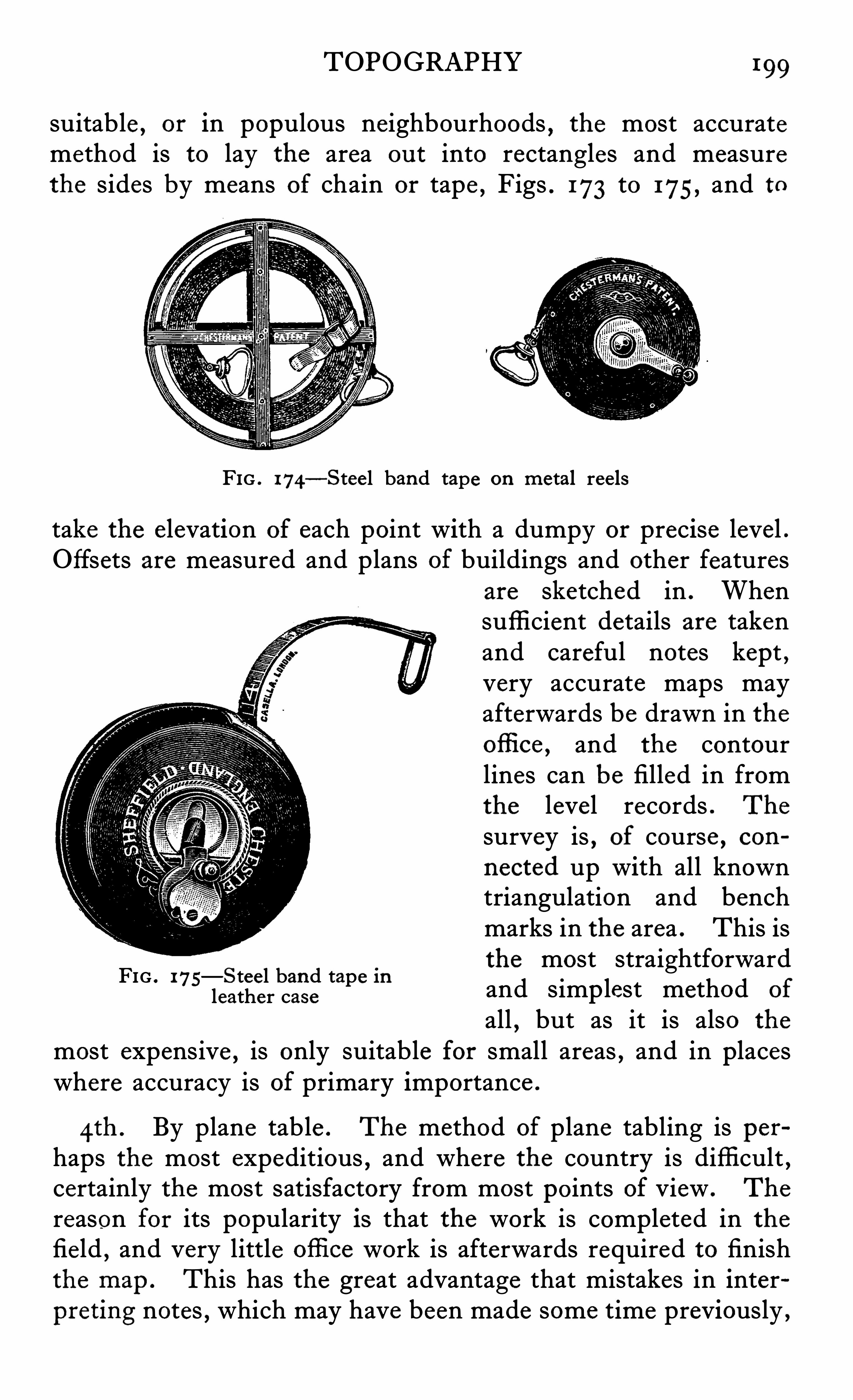
TOPOGRAPHY 199
suitable , or in populous neighbourhoods , the most accuratemethod is to lay the area ou t into rectangles and measurethe sides by means of chain or tape , Figs . 173 to 175, and to
FIG . 174—Stee l band tape on metal reels
take the elevation of each point with a dumpy or precise level .Offsets are measured and plans of buildings and other features
FIG . 175—Stee l band tape inleather case
are sketched in . Whensufficient details are takenand careful notes kept ,very accurate maps mayafterwards be drawn in theofli ce , and the contourlines can be filled in fromthe level records . The
survey is,of course , con
nected up with all knowntriangulation and benchmarks in the area . This isthe most straightforwardand simp lest method of
all,but as it is also the
most expensive , is only suitable for small areas , and in placeswhere accuracy is of primary importance .
4th . By plane table . The method of plane tabling is perhaps the most expeditious , and where the country is difficult ,certainly the most satisfactory from most points of View . The
reason for its popularity is that the work is completed in thefield , and very little ofli ce work is afterwards required to finishthe map . This has the great advantage that mistakes in interpreting notes , which may have been made some time previously ,
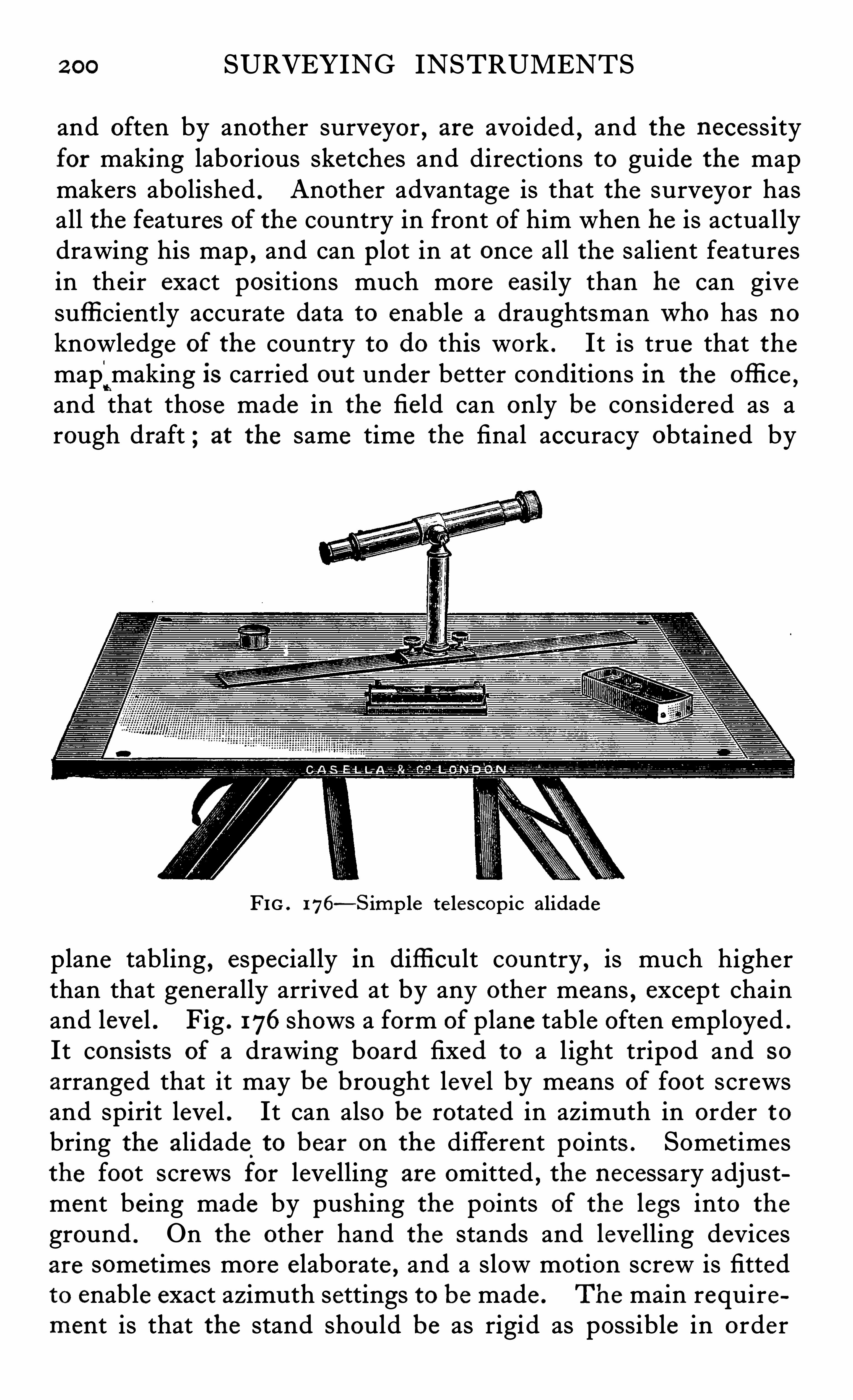
2 00 SURVEYING INSTRUMENTS
and often by another surveyor , are avoided , and the necess ityfor making laborious sketches and directions to guide the mapmakers abolished . Another advantage is that the surveyor hasall the features of the country in front of him when he is actuallydrawing his map , and can p lot in at once all the salient featuresin their exact positions much more easily than he can givesuffi ciently accurate data to enable a draughtsmanwho has noknowledge of the country to do this work . It is true that themap;making is carried ou t under better conditions in the offi ce ,and that those made in the fie ld can only be considered as arough draft ; at the same time the final accuracy obtained by
FIG . 176—S imp le te le scopic alidade
plane tabling , especially in difficult country,is much higher
than that generally arrived at by any other means , except chainand level . Fig . 176shows a form of plane table often employed .
It consists of a drawing board fixed to a light tripod and so
arranged that it may be brought leve l by means of foot screwsand spirit level . It can also be rotated in azimuth in order tobring the alidade
.
to bear on the different points . Sometimesthe foot screws for levelling are omitted
,the necessary adjust
ment being made by pushing the points of the legs into the
ground . On the other hand the stands and leve lling devicesare sometimes more elaborate , and a slow motion screw is fittedto enable exact azimuth settings to be made . The main requirement is that the stand should be as rigid as possible in order
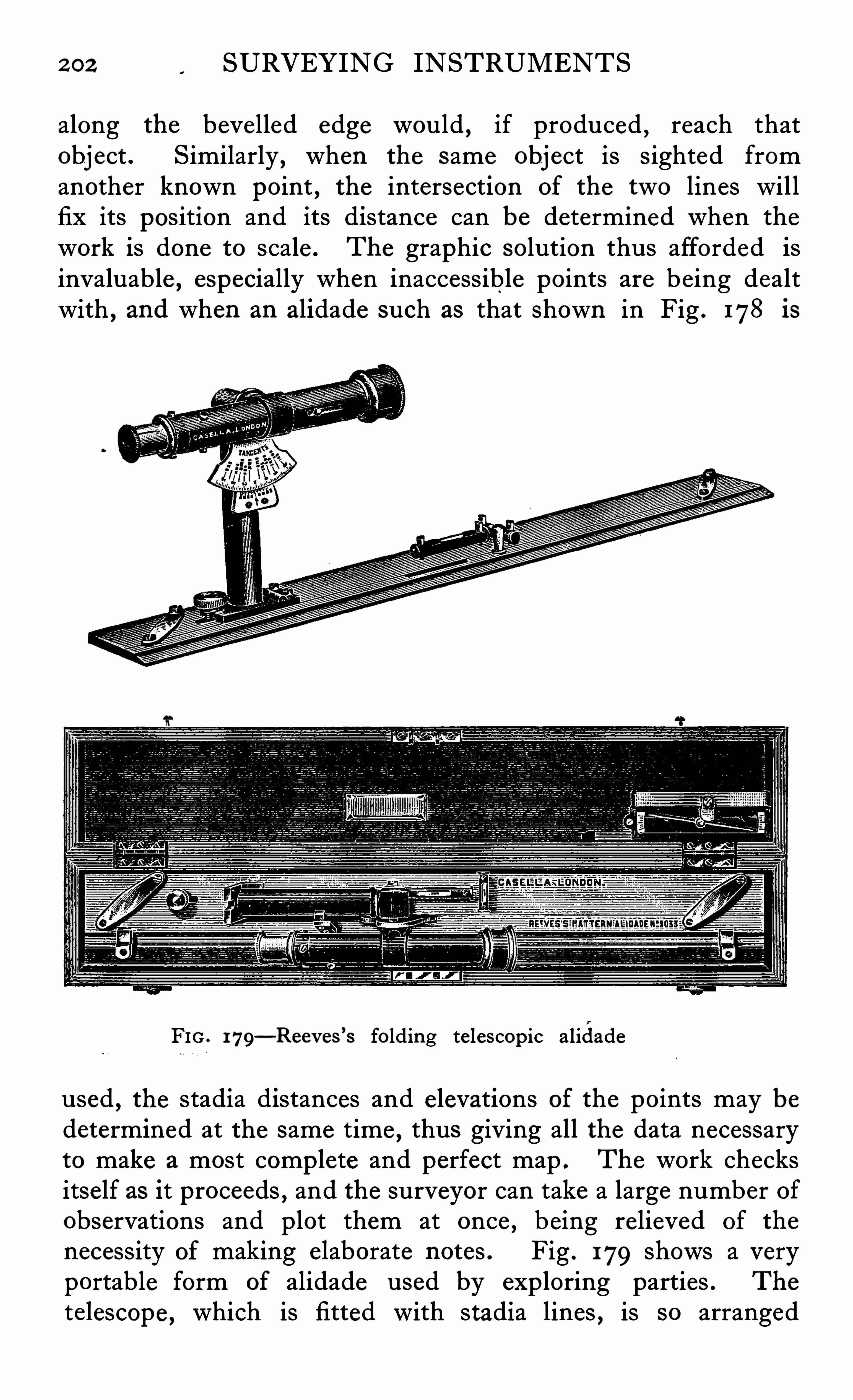
2 02 SURVEYING INSTRUMENTS
along the bevelled edge would,if produced , reach that
object . Similarly , when the same object is sighted fromanother known point , the intersection of the two lines willfix its position and its distance can be determined when the
work is done to scale . The graphic solution thus afforded isinvaluable , especially when inaccessible points are being dealtwith , and when an alidade such as that shown in Fig . 178 is
FIG . 179—Reev es ’s folding te lescopic a lidade
used , the stadia distances and e levations of the points may bedetermined at the same time , thus giving all the data necessaryto make a most complete and perfect map . The work checksitself as it proceeds
,and the surveyor can take a large number of
observations and plot them at once , being relieved of the
necessity of making e laborate notes . Fig . 179 shows a veryportable form of alidade used by exploring parties . The
telescope , which is fitted with stadia lines , is so arranged
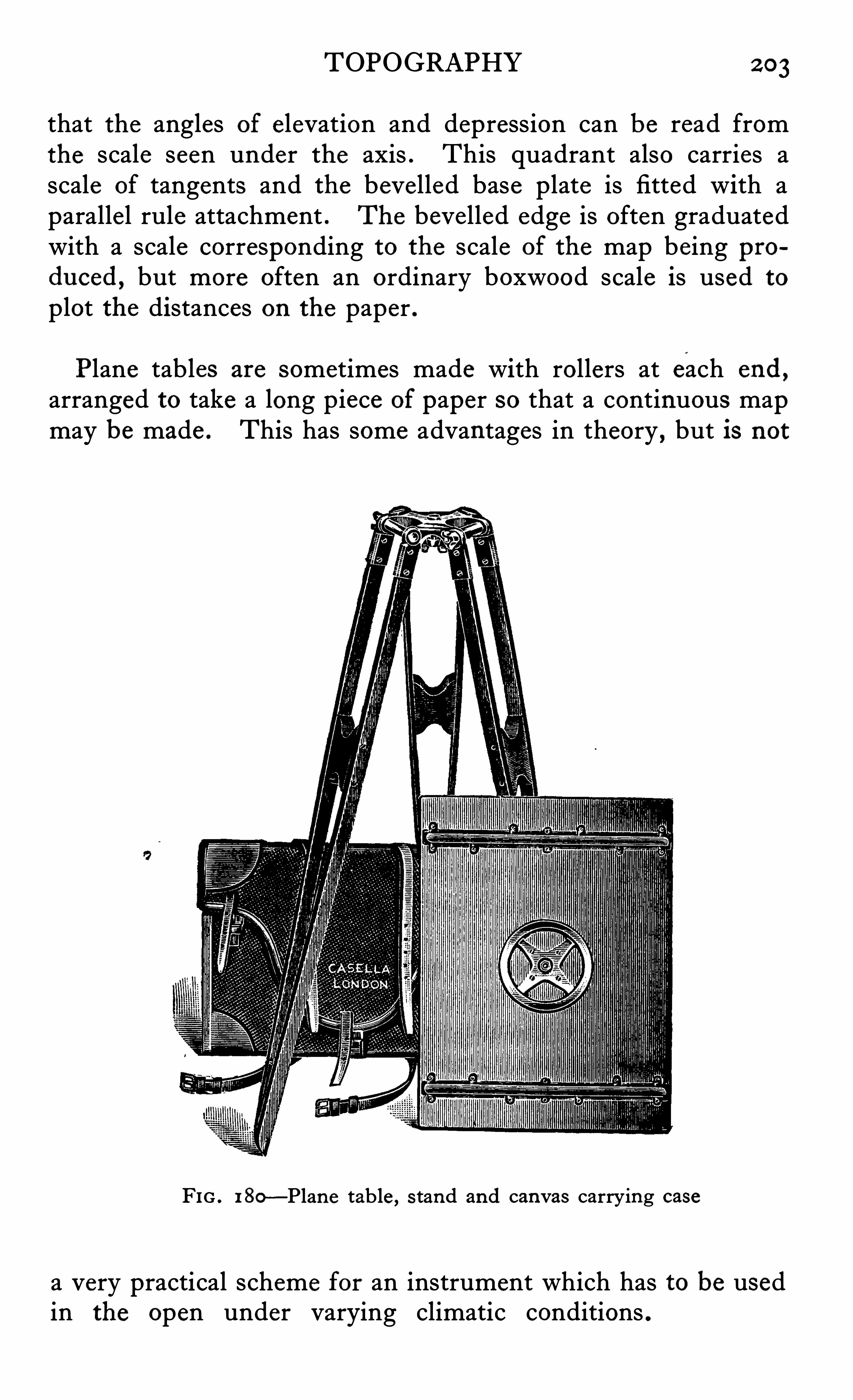
TOPOGRAPHY 2 03
that the angles of elevation and depression can be read fromthe scale seen under the axis . This quadrant also carries ascale of tangents and the bevelled base plate is fitted with aparallel rule attachment . The bevelled edge is often graduatedwith a scale corresponding to the scale of the map being produced , but more often an ordinary boxwood scale is used to
plot the distances on the paper .
Plane tables are sometimes made with rollers at each end ,
arranged to take a long piece of paper so that a continuous mapmay be made . This has some advantages in theory , but is not
FIG . 1 80 —Plan e table , s tand and canvas carrying case
a very practical scheme for an instrument which has to be usedin the open under varying climatic conditions .
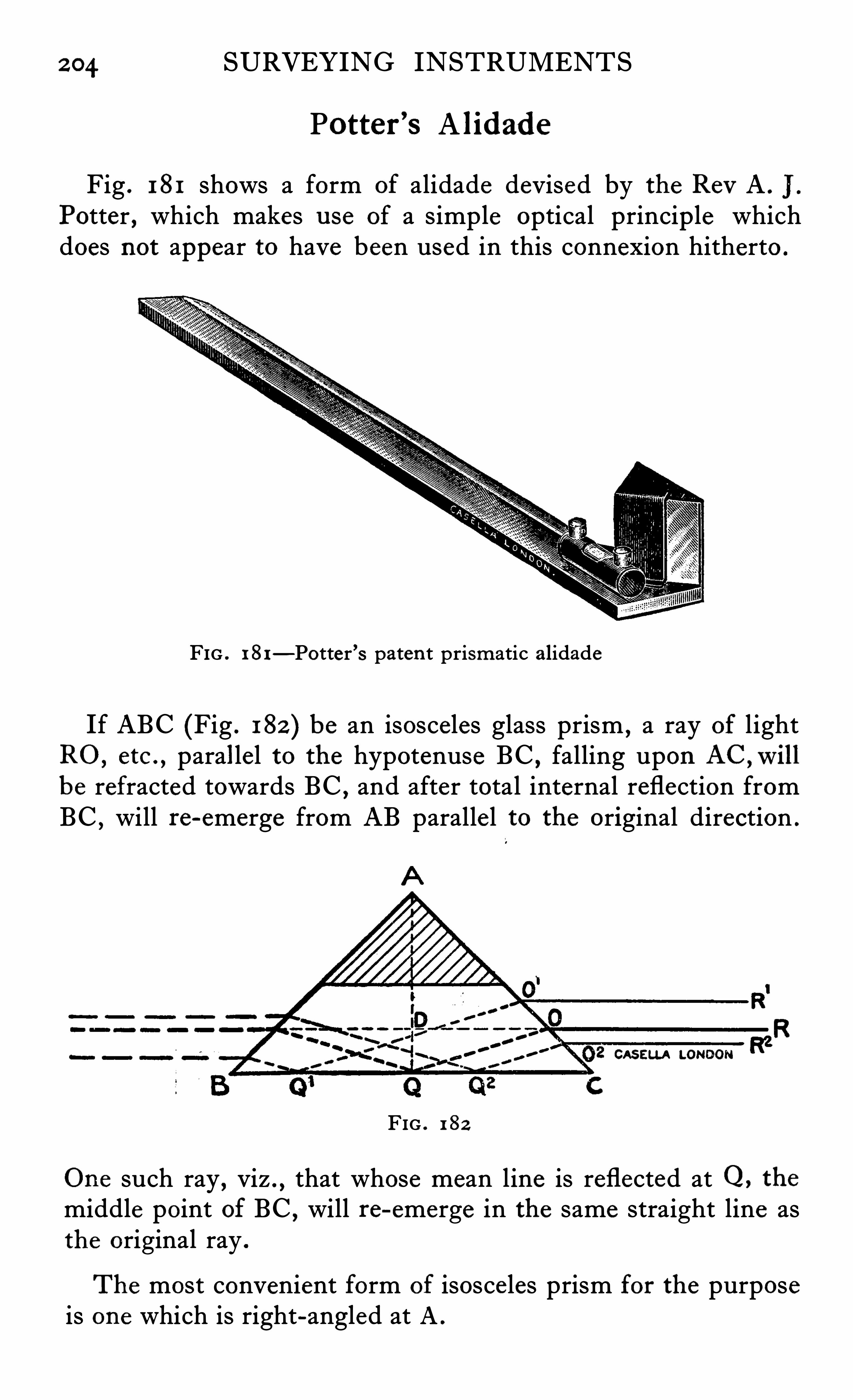
2 04 SURVEYING INSTRUMENTS
Potter ’s A lidade
Fig . 181 shows a form of alidade devised by the Rev A . I .
Potter , which makes u se of a simple optical princip le whichdoes not appear to have been used in this connexion hitherto .
FIG . 1 81—Potter ’s paten t prismatic a lidade
If ABC (Fig . 182 ) be an isosceles glass prism , a ray of lightRO, etc . , parallel to the hypotenuse BC , falling upon AC ,willbe refracted towards BC ,
and after total internal reflection fromBC , will re-emerge from AB paralle l to the original direction .
CASELLA LONDON R2
FIG . 1 82
One such ray , viz . ,that whose mean line is reflected at Q,
the
middle point of BC ,will re-emerge in the same straight line as
the original ray .
The most convenient form of isosce les prism for the purposeis one which is right-angled at A .
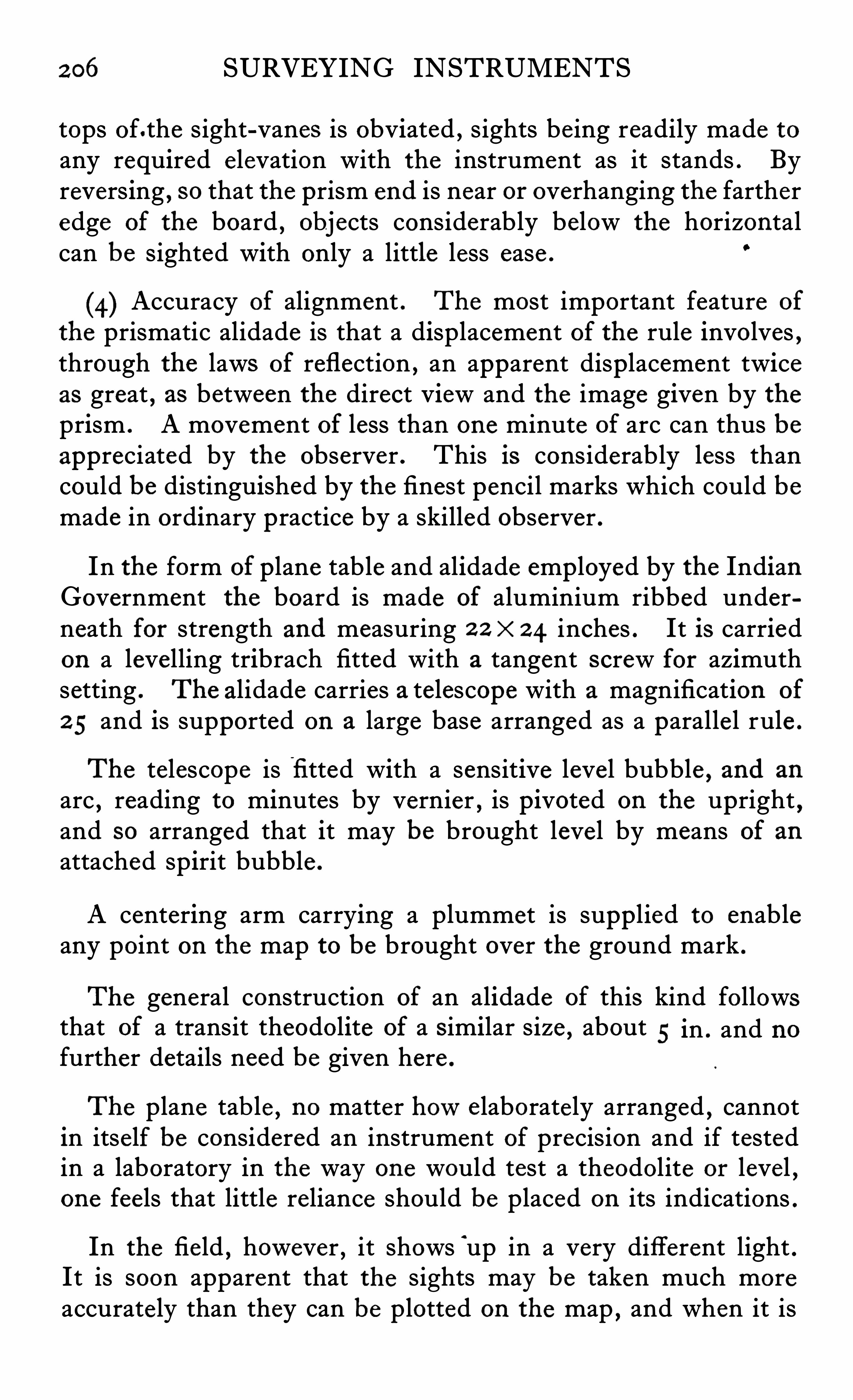
2 06 SURVEYING INSTRUMENTS
tops of.the sight-vanes is obviated , sights be ing readily made toany required elevation with the instrument as it stands . Byreversing , so that the prism end is near or overhanging the fartheredge of the board , objects considerably below the horizontalcan be sighted with only a little less ease .
(4) Accuracy of alignment . The most important feature of
the prismatic alidade is that a displacement of the rule involves ,through the laws of reflection , an apparent displacement twiceas great , as between the direct View and the image given by theprism . A movement of less than one minute of arc can thus beappreciated by the observer . This is considerably less thancould be distinguished by the finest pencil marks which could bemade in ordinary practice by a skilled observer .
In the form of plane table and alidade employed by the IndianGovernment the board is made of aluminium ribbed underneath for strength and measuring 2 2 x 2 4 inches . It is carriedon a leve lling tribrach fitted with a tangent screw for azimuthsetting . The alidade carries a telescope with a magnification of
2 5 and is supported on a large base arranged as a paralle l rule .
The telescope is fi tted with a sensitive level bubble, and an
arc , reading to minutes by vernier , is pivoted on the upright,
and so arranged that it may be brought level by means of anattached spirit bubble .
A centering arm carrying a plummet is supplied to enableany point on the map to be brought over the ground mark .
The general construction of an alidade of this kind followsthat of a transit theodolite of a s imilar size , about 5 in . and nofurther details need be given here .
The plane tab le , no matter howe laborate ly arranged , cannotin itse lf be considered an instrument of precision and if testedin a laboratory in the way one would test a theodolite or level
,
one feels that little reliance should be placed on its indications .
In the field , however , it shows‘
up in a very different light .It is soon apparent that the sights may be taken much moreaccurate ly than they can be plotted on the map
,and when it is
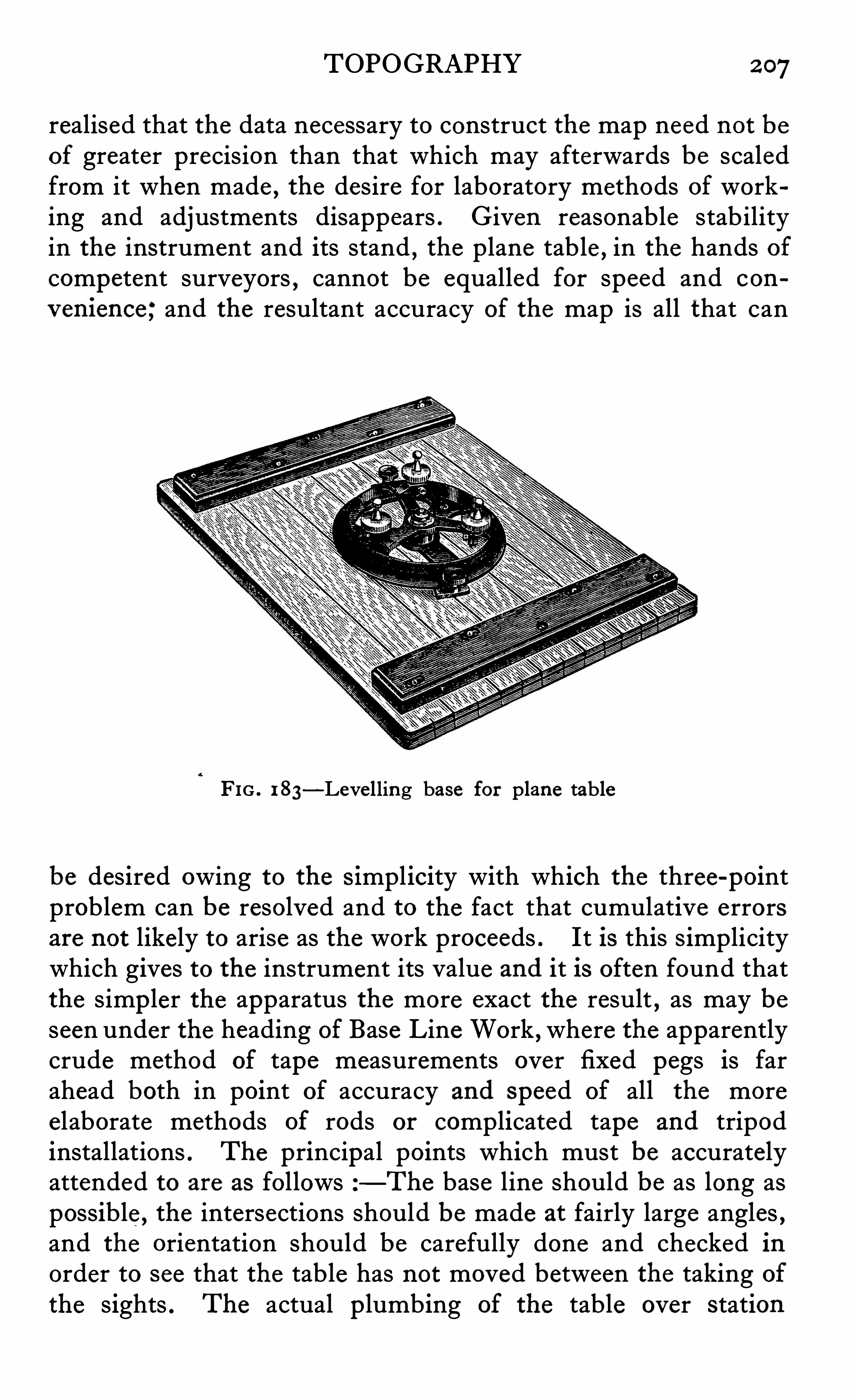
TOPOGRAPHY 2 97
realised that the data necessary to construct the map need not beof greater precision than that which may afterwards be scaledfrom it when made , the desire for laboratory methods of working and adjustments disappears . Given reasonable stabilityin the instrument and its stand , the plane table , in the hands ofcompetent surveyors , cannot be equalled for speed and con
v en ience ; and the resultant accuracy of the map is all that can
FIG . 1 83—Leve lling base for plane table
be desired owing to the s implicity with which the three-pointproblem can be resolved and to the fact that cumulative errorsare not likely to arise as the work proceeds . It is this s implicitywhich gives to the instrument its value and it is often found thatthe simp ler the apparatus the more exact the result , as may beseen under the heading of Base Line Work , where the apparentlycrude method of tape measurements over fixed pegs is farahead both in point of accuracy and speed of all the moreelaborate methods of rods or complicated tape and tripodinstallations . The principal points which must be accuratelyattended to are as follows —The base line should be as long aspossible , the intersections should be made at fairly large angles ,and the orientation should be carefully done and checked inorder to see that the table has not moved between the taking ofthe sights . The actual p lumbing of the table over station
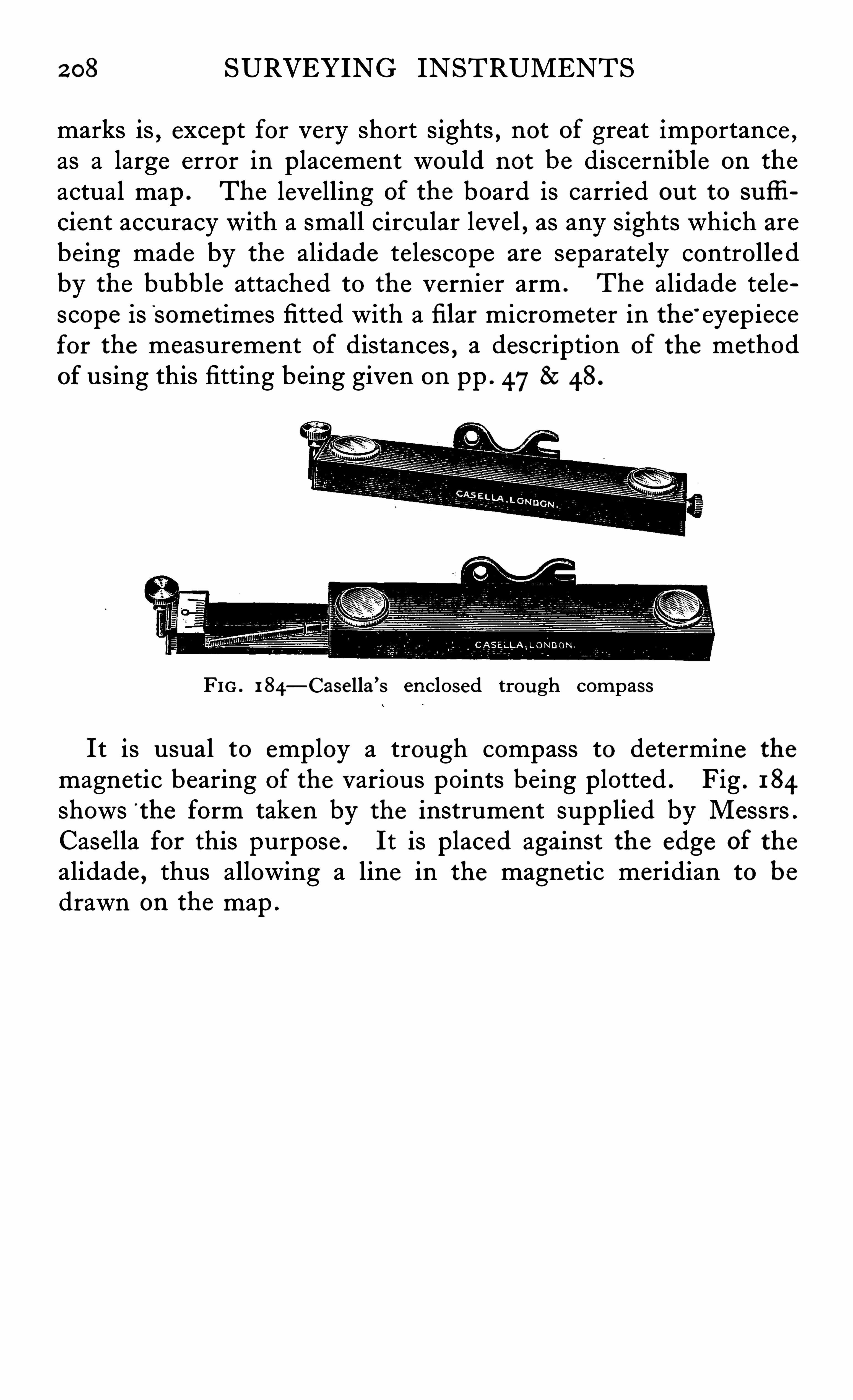
2 08 SURVEYING INSTRUMENTS
marks is,except for very short sights , not of great importance ,
as a large error in placement would not be discernible on the
actual map . The levelling of the board is carried ou t to sufli
cient accuracy with a small circular level , as any sights which arebeing made by the alidade te lescope are separate ly controlle dby the bubble attached to the vernier arm . The alidade te lescope is Sometimes fitted with a fi lar micrometer in the ’
eyepiecefor the measurement of distances , a description of the methodof using this fitting being given on pp . 478:48.
FIG . 1 84—Casella ’s enclosed trough compass
It is usual to employ a trou gh compass to determine the
magnetic bearing of the various points being plotted . Fig . 184shows ‘
the form taken by the instrument supplied by Messrs .
Casella for this purpose . It is placed against the edge of the
alidade , thus allowing a line in the magnetic meridian to be
drawn on the map .
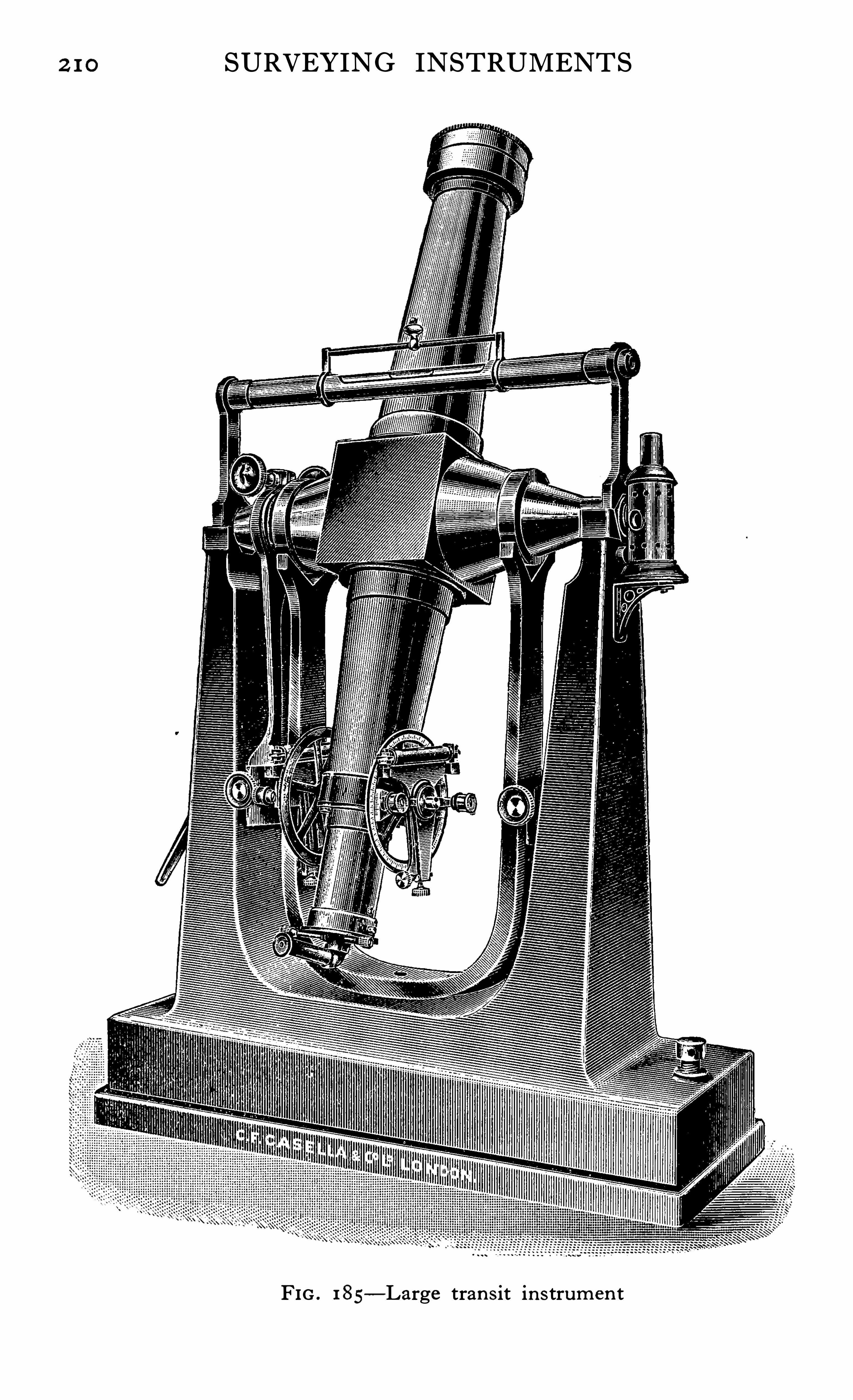
2 1 0 SURVEYING INSTRUMENTS
FIG . 1 85—Large tran s it in s trum en t
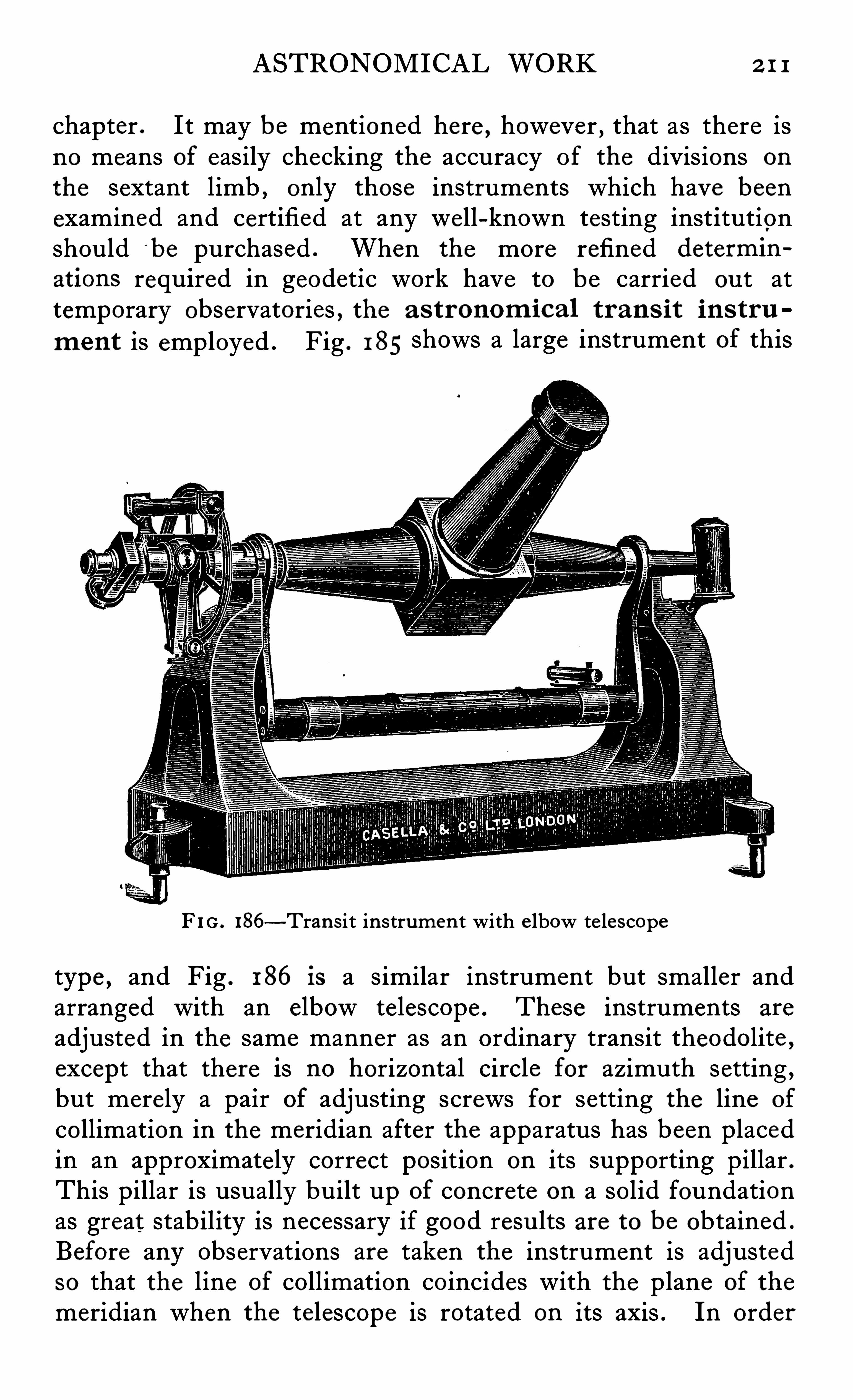
ASTRONOMICAL WORK 2 1 1
chapter .It may be mentioned here , however , that as there is
no means of easily checking the accuracy of the divisions on
the sextant limb , only those instruments which have beenexamined and certified at any we ll-known testing institutionshould ‘
be purchased . When the more refined determin
ations required in geodetic work have to be carried ou t attemporary observatories , the a s tronom ica l tran s it in s tru
m ent is employed . Fig . 1 85 shows a large instrument of this
F I G . 186—Tran sit in strumen t with e lbow te lescope
type , and Fig . 1 86 is a similar instrument but smaller andarranged with an elbow telescope . These instruments are
adjusted in the same manner as an ordinary transit theodolite ,
except that there is no horizontal circle for azimuth setting ,but merely a pair of adjusting screws for setting the line of
collimation in the meridian after the apparatus has been placedin an approximately correct position on its supporting pillar .This pillar is usually built up of concrete on a solid foundationas great stability is necessary if good results are to be obtained .
Before any observations are taken the instrument is adjustedso that the line of collimation coincides with the plane of the
meridian when the telescope is rotated on its axis . In order
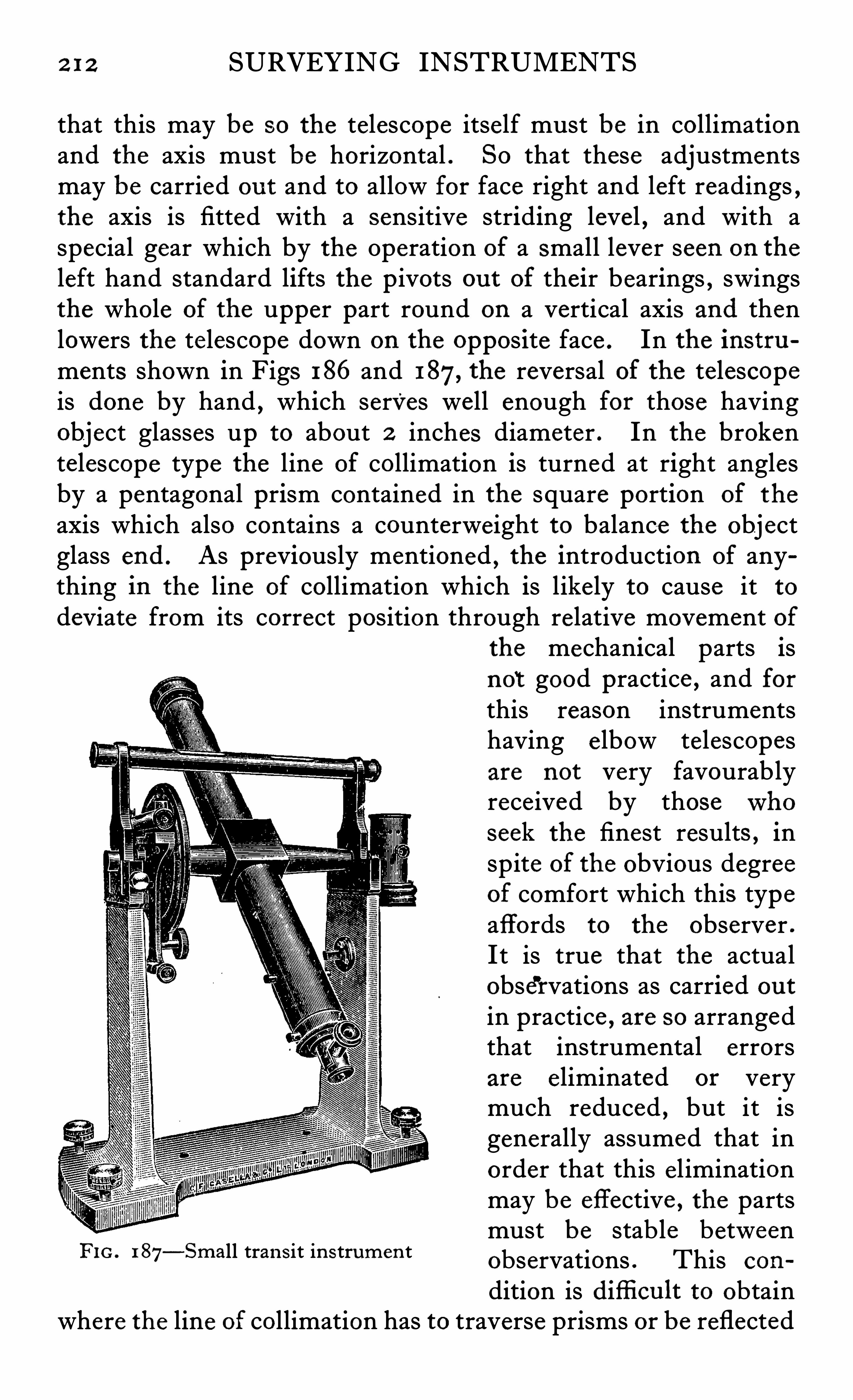
2 1 2 SURVEYING INSTRUMENTS
that this may be so the telescope itself must be in collimationand the axis must be horizontal . So that these adjustmentsmay be carried ou t and to allow for face right and left readings
,
the axis is fitted with a sensitive striding level , and with aspecial gear which by the Operation of a small lever seen on the
left hand standard lifts the p ivots ou t of their bearings , swingsthe whole of the upper part round on a vertical axis and thenlowers the telescope down on the opposite face . In the instruments shown in Figs 186 and 187, the reversal of the telescopeis done by hand
,which serves well enough for those having
object glasses up to about 2 inches diameter . In the brokentelescope type the line of collimation is turned at right anglesby a pentagonal prism contained in the square portion of the
axis which also contains a counterweight to balance the objectglass end . As previously mentioned , the introduction of anything in the line of collimation which is likely to cause it todeviate from its correct position through relative movement of
the mechanical parts isnot good practice , and forthis reason instrumentshaving e lbow telescopesare not very favourablyreceived by thosewhoseek the finest results , inspite of the obvious degreeof comfort which this typeaffords to the observer .
It is true that the actualobservations as carried ou t
in practice , are so arrangedthat instrumental errorsare eliminated or verymuch reduced , but it isgenerally assumed that inorder that this e l iminationmay be effective , the partsmust be stab le betweenobservations . This con
dition is difli cu lt to obtainwhere the line of collimation has to traverse prisms or be reflected
FIG . 1 87—Small tran s it in strumen t
2 14 SURVEYING INSTRUMENTS
by a centrifugal governor . The weight and the advantage of
the train can be altered so as to give e ither one revolution perminute or double that speed , or when electrically driven , or
rather , when the weight is wound up by an e lectric motor,
as much as one revo lution per second . Spring driven gears arenot satisfactory for this purpose so that the less portable weightdrive must be used . The governor must be very carefullyadjusted so that a uniform speed may be maintained , the successof this method of recording depending on the constancy of the,
speed of rotation of the drum .
Governors of various kinds have been tried , but the simplestand most successful hitherto have been those depending on
friction as the controlling force . This is usually arranged eitherby fitting a collar to a revolving s leeve which rises ”and touchesa light spring when the weights are thrown ou t by centrifugalforce , or as shown in the illustration , which is a photograph of
the type of instrument used by the U .S . Geodetic . Survey , bymeans of a hook piece , which is attached to and revolves with aweight concentric with the spindle , engaging with a pin on one
of the weights . When the weight rises , the pin engages withthe point of the hook and drags it round with it . The addedfriction s lows the clock down and when in consequence the
weight falls , the hook is disengaged thus allowing the clock tospeed up again . If the adjustments are carefully made , thespeed can be regulated so that there is no appreciable differencein the distance apart of the second marks
,right through the
chart , but these adjustments must be checked before any ob
serv ations are taken . In this connexion , it is interesting to
note that the time taken at any station in setting up and adjustingthe instruments is very considerably greater than that requiredfor the actual observations .
The gearing also drives the pen carriage by means of a screw ,
thus tracing a sp iral line on the chart from end to end of the
drum of about 1 / 10th inch pitch . The pen may be an ordinaryfountain or stylograph pen which is quite satisfactory for
ordinary u se . When , however , the highest accuracy is desired ,the pen and its electrical parts must be made very light and anapparatus such as the siphon recorder used for telegraphiccable work is employed .
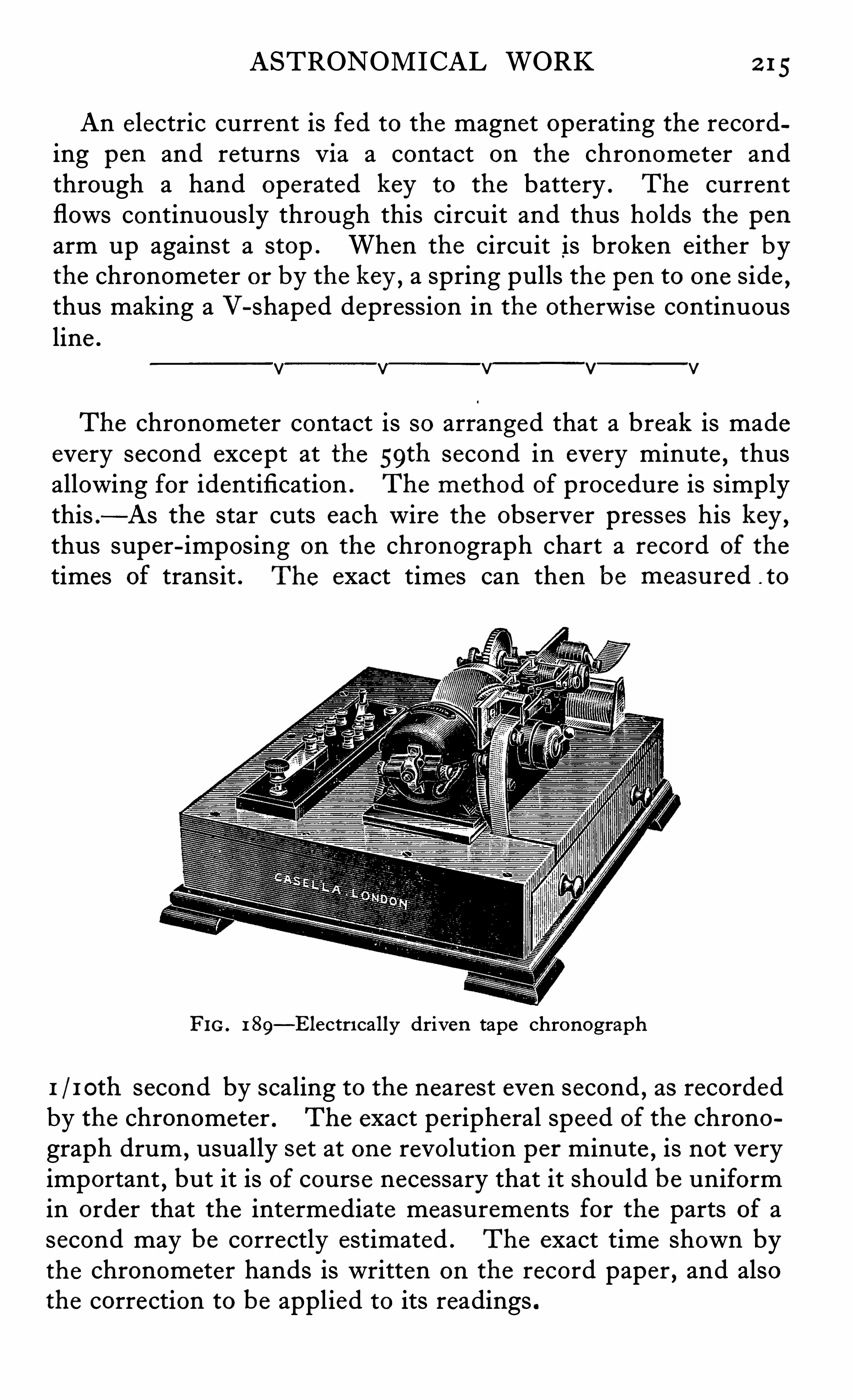
ASTRONOM ICAL WORK 2 15
An electric current is fed to the magnet operating the recording pen and returns v ia a contact on the chronometer andthrough a hand operated key to the battery . The currentflows continuously through this circuit and thus holds the penarm up against a stop . When the circuit is broken either bythe chronometer or by the key , a spring pulls the pen to one side
,
thus making a V-shaped depression in the otherwise continuousline .
v v— _
v—
v—
v
The chronometer contact is so arranged that a break is madeevery second except at the 59th second in every minute
,thus
allowing for identification . The method of procedure is simplythis . —As the star cuts each wire the observer presses his key ,thus super-imposing on the chronograph chart a record of the
times of transit . The exact times can then be measu red to
FIG. 1 89—Electrl cally driven tape chronograph
1 / 1 0th second by scaling to the nearest even second , as recordedby the chronometer . The exact peripheral speed of the chronograph drum , usually set at one revolution per minute , is not veryimportant , but it is of course necessary that it should be uniformin order that the intermediate measurements for the parts of asecond may be correctly estimated . The exact time shown bythe chronometer hands is written on the record paper , and alsothe correction to be applied to its readings .
2 16 SURVEYING INSTRUMENTS
In order to reduce still further the personal errors of observation , large instruments are often fitted with a screw micrometerin the eyep iece the divided drum of which carries a number ofcontacts which automatically break the circuit as the drum isrevolved .
Imp er sona l M icrom eter . A device of this kind is illustrated in Fig . 190 , which shows clearly the e lectrical contactstrips fas tened to the micrometer head . The number of thesecontacts may be from 5 to 2 0 , depending:on the pitch of the
FIG. 1 90
screw used and the speed of the chronograph drum , and theyare usually unequally spaced in order that they may fall intogroups , thus facilitating their identification on the chart . For
example , if a series of 5 contacts are fitted they might beplaced at 0 1 2
-5 37-5 62 5 and75 divisions of the drum ,
thus giving a trace easily interpreted .
2 1 8 SURVEYING INSTRUMENTS
i .e . the following points should be examined . First set the
micrometer wires vertical and adjust the line of collimation byreversing the axis on its pivots while ranging an object at leastone mile distant . Setting on a near terrestrial object is not
advisable , and in many instruments not possible , as no largeamount of focusing adjustment is fitted or desirable . The
telescope axis would of course already have been set up trulyhorizontal by means of the stride leve l , the adjustment of whichmust also be checked . The bubble of the finder circle shouldthen be adjusted to the mean of two readings taken on oppositefaces in order to e liminate its index error . When two findercircles are fitted , they should both be set to the same angle bymeans of their verniers , and the bubbles should then come tothe centre of their runs when the te lescope is s et at the appropriate angle . The instrument will already have been set u papproximately on the meridian , but its exact adjustment cannotbe made accurately until after dusk . All the other adjustmentsshould be made in daylight ready for the night observations .
To set the instrument in the meridian first of all set the telescopeon a star a fewdegrees from the zenith and note the time of
transit on the chronometer . From this observation the chronometer error can be obtained
,as slight error in the azimuth
setting of the te lescope will not affect the time of transit of a starso close to the zenith . Nowset the telescope ready to observeon a star of large declination which is about to transit . A littlebefore the time it is du e to transit as shown by the correctedchronometer
, set the middle wire of the te lescope to bisect thestar . Keep the star on the centre wire by means of the azimuthscrew until it is on the meridian as shown by the chronometertime. The instrument will nowbe very nearly in the meridian ,but the whole process may be repeated and the setting improved if time permits .
Latitude
As the latitude of any point on the earth ’s surface is themeridional zenith distance of any celestial obj ect
,the deter
mination may be made in an approximate way by s implymeasuring the altitude of the sun or Polaris as it crosses themeridian . This may easily be done with the ordinary surveyor ’s
ASTRONOMICAL WORK 2 19
transit theodolite or , as is usual at sea , by the sextant . Thismethod is , however ; not sufli ciently accurate for the finestgeodetic work , owing to the fact that large corrections must beapplied to the observed figures in order to eliminate the eflect
of refraction and instrumental errors . The programme of
observations may be designed to eliminate these latter errors ,but the errors du e to differences in refraction which vary withthe altitude and which may also vary from day to day
, are not
easily allowed for , so that more refined methods of observation arenecessary and have been in u se for many years . As the refrac
tion is least at the observer ’s zenith , this fact has been takenadvantage of in the HoRREBow-TALCOTT scheme , which is themost popular method to-day of making latitude determinations .
The newmethod employing the astro labe of CLAUDE 8:DRIENCOURT has made great strides in recent years however , and adescription of an instrument adapted for this work is givenlater .
Horr ebow-Ta lcott Method . In the Talcott method , instead of taking absolute measurements of the altitudes , adifferential determination is emp loyed on stars very close to the
zenith,so that errors of refraction are definitely eliminated ,
thus allowing of a much greater accuracy being obtained . Thismethod has also the added advantage that it is not necessaryto make accurate readings on a divided circle , thus e liminatinganother probable source of error . It is necessary to know the
approximate latitude of the point of observation and to calcu
late the local time of pairs of suitable stars , but tables are nowobtainable from which these pairs may be p icked , and fromwhich their declination may be extracted .
The method of using the instrument is as follows
A pair of stars which crossthe meridian within fi v e minutesof each other is se lected , one to the north and one to the
south , the difference in the zen ith distances of which iswithin a fewminutes . The instrument having been adjustedand set up truly on the meridian , the telescope is set bymeans of its finder circles about midway between the two
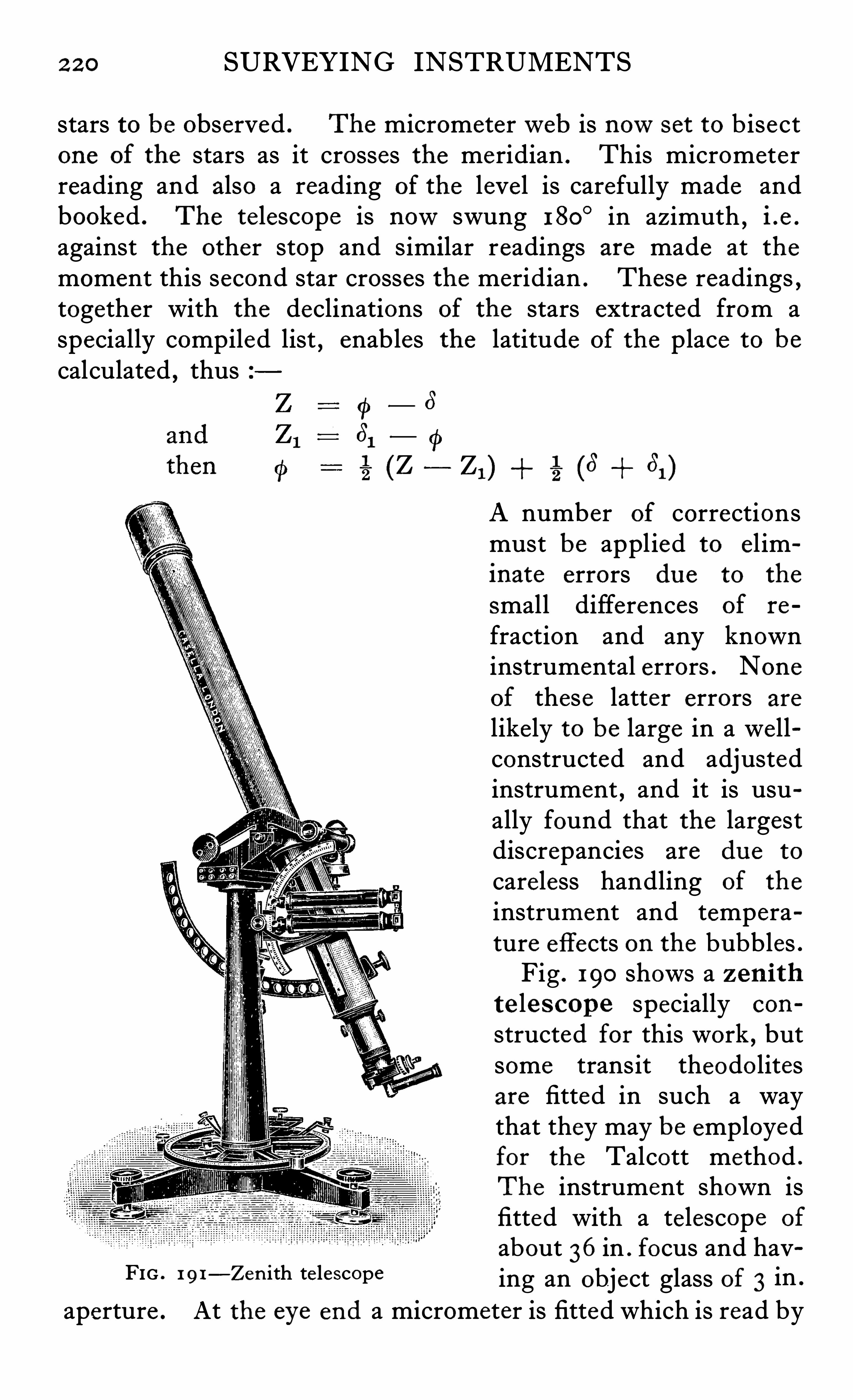
2 2 0 SURVEYING INSTRUMENTS
stars to be observed . The micrometerweb is nows et to b isectone of the stars as it crosses the meridian . This micrometerreading and also a reading of the level is carefully made andbooked . The telescope is nowswung 180
° in azimuth,i .e .
against the other stop and similar readings are made at themoment this second star crosses the meridian . These readings ,together with the declinations of the stars extracted from aspecially compiled list , enables the latitude of the place to becalculated , thus
(P61
%(Z
FIG . 1 91—Zen ith te lescope
_ 8
2 1 ) 2 (6 61 )
A number of correctionsmust be applied to el iminate errors du e to the
small differences of re
fraction and any knowninstrumental errors . Noneof these latter errors are
likely to be large in a we llconstructed and adjustedinstrument , and it is usually found that the largestdiscrepancies are du e to
careless handling of the
instrument and temperature effects on the bubbles .Fig . 190 shows a zen i th
te le s cop e specially con
structed for this work , butsome transit theodo litesare fitted in such a waythat they may be employedfor the Talcott method .
The instrument shown isfitted with a telescope of
about 36in . focus and having an object glass of 3 in .
aperture .At the eye end a micrometer is fitted which is read by
2 2 2 SURVEYING INSTRUMENTS
tube , in order to give a more convenient position for the eyep iece .
This means that a prism must be interposed in the line of
collimation which as already pointed ou t previously is not goodpractice. The stops limiting the rotation in azimuth to 1 80
°
must be accurately set , so that the telescope is exactly in the
meridian north and south , and this adjustment is made exactlyas given for the setting up a transit instrument . The findercircles must be s et to read true zenith distances , this beingaccomplished as followsSet the telescope on some well-defi ned distant point , adjust
ing the bubble to the centre of its run , and take the reading of
the circle . Nowset on the same object with the telescopereversed , when the mean of the two circle readings will be thezenith distance . If the circle is nowset to the mean reading andthe te lescope pointed again on the object
,the level bubble
may be adjusted by means of its opposing screws . This adjustment may easily be checked by pointing on to a star of knownzenith distance . It is usual to go through all the adjustmentsto check them immediately before the actual observations forlatitude are to be made .
As the Talcott method is capable of giving results of the
highest order of accuracy,it is necessary when making . the
observations to s ee that instrumental errors are e liminatedwherever possible . This is taken care of by careful adjustments of the various motions , by accurate calibration of the
micrometer'
and the leve ls,and then by taking great precautions
to insure that no relative displacement of the parts takes placeduring the time between the observations of the star pairs .
For this reason the instrument should be carefully guardedagainst changes of temperature and against wind pressure , andthe bubb les especially should be protected against the heat ofthe observer ’s body or the lamps used to illuminate them whilethey are being read . As any undue pressure placed on the
instrument by the observer when turning the micrometerhead will lead to large errors in the readings , a minimumamount of handling of this part is essential . Of course the
skilful choice of stars and the programme to be observed in theobservations will play a most important part in securing accurateresults , but as these points are more in the province of the
ASTRONOMICAL WORK 2 2 3
astronomer than the instrument designer , they need not be
enlarged upon here . Finally , the accuracy to be expected andgenerally obtained from a well-adjusted zenith telescope takingthe mean of 10 or 1 5 pairs of stars , is of the order of 1 / 10th of asecond in the astronOmic latitude .
Va lu e of Microm eter D ivi s ion s . The method of obtaining the value of the micrometer divisions is
,as mentioned before ,
best performed in the laboratory,but when it is to be .
determin
ed in the fie ld the following is a good procedure to adopt
The telescope is focused on some close circumpolar starnear e longation and the time of its transit across the movablewire is taken at several settings . For this purpose
,the wire is
set one whole turn ahead of the star,the exact moment of its
transit read and at the same time the position of the latitudelevel . The readings may also be taken at culmination , but inthis case the results are not so accurate , owing to the factthat variations in the setting in azimuth are not e liminated
,
as the corresponding variations can be in the former methodby taking into account in the calculation the readings of the
latitude level . This leve l must of course also have its valuedetermined very accu rately , bu t this work is best done in the
laboratory by means of the leve l trier . The best method of
finding the micrometer values has been found to be by meansof calculations made on the observed readings obtained whenmaking latitude determ inations . A large number of accurateobservations are generally made at each station , the figuresobtained being available for this purpose , and it is generallyfound that the mean results calculated in this way are moreconcordant than those obtained from special observations on
the circumpolar stars .
Zen i th Tub e . A most accurate method of determininglatitude , which , however , is only used at important fixedobservatories , is by means of the z en i th tub e . This inessence is a large tubular casting bolted down on a concretefoundation and set to point to the zenith . At the top an
2 2 4 SURVEYING INSTRUMENTS
object glass of large aperture is fixed in a cell which may brotated in azimuth . At half the focal distance below the
object glass a mercury trough is placed in such a positionthat the light from a star , after passing through the objectglass is reflected back and focused on to a photographicplate or a micrometer fixed to rotate with the object glass .
If the object glass is rotated 360 degrees , the image of the starwill trace a circle on the photographic plate the radius of whichwill be the zenith distance of the star . As it is the zenithdistance of the star when on the meridian which is requiredto be known , the method of using the instrument to get thisresult is as follows
The star on approaching makes a trail on the photographicplate . As soon as it reaches the meridian , the lens and plateare quickly turned 1 80
° in azimuth so that the star will nowmake a trail on the plate parallel to the first one . The distancebetween these two trails when corrected for curvature , willthen be twice the zenith distance of the star . Various cor
rections must be applied owing to the impossibility of instantreversal and to the fact that a reversal of 180° cannot be exactlymade . The photographic plates are afterwards measured bymeans of a special trave lling microscope in the manner familiarto astronomers . The idea upon which the zenith tube wasbased was du e to Airy
,and an instrument of this description
was constructed and in u se for fifty years at Greenwich Observ atory . From the data obtained by its u se Chandler firstdiscovered the phenomenon of latitude variation .
This latitude variation is extreme ly minute ,being only about
5 second of are so that the observations made for the purposeof measuring its magnitude must be very carefully carried ou t
by means of the very finest instrumental aids . The actualvariations are not yet definite ly known , as their periods which arevery complex have not been fully determ ined , nor are theylike ly to be until the observations taken over some years havebeen classified and the results computed . When it is realisedthat the total variation at the pole is probab ly less than 1 00 feetthe delicacy of the determinations will be manifest .
2 26 SURVEYING INSTRUMENTS
with each other serve to give the longitude of the newstation inrelation to the main observatory , the position of which is alreadyaccurately known . The u se of the telegraph wires introducescertain errors which must be allowed for . These errors are du eto the time lag in the line , in the relays and in the magnets used tooperate the chronographs . Whenever possible , the lines shouldbe simple and run as directly as possible between the stationswithout having to go through local relays or other circuits at thetelegraph offi ces . This cannot always be arranged of course , s othat it is necessary to take special precautions to e liminate anyerrors due to this cause . The simplest method of ensuringgood results is to make the s et of special breaks from each end
in turn,the times of which can be compared with those of the
chronometers , as in this way the mean of the two sets of breaksshould give an exact result . This will not be so unless therelays
,etc . ,
at each end are similar in lag and general characte rand there will also be the usual errors du e to the personalequation of the observers . When therefore the determinationsare required to be of the highest precision
,it becomes necessary
to make a change of observers from end to end and when anydoubt is felt as to the similarity of lag in the apparatus eachobserver should instal his own instruments at the oppos itestation . It is usual to observe each night on 1 2 stars , the specialbreaks being made after the sixth s et has been completed .
When the work is carried ou t in this way and all the usualprecautions have been taken , the probable error is somethingof the order of 0 0 1 5 second of time .
Photograph ic m ethod s of obtaining longitude have beenput forward from time to time
,but have not come into general
u se on geodetic work , owing probably to the somewhat laboriouscalculations required and to the necessity of using rather ex
pensive subsidiary apparatus to measure the photographicplates . The method is roughly as followsA very stable camera is set up and pointed so that the image
of the moon comes on the centre of the plate . A number ofinstantaneous exposures are then made at such intervals of time
that the images do not overlap . Without disturbing the cameraa set of time exposures are made on three or four bright starsof about the same declination , each such exposure leaving a
ASTRONOMICAL WORK 2 27
trail on the plate . If then the local times of all these exposuresare known the measurement of their positions will give the datanecessary for the computer .
Az imu th
In order that the triangulation points may be correctlyplaced on the map
,it is necessary to know the true north at a
number of points and as the determinations act as a check on
the triangulation angles , it is usual to take astronomical azimuthsights at each important point of the triangulation n et-work .
When the azimuth is only approximately required an observation on the sun is usually made with a transit theodolite the
procedure being simply to point first on to the sun , noting thetime
,and then on to a fixed terrestrial mark . It is necessary
to know the latitude , longitude and the local time , thus allowingthe true bearing of the azimuth mark to be calculated . Whenmore refined results such as those used in primary triangulationare required , it is usual to make the observations on Po laris oron the close circumpolar stars and these observations are madeat the same time as are those of the triangulation angles andusing the same targets . The most skilful observers and the
very finest instrumental aid are necessary for this work , andsurveyors generally consider the taking of astronomical azimuthsas the most exacting operation they are called upon to perform .
Owing to the large differences in the inclinations of the te lescopes , which must be first pointed on to a star and then on to aterrestrial object , the stability of the instrument and the controlof the horizontality of its p ivots must be most carefully attendedto . Otherwise the operation is very similar to taking ordinaryterrestrial azimuth and all the usual adjustments must becarried ou t in the way already indicated , and with the mostscrupulous care . The observations are always made in such away that the instrumental errors are e liminated so far as possib le ,and for this reason the theodolite must be arranged for changeof pivots so that face right and left readings may be made .
The procedure is as follows
The telescope is first set on to the terrestrial mark , which isusually a signal tower carrying a powerful source of light if the
2 2 8 SURVEYING INSTRUMENTS
work is being done at night , and a greading of the horizonta lmicrometers taken . I t is then pointed on to Polaris , the time
by the chronometer taken , and then the reading of the circlebooked . The telescope is nowreversed on its pivots and a pairof similar settings and readings are taken . Immediate ly aftereach pointing is made the striding leve l is read in order to findthe inclination to the horizontal o f the telescope pivots . The
calculations are made later in the ofli ce and consist in first
FIG . 192—Heliotrope
finding the bearing of Polaris to the meridian at the time of eachpointing . The various corrections are then applied and the
bearing of the line joining the instrument to the target or
triangulation mark from the meridian is obtained . With thismethod the error in the final results of say ten complete sets of
‘
four observations is somewhere in the neighbourhood of -3
to -4 second , while the usual degree of accuracy expected from
observations on the sun is about half-a-minute . For work of
the highest accuracy the time determinations are of very greatimportance and the error of the chronometer should be known
2 30 SURVEYING INSTRUMENTS
then securely clamped In azimuth . Four or fi v e settings are
nowmade on the target using the micrometer screw only and thereadings booked . The telescope is then tilted in altitude on to
the star and the striding level read . Three or four bisections ofthe star are then made with the micrometer and the chronometertimes booked , together with the settings . The striding leve lis then read and the amount of tilt booked . This level i s thenreversed and read and three more pointings are made on the
star,the figures being booked together with the times by the
chronometer . The telescope is nowreversed on its p ivots ,and the above star readings , etc . ,
repeated in the newposition .
The telescope is then lowered on to the target and four or fi v esettings are made and booked . Such a set of readings will takeabout fifteen minutes and on a suitable night two or three suchsettings may be made leaving plenty of time to read the bubblesand to set the micrometers , if the operations are thus carefullymapped ou t and rehearsed beforehand . Just before the telescope is reversed on its pivots it is usual to read the zenithdistance of the star , as it is necessary to know this when makingthe calculations . When accuracy such as that expected from amain observatory is required , it may be necessary to make anumber of determinations of the zenith distance , owing to the
fact that the value is continually changing . The value of the
micrometer turns must be accurate ly known for work of thisnature , and as explained before , this value is usually determinedin the . laboratory . The surveyor generally likes to check itsvalue or its constancy for himself however , and the simplestmethod of making this test is to measure a small angle betweentwo fixed terrestrial targets or two plumb bobs by means of thehorizontal circle of the instrument
,the mean of a number of
readings being taken in order to e liminate errors of circledividing and eccentricity . The same angle is then measuredwith the m icrometer , and , providing a sufficient number ofsettings are made and the targets are of such a nature thatthey may be accurate ly pointed upon , the results obtained bythis method are better than those to be expected from pointingson the close circumpolar stars . This latter Operation is carriedou t in the following way
The telescope is pointed on to one of the close circumpolar
ASTRONOMICAL WORK 2 3 1
stars just before elongation , ,and clamped securely in altitude
and azimuth . The micrometer is set a fewturns from its meanposition towards the side from which the star is apparentlytrave lling . When the star transits across theweb the chro
nometer time is taken and then the screw is moved on e wholeturn
,thus putting it ahead of the star ready for the next transit .
A number of transit turns are thus taken , covering the whole of
the screw . From these figures the micrometer value,may be
calculated , but it is necessary to know the leve l values and thechronometer times very accurately . The calculations requiredbefore exact values can be obtained by this method are verylaborious and it is doubtful if the results achieved repay th e
labour involved in taking the observations and making the
computation . When determinations of azimuth have to be
made in very high latitudes,the above methods are not al
together satisfactory because of the high altitude of the slowmoving stars . It is possible to calculate the azimuths from datafurnished by the Observations made for time if when theseobservations are made a pointing is also made on a terrestrialmark and its position determined by the micrometer . For
this purpose , the mark must be nearly in the meridian in orderthat it may be covered by the screw of the micrometer . The pro
cedu re otherwise is similar to the micrometer method given above .
The close meridian mark must of course be connected up to theusual triangulation marks by the direction method already given .
The target s used for azimuth work vary according to the
nature of the ground over which the sights must be made , andit is often necessary to raise them to a considerable elevationabove the surrounding country in order to get the sights clear oftrees , buildings and other obstructions . see Fig . 193 . The bestmark is undoubtedly an e lectric head light such as those used onmotor cars and for short distances such a lamp may be placedin a wooden box the front of which is covered by tracing clothhaving a piece of black tape stretched vertically across its centre .
Very good settings may be made on such a target at fair distances ,but no target should be placed closer to the instrument thanabout a mile , as otherwise the telescope focus must be changedwhen pointing on to the star
,thus leading to the possibility of
errors owing to the likelihood of displacement of the line of
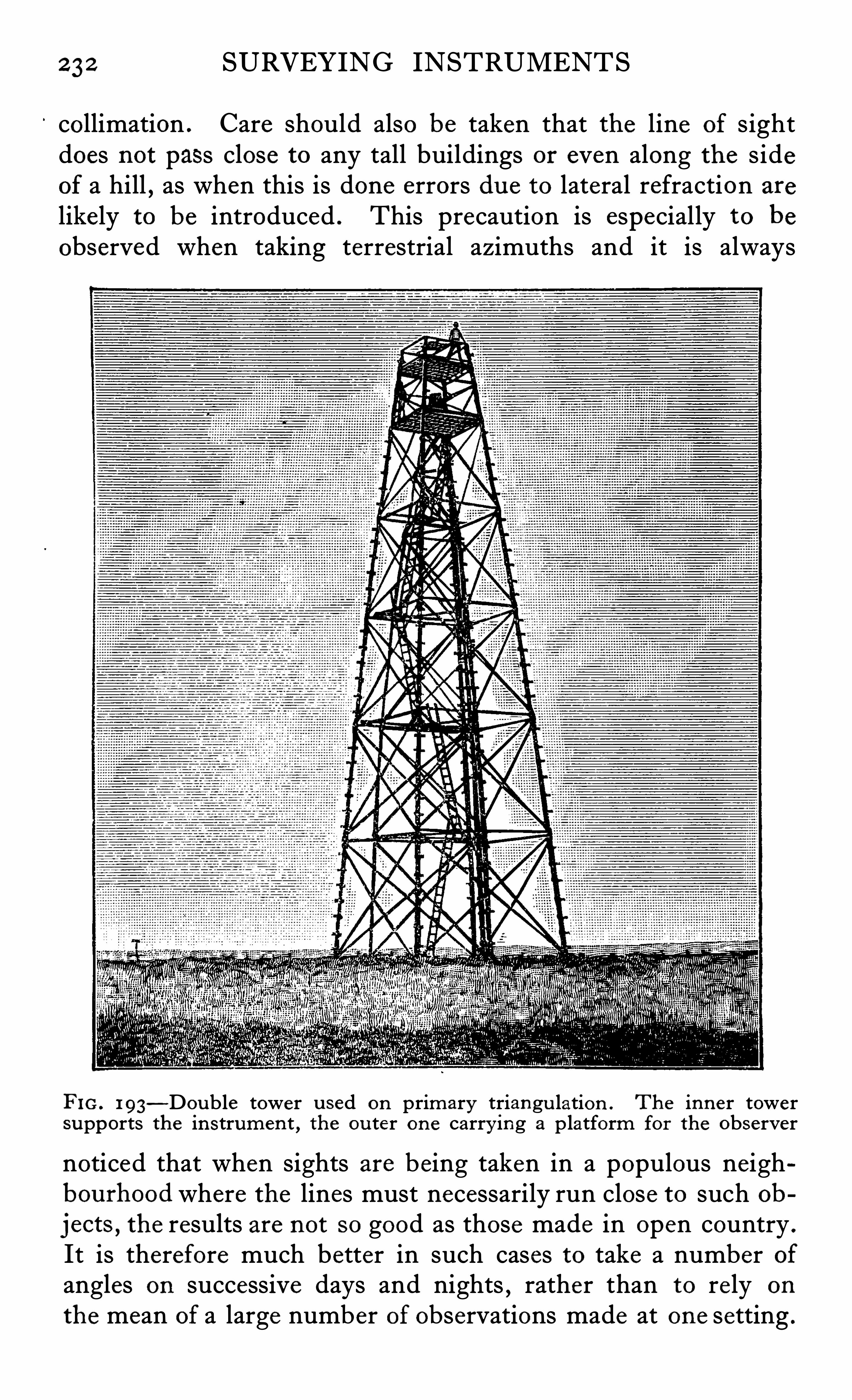
2 3 2 SURVEYING INSTRUMENTS
collimation . Care should also be taken that the line of sightdoes not pass close to any tall buildings or even along the sideof a hill , as when this is done errors du e to lateral refraction are
likely to be introduced . This precaution is especially to be
observed when taking terrestrial azimuths and it is always
FIG . 193—Dou ble tower u sed on primary triangu lation . The inner tower
supports the in strumen t,the ou ter on e carry ing a p latform for the observer
noticed that when sights are being taken in a populous neighbou rhood where the lines must necessarily run close to such ob
jects , the results are not so good as those made in open country .
It is therefore much better in such cases to take a number ofangles on successive days and nights , rather than to re ly on
the mean of a large number of observations made at one setting .
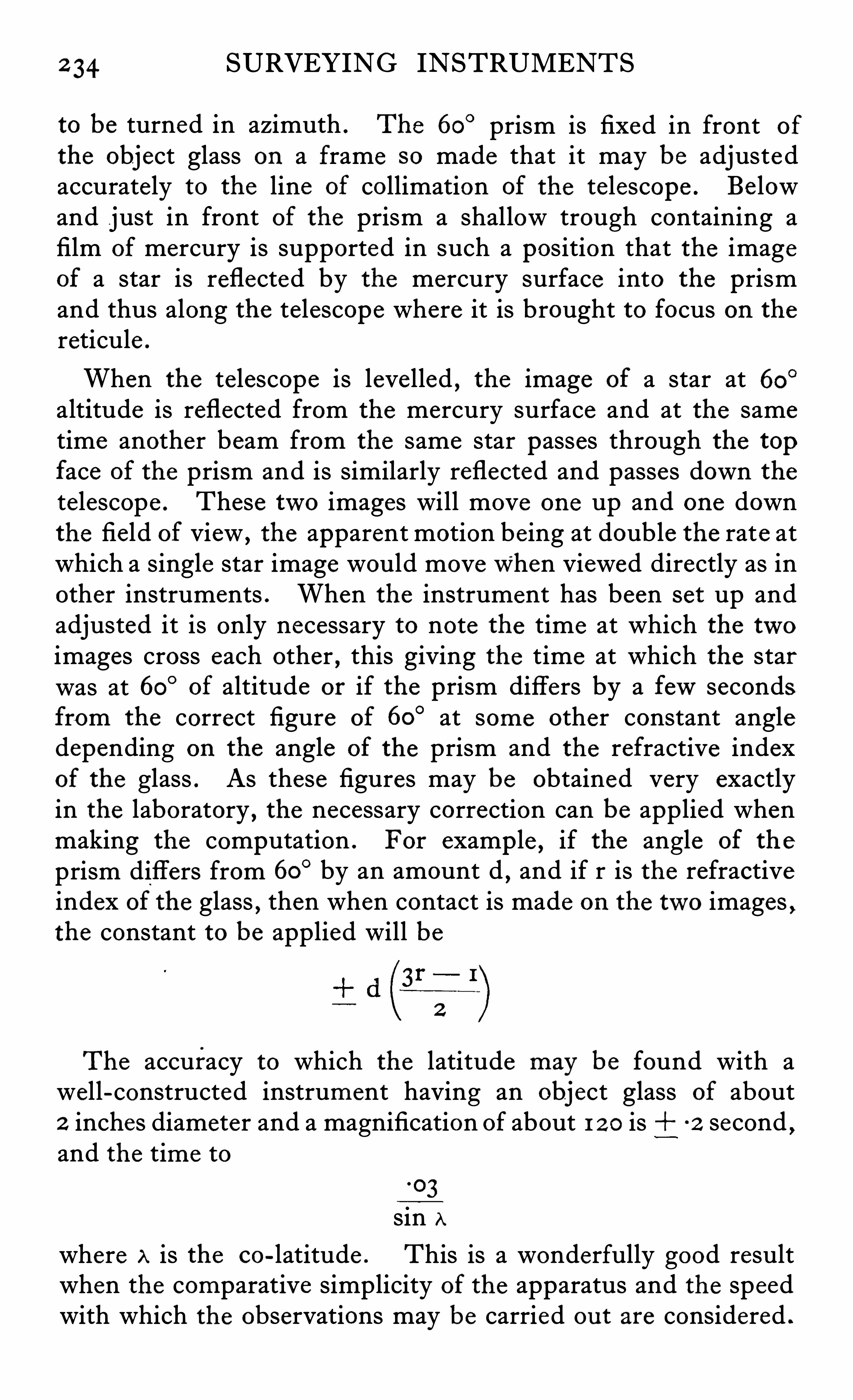
2 34 SURVEYING INSTRUMENTS
to be turned in azimuth . The 60° prism is fixed in front of
the object glass on a frame so made that it may be adjustedaccurately to the line of collimation of the telescope . Be lowand just in front of the prism a shallow trough containing afilm of mercury is supported in such a position that the imageof a star is reflected by the mercury surface into the prismand thus along the telescope where it is brought to focus on thereticule .
When the telescope is leve lled , the image of a star at 60°
altitude is reflected from the mercury surface and at the sametime another beam from the same star passes through the topface of the prism and is similarly reflected and passes down thetelescope . These two images will move one up and one downthe field of view ,
the apparent motion being at double the rate atwhich a single star image would movewhen viewed directly as inother instruments . When the instrument has been set up andadjusted it is only necessary to note the time at which the twoimages cross each other , this giving the time at which the starwas at 60° of altitude or if the prism differs by a fewsecondsfrom the correct figure of 60
° at some other constant angledepending on the angle of the prism and the refractive indexof the glass . As these figures may be obtained very exactlyin the laboratory , the necessary correction can be applied whenmaking the computation . For examp le , if the angle of th e
prism differs from 60° by an amount d,and if r is the refractive
index of the glass , then when contact is made on the two images ,the constant to be applied will be
The accuracy to which the latitude may be found with awell-constructed instrument having an object glass of about2 inches diameter and a magnification of about 1 2 0 is -2 second ,and the time to
.03
sin A
where A is the co-latitude . This is a wonderfully good resultwhen the comparative simplicity of the apparatus and the speedwith which the observations may be carried ou t are considered .
PRISMATIC ASTROLABE
FIG. 195—Prismatic astrolabe attachmen t on a microme ter theodo lite
2 35
2 36 SURVEYING INSTRUMENTS
The weight of the apparatus is small compared with other instruments giving an equivalent result , and there is no necessity to
construct special supporting piers or stands,as the ordinary
portable tripod gives sufficient stability . In addition a completedeterm ination including the setting up and the adjusting of the
instrument may be made in about two hours , s o that thereis no doubt that this method is destined to become very large lyused . It is true that the instrument is a special one of u se for
this purpose alone , but as it is so portable , this is no great disadvantage when it is considered howperfect are the results andat what a comparatively small cost the determinations can bemade .
For making similar determinations , Mr Reeves of the RoyalGeographical Society , has designed a p r i sm a ttachm ent
which may be fitted to an ordinary transit theodolite , a photograph of this being shown in Fig . 195. As may be seen
,this
attachment is arranged to be clamped on to the object glass cell ,and is so fitted that slight adjustments may be made to the prismin two directions at right angles to each other . The wholeapparatus may also be rotated slightly about the axis of collimation of the telescope . Below the prism a detachable arm carriesa small boxwood or aluminium tray containing a Copper plateamalgamated with mercury on its upper surface . The wholeattachment only weighs a fewounces , so that although it isdesirable
,it is not absolutely necessary to fit a counterbalance
weight to the other end of the te lescope .
Adju s tment of the Pr i sm Attachm ent . The theodolitehaving been set up and adjusted in the usual manner , the
telescope is directed to and accurately set on some well-defi neddistant point . The attachment is then s lipped on to the
object glass cell and clamped so that the leading edge of the
prism is about level . The telescope should nowbe depressedwhen the point ranged upon should be in the fie ld of the
telescope . By means of the two adjusting screws , the pointshould be brought accurately to the intersection of the webs .When the telescope is moved in altitude , the point should followthe verticalweb , but if it does not do so
,it may be brought to
the correct position by manipulating the small screw at the topof the cell . The readings should be repeated , when , if all is in
2 38 SURVEYING INSTRUMENTS
to those given except that the prism may be s et to correct positionin relation to the line of collimation by the method of autocollimation . In order that this may be carried ou t conveniently
,
the reticule which consists of two vertical and two horizontallines forming a rectangle in the centre of the field is stronglyilluminated by means of an electric lamp fitted to the telescopethus showing up the spider lines black against a bright background . The image of these lines is therefore reflected fromthe back face of the prism and superimposed on the wiresthemselves , a pair of adjusting screws being furnished to bringthe images into coincidence .
In an instrument recently designed by T . Y . Baker , variousimprovements have been incorporated which appear to renderthe apparatus capab le of greater accuracy . In this design theprism
,instead of being fixed in one position
,is arranged so that
it may be rotated about a horizontal axis,thus bringing each edge
to the front in turn . The three angles of the prism have purposely been made slightly different from each other , one be ingas nearly 60° as
,
it is possible to make it . The other two anglesdiffer from 60° by about 7minutes and 7minutes . It isthus possible to take three readings of each star by rotating theprism 1 2 0
° between each observation . It is obvious that theprism must be very accurately mounted to rotate so that the ad
justments remain correct for all three positions . It wouldseem that the advantages of the three readings on this instrument as against one on the original type must be great to justifya departure from the simplicity of the Claude and Driencourtdesign , especially when it is considered that the main virtue of
the astro labe lies in its extreme simplicity and freedom frominstrumental errors , and that , with a fairly large obj ect glass ,capab le of working on small magnitude stars
,plenty of oppor
tun ities are offered for observations on any reasonably clearnight . Another improvement incorporated in Baker ’s instrument is the provision of a small auxiliary prism to split the directimage of the star , so that two images appear in the fie ld separatedhorizontally by a small amount . These two images move downwards while the indirect image moves upwards in between them .
It has been found that a closer approximation of the time of
coincidence can be made on this system than on the usual scheme
having two star images only .
PRISMATIC ASTROLABE 2 39
When the instrument must be used in windy weather,it is
necessary to shie ld the mercury surface by means of a glasscover and care must be taken that the reflections from the glassare not mistaken for those from the mercury surface , and thatthe glass is so arranged that no constant error is introduced .
The cleanliness of the amalgamated surface of the tray is of
importance,as otherwise a flat clear mirror-like reflector cannot
be obtained . It is necessary to clean the copper surface withstrong nitric acid occasionally , and to take care that no greasecomes in contact with it . The old amalgam when it b ecomesthick and tarnished should be scraped offwith a safety razor blade
,
and when all is kept in proper order a film of less than 1 mm . thickis quite suffi cient to give a good reflecting surface if care is takento see that the tray is accurately level when the instrument iswhee led in azimuth . The thinner the surface , the less like lyis it to be disturbed by wind and the cleaner it is the clearerwill be the image in the telescope . Care must be taken in packing away the trough and the spare bottle ofmercury and it wouldbe best to pack these parts in a separate case as small globulesof mercury coming in contact with the working surfaces of theinstrument will Very quickly cause damage to them . When aninstrument is fitted with divided circles on silver , the divisionscan be effaced in a fewhours by coming in contact with the
merest trace of mercury .
A list of stars for u se with the astrolabe has been compiledand pub lished by Ball 85 Knox Shaw ,
and We ld Arnold , of theAmerican Geographical Society , has completed a very extensivelist
,which will no doubt be available shortly in printed form .
CHAPTER XVI
GRAVITY
BODY on the earth ’s surface is acted on by twoOpposing forces , one tending to repel it
,du e to cen
triufgal action , the other tending to attract it owingto the mass of the earth . The force du e to the latter is thegreater of the two with the result that bodies tend to falltowards the earth . The resultant of these two forces is knownas gravity . It was discovered in the 16th century that a pendulum had a different rate in different latitudes . At a later datethis variation was found to be du e to the fact that the earth isnot truly spherical . Later on , delicate measurements showedthat the variations in the density of the earth ’s crust could bedetermined and in recent years instruments have been devisedwhich enable mining engineers to locate reefs and oil bearingbeds by means of such measurements . As it is necessary to
know the shape of the earth in order that the great triangulationlines may be assigned their proper values all large continentshave been or are being surveyed for gravity . The apparatusused for this purpose is comparatively simple in its e lements ,but as the forces to be measured are so small
,or rather
,as they
differ so slightly from each other , very many precautions haveto be taken if the results are to be of any u se . The apparatusin modern form consists of a rectangular case made of bronze ,so arranged that it may be exhausted of air by means of anair pump . Inside the case , a pendulum is hung on an agateplane and knife edge . Its period of oscillation may be one
second nearly or half a second nearly , the latter length of pendulum being nowthe more usual size for comparative work ,owing to its greater portability
,and also to the fact that it is not
so diffi cult to keep the much smaller case free from vibration .
The swing of the bob is about 31‘ inch at the commencement of
2 42 SURVEYING INSTRUMENTS
there and in Europe and India , gives the value of the flatteningas -
4 . These determinations are necessary for geodeticwork which of course must take into account the departure of
the earth from an exact spherical form . The radius of the
sphere has been measured.
periodically since the Christian era .
The method of making this measurement is as followsWhen a long are on the meridian has been measured , thedifference in the altitudes of the sun or a star
,as measured at
each end of the arc , gives the data necessary to compute the circumference of the earth . As an enormous amount of data isnowavailable from the measurements made on triangulationwork
,these figures have been used in recent computations
rather than those from special measurements,but the actual
values obtained do not differ greatly from those computed byBesse l in 184 1 and by Clarke in 1866. The latter gives thefollowing values
R Radius at the equator metres
P Polar axis
R P compression 1
R 2 95
This figure of the Clarke e llipsoid is in good agreement withthe value given the U .S .A . of 1
2 974
arrived at from gravity measurements only . The accuracy of
the determinations of gravity by means of the pendulum isabout 2 0 parts in a million . Professor Michelson of the University of Chicago ,
so well-known for his work on interferometry ,has designed a newapparatus by means of which much moreaccurate and much quicker results are hoped to be obtained .
An accuracy of 1 part in is being aimed at and willprobably be realised . The apparatus in contemplation is toconsist of a long quartz rod supported at one end . The depres
sion of the free end of the beam ,du e to different values of
gravity , will be measured by means of an interferometer of aspecially sensitive kind .
A newmethod for the determination of gravity at sea hasrecently been tried by Dr Ven ing Meinesz . This apparatus
GRAVITY 2 43
was set up on a submarine belonging to the Dutch navy andused on a voyage to the East Indies . Full particulars of thisvoyage will be found in the Geographical Journal , v ol . LXV ,
No . 6, for June , 192 5.
Every schoolboy has been taught that the earth has the formof an oblate spheroid the impression left on his mind beingthat if he could see it from a sufli cient distance it wou ld looksomething like a very flattened orange or a Rugby football . Inpoint of fact the actual flattening is relatively so minute that itwould be quite impossib le for the eye to appreciate it at anyscale . If a model of the earth were made about the size of anorange and exactly to scale the actual difference between the
equatorial and polar diameters would only be about 1 / 1 00th
inch , an amount which the eye could not of course appreciate .
This simple illustration will serve to show the amount of carerequired in the handling of the instruments used on the workof making these measurements and the precision with whichthe apparatus must be constructed and adjusted .
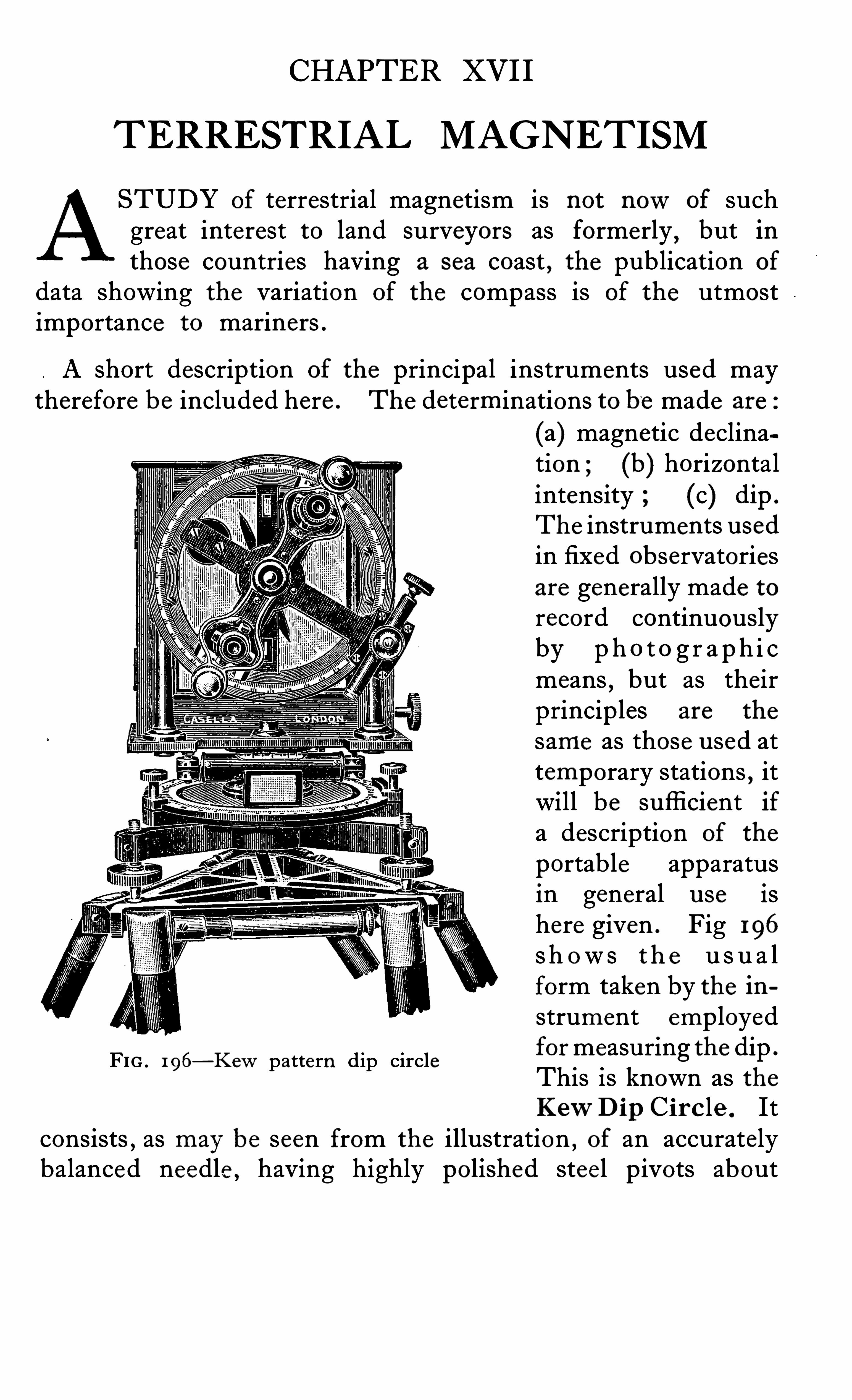
CHAPTER XVI I
TERRESTRIAL MAGNETISM
STUDY of terrestrial magnetism is not nowof suchgreat interest to land surveyors as formerly
,but in
those countries having a sea coast , the publication of
data showing the variation of the compass is of the utmostimportance to mariners .
A short description of the principal instruments used maytherefore be included here . The determinations to be made are:
(a) magnetic declination ; (b) horizontalintensity (c) dip .
The instruments usedin fixed observatoriesare generally made torecord continuouslyby p h o t o g r a p h i cmeans , but as theirprinciples are the
same as those used attemporary stations
,it
will be sufficient ifa description of the
portab le apparatusin general u se ishere given . Fig 196
s h ow s t h e u s u a lform taken by the instrument employedformeasuring the dipThis is known as theKewDip Cir c le . It
consists,as may be seen from the illustration , of an accurately
balanced needle having highly polished stee l pivots about
FIG . 1 96—Kewpattern dip circle

2 46 SURVEYING INSTRUMENTS
The mode of using the instrument is as follows
The agate edges and the pivots are carefully cleaned withpith and needle No . 1 is placed on the fork of the l ifter . The
glass window is then closed and the needle carefully loweredon to its pivots . The microscopes are set to i .e . , with theline joining them vertical , and the whole instrument turned inazimuth until
,when the needle is vertical
,the instrument is
approximately in the magnetic meridian . The needle is nowlifted off its pivots and gently lowered again , thus giving it aslight oscillation . The azimuth circle is nowadjusted untilthe upper microscopeweb b isects the swing and a reading istaken of the horizontal circle . A similar reading and settingis made with the lower microscope . Another pair of readingsis then made with the instrument turned 180
° in azimuth .
The means of these four readings allows the direction of the
magnetic meridian to be determined . The limiting stop s are
nowset , so that when the observations for dip commence , thereversals may be quickly made without the necessity of readingthe azimuth circle . No great accuracy is required in th i ssetting as the errors due to a setting slightly away from the
meridian are generally negligible . The needles , usually two innumber , are marked No . 1 and No . 2 , the ends of each be ingengraved A and B for identification purposes . The two needlesare first magnetized so that the A ends are dipping . No . 1
needle is then placed in the instrument and with circle right theupper microscope is set to bisect the swing and the verniers read .
A similar setting and reading is then made with the lowe rmicroscope . The whole instrument is then turned 1 80
° inazimuth and a similar pair of readings taken . The needle isnowreversed on its pivots
,thus bringing the engraving to the
back and a further set of readings taken . This makes fourinstrument settings and eight vernier readings and constitutesa quarter set . No . 2 needle is nowinserted in the instrument anda similar quarter set of readings taken . The needles are nowmagnetized in the opposite directions , so that the B ends are
dipping and a half set of readings taken with needles 1 and 2 .
This completes one determination,there being thus sixteen
instrument and thirty-two microscope settings . Sometimes
TERRESTRIAL MAGNETISM 2 47
a double setting of the microscopes is made at each needleposition
,this method involving sixteen instrument and Sixty
four microscope settings for one complete s et . The mean of
all these readings gives the true dip free from any instrumentalerrors . When observations are to be made near the pole , adifferent style of support for the needles is used , in order thata clear space may be left for Viewing their ends at the nearlyvertical position . It is diffi cult to set the instrument truly inthe magnetic meridian near the pole by the method given , sothat other arrangements have to be made or else determinationseach side of the meridian are made and the true dip calculatedfrom the observed dips .
Ob s ervation s at Sea . When observations for dip have tobe made at sea the instrument is constructed rather differently ,as it would be impossib le to u se needles rolling on agate edges .The needles are therefore supported on end pivots s imilar tothose used in watches , the whole instrument being swung ingimbals supported on a massive bronze pillar . The dip circleis sometimes fitted with an attachment which allows observations for tota l for ce to be made . This attachment cons ists of
a small frame fixed at right angles to the line joining the twomicroscopes and in front of them and so arranged that a specialneedle , No . 4 , may be clamped to it . Another special needle ,No . 3 , is placed in the instrument and observations on the
inter-action of the two needles are made . From these observations the total force may be calculated . The dip shown by No .
4 is taken separately with a small weight added to one en d of
it , but as these determinations are only of academic interest , thereader is referred to special publications on this subject forfuller details .
Sometimes a detachable trough compass is fitted to the topof the instrument case
,which
,in conjunction with peep sights
or a small te lescope , allows the instrument to be used to obtaina rough indication of the magnetic declination . Recently ,instruments known as d i p indu ctor s , have been used withgreat success . These give rather more accurate results , butowing to their nature , cannot be easily transported . The firstapparatus of this kind
, du e to a suggestion made by Professor
2 46 SURVEYING INSTRUMENTS
The mode of using the instrument is as follows
The agate edges and the p ivots are carefully cleaned withpith and needle No . I is placed on the fork of the l ifter . The
glass window is then closed and the needle carefully loweredon to its pivots . The microscopes are s et to i .e . , with theline joining them vertical , and the whole instrument turned inazimuth until , when the needle is vertical
,the instrument is
approximately in the magnetic meridian . The needle is nowlifted off its pivots and gently lowered again , thus giving it aslight oscillation . The azimuth circle is nowadjusted untilthe upper microscopeweb bisects the swing and a reading istaken of the horizontal circle . A similar reading and s ettingis made with the lower microscope . Another pair of readingsis then made with the instrument turned 180
° in azimuth .
The means of these four readings allows the direction of the
magnetic meridian to be determined . The limiting stops are
nows et,so that when the observations for dip commence , the
reversals may be quickly made without the necessity of readingthe azimuth circle . No great accuracy is required in th issetting as the errors du e to a setting slightly away from the
meridian are generally negligible . The needles , usually two innumber , are marked No . 1 and No . 2 , the ends of each be ingengraved A and B for identification purposes . The two needlesare first magnetized so that the A ends are dipping . No . 1
needle is then placed in the instrument and with circle right theupper microscope is set to bisect the swing and the verniers read .
A similar setting and reading is then made with the lowermicroscope . The whole instrument is then turned 1 80
° inazimuth and a similar pair of readings taken . The needle isnowreversed on its pivots
,thus bringing the engraving to the
back and a further set of readings taken . This makes fourinstrument settings and eight vernier readings and constitutesa quarter set . No . 2 needle is nowinserted in the instrument anda similar quarter set of readings taken . The needles are nowmagnetized in the opposite directions , so that the B ends are
dipping and a half set of readings taken with needles 1 and 2 .
This completes one determination , there being thus sixteeninstrument and thirty-two microscope settings . Sometimes
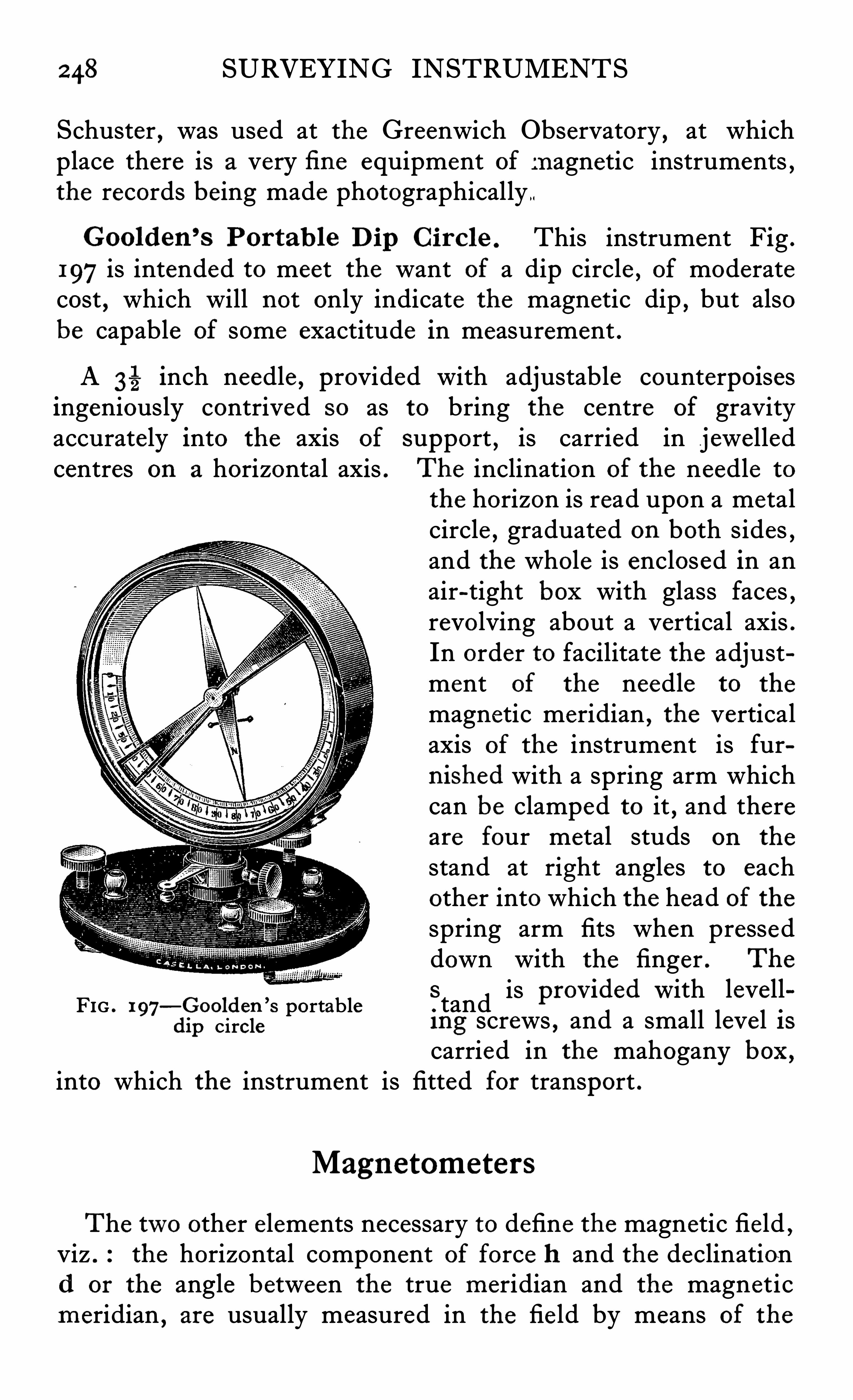
2 48 SURVEYING INSTRUMENTS
Schuster , was used at the Greenwich Observatory , at whichplace there is a very fi ne equipment of magnetic instruments ,the records being made photographically
Goolden ’s Por tab le Dip C i rcle . This instrument Fig .
197is intended to meet the want of a dip circle , of moderatecost , which will not only indicate the magnetic dip , but alsobe capable of some exactitude in measurement .
A 3 inch needle,provided with adjustable counterpoises
ingeniously contrived so as to bring the centre of gravityaccurately into the axis of support
,is carried in j ewelled
centres on a horizontal axis . The inclination of the needle to
the horizon is read upon a metalcircle , graduated on both sides ,and the whole is enclosed in anair-tight box with glass faces ,revolving about a vertical axis .In order to facilitate the adjustment of the needle to the
magnetic meridian , the verticalaxis of the instrument is furn ished with a spring arm whichcan be clamped to it , and thereare four metal studs on the
stand at right angles to eachother into which the head of thespring arm fits when presseddown with the finger . The
FIG . 197—Goolden ’
s portable .
Stand is PrOVided W ith levell
dip circle Ing screws , and a small leve l I scarried in the mahogany box ,
into which the instrument is fitted for transport .
Magnetometers
The two other elements necessary to define the magnetic field ,Viz . the horizontal component of force h and the declinationd or the angle between the true meridian and the magneticmeridian , are usually measured in the fie ld by means of the
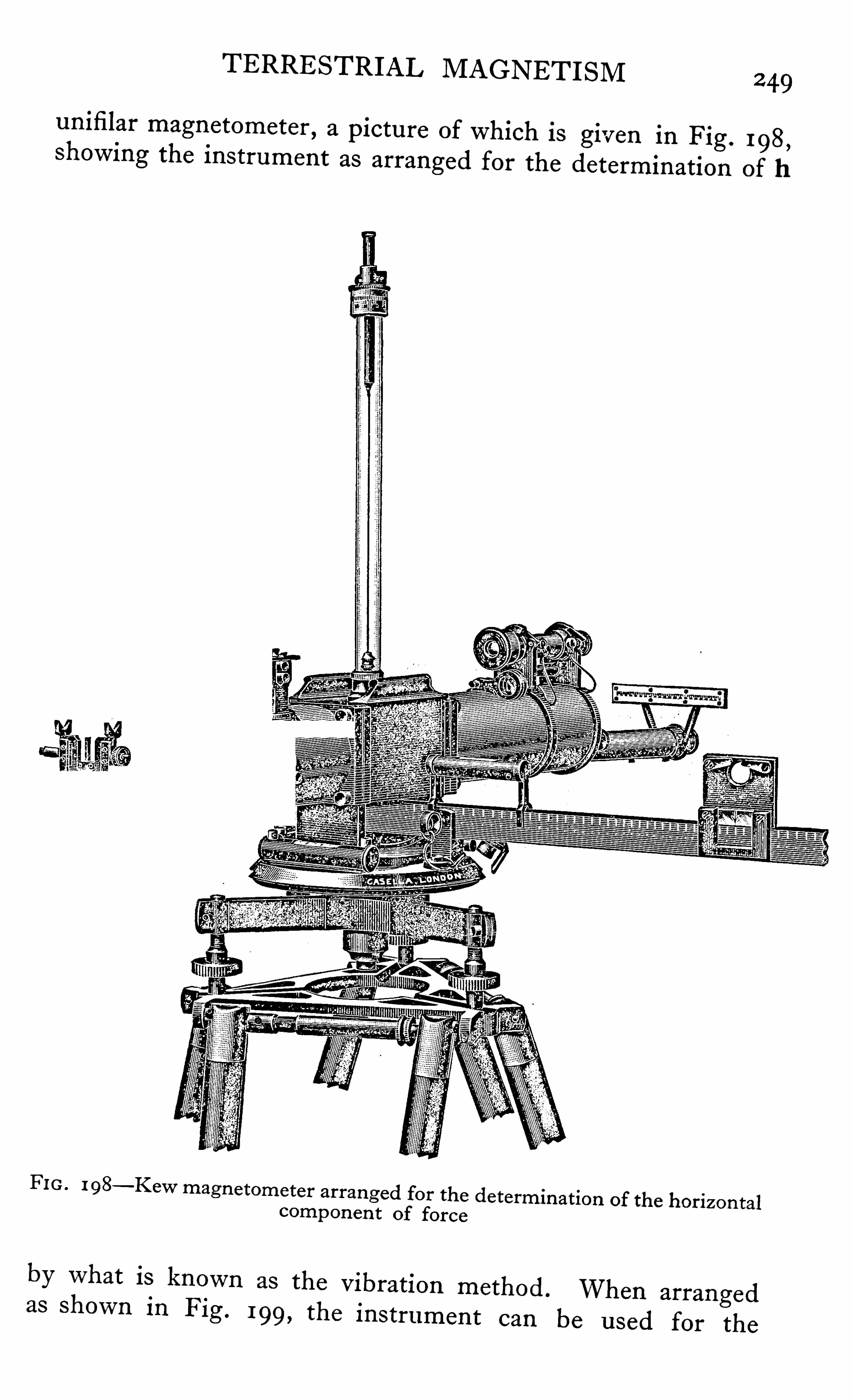
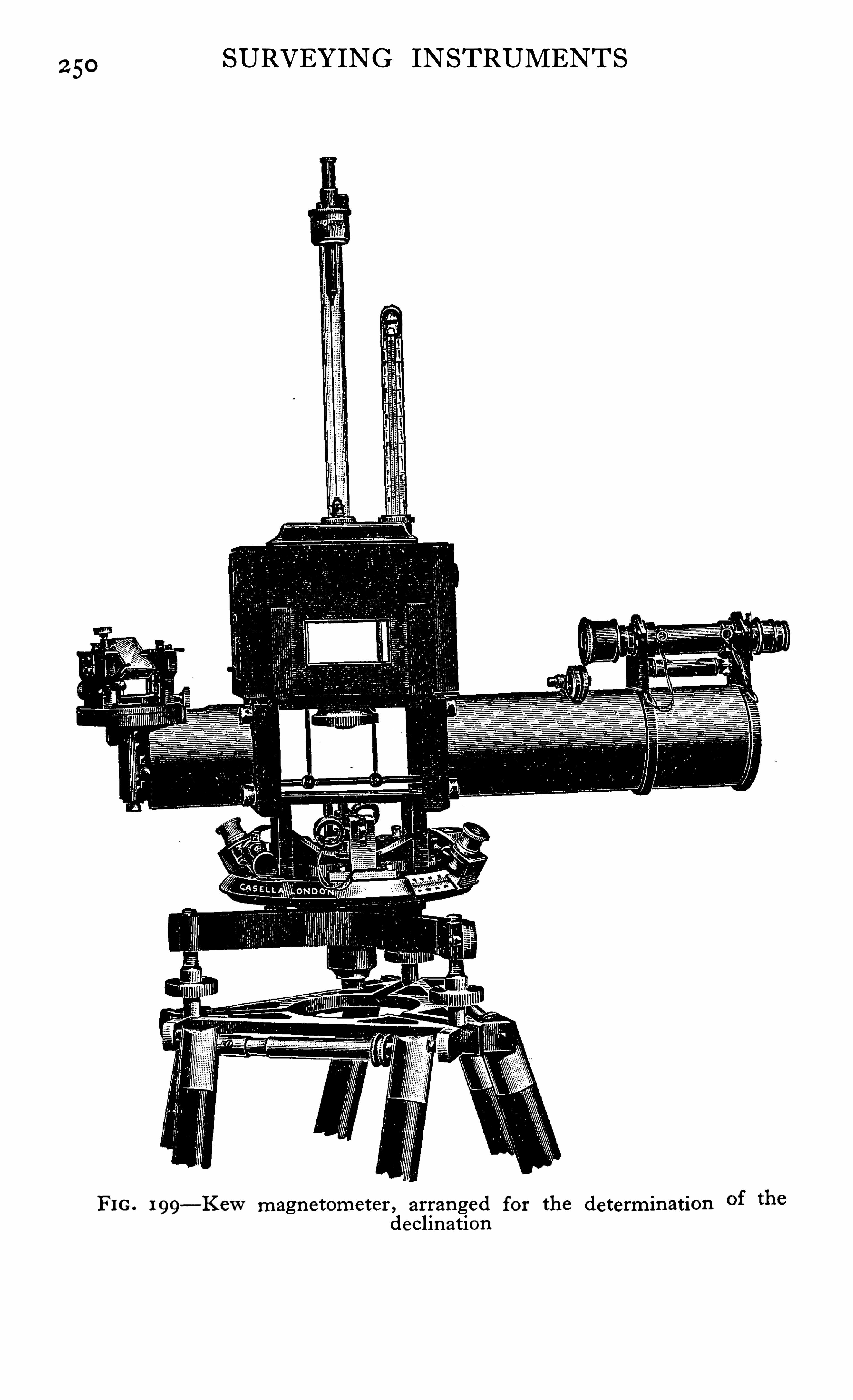
2 50SURVEYING INSTRUMENTS
FIG. 199—Kewmagne tome ter , arranged for the determination
declin ation
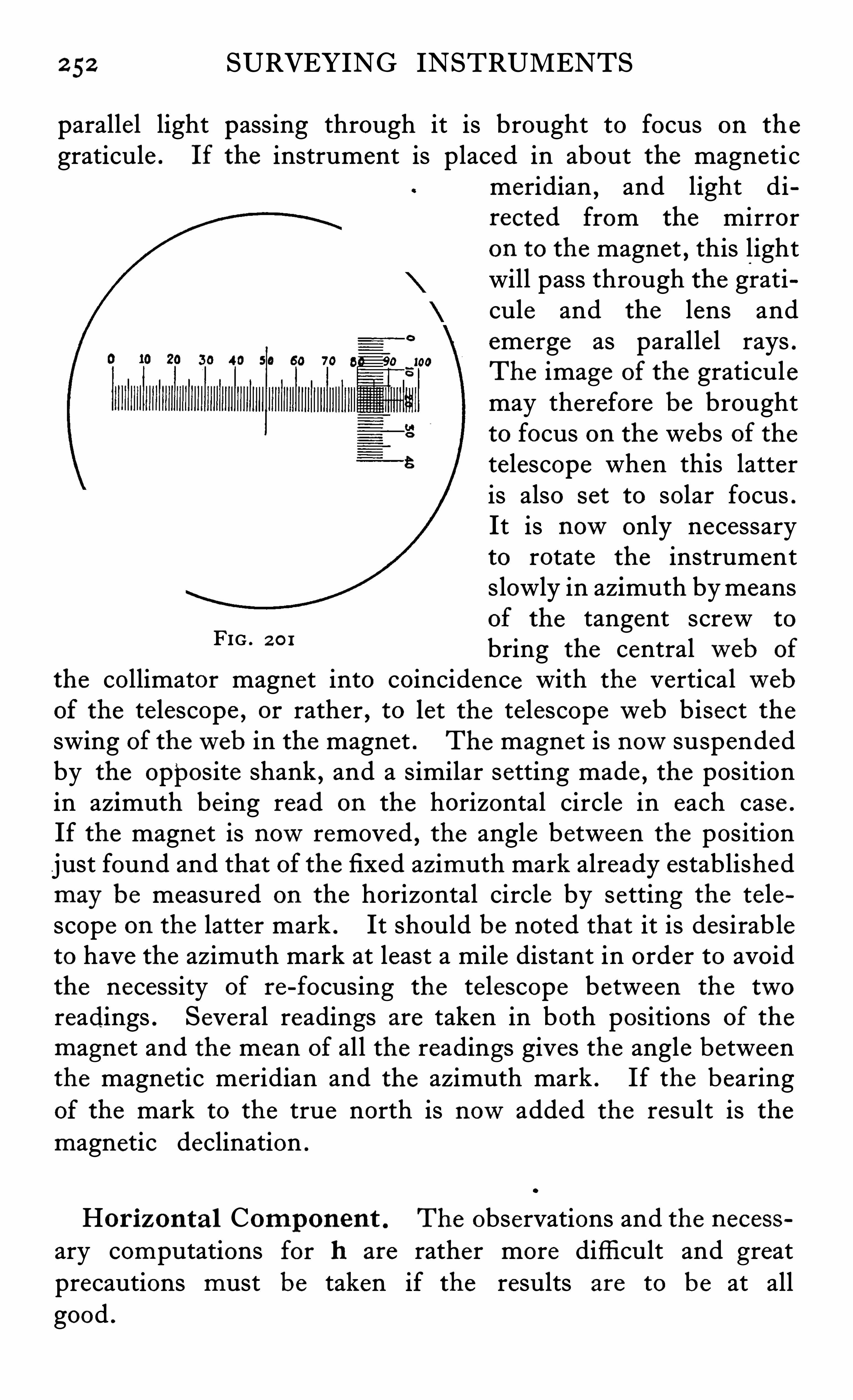
2 52 SURVEYING INSTRUMENTS
parallel light passing through it is brought to focus on the
graticule . If the instrument is placed in about the magneti cmeridian
,and light di
rected from the mirroron to the magnet , this lightwill pass through the graticule and the lens andemerge as parallel rays .The image of the graticulemay therefore be broughtto focus on the webs of thetelescope when this latteris also set to solar focus .
It is nowonly necessaryto rotate the instrumentslowly in azimuth bymeansof the tangent screw to
bring the centralweb of
the collimator magnet into coincidence with the verticalwebof the telescope , or rather , to let the te lescopeweb bisect theswing of theweb in the magnet . The magnet is nowsuspendedby the opposite shank , and a similar setting made , the positionin azimuth being read on the horizontal circle in each case .
If the magnet is nowremoved , the angle between the positionjust found and that of the fixed azimuth mark already establishedmay be measured on the horizontal circle by setting the te lescope on the latter mark . It should be noted that it is desirab leto have the azimuth mark at least a mile distant in order to avoidthe necessity of re-focusing the te lescope between the tworeadings . Several readings are taken in both positions of the
magnet and the mean of all the readings gives the angle betweenthe magnetic meridian and the azimuth mark . If the bearingof the mark to the true north is nowadded the result is themagnetic declination .
FIG . 2 0 1
Hor izon ta l Component . The observations and the necessary computations for h are rather more diffi cult and greatprecautions must be taken if the results are to be at allgood .
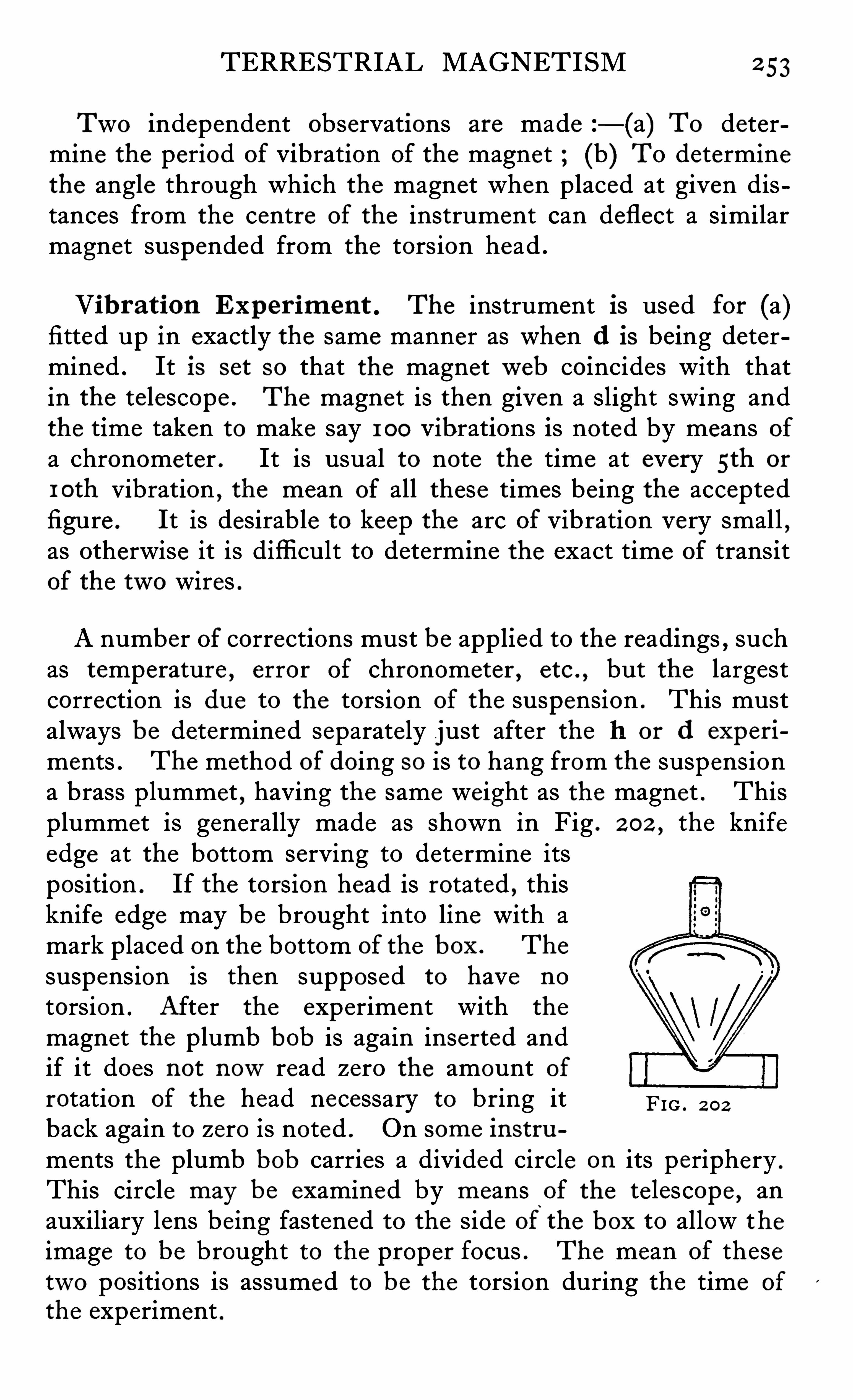
TERRESTRIAL MAGNETISM 2 53
Two independent observations are made —(a) To determine the period of Vibration of the magnet (b) To determinethe angle through which the magnet when placed at given distances from the centre of the instrument can deflect a similarmagnet suspended from the torsion head .
Vibration Exp er iment . The instrument is used for (a)fitted up in exactly the same manner as when d is being determined . It is s et so that the magnetweb coincides with thatin the telescope . The magnet is then given a slight swing andthe time taken to make say 1 00 Vibrations is noted by means ofa chronometer . It is usual to note the time at every 5th or
1 0th vibration , the mean of all these times being the acceptedfigure . It is desirable to keep the arc of vibration very small ,as otherwise it is diffi cult to determine the exact time of transitof the two wires .A number of corrections must be applied to the readings , such
as temperature , error of chronometer , etc . , but the largestcorrection is du e to the torsion of the suspension . This mustalways be determined separately just after the h or d experi
ments . The method of doing so is to hang from the suspensiona brass plummet , having the same weight as the magnet . Thisplummet is generally made as shown in Fig . 2 02 ,
the knifeedge at the bottom serving to determine itsposition . If the torsion head is rotated , thisknife edge may be brought into line with amark placed on the bottom of the box . The
suspension is then supposed to have no
torsion . After the experiment with the
magnet the plumb bob is again inserted andif it does not nowread zero the amount ofrotation of the head necessary to bring it FIG . 2 0 2
back again to zero is noted . On some instru
ments the plumb bob carries a divided circle on its periphery .
This circle may be examined by means of the te lescope , anauxiliary lens being fastened to the side of the box to allow the
image to be brought to the proper focus . The mean of thesetwo positions is assumed to be the torsion during the time of
the experiment .
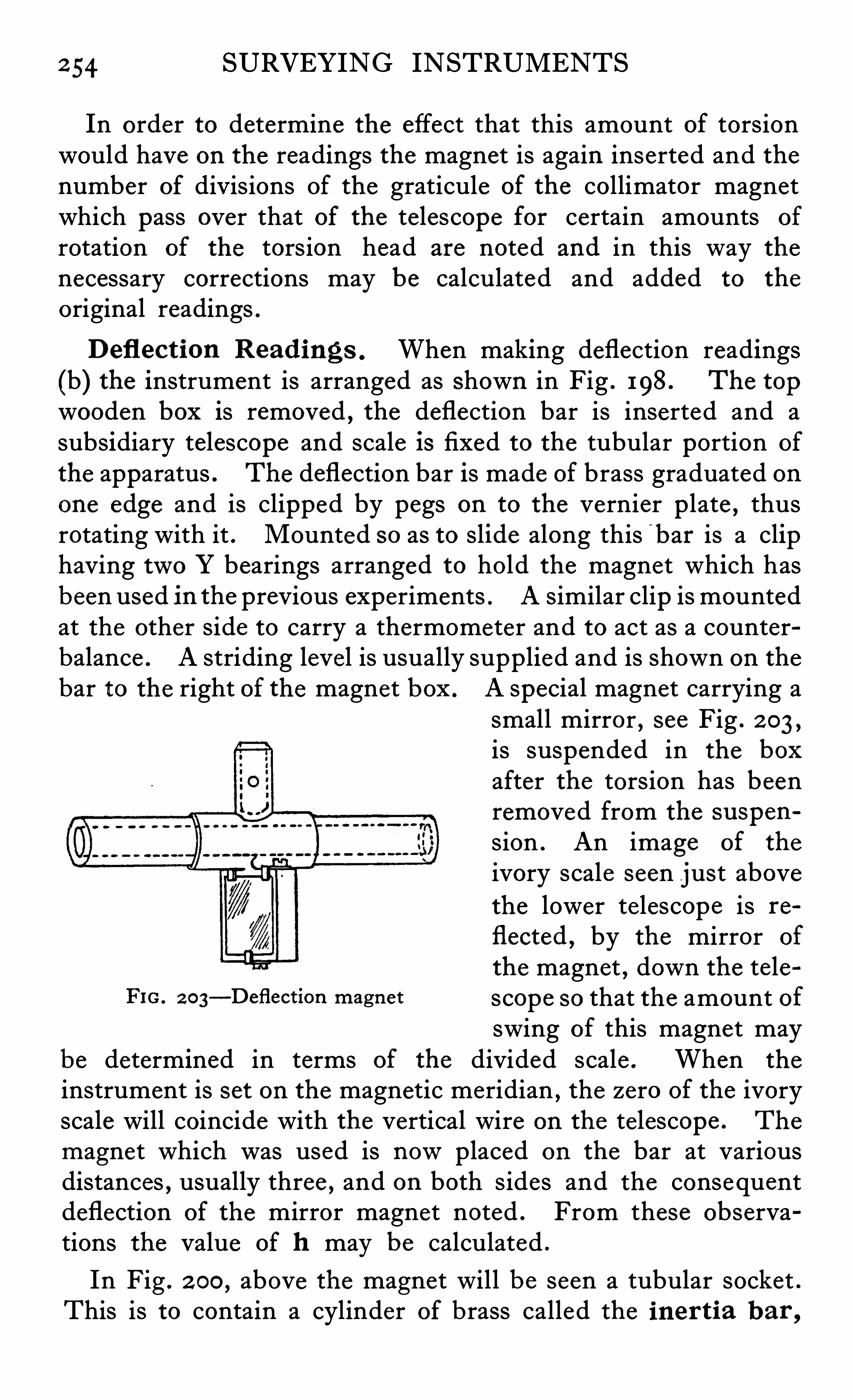
2 54 SURVEYING INSTRUMENTS
In order to determine the effect that this amount of torsionwould have on the readings the magnet is again inserted and thenumber of divisions of the graticule of the collimator magnetwhich pass over that of the telescope for certain amounts of
rotation of the torsion head are noted and in this way thenecessary corrections may be calculated and added to the
original readings .
Defl ect ion Read ings . When making deflection readings(b) the instrument is arranged as shown in Fig . 198. The topwooden box is removed , the deflection bar is inserted and asubsidiary telescope and scale is fixed to the tubular portion of
the apparatus . The deflection bar is made of brass graduated onone edge and is clipped by pegs on to the vernier p late , thusrotating with it . Mounted so as to slide along this b ar is a cliphaving two Y bearings arranged to hold the magnet which hasbeen used in the previous experiments . A similar clip is mountedat the other side to carry a thermometer and to act as a counterbalance . A striding level is usually supplied and is shown on thebar to the right of the magnet box . A special magnet carrying a
small mirror, see Fig . 2 03 ,
is suspended in the box
after the torsion has beenremoved from the su spen
sion . An image of the
ivory scale seen just abovethe lower te lescope is re
flected ,by the mirror of
the magnet , down the teleFIG 2 03
—Deflection magnet scope so that the amount ofswing of this magnet may
be determined in terms of the divided scale . When the
instrument is set on the magnetic meridian , the zero of the ivoryscale will coincide with the vertical wire on the telescope . The
magnet which was used is nowplaced on the bar at variousdistances , usually three , and on both sides and the consequentdeflection of the mirror magnet noted . From these observations the value of h may be calculated .
In Fig . 2 00 ,above the magnet will be seen a tubular socket .
This is to contain a cylinder of brass called the iner t ia b ar ,
2 56 SURVEYING INSTRUMENTS
pairs of brushes when the axis of rotation is parallel to the
di rection of the magnetic field in which the instrument issituated . A ring in which the spindle of the coil is journalledhas quick and slow motions in azimuth and in altitude so thatthe necessary adjustments are readily made . The settingswhere zero E .M .F . is obtained are indicated by a sensitivegalvanometer connected by means of a switch to either pair ofbrushes as desired . Four independent readings of dip may bemade thus allowing instrumental errors to be eliminated .
Indu ctor Magnetom eter . Recently , J. H . Shaxby hasdesigned and used a portable magnetometer of the inductortype which is arranged to measure the vertical intensity and dip
,
the first by neutralising the earth ’s vertical component by thefie ld du e to a horizontal coil supplied with an adjustable current from a small secondary cell , the second by tilting theinstrument through an angle 0until the component field normalto the base of the instrument in the tilted position is againneutralised . The dip is then given by the complement of —0.
The two elements are thus measured with a minimum of
manipulation by (1 setting on the meridian ; (2 ) leve lling ; (3 )adjusting a resistance ; (4) measuring an angle . For furtherparticulars of this instrument the reader is referred to the
Journal of Scientific Instruments,
”Vol . I , No . 8 .
CHAPTER XVI I I
THE SE"TANTHE modern sextant in its e lements and in the generaldisposition of its parts remains almost exactly as it wasfirst invented by Hadley in 173 1 , although both Hooke
and Newton had proposed similar schemes prior to that time .
The instrument received notab le improvements by Ramsdenand other makers of the late 1 8th century and except in minordetails has remained unchanged for about 1 2 0 years . Thisseems most remarkable in View of the fact that it is not particularly comfortable to handle and that all the parts are so
exposed to the weather and s o liable to damage . In alaboratory drawbacks of this kind may not be of great importance , but at s ea where the sextant is principally used , thesedefects would at the first glance appear fatal to its continuedu se . The fact remains
,however , that no other instrument has
yet been produced which can do the work so conveniently or
so well on board ship , with the result that its u se is quite universal .Apart from the unsatisfactory nature of the design of the detailsin so far as they are unprotected and fragile , the fact that thereadings cannot be checked in any way makes the design on e
which would be considered crude in any other piece of precisionapparatus . Not only must reliance be placed on a divided arc ,the accuracy of the graduations of which are always Open to
suspicion and can only be checked by comparison with a standard , but the correctness of the centering of the axis on whichthe vernier mov es
imu st be taken for granted , as no facilities
are provided for taking the mean of the opposites as in mostother instruments having graduated circles . In addition to this ,the fineness of setting of the vernier is only half that which canbe made on such an instrument as a theodolite of equal limbdiameter owing to the effect of the mirrors in halving the value
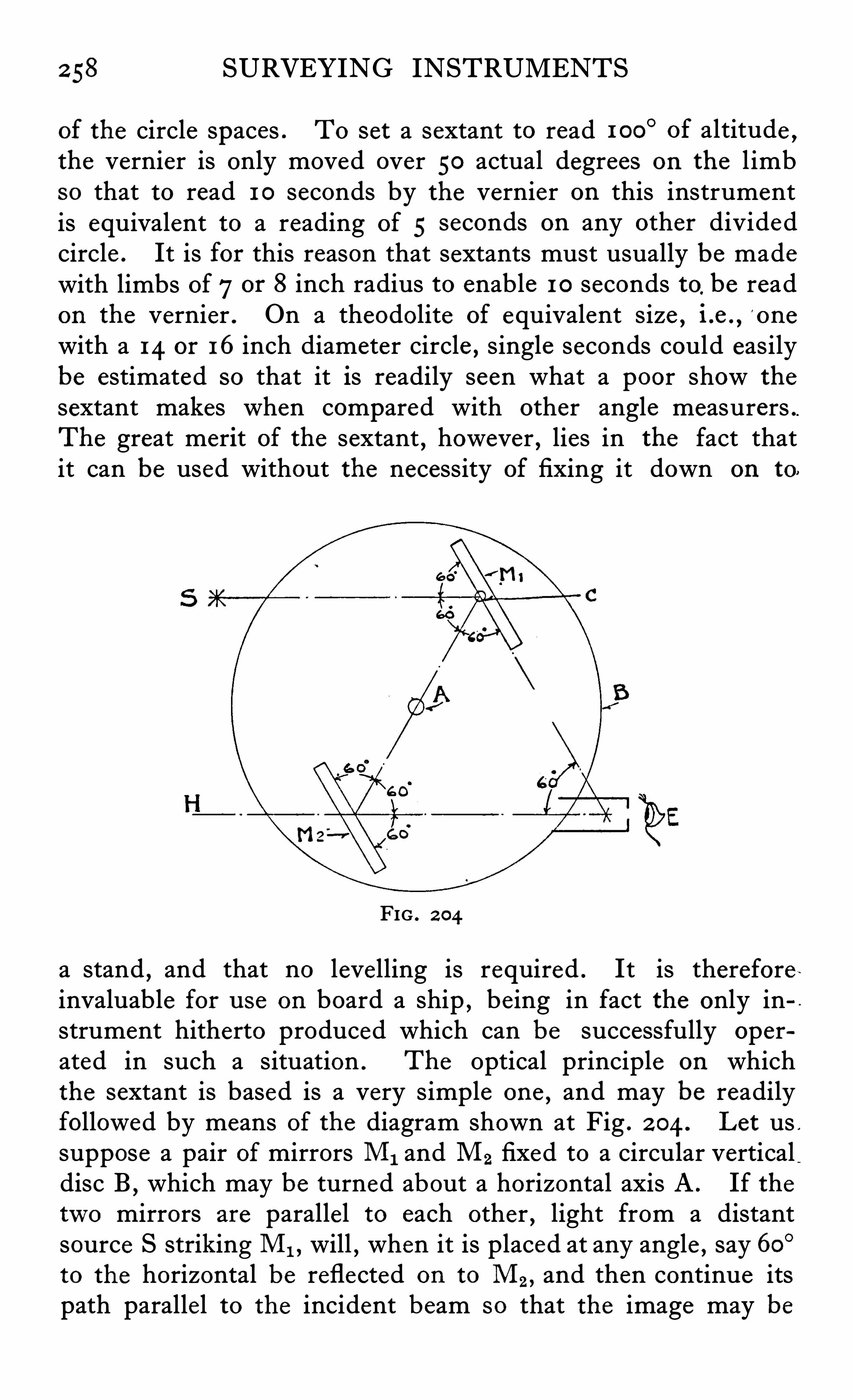
2 58 SURVEYING INSTRUMENTS
of the circle spaces . To set a sextant to read 1 00°of altitude ,
the vernier is only moved over 50 actual degrees on the l imbso that to read 1 0 seconds by the vernier on this instrumentis equivalent to a reading of 5 seconds on any other dividedcircle . It is for this reason that sextants must usually be madewith limbs of7or 8 inch radius to enable 1 0 seconds to
,be read
on the vernier . On a theodolite of equivalent size , i .e . ,o ne
with a 14 or 16 inch diameter circle , single seconds could easilybe estimated so that it is readily seen what a poor show the
sextant makes when compared with other angle measurers .The great merit of the sextant
,however , lies in the fact that
it can be used without the necessity of fixing it down on to.
FIG . 2 04
a stand , and that no levelling is required . It is thereforeinvaluable for u se on board a ship
,being in fact the only in
strument hitherto produced which can be successfully operated in such a situation . The Optical principle on whichthe sextant is based is a very simple one
,and may be readily
followed by means of the diagram shown at Fig . 2 04 . Let us ,
suppose a pair of mirrors M1 and M2 fixed to a circular verticaldisc B
,which may be turned about a horizontal axis A . If the
two mirrors are paralle l to each other , light from a distantsource S striking M1 , will , when it is placed at any angle , say 60°to the horizontal be reflected on to M2 , and then continue itspath parallel to the incident beam so that the image may be
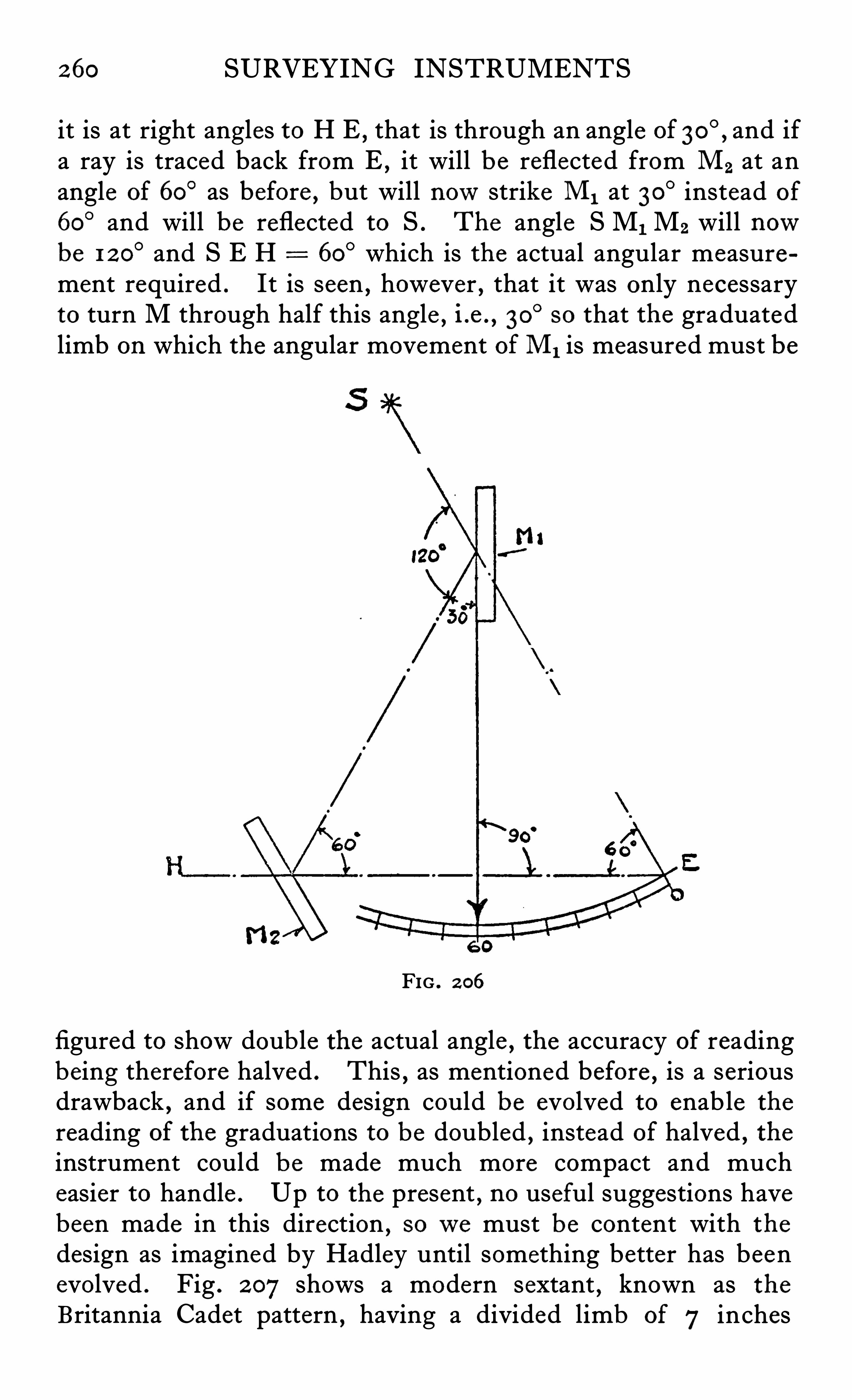
260 SURVEYING INSTRUMENTS
it is at right angles to H E , that is through an angle of and ifa ray is traced back from E , it will be reflected from M2 at anangle of 60
° as before , but will nowstrike M1 at 30° instead of
60° and will be reflected to S . The angle S M1 M2 will now
be 1 2 0° and S E H 60
° which is the actual angular measurement required . It is seen , however , that it was only necessaryto turn M through half this angle , i .e . , 30
°s o that the graduated
limb on which the angular movement ofM1 is measured must be
FIG . 2 06
figured to show doub le the actual angle , the accuracy of readingbeing therefore halved . This , as mentioned before
,is a serious
drawback , and if some design could be evolved to enable the
reading of the graduations to be doubled , instead of halved , theinstrument could be made much more compact and mucheasier to handle . Up to the present , no useful suggestions havebeen made in this direction , sowe must be content with the
design as imagined by Hadley until something better has beenevolved . Fig . 2 07shows a modern sextant , known as the
Britannia Cadet pattern , having a divided limb of 7 inches
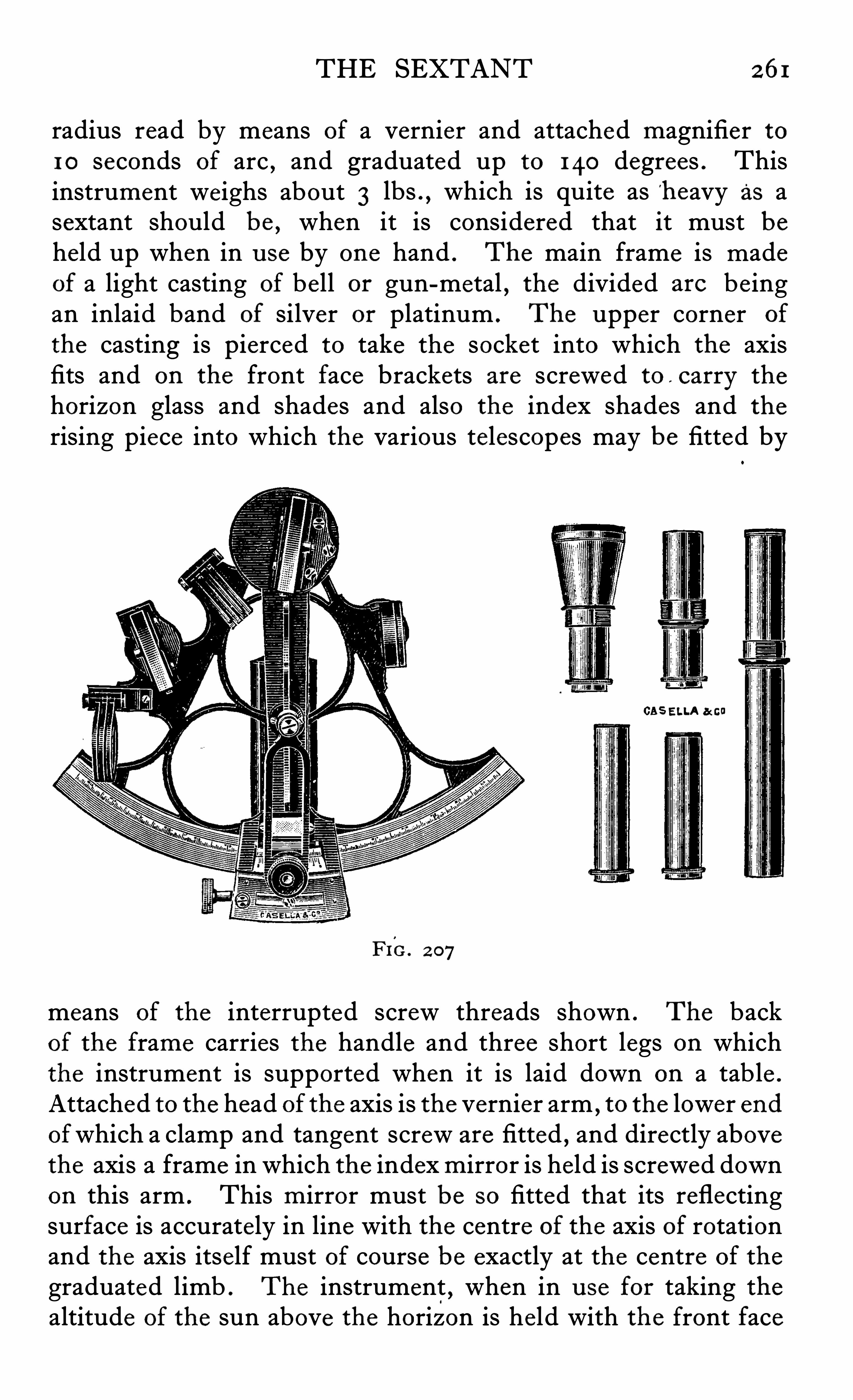
THE SEXTANT 261
radius read by means of a vernier and attached magnifier to1 0 seconds of arc , and graduated up to 140 degrees . Thisinstrument weighs about 3 lbs .
,which is quite as h eavy as a
sextant should be , when it is considered that it must beheld up when in u se by one hand . The main frame is madeof a light casting of be ll or gun-metal , the divided are be ingan inlaid band of silver or platinum . The upper corner of
the casting is pierced to take the socket into which the axisfits and on the front face brackets are screwed to carry the
horizon glass and shades and also the index shades and the
rising piece into which the various telescopes may be fitted by
GAS ELLA a cu
FIG. 2 07
means of the interrupted screw threads shown . The backof the frame carries the handle and three short legs on whichthe instrument is supported when it is laid down on a tab le .
Attached to the head of the axis is the vernier arm , to the lower endofwhich a clamp and tangent screw are fitted , and directly abovethe axis a frame in which the indexmirror is held is screwed downon this arm . This m irror must be so fitted that its reflectingsurface is accurately in line with the centre of the axis of rotationand the axis itself must of course be exactly at the centre of the
graduated limb . The instrument , when in u se for taking thealtitude of the sun above the horizon is held with the front face
262 SURVEYING INSTRUMENTS
vertical and the telescope horizontal . A suitable dark glass orany combination of the four supplied is turned up in front ofthe index glass
,which is the one attached to the vernier arm .
After unclamping the vernier it is set approximately to the altitude required . On looking through the tube the sextant isdirected towards the sun and turned in altitude until the horizonis seen by direct vision to cut across about the middle of the
horizon mirror , then the tangent screw is turned so that theimage of the sun is brought down until it can be seen in the
silvered portion of this mirror . When exact contact has'b een
secured by the tangent screw the reading of the divided limbwill give the altitude of the sun above the horizon at the time
contact was made . There are dark glasses which may , whennecessary
,be turned up in front of the horizon mirror to reduce
the glare from the surface of the sea , and dark shades may alsobe fitted to the telescopes when required . Although the reare a number of adjustments which the user may , and indeedmust make from time to time
,the quality of a sextant mainly
depends on the accuracy of the parts , and the way in whichthey have been built into the instrument
,and as defects are not
readily detected or rectified , only those instruments made byfirst class firms should be purchased , and even then only afterthey have been subjected to an independent test by some
recognized authority,such as the National Physical Laboratory
at Teddington . The principal points which must be attendedto if the instrument is to pass the rigorous tests of the NationalPhysical Laboratory are as follows -The graduations must beaccurately spaced and clearly cut and figured , and the ve rnie rshould match the limb truly at every part . The axis must beplaced exactly at the centre from which the limb was graduatedand it must fit its socket accurately and move smoothly withoutshake . The mirrors should be perfectly plano-paralle l andheld in their mounts without strain . The dark shades shouldindividually and in combination be free from any tendency todistort the image
,which means that they should also be plano
parallel . These shades must be burnished into their mountsin such a way therefore that they are not strained in the process .
The rising piece carrying the te lescopes must work smoothlyand be free from any perceptible shake , and must be accuratelyplaced in re lation to the mirrors . All these points are of
264 SURVEYING INSTRUMENTS
two dovetailed slides at right angles to each other . The top
slide carries a finely divided cross which may be brought bymeans of the adjusting screws accurately to the centre of rotationof the axis when this axis is revolved in its own socket . Thisadjustment is made under a microscope
,attention to the fineness
and clearness of the lines and their proper illumination being ofgreat importance . This operation having “ been carried ou t
it only remains to place the limb on the dividing engine andadjust it so that the intersection of the cross lines remainsstationary when the engine centre only is revolved . It is obviousthat when the limb is thus fixed down on the engine plate , thecentre of the circle will coincide with the axis carrying the
vernier . Very great care is needed in this operation the socketmust of course be firmly fixed and the axis have had its finalfinishing before the dividing is carried ou t . In fact it is usualto finish the whole instrument
,the marking of the graduations
being the last job of all before the final assembly and adjustment .Various methods of holding the index and horizon mirrors intheir frames and arranging for their adjustment have beentried and are in u se , each maker ’s design differing slightly indetail . The principle is the same in most cases , and simplyconsists in holding the glass down by spring pressure againstthe points of three screws
,each of which may be adjusted in
order to rock the mirrors in any direction . In Fig . 2 08 theseparts may be identified and also the flange pieces which serve toscrew the frames down to the limb casting and to the vernierarm . The index frame is made solid at the back , somewhatin the form of a tray ; but the horizon frame has half of the
back portion cut away in order that the horizon may be viewedthrough the clear part of the glass . Sometimes the horizonglass is only half the usual width and complete ly silvered ,but with this form it is not possib le to get such a clean line of
separation as in the usual type , where the silver , owing to itsextreme thinness , may be very sharply divided , thus giving no
shadow such as would be obtained from the thick edge of the
narrower mirror . The shades which are made from neutraltinted glass , are circular in shape and burnished into brass frames ,square for the index glass and round for the horizon . Theymust not be fitted too tightly
,owing to the possib ility of intro
du cing strain , and it is best so to arrange that while there is no
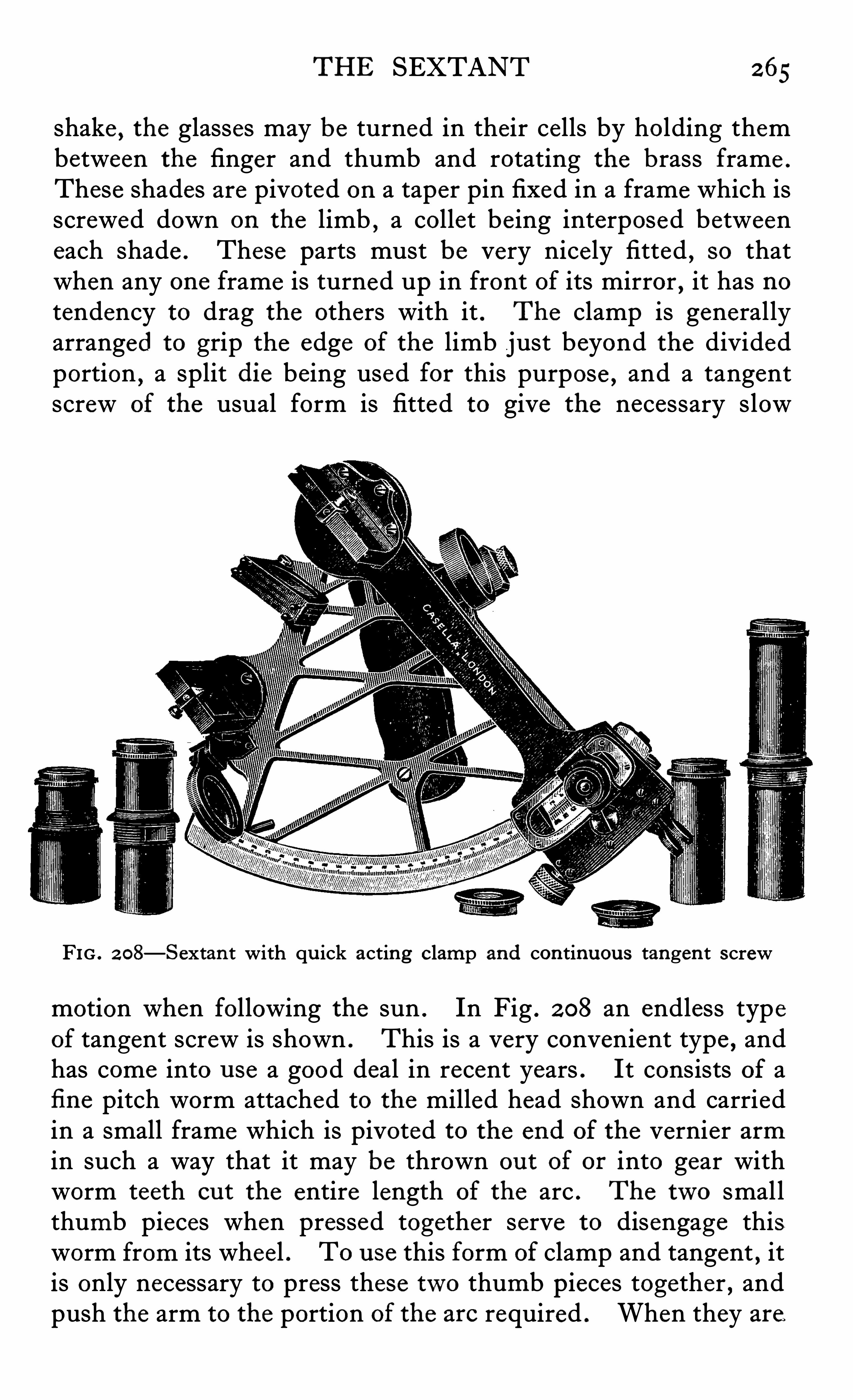
THE SEXTANT 265
shake , the glasses may be turned in their cells by holding thembetween the finger and thumb and rotating the brass frame .
These shades are pivoted on a taper pin fixed in a frame which isscrewed down on the limb
,a collet be ing interposed between
each shade . These parts must be very nice ly fitted, so that
when any one frame is turned up in front of its mirror,it has no
tendency to drag the others with it . The clamp is generallyarranged to grip the edge of the limb just beyond the dividedportion , a split die being used for this purpose , and a tangentscrew of the usual form is fitted to give the necessary slow
FIG . 2 08—Sextan t with qu ick acting clamp and continuou s tangen t screw
motion when following the sun . In Fig . 2 08 an endless typeof tangent screw is shown . This is a very convenient type , andhas come into u se a good deal in recent years . It consists of afi ne pitch worm attached to the milled head shown and carriedin a small frame which is pivoted to the end of the vernier armin such a way that it may be thrown ou t of or into gear withworm teeth ou t the entire length of the arc . The two smallthumb pieces when pressed together serve to disengage thisworm from its wheel . T0 u se this form of clamp and tangent , itis only necessary to press these two thumb pieces together , andpush the arm to the portion of the are required . When they are
266 SURVEYING INSTRUMENTS
released,the worm drops into its wheel , thus locking the arm .
The slow motion may then be carried on continuous ly by rotatingthe milled head attached to the worm . A Ramsden reade r ispivoted or arranged to slide above the vernier to facilitate the
reading . The handle at the back is generally made of ebony or
vulcanite , and various methods of fixing it to the frame are inu se . In the example shown , it is fixed at one end by means of
a metal screw passing through the main frame,the other end
being held in a sliding fitting which allows the handle to expandor contract without putting any strain on to the limb . Some
times a single central screw is used and on many instrumentsthree screws are used , two of them being at the ends of a bridgepiece which being made weak laterally allows for expansion ina longitudinal direction . Three or four telescopes or s ightingtubes are generally supplied with the sextant , the one principallyused being an ordinary Gallilean glass . A special te lescopewith high and lowpowers is used for star work , and an ordinaryplain tube with pin hole sight is also supplied for u se whennecessary . In addition
,a special telescope having four cross
wires in the mutual focus of the object glass and eyep iece is usedfor the purpose of adjusting the instrument . Each of these telescopes can be held in the ring shown on the right , just under theindex glass . This ring is supported on a square or triangularstem which is screwed at its end and fitted with a milled nut ,the turning of which raises or lowers the telescope , thus allowing it to be brought central with the horizon glass . The telescopes do not screw directly into this ring
,but into a subsidiary
flanged piece fastened inside the ring . This flange is held bytwo screws against two points at right angles to them , whichallows it to be rocked , and thus enables the adjuster to bringthe telescope truly parallel to the limb .
Fig . 2 09 shows a newtype of simple sextant designed byAppleyard for quickly taking sights such as terrestrial azimuths ,where extreme accuracy is not required . This instrument ison exactly the same principle as the ordinary marine sextantexcept that the index glass is moved by means of a micrometerscrew instead of the usual vernier arm
,the angles being read
on the micrometer head instead of on the vernier . The turnsare counted by means of gearing and read through two small
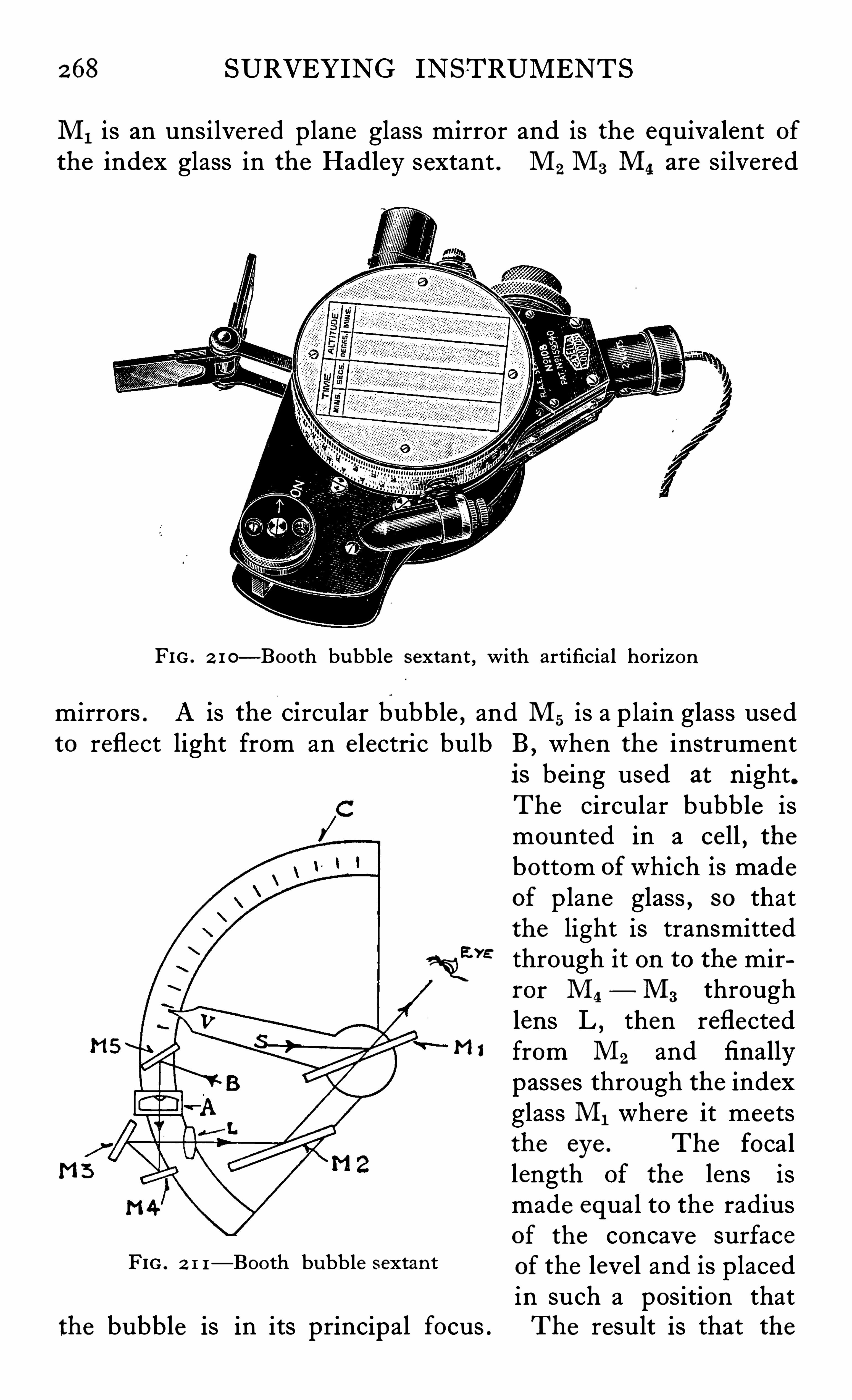
268 SURVEYING INSTRUMENTS
M1 is an unsilvered plane glass mirror and is the equivalent ofthe index glass in the Hadley sextant . M2 M3 M4 are silvered
FIG . 2 1 0—Booth bubble sextan t , with artificial horizon
mirrors . A is the Circular bubble , and M5 is a plain glass usedto reflect light from an e lectric bulb B , when the instrument
is being used at n ight.The circular bubble ismounted in a ce ll , thebottom of which is madeof plane glass , so thatthe light is transmitted
{we through it on to the mir
ror M4— M3 through
lens L,then reflected
” 1 from M2 and finallypasses through the indexglass M1 where it meetsthe eye . The focallength of the lens ismade equal to the radiusof the concave surface
FIG . 2 1 1—Booth bubble sextan t of the level and is placedin such a position that
the bubble is in its principal focus . The result is that the
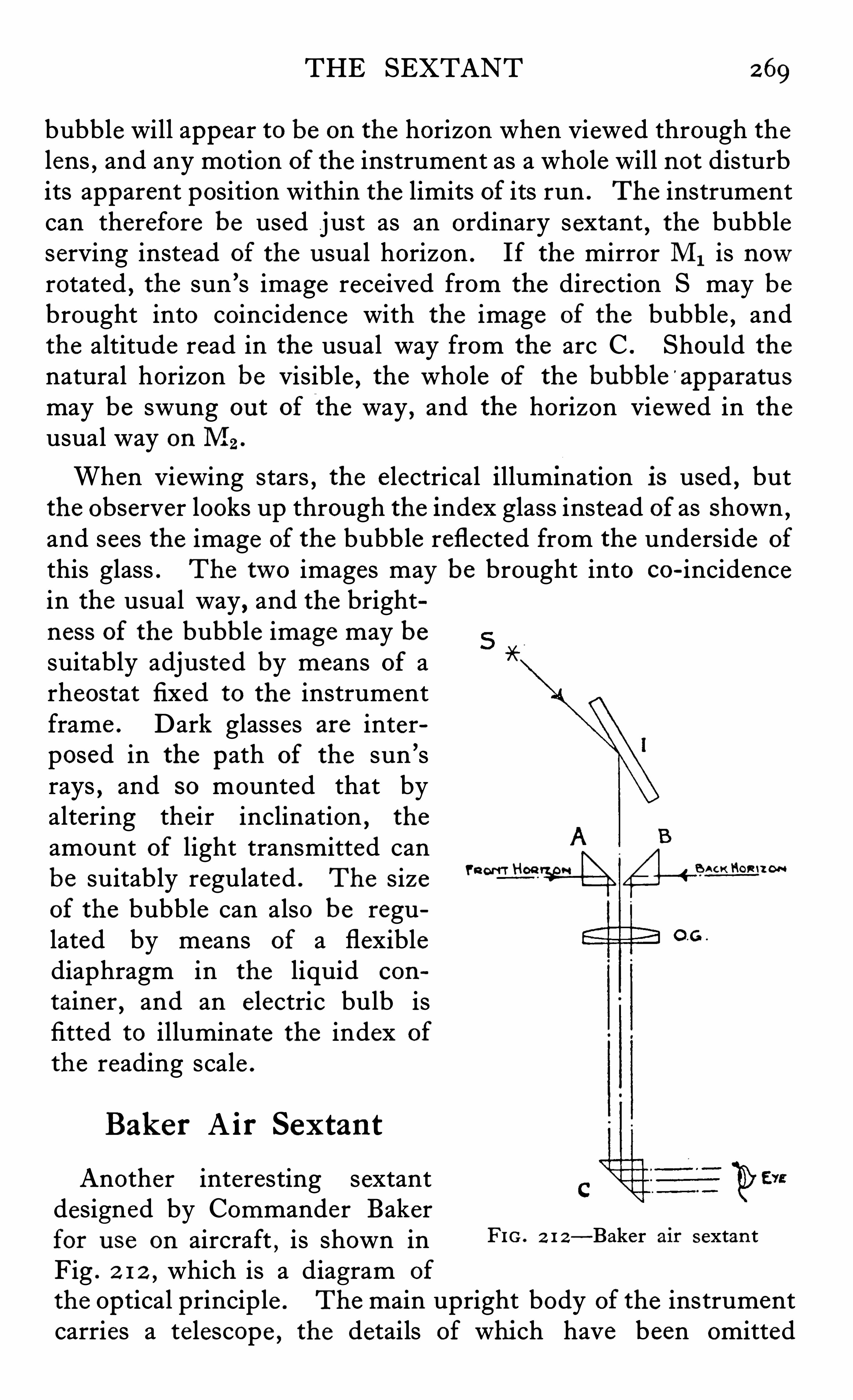
THE SEXTANT 269
bubble will appear to be on the horizon when viewed through thelens , and any motion of the instrument as a whole will not disturbits apparent position within the limits of its run . The instrumentcan therefore be used just as an ordinary sextant , the bubbleserving instead of the usual horizon . If the mirror M1 is nowrotated , the sun
’s image received from the direction S may bebrought into coincidence with the image of the bubble
,and
the altitude read in the usual way from the arc C . Should thenatural horizon be Visible , the whole of the bubble
'
apparatu s
may be swung ou t of the way , and the horizon Viewed in theusual way on M2 .
When viewing stars , the e lectrical illumination is used , butthe observer looks up through the index glass instead of as shown ,and sees the image of the bubble reflected from the underside of
this glass . The two images may be brought into co-incidencein the usual way , and the brightness of the bubble image may besuitably adjusted by means of arheostat fixed to the instrumentframe . Dark glasses are interposed in the path of the sun ’srays , and so mounted that byaltering their inclination , the
amount of light transmitted canbe suitably regulated . The size "w” 14aof the bubble can also be regulated by means of a flexiblediaphragm in the liquid con
tainer,and an electric bulb is
fitted to illuminate the index of
the reading scale .
Bak er A ir Sex tan t
Another interesting sextantdesigned by Commander Bakerfor u se on aircraft
,is shown in FIG. 2 1 2—Baker air s extan t
Fig . 2 1 2 , which is a diagram of
the Optical principle . The main upright body of the instrumentcarries a telescope , the details of whi ch have been omitted
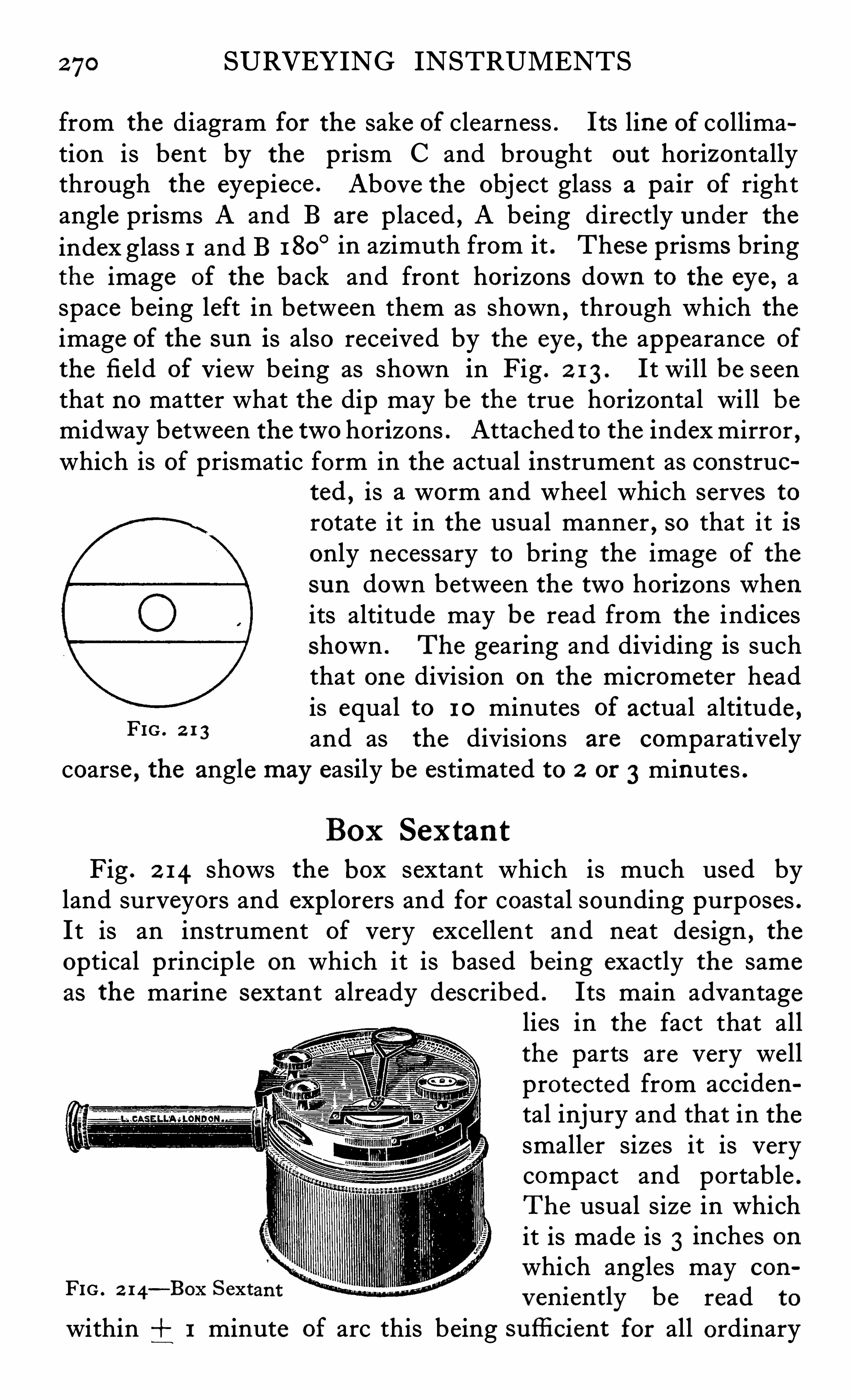
270 SURVEYING INSTRUMENTS
from the diagram for the sake of clearness . I ts line of collimation is bent by the prism C and brought ou t horizontallythrough the eyepiece . Above the object glass a pair of rightangle prisms A and B are placed , A being directly under theindex glass 1 and B 1 80
° in azimuth from it . These prisms bringthe image of the back and front horizons down to the eye , aspace being left in between them as shown , through which theimage of the sun is also received by the eye , the appearance of
the field of View being as shown in Fig . 2 1 3 . It will be seenthat no matter what the dip may be the true horizontal will bemidway between the two horizons . Attached to the index mirror ,which is of prismatic form in the actual instrument as construo
ted ,is a worm and whee l whi ch serves to
rotate it in the usual manner , so that it isonly necessary to bring the image of the
sun down between the two horizons whenits altitude may be read from the indicesshown . The gearing and dividing is suchthat one division on the micrometer headis equal to 1 0 minutes of actual altitude ,and as the divisions are comparatively
coarse , the angle may easily be estimated to 2 or 3 minutes .
FIG . 2 1 3
Box SextantFig . 2 14 shows the box sextant which is much used by
land surveyors and exp lorers and for coastal sounding purposes .It is an instrument of very excellent and neat design , theoptical princip le on which it is based being exactly the sameas the marine sextant already described . Its main advantage
lies in the fact that allthe parts are very we llprotected from acciden
tal injury and that in thesmaller sizes it is verycompact and portable .
The usual size in whichit is made is 3 inches onwhich angles may con
v eniently be read to
within 1 minute of arc this being sufli cient for all ordinary
FIG . 2 14—Box Sext
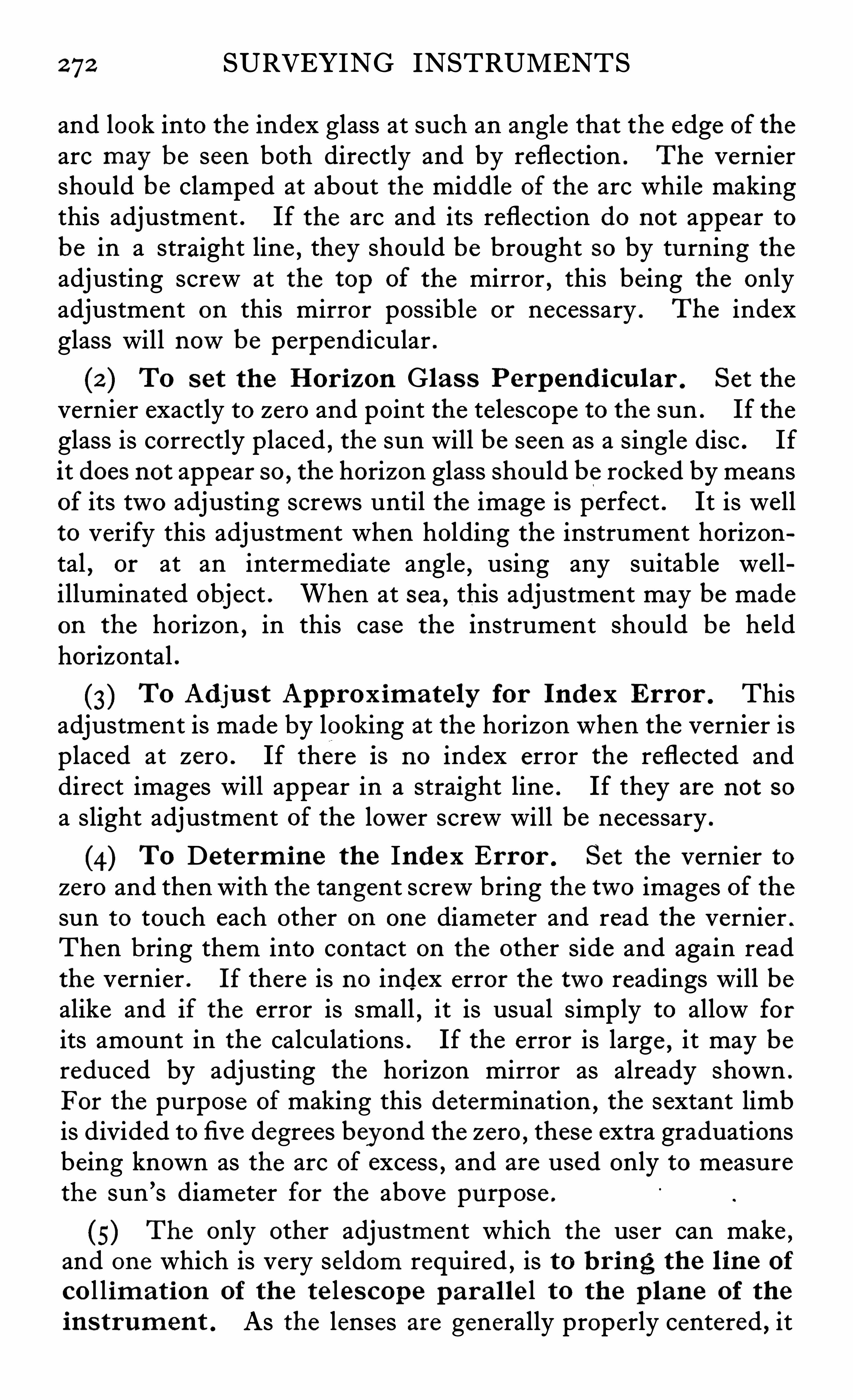
272 SURVEYING INSTRUMENTS
and look into the index glass at such an angle that the edge of thearc may be seen both directly and by reflection . The verniershould be clamped at about the middle of the arc while makingthis adjustment . If the arc and its reflection do not appear tobe in a straight line , they should be brought so by turning theadjusting screw at the top of the mirror , this being the onlyadjustment on this mirror possible or necessary . The indexglass will nowbe perpendicular .
(2 ) To s et the Hor izon Glas s Perp end icu lar . Set the
vernier exactly to zero and point the te lescope to the sun . If theglass is correctly placed , the sun will be seen as a single disc . Ifit does not appear so , the horizon glass should be rocked by meansof its two adjusting screws until the image is perfect . It is wellto verify this adjustment when holding the instrument horizontal
,or at an intermediate angle , using any suitable well
illuminated object . When at sea , this adjustment may be madeon the horizon , in this case the instrument should be he ldhorizontal .
(3) To Adju s t App rox im ate ly for Ind ex Error . Thisadjustment is made by looking at the horizon when the vernier isplaced at zero . If there Is no index error the reflected anddirect images will appear in a straight line . If they are not so
a slight adjustment of the lower screw will be necessary .
(4) To Determ ine the Index Er ror . Set the vernier tozero and then with the tangent screw bring the two images of thesun to touch each other on one diameter and read the vernier .
Then bring them into contact on the other side and again readthe vernier . If there is no index error the two readings will bealike and if the error is small
,it is usual simply to allow for
its amount in the calculations . If the error is large , it may bereduced by adjusting the horizon mirror as already shown .
For the purpose of making this determination , the sextant limbis divided to fi v e degrees bey ond the zero ,
these extra graduationsbeing known as the arc of excess , and are used only to measurethe sun ’s diameter for the above purpose .
(5) The only other adjustment which the user can make ,and one which is very seldom required , is to b r ing the l ine of
co l l im at ion of the te le s cop e p ar a l le l to the p lane of the
in s trum en t . As the lenses are generally properly centered , it
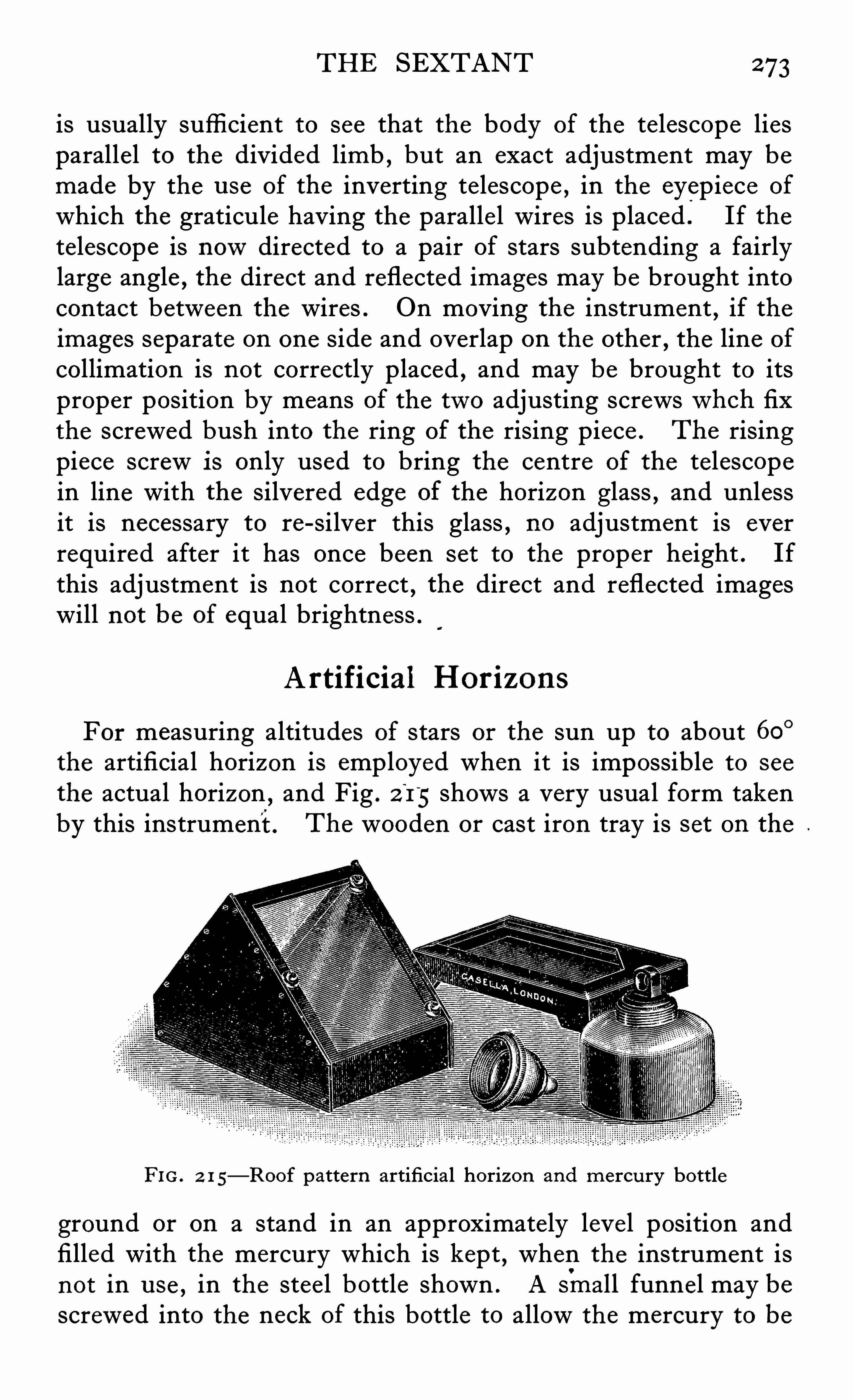
THE SEXTANT 273
is usually suffi cient to see that the body of the telescope liesparallel to the divided limb , but an exact adjustment may bemade by the u se of the inverting telescope , in the eyepiece of
which the graticule having the paralle l wires is placed . If thetelescope is nowdirected to a pair of stars subtending a fairlylarge angle , the direct and reflected images may be brought intocontact between the wires . On moving the instrument , if theimages separate on one side and overlap on the other , the line of
collimation is not correctly placed , and may be brought to itsproper position by means of the two adjusting screwswhch fixthe screwed bush into the ring of the rising piece . The risingpiece screw i s only used to bring the centre of the telescopein line with the silvered edge of the horizon glass , and unlessit is necessary to re-silver this glass , no adjustment is everrequired after it has once been s et to the proper height . Ifthis adjustment is not correct , the direct and reflected imageswill not be of equal brightness .
Artificial Hor izons
For measuring altitudes of stars or the sun up to about 60°
the artificial horizon is employed when it is impossible to see
the actual horizon,and Fig . 2 15 shows a very usual form taken
by this instrument. The wooden or cast iron tray is s et on the
FIG. 2 1 5—Roof pattern artificial horizon and mercu ry bottle
ground or on a stand in an approximately leve l position andfilled with the mercury which is kept
,when the instrument is
not in u se , in the stee l bottle shown . A sin all funnel may bescrewed into the neck of this bottle to allow the mercury to be
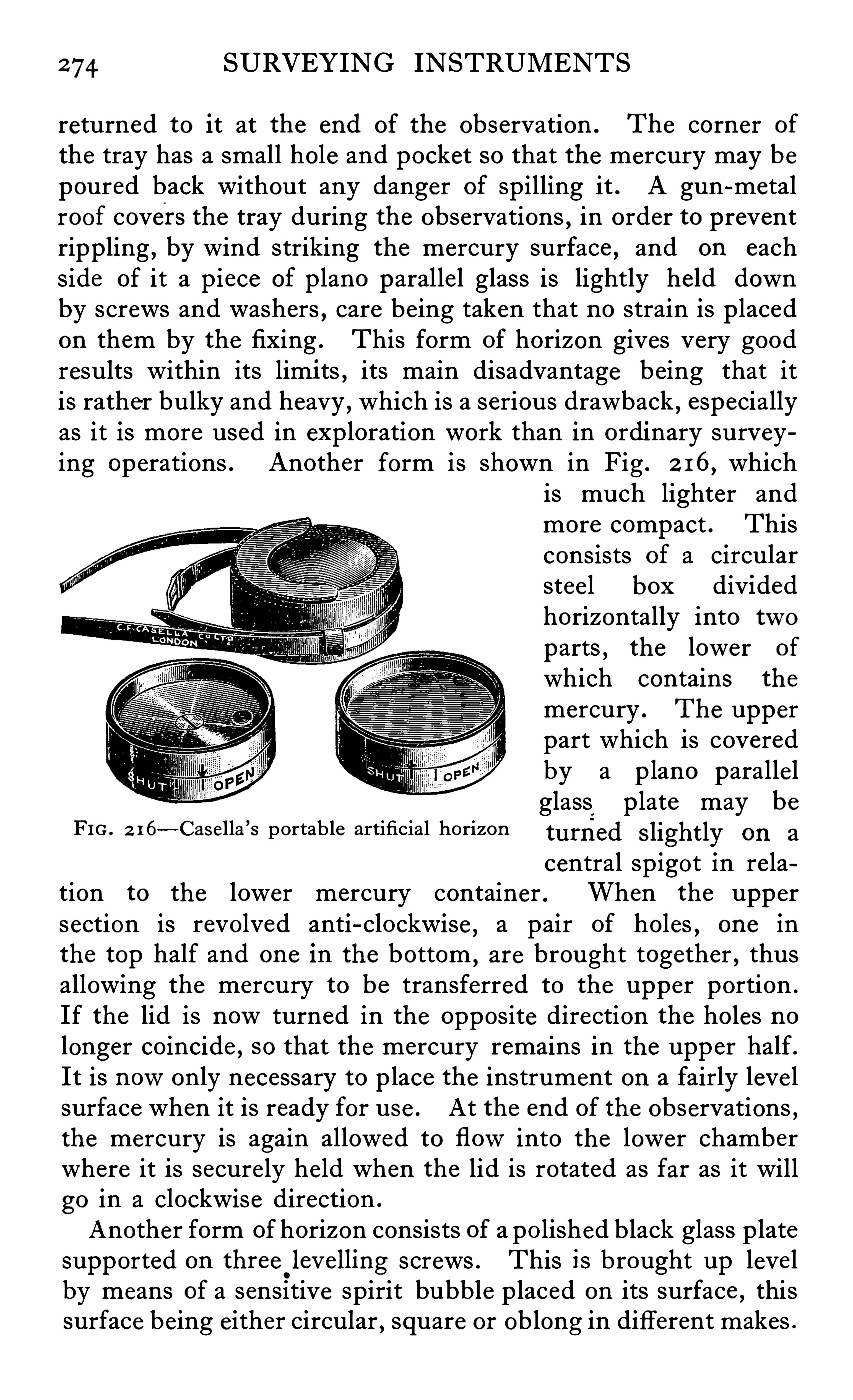
274 SURVEYING INSTRUMENTS
returned to it at the end of the observation . The corner of
the tray has a small hole and pocket so that the mercury may bepoured back without any danger of spilling it . A gun-metalroof covers the tray during the observations , in order to preventrippling
,by wind striking the mercury surface , and on each
side of it a piece of plano parallel glass is lightly he ld downby screws and washers , care being taken that no strain is p lacedon them by the fixing . This form of horizon gives very goodresults within its limi ts , its main disadvantage being that itis rather bulky and heavy , which is a serious drawback , especiallyas it is more used in exploration work than in ordinary surveying operations . Another form is shown in Fig . 2 16, which
is much lighter andmore compact . Thisconsists of a circularsteel box dividedhorizontally into twoparts
,the lower of
which contains the
mercury . The upperpart which is coveredby a plano paralle lglass p late may be
FIG . 2 16—Casella ’
s portable artificial horizon tu rfi ed Slightly on a
central spigot in relation to the lower mercury container . When the uppersection is revolved anti-clockwise , a pair of holes , one inthe top half and one in the bottom
,are brought together , thus
allowing the mercury to be transferred to the upper portion .
If the lid is nowturned in the opposite direction the holes nolonger coincide , so that the mercury remains in the upper half .It is nowonly necessary to place the instrument on a fairly leve lsurface when it is ready for u se . At the end of the observations ,the mercury is again allowed to flowinto the lower chamberwhere it is secure ly held when the lid is rotated as far as it willgo in a clockwise direction .
Another form of horizon consists of a po lished black glass platesupported on three
.
lev elling screws . This is brought up leve lby means of a sensitive spirit bubble placed on its surface , thissurface being either circular
,square or oblong in different makes .
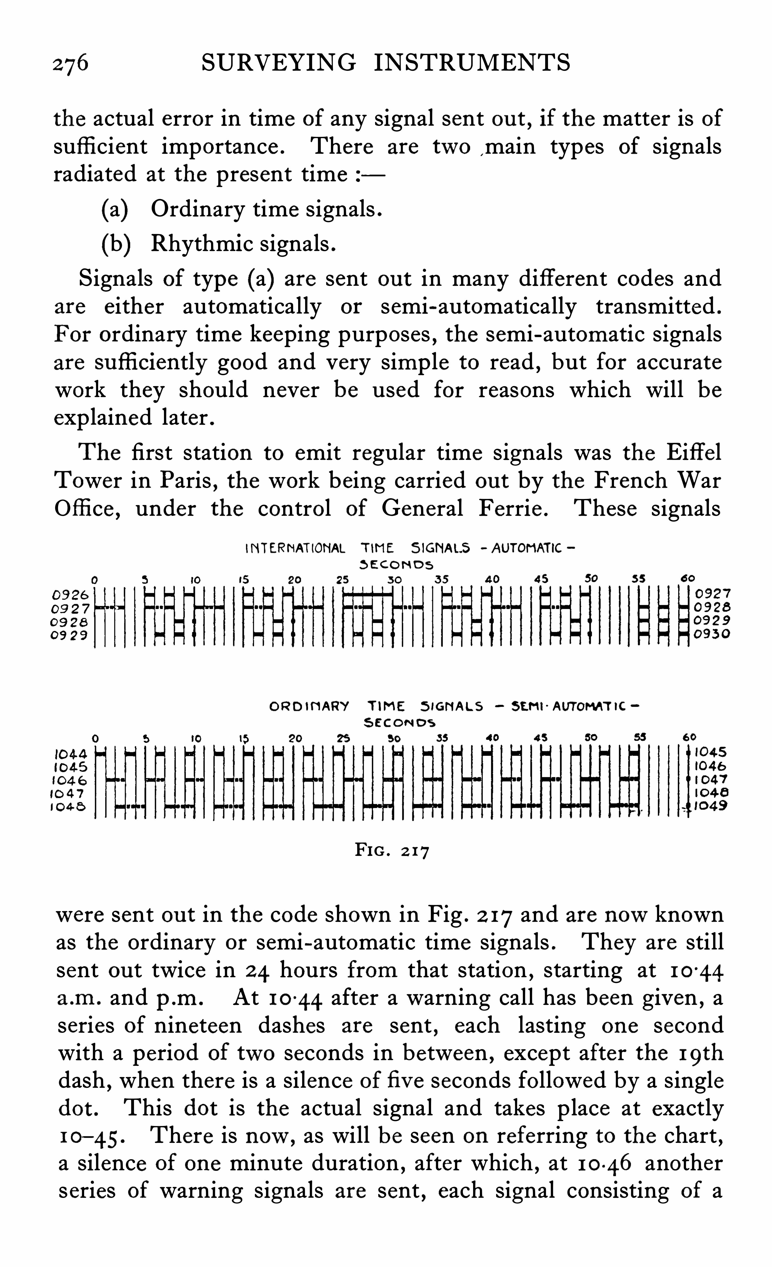
276 SURVEYING INSTRUMENTS
the actual error in time of any signal sent ou t , if the matter is ofsuffi cient importance . There are two
,main types of signals
radiated at the present time
(a) Ordinary time signals .
(b) Rhythmic signals .Signals of type (a) are sent ou t in many different codes and
are either automatically or semi-automatically transmitted .
For ordinary time keeping purposes , the semi-automatic signalsare sufli ciently good and very simp le to read , but for accuratework they should never be used for reasons which will beexplained later .
The first station to emit regular time signals was the Eiffe lTower in Paris
,the work being carried ou t by the French War
Office , under the control of General Ferrie . These signals
INTERNATIONAL TIME S IGNALS - AUTOI“ IATIC
S ECO ND S
3 0
ORD INARY TIME S IGNALS SEMI-AUTOMAT IC
S EC ON D S
25 50
FIG . 2 17
were sent ou t in the code shown in Fig . 2 17and are nowknownas the ordinary or semi-automatic time signals . They are stillsent ou t twice in 2 4 hours from that station , starting at 1 0
-44
a .m . and p m . At 1 0 44 after a warning call has been given , aseries of nineteen dashes are sent , each lasting one secondwith a period of two seconds in between , except after the 19th
dash,when there is a silence of fi v e seconds followed by a single
dot . This dot is the actual signal and takes place at exactly1 0—45. There is now, as will be seen on referring to the chart ,a silence of one minute duration , after which , at 1 0 46 anotherseries of warning signals are sent , each signal consisting of a
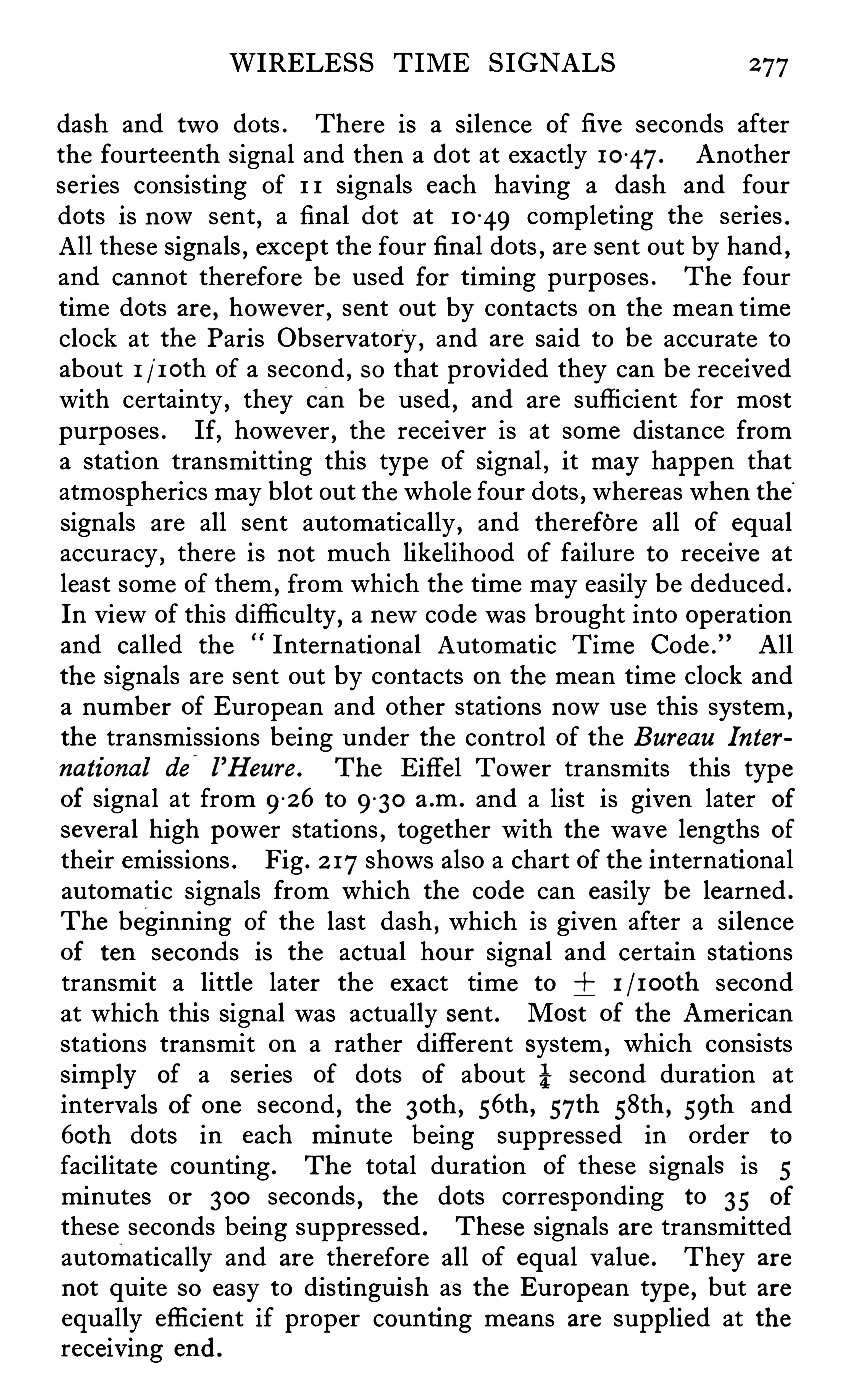
WIRELESS TIME SIGNALS 277
dash and two dots . There is a silence of fi v e seconds afterthe fourteenth signal and then a dot at exactly 10 47. Anotherseries consisting of 1 1 signals each having a dash and fourdots is nowsent , a final dot at 10
-
49 completing the series .
All these signals , except the four final dots , are sent ou t by hand ,and cannot therefore be used for timing purposes . The fourtime dots are , however , sent ou t by contacts on the mean timeclock at the Paris Observatory , and are said to be accurate toabout 1 / 10th of a second , so that provided they can be receivedwith certainty , they can be used
,and are sufficient for most
purposes . If, however , the receiver is at some distance froma station transmitting this type of signal , it may happen thatatmospherics may blot ou t the whole four dots , whereas when the
'
signals are all sent automatically , and therefore all of equalaccuracy
,there is not much likelihood of failure to receive at
least some of them , from which the time may easily be deduced .
In view of this diffi culty,a newcode was brought into operation
and called the International Automatic Time Code .
” Allthe signals are sent ou t by contacts on the mean time clock anda number of European and other stations nowu se this system
,
the transmissions being under the control of the Bureau Interna tional de
'
l’Heure . The Eiffel Tower transmits this type
of signal at from 9-26 to 9
-
30 a .m . and a list is given later of
several high power stations,together with the wave lengths of
their emissions . Fig . 2 17shows also a chart of the internationalautomatic signals from which the code can easily be learned .
The beginning of the last dash , which is given after a silenceof ten seconds is the actual hour signal and certain stationstransmit a little later the exact time to 1 / 100th secondat which this signal was actually sent . Most of the Americanstations transmit on a rather different system ,
which consistssimply of a series of dots of about second duration atintervals of one second
,the 3oth , s6th , 57th 58th , 59th and
6oth dots in each minute being suppressed in order to
facilitate counting . The total duration of these signals is 5minutes or 300 seconds , the dots corresponding to 35 of
these seconds being suppressed . These signals are transmittedautomatically and are therefore all of equal value . They are
not quite so easy to distinguish as the European type , but areequally effi cient if proper counting means are supplied at thereceiving end .
278 SURVEYING INSTRUMENTS
There is another system of time signals of totally differenttype , whi ch is sent ou t from most of the European stations .
These are known as the Rhythmic or Vern ier Signals,and are
sent in units of sidereal time . Those from the Eiffel Towerconsist of a series of dots each of about 2 second duration .
At the 6oth,1 2 0th , 180th , and 2 4oth the dot is replaced by a
dash of -9 second duration , thus enabling the counting to be
carried ou t very easily . The time interval between the dots isequal to 5—3 of a sidereal second and the method of using themis s imilar to that of a vernier on ordinary linear scales . The
beats are made to sound in a pair of telephones at the sametime as those from a regulator clock , the pendulum of whichbeats sidereal seconds . It is then possible to compare the beatsby noting at which seconds they coincide , and the accuracy whicha trained observer can obtain is somewhere in the neighbourhood of 1 1 00th second . At large observatories , the wirelesss ignals and the beats of the local clock are recorded on the
revolving chart of a chronograph , s imilar to that shown in Fig .
188. At less important stations it is usual to fix a microphoneand small dry battery in the clock case and lead the wires tothe telephones which are also connected to the wire less receiving apparatus . Many of the time s ignal stations transmit bymeans of the spark system ,
so that it is possible to receivetheir signals on a simp le crystal set when within reasonabledistance . For accurate work , where of course reliability of
reception is important , it is necessary to u se an oscillating valvereceiver and any good 'make of instrument which is arrangedto tune to the proper wave length will be found quite suitablefor ordinary purposes . When it is required to record the
signals 3 or 4 amplifying valves in addition to the necessary relayand chronograph must be used , but as each station works underdifferent conditions , and has special problems to contend with ,details of equipment need not be given here .
Fig . 2 18 shows a diagrammatic circuit , such as is used at somestations
,which will be sufli cient to indicate the general trend
of design .
The aerial circuit is tuned by means of a p lug-in coil andcondenser to the wave length required . This coil may eitherbe direct or preferably loose coupled to the valve , in the plate
2 80 SURVEYING INSTRUMENTS0
those from the clock would be constant , so that Special instruments such as the Marconi or Creed undulator must be em
ployed,the variations in the trace being obtained by alteration
of the wave length , by means of the insertion of additionalcapacity into the tuned circuit . The principal diffi culty encountered with an apparatus of this kind is that in certain places thetrace given by the atmospherics may make it difli cu lt to read therecord so that a selective receiving circuit should be employed
,
and in specially troublesome s ituations it is preferable to makeu se of some form of frame aerial the directive properties of
which help to Cu t ou t not only atmospherics but unwantedsignals fromother stations .
Generally Speaking .it is found that only the bare minimumnumber of valves necessary to get good results should be em
p loyed , as the difficulty of control and the disturbances due toatmospherics are increased when the amplification is too great .Rapid strides are being made at the present time in the designof wireless apparatus
,so that anyone contemp lating the in
stallation of a receiving set should consult the makers forup
-to-date details .The names of a fewof the more important high power stations
at presen t transmitting time s ignals are given herewith , togetherwith particulars of their wave lengths and call s igns .
WIRELESS TIME SIGNALS 2 81
These times and wave lengths may be altered from time totime , so that those contemplating the reception of signals shouldobtain the latest information from the Year Book of WirelessTelegraphy .
When the equipment has to be carried by an exploring party,
specially compact receiving sets are desirable and the problemof suitable battery power must be studied . There are on the
market nowa number of lowconsumption valves whi ch havemade the equipment much lighter than formerly , and somemonths of good service can be obtained from the ordinarycommercial dry battery , when using these valves . Specialinert cells can nowbe obtained which do not deteriorate in thetropics
,so that there is nowno reason why any important
exploring party should not be able to carry a set which wouldnot on ly enable them to get the time signals but also to receivethe news from the nearest broadcasting station . Some of the
latest exp loring parties have even been equipped with veryefficient transmitters with which they have been able to keep intouch with civilisation during the whole of the time they havebeen away in the interior .
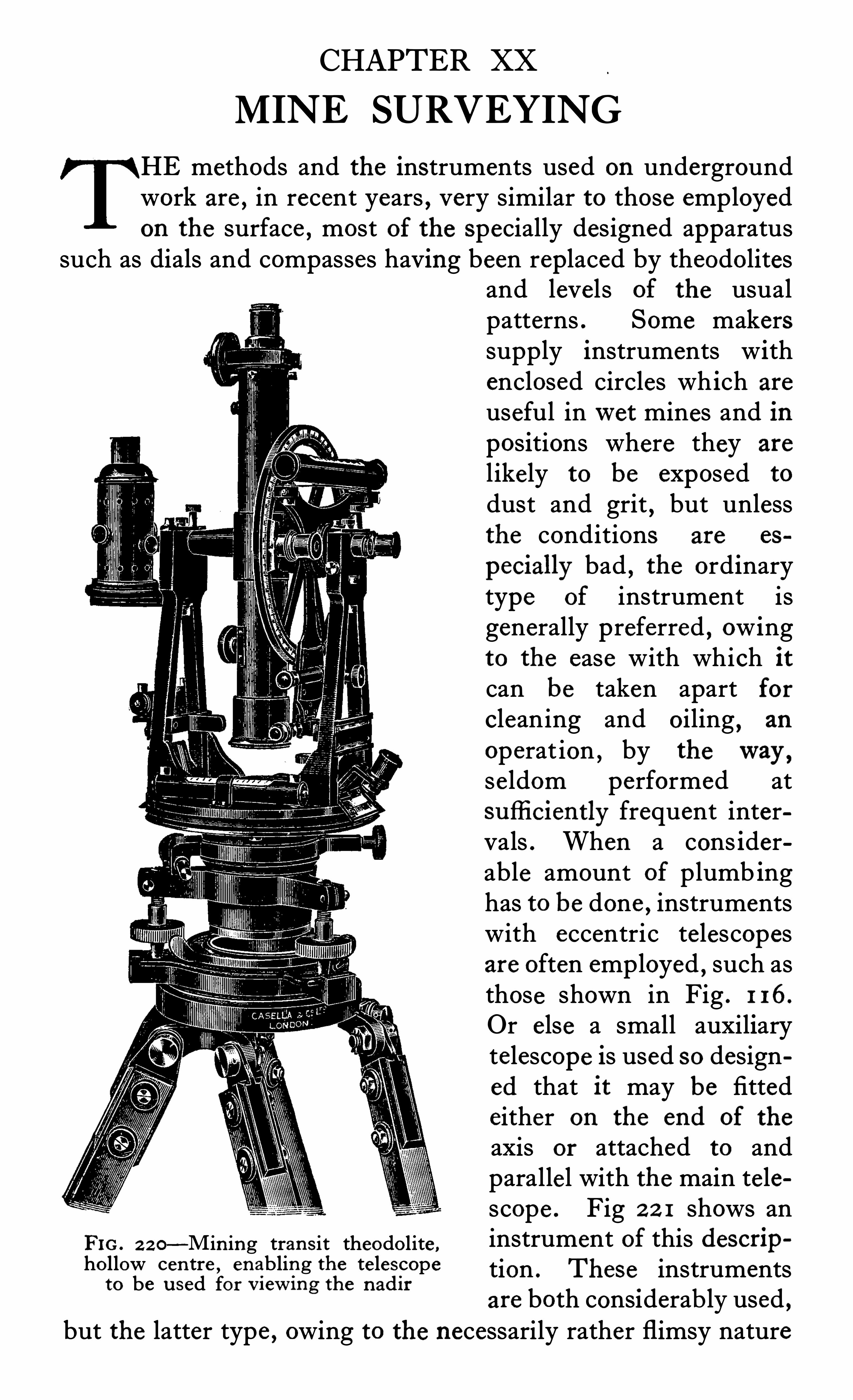
CHAPTER XX
MINE SURVEYING
HE methods and the instruments used on undergroundwork are , in recent years , very similar to those employedon the surface , most of the specially designed apparatus
such as dials and compasses having been replaced by theodolitesand levels of the usualpatterns . Some makerssupply instruments withenclosed circles wh ich are
useful inwet mines and inpositions where they are
l ikely to be exposed to
dust and grit,but unless
the conditions are es
pecially bad , the ordinarytype of instrument isgenerally preferred , owingto the ease with which itcan be taken apart forcleaning and oiling
,an
operat ion , by theway ,se ldom performed atsufli ciently frequent intervals . When a cons iderable amount of plumb inghas to be done , instrumentswith eccentric telescopesare often employed
,such as
those shown in Fig . 1 16.
Or else a small auxiliarytelescope is used so designed that it may be fittedeither on the end of the
axis or attached to andparallel with the main telescope . Fig 2 2 1 shows an
FIG. 2 2 0—Min ing tran s it theodo lite ,instrument Of this descripho llow cen tre , enabling the te lescope tion . These instruments
1 b d f i h d'
0 6 u se orwewmg 6 na 11
are both considerab ly used ,but the latter type , owing to the necessarily rather flimsy nature
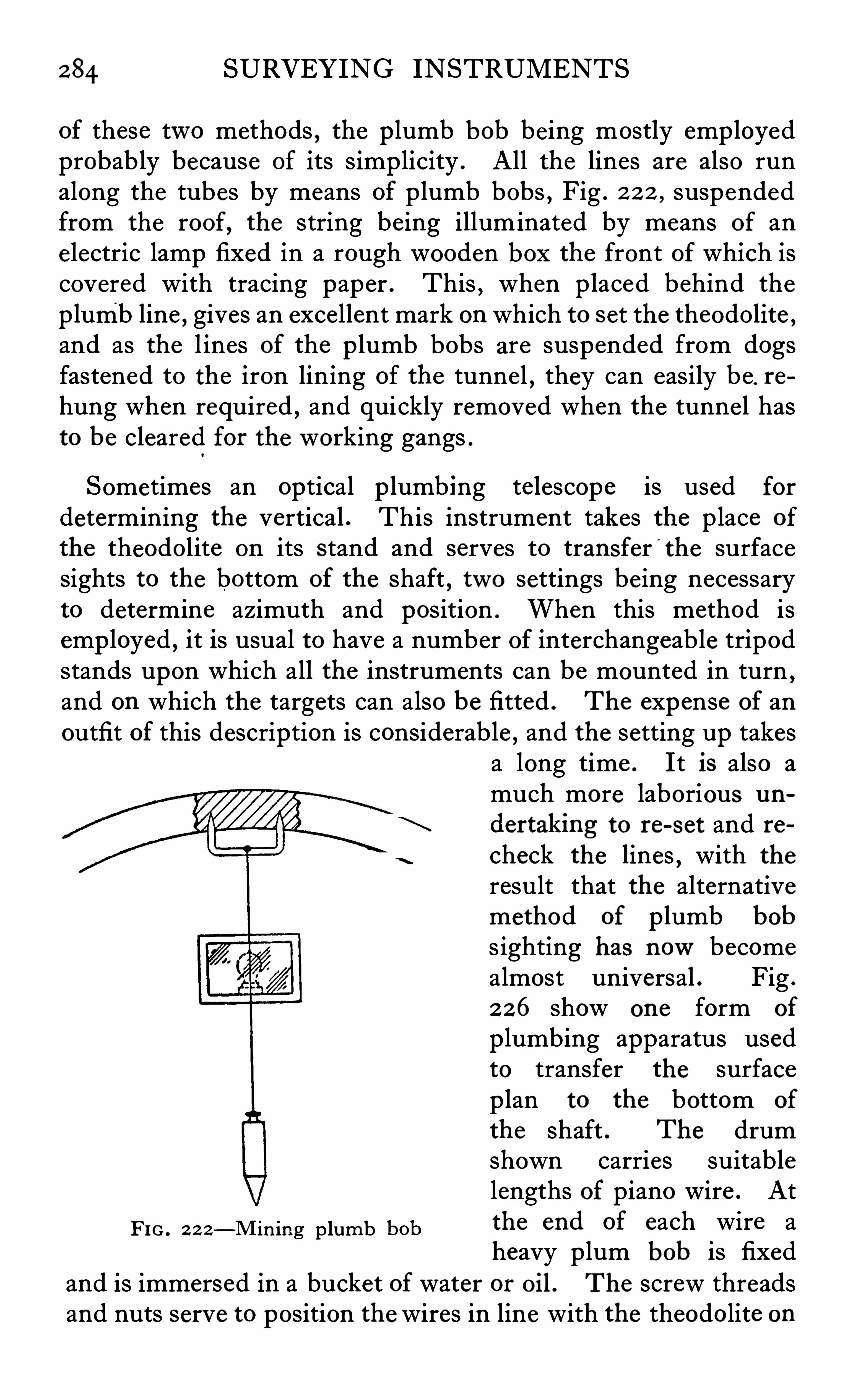
2 84 SURVEYING INSTRUMENTS
of these two methods , the p lumb bob being mostly employedprobably because of its simp licity . All the lines are also runalong the tubes by means of plumb bobs , Fig . 2 2 2 , suspendedfrom the roof, the string being illuminated by means of anelectric lamp fixed in a rough wooden box the front of which iscovered with tracing paper . This , when placed behind the
plumb line , gives an excellent mark on which to set the theodolite ,
and as the l ines of the plumb bobs are suspended from dogsfastened to the iron lining of the tunnel , they can easily be. re
hung when required , and quickly removed when the tunne l hasto be cleared for the working gangs .
Sometimes an optical p lumbing te lescope is used for
determining the vertical . This instrument takes the place of
the theodolite on its stand and serves to transfer'
the surfacesights to the bottom of the shaft , two settings being necessaryto determine azimuth and position . When this method isemp loyed , it is usual to have a number of interchangeable tripodstands upon which all the instruments can be mounted in turn ,and on which the targets can also be fitted . The expense of anoutfit of this description is considerable , and the setting up takes
a long time . It is also amuch more laborious un
dertaking to re-set and recheck the lines , with the
result that the alternativemethod of p lumb bob
s ighting has nowbecomealmost universal . Fig .
2 26 show one form of
p lumbing apparatus usedto transfer the surfaceplan to the bottom of
the shaft . The drumshown carries suitablelengths of piano wire . At
Fi c . 2 2 2—Min ing plumb the end of each wire aheavy plum bob is fixed
and is immersed in a bucket of water or oil . The screw threadsand nuts serve to position the wires in line with the theodolite on
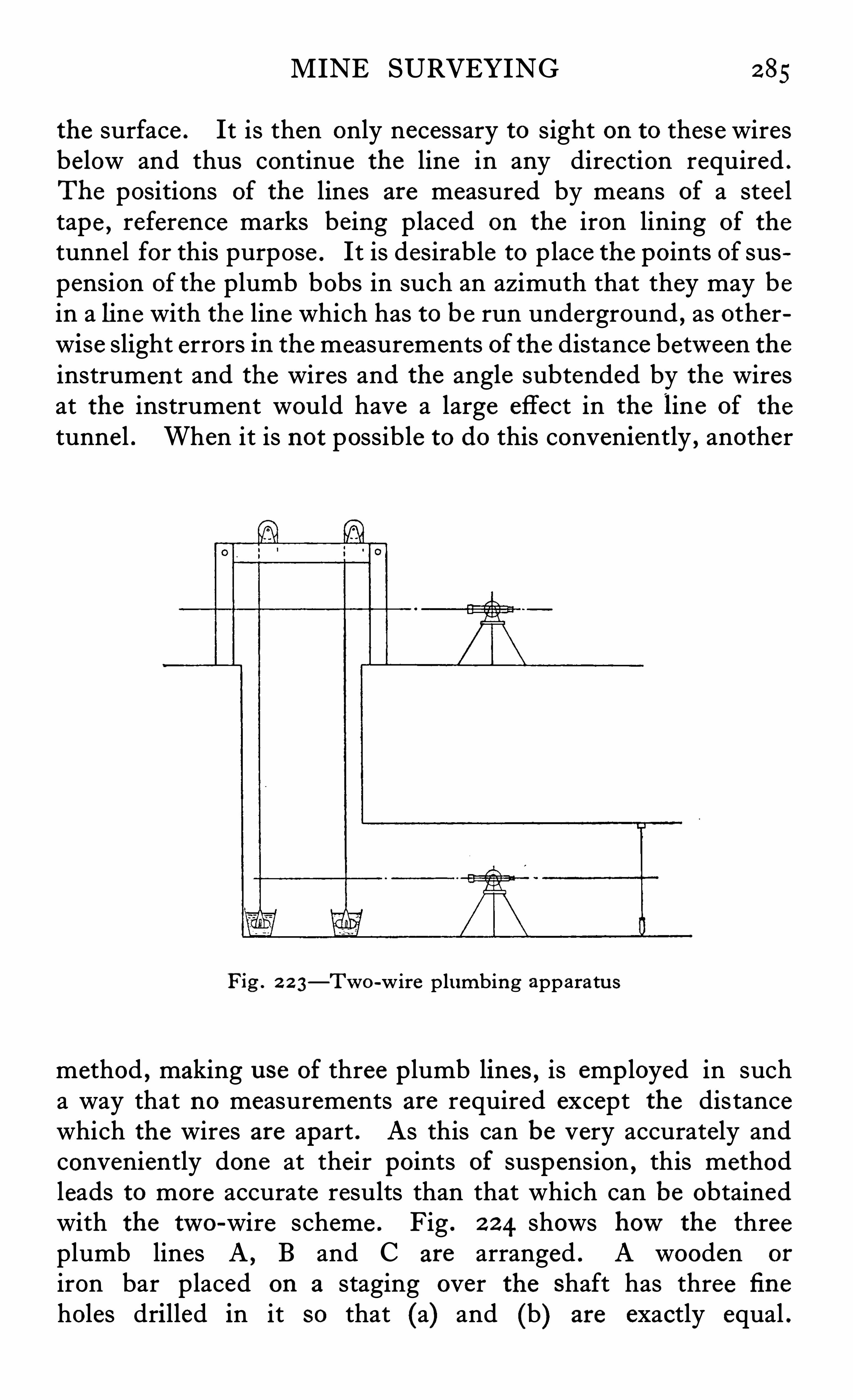
MINE SURVEYING 2 85
the surface . It is then only necessary to sight on to these wiresbelow and thus continue the line in any direction required .
The positions of the lines are measured by means of a steeltape , reference marks being placed on the iron lining of the
tunnel for this purpose . It is desirable to place the points of suspension of the plumb bobs in such an azimuth that they may bein a line with the line which has to be run underground , as otherwise slight errors in the measurements of the distance between theinstrument and the wires and the angle subtended by the wiresat the instrument would have a large effect in the line of the
tunne l . When it is not possible to do this conveniently , another
Fig . 2 2 3—Two-wire plumbing apparatu s
method , making u se of three p lumb lines , is emp loyed in sucha way that no measurements are required except the distancewhich the wires are apart . As this can be very accurately andconveniently done at their points of suspension , this methodleads to more accurate results than that which can be obtainedwith the two-wire scheme . Fig . 2 2 4 shows howthe threeplumb lines A , B and C are arranged . A wooden or
iron bar placed on a staging over the shaft has three fi neholes drilled in it so that (a) and (b) are exactly equal .
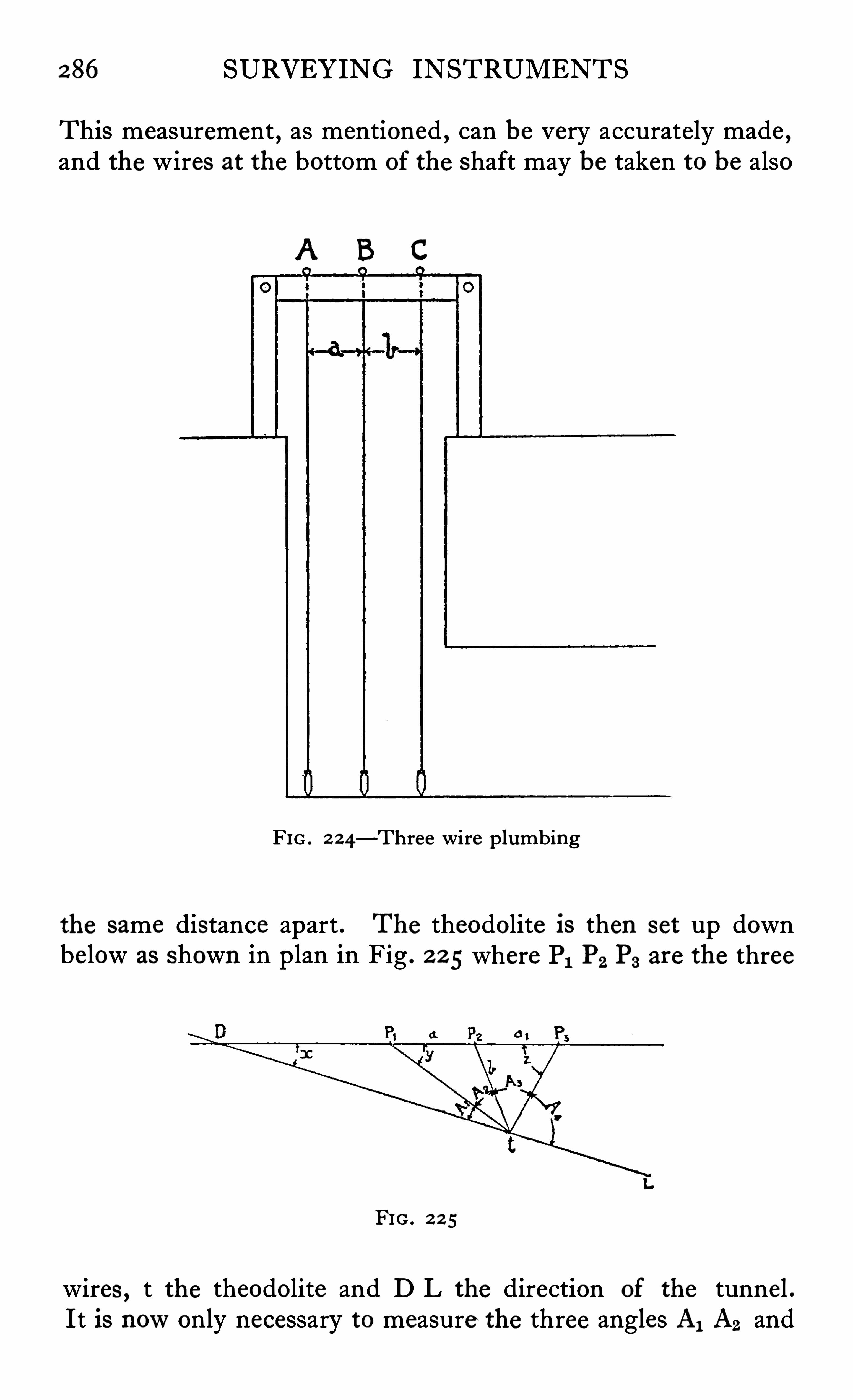
2 86 SURVEYING INSTRUMENTS
This measurement , as mentioned , can be very accurately made ,and the wires at the bottom of the shaft may be taken to be also
A B C
FIG . 2 2 4—Three wire plumbing
the same distance apart . The theodolite is then set up downbelow as shown in p lan in Fig . 2 2 5 where PI P2 P3 are the three
FIG . 2 2 5
wires , t the theodolite and D L the direction of the tunnel .It is nowonly necessary to measure the three angles AI A2 and
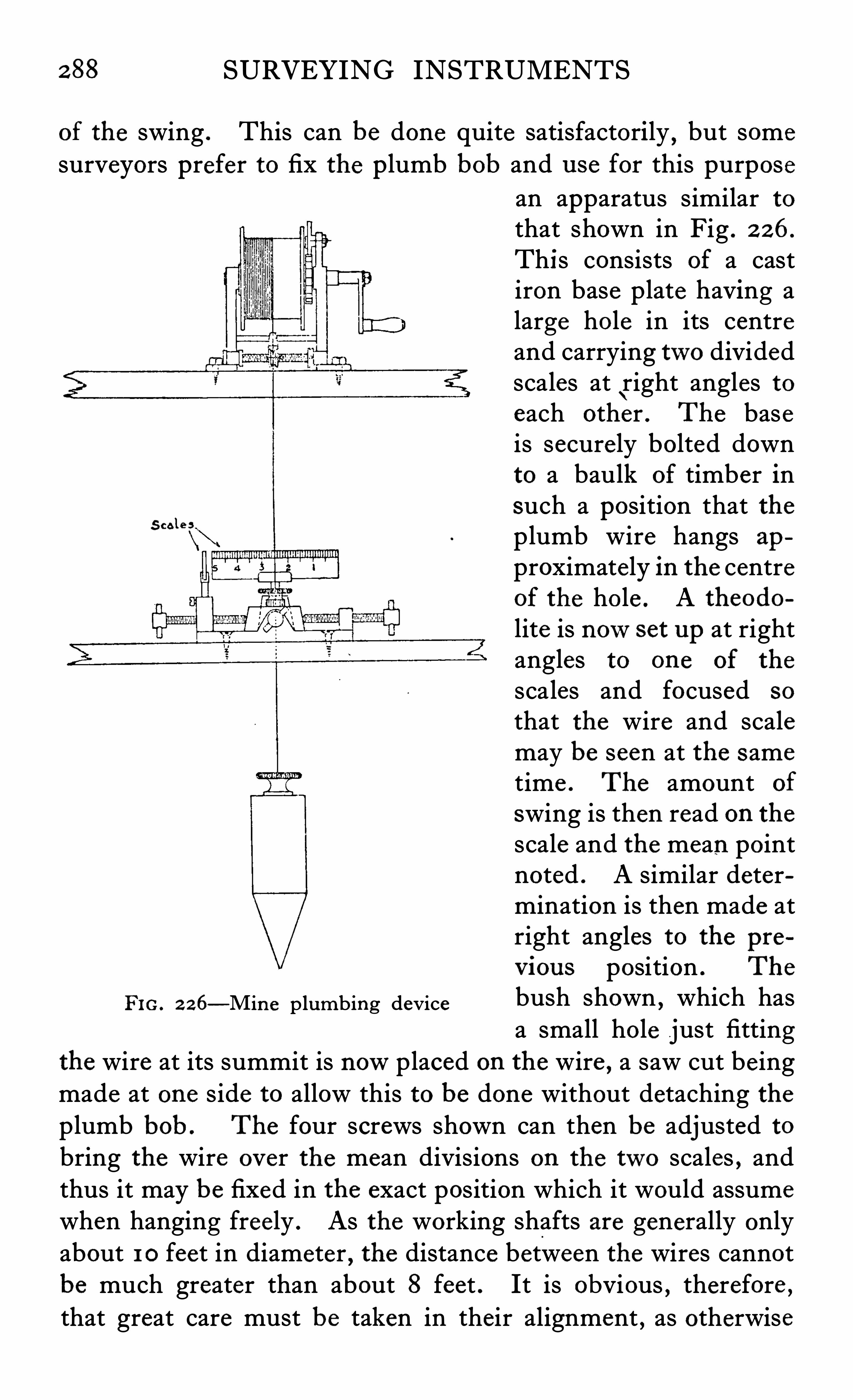
2 88 SURVEYING INSTRUMENTS
of the swing . This can be done quite satisfactorily,but some
surveyors prefer to fix the p lumb bob and use for this purpose
S ca l e s
FIG. 2 26—Min e plumbing device
an apparatus similar tothat shown in Fig . 2 26.
This consists of a castiron base plate having alarge hole in its centreand carrying two dividedscales at
\right angles to
each other . The baseis secure ly bolted downto a baulk of timber insuch a position that theplumb wire hangs ap
proximately in the centreof the ho le . A theodo
lite is nowset up at rightangles to one of the
scales and focused so
that the wire and scalemay be seen at the same
time . The amount of
swing is then read on thescale and the mean pointnoted . A similar determination is then made atright angles to the pre
v ious position . The
bush shown,which has
a small hole just fittingthe wire at its summit is nowplaced on the wire , a saw cut be ingmade at one side to allow this to be done without detaching theplumb bob . The four screws shown can then be adjusted tobring the wire over the mean divisions on the two scales , andthus it may be fixed in the exact position which it would assume
when hanging freely . As the working shafts are generally onlyabout 1 0 feet in diameter , the distance between the wires cannotbe much greater than about 8 feet . It is obvious , therefore ,that great care must be taken in their alignment , as otherwise
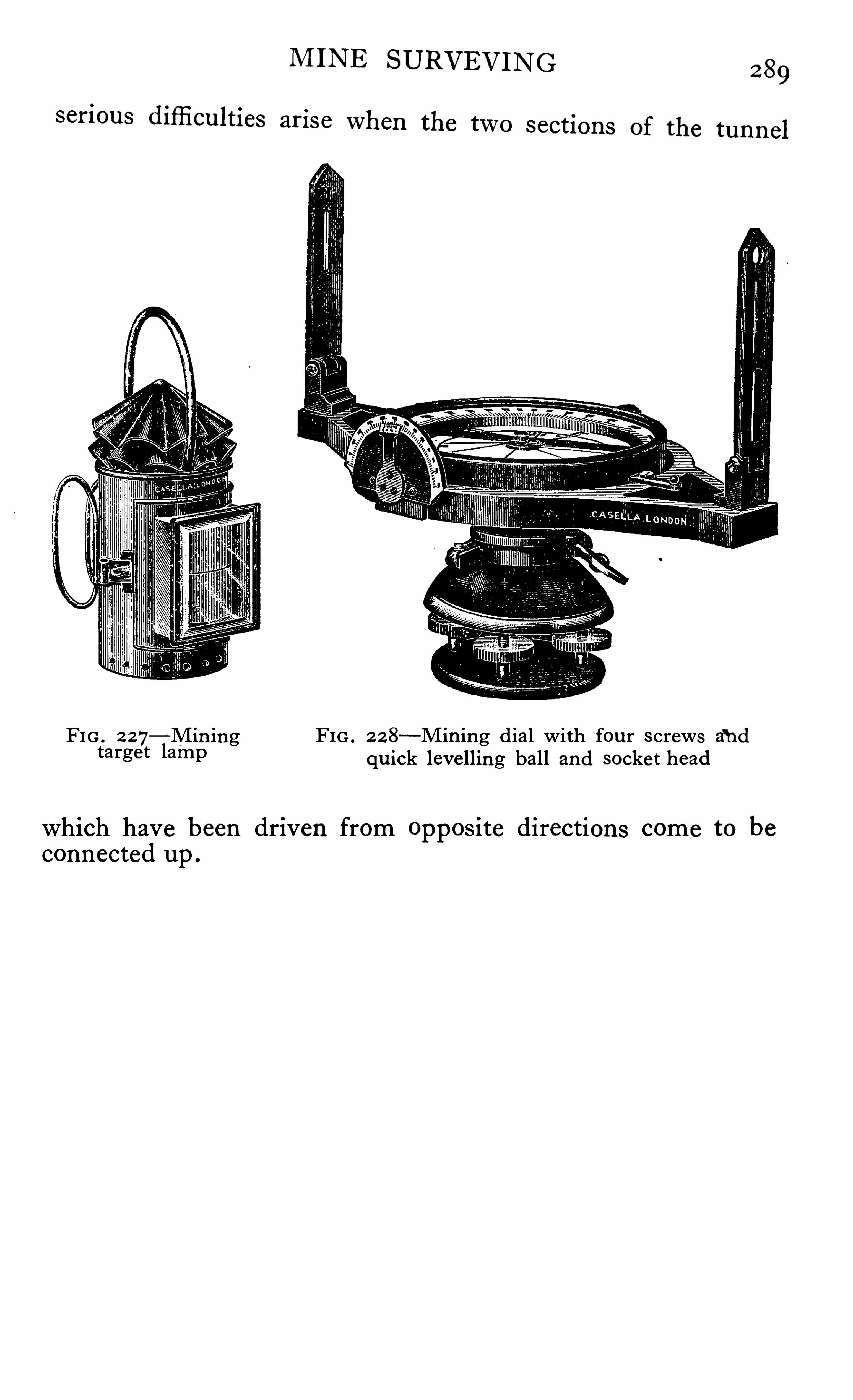
FIG . 2 27—Min ing FIG . 2 2 8—Min ing dia l with fou r s crews andtarge t lamp qu ick leve lling ball and socket head
which have been driven from opposite directions come to beconnected up .
CHAPTER ""I
ERRORS IN THE MEASUREMENTS
OF ANGLES
HE errors introduced into these measurements are of
two kinds z—(a) Instrumental errors (b) Observer’
s
errors . Of these the instrumental errors are , withmodern inst ruments , the least important , and mos t of them may
be eliminated by careful attention to an observational programmewhich is designed in such away that the errors tend to cancelou t in the final results .
The principal instrumental errors are
Collimation .
Unequal height of Y ’
s .
(3) Inequality of pivots of telescope .
(4) Graduation errors and errors in micrometers .Errors du e to 1 , 2 and 3 may be e liminated as previouslydescribed , and certain of those du e to 4 may also be eliminated .
The errors of centering are e liminated by taking the mean of
opposite readings . Those du e to actual errors in the spacingof the graduations are not easily disposed of, but may be renderedvery small by a suitable programme of observations . In orderto do this , the pointings on any particular pair of targets shouldbe made on different parts of the circle , it being usual on accuratework to take separate readings at six or eight equidistant portions .This procedure tends to eliminate any accidental errors of
graduation as well as any periodic errors which the circle mayhave . Errors du e to variations in the run of the micrometerscan only be guarded against by making careful check readingsbefore starting on the main observations , and it is often desirableto make an additional check at the '
fi nish of the work . Care
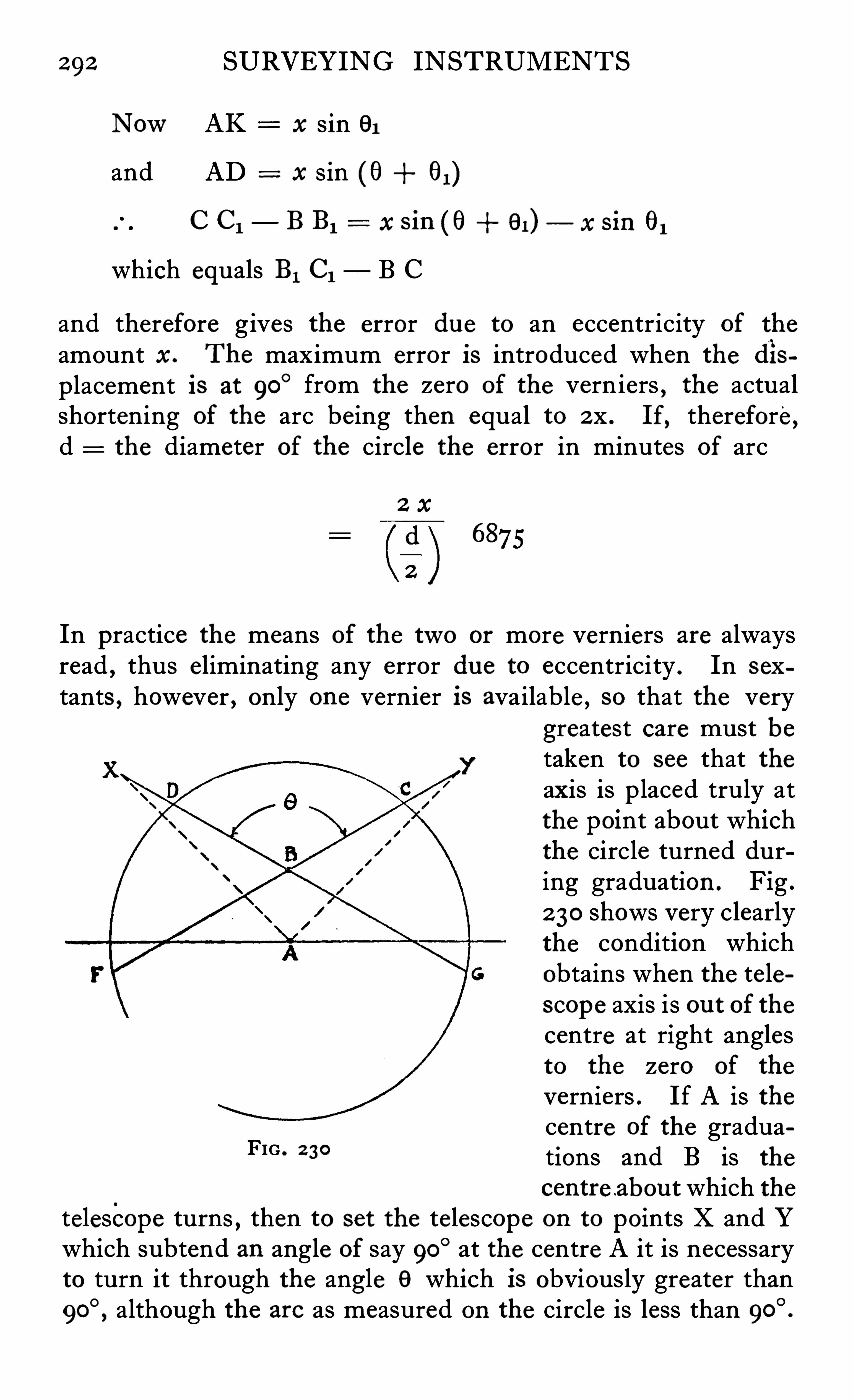
292 SURVEYING INSTRUMENTS
NowAK x sin 91
and AD x sin (0 61)
C C l— B B1 = x s in (fl 91) — x sin 61
which equals B1 C1 B C
and therefore gives the error due to an eccentricity of the
amount x . The maximum error is introduced when the displacement is at 90
° from the zero of the verniers, the actual
shortening of the arc being then equal to 2 x . If,therefore,
d the diameter of the circle the error in minutes of arc
In practice the means of the two or more verniers are alwaysread , thus eliminating any error due to eccentricity . In sex
tants , however , only one vernier is available , so that the verygreatest care must betaken to see that theaxis is placed truly atthe point about whichthe circle turned during graduation . Fig .
2 30 shows very clearlythe condition whichobtains when the telescope axis is ou t of thecentre at right anglesto the zero of the
verniers . If A is thecentre of the graduations and B is the
centre abou t which thetelescope turns , then to set the telescope on to points X and Ywhich subtend an angle of say 90
° at the centre A it is necessaryto turn it through the angle 9 which is obviously greater than
although the are as measured on the circle is less than
FIG . 2 30
ERRORS IN THE MEASUREMENTS OF ANGLES 293
In practice the graduations are read at C F and D G, the arcs
C D + F G
2
thus giving the correct angle , no matter howmuch B is displacedfrom the tru e centre A .
In addition to the e limination of the centering error the u se
of more than one microscope or vernier reduces the probableerror of the readings as follows
Let (e) be the probable error of reading one mi crometer or
vernier and E the mean of n micrometers .
Then from the method of least squares the probable error
e
V”
If, for example , the probable error (e) for one micrometer is
one second then
When using two micrometers E 7second
When us ing s ix micrometers E 4 secondV6
It will be seen that increas ing the number of micrometerswi ll decrease the probable error s lowly and that nine micrometers would be required to reduce it in the above case to one
thi rd of a second .
It is to be noted that two micrometers are suffi cient for theelimination of the centering error , so that from that point ofview there is no advantage in having more than two .
For the purpose of reducing the probable error it is unusualto employ more than four micrometers this number reducingthe error to half that obtained from a single reading . When a
greater number is fitted the theoretical advantages can hardlybe realised owing to the probability of relative movements of themountings , etc .
2 94 SURVEYING INSTRUMENTS
Observ er ’s Errors
Are due to a great number of causes , some of which are
at times very elusive and diffi cult to trace , and very difficult to cure . Marked. differences exist between observersand it is only by practice and experience that efficiencyand speed of working and accuracy in the final results may beobtained . Some of the principal errors under this head are du eto readings of the verniers or micrometers or the telescope webs ,which are inconsistent . This form of error in properly trainedobservers is unusual , due perhaps to the fact that those inclinedto make errors of this kind cease to be surveyors . Errors du eto readings which are consistently either too large or too smallare more common , but not of course so serious . The largesterrors , apart from mistakes in the actual booking of the anglesread are generally du e to poor setting up of the instrument andto failure to ensure that all the parts are properly secured andfree from shake or instability . When the tripod is set up , itmust be firmly pressed into the ground , and then , when the
instrument has been placed in position and approximate lyleve lled , all twist should be e liminated by slackening the thumbscrews thus allowing the whole apparatus to take up an unstrainedposition before finally tightening up all the elements . Especialcare should be taken to see that there is no slackness at the footscrews , neglect of this simple detai l being undoubtedly the
cause of some of the largest errors . Wooden stands usuallytwist when p laced in the sun , and as the rate of twist is variable ,it i s important that the observations should be taken as quicklyas possible , as delay between the settings on a pair of azimuthmarks may lead to large errors when the direction of twist issuch that the measures of the angles would be too great or toosmall . If twist of the support is suspected , it is we ll to measurethe angles first from one side and then from the opposite side ,the mean of these two readings being correct provided the rateof twist is uniform . On precise work it is of course importantthat the instrument be placed accurate ly over the station markand on tunnelling work , especially , this detail must be attendedto with the greatest care possible .
An idea of the accuracy of placement required is shown bythe fact that an error in centering of 1 / 1 0th inch will give an
CHAPTER XXI I
BAROMETERS 82° HYPSOMETERS
N mountainous regions there are two other methods of
finding levels or approximate heights , Viz .:by the u se ofbarometers and by determination of the temperature of the
boiling points of water at various altitudes .
The barometers used are of two classes—A the m ercu ry andB the anero id . The mercury barometers always employed areof the Fortin type , as this pattern can easily be rendered portableby screwing up the mercury until it fills the tube . Fig . 2 3 1
shows an instrument of this kind fixed to its tripod and Fig . 2 3 2
shows the leather case in which it can be packed for transport .The scale is graduated down to about 1 2 or 14 inches , which isequivalent to an altitude of about feet , and provided carebe taken in the transport and reading , fair results can be obtained .
The apparatus is , however , very cumbersome to carry , and thede licate mercury tube is easily damaged or rendered use lessby the ingress of air to the vacuum space , so that the methodis seldom used except by large we ll-equipped parties .
The aneroid barometer , on the other hand , when well madeand compensated , is a very re liable and portable instrumentand is Capable of giving excellent results in careful hands . Itis small
,portable and easily read , and not liable to damage ,
provided reasonable care be taken during transport . Figs . 2 33and 2 34 shows the type of instrument usually carried . It isabout 4 or 5 inches in diameter and may be obtained with scalesmarked for descent to feet and ascent up to as muchas feet when required . For readings up to feet ,the scale is divided to read to 2 feet intervals and forfeet the reading is generally to 5 feet . Instruments of 2 or 3
inches diameter can be obtained , but the scales are rather too
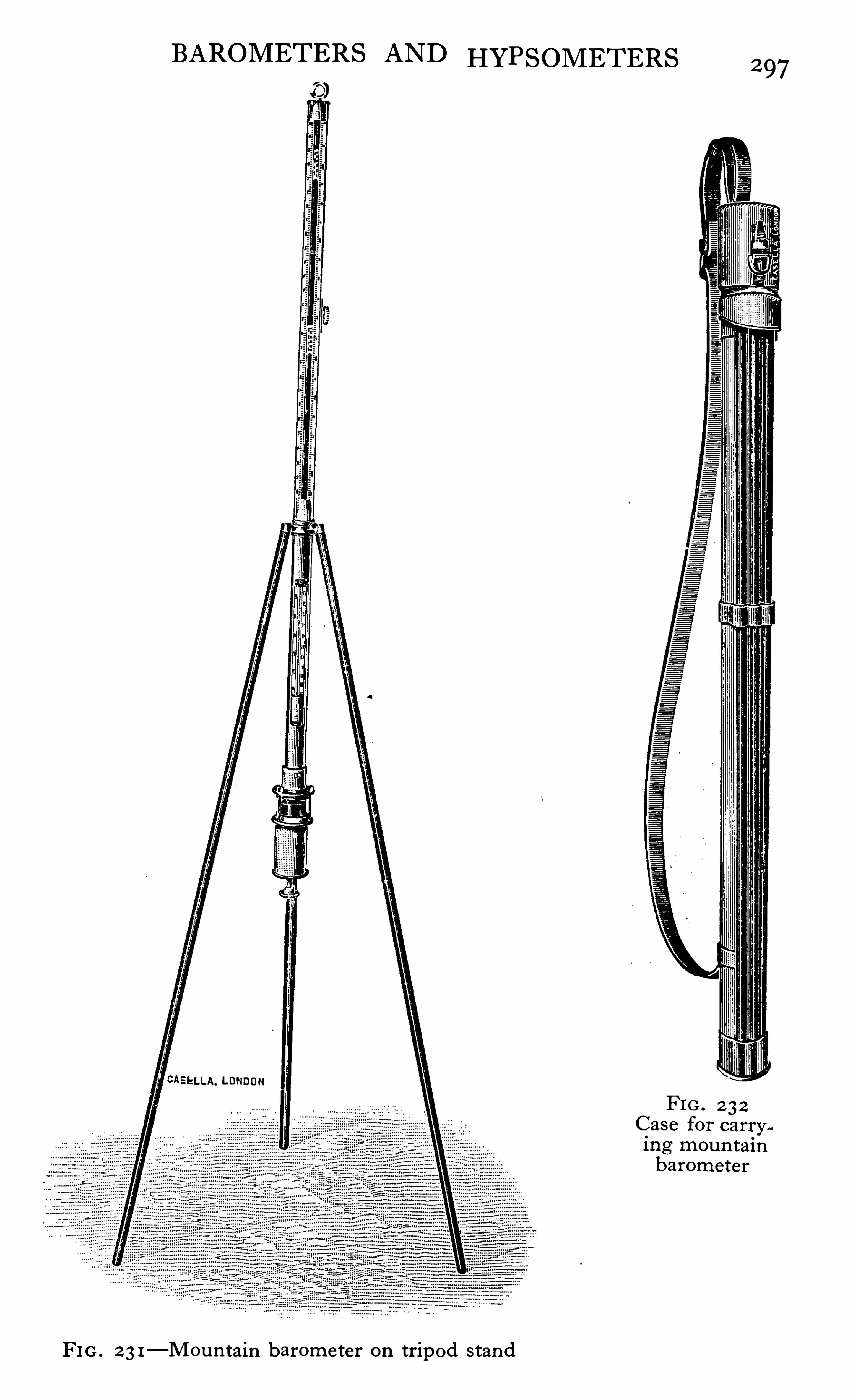
BAROMETERS AND HYPSOMETERS
EELLA. LONDON
FIG . 2 3 1—Mou n tain barometer on tripod s tand
2 97
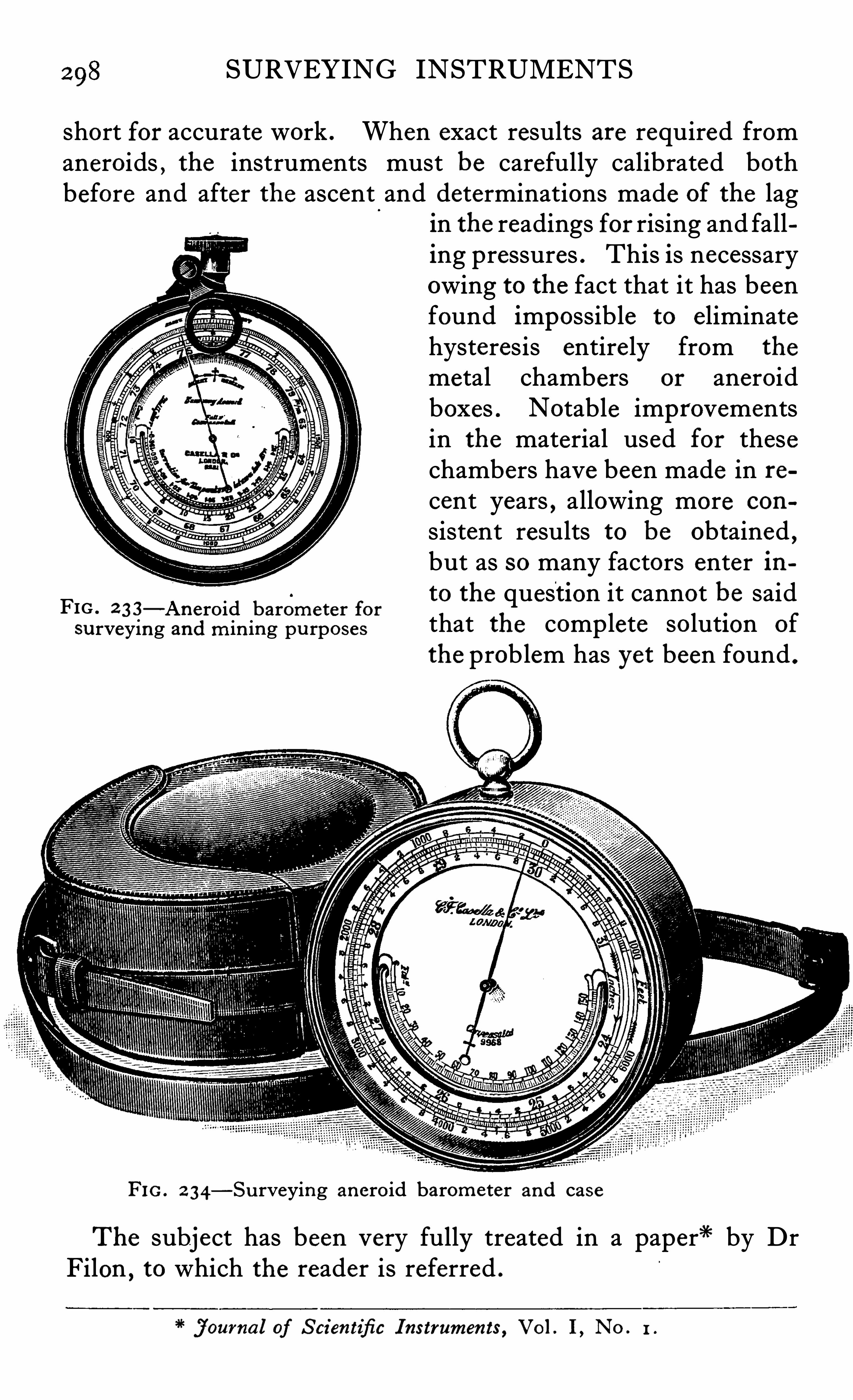
SURVEYING INSTRUMENTS
short for accurate work . When exact results are required fromaneroids , the instruments must be carefully calibrated bothbefore and after the ascent and determinations made of the lag
FIG . 2 3 3—Anero id barometer for
su rveying and min ing pu rposes
in the readings for rising and falling pressures . This is necessaryowing to the fact that it has beenfound impossible to eliminatehysteresis entirely from the
metal chambers or aneroidboxes . Notable improvementsin the material used for thesechambers have been made in recent years , allowing more con
sistent results to be obtained,
but as so many factors enter into the question it cannot be saidthat the complete solution of
the problem has yet been found .
FIG . 2 34—Su rveying anero id barometer and case
The subject has been very fully treated in a paper" by DrFilon , to which the reader is referred .
j ourna l of S cientifi c I nstrumen ts , Vo l . I , No . 1 .
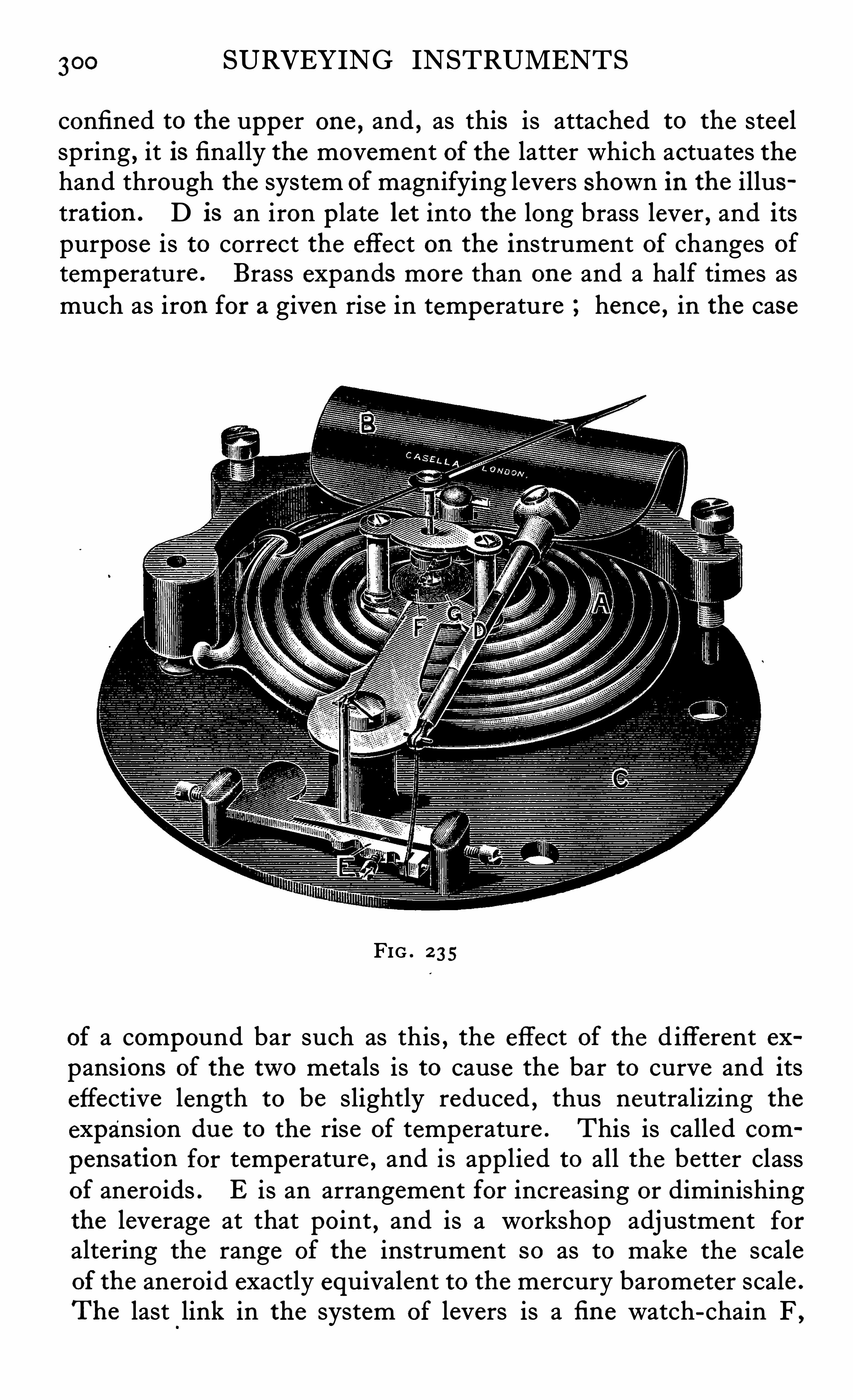
300 SURVEYING INSTRUMENTS
confined to the upper one , and , as this is attached to the steelspring
,it is finally the movement of the latter which actuates the
hand through the system of magnifying levers shown in the illustration .
D is an iron plate let into the long brass lever , and itspurpose is to correct the effect on the instrument of changes oftemperature .
Brass expands more than one and a half times asmuch as iron for a given rise in temperature hence , in the case
FIG . 2 3 5
of a compound bar such as this , the effect of the d ifferent expansions of the two metals is to cause the bar to curve and itseffective length to be slightly reduced , thus neutralizing the
expansion du e to the rise of temperature . This is called com
pensation for temperature , and is applied to all the better classof aneroids . E is an arrangement for increasing or diminishingthe leverage at that point , and is a workshop adjustment foraltering the range of the instrument so as to make the scaleof the aneroid exactly equivalent to the mercury barometer scale .
The last link in the system of levers is a fi ne watch-chain F ,
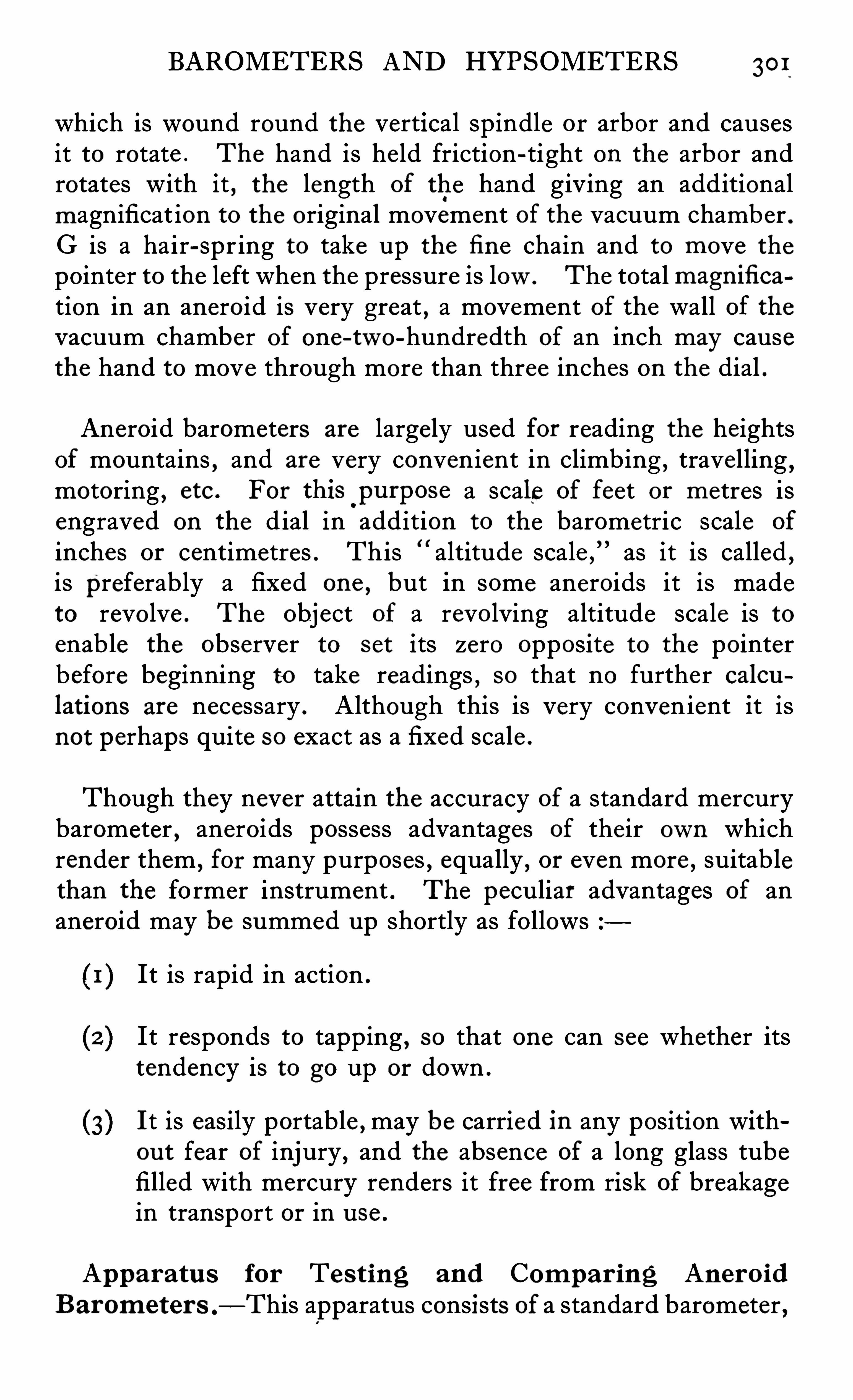
BAROMETERS AND HYPSOMETERS 30 1
which is wound round the vertical spindle or arbor and causesit to rotate . The hand is he ld friction-tight on the arbor androtates with it , the length of the hand giving an additionalmagnificat ion to the original movement of the vacuum chamber .G is a hair-spr ing to take up the fi ne chain and to move the
pointer to the left when the pressure is low. The total magn ifi ca
tion in an aneroid is very great , a movement of the wall of thevacuum chamber of one-two-hundredth of an inch may causethe hand to move through more than three inches on the dial .
Aneroid barometers are largely used for reading the heightsof mountains
,and are very convenient in climbing , travelling ,
motoring , etc . For thisOpu rpose a scale of feet or metres is
engraved on the dial in addition to the barometric scale of
inche s or centimetres . This “ altitude scale ,” as it is called ,
is preferably a fixed one,but in some aneroids it is made
to revolve . The object of a revolving altitude scale is toenable the observer to set its zero opposite to the pointerbefore beginning to take readings , so that no further calcu
lations are necessary . Although this is very convenient it isnot perhaps quite so exact as a fixed scale .
Though they never attain the accuracy of a standard mercurybarometer , aneroids possess advantages of their own whichrender them ,
for many purposes , equally , or even more , suitablethan the fo rmer instrument . The peculiar advantages of ananeroid may be summed up shortly as follows
It is rapid in action .
It responds to tapping,so that one can see whether its
tendency is to go up or down .
It is easily portable , may be carried in any position withou t fear of injury , and the absence of a long glass tubefilled with mercury renders it free from risk of breakagein transport or in u se .
Apparatu s for Tes t ing and Compar ing AneroidB arometer s .
—This apparatus consists of a standard barometer ,
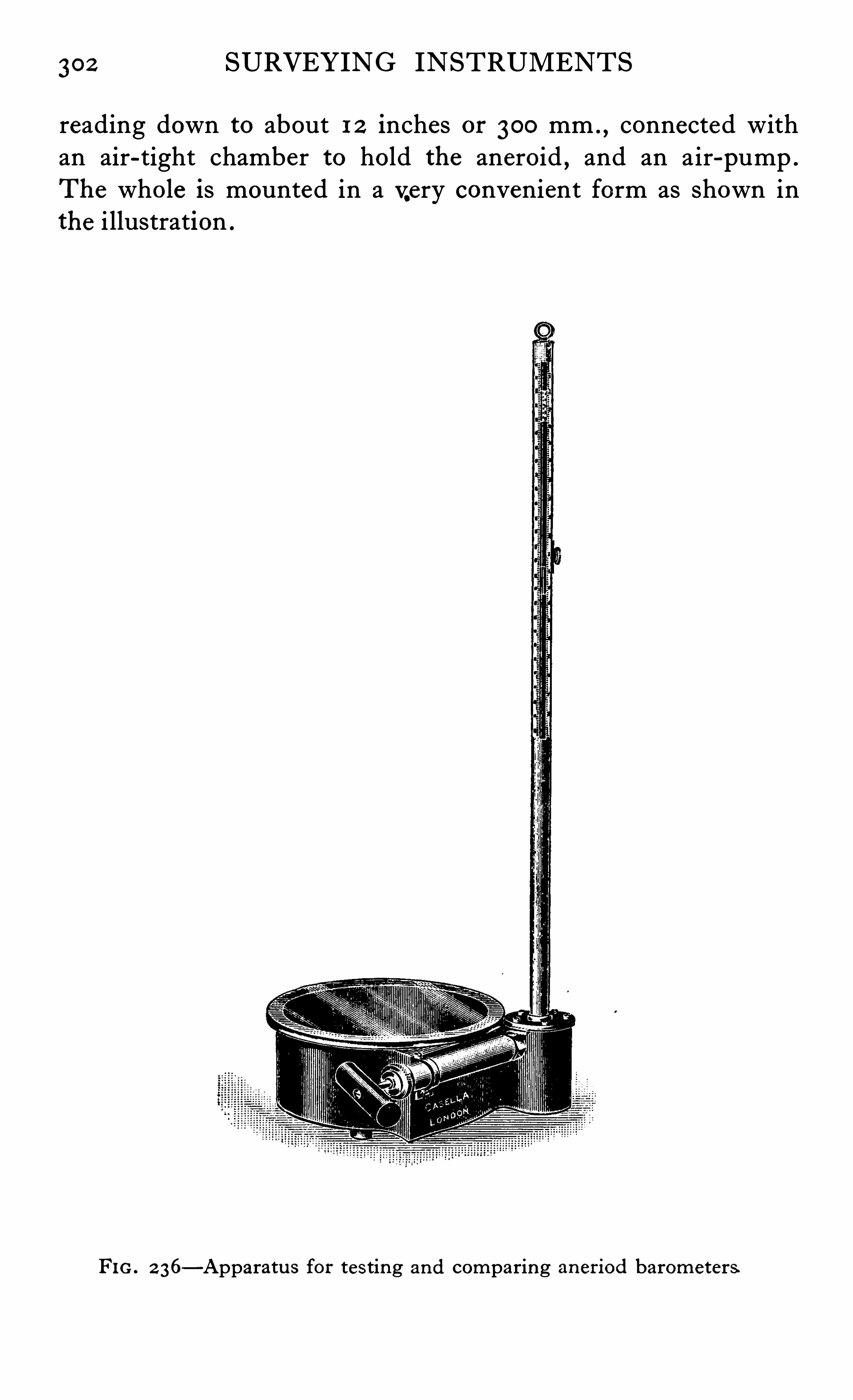
362 SURVEYING INSTRUMENTS
reading down to about 1 2 inches or 300 mm . ,connected with
an air-tight chamber to hold the aneroid,and an air-pump .
The whole is mounted in a very convenient form as shown inthe i llustration .
FIG . 2 36—Apparatu s for tes ting and comparing aneriod barometers

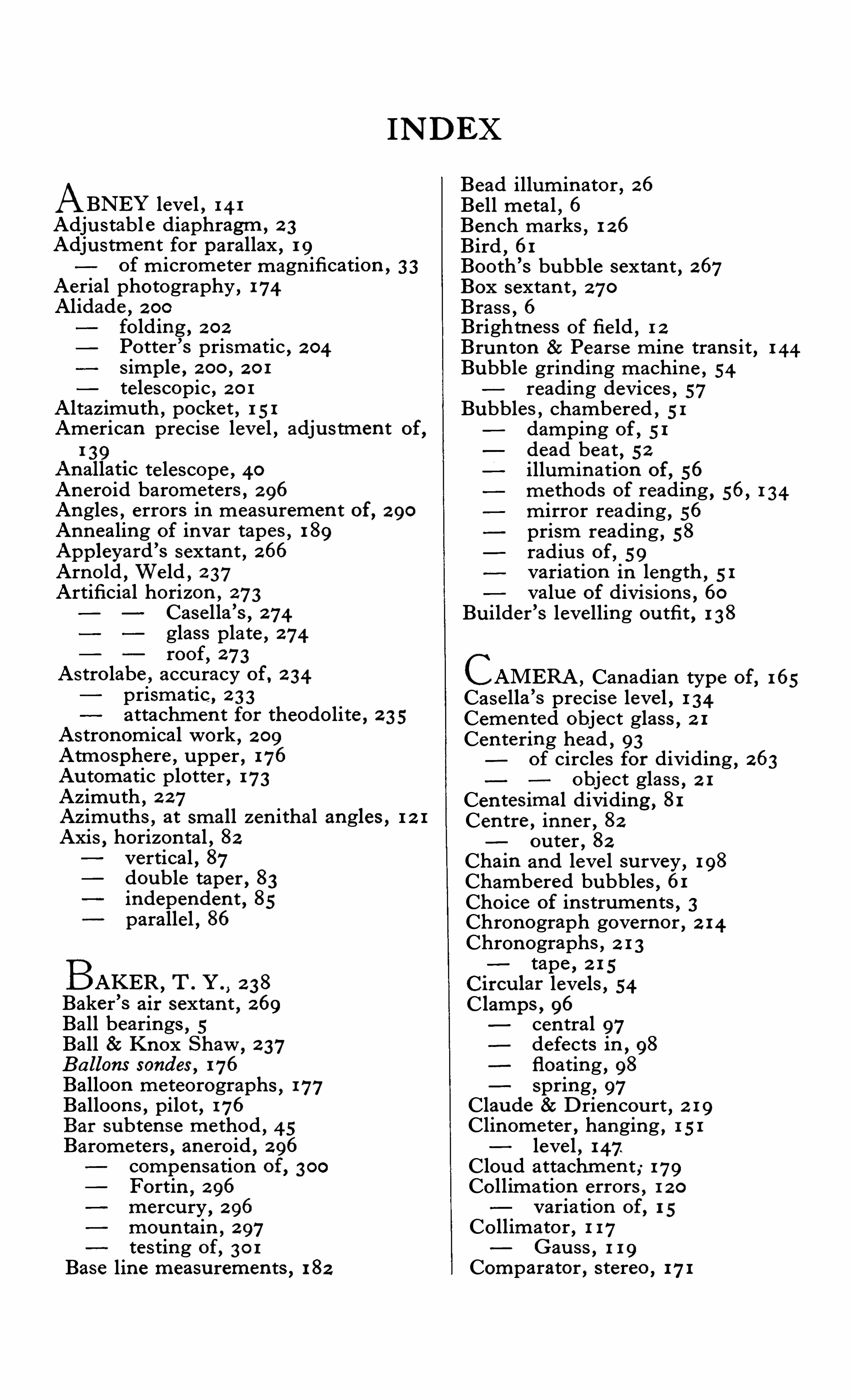
INDEX
ABNEY leve l , 14 1Adju stabl e diaphragm , 2 3Adjus tm en t for parallax , 1 9
of m icrometer magn ification , 3 3
Aerial photography , 174Alidade , 2 00fo lding , 2 02Po tter ’s prismatic , 2 04
s imple , 2 00 , 2 0 1te lescopic , 2 0 1Altazimu th , pocket , 1 51American precise leve l , adju s tmen t of,
1 39Anal latic te lescope , 40
Aneroid barometers , 2 96Angles , errors in measu remen t of, 2 90Annealing of invar tapes , 1 89App leyard
’
s sextan t , 266Arno ld
,We ld , 2 37
Artificial horizon , 273Case lla ’s
, 274glass plate , 274roof, 273As tro labe , accu racy of, 2 34prismatic , 2 3 3
attachmen t for theodo lite , 2 3 5Astronomical work , 2 09Atmosphere , u pper , 176Au tomatic plotter
,173
Azimu th , 2 27Azimu ths , at small zen ithal angles , 1 2 1Axis
,horizon tal
,82
vertical,87double taper , 83independen t , 85parallel , 86
BAKER ,T . Y . , 2 38Baker ’s air sextan t , 269Ball bearings , 5Ball Sc Knox Shaw
, 2 37B a llons sondes , 176Balloon me teorographs
,177Balloon s , pilot , 176
Bar subten se method, 45Barometers
,anero id
, 2 96compen sation of, 3 00Fortin, 2 96
mercu ry, 2 96
moun tain , 2 97tes ting of, 30 1Base line measu remen ts , 1 82
Bead illum inator , 26Be ll meta l , 6Ben ch marks,1 26
Bird,61
Booth ’s bubble sextan t , 267Box sextan t , 270Bras s
,6
Brightne ss of fie ld , 1 2Brun ton Pearse m ine tran s it , 1 44Bubble grinding machin e , 54reading devices , 57Bubbles , chambered , 51damping of , 5 1dead beat , 52illum ination of, 56
methods of reading , 56, 1 34mirror reading , 56prism reading , 58radiu s of , 59variation in length , 5 1valu e of div is ions , 60
Bu ilder ’s levelling ou tfit , 1 38
CAMERA ,Canadian type of
,165
Case lla ’
s precise leve l , 1 34Cemen ted object glass , 2 1Cen tering head , 93
of circles for dividing , 263object glass , 2 1
Cen tes imal dividing , 81Cen tre , inner , 82
ou ter , 82Chain and leve l su rvey , 198Chambered bubbles , 61Cho ice of in s trumen ts , 3Chronograph governor , 2 14Chronographs , 2 1 3tape , 2 1 5ircu lar leve ls , 54C lamps , 96cen tral 97defects in , 98
floating , 98Spring , 97
Clau de Drien cou rt , 2 19Clinome ter , hanging , 1 5 1leve l , 147.Clou d attachm en t ; 179Co llimation errors , 1 2 0variation of, 1 5Co llimator
,1 17
Gau ss,1 1 9
Comparator , s tereo ,171
INDEX
Compass , hanging , 1 5 1military , 1 50prismatic , 148trough , 2 08
Compen sation of barome ters , 300Con tou r lines , 1 97Con tou rs , 173Con tro l poin ts , 1 82
DAMPING of bubbles , 51Deville , 160Dial , m in ing , 2 89D iaphragm extractor , 2 3Diaphragms , 2 1
adju s table , 2 3glass , filming of, 1 06replaceable moun ting for , 2 3re-webbing of, 2 5Diagon al eyepiece , 2 0
Din e s , W . H . , 176Dip Circle , 2 44adju s tmen t of, 2 45Goolden
’
s, 2 48Dip indu ctor , 2 47
Schu s ter ’s 2 55D ivided circles , materials for , 72Dividing,cen tes imal , 81
on Specu lum metal , 73s ide illumination of, 1 09Dividing engines , 66compensation of errors , 69compen sation apparatu s , 65cu tting teeth of, 67
errors of, 69, 79Ramsden ’
s 64regu lation of, 65speed of working , 72Divis ion s , thickne ss of , 73
of bubble , valu e of, 60
of leve l , valu e of, 62Dollond , 8Double reading m icrometer , 3 2theodolite , ten in ch , 193Due de Chau lnes , 62Dumpy leve l , 1 27
adju s tmen t of, 1 2 9American precise , 1 37Case lla ’s totally enclosed ,
1 34.tilting
,1 34
EARTH ,radiu s of
, 2 4 2
Electrical illum ination of theodolite ,1 09Elim ination of parallax , 1 3Erecting eyepiece , 18 ICE bar apparatu s , 1 83Errors , cen tering , 2 93 I llum inator , bead , 26
in dividing engine , 69 I llumination of bubbles , 56
Errors , in s trumen tal, 2 90
observer ’s , 2 90 , 2 94of eccen tricity
, 2 91probable , 2 93Es timating m icroscope , 2 8Ether for leve ls , 5 1Eyepiece , diagonal , 2 0Extracto r for diaphragm
, 2 3Eyepiece , erecting , 1 8
inverting , 1 8orthoscopic
,1 8
Ramsden , 19m icrometer
, 47
FIELD of View,1 2 2
brightness of, 1 2
Film ing of glass su rface s , 1 06Fin ish of in s trumen ts , 7Fitting of spider webs
, 2 4Flemer , on photographic su rveying , 163Flexu re
,84Focu s , short , 37Focus ing dis tance ,
m in imum, 36Foot plate for s taff
,1 57
screws, 90Fortin barometer , 2 96Fou r-screw base , 91Frame for spider webs
, 2 5
GAUSS collimation method,1 1 8
Geodetic su rveying , 1 81Governors for chronograph
, 2 14Gradien ter screw ,
1 03Graduation of in strumen ts
, 61
Graham , 61
Gradien t te lemeter level , 140Gravity
, 2 40
Gun metal , 6
HADLEY , 2 57Hanging level , 1 47He liotrope , 2 2 8
He lmho ltz , 8Heyde ’
s micrometer , 1 1 1Hooke , 62—2 57Horrebow-Talcott method , 2 19Horizon s , artificial , 273Horizon tal axis , 82compon en t of force , 2 52Hugershaft 8c Cranz , 175Hypsome ters , 3 03
368 INDEX
Perambu lator , 1 53Performan ce of in strumen ts , 1 2 1Philade lphia rod,1 56Photographic su rvey ing , dry plates employed , 169
measu remen t of base , 170Pho togrammetry , 1 59Photographs at an angle to the horizon ,
168
inclined,175Photography , aerial , 174Photo-theodo lite , adju s tmen t of, 166Bridges-Lee ,
163Pilo t Balloon s,176Plane Table , 1 99
advan tage s of, 2 00ro ller , 2 03Plate , theodolite , 82
Plotter,au tomatic
,173
s tereo,173Plotting by in ters ection , 174Plumb bob ,pos ition of
,87Plumbing apparatu s for m in es , 2 84three wire , 2 86
two wire, 2 85
Optical, 2 83Plummet , accu racy of
, 2 94Po les,ranging , 1 58Potter ’s alidade . 2 04Porro ,8, 38Precise leve lling s taff, 1 56tilting leve l , 1 34Prismatic astro labe , 2 3 3compas s , 1 48
RAD IUS of bu bbles , 59of the earth
, 2 4 2
Railway theodolite , 95Ramsden ,
63Ram sden ’
s engin e , 64Ram sden eyepiece ,
1 9Ranging po les , 1 58
support for 48Readers
, 26
Reading len s , e lectrically illuminated ,27m icrome ters , 27
Readings in con s is ten t , 2 94Recording theodo lite , 177Redu ction of we ight
, 5Ree l for invar tape
,1 88
Reeves , E . A., 2 4
his tangen t m icrometer , 196Resolving power , 1 0Re-webbing diaphragm
, 2 5Rigid bar me thod
,1 82
Roemer , 62Ross
, 64
SEA,observation s for dip at
, 2 47valu e of gravity at, 2 4 2
Secondary triangu lation , 194Sextan t , 2 57
adju stmen t of, 2 57App leyard
’
s, 266Baker ’s air
, 269Britann ia, 260
Booth ’s bubble , 267box , 270endless tangen t screw for , 265horizon glass shades for
, 264index glas s for , 261ris ing piece for , 262Short focu s adju s tmen t , 37S ights , inclined , 44S imon
’
s leve l,1 34
Sis son,61
Socket , 82Spider webs , fitting of, 2 4frame for
, 2 5Spirit leve ls , 49Squ are , optical , 144Stadia readings , 4 2Stand , ball and socke t of, 1 03fo lding
,1 03
shoes for , 1 00tripod, 99
Staff,ho lder for , 1 58leve l for , 1 57protector for
,1 58target levelling , 1 56
Stars , lis t of, 2 39Staves , leve lling , 1 54inverted figu res for , 1 58Steel band tape ,
199for cen tres
,6
Stereo au tograph , 174comparator 171photographic system ,168
plotter,173
Su bten se bar , s imple , 46Indian pattern , 46
Support for ranging pole , 48Su rvey , geodetic , 1 81Su rvey ing , m in e , 2 82
m inor,1 81
chain and leve l , 1 98
TACHEOMETER ,8 1
Jeffco tt ’s , 1 0 5Talcott me thod
, 2 19Tangen t screw , 96
endles s , 265floating , 99
Tape,s tee l band , 1 99thermome ter for , 190s tretching apparatu s , 1 84 ,
1 89
INDEX
apes , annealing of, 189correction s for , 1 85length of, 1 84s tee l , 1 84
argers , 2 3 1aylor , Wilfrid , 16elescope , anallatic , 40illum ination of
,1 1 1
S ize of, 5, 1 2zen ith , 2 2 0ertiary triangu lation ,
194heodolite , adju stmen t of, 1 14
auxiliary te lescope for , 2 82dou ble reading microme ter for ,1 06
e lectrical illumination of,1 09
for primary triangu lation ,191horizon tal axis , 82
independen t axis , 84inn er cen tre , 82limb
,82
m in ing , 2 82ou ter cen tre , 82plate ,
82
paralle l axis , 85railway , 95mi crometer , 1 1 0recording , 177
section of s ix inch,1 2 5
se lf-checking , 81s izes of, 8 1
socket , 82taper axis , 83ten inch double-reading
,193vertical axis
,82
with eccen tric te lescope , 1 2 2hermometer , tape , 190m e , 2 09by sextan t
, 2 09wire les s , 275Opogrqphy . 197ran s i t ins trumen t , adj u stmen t of, 2 17
e lbow, 2 1 1large 2 1 0
small , 2 1 2theodo lite, 81
riangles , lengths of s ides , 191ri angu lation ,
1 90
secondary,1 94tertiary
,1 94tower , 2 3 2
Trocheameter , 1 52Trou gh compass
, 2 08
Two-screw base , 92Tu rn ing po in t
, 1 57
NDULATOR, 2 80
LEVEL , 1 27adju stmen t of , 1 3 1fou r-screw ,
1 3 2
ZENITH te le scope , 2 2 0tu be , 2 2 3
U
VACUUM chamber of aneroid , 2 99Valu e of leve l divi s ions
, 52
Variation of co llimation, 1 5latitu de , 2 2 4
Vern ier , 27beve lled , 74calcu lation s for, 78correction s for,80
edge reading, 74
flat , 75with s ide zero , 77Vern iers , 27form s of
, 73examples of
, 77mean of two , 2 92
me thods of figu ring , 76Verschoy le
’
s pocket tran s it , 147Vertical axis , 82
adju s tmen t of, 87en clo sed type , 90
Vibration experimen t , 2 53
VVEBS,illum ination of, 2 6
We ight , redu ction of, 5
to be carried, 3
Wireless con tinuou s wave , 276lis t of s tation s, 2 80rhythm ic s ignals , 276
spark sy s tem , 278time s ignals, 275