Embed Size (px)
Citation preview

Chaos, Solitons and Fractals 21 (2004) 999–1011
www.elsevier.com/locate/chaos
Synchronization of uncertain chaotic systems viabackstepping approach
Samuel Bowong a,*, F.M. Moukam Kakmeni b
a INRIA Lorraine, Project CONGE, I.S.G.M.P. Bat A, Ile de Saulcy, 57045 Metz Cedex 01, Franceb Laboratoire de M�ecanique, D�epartement de Physique, Facult�e des Sciences, Universit�e de Yaound�e I, B.P. 812 Yaound�e, Cameroon
Accepted 8 December 2003
Abstract
In this paper, adaptive synchronization of two uncertain chaotic systems is presented using adaptive backstepping
approach. The master system is any smooth nonlinear chaotic system, while the slave system is a nonlinear chaotic
system in the feedback form. Global stability and exponential synchronization between the master and slave systems
can be achieved. The proposed approach offers a systematic design procedure for adaptive synchronization of a large
class of continuous-time chaotic systems in the chaos research literature. Computer simulations are provided to verify
the operation of the designed synchronization scheme.
� 2004 Elsevier Ltd. All rights reserved.
1. Introduction
Motivated by potential applications in physics, electrical engineering, communication theory and many other fields,
the synchronization of chaotic systems has received an increasing interest [1–8]. It has been shown that two chaotic
systems exhibit identical oscillations, i.e., synchronization error tends to zero for all tP 0 [1]. But despite the amount of
theoretical and experimental results already obtained, chaos synchronization seems difficult task, over all if we think
that: (i) due to sensitive dependence of chaos on initial conditions, it is almost impossible to reduce the same starting
conditions, (ii) in matching exactly the master and slave systems, even infinitesimal parametric variations of any model
will eventually result in divergence of orbits starting nearby each other, and (iii) parametric differences between chaotic
systems (for instance, due to inaccuracy design or time variations) yield different attractors. To avoid these problems,
some strategies have been reported (see [3,4,7,9,11–14], and references therein). In particular, several authors have
reported adaptively estimation techniques. These techniques present an acceptable performance and allow synchro-
nization, although the parameters are not known [9,12,14] or they are time-varying [3,4,7,11,13]. But the only drawback
of these strategies is that the structure of parameters for a given model must be known. Although the structure of the
parameters can be known in some cases, it would be desirable to have a scheme to achieve synchronization even if slave
oscillator has little prior knowledge about the master system. This necessity of robustness can be required in some
systems (for instance, the multimode laser, animal gait or oscillatory neural systems).
In this paper, an algorithm for the adaptive chaos synchronization is developed. In particular, the synchronization
problem is interpreted as a stabilization one. The goal is to stabilize, at the origin, the discrepancy between the drive and
response systems. Discrepancy is defined as the dynamical differences between the drive and response systems and
include: (1) model mismatches, which means that the model of the drive system might not be the same as that of the
* Corresponding author. Address: B.P. 12639 Yaound�e, Cameroon. Tel.: +237-996-41-64/785-5788; fax: +237-231-9584.
E-mail addresses: [email protected] (S. Bowong), [email protected] (F.M. Moukam Kakmeni).
0960-0779/$ - see front matter � 2004 Elsevier Ltd. All rights reserved.
doi:10.1016/j.chaos.2003.12.084

1000 S. Bowong, F.M. Moukam Kakmeni / Chaos, Solitons and Fractals 21 (2004) 999–1011
response system; (2) unknown initial conditions, which implies that the time series of the master system cannot be equal
to that for the slave system; and (3) parametric uncertainty, which means that the slave system could be constructed
with inaccuracies [10].
In order to design the stabilizing feedback, the discrepancy system is transformed into a canonical form via geo-
metrical tools [15]. The main idea behind our proposal is, departing from the discrepancy system, to construct an
extended nonlinear system which should be dynamically equivalent to the canonical representation. In this way, the
discrepancy is lumped into a nonlinear function, which is rewritten into the extended nonlinear system as a state
variable [9,10]. The nonlinear feedback is designed from a simple algorithm based on backstepping approach. Back-
stepping design is a recursive procedure that combines the choice of a Lyapunov function with the design of a controller
[16]. By using the results reported by Teel and Praly [17], an observer can be constructed to get an estimated value of the
lumping nonlinear function via the augmented state variable.
Compared with the existing results in the literature, there are two advantages which make this approach attractive.
First, a systematic design procedure for adaptive synchronization is presented for a wide class of nonlinear systems with
many types of uncertainties, including most of the continuous-time chaotic and hyper-chaotic systems in the literature.
Second, it needs only one controller to realize synchronization between chaotic systems and it is easy to implemented.
The rest of the paper is organized as follows. The problem formulation is presented in Section 2. Adaptive back-
stepping is extended to the adaptive synchronization problem in Section 3. Here it is shown that the proposed design
algorithm yields robust adaptive feedback which leads to chaos synchronization in spite of the master and slave model
being nonidentical. In Section 4, two illustrative examples are presented. (1) The Chua oscillator is used to show that the
synchronization is attained in spite of parametric master/slave mismatches. (2) Two second-order driven oscillators are
presented to show that the synchronization can been achieved in spite of a strictly different model, which results in
different master/slave dynamics. Section 5 contains the conclusion.
2. Problem formulation
Consider the master system of nonlinear (chaotic) system as
_xm ¼ fmðxm; pm; tÞym ¼ x1m
�ð1Þ
where xm ¼ ½x1m; x2m; . . . ; xnm�T 2 Rn is the state vector; ym 2 R is the output, pm is the vector of unknown constant
parameters; and fm is an unknown smooth nonlinear function uniformly bounded in t.The slave system is in the form of feedback nonlinear (chaotic) system as
_xs ¼ fsðxs; t; psÞ þ Buys ¼ x1s
�ð2Þ
where xs ¼ ½x1s; x2s; . . . ; xns�T 2 Rn, ys 2 R and u 2 R are the state vector, output and control action, respectively; ps is the
vector of unknown constant parameters; and fs is an unknown smooth nonlinear function uniformly bounded in t andB a constant vector which defines the control channel.
The problem is to design an adaptive synchronization algorithm u to guarantee robust global stability and force the
states of the slave system (2) to exponentially synchronize with the states of the master system (1) despite modelling
errors, parameter variations, perturbing external forces and time lacks in the actuators, i.e., to achieve
limt!1
xs ¼ xm ð3Þ
Consider the variable e ¼ xs xm which is the measure of the nearness of the master system to the slave system.
Introducing e in Eq. (2), we obtain the following equation:
_e ¼ fsðeþ xm; t; psÞ fmðxm; t; pmÞ þ Buye ¼ e1
�ð4Þ
where ye is the system error output. The synchronization is achieved when e goes to zero as t increases or, practically, isless than a given precision.
Now, let us define a coordinates transformation z ¼ UðeÞ such that the synchronization error system (4) can be
globally transformed into the canonical form [15]

S. Bowong, F.M. Moukam Kakmeni / Chaos, Solitons and Fractals 21 (2004) 999–1011 1001
_zi ¼ ziþ1; i ¼ 1; 2; . . . ; q 1
_zq ¼ aðz; mÞ þ u
_m ¼ fðz; mÞy ¼ z1
8>>><>>>:
ð5Þ
where y is the system output, q is the relative degree of the synchronization error system (i.e., the lowest order time-
derivative such that the control command u is directly related to the output y) and m 2 Rnq is the unobservable state
vector (internal dynamics).
Often, the constant matrix B can be selected to make possible the transform from (4) to the assumed format (5).
The following must be pointed out. System (5) is very general, which contains most well known chaotic systems, and
some special models for chaotic systems like those proposed in [18]. For example, the Lorenz dynamical, the Rossler
system, and several types of Chua’s circuits can be transformed into the canonical form with a relative degree q < n. Onthe other hand, an nonautonomous second-order chaotic system such as Duffing oscillator and Van der Pol system can
be written as the canonical form with q ¼ n. In addition, if q ¼ n, the transformed system (5) is the so-called fully
linearizable nonlinear system, and if q < n, the system (5) is called a partially linearizable nonlinear system. Finally, if
the dynamical subsystem _m ¼ fð0; mÞ is asymptotically stable, we will say that the system (5) is minimum-phase [15].
However, several interesting chaotic systems are so-called minimum-phase.
Nevertheless, since the vector fields fmðxm; t; pmÞ and fsðxs; t; psÞ are uncertain, the coordinates transformation
z ¼ UðeÞ, bringing the error system (4) into the canonical form (5), is uncertain. In principle, since the coordinates
transformation is a diffeomorphism, one can suppose that the uncertain transformation exists and it is invertible.
However, since UðeÞ is uncertain, the nonlinear function aðz; mÞ is uncertain. The sources of such uncertainties could be
parameter mismatching, unknown initial conditions, or structural differences between models of master and slave
systems.
In the next section, the detailed design procedure of the feedback control law u is described with detailed expla-
nations.
3. Adaptive synchronization via backstepping
In order to design an adaptive synchronization algorithm to achieve objective (3), adaptive backstepping is em-
ployed. We present a robust control design for synchronizing uncertain chaotic systems in canonical form (5). The main
idea is to construct a dynamically equivalent system which is itself uncertain. Dynamic output feedback is applied to
perform chaos synchronization in spite of modelling errors, parameter variations, perturbing external forces and time
lack in the actuators.
3.1. Stability analysis
To describe the new design and analysis, the following assumptions are needed:
1. Only the system output y ¼ z1 is available for feedback.2. The nonlinear function aðz; mÞ is uncertain.3. The system (5) is minimum-phase.
Comments regarding the above assumptions are in order. The first assumption is realistic because in most cases only
one state is available for feedback from the coding (master) as well as the decoding (slave) circuit. For instance, in the
secure communication case only the transmitted signal x1m, and receiver signal, x1s are available for feedback from
measurements. Another example can be found in neuron synchronization where the master neuron transmits a scalar
signal. The slave neuron tracks the signal of the master neuron. Concerning the second assumption, we claim that it is a
general and practical situation because the term aðz; mÞ involves the differences in the master as well as slave systems.
The source of such uncertainties are: (i) unknown values of the model parameters or time-varying parameters; (ii) since
the master and slave systems are chaotic, their trajectories depend on the initial conditions which are often unknown
and (iii) structural differences between models of the master and slave systems. Regarding the third assumption,
minimum-phase implies that the zero dynamics fð0; mÞ converges to an attractor. In other words, the closed system is
internally stable [9]. From the control view-point this is a strong assumption. But this is reasonable for the boundness of
chaotic attractor in state space and the interaction of all the trajectories inside the attractor. So when we have taken
1002 S. Bowong, F.M. Moukam Kakmeni / Chaos, Solitons and Fractals 21 (2004) 999–1011
actions to achieve lim zi ! 0, i ¼ 1; . . . ; q 1, the part fðz; mÞ ! fð0; mÞ ! 0 asymptotically for the so-called minimum-
phase character.
Thus, let us define g ¼ Hðz; mÞ. Then, there exists a time-invariant manifold wðz; g; m; uÞ ¼ 0 such that the solution of
system (5) is a projection of the solution of the following dynamical system:
_zi ¼ ziþ1; 16 i6 q 1
_zq ¼ g þ u_g ¼ Nðz; g; m; uÞ_m ¼ fðz; mÞy ¼ z1
8>>>><>>>>:
ð6Þ
where
Nðz; g; m; uÞ ¼Xq1k¼1
zkþ1okHðz; mÞ þ ðg þ uÞoqHðz; mÞ þ omHðz; mÞfðz; mÞ
with okHðz; mÞ ¼ oHðz; mÞ=ok , and omHðz; mÞ ¼ oHðz; mÞ=om, i.e., system (6) is dynamically equivalent to system (5). It must
be pointed out that the manifold wðz; g; m; uÞ ¼ g Hðz; mÞ ¼ 0 is, by definition, time-invariant. In fact, it is straight-
forward to prove that the set
W ¼ wðz; g; m; uÞ(
¼ g Hðz; mÞ;
_g ¼Xq1k¼1
zkþ1okHðz; mÞ þ ðg þ uÞoqHðz; mÞ þ omHðz; mÞfðz; mÞ)
satisfies dw=dt ¼ 0 for all tP 0. Now, from the equality wðz; g; m; uÞ ¼ 0 and condition dw=dt ¼ 0, one can take the first
integral of system (6) to get g ¼ Hðz; mÞ. When the first integral is back-substituted into system (6), we obtain the
solution of system (5). Hence, the solution of system (5) is a projection of system (6) via the module p � ðz; g; mÞ ¼ ðz; mÞ.This is, system (6) is dynamically equivalent to system (5) if initial conditions, ðzð0Þ; gð0Þ; mð0ÞÞ, are contained in
wðz; g; u; mÞ, i.e, the augmented state g provides the dynamics of the uncertain function Hðz; mÞ which involves the
modelling errors, uncertain parameters and the unknown external disturbances.
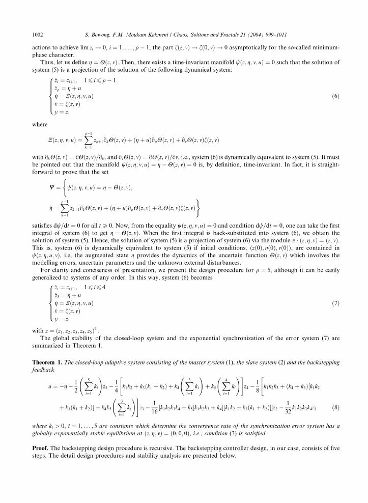
For clarity and conciseness of presentation, we present the design procedure for q ¼ 5, although it can be easily
generalized to systems of any order. In this way, system (6) becomes
_zi ¼ ziþ1; 16 i6 4
_z5 ¼ g þ u_g ¼ Nðz; g; m; uÞ_m ¼ fðz; mÞy ¼ z1
8>>>><>>>>:
ð7Þ
with z ¼ ðz1; z2; z3; z4; z5ÞT.The global stability of the closed-loop system and the exponential synchronization of the error system (7) are
summarized in Theorem 1.
Theorem 1. The closed-loop adaptive system consisting of the master system (1), the slave system (2) and the backsteppingfeedback
u ¼ g 1
2
X5i¼1
ki
!z5
1
4k1k2
"þ k3ðk1 þ k2Þ þ k4
X3i¼1
ki
!þ k5
X4i¼1
ki
!#z4
1
8k1k2k3
"þ ðk4 þ k5Þ½k1k2
þ k3ðk1 þ k2Þ� þ k4k5X3i¼1
ki
!#z3
1
16½k1k2k3k4 þ k5½k1k2k3 þ k4�½k1k2 þ k3ðk1 þ k2Þ��z2
1
32k1k2k3k4z1 ð8Þ
where ki > 0, i ¼ 1; . . . ; 5 are constants which determine the convergence rate of the synchronization error system has aglobally exponentially stable equilibrium at ðz; g; mÞ ¼ ð0; 0; 0Þ, i.e., condition (3) is satisfied.
Proof. The backstepping design procedure is recursive. The backstepping controller design, in our case, consists of five
steps. The detail design procedures and stability analysis are presented below.
S. Bowong, F.M. Moukam Kakmeni / Chaos, Solitons and Fractals 21 (2004) 999–1011 1003
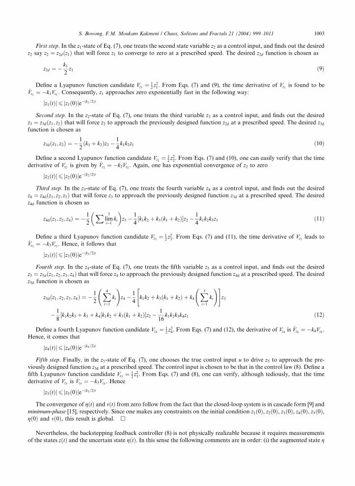
First step. In the z1-state of Eq. (7), one treats the second state variable z2 as a control input, and finds out the desiredz2 say z2 ¼ z2dðz1Þ that will force z1 to converge to zero at a prescribed speed. The desired z2d function is chosen as
z2d ¼ k12z1 ð9Þ
Define a Lyapunov function candidate Vz1 ¼ 12z21. From Eqs. (7) and (9), the time derivative of Vz1 is found to be
_Vz1 ¼ k1Vz1 . Consequently, z1 approaches zero exponentially fast in the following way:
jz1ðtÞj6 jz1ð0Þjeðk1=2Þt
Second step. In the z2-state of Eq. (7), one treats the third variable z3 as a control input, and finds out the desired
z3 ¼ z3dðz1; z2Þ that will force z2 to approach the previously designed function z2d at a prescribed speed. The desired z3dfunction is chosen as
z3dðz1; z2Þ ¼ 1
2ðk1 þ k2Þz2
1
4k1k2z1 ð10Þ
Define a second Lyapunov function candidate Vz2 ¼ 12z22. From Eqs. (7) and (10), one can easily verify that the time
derivative of Vz2 is given by _Vz2 ¼ k2Vz2 . Again, one has exponential convergence of z2 to zero
jz2ðtÞj6 jz2ð0Þjeðk2=2Þt
Third step. In the z3-state of Eq. (7), one treats the fourth variable z4 as a control input, and finds out the desired
z4 ¼ z4dðz1; z2; z3Þ that will force z3 to approach the previously designed function z3d at a prescribed speed. The desired
z4d function is chosen as
z4dðz1; z2; z4Þ ¼ 1
2
Xlim3
i¼1ki
�z3
1
4½k1k2 þ k3ðk1 þ k2Þ�z2
1
4k1k2k3z1 ð11Þ
Define a third Lyapunov function candidate Vz3 ¼ 12z23. From Eqs. (7) and (11), the time derivative of Vz3 leads to
_Vz3 ¼ k3Vz3 . Hence, it follows that
jz3ðtÞj6 jz3ð0Þjeðk3=2Þt
Fourth step. In the z4-state of Eq. (7), one treats the fifth variable z5 as a control input, and finds out the desired
z5 ¼ z5dðz1; z2; z3; z4Þ that will force z4 to approach the previously designed function z4d at a prescribed speed. The desiredz5d function is chosen as
z5dðz1; z2; z3; z4Þ ¼ 1
2
X4i¼1
ki
!z4
1
4k1k2
"þ k3ðk1 þ k2Þ þ k4
X3i¼1
ki
!#z3
1
8½k1k2k3 þ k3 þ k4½k1k2 þ k3ðk1 þ k2Þ�z2
1
16k1k2k3k4z1 ð12Þ
Define a fourth Lyapunov function candidate Vz4 ¼ 12z24. From Eqs. (7) and (12), the derivative of Vz4 is _Vz4 ¼ k4Vz4 .
Hence, it comes that
jz4ðtÞj6 jz4ð0Þjeðk4=2Þt
Fifth step. Finally, in the z5-state of Eq. (7), one chooses the true control input u to drive z5 to approach the pre-
viously designed function z5d at a prescribed speed. The control input is chosen to be that in the control law (8). Define a
fifth Lyapunov function candidate Vz5 ¼ 12z25. From Eqs. (7) and (8), one can verify, although tediously, that the time
derivative of Vz5 is _Vz5 ¼ k5Vz5 . Hence
jz5ðtÞj6 jz5ð0Þjeðk5=2Þt
The convergence of gðtÞ and mðtÞ from zero follow from the fact that the closed-loop system is in cascade form [9] and
minimum-phase [15], respectively. Since one makes any constraints on the initial condition z1ð0Þ, z2ð0Þ, z3ð0Þ, z4ð0Þ, z5ð0Þ,gð0Þ and mð0Þ, this result is global. h
Nevertheless, the backstepping feedback controller (8) is not physically realizable because it requires measurements
of the states zðtÞ and the uncertain state gðtÞ. In this sense the following comments are in order: (i) the augmented state g

1004 S. Bowong, F.M. Moukam Kakmeni / Chaos, Solitons and Fractals 21 (2004) 999–1011
is not available for feedback. This fact is obvious because g represents, by definition, the mismatches between master
and slave systems; and (ii) it is desired that only one state z1 ¼ x1s x1m is available for feedback from on-line mea-
surements. Consequently, estimated values of the states ðz; gÞ are required for practical implementation. As it has been
established in [9,14], the problem of estimating ðz; gÞ can be addressed by using high-gain observer. To this end, the
following uncertainty estimator is proposed:
_zi ¼ ziþ1 þ hiCi6ðz1 z1Þ; 16 i6 4
_z5 ¼ g þ uþ h5C56ðz1 z1Þ
_g ¼ h6ðz1 z1Þ
8<: ð13Þ
where z and g are the estimated values of z and g, respectively, Ciq ¼ q!
i!ðqiÞ! and h > 0 is a high-gain parameter which can
be interpreted as the uncertainties estimation rate. Note that the uncertain term Nðz; g; m; uÞ has been neglected in the
construction of the observer (13).
Let ~e 2 R6 be an estimation error vector whose components are defined as follows: ~ei ¼ h5iðzi ziÞ, i ¼ 0; 1; . . . ; 5,and ~e6 ¼ g g. Then, the dynamics of the estimation error can be written as follows:
_~e ¼ hA~eþ Cðz; g; m; uÞ ð14Þ
where Cðz; g; m; uÞ ¼ ½0; . . . ; 0;Nðz; g; m; uÞ�T and the companion matrix is given by
A ¼
C16 1 0 . . . 0
C26 0 1 . . . 0
..
. ... . .
. . .. ..
.
C56 0 0 . . . 1
1 0 0 0 0
266666664
377777775
It is easy to prove that all the eigenvalues of the matrix A are located at 1, i.e., A is a Hurwitz matrix. Since the
trajectories zðtÞ are contained in a chaotic attractor, Cðz; g; m; uÞ is bounded. Consequently, for a large value of the high-gain estimation parameter h, the dynamics of the estimation error, ~e, converges asymptotically to zero, that is, ~e ! 0 as
t ! 1 which implies that ðz; gÞ ! ðz; gÞ.Thus, the backstepping feedback controller (8) with estimation uncertainty becomes
u ¼ g 1
2
Xlim5
i¼1ki
�z5
1
4k1k2
"þ k3ðk1 þ k2Þ þ k4
X3i¼1
ki
!þ k5
X4i¼1
ki
!#z4
1
8k1k2k3
"þ ðk4 þ k5Þ½k1k2 þ k3ðk1 þ k2Þ� þ k4k5
X3i¼1
ki
!#z3
1
16½k1k2k3k4 þ k5½k1k2k3 þ k4�½k1k2 þ k3ðk1 þ k2Þ��z2
1
32k1k2k3k4z1 ð15Þ
Notice that the backstepping controller (15) only uses estimates of Hðz; mÞ (by means g) and z which are provided by
estimator (13). Thus, the modified feedback control law is given by the dynamic compensator (13) and the backstepping
controller (15). It should be pointed out that the output backstepping controller (13), (15) yields practical stabilization,
i.e., the synchronization error system (7) converges to a ball B whose radius is of order of h1. That is, z ! B as t ! 1with rðBÞ ¼ Oðh1Þ.
4. Simulation studies
We present two examples in this section. The first example consists of two third-order systems whose model is similar
but parameter values are different. The aim is to show that the synchronization can be achieved in spite of parametric
variations and to illustrate that the chaotic minimum-phase assumption is satisfied. The second example consists of
two strictly different oscillators. Here, the goal is to show that the synchronization can be attained in spite of model
differences between master and slave systems. We choose two second-order driven oscillators to illustrate this case.
Thus, the drive system is given by the /6-Duffing equation whereas the response system is given by /6-Van der Pol
oscillator.

S. Bowong, F.M. Moukam Kakmeni / Chaos, Solitons and Fractals 21 (2004) 999–1011 1005
4.1. Synchronization in spite of parametric variation
Chua circuit has been chosen to illustrate the proposed synchronization scheme. This oscillator is widely studied as a
carrier for synchronization schemes. The drive system can be written in dimensionless form as follows:
_x1m ¼ p1m½x2m x1m f ðx1mÞ�_x2m ¼ x1m x2m þ x3m_x3m ¼ p2mx2m
8<: ð16Þ
where f ðx1mÞ ¼ p3mx1m þ 1=2ðp4m p3mÞðjx1m þ 1j jx1m 1jÞ. Suppose that the same configuration is used as a re-
sponse system. However, assume that there are differences between the electronic devices (for instance, the nonlinear
resistance). That is, the parameter values of the response system are different than the drive system. In this way the
response system becomes
_x1s ¼ p1s½x2s x1s f ðx1sÞ� þ u_x2s ¼ x1s x2s þ x3s_x3s ¼ p2sx2s
8<: ð17Þ
where f ðx1sÞ ¼ p3sx1s þ 1=2ðp4s p3sÞðjx1s þ 1j jx1s 1jÞ, with ps 6¼ pm and u the control input which has to be chosen.From the differences ei ¼ xis xim, i ¼ 1; 2; 3, the uncertain system (4) can be obtained as follows:
_e1 ¼ p1sðe2 e1Þ p1sf ðe1 þ x1sÞ þ ðp1m p1sÞðx2m x1mÞ þ p1mf ðx1mÞ þ u_e2 ¼ e1 e2 þ e3_e3 ¼ p2se2 þ ðp2m p2sÞx2m
8<: ð18Þ
Now defining the response output by ys ¼ x1s and the drive output by ym ¼ x1m, one has that ye ¼ e1. This implies thatthe smallest integer is q ¼ 1. In this way the coordinates transformation is globally defined and becomes z1 ¼ e1, m1 ¼ e2and m2 ¼ e3. Then the uncertain system can be rewritten as
_z1 ¼ Dg1 þ u_m1 ¼ Dg2_m2 ¼ Dg3y ¼ z1
8>>><>>>:
ð19Þ
where y is the output of the uncertain system and Dgi, i ¼ 1; 2; 3 are unknown functions. In order to illustrate that
system (19) satisfies the minimum-phase assumption, one can show that Dg2 ¼ z1 m1 þ m2 and Dg3 ¼ p2sm1 þ d, whered ¼ ðp2m p2sÞx2m converge to zero when z1 ¼ 0. As z1 ! 0 (zero dynamics), one has that
_m ¼ Em þ F
where F ¼ ½0; d�T and
E ¼ 1 1
p2s 0
� �
which is Hurwitz because p2s > 0. Hence, since d is bounded, the zero dynamics subsystem _m ¼ Em þ F is asymptotically
stable. That is, the discrepancy between systems (16) and (17) is a minimum-phase system. Since Assumptions 1 to 3 are
satisfied, the augmented state can be defined as g ¼ Dg1. Then system (6) can be constructed and we get the extended
state observer (13) as the following form:
_z1 ¼ z2 þ uþ 2hðz1 z1Þ_g ¼ h2ðz1 z1Þ:
�ð20Þ
So the backstepping controller (15) can be described by
u ¼ g k12z1: ð21Þ
The parameter values of the master system are p1m ¼ 10, p2m ¼ 14:87, p3m ¼ 1:27 and p4m ¼ 0:68, whereas theparameter values of the slave system are p1s ¼ 9, p2s ¼ 15, p3s ¼ 1:5 and p4s ¼ 0:8. Note that the minimum and
maximum errors on the parameter values are 6% and 15%, respectively. The initial conditions were arbitrarily chosen as

1006 S. Bowong, F.M. Moukam Kakmeni / Chaos, Solitons and Fractals 21 (2004) 999–1011
follows: xmð0Þ ¼ ð0:1; 0; 0Þ, x1sð0Þ ¼ ð0:2; 0; 0Þ and ðz1ð0Þ; gð0ÞÞ ¼ ð1; 0Þ. The control gain k1 ¼ 8 and the high-gain
estimation parameter value h ¼ 20 were chosen.
Fig. 1 shows the synchronization of the master and slave systems. The feedback was tuned on at t ¼ 50s. Note thatthe dynamic output feedback (21) yields complete synchronization, i.e., the trajectories of the discrepancy system
converge exactly to the origin.
Fig. 2 shows the synchronization error e1 ¼ x1s x1m for three different values of the control gain k1. One can see
that, as predicted by the analysis in Theorem 1, the synchronization error system state convergence rate is determined
by the control gain k1. The larger the control gain, the faster the convergence rate is.
4.2. Synchronization in spite of strictly different model
The goal of this example is to illustrate that the synchronization can be attained in spite of different model for the
drive and response systems, which is the extreme case of drive/response mismatch and external perturbations by
oscillatory signals which can be interpreted as noise. Thus, we choose the /6-Duffing oscillator as the drive system and
the /6-Van der Pol oscillator as response system. The equation of the drive system is given as follows:
Fig. 1
system
_xm ¼ fmðxm; tÞ ð22Þ
where fmðxm; tÞ ¼ ½x2m;r1x2m r2x1m r3x31m r4x51m þ r5 cosxt�T. The equation of the response system is given by
_xs ¼ fsðxs; tÞ þ Bu ð23Þ
. Complete exact synchronization of the drive and response systems via the dynamics output feedback (21). States of the drive
(––) are tracked by states of the response system (– – –).

0 0.5 1 1.5 2 2.5 30
0.01
0.02
0.03
0.04
0.05
0.06
0.07
0.08
0.09
0.1
---- k1=8
- - - k1=10
.... k1=12
Time(s)
e 1=
x 1s-x
1m
Fig. 2. The synchronization error e1 ¼ x1s x1m for three different values of the control gain k1.
S. Bowong, F.M. Moukam Kakmeni / Chaos, Solitons and Fractals 21 (2004) 999–1011 1007
where fsðxs; tÞ ¼ ½x2s; lð1 x21sÞx2s x20x1s dx31s kx51s þ f0 cosXt�T, B ¼ ½0; 1�T and u the control input which has to be
chosen. If ym ¼ x1m and ys ¼ x1s are the outputs of the drive and response systems, respectively, and by defining
ei ¼ xim xis, i ¼ 1; 2, one gets the following uncertain system:
_e ¼ fsðeþ xm; tÞ fmðxm; tÞ þ Buye ¼ e1
�ð24Þ
Thus the coordinates transformation is given by z1 ¼ e1 and z2 ¼ e2 in such a way that, system (24) is transformed into
_z1 ¼ z2_z2 ¼ aðz; xm; tÞ þ uy ¼ z1
8<: ð25Þ
where y is the output of the uncertain system and aðz; xm; tÞ ¼ fsðzþ xm; tÞ fmðxm; tÞ denotes the uncertainties of thesetwo systems (parameter mismatching and external perturbations). Note that system (25) is fully linearizable, i.e., there is
no unobservable states m in the uncertain system because the relative degree q ¼ n. Now, defining g ¼ aðz; xm; tÞ, thedynamical system (6) can be constructed. So the extended state observer (13) can be described in the following form:
_z1 ¼ z2 þ 3hðz1 z1Þ_z2 ¼ g þ uþ 3h2ðz1 z1Þ_g ¼ h3ðz1 z1Þ
8<: ð26Þ
Hence, the backstepping controller (15) can be described by
u ¼ g 1
2ðk1 þ k2Þz2
1
4k1k2z1 ð27Þ
The parameter values were taken as r1 ¼ 1, r2 ¼ 1, r3 ¼ 3, r4 ¼ 1:5, r5 ¼ 1:5 and x ¼ 1:221 in which case the /6-
Duffing oscillator has a chaotic behavior. For the parameter values l ¼ 0:4, x0 ¼ 0:46, d ¼ 1, k ¼ 0:1, f0 ¼ 4:5 and
X ¼ 0:86, the /6-Van der Pol oscillator displays chaotic behavior. The initial conditions were chosen as follows:
xmð0Þ ¼ ð0; 0Þ, xsð0Þ ¼ ð0:1; 0Þ and ðz1ð0Þ; z2ð0Þ; gð0ÞÞ ¼ ð1; 0; 0Þ. The controller is acted at time t ¼ 40 s.

Fig. 3. Synchronization of a /6-Duffing oscillator (––) and a /6-Van der Pol oscillation (– – –): (a) position trajectory and (b) velocity
trajectory.
1008 S. Bowong, F.M. Moukam Kakmeni / Chaos, Solitons and Fractals 21 (2004) 999–1011
Fig. 3(a) and (b) shows the synchronization of the master and slave system position and velocity with k1 ¼ k2 ¼ 5
and h ¼ 30. Note that the backstepping controller (27) leads to the synchronization of the chaotic oscillators.
After the synchronization of transmitter (drive) and receiver (response), one would like to known if a message signal
can be recovered in spite of model differences between transmitter and receiver and external perturbations by oscillatory
signals which can be interpreted as noise. We can use many ways to transmit information [7,19]. Here we use the
demodulation scheme reported in [7] to discuss it simply. The transmitted signal is a sum of the information and the
output of the chaotic transmitter. In addition, the transmitter signal is also injected into the transmitter and, simul-
taneously, transmitted to the receiver. By the proposed synchronization technique, a chaotic receiver is then derived to
recover the information signal at the receiving end of communication. Fig. 4 illustrates the typical frame of the
communication. We add information signal to the right-hand side of the second equation of the /6-Duffing system.
Then, the /6-Duffing system can be described by
_x1m ¼ x2m_x2m ¼ r1x2m r2x1m r3x31m r4x51m þ r5 cosxt þ sðtÞyT ¼ ym þ sðtÞ
8<: ð28Þ
where sðtÞ is the information signal and masked by the system’s output ym ¼ x1m, and yT ¼ x1m þ s is the chaoticallytransmitted signal, which drives the receiver [7]. Here, the information signal was chosen to be a periodic function
sðtÞ ¼ 2 sin t. The frequency was chosen such that the dynamics behavior of the drive system remains chaotic. The
receiver is the /6-Van der Pol system given by
Fig. 4. The typical frame of the communication transmission.
-3-6
-4
-2
0
2
4
6
x 2m
Fig. 5
dynam
S. Bowong, F.M. Moukam Kakmeni / Chaos, Solitons and Fractals 21 (2004) 999–1011 1009
_x1s ¼ x2sx2s ¼ lð1 x21sÞx2s x2
0x1s dx31s kx51s þ f0 cosXtys ¼ x1s
8<: ð29Þ
where ys ¼ x1s is the receiver’s output. According to Fig. 4, the recovered signal is achieved by sRðtÞ ¼ yTðtÞ ysðtÞ and,by using the synchronization scheme developed in Section 3, we have
limt!1
sRðtÞ ¼ limt!1
ðx1m þ s x1sÞ ¼ limt!1
ðe1 þ sðtÞÞ ¼ sðtÞ ð30Þ
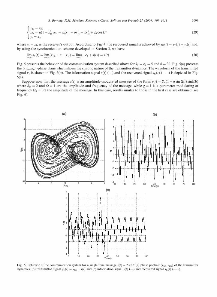
Fig. 5 presents the behavior of the communication system described above for k1 ¼ k2 ¼ 5 and h ¼ 30. Fig. 5(a) presents
the ðx1m; x2mÞ-phase plane which shows the chaotic nature of the transmitter dynamics. The waveform of the transmitted
signal yT is shown in Fig. 5(b). The information signal sðtÞ (––) and the recovered signal sRðtÞ (– – –) is depicted in Fig.
5(c).
Suppose now that the message sðtÞ is an amplitude-modulated message of the form sðtÞ ¼ Smð1þ g sinX0tÞ sinðXtÞwhere Sm ¼ 2 and X ¼ 1 are the amplitude and frequency of the message, while g ¼ 1 is a parameter modulating at
frequency X0 ¼ 0:2 the amplitude of the message. In this case, results similar to those in the first case are obtained (see
Fig. 6).
-2 -1 0 1 2 3x1m
0 10 20 30 40 50 60 70 80-4
-3
-2
-1
0
1
2
3
4
5
Time(s)
y T
0 10 20 30 40 50 60 70 80-4
-3
-2
-1
0
1
2
3
4
5
6
Time(s)
s,s R
(a) (b)
(c)
. Behavior of the communication system for a single tone message sðtÞ ¼ 2 sin t: (a) phase portrait ðx1m; x2mÞ of the transmitterics; (b) transmitted signal yTðtÞ ¼ x1m þ sðtÞ and (c) information signal sðtÞ (––) and recovered signal sRðtÞ (– – –).

-3 -2 -1 0 1 2 3-6
-4
-2
0
2
4
6
x1m
x 2m
0 10 20 30 40 50 60 70 80-6
-4
-2
0
2
4
6
8
Time(s)
y T
0 10 20 30 40 50 60 70 80-6
-4
-2
0
2
4
6
8
Time(s)
s,s R
(c)
(a) (b)
Fig. 6. Behavior of the communication system for an incoming amplitude modulated message sðtÞ ¼ 2ð1þ sin 0:2tÞ sin t: (a) phaseportrait ðx1m; x2mÞ of the transmitter dynamics; (b) transmitted signal yT ðtÞ ¼ x1m þ sðtÞ and (c) information signal sðtÞ (––) and
recovered signal sRðtÞ (– – –).
1010 S. Bowong, F.M. Moukam Kakmeni / Chaos, Solitons and Fractals 21 (2004) 999–1011
5. Conclusion
An approach for adaptive synchronization of uncertain chaotic systems using backstepping approach has been
presented in this paper. The design algorithm yields continuous feedback which allows handling realistic situations such
as unmeasured states and uncertainties.
The resulting synchronization scheme is obtained by posing a control problem in the synchronization error
dynamics. The control problem consists in the stabilization at the origin of the synchronization error system. The
proposed scheme comprises a backstepping-like controller and a state/uncertainty estimator. A central feature of our
approach is that uncertainties of the underlying vector field are lumped in an extended state whose dynamics is
reconstructed form measurements of the system output. Consequently, strong properties of global stability and
exponential synchronization can been achieved in a finite number of steps. The proposed approach offers a systematic
design procedure for the adaptive synchronization of most of chaotic systems in the chaos research literature.
References
[1] Caroll TL, Pecora LM. Synchronizing chaotic circuits. IEEE Trans Circ Syst I 1991;38:453–6.
[2] Bai EW, Lonngran EE. Synchronization of two Lorenz systems using active control. Chaos, Soliton & Fractals 1997;8:51–8.
S. Bowong, F.M. Moukam Kakmeni / Chaos, Solitons and Fractals 21 (2004) 999–1011 1011
[3] Liao TL. Adaptive synchronization of two Lorenz systems. Chaos, Soliton & Fractals 1998;9:1555–61.
[4] Wang C, Ge SS. Adaptive synchronization of uncertain chaotic systems via backstepping design. Chaos, Soliton & Fractals
2001;12:1199–206.
[5] Tan X, Zhang J, Yang Y. Synchronizing chaotic systems using backstepping design. Chaos, Soliton & Fractals 2003;16:37–45.
[6] Cuomo KM, Oppenheim AV, Strogatz SH. Synchronization of Lorenz-based chaotic circuits with applications to communi-
cations. IEEE Trans Circ Syst I 1993;40:626–33.
[7] Liao TL, Tsai SH. Adaptive synchronization of chaotic systems and its application to secure communications. Chaos, Soliton &
Fractals 2000;11:1387–96.
[8] Bai EW, Lonngren KE. Synchronization and control of chaotic systems. Chaos, Soliton & Fractals 1999;10:1571–5.
[9] Femat R, Alvarez-Ramirez J, Fernandez-Anaya G. Adaptive synchronization of high-order chaotic systems: a feedback with low-
order parametrization. Physica D 2000;139:231–46.
[10] Femat R, Jauregui-Ortiz R, Solis-Perales GA. Chaos-based communication scheme via robust asymptotic feedback. IEEE Trans
Circuits Syst I 2001;48:1161–9.
[11] Wang C, Ge SS. Synchronization of two uncertain chaotic systems via adaptive backstepping. Int J Bifur Chaos 2001;6:1743–51.
[12] Yang T, Shao H. Synchronizing chaotic dynamics with uncertainties based on a sliding mode control design. Phys Rev E
2002:65;046210-1–7.
[13] Chua LO, Yang T, Zhong GQ, Wu CW. Adaptive synchronization of Chua’s circuit. Int J Bifur Chaos 1996;6:189–201.
[14] Bowong S, Moukam Kakmeni FM. Stability and duration time of chaos synchronization of a class of nonidentical oscillators.
Phys Scr 2003;68:626–32.
[15] Isidori A. Nonlinear control systems. London, UK: Springer-Verlag; 1995.
[16] Krstic M, Kanellakopoulos K, Kokotovic P. Nonlinear and adaptive control design. New York: John Wiley; 1995.
[17] Teel A, Praly L. Tools for semiglobal stabilization by partial state and output feedback. SIAM J Contr Opt 1995;33:1443–88.
[18] Di Bernado M. Adaptive approach to the control and synchronization of continuous-time chaotic systems. Int J Bifur Chaos
1996;56:557–68.
[19] Itoh M, Wu CW, Chua LO. Communication systems via chaotic signals from a reconstruction viewpoint. Int J Bifur Chaos
1997;7:275–86.


