Embed Size (px)
Citation preview

Applied Catalysis B: Environmental 89 (2009) 635–644
Synergistic effect of TiO2 and iron oxide supported on fluorocarbon films.Part 1: Effect of preparation parameters on photocatalytic degradation oforganic pollutant at neutral pH
F. Mazille, T. Schoettl, C. Pulgarin *
Institute of Chemical Sciences and Engineering, SB, GGEC, Ecole Polytechnique Federale de Lausanne, 1015 Lausanne, Switzerland
A R T I C L E I N F O
Article history:
Received 28 July 2008
Received in revised form 27 January 2009
Accepted 31 January 2009
Available online 6 February 2009
Keywords:
Heterogeneous photo-Fenton
TiO2 photocatalysis
Polymer surface modification
Synergistic effects
Solar detoxification
A B S T R A C T
Iron oxide and TiO2 were immobilized on modified polyvinyl fluoride films in a sequential process.
Synergic effects of iron oxide and TiO2 on the polymer film were observed during the heterogeneous
degradation of hydroquinone (HQ) in the presence of H2O2 at pH close to neutrality and under simulated
solar irradiation. Within the degradation period, little iron leaching (<0.5 mg/L) was observed.
The surface of commercial polyvinyl fluoride (PVF) film was modified by TiO2 under light inducing
oxygen group (C–OH, C O, COOH) formation on the film surface. During this treatment, TiO2
nanoparticles simultaneously bind to the film, leading to PVFf–TiO2. The possible mechanistic pathway
for the TiO2 deposition and the nature of the polymer–TiO2 interaction are discussed. Furthermore PVF
and PVFf–TiO2 were immersed in an aqueous solution for the deposition of iron oxide layer by hydrolysis
of FeCl3, leading to PVF–Fe oxide and to PVFf–TiO2–Fe oxide respectively.
HQ degradation and mineralization mediated by PVFf–TiO2, PVF–Fe oxide and PVFf–TiO2–Fe oxide
were investigated under different conditions. Remarkable synergistic effects were observed for PVFf–
TiO2–Fe oxide possibly due to Fe(II) regeneration, accelerated by electron transfer from TiO2 to the iron
oxide under light.
� 2009 Elsevier B.V. All rights reserved.
Contents lists available at ScienceDirect
Applied Catalysis B: Environmental
journa l homepage: www.e lsev ier .com/ locate /apcatb
1. Introduction
The degradation of organic anthropogenic substances hasbecome an important issue during the last decades due to theirincreasing production. These compounds are bio-recalcitrant andnot degraded by microorganisms during wastewater treatment.Because of the toxic, carcinogenic or endocrinal potential of manyof them, their abatement is crucial to avoid accumulation in theenvironment damaging living species.
The application of advanced oxidation processes (AOPs) is anattractive alternative for the removal of bio-recalcitrant pollutants[1]. These degradation techniques are based on the generation ofreactive oxygen species like hydroxyl (OH
�) and hydroperoxyl
(HO2�) radicals. Among AOPs, photo-assisted processes use natural
solar light as energy source. Their application in water and airpurification [2,3], or disinfection [4], as well as in synthetic organicchemistry [5] have been reported. Among photo-assisted AOPs,TiO2 photocatalysis and photo-Fenton oxidation are efficientroutes for the degradation of recalcitrant compounds in water [6].
* Corresponding author. Tel.: +41 21 693 47 20; fax: +41 21 693 61 61.
E-mail address: [email protected] (C. Pulgarin).
URL: http://ggec.epfl.ch/page13443.html
0926-3373/$ – see front matter � 2009 Elsevier B.V. All rights reserved.
doi:10.1016/j.apcatb.2009.01.027
However these photocatalytic processes suffer from severalpractical limitations preventing wider application: (i) aftertreatment, separation of photocatalyst (highly dispersed TiO2
nanoparticles or dissolved iron ions) is required; (ii) in the case ofTiO2 photocatalysis, light absorption by TiO2 comprising only 4–6%of the solar spectrum limits the efficiency of this process; (iii)homogeneous photo-Fenton needs a pH � 3 in order to prevent theformation of insoluble amorphous ferric oxy-hydroxides [7].
To overcome limitation (i), some studies have described theimmobilization of TiO2 on supports [8–10] including polymer films[11]. However, the activity of immobilized photocatalysts isgenerally low compared to suspensions. To make TiO2 an efficientphotocatalyst under visible light, doping with different species likeiron [12], carbon [13], nitrogen–sulfur [14] among many others,has been reported. Immobilizing iron species like aqua-complexesor oxides on different supports [15–20] including polymer films[21] resulted in efficient photo-Fenton catalysts at pH close to 3.Nevertheless in the presence of ligands (aliphatic acids, humicacids, etc.) iron ions are likely to be released into the solution [22].To overcome the slow kinetics when using either TiO2 or Fentonmediated processes, the combination of iron oxide with TiO2 is anattractive option since synergistic effects are likely to occur. Somerecent studies described Fe2O3–TiO2 coatings on glass [23] andactivated carbon fiber [24]. Synergistic effects refer to the

Fig. 1. Transversal cut and characteristics of the photo-reactor.
Fig. 2. Photocatalytic setup: (1) tanks, (2) peristaltic pump, (3) photo-reactors, and
(4) solar simulator.
F. Mazille et al. / Applied Catalysis B: Environmental 89 (2009) 635–644636
phenomena when the degradation rate of combined system isgreater than the sum of its parts. These non-additive effects haverecently been observed for the combination of suspended TiO2
mediated photocatalysis with high frequency ultrasound [25],with ozonization [26] and when combining supported TiO2 withhomogeneous photo-Fenton oxidation [27].
This study presents a method to bind TiO2 and iron oxide onTedlar1 polyvinyl fluoride (PVF) film. The PVF film has beenselected due to its transparency, low cost (compared to DuPontNafion1), high resistance to weathering, durability, mechanicalresistance, chemical inertness, and absence of aging properties dueto absence of plasticizers. The method to bind TiO2 and iron oxideon PVF employs solar light, low temperature, needs shortpreparation time in aqueous solution, and generates C O, C–OH, COOH groups on the PVF surface by TiO2 photocatalysis asdescribed by Kim et al. [28,29]. The produced photocatalysts (PVFf–TiO2, PVF–Fe oxide and PVFf–TiO2–Fe oxide) were characterized byscanning electron microcopy (SEM), X-ray photoelectron spectro-scopy (XPS) and UV–vis spectroscopy.
The objective of this study is to report the performance of PVFf–TiO2–Fe oxide toward the degradation and mineralization ofhydroquinone (HQ), a model compound representative forindustrial pollutants.
2. Experimental
2.1. Chemicals
Hydroquinone, NaOH, HNO3, FeCl3, FeSO4�7H2O, ferrozine,hydroxylamine hydrochloride, acetate buffer (pH 4.65) wereFluka p.a. reagents (Buchs, Switzerland) and used as received.Hydrogen peroxide (35%) was supplied by Merck AG (Darmstadt,Germany) and TiO2 P25 (anastase to rutile ratio between 70:30and 80:20) by Degussa. The Tedlar1 A is a DuPont film(thickness: 72 mm) and consists of (–CH2–CHF–) structuralgroups. The film is tough, flexible and heat resistant up to 180 8C(flowing point).
2.2. Photocatalyst preparation
Photoactive TiO2 and/or iron oxide were deposited oncommercial PVF films as polymeric substrate. Before use, thePVF films were washed in diethyl ether ethanol (1:1) mixture andin MilliQ water in order to eliminate surface contaminants. Threedifferent preparation methods have been used:
(1) The first preparation method consisted in the application of asingle TiO2 photocatalytic surface functionalization-deposition(PSFD) treatment: The clean polymer substrates were attachedaround a cylindrical steel support and immersed in aphotoreactor containing well dispersed suspensions of TiO2
(0.2–1.7 g/L) at different pH (3, natural, 7, 11). The photoreactorwas irradiated in a CPS Suntest system (ATLAS GmbH) during2 h under magnetic stirring. Steel support was dimensioned tomaintain the PVF film close to the surface of the photoreactor.This treatment leaded to the immobilization of TiO2 particleson the functionalized PVF surface (PVFf–TiO2). The possiblenature of polymer–TiO2 bonding is proposed in Section 3.1.1.
(2) In the second preparation method, the iron oxide wasimmobilized on PVF substrates. Commercial PVF films wereimmersed in a 5 g/L solution of FeCl3 and heated under stirringat 70, 80 or 90 8C during 1 h. Optionally, the composite materialwas heated in an oven at 100 8C for 1 h. The final film showedan iron oxide coat (PVF–Fe oxide).
(3) The third preparation method consisted in applying a TiO2
PSFD treatment followed by iron oxide coating as described in
method (1) and (2) to immobilize the TiO2 and iron oxide on thePVF film leading to PVFf–TiO2–Fe oxide.
2.3. Photoreactor and irradiation procedure
All HQ degradation experiments were carried out undersimulated solar light, using thin film Pyrex glass reactors(Fig. 1). A peristaltic pump allows circulation of water (flow rateof 100 mL/min) using an Erlenmeyer flask as a recirculation tank.The total volume of the system (110 mL) consists of two parts:25 mL irradiated volume and the dead volume in connecting tubesand Erlenmeyer tank. Internal PVC supports were placed in thereactor to carry the photocatalyst films. The reactor wasilluminated inside a solar simulator CPS Suntest system (AtlasGmbH). This solar box has a light spectral distribution with about0.5% of the emitted photons below 300 nm, and 7% between 300and 400 nm. The emission spectrum between 400 and 800 nmfollows the solar spectrum. The irradiation experiments werestarted at room temperature (20 8C) and progressively thetemperature increased up to approximately 30 8C. Three reactorswere placed in parallel inside the solar box (Fig. 2). The degradationexperiments were performed using solutions containing HQ(0.18 mM) and H2O2 (1.6 mM).
2.4. Analysis of the irradiated solutions
The quantitative determination of organic compounds wascarried out by HPLC chromatography using a LC system HPLC-UVShimadzu LC-2010A equipped with a UV detector. Samples,injected via an auto-sampler, were eluted at a flow rate of 1 mL/min through a column (Nucleosil C18 Marcherey Nagel) and usingas mobile phase HPLC grade acetonitrile–acetic acid solution (10%)in a 40–60%. The total organic carbon (TOC) was monitored via an

Fig. 3. X-ray photoelectron spectra of: (i) C (1s), (ii) O (1s), (iii) F (1s) core level photoelectron spectra of (a) PVF; (b) PVF after a TiO2-PSFD treatment at pH 11; (c) PVF after a
TiO2 PSFD treatment at pH 3; and (d) PVFf–TiO2–Fe oxide (TiO2 PSFD treatment at pH 3).
Table 1Atomic composition of original polymer surface (PVF), TiO2 PSFD treated polymer
(PVFf–TiO2) at pH 3 and 11 (only principal constituents).
Samples C O F Ti F/C O/C
PVF 66.0 3.7 30.3 0 0.46 0.06
PVFf–TiO2 pH 11 80.4 10.3 9.3 0 0.11 0.12
PVFf–TiO2 pH 3 72.6 16.9 9.3 1.2 0.13 0.24
F. Mazille et al. / Applied Catalysis B: Environmental 89 (2009) 635–644 637
ASI automatic sample injector (Shimadzu 500). The peroxideconcentrations were assessed by Merkoquant1 paper at levelsbetween 0.5 and 25 mg/L. The total iron concentration in theirradiated solutions was measured by complexation with Ferro-zine1 (Aldrich 16.060-1) in the presence of hydroxylaminehydrochloride and acetate buffer (pH 4.65) [30].
2.5. Photocatalyst characterization
2.5.1. X-ray photoelectron spectroscopy
X-ray photoelectron spectroscopy data were collected by AxisUltra system (Kratos analytical, Manchester, UK) under ultra-highvacuum condition (<10�8 Torr), using a monochromatic Al Ka X-ray source (1486.6 eV) at the laboratory of Chemical Metallurgy atEPFL. The source power was maintained at 150 W (10 mA, 15 kV).The emitted photoelectrons were sampled from a square area of750 mm � 350 mm. The gold (Au 4f7/2) and copper (Cu 2p3/2) linesat 84.0 and 932.6 eV respectively, were used for calibration, andthe adventitious carbon 1s peak at 284.6 eV was used as an internalstandard to compensate for charging effects.
2.5.2. SEM analysis
The surface morphology of the supports and the catalysts wereinvestigated using a scanning electron microscope (Phillips XL30SFEG) equipped with X-ray detector.
2.5.3. UV–vis spetrophotometry analysis
UV–vis spectra were recorded on a Varian Cary 5 equipped withan integration sphere.
3. Results and discussion
3.1. PVFf–TiO2–Fe oxide characterization
The XPS spectroscopy allows determining surface compositionof the thin outermost surface layers. It also allows obtaining theelemental depth profile. XPS measurements were performed onPVFf–TiO2 and PVFf–TiO2–Fe oxide prepared under different pHcondition. An energy shift to lower binding energies (BE) of about3 eV was observed due to the low conductivity of the samples. Inthe present study, the corrected BEs are reported.
3.1.1. XPS study of the influence of pH on TiO2 photocatalytic surface
functionalization-deposition treatment of polyvinyl fluoride film
Different PVFf–TiO2 and PVFf–TiO2–Fe oxide samples have beenproduced by functionalization at various pHs. Fig. 3(i) presents theC (1s) carbon peaks at each preparation step. For the non-modifiedPVF film (trace a), there are two peaks: the higher peak centered atBE = 284.6 eV corresponding to (CH2)n groups, the second centeredat BE = 286.6 eV corresponding to C–F bond. The F/C atomic ratiofor the PVF was 0.46, which is less than the theoreticalstoichiometric value of 0.5 (Table 1). This slight difference canbe attributed to hydrocarbon contamination and the presence ofsurface oxygen. After the TiO2 PSFD treatment of PVF at pH 11,(trace b), the XPS spectrum changes with the appearance of C (1s)peaks at a BE of 287.2 and 289 eV corresponding to the formationof C O bond of ketones and carboxylic acids respectively. Thisobservation confirms that the TiO2 PSFD treatment induces theformation of oxygen functional groups in agreement with a recentstudy by Kim et al. [31]. After TiO2 PSFD treatment at pH 3 (trace c),the XPS spectrum was similar to the trace b excepting that thecarboxylic acid peak at 289 eV is not visible and that the ratio C–H/C O is considerably lower indicating a larger formation of oxygen-based groups at the Tedlar1 surface at acidic pH.
Fig. 3(ii) shows the evolution of PVF surface oxygen peak O (1s)for different preparation steps. In trace a, the O (1s) peak iscentered at BE = 533.7 eV corresponding to the oxygen containedin hydrocarbon contamination on the polymeric surface. After aTiO2 PSFD treatment at pH 11, (trace b) the O (1s) peak is shifted to532 eV, corresponding to the formation of C O and COOH groupson the PVF surface. Trace (b) shows as well a small peak at 529.4 eVwhich corresponds to the oxygen in TiO2 suggesting the presenceof traces of this oxide on PVF surface. After a TiO2 PSFD treatment atpH 3 (trace c), a significant O (1s) peak appears at BE = 529.4 eV

Fig. 4. X-ray photoelectron spectra of Ti (2p) in (a) PVF after a TiO2 PSFD treatment
at pH 3 and (b) PVF after a TiO2 PSFD treatment at pH 11.
F. Mazille et al. / Applied Catalysis B: Environmental 89 (2009) 635–644638
corresponding to the oxygen of the TiO2 while the next peak atBE = 531.8 eV corresponds to O (1s) in C O, COOH groups.
Fig. 3(iii) shows the changes in the F (1s) XPS spectrum due toTiO2 PSFD treatment. For the non-modified PVF, the F (1s) signalconsist of a single peak located at a BE of 685.9 eV. The maindifferences between non-modified PVF (trace a) and TiO2 PSFDtreated polymers (traces b and c) are a shift (of 0.3 eV) of F (1s) BEto the higher energy possibly due to the changes in the fluorinechemical environment and a decrease of the peak due to fluorinesubstitution.
Table 1 shows the atomic composition of PVF surface before andafter TiO2 PSFD treatment. From a semi-quantitative comparison ofrelative atomic percentage of oxygen, carbon, fluorine andtitanium on the surface before and after TiO2 PSFD treatment, itwas found that this treatment led to an important increase inrelative oxygen and carbon surface concentration and a con-comitant decrease in the fluorine concentration. In Table 1 can beseen that the pH during TiO2 PSFD treatment influences the surfacemodification. The surface O/C ratio changes from 0.06 in the non-modified PVF to 0.24 after a TiO2 PSFD treatment at pH 3 and to0.12 at pH 11. The surface F/C ratio changed from 0.46 in the non-modified PVF to 0.13 and 0.11 after a TiO2 PSFD treatment at pH 3and 11 respectively. Thus photocatalytic oxidation of the polymersurface induces the formation of oxygenic functional groups alongthe elimination of bounded fluorine.
Simultaneously, when submitting PVF to a TiO2 PSFD treatment,the immobilization of the TiO2 assisted by polymer surfacefunctionalization occurs. Fig. 4 (traces a and b), shows the Ti (2p)core level photoelectron spectra characteristic of Ti in TiO2 [32] afterTiO2 PSFD treatment at pH 3 and 11. Thus after the treatmentperformed at pH 3, the polymer is partially covered with TiO2 (1.3%atomic percentage of the surface) whereas after treatment at pH 11,Titanium was not detected. These results show that it is possible tocontrol the extent of TiO2 deposition by varying the pH.
The simultaneous photocatalytic functionalization of PVF surfaceand a deposition of TiO2 is illustrated in Fig. 5. As a matter of fact,under irradiation in aqueous TiO2 suspension in equilibrium with air,PVF film suffers photocatalytic attacks leading to C O, COOH groupsand to the elimination of fluorine. When the pH of the aqueoussolution is acidic, (i) the polymer surface is negatively charged sincethe TiO2 PSFD treatment induced the formation of functional groups
Fig. 5. Mechanistic proposition for TiO2 photocatalytic sur
like COO� and (ii) the superficial charge of TiO2 P25 is positive sinceits isoelectric point is near to 7. Consequently an electrostaticattraction binds the TiO2 particles to the polymer surface.
3.1.2. XPS studies of iron species and overall atomic profile of the
PVFf–TiO2–Fe oxide photocatalyst
The deposition of iron oxide on PVFf–TiO2 surfaces wasdescribed under Section 2.2. The determination of chemical natureof the iron coating was investigated by XPS.
In Fig. 6, the iron peak was located at a BE of 711 eV which ischaracteristic of Fe3+ ions in akaganeite [33]. Nevertheless, the XPSresults are not sufficient to determine with accuracy the nature ofiron oxide present at polymer surface. However, various reportsconfirm this hypothesis, as the thermal hydrolysis of FeCl3solutions leads mainly to the formation of akaganeite [34].
In Fig. 3(iii), the XPS spectrum of F (1s) core level is presented.The PVFf–TiO2–Fe oxide spectrum (trace d), includes the triplet F(1s) peak with two predominant components at a BE of 684.2 and686.3 eV. These two peaks correspond respectively to fluorineincorporated into iron oxide (FeOF) due to the anion exchange
face functionalization-deposition as a function of pH.

Fig. 6. Fe (2p) core level photoelectron spectra of PVFf–TiO2–Fe oxide.
F. Mazille et al. / Applied Catalysis B: Environmental 89 (2009) 635–644 639
properties of akaganeite [35], and to the polymeric C–F bond. Thesmaller F (1s) peak is centered at a BE = 689 eV corresponding to F�
ions adsorbed on the iron oxide surface.Fig. 7 shows the XPS depth profile of PVFf–TiO2–Fe oxide surface
indicating the atomic composition as a function of depth. Eachminute, the topmost layer of about 2 nm depth was eroded by theAr+-ions sputtering. The reported values are approximations, sincepreferential sputtering effects cannot be excluded because thesputter rate for each investigated element is different and dependson its particular sensitivity factor. Fig. 7 shows the contaminationof the first layer (about 5 nm) with hydrocarbons and oxygen. Inthe next layer of about 15 nm, iron, oxygen, fluorine and chlorineatomic concentration were seen to be close to their maximumvalue (35%, 35%, 18%, and 6% respectively) decreasing continuouslywith increasing depth. The atomic concentration of carbon followsan opposite tendency i.e. has its minimum value (10%) between 5and 20 nm and then increases. Atomic concentration of Ti is zerountil�35 nm and then increases to reach a maximum value of 2.5%at �100 nm. This result indicates that TiO2 particles are locatedclose enough to the surface of the catalyst to play a role in thedegradation processes particularly if the photocatalyst has beenreused several times and the iron oxide coat has been partiallydissolved allowing the TiO2 to diffuse to the surface. An XPS studyof PVFf–TiO2–Fe oxide surface changes after reuse will bepresented in another paper (part 2 of this work).
3.1.3. Scanning electron microscopy
Fig. 8 shows the SEM micrograph of polymer surface before andafter the sequential TiO2 PSFD and iron oxide coating.
Fig. 7. Depth profile of PVFf–TiO2–Fe oxide (PSFD treatment at pH 3).
The non-modified PVF surface, Fig. 8a, is predominantlysmooth. After a TiO2 PSFD treatment at pH 5, aggregated TiO2
particles cover a significant part of the surface exposed to the lightirradiation (Fig. 8b) and to a lesser degree in the back side (Fig. 8c).This TiO2 coating seems to increase the surface roughness favoringsubsequent iron oxide nucleation around the TiO2 particles. TiO2
decrease the interfacial energy which is a limiting factor for thecrystallization of iron oxide [36]. Fig. 8d shows the PVFf–TiO2–Feoxide catalyst surface loaded with iron oxide aggregates of about1 mm. These aggregates are composed of nanoparticles ofapproximately 50 nm, which seem to cover the polymer surface(Fig. 8e).
3.1.4. UV–vis absorbance study
Fig. 9 presents the UV–vis absorption of PVFf–TiO2, PVF–Feoxide and PVFf–TiO2–Fe oxide composites between 350 and700 nm. The absorbance of PVF in this region was negligible. ForThe PVFf–TiO2 (trace a) the UV–vis spectrum shows that thismaterial only absorbs light below 400 nm, characteristic for TiO2
particles. In contrast, PVF–Fe oxide (trace b) absorbs visiblelight. Its spectrum shows an important absorption for lowwavelength (violet and UV light) and a shoulder between 550and 450 nm (green–blue light). PVFf–TiO2–Fe oxide spectrum(trace c) presented a similar spectrum shape to trace b) but theobserved absorption was 2 times higher. Thus, the PVFf–TiO2–Feoxide UV–vis spectrum does not correspond to the sum of PVFf–TiO2 and PVF–Fe oxide spectra, which is due to a moresignificant iron oxide presence on the rough PVFf–TiO2 surfacethan on smooth PVF.
3.2. Photocatalytic activity
Fig. 10 presents the evolution of HQ within 240 min underdifferent conditions. During photolysis and dark runs (bothrepresented by trace a), HQ concentration remained constant:(i) HQ was resistant to direct photolysis by simulated solar lightand (ii) no adsorption of HQ on PVFf–TiO2–Fe oxide was detectable.For photo-assisted reaction on PVFf–TiO2 (trace b) and on PVFf–TiO2–Fe oxide (trace c), 7% and 15% of HQ was degraded in 240 minof treatment. HQ degradation by the system PVFf–TiO2/H2O2/light(trace d) reached almost 40% whereas the system PVFf–TiO2–Feoxide/H2O2 under dark (trace e) reached 50% of HQ degradation in240 min by heterogeneous Fenton-like oxidation. For the systemPVF–Fe oxide/H2O2/light (trace f), the HQ degradation rateremained low during an activation period of 30 min, but increasedbetween 30 and 120 min of treatment with 10% and 97%degradation efficiency. This behavior is typical for iron photo-leaching during the first step of the reaction leading to asubsequent important contribution of the homogeneous processto HQ degradation after the first 60 min of treatment since 0.5 mg/L of dissolved iron ions have been detected by the ferrozinemethod. For heterogeneous reaction with the system PVFf–TiO2–Feoxide/H2O2/light (trace g), HQ decreased very fast (91%) and with aconstant slope typical of heterogeneous processes during the first60 min. Only 0.2 mg/L of dissolved iron ions were detected at theend of this process. Consequently, the influence of homogeneousphoto-Fenton processes on HQ degradation is small. A moreaccurate estimation of homogeneous contribution will be pro-posed in another paper (part 2 of this work).
The evolution of the TOC versus time for some processes isillustrated in Fig. 11. For the system PVFf–TiO2–Fe oxide/H2O2,under dark, no mineralization was observed (trace a). Homo-geneous photo-Fenton process (Fe2+ (0.3 mg/L)/H2O2/light) miner-alized about 60% of TOC after 240 min (trace b). Using PVF–Feoxide/H2O2/light system (trace c), the TOC increased during thefirst 30 min, due to a degradation of the polymer substrate by

Fig. 8. Scanning electron microscopic images of: (a) PVF, (b) PVFf–TiO2 prepared at pH 5 (external side), (c) PVFf–TiO2 prepared at pH 5 (internal side), and (d)–(e) PVFf–TiO2–
Fe oxide prepared at pH 5.
F. Mazille et al. / Applied Catalysis B: Environmental 89 (2009) 635–644640
generated radicals. Thereafter, the TOC concentration decreasedrapidly up to 80% within 240 min (essentially due to mineraliza-tion caused by dissolved iron ions). TOC removal by the systemPVFf–TiO2–Fe oxide/H2O2/light (trace d) was the fastest achieving amineralization of 95% after 240 min. For each process, the residualH2O2 concentrations were measured; in no case the initially addedH2O2 was totally consumed. The decrease of mineralization ratesbetween 180 and 240 min (traces c and d) is therefore limited bydiffusion.
During the photo-assisted reaction on PVFf–TiO2–Fe oxide inpresence of H2O2, besides Eqs. (2) and (3), the Fe(II) regeneration(which is the rate determinant step of Fenton reaction) could occurvia the photo-reduction of Fe(III) species including hydroxy- ororgano-complexes (Eqs. (5) and (6)). Additionally photo-inducedreactive species (electron–hole pair) are probably formed on ironoxide under illumination enhancing HQ degradation rates (Eq. (7)).Conduction band electrons could react with H2O2 to form hydroxylradicals (Eq. (8)) or could participate in the regeneration of Fe(II)species (Eq. (9)). Valence band holes may oxidize the pollutant(Eq. (10)) [17] ( Fe(II) and Fe(III) represent the Fe(II)/Fe(III)
species in solid or solution phase).
¼FeðIIÞ þ H2O2 ! ¼FeðIIIÞ þ OH� þOH �ðk � 40�80 M=sÞ
(1)
¼FeðIIIÞ þ H2O2 ! ¼FeðIIÞ þ HO2� þHþ ðk � 0:003 M=sÞ
(2)
¼FeðIIIÞ þ O2�� ! ¼FeðIIÞ þ O2 (3)
¼FeðIIÞ þ O2�� ! ¼FeðIIIÞ þ O2
2� (4)
¼FeðIIIÞðOHÞ2þ þhn ! ¼FeðIIÞ þ OH�
(5)
¼FeðIIIÞLnþhn ! ¼FeðIIÞLn�1þ Loxþ� (6)
Fe oxideþhn ! Fe oxideðe� þhþÞ (7)
Fe oxideðe�Þ þ H2O2 ! Fe oxide þ OH� þOH� (8)

Fig. 9. UV–vis absorption spectrum of: (a) PVFf–TiO2, (b) PVF–Fe oxide, (c) PVFf–
TiO2–Fe oxide.
Table 2Initial HQ degradation rates relative to different photo-assisted processes.
Photo-process R0 (mmol/min)
H2O2 0.14
PVFf–TiO2 0.08
(PVFf–TiO2)/H2O2 0.29a
(PVF–Fe oxide)/H2O2 0.57b
(PVF–Fe oxide)virtualc/H2O2 1.3d
(PVFf–TiO2–Fe oxide)/H2O2 4.0e
a Value calculated from decay curve d of Fig. 10.b Value calculated from decay curve f of Fig. 10.c Virtual photocatalyst containing the same amount of iron oxide as PVFf–TiO2–
Fe oxide.d Rate estimated from footnote (a) and from Eqs. (19) and (20) and Fig. 9.e Value calculated from decay curve g of Fig. 10.
B: Environmental 89 (2009) 635–644 641
Fe oxideðe�Þ þ ¼FeðIIIÞ ! Fe oxide þ ¼FeðIIÞ (9)
Fe oxideðhþÞ þ Rad ! Fe oxide þ Radþ� (10)
Beside photo-Fenton oxidation (Eqs. (1)–(6)) and iron oxidephotocatalysis (Eqs. (7)–(10)), other reactions may occur mediatedby PVFf–TiO2–Fe oxide/H2O2/light involving electron–hole pairformation by TiO2 band-gap illumination (l < 400 nm). Thesereactions lead to radicals active in the degradation process asdescribed in Eqs. (11)–(16).
TiO2þhn ! TiO2ðe� þhþÞ (11)
TiO2ðhþÞ þ Rad ! TiO2þRadþ� (12)
TiO2ðhþÞ þ H2O ! TiO2þOH� þHþ (13)
TiO2ðe�Þ þ Rad ! TiO2þRad�� (14)
TiO2ðe�Þ þ O2 ! TiO2þO2�� (15)
TiO2ðe�Þ þ H2O2 ! TiO2þOH� þOH� (16)
Furthermore, synergistic effects are likely to occur betweenTiO2, iron oxide, dissolved iron ions, and functionalized polymersurface, accelerating HQ degradation in the presence of H2O2 as theelectron acceptor.
3.3. Synergistic effects
Synergistic effects can be quantified by the synergistic factor S
defined in Eq. (17), where R0 represents the initial rate ofdegradation for a given process (Eq. (18)).
S ¼ R0ðABÞR0ðAÞ þ R0ðBÞ
(17)
R0 ¼½HQ �0 � ½HQ �30
30(18)
In the system PVFf–TiO2–Fe oxide/H2O2/light, the overallprocess is a combination of polymer supported TiO2 and ironoxide photocatalysis associated with heterogeneous and homo-geneous photo-Fenton oxidation. The exact assessment of syner-gistic effects in this system is not easy due to the difficulty toprepare PVF–Fe oxide and PVFf–TiO2–Fe oxide samples with thesame iron oxide load. An approximated synergistic factor can beestimated assuming that (1) The photocatalyst UV–vis extinctioncoefficients between 450 and 550 nm (Fig. 9) are proportional tothe amount of iron oxide present on the PVF surface and (2) thephotocatalytic activity of PVF–Fe oxide increases linearly with theamount of immobilized iron oxide.
The initial HQ degradation rates (R0) have been calculatedduring the first 30 min for different photo-assisted processes(Eq. (18)) from the decay curves b, d, e, f, and g in Fig. 10 and arerepresented in Table 2.
These rates are representative for the heterogeneous reactionssince at the beginning of the process, a low amount of iron isdissolved (<0.1 mg/L). The rate R0 corresponding to a virtual PVF–Fe oxide containing the same amount of iron oxide as a PVFf–TiO2–Fe oxide was estimated according to assumptions (1) and (2). Acorrection factor C, defined in Eq. (19) as the integrated absorbanceof PVFf–TiO2–Fe oxide (trace c) over the integrated absorbance ofPVF–Fe oxide (trace b) from 450 to 550 nm (where the TiO2
absorbance is insignificant), was calculated from Fig. 9.
C ¼Z 550
450
AðPVFf�TiO2�Fe oxideÞAðPVF�Fe oxideÞ
" #¼ 2:2 (19)
F. Mazille et al. / Applied Catalysis
Multiplying R0(PVF–Fe oxide/H2O2/light) by C we can estimateR0(PVF–Fe oxide/H2O2/light)virtual corresponding to the degrada-tion rate relative to a PVF–Fe oxide with an iron oxide load as PVFf–TiO2–Fe oxide (Eq. (20)):
R0ðPVF�Fe oxide=H2O2=lightÞvirtual
¼CR0ðPVF�Fe oxide=H2O2=lightÞ (20)
Replacing R0(A), R0(B) and R0(AB) in Eq. (17) by the values ofR0(PVFf–TiO2/H2O2/light), R0(PVF–Fe oxide/H2O2/light)virtual andR0(PVFf–TiO2–Fe oxide/H2O2/light) (from Table 2) respectively, thesynergistic factor S can be calculated. A value of S � 2.5 wasobtained, meaning that the rate relative to the combined processesis 2.5 times faster than the sum of rates relative to the separatedprocesses. Compared to previous studies [25–27], this resultsuggests the presence of a significant synergistic effect in thesystem PVFf–TiO2–Fe oxide/H2O2/light.
At the beginning of the treatment (for which S factor has beencalculated), the combination of homogeneous photo-Fenton andTiO2 photocatalysis is probably not the essential interaction.Indeed the concentration of dissolved iron ions is low (about0.1 mg/L) as well as the relative atomic surface concentration oftitanium (0.3%) obtained by XPS after utilization of PVFf–TiO2–Feoxide. A more plausible suggestion would be that heterogeneousinteractions between supported iron oxide and TiO2 underirradiation are responsible of significant part of the observed

Fig. 12. Schematic representation of possible synergistic photocatalytic action in
the system PVFf–TiO2–Fe oxide/H2O2/light: (i) under visible light irradiation and (ii)
under ultraviolet light irradiation.
Fig. 10. Degradation of 0.18 mM of HQ, initial pH 5.7, 75 cm2 of heterogeneous
photocatalyst 1.6 mM H2O2 under solar simulation: (a) bare light/dark adsorption,
(b) PVF–TiO2/light, (c) PVFf–TiO2–Fe oxide/light, (d) PVFf–TiO2/H2O2/light, (e) PVFf–
TiO2–Fe oxide/H2O2, (f) PVF–Fe oxide/H2O2/light, and (g) PVFf–TiO2–Fe oxide/H2O2/
light. The traces represent an average of three consecutive runs using the same
photocatalysts (first run not included).
F. Mazille et al. / Applied Catalysis B: Environmental 89 (2009) 635–644642
synergistic effects. This interaction has been investigated recentlyby double-beam photoacoustic spectroscopy [37] and wassuggested to depend on the irradiation wavelength:
(i) Under ultraviolet irradiation, photoexcited electrons generatedin TiO2 catalyst (Eq. (11)) could be trapped into iron oxideparticles (Eq. (21)) resulting in improvement of chargeseparation on TiO2 (completed by an oxidation reactionperformed by remaining hole Eq. (12) and (13)), and, inregeneration of Fe(II) sites (Eq. (9)) (accelerating photo-Fenton reaction rates) by reduction of Fe(III) species.
Fe oxide þ TiO2ðe�Þ ! Fe oxideðe�Þ þ TiO2 (21)
This electron transfer is possible since the electrochemicalpotential position of TiO2 bands relative to those of iron oxides[38] allows electron transfer from excited TiO2 valence band toiron oxide valence band by formation of a heterojunction. Thismechanism is represented in Fig. 12(a).
Fig. 11. TOC removal of 0.18 mM of HQ, initial pH 5.7, 75 cm2 of heterogeneous
photocatalyst 1.6 mM H2O2 under solar simulation: (a) PVFf–TiO2–Fe oxide/H2O2,
(b) Fe2+ (0.3 mg/L)/H2O2/light, (c) PVF–Fe oxide/H2O2/light, and (d) PVFf–TiO2–Fe
oxide/H2O2/light. The traces represent an average of three consecutive runs using
the same photocatalysts (first run not included).
(ii) Under visible light irradiation, iron oxide (or complex) couldact as a sensitizer for TiO2. First, a photo-excited iron specieswould inject an electron into TiO2 and become oxidized. Then,the oxidized iron species (Fe(IV)) oxidize hydroquinone(polymer surface or ligand) to go back to their initial state(Fe(III)), whereas the electron injected in TiO2 is transferred toiron oxide regenerating Fe(II). This mechanism which isdescribed in Fig. 12 (b) needs further confirmation and solidevidence, due to the involvement of Fe(IV) oxidized species.
3.4. Effect of PVFf–TiO2–Fe oxide preparation parameters on HQ
degradation rates
3.4.1. Effect of the pH during TiO2 PSFD treatment on HQ degradation
rates for the system PVFf–TiO2–Fe oxide/H2O2/light
The initial pH of the aqueous media during the TiO2 PSFDtreatment determines the amount of oxygenated groups formedand the superficial charge of TiO2 nanoparticles. The extent of TiO2
photo-deposition depends on pH as well (Table 1). At acidic pH, theTiO2 being positively charged can be stably deposited onelectronegative oxygenated groups on the polymer surface. Atbasic pH, the TiO2 and polymer are both negatively charged and theinteraction is repulsive, limiting the polymer functionalization andthe TiO2 deposition. Consequently, since iron oxide crystallizationis favored by TiO2 presence, less iron oxide is deposited on itssurface leading to a less efficient PVFf–TiO2–Fe oxide photocata-lyst. HQ mineralization rates by PVFf–TiO2–Fe oxide/H2O2/lightdecrease as the pH for TiO2 PSFD treatment increased with 72%,
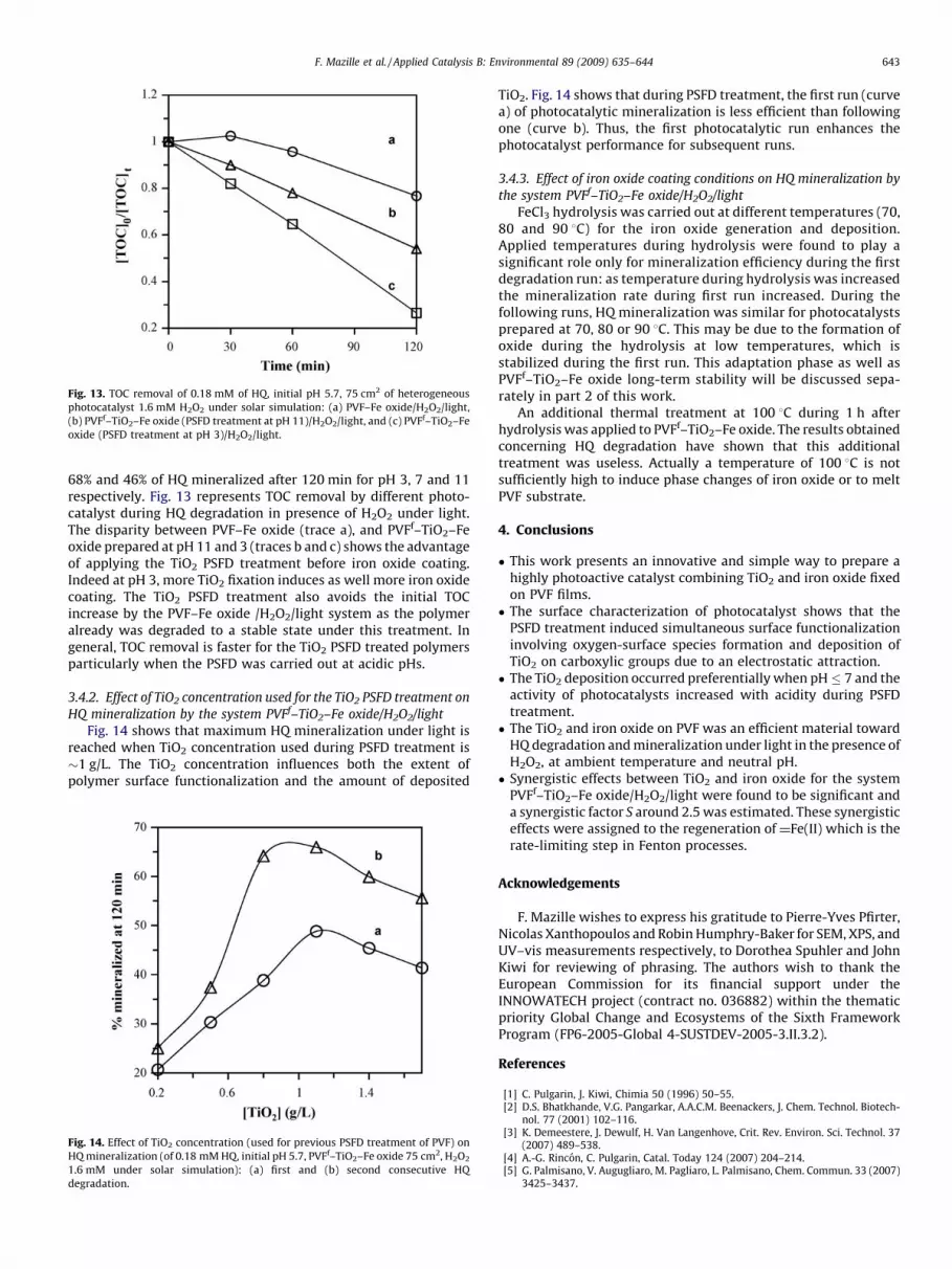
Fig. 13. TOC removal of 0.18 mM of HQ, initial pH 5.7, 75 cm2 of heterogeneous
photocatalyst 1.6 mM H2O2 under solar simulation: (a) PVF–Fe oxide/H2O2/light,
(b) PVFf–TiO2–Fe oxide (PSFD treatment at pH 11)/H2O2/light, and (c) PVFf–TiO2–Fe
oxide (PSFD treatment at pH 3)/H2O2/light.
F. Mazille et al. / Applied Catalysis B: Environmental 89 (2009) 635–644 643
68% and 46% of HQ mineralized after 120 min for pH 3, 7 and 11respectively. Fig. 13 represents TOC removal by different photo-catalyst during HQ degradation in presence of H2O2 under light.The disparity between PVF–Fe oxide (trace a), and PVFf–TiO2–Feoxide prepared at pH 11 and 3 (traces b and c) shows the advantageof applying the TiO2 PSFD treatment before iron oxide coating.Indeed at pH 3, more TiO2 fixation induces as well more iron oxidecoating. The TiO2 PSFD treatment also avoids the initial TOCincrease by the PVF–Fe oxide /H2O2/light system as the polymeralready was degraded to a stable state under this treatment. Ingeneral, TOC removal is faster for the TiO2 PSFD treated polymersparticularly when the PSFD was carried out at acidic pHs.
3.4.2. Effect of TiO2 concentration used for the TiO2 PSFD treatment on
HQ mineralization by the system PVFf–TiO2–Fe oxide/H2O2/light
Fig. 14 shows that maximum HQ mineralization under light isreached when TiO2 concentration used during PSFD treatment is�1 g/L. The TiO2 concentration influences both the extent ofpolymer surface functionalization and the amount of deposited
Fig. 14. Effect of TiO2 concentration (used for previous PSFD treatment of PVF) on
HQ mineralization (of 0.18 mM HQ, initial pH 5.7, PVFf–TiO2–Fe oxide 75 cm2, H2O2
1.6 mM under solar simulation): (a) first and (b) second consecutive HQ
degradation.
TiO2. Fig. 14 shows that during PSFD treatment, the first run (curvea) of photocatalytic mineralization is less efficient than followingone (curve b). Thus, the first photocatalytic run enhances thephotocatalyst performance for subsequent runs.
3.4.3. Effect of iron oxide coating conditions on HQ mineralization by
the system PVFf–TiO2–Fe oxide/H2O2/light
FeCl3 hydrolysis was carried out at different temperatures (70,80 and 90 8C) for the iron oxide generation and deposition.Applied temperatures during hydrolysis were found to play asignificant role only for mineralization efficiency during the firstdegradation run: as temperature during hydrolysis was increasedthe mineralization rate during first run increased. During thefollowing runs, HQ mineralization was similar for photocatalystsprepared at 70, 80 or 90 8C. This may be due to the formation ofoxide during the hydrolysis at low temperatures, which isstabilized during the first run. This adaptation phase as well asPVFf–TiO2–Fe oxide long-term stability will be discussed sepa-rately in part 2 of this work.
An additional thermal treatment at 100 8C during 1 h afterhydrolysis was applied to PVFf–TiO2–Fe oxide. The results obtainedconcerning HQ degradation have shown that this additionaltreatment was useless. Actually a temperature of 100 8C is notsufficiently high to induce phase changes of iron oxide or to meltPVF substrate.
4. Conclusions
� This work presents an innovative and simple way to prepare ahighly photoactive catalyst combining TiO2 and iron oxide fixedon PVF films.� The surface characterization of photocatalyst shows that the
PSFD treatment induced simultaneous surface functionalizationinvolving oxygen-surface species formation and deposition ofTiO2 on carboxylic groups due to an electrostatic attraction.� The TiO2 deposition occurred preferentially when pH 7 and the
activity of photocatalysts increased with acidity during PSFDtreatment.� The TiO2 and iron oxide on PVF was an efficient material toward
HQ degradation and mineralization under light in the presence ofH2O2, at ambient temperature and neutral pH.� Synergistic effects between TiO2 and iron oxide for the system
PVFf–TiO2–Fe oxide/H2O2/light were found to be significant anda synergistic factor S around 2.5 was estimated. These synergisticeffects were assigned to the regeneration of Fe(II) which is therate-limiting step in Fenton processes.
Acknowledgements
F. Mazille wishes to express his gratitude to Pierre-Yves Pfirter,Nicolas Xanthopoulos and Robin Humphry-Baker for SEM, XPS, andUV–vis measurements respectively, to Dorothea Spuhler and JohnKiwi for reviewing of phrasing. The authors wish to thank theEuropean Commission for its financial support under theINNOWATECH project (contract no. 036882) within the thematicpriority Global Change and Ecosystems of the Sixth FrameworkProgram (FP6-2005-Global 4-SUSTDEV-2005-3.II.3.2).
References
[1] C. Pulgarin, J. Kiwi, Chimia 50 (1996) 50–55.[2] D.S. Bhatkhande, V.G. Pangarkar, A.A.C.M. Beenackers, J. Chem. Technol. Biotech-
nol. 77 (2001) 102–116.[3] K. Demeestere, J. Dewulf, H. Van Langenhove, Crit. Rev. Environ. Sci. Technol. 37
(2007) 489–538.[4] A.-G. Rincon, C. Pulgarin, Catal. Today 124 (2007) 204–214.[5] G. Palmisano, V. Augugliaro, M. Pagliaro, L. Palmisano, Chem. Commun. 33 (2007)
3425–3437.

F. Mazille et al. / Applied Catalysis B: Environmental 89 (2009) 635–644644
[6] I. Munoz, J. Rieradevall, F. Torrades, J. Peral, X. Domenech, Sol. Energy 79 (2005)369–375.
[7] J.J. Pignatello, E. Oliveros, A. MacKay, Crit. Rev. Environ. Sci. Technol. 36 (2006) 1–84.
[8] S. Parra, S. Malato, C. Pulgarin, Appl. Catal. B 36 (2002) 131–144.[9] D. Gumy, A.G. Rincon, R. Hajdu, C. Pulgarin, Sol. Energy 80 (2006) 1376–1381.
[10] S.N. Hosseini, S.M. Borghei, M. Vossoughi, N. Taghavinia, Appl. Catal. B 74 (2007)53–62.
[11] Y. Zhiyong, D. Laub, M. Bensimon, J. Kiwi, Inorg. Chim. Acta 361 (2008) 589–594.[12] K.T. Ranjit, B. Viswanathan, J. Photochem. Photobiol. A: Chem. 108 (1997) 79–84.[13] S. Sakthivel, H. Kisch, Angew. Chem. Int. 42 (2003) 4908–4911.[14] J.A. Rengifo-Herrera, E. Mielczarski, J. Mielczarski, N.C. Castillo, J. Kiwi, C. Pulgarin,
Appl. Catal. B 84 (2008) 448–456.[15] J. Fernandez, J. Bandara, A. Lopez, Ph. Buffat, J. Kiwi, Langmuir 15 (1999) 185–192.[16] D. Gumy, P. Fernandez-Ibanez, S. Malato, C. Pulgarin, O. Enea, J. Kiwi, Catal. Today
101 (2005) 375–382.[17] J. Bandara, U. Klehm, J. Kiwi, Appl. Catal. B 76 (2007) 73–81.[18] F. Martınez, G. Calleja, J.A. Melero, R. Molina, Appl. Catal. B 70 (2007) 452–460.[19] J. Ramirez, C. Costa, L. Madeira, G. Mata, M. Vicente, M. Rojas-Cervantes, A. Lopez-
Peinado, R. Martin-Aranda, Appl. Catal. B 71 (2007) 44–56.[20] A. Moncayo, R.A. Torres-Palma, J. Kiwi, N. Benıtez, C. Pulgarin, Appl. Catal. B 84
(2008) 577–583.[21] M.R. Dhananjeyan, E. Mielczarski, K.R. Thampi, Ph. Buffat, M. Bensimon, A. Kulik, J.
Mielczarski, J. Kiwi, J. Phys. Chem. B 105 (2001) 12046–12055.[22] W.P. Kwan, B.M. Voelker, Environ. Sci. Technol. 36 (2002) 1467–1476.
[23] E. Celik, A.Y. Yildiz, N.F. Ak Azem, M. Tanoglu, M. Toparli, O.F. Emrullahoglu, I.Ozdemir, Mater. Sci. Eng. B 129 (2006) 193–199.
[24] X. Zhang, L. Lei, Appl. Surf. Sci. 254 (2008) 2406–2412.[25] R.A. Torres, J.I. Nieto, E. Combet, C. Petrier, C. Pulgarin, Appl. Catal. B 80 (2008)
165–175.[26] L. Zou, B. Zhu, J. Photochem. Photobiol. A: Chem. 196 (2008) 24–32.[27] P. Bouras, P. Lianos, Catal. Lett 123 (2008) 220–225.[28] G.G. Kim, J.A. Kang, J.H. Kim, S.J. Kim, N.H. Lee, S.J. Kim, Surf. Coat. Technol. 201
(2006) 3761–3766.[29] G.G. Kim, J.A. Kang, J.H. Kim, K.-Y. Lee, S.J. Kim, S.-J. Kim, Scripta Mater. 56 (2007)
349–351.[30] E. Viollier, P.W. Inglett, K. Hunter, A.N. Roychoudhury, P. Van Cappellen, Appl.
Geochem. 15 (2000) 785–790.[31] G.G. Kim, J.A. Kang, S.J. Kim, S.H. Shin, S.J. Kim, J. Alloys Compd. 449 (2008) 184–
187.[32] J. Chastain, J.F. Moulder, Handbook of X-Ray Photoelectron Spectroscopy, Perkin
Elmer Corporation, 1992, pp. 72–73.[33] E.A. Deliyanni, L. Nalbandian, K.A. Matis, J. Colloid Interface Sci. 302 (2006) 458–
466.[34] S. Music, S. Krehula, S. Popovic, Z. Skoko, Mater. Lett. 57 (2003) 1096–1102.[35] J. Cai, J. Liu, Z. Gao, A. Navrotsky, S.L. Suib, Chem. Mater. 13 (2001) 4595–
4602.[36] A.L. Greer, T.E. Quested, Philos. Mag. 86 (2006) 3665–3680.[37] N. Murakami, T. Chiyoya, T. Tsubota, T. Ohno, Appl. Catal. A 348 (2008) 148–152.[38] W. Zhang, Y. Chen, S. Yu, S. Chen, Y. Yin, Thin Solid Films 516 (2008) 4690–4694.


