Embed Size (px)
Citation preview
AIR CONDITIONER CONTENTS
SYSTEM AIR CONDITIONER4 WAY CASSETTE SERIES
1. Precautions
2. Product Specifications
3. Disassembly and Reassembly
4. Troubleshooting
5. PCB Diagram
6. Wiring Diagram
7. Reference Sheet
INDOOR UNIT OUTDOOR UNIT
Model : AC018JN4DCH/AA
AC024JN4DCH/AA
AC030JN4DCH/AA
AC036JN4DCH/AA
AC042JN4DCH/AA
AC048JN4DCH/AA
AC018JXADCH/AA
AC024JXADCH/AA
AC030JXADCH/AA
AC036JXADCH/AA
AC042JXADCH/AA
AC048JXADCH/AA
Section 0
Samsung Electronics 1
Contents
1. Precautions ........................................................................................................ 1-1
1-1 Precautions for the Service.............................................................................................................................. 1-1
1-2 Precautions related to static electricity and PL ....................................................................................... 1-1
1-3 Precautions related to product safety ........................................................................................................ 1-2
1-4 Other precautions ............................................................................................................................................... 1-2
2. Product Specifications ...................................................................................... 2-1
2-1 The Feature of Product ..................................................................................................................................... 2-1
2-1-1 Features ....................................................................................................................................................... 2-1
2-2 Product Specifications ...................................................................................................................................... 2-4
2-3 Specifications of optional items .................................................................................................................... 2-6
2-3-1 Accessories ................................................................................................................................................. 2-6
2-3-2 Filter specifications ................................................................................................................................. 2-10
3. Disassembly and Reassembly .......................................................................... 3-1
3-1 Indoor unit ..................................................................................................................................................... 3-2
3-2 Outdoor Unit ................................................................................................................................................. 3-8
4. Troubleshooting ............................................................................................... 4-1
4-1 Setting an indoor unit address and installation option ...................................................................... 4-1
4-1-1 The procedure of setting option ....................................................................................................... 4-1
4-1-2 The procedure of setting option ....................................................................................................... 4-2
4-1-3 Order for Setting Options (Wired Remote Controller) ............................................................. 4-5
4-1-4 Setting an indoor unit installation option
(Suitable for the condition of each installation location) ........................................................ 4-6
4-1-5 Changing a particular option ............................................................................................................. 4-8
4-1-6 Option code for each model............................................................................................................... 4-9
4-2 Items to check before diagnostics ............................................................................................................... 4-10
4-2-1 Test run mode and View Mode ......................................................................................................... 4-10
4-2-2 Eco Mode [Power Saving Mode] ....................................................................................................... 4-12
4-2-3 Four directions cassette type ............................................................................................................. 4-13
4-2-4 Wired remote controller ....................................................................................................................... 4-14
4-3 Troubleshooting by symptoms ..................................................................................................................... 4-17
4-3-1 Indoor temperature sensor (open/short) ...................................................................................... 4-17
4-3-2 Indoor heat exchanger temperature sensor (open/short) ..................................................... 4-18
4-3-3 Indoor FAN error ...................................................................................................................................... 4-19
4-3-4 Communication error after finishing Tracking ............................................................................ 4-20
4-3-5 Indoor unit float sensor error ............................................................................................................. 4-21
4-3-6 EEPROM circuit failure ........................................................................................................................... 4-22
4-3-7 Thermal Fuse Open Error ..................................................................................................................... 4-23
4-3-8 When the outdoor unit power is not ON – Initial Diagnosis : 3-phase products ......... 4-24
4-3-9 Indoor/outdoor communication error (1min.) (Error Code: E202) ...................................... 4-28
Section 0
2 Samsung Electronics
Contents
4-3-10 Communication error between outdoor unit INV MAIN MICOM (1 min.)
(Error Code: E203) .................................................................................................................................. 4-30
4-3-11 External Sensor Error (Error Code: E221, E231, E251, E320) ................................................. 4-31
4-3-12 Outdoor Unit Fan Error (Error Code: E458, E475) ..................................................................... 4-32
4-3-13 Error of Compressor Startup and Rotation (Error Code: E461, E467)............................... 4-33
4-3-14 Error of under-current error / PFC over-current (Error Code: E462, E484) ..................... 4-35
4-3-15 IPM Over-current Error (Error Code: E464).................................................................................. 4-36
4-3-16 DC LINK Over-current and Low-voltage Error (Error Code: E466) ..................................... 4-39
4-3-17 Gas Leakage Error (Error Code: E554 ) .......................................................................................... 4-41
4-3-18 Pipe Blocking Error (Error Code: E422) ......................................................................................... 4-43
4-3-19 Other .......................................................................................................................................................... 4-44
5. PCB Diagram and Parts List.............................................................................. 5-1
5-1 Indoor Unit ............................................................................................................................................................. 5-1
5-1-1 MAIN PCB .................................................................................................................................................... 5-1
5-1-2 Panel PCB .................................................................................................................................................... 5-3
5-2 Outdoor Unit ......................................................................................................................................................... 5-4
5-2-1 MAIN PCB .................................................................................................................................................... 5-4
5-2-2 SUB PCB ....................................................................................................................................................... 5-6
5-2-3 MAIN PCB .................................................................................................................................................... 5-7
5-2-4 INVERTER PCB ........................................................................................................................................... 5-8
5-2-5 EMI PCB........................................................................................................................................................ 5-9
6. Wiring Diagram ................................................................................................. 6-1
6-1 Indoor Unit ............................................................................................................................................................. 6-1
6-2 Outdoor Unit ......................................................................................................................................................... 6-2
7. Reference Sheet ................................................................................................ 7-1
7-1 Index for Model Name ...................................................................................................................................... 7-1
7-1-1 Indoor Unit ................................................................................................................................................. 7-1
7-1-2 Outdoor Unit ............................................................................................................................................. 7-2
7-1-3 Panel ............................................................................................................................................................. 7-3
7-2 Refrigerating Cycle Diagram .......................................................................................................................... 7-4
Precautions
Samsung Electronics 1-1
1. Precautions
1-1 Precautions for the Service
Use the standard parts when replacing the electric parts.
– Confirm the model name, rated voltage, rated current of the electric parts.
When repairing the equipment, connection of the harness parts must be firm and solid.
– A loose connection may cause noise or other malfunction.
When assembling and disassembling the equipment while it is laid down, lay it on soft cloth.
– Otherwise it may scratch the back of the exterior of the product.
Remove dust or dirt completely from the housing block, wiring block and service parts during repair.
– This helps prevent the danger of fire caused by tracking or short circuit.
Fasten the valve caps of service valves and charging valves of outdoor unit as much as possible using adjustable wrenches.
Check the status of the components’ assembly after repair service.
– The status must be the same as before the repair service.
1-2 Precautions related to static electricity and PL
The PCB power supply block is susceptible to static electricity. Therefore, care must be taken during repair or measuring
while the power is on.
– Wear insulation gloves for PCB repair or measuring.
Check whether the installation location is at least two meters away from other electronic products such as TV, video, or
audio.
– Otherwise, the video quality might be degraded or noise might be generated.
Do not let end users repair the products themselves.
– Unauthorized disassembly might cause electric shock or fire.
Precautions
1-2 Samsung Electronics
1-3 Precautions related to product safety
Do not pull the power cord and do not touch the power plug or aux power switch with wet hands.
– It might cause electric shock or fire.
A damaged power line or power plug must be replaced to prevent danger.
Do not bend the power cable with excessive force, and do not place a heavy weight on the case as it might damage the
cable.
– It might cause electric shock or fire.
Do not use multiple electric outlets.
– This might cause electric shock or fire.
Connect the ground terminal when necessary.
– You must connect the ground terminal if you determine that there is a danger of electric leakage due to moisture or water.
Unplug the power cable or turn off the auxiliary power switch for electric part replacement and repair service.
– Otherwise it might cause electric shock.
Instruct end users to separate the batteries from the remote controllers and store them separately when the product is not
used for long time.
– Otherwise leakage from the dry cell may cause problems with the remote controller.
1-4 Other precautions
The pipes should have no leaks during installation, and the compressor must be stopped before removing connecting
pipes for pump down work. Operating the compressor while the service valve is open and coolant pipe is not properly
connected may cause explosion or injury due to abnormal high pressure created inside the coolant cycle as the air can be
absorbed through the pipe.
Pump Down work procedure (When uninstalling the product)
– Turn on the air conditioner, select cooling operation, and run the compressor for more than three minutes.
– Release the high pressure and low pressure valve caps.
– Close the high pressure valve completely using an L-wrench
– After about two minutes, close the low pressure valve completely.
– Stop running the air conditioner.
– Separate the connecting pipe.
Product Specifications
Samsung Electronics 2-1
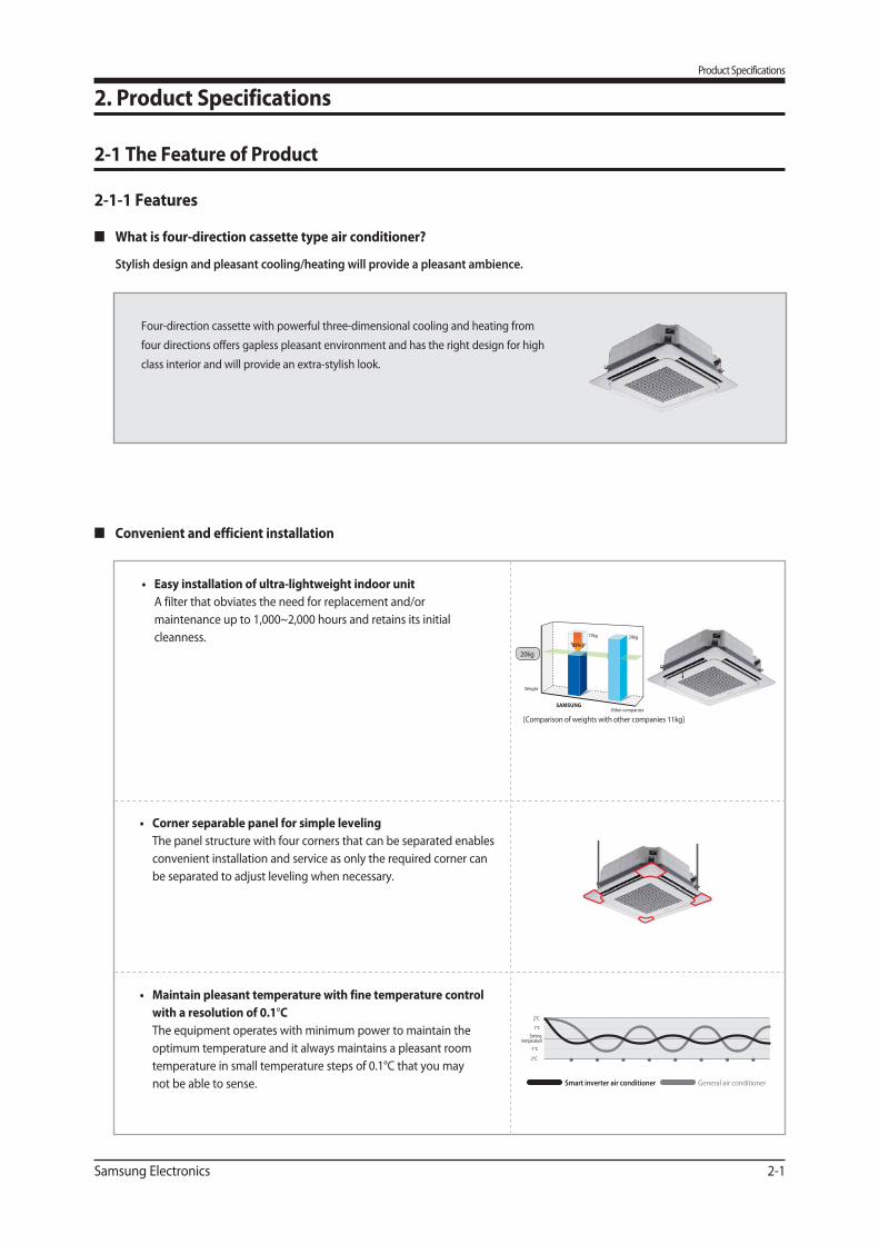
Convenient and efficient installation
The panel structure with four corners that can be separated enables
convenient installation and service as only the required corner can
be separated to adjust leveling when necessary.
with a resolution of 0.1°C
The equipment operates with minimum power to maintain the
optimum temperature and it always maintains a pleasant room
temperature in small temperature steps of 0.1°C that you may
not be able to sense.
A filter that obviates the need for replacement and/or
maintenance up to 1,000~2,000 hours and retains its initial
cleanness.
[Comparison of weights with other companies 11kg]
HAUZENOther companies
Weight
20Kg
17kg
35%
29kg
[Comparison of weights with other companies 11kg]
20kg
2. Product Specifications
2-1 The Feature of Product
2°C
1°C
Setting temperature
-1°C
-2°C
Smart inverter air conditioner General air conditioner
Four-direction cassette with powerful three-dimensional cooling and heating from
four directions offers gapless pleasant environment and has the right design for high
class interior and will provide an extra-stylish look.
2-1-1 Features
What is four-direction cassette type air conditioner?
Stylish design and pleasant cooling/heating will provide a pleasant ambience.
Product Specifications
2-2 Samsung Electronics
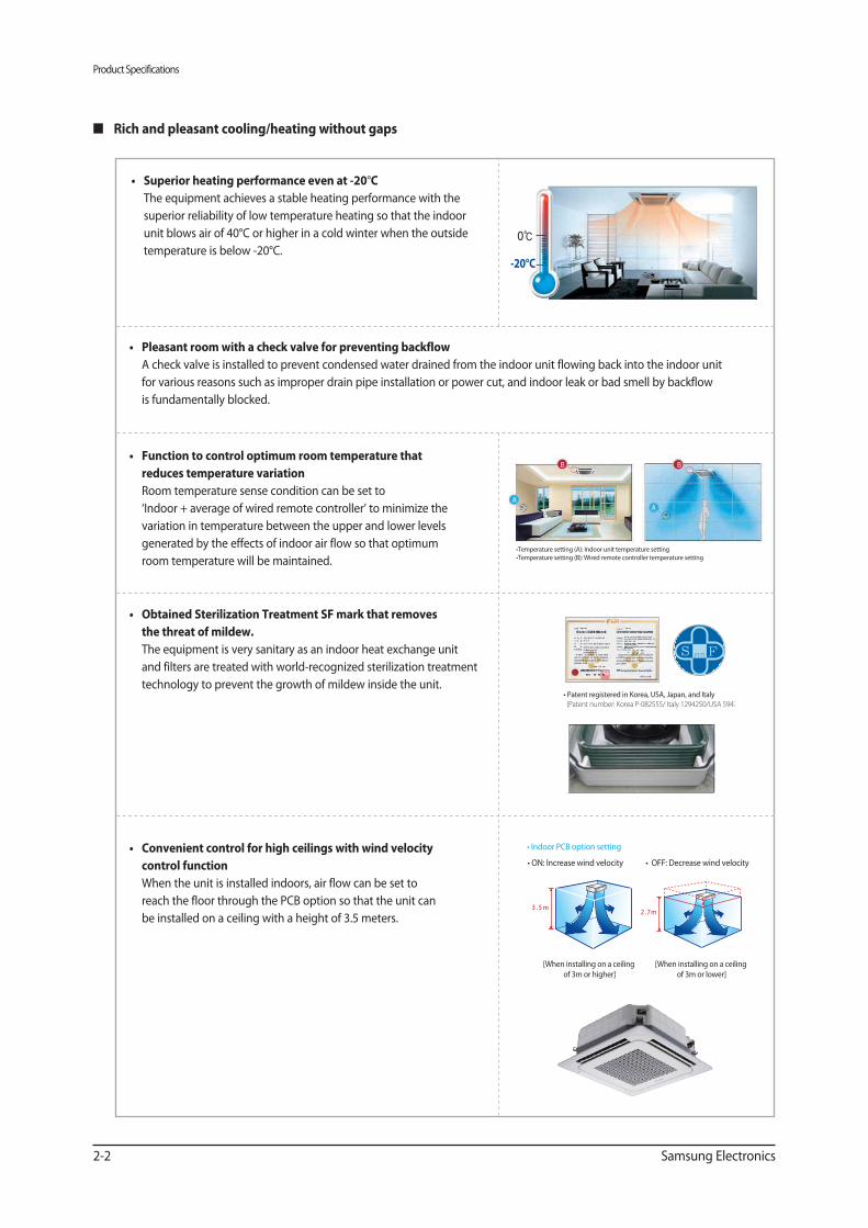
Rich and pleasant cooling/heating without gaps
°C
The equipment achieves a stable heating performance with the
superior reliability of low temperature heating so that the indoor
unit blows air of 40°C or higher in a cold winter when the outside
temperature is below -20°C.
A check valve is installed to prevent condensed water drained from the indoor unit flowing back into the indoor unit
for various reasons such as improper drain pipe installation or power cut, and indoor leak or bad smell by backflow
is fundamentally blocked.
reduces temperature variation
Room temperature sense condition can be set to
‘Indoor + average of wired remote controller’ to minimize the
variation in temperature between the upper and lower levels
generated by the effects of indoor air flow so that optimum
room temperature will be maintained.
the threat of mildew.
The equipment is very sanitary as an indoor heat exchange unit
and filters are treated with world-recognized sterilization treatment
technology to prevent the growth of mildew inside the unit.
15℃
0℃
(Patent number: Korea P-082555/ Italy 1294250/USA 5947
control function
When the unit is installed indoors, air flow can be set to
reach the floor through the PCB option so that the unit can
be installed on a ceiling with a height of 3.5 meters.
[When installing on a ceiling
of 3m or higher]
[When installing on a ceiling
of 3m or lower]
m7.2m5.3
-20°C
Product Specifications
Samsung Electronics 2-3
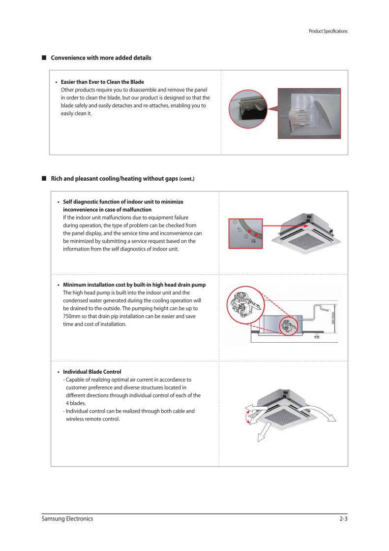
Convenience with more added details
Other products require you to disassemble and remove the panel
in order to clean the blade, but our product is designed so that the
blade safely and easily detaches and re-attaches, enabling you to
easily clean it.
Rich and pleasant cooling/heating without gaps (cont.)
inconvenience in case of malfunction
If the indoor unit malfunctions due to equipment failure
during operation, the type of problem can be checked from
the panel display, and the service time and inconvenience can
be minimized by submitting a service request based on the
information from the self diagnostics of indoor unit.
The high head pump is built into the indoor unit and the
condensed water generated during the cooling operation will
be drained to the outside. The pumping height can be up to
750mm so that drain pip installation can be easier and save
time and cost of installation.
- Capable of realizing optimal air current in accordance to
customer preference and diverse structures located in
different directions through individual control of each of the
4 blades.
- Individual control can be realized through both cable and
wireless remote control.
Product Specifications
2-4 Samsung Electronics
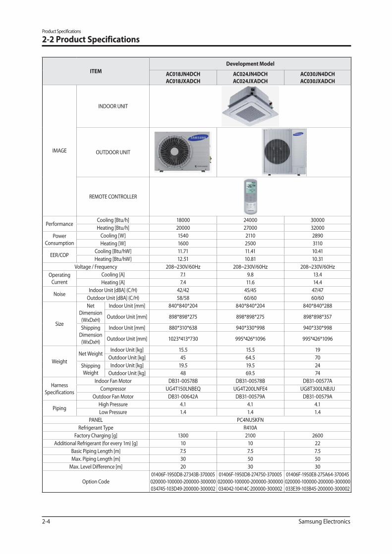
2-2 Product Specifications
ITEM
Development Model
AC018JN4DCH
AC018JXADCH
AC024JN4DCH
AC024JXADCH
AC030JN4DCH
AC030JXADCH
IMAGE
INDOOR UNIT
OUTDOOR UNIT
REMOTE CONTROLLER
PerformanceCooling [Btu/h] 18000 24000 30000
Heating [Btu/h] 20000 27000 32000
Power
Consumption
Cooling [W] 1540 2110 2890
Heating [W] 1600 2500 3110
EER/COPCooling [Btu/hW] 11.71 11.41 10.41
Heating [Btu/hW] 12.51 10.81 10.31
Voltage / Frequency 208~230V/60Hz 208~230V/60Hz 208~230V/60Hz
Operating
Current
Cooling [A] 7.1 9.8 13.4
Heating [A] 7.4 11.6 14.4
NoiseIndoor Unit [dBA] (C/H) 42/42 45/45 47/47
Outdoor Unit [dBA] (C/H) 58/58 60/60 60/60
Size
Net
Dimension
(WxDxH)
Indoor Unit [mm] 840*840*204 840*840*204 840*840*288
Outdoor Unit [mm] 898*898*275 898*898*275 898*898*357
Shipping
Dimension
(WxDxH)
Indoor Unit [mm] 880*310*638 940*330*998 940*330*998
Outdoor Unit [mm] 1023*413*730 995*426*1096 995*426*1096
Weight
Net WeightIndoor Unit [kg] 15.5 15.5 19
Outdoor Unit [kg] 45 64.5 70
Shipping
Weight
Indoor Unit [kg] 19.5 19.5 24
Outdoor Unit [kg] 48 69.5 74
Harness
Specifications
Indoor Fan Motor DB31-00578B DB31-00578B DB31-00577A
Compressor UG4T150LNBEQ UG4T200LNFE4 UG8T300LNBJU
Outdoor Fan Motor DB31-00642A DB31-00579A DB31-00579A
PipingHigh Pressure 4.1 4.1 4.1
Low Pressure 1.4 1.4 1.4
PANEL PC4NUSKFN
Refrigerant Type R410A
Factory Charging [g] 1300 2100 2600
Additional Refrigerant (for every 1m) [g] 10 10 22
Basic Piping Length [m] 7.5 7.5 7.5
Max. Piping Length [m] 30 50 50
Max. Level Difference [m] 20 30 30
Option Code
01406F-1950D8-27343B-370005
020000-100000-200000-300000
034745-103D49-200000-300002
01406F-1950D8-274750-370005
020000-100000-200000-300000
034042-10414C-200000-300002
01406F-1950E8-275A64-370045
020000-100000-200000-300000
033E39-103B45-200000-300002
Product Specifications
Samsung Electronics 2-5
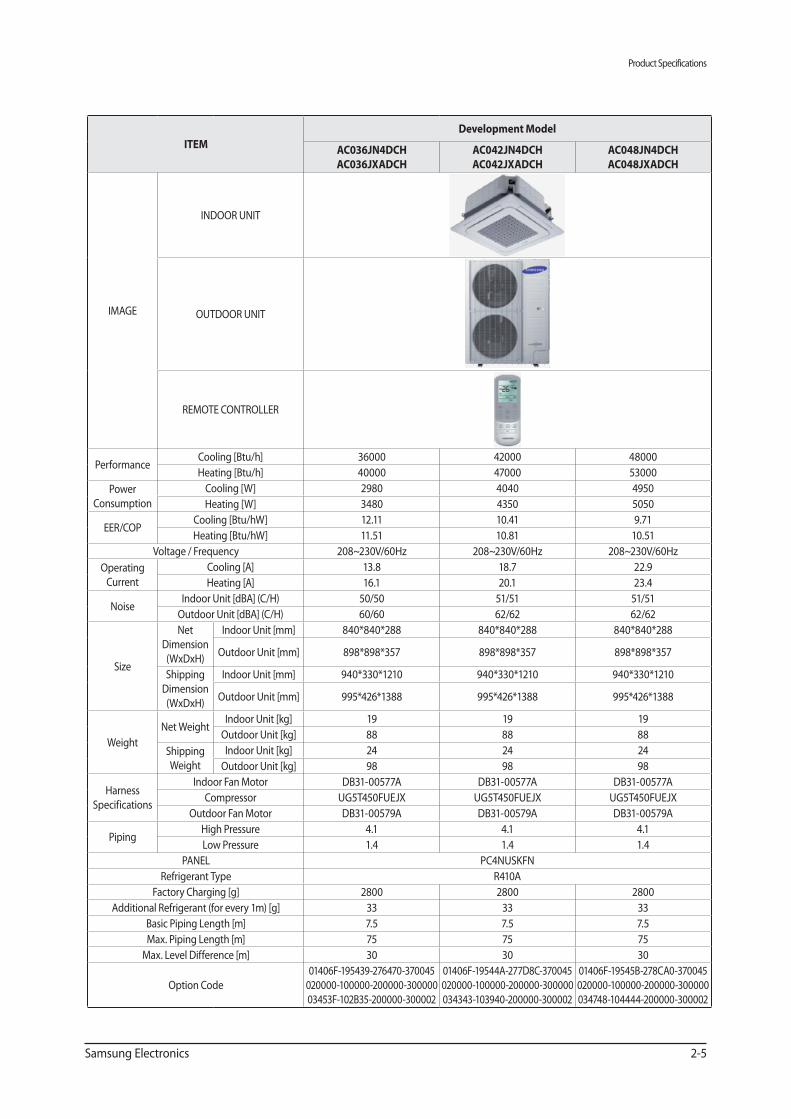
ITEM
Development Model
AC036JN4DCH
AC036JXADCH
AC042JN4DCH
AC042JXADCH
AC048JN4DCH
AC048JXADCH
IMAGE
INDOOR UNIT
OUTDOOR UNIT
REMOTE CONTROLLER
PerformanceCooling [Btu/h] 36000 42000 48000
Heating [Btu/h] 40000 47000 53000
Power
Consumption
Cooling [W] 2980 4040 4950
Heating [W] 3480 4350 5050
EER/COPCooling [Btu/hW] 12.11 10.41 9.71
Heating [Btu/hW] 11.51 10.81 10.51
Voltage / Frequency 208~230V/60Hz 208~230V/60Hz 208~230V/60Hz
Operating
Current
Cooling [A] 13.8 18.7 22.9
Heating [A] 16.1 20.1 23.4
NoiseIndoor Unit [dBA] (C/H) 50/50 51/51 51/51
Outdoor Unit [dBA] (C/H) 60/60 62/62 62/62
Size
Net
Dimension
(WxDxH)
Indoor Unit [mm] 840*840*288 840*840*288 840*840*288
Outdoor Unit [mm] 898*898*357 898*898*357 898*898*357
Shipping
Dimension
(WxDxH)
Indoor Unit [mm] 940*330*1210 940*330*1210 940*330*1210
Outdoor Unit [mm] 995*426*1388 995*426*1388 995*426*1388
Weight
Net WeightIndoor Unit [kg] 19 19 19
Outdoor Unit [kg] 88 88 88
Shipping
Weight
Indoor Unit [kg] 24 24 24
Outdoor Unit [kg] 98 98 98
Harness
Specifications
Indoor Fan Motor DB31-00577A DB31-00577A DB31-00577A
Compressor UG5T450FUEJX UG5T450FUEJX UG5T450FUEJX
Outdoor Fan Motor DB31-00579A DB31-00579A DB31-00579A
PipingHigh Pressure 4.1 4.1 4.1
Low Pressure 1.4 1.4 1.4
PANEL PC4NUSKFN
Refrigerant Type R410A
Factory Charging [g] 2800 2800 2800
Additional Refrigerant (for every 1m) [g] 33 33 33
Basic Piping Length [m] 7.5 7.5 7.5
Max. Piping Length [m] 75 75 75
Max. Level Difference [m] 30 30 30
Option Code
01406F-195439-276470-370045
020000-100000-200000-300000
03453F-102B35-200000-300002
01406F-19544A-277D8C-370045
020000-100000-200000-300000
034343-103940-200000-300002
01406F-19545B-278CA0-370045
020000-100000-200000-300000
034748-104444-200000-300002
Product Specifications
2-6 Samsung Electronics
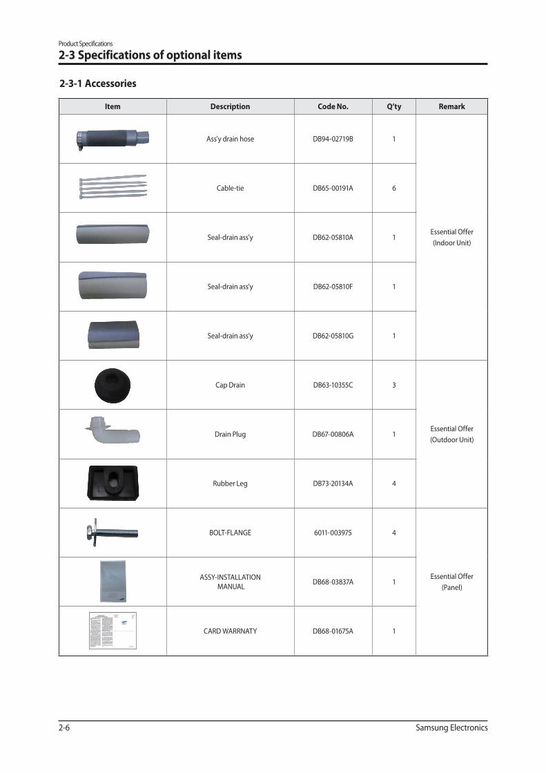
Item Description Q’ty Remark
Ass'y drain hose DB94-02719B 1
Essential Offer
(Indoor Unit)
Cable-tie DB65-00191A 6
Seal-drain ass'y DB62-05810A 1
Seal-drain ass'y DB62-05810F 1
Seal-drain ass'y DB62-05810G 1
Cap Drain DB63-10355C 3
Essential Offer
(Outdoor Unit)Drain Plug DB67-00806A 1
Rubber Leg DB73-20134A 4
BOLT-FLANGE 6011-003975 4
Essential Offer
(Panel)
ASSY-INSTALLATION
MANUALDB68-03837A 1
CARD WARRNATY DB68-01675A 1
2-3 Specifications of optional items
2-3-1 Accessories
Product Specifications
Samsung Electronics 2-7
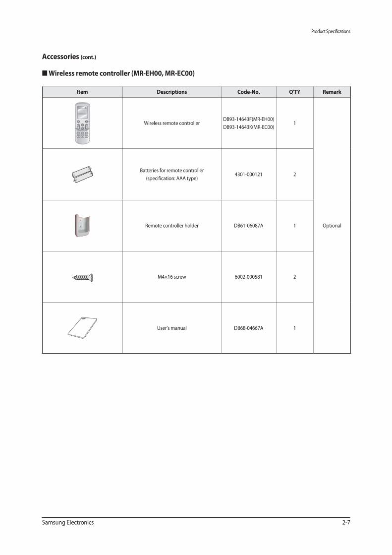
Item Descriptions Q'TY Remark
Wireless remote controllerDB93-14643F(MR-EH00)
DB93-14643K(MR-EC00)1
Optional
Batteries for remote controller
(specification: AAA type)4301-000121 2
Remote controller holder DB61-06087A 1
M4×16 screw 6002-000581 2
User’s manual DB68-04667A 1
Accessories (cont.)
■
Product Specifications
2-8 Samsung Electronics
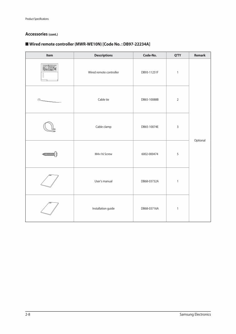
Accessories (cont.)
■
Item Descriptions Q'TY Remark
Wired remote controller DB93-11251F 1
Optional
Cable tie DB65-10088B 2
Cable clamp DB65-10074E 3
M4×16 Screw 6002-000474 5
User’s manual DB68-03732A 1
Installation guide DB68-03716A 1
Product Specifications
Samsung Electronics 2-9
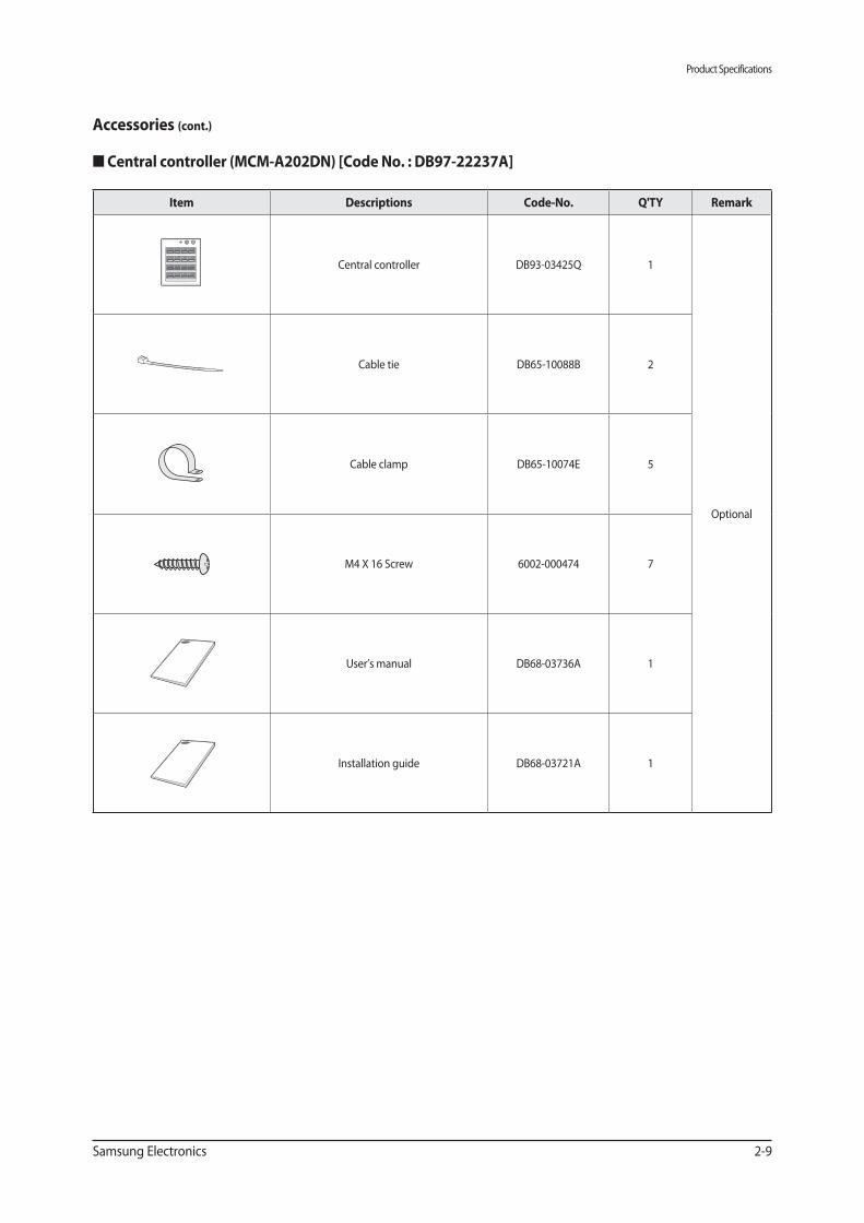
Accessories (cont.)
■
Item Descriptions Q'TY Remark
Central controller DB93-03425Q 1
Optional
Cable tie DB65-10088B 2
Cable clamp DB65-10074E 5
M4 X 16 Screw 6002-000474 7
User’s manual DB68-03736A 1
Installation guide DB68-03721A 1
Product Specifications
2-10 Samsung Electronics
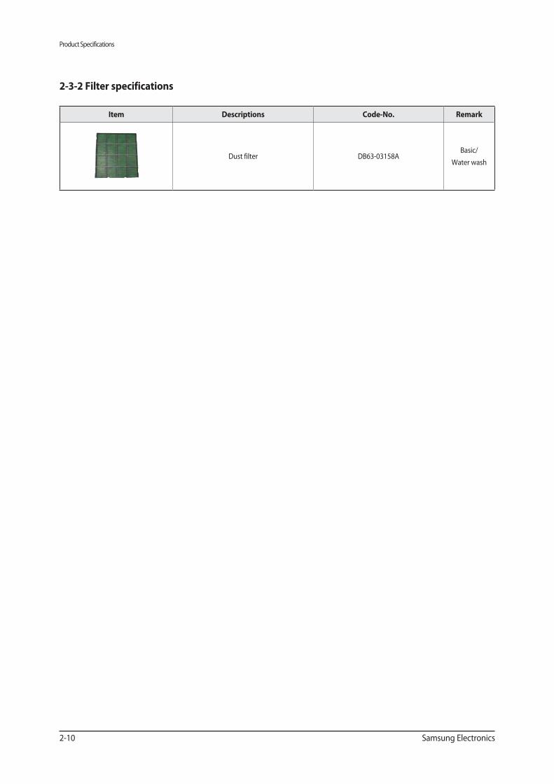
2-3-2 Filter specifications
Item Descriptions Remark
Dust filter DB63-03158ABasic/
Water wash
Samsung Electronics 3-1
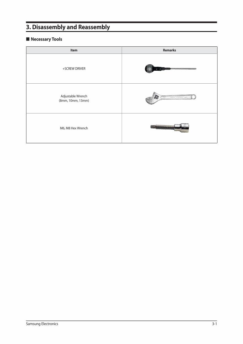
Item Remarks
+SCREW DRIVER
Adjustable Wrench
(8mm, 10mm, 13mm)
M6, M8 Hex Wrench
3. Disassembly and Reassembly
Disassembly and Reassembly
3-2 Samsung Electronics
Parts Procedure Remark
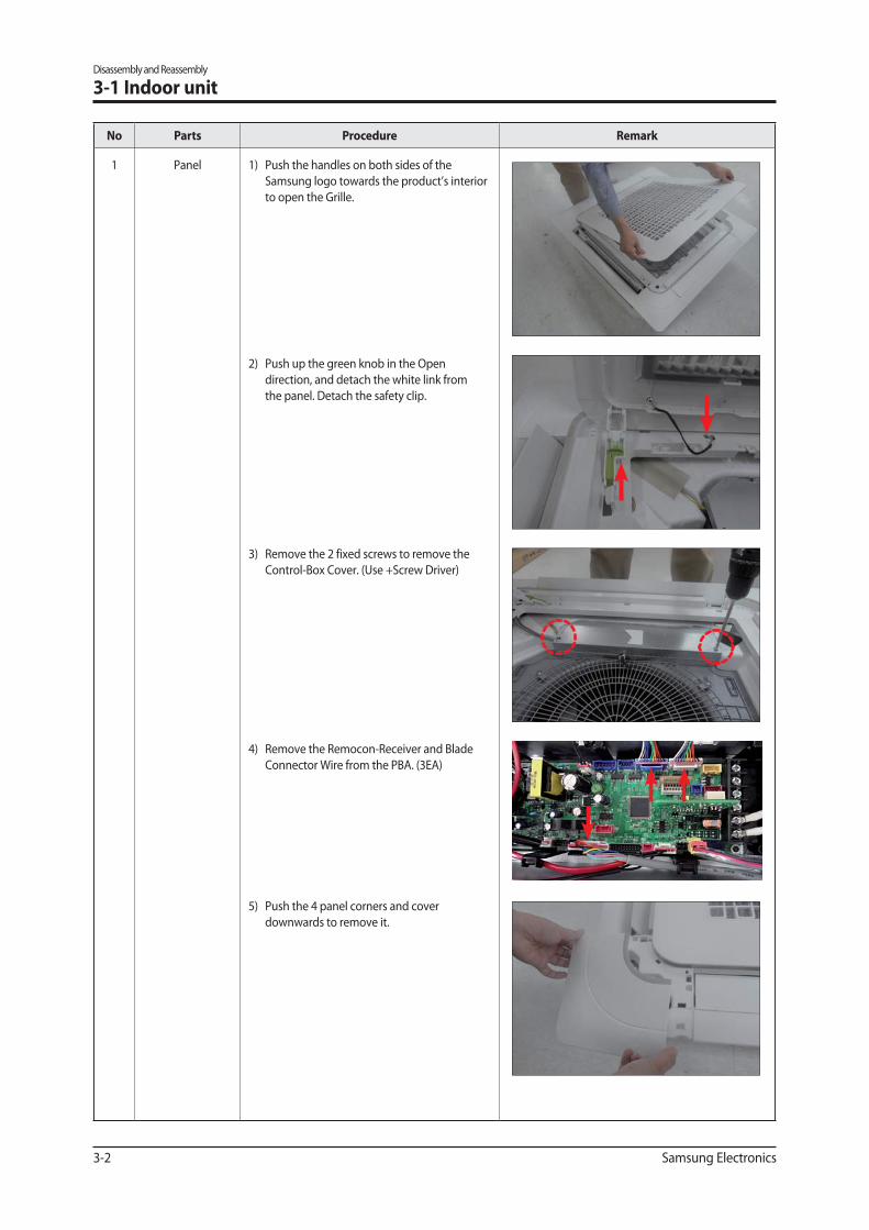
1 Panel 1) Push the handles on both sides of the
Samsung logo towards the product’s interior
to open the Grille.
2) Push up the green knob in the Open
direction, and detach the white link from
the panel. Detach the safety clip.
3) Remove the 2 fixed screws to remove the
Control-Box Cover. (Use +Screw Driver)
4) Remove the Remocon-Receiver and Blade
Connector Wire from the PBA. (3EA)
5) Push the 4 panel corners and cover
downwards to remove it.
3-1 Indoor unit
Disassembly and Reassembly
Samsung Electronics 3-3
Parts Procedure Remark
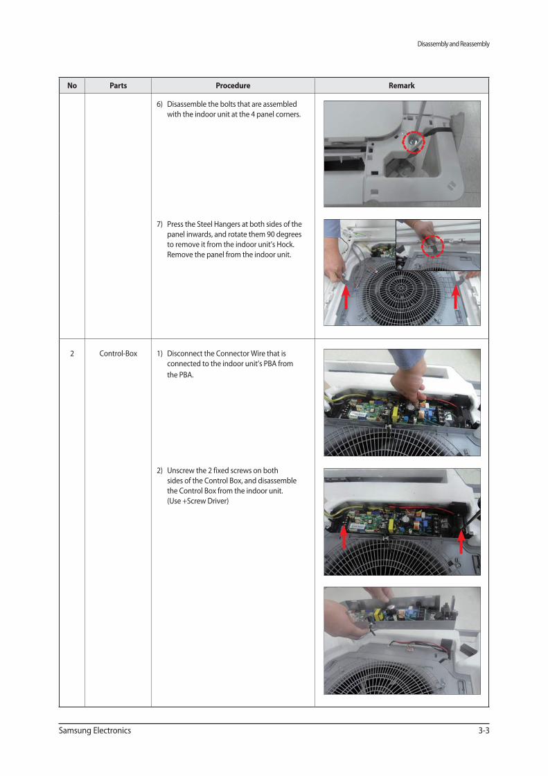
6) Disassemble the bolts that are assembled
with the indoor unit at the 4 panel corners.
7) Press the Steel Hangers at both sides of the
panel inwards, and rotate them 90 degrees
to remove it from the indoor unit’s Hock.
Remove the panel from the indoor unit.
2 Control-Box 1) Disconnect the Connector Wire that is
connected to the indoor unit’s PBA from
the PBA.
2) Unscrew the 2 fixed screws on both
sides of the Control Box, and disassemble
the Control Box from the indoor unit.
(Use +Screw Driver)
Disassembly and Reassembly
3-4 Samsung Electronics
Parts Procedure Remark
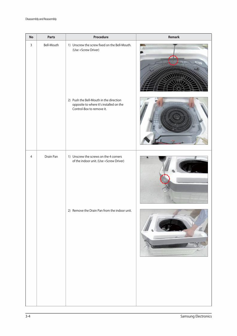
3 Bell-Mouth 1) Unscrew the screw fixed on the Bell-Mouth.
(Use +Screw Driver)
2) Push the Bell-Mouth in the direction
opposite to where it’s installed on the
Control-Box to remove it.
4 Drain Pan 1) Unscrew the screws on the 4 corners
of the indoor unit. (Use +Screw Driver)
2) Remove the Drain Pan from the indoor unit.
Disassembly and Reassembly
Samsung Electronics 3-5
Parts Procedure Remark
5 Drain Pump
&
Hose
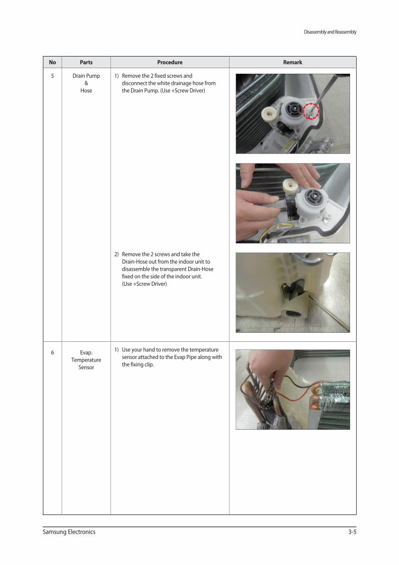
1) Remove the 2 fixed screws and
disconnect the white drainage hose from
the Drain Pump. (Use +Screw Driver)
2) Remove the 2 screws and take the
Drain-Hose out from the indoor unit to
disassemble the transparent Drain-Hose
fixed on the side of the indoor unit.
(Use +Screw Driver)
6 Evap.
Temperature
Sensor
1) Use your hand to remove the temperature
sensor attached to the Evap Pipe along with
the fixing clip.
Disassembly and Reassembly
3-6 Samsung Electronics
Parts Procedure Remark
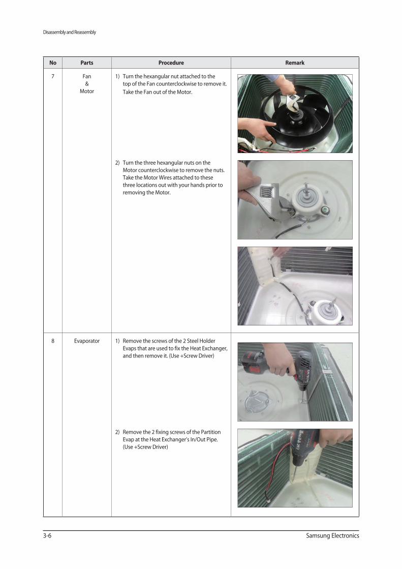
7 Fan
&
Motor
1) Turn the hexangular nut attached to the
top of the Fan counterclockwise to remove it.
Take the Fan out of the Motor.
2) Turn the three hexangular nuts on the
Motor counterclockwise to remove the nuts.
Take the Motor Wires attached to these
three locations out with your hands prior to
removing the Motor.
8 Evaporator 1) Remove the screws of the 2 Steel Holder
Evaps that are used to fix the Heat Exchanger,
and then remove it. (Use +Screw Driver)
2) Remove the 2 fixing screws of the Partition
Evap at the Heat Exchanger’s In/Out Pipe.
(Use +Screw Driver)
Disassembly and Reassembly
Samsung Electronics 3-7
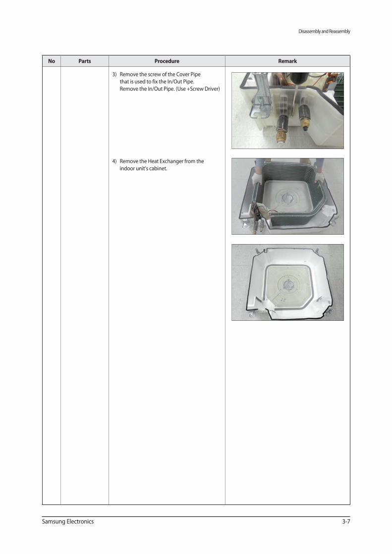
Parts Procedure Remark
3) Remove the screw of the Cover Pipe
that is used to fix the In/Out Pipe.
Remove the In/Out Pipe. (Use +Screw Driver)
4) Remove the Heat Exchanger from the
indoor unit’s cabinet.
Disassembly and Reassembly
3-8 Samsung Electronics
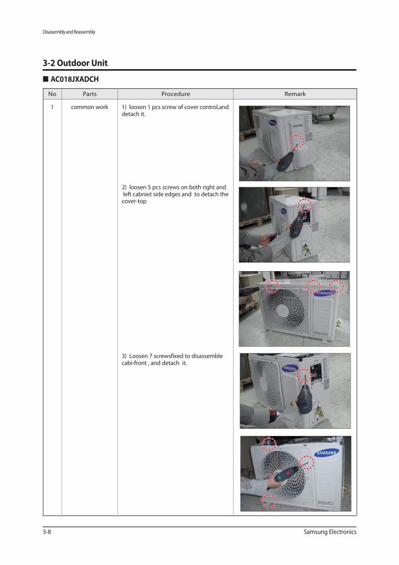
No Parts Procedure Remark
1 common work 1) loosen 1 pcs screw of cover control,and detach it.
2) loosen 5 pcs screws on both right and left cabniet side edges and to detach the cover-top
3) Loosen 7 screwsfixed to disassemble cabi-front , and detach it.
3-2 Outdoor Unit
Disassembly and Reassembly
Samsung Electronics 3-9
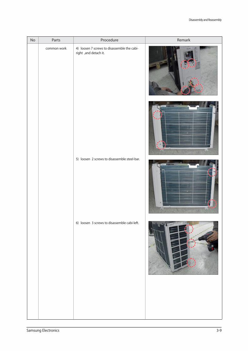
No Parts Procedure Remark
common work 4) loosen 7 screws to disassemble the cabi-
right ,and detach it.
5) loosen 2 screws to disassemble steel-bar.
6) loosen 3 screws to disassemble cabi-left.
Disassembly and Reassembly
3-10 Samsung Electronics
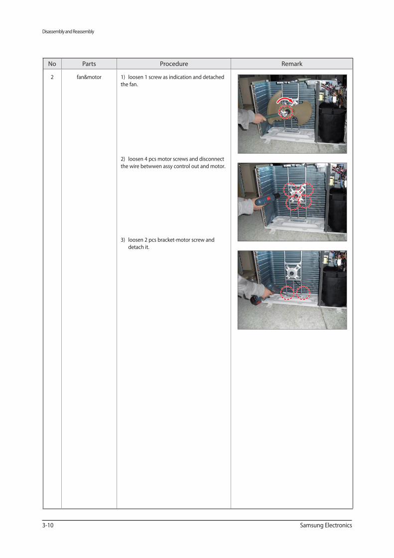
No Parts Procedure Remark
2 fan&motor 1) loosen 1 screw as indication and detached
the fan.
2) loosen 4 pcs motor screws and disconnect
the wire betwwen assy control out and motor.
3) loosen 2 pcs bracket-motor screw and
detach it.

Disassembly and Reassembly
Samsung Electronics 3-11
No Parts Procedure Remark
3 assy control out 1) lossen fixing 1 screw from cover -control
2) detach several connections from assy con-
trol out, take out assy control out.
4 Heat exchanger 1) Release the refrigerant at first
2) Looosen fixing screw on both side.
3) disaessembly the pipes in both inlet and
outlet with welding torch.
4) detach the heat exchanger.
Disassembly and Reassembly
3-12 Samsung Electronics
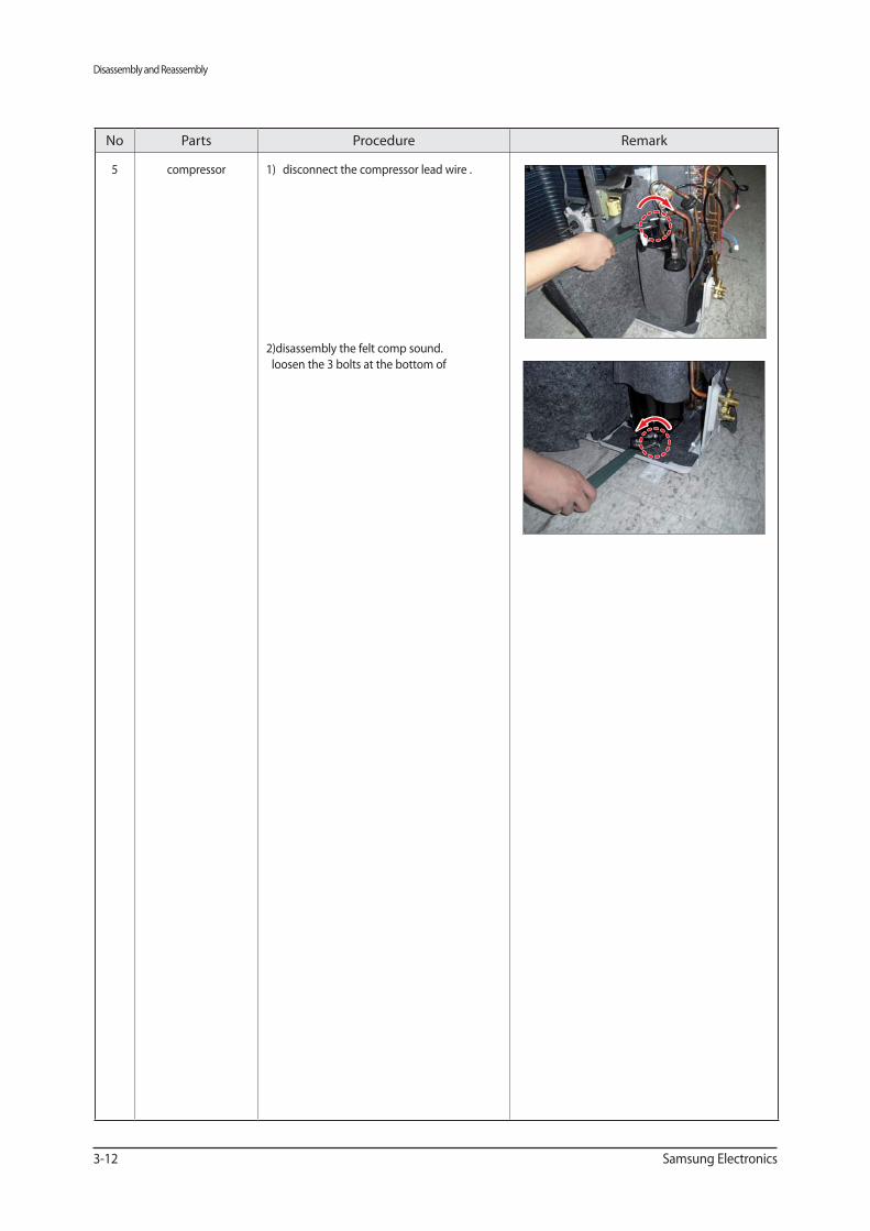
No Parts Procedure Remark
5 compressor 1) disconnect the compressor lead wire .
2)disassembly the felt comp sound.
loosen the 3 bolts at the bottom of
Disassembly and Reassembly
Samsung Electronics 3-13
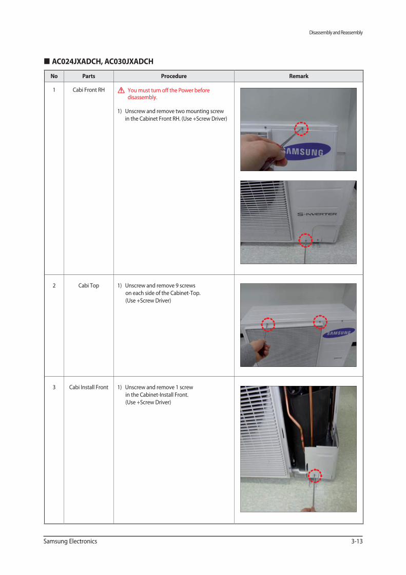
Parts Procedure Remark
1 Cabi Front RH You must turn off the Power before disassembly.
1) Unscrew and remove two mounting screw
in the Cabinet Front RH. (Use +Screw Driver)
2 Cabi Top 1) Unscrew and remove 9 screws
on each side of the Cabinet-Top.
(Use +Screw Driver)
3 Cabi Install Front 1) Unscrew and remove 1 screw
in the Cabinet-Install Front.
(Use +Screw Driver)
Disassembly and Reassembly
3-14 Samsung Electronics
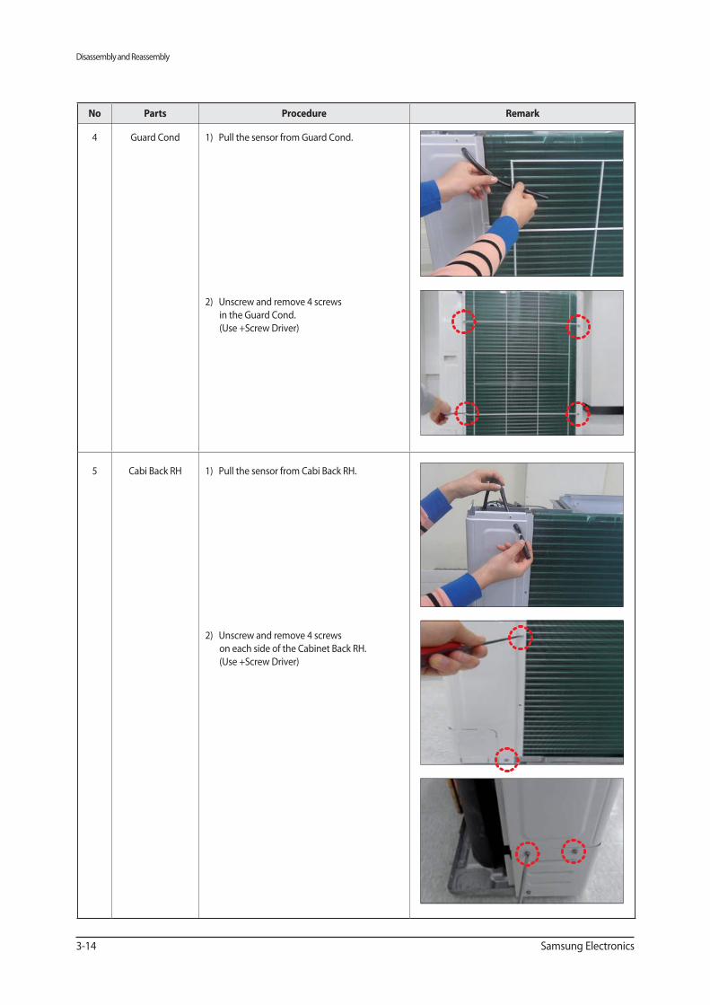
Parts Procedure Remark
4 Guard Cond 1) Pull the sensor from Guard Cond.
2) Unscrew and remove 4 screws
in the Guard Cond.
(Use +Screw Driver)
5 Cabi Back RH 1) Pull the sensor from Cabi Back RH.
2) Unscrew and remove 4 screws
on each side of the Cabinet Back RH.
(Use +Screw Driver)
Disassembly and Reassembly
Samsung Electronics 3-15
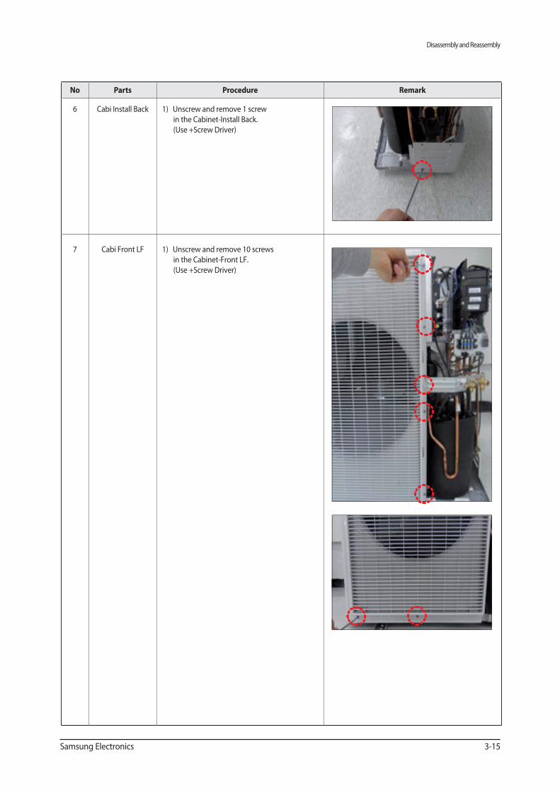
Parts Procedure Remark
6 Cabi Install Back 1) Unscrew and remove 1 screw
in the Cabinet-Install Back.
(Use +Screw Driver)
7 Cabi Front LF 1) Unscrew and remove 10 screws
in the Cabinet-Front LF.
(Use +Screw Driver)
Disassembly and Reassembly
3-16 Samsung Electronics
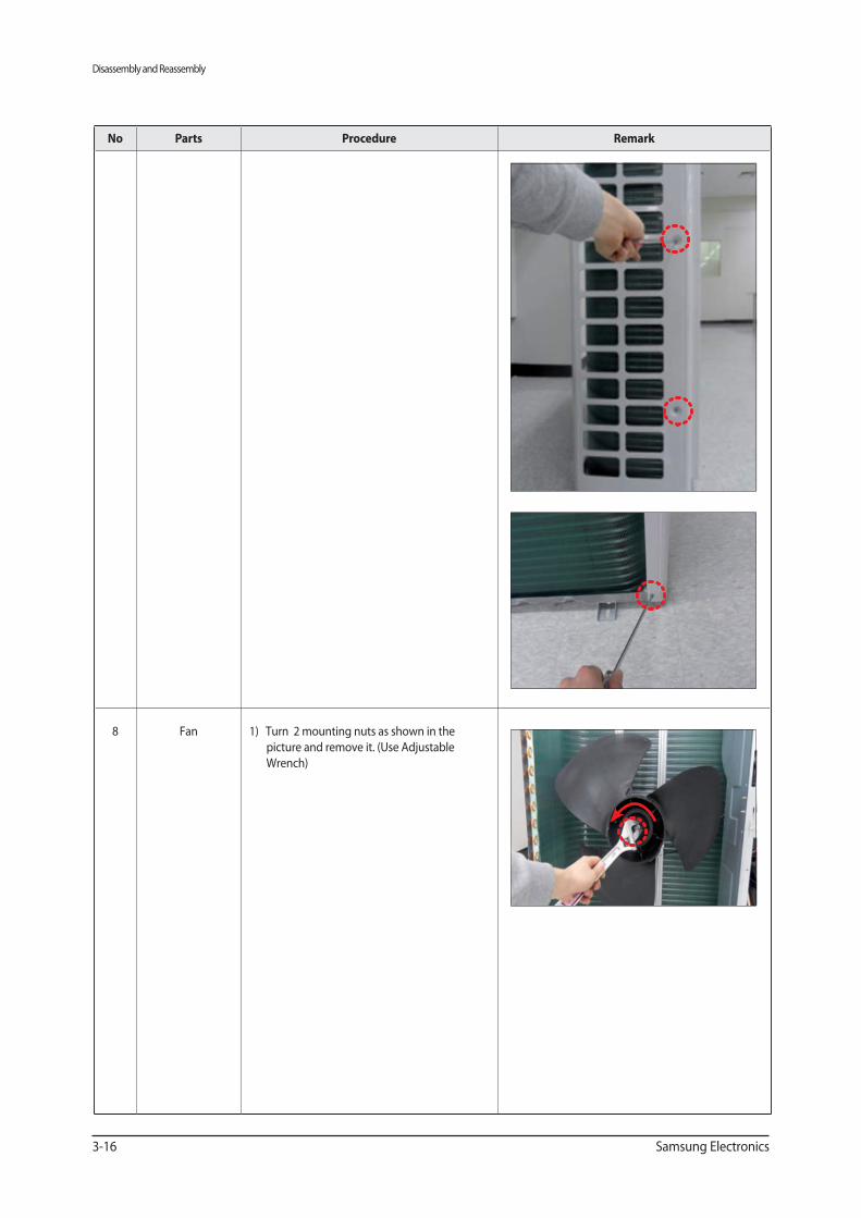
Parts Procedure Remark
8 Fan 1) Turn 2 mounting nuts as shown in the
picture and remove it. (Use Adjustable
Wrench)
Disassembly and Reassembly
Samsung Electronics 3-17
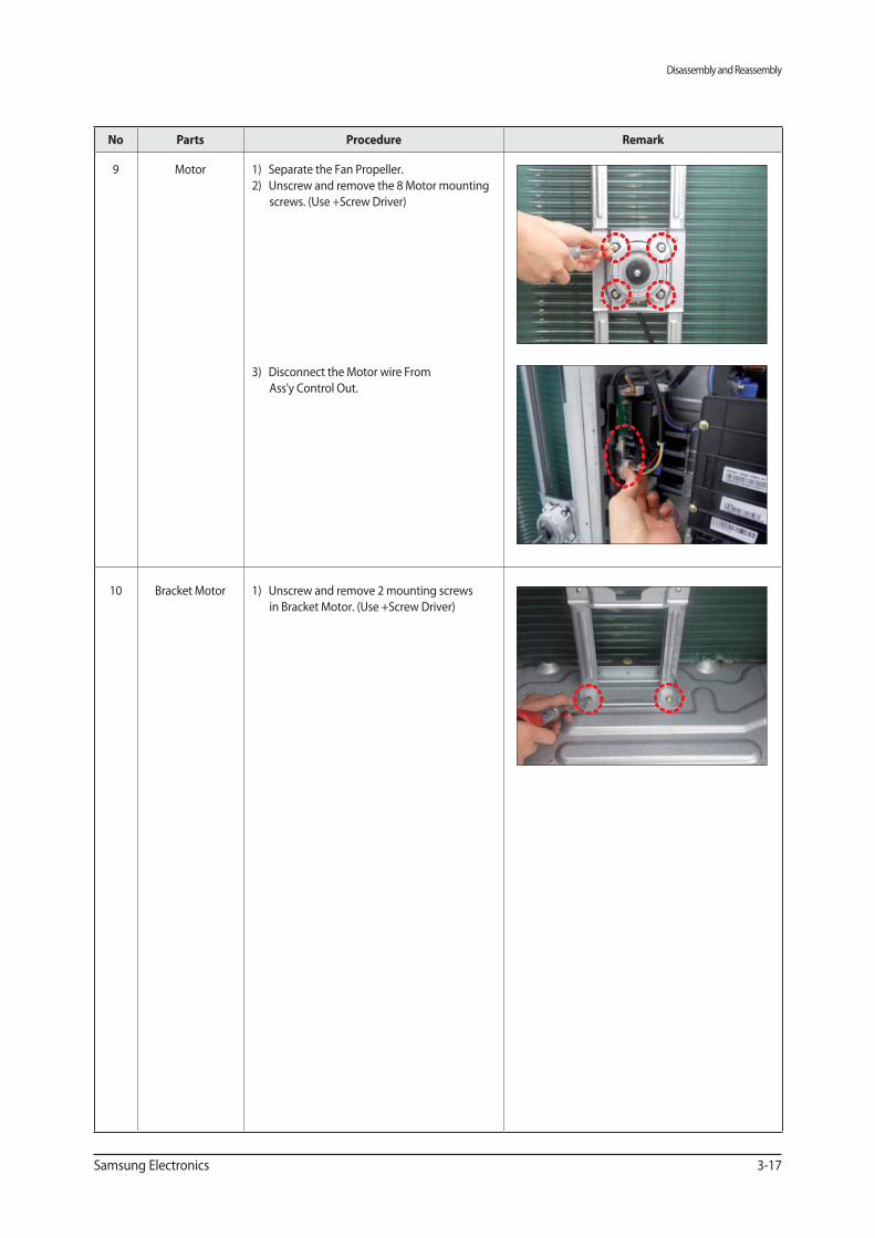
Parts Procedure Remark
9 Motor 1) Separate the Fan Propeller.
2) Unscrew and remove the 8 Motor mounting
screws. (Use +Screw Driver)
3) Disconnect the Motor wire From
Ass'y Control Out.
10 Bracket Motor 1) Unscrew and remove 2 mounting screws
in Bracket Motor. (Use +Screw Driver)
Disassembly and Reassembly
3-18 Samsung Electronics
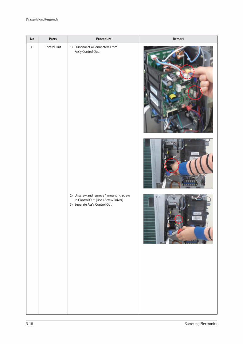
Parts Procedure Remark
11 Control Out 1) Disconnect 4 Connecters From
Ass'y Control Out.
2) Unscrew and remove 1 mounting screw
in Control Out. (Use +Screw Driver)
3) Separate Ass'y Control Out.
Disassembly and Reassembly
Samsung Electronics 3-19
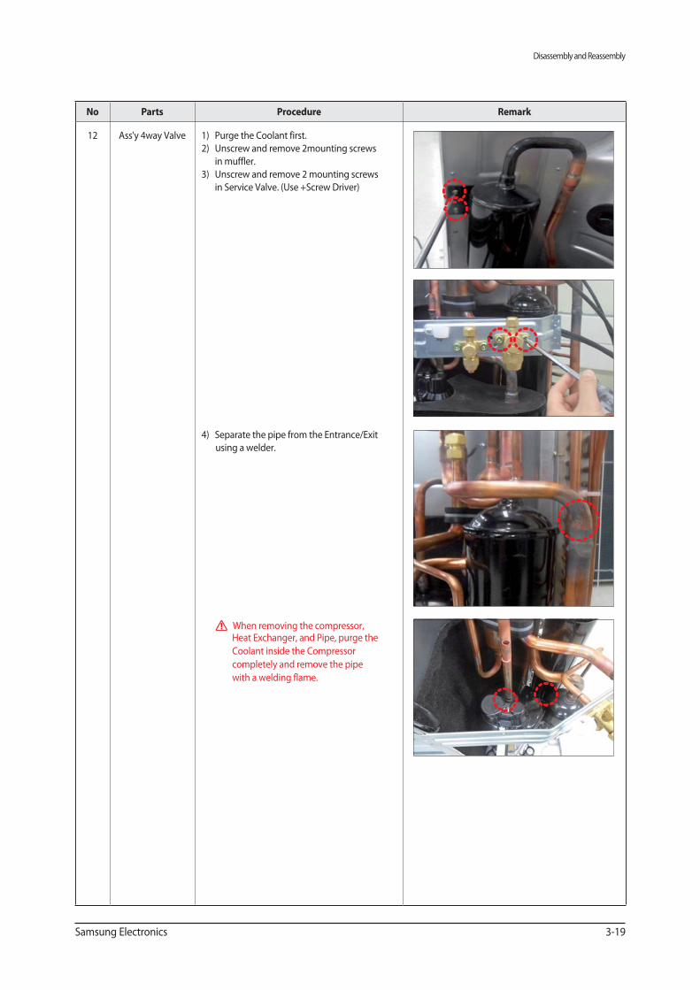
Parts Procedure Remark
12 Ass'y 4way Valve 1) Purge the Coolant first.
2) Unscrew and remove 2mounting screws
in muffler.
3) Unscrew and remove 2 mounting screws
in Service Valve. (Use +Screw Driver)
4) Separate the pipe from the Entrance/Exit
using a welder.
When removing the compressor, Heat Exchanger, and Pipe, purge the
Coolant inside the Compressor
completely and remove the pipe
with a welding flame.
Disassembly and Reassembly
3-20 Samsung Electronics
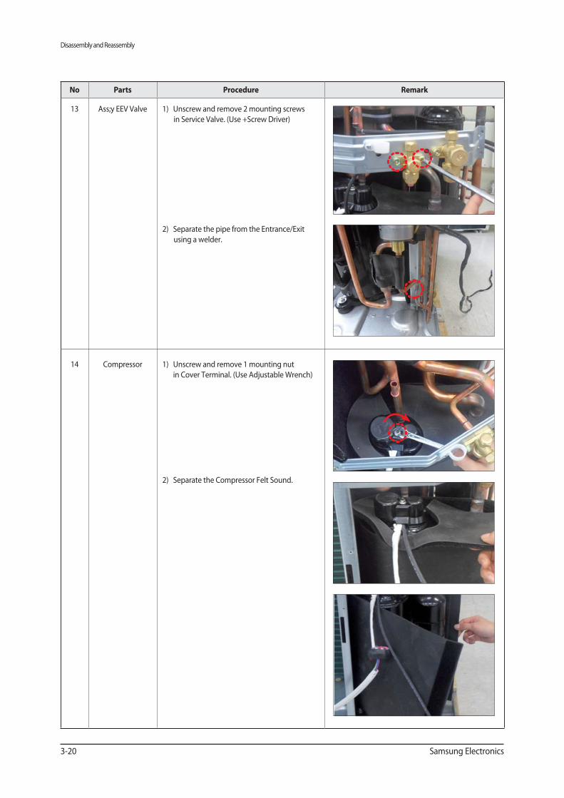
Parts Procedure Remark
13 Ass;y EEV Valve 1) Unscrew and remove 2 mounting screws
in Service Valve. (Use +Screw Driver)
2) Separate the pipe from the Entrance/Exit
using a welder.
14 Compressor 1) Unscrew and remove 1 mounting nut
in Cover Terminal. (Use Adjustable Wrench)
2) Separate the Compressor Felt Sound.
Disassembly and Reassembly
Samsung Electronics 3-21
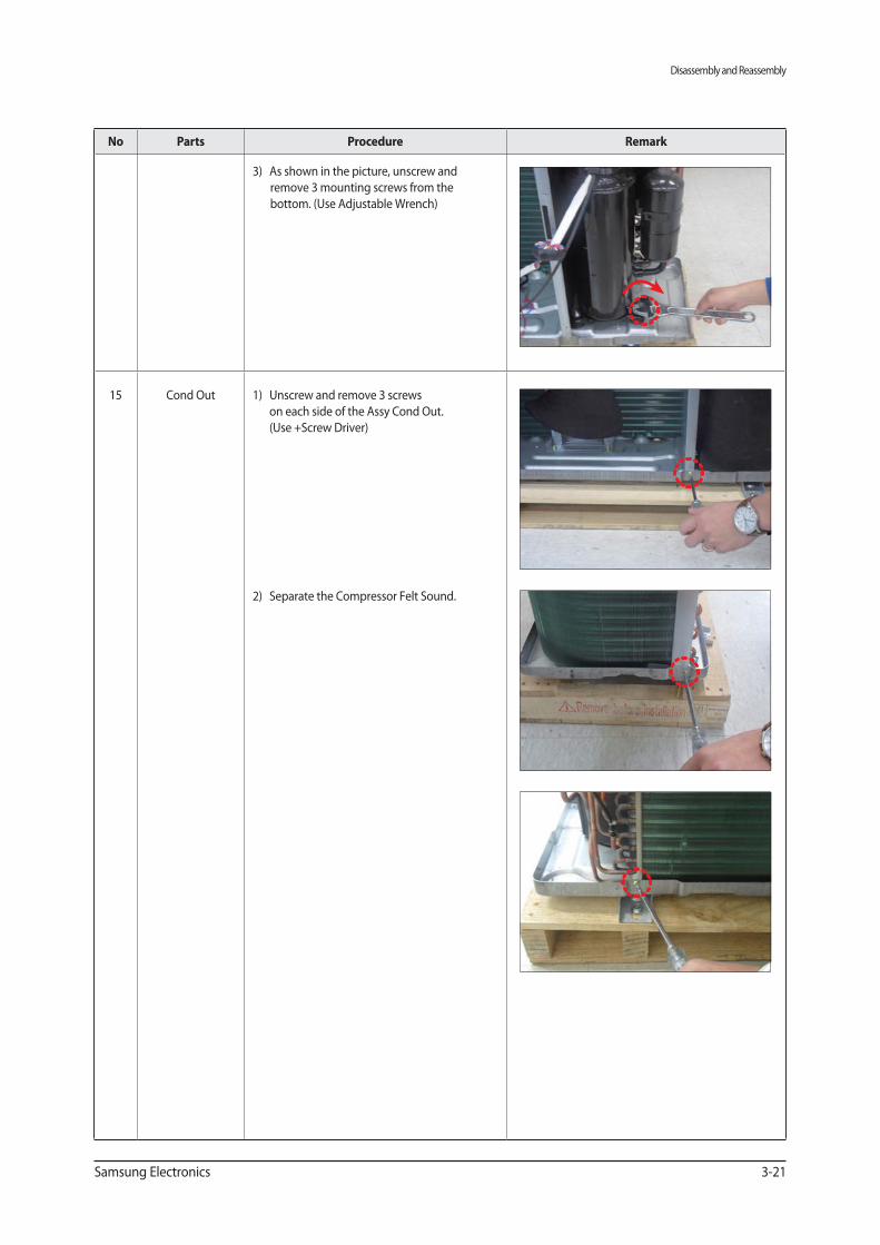
Parts Procedure Remark
3) As shown in the picture, unscrew and
remove 3 mounting screws from the
bottom. (Use Adjustable Wrench)
15 Cond Out 1) Unscrew and remove 3 screws
on each side of the Assy Cond Out.
(Use +Screw Driver)
2) Separate the Compressor Felt Sound.
Disassembly and Reassembly
3-22 Samsung Electronics
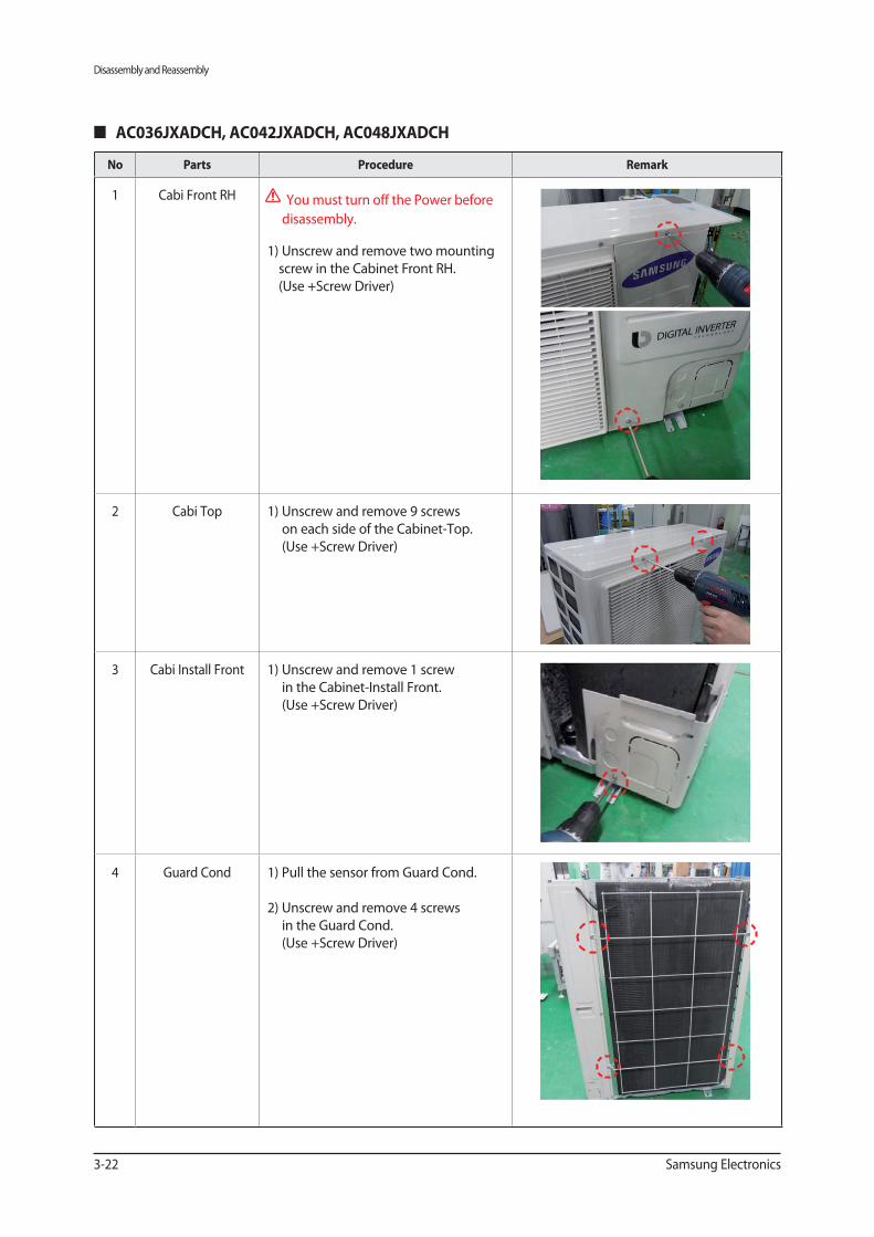
Parts Procedure Remark
1 Cabi Front RH You must turn off the Power before
disassembly.
1) Unscrew and remove two mounting
screw in the Cabinet Front RH.
(Use +Screw Driver)
2 Cabi Top 1) Unscrew and remove 9 screws
on each side of the Cabinet-Top.
(Use +Screw Driver)
3 Cabi Install Front 1) Unscrew and remove 1 screw
in the Cabinet-Install Front.
(Use +Screw Driver)
4 Guard Cond 1) Pull the sensor from Guard Cond.
2) Unscrew and remove 4 screws
in the Guard Cond.
(Use +Screw Driver)
Disassembly and Reassembly
Samsung Electronics 3-23
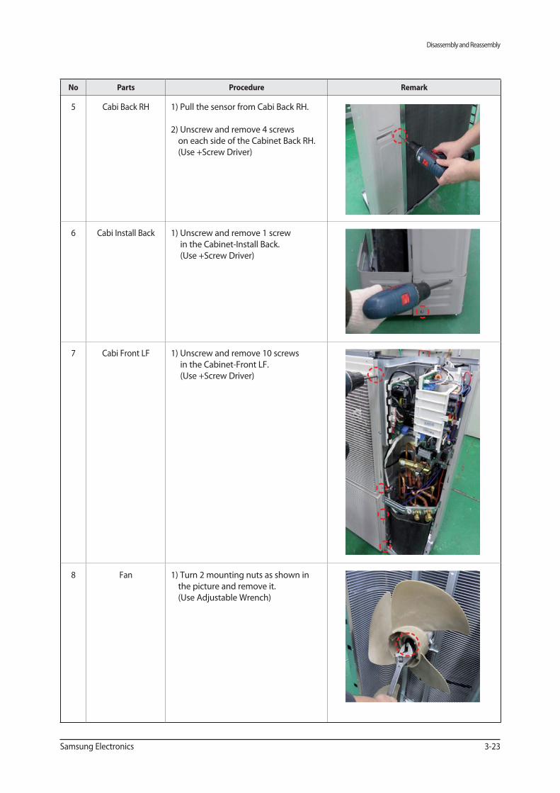
Parts Procedure Remark
5 Cabi Back RH 1) Pull the sensor from Cabi Back RH.
2) Unscrew and remove 4 screws
on each side of the Cabinet Back RH.
(Use +Screw Driver)
6 Cabi Install Back 1) Unscrew and remove 1 screw
in the Cabinet-Install Back.
(Use +Screw Driver)
7 Cabi Front LF 1) Unscrew and remove 10 screws
in the Cabinet-Front LF.
(Use +Screw Driver)
8 Fan 1) Turn 2 mounting nuts as shown in
the picture and remove it.
(Use Adjustable Wrench)
Disassembly and Reassembly
3-24 Samsung Electronics
Parts Procedure Remark
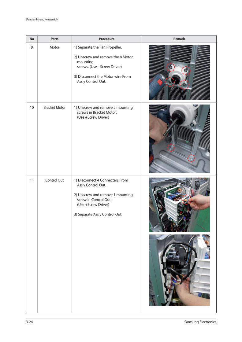
9 Motor 1) Separate the Fan Propeller.
2) Unscrew and remove the 8 Motor
mounting
screws. (Use +Screw Driver)
3) Disconnect the Motor wire From
Ass'y Control Out.
10 Bracket Motor 1) Unscrew and remove 2 mounting
screws in Bracket Motor.
(Use +Screw Driver)
11 Control Out 1) Disconnect 4 Connecters From
Ass'y Control Out.
2) Unscrew and remove 1 mounting
screw in Control Out.
(Use +Screw Driver)
3) Separate Ass'y Control Out.
Disassembly and Reassembly
Samsung Electronics 3-25
Parts Procedure Remark
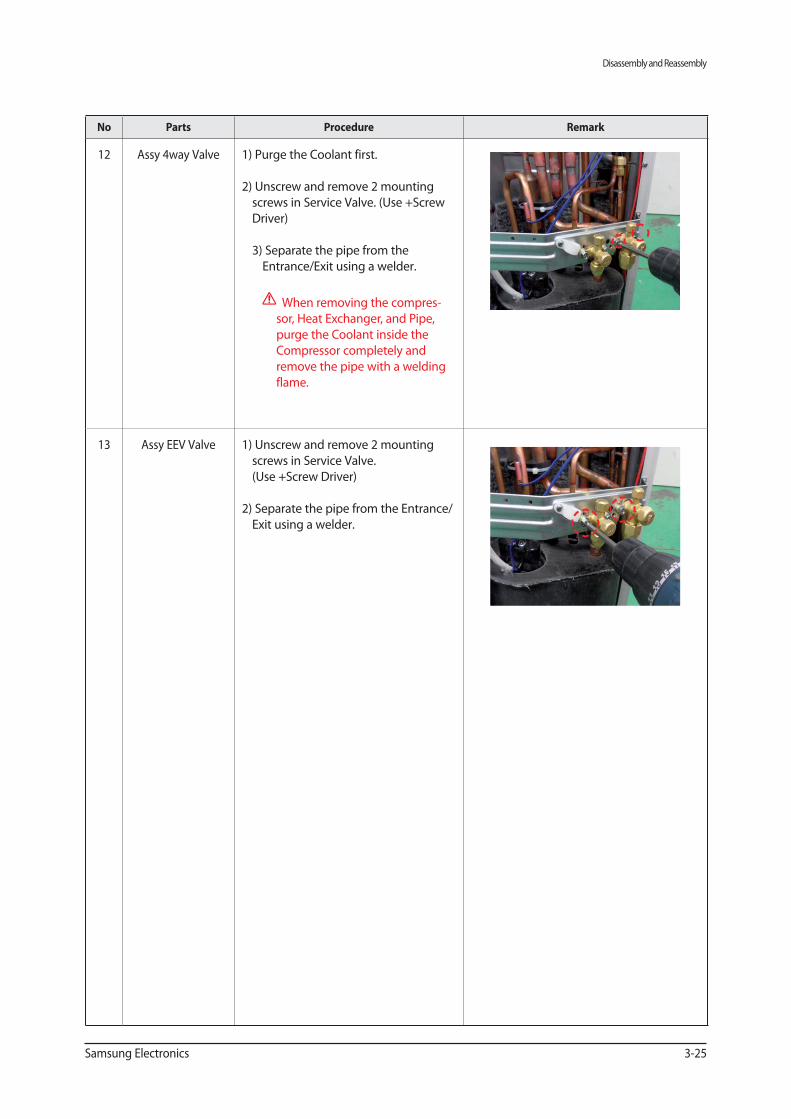
12 Assy 4way Valve 1) Purge the Coolant first.
2) Unscrew and remove 2 mounting
screws in Service Valve. (Use +Screw
Driver)
3) Separate the pipe from the
Entrance/Exit using a welder.
When removing the compres-
sor, Heat Exchanger, and Pipe,
purge the Coolant inside the
Compressor completely and
remove the pipe with a welding
flame.
13 Assy EEV Valve 1) Unscrew and remove 2 mounting
screws in Service Valve.
(Use +Screw Driver)
2) Separate the pipe from the Entrance/
Exit using a welder.
Troubleshooting
Samsung Electronics 4-1
4. Troubleshooting
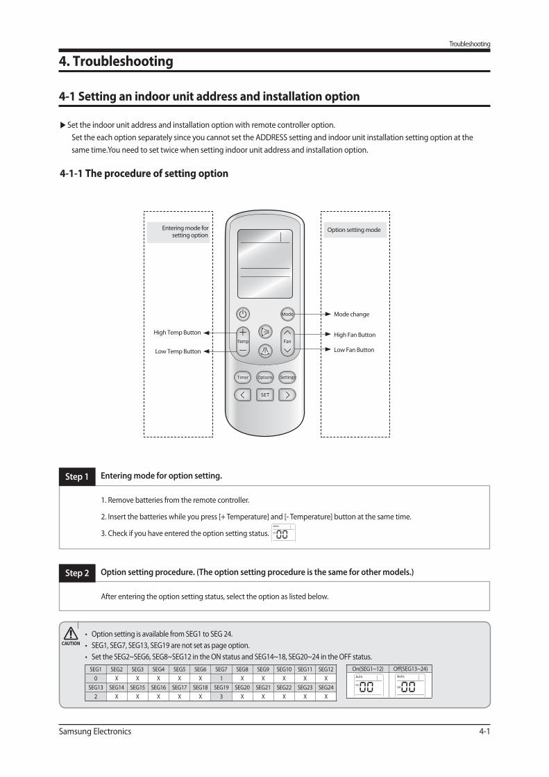
4-1 Setting an indoor unit address and installation option
▶ Set the indoor unit address and installation option with remote controller option.
Set the each option separately since you cannot set the ADDRESS setting and indoor unit installation setting option at the
same time.You need to set twice when setting indoor unit address and installation option.
4-1-1 The procedure of setting option
Step 2 Option setting procedure. (The option setting procedure is the same for other models.)
After entering the option setting status, select the option as listed below.
Step 1 Entering mode for option setting.
1. Remove batteries from the remote controller.
2. Insert the batteries while you press [+ Temperature] and [- Temperature] button at the same time.
3. Check if you have entered the option setting status.
High Temp Button High Fan Button
Mode change
Low Temp Button Low Fan Button
Entering mode for setting option
Option setting mode
SEG1 SEG2 SEG3 SEG4 SEG5 SEG6 SEG7 SEG8 SEG9 SEG10 SEG11 SEG12
0 X X X X X 1 X X X X X
SEG13 SEG14 SEG15 SEG16 SEG17 SEG18 SEG19 SEG20 SEG21 SEG22 SEG23 SEG24
2 X X X X X 3 X X X X X
On(SEG1~12) Off(SEG13~24)
Troubleshooting
4-2 Samsung Electronics
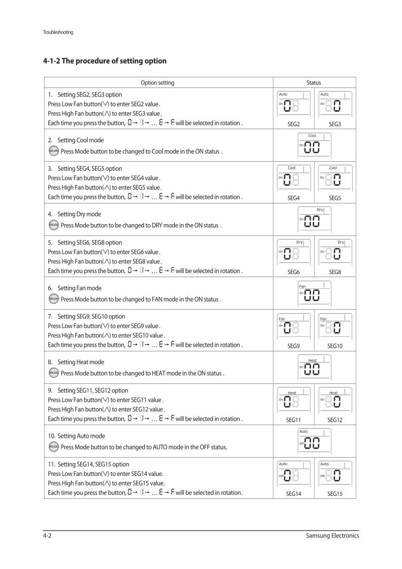
4-1-2 The procedure of setting option
Option setting Status
1. Setting SEG2, SEG3 option
Press Low Fan button( ) to enter SEG2 value .
Press High Fan button( ) to enter SEG3 value .
Each time you press the button, … will be selected in rotation . SEG2 SEG3
2. Setting Cool mode
Press Mode button to be changed to Cool mode in the ON status .
3. Setting SEG4, SEG5 option
Press Low Fan button( ) to enter SEG4 value .
Press High Fan button( ) to enter SEG5 value .
Each time you press the button, … will be selected in rotation . SEG4 SEG5
4. Setting Dry mode
Press Mode button to be changed to DRY mode in the ON status .
5. Setting SEG6, SEG8 option
Press Low Fan button( ) to enter SEG6 value .
Press High Fan button( ) to enter SEG8 value .
Each time you press the button, … will be selected in rotation . SEG6 SEG8
6. Setting Fan mode
Press Mode button to be changed to FAN mode in the ON status .
7. Setting SEG9, SEG10 option
Press Low Fan button( ) to enter SEG9 value .
Press High Fan button( ) to enter SEG10 value .
Each time you press the button, … will be selected in rotation . SEG9 SEG10
8. Setting Heat mode
Press Mode button to be changed to HEAT mode in the ON status .
9. Setting SEG11, SEG12 option
Press Low Fan button( ) to enter SEG11 value .
Press High Fan button( ) to enter SEG12 value .
Each time you press the button, … will be selected in rotation . SEG11 SEG12
10. Setting Auto mode
Press Mode button to be changed to AUTO mode in the OFF status.
11. Setting SEG14, SEG15 option
Press Low Fan button( ) to enter SEG14 value.
Press High Fan button( ) to enter SEG15 value.
Each time you press the button, … will be selected in rotation. SEG14 SEG15
Troubleshooting
Samsung Electronics 4-3
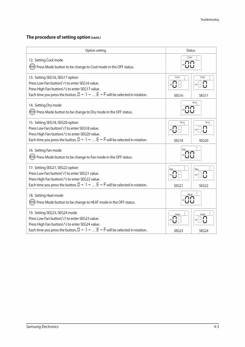
The procedure of setting option (cont.)
Option setting Status
12. Setting Cool mode
Press Mode button to be change to Cool mode in the OFF status.
13. Setting SEG16, SEG17 option
Press Low Fan button( ) to enter SEG16 value.
Press High Fan button( ) to enter SEG17 value.
Each time you press the button, … will be selected in rotation. SEG16 SEG17
14. Setting Dry mode
Press Mode button to be change to Dry mode in the OFF status.
15. Setting SEG18, SEG20 option
Press Low Fan button( ) to enter SEG18 value.
Press High Fan button( ) to enter SEG20 value.
Each time you press the button, … will be selected in rotation. SEG18 SEG20
16. Setting Fan mode
Press Mode button to be change to Fan mode in the OFF status.
17. Setting SEG21, SEG22 option
Press Low Fan button( ) to enter SEG21 value.
Press High Fan button( ) to enter SEG22 value.
Each time you press the button, … will be selected in rotation. SEG21 SEG22
18. Setting Heat mode
Press Mode button to be change to HEAT mode in the OFF status.
19. Setting SEG23, SEG24 mode
Press Low Fan button( ) to enter SEG23 value.
Press High Fan button( ) to enter SEG24 value.
Each time you press the button, … will be selected in rotation. SEG23 SEG24
Troubleshooting
4-4 Samsung Electronics
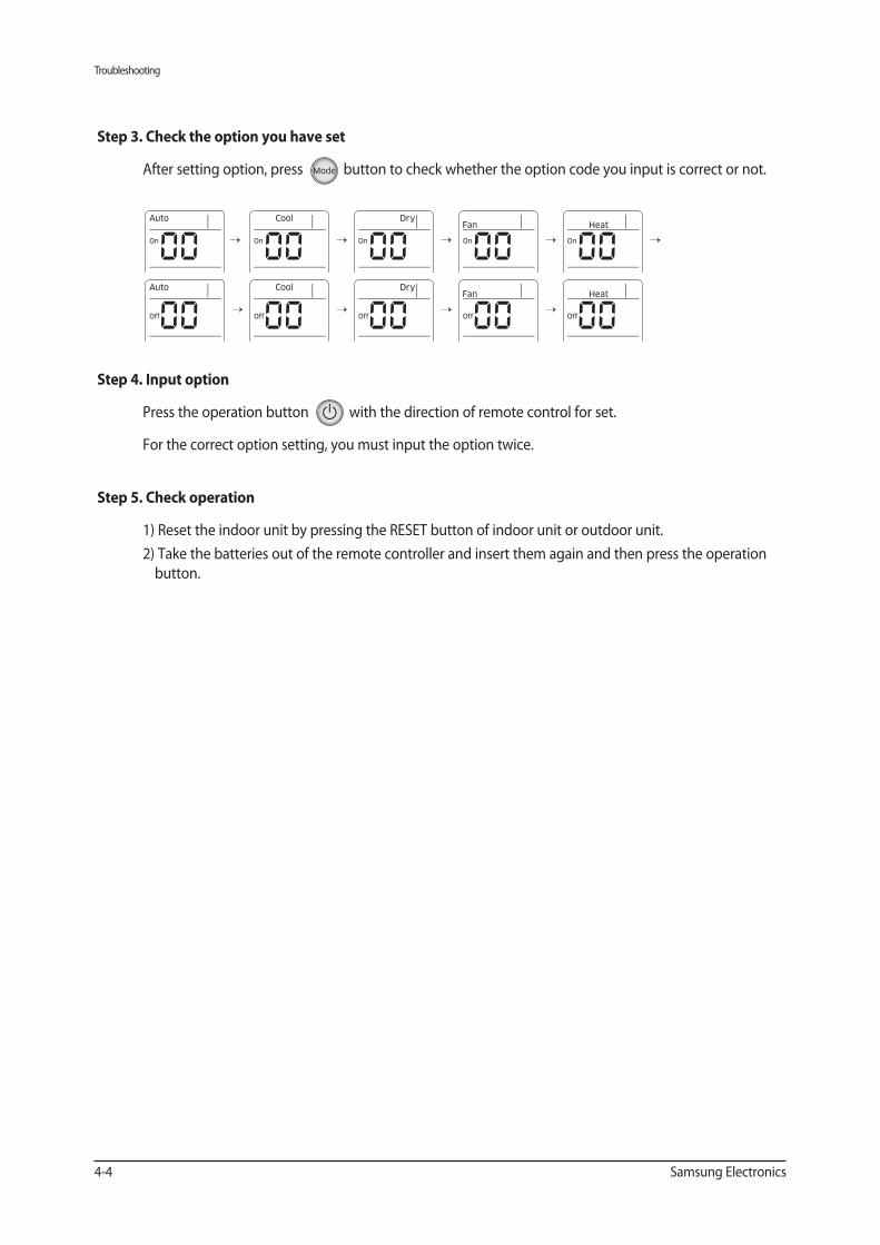
Step 3. Check the option you have set
After setting option, press button to check whether the option code you input is correct or not.
Step 4. Input option
Press the operation button with the direction of remote control for set.
For the correct option setting, you must input the option twice.
Step 5. Check operation
1) Reset the indoor unit by pressing the RESET button of indoor unit or outdoor unit.
2) Take the batteries out of the remote controller and insert them again and then press the operation
button.
→
→
→
→
→
→
→
→
→
Troubleshooting
Samsung Electronics 4-5
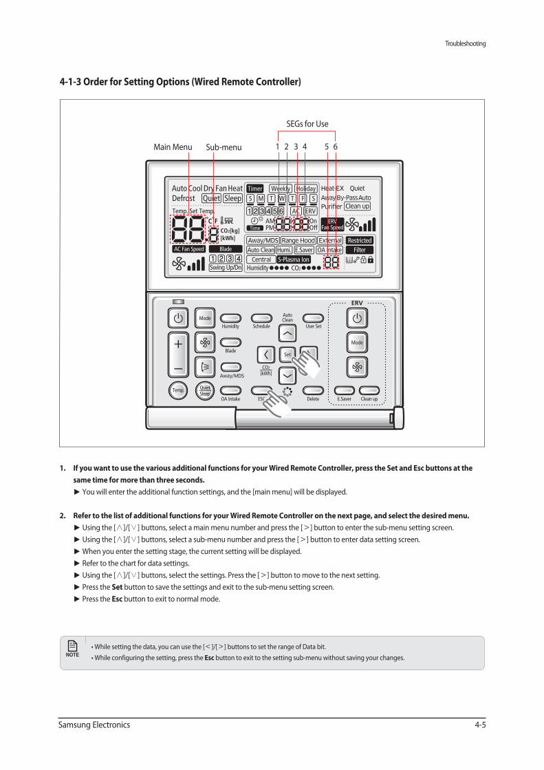
same time for more than three seconds.
You will enter the additional function settings, and the [main menu] will be displayed.
2. Refer to the list of additional functions for your Wired Remote Controller on the next page, and select the desired menu.
Using the [∧]/[ ] buttons, select a main menu number and press the [ ] button to enter the sub-menu setting screen.
Using the [∧]/[ ] buttons, select a sub-menu number and press the [ ] button to enter data setting screen.
When you enter the setting stage, the current setting will be displayed.
Refer to the chart for data settings.
Using the [∧]/[ ] buttons, select the settings. Press the [ ] button to move to the next setting.
Press the Set button to save the settings and exit to the sub-menu setting screen.
Press the button to exit to normal mode.
]/[ ] buttons to set the range of Data bit.
button to exit to the setting sub-menu without saving your changes.
4-1-3 Order for Setting Options (Wired Remote Controller)
Main Menu Sub-menu 1 2 3 54 6
SEGs for Use
Troubleshooting
4-6 Samsung Electronics
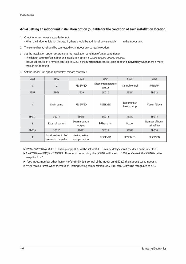
1. Check whether power is supplied or not.
- When the indoor unit is not plugged in, there should be additional power supply in the indoor unit.
2. The panel(display ) should be connected to an indoor unit to receive option.
3. Set the installation option according to the installation condition of an air conditioner.
- The default setting of an indoor unit installation option is 02000-100000-200000-300000.
- Individual control of a remote controller(SEG20) is the function that controls an indoor unit individually when there is more
than one indoor unit.
4. Set the indoor unit option by wireless remote controller.
▶ 1WAY/2WAY/4WAY MODEL : Drain pump(SEG8) will be set to 'USE + 3minute delay' even if the drain pump is set to 0.
▶ 1 WAY/2WAY/4WAY,DUCT MODEL : Number of hours using filter(SEG18) will be set to '1000hour' even if the SEG18 is set to
exept for 2 or 6.
▶ If you input a number other than 0~4 of the individual control of the indoor unit(SEG20), the indoor is set as indoor 1.
▶ 4WAY MODEL : Even when the value of Heating setting compensation(SEG21) is set to '0', it wil be recognized as '5°C'.
4-1-4 Setting an indoor unit installation option (Suitable for the condition of each installation location)
SEG1 SEG2 SEG3 SEG4 SEG5 SEG6
0 2 RESERVEDExterior temperature
sensorCentral control FAN RPM
SEG7 SEG8 SEG9 SEG10 SEG11 SEG12
1 Drain pump RESERVED RESERVEDIndoor unit at
heating stopMaster / Slave
SEG13 SEG14 SEG15 SEG16 SEG17 SEG18
2 External controlExternal control
output S-Plasma ion Buzzer
Number of hours
using filter
SEG19 SEG20 SEG21 SEG22 SEG23 SEG24
3Individual control of
a remote controller
Heating setting
compensationRESERVED RESERVED RESERVED
Troubleshooting
Samsung Electronics 4-7
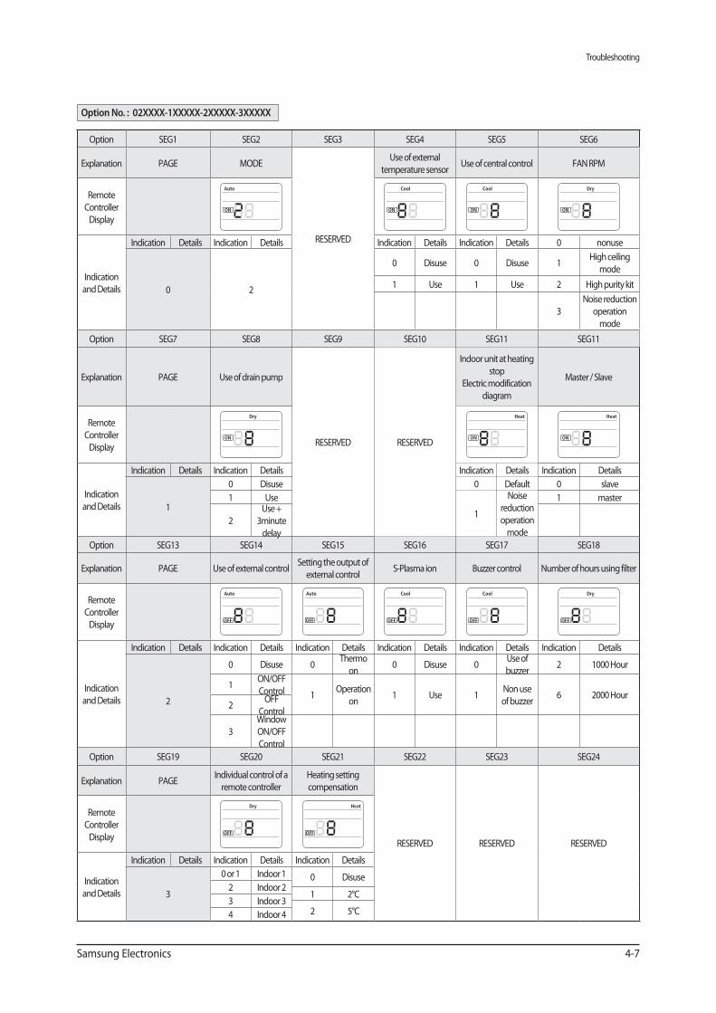
Option No. : 02XXXX-1XXXXX-2XXXXX-3XXXXX
Option SEG1 SEG2 SEG3 SEG4 SEG5 SEG6
Explanation PAGE MODE
RESERVED
Use of external
temperature sensorUse of central control FAN RPM
Remote
Controller
Display
Indication
and Details
Indication Details Indication Details Indication Details Indication Details 0 nonuse
0 2
0 Disuse 0 Disuse 1High ceiling
mode
1 Use 1 Use 2 High purity kit
3
Noise reduction
operation
mode
Option SEG7 SEG8 SEG9 SEG10 SEG11 SEG11
Explanation PAGE Use of drain pump
RESERVED RESERVED
Indoor unit at heating
stop
Electric modification
diagram
Master / Slave
Remote
Controller
Display
Indication
and Details
Indication Details Indication Details Indication Details Indication Details
1
0 Disuse 0 Default 0 slave
1 Use
1
Noise
reduction
operation
mode
1 master
2
Use +
3minute
delayOption SEG13 SEG14 SEG15 SEG16 SEG17 SEG18
Explanation PAGE Use of external controlSetting the output of
external controlS-Plasma ion Buzzer control Number of hours using filter
Remote
Controller
Display
Indication
and Details
Indication Details Indication Details Indication Details Indication Details Indication Details Indication Details
2
0 Disuse 0Thermo
on0 Disuse 0
Use of
buzzer2 1000 Hour
1ON/OFF
Control 1Operation
on1 Use 1
Non use
of buzzer6 2000 Hour
2OFF
Control
3
Window
ON/OFF
Control
Option SEG19 SEG20 SEG21 SEG22 SEG23 SEG24
Explanation PAGEIndividual control of a
remote controller
Heating setting
compensation
RESERVED RESERVED RESERVED
Remote
Controller
Display
Indication
and Details
Indication Details Indication Details Indication Details
3
0 or 1 Indoor 1 0 Disuse2 Indoor 2
1 2°C3 Indoor 3
2 5°C4 Indoor 4
Troubleshooting
4-8 Samsung Electronics
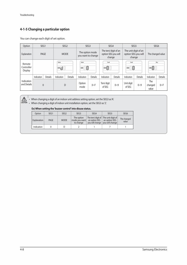
4-1-5 Changing a particular option
You can change each digit of set option.
Option SEG1 SEG2 SEG3 SEG4 SEG5 SEG6
Explanation PAGE MODEThe option
mode you want to change
The tens’ digit of an option SEG
you will change
The unit digit of an option SEG
you will change
The changed value
Indication 0 D 2 1 7 1
Option SEG1 SEG2 SEG3 SEG4 SEG5 SEG6
Explanation PAGE MODEThe option mode
you want to change
The tens’ digit of an option SEG you will
change
The unit digit of an option SEG you will
changeThe changed value
Remote Controller
Display
Indication and Details
Indication Details Indication Details Indication Details Indication Details Indication Details Indication Details
0 DOption
mode0~F
Tens’ digit
of SEG0~9
Unit digit
of SEG0~9
The
changed
value
0~F
Troubleshooting
Samsung Electronics 4-9
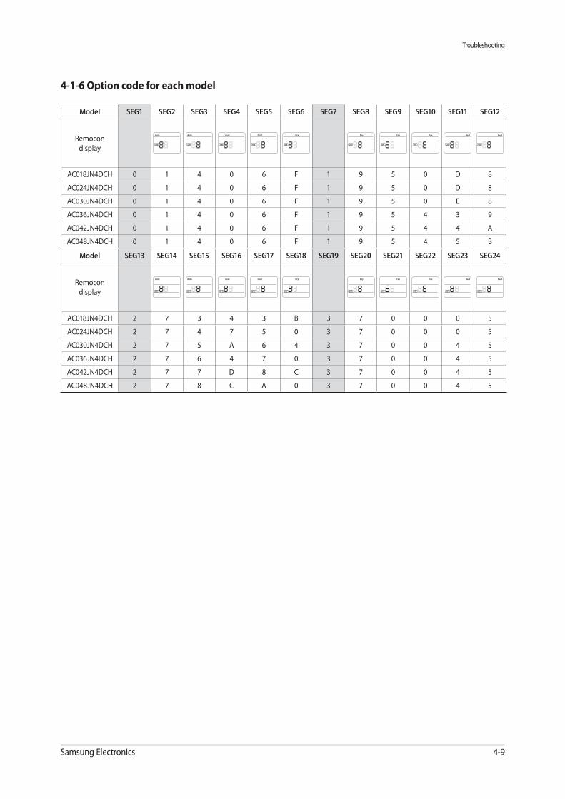
4-1-6 Option code for each model
Model SEG1 SEG2 SEG3 SEG4 SEG5 SEG6 SEG7 SEG8 SEG9 SEG10 SEG11 SEG12
Remocon
display
AC018JN4DCH 0 1 4 0 6 F 1 9 5 0 D 8
AC024JN4DCH 0 1 4 0 6 F 1 9 5 0 D 8
AC030JN4DCH 0 1 4 0 6 F 1 9 5 0 E 8
AC036JN4DCH 0 1 4 0 6 F 1 9 5 4 3 9
AC042JN4DCH 0 1 4 0 6 F 1 9 5 4 4 A
AC048JN4DCH 0 1 4 0 6 F 1 9 5 4 5 B
Model SEG13 SEG14 SEG15 SEG16 SEG17 SEG18 SEG19 SEG20 SEG21 SEG22 SEG23 SEG24
Remocon
display
AC018JN4DCH 2 7 3 4 3 B 3 7 0 0 0 5
AC024JN4DCH 2 7 4 7 5 0 3 7 0 0 0 5
AC030JN4DCH 2 7 5 A 6 4 3 7 0 0 4 5
AC036JN4DCH 2 7 6 4 7 0 3 7 0 0 4 5
AC042JN4DCH 2 7 7 D 8 C 3 7 0 0 4 5
AC048JN4DCH 2 7 8 C A 0 3 7 0 0 4 5
Troubleshooting
4-10 Samsung Electronics
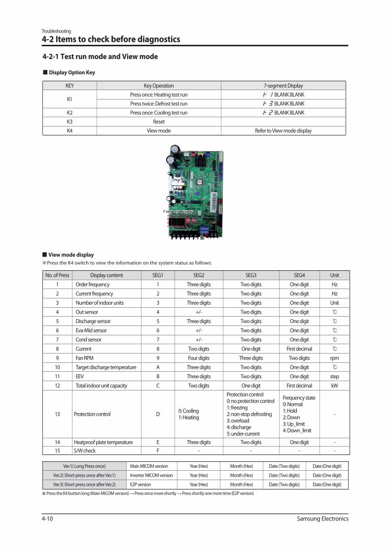
KEY Key Operation 7-segment Display
K1Press once: Heating test run BLANK BLANK
Press twice: Defrost test run BLANK BLANK
K2 Press once: Cooling test run BLANK BLANK
K3 Reset
K4 View mode Refer to View mode display
No. of Press Display content SEG1 SEG2 SEG3 SEG4 Unit
1 Order frequency 1 Three digits Two digits One digit Hz
2 Current frequency 2 Three digits Two digits One digit Hz
3 Number of indoor units 3 Three digits Two digits One digit Unit
4 Out sensor 4 +/- Two digits One digit
5 Discharge sensor 5 Three digits Two digits One digit
6 Eva-Mid sensor 6 +/- Two digits One digit
7 Cond sensor 7 +/- Two digits One digit
8 Current 8 Two digits One digit First decimal
9 Fan RPM 9 Four digits Three digits Two digits rpm
10 Target discharge temperature A Three digits Two digits One digit
11 EEV B Three digits Two digits One digit step
12 Total indoor unit capacity C Two digits One digit First decimal kW
13 Protection control D0: Cooling1: Heating
Protection control0: no protection control1: freezing2: non-stop defrosting3: overload4: discharge5: under-current
Frequency state0: Normal1: Hold2: Down3: Up_limit4: Down_limit
-
14 Heatproof plate temperature E Three digits Two digits One digit -
15 S/W check F - - - -
Ver.1( Long Press once) Main MICOM version Year (Hex) Month (Hex) Date (Two digits) Date (One digit)
Ver.2( Short press once after Ver.1) Inverter MICOM version Year (Hex) Month (Hex) Date (Two digits) Date (One digit)
Ver.3( Short press once after Ver.2) E2P version Year (Hex) Month (Hex) Date (Two digits) Date (One digit)
※ Press the K4 button long (Main MICOM version) Press once more shortly Press shortly one more time (E2P version)
4-2 Items to check before diagnostics
4-2-1 Test run mode and View mode
Display Option Key
View mode display
Press the K4 switch to view the information on the system status as follows:
7-segment display
Troubleshooting
Samsung Electronics 4-11
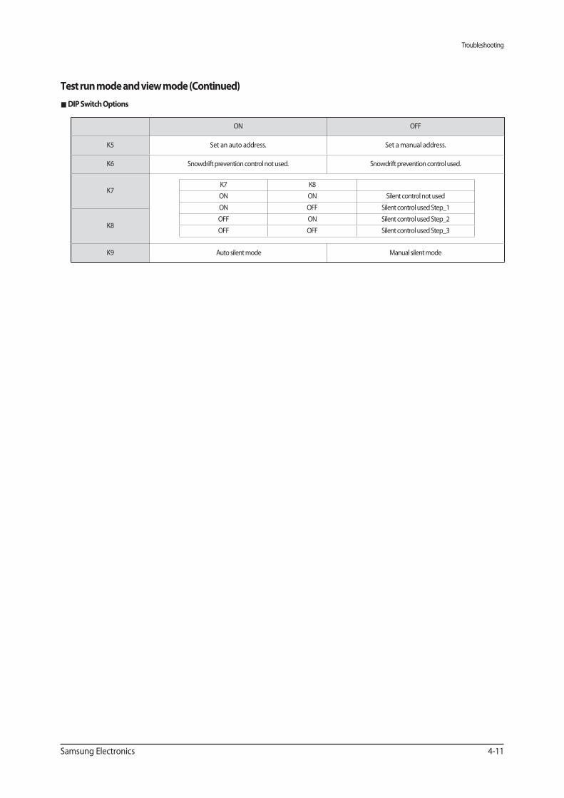
Test run mode and view mode (Continued)
DIP Switch Options
ON OFF
K5 Set an auto address. Set a manual address.
K6 Snowdrift prevention control not used. Snowdrift prevention control used.
K7K7 K8
ON ON Silent control not used
ON OFF Silent control used Step_1
OFF ON Silent control used Step_2
OFF OFF Silent control used Step_3K8
K9 Auto silent mode Manual silent mode
Troubleshooting
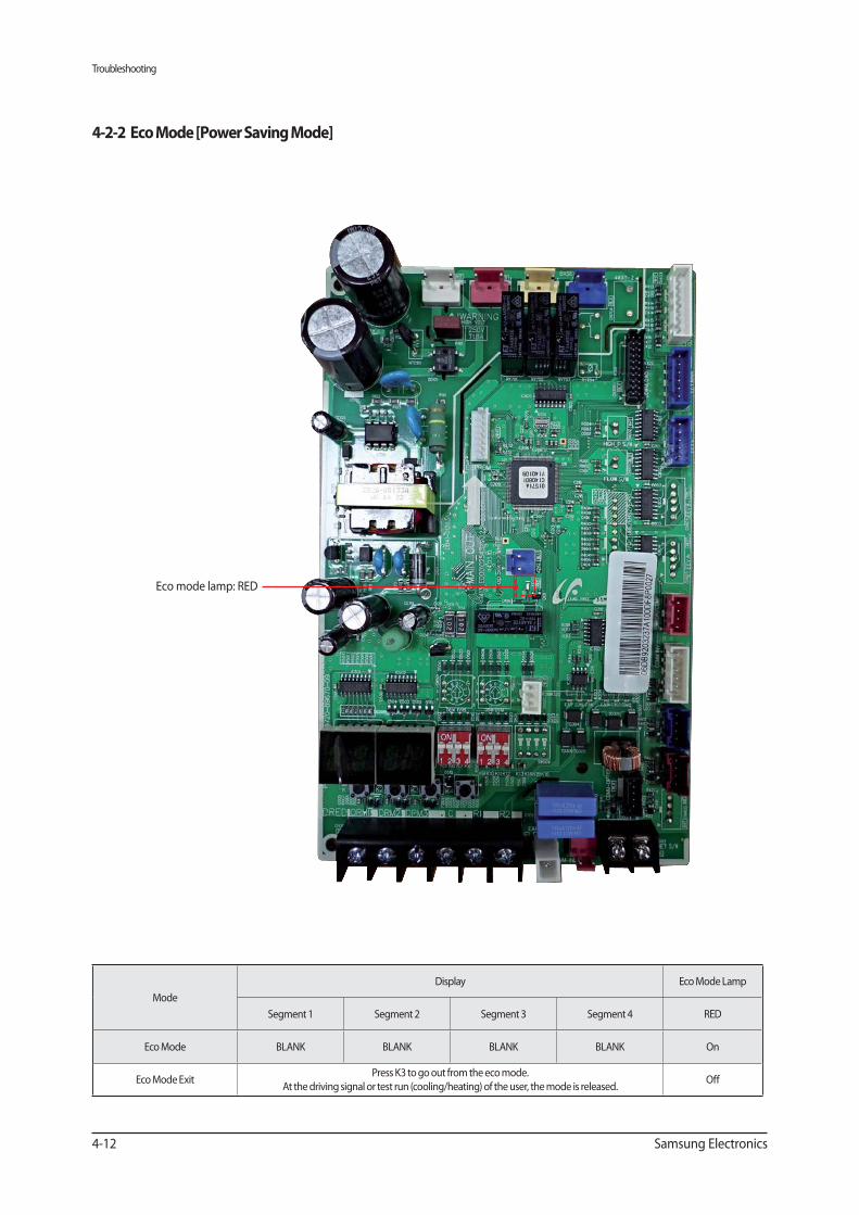
4-12 Samsung Electronics
Mode
Display Eco Mode Lamp
Segment 1 Segment 2 Segment 3 Segment 4 RED
Eco Mode BLANK BLANK BLANK BLANK On
Eco Mode ExitPress K3 to go out from the eco mode.
At the driving signal or test run (cooling/heating) of the user, the mode is released.Off
Eco mode lamp: RED
Troubleshooting
Samsung Electronics 4-13
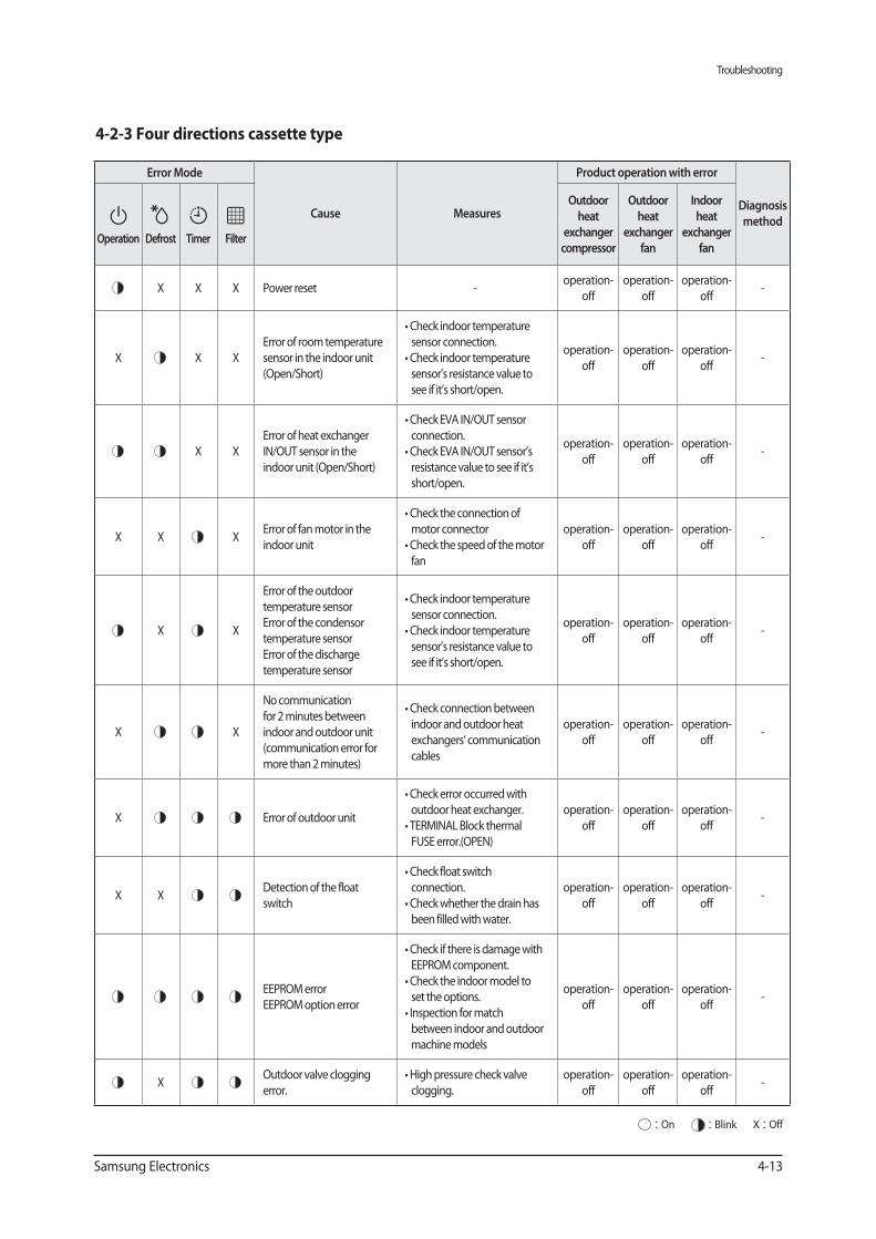
4-2-3 Four directions cassette type
Error Mode
Cause Measures
Product operation with error
Diagnosis
method
Operation Defrost Timer Filter
Outdoor
heat
exchanger
compressor
Outdoor
heat
exchanger
fan
Indoor
heat
exchanger
fan
X X X Power reset -operation-
off
operation-
off
operation-
off-
X X X
Error of room temperature
sensor in the indoor unit
(Open/Short)
sensor connection.
sensor’s resistance value to
see if it’s short/open.
operation-
off
operation-
off
operation-
off-
X X
Error of heat exchanger
IN/OUT sensor in the
indoor unit (Open/Short)
connection.
resistance value to see if it’s
short/open.
operation-
off
operation-
off
operation-
off-
X X XError of fan motor in the
indoor unit
motor connector
fan
operation-
off
operation-
off
operation-
off-
X X
Error of the outdoor
temperature sensor
Error of the condensor
temperature sensor
Error of the discharge
temperature sensor
sensor connection.
sensor’s resistance value to
see if it’s short/open.
operation-
off
operation-
off
operation-
off-
X X
No communication
for 2 minutes between
indoor and outdoor unit
(communication error for
more than 2 minutes)
indoor and outdoor heat
exchangers’ communication
cables
operation-
off
operation-
off
operation-
off-
X Error of outdoor unitoutdoor heat exchanger.
FUSE error.(OPEN)
operation-
off
operation-
off
operation-
off-
X XDetection of the float
switch
connection.
been filled with water.
operation-
off
operation-
off
operation-
off-
EEPROM error
EEPROM option error
EEPROM component.
set the options.
between indoor and outdoor
machine models
operation-
off
operation-
off
operation-
off-
XOutdoor valve clogging
error. clogging.
operation-
off
operation-
off
operation-
off-
: On : Blink X : Off
Troubleshooting
4-14 Samsung Electronics
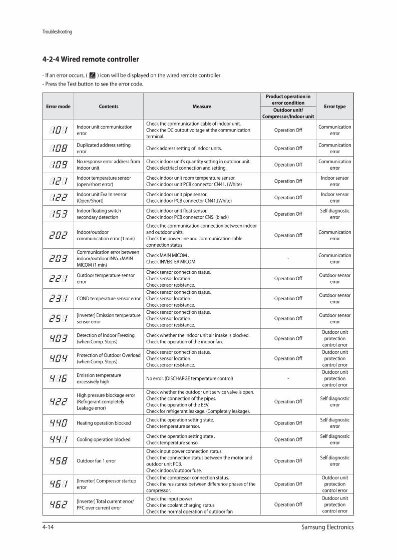
4-2-4 Wired remote controller
- If an error occurs, ( ) icon will be displayed on the wired remote controller.
- Press the Test button to see the error code.
Contents
Product operation in
error condition
Outdoor unit/
Compressor/Indoor unit
Indoor unit communication
error
Check the communication cable of indoor unit.
Check the DC output voltage at the communication
terminal.
Operation OffCommunication
error
Duplicated address setting
errorCheck address setting of Indoor units. Operation Off
Communication
error
No response error address from
indoor unit
Check indoor unit's quantity setting in outdoor unit.
Check electriacl connection and setting.Operation Off
Communication
error
Indoor temperature sensor
(open/short error)
Check indoor unit room temperature sensor.
Check indoor unit PCB connector CN41. (White) Operation Off
Indoor sensor
error
Indoor unit Eva In sensor
(Open/Short)
Check indoor unit pipe sensor.
Check indoor PCB connector CN41.(White)Operation Off
Indoor sensor
error
Indoor floating switch
secondary detection
Check indoor unit float sensor.
Check indoor PCB connector CN5. (black)Operation Off
Self diagnostic
error
Indoor/outdoor
communication error (1 min)
Check the communication connection between indoor
and outdoor units.
Check the power line and communication cable
connection status
Operation OffCommunication
error
Communication error between
indoor/outdoor INV MAIN
MICOM (1 min)
Check MAIN MICOM .
Check INVERTER MICOM.-
Communication
error
Outdoor temperature sensor
error
Check sensor connection status.
Check sensor location.
Check sensor resistance.
Operation OffOutdoor sensor
error
COND temperature sensor error
Check sensor connection status.
Check sensor location.
Check sensor resistance.
Operation OffOutdoor sensor
error
[Inverter] Emission temperature
sensor error
Check sensor connection status.
Check sensor location.
Check sensor resistance.
Operation OffOutdoor sensor
error
Detection of Indoor Freezing
(when Comp. Stops)
Check whether the indoor unit air intake is blocked.
Check the operation of the indoor fan.Operation Off
Outdoor unit
protection
control error
Protection of Outdoor Overload
(when Comp. Stops)
Check sensor connection status.
Check sensor location.
Check sensor resistance.
Operation Off
Outdoor unit
protection
control error
Emission temperature
excessively highNo error. (DISCHARGE temperature control) -
Outdoor unit
protection
control error
High pressure blockage error
(Refrigerant completely
Leakage error)
Check whether the outdoor unit service valve is open.
Check the connection of the pipes.
Check the operation of the EEV.
Check for refrigerant leakage. (Completely leakage).
Operation OffSelf diagnostic
error
Heating operation blockedCheck the operation setting state.
Check temperature sensor.Operation Off
Self diagnostic
error
Cooling operation blockedCheck the operation setting state .
Check temperature senso.Operation Off
Self diagnostic
error
Outdoor fan 1 error
Check input power connection status.
Check the connection status between the motor and
outdoor unit PCB.
Check indoor/outdoor fuse.
Operation OffSelf diagnostic
error
[Inverter] Compressor startup
error
Check the compressor connection status.
Check the resistance between difference phases of the
compressor.
Operation Off
Outdoor unit
protection
control error
[Inverter] Total current error/
PFC over current error
Check the input power
Check the coolant charging status
Check the normal operation of outdoor fan
Operation Off
Outdoor unit
protection
control error
Troubleshooting
Samsung Electronics 4-15
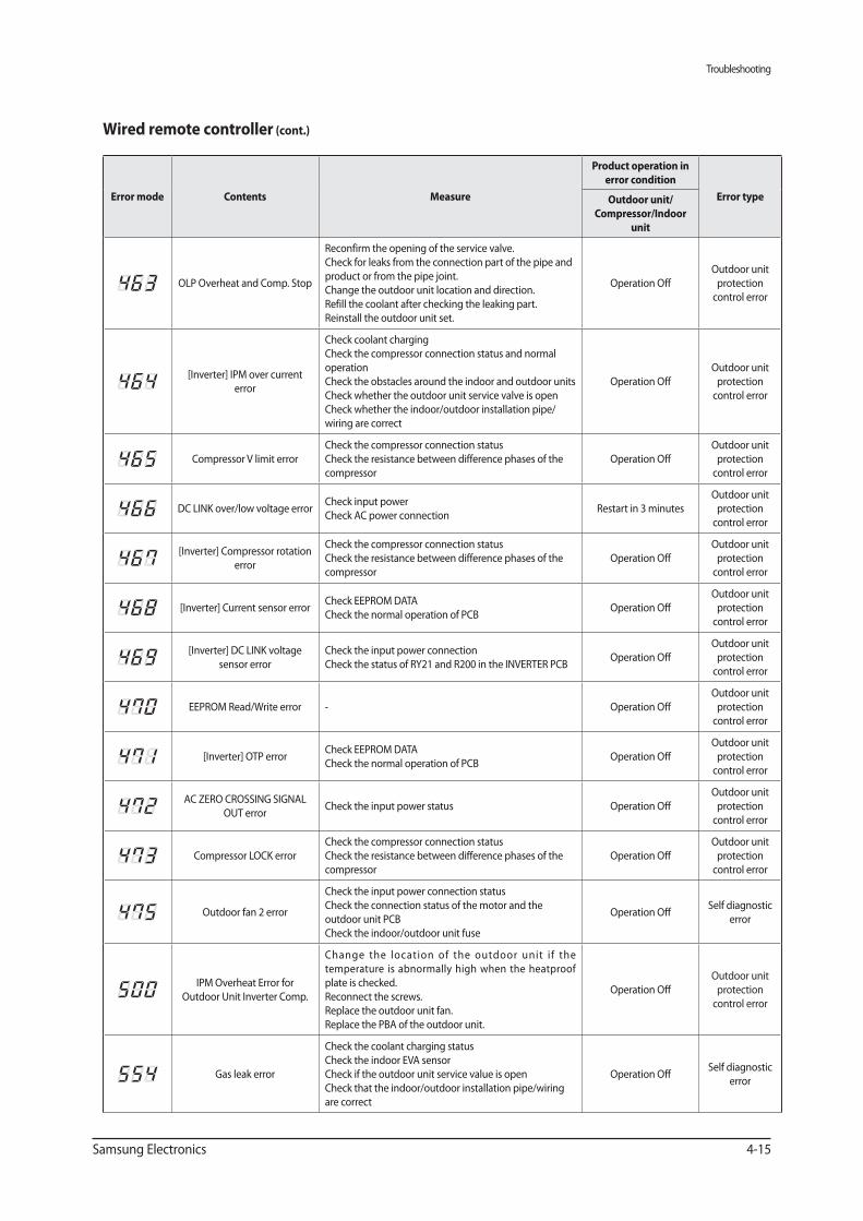
Wired remote controller (cont.)
Contents
Product operation in
error condition
Outdoor unit/
Compressor/Indoor
unit
OLP Overheat and Comp. Stop
Reconfirm the opening of the service valve.
Check for leaks from the connection part of the pipe and
product or from the pipe joint.
Change the outdoor unit location and direction.
Refill the coolant after checking the leaking part.
Reinstall the outdoor unit set.
Operation Off
Outdoor unit
protection
control error
[Inverter] IPM over current
error
Check coolant charging
Check the compressor connection status and normal
operation
Check the obstacles around the indoor and outdoor units
Check whether the outdoor unit service valve is open
Check whether the indoor/outdoor installation pipe/
wiring are correct
Operation Off
Outdoor unit
protection
control error
Compressor V limit error
Check the compressor connection status
Check the resistance between difference phases of the
compressor
Operation Off
Outdoor unit
protection
control error
DC LINK over/low voltage errorCheck input power
Check AC power connectionRestart in 3 minutes
Outdoor unit
protection
control error
[Inverter] Compressor rotation
error
Check the compressor connection status
Check the resistance between difference phases of the
compressor
Operation Off
Outdoor unit
protection
control error
[Inverter] Current sensor errorCheck EEPROM DATA
Check the normal operation of PCBOperation Off
Outdoor unit
protection
control error
[Inverter] DC LINK voltage
sensor error
Check the input power connection
Check the status of RY21 and R200 in the INVERTER PCBOperation Off
Outdoor unit
protection
control error
EEPROM Read/Write error - Operation Off
Outdoor unit
protection
control error
[Inverter] OTP errorCheck EEPROM DATA
Check the normal operation of PCBOperation Off
Outdoor unit
protection
control error
AC ZERO CROSSING SIGNAL
OUT errorCheck the input power status Operation Off
Outdoor unit
protection
control error
Compressor LOCK error
Check the compressor connection status
Check the resistance between difference phases of the
compressor
Operation Off
Outdoor unit
protection
control error
Outdoor fan 2 error
Check the input power connection status
Check the connection status of the motor and the
outdoor unit PCB
Check the indoor/outdoor unit fuse
Operation OffSelf diagnostic
error
IPM Overheat Error for
Outdoor Unit Inverter Comp.
Change the location of the outdoor unit i f the
temperature is abnormally high when the heatproof
plate is checked.
Reconnect the screws.
Replace the outdoor unit fan.
Replace the PBA of the outdoor unit.
Operation Off
Outdoor unit
protection
control error
Gas leak error
Check the coolant charging status
Check the indoor EVA sensor
Check if the outdoor unit service value is open
Check that the indoor/outdoor installation pipe/wiring
are correct
Operation OffSelf diagnostic
error
Troubleshooting
4-16 Samsung Electronics
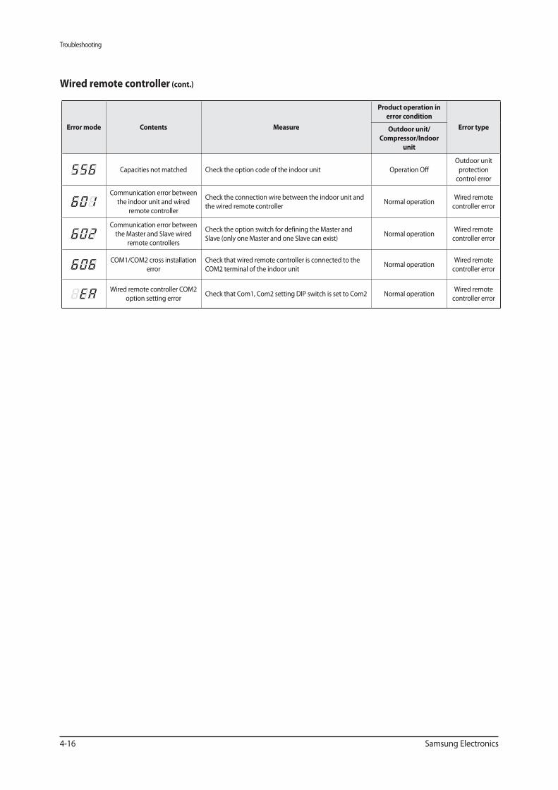
Contents
Product operation in
error condition
Outdoor unit/
Compressor/Indoor
unit
Capacities not matched Check the option code of the indoor unit Operation Off
Outdoor unit
protection
control error
Communication error between
the indoor unit and wired
remote controller
Check the connection wire between the indoor unit and
the wired remote controllerNormal operation
Wired remote
controller error
Communication error between
the Master and Slave wired
remote controllers
Check the option switch for defining the Master and
Slave (only one Master and one Slave can exist)Normal operation
Wired remote
controller error
COM1/COM2 cross installation
error
Check that wired remote controller is connected to the
COM2 terminal of the indoor unitNormal operation
Wired remote
controller error
Wired remote controller COM2
option setting error Check that Com1, Com2 setting DIP switch is set to Com2 Normal operation
Wired remote
controller error
Wired remote controller (cont.)
Troubleshooting
Samsung Electronics 4-17
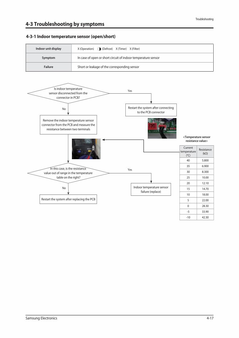
Indoor unit display X (Operation) (Defrost) X (Timer) X (Filter)
Symptom In case of open or short circuit of indoor temperature sensor
Failure Short or leakage of the corresponding sensor
Yes
No
No
In this case, is the resistance
value out of range in the temperature
table on the right?
YesIs indoor temperature
sensor disconnected from the
connector in PCB?
Restart the system after replacing the PCB
Restart the system after connecting
to the PCB connector
Indoor temperature sensor
failure (replace)
Remove the indoor temperature sensor
connector from the PCB and measure the
resistance between two terminals
4-3 Troubleshooting by symptoms
4-3-1 Indoor temperature sensor (open/short)
Current
temperature
(°C)
Resistance
(kΩ)
40 5.800
35 6.900
30 8.300
25 10.00
20 12.10
15 14.70
10 18.00
5 22.00
0 28.30
-5 33.90
-10 42.30
<Temperature sensor
resistance value>
Troubleshooting
4-18 Samsung Electronics
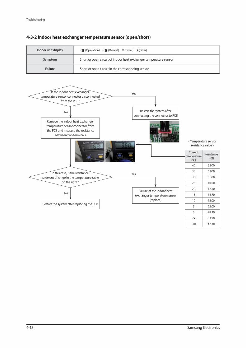
Yes
No
No
In this case, is the resistance
value out of range in the temperature table
on the right?
YesIs the indoor heat exchanger
temperature sensor connector disconnected
from the PCB?
Restart the system after replacing the PCB
Restart the system after
connecting the connector to PCB
Failure of the indoor heat
exchanger temperature sensor
(replace)
Remove the indoor heat exchanger
temperature sensor connector from
the PCB and measure the resistance
between two terminals
Indoor unit display (Operation) (Defrost) X (Timer) X (Filter)
Symptom Short or open circuit of indoor heat exchanger temperature sensor
Failure Short or open circuit in the corresponding sensor
4-3-2 Indoor heat exchanger temperature sensor (open/short)
Current
temperature
(°C)
Resistance
(kΩ)
40 5.800
35 6.900
30 8.300
25 10.00
20 12.10
15 14.70
10 18.00
5 22.00
0 28.30
-5 33.90
-10 42.30
<Temperature sensor
resistance value>
Troubleshooting
Samsung Electronics 4-19
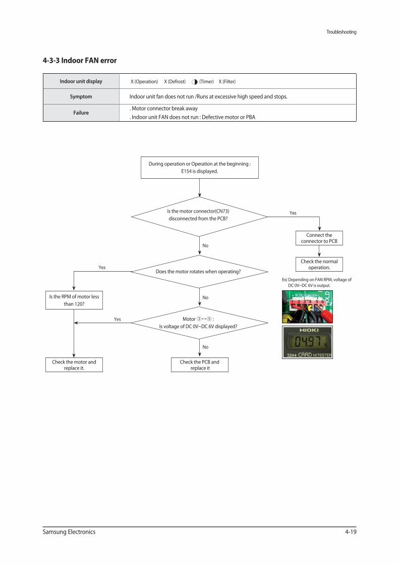
Indoor unit display X (Operation) X (Defrost) (Timer) X (Filter)
Symptom Indoor unit fan does not run /Runs at excessive high speed and stops.
Failure. Motor connector break away
. Indoor unit FAN does not run : Defective motor or PBA
Check the normal operation.
No
Is the motor connector(CN73)
disconnected from the PCB?
Connect the connector to PCB
Yes
No
Does the motor rotates when operating?
Motor :
Is voltage of DC 0V~DC 6V displayed?
Check the PCB and replace it
Is the RPM of motor less
than 120?
Yes
During operation or Operation at the beginning :
E154 is displayed.
No
Check the motor and replace it.
Yes
Ex) Depending on FAN RPM, voltage of
DC 0V~DC 6V is output.
↓ ↓1 2 3 4 5 6
Troubleshooting
4-20 Samsung Electronics
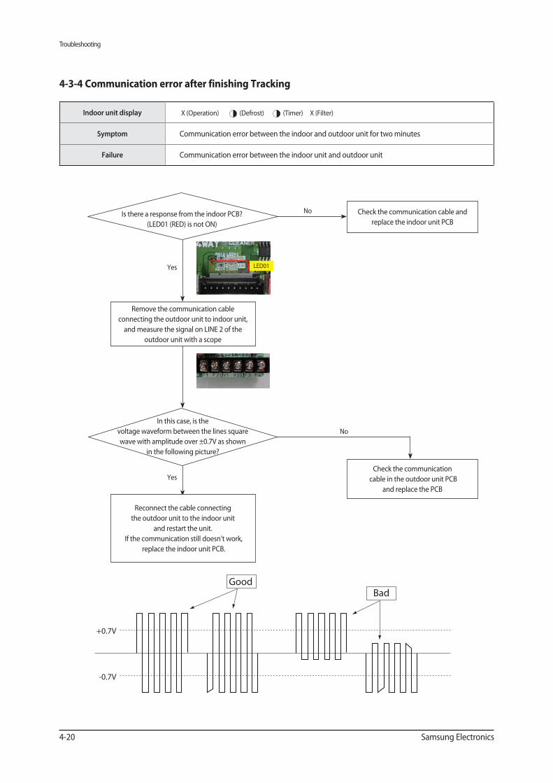
Indoor unit display X (Operation) (Defrost) (Timer) X (Filter)
Symptom Communication error between the indoor and outdoor unit for two minutes
Failure Communication error between the indoor unit and outdoor unit
4-3-4 Communication error after finishing Tracking
No
Yes
No
Yes
Is there a response from the indoor PCB?
(LED01 (RED) is not ON)
In this case, is the
voltage waveform between the lines square
wave with amplitude over ±0.7V as shown
in the following picture?
+0.7V
-0.7V
GoodBad
Check the communication cable and
replace the indoor unit PCB
Remove the communication cable
connecting the outdoor unit to indoor unit,
and measure the signal on LINE 2 of the
outdoor unit with a scope
Reconnect the cable connecting
the outdoor unit to the indoor unit
and restart the unit.
If the communication still doesn’t work,
replace the indoor unit PCB.
Check the communication
cable in the outdoor unit PCB
and replace the PCB
LED01
Troubleshooting
Samsung Electronics 4-21
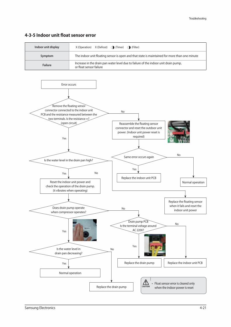
Indoor unit display X (Operation) X (Defrost) (Timer) (Filter)
Symptom The indoor unit floating sensor is open and that state is maintained for more than one minute
FailureIncrease in the drain pan water level due to failure of the indoor unit drain pump, or float sensor failure
4-3-5 Indoor unit float sensor error
No
No
No
No
NoYes
Yes
Yes
Yes
Yes
Yes
Remove the floating sensor
connector connected to the indoor unit
PCB and the resistance measured between the
two terminals. Is the resistance ∞?
(open circuit)
Is the water level in the drain pan high?
Does drain pump operate
when compressor operates?
Same error occurs again
No
Drain pump PCB
Is the terminal voltage around
AC 220V?
Is the water level in
drain pan decreasing?
Reset the indoor unit power and
check the operation of the drain pump.
(it vibrates when operating)
Normal operation
Replace the indoor unit PCB
Reassemble the floating sensor
connector and reset the outdoor unit
power. (Indoor unit power reset is
required)
Normal operation
Replace the floating sensor
when it fails and reset the
indoor unit power
Replace the drain pump
Replace the drain pump Replace the indoor unit PCB
Error occurs
when the indoor power is reset
Troubleshooting
4-22 Samsung Electronics
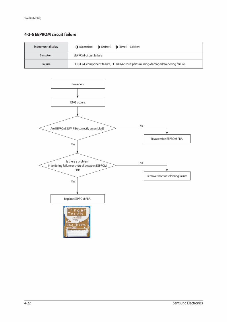
Indoor unit display (Operation) (Defrost) (Timer) X (Filter)
Symptom EEPROM circuit failure
Failure EEPROM component failure, EEPROM circuit parts missing/damaged/soldering failure
Power on.
E162 occurs.
Replace EEPROM PBA.
Yes
Yes
No
No
Are EEPROM SUM PBA correctly assembled?
Is there a problem
in soldering failure or short of between EEPROM
PIN?
Reassemble EEPROM PBA.
Remove short or soldering failure.
Troubleshooting
Samsung Electronics 4-23
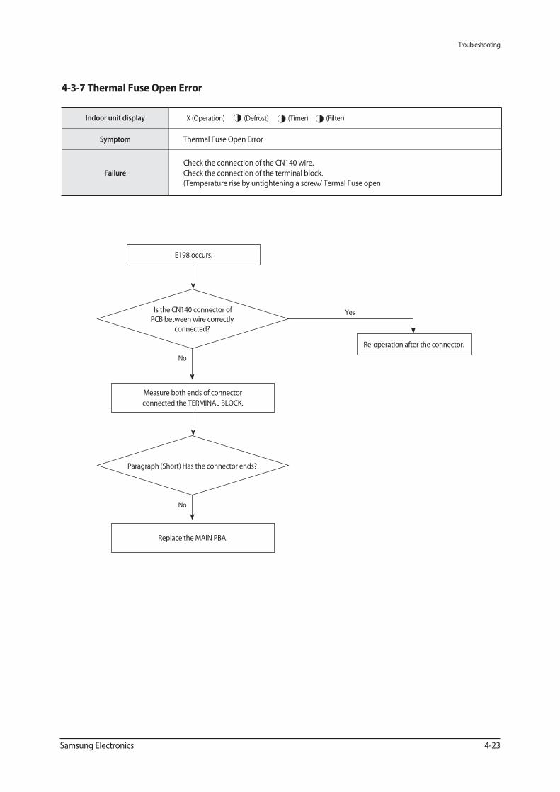
Indoor unit display X (Operation) (Defrost) (Timer) (Filter)
Symptom Thermal Fuse Open Error
Failure
Check the connection of the CN140 wire.
Check the connection of the terminal block.
(Temperature rise by untightening a screw/ Termal Fuse open
E198 occurs.
Measure both ends of connector
connected the TERMINAL BLOCK.
Replace the MAIN PBA.
No
No
Yes Is the CN140 connector of
PCB between wire correctly
connected?
Paragraph (Short) Has the connector ends?
Re-operation after the connector.
Troubleshooting
4-24 Samsung Electronics
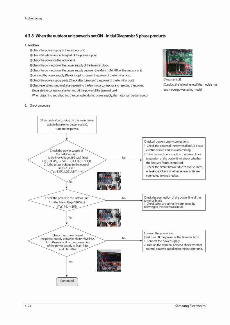
1. Test Item
1) Check the power supply of the outdoor unit.
2) Check the whole connection part of the power supply.
3) Check the power on the indoor unit.
4) Check the connection of the power supply of the terminal block.
5) Check the connection of the power supply between the Main EMI PBA of the outdoor unit.
6) Connect the power supply. (Never forget to turn off the power of the terminal box).
7) Check the power supply parts. (Check after turning off the power of the terminal box!)
8) Check everything is normal after separating the fan motor connector and resetting the power.
(Separate the connector after turning off the power of the terminal box!
When detaching and attaching the connector during power supply, the motor can be damaged.)
2. Check procedure
∙ 7-segment off.
∙ Conduct the following test if the mode is not
eco mode (power saving mode):
Yes
Yes
Yes
30 seconds after turning off the main power
switch (breaker or power socket),
turn on the power.
Check all power supply connections.
1. Check the power of the terminal box, 3-phase
electric power, and wire assembling.
2. If the connection is made in the power lines
(extension of the power line), check whether
the lines are firmly connected.
3. Check the circuit breaker due to over-current,
or leakage. Check whether several units are
connected to one breaker.
Check the connection of the power line of the terminal block.1. Check wires are correctly connected by referring to the electrical circuit.
Connect the power line (First turn off the power of the terminal box!)1. Connect the power supply.2. Turn on the terminal box and check whether normal power is supplied to the outdoor unit.
No
No
No
Check the power supply of the outdoor unit.
1. Is the line voltage 380 Vac? (Yes) L1(R) L2(S), L2(S) L3(T), L1(R) L3(T)
2. Is the phase voltage to the neutral line 220 Vac?
(Yes) L1(R)/L2(S)/L3(T) N
Check the power to the indoor unit.
1. Is the line voltage 220 Vac?
(Yes) 1(L) 2(N)
Check the connection of the power supply between Main EMI PBA.
1. Is there a fault in the connection of the power supply to Main PBA
and EMI PBA?
Continued
Troubleshooting
Samsung Electronics 4-25
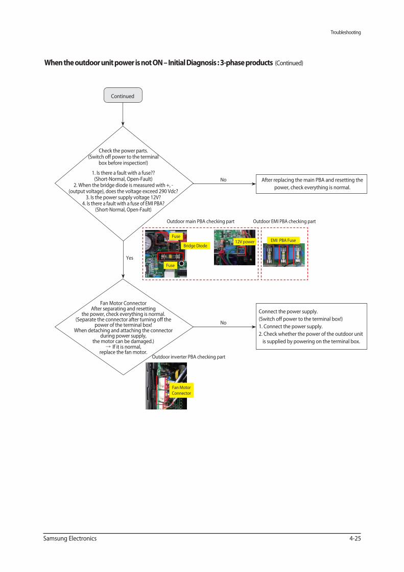
(Continued)
Continued
Yes
After replacing the main PBA and resetting the
power, check everything is normal.
Connect the power supply.
(Switch off power to the terminal box!)
1. Connect the power supply.
2. Check whether the power of the outdoor unit
is supplied by powering on the terminal box.
No
No
Check the power parts.(Switch off power to the terminal
box before inspection!)
1. Is there a fault with a fuse??(Short-Normal, Open-Fault)
2. When the bridge diode is measured with +, - (output voltage), does the voltage exceed 290 Vdc?
3. Is the power supply voltage 12V?4. Is there a fault with a fuse of EMI PBA?
(Short-Normal, Open-Fault)
Fan Motor ConnectorAfter separating and resetting
the power, check everything is normal.(Separate the connector after turning off the
power of the terminal box!When detaching and attaching the connector
during power supply, the motor can be damaged.)
If it is normal, replace the fan motor.
Fuse
Fan Motor
Connector
12V power
Fuse
Bridge DiodeEMI PBA Fuse
Outdoor main PBA checking part
Outdoor inverter PBA checking part
Outdoor EMI PBA checking part
Troubleshooting
4-26 Samsung Electronics
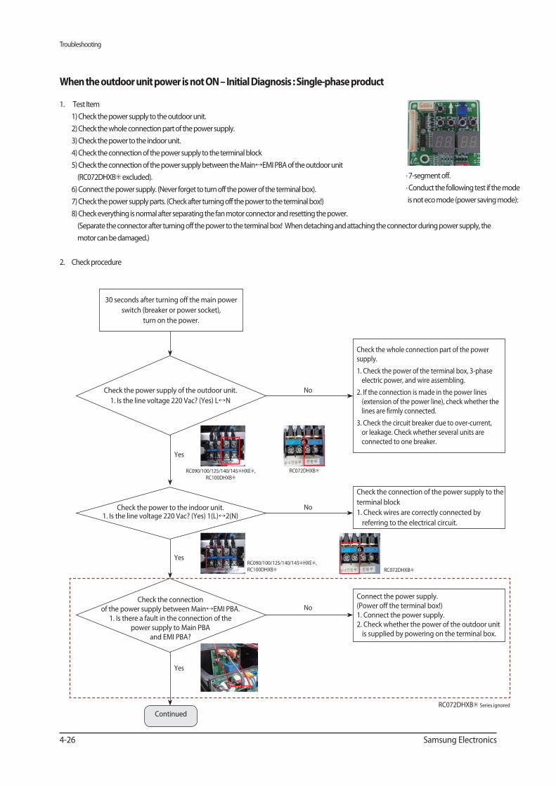
1. Test Item
1) Check the power supply to the outdoor unit.
2) Check the whole connection part of the power supply.
3) Check the power to the indoor unit.
4) Check the connection of the power supply to the terminal block
5) Check the connection of the power supply between the Main EMI PBA of the outdoor unit
(RC072DHXB excluded).
6) Connect the power supply. (Never forget to turn off the power of the terminal box).
7) Check the power supply parts. (Check after turning off the power to the terminal box!)
8) Check everything is normal after separating the fan motor connector and resetting the power.
(Separate the connector after turning off the power to the terminal box! When detaching and attaching the connector during power supply, the
motor can be damaged.)
2. Check procedure
Yes
Yes
Yes
30 seconds after turning off the main power
switch (breaker or power socket),
turn on the power.
Check the whole connection part of the power supply.
1. Check the power of the terminal box, 3-phase electric power, and wire assembling.
2. If the connection is made in the power lines (extension of the power line), check whether the lines are firmly connected.
3. Check the circuit breaker due to over-current, or leakage. Check whether several units are connected to one breaker.
Check the connection of the power supply to the
terminal block
1. Check wires are correctly connected by
referring to the electrical circuit.
Connect the power supply. (Power off the terminal box!)1. Connect the power supply.2. Check whether the power of the outdoor unit is supplied by powering on the terminal box.
No
No
No
Check the power supply of the outdoor unit.
1. Is the line voltage 220 Vac? (Yes) L N
Check the power to the indoor unit.1. Is the line voltage 220 Vac? (Yes) 1(L) 2(N)
Check the connection of the power supply between Main EMI PBA.
1. Is there a fault in the connection of the power supply to Main PBA
and EMI PBA?
∙ 7-segment off.
∙ Conduct the following test if the mode
is not eco mode (power saving mode):
Continued
RC090/100/125/140/145 HXE ,
RC100DHXB
RC090/100/125/140/145 HXE ,
RC100DHXB RC072DHXB
RC072DHXB
RC072DHXB Series ignored
Troubleshooting
Samsung Electronics 4-27
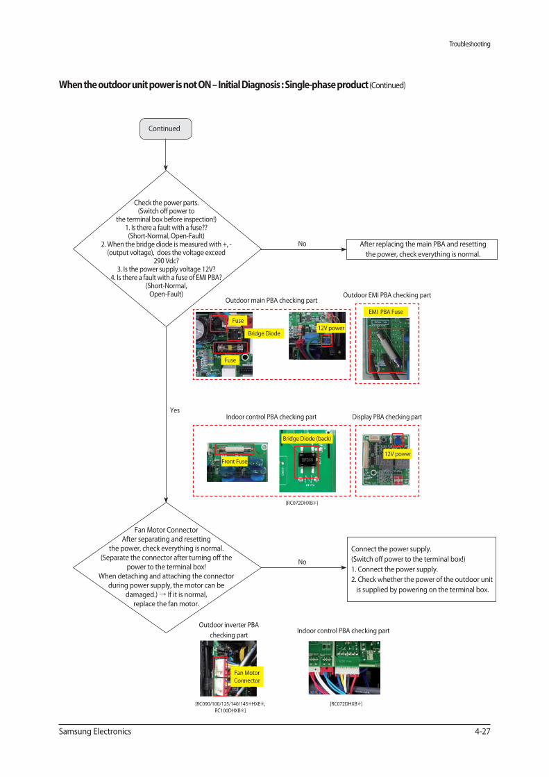
Outdoor inverter PBA
checking partIndoor control PBA checking part
(Continued)
Yes
After replacing the main PBA and resetting
the power, check everything is normal.
Connect the power supply.
(Switch off power to the terminal box!)
1. Connect the power supply.
2. Check whether the power of the outdoor unit
is supplied by powering on the terminal box.
No
No
Check the power parts.(Switch off power to
the terminal box before inspection!)1. Is there a fault with a fuse?? (Short-Normal, Open-Fault)
2. When the bridge diode is measured with +, - (output voltage), does the voltage exceed
290 Vdc?3. Is the power supply voltage 12V?
4. Is there a fault with a fuse of EMI PBA? (Short-Normal, Open-Fault)
Fan Motor Connector After separating and resetting
the power, check everything is normal.(Separate the connector after turning off the
power to the terminal box!When detaching and attaching the connector
during power supply, the motor can be damaged.) If it is normal,
replace the fan motor.
Fan Motor
Connector
Continued
Outdoor main PBA checking partOutdoor EMI PBA checking part
Fuse 12V power
Fuse
Bridge Diode
EMI PBA Fuse
[RC090/100/125/140/145 HXE ,
RC100DHXB ]
Indoor control PBA checking part Display PBA checking part
Bridge Diode (back)
Front Fuse
[RC072DHXB ]
12V power
[RC072DHXB ]
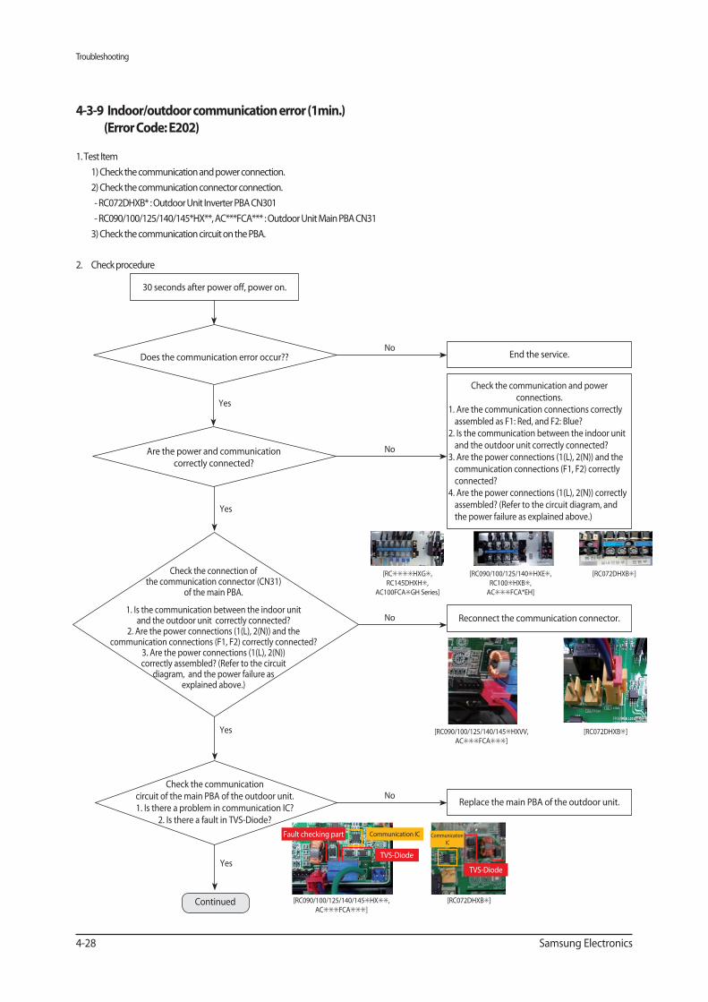
Troubleshooting
4-28 Samsung Electronics
1. Test Item
1) Check the communication and power connection.
2) Check the communication connector connection.
- RC072DHXB* : Outdoor Unit Inverter PBA CN301
- RC090/100/125/140/145*HX**, AC***FCA*** : Outdoor Unit Main PBA CN31
3) Check the communication circuit on the PBA.
2. Check procedure
Yes
End the service.No
Does the communication error occur??
Check the communication and power connections.
1. Are the communication connections correctly assembled as F1: Red, and F2: Blue?
2. Is the communication between the indoor unit and the outdoor unit correctly connected?
3. Are the power connections (1(L), 2(N)) and the communication connections (F1, F2) correctly connected?
4. Are the power connections (1(L), 2(N)) correctly assembled? (Refer to the circuit diagram, and the power failure as explained above.)
No
Yes
Replace the main PBA of the outdoor unit.No
Yes
30 seconds after power off, power on.
[RC HXG ,
RC145DHXH ,
AC100FCA GH Series]
[RC090/100/125/140 HXE ,
RC100 HXB ,
AC FCA*EH]
[RC072DHXB ]
Reconnect the communication connector.No
Yes
Continued
Check the communication circuit of the main PBA of the outdoor unit.1. Is there a problem in communication IC?
2. Is there a fault in TVS-Diode?
TVS-Diode
Communication ICFault checking part
TVS-Diode
Communication
IC
Are the power and communication correctly connected?
Check the connection of the communication connector (CN31)
of the main PBA.
1. Is the communication between the indoor unit and the outdoor unit correctly connected?
2. Are the power connections (1(L), 2(N)) and the communication connections (F1, F2) correctly connected?
3. Are the power connections (1(L), 2(N)) correctly assembled? (Refer to the circuit
diagram, and the power failure as explained above.)
[RC090/100/125/140/145 HXVV,
AC FCA ]
[RC090/100/125/140/145 HX ,
AC FCA ]
[RC072DHXB ]
[RC072DHXB ]
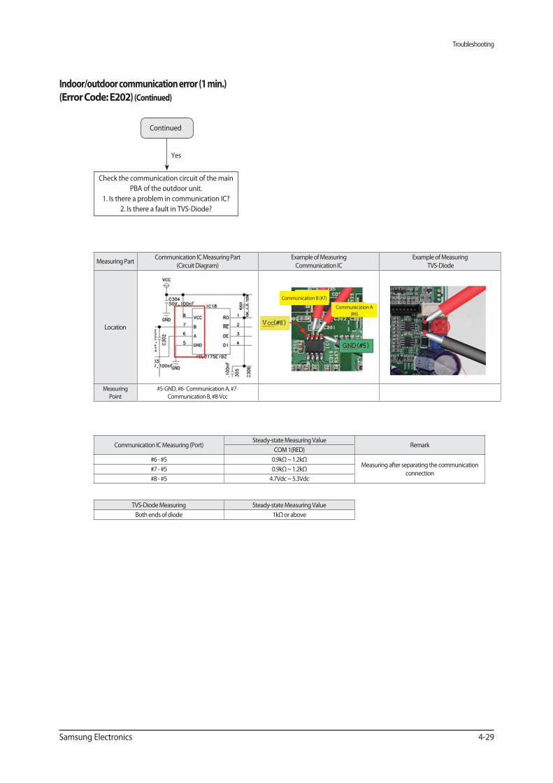
Troubleshooting
Samsung Electronics 4-29
Yes
Indoor/outdoor communication error (1 min.)
( ) (Continued)
Continued
Check the communication circuit of the main
PBA of the outdoor unit.
1. Is there a problem in communication IC?
2. Is there a fault in TVS-Diode?
Measuring PartCommunication IC Measuring Part
(Circuit Diagram)
Example of Measuring
Communication IC
Example of Measuring
TVS-Diode
Location
Measuring
Point
#5-GND, #6- Communication A, #7-
Communication B, #8-Vcc
Communication IC Measuring (Port)Steady-state Measuring Value
RemarkCOM 1(RED)
#6 - #5 0.9kΩ ~ 1.2kΩMeasuring after separating the communication
connection#7 - #5 0.9kΩ ~ 1.2kΩ
#8 - #5 4.7Vdc ~ 5.3Vdc
TVS-Diode Measuring Steady-state Measuring Value
Both ends of diode 1kΩ or above
Communication B (#7)
Communication A
(#6)
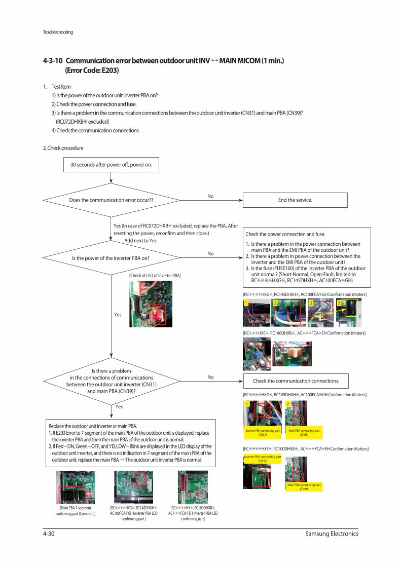
Troubleshooting
4-30 Samsung Electronics
1. Test Item
1) Is the power of the outdoor unit inverter PBA on?
2) Check the power connection and fuse.
3) Is there a problem in the communication connections between the outdoor unit inverter (CN31) and main PBA (CN39)?
(RC072DHXB excluded)
4) Check the communication connections.
2. Check procedure
Yes (In case of RC072DHXB excluded, replace the PBA, After
resetting the power, reconfirm and then close.)
Add next to Yes
End the service.No
Does the communication error occur??
Check the power connection and fuse.
1. Is there a problem in the power connection between main PBA and the EMI PBA of the outdoor unit?
2. Is there a problem in power connection between the inverter and the EMI PBA of the outdoor unit?
3. Is the fuse (FUSE100) of the inverter PBA of the outdoor unit normal? (Short-Normal, Open-Fault, limited to RC HXG , RC145DHXH , AC100FCA GH)
No
Yes
30 seconds after power off, power on.
Replace the outdoor unit inverter or main PBA.1. If E203 Error to 7-segment of the main PBA of the outdoor unit is displayed, replace the inverter PBA and then the main PBA of the outdoor unit is normal.
2. If Red – ON, Green – OFF, and YELLOW – Blink are displayed in the LED display of the outdoor unit inverter, and there is no indication in 7-segment of the main PBA of the outdoor unit, replace the main PBA The outdoor unit inverter PBA is normal.
[RC HXE , RC100DHXB , AC FCA EH Confirmation Matters]
[Check of LED of Inverter PBA]
Check the communication connections.No
Yes
[RC HXG , RC145DHXH , AC100FCA GH Confirmation Matters]
1 2 2 3
[RC HXG , RC145DHXH , AC100FCA GH Confirmation Matters]
[RC HXE , RC100DHXB , AC FCA EH Confirmation Matters]
Is the power of the inverter PBA on?
Inverter PBA connecting part
(CN31)
1 2
Inverter PBA connecting part
(CN31)
Main PBA connecting part
(CN39)
Main PBA connecting part
(CN39)
Is there a problem in the connections of communications
between the outdoor unit inverter (CN31) and main PBA (CN39)?
[RC HXG , RC145DHXH , AC100FCA GH Inverter PBA LED
confirming part ]
[RC HX , RC100DHXB , AC FCA EH Inverter PBA LED
confirming part]
[Main PBA 7-segment
confirming part (Common)]
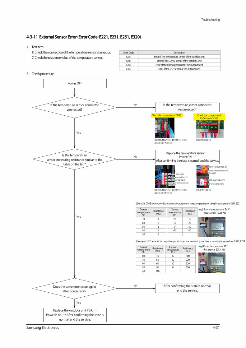
Troubleshooting
Samsung Electronics 4-31
1. Test Item
1) Check the connection of the temperature sensor connector.
2) Check the resistance value of the temperature sensor.
2. Check procedure
Error Code Description
E221 Error of the temperature sensor of the outdoor unit
E231 Error of the COND. sensor of the outdoor unit
E251 Error of the discharge sensor of the outdoor unit
E320 Error of the OLP sensor of the outdoor unit
Power OFF
Is the temperature sensor connector
reconnected?
No
Yes
Yes
Replace the temperature sensor, Power ON.
After confirming the state is normal, end the service. NoIs the temperature
sensor-measuring resistance similar to the
table on the left?
After confirming the state is normal,
end the service.
No
Yes
Replace the outdoor unit PBA.
Power is on. After confirming the state is
normal, end the service.
(Example) COND. sensor/outdoor unit temperature sensor measuring resistance value by temperature: E231, E221
(Example) OLP sensor/discharge temperature sensor measuring resistance value by temperature: E320, E251.
Current temperature
(°C)
Resistance (KΩ)
Current temperature
(°C)
Resistance (KΩ)
70 4 20 10
60 5 10 20
50 6 0 30
40 7 -10 40
30 8
Current temperature
(°C)
Resistance (KΩ)
Current temperature
(°C)
Resistance (KΩ)
80 40 30 180
70 50 20 220
60 60 10 320
50 90 0 550
40 110
Check the connection of CN43.
Is the temperature sensor connector
connected?
OLP sensor: 200kΩ at 25
Discharge sensor: 200kΩ at 25°C
Outdoor unit temperature sensor:
10kΩ at 25°C
COND. sensor: 10kΩ at 25°C
OLP sensor: 200kΩ at 25°C
Discharge sensor: 200kΩ at 25
COND. sensor: 10kΩ at 25
Outdoor unit temperature sensor:
10kΩ at 25
e.g.) Room temperature: 26 - Resistance: 10.28 KΩ
e.g.) Room temperature: 21- Resistance: 205.4 KΩ
Does the same error occur again
after power is on?
[RC090/100/125/140/145 ,
AC FCA ]
[RC090/100/125/140/145 ,
AC FCA ]
[RC072DHXB ]
[RC072DHXB ]
Check the connection of CN501 and CN502.
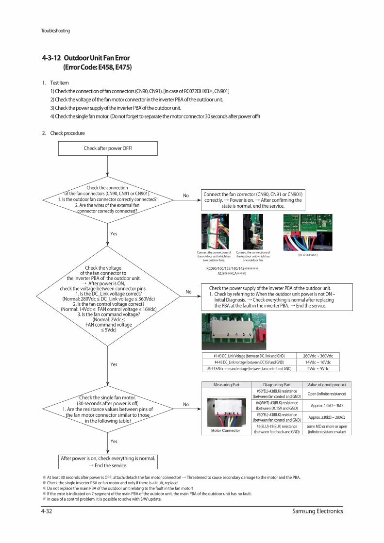
Troubleshooting
4-32 Samsung Electronics
No
No
No
1. Test Item
1) Check the connection of fan connectors (CN90, CN91). [In case of RC072DHXB , CN901]
2) Check the voltage of the fan motor connector in the inverter PBA of the outdoor unit.
3) Check the power supply of the inverter PBA of the outdoor unit.
4) Check the single fan motor. (Do not forget to separate the motor connector 30 seconds after power off!)
2. Check procedure
Yes
Yes
Connect the fan corrector (CN90, CN91 or CN901) correctly. Power is on. After confirming the
state is normal, end the service.
Check the power supply of the inverter PBA of the outdoor unit.1. Check by referring to When the outdoor unit power is not ON –
Initial Diagnosis. Check everything is normal after replacing the PBA at the fault in the inverter PBA. End the service.
Check the connection of the fan connectors (CN90, CN91 or CN901).
1. Is the outdoor fan connector correctly connected?2. Are the wires of the external fan connector correctly connected?
Check the voltage of the fan connector to
the inverter PBA of the outdoor unit. After power is ON,
check the voltage between connector pins.1. Is the DC_Link voltage correct?
(Normal: 280Vdc ≤ DC_Link voltage ≤ 360Vdc) 2. Is the fan control voltage correct?
(Normal: 14Vdc ≤ FAN control voltage ≤ 16Vdc)3. Is the fan command voltage?
(Normal: 2Vdc ≤ FAN command voltage
≤ 5Vdc)
Check after power OFF!
After power is on, check everything is normal.
End the service.
Connect the connections of
the outdoor unit which has
two outdoor fans.
Connect the connections of
the outdoor unit which has
one outdoor fan.
#1-#3 DC_Link Voltage (between DC_link and GND) 280Vdc ~ 360Vdc
#4-#3 DC_Link voltage (between DC15V and GND) 14Vdc ~ 16Vdc
#5-#3 FAN command voltage (between fan control and GND) 2Vdc ~ 5Vdc
Measuring Part Diagnosing Part Value of good product
#5(YEL)-#3(BLK) resistance
(between fan control and GND)Open (infinite resistance)
#4(WHT)-#3(BLK) resistance
(between DC15V and GND)Approx. 1.0kΩ ~ 3kΩ
#5(YEL)-#3(BLK) resistance
(between fan control and GND)Approx. 230kΩ ~ 280kΩ
#6(BLU)-#3(BLK) resistance
(between feedback and GND)
some MΩ or more or open
(infinite resistance value)Motor Connector
Yes
Check the single fan motor.(30 seconds after power is off,
1. Are the resistance values between pins of the fan motor connector similar to those
in the following table?
At least 30 seconds after power is OFF, attach/detach the fan motor connector! Threatened to cause secondary damage to the motor and the PBA.
Check the single inverter PBA or fan motor and only if there is a fault, replace!
Do not replace the main PBA of the outdoor unit relating to the fault in the fan motor!
If the error is indicated on 7-segment of the main PBA of the outdoor unit, the main PBA of the outdoor unit has no fault.
In case of a control problem, it is possible to solve with S/W update.
[RC090/100/125/140/145
AC FCA ]
[RC072DHXB ]
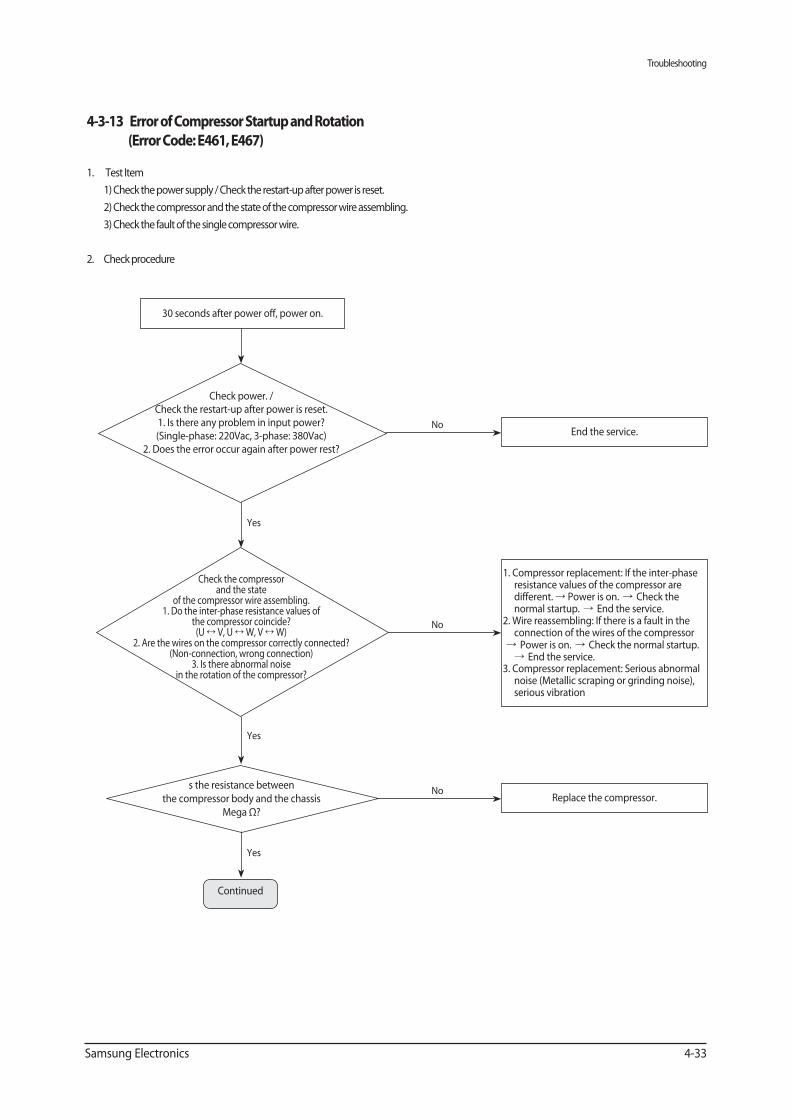
Troubleshooting
Samsung Electronics 4-33
1. Test Item
1) Check the power supply / Check the restart-up after power is reset.
2) Check the compressor and the state of the compressor wire assembling.
3) Check the fault of the single compressor wire.
2. Check procedure
Yes
30 seconds after power off, power on.
End the service.No
Check power. /Check the restart-up after power is reset.1. Is there any problem in input power? (Single-phase: 220Vac, 3-phase: 380Vac)
2. Does the error occur again after power rest?
Yes
1. Compressor replacement: If the inter-phase resistance values of the compressor are different. Power is on. Check the normal startup. End the service.
2. Wire reassembling: If there is a fault in the connection of the wires of the compressorPower is on. Check the normal startup.
End the service.3. Compressor replacement: Serious abnormal
noise (Metallic scraping or grinding noise), serious vibration
No
Check the compressor and the state
of the compressor wire assembling.1. Do the inter-phase resistance values of
the compressor coincide?(U V, U W, V W)
2. Are the wires on the compressor correctly connected? (Non-connection, wrong connection)
3. Is there abnormal noise in the rotation of the compressor?
Replace the compressor.No
s the resistance between
the compressor body and the chassis
Mega Ω?
Yes
Continued
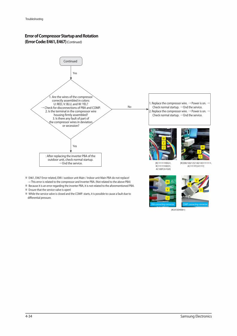
Troubleshooting
4-34 Samsung Electronics
1. Replace the compressor wire. Power is on. Check normal startup. End the service.
2. Replace the compressor wire. Power is on. Check normal startup. End the service.
No
1. Are the wires of the compressor correctly assembled in colors:
U: RED, V: BLU, and W: YEL? Check for disconnections of PBA and COMP.
2. Is the terminal in the compressor wire housing firmly assembled?3. Is there any fault of part of
the compressor wires in deviation or secession?
Yes
Yes
(Continued)
Continued
: After replacing the inverter PBA of the outdoor unit, check normal startup.
End the service.
W
V
U W
V
U
W
V
U
W
V
U
E461, E467 Error-related, EMI / outdoor unit Main / Indoor unit Main PBA do not replace!
This error is related to the compressor and Inverter PBA. (Not related to the above PBA)
Because it is an error regarding the inverter PBA, it is not related to the aforementioned PBA.
Ensure that the service valve is open!
While the service valve is closed and the COMP. starts, it is possible to cause a fault due to
differential pressure.
[RC HXG ,
RC HXH ,
AC100FCA GH]
[RC072DHXB ]
[RC090/100/125/140/145 ,
AC FCA ]
PBA connecting connector COMP connecting connector
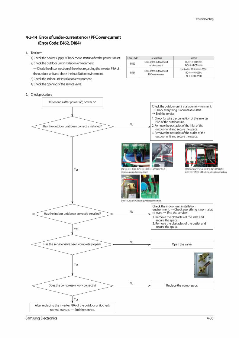
Troubleshooting
Samsung Electronics 4-35
1. Test Item
1) Check the power supply. / Check the re-startup after the power is reset.
2) Check the outdoor unit installation environment.
Check the disconnection of the wires regarding the inverter PBA of
the outdoor unit and check the installation environment.
3) Check the indoor unit installation environment.
4) Check the opening of the service valve.
2. Check procedure
Yes
Check the outdoor unit installation environment. Check everything is normal at re-start.End the service.
1. Check for wire disconnection of the inverter PBA of the outdoor unit.
2. Remove the obstacles of the inlet of the outdoor unit and secure the space.
3. Remove the obstacles of the outlet of the outdoor unit and secure the space.
Check the indoor unit installation environment. Check everything is normal at re-start. End the service.
1. Remove the obstacles of the inlet and secure the space.
2. Remove the obstacles of the outlet and secure the space.
NoHas the outdoor unit been correctly installed?
After replacing the inverter PBA of the outdoor unit, check
normal startup. End the service.
Yes
NoHas the indoor unit been correctly installed?
Yes
Replace the compressor.No
Yes
30 seconds after power off, power on.
Open the valve.No
Has the service valve been completely open?
Error Code Description Model
E462Error of the outdoor unit
under-current
RC HX ,
AC FCA
E484Error of the outdoor unit
PFC over-current
Limited to RC HXE ,
RC HXB ,
AC FCA*EH
Does the compressor work correctly?
[RC HXG , RC HXH , AC100FCA GH:
Checking wire disconnection]
[RC072DHXB : Checking wire disconnection]
[RC090/100/125/140 HXE , RC100DHXB ,
AC FCA EH: Checking wire disconnection]
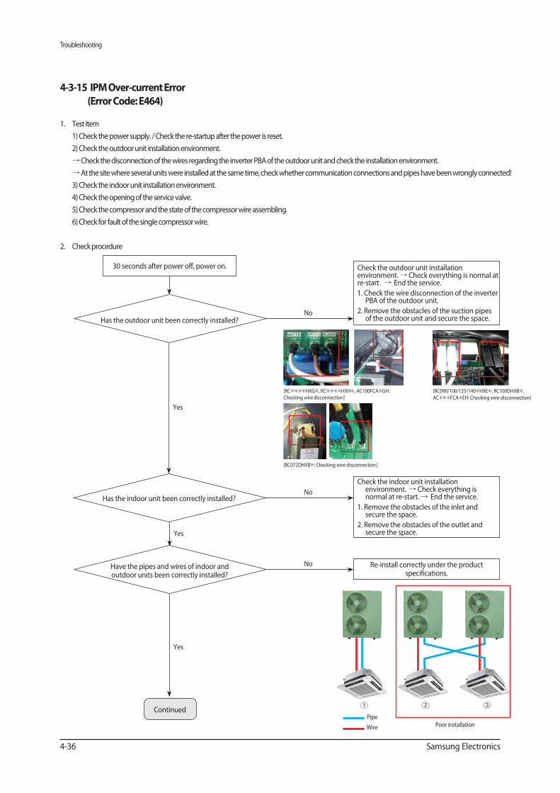
Troubleshooting
4-36 Samsung Electronics
1. Test Item
1) Check the power supply. / Check the re-startup after the power is reset.
2) Check the outdoor unit installation environment.
Check the disconnection of the wires regarding the inverter PBA of the outdoor unit and check the installation environment.
At the site where several units were installed at the same time, check whether communication connections and pipes have been wrongly connected!
3) Check the indoor unit installation environment.
4) Check the opening of the service valve.
5) Check the compressor and the state of the compressor wire assembling.
6) Check for fault of the single compressor wire.
2. Check procedure
Yes
Check the outdoor unit installation environment. Check everything is normal at re-start End the service.
1. Check the wire disconnection of the inverter PBA of the outdoor unit.
2. Remove the obstacles of the suction pipes of the outdoor unit and secure the space.
Check the indoor unit installation environment. Check everything is normal at re-start. End the service.
1. Remove the obstacles of the inlet and secure the space.
2. Remove the obstacles of the outlet and secure the space.
NoHas the outdoor unit been correctly installed?
No
Yes
Continued
30 seconds after power off, power on.
Re-install correctly under the product specifications.
No
Yes
Poor installationPipe
Wire
Have the pipes and wires of indoor and outdoor units been correctly installed?
Has the indoor unit been correctly installed?
[RC HXG , RC HXH , AC100FCA GH: Checking wire disconnection]
[RC072DHXB : Checking wire disconnection]
[RC090/100/125/140 HXE , RC100DHXB ,
AC FCA EH: Checking wire disconnection]
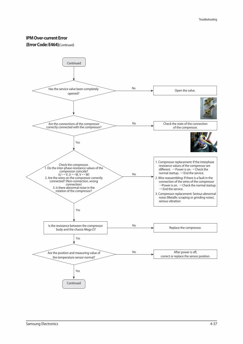
Troubleshooting
Samsung Electronics 4-37
Yes
After power is off, correct or replace the sensor position.
NoAre the position and measuring value of
the temperature sensor normal?
Continued
(Continued)
Check the state of the connection of the compressor.
NoAre the connections of the compressor correctly connected with the compressor?
Yes
1. Compressor replacement: If the interphase resistance values of the compressor are different. Power is on. Check the normal startup. End the service.
2. Wire reassembling: If there is a fault in the connection of the wires of the compressor Power is on. Check the normal startup. End the service.
3. Compressor replacement: Serious abnormal noise (Metallic scraping or grinding noise), serious vibration
No
Check the compressor.1. Do the inter-phase resistance values of the
compressor coincide?(U V, U W, V W)
2. Are the wires on the compressor correctly connected? (Non-connection, wrong
connection)3. Is there abnormal noise in the rotation of the compressor?
Yes
Replace the compressor.No
Yes
Is the resistance between the compressor body and the chassis Mega Ω?
Open the valve.NoHas the service valve been completely
opened?
Continued
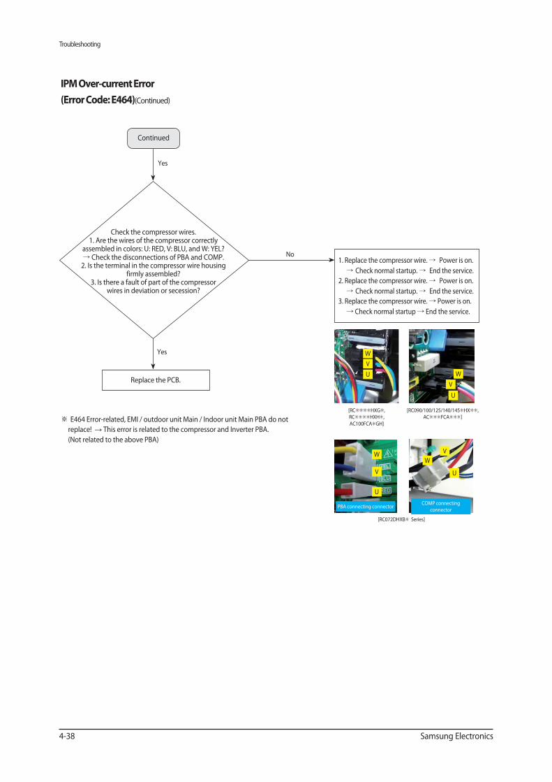
Troubleshooting
4-38 Samsung Electronics
(Continued)
Yes
1. Replace the compressor wire. Power is on.
Check normal startup. End the service.
2. Replace the compressor wire. Power is on.
Check normal startup. End the service.
3. Replace the compressor wire. Power is on.
Check normal startup End the service.
No
Check the compressor wires.1. Are the wires of the compressor correctly
assembled in colors: U: RED, V: BLU, and W: YEL? Check the disconnections of PBA and COMP.
2. Is the terminal in the compressor wire housing firmly assembled?
3. Is there a fault of part of the compressor wires in deviation or secession?
Replace the PCB.
Continued
Yes
E464 Error-related, EMI / outdoor unit Main / Indoor unit Main PBA do not
replace! This error is related to the compressor and Inverter PBA.
(Not related to the above PBA)
W
V
U W
V
U
W
V
U
W
V
U
[RC HXG ,
RC HXH ,
AC100FCA GH]
[RC072DHXB Series]
[RC090/100/125/140/145 HX ,
AC FCA ]
PBA connecting connectorCOMP connecting
connector
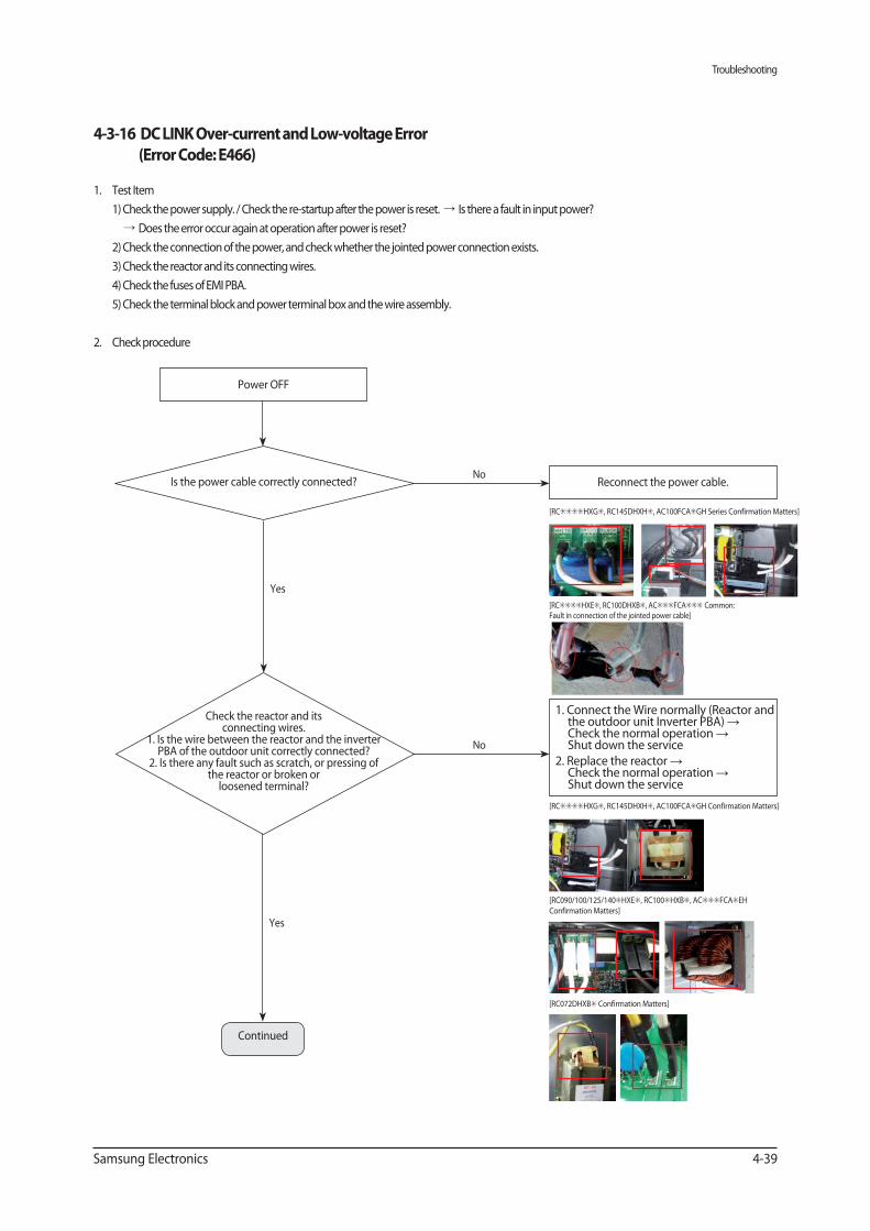
Troubleshooting
Samsung Electronics 4-39
1. Test Item
1) Check the power supply. / Check the re-startup after the power is reset. Is there a fault in input power?
Does the error occur again at operation after power is reset?
2) Check the connection of the power, and check whether the jointed power connection exists.
3) Check the reactor and its connecting wires.
4) Check the fuses of EMI PBA.
5) Check the terminal block and power terminal box and the wire assembly.
2. Check procedure
Yes
Reconnect the power cable.No
Is the power cable correctly connected?
1. Connect the Wire normally (Reactor and the outdoor unit Inverter PBA) Check the normal operation Shut down the service
2. Replace the reactor Check the normal operation Shut down the service
No
Power OFF
[RC HXG , RC145DHXH , AC100FCA GH Series Confirmation Matters]
[RC HXE , RC100DHXB , AC FCA Common: Fault in connection of the jointed power cable]
[RC HXG , RC145DHXH , AC100FCA GH Confirmation Matters]
[RC090/100/125/140 HXE , RC100 HXB , AC FCA EH
Confirmation Matters]
[RC072DHXB Confirmation Matters]
Yes
Continued
Check the reactor and its connecting wires.
1. Is the wire between the reactor and the inverter PBA of the outdoor unit correctly connected?
2. Is there any fault such as scratch, or pressing of the reactor or broken or
loosened terminal?
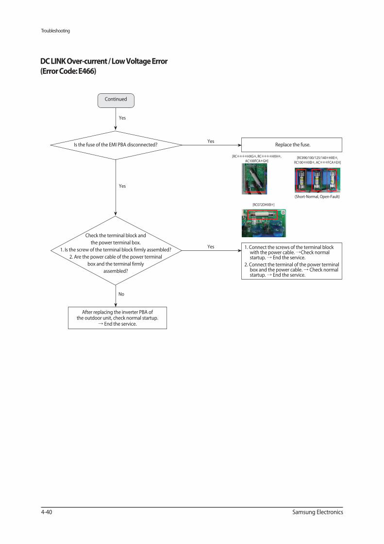
Troubleshooting
4-40 Samsung Electronics
1. Connect the screws of the terminal block with the power cable. Check normal startup. End the service.
2. Connect the terminal of the power terminal box and the power cable. Check normal startup. End the service.
Replace the fuse.
Yes
Yes
No
After replacing the inverter PBA of the outdoor unit, check normal startup.
End the service.
Check the terminal block and
the power terminal box.
1. Is the screw of the terminal block firmly assembled?
2. Are the power cable of the power terminal
box and the terminal firmly
assembled?
Is the fuse of the EMI PBA disconnected?
[RC HXG , RC HXH ,
AC100FCA GH]
[RC072DHXB ]
Continued
Yes
Yes
[RC090/100/125/140 HXE ,
RC100 HXB , AC FCA EH]
(Short-Normal, Open-Fault)
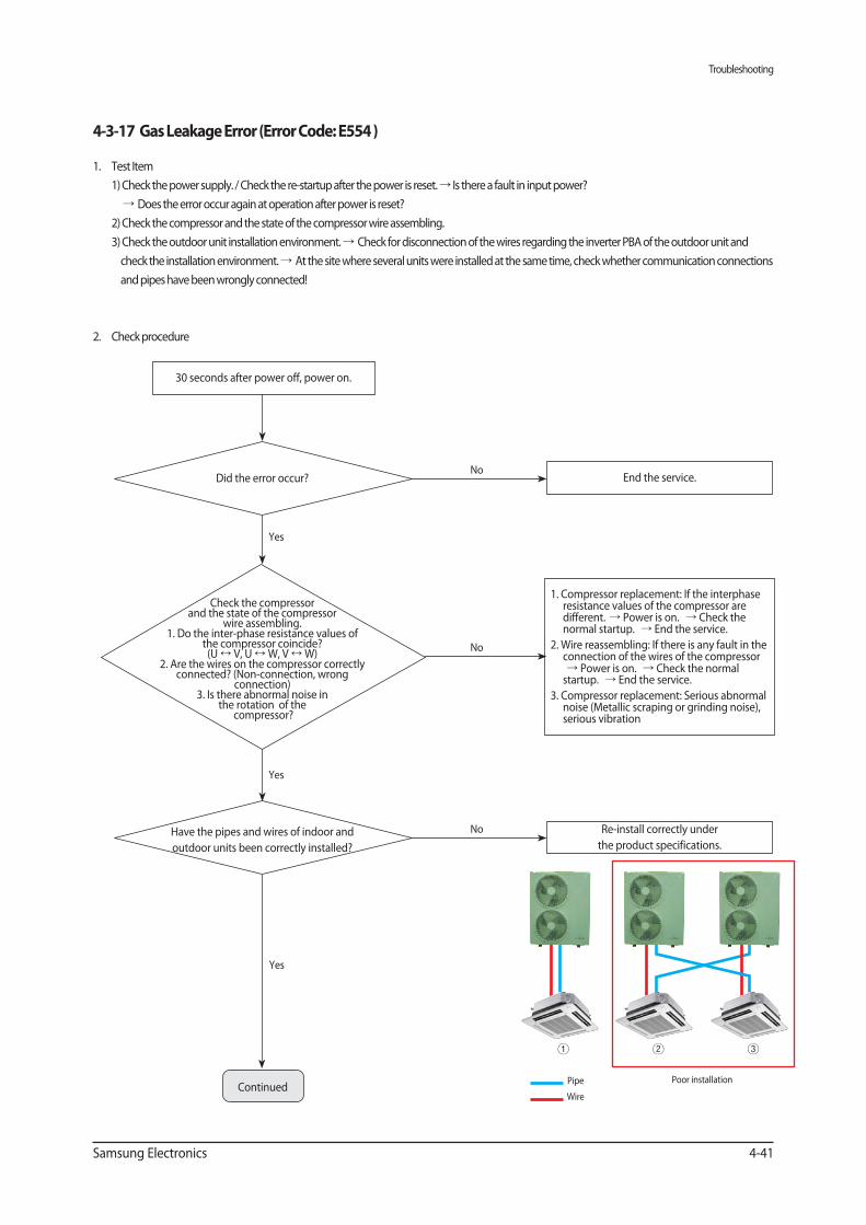
Troubleshooting
Samsung Electronics 4-41
1. Test Item
1) Check the power supply. / Check the re-startup after the power is reset. Is there a fault in input power?
Does the error occur again at operation after power is reset?
2) Check the compressor and the state of the compressor wire assembling.
3) Check the outdoor unit installation environment. Check for disconnection of the wires regarding the inverter PBA of the outdoor unit and
check the installation environment. At the site where several units were installed at the same time, check whether communication connections
and pipes have been wrongly connected!
2. Check procedure
Yes
30 seconds after power off, power on.
End the service.No
Did the error occur?
1. Compressor replacement: If the interphase resistance values of the compressor are different. Power is on. Check the normal startup. End the service.
2. Wire reassembling: If there is any fault in the connection of the wires of the compressor
Power is on. Check the normal startup. End the service.
3. Compressor replacement: Serious abnormal noise (Metallic scraping or grinding noise), serious vibration
No
Yes
Re-install correctly under
the product specifications.
No
Yes
ContinuedPipe
Wire
Poor installation
Check the compressor and the state of the compressor
wire assembling.1. Do the inter-phase resistance values of
the compressor coincide?(U V, U W, V W)
2. Are the wires on the compressor correctly connected? (Non-connection, wrong
connection)3. Is there abnormal noise in
the rotation of the compressor?
Have the pipes and wires of indoor and
outdoor units been correctly installed?
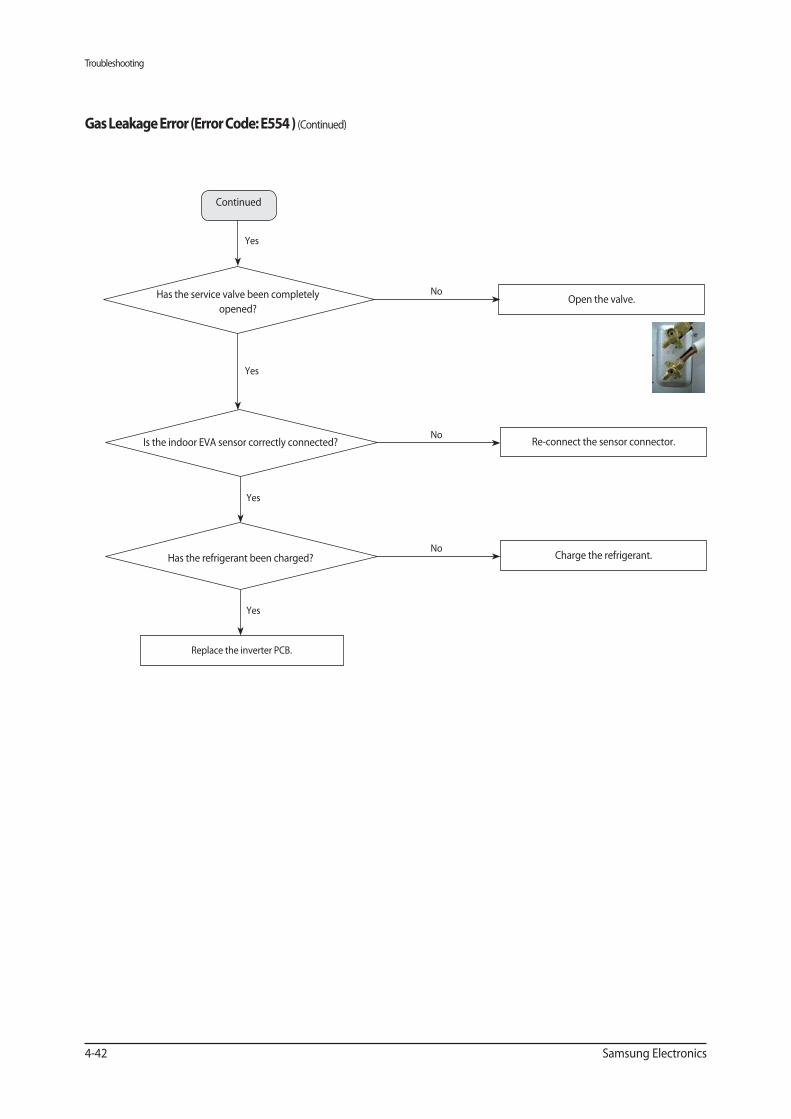
Troubleshooting
4-42 Samsung Electronics
Open the valve.
) (Continued)
Yes
Re-connect the sensor connector.No
No
Is the indoor EVA sensor correctly connected?
Yes
Charge the refrigerant.No
Has the refrigerant been charged?
Replace the inverter PCB.
Continued
Yes
Yes
Has the service valve been completely
opened?
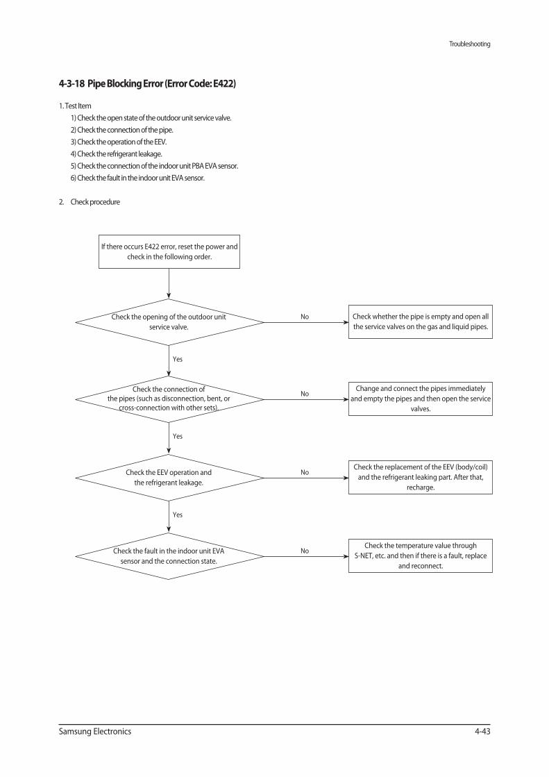
Troubleshooting
Samsung Electronics 4-43
1. Test Item
1) Check the open state of the outdoor unit service valve.
2) Check the connection of the pipe.
3) Check the operation of the EEV.
4) Check the refrigerant leakage.
5) Check the connection of the indoor unit PBA EVA sensor.
6) Check the fault in the indoor unit EVA sensor.
2. Check procedure
Yes
Yes
Yes
If there occurs E422 error, reset the power and
check in the following order.
Check whether the pipe is empty and open all
the service valves on the gas and liquid pipes.
Change and connect the pipes immediately
and empty the pipes and then open the service
valves.
Check the replacement of the EEV (body/coil)
and the refrigerant leaking part. After that,
recharge.
Check the temperature value through
S-NET, etc. and then if there is a fault, replace
and reconnect.
No
No
No
No
Check the opening of the outdoor unit
service valve.
Check the connection of the pipes (such as disconnection, bent, or
cross-connection with other sets).
Check the EEV operation and
the refrigerant leakage.
Check the fault in the indoor unit EVA
sensor and the connection state.
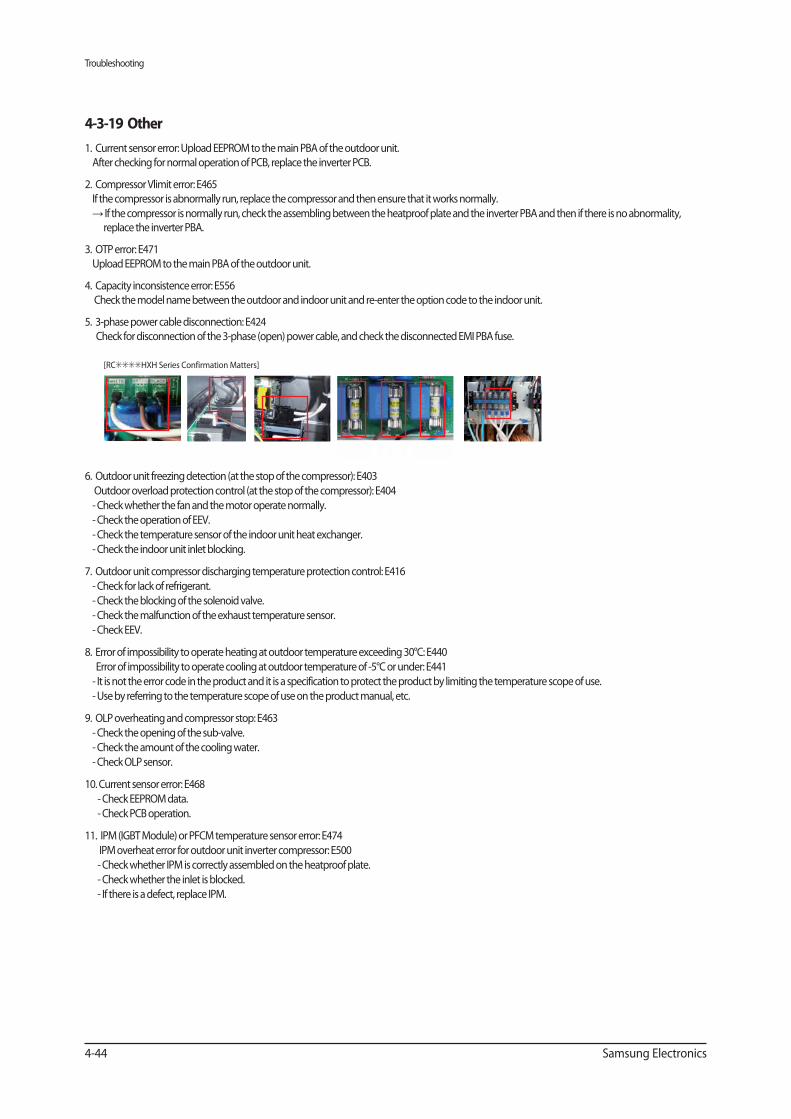
Troubleshooting
4-44 Samsung Electronics
1. Current sensor error: Upload EEPROM to the main PBA of the outdoor unit.
After checking for normal operation of PCB, replace the inverter PCB.
2. Compressor Vlimit error: E465
If the compressor is abnormally run, replace the compressor and then ensure that it works normally.
If the compressor is normally run, check the assembling between the heatproof plate and the inverter PBA and then if there is no abnormality, replace the inverter PBA.
3. OTP error: E471
Upload EEPROM to the main PBA of the outdoor unit.
4. Capacity inconsistence error: E556
Check the model name between the outdoor and indoor unit and re-enter the option code to the indoor unit.
5. 3-phase power cable disconnection: E424
Check for disconnection of the 3-phase (open) power cable, and check the disconnected EMI PBA fuse.
6. Outdoor unit freezing detection (at the stop of the compressor): E403
Outdoor overload protection control (at the stop of the compressor): E404
- Check whether the fan and the motor operate normally.
- Check the operation of EEV.
- Check the temperature sensor of the indoor unit heat exchanger.
- Check the indoor unit inlet blocking.
7. Outdoor unit compressor discharging temperature protection control: E416
- Check for lack of refrigerant.
- Check the blocking of the solenoid valve.
- Check the malfunction of the exhaust temperature sensor.
- Check EEV.
8. Error of impossibility to operate heating at outdoor temperature exceeding 30°C: E440
Error of impossibility to operate cooling at outdoor temperature of -5°C or under: E441
- It is not the error code in the product and it is a specification to protect the product by limiting the temperature scope of use.
- Use by referring to the temperature scope of use on the product manual, etc.
9. OLP overheating and compressor stop: E463
- Check the opening of the sub-valve.
- Check the amount of the cooling water.
- Check OLP sensor.
10. Current sensor error: E468
- Check EEPROM data.
- Check PCB operation.
11. IPM (IGBT Module) or PFCM temperature sensor error: E474
IPM overheat error for outdoor unit inverter compressor: E500
- Check whether IPM is correctly assembled on the heatproof plate.
- Check whether the inlet is blocked.
- If there is a defect, replace IPM.
[RC HXH Series Confirmation Matters]
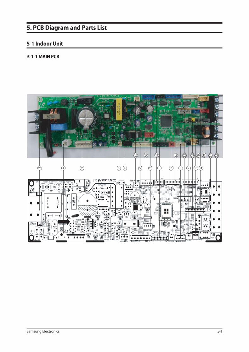
Samsung Electronics 5-1
5. PCB Diagram and Parts List
5-1 Indoor Unit
5-1-1 MAIN PCB
22 1 2 3 4 5 7 8 9 1011 6
12 13 1516 17 18 19 20
14
21 23
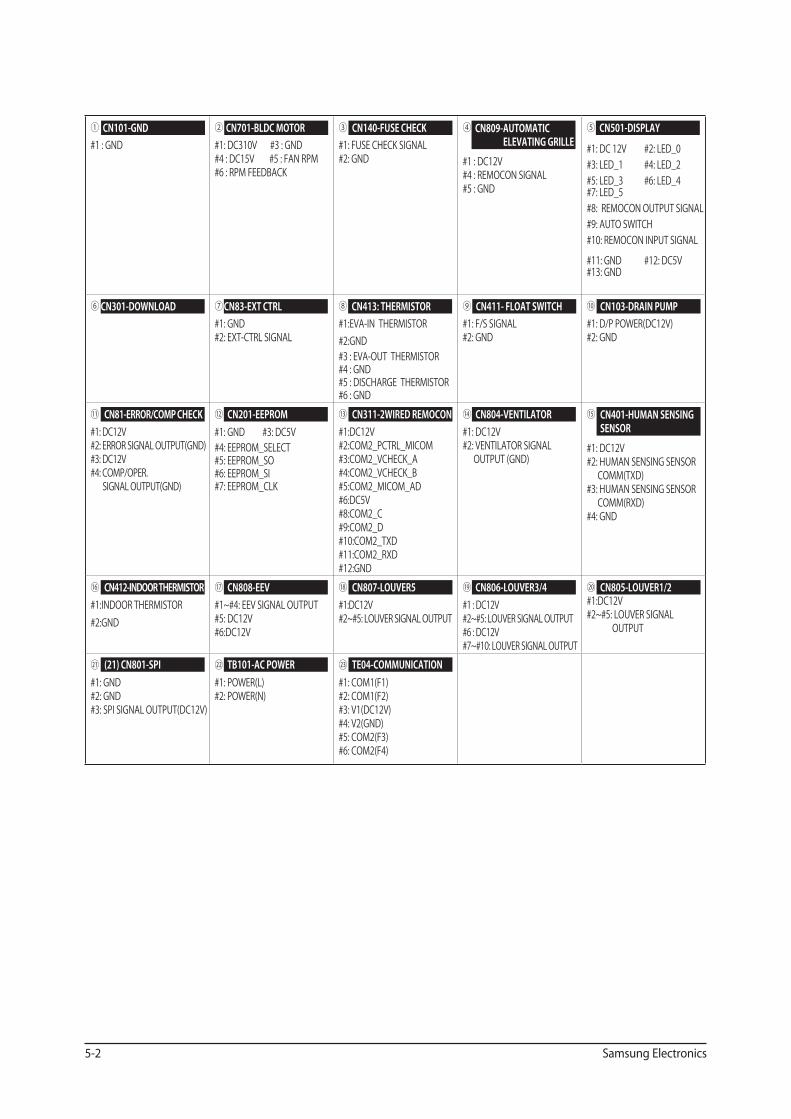
5-2 Samsung Electronics
① #1 : GND
② #1: DC310V #3 : GND#4 : DC15V #5 : FAN RPM#6 : RPM FEEDBACK
③#1: FUSE CHECK SIGNAL#2: GND
④
#1 : DC12V#4 : REMOCON SIGNAL#5 : GND
⑤
#1: DC 12V #2: LED_0 #3: LED_1 #4: LED_2 #5: LED_3 #6: LED_4 #7: LED_5 #8: REMOCON OUTPUT SIGNAL #9: AUTO SWITCH #10: REMOCON INPUT SIGNAL
#11: GND #12: DC5V#13: GND
⑥ ⑦ #1: GND #2: EXT-CTRL SIGNAL
⑧ #1:EVA-IN THERMISTOR #2:GND #3 : EVA-OUT THERMISTOR#4 : GND#5 : DISCHARGE THERMISTOR #6 : GND
⑨ #1: F/S SIGNAL #2: GND
⑩ #1: D/P POWER(DC12V) #2: GND
⑪ #1: DC12V #2: ERROR SIGNAL OUTPUT(GND) #3: DC12V #4: COMP/OPER. SIGNAL OUTPUT(GND)
⑫ #1: GND #3: DC5V#4: EEPROM_SELECT #5: EEPROM_SO #6: EEPROM_SI#7: EEPROM_CLK
⑬ #1:DC12V#2:COM2_PCTRL_MICOM #3:COM2_VCHECK_A #4:COM2_VCHECK_B#5:COM2_MICOM_AD #6:DC5V #8:COM2_C#9:COM2_D#10:COM2_TXD #11:COM2_RXD#12:GND
⑭ #1: DC12V #2: VENTILATOR SIGNAL OUTPUT (GND)
⑮
#1: DC12V #2: HUMAN SENSING SENSOR COMM(TXD)
#3: HUMAN SENSING SENSOR COMM(RXD)
#4: GND
⑯ #1:INDOOR THERMISTOR#2:GND
⑰ #1~#4: EEV SIGNAL OUTPUT#5: DC12V#6:DC12V
⑱#1:DC12V #2~#5: LOUVER SIGNAL OUTPUT
⑲ #1 : DC12V#2~#5: LOUVER SIGNAL OUTPUT#6 : DC12V#7~#10: LOUVER SIGNAL OUTPUT
⑳ #1:DC12V#2~#5: LOUVER SIGNAL
OUTPUT
㉑ #1: GND#2: GND#3: SPI SIGNAL OUTPUT(DC12V)
㉒ #1: POWER(L)#2: POWER(N)
㉓ #1: COM1(F1)#2: COM1(F2)#3: V1(DC12V)#4: V2(GND)#5: COM2(F3)#6: COM2(F4)
CN101-GND
CN301-DOWNLOAD
CN81-ERROR/COMP CHECK
CN412-INDOOR THERMISTOR
(21) CN801-SPI
CN701-BLDC MOTOR
CN83-EXT CTRL
CN201-EEPROM
CN808-EEV
TB101-AC POWER
CN140-FUSE CHECK
CN413: THERMISTOR
CN311-2WIRED REMOCON
CN807-LOUVER5
TE04-COMMUNICATION
CN809- AUTOMATIC ELEVATING GRILLE
CN411- FLOAT SWITCH
CN804-VENTILATOR
CN806-LOUVER3/4
CN501-DISPLAY
CN103-DRAIN PUMP
CN401-HUMAN SENSING SENSOR
CN805-LOUVER1/2
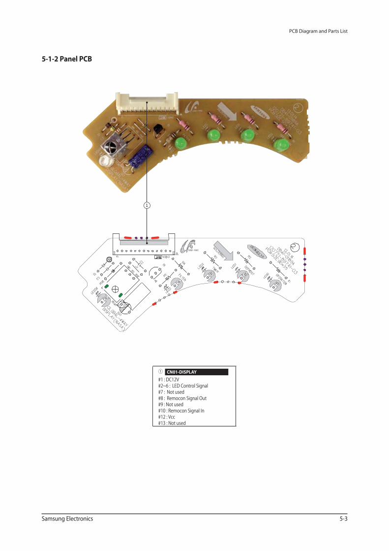
PCB Diagram and Parts List
Samsung Electronics 5-3
① #1 : DC12V#2~6 : LED Control Signal#7 : Not used#8 : Remocon Signal Out#9 : Not used#10 : Remocon Signal In#12 : Vcc#13 : Not used
CN01-DISPLAY
5-1-2 Panel PCB
1
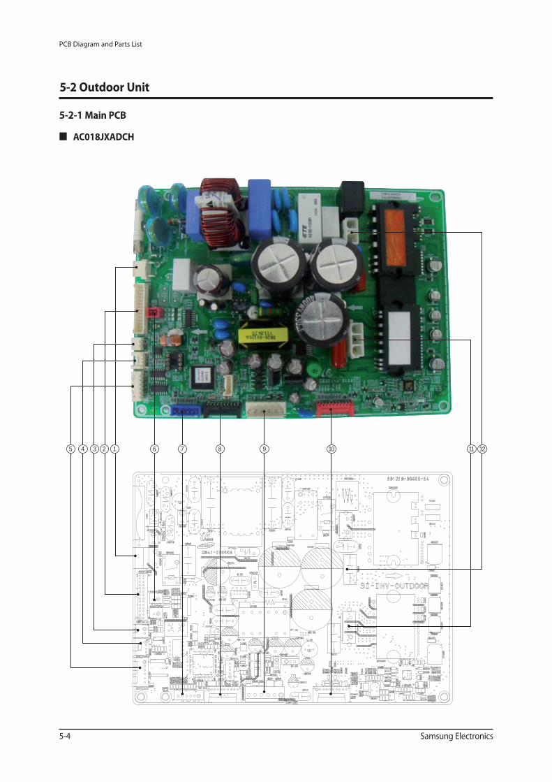
PCB Diagram and Parts List
5-4 Samsung Electronics
5-2-1 Main PCB
AC018JXADCH
5 4 3 2 1 76 8 9 10 11 12
5-2 Outdoor Unit
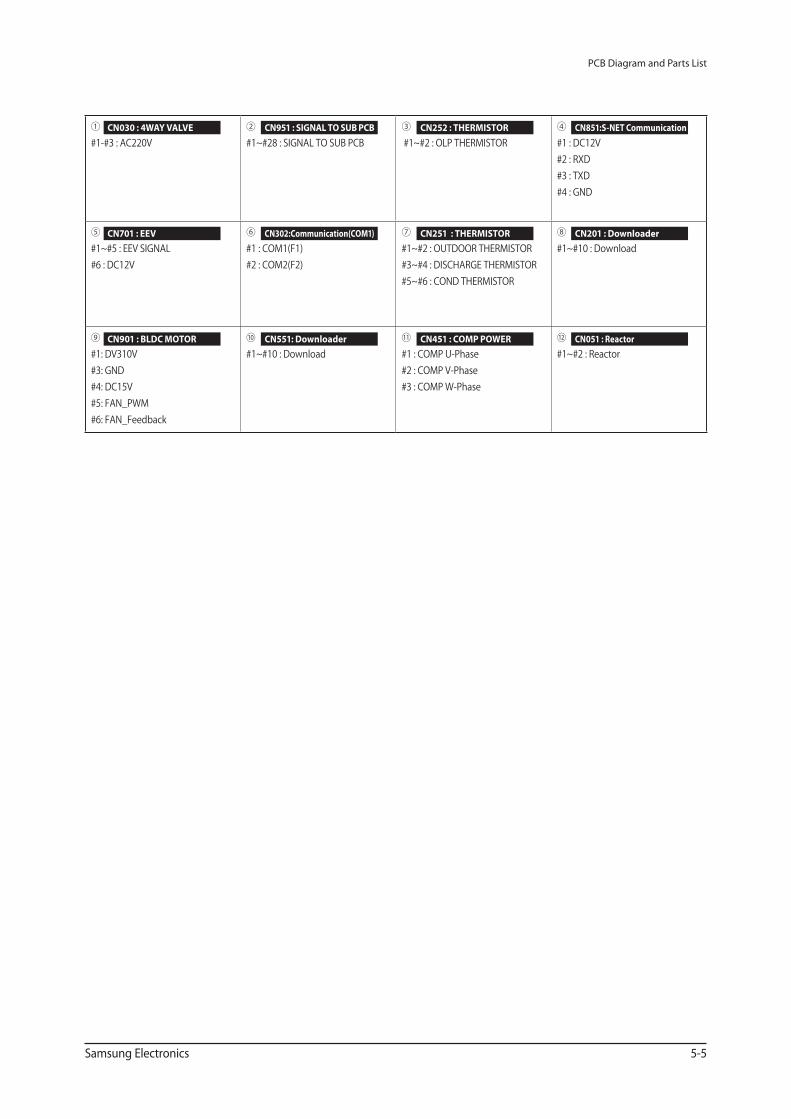
PCB Diagram and Parts List
Samsung Electronics 5-5
① #1-#3 : AC220V
②#1~#28 : SIGNAL TO SUB PCB
③ #1~#2 : OLP THERMISTOR
④#1 : DC12V#2 : RXD#3 : TXD#4 : GND
⑤ #1~#5 : EEV SIGNAL#6 : DC12V
⑥#1 : COM1(F1)#2 : COM2(F2)
⑦ #1~#2 : OUTDOOR THERMISTOR#3~#4 : DISCHARGE THERMISTOR#5~#6 : COND THERMISTOR
⑧#1~#10 : Download
⑨ #1: DV310V#3: GND#4: DC15V#5: FAN_PWM#6: FAN_Feedback
⑩#1~#10 : Download
⑪ #1 : COMP U-Phase#2 : COMP V-Phase#3 : COMP W-Phase
⑫#1~#2 : Reactor
CN030 : 4WAY VALVE CN951 : SIGNAL TO SUB PCB CN252 : THERMISTOR CN851:S-NET Communication
CN701 : EEV
CN901 : BLDC MOTOR
CN302:Communication(COM1)
CN551: Downloader
CN251 : THERMISTOR
CN451 : COMP POWER
CN201 : Downloader
CN051 : Reactor
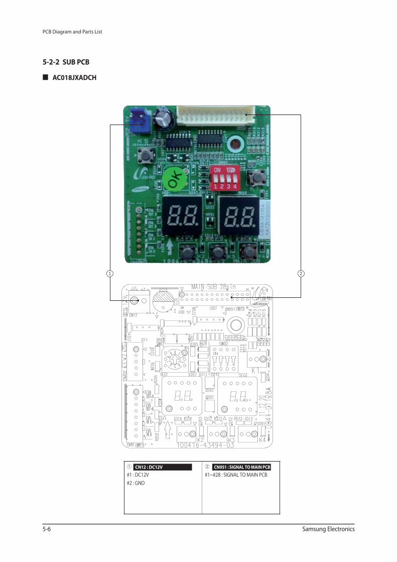
PCB Diagram and Parts List
5-6 Samsung Electronics
5-2-2 SUB PCB
AC018JXADCH
1 2
① #1 : DC12V#2 : GND
②#1~#28 : SIGNAL TO MAIN PCB
CN12 : DC12V CN951 : SIGNAL TO MAIN PCB
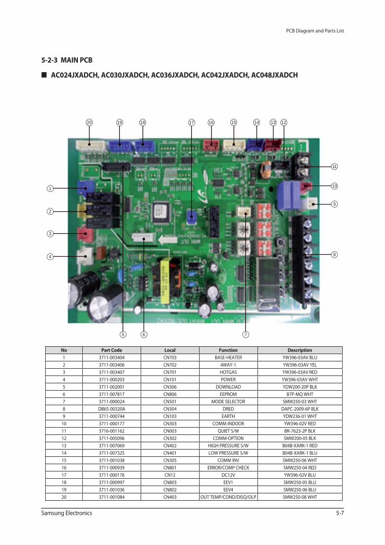
PCB Diagram and Parts List
Samsung Electronics 5-7
20 19 18 17 16 15 1314 12
11
10
9
8
765
1
2
3
4
No Part Code Local Function Description
1 3711-003404 CN703 BASE-HEATER YW396-03AV BLU
2 3711-003406 CN702 4WAY-1 YW396-03AV YEL
3 3711-003407 CN701 HOTGAS YW396-03AV RED
4 3711-000203 CN101 POWER YW396-03AV WHT
5 3711-002001 CN306 DOWNLOAD YDW200-20P BLK
6 3711-007817 CN806 EEPROM B7P-MQ WHT
7 3711-000024 CN501 MODE SELECTOR SMW250-03 WHT
8 DB65-00320A CN304 DRED DAPC-2009-6P BLK
9 3711-000744 CN103 EARTH YDW236-01 WHT
10 3711-000177 CN303 COMM-INDOOR YW396-02V RED
11 3716-001162 CN003 QUIET S/W BR-7623-2P BLK
12 3711-005096 CN302 COMM-OPTION SMW200-05 BLK
13 3711-007069 CN402 HIGH PRESSURE S/W B04B-XARK-1 RED
14 3711-007325 CN401 LOW PRESSURE S/W B04B-XARK-1 BLU
15 3711-001038 CN305 COMM INV SMW250-06 WHT
16 3711-000939 CN801 ERROR/COMP CHECK SMW250-04 RED
17 3711-000176 CN12 DC12V YW396-02V BLU
18 3711-000997 CN803 EEV1 SMW250-05 BLU
19 3711-001036 CN802 EEV4 SMW250-06 BLU
20 3711-001084 CN403 OUT TEMP/COND/DISQ/OLP SMW250-08 WHT
5-2-3 MAIN PCB
AC024JXADCH, AC030JXADCH, AC036JXADCH, AC042JXADCH, AC048JXADCH
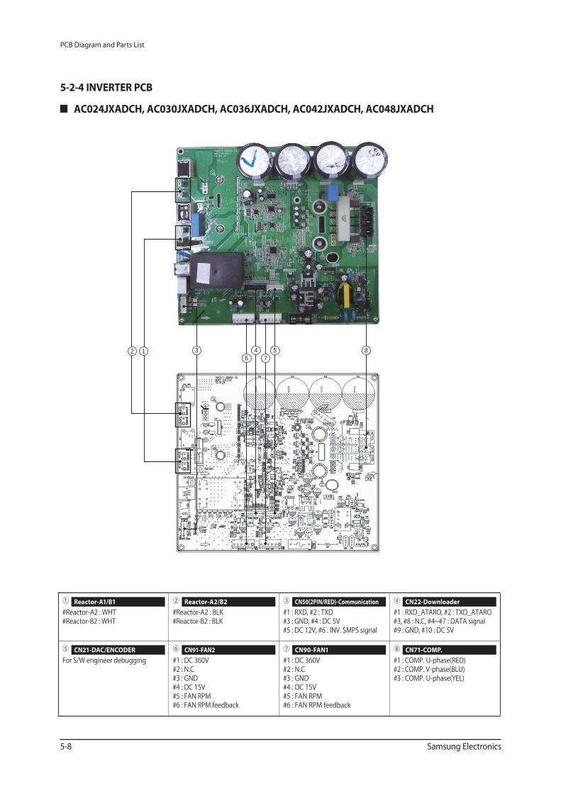
PCB Diagram and Parts List
5-8 Samsung Electronics
① #Reactor-A2 : WHT #Reactor-B2 : WHT
② #Reactor-A2 : BLK #Reactor-B2 : BLK
③ #1 : RXD, #2 : TXD #3 : GND, #4 : DC 5V #5 : DC 12V, #6 : INV. SMPS signal
④ #1 : RXD_ATARO, #2 : TXD_ATARO #3, #8 : N.C, #4~#7 : DATA signal #9 : GND, #10 : DC 5V
⑤ For S/W engineer debugging
⑥ #1 : DC 360V #2 : N.C #3 : GND #4 : DC 15V #5 : FAN RPM #6 : FAN RPM feedback
⑦ #1 : DC 360V #2 : N.C #3 : GND #4 : DC 15V #5 : FAN RPM #6 : FAN RPM feedback
⑧ #1 : COMP. U-phase(RED) #2 : COMP. V-phase(BLU) #3 : COMP. U-phase(YEL)
Reactor-A1/B1 Reactor-A2/B2 CN50(2PIN/RED)-Communication CN22-Downloader
CN21-DAC/ENCODER CN91-FAN2 CN90-FAN1 CN71-COMP.
2 3 46
5 87
1
AC024JXADCH, AC030JXADCH, AC036JXADCH, AC042JXADCH, AC048JXADCH
5-2-4 INVERTER PCB
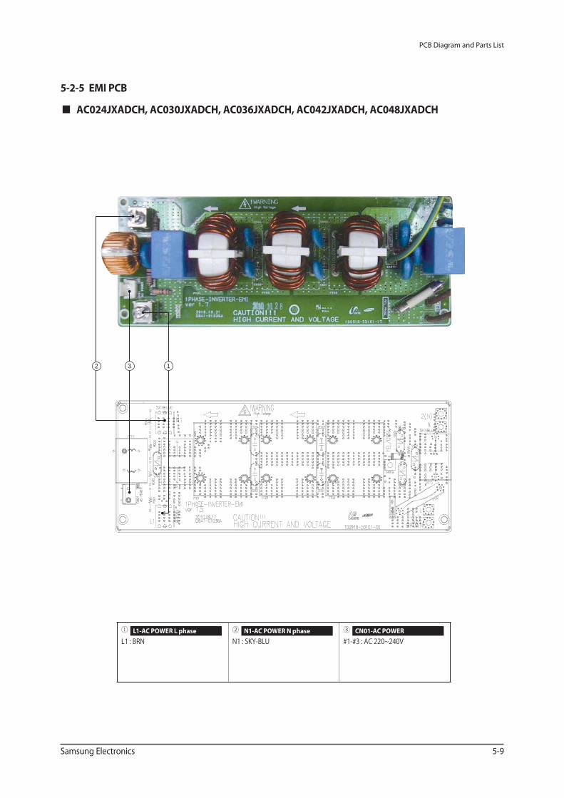
PCB Diagram and Parts List
Samsung Electronics 5-9
AC024JXADCH, AC030JXADCH, AC036JXADCH, AC042JXADCH, AC048JXADCH
① L1 : BRN
② N1 : SKY-BLU
③ #1-#3 : AC 220~240V
L1-AC POWER L phase N1-AC POWER N phase CN01-AC POWER
3 12
5-2-5 EMI PCB
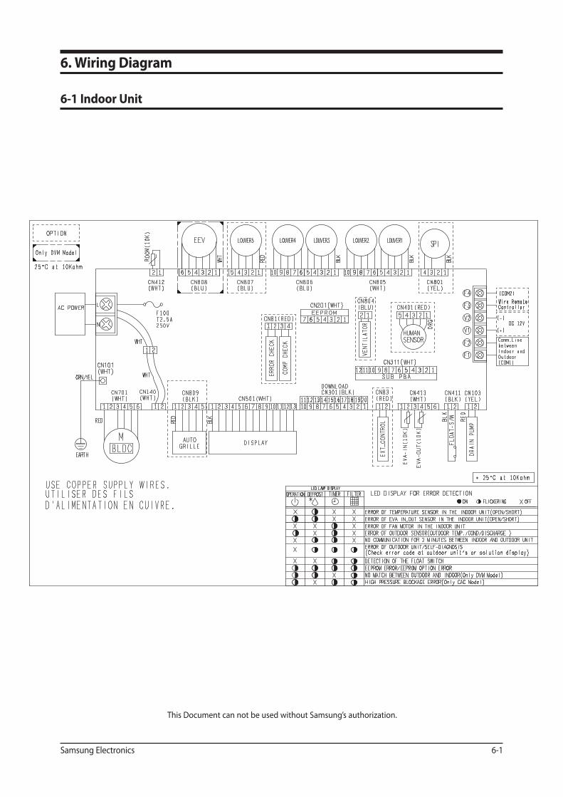
Samsung Electronics 6-1
6. Wiring Diagram
6-1 Indoor Unit
This Document can not be used without Samsung’s authorization.
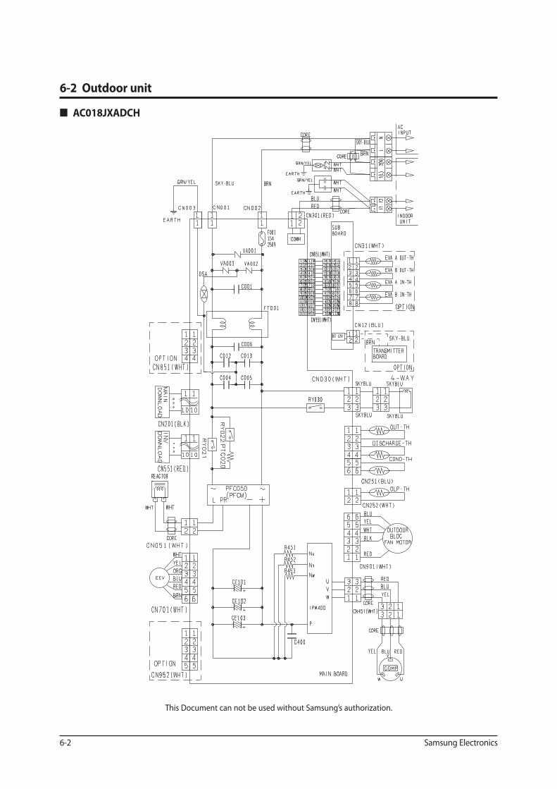
6-2 Samsung Electronics
6-2 Outdoor unit
This Document can not be used without Samsung’s authorization.
AC018JXADCH
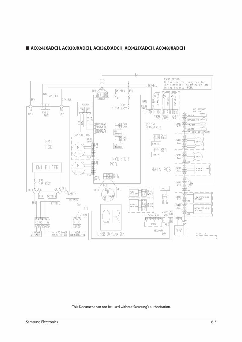
Samsung Electronics 6-3
This Document can not be used without Samsung’s authorization.
AC024JXADCH, AC030JXADCH, AC036JXADCH, AC042JXADCH, AC048JXADCH
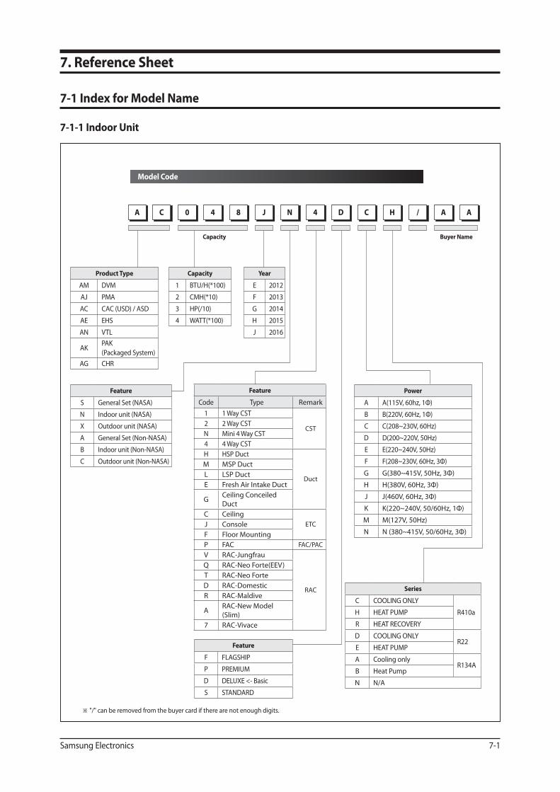
Samsung Electronics 7-1
Model Code
7. Reference Sheet
7-1 Index for Model Name
7-1-1 Indoor Unit
※ "/" can be removed from the buyer card if there are not enough digits.
Product Type
AM DVM
AJ PMA
AC CAC (USD) / ASD
AE EHS
AN VTL
AKPAK
(Packaged System)
AG CHR
Feature
S General Set (NASA)
N Indoor unit (NASA)
X Outdoor unit (NASA)
A General Set (Non-NASA)
B Indoor unit (Non-NASA)
C Outdoor unit (Non-NASA)
Feature
F FLAGSHIP
P PREMIUM
D DELUXE <- Basic
S STANDARD
Capacity
1 BTU/H(*100)
2 CMH(*10)
3 HP(/10)
4 WATT(*100)
Power
A A(115V, 60hz, 1Ф)
B B(220V, 60Hz, 1Ф)
C C(208~230V, 60Hz)
D D(200~220V, 50Hz)
E E(220~240V, 50Hz)
F F(208~230V, 60Hz, 3Ф)
G G(380~415V, 50Hz, 3Ф)
H H(380V, 60Hz, 3Ф)
J J(460V, 60Hz, 3Ф)
K K(220~240V, 50/60Hz, 1Ф)
M M(127V, 50Hz)
N N (380~415V, 50/60Hz, 3Ф)
Year
E 2012
F 2013
G 2014
H 2015
J 2016
Buyer NameCapacity
Series
C COOLING ONLY
R410a H HEAT PUMP
R HEAT RECOVERY
D COOLING ONLYR22
E HEAT PUMP
A Cooling onlyR134A
B Heat Pump
N N/A
HC H0
H4 H8 HJ
HN
H4
HD
HC
HH
H/
HA
HAHA
Feature
Code Type Remark
1 1 Way CST
CST 2 2 Way CST
N Mini 4 Way CST
4 4 Way CST
H HSP Duct
Duct
M MSP Duct
L LSP Duct
E Fresh Air Intake Duct
GCeiling Conceiled
Duct
C Ceiling
ETC J Console
F Floor Mounting
P FAC FAC/PAC
V RAC-Jungfrau
RAC
Q RAC-Neo Forte(EEV)
T RAC-Neo Forte
D RAC-Domestic
R RAC-Maldive
A RAC-New Model
(Slim)
7 RAC-Vivace
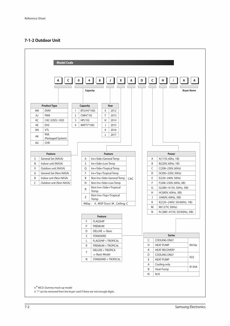
Reference Sheet
7-2 Samsung Electronics
Model Code
7-1-2 Outdoor Unit
※★MCD: Dummy mock-up model
※ “/” can be removed from the buyer card if there are not enough digits.
Product Type
AM DVM
AJ PMA
AC CAC (USD) / ASD
AE EHS
AN VTL
AKPAK
(Packaged System)
AG CHR
Feature
S General Set (NASA)
N Indoor unit (NASA)
X Outdoor unit (NASA)
A General Set (Non-NASA)
B Indoor unit (Non-NASA)
C Outdoor unit (Non-NASA)
Feature
F FLAGSHIP
P PREMIUM
D DELUXE ⇦ Basic
S STANDARD
L FLAGSHIP + TROPICAL
R PREMIUM + TROPICAL
T DELUXE + TROPICA
⇦ Basic Model
N STANDARD + TROPICAL
Feature
A Inv+Side+General Temp
CAC
S Inv+Side+Low Temp
Q Inv+Side+Tropical Temp
F Inv+Top+Tropical Temp
B Non Inv+Side+General Temp
N Non Inv+Side+Low Temp
R Non Inv+Side+Tropical
Temp
Z Non Inv+Top+Tropical
Temp
4Way : 4 , MSP Duct: M , Ceiling: C
Power
A A(115V, 60hz, 1Ф)
B B(220V, 60Hz, 1Ф)
C C(208~230V, 60Hz)
D D(200~220V, 50Hz)
E E(220~240V, 50Hz)
F F(208~230V, 60Hz, 3Ф)
G G(380~415V, 50Hz, 3Ф)
H H(380V, 60Hz, 3Ф)
J J(460V, 60Hz, 3Ф)
K K(220~240V, 50/60Hz, 1Ф)
M M(127V, 50Hz)
N N (380~415V, 50/60Hz, 3Ф)
Year
E 2012
F 2013
H 2014
J 2015
K 2016
L 2017
Buyer NameCapacity
Series
C COOLING ONLY
R410a H HEAT PUMP
R HEAT RECOVERY
D COOLING ONLYR22
E HEAT PUMP
A Cooling onlyR134A
B Heat Pump
N N/A
HC H0
H4 H8 HJ
HX
HA
HD
HC
HH
H/
HA
HAHA
Capacity
1 BTU/H(*100)
2 CMH(*10)
3 HP(/10)
4 WATT(*100)
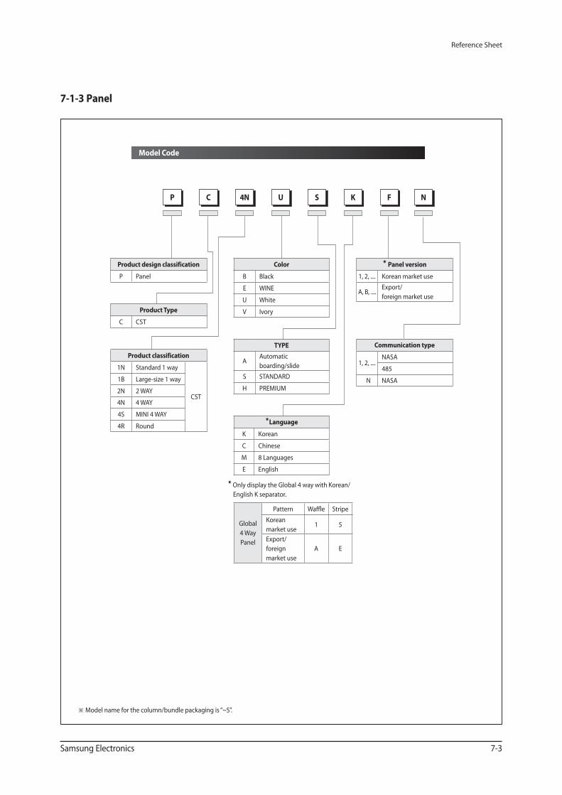
Reference Sheet
Samsung Electronics 7-3
Model Code
7-1-3 Panel
※ Model name for the column/bundle packaging is “~S”.
★ Only display the Global 4 way with Korean/
English K separator.
HK
HS
HF
HN
HC
HP
H4N
HU
Product design classification
P Panel
Product Type
C CST
Product classification
1N Standard 1 way
CST
1B Large-size 1 way
2N 2 WAY
4N 4 WAY
4S MINI 4 WAY
4R Round
★ Panel version
1, 2, .... Korean market use
A, B, ....Export/
foreign market use
Communication type
1, 2, ....NASA
485
N NASA
Color
B Black
E WINE
U White
V Ivory
★Language
K Korean
C Chinese
M 8 Languages
E English
TYPE
AAutomatic
boarding/slide
S STANDARD
H PREMIUM
Global
4 Way
Panel
Pattern Waffle Stripe
Korean
market use1 5
Export/
foreign
market use
A E
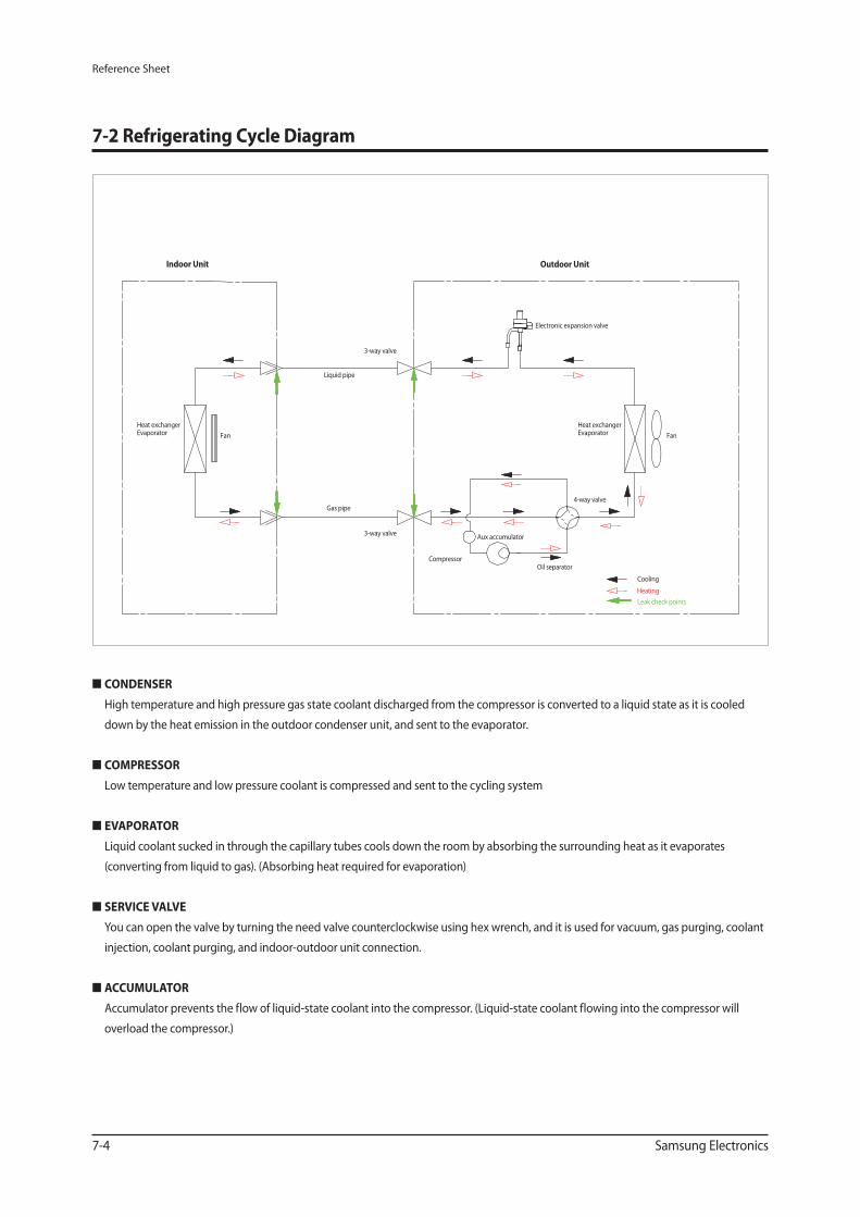
Reference Sheet
7-4 Samsung Electronics
■ CONDENSER
High temperature and high pressure gas state coolant discharged from the compressor is converted to a liquid state as it is cooled
down by the heat emission in the outdoor condenser unit, and sent to the evaporator.
■ COMPRESSOR
Low temperature and low pressure coolant is compressed and sent to the cycling system
■ EVAPORATOR
Liquid coolant sucked in through the capillary tubes cools down the room by absorbing the surrounding heat as it evaporates
(converting from liquid to gas). (Absorbing heat required for evaporation)
■ SERVICE VALVE
You can open the valve by turning the need valve counterclockwise using hex wrench, and it is used for vacuum, gas purging, coolant
injection, coolant purging, and indoor-outdoor unit connection.
■ ACCUMULATOR
Accumulator prevents the flow of liquid-state coolant into the compressor. (Liquid-state coolant flowing into the compressor will
overload the compressor.)
Indoor Unit Outdoor Unit
Heat exchangerEvaporator
Liquid pipe
Gas pipe
3-way valve
3-way valve
Electronic expansion valve
CompressorOil separator
4-way valve
Cooling
Heating
Leak check points
Aux accumulator
Fan
Heat exchangerEvaporator Fan
7-2 Refrigerating Cycle Diagram
This Service Manual is a property of Samsung Electronics Co., Ltd.
Any unauthorized use of Manual can be punished under applicable
International and/or domestic law.
© Samsung Electronics Co., Ltd. January. 2015.
Printed in Korea.
Code No. AC-00094E_1
GSPN (GLOBAL SERVICE PARTNER NETWORK)
Area Web Site
Europe, CIS, Mideast & Africa gspn1.samsungcsportal.com
Asia gspn2.samsungcsportal.com
North & Latin America gspn3.samsungcsportal.com
China china.samsungportal.com


