Embed Size (px)
Citation preview
GSM Association Non-confidential
Official Document IR.80 - Technical Architecture Alternatives for Open Connectivity Roaming Hubbing
Model
V3.0 Page 1 of 103
Technical Architecture Alternatives for Open Connectivity Roaming Hubbing Model
Version 3.0
16 November 2021
This is a Non-binding Permanent Reference Document of the GSMA
Security Classification: Non-confidential
Access to and distribution of this document is restricted to the persons permitted by the security classification. This document is confidential to the
Association and is subject to copyright protection. This document is to be used only for the purposes for which it has been supplied and
information contained in it must not be disclosed or in any other way made available, in whole or in part, to persons other than those permitted
under the security classification without the prior written approval of the Association.
Copyright Notice
Copyright © 2021 GSM Association
Disclaimer
The GSM Association (“Association”) makes no representation, warranty or undertaking (express or implied) with respect to and does not accept
any responsibility for, and hereby disclaims liability for the accuracy or completeness or timeliness of the information contained in this document.
The information contained in this document may be subject to change without prior notice.
Antitrust Notice
The information contain herein is in full compliance with the GSM Association’s antitrust compliance policy.
GSM Association Non-confidential
Official Document IR.80 - Technical Architecture Alternatives for Open Connectivity Roaming Hubbing
Model
V3.0 Page 2 of 103
Table of Contents
1 Overview 5
About this Document 6
Scope 6
Purpose 6
Definitions 6
1.5 Document Cross-References 8
1.6 Naming Conventions 8
2 Roaming Hub Requirements 9
2.1 High Level Requirements 9
2.1.1 Open Solution: interoperability of Solutions 9
2.1.2 Obligation 9
2.1.3 Transparency 9
2.1.4 Efficiency 10
2.1.5 Quality End to End 10
2.1.6 Education 11
2.1.7 Fraud & Security 11
2.1.8 Availability 11
2.1.9 Testing 11
2.1.10 Contract Aggregation 12
2.1.11 Service & Enabler Support 12
2.1.12 Roaming Transparency 12
2.1.13 Cascade Billing 12
2.1.14 Interconnection with Third Parties 13
2.2 Technical Requirements 13
Centralized Signalling 13
Cascading Signal Flow 13
2.2.3 Agreement Management 14
2.2.4 Testing & QoS Monitoring 14
2.2.5 Billing, Settlement & Clearing 14
2.2.6 Fraud-prevention Mechanisms 14
2.2.7 Service Troubleshooting 14
2.2.8 Business Intelligence & Reporting 14
2.2.9 Technology Coexistence 14
3 Technical Architecture 14
Current Bi-lateral Architecture for SS7 Based Connections 14
3.2 Current Bi-lateral Architecture for Diameter Based Connections 15
3.2 Current Bi-lateral Architecture for HTTPS Based Connections 17
3.3 Roaming Hubbing Common Aspects 17
3.4.1 Operators with ‘Shared’ Network Elements 17
3.4.2 Traffic Separation 18
3.4.3 Symmetric Routing 20
3.4.4 Testing 20
GSM Association Non-confidential
Official Document IR.80 - Technical Architecture Alternatives for Open Connectivity Roaming Hubbing
Model
V3.0 Page 3 of 103
3.5 SS7 Based Roaming Hub Architecture Alternatives 21
3.5.1 Alternative 1: MTP Direct Routing 21
29
29
29
29
29
29
Alternative 2: SUA/SCTP 29
Alternative 3: SCCP Translation Type (TT) 38
3.5.5 Alternative 4: Alias GT 47
3.6 Diameter based Roaming Hubbing Architecture Alternatives 58
3.6.1 Alternative 1: Direct connection 58
3.6.1.2 Architecture Description 58
3.6.1.3 Call Flows 59
3.6.2 Alternative 2: Origin/Destination Realm Based Routing 60
3.6.3 Alternative 3: Destination-Realm modification 62
5G Operator Group Roaming Hub 65
HTTPS Direct Routing Architecture 66
4 Interoperability of Architectures 71
4.1 Interoperability within a Roaming Hub 71
4.2 Interoperability between Roaming Hubs 71
4.2.1 Roaming Hub-to-Roaming Hub via MTP Direct Routing 72
4.2.2 Roaming Hub-to-Roaming Hub via SUA/SCTP over IP 73
4.2.3 Roaming Hub-to-Roaming Hub via Diameter Direct Routing Architecture 74
4.3 Interoperability with SMS Interworking when Roaming 75
4.4 Interoperability with TCAPsec 76
Annex A Roaming Hub and SMS-IW 78
Background 78
Signalling independent of routing method 80
MOForwardSM 80
SRI-SM and MTForwardSM 80
AlertSC / InformSC 87
Signalling dependant UPON routing method 88
MOForwardSM 88
SRI-SM and MTForwardSM 88
ReportSMDeliveryStatus 96
AlertSC / InformSC 97
MOForwardSM 97
A.2 SMS Interworking Anomalies 97
Traffic Separation for MTP/TT/SUA 97
Address Routing Alias GT 99
Conclusion 101
Annex B Document Management 102
GSM Association Non-confidential
Official Document IR.80 - Technical Architecture Alternatives for Open Connectivity Roaming Hubbing
Model
V3.0 Page 4 of 103
Document History 102
Other Information 103
GSM Association Non-confidential
Official Document IR.80 - Technical Architecture Alternatives for Open Connectivity Roaming Hubbing
Model
V3.0 Page 5 of 103
1 Overview
Roaming and inter-working are at the core of the mobile communication success story. The
subscribers now expect to access the same set of services at home and abroad. They
expect to be able to share all mobile communication services with any other subscriber on
any network.
The bi-lateral relationship, on which this success has been based, however, is now
becoming a limiting factor to future success. With over 600 GSMA operator members,
diversification of services and an increasing number of access technologies, it is unlikely that
the current paradigm of bilateral relationships between networks will meet the expectations
of operators going forward.
The overall cost of establishing bi-lateral relationships is preventing some operators from
opening new roaming and inter-working agreements. Often when a new roaming relationship
is taken individually, the venture represents insufficient additional value for an operator that
is already established with other roaming partners in the region or when the volume potential
is low. With the introduction of new services, the problem becomes more evident and the
overall costs greater.
This is a particular concern for the newer GSM networks. Those networks that are late
entries into this market are finding it difficult to set-up roaming relations with the more
established operators.
At the same time, the problem is arising for many established operators who already have
roaming relationships, but face low return on investments in rolling out roaming for new
access technologies.
Open Connectivity for roaming is defined as the following:
To ensure that an operator is able to allow its customers to roam on the network of
any other GSMA member.
Open Connectivity is needed for roaming so that:
The continued growth of mobile communication is ensured and all GSMA members
can access the full advantages of 3GSM Roaming
Operators can optimise costs involved in establishing and maintaining mobile
communication in roaming
The Roaming Hubbing Trial Interest Group held a successful Proof of Concept in January
2007. This will be followed by more extensive testing during a Roaming Hubbing Trial.
A Roaming Hub Service Provider assists operators with signalling traffic, testing, support,
and troubleshooting. An operator can benefit by have a single point of presence with a
Roaming Hub service provider for issues related to signalling traffic, testing, support,
troubleshooting, etc.
GSM Association Non-confidential
Official Document IR.80 - Technical Architecture Alternatives for Open Connectivity Roaming Hubbing
Model
V3.0 Page 6 of 103
Many network operator companies own or have partners in one or more countries, forming a
network operator group. For reasons of cost, efficiency and security, these network operator
groups often have a common, centralised roaming aggregation point. This roaming
aggregation point forms an Operator Group Roaming Hub and is then establishing
centralized roaming services (commercial and technical) between all network operator group
members and to all or some roaming partners of this network operator group, i.e., each
roaming partner of the Operator Group Roaming Hub can reach each network operator
group member and vice versa.
The document will use the term Roaming Hub for all types of Roaming Hubs unless
otherwise stated.
A Roaming Hub is expected to fulfil the requirements defined by the Open Connectivity
Group of GSMA. Roaming Hub requirements are defined later in this document.
About this Document
The document consists of three major sections dealing with Roaming Hub requirements,
technical architectures, and interoperability. The technical architecture section defines
separate and distinct architecture choices available to a Roaming Hub Service Provider.
The interoperability section covers interworking between architectures, and interworking
between Roaming Hubs.
Scope
This document describes specific aspects of the technical architecture alternatives for
Roaming Hubs that are being recommended by the IREG Roaming Hub Group.
Purpose
The purpose of this document is to provide details on Roaming Hub architecture solutions for
mobile roaming.
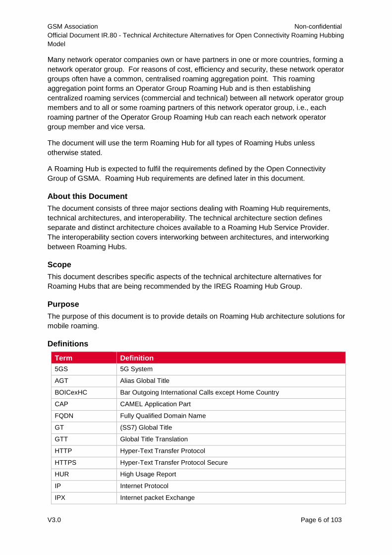
Definitions
Term Definition
5GS 5G System
AGT Alias Global Title
BOICexHC Bar Outgoing International Calls except Home Country
CAP CAMEL Application Part
FQDN Fully Qualified Domain Name
GT (SS7) Global Title
GTT Global Title Translation
HTTP Hyper-Text Transfer Protocol
HTTPS Hyper-Text Transfer Protocol Secure
HUR High Usage Report
IP Internet Protocol
IPX Internet packet Exchange
GSM Association Non-confidential
Official Document IR.80 - Technical Architecture Alternatives for Open Connectivity Roaming Hubbing
Model
V3.0 Page 7 of 103
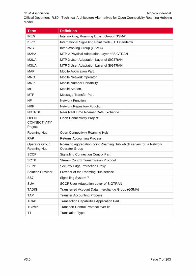
Term Definition
IREG Interworking, Roaming Expert Group (GSMA)
ISPC International Signalling Point Code (ITU standard)
IWG Inter-Working Group (GSMA)
M2PA MTP 2 Physical Adaptation Layer of SIGTRAN
M2UA MTP 2 User Adaptation Layer of SIGTRAN
M3UA MTP 3 User Adaptation Layer of SIGTRAN
MAP Mobile Application Part:
MNO Mobile Network Operator
MNP Mobile Number Portability
MS Mobile Station.
MTP Message Transfer Part
NF Network Function
NRF Network Repository Function
NRTRDE Near Real Time Roamer Data Exchange
OPEN
CONNECTIVITY
Project
Open Connectivity Project
Roaming Hub Open Connectivity Roaming Hub
RAP Returns Accounting Process
Operator Group
Roaming Hub
Roaming aggregation point Roaming Hub which serves for a Network
Operator Group
SCCP Signalling Connection Control Part
SCTP Stream Control Transmission Protocol
SEPP Security Edge Protection Proxy
Solution Provider Provider of the Roaming Hub service
SS7 Signalling System 7
SUA SCCP User Adaptation Layer of SIGTRAN
TADIG Transferred Account Data Interchange Group (GSMA)
TAP Transfer Accounting Process
TCAP Transaction Capabilities Application Part
TCP/IP Transport Control Protocol over IP
TT Translation Type
GSM Association Non-confidential
Official Document IR.80 - Technical Architecture Alternatives for Open Connectivity Roaming Hubbing
Model
V3.0 Page 8 of 103
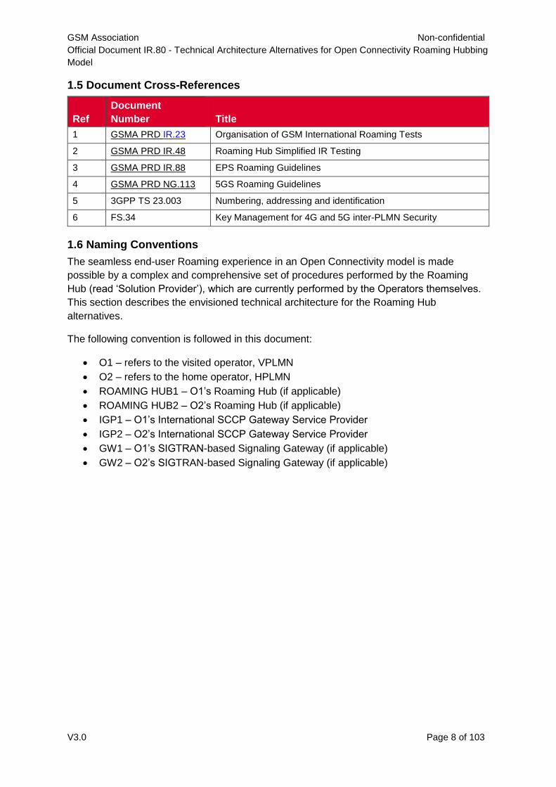
1.5 Document Cross-References
Ref
Document
Number Title
1 GSMA PRD IR.23 Organisation of GSM International Roaming Tests
2 GSMA PRD IR.48 Roaming Hub Simplified IR Testing
3 GSMA PRD IR.88 EPS Roaming Guidelines
4 GSMA PRD NG.113 5GS Roaming Guidelines
5 3GPP TS 23.003 Numbering, addressing and identification
6 FS.34 Key Management for 4G and 5G inter-PLMN Security
1.6 Naming Conventions
The seamless end-user Roaming experience in an Open Connectivity model is made
possible by a complex and comprehensive set of procedures performed by the Roaming
Hub (read ‘Solution Provider’), which are currently performed by the Operators themselves.
This section describes the envisioned technical architecture for the Roaming Hub
alternatives.
The following convention is followed in this document:
O1 – refers to the visited operator, VPLMN
O2 – refers to the home operator, HPLMN
ROAMING HUB1 – O1’s Roaming Hub (if applicable)
ROAMING HUB2 – O2’s Roaming Hub (if applicable)
IGP1 – O1’s International SCCP Gateway Service Provider
IGP2 – O2’s International SCCP Gateway Service Provider
GW1 – O1’s SIGTRAN-based Signaling Gateway (if applicable)
GW2 – O2’s SIGTRAN-based Signaling Gateway (if applicable)
GSM Association Non-confidential
Official Document IR.80 - Technical Architecture Alternatives for Open Connectivity Roaming Hubbing
Model
V3.0 Page 9 of 103
2 Roaming Hub Requirements
2.1 High Level Requirements
This section contains a number of high-level requirements that need to be met by any Open
Connectivity solution employed in the roaming environment. Inter-working requirements are
out of scope for this section.
The source of information presented in this section is
OC Doc 8/004rev1 High Level Requirements for Open Connectivity, 18 October 2005
EPS Roaming Guidelines IR.88 [3]
5GS roaming Guidelines NG.113 [4].
The contents have been slightly modified to focus on Roaming Hubs.
2.1.1 Open Solution: interoperability of Solutions
The Solution Provider must be prepared to work with all other providers of like-solutions to
ensure that the solutions are inter-operable. Like-solutions are defined as any solution that
is in compliance with Open Connectivity requirements.
This must be achieved without compromising the quality of the solution. The solution must
remain efficient and guarantee quality at all times.
The objective is to enable operators to enter the market in a timely manner with access to
the broadest range of partners and to have a choice of Solution Provider.
Upon the request of the Client Operator the Solution Provider must provide the connection
(either direct or through a Third Party) with any mobile operator with whom the Client
Operator wants to activate roaming services. This connection must be provided even if such
mobile operators are not connected directly to the Solution Provider's system (but are
connected to a Third Party). Should there be neither a direct connection nor a connection to
a Third Party, the Solution Provider must contact the targeted mobile operator and inform the
Client Operator accordingly.
In any case, the connection will be established at no extra-charge (with respect to the
charging already applied for the connection to the Participating MNOs) and within a timeline
agreed with the Client Operator.
A maximum of 2 (two) Solution Providers must be involved in this roaming relationship.
2.1.2 Obligation
An operator may have valid justification (regulatory, strategic or commercial) not to start
roaming relations with another operator. Any solution employed must then allow a Client
Operator to opt out roaming relations with any operator(s) of their choosing.
2.1.3 Transparency
The Solution Provider must:
GSM Association Non-confidential
Official Document IR.80 - Technical Architecture Alternatives for Open Connectivity Roaming Hubbing
Model
V3.0 Page 10 of 103
give full visibility of all components of the price levied by the Solution Provider, i.e. the
fee applied by the latter as remuneration for the service offered and the charges
levied by operators providing roaming services.
provide the client operator information on which network the traffic is originating and
terminating, and on any third party (i.e. other provider/carrier/operator) involved in the
traffic handling/delivery. The involvement of Roaming Hubs shall neither affect the
visibility of the HPMN or the VPMN i.e.
It must be visible to the VPMN from which Home network subscribers are actually
roaming to its network (Origin of Inbound Roamers)
It must be visible to the HPMN to which VPMN its subscribers are roaming to
(Destination of Outbound Roamers)
For each roaming subscriber it must be visible to which network he/she is roaming
to
Technical information required for troubleshooting must be visible to both HPMN and VPMN.
In addition, any Home Billing solutions employed by the Home Network shall work
seamlessly. Technical transparency may also be required to allow the Client Operator to
meet possible regulatory, legal and commercial obligations.
never manipulate any content, format or any information related to the traffic
transmitted through its solution, in order to avoid fraud and to ensure consistency,
unless manipulation is explicitly required within GSMA specifications or required by
local regulations and laws, or subject to any arrangements made between two
parties.
provide all necessary technical information to the Client Operator to enable timely
trouble shooting (e.g. routing, connectivity,…).
2.1.4 Efficiency
All solutions must make efficient use of network resources (network infrastructure, signalling
links, etc.).
The solution must minimize any overhead on the visited or home networks.
The solution must minimize network configuration restraints. The solution shall be as good
or better than current bi-lateral arrangements
2.1.5 Quality End to End
The Solution Provider must give a commitment on the QoS/level of performance for end-to-
end traffic transmission. There must be no reduction in quality including the case when Third
Parties (i.e. other providers/carriers/operators) are involved in the traffic transmission end-to-
end. Additionally, the provider must be able to provide a mechanism to measure the level of
quality met.
GSM Association Non-confidential
Official Document IR.80 - Technical Architecture Alternatives for Open Connectivity Roaming Hubbing
Model
V3.0 Page 11 of 103
For roaming the solution must provide quick and accurate network selection when a roamer
is registering on the network. This must take into account PMN preferences as specified by
the HPMN.
The transmission of billing data must not be delayed by the solution offered. TAP and RAP
exchange must still fit the timescales outlined within BA.08.
The provider shall offer the Client Operator comprehensive and efficient service support for
its own services in terms of:
service management (customer care service on non-fault situations and forecast +
report exchange)
fault management including as a minimum:
a) proactive fault detection service
b) fault resolution service
c) trouble report handling service h24x7
For roaming, these obligations extend to the end-to-end service from the Client Operator
network to the roaming partner operator network including the case of Third Parties involved
in the traffic handling.
2.1.6 Education
Solution Provider must offer full support and training to users of the solution.
2.1.7 Fraud & Security
All roaming solutions must ensure the Near Real Time Record Data Exchange (NRTRDE) is
delivered in a timely and correct manner as defined in GSMA PRDs. In addition, where the
VPMN supports Near Real Time Record Data Exchange (NRTRDE) the Solution Provider
must also facilitate this exchange of information.
2.1.8 Availability
All solutions must ensure a highly available, redundant and robust architecture. All providers
of solutions must have an operational disaster recovery plan to execute in the event of
disaster. Where the end-to-end service is via more than one Solution Provider then the
disaster recovery plan needs to be agreed between all Solution Providers.
The Solution Provider must make information on their End-to-End Disaster Recovery Plan
available to the Client Operator.
2.1.9 Testing
The solution must decrease testing time and effort to a minimum for the operators involved.
The Solution Provider must be able to perform all end-to-end tests described in the
appropriate IREG and TADIG documentation and will ensure that the services offered
function correctly and billing exchange details are correct.
The Client Operator will always have the option to outsource some or all of the end-to-end
testing to the provider or to perform them on his own.
GSM Association Non-confidential
Official Document IR.80 - Technical Architecture Alternatives for Open Connectivity Roaming Hubbing
Model
V3.0 Page 12 of 103
2.1.10 Contract Aggregation
The Solution Provider will include in the contract with the Client Operator the relationship
required with any Elected Participating MNO and any involved Third Party provider to ensure
the proper provisioning of roaming data.
It is expected that the Client Operator will just need to negotiate and sign one contract with
the provider in order to have contractual Inter-working and roaming relationships with all
participating operators.
2.1.11 Service & Enabler Support
It is foreseen that there could be the need for different solutions for Inter-working than that of
roaming. Likewise, there could be the need for different solutions for different types of
services within these markets. However, it is required that where possible one solution will
aim to support all services and enablers. To this extent, solutions need to consider and be
compatible with existing services/enablers and be futureproof.
Additionally, services must be offered independently by the Solution Provider to allow
operators to choose which services to deploy via the Solution Provider.
2.1.12 Roaming Transparency
Transparency must be granted by the solution on:
The Destination of the outbound roamers – The home operator must always have full
technical and commercial visibility of which country their customer is roaming to and
which network the customer is using.
The roaming partner network – The visited operator must have full visibility of inbound
subscribers and to which home network they belong.
The Solution Provider’s pricing components, i.e. IOT plus transit fee per transaction.
Without full transparency of the IOT associated with each Roaming Partner, there is a risk
that the provider charge inappropriate additional Transit Charges.
This cost increase will effectively inflate the retail price and slow down the market take-up.
There is also a risk that the provider can discriminate against some operators by increasing
the prices charged for transit fee on specific Elected Participating Operator networks.
This would happen in such a way that operator A may has a tariff X to roam on operator B,
whereas Operator C may be charged tariff Y to roam on the same network B.
It is however necessary to avoid such situations since this would create a barrier to the
market take up and would introduce an element of discrimination.
2.1.13 Cascade Billing
The Solution Provider will comply with a cascade-billing model (as per the current voice
model). The provider will manage in total the billing and financial relationship with the
roaming partners and peered providers.
GSM Association Non-confidential
Official Document IR.80 - Technical Architecture Alternatives for Open Connectivity Roaming Hubbing
Model
V3.0 Page 13 of 103
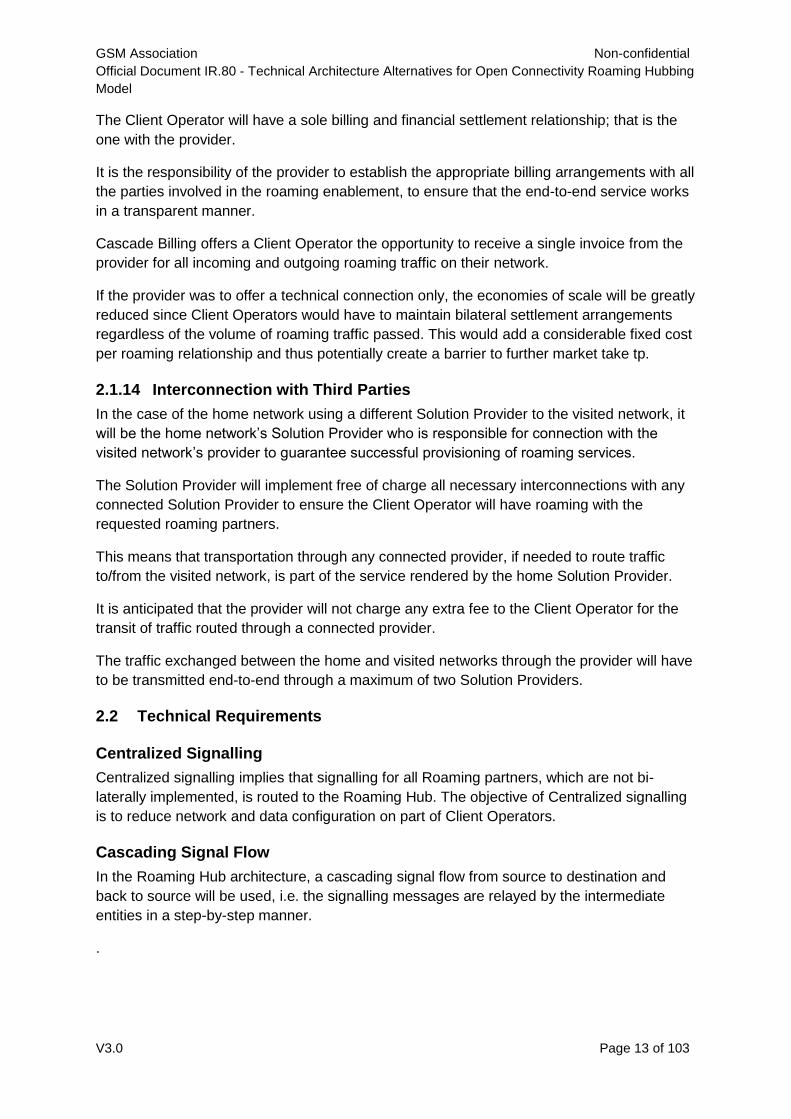
The Client Operator will have a sole billing and financial settlement relationship; that is the
one with the provider.
It is the responsibility of the provider to establish the appropriate billing arrangements with all
the parties involved in the roaming enablement, to ensure that the end-to-end service works
in a transparent manner.
Cascade Billing offers a Client Operator the opportunity to receive a single invoice from the
provider for all incoming and outgoing roaming traffic on their network.
If the provider was to offer a technical connection only, the economies of scale will be greatly
reduced since Client Operators would have to maintain bilateral settlement arrangements
regardless of the volume of roaming traffic passed. This would add a considerable fixed cost
per roaming relationship and thus potentially create a barrier to further market take tp.
2.1.14 Interconnection with Third Parties
In the case of the home network using a different Solution Provider to the visited network, it
will be the home network’s Solution Provider who is responsible for connection with the
visited network’s provider to guarantee successful provisioning of roaming services.
The Solution Provider will implement free of charge all necessary interconnections with any
connected Solution Provider to ensure the Client Operator will have roaming with the
requested roaming partners.
This means that transportation through any connected provider, if needed to route traffic
to/from the visited network, is part of the service rendered by the home Solution Provider.
It is anticipated that the provider will not charge any extra fee to the Client Operator for the
transit of traffic routed through a connected provider.
The traffic exchanged between the home and visited networks through the provider will have
to be transmitted end-to-end through a maximum of two Solution Providers.
2.2 Technical Requirements
Centralized Signalling
Centralized signalling implies that signalling for all Roaming partners, which are not bi-
laterally implemented, is routed to the Roaming Hub. The objective of Centralized signalling
is to reduce network and data configuration on part of Client Operators.
Cascading Signal Flow
In the Roaming Hub architecture, a cascading signal flow from source to destination and
back to source will be used, i.e. the signalling messages are relayed by the intermediate
entities in a step-by-step manner.
.
GSM Association Non-confidential
Official Document IR.80 - Technical Architecture Alternatives for Open Connectivity Roaming Hubbing
Model
V3.0 Page 14 of 103
2.2.3 Agreement Management
Agreement management functionality is implemented by the Roaming Hubs to verify the
contractual relationships between Roaming partners before allowing the signalling exchange
to proceed towards the destination. Any specific black-listing and/or Opt-in/Opt-out
arrangements specified by Client Operators are also taken into account for such verification.
2.2.4 Testing & QoS Monitoring
Testing and QoS Monitoring is a value-added function of the Roaming Hub, whereby the
Solution Provider can bring-in significant efficiency gains for the Client Operator by assuming
the responsibility of performing the IREG/TADIG testing on behalf of the Client Operator with
its Roaming partners. Additionally, the Solution Provider can also perform periodic
monitoring and testing of the different KPIs/metrics for various services provided by its Client
Operator. Both the Testing and QoS monitoring can be performed either automated or
manually.
2.2.5 Billing, Settlement & Clearing
Roaming Hubs are expected to provide this function in a post-trial commercial service
offering.
2.2.6 Fraud-prevention Mechanisms
The Fraud-preventions mechanisms, if implemented may include NRTRDE, HUR, Anti-
Spamming, Anti-Spoofing features. Roaming Hubs are expected to provide these functions
in a post-trial commercial service offering.
2.2.7 Service Troubleshooting
The Roaming Hub shall be able to provide visibility into message routing, and actual path
traversed by any specific message for troubleshooting purposes. Roaming Hubs are
expected to provide this function in a post-trial commercial service offering.
2.2.8 Business Intelligence & Reporting
Roaming Hubs are expected to provide this function in a post-trial commercial service
offering.
2.2.9 Technology Coexistence
If a Roaming Hub is offering 2G/3G, 4G and 5G services then it needs to ensure that all
technologies will coexist on the Roaming Hub.
3 Technical Architecture
Current Bi-lateral Architecture for SS7 Based Connections
This section illustrates the technical connectivity architecture that is used between operators
currently to support roaming with each other using standard SS7 MAP in a bi-lateral model.
GSM Association Non-confidential
Official Document IR.80 - Technical Architecture Alternatives for Open Connectivity Roaming Hubbing
Model
V3.0 Page 15 of 103
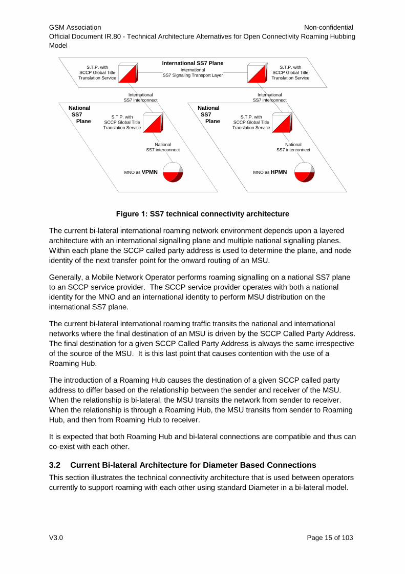
Figure 1: SS7 technical connectivity architecture
The current bi-lateral international roaming network environment depends upon a layered
architecture with an international signalling plane and multiple national signalling planes.
Within each plane the SCCP called party address is used to determine the plane, and node
identity of the next transfer point for the onward routing of an MSU.
Generally, a Mobile Network Operator performs roaming signalling on a national SS7 plane
to an SCCP service provider. The SCCP service provider operates with both a national
identity for the MNO and an international identity to perform MSU distribution on the
international SS7 plane.
The current bi-lateral international roaming traffic transits the national and international
networks where the final destination of an MSU is driven by the SCCP Called Party Address.
The final destination for a given SCCP Called Party Address is always the same irrespective
of the source of the MSU. It is this last point that causes contention with the use of a
Roaming Hub.
The introduction of a Roaming Hub causes the destination of a given SCCP called party
address to differ based on the relationship between the sender and receiver of the MSU.
When the relationship is bi-lateral, the MSU transits the network from sender to receiver.
When the relationship is through a Roaming Hub, the MSU transits from sender to Roaming
Hub, and then from Roaming Hub to receiver.
It is expected that both Roaming Hub and bi-lateral connections are compatible and thus can
co-exist with each other.
3.2 Current Bi-lateral Architecture for Diameter Based Connections
This section illustrates the technical connectivity architecture that is used between operators
currently to support roaming with each other using standard Diameter in a bi-lateral model.
International SS7 Plane
National
SS7
Plane
National
SS7
PlaneS.T.P. with
SCCP Global Title
Translation Service
MNO as VPMN
S.T.P. with
SCCP Global Title
Translation Service
S.T.P. with
SCCP Global Title
Translation Service
MNO as HPMN
S.T.P. with
SCCP Global Title
Translation Service
National
SS7 interconnect
National
SS7 interconnect
International
SS7 interconnect
International
SS7 interconnect
International
SS7 Signaling Transport Layer
GSM Association Non-confidential
Official Document IR.80 - Technical Architecture Alternatives for Open Connectivity Roaming Hubbing
Model
V3.0 Page 16 of 103
DEA DEA
IPX
DRA
IPX
DRARoaming Diameter Signalling
MNO as VPLMN MNO as HPLMN
Diameter
Signalling
Diameter
Signalling
Diameter
Signalling
Diameter
Signalling
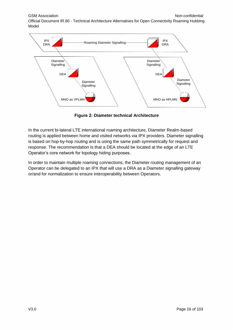
Figure 2: Diameter technical Architecture
In the current bi-lateral LTE international roaming architecture, Diameter Realm-based
routing is applied between home and visited networks via IPX providers. Diameter signalling
is based on hop-by-hop routing and is using the same path symmetrically for request and
response. The recommendation is that a DEA should be located at the edge of an LTE
Operator’s core network for topology hiding purposes.
In order to maintain multiple roaming connections, the Diameter routing management of an
Operator can be delegated to an IPX that will use a DRA as a Diameter signalling gateway
or/and for normalization to ensure interoperability between Operators.
GSM Association Non-confidential
Official Document IR.80 - Technical Architecture Alternatives for Open Connectivity Roaming Hubbing
Model
V3.0 Page 17 of 103
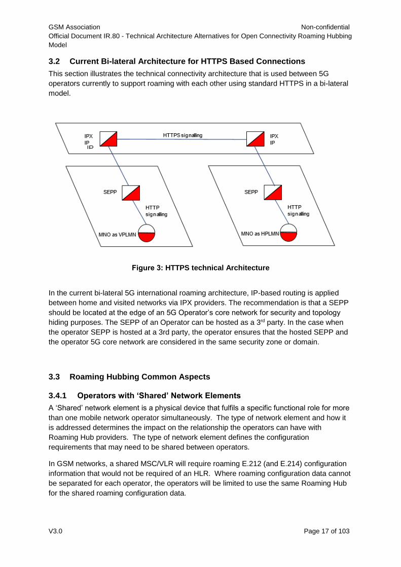
3.2 Current Bi-lateral Architecture for HTTPS Based Connections
This section illustrates the technical connectivity architecture that is used between 5G
operators currently to support roaming with each other using standard HTTPS in a bi-lateral
model.
Figure 3: HTTPS technical Architecture
In the current bi-lateral 5G international roaming architecture, IP-based routing is applied
between home and visited networks via IPX providers. The recommendation is that a SEPP
should be located at the edge of an 5G Operator’s core network for security and topology
hiding purposes. The SEPP of an Operator can be hosted as a 3rd party. In the case when
the operator SEPP is hosted at a 3rd party, the operator ensures that the hosted SEPP and
the operator 5G core network are considered in the same security zone or domain.
3.3 Roaming Hubbing Common Aspects
3.4.1 Operators with ‘Shared’ Network Elements
A ‘Shared’ network element is a physical device that fulfils a specific functional role for more
than one mobile network operator simultaneously. The type of network element and how it
is addressed determines the impact on the relationship the operators can have with
Roaming Hub providers. The type of network element defines the configuration
requirements that may need to be shared between operators.
In GSM networks, a shared MSC/VLR will require roaming E.212 (and E.214) configuration
information that would not be required of an HLR. Where roaming configuration data cannot
be separated for each operator, the operators will be limited to use the same Roaming Hub
for the shared roaming configuration data.
GSM Association Non-confidential
Official Document IR.80 - Technical Architecture Alternatives for Open Connectivity Roaming Hubbing
Model
V3.0 Page 18 of 103
If the physical device is logically addressed with the same E.164 value for multiple operators,
the operators will be limited to use the same Roaming Hub for the shared network element.
The following list of network elements has been known to be shared at times between
operators and between countries:
o SMSC
o HLR
o MSC/VLR
o GGSN
o SGSN
For 4G networks, 3GPP has defined two approaches for the eUTRAN sharing:
The Multi-Operator Core Network (MOPEN CONNECTIVITYN) approach
The Gateway Core Network (GWCN) approach
In the MOPEN CONNECTIVITYN approach the shared eUTRAN is connected to several
Core Networks via the S1 interface. Each mobile network operator has its own EPC. Thus
the MME, the SGW and the PGW are not shared and are located in different Core Networks.
In the GWCN approach, contrary to the MOPEN CONNECTIVITYN approach, the MME is
also shared between the different mobile network operators.
In roaming, the MOPEN CONNECTIVITYN approach is a drawback as HSS address of each
roaming partner needs to be defined in shared MME for each Core Network connected to
the shared eUTRAN.
3.4.2 Traffic Separation
Common aspects of Roaming Hub apply to all architecture alternatives. One common
aspect that applies to all architecture alternatives is the separation of signalling traffic
associated with roaming.
Assume a given mobile network operator chooses to have both bi-lateral roaming
agreements and Open Connectivity roaming relationships. The mobile network operator has
a responsibility to separate traffic between the bi-lateral roaming agreements and the Open
Connectivity roaming relationships.
Signalling traffic associated with bi-lateral roaming agreements transits the national and
international signalling network infrastructure currently in use. Signalling traffic associated
with Open Connectivity roaming relationships is separated from the existing bi-lateral
roaming traffic and directed to the appropriate Roaming Hub.
GSM Association Non-confidential
Official Document IR.80 - Technical Architecture Alternatives for Open Connectivity Roaming Hubbing
Model
V3.0 Page 19 of 103
The separation of traffic is a basic and common aspect to all Roaming Hub architectures and
must be performed by the mobile network operator as part of the implementation of Open
Connectivity roaming, unless a solution offering for separation is made by the Roaming Hub.
In 3GSM, the separation of signalling traffic is accomplished through provisioning of various
addresses within the signalling environment of each operator. Addresses associated with
signalling traffic are comprised of E.212, E.214, and E.164 values.
A roaming operator in the role of VPMN will need to direct E.212 and E.214 subscriber
addresses toward the chosen Roaming Hub. Likewise, E.164 addresses of HLRs, gsmSCFs,
Home MSCs, Home SMSCs including Subscriber SIM based SMSCs will need to be
directed toward the chosen Roaming Hub.
A roaming operator in the role of HPMN will need to direct E.164 VLR, MSC and SGSN
addresses toward the chosen Roaming Hub.
In 4G the separation of signalling traffic is accomplished through Destination-Realm
modification performed by the Diameter Proxy agent of the PMNs. The traffic separation can
be also performed through Origin/Destination based routing by 3rd party Diameter providers.
Information associated with Diameter signalling traffic are comprised of Destination-Host,
Origin-Host, Destination-Realm and Origin-Realm.
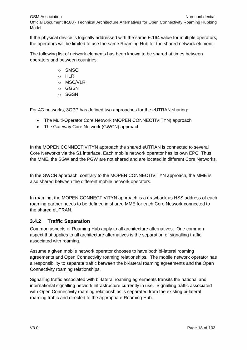
In case of 5G Operator Group Roaming Hub the roaming traffic separation is performed by
Operators as illustrated below:
Figure 4: 5G roaming traffic separation
The separation of 5G signalling traffic is accomplished by the SEPP of the PMNs using a
local rule base based on the FQDN of the other participating client MNO present in the
“apiRoot” header.
GSM Association Non-confidential
Official Document IR.80 - Technical Architecture Alternatives for Open Connectivity Roaming Hubbing
Model
V3.0 Page 20 of 103
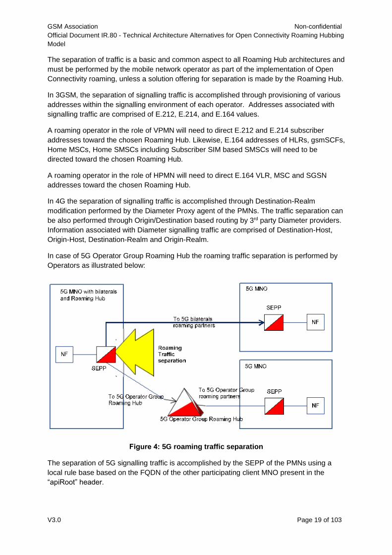
3.4.3 Symmetric Routing
The signalling traffic associated with an Open Connectivity roaming relationship must transit
each of the operators’ chosen Roaming Hubs. Each operator in an Open Connectivity
roaming relationship may have their own Roaming Hub provider. Roaming Hub-to-Roaming
Hub interworking ensures that the signalling traffic of each operator transit their chosen
Roaming Hub as shown in the diagram below.
Figure 5: Roaming Hub-to-Roaming Hub interworking signaling traffic
Each Roaming Hub (Roaming Hub1 and Roaming Hub2) must be in the path to ensure that
the signalling is associated with an established relationship and that the state of the
relationship is correct relative to the signalling operations and entities. The signalling
environment for Roaming Hub involves cascaded billing with financial liability. The risks
associated with cascaded billing and financial liability requires that the signalling traffic flow
with symmetric routing through the Roaming Hubs, thereby affording the Roaming Hub
providers the opportunity to reject inappropriate signalling traffic.
Symmetric routing is a common requirement for the Roaming Hub. Asymmetric routing must
not be permitted. For the avoidance of doubt, this pertains to routing of messages and their
corresponding ACK or acknowledge or RESP or response.
In the MSU flow diagram shown above, four (4) distinct management entities are involved
with the routing decisions to move MSUs between the VPMN and HPMN. The
synchronization of routing is a responsibility of each management entity [O1, Roaming Hub1,
Roaming Hub2, O2].
3.4.4 Testing
The solution must decrease testing time and effort to a minimum for the operators involved.
The Solution Provider should be able to perform the end-to-end tests as described in IR 23:
“Organisation of GSM International Roaming Tests” and will ensure that the services offered
function correctly and billing exchange details are correct.
A Roaming Hub will have to propose to the PMN testing procedures which are fully
compliant with the IREG test PRDs. In order to guarantee the quality of the service it will be
needed that the Roaming Hub will define together with the PMN an initial test set and
subsequent lighter test set. The common test could be skipped if bilaterally agreed between
the PMNs and the Roaming Hub. The same rule will be applied in case of peering.
MSU to
VPMN
MSU to
VPMN
MSU to
HPMNMSU to
HPMN
MSU to
HPMN
MSU to
VPMNO1 (VPMN) Hub1 O2 (HPMN)Hub2
GSM Association Non-confidential
Official Document IR.80 - Technical Architecture Alternatives for Open Connectivity Roaming Hubbing
Model
V3.0 Page 21 of 103
3.5 SS7 Based Roaming Hub Architecture Alternatives
3.5.1 Alternative 1: MTP Direct Routing
3.5.1.1 Brief Synopsis
The basic principle of this architecture is to use direct MTP routing between a mobile
network operator’s signalling network and a Roaming Hub. This architecture is not
universally applicable, but it can provide key capabilities in certain environments. The MTP
route is used as a tunnel for MSU transfer between the network elements of an MNO and a
Roaming Hub.
3.5.1.2 Architecture Description
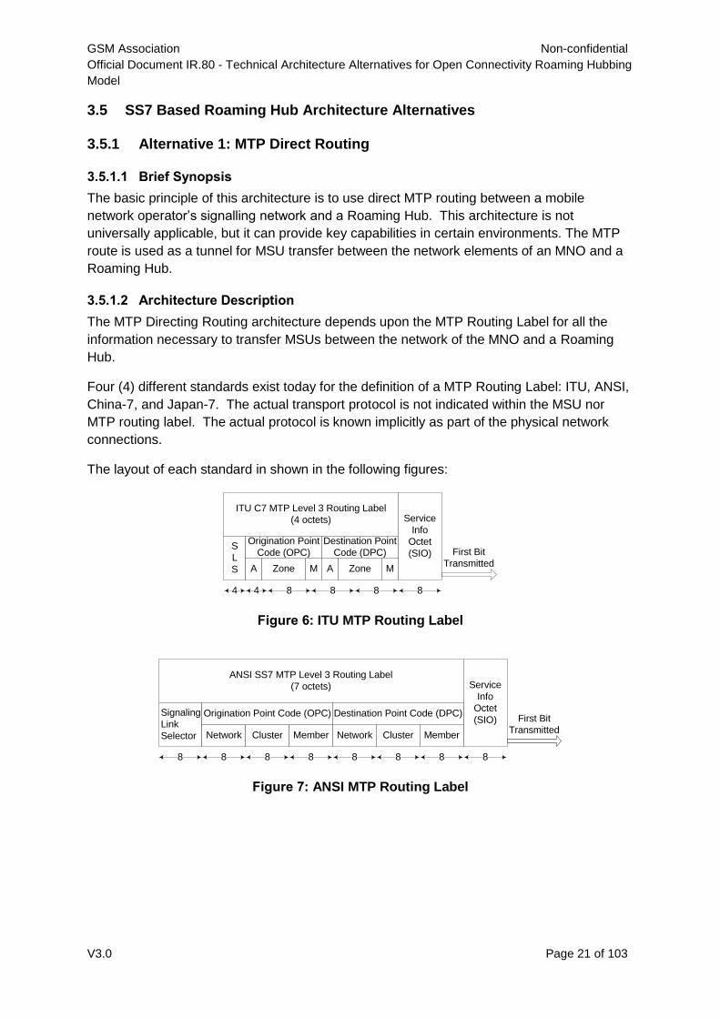
The MTP Directing Routing architecture depends upon the MTP Routing Label for all the
information necessary to transfer MSUs between the network of the MNO and a Roaming
Hub.
Four (4) different standards exist today for the definition of a MTP Routing Label: ITU, ANSI,
China-7, and Japan-7. The actual transport protocol is not indicated within the MSU nor
MTP routing label. The actual protocol is known implicitly as part of the physical network
connections.
The layout of each standard in shown in the following figures:
Figure 6: ITU MTP Routing Label
Figure 7: ANSI MTP Routing Label
ITU C7 MTP Level 3 Routing Label
(4 octets)
S
L
S
Service
Info
Octet
(SIO)
Origination Point
Code (OPC)
Destination Point
Code (DPC)
A Zone M
44 8 8 8 8
A Zone M
First Bit
Transmitted
ANSI SS7 MTP Level 3 Routing Label
(7 octets)
Signaling
Link
Selector Network Cluster Member
Service
Info
Octet
(SIO)Origination Point Code (OPC) Destination Point Code (DPC)
First Bit
Transmitted
8
Network Cluster Member
8 8 8 8 8 8 8
GSM Association Non-confidential
Official Document IR.80 - Technical Architecture Alternatives for Open Connectivity Roaming Hubbing
Model
V3.0 Page 22 of 103
Figure 8: China-7 MTP Routing Label
Figure 9: Japan-7 MTP Routing Label
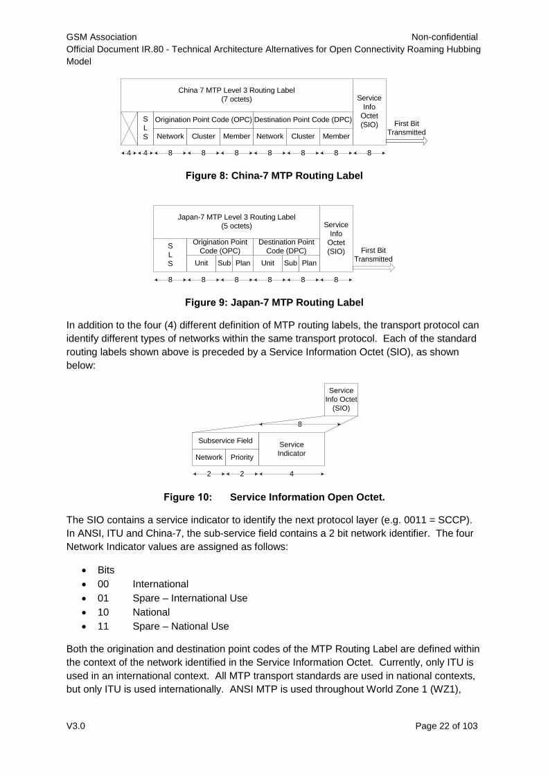
In addition to the four (4) different definition of MTP routing labels, the transport protocol can
identify different types of networks within the same transport protocol. Each of the standard
routing labels shown above is preceded by a Service Information Octet (SIO), as shown
below:
Service
Info Octet
(SIO)
Service
Indicator
Subservice Field
Network Priority
2 2 4
8
Figure 10: Service Information Open Octet.
The SIO contains a service indicator to identify the next protocol layer (e.g. 0011 = SCCP).
In ANSI, ITU and China-7, the sub-service field contains a 2 bit network identifier. The four
Network Indicator values are assigned as follows:
Bits
00 International
01 Spare – International Use
10 National
11 Spare – National Use
Both the origination and destination point codes of the MTP Routing Label are defined within
the context of the network identified in the Service Information Octet. Currently, only ITU is
used in an international context. All MTP transport standards are used in national contexts,
but only ITU is used internationally. ANSI MTP is used throughout World Zone 1 (WZ1),
China 7 MTP Level 3 Routing Label
(7 octets)
S
L
S Network Cluster Member
Service
Info
Octet
(SIO)Origination Point Code (OPC) Destination Point Code (DPC)
8
Network Cluster Member
44 8 8 8 8 8 8
First Bit
Transmitted
Japan-7 MTP Level 3 Routing Label
(5 octets)
S
L
S
Service
Info
Octet
(SIO)
Origination Point
Code (OPC)
Destination Point
Code (DPC)
Unit Plan
8 8 8 888
SubUnit PlanSub
First Bit
Transmitted
GSM Association Non-confidential
Official Document IR.80 - Technical Architecture Alternatives for Open Connectivity Roaming Hubbing
Model
V3.0 Page 23 of 103
which operates under the North American Numbering Plan Administration (NANPA). China-
7 and Japan-7 are limited to their national environment respectively.
For two network elements to exchange MSUs with MTP Direct Routing, both network
elements must use the same variant of MTP, with the same network indication. Their point
codes share a common protocol definition and a common network definition.
A network element addressed with a national point code cannot use MTP Direct Routing to
exchange MSUs with a network element addressed with an international point code.
When the MNO’s signalling network uses the same implicit MTP and network definition as a
Roaming Hub, then MTP Direct Routing is a possible architecture for Roaming Hub.
3.5.1.3 Call Flows
3.5.1.3.1 MTP Direct Routing Flow
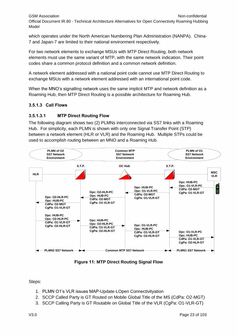
The following diagram shows two (2) PLMNs interconnected via SS7 links with a Roaming
Hub. For simplicity, each PLMN is shown with only one Signal Transfer Point (STP)
between a network element (HLR or VLR) and the Roaming Hub. Multiple STPs could be
used to accomplish routing between an MNO and a Roaming Hub.
Figure 11: MTP Direct Routing Signal Flow
Steps:
1. PLMN O1’s VLR issues MAP-Update-LOpen Connectivityation
2. SCCP Called Party is GT Routed on Mobile Global Title of the MS (CdPa: O2-MGT)
3. SCCP Calling Party is GT Routable on Global Title of the VLR (CgPa: O1-VLR-GT)
HLR
S.T.P. S.T.P.
MSC
VLR
OC Hub
Dpc: HUB-PC
Opc: O1-VLR-PC
CdPa: O2-MGT
CgPa: O1-VLR-GT
Dpc: HUB-PC
Opc: O2-HLR-PC
CdPa: O1-VLR-GT
CgPa: O2-HLR-GT
Common MTP
SS7 Network
Environment
PLMN of O1
SS7 Network
Environment
PLMN of O2
SS7 Network
Environment
PLMN2 SS7 Network PLMN1 SS7 NetworkCommon MTP SS7 Network
Dpc: HUB-PC
Opc: O1-VLR-PC
CdPa: O2-MGT
CgPa: O1-VLR-GT
Dpc: O2-HLR-PC
Opc: HUB-PC
CdPa: O2-MGT
CgPa: O1-VLR-GT
Dpc: O2-HLR-PC
Opc: HUB-PC
CdPa: O2-MGT
CgPa: O1-VLR-GT
Dpc: HUB-PC
Opc: O2-HLR-PC
CdPa: O1-VLR-GT
CgPa: O2-HLR-GT
Dpc: O1-VLR-PC
Opc: HUB-PC
CdPa: O1-VLR-GT
CgPa: O2-HLR-GT
Dpc: O1-VLR-PC
Opc: HUB-PC
CdPa: O1-VLR-GT
CgPa: O2-HLR-GT
GSM Association Non-confidential
Official Document IR.80 - Technical Architecture Alternatives for Open Connectivity Roaming Hubbing
Model
V3.0 Page 24 of 103
4. The MGT entry in VLR indicates that the MSU should be forwarded to the OPEN
CONNECTIVITY Roaming Hub’s point code (Roaming Hub-PC). The MTP Routing
Label is constructed with the destination point code of Roaming Hub-PC and the
originating point code of O1-VLR-PC.
5. In this example call flow, the Roaming Hub-PC is defined in the VLR over a route set
over that use the physical links to an STP. The Roaming Hub’s PC must be provisioned
in the VLR as well as any intermediate network devices (e.g. STPs).
6. The MSU is forwarded over physical links to O1’s STP (Dpc: Roaming Hub-PC) from
local VLR (Opc: O1-VLR-PC)
PLMN O1’s STP evaluates the DPC (ROAMING HUB-PC), notes that it is not the STP’s
point code and attempts to onward route the MSU. The STP uses the DPC (ROAMING
HUB-PC) to determine that the next network element is the Roaming Hub. In actuality,
multiple STPs may be involved to onward route the MSU to the Roaming Hub. Each STP
will perform exactly the same evaluation and determination for distribution. The SCCP layer
is unchanged and forwarded as received.
MSU is forwarded to Roaming Hub (Dpc: Roaming Hub-PC) from O1’s STP (Opc: O1-VLR-
PC). The OPC is not modified by the STP because it only performed transfer services. The
STP did not invoke higher layer functions like SCCP routing. The OPC is only modified
when high layer functions are invoked within the STP.
The Roaming Hub uses information within the received MSU to determine the existence of
an OC roaming agreement between the serving and home PLMNs. An OC roaming
agreement permits the operation to be forwarded accordingly. The Roaming Hub
determines the destination of the signalling message based on the Called Party Address
(SCCP CdPa) effectively performing intermediate Global Title routing. The determination
provides a point code route to PLMN O2’s HLR. A routing label is constructed for the MSU,
destined to PLMN O2’s HLR. The physical links to O2’s STP are used for the route set
associated with O2’s HLR point code. The SCCP contents are not changed and forwarded
as received with repackaging of the routing label origination and destination point codes.
MSU is forwarded to O2’s STP (Dpc: O2-HLR_PC) from Roaming Hub (Opc: Roaming Hub-
PC)
PLMN O2’s STP evaluates the DPC of the received MSU. Since it is not the STP’s point
code, it is onward routed to the DPC. The STP determines that the next network element is
the PLMN O2’s HLR. The SCCP layer is unchanged and forwarded as received.
MSU is forwarded to O2’s HLR (Dpc: O2-HLR-PC) from O2’s STP (Opc: ROAMING HUB -
PC). The STP does not alter the OPC since it is not the addressed destination and it did not
invoke any high layer function, like global title routing.
The remaining signalling traffic transfers are similar to steps 1 through 4 where the
destination point code and origination point codes are swapped in sequence. The SCCP
addresses change also, but they are not used for routing purposes within the SS7 network.
Only the Roaming Hub uses the SCCP party addresses for routing determination.
GSM Association Non-confidential
Official Document IR.80 - Technical Architecture Alternatives for Open Connectivity Roaming Hubbing
Model
V3.0 Page 25 of 103
The original SCCP Calling Party (O1-VLR-GT) address becomes the new SCCP Called
Party Address and the PLMN O2’s HLR identifies itself as the new SCCP Calling Party
address (O2-HLR-GT) in place of O2 Mobile Station’s Mobile Global Title (O2-MGT).
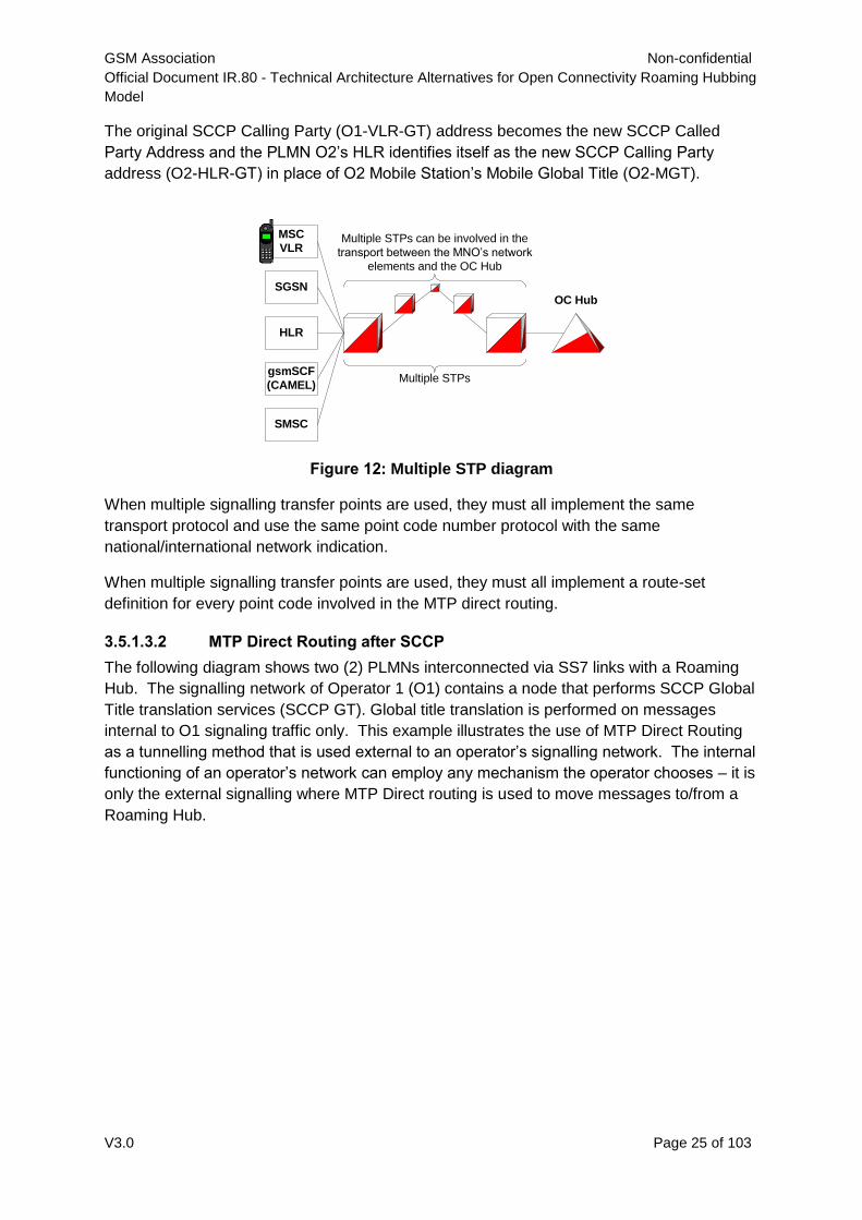
Figure 12: Multiple STP diagram
When multiple signalling transfer points are used, they must all implement the same
transport protocol and use the same point code number protocol with the same
national/international network indication.
When multiple signalling transfer points are used, they must all implement a route-set
definition for every point code involved in the MTP direct routing.
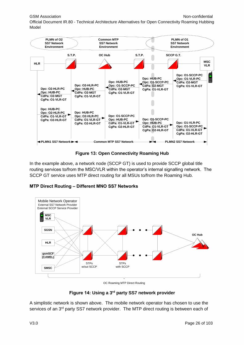
3.5.1.3.2 MTP Direct Routing after SCCP
The following diagram shows two (2) PLMNs interconnected via SS7 links with a Roaming
Hub. The signalling network of Operator 1 (O1) contains a node that performs SCCP Global
Title translation services (SCCP GT). Global title translation is performed on messages
internal to O1 signaling traffic only. This example illustrates the use of MTP Direct Routing
as a tunnelling method that is used external to an operator’s signalling network. The internal
functioning of an operator’s network can employ any mechanism the operator chooses – it is
only the external signalling where MTP Direct routing is used to move messages to/from a
Roaming Hub.
MSC
VLR
OC Hub
Multiple STPs can be involved in the
transport between the MNO’s network
elements and the OC Hub
SGSN
HLR
gsmSCF
(CAMEL)Multiple STPs
SMSC
GSM Association Non-confidential
Official Document IR.80 - Technical Architecture Alternatives for Open Connectivity Roaming Hubbing
Model
V3.0 Page 26 of 103
Figure 13: Open Connectivity Roaming Hub
In the example above, a network node (SCCP GT) is used to provide SCCP global title
routing services to/from the MSC/VLR within the operator’s internal signalling network. The
SCCP GT service uses MTP direct routing for all MSUs to/from the Roaming Hub.
MTP Direct Routing – Different MNO SS7 Networks
Figure 14: Using a 3rd party SS7 network provider
A simplistic network is shown above. The mobile network operator has chosen to use the
services of an 3rd party SS7 network provider. The MTP direct routing is between each of
HLR
S.T.P. OC Hub SCCP G.T.
MSC
VLR
S.T.P.
PLMN1 SS7 Network Common MTP SS7 Network PLMN2 SS7 Network
Dpc: O1-SCCP-PC
Opc: O1-VLR-PC
CdPa: O2-MGT
CgPa: O1-VLR-GT
Dpc: HUB-PC
Opc: O1-SCCP-PC
CdPa: O2-MGT
CgPa: O1-VLR-GT
Dpc: HUB-PC
Opc: O1-SCCP-PC
CdPa: O2-MGT
CgPa: O1-VLR-GT
Dpc: O2-HLR-PC
Opc: HUB-PC
CdPa: O2-MGT
CgPa: O1-VLR-GT
Dpc: O2-HLR-PC
Opc: HUB-PC
CdPa: O2-MGT
CgPa: O1-VLR-GT
Dpc: HUB-PC
Opc: O2-HLR-PC
CdPa: O1-VLR-GT
CgPa: O2-HLR-GT
Dpc: HUB-PC
Opc: O2-HLR-PC
CdPa: O1-VLR-GT
CgPa: O2-HLR-GT
Dpc: O1-SCCP-PC
Opc: HUB-PC
CdPa: O1-VLR-GT
CgPa: O2-HLR-GT
Dpc: O1-SCCP-PC
Opc: HUB-PC
CdPa: O1-VLR-GT
CgPa: O2-HLR-GT
Dpc: O1-VLR-PC
Opc: O1-SCCP-PC
CdPa: O1-VLR-GT
CgPa: O2-HLR-GT
Common MTP
SS7 Network
Environment
PLMN of O2
SS7 Network
Environment
PLMN of O1
SS7 Network
Environment
Mobile Network OperatorExternal SS7 Network Provider
External SCCP Service Provider
OC Roaming MTP Direct Routing
MSC
VLR
OC Hub
SGSN
HLR
gsmSCF
(CAMEL)
SMSC
STPs
w/out SCCP
STPs
with SCCP
GSM Association Non-confidential
Official Document IR.80 - Technical Architecture Alternatives for Open Connectivity Roaming Hubbing
Model
V3.0 Page 27 of 103
the MNO’s network elements (MSC/VLR, SGSN, HLR, gsmSCF, SMSC) and the Roaming
Hub.
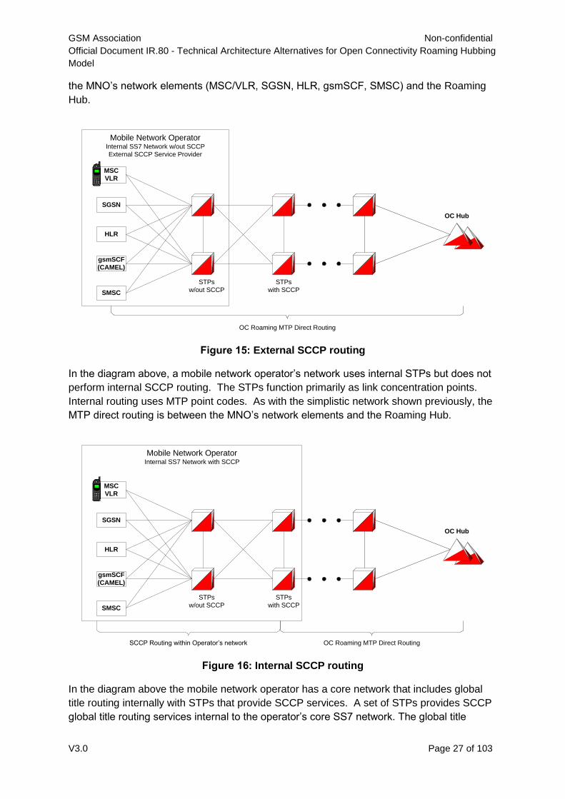
Figure 15: External SCCP routing
In the diagram above, a mobile network operator’s network uses internal STPs but does not
perform internal SCCP routing. The STPs function primarily as link concentration points.
Internal routing uses MTP point codes. As with the simplistic network shown previously, the
MTP direct routing is between the MNO’s network elements and the Roaming Hub.
Figure 16: Internal SCCP routing
In the diagram above the mobile network operator has a core network that includes global
title routing internally with STPs that provide SCCP services. A set of STPs provides SCCP
global title routing services internal to the operator’s core SS7 network. The global title
Mobile Network OperatorInternal SS7 Network w/out SCCP
External SCCP Service Provider
OC Roaming MTP Direct Routing
MSC
VLR
OC Hub
SGSN
HLR
gsmSCF
(CAMEL)
SMSC
STPs
w/out SCCP
STPs
with SCCP
Mobile Network OperatorInternal SS7 Network with SCCP
OC Roaming MTP Direct Routing
MSC
VLR
OC Hub
SGSN
HLR
gsmSCF
(CAMEL)
SMSC
SCCP Routing within Operator’s network
STPs
w/out SCCP
STPs
with SCCP
GSM Association Non-confidential
Official Document IR.80 - Technical Architecture Alternatives for Open Connectivity Roaming Hubbing
Model
V3.0 Page 28 of 103
translation STPs provide the traffic separation point where MTP direct routing can be used
to/from the Roaming Hub. The MNO’s network elements can use SCCP global title routing
to/from the core internal Global Title STPs. MTP direct routing is used between the MNO’s
global title STPs and the Roaming Hub.
3.5.1.4 Implementation Considerations
3.5.1.4.1 General Considerations
General considerations of MTP Direct Routing tend to expose the restrictions that are
imposed by this architecture alternative. The relationship between a Roaming Hub and an
operators sending/receiving nodes can be based on MTP direct routing if and only if all
network elements involved have the ability to operate with the same protocol definition
(ANSI, ITU, China-7, Japan-7) and the same network indication (national, international).
3.5.1.4.1.1 Applicable Environments
Certain operating environments are more suited to this particular set of restrictions than
others. World Zone 1 (WZ1) employs an ANSI message transport protocol in a national
network identity. Hundreds of operators exist in the same transport protocol definition with
the same network indication. This characteristic provides an excellent environment for the
use of MTP Direct Routing as an architecture alternative.
Another environment where MTP Direct Routing can be applied is the ITU International
signalling layer. The international signalling layer qualifies with a single transport protocol
and common network indication. Roaming Hubs can operate with international ITU point
codes. Operators can use network elements to function as points of ingress/egress with
international ITU point codes. MTP Direct Routing becomes a valid option for these
operators and these Roaming Hubs.
MTP direct routing using international signalling point codes becomes a very easy method
for inter-Roaming Hub communications. Route set definitions are required for the Roaming
Hubs point codes in all the network elements needed to support the MTP routing path. The
route set definitions are a one-time setup requirement for the international SS7 network
providers on behalf of the Roaming Hubs.
MTP direct routing can be a viable method for remote operators with dedicated facilities to
interconnect with a Roaming Hub. Careful point code planning is required to ensure that
point code overlap does not occur.
3.5.1.4.1.2 Restricted Environments
MTP Direct routing is not an optimal choice in certain environments. Operators in countries
where a Roaming Hub is not present eliminates the use of national point codes. Operator
that do not have or choose not to have international point codes may be restricted from
using MTP direct routing. Operators who choose not to provision dedicated facilities to a
Roaming Hub may be restricted from using MTP direct routing.
GSM Association Non-confidential
Official Document IR.80 - Technical Architecture Alternatives for Open Connectivity Roaming Hubbing
Model
V3.0 Page 29 of 103
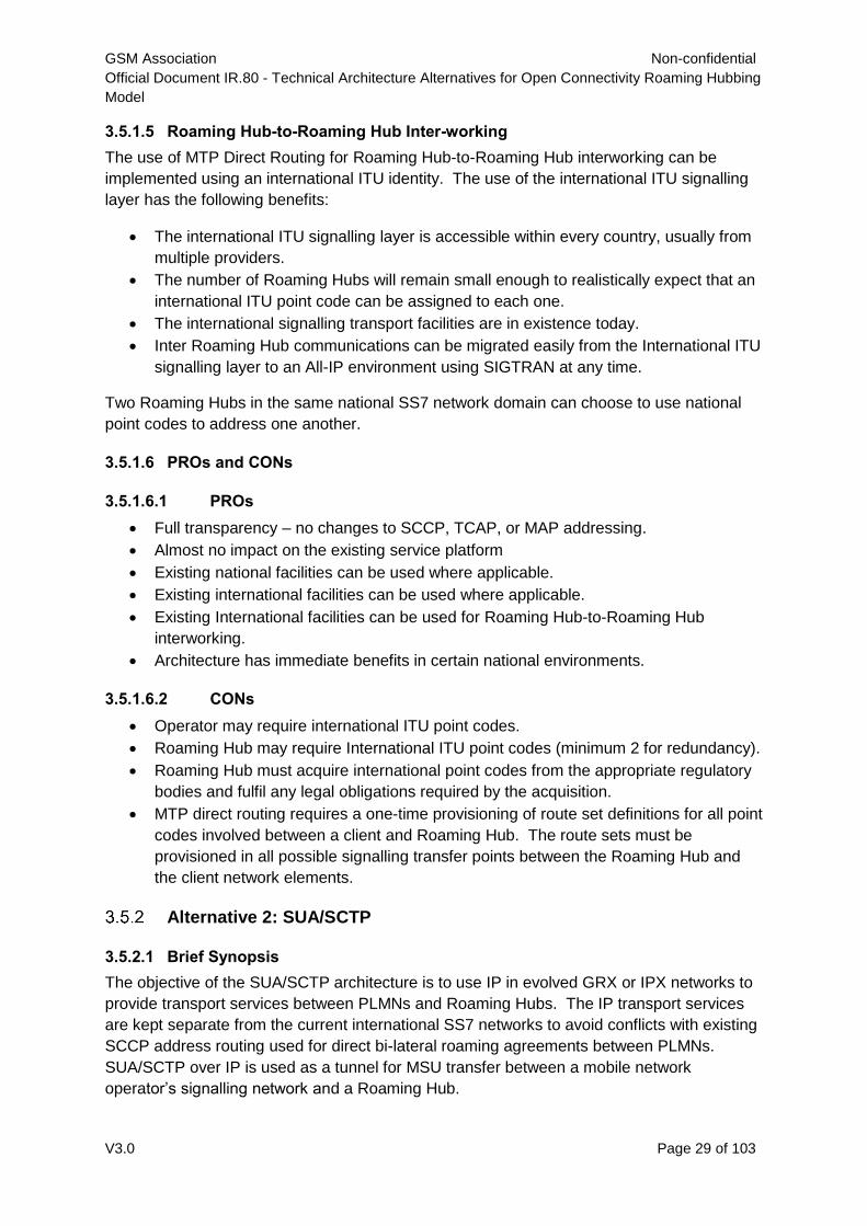
3.5.1.5 Roaming Hub-to-Roaming Hub Inter-working
The use of MTP Direct Routing for Roaming Hub-to-Roaming Hub interworking can be
implemented using an international ITU identity. The use of the international ITU signalling
layer has the following benefits:
The international ITU signalling layer is accessible within every country, usually from
multiple providers.
The number of Roaming Hubs will remain small enough to realistically expect that an
international ITU point code can be assigned to each one.
The international signalling transport facilities are in existence today.
Inter Roaming Hub communications can be migrated easily from the International ITU
signalling layer to an All-IP environment using SIGTRAN at any time.
Two Roaming Hubs in the same national SS7 network domain can choose to use national
point codes to address one another.
3.5.1.6 PROs and CONs
3.5.1.6.1 PROs
Full transparency – no changes to SCCP, TCAP, or MAP addressing.
Almost no impact on the existing service platform
Existing national facilities can be used where applicable.
Existing international facilities can be used where applicable.
Existing International facilities can be used for Roaming Hub-to-Roaming Hub
interworking.
Architecture has immediate benefits in certain national environments.
3.5.1.6.2 CONs
Operator may require international ITU point codes.
Roaming Hub may require International ITU point codes (minimum 2 for redundancy).
Roaming Hub must acquire international point codes from the appropriate regulatory
bodies and fulfil any legal obligations required by the acquisition.
MTP direct routing requires a one-time provisioning of route set definitions for all point
codes involved between a client and Roaming Hub. The route sets must be
provisioned in all possible signalling transfer points between the Roaming Hub and
the client network elements.
Alternative 2: SUA/SCTP
3.5.2.1 Brief Synopsis
The objective of the SUA/SCTP architecture is to use IP in evolved GRX or IPX networks to
provide transport services between PLMNs and Roaming Hubs. The IP transport services
are kept separate from the current international SS7 networks to avoid conflicts with existing
SCCP address routing used for direct bi-lateral roaming agreements between PLMNs.
SUA/SCTP over IP is used as a tunnel for MSU transfer between a mobile network
operator’s signalling network and a Roaming Hub.
GSM Association Non-confidential
Official Document IR.80 - Technical Architecture Alternatives for Open Connectivity Roaming Hubbing
Model
V3.0 Page 30 of 103
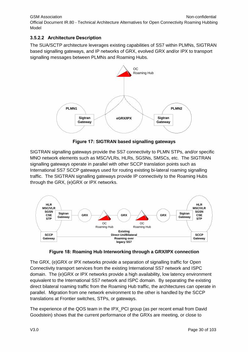
3.5.2.2 Architecture Description
The SUA/SCTP architecture leverages existing capabilities of SS7 within PLMNs, SIGTRAN
based signalling gateways, and IP networks of GRX, evolved GRX and/or IPX to transport
signalling messages between PLMNs and Roaming Hubs.
Figure 17: SIGTRAN based signalling gateways
SIGTRAN signalling gateways provide the SS7 connectivity to PLMN STPs, and/or specific
MNO network elements such as MSC/VLRs, HLRs, SGSNs, SMSCs, etc. The SIGTRAN
signalling gateways operate in parallel with other SCCP translation points such as
International SS7 SCCP gateways used for routing existing bi-lateral roaming signalling
traffic. The SIGTRAN signalling gateways provide IP connectivity to the Roaming Hubs
through the GRX, (e)GRX or IPX networks.
Figure 18: Roaming Hub Interworking through a GRX/IPX connection
The GRX, (e)GRX or IPX networks provide a separation of signalling traffic for Open
Connectivity transport services from the existing International SS7 network and ISPC
domain. The (e)GRX or IPX networks provide a high availability, low latency environment
equivalent to the International SS7 network and ISPC domain. By separating the existing
direct bilateral roaming traffic from the Roaming Hub traffic, the architectures can operate in
parallel. Migration from one network environment to the other is handled by the SCCP
translations at Frontier switches, STPs, or gateways.
The experience of the QOS team in the IPX_PCI group (as per recent email from David
Goodstein) shows that the current performance of the GRXs are meeting, or close to
eGRX/IPX
PLMN1
Sigtran
Gateway
PLMN2
Sigtran
Gateway
OC
Roaming Hub
GRX
HLR
MSC/VLR
SGSN
CSE
STP
Sigtran
Gateway
SCCP
Gateway
GRX GRX
HLR
MSC/VLR
SGSN
CSE
STP
Sigtran
Gateway
SCCP
Gateway
Existing
Direct Uni/Bilateral
Roaming over
legacy SS7
OC
Roaming Hub
OC
Roaming Hub
GSM Association Non-confidential
Official Document IR.80 - Technical Architecture Alternatives for Open Connectivity Roaming Hubbing
Model
V3.0 Page 31 of 103
meeting the requirements table of IR.34 for Round Trip Time. In summary, they are now
comparable to the performance of TDM/legacy SS7 networks.
The GSMA presentation entitled IPX Validation, Early Indicators from IPX performance
Tests, Orange UK <-> Vodafone Australia, version 1.1, dated 24th August, 2007 contains
consist one-way delay and round trip time results. The round trip times from UK to Australia
to UK averaged 344 milliseconds.
So while latency remains important, it is solely an issue for the local end-tail dimensioning,
and not a generic concern with the SUA/SCTP Architecture. Any references to GRX, evolved
GRX [(e)GRX], or IPX networks can be satisfied with the existing GRX networks.
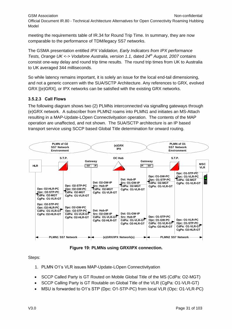
3.5.2.3 Call Flows
The following diagram shows two (2) PLMNs interconnected via signalling gateways through
(e)GRX network. A subscriber from PLMN2 roams into PLMN1 and initiates an MS-Attach
resulting in a MAP-Update-LOpen Connectivityation operation. The contents of the MAP
operation are unaffected, and not shown. The SUA/SCTP architecture is an IP based
transport service using SCCP based Global Title determination for onward routing.
Figure 19: PLMNs using GRX/IPX connection.
Steps:
1. PLMN O1’s VLR issues MAP-Update-LOpen Connectivityation
SCCP Called Party is GT Routed on Mobile Global Title of the MS (CdPa: O2-MGT)
SCCP Calling Party is GT Routable on Global Title of the VLR (CgPa: O1-VLR-GT)
MSU is forwarded to O1’s STP (Dpc: O1-STP-PC) from local VLR (Opc: O1-VLR-PC)
HLR
S.T.P.Gateway
SS7 IP
Gateway
SS7IP
S.T.P.
MSC
VLR
OC Hub
Dpc: O1-STP-PC
Opc: O1-VLR-PC
CdPa: O2-MGT
CgPa: O1-VLR-GT
Dpc: O1-GW-PC
Opc: O1-STP-PC
CdPa: O2-MGT
CgPa: O1-VLR-GT
Dst: Hub-IP
Src: O1-GW-IP
CdPa: O2-MGT
CgPa: O1-VLR-GT
Dst: O2-GW-IP
Src: Hub-IP
CdPa: O2-MGT
CgPa: O1-VLR-GT
Dpc: O2-STP-PC
Opc: O2-GW-PC
CdPa: O2-MGT
CgPa: O1-VLR-GT
Dpc: O2-HLR-PC
Opc: O2-STP-PC
CdPa: O2-MGT
CgPa: O1-VLR-GT
Dpc: O2-STP-PC
Opc: O2-HLR-PC
CdPa: O1-VLR-GT
CgPa: O2-HLR-GT
Dpc: O2-GW-PC
Opc: O2-STP-PC
CdPa: O1-VLR-GT
CgPa: O2-HLR-GT
Dst: Hub-IP
Src: O2-GW-IP
CdPa: O1-VLR-GT
CgPa: O2-HLR-GT
Dst: O1-GW-IP
Src: Hub-IP
CdPa: O1-VLR-GT
CgPa: O2-HLR-GT
Dpc: O1-STP-PC
Opc: O1-GW-PC
CdPa: O1-VLR-GT
CgPa: O2-HLR-GT
Dpc: O1-VLR-PC
Opc: O1-STP-PC
CdPa: O1-VLR-GT
CgPa: O2-HLR-GT
(e)GRX
IPX
PLMN of O1
SS7 Network
Environment
PLMN of O2
SS7 Network
Environment
PLMN1 SS7 Network PLMN2 SS7 Network(e)GRX/IPX Network(s)
GSM Association Non-confidential
Official Document IR.80 - Technical Architecture Alternatives for Open Connectivity Roaming Hubbing
Model
V3.0 Page 32 of 103
PLMN O1’s STP performs intermediate Global Title routing with the SCCP Called Party
Address and determines that the next network element is the PLMN O1’s SIGTRAN
Signaling Gateway. The SCCP layer is unchanged and forwarded as received.
MSU is forwarded to O1’s GW (Dpc: O1-GW-PC) from O1’s STP (Opc: O1-STP-PC)
PLMN O1’s Signaling Gateway performs intermediate Global Title routing with the SCCP
Called Party Address and determines that the next network element is the Roaming Hub.
The Roaming Hub is a SIGTRAN addressable entity, so the SCCP information (which
includes the TCAP MAP/CAP) is repackaged in a Connectionless Data packet (as per SUA)
and forwarded to the Roaming Hub via the (e)GRX/IPX network. The Roaming Hub has an
SCTP Association with an underlying IP Address. The Roaming Hub’s IP Address is set as
the Destination with the signalling gateway’s IP address as the source identity of the packet.
The SCCP contents are not functionally changed and forwarded as received with
repackaging.
Logical MSU is forwarded to the Roaming Hub (Dst: Roaming Hub-IP) from O1’s GW (Src:
O1-GW-IP)
The Roaming Hub receiving the SUA Connectionless Data packet uses information within
the packet to determine the existence of an OC roaming agreement between the serving and
home PLMNs. An OC roaming agreement permits the operation to be forwarded
accordingly. The Roaming Hub determines the destination of the signalling message based
on the Called Party Address (SCCP CdPa) effectively performing intermediate Global Title
routing. The determination provides a route to PLMN O2’s signalling gateway which has an
SCTP association with an underlying IP address. A SUA Connectionless Data packet is
constructed, destined to PLMN O2’s signaling gateway. The SCCP contents are not
functionally changed and forwarded as received with repackaging of the source and
destination IP addresses.
Logical MSU is forwarded to O2’s GW (Dst: O2-GW-IP) from the Roaming Hub (Src:
Roaming Hub-IP)
PLMN O2’s Signaling Gateway performs intermediate Global Title routing with the SCCP
Called Party Address and determines that the next network element is the network local STP
(PLMN O2’s STP). The STP is a local SS7 addressable entity, so the SCCP information
(which includes the TCAP MAP/CAP) is repackaged in an N-UnitData MSU and forwarded to
the STP via the local SS7 network. The SCCP contents are not functionally changed and
forwarded as received with repackaging to an SS7 MSU.
MSU is forwarded to O2’s STP (Dpc: O2-STP-PC) from O2’s GW (Opc: O2-GW-PC)
PLMN O2’s STP performs intermediate (or final) Global Title routing with the SCCP Called
Party Address and determines that the next network element is the PLMN O2’s HLR. The
SCCP layer is unchanged and forwarded as received.
GSM Association Non-confidential
Official Document IR.80 - Technical Architecture Alternatives for Open Connectivity Roaming Hubbing
Model
V3.0 Page 33 of 103
MSU is forwarded to O2’s HLR (Dpc: O2-HLR-PC) from O2’s STP (Opc: O2-STP-PC)
The remaining signalling traffic transfers are similar to steps 1 through 6 where the original
SCCP Calling Party (O1-VLR-GT) address becomes the new SCCP Called Party Address
and the PLMN O2’s HLR identifies itself as the new SCCP Calling Party address (O2-HLR-
PC) in place of O2 Mobile Station’s Mobile Global Title (O2-MGT).
In all of the above steps, the SCCP addressing information (called and calling party address
Global Titles, and user information (TCAP MAP) remain unchanged, providing full
transparency between the VLR and HLR.
Routing determination is performed in each PLMN network to choose either a gateway for
Open Connectivity roaming or an International SCCP provider for existing
unidirectional/bidirectional roaming.
3.5.2.4 Implementation Considerations
3.5.2.4.1 General Considerations
Physical connectivity is required to a GRX network. Many MNOs already have access to
GRX to support packet switched services.
SIGTRAN signalling gateways need to be put in place if not already present. MNOs that use
SIGTRAN as part of their internal core signalling network may already have the necessary
gateways. SIGTRAN signalling gateways must be integrated with the existing BGP-GRX
infrastructure and PLMN network management.
An MNO that has no existing SIGTRAN infrastructure, nor knowledge of SIGTRAN, may
desire their Roaming Hub to install, configure and manage the SIGTRAN signalling
gateways as an outsourced service.
IR.21 processing will need to differentiate between Open Connectivity roaming versus
unidirectional/bidirectional roaming, such that global title routing uses the appropriate
gateway.
Routing determination requires an addressable interface point to transition from an SS7
network to a (e)GRX/IPX network. The addressable interface point must have a SS7 point
code address and an IP address. It should have the ability to perform SCCP routing
determination through the use of global title tables. Global title addresses belonging to the
connected MNO will point toward the network elements of the MNO, all other global title
addresses will point to the Roaming Hub.
Several network topologies need to be considered relative to the basic implementation of a
signalling gateway and GRX routing path to a Roaming Hub.
The characteristics of the MNOs signalling network that define the various topologies are as
follows:
GSM Association Non-confidential
Official Document IR.80 - Technical Architecture Alternatives for Open Connectivity Roaming Hubbing
Model
V3.0 Page 34 of 103
STP with SCCP services is internal to / external to MNO’s network [Paolo: what is an
STP with SCCP service? Is there any other kind?]
More than 1 pair of STPs with SCCP Services for ingress/egress to network
Uses international point code or is limited to national point code
3.5.2.4.2 Client Considerations
The routing decision point that separates traffic of bi-lateral roaming partners from OPEN
CONNECTIVITY roaming partners shall direct the OPEN CONNECTIVITY roaming partner
traffic to a local SUA/SCTP Gateway. The local SUA/SCTP can be implemented on a local
(national) point code to eliminate dependency on international signalling point code
availability.
The MNO’s internal signaling network may have an IP core, or an SS7 core, or the core may
be provided by a third party signalling service, depending upon the sophistication of the
MNO.
When the internal signalling network has an IP core, the use of SUA/SCTP is significantly
easier to implement, and the MNO may already have the necessary hardware to accomplish
the required SIGTRAN connectivity.
When the internal signalling network has an SS7 core, the use of SUA/SCTP may require
additional hardware to form the bridge between the internal SS7 signaling network and the
(e)GRX network.
The use of SUA/SCTP may require additional hardware to separate signalling traffic of bi-
lateral roaming partners from OPEN CONNECTIVITY roaming partners. This is especially
true when the internal signalling network is provided by a 3rd party signalling service. Once
separation of signaling traffic is completed, then hardware may be required to bridge the
OPEN CONNECTIVITY roaming partners’ traffic to the (e)GRX network via SUA/SCTP.
3.5.2.4.3 Roaming Partner Considerations
Same as above.
3.5.2.4.4 Roaming Hub-to-Roaming Hub Inter-working
The use of SUA/SCTP for Roaming Hub-to-Roaming Hub interworking is an excellent choice
since it provides a fully transparent tunnelling path for MSUs to retain all their exact SCCP,
TCAP, MAP and CAP components.
3.5.2.5 PROs and CONs
3.5.2.5.1 PROs
Centralised signalling and signalling management are maintained. A cascading signalling
flow provides identical message handling relative to existing unidirectional or bidirectional
roaming with respect to SCCP, TCAP, MAP, and CAP protocols. With an architecture that
does not require or is not dependent upon content manipulation, existing MNO services
should not be affected. Such services may include USSD based services, steerage of
roaming, SMS welcome, interoperability with SMS Roaming Hubs, CAP based services, etc.
GSM Association Non-confidential
Official Document IR.80 - Technical Architecture Alternatives for Open Connectivity Roaming Hubbing
Model
V3.0 Page 35 of 103
Introducing a Roaming Hub should have minimal impact on operational areas such as fraud
prevention, testing and QoS monitoring, and service troubleshooting.
The SUA/SCTP architecture for Roaming Hubs maximizes transparency and visibility to
meet OC requirements.
This architecture provides parallel co-existence with existing signalling routing avoiding any
impact to existing unidirectional or bidirectional roaming relationships.
The SUA/SCTP architecture is a move forward to an All-IP network environment aligning it
with the future of signalling services. Its direction is consistent with 3GPP adoption of
Diameter-based macro-mobility protocols in IMS.
The SUA/SCTP architecture provides a more global solution for signalling Roaming
Hubbing.
The SUA/SCTP Architecture is in alignment with PRD IR.72 providing the benefits of
increased bandwidth, decreased cost, easier dimensioning, and increased QoS over existing
narrowband SS7 based solutions.
The SUA/SCTP architecture has no explicit requirements for ISPC assignment. The SS7
module of the SGW exists on the national-layer/carrier-specific (thus not requiring ISPC),
and the IP module can address the signalling routing/transport in the international network
domain without using a point code. Point codes need not be transferred across the SS7/IP
GW boundary when using SUA.
The SUA/SCTP architecture’s key components of are available now. The GRX is available in
approximately half of the active GSMA operators' networks, either accessed by dedicated
transmission links, or via secure tunnels over the internet. A router supporting legacy-SS7 to
Sigtran (including SUA) can be sourced from at least one major manufacturer, and routers
and protocol-stack "plug-ins" supporting other SIGTRAN protocols can be sourced from a
wide selection of vendors. There are no external dependencies on organisations such as
ITU-T to assign addresses or address ranges. Extension to new operators who have no
GRX is dependent on the availability of Internet to a reliability level consistent with the
PLMN's aspiration on the availability of roaming services.
It is considered that The SUA/SCTP architecture can be trialled as soon as a project is
sponsored and funded. Full commercial implementation of The SUA/SCTP architecture is
possible as soon as GSMA complete contractual and procedural documentation and
Roaming Hubs can establish a basis for commercial service.
The SUA/SCTP architecture is ideally suited to those operators with existing access to the
GRX, either via direct transmission or via secure tunnels (e.g. IPsec) As per IR.34 version
4.1, dated January 2007, section 7.3 states:
The end-to-end SLA [22, Annex] describes the different options for establishing physical
connections from a Service Provider to the IPX. Different connection options can be divided
into three categories:
Layer 1 connection (e.g. leased line or fiber) or
GSM Association Non-confidential
Official Document IR.80 - Technical Architecture Alternatives for Open Connectivity Roaming Hubbing
Model
V3.0 Page 36 of 103
Layer 2 logical connection (e. g. ATM, LAN, Frame Relay) or
Layer 3 IP VPN connection over public IP network (IPSec is recommended)
The use by a Service Provider of an Internet IPSec VPN for the local tail is strongly
discouraged unless there is no viable alternative.
Operators without GRX capability would need to be access a GRX which can mostly easily
be done by arranging a secure tunnel over the public Internet (because the bandwidth
requirements are low). SUA/SCTP complements MTP Direct Routing (MTP) and both are
"tunnelling solutions" in much the same sense that microwave and fibre are both "transport
systems". It has been noted that in Europe that GRX is widely available, but ISPCs
(International Signal Point Codes) and the necessary MTP Route set activations are difficult
to achieve. Elsewhere in the world the opposite often holds true. In North America and
China, the availability of "national" MTP Direct Routing capability is also available to provide
"tunnelling".
The SUA/SCTP architecture is equally viable in big and small networks, and supports
options on whether the PLMN sources and manages the SS7 router/gateway, or seeks a
Roaming Hub to manage it.
The SUA/SCTP architecture can support multiple gateways for scalability of loading,
because they may be stateless at the application level for MAP/CAP/TCAP/SCCP.
The SUA/SCTP architecture can be mixed or integrated with bilateral and Roaming Hub
signalling architectures, with legacy SS7 interworking to International SCCP providers, (and
if GSMA can solve the intrinsic separation and MNP issues) with the use of split SMS and
Roaming signalling/Roaming Hubs. The complexity or sophistication of the mixing is solely a
function of the depth of SCCP Called party address analysis undertaken within the PLMN at
source nodes, at STPs, at Frontier STP/SCCP gateways and/or at the Sigtran-GRX
gateways, and will be part of the combined business plan to reduce the cost of providing
roaming services. In other words, it is "fully flexible"
The SUA/SCTP architecture is forward compatible with developments such as 3GPP
Release 7 functions such as TCAPsec, and the Release 8 Diameter-based Roaming
signalling. The position of the Sigtran-GRX Gateway in a PLMN architecture leads to
possible integration with Firewalls and proxies.
The SUA/SCTP architecture (and MTP Direct Routing) has no impact on SCCP called and
calling party addresses, TCAP addresses, MAP addresses, and so provides absolute
transparency to PLMNs.in accordance with OPEN CONNECTIVITY requirements.
3.5.2.5.2 CONs
The following CONs listed are not about the SUA/SCTP Architecture itself but about the
range of sophistication that may not yet exist with the mobile Network Operators
environment or plans.
The SUA/SCTP architecture may impact the operational environment of MNOs that
do not have existing GRX connectivity.
GSM Association Non-confidential
Official Document IR.80 - Technical Architecture Alternatives for Open Connectivity Roaming Hubbing
Model
V3.0 Page 37 of 103
The SUA/SCTP architecture may impact the MNOs that do not have SIGTRAN
capabilities, or do not have SIGTRAN capabilities in their network plans.
The SUA/SCTP architecture may require significant testing of the capabilities and
interoperability of different type of SGWs that are commercially available.
The SUA/SCTP architecture implementation may have a longer market adoption
timescale based on affected MNOs that have neither GRX nor experience with
SIGTRAN.
GSM Association Non-confidential
Official Document IR.80 - Technical Architecture Alternatives for Open Connectivity Roaming Hubbing
Model
V3.0 Page 38 of 103
Alternative 3: SCCP Translation Type (TT)
Brief Synopsis
The objective of the SCCP Translation Type architecture is to use the SCCP Called Party
Translation Type value to indicate a specific Roaming Hub. SCCP Translation Type (TT)
routing is based on standard SCCP operations while the routing decision of SCCP service
providers is changed. SCCP Service Providers alter their routing decisions according to
Translation Type. If The SCCP Called Party Address Translation Type is not zero, routing is
based on SCCP Called Party Translation Type, otherwise, the existing method of routing is
performed with the SCCP Called Party Global Title Address (GT). The TT route is used as a
tunnel through existing routing facilities to transfer MSUs between an operator’s network
elements and a Roaming Hub.
This solution avoids any SCCP/MAP/CAP Address manipulations, translations or
modifications.
3.5.4.2 Architecture Description
SCCP Translation Type routing provides the ability to route SCCP messages to a Roaming
Hub based on the called party address translation type. The Roaming Hub routes to the
destination MNO of the message based on the called party address global title digits.
3.5.4.2.1 Translation Type in ITU Transport
In bi-lateral roaming the common SCCP routing is based on analysis of SCCP called party
global title address in the context of the numbering plan (E.164 or E.214) in ITU networks.
ITU networks use only one routing table for ISDN addresses. The addresses can be either
E.164 [MSISDN & Network Element Address] or E.214 [Mobile Global Title]. Both E.164 and
E.214 use the same global title translator service within SCCP. Translation Type is not used
because it is not needed to select different GT translators. Both numbering plans use the
same service. Since Translation Type is not used in ITU networks currently, it becomes an
available discriminator for an alternate routing mechanism for Roaming Hubs. ITU networks
use a numbering plan indicator to properly identify an E.164 (NP=1) and an E.214 (NP=7).
The following conceptual diagram shows bi-lateral SCCP routing in an ITU network using
global title digits (CC…) as routing criteria:
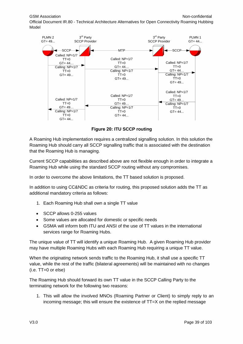
GSM Association Non-confidential
Official Document IR.80 - Technical Architecture Alternatives for Open Connectivity Roaming Hubbing
Model
V3.0 Page 39 of 103
Figure 20: ITU SCCP routing
A Roaming Hub implementation requires a centralized signalling solution. In this solution the
Roaming Hub should carry all SCCP signalling traffic that is associated with the destination
that the Roaming Hub is managing.
Current SCCP capabilities as described above are not flexible enough in order to integrate a
Roaming Hub while using the standard SCCP routing without any compromises.
In order to overcome the above limitations, the TT based solution is proposed.
In addition to using CC&NDC as criteria for routing, this proposed solution adds the TT as
additional mandatory criteria as follows:
1. Each Roaming Hub shall own a single TT value
SCCP allows 0-255 values
Some values are allocated for domestic or specific needs
GSMA will inform both ITU and ANSI of the use of TT values in the international
services range for Roaming Hubs.
The unique value of TT will identify a unique Roaming Hub. A given Roaming Hub provider
may have multiple Roaming Hubs with each Roaming Hub requiring a unique TT value.
When the originating network sends traffic to the Roaming Hub, it shall use a specific TT
value, while the rest of the traffic (bilateral agreements) will be maintained with no changes
(i.e. TT=0 or else)
The Roaming Hub should forward its own TT value in the SCCP Calling Party to the
terminating network for the following two reasons:
1. This will allow the involved MNOs (Roaming Partner or Client) to simply reply to an
incoming message; this will ensure the existence of TT=X on the replied message
PLMN 2
GT= 49...
3rd
Party
SCCP Provider
PLMN 1
GT= 44...
3rd
Party
SCCP Provider
SCCPSCCP MTP
Called: NP=1/7
TT=0
GT= 44…
Calling: NP=1/7
TT=0
GT= 49...
Called: NP=1/7
TT=0
GT= 44…
Calling: NP=1/7
TT=0
GT= 49...
Called: NP=1/7
TT=0
GT= 49…
Calling: NP=1/7
TT=0
GT= 44...
Called: NP=1/7
TT=0
GT= 44…
Calling: NP=1/7
TT=0
GT= 49...
Called: NP=1/7
TT=0
GT= 49…
Calling: NP=1/7
TT=0
GT= 44...
Called: NP=1/7
TT=0
GT= 49…
Calling: NP=1/7
TT=0
GT= 44...
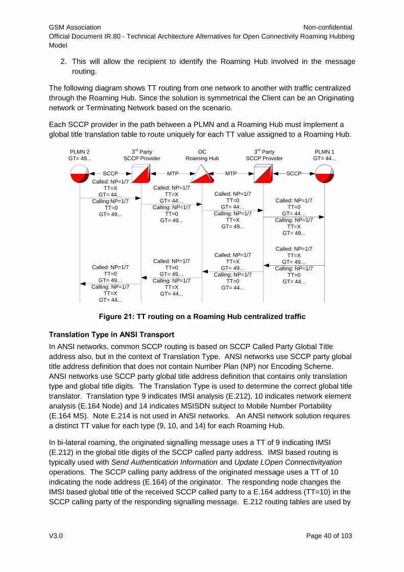
GSM Association Non-confidential
Official Document IR.80 - Technical Architecture Alternatives for Open Connectivity Roaming Hubbing
Model
V3.0 Page 40 of 103
2. This will allow the recipient to identify the Roaming Hub involved in the message
routing.
The following diagram shows TT routing from one network to another with traffic centralized
through the Roaming Hub. Since the solution is symmetrical the Client can be an Originating
network or Terminating Network based on the scenario.
Each SCCP provider in the path between a PLMN and a Roaming Hub must implement a
global title translation table to route uniquely for each TT value assigned to a Roaming Hub.
Figure 21: TT routing on a Roaming Hub centralized traffic
Translation Type in ANSI Transport
In ANSI networks, common SCCP routing is based on SCCP Called Party Global Title
address also, but in the context of Translation Type. ANSI networks use SCCP party global
title address definition that does not contain Number Plan (NP) nor Encoding Scheme.
ANSI networks use SCCP party global title address definition that contains only translation
type and global title digits. The Translation Type is used to determine the correct global title
translator. Translation type 9 indicates IMSI analysis (E.212), 10 indicates network element
analysis (E.164 Node) and 14 indicates MSISDN subject to Mobile Number Portability
(E.164 MS). Note E.214 is not used in ANSI networks. An ANSI network solution requires
a distinct TT value for each type (9, 10, and 14) for each Roaming Hub.
In bi-lateral roaming, the originated signalling message uses a TT of 9 indicating IMSI
(E.212) in the global title digits of the SCCP called party address. IMSI based routing is
typically used with Send Authentication Information and Update LOpen Connectivityation
operations. The SCCP calling party address of the originated message uses a TT of 10
indicating the node address (E.164) of the originator. The responding node changes the
IMSI based global title of the received SCCP called party to a E.164 address (TT=10) in the
SCCP calling party of the responding signalling message. E.212 routing tables are used by
OC
Roaming Hub
MTP MTP
PLMN 2
GT= 49...
3rd
Party
SCCP Provider
PLMN 1
GT= 44...
3rd
Party
SCCP Provider
SCCPSCCP
Called: NP=1/7
TT=X
GT= 44…
Calling:NP=1/7
TT=0
GT= 49...
Called: NP=1/7
TT=X
GT= 49…
Calling: NP=1/7
TT=0
GT= 44...
Called: NP=1/7
TT=0
GT= 44…
Calling: NP=1/7
TT=X
GT= 49...
Called: NP=1/7
TT=0
GT= 49…
Calling: NP=1/7
TT=X
GT= 44...
Called: NP=1/7
TT=X
GT= 44…
Calling: NP=1/7
TT=0
GT= 49...
Called: NP=1/7
TT=0
GT= 44…
Calling: NP=1/7
TT=X
GT= 49...
Called: NP=1/7
TT=X
GT= 49…
Calling: NP=1/7
TT=0
GT= 44...
Called: NP=1/7
TT=0
GT= 49…
Calling: NP=1/7
TT=X
GT= 44...
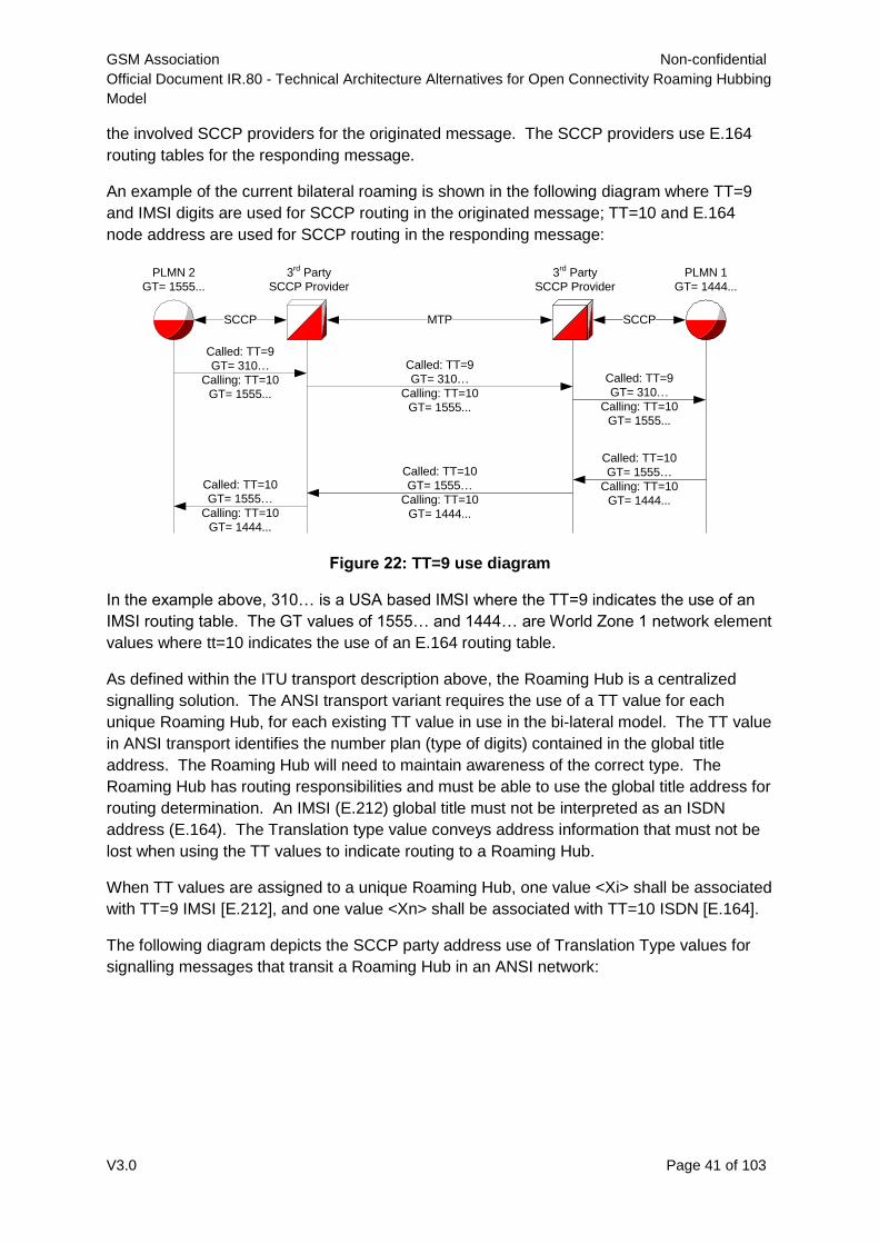
GSM Association Non-confidential
Official Document IR.80 - Technical Architecture Alternatives for Open Connectivity Roaming Hubbing
Model
V3.0 Page 41 of 103
the involved SCCP providers for the originated message. The SCCP providers use E.164
routing tables for the responding message.
An example of the current bilateral roaming is shown in the following diagram where TT=9
and IMSI digits are used for SCCP routing in the originated message; TT=10 and E.164
node address are used for SCCP routing in the responding message:
Figure 22: TT=9 use diagram
In the example above, 310… is a USA based IMSI where the TT=9 indicates the use of an
IMSI routing table. The GT values of 1555… and 1444… are World Zone 1 network element
values where tt=10 indicates the use of an E.164 routing table.
As defined within the ITU transport description above, the Roaming Hub is a centralized
signalling solution. The ANSI transport variant requires the use of a TT value for each
unique Roaming Hub, for each existing TT value in use in the bi-lateral model. The TT value
in ANSI transport identifies the number plan (type of digits) contained in the global title
address. The Roaming Hub will need to maintain awareness of the correct type. The
Roaming Hub has routing responsibilities and must be able to use the global title address for
routing determination. An IMSI (E.212) global title must not be interpreted as an ISDN
address (E.164). The Translation type value conveys address information that must not be
lost when using the TT values to indicate routing to a Roaming Hub.
When TT values are assigned to a unique Roaming Hub, one value <Xi> shall be associated
with TT=9 IMSI [E.212], and one value <Xn> shall be associated with TT=10 ISDN [E.164].
The following diagram depicts the SCCP party address use of Translation Type values for
signalling messages that transit a Roaming Hub in an ANSI network:
PLMN 2
GT= 1555...
3rd
Party
SCCP Provider
PLMN 1
GT= 1444...
3rd
Party
SCCP Provider
SCCPSCCP MTP
Called: TT=9
GT= 310…
Calling: TT=10
GT= 1555...
Called: TT=10
GT= 1555…
Calling: TT=10
GT= 1444...
Called: TT=9
GT= 310…
Calling: TT=10
GT= 1555...
Called: TT=9
GT= 310…
Calling: TT=10
GT= 1555...
Called: TT=10
GT= 1555…
Calling: TT=10
GT= 1444...
Called: TT=10
GT= 1555…
Calling: TT=10
GT= 1444...
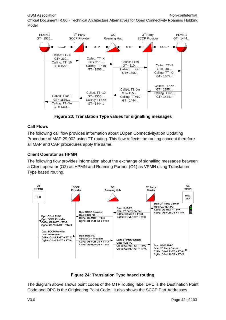
GSM Association Non-confidential
Official Document IR.80 - Technical Architecture Alternatives for Open Connectivity Roaming Hubbing
Model
V3.0 Page 42 of 103
Figure 23: Translation Type values for signalling messages
Call Flows
The following call flow provides information about LOpen Connectivityation Updating
Procedure of MAP 29.002 using TT routing. This flow reflects the routing concept therefore
all MAP and CAP procedures apply the same.
Client Operator as HPMN
The following flow provides information about the exchange of signalling messages between
a Client operator (O2) as HPMN and Roaming Partner (O1) as VPMN using Translation
Type based routing.
Figure 24: Translation Type based routing.
The diagram above shows point codes of the MTP routing label DPC is the Destination Point
Code and OPC is the Originating Point Code. It also shows the SCCP Part Addresses,
PLMN 2
GT= 1555...
3rd
Party
SCCP Provider
PLMN 1
GT= 1444...
3rd
Party
SCCP Provider
SCCPSCCP MTP
Called: TT=Xi
GT= 310…
Calling: TT=10
GT= 1555...
Called: TT=Xn
GT= 1555…
Calling: TT=10
GT= 1444...
Called: TT=9
GT= 310…
Calling: TT=Xn
GT= 1555...
Called: TT=10
GT= 1555…
Calling: TT=Xn
GT= 1444...
OC
Roaming Hub
MTP
Called: TT=Xi
GT= 310…
Calling: TT=10
GT= 1555...
Called: TT=9
GT= 310…
Calling: TT=Xn
GT= 1555...
Called: TT=10
GT= 1555…
Calling: TT=Xn
GT= 1444...
Called: TT=Xn
GT= 1555…
Calling: TT=10
GT= 1444...
HLR
SCCP
Provider
3rd Party
Carrier
MSC
VLR
OC
Roaming Hub
Dpc: 3rd Party Carrier
Opc: O1-VLR-PC
CdPa: O2-MGT + TT=X
CgPa: O1-VLR-GT + TT=0
Dpc: SCCP Provider
Opc: O2-HLR-PC
CdPa: O1-VLR-GT + TT=X
CgPa: O2-HLR-GT + TT=0
Dpc: HUB-PC
Opc: 3rd
Party Carrier
CdPa: O2-MGT + TT=X
CgPa: O1-VLR-GT + TT=0
Dpc: SCCP Provider
Opc: HUB-PC
CdPa: O2-MGT + TT=0
CgPa: O1-VLR-GT + TT=X
Dpc: O2-HLR-PC
Opc: SCCP Provider
CdPa: O2-MGT + TT=0
CgPa: O1-VLR-GT + TT= X
Dpc: HUB-PC
Opc: SCCP Provider
CdPa: O1-VLR-GT + TT=X
CgPa: O2-HLR-GT + TT=0
Dpc: 3rd Party Carrier
Opc: HUB-PC
CdPa: O1-VLR-GT + TT=0
CgPa: O2-HLR-GT + TT=X
Dpc: O1-VLR-PC
Opc: 3rd
Party Carrier
CdPa: O1-VLR-GT + TT=0
CgPa: O2-HLR-GT + TT=X
O1
(VPMN)
O2
(HPMN)
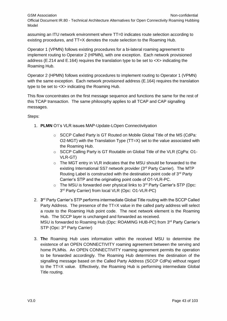
GSM Association Non-confidential
Official Document IR.80 - Technical Architecture Alternatives for Open Connectivity Roaming Hubbing
Model
V3.0 Page 43 of 103
assuming an ITU network environment where TT=0 indicates route selection according to
existing procedures, and TT=X denotes the route selection to the Roaming Hub.
Operator 1 (VPMN) follows existing procedures for a bi-lateral roaming agreement to
implement routing to Operator 2 (HPMN), with one exception. Each network provisioned
address (E.214 and E.164) requires the translation type to be set to <X> indicating the
Roaming Hub.
Operator 2 (HPMN) follows existing procedures to implement routing to Operator 1 (VPMN)
with the same exception. Each network provisioned address (E.164) requires the translation
type to be set to <X> indicating the Roaming Hub.
This flow concentrates on the first message sequence and functions the same for the rest of
this TCAP transaction. The same philosophy applies to all TCAP and CAP signalling
messages.
Steps:
1. PLMN O1’s VLR issues MAP-Update-LOpen Connectivityation
o SCCP Called Party is GT Routed on Mobile Global Title of the MS (CdPa:
O2-MGT) with the Translation Type (TT=X) set to the value associated with
the Roaming Hub.
o SCCP Calling Party is GT Routable on Global Title of the VLR (CgPa: O1-
VLR-GT)
o The MGT entry in VLR indicates that the MSU should be forwarded to the
existing International SS7 network provider (3rd Party Carrier). The MTP
Routing Label is constructed with the destination point code of 3rd Party
Carrier’s STP and the originating point code of O1-VLR-PC.
o The MSU is forwarded over physical links to 3rd Party Carrier’s STP (Dpc:
3rd Party Carrier) from local VLR (Opc: O1-VLR-PC)
2. 3rd Party Carrier’s STP performs intermediate Global Title routing with the SCCP Called
Party Address. The presence of the TT=X value in the called party address will select
a route to the Roaming Hub point code. The next network element is the Roaming
Hub. The SCCP layer is unchanged and forwarded as received.
MSU is forwarded to Roaming Hub (Dpc: ROAMING HUB-PC) from 3rd Party Carrier’s
STP (Opc: 3rd Party Carrier)
3. The Roaming Hub uses information within the received MSU to determine the
existence of an OPEN CONNECTIVITY roaming agreement between the serving and
home PLMNs. An OPEN CONNECTIVITY roaming agreement permits the operation
to be forwarded accordingly. The Roaming Hub determines the destination of the
signalling message based on the Called Party Address (SCCP CdPa) without regard
to the TT=X value. Effectively, the Roaming Hub is performing intermediate Global
Title routing.
GSM Association Non-confidential
Official Document IR.80 - Technical Architecture Alternatives for Open Connectivity Roaming Hubbing
Model
V3.0 Page 44 of 103
The determination provides a point code route to PLMN O2’s chosen SCCP provider. The
SCCP party addresses are changed to reflect the different TT values required when onward
routing the MSU. The called party address TT value is set to 0 (ITU network), and the
calling party address TT value is set to X, the value for TT routing to the Roaming Hub.
A routing label is constructed for the MSU, destined to the SCCP Provider. The TCAP
contents are not changed and forwarded as received with repackaging of the routing label
origination and destination point codes, and the SCCP changes described above.
MSU is forwarded to SCCP Provider’s STP (Dpc: SCCP Provider) from Roaming Hub (Opc:
Roaming Hub-PC)
4. SCCP Provider’s STP is the MTP addressed entity, so it performs intermediate (or final)
Global Title routing with the SCCP Called Party Address and determines that the next
network element is the PLMN O2’s HLR. The SCCP layer is unchanged and forwarded
as received.
MSU is forwarded to O2’s HLR (Dpc: O2-HLR-PC) from SCCP Provider’s STP (Opc:
SCCP Provider)
5. PLMN O2’s HLR responds to the MSU, placing the received SCCP calling party
address in the SCCP called party address on the outbound MSU. The SCCP calling
party address of the outbound MSU is set to the global title value of the network element
issuing the MSU (PLMN O2’s HLR). Depending upon the actual implementation of the
network element, it may reconstruct the SCCP called party address from routing
information associated with the far end global title address digits. The network element
will need the routing information to the far end GT address to indicate the use of a TT
value other than the default of 0. Specifically, the address must be constructed with a
TT value of X.
Note: If PLNM O2’s network uses an internal STP with SCCP routing services, the far end
addresses can be configured to perform a global title change to the SCCP called party
address by setting the TT=X.
MSU is forwarded to SCCP Provider (DPC: SCCP Provider) from O2’s HLR (OPC: O2-HLR-
PC)
6. SCCP Provider’s STP performs intermediate Global Title routing with the SCCP Called
Party Address. The presence of the TT=X value in the called party address will select
a route to the Roaming Hub point code. The next network element is the Roaming
Hub. The SCCP layer is unchanged and forwarded as received.
MSU is forwarded to Roaming Hub (Dpc: ROAMING HUB-PC) from SCCP Provider’s
STP (Opc: SCCP Provider).
7. The Roaming Hub performs an intermediate global title translation using the SCCP
Called Party Address digits without the effect of the TT=X. The SCCP party addresses
are changed to reflect the different TT values required when onward routing the MSU.
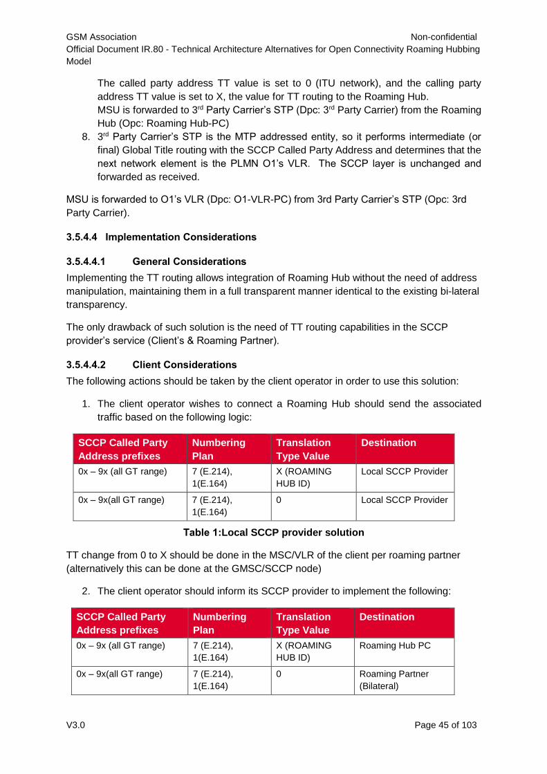
GSM Association Non-confidential
Official Document IR.80 - Technical Architecture Alternatives for Open Connectivity Roaming Hubbing
Model
V3.0 Page 45 of 103
The called party address TT value is set to 0 (ITU network), and the calling party
address TT value is set to X, the value for TT routing to the Roaming Hub.
MSU is forwarded to 3rd Party Carrier’s STP (Dpc: 3rd Party Carrier) from the Roaming
Hub (Opc: Roaming Hub-PC)
8. 3rd Party Carrier’s STP is the MTP addressed entity, so it performs intermediate (or
final) Global Title routing with the SCCP Called Party Address and determines that the
next network element is the PLMN O1’s VLR. The SCCP layer is unchanged and
forwarded as received.
MSU is forwarded to O1’s VLR (Dpc: O1-VLR-PC) from 3rd Party Carrier’s STP (Opc: 3rd
Party Carrier).
3.5.4.4 Implementation Considerations
3.5.4.4.1 General Considerations
Implementing the TT routing allows integration of Roaming Hub without the need of address
manipulation, maintaining them in a full transparent manner identical to the existing bi-lateral
transparency.
The only drawback of such solution is the need of TT routing capabilities in the SCCP
provider’s service (Client’s & Roaming Partner).
3.5.4.4.2 Client Considerations
The following actions should be taken by the client operator in order to use this solution:
1. The client operator wishes to connect a Roaming Hub should send the associated
traffic based on the following logic:
SCCP Called Party
Address prefixes
Numbering
Plan
Translation
Type Value
Destination
0x – 9x (all GT range) 7 (E.214),
1(E.164)
X (ROAMING
HUB ID)
Local SCCP Provider
0x – 9x(all GT range) 7 (E.214),
1(E.164)
0 Local SCCP Provider
Table 1:Local SCCP provider solution
TT change from 0 to X should be done in the MSC/VLR of the client per roaming partner
(alternatively this can be done at the GMSC/SCCP node)
2. The client operator should inform its SCCP provider to implement the following:
SCCP Called Party
Address prefixes
Numbering
Plan
Translation
Type Value
Destination
0x – 9x (all GT range) 7 (E.214),
1(E.164)
X (ROAMING
HUB ID)
Roaming Hub PC
0x – 9x(all GT range) 7 (E.214),
1(E.164)
0 Roaming Partner
(Bilateral)
GSM Association Non-confidential
Official Document IR.80 - Technical Architecture Alternatives for Open Connectivity Roaming Hubbing
Model
V3.0 Page 46 of 103
Table 2: Roaming Hub and Bilateral solution
3. The client operator should ask its SCCP provider to ensure that the TT = X is
maintained in the onward MTP3 rout sets towards the Roaming Hub (if any).
For further details please refer to Call flow section Error! Reference source not
found.
3.4.3.4.3 Roaming Partner Considerations
Roaming partner considerations are the same as the client ones as detailed in section
3.5.4.4.4 PROs and CONs
PROs
1. Full Transparency without any address changes
2. No Coverage issues – uses SCCP routing capabilities and allows in-direct routing
3. No implications on:
GSM service such as: Voice, SMS, MMS, CAMEL, GPRS, 3G (DATA & VT), USSD,
SS, VHE (SC, Dialling Corrections), VPN, SOR, WSMS etc.
3rd party service in the network such as: SMS Anti-Fraud/Spam, Voice Anti-Fraud,
Real-time monitoring systems, Reporting etc.
Billing systems
Each Roaming Hub owns an ID – TT value per Roaming Hub
TT routing allows the MNOs involved to identify with real-time monitoring the HLR,
VLR, and a Roaming Hub identity.
TT routing allows the MNO to control and separate SMS I/W from SMS Roaming
The SMSC shall send SMS I/W traffic (MOForwardSM) using TT=0
While rest of traffic (from VLR/HLR/SCP etc.) will be sent using TT=X
CONs
1. Requires TT translation capabilities at the MNO (Client or Roaming Partner) side
(commonly used at the VLR/MSC/GSMC)
2. Requires TT routing criteria at the SCCP provider side
3. Requires TT manipulation at the Roaming Partner side
4. Network elements at either end of a relationship where TT is used may not be able to
understand, distinguish or set TT.
5. Only ITU SCCP layer sets the Translation Type to 0. ANSI (used in World Zone 1)
makes explicit use of Translation Type to denote the difference between an IMSI, node
address, and MSISDN.
The following extract from section 6.1.3.1 Introduction [of SCCP addressing within Use of
SCCP] in 3GPP TS 29.002 version 4.9.0 Release 4 document states:
“If ANSI T1.112 SCCP is used, the format and coding of address parameters carried by the
SCCP for that purpose shall comply with ANSI specification T1.112 with the following
restrictions:
1) Intra-PLMN addressing
GSM Association Non-confidential
Official Document IR.80 - Technical Architecture Alternatives for Open Connectivity Roaming Hubbing
Model
V3.0 Page 47 of 103
For communication between entities within the same PLMN, a MAP SSN shall always be
included in the called and calling party addresses. All other aspects of SCCP addressing are
network specific.
2) Inter-PLMN addressing
a) Called Party Address
- SSN indicator = 1 (MAP SSN always included);
- Global title indicator = 0010 (Global title includes translation type);
- the Translation Type (TT) field will be coded as follows:
TT = 9, if IMSI is included;
TT = 14, if MSISDN is included;
Or TT = 10, if Network Element is included.
(If TT=10, then Number Portability GTT is not invoked,
if TT=14, then Number Portability GTT may be invoked).
- Routing indicator = 0 (Routing on global title);”
3.5.5 Alternative 4: Alias GT
Brief Synopsis
Alias GT (AGT) is proposed for the purpose of achieving an easy way to implement Roaming
Hub method. It solves the obstacle found with the GT prefix method and the maximum
length of 15 digits for E.164 addresses.
Introduction of AGT addresses several concerns that have been highlighted with GT
Modification methods. AGT stands for a GT that is only valid when roaming via Roaming
Hub(s). AGT has a unique mapping to real GT and uniquely identifies any network node that
is addressable by GT. The Alias GT is structured in such a way that the concerned operator,
node and the Roaming Hub can be identified for signaling between the MNO and Roaming
Hub. AGT method enables same level of AAA as required for Steering Of Roaming and
Screening/BlOpen Connectivityking of SMSC GTs and lOpen Connectivityation based
services. The introduction of the AGT will not have any adverse impact on the MNO’s exiting
roaming implementation process.
This model provides global roaming to client operators with minimum effort in both client
operators and roaming partners. Only Roaming Hub number ranges will need to be
configured. In case the Roaming Hub is a mobile network, all its roaming partners and their
IGPs will already have those ranges configured.
3.5.5.1 Architecture Description
AGT based Roaming Hub architecture involves assigning an Alias GT to each network node
in a client MNO network. The AGT is only valid when roaming through an Open Connectivity
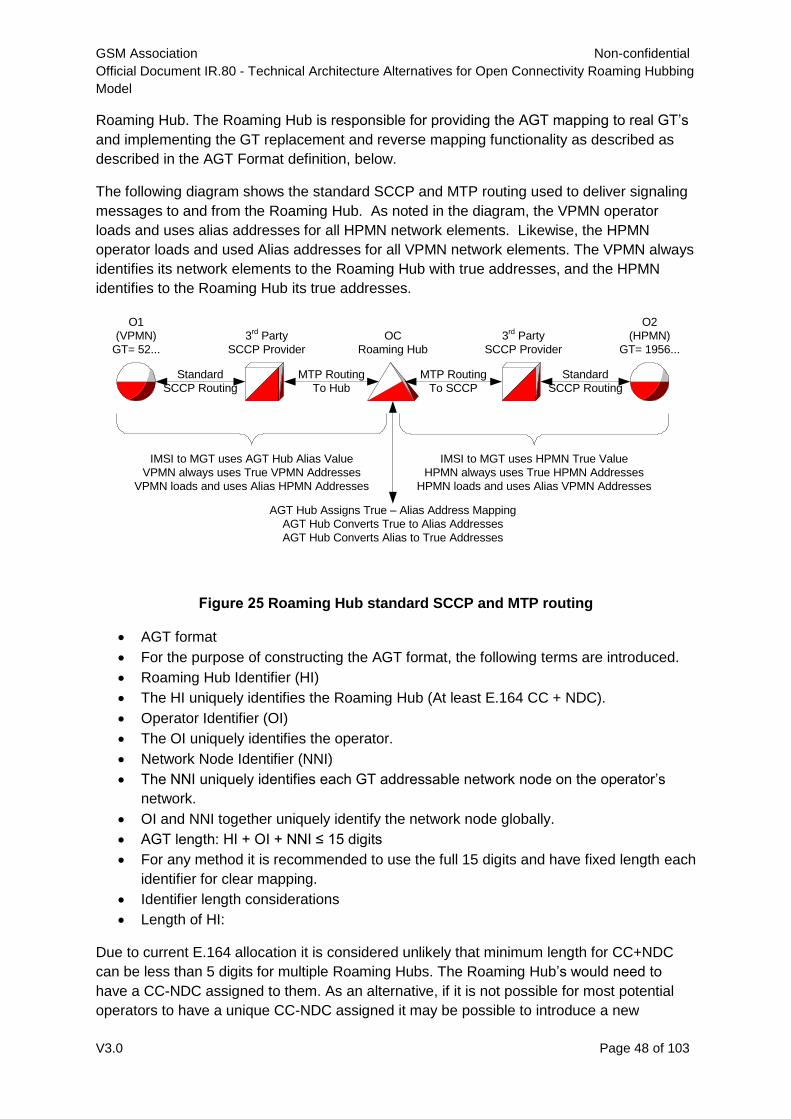
GSM Association Non-confidential
Official Document IR.80 - Technical Architecture Alternatives for Open Connectivity Roaming Hubbing
Model
V3.0 Page 48 of 103
Roaming Hub. The Roaming Hub is responsible for providing the AGT mapping to real GT’s
and implementing the GT replacement and reverse mapping functionality as described as
described in the AGT Format definition, below.
The following diagram shows the standard SCCP and MTP routing used to deliver signaling
messages to and from the Roaming Hub. As noted in the diagram, the VPMN operator
loads and uses alias addresses for all HPMN network elements. Likewise, the HPMN
operator loads and used Alias addresses for all VPMN network elements. The VPMN always
identifies its network elements to the Roaming Hub with true addresses, and the HPMN
identifies to the Roaming Hub its true addresses.
Figure 25 Roaming Hub standard SCCP and MTP routing
AGT format
For the purpose of constructing the AGT format, the following terms are introduced.
Roaming Hub Identifier (HI)
The HI uniquely identifies the Roaming Hub (At least E.164 CC + NDC).
Operator Identifier (OI)
The OI uniquely identifies the operator.
Network Node Identifier (NNI)
The NNI uniquely identifies each GT addressable network node on the operator’s
network.
OI and NNI together uniquely identify the network node globally.
AGT length: HI + OI + NNI ≤ 15 digits
For any method it is recommended to use the full 15 digits and have fixed length each
identifier for clear mapping.
Identifier length considerations
Length of HI:
Due to current E.164 allocation it is considered unlikely that minimum length for CC+NDC
can be less than 5 digits for multiple Roaming Hubs. The Roaming Hub’s would need to
have a CC-NDC assigned to them. As an alternative, if it is not possible for most potential
operators to have a unique CC-NDC assigned it may be possible to introduce a new
OC
Roaming Hub
MTP Routing
To Hub
MTP Routing
To SCCP
O1
(VPMN)
GT= 52...
3rd
Party
SCCP Provider
O2
(HPMN)
GT= 1956...
3rd
Party
SCCP Provider
Standard
SCCP Routing
Standard
SCCP Routing
IMSI to MGT uses AGT Hub Alias Value
VPMN always uses True VPMN Addresses
VPMN loads and uses Alias HPMN Addresses
IMSI to MGT uses HPMN True Value
HPMN always uses True HPMN Addresses
HPMN loads and uses Alias VPMN Addresses
AGT Hub Assigns True – Alias Address Mapping
AGT Hub Converts True to Alias Addresses
AGT Hub Converts Alias to True Addresses
GSM Association Non-confidential
Official Document IR.80 - Technical Architecture Alternatives for Open Connectivity Roaming Hubbing
Model
V3.0 Page 49 of 103
CC+NDC specifically for Roaming Hubs (and SMS Roaming Hubs). At least as an
alternative for Roaming Hubs that may not have access to large number ranges in their
country.
E.g. the CC 888 (currently reserved by ITU for future global service) could be used.
Assuming total 5 digits it would allow for 99 Roaming Hubs, in addition current CC+NDC
ranges.
Note: It is to be noted that a separate CC and NDC is NOT a requirement for the AGT
method
Length of OI:
Using existing OI like CC-NDC or CC-MNC could be beneficial, but may also be
considered as limiting for the intended purpose.
Currently there are ~900 operators, likely to break the 1K barrier soon. Therefore at
least 4 digits are needed for OI.
Length of NNI:
It is known that networks have over 1000 GT addressable nodes on their networks
and it is possible that some have over 10000.
Example Options for AGT construction:
HI – OI - NNI
7 – 4 – 4
7 – 5 – 3
Many Roaming Hubs can get 7 digit CC-NDC values. New CC allocation from ITU not strictly
required.
A Roaming Hub service provider could allocate more than one OI to operators with more
than 999 or 9999 NNIs
Since the use of Alias Global Title is limited to the Operator to – Roaming Hub interface, the
exact format of the Alias Global Title is a between the Roaming Hub Service Provider and
the operator. However, since the AGT values will be seen externally by any entity that may
query an HLR for a mobile station’s location, the value should be standardized.
It is recommended that one AGT format with fixed HI,OI,NNI be decided so as to ensure a
consistent implementation on Roaming Hubs using the AGT method.
Example:
[6-5-4] format: 628745-01033-0142
[7-4-4] format: 3543357-0004-0040
[5-5-5] format: 88808-00002-00087
AGT Roaming Hub will set up a method to publish the mapping between Real and modified
GTs as i.e. through a secure internet web page. User and password will be distributed by the
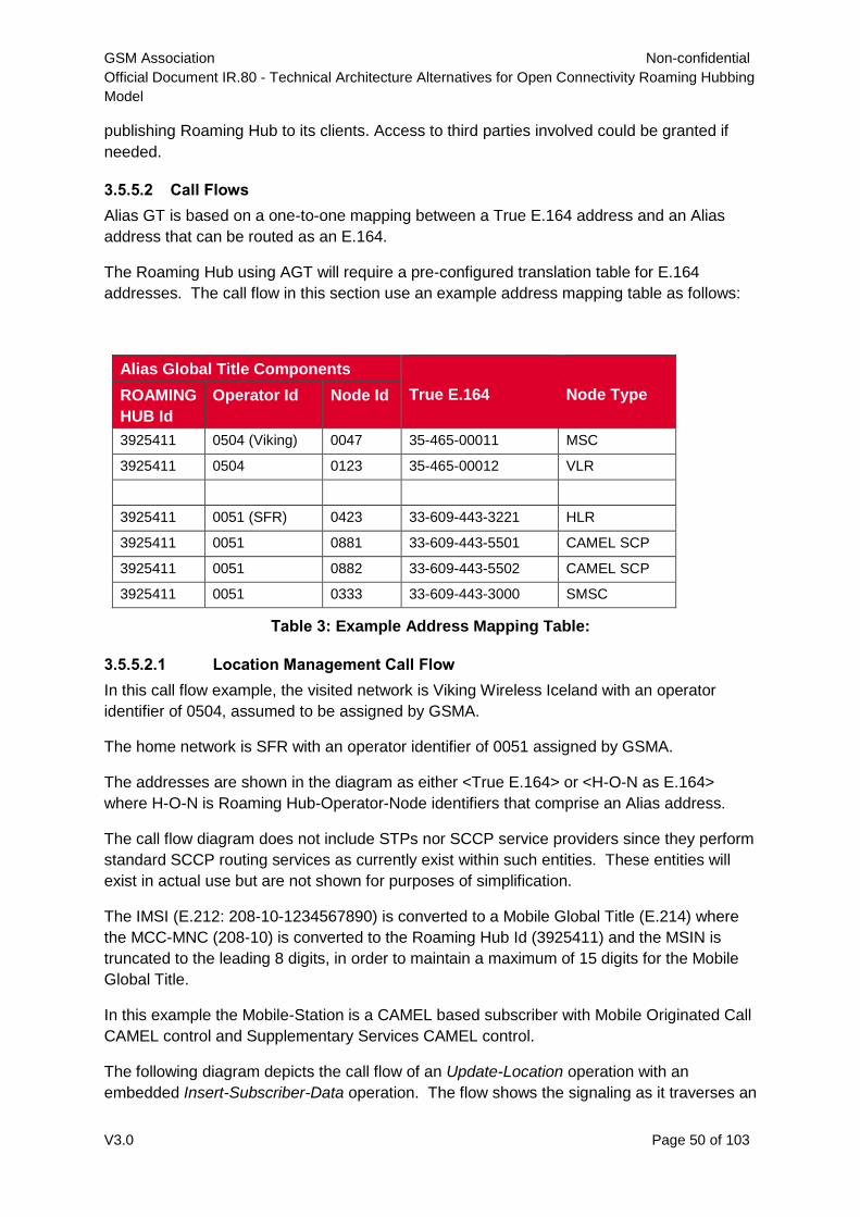
GSM Association Non-confidential
Official Document IR.80 - Technical Architecture Alternatives for Open Connectivity Roaming Hubbing
Model
V3.0 Page 50 of 103
publishing Roaming Hub to its clients. Access to third parties involved could be granted if
needed.
3.5.5.2 Call Flows
Alias GT is based on a one-to-one mapping between a True E.164 address and an Alias
address that can be routed as an E.164.
The Roaming Hub using AGT will require a pre-configured translation table for E.164
addresses. The call flow in this section use an example address mapping table as follows:
Alias Global Title Components
True E.164
Node Type ROAMING
HUB Id
Operator Id Node Id
3925411 0504 (Viking) 0047 35-465-00011 MSC
3925411 0504 0123 35-465-00012 VLR
3925411 0051 (SFR) 0423 33-609-443-3221 HLR
3925411 0051 0881 33-609-443-5501 CAMEL SCP
3925411 0051 0882 33-609-443-5502 CAMEL SCP
3925411 0051 0333 33-609-443-3000 SMSC
Table 3: Example Address Mapping Table:
3.5.5.2.1 Location Management Call Flow
In this call flow example, the visited network is Viking Wireless Iceland with an operator
identifier of 0504, assumed to be assigned by GSMA.
The home network is SFR with an operator identifier of 0051 assigned by GSMA.
The addresses are shown in the diagram as either <True E.164> or <H-O-N as E.164>
where H-O-N is Roaming Hub-Operator-Node identifiers that comprise an Alias address.
The call flow diagram does not include STPs nor SCCP service providers since they perform
standard SCCP routing services as currently exist within such entities. These entities will
exist in actual use but are not shown for purposes of simplification.
The IMSI (E.212: 208-10-1234567890) is converted to a Mobile Global Title (E.214) where
the MCC-MNC (208-10) is converted to the Roaming Hub Id (3925411) and the MSIN is
truncated to the leading 8 digits, in order to maintain a maximum of 15 digits for the Mobile
Global Title.
In this example the Mobile-Station is a CAMEL based subscriber with Mobile Originated Call
CAMEL control and Supplementary Services CAMEL control.
The following diagram depicts the call flow of an Update-Location operation with an
embedded Insert-Subscriber-Data operation. The flow shows the signaling as it traverses an
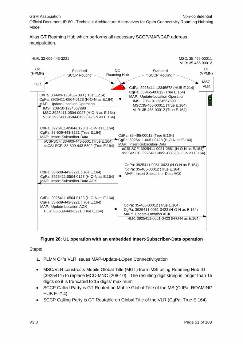
GSM Association Non-confidential
Official Document IR.80 - Technical Architecture Alternatives for Open Connectivity Roaming Hubbing
Model
V3.0 Page 51 of 103
Alias GT Roaming Hub which performs all necessary SCCP/MAP/CAP address
manipulation.
Figure 26: UL operation with an embedded Insert-Subscriber-Data operation
Steps:
1. PLMN O1’s VLR issues MAP-Update-LOpen Connectivityation
MSC/VLR constructs Mobile Global Title (MGT) from IMSI using Roaming Hub ID
(3925411) to replace MCC-MNC (208-10). The resulting digit string is longer than 15
digits so it is truncated to 15 digits’ maximum.
SCCP Called Party is GT Routed on Mobile Global Title of the MS (CdPa: ROAMING
HUB E.214)
SCCP Calling Party is GT Routable on Global Title of the VLR (CgPa: True E.164)
HLRMSC
VLR
OC
Roaming Hub
CdPa: 3925411-12345678 (HUB E.214)
CgPa: 35-465-00012 (True E.164)
MAP: Update-Location Operation
IMSI: 208-10-1234567890
MSC:35-465-00011 (True E.164)
VLR: 35-465-00012 (True E.164)
O1
(VPMN)
O2
(HPMN)
MSC: 35-465-00011
VLR: 35-465-00012
Standard
SCCP Routing
Standard
SCCP Routing
CdPa: 33-609-1234567890 (True E.214)
CgPa: 3925411-0504-0123 (H-O-N as E.164)
MAP: Update-Location Operation
IMSI: 208-10-1234567890
MSC:3925411-0504-0047 (H-O-N as E.164)
VLR: 3925411-0504-0123 (H-O-N as E.164)
CdPa: 3925411-0504-0123 (H-O-N as E.164)
CgPa: 33-609-443-3221 (True E.164)
MAP: Insert-Subscriber-Data
oCSI-SCF: 33-609-443-5501 (True E.164)
ssCSI-SCF: 33-609-443-5502 (True E.164)
HLR: 33-609-443-3221
CdPa: 35-465-00012 (True E.164)
CgPa: 3925411-0051-0423 (H-O-N as E.164)
MAP: Insert-Subscriber-Data
oCSI-SCF: 3925411-0051-0881 (H-O-N as E.164)
ssCSI-SCF: 3925411-0051-0882 (H-O-N as E.164)
CdPa: 3925411-0051-0423 (H-O-N as E.164)
CgPa: 35-465-00012 (True E.164)
MAP: Insert-Subscriber-Data ACKCdPa: 33-609-443-3221 (True E.164)
CgPa: 3925411-0504-0123 (H-O-N as E.164)
MAP: Insert-Subscriber-Data ACK
CdPa: 3925411-0504-0123 (H-O-N as E.164)
CgPa: 33-609-443-3221 (True E.164)
MAP: Update-Location ACK
HLR: 33-609-443-3221 (True E.164)
CdPa: 35-465-00012 (True E.164)
CgPa: 3925411-0051-0423 (H-O-N as E.164)
MAP: Update-Location ACK
HLR: 3925411-0051-0423 (H-O-N as E.164)
GSM Association Non-confidential
Official Document IR.80 - Technical Architecture Alternatives for Open Connectivity Roaming Hubbing
Model
V3.0 Page 52 of 103
The GT entry indicates that the MSU should be forwarded through the normal SCCP
service providers (not shown) and SS7 network providers (not shown) which route the
MSU to the Roaming Hub.
The Roaming Hub has responsibility to map various addresses from Roaming Hub Alias
values to True values and from True values to alias values.
The SCCP Called Party address to be routed forward must become a true E.214 based on
the IMSI. The received called party address is a Roaming Hub based E.214 MGT with
information loss. The IMSI value from the TCAP package is used to construct a correct
MGT value (True E.214) in the outbound MSU.
The SCCP Calling Party Address to be routed forward must become an Alias GT of the True
VLR address. The True VLR address is located in an address mapping table, and the one-
to-one matching alias value is substituted in the outbound MSU. The Alias value is a
Roaming Hub-Operator-Node (H-O-N) value treated as an E.164 address.
The TCAP package is opened and each E.164 network element address (True E.164) within
the package is located and substituted with its matching Alias H-O-N as E.164 value. In this
particular case, the E.164 network element addresses present are MSC and VLR.
The resulting outbound MSU’s SCCP layer has a True E.214 called party address, an Alias
GT calling party address. The MSU’s TCAP layer has an Alias for the MSC address, and an
Alias for the VLR address.
The MSU is forwarded through the normal SCCP service providers (not shown) and SS7
network providers (not shown) which route the MSU to the Home operator’s HLR.
2. PLMN O2’s HLR receives the MSU, stores the alias MSC and VLR addresses for the
given IMSI, and responds with an Insert-Subscriber-Data operation. The HLR indicates
that the IMSI is subject to CAMEL control by providing Originating CAMEL Subscription
Information (OCSI) and supplementary services CAMEL Subscription Information
(ssCSI) in the subscriber data. The CAMEL subscription information contains the
E.164 address of the CAMEL gsmSCF (SCP) in True E.164 form.
The responding MSU’s SCCP called party address is reflected from the original calling party
address (Alias GT of the originating VLR). The calling party address is set to the HLR’s True
E.164 address.
The MSU is forwarded through the normal SCCP service providers (not shown) and SS7
network providers (not shown) which route the MSU to the Roaming Hub.
3. The Roaming Hub handles the responding MSU by mapping various addresses from
Roaming Hub Alias values to True values and from True values to Alias values.
The received SCCP called party address is an Alias GT E.164 of the True VLR. The Alias
E.164 VLR address is located in an address mapping table and the matching True E.164
VLR address is substituted in the outbound MSU.
GSM Association Non-confidential
Official Document IR.80 - Technical Architecture Alternatives for Open Connectivity Roaming Hubbing
Model
V3.0 Page 53 of 103
The received SCCP calling part address is a True E.164 HLR address which is substituted
with its matching Alias GT address from an address mapping table.
The TCAP package is opened and each E.164 network element address (True E.164) within
the package is located and substituted with its matching Alias H-O-N as E.164 value. In this
particular case, the E.164 network element addresses present are gsmSCF addresses
within the two CAMEL subscription information parameters (OCSI and ssCSI)
The resulting outbound MSU’s SCCP layer has a True E.164 called party address, an Alias
GT calling party address. The MSU’s TCAP layer has an Alias for the OCSI gsmSCF
address, and an Alias for the ssCSI gsmSCF address.
The MSU is forwarded through the normal SCCP service providers (not shown) and SS7
network providers (not shown) which route the MSU to the visited operator’s VLR.
4. PLMN O1’s VLR accepts and retains the subscriber data and responds with an
acknowledgement to the Insert-Subscriber-Data operation.
The resulting outbound MSU has the SCCP party addresses reversed from the received
MSU. The received SCCP called party address becomes the outbound calling party address
and the received calling party address become the outbound MSU’s called party address.
The called party address is an Alias GT of PLMN O2’s HLR.
The MSU is forwarded through the normal SCCP service providers (not shown) and SS7
network providers (not shown) which route the MSU to the Roaming Hub.
5. The Roaming Hub relays the received MSU from the O1’s VLR to O2’s HLR. The
SCCP addresses are modified from Alias GT of HLR to True HLR, and True VLR to
Alias GT of VLR.
The Roaming Hub inspects the contents of the TCAP and finds no addresses that require
True-Alias mapping.
The MSU is forwarded through the normal SCCP service providers (not shown) and SS7
network providers (not shown) which route the MSU to the Home operator’s HLR.
6. PLMN O2’s HLR receives the acknowledgement to the Insert-Subscriber-Data
operation, determines that no other intermediate operations are required and
constructs a response to the original Update-LOpen Connectivityation operation.
The result of the Update-LOpen Connectivityation contains the HLR E.164 address as a
mandatory parameter when the operation is successful.
The resulting outbound MSU has the SCCP party addresses reversed from the received
MSU. The received SCCP called party address becomes the outbound calling party address
and the received calling party address become the outbound MSU’s called party address.
The called party address is an Alias GT of PLMN O1’s VLR.
The MSU is forwarded through the normal SCCP service providers (not shown) and SS7
network providers (not shown) which route the MSU to the Roaming Hub.
GSM Association Non-confidential
Official Document IR.80 - Technical Architecture Alternatives for Open Connectivity Roaming Hubbing
Model
V3.0 Page 54 of 103
7. The Roaming Hub relays the result of the Update-LOpen Connectivityation operation
from O2’s HLR to O1’s VLR. The SCCP addresses are modified from True E.164 of
HLR to Alias GT of HLR and from Alias GT of VLR to True E.164 of VLR.
The Roaming Hub opens the TCAP package, determines the True HLR E.164 in the result
and substitutes its Alias GT address based on the matching entry in an address mapping
table.
The MSU is forwarded through the normal SCCP service providers (not shown) and SS7
network providers (not shown) which route the MSU to the visited operator’s VLR. The VLR
completes the transaction and retains the Alias HLR address in association with the newly
attached IMSI.
3.5.5.2.2 Mobile Originated SMS
3.5.5.2.3 VPMN loading SMSC Alias GT Addresses
True E.164 SMSC Addresses are programmed on SIM cards. The True E.164 SMSC
address is sent to the serving MSC as the Destination Address (SM-RP-DA) over the air
interface as part of a SUBMIT-SM request. The SUBMIT-SM request becomes a
MO_FORWARD_SM from the serving MSC to the destination SMSC in the application
context of a ShortMsgMO-Relay.
PLMN O1 (VPMN) must set up a mechanism to ensure the proper handling of
MO_Forward_SM. Roaming Hub is responsible to provide the VPMN with the mechanism.
3.5.5.3 Implementation Considerations
3.5.5.3.1 General Considerations:
All AGT compliant Roaming Hubs need to have CC-NDC of 7 digits to be used as
Roaming Hub ID.
Roaming Hubs need to maintain the GT-AGT mapping and implement the logic for
GT replacement and reverse lookup
All network nodes in IR21 for operators using Roaming Hub based roaming need to
have a corresponding AGT
All value added roaming service implemented at the PLMN that rely on GT will need
to consider AGT as the network node GT
3.5.5.3.2 Client Considerations
3.5.5.3.2.1 As HPMN
As HPLMN the client operator will need to consider the following:
The only GT maintenance needed on the roaming partner side will be for the
Roaming Hub’s AGTs.
For implementation of Steering of Roaming and other Value added services reliant on
GT availability, AGT will identify the visited network range/node instead of the real
GT.
GSM Association Non-confidential
Official Document IR.80 - Technical Architecture Alternatives for Open Connectivity Roaming Hubbing
Model
V3.0 Page 55 of 103
3.5.5.3.2.2 As VPMN
Client MNOs will be asked to implement IMSI ranges from those Roaming Hub’s
clients they would like to receive roamers from. All these IMSI ranges will be
translated into a single Roaming Hub MGT for minimum GT O&M on the roaming
partner side. AGTs will have to be configured instead of the real ones in GT-based
services.
To ensure centralized signaling through the Roaming Hub the VPLMN will perform
GT translation on the HPLMN SMSC address to MNO-AGT for SMSC. This is
required as the SIM cards from HPLMN need to have the same SMSC address for
Roaming Hub based and bilateral roaming. If the VPLN cannot perform this GT
translation, the VPLMN could route the SMSC address directly toward the Roaming
Hub.
3.5.5.3.3 Roaming Partner Considerations
3.5.5.3.3.1 As HPMN
For implementation of Steering of Roaming and other Value added services reliant on
GT availability, AGT will identify the visited network range/node instead of the real
GT.
3.5.5.3.3.2 As VPMN
E212-E214 Translation will be performed as IMSI Roaming Hub MGT
To ensure centralized signaling through the Roaming Hub the VPLMN will perform
GT translation on the HPLMN SMSC address to MNO-AGT for SMSC. This is
required as the SIM cards from HPLMN need to have the same SMSC address for
Roaming Hub based and bilateral roaming. If VPLN cannot perform this GT
translation VPLMN could route the SMSC address directly toward the Roaming Hub.
3.5.5.4 PROs and CONs
PROs:
The splitting of Roaming Hub traffic and bilateral agreements traffic is solved by the
IMSI to MGT translation at the VPMN without the need of any further analysis.
Ensures Centralized signaling through the Roaming Hubs
No impact on GSM services like USSD, SOR, and CAMEL etc.
Full transparency for the clients and indirect transparency for the MNOs.
Roaming Hub provider does not have to be a SCCP provider. Allows for use of
existing SCCP network without any changes at the SCCP provider level.
This solution can be up and running in a very short term.
CONs
Intermediate GT translation at the operator level required for SMS-MO.
Third party systems (SOR, SMS Antifraud, CAMEL Billing etc.) will need to know the
Alias GTs assigned to all network nodes. This needs to be addressed at the
process/implementation level and is not a limitation in itself.
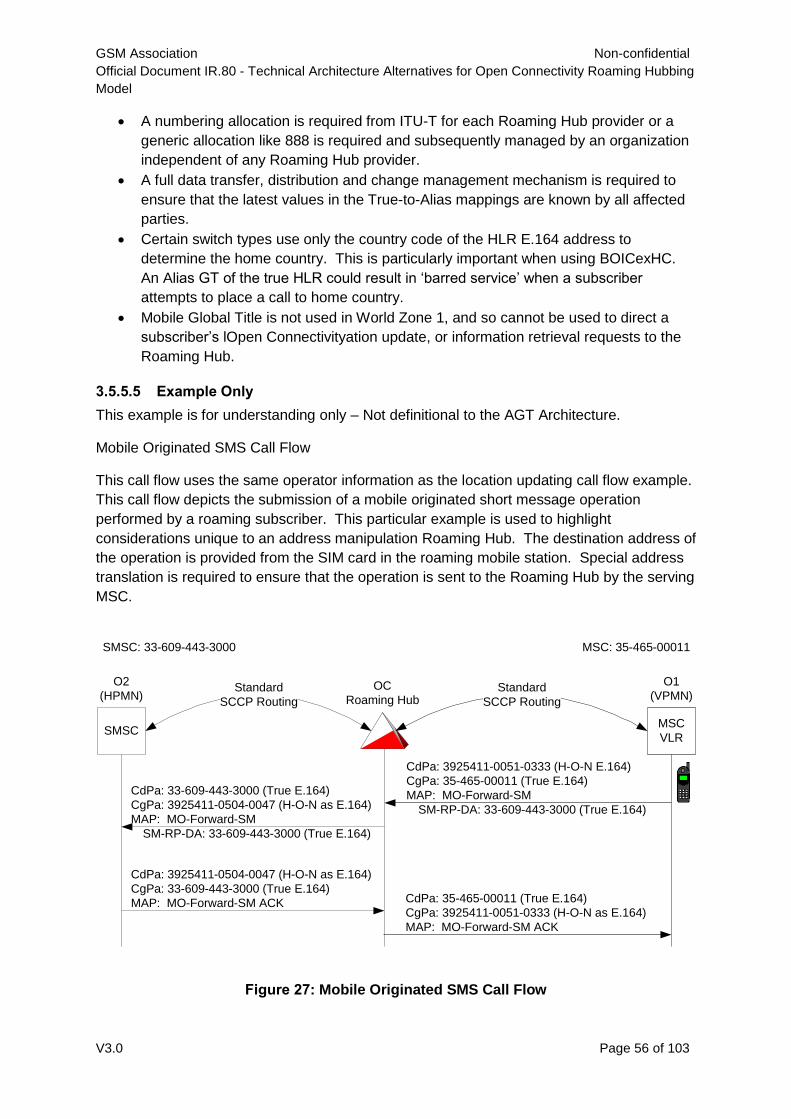
GSM Association Non-confidential
Official Document IR.80 - Technical Architecture Alternatives for Open Connectivity Roaming Hubbing
Model
V3.0 Page 56 of 103
A numbering allocation is required from ITU-T for each Roaming Hub provider or a
generic allocation like 888 is required and subsequently managed by an organization
independent of any Roaming Hub provider.
A full data transfer, distribution and change management mechanism is required to
ensure that the latest values in the True-to-Alias mappings are known by all affected
parties.
Certain switch types use only the country code of the HLR E.164 address to
determine the home country. This is particularly important when using BOICexHC.
An Alias GT of the true HLR could result in ‘barred service’ when a subscriber
attempts to place a call to home country.
Mobile Global Title is not used in World Zone 1, and so cannot be used to direct a
subscriber’s lOpen Connectivityation update, or information retrieval requests to the
Roaming Hub.
3.5.5.5 Example Only
This example is for understanding only – Not definitional to the AGT Architecture.
Mobile Originated SMS Call Flow
This call flow uses the same operator information as the location updating call flow example.
This call flow depicts the submission of a mobile originated short message operation
performed by a roaming subscriber. This particular example is used to highlight
considerations unique to an address manipulation Roaming Hub. The destination address of
the operation is provided from the SIM card in the roaming mobile station. Special address
translation is required to ensure that the operation is sent to the Roaming Hub by the serving
MSC.
Figure 27: Mobile Originated SMS Call Flow
SMSCMSC
VLR
OC
Roaming Hub
CdPa: 3925411-0051-0333 (H-O-N E.164)
CgPa: 35-465-00011 (True E.164)
MAP: MO-Forward-SM
SM-RP-DA: 33-609-443-3000 (True E.164)
O1
(VPMN)
O2
(HPMN)
MSC: 35-465-00011
Standard
SCCP Routing
Standard
SCCP Routing
CdPa: 33-609-443-3000 (True E.164)
CgPa: 3925411-0504-0047 (H-O-N as E.164)
MAP: MO-Forward-SM
SM-RP-DA: 33-609-443-3000 (True E.164)
CdPa: 3925411-0504-0047 (H-O-N as E.164)
CgPa: 33-609-443-3000 (True E.164)
MAP: MO-Forward-SM ACK
SMSC: 33-609-443-3000
CdPa: 35-465-00011 (True E.164)
CgPa: 3925411-0051-0333 (H-O-N as E.164)
MAP: MO-Forward-SM ACK
GSM Association Non-confidential
Official Document IR.80 - Technical Architecture Alternatives for Open Connectivity Roaming Hubbing
Model
V3.0 Page 57 of 103
Steps:
1) PLMN O1’s MSC issues MAP-MO-Forward-SM.
MSC performs GT translation of the True E.164 SMSC address to the pre-configured
Alias GT E.164 address of the SMSC.
SCCP Called Party Address is GT routed on Alias GT of SMSC (CdPa: H-O-N
SMSC).
SCCP calling Party Address is GT routable on the True E.164 address of the MSC
(CgPa: True E.164 MSC).
The GT entry indicates that the MSU should be forwarded through the normal SCCP
service providers (not shown) and SS7 network providers (not shown) which route the
MSU to the Roaming Hub.
2) The Roaming Hub has responsibility to map various addresses from Roaming Hub Alias values to True values and from True values to alias values.
The SCCP Called Party Address to be routed forward must become the True E.164 address
of the Alias SMSC address. The Alias E.164 SMSC address is located in an address
mapping table and the matching True E.164 SMSC address is substituted in the outbound
MSU.
The SCCP Calling Party Address to be routed forward must become an Alias GT of the True
MSC address. The True MSC address is located in an address mapping table, and the one-
to-one matching alias value is substituted in the outbound MSU. The Alias value is a
Roaming Hub-Operator-Node (H-O-N) value treated as an E.164 address.
The TCAP package may contain the MO-Forward-SM operation; if it is present, the SM-RP-
DA parameter contains the True E.164 address of the destination SMSC. In this particular
case, the operation is present; the address is left in True E.164 form; it is not mapped to an
alias address.
The MSU is forwarded through the normal SCCP service providers (not shown) and SS7
network providers (not shown) which route the MSU to the Home operator’s SMSC.
3) PLMN O2’s SMSC receives the MSU, and responds with an acknowledgement to the sending MSC.
The responding MSU’s SCCP called party address is reflected from the original calling party
address (Alias GT of the originating MSC). The calling party address is set to the SMSC’s
True E.164 address.
The MSU is forwarded through the normal SCCP service providers (not shown) and SS7
network providers (not shown) which route the MSU to the Roaming Hub.
4) The Roaming Hub relays the result of the Mo-Forward-SM operation from O2’s SMSC to
O1’s MSC. The SCCP addresses are modified from True E.164 of SMSC to Alias GT of
SMSC and from Alias GT of MSC to True E.164 of MSC.
The Roaming Hub does not need to open the TCAP package since a result does not contain
any addresses that may require mapping.
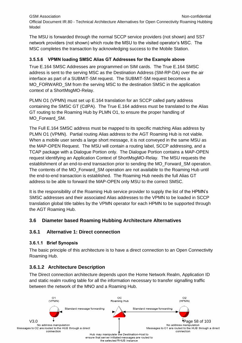
GSM Association Non-confidential
Official Document IR.80 - Technical Architecture Alternatives for Open Connectivity Roaming Hubbing
Model
V3.0 Page 58 of 103
The MSU is forwarded through the normal SCCP service providers (not shown) and SS7
network providers (not shown) which route the MSU to the visited operator’s MSC. The
MSC completes the transaction by acknowledging success to the Mobile Station.
3.5.5.6 VPMN loading SMSC Alias GT Addresses for the Example above
True E.164 SMSC Addresses are programmed on SIM cards. The True E.164 SMSC
address is sent to the serving MSC as the Destination Address (SM-RP-DA) over the air
interface as part of a SUBMIT-SM request. The SUBMIT-SM request becomes a
MO_FORWARD_SM from the serving MSC to the destination SMSC in the application
context of a ShortMsgMO-Relay.
PLMN O1 (VPMN) must set up E.164 translation for an SCCP called party address
containing the SMSC GT (CdPA). The True E.164 address must be translated to the Alias
GT routing to the Roaming Hub by PLMN O1, to ensure the proper handling of
MO_Forward_SM.
The Full E.164 SMSC address must be mapped to its specific matching Alias address by
PLMN O1 (VPMN). Partial routing Alias address to the AGT Roaming Hub is not viable.
When a mobile user sends a large short message, it is not conveyed in the same MSU as
the MAP-OPEN Request. The MSU will contain a routing label, SCCP addressing, and a
TCAP package with a Dialogue Portion only. The Dialogue Portion contains a MAP-OPEN
request identifying an Application Context of ShortMsgMO-Relay. The MSU requests the
establishment of an end-to-end transaction prior to sending the MO_Forward_SM operation.
The contents of the MO_Forward_SM operation are not available to the Roaming Hub until
the end-to-end transaction is established. The Roaming Hub needs the full Alias GT
address to be able to forward the MAP-OPEN only MSU to the correct SMSC.
It is the responsibility of the Roaming Hub service provider to supply the list of the HPMN’s
SMSC addresses and their associated Alias addresses to the VPMN to be loaded in SCCP
translation global title tables by the VPMN operator for each HPMN to be supported through
the AGT Roaming Hub.
3.6 Diameter based Roaming Hubbing Architecture Alternatives
3.6.1 Alternative 1: Direct connection
3.6.1.1 Brief Synopsis
The basic principle of this architecture is to have a direct connection to an Open Connectivity
Roaming Hub.
3.6.1.2 Architecture Description
The Direct connection architecture depends upon the Home Network Realm, Application ID
and static realm routing table for all the information necessary to transfer signalling traffic
between the network of the MNO and a Roaming Hub.
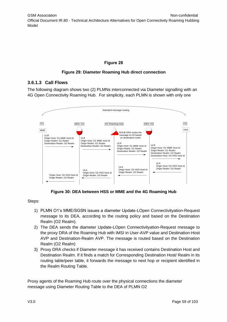
GSM Association Non-confidential
Official Document IR.80 - Technical Architecture Alternatives for Open Connectivity Roaming Hubbing
Model
V3.0 Page 59 of 103
Figure 28
Figure 29: Diameter Roaming Hub direct connection
3.6.1.3 Call Flows
The following diagram shows two (2) PLMNs interconnected via Diameter signalling with an
4G Open Connectivity Roaming Hub. For simplicity, each PLMN is shown with only one
MME HSS
O1 O2DEA: O1 DEA: O2OC Roaming Hub
ULR
Origin Host: O1 MME Host Id
Origin Realm: O1 Realm
Destination Realm: O2 Realm
ULR
Origin Host: O1 MME Host Id
Origin Realm: O1 Realm
Destination Realm: O2 Realm
ULR
Origin Host: O1 MME Host Id
Origin Realm: O1 Realm
Destination Realm: O2 Realm
ULR
Origin Host: O1 MME Host Id
Origin Realm: O1 Realm
Destination Realm: O2 Realm
Destination Host: O2 HSS Host Id
ULA
Origin Host: O2 HSS Host Id
Origin Realm: O2 RealmULA
Origin Host: O2 HSS Host Id
Origin Realm: O2 RealmULA
Origin Host: O2 HSS Host Id
Origin Realm: O2 RealmOrigin Host: O2 HSS Host Id
Origin Realm: O2 Realm
Standard message routing
RHUB DRA routes the
message to O2 based
on destination-realm
Figure 30: DEA between HSS or MME and the 4G Roaming Hub
Steps:
1) PLMN O1’s MME/SGSN issues a diameter Update-LOpen Connectivityation-Request
message to its DEA, according to the routing policy and based on the Destination
Realm (O2 Realm).
2) The DEA sends the diameter Update-LOpen Connectivityation-Request message to
the proxy DRA of the Roaming Hub with IMSI in User-AVP value and Destination-Host
AVP and Destination-Realm AVP. The message is routed based on the Destination
Realm (O2 Realm)
3) Proxy DRA checks if Diameter message it has received contains Destination Host and
Destination Realm. If it finds a match for Corresponding Destination Host/ Realm in its
routing table/peer table, it forwards the message to next hop or recipient identified in
the Realm Routing Table.
Proxy agents of the Roaming Hub route over the physical connections the diameter
message using Diameter Routing Table to the DEA of PLMN O2
GSM Association Non-confidential
Official Document IR.80 - Technical Architecture Alternatives for Open Connectivity Roaming Hubbing
Model
V3.0 Page 60 of 103
4) PLMN O2’s DEA evaluates the IMSI in User-AVP value of the received Diameter
Update-LOpen Connectivityation-Request message. Then route the request message
to O2’s HSS.
5) The remaining Diameter signalling traffic transfers are similar to steps 1 through 4
where the Destination Realm and Destination Host swapped with Origin Realm and
Origin Host. The original Destination Realm becomes the new Origin Realm and the
original Destination Host becomes the new Origin Host. The Origin Realm and Origin
Host are not used for routing purposes. Only the Route-Record is used for the
Response message routing determination.
3.6.1.4 PROs and CONs
PROs:
CONs: More complex to manage if an Operator will open services via a Roaming Hub and
also bilateral via an IPX provider
3.6.2 Alternative 2: Origin/Destination Realm Based Routing
3.6.2.1 Brief Synopsis
The basic principle of this architecture is to leverage common capabilities of the Diameter
proxies. Diameter proxies are capable not only to route based on destination-host and
destination-realm but they are capable of routing based on origin-realm and origin-host,
application-id and command-codes.
The IPX carrier in between the Roaming Hub and the MNO shall support this feature.
The Diameter proxy in the IPX performs routing based on origin and destination realm when
receiving a message and route appropriately depending of the roaming agreement.
If there is a direct roaming agreement between the MNOs then the IPX sends the traffic to
the destination MNOs or to its IPX carrier.
If there is a Roaming Hubbing agreement, then the IPX carrier delivers the message to the
originating MNO’s Roaming Hub provider.
3.6.2.2 Architecture Description
The Origin/destination realm alternative relies on the capability of the IPX carrier to perform
it. The following diagram shows the routing used to deliver signaling messages to and from
the Roaming Hub.
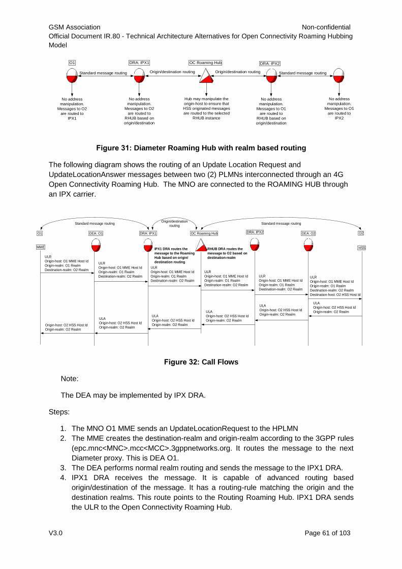
GSM Association Non-confidential
Official Document IR.80 - Technical Architecture Alternatives for Open Connectivity Roaming Hubbing
Model
V3.0 Page 61 of 103
O1
Standard message routing
OC Roaming HubDRA: IPX1
Origin/destination routing Origin/destination routing
DRA: IPX2
Standard message routing
No address
manipulation.
Messages to O2
are routed to
IPX1
No address
manipulation.
Messages to O1
are routed to
IPX2
No address
manipulation.
Messages to O1
are routed to
RHUB based on
origin/destination
No address
manipulation.
Messages to O2
are routed to
RHUB based on
origin/destination
Hub may manipulate the
origin-host to ensure that
HSS originated messages
are routed to the selected
RHUB instance
Figure 31: Diameter Roaming Hub with realm based routing
The following diagram shows the routing of an Update Location Request and
UpdateLocationAnswer messages between two (2) PLMNs interconnected through an 4G
Open Connectivity Roaming Hub. The MNO are connected to the ROAMING HUB through
an IPX carrier.
Figure 32: Call Flows
Note:
The DEA may be implemented by IPX DRA.
Steps:
1. The MNO O1 MME sends an UpdateLocationRequest to the HPLMN
2. The MME creates the destination-realm and origin-realm according to the 3GPP rules
(epc.mnc<MNC>.mcc<MCC>.3gppnetworks.org. It routes the message to the next
Diameter proxy. This is DEA O1.
3. The DEA performs normal realm routing and sends the message to the IPX1 DRA.
4. IPX1 DRA receives the message. It is capable of advanced routing based
origin/destination of the message. It has a routing-rule matching the origin and the
destination realms. This route points to the Routing Roaming Hub. IPX1 DRA sends
the ULR to the Open Connectivity Roaming Hub.
MME HSS
O1 O2DEA: O1 DRA: IPX2
ULR
Origin-host: O1 MME Host Id
Origin-realm: O1 Realm
Destination-realm: O2 Realm
ULA
Origin-host: O2 HSS Host Id
Origin-realm: O2 Realm
OC Roaming HubDRA: IPX1
IPX1 DRA routes the
message to the Roaming
Hub based on origin/
destination routing
DEA: O2
ULR
Origin-host: O1 MME Host Id
Origin-realm: O1 Realm
Destination-realm: O2 Realm
Destination-host: O2 HSS Host Id
ULA
Origin-host: O2 HSS Host Id
Origin-realm: O2 RealmULA
Origin-host: O2 HSS Host Id
Origin-realm: O2 Realm
ULA
Origin-host: O2 HSS Host Id
Origin-realm: O2 Realm
ULA
Origin-host: O2 HSS Host Id
Origin-realm: O2 RealmOrigin-host: O2 HSS Host Id
Origin-realm: O2 Realm
ULR
Origin-host: O1 MME Host Id
Origin-realm: O1 Realm
Destination-realm: O2 Realm
ULR
Origin-host: O1 MME Host Id
Origin-realm: O1 Realm
Destination-realm: O2 Realm
ULR
Origin-host: O1 MME Host Id
Origin-realm: O1 Realm
Destination-realm: O2 Realm
ULR
Origin-host: O1 MME Host Id
Origin-realm: O1 Realm
Destination-realm: O2 Realm
Standard message routing Standard message routingOrigin/destination
routing
RHUB DRA routes the
message to O2 based on
destination-realm

GSM Association Non-confidential
Official Document IR.80 - Technical Architecture Alternatives for Open Connectivity Roaming Hubbing
Model
V3.0 Page 62 of 103
5. The Roaming Hub receives the ULR and performs a standard routing based on the
destination realm. It sends it to the DRA of MNO O2’s IPX carrier
6. The ULR is routed by IPX O2 to O2 DEA and eventually to the HSS. The DEA performs
the last routing and sends it to the HSS where the roamer’s subscription is recorded. It
sets the Destination-host.
7. The HSS receives the ULR, performs the subscription verification and creates an
UpdateLocationAnswer message.
8. The HSS sends the ULA to the host that it received the original request from: the DEA
O2
9. The ULA is routed back to the MME following the reverse path of the Request
For HSS originated messages like CancelLocationRequest or InsertsubscriberDataRequest,
the same routing principles apply but the origin/destination realm based routing is performed
by the DRA of MNO O2’s IPX carrier.
3.6.2.3 Implementation Considerations
There is no specific implementation consideration for the roaming partners.
The only requirement is on the IPX carriers’ DRA.
They must support the origin/destination realm based routing. For a roaming relation
between MNO O1 and MNO O2 through a Roaming Hub 1 then it must have a routing rule:
If origin-realm is O1 realm and destination-realm is O2 realm then route to Roaming
Hub
3.6.2.4 PROs and CONs
PROs:
The splitting of Roaming Hub traffic and bilateral agreements traffic is solved by the
IPX carrier of MNOs.
It doesn’t require a new direct Diameter connection with the Roaming Hub
Full transparency
Roaming Hub provider does not have to be a IPX carrier
CONs:
The IPX carrier may not support origin/destination based routing capability.
3.6.3 Alternative 3: Destination-Realm modification
3.6.3.1 Brief Synopsis
The basic principle of this architecture is not to change the Real-Based Diameter routing.
This architecture allows a MNO with a Roaming Hubbing agreement to route its traffic
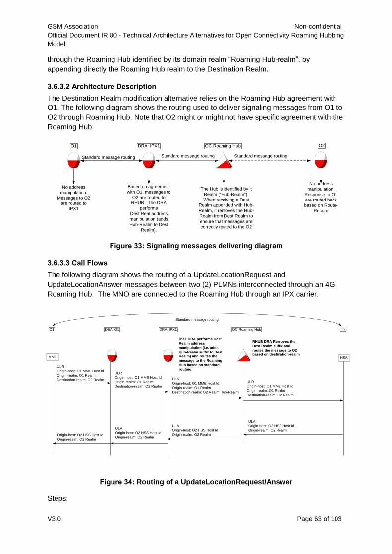
GSM Association Non-confidential
Official Document IR.80 - Technical Architecture Alternatives for Open Connectivity Roaming Hubbing
Model
V3.0 Page 63 of 103
MME HSS
O1 O2DEA: O1
ULR
Origin-host: O1 MME Host Id
Origin-realm: O1 Realm
Destination-realm: O2 Realm
OC Roaming HubDRA: IPX1
IPX1 DRA performs Dest
Realm address
manipulation (i.e. adds
Hub-Realm suffix to Dest
Realm) and routes the
message to the Roaming
Hub based on standard
routing
ULA
Origin-host: O2 HSS Host Id
Origin-realm: O2 Realm
ULA
Origin-host: O2 HSS Host Id
Origin-realm: O2 Realm
ULA
Origin-host: O2 HSS Host Id
Origin-realm: O2 RealmOrigin-host: O2 HSS Host Id
Origin-realm: O2 Realm
ULR
Origin-host: O1 MME Host Id
Origin-realm: O1 Realm
Destination-realm: O2 Realm
ULR
Origin-host: O1 MME Host Id
Origin-realm: O1 Realm
Destination-realm: O2 Realm.Hub-Realm
ULR
Origin-host: O1 MME Host Id
Origin-realm: O1 Realm
Destination-realm: O2 Realm
Standard message routing
RHUB DRA Removes the
Dest Realm suffix and
routes the message to O2
based on destination-realm
through the Roaming Hub identified by its domain realm “Roaming Hub-realm”, by
appending directly the Roaming Hub realm to the Destination Realm.
3.6.3.2 Architecture Description
The Destination Realm modification alternative relies on the Roaming Hub agreement with
O1. The following diagram shows the routing used to deliver signaling messages from O1 to
O2 through Roaming Hub. Note that O2 might or might not have specific agreement with the
Roaming Hub.
O1
Standard message routing
OC Roaming HubDRA: IPX1
No address
manipulation.
Messages to O2
are routed to
IPX1
No address
manipulation.
Response to O1
are routed back
based on Route-
Record
Based on agreement
with O1, messages to
O2 are routed to
RHUB : The DRA
performs
Dest Real address
manipulation (adds
Hub-Realm to Dest
Realm).
The Hub is identified by it
Realm (“Hub-Realm”).
When receiving a Dest
Realm appended with Hub-
Realm, it removes the Hub-
Realm from Dest Realm to
ensure that messages are
correctly routed to the O2
Standard message routing Standard message routing
O2
Figure 33: Signaling messages delivering diagram
3.6.3.3 Call Flows
The following diagram shows the routing of a UpdateLocationRequest and
UpdateLocationAnswer messages between two (2) PLMNs interconnected through an 4G
Roaming Hub. The MNO are connected to the Roaming Hub through an IPX carrier.
Figure 34: Routing of a UpdateLocationRequest/Answer
Steps:
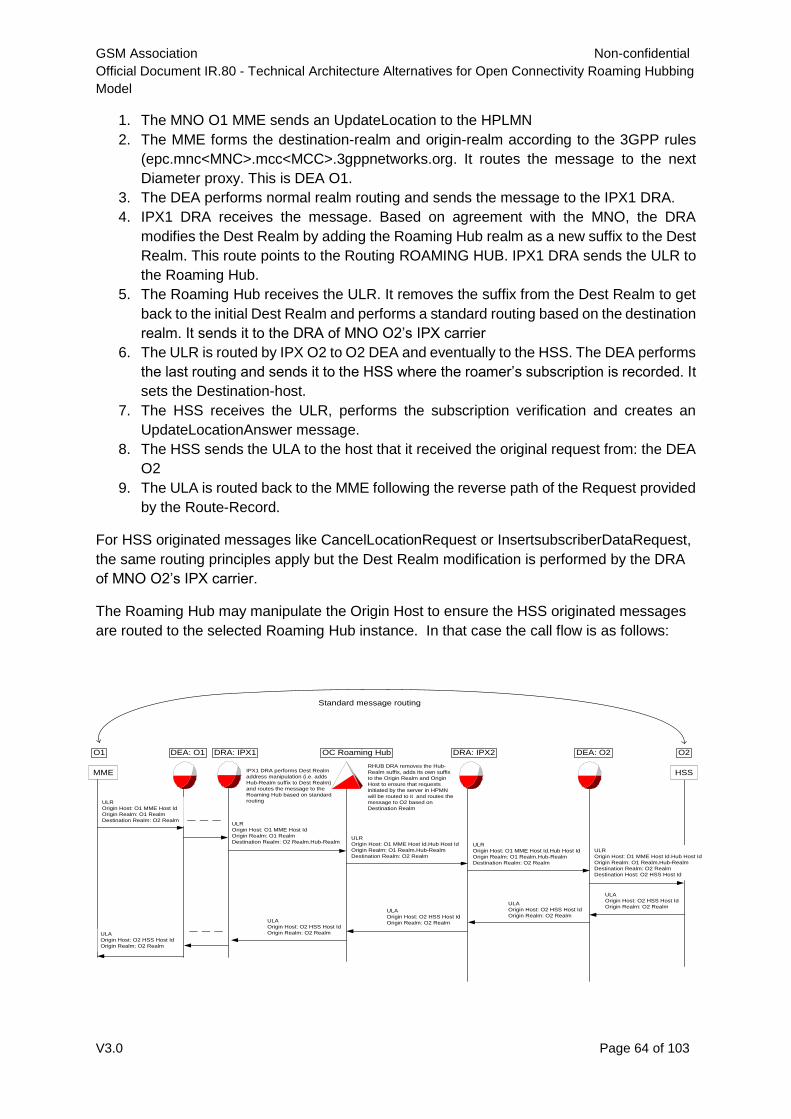
GSM Association Non-confidential
Official Document IR.80 - Technical Architecture Alternatives for Open Connectivity Roaming Hubbing
Model
V3.0 Page 64 of 103
MME
O1 DEA: O1 OC Roaming HubDRA: IPX1
ULR
Origin Host: O1 MME Host Id
Origin Realm: O1 Realm
Destination Realm: O2 RealmULR
Origin Host: O1 MME Host Id
Origin Realm: O1 Realm
Destination Realm: O2 Realm.Hub-RealmULR
Origin Host: O1 MME Host Id.Hub Host Id
Origin Realm: O1 Realm.Hub-Realm
Destination Realm: O2 Realm
ULA
Origin Host: O2 HSS Host Id
Origin Realm: O2 RealmULA
Origin Host: O2 HSS Host Id
Origin Realm: O2 RealmULA
Origin Host: O2 HSS Host Id
Origin Realm: O2 Realm
Standard message routing
IPX1 DRA performs Dest Realm
address manipulation (i.e. adds
Hub-Realm suffix to Dest Realm)
and routes the message to the
Roaming Hub based on standard
routing
RHUB DRA removes the Hub-
Realm suffix, adds its own suffix
to the Origin Realm and Origin
Host to ensure that requests
initiated by the server in HPMN
will be routed to it and routes the
message to O2 based on
Destination Realm
HSS
DRA: IPX2 DEA: O2
ULR
Origin Host: O1 MME Host Id.Hub Host Id
Origin Realm: O1 Realm.Hub-Realm
Destination Realm: O2 Realm
ULR
Origin Host: O1 MME Host Id.Hub Host Id
Origin Realm: O1 Realm.Hub-Realm
Destination Realm: O2 Realm
Destination Host: O2 HSS Host Id
ULA
Origin Host: O2 HSS Host Id
Origin Realm: O2 Realm
ULA
Origin Host: O2 HSS Host Id
Origin Realm: O2 Realm
O2
1. The MNO O1 MME sends an UpdateLocation to the HPLMN
2. The MME forms the destination-realm and origin-realm according to the 3GPP rules
(epc.mnc<MNC>.mcc<MCC>.3gppnetworks.org. It routes the message to the next
Diameter proxy. This is DEA O1.
3. The DEA performs normal realm routing and sends the message to the IPX1 DRA.
4. IPX1 DRA receives the message. Based on agreement with the MNO, the DRA
modifies the Dest Realm by adding the Roaming Hub realm as a new suffix to the Dest
Realm. This route points to the Routing ROAMING HUB. IPX1 DRA sends the ULR to
the Roaming Hub.
5. The Roaming Hub receives the ULR. It removes the suffix from the Dest Realm to get
back to the initial Dest Realm and performs a standard routing based on the destination
realm. It sends it to the DRA of MNO O2’s IPX carrier
6. The ULR is routed by IPX O2 to O2 DEA and eventually to the HSS. The DEA performs
the last routing and sends it to the HSS where the roamer’s subscription is recorded. It
sets the Destination-host.
7. The HSS receives the ULR, performs the subscription verification and creates an
UpdateLocationAnswer message.
8. The HSS sends the ULA to the host that it received the original request from: the DEA
O2
9. The ULA is routed back to the MME following the reverse path of the Request provided
by the Route-Record.
For HSS originated messages like CancelLocationRequest or InsertsubscriberDataRequest,
the same routing principles apply but the Dest Realm modification is performed by the DRA
of MNO O2’s IPX carrier.
The Roaming Hub may manipulate the Origin Host to ensure the HSS originated messages
are routed to the selected Roaming Hub instance. In that case the call flow is as follows:
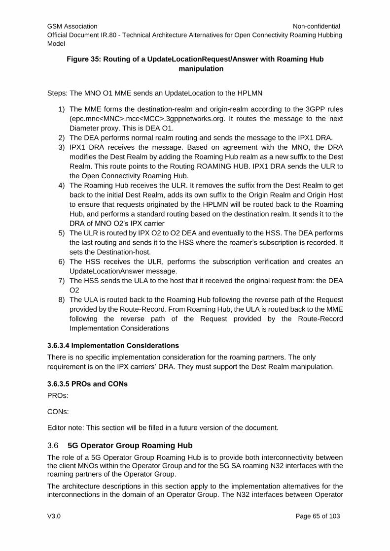
GSM Association Non-confidential
Official Document IR.80 - Technical Architecture Alternatives for Open Connectivity Roaming Hubbing
Model
V3.0 Page 65 of 103
Figure 35: Routing of a UpdateLocationRequest/Answer with Roaming Hub
manipulation
Steps: The MNO O1 MME sends an UpdateLocation to the HPLMN
1) The MME forms the destination-realm and origin-realm according to the 3GPP rules
(epc.mnc<MNC>.mcc<MCC>.3gppnetworks.org. It routes the message to the next
Diameter proxy. This is DEA O1.
2) The DEA performs normal realm routing and sends the message to the IPX1 DRA.
3) IPX1 DRA receives the message. Based on agreement with the MNO, the DRA
modifies the Dest Realm by adding the Roaming Hub realm as a new suffix to the Dest
Realm. This route points to the Routing ROAMING HUB. IPX1 DRA sends the ULR to
the Open Connectivity Roaming Hub.
4) The Roaming Hub receives the ULR. It removes the suffix from the Dest Realm to get
back to the initial Dest Realm, adds its own suffix to the Origin Realm and Origin Host
to ensure that requests originated by the HPLMN will be routed back to the Roaming
Hub, and performs a standard routing based on the destination realm. It sends it to the
DRA of MNO O2’s IPX carrier
5) The ULR is routed by IPX O2 to O2 DEA and eventually to the HSS. The DEA performs
the last routing and sends it to the HSS where the roamer’s subscription is recorded. It
sets the Destination-host.
6) The HSS receives the ULR, performs the subscription verification and creates an
UpdateLocationAnswer message.
7) The HSS sends the ULA to the host that it received the original request from: the DEA
O2
8) The ULA is routed back to the Roaming Hub following the reverse path of the Request
provided by the Route-Record. From Roaming Hub, the ULA is routed back to the MME
following the reverse path of the Request provided by the Route-Record
Implementation Considerations
3.6.3.4 Implementation Considerations
There is no specific implementation consideration for the roaming partners. The only
requirement is on the IPX carriers’ DRA. They must support the Dest Realm manipulation.
3.6.3.5 PROs and CONs
PROs:
CONs:
Editor note: This section will be filled in a future version of the document.
5G Operator Group Roaming Hub
The role of a 5G Operator Group Roaming Hub is to provide both interconnectivity between the client MNOs within the Operator Group and for the 5G SA roaming N32 interfaces with the roaming partners of the Operator Group.
The architecture descriptions in this section apply to the implementation alternatives for the interconnections in the domain of an Operator Group. The N32 interfaces between Operator
GSM Association Non-confidential
Official Document IR.80 - Technical Architecture Alternatives for Open Connectivity Roaming Hubbing
Model
V3.0 Page 66 of 103
Group Roaming Hub and the roaming partners of the Operator Group will work as per the bilateral scenario described in NG.113 Annex B, using separate N32-c connections between Operator Group Roaming Hub’s SEPP and the SEPPs of the roaming partners for each client MNO. Other options could be considered and may be added in a future version of this document. The specific operational and security aspects of a 5G Operator Group Roaming Hub are not further detailed here or else because this an internal 5G SA roaming deployment matter within the domain of an Operator Group. These architecture descriptions are provided here: • Giving guidance to Operator Groups and vendors how to implement such an
internal Roaming Hub solution.
• Providing general insights to roaming partners of Operator Groups how these
internal Roaming Hub solutions in Operator Groups are working.
Other solutions for Roaming Hubs are for further study in both GSMA and 3GPP and will be added in a future version of this document.
HTTPS Direct Routing Architecture
Brief Synopsis
This architecture requires a direct connection between the SEPP of the client MNO and the SEPP of an Operator Group Roaming Hub, and the client MNO’s SEPP to support the 3gpp-Sbi-Target-apiRoot header as specified in 3GPP Release 16 TS 29.500.
Architecture Description
The N32-c initial handshake procedure between the initiating and responding SEPPs of the client MNO and Operator Group Roaming Hub involves capability negotiation and parameter exchange as specified in 3GPP TS 33.501. The Operator Group Roaming Hub’s SEPP will establish multiple separate N32-c connections with the client MNOs for each roaming relation, using FQDNs from the roaming partner client MNOs domain. The SEPP of the consumer client MNO extracts the FQDN of the producer client MNO from the “apiRoot” header and, based on a local rule base, forward the message via N32-f to the next hop, the SEPP of the Operator Group Roaming Hub. The message shall be forwarded by changing only the Authority header indicating the next hop, and leaving other headers such as "3gpp-SBI-Target-apiRoot" unchanged. The Operator Group Roaming Hub shall change the value of the Authority header indicating the SEPP of the producer client MNO and forward the message to the next hop on N32 interface based on the 3gpp-SBI-Target-apiRoot header, leaving other headers such as "3gpp-SBI-Target-apiRoot" unchanged. TLS will be the negotiated security policy between the SEPPs and the Operator Group
Roaming Hub will relay the HTTP/2 messages between the NF service producers and the
NF service consumers as specified in 3GPP TS 29.573.
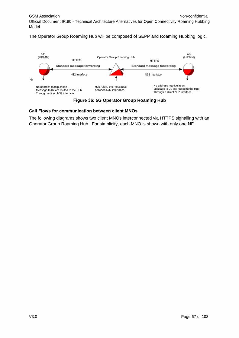
GSM Association Non-confidential
Official Document IR.80 - Technical Architecture Alternatives for Open Connectivity Roaming Hubbing
Model
V3.0 Page 67 of 103
The Operator Group Roaming Hub will be composed of SEPP and Roaming Hubbing logic.
Figure 36: 5G Operator Group Roaming Hub
Call Flows for communication between client MNOs
The following diagrams shows two client MNOs interconnected via HTTPS signalling with an
Operator Group Roaming Hub. For simplicity, each MNO is shown with only one NF.
No address manipulation Message to 02 are routed to the Hub Through a direct N32 interface
No address manipulation Message to 01 are routed to the Hub Through a direct N32 interface
Hub relays the messages between N32 interfaces
N32 interface N32 interface
HTTPS HTTPS Operator Group Roaming Hub
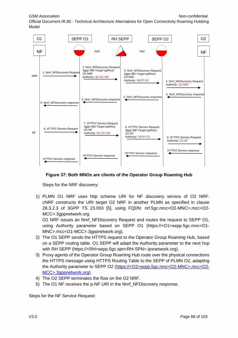
GSM Association Non-confidential
Official Document IR.80 - Technical Architecture Alternatives for Open Connectivity Roaming Hubbing
Model
V3.0 Page 68 of 103
Figure 37: Both MNOs are clients of the Operator Group Roaming Hub
Steps for the NRF discovery:
1) PLMN O1 NRF uses http scheme URI for NF discovery service of O2 NRF.
cNRF constructs the URI target O2 NRF in another PLMN as specified in clause
28.3.2.3 of 3GPP TS 23.003 [5], using FQDN: nrf.5gc.mnc<O2-MNC>.mcc<O2-
MCC>.3gppnetwork.org.
O1 NRF issues an Nnrf_NFDiscovery Request and routes the request to SEPP O1,
using Authority parameter based on SEPP O1 (https://<O1>sepp.5gc.mnc<O1-
MNC>.mcc<O1-MCC>.3gppnetwork.org).
2) The O1 SEPP sends the HTTPS request to the Operator Group Roaming Hub, based
on a SEPP routing table. O1 SEPP will adapt the Authority parameter to the next hop
with RH SEPP (https://<RH>sepp.5gc.spn<RH-SPN>.ipxnetwork.org).
3) Proxy agents of the Operator Group Roaming Hub route over the physical connections
the HTTPS message using HTTPS Routing Table to the SEPP of PLMN O2, adapting
the Authority parameter to SEPP O2 (https://<O2>sepp.5gc.mnc<O2-MNC>.mcc<O2-
MCC>.3gppnetwork.org).
4) The O2 SEPP terminates the flow on the O2 NRF.
5) The O1 NF receives the p-NF URI in the Nnrf_NFDiscovery response.
Steps for the NF Service Request:
NF
NF
O1 O2 SEPP O2 SEPP O1 RH SEPP
1. Nnrf_NFDiscovery Request
2. Nnrf_NFDiscovery Request 3gpp-SBI-Target-apiRoot: O2 NRF Authority: 5G OC RH
3. Nnrf_NFDiscovery Request 3gpp-SBI-Target-apiRoot: O2 NRF Authority: SEPP O2 4. Nnrf_NFDiscovery Request
Authority: O2 NRF
5. Nnrf_NFDiscovery response 5. Nnrf_NFDiscovery response
5. Nnrf_NFDiscovery response 5. Nnrf_NFDiscovery response
6. HTTP/2 Service Request
7. HTTP/2 Service Request 3gpp-SBI-Target-apiRoot: O2 NF Authority: 5G OC RH
8. HTTP/2 Service Request 3gpp-SBI-Target-apiRoot: O2 NF Authority: SEPP O2
9. HTTP/2 Service Request Authority: O2 NF
HTTP/2 Service response HTTP/2 Service response
HTTP/2 Service response HTTP/2 Service response
NRF
NF
N32 N32
GSM Association Non-confidential
Official Document IR.80 - Technical Architecture Alternatives for Open Connectivity Roaming Hubbing
Model
V3.0 Page 69 of 103
6) The O1 NF selects the p-NF URI received during the discovery procedure and sends
to O1 SEPP this p-NF URI (https://<O2>nf.5gc.mnc<O2-MNC>.mcc<O2-
MCC>.3gppnetwork.org).
The Authority parameter is fulfilled based on SEPP O1
(https://<O1>sepp.5gc.mnc<O1-MNC>.mcc<O1-MCC>.3gppnetwork.org).
7) The O1 SEPP sends the HTTPS request to the Operator Group Roaming Hub, based
on a SEPP routing table. O1 SEPP will adapt the Authority parameter to the next hop
with RH SEPP (https://<RH>sepp.5gc.spn<RH-SPN>.ipxnetwork.org).
8) Proxy agents of the Operator Group Roaming Hub route over the physical connections
the HTTPS message using HTTPS Routing Table to the SEPP of PLMN O2, adapting
the Authority parameter to SEPP O2 (https://<O2>sepp.5gc.mnc<O2-MNC>.mcc<O2-
MCC>.3gppnetwork.org).
9) The O2 SEPP terminates the NF Service Request on the O2 NF.PROs and CONs
PROs and CONs
PROs:
o Centralised signalling and signalling management at Operator Group Roaming Hub
are maintained.
CONs:
o Access to information elements visible to Operator Group Roaming Hubs may need
to be contractually enforced between MNOs and Operator Group Roaming Hubs in
order to fulfil legal obligations
Connectivity with MNOs external to the Operator Group Roaming Hub
The N32-c initial handshake procedure between the initiating and responding SEPPs of the external MNO and Operator Group Roaming Hub involves capability negotiation and parameter exchange as specified in 3GPP TS 33.501. The Operator Group Roaming Hub’s SEPP will establish separate N32-c connections with the external MNOs for each roaming relation using FQDNs from the client MNOs domain. If the MNO external to the Operator Group Roaming Hub does not indicate support of 3gpp-Sbi-Target-apiRoot header, the Operator Group Roaming Hub SEPP must insert the 3gpp-Sbi-Target-apiRoot header in the HTTP request towards the SEPP of the client MNO and set it to the apiRoot of the target NF derived from the telescopic FQDN or from the request URI respectively as per PRD NG.113.
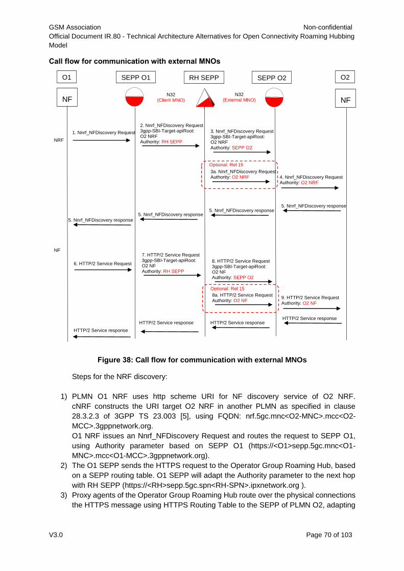
GSM Association Non-confidential
Official Document IR.80 - Technical Architecture Alternatives for Open Connectivity Roaming Hubbing
Model
V3.0 Page 70 of 103
Call flow for communication with external MNOs
Figure 38: Call flow for communication with external MNOs
Steps for the NRF discovery:
1) PLMN O1 NRF uses http scheme URI for NF discovery service of O2 NRF.
cNRF constructs the URI target O2 NRF in another PLMN as specified in clause
28.3.2.3 of 3GPP TS 23.003 [5], using FQDN: nrf.5gc.mnc<O2-MNC>.mcc<O2-
MCC>.3gppnetwork.org.
O1 NRF issues an Nnrf_NFDiscovery Request and routes the request to SEPP O1,
using Authority parameter based on SEPP O1 (https://<O1>sepp.5gc.mnc<O1-
MNC>.mcc<O1-MCC>.3gppnetwork.org).
2) The O1 SEPP sends the HTTPS request to the Operator Group Roaming Hub, based
on a SEPP routing table. O1 SEPP will adapt the Authority parameter to the next hop
with RH SEPP (https://<RH>sepp.5gc.spn<RH-SPN>.ipxnetwork.org ).
3) Proxy agents of the Operator Group Roaming Hub route over the physical connections
the HTTPS message using HTTPS Routing Table to the SEPP of PLMN O2, adapting
NF
NF
O1 O2 SEPP O2 SEPP O1 RH SEPP
1. Nnrf_NFDiscovery Request
2. Nnrf_NFDiscovery Request 3gpp-SBI-Target-apiRoot: O2 NRF Authority: RH SEPP
3. Nnrf_NFDiscovery Request 3gpp-SBI-Target-apiRoot: O2 NRF Authority: SEPP O2
4. Nnrf_NFDiscovery Request Authority: O2 NRF
5. Nnrf_NFDiscovery response 5. Nnrf_NFDiscovery response
5. Nnrf_NFDiscovery response 5. Nnrf_NFDiscovery response
6. HTTP/2 Service Request
7. HTTP/2 Service Request 3gpp-SBI-Target-apiRoot: O2 NF Authority: RH SEPP
8. HTTP/2 Service Request 3gpp-SBI-Target-apiRoot: O2 NF Authority: SEPP O2
9. HTTP/2 Service Request Authority: O2 NF
HTTP/2 Service response HTTP/2 Service response HTTP/2 Service response
HTTP/2 Service response
NRF
NF
N32 (Client MNO)
N32 (External MNO)
3a. Nnrf_NFDiscovery Request Authority: O2 NRF
Optional: Rel 15
8a. HTTP/2 Service Request Authority: O2 NF
Optional: Rel 15
GSM Association Non-confidential
Official Document IR.80 - Technical Architecture Alternatives for Open Connectivity Roaming Hubbing
Model
V3.0 Page 71 of 103
the Authority parameter to SEPP O2 (https://<O2>sepp.5gc.mnc<O2-MNC>.mcc<O2-
MCC>.3gppnetwork.org).
Optionally 3b: SEPP O2 does not support 3gpp-Sbi-Target-apiRoot header so sets
Authority parameter to O2 NRF using Telescopic FQDN.
4) The O2 SEPP terminates the flow on the O2 NRF.
5) The O1 NF receives the p-NF URI in the Nnrf_NFDiscovery response.
Steps for the NF Service Request:
6) The O1 NF selects the p-NF URI received during the discovery procedure and sends
to O1 SEPP this p-NF URI (https://<O2>nf.5gc.mnc<O2-MNC>.mcc<O2-
MCC>.3gppnetwork.org).
The Authority parameter is fulfilled based on SEPP O1
(https://<O1>sepp.5gc.mnc<O1-MNC>.mcc<O1-MCC>.3gppnetwork.org).
7) The O1 SEPP sends the HTTPS request to the Operator Group Roaming Hub, based
on a SEPP routing table. O1 SEPP will adapt the Authority parameter to the next hop
with RH SEPP (https://<RH>sepp.5gc.spn<RH-SPN>.ipxnetwork.org ).
8) Proxy agents of the Operator Group Roaming Hub route over the physical connections
the HTTPS message using HTTPS Routing Table to the SEPP of PLMN O2, adapting
the Authority parameter to SEPP O2 (https://<O2>sepp.5gc.mnc<O2-MNC>.mcc<O2-
MCC>.3gppnetwork.org).
Optionally 8b: SEPP O2 does not support 3gpp-Sbi-Target-apiRoot header so sets
Authority parameter to O2 NF using Telescopic FQDN.
9) The O2 SEPP terminates the NF Service Request on the O2 NF.
Note 1: The naming and the format of the fields are defined in FS.34
Note 2: Other alternatives may be added in the future.
4 Interoperability of Architectures
4.1 Interoperability within a Roaming Hub
The interoperability of different architectures or multiple architectures within a Roaming Hub
is the responsibility of the Roaming Hub implementer. The Roaming Hub implementer shall
provide interoperability for those architectures made available for commercial use.
4.2 Interoperability between Roaming Hubs
The Open Connectivity high level requirements indicate that the Roaming Hub Solution
Provider must be prepared to work with all other providers of like-solutions to ensure that the
solutions are inter-operable. Like-solutions are defined as any solution that is in compliance
with Open Connectivity requirements.
A common framework for Roaming Hub-to-Roaming Hub interface is necessary to define a
minimum capability for interoperable solutions.
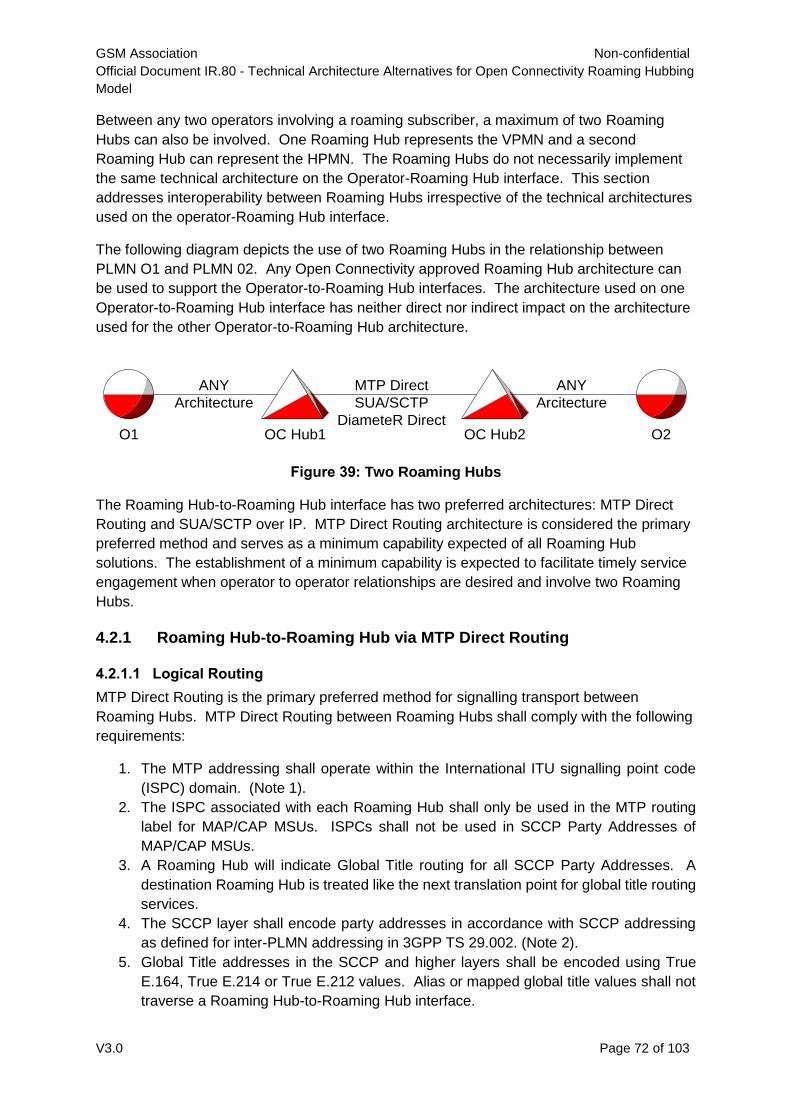
GSM Association Non-confidential
Official Document IR.80 - Technical Architecture Alternatives for Open Connectivity Roaming Hubbing
Model
V3.0 Page 72 of 103
Between any two operators involving a roaming subscriber, a maximum of two Roaming
Hubs can also be involved. One Roaming Hub represents the VPMN and a second
Roaming Hub can represent the HPMN. The Roaming Hubs do not necessarily implement
the same technical architecture on the Operator-Roaming Hub interface. This section
addresses interoperability between Roaming Hubs irrespective of the technical architectures
used on the operator-Roaming Hub interface.
The following diagram depicts the use of two Roaming Hubs in the relationship between
PLMN O1 and PLMN 02. Any Open Connectivity approved Roaming Hub architecture can
be used to support the Operator-to-Roaming Hub interfaces. The architecture used on one
Operator-to-Roaming Hub interface has neither direct nor indirect impact on the architecture
used for the other Operator-to-Roaming Hub architecture.
Figure 39: Two Roaming Hubs
The Roaming Hub-to-Roaming Hub interface has two preferred architectures: MTP Direct
Routing and SUA/SCTP over IP. MTP Direct Routing architecture is considered the primary
preferred method and serves as a minimum capability expected of all Roaming Hub
solutions. The establishment of a minimum capability is expected to facilitate timely service
engagement when operator to operator relationships are desired and involve two Roaming
Hubs.
4.2.1 Roaming Hub-to-Roaming Hub via MTP Direct Routing
4.2.1.1 Logical Routing
MTP Direct Routing is the primary preferred method for signalling transport between
Roaming Hubs. MTP Direct Routing between Roaming Hubs shall comply with the following
requirements:
1. The MTP addressing shall operate within the International ITU signalling point code
(ISPC) domain. (Note 1).
2. The ISPC associated with each Roaming Hub shall only be used in the MTP routing
label for MAP/CAP MSUs. ISPCs shall not be used in SCCP Party Addresses of
MAP/CAP MSUs.
3. A Roaming Hub will indicate Global Title routing for all SCCP Party Addresses. A
destination Roaming Hub is treated like the next translation point for global title routing
services.
4. The SCCP layer shall encode party addresses in accordance with SCCP addressing
as defined for inter-PLMN addressing in 3GPP TS 29.002. (Note 2).
5. Global Title addresses in the SCCP and higher layers shall be encoded using True
E.164, True E.214 or True E.212 values. Alias or mapped global title values shall not
traverse a Roaming Hub-to-Roaming Hub interface.
O1 OC Hub1 OC Hub2 O2
ANY
Architecture
MTP Direct
SUA/SCTP
DiameteR Direct
ANY
Arcitecture
GSM Association Non-confidential
Official Document IR.80 - Technical Architecture Alternatives for Open Connectivity Roaming Hubbing
Model
V3.0 Page 73 of 103
Note 1: As an exception, if two connecting Roaming Hubs are in the same national point
code domain, they may connect using MTP direct routing with national point codes.
When national point codes alter the MTP transport variant from ITU to a national variant,
the SCCP layer can be altered to the same national variant. Example: Two Roaming
Hubs in World Zone 1 may choose to interoperate using ANSI MTP point codes with an
ANSI transport variant; this requires the SCCP layer to switch to the ANSI variant.
Note 2: Typically, the SCCP layer variant shall follow the MTP variant chosen. The
minimum expectation is an ITU-T compliant implementation using ISPCs for MTP
transport.
4.2.1.2 Physical Routing
MTP Direct Routing defines the logical routing between Roaming Hubs with a requirement
for physical connectivity that supports the route definitions between involved point codes.
The physical connectivity can employ traditional SS7 signaling transport with MTP1, MTP2
and MTP3 over low speed links or high speed links. Any number of SS7 network providers
may be involved to accomplish end-to-end physical connectivity.
The physical connectivity can also be accomplished using SIGTRAN based solutions on any
one or more of the physical connections between Roaming Hubs. SIGTRAN capabilities
include M2PA, M2UA and M3UA.
The choices for physical connectivity and lower level protocols mentioned above are left to
the two Roaming Hub Service Providers.
4.2.2 Roaming Hub-to-Roaming Hub via SUA/SCTP over IP
SUA /SCTP is an alternate preferred method for signalling transport between Roaming
Hubs. SUA/SCTP shall comply with the following requirements:
1) The SUA implementation shall not impose point code requirements on either Roaming
Hub; this eliminates the issues associated with ITU/ANSI/CHINA/JAPAN variants, the
national/international network indicator, and formal assignment of specific point codes
by regulatory bodies.
2) The default address encoding variant shall be ITU with the use of Global Title Indicator
of 01002 common with ITU networks. (Note 1)
3) A Roaming Hub will indicate Global Title routing for source and destination addresses.
A destination Roaming Hub is treated like the next translation point for global title
routing services.
4) The source and destination addresses shall be encoded in accordance with SCCP
Addressing as defined for inter-PLMN addressing in 3GPP TS 29.002. (Note 1).
5) Global Title addresses in the SCCP and higher layers shall be encoded using True
E.164, True E.214 or True E.212 values. Alias or mapped global title values shall not
traverse a Roaming Hub-to-Roaming Hub interface.
Note 1: As an exception, if two connecting Roaming Hubs are in the ANSI signalling domain,
they may choose to communicate via SUA with address encoding variant using Global Title
Indicator of 00102 common with ANSI networks.
GSM Association Non-confidential
Official Document IR.80 - Technical Architecture Alternatives for Open Connectivity Roaming Hubbing
Model
V3.0 Page 74 of 103
The following statements have been used to direct the writing of this section as the
controlling text which was produced during IRHG#5 in Seattle, WA, on 1st October, 2007.
“There are two preferred Roaming Hub-to-Roaming Hub interfaces:
1. - Direct MTP (International ITU Point Code Domain) either classical (MTP1, MTP2 and MTP3) or
SIGTRAN based (M2PA, M2UA or M3UA)
2. - SUA over SCTP over IP (ITU Global Title).
SCCP and higher layers shall use unmodified addresses.
As an exception, if the two connecting Roaming Hubs are in the same national point code domain,
they may connect using MTP with national point codes.
As an exception, if the two connecting Roaming Hubs are in the ANSI signaling domain, they may
connect using SUA over SCTP over IP with ANSI Global Title.”
4.2.3 Roaming Hub-to-Roaming Hub via Diameter Direct Routing Architecture
4.2.3.1 Logical Routing
Diameter Direct Routing between Roaming Hubs shall comply with the following
requirements:
1. The SCTP addressing shall operate within the International public IP address domain.
2. A Roaming Hub will perform routing of all Diameter messages based on realm. The
destination’s Roaming Hub is a Diameter peer of the origin’s one.
3. The Diameter ream and hostnames shall comply with Diameter addressing as defined
for inter-PLMN addressing in
Realm shall be encoded using True values. Realm values shall not traverse a Roaming Hub-
to-Roaming Hub interface.
4.2.3.2 Physical Routing
SCTP is the only allowed Diameter transport protocol between Roaming Hubs.
Diameter Direct Routing defines the logical routing between Roaming Hubs with a
requirement for physical connectivity that supports the route definitions between involved IP
address.
The physical connectivity can use traditional IP transport over dedicated leased line, MPLS
or VPN tunnels. Any number of IP network providers may be involved to accomplish end-to-
end physical connectivity. The choices for physical connectivity and lower level protocols
mentioned above are left to the two Roaming Hub Service Providers.
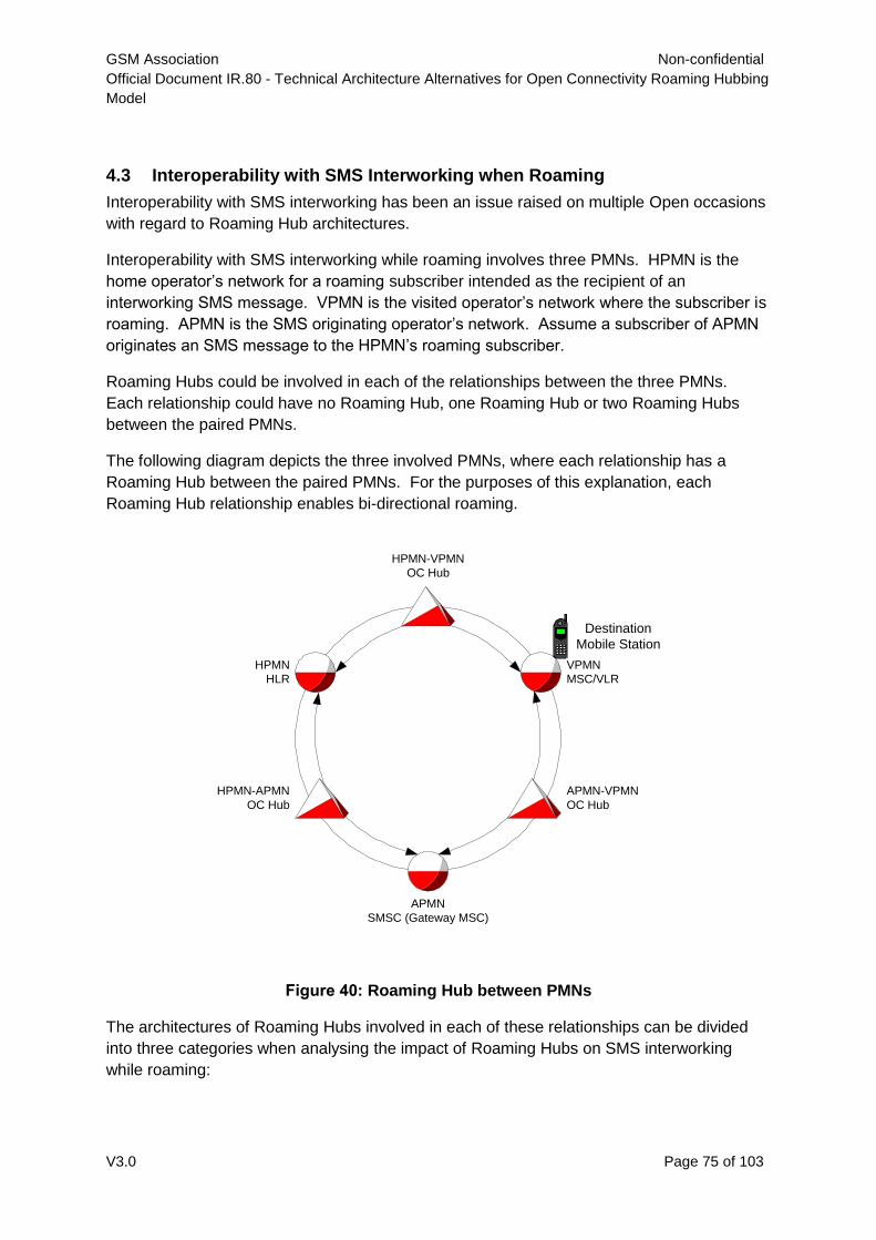
GSM Association Non-confidential
Official Document IR.80 - Technical Architecture Alternatives for Open Connectivity Roaming Hubbing
Model
V3.0 Page 75 of 103
4.3 Interoperability with SMS Interworking when Roaming
Interoperability with SMS interworking has been an issue raised on multiple Open occasions
with regard to Roaming Hub architectures.
Interoperability with SMS interworking while roaming involves three PMNs. HPMN is the
home operator’s network for a roaming subscriber intended as the recipient of an
interworking SMS message. VPMN is the visited operator’s network where the subscriber is
roaming. APMN is the SMS originating operator’s network. Assume a subscriber of APMN
originates an SMS message to the HPMN’s roaming subscriber.
Roaming Hubs could be involved in each of the relationships between the three PMNs.
Each relationship could have no Roaming Hub, one Roaming Hub or two Roaming Hubs
between the paired PMNs.
The following diagram depicts the three involved PMNs, where each relationship has a
Roaming Hub between the paired PMNs. For the purposes of this explanation, each
Roaming Hub relationship enables bi-directional roaming.
Figure 40: Roaming Hub between PMNs
The architectures of Roaming Hubs involved in each of these relationships can be divided
into three categories when analysing the impact of Roaming Hubs on SMS interworking
while roaming:
HPMN
HLR
VPMN
MSC/VLR
Destination
Mobile Station
APMN
SMSC (Gateway MSC)
HPMN-APMN
OC Hub
APMN-VPMN
OC Hub
HPMN-VPMN
OC Hub
GSM Association Non-confidential
Official Document IR.80 - Technical Architecture Alternatives for Open Connectivity Roaming Hubbing
Model
V3.0 Page 76 of 103
1) True: Direct transparent addressing with no additional information modification – this
category includes both MTP Direct Routing and SUA/SCTP architectures
2) TT: Direct transparent addressing with translation type information modified – this
category includes the Translation Type architecture.
3) AGT: Indirect transparent addressing with Alias Global Title Mappings – this category
includes the Alias Global Title architecture
SMS Interworking while roaming involves tasks necessary to deliver a text message from an
SMSC of the APMN to an MS of the HPMN while the MS is roaming in the VPMN.
A discussion of SMS Interworking while roaming, true roaming, true interworking and mixed
cases of interworking and roaming are presented in Annex A – Roaming Hub and SMS-IW.
According to the signalling diagrams of Annex A, it can be concluded that the SMS-IW traffic
can be transported when Roaming Hubs are used. It is possible as well to have in parallel
Roaming Hub agreement and SMS-IW agreement towards an independent SMS Roaming
Hub or on a bilateral way.
Depending of the topology of the APMN, HPMN and VPMN networks, it will be possible for
the PMN to choose the Roaming Hub according to connection options that the Roaming Hub
are offering. Therefore, the PMNs using Roaming Hub have to be aware that in the case
where the SMS will not be transiting via the Roaming Hub, the Roaming Hub will not be in
position to screen this traffic and to guaranty the delivery of the message in case of mixed
scenario. In order to ensure a minimum quality of service for SMS, it would be recommended
that the connection between the Roaming Hub and the PMN is setup in a way that the
Roaming Hub is transporting the roaming leg of the SMS whatever architecture is used.
However, if the PMN chooses to have an SMS-Hub to provide all SMS interworking including
SMS interworking to roamers, without the involvement of a Roaming Hub, this choice is also
available. GSMA PRD IR.75 has a recommended preferred solution for SMS interworking to
an MS while roaming. It is a pure SMS Roaming Hub solution that allows each operator to
limit access to their network elements to only their chosen SMSIP for all interworking
including interworking to roamers.
4.4 Interoperability with TCAPsec
Impact to Roaming Hub – two fold, mode 1 allows viewing of fields – TCAP package is
transmitted in clear – with security tag to ensure no ‘corruption’? Mode two does not allow
viewing of fields – TCAP package is encrypted and security tag is included to ensure no
corruption. if the IMSI or any other field is needed, then it must be made visible…
Impact on TCAP rebuild – the rebuild will force a new computation for any mode of
TCAPsec. Security tag is an encryption function applied to the TCAP package.
If TCAPsec is an issue between client and Roaming Hub, it will be an issue between
Roaming Hub and Roaming Hub.
TCAPsec is defined as Transaction Capability Application Part User Security within Network
Domain Security within 3G Security, in the 3GPP Technical Specification 33.204. As IPsec
applies to IP network domains, TCAPsec is applied to TCAP signalling domains.
GSM Association Non-confidential
Official Document IR.80 - Technical Architecture Alternatives for Open Connectivity Roaming Hubbing
Model
V3.0 Page 77 of 103
TCAPsec is applicable to different types of signalling domains:
PLMN to PLMN
PLMN to Service Provider
Service Provider to Service Provider
TCAPsec is defined with two distinct architectures:
End to End (typical in PLMN to PLMN domains)
Roaming Hub and Spoke (typical with Service Provider needing TCAP access)
Roaming Hubs serve as an ideal centralizing point to function as SS7 Security Gateways –
single point of control for key sharing – one location can then function on behalf of all
support networks using TCAPsec.
By using a Roaming Hub as a security gateway, distribution of encryption vectors is
simplified for the operator. The Roaming Hub as a security gateway fulfils the efficiency
gains of a one-to-many relationship.
Troubleshooting requires Roaming Hubs to have visible access to signalling messages in
the clear. This can be accomplished with TCAPsec Mode 1, but not with mode 2. TCAPsec
mode 2 requires the Roaming Hub to function as a security gateway in order to have visible
access to signalling messages in the clear.
GSM Association Non-confidential
Official Document IR.80 - Technical Architecture Alternatives for Open Connectivity Roaming Hubbing
Model
V3.0 Page 78 of 103
Annex A Roaming Hub and SMS-IW
Background
Roaming and inter-working are at the core of the GSM success story. 3GSM subscribers
now expect to access the same set of services at home and abroad. They expect to be able
to share all 3GSM services with any other subscriber on any network.
The bi-lateral relationship, on which this success has been based, however, is now
becoming a limiting factor to future success. With over 600 GSMA operator members,
diversification of services and an increasing number of access technologies, it is unlikely that
the current paradigm of bilateral relationships between networks will meet the expectations
of operators going forward.
Since the interworking traffic must not be transported by the Roaming Hub, the SMS traffic
has to be transported via the signalling path agreed in the AA.73/AA.71. According to the
OPEN CONNECTIVITY High level requirement, the PLMN must be able to setup a roaming
relation via a Roaming Hub and a SMS interworking relation via a SMS Roaming Hub which
can be different. It can be possible for the PLMN to have the roaming relation via a
ROAMING HUB and the SMS interworking relation bilaterally. It means the interworking
traffic must be separated from the roaming SMS message in the case where the AA.19
agreements is signed bilaterally or with a ROAMING HUB other than the Roaming Hub.
When SMPP is used to accomplish SMS interworking, the presence of a Roaming Hub is not
relevant. SMPP is an IP based SMS transport protocol that does not involve direct delivery
to the MS. SMPP is used between SMSCs, SMS Roaming Hubs, and both.
When SS7 is used to complete SMS interworking, the following GSM MAP operations are
used between the various network elements.
SRI-SM acquire MS identity (IMSI) and location (Serving MSC) Sent by SMSC or SMS Roaming Hub to HLR of destination
MSISDN InformSC provide MS status, and SC presence on Message Waiting List Sent by HLR to SMSC or SMS Roaming Hub w/response to
SRI_SM ReadyForSM indicate MS can receive SMS Sent by Serving MSC to HLR AlertSC indicate MS can receive SMS Sent by HLR to each SC on Message Waiting List ReportSMDeliveryStatus indicates a change of status for MS receiving SMS Sent by SMSC or SMS Roaming Hub to HLR MOForwardSM Mobile originated SMS message Sent by Serving MSC to SMSC (from SIM in MS) MTForwardSM Mobile terminated SMS (SMS delivery to MS)
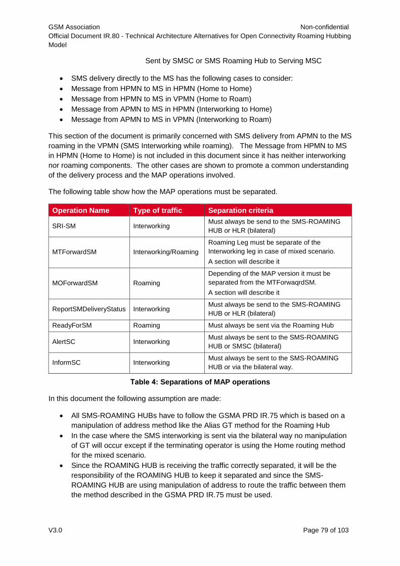
GSM Association Non-confidential
Official Document IR.80 - Technical Architecture Alternatives for Open Connectivity Roaming Hubbing
Model
V3.0 Page 79 of 103
Sent by SMSC or SMS Roaming Hub to Serving MSC
SMS delivery directly to the MS has the following cases to consider:
Message from HPMN to MS in HPMN (Home to Home)
Message from HPMN to MS in VPMN (Home to Roam)
Message from APMN to MS in HPMN (Interworking to Home)
Message from APMN to MS in VPMN (Interworking to Roam)
This section of the document is primarily concerned with SMS delivery from APMN to the MS
roaming in the VPMN (SMS Interworking while roaming). The Message from HPMN to MS
in HPMN (Home to Home) is not included in this document since it has neither interworking
nor roaming components. The other cases are shown to promote a common understanding
of the delivery process and the MAP operations involved.
The following table show how the MAP operations must be separated.
Operation Name Type of traffic Separation criteria
SRI-SM Interworking Must always be send to the SMS-ROAMING
HUB or HLR (bilateral)
MTForwardSM Interworking/Roaming
Roaming Leg must be separate of the
Interworking leg in case of mixed scenario.
A section will describe it
MOForwardSM Roaming
Depending of the MAP version it must be
separated from the MTForwaqrdSM.
A section will describe it
ReportSMDeliveryStatus Interworking Must always be send to the SMS-ROAMING
HUB or HLR (bilateral)
ReadyForSM Roaming Must always be sent via the Roaming Hub
AlertSC Interworking Must always be sent to the SMS-ROAMING
HUB or SMSC (bilateral)
InformSC Interworking Must always be sent to the SMS-ROAMING
HUB or via the bilateral way.
Table 4: Separations of MAP operations
In this document the following assumption are made:
All SMS-ROAMING HUBs have to follow the GSMA PRD IR.75 which is based on a
manipulation of address method like the Alias GT method for the Roaming Hub
In the case where the SMS interworking is sent via the bilateral way no manipulation
of GT will occur except if the terminating operator is using the Home routing method
for the mixed scenario.
Since the ROAMING HUB is receiving the traffic correctly separated, it will be the
responsibility of the ROAMING HUB to keep it separated and since the SMS-
ROAMING HUB are using manipulation of address to route the traffic between them
the method described in the GSMA PRD IR.75 must be used.
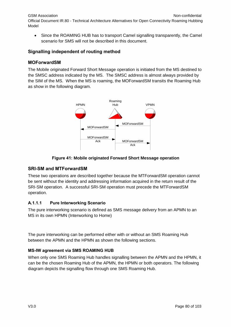
GSM Association Non-confidential
Official Document IR.80 - Technical Architecture Alternatives for Open Connectivity Roaming Hubbing
Model
V3.0 Page 80 of 103
Since the ROAMING HUB has to transport Camel signalling transparently, the Camel
scenario for SMS will not be described in this document.
Signalling independent of routing method
MOForwardSM
The Mobile originated Forward Short Message operation is initiated from the MS destined to
the SMSC address indicated by the MS. The SMSC address is almost always provided by
the SIM of the MS. When the MS is roaming, the MOForwardSM transits the Roaming Hub
as show in the following diagram.
Figure 41: Mobile originated Forward Short Message operation
SRI-SM and MTForwardSM
These two operations are described together because the MTForwardSM operation cannot
be sent without the identity and addressing information acquired in the return result of the
SRI-SM operation. A successful SRI-SM operation must precede the MTForwardSM
operation.
A.1.1.1 Pure Interworking Scenario
The pure interworking scenario is defined as SMS message delivery from an APMN to an
MS in its own HPMN (Interworking to Home)
The pure interworking can be performed either with or without an SMS Roaming Hub
between the APMN and the HPMN as shown the following sections.
MS-IW agreement via SMS ROAMING HUB
When only one SMS Roaming Hub handles signalling between the APMN and the HPMN, it
can be the chosen Roaming Hub of the APMN, the HPMN or both operators. The following
diagram depicts the signalling flow through one SMS Roaming Hub.
HPMN VPMN
Roaming
Hub
MOForwardSM
Ack
MOForwardSMMOForwardSM
MOForwardSM
Ack
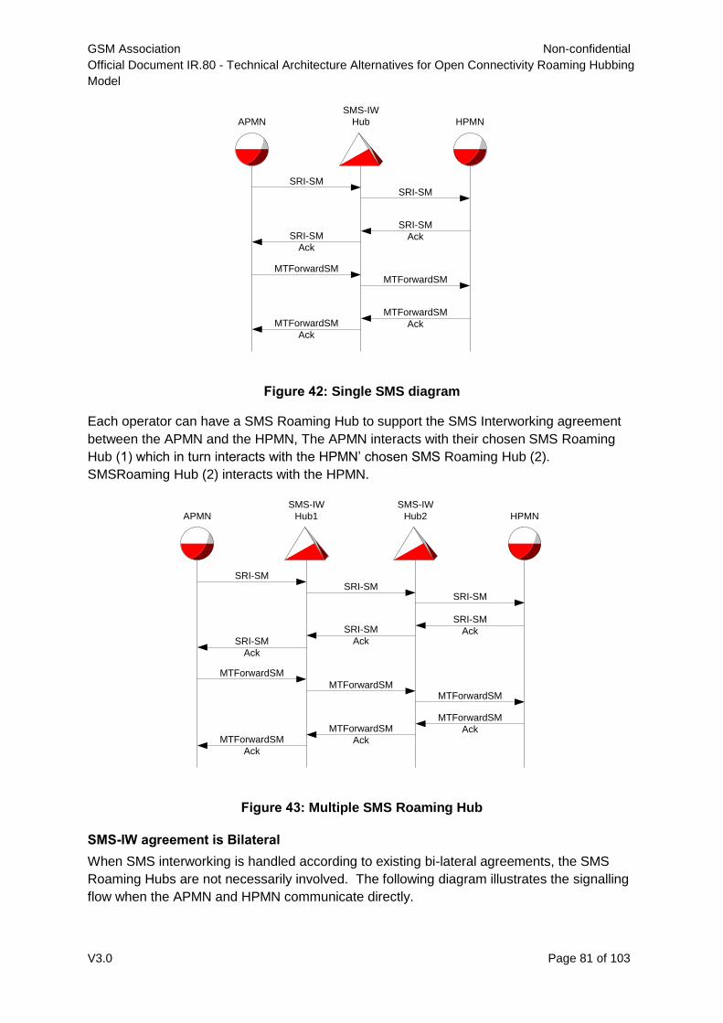
GSM Association Non-confidential
Official Document IR.80 - Technical Architecture Alternatives for Open Connectivity Roaming Hubbing
Model
V3.0 Page 81 of 103
Figure 42: Single SMS diagram
Each operator can have a SMS Roaming Hub to support the SMS Interworking agreement
between the APMN and the HPMN, The APMN interacts with their chosen SMS Roaming
Hub (1) which in turn interacts with the HPMN’ chosen SMS Roaming Hub (2).
SMSRoaming Hub (2) interacts with the HPMN.
Figure 43: Multiple SMS Roaming Hub
SMS-IW agreement is Bilateral
When SMS interworking is handled according to existing bi-lateral agreements, the SMS
Roaming Hubs are not necessarily involved. The following diagram illustrates the signalling
flow when the APMN and HPMN communicate directly.
APMN
SMS-IW
Hub HPMN
SRI-SMSRI-SM
SRI-SM
AckSRI-SM
Ack
MTForwardSMMTForwardSM
MTForwardSM
AckMTForwardSM
Ack
APMN
SMS-IW
Hub1 HPMN
SRI-SMSRI-SM
SRI-SM
AckSRI-SM
Ack
MTForwardSM
MTForwardSM
MTForwardSM
AckMTForwardSM
Ack
SMS-IW
Hub2
SRI-SM
SRI-SM
Ack
MTForwardSM
MTForwardSM
Ack
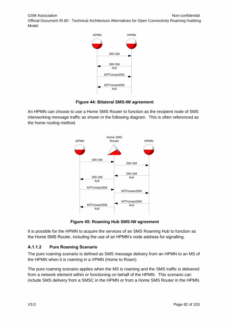
GSM Association Non-confidential
Official Document IR.80 - Technical Architecture Alternatives for Open Connectivity Roaming Hubbing
Model
V3.0 Page 82 of 103
Figure 44: Bilateral SMS-IW agreement
An HPMN can choose to use a Home SMS Router to function as the recipient node of SMS
interworking message traffic as shown in the following diagram. This is often referenced as
the home routing method.
Figure 45: Roaming Hub SMS-IW agreement
It is possible for the HPMN to acquire the services of an SMS Roaming Hub to function as
the Home SMS Router, including the use of an HPMN’s node address for signalling.
A.1.1.2 Pure Roaming Scenario
The pure roaming scenario is defined as SMS message delivery from an HPMN to an MS of
the HPMN when it is roaming in a VPMN (Home to Roam)
The pure roaming scenario applies when the MS is roaming and the SMS traffic is delivered
from a network element within or functioning on behalf of the HPMN. This scenario can
include SMS delivery from a SMSC in the HPMN or from a Home SMS Router in the HPMN.
APMN HPMN
SRI-SM
SRI-SM
Ack
MTForwardSM
MTForwardSM
Ack
APMN
Home SMS
Router HPMN
SRI-SMSRI-SM
SRI-SM
AckSRI-SM
Ack
MTForwardSMMTForwardSM
MTForwardSM
AckMTForwardSM
Ack
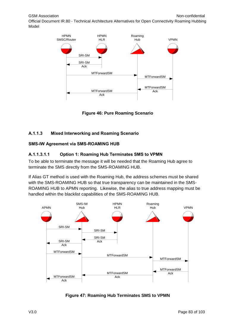
GSM Association Non-confidential
Official Document IR.80 - Technical Architecture Alternatives for Open Connectivity Roaming Hubbing
Model
V3.0 Page 83 of 103
Figure 46: Pure Roaming Scenario
A.1.1.3 Mixed Interworking and Roaming Scenario
SMS-IW Agreement via SMS-ROAMING HUB
A.1.1.3.1.1 Option 1: Roaming Hub Terminates SMS to VPMN
To be able to terminate the message it will be needed that the Roaming Hub agree to
terminate the SMS directly from the SMS-ROAMING HUB.
If Alias GT method is used with the Roaming Hub, the address schemes must be shared
with the SMS-ROAMING HUB so that true transparency can be maintained in the SMS-
ROAMING HUB to APMN reporting. Likewise, the alias to true address mapping must be
handled within the blacklist capabilities of the SMS-ROAMING HUB.
Figure 47: Roaming Hub Terminates SMS to VPMN
HPMN
SMSC/Router
SRI-SM
SRI-SM
Ack
MTForwardSM
MTForwardSM
Ack
HPMN
HLR VPMN
Roaming
Hub
MTForwardSM
MTForwardSM
Ack
APMN
SMS-IW
Hub
SRI-SMSRI-SM
SRI-SM
AckSRI-SM
Ack
MTForwardSMMTForwardSM
MTForwardSM
AckMTForwardSM
Ack
HPMN
HLR VPMN
Roaming
Hub
MTForwardSM
MTForwardSM
Ack
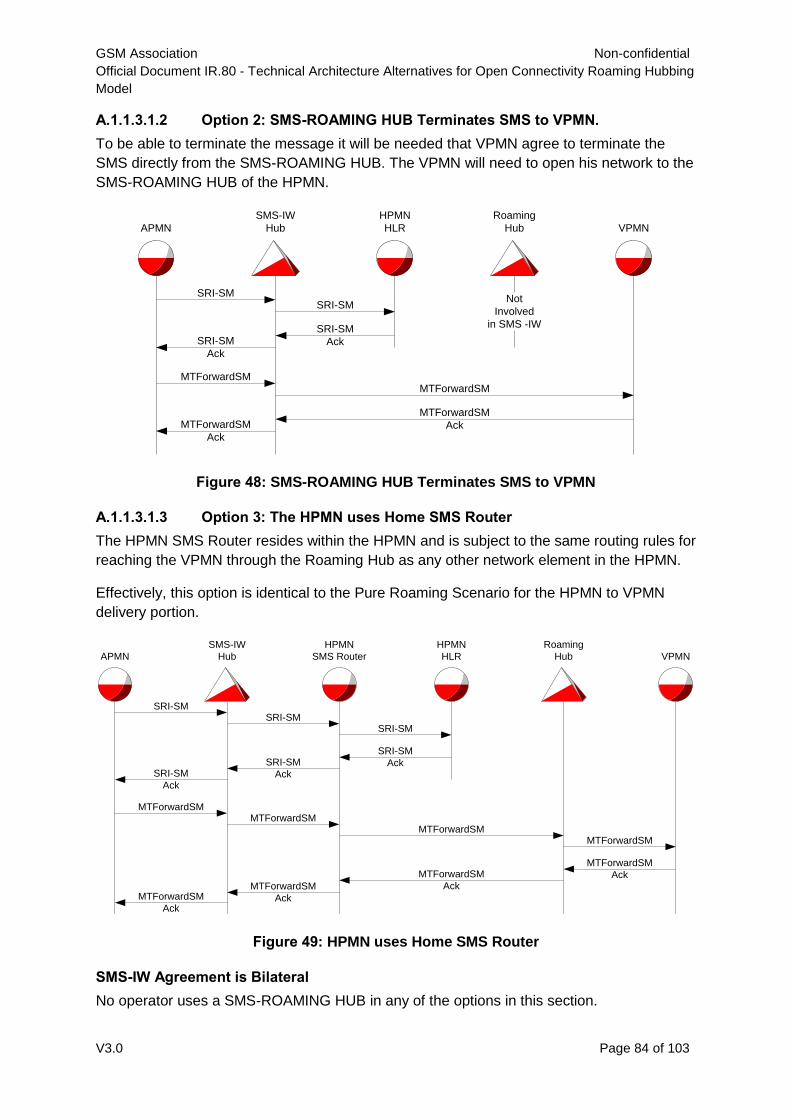
GSM Association Non-confidential
Official Document IR.80 - Technical Architecture Alternatives for Open Connectivity Roaming Hubbing
Model
V3.0 Page 84 of 103
A.1.1.3.1.2 Option 2: SMS-ROAMING HUB Terminates SMS to VPMN.
To be able to terminate the message it will be needed that VPMN agree to terminate the
SMS directly from the SMS-ROAMING HUB. The VPMN will need to open his network to the
SMS-ROAMING HUB of the HPMN.
Figure 48: SMS-ROAMING HUB Terminates SMS to VPMN
A.1.1.3.1.3 Option 3: The HPMN uses Home SMS Router
The HPMN SMS Router resides within the HPMN and is subject to the same routing rules for
reaching the VPMN through the Roaming Hub as any other network element in the HPMN.
Effectively, this option is identical to the Pure Roaming Scenario for the HPMN to VPMN
delivery portion.
Figure 49: HPMN uses Home SMS Router
SMS-IW Agreement is Bilateral
No operator uses a SMS-ROAMING HUB in any of the options in this section.
APMN
SMS-IW
Hub
SRI-SMSRI-SM
SRI-SM
AckSRI-SM
Ack
MTForwardSMMTForwardSM
MTForwardSM
AckMTForwardSM
Ack
HPMN
HLR VPMN
Roaming
Hub
Not
Involved
in SMS -IW
APMN
SMS-IW
Hub
SRI-SM
SRI-SM
Ack
MTForwardSM
MTForwardSM
Ack
HPMN
SMS Router
SRI-SM
SRI-SM
Ack
MTForwardSM
MTForwardSM
Ack
HPMN
HLR VPMN
Roaming
Hub
MTForwardSM
MTForwardSM
Ack
SRI-SM
SRI-SM
Ack
MTForwardSM
MTForwardSM
Ack
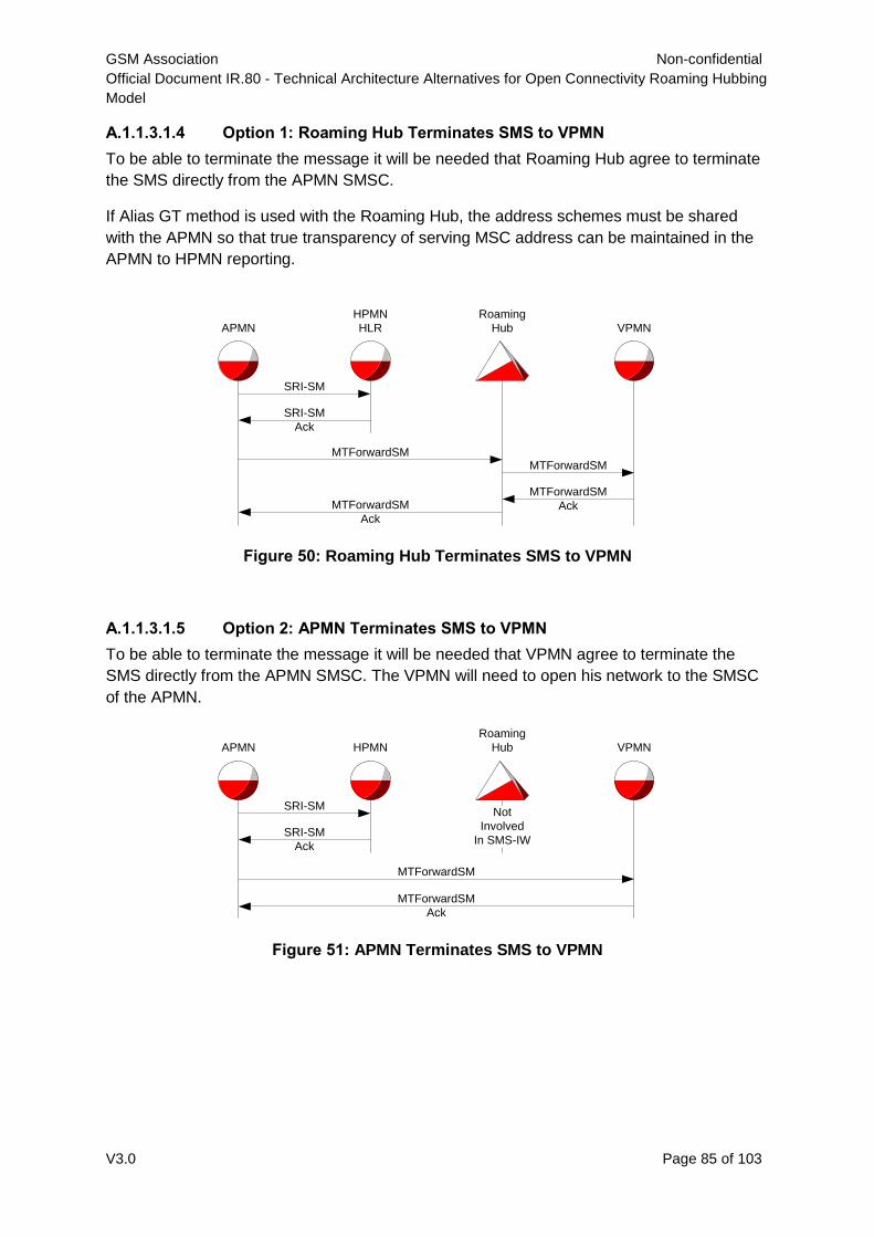
GSM Association Non-confidential
Official Document IR.80 - Technical Architecture Alternatives for Open Connectivity Roaming Hubbing
Model
V3.0 Page 85 of 103
A.1.1.3.1.4 Option 1: Roaming Hub Terminates SMS to VPMN
To be able to terminate the message it will be needed that Roaming Hub agree to terminate
the SMS directly from the APMN SMSC.
If Alias GT method is used with the Roaming Hub, the address schemes must be shared
with the APMN so that true transparency of serving MSC address can be maintained in the
APMN to HPMN reporting.
Figure 50: Roaming Hub Terminates SMS to VPMN
A.1.1.3.1.5 Option 2: APMN Terminates SMS to VPMN
To be able to terminate the message it will be needed that VPMN agree to terminate the
SMS directly from the APMN SMSC. The VPMN will need to open his network to the SMSC
of the APMN.
Figure 51: APMN Terminates SMS to VPMN
APMN
SRI-SM
SRI-SM
Ack
MTForwardSM
MTForwardSM
Ack
HPMN
HLR VPMN
Roaming
Hub
MTForwardSM
MTForwardSM
Ack
APMN
SRI-SM
SRI-SM
Ack
MTForwardSM
MTForwardSM
Ack
HPMN VPMN
Roaming
Hub
Not
Involved
In SMS-IW
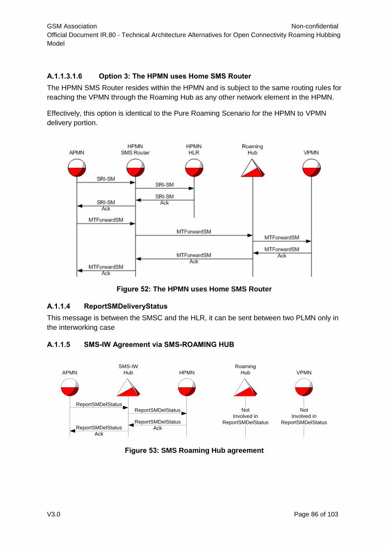
GSM Association Non-confidential
Official Document IR.80 - Technical Architecture Alternatives for Open Connectivity Roaming Hubbing
Model
V3.0 Page 86 of 103
A.1.1.3.1.6 Option 3: The HPMN uses Home SMS Router
The HPMN SMS Router resides within the HPMN and is subject to the same routing rules for
reaching the VPMN through the Roaming Hub as any other network element in the HPMN.
Effectively, this option is identical to the Pure Roaming Scenario for the HPMN to VPMN
delivery portion.
Figure 52: The HPMN uses Home SMS Router
A.1.1.4 ReportSMDeliveryStatus
This message is between the SMSC and the HLR, it can be sent between two PLMN only in
the interworking case
A.1.1.5 SMS-IW Agreement via SMS-ROAMING HUB
Figure 53: SMS Roaming Hub agreement
APMN
ReportSMDelStatus
HPMN VPMN
Roaming
Hub
Not
Involved in
ReportSMDelStatus
SMS-IW
Hub
ReportSMDelStatus
ReportSMDelStatus
AckReportSMDelStatus
Ack
Not
Involved in
ReportSMDelStatus

GSM Association Non-confidential
Official Document IR.80 - Technical Architecture Alternatives for Open Connectivity Roaming Hubbing
Model
V3.0 Page 87 of 103
A.1.1.6 SMS-IW Agreement is Bilateral
Figure 54: Bilateral SMS IW agreement
A.1.1.7 ReadyForSM
This message can only be sent between two PLMN in the case of roaming
Figure 55: ReadyForSM diagram
AlertSC / InformSC
These two messages are similar and are sent from the HLR to the SMSC. The AlertSC is
exchanged between the HPMN and APMN only in the case of interworking. The InformSC is
an operation invoked with no reply. The InformSC invoke component is conveyed with the
reply to an SRI_SM invoke component.
APMN
ReportSMDelStatus
HPMN VPMN
Roaming
Hub
Not
Involved in
ReportSMDelStatus
SMS-IW
Hub
ReportSMDelStatus
Ack
Not
Involved in
ReportSMDelStatus
APMN
ReadyForSM
HPMN VPMN
Roaming
Hub
Not
Involved in
ReadyForSM
SMS-IW
Hub
ReadyForSM
Ack
Not
Involved in
ReadyForSM
ReadyForSM
ReadyForSM
Ack
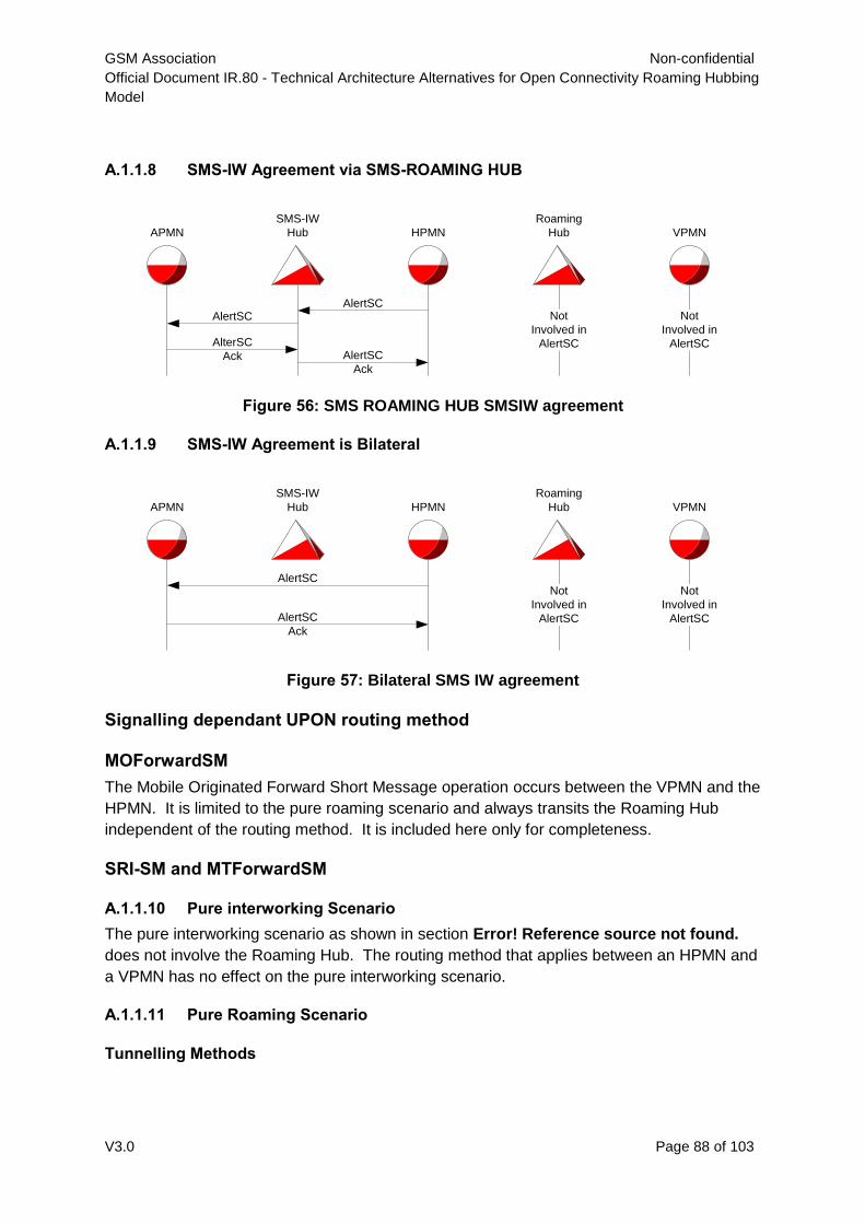
GSM Association Non-confidential
Official Document IR.80 - Technical Architecture Alternatives for Open Connectivity Roaming Hubbing
Model
V3.0 Page 88 of 103
A.1.1.8 SMS-IW Agreement via SMS-ROAMING HUB
Figure 56: SMS ROAMING HUB SMSIW agreement
A.1.1.9 SMS-IW Agreement is Bilateral
Figure 57: Bilateral SMS IW agreement
Signalling dependant UPON routing method
MOForwardSM
The Mobile Originated Forward Short Message operation occurs between the VPMN and the
HPMN. It is limited to the pure roaming scenario and always transits the Roaming Hub
independent of the routing method. It is included here only for completeness.
SRI-SM and MTForwardSM
A.1.1.10 Pure interworking Scenario
The pure interworking scenario as shown in section Error! Reference source not found.
does not involve the Roaming Hub. The routing method that applies between an HPMN and
a VPMN has no effect on the pure interworking scenario.
A.1.1.11 Pure Roaming Scenario
Tunnelling Methods
APMN
AlertSC
HPMN VPMN
Roaming
Hub
Not
Involved in
AlertSC
SMS-IW
Hub
AlertSC
AlertSC
Ack
AlterSC
Ack
Not
Involved in
AlertSC
APMN HPMN VPMN
Roaming
Hub
Not
Involved in
AlertSC
SMS-IW
Hub
AlertSC
AlertSC
Ack
Not
Involved in
AlertSC
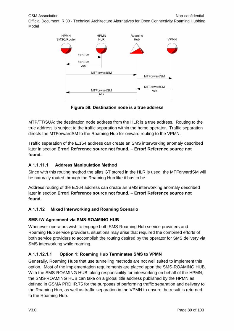
GSM Association Non-confidential
Official Document IR.80 - Technical Architecture Alternatives for Open Connectivity Roaming Hubbing
Model
V3.0 Page 89 of 103
Figure 58: Destination node is a true address
MTP/TT/SUA: the destination node address from the HLR is a true address. Routing to the
true address is subject to the traffic separation within the home operator. Traffic separation
directs the MTForwardSM to the Roaming Hub for onward routing to the VPMN.
Traffic separation of the E.164 address can create an SMS interworking anomaly described
later in section Error! Reference source not found. – Error! Reference source not
found..
A.1.1.11.1 Address Manipulation Method
Since with this routing method the alias GT stored in the HLR is used, the MTForwardSM will
be naturally routed through the Roaming Hub like it has to be.
Address routing of the E.164 address can create an SMS interworking anomaly described
later in section Error! Reference source not found. – Error! Reference source not
found..
A.1.1.12 Mixed Interworking and Roaming Scenario
SMS-IW Agreement via SMS-ROAMING HUB
Whenever operators wish to engage both SMS Roaming Hub service providers and
Roaming Hub service providers, situations may arise that required the combined efforts of
both service providers to accomplish the routing desired by the operator for SMS delivery via
SMS interworking while roaming.
A.1.1.12.1.1 Option 1: Roaming Hub Terminates SMS to VPMN
Generally, Roaming Hubs that use tunnelling methods are not well suited to implement this
option. Most of the implementation requirements are placed upon the SMS-ROAMING HUB.
With the SMS-ROAMING HUB taking responsibility for interworking on behalf of the HPMN,
the SMS-ROAMING HUB can take on a global title address published by the HPMN as
defined in GSMA PRD IR.75 for the purposes of performing traffic separation and delivery to
the Roaming Hub, as well as traffic separation in the VPMN to ensure the result is returned
to the Roaming Hub.
HPMN
SMSC/Router
SRI-SM
SRI-SM
Ack
MTForwardSM
MTForwardSM
Ack
HPMN
HLR VPMN
Roaming
Hub
MTForwardSM
MTForwardSM
Ack
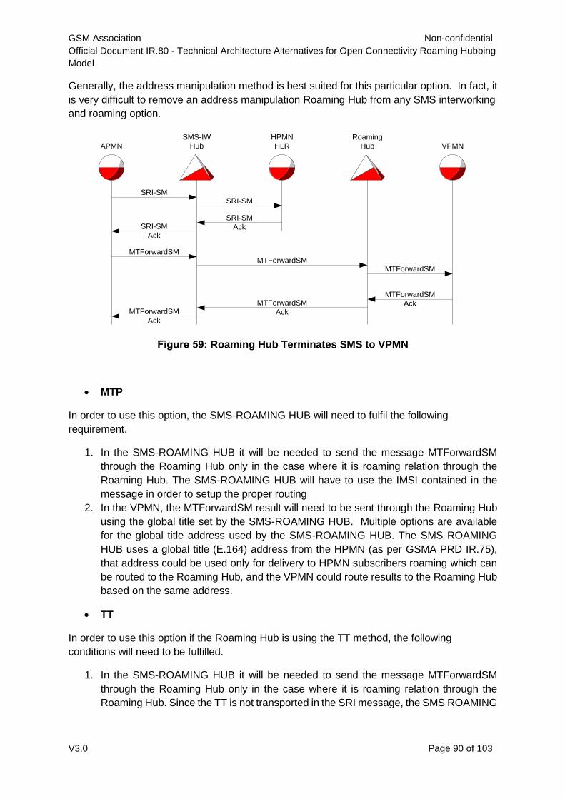
GSM Association Non-confidential
Official Document IR.80 - Technical Architecture Alternatives for Open Connectivity Roaming Hubbing
Model
V3.0 Page 90 of 103
Generally, the address manipulation method is best suited for this particular option. In fact, it
is very difficult to remove an address manipulation Roaming Hub from any SMS interworking
and roaming option.
Figure 59: Roaming Hub Terminates SMS to VPMN
MTP
In order to use this option, the SMS-ROAMING HUB will need to fulfil the following
requirement.
1. In the SMS-ROAMING HUB it will be needed to send the message MTForwardSM
through the Roaming Hub only in the case where it is roaming relation through the
Roaming Hub. The SMS-ROAMING HUB will have to use the IMSI contained in the
message in order to setup the proper routing
2. In the VPMN, the MTForwardSM result will need to be sent through the Roaming Hub
using the global title set by the SMS-ROAMING HUB. Multiple options are available
for the global title address used by the SMS-ROAMING HUB. The SMS ROAMING
HUB uses a global title (E.164) address from the HPMN (as per GSMA PRD IR.75),
that address could be used only for delivery to HPMN subscribers roaming which can
be routed to the Roaming Hub, and the VPMN could route results to the Roaming Hub
based on the same address.
TT
In order to use this option if the Roaming Hub is using the TT method, the following
conditions will need to be fulfilled.
1. In the SMS-ROAMING HUB it will be needed to send the message MTForwardSM
through the Roaming Hub only in the case where it is roaming relation through the
Roaming Hub. Since the TT is not transported in the SRI message, the SMS ROAMING
APMN
SMS-IW
Hub
SRI-SMSRI-SM
SRI-SM
AckSRI-SM
Ack
MTForwardSMMTForwardSM
MTForwardSM
AckMTForwardSM
Ack
HPMN
HLR VPMN
Roaming
Hub
MTForwardSM
MTForwardSM
Ack
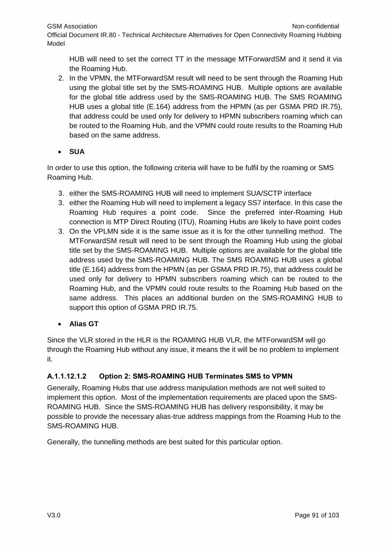
GSM Association Non-confidential
Official Document IR.80 - Technical Architecture Alternatives for Open Connectivity Roaming Hubbing
Model
V3.0 Page 91 of 103
HUB will need to set the correct TT in the message MTForwardSM and it send it via
the Roaming Hub.
2. In the VPMN, the MTForwardSM result will need to be sent through the Roaming Hub
using the global title set by the SMS-ROAMING HUB. Multiple options are available
for the global title address used by the SMS-ROAMING HUB. The SMS ROAMING
HUB uses a global title (E.164) address from the HPMN (as per GSMA PRD IR.75),
that address could be used only for delivery to HPMN subscribers roaming which can
be routed to the Roaming Hub, and the VPMN could route results to the Roaming Hub
based on the same address.
SUA
In order to use this option, the following criteria will have to be fulfil by the roaming or SMS
Roaming Hub.
3. either the SMS-ROAMING HUB will need to implement SUA/SCTP interface
3. either the Roaming Hub will need to implement a legacy SS7 interface. In this case the
Roaming Hub requires a point code. Since the preferred inter-Roaming Hub
connection is MTP Direct Routing (ITU), Roaming Hubs are likely to have point codes
3. On the VPLMN side it is the same issue as it is for the other tunnelling method. The
MTForwardSM result will need to be sent through the Roaming Hub using the global
title set by the SMS-ROAMING HUB. Multiple options are available for the global title
address used by the SMS-ROAMING HUB. The SMS ROAMING HUB uses a global
title (E.164) address from the HPMN (as per GSMA PRD IR.75), that address could be
used only for delivery to HPMN subscribers roaming which can be routed to the
Roaming Hub, and the VPMN could route results to the Roaming Hub based on the
same address. This places an additional burden on the SMS-ROAMING HUB to
support this option of GSMA PRD IR.75.
Alias GT
Since the VLR stored in the HLR is the ROAMING HUB VLR, the MTForwardSM will go
through the Roaming Hub without any issue, it means the it will be no problem to implement
it.
A.1.1.12.1.2 Option 2: SMS-ROAMING HUB Terminates SMS to VPMN
Generally, Roaming Hubs that use address manipulation methods are not well suited to
implement this option. Most of the implementation requirements are placed upon the SMS-
ROAMING HUB. Since the SMS-ROAMING HUB has delivery responsibility, it may be
possible to provide the necessary alias-true address mappings from the Roaming Hub to the
SMS-ROAMING HUB.
Generally, the tunnelling methods are best suited for this particular option.
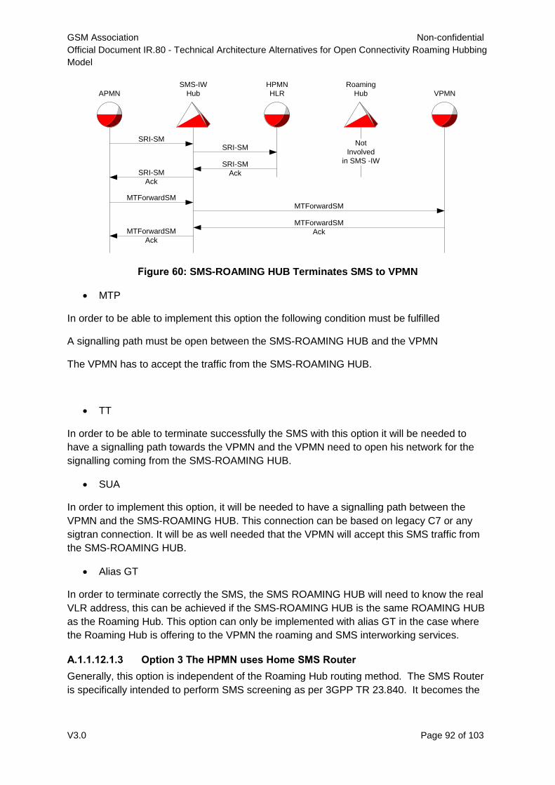
GSM Association Non-confidential
Official Document IR.80 - Technical Architecture Alternatives for Open Connectivity Roaming Hubbing
Model
V3.0 Page 92 of 103
Figure 60: SMS-ROAMING HUB Terminates SMS to VPMN
MTP
In order to be able to implement this option the following condition must be fulfilled
A signalling path must be open between the SMS-ROAMING HUB and the VPMN
The VPMN has to accept the traffic from the SMS-ROAMING HUB.
TT
In order to be able to terminate successfully the SMS with this option it will be needed to
have a signalling path towards the VPMN and the VPMN need to open his network for the
signalling coming from the SMS-ROAMING HUB.
SUA
In order to implement this option, it will be needed to have a signalling path between the
VPMN and the SMS-ROAMING HUB. This connection can be based on legacy C7 or any
sigtran connection. It will be as well needed that the VPMN will accept this SMS traffic from
the SMS-ROAMING HUB.
Alias GT
In order to terminate correctly the SMS, the SMS ROAMING HUB will need to know the real
VLR address, this can be achieved if the SMS-ROAMING HUB is the same ROAMING HUB
as the Roaming Hub. This option can only be implemented with alias GT in the case where
the Roaming Hub is offering to the VPMN the roaming and SMS interworking services.
A.1.1.12.1.3 Option 3 The HPMN uses Home SMS Router
Generally, this option is independent of the Roaming Hub routing method. The SMS Router
is specifically intended to perform SMS screening as per 3GPP TR 23.840. It becomes the
APMN
SMS-IW
Hub
SRI-SMSRI-SM
SRI-SM
AckSRI-SM
Ack
MTForwardSMMTForwardSM
MTForwardSM
AckMTForwardSM
Ack
HPMN
HLR VPMN
Roaming
Hub
Not
Involved
in SMS -IW
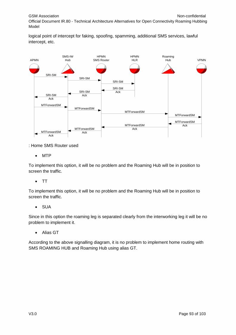
GSM Association Non-confidential
Official Document IR.80 - Technical Architecture Alternatives for Open Connectivity Roaming Hubbing
Model
V3.0 Page 93 of 103
logical point of intercept for faking, spoofing, spamming, additional SMS services, lawful
intercept, etc.
: Home SMS Router used
MTP
To implement this option, it will be no problem and the Roaming Hub will be in position to
screen the traffic.
TT
To implement this option, it will be no problem and the Roaming Hub will be in position to
screen the traffic.
SUA
Since in this option the roaming leg is separated clearly from the interworking leg it will be no
problem to implement it.
Alias GT
According to the above signalling diagram, it is no problem to implement home routing with
SMS ROAMING HUB and Roaming Hub using alias GT.
APMN
SMS-IW
Hub
SRI-SM
SRI-SM
Ack
MTForwardSM
MTForwardSM
Ack
HPMN
SMS Router
SRI-SM
SRI-SM
Ack
MTForwardSM
MTForwardSM
Ack
HPMN
HLR VPMN
Roaming
Hub
MTForwardSM
MTForwardSM
Ack
SRI-SM
SRI-SM
Ack
MTForwardSM
MTForwardSM
Ack
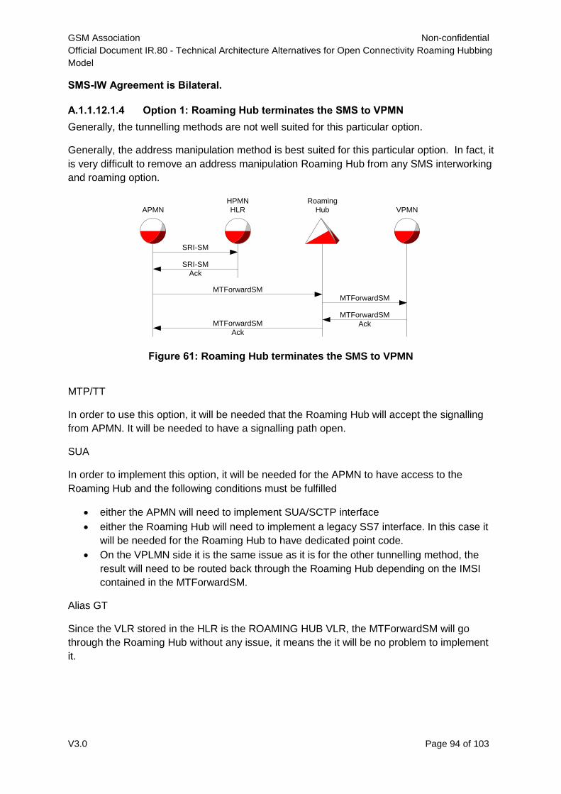
GSM Association Non-confidential
Official Document IR.80 - Technical Architecture Alternatives for Open Connectivity Roaming Hubbing
Model
V3.0 Page 94 of 103
SMS-IW Agreement is Bilateral.
A.1.1.12.1.4 Option 1: Roaming Hub terminates the SMS to VPMN
Generally, the tunnelling methods are not well suited for this particular option.
Generally, the address manipulation method is best suited for this particular option. In fact, it
is very difficult to remove an address manipulation Roaming Hub from any SMS interworking
and roaming option.
Figure 61: Roaming Hub terminates the SMS to VPMN
MTP/TT
In order to use this option, it will be needed that the Roaming Hub will accept the signalling
from APMN. It will be needed to have a signalling path open.
SUA
In order to implement this option, it will be needed for the APMN to have access to the
Roaming Hub and the following conditions must be fulfilled
either the APMN will need to implement SUA/SCTP interface
either the Roaming Hub will need to implement a legacy SS7 interface. In this case it
will be needed for the Roaming Hub to have dedicated point code.
On the VPLMN side it is the same issue as it is for the other tunnelling method, the
result will need to be routed back through the Roaming Hub depending on the IMSI
contained in the MTForwardSM.
Alias GT
Since the VLR stored in the HLR is the ROAMING HUB VLR, the MTForwardSM will go
through the Roaming Hub without any issue, it means the it will be no problem to implement
it.
APMN
SRI-SM
SRI-SM
Ack
MTForwardSM
MTForwardSM
Ack
HPMN
HLR VPMN
Roaming
Hub
MTForwardSM
MTForwardSM
Ack
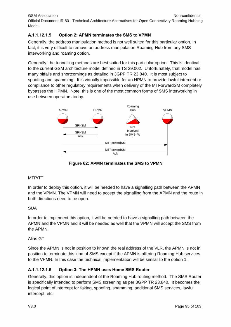
GSM Association Non-confidential
Official Document IR.80 - Technical Architecture Alternatives for Open Connectivity Roaming Hubbing
Model
V3.0 Page 95 of 103
A.1.1.12.1.5 Option 2: APMN terminates the SMS to VPMN
Generally, the address manipulation method is not well suited for this particular option. In
fact, it is very difficult to remove an address manipulation Roaming Hub from any SMS
interworking and roaming option.
Generally, the tunnelling methods are best suited for this particular option. This is identical
to the current GSM architecture model defined in TS 29.002. Unfortunately, that model has
many pitfalls and shortcomings as detailed in 3GPP TR 23.840. It is most subject to
spoofing and spamming. It is virtually impossible for an HPMN to provide lawful intercept or
compliance to other regulatory requirements when delivery of the MTForwardSM completely
bypasses the HPMN. Note, this is one of the most common forms of SMS interworking in
use between operators today.
Figure 62: APMN terminates the SMS to VPMN
MTP/TT
In order to deploy this option, it will be needed to have a signalling path between the APMN
and the VPMN. The VPMN will need to accept the signalling from the APMN and the route in
both directions need to be open.
SUA
In order to implement this option, it will be needed to have a signalling path between the
APMN and the VPMN and it will be needed as well that the VPMN will accept the SMS from
the APMN.
Alias GT
Since the APMN is not in position to known the real address of the VLR, the APMN is not in
position to terminate this kind of SMS except if the APMN is offering Roaming Hub services
to the VPMN. In this case the technical implementation will be similar to the option 1.
A.1.1.12.1.6 Option 3: The HPMN uses Home SMS Router
Generally, this option is independent of the Roaming Hub routing method. The SMS Router
is specifically intended to perform SMS screening as per 3GPP TR 23.840. It becomes the
logical point of intercept for faking, spoofing, spamming, additional SMS services, lawful
intercept, etc.
APMN
SRI-SM
SRI-SM
Ack
MTForwardSM
MTForwardSM
Ack
HPMN VPMN
Roaming
Hub
Not
Involved
In SMS-IW
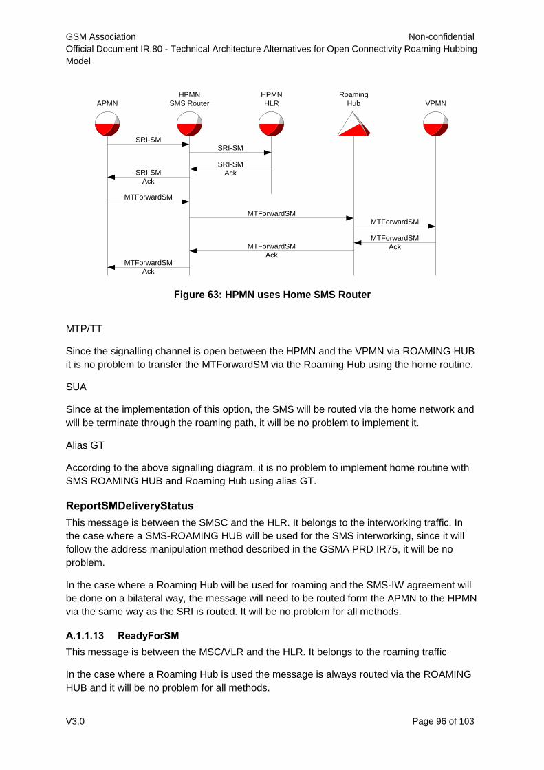
GSM Association Non-confidential
Official Document IR.80 - Technical Architecture Alternatives for Open Connectivity Roaming Hubbing
Model
V3.0 Page 96 of 103
Figure 63: HPMN uses Home SMS Router
MTP/TT
Since the signalling channel is open between the HPMN and the VPMN via ROAMING HUB
it is no problem to transfer the MTForwardSM via the Roaming Hub using the home routine.
SUA
Since at the implementation of this option, the SMS will be routed via the home network and
will be terminate through the roaming path, it will be no problem to implement it.
Alias GT
According to the above signalling diagram, it is no problem to implement home routine with
SMS ROAMING HUB and Roaming Hub using alias GT.
ReportSMDeliveryStatus
This message is between the SMSC and the HLR. It belongs to the interworking traffic. In
the case where a SMS-ROAMING HUB will be used for the SMS interworking, since it will
follow the address manipulation method described in the GSMA PRD IR75, it will be no
problem.
In the case where a Roaming Hub will be used for roaming and the SMS-IW agreement will
be done on a bilateral way, the message will need to be routed form the APMN to the HPMN
via the same way as the SRI is routed. It will be no problem for all methods.
A.1.1.13 ReadyForSM
This message is between the MSC/VLR and the HLR. It belongs to the roaming traffic
In the case where a Roaming Hub is used the message is always routed via the ROAMING
HUB and it will be no problem for all methods.
APMN
SRI-SM
SRI-SM
Ack
MTForwardSM
MTForwardSM
Ack
HPMN
SMS Router
SRI-SM
SRI-SM
Ack
MTForwardSM
MTForwardSM
Ack
HPMN
HLR VPMN
Roaming
Hub
MTForwardSM
MTForwardSM
Ack
GSM Association Non-confidential
Official Document IR.80 - Technical Architecture Alternatives for Open Connectivity Roaming Hubbing
Model
V3.0 Page 97 of 103
AlertSC / InformSC
These messages are sent from the HLR to the SMSC and belong to the interworking traffic,
in the case where a SMS-ROAMING HUB will be used for SMS interworking, since it will
follow the address manipulation method described in the GSMA PRD IR.75, it will be no
problem for all methods.
In the case where a Roaming Hub will be used for roaming and an SMS-IW will be setup on
a bilateral way, the message will need to be routed from the HPMN to the APMN in the same
way that the SRI_rslt will be routed. For all methods it will be no problem.
MOForwardSM
This message is from the MSC/VLR to the SMSC and belongs to the roaming traffic. In the
case where a Roaming Hub will be used it must always go via the Roaming Hub. For the
Roaming Hub using the alias GT method it is needed that they can receive this message
with the real address or with the alias address. It will be the responsibility of the ROAMING
HUB to find out a solution in order to separate this message.
A.2 SMS Interworking Anomalies
Traffic Separation for MTP/TT/SUA
In the pure roaming environment, it is possible for the inclusion of a Roaming Hub to present
a routing anomoly when a tunneling method is used.
Since the VLR addresses are not manipulated, the MTForwardSM will need to be sent to the
Roaming Hub. It means in the case where it is a bilateral SMS-IW agreement, it is necessary
for the HPMN to route the MTForwardSM message to the Roaming Hub if the IMSI
contained in the message belongs to the HPMN network.
But what happens when the IMSI in the MTForwardSM does not belong to the HPMN, but is
the result of the SMSC delivering an interworking SMS?
The traffic separation mechanism of the HPMN may be as simple as just routing based on
the SCCP called Party Address (the visited MSC in the VPMN).
When the SMS is destined to an IMSI belonging to the HPMN, this traffic separation is
completely acceptable. When interworking traffic is involved, other dependencies must be
examined. Does the HPMN use an SMS-ROAMING HUB for interworking? If so, then the
SMS for the interworking IMSI should be passed to the SMS-ROAMING HUB. If no SMS-
ROAMING HUB is used for interworking, then routing may not have worked prior to
introduction of the Roaming Hub since the two operators had no agreement between them.
The roaming could choose to offer the interworking service or re-route the traffic on behalf of
the HPMN using the same method employed prior to the Roaming Hub presence.
In order to solve this issue, it could be imagined that all the MTForwardSM message will be
sent to the Roaming Hub. In this case the Roaming Hub will need to provide the SCCP
carrier service to the HPMN.
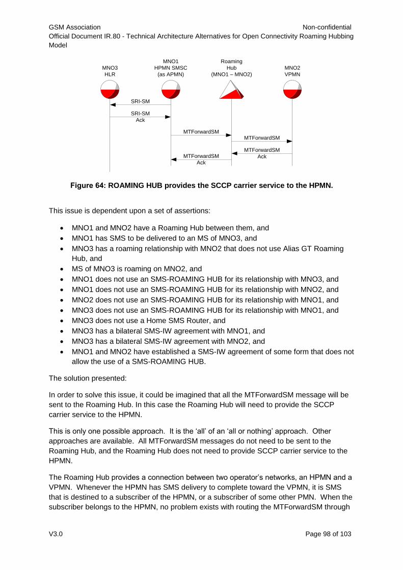
GSM Association Non-confidential
Official Document IR.80 - Technical Architecture Alternatives for Open Connectivity Roaming Hubbing
Model
V3.0 Page 98 of 103
Figure 64: ROAMING HUB provides the SCCP carrier service to the HPMN.
This issue is dependent upon a set of assertions:
MNO1 and MNO2 have a Roaming Hub between them, and
MNO1 has SMS to be delivered to an MS of MNO3, and
MNO3 has a roaming relationship with MNO2 that does not use Alias GT Roaming
Hub, and
MS of MNO3 is roaming on MNO2, and
MNO1 does not use an SMS-ROAMING HUB for its relationship with MNO3, and
MNO1 does not use an SMS-ROAMING HUB for its relationship with MNO2, and
MNO2 does not use an SMS-ROAMING HUB for its relationship with MNO1, and
MNO3 does not use an SMS-ROAMING HUB for its relationship with MNO1, and
MNO3 does not use a Home SMS Router, and
MNO3 has a bilateral SMS-IW agreement with MNO1, and
MNO3 has a bilateral SMS-IW agreement with MNO2, and
MNO1 and MNO2 have established a SMS-IW agreement of some form that does not
allow the use of a SMS-ROAMING HUB.
The solution presented:
In order to solve this issue, it could be imagined that all the MTForwardSM message will be
sent to the Roaming Hub. In this case the Roaming Hub will need to provide the SCCP
carrier service to the HPMN.
This is only one possible approach. It is the ‘all’ of an ‘all or nothing’ approach. Other
approaches are available. All MTForwardSM messages do not need to be sent to the
Roaming Hub, and the Roaming Hub does not need to provide SCCP carrier service to the
HPMN.
The Roaming Hub provides a connection between two operator’s networks, an HPMN and a
VPMN. Whenever the HPMN has SMS delivery to complete toward the VPMN, it is SMS
that is destined to a subscriber of the HPMN, or a subscriber of some other PMN. When the
subscriber belongs to the HPMN, no problem exists with routing the MTForwardSM through
MNO1
HPMN SMSC
(as APMN)
SRI-SM
SRI-SM
Ack
MTForwardSM
MTForwardSM
Ack
MNO3
HLR
MNO2
VPMN
Roaming
Hub
(MNO1 – MNO2)
MTForwardSM
MTForwardSM
Ack
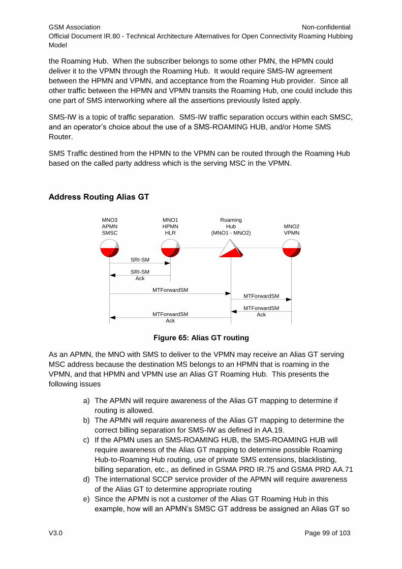
GSM Association Non-confidential
Official Document IR.80 - Technical Architecture Alternatives for Open Connectivity Roaming Hubbing
Model
V3.0 Page 99 of 103
the Roaming Hub. When the subscriber belongs to some other PMN, the HPMN could
deliver it to the VPMN through the Roaming Hub. It would require SMS-IW agreement
between the HPMN and VPMN, and acceptance from the Roaming Hub provider. Since all
other traffic between the HPMN and VPMN transits the Roaming Hub, one could include this
one part of SMS interworking where all the assertions previously listed apply.
SMS-IW is a topic of traffic separation. SMS-IW traffic separation occurs within each SMSC,
and an operator’s choice about the use of a SMS-ROAMING HUB, and/or Home SMS
Router.
SMS Traffic destined from the HPMN to the VPMN can be routed through the Roaming Hub
based on the called party address which is the serving MSC in the VPMN.
Address Routing Alias GT
Figure 65: Alias GT routing
As an APMN, the MNO with SMS to deliver to the VPMN may receive an Alias GT serving
MSC address because the destination MS belongs to an HPMN that is roaming in the
VPMN, and that HPMN and VPMN use an Alias GT Roaming Hub. This presents the
following issues
a) The APMN will require awareness of the Alias GT mapping to determine if
routing is allowed.
b) The APMN will require awareness of the Alias GT mapping to determine the
correct billing separation for SMS-IW as defined in AA.19.
c) If the APMN uses an SMS-ROAMING HUB, the SMS-ROAMING HUB will
require awareness of the Alias GT mapping to determine possible Roaming
Hub-to-Roaming Hub routing, use of private SMS extensions, blacklisting,
billing separation, etc., as defined in GSMA PRD IR.75 and GSMA PRD AA.71
d) The international SCCP service provider of the APMN will require awareness
of the Alias GT to determine appropriate routing
e) Since the APMN is not a customer of the Alias GT Roaming Hub in this
example, how will an APMN’s SMSC GT address be assigned an Alias GT so
MNO3
APMN
SMSC
SRI-SM
SRI-SM
Ack
MTForwardSM
MTForwardSM
Ack
MNO1
HPMN
HLR
MNO2
VPMN
Roaming
Hub
(MNO1 - MNO2)
MTForwardSM
MTForwardSM
Ack

GSM Association Non-confidential
Official Document IR.80 - Technical Architecture Alternatives for Open Connectivity Roaming Hubbing
Model
V3.0 Page 100 of 103
that it is understood by the VPMN, and results routed back through the Alias
GT Roaming Hub?
Note: This behaviour is parallel to what it is actually happening with bilateral roaming.
GSM Association Non-confidential
Official Document IR.80 - Technical Architecture Alternatives for Open Connectivity Roaming Hubbing
Model
V3.0 Page 101 of 103
Conclusion
According to the signalling diagrams of previous sections, it can be concluded that the SMS-
IW traffic can be transported when Roaming Hubs are used. It is possible as well to have in
parallel Roaming Hub agreement and SMS-IW agreement towards an independent SMS
Roaming Hub or on a bilateral way.
Depending of the topology of the APMN, HPMN and VPMN networks, it will be possible for
the PMN to choose the ROAMING HUB according to connection options that the ROAMING
HUB are offering. Therefore, the PMNs using Roaming Hub have to be aware that in the
case where the SMS will not be transiting via the Roaming Hub, the Roaming Hub will not be
in position to screen this traffic and to guaranty the delivery of the message in case of mixed
scenario. In order to ensure a minimum quality of service for SMS, it would be recommended
that the connection between the Roaming Hub and the PMN is setup in a way that the
Roaming Hub is transporting the roaming leg of the SMS whatever architecture is used.
However, if the PMN chooses to have an SMS-ROAMING HUB provide all SMS interworking
including SMS interworking to roamers, without the involvement of a Roaming Hub, this
choice is also available. GSMA PRD IR.75 has a recommended preferred solution for SMS
interworking to an MS while roaming. It is a pure SMS ROAMING HUB solution that allows
each operator to limit access to their network elements to only their chosen SMSIP for all
interworking including interworking to roamers.
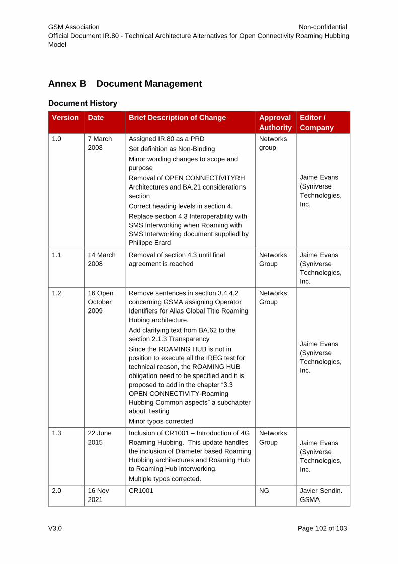
GSM Association Non-confidential
Official Document IR.80 - Technical Architecture Alternatives for Open Connectivity Roaming Hubbing
Model
V3.0 Page 102 of 103
Annex B Document Management
Document History
Version Date Brief Description of Change Approval
Authority
Editor /
Company
1.0 7 March
2008
Assigned IR.80 as a PRD
Set definition as Non-Binding
Minor wording changes to scope and
purpose
Removal of OPEN CONNECTIVITYRH
Architectures and BA.21 considerations
section
Correct heading levels in section 4.
Replace section 4.3 Interoperability with
SMS Interworking when Roaming with
SMS Interworking document supplied by
Philippe Erard
Networks
group
Jaime Evans
(Syniverse
Technologies,
Inc.
1.1 14 March
2008
Removal of section 4.3 until final
agreement is reached
Networks
Group
Jaime Evans
(Syniverse
Technologies,
Inc.
1.2 16 Open
October
2009
Remove sentences in section 3.4.4.2
concerning GSMA assigning Operator
Identifiers for Alias Global Title Roaming
Hubing architecture.
Add clarifying text from BA.62 to the
section 2.1.3 Transparency
Since the ROAMING HUB is not in
position to execute all the IREG test for
technical reason, the ROAMING HUB
obligation need to be specified and it is
proposed to add in the chapter “3.3
OPEN CONNECTIVITY-Roaming
Hubbing Common aspects” a subchapter
about Testing
Minor typos corrected
Networks
Group
Jaime Evans
(Syniverse
Technologies,
Inc.
1.3 22 June
2015
Inclusion of CR1001 – Introduction of 4G
Roaming Hubbing. This update handles
the inclusion of Diameter based Roaming
Hubbing architectures and Roaming Hub
to Roaming Hub interworking.
Multiple typos corrected.
Networks
Group Jaime Evans
(Syniverse
Technologies,
Inc.
2.0 16 Nov
2021
CR1001 NG Javier Sendin.
GSMA
GSM Association Non-confidential
Official Document IR.80 - Technical Architecture Alternatives for Open Connectivity Roaming Hubbing
Model
V3.0 Page 103 of 103
3.0 16 Nov
2021
CR1002 NG Javier Sendin
GSMA
Other Information
Type Description
Document Owner Networks Group
Editor / Company Javier Sendin (GSMA)
It is our intention to provide a quality product for your use. If you find any errors or omissions,
please contact us with your comments. You may notify us at [email protected]
Your comments or suggestions & questions are always welcome.