Embed Size (px)
Citation preview

ICS 27.060.30
J98
Record number: NB Energy Sector Standard of the People's Republic of China
NB/T 47043—2014 Replace JB/T 1620—1993
Technical specification for
manufacture of boiler steel structures
锅炉钢结构制造技术规范
(English translation)
Issue date:2014-06-29 Implementation date:2014-11-01
Issued by National Energy Administration of the People's Republic of China


NB/T 47043—2014
I
Foreword
SAC/TC 262 is in charge of this English translation. In case of any doubt about the contents
of English translation, the Chinese original shall be considered authoritative.
This standard is drafted in accordance with the rules given in GB/T 1.1—2009 Directives for
standardization—Part 1: Structure and drafting of standards.
This standard replaces the JB/T 1620— 1993 (Technical specifications for boiler steel
structure) in whole.
In addition to a number of editorial changes, the following revisions have been made with
respect to the JB/T 1620—1993(Technical specifications for boiler steel structure) (the
previous edition):
—The Chapter of Terms and Definitions is added, and the definitions of main terms are given
to correctly explain the content of this Standard, and avoid misunderstanding.
—The requirement that the main girder and steel plate with thickness of greater than or equal
to 60 mm need to be subject to 100% ultrasonic testing is added in Chapter V.
—The requirements for eliminating residual stress and flame cutting preheating in preparation
are added.
—Provision for H-steel splicing is added.
—The specific requirements for welding operation environment, welding material management,
welding preheating, post welding heat treatment, etc. are added.
—The content of drilling is added, and the high strength bolt hole and hole diameter tolerance
are specified.
—Provision for friction type high strength bolt faying surface is added.
—The requirements on allowable deviation for various kinds of compound sections are added.
—Requirements for beam, column bending vector and beam camber are modified.

NB/T 47043—2014
II
—The tolerance requirements for high strength bolt jointing members and connections are added.
—Provision for flame cutting tolerance is added.
—Provision for fabrication tolerance of horizontal split girder is added.
—Provision for fabrication tolerance of column base is added.
—The quality grades and the relevant detection requirements of types of welds are added.
—The chapter of trial assembly is added.
This Standard was proposed and prepared by SAC/TC 262(China Standardization Committee on
Boilers and Pressure Vessels).
The main translation organization of the English version of this standard is Babcock & Wilcox
Beijing Co, Ltd.
The main translators of the English version of this standard are Sun Hongpeng and Qu Zhen.
The previous edition of this standard is as follows:
—JB/T 1620-1993.

NB/T 47043—2014
III
Contents
Foreword ............................................................................. I
1 Scope .............................................................................. 1
2 Normative References ............................................................... 1
3 Terms and Definitions .............................................................. 2
4 General Requirements ............................................................... 2
5 Materials .......................................................................... 3
6 Manufacture ........................................................................ 4
7 Welding ............................................................................ 8
8 Dimensional Tolerances ............................................................. 9
9 Inspection ........................................................................ 23
10 Repair ........................................................................... 26
11 Trial Assembly ................................................................... 27
12 Rust Removal, Painting and Packaging ............................................. 28
13 Marking .......................................................................... 28
14 Quality Certificate .............................................................. 29


NB/T 47043—2014
1
Technical specification for manufacture of boiler
steel structures
1 Scope
This standard specifies the requirements of boiler steel structure fabrication and inspection.
This standard is applicable to boiler steel structure columns, beams, vertical braces,
horizontal braces, trusses, frameworks, platform and stairs, column base plates, anchor bolt
fixing frames, buckstays, etc.
2 Normative References
The following referenced documents are indispensable for the application of this standard.
For dated references, only the edition cited applies. For undated references, the latest
edition of the referenced document (including any amendments) applies.
GB/T 700 Carbon structural steels
GB/T 1228 High strength bolts with large hexagon head for steel structures
GB/T 1229 High strength large hexagon nuts for steel structures
GB/T 1230 high strength plain washers for steel structures
GB/T 1231 Specifications of high strength bolts with large hexagon head, large hexagon nuts,
plain washers for steel structures
GB/T 1591 High strength low alloy structural steels
GB/T 3632 Sets of torshear type high strength bolt hexagon nut and plain washer for steel structure
GB/T 5117 Covered electrodes for manual metal arc welding of non-alloy and fine grain steels
GB/T 5118 Covered electrodes for manual metal arc welding of creep-resisting steels
GB/T 5293 Carbon steel wire and flux for submerged arc welding
GB/T 5313 Steel plates with through-thickness characteristics
GB/T 8110 Welding wires for gas shielding arc welding of carbon and low alloy steels
GB/T 10045 Carbon steel flux cored wire
GB/T 12470 Low-alloy steel wire and flux for submerged arc welding
GB/T 14957 Steel wires for melt welding
GB/T 17493 Low alloy steel flux cored electrodes for arc welding
GB/T 22395 Specification for design of boiler steel structures
GB 50661 Code for welding of steel structures
JB/T 1615 Specifications for painting and packing of boiler
JB/T 3223 Rules of quality management of welding materials
JB/T 3375 Rules for receiving acceptance of materials for boiler construction
JB/T 4730.3 Nondestructive testing of pressure equipment Part 3: ultrasonic testing

NB/T 47043—2014
2
JB/T 4730.4 Nondestructive testing of pressure equipment Part 4: magnetic particle testing
JGJ 82 Technical specification for high strength bolt connections of steel structures
YB/T 4001.1 Steel bar grating and matching parts Part 1:steel bar grating
3 Terms and Definitions
3.1
main column
It mainly bears the boiler proper load, wind load and seismic action, including the internal
columns and external columns of boiler steel structure
3.2
main boiler support level
It is the general name of the girders used to suspend or support the boiler proper load at
the top of boiler steel structure
3.3
main girder
It is the girder in the main boiler support level directly transferring the boiler proper load
to column
3.4
secondary girder
It is connected with the main girder and transfers load to the main girder
3.5
horizontal split girder
The girder is composed of upper part and lower part, which are connected by bolts or welds
to operate together
3.6
buckstay
It surrounds and is hung on the periphery of the wall of the boiler, and it is a steel structure
system to protect the wall of the boiler
4 General Requirements
4.1 The boiler steel structure designed by GB/T 22395 shall be manufactured and inspected
according to this standard.
4.2 The manufacturer of boiler steel structure shall have the relevant qualification, and
have the effective quality management system and quality control and inspection system.
4.3 The manufacture and acceptance of boiler steel structure shall adopt the qualified
measuring instruments which have been subject to metrological verification and calibration.
4.4 Welder (including tack welder) shall have the relevant operation qualification
certificate, his/her welding scope shall not exceed the provision of the qualification
certificate, and welding operation shall meet the requirements in the process documents.
4.5 Nondestructive testing operator and adjudicator shall get the relevant qualification
certificate by assessment according to the relative requirements.

NB/T 47043—2014
3
4.6 When the steel, welding materials, structure form, requirements of post welding heat
treatment(PWHT), welding specification parameters, preheating and post heat treatment
measures are adopted for the first time, the welding process shall be evaluated according to
GB 50661.
4.7 If quality issue appears during manufacture process of boiler steel structure, reasons
shall be found out timely while repairing, and measures shall be taken.
4.8 When bolt connected structure or complex structure is finished, it should be subject to
trial assembly in the factory.
5 Materials
5.1 The materials for boiler steel structure shall meet the requirements in the design
documents, and the welding material shall meet the requirements in the process documents.
5.2 A quality certificate shall be provided for all the steel and welding materials for boiler
steel structure. Mechanical property and chemical composition of steel shall meet the
requirements in GB/T 700, GB/T 1591 and GB 5313; electrodes shall meet the requirements in
GB/T 5117 and GB/T 5118. Welding wires and flux for submerged arc welding shall meet the
requirements in GB/T 5293 and GB/T 12470. Welding wires for gas-shielded arc welding shall
meet the requirements in GB/T 8110, GB/T 10045, GB/T 14957 and GB/T 17493.
5.3 The set of high strength bolt assemblies shall meet the requirements in GB/T 1228, GB/T
1229, GB/T 1230, GB/T 1231 and GB/T 3632 respectively.
5.4 Other materials, not specified in this standard, shall meet the relevant standards
5.5 For the material meeting one of the following conditions, the steel plate shall be subject
to 100% ultrasonic testing, and the quality grade shall meet the requirements of Grade III
in JB/T 4730.3:
a) For flange and web of main girder, when the thickness of the low-alloy high-strength
structural steel adopted is more than or equal to 32 mm, or of the carbon structural steel
adopted is more than or equal to 36 mm.
b) When the thickness of steel plate is more than or equal to 60 mm.
c) When required by design, even if the thickness of steel plate is less than 60 mm.
5.6 Materials, meeting one of the following conditions, shall be subject to re-inspection
according to JB/T 3375, and unqualified materials shall not be used:
a) Welding materials.
b) Steel plate thickness more than 50 mm incl., and having the Z direction performance
requirement.
c) Steel for manufacturing main girder (including connecting plates at both ends or connecting
angles at both ends) and main column.
d) Steel having quality doubts.
e) When there are design requirements.
5.7 To avoid misuse of materials, materials shall be marked, and the marking transferring
shall meet the relative requirements.
5.8 Material substitution shall be approved according to the specific procedures.

NB/T 47043—2014
4
6 Manufacture
6.1 Material preparation
6.1.1 Steel products(steel plates and section steels) shall be corrected before material
preparation.
6.1.2 The methods of machining, shearing (punching), band sawing, flame cutting and grinding
may be used for material preparation, no lamination, crack, slag inclusion and other defects
shall be allowed at the steel edge after material preparation, where the slag and burr shall
be removed to ensure the edge of material to be flat.
6.1.3 When the thickness of steel plate is more than 20 mm, the heat treatment shall be
performed to relieve the residual stress after shearing (punching).
6.1.4 After flame cutting is performed for the steel plate at bottom flange of main girder,
relevant measures may be taken to relieve the residual stress.
6.1.5 When the thickness of steel plate is more than 40 mm, and the flame cutting is adopted,
the preheating may be required and carried out according to the process requirements.
6.2 Splicing
6.2.1 Splicing of steel plates and hot rolled section steels shall conform to the requirements
specified in this standard.
6.2.2 As for the beams, columns and other members that need to be spliced, the manufacturer
shall make the splicing drawings in advance, and the splicing drawings of main girder shall
be countersigned by the design department.
6.2.3 Splicing of hot rolled section steel may adopt the following two forms:
a) Butt weld with full penetration.
b) Reinforced plate structure. As for the splicing of angle steels, channel steels, I steels
and H steels, single-V butt weld shall be adopted for the areas covered by the reinforced plate,
other splicing areas shall adopt single-V butt weld with welding by both sides (back sealing
weld), as shown in Figure 1. Groove size shall conform to the process requirements given by
the manufacturer, the size of reinforced plate and the leg size K of fillet weld surrounding
the reinforced plate shall comply with the values specified in Tables 1 through 3.
Figure 1 Splicing Drawing of Angle Steels, Channel Steels, I Steels and H Steels

NB/T 47043—2014
5
Table 1 Size of Reinforced Plate for Angle Steel
Section Size Reinforced plate size(A ×
B) mm
K
mm Section Size
Reinforced plate size(A
× B) mm
K
mm
L75x50x8 δ=6 ,30x100 5 L160x100x12
δ=8,100x100
60x100 6
L75x75x8 δ=6, 40x100 5
L100x63x8 δ=6, 40x100 5 L160x100x16
δ=8 ,100x140
60x140
6 L100x63x10 δ=6 ,40x100 5
L100x100x10 δ=6 , 60x100 5 L160x160x12 δ=8 ,100x140 6
L125x80x10 δ=6 ,60x100 5 L160x160x16 δ=8 ,100x140 6
L125x125x12 δ=8 ,80x100 6 L200x200x20 δ=12,140x200 10
Table 2 Size of Reinforced Plate for I Steel and Channel Steel
Section Size Reinforced plate size
(A × B)mm
K
mm Section Size
Reinforced plate size
(A × B) mm
K
mm
I10 [10 No reinforced plate
(groove welding) — I32 [32 δ=8,220x200 6
I12 [12 No reinforced plate
(groove welding) — I36 [36 δ=8,240x200 6
I14 [14 δ=6 ,100x200 5 I40 [40 δ=10,280x200 8
I16 [16 δ=6 ,120x200 5 I45 δ=10,320x200 8
I20 [20 δ=6 ,140x200 5 I50 δ=10,360x200 8
I25 [25 δ=8 ,160x200 6 I56 δ=10,400x200 8
I28 [28 δ=8 ,180x200 6 I60 δ=12,400x200 8
I30 [30 δ=8 ,200x200 6 I63 δ=12,500x200 8
Table 3 Size of Reinforced Plate for H Steel
Section Size (height × width) Reinforced plate size (A ×
B)mm
K
mm HW HM HN
150x150 150x100 150x75 δ=6 ,90x200 5
175x175 - 175x90 δ=6 ,100x200
200x200 200x150 200x100 δ=8 ,140x200 6
250x250 250x175 250x125 δ=8 ,160x200
300x300 300x200 300x150 δ=10 ,200x200
8 350x350 350x250 350x175 δ=10 ,240x200
400x400 400x300 400x200 δ=10 ,280x200
- 450x300 450x200 δ=10 ,320x200
- 500x300 500x200 δ=14 ,400x200
12 - 600x300 600x200 δ=14 ,450x200
- - 700x300 δ=14 ,500x200

NB/T 47043—2014
6
6.2.4 Hot rolled H-steel shall be procured in specified length, and splicing is not
recommended in manufacturing. When it has to be spliced, the weld access hole may be drilled
on the web according to the following requirements:
a) The height of weld access hole should be 1.5 times of the thickness of web, and shall be
more than or equal to 20 mm, the spacing between the junction of hole edge and flange and the
weld-fusion line of flange shall be more than 10 mm, and the radius of weld access hole on
web should be better in 25 mm - 35 mm.
b) Deposit welding shall not be adopted to block the weld access hole.
6.2.5 Layout of splicing welding joint shall conform to the following requirements:
a) The spacing between the centerlines of two splicing welding joints for adjacent parts of
an assembled unit shall be more than or equal to 200 mm.
b) The spacing between the centerline of splicing welding joint of beam or column and the
edge of weld for bracket, clapboard or other weld assemblies should be more than or equal to
100 mm.
c) When splicing is required in both the longitudinal and transverse direction on the same steel
plates, the T-shaped cross welding joint should be adopted, and the spacing between two T-shaped
cross points shall be more than or equal to 200 mm.
d) Splicing weld shall keep away from the bolt holes, and the distance between the center
line of splicing weld and hole should be more than or equal to 120 mm.
6.2.6 If the member is too long, hot rolled section steel or steel plate needs to be spliced
in the length direction, the allowed number of splicing joints shall conform to the requirements
in Table 4, the shortest splice length shall be more than or equal to 1,000 mm.
Table 4 Allowed Number of Splicing Joints for Hot Rolled Section Steels or Steel Plates
Member length L/m L≤6 6<L≤ 10 10<L≤ 16 16<L≤ 24 24<L≤ 30 L>30
Allowed number of
splicing joints 1 2 3 4 5 6
6.2.7 No longitudinal splicing weld shall be allowed on the flange of combined section beams,
the number of splicing welds on the web in longitudinal direction (height) shall comply with
the requirements in Table 5, and the minimum width of splicing plate is 350 mm.
Table 5 Allowed Number of Splicing Joints on the Web of Built-up Beam Spliced in Longitudinal
Direction(Height)
Height of plate girder web H/mm 1,600<H≤2,600 2,600<H≤ 4,000 H>4,000
Allowed number of splicing
joints 1 2 3
6.2.8 Splicing of main girder is as shown in Figure 2.

NB/T 47043—2014
7
Figure 2 Splicing of Main Girder
6.2.9 Rolled direction of splicing plate shall be in line with the member length.
6.2.10 Column base should not be spliced.
6.3 Drilling
6.3.1 Standard hole and large circular hole for high strength bolt shall be prepared by
drilling, while slotted hole may be prepared by milling, with a surface roughness of Ra25.
6.3.2 The wall of hole for high strength bolt shall be perpendicular to the member surface.
6.3.3 The burrs and flashing around the holes shall be cleaned.
6.3.4 Hole needs to be match drilled required by the designer shall adopt the match drill
method.
6.3.5 Matching and allowable deviation of high strength bolt hole shall comply with the
requirements in Table 6.
Table 6 Matching and Allowable Deviation of High Strength Bolt Hole Unit mm
Nominal diameter M12 M16 M20 M22 M24 M27 M30 M33 M36
Type of
hole
Standard
hole
Diameter 13.5 17.5 22.0 24.0 26.0 30.0 33.0 36.0 39.0
Allowable deviation +0.43
0
+0.43
0
+0.52
0
+0.52
0
+0.52
0
+0.84
0
+0.84
0
+0.84
0
+0.84
0
Roundness 1.00 1.50
Large
circular
hole
Diameter 16.0 20.0 24.0 28.0 30.0 35.0 38.0 41.0 44.0
Allowable deviation +0.43
0
+0.43
0
+0.52
0
+0.52
0
+0.52
0
+0.84
0
+0.84
0
+0.84
0
+0.84
0
Roundness 1.00 1.50
Slotted
hole
Length
Short
direction 13.5 17.5 22.0 24.0 26.0 30.0 33.0 36.0 39.0
Long
direction 22.0 30.0 37.0 40.0 45.0 50.0 55.0 60.0 65.0
Allowable
deviation
Short
direction
+0.43
0
+0.43
0
+0.52
0 +0.52
+0.52
0
+0.84
0
+0.84
0
+0.84
0
+0.84
0
Long
direction
+0.84
0
+0.84
0
+1.00
0
+1.00
0
+1.00
0
+1.00
0
+1.00
0
+1.00
0
+1.00
0
Inclination of center line It shall be 3% of plate thickness, single layer plate shall be 2.0 mm,
and the multilayer plate shall be 3.0 mm

NB/T 47043—2014
8
6.4 Treatment of faying surface
6.4.1 The faying surface of high strength bolt friction-type joint shall be treated according
to the requirements of design document, and the mean slip coefficient of treated faying surface
shall conform to the requirements of design document.
6.4.2 To ensure that the mean slip coefficient of faying surface of high strength bolt friction
joint conforms to the design requirements, the manufacturer shall use the manufacturing batch
as the unit to carry out the mean slip coefficient test, every 2,000 t in the project is seemed
as a batch, and the part that less than 2,000 t is considered as a batch, each batch includes
three groups of specimens. The manufacturer shall provide the same number of specimens to
installation site for retesting the mean slip coefficient of faying surface before installation.
The test method shall conform to JGJ 82.
6.4.3 The steel surface at the joint of high strength bolts shall be smooth. The welding
spatter, burr, oxide scale and greasy dirt shall not be allowed on the surface.
6.4.4 Treated faying surface at the junction of high strength bolts shall be taken protective
measures, so as to prevent to be infected by dirt or grease.
6.5 Straightening
6.5.1 In order to make the profile of the member conform to the requirements, the mechanical
( cold straightening)or flame( hot straightening) shall be allowed before and after assembly.
6.5.2 When the environment temperature is less than -12°C for low alloy high strength
structural steel, or less than -16°C for carbon structural steel, mechanical straightening
shall not be allowed, and the mechanically straightened steel surface shall not has obvious
indentation or damage. The temperature of flame heating for the straightening is generally
in the range of 600°C - 900°C, while local overheating shall be avoided, air cooling shall
be adopted, and water cooling is forbidden, the straightening by flame heating should not be
performed more than two times.
7 Welding
7.1 The operation environment of welding shall conform to the following requirements:
a) Relative humidity at welding area shall not be more than 90%.
b) Welding shall not be implemented without preheating measures when the environmental
temperature is lower than 0 ℃.
c) When the surface of weldment is moist, the preheating and drying measures shall be taken
before welding, and the preheating shall conform to relevant requirements.
d) Welding operation area shall be taken the wind resistant measures to ensure the welding
quality.
7.2 Welding material shall conform to the requirements of JB/T 3223.
7.3 Welding material baking and holding shall conform to the requirements of product
specification and relevant process documents, and the repeated baking shall not be more than
two times. Welding material in use shall have an obvious mark, and there is no corrosion, greasy
dirt and other dirt on the welding wire.

NB/T 47043—2014
9
7.4 According to the environmental temperature and humidity, as well as steel material
category and plate thickness at the work place, the appropriate temperature shall be adopted
to preheat the weldment before welding. Members that need to be preheated, may be uniformly
preheated on both sides of welding bead within the range of 1.5 times the plate thickness,
which shall be more than or equal to 100 mm, and the preheating temperature shall be measured
at the place 75 mm away from the bead edge.
The resistance heat, flame heat or far-infrared ray heat may be taken as the source of welding
preheating, but the heat produced by welding shall not be used instead.
7.5 No metal rod or electrode is allowed to be inserted into the assembling clearance of weld.
7.6 For the double-sided fully penetrated weld, after the front welding is finished, it is
requested to remove the slag, overlap and clean the areas that lack of penetration at the root
of weld joint from back side till the metal of front weld is exposed.
7.7 The surface and edge to be welded shall be kept smooth and clean, free from flash, crack
or any other defects that have negative effects on welding quality or weld strength. The scale,
slag, rust, grease, oil paint and other foreign objects on the edges and grooves and on the
surface of weldment to be welded in a 30 mm width on both sides shall be cleaned up before
the completion of welding.
7.8 To correctly position the member to be welded, tack welding shall be performed after the
weldment is fixed by appropriate means, and qualified material used for tack welding shall
be in the same level as that for final welding. If the tack weld is to be taken as a part of
final weld, it shall meet the quality requirements of final weld, and if it is not, the tack
weld shall be removed and ground.
7.9 Arc striking is not allowed on the base metal. The crack and surface defects caused by
the arc striking shall be ground, and magnetic particle tests shall be carried out if necessary.
7.10 Both edges of a butt joint shall be correctly aligned, and the edge deviation shall not
exceed 10% of the thickness of the thinner side, which shall be less than or equal to 3 mm,
the thicker side shall be tapered at a gradient not greater than 1:2.5, to achieve sound
alignment with the thinner side.
7.11 Put the welder stamp on the product once Class I weld is finished, and make the welding
records for other classes of welds.
7.12 For structural steels sensitive to cold cracks, hydrogen relief treatment shall be
performed immediately after welding, so as to prevent the generation of delayed crack resulting
from the accumulation of diffusible hydrogen. If the post weld heat treatment(PWHT) is to be
made within 24 hours after the welding, the hydrogen relief treatment may be omitted.
7.13 The PWHT shall be made according to the welding procedure specification. When resistance
heating is used to perform local heat treatment for the weldment, the width of the heating
plate (strip) at each side of the weld joint shall be more than or equal to 3 times of the
plate thickness and more than or equal to 200 mm, and the base metal out of the heating plate
(strip) shall be insulated to prevent producing excessive temperature gradient. The
temperature of heated parts shall be measured, while PWHT records shall be made. All
thermocouples, measuring instruments and recording devices shall be calibrated and validated.
8 Dimensional Tolerances

NB/T 47043—2014
10
8.1 Dimensional tolerances of built-up sections shall comply with the requirements in Table
7.
Table 7 Dimensional Tolerances of Built-up Section
No Legend Item Tolerances mm
1
Sectional
height(H)
H≤ 500 ±2
500<H≤1,000 ±3
1,000<H≤2,000 ±5
H>2,000 +8
-5
Sectional
width(B)
B≤ 500 ±2
500<B≤1,000 ±3
B>1,000 ±5
2
Web center
tolerances (Δ)
H≤ 1,000 2
1,000<
H≤2,000
4
H>2,000
6
3
Perpendicularity
of flange to web
(Δ)
Joint is 1.5,
other place is B/100, and shall
not be more than 5
4
Distance
tolerances of
double web girder
(b)
±2
5
Outline dimension
of section B (H)
B(H)≤ 500 ±2
500<B(H)≤1,000 ±3
1,000<B(H)≤2,000 ±5
B(H)>2,000 +8
-5

NB/T 47043—2014
11
Table 7 (continued)
No. Legend Item Tolerances mm
6
Diagonal
difference 5
7
Diagonal
difference of
section in box
shape
3
8
Perpendiculari
ty of box wall
of section in
box shape (Δ)
B(H)/150, and not more than
5
9
Local flatness
of web (f)
tw<14 3
tw≥ 14 2
10
Distortion of
H-shaped
section (Δ)
H≤ 800 3
800<
H≤2,000 6
H>2,000 H/250≤ 12
NB/T 47043—2014
12
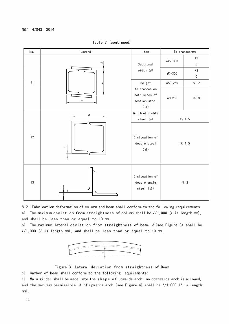
Table 7 (continued)
No. Legend Item Tolerances/mm
11
Sectional
width (B)
B≤ 300 +2
0
B>300 +3
0
Height
tolerances on
both sides of
section steel
(Δ)
H≤ 250 ≤ 2
H>250 ≤ 3
12
Width of double
steel (B)
≤ 1.5
Dislocation of
double steel
(Δ)
≤ 1.5
13
Dislocation of
double angle
steel (Δ)
≤ 2
8.2 Fabrication deformation of column and beam shall conform to the following requirements:
a) The maximum deviation from straightness of column shall be L/1,000 (L is length mm),
and shall be less than or equal to 10 mm.
b) The maximum lateral deviation from straightness of beam Δ(see Figure 3) shall be
L/1,000 (L is length mm), and shall be less than or equal to 10 mm.
Figure 3 Lateral deviation from straightness of Beam
c) Camber of beam shall conform to the following requirements:
1) Main girder shall be made into the shape of upwards arch, no downwards arch is allowed,
and the maximum permissible Δ of upwards arch (see Figure 4) shall be L/1,000 (L is length
mm).

NB/T 47043—2014
13
2) Except for the main girder, when the length is less than or equal to 20,000 mm, the camber
Δ of other beams should be -5 mm - +10 mm, and when the length is more than 20,000 mm, the
camber should be -5 mm-+15 mm, and generally, it should be made into the shape of upwards
arch.
Figure 4 Girder camber
8.3 Length tolerances of members shall conform to the following requirements:
a)Length tolerances of welding structure shall comply with the values in Table 8.
Table 8 Length Tolerances of Welding Structure Unit: mm
Item
Length L
L≤ 1,000 1,000<L≤
3,000
3,000<L≤
5,000
5,000<L≤
8,000
8,000<L≤
10,000
10,000<L
≤ 15,000 L>15,000
Length tolerances
Column 0
-4
0
-4
0
-4
0
-4
+2
-6
+2
-6
+2
-6
Girder 0
-4
0
-6
0
-8
0
-10
0
-10
0
-10
0
-10
Brace and
column
0
-3
0
-3
0
-3
0
-4
0
-4
0
-6
0
-8
Guard frame 0
-6
0
-8
0
-10
0
-12
0
-12
0
-12
0
-12
Truss 0
-3
0
-5
0
-6
0
-8
0
-9
0
-12
0
-12
b) The tolerances of length L1 (see Figure 5) from center line of main girder to the bearing
axis: less than or equal to 2 mm for the case with hole, and less than or equal to 5 mm for
the case without hole.

NB/T 47043—2014
14
Figure 5 Length Tolerances between Supports of Main Girder
c) For the beam with angle steels (or end plates) welded at both ends for connecting bolts,
the tolerances of its length (see Figure 6) shall be ±2 mm.
Figure 6 Length Tolerances of the beam with connection angles at both ends
d) For the beam with angle steel (or end plate) welded at one end for connecting bolts, the
tolerances of its length (see Figure 7) shall be ±3 mm.
Figure 7 Length Tolerances of the beam with connection angle at one end
e) In the case of free ends, the tolerances for the main girder is ±10 mm, and for other girders
the values in Table 8 shall be complied, the vertical tolerances between the free end and the
flange is 1/200 of the beam height H, and is less than or equal to 5 mm.
f) The length tolerances of milled members (column or other members) at both ends is ±2 mm.
g) The total length tolerances of the horizontal brace and vertical brace with free at both
ends is ±4 mm.
h) During manufacturing of a column, the length tolerance of each section shall meet the
requirements of this standard, and each column shall also be adjusted according to actual
dimension, so as to ensure that the accumulated tolerance of the length of the entire column
is within the permissible range.
8.4 The tolerances of hole pitch for high strength bolt shall comply with the values in Table
9, and the grouping methods of holes are listed below:
a) All holes on the connection plate connecting with one member are classified into one group.
b) Holes at one side of the connection plate of the butt joint are classified into one group.
c) Connecting holes between two adjacent nodes or joints (excluding holes mentioned above)
are classified into one group.
d) Holes within every 1 m at the flange of a flexural member are classified into one group.

NB/T 47043—2014
15
Table 9 Tolerances of Holes for High Strength Bolt Unit: mm
Hole pitch p p≤ 500 500<p≤ 1,200 1 200<p≤ 3,000 p>3,000
Between any two holes in the same
group ±1 ±1.5 — —
Between hole ends of two adjacent
groups ±1.5 ±2 ±2.5 ±3
8.5 The tolerance of the distance from center line of the outermost hole to the free edge
is ± 2 mm.
Note: the free edge refers to that the end face of the member is neither the datum plane nor used as a support,
and the end face is not connected with other parts.
8.6 The tolerances of the milled plane of the end face shall conform to the following
requirements:
a) The planeness of the milled plane shall be less than or equal to 0.3 mm.
b) The inclination (tangent value) of the milled plane shall be less than or equal to 1/1500,
and not more than 0.5 mm.
8.7 The tolerances at the edge of a butt joint between steel plates shall comply with the
values in Table 10.
Table 10 Tolerances at the Edge of a Butt Joint between Steel Plates Unit: mm
Thickness of steel
plate t 1≤ t≤4 4<t≤12 12<t≤18 t>18
Tolerances Δ ≤ 0.5 ≤ 1 ≤ 1.5 ≤ 2
8.8 The tolerances for flame cutting shall conform to the following requirements:
a) The depth of cutting veins shall be less than or equal to 0.3 mm.
b) The depth of the local notch at the cutting edge and surface shall be less than or equal
to 1 mm.
c) The tolerances of the perpendicularity of the cutting edge and surface shall be less than
or equal to 5% of plate thickness, and shall be less than or equal to 2 mm.
8.9 Besides the requirements in Section 8.3, other dimensional tolerances of the welding
connected column shall comply with the values in Figure 8.
NB/T 47043—2014
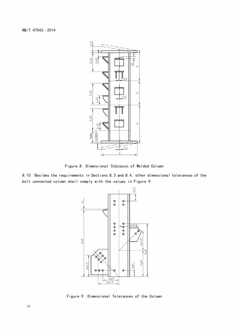
16
Figure 8 Dimensional Tolerances of Welded Column
8.10 Besides the requirements in Sections 8.3 and 8.4, other dimensional tolerances of the
bolt connected column shall comply with the values in Figure 9.
Figure 9 Dimensional Tolerances of the Column

NB/T 47043—2014
17
8.11 Besides the requirements in Sections 8.3 and 8.4, other dimensional tolerances of the
bolt connected girder shall comply with the following requirements:
a) For type I girder, see Figure 10:
Figure 10 Dimensional Tolerances of Girder (Type I)
b) For type II girder, see Figure 11.
Figure 11 Dimensional Tolerances for Girder (Type II)
8.12 The dimensional tolerances of connecting angle steel for the girder shall comply with
the values in Figure 12.
Figure 12 Dimensional Tolerances of Connecting Angle for Girder
8.13 When there is no connecting hole at the rib or division plate on the member, the tolerances
Δ1 of the spacing L between ribs or division plates will be ± 3 mm, and the tolerances Δ2 of

NB/T 47043—2014
18
the perpendicularity will be ± 3 mm. While there is connecting hole, the tolerances Δ1 of the
spacing L between ribs or division plate s will be ± 1.5 mm, while the tolerances Δ2 of the
perpendicularity will be ± 1 mm (see Figure 13).
Figure 13 Dimensional Deviation of Rib or Separator
8.14 Besides the requirements in Section 8.4, the dimensional tolerances of the node plate
for vertical support shall comply with the values in Figure 14.
Note: Δ1≤B/1 000≤1.5,
Δ2≤A/1 000≤1.5.
Figure 14 Dimensional Tolerances of Joint Plate for Vertical Support
8.15 Besides the requirements in Section 8.4, the dimensional tolerances of the joint plate
for horizontal support shall comply with the values in Figure 15.
Figure 15 Dimensional Tolerances of Joint Plate for Horizontal Support

NB/T 47043—2014
19
8.16 The tolerances of bolt connecting angle steel at the girder end shall comply with the
values in Figure 16.
Figure 16 Dimensional Tolerances of Connecting Angle at the Girder End
8.17 The tolerances of the connecting plate for column shall conform to the following
requirements(see Figure 17).
The surface planeness of the connecting plate shall not be greater than 1 mm, the tolerances
of spacing L2 is 0 mm - + 2 mm (measured at bottom), the perpendicularity Δ1 shall be less
than or equal to L1/200, and shall not be greater than 2 mm.
Figure 17 Dimensional Tolerances of Connecting Plate for Column
8.18 The tolerances of horizontal split girder shall conform to the following requirements:
a) After assembly of the split girder, the tolerances between center lines of upper and lower
webs Δ1 is 2 mm, and the allowable warping value for the combined interface Δ2 is 2 mm (see
Figure 18).

NB/T 47043—2014
20
Figure 18 Tolerances of Horizontal Split Girder
b) The total height tolerance of the horizontal split girder is -5 mm - + 8 mm.
c) Other tolerances of the horizontal split girder shall conform to the requirements in this
chapter.
8.19 The tolerances of the bracket dimension for the girder shall conform to the following
requirements (see Figure 19):
a) When the distance from the center line of bracket to the datum line is less than or equal
to 2,000 mm, the tolerance is ± 3 mm.
b) When the distance from the center line of bracket to the datum line is more than 2,000
mm, the tolerance is ± 5mm.
Figure 19 Dimensional Tolerances of Bracket on the Girder
8.20 The dimensional tolerances of the column base shall conform to the following
requirements:
a) For type I column base, see Figure 20:

NB/T 47043—2014
21
Figure 20 Dimensional Tolerances of Hinged Column Base Plate (Type I)
b) For type II column base, see Figure 21.
Figure 21 Dimensional Tolerances of Welded Column Base (Type II)

NB/T 47043—2014
22
8.21 Foundation bolt fixing frame shall conform to the following requirements:
a) The distortion of fixing frame shall be less than or equal to 5 mm.
b) The difference between diagonals on the same plane in the length, width and height direction
of fixing frame shall be less than or equal to 5 mm.
c) The tolerance for the hole diameter of the anchor bolt is 0 mm - + 1.5 mm, and the tolerance
of the hole pitch is ± 3 mm.
8.22 The dimensional tolerances of welded connecting truss (including frame) shall conform
to the following requirements:
a) The offset Δ1 of the crossing point of diagonal member axes at the truss shall be less
than or equal to 10 mm, the position offset Δ2 of the vertical bar shall be less than or equal
to 5 mm (see Figure 22), and the tolerances of the length shall comply with the values in Table
8.
Figure 22 Dimensional Tolerances of Truss
b) The tolerances and side-bend value of the truss diagonal shall comply with the values in
Table 11.
Table 11 Allowable Value of Diagonal Length Tolerances and Side-bend of Truss (Frame) Unit: mm
Length of truss
(frame) L ≤ 2,500 2,500<L≤5,000 5,000<L≤ 8,000 8,000<L≤ 10,000 L>10,000
Tolerance between
two diagonals 5 8 10 12 14
Side-bend value 4 6 8 10 12
8.23 The tolerances of the platform frame shall conform to the following requirements:
a) The dimensional tolerance of the length is -2 mm-0 mm per meter, and the total length
deviation shall not exceed -10 mm- 0 mm.
b) The dimensional tolerance of the width is ± 5 mm.
c) The allowable side-bend value shall comply with the values in Table 11.
8.24 The dimensional tolerances of the stair shall conform to the values in Figure 23.

NB/T 47043—2014
23
Figure 23 Dimensional Tolerances of Stair
8.25 The tolerances of the length of the baluster shall not exceed ± 5 mm.
8.26 The dimensional tolerances of the strut shall conform to the values in Figure 24.
Figure 24 Dimensional Tolerances of Strut
8.27 The planeness of the checker plate shall comply with the values in Table 12.
Table 12 Planeness of Checker Plate Unit: mm
Dimension of checker plate L Deviation
L≤ 800 ≤ 6
800<L≤ 1 200 ≤ 10
1 200<L≤ 1 700 ≤ 25
L>1 700 ≤ 38
8.28 The tolerances of steel grating plate and steel grating tread shall conform to the
requirements in YB/T 4001.1.
9 Inspection
NB/T 47043—2014
24
9.1 The boiler steel structure shall be inspected as per requirements given in the design
documents and this standard, and the product shall meet all requirements in the design documents
and this standard.
9.2 The weld shall be inspected as per the following quality grades and requirements. Unless
otherwise specified in the design document, the quality grade of other unspecified welds shall
be of Class III:
a) The quality grade of welds on main girders shall meet the following requirements:
1) The quality grade of butt welds of flanges and webs shall be of Class I.
2) The quality grade of fully penetrated T-joints between flanges and webs shall be of Class
II.
b) The quality grade of welds on secondary girders shall meet the following requirements:
1) The quality grade of butt welds of tension flanges shall be of Class I.
2) When the low-alloy high-strength structural steel with thickness greater than or equal
to 32 mm, or the carbon structural steel with thickness greater than or equal to 36 mm is used
for compression flanges and webs, the quality grade of their butt welds shall be of Class I,
and that of others shall be of Class II.
3) The quality grade of fully penetrated T-shaped welds between flanges and webs shall be
of Class II.
c) The quality grade of welds on main columns shall meet the following requirements:
1) The quality grade of butt welds of flanges and webs shall be of Class I.
2) The quality grade of fully penetrated T-shaped welds between flanges and webs shall be
of Class II.
d) The quality grade of welds on other beams, columns and vertical braces shall meet the
following requirements:
1) When the low-alloy high-strength structural steel with thickness greater than or equal
to 32 mm, or the carbon structural steel with thickness greater than or equal to 36 mm is used
for flanges and webs, their butt welds shall be of Class I, and that of others shall be of
Class II.
2) The quality grade of fully penetrated T-shaped welds between flanges and webs shall be
of Class II.
e) The quality grade of fully penetrated butt welds on hot rolled section steels (H-steel,
I-steel, U-steel and angle steel) used for main girders, secondary girders and main columns
shall be of Class I, and that of others shall be of Class II.
f) If there are butt joints on the column base plate, when the low-alloy high-strength
structural steel with thickness greater than or equal to 32 mm, or the carbon structural steel
with thickness greater than or equal to 36 mm is used for the colum base plate , the quality
grade of these butt welds shall be of Class I, and that of others shall be of Class II.
9.3 The visual inspection of welds shall meet the following requirements:
a) Overall dimension of all welds shall meet the requirements specified in design documents
and this standard. The weld surface shall present uniform ripple features, free from overlap
and burnt through, and the height of butt welds shall be greater than or equal to the thinkness
of base metal.
b) All welds shall be cooled down to ambient temperature before visual inspection.
NB/T 47043—2014
25
c) Visual inspection shall be adopted for the appearance of welds, and cracks shall be
inspected under proper light condition with 5 times power magnifying glass. If necessary,
magnetic particle testing shall be conducted. The dimension shall be measured with appropriate
tools and caliper gauges.
d) Dimension, position, length and intermittent weld interval of all welds shall be in
accordance with the requirements specified in design documents. The appearance quality of welds
shall comply with the requirements in Table 13.
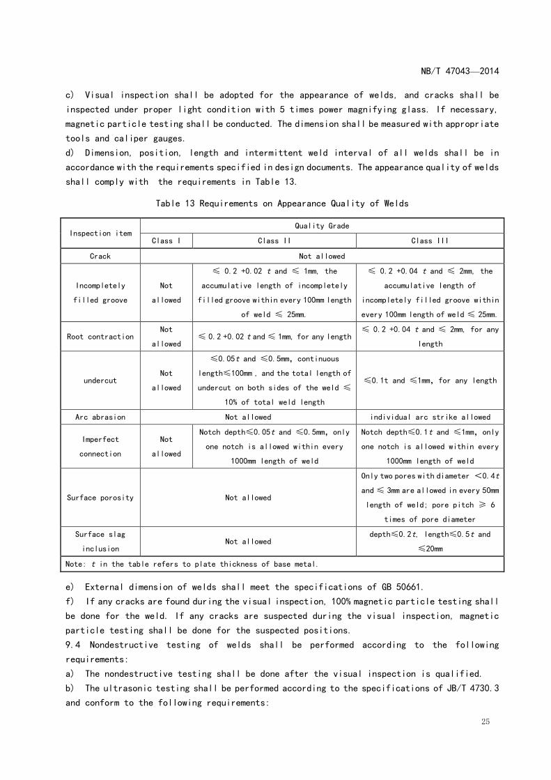
Table 13 Requirements on Appearance Quality of Welds
Inspection item Quality Grade
Class I Class II Class III
Crack Not allowed
Incompletely
filled groove
Not
allowed
≤ 0.2 +0.02 t and ≤ 1mm, the
accumulative length of incompletely
filled groove within every 100mm length
of weld ≤ 25mm.
≤ 0.2 +0.04 t and ≤ 2mm, the
accumulative length of
incompletely filled groove within
every 100mm length of weld ≤ 25mm.
Root contraction Not
allowed ≤ 0.2 +0.02 t and ≤ 1mm, for any length
≤ 0.2 +0.04 t and ≤ 2mm, for any
length
undercut Not
allowed
≤0.05t and ≤0.5mm,continuous
length≤100mm , and the total length of
undercut on both sides of the weld ≤
10% of total weld length
≤0.1t and ≤1mm,for any length
Arc abrasion Not allowed individual arc strike allowed
Imperfect
connection
Not
allowed
Notch depth≤0.05t and ≤0.5mm,only
one notch is allowed within every
1000mm length of weld
Notch depth≤0.1t and ≤1mm,only
one notch is allowed within every
1000mm length of weld
Surface porosity Not allowed
Only two pores with diameter <0.4t
and ≤ 3mm are allowed in every 50mm
length of weld; pore pitch ≥ 6
times of pore diameter
Surface slag
inclusion Not allowed
depth≤0.2t, length≤0.5t and
≤20mm
Note: t in the table refers to plate thickness of base metal.
e) External dimension of welds shall meet the specifications of GB 50661.
f) If any cracks are found during the visual inspection, 100% magnetic particle testing shall
be done for the weld. If any cracks are suspected during the visual inspection, magnetic
particle testing shall be done for the suspected positions.
9.4 Nondestructive testing of welds shall be performed according to the following
requirements:
a) The nondestructive testing shall be done after the visual inspection is qualified.
b) The ultrasonic testing shall be performed according to the specifications of JB/T 4730.3
and conform to the following requirements:

NB/T 47043—2014
26
1) Technical grade of the ultrasonic testing shall not be less than Grade B, and the quality
evaluation grade shall be of Class I.
2) 100% ultrasonic testing shall be conducted for Class I welds. At least 20% ultrasonic
testing shall be conducted for Class II welds, the testing proportion shall be counted upon
calculation percentage of each weld, and the testing length shall be equal to or more than
200 mm, in case of weld length not more than 200 mm, the whole weld shall be tested.
c) The magnetic particle testing shall be performed in accordance with JB/T 4730.4, and the
quality grade of the magnetic particle testing shall be of Class II. 100% magnetic particle
testing shall be conducted for Class I welds. For Class II welds, at least 20% of the weld
length shall be randomly selected to perform magnetic particle testing.The testing proportion
shall be calculated upon the specifications in 9.4 b) 2)of this standard.
d) For the T-shaped joint or fillet weld between main girder flange and web without
requirements of full penetration, full length magnetic particle testing shall be conducted,
and the appearance quality grade of such weld shall be of Class II.
e) For the T joint or fillet weld between flange and web of main column and secondary girder
that is not subjected to complete penetration, if the thickness of the web is more than or
equal to 25 mm, full length magnetic particle testing shall be conducted. 20% length of weld
shall be randomly selected to perform magnetic particle testing under other conditions, and
the appearance quality grade of such weld shall be of Class II.
f) Except for main girder, secondary girder and main column, for the T joint or fillet weld
between flange and web of other compound sections that is not subjected to complete penetration,
if the web thickness is not less than 25 mm, full length magnetic particle testing shall be
conducted. For other conditions, 5 pieces of members shall be randomly selected on every layer
to conduct magnetic particle testing within 100 mm from the end.
g) Ultrasonic testing shall be done for the weld within the scope 200mm away from the cross
point of cross-shaped or T-shaped joint on beam web.
h) When splicing is required for the low-alloy high-strength structural steel with thickness
more than or equal to 32 mm, or for the carbon structural steel with thickness more than or
equal to 36 mm, ultrasonic testing shall be done on both sides of the butt welds within the
scope of 2 times plate thickness plus 30mm, or magnetic particle testing shall be done on the
formed groove.
i) 100% magnetic particle testing shall be done for outside fillet welds of ribs on 2 brackets
that are randomly selected for every beam.
j) If any welds are found to be unqualified by random nondestructive testing, doubled samples
shall be subject to the same nondestructive testing by the same methods. If any weld is still
found to be unqualified, the same kind of nondestructive testing shall be conducted over the
total length of weld.
9.5 After tension flange of main girder is processed by flame cutting, magnetic particle
testing shall be done over the total length.
10 Repair

NB/T 47043—2014
27
10.1 If any defect is found during the visual inspection on weld, the weld shall be repaired
with original welding process, and the visual inspection shall be repeated for the repaired
weld.
10.2 Those welds that have been found unqualified by nondestructive testing shall be repaired
with original welding process, and then 100% nondestructive testing same as original method
shall be repeated for the repaired weld.
10.3 The repair of a weld at the same position shall not exceed 3 times.
10.4 The surface of repaired welds shall be polished in line with the original welds. Repaired
welds shall be recorded.
10.5 If holes for high strength bolts are required to be enlarged, it shall be approved by
the designer. The diameter of enlarged holes shall not exceed 1.2 times of the bolt diameter,
and the number of enlarged holes for each group shall not be more than 30%, where flame cutting
is prohibited.
10.6 If repair welding and redriling are required in the area around the hole for high strength
bolt, it shall be approved by the designer. Welding rod matching the base metal shall be adopted,
no steel bar insertion is allowed for repair welding. The number for each group of holes upon
repair welding and redriling shall not exceed 20%, and the holes treated shall be recorded.
11 Trial Assembly
11.1 Common bolts with the same diameter shall be used for bolt connected structures during
the trial assembly. The number of bolts shall be more than or equal to 30% of required number
of bolts at each joint, which shall be more than or equal to 2.
11.2 During the trial assembly, all standard holes shall be checked by gauge, and the passing
rate shall meet the following requirements:
a) When the gauge with nominal diameter 1.0 mm less than the holes’ is used for checking,
the passing rate of each group of holes shall be more than or equal to 85%.
b) Holes for bolts with the nominal diameter equal to or less than M22 shall be checked by
the gauge whose nominal diameter is 0.2 mm larger than those of the bolts. Holes for bolts
with the nominal diameter more than M22 shall be checked by the gauge whose nominal diameter
is 0.3 mm larger than those of the bolts, with passing rate of 100%.
11.3 When the connection position of column end is required to be milled and tightened, the
end surface shall fit closely, and the contact area shall be more than or equal to 70% of the
end surface. The gap between untouched surfaces of columns shall be less than or equal to 0.3
mm. The maximum interval between local edges shall be less than or equal to 0.8 mm. The passing
rate of high strength bolts for columns shall reach 100%.
11.4 Allowable deviation of trial assembly in plane shall comply with the requirements in
Table 14.
Table 14 Allowable Deviation of Trial Assembly in plane
Assembly item Allowable deviation mm
Center distance of diagonal brace or chord member ±2

NB/T 47043—2014
28
Plane diagonal ±3
Skew distance of diagonal brace in the plane ±3
11.5 Trial assembly for upper and lower part of horizontal split girder shall be done. The
passing rate of holes on the plates connecting combined interfaces shall reach 100%. Other
dimensional deviation shall conform to the requirements in this standard.
11.6 The clearance between contact surfaces caused by the tolerance of plate thickness,
manufacture deviation or others reasons shall comply with the values in Table 15.
Table 15 Treatment for Clearance between Contact Surfaces
Item Schematic diagram Treatment method
1
When Δ<1 mm, no treatment is required
2
When Δ = 1 mm -3 mm, the side of the
thicker plate shall be ground to form
a taper transition of 1: 10, the
clearance shall be less than 1 mm.
3
When Δ >3 mm, add pads with
thickness not less than 3mm, and at
maximum 3 layers are allowed, the pad
material and the treatment method of
faying surface shall be the same as
that of members.
12 Rust Removal, Painting and Packaging
12.1 Surface of all members whose fabrication is completed and inspection is passed shall
be treated according to the process requirements. The grade of rust removal from steel surface
shall meet the requirements in technical documents.
12.2 The painting and packaging shall conform to the specifications in JB/T 1615, and relevant
technical documents shall be obeyed if there are special requirements.
12.3 Except for special requirements, the following positions are not required to be painted
in general:
a) Within 75 mm scope around outside holes of high strength bolts.
b) Column end surface.
c) Anchor bolt and fixing frame.
d) Base plate of separated column.
e) Welded column base below 0 m elevation.
f) Combined interface of horizontal split girder.
13 Marking

NB/T 47043—2014
29
All members of boiler steel structure shall be marked after passing the inspection.
14 Quality Certificate
The manufacturer shall check the material and the manufacture quality according to relevant
drawings and this Standard. After passing inspection, all parts shall be marked, and the results
of main inspection items shall be filled in Quality Certificate of Boiler Steel Structures.
_________________________________


