Embed Size (px)
Citation preview
1
Tekla Structural Designer
2018i Reference Guides (Indian Standards)
September 2018 (6.1.06)
© 2018 Trimble Solutions Corporation.


3


i
Table of Contents
Analysis Verification Examples ............................................................................................................................ 1
1st Order Linear - Simple Cantilever ............................................................................................................ 1
Problem Definition ......................................................................................................................................... 1
Assumptions ..................................................................................................................................................... 1
Key Results ......................................................................................................................................................... 1
Conclusion ......................................................................................................................................................... 2
1st Order Linear - Simply Supported Square Slab .................................................................................. 2
Problem Definition ......................................................................................................................................... 2
Assumptions ..................................................................................................................................................... 2
Key Results ......................................................................................................................................................... 2
Conclusion ......................................................................................................................................................... 3
1st Order Linear - 3D truss ............................................................................................................................... 3
Problem Definition ......................................................................................................................................... 3
Key Results ......................................................................................................................................................... 3
Conclusion ......................................................................................................................................................... 4
1st Order linear - Thermal Load on Simply Supported Beam ............................................................ 4
Problem Definition ......................................................................................................................................... 4
Assumptions ..................................................................................................................................................... 4
Key Results ......................................................................................................................................................... 4
Conclusion ......................................................................................................................................................... 4
1st Order Nonlinear - Simple Cantilever .................................................................................................... 5
Problem Definition ......................................................................................................................................... 5
Assumptions ..................................................................................................................................................... 5
Key Results ......................................................................................................................................................... 5
Conclusion ......................................................................................................................................................... 5
1st Order Nonlinear - Nonlinear Supports ................................................................................................ 5
Problem Definition ......................................................................................................................................... 5
Assumptions ..................................................................................................................................................... 6
Key Results ......................................................................................................................................................... 6
Conclusion ......................................................................................................................................................... 6
1st Order Nonlinear - Displacement Loading of a Plane Frame ........................................................ 6
Problem Definition ......................................................................................................................................... 6
Assumptions ..................................................................................................................................................... 7
Key Results ......................................................................................................................................................... 7
Conclusion ......................................................................................................................................................... 7
Table of Contents
ii
2nd Order Linear - Simple Cantilever .......................................................................................................... 7
Problem Definition ......................................................................................................................................... 7
Assumptions ..................................................................................................................................................... 8
Key Results ......................................................................................................................................................... 8
Conclusion ......................................................................................................................................................... 8
2nd Order linear - Simply Supported Beam .............................................................................................. 8
Problem Definition ......................................................................................................................................... 8
Assumptions ..................................................................................................................................................... 9
Key Results ......................................................................................................................................................... 9
Conclusion ......................................................................................................................................................... 9
Reference ........................................................................................................................................................... 9
2nd Order Nonlinear - Tension Only Cross Brace ................................................................................... 9
Problem Definition ......................................................................................................................................... 9
Assumptions .................................................................................................................................................. 10
Key Results ...................................................................................................................................................... 10
Conclusion ...................................................................................................................................................... 10
2nd Order Nonlinear - Compression Only Element ............................................................................ 11
Problem Definition ...................................................................................................................................... 11
Assumptions .................................................................................................................................................. 11
Key Results ...................................................................................................................................................... 11
Conclusion ...................................................................................................................................................... 11
1st Order Vibration - Simply Supported Beam ..................................................................................... 11
Problem Definition ...................................................................................................................................... 11
Assumptions .................................................................................................................................................. 11
Key Results ...................................................................................................................................................... 12
Conclusion ...................................................................................................................................................... 12
1st Order Vibration - Bathe and Wilson Eigenvalue Problem ......................................................... 12
Problem Definition ...................................................................................................................................... 12
Assumptions .................................................................................................................................................. 13
Key Results ...................................................................................................................................................... 13
Conclusion ...................................................................................................................................................... 13
References ...................................................................................................................................................... 13
2nd Order Buckling - Euler Strut Buckling .............................................................................................. 13
Problem Definition ...................................................................................................................................... 13
Assumptions .................................................................................................................................................. 14
Key Results ...................................................................................................................................................... 14
Reference Guides (IS)
iii
Conclusion ...................................................................................................................................................... 14
2nd Order Buckling - Plane Frame ............................................................................................................. 14
Problem Definition ...................................................................................................................................... 14
Assumptions .................................................................................................................................................. 15
Key Results ...................................................................................................................................................... 15
Conclusion ...................................................................................................................................................... 16
References ...................................................................................................................................................... 16
Concrete Design - IS 456 ................................................................................................................................... 17
Concrete Design to IS 456 ................................................................................................................................. 17
Beam Design to IS 456 ................................................................................................................................... 17
Limitations and Exclusions (Beams: IS 456) ............................................................................................ 17
Materials (Beams: IS 456) ............................................................................................................................... 17
Concrete ...................................................................................................................................................... 17
Reinforcement .......................................................................................................................................... 18
Slender Beams (Beams: IS 456) ................................................................................................................... 18
Cover to Reinforcement (Beams: IS 456) ................................................................................................. 18
Design Parameters for Longitudinal Bars (Beams: IS 456) ........................................................... 20
Minimum Distance between Bars .......................................................................................................... 20
Maximum Spacing of Tension Bars ....................................................................................................... 20
Minimum Area of Reinforcement .......................................................................................................... 21
Maximum Area of Reinforcement ......................................................................................................... 21
Side Reinforcement in Beams (Beams: IS 456) ...................................................................................... 22
Effective Depth of Section (Beams: IS 456) ............................................................................................. 23
Design for Bending (Beams: IS 456) ...................................................................................................... 23
Design for Bending for Rectangular Sections (Beams: IS 456) ................................................... 23
Design for Bending for Flanged Sections (Beams: IS 456) ........................................................... 24
Design for Shear (Beams: IS 456) ........................................................................................................... 25
Design Shear Resistance (Beams: BS 8110) ........................................................................................ 25
Minimum Area of Shear Reinforcement (Beams: IS 456) .............................................................. 26
Spacing of Shear Reinforcement (Beams: IS 456) ............................................................................ 27
Design for Torsion (Beams: IS 456) ............................................................................................................ 27
Deflection Check (Beams: BS 8110) ........................................................................................................... 28
Column Design to IS 456 ............................................................................................................................... 29
Limitations and Exclusions (Columns: IS 456) ........................................................................................ 29
Materials (Columns: IS 456) .......................................................................................................................... 29
Concrete ...................................................................................................................................................... 29
Table of Contents
iv
Reinforcement .......................................................................................................................................... 30
Cover to Reinforcement (Columns: IS 456) ............................................................................................. 30
Design Parameters for Longitudinal Bars (Columns: IS 456) ....................................................... 31
Minimum Longitudinal Bar Spacing ..................................................................................................... 31
Minimum Longitudinal Total Steel Area ............................................................................................. 31
Maximum Longitudinal Total Steel Area ............................................................................................. 31
Ultimate Axial Load Limit (Columns: IS 456) .......................................................................................... 31
Effective Length Calculations (Columns: IS 456) .............................................................................. 32
Clear Height ................................................................................................................................................... 32
Effective Length ............................................................................................................................................ 32
Column Stack Classification (Columns: IS 456) ................................................................................. 33
Slenderness ratio .......................................................................................................................................... 33
limiting slenderness ratio .......................................................................................................................... 34
Design Moment Calculations (Columns: IS 456) .............................................................................. 34
Minimum Eccentricity ................................................................................................................................. 34
Short columns ............................................................................................................................................... 35
Slender columns ........................................................................................................................................... 35
Additional Moments for Slender Columns: ................................................................................... 35
Design for Combined Axial and Bending (Columns: IS 456) ............................................................ 36
Design for Shear (Columns: IS 456)....................................................................................................... 36
Design Parameters for Shear Design .................................................................................................... 36
Maximum Span Region Shear Link Spacing .................................................................................. 36
Design of Column Shear Reinforcement ............................................................................................. 36
A) Calculate Design Shear Stress ....................................................................................................... 36
B) Check Maximum Shear Capacity .................................................................................................. 37
C) Check Section Nominal Shear Capacity .................................................................................... 37
D) Nominal Shear Capacity Not Adequate .................................................................................... 37
Wall Design to IS 456 ...................................................................................................................................... 38
Limitations and Exclusions (Walls: IS 456) ............................................................................................... 38
Materials (Walls: IS 456) ................................................................................................................................. 38
Concrete ...................................................................................................................................................... 38
Reinforcement .......................................................................................................................................... 38
Cover to Reinforcement (Walls: IS 456).................................................................................................... 39
Vertical reinforcement (Walls: IS 456) .................................................................................................. 39
Plain Wall Check ........................................................................................................................................... 39
Reinforcement area for a Plain wall ...................................................................................................... 40
Reference Guides (IS)
v
Reinforcement area for a RC wall .......................................................................................................... 41
Spacing of vertical loose bars ................................................................................................................. 41
Check for vertical reinforcement when wall in tension ................................................................. 42
Horizontal reinforcement (Walls: IS 456) ............................................................................................ 42
Reinforcement area for Plain or RC wall ............................................................................................. 42
Diameter of horizontal bar .................................................................................................................. 43
Spacing of horizontal loose bars ....................................................................................................... 43
Reinforcement area for a Plain wall ...................................................................................................... 44
Link/Confinement Reinforcement (Walls: IS 456) ............................................................................ 44
Reinforcement area ..................................................................................................................................... 44
Diameter of confinement reinforcement ............................................................................................ 44
Spacing of confinement reinforcement ............................................................................................... 44
Ultimate Axial Load Limit (Walls: IS 456) ................................................................................................. 45
Effective Length and Slenderness Calculations (Walls: IS 456)........................................................ 45
Design Moment Calculations (Walls: IS 456) ......................................................................................... 45
Design for Combined Axial and Bending (Walls: IS 456) ................................................................... 45
Design for Shear (Walls: IS 456) .................................................................................................................. 45
Slab Design to IS 456 ...................................................................................................................................... 45
Limitations and Exclusions (Slabs: IS 456) ............................................................................................... 45
Materials (Slabs: IS 456) ................................................................................................................................. 46
Concrete ...................................................................................................................................................... 46
Reinforcement .......................................................................................................................................... 46
Reinforcement Parameters (Slabs: IS 456) .............................................................................................. 46
Cover to Reinforcement (Slabs: IS 456) .................................................................................................... 47
Limiting Reinforcement Parameters (Slabs: IS 456) ........................................................................ 47
Minimum and Maximum Loose Bar Diameter (Slabs: IS 456) ..................................................... 47
Minimum Loose Bar Diameter ............................................................................................................ 47
Maximum Loose Bar Diameter ........................................................................................................... 47
Minimum Clear Spacing (Slabs: IS 456) ............................................................................................... 47
Basic Cross Section Design (Slabs: IS 456).......................................................................................... 48
Matching Design Moments to Reinforcement Layers (Slabs: IS 456) ...................................... 48
Design for Bending (Slabs: IS 456) ............................................................................................................. 49
Deflection Check (Slabs: IS 456) .................................................................................................................. 49
References................................................................................................................................................................ 49

1
Analysis Verification Examples
A small number of verification examples are included in this section. Our full automatic test
suite for the Solver contains many hundreds of examples which are run and verified every
time the Solver is enhanced.
These verification examples use SI units unless otherwise stated.
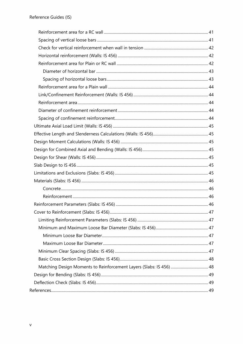
1st Order Linear - Simple Cantilever
Problem Definition
A 4 long cantilever is subjected to a tip load of 20,000.
Assumptions
Flexural and shear deformations are included.
Key Results
Result Theoretical
Formula
Theoretical
Value
Solver
Value
%
Error
Support Reaction
-P 20,000 20,000 0%
Support Moment PL -80,000 -80,000 0%
Tip Deflection
-0.0519 -0.0519 0%
Analysis Verification Examples
2
Conclusion
An exact match is observed between the values reported by the solver and the values
predicted by beam theory.
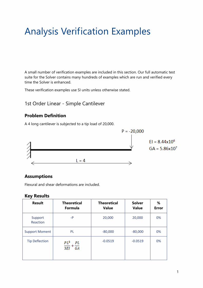
1st Order Linear - Simply Supported Square Slab
Problem Definition
Calculate the mid span deflection of an 8x8 simply supported slab of 0.1 thickness under
self-weight only. Take material properties E=2x10¹¹, G=7.7x10¹⁰ and =7849.
Assumptions
A regular triangular finite element mesh is used with sufficient subdivision. Flexural and shear
deformation is included, and the material is assumed to be isotropic.
Key Results
The mid-span deformation is calculated using Navier's Method.
Result Theoretical Value Comparison 1 Solver
Value
%
Error
Reference Guides (IS)
3
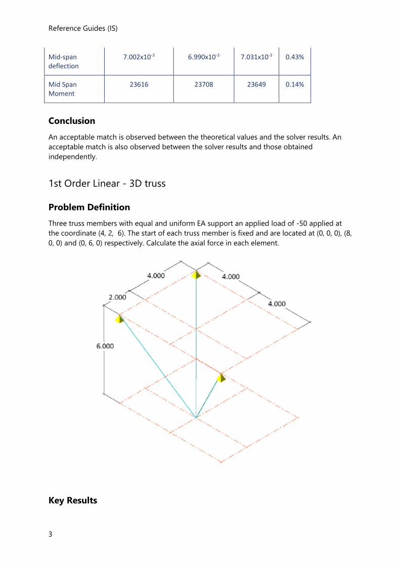
Mid-span deflection
7.002x10⁻³ 6.990x10⁻³ 7.031x10⁻³ 0.43%
Mid Span Moment
23616 23708 23649 0.14%
Conclusion
An acceptable match is observed between the theoretical values and the solver results. An
acceptable match is also observed between the solver results and those obtained
independently.
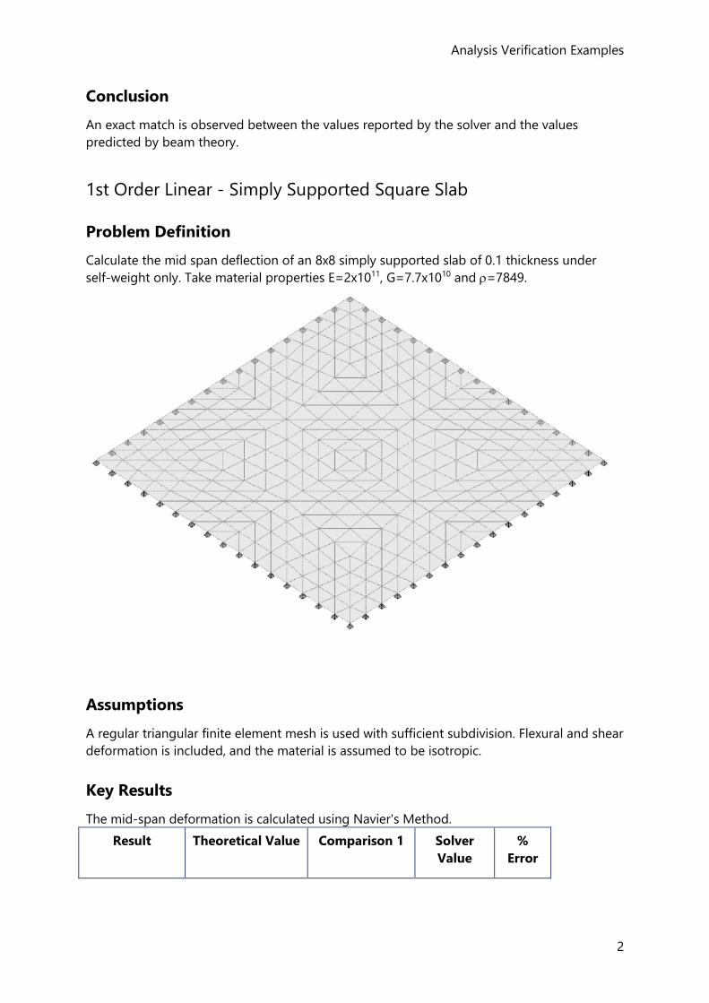
1st Order Linear - 3D truss
Problem Definition
Three truss members with equal and uniform EA support an applied load of -50 applied at
the coordinate (4, 2, 6). The start of each truss member is fixed and are located at (0, 0, 0), (8,
0, 0) and (0, 6, 0) respectively. Calculate the axial force in each element.
Key Results
Analysis Verification Examples
4
The results for this problem are compared against those published by Beer and Johnston and
against another independent analysis package
Result Beer and
Johnston
Comparison 1 Solver
Value
%
Error
(0, 0, 0) - (4, 2, -6) 10.4 10.4 10.4 0%
(8, 0, 0) - (4, 2, -6) 31.2 31.2 31.2 0%
(0, 6, 0) - (4, 2, -6) 22.9 22.9 22.9 0%
Conclusion
An exact match is observed between the values reported by the solver those reported by
Beer and Johnston.
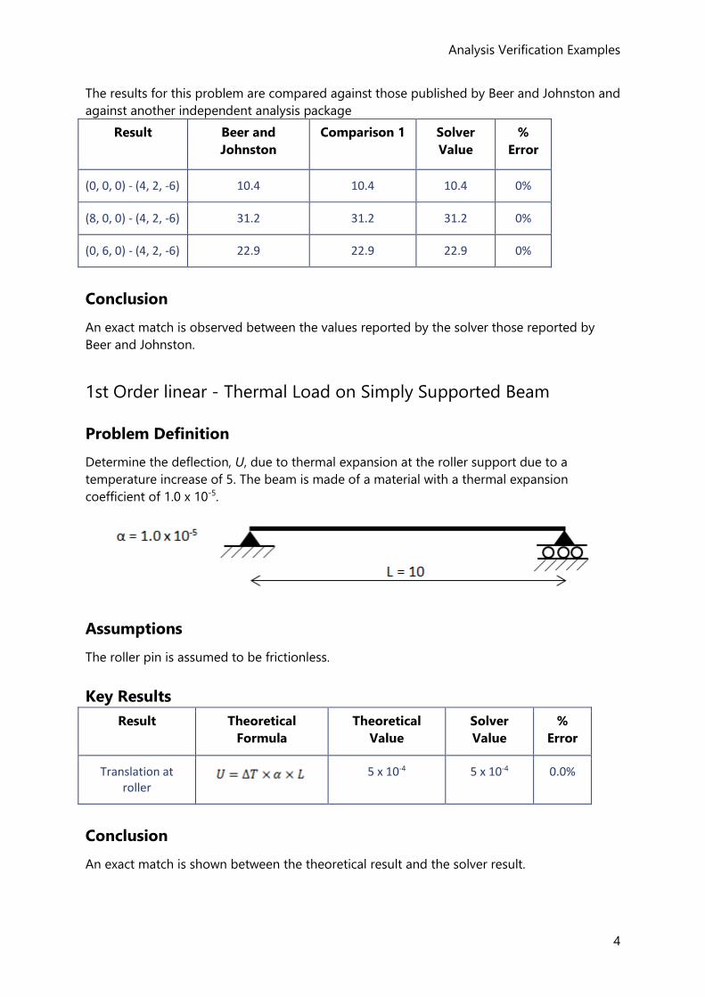
1st Order linear - Thermal Load on Simply Supported Beam
Problem Definition
Determine the deflection, U, due to thermal expansion at the roller support due to a
temperature increase of 5. The beam is made of a material with a thermal expansion
coefficient of 1.0 x 10⁻⁵.
Assumptions
The roller pin is assumed to be frictionless.
Key Results
Result Theoretical
Formula
Theoretical
Value
Solver
Value
%
Error
Translation at roller
5 x 10⁻⁴ 5 x 10⁻⁴ 0.0%
Conclusion
An exact match is shown between the theoretical result and the solver result.
Reference Guides (IS)
5
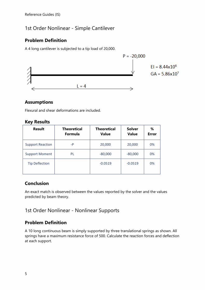
1st Order Nonlinear - Simple Cantilever
Problem Definition
A 4 long cantilever is subjected to a tip load of 20,000.
Assumptions
Flexural and shear deformations are included.
Key Results
Result Theoretical
Formula
Theoretical
Value
Solver
Value
%
Error
Support Reaction -P 20,000 20,000 0%
Support Moment PL -80,000 -80,000 0%
Tip Deflection
-0.0519 -0.0519 0%
Conclusion
An exact match is observed between the values reported by the solver and the values
predicted by beam theory.
1st Order Nonlinear - Nonlinear Supports
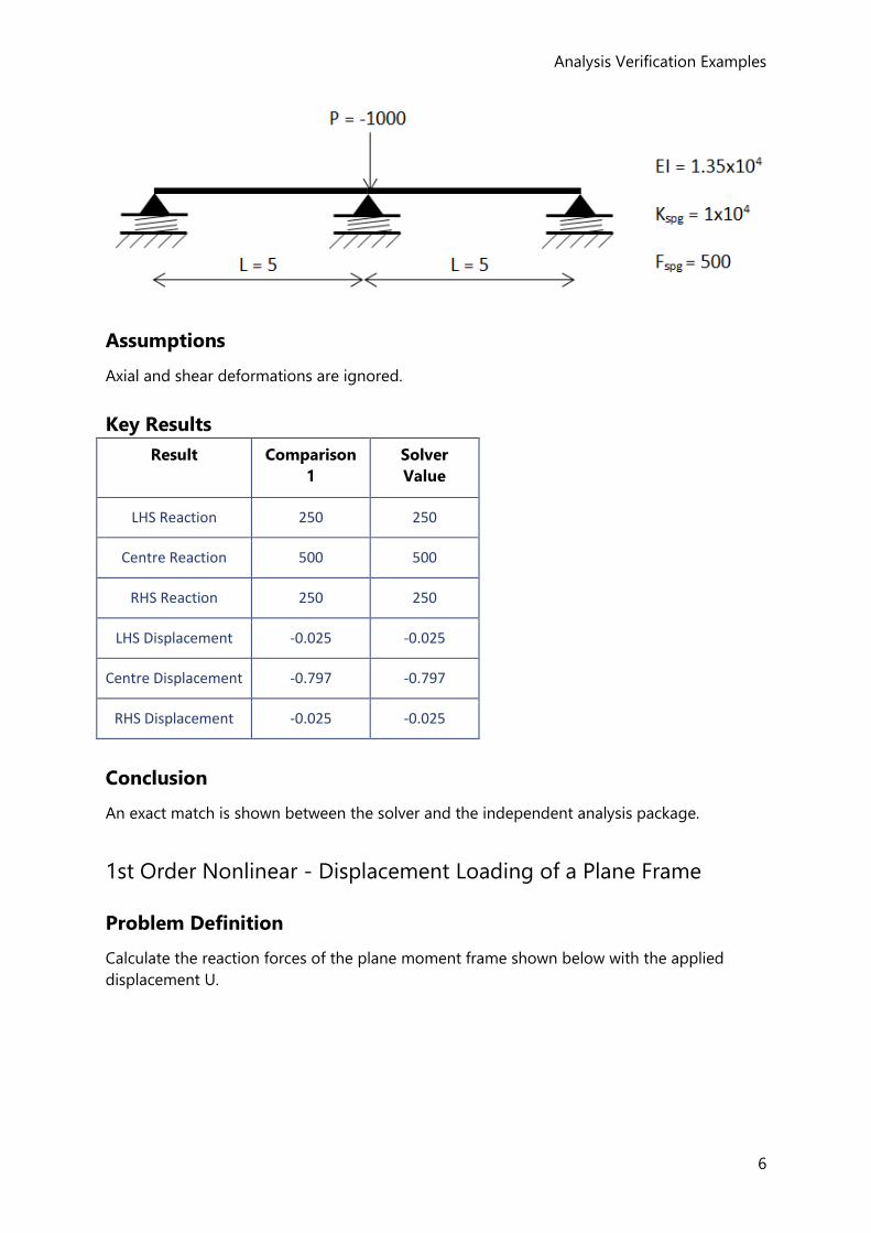
Problem Definition
A 10 long continuous beam is simply supported by three translational springs as shown. All
springs have a maximum resistance force of 500. Calculate the reaction forces and deflection
at each support.
Analysis Verification Examples
6
Assumptions
Axial and shear deformations are ignored.
Key Results
Result Comparison
1
Solver
Value
LHS Reaction 250 250
Centre Reaction 500 500
RHS Reaction 250 250
LHS Displacement -0.025 -0.025
Centre Displacement -0.797 -0.797
RHS Displacement -0.025 -0.025
Conclusion
An exact match is shown between the solver and the independent analysis package.
1st Order Nonlinear - Displacement Loading of a Plane Frame
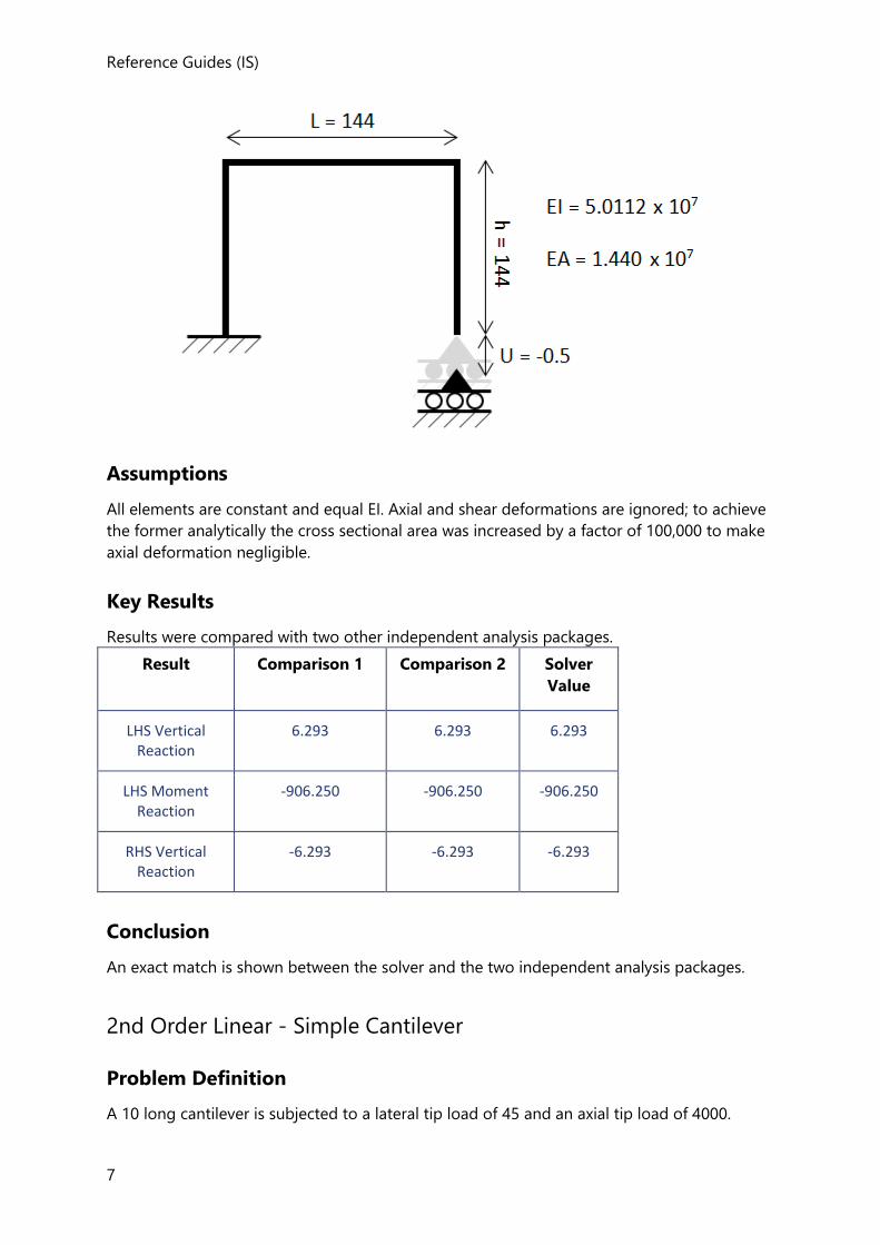
Problem Definition
Calculate the reaction forces of the plane moment frame shown below with the applied
displacement U.
Reference Guides (IS)
7
Assumptions
All elements are constant and equal EI. Axial and shear deformations are ignored; to achieve
the former analytically the cross sectional area was increased by a factor of 100,000 to make
axial deformation negligible.
Key Results
Results were compared with two other independent analysis packages.
Result Comparison 1 Comparison 2 Solver
Value
LHS Vertical Reaction
6.293 6.293 6.293
LHS Moment Reaction
-906.250 -906.250 -906.250
RHS Vertical Reaction
-6.293 -6.293 -6.293
Conclusion
An exact match is shown between the solver and the two independent analysis packages.
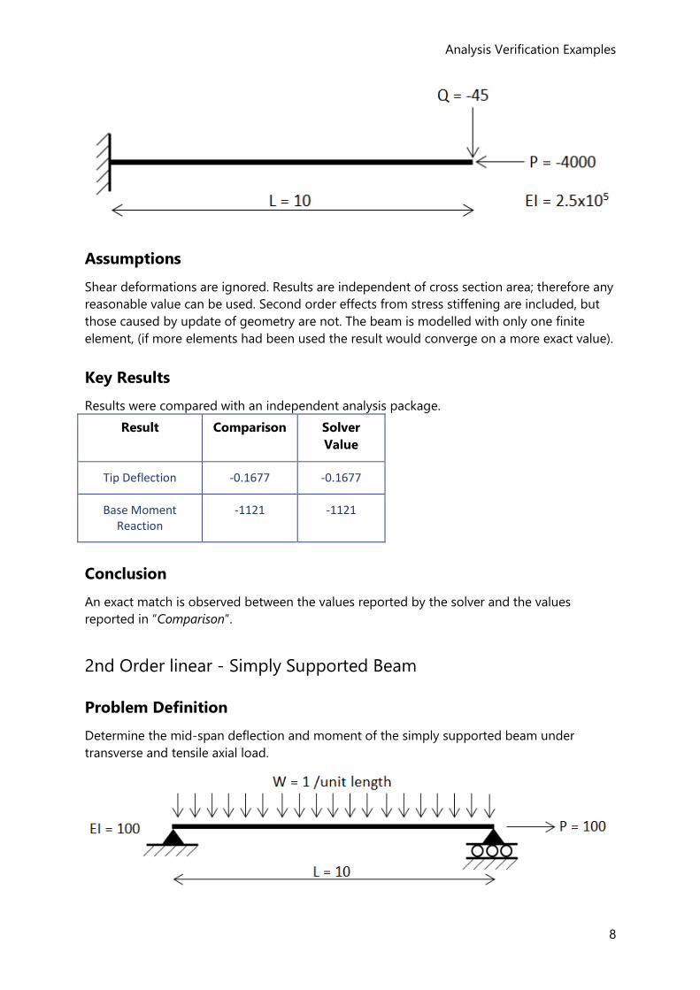
2nd Order Linear - Simple Cantilever
Problem Definition
A 10 long cantilever is subjected to a lateral tip load of 45 and an axial tip load of 4000.
Analysis Verification Examples
8
Assumptions
Shear deformations are ignored. Results are independent of cross section area; therefore any
reasonable value can be used. Second order effects from stress stiffening are included, but
those caused by update of geometry are not. The beam is modelled with only one finite
element, (if more elements had been used the result would converge on a more exact value).
Key Results
Results were compared with an independent analysis package.
Result Comparison Solver
Value
Tip Deflection -0.1677 -0.1677
Base Moment Reaction
-1121 -1121
Conclusion
An exact match is observed between the values reported by the solver and the values
reported in “Comparison”.
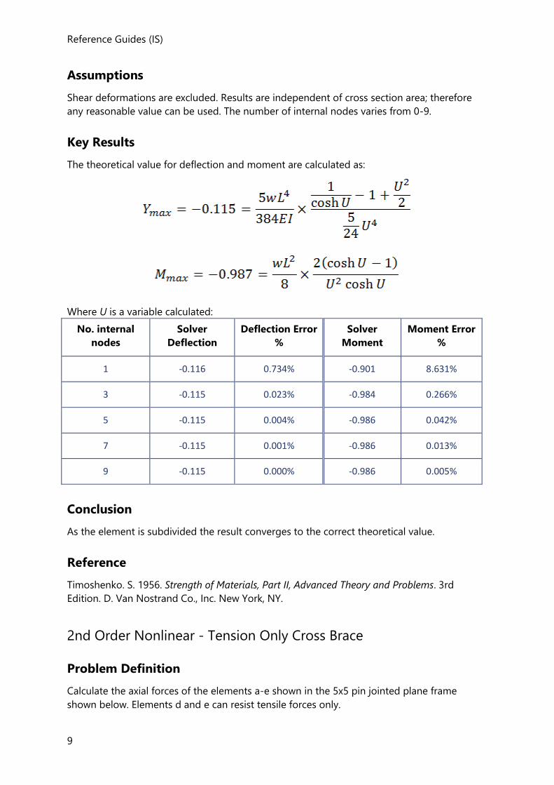
2nd Order linear - Simply Supported Beam
Problem Definition
Determine the mid-span deflection and moment of the simply supported beam under
transverse and tensile axial load.
Reference Guides (IS)
9
Assumptions
Shear deformations are excluded. Results are independent of cross section area; therefore
any reasonable value can be used. The number of internal nodes varies from 0-9.
Key Results
The theoretical value for deflection and moment are calculated as:
Where U is a variable calculated:
No. internal
nodes
Solver
Deflection
Deflection Error
%
Solver
Moment
Moment Error
%
1 -0.116 0.734% -0.901 8.631%
3 -0.115 0.023% -0.984 0.266%
5 -0.115 0.004% -0.986 0.042%
7 -0.115 0.001% -0.986 0.013%
9 -0.115 0.000% -0.986 0.005%
Conclusion
As the element is subdivided the result converges to the correct theoretical value.
Reference
Timoshenko. S. 1956. Strength of Materials, Part II, Advanced Theory and Problems. 3rd
Edition. D. Van Nostrand Co., Inc. New York, NY.
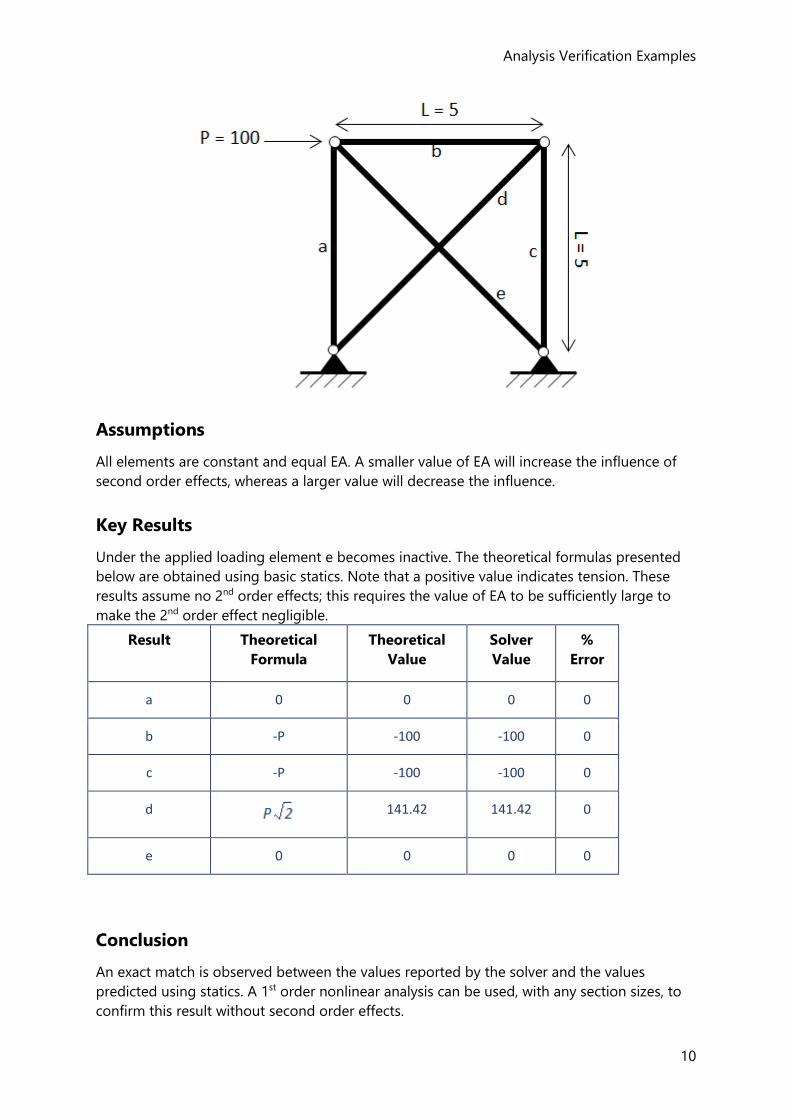
2nd Order Nonlinear - Tension Only Cross Brace
Problem Definition
Calculate the axial forces of the elements a-e shown in the 5x5 pin jointed plane frame
shown below. Elements d and e can resist tensile forces only.
Analysis Verification Examples
10
Assumptions
All elements are constant and equal EA. A smaller value of EA will increase the influence of
second order effects, whereas a larger value will decrease the influence.
Key Results
Under the applied loading element e becomes inactive. The theoretical formulas presented
below are obtained using basic statics. Note that a positive value indicates tension. These
results assume no 2nd order effects; this requires the value of EA to be sufficiently large to
make the 2nd order effect negligible.
Result Theoretical
Formula
Theoretical
Value
Solver
Value
%
Error
a 0 0 0 0
b -P -100 -100 0
c -P -100 -100 0
d
141.42 141.42 0
e 0 0 0 0
Conclusion
An exact match is observed between the values reported by the solver and the values
predicted using statics. A 1st order nonlinear analysis can be used, with any section sizes, to
confirm this result without second order effects.
Reference Guides (IS)
11
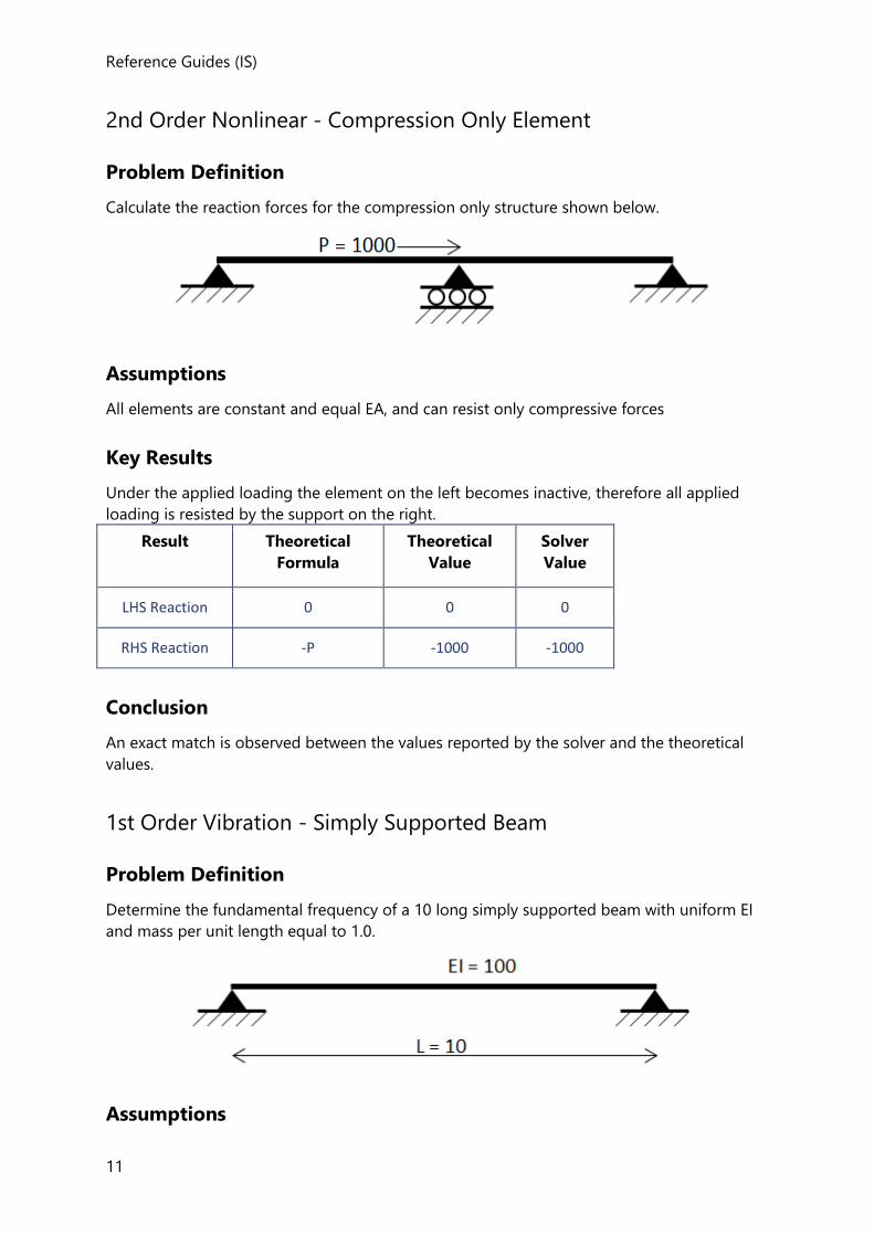
2nd Order Nonlinear - Compression Only Element
Problem Definition
Calculate the reaction forces for the compression only structure shown below.
Assumptions
All elements are constant and equal EA, and can resist only compressive forces
Key Results
Under the applied loading the element on the left becomes inactive, therefore all applied
loading is resisted by the support on the right.
Result Theoretical
Formula
Theoretical
Value
Solver
Value
LHS Reaction 0 0 0
RHS Reaction -P -1000 -1000
Conclusion
An exact match is observed between the values reported by the solver and the theoretical
values.
1st Order Vibration - Simply Supported Beam
Problem Definition
Determine the fundamental frequency of a 10 long simply supported beam with uniform EI
and mass per unit length equal to 1.0.
Assumptions
Analysis Verification Examples
12
Shear deformations are excluded. The number of internal nodes varies from 0-5. Consistent
mass is assumed.
Key Results
The theoretical value for the fundamental frequency is calculated as:
With m is the total mass of the beam.
No. internal
nodes
Solver
Value
% Error
0 1.0955 10.995%
1 0.9909 0.395%
2 0.9878 0.081%
3 0.9872 0.026%
4 0.9871 0.011%
5 0.9870 0.005%
Conclusion
As the element is subdivided the result converges to the correct theoretical value.
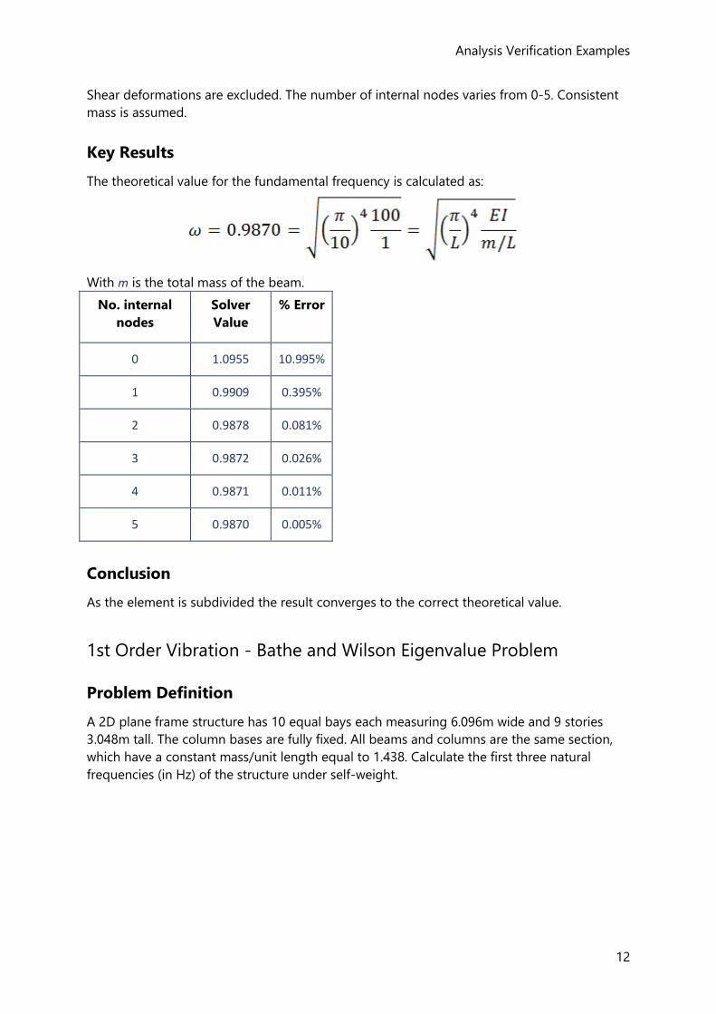
1st Order Vibration - Bathe and Wilson Eigenvalue Problem
Problem Definition
A 2D plane frame structure has 10 equal bays each measuring 6.096m wide and 9 stories
3.048m tall. The column bases are fully fixed. All beams and columns are the same section,
which have a constant mass/unit length equal to 1.438. Calculate the first three natural
frequencies (in Hz) of the structure under self-weight.
Reference Guides (IS)
13
Assumptions
Shear deformations are excluded. Each beam/column is represented by one finite element.
Consistent mass is assumed.
Key Results
The results for this problem are compared with those published by Bathe and Wilson and
against an independent analysis package.
Mode Bathe and
Wilson
Comparison Solver
Value
1 0.122 0.122 0.122
2 0.374 0.374 0.375
3 0.648 0.648 0.652
Conclusion
The results show a good comparison with the original published results and against the
other analysis packages.
References
Bathe, K.J. and E.L. Wilson. 1972. Large Eigen Values in Dynamic Analysis. Journal of the
Engineering Mechanics Division. ASCE Vol. 98, No. EM6. Proc. Paper 9433. December.
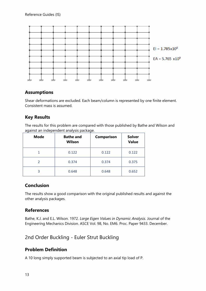
2nd Order Buckling - Euler Strut Buckling
Problem Definition
A 10 long simply supported beam is subjected to an axial tip load of P.
Analysis Verification Examples
14
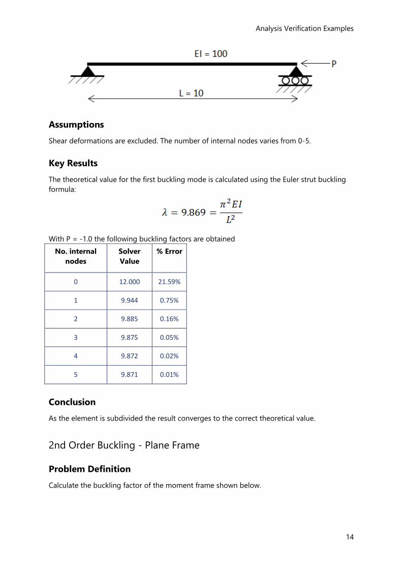
Assumptions
Shear deformations are excluded. The number of internal nodes varies from 0-5.
Key Results
The theoretical value for the first buckling mode is calculated using the Euler strut buckling
formula:
With P = -1.0 the following buckling factors are obtained
No. internal
nodes
Solver
Value
% Error
0 12.000 21.59%
1 9.944 0.75%
2 9.885 0.16%
3 9.875 0.05%
4 9.872 0.02%
5 9.871 0.01%
Conclusion
As the element is subdivided the result converges to the correct theoretical value.
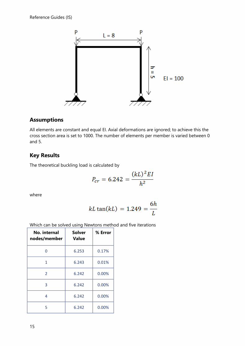
2nd Order Buckling - Plane Frame
Problem Definition
Calculate the buckling factor of the moment frame shown below.
Reference Guides (IS)
15
Assumptions
All elements are constant and equal EI. Axial deformations are ignored; to achieve this the
cross section area is set to 1000. The number of elements per member is varied between 0
and 5.
Key Results
The theoretical buckling load is calculated by
where
Which can be solved using Newtons method and five iterations
No. internal
nodes/member
Solver
Value
% Error
0 6.253 0.17%
1 6.243 0.01%
2 6.242 0.00%
3 6.242 0.00%
4 6.242 0.00%
5 6.242 0.00%
Analysis Verification Examples
16
Conclusion
A good match is shown between the solver and theory. The discrepancy decreases as the
level of discretization is increased.
References
Timoshenko, S. and J. M. Gere. 1961. Theory of Elastic Stability. 2nd Edition. McGraw-Hill
Book Company.
17
Concrete Design - IS 456
Concrete Design to IS 456
This handbook describes how IS 456:2000 (Ref. 1) is applied to the design of concrete
members in Tekla Structural Designer.
Unless explicitly noted otherwise, all clauses, figures and tables referred to are from IS
456:2000
Beam Design to IS 456
•
Limitations and Exclusions (Beams: IS 456)
The following general exclusions apply:
• Bundled bars.
• Design for minor axis bending and shear.
• Design for axial forces.
• Beams with a ratio of effective span/overall depth < 2.0 for simply supported beam; and
effective span/overall depth < 2.5 for continuous beam are classified as deep beams and
“Beyond Scope”
Materials (Beams: IS 456)
Concrete
Only normal weight is included in this release. (Lightweight concrete is excluded).
Concrete Design to IS 456
18
Reinforcement
The reinforcement options are:
• Loose reinforcing bars,
• Loose reinforcing bars bent to form links.
Slender Beams (Beams: IS 456)
The clear distance between restraints is taken as below;
For simply supported or continuous beams:A
Clear distance between restraints ≤ MIN [60*bc, 250*b2c/d]
For cantilevers with lateral restraints only at support:
Clear distance between restraints ≤ MIN [25*bc or 100*b2c/d]
where
bc = breadth of the compression face of the beam,
d = effective depth of beam
AIS 456 : 2000 clause 23.3
Cover to Reinforcement (Beams: IS 456)
The greatest nominal cover is selected derived from:
1. Bar Size1- The nominal cover to all steel should be such that the resulting cover to main
bar is not less than the size of the main bar.
cnom, φ ≥ φ
where
φ = maximum diameter of bar in longitudinal reinforcement
The cover stated above is the cover up-to main bars and if links are present this cover is up-to the link bar.
2. Durability Requirements - The cover required to protect the reinforcement against
corrosion depends on the exposure conditions. Values to be set by the user with
reference to Table 16, of IS 456 : 2000 to meet the durability requirements.
Reference Guides (IS)
19
3. Fire Resistance - For fire protection the values given in Table 16A of IS 456 : 2000 will
ensure that fire resistance requirements are satisfied. In order to take due account of the
cover required for fire resistance, a value for the nominal cover should be set by the user.
The “Durability Requirements” and “Fire Resistance” provisions are not implemented in the current version of Tekla Structural Designer.
Nominal limiting cover to reinforcement:
A minimum value for the nominal cover, cnom, u, is set by the user with the following default
values;
Nominal cover from top surface of beam, cnom,u,top Default value: 30.0mm
Nominal cover from bottom surface of beam, cnom,u,bot Default value: 30.0mm
Nominal cover from side face of beam, cnom,u,side Default value: 30.0mm
Nominal cover from end surface of beam, cnom,u,end Default value: 30.0mm
The nominal limiting cover depends on the diameter of the reinforcement, and the nominal
covers to be used for design and detailing purposes are given by;
Nominal limiting cover to reinforcement from the side face of a beam;
cnom,lim,side = MAX[φtop, φbot , φside]
Nominal limiting cover to reinforcement from the top face of a beam;
cnom,lim,top = MAX[φtop]
Nominal limiting cover to reinforcement from the bottom face of a beam;
cnom,lim,bot = MAX[φbot]
Nominal cover to reinforcement from the end of a beam;
cnom,lim,end = MAX[φtop, φbot , φside]
and where
φtop = maximum diameter of the longitudinal reinforcing bar nearest to the top surface of the beam
φbot = maximum diameter of the longitudinal reinforcing bar nearest to the bottom surface of the beam
φside = the diameter of the longitudinal reinforcing bar nearest to the side of the
Concrete Design to IS 456
20
beam
If cnom,u < cnom,lim a warning is displayed in the calculations. 1. IS 456 : 2000 26.4
Design Parameters for Longitudinal Bars (Beams: IS 456)
For each of these parameters, the user defined limits (specified in Design Options > Beam
> Reinforcement Settings) are considered in addition to any IS 456 recommendations.
Minimum Distance between Bars
To allow you to make decisions regarding access for concrete compaction or size of
aggregate, a value for the minimum clear distance between bars is specified in Design
Options > Beam > Reinforcement Settings - separate values being set for bars in the top
of the beam and for those in the bottom of the beam.
The minimum clear horizontal distance between individual parallel bars, scl,min, is given by;1
scl,min ≥ MAX[hagg + 5mm, scl,u,min]
where
hagg = maximum size of coarse aggregate
scl,u,min = user specified minimum clear distance between bars
The minimum clear vertical distance between horizontal layers of parallel bars, scl,min, is given
by;
scl,min ≥ MAX[15mm, 2hagg/3, φ
where
hagg = nominal maximum size of coarse aggregate
φ = the maximum diameter of bar
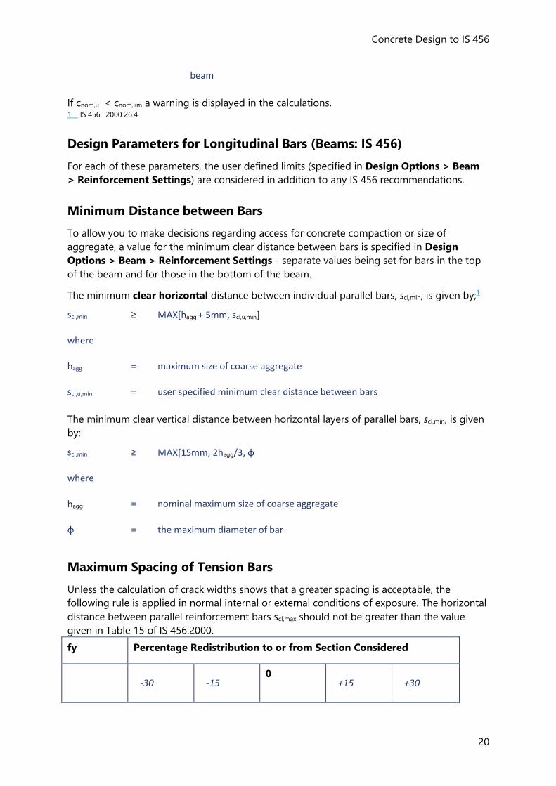
Maximum Spacing of Tension Bars
Unless the calculation of crack widths shows that a greater spacing is acceptable, the
following rule is applied in normal internal or external conditions of exposure. The horizontal
distance between parallel reinforcement bars scl,max should not be greater than the value
given in Table 15 of IS 456:2000.
fy Percentage Redistribution to or from Section Considered
-30 -15
0 +15 +30
Reference Guides (IS)
21
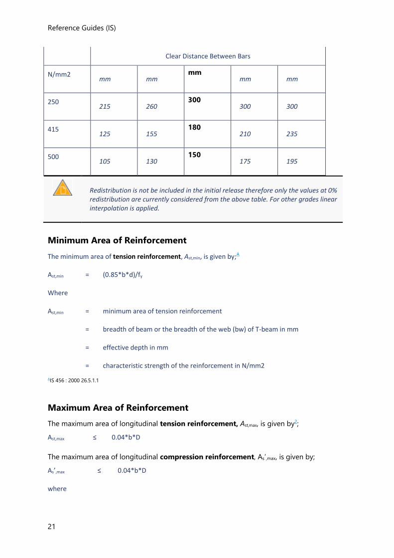
Clear Distance Between Bars
N/mm2 mm mm
mm mm mm
250 215 260
300 300 300
415 125 155
180 210 235
500 105 130
150 175 195
Redistribution is not be included in the initial release therefore only the values at 0% redistribution are currently considered from the above table. For other grades linear interpolation is applied.
Minimum Area of Reinforcement
The minimum area of tension reinforcement, Ast,min, is given by;A
Ast,min = (0.85*b*d)/fy
Where
Ast,min = minimum area of tension reinforcement
= breadth of beam or the breadth of the web (bw) of T-beam in mm
= effective depth in mm
= characteristic strength of the reinforcement in N/mm2
AIS 456 : 2000 26.5.1.1
Maximum Area of Reinforcement
The maximum area of longitudinal tension reinforcement, Ast,max, is given by2;
Ast,max ≤ 0.04*b*D
The maximum area of longitudinal compression reinforcement, As’,max, is given by;
As’,max ≤ 0.04*b*D
where
Concrete Design to IS 456
22
b = breadth of beam or the breadth of the web of T-beam in mm
D = overall depth of beam in mm
Compression reinforcement in beams shall be enclosed by stirrups for effective lateral restraint. The arrangement of stirrups shall be as specified in IS 456 : 2000 26.5.3.2
1. IS 456 : 2000 26.3.2
2. IS 456 : 2000 26.5.1.1 26.5.1.2
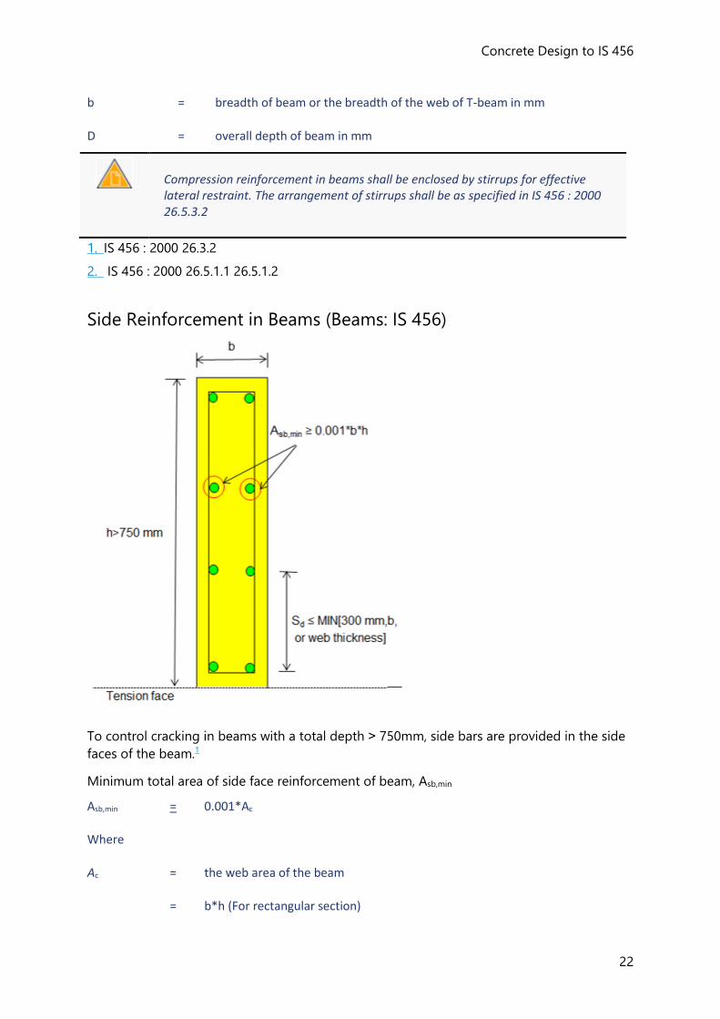
Side Reinforcement in Beams (Beams: IS 456)
To control cracking in beams with a total depth ˃ 750mm, side bars are provided in the side
faces of the beam.1
Minimum total area of side face reinforcement of beam, Asb,min
Asb,min = 0.001*Ac
Where
Ac = the web area of the beam
= b*h (For rectangular section)
Reference Guides (IS)
23
= bv*h (For flanged section)
Asb,min shall be distributed equally on two faces at a spacing not exceeding 300 mm or web thickness whichever is less.
1. IS 456 : 2000 26.5.1.3
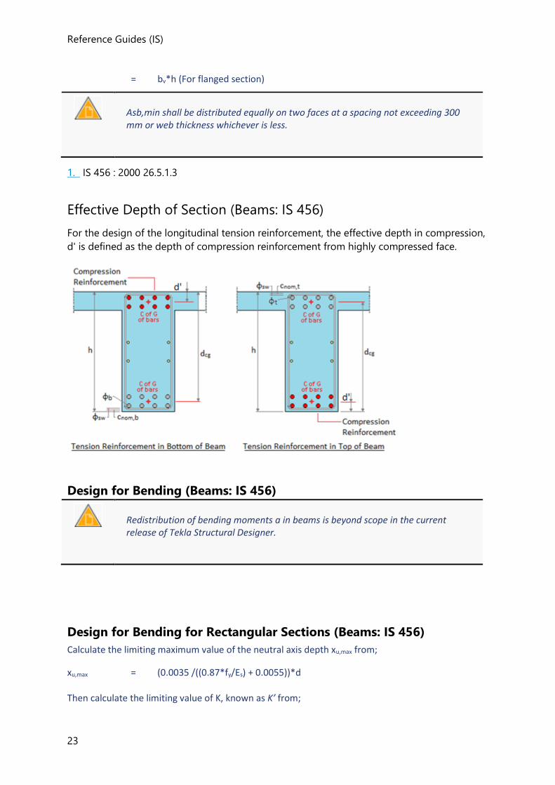
Effective Depth of Section (Beams: IS 456)
For the design of the longitudinal tension reinforcement, the effective depth in compression,
d' is defined as the depth of compression reinforcement from highly compressed face.
Design for Bending (Beams: IS 456)
Redistribution of bending moments a in beams is beyond scope in the current release of Tekla Structural Designer.
Design for Bending for Rectangular Sections (Beams: IS 456)
Calculate the limiting maximum value of the neutral axis depth xu,max from;
xu,max = (0.0035 /((0.87*fy/Es) + 0.0055))*d
Then calculate the limiting value of K, known as K’ from;
Concrete Design to IS 456
24
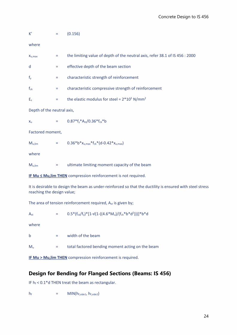
K’ = (0.156)
where
xu,max = the limiting value of depth of the neutral axis, refer 38.1 of IS 456 : 2000
d = effective depth of the beam section
fy = characteristic strength of reinforcement
fck = characteristic compressive strength of reinforcement
Es = the elastic modulus for steel = 2*105 N/mm2
Depth of the neutral axis,
xu = 0.87*fy*Ast/0.36*fck*b
Factored moment,
Mu,lim = 0.36*b*xu,max*fck*(d-0.42*xu,max)
where
Mu,lim = ultimate limiting moment capacity of the beam
IF Mu ≤ Mu,lim THEN compression reinforcement is not required.
It is desirable to design the beam as under-reinforced so that the ductility is ensured with steel stress reaching the design value;
The area of tension reinforcement required, Ast is given by;
Ast = 0.5*(fck/fy)*[1-√(1-((4.6*Mu)/(fck*b*d2)))]*b*d
where
b = width of the beam
Mu = total factored bending moment acting on the beam
IF Mu > Mu,lim THEN compression reinforcement is required.
Design for Bending for Flanged Sections (Beams: IS 456)
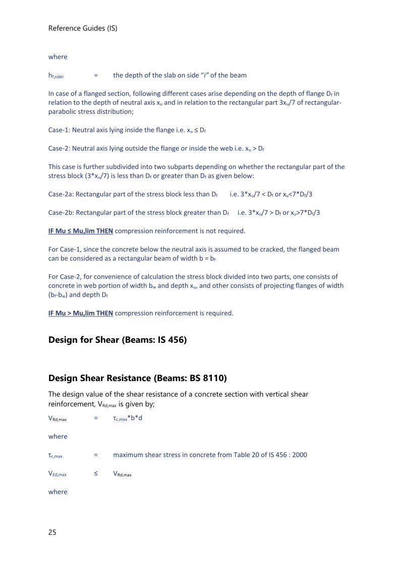
IF hf < 0.1*d THEN treat the beam as rectangular.
hf = MIN(hf,side1, hf,side2)
Reference Guides (IS)
25
where
hf,sidei = the depth of the slab on side “i” of the beam
In case of a flanged section, following different cases arise depending on the depth of flange Df in relation to the depth of neutral axis xu and in relation to the rectangular part 3xu/7 of rectangular-parabolic stress distribution;
Case-1: Neutral axis lying inside the flange i.e. xu ≤ Df
Case-2: Neutral axis lying outside the flange or inside the web i.e. xu > Df
This case is further subdivided into two subparts depending on whether the rectangular part of the stress block (3*xu/7) is less than Df or greater than Df as given below:
Case-2a: Rectangular part of the stress block less than Df i.e. 3*xu/7 < Df or xu<7*Df/3
Case-2b: Rectangular part of the stress block greater than Df i.e. 3*xu/7 > Df or xu>7*Df/3
IF Mu ≤ Mu,lim THEN compression reinforcement is not required.
For Case-1, since the concrete below the neutral axis is assumed to be cracked, the flanged beam can be considered as a rectangular beam of width b = bf
For Case-2, for convenience of calculation the stress block divided into two parts, one consists of concrete in web portion of width bw and depth xu, and other consists of projecting flanges of width (bf-bw) and depth Df
IF Mu > Mu,lim THEN compression reinforcement is required.
Design for Shear (Beams: IS 456)
Design Shear Resistance (Beams: BS 8110)
The design value of the shear resistance of a concrete section with vertical shear
reinforcement, VRd,max is given by;
VRd,max = τc,max*b*d
where
τc,max = maximum shear stress in concrete from Table 20 of IS 456 : 2000
VEd,max ≤ VRd,max
where
Concrete Design to IS 456
26
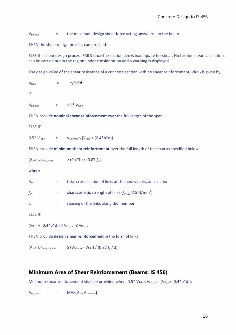
VEd,max = the maximum design shear force acting anywhere on the beam
THEN the shear design process can proceed.
ELSE the shear design process FAILS since the section size is inadequate for shear. No further shear calculations can be carried out in the region under consideration and a warning is displayed.
The design value of the shear resistance of a concrete section with no shear reinforcement, VRd,c is given by;
VRd,c = τc*b*d
IF
VEd,max < 0.5* VRd,c
THEN provide nominal shear reinforcement over the full length of the span
ELSE IF
0.5* VRd,c < VEd,max ≤ (VRd,c + (0.4*b*d))
THEN provide minimum shear reinforcement over the full length of the span as specified below;
(Asv/ sv)min,shear ≥ (0.4*b) / (0.87 fyv)
where
Asv = total cross-section of links at the neutral axis, at a section
fyv = characteristic strength of links (fyv < 415 N/mm2)
sv = spacing of the links along the member
ELSE IF
(VRd,c + (0.4*b*d)) < VEd,max ≤ VRd,max
THEN provide design shear reinforcement in the form of links
(Asv/ sv)design,shear ≥ (VEd,max - VRd,c) / (0.87 fyv*d)
Minimum Area of Shear Reinforcement (Beams: IS 456)
Minimum shear reinforcement shall be provided when, 0.5* VRd,c< VEd,max< (VRd,c+ (0.4*b*d));
Asv, min = MAX[Asv, Asv,min,u]
Reference Guides (IS)
27
where
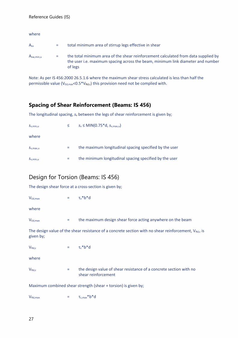
Asv = total minimum area of stirrup legs effective in shear
Asw,min,u = the total minimum area of the shear reinforcement calculated from data supplied by the user i.e. maximum spacing across the beam, minimum link diameter and number of legs
Note: As per IS 456:2000 26.5.1.6 where the maximum shear stress calculated is less than half the permissible value (VEd,max<0.5*VRd,c) this provision need not be complied with.
Spacing of Shear Reinforcement (Beams: IS 456)
The longitudinal spacing, sv between the legs of shear reinforcement is given by;
sv,min,u ≤ sv ≤ MIN(0.75*d, sv,max,u)
where
sv,max,u = the maximum longitudinal spacing specified by the user
sv,min,u = the minimum longitudinal spacing specified by the user
Design for Torsion (Beams: IS 456)
The design shear force at a cross-section is given by;
VEd,max = τv*b*d
where
VEd,max = the maximum design shear force acting anywhere on the beam
The design value of the shear resistance of a concrete section with no shear reinforcement, VRd,c is given by;
VRd,c = τc*b*d
where
VRd,c = the design value of shear resistance of a concrete section with no shear reinforcement
Maximum combined shear strength (shear + torsion) is given by;
VRd,max = τc,max*b*d
Concrete Design to IS 456
28
Check IF
Ve ≤ VRd,max
where
Ve = the equivalent shear calculated
THEN the torsion design process can proceed.
ELSE the torsion design process FAILS since the section size is inadequate for torsion.
IF
Ve < 0.5*VRd,c
THEN provide nominal shear reinforcement over the full length of the span.
ELSE IF
0.5*VRd,c ≤ Ve< (VRd,c+ (0.4*b*d))
THEN provide minimum shear reinforcement over the full length of the span as specified and No torsion reinforcement.
ELSE provide both longitudinal and transverse reinforcement.
Deflection Check (Beams: BS 8110)
The deflection of reinforced concrete beams is not directly calculated and the serviceability
of the beam is measured by comparing the calculated limiting basic span/effective depth
ratio L/d
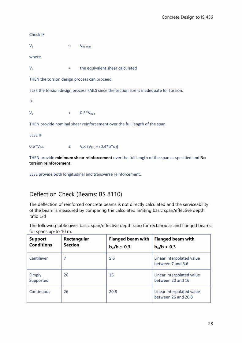
The following table gives basic span/effective depth ratio for rectangular and flanged beams
for spans up-to 10 m.
Support
Conditions
Rectangular
Section
Flanged beam with
bw/b ≤ 0.3
Flanged beam with
bw/b > 0.3
Cantilever 7 5.6 Linear interpolated value between 7 and 5.6
Simply Supported
20 16 Linear interpolated value between 20 and 16
Continuous 26 20.8 Linear interpolated value between 26 and 20.8
Reference Guides (IS)
29
For spans exceeding 10 m values in the above table are multiplied by (10/Span) except for cantilevers where the design is
justified by calculations.A
For beams with tension reinforcement, the basic L/d value is multiplied by the modification factor, MFtB;
MFt = 1/[0.225+(0.00322*fs)-(0.625*log10*((b*d)/(100*Ast)))]
In case of tension reinforcement maximum value of MFt is 2
where
fs = the design service stress in the tension reinforcement
= 5/8*(fy*As req) / As prov*1/βb
For beams with compression reinforcement, the basic L/d value is multiplied by the modification factor, MFc;C
MFc = (1.6*pc)/(pc+0.275)
where
pc = (100*Asc)/(b*d)
AIS 456 : 2000 23.2.1(e) B SP 24-1983 (IS 456 : 1978) page 55 CSP 24-1983 (IS 456 : 1978) page 55
Column Design to IS 456
Limitations and Exclusions (Columns: IS 456)
The following general exclusions also apply:
• Seismic design,
• Consideration of fire resistance. [You are however given full control of the minimum
cover dimension to the reinforcement and are therefore able to take due account of fire
resistance requirements.],
• Lightweight concrete,
• Chamfers,
• Multi-stack reinforcement lifts.
Materials (Columns: IS 456)
Concrete
Concrete Design to IS 456
30
Only normal weight is included in this release. (Lightweight concrete is excluded).
Reinforcement
The reinforcement options are:
• Loose reinforcing bars,
• Loose reinforcing bars bent to form links.
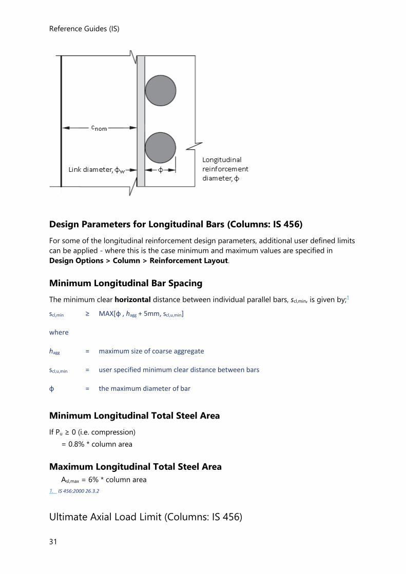
Cover to Reinforcement (Columns: IS 456)
The nominal cover is selected derived from greatest of the following:
1. Bar Size
The nominal cover to all steel should be such that the resulting cover to main bar should not
be less than the size of the main bar.
where
φlargest= maximum diameter of bar in longitudinal reinforcement
IF
φlargest ≤ 12 mm and b ≤ 200 mm
cnom,lim ≥ 25 mm
2. Nominal maximum size of aggregate
The nominal cover should be not less than the nominal maximum size of the aggregate
hagg (specified in Design Options > Column > General Parameters).
3. A minimum value for the nominal cover
The minimum value for the nominal cover, cnom,u, for each column is specified in the column
properties.
Nominal limiting cover to reinforcement:
cnom,lim = MAX [φlargest, hagg, cnom,u]
If cnom,u < cnom,lim then a warning is displayed in the calculations.
Nominal cover is the design depth of concrete cover to all steel reinforcement, including links.If links are present cover is up-to link bar. Ref: IS 456 : 2000 26.4.1.
Reference Guides (IS)
31
Design Parameters for Longitudinal Bars (Columns: IS 456)
For some of the longitudinal reinforcement design parameters, additional user defined limits
can be applied - where this is the case minimum and maximum values are specified in
Design Options > Column > Reinforcement Layout.
Minimum Longitudinal Bar Spacing
The minimum clear horizontal distance between individual parallel bars, scl,min, is given by;1
scl,min ≥ MAX[φ , hagg + 5mm, scl,u,min]
where
hagg = maximum size of coarse aggregate
scl,u,min = user specified minimum clear distance between bars
φ = the maximum diameter of bar
Minimum Longitudinal Total Steel Area
If Pu ≥ 0 (i.e. compression)
= 0.8% * column area
Maximum Longitudinal Total Steel Area
Asl,max = 6% * column area
1. IS 456:2000 26.3.2
Ultimate Axial Load Limit (Columns: IS 456)
Concrete Design to IS 456
32
The ultimate axial load carrying capacity Pu, for a braced or unbraced short column is obtained as below:
Pu = 0.4*fck*Ac + 0.67*Asc*fy
Where
Pu = ultimate axial load on the member
Ac = net cross-sectional area of concrete in a column
fck = characteristic strength of concrete
Asc = area of vertical reinforcement in a column
fy = characteristic strength of compression reinforcement
Effective Length Calculations (Columns: IS 456)
Clear Height
The clear height is the clear dimension between the restraining beams at the bottom of the
stack and the restraining beams at the top of the stack. The clear height may be different in
each direction.
If, at an end of the stack, no effective beams or flat slab to include are found, then the clear
height includes the stack beyond this restraint, and the same rules apply for finding the end
of the clear height at the end of the next stack (and so on).
Effective Length
The effective length, le is calculated automatically - you also have the ability to override the
calculated value.
le = K * l
where
l = clear height between end restraints
K = effective length factor
The value of K may is obtained from the following equationsAA:
a) For non sway (braced frames):
K = [(1 + 0.145*(β1 + β2) - 0.265*β1*β2] / (2 - 0.364*(β1 + β2) - 0.247*β1*β2]
Reference Guides (IS)
33
b) Sway frames (Moment resisting frames):
K = MIN(1.2,{[1 - 0.2*(β1 + β2) - 0.12*β1*β2] / [1 - 0.8(β1 + β2) + 0.6 β1*β2]}0.5
where
β is the rotation release factor and has two values, β1 and β2 at the two ends (top and bottom of the columns respectively)
β1 , β2 = ƩKc/(ƩKc+ƩKb)
ƩKc = effective flexural stiffness of the columns
ƩKb = effective flexural stiffness of the beams
ARefer IS 800 : 2007 Annex D and Shah & Karve text book Sect. 11.2
Determination of the non-sway or sway columnB:
If Q ≤ 0.04
If Q > 0.04
where
Q = Stability index
A B Refer IS 456 : 2000 Annex E
Column Stack Classification (Columns: IS 456)
Slenderness ratio
The slenderness ratio, λ, of the column about each axis is calculated as follows:
λx = lex / D
λy = ley / b
where
λx = slenderness ratio about major axis (x axis)
λy = slenderness ratio about minor axis (y axis)
D = larger dimension of the column
Concrete Design to IS 456
34
b = smaller dimension of the column
lex = effective length in respect of major axis (y axis)
ley = effective length in respect of minor axis (z axis)
IF λx and λy < 12
Column is considered as short
Else
Column is considered as slender
If column is slender in any direction the additional moments will be induced by the lateral deflection of the loaded column.
limiting slenderness ratio
The limiting value of slenderness ratio λlim is calculated as below:
For braced or unbraced columnsA
l /b ≤ 60
For an unbraced column, if in any given plane one end is unrestrained (e.g a cantilever
column)B
l0 /b ≤ 100*b / D]
Where
l = clear height between end restraints
If the slenderness ratio (l/b) exceeds the limiting value calculated above then the column design process FAILS.
AIS 456 : 2000 25.3.1 B IS 456 : 2000 25.3.2
Design Moment Calculations (Columns: IS 456)
Minimum Eccentricity
At no section in a column should the design moment be taken as less than that produced by
considering the design ultimate axial load, Pu as acting at a minimum eccentricity emin
Reference Guides (IS)
35
The minimum eccentricity emin is calculated as below:A
emin,x = MAX [lux/500 + D/30, 20mm]
emin,y = MAX [luy/500 + d/30, 20mm]
Where
emin,x = minimum eccentricity along major axis (xx-axis)
emin,y = minimum eccentricity along minor axis (yy-axis)
lux = unsupported length in respect of major axis (xx-axis)
luy = unsupported length in respect of major axis (yy-axis)
A IS 456 : 2000 25.4
Short columns
The design ultimate moment of braced short or unbraced short column at top, bottom and
mid-fifth span of column is obtained as below:
Mx = MAX [Mx,analysis, Mx,emin,x]
My = MAX [My,analysis, My,emin,y]
Slender columns
Additional Moments for Slender Columns:
For braced slender column it is necessary to consider additional moments induced by the
lateral deflection of the loaded column.
The additional moment are obtained as below:A
Max = kx*[((Pu*D)/2000)*(lex/D)2]
May = ky*[((Pu*b)/2000)*(ley/b)2]
Where
Max = additional moment about major axis (x axis) as per Cl 39.7 of IS 456 : 2000
May = additional moment about major axis (yaxis) as per Cl 39.7 of IS 456 : 2000
kx or ky = reduction factor
A IS 456 : 2000 39.7.1
Concrete Design to IS 456
36
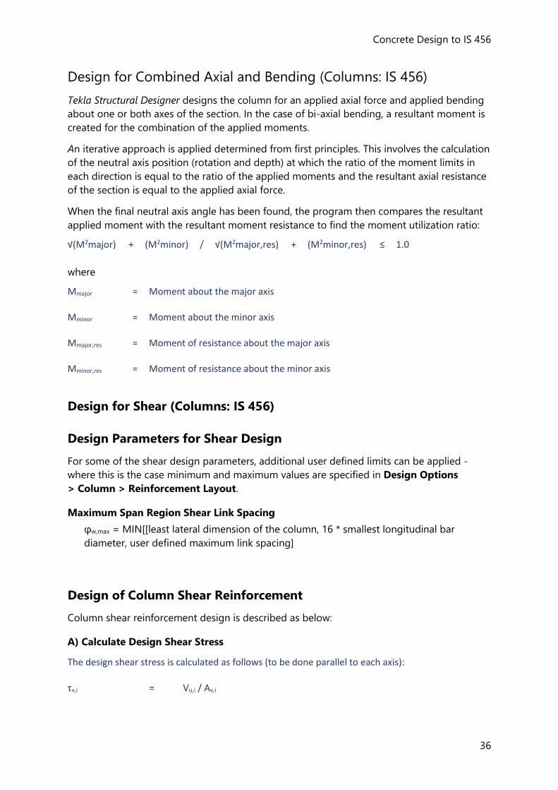
Design for Combined Axial and Bending (Columns: IS 456)
Tekla Structural Designer designs the column for an applied axial force and applied bending
about one or both axes of the section. In the case of bi-axial bending, a resultant moment is
created for the combination of the applied moments.
An iterative approach is applied determined from first principles. This involves the calculation
of the neutral axis position (rotation and depth) at which the ratio of the moment limits in
each direction is equal to the ratio of the applied moments and the resultant axial resistance
of the section is equal to the applied axial force.
When the final neutral axis angle has been found, the program then compares the resultant
applied moment with the resultant moment resistance to find the moment utilization ratio:
√(M2major) + (M2minor) / √(M2major,res) + (M2minor,res) ≤ 1.0
where
Mmajor = Moment about the major axis
Mminor = Moment about the minor axis
Mmajor,res = Moment of resistance about the major axis
Mminor,res = Moment of resistance about the minor axis
Design for Shear (Columns: IS 456)
Design Parameters for Shear Design
For some of the shear design parameters, additional user defined limits can be applied -
where this is the case minimum and maximum values are specified in Design Options
> Column > Reinforcement Layout.
Maximum Span Region Shear Link Spacing
φw,max = MIN[[least lateral dimension of the column, 16 * smallest longitudinal bar
diameter, user defined maximum link spacing]
Design of Column Shear Reinforcement
Column shear reinforcement design is described as below:
A) Calculate Design Shear Stress
The design shear stress is calculated as follows (to be done parallel to each axis):
τv,i = Vu,i / Av,i
Reference Guides (IS)
37
Where
Vu,i = highest shear force in the stack in this direction,
Av,i = shear area parallel to the axis i.
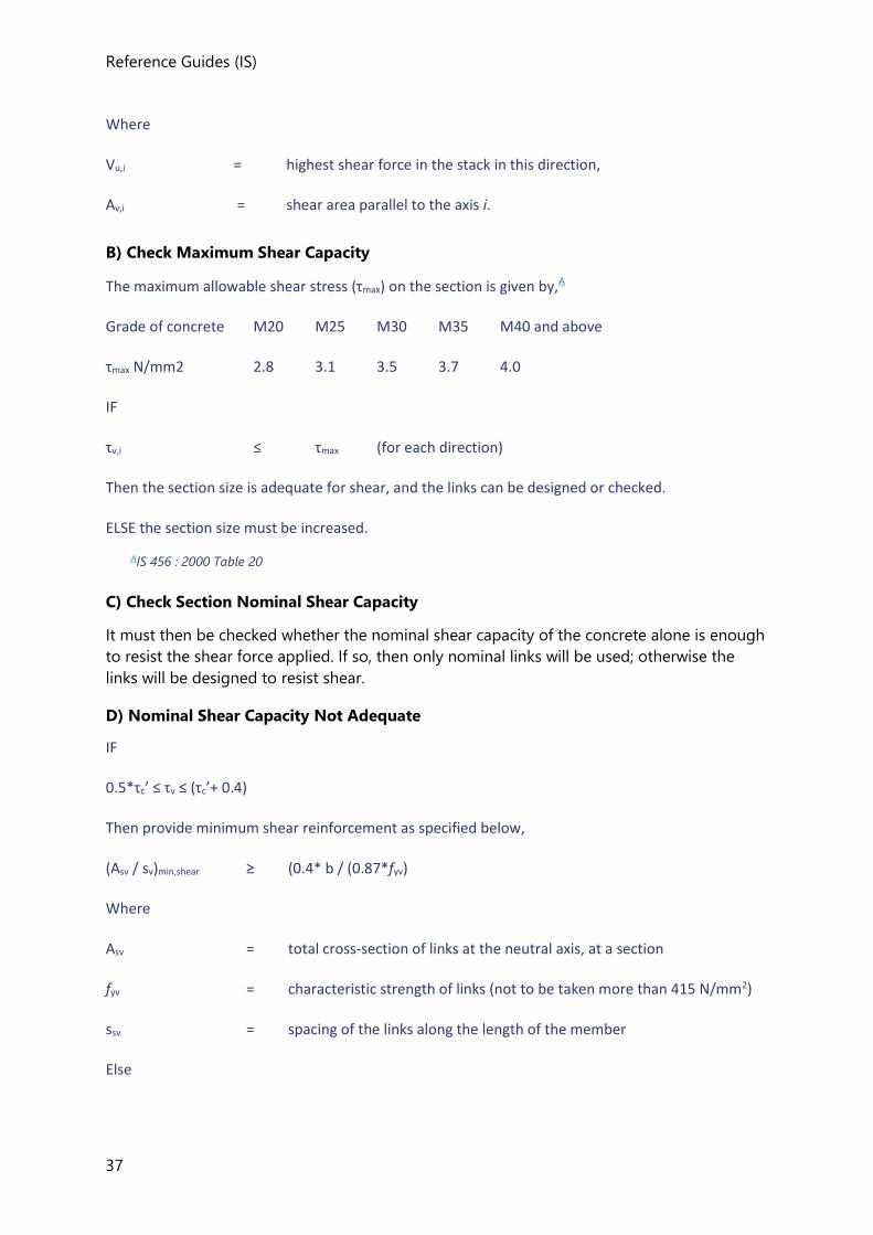
B) Check Maximum Shear Capacity
The maximum allowable shear stress (τmax) on the section is given by,A
Grade of concrete M20 M25 M30 M35 M40 and above
τmax N/mm2 2.8 3.1 3.5 3.7 4.0
IF
τv,i ≤ τmax (for each direction)
Then the section size is adequate for shear, and the links can be designed or checked.
ELSE the section size must be increased.
AIS 456 : 2000 Table 20
C) Check Section Nominal Shear Capacity
It must then be checked whether the nominal shear capacity of the concrete alone is enough
to resist the shear force applied. If so, then only nominal links will be used; otherwise the
links will be designed to resist shear.
D) Nominal Shear Capacity Not Adequate
IF
0.5*τc’ ≤ τv ≤ (τc’+ 0.4)
Then provide minimum shear reinforcement as specified below,
(Asv / sv)min,shear ≥ (0.4* b / (0.87*fyv)
Where
Asv = total cross-section of links at the neutral axis, at a section
fyv = characteristic strength of links (not to be taken more than 415 N/mm2)
ssv = spacing of the links along the length of the member
Else
Concrete Design to IS 456
38
Provide design reinforcement as,
(Asv / sv)design,shear ≥ VEd,design / (0.87*fyv*di)
Where
VEd,design = (τv*b*di) - (τc*b*di)
= (VEd,max - VRd,c)
When, (τc'+ 0.4) ≤ τv ≤ τc,max
The spacing s is given byA
(smin,u ≤ s ≤ MIN[0.75*di, 300mm, sv,max,u )
A IS 456 : 2000 26.5.1.5
Chapter
Wall Design to IS 456
Tekla Structural Designer will design wall panels to resist axial load combined with shear and
bending in each of the two planes of the wall.
Limitations and Exclusions (Walls: IS 456)
The following general exclusions apply:
• Seismic design,
• Consideration of fire resistance. [You are however given full control of the minimum
cover dimension to the reinforcement and are therefore able to take due account of fire
resistance requirements],
• Lightweight concrete,
• Multi-stack reinforcement lifts.
Materials (Walls: IS 456)
Concrete
Only normal weight is included in the current release. (Lightweight concrete is excluded).
Reinforcement
The reinforcement options are:
Reference Guides (IS)
39
• Loose reinforcing bars,
• Mesh (Standard Meshes)
• Loose reinforcing bars bent to form links.
Cover to Reinforcement (Walls: IS 456)
The nominal cover is selected derived from greatest of the following:
1. Bar Size
The nominal cover to all steel should be such that the resulting cover to main bar including
links should not be less than the size of the main bar.
where
φ = maximum diameter of main bar
2. Nominal maximum size of aggregate
The nominal cover should be not less than the nominal maximum size of the aggregate
hagg (specified in Design Options > Wall > General Parameters).
3. A minimum value for the nominal cover
The minimum value for the nominal cover, cnom,u, for each wall is specified in the wall
properties.
Nominal limiting cover to reinforcement:
cnom,lim = MAX [φ, hagg, cnom,u]
If cnom,u < cnom,lim then a warning is displayed in the calculations.
Vertical reinforcement (Walls: IS 456)
For some of the vertical bar parameters, additional user defined limits can be applied - where
this is the case minimum and maximum values are specified in Design Options > Wall >
Reinforcement Layout.
In the following, the concrete area is the gross area of the general wall, or the gross area of the mid zone if one exists. For the end zone the design criteria for a reinforced concrete column element applies.
Plain Wall Check
Before placing vertical reinforcement in the wall, the following checks are performed to
determine if the given section of wall can act potentially as a plain wall or not.
Concrete Design to IS 456
40
a) Check for stresses at the corner of a wall
If there are no tensile stresses developed in the wall it is in compression throughout and
check passes.
b) Check for bending utilization
Check the bending utilization is less than 10%, i.e.
Asc, required = 0.1*0.0012* Ac = 0.00012* Ac (For φ ≤ 16mm fy ≥ 415 N/mm2)
Asc, required = 0.1*0.0015* Ac = 0.00015* Ac (For other types of bar)
The figure 10% stated above is not a code dependent value, it is a matter of engineering judgment.
c) Check for limiting axial load
Maximum design load per unit length of a braced plain wall is assessed from the
following equations:
puw ≤ 0.3*(t – 1.2*ex - 2ea)*fck1
Where
t = thickness of wall
fck = characteristic strength of concrete
ex = eccentricity of load at right angles to the plane of the wall ( minimum resultant
eccentricity of load at right angles to the plane of the wall = 0.05*t
ea = additional eccentricity due to slenderness effect
IF all the checks stated above (a, b, and c) pass, the given section of wall is classified as plain
wall.
Reinforcement area for a Plain wall
Following parameters control the vertical reinforcement area of plain wall,
Limiting minimum ratio of vertical reinforcement area to gross concrete area2, v,lim,min
For reinforcement in one grid (for single layer reinforcement)
For φ ≤ 16 mm and fy ≥ 415 N/mm2
Total minimum area of vertical reinforcement, Asc,min = v,lim,min*Ac = 0.0012*Ac
For other types of bars
Total minimum area of vertical reinforcement, Asc,min = v,lim,min*Ac = 0.0015*Ac
For reinforcement in two grids, one near each face (for double layers reinforcement)
For φ ≤ 16 mm and fy ≥ 415 N/mm2
Total minimum area of vertical reinforcement, Asc,min = v,lim,min*Ac = (2*0.0012)*Ac
For other types of bars
Reference Guides (IS)
41
Total minimum area of vertical reinforcement, Asc,min = v,lim,min*Ac = (2*0.0015)*Ac
For walls having thickness more than 200 mm, the vertical and horizontal reinforcement shall be provided in two grids.
Reinforcement area for a RC wall
The following parameters control the vertical reinforcement area of RC wall,
Limiting minimum ratio of vertical reinforcement area to gross concrete area, v,lim,min
Total minimum area of vertical reinforcement, Asc,min = v,lim,min*Ac = 0.004*Ac
Total maximum area of vertical reinforcement, Asc,max = v,lim,max*Ac = 0.04*Ac
Where
Ac = Gross area of the concrete wall
pu= The total design axial load on the wall due to design ultimate loads
Where 2 layers are specified distributed equally to each face, this is a minimum of
0.002*Ac placed at each face.
To avoid practical difficulties while placing the bars, SP : 24-1983 suggests a maximum vertical steel of 2 percent of the cross-section.
Spacing of vertical loose bars
Limiting minimum clear horizontal spacing of the vertical bars, scl, v,min is given by, 3
scl,v,min = MAX [hagg + 5mm, scl,u,v,min ]
Where
hagg = maximum size of coarse aggregate
scl,u,v,min = user specified minimum clear horizontal distance between bars
scl,v,min = minimum clear horizontal distance between bars
IF
> hagg + 5mm,
THEN
scl,v,min >
Where
= maximum diameter of vertical bar
Limiting maximum spacing of vertical bars in the wall, scl,v,max = MIN [3*t,450 mm]4
Concrete Design to IS 456
42
As per SP 34-1987, cl 11.2.4.1, vertical bars that are not fully restrained should not be placed further than 200 mm from a restrained bar.
Check for vertical reinforcement when wall in tension
For RC wall –
For wall thickness, t > 200 mm
The user has to put reinforcement in two grids / 'double' layers, one near each face.
It is NOT necessary to check the axial load acting on the wall is tension or compression.
For wall thickness, t < 200 mm
In the wall properties a “Reinforcement layers” option is present in which the user can set 1
or 2 layers.
If a single layer has been selected then it is necessary to check if the axial load acting on the
wall is tension or compression.
1. IS 456 : 2000 cl 32.2.5
2. IS 456 : 2000 cl 32.5
3. IS 456 : 2000 cl 26.3.2
4. IS 456 : 2000 cl 32.5
Horizontal reinforcement (Walls: IS 456)
For some of the horizontal bar parameters, additional user defined limits can be applied -
where this is the case values are specified in Design Options > Wall > Reinforcement
Layout.
Reinforcement area for Plain or RC wall
The following parameters control the horizontal reinforcement area of a Plain or RC wall,
Limiting minimum ratio of horizontal reinforcement area to gross concrete area, h,lim,min
Limiting maximum ratio of horizontal reinforcement area to gross concrete area, h,lim,max
For reinforcement in one grid (for single layer reinforcement)
For φ ≤ 16 mm and fy ≥ 415 N/mm2
Total minimum area of horizontal reinforcement, Ash,min = h,lim,min*Ac = 0.0020*Ac
For other types of bars
Total minimum area of horizontal reinforcement, Ash,min = h,lim,min*Ac = 0.0025*Ac
Reference Guides (IS)
43
For reinforcement in two grids, one near each face (for double layers reinforcement)
For φ ≤ 16 mm and fy ≥ 415 N/mm2
Total minimum area of horizontal reinforcement, Ash,min = h,lim,min*Ac = (2*0.0020)*Ac
For other types of bars
Total minimum area of horizontal reinforcement, Ash,min = h,lim,min*Ac = (2*0.0025)*Ac
Where
Ac= Gross area of the concrete wall
IF
Asc > 0.01*Ac
THEN
Links are provided as per section Link/Confinement Reinforcement in addition to the above
requirement.
Where
Asc= Vertical reinforcement
Total maximum area of horizontal reinforcement, Ash,max = h,lim,max*Ac = 0.04*Ac
Diameter of horizontal bar
Minimum diameter of horizontal bar, h,min = MAX [ 0.25*v , h,min,u , 6 mm ]1
Where
v = maximum diameter of vertical bar
h,min,u = minimum diameter of link specified by user
Spacing of horizontal loose bars
Limiting minimum clear vertical spacing of the horizontal bars, scl,h,min is given by, 2
scl,h,min = MAX [hagg + 5mm, scl,u,h,min ]
Where
hagg = maximum size of coarse aggregate
scl,u,h,min = user specified minimum clear vertical distance between bars
scl,h,min = minimum clear vertical distance between bars
IF
> hagg + 5mm,
THEN
scl,h,min >
Where
= diameter of horizontal bar
Limiting maximum horizontal spacing, scl,h,max = MIN [ 3*t , 450mm ]
Concrete Design to IS 456
44
Reinforcement area for a Plain wall
For a plain wall,
0 ≤ v < 0.004
The same bar limit checks that are performed for an RC wall are also performed for a plain
wall.
1. IS 456 : 2000 cl 26.5.3.2
2. IS 456 : 2000 cl 26.3.2
Link/Confinement Reinforcement (Walls: IS 456)
The confinement steel reinforcement provided in the form of link contributes to the shear
resistance.
It must be provided when the vertical area of reinforcement in the 2 faces exceeds 0.02*Ac
Reinforcement area
There is no code requirement to satisfy.
Diameter of confinement reinforcement
Minimum diameter of link, w,min = MAX [ 0.25*v , 6 mm , w,min,u ]1
Where
v = maximum diameter of vertical bar
w,min,u = minimum diameter of link specified by user
It is expected that the maximum diameter of link, w,max will not be greater than the vertical
bar diameter.
v,max ≤ v
Spacing of confinement reinforcement
The spacing of links, sv in horizontal direction is given by;2
sv,min,u ≤ sv ≤ MIN [ 2*t, 200mm ]
No vertical bar should be further than 200mm from a restrained bar, at which a link passes
round the bar with an included angle of not more than 900
The spacing of links, sv in the vertical direction is given by;
sv,min,u ≤ sv ≤ MIN [ 15*v , sv,max,u ,300 mm]
Where
sv,min,u = the minimum link spacing specified by user
sv,max,u = the maximum link spacing specified by user
v = maximum diameter of vertical bar
Reference Guides (IS)
45
You are given control over these values by specifying upper and lower limits in Design
Options > Wall > Reinforcement Layout.
1. IS 456 : 2000 cl 26.5.3.2 4c
2. SP 34-1987 cl 11.2.4.1
Ultimate Axial Load Limit (Walls: IS 456)
The axial resistance calculations for walls are the same as for columns. (See Column Design -
).
Effective Length and Slenderness Calculations (Walls: IS 456)
The slenderness calculations for walls are generally the same as for columns. (See Column
Design - and ).
Design Moment Calculations (Walls: IS 456)
For each combination, a set forces are returned from one or more sets of analyses, in the
same way as for columns. For details, see: See Column Design - .
Design for Combined Axial and Bending (Walls: IS 456)
These calculations are the same whether the design element is a column or a wall.
See Column Design - ).
Design for Shear (Walls: IS 456)
The shear design calculations are the same whether the design element is a column or a wall.
See Column Design - ). Chapter
Slab Design to IS 456
•
Limitations and Exclusions (Slabs: IS 456)
The following general exclusions apply:
• Seismic design
• Consideration of fire resistance. [You are however given full control of the minimum
cover dimension to the reinforcement and are therefore able to take due account of fire
resistance requirements]
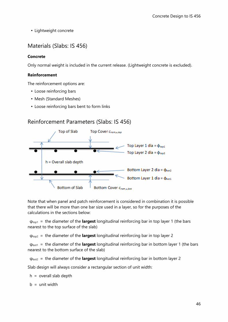
Concrete Design to IS 456
46
• Lightweight concrete
Materials (Slabs: IS 456)
Concrete
Only normal weight is included in the current release. (Lightweight concrete is excluded).
Reinforcement
The reinforcement options are:
• Loose reinforcing bars
• Mesh (Standard Meshes)
• Loose reinforcing bars bent to form links
Reinforcement Parameters (Slabs: IS 456)
Note that when panel and patch reinforcement is considered in combination it is possible
that there will be more than one bar size used in a layer, so for the purposes of the
calculations in the sections below:
φtop1 = the diameter of the largest longitudinal reinforcing bar in top layer 1 (the bars
nearest to the top surface of the slab)
φtop2 = the diameter of the largest longitudinal reinforcing bar in top layer 2
φbot1 = the diameter of the largest longitudinal reinforcing bar in bottom layer 1 (the bars
nearest to the bottom surface of the slab)
φbot2 = the diameter of the largest longitudinal reinforcing bar in bottom layer 2
Slab design will always consider a rectangular section of unit width:
h = overall slab depth
b = unit width
Reference Guides (IS)
47
for design the unit width of slab is 1m, and so the design cross section will always be a
rectangular section where b = 1000mm
Cover to Reinforcement (Slabs: IS 456)
The nominal concrete cover is the distance between the surface of the reinforcement closest
to the nearest concrete surface (including links and surface reinforcement where relevant)
and the nearest concrete surface.
You are required to set a minimum value for the nominal cover, cnom,u , for each slab panel.
These values for top and bottom cover are specified in the Reinforcement properties section
of the slab panel properties.
This value is then checked against the nominal limiting cover, cnom,lim which depends on the
diameter of the reinforcement.
If cnom,u < cnom,lim then a warning is displayed in the calculations.
Limiting Reinforcement Parameters (Slabs: IS 456)
Limiting reinforcement parameters are specified in Design Options > Slab >
Reinforcement Layout.
The parameters applied to “flat slab” design are held separately to those for “beam and
slab” design.
Minimum and Maximum Loose Bar Diameter (Slabs: IS 456)
Bar diameters are checked against the user defined minimum and maximum sizes specified
in Design Options > Slab > Reinforcement Layout.
Minimum Loose Bar Diameter
For “flat slab”:
φmin = 8mm (default)
For “beam and slab”:
φmin = 8mm (default)
Maximum Loose Bar Diameter
For “flat slab”:
φmin = 16mm (default)
For “beam and slab”:
φmin = 16mm (default)
Minimum Clear Spacing (Slabs: IS 456)
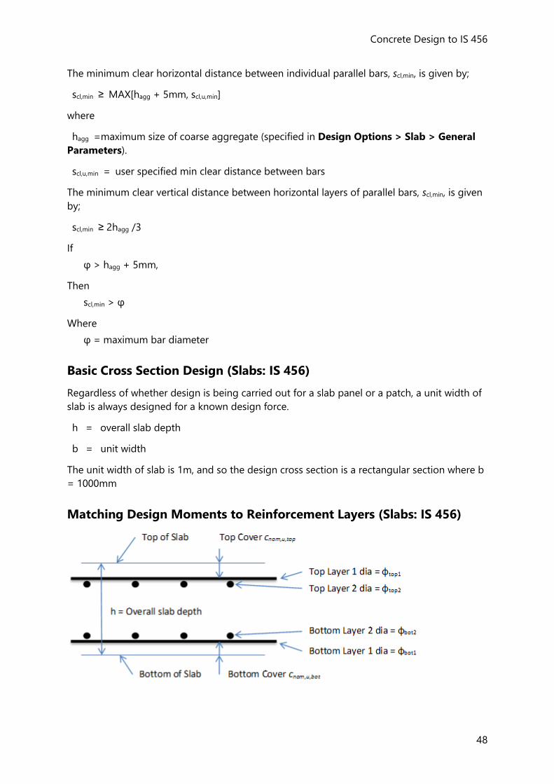
Concrete Design to IS 456
48
The minimum clear horizontal distance between individual parallel bars, scl,min, is given by;
scl,min ≥ MAX[hagg + 5mm, scl,u,min]
where
hagg =maximum size of coarse aggregate (specified in Design Options > Slab > General
Parameters).
scl,u,min = user specified min clear distance between bars
The minimum clear vertical distance between horizontal layers of parallel bars, scl,min, is given
by;
scl,min ≥ 2hagg /3
If
φ > hagg + 5mm,
Then
scl,min > φ
Where
φ = maximum bar diameter
Basic Cross Section Design (Slabs: IS 456)
Regardless of whether design is being carried out for a slab panel or a patch, a unit width of
slab is always designed for a known design force.
h = overall slab depth
b = unit width
The unit width of slab is 1m, and so the design cross section is a rectangular section where b
= 1000mm
Matching Design Moments to Reinforcement Layers (Slabs: IS 456)
Reference Guides (IS)
49
In any panel or patch potentially up to 4 sets of Design Bending Moments are established:
• Mdx-top - used to determine the reinforcement requirement of the x-direction bars in
the top of the slab.
• Mdy-top - used to determine the reinforcement requirement of the y-direction bars in
the top of the slab
• Mdx-bot - is used to determine the reinforcement requirement of the x-direction bars in
the bottom of the slab.
• Mdy-bot - is used to determine the reinforcement requirement of the y-direction bars in
the bottom of the slab.
For each set of design bending moments, the effective depths d and d2 are established -
taking account of the direction of the outer bar layer (as specified in the Reinforcement
properties section of the slab panel properties).
Design for Bending (Slabs: IS 456)
For the design moment under consideration the appropriate effective depths d and d2 are
calculated. The design is then basically the same as employed for the design of rectangular
beams.
see: Design for Bending (Beams: IS 456)
Deflection Check (Slabs: IS 456)
The span-effective depth check only applies to “Beam and Slab” panels. The basic principle is
the same as used for beams.
see: Deflection Check (Beams: IS 456) Chapter
References
1. Bureau of Indian Standards. IS 456 : 2000. Plain and Reinforced Concrete - Code of Practice. BIS 2000.


