Embed Size (px)
Citation preview

TENDER NO: 1/2019 Dated 24/6/2019
INVITATION OF TENDERS for
PACKAGE I
WORKS OF INTERIORS (INCLUDING ELECTRICALS) FOR IIITD INNOVATION & INCUBATION CENTRE
ARCHITECTS SIKKA ASSOCIATES A-2/1, Africa Avenue Safdarjang Enclave New Delhi – 110029 PH. : 26107053, 43235235 FAX : 26194481
E-Mail : [email protected]
1

IIITD Innovation & Incubation Center, Delhi
INDEX
S. No. SUB HEAD PAGE NO.
1 TENDER DOCUMENT 3-54
2 SPECIFICATIONS/LIST OF MAKES attached
3 DRAWINGS attached
4 SCHEDULE OF QUANTITIES attached
2
IIITD Innovation & Incubation Center, Delhi
IIIT Innovation & Incubation Center, New Delhi (IIIC)
Dated: 24.6.2019
TENDER NOTICE
1. Last Date & Time of issue of tender documents from: 24.06.2018 2. Last Date & Time of receipt of tender: 09.07.2018 up to 3.00 p.m
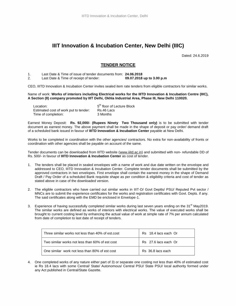
CEO, IIITD Innovation & Incubation Center invites sealed item rate tenders from eligible contractors for similar works. Name of work: Works of interiors including Electrical works for the IIITD Innovation & Incubation Centre (IIIC), A Section (8) company promoted by IIIT Delhi, Okhla Industrial Area, Phase III, New Delhi 110020.
Location: 5
th floor of Lecture Block
Estimated cost of work put to tender: Rs.46 Lacs Time of completion: 3 Months
Earnest Money Deposit: Rs. 92,000/- (Rupees Ninety Two Thousand only) is to be submitted with tender
document as earnest money. The above payment shall be made in the shape of deposit or pay order/ demand draft of a scheduled bank issued in favour of IIITD Innovation & Incubation Center payable at New Delhi.
Works to be completed in coordination with the other agencies/ contractors. No extra for non-availability of fronts or coordination with other agencies shall be payable on account of the same.
Tender documents can be downloaded from IIITD website (www.iiitd.ac.in) and submitted with non- refundable DD of Rs. 500/- in favour of IIITD Innovation & Incubation Center as cost of tender.
1. The tenders shall be placed in sealed envelopes with a name of work and due date written on the envelope and addressed to CEO, IIITD Innovation & Incubation Center. Complete tender documents shall be submitted by the approved contractors in two envelopes. First envelope shall contain the earnest money in the shape of Demand Draft / Pay Order of a scheduled Bank requisite shape as per condition & eligibility criteria and cost of tender as stated above in case of the downloaded version.
2. The eligible contractors who have carried out similar works in IIIT-D/ Govt Deptts/ PSU/ Reputed Pvt sector / MNCs are to submit the experience certificates for the works and registration certificates with Govt. Depts. if any. The said certificates along with the EMD be enclosed in Envelope-1.
3. Experience of having successfully completed similar works during last seven years ending on the 31st May2019.
The similar works are defined as works of interiors with electrical works. The value of executed works shall be brought to current costing level by enhancing the actual value of work at simple rate of 7% per annum calculated from date of completion to last date of receipt of tenders.
Three similar works not less than 40% of est.cost Rs 18.4 lacs each Or
Two similar works not less than 60% of est cost Rs 27.6 lacs each Or
One similar work not less than 80% of est cost Rs 36.8 lacs each
4. One completed works of any nature either part of 3) or separate one costing not less than 40% of estimated cost ie Rs 18.4 lacs with some Central/ State/ Autonomous/ Central PSU/ State PSU/ local authority formed under any Act published in Central/State Gazette.
3

IIITD Innovation & Incubation Center, Delhi
5. The applications not supported with requisite experience certificates, GST registration certificate, TIN no. and
ITCC in Envelope-1 shall not be entertained.
6. Average Annual Turnover over Interior and electrical works should be at least Rs 115 lacs during immediate last 3 consecutive financial years ending 31
st March 2019.
7. Should not have incurred any loss in the more than two years in the last five years ending 31st Mar 2019.
8. Should submit solvency certificate of 40% of estimate i.e. for 18.4 lacs from their bankers .
9. Performance certificates must be submitted by the vendors for the works .
10. A pre-bid conference would be held on the 1st
July 2019 at 10.00 AM at the 5th
Floor of Lecture Hall Complex .
11. The second envelope shall contain the financial bids including Priced Schedule of Quantities, Form of Tender,
Conditions of Tender, Articles of Agreement, Brief Specifications, Condition of contract, Drawings all duly signed by the authorized signatory of the firms.
12. All these envelopes are to be put in a single envelope duly super-scribed the name of work, and addressed to CEO, IIITD Innovation & Incubation Center and with their address. Incase the tenderer does not fulfill the laid down eligibility criteria or fails to deposit the earnest money in prescribed form, financial bid shall not be opened.
13. Tenderers shall seal the tender affix their initials and put stamp on each and every page of tender document before submission. The tender of the contractor, who submits in-complete tender document or submits more than one tender for one work, shall not be considered at all.
14. Tenders will be received by the CEO up to 3.00 P.M on 09/07/2019 and will be opened by him or his authorized
representative in the office of Registrar, IIITD on the same day at 3.30 P.M.
15. First the Technical Bids will be opened and screened. The bids shall be examined whether the EMD is in order and the bidder meets the minimum eligibility criteria specified above. Those bidders whose EMD is in order, meets the minimum eligibility criteria, has submitted all the required documents and meet the technical requirements shall be considered for opening of financial bid. Conditional tenders would not be accepted. Financial bids in respect of contractors who do not fulfill above criterion shall not be opened.
16. No Xerox / certified copies of tenders shall be accepted, if submitted these tenders shall be rejected.
CEO, IIITD Innovation & Incubation Center
4
IIITD Innovation & Incubation Center, Delhi
CONDITIONS
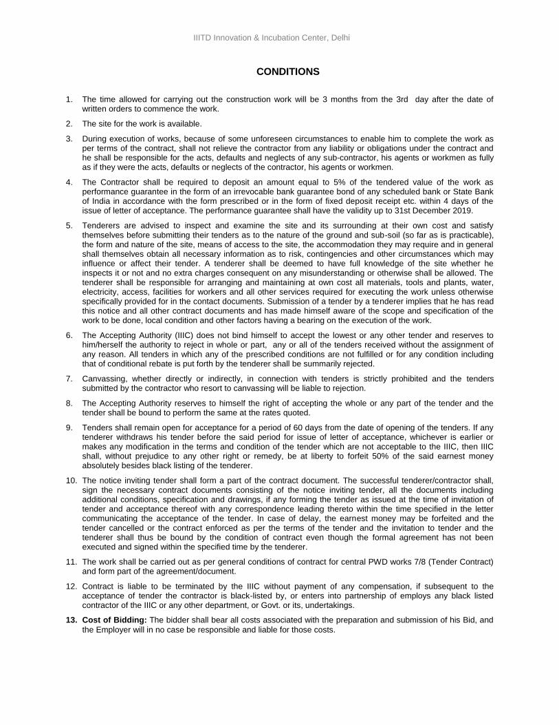
1. The time allowed for carrying out the construction work will be 3 months from the 3rd day after the date of written orders to commence the work.
2. The site for the work is available.
3. During execution of works, because of some unforeseen circumstances to enable him to complete the work as per terms of the contract, shall not relieve the contractor from any liability or obligations under the contract and he shall be responsible for the acts, defaults and neglects of any sub-contractor, his agents or workmen as fully as if they were the acts, defaults or neglects of the contractor, his agents or workmen.
4. The Contractor shall be required to deposit an amount equal to 5% of the tendered value of the work as performance guarantee in the form of an irrevocable bank guarantee bond of any scheduled bank or State Bank of India in accordance with the form prescribed or in the form of fixed deposit receipt etc. within 4 days of the issue of letter of acceptance. The performance guarantee shall have the validity up to 31st December 2019.
5. Tenderers are advised to inspect and examine the site and its surrounding at their own cost and satisfy themselves before submitting their tenders as to the nature of the ground and sub-soil (so far as is practicable), the form and nature of the site, means of access to the site, the accommodation they may require and in general shall themselves obtain all necessary information as to risk, contingencies and other circumstances which may influence or affect their tender. A tenderer shall be deemed to have full knowledge of the site whether he inspects it or not and no extra charges consequent on any misunderstanding or otherwise shall be allowed. The tenderer shall be responsible for arranging and maintaining at own cost all materials, tools and plants, water, electricity, access, facilities for workers and all other services required for executing the work unless otherwise specifically provided for in the contact documents. Submission of a tender by a tenderer implies that he has read this notice and all other contract documents and has made himself aware of the scope and specification of the work to be done, local condition and other factors having a bearing on the execution of the work.
6. The Accepting Authority (IIIC) does not bind himself to accept the lowest or any other tender and reserves to him/herself the authority to reject in whole or part, any or all of the tenders received without the assignment of any reason. All tenders in which any of the prescribed conditions are not fulfilled or for any condition including that of conditional rebate is put forth by the tenderer shall be summarily rejected.
7. Canvassing, whether directly or indirectly, in connection with tenders is strictly prohibited and the tenders submitted by the contractor who resort to canvassing will be liable to rejection.
8. The Accepting Authority reserves to himself the right of accepting the whole or any part of the tender and the tender shall be bound to perform the same at the rates quoted.
9. Tenders shall remain open for acceptance for a period of 60 days from the date of opening of the tenders. If any tenderer withdraws his tender before the said period for issue of letter of acceptance, whichever is earlier or makes any modification in the terms and condition of the tender which are not acceptable to the IIIC, then IIIC shall, without prejudice to any other right or remedy, be at liberty to forfeit 50% of the said earnest money absolutely besides black listing of the tenderer.
10. The notice inviting tender shall form a part of the contract document. The successful tenderer/contractor shall, sign the necessary contract documents consisting of the notice inviting tender, all the documents including additional conditions, specification and drawings, if any forming the tender as issued at the time of invitation of tender and acceptance thereof with any correspondence leading thereto within the time specified in the letter communicating the acceptance of the tender. In case of delay, the earnest money may be forfeited and the tender cancelled or the contract enforced as per the terms of the tender and the invitation to tender and the tenderer shall thus be bound by the condition of contract even though the formal agreement has not been executed and signed within the specified time by the tenderer.
11. The work shall be carried out as per general conditions of contract for central PWD works 7/8 (Tender Contract) and form part of the agreement/document.
12. Contract is liable to be terminated by the IIIC without payment of any compensation, if subsequent to the acceptance of tender the contractor is black-listed by, or enters into partnership of employs any black listed contractor of the IIIC or any other department, or Govt. or its, undertakings.
13. Cost of Bidding: The bidder shall bear all costs associated with the preparation and submission of his Bid, and
the Employer will in no case be responsible and liable for those costs.
5
IIITD Innovation & Incubation Center, Delhi
14. Clarification of Bidding Documents: A prospective bidder requiring any clarification of the bidding documents
may notify the Employer in writing/mail at the Employer's address indicated in the invitation to bid not later than 5 days before the Date of Submission of Tenders.
Email: [email protected]
15. Currencies of Bid and Payment: The unit rates and the prices shall be quoted by the bidder entirely in Indian
Rupees. All payments will be invariably made in Indian Currency (Indian Rupees.)
16. Protection of Environment and Other Laws: The contractor shall take all reasonable steps to protect the
environment on and off the Site and to avoid damage or nuisance to persons or to property of the public or others resulting from pollution, noise or other causes arising as a consequence of his methods of operation.
17. During continuance of the contract, the contractor and his sub-contractors shall abide at all times by all existing enactments on environmental protection and other local Acts/ Laws/ rules made there under, regulations, notifications and bye-laws of local authorities or any other law, bye-laws, regulations that may be passed or notification that may be issued in this respect in future by the State/ Local authority.
For and on behalf of
IIITD Innovation & Incubation Center New Delhi
6
IIITD Innovation & Incubation Center, Delhi
TENDER
I/We have read and examined and understood the notice inviting tender, schedule, A, B, C, D, E & F, Specifications applicable, drawings & Designs, General Rules and Directions, Conditions of Contract, clauses of contract, special conditions, Schedule of Rate & other documents and Rules referred to in the conditions of contract and all other contents in the tender document for the work. I / We hereby tender for the execution of the work specified for the IIITD Innovation & Incubation Center within the time specified in Schedule ' F ', viz., schedule of quantities and in accordance in all respects with the specifications, designs, drawings and instructions in writing referred to in Rule-1 of General Rules and Directions and in Clause 11 of the Conditions of contract and with such materials as are provided for, by, and in respect in accordance with, such conditions so far as applicable. We agree to keep the tender open for sixty (60) days from the due date of its opening and not to make any modifications in its terms and condition.
A sum of Rs………………. Rupees (…………………………………………………………………………………..) has been deposited in demand draft of a scheduled bank issued by a scheduled bank as earnest money. If I / we, fail to furnish the prescribed performance guarantee within prescribed period, l / we agree that the said Chairman, IIITD Innovation & Incubation Center or his successors in office shall without prejudice to any other right or remedy, be at liberty to forfeit the said earnest money absolutely. Further, if l / we fail to commence work as specified, I / we agree that Chairman, IIITD Innovation & Incubation Center or his successors in office shall without prejudice to any other right or remedy available in law, be at liberty to forfeit the said earnest money and the performance guarantee absolutely, otherwise the said earnest money shall be retained by him towards security deposit to execute all the works referred to in the tender documents upon the terms and conditions contained or referred to therein and to carry out such deviations as may be ordered, up to maximum of the percentage mentioned in Schedule ' F' and those in excess of that limit at the rates to be determined in accordance with the provision contained in Clause 12.2 and 12.3 of the tender form. Further, I / We agree that in case of forfeiture of earnest money or both Earnest Money & Performance Guarantee as aforesaid, I / We shall be debarred for participation in the re-tendering process of the work. I / We hereby declare that I / we shall treat the tender documents drawings and other records connected with the work as secret / confidential documents and shall no communicate information / derived there from to any person other than a person to whom I / we am / are authorized to communicate the same or use the information in any manner prejudicial to the safety of the State. Dated. . . . . . . . . . . . . . . . . . . . . . . . . . . . . ... Witness: Signatures of Contractor Address: Occupation:
7
IIITD Innovation & Incubation Center, Delhi
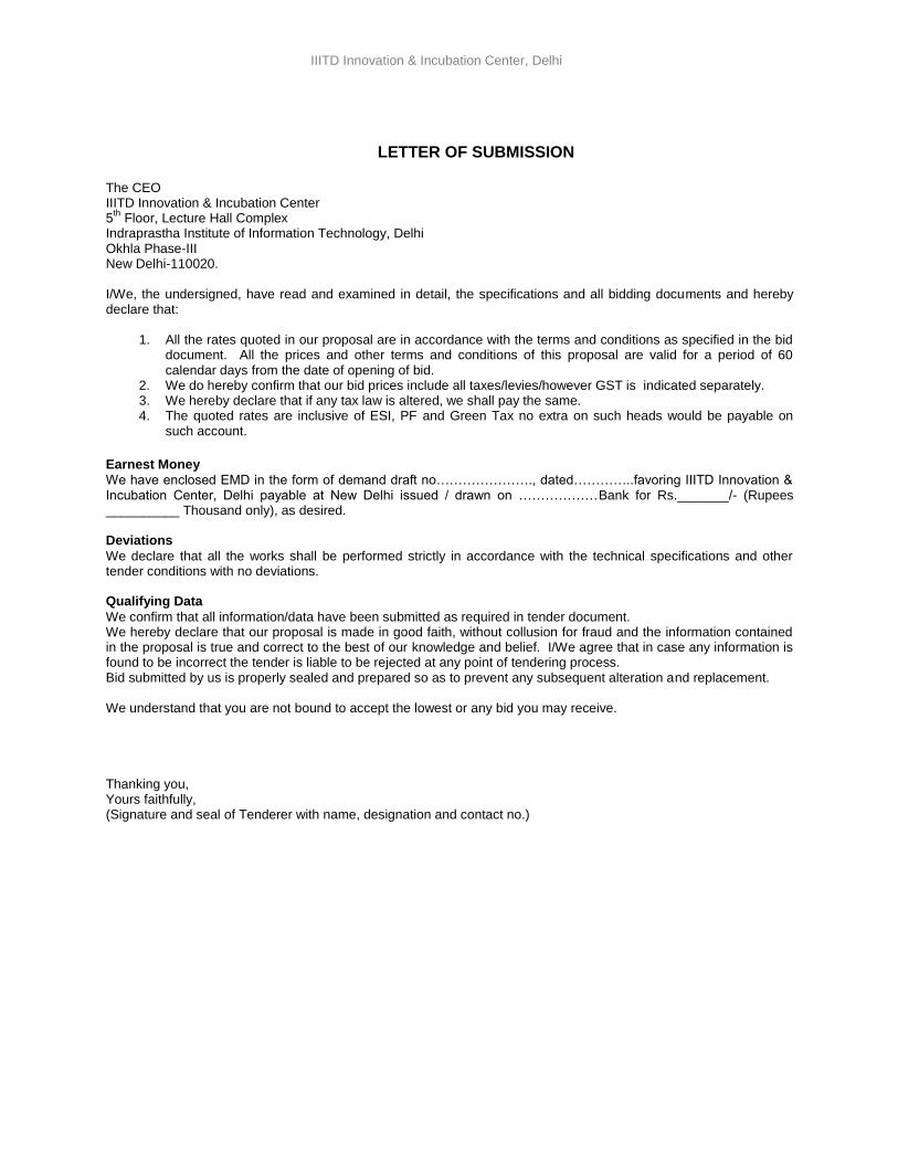
LETTER OF SUBMISSION
The CEO IIITD Innovation & Incubation Center 5
th Floor, Lecture Hall Complex
Indraprastha Institute of Information Technology, Delhi Okhla Phase-III New Delhi-110020. I/We, the undersigned, have read and examined in detail, the specifications and all bidding documents and hereby declare that:
1. All the rates quoted in our proposal are in accordance with the terms and conditions as specified in the bid document. All the prices and other terms and conditions of this proposal are valid for a period of 60 calendar days from the date of opening of bid.
2. We do hereby confirm that our bid prices include all taxes/levies/however GST is indicated separately. 3. We hereby declare that if any tax law is altered, we shall pay the same. 4. The quoted rates are inclusive of ESI, PF and Green Tax no extra on such heads would be payable on
such account.
Earnest Money
We have enclosed EMD in the form of demand draft no…………………., dated…………..favoring IIITD Innovation & Incubation Center, Delhi payable at New Delhi issued / drawn on ………………Bank for Rs._______/- (Rupees __________ Thousand only), as desired. Deviations
We declare that all the works shall be performed strictly in accordance with the technical specifications and other tender conditions with no deviations. Qualifying Data
We confirm that all information/data have been submitted as required in tender document. We hereby declare that our proposal is made in good faith, without collusion for fraud and the information contained in the proposal is true and correct to the best of our knowledge and belief. I/We agree that in case any information is found to be incorrect the tender is liable to be rejected at any point of tendering process. Bid submitted by us is properly sealed and prepared so as to prevent any subsequent alteration and replacement. We understand that you are not bound to accept the lowest or any bid you may receive. Thanking you, Yours faithfully, (Signature and seal of Tenderer with name, designation and contact no.)
8

IIITD Innovation & Incubation Center, Delhi
ACCEPTANCE The above tender (as modified by you as provided in the letters mentioned hereunder) is accepted by me for and on behalf of CEO, IIITD Innovation & Incubation Center for a sum of Rs. --------------------------- (Rupees -----------------------------------------------------------------------) The documents referred to below shall form part of this contract Agreement:-
NIT
Performa for Agreement
Additional conditions.
Special conditions
Schedule of Quantities &
Drawings
General conditions of contract for CPWD Works-2012 with up to date correction slip
For & on behalf of CEO
IIITD Innovation & Incubation Center Signature. …………………… Dated..................... Designation..........................
9
IIITD Innovation & Incubation Center, Delhi
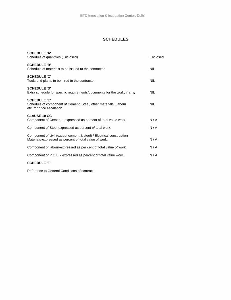
SCHEDULES SCHEDULE 'A'
Schedule of quantities (Enclosed) Enclosed SCHEDULE 'B'
Schedule of materials to be issued to the contractor NIL SCHEDULE 'C'
Tools and plants to be hired to the contractor NIL SCHEDULE 'D'
Extra schedule for specific requirements/documents for the work, if any, NIL SCHEDULE 'E' Schedule of component of Cement, Steel, other materials, Labour NIL etc. for price escalation. CLAUSE 10 CC
Component of Cement - expressed as percent of total value work, N / A Component of Steel-expressed as percent of total work. N / A Component of civil (except cement & steel) / Electrical construction Materials-expressed as percent of total value of work. N / A Component of labour-expressed as per cent of total value of work. N / A Component of P.O.L. - expressed as percent of total value work. N / A SCHEDULE 'F'
Reference to General Conditions of contract.
10
IIITD Innovation & Incubation Center, Delhi
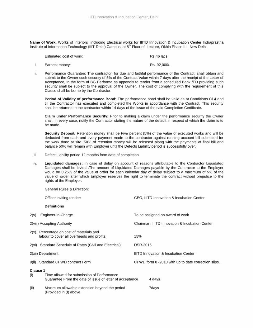
Name of Work: Works of Interiors including Electrical works for IIITD Innovation & Incubation Center Indraprastha
Institute of Information Technology (IIIT-Delhi) Campus, at 5th Floor of Lecture, Okhla Phase III , New Delhi.
Estimated cost of work: Rs.46 lacs
i. Earnest money: Rs. 92,000/-
ii. Performance Guarantee: The contractor, for due and faithful performance of the Contract, shall obtain and
submit to the Owner such security of 5% of the Contract Value within 7 days after the receipt of the Letter of Acceptance, in the form of BG Performa as appendix to tender from a scheduled Bank /FD providing such security shall be subject to the approval of the Owner. The cost of complying with the requirement of this Clause shall be borne by the Contractor. Period of Validity of performance Bond: The performance bond shall be valid as at Conditions Cl 4 and
till the Contractor has executed and completed the Works in accordance with the Contract. This security shall be returned to the contractor within 14 days of the issue of the said Completion Certificate. Claim under Performance Security: Prior to making a claim under the performance security the Owner
shall, in every case, notify the Contractor stating the nature of the default in respect of which the claim is to be made.
Security Deposit/ Retention money shall be Five percent (5%) of the value of executed works and will be
deducted from each and every payment made to the contractor against running account bill submitted for the work done at site. 50% of retention money will be released along with the payments of final bill and balance 50% will remain with Employer until the Defects Liability period is successfully over.
iii. Defect Liability period 12 months from date of completion.
iv. Liquidated damages: In case of delay on account of reasons attributable to the Contractor Liquidated
Damages shall be levied .The amount of Liquidated Damages payable by the Contractor to the Employer would be 0.25% of the value of order for each calendar day of delay subject to a maximum of 5% of the value of order after which Employer reserves the right to terminate the contract without prejudice to the rights of the Employer.
General Rules & Direction: Officer inviting tender: CEO, IIITD Innovation & Incubation Center Definitions
2(v) Engineer-in-Charge To be assigned on award of work 2(viii) Accepting Authority Chairman, IIITD Innovation & Incubation Center 2(x) Percentage on cost of materials and labour to cover all overheads and profits. 15% 2(xi) Standard Schedule of Rates (Civil and Electrical) DSR-2016 2(xii) Department IIITD Innovation & Incubation Center 9(ii) Standard CPWD contract Form CPWD form 8 -2010 with up to date correction slips. Clause 1
(i) Time allowed for submission of Performance Guarantee From the date of issue of letter of acceptance 4 days
(ii) Maximum allowable extension beyond the period 7days
(Provided in (I) above
11
IIITD Innovation & Incubation Center, Delhi
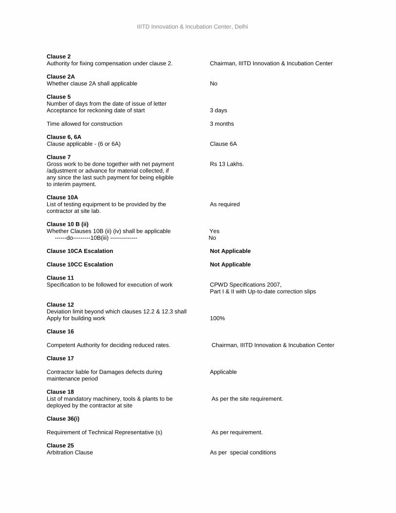
Clause 2
Authority for fixing compensation under clause 2. Chairman, IIITD Innovation & Incubation Center Clause 2A
Whether clause 2A shall applicable No Clause 5
Number of days from the date of issue of letter Acceptance for reckoning date of start 3 days Time allowed for construction 3 months
Clause 6, 6A
Clause applicable - (6 or 6A) Clause 6A Clause 7
Gross work to be done together with net payment Rs 13 Lakhs. /adjustment or advance for material collected, if any since the last such payment for being eligible to interim payment. Clause 10A
List of testing equipment to be provided by the As required contractor at site lab. Clause 10 B (ii)
Whether Clauses 10B (ii) (iv) shall be applicable Yes ------do---------10B(iii) -------------- No Clause 10CA Escalation Not Applicable
Clause 10CC Escalation Not Applicable Clause 11
Specification to be followed for execution of work CPWD Specifications 2007, Part I & II with Up-to-date correction slips
Clause 12
Deviation limit beyond which clauses 12.2 & 12.3 shall Apply for building work 100% Clause 16
Competent Authority for deciding reduced rates. Chairman, IIITD Innovation & Incubation Center Clause 17
Contractor liable for Damages defects during Applicable maintenance period Clause 18
List of mandatory machinery, tools & plants to be As per the site requirement. deployed by the contractor at site Clause 36(i)
Requirement of Technical Representative (s) As per requirement. Clause 25
Arbitration Clause As per special conditions
12
IIITD Innovation & Incubation Center, Delhi
SPECIAL CONDITIONS
1. In the event of the tender being submitted by a firm, it must be signed by a person duly authorized through a power of attorney issued by all the partners and a certified copy of the power of attorney should be enclosed with the forwarding letter or separately by each member thereof, or in the event of the absence of any partner, it must be signed on his behalf by a person holding a power of attorney authorizing him to do so and such power of attorney shall be produced with the tender and it must disclose that the firm is registered under the Indian partnership Act.
Each and every signature given shall be separately witnessed. A Contractor or a contractor who himself / themselves has/have tendered or who may tender for the work shall not witness the tender of another person for the same work. Failure to observe this condition would render tenders of the contractors tendering as well as witnessing the tenders liable for summary rejection.
2. The conditions for item rate tender only will be applicable as given in general conditions of contract for central PWD works 2010. As mentioned there in also, in event no rate has been quoted for any items leaving space bolts in figure (s), word(s) and amount blank, it will be presumed that the contractor has included the cost of this/these item(s) in other item(s) and rate for such items will be considered as zero and work will be required to be executed accordingly.
3. Rates quoted as percentage below/above in the tender will be summarily rejected.
4. It must be understood that the work has to be completed as per the time provided in the contract and as such time is the essence of the contract.
5. The quantities furnished in the bills of quantities are only probable quantities liable to alternation by omission, deduction or addition, and it would be clearly understood that the contract is not a lump sum contract and the IIIC do not, in any way, assure the tenderer or guarantee that the said probable quantities
are correct or that the work would correspond thereto. Payments will be regulated on the actual quantities of work authorizedly done and measured at the accepted rates. No claims due to change in quantities (+ or -) will be entertained. The drawings, forming parts of complementary installations work specifications and the bills of quantities, of the contract, are explanatory of and are to one another, representing together the works / to be carried out. If neither the drawings nor the specifications nor the accepted bills of quantities include any part/parts the intention to include which is nevertheless clearly inferred and which are obviously necessary for the proper completion of the works/ installations, all such parts shall be supplied and executed by the contractor at no extra charge. Anything contained in one or another of (a) the drawings, (b) the specifications and (c) the accepted bills of quantities and not found in the others will be equally binding as if it were contained in each of them.
6. No alterations, which are made by the tenderer in the drawings, specifications, conditions or probable quantities accompanying this notice will be recognized and if any such alterations are made the tender, will be invalid. Conditional tenders will however be liable for rejection.
7. The tenderer must obtain for himself on his own responsibility and at his own expense all the information necessary, including risks, contingencies and other circumstances to enable him to make a proper tender and to enter into a contract with the IIIC. He must examine the drawings, specifications, conditions and so on and must inspect the site of work, examine the nature of the ground and the subsoil (so far as is practicable) and acquaint himself with local conditions, means of access to the work, storage facilities or areas for staff colony, the nature of the work, in fact all matters pertaining thereto before he submits his tender.
8. The tenderer shall also bear all expenses in connection with the preparation and submission of his tender and attendance for subsequent negotiations/clarifications.
(I) Omission, neglect or failure on the part of the tenderer to obtain requisite and reliable information on any matter affecting his tender, the contract and the construction, completion, maintenance, (dismantling and disposal) of the work shall not relieve the tenderer whose tender is accepted from any liability in respect of the contract.
13
IIITD Innovation & Incubation Center, Delhi
(II) The tenderer whose tender is accepted shall not be entitled to make any claim for increase in the rates quoted and accepted excepting in pursuance of any specific provision in the contract.
9. The Contractor, upon award of work, shall furnish the following details for the approval of the Engineer in charge:
9.1. The names of manufacturers of specialized items such as patented water proofing systems / materials, doors, flooring tiles, false ceilings, insulating materials, wind mill, cement, steel, glazing, and any other materials etc. which he proposes to use in the work.
9.2. The makes and types of fittings, materials, subject to the makes and type stipulated in the specifications, which he proposes to use in the work.
9.3. The details of licenses granted to him and/or to professional qualified and/or licensed technical personnel on his staff who will be engaged on the work (and submit, if called for, the licenses for inspection by the Officer in charge in consultation with Engineer in charge).
9.4. Only approved agencies/ skilled workers shall be deployed to carry out requisite specialized items of work. The Officer/ Engineer in charge’s decision in consultation with Architect's/ in this regard shall be binding to all the parties concerned.
10. The rates quoted in the bills of quantities shall unless specified otherwise will be for all heights, depths deemed to be for finished work in-situ/ item by item as provided for, and shall include cost for all necessary material and labours, all necessary tools and plants and machinery, sheds, marking out, clearing site, etc. and for all taxes, octroi, excise, VAT works contract and any other tax or duty levied by Government, Central or Local, Green Tax, ESI and PF. or Local Authority if any as applicable. The GST indicated separately, if any as applicable.
10.1. The rates shall be firm and not be subject to any variations in exchange rates, in taxes, duties etc. in railway freight and the like including labour conditions, etc. The rates are not subject to escalation.
11. It will be the sole responsibility of the contractor to procure all the equipments/ materials and other materials required for the work.
13. The IIIC further reserves the right to delete or reduce at any time, any section of the bills of quantities with out assigning any reasons whatsoever there for and no claim will be entertained in this regard.
14. The tenderer whose tender is accepted is bound to execute formal agreement with the IIITD Innovation & Incubation Center within one week of the date of intimation of award of work in accordance with the draft agreement which will include conditions of tender, form of tender (general conditions of contract for central PWD works 2010), Articles of Agreement, Bills of quantities, Conditions of contract, Special conditions if any, the drawings and specifications, but his liability under the contract shall commence from the date of written order to commence work whether the formal agreement is drawn or not.
The Contractor shall bear all expenses in connection with the execution of the said agreement including fees for stamping and registration of documents as required.
15. The Security Deposit will bear no interest what so ever until the date of release.
16. a) The contractor, upon award of work, shall submit a memorandum of procedure giving the outline of his general scheme, programme and time table, in the form of a chart that shall be scrutinized and approved (with modifications as necessary), which shall become the approved programme for execution. The approved programme shall be the basis for assessment of comparative progress under the relevant conditions of contract.
(b). Over and above, the contractor has to supply programme chalked out showing important milestones to be achieved and the progress actually achieved compared with, the target of the same in the programme and shortfall, if any planned for being made up in the programme for next month.
14
IIITD Innovation & Incubation Center, Delhi
17. (a) The work in general shall conform to the CPWD Specifications 2007 with up to date correction slips & any other latest civil specification published by CPWD, New Delhi and the "Specifications for works".
(b)In case items not covered by the general specifications referred above, reference shall be made to the appropriate I.S. Code.
(c) Should there be any difference in the particular specifications of individual item of work and the description of item as given in the Schedule of quantity, the latter shall prevail, which will be as per the relevant drawing.
(d), In case of any work for which there is no specification in I.S. specifications or in the specifications forming part of tender documents or in case there is any variation, such work shall be carried out in all respects in accordance with the instructions to be issued by the Engineer in charge.
18. On acceptance of the tender the Contractor shall in writing and at once inform the IIIC and the Architects the name of his accredited representative(s) who will be responsible to take instructions from the Architects / Officer in Charge.
The work of any part of it shall not be transferred, assigned or sublet without the written consent of the IIIC.
19. The Contractor shall be required to co-operate and work in co-ordination with and afford reasonable facilities for such other agencies / specialists / interior designers / consultants as may be employed by the Architects / Project Management Consultant/ Officer in Charge on other works / sub-works in connection with the project/scheme of which this work forms a part.
20. The Contractor shall get the necessary insurance done for their personal employed/ company insurance, third party insurance, marine insurance, all risk insurance or any other insurance as required.
21. The Contractor shall make arrangements of carrying water and electricity beyond one point where same shall be provided and recovery @1% of the cost of works shall be effected accordingly.
22. The Contractor is required to comply with all Acts of Government relating to labour, safety, environment and other Rules and Regulations made there under from time to time and to submit at the proper times all particulars and statements required to be furnished to the appropriate Authorities.
23. Delay and extension of time
If in the opinion of the Architect/PMC/Owner the Work is delayed:
a) By force majeure, or
b) By reason of any exceptionally inclement weather, or
c) By reason of proceedings taken or threatened by or dispute with adjoining or neighboring owners or public authorities arising otherwise than through the Contractor’s own default, or
d) By the works or delays of other Contractor or tradesmen engaged or nominated by the Owner or the Architect/PMC and not referred to in the Schedule of Quantities and/or Specification, or
e) By reason of Architect’s/PMC/Owner Instructions to delay work, or
f) By reason of civil commotion, local combination of workmen or strike or lock-out affecting any of the building traders, or
g) In consequence of the Contractor not having received in due time necessary Instructions from the Architect/PMC/Owner for which he shall have specifically applied in writing, Then the Architect/PMC/Owner shall make a fair and reasonable extension of time for completion of the Contract Work; in case of such strike or lock-out the Contractor shall, as soon as may be, give written notice thereof to the Architect/PMC/Owner, but the Contractor shall nevertheless constantly use his endeavors to
15
IIITD Innovation & Incubation Center, Delhi
prevent delay and shall do all that may reasonably be required to the satisfaction of the Architect to proceed with the work.
24. Failure by Contractor to comply with Architect’s Instructions
If the Contractor after receipt of written notice from the Architect requiring compliance fails within ten days to comply with such further drawings and/ or Architect’s Instructions the Owner with the consent of the Architect may employ and pay other persons to execute any such work whatsoever that may be necessary to give effect thereto, and all costs incurred in connection therewith shall be recoverable from the Contractor.
25. Termination or Abridgment of Contract by the Owner
a) If the Contractor being an individual or a Firm commit any ‘Act or Insolvency’ or shall be adjudged an Insolvent or being an Incorporated Company or Society shall have an order for compulsory winding up made against it or pass an effective resolution for winding up voluntarily or subject to the supervision of the Court and of the Official Assignee of the Liquidator in such acts of insolvency or winding up shall be unable within seven days after notice to him requiring him to do so, to show to the reasonable satisfaction of the Architect that he is able to carry out and fulfill the Contract, and to give security therefore, if so required by the Architect, or
b) If the Contractor (whether an individual, Firm, Incorporated Company or Society) shall suffer execution to be issued, or
c) Shall suffer any payment under this Contract to be attached by or on behalf of any or the creditors of the Contractor, or
d) Shall assign or sublet this Contract without the consent in writing of the Architect/PMC first obtained, or
e) Shall charge or encumber this Contract or any payments due or which may become due to the Contractor there under, or
f) If the Architect/PMC shall certify in writing to the Owner that the Contractor:
i) Has abandoned the Contract, or
ii) Has failed to commence the works, or has without any lawful excuse under these Conditions suspended the progress of the works for 14 days after receiving from the Architect/PMC/Owner written notice to proceed, or
iii) Has failed to proceed with the works with such due diligence and failed to make such due progress as would enable the works to be completed within the time agreed upon, or
iv) Has failed to remove materials from the site or to pull down and replace work for seven days after receiving from the Architect written notice the said materials or work were condemned and rejected by the Architect under these conditions, or
v) Has neglected or failed persistently to observe and perform all or any of the acts, matters or things by this Contract to be observed and performed by the Contractor for seven days after written notice shall have been given to the Contractor requiring the Contractor to observe or perform the same, or
vi) Has to the detriment of good workmanship or in defiance of the Architect’s/PMC Instructions to the contrary sub-let any part of the Contract,
26. Then and in any of the said cases the Owner with the written consent of the Architect/PMC may, notwithstanding any previous waiver, after giving seven days’ notice in writing to the Contractor, determine the Contract, but without hereby affecting the powers of the Architect or the obligations and liabilities of the Contract the whole of which shall continue in force as fully as if the Contract had not been so determined and as if the works subsequently executed had been executed by or on behalf of the Contractor. The costs of these works are therefore recoverable from the Contractor. And further, the Owner under instructions of the Architect, by his Agents or servants may enter upon and take possession of the works and all plants,
16
IIITD Innovation & Incubation Center, Delhi
tools, scaffolding, sheds, machinery, steam and other power utensils and materials lying upon the premises or the adjoining lands or roads, and use the same as his own property or may employ the same by means of his own servants and workmen in carrying on and completing the works or by employing any other Contractor or other person or persons to complete the Work, and the Contractor shall not in any way interrupt or do any act, matter or thing to prevent or hinder such other Contractor or other person or persons employed for completing and finishing or using the materials and plant for the Work. When the Work shall be completed or as soon thereafter as convenient the Architect shall give a notice in writing to the Contractor to remove his surplus materials and plant, and should the Contractor fail to do so within a period of 14 days after receipt thereof by him, Owner shall sell the same, and shall give credit to the Contractor for the amount realized. The Architect shall thereafter ascertain and certify in writing what (if anything) shall be due or payable to or by the Owner for the value of the said plant and materials so taken possession of by the Owner and the expense or loss which the Owner shall have been put to in procuring the works to be completed, and the amount, if any, owing to the Contractor and the amount which shall be so certified shall thereupon be paid by the Owner to the Contractor or by the Contractor to the Owner, as the case may be, and the certificate of the Architect shall be final and conclusive between the parties.
27. If at any time after the commencement of the work the Owner shall for any reason whatsoever not require the whole thereof, as specified in the tender, to be carried out, but need to abridge the Contract, the Owner shall give notice in writing of the fact to the Contractor who shall have no claim to any payment or compensation which he might have derived from the execution of the work in full, but which he did not derive in consequence of the whole amount of the work not having been carried out. The Contractor shall in this case, however, be entitled to payment for the work already executed by him in accordance with the agreed rates. The Owner shall also take over all building materials as might have been ordered for the work, but orders for which cannot be canceled, if delivered within a reasonable time, and shall pay for them at cost price. The Contractor shall also be allowed to remove his tools and plants from the site.
28. Termination of Contract by Contractor
a) If payment of the amount payable by the Owner under Certificate of the Architect /PMC for beyond two months from date of issue of certificate due to reason not attributable to the contractor.
b) The Owner commits any ‘Act of Insolvency’, or
c) If the Owner (being an individual, or firm) shall be adjudged an Insolvent, or (being an Incorporated Company or Society) shall have an order made against him or pass an effective resolution for winding up, either compulsorily or subject to the supervision of the Court or voluntarily, or if the Officials Assignee or the Owner shall repudiate the contract, or if the Official Assignee or the Liquidator in any such winding up shall be unable within fifteen days after notice to him requiring him so to do, to show to the reasonable satisfaction of the Contractor that he is able to carry out and fulfill the Contract and to make all payments due, and to become due there under and, if required by the Contractor, to give security of the same, or
d) If the works be stopped for three months or more under a continuous spell under the order of the Architect /PMC or the Owner or by any injunction or other order of any Court of Law,
29. Then and in any of the above said (Clause28) cases the Contractor shall be at liberty to determine the Contract by notice in writing to the Owner, through the Architect, and he shall be entitled to recover from the Owner payment for all works executed and cost of the material supplied and lying at site for the purpose of the Contract as on the said day of the termination. No other claim for idle labour , loss of overheads , profits shall be entertained nor shall any other claim on account of the delay in completion of the work /availability of site/ unwarranted conditions whatsoever shall be tenable, even if it is caused by circumstances beyond the Contractor’s control.
30. Procedure for Settlement of Disputes 30.1 Engineer’s Decision
If a dispute of any kind whatsoever arises between IIIT-Delhi and the contractor in connection with, or arising out of , the contract or the execution of the works, whether during the execution of the works or after their completion and whether before or after any repudiation or other termination of the contract, including any dispute as to any opinion, instruction, determination, certificate or valuation of the engineer, the matter in dispute shall, in the first place, be referred in writing to the engineer, with a copy to all parties. Such
17
IIITD Innovation & Incubation Center, Delhi
reference shall be made within one (1) month of arising of any such dispute and state that it is made pursuant to this clause. No later than one (1) month after the day on which he received such reference the engineer shall give notice of his decision to IIIT-Delhi and the contractor. Such decision shall state that it is made pursuant to the reference under this clause.
Unless the contract has already been repudiated or terminated, the contractor shall in every case, continue to proceed with the works with all due diligence and the contractor and IIIT-Delhi shall give effect forthwith to any / every such decision of the engineer unless and until the same shall be revised, as hereinafter provided, in an amicable settlement or an arbitral award. If either IIIT-Delhi or the contractor be dissatisfied with any decision of the engineer, or if the engineer fails to give notice of his decision on or before one (1) month after the day on which he received the reference, then either IIIT-Delhi or the contractor may within a further period of one (1) month from the day on which it / they receive(s) the notice of such decision, or on the day on which the said period of notice of / for decision expired, as the case may be, give notice to the other party, with copy for information to the engineer, of its / their intention to commence arbitration. Such notice shall establish the entitlement of the party giving the same to commence arbitration, as hereinafter provided, as to such dispute and no arbitration in respect thereof may be commenced unless such notice is given. If the engineer has given notice of his decision as to a matter in dispute to IIIT-Delhi and the contractor and no notification of intention to commence arbitration as to such dispute has been given by either IIIT-Delhi or the contractor as herein provided, the said decision shall become final and binding upon IIIT-Delhi and the contractor.
30.2. Amicable Settlement
Where notice of intention to commence arbitration as to a dispute has been given in accordance with sub-clause 22.1, arbitration of such dispute shall not be commenced unless an attempt has first been made by the parties to settle such dispute amicably. Provided that, unless the parties otherwise agree, arbitration may be commenced on or after one (1) month from the day on which notice of intention to commence arbitration of such dispute was given, whether or not any attempt at amicable settlement thereof has been made or result achieved.
30.3. Arbitration
Any dispute in respect of which:
a) the decision, if any, of the engineer has not become final and binding pursuant to the first sub-clause above,
b) amicable settlement has not been reached within the period stated in the second sub-clause above, shall be finally settled, unless otherwise specified in the contract, by arbitration to be held in New Delhi in English, under the provisions of the Arbitration and Conciliation Act 1996, including any statutory reenactment(s) / amendment(s) thereof and Rules made thereunder, by the arbitrator. The Director of the Institute shall appoint one person as the sole arbitrator. Either party shall be limited in the proceeding before such arbitrator to evidence or arguments put before the engineer for the purposes of obtaining the said decision pursuant to the first sub-clause herein. No such decision shall disqualify the engineer from being called as a witness and giving evidence before the arbitrator on any matter whatsoever relevant to the dispute. Arbitration proceedings shall not be commenced prior to the completion of the works, unless any major pre-requisite criticality is discerned by the arbitrator, and the obligations of IIIT-Delhi, the engineer and the contractor shall not be altered by reason of the arbitration. The works shall not be stopped on account of the said process of arbitration and the contractor shall not be relieved of his responsibilities for the completion of the work under any circumstances whatsoever.
31.2. Contractor to provide everything necessary
The Contractor shall provide everything necessary for the proper execution of the Work according to the intent and meaning of the Drawings, Schedule of Quantities and Specifications taken together whether the same may or may not be particularly shown or described therein provided that the same can reasonably be inferred there from, and if the Contractor finds any discrepancy in the Drawings or between the Drawings, Schedule of Quantities and Specification he shall immediately and in writing refer the same to the Architect who shall decide which is to be followed.
31.3. Materials and Workmanship to conform to Descriptions
18
IIITD Innovation & Incubation Center, Delhi
All materials and workmanship shall so far as procurable be of the respective kinds described in the Schedule of Quantities and/or Specification and in accordance with the Architect’s Instructions, and the Contractor shall upon the request of the Architect furnish him with all invoices, accounts, receipts and other vouchers to prove that the materials comply therewith. The Contractor shall at his own cost arrange for and/or carry out any test of any materials which the Architect may require.
31.4. Assignment and Sub-letting
The whole of the works included in the Contract shall be executed by the Contractor and the Contractor shall not directly or indirectly transfer, assign or underlet the Contract or any part share thereof or interest therein without the written consent of the Architect, and no undertaking shall relieve the Contractor from the full and entire responsibility of the Contract or from active superintendence of the Work during its progress.
31.5. Removal of improper work
The Architect shall, during the progress of the Work, have the power to order the removal, from the Site or works within such reasonable time or times as may be specified in the order, of any materials which in the opinion of the Architect are not in accordance with the Specification or the Instructions of the Architect, the substitution of proper materials, and the removal and proper re-execution of any works executed with materials or workmanship not in accordance with the Drawings, Specifications or Instructions and the Contractor shall forthwith carry out such order at his own cost. In case of default on the part of the Contractor to carry out such order, the Owner shall have the power to employ and pay other persons to carry out the same, and all expenses consumed thereon or incidental thereto as certified by the Architect shall be borne by the Contractor, or may be deducted by the Owner from any moneys due or that may become due to the Contractor.
19
IIITD Innovation & Incubation Center, Delhi
ADDITIONAL CONDITIONS
1. General conditions of contract for Central PWD Works 7/8 (Tender of Form) shall be part of the agreement.
2. The work shall be carried out strictly as per CPWD specifications 2007, Part I & II with up to date correction slips. Wherever no specification is available in the above said document, drawings and specifications supplied with bill of quantities shall be applicable
3. The Contractor shall have to clear the site for the work of all overlying rubbish /garbage/dumped refuse material prior to commencement of the work in case required at no extra cost. The contractor shall take approval from the Engineer /Officer in Charge in writing for collection and stacking of materials.
4. The contractor must follow CPWD Safety Code as provided in general conditions of contract for CPWD Works.
5. Any damage done by the contractor or his workmen to any existing work during the course of execution of the work shall be made good by him at his own cost.
6. Contractor shall clear the site thoroughly of all rubbish etc. left out of his materials immediately on completion of the work and properly keep the site clean around the building to the satisfaction of the Engineer- in-Charge.
7. The preference of the codes will be IS codes.
8. The rates are inclusive of all staging, material and labour as required for the works. The items in the bill of quantities include all the materials, labour, and installation, complete as a finish items unless otherwise stated.
9. Unless specifically mentioned otherwise, quoted Rates shall be deemed to include work to be carried out at all curvatures, heights, depths, inclinations and locations, and in wet/foul locations, as and when they are encountered. The rates quoted for the various works as specified in the Priced Schedule of Quantities are work in all types of soils/rock and prevailing Site conditions including earth work, excavation, shoring, execution of various other items of work, i.e., laying of pipes, joining, concreting, masonry, plastering, etc. in and under water and dewatering as required. Nothing extra is payable on this account.
10. All security precautions shall be taken during dismantling work. The site shall be fenced /barricaded with suitable material during construction period .No payment shall be made for fencing/barricading work. Fencing/barricading shall be done immediately after possession of site and shall be removed after completion of construction period
11. No space on site/otherwise for labour huts shall be provided by IIITD, cost of same shall be borne by contractor.
12. The general condition of contract for Central P.W.D. Works has reference of various laws /acts /rules. The settlement of any disputes and arbitration, only Indian arbitration and conciliation act 1996 shall be applicable.
13. In case any specific brand of material has been specified either the same brand or of approved make of same specifications shall be used. The contractor shall take approval in advance for all such materials.
14. Costs for all materials and labour for the preparation of samples, market research, etc. shall be borne by the Contractor within his quoted Rates and nothing extra shall be payable for this. The works shall not be proceeded with without approval of the sample. In case sample is rejected and works cannot be proceeded with the IIITD shall be at liberty to terminate the contract and the Contractor shall have no claim for the works under such circumstances whatsoever.
15. The contractor should take utmost care to avoid any damage to the existing flooring, electrical works/cables, telephone cables, false ceiling, sprinkler system, fire alarm etc. in place. In case of any damage, it would be the responsibility of the contractor to restore the same immediately.
20
IIITD Innovation & Incubation Center, Delhi
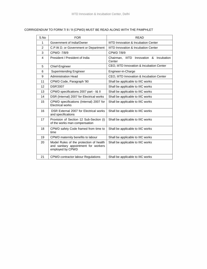
CORRIGENDUM TO FORM 7/ 8 / 9 (CPWD) MUST BE READ ALONG WITH THE PAMPHLET
S.No FOR READ
1 Government of India/Owner IIITD Innovation & Incubation Center
2 C.P.W.D. or Government or Department IIITD Innovation & Incubation Center
3 CPWD -7/8/9 CPWD 7/8/9
4 President / President of India Chairman, IIITD Innovation & Incubation Center
5 Chief-Engineer CEO, IIITD Innovation & Incubation Center
6 Superintending Engineer Engineer-in-Charge
9 Administration Head CEO, IIITD Innovation & Incubation Center
11 CPWD Code, Paragraph '90 Shall be applicable to IIIC works
12 DSR'2007 Shall be applicable to IIIC works
13 CPWD specifications 2007 part - I& II Shall be applicable to IIIC works
14 DSR (Internal) 2007 for Electrical works Shall be applicable to IIIC works
15 CPWD specifications (Internal) 2007 for Electrical works
Shall be applicable to IIIC works
16 DSR External 2007 for Electrical works and specifications
Shall be applicable to IIIC works
17 Provision of Section 12 Sub-Section (i) of the works man compensation
Shall be applicable to IIIC works
18 CPWD safety Code framed from time to time
Shall be applicable to IIIC works
19 CPWD maternity benefits to labour Shall be applicable to IIIC works
20
Model Rules of the protection of health and sanitary appointment for workers employed by CPWD
Shall be applicable to IIIC works
21 CPWD contractor labour Regulations Shall be applicable to IIIC works
21
IIITD Innovation & Incubation Center, Delhi
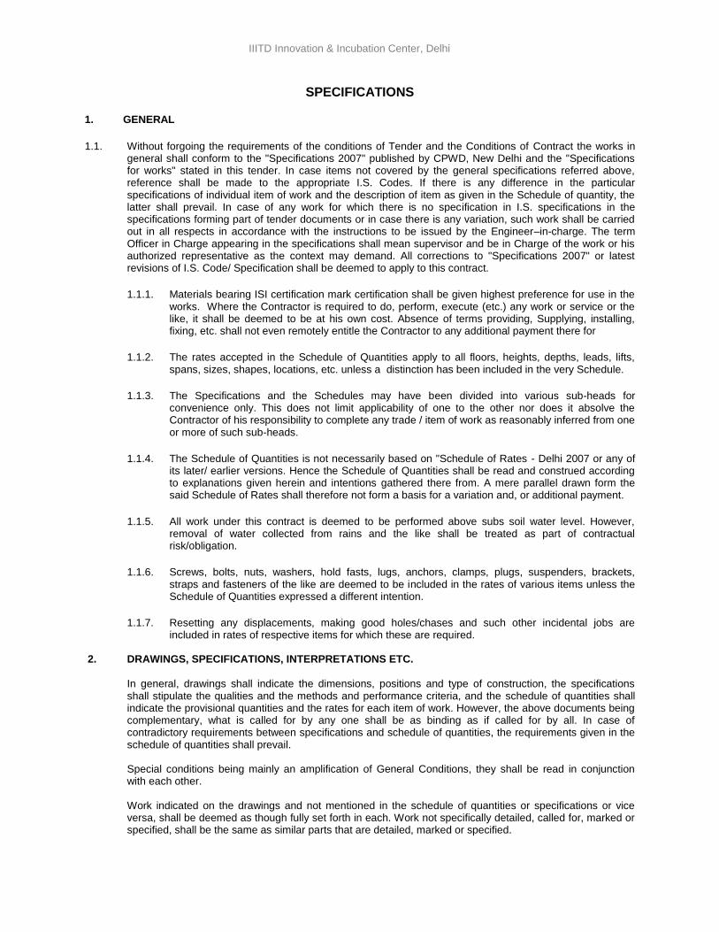
SPECIFICATIONS
1. GENERAL
1.1. Without forgoing the requirements of the conditions of Tender and the Conditions of Contract the works in general shall conform to the "Specifications 2007" published by CPWD, New Delhi and the "Specifications for works" stated in this tender. In case items not covered by the general specifications referred above, reference shall be made to the appropriate I.S. Codes. If there is any difference in the particular specifications of individual item of work and the description of item as given in the Schedule of quantity, the latter shall prevail. In case of any work for which there is no specification in I.S. specifications in the specifications forming part of tender documents or in case there is any variation, such work shall be carried out in all respects in accordance with the instructions to be issued by the Engineer–in-charge. The term Officer in Charge appearing in the specifications shall mean supervisor and be in Charge of the work or his authorized representative as the context may demand. All corrections to "Specifications 2007" or latest revisions of I.S. Code/ Specification shall be deemed to apply to this contract.
1.1.1. Materials bearing ISI certification mark certification shall be given highest preference for use in the works. Where the Contractor is required to do, perform, execute (etc.) any work or service or the like, it shall be deemed to be at his own cost. Absence of terms providing, Supplying, installing, fixing, etc. shall not even remotely entitle the Contractor to any additional payment there for
1.1.2. The rates accepted in the Schedule of Quantities apply to all floors, heights, depths, leads, lifts, spans, sizes, shapes, locations, etc. unless a distinction has been included in the very Schedule.
1.1.3. The Specifications and the Schedules may have been divided into various sub-heads for convenience only. This does not limit applicability of one to the other nor does it absolve the Contractor of his responsibility to complete any trade / item of work as reasonably inferred from one or more of such sub-heads.
1.1.4. The Schedule of Quantities is not necessarily based on "Schedule of Rates - Delhi 2007 or any of its later/ earlier versions. Hence the Schedule of Quantities shall be read and construed according to explanations given herein and intentions gathered there from. A mere parallel drawn form the said Schedule of Rates shall therefore not form a basis for a variation and, or additional payment.
1.1.5. All work under this contract is deemed to be performed above subs soil water level. However, removal of water collected from rains and the like shall be treated as part of contractual risk/obligation.
1.1.6. Screws, bolts, nuts, washers, hold fasts, lugs, anchors, clamps, plugs, suspenders, brackets, straps and fasteners of the like are deemed to be included in the rates of various items unless the Schedule of Quantities expressed a different intention.
1.1.7. Resetting any displacements, making good holes/chases and such other incidental jobs are included in rates of respective items for which these are required.
2. DRAWINGS, SPECIFICATIONS, INTERPRETATIONS ETC.
In general, drawings shall indicate the dimensions, positions and type of construction, the specifications shall stipulate the qualities and the methods and performance criteria, and the schedule of quantities shall indicate the provisional quantities and the rates for each item of work. However, the above documents being complementary, what is called for by any one shall be as binding as if called for by all. In case of contradictory requirements between specifications and schedule of quantities, the requirements given in the schedule of quantities shall prevail. Special conditions being mainly an amplification of General Conditions, they shall be read in conjunction with each other. Work indicated on the drawings and not mentioned in the schedule of quantities or specifications or vice versa, shall be deemed as though fully set forth in each. Work not specifically detailed, called for, marked or specified, shall be the same as similar parts that are detailed, marked or specified.
22

IIITD Innovation & Incubation Center, Delhi
Special Note
Though every care is taken while preparing this document to cover all necessary matters, specifications, general conditions, special conditions, provisions for smooth and complete execution of work, however in case of any omission in the tender/ contract document, latest correction slips of general conditions of contract for CPWD Works 2014 will be the reference manual but not in supersession to aforesaid conditions.
23
IIITD Innovation & Incubation Center, Delhi
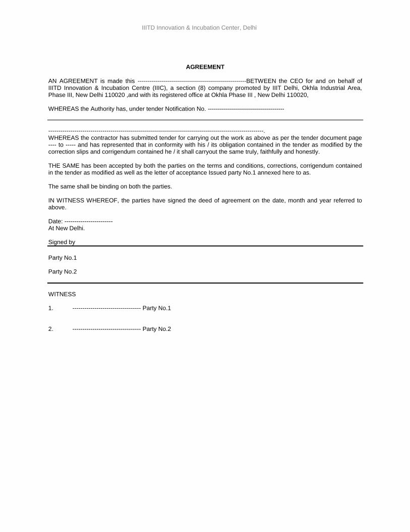
AGREEMENT
AN AGREEMENT is made this ------------------------------------------------------BETWEEN the CEO for and on behalf of IIITD Innovation & Incubation Centre (IIIC), a section (8) company promoted by IIIT Delhi, Okhla Industrial Area, Phase III, New Delhi 110020 ,and with its registered office at Okhla Phase III , New Delhi 110020, WHEREAS the Authority has, under tender Notification No. --------------------------------------
-----------------------------------------------------------------------------------------------------------. WHEREAS the contractor has submitted tender for carrying out the work as above as per the tender document page ---- to ----- and has represented that in conformity with his / its obligation contained in the tender as modified by the correction slips and corrigendum contained he / it shall carryout the same truly, faithfully and honestly. THE SAME has been accepted by both the parties on the terms and conditions, corrections, corrigendum contained in the tender as modified as well as the letter of acceptance Issued party No.1 annexed here to as. The same shall be binding on both the parties. IN WITNESS WHEREOF, the parties have signed the deed of agreement on the date, month and year referred to above. Date: ------------------------ At New Delhi. Signed by
Party No.1 Party No.2
WITNESS 1. ---------------------------------- Party No.1
2. ---------------------------------- Party No.2
24
IIITD Innovation & Incubation Center, Delhi
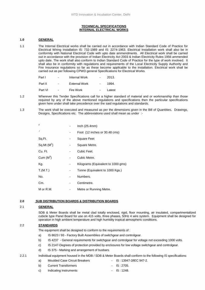
TECHNICAL SPECIFICATIONS INTERNAL ELECTRICAL WORKS
1.0 GENERAL
1.1 The Internal Electrical works shall be carried out in accordance with Indian Standard Code of Practice for Electrical Wiring Installation IS: 732-1989 and IS: 2274-1963. Electrical Installation work shall also be in conformity with National Electrical Code with upto date ammendments. All Electrical work shall be carried out in accordance with the provision of Indian Electricity Act 2003 & Indian Electricity Rules 1956 ammended upto date. The work shall also conform to Indian Standard Code of Practice for the type of work involved. It shall also be in conformity with regulations and requirements of the Local Electricity Supply Authority and Fire Insurance regulations so far as these become applicable to the installation. Electrical work shall be carried out as per following CPWD general Specifications for Electrical Works.
Part I - Internal Work - 2013.
Part II - External Work - 1994.
Part VI - Fire Work - Latest
1.2 Wherever this Tender Specifications call for a higher standard of material and or workmanship than those required by any of the above mentioned regulations and specifications then the particular specifications given here under shall take precedence over the said regulations and standards.
1.3 The work shall be executed and measured as per the dimensions given in the Bill of Quantities. Drawings, Designs, Specifications etc. The abbreviations used shall mean as under :-
// - Inch (25.4mm)
/ - Foot (12 inches or 30.48 cms)
Sq.Ft. - Square Feet
Sq.Mt (M2) - Square Metre.
Cu. Ft. - Cubic Feet.
Cum (M3) - Cubic Metre.
Kg. - Kilograms (Equivalent to 1000 gms)
T.(M.T.) - Tonne (Equivalent to 1000 Kgs.)
No. - Numbers.
Cm. - Centimetre.
M or R.M. - Metre or Running Metre.
2.0 SUB DISTRIBUTION BOARDS & DISTRIBUTION BOARDS
2.1 GENERAL
SDB & Meter Boards shall be metal clad totally enclosed, rigid, floor mounting, air insulated, compartmentalized cubicle type Panel Board for use on 415 volts, three phases, 50Hz 4 wire system. Equipment shall be designed for operation in high ambient temperature and high humidity tropical atmospheric conditions.
2.2 STANDARDS
The equipment shall be designed to conform to the requirements of :
a) IS 8623 / 93 - Factory Built Assemblies of switchgear and controlgear.
b) IS 4237 - General requirements for switchgear and controlgear for voltage not exceeding 1000 volts.
c) IS 2147-Degrees of protection provided by enclosures for low voltage switchgear and controlgear.
d) IS 375 - Marking and arrangement of busbars.
2.2.1 Individual equipment housed in the MDB / SDB & Meter Boards shall conform to the following IS specifications:
a) Moulded Case Circuit Breakers - IS : 13947-2/IEC 947-2.
b) Current Transformers - IS : 2705.
c) Indicating Instruments - IS : 1248.
25
IIITD Innovation & Incubation Center, Delhi
d) Integrating Instruments - IS : 722.
e) HRC fuse links - IS : 13703 / IEC 269.
2.3 CONSTRUCTIONS
2.3.1 METER BOARD
Meter Board shall be metal clad totally enclosed, rigid, floor/wall mounting, air insulated, cubicle type for use on 415 volts, 3 phase, 50 cycle system and shall conform to IP-42 protection (indoor application). The Meter Board shall be fabricated with a 2mm CRCA sheet steel for load bearing members and 1.6mm for doors and partitions. Meter chamber dimension shall be as mention in BOQ item with separate cover and locking arrangement. All sheet steel work forming the exterior of meter board shall be smoothly finished leveled and free from flaws. The corner shall be rounded. Synthetic/Neoprene gasket shall be provided for each meter chamber. Main incoming MCCB and Busbars shall be in separate compartment. Cable alley shall be provided for housing wiring from Busbar chamber to individual meter chamber and for outgoing submain wiring originating from Meter chamber to each shop / office. Operating handle of the highest unit shall be at a height not more than 1700mm. Earth strip
shall be fixed at bottom of Meter Board (Minimum size 20mm x 3mm GI) terminated at both end into terminal bolt. Overall height of Meter Board shall not exceed 2000mm.
2.3.2 SUB DISTRIBUTION BOARD
Sub Distribution Boards shall be constructed only of materials capable of withstanding the mechanical, electrical and thermal stresses, as the effects of humidity, which are likely to be encountered in normal service.
Each vertical section shall comprise of :
a) A front framed structure of rolled/folded sheet steel channel section, of minimum 2mm thickness, rigidly bolted together. This structure shall house the components contributing to the major weight of the equipment, such as circuit breaker cassettes, fuse switch units, main horizontal busbars, vertical risers and other front mounted accessories.
b) The structure shall be mounted on a rigid base frame of folded sheet steel of minimum 2mm thickness and 100 mm height or 100 mm x 50mm x 5mm thick MS Channel. The design shall ensure that the weight of the components is adequately supported without deformation or loss of alignment during transit or during operation.
c) A side cable chamber in Main / Sub Distribution Boards for housing the cable end connections, and power/ control cable terminations. The design shall ensure generous availability of space for ease of installation and maintenance of cabling, and adequate safety for working in one vertical section without coming into accidental contact with live parts in an adjacent section.
d) A cover plate at the top of the vertical section, provided with a ventilating hood where necessary. Any aperture for ventilation shall be covered with a perforated sheet having less than 1 mm diameter perforations to prevent entry of vermin.
e) Front and rear doors fitted with dust excluding neoprene gaskets with fasteners designed to ensure proper compression of the gaskets. When covers are provided in place of doors, generous overlap shall be assured between sheet steel surfaces with closely spaced fasteners to preclude the entry of dust.
f) All doors shall be lockable mounted lock.
g) Gland plate shall be 3mm thick.
2.3.3 The height of the Main / Sub Distribution Boards / Meter Boards should not be more than 2000mm. The total depth of the panel should be adequate to cater to proper cabling space and should not be less than 400mm. Operating handle not higher than 1700mm and not lower than 300mm from bottom of MDB / SDB / Meter Board.
2.3.4 Doors and covers shall be of minimum 2mm thick sheet steel. Sheet steel shrouds and partitions shall be of minimum 2mm thickness. All sheet panels shall be smoothly finished, levelled and free from flaws. The corners should be rounded.
2.3.5 The apparatus and circuits in the panel board shall be so arranged as to facilitate their operation and maintenance and at the same time to ensure the necessary degree of safety.
2.3.6 Apparatus forming part of the Main / Sub Distribution Boards & Meter Boards shall have the following minimum clearances.
i. Between phases - 32mm.
ii. Between phases and neutral - 26mm.
iii. Between phases and earth - 26mm.
iv. Between neutral and earth - 26mm.
2.3.7 When, for any reason, the above clearances are not available, suitable insulation shall be provided. Clearances shall be maintained during normal service conditions.
2.3.8 Creepage distances shall comply to those specified in relevant standards.
26
IIITD Innovation & Incubation Center, Delhi
2.3.9 All insulating material used in the construction of the equipment shall be of non-hygroscopic material, duly treated to withstand the effects of the high humidity, high temperature tropical ambient service conditions.
2.3.10 Functional units such as circuit breakers and fuse switches shall be arranged in multi-tier formation, except that not more than two air circuit breakers shall be housed in a single vertical section. Cable entry for various feeders shall be from the rear / front. Panel board shall be suitable for termination of cable for incoming breakers.
2.3.11 Metallic perforated barriers shall be provided within vertical sections and between adjacent sections to ensure prevention of accidental contact with:
i. Main busbars and vertical risers during operation, inspection or maintenance of functional units and front mounted accessories.
ii. Cable termination of one functional unit, when working on those of adjacent unit/units.
All doors/covers providing access to live power equipment/ circuits shall be provided with tool operated fasteners to prevent unauthorized access.
Provision shall also be made for permanently earthing the frames and other metal parts of the switchgear by two independent connections.
2.3.12 Main / Sub Distribution Board shall have full length of Earthing strip (minimum size 25mm x 3mm GI) at bottom of Panel for earth connection and brought out through terminal bolt at two end of Panel.
2.4 METAL TREATMENT AND FINISH.
All metal work used in the construction of the MDB / SDB & Meter Boards should have under gone a rigorous metal treatment process (7 tank) as follows.
i. Effective cleaning by hot alkaline degreasing solution followed by cold water rinsing to remove traces of alkaline solution.
ii. Picking in dilute sulphuric acid to remove oxide scales & rust formation, if any, followed by cold water rinsing to remove traces of acidic solution.
iii. A recognised phosphating process to facilitate durable coating of the paint on the metal surfaces and also to prevent the spread of rusting in the event of the paint film being mechanically damaged. This again, shall be followed by hot water rinsing to remove traces of phosphate solution.
iv. Passivating in de-oxalite solution to retain and augment the effects of phosphating.
v. Drying with compressed air in a dust free atmosphere.
vi. A finishing coat of powder coat painting having a paint thickness of 60 microns and the powder paint shall be subjected to over heated process.
2.5 BUSBARS
2.5.1 The busbars shall be air insulated and made of high conductivity, high strength Aluminium complying with the requirement of grade 63401 WP.
2.5.2 The busbars shall be suitably braced with non-hygroscopic SMC supports to provide a through fault withstand capacity of maximum 50KA RMS symmetrical for one second and a peak short circuit with stand capacity of 105 KA.
2.5.3 The neutral as well as the earth bar should be capable of with standing the above level. Ridges shall be provided on the SMC supports to prevent tracking between adjacent busbars. Large clearances and creepage distance shall be provided on the busbar system to minimize the possibility of fault. The main phase busbars shall have continues current rating throughout the length of the Panel. The cross section of neutral busbars shall be same as that of the phase busbar for busbars of capacity upto 200 Amp; for higher capacities, the neutral busbar shall not be less than half (50%) the cross section of that of the phase busbars. Minimum cross section size of busbars shall be as per Table IV of (CPWD General specification Electrical works Part-I Internal -2013). Connections from the main busbars to functional circuits shall be so arranged and supported to withstand without any damage or deformation the thermal and dynamic stresses due to short circuit currents. Busbars shall be colour coded with PVC heat shrinkable sleeves. All connectors of bus bars to busbars & outgoing termination arrangement is to be in Stainless steel non magnetic grade nut & bolts.
2.5.4 For Aluminium busbars, the busbar shall be of sufficient cross section so that current density of (One) Amp/Sq.mm is not exceeded at nominal current rating.
2.6 MOULDED CASE CIRCUIT BREAKERS
2.6.1 GENERAL
Moulded Case Circuit Breakers shall be incorporated wherever specified. MCCB’s shall conform to IS 13947-2 and/or IEC 947-2 in all respects. MCCB’s shall be suitable either for single phase AC 230 volts or three phase 415 volts. MCCB shall be with thermo magnetic release type. All MCCB of 250Amp and above rating shall have microprocessor released.
27
IIITD Innovation & Incubation Center, Delhi
2.6.2 FRAME SIZES
The MCCB’s shall have the following frame sizes subject to meeting the fault level specified elsewhere.
i) Up to 100A rating ........... 100Amp frame.
ii) Above 100A to 200A ........... 200Amp frame.
iii) Above 200A to 250A ........... 250Amp frame.
iv) Above 250A to 400A ........... 400Amp frame.
v) Above 400A to 630A ........… 630Amp frame.
2.6.3 CONSTRUCTIONS
The MCCB cover and case shall be made of high strength heat treatment and flame retardant thermo-setting insulating material. Operating handle shall be of rotary type quick make/quick break, trip-free type. The operating handle for simultaneous operation and tripping of all the three phases.
Suitable fire arc extinguishing device shall be provided for each contact. Tripping unit shall be of thermomagnetic type provided in each pole and connected by a common trip bar such that tripping of any one pole operates all three poles to open simultaneously. MCCB shall be line load reversible type. MCCB’s shall be site adjustable thermal release (80% to 100%) of rated current. Device shall have IDMT characteristics for sustained overload and short circuits. MCCB shall be current limiting type MCCB shall be provided with rotary handle.
Contacts tips shall be made of suitable arc resistant, silver alloy for long electrical life. Terminals shall be of liberal design with adequate clearance.
2.6.4 RUPTURING CAPACITY.
The Moulded Case Circuit Breaker shall have a minimum fault breaking capacity (Ics) of not less than 25 KA RMS at 415 volts for MDB / SDB & Meter Boards and / or higher capacity as specified in individual panel item.
2.6.5 TESTING.
Test certificate of the MCCB as per relevant Indian Standards (IS) shall be furnished.
2.7 MEASURING INSTRUMENTS, FOR METERING.
GENERAL
Direct reading electrical instruments shall be in conformity with IS 1248. The accuracy of direct reading shall be 1.0 for voltmeter and 1.0 for ammeters. Other type of instruments shall have accuracy of 1.0. The errors due to variations in temperature shall be limited to a minimum. The meter shall be suitable for continuous operation between-10 degree Centigrade to + 50 degree Centigrade. All meters shall be of flush mounting type of 96mm square or circular pattern. The meter shall be enclosed in a dust tight housing. The housing shall be of steel or phenolic mould. The design and manufacture of the meters shall ensure the prevention of fogging of instruments glass. Instruments meters shall be sealed in such a way that access to the measuring element and to the accessories within the case shall not be possible without removal of the seal. The meters shall be provided with white dials and black scale markings.
The pointer shall be black in colour and shall have zero position adjustment device which could be operated from outside. The direction of deflection shall be from left to right.
Suitable selector switches shall be provided for all ammeters and voltmeters intended to be used on three phase supply.
The specifications herein after laid down shall also cover all the meters, instrument and protective devices required for the electrical work. The ratings type and quantity of meters, instruments and protective devices shall be as per the schedule of quantities.
2.8 DIGITAL AMMETERS
Ammeters shall be digital type 7 segment LED display. Ammeter shall be suitable for accuracy class 1.0 and burden 0.5 VA approx. The ammeters shall be capable of carrying sustained overloads during fault conditions without damage or loss of accuracy.
2.9 DIGITAL VOLTMETERS
Voltmeter shall be digital type 7 segment LED display. Voltmeter shall be suitable for accuracy class 1.0 and burden 0.5 VA approx. The range for 3 phase voltmeters shall be 0 to 500 volts. The voltmeter shall be provided with protection fuse of suitable capacity.
2.10 CURRENT TRANSFORMERS
28
IIITD Innovation & Incubation Center, Delhi
2.10.1 Current transformers shall be in conformity with IS: 2705 (Part I, II & III) in all respects. All current transformers used for medium voltage applications shall be rated for 1kv. Current transformers shall have rated primary current, rated burden and class of accuracy as required. However, the rated secondary current shall be 5A unless otherwise specified. The acceptable minimum class of various applications shall be as given below:
Measuring : Class 1.
Protection : Class 5P10.
2.10.2 Current transformers shall be capable of withstanding without damage, magnetic and thermal stresses due to short circuit fault of 50KA on medium voltage system. Terminals of the current transformers shall be marked permanently for easy identification of poles. Separate CT shall be provided for measuring instruments and protection relays. Each C.T. shall be provided with rating plate.
2.10.3 Current transformers shall be mounted such that they are easily accessible for inspection, maintenance and replacement. The wiring for CT’s shall be copper conductor, PVC insulated wires with proper termination lugs and wiring shall be bunched with cable straps and fixed to the panel structure in a neat manner.
2.11 MISCELLANEOUS
Control switches shall be of the heavy-duty rotary type with escutcheon plates clearly marked to show the operating position. They shall be semi-flush mounting with only the front plate and operating handle projecting.
Indicating lamps shall be of the LED type, and with translucent lamps covers. Bulbs & lenses shall be easily replaced from the front.
Push buttons shall be on the momentary contact, push to actuate type fitted with self-reset contacts & provided with integral escutcheon plates marked with its functions.
2.12 CABLE TERMINATIONS
Cable entries and terminals shall be provided in the sub distribution boards to suit the number, type and size of aluminium conductor power cable and copper conductor control cable specified.
Provision shall be made for top or bottom entry of cables as required. Generous size of cabling chambers shall be provided, with the position of cable gland and terminals such that cables can be easily and safely terminated. Cable glands shall be double compression type, barriers or shrouds shall be provided to permit safe working at the terminals of one circuit without accidentally touching that of another live circuit.
Cable risers shall be adequately supported to withstand the effects of rated short circuit currents without damage and without causing secondary faults.
2.13 CONTROL WIRING
All control wirings shall be carried out with 1100/660V grade single core PVC cable conforming to IS 694/ IS 8130 having stranded copper conductors of minimum 1.5 sq.mm for potential circuits and 2.5 sq.mm for current transformer circuits. Wiring shall be neatly bunched, adequately supported and properly routed to allow for easy access and maintenance. Wiring shall be identified by numbering ferrules at each end. All control fuses shall be mounted in front of the panel and shall be easily accessible.
2.14 TERMINAL BLOCKS
Terminal blocks shall be 500 Volts grade of the stud type. Insulating barriers shall be provided between adjacent terminals. Terminals block shall have a minimum current rating of 10 Amps and shall be shoruded. Provisions shall be made for label inscriptions.
2.15 LABELS
Labels shall be of anodized aluminium, with white engraving on block background. They shall be properly secured with fasteners.
2.16 TEST AT MANUFACTURES WORK
All routine tests specified is IS : 8623-1977 shall be carried out and test certificates submitted to the Engineer-in-Charge.
2.16.1 TESTING AND COMMISSIONING
Commissioning checks and tests shall be included all wiring checks and checking up of connections. Primary/secondary injection tests for the relays adjustment/ setting shall be done before commissioning in addition to routine meggar test. Checks and tests shall include the following.
a) Operation checks and lubrication of all moving parts.
b) Interlocking function check.
c) Insulation test : When measured with 500V meggar, the insulation resistance shall not be less than 100 mega ohms.
29
IIITD Innovation & Incubation Center, Delhi
d) Trip tests & protection gear test.
2.17 MINIATURE CIRCUIT BREAKER
The MCB’s shall be of the completely moulded design suitable for operation at 240/415 Volts 50 Hz system.
The MCB’s shall have a rupturing capacity of 10 KA.
The MCB’s shall have inverse time delayed thermal overload and instantaneous magnetic short circuit protection.
Type test certificates from independent authorities shall be furnished.
-o-o-o-
3.0 DISTRIBUTION BOARDS.
3.1 Distribution boards for final distribution for lighting & small power shall be provided under Internal Electrical Works. DB’s shall be prewired type (Three phase or Single phase).
3.2 Distribution Board shall be double door type with extended loose wire box at the top and suitable for flush installation. All distribution boards shall be of three phase (415 Volts) or single-phase (240Volts) type with incoming isolator or MCB and/or ELCB as in bill of quantities. Distribution boards shall contain plug in or bolted
type miniature circuit breaker mounted on busbars. Miniature circuit breakers shall be quick make & quick break type with trip free mechanism. MCB shall have thermal & magnetic short circuit protection. MCB shall conform with IS 8828-1978. Busbars shall be of electrolytic copper. Neutral busbars shall be provided with the same number of terminals, as there are single ways on the board, in addition to the terminals for incoming mains. An earth bar of similar size as the neutral bar shall also be provided. Phase barrier shall be fitted and all live parts shall be screened from the front. Ample clearance shall be provided between all live metal and the earth case and adequate space for all incoming and outgoing cables. All distribution board enclosures shall have an etched zinc base stove painted followed by synthetic stoved enamel, colour light gray. A circuit identification card in clear plastic cover shall be provided for each distribution board.
3.3 Distribution Board with single-phase outgoings requirement shall be Horizontal type. Distribution Board with three-phase outgoings requirement shall be Vertical/ Horizontal type. Distribution Board installed in indoor dry locations shall conform to IP-42.Distribution Board installed in outdoor & wet locations shall conform to IP- 65.
3.4 Miniature Circuit Breakers for lighting circuits shall be of "C" series. All miniature circuit breakers shall be of not less than 10 KA rated rupturing capacity.
3.5 Distribution Board shall be provided with isolator or MCB and/or Residual Current Circuit Breaker as mentioned in drawings and BOQ. Residual Current Circuit Breaker shall be current operated type and of minimum 30mA sensitivity unless otherwise stated. RCCB shall be mounted within distribution board box for single phase distribution board while in three phase distribution board RCCB shall be either mounted within distribution board box or in a separate MS box below distribution board. Width and depth of RCCB box shall be same as that of distribution board box and of same finish. Height of RCCB box shall be sufficient to accomodate RCCB & termination of incoming & outgoing wires. Distribution board box, isolator, MCB'S used shall be of one/same manufacturer. Standard size manufactured by approved manufacturer shall be used. In case size specified in BOQ is not standard size of manufacturer, in that case next standard size distribution board box shall be used with incoming & outgoing MCB as specified in BOQ. Additional cutout/space for outgoing MCB shall be plugged with blank plates. No extra cost shall be paid for using bigger/higher size distribution board box and blank plates.
-0-0-0-
4.0 CONDUIT AND WIRING SYSTEM
4.1 General
4.1.1 Conduit & wiring of light points, fan points, light plug points, power points (general & for equipment wiring),
indoor AC unit / FCU 6A light plug points & shall be in general shall be carried out in concealed / recess / surface system with PVC conduit & accessories.
4.1.2 Conduiting of telephone, data networking & CCTV, access control points conduiting shall be carried out in with PVC conduit & accessories and shall in general carried out in concealed/ recess/ surface conduit system. Fish wire shall be provided in all conduits provided for telephone & data networking to facilitate drawing of wires.
4.1.3 Wiring for FDA system shall be carried out with Fire Survival cables.
30
IIITD Innovation & Incubation Center, Delhi
4.1.4 Conduiting for submain wiring shall be carried out in PVC conduit with junction boxes to facilitate drawing of submain wiring.
4.1.5 Conduiting works may be carried out on surface . Conduits shall be fixed directly to soffit of slab / wall and / or fixed on purposed made suspender/ supports as per the direction of Engineer – in – charge. Cost of purpose made suspenders / supports, saddles etc. shall deemed to be included in the quoted rates of the point wiring / conduiting items.
4.1.6 All conduiting works in walls shall be carried out in recessed / concealed in wall.
4.1.7 Wiring of light circuit (namely light point, fan point & light plug point) shall be in separate conduit than wiring for power points.
4.1.8 Separate conduiting shall be provided for lighting point, power points, telephone points, CCTV point, Data Networking, access control etc. wiring for normal & UPS supply shall be in separate conduit etc. Low voltage conduits shall in general kept way at least 300mm for electrical wiring conduits.
4.2 PVC CONDUIT
Conduits shall be heavy gauge rigid PVC of minimum thickness of 2mm. Conduits shall be ISI marked confirming to IS : 9537 (Part-3)-1983. All conduit and conduit accessories shall be of PVC. Conduits shall be joined together by vinyle type cement / solvents. Minimum size of conduit shall be 25mm dia. Conduit shall be fixed on ceiling or wall. All conduits shall be concealed in wall ceiling etc. or fixed on surface of wall with clamps at regular interval as called for elsewhere. For termination of PVC conduits into switch outlet boxes, PVC female adopters shall be used. Wherever conduit run exceeds 10 metre, circular junction boxes shall be provided to facilitate pulling & inspection of wires. Inspection boxes shall be suitable located in co-ordination with the Engineer-in-charge. Conduits shall be bend using suitable size springs. Long radius bends shall be provided. Heating shall not be used to bend the conduits. Size of conduit shall depend upon number and size of wires to be drawn.
4.3 M.S. CONDUIT
a) All conduit pipes shall be of approved gauge (not less than 16 SWG for conduits of sizes up to 32mm diameter and not less than 14 SWG for conduit of size above 32mm diameter) solid drawn or reamed by welding finished with stove enameled surface. All conduit accessories shall be of threaded type and under no circumstances pin grip type accessories shall be used. The maximum number of PVC insulated 650/1100 volts grade copper conductor cable that can be drawn in conduit of various sizes shall be as per IS code. No steel conduit less than 25mm in diameter shall be used.
b) CONDUIT JOINTS
Conduit pipes shall be joined by means of threaded couplers, and threaded accessories only. In long distance straight run of conduits, inspection type couplers at reasonable intervals shall be provided or running threads with couplers and jamnuts shall be provided. In the later case the bare threaded portion shall be treated with anti-corrosive preservative. Threads on conduit pipes in all cases shall be between 13mm to 19mm long sufficient to accomodate pipes to full threaded portion of couplers or accessories. Cut ends of conduit pipe shall have neither sharp edges nor any burrs left to avoid damage to the insulation of conductor while pulling them through such pipes.
Wherever conduit passes a building expansion joint, galvanised flexible mettallic conduit shall be provided for connecting rigid M.S. Conduit in either slab.
c) PROTECTION AGAINST CONDENSATION.
The layout of conduit should be such that any condensation or sweating inside the conduit is drained out. Suitable precaution should also be taken to prevent entry of insects inside the conduit.
d) PROTECTION OF CONDUIT AGAINST RUST
The outer surface of conduit including all bends, unions, tees, junction boxes etc forming part of conduit system shall be adequately protected against rust when such system is exposed to weather by being painted with two coats of oxide paint applied before they are fixed. In all cases, no bare threaded portion of conduit pipe shall be allowed. Unless such bare thread portion of conduit is treated with anticorrosive preservative or covered with approved plastic compound.
e) PAINTING OF CONDUIT AND ACCESSORIES
After installation, all accessible surface of conduit pipes, fittings, switch and regulator boxes etc. shall be painted with two coats of approved enamelled paint or aluminium paint as required to match the finish of surrounding wall, trusses etc.
4.4 FIXING OF CONDUITS
31
IIITD Innovation & Incubation Center, Delhi
a) SURFACE CONDUIT
Conduit pipes shall be fixed by heavy gauge saddles, secured to suitable rawl plugs or other approved plugs with screws in an approved manner at an interval of not more than one metre but on either side of the couplers or bends or similar fittings, saddles shall be fixed at a distance of 30cm from the centre of such fittings. The saddles should not be less than 24 gauges for conduits upto 25mm dia and not less than 20 gauge for larger diameter conduits. The corresponding widths shall be 19mm & 25mm. Where conduit pipes are to be laid along the trusses, steel joint etc. the same shall be secured by means of special clamps made of MS. Where as it is not possible to drill holes in the trusses members suitable clamps with bolts and nuts shall be used. All fixing arrangement like saddles, special purpose clamps, nuts, bolts etc. shall deemed to be included in quoted rates of conduit. Conduits above false ceiling shall be fixed on purposed made suspension / supporting arrangement and duly saddled to supports and cost of the suspenders / supports deemed to be included in the quoted rates.
For 25mm diameter conduit width of clip shall be 19mm and of 20 SWG. For conduit of 32mm and above, width of clip shall be 25mm and of 18 SWG.
Where conduit pipes are to be laid above false ceiling, conduit pipes shall not be clamp to false ceiling framework. Conduits shall be either fixed to soffit of slab / wall or suspended with suitable supports from the soffit of slab. For conduit pipe run along with wall, the conduit pipe shall be clamped to wall above false ceiling in uniform pattern with special clamps if required to be approved by the Engineer-In-Charge at site.
b) RECESS / CONCEALED CONDUIT
The chase in the wall shall be neatly made and of ample dimensions to permit the conduit to be fixed in the manner desired. In the case of building under construction, conduit shall be buried in the wall before plastering and shall be finished neatly after erection of conduit. Incase of exposed brick/rubble masonry work, special care shall be taken to fix the conduit and accessories in position along with the building work. Entire work of chasing the wall, fixing the conduit in chases, and during the conduit in mortar before plastering shall form part of point wiring work. (For chase cutting-chase cutting machine shall be used and no manual cutting shall be allowed).
The conduit pipe shall be fixed by means of stapples or by means of saddles not more than 60cm apart or by any other approved means of fixing. Fixing of standard bends and elbows shall be avoided as far as practicable and all curves maintained by bending the conduit pipe itself with the long radius, which shall permit easy drawing in of conductors. All threaded joint of conduit pipe shall treated with some approved preservative compound to secure protection against rust. Suitable inspection boxes to the barest minimum requirements shall be provided to permit periodical inspection and to facilitate replacement of wires, if necessary. These shall be mounted flush with the wall. Suitable ventilating holes shall be provided in the inspection box covers. Wherever the length of conduit run is more than 10 metres, then circular junction box shall be provided to facilitate pulling of wires.
c) CONDUITING FLOOR
Conduiting works in general shall not be carried in flooring (floor finish). However in case conduiting works is carried in floor, then conduit shall be of mild steel. Conduits shall be fixed on top of RCC slab prior for floor finishing.
4.5 ERECTION AND EARTHING OF CONDUITS:-
The conduit of each circuit or section shall be completed before conductors are drawn in. The entire system of conduit after erection shall be tested for mechanical and electrical continuity throughout and permanently connected to earth conforming to the requirement by means of special approved type of earthing clamp effectively fastened to conduit pipe in a workmen like manner for a perfect continuity between the earth and conduit. Gas, water pipe shall not be used as earth medium.
4.6 LIGHT & POWER ACCESSORIES :-
a) GENERAL
All light & power accessories shall be of modular range of plate switch type and shall be of one manufacturer (brand) and type. Boxes for switch & outlet (light & power accessories) shall be of specific manufacture standard design.
b) LIGHT SWITCHES
All switches for control of light shall be of 6Amp unless otherwise stated. All switches shall be modular range of plate switch type. The switches shall be rocker mechanism type with silver contact. All switches shall be of white finish.
c) 6/16 AMP SWITCH SOCKET OUTLET
Switch socket outlet on lighting circuit shall be of 3 pin 6Amp outlet shall have safety shutters. The switch shall be of rocker mechanism type with silver contact. Socket outlet shall be shutter type and of modular range of
32
IIITD Innovation & Incubation Center, Delhi
plate type and having white finish. Switch and socket outlet shall be mounted on a suitable size GI box with suitable size modular cover plate.
Switch socket outlet on power circuit shall be of 6 pin 16/6 Amp outlet (Universal Socket) shall have safety shutters. The switch shall be of rocker mechanism type with silver contacts. Socket outlet shall be shutter type and of modular range of plate type and having white finish. Switch and socket outlet shall be mounted on a suitable size G.I. box with suitable size modular cover plate.
e) TV COAXIAL OUTLET TV outlet shall be provided with modular range of cover plate, box and coaxial outlet. Cover plate shall match
in shape & finish with other light and power accessories.
g) TELEPHONE OUTLET
Each Telephone outlet location shall be provided with 1 No. telephone Jack type outlet (RJ 45). The telephone outlet shall be of modular range of plate switch type and shall be mounted on a suitable size G.I. box with modular range cover plate.
4.7 WIRING
All PVC insulated copper conductor multi-stranded wires (FRLS Type) shall conform to relevant IS Codes. Cable conductor size and material shall be as specified in BOQ.
All internal wiring shall be carried out with PVC insulated wires of 650/1100 volts grade. The circuit
wiring for points shall be carried out in looping in system and no joint shall be allowed in the length of the conductors. Circuit wiring shall be laid in separate conduit originating from distribution board to switch board for light/fan. A light/fan switchboard may have more than one circuit but shall have to be of same phase. Looping circuit wiring shall be drawn in same conduit as for point wiring. Each circuit shall have a separate neutral wire. Neutral looping shall be carried out from point to point or in light/fan switchboards. A separate PVC insulated copper conductor earthwire shall be provided alongwith circuit wiring for each circuit. For point wiring red colour wire shall be used for phase and black colour wire for neutral. Circuit wiring shall be carried out with red, yellow or blue colour PVC insulated wire for RYB phase wire respectively and black colour PVC insulated wire for the neutral wires. copper wire shall be used as earth continuity conductor and shall be drawn alongwith other wires. No wire shall be drawn into any conduit until all work of any nature, that may cause injury to wire is completed. Care shall be taken in pulling the wires so that no damage occurs to the insulation of the wire.
Before the wires are drawn into the conduit, the conduits shall be throughly cleaned of moisture, dust and dirt. Drawing & jointing of copper conductor wires & cables shall be as per CPWD specifications.
4.8 JOINTS
All joints shall be made at main switches, distribution board socket and switch boxes only. No joint shall be made in conduits & junction boxes. Conductors shall be continuous from outlet to outlet.
4.9 SUB MAINS
4.9.1 Submain wiring shall be carried out with PVC Insulated Copper conductor multi- stranded wires/cables (FRLS Type) in suitable PVC conduit for final distribution board.
4.9.2 Sub-main cable where called for shall be of the rated capacity and approved make. Every sub-main shall be drawn into an independent adequate size conduit. Adequate size draw boxes shall be provided at convenient locations to facilitate easy drawings of the sub-main cables. Cost of junction box/drawn box is deemed to be included in the rates of submain wiring. An independent earth wire of proper rating shall be provided for every sub-main. Single phase submain shall have single earth wire whereas three phase submain shall be provided with two earth wire. Earth wire for sub-main wiring shall also be PVC insulated copper conductor for suitable size / capacity and shall be draw alongwith phase & neutral wired in the same conduit
Where sub-mains cables are connected to the switchgear, sufficient extra lengths of submain and mains cable shall be provided to facilitate easy connections and maintenance. For termination of cables criping type cable socket/lugs shall be provided. Same colour code as for circuit wiring shall be followed.
4.10 LOAD BALANCING
Balancing of circuits in three phase installation shall be planned before the commencement of wiring and shall be strictly adhered to.
4.11 COLOUR CODE FOR CIRCUIT & SUBMAIN WIRING
Colour code for circuit & submain wiring installation shall be Red, Yellow, Blue for three phases. Black for neutral and yellow/ green or green only for earth incase of insulated earth wire.
4.12 CLASSIFICATION OF POINTS
33
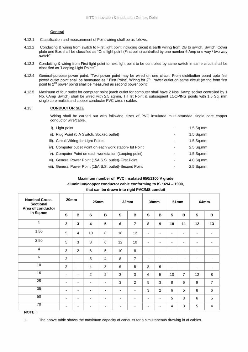
IIITD Innovation & Incubation Center, Delhi
General
4.12.1 Classification and measurement of Point wiring shall be as follows:
4.12.2 Conduiting & wiring from switch to First light point including circuit & earth wiring from DB to switch, Switch, Cover plate and Box shall be classified as “One light point (First point) controlled by one number 6 Amp one way / two way switch”.
4.12.3 Conduiting & wiring from First light point to next light point to be controlled by same switch in same circuit shall be classified as “Looping Light Points”.
4.12.4 General-purpose power point, “Two power point may be wired on one circuit. From distribution board upto first power outlet point shall be measured as “ First Point”. Wiring for 2
nd Power outlet on same circuit (wiring from first
point to 2nd
power point) shall be measured as second power point.
4.12.5 Maximum of four outlet for computer point (each outlet for computer shall have 2 Nos. 6Amp socket controlled by 1 No. 6Amp Switch) shall be wired with 2.5 sqmm. Till Ist Point & subsequent LOOPING points with 1.5 Sq. mm single core multistrand copper conductor PVC wires / cables
4.13 CONDUCTOR SIZE
Wiring shall be carried out with following sizes of PVC insulated multi-stranded single core copper conductor wire/cable.
i). Light point. - 1.5 Sq.mm
ii). Plug Point (5 A Switch. Socket. outlet) - 1.5 Sq.mm
iii). Circuit Wiring for Light Points - 1.5 Sq.mm
iv). Computer outlet Point on each work station- Ist Point - 2.5 Sq.mm
v). Computer Point on each workstation (Looping point) - 1.5 Sq.mm
vi). General Power Point (15A S.S. outlet)-First Point - 4.0 Sq.mm
vii). General Power Point (15A S.S. outlet)-Second Point - 2.5 Sq.mm
Maximum number of PVC insulated 650/1100 V grade
aluminium/copper conductor cable conforming to IS : 694 – 1990,
that can be drawn into rigid PVC/MS conduit
Nominal Cross- Sectional
Area of conductor In Sq.mm
20mm
25mm 32mm 38mm 51mm 64mm
S B S B S B S B S B S B
1 2 3 4 5 6 7 8 9 10 11 12 13
1.50 5 4 10 8 18 12 - - - - - -
2.50 5 3 8 6 12 10 - - - - - -
4 3 2 6 5 10 8 - - - - - -
6 2 - 5 4 8 7 - - - - - -
10 2 - 4 3 6 5 8 6 - - -
16 - - 2 2 3 3 6 5 10 7 12 8
25 - - - - 3 2 5 3 8 6 9 7
35 - - - - - - 3 2 6 5 8 6
50 - - - - - - - - 5 3 6 5
70 - - - - - - - - 4 3 5 4
NOTE :
1. The above table shows the maximum capacity of conduits for a simultaneous drawing in of cables.
34
IIITD Innovation & Incubation Center, Delhi
2. The columns headed ‘S' apply to runs of conduits which have distance not exceeding 4.25m between draw in boxes and which do not deflect from the straight by an angle of more than 15 degrees. The columns headed `B' apply to runs of conduit which deflect from the straight by an angle of more than 15 degrees.
3. Conduit sizes are the nominal external diameters.
-0-0-0-
5.0 L.T CABLES
5.1 GENERAL
L.T. Cables shall be supplied, inspected, laid tested and commissioned in accordance with drawings, specifications, relevant Indian Standards specifications and cable manufacturer’s instructions. The cable shall be delivered at site in original drums with manufacturer’s name clearly written on the drums. The recommendations of the cable manufacturer with regard to jointing and sealing shall be strictly followed.
5.2 MATERIALS
The L.T. Power cables shall be XLPE insulated PVC sheathed type aluminium conductor armoured cable conforming to IS : 7098 : 1988 (Part-I) with upto date ammendments where as control cable shall be XLPE insulated and PVC sheathed copper conductor armoured/ unarmoured cable conforming to IS:7098 (Part-I) 1988.
5.3 INSTALLATION OF CABLES
Cables shall be laid directly in ground, pipes, masonry ducts, on cable tray, surface of wall/ceiling etc. as indicated on drawings and/or as per the direction of Engineer-In-Charge. Cable laying shall be carried out as per CPWD specifications.
5.4 INSPECTION
All cables shall be inspected at site and checked for any damage during transit.
5.5 JOINTS IN CABLES
The Contractor shall take care to see that the cables received at site are apportioned to various locations in such a manner as to ensure maximum utilisation and avoiding of cable joints. This apportioning shall be got approved from Engineer-In-Charge before the cables are cut to lengths.
5.6 LAYING CABLES IN GROUND
Cables shall be laid by skilled experienced workmen using adequate rollers to minimize stretching of the cables. The cable drums shall be placed on jacks before unwinding the cable. With great care it shall be unrolled on over wooden rollers placed in trenches at intervals not exceeding 2 metres. Cables shall be laid at depth of 0.75 metres below ground level. A cushion of sand total of 250mm shall be provided both above and below the cable, joint boxes and other accessories. Cable shall not be laid in the same trench or along side a water main.
The cable shall be laid in excavated trench over 80mm layer of sand cushion. The relative position of the cables, laid in the same trench shall preserved. At all changes in direction in horizontal and vertical planes, the cables shall be bent smooth with a radius of bent not less than 12 times the diameter of cables. Minimum 3 metre long loop shall be provided at both end of cable.
Distinguishing marks may be made on the cable ends for identifications of phases. Insulation tapes of
appropriate voltage and in red, yellow and blue colours shall be wrapped just below the sockets for phase identifications.
5.7 PROTECTION OF CABLES
The cables shall be protected by bricks laid on the top layer of the sand for the full length of underground cable. Where more than one cables is laid in the same trench, the bricks shall cover all the cables and shall project a minimum of approximately 80mm on either side of the cables. Cable under road crossings and any other places subject to heavy traffic, shall be protected by running them through Hume Pipes of suitable size.
5.8 EXCAVATION & BACK FILL
All excavation and back fill required for the installation of the cables shall be carried out by the Contractor in accordance with the drawings and requirements laid down elsewhere. Trenches shall be dug true to line and grades. Back fill for trenches shall be filled in layer not exceeding 150mm. Each layer shall be properly rammed and consolidated before laying the next layer.
The Contractor shall restore all surface, roadways, side walks, kerbs wall or the works cut by excavation to their original condition to the satisfaction of the Engineer-In-Charge.
5.9 LAYING OF CABLES ON CABLE TRAY/SURFACE OF WALL/CEILING
Cable shall be laid on perforated M.S. Cable tray. Cables shall be properly dressed before cable ties/clamps are fixed. Wherever cable tray is not proposed, cables shall be fixed on surface of wall or ceiling slab by suitable MS clamps/ saddles. Care shall be taken to avoid crossing of cable.
35
IIITD Innovation & Incubation Center, Delhi
5.10 CABLES ON HANGERS OR RACKS
The Contractor shall provide and install all iron hangers racks or racks with die cast cleats with all fixings, rag bolts or girder clamps or other specialist fixing as required.
Where hangers or racks are to be fixed to wall sides, ceiling and other concrete structures, the Contractor shall be responsible for cutting away, fixing and grouting in rag bolts and making good.
The hangers or racks shall be designed to leave at least 25mm clearance between the cables and the face to which it is fixed. Multiple hangers shall have two or more fixing holes. All cables shall be saddled at not more than 150mm centres. These shall be designed to keep provision of some spare capacity for future development.
5.11 CABLES TAGS
Cable tags shall be made out of 2mm thick aluminium sheets, each tag 1-1/2 inch in dia with one hole of 2.5mm dia, 6mm below the periphery. Cable designations are to be punched with letter/number punches and the tags are to be tied inside the panels beyond the glanding as well as below the glands at cable entries. Trays tags are to be tied at all bends. On straight lengths, tags shall be provided at every 5 metres.
5.12 TESTING OF CABLES
Prior to installation, burying of cables, following tests shall be carried out. Insulation test between phases, phase & neutral, phase & earth for each length of cable.
a. Before laying.
b. After laying.
c. After jointing.
On completion of cable laying work, the following tests shall be conducted in the presence of the Engineer-In-Charge.
a. Insulation Resistance Test (Sectional and overall).
b. Continuity Resistance Test.
c. Earth Test.
All tests shall be carried out in accordance with relevant Indian Standard code of practice and Indian Electricity Rules. The Contractor shall provide necessary instruments, equipments and labour for conducting the above
tests & shall bear all expenses of conducting such tests.
-o-o-o-
6.0 CABLE TRAY
6.1 PERFORATED TYPE CABLE TRAY
The cable tray shall be fabricated out of slotted/perforated MS sheets as channel sections, single or double bended. The channel sections shall be supplied in convenient lengths and assembled at site to the desired lengths. These may be galvanised or painted as specified.
Typically, the dimensions, fabrication details etc. are shown in CPWD General Specification for Electrical Works Part-II-External: 1994.
The jointing between the sections shall be made with coupler plates of the same material and thickness as the channel section. Two coupler plates, each of minimum 200mm length, shall be bolted on each of the two sides of the channel section with 8mm dia round headed bolts, nuts and washers. In order to maintain proper earth
continuity bond, the paint on the contact surface between the coupler plates and cable tray shall be scraped and removed before the installation.
The maximum permissible uniformly distributed load for various sizes of cable trays and for different supported span are as per Table-IV of CPWD General Specifications of Electrical Works Part II(External) : 1994 . The sizes shall be specified considering the same.
Factory fabricated bends, reducers, tee/cross junctions, etc. shall be provided as per good engineering practice. (Details are typically shown in figure-3) of CPWD General Specifications of Electrical Work Part-II – 1994. The radius of bends, junctions etc. shall not be less than the minimum permissible radius of bending of the largest size of cable to be carried by the cable tray.
The entire tray (except in the case of galvanised type) and the suspenders shall be painted with two coats of red oxide primer paint after removing the dirt and rust, and finished with two coats of spray paint of approved make synthetic enamel paint.
6.2 LADDER TYPE CABLE TRAY
36
IIITD Innovation & Incubation Center, Delhi
Ladder type cable tray shall be fabricated out of double bended channel section longitudinal members with single bended channel section rungs of cross members welded to the base of the longitudinal members at a centre to centre spacing of 250mm. The channel sections shall be supplied in convenient lengths and assembled at side to the desired lengths. These may be galvanised or painted to the desired lengths. Alternatively, where specified, the cable tray may be fabricated by two angle irons of 50mm x 50mm x 6mm as two longitudinal members, with crosses bracings between them by 50mm x 5mm flats welded/bolted to the angles at 1 m spacing.
Typically, the dimensions, fabrication details etc. are shown in CPWD General Specification for Electrical Works - Part II -External, 1994.
The jointing between the sections shall be made with coupler plates of the same material and thickness as the channel section. Two coupler plates, each of minimum 200mm length, shall be bolted on each of the two sides
of the channel section with 8mm dia round headed bolts, nuts and washers. In order to maintain proper earth continuity bond, the paint on the contact surfaces between the coupler plates and cable tray shall be scraped and removed before the installation.
The maximum permissible uniformly distributed load for various sizes of cables trays and for different supported span are as per CPWD General Specification of Electrical Work Part II -1994. The sizes shall be specified considering the same.
The width of the cable tray shall be chosen so as to accommodate all the cable in one tier, plus 30 to 50% additional width for future expansion. This additional width shall be minimum 100mm. The overall width of one cable tray shall be limited to 900mm.
Factory fabricated bends, reducers, tee/cross junctions, etc. shall be provided as per good engineering practice. Details are typically shown in figure 3 of CPWD General Specification of Electrical Work Part-II-External, 1994. The radius of bends, junctions etc. shall not be less than the minimum permissible radius of bending of the largest size of cable to be carried by the cable tray.
The entire tray (except in the case of galvanised type) and the suspenders shall be painted with two coats of red oxide primer paint after removing the dirt and rust, and finished with two coats of spray paint of approved make synthetic enamel paint.
The cable tray shall be bonded to the earth Terminal of the switch bonds at both ends.
The cable trays shall be measured on unit length basis, along the center line of the cable tray, including bends, reducers, tees, cross joints, etc, and paid for accordingly.
The cable tray shall be suspended from the ceiling slab with the help of 10mm dia MS rounds or 25mm x 5mm flats at specified spacing as per of CPWD General Specification of Electrical Work Part II –External, 1994. Flat type suspenders may be used for channels upto 450mm width bolted to cable trays. Round suspenders shall be threaded and bolted to the cable trays or to independent support angles 50mm x 50mm x 5mm at the bottom end as specified. These shall be grouted to the ceiling slab at the other end through an effective means, as approved by the Engineer, to take the weight of the cable tray with the cables.
-o-o-o-
7.0 INSTALLATION OF LIGHT FIXTURES
7.1 SUPPORTS AND FIXINGS
7.1.1 Where Linear LED fluorescent luminaires 1200 mm or more in length are supported directly by the conduit system they shall be fixed to two circular conduit boxes both of which shall form an integral part of the conduit system.
7.1.2 Where the weight of the luminaire is supported by a conduit box or cable trunking the fixing of the conduit box or trunking shall be adequate for the purpose and approved by Architect/Consultant.
7.1.3 Support of luminaires from cable trunking shall be by means of appropriate clamps or brackets.
7.1.4 Luminaires mounted on or recessed into suspended ceilings shall not be support on the false ceiling unless specifically shown and approved.
7.1.5 For wall mounted luminaires, the mounting height specified on drawings shall be above finished floor level measured to the centre of the conduit box, unless otherwise indicated.
7.2 WIRING CONNECTIONS
7.2.1 Where luminaires, other than those are fixed direct to circular boxes or supported by pendants or chains,the final circuit wiring shall terminate at a terminal block in the conduit box.
7.2.2 Where luminaires having fluorescent tubes are fixed direct to circular conduit boxes, the final circuit wiring may be terminated within the lnuinaire unless otherwise indicated. The wiring shall enter each luminaire at the conduit entry nearest to the terminal block and where the loop - in wiring system is used leave by same entry wiring shall not pass through a luminaire.
37
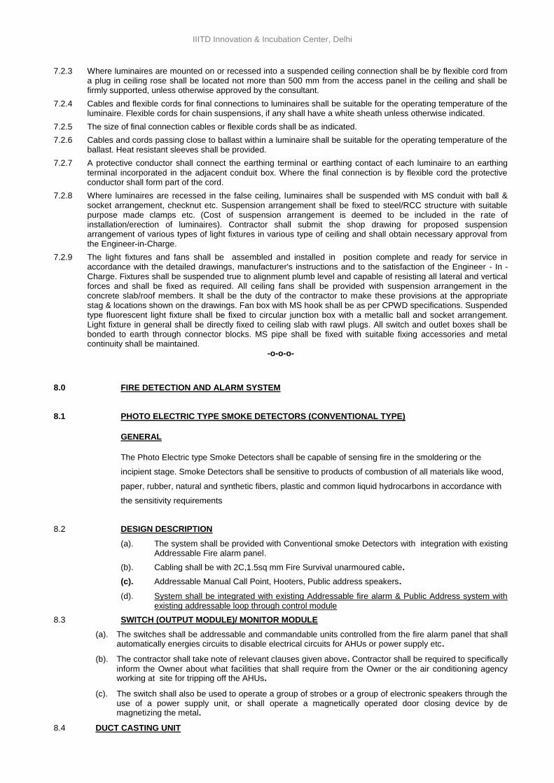
IIITD Innovation & Incubation Center, Delhi
7.2.3 Where luminaires are mounted on or recessed into a suspended ceiling connection shall be by flexible cord from a plug in ceiling rose shall be located not more than 500 mm from the access panel in the ceiling and shall be firmly supported, unless otherwise approved by the consultant.
7.2.4 Cables and flexible cords for final connections to luminaires shall be suitable for the operating temperature of the luminaire. Flexible cords for chain suspensions, if any shall have a white sheath unless otherwise indicated.
7.2.5 The size of final connection cables or flexible cords shall be as indicated.
7.2.6 Cables and cords passing close to ballast within a luminaire shall be suitable for the operating temperature of the ballast. Heat resistant sleeves shall be provided.
7.2.7 A protective conductor shall connect the earthing terminal or earthing contact of each luminaire to an earthing terminal incorporated in the adjacent conduit box. Where the final connection is by flexible cord the protective conductor shall form part of the cord.
7.2.8 Where luminaires are recessed in the false ceiling, luminaires shall be suspended with MS conduit with ball & socket arrangement, checknut etc. Suspension arrangement shall be fixed to steel/RCC structure with suitable purpose made clamps etc. (Cost of suspension arrangement is deemed to be included in the rate of installation/erection of luminaires). Contractor shall submit the shop drawing for proposed suspension arrangement of various types of light fixtures in various type of ceiling and shall obtain necessary approval from the Engineer-in-Charge.
7.2.9 The light fixtures and fans shall be assembled and installed in position complete and ready for service in accordance with the detailed drawings, manufacturer's instructions and to the satisfaction of the Engineer - In - Charge. Fixtures shall be suspended true to alignment plumb level and capable of resisting all lateral and vertical forces and shall be fixed as required. All ceiling fans shall be provided with suspension arrangement in the concrete slab/roof members. It shall be the duty of the contractor to make these provisions at the appropriate stag & locations shown on the drawings. Fan box with MS hook shall be as per CPWD specifications. Suspended type fluorescent light fixture shall be fixed to circular junction box with a metallic ball and socket arrangement. Light fixture in general shall be directly fixed to ceiling slab with rawl plugs. All switch and outlet boxes shall be bonded to earth through connector blocks. MS pipe shall be fixed with suitable fixing accessories and metal continuity shall be maintained.
-o-o-o-
8.0 FIRE DETECTION AND ALARM SYSTEM
8.1 PHOTO ELECTRIC TYPE SMOKE DETECTORS (CONVENTIONAL TYPE)
GENERAL
The Photo Electric type Smoke Detectors shall be capable of sensing fire in the smoldering or the
incipient stage. Smoke Detectors shall be sensitive to products of combustion of all materials like wood,
paper, rubber, natural and synthetic fibers, plastic and common liquid hydrocarbons in accordance with
the sensitivity requirements
8.2 DESIGN DESCRIPTION
(a). The system shall be provided with Conventional smoke Detectors with integration with existing Addressable Fire alarm panel.
(b). Cabling shall be with 2C,1.5sq mm Fire Survival unarmoured cable.
(c). Addressable Manual Call Point, Hooters, Public address speakers.
(d). System shall be integrated with existing Addressable fire alarm & Public Address system with existing addressable loop through control module
8.3 SWITCH (OUTPUT MODULE)/ MONITOR MODULE
(a). The switches shall be addressable and commandable units controlled from the fire alarm panel that shall automatically energies circuits to disable electrical circuits for AHUs or power supply etc.
(b). The contractor shall take note of relevant clauses given above. Contractor shall be required to specifically
inform the Owner about what facilities that shall require from the Owner or the air conditioning agency working at site for tripping off the AHUs.
(c). The switch shall also be used to operate a group of strobes or a group of electronic speakers through the use of a power supply unit, or shall operate a magnetically operated door closing device by de magnetizing the metal.
8.4 DUCT CASTING UNIT
38
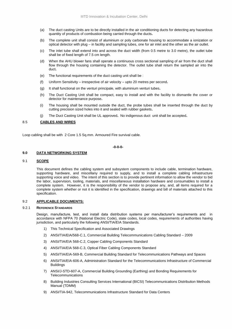
IIITD Innovation & Incubation Center, Delhi
(a) The duct casting Units are to be directly installed in the air conditioning ducts for detecting any hazardous quantity of products of combustion being carried through the ducts.
(b) The complete unit shall consist of aluminium or poly carbonate housing to accommodate a ionization or optical detector with plug – in facility and sampling tubes, one for air inlet and the other as the air outlet.
(c) The inlet tube shall extend into and across the duct width (from 0.5 metre to 3.0 metre), the outlet tube shall be of fixed length of 7.5 cm length.
(d) When the AHU blower fans shall operate a continuous cross sectional sampling of air from the duct shall flow through the housing containing the detector. The outlet tube shall return the sampled air into the duct.
(e) The functional requirements of the duct casting unit shall be :
(f) Uniform Sensitivity – irrespective of air velocity – upto 20 metres per second.
(g) It shall functional on the venturi principale, with aluminium venturi tubes.
(h) The Duct Casting Unit shall be compact, easy to install and with the facility to dismantle the cover or detector for maintenance purpose.
(i) The housing shall be mounted outside the duct, the probe tubes shall be inserted through the duct by cutting precision sized holes into it and sealed with rubber gaskets.
(j) The Duct Casting Unit shall be UL approved. No indigenous duct unit shall be accepted.
8.5 CABLES AND WIRES
Loop cabling shall be with 2 Core 1.5 Sq.mm. Armoured Fire survival cable.
-0-0-0-
9.0 DATA NETWORKING SYSTEM
9.1 SCOPE
This document defines the cabling system and subsystem components to include cable, termination hardware, supporting hardware, and miscellany required to supply, and to install a complete cabling infrastructure supporting voice and video. The intent of this section is to provide pertinent information to allow the vendor to bid the labor, supervision, tooling, materials, and miscellaneous installation hardware and consumables to install a complete system. However, it is the responsibility of the vendor to propose any, and, all items required for a complete system whether or not it is identified in the specification, drawings and bill of materials attached to this specification.
9.2 APPLICABLE DOCUMENTS:
9.2.1 REFERENCE STANDARDS
Design, manufacture, test, and install data distribution systems per manufacturer’s requirements and in accordance with NFPA 70 (National Electric Code), state codes, local codes, requirements of authorities having jurisdiction, and particularly the following ANSI/TIA/EIA Standards.
1) This Technical Specification and Associated Drawings
2) ANSI/TIA/EIA/568-C.1, Commercial Building Telecommunications Cabling Standard – 2009
3) ANSI/TIA/EIA 568-C.2, Copper Cabling Components Standard
4) ANSI/TIA/EIA 568-C.3, Optical Fiber Cabling Components Standard
5) ANSI/TIA/EIA-569-B, Commercial Building Standard for Telecommunications Pathways and Spaces
6) ANSI/TIA/EIA-606-A, Administration Standard for the Telecommunications Infrastructure of Commercial Buildings
7) ANSI/J-STD-607-A, Commercial Building Grounding (Earthing) and Bonding Requirements for Telecommunications
8) Building Industries Consulting Services International (BICSI) Telecommunications Distribution Methods Manual (TDMM)
9) ANSI/TIA-942, Telecommunications Infrastructure Standard for Data Centers
39
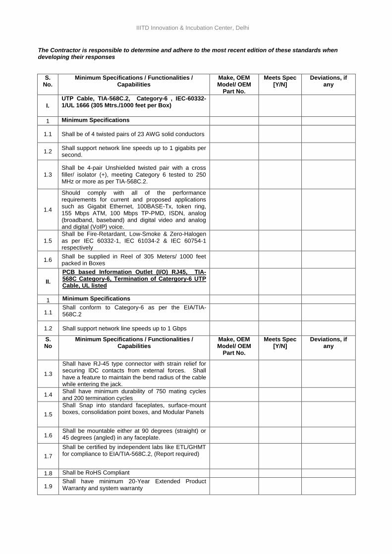
IIITD Innovation & Incubation Center, Delhi
The Contractor is responsible to determine and adhere to the most recent edition of these standards when developing their responses
S. No.
Minimum Specifications / Functionalities / Capabilities
Make, OEM Model/ OEM
Part No.
Meets Spec [Y/N]
Deviations, if any
I.
UTP Cable, TIA-568C.2, Category-6 , IEC-60332-1/UL 1666 (305 Mtrs./1000 feet per Box)
1 Minimum Specifications
1.1 Shall be of 4 twisted pairs of 23 AWG solid conductors
1.2 Shall support network line speeds up to 1 gigabits per second.
1.3 Shall be 4-pair Unshielded twisted pair with a cross filler/ isolator (+), meeting Category 6 tested to 250 MHz or more as per TIA-568C.2.
1.4
Should comply with all of the performance requirements for current and proposed applications such as Gigabit Ethernet, 100BASE-Tx, token ring, 155 Mbps ATM, 100 Mbps TP-PMD, ISDN, analog (broadband, baseband) and digital video and analog and digital (VoIP) voice.
1.5 Shall be Fire-Retardant, Low-Smoke & Zero-Halogen as per IEC 60332-1, IEC 61034-2 & IEC 60754-1 respectively
1.6 Shall be supplied in Reel of 305 Meters/ 1000 feet packed in Boxes
II.
PCB based Information Outlet (I/O) RJ45, TIA-568C Category-6, Termination of Catergory-6 UTP Cable, UL listed
1 Minimum Specifications
1.1 Shall conform to Category-6 as per the EIA/TIA-568C.2
1.2 Shall support network line speeds up to 1 Gbps
S. No
Minimum Specifications / Functionalities / Capabilities
Make, OEM Model/ OEM
Part No.
Meets Spec [Y/N]
Deviations, if any
1.3
Shall have RJ-45 type connector with strain relief for securing IDC contacts from external forces. Shall have a feature to maintain the bend radius of the cable while entering the jack.
1.4 Shall have minimum durability of 750 mating cycles and 200 termination cycles
1.5
Shall Snap into standard faceplates, surface-mount boxes, consolidation point boxes, and Modular Panels
1.6 Shall be mountable either at 90 degrees (straight) or 45 degrees (angled) in any faceplate.
1.7
Shall be certified by independent labs like ETL/GHMT for compliance to EIA/TIA-568C.2, (Report required)
1.8 Shall be RoHS Compliant
1.9 Shall have minimum 20-Year Extended Product Warranty and system warranty
40
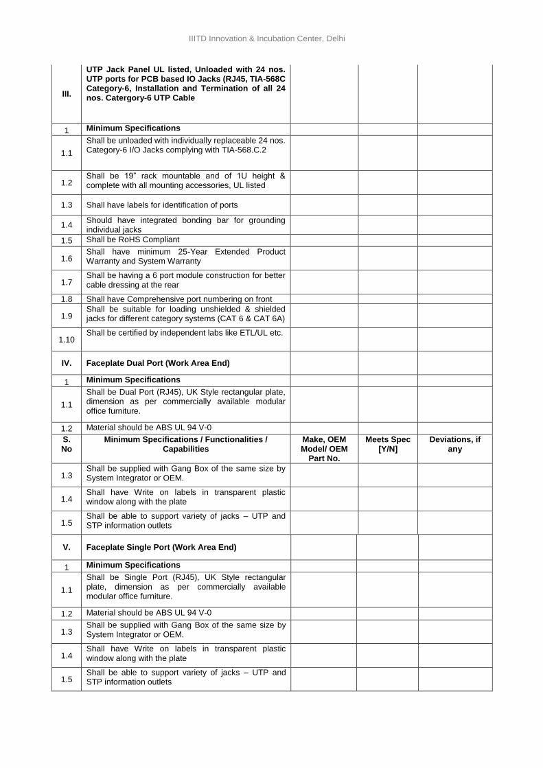
IIITD Innovation & Incubation Center, Delhi
III.
UTP Jack Panel UL listed, Unloaded with 24 nos. UTP ports for PCB based IO Jacks (RJ45, TIA-568C Category-6, Installation and Termination of all 24 nos. Catergory-6 UTP Cable
1 Minimum Specifications
1.1
Shall be unloaded with individually replaceable 24 nos. Category-6 I/O Jacks complying with TIA-568.C.2
1.2 Shall be 19” rack mountable and of 1U height & complete with all mounting accessories, UL listed
1.3 Shall have labels for identification of ports
1.4 Should have integrated bonding bar for grounding individual jacks
1.5 Shall be RoHS Compliant
1.6 Shall have minimum 25-Year Extended Product Warranty and System Warranty
1.7 Shall be having a 6 port module construction for better cable dressing at the rear
1.8 Shall have Comprehensive port numbering on front
1.9 Shall be suitable for loading unshielded & shielded jacks for different category systems (CAT 6 & CAT 6A)
1.10 Shall be certified by independent labs like ETL/UL etc.
IV. Faceplate Dual Port (Work Area End)
1 Minimum Specifications
1.1
Shall be Dual Port (RJ45), UK Style rectangular plate, dimension as per commercially available modular office furniture.
1.2 Material should be ABS UL 94 V-0
S. No
Minimum Specifications / Functionalities / Capabilities
Make, OEM Model/ OEM
Part No.
Meets Spec [Y/N]
Deviations, if any
1.3 Shall be supplied with Gang Box of the same size by System Integrator or OEM.
1.4 Shall have Write on labels in transparent plastic window along with the plate
1.5 Shall be able to support variety of jacks – UTP and STP information outlets
V. Faceplate Single Port (Work Area End)
1 Minimum Specifications
1.1
Shall be Single Port (RJ45), UK Style rectangular plate, dimension as per commercially available modular office furniture.
1.2 Material should be ABS UL 94 V-0
1.3 Shall be supplied with Gang Box of the same size by System Integrator or OEM.
1.4 Shall have Write on labels in transparent plastic window along with the plate
1.5 Shall be able to support variety of jacks – UTP and STP information outlets
41
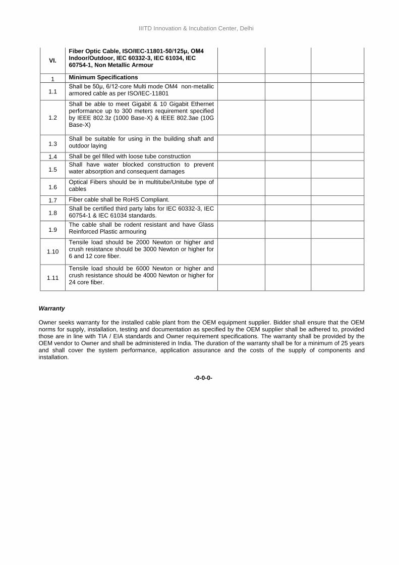
IIITD Innovation & Incubation Center, Delhi
VI.
Fiber Optic Cable, ISO/IEC-11801-50/125μ, OM4 Indoor/Outdoor, IEC 60332-3, IEC 61034, IEC 60754-1, Non Metallic Armour
1 Minimum Specifications
1.1 Shall be 50μ, 6/12-core Multi mode OM4 non-metallic armored cable as per ISO/IEC-11801
1.2
Shall be able to meet Gigabit & 10 Gigabit Ethernet performance up to 300 meters requirement specified by IEEE 802.3z (1000 Base-X) & IEEE 802.3ae (10G Base-X)
1.3 Shall be suitable for using in the building shaft and outdoor laying
1.4 Shall be gel filled with loose tube construction
1.5 Shall have water blocked construction to prevent water absorption and consequent damages
1.6 Optical Fibers should be in multitube/Unitube type of cables
1.7 Fiber cable shall be RoHS Compliant.
1.8 Shall be certified third party labs for IEC 60332-3, IEC 60754-1 & IEC 61034 standards.
1.9 The cable shall be rodent resistant and have Glass Reinforced Plastic armouring
1.10
Tensile load should be 2000 Newton or higher and crush resistance should be 3000 Newton or higher for 6 and 12 core fiber.
1.11
Tensile load should be 6000 Newton or higher and crush resistance should be 4000 Newton or higher for 24 core fiber.
Warranty
Owner seeks warranty for the installed cable plant from the OEM equipment supplier. Bidder shall ensure that the OEM norms for supply, installation, testing and documentation as specified by the OEM supplier shall be adhered to, provided those are in line with TIA / EIA standards and Owner requirement specifications. The warranty shall be provided by the OEM vendor to Owner and shall be administered in India. The duration of the warranty shall be for a minimum of 25 years and shall cover the system performance, application assurance and the costs of the supply of components and installation.
-0-0-0-
42
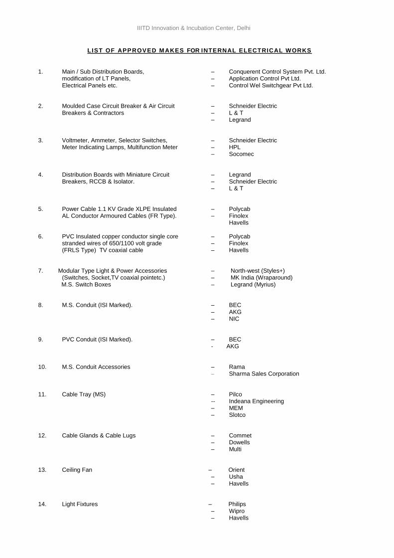
IIITD Innovation & Incubation Center, Delhi
LIST OF APPROVED MAKES FOR INTERNAL ELECTRICAL WORKS
1. Main / Sub Distribution Boards, – Conquerent Control System Pvt. Ltd. modification of LT Panels, – Application Control Pvt Ltd. Electrical Panels etc. – Control Wel Switchgear Pvt Ltd. 2. Moulded Case Circuit Breaker & Air Circuit – Schneider Electric Breakers & Contractors – L & T – Legrand 3. Voltmeter, Ammeter, Selector Switches, – Schneider Electric Meter Indicating Lamps, Multifunction Meter – HPL – Socomec 4. Distribution Boards with Miniature Circuit – Legrand Breakers, RCCB & Isolator. – Schneider Electric – L & T 5. Power Cable 1.1 KV Grade XLPE Insulated – Polycab AL Conductor Armoured Cables (FR Type). – Finolex
Havells
6. PVC Insulated copper conductor single core – Polycab stranded wires of 650/1100 volt grade – Finolex
(FRLS Type) TV coaxial cable – Havells 7. Modular Type Light & Power Accessories – North-west (Styles+) (Switches, Socket,TV coaxial pointetc.) – MK India (Wraparound) M.S. Switch Boxes – Legrand (Myrius) 8. M.S. Conduit (ISI Marked). – BEC – AKG – NIC 9. PVC Conduit (ISI Marked). – BEC - AKG
10. M.S. Conduit Accessories – Rama – Sharma Sales Corporation
11. Cable Tray (MS) – Pilco -- Indeana Engineering – MEM – Slotco 12. Cable Glands & Cable Lugs – Commet – Dowells – Multi 13. Ceiling Fan – Orient – Usha – Havells 14. Light Fixtures – Philips – Wipro – Havells
43
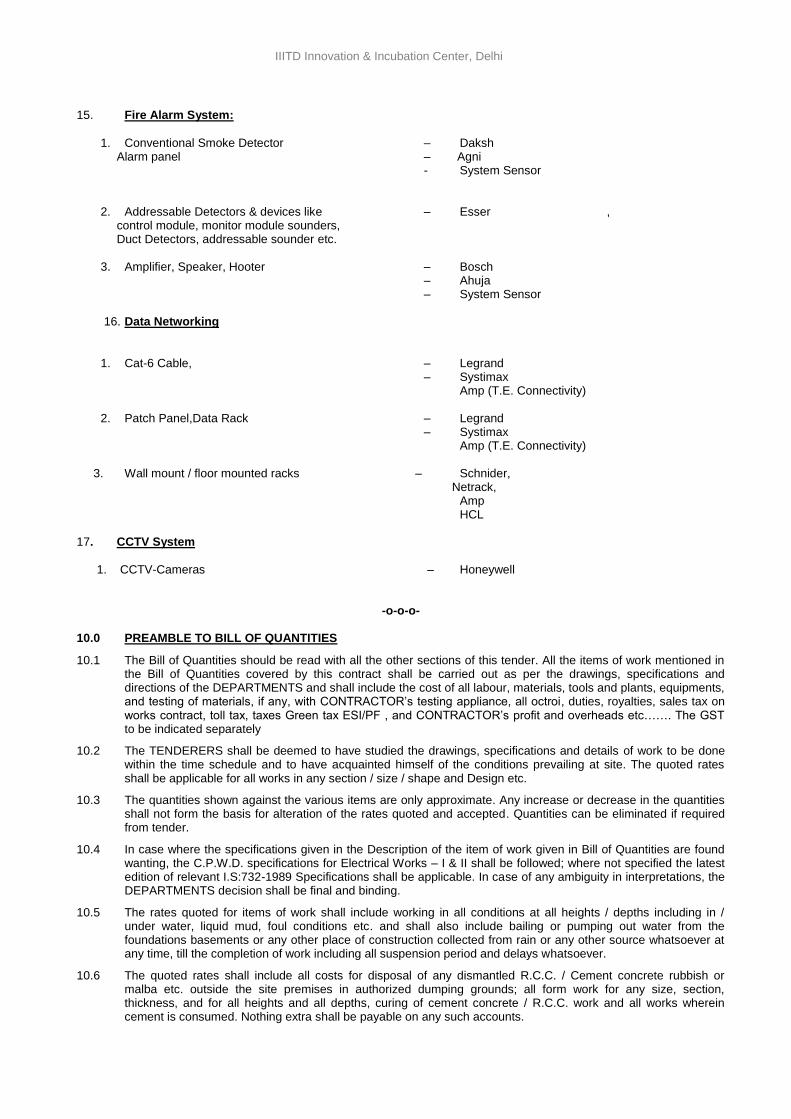
IIITD Innovation & Incubation Center, Delhi
15. Fire Alarm System:
1. Conventional Smoke Detector – Daksh Alarm panel – Agni - System Sensor 2. Addressable Detectors & devices like – Esser , control module, monitor module sounders, Duct Detectors, addressable sounder etc. 3. Amplifier, Speaker, Hooter – Bosch – Ahuja – System Sensor 16. Data Networking
1. Cat-6 Cable, – Legrand – Systimax Amp (T.E. Connectivity) 2. Patch Panel,Data Rack – Legrand – Systimax Amp (T.E. Connectivity)
3. Wall mount / floor mounted racks – Schnider, Netrack,
Amp HCL
17. CCTV System
1. CCTV-Cameras – Honeywell
-o-o-o-
10.0 PREAMBLE TO BILL OF QUANTITIES
10.1 The Bill of Quantities should be read with all the other sections of this tender. All the items of work mentioned in the Bill of Quantities covered by this contract shall be carried out as per the drawings, specifications and directions of the DEPARTMENTS and shall include the cost of all labour, materials, tools and plants, equipments, and testing of materials, if any, with CONTRACTOR’s testing appliance, all octroi, duties, royalties, sales tax on works contract, toll tax, taxes Green tax ESI/PF , and CONTRACTOR’s profit and overheads etc……. The GST to be indicated separately
10.2 The TENDERERS shall be deemed to have studied the drawings, specifications and details of work to be done within the time schedule and to have acquainted himself of the conditions prevailing at site. The quoted rates shall be applicable for all works in any section / size / shape and Design etc.
10.3 The quantities shown against the various items are only approximate. Any increase or decrease in the quantities shall not form the basis for alteration of the rates quoted and accepted. Quantities can be eliminated if required from tender.
10.4 In case where the specifications given in the Description of the item of work given in Bill of Quantities are found wanting, the C.P.W.D. specifications for Electrical Works – I & II shall be followed; where not specified the latest edition of relevant I.S:732-1989 Specifications shall be applicable. In case of any ambiguity in interpretations, the DEPARTMENTS decision shall be final and binding.
10.5 The rates quoted for items of work shall include working in all conditions at all heights / depths including in / under water, liquid mud, foul conditions etc. and shall also include bailing or pumping out water from the foundations basements or any other place of construction collected from rain or any other source whatsoever at any time, till the completion of work including all suspension period and delays whatsoever.
10.6 The quoted rates shall include all costs for disposal of any dismantled R.C.C. / Cement concrete rubbish or malba etc. outside the site premises in authorized dumping grounds; all form work for any size, section, thickness, and for all heights and all depths, curing of cement concrete / R.C.C. work and all works wherein cement is consumed. Nothing extra shall be payable on any such accounts.
44
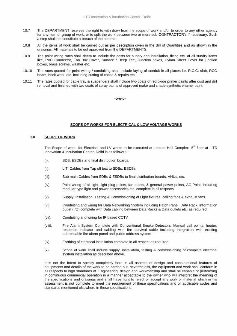
IIITD Innovation & Incubation Center, Delhi
10.7 The DEPARTMENT reserves the right to with draw from the scope of work and/or to order to any other agency for any item or group of work, or to split the work between two or more sub-CONTRACTOR’s if necessary. Such a step shall not constitute a breach of the contract.
10.8 All the items of work shall be carried out as per description given in the Bill of Quantities and as shown in the drawings. All materials to be got approved from the DEPARTMENTS.
10.9 The point wiring rates shall deem to include the costs for supply and installation, fixing etc. of all sundry items like, PVC Connector, Fan Box Cover, Surface / Deep Tee, Junction boxes, Hylam Sheet Cover for junction boxes, brass screws, washer etc.
10.10 The rates quoted for point wiring / conduiting shall include laying of conduit in all places i.e. R.C.C. slab, RCC beam, brick work, etc. including cutting of chase & repairs etc.
10.11 The rates quoted for cable tray & suspenders shall include two coats of red oxide primer paints after dust and dirt removal and finished with two coats of spray paints of approved make and shade synthetic enamel paint.
-o-o-o-
SCOPE OF WORKS FOR ELECTRICAL & LOW VOLTAGE WORKS 1.0 SCOPE OF WORK
The Scope of work for Electrical and LV works to be executed at Lecture Hall Complex -5th
floor at IIITD Innovation & Incubation Center, Delhi is as follows :-
(i). SDB, ESDBs and final distribution boards.
(ii). L.T. Cables from Tap off box to SDBs, ESDBs.
(iii). Sub main Cables from SDBs & ESDBs to final distribution boards, AHUs, etc.
(iv). Point wiring of all light, light plug points, fan points, & general power points, AC Point, including modular type light and power accessories etc. complete in all respects.
(v). Supply, Installation, Testing & Commissioning of Light fixtures, ceiling fans & exhaust fans.
(vi). Conduiting and wiring for Data Networking System including Patch Panel, Data Rack, information outlet (I/O) complete with Data cabling between Data Racks & Data outlets etc. as required.
(vii). Conduiting and wiring for IP based CCTV
(viii). Fire Alarm System Complete with Conventional Smoke Detectors, Manual call points, hooter, response indicator and cabling with fire survival cable including integration with existing addressable fire alarm panel and public address system.
(ix). Earthing of electrical installation complete in all respect as required.
(x). Scope of work shall include supply, installation, testing & commissioning of complete electrical system installation as described above.
It is not the intent to specify completely here in all aspects of design and constructional features of equipments and details of the work to be carried out, nevertheless, the equipment and work shall conform in all respects to high standards of Engineering, design and workmanship and shall be capable of performing in continuous commercial operation in a manner acceptable to the owner who will interpret the meaning of the specifications and drawings and shall have right to reject or accept any work or material which in his assessment is not complete to meet the requirement of these specifications and or applicable codes and standards mentioned elsewhere in these specifications.
45
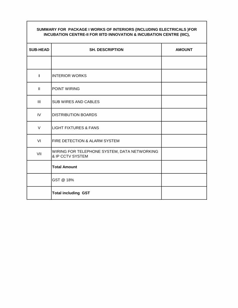
SUB-HEAD SH. DESCRIPTION AMOUNT
I INTERIOR WORKS
II POINT WIRING
III SUB WIRES AND CABLES
IV DISTRIBUTION BOARDS
V LIGHT FIXTURES & FANS
VI FIRE DETECTION & ALARM SYSTEM
VIIWIRING FOR TELEPHONE SYSTEM, DATA NETWORKING
& IP CCTV SYSTEM
Total Amount
GST @ 18%
Total including GST
SUMMARY FOR PACKAGE I WORKS OF INTERIORS (INCLUDING ELECTRICALS )FOR
INCUBATION CENTRE-II FOR IIITD INNOVATION & INCUBATION CENTRE (IIIC),
46
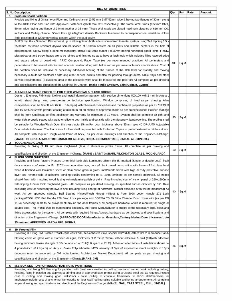
S. No.Description. Qty. Unit Rate Amount.
1 Gypsum Board Partition
Provide and fixing of GI frame on Floor and Ceiling channel (0.55 mm BMT,52mm wide & having two flanges of 30mm each)
to the RCC Floor and Slab with Approved Fasteners @600 mm C/C respectively. The frame Wall Studs (0.55mm BMT,
50mm wide having one flange of 34mm another of 36 mm). These Wall studs are placed maximum distance of 610 mm C/C
in Floor and Ceiling channel. 50mm thick @ 48kg/cum density Rockwool Insulation to be suspended on Insulation Holder
Strip positioned at 1200mm vertical centers within the stud cavity.
2x12.5 mm thick Standard Plasterboard up to all heights on both side is screw fixed to metal system using Self tapping 3.5 x
25/38mm corrosion resistant drywall screws spaced at 150mm centers on all joints and 300mm centers in the field of
plasterboards. Screw fixing is done mechanically. Install Flat Strap 90mm x 0.55mm behind horizontal board joints. Finally,
plasterboards and screw heads are to be jointed and finished so as to have a flush look which includes filling tapered edge
and square edges of board with APJC Compound, Paper Tape (As per recommended practice). All perimeters and
penetrations to be sealed with fire and acoustic sealant along with baker rod as per manufacturer’s specifications. Cost of
the partition shall be inclusive of necessary additional bracing of the frames at the slab level for stability and making
necessary cutouts for electrical / data and other service outlets and also for passing through ducts, cable trays and other
service requirements. (Elevational area of the executed work shall be measured and paid for) All complete as per drawing
and specifications and direction of the Engineer-in-Charge. (Make : India Gypsum, Saint Gobain, Gyproc)
400 Sq.M
2 ALUMINIUM FRAME PROFILES FOR FIXED WINDOWS & FLUSH DOORS
Design , Engineer, Fabricate, Deliver and Install aluminium partation with section dimentions 50X100 with 2 mm thickness ,
to with stand design wind pressure as per technical specification. Window comprising of fixed as per drawing. Alloy
composition shall be 63400 WP (6063 T6 temper) with chemical composition and mechanical properties as per IS:733:1983
and IS:1285:2002 with powder coating of minimum 50-60 micros of approved shade as per architect/client. Powder coatings
shall be from Quallicoat certified applicator and warranty for minimum of 10 years. System shall be complete air tight and
water tight properly sealed with weather silicone both inside and out side with the Mesenery Jamb/opening. The profiles shall
be suitable for Wooden/Flush Door thickness upto 35mm.For door thickness above 35mm upto 40 DP-AJ45 Adjustable
Door rebate to be used.The Aluminium Profiles shall be protected with Protection Tapes to protect external scratches at site.
All complete with required rough wood frame at back, as per detail drawings and direction of the Engineer-in-Charge.
(MAKE : BHORUKA INDUSTRIES,INDALCO ALLOYS, HINDALCO INDUSTRIES, JINDAL ALUMINIUM.)
90 Sq.M
3 TOUGHENED GLASS
Providing & Fixing of 10 mm clear toughened glass in aluminium profile frame. All complete as per drawing and
specifications and direction of the Engineer-in-Charge. (MAKE : SAINT GOBAIN, PILKINGTON GLASS, MODIGUARD )
50 Sq.M
4 FLUSH DOOR SHUTTERS
Providing and fixing Factory Pressed 1mm thick both side Laminated 35mm thk ISI marked (Single or double Leaf) flush
door shutters conforming to IS : 2202 non decorative type, core of block board construction with frame of 1st class hard
wood & finished with laminated sheet of plain /wood grain in gloss /matt/suede finish with high density protective surface
layer and reverse side of adhesive bonding quality conforming to IS: 2046 laminate as per sample approved. All edges
should finish with matching wood lipping with melamine polish or paint . Rate including cost of vision panel of 250x1500mm
with lipping & 8mm thick toughened glass . All complete as per detail drawing, as specified and as directed by EIC. Rate
excluding cost of necessary hardware and including fixing charge of hardware. (Actual executed area will be measured) All
work As per approved sample. Ball Bearing Hinges/Flush Hinges (4Nos) & Pure 8998 Lever Handle 271 Lock
package/TGDI H350 Pull Handle 278 Dead Lock package and DORMA TS 89 Slide Channel Door closer with (as per EN
1154) necessary seals to be provided all around the door frames & all complete hardware which is required for single or
double door. The Profile shall be matt natural anodized, the Profile Manufacturer to supply all the necessary clips, seals and
fixing accessories for the system. All complete with required fittings,fixtures, hardware as per drawing and specifications and
direction of the Engineer-in-Charge. (APPROVED DOOR Manufacturer: Greenlam,Century,Merino Door thickness Upto
35mm) and APPROVED HARDWARE: DORMA
40 Sq.M
5 3M Frosted Film
Providing & Fixing 3M Frosted Translucent, cast PVC, self-adhesive vinyl, special CRYSTAL-effect film to reproduce Sand-
blasting effect on glass with customised designs, thickness of 2 mil (0.05mm) without adhesive & 3mil (0.8)with adhesive
having minimum tensile strength of 3.5 pound/inch at 73 F(0.6 kg/cm at 23 C). Adhesion after 24hrs of installation should be
4 pounds/inch (0.7 kg/cm) on Acrylic, Glass Polycarbonate: MCS warranty of 3yrs (if exposed to direct sunlight) to 15yrs
(indoors) must be endorsed by 3M India Limited Architectural Market Department. All complete as per drawing and
specifications and direction of the Engineer-in-Charge.(MAKE: 3M)
25 Sq.M
6 M.S BOX SECTION FOR INSIDE FRAMING IN PARTITIONS
Providing and fixing MS Framing for partition with Steel work welded in built up sections/ framed work including cutting,
hoisting, fixing in position and applying a priming coat of approved steel primer using structural steel etc. as required.Include
cost of cutting and making good walls/floor / false ceiling to continue framework till RCC slab/members for
anchorage.Include cost of anchoring frameworks to floor /wall/ ceiling using suitable anchoring arrangements.All complete
as per drawing and specifications and direction of the Engineer-in-Charge. (MAKE : SAIL, TATA STEEL, RINL, JINDAL)
BILL OF QUANTITIES
47
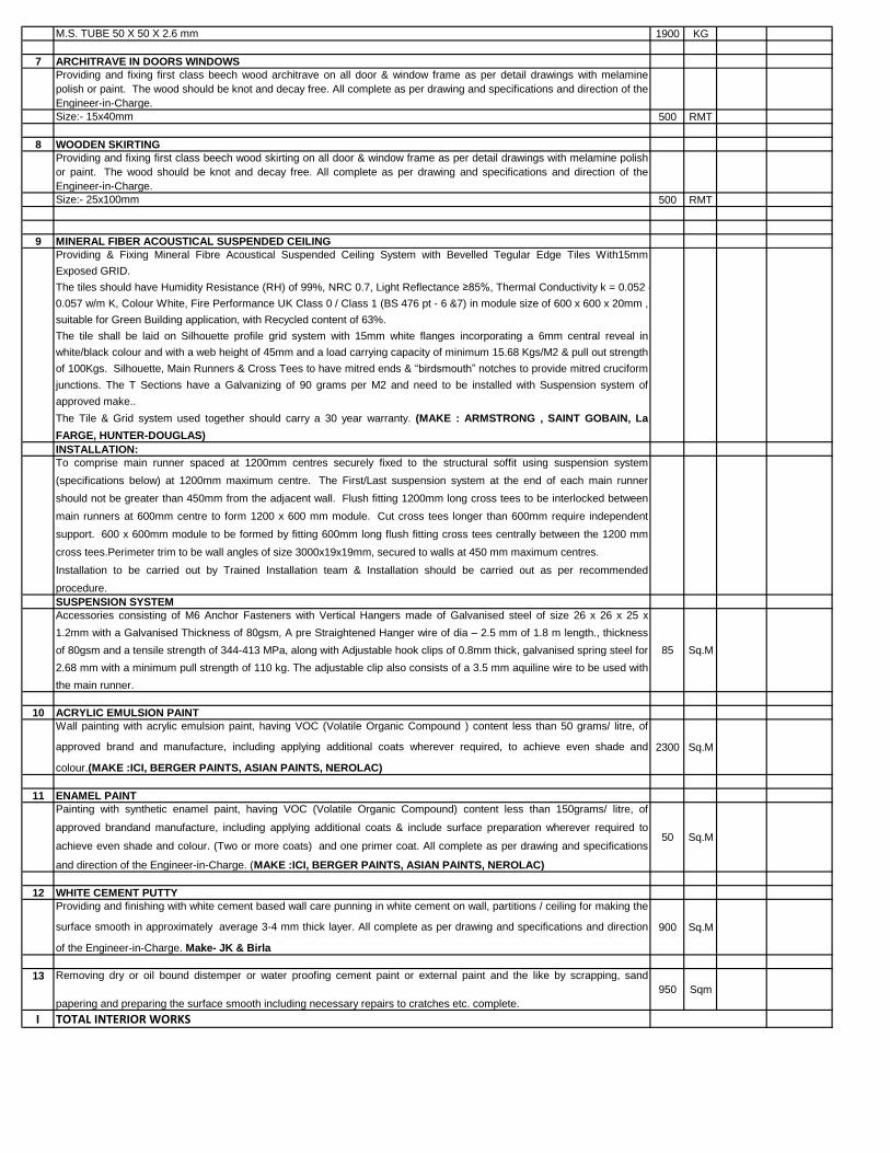
M.S. TUBE 50 X 50 X 2.6 mm 1900 KG
7 ARCHITRAVE IN DOORS WINDOWS
Providing and fixing first class beech wood architrave on all door & window frame as per detail drawings with melamine
polish or paint. The wood should be knot and decay free. All complete as per drawing and specifications and direction of the
Engineer-in-Charge.
Size:- 15x40mm 500 RMT
8 WOODEN SKIRTING
Providing and fixing first class beech wood skirting on all door & window frame as per detail drawings with melamine polish
or paint. The wood should be knot and decay free. All complete as per drawing and specifications and direction of the
Engineer-in-Charge.
Size:- 25x100mm 500 RMT
9 MINERAL FIBER ACOUSTICAL SUSPENDED CEILING
Providing & Fixing Mineral Fibre Acoustical Suspended Ceiling System with Bevelled Tegular Edge Tiles With15mm
Exposed GRID.
The tiles should have Humidity Resistance (RH) of 99%, NRC 0.7, Light Reflectance ≥85%, Thermal Conductivity k = 0.052 -
0.057 w/m K, Colour White, Fire Performance UK Class 0 / Class 1 (BS 476 pt - 6 &7) in module size of 600 x 600 x 20mm ,
suitable for Green Building application, with Recycled content of 63%.
The tile shall be laid on Silhouette profile grid system with 15mm white flanges incorporating a 6mm central reveal in
white/black colour and with a web height of 45mm and a load carrying capacity of minimum 15.68 Kgs/M2 & pull out strength
of 100Kgs. Silhouette, Main Runners & Cross Tees to have mitred ends & “birdsmouth” notches to provide mitred cruciform
junctions. The T Sections have a Galvanizing of 90 grams per M2 and need to be installed with Suspension system of
approved make..
The Tile & Grid system used together should carry a 30 year warranty. (MAKE : ARMSTRONG , SAINT GOBAIN, La
FARGE, HUNTER-DOUGLAS)
INSTALLATION:
To comprise main runner spaced at 1200mm centres securely fixed to the structural soffit using suspension system
(specifications below) at 1200mm maximum centre. The First/Last suspension system at the end of each main runner
should not be greater than 450mm from the adjacent wall. Flush fitting 1200mm long cross tees to be interlocked between
main runners at 600mm centre to form 1200 x 600 mm module. Cut cross tees longer than 600mm require independent
support. 600 x 600mm module to be formed by fitting 600mm long flush fitting cross tees centrally between the 1200 mm
cross tees.Perimeter trim to be wall angles of size 3000x19x19mm, secured to walls at 450 mm maximum centres.
Installation to be carried out by Trained Installation team & Installation should be carried out as per recommended
procedure.
SUSPENSION SYSTEM
Accessories consisting of M6 Anchor Fasteners with Vertical Hangers made of Galvanised steel of size 26 x 26 x 25 x
1.2mm with a Galvanised Thickness of 80gsm, A pre Straightened Hanger wire of dia – 2.5 mm of 1.8 m length., thickness
of 80gsm and a tensile strength of 344-413 MPa, along with Adjustable hook clips of 0.8mm thick, galvanised spring steel for
2.68 mm with a minimum pull strength of 110 kg. The adjustable clip also consists of a 3.5 mm aquiline wire to be used with
the main runner.
85 Sq.M
10 ACRYLIC EMULSION PAINT
Wall painting with acrylic emulsion paint, having VOC (Volatile Organic Compound ) content less than 50 grams/ litre, of
approved brand and manufacture, including applying additional coats wherever required, to achieve even shade and
colour.(MAKE :ICI, BERGER PAINTS, ASIAN PAINTS, NEROLAC)
2300 Sq.M
11 ENAMEL PAINT
Painting with synthetic enamel paint, having VOC (Volatile Organic Compound) content less than 150grams/ litre, of
approved brandand manufacture, including applying additional coats & include surface preparation wherever required to
achieve even shade and colour. (Two or more coats) and one primer coat. All complete as per drawing and specifications
and direction of the Engineer-in-Charge. (MAKE :ICI, BERGER PAINTS, ASIAN PAINTS, NEROLAC)
50 Sq.M
12 WHITE CEMENT PUTTY
Providing and finishing with white cement based wall care punning in white cement on wall, partitions / ceiling for making the
surface smooth in approximately average 3-4 mm thick layer. All complete as per drawing and specifications and direction
of the Engineer-in-Charge. Make- JK & Birla
900 Sq.M
13 Removing dry or oil bound distemper or water proofing cement paint or external paint and the like by scrapping, sand
papering and preparing the surface smooth including necessary repairs to cratches etc. complete.
950 Sqm
I TOTAL INTERIOR WORKS
48
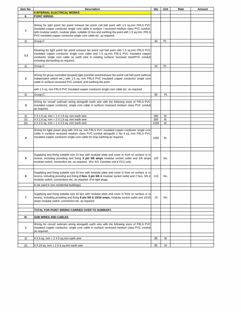
Item No. Description Qty Unit Rate Amount
II INTERNAL ELECTRICAL WORKS
II. POINT WIRING
1
Wiring for light point/ fan point/ exhaust fan point/ call bell point with 1.5 sq.mm FRLS PVC
insulated copper conductor single core cable in surface / recessed medium class PVC conduit,
with modular switch, modular plate, suitable GI box and earthing the point with 1.5 sq.mm. FRLS
PVC insulated copper conductor single core cable etc. as required.
(i) Group-C 40 Pt.
1.1
Rewiring for light point/ fan point/ exhaust fan point/ call bell point with 1.5 sq.mm FRLS PVC
insulated copper conductor single core cable and 1.5 sq.mm FRLS PVC insulated copper
conductor single core cable as earth wire in existing surface/ recessed steel/PVC conduit
including dismantling as required.
(i) Group-C 20 Pt.
2
Wiring for group controlled (looped) light point/fan point/exhaust fan point/ call bell point (without
independent switch etc.) with 1.5 sq. mm FRLS PVC insulated copper conductor single core
cable in surface/ recessed PVC conduit, and earthing the point
with 1.5 sq. mm FRLS PVC insulated copper conductor single core cable etc. as required
(i) Group-C 56 Pt.
3
Wiring for circuit/ submain wiring alongwith earth wire with the following sizes of FRLS PVC
insulated copper conductor, single core cable in surface/ recessed medium class PVC conduit
as required.
(i) 2 X 1.5 sq. mm + 1 X 1.5 sq. mm earth wire 300 M.
(ii) 4 X 1.5 sq. mm + 2 X 1.5 sq. mm earth wire 300 M.
(iii) 2 X 2.5 sq. mm + 1 X 2.5 sq. mm earth wire 2100 M.
4
Wiring for light/ power plug with 2X4 sq. mm FRLS PVC insulated copper conductor single core
cable in surface/ recessed medium class PVC conduit alongwith 1 No 4 sq. mm FRLS PVC
insulated copper conductor single core cable for loop earthing as required. 1500 M.
5
Supplying and fixing suitable size GI box with modular plate and cover in front on surface or in
recess, including providing and fixing 3 pin 5/6 amps modular socket outlet and 5/6 amps
modular switch, connection etc. as required. (For A/C Cassette unit & FCU unit)
120 No.
6
Supplying and fixing suitable size GI box with modular plate and cover in front on surface or in
recess, including providng and fixing 2 Nos. 3 pin 5/6 A modular socket outlet and 2 Nos. 5/6 A
modular switch, connections etc. as required. (For light plugs
110 No.
to be used in non residential buildings).
7
Supplying and fixing suitable size GI box with modular plate and cover in front on surface or in
recess, including providing and fixing 6 pin 5/6 & 15/16 amps, modular socket outlet and 15/16
amps modular switch, connection etc. as required.
10 No.
TOTAL FOR POINT WIRING CARRIED OVER TO SUMMARY.
III. SUB WIRES AND CABLES
1
Wiring for circuit/ submain wiring alongwith earth wire with the following sizes of FRLS PVC
insulated copper conductor, single core cable in surface/ recessed medium class PVC conduit
as required.
(i) 4 X 6 sq. mm + 2 X 6 sq.mm earth wire 85 M
(ii) 4 X 10 sq. mm + 2 X 6 sq.mm earth wire 85 M
49
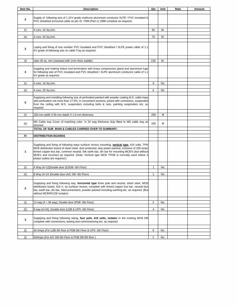
Item No. Description Qty Unit Rate Amount
2Supply of following size of 1.1KV grade multicore aluminium conductor XLPE / PVC insulated &
PVC sheathed armoured cable as per IS: 7098 (Part-1) 1988 complete as required.
(i) 4 core, 16 Sq.mm. 60 M.
(ii) 4 core, 25 Sq.mm. 75 M.
3Laying and fixing of one number PVC insulated and PVC sheathed / XLPE power cable of 1.1
KV grade of following size on cable Tray as required.
(i) Upto 35 sq. mm (clamped with 1mm thick saddle) 135 M.
4
Suppling and making indoor end termination with brass compression gland and aluminium lugs
for following size of PVC insulated and PVC sheathed / XLPE aluminium conductor cable of 1.1
KV grade as required.
(i) 4 core, 16 Sq.mm. 6 No.
(ii) 4 core, 25 Sq.mm. 6 No.
5
Supplying and installing following size of perforated painted with powder coating M.S. cable trays
with perforation not more than 17.5%, in convenient sections, joined with connectors, suspended
from the ceiling with M.S. suspenders including bolts & nuts, painting suspenders etc. as
required
(i) 150 mm width X 50 mm depth X 1.6 mm thickness 200 M
(ii)MS Cable tray Cover of matching color in 24 swg thickness duly fitted to MS cable tray as
directed.100 M
TOTAL OF SUB MAIN & CABLES CARRIED OVER TO SUMMARY.
IV DISTRIBUTION BOARDS
1
Supplying and fixing of following ways surface/ recess mounting, vertical type, 415 volts, TPN
MCB distribution board of sheet steel, dust protected, duly power painted, inclusive of 200 amps
tinned copper bus bar, common neutral, link earth bar, din bar for mounting MCB'S (but without
MCB's and incomer) as required. (Note: Vertical type MCB TPDB is normally used where 3
phase outlets are required.)
(i) 4 Way (4+12)Double door (ESDB -5th Floor) 1 No.
(ii) 8 Way (4+24 )Double door (A/C DB -5th Floor) 1 No.
2
Supplying and fixing following way, horizontal type three pole and neutral, sheet steel, MCB
distribution board, 415 V, on surface/ recess, complete with tinned copper bus bar, neutral bus
bar, earth bar, din bar, interconnections, powder painted including earthing etc. as required. (But
without MCB/RCCB/ Isolator)
(i) 12 way (4 + 36 way), Double door (PDB -5th Floor) 2 No.
(ii) 8 way (4+24), Double door (LDB & UPS -5th Floor) 4 No.
3Supplying and fixing following rating, four pole, 415 volts, isolator in the existing MCB DB
complete with connections, testing and commissioning etc. as required.
(i) 40 Amps (For LDB 5th floor & PDB-5th Floor & UPS -5th Floor) 6 No.
(i) 63Amps (For A/C DB-5th Floor & PDB DB 5th floor ) 2 No.
50
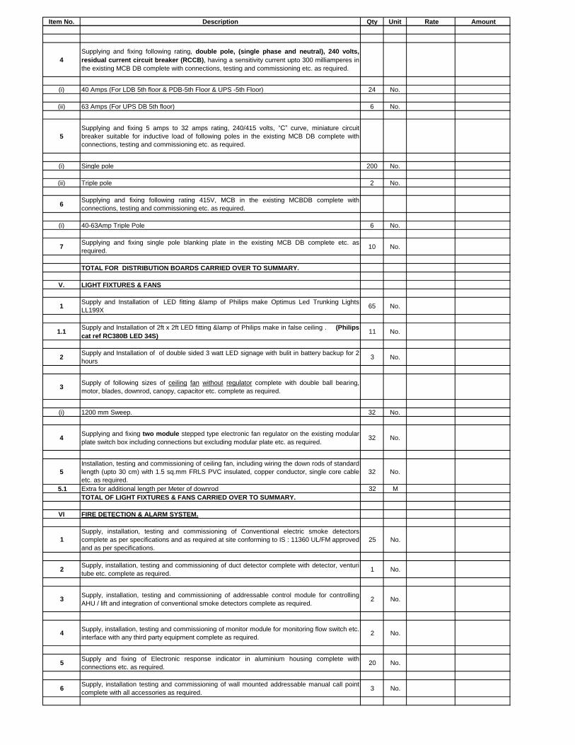
Item No. Description Qty Unit Rate Amount
4
Supplying and fixing following rating, double pole, (single phase and neutral), 240 volts,
residual current circuit breaker (RCCB), having a sensitivity current upto 300 milliamperes in
the existing MCB DB complete with connections, testing and commissioning etc. as required.
(i) 40 Amps (For LDB 5th floor & PDB-5th Floor & UPS -5th Floor) 24 No.
(ii) 63 Amps (For UPS DB 5th floor) 6 No.
5
Supplying and fixing 5 amps to 32 amps rating, 240/415 volts, “C” curve, miniature circuit
breaker suitable for inductive load of following poles in the existing MCB DB complete with
connections, testing and commissioning etc. as required.
(i) Single pole 200 No.
(ii) Triple pole 2 No.
6Supplying and fixing following rating 415V, MCB in the existing MCBDB complete with
connections, testing and commissioning etc. as required.
(i) 40-63Amp Triple Pole 6 No.
7Supplying and fixing single pole blanking plate in the existing MCB DB complete etc. as
required.10 No.
TOTAL FOR DISTRIBUTION BOARDS CARRIED OVER TO SUMMARY.
V. LIGHT FIXTURES & FANS
1Supply and Installation of LED fitting &lamp of Philips make Optimus Led Trunking Lights
LL199X 65 No.
1.1Supply and Installation of 2ft x 2ft LED fitting &lamp of Philips make in false ceiling . (Philips
cat ref RC380B LED 34S)11 No.
2Supply and Installation of of double sided 3 watt LED signage with bulit in battery backup for 2
hours3 No.
3Supply of following sizes of ceiling fan without regulator complete with double ball bearing,
motor, blades, downrod, canopy, capacitor etc. complete as required.
(i) 1200 mm Sweep. 32 No.
4Supplying and fixing two module stepped type electronic fan regulator on the existing modular
plate switch box including connections but excluding modular plate etc. as required.32 No.
5
Installation, testing and commissioning of ceiling fan, including wiring the down rods of standard
length (upto 30 cm) with 1.5 sq.mm FRLS PVC insulated, copper conductor, single core cable
etc. as required.
32 No.
5.1 Extra for additional length per Meter of downrod 32 M
TOTAL OF LIGHT FIXTURES & FANS CARRIED OVER TO SUMMARY.
VI FIRE DETECTION & ALARM SYSTEM.
1
Supply, installation, testing and commissioning of Conventional electric smoke detectors
complete as per specifications and as required at site conforming to IS : 11360 UL/FM approved
and as per specifications.
25 No.
2Supply, installation, testing and commissioning of duct detector complete with detector, venturi
tube etc. complete as required.1 No.
3Supply, installation, testing and commissioning of addressable control module for controlling
AHU / lift and integration of conventional smoke detectors complete as required.2 No.
4Supply, installation, testing and commissioning of monitor module for monitoring flow switch etc.
interface with any third party equipment complete as required.2 No.
5Supply and fixing of Electronic response indicator in aluminium housing complete with
connections etc. as required.20 No.
6Supply, installation testing and commissioning of wall mounted addressable manual call point
complete with all accessories as required.3 No.
51
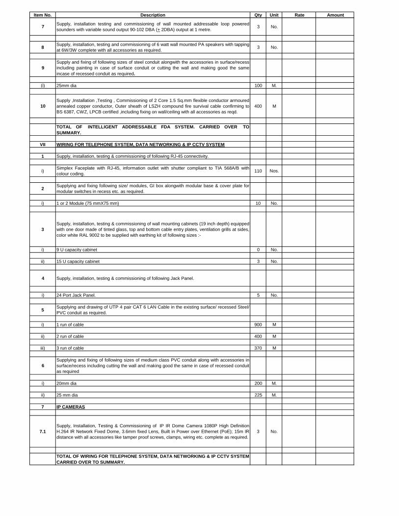
Item No. Description Qty Unit Rate Amount
7Supply, installation testing and commissioning of wall mounted addressable loop powered
sounders with variable sound output 90-102 DBA (+ 2DBA) output at 1 metre.3 No.
8Supply, installation, testing and commissioning of 6 watt wall mounted PA speakers with tapping
at 6W/3W complete with all accessories as required.3 No.
9
Supply and fixing of following sizes of steel conduit alongwith the accessories in surface/recess
including painting in case of surface conduit or cutting the wall and making good the same
incase of recessed conduit as required.
(i) 25mm dia 100 M.
10
Supply ,Installation ,Testing , Commissioning of 2 Core 1.5 Sq.mm flexible conductor armoured
annealed copper conductor, Outer sheath of LSZH compound fire survival cable confirming to
BS 6387, CWZ, LPCB certified ,including fixing on wall/ceiling with all accessories as reqd.
400 M
TOTAL OF INTELLIGENT ADDRESSABLE FDA SYSTEM. CARRIED OVER TO
SUMMARY.
VII WIRING FOR TELEPHONE SYSTEM, DATA NETWORKING & IP CCTV SYSTEM
1 Supply, installation, testing & commissioning of following RJ-45 connectivity.
i)Simplex Faceplate with RJ-45, information outlet with shutter compliant to TIA 568A/B with
colour coding.110 Nos.
2Supplying and fixing following size/ modules, GI box alongwith modular base & cover plate for
modular switches in recess etc. as required.
i) 1 or 2 Module (75 mmX75 mm) 10 No.
3
Supply, installation, testing & commissioning of wall mounting cabinets (19 inch depth) equipped
with one door made of tinted glass, top and bottom cable entry plates, ventilation grills at sides,
color white RAL 9002 to be supplied with earthing kit of following sizes :-
i) 9 U capacity cabinet 0 No.
ii) 15 U capacity cabinet 3 No.
4 Supply, installation, testing & commissioning of following Jack Panel.
i) 24 Port Jack Panel. 5 No.
5Supplying and drawing of UTP 4 pair CAT 6 LAN Cable in the existing surface/ recessed Steel/
PVC conduit as required.
i) 1 run of cable 900 M
ii) 2 run of cable 400 M
iii) 3 run of cable 370 M
6
Supplying and fixing of following sizes of medium class PVC conduit along with accessories in
surface/recess including cutting the wall and making good the same in case of recessed conduit
as required
i) 20mm dia 200 M.
ii) 25 mm dia 225 M.
7 IP CAMERAS
7.1
Supply, Installation, Testing & Commissioning of IP IR Dome Camera 1080P High Definition
H.264 IR Network Fixed Dome, 3.6mm fixed Lens, Built in Power over Ethernet (PoE); 15m IR
distance with all accessories like tamper proof screws, clamps, wiring etc. complete as required.
3 No.
TOTAL OF WIRING FOR TELEPHONE SYSTEM, DATA NETWORKING & IP CCTV SYSTEM
CARRIED OVER TO SUMMARY.
52
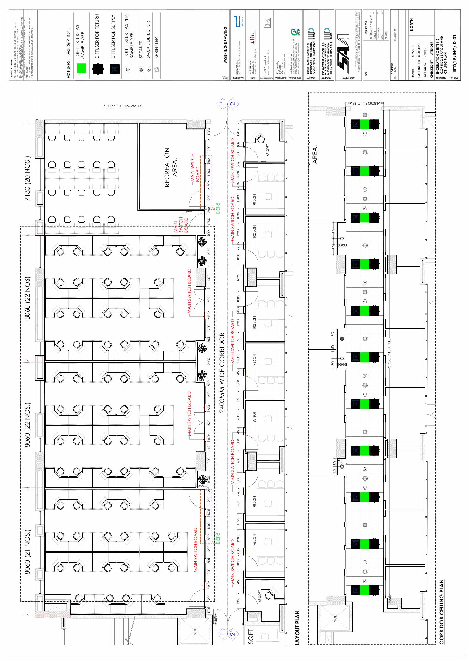
53
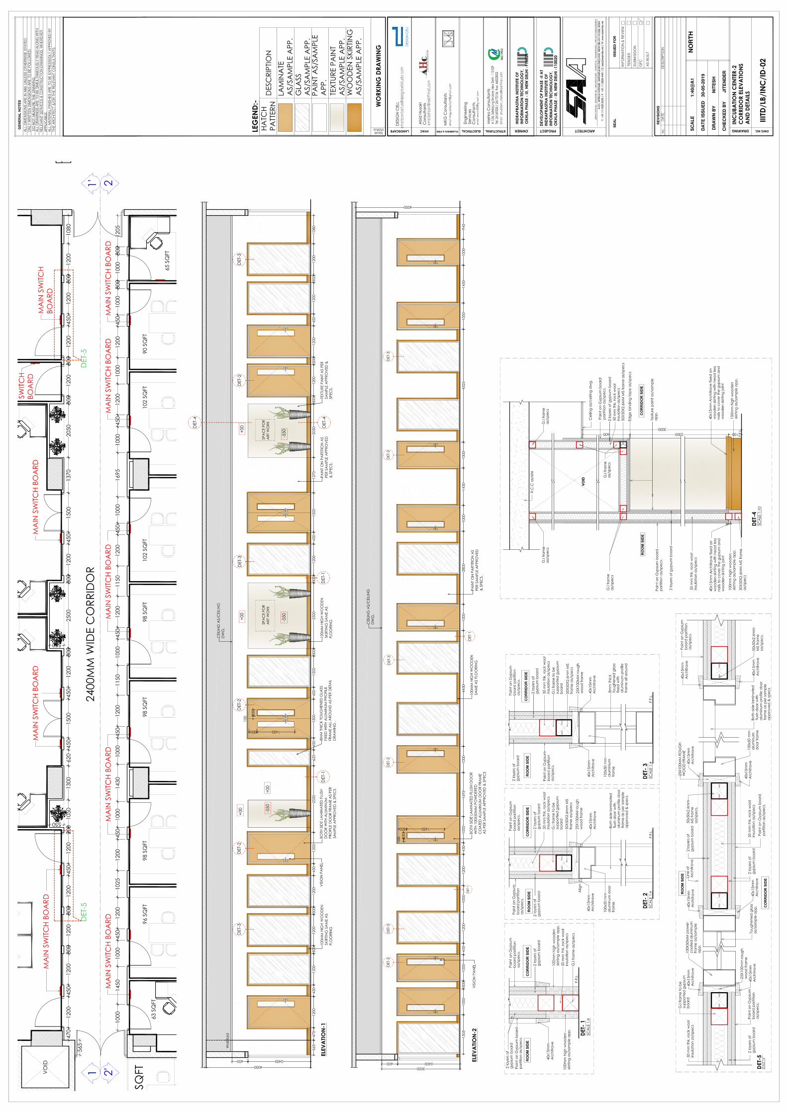
54


