Embed Size (px)
Citation preview

Louisiana State UniversityLSU Digital Commons
LSU Agricultural Experiment Station Reports LSU AgCenter
1916
Tests of the power and steam consumption of sugarfactoriesEugene Wycliffe Kerr
Follow this and additional works at: http://digitalcommons.lsu.edu/agexp
This Article is brought to you for free and open access by the LSU AgCenter at LSU Digital Commons. It has been accepted for inclusion in LSUAgricultural Experiment Station Reports by an authorized administrator of LSU Digital Commons. For more information, please [email protected].
Recommended CitationKerr, Eugene Wycliffe, "Tests of the power and steam consumption of sugar factories" (1916). LSU Agricultural Experiment StationReports. 652.http://digitalcommons.lsu.edu/agexp/652

Louisiana Bulletin No. 1 58. September, 1916.
Agricultural Experiment Station
OF THE
Louisiana State University and
A. & M. College,
BATON ROUGE
TESTS OF THE
Power and Steam Consumption
OF
Sugar Factories
E. W. KERR, M. E.,
Professor of Mechanical Engineering, Louisiana State University,
ASSISTED BY
W. A. ROLSTON, B. S., and S/J. WEBRE, B. S.
Baton Rouge, La.
Ramires-Jones Printing Co.
1916

TESTS OF THE POWER AND STEAM CON-
SUMPTION OF SUGAR FACTORIES.
INTRODUCTION.
In designing sugar factories that will give the maximum of
fuel economy, it is important to have at hand data regarding the
consumption of power and steam. An especially important item
is the ratio of exhaust steam to total boiler steam. In fact, the
question of the advisability of using pre-evaporators, vacuum
juice heaters, and thermo-compressors depends upon this ratio.
In other words, the size and arrangement of heating and evap-
orating apparatus—also the boiler plant—depends upon the
amount of exhaust steam available. For example, it would not
be advisable to use a quadruple effect where there is already an
amount of exhaust steam in excess of that which would be re-
quired to operate a triple effect. There is a considerable differ-
ence of opinion as to the relative merits of different kinds of
power distribution, such as direct steam drive, line shafting with
centrifugal or power pumps driven by a central steam engine, di-
rect electric motor drive, etc.
This bulletin contains data which has been secured during the
last four years with the view of supplying information of the
kind outlined above in so far as it has been possible. During the
period of time mentioned this department has confined its experi-
ments to two lines, namely, tests on heating and evaporating
apparatus and tests on bagasse furnaces and boilers. Some of the
results of the first line of work mentioned have been given in
Louisiana Bulletins 138 and 149. In connection with these ex-
periments, which were mostly of a research nature, it was com-
paratively easy to secure the data recorded in the present bul-
letin. The data in this bulletin were obtained at three typical,
modern sugar factories, namely, the Adeline Sugar Factory Com-
pany, Adeline, Louisiana; the Guanica Central, Ensenada, Porto
Rico ; and Florida Central, Florida, Cuba.
The Adeline factory was designed to handle 1500 tons of
cane per day to make white sugar and molasses of a grade suit-
able for table consumption. The sulphitation process of clari-

4
fication is used. This system is practically the same as that com-monly practiced in Louisiana, except that juices and syrup are
filtered several times. In this respect the process is similar to
that used in beet sugar manufacture. Most of the pumps in
this factory are of the centrifugal type and operated throughline shafting and belting from a Corliss engine, which also oper-
ated the centrifugals.
The capacity of Guanica Central is about 4500 tons per day,
the product being raw sugar of 96 test. Most of the engines and"
pumps are direct steam driven, though a few of the pumps, the
centrifugals, and the different conveyors are driven by electric
motors.
Central Florida was designed to grind 1000 tons of cane
per day, the product being 96 test raw sugar. All of the machin-
ery, including the mills, in this house are driven by electric
motors.
It may be well to state why these three particular factories
were selected for these experiments. In the first place, such data
is very difficult to obtain, and the expense is considerable. Fewhouses are arranged so that it is possible to secure such data
under any circumstances. The three factories selected were all
unusually well supplied with instruments and apparatus neces-
sary for measuring the different quantities which it was necessary
to measure. In addition to this, the management in each case
was not only willing to furnish permission to carry on the experi-
ments but assistance in preparing and making the tests as well.
The writer desires to acknowledge with thanks the cooperation
of the managements of the three factories at which these data
were secured. Among these may be mentioned in particular Mr.B. O. Sprague, superintendent of the Adeline Sugar Factory;
Messrs. A. J. Grief and F. T. Maxwell, vice-president and gen-
eral manager and superintendent of fabrication, respectively, at
the Guanica Central; and Mr. William Bancroft, president of
Dibert, Bancroft & Ross Company, which designed Florida Cen-
tral and furnished most of its machinery.

5
EXPERIMENTS AT ADELINE.
OBJECT OF THE EXPERIMENTS.
The object of the tests at Adeline was to obtain data that
would make it possible to construct a steam balance of the fac-
tory; that is, to determine the amount of steam generated in the
boilers and the amounts of this steam used at the different sta-
tions throughout the factory.
FACTORY EQUIPMENT AND PROCESS.
As stated heretofore, the factory was designed to work 1500
tons of cane per 24 hours, though this capacity has seldom been
attained in actual operation. The factory building has the shape
of the letter "L," with the boiler room forming the L. The mill
room is 68' wide x 112' long. The boiler room is68' 'by 154'.
The clarification house is 80' wide x 120' long and contains two
galleries along one side of the building and across the end. one
above the other, and a small stage at one end above the top gal-
lery. The boiling house is 80' wide x 56' long x 48' high to the
eaves. The boiling house has two full floors above the ground
floor and a gallery for tanks and for supporting a sugar storage
hopper. The distance from the boilers to the vacuum pans is
approximately 260', to the evaporators 220', and to the heaters
120'. The cane is supplied to the mill carrier by means of a
Walsh rake and three cane derricks of the grab type. These
hoists are approximately 350' from the boilers. The distance is
so great that the steam from the hoisting engines is exhausted
to the atmosphere, no attempt being made to conduct it back to
the factory and use it.
As stated, the sulphitation process is used with several nitra-
tions of juice and syrup. Figure 1 shows graphically the prin-
cipal steps of the process. Figure 2 shows the method of handling
condensation and returning it to the boilers. There are four
boiler feed pumps, three of which are of the automatic receiver
type, the other without a receiver. There are two vacuum pans,
the condensation from which is removed by two of these auto-
matic receiver pumps. One of the raw juice heaters operates
with live steam and the other with exhaust steam. A large por-

6

I
bo

8
tion of the feed water naturally comes from these raw juiceheaters. There are also two thin juice and two thick juice heat-ers, though only one of each is operated at one time under normalrunning conditions. Automatic receiver pump, No. 3, handlesall of the condensation except that from the two vacuum pans.This includes condensation from the raw juice heaters, the thinjuice heaters, the thick juice heaters, the steam engine separators,
and the first bodies of the evaporators; also the drips from thehigh pressure steam lines. Each of these different lines drainsinto a trap and the traps discharge through separate lines intothe header above the receiver of pump No. 3. The traps for theraw juice heaters are located on the ground floor below the level
of the header, each trap having a live steam connection for dis-
charging.
In order to provide for flash from the vapors coming from the
condensation leaving the live steam raw juice heaters, a flash
drum is provided as shown. The raw juice heaters are so con-
nected that condensation from the exhaust heater can always beby-passed around the trap directly to the header. The condensa-tion from the live steam heater passes through the relief valveinto the flash drum and from there to the header, where it mixeswith the condensation from other sources. From the top of this
flash drum a flash connection is made to the exhaust steam mains.At one end of this drum there is an outlet with float-operated
valve so that water can not rise above a certain height in thedrum. This prevents water from getting into the exhaust main.By means of this drum all disturbances of the kind mentionedabove are prevented, the liberated flash being utilized along withthe exhaust steam in the evaporators and other apparatus usingexhaust steam. The make-up feed water is handled by pumpNo. 4, which draws from an open tank outside of the boiler room.The water in this tank is condensation coming from the secondand third bodies of the evaporators. There is also an overflowinto this tank from the header described above, which operatesoccasionally when the supply of condensation is greater than the
boiler feed requirements at the time. This make-up feed water,coming from the tank, passes through a closed feed water heaterheated by live steam.

9
For a list of the principal apparatus contained in the factory,
see Appendix A. The two 13' vacuum pans of the express type
are operated with an average steam pressure of 30 pounds gauge,
requiring live steam most of the time. However, at the beginning
of a strike, exhaust steam is occasionally used. There are no direct
acting steam pumps in the factory with the exception of boiler
feed pumps and a few others, the majority of the pumps being of
the centrifugal type operated through belting and line shafting
from a single Corliss engine. The water supply for the factory is
taken from Bayou Teche, which is approximately 150' from the
boiling house where the condensers are located. The lift from the
surface of the water in the bayou to the ground floor of the fac-
tory is approximately 10 feet. The water is pumped into a stand-
pipe 5' in diameter by means o fa 12" centrifugal pump, driven
from the line shaft heretofore mentioned and lifted a height of
approximately 60' above the ground floor. This standpipe sup-
plies injection water to the condensing system, this condensing
system being of a special central type. Each of the quadruple
effects and vacuum pans is served by an individual condenser, but
the air pipes from each condenser are connected to a central con-
denser, from which a single vacuum pump of the rotative dry
vacuum type pumps the air and other incondensable gases.
Each individual condenser has its own injection water supply
under control.
All steam pipes and containers in the factory are well covered
with insulating material. A large portion of the hot liquid pipes
and containers, however, are uncovered. On account of the large
number of nitrations with intermediate reheatings, also on ac-
count of the large amount of remelting, the steam consumption
with this process is considerably greater than with the process
commonly practiced in Louisiana.
PROCEDURE IN MAKING THE EXPERIMENTS.
The principal steam consuming stations in the house are as
follows: (1) raw juice heaters; (2) thin juice heaters
; (3) thick
juice heaters; (4) feed water heater
; (5) quadruple effects; (6)
vacuum pans; (7) granulators; (8) cane hoisting engines; (9)

10
syrup blow-ups; (10) syrup melters; (11) molasses melters
; (12)mud defecators; (13) steam power; (14) radiation and un-accounted.
The general procedure in making the steam balance was to
determine (a) the total steam generated by means of boiler tests;
(b) the steam consumed at stations 1 to 14, inclusive; (c) sub-tracting the steam consumed (b) from the steam generated (a) toget radiation and unaccounted for (c). In determining (a) thefeed water was measured by means of a recording Venturimeterwhich was a permanent part of the factory equipment. Thesteam pressures and feed water temperatures were found bymeans of recording apparatus, also part of the factory equip-ment. The steam quality was determined by means of a specialthrottling calorimeter. In determining items 1 to 7, inclusive, of(b) the thermal efficiency in percent was first found in each caseby one or more individual tests, in which the condensation wasweighed and pressures, temperatures and other necessary observa-tions made. The results of many of these individual tests aregiven in Louisiana Bulletin 149. Next, the weight of the producthandled by each apparatus per ton of cane was found by weighingor by calculation. With these data known, the heat required andthe corresponding weight of steam was calculated. The steam con-sumption for items 8 to 12, inclusive, was determined directlyby means of steam orifices. Item 13 (steam for power purposes)was found through I. H. P. tests of the steam engines and pumpsin the house. With the total I. H. P. known, the equivalent heat(B. T. U.) and weight of the boiler steam were calculated. Thetests upon which the steam balance was based covered the periodfrom 7 a. m., December 2, 1915, to 11 a. m,, December 11, 1915.However, some of the individual tests for thermal efficiency andsteam consumption per unit of work done were made during the
1911 and 1913 seasons. During the period of the tests a recordwas also made of the oil fuel burned, which gave the data neces-sary for calculating the fuel cost at each station.
All instruments, such as thermometers, pressure gauges,vacuum gauges, etc., used in the experiments were carefully
calibrated. The temperatures referred to in this 'bulletin are inall cases according to the Fahrenheit scale.

11
Steam Balance.
Period covered, from 7 a. m., December 2, 1915, to
11 a. m., December 11, 1915.
Total time, hours 210.75
Total cane ground, tons 12,144.58
Cane ground per hour, tons 57.62
Cane ground per 24 hours, tons 1,383
Raw Juice Heaters.
Total mixed juice, tons (juice scales) 11,188.23
Mixed juice per ton of cane, tons .9213
Mixed juice per ton of cane, lbs 1,842.6
Mixed juice per 24 hours, tons 1,274.17
Temperature juice entering raw juice heaters 82
Temperature juice leaving raw juice heaters 201
Heat added=(201 — 82) X .914 X 2,548,340 = (B. T. Us. per
24 hrs.) 277,182,941.8
(B. T. Us. per hr.) 277,182,941.8 -=- 24 11,549,289
Equivalent lbs. water F. & A. 212°, 11,549,289 -f- 970.4 11,901
Efficiency (Thermal) of raw juice heaters, % (from indi-
vidual tests) 95
11901
Steam F. & A. 212° (actual), lbs. = 12,527.9
.95
Steam F. & A. 212° (actual), % on cane 10.87
Equivalent steam at boiler pressure of 100 lbs. gage, feed wa-ter temperature 231° and steam quality 96% (boiler con-
ditions) 10.87 = 10.66%
1.02
U188.8 — 199.2 989.6
factor of evaporation, = = 1.02
970.4 970.4
Thjn Juice Heaters.
"Rx. of mixed juice 13.19
Bx. of thin juice 13.42
Mud in mixed juice, lbs. per ton of cane (by test) 22.23
Total mud per day, lbs., 1383 X 22.23 30,744
Total mud per day, tons 15.372
Mixed juice, less mud tons, 1272 — 15.372 1,258.8
13.42 — 13.19
Water lost, % on mixed juice (without mud) = 1.714
13.42
Water lost tons, 1258.8 X .01714 = 21.58
Thin juice per day, tons = 1258.8 — 21.58 = 1.237.22
1237.22 X 100
Thin juice % on cane. = 89.46
1383.01
Specific heat corresponding to 13.42 Bx -912

12
Temperature juice entering thin juice heater 180Temperature juice leaving thin juice heater 20SHeat added B. T. U. per 24 hrs.
(203— 180) X .912 X 1237.22 X 2000 = 51,924,829
Heat added per hr. B. T. U 2,163,534
2,163,534.5
Equivalent steam F. & A. 212°, lbs. = 2229.5
970.4
Thermal efficiency, % (from individual tests) 92
2229.5
Steam F. & A. actually required, lbs. = 2,423.4
.92
Equivalent steam F. & A., actually required, % on cane 2.103
2.103
Equivalent steam, boiler conditions, % on cane, = . . . . 2.06
1.02
Thick Juice Heaters.
Brix of evaporator thick juice 56.21Brix thin juice 13.42
56.21 — 13.42
% Evaporation = == 76.13
56.21
Water evaporated in quads, tons per day, 1237.2 X .7613 = . . 941.8Thick juice, tons per days, 1237.2 — 941.8 = 295.4
295.4
Thick juice, % on cane = 21.36
1383
Specific heat, thick juice .633
Temperature juice entering 132.1
Temperature juice leaving 207Heat added, B. T. U. per 24 hrs.,
(207 — 132.1) x -633 x 295.4 X 2000 = 28,048,230
Heat added, per hr., B. T. U 1,168,676
Equivalent of heat added, lbs. -steam F. & A. 212° per hr.,
1,168,676
= 1,204
970.4
Efficiency % (by individual test) . ... 82
1204Steam F. & A. 212° actually required, lbs. per hr., = . . . 1,468
82
Equivalent steam F. & A. 212° actually required, % on cane. 1.274
Equivalent, steam, boiler conditions, % on cane 1.249
Quadruple Effect.
Thin juice, tons per day 1,237.22
Thick juice, tons per day 295.40
Water evaporated, tons per day 941.82
Water evaporated per lb. of steam, lbs. (by test) 3.637
Steam pressure, 1st Calandria, lbs., gage 3.60
941.82 X 2000Steam per day, lbs. = = 517,824
3.637

18
517,824
Steam per day, tons, = =2000
258.912
Steam, % on cane= =1383
963
Steam, F. & A. 212% % on cane, IS. 72 X970.4
18.57
-Equivalent steam, boiler conditions, = • •
1.02
Vacuum Pans
Brix of standard syrup (calculation)
52.2 — 13.19
% decrease in water content' 52.2
Decrease in water content, tons per day, 1258.8
Standard syrup, tons per day, 1258.8-^940.7..
318.1
Standard syrup, 9c on cane;
258.912
18.72
18.57
18.21
74.7
X.7473 940-71
318.1
23.00
1383
Molasses (actual measurement.).
Molasses, tons during period
157.35
Molasses, per ton of cane, tons, =12,144.58
Molasses, per day, tons, 13S3X.0129=Wash, tons during period (actual measurement)
1,230.1
Wash per ton of cane, tons, =12,144.58
Wash per day, tons, 1383.01 X .10128 =Brix of massecuite
Brix of standard syrup
95.5— 52.2
% Evaporation = —95.5
Water evaporated, tons per day, 31S.1 X 4534 ^J**-
Massecuite per day from syrup, tons, 318.1 — 144.3 -
Brix of molasses
95.5 — 76.5
% Evaporation = =95.5
Water evaporated, tons per day= 17.92 X .99 -
Massecuite per day from molasses, tons, 17.92 — 3.57 —
Brix of wash
95.5 — 75.0
% Evaporation =95.5
157.35
.0129
17.92
1,230.1
.1012!
140.07
95.5
52.2
45.34
76.5
19.90
3.566
4.3;
75.0
21.4^

14
Water evaporated, tons per day, 140.07 X .2147 30.07Massecuite per day from wash, tons, 140.07 — 30.07 = 110^00Total massecuite per day, tons, 173.8 + 14.35 + 110.0 = 298.15
298.15Massecuite per ton of cane, tons, = 2156
1383
Massecuite, % on cane 2156Total syrup, molasses and wash per day, tons,
318.1 + 17.92 + 140.07= 476.09Total massecuite per day, tons 298 15Total water evaporated in pans per day, tons 177.94Water evaporated per lb. of steam, lbs. (by individual tests) .
0*85
177.94Steam per day, tons, — 209 34
0.85
209.34Steam, % weight on cane, = 15.14
' 1383
15.14 X 928.15Equivalent steam F. & A. 212° % on cane, — 14.43
970.4
14.48Equivalent steam, boiler conditions, = 14.20
1.02
Granulator.Condensed steam on raw juice, % 572Condensed steam on cane, % .572 X .9213 = .527Steam pressure, lbs., gage
. 71>0Steam F. & A. 212°, % cane, .527 X 896.6
= .49
970.4
.49
Equivalent steam, boiler conditions, %, = .48
1.02
Feed Water Heater.Steam condensed per 24 hours (by individual test), lbs. .... . 74,385.0Steam condensed per 24 hours (by individual test), tons 37.19Pressure of steam, lbs., gage 11.7
37.19 X 950Steam F. & A. 212°, tons, = 36.41
970.4
36.41
Steam F. & A. 212°, % on cane, 2.63
1383
2.63Equivalent, steam, boiler conditions, % on cane, = . . . . 2.58
1.02
Steam Orifices.
Table 1 gives the steam consumption at a number of stations
as dete: ~nined by means of steam orifices. The orifices were innearly all cases about 14" long with sharp edges. Observations

15
of the steam pressure entering and leaving were made and the
steam flow per hour determined by means of the formula :
CAP* 97
F = where
60 V"x~
C = A constant, the value of which depends upon the ratio of initial to
final pressure.
A = Area of orifice, sq. in.
P = Initial absolute pressure of steam, lbs. per sq. in.
x = Quality of steam = .96.
The values of C were determined by methods and data given in Moyer's Steam
Turbines and Thomas' Steam Turbines.
TABLE 1.
Steam Measured by Means of Orifices.
a? 6
X o090 a u < kM
Statiox & in- - a - a o
n-i
o
r.
_ DO
o=
o sg
—* -m -
~ 3 > >
Mud Defecators .... 92.1 82.0 9/16 1 .539 .248 0.6T
Syrup Blow-ups. . . . 89.1 74.1 9/16 .644 .248 925 0.80
Thick Juice Melters 95.2 90.0 1/2 .382 .196 ' 318 0.34
Molasses Melters. . . 96.5 94.8 1/2 .28j
.196 318 0.28
1347 1.16
Cane Handling Ma-chinery 95.4 84.8 1.0 .539
|.785
1
2448 2.16
TABLE 2.
Mechanical Energy.
I. H. P., Steam Engines and Pumps.
Crusher
First, second and third mills
Fourth mill
Vacuum pumpCentrifugals, centrifugal pumps, etc,
Bagasse drag
Raw juice pumpMill well pumpBoiler feed pumps
48.55
377.64
135.72
55.10
255.04
5.21
16.00
6.18
7.82
Total I. H. P. 90 7.26
Total work, ft. lbs. per minute, 907.26 X 33,000 = 29,939,580.0
Total work, ft. lbs. per hour, 29,939,580 X 60 = 1,796,374,800
Equivalent heat B. T. U. per hour, 1,796,374,800 -f- 778.0 =Equivalent steam F. & A. per hour, lbs., 2,308,965 -r 970.4 =
Equivalent steam F. & A., % on cane
2.06
on cane, =1.02
Equivalent steam, boiler conditions,
2,308,965
2,379.4
2.06
2.02

16
Boiler Feed Water.Feed water per hour lbs. ( Venturimeter) 80,295.6Peed water, per 24 hours, lbs., 81,295.6 X 24 = 1,951,094.4
1,951,094.4
Peed water per 24 hours, tons, — 975.52000
975.5
Peed water, % on cane, = 70.5381383
Average boiler pressure, lbs. gage 100.00Average feed water temperature 231.00
.7053 X 1.02 X 1383 X 2000Boiler H. P. = 2,420
24 X 34.5
2420Boiler H. P. per ton of cane per 24 hours, •- = I.74
1383
Summary.
TABLE 3.
Adeline Steam Balance.
03
O Tot
S3O c
0
' wam, S<X> CD 0w w PQ
70.54 100 2420.0Raw juice heaters 10.66 15.10 365.0Thin juice heaters 2.06 2.92 71.0Thick juice heaters 1.25 1.77 43.0
18.21 25.82 625.0Vacuum pans 14.20 20.13 486.0
0.80 1.13 27.0Granulators 0.48 .68 17.0Oil burners 1.16 1.65 40.0Cane handling machinery 2.16 3.06 74.0
0.34 .48 12.0Molasses melters 0.28 .40 10.0Mud defecators -. 0.67 .95 23.0
2.58 3.66 89.0
2.02 2.86 69.0Radiation and unaccounted 13.67 19.39 469.0

17
Fuel Costs.
Table 4 gives the estimated fuel cost to be charged to each of
the stations, including radiation. The following shows the. meth-
od used for calculating the fuel cost charged to the raw juice
heaters. The same method was used for the other stations
:
Oil used, bbls 12 30.87
1230.87 X 42
Oil used, gals, per ton cane, = 4 - 26
,12,144.6
Price of oil per bbl. (assumed), dollars 1 -00
Steam consumed by raw juice heaters, % on boiler steam (Table 3) . .15.10
Equivalent oil, raw juice heaters, bbls., .151 X 1230.87 = 186.00
Equivalent oil, raw juice heaters, in dollars, 186.00 X 1.00 = 186.00
Total radiation loss in factory, % on boiler steam 19-39
Equivalent oil, bbls., 1230.87 X .1939 = - 238.54
Radiation loss charged to raw juice heaters, bbls. of oil,
15.1
X 238.54 44 - 70
(100 — 19.38)
Value of oil charged to heaters, dollars, = 186.00 + 44.70= 230.70
230.7
Value of oil consumed by heaters per 1000 tons cane, = $18.99
12.144
TABLE 4.
Fuel Costs.Fuel Costper 1000Tons ofCane
% 18 99Raw juice heaters *
Thin juice heaters 3 - 68
Thick juice heaters2,23
Quadruple effects"• 32 ' 47
25 32Vacuum pans .
Syrup blow-ups 1-43
Granulator °-*6
9 07Oil burners
Cane handling machinery 3 - 85
Syrup melters u
0.50Molasses melters. . .
Mud defecators
Feed water heaters.
Mechanical energy..
1.20
4.56
3.69
Total $101.46

18
HEAT LOSSES FROM HOT LIQUID LINES
AND CONTAINERS.
During the 1911 season, observations were made at Adelinecovering a period of 24 hours, the object of which was to secure
data from which the heat losses, including radiation from liquid
lines and containers, could be calculated. The calculation of
these heat losses was based on the weight of the product handledat each station and the loss in temperature between any twopoints. The temperature observations made during the 24 hourperiod are shown on the process diagram, Figure 1. The weights
of products involved were for the operating conditions of the
1911 season and are therefore different from those of 1915 used
in making out the heat balance given above.
To show the method of calculating the heat losses, the follow-
ing calculation for the loss of heat between the thin juice heaters
and leaving the Danek niters, is given. Table 5 gives the results
of the observations therefrom.
TABLE 5.
Heat Losses From Liquid Lines and Containers.
(Adeline.)
3 s
d O
Loss of heat from thin juice between Deming separatorsand leaving bag filters 31.0 2.59 82.6
Loss of heat between thin juice heaters and leaving
9.0 .675 21.5Radiation loss in pipe line between Danek filters and
4.0
12.0
20.0
.300
.209
.352
9.6
Radiation loss in thick juice bag niters 6.7
11.2Loss between bag filters and syrup heaterLoss between thick juice heater and leaving thick juice
Danek filters 10.0
2.0
7.3
.176
.036
.128
5.6
1.2
4.1
Radiation loss between thick juice Daneks and vacuum17.0 .300 9.6
4.76 151.9

19
It may be well to call special attention to the first item in the
above table, namely, the loss of heat from the thin juice between
the Deming separators and leaving the bag filters. It will be
noted that the temperature drop was 31°. This drop was not
due to radiation but to the reduced pressure of the hot juice on
leaving the closed Deming separators. In other words, when
the juice under pressure was released into the bag filters, the
temperature dropped to 212°, and a loss of heat through vapor-
ization occurred. By referring to the heat balance heretofore
given it will be noted that this loss was avoided by heating the
juice in the raw juice heaters to 212° or less.

20
EXPERIMENTS AT GUANICA CENTRAL.OBJECT OF THE EXPERIMENTS.
The object of the experiments at Guanica was similar to thatat Adeline, except that the steam consumed only could be deter-mined. On account of the particular conditions it was not pos-sible to measure the steam generated by the boilers.
FACTORY EQUIPMENT AND PROCESS.
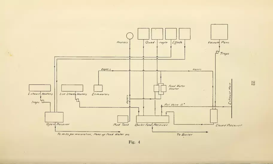
As stated heretofore, the factory is supposed to handle about4500 tons of cane per day when operating normally. There aretwo main departments in the factory organization, namely, theengineering department and the fabrication department, themilling plant being under the control of the former. The prod-ucts of the factory are 96 test raw sugar and low molasses. Theclarification system is of the closed Deming type. Figure 3 is aflow diagram which illustrates the process. It will be noted thatthree grades of massecuite are boiled, which are termed straight
strikes, mixed strikes, and crystallizer strikes. Figure 4 is a,
diagram of the method of handling hot condensation and return-ing same to the boilers. The vacuum pans operate under pres-sures of 80 to 100 pounds gauge, the evaporators under pressuresof approximately 3 to 5 pounds gauge, the exhaust heaters undera pressure of about one pound gauge, and the live steam heatersunder a pressure of about 12 pounds gauge. All of the conden-sation from these different sources used for feed water is deliv-
ered to a boiler feed receiver, from which hand-controlled direct-
acting feed pumps deliver it to the boilers. The quadruple effects
and the vacuum pans are situated some 40 feet above the boiler
feed receiver. From the top of the boiler feed receiver thereis a vapor line connecting to the exhaust main. In this line thereis a relief valve set at 15 pounds gauge, so that there will be apressure of 15 pounds gauge in the receiver. The condensationfrom the vacuum pans is discharged by traps into an auxiliaryclosed receiver with a vapor connection to the feed water heaterused for heating make-up feed water. The condensation is dis-
charged by gravity into the boiler feed receiver. The condensa-tion from live steam heaters is discharged, by traps, directly to

21
22

2-3
the boiler feed recover. As shown, the juice heaters us ng ex
haust steam, discharge their condensation by means of a trap to
an open receiver. The pressure in the exhaust heaters is seldom
Lch above atmosphere. The hot juice leaving the live steam
juice heaters usually has a temperature of 220°. On its way to
the Deming separators it is passed through eliminators consist-
ing in the main of closed drums with practically atmospheric
pressure in them. The object of these eliminators is to remove
and make possible the utilization of the heat in the juice above
212° This heat passes off in vapor, which mixes with that from
the auxiliary pan receiver and which is utilized in gating the
feed water or in pre-heating the juice entering one of the Lillie
evaporators and the Kestner evaporator, also in heating scums
in the mud tanks. At the time the tests were being made, the
average temperature of the boiler feed water leaving the boiler
feed receiver averaged about 227°.
As stated elsewhere, the evaporating plant consists of three
Lillie quadruple effects and one Kestner quadruple effect, each
with a rated capacity of 400,000 gallons of juice per day, also
six vacuum pans of the coil type, four of which are 12 m
diameter and two of which are 12' 6" in diameter. The aver-
age distance traveled by the condensation from the vacuum pans
the evaporators, and the heaters to the boilers is 540 feet, 550
feet, and 430 feet, respectively. The juice from the mill is
heated by four tubular heaters arranged in two sets, the first
set is heated by exhaust steam and the second set by live steam
about 70% of the work being done by the exhaust heaters. Most
of the pumps handling liquids in this factory are of the direct
acting steam type. Salt water is used for condenser injection.
It is first pumped to the factory by large centrifugal pumps
located at the water's edge. It is then lifted by reciproca ing
pumping engines of the fly wheel type to a small central tank m
the top of the factory, the total lift being approximately 70 feet
Each quadruple effect and each vacuum pan has its individual
condenser of the parallel current type. The injection water is
applied to these condensers from an injection water mam,
ihroucdi .branch lines controlled by valves. These condensers are
also connected to air mains served by a number of vacuum pumps,

24
some of which are of the rotative dry vacuum type and some ofthe slow speed, water sealed type. This factory has no hoistingapparatus outside of the factory, the railroad switches beingsuch as to allow the passage of cars through the mill room. Thisreduces the amount of hoisting to a minimum. All steam pipesand containers are thoroughly insulated with pipe covering. Thesame may be said of liquid lines and containers. In fact, thelatter is unusually well cared for.
A list of the principal apparatus comprising the equipmentof this factory will be found in Table 1, Appendix B.
PROCEDURE IN MAKING THE EXPERIMENTS.The principal steam consuming stations at this factory are
the three Lillie quadruple effects A, B, and C ; the Kestner quad-ruple effect; the vacuum pan work, which may be subdividedinto straight strikes, mixed strikes, and crystallizer strikes; thelive steam juice heaters, the exhaust steam juice heaters, theKestner juice heater, and steam power. The general procedurein carrying on the tests was much the same as that described forAdeline, namely, individual tests of steam consumption andthermal efficiency were made for the different stations and fromthese data, together with other general factory data from whichthe quantities handled at each, station were found, the steam con-sumption for the different stations was calculated. In making theindividual tests on the evaporators, vacuum pans, and heatersthe condensation was weighed on scales. Other necessary ob-servations of pressure, temperatures, etc., were also made. Thefactory is unusually well equipped with scales, Venturimeters,etc., for weighing or measuring cane, juice, etc. By means ofsuch equipment, the factory is able to maintain very completerecords of this quantity. The period covered was from the be-ginning of the season up to and including February 22, 1914, aperiod of about two months.
Results of the Tests.
Table 6 contains general factory data obtained from thelaboratory which has been used in the calculations.

25
TABLE 6.
General Factory Data Used in Calculating Evap-
orator and Vacuum Pan Tests.
(Guanica.)
Average for Period.
% Dilute juice on cane 107.5
Brix of dilute juice 13.34
% Syrup on cane 29.05
Brix of syrup 56.5
Weight of massecuite per strike, tons, average 49.4
Number of straight strikes 446
Number of mixed strikes 369
Number of crj^stallizer strikes 329
Cane ground, tons 261,702.6
Sugar Made, Tons 28,506.16
Table 7 contains other data used in the calculations which
were obtained through the individual tests.
TABLE 7.
Data From Individual Tests.
( Guanica.
)
Average, boiler pressure, lbs. gage 90
Quality of steam, % dry 98.5
Temperature boiler feed water 227.0
Factor of evaporation 1.009
Work done by Kestner evaporator, % of total 35.0
Work done by Lillie (A) 25.0
Work done by Lillie (B) 20.0
Work done by Lillie (C) 20.0
Water evaporated per lb. of steam, lbs.
—
Kestner evaporator 4.2 4
Lillie evaporator (A) 3.71
Lillie evaporator (B) 3.69
Average for all evaporators 3.93
Vacuum pans, straight strikes .845
Vacuum pans, mixed strikes .850
Vacuum .pans, crystallizer strikes .• .811
Average for all pan work .835
It may be well also to call attention to the fact that additional
data regarding these individual tests may be found in Louisiana
Bulletin 149.
In order to determine the amount of steam consumed for
power (mechanical energy) horse-power tests were made on most
of the engines, pumps, and motors in the house. It was not pos-
sible, however, to do this very accurately, especially for the elec-
tric motors, on account of the large number of them and the
difficulty of connecting up the electric measuring instruments.
Table 8 gives a list of the electric motors with rated H. P., also
developed H. P. where it was possible to obtain same.

26
TABLE 8.
H. P. of Motors (Guanica).
6 A Centrifugals •
1 A Mixer •
1 A Molasses pump1 No. 2 centrifugal scroll conveyor,
1 B Centrifugal
1 C Centrifugals
12 D Centrifugals
1 E Centrifugals
1 Old crystallizers
1 New crystallizer
1 Electric vacuum pump1 No. 2 Cross conveyor (Servell)..
1 No. 1 Cross conveyor, Sc
1 No. 1 washing machine
1 No. 2 washing machine
1 Kestner centrifugal feed pump . .
1 Hot juice pump1 Deming eliminator pump1 Murphy eliminator pump.
1 A Quad, centrifugal pumps1 B Quad, centrifugal pumps1 C Quad, centrifugal pumps1 Lime house
1 Main bagasse conveyor
1 Strainer tank
1 North end bagasse conveyor. . . .
1 South end bagasse conveyor
1 Cross bagasse conveyor
1 Climax bagasse conveyor
1 Main bagasse conveyor
1 Return bagasse conveyor
1 Magma pump1 Disintegrator
1 No. 1 salt water pump1 No. 2 salt water pump8 Hoist cranes .
4 Hoist cranes ^
2 Hoist sugar W. H1 Hoist sugar W. H
Total.
20
15
10
25
100
100
20
100
30
50
35
20
10
15
15
10
10
30
30
100
75
75
15
15
7.5
7.5
7.5
15
15
35
15
15
5
160
160
25
3.5
7.5
3
9.00
80.4
51.6
48.2
15
15
30
16.6
7.2
9.0
8.2
5.9
17.6
17.6
71.5
45.0
31.8
12
5.2
8.0
10.0
18.0
9
19
154
154
1359
In making up the total the " rated H. P." was used where the
"developed H. P." was lacking.
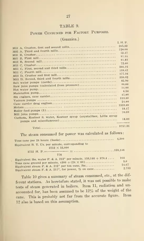
Table 9 gives a summary of th 3 power consumed for factory
purposes, including the 1359 H. P. for motors.
27
I. H. P.
265.32
220.00
TABLE 9.
Power Consumed for Factory Purposes.
(G-uanica.)
Mill A, Crusher, first and second mills
Mill A, Third and fourth mills
Mill B, Crusher.gi
'
8gMill B, First mill
91
'
g8Mill B, Second mill '
QQMill C, Crusher '
Mill C, First, second and third mills139 49
Mill C, Fourth mill 177*94Mill D, Crusher and first mill •
Mill D, Second, third and fourth mills • ••
Salt water pumps (cards) •
Raw juice pumps (calculated from pressure) |U.uv
Hot water pump ;'
Maceration pump..
Six engines, cane carrier •
318 00Vacuum pumps 24 00Cane carrier drag engines
1359*00Motors 18 17Boiler feed pumps (5)
20 00Mill juice pumps " * '
'
Cachaza, Kestner S. water, Kestner syrup (crystallizer, Lillie syrup^
pumps and miscellaneous)'
m -
,3752.36
Total
The steam consumed for power was calculated as follows
:
Tons cane per 24 hours (basis) 4,300
Equivalent B. T. Us. per minute, corresponding to
3752 X 33,000
3752 H. P.= = 159 '146
778
Equivalent lbs. water F. & A. 212° per minute, 159,146 -f- 970.4 .... 164
Tons cane ground per minute, 4300 -f- (24 X 60) 3.0
Equivalent steam F. & A. 212° per ton cane, lbs9 7I0
Equivalent steam F. & A. 212°, for power, % on cane 2.73 3
Table 10 gives a summary of steam consumed, etc., at the dif-
ferent stations. As heretofore stated, it was not possible to make
tests of steam generated in boilers. Item 11, radiation and un-
accounted for, has been assumed to be 12% of the weight of the
cane. This is probably not far from the accurate figure. Item
12 also is based on this assumption.

28
TABLE 10.
Summary of Steam Consumption Tests.
( Guardca.)
10.
n.
12.
EvaporatorsVacuum pans, straight
Vacuum pans, mixed.
.
Vacuum pan crystallizer
Vacuum pan average. . .
Live steam heaters ....
Exhaust steam heaters.
Kestner heater
Equivalent of mechan-ical work
Total accounted for in
factory
Radiation, and unac-counted, assumed . . .
Total delivered by boil-
ers t
* SCO CO
AOCD
116 H
rHne,
cd
O< <H
0
It n S
417.0
191.4
164.2
89.32
444.92
81.5
210.7
28.0
1182.12
413.7 410.0 20.68 28.2 .4985 2242.3192.7 191.0 9.63 13.17 .2323 1045.3164.87 163.4 8.24 11.02 .1887 849.1590.00 89.2 4.50 6.11 .1084 477.8
447.57 443.6 22.37 30.3 .5395 2427.781.4 80.7 4.07 5.52 .0977 439.6
208.6 206.7 10.43 14.16 .2512 1130.427.75 27.5 1.39 1.88 .0332 149.2
54.66 54.17 2.73 3.72 .0657 295.65
1233.68 1222.67 61.67 83.70 1.4859 6686.5
239.0 236.8 12.00 16.22 .2790 1246.0
1479.68 1459.47 73.67 100.00 1.7649 7932.5
I*
Ph CP
u
a oohM
IS
f Based on the assumed radiation and unaccounted for of 12%.Heat Losses From Hot Liquid Lines and Containers.A series of temperature measurements were made in a manner
similar to those at Adeline, the object of which was to get someinformation relative to heat losses from hot liquid lines and con-
tainers. The methods used in securing these data were similarto those described for Adeline. Table 11 gives the results ob-
tained from these observations.
TABLE 11.
(Gruanica.)
OCD
IID°o ^EH £
Steam,
Per
Weig-ht
oi
Per
Cent
(
(Approxir
Radiation loss, hot water lines .84
2.02
.082
.085
3.027
1.14
2.74
.11
.11
4.10
Radiation loss, juice lines and tanksRadiation loss, syrup lines and tanksRadiation loss, molasses lines and tanksTotal, hot liquid containers

29
EXPERIMENTS AT FLORIDA.
OBJECT OF THE EXPERIMENTS.
As stated heretofore, Central Florida is driven entirely by
electric power. In fact, this factory is said to be one of the first,
if not the first, house planned from the beginning for all-electric
drive. The object of the experiments was to obtain data that
would bear upon the question of the relative merits of electric
drive. This included not only power measurements but especially
the determination of the ratio of exhaust steam to direct or boiler
steam used. The present tendency in sugar house design is to
reduce the amount of exhaust steam to a minimum, so as to make
possible the use of vapor juice heaters, pre-evaporators, etc., for
reducing the fuel consumption to a minimum.
FACTORY EQUIPMENT AND PROCESS.
This house was designed to grind 1000 tons of cane per 24
hours. The arrangement of the machinery is such that the house
is very open, platforms being used instead of floors, with the
result that one can stand at almost any place in the factory and
see almost the entire lay-out. A list of the principal equipment
of the house is given in Appendix C.
The cane is unloaded from the cars by means of an hydraulic
side-dumping platform designed and patented by Cuervo & Pag-
liery. Each car of cane is dumped sidewise by releasing water
from two hydraulic cylinders supporting one side of the track
on which the car stands, the other side being hinged. A vertical
triplex power pump, driven by an electric motor, supplies water
to the two hydraulic cylinders. The cane falls upon a short,
horizontal carrier, which delivers it to the main cane carrier. The
mill is a 12 roller outfit. The generating station consists of two
800 Kw. steam turbines, direct connected to A. C. generators.
One of the turbines is sufficient to carry the load, the other one,
being kept in reserve for emergencies.
The boiler plant consists of six H. R. T. boilers, each rated
at 250 H. P. Four of these boilers are equipped with Foster
superheaters, which are designed to deliver steam to the steam
turbines at 125 pounds gauge and 100 degrees superheat. The

30
other two boilers supply steam for heating and evaporating
through a separate steam main. The furnaces are of a special
Dutch oven type, the entire setting being encased in sheet steel.
All carriers are operated by electric motors. The pumping in
the factory is done by centrifugal pumps direct connected to
electric motors. The molasses and filter press scums are handled
by means of vertical, triplex power pumps, direct connected to
electric motors. In most cases, individual motor drives are used,
though there are a few groupings. For example, the washing
machine for filter press cloths and centrifugal wringers, also the
filter press mud drag, are driven by one motor through belts
and shafting.
The evaporating plant consists of a quadruple effect of the
standard type, with the first body 10 feet in diameter and the
other three bodies 9 feet in diameter. Vapor is taken off from
the first body for heating the cold juice from about 80 degrees to
190 degrees, the balance of the heating 'being done by exhaust or
live steam. There are two 11 foot vacuum pans with double
calandrias of the express type. These two vacuum pans are con-
nected to a single vapor pipe served by a single No. 11 Westing-
house-LeBlanc low-level condenser situated on the ground floor.
There is also an auxiliary vacuum pump of the Rotrex type used
for raising vacuum quickly in the pans. The last body of the
quadruple effect is also served by another No. 11 Westinghouse-
LeBlanc low-level condenser. Both of the low-level condensers
discharge their hot injection water into a main, which delivers
it to a spray pond outside of the factory against a pressure of
10 to 12 pounds per square inch. The vacuum in the condenser
draws the injection water back from the spray pond. The cen-
trifugal pumps are all of the single stage type manufactured by
the Allis-Chalmers Company. The juice as it leaves the mill is
pumped to juice scales situated at practically the highest point
in the factory. From this point it flows, with a few exceptions,
by gravity through the various steps in the process. The steam
pipes and containers through the house are well inflated wTith
85% magnesia covering. The vacuum pans operate with steam
pressures of 7 pounds gauge or less, the same being true of the
juice heaters. The temperature of all the condensation fit to

31
use for boiler feed is, therefore, of relatively low temperature^
This beiu. the case, there would be little saved by returning it to
toiler under pressure. Consequently, the system for handling
ondensation is of the open type illustrated by Ftgore
The onlv trap used in handling condensation is m connect on
^ith the vacuum pan. The juice prior to clarification is heated
to a temperature of 210 degrees or lower; consequently, there is
no loss of heat by flash. The water supply (make-up) for the
factory is pumped from a spring approximately 1000 feet from
the factory to a tank in the factory about 70 feet above the floor.
The product of the factory is 96 test raw sugar and low grade
molasses; Figure 6 shows the juice flow and the method ot
"boiling.

32
I

33
PROCEDURE IX MAKING THE EXPERIMENTS.
The data obtained in these experiments,, as will he seen, differ
somewhat from those at Adeline and Guanica in that no steam
consumption tests were made at individual stations. Practically
all of the exhaust steam in the factory comes from the steam
turbine of the generating station. This exhaust steam is con-
sumed in the quadruple effect, the vacuum parrs and the exhaust
steam juice heaters, the deficiency at these stations being made
up with direct (boiler) steam., all of which is generated in the
two house boilers. The larger part of the boiler steam goes to
the vacuum pans. Pressure reducing valves are used to reduce
the pressure for use at these stations. Boiler steam is also used
in the scum blow-ups. The steam consumption tests were con-
fined entirely to the measurement, during a record run, of the
steam simultaneously supplied to the steam turbine and direct
steam for the house. This was done by simultaneous measure-
ments of the feed water to the two sets of boilers, indicating
Yenturimeters being used. It was planned to have this test last
2± hours, but. due to a shut-down of the house, it was necessary
to limit it to 15 hours.
Power measurements of most of the motors in the house were
also made. For this purpose a Westinghouse portable indicating
Wattmeter was used, together with the necessary voltage and cur-
rent transformers. The instrument was a good one, but un-
fortunately it was not possible to calibrate it. In view of this.,
we cannot be definitely sure that these measurements are abso-
lutely accurate, though it is probable that they are.
In the case of the larger motors, and especially those with
variable load, the power observations were made at frequent in-
tervals throughout a considerable period of time. This is espe-
cially true of the motors operating the mills, the condensers, etc.
In the case of small motors with little load variation only a few
readings were taken.

34
Results of the Experiments.
Table 12 gives the principal results obtained from the tests onthe boilers supplying steam to the steam turbine, also the boilers
supplying direct steam to the house. The Venturimeter affords
a very accurate means for measuring water, especially under the
conditions obtaining in these particular tests, namely, with the
centrifugal feed water pump, which gives a very steady flow.
However, especially in the case of the turbine boilers, the flowthrough the meter was considerably below its normal capacity.
Under this condition, the Venturimeter is less accurate thanwhen operating at normal capacity. However, the error, if any,should not exceed three or four percent. The Venturimeter usedwith the house boilers operated near its rated load and should beaccurate to within one percent. During the tests the safety valveson the house boilers blew off occasionally, which introduced asmall immeasurable error. This error, however, is so small as tobe negligible.
Figure 7 is a graphical log of the principal observations madein these tests, together with some calculated values.

800
600
400
zoo
'000
/am zm

34
Results of the Experiments.
Table 12 gives the principal results obtained from the tests onthe boilers supplying steam to the steam turbine, also the boilers
supplying direct steam to the house. The Venturimeter affords
a very accurate means for measuring water, especially under the,
conditions obtaining in these particular tests, namely, with thecentrifugal feed water pump, which gives a very steady flow.
However, especially in the case of the turbine boilers, the flowthrough the meter was considerably
, below its normal capacity.
Under this condition, the Venturimeter is less accurate thanwhen operating at normal capacity. However, the error, if any,should not exceed three or four percent. The Venturimeter usedwith the house boilers operated near its rated load and should beaccurate to within one percent. During the tests the safety valveson the house boilers blew off occasionally, which introduced asmall unmeasurable error. This error, however, is so small as tobe negligible.
Figure 7 is a graphical log of the principal observations madein these tests, together with some calculated values.

izn. ip/v apri. 3p.m. 4Pn. 5Pn. 6p.n 7PM. ep/i. 9p/y. /opn /ipi 12. M. /AM 2.nn
Fig. 7

35
TABLE 12.
Test of Boiler Plant and Steam Turbine.
(Central Florida.)
1. Date of Test Jan. 19, 1916
2. Duration of test, hours 14.35
3. Rate of grinding (36.4 tons per hour), average tons per 24 hrs. 873.6
4. Extraction, % 81.6
5. Moisture in bagasse, approximate, % 49.4
6. Temperature feed water 195.3
7. Temperature flue gases 510
8. Atmospheric pressure, lbs. per sq. in 14.70
9. Reading at switch board, average K. W 577
Turbine Boilers.
10. Steam pressure turbine boilers, lbs. gage 133.6
11. Degrees superheat of steam to turbine boilers, °F 87.8
12. Steam pressure at turbine, lbs. gage 125.2
13. Back pressure on turbine, lbs., gage 3.56
14. Water fed to turbine boilers per hour 22,248.36
15. Steam per K. W. hr., lbs 38.55
16. Steam per H. P. hour, at switchboard, lbs 28.76
17. Boiler H. P. developed by turbine boilers 717.78
House Boilers.
18. Steam pressure house boilers, lbs. gage 110.9
19. Water fed to house boilers per hour, lbs 13,00020. Quality of steam
, 99
21. Factor of evaporation 1.049
22. Water evaporated F. & A. 212° per hour, lbs 13,62023. Boiler H. P. developed by house boilers 397.524. Total boiler H. P. of house 1,115.3
25. B. H. P. per ton of cane per 24 hours 1.27726. Exhaust steam from turbines, % weight of cane 30.52
27. Direct steam for house, % weight of cane 14.8528. Total steam, % weight of cane 45.37
Power Tests.
(Florida.)
Table 13 gives a summary of the electrical power tests madeat Florida. The methods and apparatus used in making these
tests have already been described on page 33.

36
Summary.
TABLE 13.
Power of Electric Driven Apparatus.
(Florida.)
Hi °
10.
11.
12.
13.
14.
15.
16.
17.
18.
19.
20.
21.
22.
23.
24.
25.
26.
27.
28.
29.
30.
31.
32.
33.
34.
35.
36.
37.
38.
Crusher, first and second mills (33 tons per hour)
Third and fourth mills (29.4 tons per hour)
Third and fourth mills (36.5 tons per hour)
Third and fourth mills (38.25 tons per hour)
Crusher, first and second mills (42.6 tons per hour)
Crusher, first and second mills (53.4 tons per hour)
Centrifugals (both stes)
Westinghouse-LeBlanc condenser (pan)
Westinghouse-LeBlanc condenser (quad)
Crystallizers
Bagasse carrier to storage and boilers
Cane carrier
Electric hoist for unloading wagonSugar elevator and screw conveyor
Cush-Cush elevator
Bagasse drag
Bagasse hoppers
Filter press mud drag, washing machine and dryer, carrier
only
(194.0)
(162.2)
(186.2)
(194.0)
191.5
210.0
83.2
87.4
88.2
Carrier and washing machine—latter emptyCarrier and dryer only—latter emptyAuxiliary cane carrier
Hydraulic cane dump (pump)Juice heater pumpRotrex vacuum pumpSyrup pumpSweet water pump second body, also for condensation from
vapor juice heaters
Quad, juice feed pumpTriplex mud pumpMolasses pump for first centrifugals
Molasses pump, second" centrifugals
Mill journal and maceration water pumpMill well pump, first stage
Mill well pump, second stage.
Lime mixers and lime pumpsMagma pump >
Centrifugal feed water pump, fifth stage
Pump from boiler recipient to house hot water tank
Centrifugal pump (water supply) at spring
6.2
2.0
2.8
0.6
3.1
3.8
3
20.6
10.7
1.6
2.2
2.4
1.9
1.2
6.4
7.4
3.6
37
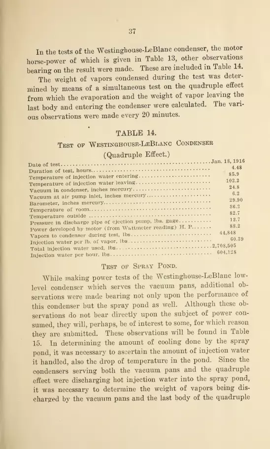
In the tests of the Westinghouse-LeBlanc condenser, the motor
horse-power of which is given in Table 13, other observations
bearing on the result were made. These are included in Table 14.
The weight of vapors condensed during the test was deter-
mined by means of a simultaneous test on the quadruple effect
from which the evaporation and the weight of vapor leaving the
last body and entering the condenser were calculated. The vari-
ous observations were made every 20 minutes.
TABLE 14.
Test of Westinghouse-LeBlanc Condenser
(Quadruple Effect.)
„ . . Jan. 18, 1916Date of test
4gDuration of test, hours
Temperature of injection water entering °
Temperature of injection water leaving
Vacuum in condenser, inches mercury
Vacuum at air pump inlet, inches mercury
Barometer, inches mercury^
Temperature of room ^Temperature outside '
Pressure in discharge pipe of ejection pump, lbs. gage ,
Power developed by motor (from Wattmeter reading) H. P 88.2
Vapors to condenser during test, lbs 44,848
Injection water per lb. of vapor, lbs 60 -
Total injection water used, lbs • 2,708,500
Injection water per hour, lbs604
'
*
Test of Spray Pond.
While making power tests of the Westinghouse-LeBlanc low-
level condenser which serves the vacuum pans, additional ob-
servations were made bearing not only upon the performance of
this condenser but the spray pond as well. Although these ob-
servations do not bear directly upon the subject of power con-
sumed, they will, perhaps, be of interest to some, for which reason
they are submitted. These observations will be found in Table
15. In determining the amount of cooling done by the spray
pond, it was necessary to ascertain the amount of injection water
it handled, also the drop of temperature in the pond. Since the
condensers serving both the vacuum pans and the quadruple
effect were discharging hot injection water into the spray pond,
it was necessary to determine the weight of vapors being dis-
charged by the vacuum pans and the last body of the quadruple

38
effect into the condensers. With these quantities and the initial
and final temperatures of the injection water at the condensersknown, it was possible to calculate the weight of injection water.
It should be noted that the weight of injection water determinedin this manner is somewhat approximate, as it was impossible to
obtain very accurate measurements of so many different quan-tities simultaneously. The results, however, will be of some valuein a general way.
TABLE 15.
Spray Pond Test.
(Florida.)
1. Date of test Jan 8> 19162. Duration of test, hours 7 13. Barometer reading, inches mercury 29.874. Temperature of room 7g_55. Temperature outside 73 q6. Relative humidity
# _ t 62 9
7. Temperature injection water entering pan condenser 86.78. Temperature injection water leaving pan condenser 99.O9. Vacuum in pan condenser, inches mercury 26.40
10. Vacuum at air pump inlet, pan condenser, inches of mer-cury 6.80
11. Vapor to pan condenser during test, lbs 67,78412. Injection water, per lb. of vapor, pan condenser, lbs 79.
S
13. Injection water, pan condenser, lbs ., 5,409,16314. Injection water per hour, pan condenser, lbs 761,85415. Pressure on discharge of cooling water pump, pan condenser.
lbs. gage 10 fi
16. Power developed by motor of pan condenser (from Watt-meter readings) H. P gg 7
17. Temperature injection water entering quad condenser. 88.218. Temperature injection water leaving quad condenser 107.5 •
19. Vacuum in quad condenser, inches mercury. 25.420. Vapor to quad condenser, lbs 112.32821. Injection water, per lb. of vapor, quad condenser, lbs 50.6222. Total injection water used, quad condenser, lbs 5,686,04323. Injection water per hour, quad condenser, lbs 800,85124. System, Spraco.
25. Number of spray nozzles 10026. Cooling effect per hour, pan injection,
B. T. IT., (99.0 — S6. 7) 761,854 = 9:380,8012?. Cooling effect per hour, quad injection,
B. T..TJ.; (107. 5-— 88.2) 800,851 = 15.456,42428. Cooling, total, B. T. U. hour .* .....24,837,225

39
GENERAL SUMMARY.Table 16 includes some of the most general data secured in
these tests that will facilitate comparisons of the steam power
consumption at the three factories. As heretofore stated, the
power measurements at Guanica were somewhat crude, and for
that reason too much dependence should not be placed in them.
It should also be remembered that the data at Guanica for boiler
feed water—that is, steam generated—is based on an assumed
radiation and unaccounted for in the factory of 12% on the
weight of cane ground. Guanica has the advantage in being a
very large factory, for it goes without saying that both power
and heat losses are proportionately smaller in a large factory
than in a small one. In comparing the steam consumption at
Adeline and Guanica it will be noted that the steam for the
vacuum pans was very much less at Adeline. This is due to the
fact that the pan work at Adeline requires very much less boiling
back. This advantage, however, was partly offset by the in-
creased amount of re-heating of juice and syrup, also granulation,
at Adeline. The weight of exhaust steam at Florida was de-
termined accurately, though that at Adeline is approximate,
having been estimated from the I. H. P. tests of the different
engines and pumps given in Table 2, page 15. The water rates
assumed in this calculation were 30 pounds II. P. hour for Corliss
engines, 125 pounds H. P. hour for direct acting steam pumps,
and 60 pounds H. P. hour for the bagasse drag engine. The
water rate of 30 seems rather high for Corliss engines, though
in view of the general underloaded condition, it is probably not
too high.

40
TABLE 16.
Adeline GUANICA Florida
White Granu- 96 Test Sugar. 96 Test Sugar.lated Sugar.Saleable Mo- Low Molasses. Low Molasses.
lasses
System of Evaporating.. Plain Quad. Plain Quad. Quad, and VaporJuice Heater.
Centrifugal Part Electric All ElectricPumps, Belt Motor Drive. Motor Drive.and Shafting Part Direct
Steam Drive
Power per ton cane per 24
hours, H. P .65 .873 .98
Steam for power, % cane . . 2.06 2.73 3.02
Steam for pans, % cane. . . 14.48 22.37
Boiler feed water P. & A.,
71.95 73.67 | 45.37
Radiation and unaccountedP. & A., % cane 13.94 12.0 f
Exhaust steam, % cane. . . . 28.8 30.52
Ratio exhaust steam to to-
.40 .67
Rated capacity, tons per 24
hours 1500 4500 1000
Capacity, time of tests 1380 4300 875
|Based on the assumed radiation and unaccounted of 12%.

41
APPENDIX A.
EQUIPMENT, ADELINE SUGAR FACTORY.
6 H. R. T. boilers, 84"x20', 2500 sq. ft. H. S. each, for bagasse.
2 H* R. T. boilers, 84"x20', 2500 sq. ft. H. S. each, for oil.
1 H. R. T. boiler, 150 H. P.
1 Heine boiler, 2500 sq. ft. H. S. each, for oil.
1 Twelve-roller mill and 1 Krajewski crusher preceded by a revolving cutter.
Mill rollers 34" x 84", crusher rollers, 32"x84".
2 Juice scales with tanks, capacity 10,000 lbs. each.
5 Liming tanks, 9' diam. x 11', 700 cu. ft. capacity each.
3 Raw juice heaters, 760 sq. ft. H. S. each.
96 tubes each, 17' 4" long x 1%" O. D.—16 passes, 585 sq. ft. H. S.
2 Thin juice heaters.
96 tubes each, 11' 4" long x 1%" O. D.—16 passes, 490 sq. ft. H. S.
2 Thick juice heaters,
56 tubes each, 10' 10" long x 1%" O. D.—28 passes, 275 sq. ft. H. S.
1 Molasses heater,
56 tubes each, 6' 10" long x 1%" O. D.—56 passes, 175 sq. ft. H. S.
The tubes of all heaters are of brass and are No. 15 U. S. standard
gauge, about 1/16" thick.
3 Deming separators.
6 Mud defecators with steam coils.
8 Kelly filter presses.
8 Bag filters, each 11 ' x 5' — %" x 6
' high with 250 bags.
Five filters used for the thin juice and three for thick juice.
Danek filters for thin juice and for thick juice.
2 Swenson quadruple effects with 8000 sq. ft. H. S. each.
Tubes 3y2 ' longx %" O. D.—2000 sq. ft. per body.
2 Sugar melters with revolving stirrers.
2 Molasses melters with revolving stirrers.
3 Cylindrical syrup biow-up tanks 7' diam. with a capacity of 200 cu. ft.
each.
Pan Charge Tanks. (For syrup, for molasses, and for wash.)
2 Express vacuum pans with single calandria, each 13' diameter and 750
sq. ft. H. S.
2 Mixers, one having a capacity of 371.2 cu. ft. and other having a capacity
of 984.4 cu. ft.
(Actually one large mixer with a cap. of 1355 cu. ft. divided into 2
compartments.
)
8 Belt-driven Weston centrifugals, 40".
2 Hersey graulators working in tandem.
1 Crusher engine (Corliss) , 16" x 42".
1 Engine driving first, second and third mills (Corliss), 32" x 60".
1 Engine driving fourth mill (Corliss), 24"x48".
1 Bagasse drag engine (plain slide valve), 11" x 12".
3 Hoisting engines (derricks).
1 Hoisting engine (Walsh rake).
1 Electric light engine (automatic high speed), 12"xl2".
1 Engine driving centrifugals and pumps (Corliss), 26"x48".
This engine drives eight 40" Weston centrifugals and the following
centrifugal pumps, through shafting and belts :
1 Thin juice pump 3 " 1156 R. P. M.

42
1 Filter press pump 3" 11001 Sweet water pump 3" 11401 Thick juice pump 2" 13501 Water to presses pump. 2" 14302 Evaporator drain pumps, second and third body 2" 12002 Evaporator drain pumps, fourth body iy2 " looo2 Evaporator syrup pumps 2" 10351 Milk of lime pump 9891 Soda to evaporators and pans 4" 7801 Mill juice pump 3" noo1 Hot water pump 2%" 12231 Kelly press pump 2" 11701 Acid press pump 2" 9251 Maceration water pump 2" 13752 Cold water pumps 8" 8401 First body evaporator drain 2" 10001 Vacuum pump (vacuum cylinder 36"x24"), steam
cylinder 22" x 24"
1 Raw juice pump, duplex system 14x10x121 Mill well pump, single steam 21 x 14% x 242 Boiler feed pumps, duplex steam 12 x 7 x 122 Boiler feed pumps, drip, duplex, steam 12 x 8 x 121 Thick juice pump to bag filters -. 12x 7x12
43
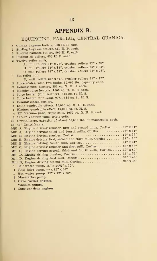
APPENDIX B.
EQUIPMENT, PARTIAL, CENTRAL GUANICA.
4 Climax bagasse boilers, 508 H. P. each.
2 Stirling bagasse boilers, 650 H. P. each.
2 Stirling bagasse boilers, 500 H. P. each.
2 Stirling oil boilers, 650 H. P. each.
3 Twelve-roller mills,
A, mill rollers 34"x78", crusher rollers 32" x 78".
B, mill rollers 34"x84", crusher rollers 28"x84".
C, mill rollers 34"x78", crusher rollers 32"x78".
1 Six-roller mill,
D, mill rollers 32" x 72", crusher rollers 25"x72".
8 Juice scales, with two tanks, 10,000 lbs. capacity each.
2 Deming juice heaters, 850 sq. ft. H. S. each.
2 Murphy juice heaters, 1005 sq. ft. H. S. each.
1 Juice heater (for Kestner), 618 sq. ft. H. S.
1 Juice heater (for Lillie fCj), 618 sq. ft. H. S.
5 Deming closed settlers.
3 Lillie quadruple effects, 10,000 sq. ft. H. S. each.
1 Kestner quadruple effect, 16,0.00 sq. ft H. S.
4 12' Vacuum pans, triple coils, 1050 sq. ft. H. S. each.
2 12 '-6" Vacuum pans, triple coils.
32 Crystallizers, capacity of about 50,000 lbs. of massecuite each.
33 40" Centrifugals.
Mill A, Engine driving crusher, first and second mills, Corliss 28"x54"
Mill A, Engine driving third and fourth mills, Corliss 2 8"x54"
Mill P>, Engine driving crusher, Corliss 16"x36'
Mill B, Engine driving first, second and third mills, Corliss 34"x60'
Mill B, Engine driving fourth mill, Corliss 24"x54'
Mill C, Engine driving crusher and first mill, Corliss 26" x 48'
Mill C, Engine driving second, third and fourth mills, Corliss 30"x60'
Mill E>, Engine driving crusher, Corliss 16"x36'
Mill D, Engine driving first mill, Corliss 22" x 48'
Mill D, Engine driving second mill, Corliss 22"x48'
1 Salt water pump, 18" x 14 % " x 30".
1 Raw juice pump, — xl2"x30".1 Hot water pump, 12" x 12" x 20".
1 Maceration pump.
6 Cane carrier engines.
Vacuum pumps.
4 Cane car drag engines.

44
APPENDIX CEQUIPMENT, CENTRAL FLORIDA.
4 H. R. T. boilers, 84"x20', 2500 sq. ft. H. S. each, burn bagasse and wood,to supply turbines.
2 H. R. T. boilers, 84"x20', 2500 sq. ft. H. S. each, burn bagasse and wood,to supply boiling house.
2 Allis-Chalmers steam turbines, 800 K. W. each, direct connected to West-inghouse A. C. generators,. Phase 3, frequency 60, voltage 440, R. P.
M. 3600.
Note.—Normally only one of these units is in service.
1 Twelve-roller mill and 1 Krajewski crusher.
Mill rollers are 32"x72", crusher rollers 28"x72".2 Juice scales, with tanks, 10,000 lbs. capacity each.
3 Liming tanks of 7' %" dia. x 4' 1", 160 cu. ft. cap. each.
1 Heater charge tank, 8'x5'xl%"x4', 164 cu. ft. cap.
3 Vapor raw juice heaters, each 225 sq. ft. H. S., 30 tubes, 15' long x 2" O. D.
2 Exhaust steam raw juice heaters, same as above.
8 Settling tanks, 10' 1" dia. x 5' 7%", 456 cu. ft. cap. each.
1 Receiving tank for clear juice. Two compartments, 198 cu. ft. total cap.
6 Mud defecators with steam coils, 6' dia. x3%', 107.5 cu. ft. cap. each.
1 Filter press charge tank. Two compartments, 406 cu. ft. total cap.
6 Filter presses.
1 Effect charge tank, 7' dia. x4', 154 cu. ft. cap.
1 Quadruple effect, 13,000 sq. ft. H. S.
4000 sq. ft. in first body and 3000 sq. ft. in each of the other bodies.
3 Pan charge tanks (syrup), 18' x 8' x7%', 720 cu. ft. cap. each.
4 Molasses pan charge tanks (molasses), same as above.
2 11' double calandria express pans, 1208 sq. ft. H. S. each.
3 Crystallizers for first products, 7%' dia. x 24', 1053 cu. ft. cap. each.
6 Crystallizers for low grade products, 7%' dia. x 20', 879 cu. ft. cap. each.
1 Small mixer for first products.
1 Small mixer for low grade products.
5 Electric driven 42" centrifugals for first products.
4 Electric driven 48" centrifugals for low grade products.
2 Final molasses tanks.

45
Motors.
1 Crusher, first and second mills
1 Third and fourth mills
1 Cush-cush elevator
1 Cane carrier
1 Auxiliary cane carrier
1 Hoist for unloading wagons1 Bagasse drag
1 Bagasse hopper
1 Bagasse carrier to storage and boilers
1 Filter press mud drag, washing machine and dryer]
1 Lime mixer and small lime pumps5 Centrifugals, first product
4 Centrifugals, low grade product
1 Crystallizer|
1 Sugar elevator and screw conveA'or I
20.0
10.0
250.0 580
200.0 580
10.0 860
15.0 variable speed
3.0 variable speed
15.0 830
8.5
3.0 850
20.0 1150
10.0 860
2.0 850
160
Pumps and Motors.
1 Mill well, first stage
1 Mill well, second stage
1 Mill journal and maceration water
2 Juice heaters (2 units)
1 Quad, juice feed
1 Syrup, last body1 Magma1 Molasses, first product centrifugals
1 Molasses, low grade product centrifugals
2 Triplex mud1 Sweet water, last body1 Sweet water, third body1 Sweet water, second body1 Westinghouse-LeBlanc condenser, pans
1. Westinghouse-LeBlanc condenser, quad1 Rotrex vacuum, pans1 Hydraulic cane dump1 Boiler feed, 5 stage
j
1 Pump from boiler recipient to house hot water tank 1
1 "Water supply pump (at spring)
7.5 1730j
300
7.5 1730|
300
2.0 1130 50
25.0 1750 300
3.0 1140 300
5.0
10.0
. 1
870 !8" x 12"
3.0 850I
40
3.0 850j
40
3.0 570|.
2.0 1130' 100
2.0 1130;
100
5.0 1150 1 200
80.0 700 j.
80.0 700 I.
10.0 350|.
3.0
50.0 1750|
220
10.0 1730 300
20.0|
/


