Embed Size (px)
Citation preview

The City of Waltham
Invites Interested Parties
To propose the best offer and or bid For the service or product herewith described:
FORMER BRIGHT SCHOOL, PHASE III, RENOVATIONS
The GENERAL BID is due: Monday July 14, 2014 at 10:00 am
The FILED SUB BIDS are due: Monday June 30, 2014 at 10:00 am
PRE BID Meeting and Briefing on Site: Wednesday June 18, 2014 at 11:00 am (Meet at 260 Grove Street, Waltham)
Last Day for Written QUESTIONS: 12 noon June 24, 2014
1
NOTICE TO BIDDERS, INCLUDING SUB-BIDDERS 00050 - 1
SECTION 00050 CITY OF WALTHAM MASSACHUSETTS
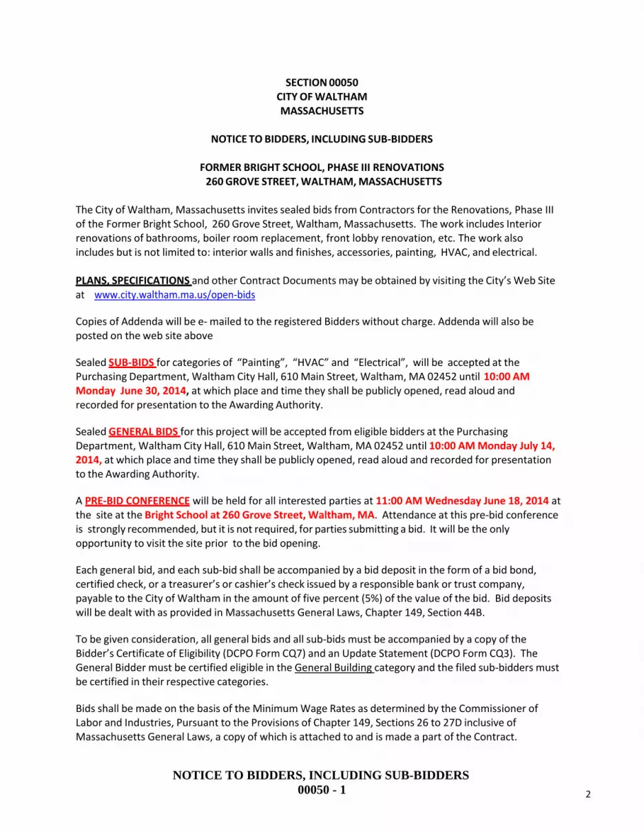
NOTICE TO BIDDERS, INCLUDING SUB‐BIDDERS
FORMER BRIGHT SCHOOL, PHASE III RENOVATIONS 260 GROVE STREET, WALTHAM, MASSACHUSETTS
The City of Waltham, Massachusetts invites sealed bids from Contractors for the Renovations, Phase III of the Former Bright School, 260 Grove Street, Waltham, Massachusetts. The work includes Interior renovations of bathrooms, boiler room replacement, front lobby renovation, etc. The work also includes but is not limited to: interior walls and finishes, accessories, painting, HVAC, and electrical.
PLANS, SPECIFICATIONS and other Contract Documents may be obtained by visiting the City’s Web Site at www.city.waltham.ma.us/open‐bids
Copies of Addenda will be e‐ mailed to the registered Bidders without charge. Addenda will also be posted on the web site above
Sealed SUB‐BIDS for categories of “Painting”, “HVAC” and “Electrical”, will be accepted at the Purchasing Department, Waltham City Hall, 610 Main Street, Waltham, MA 02452 until 10:00 AM Monday June 30, 2014, at which place and time they shall be publicly opened, read aloud and recorded for presentation to the Awarding Authority.
Sealed GENERAL BIDS for this project will be accepted from eligible bidders at the Purchasing Department, Waltham City Hall, 610 Main Street, Waltham, MA 02452 until 10:00 AM Monday July 14, 2014, at which place and time they shall be publicly opened, read aloud and recorded for presentation to the Awarding Authority.
A PRE‐BID CONFERENCE will be held for all interested parties at 11:00 AM Wednesday June 18, 2014 at the site at the Bright School at 260 Grove Street, Waltham, MA. Attendance at this pre‐bid conference is strongly recommended, but it is not required, for parties submitting a bid. It will be the only opportunity to visit the site prior to the bid opening.
Each general bid, and each sub‐bid shall be accompanied by a bid deposit in the form of a bid bond, certified check, or a treasurer’s or cashier’s check issued by a responsible bank or trust company, payable to the City of Waltham in the amount of five percent (5%) of the value of the bid. Bid deposits will be dealt with as provided in Massachusetts General Laws, Chapter 149, Section 44B.
To be given consideration, all general bids and all sub‐bids must be accompanied by a copy of the Bidder’s Certificate of Eligibility (DCPO Form CQ7) and an Update Statement (DCPO Form CQ3). The General Bidder must be certified eligible in the General Building category and the filed sub‐bidders must be certified in their respective categories.
Bids shall be made on the basis of the Minimum Wage Rates as determined by the Commissioner of Labor and Industries, Pursuant to the Provisions of Chapter 149, Sections 26 to 27D inclusive of Massachusetts General Laws, a copy of which is attached to and is made a part of the Contract.
2

NOTICE TO BIDDERS, INCLUDING SUB-BIDDERS 00050 - 2
Bidders’ selection procedures and contract award shall be in conformity with applicable statues of the Commonwealth of Massachusetts.
Performance and Labor and Materials payment bonds in the full amount of the contract price will be required from the successful bidder.
The Awarding Authority reserves the right to reject any or all general bids, if it be in the public interest to do so, and to reject any sub‐bid on any sub‐trade if it determines that such sub‐bid does not represent the sub‐bid of a person competent to perform the work as specified or that less than three such sub‐bids were received and that the prices are not reasonable for acceptance without further competition.
The successful bidder will be required to furnish a Certificate of Insurance, naming the City of Waltham as an Additional Named Insured with a waiver of subrogation, for General Liability and Vehicle Liability in the amount of $500,000 per occurrence and $1,000,000 in the aggregate and Worker’s Compensation Insurance as prescribed by law.
In accordance with M.G.L.Ch 149 the undersigned certifies that all employees to be employed at the worksite will have successfully completed a course in construction safety and health approved by OSHA that is at least 10 hours in duration at the time the employee begins work and shall furnish documentation of successful completion of said course with the first certified payroll report for each employee.
CITY ORDINANCE. APPROVAL OF CONTRACTS BY MAYOR, SEC. 3‐12 OF THE CITY ORDINANCES. All contract made by any department, board or commission where the amount involved is two thousand dollars ($2,000) or more shall be in writing, and no such contract shall be deemed to have been made or executed until the approval of the Mayor is affixed thereto. Any construction contract shall, and all other contracts may, where the contract exceed five thousand dollars ($5,000) be required to be accompanied by a bond with sureties satisfactory to the Mayor.
CITY OF WALTHAM
Joseph Pedulla, CPO Purchasing Department City Hall, 610 Main Street Waltham, MA 02452
3

INSTRUCTION TO BIDDERS00100 - 1
SECTION 00100 ‐ INSTRUCTION TO BIDDERS
PART 1 ‐ GENERAL
1.1 SCHEDULE OF DATES
A. Advertisement appears in Central Register, Plans and Specifications ready for Bidders at the Offices of the Waltham Purchasing Agent after 8:30 P.M. on June 11, 2014.
B. Pre‐bid walkthrough on Wednesday, June 18, 2014, at 11:00 AM at the Bright School, Waltham, MA.
C. Questions and requests for interpretations may be submitted in writing via e‐mail ONLY to [email protected] up to and including: June 24, 2014, 12:00 Noon.
D. E. Addenda will be issued with interpretations as determined by the Purchasing
Department only via e‐mail and posting on the web site.
F. File Sub‐Bids Deadline: 10:00 A.M. on June 30, 2014, in the Purchasing Department, City Hall, 610 Main Street, Waltham, MA 02452, Attn: J. Pedulla, CPO, where the bids will be publicly opened and read.
G. General Bids Deadline: 10:00 A.M. on July 14, 2012, in the Purchasing Department, City Hall, 610 Main Street, Waltham, MA 02452, Attn: J. Pedulla, CPO, where the bids will be publicly open and read.
1.2 BIDDING PROCEDURE
A. Bids for the work are subject to the provisions of General Laws, Chapter 149, Sections 44A‐44L inclusive, as amended. Regulations governing the bidding procedures as set forth in the above mentioned amended General Laws must be followed.
B. In the event of any inconsistencies between any of the provisions of these Contract Documents and of the cited statute, anything herein to the contrary notwithstanding, the provisions of the said statute shall control.
C. No General Bid received by the Awarding Authority after the time respectively established herein for the opening of General Bids will be considered, regardless of the cause for the delay in the receipt of any such bid.
1.3 WITHDRAWAL OF BIDS
A. Bids may be withdrawn prior to the time respectively established for the opening of General Bids only on written request to the Awarding Authority.
4

INSTRUCTION TO BIDDERS00100 - 2
1.4 INTERPRETATION OF CONTRACT DOCUMENTS
A. No oral interpretation will be made to any bidder. All questions or requests for interpretations must be made in writing to the Architect.
B. Every interpretation made to a bidder will be in the form of an Addendum to the drawings and/or specifications, which will be made available to all persons to whom Contract Documents have been issued.
C. Failure of the Awarding Authority to send, or of any bidder to receive any such Addendum shall not relieve any bidder form obligation under his bid as submitted.
D. All such Addenda shall become a part of the Contract Documents.
1.5 EXAMINATION OF SITE AND CONTRACT DOCUMENTS
A. Each bidder shall visit the site of the proposed work and fully acquaint himself with conditions as they exist, and shall also thoroughly examine the Contract Documents. Failure of any bidder to visit the site and acquaint himself with the Contract Documents shall not relieve any bidder from any obligation with respect to his bid.
B. By submitting a bid, the bidder agrees that the Contract Documents are adequate and that the required result for a full and complete installation can be produced. The successful bidder shall furnish any and all labor, materials, insurance, permits and all other items needed to produce the required result to the satisfaction of the Awarding Authority.
1.6 BID SECURITY
A. The General Contractor’s bid must be accompanied by bid security in the amount of five percent (5%) of the bid.
B. At the option of the bidder, the security may be bid bond, certified, treasurer’s or cashier’s check issued by a responsible bank or trust company. No other type of bid security is acceptable.
Bid Bonds shall be issued by a Surety Company qualified to do business under the laws of the Commonwealth of Massachusetts.
C. Certified, Treasurer’s or Cashier’s check shall be made payable to the City of Waltham, Massachusetts.
D. The bid security shall secure the execution of the Contract and the furnishing of a Performance and Payment Bond by the successful General Bidder for 100% of the contract value.
E. Should any General Bidder to whom an award is made fail to enter into a contract therefore within five (5) days, Saturdays, Sundays and Legal Holidays, excluded, after
5

INSTRUCTION TO BIDDERS00100 - 3
notice of award has been mailed to him or fail within such time to furnish a Performance Bond and also a Labor and Materials or Payment Bond as required, the amount so received from such General Bidder through his Bid Bond, Certified, Treasurer’s or Cashier’s check as bid deposit shall become the property of the City of Waltham, Massachusetts as liquidated damages; provided that the amount of the bid deposit, which becomes the property of the City of Waltham, Massachusetts, shall not in any event exceed the difference between his bid price and the bid price of the next lowest responsible and eligible bidder; and provided further that, in case of death, disability, bona fide clerical error or mechanical error of a substantial nature, or other unforeseen circumstances affecting the General Bidder, his deposit shall be returned to him.
1.7 BID FORM
A. General Bids shall be submitted on the “FORM FOR GENERAL BID” enclosed. Erasures or
other changes must be explained or noted over the signature of the bidder.
B. Bid forms must be completely filled in. Bids which are incomplete, conditional, or obscure, or which contain additions not called for will be rejected.
C. General Bidders shall submit one set of executed bid forms to the Awarding Authority.
1.8 SUBMISSION OF BIDS AND BID SECURITIES
A. Each bid submitted by a General Contractor shall be enclosed in a sealed envelope that
shall be placed with the bid security in an outer envelope. The outer envelope shall be sealed and clearly marked as follows:
(Firm Name):
General Bid and Bid Security for: Former Bright School Phase III, Renoivation
1.9 AWARD OF CONTRACT
A. The Contract shall be awarded to the lowest responsible and eligible General Bidder on
the basis of competitive bids in accordance with the procedure set forth in the provision of Section 44B‐44L inclusive, as amended or inserted, of Chapter 149 of the General Laws of the Commonwealth of Massachusetts.
B. If the bidder selected as the General Contractor fails to perform his agreement to
execute a contract in accordance with the terms of his General Bid, and furnish a Performance Bond and also a Labor and Materials or Payment Bond, as stated in his General Bid in accordance with Section 44F, an award shall be made to the next lowest responsible and eligible bidder.
C. The words “lowest responsible and eligible bidder” shall be the bidder whose name is
the lowest of those bidders possessing the skill, ability and integrity necessary for the faithful performance of the work and who shall certify that he is able to furnish labor
6

INSTRUCTION TO BIDDERS00100 - 4
that can work in harmony with all other elements of labor employed, or to be employed, on the work. Essential information in regard to such qualifications shall be submitted in such form as the Awarding Authority may require.
D. Action on the award will be taken within sixty (60) days, Saturdays, Sundays and Legal Holidays excluded after the opening of the bids.
1.10 SECURITY FOR FAITHFUL PERFORMANCE
A. The successful bidder must deliver to the Awarding Authority simultaneously with his delivery of the executed contract, an executed Performance Bond, and also a Labor and materials or Payment Bond, each issued by a surety company qualified to do business under the laws of the Commonwealth and satisfactory to the Awarding Authority and each in the sum of One Hundred Percent (100%) of the Contract Price, as surety for the faithful performance of his contract, and for the payment of all persons performing labor or furnishing materials in connection therewith. Said bonds shall provide that, if the General Contractor fails or refuses to complete the Contract, the Surety Company will be obligated to do so.
B. Premiums are to be paid by the General Contractor, and are to be included in the Contract Price.
1.11 EQUAL OPPORTUNITY
A. The City of Waltham is an Equal Opportunity employer and will require compliance with the minority business enterprise plan (MBE) on file in the Purchasing Department
1.12 PRE‐BID WALK‐THRU
A. A pre‐bid conference will be held at the site on Wednesday, June 18, 2014, at 11:00 AM. at the Bright School 260 Grove Street, Waltham, MA. Interested parties are encouraged to attend given that this will be the only time the building is open prior to the submission of bids. Further, prior to the bid opening, potential bidders may not go onto the site any time other than the aforementioned pre‐bid conference.
1.13 SITE VISITS
A. Prospective bidders are prohibited from going onto the site prior to the Bid Opening or any time other than the pre‐bid walk‐thru, as set forth in Section 1.12 above, unless authorized by the Architect in an Addendum to the bid documents.
1.14 CONTRACT DOCUMENTS
A. The Awarding Authority shall make available the bid documents and addenda in the City Web site at www.city.waltham.ma.us/open‐bids. No plans will be mailed.
7

INSTRUCTION TO BIDDERS00100 - 5
1.15 EQUALITY
A. Except where otherwise specifically provided to the contrary, the words “or approved equal” are hereby inserted immediately following the name or description of each article, assembly, system, or any component part thereof in the Contract Documents. It is the Contractor’s responsibility to provide all the research and documentation that would prove a product or assembly is “equal”. Failure to provide research or documentation does not alleviate the Contractor’s responsibility to meet the schedule.
1.16 TAX FREE NUMBER
A. The City of Waltham has a tax‐free number.
1.17 SCHEDULE
A. The work of the Contract shall be Substantially Complete in 90 calendar days after the date of the Notice‐to‐Proceed.
1.18 LATE PENALTY FEES
A. If the work is not Substantially Complete as specified in 1.17, the Contractor shall be charged Five Hundred Dollars ($500.00) per day to pay for consulting and testing fees required to manage and arrange for the completion of the project. Late fees will be deducted from the Contract via Change Order.
1.19 WEEKLY JOB MEETINGS
A. There will be a weekly job meeting at the site on the same agreed‐upon day and time. Time will be provided to discuss and view the progress of the work and to answer questions. The Contractor’s job Superintendent and Project Manager shall attend each meeting. The City reserves the right to have job meetings conducted in the Planning Department at 119 School Street, Waltham.
1.20 PROJECT SUPERINTENDENT
A. The Contractor shall provide the same person as Superintendent for the entire duration of the project. Failure to maintain the same person in this position shall result in a One Thousand Dollar ($1,000.00) penalty per incident which shall cover the Architect’s time to re‐orient new personnel.
1.21 AWARD
A. The Awarding Authority reserves the right to reject any or all bids if it be in the public interest to do so, and to act upon the bids and make its award in any lawful manner.
8

INSTRUCTION TO BIDDERS00100 - 6
1.22 PREVAILING WAGE SCHEDULE
A. Bids shall be made on the basis of the Prevailing Wage Schedule, as determined by the Commissioner of Labor and Industries, pursuant to the provision of Chapter 149, Section 26 to 27D inclusive, of the Massachusetts General Laws. The Prevailing wage Schedule for this project can be found in the City’s web Site at www.city.waltham.ma.us/open‐ bids
1.23 CONFLICT OF INTEREST
A. A bidder filing a proposal thereby certifies that the proposal is made in good faith, without fraud, collusion, or connection of any kind with any other bidder for the same work, and that the bidder is competing solely on its own behalf without connection with, or obligation to, any undisclosed person or firm.
1.24 PROCEED ORDERS
A. No bidder is to proceed without a proceed order as set out in the contract.
1.25 STAGING
A. See Temporary Facilities paragraph 11.1
1.26 COMPLIANCE WITH MASSACHUSETTS GENERAL LAWS
A. Pursuant to Massachusetts General Laws, Chapter 62C, Section 49A, I certify under the penalty of perjury that I, to the best of my knowledge and belief have filed all state tax returns and paid all the state taxes required under law.
1.27 CONSTRUCTION BARRICADES
A. The General Contractor shall provide all barricades to enclose the work area to prevent unauthorized access to the site.
1. The barricades shall provide enough room for all construction activities to beperformed while separated from pedestrians, students, and staff on site.
2. Safety is the sole responsibility of the Contractor and any barricades necessaryto protect the work and the public shall be provided.
3. Provide entrance protection.
9

INSTRUCTION TO BIDDERS00100 - 7
1.28 INSURANCE
A. The contractor shall purchase and maintain, at his expense all insurance required by the Contract. Documents and all insurance required by the applicable laws of Massachusetts, including but not limited to, General Laws, Chapter 146, in connection with all hoisting equipment.
B. The Contractor shall purchase and maintain such insurance as will protect him from
claims under workmen’s compensation acts and from claims for damages because of bodily injury, including death and all property damage including, without limitation, damage to buildings and adjoining the site of construction which might arise from and during operations under this contract, whether such operations be by himself or by any subcontractor or anyone directly or indirectly employed by either of them including:
1. Statutory Worker’s Compensation and Employer’s Liability
The contractor shall provide insurance for the payment of compensation and the furnishing of other benefits under Chapter 152 of the General Laws (so‐ called Worker’s Compensation Act) to all persons to be employed under this contract and shall continue in force such insurance as aforesaid shall be deemed a material breach of this Contract and shall operate as an immediate termination thereof. The contractor shall, without limiting the generality of the foregoing, conform to the provisions of Section 34A of Chapter 149 of the General Laws, which Section is incorporated herein by reference and made a part of hereof.
2. Comprehensive General Liability Insurance
Minimum bodily injury limits of $ 500,000 per person and $ 1,000,000 per accident, and property damage limits of $ 500,000 per accident and $ 1,000,000 aggregate during any 12 month period, shall include the following:
a. Public liability (bodily injury and property damage) b. X.C.U. (explosion, collapse, and underground utilities) c. Independent contractor’s protective liability. d. Products and completed operations. e. Save harmless agreement for Owner and Architects set forth in ARTICLE
10.11 of the GENERAL CONDITIONS.
3. Comprehensive All Risk Motor Vehicle Liability Insurance
Minimum bodily injury limits of $ 500,000 per person, $ 1,000,000 per accident, and property damage limit of $ 1,000,000 per accident.
4. All Risk Insurance
Covering all Contractor’s equipment with a provision for Waiver of Subrogation against the Owner.
10

INSTRUCTION TO BIDDERS00100 - 8
5. Excess Liability Insurance in Umbrella Form with combined Bodily Injury and Property Damage Limit of $ 1,000,000.
City of Waltham is a Named Additional Insured for General Liability
with a Waiver of Subrogation on the insurance policy for this project.
1.29 SITE ACCESS
A. The General Contractor shall gain access to the site via routes approved by the Owner.
1. The General Contractor as part of the bid price will restore all roads, curbs, driveways, walks and grassed or landscaped areas damaged during construction.
1.30 CONSTRUCTION TRAILER
A. The General Contractor shall locate the construction trailer at locations approved by the
Owner.
B. The General Contractor shall locate all on site stored or staged materials within the enclosed area designated by the Owner.
1.31 BUILDING PERMIT FEES
A. Building permit fees will be waived for this project. However, the general Contractor is
expected to obtain all proper permits as required by City Ordinances
1.32 COMPLETE BID FORMS
A. Please Note: Each bidder must fill in all the blanks on all the bid forms, even if the information is “zero dollars” or “not applicable”. Also, please acknowledge all Addenda even if they do not pertain to your trade.
1.321 READ ALL DOCUMENTS. Bidders should familiarize themselves with all the documents contained herein; it is mandatory that all Bids be in compliance with all the provisions contained in said documents.
1.33. FORMS AND ATTACHMENTS.
Bids are to be completed on the forms provided ONLY and enclosed in a sealed envelope marked on the outside “BID (title)” and the name and address of bidder. Attachments submitted in addition to the Waltham Purchasing Department produced forms may not be considered.
11

INSTRUCTION TO BIDDERS00100 - 9
1.34. PRINTED OR TYPED RESPONSE. All information must be typewritten or printed in ink, including the price the bidder offers in the space as provided on the bid form.
1.35. CORRECTIONS. Bids that are submitted containing cross outs, white outs or erasures, will be rejected. All corrections or modifications to the original bid are to be submitted in a separate envelope, properly marked on the outside, “CORRECTION/ MODIFICATION TO BID (title)” and submitted prior to the bid opening.
ALL DOCUMENTS SUBMITTED WITH YOUR RESPONSE WILL BE INCORPORATED INTO THE CONTRACT. 1.36. PRICE IS ALL INCLUSIVE.
Bid prices shall encompass everything necessary for furnishing all items, materials, supplies or services as specified, and in accordance with the specifications, including proper packing, cost of delivery, and in the case of services, completion of same, as per specifications.
1.37. PRICE DISCREPANCY.
In the event of a discrepancy between the Unit Price and the Extension, the Unit Price shall prevail.
1.38. EXPLANATIONS, EXCEPTIONS
Explanations, exceptions or other information pertinent to the specifications may be made in writing and included in the same envelope with the bid.
1.39. BID DEPOSITS. Bid deposits are to be made payable to the City of Waltham. In the event that the successful bidder fails to execute a Contract within (10) days of the receipt of said contract, such security shall be retained by the city as liquidated damages. Unsuccessful bidders’ deposits will be returned immediately following the award to said successful bidder.
1.40. WITHDRAW.
A Bid may be withdrawn by written request prior to the schedule for the Bid Opening. No withdrawals are permitted after the bid opening date and time. Withdrawals after the bid opening date will cause the forfeit of the bid Deposit.
1.41. AWARD. Bids will be awarded not later than (90) ninety days after the scheduled bid opening date, unless otherwise stated, in the specifications. Unless otherwise specified, bids will be evaluated on the basis of, completeness of your RFP response, responsiveness, responsibility, best price and experience.
12

INSTRUCTION TO BIDDERS00100 - 10
1.42. AWARD CRITERIA.
Qualified and responsive proposals will be evaluated based on Price, Technical, and Compliance requirements.
1.43. DISCOUNTS. Discounts for prompt payments will be considered when making awards.
1.44. TAX EXEMPT.
Purchases by the City of Waltham are exempt from any Federal, State or Massachusetts Municipal Sales and/or Excise Taxes.
1.45. SAMPLES.
The City of Waltham may require the submission of samples either before or after the awarding of a contract. Samples are to be submitted, at no charge to the City, so as to ascertain the product's suitability. If specifically stated in the Bid that samples are required, said samples must be submitted with the Bid prior to the Official Bid Opening. Failure to submit said samples would be cause for rejection of Bid. All samples must be called for and picked up within (30) thirty days of award or said samples will be presumed abandoned and will be disposed of.
1.46. ACTIVE VENDOR LIST.
Vendors who wish to remain on the Active Bid List must either submit a Bid, No Bid, or a letter requesting same, no later than the Official Bid Opening. This is applicable to those vendors who have received the Invitation to Bid.
1.47. FUNDS APPROPRIATION.
THE CONTRACT OBLIGATION ON BEHALF OF THE CITY IS SUBJECT TO PRIOR APPROPRIATION OF MONIES FROM THE GOVERNMENTAL BODY AND AUTHORIZATION BY THE MAYOR.
1.48. THE AWARDING AUTHORITY RESERVES THE RIGHT TO REJECT ANY OR ALL BIDS, OR ANY PART OF ANY BID, WHICH IN THE OPINION OF THE AWARDING AUTHORITY, IS IN THE BEST INTERESTS OF THE CITY OF WALTHAM. 1.49. THE TAX ATTESTATION CLAUSE, CERTIFICATION OF NON‐COLLUSION AND THE CERTIFICATE OF VOTE AUTHORIZATION, are required by statute and are an integral part of the Invitation for Bid and must be completed and signed by the person submitting the Bid, or by the person/persons who are officially authorized to do so. Failure to do so may disqualify the bid. 1.50. STANDARD OF QUALITY.
Where, in the specifications, one certain kind, type, catalog number, brand or manufacturer of material is named, it shall be regarded as the required standard of quality. Where two or more are named, these are presumed to be equal and the Bidder
13

INSTRUCTION TO BIDDERS00100 - 11
may select one or the other. If the Bidder proposes to offer a substitute as an equal, he shall so indicate on the Bid Form, the kind, type, catalog number, brand, or manufacturer of material that is offered as an equal, and describe where it differs from the specifications. Substituted items must be capable of performing all the functions and/or operational features described or indicated in the specifications. Failure to indicate the description of any substitute item on the Bid will be interpreted to mean that the Bidder will furnish the item or service as specified.
1.51. MODIFICATION.
No agreement, understanding, alteration or variation of the agreement, terms or provisions herein contained shall bind the parties, hereto unless made and executed in writing by the parties hereto.
1.52. ASSIGNMENT.
The final payment for work done under this Contract shall be made only after the Contractor has signed a statement under the penalty of perjury, certifying that he has completed the work described in the final estimate. Neither party hereto shall assign this Contract or sublet it in part or as a whole without the prior written consent of the other party hereto. The Contractor shall not assign any sum or sums due or becoming due to him hereunder without the prior written consent of the City.
1.53. DELIVERIES:
a) The Contractor shall pay all freight and delivery charges. TheWaltham Purchasing Department does not pay for shipping and packaging expenses. Items must be delivered as stipulated in the specifications. All deliveries must be made to the inside of city buildings. Sidewalk deliveries will not be accepted. City personnel are not required to assist in the deliveries and contractors are cautioned to notify their shippers that adequate assistance must be provided at the point of delivery, when necessary. b) All items of furniture must be delivered inside the building, set up, in place and ready for use. Deliveries are to be made between the hours of 8:30 a.m. and 3:00 p.m., Monday through Friday, except on holidays. c) All damaged items, or items which do not comply with specifications will not be accepted and title therefore will not vest to the Waltham Purchasing Department until such items are accepted and signed for, in good order, by the receiving department. d) The contractor must replace, without further cost to theWaltham Purchasing Department, such damaged or non‐complying items before payment will be made.
1.54. LABELING.
All packages cartons or other containers must be clearly marked with (a) building and room destination; (b) description of contents of item number from specifications; (c) quantity; (d) City of Waltham Purchase Order Number and (e) Vendor’s name and order number.
1.56. GUARANTEES.
Unless otherwise stipulated in the specifications, furniture, equipment and similar durable items shall be guaranteed by the contractor for a period of not less than one year from the
14

INSTRUCTION TO BIDDERS00100 - 12
date of delivery and acceptance by the receiving department. In addition, the manufacturer’s guarantee shall be furnished. Any items provided under this contract which are or become defective during the guarantee period shall be replaced the contractor free of charge with the specific understanding that all replacements shall carry the same guarantee as the original equipment. The contractor shall make such replacement immediately upon receiving notice from the Purchasing Agent.
1.57. CHANGE ORDERS.
Change orders are not effective until, if, as and when signed by the Mayor and no work is to commence until the change orders are fully executed.
1.58. BID OPENING INCLEMENT WEATHER
If, at the time of the originally scheduled bid opening, City Hall is closed to inclement weather or another unforeseeable event, the bid opening will be extended until 2:00 PM on the next normal business day. Bids will be accepted until that date and time.
Signature of Individual or Corporate Name
By:
(Signature of Corporate Officer if applicable)
Title:
Social Security Number or Federal Identification Number:
END OF SECTION
15

FORM OF SUB-BID
To All General Bidders Except those Excluded:
A. The undersigned proposes to furnish all labor and materials required for completing, in accordancewith the hereinafter described plans, specifications and addenda, all work specified in
of the specifications and in any plans specified insuch section, prepared by Kang Associates, Inc. for the Bright School - Phase 3 Renovations,Waltham, MA for the contract sum of:
dollars ($ ).
For Alternate #1:
Add $ dollars ($ ).
For Alternate #2:
Add $ dollars ($ ).
For Alternate #3:
Add $ dollars ($ ).
B. This sub-bid includes addenda numbered .
C. This sub-bid
G may be used by any general bidder except:
G may only be used by the following general bidders:
(To exclude general bidders, insert an "X" in one box only and fill in blank following that box. Do notanswer C if no general bidders are excluded.)
D. The undersigned agrees that, if he is selected as sub-bidder, he will within five days, Saturdays,Sundays, and legal holidays excluded, after presentation of a subcontract by the general bidderselected as the general contractor, execute with such general bidder a subcontract in accordancewith the terms of this sub-bid, and contingent upon the execution of the general contract, and, ifrequested so to do in the general bid by such general bidder, who shall pay the premiums therefor,or if prequalification is required pursuant to section 44D 3/4, furnish a performance and paymentbond of a surety company qualified to do business under the laws of the Commonwealth andsatisfactory to the awarding authority in full sum of the subcontract price.
E. The names of all persons, firms and corporations furnishing to the undersigned labor or labor andmaterials for the class or classes or part thereof work for which the provisions of the section of thespecifications for this sub-trade requires a listing in this paragraph, including the undersigned ifcustomarily furnished by persons on his own payroll and in the absence of a contrary provisions inthe specifications, the name of each such class of work or part thereto and the Bid price for suchclass of work or part thereof are:
16

Name Class of Work Bid Price
(Do not give bid price for any class or part thereof furnished by undersigned.)
F. The undersigned agrees that the above list of bids to the undersigned represents bona fide bidsbased on the hereinbefore described plans, specifications and addenda and that, if the undersignedis awarded the contract, they will be used for the work indicated at the same amounts stated, ifsatisfactory to the awarding authority.
G. The undersigned further agrees to be bound to the general contractor by the terms of thehereinbefore described plans, specifications, including all general conditions stated therein, andaddenda, and to assume toward him all the obligations and responsibilities that he, by thosedocuments, assumes toward the owner.
H. The undersigned offers the following information as evidence of his qualifications to perform thework as bid upon according to all the requirements of the plans and specifications:
1. Have been in business under present business name years.
2. Ever failed to complete any work awarded?
3. List one or more recent buildings with names of the general contractor and architect on whichyou served as a subcontractor for work of similar character as required for the above namedbuildings.
Building Architect . General Contractor Amount of Contract
(a)
(b)
(c)
4. Bank reference
I. The undersigned hereby certifies that he is able to furnish labor that can work in harmony with allother elements of labor employed or to be employed on the work; that all employees to be employedat the worksite will have successfully completed a course in construction safety and health approvedby the United States Occupational Safety and Health Administration that is at least 10 hours induration at the time the employee begins work and who shall furnish documentation of successfulcompletion of said course with the first certified payroll report for each employee; and that he willcomply fully with all laws and regulations applicable to awards of subcontracts subject to section44F.
The undersigned further certifies under penalties of perjury that this sub-bid is in all respects bonafide, fair and made without collusion or fraud with any other person. As used in this subsection theword “person” shall mean any natural person, joint venture, partnership, corporation or otherbusiness or legal entity. The undersigned further certifies under penalty of perjury that the saidundersigned is not presently debarred from doing public construction work in the commonwealth
17

under the provisions of section twenty-nine F of chapter twenty-nine, or any other applicabledebarment provisions of any other chapter of the General Laws or any rule or regulationpromulgated thereunder.
Date (Name of Sub-Bidder)
By:Signature and Title of Person Signing Bid
Business Address
City and State
SUB-BIDDER'S CHECKLIST:
Addenda Recognized
Bid Deposit
DCAM Certificate of Eligibility
Sub-Bidder Update Statement
Certificate of Corporate Bidder
18

FORM OF GENERAL BID
To the Awarding Authority:
A. The undersigned proposes to furnish all labor and materials required for the Bright School -Phase 3 Renovations, Waltham, MA, in accordance with the accompanying plans andspecifications prepared by Kang Associates, Inc. for the contract price specified below, subject toadditions and deductions according to the terms of the specifications.
B. This Bid includes addenda numbered .
C. The proposed contract price is:
dollars ($ ).
For Alternate #1:
Add $ dollars ($ ).
For Alternate #2:
Add $ dollars ($ ).
For Alternate #3:
Add $ dollars ($ ).
D. The subdivision of the proposed contract price is as follows:
Item 1. The work of the general contractor, being all work other than that covered by Item 2:
$ .
Item 2. Sub-bids as follows:
Sub-trade Name of Sub-Bidder AmountBond req'dYes/No
09.90.00 Painting and Coating $
23.00.00 HVAC $
26.00.00 Electrical $
Total of Item 2: $
The undersigned agrees that each of the above named sub-bidders will be used for the workindicated at the amount stated, unless a substitution is made. The undersigned further agrees topay the premiums for the performance and payment bonds furnished by sub-bidders as requestedherein and that all of the cost of all such premiums is included in the amount set forth in Item 1 ofthis bid.
The undersigned agrees that if he is selected as general contractor, he will promptly confer with theawarding authority on the question of sub-bidders; and that the awarding authority may substitute for
19
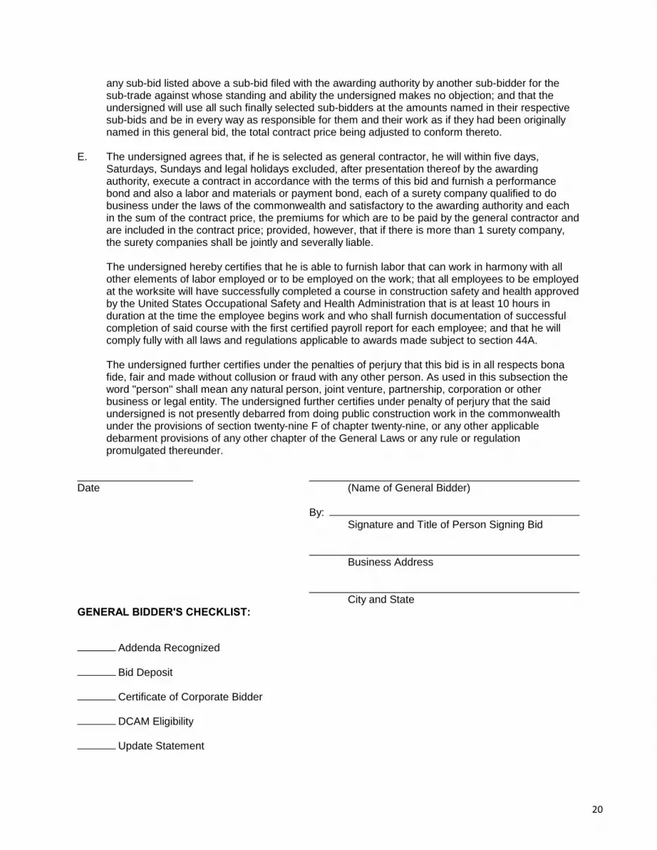
any sub-bid listed above a sub-bid filed with the awarding authority by another sub-bidder for thesub-trade against whose standing and ability the undersigned makes no objection; and that theundersigned will use all such finally selected sub-bidders at the amounts named in their respectivesub-bids and be in every way as responsible for them and their work as if they had been originallynamed in this general bid, the total contract price being adjusted to conform thereto.
E. The undersigned agrees that, if he is selected as general contractor, he will within five days,Saturdays, Sundays and legal holidays excluded, after presentation thereof by the awardingauthority, execute a contract in accordance with the terms of this bid and furnish a performancebond and also a labor and materials or payment bond, each of a surety company qualified to dobusiness under the laws of the commonwealth and satisfactory to the awarding authority and eachin the sum of the contract price, the premiums for which are to be paid by the general contractor andare included in the contract price; provided, however, that if there is more than 1 surety company,the surety companies shall be jointly and severally liable.
The undersigned hereby certifies that he is able to furnish labor that can work in harmony with allother elements of labor employed or to be employed on the work; that all employees to be employedat the worksite will have successfully completed a course in construction safety and health approvedby the United States Occupational Safety and Health Administration that is at least 10 hours induration at the time the employee begins work and who shall furnish documentation of successfulcompletion of said course with the first certified payroll report for each employee; and that he willcomply fully with all laws and regulations applicable to awards made subject to section 44A.
The undersigned further certifies under the penalties of perjury that this bid is in all respects bonafide, fair and made without collusion or fraud with any other person. As used in this subsection theword "person'' shall mean any natural person, joint venture, partnership, corporation or otherbusiness or legal entity. The undersigned further certifies under penalty of perjury that the saidundersigned is not presently debarred from doing public construction work in the commonwealthunder the provisions of section twenty-nine F of chapter twenty-nine, or any other applicabledebarment provisions of any other chapter of the General Laws or any rule or regulationpromulgated thereunder.
Date (Name of General Bidder)
By:Signature and Title of Person Signing Bid
Business Address
City and StateGENERAL BIDDER'S CHECKLIST:
Addenda Recognized
Bid Deposit
Certificate of Corporate Bidder
DCAM Eligibility
Update Statement
20

COMPLIANCE FORMS
(PLEASE COMPLETE AND SUBMIT THESE FORMS WITH YOUR RESPONSE)
21

NON-COLLUSION FORM AND TAX COMPLIANCE FORM
CERTIFICATE OF NON-COLLUSION
The undersigned certifies under penalties of perjury that this bid or proposal has been made and submitted
in good faith and without collusion or fraud with any other person. As used in this certification, the word
“person” shall mean any natural person, business, partnership, corporation, union, committee, club, or other
organization, entity or group of individuals. The undersigned certifies that no representations made by any
City officials, employees, entity, or group of individuals other than the Purchasing Agent of the City of
Waltham was relied upon in the making of this bid
_____________________________________, ______________ (Signature of person signing bid or proposal) Date _____________________________________ (Name of business)
TAX COMPLIANCE CERTIFICATION
Pursuant to M.G.L. c. 62C, & 49A,I certify under the penalties of perjury that, to the best of my knowledge and belief, I am in compliance with all laws of the Commonwealth relating to taxes, reporting of employees and contractors, and withholding and remitting child support. ________________________________________, _____________ Signature of person submitting bid or proposal Date ________________________________________ Name of business NOTE
Failure to submit any of the required documents, in this or in other sections, with your bid response package may cause the disqualification of your proposal.
22

CERTIFICATE OF VOTE OF AUTHORIZATION
Date: I __________________________, Clerk of_______________________________hereby certify that at a meeting of the Board of Directors of said Corporation duly held on the______day of__________________at which time a quorum was present and voting throughout, the following vote was duly passed and is now in full force and effect:
VOTED: That ___________________(name) is hereby authorized, directed and empowered for the name and on behalf of this Corporation to sign, seal with the corporate seat, execute, acknowledge and deliver all contracts and other obligations of this Corporation; the execution of any such contract to be valid and binding upon this Corporation for all purposes, and that this vote shall remain in full force and effect unless and until the same has been altered, amended or revoked by a subsequent vote of such directors and a certificate of such later vote attested by the Clerk of this Corporation. I further certify that________________ is duly elected/appointed____________________ ____________________of said corporation
SIGNED:
(Corporate Seal)
________________________ Clerk of the Corporation: Print Name: ______________________
COMMONWEALTH OF MASSACHUSETTS
County of________________
Date:
Then personally appeared the above named and acknowledged the foregoing instrument to be their free act and deed before me,__________________________________________
Notary Public; My Commission expires: _________________________________
23

CORPORATION IDENTIFICATION
The bidder for the information of the Awarding Authority furnishes the following information. If a Corporation: Incorporated in what state _________________________________________ President ________________________________________________________ Treasurer ________________________________________________________ Secretary _______________________________________________________
Federal ID Number_______________________________________________ If a foreign (out of State) Corporation – Are you registered to do business in Massachusetts? Yes _______, No _______ If you are selected for this work you are required under M.G.L.ch. 30S, 39L to obtain from the Secretary of State, Foreign Corp. Section, State House, Boston, a certificate stating that you Corporation is registered, and furnish said certificate to the Awarding Authority prior to the award. If a Partnership: (Name all partners) Name of partner ______________________________________________________ Residence ___________________________________________________________ Name of partner _______________________________________________________ Residence ____________________________________________________________ If an Individual: Name ________________________________________________________________ Residence ____________________________________________________________ If an Individual doing business under a firm’s name: Name of Firm ________________________________________________________ Name of Individual ___________________________________________________ Business Address _____________________________________________________ Residence ___________________________________________________________ Date ________________________ Name of Bidder _______________________________________________________ By ________________________________________________________________ Signature _______________________________________________________ Title_________________________________________________________________ ____________________________________________________________________ Business Address (POST OFFICE BOX NUMBER NOT ACCEPTABLE) ____________________________________________________________________
City State Telephone Number Today’s Date
24

RIGHT TO KNOW LAW
Any vendor who receives an order or orders resulting from this invitation agrees to submit a
Material Safety Data Sheet (MSDS) for each toxic or hazardous substance or mixture containing
such substance, pursuant to M.G.L. c. 111F, §§8,9 and 10 and the regulations contained in 441
CMR 21.06 when deliveries are made. The vendor agrees to deliver all containers properly
labeled pursuant to M.G.L. c. 111F §7 and regulations contained in 441 CMR 21.05. Failure to
furnish MSDS and/or labels on each container may result in civil or criminal penalties, including
bid debarment and action to prevent the vendor from selling said substances, or mixtures
containing said substances within the Commonwealth. All vendors furnishing substances or
mixtures subject to Chapter 111F or M.G.L. are cautioned to obtain and read the laws, rules and
regulations referenced above. Copies may be obtained from the State House Bookstore,
Secretary of State, State House, Room 117, Boston, MA (617) 727-2834.
Authorized Signature Indicating Compliance with the Right-to-know laws:
Signature Date
Print Name
NOTE
Failure to submit any of the required documents, in this or in other sections, with your bid response package may cause the disqualification of your proposal.
25

MASSACHUSETTS WEEKLY CERTIFIED PAYROLL REPORT FORM
Company's Name: Address: Phone No.: Payroll No.:
Employer's Signature: Title: Contract No: Tax Payer ID Number Work Week Ending:
Awarding Authority's Name: Public Works Project Name: Public Works Project Location: Min. Wage Rate Sheet Number
General / Prime Contractor's Name: Subcontractor's Name: "Employer" Hourly Fringe Benefit Contributions
(B+C+D+E) (A x F)
Employee Name & Complete Address
Work Classification:
Employee is OSHA
10 certified
(?)
Appr. Rate (%) Su. Mo. Tu. We. Th. Fr. Sa.
All Other Hours
Hourly Base Wage
(B)
Health & Welfare
Insurance (C)
ERISA Pension
Plan (D)
Supp. Unemp.
(E)
Total Hourly
Prev. Wage (F)
Total Gross Wages
Check No. (H)
Are all apprentice employees identified above currently registered with the MA DLS's Division of Apprentice Standards? YES NO
No apprentices are identified above
Date Received by Awarding Authority
Page ________of________ / /
NOTE: Pursuant to MGL c. 149, s. 27B, every contractor and subcontractor is required to submit a true and accurate copy of their certified weekly payroll records to the awarding authority by first-class mail or e-mail. In addition, each weekly payroll must be accompanied by a statement of compliance signed by the employer. Failure to comply may result in the commencement of a criminal action or the issuance of a civil citation.
For all apprentices performing work during the reporting period, attach a copy of the apprentice identification card issued by the Massachusetts Department of Labor Standards / Division of Apprentice Standards.
Hours WorkedProject Gross Wages
Project Hours
(A)
26

WEEKLY PAYROLL RECORDS REPORT & STATEMENT OF COMPLIANCE
In accordance with Massachusetts General Law c. 149, §27B, a true and accurate record must be kept of all persons employed on the public works project for which the enclosed rates have been provided. A Payroll Form is available from the Department of Labor Standards (DLS) at www.mass.gov/dols/pw and includes all the information required to be kept by law. Every contractor or subcontractor is required to keep these records and preserve them for a period of three years from the date of completion of the contract.
On a weekly basis, every contractor and subcontractor is required to submit a certified copy of their weekly payroll records to the awarding authority; this includes the payroll forms and the Statement of Compliance form. The certified payroll records must be submitted either by regular mail or by e-mail to the awarding authority. Once collected, the awarding authority is required to preserve those records for three years from the date of completion of the project.
Each such contractor and subcontractor shall furnish weekly and within 15 days after completion of its portion of the work, to the awarding authority directly by first-class mail or e-mail, a statement, executed by the contractor, subcontractor or by any authorized officer thereof who supervised the payment of wages, this form, accompanied by their payroll:
STATEMENT OF COMPLIANCE _______________, 20_______ I,___________________________________,___________________________________ (Name of signatory party) (Title) do hereby state: That I pay or supervise the payment of the persons employed by ___________________________________ on the ______________________________ (Contractor, subcontractor or public body) (Building or project) and that all mechanics and apprentices, teamsters, chauffeurs and laborers employed on said project have been paid in accordance with wages determined under the provisions of sections twenty-six and twenty-seven of chapter one hundred and forty nine of the General Laws. Signature _________________________ Title _____________________________
27

DEBARMENT CERTIFICATION
In connection with this bid and all procurement transactions, by signature thereon, the respondent
certifies that neither the company nor its principals are suspended, debarred, proposed for
debarment, declared ineligible, or voluntarily excluded from the award of contracts, procurement or
non procurement programs from the Commonwealth of Massachusetts, the US Federal Government
and /or the City of Waltham. “Principals” means officers, directors, owners, partners and persons
having primary interest, management or supervisory responsibilities with the business entity.
Vendors shall provide immediate written notification to the Purchasing Agent of the City of
Waltham at any time during the period of the contract of prior to the contract award if the vendor
learns of any changed condition with regards to the debarment of the company or its officers. This
certification is a material representation of fact upon which reliance will be placed when making the
business award. If at any time it is determined that the vendor knowingly misrepresented this
certification, in addition to other legal remedies available to the City of Waltham, the contract will
be cancelled and the award revoked.
Company Name _______________________________________________________________ Address _____________________________________________________________________ City _________________________, State____________________, Zip Code ______________ Phone Number (____) ___________________ E-Mail Address ________________________________________________________________ Signed by Authorized Company Representative: ____________________________________ ______________________________________Print name. Date _____________________
28

10 HOURS OSHA TRAINING CONFIRMATION
Chapter 306 of the Acts of 2004
CONSTRUCTION PROJECTS AN ACT RELATIVE TO THE HEALTH AND SAFETY ON PUBLIC
The undersigned hereby certifies that all employees to be employed at a worksite for construction, reconstruction, alteration, remodeling, repair, installation, demolition, maintenance or repair of any public work or any public building estimated to cost more than $10,000.00 have successfully completed a course in construction safety and health approved by the United States Occupational Safety and Health Administration that is at least 10 hours in duration at the time the employee begins work and who shall furnish documentation of successful completion of said course with the first payroll report for each employee and will comply with all laws and regulations applicable to awards of subcontracts subject to section 44F. Company Name: _____________________________________________________________ Address: ____________________________________________________________________ Signature:___________________________________________________________________ Title: _______________________________________________________________________ Print Name __________________________________________________________________ Date _____________________ See following Chapter 306 of the Acts of 2004
NOTE
Failure to submit any of the required documents, in this or in other sections, with your bid response package will be cause for the disqualification of your company.
29
30

Project Manual including Specifications for:
BRIGHT SCHOOL PHASE 3RENOVATIONS
Awarding Authority:
City of Waltham
610 Main Street
Waltham, MA 02452
Mechanical/Electrical Engineer:
Macritchie Engineering, Inc.
197 Quincy Avene
Braintree, MA 02184
Architect:
Kang Associates, Inc.
339 Boston Post Road
Sudbury, MA 01776
Date:
May 30, 2014
31

TITLE SHEET
PROJECT:BRIGHT SCHOOL PHASE 3 RENOVATIONS260 Grove StreetWaltham, MA 02453
AWARDING AUTHORITY:TOWN OF WALTHAM610 Main StreetWaltham, MA 02452tel: 781-314-3244fax: 781-314-3245
ARCHITECT:KANG ASSOCIATES, INC.339 Boston Post RoadSudbury, MA 01776tel: 978-443-6383fax: 978-443-1360
MECHANICAL/ELECTRICAL ENGINEER:MACRITCHIE ENGINEERING, INC.197 Quincy AveneBraintree, MA 02184tel: 781-848-4464fax: 781-848-2613
DATE: May 30, 2014
32

DIVISIONS 01 THROUGH 31TABLE OF CONTENTS
Number of PagesDIVISION 01 - GENERAL REQUIREMENTS01.11.00 Summary of Work . . . . . . . . . . . . . . . . . . . . . . . . . . . . . . . . . . . . . . . . . . . . . . . . . . . . . . . . . . 201.23.00 Alternates . . . . . . . . . . . . . . . . . . . . . . . . . . . . . . . . . . . . . . . . . . . . . . . . . . . . . . . . . . . . . . . . 101.31.00 Coordination . . . . . . . . . . . . . . . . . . . . . . . . . . . . . . . . . . . . . . . . . . . . . . . . . . . . . . . . . . . . . . 201.32.00 Project Procedures . . . . . . . . . . . . . . . . . . . . . . . . . . . . . . . . . . . . . . . . . . . . . . . . . . . . . . . . . 401.33.00 Submittals . . . . . . . . . . . . . . . . . . . . . . . . . . . . . . . . . . . . . . . . . . . . . . . . . . . . . . . . . . . . . . . . 301.41.00 Regulatory Requirements . . . . . . . . . . . . . . . . . . . . . . . . . . . . . . . . . . . . . . . . . . . . . . . . . . . . 101.50.00 Temporary Facilities . . . . . . . . . . . . . . . . . . . . . . . . . . . . . . . . . . . . . . . . . . . . . . . . . . . . . . . . 301.77.00 Contract Closeout . . . . . . . . . . . . . . . . . . . . . . . . . . . . . . . . . . . . . . . . . . . . . . . . . . . . . . . . . . 4
DIVISION 02 - EXISTING CONDITIONS02.41.19 Selective Demolition . . . . . . . . . . . . . . . . . . . . . . . . . . . . . . . . . . . . . . . . . . . . . . . . . . . . . . . . 4
DIVISION 03 - CONCRETE03.30.00 Cast-in-Place Concrete . . . . . . . . . . . . . . . . . . . . . . . . . . . . . . . . . . . . . . . . . . . . . . . . . . . . . . 5
DIVISION 04 - MASONRY (Add In Alternate #2)04.01.20 Masonry Restoration . . . . . . . . . . . . . . . . . . . . . . . . . . . . . . . . . . . . . . . . . . . . . . . . . . . . . . . . 4
DIVISION 05 - METALS05.50.00 Metal Fabrications . . . . . . . . . . . . . . . . . . . . . . . . . . . . . . . . . . . . . . . . . . . . . . . . . . . . . . . . . . 3
DIVISION 06 - WOOD, PLASTICS, AND COMPOSITES06.10.00 Rough Carpentry . . . . . . . . . . . . . . . . . . . . . . . . . . . . . . . . . . . . . . . . . . . . . . . . . . . . . . . . . . . 206.20.00 Finish Carpentry . . . . . . . . . . . . . . . . . . . . . . . . . . . . . . . . . . . . . . . . . . . . . . . . . . . . . . . . . . . 4
DIVISION 07 - THERMAL AND MOISTURE PROTECTION07.92.00 Joint Sealants . . . . . . . . . . . . . . . . . . . . . . . . . . . . . . . . . . . . . . . . . . . . . . . . . . . . . . . . . . . . . 4
DIVISION 08 - OPENINGS08.11.00 Metal Doors and Frames . . . . . . . . . . . . . . . . . . . . . . . . . . . . . . . . . . . . . . . . . . . . . . . . . . . . 408.14.00 Wood Doors . . . . . . . . . . . . . . . . . . . . . . . . . . . . . . . . . . . . . . . . . . . . . . . . . . . . . . . . . . . . . . 308.71.00 Door Hardware . . . . . . . . . . . . . . . . . . . . . . . . . . . . . . . . . . . . . . . . . . . . . . . . . . . . . . . . . . . . 5
DIVISION 09 - FINISHES09.20.00 Gypsum Board . . . . . . . . . . . . . . . . . . . . . . . . . . . . . . . . . . . . . . . . . . . . . . . . . . . . . . . . . . . . 509.30.13 Ceramic Tiling . . . . . . . . . . . . . . . . . . . . . . . . . . . . . . . . . . . . . . . . . . . . . . . . . . . . . . . . . . . . . 409.51.23 Acoustical Tile Ceilings . . . . . . . . . . . . . . . . . . . . . . . . . . . . . . . . . . . . . . . . . . . . . . . . . . . . . . 309.65.00 Resilient Flooring . . . . . . . . . . . . . . . . . . . . . . . . . . . . . . . . . . . . . . . . . . . . . . . . . . . . . . . . . . 509.68.00 Carpeting . . . . . . . . . . . . . . . . . . . . . . . . . . . . . . . . . . . . . . . . . . . . . . . . . . . . . . . . . . . . . . . . 509.90.00 Painting (Filed Sub-Bid required) . . . . . . . . . . . . . . . . . . . . . . . . . . . . . . . . . . . . . . . . . . . . . . 6
DIVISION 10 - SPECIALTIES10.10.00 Information Specialties . . . . . . . . . . . . . . . . . . . . . . . . . . . . . . . . . . . . . . . . . . . . . . . . . . . . . . 210.22.13 Wire Mesh Partitions . . . . . . . . . . . . . . . . . . . . . . . . . . . . . . . . . . . . . . . . . . . . . . . . . . . . . . . . 210.28.13 Toilet Accessories . . . . . . . . . . . . . . . . . . . . . . . . . . . . . . . . . . . . . . . . . . . . . . . . . . . . . . . . . . 3
DIVISION 11 - EQUIPMENT . . . . . . . . . . . . . . . . . . . . . . . . . . . . . . . . . . . . . . . . . . . . . . . . . . . . . Not Used
DIVISION 12 - FURNISHINGS . . . . . . . . . . . . . . . . . . . . . . . . . . . . . . . . . . . . . . . . . . . . . . . . . . . . Not Used
33

DIVISION 13 - SPECIAL CONSTRUCTION. . . . . . . . . . . . . . . . . . . . . . . . . . . . . . . . . . . . . . . . . . Not Used
DIVISION 14 - CONVEYING EQUIPMENT. . . . . . . . . . . . . . . . . . . . . . . . . . . . . . . . . . . . . . . . . . . Not Used
DIVISION 21 - FIRE SUPPRESSION21.13.16 Sprinkler. . . . . . . . . . . . . . . . . . . . . . . . . . . . . . . . . . . . . . . . . . . . . . . . . . . . . . . . . . . . . . . . . . 7
DIVISION 22 - PLUMBING22.00.01 Plumbing. . . . . . . . . . . . . . . . . . . . . . . . . . . . . . . . . . . . . . . . . . . . . . . . . . . . . . . . . . . . . . . . . 13
DIVISION 23 - HEATING, VENTILATING, AND AIR CONDITIONING23.00.00 Heating, Ventilating, and Air Conditioning (Filed Sub-Bid required). . . . . . . . . . . . . . . . . . . . 42
DIVISION 26 - ELECTRICAL (Filed Sub-Bid required). . . . . . . . . . . . . . . . . . . . . . . . . . . . . . . . . . . . . . . 4026.05.00 General Conditions for Electrical Work26.05.19 Low -Voltage Electrical Power Conductors and Cables26.05.26 Grounding and Bonding for Electrical Systems26.05.29 Hangers and Supports for Electrical Systems26.05.33 Raceway and Boxes for Electrical Systems26.05.53 Identification for Electrical Systems26.27.26 Wiring Devices26.51.00 Interior Lighting
34

DRAWINGS INDEX
Cover Sheet
D1 Key Plans & Demolition PlansA1 Ground Floor Plans & Interior ElevationsA2 First Floor Plans & Interior ElevationsA3 Schedules and Details, Interior ElevationsA4 Ground Floor Reflected Ceiling Plans
SP1 Sprinkler Alteration Plan
P1 Ground Floor Plumbing Plan
M0 Mechanical Plans, Notes, and DetailsM1 Mechanical Basement Plan
E0 Electrical LegendE1 Ground Floor Electrical Demolition PlanE2 Ground Floor Electrical Power and Lighting PlanE3 Electrical Details
35

DIVISION 01 - GENERAL REQUIREMENTS
SECTION 01.11.00SUMMARY OF WORK
1.0 RELATED DOCUMENTS: All Contract Documents, including General and SupplementaryConditions, apply to the Work of this Section.
2.0 DESCRIPTION OF WORK
2.1 The name of the Project is: Bright School Phase 3 Renovations, 260 Grove Street,Waltham, Massachusetts.
2.2 The Work required under the Contract consists of providing all labor and materials inaccordance with the Contract Documents and all equipment, accessories, and related devicesrequired to execute the intentions of the Contract Documents.
2.3 ABBREVIATED SUMMARY: The Project consists of interior renovations to existing spaces,including but not limited to the following:
A. Demolition of selected building components.
B. Finishes for selected interior spaces.
C. Finishes for additional selected ground floor spaces, first floor space, and one stairway(Alternates #1-3)
D. New doors, frames and hardware.
E. New unisex HP toilet room.
F. Wire mesh partitions at existing Archive Storage Room.
G. Modifications to existing fire suppression system.
H. New boiler and modifications to existing boiler room.
I. New lighting for selected interior spaces.
J. Modifications to existing electrical systems.
2.4 LIMIT OF CONSTRUCTION: Work of this Contract includes, without limitation, all workoutside the Project site, property lines, construction limit lines as shown on the Drawings tothe extent that such work is required for the proper performance and completion of the Workin this Contract, including restoration to its original condition of all work damaged or destroyedby work in areas outside the Project site.
2.5 UTILITIES: Work of this Contract includes, without limitation, full coordination and cooperationwith local utility companies. The Contractor shall be responsible for the full coordination of allutility services including, but not limited to, natural gas, electrical, water, sewer, telephone,cable television, and other utilities. The Contractor shall provide all work required by utilitycompanies in support of the provision, relocation, and installation of utilities, including thatwhich is expressly and not expressly specified in the Contract Documents. The Contractorshall pay all charges and fees related to temporary and permanent utility services assessedby the utility companies.
36

2.6 COORDINATION
A. Work of this Contract includes coordination with the Owner's work and work underseparate contracts as described in Section 01.31.00.
B. The General Contractor is ultimately responsible for all coordination with subcontractorsand shall ensure that all subcontractors have access to and are familiar with all Drawingsand Specifications. Subcontractors are responsible for being familiar with the Work ofother trades, as shown on all the Drawings and as specified in all Specifications sections,and for coordinating their Work with the Work of other trades.
2.7 SPECIFICATIONS
A. The Specifications are written and organized in general conformance with ConstructionSpecifications Institute Masterformat System. The organization of Specifications Sectionsis not intended to define the scope or limit of work for individual trades or sub-contractors. The General Contractor is solely responsible for the allocation of responsibilities amongsthis sub-contractors.
B. The intent of the Specifications is to establish minimum performance standards. Designation of a particular material, product, or system as "acceptable" does not implythat no modifications, alterations, or customizations are required to meet the specifiedperformance criteria or design intent.
2.8 DRAWINGS: The Drawings show design intent only. The Contractor is responsible formethods, procedures, and sequencing of construction to achieve the design intent.
3.0 TIME OF COMPLETION
3.1 The Work shall commence at the time stated in the Notice to Proceed and shall be completedwithin 180 consecutive calendar days thereafter.
END OF SECTION
37

SECTION 01.23.00ALTERNATES
1.0 RELATED DOCUMENTS: All Contract Documents, including General and SupplementaryConditions, apply to the Work of this Section.
2.0 SCHEDULE OF ALTERNATES
2.1 Alternate #1: Add Work in stair #2, from ground floor to second floor ceiling.
A. Sections affected by this alternate include, but are not limited to:
1. Selective Demolition (Section 02.41.19).2. Door Hardware (Section 08.71.00).3. Resilient Flooring (Section 09.65.00).4. Painting (Section 09.90.00).
2.2 Alternate #2: Add Work in Storage Room #008, as shown on the Drawings.
A. Sections affected by this alternate include, but are not limited to:
1. Selective Demolition (Section 02.41.19).2. Sheet Carpeting (Section 09.68.16)3. Painting (Section 09.90.00)4. Electrical (Division 26)
2.3 Alternate #3: Add Work in Police Room #006, Pantry #007 and Record Viewing and StorageRoom #103, as shown on the Drawings.
A. Sections affected by this alternate include, but are not limited to:
1. Selective Demolition (Section 02.41.19).2. Painting (Section 09.90.00)3. Electrical (Division 26)
3.0 SELECTION OF ALTERNATES: The Owner reserves the right to select or reject Alternates.
END OF SECTION
38

SECTION 01.31.00COORDINATION
1.0 RELATED DOCUMENTS: All Contract Documents, including General and SupplementaryConditions, apply to the work of this Section.
2.0 OWNER'S WORK
2.1 EXTENT: The Owner shall be responsible for:
A. Relocation of movable equipment and furnishings, except those specifically shown on thedrawings.
B. Owner shall be responsible for hazardous materials abatement.
2.2 CONTRACTOR'S RESPONSIBILITIES
A. The Contractor shall coordinate his Work with that of the Owner. The Contractor shalladvise the Owner, in advance, of his schedule and notify the Owner with adequate time toallow completion of the Owner’s work. Failure to do so shall not delay the progress ofWork and shall imply acceptance of conditions by the Contractor.
B. Protection: The Contractor shall adequately protect furnishings, landscaping, andequipment left in place or temporarily stored by the Owner.
3.0 WORK UNDER SEPARATE CONTRACT
3.1 EXTENT: The Owner reserves the right to perform work under separate contract.
A. Entry paving: The Owner will use a separate contractor to replace exterior concretepaving at the Lobby entry, north side.
3.2 CONTRACTOR’S RESPONSIBILITIES
A. General: The Contractor shall coordinate his Work with that of contractors under separatecontract. He shall provide full access to the site and building and shall not interfere withthe work of contractors under separate contract.
4.0 FILED SUB-BID TRADES
4.1 CONTRACTOR’S RESPONSIBILITIES
A. General: The Contractor shall be responsible for coordination for all subcontractors,including Filed Sub-bid contractors. The Contractor shall review Specifications Sectionsand Drawings to become familiar with all Work to be performed by Filed Sub-bidcontractors. The Contractor shall provide all Work required in support of the Work of FiledSub-bid trades, both expressly and not expressly shown on the Drawings.
B. Extent: Work in support of Filed Sub-bid trades include, but is not limited to the following:
1. Access panels.2. Cutting and patching.3. Joint sealants and firestopping at penetrations.4. Trenching and backfilling for utilities.
39

4.2 RESPONSIBILITIES OF FILED SUB-BID TRADES
A. General: Each Filed Sub-bid contractor shall review Specifications Sections and Drawingsto become familiar with Work to be performed by other trades, including other Filed Sub-bid contractors, and coordinate his/her Work with those of others. Provide all Workrequired in support of others’ Work, both expressly and not expressly shown on Drawings.
B. Extent: Work in support of Filed Sub-bid trades include, but is not limited to the following:
1. Plumbing subcontractor shall be responsible for gas piping associated with theboiler replacement Work.
2. Electrical subcontractor shall be responsible for electrical connections anddisconnections associated with the boiler replacement Work.
END OF SECTION
40
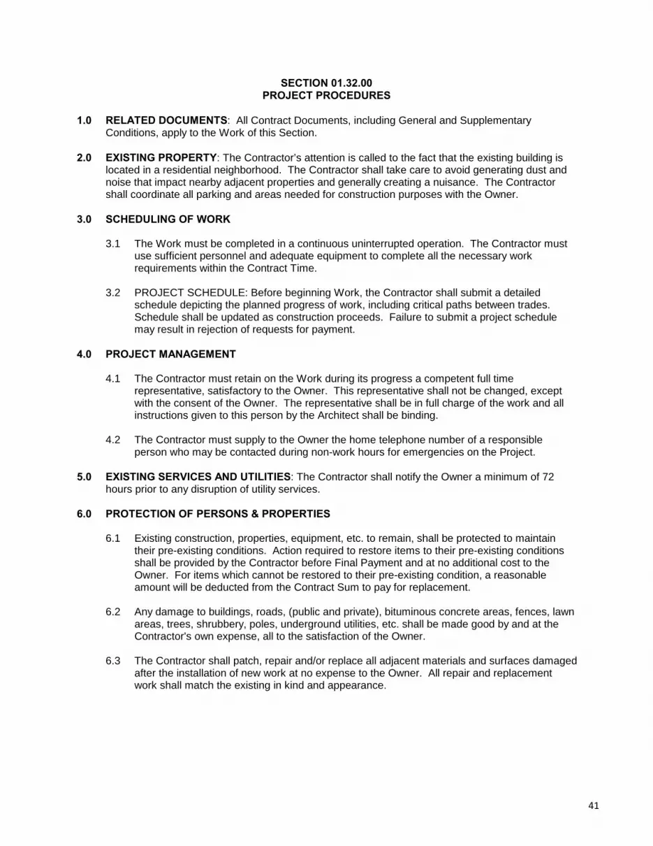
SECTION 01.32.00PROJECT PROCEDURES
1.0 RELATED DOCUMENTS: All Contract Documents, including General and SupplementaryConditions, apply to the Work of this Section.
2.0 EXISTING PROPERTY: The Contractor’s attention is called to the fact that the existing building islocated in a residential neighborhood. The Contractor shall take care to avoid generating dust andnoise that impact nearby adjacent properties and generally creating a nuisance. The Contractorshall coordinate all parking and areas needed for construction purposes with the Owner.
3.0 SCHEDULING OF WORK
3.1 The Work must be completed in a continuous uninterrupted operation. The Contractor mustuse sufficient personnel and adequate equipment to complete all the necessary workrequirements within the Contract Time.
3.2 PROJECT SCHEDULE: Before beginning Work, the Contractor shall submit a detailedschedule depicting the planned progress of work, including critical paths between trades. Schedule shall be updated as construction proceeds. Failure to submit a project schedulemay result in rejection of requests for payment.
4.0 PROJECT MANAGEMENT
4.1 The Contractor must retain on the Work during its progress a competent full timerepresentative, satisfactory to the Owner. This representative shall not be changed, exceptwith the consent of the Owner. The representative shall be in full charge of the work and allinstructions given to this person by the Architect shall be binding.
4.2 The Contractor must supply to the Owner the home telephone number of a responsibleperson who may be contacted during non-work hours for emergencies on the Project.
5.0 EXISTING SERVICES AND UTILITIES: The Contractor shall notify the Owner a minimum of 72hours prior to any disruption of utility services.
6.0 PROTECTION OF PERSONS & PROPERTIES
6.1 Existing construction, properties, equipment, etc. to remain, shall be protected to maintaintheir pre-existing conditions. Action required to restore items to their pre-existing conditionsshall be provided by the Contractor before Final Payment and at no additional cost to theOwner. For items which cannot be restored to their pre-existing condition, a reasonableamount will be deducted from the Contract Sum to pay for replacement.
6.2 Any damage to buildings, roads, (public and private), bituminous concrete areas, fences, lawnareas, trees, shrubbery, poles, underground utilities, etc. shall be made good by and at theContractor's own expense, all to the satisfaction of the Owner.
6.3 The Contractor shall patch, repair and/or replace all adjacent materials and surfaces damagedafter the installation of new work at no expense to the Owner. All repair and replacementwork shall match the existing in kind and appearance.
41

7.0 TEMPORARY PROTECTION
7.1 The Contractor shall:
A. Protect buildings and materials at all times from rain water, ground water, backing-up, orleakage of sewers, drains, or other piping, or from water damage of any origin. Provide allpumps, piping, coverings, and other materials and equipment as required by jobconditions to accomplish this requirement.
B. In addition to the weather protection during the months of November to March specifiedelsewhere, provide temporary watertight enclosures for openings in exterior walls whenand as required to protect the Work from damage by inclement weather. Temporaryenclosures shall be provided with adequate means of ventilation to prevent accumulationof moisture in the buildings.
C. Provide temporary wood doors for exterior entrances and elsewhere as required. Permanent door enclosures shall not be used as temporary enclosures.
D. Protect sills, jambs, and heads of openings through which materials are handled.
E. Protect decks and slabs to receive work by other trades from any soiling which willprevent proper adhesion of subsequent Work. Decks and slabs shall be left clean andfree of blemishes at the time other trades begin the application of their work.
F. Protect concrete slabs to remain exposed and finished floors against mechanical damage,plaster droppings, oil, grease, paint, or other material which will stain the floor finish. Install and maintain adequate strips of building paper or other protection on finished floorsin rooms where future Work will be done by other trades.
G. Protect all surfaces to receive work by other trades from any soiling which will preventproper execution of subsequent work.
7.2 Waterproofed surfaces shall not be subjected to traffic nor shall they be used for storage ofmaterials. Where some activity must take place in order to carry out the Work, adequateprotection must be provided.
7.3 After the installation of the Work by any Subcontractor is completed, the Contractor shall beresponsible for its protection and for repairing, replacing, or cleaning any such Work whichhas been damaged by other trades or by any other cause, so that all Work is in first classcondition at the time of Substantial Completion.
8.0 SAFETY
8.1 The project site shall be maintained in a safe and orderly state. Required exitways shall bekept clear and unobstructed at all times. Ensure egress routes are clear at all times. Ifexisting egress routes are disrupted, submit alternative plans for egress for approval by statebuilding inspector, the Authority, and the Architect.
8.2 The Contractor shall, at all times, leave an unobstructed way along walks and roadways, andshall maintain barriers and lights for the protection of all persons and property in all locationswhere materials are stored or work is in progress.
8.3 Where excavation is involved, the Contractor shall be responsible for providing continuouswatchmen services as necessary, to insure adequate protection of the general public.
42

9.0 SECURITY
9.1 The Contractor shall be responsible for providing all security precautions necessary to protectthe Contractor's and Owner's interests.
9.2 All personnel on site shall be subject to criminal background checks as required by theOwner.
9.3 The building and any interior locked spaces must remain secure and accessible at all times.
10.0 NOISE AND DUST CONTROL
10.1 The Contractor shall take special measures to protect visitors, neighbors, and the generalpublic from noise, dust, and other disturbances by:
A. Keeping common pedestrian and vehicular circulation areas clean and unobstructed.
B. Sealing dust and fumes from contaminating occupied areas.
11.0 FIRE PROTECTION
11.1 The Contractor shall take necessary precautions to insure against fire during construction. The Contractor shall be responsible to ensure that any area accessed to perform the Workunder this contract is kept orderly and clean and that combustible rubbish and constructiondebris is promptly removed from the site.
11.2 Installation of equipment suitable for fire protection shall be done as soon as possible aftercommencement of the Work. The Contractor's attention is directed to the requirements of theCommonwealth of Massachusetts, Department of Labor and Industries Regulation 454 CMR.
12.0 WEATHER PROTECTION
12.1 The Contractor shall provide Weather Protection as required by Specification Section01.50.00 Temporary Facilities and any other specific requirements of the ContractDocuments.
12.2 Should high wind warnings be issued by the U.S. Weather Bureau, the Contractor shall takeevery precaution to minimize danger to persons, to the Work, and to the adjacent property.
13.0 CLEANING DURING CONSTRUCTION
13.1 Conduct cleaning and disposal operations to comply with local ordinances and anti-pollutionlaws.
A. Pollution: Do not burn or bury rubbish and waste materials on the site. Do not dispose ofvolatile wastes such as mineral spirits, oil, or paint thinner in storm or sanitary drains. Donot dispose of wastes into streams or waterways.
B. Dust: Wet down dry materials and rubbish to lay dust and prevent blowing dust. Do notallow materials and rubbish to drop free or be thrown from upper floors, but remove byuse of a material hoist or rubbish chutes.
C. Maintain the site free from accumulations of waste, debris, and rubbish. Provide on-sitecontainers for collection of waste materials and rubbish. Remove and legally disposewaste materials and rubbish from site. Disposal of materials shall be in compliance withall applicable laws, ordinances, codes, and by-laws.
43

D. Vacuum clean interior building areas when ready to receive finish painting, and continuevacuum cleaning on an as-needed basis until Substantial Completion. Schedule cleaningoperations so that dust and other contaminants resulting from cleaning process will not fallon wet, newly painted surfaces.
14.0 PROJECT MEETINGS: Project meetings shall be held to aid coordination and planning ofconstruction progress. The Contractor, the Architect, and the Owner shall mutually agree on aschedule of regular project meetings. The Owner and the Architect reserve the right to requirespecial meetings at which the attendance of the Contractor and affected sub-contractors is required.
END OF SECTION
44

SECTION 01.33.00SUBMITTALS
1.0 RELATED DOCUMENTS: All Contract Documents, including General and SupplementaryConditions, apply to the Work of this Section.
2.0 COPIES AND DISTRIBUTION
2.1 COPIES: Electronic files for all submittals requiring action by the Architect are preferred, butare not permitted for MEP submittals. For all hard copy submittals, a minimum of 7 printsshall be submitted.
2.2 SCHEDULING: The Contractor is responsible for the scheduling of all submittals to allow foradequate time for review and approval; fabrication; and installation. Allow a minimum of 10working days for the Architect's review and approval of each submission. Failure to plan forthe review process shall not relieve the Contractor of his responsibilities to meet the ContractTime.
2.3 PREPARATION: Each submittal shall be identified with the Contractor's name, manufacturer'sname, Project name, date, and reference numbers of relevant Specifications sections andDrawings. The Contractor shall modify and customize all submittals to show all dimensionsand coordination with adjacent work and field conditions. Clearly note and describe allqualifications to and deviations from the Contract Documents. The Contractor shall stamp,date, and sign each submittal to attest to his review and approval before submitting it to theArchitect. Submittals not prepared in accordance with these requirements shall be returnedwithout action to the Contractor.
2.4 DISTRIBUTION: Submittals which are marked "Approved" or "Approved as Noted" by theArchitect, following the guidelines stipulated below in subparagraph 4.2 will be returned to theContractor for distribution, with 2 copies retained by the Architect. Contractor shall distributecopies to subcontractors and all other parties requiring the information contained in thesubmittal.
3.0 REQUIRED SUBMITTALS
3.1 SCHEDULE OF VALUES: A Schedule of Values distinguishing the values of labor andmaterials for each trade component shall be submitted to the Architect prior to the first requestfor payment.
A. The total value for General Conditions, including costs for bonds and insurance, shall totala minimum of 10% of the total contract amount.
B. No values shall be assigned to the preparation of shop drawings.
3.2 ESTIMATED PAYMENT SCHEDULE: A schedule of anticipated monthly payment requestsshall be submitted to the Architect prior to the first request for payment.
3.3 PRODUCT DATA: Manufacturer's printed literature, when required by the Specifications, shallbe submitted to the Architect for review. One approved copy shall be included in theMaintenance Manual in accordance with Section 01.77.00.
3.4 SHOP DRAWINGS: Submit accurate, detailed, large scaled drawings prepared specifically forthis Project. Drawings shall show adjacent conditions, related work, accurate fielddimensions, materials, products, and any required special coordination.
3.5 SAMPLES, when required by the Specifications, shall be submitted to the Architect for review. In-place samples shall be in accordance with the Specifications.
45

3.6 WARRANTIES: Warranties and certifications, as required by the Specifications, shall besubmitted to the Owner through the Architect. Warranties shall become effective uponSubstantial Completion.
4.0 ARCHITECT'S ACTION ON SUBMITTALS
4.1 The Architect will review product data and samples for conformity to the design intent of theContract Documents. Approval by the Architect shall not relieve the Contractor of hisresponsibilities to fulfill all the requirements of the Contract.
4.2 The Architect's action will have the following meanings:
A. Approved: Work covered by the submittal may proceed. Approval by the Architect doesnot relieve the Contractor of responsibilities to comply with the requirements of theContract Documents without limitation.
B. Approved as Noted: Work covered by the submittal may proceed provided it complieswith the Architect's notes. A re-submission of the submittal is not required. Neitherapproval by the Architect and nor the Architect’s notes relieve the Contractor ofresponsibilities to comply with the requirements of the Contract Documents withoutlimitation.
C. Revise and Resubmit: Make changes to the submittal as noted and resubmit to theArchitect for review before work covered by the submittal can proceed.
D. Disapproved: Prepare a new submittal and resubmit to the Architect for review beforework covered by the submittal can proceed.
4.3 Submittals not requiring action by the Architect shall be retained for information only.
5.0 REQUESTS FOR SUBSTITUTIONS
5.1 Requests for product substitutions shall be submitted for review and approval prior to thecommencement of Work. Clearly identify the product to be replaced by the substitute.
5.2 Product substitutions are not allowed except with evidence provided by the Contractor of oneof the following conditions.
A. The product substitution is allowed under an "or equal" clause in the Specifications.
B. The specified product is not produced or cannot be produced in time to meet the ContractTime.
C. The specified product is not acceptable to authorities having jurisdiction.
D. There is substantial advantage to the Owner in terms of cost, time, or value with the useof the substitute product.
5.3 The Architect shall be the sole judge of whether a proposed substitution is comparable to theproduct specified and meets the requirements specified.
6.0 REQUESTS FOR PAYMENT
6.1 Submit 4 originals of each request for payment on MSP SB1 form. Provide completedocumentation to substantiate requests.
46

6.2 Before the first request for payment can be approved, the following items, some of which arestipulated in other Sections, must be submitted:
A. Schedule of Values. B. Estimated Payment Schedule.C. Project Schedule.D. List of Contractor's key project personnel.E. Contractor's Certificate of Insurance.F. Performance and Payment Bonds.
END OF SECTION
47

SECTION 01.41.00 REGULATORY REQUIREMENTS
1.0 RELATED DOCUMENTS: All Contract Documents, including General and SupplementaryConditions, apply to the Work of this Section.
2.0 GENERAL REGULATORY REQUIREMENTS
2.1 All Work shall comply with all codes, standards, and requirements of all federal, state, andlocal authorities having jurisdiction over this Project. The Contractor shall be responsible forproviding evidence of compliance when required to do so.
2.2 When a specific code or standard is referenced in the Contract Documents, the Contractorshall be responsible for understanding general and specific requirements of that code orstandard. Except as specified otherwise, comply with current industry standards in effect asof the date of the Owner/Contractor Agreement. The Contractor shall verify that materials andworkmanship used meets or exceeds the requirements of the code or standard referenced bythe Contract Documents.
2.3 When a discrepancy exists between an applicable code or standard and the requirements ofthe Contract Documents, the more restrictive requirement or higher quality material orworkmanship is required.
END OF SECTION
48

SECTION 01.50.00TEMPORARY FACILITIES
1.0 RELATED DOCUMENTS: All Contract Documents, including General and SupplementaryConditions, apply to the Work of this Section.
2.0 WEATHER PROTECTION
2.1 The Contractor shall provide temporary enclosures and heat to permit work to be carried onduring the months of November through March. These specifications are not to be construedas requiring enclosures or heat for operations that are not economically feasible in the opinionof the Owner. Without limitation this includes such items as excavation, pile driving, steelerection, erection of certain exterior wall panels, roofing, and similar operations.
2.2 "Weather Protection" means the temporary protection of that Work adversely affected bymoisture, wind, and cold by covering, enclosing, and/or heating. This protection shall provideadequate working areas during the months of November through March as determined by theOwner and consistent with the construction schedule to permit the continuous progress of allWork necessary to maintain an orderly and efficient sequence of construction operations. TheContractor shall furnish and install "Weather Protection" material and be responsible for allcosts, including heating required to maintain a minimum of 40 F at the working surface. Thiso
provision does not supersede any specific requirements for methods of construction, curing ofmaterials, or the applicable conditions set forth in the Contract Articles with added regard toperformance obligations of the Contractor.
2.3 The Contractor shall assume the entire responsibility for weather protection duringconstruction (until Substantial Completion), and shall be liable for any damage to any Workcaused by failure to supply proper weather protection and proper ventilation.
2.4 It is to be specifically understood that the Contractor shall do no work under any conditionsdeemed unsuitable by the Contractor to the perfect execution of the Work. This provisionshall not constitute any waiver, release, or lessening of the Contractor's obligation to bring theWork to Substantial Completion within the period of time set forth in the Contract Documents.
3.0 TEMPORARY OFFICE: The Owner shall provide a suitable space in the existing building for use bythe Contractor as an office.
4.0 TEMPORARY TELEPHONE: The Contractor shall provide telephones for use by the Contractor’spersonnel. The Owner shall provide internet and telephone service.
5.0 TEMPORARY TOILETS: The Contractor may use existing toilet facilities provided the Contractor isresponsible for daily cleaning.
6.0 TEMPORARY WATER
6.1 The Contractor can use the on-site water supply, providing temporary water connections andpaying costs thereby incurred. This includes the furnishing, installing, and removing ofequipment and piping to provide water for the execution of the Work.
6.2 The Contractor shall pay the cost of water consumed by trades until Substantial Completion.
6.3 The Contractor shall provide an adequate supply of cool drinking water with individual drinkingcups for the personnel on the job.
49

7.0 TEMPORARY HEAT
7.1 The Contractor shall provide minimum temperatures as specified for storage of materials andfor construction activities.
7.2 The Contractor may utilize the existing heating system for temporary heat, providing theContractor complies with all provisions stated elsewhere in the Contract Documents and thefollowing.
A. The Contractor shall furnish and pay the costs of any materials and equipment which arenot part of the permanent heating system and which may be required to operate thepermanent heating system on a temporary basis.
B. The heating Subcontractor shall be in charge of and provide all labor required for theattendance, operation and final restoration of the permanent heating system and fortemporary heating purposes during working hours. The Contractor shall check theheating system a minimum of twice daily, when no work is being performed at the site.
C. The Contractor shall reimburse the heating Subcontractor for costs incurred in providingtemporary heating that is not part of the permanent heating system until SubstantialCompletion.
7.3 Installation of weather protection and heating devices shall comply with all safety regulationsincluding provisions for adequate ventilation and fire protection devices.
7.4 The Contractor shall provide thermometers at places designated by the Architect in order todetermine if specified temperatures are being maintained.
7.5 Unit heaters, if used, shall be of the smokeless type and be installed and operated in such away that finished work will not be damaged. "Salamanders" shall not be used.
8.0 TEMPORARY ELECTRICITY: The Contractor may use electricity available at the site. Contractorshall provide proper adapters, extension cords, etc. for connection to existing power. All temporaryelectrical work shall be in conformance with codes and requirements of the power company.
9.0 TEMPORARY CONSTRUCTION FENCE: The Contractor shall be responsible for providing andmaintaining temporary fencing or barricades around the construction as may be necessary to assurethe safety of all persons authorized or unauthorized. Such protective measures shall be located andconstructed as required by local, state, and federal ordinances, laws, codes, or regulations.
10.0 TEMPORARY STRUCTURES AND MATERIAL HANDLING
10.1 The Contractor shall provide such storage sheds, temporary buildings, or trailers as requiredfor the performance of the Contract. Subcontractors shall provide their own temporarybuildings and trailers.
10.2 Materials shall be handled, stored, installed, cleaned, and protected in accordance with thebest practice in the industry and, except where otherwise specified in the ContractDocuments, in accordance with manufacturer's specifications and directions.
11.0 TEMPORARY STAGING, STAIRS, CHUTES
11.1 Filed Sub-bid contractors shall furnish, install, maintain, and remove all scaffolds, staging, andplanking as required for the proper execution of the Work in their Sections. The Contractorshall furnish, install, maintain in safe condition, and remove all scaffolds, staging, and plankingover 8 ft. in height, as required for the use of all trades for proper execution of the Work.
50

11.2 The Contractor shall furnish, install, maintain in safe condition, and remove all temporaryramps, stairs, ladders, and similar items as required for the use of all trades for the properexecution of the Work.
11.3 The Contractor shall furnish, install, maintain, and remove covered chutes from openings inthe exterior walls of upper floors. Such shall be in convenient locations and permit disposal ofrubbish directly into trucks or disposal units. Debris shall not be allowed to fall freely fromupper levels of the building. Materials shall not be dropped from open windows.
12.0 HOISTING FACILITIES: Filed Sub-bid contractors shall provide, operate, and remove material,hoists, cranes, and other hoisting as required for the proper execution of the Work of their Sections.The Contractor shall provide, operate, and remove material hoists, cranes, and other hoisting asrequired for the performance of the Work by all trades. The existing elevator may not be used as afreight elevator for heavy materials brought into or out of the building.
END OF SECTION
51

SECTION 01.77.00CONTRACT CLOSEOUT
1.0 RELATED DOCUMENTS: All Contract Documents, including General and SupplementaryConditions, apply to the Work of this Section.
2.0 SUBSTANTIAL COMPLETION
2.1 The Project shall be considered in Substantial Completion when there is less than onepercent of the Contract remaining to be completed. The following items must be completedbefore the Architect makes his inspection for Substantial Completion.
A. Submission of Contractor's Punch List of incomplete items.
B. Submission of all warranties and similar documents.
C. Submission of Record Documents.
D. Submission of Maintenance Manual.
E. Record of compliance with labor wage rates is up to date.
F. Replacement of all broken glass and repair of damaged items (existing and new) andfinishes.
G. Delivery of maintenance stocks of materials where specified.
H. Clean-up of work.
3.0 CONTRACTOR'S PUNCH LIST
3.1 Prior to requesting Substantial Completion, the Contractor shall make a thorough inspection ofthe Work. During this inspection the Contractor shall prepare a comprehensive list of all itemsremaining to be completed or corrected. This list shall include all remaining Contractor itemsto be provided under the Contract Documents. After reviewing the Contractor's list, theArchitect may amend the list with additional items that are not acceptable or incomplete.
3.2 The Contractor shall not be relieved of the responsibility to provide Contract items left off ofthe punch list.
4.0 RECORD DRAWINGS
4.1 Consult the individual sections of the Specifications for the specific requirements of thosesections. In cases of inconsistency the more stringent requirement, as directed by theArchitect, shall be required.
4.2 From the sets of Contract Drawings furnished by the Owner, the Contractor shall reserve oneset for record purposes. From this set, the Contractor shall detach and furnish, at no chargeto the Mechanical and Electrical Subcontractors the drawings of their portion of the Work forthe same purpose.
4.3 The Contractor and the above Subcontractors shall keep their marked up As-Built set on thesite at all times and note on it in colored ink or pencil, neatly and accurately, at the end ofeach working day, the exact location of their work as actually installed. This shall include thelocation and dimensions of underground and concealed Work, and any architectural,mechanical, or electrical variations from the Contract Drawings. All changes, including those
52

issued by Addendum, Change Order, or instructions by the Architect shall be recorded. Marked up As-Built drawings shall be prepared for the entire project and include all Work,including but not limited to:
A. The location of all internal utilities and appurtenances, concealed by finish materials,including but not limited to valves, coils, dampers, vents, cleanouts, strainers, pipes,junction boxes, turning vanes, variable and constant volume boxes, ducts, traps, andmaintenance devices.
B. The location of these items shall be shown by offsets to structure and drawing grid lines. The tolerance for the actual location of these items on the marked up As-Built Drawingsshall be plus or minus two (2) inches.
C. Each item shall be referenced by showing a tag number, areas served, and function onthe marked up As-Built drawing
4.4 The Architect may periodically inspect the marked up As-Built drawings at the site. Theproper and current maintenance of the information required on these drawings shall be acondition precedent to approval of the monthly applications for payment.
4.5 At Substantial Completion the Contractor shall submit the complete set of marked up As-Builtdrawings to the Architect. The Contractor shall check all marked up As-Builts prepared bysubcontractors and certify in writing on the title sheet of the drawings that they are completeand correct, prior to submission to the Architect.
4.6 Submission of accurate marked up As-Built drawings and their approval by the Architect shallbe a condition precedent to final payment.
5.0 OPERATING AND MAINTENANCE INSTRUCTIONS
5.1 Consult the individual sections of the specifications for the specific requirements for thosesections and for further details and descriptions of the requirements
5.2 Prior to final payment and completion the Contractor shall provide all Operating Manuals andMaintenance Instructions as required by the Contract Documents.
5.3 OPERATING INSTRUCTIONS AND MANUALS
A. Installers, and suppliers shall furnish to the Contractor two sets of operating andmaintenance instructions of all manually operated equipment furnished and installed bythem.
B. The Contractor shall collect all of the above instructions, bind them into two completesets, and submit them to the Architect who will deliver them to the Owner.
C. Submission of operating and maintenance instructions shall be a condition precedent tofinal payment.
5.4 INSTRUCTION OF OWNER'S PERSONNEL
A. Where specified in the individual sections of the specifications, the Contractor andSubcontractor shall instruct the Owner's personnel at the site, in the use and maintenanceof equipment installed under the Contract.
B. Submission to the Architect of a certificate of compliance to this requirement, signed bythe Contractor and the Owner's Representative, shall be a condition precedent to finalpayment.
53
6.0 FINAL CLEANING
6.1 Prior to submitting a request to the Architect to certify Substantial Completion of the Work, theContractor shall inspect all interior and exterior spaces and verify that all waste materials,rubbish, tools, equipment, machinery, and surplus materials have been removed, and that allsight-exposed surfaces are clean. Leave the Project clean and ready for occupancy. Cleaning shall include all surfaces, interior and exterior, which the Contractor has had accessto. Employ experienced workmen or professional cleaners for final cleaning. Unlessotherwise specified under other sections of the Specifications, the Contractor shall performfinal cleaning operations as herein specified prior to final inspection.
A. All broken or defective glass caused by the Contractor's Work shall be replaced at theexpense of the Contractor. Clean and polish all new and existing glass and plasticglazing (if any) in construction area, on both sides. Clean plastic glazing in accordancewith the manufacturer's directions. This cleaning shall be completed by qualified windowcleaners at the expense of the Contractor just prior to acceptance of the Work.
B. Repair, patch, and touch up marred surfaces to the specified finish, to match adjacentsurfaces.
C. Remove grease, mastic, adhesive, dust, dirt, stains, labels, fingerprints, and other foreignmaterials from sight-exposed interior and exterior surfaces. This includes cleaning of theWork of all finishing trades where needed, whether or not cleaning by such trades isincluded in their respective specifications.
D. In cleaning items with manufacturer's finish or items previously finished by aSubcontractor, care shall be taken not to damage such manufacturer's or Subcontractor'sfinish. In cleaning glass and finish surfaces, care shall be taken not to use detergents orother cleaning agents which may stain adjoining finish surfaces. Any damage to finishescaused by cleaning operations shall be repaired at the Contractor's expense. Polishglossy surfaces to a clear shine.
E. Do the final cleaning of resilient floors as specified under the respective section of theSpecifications.
F. Leave all architectural metals, hardware, and fixtures in undamaged, polished conditions.
G. Leave pipe and duct spaces, plenums, furred spaces and the like clean of debris anddecayable materials.
H. Broom clean exposed concrete surfaces and paved surfaces. Rake clean other surfacesof grounds.
I. Ventilating systems - Replace filters and clean ducts, blowers, and coils if units wereoperated during construction.
6.2 Use only cleaning materials recommended by the manufacturer of the surface to be cleaned. Use cleaning materials which will not create a hazard to health or property and which will notdamage surfaces.
7.0 FINAL ACCEPTANCE
7.1 OCCUPANCY PERMIT: The Contractor shall coordinate the efforts of all Subcontractors andobtain the Occupancy Permit from the local Building Department. The Owner shall pay anyBuilding Department fee associated with the Occupancy Permit.
54

7.2 FINAL PAYMENT shall be made only upon the completion of the following items:
A. Requirements for Substantial Completion and satisfactory inspection by the Architect.
B. Submission of a certified copy of the final Punch List verifying that the Contractor hascompleted all items on the List.
C. Final cleaning of the premises.
7.3 FINAL CLEANING: The premises shall be restored to pre-existing conditions. All areas shallbe clean and free from dirt, dust, and debris.
END OF SECTIONAND DIVISION 01
55

DIVISION 02 - EXISTING CONDITIONS
SECTION 02.41.19SELECTIVE DEMOLITION
1.0 PART 1: GENERAL
1.1 GENERAL REQUIREMENTS: All Contract Documents, including General and SupplementaryConditions, General Requirements (Division 01), and Drawings, apply to the Work in thisSection.
1.2 DESCRIPTION OF WORK
A. The Work of this Section includes all labor, materials, tools, and equipment needed toselectively demolish existing construction as shown on the Drawings and as specified.
B. The Work of this Section includes, but is not limited to:
1. Sawcutting anddemolition of existing concrete slab for plumbing connections at newtoilet room.
2. Sawcutting and demolition of portions of existing concrete base.3. Demolition of interior wood stud partitions.4. Demolition of existing doors.5. Demolition of door hardware for replacement with new hardware at existing doors.6. Demolition of existing casework and millwork.7. Demolition of existing floor and ceiling finishes.8. Cutting and coring for other trades.9. Removal of demolished materials from the site.10. Removal and disposal of materials disconnected and demolished by other trades.11. Cleaning of spaces and surfaces after demolition.
C. Intent: The intent of the demolition Work is to safely remove and properly dispose of allexisting construction, both expressly shown and not expressly shown on the Drawings, asrequired to complete new construction.
D. Alternates: Alternates #1-3 affect the Work of this Section. Closely examine the ContractDocuments to determine the full extent that alternates affect the Work of this Section.
1. Alternate #1: Demolish door hardware from exterior door. Demolish metal stairtread covers and nosings.
2. Alternate #2: Remove and dispose of additional light fixtures disconnected anddemolished by electrical subcontractor. Demolish existing glued down sheet carpetand ceramic tile wainscot. Detach and remove cabinets and shelving units.
3. Alternate #3: Remove and dispose of light fixtures disconnected and demolishedby electrical subcontractor. Demolish and remove shelving. Demolish and removepipe insulation from exposed pipes.
1.3 RELATED WORK
A. Carefully examine all the Contract Documents for requirements which affect the Work ofthis Section.
56

B. Other Work which directly relate to the Work of this Section include, but are not limited to:
1. Cast-in-Place Concrete (Section 03.30.00).2. Metal Doors and Frames (Section 08.11.00)3. Plumbing (Section 22.00.00).4. Electrical (Division 26)
1.4 SUBMITTALS
A. Permits and Certificates
1. Permits and notices authorizing building demolition.2. Certificates of severance of utility services.3. Permit of transport and legal disposal of debris.
B. Schedule: Submit proposed methods and schedule of demolition prior to the start ofWork. Include the coordination for shut-off, capping, and continuation of utility services asrequired.
1.5 EXISTING CONDITIONS
A. Existing Structure: The Owner and Architect assume no responsibility nor make anyclaim regarding the condition or structural adequacy of existing construction to bedemolished.
B. Existing Uses: The property is located in a residential neighborhood. The Contractor shalltake care not to disrupt other uses of the property and shall protect the construction sitefrom other users. The Contractor shall take care to avoid generating dust and noise thatimpact nearby uses and generally creating a nuisance.
C. Hazardous Materials: Inspections and testing of asbestos containing materials will beconducted and remediation will be completed under separate contract. Generaldemolition work shall begin only after asbestos abatement completion has been cleared.
1.6 PROJECT CONDITIONS
A. Public Safety: Ensure the safe passage of persons and traffic on and around the Projectsite, the Owner's property, adjacent properties, and public ways.
B. Explosives: Do not bring explosives to the site or use explosives.
C. Damages: Report all damages immediately. Promptly repair damages caused bydemolition operations at no cost to the Owner.
2.0 PART 2: PRODUCTS
2.1 PROTECTIONS: Provide miscellaneous protections including, but not limited to dust barriers,plywood panels, and moisture barriers.
2.2 SHORING: Provide temporary shoring and bracing of adequate size and proper configurationto maintain the integrity of existing building.
3.0 PART 3: EXECUTION
3.1 INSPECTION: Inspect and verify all existing conditions before beginning Work.
57

3.2 PROTECTION
A. Ensure safety of persons and property at all times. Provide temporary shoring andbracing as required. Protect openings. Maintain weathertightness.
B. Protect against damage to existing construction to remain.
C. Ensure egress routes are clear at all times. If existing egress routes are disrupted, submitalternative plans for egress for approval by local building inspector, the Owner, and theArchitect.
3.3 DEMOLITION
A. General
1. Demolish all existing construction designated to be demolished or removed andremove from site, unless material is noted to be salvaged.
2. Demolish and remove all existing construction required for the proper completion ofnew work, not expressly indicated on the Drawings. Identify and remove allconstruction which is unsuitable for re-use. Notify the Architect and obtain approvalbefore removing construction which is not indicated on the Drawings.
3. Use demolition methods within the limitations of governing regulations.
4. Use demolition methods which will ensure existing construction to remain is notdamaged. Use saws and drills to ensure neat, accurately formed joints and holes.
5. Remove all debris from site and dispose of legally.
6. Ensure structure and construction is adequately and properly shored and supportedbefore, during, and after demolition.
B. Pollution Controls: Use water sprinkling, temporary enclosures, and other suitablemethods to limit the amount of dust and dirt rising and scattering in the air to the lowestpractical level. Comply with governing regulations pertaining to environmental protection.
C. Interior Construction: Remove existing walls, doors and frames, finish flooring, and otherinterior construction using methods and tools which will minimize the amount of patchingof walls and floors to remain.
D. Concrete Ground Slabs: Limit removal of concrete slab sections to the minimum amountrequired for completion of new Work. The structural integrity of slabs shall not becompromised. Removal and interruption of existing slab reinforcing shall only beperformed with approval by the Architect. Should removal of slab reinforcing beapproved, remove additional concrete as required to permit proper overlapping of newreinforcing. Avoid disruption and puncturing of existing vapor retarders under slabs. Should removal of sections of vapor retarders be necessary, remove additional concreteas required to permit overlapping and sealing of new vapor retarder.
E. Lead Containing Items: Assume all paint contains hazardous levels of lead until testresults show otherwise. Remove all paint scrapings and painted materials in strictcompliance with OSHA and all applicable environmental regulations governing leadremoval. Demolished painted metal items exhibiting no flaking or scaling paint shall be
58

recycled in the metal salvage market. Paint scrapings and painted non-metal items shallbe tested for EP toxicity in accordance with 310 CMR 30. Materials found to exceed theallowable toxicity limit of 5.0 milligrams/liter shall be disposed of as hazardous waste instrict compliance with 310 CMR 30 and U.S. Department of Transportation regulations49CFR Parts 170 through 179 inclusive.
F. Assume all existing light ballasts contain polychlorinated biphenyl (PCB). Assume allexisting lamps and thermostats contain mercury. Remove, containerize, and dispose of inaccordance with all applicable state and federal regulations. The disposal of thesematerials shall be to a TSCA licensed facility.
3.4 SALVAGED ITEMS
A. Remove and salvage existing door hardware as shown on the drawings. Clean, protect,and temporarily store for reuse.
3.5 CLEANING AND PROTECTION
A. General Cleaning: Remove protections and clean surfaces exhibiting dust and dirt fromdemolition activities.
END OF SECTIONAND DIVISION 02
59

DIVISION 03 - CONCRETE
SECTION 03.30.00CAST-IN-PLACE CONCRETE
1.0 PART 1: GENERAL
1.1 GENERAL REQUIREMENTS: All Contract Documents, including General and SupplementaryConditions, General Requirements (Division 01), and Drawings, apply to the Work in this Section.
1.2 DESCRIPTION OF WORK
A. The Work in this Section includes all labor, materials, tools, and equipment needed tocomplete concrete foundations as shown on the Drawings and as specified.
B. The Work includes, but is not limited to:
1. Formwork, reinforcing, concrete, and accessories.2. Patching existing concrete surfaces previously demolished or disturbed by the work
of this contract.
1.3 RELATED WORK
A. Carefully examine all the Contract Documents for requirements which affect the Work ofthis Section.
B. Other specifications which directly relate to the Work of this Section include, but are notlimited to:
1. Rough Carpentry (Section 06.10.00)2. Ceramic Tiling (Section 09.30.00).3. Plumbing (Section 22.00.01).
1.4 QUALITY ASSURANCE
A. Standards: All Work shall comply with applicable portions of the following referencedindustry standards:
1. ACI 301, Specifications for Structural Concrete for Buildings.2. ACI 303R, Guide to Cast-in-Place Architectural Concrete Practice.3. ACI 304, Recommended Practice for Measuring, Mixing, Transporting, and Placing
Concrete.4. ACI 306, Cold Weather Concreting.5. ACI 307, Hot Weather Concreting.6. ACI 308, Standard Practice for Curing Concrete.7. ACI 315, Details and Detailing of Concrete Reinforcement.8. ACI 318, Building Code Requirements for Reinforced Concrete.9. ACI 347, Recommended Practice for Concrete Formwork.10. ASTM A185, Welded Steel Wire Fabric for Concrete Reinforcement.11. ASTM A615, Deformed Billet Steel for Concrete Reinforcement.12. ASTM C31, Method of Making and Curing Concrete Test Specimens.13. ASTM C33, Concrete Aggregates.14. ASTM C39, Test Method for Compressive Strength of Cylindrical Concrete
Specimens.15. ASTM C88, Soundness of Aggregates by Use of Sodium Sulfate.16. ASTM, C94, Specification for Ready-mix Concrete.
60

17. ASTM C150, Portland Cement.18. ASTM C172, Method of Sampling Fresh Concrete.19. ASTM C260, Air Entraining Admixtures for Concrete.20. ASTM C231, Test Method for Air Content of Fresh Concrete.
B. TESTING: The Owner reserves the right to test any materials by an independent testingagency to verify conformity to Contract Documents. The cost of failed tests shall be borneby the Contractor and corrective work shall be performed at no additional cost to theOwner.
1.5 SUBMITTALS
A. Certificates of Compliance: Submit signed statement of compliance with specifiedrequirements for the concrete mixes, cement, aggregate, and reinforcing steel.
B. Product Data: Submit manufacturer's product data, including product analysis andrecommended use and limitations for air entraining admixtures, form releasing agent, andcuring compound.
C. Reports: Submit written reports for concrete mixes, proposed curing methods, andcertified daily records at concrete placement locations.
D. Shop Drawings: Submit large scaled detailed drawings for fabricating and placingreinforcing steel. Show all required information for cutting, bending, and placingreinforcing bars and show all accessories and support bars on placing drawings. Indicatesuitable marks for placing bars.
1.6 DELIVERY, HANDLING, AND STORAGE
A. Aggregate: Store aggregate to prevent deterioration or contamination by foreign matter.
B. Reinforcement and Metal Accessories: Store off the ground and protect fromdeterioration by weather, dirt, and construction operations.
C. Other Materials: Deliver, handle, and store and protect other materials strictly inaccordance with manufacturers' recommendations.
1.7 PROJECT CONDITIONS: Comply with the requirements of ACI 301, ACI 306R, and ACI307R when performing concreting work in temperatures below 45 F and above 90 F.o o
2.0 PART 2: PRODUCTS
2.1 CEMENT: Cement shall meet the requirements of ASTM C150, Type I or Type II. One brandof cement shall be used throughout the Work.
2.2 AGGREGATE
A. Fine Aggregate: Washed, inert, natural sand that meets the requirements of ASTM C33. Fine aggregate shall be uniform in color and come from the same source.
B. Course Aggregate: Well-graded, washed gravel or crushed stone that meets therequirements of ASTM C33.
61

C. Aggregate Gradation: Conform to the following:
Sieve % (by weight) Finer (passing through)1" 1003/4" 95-1003/8" 20-55No. 4 0-10No. 8 0-5
D. Aggregate shall not show average loss of more than 6% for fine aggregate and 7½% forcoarse aggregate when subjected to five cycles of sodium sulfate soundness test asdetermined by ASTM C88.
2.3 WATER: Water used in mixing concrete shall be potable, clean, and free from deleteriousmaterials.
2.4 ADMIXTURES
A. Air Entraining Admixture: Conform to ASTM C260. Testing shall be done as specified inASTM C173 or C231. Limits shall be 4% to 6%.
B. The use of calcium chloride is strictly prohibited.
C. The use of other admixtures must be approved by the Architect.
2.5 CONCRETE MIXES
A. Source: Concrete shall be the product of a central mix plant or a ready mix plant withtransit mixing equipment, and shall be composed of cement, aggregate, admixtures, andwater in proportions to develop designated strength and to satisfy requirements fordurability and appearance.
B. Mix Designs: Provide the following concrete strengths for each application.
1. Slabs: 4,000 psi, maximum W/C ratio of 0.50, 4%-6% entrained air content, 3"-4"slump.
2.6 REINFORCEMENT
A. Rebars: Provide ASTM A615, Grade 60.
1. Provide smooth shear dowels for connecting new concrete to existing concrete or asdetailed on the Drawings.
2. Provide deformed bars for reinforcing foundations.
B. Welded Wire Fabric: 6X6 6/6 WWF shall meet ASTM A185 and be supplied in sheets.
C. Accessories: Reinforcement accessories resting on forms shall conform in type and ingauge of material to those designated in ACI 315. Provide solid precast concrete blocksto support reinforcement in concrete laid on sub-grade.
2.7 FORMS
A. Forms: Douglas Fir structural grade plywood conforming to US Commercial StandardCS-45.
62

B. Form Releasing Agent: Non-staining mineral oil or form coating compound, or two coatsof nitrocellulose lacquer.
2.8 CONCRETE ACCESSORIES
A. Grout: Non-shrink, premixed compound consisting of non-metallic aggregate, cement,water reducing and plasticizing agents, and capable of developing minimum compressivestrength of 3,000 psi in 28 days.CS-45.
B. Vapor Retarder: 15 mil polyolefin sheet membrane in conformance with class Arequirements of ASTM E 1745
3.0 PART 3: EXECUTION
3.1 INSPECTION: The Installer shall examine previous work, related work, and conditions underwhich this Work is to be performed and notify the General Contractor in writing of alldeficiencies and conditions detrimental to the proper completion of his Work. Beginning Workmeans the Installer accepts substrates, previous work, and conditions.
3.2 FORMWORK
A. Design and Construction: Formwork shall be designed for loads, lateral pressures,tolerances of dimension, and allowable stresses stipulated in ACI 347. Formwork shall beplumb, straight, and sufficiently tight to prevent loss of cement, grout, or water duringplacement.
B. Releasing Agent: Forms and form linings in contact with concrete placement shall betreated with form releasing agent applied according to manufacturer's instructions. Releasing agent shall be applied in two coats for first use of form and in one coat for eachadditional use.
C. Cleaning: Forms shall be thoroughly cleared of debris and foreign matter before eachuse.
D. Tolerances: Erect formwork straight and plumb within the following tolerances.
1. ¼" in 10' deviation from horizontal and vertical lines.2. ¼" deviation from indicated dimensions.3. ±¼" deviation in thickness of slabs, foundations, and footings.
3.3 REINFORCEMENT
A. Bonding: Reinforcing shall be clean and free of loose mill scale, heavy rust, formreleasing agent, or any other material that may affect bonding.
B. Bending: Rebars shall be bent cold and shall not be heated for any purpose.
C. Placement: Place welded wire fabric in large flat sheets and lap seams at least 10". Support WWF at least 3'-0" o.c. Reinforcing supports, wire ties, and spacers shall beplaced to avoid exposure in finished slab.
D. Concrete Cover: Concrete cover for reinforcement shall be as shown on the Drawings,but in no case less than dimensions indicated in ACI 318.
63

3.4 BATCHING, MIXING, AND CONVEYING CONCRETE
A. Concrete shall be batched at the plant by weight, with water measured by volume, andadmixtures dispensed and used in accordance with manufacturer's recommendations.
B. Concrete from central mixing plant shall be agitated continuously in transit.
C. Concrete not used within 1½ hours after cement is added to mixture shall not be used. Retempering or remixing with or without the addition of water is prohibited.
3.5 PLACEMENT OF CONCRETE
A. Inspection: No concrete shall be placed until forms, reinforcing steel, pipes, conduits,sleeves, inserts, anchors, and other work required to be built into concrete has beenproperly installed and inspected by the Architect.
B. Conveying: Transport concrete from truck to place of final deposit as rapidly as practicalby methods which prevent separation of ingredients and displacement of reinforcement,and which avoid rehandling. Partially hardened concrete shall not be displaced under anycircumstances.
C. Chutes: When concrete is conveyed by chutes, chutes shall be U-shaped and shall bemetal or metal lined with a continuous slope. Aluminum chutes shall not be used.
D. Depositing: Deposit concrete continuously or in lifts not exceeding 12" so that noconcrete shall be deposited on concrete which already has taken its initial set. Free fall ofconcrete shall not exceed 5 feet. The top of each lift shall be, in all cases, free fromlaitance. Concrete shall not be allowed to flow horizontally in forms over distances inexcess of 5 feet.
E. Vibrating: Internally vibrate concrete after placement manually and mechanically toeliminate air pockets. Contractor is required to have a spare vibrator on site.
F. Curing: Protect newly placed concrete against low and extremely high temperatures andagainst rapid loss of moisture. During curing period, concrete shall be maintained at aminimum temperature of 50 degrees F. Duration of curing, measured in degree days,shall be in strict accordance with ACI 301.
3.6 CLEANING, PATCHING, AND REPAIRING
A. Patching and Repair: Patch and repair spalled and honeycombed surfaces not conformingto specified finish quality.
B. Cleaning: Clean exposed concrete surfaces of stains, water marks, and leaked fines.
END OF SECTIONAND DIVISION 03
64

DIVISION 04 - MASONRY
SECTION 04.01.20MASONRY RESTORATION
(Add In Alternate #2)
1.0 PART 1: GENERAL
1.1 GENERAL REQUIREMENTS: All Contract Documents, including General andSupplementary Conditions, General Requirements (Division 01), and Drawings, apply to theWork of this Section.
1.2 DESCRIPTION OF WORK
A. The Work of this Section includes the furnishing of all materials, labor, tools, andequipment required to complete restoration of interior brick as shown on the Drawings andas specified.
B. The Work of this Section includes, but is not limited to:
1. Repoint joints, voids, and cracks in existing brick walls.2. Remove and replace broken, cracked, and damaged bricks with new bricks.3. Remove miscellaneous metal items embedded in existing brick and fill remaining
voids.
C. Extent of Restoration Work: The estimated extent of restoration work is shown on theDrawings. Actual restoration work exceeding the amount shown on the Drawings by 15%shall be completed at no additional cost.
D. Alternates: Alternate #2 affects the Work of this Section. Closely examine the ContractDocuments to determine the full extent that alternates affect the Work of this Section.
1. Alternate #2: Restore masonry walls in one room.
1.3 RELATED WORK
A. Carefully examine all the Contract Documents for requirements which affect the Work ofthis Section.
B. Other Specifications which directly relate to the Work of this Section include, but are not
limited to:
1. Selective Demolition (Section 02.41.19).
1.4 QUALITY ASSURANCE
A. Contractor: Contractor shall have at least five years experience in the Work required bythis Section and shall employ skilled and experienced personnel and shall be able todemonstrate a consistent record in the performance of successful repointing and masonryrestoration work.
B. Source: For each type of material required for the Work of this Section, provide primarymaterials which are the products of one manufacturer to ensure uniformity of final colorand appearance.
C. Matching: All Work shall match size, profile, texture, tooling, and appearance of
65

acceptable original masonry construction. New bricks shall match existing brick in size. Re-pointing mortar shall match compressive strength and composition of existing mortar.
1. Testing: Contractor shall have existing interior mortar tested by an independenttesting agency to ascertain its compressive strength and composition.
1.5 SUBMITTALS
A. Product Data: Submit manufacturer's product data, installation instructions, uselimitations, and recommendations for each material used.
1.6 DELIVERY, STORAGE, AND HANDLING: Deliver materials and products in unopenedfactory labeled packages. Store and handle in strict compliance with manufacturers'instructions and recommendations. Protect from damage, deleterious effects ofenvironmental conditions, and contamination by foreign materials. Store masonry units off theground and protected from the weather.
1.7 PROJECT CONDITIONS
A. Hot Weather: Use mortar within 1½ hours after mixing. Discard mortar over 1½ hours oldand all stiffened mortar.
2.0 PART 2: PRODUCTS
2.1 MORTAR
A. Portland Cement: Comply with ASTM C 150, type 1. Use cement which exhibits noefflorescence when tested in conformance with standard efflorescence test, ASTM C67.
B. Sand: Comply with ASTM C144, well graded, sharp, bagged mason's mortar sand,screened to remove coarsest particles.
C. Lime: Comply with ASTM C207, hydrated, type S.
D. Pigment: Provide inorganic oxide masonry pigments as manufactured by Davis Colors,Solomon Grind Chem, Lander-Segal, or approved equal.
E. Mix: Provide mortar consisting of portland cement, lime, sand, and pigment in the sameproportions as existing. Color and texture to be selected by the Architect. Compressivestrength shall match existing mortar exactly.
2.2 BRICK MASONRY: Provide face brick conforming to ASTM C216, type FBX, grade SW. New brick shall match in size, texture, and type with original existing brick being replaced asapproved by the Architect. Use of used or salvaged bricks must be approved by the Architect.
2.3 MISCELLANEOUS: Materials include, but are not limited to cleaning agents.
3.0 PART 3: EXECUTION
3.1 GENERAL
A. Inspection: The Installer shall inspect all existing conditions, construction, and otherrelated work before beginning Work. The Installer shall notify the General Contractor inwriting of deficient conditions. Beginning Work shall mean the Installer accepts existingconstruction, conditions, and other related work.
66

B. Protection: Prevent mortar from staining surrounding masonry. Prevent mortar fromcontact with non-masonry surfaces that can be damaged by such contact.
C. Manufacturer's Recommendations: Strictly comply with manufacturer's instructions andrecommendations except where more restrictive requirements are specified.
3.2 PREPARATION FOR RESTORATION
A. Joints: Rake-out joints to a uniform depth of ¾" or until sound mortar is reached,whichever is greater. Carefully remove mortar with hand tools only. Do not enlarge jointwidths. Remove all dust and debris by brushing, blowing with air, or rinsing with water. Joint surfaces shall be damp, but free of standing water at time of repointing.
B. Bricks: Remove all brick that is loose, damaged, or otherwise deteriorated. Carefullychisel out old mortar. Clean area of all dust and debris by brushing. Dampen remainingbrick surfaces and allow surface moisture to be absorbed before placing new brick.
C. Mortar: Repointing mortar shall be pre-hydrated to reduce excessive shrinkage. All dryingredients shall be thoroughly mixed. Only enough clean water should be added to thedry mix to produce a damp, workable consistency which will retain its shape when formedinto a ball. Let mortar stand in this dampened condition for 1 to 1½ hrs.
D. Items in Brickwork: Permanently remove abandoned penetrating items, both expresslyshown and not expressly shown.
1. Remove miscellaneous metal items embedded in brickwork, taking care not todamage surrounding brick surfaces.
2. Protect items designated to remain from damage during masonry restoration process.
3.3 RESTORATION
A. Rebuilding Brick: In areas where brick is removed, rebuild with new brick set in full mortarbeds using repointing mortar. Match exactly pattern, coursing, joint width, andappearance of original work so that the limits of rebuilt work cannot be distinguished.
B. Repointing: Pack mortar into joints in layers of not more than ¼" deep. Allow each layerto become "thumbprint" hard before applying the next layer. Do not spread mortar overmasonry surfaces and do not featheredge mortar. Tool joints after last layer of mortar is"thumbprint" hard to form dense, weathertight surfaces. Size, tooling, and appearance offinished joints shall match adjacent original joints in good condition
C. Curing: Cure mortar in damp condition for no less than 72 hours.
D. Cleaning: Clean excess mortar from masonry surfaces before it sets using bristle brushesor rubbing with burlap or clean sand
3.4 REPAIR, CLEANING, AND PROTECTION
A. Repair: Repair minor damage to eliminate all evidence of repair. Remove and replaceWork that cannot be successfully repaired.
B. Cleaning: Clean brick wall surfaces after repointing, using low pressure water and brushmethods recommended by the Brick Institute of America. Remove and replace Work thatcannot be successfully cleaned.
C. Protection: Provide temporary protection to ensure work is without damage or
67

deterioration at time of final acceptance. Remove protection and reclean as necessaryimmediately before final acceptance.
END OF SECTIONAND DIVISION 04
68
SECTION 05.50.00METAL FABRICATIONS
1.0 PART 1: GENERAL
1.1 GENERAL REQUIREMENTS: All Contract Documents, including General andSupplementary Conditions, General Requirements (Division 01), and Drawings, apply to theWork of this Section.
1.2 DESCRIPTION OF WORK
A. The Work of this Section includes all labor, materials, tools, and equipment needed tofurnish and install miscellaneous metal as shown on the Drawings and as specified.
B. The Work of this Section includes, but is not limited to:
1. All miscellaneous steel supports, brackets, braces, etc. as required to fully completethe Project.
1.3 RELATED WORK
A. Carefully examine all the Contract Documents for requirements which affect the Work ofthis Section.
1.4 QUALITY ASSURANCE
A. Reference Standard: AISC Specifications.
B. Design Loads: All steel fabrications shall conform to structural loading requirements ofthe Massachusetts Building Code.
C. Welding: All welding shall be in compliance with the American Welding Society Code.
1.5 SUBMITTALS
A. Product Data: For each product used, submit manufacturer's product data, includinginstallation instructions, use limitations, and recommended maintenance procedures.
1.6 DELIVERY, STORAGE, AND HANDLING: Store materials off the ground and under cover. Maintain shop applied primer coatings until finish painting is complete. Protect from allpossible damage. Manufactured materials shall be delivered and stored in their originalunopened containers.
2.0 PART 2: PRODUCTS
2.1 MATERIALS
A. Steel Shapes: ASTM A36.
B. Steel Tubes: ASTM A500 or A513.
C. Bolts and Fasteners: ASTM A307. Where work is indicated to be attached to existingmasonry, provide Hilti "Hit-Reno" epoxy set bolts.
D. Steel Pipe: Provide steel pipe conforming to ASTM A53, schedule 40. Steel shall be freefrom defects impairing strength, durability, and appearance.
69

E. Grout: Provide pre-mixed, non-staining, non-corrosive, non-shrink, non-metallic groutcomplying with CE CRD-C588, type D, 5,000 psi. Acceptable products are:
1. "POR-ROK" expanding grout manufactured by Hallemite Manufacturing Co.,Cleveland, OH.
2. "Embeco Pre-Mixed Grout" manufactured by Master Builders, Cleveland, OH.3. An approved equal.
F. Accessory items include, but are not limited to fasteners, sleeves, and brackets. Allaccessory items exposed to view shall match primary steel material in color and finish.
2.2 FABRICATION
A. General: Fabricate all Work to be truly straight, plumb, level, and square. Cut, reinforce,drill, and tap as necessary for proper assembly and use. Curved work shall be formed totrue radii. Shop fabricate work to the greatest extent possible. All joints and connectionsexposed to the weather shall be formed to exclude water. Form hairline tight joints. Formwelded joints and seams continuously and grind welds flush and smooth to be invisibleafter painting.
B. Coordination: Fabricate Work to coordinate with requirements of other Specificationssections. Obtain loading requirements from suppliers of Work to be supported and designand fabricate support systems with a minimum safety factor of 6.
C. Welding: Perform welding in accordance with the American Welding Society Code.
2.3 FINISHES
A. Paint Primer: Paint all work not indicated to be galvanized. Prepare work for priming inaccordance with Steel Structures Painting Council SP-6, Commercial Blast Cleaning. Provide two coats for total of 2 mil dry film thickness of rust inhibitive primer as specifiedin Painting (Section 09.90.00).
B. Galvanizing: Hot-dip nickel galvanize all items located in exterior wall assemblies and incontact with masonry or concrete. Prepare metal for galvanizing by cleaning inaccordance with SSPC-SP8. Ensure surfaces are clean, dry, undamaged, and free of allloose rust, dirt, grease, or other contaminants. Hot-dip galvanize in strict compliance withASTM A123, ASTM A153, ASTM A386, ASTM A143, ASTM A384, and ASTM A385. Thegalvanizing bath shall contain .05-.09% nickel. Immediately before galvanizing, the steelshall be immersed in a bath of zinc ammonium chloride. The use of the wet kettle processis prohibited. Provide minimum 2 ounces per square foot nickel zinc coverage, but notless than that required by referenced standards. To the greatest extent possiblegalvanize after fabrication. Do not field cut galvanized items. Touch up damaged orabraded galvanized surfaces with cold galvanizing compound or paint.
3.0 PART 3: EXECUTION
3.1 GENERAL
A. Manufacturers' Instructions: Execute all Work in accordance with manufacturer'srecommendations and instructions except where the Specifications call for morerestrictive requirements.
B. Inspection: The Installer shall examine previous work, related work, and conditions underwhich this Work is to be performed and notify the General Contractor in writing of alldeficiencies and conditions detrimental to the proper completion of his Work. BeginningWork means the Installer accepts substrates, previous work, and conditions.
70

C. Field Conditions: Field measure and verify existing conditions to accurately to minimizethe necessity for field adjustments.
D. Coordination: Provide suitable anchors and fasteners to connect miscellaneous metalitems to other construction. Provide setting templates and diagrams and coordinate withother Work so that adequate anchor bolts, blocking, and bracing is in place and accuratelylocated.
3.2 INSTALLATION
A. Miscellaneous Supports: Coordinate support requirements with work of other Sections. Design and provide miscellaneous steel support system as required to provide adequatesupport and clearances.
3.3 ADJUSTING AND REPAIR: Check all Work and readjust as required. Ensure all surfacesare smooth to the touch. Grind welds smooth. Touch-up damaged coatings and finishes andrepair minor damage to eliminate all evidence of repair. Remove and replace Work thatcannot be successfully repaired.
END OF SECTIONAND DIVISION 05
71

DIVISION 06 - WOOD, PLASTICS, AND COMPOSITES
SECTION 06.10.00ROUGH CARPENTRY
1.0 PART 1: GENERAL
1.1 GENERAL REQUIREMENTS: All Contract Documents, including General and SupplementaryConditions, General Requirements (Division 01), and Drawings, apply to the Work in thisSection.
1.2 DESCRIPTION OF WORK
A. The Work of this Section includes all labor, materials, tools, and equipment needed tofurnish and install rough wood framing as shown on the Drawings and as specified.
B. The Work of this Section includes, but is not limited to:
1. Wood blocking, grounds, nailers, and miscellaneous framing.2. Fasteners and rough hardware.
1.3 RELATED WORK
A. Carefully examine all the Contract Documents for requirements which affect the Work ofthis Section.
B. Other Work which directly relate to the Work of this Section include, but are not limited to:
1. Gypsum Board (Section 09.20.00).
1.4 QUALITY ASSURANCE
A. Standards: Comply with the following reference standards.
1. PS 20, American Softwood Lumber Standard.2. NFPA National Design Specifications for Wood Construction.
1.5 DELIVERY, STORAGE, AND HANDLING: Keep wood materials dry at all times. Stackmaterials to provide air circulation.
2.0 PART 2: PRODUCTS
2.1 DIMENSION LUMBER: Provide dressed S4S lumber complying with PS-20.
A. Species:
1. Provide spruce-pine-fir for regular framing. 2. Provide pressure treated southern yellow pine for framing in contact with masonry or
concrete.
B. Grading: Provide the following grades of lumber for each application.
b1. Structural Light Framing: No. 1 or No. 1 dense, No. 2 or No. 2 dense. Minimum f =1,200 psi and minimum E = 1,400,000 psi.
b2. Studs: Stud. Minimum f = 1,000 psi and minimum E = 1,400,000 psi.
72

C. Moisture Content: Lumber shall be seasoned to a maximum moisture content of 19%. Southern yellow pine shall be kiln dried to a maximum moisture content of 15%.
D. Preservative Treatment: All lumber in contact with concrete or masonry or used inconnection with waterproofing, roofing, and flashing or used in areas of high humidity ormoisture, shall be pressure treated with waterborne preservatives complying with AWPAP5-10.
2.2 FASTENERS: Provide fastening devices of the size, type, and material as suited for eachapplication.
A. Bolts, Screws, Nuts, Washers: Provide square, round, and hex head items in compliancewith ANSI B18 and ASTM A307.
B. Wood Screws: Provide slotted head items in compliance with ANSI B18 and ASTM A549.
C. Nails: Comply with ASTM A510 and F547.
D. Finish: All fasteners in contact with concrete or masonry or used in areas of high humidityor moisture, shall be hot-dip galvanized in accordance with ASTM A153.
3.0 PART 3: EXECUTION
3.1 PREPARATION
A. Inspection: Inspect and verify all existing conditions and previous Work before beginningthis Work. Beginning Work means that the Installer accepts substrates, previous Work,and existing conditions.
B. Field Measurement: Where rough carpentry is fitted to other Work, obtain measurements,verify dimensions, and check design intent as shown on the Drawings to ensure properplacement.
3.2 DIMENSION LUMBER FRAMING
A. General: Select individual wood pieces which are free of splits, warps, and twisting. Knots and other acceptable defects shall not interfere with proper placement of fasteners.
B. Blocking and Nailers: Provide blocking, nailers, and shims as required to properlysupport other Work and to meet tolerances specified in other Sections. Ensure thatblocking, nailers, and fasteners are capable of supporting other Work and appliedloadings. The complete extent and size of required blocking, nailers, and shims are notshown on the Drawings.
3.3 CLEANING: Clean work area of accumulations of sawdust, cut ends, and debris.
END OF SECTION
73
SECTION 06.20.00FINISH CARPENTRY
1.0 PART 1: GENERAL
1.1 GENERAL REQUIREMENTS: All Contract Documents, including General and SupplementaryConditions, General Requirements (Division 01), and Drawings, apply to the Work in thisSection.
1.2 DESCRIPTION OF WORK
A. The Work of this Section includes all labor, materials, tools, and equipment needed tofurnish and install finish woodwork and custom millwork as shown on the Drawings and asspecified.
B. The Work of this Section includes, but is not limited to:
1. Interior standing, running, and miscellaneous trim2. Plastic laminate counter.3. Solid surface counter w/integral sink4. Wire glass in existing transom.
C. Intent : A major intent of the Work of this Section is to match existing wood trim sizes andprofiles to the greatest extent possible.
D. Alternates: Alternates #2 and 3 affect the Work of this Section. Closely examine theContract Documents to determine the full extent that alternates affect the Work of thisSection.
1. Alternate #2: Provide finish carpentry at new partial height partitions in Storage 008.2. Alternate #3: Provide plastic laminate counter at existing cabinets in Pantry 007.
1.3 RELATED WORK
A. Carefully examine all the Contract Documents for requirements which affect the Work ofthis Section.
B. Other Work which directly relate to the Work of this Section include, but are not limited to:
1. Rough Carpentry (Section 06.10.00).2. Joint Sealants (Section 07.92.00).3. Metal Doors and Frames (Section 08.11.00).4. Gypsum Board (Section 09.20.00).5. Painting (Section 09.90.00).6. Plumbing (Section 22.00.00).
1.4 QUALITY ASSURANCE
A. Manufacturer: Provide millwork only from manufacturers who comply with AWIArchitectural Woodwork Quality Standards and who have been producing similar productsfor a minimum of 5 years.
B. Installer: Employ only experienced personnel for fabrication and installation of millwork.
74

1.5 SUBMITTALS
A. Product Data: Submit manufacturer's product data, including installation instructions,recommended uses, and certification of compliance with specifications requirements.
B. Shop Drawings: Submit large scaled plans, elevations, and details. Show anchoragesand connections.
C. Samples: Submit samples of all exposed materials.
D. In-Place Samples: Before beginning Work, provide typical in-place samples of each itemand type of Work. Protect and maintain acceptable in-place samples.
1.6 PROJECT CONDITIONS: Comply with AWI standards and recommendations forenvironmental conditions during storage and installation to prevent shrinkage and swelling ofwoodwork.
1.7 DELIVERY, STORAGE, AND HANDLING
A. General: Deliver materials and products in unopened factory labeled packages. Storeand handle in strict compliance with manufacturer's instructions and recommendations.
B. Wood: Store materials in a weathertight, well-ventilated area. Keep wood materials dry atall times. Stack materials to provide air circulation.
2.0 PART 2: PRODUCTS
2.1 INTERIOR STANDING, RUNNING, AND MISCELLANEOUS TRIM
A. Solid Stock Lumber
1. Natural Finish: Provide kiln-dried red oak for natural finish, complying with ASTMD3110, worked to shapes as indicated on the Drawings.
2. Painted Finish: Provide kiln-dried poplar for painted finish, complying with ASTMD3110, worked to shapes as indicated on the Drawings. Finger-jointed lumber is notallowed.
B. Extent: Interior trim includes, but is not limited to:
1. Door casings.2. Moldings and wall caps at partial height partitions.
2.2 COUNTERTOPS, APRONS, AND BACKSPLASHES
A. Plastic Laminate Countertops: Countertops shall be high pressure laminate on 1½"particle board substrate, fabricated in a single piece no seams.
1. Substrate: Provide 2 layers of ¾" particle board substrate complying with provisionsof U.S. Product Standard PS-1 for Construction and Industrial Plywood.
2. Plastic Laminate: Provide high pressure plastic laminate surfacing material whichconforms with NEMA LD-3 for all exposed surfaces and edges, with the followingcharacteristics.
a. Thickness: 0.048".
75

b. Type: General Purpose Type HGS.c. Color: Colors shall be selected by the Architect from the manufacturer's
standard range of colors. Up to four colors may be selected.
3. Backer Sheets: Provide NEMA LD-3 BK20 backer sheets for all unfinished substratesless than 1½" thick to minimize warping.
4. Backsplashes: Provide 4" high backsplashes and sideplashes, high pressurelaminate on ¾” plywood substrate.
B. Solid Surface Counters: Provide solid, non-porous surfacing material homogeneouslycomposed of natural minerals and high performance acrylic with or without polyester. Solid surfacing material shall meet or exceed all applicable tests in ANSI Z124.1/Z124.2. Provide ¾” thick solid surface material with integral 4" backsplash and ¾” radius edges.
1. Sink: Provide integral pre-cast solid surfacing counter and sink with an offset drain.
2. Acceptable Product: Corian by DuPont, Gibraltar by Wilsonart, Formica Classics, orequal.
C. Accessory Pieces: Provide accessory pieces as indicated on the Drawings and asrequired to complete installation. Pieces shall include, but are not limited to plasticlaminate and solid surface aprons, sink fronts, panels.
2.3 GLASS
A. Glass Thickness: Thickness indicated in the Contract Documents are minimumthicknesses only. Provide the proper thickness required for each application. Provideedge clearances and tolerances which comply with manufacturer's recommendations.
B. Wire Glass: UL listed, fire rated, ASTM C1036 polished transparent wire glass complyingwith ANSI Z97.1, ¼" thickness.
2.4 GLAZING MATERIALS
A. Glazing Sealant: Provide sealant which is compatible with all substrates and materialsand which has performance characteristics which are suitable for the intended application. Color shall be selected by the Architect from the manufacturer's standard range of colors.
3.0 PART 3: EXECUTION
3.1 GENERAL
A. Execute all Work in accordance with manufacturer's recommendations and instructionsexcept where the Specifications call for more restrictive requirements.
B. Inspection: Inspect and verify all existing conditions and previous Work before beginningthis Work. Beginning Work means that the Installer accepts substrates, previous Work,and existing conditions.
3.2 PREPARATION
A. Field measurements: Verify size of countertops prior to fabrication.
B. Backprime all interior wood.
76

3.3 STANDING, RUNNING, AND MISCELLANEOUS TRIM: Install in longest practical lengthswith a minimum of joints. Scribe and fit work neatly and accurately with hairline tight joints. Stagger joints in adjacent or related members.
3.4 COUNTERTOPS
A. Mechanically fasten countertops to wall framing. Conceal shims, cleats, and blockingfrom view.
B. Adhere backsplashes and side splashes to walls with waterproof mastic adhesive,concealed from view.
C. Sealant: Seal all joints and items set in countertop with sanitary silicone rubber sealant.
3.5 TOLERANCES
A. Plumb and Level: c" in 8'.B. Offset in Surface Alignment: 1/16" maximum.C. Offset in Revealed Adjoining Surface: c" maximum.
3.6 REPAIR, CLEANING, AND PROTECTION
A. Repair: Repair minor damages to eliminate all evidence of repair. Remove and replaceWork which cannot be successfully repaired.
B. Protection: Provide temporary protections to ensure that Work is not damaged beforefinal acceptance. Remove protections and re-clean as necessary immediately before finalacceptance.
END OF SECTIONAND DIVISION 06
77

DIVISION 07 - THERMAL AND MOISTURE PROTECTION
SECTION 07.92.00JOINT SEALANTS
1.0 PART 1: GENERAL
1.1 GENERAL REQUIREMENTS: All Contract Documents, including General and SupplementaryConditions, General Requirements (Division 01), and Drawings, apply to the Work in thisSection.
1.2 DESCRIPTION OF WORK
A. The Work of this Section includes all labor, materials, tools, and equipment needed tofurnish and install joint sealers and fillers, not explicitly provided by others and as shownon the Drawings and as specified.
B. The Work of this Section includes, but is not limited to:
1. Sealing interior joints.2. Sealing exterior joints.3. Fire stopping.
C. Intent
1. Exterior Work: A major intent of exterior Work of this section is to keep the buildingdry and to permanently establish and maintain airtight and watertight continuous sealswithin the limits of normal wear and aging.
2. Interior Work: A major intent of interior Work are to seal and fill all cracks, voids, andgaps, usually, but not always, located between dissimilar materials. In fire-ratedassemblies, the Work of this section is intended to maintain required fire-ratingsaround penetrations.
D. Alternates: Alternates #2 and 3 affect the Work of this Section. Closely examine theContract Documents to determine the full extent that alternates affect the Work of thisSection.
1. Alternate #2: Seal new and existing joints in Storage 008.2. Alternate #3: Seal new and existing joints in Police Room 006 and Pantry 007.
1.3 RELATED WORK
A. Carefully examine all the Contract Documents for requirements which affect the Work ofthis Section.
B. Other Specifications which directly relate to the Work of this Section include, but are not
limited to:
1. Gypsum Board (09.20.00).2. Painting (Section 09.90.00).3. Fixed Louvers (Section 08.91.19).4. Plumbing (Section 22.00..00)5. HVAC (Section 23.00.00)6. Electrical (Division 26)
78
1.4 QUALITY ASSURANCE: For each type of primary material specified, provide products from asingle manufacturer. Provide secondary materials which are acceptable to the manufacturersof the primary materials.
1.5 SUBMITTALS
A. Product Data: Submit manufacturer's product data, including installation and curinginstructions, recommended uses, and certification of compliance with specificationsrequirements.
B. Samples: Submit 4" long samples showing full range of colors available and color andfinish variations expected.
C. In-place Samples: Provide typical in-place sample not less than 4 linear feet of each typeof sealant and filler.
D. Warranty: Submit written warranty signed by manufacturer, Installer, and Contractor,agreeing to repair or replace Work which exhibits defects in materials or workmanship fora period of 5 years from the date of Substantial Completion. Defects include, but are notlimited to, leakage of water, abnormal aging or deterioration, and failure to perform asrequired. Repair work shall include removal and replacement of adjacent and coveringwork.
1.6 PROJECT CONDITIONS
A. Environmental Conditions: Execute Work only when existing and forecastedenvironmental conditions are within the limits established and recommended bymanufacturers of the products being used.
B. Joint Conditions: Joints to be sealed shall be in the mid-range of the joints's intendedmovement, not near their fully closed nor fully open extremes. Joints shall be sealedwhen ambient temperatures produce this condition, between 50 and 85 degrees F.
1.7 DELIVERY, STORAGE, AND HANDLING: Deliver materials in unopened factory labeledpackages. Store and handle in strict compliance with manufacturer's instructions andrecommendations.
2.0 PART 2: PRODUCTS
2.1 GENERAL
A. Colors: Colors shall be selected by the Architect from manufacturer's standard range ofcolors.
B. Compatibility: Select and use sealers which are recommended by manufacturer for eachintended application. Verify compatibility with adjacent materials.
2.2 SEALANTS
A. Silicone Sealant: Provide one part, mold and mildew resistant, sanitary interior typesilicone rubber based elastomeric sealant, complying with ASTM C920 Type S, Class 25,Grade NS and FS TT-S-001543 Class A.
1. Use: All joints in bathroom and pantry countertops and backsplashes and other wetlocations.
79

B. Acrylic Latex Sealant: Provide permanently flexible, latex rubber modified acrylicemulsion sealant, complying with ASTM C834.
1. Use: All interior joints except where silicone sealant is indicated.
C. Exterior Sealant: Provide silicone sealant conforming with AAMA 803.3-92, 809.2-92 orASTM C920-87, Type S, Grade NS, Class 25.
2.3 FIRESTOPPING
A. Intent: The major intent of this Work is to comply with the Massachusetts State BuidlingCode. Provide materials to prevent passage of flame and products of combustion throughconcealed spaces and openings including, but not limited to:
1. Between stories, except within fire-rated shaft enclosures.2. Above fire-rated wall or partitions required to extend to underside of structure above.3. Concealed furring spaces behind finished surfaces.4. Locations at penetrations which pass through fire-rated assemblies.5. Locations at recessed items that penetrate or interrupt fire-rated assemblies.
B. Standards: Provide materials and products which conform to the following:
1. Fire Resistance: ASTM E119, UL 263, ANSI A2.1, and NFPA 251, as tested byindependent agencies.
2. Burning Characteristics: ASTM E84, Class A or Class 1.
C. Materials and Products
1. Safing Insulation: Provide UL listed and labeled semi-rigid, non-asbestos mineralfiberboard, rated non-combustible when tested in accordance with ASTM E136,conforming with FS HH-I-558B form A. Provide US Gypsum Thermal SafingInsulation or equal.
2. Mineral Wool: Provide loose mineral wool rated noncombustible when tested inaccordance with ASTM E136, and free of asbestos and glass fiber.
3. Caulk, Putty, and Foam: Provide 3M Fire-Barrier Caulk and Putty, Nelson ElectricFlame Seal Putty, or Dow Corning Silicone RTV Foam.
4. Accessories: Provide anchorage and other accessories as needed to providecomplete, effective firestopping systems complying with UL designs.
2.4 MISCELLANEOUS MATERIALS AND ACCESSORIES
A. Primer: Provide primers as recommended by sealant manufacturers for each surface towhich sealant is applied.
B. Bond Breaker Tape: Provide polyethylene or other plastic tape as recommended bysealant manufacturer to prevent three-sided adhesion.
C. Backer Rod: Provide compressible rod of durable nonabsorptive foam material asrecommended by sealant manufacturer for compatibility with sealant.
D. Provide any and all additional materials, including sealants, which are required to achievespecified intent of this Section.
80

3.0 PART 3: EXECUTION
3.1 GENERAL
A. Execute all Work in accordance with manufacturer's recommendations and instructionsexcept where the Specifications call for more restrictive requirements.
B. Inspection: Inspect and verify all existing conditions and previous Work before beginningthis Work. Beginning Work means that the Installer accepts substrates, previous Work,and existing conditions.
3.2 PREPARATION
A. Cleaning: Clean joint surfaces immediately before installation of sealants andaccessories. Remove all substances which could interfere with bonding.
B. Tape or mask adjoining surfaces to prevent spillage and migration.
C. Etch or roughen joint surfaces to improve bonding.
D. Prevent three sided adhesion by use of bond breaker tapes or backer rods.
3.3 GENERAL SEALING
A. Force sealant into joints to provide uniform dense, continuous ribbons with no gaps andair pockets. Dry tool sealant to forma smooth dense surface with joint surfaces adheringequally on opposite sides. Ensure compressed sealants will not protrude from joints.
B. Profile: Ensure sealants are tooled to a profile which will prevent trapping of water.
C. Sealant Depth: Comply with manufacturer's recommendations and instructions and thefollowing general guidelines.
1. Joint depth shall be equal to joint width for joints up to ½" wide.
2. Joint depth shall be equal to one-half of the joint width for joints over ½" wide.
3.4 FIRESTOPPING: Install firestopping materials in thicknesses as required to maintain fire-ratings of assemblies to strictly match UL standard designs.
3.5 CURING: Cure sealants in strict compliance with manufacturer instructions andrecommendations.
3.6 REPAIR AND CLEANING: Remove and replace Work which is damaged or deteriorated inany respect, Clean adjacent surfaces using materials and methods recommended by sealantmanufacturer. Remove and replace Work which cannot be successfully cleaned.
END OF SECTIONAND DIVISION 07
81

DIVISION 08 - OPENINGS
SECTION 08.11.00METAL DOORS AND FRAMES
1.0 PART 1: GENERAL
1.1 GENERAL REQUIREMENTS: All Contract Documents, including General and SupplementaryConditions, General Requirements (Division 01), and Drawings, apply to the Work in thisSection.
1.2 DESCRIPTION OF WORK
A. The Work of this Section includes all labor, materials, tools, and equipment needed tofurnish and install steel door and frames as shown on the Drawings and as specified.
B. The Work of this Section includes, but is not limited to:
1. Hollow metal doors and frames.
C. Alternates: Alternate #2 affects the Work of this Section. Closely examine the ContractDocuments to determine the full extent that alternates affect the Work of this Section.
1. Alternate #2: Provide additional new hollow metal door frame as shown on theDrawings.
1.3 RELATED WORK
A. Carefully examine all the Contract Documents for requirements which affect the Work ofthis Section.
B. Other Work which directly relate to the work of this Section include, but are not limited to:
1. Rough Carpentry (06.10.00).2. Finish Carpentry (06.20.00)3. Joint Sealants (Section 07.92.00).4. Wood Doors (Section 08.14.00).5. Door Hardware (Section 08.71.00).6. Ceramic Tiling (Section 09.30.00).7. Painting (Section 09.90.00).
1.4 QUALITY ASSURANCE
A. Standards: Comply with applicable sections of the following reference standards aspublished by the Hollow Metal Manufacturers Association, a division of the NationalAssociation of Architectural Metal Manufacturers:
1. NAAMM/HMMA 861, "Guide Specifications for Commercial Hollow Metal Doors andFrames."
B. Source: Provide products of one manufacturer of frames. Provide secondary productsand materials which are acceptable to the frames manufacturer.
82

1.5 SUBMITTALS
A. Product Data: Submit manufacturer's product data, including installation instructions,recommended uses, and certification of compliance with specifications requirements.
B. Shop Drawings: Submit large scaled shop drawings and door schedule.
1.6 DELIVERY, STORAGE, AND HANDLING: Deliver, store, and handle doors in strictcompliance with Steel Door Institute recommendations.
2.0 PART 2: PRODUCTS
2.1 ACCEPTABLE MANUFACTURERS: Provide products which meet or exceed therequirements of these specifications from one of the following manufacturers:
A. CurriesB. CecoC. AmweldD. FenestraE. SteelcraftF. American Steel Products
2.2 MATERIALS
A. Steel: Provide commercial quality, level, cold-rolled steel conforming to ASTM A366 orhot-rolled, pickled and oiled steel conforming to ASTM A569.
B. Galvanized Steel: Hot dipped zinc coated steel shall comply with ASTM designationsA526. Coating weights shall meet or exceed minimum requirements of A60 for alloyedcoatings and G60 for spangled coatings, 0.30 ounces per square foot per side or 0.60ounces per square foot total.
C. Glass:
1. Fire Rated Doors: Provide factory glazed UL-labeled fire-rated doors. Doors shall beglazed with fire-rated glass ceramic clear and wireless glazing material, listed for usein impact safety-rated locations, with the following characteristics.
a. Thickness: 5/16 inch [8 mm] overall.b. Weight: 4 lbs./sq. ft.c. Approximate Visible Transmission: 85 percent.d. Approximate Visible Reflection: 9 percent.e. Fire-rating: 20 minutes to 3 hours for doors.f. Impact Safety Resistance: ANSI Z97.1 and CPSC 16CFR1201 (Cat. I and II).g. STC Rating: Approximately 35 dB.h. Surface Finish: Polished.i. Positive Pressure Test: UL 10C, UBC 7-2 and 7-4; passes.j. Acceptable Product: FireLite Plus manufactured by Nippon Electric Glass
Company, LTD.
2. Non-rated Doors: Provide ASTM C1048, Condition A, Type 1, Class I, Quality q3, kindFT clear tempered glass.
D. Galvanized Anchors: Electrolytically deposited zinc coated steel for anchors andaccessories shall comply with ASTM A591 and A568, with class B minimum coatingweight.
83
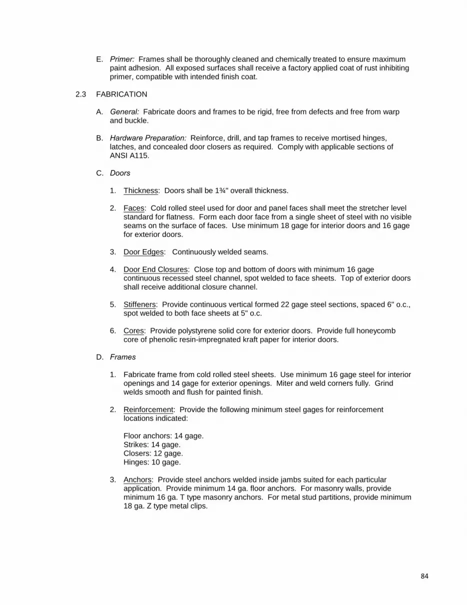
E. Primer: Frames shall be thoroughly cleaned and chemically treated to ensure maximumpaint adhesion. All exposed surfaces shall receive a factory applied coat of rust inhibitingprimer, compatible with intended finish coat.
2.3 FABRICATION
A. General: Fabricate doors and frames to be rigid, free from defects and free from warpand buckle.
B. Hardware Preparation: Reinforce, drill, and tap frames to receive mortised hinges,latches, and concealed door closers as required. Comply with applicable sections ofANSI A115.
C. Doors
1. Thickness: Doors shall be 1¾" overall thickness.
2. Faces: Cold rolled steel used for door and panel faces shall meet the stretcher levelstandard for flatness. Form each door face from a single sheet of steel with no visibleseams on the surface of faces. Use minimum 18 gage for interior doors and 16 gagefor exterior doors.
3. Door Edges: Continuously welded seams.
4. Door End Closures: Close top and bottom of doors with minimum 16 gagecontinuous recessed steel channel, spot welded to face sheets. Top of exterior doorsshall receive additional closure channel.
5. Stiffeners: Provide continuous vertical formed 22 gage steel sections, spaced 6" o.c.,spot welded to both face sheets at 5" o.c.
6. Cores: Provide polystyrene solid core for exterior doors. Provide full honeycombcore of phenolic resin-impregnated kraft paper for interior doors.
D. Frames
1. Fabricate frame from cold rolled steel sheets. Use minimum 16 gage steel for interioropenings and 14 gage for exterior openings. Miter and weld corners fully. Grindwelds smooth and flush for painted finish.
2. Reinforcement: Provide the following minimum steel gages for reinforcementlocations indicated:
Floor anchors: 14 gage.Strikes: 14 gage.Closers: 12 gage.Hinges: 10 gage.
3. Anchors: Provide steel anchors welded inside jambs suited for each particularapplication. Provide minimum 14 ga. floor anchors. For masonry walls, provideminimum 16 ga. T type masonry anchors. For metal stud partitions, provide minimum18 ga. Z type metal clips.
84

3.0 PART 3: EXECUTION
3.1 GENERAL
A. Execute all Work in accordance with manufacturer's recommendations and instructionsexcept where the Specifications call for more restrictive requirements.
B. Inspection: Inspect and verify all existing conditions and previous Work before beginningthis Work. Beginning Work means that the Installer accepts substrates, previous Work,and existing conditions.
3.2 INSTALLATION: Install doors and frames true and plumb. Anchor steel frames with aminimum of three masonry anchors and a floor anchor at each jamb.
3.3 ADJUSTING, TOUCH-UP, AND REPAIR
A. Adjusting: Adjust clearances and operating parts to work smoothly, easily, and correctly.
B. Touch-up and Repair: Touch damaged shop coatings and repair minor damages so thatthere is no evidence of repair. Remove and replace Work which cannot be satisfactorilyrepaired.
END OF SECTION
85

SECTION 08.14.00WOOD DOORS
1.0 PART 1: GENERAL
1.1 GENERAL REQUIREMENTS: All Contract Documents, including General and SupplementaryConditions, General Requirements (Division 01), and Drawings, apply to the Work in thisSection.
1.2 DESCRIPTION OF WORK
A. The Work of this Section includes all labor, materials, tools, and equipment needed tofurnish and install wood doors and frames as shown on the Drawings and as specified.
B. The Work of this Section includes, but is not limited to:
1. Wood doors.
C. Alternates: Alternate #2 affects the Work of this Section. Closely examine the ContractDocuments to determine the full extent that alternates affect the Work of this Section.
1. Alternate #2: Provide additional new wood doors.
1.3 RELATED WORK
A. Carefully examine all the Contract Documents for requirements which affect the Work ofthis Section.
B. Other Work which directly relate to the work of this Section include, but are not limited to:
1. Rough Carpentry (Section 06.10.00).2. Finish Carpentry (Section 06.20.00).3. Metal Doors and Frames (Section 08.11.00).4. Door Hardware (Section 08.70.00).5. Ceramic Tiling (Section 09.30.00).6. Painting (Section 09.90.00).
1.4 QUALITY ASSURANCE
A. Reference Standards
1. ASTM E119: Standard Test Method for Fire Tests of Building Construction andMaterials.
2. Glass Association of North America (GANA) Glazing Manual.3. FGMA Sealant Manual.4. National Fire Protection Association (NFPA) 80: Fire Doors and Windows.5. FPA 252: Fire Tests of Door Assemblies.6. Underwriters Laboratories, Inc. (UL) 10B: Fire Tests of Door Assemblies.7. UL 10C: Positive Pressure Fire Tests of Door Assemblies.
1.5 SUBMITTALS
A. Product Data: Submit manufacturer's product data, including installation instructions,recommended uses, and certification of compliance with specifications requirements.
86

1. Product Test Listings: From UL indicating fire-rated glass complies withrequirements, based on comprehensive testing of current product.
B. Shop Drawings: Submit large scaled shop drawings and door schedule.
1.6 WARRANTY: Provide written warranty from the door and frame manufacturer, agreeing torepair or replace Work which exhibits defects in materials or workmanship for the life of theinstallation.
1.7 DELIVERY, STORAGE, AND HANDLING: Deliver doors and frames polywrapped to protectagainst moisture. Store and handle in strict compliance with manufacturer'srecommendations. Store doors flat, in a clean, dry, and well ventilated area.
2.0 PART 2: PRODUCTS
2.1 FLUSH DOORS
A. Industry Standards: Provide products in compliance with NWMA Industry Standard No. 1.
B. Thickness: Provide 1¾" thick doors.
C. Materials
1. AWI Premium Grade red oak for transparent finish. Wood shall be kiln dried tomoisture content of 6-8%.
D. Veneers
1. AWI Premium Grade red oak for transparent finish.
E. Adhesive: Type I waterproof for face assembly and Type II water-resistant for coreassembly.
F. Machining: Factory machine doors for hardware.
G. Non-rated Doors: Construct doors from solid lumber rails and stiles with particle boardcore.
2.2 FIRE-RATED DOORS
A. Construct doors from solid lumber rails and stiles with manufacturer's standard coreconstruction to obtain fire-resistance rating indicated or required. Provide doors whichhave identical construction as doors whose fire resistance rating has been tested incompliance with ASTM E152 by independent agencies. Doors shall be labeled and listedby and agency acceptable to authorities having jurisdiction.
B. Glazing: Provide factory glazed UL-labeled fire-rated doors. Doors shall be glazed withfire-rated glass ceramic clear and wireless glazing material, listed for use in impact safety-rated locations, with the following characteristics.
1. Thickness: 5/16 inch [8 mm] overall.2. Weight: 4 lbs./sq. ft.3. Approximate Visible Transmission: 85 percent.4. Approximate Visible Reflection: 9 percent.5. Fire-rating: 20 minutes to 3 hours for doors.6. Impact Safety Resistance: ANSI Z97.1 and CPSC 16CFR1201 (Cat. I and II).
87

7. STC Rating: Approximately 35 dB.8. Surface Finish: Polished.9. Positive Pressure Test: UL 10C, UBC 7-2 and 7-4; passes.10. Acceptable Product: FireLite Plus manufactured by Nippon Electric Glass
Company, LTD.
2.3 PRE-FITTING AND PRE-MACHINING: Prefit and premachine doors as required. Trimequally on both sides to prevent unbalanced construction. Do not trim tops or bottoms morethan ¾".
3.0 PART 3: EXECUTION
3.1 GENERAL
A. Execute all Work in accordance with manufacturer's recommendations and instructionsexcept where the Specifications call for more restrictive requirements.
B. Inspection: Inspect and verify all existing conditions and previous Work before beginningthis Work. Beginning Work means that the Installer accepts substrates, previous Work,and existing conditions.
3.2 ENVIRONMENTAL CONDITIONS
A. Begin installation only after plaster, concrete and other wet Work is completed and dried.
B. Condition doors to prevailing humidity conditions before installing.
3.3 FITTING AND MACHINING: Fit doors to frames and machine for hardware to that extentwhich was not done at the factory.
3.4 CLEARANCES AND TOLERANCES
A. Non-rated Doors: Provide a uniform c" clearance at heads, jambs, and meeting stilesand a uniform ½" clearance at bottoms of doors.
B. Fire Rated Doors: Provide clearances complying with NFPA 80 Trim as necessary and instrict compliance with door manufacturer's instructions and recommendations. Do nottrim top rails. Do not remove labels.
3.5 ADJUSTING AND PROTECTION
A. Adjusting: Adjust doors to work smoothly. Replace doors which cannot be successfullyadjusted to operate correctly or fit properly into frames.
B. Protection: Protect doors, frames, and hardware from damage during construction.
END OF SECTION
88

SECTION 08.71.00DOOR HARDWARE
1.0 PART 1: GENERAL
1.1 GENERAL REQUIREMENTS: All Contract Documents, including General and SupplementaryConditions, General Requirements (Division 01), and Drawings, apply to the Work in thisSection.
1.2 DESCRIPTION OF WORK
A. The Work of this Section includes all labor, materials, tools, and equipment needed tofurnish and install finish hardware on new and existing doors as shown on the Drawingsand as specified.
B. The Work of this Section includes, but is not limited to:
1. Finish hardware for new doors.2. New hardware for existing doors.
C. Alternates: Alternates #1 and 2 affect the Work of this Section. Closely examine theContract Documents to determine the full extent that alternates affect the Work of thisSection.
1. Alternate #1: Provide new hardware at existing exterior doors in stair.2. Alternate #2: Provide new hardware for new doors in one Storage 008.
1.3 RELATED WORK
A. Carefully examine all the Contract Documents for requirements which affect the Work ofthis Section.
B. Other Work which directly relate to the work of this Section include, but are not limited to:
1. Metal Doors and Frames (Section 08.11.00).2. Wood Doors (Section 08.14.00).
1.4 SUBMITTALS
A. Product Data: Submit manufacturer's product data, including installation instructions andrecommendations for use for each item.
B. Schedules: Submit hardware and keying schedules coordinated with manufacturer'sdata, samples, and Contract Documents.
C. Templates: Provide installation templates.
D. Samples: Submit samples for review of styles and finishes.
1.5 DELIVERY, STORAGE, AND HANDLING: Deliver hardware in factory wrapped packages,labeled to coordinate with the final hardware schedule. Each package shall containappropriate fastenings, instructions, installation templates, and any special tools required forinstallation. Securely store hardware to prevent damage or theft.
1.6 MAINTENANCE STOCK: Provide factory wrapped maintenance stock for all hardware itemsin the amount of 5% of each type, but never less than one maintenance stock item for each
89

hardware item used. Each package shall contain appropriate fastenings, instructions,installation templates, and any special tools required for installation.
2.0 PART 2: PRODUCTS
2.1 GENERAL
A. Finishes: Finishes shall exactly match those of selected samples with no variation in hue,regardless of base metal. All hardware for doors shall be BHMA 606, Satin Brass, orBHMA 605 Bright Brass, to match existing hardware.
B. Fasteners: Use concealed fasteners whenever possible. Where concealed fasteners arenot possible, provide tamper proof screws. Supply Owner with applicable tool to unfastentamper proof screws.
C. Acceptable Products and Manufacturers: Manufacturers and products are listed toestablish the standard of quality, design, and function. Provide the hardware specified ora product of a specified manufacturer which meets or exceeds the specified standard.
2.2 HINGES
A. Acceptable Manufacturers: Roton, Hager, Stanley.
B. Type: Provide template produced, full mortise, 5 knuckle, standard weight, 0.134 gagehinges with non-rising pins. Provide two ball bearings for hinges of doors with closers.
C. Size: Height of hinges shall be 4½". Width shall be coordinated with door jamb and trimconditions.
D. Quantity: Provide three hinges for all doors and door leafs.
2.3 LATCHES AND LOCKS: Provide locks with interchangeable cores that are compatible withexisting locksets.
A. Acceptable Manufacturers: Best, Schlage, Yale. Provide latchsets and locksets of onemanufacturer.
B. Types: Provide cylinder locks as scheduled. Latch throws shall have a minimum ½"projection. Deadbolts shall have a minimum 1" throw. Locksets shall meet ANSI 156.13Grade 1.
C. Operating Trim: Provide lever handles for all doors. Provide escutcheons for mortiselocks. Provide U-shaped escutcheon plates to adapt existing doors for new locksets.
D. Strikes: Provide standard closed box strikes with extended curved lips of sufficient lengthto protect door frames.
2.4 CLOSERS
A. Acceptable Manufacturers: LCN, Sargent, Yale.
B. Type: Provide barrier-free closers, complying with ANSI A117.1 and the MassachusettsArchitectural Barriers Board for opening force and delayed action closing. Use parallelarm closers where closers are mounted on push sides of doors.
2.5 EXIT DEVICES (Panic Hardware)
A. Acceptable Manufacturers: Adams Rite, Sargent, Von Duprin, Yale.
90

B. Type: Provide mortise type exit device at new doors and rim type exit device at existingdoors, with matching lever operating trim.
2.6 MISCELLANEOUS HARDWARE
A. Door Stops: Provide types suited for locations.
B. Push/Pulls: Provide 4" wide X 16" long X 0.050" thick push/pull plates conforming withANSI A156.6.
2.7 KEYING
A. Lock Function: Review lock functions with Owner before ordering hardware.
B. Provide Masterkey System. Review specific keying applications with Owner.
C. Number of Keys: Provide three keys and one blank for each lock and 5 master keys.
3.0 PART 3: EXECUTION
3.1 GENERAL
A. Execute all Work in accordance with manufacturer's recommendations and instructionsexcept where the Specifications call for more restrictive requirements.
B. Inspection: Inspect and verify all existing conditions and previous Work before beginningthis Work. Beginning Work means that the Installer accepts substrates, previous work,and existing conditions.
3.2 MOUNTING HEIGHTS AND LOCATIONS
A. Hinges: Mount bottom hinge 10" above the floor. Mount top hinge 5" from top of door. Space other hinges equally between top and bottom hinges.
B. Locksets: Mount center of operating trim 3'-0" above the floor.
C. Closers: Mount closers on secure sides or least public sides of doors.
3.3 INSTALLATION: Fit locksets in doors and remove before painting of doors and frames. Re-install locksets after painting is complete.
3.4 ADJUSTING, CLEANING, AND PROTECTION
A. Adjusting: Adjust hardware to work easily, smoothly, and properly. Adjust hardware sothat doors operate properly and smoothly, without binding or rubbing frames.
B. Cleaning: Clean and polish exposed surfaces of new and existing hardware with a non-abrasive polish.
C. Protection: Provide temporary protections to prevent damage during construction. Remove protections and re-clean and re-adjust hardware as required before finalacceptance.
91

3.5 HARDWARE SCHEDULE
A. Acceptable Products and Manufacturers: Manufacturers and products are listed toestablish the standard of quality, design, and function. Provide the hardware specified ora product of a specified manufacturer which meets or exceeds the specified standard.
B. Hardware Sets: All operating trim to be Sparta lever, except as otherwise noted.
1. H1: New Double Exit Doors:a. Hinges: Hager BB1191(2 sets)b. Closer: LCN 4040 series (2 each)c. Exit Device: Von Duprin 9875 w/ Lever 17(2 each)d. Kick Plates: (2 each)
2. H2: Private Bathroom Door:a. Hinges: Hager BB1191b. Lockset: Schlage ND40S (ANSI F76)c. Closer: LCN 4040 series
3. H3: Janitor and Service Doors:a. Hinges: Hager 1191b. Lockset: Schlage ND80PD (ANSI F86)
4. H4: Double Stair Doors:a. Hinges: Hager BB1191(2 sets)b. Lockset (active leaf): Schlage ND10S (ANSI F75)c. Lockset (inactive leaf): Schlage ND170d. Automatic Flush bolt: Ivese. Kick Plates: (2 each)
5. H5: Existing Double Doors:a. Push Plate: Ives 8200 series (2 each)b. Pull Plate: Ives 8300 series (2 each)c. Kick Plates: (2 each)
6. H6: Existing Single Doors:a. Kick Plate
7. H7: Existing Exit Doors:a. Exit Device: Sargent 9800 Series (2 each)b. Kick Plates: (2 each)
8. H8: Existing Stair Double Doors:a. Locksets: replace one lever with salvaged leverb. Kick Plates: (2 each)
9. H9: New Single Stair Door:a. Hinges: Hager BB1191b. Closer: LCN 4040 seriesc. Lockset: Schlage ND10S (ANSI F75)d. Kick Plate
10. H10: Shaft Access Door:a. Hinges: Hager 1191b. Deadbolt: Schlage B664Pc. Dummy Trim: Schlage ND170
92

11. H11: Existing Exterior Stair Double Doors:a. Lockset (active leaf): Schlage ND80PD (ANSI F86))b. Lockset (inactive leaf): Schlage ND170c. Automatic Flush bolt: Ives
END OF SECTIONAND DIVISION 08
93

DIVISION 09 - FINISHES
SECTION 09.20.00GYPSUM BOARD
1.0 PART 1: GENERAL
1.1 GENERAL REQUIREMENTS: All Contract Documents, including General and SupplementaryConditions, General Requirements (Division 01), and Drawings, apply to the Work in thisSection.
1.2 DESCRIPTION OF WORK
A. The Work of this Section includes all labor, materials, tools, and equipment needed tofurnish and install new gypsum board walls, ceilings, and soffits as shown on theDrawings and as specified.
B. The Work of this Section includes, but is not limited to:
1. Gypsum board.2. Veneer plaster.3. Metal framing supports.4. Patching existing plaster ceilings and walls.
C. Alternates: Alternates #2 and 3 affect the Work of this Section. Closely examine theContract Documents to determine the full extent that alternates affect the Work of thisSection.
1. Alternate #2: Provide partial height partitions along existing masonry walls in Storage008.
2. Alternate #3: Provide soffit below horizontal ducts in Pantry 007 and patch ceiling inPolice 006.
1.3 RELATED WORK
A. Carefully examine all the Contract Documents for requirements which affect the Work ofthis Section.
B. Other Work which directly relate to the work of this Section include, but are not limited to:
1. Rough Carpentry (Section 06.10.00).2. Painting (Section 09.90.00).
1.4 QUALITY ASSURANCE
A. Reference Standards: Comply with the applicable provisions of the following referencestandards:
1. GA Fire Resistance Design Manual, 11 Edition.th
2. UL Fire Resistance Directory.3. UL Building Materials Directory.4. GA 216, Recommended Specifications for Application and Finishing of Gypsum
Board.5. GA 505, Gypsum Board Terminology Standard.6. Plastering Information Bureau, "Lath and Plastering".
94

B. Single Source: For each type of primary material specified, provide products from asingle manufacturer. Provide secondary materials which are acceptable to themanufacturers of the primary materials.
1.5 SUBMITTALS
A. Product Data: Submit manufacturer's product data, including installation instructions andrecommended uses, for each material specified.
B. Certificates: Submit written certification that fire resistive construction conforms to UL andGA standards.
1.6 PROJECT CONDITIONS
A. Environment: Perform Work only when existing and forecasted conditions conform withrecommendations of product manufacturers and GA publications. Ambient interiortemperature shall be between 55 and 70 F. Do not perform exterior plastering work ino
temperatures below 45 F and above 90 F.o o
B. Ventilation: Provide adequate ventilation. Comply with manufacturers' and GArecommendations. Avoid rapid drying in hot weather.
1.7 DELIVERY, STORAGE, AND HANDLING: Deliver materials in unopened factory labeledpackages. Store gypsum panels off the ground, in a dry, ventilated space. Provide adequatesupport under stored gypsum panels to prevent sagging.
2.0 PART 2: PRODUCTS
2.1 METAL FRAMING AND SUPPORTS
A. Acceptable Manufacturers: Provide products which meet or exceed specifiedrequirements by one of the following manufacturers:
1. Allied Industries.2. National Gypsum Co.3. National Rolling Mills4. Marino Industries5. U.S. Gypsum Co.6. Or equal.
B. Coating: All metal studs and framing supports shall be galvanized with not less thanASTM A525 G60 coating.
C. Studs and Runners: Provide galvanized steel studs complying with ASTM A446, A527,and C645. Provide 20 gage studs, unless otherwise recommended by manufacturer forconditions, span, and recommended deflections. Provide "knock-out" provisions forpiping and electrical installations.
D. Furring: Provide 25 gage f" hat shaped and resilient galvanized furring channelscomplying with ASTM C645.
2.2 GYPSUM BOARDS
A. Acceptable Manufacturers: Provide products which meet or exceed specifiedrequirements from one of the following manufacturers:
1. Celotex Corp.2. Georgia-Pacific Corp.
95

3. Gold Bond Building Products.4. National Gypsum Co.5. U.S. Gypsum Co.6. Or equal.
B. Gypsum Base for Veneer Plaster: Provide regular gypsum base (blueboard) with taperededges, complying with ASTM C585. Use ½" thick for ceiling and soffit applications ande" thick for wall applications.
C. Water Resistant Gypsum Board: Provide water resistant gypsum board conforming toASTM C630, regular and Type X fire rated, for use in bathroom walls and ceilings. Use½" thick for ceiling and soffit applications and e" thick for wall applications.
2.3 VENEER PLASTER: Provide gypsum plaster with compressive strength of 1500 psi for handor machine application in a thin monolithic single coat system.
2.4 ACCESSORIES
A. Metal Trims: Provide galvanized metal trims, formed for full joint treatment coverage,sized to the thickness of the gypsum board. Trims shall include, but not be limited to,mesh type corner beads, casing beads, plaster grounds and screeds, and expansionjoints.
B. Fasteners: Provide screws, complying with ASTM 646 and C514, for each of thefollowing applications:
1. Gypsum board to metal framing: U.S.G. Type S, bugle head.
2. Gypsum board to wood framing and blocking: U.S.G. Type W, bugle head.
3. Gypsum board to gypsum board: U.S.G. Type G, bugle head.
C. Ceiling Anchors: Provide fasteners which are capable of supporting a minimum of 150pounds.
3.0 PART 3: EXECUTION
3.1 GENERAL
A. Execute all Work in accordance with manufacturer's recommendations and instructionsexcept where the Specifications call for more restrictive requirements.
B. Inspection: Inspect and verify all existing conditions and previous Work before beginningthis Work. Beginning Work means that the Installer accepts substrates, previous Work,and existing conditions.
C. Coordination: Special attention is called to finishing the interior of the modular vault. Apply gypsum wallboard in strict compliance with recommendations and instructions of modular vault manufacturer.
3.2 FRAMING: Erect framing in compliance with ASTM C754, recommendations of the gypsumboard manufacturer, and the U.S. Gypsum "Gypsum Construction Handbook".
A. Walls: Framing shall extend to the bottom of structure above, except as noted otherwise.
B. Blocking: Provide additional framing and blocking as required at openings, cut-outs, andbuilt-in anchorages and attachments for other Work.
96

3.3 GYPSUM BOARD: Install gypsum board in strict compliance with ASTM C840 and GypsumAssociation publication 216, "Recommended Specifications for the Application and Finishingof Gypsum Board".
A. Fasteners: Space power driven screws a maximum of 12" o.c. to a uniform dimple 1/32"deep. Avoid damage to face paper. Install screws d" from edges and ends of gypsumpanels.
B. Wall Openings
1. Cut both face and back paper of gypsum board.
2. Maintain close tolerances at openings for electrical outlets, piping, and otherpenetrations.
3. Provide additional reinforcement tape at corners of wall penetrations, including, butnot limited to borrowed lites and access panels.
C. Corners and Edges
1. Corners: Install corner bead trim at all external corners and joint reinforcing tape at allinternal corners. Fasten corner beads with screws spaced a minimum of 9" o.c.
2. Edges: Install metal edge trim at all exposed gypsum board edges and wherevergypsum board terminates against masonry, concrete, metal or other dissimilarmaterial. Fasten edge trim with screws spaced a minimum of 9"o.c.
3.4 FINISHING GYPSUM BOARD
A. Veneer Plaster
1. Extent: Cover all new exposed gypsum wall board surfaces, including walls, ceilings,and soffits, with veneer plaster.
2. Apply plaster in one coat to a uniform thickness of 1/16" to 3/32". Finish shall besmooth.
3. Scribe joints between plaster and dissimilar materials.
3.5 PLASTER PATCHING
A. Extent
1. Patch existing exposed plaster walls and ceilings where penetrations and alterationshave occurred.
2. Patch existing plaster walls and ceilings where previous damage are evident andvisible.
B. Preparation: Sand down any protrusions in wall and ceiling surfaces. Remove switchplate covers, light fixture covers, and other devices mounted to the walls and ceilings. Apply plaster bonding agent and then plaster to all existing surfaces to be repaired. Re-install wall and ceiling mounted items after painting is complete.
97

C. Plaster Patching
1. Apply plaster in one coat to a uniform thickness to match existing finished surfaces. Finish shall be smooth.
2. Repair cracks and indented surfaces by moistening plaster and filling with newmaterial, troweled or ramped flush with adjoining surfaces.
3. Point-up and finish surfaces around fixtures, outlet boxes, piping, fittings, and otherWork flush with adjacent plaster.
4. Where new plaster adjoins existing plaster, cut existing plaster at an angle ofapproximately 45 degrees.
3.6 TOLERANCES: The allowable variation from true, plumb, level, and line is c" in 20'-0".
END OF SECTION
98

SECTION 09.30.13CERAMIC TILING
1.0 PART 1: GENERAL
1.1 GENERAL REQUIREMENTS: All Contract Documents, including General and SupplementaryConditions, General Requirements (Division 01), and Drawings, apply to the Work in thisSection.
1.2 DESCRIPTION OF WORK
A. The Work of this Section includes all labor, materials, tools, and equipment needed tofurnish and install new porcelain tile as shown on the Drawings and as specified.
B. The Work of this Section includes, but is not limited to:
1. Porcelain tile floors and base.
1.3 RELATED WORK
A. Carefully examine all the Contract Documents for requirements which affect the Work ofthis Section.
B. Other Work which directly relate to the Work of this Section include, but are not limited to
1. Cast-in-Place Concrete (Section 03.30.00).2. Metal Doors and Frames (Section 08.11.00).
1.4 QUALITY ASSURANCE
A. Standards: Comply with the following reference standards:
1. Tile Council of America, Handbook for Ceramic Tile Installation.2. ANSI 108 series, Standard Specifications for the Installation of Ceramic Tile.3. ANSI 118 series, Standard Specifications for Materials Used in Ceramic Tile.4. ANSI 137.1, Ceramic Tile.
B. Source: For each type of primary material specified, provide products form a singlemanufacturer. Provide secondary materials which are acceptable to the manufacturers ofthe primary materials.
1.5 SUBMITTALS
A. Product Data: Submit manufacturer's product data, including installation instructions andrecommended uses, for each material specified.
B. Samples: Submit samples for color selection.
1.6 DELIVERY, HANDLING, AND STORAGE: Deliver all products in manufacturer's unopenedcontainers with grade seals unbroken and labels intact.
1.7 ENVIRONMENTAL CONDITIONS: Maintain temperature at a minimum of 50 F duringo
tilework and for 7 days after completion.
1.8 MAINTENANCE STOCK: Supply extra 2% of each tile and color used in clean markedcartons.
99

2.0 PART 2: PRODUCTS
2.1 TILE
A. Porcelain Tile: Provide Standard Grade unglazed porcelain tiles with all-purpose edgesconforming with ANSI A137.1 and the following requirements.
1. Tile Size: 12"X12".2. Thickness: Tile shall be manufactured to specific thickness after firing, nominally
6.0mm or greater.3. Color: As selected by Architect from manufacturers’ standard colors.4. Water Absorption: 0.09%.5. Breaking Strength: 288 lbs.6. Bond Strength: 217 psi.7. Coefficient of Friction/Dry: Greater than 0.7.8. Coefficient of Friction/Wet: Greater than 0.69. Acceptable Manufacturer: Crossville Color Blox, Heathland by Daltile, Crossville
Bluestone Series, or equal.
B. Trim Tile: Provide size, color, and finish to match field tile.
1. Base: 4" high cove.
2.2 WATERPROOFING MEMBRANE
A. Provide liquid rubber and powder, job-mixed, cold-applied with reinforcing fabric,seamless, trowel applied waterproofing membrane with the following characteristics.
1. Service Life: Minimum 10 years.2. Tensile Strength: 2000 lbs. per lin. ft.3. Compressive Strength: 2000 psi.
B. Acceptable Manufacturers: Laticrete International, Boiardi Products, American Olean.
2.3 MORTAR MATERIALS
A. Portland Cement: Provide cement compying with ASTM C-150 Type 1.
B. Sand: Provide sand complying with ASTM C-144.
C. Water: Potable.
D. Lime: Provide lime conforming with ASTM C-206 Type S or ASTM C-207 Type S.
E. Reinforcing: Provide 2"x2"x16/16 gauge welded wire mesh or equivalent.
F. Latex Thinset Admixture: Provide compounded and stabilized latex for blending with neatportland cement or portland-sand mix complying with ANSI 108.5 and ANSI 118.4 thefollowing characteristics:
1. Service Life: Minimum 10 years.2. Compressive Strength: Minimum 5,000 psi.3. Bond Strength: Minimum 600 psi in shear at 28 days.4. Water Absorption: Maximum 3%.5. Density: 83 lbs. per cu. ft.6. Acceptable Manufacturers: Laticrete International, Boiardi Products.
100

2.4 MORTAR
A. Cement Mortar:
1. Floors: Provide reinforced cement mortar composed of 1 part portland cement and 6parts damp sand by volume.
2. Walls: Provide mortar composed of 1 part portland cement, ½ to 1 part lime, and 5 to7 parts by volume.
3. Scratch Coat: Provide scratch coat for wall application composed of 1 part portlandcement and 3 parts dry to 4 parts damp sand, by volume:
B. Latex Portland Cement Mortar: Provide latex modified portland cement mortar complyingwith ANSI 118.4 for thinset application.
C. Dry-Set Mortar: Provide mortar complying with ANSI A118.1.
2.5 GROUT: Provide latex modified portland cement grout conforming with ANSI 118.6, color asselected by Architect.
A. Waterproofing Admixture: Provide mortar additive for factory prepared grout with thefollowing characteristics:
1. Service Life: Minimum 10 years.2. Compressive Strength: 3000 psi.3. Bond Strength: 500 psi.4. Acceptable Manufacturers: Laticrete International, Boiardi Products, or equal.
2.6 ACCESSORY MATERIALS
A. Sealant: Provide one part mildew resistant sanitary silicone sealant, Type S, Grade NS,Class 25 formulated with fungicide.
B. Provide 4 mil polyethylene sheet.
C. Metal Lath: Provide galvanized expanded metal lath.
3.0 PART 3: EXECUTION
3.1 GENERAL
A. Execute all Work in accordance with manufacturer's recommendations and instructionsexcept where the Specifications call for more restrictive requirements.
B. Inspection: Inspect and verify all existing conditions and previous Work before beginningthis Work. Beginning Work means that the Installer accepts substrates, previous Work,and existing conditions.
3.2 LAYOUT
A. Floors: Lay out flooring from centerlines with floor patterns accurately aligned in alldirections.
B. Joints: Align all wall joints to give straight uniform grout lines, plumb and level. Makejoints between tile sheets same width as joints within sheets.
101

C. Cutting Tile: Lay out so as to minimize cuts less than one half tile in size. Locate tile cutsso as to be least conspicuous. Clean and smooth all cut tile edges before installing.
D. Fitting Tile: Fit tile carefully against trim, door frames, existing adjacent flooring and otherbuilt-in items so that joints are uniform in appearance and width. Sawcut existingconcrete base at floor cove as needed to ensure a tight fit, leaving no exposed unfinishedconcrete. Fit tile carefully against trim, pipes, bath accessories, and other built-in items sothat escutcheons, plates and collars will completely overlap cut edges.
3.3 SETTING
A. Floors: Set tile in accordance with ANSI A108.5 and TCA Method F144, Dry-set Mortar orLatex Portland Cement Mortar.
1.2 GROUTING: Apply grout to new ceramic tile walls and floors in strict compliance withmanufacturer's recommendations and ANSI A108.10.
1.3 SEALANTS: Apply sanitary silicone sealant at all joints between dissimilar materials inaccordance to manufacturer's recommendations.
1.4 CLEANING AND PROTECTION
A. Cleaning: Remove all grout haze, using methods recommended by grout manufacturer. Rinse tile thoroughly and polish surface with soft cloth.
B. Protection: Protect from damage. Prohibit all traffic from newly tiled floors for 7 days.
END OF SECTION
102
SECTION 09.51.23ACOUSTICAL TILE CEILINGS
1.0 PART 1: GENERAL
1.1 GENERAL REQUIREMENTS: All Contract Documents, including General and SupplementaryConditions, General Requirements (Division 01), and Drawings, apply to the Work in thisSection.
1.2 DESCRIPTION OF WORK
A. The Work of this Section includes all labor, materials, tools, and equipment needed tofurnish and install new suspended acoustical ceiling tiles as shown on the Drawings andas specified.
B. The Work includes, but is not limited to:
1. Lay-in acoustical tile ceilings.2. Coordinating lay-out of related Work and Work located in ceilings.
1.3 RELATED WORK
A. Carefully examine all the Contract Documents for requirements which affect the Work ofthis Section.
B. Other Work which directly relate to the work of this Section include, but are not limited to:
1. Gypsum Board (Section 09.20.00).2. Fire Suppression (Section 21.00.00)3. HVAC (Section 23.00.00).4. Electrical (Division 26).
1.4 QUALITY ASSURANCE: For each type of primary material required for the Work of thisSection, provide first quality products from one manufacturer. Provide secondary materialswhich are acceptable to the manufacturers of the primary products.
1.5 SUBMITTALS
A. Product Data: Submit manufacturer's product data, including installation instructions, uselimitations and recommendations for each material used.
B. Samples: Submit minimum 3"X3" samples of each type of acoustical tile, showing fullrange of colors, textures, and finishes available. Submit 12" long samples of edge trims.
1.6 WARRANTY: All workmanship and materials shall be guaranteed for a period of one yearfrom the date of final acceptance.
1.7 DELIVERY, STORAGE, AND HANDLING: All materials and products shall be delivered inunopened, factory labeled packages and stored and handled in conformity withmanufacturer's recommendations. Store all materials off the ground and away from all dampsurface until ready for use.
1.8 MAINTENANCE STOCK: Provide packaged, wrapped, and labeled maintenance stock equalto 2% of the actual quantity of each type of ceiling tile installed.
103

1.9 PROJECT CONDITIONS
A. Perform work only when conditions are within the limits established by manufacturers ofthe materials and products used.
B. Temperatures shall be within the expected occupancy range of 60 to 85 degrees F. Relative humidity shall be no more than 70%.
C. All plastering, concreting, and any other wet Work shall be complete and dry.
2.0 PART 2: PRODUCTS
2.1 ACOUSTICAL CEILING TILES
A. Provide 24"X24"Xe" tegular non-directional Minatone Cortega acoustical ceiling tiles asmanufactured by Armstrong World Industries, Inc. or equal.
B. Provide 24"X48"Xe" lay in non-directional Minatone Cortega acoustical ceiling tiles asmanufactured by Armstrong World Industries, Inc. or equal.
C. Standards: Acoustical tiles shall meet the following standards and performance:
1. Flame Spread
a. Federal Specification SS-S-118B: Class A.b. ASTM E84: 0-25.c. UL Label: 25 or under.
2. Light Reflectance: LR-1 light reflectance (75% or over).
3. Acoustical Performance
a. STC Range: 35-39.b. ASTM C 423: Noise Reduction Coefficient in the 0.50-0.60 range.
2.2 SUSPENSION SYSTEM
A. Provide direct hung T framing of electrogalvanized steel, finished with low-sheen satinwhite enamel.
B. Standards: Provide framing which meets ASTM C 635, intermediate duty class.
2.3 ACCESSORIES
A. Accessories include, but are not limited to hanger wires, attachment devices, andmoldings and trim.
B. Hangers: Support suspension system by 12 gage hanger wires. C. Moldings and Trim: Provide edge moldings and trim to exactly match runners of
suspension system.
104

3.0 PART 3: EXECUTION
3.1 GENERAL
A. Execute all Work in accordance with manufacturer's recommendations and instructionsexcept where the Specifications call for more restrictive requirements.
B. Inspection: Inspect and verify all existing conditions and previous Work before beginningthis Work. Beginning Work means that the Installer accepts substrates, previous Work,and existing conditions.
3.2 LAY-OUT
A. Lay out from centerlines of spaces in both directions. In the case of intersecting corridors,start from the center of the intersection. Lay out as shown on Drawings.
B. Lay out ceilings in a manner which avoids use of tiles less than 12" in width.
3.3 SUSPENSION SYSTEM: Install ceiling suspension system in strict compliance with ASTMC636. Hanger wires shall be attached to structure above ceiling.
3.4 CEILING TILES: Scribe and cut tiles to fit accurately. Use clean gloves when handling ceilingtiles.
3.5 EDGE MOLDINGS AND TRIM
A. Provide edge moldings at entire perimeter and provide trim wherever necessary toconceal edges of acoustical tile.
B. Miter corners accurately with hairline tight joints and connect securely with non-exposedfasteners.
C. Provide a continuous tooled bead of exposed acoustical sealant between edge moldingsand irregular walls to effectively close gaps.
3.6 TOLERANCES: Finished installation shall be level to within c" in 12'-0".
3.7 REPAIR AND CLEANING
A. Repair: Repair minor damages so that there is no evidence of repair. Remove andreplace Work which cannot be satisfactorily repaired.
B. Cleaning: Clean according to methods recommended by manufacturers. Remove andreplace Work which cannot be satisfactorily cleaned.
END OF SECTION
105

SECTION 09.65.00RESILIENT FLOORING
1.0 PART 1: GENERAL
1.1 GENERAL REQUIREMENTS: All Contract Documents, including General and SupplementaryConditions, General Requirements (Division 01), and Drawings, apply to the Work in thisSection.
1.2 DESCRIPTION OF WORK
A. The Work of this Section includes all labor, materials, tools, and equipment needed tofurnish and install resilient flooring and base as shown on the Drawings and as specified.
B. The Work includes, but is not limited to:
1. Vinyl composition tile.2. Rubber floor tiles for stair landings.3. Resilient wall base. 4. Rubber treads and risers for stairways.5. Reducer strips and trim.
C. Alternates: Alternates #1 and 2 affect the Work of this Section. Closely examine theContract Documents to determine the full extent that alternates affect the Work of thisSection.
1. Alternate #1: Provide rubber flooring and base in stairway.2. Alternate #2: Provide vinyl base at new carpeting.
1.3 RELATED WORK
A. Carefully examine all the Contract Documents for requirements which affect the Work ofthis Section.
B. Other Work which directly relate to the Work of this Section include, but are not limited to:
1. Selective Demolition (Section 02.41.19).2. Sheet Carpeting (Section 09.68.16).
1.4 QUALITY ASSURANCE
A. For each type of primary material required for the work of this Section, provide first qualityproducts from one manufacturer. Provide secondary materials which are acceptable tothe manufacturers of the primary products.
B. Dye Lots: Use materials from the same manufactured lots to maintain uniformity of colorand pattern.
1.5 SUBMITTALS
A. Product Data: Submit manufacturer's product data, including product analysis, applicationinstructions and recommended uses for each material used.
B. Samples: Submit samples of all materials used, including 12"X12" resilient tile, base, andtrims, to the Architect for review.
106

1.6 WARRANTIES: Vinyl composition floor tile shall have a limited five year warranty.
1.7 DELIVERY, STORAGE, AND HANDLING: All materials and products shall be delivered inunopened, factory labeled packages and stored and handled in conformity withmanufacturer's recommendations. Store all materials off the ground and away from all dampsurfaces until ready for use.
1.8 MAINTENANCE STOCK: Provide packaged, wrapped, and labeled maintenance stock equalto 2% of the actual quantity of each type and color of flooring, trim, and base installed.
1.9 PROJECT CONDITIONS
A. Environmental Conditions: Perform work when temperature and humidity are within rangeestablished by products' manufacturers. All rooms, subfloors, tiles, and adhesives shallbe maintained at minimum temperature of 70 F for at least 48 hours before commencingo
Work.
B. Sequencing: To the greatest extent possible, proceed with Work in this Section afterfinishing operations, such as painting, have been completed.
C. Existing Conditions: Some preparation work of existing substrates is expected. Noadditional costs will be incurred for any preparation work required to complete finishflooring work as Specified.
2.0 PART 2: PRODUCTS
2.1 ACCEPTABLE MANUFACTURERS: Provide products from the manufacturers indicated orequal. When products from other manufacturers are provided, those products must meet orexceed the requirements specified.
2.2 VINYL COMPOSITION FLOOR TILE
A. Provide 12"X12"X1/8" thick vinyl composition thru-chip floor tile (VCT) conforming to thefollowing standards:
1. ASTM F 1066-87.2. Federal Spec. SS-T-312B, Type IV, Composition 1.3. NFPA (ASTM E-84), Class A.4. NFPA 255 or 258 (smoke density), less than 450.
B. Acceptable Products:
1. Armstrong Excelon Stonetex2. Mohawk Selections3. Tarkett Thru-Quartz
C. Colors: Up to three different colors will be selected from the full range of themanufacturer, including premium designer, deeptone, or bright colors.
2.3 RUBBER FLOOR TILE
A. Provide rubber flooring formulated with 100% virgin elastomers, reinforcing agents, soil-releasing agents, and migrating waxes.
1. Base Thickness: 0.125".2. Tile Size: 18"x18" nominally.
107
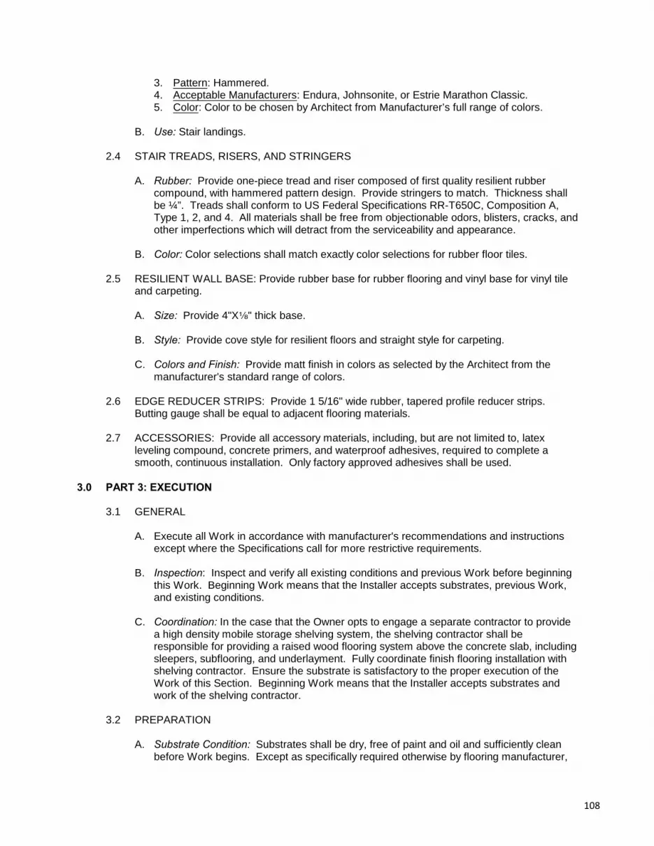
3. Pattern: Hammered.4. Acceptable Manufacturers: Endura, Johnsonite, or Estrie Marathon Classic.5. Color: Color to be chosen by Architect from Manufacturer’s full range of colors.
B. Use: Stair landings.
2.4 STAIR TREADS, RISERS, AND STRINGERS
A. Rubber: Provide one-piece tread and riser composed of first quality resilient rubbercompound, with hammered pattern design. Provide stringers to match. Thickness shallbe ¼”. Treads shall conform to US Federal Specifications RR-T650C, Composition A,Type 1, 2, and 4. All materials shall be free from objectionable odors, blisters, cracks, andother imperfections which will detract from the serviceability and appearance.
B. Color: Color selections shall match exactly color selections for rubber floor tiles.
2.5 RESILIENT WALL BASE: Provide rubber base for rubber flooring and vinyl base for vinyl tileand carpeting.
A. Size: Provide 4"Xc" thick base.
B. Style: Provide cove style for resilient floors and straight style for carpeting.
C. Colors and Finish: Provide matt finish in colors as selected by the Architect from themanufacturer's standard range of colors.
2.6 EDGE REDUCER STRIPS: Provide 1 5/16" wide rubber, tapered profile reducer strips. Butting gauge shall be equal to adjacent flooring materials.
2.7 ACCESSORIES: Provide all accessory materials, including, but are not limited to, latexleveling compound, concrete primers, and waterproof adhesives, required to complete asmooth, continuous installation. Only factory approved adhesives shall be used.
3.0 PART 3: EXECUTION
3.1 GENERAL
A. Execute all Work in accordance with manufacturer's recommendations and instructionsexcept where the Specifications call for more restrictive requirements.
B. Inspection: Inspect and verify all existing conditions and previous Work before beginningthis Work. Beginning Work means that the Installer accepts substrates, previous Work,and existing conditions.
C. Coordination: In the case that the Owner opts to engage a separate contractor to providea high density mobile storage shelving system, the shelving contractor shall beresponsible for providing a raised wood flooring system above the concrete slab, includingsleepers, subflooring, and underlayment. Fully coordinate finish flooring installation withshelving contractor. Ensure the substrate is satisfactory to the proper execution of theWork of this Section. Beginning Work means that the Installer accepts substrates andwork of the shelving contractor.
3.2 PREPARATION
A. Substrate Condition: Substrates shall be dry, free of paint and oil and sufficiently cleanbefore Work begins. Except as specifically required otherwise by flooring manufacturer,
108

concrete subfloors shall have hydrometer readings of between 35% and 65%. Reducemoisture content as needed to meet necessary requirements. Make bond and moisturetests as recommended by flooring manufacturer.
B. Leveling: Inspect all surfaces to receive flooring and base. Fill low areas with latexleveling compound to achieve a true, even surface for tiles or base. Scrape, grind, orsand down ridges and protruding irregularities to create a level, even substrate.
1. Existing conditions: Note that existing basement floor slab may be significantlyuneven. Additional leveling required to achieve a suitable substrate for new flooringshall not incur any additional costs.
C. Cleaning: Thoroughly clean and vacuum substrates immediately before installation ofmaterials.
D. Primers: Apply primer prior to the application of adhesive if recommended by themanufacturer for porous or powdery substrates.
3.3 FLOOR TILES
A. Extent: Extend flooring into closets, toe spaces, and similar areas. Provide flooring onremovable covers, fixed plates, and other items within floor areas.
B. Cutting and Fitting
1. Joints: All joints shall be truly aligned, tight and as inconspicuous as possible. Cutand fit tile close enough to walls that joint will be covered by base, where installed. Atother surfaces, scribe and accurately fit tile as required.
2. At Doors: Terminate flooring at the centerline of doors when adjacent finish or color isdissimilar to avoid seeing dissimilar material or color when door is closed.
C. Edges and Trim: Provide securely bonded edge strips and trim where necessary for acomplete and finished installation. Edge of flooring shall not be exposed.
D. Layout and Patterns
1. Lay out flooring from centerlines with floor patterns accurately aligned in all directions. A drawing showing a pattern with up to 3 colors will be provided.
2. Lay out tiles so that, as far as practicable, no piece of tile shall be less than 6" wide.
E. Bonding: Adhere with full coverage of adhesive, following the manufacturer'srecommended trowel notching spreading rates and open times. Roll floor with 150 poundroller in both directions to ensure good contact and bond.
3.4 STAIR TREADS & RISERS: Provide a single length of tread/riser for width of stair. Securelyadhere with full coverage of adhesive, following the manufacturer’s recommended trowelnotching spread rates and open times. Roll horizontal surfaces with 150 pound roller andvertical surfaces with hand rollers.
3.5 RESILIENT BASE
A. Extent: Adhere base to walls, columns, kitchen base cabinets, casework and all otherpermanent fixtures and surfaces. Provide base behind movable items.
109
B. Corners: Outside corners shall be preformed or field formed. At inside corners, cut andcope base.
C. Sealing: Where base runs along an irregular wall surface, fill top edge with sealant toclose all gaps and voids. Provide sealant color to closely match base color as approvedby the Architect.
D. Bonding: Tightly bond base with no gaps and with 100% coverage of adhesive. Hand rollbase to ensure full contact and adhesion.
3.6 REPAIR, CLEANING, AND PROTECTION
A. Repair: Repair minor damages so that there is no evidence of the repair.
B. Cleaning: Clean surfaces and remove excess adhesive at once. Replace Work thatcannot be adequately cleaned or repaired. Polish floor and base to a smooth and evenfinish.
C. Protection: Prohibit traffic over newly installed flooring for at least 48 hours. Protect theflooring until acceptance of the Work. Re-clean and polish as necessary immediatelybefore final acceptance.
END OF SECTION
110

SECTION 09.68.00CARPETING
1.0 PART 1: GENERAL
1.1 GENERAL REQUIREMENTS: All Contract Documents, including General andSupplementary Conditions, General Requirements (Division 01), and Drawings, apply to theWork of this Section.
1.2 DESCRIPTION OF WORK
A. The Work of this Section includes all labor, materials, tools, and equipment needed tofurnish and install carpeting as shown on the Drawings and as specified.
B. The Work includes, but is not limited to:
1. Modular carpet tiles.2. Resilient edge strips.3. Entry carpet.
C. Alternates: Alternate #2 affects the Work of this Section. Closely examine the ContractDocuments to determine the full extent that alternates affect the Work of this Section.
1. Alternate #1: Provide carpeting in Storage 008.
1.3 RELATED WORK
A. Carefully examine all the Contract Documents for requirements which affect the Work ofthis Section.
1.4 QUALITY ASSURANCE
A. Single Source: For each type of primary material required for the Work of this Section,provide first quality products from one manufacturer. Provide secondary materials whichare acceptable to the manufacturers of the primary products.
B. Dye Lots: Provide all material, including maintenance stock, from one dye lot for eachcolor required.
1.5 TESTS AND PERFORMANCE
A. Flame Spread: Provide carpet which complies with applicable state and local codesregarding flame spread, as tested by ASTM E-84.
B. Floor Radiant Panel Test: Provide Class I carpet, in accordance with ASTM E-648.
C. Smoke Density Test: Provide carpet which does not exceed 450 when tested accordingto ASTM E-662.
D. Pill Test: Provide carpet which passes the Methanamine Pill Test.
E. Static: Provide carpet with static requirements not exceeding 3.5 KV.
111

1.6 SUBMITTALS
A. Product Data: Submit manufacturer's product data, including product analysis, applicationinstructions, and recommended uses for each material used.
B. Verification Samples: Provide samples showing range of color and finish variationsexpected, having minimum size of 18"X18" and 6" long samples of edge strips.
1.7 WARRANTIES
A. Material Warranty: Submit the following warranties for the lifetime of the carpet.
1. Colorfastness.2. Antistatic.3. Wear.4. Moisture Barrier.5. Pattern Loss.6. Edge Unravel: No edge unravel under normal use.7. Delamination: No delamination under normal use.8. Tuft Bind: Will not zipper, wet or dry.
B. Installation Warranty
1. The Installer shall agree in writing to repair or replace all carpet which is notwrinkle-free, has open seams, is stained, or has other installation defects.
2. The warranty period shall last 1 year beginning from the date of SubstantialCompletion of the Project.
1.8 DELIVERY, STORAGE, AND HANDLING
A. Products and materials shall be delivered and stored in unopened factory packages withmill register number attached. Tag and mark accessory items for identification. Provideprotection from loss or damage.
B. Verify availability of color and style of carpet selected. Schedule deliveries to minimizedelay.
1.9 MAINTENANCE STOCK: Provide packaged, wrapped, and labeled maintenance stock equalto 2% of the actual quantity of each type and color of carpet installed. In addition, providewrapped and labeled usable remnants and scrap pieces.
1.10 PROJECT CONDITIONS
A. Environmental Conditions: Ensure that ambient temperatures are maintained above 65 Fo
and relative humidity is maintained at between 35% and 65% for 72 hours before carpet isinstalled, during installation and for a minimum of 72 hours after installation is complete.
B. Sequencing: To the greatest extent possible, proceed with Work in this Section afterfinishing operations, such as painting, have been completed.
C. Existing Conditions: Existing asbestos-containing vinyl tile will be left in place. Take carein preventing damage during installation of carpeting (Alternate #1).
112

2.0 PART 2: PRODUCTS
2.1 CARPET:
A. Performance: Provide commercial grade modular carpet tiles that meet the followingperformance criteria.
1. Flammibility (Radiant Panel ASTM E648): $0.45 (Class 1).2. Smoke Density (ASTM E662): #450.3. Methanamine Pill Test (ASTM D2859): Self-extinguishing.4. Lightfastness (AATCC 16E): $4.0 at 80 hours.5. Crocking (AATCC 165): $4.0 wet or dry.6. Static Electricity (AATCC 134) 20% RH, 70 F: #3.5 KV, permanent conductive fiber.o
7. Dimensional Stability, Aachener Test: #0.2%.8. Indoor Air Quality: GLP0793, Carpet Category 5Y.
B. Type: Provide carpet tiles with the following characteristics.
1. Construction: Tufted, textured loop.2. Fiber: 100% Nylon with built-in static guard.3. Gauge: 1/10.4. Stitches: 10.3/in.5. Tufts: 103/sq. in.6. Tufted Face Weight: 20 oz./sq. yd.7. Finished Pile Height: 0.11 in.8. Nominal Total Weight: 104 oz./sq. yd.9. Average Density: 6,583.10. Dye Method: Solution dyed.11. Standard Backing: PVC-free Comfort Plus ES cushion.12. Modular Tile Size: 36"x36".13. Acceptable Product: Image Series Four as manufactured by Milliken.
2.2 ENTRY CARPET: Provide 100% solution dyed UV stabilized polypropylene fiber modular tileentry carpet with the following characteristics:
A. Total Weight: 131oz.
B. Overall Thickness: 3/8"
C. Size: 19-11/16" x 19-11/16"
D. Backing: Bitumen
E. Pattern: Diagonal pattern installed quarter turn.
F. Acceptable products: Diagonal Tile as manufactured by Mats, Inc., or equal.
2.3 ACCESSORY MATERIALS
A. Accessory materials include, but are not limited to, adhesives, latex leveling compound,and transition strips.
B. Adhesive: Provide the highest quality, water resistant, non-staining, non-bleedingstrippable type as recommended by the carpet manufacturer, which meets flammabilityrequirements for the installed carpet.
113

C. Seaming Adhesive: Provide hot-melt seaming adhesive recommended by the carpetmanufacturer for taping seams and sealing cut ends.
D. Carpet Edging: Where carpet terminates at other types of floor finishes, use carpettransition reducer, as required, of thickness to match carpet. Provide profile and colorselected and approved by the Architect.
3.0 PART 3: EXECUTION
3.1 GENERAL
A. Execute all Work in accordance with manufacturer's recommendations and instructionsexcept where the Specifications call for more restrictive requirements.
B. Inspection: Inspect and verify all existing conditions and previous Work before beginningthis Work. Beginning Work means that the Installer accepts substrates, previous work,and existing conditions.
3.2 PREPARATION
A. Substrate Condition: Verify suitability of substrate to accept carpeting. Check moisturecontent to be sure it is within limits recommended by the manufacturer. Providecorrection measures as needed to reduce moisture when readings exceed 65%. Beforebeginning Work, acclimatize carpet in installation area for at least 24 hours.
B. Leveling: Fill and level cracks and holes with non-crumbling latex base floor filler.
C. Cleaning: Thoroughly clean and make free of foreign matter. Vacuum immediatelybefore installation of carpet.
3.3 INSTALLATION
A. Layout: Install carpet with a minimum of cross seams or visible side seams. Lay so thatpile of adjacent pieces have the same direction. Install in longest practicable lengths anddo not piece carpeting.
B. Bonding: Apply adhesive uniformly for 100% coverage and roll whole area slowly andcompletely in both directions using a 150 pound roller to remove air pockets. Roll wholearea a second time to ensure elimination of air pockets.
C. Seams: Provide securely glued seams. Bind all seams with seam cement.
3.4 REPAIR, CLEANING, AND PROTECTION
A. Repair: Repair minor damages so that there is no evidence of repair. Remove andreplace Work which cannot be satisfactorily repaired.
B. Cleaning: Remove any spillage of glue or adhesive from carpet face or seamimmediately, using remover recommended by manufacturer. After installation iscomplete, clean up all dirt and debris. Clean carpet of all spots, using materials andmethods recommended by manufacturer. Remove all loose threads with sharp scissors. Vacuum thoroughly, using commercial machine with face beater element.
C. Protection: Provide temporary protections to ensure Work is without damage ordeterioration at time of final acceptance. Remove protections and re-clean as necessaryimmediately before final acceptance.
114

3.5 ADJUSTMENT: Return to Project when requested during warranty period for carpet, repairseams and trim and adjust edges to maintain an attractive, freshly-installed appearance.
END OF SECTION
115

SECTION 09.90.00PAINTING
(Filed Sub-Bid Required)
1.0 PART 1: GENERAL
1.1 GENERAL REQUIREMENTS: All Contract Documents, including General and SupplementaryConditions, General Requirements (Division 01), and Drawings, apply to the Work in thisSection.
1.2 FILED SUB-BIDS: Sub-bids shall be submitted for the Work of this Section in accordancewith the provisions of MGL c.149 §§44A-J. The time and place for submission of sub-bids areset forth in the Advertisement. The procedures and requirements for submitting sub-bids areset forth in the Instructions to Bidders.
1.3 DESCRIPTION OF WORK
A. The Work of this Section includes all labor, materials, tools, and equipment needed tocomplete painting as shown on the Drawings and as specified.
B. The Work includes, but is not limited to:
1. Surface preparation and protection.2. Priming and painting of all previously painted interior surfaces, within the Work area,
except those specifically excluded.3. Priming and painting of all previously painted interior surfaces, outside the Work area,
that are patched, repaired, or modified.4. Priming and painting of all new interior surfaces, except those specifically excluded.5. Refinishing existing stained wood casework.
C. Excluded Work: The Work does not include painting of:
1. Concealed surfaces.2. Surfaces which retain a factory finish.
D. Intent: A major intent of the re-painting Work is to eliminate any evidence of previouspaint.
E. Alternates: Alternates #1-3 affect the Work of this Section. Closely examine the ContractDocuments to determine the full extent that alternates affect the Work of this Section.
1. Alternate #1: Paint surfaces in stairwell.
2. Alternate #2: Paint surfaces in additional Work area, as indicated on the Drawings.
3. Alternate #3: Paint surfaces in additional Work area, as indicated on the Drawings.
1.4 RELATED WORK
A. Carefully examine all the Contract Documents for requirements which affect the Work ofthis Section.
B. Other Work which directly relate to the Work of this Section include, but are not limited to:
1. Joint Sealants (Section 07.92.00).2. Metal Doors and Frames (Section 08.11.00).3. Wood Doors (Section 08.14.00).4. Gypsum Board (Section 09.20.00).
116

1.5 QUALITY ASSURANCE: For each type of primary material required for the Work of thisSection, provide first quality products from one manufacturer. Provide secondary materialswhich are acceptable to the manufacturers of the primary products.
1.6 TESTS: The Owner reserves the right to test any materials and Work by an independenttesting agency to verify conformity to Contract Documents. The cost of failed tests shall beborne by the Contractor and corrective work shall be performed at no additional cost to theOwner.
1.7 A. SUBMITTALS
B. Product Data: Submit manufacturer's product data, including product analysis, applicationinstructions, and recommend uses for each material used.
C. Verification Samples: Before painting in-place samples, submit samples, with a minimalsize of 144 square inches, for each type of finish and color selected by the Architect.Samples shall show the full range of color and finish variations expected.
D. In-place Samples: Before beginning Work, provide in-place samples, with a minimal sizeof 100 square feet, for each type of substrate to be painted or stained.
E. Warranty: All workmanship and materials shall be guaranteed for a period of one year.
1.8 DELIVERY, STORAGE, AND HANDLING
A. Products and materials shall be delivered and stored in their unopened factory containerswith labels intact. Store and handle in accordance with manufacturer's directions toprevent damage.
B. Maintain and leave storage and work areas free from fire hazards related to improperlystored rags, solvents, or thinners.
1.9 MAINTENANCE STOCK: Provide one gallon of each color and type of finish coating used, inlabeled unopened factory containers.
1.10 PROJECT CONDITIONS
A. Interior Conditions: Ensure a minimum interior temperature of 65 F is maintainedo
throughout application and drying time. Paint shall not be applied at temperatures above90 F. Adequate ventilation, in accordance with manufacturer's recommendations, shallo
be maintained at all times.
B. Exterior Conditions: No exterior painting shall be undertaken if air or surface temperatureis below 50 F, nor immediately following rain or until frost, dew, or condensation haso
evaporated. Surfaces shall always be tested with moisture meter before proceeding.
C. Humidity: Paint shall not be applied at humidities above 85% RH.
2.0 PART 2: PRODUCTS
2.1 COATINGS
A. Acceptable Manufacturers: Manufacturer's product numbers are included to facilitateproduct identification. In cases where a discrepancy exists between the name andnumber of the product, the name takes precedence. Paint products specified aremanufactured by Benjamin Moore and Co. except as otherwise noted. Other acceptablepaint manufacturers are Sherwin Williams, Pratt and Lambert, and Pittsburgh Paints.
117
Products of these alternate acceptable manufacturers shall meet or exceed allrequirements specified.
B. Accessory Materials: Provide accessory and secondary products in accordance withrecommendations by the paint manufacturer and compatible with paint systems specified.
C. Colors: Colors as selected by the Architect, shall be strictly adhered to. Colors shall beselected from Benjamin Moore's Custom Color System. Paint provided by alternatemanufacturers must be mixed to exactly match selected colors. The number of interiorand exterior colors selected shall not be limited.
2.2 PRIMERS
A. Colors: All primers and undercoats shall be tinted to the approximate shade of theselected finish coat. Provide appropriate Deep Color Base Primers as manufactured byBenjamin Moore, or equal, under deeptone or vivid colors and to cover existing deeptoneor vivid colors.
B. Stain-sealing Primer: Provide solvent-thinned stain-sealing primer for sealing water stainsand other surface defacements. Provide one of the following products:
1. Benjamin Moore's Speedy Primer Sealer (340).2. Benjamin Moore's QD 30 (202).3. Or equal.
2.3 ACCESSORY MATERIALS: Accessory materials include, but are not limited to, paintstrippers, solvents, cleaners, caulking, putty, and fillers.
3.0 PART 3: EXECUTION
3.1 GENERAL
A. Execute all Work in accordance with manufacturer's recommendations and instructionsexcept where the Specifications call for more restrictive requirements.
B. Inspection: Inspect and verify all existing conditions and previous Work before beginningthis Work. Beginning Work means that the Installer accepts substrates, previous work,and existing conditions.
3.2 PROTECTION
A. Remove finish hardware, fixtures, switch plate covers, and similar items before painting,store carefully, and replace after painting is complete.
B. Protect pre-finished items and in-place construction not to be painted with masking tape,canvas drop cloths, polyethylene sheets, or other suitable means as approved by theArchitect.
C. Provide temporary signs to protect newly painted surfaces.
3.3 SURFACE PREPARATION
A. General
1. Thoroughly clean all substances from substrates which may interfere with properpaint adhesion.
118

2. Fill all dents, cracks, open joints, and other irregularities with suitable filler materialand sand smooth.
3. Vacuum all surfaces to remove dust and dirt to prevent raising of dust during thepainting process.
4. Prime surfaces within 8 hours after cleaning to prevent contamination of cleansubstrates.
B. New and Unpainted Existing Interior Surfaces
1. Gypsum Board and Plaster: Repair minor surface defects with joint compound andsand smooth. All surfaces must be free of dust, dry, and clean. Allow adequate timefor plaster to cure.
2. Wood to Receive Painted Finish: All surfaces shall be dry and sanded smooth, freeof loose dirt, dust, and oil. Putty all nail holes, cracks, and blemishes and seal knots. Backprime all woodwork before installation.
3. Wood Surface to Receive Transparent Finish: All surfaces shall be dry and sandedsmooth, free of loose dirt, dust, or grit. Fill joints, cracks, nail holes with paste woodfiller, color to match wood, and allowed to dry for 24 hours.
4. Ferrous Metals: Wash all metal surfaces with solvent to remove dirt, grease, and oil. Where shop primer coat is damaged, sand to remove rust and spot prime with rustinhibitive primer.
5. Galvanized Steel: Aggressively clean with solvents to remove grease and oils inaccordance with Steel Structures Painting Council Bulletin SSPC-SP1. Removeinsoluble contaminants by Brush-off Blast Cleaning (SSPC-SP7).
6. Unprimed Steel: Prepare work for priming in accordance with Steel StructuresPainting Council SP-6, Commercial Blast Cleaning.
C. Existing and Previously Painted Surfaces
1. Cleaning: Clean all surfaces to remove dirt, oil, grease, wax, mildew, rust, watersoluble materials, and other contaminating substances. All surfaces shall be washedwith a mild detergent solution and clean water rinse and dry before painting.
2. Scraping: Scrape off all loose, peeling, or scaling existing paint; sand thoroughly tofeather edges smooth with adjacent surfaces; and spot prime.
3. Glossy surfaces: Dull glossy surfaces by sanding to ensure proper paint adhesion. Do not use liquid deglossers
4. Repair and Patching: Repair holes, cracks, and blemished areas with appropriatepatching compound; sand flush with adjacent surfaces; and then spot prime.
5. Stains and Marks: Wash all surfaces that have been defaced with marking pens,crayons, or lipsticks with solvents and then sealed to control residual bleeding. Sealwater stains.
D. Existing and Previously Stained Surfaces: Dull glossy surfaces on existing wood surfaces,including molding, doors, door trims, casework and stair railing components, by sanding toensure proper finish adhesion. Eliminate cracked finish by sanding or stripping.
119

3.4 APPLICATION
A. Mixing: Thoroughly mix coatings by hand or mechanical means before using. Letmechanically agitated latex container stand for an hour or until the air bubbles are nolonger visible, whichever is longer. Stir coatings before and occasionally during use. Intermix contents of multiple containers of each color to avoid color differences. Thinningmust be approved by the Architect and in accordance with the manufacturer's directions.
B. Workmanship: All materials shall be applied free from runs, sags, wrinkles, streaks,shiners, and brush marks. Apply all materials uniformly. Maintain clean, sharp edges atboundaries between different colors and materials.
C. First Coats: Apply first coat shortly after surface preparation to prevent contamination ofthe substrate.
D. Finishes: Final finishes shall be uniform and match approved verification and in-placesamples. Finish top and bottoms of doors in the same manner as door facings. Do notcover Underwriters Label on doors and frames.
E. Unpainted Surfaces: Previously unpainted surfaces shall receive a minimum of 1 primecoat and 2 finish coats. Apply additional finish coats as required to achieve propercoverage.
1. Unprimed Steel: Provide two coats for total of 2 mil dry film thickness of rust inhibitiveprimer.
F. Factory Primed Surfaces: Factory primed surfaces shall be spot primed as required andreceive a minimum of 2 finish coats. In the case of existing deep colors, primers shall beapplied completely over entire surface. Apply additional finish coats as required toachieve proper coverage.
G. Previously Painted Surfaces: Previously painted surfaces shall be spot primed asrequired and receive a minimum of 2 finish coats. In the case of existing deep colors,primers shall be applied completely over entire surface. Apply additional finish coats asrequired to achieve proper coverage.
H. Transparent Wood Finish: Stir thoroughly and apply as received in the factory sealedcontainer with a good quality synthetic or bristle brush, a short nap roller, or an applicationpad. Allow first coat to dry overnight and then sand lightly, rubbing with the wood grain,before applying second coat. Apply additional coats as needed to achieve a uniformfinish between all wood surfaces.
3.5 ADJUSTING AND CLEANING
A. Restoration: Re-install and re-position items previously removed and stored for safetyand protection.
B. Touch up: Touch up damaged coatings without showing evidence of repair.
C. Cleaning: Clean finished surfaces and remove all splatters from adjacent work.
D. Remove all drop cloths and maskings, equipment and materials, and debris. Re-cleanand touch-up as necessary immediately before final acceptance.
120

3.6 SCHEDULE OF COATING MATERIALS
A. Interior Gypsum Board, Plaster and Previously Painted Masonry
1. Eggshell Latex System: a. Primer: Latex Quick Dry Prime Seal (201).b. Finish: Regal AquaVelvet (319).c. Use: Walls.
2. Flat Latex System:a. Primer: Latex Quick Dry Prime Seal (201).b. Finish: Regal Wall Satin (215).c. Use: Ceilings and soffits.
B. Transparent Finished Stained Wood
1. Low-Lustre Polyurethane System:a. Primer: Moore's Interior Wood Finishes Penetrating Stain (241)b. Finish: Benwood Polyurethane Finish (435)
C. Interior Ferrous Metals
1. High Gloss Acrylic Latex System: a. Primer: IronClad Retard-X Rust Inhibitive Latex Primer (162).b. Finish: Impervex Enamel (309).
D. Galvanized Metals and Exposed Steel Structure
1. Semi-Gloss Epoxy/Polyurethane System:a. Primer: Tnemec Series 161 Tneme-Fascure.b. Finish: Tnemec Series 73 Endura-Shield.
END OF SECTIONAND DIVISION 09
121
DIVISION 10 - SPECIALTIES
SECTION 10.10.00INFORMATION SPECIALTIES
1.0 PART 1: GENERAL
1.1 GENERAL REQUIREMENTS: All Contract Documents, including General and SupplementaryConditions, General Requirements (Division 01), and Drawings, apply to the Work of thisSection.
1.2 DESCRIPTION OF WORK
A. The Work of this Section includes all labor, materials, tools, and equipment needed tocomplete signs as shown on the Drawings and as specified.
B. The Work includes, but is not limited to:
1. Room identification signs.
1.3 RELATED WORK: Carefully examine all the Contract Documents for requirements whichaffect the Work of this Section.
1.4 SUBMITTALS
A. Product Data: Submit manufacturer's product data, including installation instructions andrecommended uses, for each material specified.
B. Shop Drawings: Provide dimensioned drawings showing layout of signs, typeface stylesand sizes, text and text spacing. For all products, provide dimensioned drawings showinganchorages, mounting, and coordination with adjacent construction.
C. Samples: Submit 3"X3" samples showing full range of colors and finishes available.
D. Warranty: Provide warranty against any defects due to faulty materials or workmanshipfor the "life of the building".
1.5 DELIVERY, STORAGE, AND HANDLING: Deliver products in unopened factory labeledpackages, including mounting hardware. Store and handle in strict compliance withmanufacturer's instructions and recommendations.
1.6 PROJECT CONDITIONS: To the greatest extent possible, provide new signs that matchexisting signs from previously completed Phase 2 construction project.
2.0 PART 2: PRODUCTS
2.1 ROOM IDENTIFICATION SIGNS: Provide identification signs for interior spaces. Signs shallbe one-piece with all graphics, raised characters, and Braille integral to sign. All signs shallconform with the requirements of the regulations of the Massachusetts Access Board.
A. Sign Material: Provide 0.125 thick scratch-resistant, non-static, fire retardant, washable 3-ply melamine surface laminate with a non-glare surface and phenolic core.
B. Size: Signs shall be minimum 4¾" high X 9½" long.
C. Typeface: Provide sans serif typeface and upper case letters.
122
D. Character Proportion: Letters and numbers on signs shall have a width-to-height rationbetween 3:5 and 1:1 and a stroke-width-to-height ratio between 1:5 and 1:10.
E. Character Height: Characters and numbers on signs shall be sized consistently at eachlocation and in no case less than 5/8" or greater than 2" high.
F. Raised and Braille Characters: Letters, graphics, and numerals shall be raised 1/32". Letters shall be accompanied by Grade 2 Braille.
G. Finish and Contrast: The background of signs shall be non-glare finish. Color ofcharacters and graphics shall be a contrasting color to background of sign. Colors to beselected by the Architect.
H. Acceptable Product and Manufacturers: Provide HC200C-S as manufactured by BestManufacturing Sign Systems. Other acceptable manufacturers are Mohawk Systems,Andco Industries, or equal.
3.0 PART 3: EXECUTION
3.1 GENERAL
A. Execute all Work in accordance with manufacturer's recommendations and instructionsexcept where the Specifications call for more restrictive requirements.
B. Inspection: Inspect and verify all existing conditions and previous Work before beginningthis Work. Beginning Work means that the Installer accepts substrates, previous work,and existing conditions.
C. Coordination: Coordinate installation of signs after painting is complete.
3.2 ROOM IDENTIFICATION SIGNS: Mount signs on the wall adjacent to the latch side of doorsor in locations as indicated. Mounting location shall allow a person to approach within 3" ofsignage without encountering protruding objects or standing within the swing of a door. Mountsigns so that centerline of sign is 60" above finished floors, using concealed mountingwhenever possible. Provide tamperproof fasteners for exposed mounting conditions.
3.3 CLEANING, REPAIR AND PROTECTION
A. Touch-up: Touch-up damaged coatings and finishes.
B. Repair: Repair minor damages so that there is no evidence of repair. Remove andreplace Work which cannot be satisfactorily repaired.
C. Cleaning: Clean exposed surfaces using materials and methods recommended bymanufacturers of material being cleaned.
3.4 SIGN SCHEDULE: Provide one sign each, unless otherwise noted, with the following copy. Graphics will be included with each sign.
A. Men (include accessibility symbol and men’s graphics)B. Women (include accessibility symbol and women’s graphics)C. Restroom (include accessibility symbol and men’s and women’s graphics)D. Janitor (2 signs)E. ElevatorF. Gymnasium
END OF SECTION
123

SECTION 10.22.13WIRE MESH PARTITIONS
1.0 PART 1: GENERAL
1.1 GENERAL REQUIREMENTS: All Contract Documents, including General and SupplementaryConditions, General Requirements (Division 01), and Drawings, apply to the Work of thisSection.
1.2 DESCRIPTION OF WORK
A. The Work of this Section includes all labor, materials, tools, and equipment needed tofurnish and install wire mesh partitions as shown on the Drawings and as specified.
B. The Work includes, but is not limited to:
1. Wire mesh partitions for storage compartments.
1.3 RELATED WORK
A. Carefully examine all the Contract Documents for requirements which affect the Work ofthis Section.
1.4 QUALITY ASSURANCE: Provide primary products from one manufacturer and secondarymaterials which are acceptable to the manufacturer of the primary materials.
1.5 SUBMITTALS
A. Product Data: Submit manufacturer's product data, including installation instructions andrecommended uses, for each material specified.
B. Shop Drawings: Submit large scale shop drawings showing complete layout andfabrication details.
C. Samples: Submit finish color samples showing full range of colors and finishes available.
D. Warranty: Provide warranty against any defects due to faulty materials for twenty fiveyears, and workmanship for one year from date of Substantial Completion.
1.6 DELIVERY, STORAGE, AND HANDLING: Deliver products in unopened factory labeledpackages. Store and handle in strict compliance with manufacturer's instructions andrecommendations.
1.7 PROJECT CONDITIONS: Ensure new partition system is compatible with existing partitionsfrom previously completed Phase 2 construction project. To the greatest extent possible,match existing finish and design.
2.0 PART 2: PRODUCTS
2.1 PARTITIONS: Provide wire mesh panels between post uprights, complete with allcomponents, accessories, hardware, and fasteners.
A. Wire mesh panels: Provide steel angle frames with wire mesh securely welded in place;frame joints coped at corner and securely welded; factory drilled holes for fasteners.
B. Wire Mesh: 10 gauge, 0.135 inch steel wire woven into 2 by 1 inch rectangular mesh.
124

C. Frame: 1 1/4 by 1 1/4 by 1/8 inch hot rolled steel angle.
D. Posts: square 2 by 2 inch 14 gauge steel tube with welded base plate and factory drilledholes for floor anchors and panel attachment. Provide anchors and fasteners appropriatefor substrate material.
E. Post spacing: As required to suit dimensions, using manufacturer’s standard panelwidths. Panels 4 feet or wider require vertical panel stiffeners
F. Panel Height: combine panels using manufacturer’s standard panel heights to reachwithin 2" of bottom of new ductwork. Extend frames to ceiling as required for stability.
G. Vertical Panel Stiffeners: 1/4 by 3/4 inch steel bar securely welded to frame behind mesh.
H. Fit: Fit panel tight to floor. Provide 2 inches nominal clearance around pipes and otherpenetrations
I. Doors: Provide hinged 36 inch wide by minimum 84 inch high single wire mesh doorsconstructed from same frame and mesh specifications as panels.
1. Stiffeners: two horizontal and one vertical stiffener.2. Hinges: 3 5-knuckle butt hinges3. Locking: Mortise cylinder lock operated by key outside, lever handle inside.
J. Finish: Electrostatic sprayed enamel, as selected by Architect from manufacturer’sstandard colors.
K. Acceptable Product and Manufacturers: Provide Style 840 wire partition system asmanufactured by WireCrafters, or equal.
3.0 PART 3: EXECUTION
3.1 GENERAL
A. Execute all Work in accordance with manufacturer's recommendations and instructionsexcept where the Specifications call for more restrictive requirements.
B. Inspection: Inspect and verify all existing conditions and previous Work before beginningthis Work. Beginning Work means that the Installer accepts substrates, previous work,and existing conditions.
C. Coordination: Coordinate installation of partitions after painting and resilient floorinstallation is complete.
3.2 INSTALLATION: Install partitions in accordance with manufacturer’s instructions. Installplumb, level, and securely anchored to floor and to other structural members where in
3.3 ADJUSTING, TOUCH-UP, AND REPAIR
A. Adjusting: Adjust doors to work smoothly, easily, and correctly.
B. Touch-up and Repair: Touch-up damaged shop coatings and repair minor damages sothat there is no evidence of repair. Remove and replace Work which cannot besatisfactorily repaired.
END OF SECTION
125

SECTION 10.28.13TOILET ACCESSORIES
1.0 PART 1: GENERAL
1.1 GENERAL REQUIREMENTS: All Contract Documents, including General andSupplementary Conditions, General Requirements (Division 01), and Drawings, apply to theWork of this Section.
1.2 DESCRIPTION OF WORK
A. The Work of this Section includes all labor, materials, tools, and equipment needed tofurnish and install toilet accessories as shown on the Drawings and as specified.
B. The Work includes, but is not limited to:
1. Toilet accessories.
1.3 RELATED WORK
A. Carefully examine all the Contract Documents for requirements which affect the Work ofthis Section.
B. Other Work which directly relate to the work of this Section include, but are not limited to:
1. Rough Carpentry (Section 06.10.00).2. Gypsum Board (Section 09.20.00).
1.4 QUALITY ASSURANCE: Provide primary products from one manufacturer and secondarymaterials which are acceptable to the manufacturer of the primary materials.
1.5 SUBMITTALS
A. Product Data: Submit manufacturer's product data, including installation instructions andrecommended uses, for each material specified.
B. Setting Drawings: Provide drawings for installation of all accessories. Provide installationtemplates and instructions for work installed by others. Show mounting and connectionslocations and heights and blocking required for adequate support.
1.6 DELIVERY, STORAGE, AND HANDLING: Deliver products in unopened factory labeledpackages, including mounting hardware and templates. Store and handle in strict compliancewith manufacturer's instructions and recommendations.
2.0 PART 2: PRODUCTS
2.1 BATHROOM ACCESSORIES
A. Acceptable Manufacturers: Provide products which meet or exceed the specifiedrequirements from one of the following manufacturers:
1. Brobrick Washroom Equipment Co.2. Bradley Corporation.3. McKinney/Parker Co.4. Or equal.
126

B. Materials: All stainless steel shall comply with ANSI type 302/304, NAAMM #4 satinfinish, 22 gage minimum.
2.2 BATHROOM MIRRORS
A. Glass: Provide ¼" thick, Quality q2, clear float glass with full silver, copper and organiccoatings, with uniformly ground and polished edges.
B. Mirror Fastening: Provide concealed galvanized steel wall hanger with theft-resistantscrews.
3.0 PART 3: EXECUTION
3.1 GENERAL
A. Execute all Work in accordance with manufacturer's recommendations and instructionsexcept where the Specifications call for more restrictive requirements.
B. Inspection: Inspect and verify all existing conditions and previous Work before beginningthis Work. Beginning Work means that the Installer accepts substrates, previous work,and existing conditions.
3.2 BATHROOM ACCESSORIES
A. Secure toilet accessories to walls with concealed fasteners which are appropriate for thecondition and application. Ensure that adequate blocking and support is provided.
B. Mounting Heights: All bathrooms shall be accessible to the disabled. Mount toiletaccessories at locations and heights required by authorities having jurisdiction andapproved by the Architect.
3.3 ADJUSTING, REPAIR, CLEANING, AND PROTECTION
A. Adjusting: Adjust operating parts to work easily, smoothly, and correctly.
B. Repair: Repair minor damages so that there is no evidence of repair. Remove andreplace Work which cannot be satisfactorily repaired.
C. Cleaning: Clean exposed surfaces using materials and methods recommended bymanufacturers of material being cleaned.
D. Protection: Provide temporary protections to prevent damage during construction. Remove protections and re-clean as required before final acceptance.
3.4 SCHEDULE OF ACCESSORIES: For the purposes of establishing a standard of quality, catalog numbers from Brobrick Washroom Equipment Co. have been specified. Productsfrom other manufacturers must meet or exceed the specified standard.
A. Surface Mounted Toilet Tissue Dispensers: B-76857.
1. Finish: Satin stainless steel with chrome-plated plastic roller.2. Location: One for each toilet.
127

B. Grab Bars: B-6806 series.
1. Finish: 1½” diameter stainless steel, with peened non-slip gripping surface and satinends and flanges.
2. Locations: One set each for each handicapped toilet.
C. Recessed Paper Towel Dispenser/Waste Receptacle: B-369.
1. Finish: Satin stainless steel.2. Location: One for each restroom.
D. Surface Mounted Soap Dispenser: B-4112.
1. Finish: Satin stainless steel.2. Location: One for each sink.
E. Utility Hook: B-76717.
1. Finish: Satin stainless steel.2. Location: One for each toilet.
F. Mirror: B-290 series.
1. Finish: Satin stainless steel.2. Location: One in each rest room.
G. Waste Receptacle: B-270.
1. Finish: Satin Stainless Steel.2. Location: One for each women’s or unixex toilet.
END OF SECTIONAND DIVISION 10
128

SECTION 21 13 16 SPRINKLER
PART 1 - GENERAL 1.00 GENERAL PROVISIONS
A. Drawings and general provisions of Contract, including General and Supplementary Conditions and Division 1 Specification Sections, apply to this Section.
B. Examine all Drawings and all Sections of the Specifications for requirements and provisions
affecting the work of this Section. 1.01 SCOPE OF WORK A. Work Included: Provide all services necessary for the complete additions and alterations to
the existing sprinkler system for work within areas of construction and without limiting the generality thereof, including:
1. The daily shutdown of the existing sprinkler system for the addition and alteration
work including recharging at the end of the daily work period. 2. The removal and replacement of all existing sprinkler heads within the building area of
work. 3. New sprinkler piping and sprinkler heads, as indicated. 4. Preparation of fire protection shop drawings indicating pipe sizes, elevations and
interferences, including hydraulic calculations. 5. Notification and coordination of outages with the City of Waltham Fire Prevention
Officer. 6. The construction of the sprinkler alterations and additions as indicated on the drawings. 7. Obtain all permits and approvals required for work under this section. 1.03 PERMITS, CERTIFICATES, CODES, AND ORDINANCES A. The Sprinkler Contractor shall give all requisite notices and file all requisite plans relating
to his work with the proper authorities. He shall also be responsible for coordination with applicable agencies and furnishing all materials and installation in accordance with their requirements. Applicable agencies shall include but not be limited to the City of Waltham Building Dept., the City of Waltham Fire Dept., State Dept. of Public Safety, Department of Environmental Protection, etc.
1.04 SITE EXAMINATION
129

A. Before submitting bid proposal or the start of work, thoroughly examine the site and the Contract Documents.
1.05 SUBMITTALS A. Immediately upon award of this contract or receipt of notice to proceed, this contractor
shall gather drawings and any required data as may be required and submit for review and approval to the City of Waltham Fire Department along with appropriate catalogue cuts, manufacturer's literature, etc.
B. Supply manufacturers' drawings of all materials, equipment and apparatus remaining on the list,
giving full information as to dimensions, construction, capacity and other pertinent facts, which shall be submitted to the Architect, and approval secured, before apparatus is ordered, built or installed. Samples shall be submitted, if required.
C. Approval by the Architect of shop drawings for any materials, apparatus, devices and layouts
shall not relieve the responsibility of furnishing same of proper dimensions, size, quantity, quality and all performance characteristics to efficiently perform the requirements and intent of the contract documents. Such approval shall not relieve This Contractor from responsibility of errors of any sort on the shop drawings. If the shop drawings deviate from the contract documents, advise the Architect of the deviations in writing accompanying the shop drawings, including the reasons for the deviations. Shop drawings without specific notations or without schedules as described herein, may be returned not approved. Each shop drawing for any item shall be clearly identified with codings used on the drawings complete with name and/or locations of equipment. Shop drawings covering more than one item shall be accompanied by a suitable location schedule.
1.06 COORDINATION A. This Contractor shall be responsible for coordination with other Contractors of the
construction work required by these other Contractors and shall include all such include all such work in his proposal.
1.07 WORKMANSHIP A. The entire work provided in this section shall be constructed and finished in a workmanlike
and substantial manner. 1.08 GUARANTEE A. Guarantee all work and material for a period of one full year from date of substantial
completion. 1.09 AS-BUILT DRAWINGS A. At completion of job, two sets of bluelines and electronic files shall be provided correct and
complete, showing locations of piping, valve, drains, and sprinkler heads. 1.10 CERTIFICATES OF APPROVAL
130

A. Certificates of testing and approval of the completed installation by the insuring agency and the
City of Boston Fire Department shall be furnished to the Owner. 1.11 TESTS A. After completion, the new piping system shall be subjected to a hydrostatic pressure of not less
than 200 psi for a period of two hours in the presence of the Owner and/or his representative. Any defects showing during the test period shall be repaired by this Subcontractor at his expense. Defects shall be repaired by replacing the defective parts with new material. No caulking of leaks or joints shall be permitted.
B. This Sub-Contractor shall conduct a full system operation test of all devices. In the event that a
device does not operate or perform as required, the device shall be replaced and the system retested until all devices operate as required.
1.12 DAMAGE TO OTHER WORK A. This Subcontractor shall be held responsible and shall pay for all damage to other work caused
by his work or workmen. Repairing of such damage shall be done by this Subcontractor who installed the work and as directed by the Owner or his representative.
B. Protect work and material of other trades from damage that might be caused by work or
workmen and make good any damage thus caused. 1.13 GUARANTEE A. All equipment, labor and materials furnished under this section of the specifications shall be
guaranteed for a period of one year from the date of beneficial occupancy thereof against defective materials, design and workmanship. Materials and/or equipment found defective shall be replaced with new materials and/or equipment at this Subcontractor's expense. This Subcontractor shall guarantee that all elements of the system are of sufficient capacity to meet the requirements set forth herein. Upon receipt of notice from the Owner or his representative of any failure during the guarantee period, the defect shall be remedied promptly by and at the expense of this Subcontractor.
B. This Subcontractor shall see that there is no conflict in the work and no conflict with the work
of other trades. Any conflict shall be immediately brought to the attention of the Owner's representative.
C. In general, the plumbing piping and ventilation systems shall be given the right of way. All fire
protection piping shall be installed to conform to finished work as shown on the floor plans, and shall be installed to clear all electrical equipment indicated.
1.14 RECORD DRAWINGS A. In accordance with the requirements of the SUPPLEMENTARY GENERAL CONDITIONS,
furnish and keep on the job at all times, one complete and separate set of blackline prints of the fire protection work on which shall be clearly, neatly and accurately noted, promptly as the
131

work progresses, all architectural and fire protection changes, revisions and additions to the work. Wherever work is installed than as otherwise shown on the Contract Drawings, such changes shall be noted.
B. Indicate daily progress on these prints by coloring in the various pipes, valves, apparatus, and
associated appurtenance as they are erected. C. No approval of requisition for payment for work installed will be given unless supported by
record prints as required above. D. At the conclusion of work, prepare record drawings in accordance with the requirements of the
SUPPLEMENTARY GENERAL CONDITIONS. PART 2 - PRODUCTS 2.01 PIPE AND FITTING A. Interior Above ground piping: 1. New piping shall be standard weight black steel pipe, Schedule 40, ASTM-A-120,
Grade B, with cast iron sprinkler pattern, 175 pound, screwed fittings for piping smaller than 2 inch.
2. Schedule 10, thin wall steel pipe for piping 2” and larger. 3. Piping larger than 2 inch shall be assembled with mechanical joints using rolled
grooved method. 2.02 SPRINKLER HEADS A. Sprinkler heads shall be FM Approved and shall be Central, Viking, Grinnell, Automatic
Sprinkler, or equal, frangible bulb type or fusible link type, bronze construction, 1/2 inch IPS thread and 1/2 inch orifice, chrome plated, pendent, as listed and noted. All heads shall have temperature rating for area protected.
B. All sprinkler piping and heads shall be installed to avoid freezing. 2.03 HANGERS, MISCELLANEOUS SUPPORTS AND INSERTS A. Pipe - 2 inches and smaller - FM Approved 1A band type complete with threaded rod
hanger nut, lock nut and properly sized for pipe supported, and shall be similar to Carpenter-Paterson Figure 1A.
B. Piping - 2 1/2 inches and larger - FM Approved clevis hanger type complete with threaded
rod, locking and adjusting nuts and sized for size of pipe supported, and shall be similar to Carpenter-Paterson Figure 100 or equal.
C. Pipe hangers and supports shall be installed on all piping systems as follows:
132
PIPE SIZE MINIMUM ROD DIAMETER 1/2 to 1 inch 3/8 inch 1 1/2 to 2 inch 3/8 inch 2 1/2 and larger 1/2 inch D. Hangers and supports shall be furnished complete with all appurtenances and shall be
Central Iron, Grinnell, Carpenter- Paterson or equal. Hangers and supports shall be hot-dipped galvanized where exposed or installed in the crawlspace, and dip painted where concealed. All hangers and supports shall bear the approval of a recognized testing agency.
E. Hangers, Anchors and Inserts: Hangers or brackets shall support the piping from the building
structure to maintain the required grade and pitch of the pipe lines, prevent vibration, secure the piping in place, and provide for expansion and contraction. All piping shall be seismically braced and supported in accordance with the latest edition of the NFPA #13.
F. Sleeves and Escutcheons: 1. Sleeves shall be installed around all piping passing through firewalls, slabs, partitions, or
other building construction. This Contractor shall be responsible for the location, setting, and anchoring of sleeves in substantial manner. All sleeves installed in vertical position shall be constructed of galvanized sheet metal pipe projecting 1/2" above finished floor. All sleeves installed in horizontal position shall be constructed of standard weight steel pipe. Sleeves in floor or exterior building walls below grade shall be installed with approved caulking between sleeves and piping to make it waterproof. Sleeves provided for piping between floors shall be installed with approved packing between sleeves and piping to provide for smoke and fire stop.
2. This Contractor shall provide and set inserts and sleeves. 2.04 PIPE EXPANSION AND MOVEMENTS A. Approved means of relieving movement in long straight runs of sprinkler piping, where serious
movement of sprinkler pipe is likely, shall be provided. PART 3 - EXECUTION 3.01 INSTALLATION AND WORKMANSHIP A. The entire work provided in this Contractor shall be constructed and finished in every
respect in a workmanlike and substantial manner. This Contractor shall furnish and install all such parts as may be necessary to complete the systems in accordance with the best trade practice and to the satisfaction of the Architect and/or Owner.
B. Installation shall conform to the requirements of the National Fire Protection Association,
local codes, other agencies having jurisdiction, and the recommendations of the Owner's insurance company's rating agency.
3.02 TESTS
133
A. After completion of the work the system shall be air tested to assure that no leaks exist.
Any leaks found shall be repaired and piping retested. 3.03 GUARANTEE A. Manufacturers shall provide their standard guarantees for work under this section.
However, such guarantees shall be in addition to, and not in lieu of, all other liabilities, which the manufacturer and Contractor may have by law or by other provisions of the Contract Documents.
B. All materials, items of equipment and workmanship furnished under this section shall carry
the standard warranty against all defects in material and workmanship for a period of one full year after substantial completion. Any fault due to design which may develop shall be made good, forthwith, by, and at the expense of, this Contractor, including all other damage done to areas, materials and other systems resulting from this failure.
C. Guarantee that all elements of the system are of sufficient capacity to meet the specified
performance of requirements as set forth herein or as indicated. 3.04 WORKING DRAWINGS A. Submit these drawings for approval of the new sprinkler work. Prepare any and all
additional drawings required by the Fire Department with indications of existing piping and other information required by these authorities outlined in this specification.
B. All drawings prepared by the Fire Protection Contractor shall be affixed with the seal of an
engineer registered. C. Before buying or installing any equipment, complete working plans shall be submitted by
the Fire Protection Contractor for approval by the Insuring Agency, his rating association, and the local fire department. The word "approved" as used in these specifications means acceptable to the Rating Agency and the local fire department.
D. After approval of working plans is received from the above authorities, seven (7) copies
shall be submitted to the Engineer for approval. 3.05 CLEANING OF SYSTEMS A. The Fire Protection Contractor shall be responsible for the cleaning and purging the new
and existing fire protection system after installation and before system operation. B. All sprinkler heads and equipment shall be thoroughly cleaned of all plaster, sticks, rust
stains and other foreign matter or discoloration, leaving every part in an acceptable condition and ready for use. Surfaces shall be cleaned, polished and left bright.
C. All finished metal work shall be cleaned, polished and left bright. All equipment, pipe,
valves, drains and fittings shall be cleaned of grease, metal cutting and sludge, which may have accumulated during construction and/or testing.
134

3.06 INSPECTION AND TESTS A. All inspections, examinations and tests required by the authorities and/or agencies specified
in this Section of the specifications shall be arranged and paid for by this Contractor, as necessary to obtain complete and final acceptance of the Fire Protection Work. He shall deliver certificates of all such inspections to the Engineer.
3.07 TEMPORARY FIRE PROTECTION A. This Contractor shall make provisions for temporary supplementary fire protection during
the construction of the fire protection systems. This shall be provided through the use of hand-held 20 lb multi-purpose dry chemical type hand-held extinguishers in all areas of construction.
B. Every effort shall be made to provide and maintain the greatest amount of fire protection
available at any time.
END OF SECTION
135

SECTION 22 00 01 PLUMBING PART 1 - GENERAL 1.00 GENERAL PROVISIONS
A. Drawings and general provisions of Contract, including General and Supplementary Conditions and Division 01 Specification Sections, apply to this Section.
B. Examine all Drawings and all Sections of the Specifications for requirements and provisions
affecting the work of this Section. 1.01 SCOPE OF WORK A. Work Included: Provide labor, materials and equipment necessary to complete the work of
this section and, without limiting the generality thereof, including: 1. Demolition of the existing plumbing systems, as indicated on the plumbing and
architectural drawings and as required. 2. Additions and alterations to the existing, interior sanitary drainage system, including
soil, waste, and vent piping with connection to existing piping. 3. Additions and alterations to the existing cold water piping commencing at the
existing cold water piping extending to all new plumbing fixtures. 4. Additions and alterations to the existing hot water piping commencing at the existing
hot water piping extending to all new plumbing fixture. 5. Alterations to the existing, natural gas piping system as indicated. 6. New plumbing fixtures and all trim. 7. Drainage specialties incuding cleanouts, vacuum breakers, etc. 8. Temporary water. B. Items to be Furnished Only: Furnish access panels to the General Contractor for
distribution by him to the various trade sections in whose work the panels occur. C. Related Work in Other Sections: 1. Cutting and patching. 2. Excavation, trenching and backfill. 3. All electric power wiring, except as specified herein. 4. Building heating, ventilating and air conditioning. 5. Toilet room accessories.
136

6. Installation of access panels. 7. Painting. 1.02 CODES, ORDINANCES AND PERMITS A. All work shall be installed in accordance with the laws, ordinances, rules and regulations of
all local and state authorities having jurisdiction, and the rules and regulations of the Massachusetts State Plumbing and Gas Codes. In case of conflict, the higher standard shall prevail. Extra payment will not be allowed for work or changes required by code enforcement authorities.
B. Apply and pay for inspection permits, certificates of inspection, and license fees in
connection with this work, and deliver to the Owner at the completion of the work. All diagrams or drawings required by local or state authorities shall be supplied by This Contractor.
1.03 JURISDICTIONAL DISPUTES A. Sub-contract all portions of this work as necessary to avoid jurisdictional disputes and work
stoppages that could arise during the installation of this work. 1.04 INTENT A. It is the intention of these specifications and drawings to require the equipment to be
furnished complete in every respect, and this Contractor shall furnish all equipment needed and usually supplied in connection with such systems. Equipment, materials and articles incorporated in the work shall be new, and of the best grade of their respective kinds for the type of work involved.
1.05 DRAWINGS A. The drawings show the extent and general arrangement of piping, and locations of the
equipment.Piping, fixtures, and equipment are shown diagrammatically. This Contractor shall be responsible for the locations in the most practical manner, free from interferences with other piping or structural features. If any changes from the drawings are deemed advisable, details of such proposed changes shall be submitted for approval. No changes shall be made without such approval. Maintain maximum headroom or space conditions at all points. Where headroom or space conditions appear inadequate, Architect shall be notified before pro-ceeding with the installation.
1.06 SHOP DRAWINGS AND SUBMITTALS A. Within thirty days after award of the contract, provide seven copies of schedule of materials
proposed to be submitted for approval, prior to submission of any detailed drawings. The Architect will review this schedule and may supplement it with additional items or eliminate some items.
B. Supply manufacturers' drawings of all materials, equipment and apparatus remaining on the
list, giving full information as to dimensions, construction, capacity and other pertinent facts, which shall be submitted to the Architect, and approval secured, before apparatus is ordered, built or installed. Samples shall be submitted, if required.
137

C. Approval by the Architect of shop drawings for any materials, apparatus, devices and layouts shall not relieve the responsibility of furnishing same of proper dimensions, size, quantity, quality and all performance characteristics to efficiently perform the requirements and intent of the contract documents. Such approval shall not relieve This Contractor from responsibility of errors of any sort on the shop drawings. If the shop drawings deviate from the contract documents, advise the Architect of the deviations in writing accompanying the shop drawings, including the reasons for the deviations. Shop drawings without specific notations or without schedules as described herein, may be returned not approved. Each shop drawing for any item shall be clearly identified with codings used on the drawings complete with name and/or locations of equipment. Shop drawings covering more than one item shall be accompanied by a suitable location schedule.
D. Shop drawings are required for: 1. Plumbing fixtures and equipment. 2. Pipe and fittings. 3. Valves. 4. Pipe insulation. 5. Drains and appurtenances. 6. Pipe hangers, supports and special equipment. 1.07 SUBSTITUTIONS A. Substitutions of equipment or materials other than those shown on the drawings or named in
the specifications may be made only with the written approval of the Engineer, who reserves the right to require adequate proof of the quality of the substitute before permitting its use.
B. Where This Contractor proposes to use an item of equipment other than that specified or
detailed on the drawings, which requires any redesign of the structure, partitions, foundations, piping, wiring, or of any other part of the mechanical, electrical or architectural layout, all such redesign, and all new drawings and detailing required therefore shall, with the approval of the Architect, be prepared by This Contractor at his expense.
C. Where such approved deviation requires a different quantity and arrangement of ductwork,
piping, wiring, conduit and equipment from that specified or indicated on the drawings, with the approval of the Architect, This Contractor shall furnish and install any such ductwork, piping, structural supports, insulation, controllers, motors, starters, electrical wiring and conduit, and any other additional equipment required by the system, at no additional cost to the Owner.
1.08 WORKMANSHIP A. The entire work provided in this division shall be constructed and finished in a workmanlike
and substantial manner. It is not intended that the drawings show every pipe, fitting and appliance, but This Contractor shall furnish and install all such parts as may be necessary to complete the systems in accordance with the best practice and to the satisfaction of the Architect.
138

B. Keep other contractors fully informed as to the shape, size and position of all openings required for apparatus and give full information to the General Contractor and other subcontractors sufficiently in advance of the work so that all openings may be built in advance. Furnish and install all sleeves, supports, etc., specified herein, or required.
C. In case of failure to give proper and timely information, provide cutting and patching or have
same done by the General Contractor, but in any case, without extra expense to the Owner. D. Obtain detailed information from the manufacturers of apparatus as to the proper method of
installing and connecting same. Obtain all information from the General Contractor and other subcontractors which may be necessary to facilitate the work and the completion of the whole project.
1.09 ACCESSIBILITY A. All work shall be installed so that all parts required are readily accessible for inspection,
operation, maintenance and repair. Minor deviations from the drawings may be made to accomplish this end, but changes of magnitude shall not be made without prior written approval from the Architect.
1.10 PROTECTION A. Be responsible for work and equipment until finally inspected, tested and accepted. Carefully
store materials and equipment which are not immediately installed after delivery to the site. Close open ends of work with temporary covers or plugs during construction to prevent entry of obstructing material.
B. Protect work and material of other trades from damage that might be caused by work or
workmen and make good any damage thus caused. 1.11 EXAMINATION OF SITE A. Before submitting proposal, visit the site, examine its condition, and become acquainted with the
obstacles and advantages for performing the work. Study the drawings and specifications explanatory of the work to be performed and compare them with the information gathered by the examination of the site.
B. No claim for extra compensation will be recognized if difficulties are encountered which an
examination of the site conditions and contract documents prior to executing the contract would have revealed.
1.12 TEMPORARY OPENINGS A. Ascertain from examination of the architectural drawings, whether any special temporary
openings in the building will be required for the admission of apparatus furnished under this contract, and notify the Architect accordingly. In the event of failure to give sufficient notice to the Architect in time to arrange for these openings during construction, assume all costs of providing such openings thereafter.
1.13 OPENINGS IN EXTERIOR WALLS A. Openings in exterior walls and roofs shall be kept properly plugged and caulked at all times,
except when being worked on, to preclude the possibility of flooding due to storms or other
139

causes. After completion of the work, openings for which This Contractor is responsible shall be permanently sealed and caulked in a manner approved by the Architect.
1.14 TESTS A. Furnish all labor, material, instruments, supplies and services, and bear all costs for the
accomplishment of the tests specified herein. Correct all defects appearing under test, and repeat the tests until no defects are disclosed. Leave the equipment clean and ready for use.
B. Perform all tests, other than specified herein, which may be required by legal authorities or
by agencies to whose requirements this work is to conform. 1.15 GUARANTEE A. Attention is directed to the provisions of the GENERAL CONDITIONS and
SUPPLEMENTARY CONDITIONS regarding guarantees and warranties for work under this contract.
B. Manufacturers shall provide their standard guarantees for work under this section. However,
such guarantees shall be in addition to, and not in lieu of, all other liabilities which the manufacturer and contractor may have by law or by other provisions of the Contract Documents.
C. All materials, items of equipment and workmanship furnished under this section shall carry
the standard warranty against all defects in material and workmanship. Any fault due to design which may develop shall be made good by and at the expense of This Contractor, including all other damage done to areas, materials and other systems resulting from this failure.
D. This Contractor shall guarantee that all elements of the systems are of sufficient capacity to
meet the specified performance requirements as set forth herein or as indicated. E. Upon receipt of notice from the Owner of failure of any part of the systems or equipment
during the guarantee period, the affected part or parts shall be replaced. F. Any apparatus that requires excessive service during the guarantee period will be considered
defective and shall be replaced. G. Furnish, before the final payment is made, a written guarantee covering the above
requirements. PART 2 - PRODUCTS 2.01 PIPE AND FITTINGS A. Sanitary drainage piping systems above grade, within the building: 1. Piping 2" and larger shall be no-hub cast iron with rubber gaskets and mechanical
couplings. 2. Piping 1-1/2" and smaller shall be type DWV copper piping with wrought copper
drainage fittings, 95/5 lead-free solder joints.
140
3. Vents 1-1/2" smaller may be schedule 40 galvanized steel pipe and fittings, threaded joints.
B. Water piping: 1. Above ground: Copper tubing, Type L, conforming to ASTM B-88 with solder joint
wrought copper fittings conforming to ANSI B16.18 or B16.22, lead-free solder joints.
C. Gas Piping: 1. Gas piping shall be schedule 40 black steel with steel fittings, threaded joints. 2.02 VALVES A. Valves shall be: 1. Ball valves - 2 inches and smaller, bronze, 400 lb., 1/4 turn solder ends for Type "L"
tubing, Watts No. B-600l. 2. Ball valves - 3 inches and larger - 400 lb., 1/4 turn, bronze. threaded ends. 3. Check valves - 2 inches and smaller - brass, 125 lb., swing check, solder ends, Nibco
#F-918. 4. Check valves - 2-1/2 inches and larger - bronze, 125 lb., swing check, flanged ends,
Nibco #F-918. 5. Drain valves - cast bronze, 1/2" and 3/4", threaded outlet for garden type hose
connection, Nibco #72. 2.03 MISCELLANEOUS PIPING MATERIALS A. Nipples: Nipples shall conform to WW-N-351 and shall be the same material as the piping in
which installed. B. Unions: Unions shall be brass or bronze, 125 lb., either threaded or with solder joint ends,
conforming to WW-U-516 for use in copper tubing. For use in steel piping unions shall conform to WW-U-531.
C. Insulating bushings and Unions: hard rubber threaded bushing inserted between two
dissimilar metals. D. Flanges on copper tube or pipe: cast bronze, 150 lb., solder joint connection. E. Flanges on steel piping: carbon steel, 150 lb., welding neck or slip-on ASTM A181, Grade 1,
ANSI B16.5 F. Floor and ceiling escutcheon plates: Floor and ceiling escutcheon plates shall be split hinged,
locked type. Plates shall be of pressed steel with a heavy coating of copper, nickel and chromium.
G. Copper: Copper for flashing shall be soft temper or light cold rolled, minimum weight 16
ounces per square foot.
141
H. Sheet lead: Sheet lead for flashing shall be at least four pounds per square foot. I. End cleanout: Threaded brass tapered plug fitted with raised head for cast iron piping with
plug fitted with raised head. J. Shock or water hammer arrestors: Shock or water hammer arrestors shall conform to the
requirements of PDI-WH-201, ASSE 1010, or ANSI A112.26.1, size as required. Units shall be the standard factory prefabricated products as manufactured by Jay R. Smith, or equal.
2.04 HANGERS, SUPPORTS AND INSERTS A. Pipe - 2 inches and smaller - 1A band type complete with threaded rod hanger nut, lock nut
and sized to encompass insulation and pipe supported, similar to Carpenter-Patterson Fig. 1A or 122 CT or equal.
B. Piping - 2-1/2 inches and larger - clevis hanger type complete with threaded rod, locking and
adjusting nuts and sized to encompass insulation and pipe supported, similar to Carpenter-Patterson Fig. 100 or equal.
C. Where due to space requirements, pipe must run close to structure above, a roll hanger with
two threaded rods and nuts shall be used similar to Carpenter-Patterson Fig. 142 or Fig. 109. D. Supports for piping from below shall be Carpenter-Patterson Fig. 333 or equal. E. Extension pipe or friction deck clamp shall be used on all piping except water piping passing
through floors, similar to Carpenter-Patterson Fig. 126. F. Pipe hangers and supports shall be installed for all piping systems as follows: PIPE SIZE MINIMUM ROD DIAMETER 1/2 to 1 inch 3/8 inch 1-1/2 to 2 inch 3/8 inch 2-1/2 to 3 inch 1/2 inch 4 inch & larger 5/8 inch G. Hangers and supports shall be furnished complete with all appurtenances and shall be Central
Iron, Grinnell, Carpenter-Patterson, or equal. Hangers and supports shall be hot-dipped galvanized where exposed and dip painted, where concealed. Copper tubing shall be suspended from copper plated hangers.
H. Furnish and install all necessary, and required hangers, supports, incidental steel, etc. for seismic
control in accordance with the requirements of the latest NFPA Standards. Submit shop drawings indicating all equipment to meet this requirement.
I. Provide 12 inch long insulation shields on all insulated piping. 2.05 ACCESS PANELS A. Furnish access panels for access to plumbing equipment. The sizes of the access panels for
hidden valves, cocks and cleanouts in walls and ceilings shall be 12 x 12 inches. The panels shall be factory fabricated completely flush with heavy metal door and frame. Frames shall be welded construction of not less than 14-gauge steel, with heavy piano type hinges set flush with frame, and shall be secured in the closed position. In no case shall opening of the door
142

require removal of nuts, bolts, screws, wing-nuts wedges or any other screwed or loose device. Access panels shall have UL rating, conforming to requirements of area in which it is installed. Access panels shall be Milcor, WayLocktor, Jay R. Smith or equal. Access panels shall be turned over to the General Contractor for installation. Access panels shall not be required in removable tile ceilings. Access panels in fire rated ceilings and/or walls shall have U.L. fire ratings comparable to that location installed.
2.06 SPECIALTIES AND ACCESSORIES A. Vacuum breakers shall have bronze body and internal trim with high temperature resisting
rubber disc and external trim, similar to Chicago, Beacon, Watts #188, or equal. Furnish at hose bibbs, wall hydrants and at locations shown on the drawings and governed by code.
B. Backflow preventer assemblies shall be equal to Watts, Series 909, Rockwell, Hersey or
equal, installed where shown and noted on drawings or as required by code to prevent contamination of the potable water system. Furnish test and rebuilding kits to Owner.
2.07 INSULATION A. General - All insulation work shall be as manufactured by Johns-Manville, Gustin-Bacon,
Owens-Corning Fiberglass Corp. or equal, and be executed by a qualified Insulation Sub-contractor who is thoroughly experienced in this type of work, who has adequate facilities and equipment for erecting same; who is acceptable to the Architect. Application and finish on all pipes, fitting and valves shall be as recommended by manufacturer and approved by the Architect. Details shall be submitted for approval. All jackets and adhesives shall be flame retardant. Insulation shall be provided on all piping, valves and fittings.
B. All new hot water supply piping: 1. Piping - 1 inch thick, fibrous glass, 3-1/2 pound per cubic foot density minimum
sectional pipe insulation with factory applied white All-Service-Jacket (ASJ) with butt strips and Benjamin-Foster, or equal BF85-75, or longitudinal seams.
2. Fittings and Valves - shall be insulated with insulation cement or molded fitting
insulation to thickness of adjoining insulation finished with two coats of Benjamin-Foster, or equal "Foster Sealfas" 30-36 lagging cloth.
C. All cold water piping and horizontal rainwater piping, including underside of roof drain bodies: 1. Piping – 1” thick, fibrous glass, 3-1/2 pound per cubic foot density, sectional pipe
insulation with a white flame retardant vapor barrier jacket covering all pipe insulation butted. All longitudinal seams and butt seams shall be sealed with Benjamin-Foster, or equal, "Foster Sealfas" 30-36 adhesive and covered with vapor barrier jacket. No staples shall be utilized or accepted on the installation of the insulation on cold water piping.
2. Fittings, including flanges and valves, shall be insulated with molded fitting insulation to
equal thickness of adjoining insulation. Fitting and valve covering shall be vapor-sealed with 2 coats of Benjamin-Foster, or equal, "Foster Sealfas" 30-36 lagging cloth. Seal all butt joints to pipe every 21 feet of straight run with Benjamin-Foster, or equal, "Foster" 81-89.
D. All pipe insulation shall have a flame spread rating of 25. 2.08 PLUMBING FIXTURES
143

A. Furnish and install American Standard, Gerber, Kohler, Eljer or equal toilet plumbing fixtures
as described in the following schedule. B. The Gerber and American Stadard plate numbers are used for setting a standard of type and
quality for the plumbing fixtures. C. Mounting heights shall be as shown on architectural details. D. Water closet toilet seats shall be Church or equal, solid plastic, open front, less cover,
elongated, with check hinges. All seats shall be white. E. Each individual fixture shall be provided with supply stops for each water service. F. All plumbing fixtures shall be white.
G. P1H Water Closet (accessible): Gerber #21-417103 floor mounted, 17” high, siphon jet,
vitreous china, elongated bowl, 1.6 GPF, white; open front, elongated seat less cover, SS check hinge; setting ring, nuts, bolts, caps.
H. P2H Lavatory (accessible): The countertop and lavatory shall be as one piece furnished and
installed by the General Contractor. The Plumbing Subcontractor shall furnish and install;l the flowing: Symmons Scot #S-60-G-H single handle metering faucet assembly, open grid drain, 1-1/4" tailpiece; 1-1/4" x 1-1/2" P-trap, C.P.; pair 1/2" C.P. stops with flexible risers; escutcheon plates. Mount all piping agaist wall. Insulate all under lav piping with "Trap-Wrap", premolded insulation and covers.
I. P3 Service Sink: American Standard #7692.000, 22" x 18" acid resistant enameled cast iron, rim
guard; #8341.076 sink faucet with vacuum breaker, pail hook, 3" integral drain; #7798.030, 3” “P-trap” standard.
J. P4 Sink Faucet: American Standard #7295.152 sink faucet with soap dish, brass lever handles. PART 3 - EXECUTION 3.01 INSTALLATION A. The plumbing drawings intend to show only the scope of the design, and the Plumbing
Contractor shall be responsible for the correct installation of his work in a manner satisfactory to the best practices of his trade and to complete the scope of this work in all respects.
B. The location of piping as indicated on the drawings is diagrammatically only, and the exact
location shall be determined in the field. The run and arrangement of all pipes shall be approximately as shown on the drawings, as directed during installation, as straight and direct as possible, forming right angles or parallel lines with building wall and other pipes, and neatly spaced. All risers shall be erected true and plumb, parallel with walls and other pipes, and neatly spaced. All horizontal runs of piping except where concealed in partitions, shall be kept as high as possible and close to walls. Wherever possible, adjacent pipe lines, both heating and plumbing, shall be grouped in the same vertical or horizontal planes. All piping shall be concealed and shall have a minimum number of fittings. Piping shall not interfere with the operation or accessibility of doors, windows, access panels, or equipment and shall not encroach on aisles or passageways. All piping shall be installed to preserve access to all valves, traps and equipment.
144

C. This Contractor shall be responsible for the correctness of field dimensions and shall check
for himself all grades, lines, measurements, and other data in any way affecting his work. He shall refer to the project, phasing schedule together with architectural, structural, and drawings of other trades for a full comprehension of the extent of the work to be performed and to avoid interference, and shall not be entitled to any extra compensation for any additional work or expense arising from his failure to do so. In case interference develops, the Architect shall decide which work is to be relocated, regardless of which was first installed. Work installed by the Contractor which is improperly located and/or interferes with or modifies either the phasing schedule or the architectural or structural design, shall be changes as directed by the Architect, and all costs incidental to such changes shall be paid by the Plumbing Contractor.
D. The Plumbing Contractor shall also provide the necessary data and supervision for the
provision of all openings in the structure, including bolt hole templates, weights of equipment and manufacturer's recommendations for proper emplacement design. This shall be furnished to the General Contractor and other related trades.
E. No plumbing fixtures, devices, equipment or piping shall be installed which will provide a
cross or interconnection between a distributing supply for drinking or domestic hot water system and a polluted supply or drainage system. Backflow preventers and vacuum breakers shall be installed where noted on the drawings, and in conjunction with all hydrants, hose bibbs, water lines to equipment, water closets, service sinks, and where required to prevent polluted back siphonage.
F. All exposed runouts to equipment, materials and fixtures having chrome plated trim and/or
fittings shall be chrome plated brass with chrome plated brass fittings, unless otherwise noted. 3.02 SANITARY PIPING SYSTEM A. Interior piping shall pitch in accordance with code requirements, unless otherwise noted. B. All changes in pipe size and direction on soil and waste piping shall be made with Y's and
cleanouts, reducing fittings, recessed reducers. Y's and 45 degree fittings or 45 degree combination fittings shall be used wherever conditions permit.
C. Sanitary long sweep bends and Y's shall be used for connections to branch lines for fixtures
and TY's on vertical runs of pipe. Long turn fittings shall be used wherever conditions permit. D. All fittings, regardless of type, shall be furnished complete with the necessary bolts, nuts and
washers, as well as brass or chrome plated nipples of the proper length and graphited asbestos gaskets for the water closet connection.
E. Cleanouts shall be installed where indicated on the drawings, or approximately every 50 ft.
along horizontal runs, at all changes in direction, and at the base of all soil, waste and leader stacks. Test tees with brass clean out plugs shall be installed at the base of all vertical piping. No projection above the floor line will be permitted. Cleanouts occurring in or back of walls shall be extended out to finished wall and finished with flush metal access panel. Cleanouts located in floor shall be extended to grade and finished with an access panel. Cleanouts located above hung ceilings are to be made accessible through metal access panels. Running cleanouts may be used where it is impractical to use end cleanouts at base of risers.
F. Each fixture, drain and piece of equipment must be separately trapped unless otherwise noted,
and all traps must be vented. All main stacks of back ventilation shall run parallel and as
145

close as possible to the soil stack, and shall connect to the vent continuation of the soil stack at least 3 feet above the highest plumbing fixture on the stack. Horizontal vent lines shall pitch toward a waste line.
G. Vents shall extend sufficiently above roof so that outlet will be minimum of 30 inches above
roof. H. Fittings for piping above ground shall be drainage patterns. 3.03 DOMESTIC COLD AND HOT WATER PIPING A. All interior water piping shall be installed without traps or pockets and shall pitch to
draw-offs so that the whole system or individual sections can be properly drained. Piping shall be graded and valved to allow for complete drainage of the system. All draw-off valves shall have hose end which shall be capped. Piping shall be pitched up toward risers and fixtures for proper air relief. Piping subject to expansion shall be flexible and installed to safely absorb all deflection stressed.
3.05 PIPE JOINTS A. Joints for hub and spigot cast iron soil pipe shall be made with rubber gaskets conforming to
the Massachusetts State Plumbing Code. B. Soldered joints on water and waste piping shall be made up using lead-free tin antimony
solder, conforming to Fed. Spec. QQ-S-571C, and joint shall be filled the full length of the socket. The fitting shall be heated evenly to the proper temperature to run the solder. The ends of the tubing and the inside of the fitting shall be thoroughly cleaned to a bright shining finish before applying flux. Flux shall be non-corrosive type conforming to Fed. Spec. 0-F-506.
C. Joints for steel pipe shall be made with threaed connections conforming to the Massachusetts
State Gas Code. 3.06 VALVES A. All piping systems shall be provided with valves so located that they can be operated,
replaced, repaired and offer complete control to each group of fixtures, appliance, equipment, and each gas, hot and cold water branch. Each fixture, appliance or piece of equipment shall have a separate shut-off valve, furnished and installed, of approved type, for service to be connected to. Locate valves on supply and return, at each piece of equipment or fixture, each side of regulating valves, each side of pumps, each side of meter and on main branches. Drain valves on systems containing water shall be installed at the base of each riser (after the shut-off valve), on downfed fixtures and at equipment, also at such other locations as required to allow for complete drainage of the system. Valves shall be located as shown on the drawings or as here-in-before specified.
3.07 HANGERS AND SUPPORTS A. Sanitary vent piping shall have a hanger at each hub or every 5 feet, whichever is less. Water
piping and gas piping shall be supported at all changes in direction and on branch lines regardless of length.
3.08 ACCESS PANELS
146

A. Access panels shall be turned over to the General Contractor for installation into structure. This Contractor shall direct the General Contractor as to location of access panels.
3.09 SLEEVES A. Provide sleeves for all piping penetrating new walls, ceilings and floors. Where pipes run
through sleeves, the annular openings shall be sealed with fire resistant materials as called for under PART 2 - MATERIALS.
3.10 TESTING A. The Plumbing Contractor shall notify the Architect three working days prior to day tests are
to be made. Test all piping and make it gas and water tight, in accordance with the authority having jurisdiction and ordinances, and in the presence and to the satisfaction of the applicable Inspector along with the Architect and his representative.
B. No piping shall be buried, concealed or insulated before tested and approved. Partial tests
shall be made as required, by the progress of the work, and the Plumbing Contractor shall accommodate the testing operations to the progress of the project. Furnish all equipment, labor, services and apparatus, also pay for all costs for pertinent tests. All approvals shall be rendered in writing and submitted to the Architect. Remedy all defective work and replace all defective materials, equipment or fixtures with new ones of the specified grade. No caulking, peening, or wicking of screwed joints or holes will be acceptable. This Contractor shall make and remove all temporary piping and line connections required for the tests and shall dispose of test water and all wastes after tests in a satisfactory and non-damaging manner.
C. Piping Systems 1. Upon completion of the roughing in and before setting plumbing fixtures, the new
water piping system shall be tested at a hydrostatic pressure of not less than 150 percent of the maximum working pressure of the system, and shall hold tight at this pressure for 2 hours, without additional pumping. Where a portion of the work is to be concealed before completion, this portion shall be tested separately in the same manner as described for the entire system.
2. Upon roughing in and before setting fixtures, all outlets in soil, waste and vent
systems shall be temporarily capped and made tight. The piping within the building shall then be filled with water up to the roof and must remain full, without showing any leakage of water. All parts of the system shall be subject to not less than 10 feet of hydrostatic head, above the point being tested. Test tees shall be provided as to facilitate testing.
3. All new buried piping in the sanitary drainage system under the building and outside the
building walls shall be tested as specified in 2. above by proving the lines tight under a head of 10 ft. of water above the highest horizontal line to be tested.
4. Gas Piping: 3" mercury; hold for 30 minutes. 3.11 CLEANING AND STERILIZATION OF SYSTEMS A. The Plumbing Contractor shall be responsible for the cleaning and purging of all pertinent
systems after installation and before system operation. Any damage to part of the building, its
147

finish or furnishings, due to This Contractor's failure to properly clean the system, shall be repaired or replaced, at his expense.
B. All plumbing fixtures shall be thoroughly cleaned of all plaster, sticks, rust stains and other
foreign matter or discoloration, leaving every part in an acceptable condition and ready for use. Surfaces shall be cleaned, polished and left bright. The surfaces of all pumps, meters, floor drains, cleanouts, sediment buckets and other equipment shall be cleaned and each items hall be left in a first class condition.
C. All finished metal work shall be cleaned, polished and left bright. All equipment, pipe,
valves, drains and fittings shall be cleaned of grease, metal cutting and sludge, which may have accumulated during construction and/or testing.
D. The Plumbing Contractor shall refinish and restore to its original condition all plumbing
equipment which has sustained damage to the manufacturer's prime and finish coats of paint and/or enamel.
E. The entire new potable water system shall be thoroughly sterilized by the Plumbing
Contractor with a solution containing not less than 50 parts per million of available chlorine. The chlorinating materials shall be either liquid chlorine conforming to the requirements of the U.S. Army Spec. No. 4-1 or sodium hypochlorite solution conforming to the requirements of Fed. Spec. O-B-441, Grade D. The sterilizing solution shall be allowed to remain in the system for a period of 8 hours, during which time all valves and faucets shall be opened and closed several times. After sterilization, the solution shall be flushed from the system with clean water until the residual chlorine content is not greater than 0.2 parts per million. Sterilization shall be to the satisfaction of the Board of Health. Submit certification, in writing, that this work has been accomplished in conformance with the above.
END OF SECTION
148

DIVISION 23 - HVAC
SECTION 23.00.00 HVAC WORK
(FILED SUB-BID REQUIRED)
PART 1 - GENERAL
1.1 GENERAL PROVISIONS
A. Attention is directed to the CONTRACT AND GENERAL CONDITIONS and all Sections within
DIVISION 01 - GENERAL REQUIREMENTS which are hereby made a part of this Section of the Specifications.
B. Filed Sub-bids
1. Sub-bids shall be submitted for the Work of this Section in accordance with the provisions of M.G.L. c.149 §§44A-J. The time and place for submission of sub-bids are set forth in the Advertisement. The procedures and requirements for submitting sub-bids are set forth in the Instructions to Bidders.
2. Sub-bidders must be DCAM Certified in the listed trade and shall include a Current DCAM sub-bidder Certificate of Eligibility and a signed DCAM Sub-bidder’s Update Statement with the bid.
C. Sub Sub-Bid Requirements: None under this Section.
D. Reference Drawings: The Work of this Filed Sub-Bid is shown on the following Contract Drawings: M0, M1.
1.2 SUMMARY
A. Perform work and provide material and equipment as shown on the drawings, as specified and in accordance with this Section. Completely coordinate work of this Division with work of others and provide a complete and fully functional installation.
B. Drawings and Specifications form complimentary requirements. Provide work specified and not shown, work shown and not specified as though explicitly required by both. Although work is not specifically shown or specified, provide supplementary or miscellaneous items, appurtenances, devices and materials obviously necessary for a sound, secure and complete installation.
C. Give notices, file plans, obtain permits and licenses, pay fees and back charges, and obtain necessary approvals from authorities that have jurisdiction. Perform work in accordance with all legal requirements and with Specifications, Drawings, Addenda and Change Orders, all of which are part of Contract Documents.
D. Examine Drawings and other Sections of Specifications for requirements that affect work of this
Section.
1.3 CONTRACT DOCUMENTS
A. Listing of Drawings does not limit responsibility of determining full extent of work required by these Contract Documents. Refer to Architectural, HVAC, Plumbing, Fire Protection, Electrical,
149

Structural, Site Utility and all other Drawings and other Sections that indicate types of construction in which work shall be installed and work of other trades with which work of this Section must be coordinated.
B. Except where modified by a specific notation to the contrary, it shall be understood that the indication and/or description of an item, in the drawings or specifications or both, carries with it the instruction to furnish and install the item, regardless of whether or not this instruction is explicitly stated as part of the indication or description.
C. Items referred to in singular number in Contract Documents shall be provided in quantities necessary to complete work.
D. Drawings are diagrammatic. They are not intended to be absolutely precise; they are not intended to specify or to show every offset, fitting, and component. The purpose of the drawings is to indicate a systems concept, the main components of the systems, and the approximate geometrical relationships. Based on the systems concept, the main components, and the approximate geometrical relationships, provide all other components and materials necessary to make the systems fully complete and operational.
E. Data that may be furnished electronically (on compact disk (CD), diskette, electronic mail, or otherwise) is diagrammatic. Electronically furnished information is subject to the same limitation of precision described above. If furnished, electronic data is for convenience and generalized reference, and shall not substitute for sealed or stamped construction documents.
1.4 DISCREPANCIES IN DOCUMENTS
A. Where Drawings or Specifications conflict or are unclear, submit clarification request in writing before Award of Contract. Otherwise, Architect's interpretation of Contract Documents shall be final, and no additional compensation shall be permitted due to discrepancies or unclarities thus resolved.
B. Where Drawings or Specifications do not coincide with manufacturers' recommendations or with applicable codes and standards, submit clarification request in writing before installation. Otherwise, make changes in installed work required for compliance with manufacturer instructions or codes and standards within Contract Price.
C. If the required material, installation, or work can be interpreted differently from drawing to drawing, or between drawings and specs, provide material, installation or work that is of the higher standard.
D. It is the requirement of these contract documents to require provision of systems and components that are fully complete and operational and fully suitable for the intended use. There may be situations in the documents where insufficient information exists to precisely describe a certain component or subsystem, or the routing of a component or its coordination with other building elements. In these cases, where notification required by Paragraph (A) above has not been submitted, provide the specific component or subsystem with all parts necessary for the intended use, fully complete and operational, and installed in workmanlike manner either concealed or exposed in accordance with the design intent.
E. In cases covered by Paragraph (D) above, where the contractor believes engineering guidance is needed, submit a sketch identifying proposed solution. Architect shall review, note if necessary, and approve the sketch.
F. Where discrepancies exist between the mechanical, plumbing, fire protection, and electrical drawings in regards to what trade owns equipment such as disconnects, starters, etc., the discrepancy shall be brought to the Architect’s attention in accordance with paragraph (A)
150

above. If the scope is not resolved prior to the Award of Contract, the Electrical Contractor shall provide such items.
1.5 MODIFICATIONS IN LAYOUT
A. Drawings are diagrammatic. They indicate general arrangements of mechanical systems and other work. They do not show all offsets required for coordination nor do they show the exact routings and locations needed to coordinate with structure and other trades and to meet Architectural requirements.
B. Check Contract Drawings, as well as Shop Drawings, to verify and coordinate spaces in which work of this section will be installed.
C. Maintain maximum headroom at all locations. All piping, duct, conduit, and associated components to be as tight to underside of structure as possible.
D. Make reasonable modifications in layout and components needed to prevent conflict with work of other trades and to coordinate according to paragraphs above. Systems shall be run in a rectilinear fashion.
E. Where conflicts or potential conflicts exist and engineering guidance is desired, submit sketch of proposed resolution to Architect for review and approval.
1.6 REQUEST FOR INFORMATION (RFI’S)
A. Where an RFI is a request to resolve a conflict or an unclarity, or a request for additional detail, contractor’s RFI shall include a sketch or equivalent description of contractor’s proposed solution, in accordance with paragraphs “Discrepancies in Documents; and “Modifications in Layout” above.
B. To expedite the processing of RFIs under Division 23, the Contractor shall request an RFI form, or similar form including the same information to the Architect, with a copy to the Engineer. Contractor shall include proposed solution, with sketches as required, in the indicated space on the form.
1.7 RELATED WORK IN OTHER SECTIONS
A. The following work is not included in Division 23 Sections and shall be performed under other Sections.
1. Cutting and patching of masonry, concrete, tile and other parts of structure, with the exception of drilling for hangers and providing holes and openings in metal decks.
2. Installation of access panels in floors, walls, furred spaces or above ceilings.
3. Electric power wiring for all equipment shall be provided by Division 26 Electrical Work.
4. Installation of circuit breakers (furnished by ATC Contractor) and final electrical panel terminal connections for ATC control power wiring shall be provided by Division 26 Electrical Work.
1.8 CODES, STANDARDS, AUTHORITIES AND PERMITS
A. Perform work in accordance with rules, regulations, standards, codes, ordinances, and laws of local, state, and Federal governments, and other authorities that have legal jurisdiction over the site.
151

B. Prior to work commencement of work, notify State and applicable authorities and submit all of the applicable notifications for construction, operation and/or demolition.
C. Materials and equipment shall be manufactured, installed and tested as specified in latest editions of applicable publications, standards, rulings and determinations of:
1. Local and state building, plumbing, mechanical, electrical, fire and health department codes.
2. American Gas Association (AGA).
3. National Fire Protection Association (NFPA).
4. American Insurance Association (AIA) (formerly National Board of Fire Underwriters).
5. Occupational Safety and Health Act (OSHA).
6. Underwriters Laboratories (UL)
7. Factory Mutual Association (FM)
8. Owner’s Insurance Underwriter.
D. Material and equipment shall be listed by Underwriters' Laboratories (UL), and approved by ASME, ANSI, ASTM, and AGA for intended service.
E. When requirements cited in this Specification conflict with each other or with Contract Documents, most stringent shall govern work. Architect may relax this requirement when relaxation does not violate ruling of authorities that have jurisdiction. Approval for relaxation shall be obtained in writing.
F. Unless indicated otherwise, the most recent editions of applicable specifications and publications of the following organizations form part of these Contract Documents.
1. American National Standards Institute (ANSI).
2. American Society of Mechanical Engineers (ASME).
3. National Electric Manufacturers Association (NEMA).
4. American Society for Testing and Materials (ASTM).
5. American Water Works Association (AWWA).
6. American Society for Heating, Refrigerating and Air Conditioning Engineers (ASHRAE).
7. Air Moving and Conditioning Association (AMCA).
8. Sheet Metal and Air Conditioning Contractors National Association (SMACNA).
9. Air Conditioning and Refrigeration Institute (ARI).
10. Thermal Insulation Manufacturers Association (TIMA).
152

11. Institute of Electrical and Electronics Engineers (IEEE).
12. Insulated Cable Engineers Association (ICEA).
13. Manufacturer's Standardization Society of the Valve & Fittings Industry (MSS)
G. Secure and pay for all permits and inspections required by the Authorities having Jurisdiction. Secure trade permits prior to beginning work.
1.9 GUARANTEE AND 24 HOUR SERVICE
A. Guarantee the Work of this Section in writing for one year following the date of Substantial Completion. If the equipment is used for ventilation, temporary heat, or other use prior to initial beneficial occupancy by the Owner, the bid price shall include an extended period of warranty covering the one-year of beneficial occupancy by the Owner. The guarantee shall repair or replace defective materials, equipment, workmanship and installation that develop within this period, promptly and to Architect's satisfaction and correct damage caused in making necessary repairs and replacements under guarantee within Contract Price.
B. In addition to guarantee requirements of Division 01 and of Paragraph A above, obtain written equipment and material warranties offered in manufacturer's published data without exclusion or limitation, in Owner's name.
C. Replace material and equipment that require excessive service during guarantee period. Excessive service shall be defined as more than 3 service calls for the same material or equipment within a 12 month period.
D. Provide 24-hour service beginning on the date of Substantial Completion and lasting until the termination of the guarantee period. Service may be provided by a separate service organization subject to Owner approval. Submit name and a phone number that will be answered on a 24-hour basis each day of the week, for the duration of the service.
E. At end of guarantee period, transfer manufacturers' equipment and material warranties still in force to Owner.
F. This Paragraph shall not be interpreted to limit Owner's rights under applicable codes and laws and under this Contract.
1.10 RECORD DRAWINGS
A. As work progresses and for duration of Contract, maintain complete and separate set of prints of Contract Drawings at job site at all times. Record work completed and all changes from original Contract Drawings clearly and accurately including work installed as a modification or addition to the original design. Include actual location of existing utilities if they differ from design documents. Record valve tags as they are installed. In addition, take photographs of all concealed equipment in gypsum board ceilings, shafts, underground (buried) piping routes and supports and other concealed, inaccessible work. At completion of work, make copies of photographs with written explanation on back. These shall become part of Record Documents.
B. Drawings shall show record condition of details, sections, riser diagrams, control changes and corrections to schedules. Schedules shall show actual manufacturer and make and model numbers of final equipment installation.
C. At completion of work, prepare a complete set of record drawings in electronic format. Deliver the following to the Engineer for approval.
1. CD delivered in most current AutoCAD format, or approved format drawings.
153

2. It is the Contractor’s responsibility to configure the drawing layers consistent with the Engineers format for this project.
3. One set of blackline drawings stamped “record” and signed by the appropriate subcontractor. A hard copy of Record Drawings must indicate changes and deviations from design by the use of revision clouds.
D. The Installing Contractor shall certify Record Drawings for accuracy.
1. The Architect/Engineer will not certify the accuracy of the record drawings - this is the sole responsibility of the contractor.
E. Each trade shall submit the record set for approval by the Authority Having Jurisdiction in a form acceptable to the Authority, when required by the jurisdiction. Such drawing format size changes, and supplemental information required for the submittal are the requirement of the contractor.
1.11 BULLETINS, MANUALS, AND OPERATING INSTRUCTIONS
A. Obtain at time of purchase of equipment, electronic versions of operation, lubrication and maintenance manuals for all items. Assemble this literature along with other information in coordinated electronic manuals with additional information describing combined operation of field assembled units, including as-built wiring diagrams. Manual shall contain names and addresses of manufacturers and local representatives who stock or furnish repair parts for items or equipment. The manuals shall contain the following:
1. Engineering flow diagrams and controls sequences from project mechanical drawings, approved automatic temperature controls submittal, equipment startup procedures and operational instructions. Startup and operational instructions shall list valves, switches, and other devices used to start, stop and control systems. Describe procedure to be followed in case of malfunctions. Include approved valve directory showing each valve number, location of each valve, and equipment or fixture controlled by valve.
2. Detailed maintenance and trouble shooting manuals containing data furnished by manufacturer for complete maintenance. Include copy of balancing report.
3. Lubrication instructions detailing type of lubricant, amount, and intervals recommended by manufacturer for each item of equipment. Include additional instructions necessary for implementation of first class lubrication program. Include approved summary of lubrication instructions in chart form, where appropriate.
B. Operating instructions: Upon completion of installation, prior to Owner accepting portions of building and equipment for operational use, instruct Owner's operating personnel in operation of systems and equipment. Instruction shall be performed by equipment and controls vendors’ factory-trained personnel. Owner shall determine which systems require additional instruction. Duration of instructions for controls shall take equipment through complete cycle of operation (at least five working days or 40 hours of training). Make adjustments under operating conditions.
1.12 SUBMITTALS
A. This Paragraph supplements Division 1.
B. Submittal Cover Sheet:
1. Shop drawings shall be submitted with a separate cover sheet completed for each product, rather than one cover sheet for multiple products, whether or not supplied by one manufacturer or vendor.
C. Submittal Procedures and Format
154
1. Review submittal packages for compliance with Contract Documents and then submit for review. Review by Contractor is intended to ensure that the shop drawings contain adequate information to verify each specification requirements as well as the performance and dimensional requirements shown on the drawings before submitted to Architect. If a shop drawing is returned with a “rejected” or “revise and resubmit” it indicates the shop drawing was not adequately reviewed by the Contractor. Subsequent submittals shall include a written response to previous items.
2. Submit seven sets of each product data shop drawing. After review, two sets of each product data shop drawing will be returned with reviewer's comments attached.
3. Provide additional copies of reviewed shop drawings for full distribution.
4. Shop drawings showing manufacturer's product data shall contain detailed dimensional drawings, accurate and complete description of materials of construction, manufacturer's published performance characteristics and capacity ratings (performance data, alone, is not acceptable), electrical requirements and wiring diagrams. Drawings shall clearly indicate location (terminal block or wire number), voltage and function for all field terminations, and other information necessary to demonstrate compliance with all requirements of Contract Documents.
D. Acceptable Manufacturers: The Architect's mechanical design for each product is based on the single manufacturer listed in the schedule or shown on the drawings. In Part 2 of the specifications certain Alternate Manufacturers are listed as being acceptable. These are acceptable only if, as a minimum, they:
1. Meet all performance criteria listed in the schedules and outlined in the specification. For example, to be acceptable, an air handling unit must deliver equal CFM against equal external static pressure using equal or less horsepower as the air handler listed in the schedules.
2. Have identical operating characteristics to those called for in the specification. For example, a reciprocating compressor will not be acceptable if a rotary model is specified.
3. Fit within the available space it was designed for, including space for maintenance and component removal, with no modification to either the space or the product. Clearances to walls, ceilings and other equipment will be at least equal to those shown on the design drawings. The fact that a manufacturer’s name appears as acceptable shall not be taken to mean that the Architect has determined that the manufacturer’s products will fit within the available space - this determination is solely the responsibility of the contractor.
4. Products must adhere to all architectural considerations including, but not limited to: being of the same color as the product scheduled or specified, fitting within architectural enclosures and details, and for diffusers and plumbing fixtures - being the same size and of the same physical appearance as scheduled or specified products.
E. Responsibility
1. Intent of Submittal review is to check for capacity, rating, and certain construction features. Ensure that work meets requirements of Contract Documents regarding information that pertains to fabrication processes or means, methods,
155

techniques, sequences and procedures of construction; and for coordination of work of this and other Sections. Work shall comply with submittals marked "APPROVED" to extent that they agree with Contract Documents. Submittal review shall not diminish responsibility under this Contract for dimensional coordination, quantities, installation, wiring, supports and access for service, nor shop drawing errors or deviations from requirements of Contract Documents. Noting of some errors while overlooking others will not excuse proceeding in error. Contract Documents requirements are not limited, waived nor superseded by review.
2. INFORM SUBCONTRACTORS, MANUFACTURERS AND SUPPLIERS OF SCOPE AND LIMITED NATURE OF REVIEW PROCESS AND ENFORCE COMPLIANCE WITH CONTRACT DOCUMENTS.
F. Schedule: Incorporate shop drawing review period into construction schedule so that Work is not delayed. Contractor shall assume full responsibility for delays caused by not incorporating the following shop drawing review time requirements into his project schedule. Working days listed reference the time in the Engineer's office. It does not include transmittal or review time of others. Allow at least 10 working days, exclusive of transmittal time, for review each time shop drawing is submitted or resubmitted with the exception that 20 working days, exclusive of transmittal time, are required for the following:
1. HVAC temperature control submittals.
2. HVAC balancing report.
3. Coordination Drawings.
4. If more than five shop drawings of a single trade are received in one calendar week.
G. Material and equipment requiring Shop Drawing and Product Data Submittals shall include but not limited to:
1. Piping, pipe fittings, valves and strainers.
2. Water system special fittings.
3. Diffusers, registers, grilles, splitters, dampers and accessories.
4. Ceiling fan.
5. Automatic controls and temperature controls.
6. Ductwork insulation.
7. Vibration isolators.
8. Pipe, pipe hangers, sleeves and inserts.
9. Boilers.
10. Access panels.
11. Color selection chart for equipment.
12. Complete ductwork construction details and duct construction standards.
156

13. Identification for pipe, duct, valves and equipment.
1.13 DESCRIPTION OF WORK
A. Work Included: Provide labor, materials and equipment necessary to complete the work of this Section, including but not limited to the following:
1. Demolition of existing steam heating boiler as shown on drawings.
2. Sleeves, inserts and hangers.
3. Flexible connections for vibrating and rotating equipment.
4. Equipment supports.
5. Vibration isolators.
6. Sheet metal work.
7. Complete exhaust air system including low pressure ductwork, dampers, and similar items.
8. Insulation for duct, piping, equipment and tanks.
9. Ventilating air fans.
10. Pipe, duct, valve and equipment identification.
11. Instruction manuals and startup instructions.
12. Testing and balancing.
13. Cleaning.
14. Automatic temperature controls and other controls.
15. Core drilling for the Work of this Section.
16. Coordination drawings and record drawings and similar requirements.
B. Related Work: The following items are not included in this Section and will be performed
under the designated Sections:
1. Section 07.92.00 – JOINT SEALANTS for coordination of floor and wall penetrations with firestopping contractor.
2. Section 09.51.23 – ACOUSTICAL TILE CEILINGS for coordination with acoustical ceilings.
3. Section 26.00.00 - ELECTRICAL WORK for electrical power to mechanical equipment as indicated on the Drawings.
C. Perform work and provide material and equipment as shown on Drawings and as
specified or indicated in this Section of the Specifications. Completely coordinate work of this Section with work of other trades and provide a complete and fully functional installation.
157

D. Give notices, file plans, obtain permits and licenses, pay fees and backcharges, and obtain necessary approvals from authorities that have jurisdiction as required to perform work in accordance with all legal requirements and with Specifications, Drawings, Addenda and Change Orders, all of which are part of Contract Documents.
E. Demolition work shall include the following:
1. The contractor shall completely familiarize himself with all existing building and site conditions and limitations which may have a bearing on the operations herein specified, and shall include all work required to complete the project as shown on the drawings. No extra compensation will be allowed for unforeseen conditions that can be determined from a careful examination of the site and areas to be renovated.
2. Items of value which are not indicated to be returned to the owner shall become the property of the contractor. Storage or sale of items on the project site is prohibited.
3. Protection: ensure the safe passage of persons in and around the building
during demolition. Prevent injury to persons and damage to property. Provide adequate shoring and bracing to prevent collapse. Immediately repair damaged property to the condition before being damaged. Take effective measures to prevent dust migration.
4. Utilities: maintain all utilities except those requiring removal or relocation. Keep
utilities in service and protect from damage. Do not interrupt utilities serving used areas without first obtaining permission from the owner. Provide temporary services as required. Coordinate all work with owner.
5. All work must be coordinated w/ owner prior to any commencement of work.
6. Perform work and provide material and equipment as shown on drawings and as
specified in this section of specifications. Give notices, file plans, obtain permits from authorities that have jurisdiction as required to perform work in accordance with all legal requirements and with specifications and drawings.
7. Strictly comply with applicable codes, regulations and requirements of authority
having jurisdiction.
8. The general contractor shall remove all material debris from the site as it accumulates. Do not store, sell, burn, or otherwise dispose of debris on site. Remove all materials in such manner as to prevent spillage. Keep all pavements and areas adjacent to and leading from the site, clean and free of mud, dirt, and debris at all times.
9. Transfer of responsibility and disposition of materials
a. Upon receipt of notice to proceed with the work, the title to all materials for
demolition shall be vested in the contractor whereupon the owner will not be responsible for the condition, loss, or damage to said property. All such items shall be removed from the owner's property
10. Clean-up and repair
158

a. Upon completion of demolition work, remove tools, equipment and demolished materials from site. Remove protection and leave interior areas broom clean.
b. Repair demolition performed in excess of that required. Return structures and surfaces to existing condition prior to commencement of selective demolition work. Repair adjacent construction or surfaces soiled or damaged by selective demolition work.
11. All existing ductwork, equipment, and piping systems serving the building and
specified for removal shall be disconnected and dropped to the floor for removal by the general contractor.
12. The associated steam piping shall be disconnected and demolished from the
existing unit ventilator and radiators serving the new vault space. The demolition shall include the removal of all hangers.
PART 2 - PRODUCTS
2.1 DUCTWORK
A. General: Except where applicable codes require more stringent duct construction standards, fabricate rectangular ducts with galvanized sheet steel, in accordance with SMACNA “HVAC Duct Construction Standards”. Conform to the requirements in the referenced standard for metal thickness, reinforcing types and intervals, tie rod applications and joint types and intervals. Where duct pressure requirements exceed SMACNA “HVAC Duct Construction Standards”, SMACNA Round and Rectangular “Industrial Duct Construction Standards” shall be used. In jurisdictions where codes require different construction standards, comply with the most stringent standard.
1. Fabricate rectangular ducts in lengths appropriate to reinforcement and rigidity class required for pressure classification.
2. Tie Rods: Galvanized steel, ¼ inch (6 mm) minimum diameter for 36 inch (900 mm) length or less; 3/8 inch (9 mm) minimum diameter for lengths longer than 36 inches (900 mm).
3. Spin in collars shall not be used.
B. Materials:
1. Sheet metal ducts shall be constructed of hot-dipped galvanized sheet metal with G90 Commercial coating according to ASTM A 653/A 653M unless specified otherwise.
Duct
Construction Class
Static Pressure Rating Pressure
SMACNA Seal Class
SMACNA Leakage Class***
Velocity
2” wg (500 Pa) 2” (500 Pa) Pos. or Neg. A 6 2500 fpm (13 m/s)or less
*** Total system leakage shall not exceed 2% of design CFM for return and exhaust ductwork.
159

Duct Construction
Class
Static Pressure Rating Pressure
SMACNA Seal Class
SMACNA Leakage Class*
Velocity
2” wg(500 Pa) 2” (500 Pa) Pos. or Neg. B 12 2500 fpm (13 m/s)or less
*total system leakage shall not exceed 5% of design CFM.
C. Rectangular Duct Fittings: General
1. Fabricate elbows, transitions, offsets, branch connections, and other duct construction in accordance with applicable SMACNA “HVAC Metal Duct Construction Standard”, 1985, 1st Edition, Figures 2-1 through 2-10 or “Industrial Duct Construction Standards”. All elbows shall be full radius (centerline radius = 1.5 times duct width) type. No mitered elbows are permitted. Where full radius will not fit, provide short radius elbow with full length splitter vanes. Note: Vanes are not shown on plans for clarity at reduced scale, but are required. Where square elbows are shown, provide turning vanes.
a. Turning vanes shall be single wall type fabricated from the same material as the duct. Tab spacing shall be SMACNA Standard. Non-standard tab spacings are not acceptable. Do not skip tabs. Mounting rails shall have friction insert tabs that align the vanes automatically. Acceptable manufacturers: Ductmate “Pro-Rail” or equal.
D. Round Duct Fabrication
1. General: "Basic Round Diameter" as used in this section is the diameter of the size of round duct that has a circumference equal to the perimeter of a given size of flat oval duct.
2. Round Ducts: Fabricate round supply ducts and exhaust ducts with spiral lockseam construction.
3. Round Ducts: Fabricate round supply ducts using seam types identified in SMACNA "Industrial Duct Construction Standards" and "HVAC Duct Construction Standards," 1985 Edition, Figure 3-1, RL-1, RL-4, or RL-5. Seams Types RL-2 or RL- 3 may be used if spot-welded on 1 inch intervals.
E. Round Supply Fittings Fabrication
1. 90-Degree Tees and Laterals and Conical Tees: Fabricate to conform to SMACNA "Industrial Duct Construction Standards" and "HVAC Duct Construction Standards," 1985 Edition, Figures 3-4 (except 90 tee fittings, 90 tap and 90 saddle tap shall not be used) and 3-5 and with metal thickness’ specified for longitudinal seam straight duct.
2. Diverging-Flow Fittings: Fabricate with a reduced entrance to branch taps with no excess material projecting from the body onto branch tap entrance.
3. Elbows: Fabricate in die-formed, gored or pleated, construction. Fabricate the bend radius of die-formed, gored, and pleated elbows with centerline radius equal to 1.5 times the elbow diameter. Unless elbow construction type is indicated, provide elbows meeting the following requirements:
160

a. Round Elbows – 8 inches (200 mm) and Smaller: Die-formed elbows for 45- and 90-degree elbows and pleated elbows for 30, 45, 60, and 90 degrees only. Fabricate nonstandard bend angle configurations with gored construction.
b. Round Elbows – 10 inches (250 mm) Through 14 inches (350 mm): Gored or pleated elbows for 30, 45, 60, and 90 degrees. Fabricate nonstandard bend angle configurations with gored construction.
c. Round Elbows - Larger Than 14” (350 mm): Gored elbows.
F. Automatic Dampers: Install automatic dampers furnished under Automatic Temperature Control Paragraph, as shown on Drawings, and as specified. Provide sealed wall penetrations for Seal Class A ductwork.
2.2 FLEXIBLE DUCTWORK
A. Flexible duct connected to insulated or lined duct shall be insulated with 1-1/2", 1/2 lb. density fiberglass insulation and flame retardant (UL Listed) vapor barrier, meeting ASTM E-84 rating.
B. Submittals shall include data on core, in addition to other data listed above required to ensure that submitted product meets the requirements of these specifications.
C. Provide sealing compound for installation. D. Flexible duct length shall not exceed 5 feet at connection to air terminals.
2.3 SEALING MATERIALS
A. Joint and Seam Sealants, General: The term sealant used here is not limited to materials of adhesive or mastic nature, but also includes tapes and combinations of open weave fabric strips and mastics.
B. Joint and Seam Tape: 2 inches (50 mm) wide, glass-fiber-fabric reinforced.
C. Tape Sealing System: Woven-fiber tape impregnated with a gypsum mineral compound and a modified acrylic/silicone activator to react exothermically with the tape to form a hard, durable, airtight seal.
D. Joint and Seam Sealant: One-part, non-sag, solvent-release-curing, polymerized butyl sealant
complying with FS TT-S-001657, Type I; formulated with a minimum of 75 percent solids.
E. Flanged Joint Mastics: One-part, acid-curing, silicone elastometric joint sealants, complying with ASTM C 920, Type S, Grade NS, Class 25, Use O.
F. Sealants shall have maximum flame spread of 25 and maximum smoke developed of 50.
2.4 SHEETMETAL PLENUMS AND CONNECTIONS TO LOUVERS
A. Shall be cross-broken and properly reinforced with angle irons to SMACNA requirements. B. Shall have bottom and corner seams soldered watertight at least 12 inches (305 mm) up from
bottom.
C. Shall have neoprene gaskets or other non-corrosive material to make connections to louvers watertight.
D. Shall pitch connection back towards the louver. Provide 2 inches (50 mm) half-coupling drain connection at bottom of plenum unless noted otherwise. Pipe drain to nearest floor drain.
161

E. Shall have unused portions of louvers blocked off with sheet metal; sealed air- and water-tight;
insulated with 2 inches (50 mm) thick rigid or board insulation.
2.5 DUCT ACCESS PANELS/DOORS
A. Provide proper pressure and leakage rated, gasketed, duct mounted access panels/doors. In insulated ducts, access doors shall be insulated double wall. Gauges of door materials, no. of hinges, no. and type of door locks shall be as required by the SMACNA Duct Construction Standards. Unhinged doors shall be chained to frame with a minimum length of 6" to prevent loss of door. For seal Class A, hinged doors are not acceptable, screwed or bolted access panels are not acceptable. Access doors shall be leakage rated, neoprene gasketed UL 94 HF1 listed, DUCTMATE "Sandwich." Door metal shall be the same as the attached duct material. For grease and high temperature ducts, door assembly shall be rated for 2300F. The minimum sizes are:
1. Fire dampers - 12" x 12", or larger.
2. Automatic control dampers - 6" x 6" minimum.
3. All louver plenums – 12”x12”
B. Generally access doors are not shown on the drawings, but shall be provided in accordance with the above.
2.6 MANUAL VOLUME DAMPERS
A. General: Provide factory fabricated manual adjustable volume dampers with required hardware and accessories. Provide all damper operators with locking devices and damper position indicators, which hold dampers in position without vibration. Seal duct penetrations consistent with pressure class.
1. Manual volume dampers shall be provided on each supply, return and general exhaust duct take-off and at each take-off to register, grille, or diffuser (not all are shown on drawings.)
2. Dampers larger than 12” in height shall be opposed multi-blade.
3. Dampers shall be made ¼” undersize.
B. Dampers shall have linkage outside airstream and suitable for vertical or horizontal applications.
1. Frames: Galvanized sheet steel channels with welded corners or aluminum sheet channels for use in aluminum ductwork.
2. Blades: Damper blades shall be two gauges heavier than adjoining ductwork, opposed blade dampers shall have blades 16-gauge minimum.
C. Dampers shall have 2” handle extensions where used on externally insulated ductwork.
2.7 DIFFUSERS, REGISTERS, AND GRILLES
A. Provide steel diffusers, registers, and grilles for supply, return and exhaust outlets of size, type and design shown on Drawings. Reggio or approved diffusers shall be provided in critical historical areas as defined by the architect.
B. Manufacturers: Subject to compliance with the requirements of this specification and requirements of the product schedule, provide products by one of the following:
1. Titus
2. Kruegar
162

3. Price Industries
C. Equipment shall be tested and rated according to ASHRAE 70, “Method of Testing for Rating the Performance of Air Outlets and Inlets”.
D. Equipment shall handle air quantities at operating velocities:
1. With maximum diffusion within space supplied or exhausted.
2. Without objectionable air movement as determined by Architect.
3. With sound pressure level not to exceed NC30.
E. Supply, return and exhaust outlets shall have opposed blade volume dampers operable from front.
F. Supply registers shall have two sets of directional control blades.
G. Surface mount diffusers, registers and grilles shall be furnished with gaskets and installed with faces set level and plumb, tightly against mounting surface.
H. Finish shall be as directed by Architect. I. Coordinate diffusers, registers and grilles with ceiling and wall construction. Refer to
Architectural Drawings for exact lengths and for framing and mitering arrangements that may differ from those shown on HVAC Drawings.
2.8 HVAC SYSTEMS INSULATION
A. MANUFACTURERS
1. Use products manufactured by Owens-Corning, Manville, Knauf, Schuller or Certainteed except where the product of another manufacturer is specifically identified for a special type of insulation.
B. MATERIALS
1. Products shall possess a flame spread rating of not over 25, a smoke developed rating and a fuel contributed rating no higher than 50, as determined by ASTM E84 testing.
C. DUCT INSULATION (EXTERNAL)
1. General: Insulation shall be Certain-Teed, Knauf, Manville or Owens Corning. Install insulation, mastics, adhesives, coatings, covers, weather-protection and other work exactly as required by manufacturer's recommendations. Materials shall meet requirements of Adhesive and Sealant Council Standards and SMACNA.
2. Apply insulation after systems have been tested, proved tight and approved by Architect. Remove dirt, scale, oil, rust and other foreign matter prior to installation of insulation.
3. Leaks in vapor barrier or voids in insulation will not be accepted.
4. ASTM E-84 minimum fire hazard ratings shall be 25 flame spread, 50 fuel contributed and 50 smoke developed.
5. Where ducts are insulated, flexible connections to ducts shall be insulated.
163

6. Insulate standing seams with same material and thickness as duct.
7. Acoustically lined ductwork shall not be insulated externally, except as noted otherwise.
8. Insulation shall be continuous through wall and ceiling openings and in sleeves.
9. Transmission rates of vapor barriers shall not exceed 0.02 perms.
10. Insulation and vapor barrier shall be continuous around entire perimeter of ducts. Ducts supported by metal straps shall have insulation encompassing straps, where straps penetrate at top of duct tightly seal around strap with insulating tape. Ducts supported by trapeze type hangers under ducts shall have 6 lb. density rigid insulation provided between duct and hanger, insulation shall be same thickness and vapor barrier as specified for specific duct type. Rigid insulation section shall be full width of duct and minimum 12” long. Tape and seal all seams where rigid insulation meets other insulation.
D. Concealed Rectangular/Circular Ductwork
1. Insulate supply and outside air ducts in concealed spaces and return duct not in return air plenum ceilings with at least 2" thick fibrous glass duct wrap, with foil-kraft flame resistant vapor barrier.
2. Insulation density shall be ¾ lb/cf and maximum K-factor shall be 0.30 at 75F mean temperature.
3. If insulation does not have precut lap make lapped, butt joints by cutting 2" strip of insulation away from vapor barrier. Apply 6" strips of approved adhesive on 16" centers and wrap duct with insulation. Staple lapped joint with outward-clinching staples. Seal stapled joints airtight with approved vapor barrier mastic or pressure-sensitive tape.
4. For rectangular duct 24" or larger in any dimension, augment application method specified in item 3 with approved mechanical fasteners, such as weld pins with speed washers, on 18" centers on bottom of duct.
5. Cover breaks in vapor material with patches of same material, secured with adhesive and staples. Seal staples with approved vapor barrier coating.
6. Fill voids in insulation at jacket penetrations and seal with vapor barrier coating.
7. Seal and flash terminations and punctures with fibrous glass cloth between two coats of vapor barrier coating.
8. Terminate vapor barrier and extend insulation at standoff brackets.
2.9 PIPE INSULATION
A. Insulation shall be fibrous glass insulation with factory-applied fire retardant vapor barrier jacket with K factor of at least 0.23 at 75F mean temperature: by Owens Corning, Certain-Teed, Johns-Manville or Knauf, installed as required by manufacturer. ASTM E-84 fire hazard ratings shall be 25 flame spread, 50 smoke developed and 50 fuel contributed.
B. Apply insulation after systems have been tested, proved tight and approved by Architect. Remove dirt, scale, oil, rust and foreign matter prior to installation of insulation.
164

C. No leaks in vapor barrier or voids in insulation will be accepted.
D. Insulation and vapor barrier on piping which passes through walls or partitions shall pass
continuously through sleeve, except that piping between floors and through fire walls or smoke partitions shall have space allowed for application of approved packing between sleeves and piping, to provide firestop as required by NFPA. Seal ends to provide continuous vapor barrier where insulation is interrupted.
E. Insulate flexible connections to same thickness and with same material as adjoining pipe insulation.
F. Provide fibrous dual temperature insulation with factory applied vapor barrier jacket on chilled water, condensate drain, hot and cold water piping, unless noted otherwise.
G. Cooling coil condensate drain piping shall have ¾" thick insulation. Insulation thickness for indoor steam and condensate piping shall be as follows:
TABLE A Insulation Thickness
Piping System Types
Fluid Temperature
Range, F
≤ 1.5”
> 1.5”
Insulation Conductivity Btuh-
in/Hr-F-SF at Mean Temperature F
HEATING SYSTEMS Steam/Cond. 180-220 1.5 3 0.27 @ 75
H. Provide longitudinal lap and 6" wide vapor barrier joint seal strips secured with approved adhesive.
2.10 STEAM AND CONDENSATE HEATING PIPING
A. SUMMARY This Section includes the following for LP steam less than 15 psig and condensate piping:
1. Pipe and fittings.
2. Strainers.
3. Steam traps.
4. Thermostatic air vents.
B. PERFORMANCE REQUIREMENTS
1. Components and installation shall be capable of withstanding the following minimum working pressures and temperatures:
2. LP Steam Piping: 125 psig.
3. Condensate Piping: 125 psig at 250 deg F.
C. SUBMITTALS
1. Product Data: For each type of the following:
2. Pressure-reducing and safety valve.
165

3. Steam trap.
4. Air vent and vacuum breaker.
5. Shop Drawings: Detail, 1/4 inch equals 1 foot scale, fabrication of pipe anchors, hangers, pipe, multiple pipes, alignment guides, and expansion joints and loops and their attachment to the building structure. Detail locations of anchors, alignment guides, and expansion joints and loops.
6. Field quality-control test reports.
7. Operation and maintenance data.
D. QUALITY ASSURANCE
1. ASME Compliance: Comply with ASME B31.1, "Power Piping" and ASME B31.9, "Building Services Piping" for materials, products, and installation. Safety valves and pressure vessels shall bear the appropriate ASME label.
E. STEEL PIPE AND FITTINGS
1. Steel Pipe: ASTM A 53/A 53M, black steel, plain ends, Type, Grade, and Schedule as indicated in Part 3 piping applications articles.
2. Cast-Iron Threaded Fittings: ASME B16.4; Classes 125, 150, and 300 as indicated in Part 3 piping applications articles.
3. Malleable-Iron Unions: ASME B16.39; Classes 150, 250, and 300 as indicated in Part 3 piping applications articles.
4. Cast-Iron Threaded Flanges and Flanged Fittings: ASME B16.1, Classes 125 and 250 as indicated in Part 3 piping applications articles; raised ground face, and bolt holes spot faced.
5. Stainless-Steel Bellows, Flexible Connectors:
6. Body: Stainless-steel bellows with woven, flexible, bronze, wire-reinforced, protective jacket.
7. End Connections: Threaded or flanged to match equipment connected.
8. Performance: Capable of 3/4-inch misalignment.
9. CWP Rating: 150 psig.
10. Maximum Operating Temperature: 250 deg F.
F. JOINING MATERIALS
1. Pipe-Flange Gasket Materials: Suitable for chemical and thermal conditions of piping system contents.
2. ASME B16.21, nonmetallic, flat, asbestos free, 1/8-inch maximum thickness unless thickness or specific material is indicated.
166

a. Full-Face Type: For flat-face, Class 125, cast-iron and cast-bronze flanges.
b. Narrow-Face Type: For raised-face, Class 250, cast-iron and steel flanges.
3. Flange Bolts and Nuts: ASME B18.2.1, carbon steel, unless otherwise indicated.
G. DIELECTRIC FITTINGS
1. Description: Combination fitting of copper alloy and ferrous materials with threaded, solder-joint, plain, or weld-neck end connections that match piping system materials.
2. Insulating Material: Suitable for system fluid, pressure, and temperature.
3. Dielectric Unions:
4. Available Manufacturers: Subject to compliance with requirements, manufacturers offering products that may be incorporated into the Work include, but are not limited to, the following:
a. Capitol Manufacturing Company.
b. Central Plastics Company.
c. Hart Industries, International Inc.
d. Watts Water Technologies, Inc.
e. Zurn Plumbing Products Group.
5. Factory-fabricated union assembly, for 250-psig minimum working pressure at 180 deg F.
H. VALVES
1. Gate, Globe, Check, Ball, and Butterfly Valves: Comply with requirements specified in Division 23 Section "General-Duty Valves for HVAC Piping."
2. Stop-Check Valves:
3. Available Manufacturers: Subject to compliance with requirements, manufacturers offering products that may be incorporated into the Work include, but are not limited to, the following:
a. Crane Co.
b. Jenkins Valves; a Crane Company.
c. Lunkenheimer Valves.
d. A.Y. McDonald Mfg. Co.
4. Body and Bonnet: Malleable iron.
167
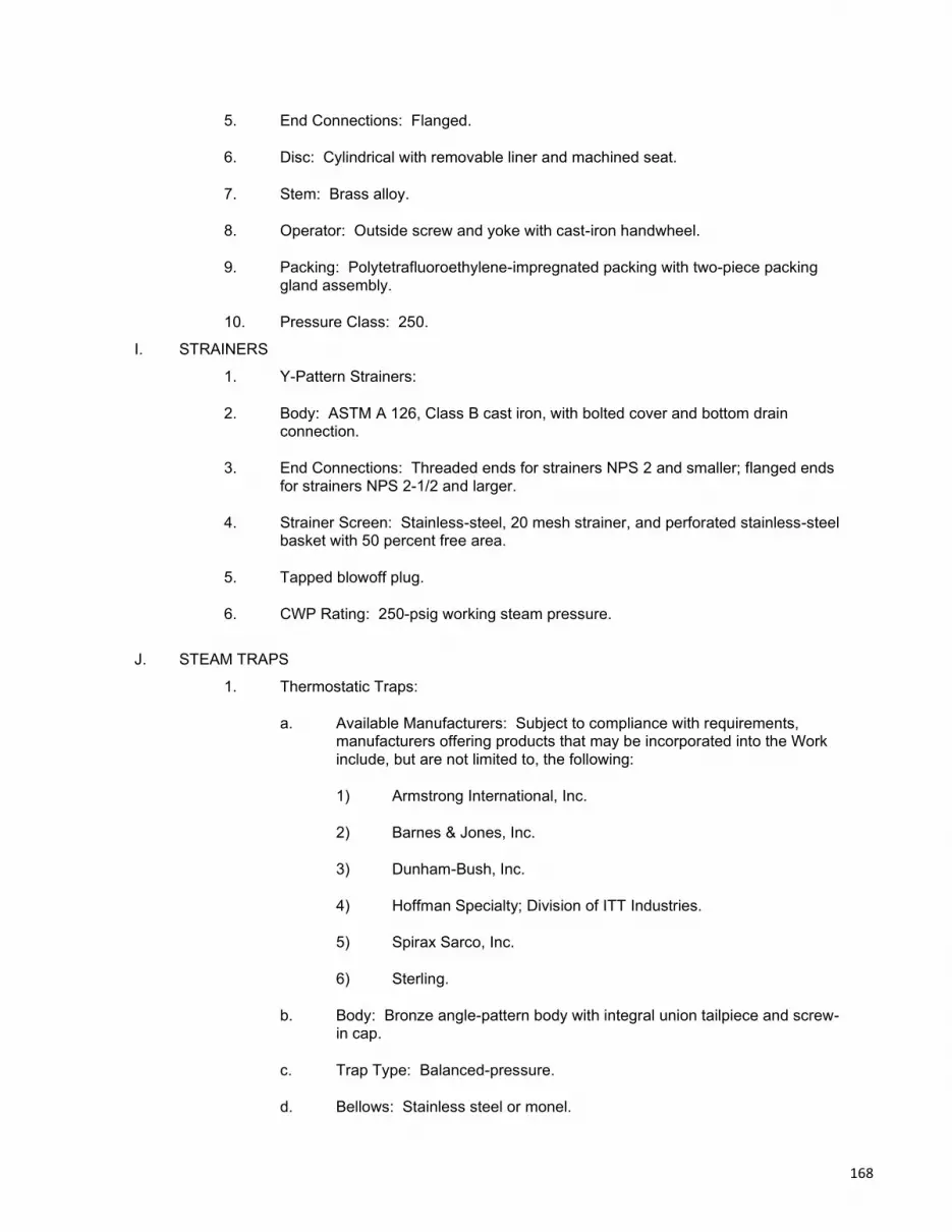
5. End Connections: Flanged.
6. Disc: Cylindrical with removable liner and machined seat.
7. Stem: Brass alloy.
8. Operator: Outside screw and yoke with cast-iron handwheel.
9. Packing: Polytetrafluoroethylene-impregnated packing with two-piece packing gland assembly.
10. Pressure Class: 250.
I. STRAINERS
1. Y-Pattern Strainers:
2. Body: ASTM A 126, Class B cast iron, with bolted cover and bottom drain connection.
3. End Connections: Threaded ends for strainers NPS 2 and smaller; flanged ends for strainers NPS 2-1/2 and larger.
4. Strainer Screen: Stainless-steel, 20 mesh strainer, and perforated stainless-steel basket with 50 percent free area.
5. Tapped blowoff plug.
6. CWP Rating: 250-psig working steam pressure.
J. STEAM TRAPS
1. Thermostatic Traps:
a. Available Manufacturers: Subject to compliance with requirements, manufacturers offering products that may be incorporated into the Work include, but are not limited to, the following:
1) Armstrong International, Inc.
2) Barnes & Jones, Inc.
3) Dunham-Bush, Inc.
4) Hoffman Specialty; Division of ITT Industries.
5) Spirax Sarco, Inc.
6) Sterling.
b. Body: Bronze angle-pattern body with integral union tailpiece and screw-in cap.
c. Trap Type: Balanced-pressure.
d. Bellows: Stainless steel or monel.
168

e. Head and Seat: Replaceable, hardened stainless steel.
f. Pressure Class: 125.
2. Float and Thermostatic Traps:
a. Available Manufacturers: Subject to compliance with requirements, manufacturers offering products that may be incorporated into the Work include, but are not limited to, the following:
1) Armstrong International, Inc.
2) Barnes & Jones, Inc.
3) Dunham-Bush, Inc.
4) Hoffman Specialty; Division of ITT Industries.
5) Spirax Sarco, Inc.
6) Sterling.
b. Body and Bolted Cap: ASTM A 126, cast iron.
c. End Connections: Threaded.
d. Float Mechanism: Replaceable, stainless steel.
e. Head and Seat: Hardened stainless steel.
f. Trap Type: Balanced pressure.
g. Thermostatic Bellows: Stainless steel or monel.
h. Thermostatic air vent capable of withstanding 45 deg F of superheat and resisting water hammer without sustaining damage.
i. Maximum Operating Pressure: 125 psig.
K. THERMOSTATIC AIR VENTS
1. Available Manufacturers: Subject to compliance with requirements, manufacturers offering products that may be incorporated into the Work include, but are not limited to, the following:
a. Armstrong International, Inc.
b. Barnes & Jones, Inc.
c. Dunham-Bush, Inc.
d. Hoffman Specialty; Division of ITT Industries.
e. Spirax Sarco, Inc.
169

f. Sterling.
2. Body: Cast iron, bronze, or stainless steel.
3. End Connections: Threaded.
4. Float, Valve, and Seat: Stainless steel.
5. Thermostatic Element: Phosphor bronze bellows in a stainless-steel cage.
6. Pressure Rating: 125 psig.
7. Maximum Temperature Rating: 350 deg F.
L. LP STEAM PIPING APPLICATIONS
1. LP Steam Piping: Schedule 80, Type S, Grade B, steel pipe; Class 125 cast-iron fittings; and threaded joints.
2. Condensate Piping above Grade: Schedule 80, Type S, Grade B, steel pipe; Class 125 cast-iron fittings; and threaded joints.
3. Condensate Piping below Grade: Schedule 80, Type S, Grade B, steel pipe; Class 125 cast-iron fittings; and threaded joints.
M. VALVE APPLICATIONS
1. Install shutoff duty valves at branch connections to steam supply mains, at steam supply connections to equipment, and at the outlet of steam traps.
N. PIPING INSTALLATION
1. Drawing plans, schematics, and diagrams indicate general location and arrangement of piping systems. Use indicated piping locations and arrangements if such were used to size pipe and calculate friction loss, expansion, and other design considerations. Install piping as indicated unless deviations to layout are approved on Coordination Drawings.
2. Install piping in concealed locations, unless otherwise indicated and except in equipment rooms and service areas.
3. Install piping indicated to be exposed and piping in equipment rooms and service areas at right angles or parallel to building walls. Diagonal runs are prohibited unless specifically indicated otherwise.
4. Install piping above accessible ceilings to allow sufficient space for ceiling panel removal.
5. Install piping to permit valve servicing.
6. Install piping free of sags and bends.
7. Install fittings for changes in direction and branch connections.
8. Install piping to allow application of insulation.
170

9. Select system components with pressure rating equal to or greater than system operating pressure.
10. Install groups of pipes parallel to each other, spaced to permit applying insulation and servicing of valves.
11. Install drains, consisting of a tee fitting, NPS 3/4 full port-ball valve, and short NPS 3/4 threaded nipple with cap, at low points in piping system mains and elsewhere as required for system drainage.
12. Install steam supply piping at a minimum uniform grade of 0.2 percent downward in direction of steam flow.
13. Install condensate return piping at a minimum uniform grade of 0.4 percent downward in direction of condensate flow.
14. Reduce pipe sizes using eccentric reducer fitting installed with level side down.
15. Install branch connections to mains using mechanically formed tee fittings in main pipe, with the branch connected to top of main pipe.
16. Install valves according to Division 23 Section "General-Duty Valves for HVAC Piping."
17. Install unions in piping, NPS 2 and smaller, adjacent to valves, at final connections of equipment, and elsewhere as indicated.
18. Install flanges in piping, NPS 2-1/2 and larger, at final connections of equipment and elsewhere as indicated.
19. Install strainers on supply side of control valves, pressure-reducing valves, traps, and elsewhere as indicated. Install NPS 3/4 nipple and full port ball valve in blowdown connection of strainers NPS 2 and larger. Match size of strainer blowoff connection for strainers smaller than NPS 2.
20. Identify piping as specified in Division 23 Section "Identification for HVAC Piping and Equipment."
21. Install drip legs at low points and natural drainage points such as ends of mains, bottoms of risers, and ahead of pressure regulators, and control valves.
a. On straight runs with no natural drainage points, install drip legs at intervals not exceeding 300 feet.
b. Size drip legs same size as main. In steam mains NPS 6 and larger, drip leg size can be reduced, but to no less than NPS 4.
22. Install sleeves for piping penetrations of walls, ceilings, and floors. Comply with requirements for sleeves specified in Division 23 Section "Sleeves and Sleeve Seals for HVAC Piping."
a. Install sleeve seals for piping penetrations of concrete walls and slabs. Comply with requirements for sleeve seals specified in Division 23 Section "Sleeves and Sleeve Seals for HVAC Piping."
171

b. Install escutcheons for piping penetrations of walls, ceilings, and floors. Comply with requirements for escutcheons specified in Division 23 Section "Escutcheons for HVAC Piping."
O. STEAM-TRAP INSTALLATION
1. Install steam traps in accessible locations as close as possible to connected equipment.
2. Install full-port ball valve, strainer, and union upstream from trap; install union, check valve, and full-port ball valve downstream from trap unless otherwise indicated.
P. HANGERS AND SUPPORTS
1. Install hangers and supports according to Division 23 Section "Hangers and Supports for HVAC Piping and Equipment." Comply with requirements below for maximum spacing.
2. Seismic restraints are specified in Division 23 Section "Vibration and Seismic Controls for HVAC Piping and Equipment."
3. Install the following pipe attachments:
a. Adjustable steel clevis hangers for individual horizontal piping less than 20 feet long.
b. Adjustable roller hangers and spring hangers for individual horizontal piping 20 feet or longer.
c. Pipe Roller: MSS SP-58, Type 44 for multiple horizontal piping 20 feet or longer, supported on a trapeze.
d. Spring hangers to support vertical runs.
4. Install hangers with the following maximum spacing and minimum rod sizes:
a. NPS 3/4: Maximum span, 9 feet; minimum rod size, 1/4 inch.
b. NPS 1: Maximum span, 9 feet; minimum rod size, 1/4 inch.
c. NPS 1-1/2: Maximum span, 12 feet; minimum rod size, 3/8 inch.
d. NPS 2: Maximum span, 13 feet; minimum rod size, 3/8 inch.
e. NPS 2-1/2: Maximum span, 14 feet; minimum rod size, 3/8 inch.
f. NPS 3: Maximum span, 15 feet; minimum rod size, 3/8 inch.
g. NPS 4: Maximum span, 17 feet; minimum rod size, 1/2 inch.
5. Support vertical runs at roof, at each floor, and at 10-foot intervals between floors.
172
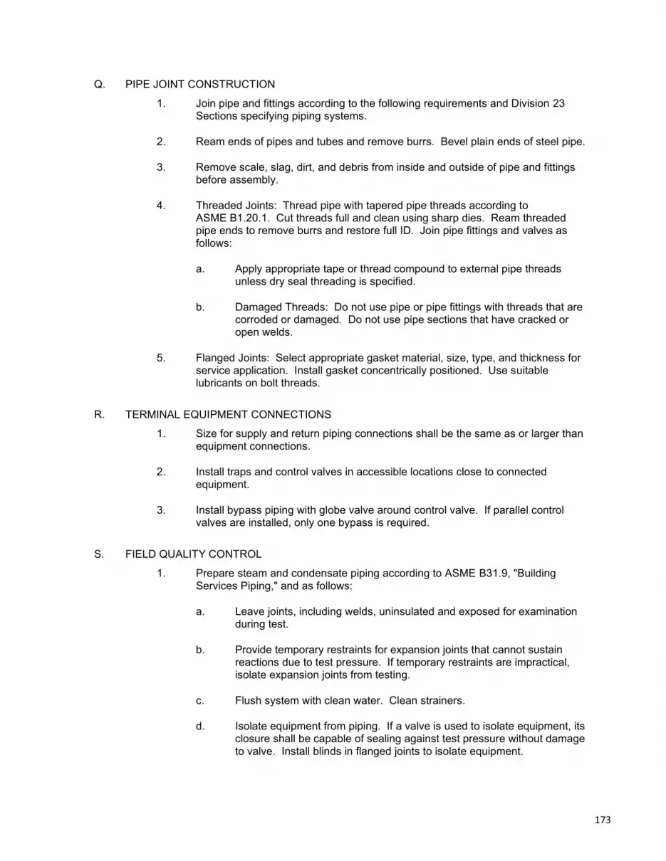
Q. PIPE JOINT CONSTRUCTION
1. Join pipe and fittings according to the following requirements and Division 23 Sections specifying piping systems.
2. Ream ends of pipes and tubes and remove burrs. Bevel plain ends of steel pipe.
3. Remove scale, slag, dirt, and debris from inside and outside of pipe and fittings before assembly.
4. Threaded Joints: Thread pipe with tapered pipe threads according to ASME B1.20.1. Cut threads full and clean using sharp dies. Ream threaded pipe ends to remove burrs and restore full ID. Join pipe fittings and valves as follows:
a. Apply appropriate tape or thread compound to external pipe threads unless dry seal threading is specified.
b. Damaged Threads: Do not use pipe or pipe fittings with threads that are corroded or damaged. Do not use pipe sections that have cracked or open welds.
5. Flanged Joints: Select appropriate gasket material, size, type, and thickness for service application. Install gasket concentrically positioned. Use suitable lubricants on bolt threads.
R. TERMINAL EQUIPMENT CONNECTIONS
1. Size for supply and return piping connections shall be the same as or larger than equipment connections.
2. Install traps and control valves in accessible locations close to connected equipment.
3. Install bypass piping with globe valve around control valve. If parallel control valves are installed, only one bypass is required.
S. FIELD QUALITY CONTROL
1. Prepare steam and condensate piping according to ASME B31.9, "Building Services Piping," and as follows:
a. Leave joints, including welds, uninsulated and exposed for examination during test.
b. Provide temporary restraints for expansion joints that cannot sustain reactions due to test pressure. If temporary restraints are impractical, isolate expansion joints from testing.
c. Flush system with clean water. Clean strainers.
d. Isolate equipment from piping. If a valve is used to isolate equipment, its closure shall be capable of sealing against test pressure without damage to valve. Install blinds in flanged joints to isolate equipment.
173

2. Perform the following tests on steam and condensate piping:
a. Use ambient temperature water as a testing medium unless there is risk of damage due to freezing. Another liquid that is safe for workers and compatible with piping may be used.
b. Subject piping system to hydrostatic test pressure that is not less than 1.5 times the working pressure. Test pressure shall not exceed maximum pressure for any vessel, pump, valve, or other component in system under test. Verify that stress due to pressure at bottom of vertical runs does not exceed 90 percent of specified minimum yield strength.
c. After hydrostatic test pressure has been applied for at least 10 minutes, examine piping, joints, and connections for leakage. Eliminate leaks by tightening, repairing, or replacing components, and repeat hydrostatic test until there are no leaks.
3. Prepare written report of testing.
2.11 PIPE HANGERS AND SUPPORTS
A. Provide pipe stands, supports, hangers and other supporting appliances as necessary to support work required by Contract Documents.
A. Secure vertical piping to building construction to prevent sagging or swinging.
B. Horizontal copper tubing shall have maximum hanger spacing of 5 ft. for tubing 1¼" dia. and smaller and 10' for tubing 1½" and larger.
C. Reduce spacing to a maximum of 10'- 0" apart, regardless of pipe size, as necessary for fittings, valves and other concentrated loads.
D. Support piping 3" dia. and under from structure with Carpenter and Patterson Fig. 100 clevis hangers or approved equal.
E. Hangers shall be by Carpenter and Patterson, F & S, or Grinnell Co. Figure numbers of Carpenter and Patterson are specified to establish standards of quality for performance and materials.
F. Hangers for horizontal lines shall be vertically adjustable to obtain pitch requirements of Piping Paragraph.
2.12 ESCUTCHEONS AND DUCT COLLARS
A. Provide adjustable escutcheons on exposed piping that passes through finished floors, walls and ceilings. Escutcheons shall be chromium-plated cast brass, sized to cover sleeve opening and to accommodate pipe and insulation.
B. Provide 4" wide 20 gauge galvanized sheet metal collars at sleeves and prepared openings, sized to cover entire duct penetration including sleeve and seal, and to accommodate duct and insulation as necessary. Edges shall have milled lips ground smooth. Paint to match finish of duct or as directed by Architect.
2.13 ACCESS PANELS
A. Description: Interior construction access panels.
174

1. Manufacturers:
a. Milcor
b. Knapp
c. Nystorm
d. Inland Steel
B. Coordinate selection with other Divisions supplying similar access panels.
C. Access panels shall have same fire rating classification as surface penetrated.
D. Access panels are generally not shown on the drawings, but shall be provided.
E. Provide proper access to materials and equipment that require inspection, replacement, repair or service, and coordinate their delivery with the installing Trade. If proper access cannot be provided, confer with Architect as to best method of approach for minimizing effect of reduced access that may result.
F. Coordinate and prepare a location, size, and function schedule of access panels required to fully service equipment and deliver to a representative of the installing Trade. Furnish and install distinctively colored buttons (color as selected by Architect) in finished ceiling to identify access panels
G. Furnish access panels for installation under other Sections where fire dampers, smoke detectors, controls, shut-off valves, control valves, or other items installed under this Section require access and are concealed in floor, wall, furred space or above ceiling.
H. Access panels shall be at least large enough to remove the component requiring access. Where individual components (e.g. control valves) requiring access are within 8” of the finished surface, panels shall be a minimum of 12" x 12". Where component is more than 8” from surface and at equipment requiring service (e.g. fire dampers), access panels shall be a minimum of 24" x 24".
2.14 HVAC POWER VENTILATORS
A. SUMMARY
1. Section Includes:
a. Ceiling-mounted ventilators.
B. ACTION SUBMITTALS
1. Product Data: For each type of product indicated.
2. Shop Drawings: Include plans, elevations, sections, details, and attachments to other work.
a. Detail equipment assemblies and indicate dimensions, weights, loads, required clearances, method of field assembly, components, and location and size of each field connection.
b. Wiring Diagrams: For power, signal, and control wiring.
175

c. Vibration Isolation Base Details: Detail fabrication including anchorages and attachments to structure and to supported equipment. Include adjustable motor bases, rails, and frames for equipment mounting.
C. CLOSEOUT SUBMITTALS
1. Operation and maintenance data.
D. QUALITY ASSURANCE
1. Electrical Components, Devices, and Accessories: Listed and labeled as defined in NFPA 70, by a qualified testing agency, and marked for intended location and application.
2. AMCA Compliance: Fans shall have AMCA-Certified performance ratings and shall bear the AMCA-Certified Ratings Seal.
E. CEILING-MOUNTED VENTILATORS
1. Basis of design is Panasonic as shown on drawings (or approved equal).
2. Housing: Steel, lined with acoustical insulation.
3. Fan Wheel: Centrifugal wheels directly mounted on motor shaft. Fan shrouds, motor, and fan wheel shall be removable for service.
4. Grille: Plastic, louvered grille with flange on intake and thumbscrew attachment to fan housing.
5. Electrical Requirements: Junction box for electrical connection on housing and receptacle for motor plug-in.
6. Accessories:
a. Motion Sensor: Motion detector with adjustable shutoff timer.
b. Isolation: Rubber-in-shear vibration isolators.
c. Manufacturer's standard roof jack or wall cap, and transition fittings.
F. MOTORS
1. Comply with NEMA designation, temperature rating, service factor, enclosure type, and efficiency requirements for motors specified in Section 230513 "Common Motor Requirements for HVAC Equipment."
a. Motor Sizes: Minimum size as indicated. If not indicated, large enough so driven load will not require motor to operate in service factor range above 1.0.
2. Enclosure Type: Totally enclosed, fan cooled.
G. SOURCE QUALITY CONTROL
1. Certify sound-power level ratings according to AMCA 301, "Methods for Calculating Fan Sound Ratings from Laboratory Test Data." Factory test fans according to AMCA 300, "Reverberant Room Method for Sound Testing of Fans." Label fans with the AMCA-Certified Ratings Seal.
176

2. Certify fan performance ratings, including flow rate, pressure, power, air density, speed of rotation, and efficiency by factory tests according to AMCA 210, "Laboratory Methods of Testing Fans for Aerodynamic Performance Rating." Label fans with the AMCA-Certified Ratings Seal.
H. INSTALLATION
1. Equipment Mounting:
a. Mount in accordance with manufacturer’s installation manual.
2. Ceiling Units: Suspend units from structure; use steel wire or metal straps.
3. Support suspended units from structure using threaded steel rods and elastomeric hangers having a static deflection of 1 inch.
4. Install units with clearances for service and maintenance.
5. Label units according to requirements specified in Section 230553 "Identification for HVAC Piping and Equipment."
I. CONNECTIONS
1. Drawings indicate general arrangement of ducts and duct accessories. Make final duct connections with flexible connectors. Flexible connectors are specified in Section 233300 "Air Duct Accessories."
2. Install ducts adjacent to power ventilators to allow service and maintenance.
3. Ground equipment according to Section 260526 "Grounding and Bonding for Electrical Systems."
4. Connect wiring according to Section 260519 "Low-Voltage Electrical Power Conductors and Cables."
J. FIELD QUALITY CONTROL
1. Perform tests and inspections.
2. Tests and Inspections:
a. Verify that shipping, blocking, and bracing are removed.
b. Verify that unit is secure on mountings and supporting devices and that connections to ducts and electrical components are complete. Verify that proper thermal-overload protection is installed in motors, starters, and disconnect switches.
c. Verify that cleaning and adjusting are complete.
d. Disconnect fan drive from motor, verify proper motor rotation direction, and verify fan wheel free rotation and smooth bearing operation. Reconnect fan drive system, align and adjust belts, and install belt guards.
e. Adjust belt tension.
f. Adjust damper linkages for proper damper operation.
177

g. Verify lubrication for bearings and other moving parts.
h. Verify that manual and automatic volume control and fire and smoke dampers in connected ductwork systems are in fully open position.
i. Disable automatic temperature-control operators, energize motor and adjust fan to indicated rpm, and measure and record motor voltage and amperage.
j. Shut unit down and reconnect automatic temperature-control operators.
k. Remove and replace malfunctioning units and retest as specified above.
3. Test and adjust controls and safeties. Replace damaged and malfunctioning controls and equipment.
4. Prepare test and inspection reports.
K. ADJUSTING
1. Adjust damper linkages for proper damper operation.
2. Adjust belt tension.
3. Comply with requirements in Section 230593 "Testing, Adjusting, and Balancing for HVAC" for testing, adjusting, and balancing procedures.
4. Replace fan and motor pulleys as required to achieve design airflow.
5. Lubricate bearings.
2.15 GAS VENTS
A. SUMMARY
1. Section Includes: Listed double-wall vents.
B. ACTION SUBMITTALS
1. Product Data: For each type of product.
2. Shop Drawings: For vents.
a. Include plans, elevations, sections, and attachment details.
b. Include details of equipment assemblies. Indicate dimensions, weights, loads, required clearances, method of field assembly, components, and location and size of each field connection.
c. Detail fabrication and assembly of hangers and seismic restraints.
C. INFORMATIONAL SUBMITTALS
1. Welding certificates.
2. Sample Warranty: For special warranty.
D. QUALITY ASSURANCE
178

1. Welding Qualifications: Qualify procedures and personnel according to the following:
a. AWS D1.1/D1.1M, "Structural Welding Code - Steel," for hangers and supports.
b. AWS D9.1/D9.1M, "Sheet Metal Welding Code," for shop and field welding of joints and seams in vents.
2. Certified Sizing Calculations: Manufacturer shall certify venting system sizing calculations.
E. LISTED SPECIAL GAS VENTS
1. Description: Double-wall metal vents tested according to UL 1738 and rated for 480 deg F continuously, with positive or negative flue pressure complying with NFPA 211.
2. Construction: Inner shell and outer jacket separated by at least a 1/2-inch airspace.
3. Inner Shell: ASTM A 959, Type 29-4C stainless steel.
4. Outer Jacket: Aluminized steel.
5. Accessories: Tees, elbows, increasers, draft-hood connectors, terminations, adjustable roof flashings, storm collars, support assemblies, thimbles, firestop spacers, and fasteners; fabricated from similar materials and designs as vent-pipe straight sections; all listed for same assembly.
a. Termination: Round chimney top designed to exclude minimum 98 percent of rainfall.
F. APPLICATION
1. Listed Special Gas Vent: Condensing gas appliances, positive pressure vent appliances.
G. INSTALLATION OF LISTED VENTS
1. Comply with minimum clearances from combustibles and minimum termination heights according to product listing or NFPA 211, whichever is most stringent.
2. Seal between sections of positive-pressure vents according to manufacturer's written installation instructions, using sealants recommended by manufacturer.
3. Support vents at intervals recommended by manufacturer to support weight of vents and all accessories, without exceeding appliance loading.
4. Lap joints in direction of flow.
5. After completing system installation, including outlet fittings and devices, inspect exposed finish. Remove burrs, dirt, and construction debris, and repair damaged finishes.
2.16 CAST-IRON BOILERS
A. SUMMARY
179

1. Section includes cast-iron boilers, trim, and accessories for generating low pressure steam.
B. ACTION SUBMITTALS
1. Product Data: For each type of product.
2. Shop Drawings: For boilers, boiler trim, and accessories.
a. Include plans, elevations, sections, and mounting details.
b. Include details of equipment assemblies. Indicate dimensions, weights, loads, required clearances, method of field assembly, components, and location and size of each field connection.
c. Include diagrams for power, signal, and control wiring.
3. Delegated-Design Submittal: For each boiler.
a. Design calculations and vibration isolation base details, signed and sealed by a qualified professional engineer.
1) Design Calculations: Calculate requirements for selecting vibration isolators and seismic restraints and for designing vibration isolation bases.
2) Vibration Isolation Base Details: Detail fabrication, including anchorages and attachments to structure and to supported equipment. Include adjustable motor bases, rails, and frames for equipment mounting.
C. INFORMATIONAL SUBMITTALS
1. Seismic Qualification Certificates: For boiler, accessories, and components, from manufacturer.
2. Source quality-control reports.
3. Field quality-control reports.
4. Sample Warranty: For special warranty.
D. CLOSEOUT SUBMITTALS
1. Operation and maintenance data.
E. WARRANTY
1. Manufacturer's Warranty: Manufacturer agrees to repair or replace controls and heat exchangers of boilers that fail in materials or workmanship within specified warranty period.
a. Warranty Period for Controls: Two years from date of Substantial Completion.
b. Warranty Period for Heat Exchangers: 10 years from date of Substantial Completion.
F. PERFORMANCE REQUIREMENTS
180

1. Electrical Components, Devices, and Accessories: Listed and labeled as defined in NFPA 70, by a qualified testing agency, and marked for intended location and application.
2. ASME Compliance: Fabricate and label boilers to comply with 2010 ASME Boiler and Pressure Vessel Code.
3. ASHRAE/IES 90.1 Compliance: Boilers shall have minimum efficiency according to "Gas and Oil Fired Boilers - Minimum Efficiency Requirements."
4. DOE Compliance: Minimum efficiency shall comply with 10 CFR 430, Subpart B, Appendix N.
5. I=B=R Compliance: Boilers shall be tested and rated according to AHRI's "Rating Procedure for Heating Boilers" and "Testing Standard for Commercial Boilers," with I=B=R emblem on a nameplate affixed to boiler.
6. UL Compliance: Test boilers for compliance with UL 726 and UL 795. Boilers shall be listed and labeled by a testing agency acceptable to authorities having jurisdiction.
7. CSA Compliance: Test boilers for compliance with CSA B51.
8. Mounting Frame: Steel rails used to mount assembled boiler package on concrete base.
a. Seismic Fabrication Requirements: Fabricate mounting base and attachment to boiler, accessories, and components with reinforcement strong enough to withstand seismic forces defined in Section 230548 "Vibration and Seismic Controls for HVAC" when mounting base is anchored to building structure.
G. MANUFACTURERS
1. Basis of design is Weil McLain as shown on drawings (or approved equal). The basis of design selection is the same manufacture and model as the existing boiler to be removed. Any substitution may require additional piping, venting, gas, & electrical work to connect to existing utilities to remain. All additional work as the result of a substitution is the responsibility of this contractor.
H. MANUFACTURED UNITS
1. Description: Factory fabricated and shipped knocked down for assembly on site.
a. Cast-iron sections shall be sealed pressure tight and held together with tie rods set on an insulated steel base, including insulated jacket and flue-gas vent connection.
2. Cast-Iron Section Design:
a. Configuration: Wet base.
b. Number of Passes: Multiple.
c. Sectional Joints: High-temperature sealant to seal flue-gas passages not in contact with heating medium, O-ring gaskets, and held together with tie rods.
181

d. Drain and blowdown tappings.
e. Return injection tube to equalize water flow to all sections.
f. Crown inspection tappings with brass plugs.
g. Built-in air separator.
3. Combustion Chamber: Equipped with refractory and flame observation ports, front and back.
4. Casing:
a. Jacket: Galvanized sheet metal, with snap-in or interlocking closures and powder-coated protective finish.
b. Insulation: Minimum 2-inch-thick, mineral-fiber insulation surrounding the heat exchanger.
c. Combustion Chamber Access: Refractory lined, hinged, front.
d. Access: For cleaning between cast-iron sections.
e. Draft Hood: Flue canopy and rear flue connection shall be constructed of stainless steel containing adjustable outlet damper assembly.
I. ATMOSPHERIC-GAS BURNER
1. Burner Tubes and Orifices: Stainless steel, for natural gas.
2. Gas Train: Control devices and low-high-low control sequence shall comply with requirements in UL.
3. Gas Train: Combination-gas valve with manual shutoff, pressure regulator, and pilot adjustment.
4. Pilot: Intermittent-electric-spark pilot ignition with 100 percent main-valve and pilot-safety shutoff with electronic supervision of burner flame.
J. BOILER TRIM
1. Include devices sized to comply with ASME B31.9.
2. All electrical components to be of high quality and bear the UL label.
3. Steam boiler(s) standard controls furnished:
a. Low pressuretrol (operating) and high pressuretrol set at maximum pressure as a safety control.
b. Steam pressure gauge with dial clearly marked and easy to read.
c. Gauge cock water set with gauge glass, guards and aluminum water level plate.
182

d. ASME certified pressure relief valve, set to relieve at 15 PSIG. Side outlet discharge type; contractor to pipe outlet to floor drain or near floor, avoiding any area where freezing could occur.
4. Low water cut-off for water or steam boiler(s):
a. Boiler(s) to be furnished with U.L. labeled low water cut-off with ASME working pressure rating equal to the ASME rating of the relief valve.
b. Do not use quick-connect fittings on boiler(s).
c. Install cut-off according to manufacturer’s instructions.
d. Locate so burner shuts down if boiler water level falls below allowable safe waterline (steam boilers, ¼” above bottom of gauge glass).
e. Steam boiler primary low water cut-off shall be a float type – auto reset.
f. Steam boiler secondary low water cut-off shall be a float type – manual reset.
5. Boiler Air Vent: Automatic.
6. Drain Valve: Minimum NPS 3/4 hose-end gate valve.
K. CONTROLS
1. Boiler operating controls shall include the following devices and features:
a. Control transformer.
b. Set-Point Adjust: Set points shall be adjustable.
c. Low-Water Cutoff and Pump Control: Open control valve and cycle feedwater pump(s) for makeup water control.
2. Safety Controls: To maintain safe operating conditions, burner safety controls limit burner operation.
a. Low-Water Cutoff Switch: Electronic probe shall prevent burner operation on low water. Cutoff switch shall be manual-reset type.
b. Blocked Vent Safety Switch: Manual-reset switch factory mounted on draft diverter.
c. Rollout Safety Switch: Factory mounted on boiler combustion chamber.
d. Audible Alarm: Factory mounted on control panel with silence switch; shall sound alarm for above conditions.
L. ELECTRICAL POWER
1. Single-Point Field Power Connection: Factory-installed and -wired switches, motor controllers, transformers, and other electrical devices necessary shall provide a single-point field power connection to boiler.
a. House in NEMA 250, Type 1 enclosure.
183

b. Wiring shall be numbered and color coded to match wiring diagram.
c. Install factory wiring outside of an enclosure in a metal raceway.
d. Field power interface shall be to nonfused disconnect switch.
e. Provide branch power circuit to each motor and to controls with disconnect switch.
f. Provide each motor with overcurrent protection.
M. BOILER INSTALLATION
1. Assemble and install boiler-burner unit in compliance with manufacturer’s installation instructions. All work must be done in a neat and workman-like manner.
2. Equipment Mounting:
a. Install boilers on existing concrete equipment base.
3. Install gas-fired boilers according to NFPA 54.
4. Assemble and install boiler trim.
5. Install electrical devices furnished with boiler but not specified to be factory mounted.
6. Install control wiring to field-mounted electrical devices.
N. CONNECTIONS
1. Piping installation requirements are specified in Division 23 "Steam and Condensate Heating Piping." Drawings indicate general arrangement of piping, fittings, and specialties.
2. Install piping adjacent to boiler to allow service and maintenance.
3. Connect gas piping to boiler gas-train inlet with union. Piping shall be at least full size of gas-train connection. Provide a reducer if required.
4. Connect steam and condensate piping to supply- and return-boiler tappings with flange at each connection.
5. Install piping from safety relief valves to nearest floor drain.
6. Install piping from equipment drain connection to nearest floor drain. Piping shall be at least full size of connection. Provide an isolation valve if required.
7. Connect breeching full size to boiler outlet.
O. FIELD QUALITY CONTROL
1. Perform the following tests and inspections with the assistance of a factory-authorized service representative:
a. Perform installation and startup checks according to manufacturer's written instructions.
184

b. Leak Test: Hydrostatic test. Repair leaks and retest until no leaks exist.
c. Operational Test: Start units to confirm proper motor rotation and unit operation. Adjust air-fuel ratio and combustion.
d. Test and adjust controls and safeties. Replace damaged and malfunctioning controls and equipment.
1) Burner Test: Adjust burner to eliminate excess oxygen, carbon dioxide, oxides of nitrogen emissions, and carbon monoxide in flue gas and to achieve combustion efficiency.
2) Check and adjust initial operating set points and high- and low-limit safety set points of fuel supply, water level, and water temperature.
2. Remove and replace malfunctioning units and retest as specified above.
3. Boiler will be considered defective if it does not pass tests and inspections.
4. Prepare test and inspection reports.
P. ADJUSTING
1. Occupancy Adjustments: When requested within 12 months of date of Substantial Completion, provide on-site assistance in adjusting system to suit actual occupied conditions. Provide up to two visits to Project during other-than-normal occupancy hours for this purpose.
Q. DEMONSTRATION
1. Train Owner's maintenance personnel to adjust, operate, and maintain boilers. Refer to Division 01 "Demonstration and Training."
PART 3 - EXECUTION
3.1 MATERIALS AND WORKMANSHIP
A. Work shall be neat and rectilinear. Ductwork, piping and conduit shall run concealed except in mechanical rooms and areas where no hung ceiling exists. Install material and equipment in accordance with manufacturers written instructions. Installation shall operate safely and without leakage, undue wear, noise, vibration, corrosion or water hammer. Work shall be properly and effectively protected, and pipe and duct openings shall be temporarily closed to prevent obstruction and damage before completion.
B. Except as specified otherwise, material and equipment shall be new. Provide supplies, appliances and connections necessary for complete and operational installation. Provide components required or recommended by OSHA and applicable NFPA documents.
C. Owner will not be responsible for material and equipment before testing, commissioning, and acceptance.
3.2 SPECIAL RESPONSIBILITIES
A. Cooperate and coordinate with work of other Sections in executing work of this Section.
1. Perform work so that progress of entire project including work of other Sections shall not be interfered with or delayed.
185
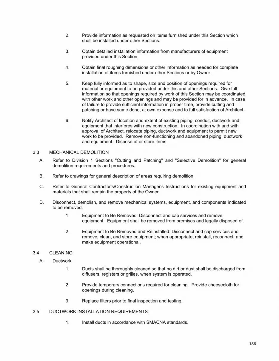
2. Provide information as requested on items furnished under this Section which shall be installed under other Sections.
3. Obtain detailed installation information from manufacturers of equipment provided under this Section.
4. Obtain final roughing dimensions or other information as needed for complete installation of items furnished under other Sections or by Owner.
5. Keep fully informed as to shape, size and position of openings required for material or equipment to be provided under this and other Sections. Give full information so that openings required by work of this Section may be coordinated with other work and other openings and may be provided for in advance. In case of failure to provide sufficient information in proper time, provide cutting and patching or have same done, at own expense and to full satisfaction of Architect.
6. Notify Architect of location and extent of existing piping, conduit, ductwork and equipment that interferes with new construction. In coordination with and with approval of Architect, relocate piping, ductwork and equipment to permit new work to be provided. Remove non-functioning and abandoned piping, ductwork and equipment. Dispose of or store items.
3.3 MECHANICAL DEMOLITION
A. Refer to Division 1 Sections "Cutting and Patching" and "Selective Demolition" for general demolition requirements and procedures.
B. Refer to drawings for general description of areas requiring demolition.
C. Refer to General Contractor's/Construction Manager's Instructions for existing equipment and materials that shall remain the property of the Owner.
D. Disconnect, demolish, and remove mechanical systems, equipment, and components indicated to be removed.
1. Equipment to Be Removed: Disconnect and cap services and remove equipment. Equipment shall be removed from premises and legally disposed of.
2. Equipment to Be Removed and Reinstalled: Disconnect and cap services and remove, clean, and store equipment; when appropriate, reinstall, reconnect, and make equipment operational.
3.4 CLEANING
A. Ductwork
1. Ducts shall be thoroughly cleaned so that no dirt or dust shall be discharged from diffusers, registers or grilles, when system is operated.
2. Provide temporary connections required for cleaning. Provide cheesecloth for openings during cleaning.
3. Replace filters prior to final inspection and testing.
3.5 DUCTWORK INSTALLATION REQUIREMENTS:
1. Install ducts in accordance with SMACNA standards.
186

2. Install ducts with the fewest possible joints.
3. Provide clearance of 1 inch (25 mm) where furring is shown for enclosure or concealment of ducts, plus allowance for insulation thickness, where applicable.
4. Ductwork shall be free from vibration under all conditions of operation.
5. Install control dampers furnished by the ATC contractor.
3.6 CONNECTIONS
A. Connect inlets and outlets of air handling units and fans to ductwork with flexible connections unless fan has vibration isolator mounts inside unit with flexible connection and no external vibration isolators.
B. Secure flexible connections tightly to air handlers with metal bands. Bands shall be same material as duct construction.
C. Connections from trunk to branch ducts shall be as detailed on Drawings.
D. Spin in collars shall not be used.
3.7 EQUIPMENT INSTALLATION - COMMON REQUIREMENTS
A. Install equipment to allow maximum possible headroom unless specific mounting heights are not indicated.
B. Install equipment level and plumb, parallel and perpendicular to other building systems and components in exposed interior spaces, unless otherwise indicated.
C. Install mechanical equipment to facilitate service, maintenance, and repair or replacement of components. Connect equipment for ease of disconnecting, with minimum interference to other installations. Extend grease fittings to accessible locations.
D. Install equipment to allow right of way for piping installed at required slope
E. Avoid interference with structure and with work of other trades, preserving adequate headroom and clearing doors and passageways, to satisfaction of Architect and in accordance with code requirements.
F. Distribute equipment loads on building structural members provided for equipment support.
G. Provide suspended platforms, strap hangers, brackets, shelves, stands or legs for floor, wall or ceiling mounting of equipment.
H. Provide steel supports and hardware for proper installation of hangers, anchors and guides.
I. Provide cuts, weights, and other pertinent data required for proper coordination of equipment support provisions and installation.
J. Structural steel and hardware shall conform to Standard Specifications of ASTM; use of steel and hardware shall conform to requirements of Section Five of Code of Practice of American Institute of Steel Construction.
K. Verify site conditions and dimensions of equipment to ensure access for proper installation of equipment without disassembly that will void warrantee. Report in writing to Architect, prior to purchase or shipment of equipment involved, on conditions that may prevent proper installation.
187

3.8 EQUIPMENT IDENTIFICATION DEVICES
A. Equipment Nameplates: Metal, with data engraved or stamped, for permanent attachment on equipment.
B. Equipment Markers: Engraved, color-coded laminated plastic. Include contact-type, permanent adhesive.
1. Terminology: Match schedules as closely as possible.
2. Data:
a. Name and plan number.
b. Equipment service.
c. Design capacity.
d. Other design parameters such as pressure drop, entering and leaving conditions, and speed.
3. Size: 2-1/2 by 4 inches (64 by 100 mm) for control devices, dampers, and valves; 4-1/2 by 6 inches (115 by 150 mm) for equipment.
C. Access Panel and Door Markers: 1/16-inch- (1.6-mm-) thick, engraved laminated plastic, with abbreviated terms and numbers corresponding to identification. Provide 1/8-inch (3.2-mm) center hole for attachment.
1. Fasteners: Self-tapping, stainless-steel screws or contact-type, permanent adhesive.
3.9 START UP, TESTING AND BALANCING A. General
1. Provide qualified personnel, equipment, apparatus and services for start-up, testing and balancing of mechanical systems, to performance data shown in schedules, as specified, and as required by codes, standards, regulations and authorities having jurisdiction including City, Town or County Inspectors, Owners and Architect. Ensure that all contractors are present on site during the entire time that these procedures take place. Note that some procedures listed below have a distinct order of precedence; e.g., the testing of the temperature control system shall not occur until major pieces of mechanical equipment have been started up and testing is complete. Ensure that any listed orders of precedence for procedures are followed.
2. Do not cover or conceal work before testing and inspection and obtaining approval.
3. Instruments for testing and balancing shall have been calibrated within one month prior to testing and balancing. Calibration shall be traceable to NBS Standards. Provide photostat of certificate of calibration to Architect's representative at meeting demonstrating balancing procedures mentioned in Paragraph 4 above.
4. Leaks, damage and defects discovered or resulting from start up, testing and balancing shall be repaired or replaced to like-new condition with acceptable materials. Tests shall be continued until system operates without adjustments or repairs.
188

5. For each piece of equipment, copy nameplate data and include in report.
6. Submit six copies of testing and balancing reports to Architect for approval.
7. Provide capacity and performance of equipment by field testing. Install equipment and instruments required for testing, thermo-wells and gauge connections at no additional cost to Owner.
8. Qualified representative of equipment manufacturer shall be present at test.
B. Equipment Start Up
1. Start up the following pieces of equipment in strict accordance with manufacturer’s instructions and with manufacturer’s representative present:
a. Fans
b. Boilers
C. Automatic Temperature Controls Testing
1. General
a. Installation of the building automation system shall be performed by this Contractor or his subcontractor(s). However, all installation shall be under the personal supervision of the Contractor. The Contractor shall certify all work as proper and complete. Under no circumstances shall the design, scheduling, coordination, programming, training, and warranty requirements for the project be delegated to a subcontractor.
2. Access to Site
a. Unless notified otherwise, entrance to building is restricted. No one will be permitted to enter the building unless their names have been cleared with the Owner or the Owner’s Representative.
3. Code Compliance
a. All wiring shall be installed in accordance with the more stringent of all applicable electrical codes, equipment manufacturer's recommendations, and wiring specifications in Division 26.
4. Cleanup
a. At the completion of the work, all equipment pertinent to this contract shall be checked and thoroughly cleaned, and all other areas shall be cleaned around equipment provided under this contract. Clean the exposed surfaces of tubing, hangers, and other exposed metal of grease, plaster, or other foreign materials.
D. Air and Water Balancing
1. General
a. Provide qualified personnel, equipment and services for balancing and adjusting of mechanical systems. Submit resumes at demonstration of balancing meeting.
189
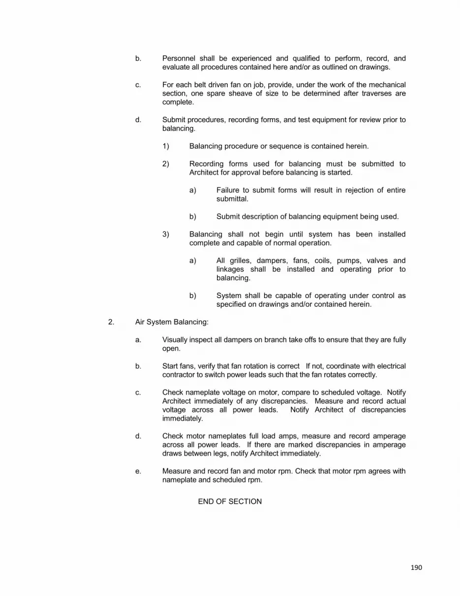
b. Personnel shall be experienced and qualified to perform, record, and evaluate all procedures contained here and/or as outlined on drawings.
c. For each belt driven fan on job, provide, under the work of the mechanical section, one spare sheave of size to be determined after traverses are complete.
d. Submit procedures, recording forms, and test equipment for review prior to balancing.
1) Balancing procedure or sequence is contained herein.
2) Recording forms used for balancing must be submitted to Architect for approval before balancing is started.
a) Failure to submit forms will result in rejection of entire submittal.
b) Submit description of balancing equipment being used.
3) Balancing shall not begin until system has been installed complete and capable of normal operation.
a) All grilles, dampers, fans, coils, pumps, valves and linkages shall be installed and operating prior to balancing.
b) System shall be capable of operating under control as specified on drawings and/or contained herein.
2. Air System Balancing:
a. Visually inspect all dampers on branch take offs to ensure that they are fully open.
b. Start fans, verify that fan rotation is correct If not, coordinate with electrical contractor to switch power leads such that the fan rotates correctly.
c. Check nameplate voltage on motor, compare to scheduled voltage. Notify Architect immediately of any discrepancies. Measure and record actual voltage across all power leads. Notify Architect of discrepancies immediately.
d. Check motor nameplates full load amps, measure and record amperage across all power leads. If there are marked discrepancies in amperage draws between legs, notify Architect immediately.
e. Measure and record fan and motor rpm. Check that motor rpm agrees with nameplate and scheduled rpm.
END OF SECTION
190
DIVISION 26 - ELECTRICAL WORK
SECTION 26.05.00GENERAL CONDITIONS FOR ELECTRICAL WORK
FILED SUB BID REQUIRED(COMBINED WITH SECTIONS:
260500, 260519, 260526, 260529, 260533, 260553, 262726 & 265100)
PART 1 - GENERAL
1.1 GENERAL PROVISIONS
A. RELATED DOCUMENTS
1. Drawings and General Provision of Contract, including General and Sup-plementary Conditions and DIVISION 01 specifications, apply to this sec-tion.
2. Where Paragraphs of this Section conflict with similar paragraphs of theGeneral and Supplementary Conditions and DIVISION 01, requirementsof this Section shall prevail.
B. Filed Sub-bids
1. Sub-bids shall be submitted for the Work of this Section in accordancewith the provisions of M.G.L. c.149 §§44A-J. The time and place for sub-mission of sub-bids are set forth in the Advertisement. The proceduresand requirements for submitting sub-bids are set forth in the Instructionsto Bidders.
2. Sub-bidders must be DCAM Certified in the listed trade and shall includea Current DCAM sub-bidder Certificate of Eligibility and a signed DCAMSub-bidder’s Update Statement with the bid
C. Sub Sub-Bid Requirements: None under this Section.
D. Reference Drawings: The Work of this Filed Sub-Bid is shown on the followingContract Drawings: E0, E1, E2 and E3.
1.2 DESCRIPTION OF WORK
A. The general scope of work for this project shall be general renovations to thelobby and toilet room and replacement of one of the two heating system boilers.
B. Work Included: Provide labor, materials and equipment necessary to completethe work of this Section, including but not limited to the following:
1. Lighting (indoor, normal, emergency and exit) including all fixtures, lamps,mounting accessories, switches, controls, outlets, wiring, raceways, and
191

all other components and fittings required to complete the work indicatedin the contract documents.
2. Grounding and bonding of all electrical systems and equipment installedor modified under this contract.
3. Fire alarm system modifications required to complete the work indicatedin the contract documents. The existing fire alarm system shall remain inplace and in operation. The new fire alarm work will tie into existing firealarm system wiring at existing devices. The electrical contractor shalltest the existing system upon completion of his work and provide a signedcopy of the NFPA 72 record of completion to the engineer prior to submit-ting for final payment.
4. Wiring devices (switches and receptacles) complete with associated wall-plates.
5. Power wiring to HVAC equipment.6. Testing of all electrical systems installed or modified under this contract.7. Coordination between electrical and other trades.8. All other systems hereinafter specified or indicated on the Contract Draw-
ings, complete, leaving ready an electrical system in perfect operatingcondition.
9. Core drilling for the Work of this Section.10. Coordination drawings and record drawings and similar requirements.11. Hoisting Equipment: The Electrical Work subcontractor shall furnish, in-
stall and maintain in safe and adequate condition all mechanical hoistingequipment, operating personnel and rigging that is necessary for theproper execution of the Work of this Section. The requirements ofDIVISION 01 in relation to hoisting and rigging being the responsibility ofthe General Contractor, do not apply to the work of this Section.
12. Staging, Planking and Scaffolding: The Electrical Work subcontractorshall furnish, install and maintain in safe and adequate condition, all stag-ing, planking and scaffolding up to eight feet in height that is necessaryfor the proper execution of the Work in this Section. The General Con-tractor shall furnish, install and maintain in safe and adequate conditionall staging, planking and scaffolding above eight feet in height.
C. Alternates:1. Alternate #1: Not Applicable.2. Alternate #2: Add occupancy sensors and replace the existing luminaires
in the lower level room 008.3. Alternate #3: Add occupancy sensors and replace the existing luminaires
in rooms 007 and 006.
D. Items To Be Installed Only: Install the following items as furnished by the desig-nated Sections:
1. DIVISION 23 – HEATING, VENTILATING, AND AIR CONDITIONING:a. Power connections for new boiler and other controls provided by
the HVAC Contractor.
E. Related Work: The following items are not included in this Section and will beperformed under the designated Sections:
192
1. DIVISION 23 - HEATING, VENTILATING, AND AIR CONDITIONING:a. Coordination with HVAC piping and ductwork, motors, and DDC
wiring except 120 VAC power to control panel as indicated on theDrawings
F. The Electrical Sub-Contractor shall be responsible for filing all documents andsecuring of all inspections and approvals necessary for the electrical work. TheOwner shall be responsible for payment of all fees related to these permits.
1.3 SUBMITTALS
A. Comply with requirements specified in DIVISION 01.
B. Material and equipment requiring Shop Drawing Submittals shall include but notbe limited to:
1. Light fixtures, including ballasts and lamps.2. Overcurrent and switching devices.3. Wiring devices and wall plates.4. Fire alarm system wiring.5. Wiring and cables.6. Conduit.7. Boxes and fittings.8. Safety switches.
1.4 REFERENCES
A. Except where modified by a specific notation to the contrary, it shall be under-stood that the indication and/or description of any electrical item in the drawingsor specifications for electrical work carries with it the instruction to furnish, installand connect the item as part of the electrical work, regardless of whether or notthis instruction is explicitly stated.
B. It shall be understood that the specifications and drawings for electrical work arecomplimentary and are to be taken together for a complete interpretation of theelectrical work except that indications on the drawings, which refer to an individ-ual element of work, take precedence over the specifications where they conflictwith same.
1.5 REGULATORY REQUIREMENTS
A. Comply with all applicable federal and state laws, and all local codes, by-lawsand ordinances.
B. Where provisions of the Contract Documents conflict with any codes, rules orregulations, the latter shall govern. Where the contract requirements are in ex-cess of applicable codes, rules or regulations, the contract provisions shall gov-ern unless the Engineer rules otherwise.
C. Request inspections from authorities having jurisdiction, obtain all permits andpay for all fees and inspection certificates as applicable and/or required. All per-
193

mits and certificates shall be turned over to the Owner’s representative at thecompletion of the work. Copies of permits shall be given to the resident engineerprior to the start of work.
D. Unless otherwise specified or indicated, materials and workmanship and equip-ment performance shall conform with the latest edition of the following standards,codes, specifications, requirements and regulations:
1. State Building Code2. State Electrical Code3. National Fire Protection Association (NFPA)4. Local Town Regulations and By-laws5. Underwriter's Laboratories, Inc. (UL)6. National Electrical Manufacturer's Association (NEMA)7. American National Standards Institute (ANSI)
E. All electrical work shall meet or exceed any other state and local codes and/orauthorities having jurisdiction including all other standards indicated herein.
1.6 SURVEYS AND MEASUREMENTS
A. Base all required measurements, both horizontal and vertical, on referencepoints established by the General Contractor and be responsible for the correctlaying out of the electrical work. In the event of a discrepancy between actualmeasurements and those indicated, notify the General Contractor in writing, anddo not proceed with the work required until written instructions have been issuedby the General Contractor.
1.7 COORDINATION
A. HVAC, Plumbing, Fire Protection, Fire Alarm and Electrical Drawings are dia-grammatic. They indicate general arrangements of mechanical and electricalsystems and other work. They do not show all offsets required for coordinationnor do they show the exact routings and locations needed to coordinate withstructure and other trades and to meet Architectural requirements.
B. Work shall be performed in cooperation with other trades on the project and soscheduled as to allow speedy and efficient completion of the work.
C. Furnish to other trades advance information on locations and sizes of all frames,boxes, sleeves and openings needed for their work, and also furnish informationand shop drawings necessary to permit trades affected by the work to installsame properly and without delay.
D. In all spaces, prior to installation of visible material and equipment, including ac-cess panels, review Architectural Drawings for exact locations and where not def-initely indicated, request information from Engineer. Where the electrical workshall interfere with the work of other trades, assist in working out the space con-ditions to make satisfactory adjustments before installation. Without extra cost toOwner, make reasonable modifications to the work as required by normal struc-tural interferences. Pay the General Contractor for additional openings, or relo-
194

cating and/or enlarging existing openings through concrete floors, walls, beamsand roof required for any work which was not properly coordinated. Maintainmaximum headroom at all locations. All piping, duct, conduit, and associatedcomponents to be as tight to underside of structure as possible.
E. If any electrical work has been installed before coordination with other trades soas to cause interference with the work of such trades, all necessary adjustmentsand corrections shall be made by the electrical trades involved without extra costto Owner.
F. Where conflicts or potential conflicts exist and engineering guidance is desired,submit sketch of proposed resolution to Engineer for review and approval.
G. Protect all materials and work of other trades from damage which may be causedby the electrical work, and repair all damages without extra cost to Owner.
1.8 MECHANICAL AND ELECTRICAL COORDINATION
A. Heating and Ventilating Subcontractor shall furnish and install various electricalitems relating to the heating and ventilating equipment and control apparatus.The Electrical Subcontractor shall be required to connect power wiring to thisequipment unless noted otherwise.
B. The Heating and Ventilating and Electrical Subcontractors shall coordinate theirrespective portions of the work, as well as the electrical characteristics of theheating and ventilating equipment.
C. All power wiring and local disconnect switches will be provided by the ElectricalSubcontractor for the line voltage power. All control and interlocking wiring shallbe the responsibility of the Heating and Ventilating Subcontractor.
D. 120V and above power wiring sources extended and connected to heating andventilating control panels, transformers and switches shall be the responsibility ofthe Electrical Subcontractor. All low voltage thermostats, zone valve and anyswitch wiring shall be the responsibility of the Heating and Ventilating Subcon-tractor.
E. Temperature control and equipment wiring shall be installed by the Heating andVentilating Subcontractor.
1.9 INSTALLATION REQUIREMENTS
A. The arrangement of all electrical work shown on the drawings is diagrammaticonly and indicates the minimum requirements of the work. Conditions at thebuilding including actual measurements shall determine the details of the installa-tion. All work shall be laid out and installed so as to require the least amount ofcutting and patching.
B. Check the Architectural plans and specifications before ordering any material andequipment. Any discrepancies shall be brought to the attention of the Engineerfor his determination prior to proceeding with the work.
195

1.10 TYPICAL DETAILS
A. Typical details where shown on the drawings shall apply to each and every itemof the project where such items are applicable. They are not repeated in full onthe drawings, which in many cases are diagrammatic only, but with the intentionthat such details shall be incorporated in full. Any alternate method proposed foruse by the Contractor shall have the prior approval of the Engineer.
1.11 CORING, DRILLING
A. Core, cut and/or drill all small holes 4.5" diameter or less in walls and floors re-quired for the installation of sleeves and supports for the electrical work.
1.12 ACCESSIBILITY
A. Install all work such that parts requiring periodic inspection, operation, mainte-nance and repair are readily accessible.
B. Furnish all access panels appropriate to particular conditions, to be installed bytrades having responsibility for the construction of actual walls, floors or ceilingsat required locations.
1.13 SUPPLEMENTARY SUPPORTING STEEL
A. Provide all supplementary steelwork required for mounting or supporting equip-ment and materials.
B. Steelwork shall be firmly connected to building construction as required.
C. Steelwork shall be of sufficient strength to allow only minimum deflection in con-formity with manufacturer's published requirements.
D. All supplementary steelwork shall be installed in a neat and workmanlike mannerparallel to floor, wall and ceiling construction; all turns shall be made at forty-fiveand ninety degrees, and/or as dictated by construction and installation condi-tions.
E. All manufactured steel parts and fittings shall be galvanized.
1.14 TOOLS AND EQUIPMENT
A. Provide all tools and equipment required for the fabrication and installation of themechanical and electrical equipment at the site.
1.15 PORTABLE AND DETACHABLE PARTS
196

A. Contractors shall retain in their possession all portable and/or detachable partsand portions of materials, devices, equipment etc. necessary for the proper oper-ation and maintenance of the mechanical and electrical systems until final com-pletion of the work, at which time they shall be handed over to Owner’s repre-sentative.
1.16 RECORD DRAWINGS, PROJECT CLOSEOUT
A. Comply with requirements specified in DIVISION 01.
B. This trade shall submit the record set for approval by the fire and building de-partments in a form acceptable to the departments, when required by the jurisdic-tion.
C. Drawings shall show record condition of details, sections, riser diagrams, controlchanges and corrections to schedules. Schedules shall show actual manufac-turer and make and model numbers of final equipment installation.
D. Availability of marked up As Built drawings shall be a prerequisite to scheduling fi-nal inspection of this contract and said drawings and original contract documentswill be used in checking completion of the work.
E. Non-availability of marked up As Built drawings or inaccuracies therein may begrounds for cancellation and postponement of any scheduled final inspection bythe Architect until the discrepancy has been corrected.
1.17 GUARANTEE/WARRANTY
A. Guarantee Work of this Section in writing for one year following the date of bene-ficial occupancy by the Owner. The guarantee shall repair or replace defectivematerials, equipment, workmanship and installation that develop within this peri-od, promptly and to Engineer's satisfaction and correct damage caused in mak-ing necessary repairs and replacements under guarantee within Contract Price.
B. In addition to guarantee requirements of DIVISION 01 and of Subparagraph Aabove, obtain written equipment and material warranties offered in manufactur-er's published data without exclusion or limitation, in Owner's name.
1. Upon receipt of notice from Owner’s representative of failure of any partof the systems or equipment during the warranty period, the affected partor parts shall be replaced by this Contractor without any reimbursement.
2. Replace material and equipment that require excessive service duringguarantee period as defined and as directed by Engineer.
3. Provide 24 hour service beginning on the date the project is accepted byOwner, whether or not fully occupied, and lasting until the termination ofthe guarantee period. Service shall be at no cost to Owner. Service canbe provided by this contractor or a separate service organization. Choiceof service organization shall be subject to Engineer and Owner’s repre-sentative’s approval. Submit name and a phone number that will be an-
197

swered on a 24-hour basis each day of the week, for the duration of theservice.
4. Submit copies of equipment and material warranties to Engineer beforefinal payment.
5. At end of guarantee period, transfer manufacturers' equipment and mate-rial warranties still in force to Owner.
6. This Paragraph shall not be interpreted to limit Owner's rights under ap-plicable codes and laws and under this Contract.
7. Other sections of this Specification may specify warranty requirementsthat exceed those of this Paragraph. Those paragraphs will govern.
8. Use of systems provided under this Section for temporary services andfacilities shall not constitute Final Acceptance of work by Owner’s repre-sentative, and shall not initiate the guarantee period.
9. Non-durable items, such as electric lamps, shall be replaced up to thedate of acceptance, such that they shall have had no more than 100hours use prior to this date.
10. Provide manufacturer's engineering and technical staff at site to analyzeand rectify problems that develop during guarantee period immediately. Ifproblems cannot be rectified immediately to Owner’s representative's sat-isfaction, advice Engineer in writing, describe efforts to rectify situation,and provide analysis of cause of problem. Engineer will direct course ofaction.
1.18 OPERATING, INSTRUCTION AND MAINTENANCE MANUALS
A. Refer to DIVISION 01 for submittal procedures pertaining to operating andmaintenance manuals.
B. Each copy of the approved operating and maintenance manual shall contain cop-ies of approved shop drawings, equipment literature, cuts, bulletins, details,equipment and engineering data sheets and typewritten instructions relative tothe care and maintenance for the operation of the equipment, all properly in-dexed. Each manual shall have the following minimum contents:
1. TABLE OF CONTENTS
2. Introduction
a. Explanation of manual and its purpose and use.b. Description of the electrical systems.c. Safety precautions necessary for equipment.d. Illustrations, schematics and diagrams.e. Installation drawing.
198

3. Maintenance
a. Maintenance and lubricating instructions.b. Replacement charts.
c. Trouble shooting charts for equipment components.d. Testing instructions for each typical component.e. Two typed sets of instructions for ordering spare parts. Each set
shall include name, price, telephone number and address ofwhere they may be obtained.
4. Manufacturer's Literature
a. The equipment for which shop drawings have been submitted andapproved.
1.19 QUALITY ASSURANCE
A. The requirements of the State Building Code and local regulations establish theminimum acceptable quality of workmanship and materials, and all work shallconform thereto unless more stringent requirements are indicated or specifiedherein.
B. All work shall comply with the latest editions of the codes as referenced herein.
C. Follow manufacturer's directions for articles furnished, in addition to directionsshown on drawings or specified herein.
D. Protect all work, materials and equipment from damage during process of work.Replace all damaged or defective work, materials and equipment without addi-tional cost to Owner.
E. All equipment and materials for permanent installation shall be the products ofrecognized manufacturers and shall be new.
F. Equipment and materials shall:
1. Where normally subject to Underwriters Laboratory Inc. listing or labelingservices, be so listed or labeled.
2. Be without blemish or defect.
3. Not be used for temporary light and power purposes.
4. Be in accordance with the latest applicable NEMA standards.
5. Be products which will meet with the acceptance of all authorities havingjurisdiction over the work. Where such acceptance is contingent uponhaving the products examined, tested and certified by Underwriters or
199

other recognized testing laboratory, the product shall be so examined,tested and certified.
G. Except for conduit, conduit fittings, outlet boxes, wire and cable, all items ofequipment or material of one generic type shall be the product of one manufac-turer throughout.
H. For items which are to be installed but not purchased as part of the electricalwork, the electrical work shall include:
1. The coordination of their delivery.
2. Their unloading from delivery trucks driven into any point on the propertyline at grade level.
3. Their safe handling and field storage up to the time of permanent place-ment in the project.
4. The correction of any damage, defacement or corrosion to which theymay have been subjected. Replacement if necessary shall be coordinat-ed with Contractor who originally purchased the item.
5. Their field make-up and internal wiring as may be necessary for theirproper operation.
6. Their mounting in place including the purchase and installation of all dun-nage, supporting members and fastenings necessary to adapt them to ar-chitectural and structural conditions.
7. Their connection to building wiring including the purchase and installationof all termination junction boxes necessary to adapt and connect them tothis wiring. Included also shall be the purchase and installation of anysubstitute lugs or other wiring terminations as may be necessary to adapttheir terminals to the building wiring as called for and to the connectionmethods set forth in these specifications.
I. Items which are to be installed but not purchased as part of the electric workshall be carefully examined upon delivery to the project. Claims that any of theseitems have been received in such condition that their installation will require pro-cedures beyond the reasonable scope of the electric work will be considered onlyif presented in writing within one week of the date of delivery to the project of theitems in question. The electric work includes all procedures, regardless of howextensive, necessary to put into satisfactory operation, all items for which noclaims have been submitted as outlined above.
1.20 DELIVERY, STORAGE AND HANDLING
A. All materials for the work of this section shall be delivered, stored and handled soas to preclude damage of any nature. Manufactured materials shall be deliveredand stored in their original containers, plainly marked with the products' andmanufacturer's name. Materials in broken containers or in packages showing
200

watermarks or other evidence of damage, shall not be used and shall be re-moved from the site.
1.21 TEMPORARY POWER AND LIGHTING
A. The Electrical Subcontractor shall furnish and install feeders of sufficient sizefrom the existing electrical service for the electric light and power requirementsfor the areas of work while under construction and until the permanent feedersand related equipment have been installed and are in operation. Temporarylighting shall be based on a minimum of one watt per square foot covering eachand every square foot of floor area in the building. Sufficient wiring, lamps andoutlets shall be installed to insure proper lighting in all rooms, space, stairwellsand corridors. Minimum sized lamp used shall be 100 watt. Where higher light-ing intensities are required by Federal or State Standards of Laws or otherwisespecified, the above specified wattage shall be increased to provide these in-creased intensities.
B. All cables, panelboards, switches, temporary lamp replacements and accesso-ries required for the temporary light and power installation shall be provided bythe Electrical Subcontractor.
C. The Electrical Subcontractor shall provide and maintain on each floor of thebuilding, a feeder or feeders of sufficient capacity for the requirements of the en-tire floor and shall provide a sufficient number of outlets, located at convenientpoints, so that extension cords of not over 50 ft. in length will reach all work re-quiring temporary light or power.
D. The Electrical Subcontractor shall install and maintain the wiring and accessoriesfor the offices of the General Contractor and Owner’s representative as specifiedin the contract form.
E. All temporary electrical work shall meet the requirements of the National Electri-cal Code Article 590 Temporary Installations, the Local Authority Having Jurisdic-tion and all Federal Standards and Laws.
F. All temporary wiring and accessories thereto installed by the Electrical Subcon-tractor shall be removed after their purposes have been served.
G. The General Contractor will pay for the cost of electric energy consumed by him-self and by all of his Subcontractors, unless otherwise indicated.
H. All lamps installed in permanent lighting fixtures and used for lighting during con-struction shall be replaced by the Electrical Subcontractor just prior to date ofUse and Occupancy or Final Acceptance.
I. Provide all temporary lighting and power required above during the normal work-ing hours of the project or a total of ten (10) hours per normal working day; Sat-urdays, Sundays and legal holidays are excluded. The ten hours per day shallinclude manning the temporary power and lighting 2 hour before and 2 hour aftera normal eight (8) hour working day. In addition to the above, provide and main-tain, to the satisfaction of the local authorities having jurisdiction, all temporary
201

lighting and power that may be required for safety purposes. The Electrical Sub-contractor will be compensated by the General Contractor for any additionalstandby time, materials or equipment required by the General Contractor or otherSubcontractors beyond the normal working hours, as defined above.
1.22 PHASING, DEMOLITION AND MAINTAINING EXISTING SERVICES
A. During the execution of the work, required relocation, etc., of existing equipmentand systems in the existing building areas where new work is to be installed ornew connections are scheduled to be made, shall be performed by the ElectricalSubcontractor, as required by job conditions and as determined by the Engineerin the field, to facilitate the installation of the new system, while demolition, relo-cation work or new tie ins will be performed. Outages required for constructionpurposes shall be scheduled for the shortest practical periods of time, in coordi-nation with the Owner’s designated representative, for specified, mutually agree-able periods of time, after each of which the interruption shall cease and the ser-vice shall be restored. This procedure shall be repeated to suit the Owner’sworking schedule, as many times as required until all work is completed. Anyoutages of service shall be approved by Owner’s representative, prior to com-mencing the work. No outages or shutdowns of service shall occur without thewritten authorization of the Owner’s representative prior to commencing the work.Give notice of any scheduled shutdowns, a minimum of weeks in advance.Owner shall make their best efforts to meet this request without adversely affect-ing the electric service to the existing building.
B. Prior to any deactivation and relocation or demolition work, consult the drawingsand arrange a conference with the Engineer and the Owner’s representative inthe field to inspect each of the items to be deactivated, removed or relocated.Care shall be taken to protect all equipment designated to be relocated and re-used or to remain in operation and be integrated with the new systems.
C. All deactivation, relocation and temporary tie ins of electrical systems andequipment shall be provided by the Electrical Subcontractor. All demolition andremoval of electrical systems and equipment designed to be demolished shall beprovided by the Electrical Subcontractor. Place all demolished electrical materi-als except hazardous materials (PCB lighting ballasts, fluorescent lamps, etc.)as determined by the Authority having jurisdiction in general contractors provideddumpster. All hazardous electrical materials shall be legally disposed by theelectrical subcontractor.
D. Owner’s Representative reserves the right to inspect the material scheduled forremoval and salvage any items he deems usable as spare parts.
PART 2 - PRODUCTS
2.01 MANUFACTURERS
A. Product specifications are written in such a manner so as to specify what materi-als may be used in a particular location or application and therefore do not indi-cate what is not acceptable or suitable for a particular location or application. As
202

an example: non-metallic sheathed cable is not specified; therefore, it is not ac-ceptable.
B. For purpose of establishing a standard of quality and not for purpose of limitingcompetition, the basis of this Specification is upon specified models and types ofequipment and materials, as manufactured by specified manufacturers.
C. In all cases, standard cataloged materials and systems have been selected. Ma-terials such as lighting fixtures specially manufactured for this particular projectand not part of a manufacturer’s standard product line will not be acceptable. Inthe case of systems, the system components shall be from a single source regu-larly engaged in supplying such systems. A proposed system made up of a col-lection of various manufacturers products will be unacceptable.
D. Where Specifications list manufacturer's names and/or "as approved" or "Equalapproved by Engineer”, other manufacturers equipment will be considered ifequipment meets Specification requirements and has all features of the specifieditems as are considered essential by Engineer.
E. All materials shall be new and shall be UL listed.
PART 3 - EXECUTION
Not Used.
END OF SECTION 260500
203

SECTION 260519 - LOW-VOLTAGE ELECTRICAL POWER CONDUCTORS AND CABLES
PART 1 - GENERAL
1.1 SUMMARY
A. This Section includes the following:
1. Building wires and cables rated 600 V and less.2. Connectors, splices and terminations rated 600 V and less.
1.2 SUBMITTALS
A. Product Data: For each type of product indicated.
1.3 QUALITY ASSURANCE
A. Electrical Components, Devices and Accessories: Listed and labeled as defined inNFPA 70, Article 100, by a testing agency acceptable to authorities having jurisdiction,and marked for intended use.
PART 2 - PRODUCTS
2.1 CONDUCTORS AND CABLES
A. Copper Conductors: Comply with NEMA WC 70.
B. Conductor Insulation: Comply with NEMA WC 70 for Types THHN-THWN-2.
C. Multiconductor Cable: Comply with NEMA WC 70 for metal-clad cable Type MC withground wire.
2.2 CONNECTORS AND SPLICES
A. Available Manufacturers: Subject to compliance with requirements, manufacturersoffering products that may be incorporated into the Work include, but are not limited to,the following:
1. AFC Cable Systems, Inc.2. O-Z/Gedney; EGS Electrical Group LLC.3. 3M; Electrical Products Division.
B. Description: Factory-fabricated connectors and splices of size, ampacity rating,material, type and class for application and service indicated.
204

PART 3 - EXECUTION
3.1 CONDUCTOR MATERIAL APPLICATIONS
A. Branch Circuits: Copper. Solid for No. 10 AWG and smaller; stranded for No. 8 AWGand larger.
3.2 CONDUCTOR INSULATION AND MULTICONDUCTOR CABLE APPLICATIONSAND WIRING METHODS
A. Exposed Branch Circuits, Including in Crawlspaces: Type THHN-THWN-2 singleconductors in raceway.
B. Branch Circuits Concealed in Ceilings, Walls and Partitions: Type THHN-THWN-2single conductors in raceway or Metal-clad cable Type MC.
C. Class 1 Control Circuits: Type THHN-THWN-2, in raceway.
D. Class 2 Control Circuits: Power-limited cable, concealed in building finishes.
3.3 INSTALLATION OF CONDUCTORS AND CABLES
A. Conceal cables in finished walls, ceilings and floors, unless otherwise indicated.
B. Use manufacturer-approved pulling compound or lubricant where necessary;compound used must not deteriorate conductor or insulation. Do not exceedmanufacturer's recommended maximum pulling tensions and sidewall pressure values.
C. Use pulling means, including fish tape, cable, rope and basket-weave wire/cable grips,that will not damage cables or raceway.
D. Install exposed cables parallel and perpendicular to surfaces of exposed structuralmembers, and follow surface contours where possible.
E. Support cables according to Division 26 Sections "Hangers and Supports for ElectricalSystems."
F. Identify and color-code conductors and cables according to Division 26 Section"Identification for Electrical Systems."
G. Tighten electrical connectors and terminals according to manufacturer's publishedtorque-tightening values. If manufacturer's torque values are not indicated, use thosespecified in UL 486A and UL 486B.
H. Make splices and taps that are compatible with conductor material and that possessequivalent or better mechanical strength and insulation ratings than unsplicedconductors.
205

3.4 FIRESTOPPING
A. Apply firestopping to electrical penetrations of fire-rated floor and wall assemblies torestore original fire-resistance rating of assembly according to DIVISION 07.
END OF SECTION 260519
206

SECTION 260526 - GROUNDING AND BONDING FOR ELECTRICAL SYSTEMS
PART 1 - GENERAL
1.1 SUMMARY
A. This Section includes methods and materials for grounding systems and equipment.
1.2 SUBMITTALS
A. Product Data: For each type of product indicated.
1.3 QUALITY ASSURANCE
A. Electrical Components, Devices and Accessories: Listed and labeled as defined inNFPA 70, Article 100, by a testing agency acceptable to authorities having jurisdiction,and marked for intended use.
B. Comply with UL 467 for grounding and bonding materials and equipment.
PART 2 - PRODUCTS
2.1 CONDUCTORS
A. Insulated Conductors: Copper wire or cable insulated for 600 V unless otherwiserequired by applicable Code or authorities having jurisdiction.
B. Bare Copper Conductors:
1. Solid Conductors: ASTM B 3.2. Stranded Conductors: ASTM B 8.3. Tinned Conductors: ASTM B 33.
2.2 CONNECTORS
A. Listed and labeled by a nationally recognized testing laboratory acceptable toauthorities having jurisdiction for applications in which used, and for specific types,sizes, and combinations of conductors and other items connected.
207

PART 3 - EXECUTION
3.1 EQUIPMENT GROUNDING
A. Install insulated equipment grounding conductors with the following items, in addition tothose required by NFPA 70:
1. Feeders and branch circuits.2. Lighting circuits.3. Receptacle circuits.4. Single-phase motor and appliance branch circuits.5. Three-phase motor and appliance branch circuits.6. Flexible raceway runs.7. Armored and metal-clad cable runs.
B. Air-Duct Equipment Circuits: Install insulated equipment grounding conductor to duct-mounted electrical devices operating at 120 V and more, including air cleaners,heaters, dampers, humidifiers, and other duct electrical equipment. Bond conductor toeach unit and to air duct and connected metallic piping.
3.2 INSTALLATION
A. Grounding Conductors: Route along shortest and straightest paths possible, unlessotherwise indicated or required by Code. Avoid obstructing access or placingconductors where they may be subjected to strain, impact or damage.
B. Bonding Straps and Jumpers: Install in locations accessible for inspection andmaintenance, except where routed through short lengths of conduit.
1. Bonding to Structure: Bond straps directly to basic structure, taking care not topenetrate any adjacent parts.
2. Bonding to Equipment Mounted on Vibration Isolation Hangers and Supports:Install so vibration is not transmitted to rigidly mounted equipment.
3. Use exothermic-welded connectors for outdoor locations, but if a disconnect-typeconnection is required, use a bolted clamp.
C. Bonding Interior Metal Ducts: Bond metal air ducts to equipment grounding conductorsof associated fans, blowers, electric heaters and air cleaners. Install tinned bondingjumper to bond across flexible duct connections to achieve continuity.
END OF SECTION 260526
208
SECTION 260529 - HANGERS AND SUPPORTS FOR ELECTRICAL SYSTEMS
PART 1 - GENERAL
1.1 SUMMARY
A. Section includes:
1. Hangers and supports for electrical equipment and systems.
1.2 SUBMITTALS
A. Product Data: For steel slotted support systems.
1.3 QUALITY ASSURANCE
A. Comply with NFPA 70.
PART 2 - PRODUCTS
2.1 SUPPORT, ANCHORAGE, AND ATTACHMENT COMPONENTS
A. Steel Slotted Support Systems: Comply with MFMA-4, factory-fabricated componentsfor field assembly.
1. Available Manufacturers: Subject to compliance with requirements,manufacturers offering products that may be incorporated into the Work include,but are not limited to, the following:
a. Allied Tube & Conduit.b. Cooper B-Line, Inc.; a division of Cooper Industries.c. Unistrut; Tyco International, Ltd.
2. Metallic Coatings: Hot-dip galvanized after fabrication and applied according toMFMA-4.
3. Nonmetallic Coatings: Manufacturer's standard PVC, polyurethane or polyestercoating applied according to MFMA-4.
4. Painted Coatings: Manufacturer's standard painted coating applied according toMFMA-4.
5. Channel Dimensions: Selected for applicable load criteria.
B. Raceway and Cable Supports: As described in NECA 1 and NECA 101.
C. Conduit and Cable Support Devices: Steel hangers, clamps, and associated fittings,designed for types and sizes of raceway or cable to be supported.
209

D. Support for Conductors in Vertical Conduit: Factory-fabricated assembly consisting ofthreaded body and insulating wedging plug or plugs for non-armored electricalconductors or cables in riser conduits. Plugs shall have number, size and shape ofconductor gripping pieces as required to suit individual conductors or cables supported.Body shall be malleable iron.
E. Structural Steel for Fabricated Supports and Restraints: ASTM A 36/A 36M, steelplates, shapes, and bars; black and galvanized.
F. Mounting, Anchoring, and Attachment Components: Items for fastening electricalitems or their supports to building surfaces include the following:
1. Powder-Actuated Fasteners: Threaded-steel stud, for use in hardened Portlandcement concrete, steel, or wood, with tension, shear, and pullout capacitiesappropriate for supported loads and building materials where used.
a. Available Manufacturers: Subject to compliance with requirements,manufacturers offering products that may be incorporated into the Workinclude, but are not limited to, the following:
1) Hilti Inc.2) ITW Ramset/Red Head; a division of Illinois Tool Works, Inc.3) MKT Fastening, LLC.
2. Mechanical-Expansion Anchors: Insert-wedge-type, zinc-coated steel, for use inhardened Portland cement concrete with tension, shear, and pullout capacitiesappropriate for supported loads and building materials in which used.
a. Available Manufacturers: Subject to compliance with requirements,manufacturers offering products that may be incorporated into the Workinclude, but are not limited to, the following:
1) Hilti Inc.2) ITW Ramset/Red Head; a division of Illinois Tool Works, Inc.3) MKT Fastening, LLC.
3. Concrete Inserts: Steel or malleable-iron, slotted support system units similar toMSS Type 18; complying with MFMA-4 or MSS SP-58.
4. Clamps for Attachment to Steel Structural Elements: MSS SP-58, type suitablefor attached structural element.
5. Through Bolts: Structural type, hex head and high strength. Comply withASTM A 325.
6. Toggle Bolts: All-steel springhead type.7. Hanger Rods: Threaded steel.
2.2 FABRICATED METAL EQUIPMENT SUPPORT ASSEMBLIES
A. Description: Welded or bolted, structural-steel shapes, shop or field fabricated to fitdimensions of supported equipment.
210

PART 3 - EXECUTION
3.1 APPLICATION
A. Comply with NECA 1 and NECA 101 for application of hangers and supports forelectrical equipment and systems except if requirements in this Section are stricter.
B. Maximum Support Spacing and Minimum Hanger Rod Size for Raceway: Spacesupports for EMT, IMC and RMC as scheduled in NECA 1, where it’s Table 1 listsmaximum spacings less than stated in NFPA 70. Minimum rod size shall be 1/4 inch indiameter.
C. Multiple Raceways or Cables: Install trapeze-type supports fabricated with steelslotted or other support system, sized so capacity can be increased by at least 25percent in future without exceeding specified design load limits.
1. Secure raceways and cables to these supports with two-bolt conduit clamps.
D. Spring-steel clamps designed for supporting single conduits without bolts may be usedfor 1-1/2-inch and smaller raceways serving branch circuits and communicationsystems above suspended ceilings and for fastening raceways to trapeze supports.
3.2 SUPPORT INSTALLATION
A. Comply with NECA 1 and NECA 101 for installation requirements except as specifiedin this Article.
B. Raceway Support Methods: In addition to methods described in NECA 1, EMT, IMCand RMC may be supported by openings through structure members, as permitted inNFPA 70.
C. Strength of Support Assemblies: Where not indicated, select sizes of components sostrength will be adequate to carry present and future static loads within specifiedloading limits. Minimum static design load used for strength determination shall beweight of supported components plus 200 lb.
D. Mounting and Anchorage of Surface-Mounted Equipment and Components: Anchorand fasten electrical items and their supports to building structural elements by thefollowing methods unless otherwise indicated by code:
1. To Wood: Fasten with lag screws or through bolts.2. To New Concrete: Bolt to concrete inserts.3. To Masonry: Approved toggle-type bolts on hollow masonry units and expansion
anchor fasteners on solid masonry units.4. To Existing Concrete: Expansion anchor fasteners.5. Instead of expansion anchors, powder-actuated driven threaded studs provided
with lock washers and nuts may be used in existing standard-weight concrete 4inches thick or greater. Do not use for anchorage to lightweight-aggregateconcrete or for slabs less than 4 inches thick.
211

6. To Steel: Beam clamps (MSS Type 19, 21, 23, 25, or 27) complying withMSS SP-69.
7. To Light Steel: Sheet metal screws.8. Items Mounted on Hollow Walls and Nonstructural Building Surfaces: Mount
cabinets, panelboards, disconnect switches, control enclosures, pull and junctionboxes, transformers, and other devices on slotted-channel racks attached tosubstrate by means that meet seismic-restraint strength and anchoragerequirements.
E. Drill holes for expansion anchors in concrete at locations and to depths that avoidreinforcing bars.
3.3 INSTALLATION OF FABRICATED METAL SUPPORTS
A. Comply with installation requirements in DIVISION 05 for site-fabricated metalsupports.
B. Cut, fit and place miscellaneous metal supports accurately in location, alignment andelevation to support and anchor electrical materials and equipment.
C. Field Welding: Comply with AWS D1.1/D1.1M.
3.4 PAINTING
A. Touchup: Comply with requirements in DIVISION 09 painting Sections for cleaningand touchup painting of field welds, bolted connections, and abraded areas of shoppaint on miscellaneous metal.
B. Galvanized Surfaces: Clean welds, bolted connections, and abraded areas and applygalvanizing-repair paint to comply with ASTM A 780.
END OF SECTION 260529
212
SECTION 260533 - RACEWAY AND BOXES FOR ELECTRICAL SYSTEMS
PART 1 - GENERAL
1.1 SUMMARY
A. This Section includes raceways, fittings, boxes, enclosures and cabinets for electricalwiring.
1.2 SUBMITTALS
A. Product Data: For raceways, wireways and fittings, enclosures, and cabinets.
1.3 QUALITY ASSURANCE
A. Electrical Components, Devices and Accessories: Listed and labeled as defined inNFPA 70, Article 100, by a testing agency acceptable to authorities having jurisdiction,and marked for intended use.
PART 2 - PRODUCTS
2.1 METAL CONDUIT AND TUBING
A. Rigid Steel Conduit: ANSI C80.1.
B. IMC: ANSI C80.6.
C. EMT: ANSI C80.3.
D. FMC: Zinc-coated steel.
E. LFMC: Flexible steel conduit with PVC jacket.
F. Fittings for Conduit (Including all Types and Flexible and Liquidtight), EMT, and Cable:NEMA FB 1; listed for type and size raceway with which used, and for application andenvironment in which installed.
1. Conduit Fittings for Hazardous (Classified) Locations: Comply with UL 886.2. Fittings for EMT: Steel, compression type.
2.2 SURFACE RACEWAYS
A. Surface Metal Raceways: Galvanized steel with snap-on covers. Manufacturer'sstandard enamel finish in color selected by Architect.
213

1. Available Manufacturers: Subject to compliance with requirements,manufacturers offering products that may be incorporated into the Work include,but are not limited to, the following:
a. Thomas & Betts Corporation.b. Hubbell Incorporated; Wiring Device-Kellems Divisionc. Wiremold Company (The); Electrical Sales Division.
B. Surface Nonmetallic Raceways: Two-piece construction, manufactured of rigid PVCwith texture and color selected by Architect from manufacturer's standard colors.
1. Available Manufacturers: Subject to compliance with requirements,manufacturers offering products that may be incorporated into the Work include,but are not limited to, the following:
a. Thomas & Betts Corporation.b. Hubbell Incorporated; Wiring Device-Kellems Division.c. Wiremold Company (The); Electrical Sales Division.
2.3 BOXES, ENCLOSURES, AND CABINETS
A. Sheet Metal Outlet and Device Boxes: NEMA OS 1.
B. Cast-Metal Outlet and Device Boxes: NEMA FB 1, ferrous alloy, Type FD, withgasketed cover.
C. Nonmetallic Outlet and Device Boxes: NEMA OS 2.
D. Metal Floor Boxes: Cast metal, fully adjustable, rectangular.
E. Nonmetallic Floor Boxes: Nonadjustable, round.
F. Small Sheet Metal Pull and Junction Boxes: NEMA OS 1.
G. Cast-Metal Access, Pull and Junction Boxes: NEMA FB 1, cast aluminum withgasketed cover.
H. Hinged-Cover Enclosures: NEMA 250, Type 1, with continuous-hinge cover with flushlatch, unless otherwise indicated.
1. Metal Enclosures: Steel, finished inside and out with manufacturer's standardenamel.
2. Nonmetallic Enclosures: Plastic.
I. Cabinets:
1. NEMA 250, Type 1, galvanized-steel box with removable interior panel andremovable front, finished inside and out with manufacturer's standard enamel.
2. Hinged door in front cover with flush latch and concealed hinge.3. Key latch to match panelboards.4. Metal barriers to separate wiring of different systems and voltage.
214

5. Accessory feet where required for freestanding equipment.
PART 3 - EXECUTION
3.1 RACEWAY APPLICATION
A. Comply with the following applications, unless otherwise indicated:
1. Exposed, Not Subject to Physical Damage: EMT.2. Exposed and Subject to Physical Damage: Rigid steel conduit. Includes
raceways in the following locations:
a. Loading dock.b. Corridors used for traffic of mechanized carts, forklifts and pallet-handling
units.c. Mechanical rooms.
3. Concealed in Ceilings and Interior Walls and Partitions: EMT.4. Connection to Vibrating Equipment (Including Transformers and Hydraulic,
Pneumatic, Electric Solenoid, or Motor-Driven Equipment): FMC, except useLFMC in damp or wet locations.
5. Damp or Wet Locations: Rigid steel conduit.6. Raceways for Optical Fiber or Communications Cable: EMT.7. Boxes and Enclosures: NEMA 250, Type 1, except use NEMA 250, Type 4,
stainless steel in damp or wet locations.
B. Minimum Raceway Size: 3/4-inch trade size.
C. Raceway Fittings: Compatible with raceways and suitable for use and location.
1. Rigid and Intermediate Steel Conduit: Use threaded rigid steel conduit fittings,unless otherwise indicated.
3.2 INSTALLATION
A. Comply with NECA 1 for installation requirements applicable to products specified inPart 2 except where requirements on Drawings or in this Article are stricter.
B. Keep raceways at least 6 inches away from parallel runs of flues and steam or hot-water pipes. Install horizontal raceway runs above water and steam piping.
C. Complete raceway installation before starting conductor installation.
D. Support raceways as specified in Division 26 Section "Hangers and Supports forElectrical Systems."
E. Install no more than the equivalent of three 90-degree bends in any conduit run exceptfor communications conduits, for which fewer bends are allowed.
215

F. Conceal conduit and EMT within finished walls, ceilings and floors, unless otherwiseindicated.
G. Raceway Terminations at Locations Subject to Moisture or Vibration: Use insulatingbushings to protect conductors, including conductors smaller than No. 4 AWG.
H. Install pull wires in empty raceways. Use polypropylene or monofilament plastic linewith not less than 200-lb tensile strength. Leave at least 12 inches of slack at eachend of pull wire.
I. Install raceway sealing fittings at suitable, approved and accessible locations and fillthem with listed sealing compound. For concealed raceways, install each fitting in aflush steel box with a blank cover plate having a finish similar to that of adjacent platesor surfaces. Install raceway sealing fittings at the following points:
1. Where conduits pass from warm to cold locations, such as boundaries ofrefrigerated spaces.
2. Where otherwise required by NFPA 70.
J. Expansion-Joint Fittings for RNC: Install in each run of aboveground conduit that islocated where environmental temperature change may exceed 30 deg F, and that hasstraight-run length that exceeds 25 feet.
1. Install expansion-joint fittings for each of the following locations, and provide typeand quantity of fittings that accommodate temperature change listed for location:
a. Outdoor Locations Not Exposed to Direct Sunlight: 125 deg F temperaturechange.
b. Outdoor Locations Exposed to Direct Sunlight: 155 deg F temperaturechange.
c. Indoor Spaces: Connected with the Outdoors without Physical Separation:125 deg F temperature change.
d. Attics: 135 deg F temperature change.
2. Install fitting(s) that provide expansion and contraction for at least 0.00041 inchper foot of length of straight run per deg F of temperature change.
3. Install each expansion-joint fitting with position, mounting and piston settingselected according to manufacturer's written instructions for conditions at specificlocation at the time of installation.
K. Flexible Conduit Connections: Use maximum of 72 inches of flexible conduit forrecessed and semirecessed lighting fixtures, equipment subject to vibration, noisetransmission or movement; and for transformers and motors.
1. Use LFMC in damp or wet locations subject to severe physical damage.2. Use LFMC or LFNC in damp or wet locations not subject to severe physical
damage.
216

3.3 FIRESTOPPING
A. Apply firestopping to electrical penetrations of fire-rated floor and wall assemblies torestore original fire-resistance rating of assembly. Firestopping materials andinstallation requirements are specified in DIVISION 07.
END OF SECTION 260533
217

SECTION 260553 - IDENTIFICATION FOR ELECTRICAL SYSTEMS
PART 1 - GENERAL
1.1 SUMMARY
A. Section Includes:
1. Identification for raceways.2. Identification of power and control cables.3. Identification for conductors.4. Equipment identification labels.5. Miscellaneous identification products.
1.2 SUBMITTALS
A. Product Data: For each electrical identification product indicated.
1.3 QUALITY ASSURANCE
A. Comply with ANSI A13.1.
B. Comply with NFPA 70.
C. Comply with 29 CFR 1910.144 and 29 CFR 1910.145.
D. Comply with ANSI Z535.4 for safety signs and labels.
E. Adhesive-attached labeling materials, including label stocks, laminating adhesives, andinks used by label printers, shall comply with UL 969.
PART 2 - PRODUCTS
2.1 CONDUCTOR IDENTIFICATION MATERIALS
A. Color-Coding Conductor Tape: Colored, self-adhesive vinyl tape not less than 3 milsthick by 1 to 2 inches wide.
2.2 WARNING LABELS AND SIGNS
A. Comply with NFPA 70 and 29 CFR 1910.145.
218

B. Self-Adhesive Warning Labels: Factory-printed, multicolor, pressure-sensitiveadhesive labels, configured for display on front cover, door, or other access toequipment unless otherwise indicated.
C. Warning label and sign shall include, but are not limited to, the following legends:
1. Multiple Power Source Warning: "DANGER - ELECTRICAL SHOCK HAZARD -EQUIPMENT HAS MULTIPLE POWER SOURCES."
2. Workspace Clearance Warning: "WARNING - OSHA REGULATION - AREA INFRONT OF ELECTRICAL EQUIPMENT MUST BE KEPT CLEAR FOR 36INCHES."
2.3 EQUIPMENT IDENTIFICATION LABELS
A. Self-Adhesive, Engraved, Laminated Acrylic or Melamine Label: Adhesive backed,with white letters on a dark-gray background. Minimum letter height shall be 3/8 inch.
2.4 MISCELLANEOUS IDENTIFICATION PRODUCTS
A. Fasteners for Labels and Signs: Self-tapping, stainless-steel screws or stainless-steelmachine screws with nuts and flat and lock washers.
PART 3 - EXECUTION
3.1 INSTALLATION
A. Location: Install identification materials and devices at locations for most convenientviewing without interference with operation and maintenance of equipment.
B. Apply identification devices to surfaces that require finish after completing finish work.
C. Self-Adhesive Identification Products: Clean surfaces before application, usingmaterials and methods recommended by manufacturer of identification device.
D. Attach signs and plastic labels that are not self-adhesive type with mechanicalfasteners appropriate to the location and substrate.
E. System Identification Color-Coding Bands for Raceways and Cables: Each color-coding band shall completely encircle cable or conduit. Place adjacent bands of two-color markings in contact, side by side. Locate bands at changes in direction, atpenetrations of walls and floors, at 50-foot maximum intervals in straight runs, and at25-foot maximum intervals in congested areas.
219

3.2 IDENTIFICATION SCHEDULE
A. Accessible Raceways and Metal-Clad Cables, 600 V or Less, for Service, Feeder andBranch Circuits More Than 30 A, and 120 V to ground: Install labels at 10-footmaximum intervals.
B. Accessible Raceways and Cables within Buildings: Identify the covers of each junctionand pull box of the following systems with self-adhesive vinyl labels with the wiringsystem legend and system voltage. System legends shall be as follows:
1. Emergency Lighting.2. Normal Power.3. Fire Alarm.
C. Power-Circuit Conductor Identification, 600 V or Less: For conductors in vaults, pulland junction boxes, manholes, and handholes, use color-coding conductor tape toidentify the phase.
1. Color-Coding for Phase and Voltage Level Identification, 600 V or Less: Usecolors listed below for ungrounded service feeder and branch-circuit conductors.
a. Color shall be factory applied or field applied for sizes larger thanNo. 8 AWG, if authorities having jurisdiction permit.
b. Colors for 208/120-V Circuits:
1) Phase A: Black.2) Phase B: Red.3) Phase C: Blue.
c. Field-Applied, Color-Coding Conductor Tape: Apply in half-lapped turns fora minimum distance of 6 inches from terminal points and in boxes wheresplices or taps are made. Apply last two turns of tape with no tension toprevent possible unwinding. Locate bands to avoid obscuring factory cablemarkings.
D. Install instructional sign including the color code for grounded and ungroundedconductors using adhesive-film-type labels.
E. Conductors to Be Extended in the Future: Attach write-on tags to conductors and listsource.
F. Auxiliary Electrical Systems Conductor Identification: Identify field-installed alarm,control, and signal connections.
1. Identify conductors, cables and terminals in enclosures and at junctions,terminals and pull points. Identify by system and circuit designation.
2. Use system of marker tape designations that is uniform and consistent withsystem used by manufacturer for factory-installed connections.
3. Coordinate identification with Project Drawings, manufacturer's wiring diagrams,and the Operation and Maintenance Manual.
220

G. Warning Labels for Indoor Cabinets, Boxes and Enclosures for Power and Lighting:Self-adhesive warning labels.
1. Comply with 29 CFR 1910.145.2. Identify system voltage with black letters on an orange background.3. Apply to exterior of door, cover, or other access.4. For equipment with multiple power or control sources, apply to door or cover of
equipment including, but not limited to, the following:
a. Power transfer switches.b. Controls with external control power connections.
H. Operating Instruction Signs: Install instruction signs to facilitate proper operation andmaintenance of electrical systems and items to which they connect. Install instructionsigns with approved legend where instructions are needed for system or equipmentoperation.
I. Equipment Identification Labels: On each unit of equipment, install unique designationlabel that is consistent with wiring diagrams, schedules, and the Operation andMaintenance Manual. Apply labels to disconnect switches and protection equipment,central or master units, control panels, control stations, terminal cabinets and racks ofeach system. Systems include power, lighting, control, communication, signal,monitoring, and alarm systems unless equipment is provided with its own identification.
1. Labeling Instructions:
a. Indoor Equipment: Engraved, laminated acrylic or melamine label. Unlessotherwise indicated, provide a single line of text with 1/2-inch- high letterson 1-1/2-inch- high label; where two lines of text are required, use labels 2inches high.
b. Outdoor Equipment: Engraved, laminated acrylic or melamine label.c. Elevated Components: Increase sizes of labels and letters to those
appropriate for viewing from the floor.d. Unless provided with self-adhesive means of attachment, fasten labels with
appropriate mechanical fasteners that do not change the NEMA or NRTLrating of the enclosure.
END OF SECTION 260553
221

SECTION 262726 - WIRING DEVICES
PART 1 - GENERAL
1.1 SUMMARY
A. This Section includes the following:
1. Receptacles and associated device plates.2. Wall-box motion sensors.3. Snap switches.4. Occupancy sensors.
1.2 SUBMITTALS
A. Product Data: For each type of product indicated.
B. Shop Drawings: List of legends and description of materials and process used forpremarking wall plates.
C. Operation and Maintenance Data: For wiring devices to include in all manufacturers'packing label warnings and instruction manuals that include labeling conditions.
1.3 QUALITY ASSURANCE
A. Electrical Components, Devices and Accessories: Listed and labeled as defined inNFPA 70, Article 100, by a testing agency acceptable to authorities having jurisdiction,and marked for intended use.
B. Comply with NFPA 70.
PART 2 - PRODUCTS
2.1 MANUFACTURERS
A. Manufacturers' Names: Shortened versions (shown in parentheses) of the followingmanufacturers' names are used in other Part 2 articles:
1. Hubbell Incorporated; Wiring Device-Kellems (Hubbell).2. Leviton Mfg. Company Inc. (Leviton).3. Pass & Seymour/Legrand; Wiring Devices & Accessories (Pass & Seymour).
222

2.2 STRAIGHT BLADE RECEPTACLES
A. Convenience Receptacles, 125 V, 20 A: Comply with NEMA WD 1, NEMA WD 6configuration 5-20R and UL 498.1. Products: Subject to compliance with requirements, manufacturers offering
products that may be incorporated into the Work include, but are not limited to,the following:a. Hubbell; HBL5351 (single), CR5352 (duplex).b. Leviton; 5891 (single), 5352 (duplex).c. Pass & Seymour; 5381 (single), 5352 (duplex).
2. Products used in Damp and Wet locations shall be listed weather-resistant type.
2.3 GFCI RECEPTACLES
A. General Description: Straight blade, non-feed-through type. Comply withNEMA WD 1, NEMA WD 6, UL 498, and UL 943, Class A, and include indicator lightthat is lighted when device is tripped.
B. Duplex GFCI Convenience Receptacles, 125 V, 20 A:1. Products: Subject to compliance with requirements, manufacturers offering
products that may be incorporated into the Work include, but are not limited to,the following:
a. Hubbell; GFST20b. Leviton; 8598c. Pass & Seymour; 2084
2. Products used in Damp and Wet locations shall be listed weather-resistant type.
2.4 SNAP SWITCHES
A. Comply with NEMA WD 1 and UL 20.
B. Switches, 120/277 V, 20 A:1. Products: Subject to compliance with requirements, manufacturers offering
products that may be incorporated into the Work include, but are not limited to,the following:a. Hubbell; CS1221 (single pole), CS1222 (two pole), CS1223 (three way),
CS1224 (four way).b. Leviton; 1221-2 (single pole), 1222-2 (two pole), 1223-2 (three way), 1224-
2 (four way).c. Pass & Seymour; 20AC1 (single pole), 20AC2 (two pole), 20AC3 (three
way), 20AC4 (four way).
223

2.5 WALL PLATES
A. Single and combination types to match corresponding wiring devices.
1. Plate-Securing Screws: Metal with head color to match plate finish.2. Material for Finished Spaces: Smooth, high-impact nylon (unless otherwise
noted).3. Material for Unfinished Spaces: Galvanized steel.4. Material for Damp Locations: Cast aluminum with spring-loaded lift cover, and
listed and labeled for use in "wet locations."
2.6 FINISHES
A. Color: Wiring device catalog numbers in Section Text do not designate device color.
1. Wiring Devices Connected to Normal Power System: As selected by Architect,unless otherwise indicated or required by NFPA 70 or device listing.
PART 3 - EXECUTION
3.1 INSTALLATION
A. Comply with NECA 1, including the mounting heights listed in that standard, unlessotherwise noted.
B. Coordination with Other Trades:
1. Take steps to insure that devices and their boxes are protected. Do not placewall finish materials over device boxes and do not cut holes for boxes withrouters that are guided by riding against outside of the boxes.
2. Keep outlet boxes free of plaster, drywall joint compound, mortar, cement,concrete, dust, paint and other material that may contaminate the racewaysystem, conductors and cables.
3. Install device boxes in brick or block walls so that the cover plate does not crossa joint unless the joint is troweled flush with the face of the wall.
4. Install wiring devices after all wall preparation, including painting, is complete.
C. Conductors:
1. Do not strip insulation from conductors until just before they are spliced orterminated on devices.
2. Strip insulation evenly around the conductor using tools designed for thepurpose. Avoid scoring or nicking of solid wire or cutting strands from strandedwire.
3. The length of free conductors at outlets for devices shall meet provisions ofNFPA 70, Article 300, without pigtails.
4. Existing Conductors:
224

a. Cut back and pigtail, or replace all damaged conductors.b. Straighten conductors that remain and remove corrosion and foreign
matter.c. Pigtailing existing conductors is permitted provided the outlet box is large
enough.
D. Device Installation:
1. Replace all devices that have been in temporary use during construction or thatshow signs that they were installed before building finishing operations werecomplete.
2. Keep each wiring device in its package or otherwise protected until it is time toconnect conductors.
3. Do not remove surface protection, such as plastic film and smudge covers, untilthe last possible moment.
4. Connect devices to branch circuits using pigtails that are not less than 6 inches inlength.
5. Use side wiring with binding-head screw terminals. Wrap solid conductor tightlyclockwise, 2/3 to 3/4 of the way around terminal screw.
6. Use a torque screwdriver when a torque is recommended or required by themanufacturer.
7. When conductors larger than No. 12 AWG are installed on 15- or 20-A circuits,splice No. 12 AWG pigtails for device connections.
8. Tighten unused terminal screws on the device.9. When mounting into metal boxes, remove the fiber or plastic washers used to
hold device mounting screws in yokes, allowing metal-to-metal contact.
E. Receptacle Orientation:
1. Install ground pin of vertically mounted receptacles down, and on horizontallymounted receptacles to the right.
F. Device Plates: Do not use oversized or extra-deep plates. Repair wall finishes andremount outlet boxes when standard device plates do not fit flush or do not cover roughwall opening.
G. Arrangement of Devices: Unless otherwise indicated, mount flush, with long dimensionvertical and with grounding terminal of receptacles on top. Group adjacent switchesunder single, multigang wall plates.
3.2 IDENTIFICATION
A. Comply with DIVISION 26 Section "Identification for Electrical Systems."
1. Receptacles: Identify panelboard and circuit number from which served. Usehot, stamped or engraved machine printing with black-filled (normal power) andred-filled (normal/emergency or emergency power) lettering on face of plate, anddurable wire markers or tags inside outlet boxes.
225

3.3 FIELD QUALITY CONTROL
A. Perform tests and inspections and prepare test reports.
1. Test Instruments: Use instruments that comply with UL 1436.2. Test Instrument for Convenience Receptacles: Digital wiring analyzer with digital
readout or illuminated LED indicators of measurement.
B. Tests for Convenience Receptacles:
1. Line Voltage: Acceptable range is 105 to 132 V.2. Percent Voltage Drop under 15-A Load: A value of 6 percent or higher is not
acceptable.3. Ground Impedance: Values of up to 2 ohms are acceptable.4. GFCI Trip: Test for tripping values specified in UL 1436 and UL 943.5. Using the test plug, verify that the device and its outlet box are securely
mounted.6. The tests shall be diagnostic, indicating damaged conductors, high resistance at
the circuit breaker, poor connections, inadequate fault current path, defectivedevices or similar problems. Correct circuit conditions, remove malfunctioningunits and replace with new, and retest as specified above.
END OF SECTION 262726
226

SECTION 265100 - INTERIOR LIGHTING
PART 1 - GENERAL
1.1 SUMMARY
A. This Section includes the following:
1. Interior lighting fixtures, lamps and ballasts.2. Interior solid-state luminaires that use LED technology.3. Emergency lighting units.4. Exit signs.5. Lighting fixture supports.
1.2 SUBMITTALS
A. Product Data: For each type of lighting fixture, arranged in order of fixture designation.Include data on features, accessories, finishes.
B. Shop Drawings: Show details of nonstandard or custom lighting fixtures. Indicatedimensions, weights, methods of field assembly, components, features andaccessories.
C. Product Certificates: For each type of ballast for bi-level and dimmer-controlledfixtures, signed by product manufacturer.
D. Field quality-control test reports.
1.3 QUALITY ASSURANCE
A. Electrical Components, Devices and Accessories: Listed and labeled as defined inNFPA 70, Article 100, by a testing agency acceptable to authorities having jurisdiction,and marked for intended use.
PART 2 - PRODUCTS
2.1 MANUFACTURERS
A. In Interior Lighting Fixture Schedule where titles below are column or row headings thatintroduce lists, the following requirements apply to product selection:
1. Basis-of-Design Product: The design of each luminaire and its support is basedon the product named. Subject to compliance with requirements, provide eitherthe named product or a pre-approved equivalent product by anothermanufacturer.
227

a. See luminaire schedule on Drawing E3.
2.2 LIGHTING FIXTURES AND COMPONENTS, GENERAL REQUIREMENTS
A. Recessed Fixtures: Comply with NEMA LE 4 for ceiling compatibility for recessedfixtures.
B. Fluorescent Fixtures: Comply with UL 1598. Where LER is specified, test according toNEMA LE 5 and NEMA LE 5A as applicable.
C. Metal Parts: Free of burrs and sharp corners and edges.
D. Sheet Metal Components: Steel, unless otherwise indicated. Form and support toprevent warping and sagging.
E. Doors, Frames and Other Internal Access: Smooth operating, free of light leakageunder operating conditions and designed to permit relamping without use of tools.Designed to prevent doors, frames, lenses, diffusers, and other components fromfalling accidentally during relamping and when secured in operating position.
F. Reflecting surfaces shall have minimum reflectance as follows, unless otherwiseindicated:
1. White Surfaces: 85 percent.2. Specular Surfaces: 83 percent.3. Diffusing Specular Surfaces: 75 percent.4. Laminated Silver Metallized Film: 90 percent.
G. Housings:
1. Extruded-aluminum housing and heat sink
H. Rated lamp life of 50,000 hours.
I. Internal driver.
J. Integral junction box with conduit fittings.
K. Plastic Diffusers, Covers, and Globes:
1. Acrylic Lighting Diffusers: 100 percent virgin acrylic plastic. High resistance toyellowing and other changes due to aging, exposure to heat, and UV radiation.
a. Lens Thickness: At least 0.125 inch minimum unless different thickness isindicated.
b. UV stabilized.
2. Glass: Annealed crystal glass, unless otherwise indicated.
228
2.3 BALLASTS
A. Electronic Ballasts for Linear Fluorescent Lamps: Comply with ANSI C82.11;programmed-start type, unless otherwise indicated, and designed for type and quantityof lamps served. Ballasts shall be designed for full light output unless dimmer or bi-level control is indicated.
1. Sound Rating: A.2. Total Harmonic Distortion Rating: Less than 10 percent.3. Transient Voltage Protection: IEEE C62.41, Category A or better.4. Operating Frequency: 42 kHz or higher.5. Lamp Current Crest Factor: 1.7 or less.6. BF: 0.85 or higher.7. Power Factor: 0.98 or higher.
2.4 EXIT SIGNS
A. Internally Lighted Signs: Comply with UL 924; for sign colors, visibility, luminance, andlettering size, comply with authorities having jurisdiction.
1. Lamps for AC Operation: LEDs, 70,000 hours minimum rated lamp life.
2.5 EMERGENCY LIGHTING UNITS
A. Description: Self-contained units complying with UL 924.
1. Battery: Sealed, maintenance-free, lead-acid type.2. Charger: Fully automatic, solid-state type with sealed transfer relay.3. Operation: Relay automatically turns lamp on when power supply circuit voltage
drops to 80 percent of nominal voltage or below. Lamp automaticallydisconnects from battery when voltage approaches deep-discharge level. Whennormal voltage is restored, relay disconnects lamps from battery, and battery isautomatically recharged and floated on charger.
4. Test Push Button: Push-to-test type, in unit housing, simulates loss of normalpower and demonstrates unit operability.
5. LED Indicator Light: Indicates normal power on. Normal glow indicates tricklecharge; bright glow indicates charging at end of discharge cycle.
2.6 LAMPS
A. Low-Mercury Fluorescent Lamps: Comply with EPA's toxicity characteristic leachingprocedure test; shall yield less than 0.2 mg of mercury per liter when tested accordingto NEMA LL 1.
B. T8 Rapid-Start low-mercury Fluorescent Lamps: Rated 32 W maximum, nominallength 48 inches, 2800 initial lumens (minimum), CRI 85 (minimum), color temperature3500 K, and average rated life 24,000 hours, unless otherwise indicated.
229

2.7 LIGHTING FIXTURE SUPPORT COMPONENTS
A. Comply with DIVISION 26 Section "Hangers and Supports for Electrical Systems" forchannel- and angle-iron supports and nonmetallic channel and angle supports.
PART 3 - EXECUTION
3.1 INSTALLATION
A. Lighting fixtures: Set level, plumb and square with ceilings and walls.
B. Install lamps in each fixture.
C. Comply with NFPA 70 for minimum fixture supports.
D. Suspended Lighting Fixture Support:
1. Pendants and Rods: Where longer than 48 inches, brace to limit swinging.2. Stem-Mounted, Single-Unit Fixtures: Suspend with twin-stem hangers.3. Continuous Rows: Use tubing or stem for wiring at one point and tubing or rod
for suspension for each unit length of fixture chassis, including one at each end.
E. Adjust aimable lighting fixtures to provide practical light intensities.
F. Connect wiring according to DIVISION 26 Section "Low-Voltage Electrical PowerConductors and Cables."
3.2 FIELD QUALITY CONTROL
A. Test for Emergency Lighting: Interrupt power supply to demonstrate proper operation.Verify transfer from normal power to battery and retransfer to normal.
B. Prepare a written report of tests, inspections, observations and verifications indicatingand interpreting results. If adjustments are made to lighting system, retest todemonstrate compliance with standards.
END OF SECTION 265100
230

231

232

233

234

235

236

ELEVATO
R
VAULT 2
LOBBY
001
ELEV V
ESTIB
ULE
STA
IR #1
ST1
ELEV
DN UP
EXIST'G
ARCH TO
REM
AIN
EXIST'G
TOILET
004
VES
TIBULE
009
JAN
010
BO
ILER R
OO
M
005
BO
ILER R
OO
M
ELEVATO
RM
AC
HIN
E RO
OM
SPR
INKLER
ALTER
ATIO
NPLA
N
SCALE: A
S N
OTED
KEY PLAN
SCALE:
DATE:
KANG ASSOCIATES, INC.339 BOSTON POST ROADSUDBURY, MA 01776BRIGHT SCHOOL
260 GROVE STREET, WALTHAM, MAPHASE 3 RENOVATIONS
MAY 2
9, 2
014
237

238

SCALE:
DATE:
KANG ASSOCIATES, INC.339 BOSTON POST ROADSUDBURY, MA 01776BRIGHT SCHOOL
260 GROVE STREET, WALTHAM, MAPHASE 3 RENOVATIONS
MAY 2
9, 2
014
MEC
HANIC
AL
NO
TES,
LEGEN
D, &
SCHED
ULES
A
S N
OTED
239

ALT. #2
AREA
CON
TRACTO
RS PLEASE N
OTE:
DEM
OLITIO
N N
OTES:
SCALE:
DATE:
KANG ASSOCIATES, INC.339 BOSTON POST ROADSUDBURY, MA 01776BRIGHT SCHOOL
260 GROVE STREET, WALTHAM, MAPHASE 3 RENOVATIONS
MAY 2
9, 2
014
MEC
HANIC
AL
GRO
UND
FLOO
R PLA
N
1
/4" =
1'-0
"
240

SCALE:
DATE:
KANG ASSOCIATES, INC.339 BOSTON POST ROADSUDBURY, MA 01776BRIGHT SCHOOL
260 GROVE STREET, WALTHAM, MAPHASE 3 RENOVATIONS
MAY 2
9, 2
014
AS N
OTED
ELECTR
ICAL
LEGEN
DSHEET
241

JAN
010
TOILET
004
VES
TIBULE
009
STA
IR #2
ST2
BO
ILER R
OO
M
005
STA
IR #3
ST3
POLIC
E RO
OM
006
PANTR
Y
007
STO
RAG
E
008
ALT. #3
AREA
ALT. #2
AREA
SCALE:
DATE:
KANG ASSOCIATES, INC.339 BOSTON POST ROADSUDBURY, MA 01776BRIGHT SCHOOL
260 GROVE STREET, WALTHAM, MAPHASE 3 RENOVATIONS
MAY 2
9, 2
014
AS N
OTED
ELECTR
ICAL
GRO
UND
FLOO
RD
EMO
LITION
PLAN
242

STA
IR #2
ST2
STA
IR #3
ST3
POLIC
E RO
OM
006
PANTR
Y
007
STO
RAG
E
008
SPR
INKLER
OPEN
TOBELO
W
JAN
010
TOILET
004
EXIST'G
ARCH TO
REM
AIN
VES
TIBULE
009
HW
±8'-4 1/2" AFF
±8'-8" AFF
ELEVATO
RM
ACHIN
E RO
OM
VAULT 2
VAULT 1
LOBBY
001
ELEV V
ESTIB
ULE
002
STA
IR #1
ST1
ELEV
003
BO
ILER R
OO
M
005
DN UP
ALT. #3
AREA
ALT. #2
AREA
SCALE:
DATE:
KANG ASSOCIATES, INC.339 BOSTON POST ROADSUDBURY, MA 01776BRIGHT SCHOOL
260 GROVE STREET, WALTHAM, MAPHASE 3 RENOVATIONS
MAY 2
9, 2
014
AS N
OTED
ELECTR
ICAL
GRO
UND
FLOO
RPO
WER
AND
LIGHTIN
GPLA
N
243

SCALE:
DATE:
KANG ASSOCIATES, INC.339 BOSTON POST ROADSUDBURY, MA 01776BRIGHT SCHOOL
260 GROVE STREET, WALTHAM, MAPHASE 3 RENOVATIONS
MAY 2
9, 2
014
AS N
OTED
ELECTR
ICAL
DETA
ILSSHEET
244


