Embed Size (px)
Citation preview

The development of enabling technologies for producing activeinterrogation beams
Thomas J. T. Kwan,1 Richard E. Morgado,1 Tai-Sen F. Wang,1 B. Vodolaga,2
V. Terekhin,2 L. M. Onischenko,3 S. B. Vorozhtsov,3 E. V. Samsonov,3 A. S. Vorozhtsov,3
Yu. G. Alenitsky,3 E. E. Perpelkin,3 A. A. Glazov,3 D. L. Novikov,3 V. Parkhomchuk,4
V. Reva,4 V. Vostrikov,4 V. A. Mashinin,5 S. N. Fedotov,5 and S. A. Minayev5
1Los Alamos National Laboratory, Los Alamos, New Mexico 87544, USA2All-Russia Scientific Research Institute of Technical Physics, Snezhinsk, Russia3Joint Institute of Nuclear Research, Joliot-Curie 6, 141980 Dubna, Moscow Region, Russia4Budker Institute of Nuclear Physics (BINP), Av. Lavrent’ev, 630090 Novosibirsk, Russia5Research Firm IFI, Moscow, Russia
�Received 17 May 2010; accepted 16 August 2010; published online 25 October 2010�
A U.S./Russian collaboration of accelerator scientists was directed to the development of highaveraged-current ��1 mA� and high-quality �emittance �15 �mm mrad; energy spread �0.1%�1.75 MeV proton beams to produce active interrogation beams that could be applied tocounterterrorism. Several accelerator technologies were investigated. These included an electrostatictandem accelerator of novel design, a compact cyclotron, and a storage ring with energycompensation and electron cooling. Production targets capable of withstanding the beam powerlevels were designed, fabricated, and tested. The cyclotron/storage-ring system was theoreticallystudied and computationally designed, and the electrostatic vacuum tandem accelerator at BINP wasdemonstrated for its potential in active interrogation of explosives and special nuclear materials.© 2010 American Institute of Physics. �doi:10.1063/1.3488354�
I. INTRODUCTION
Accelerator scientists and nuclear physicists from Rus-sian Institutes and an American National Laboratory haveworked together since 2004 to develop several acceleratorvariants capable of producing high-quality, megavoltage,multimilliampere proton beams. An accelerator system con-sisting of a compact cyclotron and a storage ring with energycompensation and electron cooling was studied and de-signed. Experiments were conducted using the proton beamfrom an advanced electrostatic tandem accelerator at BINP todemonstrate the feasibility of nuclear resonance absorptionas a method of active interaction of concealed high explo-sives and special nuclear materials. The proton beam fromthe accelerator is required to produce the secondary gammaray and neutron active interrogation beams for interrogation.Participants included the All Russian Institute for TechnicalPhysics �VNIITF� in Snezhinsk, the Joint Institute of NuclearResearch �JINR� in Dubna, the Budker Institute of NuclearPhysics �BINP� in Novosibirsk, the Research Firm IFI ofMoscow, and Los Alamos National Laboratory. We report onthe results of the project that was concluded in 2008.
II. RATIONALE
The accelerator technologies considered were those ca-pable of producing resonant gamma-ray beams from protoncapture reactions suitable for nuclear resonance absorption�NRA� and gamma-ray resonant scattering �GRS�, as well asmonoenergetic gamma ray and neutron beams to induce fis-sion in highly enriched uranium. These technologies in-cluded a high-current electrostatic variant, the vacuum insu-
lated tandem accelerator �VITA� at the Budker Institute ofNuclear Physics �BINP�, two variants of a compact cyclotronat the Joint Institute of Nuclear Research �JINR�, and a stor-age ring with an internal target, energy compensation, andelectron cooling, at BINP and JINR.
A. NRA for explosives detection
NRA in the nitrogen component of high explosives re-quires a very narrow spectrum of gamma rays, centered at9.17 MeV. One method of producing such a spectrum utilizesthe proton-capture resonant reaction
13C�p,��14N
in which a beam of well-defined 1.75 MeV protons are cap-tured in carbon-13 to form the 9.17 MeV excited state ofnitrogen-14. The recoiling nitrogen-14 nucleus subsequentlydecays in flight, emitting a Doppler-shifted 9.17 MeVgamma ray. At 80.6° with respect to the recoiling nitrogen-14, the emitted gamma-ray energy has Doppler-shifted anenergy equivalent to two nuclear-recoils: one nuclear recoilenergy that is lost during emission and an additional nuclearrecoil energy required for subsequent resonant absorption innitrogen.
The detection of explosives utilizes the prominent andnarrow �122 eV� gamma-ray resonance absorption via theinverse reaction
14N��,p�13C.
This results in a very strong absorption of gamma rays innitrogen at precisely 9.17 MeV. Since most high explosivescontain high percent weight compositions of nitrogen, this
REVIEW OF SCIENTIFIC INSTRUMENTS 81, 103304 �2010�
0034-6748/2010/81�10�/103304/13/$30.00 © 2010 American Institute of Physics81, 103304-1

method provides a very penetrating probe emanating from apoint source that is specific to nitrogen and inherently imag-ing. Several variants based on the method successfully dem-onstrated explosives detection in the early 1990s.1–3
B. GRS for explosives detection
The gamma-ray scattering �GRS� method, unlike NRA,requires neither the narrow energy spectrum of gamma raysnor the well-defined proton beam emittance to produce it.GRS may be the only resort for explosive detection whenaccess is limited to one side of the interrogated object.
In the GRS version the signal is derived from the elasti-cally scattered resonant gamma rays from the 14N�� ,��� 14Nreaction in nitrogen. The cross section for resonant scatteringis a fraction �0.05� of that of resonant absorption but a sig-nificant advantage of GRS is that there is no need to shape anextremely narrow spectrum of gamma rays, as the scatteringmedium serves as the “analyzer” for the resonant componentin the energy spectrum.
C. Radiography and photofission usingmonoenergetic gamma-ray beams
The same proton beams can also produce intense mo-noenergetic gamma-ray beams utilizing �p ,�� and �p ,���reactions in selected targets for other applications, such asdual-energy radiography and the detection of special nuclearmaterial �SNM� via photofission. Neutron beams from �p ,n�reactions in low-Z targets can also be produced and used toinduce fission in SNM. The estimated yields of monoener-getic gamma rays from �p ,�� reactions in selected targets areshown in Table I.
The 19F�p ,��� 16O reaction is particularly interesting asa source of monoenergetic gamma rays.4,5 The dependenceof the relative yield of 6 and 7 MeV gamma rays from theexcited states of oxygen-16 as a function of proton energy isshown in Fig. 1. These gamma rays are suitable for penetrat-ing dual-energy radiography of dense materials or could beused to produce photofission in SNM while reducing theoverall dose to the contents of the object being screened thanwould be the case for bremsstrahlung beams.
III. ENABLING TECHNOLOGIES
A. Compact cyclotron as a proton source for activeinterrogation
1. High-current, low-quality beam proton source
Earlier investigations of the beam dynamics in a cyclo-tron with an external H− source resulted in the followingcharacteristics:6
• Maximum current ��1.8 MeV� 2.2–2.5 mA,• Transverse emittances: 150–300 �mm mrad,• Energy spread, �E /E: �8%.
Although these beam parameters did not meet the strin-gent proton source requirements for NRA due to the narrowresonance width, this cyclotron design is adequate as asource for the GRS method and for the production of mo-noenergetic gamma ray and neutron interrogation beams as astandalone system as described in the previous section.
2. Neutron interrogation beam based on a compactcyclotron
The compact high-current cyclotron accelerator of pro-tons designed by JINR was originally intended for producinggamma rays of sufficient quality for NRA. As a standalone
TABLE I. Gamma-ray yields from �p ,�� reactions in selected target.
Targetnuclei
Daughternuclei
Gamma-rayenergy�keV�
Width of spectrum�eV�
Levelenergy�keV�
Protonenergy�keV�
Gamma-ray yieldper proton
13C 14N 8062 2.30�104 8062 551 9.40�10−9
13C 14N 8776 4.10�105 8776 1320 1.10�10−8
13C 14N 9172.25 1.20�102 9172.25 1747.6 6.00�10−9
11B 12C 12131.1 3.00�105 16570 675 4.10�10−9
11B 12C 12791.1 1.10�106 17230 1388 2.60�10−9
11B 12C 17230 1.10�106 17230 1388 2.40�10−8
11B 12C 4439 3.00�105 16570 675 4.10�10−9
15N 12C 4439 2.2�103 16105 898 7.0�10−8
15N 12C 4439 7�104 1640 �1�10−6
FIG. 1. Gamma-ray yield vs proton energy for the 19F�p ,a�� 16O reaction�Ref. 5�.
103304-2 Kwan et al. Rev. Sci. Instrum. 81, 103304 �2010�

system it was determined to be unable to meet the require-ments for NRA. However, it is capable of producing neutronbeams as a stand-along source for detecting SNM.
The cross section of reaction for the reaction 7Li�p ,n�7Be from a threshold proton energy of 1.881 MeV up to�2.4 MeV is depicted in Fig. 2.
The energy distribution of the neutrons �s−1 keV−1� froma thick lithium target at various angles in 5° steps beginningfrom 0° �upper curve� produced by 10 mA protons at 1.92MeV is depicted in Fig. 3.
B. Low-current, high-quality-beam proton source
To achieve the stringent NRA requirements of a 1.747MeV proton beam with an intensity of several milliamperesand as small as possible energy spread and angulardivergence,1 a compact isochronous cyclotron with internalH− ion source and current of �200 �A was considered asan injector into a storage ring.8,9
An internal ion source capable of delivering 6 mA of H−
was examined. A delimiting diaphragm on the first turn re-duced the transverse emittances and the energy spread toNRA acceptable levels at the expense of a 30-fold reductionin average captured beam current from 6 mA to 200 �A.
1. Basic cyclotron parameters
The general view of the cyclotron magnet and rf struc-tures are shown in Fig. 4. Cyclotron parameters are given inTable II. The fourfold-type magnet with all-round yoke cy-clotron is shown in Fig. 4. Magnet parameters are given inTable III. The choice of magnetic field strength �0.64 T� wasa compromise: the higher the field, the smaller the cyclotronand the larger the space-charge limit due to increased axialfocusing. On the other hand, turn separation is decreasedalong with extraction efficiency.
The radio frequency �rf� system consists of two resona-tors with two 45° dees located in opposite valleys and withtwo resonance lines supplied by feeders and rf voltage andphase stabilization and control. The �39 MHz frequencycorresponds to the fourth harmonic of the ion orbit fre-quency. The accelerating voltage amplitude is U=60 kV andthe peak energy gain per turn is �W=4U. The dissipatedpower in each resonator is �5 kW. To accelerate the0.2 mA H− beam, the internal ion source10 has to produce�2 mA and be small enough to be placed in the compactcyclotron central region.
When the cyclotron is used as an injector, the systemconsists of a compact cyclotron, a beam delivery system�BDS�, and a storage ring.9 The main criteria included good
FIG. 2. Total cross section for 7Li�p ,n� 7Be from threshold to 2.4 MeV�Ref. 7�. Relative error in cross section is �1%, and absolute error is esti-mated to be �5%.
FIG. 3. Energy distribution of the neutrons at various angles in 5° steps�Ref. 8� from a thick lithium target from the incidence of a 10 mA protonbeam at an energy of 1.92 MeV. The top curve is at 0°.
FIG. 4. �Color online� Magnet and rf structures.
TABLE II. Cyclotron parameters.
Parameter Value
Type of ion H−
Injection energy �keV� 30Extraction energy �keV� 1747Average magnetic field �T� 0.64Number of sectors 4Number of dees 2Betatron frequencies �Qr ,Qz� 1.1, 0.85Angular span of dees �deg.� 45rf voltage �kV� 60Orbital frequency �MHz� 9.76Harmonic number 4
103304-3 Kwan et al. Rev. Sci. Instrum. 81, 103304 �2010�

centering, the highest energy gain in the accelerating gaps,maximum transmission, and the best possible beam quality atthe final energy. Simulation of the interface between the cy-clotron and the storage ring was performed in order to pro-vide the required intensity and beam quality for injection intothe storage ring.
C. BDS
Dedicated structure elements in the injection channelprovided dispersion control at the storage-ring injection. Theoptical elements were chosen to regulate the beam param-eters at the target point �beta functions and dispersion�. Byadjusting the corresponding parameters of the cyclotron andthe BDS, the required intensity and beam quality for injec-tion into the storage ring were provided.
Figure 5 depicts the layout of the cyclotron, the BDSwith the structure elements mentioned above, and the storagering. H− ions from the cyclotron strike charge-exchange tar-get 1 �H−→H0� and, subsequently, charge-exchange target2�H0→H+�. The dispersion function at target 2 is controlledto provide the proper correlation between the particle mo-mentum and horizontal position needed for injection into thestorage ring. Two triplets and a bending magnet were se-lected to satisfy the majority of the requirements.
Estimation of the BDS parameters requires knowledgeof the energy dispersion function D and its derivative D�along the beam central trajectory at the exit of the cyclotron.To define those parameters, the dependence of the particleenergy on its transverse horizontal displacement from thecentral trajectory was calculated at two successive points
along the trajectory. The results obtained at the BDS en-trance, summarized in Table IV, show the impact of thespace charge on the beam quality. The results were used forparticle tracing through the BDS to the injection point in thecooling ring.
In order to eliminate a mismatch between the injectionparameters and the beam, i.e., beam widening in the ring, thenecessary energy dispersion of the beam �Fig. 6� was pro-duced in the injection channel. The improved qualities of theinjected beam, compared to the previous case, permit a sub-stantial increase �by a factor of 4, up to �40%� in the inten-sity of the particles captured into the ring.
D. High-luminosity proton storage ring with electroncooling
The role of the proton storage ring is to accumulate andcondition the beam for NRA application. To provide thebeam quality required for gamma-ray production, electroncooling11,12 is invoked to decrease the six-dimensional phasespace of the proton beam from the accelerator and to mitigatethe degradation of beam quality due to interactions with thegamma-ray-production target. In the following, we summa-rize two investigations: an estimation of the storage-ring re-quirements for a luggage interrogation system based on aconventional storage-ring design with an external productiontarget13,14 and a study of several novel ideas in the storage-ring design with an internal production target.15
1. Requirements for a conventional design with anexternal target
In this section, we investigate the requirements for astorage ring with an external target for a variant of a luggage
TABLE III. Magnet parameters.
Parameter Value
Magnet height 89 cmMagnet outer radius 70 cmPole outer radius 35 cmFinal orbit radius 30 cmHill field at final radius 1.35 TValley field 0.2 THill gap 3 cmValley gap 40 cmSector angular width 10°–30°Power consumption 10 kW
FIG. 5. �Color online� General view of the facility.
TABLE IV. Beam characteristics at the BDS entrance at two intensities.
Intensity ��A� 100 260Effective horizontal emittance ��mm mrad� 24.2 33Uncorrelated horizontal emittance ��mm mrad� 3.1 4.9Energy dispersion function �cm� 14.3 15.3Energy spread �keV� 31 34Axial emittance ��mm mrad� 3.2 7.2Longitudinal emittance ��mm keV� 155 177
FIG. 6. �Color online� Estimate of dispersion at storage-ring injection point,130 �A beam current.
103304-4 Kwan et al. Rev. Sci. Instrum. 81, 103304 �2010�

inspection system using a tomographic imaging approachsimilar to what was considered in earlier LANLexperiments.16 It is assumed that at each luggage inspectionstation, four pieces of luggage are interrogated on a platformin a one-bag-per-quadrant arrangement. Each bag is placedon a turntable to rotate the luggage in four 90° intervals andto translate the luggage vertically in four increments. Foreach vertical step, the luggage is scanned through four rota-tions of one rotation per second. Assuming a loading time of8 s, the system is expected to achieve an inspection rate offour bags every 24 s.
Each inspection station includes an array of 64 gamma-ray detectors per quadrant. In the absence of any nitrogen-rich material, each detector should receive about 400 gammarays per view. At the yield of 0.63�10−8 gamma rays perproton, this will require a proton beam that can deliver ap-proximately 1.6�1013 protons per pulse.
Accelerated protons are injected into the storage ring,stored, and cooled to achieve the required emittance. Whenthe luggage is positioned and the required beam quality hasbeen achieved, the proton beam is ejected from the storagering and transported to the gamma-ray-production target. Theinteraction of protons with the target increases the emittanceand decreases the energy of the protons. The increase of thetransverse beam emittance in a 20 �g /cm2 carbon foil pertransit is �3.17 �mm mrad�0.20, where 0
�15 �mm mrad, which is the upper limit of the beam emit-tance for a 0.5 cm radius spot with a divergence less than 3mrad. After exiting the foil, protons are returned to the stor-age ring, accelerated, and cooled for the next interrogation.
A conceptual storage-ring design is depicted in Fig. 7,showing the layout of the major ring elements. The ring is 10m in circumference and has four straight sections. Focusingis accomplished by four combined-function bending magnetshaving a field intensity of 0.375 T, a field index of �1.58,and with edge-pole faces that are normal to the beam line.The horizontal and vertical betatron tunes are 1.63 and 1.24,respectively. Space is reserved in the straight sections for upto four 10-cm-long trim quadrupoles. The cooling section,located in one of the straight sections, has a 0.9-m-long so-
lenoid for providing an axial magnetic field up to 5kG. A1.5-m-long fast kicker, located in another straight section, isto be operated at 5 kV per plate for a total voltage of 10 kVfor beam extraction and injection. A carbon foil and fourinjection bump magnets are used to facilitate both the initialinjection and the reinjection of protons from the target. Aferrite-loaded rf cavity operates at the first and the secondharmonics of the proton revolution frequency �1.835 and3.67 MHz� with maximum voltages of 300 and 100 V, re-spectively. The rf field is used to compensate the proton en-ergy loss due to the proton-target interaction as well as tomaintain the longitudinal bunching of the protons. A single-bunch time structure is sustained in the ring by the rf field atthe fundamental harmonic. A gap of more than 130 ns can bemaintained prior to the ejection of protons to accommodate aclean extraction by a faster kicker with a moderate rise timeless than 120 ns. The use of dual harmonics in the rf cavityenhances the bunching factor and reduces the maximal trans-verse coherent tune shift by decreasing the peak current atbunch center without losing the averaged proton beam cur-rent.
Cooling time is estimated using the lattice functionscomputed from the program MAD-X �Ref. 17� as an input tothe program BETACOOL �Ref. 18� for 0.2 A of electron beamcurrent and 5 kG of solenoid field in the model ring latticestructure. For the increments of 20% in the transverse beamemittance and 100% in energy spread due to the beam-foilinteraction ��E�1.9 keV per traversal of the target�, BETA-
COOL gives about 0.004 s to cool the transverse emittanceback to 15 �mm mrad and about 0.02 s to cool the energyspread down to �E /E�1�10−3, as shown in Fig. 8. Thecorresponding average cooling rate is about 35 s−1, limitingthe maximal repetition rate of the storage ring to 50 Hz.
In estimating the number of storage rings needed for ournominal explosive detecting system under study, we first no-tice that the most obvious limitation on the accumulated pro-tons in a storage ring is the space-charge effect, which isroughly given by
N = x�Qx4��2�3
rp, �1�
where �Qx is the maximum allowed incoherent betatrontune-shift, ��Qx�0.25 for rapid beam loss�, x= x
2�x
=�x2 /�x is the rms beam emittance, �=v /c, �= �1−�2�−1/2, v
FIG. 7. Layout of the model storage ring.
FIG. 8. �Color online� The emittance and the energy spread of the protonbeam during the first 0.05 s of cooling.
103304-5 Kwan et al. Rev. Sci. Instrum. 81, 103304 �2010�

is the velocity of a beam particle, and rp is the classicalradius of a proton. Then, either by directly applying Eq. �1�or by using the equation to scale from the storage rings MI-MAS, PSR, and the storage ring at BINP, we conclude thatthe maximum number of protons that can be stored in ourmodel ring is between 1010 and 1011.14 If we also assume a20 �g /cm2 carbon foil is used for the target and 0.02 s isneeded for beam cooling, we estimate that four rings areneeded to achieve a 1.6�1013 proton/second average beamcurrent at the target.
Thus, a single storage ring is unlikely to provide therequired proton beam intensity, but it is possible that no morethan a few storage rings per inspection station will provide apractical luggage inspection complex with more than ten in-spection stations.
For practical applications, it is highly desirable to pro-duce all the required flux using only one storage ring, whichwill require novel design concepts, as discussed in the nextsection. It should be noted that the system discussed above islimited to the use of an external target, and we have notconsidered the proton beam intensity limitation in the storagerings due to collective instabilities, which might be morestringent than the limit imposed by the space-charge effect.
2. Storage-ring designs based on novel ideas and aninternal target
To increase the gamma ray production, one would like tostore as many protons as possible in the storage ring andlocate the target inside the ring to maximize the interactionsbetween the beam and target. The continuous traversal of theproton beam through the target rapidly degrades proton beamquality, thus requiring an electron beam current greater thanthe proton beam current to achieve fast cooling. New ideasare being sought on how to operate the storage ring with boththe proton and the electron beam currents above their indi-vidual and possibly even their net space-charge limit. Furtherstudies are required to assess the feasibility of these newideas.
Two approaches addressing the space-charge limit arepossible. The first uses a special magnetic structure with astrong longitudinal magnetic field resembling a tokamak or astellarator.19 The protons are magnetized and move along thelines of force of the longitudinal magnetic field. Proton mo-tion can be described as two types: a fast cyclotron rotationaround the lines of force and a slow drift from one magneticline of force to another. Such a dynamic proton beam can bedescribed by two beta functions. One is responsible forstrong focusing and has a small value
�s =��mpc2
eB.
If the magnetic field B=10 kG, e.g., �s=20 cm.The other �-function is larger
�max = Rav/Q�,
where Q� is a drift frequency around the magnetic axis. ForQ�=0.2, the maximum beta-function would be �max
=700 cm. The proton beam consists of many small beamcomponents comprising the larger whole beam. For an angu-
lar spread �1 mrad, the rotation radius around the force lineat 10 kG magnetic field will be ap=�s max=0.2 mm, and thetotal proton beam size �max max=0.7 cm.
The second approach to mitigate the space-charge effectis to neutralize the net negative space charge due to the ex-cessive electron beam current with the help of the accumu-lation of ions from the residual gas and/or target ionization.This is studied in conjunction with the electron cooling. Fig-ure 9 shows the Monte Carlo simulation result of the com-bined processes in the target and electron cooler. Figure 10depicts the interaction of the proton beam with the targetwithout cooling. It is shown that cooling enables a practi-cally “quasistationary” process without degradation of beamquality. The absence of the cooler leads to rapid degradationof the proton beam for even a small target density.
If the electron cooling effectively compensates thebeam-quality degradation due to interaction with the target,then the luminosity can be determined
L =Ip
ena = 1.6 � 1034 cm−2 s−1
for a target density na=5�1015 cm−2 and proton current Ip
=0.5 A, corresponding to a gamma-ray flux of about 5.5�108 s−1 ���=3.5�10−26 cm−2�. This optimistic estima-tion of the ultimate luminosity requires detailed research anddevelopment and the investigation of prototypes of manyelements.
It is maybe unrealistic to cool with an electron beamcurrent in the range of amperes, but we can conceive that apractical cooling system with a few hundred milliamps ofelectron beam current could be possible. But even at thelowered electron beam current, the net charge in the system
FIG. 9. �Color online� Monte Carlo simulations showing angular spread ofthe proton beam with cooling and target degrading processes: �a� �t=147 �s and �b� �t=750 �s. The target thickness is 4.0�1015 cm−2 andthe initial proton beam is cooled. The electron current is 1.5 A and the radiusof the electron beam is 0.4 cm. Multiple scattering is described by theRutherford model.
FIG. 10. �Color online� Monte Carlo simulations showing angular spread ofthe proton beam due to a 1.0�1015 cm−2 target: �a� �t=73 �s and �b��t=370 �s. The initial proton beam is cooled. Multiple scattering is de-scribed by the Rutherford model.
103304-6 Kwan et al. Rev. Sci. Instrum. 81, 103304 �2010�
could be negative, and neutralization by introducing ions isrequired to ameliorate space-charge effects in the electronbeam. The secondary ions not only decrease the effect of thespace-charge field on the electron motion but also allow elec-tron beams with higher intensity. Figure 11 compares thecooling rates for different levels of the neutralization param-eter. If the non-neutralized electric field is more than 0.2% ofthe maximum value there are significant problems in obtain-ing maximal parameters.
One of the limitations to achieving a stable compensatedstate is the appearance and progression of different beam-driven instabilities. A rough criterion for compensated-statestability is a small value of oscillation phase advance of theelectron drift motion during time of flight through the cool-ing region
�dlcool
�c� 1.
It gives the limit of the maximum possible density of elec-tron beam, namely
ne �B�
2�elcool=
�2 � 104��6.5 � 10−2�2��4.8 � 10−10��100�
� 4 � 109 cm−3.
Although this condition is not absolute, its realization leadsto a short length of the electron beam and a large value of themagnetic field. The coherent processes determine the com-
pensation stability. The experiences with compensated pro-ton and electron beams at BINP have shown that stable statesare possible but this problem may be finally solved only byexperiments.20
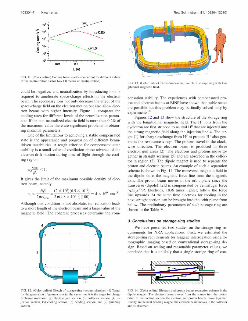
Figures 12 and 13 show the structure of the storage ringwith the longitudinal magnetic field. The H− ions from thecyclotron are first stripped to neutral H0 that are injected intothe strong magnetic field along the injection line 4. The tar-get �1� for charge exchange from H0 to protons H+ also gen-erates the resonance x-rays. The protons travel in the clock-wise direction. The electron beam is produced in threeelectron gun areas �2�. The electrons and protons move to-gether in straight sections �5� and are absorbed in the collec-tor in region �3�. The dipole magnet is used to separate theproton and electron beams. An example of such a separationscheme is shown in Fig. 14. The transverse magnetic field inthe dipole shifts the magnetic force line from the magneticaxis. The proton beam moves in the orbit plane since thetransverse �dipole� field is compensated by centrifugal force��mpc2 /R. Electrons, 1836 times lighter, follow the forceline upwards. At the same time electrons for cooling in thenext straight section can be brought into the orbit plane frombelow. The preliminary parameters of such storage ring areshown in the Table V.
3. Conclusions on storage-ring studies
We have presented two studies on the storage-ring re-quirements for NRA applications. First, we estimated thestorage-ring requirements for luggage interrogation using to-mographic imaging based on conventional storage-ring de-sign. Based on scaling and reasonable parameter values, weconclude that it is unlikely that a single storage ring of con-
FIG. 12. �Color online� Sketch of storage-ring vacuum chamber. �1� Targetfor the generation of gamma rays �at the same time it is the target for chargeexchange injection�, �2� electron gun section, �3� collector section, �4� in-jection section, �5� cooling section, �6� bending section, and �7� pumpingsection.
FIG. 13. �Color online� Three-dimensional sketch of storage ring with lon-gitudinal magnetic field.
FIG. 11. �Color online� Cooling force vs electron current for different valuesof the neutralization factor ��=1.0 means no neutralization�.
FIG. 14. �Color online� Electron and proton beams separation scheme in thedipole magnet. The electron beam moves from the source into the protonorbit. In the cooling section the electron and proton beams move together.Finally, in the next bending magnet the electron beam moves to the collectorand is absorbed.
103304-7 Kwan et al. Rev. Sci. Instrum. 81, 103304 �2010�

ventional design would be able to provide the requiredproton-beam intensity for NRA applications. However, wefound that for a carbon foil thickness of 20 �g /cm2 or less,a practical NRA inspection complex having more than teninspection stations is possible with no more than a few stor-age rings per station.
In our second study, we have tried to incorporate the newideas of charge neutralization and adding a longitudinal mag-netic field in the storage-ring design to increase the gamma-ray flux. We found that the use of electron cooling in a stor-age ring with an internal target strongly suppresses thedegradation of proton beam quality. This makes it possible toachieve a flux of resonant gamma rays of about 5.0�108
gamma rays per second. This highly effective cooling pro-cess is made possible as a result of the space-charge neutral-ization of the electron beam. We also found that adding alongitudinal magnetic field to the storage rings may help tomitigate the excessive betatron tune shift caused by the re-quired large proton current and small angular spread. Specialefforts will have to be made to achieve a stable state of thebeam-plasma system. Additional studies, both theoretical andexperimental, are needed to prove that a storage ring basedon these ideas is practical.
E. VITA for the detection of explosives based on NRAin nitrogen
To produce the high-intensity, high-quality, proton beamrequired by the NRA method a tandem accelerator is pre-ferred over other electrostatic accelerators because its ionsource and gamma-ray production target are at ground poten-
tial and its required operating voltage is only half of thatrequired in single-ended accelerators.
Conventional electrostatic tandem accelerator designshave limited beam current potential.21 In the conventionalsystem, two accelerating columns based on ceramic tubes areconnected to a high voltage power supply and the strippingtarget is located between them. This scheme has major dis-advantages for operations that require currents of a few mil-liamperes:
• The stripper gas is pumped through the accelerating col-umns.
• Charge builds up on the inner surfaces of the high voltageelectrodes and ceramic insulators due to the emission ofsecondary electrons and ions produced by the interactionof the high current beam with the residual vacuum. Thisbuildup of charge will eventually lead to arcing and even-tual breakdown of the ceramic insulating properties.
To circumvent these limitations, a new concept for anintense-beam proton tandem accelerator was conceived at theBudker Nuclear Physics Institute �BINP� in Novosibirsk,Russia: the VITA.
The basis of the VITA design is that it does not containaccelerating columns with ceramic insulation. Instead,vacuum insulation replaces the accelerating columns. Highvoltage is applied through an electrical feedthrough insulator�an arbitrarily remote distance from the accelerator beamchannel� to the cylindrical electrodes and the charge-exchange stripper is located within the vacuum tank. Thepumping of the stripper gas is realized, not through the ac-celerating columns, but through regions without solid insu-lation at high voltage potential.
An additional advantage of the VITA design is a widerrange of choices of high-voltage gradient for the elements ofthe feedthrough insulator in comparison with the choice ofhigh-voltage gradient for accelerating columns.
Figure 15 depicts the full-scale design of the NRA com-plex based on the vacuum insulated tandem accelerator. Anegative hydrogen-ion beam is formed by the ion source 3and injected into the accelerator through the low-energybeam tract �LEBT� 4. Acceleration proceeds up to one-halfthe design energy and the beam is stripped from H− to H+
ions in the charge-exchange stripper tube at the center ofhigh-voltage electrode 5. After charge exchange, a protonbeam is formed at the exit. The beam is accelerated to twicethe voltage of the high-voltage electrode. The full-energyproton beam is transported through the high-energy beamtract �HEBT� 7 and interacts with the gamma-ray productiontarget 8.
The high-voltage electrode of the tandem is surroundedby a system of shields at different potential to provide ho-mogeneous distribution of the potential and prevent any full-voltage breakdowns.
The most important component of the accelerator is thehigh-voltage feedthrough insulator 2, connecting the high-voltage power supply �HVPS� 1 located in a tank filled withSF6 gas �0.8 MPa� to the vacuum tank of the accelerator. Thehigh-voltage feedthrough insulator can be located away fromthe region of the accelerated beam.
TABLE V. Preliminary storage-ring parameters.
Parameter Value
Proton energy 1.75 MeVCircumference �R=80 cm, L=150 cm� 11.0 mLength of straight sections 150 cmAverage radius 1.75 mRevolution frequency 1.66 MHzTotal length of cooling sections about 420 cmElectron current about 1.0 ARadius of bending magnet 80 cmTransverse field in bending magnet �R=80 cm� 2.4 kGField index 0.5Longitudinal magnetic field 25 kG
Electron beam radiusthe same as proton
beam radiusAperture of vacuum chamber � 5–10 cmProton current 100 mA–1 AInjection current �dc� 100–300 �AInjected particle H0
Injection methodstripping on theinternal target
Initial angular spread at injection 3 mradInitial energy spread of proton beam �30 KeVTarget CH4 �methane�Target density up to 1016 cm−2
Average energy losses in target up to 40 eV per turnLuminosity up to 1035 cm2 s−1
103304-8 Kwan et al. Rev. Sci. Instrum. 81, 103304 �2010�

The high-voltage electrode is at the vacuum end of thehigh-voltage feedthrough insulator, on the metal flange thatis vacuum-sealed by the pipe passing along its axis. The pipeis connected to another metal flange placed at thepressurized-gas end of the insulator that is connected to theHVPS. The end of the high-voltage feedthrough insulator inthe SF6 is made up of a stack of ceramic rings separated bymetal rings that distribute the potential. The end of the insu-lator located in the vacuum is made of glass rings, separatedby metal rings. Thin-walled pipes of various lengths concen-trically connect the metal rings of different potential on theSF6 gas end of the insulator to its counterparts within thevacuum. Voltage is applied to these rings through a resistivedivider that distributes the potential homogeneously alongthe insulator.
The chosen electrostatic field intensity is 15 kV/cmacross the separate insulators on the vacuum side of the high-voltage feedthrough insulator and 18 kV/cm for the insula-tors in the gas. Electrostatic intensity at the six acceleratinggaps is 33 kV/cm. The stored energy in each high-voltagevacuum gap is limited to 30J.
Vacuum is maintained by cryogenic pump 6. Coaxialround holes for the passage of the beam are located in thewalls of the vacuum tank, in the high-voltage electrode, andin the shields. Since the thin-walled shields are positionedalong equipotential surfaces, the electrostatic field contrib-utes slightly to focusing.
Argon gas was chosen for stripping the negative ionbeam. The stripping target is a �400-mm-long pipe with 10
mm diameter. Gas is supplied at a rate to produce a densityof 3�1016 mol cm−2 as required for 99% stripping effi-ciency.
Several stripper designs were considered:
�i� with external pumping through the heads of the equi-potential shields,
�ii� with argon gas recycling using a turbo-molecularpump inside the high-voltage electrode.
High-voltage conditioning procedures, as well as high-voltage standoff of the vacuum gap, depend on the energystored in capacitors before breakdown. When the machinestarts up, high-voltage conditioning through cycling rf powerin successively higher magnitudes is needed to avoid electri-cal breakdown for the acceleration of proton beams at anenergy of 1.75 MeV and a current up to 1 mA. Figures16–18 depict the major VITA subsystems.
FIG. 15. VITA-based NRA complex.
FIG. 16. �Color online� Vacuum tank.
FIG. 17. �Color online� Feedthrough insulator.
103304-9 Kwan et al. Rev. Sci. Instrum. 81, 103304 �2010�

IV. USE OF ENABLING TECHNOLOGIES
A. High-power NRA target design and performance
1. Effects of high beam power
Several destructive factors threaten the operation andsurvival of the resonance absorption gamma-ray productiontarget and require minimization. These include the influencesof physical, chemical, and surface sputtering, and embrittle-ment. Experimental and theoretical research of graphite sta-bility under the influence of a proton beam was studied indetail in previous works �for example, Ref. 12�. Numericalcalculations based on the Roth model,22 where physical andchemical factors are considered as coexisting simultaneously,concluded that the region of optimum temperatures for aworking target is in the range from 1100 to 2100 K for aproton beam energy up to 2 MeV.
Physical sputtering starts at proton energies higher thansome minimum threshold, reaches a maximum, and then de-creases as a function of the increase of proton range ingraphite. Chemical sputtering, on the other hand, dependsmainly on target temperature and reaches a maximum at tar-get temperature T�800 K, then decreases with increasingtemperature due to thermal decomposition of hydrocarbonsformed in the target. Surface sputtering, in turn, is caused bythe accumulation of gases in the surface layer and its diffu-sion accompanying graphite decondensation. At target tem-peratures greater than 1100 K, the total rate of target sputter-ing will not exceed 0.5 �m per day.23 It should be noted thatsynthesis of methane occurs at a target temperature lowerthan 1100 K, and acetylenes synthesizes at T�1100 K, theoutput of which grows a little with the increase of the targettemperature.
With the increase of the graphite temperature, its evapo-ration increases as well, so graphite vapor pressure reaches 1atm at T�3700 K. At working temperature of the target upto 2100 K, vapor pressure is too low to have a significantinfluence on vacuum conditions.
2. Target design and testing
Based on the above data, a thick graphite target wasdesigned and fabricated with equal concentrations ofcarbon-12 and carbon-13. Secondary electrons were sup-pressed with a high-voltage suppressor. Resonant gammarays are emitted through a thin copper window. Proton cur-
rent on target is measured. Heat deposition on the target sur-face is calculated based on the measurements of temperatureand cooling water flow.
Two targets were used in experiments, the first of whichwas exposed to a high power density ��3–5 kW /cm2�.Scorches made by the proton beam on the target surface areshown in Fig. 19. Target temperature in the area of the beamwas �3000 K according to estimations, so the rate of graph-ite evaporation exceeded 2.6 �m /s.
This experience was taken into account in designing thesecond target which was located at a point in the beam linewhere an acceptable power density and surface temperaturewas achieved. The second target, shown in Fig. 20, hasworked in a series of experiments totaling about 40 h at aproton beam current of �200 �A. Surface sputtering ap-pears to be insignificant.
B. NRA experimental measurements
1. NRA measurement apparatus
A gamma-ray spectrometer complex has been created�Fig. 21�, including two scintillation detectors, positionedone over the other, inside a lead shield with �10 cm wallthickness as well as two lead collimators directed at the car-bon target.
A vessel containing liquid nitrogen is positioned suchthat gamma rays pass through the nitrogen and into one de-tector and miss the nitrogen in the other. To register thegamma rays attenuated by resonance absorption in nitrogen,the bismuth germanate Bi4GE3O12 �BGO� scintillator detec-tor is used; CsI is used as the other gamma-ray detector
FIG. 18. �Color online� LEBT channel. FIG. 19. �Color online� The first target after two experiments, operatingabout 10 min in the 1.8 MeV proton beam at 1 mA.
FIG. 20. �Color online� The second target after �40 h in the beam at�200 �A.
103304-10 Kwan et al. Rev. Sci. Instrum. 81, 103304 �2010�

intended to continuously monitor the intensity of the protonbeam on the target.
The entire system is placed on the goniometer, a mobileplatform that rotates about an axis through the gamma-raygenerating target. It provides for the measurement of both theresonant and nonresonant attenuation in the nitrogen bychanging the angle. The accuracy of the goniometer rotationis approximately �0.1°.
By gradually increasing the proton beam energy, thegamma rays associated with resonant production are encoun-tered. Integrating the number of gamma rays in this 9.17MeV region as the proton energy is increased through theresonant energy, an excitation curve for the given resonanceis generated �Fig. 22�. The threshold of the reaction is1746.6�0.9 keV, very narrow, indeed.24 Thus, the slope ofthe excitation curve is defined entirely by the instability ofthe proton beam energy. As was established by the curve inFig. 22, the proton energy resolution in the VITA beam isapproximately �1% of the average beam energy.
2. Results
A 2 MeV electrostatic proton tandem accelerator withvacuum insulation, originally developed to generate epither-mal neutrons for boron neutron capture therapy of malignant
tumors, has been used for explosive-detectionexperiments.25,26 Using the 9.17 MeV gamma rays producedin the 13C�p ,�� 14N reaction, the gamma rays are resonantlyabsorbed in the nitrogen that constitutes most explosives.
A thick carbon target made from graphite enriched incarbon-13 capable of withstanding a proton beam with highpower density has been developed for generating the 9.17MeV gamma rays. The diagnostic complex for detecting andanalyzing the nitrogen-absorbing resonance gamma rays hasbeen assembled and tested. It includes a goniometer with twocollimators and lead-shielded gamma-ray detectors.
The spectrum of radiation generated by a thickcarbon-13 target �Fig. 23� appears complicated, in addition tothe gamma rays generated by carbon-12, which is also amajor component of the target.
In the process of carrying out this work, a new methodfor normalizing the measured data was suggested—normalization by the 2.36 MeV gamma ray connected withthe reaction 12S�p ,�� 13N. This line appears far enough fromthe 9.17 MeV line and, therefore, has a little susceptibility tochanges in the resonant gamma-ray output. At the same time,the output of 2.36 MeV gamma rays also depends directly onthe intensity of the proton beam. Thus, this gamma ray canbe used for normalizing the measured data because they arenot resonantly absorbed in nitrogen. The transmission factorK, then, is the relation of the number of measured resonant�-rays, Nr, to the number of measured non-resonant 2.36-MeV �-rays, Nn.�Fig. 24�.
The pulse-height distributions of the several gamma rayswere measured and the transmission factor K was defined fordifferent angular positions of the goniometer. A 38-cm-longvessel filled with either liquid nitrogen or water was placedin the path of the collimated beam of the �-rays registered bythe detector. For these two cases the dependence of the trans-mission factors K on the goniometer position is depicted inFig. 25. Noticeable attenuation of the resonant �-rays is ob-served at an angle around 80.7° when the vessel is filled withnitrogen. As observed in earlier experiments in our study,resonance attenuation of 9.17 MeV gamma rays is still de-tectable when the vessel length is scaled down to 7.5 cm.
FIG. 21. �Color online� Experimental layout for resonant gamma absorptionmeasurements.
FIG. 22. Excitation curve for 9.17 MeV gamma rays from the reaction,13C�p ,�� 14N.
FIG. 23. Gamma-ray pulse-height distribution measured from a thickcarbon-composite target at 1800 keV proton energy.
103304-11 Kwan et al. Rev. Sci. Instrum. 81, 103304 �2010�

Thus, the results of the measurements presented here notonly confirm the conclusions of previous research studies,but also show ways to improve the technique. First, it isshown that using a thick gamma-ray generating target sim-plifies its design and should increase the target lifetime. Amore complicated distribution of gamma radiation in com-parison with a thin target is not an absolute obstacle. Second,a new normalization method is suggested and tested experi-mentally. This method allows us to discard the secondgamma-detector that naturally reduces measurement time.
V. CONCLUSIONS
Our analysis and computer simulations show that the useof electron cooling in the storage ring with internal targetstrongly suppresses the degradation of proton beam quality.This makes it possible to achieve a flux of resonant gammarays of about 5.0�108 gamma rays per second. The effectivecooling process is possible as a result of the space-chargeneutralization of the electron beam. Special efforts will haveto be made to achieve a stable state of the beam-plasmasystem. The requirement for large proton current and small
angular spread leads to an inadmissible value of the betatrontune shift. The choice of the ring structure with longitudinalmagnetic field may help to solve this problem. Developmentof the cyclotron-storage-ring accelerator system is techno-logically high-risk but high payoff, and it will require a dedi-cated experimental effort of significant magnitude to quan-tify critical issues such as electron cooling and proton beamstability in the storage ring. If such cyclotron-storage-ringsystem can be realized, this technology will open many newpossibilities for applications of high-quality and high-averaged current proton beams. In the near term, the vacuuminsulated tandem accelerator with an intense ion source holdsa bright promise in the production of high-averaged currentproton beams to generate active interrogation beams such asneutron and gamma for detection of explosives and SNMs.In our study, the vacuum insulated tandem accelerator atBINP achieved proton beams at energies up to 2.0 MeV andcurrent up to 1.0 mA with an estimated emittance of 30� mmmrad. With the use of high frequency radiofrequency-powerin the future, the footprint of such an accelerator can bereduced for compact applications.
ACKNOWLEDGMENTS
This work, supported by the Weapons Safeguards andSecurity Exchange �WSSX� program, was performed by LosAlamos National Laboratory operated by Los Alamos Na-tional Security, LLC, for the National Nuclear Security Ad-ministration of the U.S. Department of Energy under contractno. DE-AC52-06NA25396.
1 R. E. Morgado, C. C. Cappiello, M. P. Dugan, C. A. Goulding, S. D.Gardner, C. L. Hollas, B. L. Berman, R. W. Hamm, K. R. Crandall, J. M.Potter, and R. A. Krauss, in Proceedings of the SPIE Conference on Sub-stance Detection Systems, Insbruck, Austria, October 1993, Vol. 2092, pp.503–513.
2 D. Vartsky, M. B. Goldberg, G. Engler, A. Breskin, A. Goldschmidt, E.Izak, and O. Even, U.S. Patent No. 4,941,162 �10 July 1990�.
3 J. Brondo, L. Wielopolski, P. Thieberger, J. Alessi, D. Vartsky, and J.Sredniawski, AIP Conf. Proc. 680, 931 �2003�.
4 A. Fessler, T. N. Massey, B. J. Micklich, and D. L. Smith, Nucl. Instrum.Methods Phys. Res. A 450, 353 �2000�.
5 Handbook on Nuclear Activation Cross-Sections, IAEA Technical ReportSeries No. 156, International Atomic Energy Agency, Vienna, 1974.
6 L. M. Onischenko, Yu. G. Alenitsky, A. A. Glazov, G. A. Karamysheva,D. L. Novikov, E. V. Samsonov, A. S. Vorozhtsov, S. B. Vorozhtsov, andN. L. Zaplatin, in Proceedings of The XIX Russian Accelerator Conference(RuPAC2004), Dubna, Russia, 4–9 October 2004.
7 R. L. Macklin and J. H. Gibbons, Phys. Rev. 109, 105 �1958�.8 B. F. Bayanov, V. P. Belov, E. D. Bender, M. V. Bokhovko, G. I. Dimov,V. N. Kononov, O. E. Kononov, N. K. Kuksanov, V. E. Palchikov, V. A.Pivovarov, R. A. Salimov, G. I. Silvestrov, A. N. Skrinsky, N. A. Solov-iov, and S. Yu. Taskaev, Nucl. Instrum. Methods Phys. Res. A 413, 397�1998�.
9 D. L. Novikov �private communication�.10 S. B. Vorozhtsov, E. E. Perepelkin, and L. M. Onischenko, “Customs
cyclotron and beam delivery system,” in Proceedings of The 18th Inter-national Conference on Cyclotrons and their Applications Cyclotrons2007, Laboratori Nazionali del Sud, Giardini Naxos, Italy, October 2007.
11 G. Dimov, V. Shamovskii, and V. Chupriyanov, Sov. Phys. Tech. Phys. 16,1662 �1972�.
12 L. A. Ferrari and M. S. Zucker, Phys. Fluids 12, 1312 �1969�.13 T. F. Wang and T. J. T. Kwan, “A study of storage ring requirements for an
explosive detection system using NRA methods,” in Proceedings of the2005 Particle Accelerator Conference, Knoxville, TN �2005�, Vol 2.
14 T. F. Wang and T. J. T. Kwan, Los Alamos National Laboratory ReportNo. LA-UR-04–5457, 2004.
FIG. 24. Method of normalizing of the resonance gamma-ray intensity.
FIG. 25. Dependence of transmission coefficient K on the angle of thegoniometer for liquid-nitrogen-filled vessel �squares� and water-filled vessel�circles�.
103304-12 Kwan et al. Rev. Sci. Instrum. 81, 103304 �2010�

15 V. V. Parkhomchuk, V. B. Reva, V. A. Vostikov, and V. F. Dimitriev,“Theoretical investigation and computer simulation of the storage ringwith electron cooling of proton beam and compensation of target influ-ence,” BINP Report, 2005.
16 R. E. Morgado, G. Arnone, C. C. Cappiello, S. D. Gardner, C. L. Hollas,L. E. Ussery, J. M. White, Z. D. Zahrt, and R. A. Krauss, Los AlamosNational Laboratory Report No. LA-12776-MS, 1994.
17 See http://mad.home.cern.ch/mad for MAD-X.18 A. Smirnov, A. Sidorin, and G. Trubnikov, “Description of software for
BETACOOL program based on BOLIDE interface,” JINR Report, 2004.19 G. Dimov, V. Dudnikov, and V. Shamovskii, J. Tech. Phys. 41, 2028
�1971�.20 G. Budker, Ya. S. Derbenev, N. Dikansky, V. Kudelainen, I. N. Meshkov,
V. V. Parkhomchuk, D. V. Pestrikov, B. N. Sukhina, and N. N. Skrinsky,IEEE Trans. Nucl. Sci. NS–22 �1975�.
21 V. V. Parkhomchuk and A. N. Skrinsky, Rep. Prog. Phys. 54, 919 �1991�.
22 V. Kudelainen, V. Parkhomchuk, and D. Pestrikov, J. Tech. Phys. 53, 870�1983�.
23 B. F. Milton, “A high current tandem accelerator for gamma-resonancecontraband detection,” in Proceedings of the Particle Accelerator Confer-ence, Vancouver, Canada, 1997.
24 V. T. Astreliin, A. V. Burdakov, P. Z. Chebotaev, V. V. Filippov, V. S.Koidan, K. I. Mekler, P. I. Melnikov, V. V. Postupaev, A. F. Rovenskikh,M. A. Shcheglov, and H. Wuerz, Nucl. Fusion 37, 1541 �1997�.
25 L. Barkov, G. Derebyankin, G. Dimov, G. Kraynow, A. Krivenko, S.Fadeev, V. Shirokov, G. Silvestrov, I. Sorokin, S. Taskaev, and M. Tiunov,Proceedings of EPAC 2002, Paris, France, 2002, p. 852.
26 A. Burdakov, V. Davydenko, V. Dolgushin, A. Dranichnikov, A. Ivanov,J. P. Farrell, A. Khilchenko, V. Kobets, S. Konstantinov, A. Krivenko, A.Kudryavtsev, M. Tiunov, V. Savkin, V. Shirokov, and I. Sorokin, Nucl.Instrum. Methods Phys. Res. B 261, 286 �2007�.
103304-13 Kwan et al. Rev. Sci. Instrum. 81, 103304 �2010�


