Embed Size (px)
Citation preview

Crystal Engineering 5 (2002) 123–136www.elsevier.com/locate/cryseng
The hydrogen-bonding networks of 2-amino-4-phenyl-1,3-thiazole derivatives
Daniel E. Lynch a,*, Ian McClenaghan b, Mark E. Light c,Simon J. Coles c
a School of Science and the Environment, Coventry University, Coventry CV1 5FB, UKb Spa Contract Synthesis, School of Science and the Environment,
Coventry University, Coventry CV1 5FB, UKc Department of Chemistry, University of Southampton, Southampton SO17 1BJ, UK
Received 17 October 2001; received in revised form 6 March 2002; accepted 8 March 2002
Abstract
The solid-state packing arrays of nine 4-phenyl substituted 2-amino-1,3-thiazoles have beenexamined and their hydrogen-bonding networks discussed. The nine compounds, in additionto 2-amino-1,3-thiazole 1, were 2-amino-4-phenyl-1,3-thiazole 2, 2-amino-4-phenyl-1,3-thia-zolium bromide monohydrate 3, ethyl 2-amino-4-phenyl-1,3-thiazole-5-carboxylate 4, 2-amino-4-(3-coumarin)-1,3-thiazole 5, 2-amino-4-(4-methylphenyl)-1,3-thiazole 6, 2-amino-4-(2-hydroxyphenyl)-1,3-thiazole 7, 2-amino-4-(4-bisphenyl)-1,3-thiazole 8, 2-amino-4-(1-naphthyl)-1,3-thiazole 9, and 2-amino-4-(2-naphthyl)-1,3-thiazolium bromide 10. The single-crystal x-ray structures of 1–5 have been previously reported while the structures of 6–10 arepresented in this paper. A variety of different packing motifs are observed with only four (4,5, 6 and 9) exhibiting the characteristic R2
2(8) hydrogen-bonded 2-amino-1,3-thiazole dimers.In two of these four structures (6 and 9) potential N–H%π hydrogen-bonding interactionsexist whereas all remaining structures exhibit a combination of N–H%N with either N–H%O,N–H%S or N–H%Br associations in their hydrogen-bonding networks. 2002 Elsevier Science Ltd. All rights reserved.
Keywords: 2-amino-1,3-thiazole; hydrogen bond; x-ray crystal structure
* Corresponding author.E-mail address: [email protected] (D.E. Lynch).
1463-0184/02/$ - see front matter 2002 Elsevier Science Ltd. All rights reserved.PII: S 14 63 -0184( 02 )0 0011-4

124 D.E. Lynch et al. / Crystal Engineering 5 (2002) 123–136
1. Introduction
2-Amino-1,3-thiazole 1 (Fig. 1) is a simple heterocyclic molecule with two hydro-gen-bond donor elements (NH2) and three hydrogen-bond acceptors (S, N and NH2).The potential for strong hydrogen-bonding interactions to either the sulfur atom orthe amino nitrogen is much less than that to the heterocyclic sp2 nitrogen, which iscertainly evident in the solid-state hydrogen-bonding network of 1 (Fig. 2) [1] whereboth amino hydrogen atoms associate to the heterocyclic nitrogen. One of theseassociations forms a hydrogen-bonded R2
2(8) graph set dimer pattern that is commonto the packing mode of any simple heterocycle containing an sp2 nitrogen with anα-substituted amino group; 2-aminopyridine [2] being another example. As part of acontinuing series of studies on the hydrogen-bonding aspects of 2-amino-1,3-thiazolederivatives we decided to investigate the solid-state packing of molecules which hadspatial access to the heterocyclic nitrogen (N3) hindered by an adjacent phenyl ring.Such hindrance was not expected to interfere with the R2
2(8) motif but with thisassociation in place the substituent phenyl ring was intended to prevent any additionalinteraction to N3, thus increasing the possibilities for the second amino hydrogenatom to bind to either one (or both) of the remaining hydrogen-bond acceptors, oranother hydrogen-bond accepting agent such as a π system.
A search of the Cambridge Structural Database (CSD) revealed that there werefour previously reported structures that have a phenyl ring (or equivalent) substitutedin the 4-position of the thiazole ring. These were 2-amino-4-phenyl-1,3-thiazole 2[3], 2-amino-4-phenyl-1,3-thiazolium bromide monohydrate 3 [4], ethyl 2-amino-4-phenyl-1,3-thiazole-5-carboxylate 4 [5] and 2-amino-4-(3-coumarin)-1,3-thiazole 5[6] (Fig. 1). To add to these we characterized the structures of 2-amino-4-(4-
Fig. 1. Chemical diagrams for the 4-phenyl-1,3-thiazole derivatives discussed in this study.

125D.E. Lynch et al. / Crystal Engineering 5 (2002) 123–136
Fig. 2. Packing diagram and selected naming for compound 1. Hydrogen bonds shown as dotted lines.
methylphenyl)-1,3-thiazole 6, 2-amino-4-(2-hydroxyphenyl)-1,3-thiazole 7, 2-amino-4-(4-bisphenyl)-1,3-thiazole 8, 2-amino-4-(1-naphthyl)-1,3-thiazole 9, and 2-amino-4-(2-naphthyl)-1,3-thiazolium bromide 10 (Fig. 1). Reported in this paper are thesingle crystal structures of compounds 6–10 as well as a comparative discussion ofthe solid-state hydrogen-bonding networks of compounds 2–10. For compounds 1–10 in this paper a common naming scheme, which may not equate to that in thepreviously published structures, has been employed around the thiazole ring in allpacking diagrams.
2. Experimental
2.1. Preparations
Compounds 6–10 were obtained from Spa Contract Synthesis. For 6, colourlessprisms (m.p. 130–130.5 °C) were grown from methanol; for 7, colourless prisms

126 D.E. Lynch et al. / Crystal Engineering 5 (2002) 123–136
Fig. 3. Packing diagram and selected naming for compound 2.
(m.p. 133 °C) were grown from ethanol; for 8, colourless plates (m.p. 195–197 °C)were grown from DMF; for 9, orange prisms (m.p. 155–158 °C) were grown fromethanol; for 10, colourless plates (m.p. 142–144 °C) were recrystallized from a 50/50DMF/water mixture and were kept in solution until a sample was chosen for x-ray analysis.
2.2. Crystallography
Crystallographic details for compounds 6 – 10 are listed in Table 1. Data werecollected on a Bruker Nonius Kappa CCD area detector diffractometer using mon-ochromatized Mo Kα X-radiation (l 0.71073 A) and equipped with an Oxford Cryos-ystems low-temperature device. Multi-scan absorption corrections were applied toall data sets using the program SORTAV [7]. Structures were solved by directmethods and refined using the SHELX-97 package [8]. All hydrogen atoms notinvolved in the hydrogen-bonding interactions were included in the refinement, atcalculated positions, using a riding model. All 2-amino hydrogen atoms, the hydroxy

127D.E. Lynch et al. / Crystal Engineering 5 (2002) 123–136
Tab
le1
Cry
stal
logr
aphi
cda
ta
Stru
ctur
alfo
rmul
a6
78
910
CC
DC
depo
sit
no.
CC
DC
-129
0/#
CC
DC
-129
0/#
CC
DC
-129
0/#
CC
DC
-129
0/#
CC
DC
-129
0/#
Che
mic
alfo
rmul
aC
10H
10N
2S
C9H
8N
2O
SC
15H
12N
2S
C13H
10N
2S
C1
3H
11B
rN2S
Form
ula
wei
ght
190.
2619
2.23
252.
3322
6.29
307.
21C
ryst
alsy
stem
orth
orho
mbi
cor
thor
hom
bic
orth
orho
mbi
cm
onoc
linic
mon
oclin
icSp
ace
grou
pP
bca
Pna
2 1P
ccn
P2 1
/cP
2 1/n
T,
°C�
123
�12
3�
123
�12
3�
123
a,A
10.8
67(2
)12
.724
2(7)
17.3
68(1
)8.
4487
(2)
7.36
23(2
)b,
A8.
882(
2)12
.184
1(7)
17.1
47(1
)11
.909
7(4)
12.1
901(
3)c,
A19
.182
(4)
5.65
22(3
)8.
2031
(5)
10.9
764(
3)13
.590
1(4)
β,de
g10
2.37
1(2)
96.8
47(1
)V
,A
318
51.5
(6)
876.
28(8
)24
42.9
(3)
1078
.82(
5)12
10.9
8(6)
Z8
48
44
r cal
cd,
gcm
�3
1.36
51.
457
1.37
21.
393
1.68
5m,
mm
�1
0.29
90.
325
0.24
60.
270
3.54
3T
min
,T
max
0.90
5,0.
926
0.95
3,0.
990
0.97
6/
0.99
80.
948,
0.97
40.
619,
0.93
3R
a0.
035/
0.04
10.
036/
0.04
70.
056/
0.14
30.
043/
0.06
80.
044/
0.08
0R
wa
0.09
7/0.
102
0.07
9/0.
084
0.12
8/0.
189
0.11
2/0.
123
0.09
3/0.
104
aU
sing
obse
rved
data
[F2�
2σ(F
o2)]
/all
data
.

128 D.E. Lynch et al. / Crystal Engineering 5 (2002) 123–136T
able
2H
ydro
gen-
bond
ing
geom
etry
and
dihe
dral
angl
es(�
)fo
rco
mpo
unds
1–10
N21
–H%
N3
N21
–H%
ON
21–H
%S1
N21
–H%
Br1
�
13.
064(
1)A
3.21
1(1)
A2
2.99
(2)
A3.
57(2
)A
,13
9(3)
°6.
22°
32.
78(2
)A
3.46
(2)
A0(
2)°
3.34
(2)
A4
2.98
9(2)
A2.
930(
2)A
42.4
1(6)
°5
3.10
8(3)
A3.
096(
4)A
9.62
°6
3.01
3(2)
A,
174(
3)°
12.8
0(8)
°�
x+2,
�y+
1,�
z+1
72.
585(
3)A
,15
1(6)
°a2.
919(
4)A
,15
5(4)
°3.
586(
4)A
,13
8(2)
°5.
1(2)
°�
x+3/
2,y+
1/2,
z�1/
2x,
y,z+
18
3.02
5(6)
A,
177(
5)°
3.49
3(5)
A,
125(
4)°
24.8
(2)°
�x+
1/2,
y,z+
1/2
�x+
1/2,
y,z�
1/2
35.4
(2)°
b
92.
980(
2)A
,17
4(3)
°43
.46(
6)°
�x+
2,�
y+1,
�z
103.
466(
4)A
,16
1(4)
°c7.
3(2)
°3.
488(
4)A
,14
9(4)
°3.
233(
4)A
,17
0(4)
°�
x+1/
2,y+
1/2,
�z+
5/2
aO
–H%
N3.
bA
ngle
betw
een
bisp
heny
lri
ngs.
cN
3–H
%B
r1.

129D.E. Lynch et al. / Crystal Engineering 5 (2002) 123–136
Fig. 4. Packing diagram and selected naming for compound 3.
proton in 7 and the heterocyclic salt proton in 10 were located using differencesyntheses and both positional and displacement parameters refined. For 8 and 10,respective Rint values of 0.165 and 0.171 were the result of weak data at high angle.
3. Results
Compounds 2–10 (Figs. 3–11) can be subdivided into three groups: the 4-phenylthiazoles, those with additional hydrogen-bond acceptor atoms and the two hydrobro-mide salts. In terms of molecular packing and hydrogen-bonding arrays (Table 2)however, different divisions apply. Compounds 6 (Fig. 7) and 9 (Fig. 10) form thesimplest hydrogen-bonding network by associating as R2
2(8) graph set dimers. Poss-ible N–H%π close-contacts are observed for the second N21–H in these compoundswith the closest non-hydrogen atom for 6 being C45 [H%C 2.79(2) A], while for9, the closest non-hydrogen atom is C8 [H%C 2.53(2) A, H%C7 2.97(2) A]. Both

130 D.E. Lynch et al. / Crystal Engineering 5 (2002) 123–136
Fig. 5. Packing diagram and selected naming for compound 4.
atoms (C45 and C8) are part of the 4-phenyl rings and are essentially in similarpositions adjacent to C5 in the thiazole ring. Compound 8 (Fig. 9) does not formthe common R2
2(8) dimer observed in 6 and 9 but alternatively forms a zig-zaghydrogen-bonded polymer consisting of a continuous series of R2
2(8) associationsvia N–H%S interactions. In this particular case (compound 8), the N%S distanceof 3.493(5) A is slightly shorter than the average distance [3.58(3) A] listed by Allenet al. [9] for N–H%S hydrogen bonds to a Csp2–S–Csp2 system, while the N–H%Sangle of 125(4)° is more acute than the similar listed Allen et al. angle of 145(3)°.Because of the increased deviation of the hydrogen atom out of the direct N%S line,the H%S distance of 2.96(6) A in 8 is only just inside the Allen et al. H%S cut-off of �3.0 A. This is also the case for compound 2, which displays similar interac-tions to 8 but has a totally different packing arrangement. Again the N%S distance
131D.E. Lynch et al. / Crystal Engineering 5 (2002) 123–136
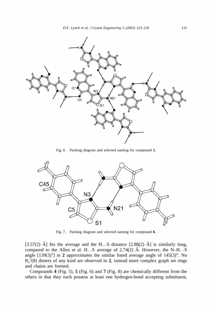
Fig. 6. Packing diagram and selected naming for compound 5.
Fig. 7. Packing diagram and selected naming for compound 6.
[3.57(2) A] fits the average and the H%S distance [2.88(2) A] is similarly long,compared to the Allen et al. H%S average of 2.74(2) A. However, the N–H%Sangle [139(3)°] in 2 approximates the similar listed average angle of 145(3)°. NoR2
2(8) dimers of any kind are observed in 2, instead more complex graph set ringsand chains are formed.
Compounds 4 (Fig. 5), 5 (Fig. 6) and 7 (Fig. 8) are chemically different from theothers in that they each possess at least one hydrogen-bond accepting substituent,

132 D.E. Lynch et al. / Crystal Engineering 5 (2002) 123–136
Fig. 8. Packing diagram and selected naming for compound 7.
as opposed to the two hydrobromide salts (compounds 3 and 10) which possess anexternal hydrogen-bond accepting atom. Thus these C=O or C–O–R oxygen atoms in4, 5 and 7 are invariably expected to be involved in the hydrogen-bonding networks.Compound 4 has both such oxygen atoms in the ethyl carboxylate group. The struc-ture of 4 shows that the molecules associate through N21–H%N3 R2
2(8) dimersleaving the second N21–H as the only strong hydrogen-bond donor atom. The ethylcarboxylate group places O40 (and not O41) in the N21–H%O hydrogen bond, mostprobably because of the proximity of the molecule that hydrogen-bonds to O40 andthe lack of space to fit the ethyl chain (if O41 were involved). Furthermore, com-pound 4 is prevented from forming dimers via the N21–H%O40 association, which

133D.E. Lynch et al. / Crystal Engineering 5 (2002) 123–136
Fig. 9. Packing diagram and selected naming for compound 8.
would produce flat hydrogen-bonded ribbons, because of hindrance from the sulfuratoms. For this reason the hydrogen bonds from the second N21–H and the hydrogenbonds to O40 are from different molecules.
Compound 5, similar to 4, forms a N21–H%N3 R22(8) dimer with the second
N21–H binding to the C=O group. Considering the packing, this second N21–Hcould have bonded to either C=O or C–O–C oxygen atom, or possibly formed athree-centre association to both. In contrast to 4 and 5, compound 7 may have anadditional hydrogen-bond accepting oxygen atom but this atom contains its ownhydrogen-bond donor which is in a suitable position to form an intramolecular associ-ation to N3, thus hindering the possibility of a N21–H%N3 R2
2(8) dimer. Com-pounds 2 and 7 share similar hydrogen-bonding patterns although for 7, both theN%S [3.586(4) A] and H%S [2.76(5) A] distances and the N–H%S angle [138(2)°]approximates the Allen et al. averages for a N–H%S hydrogen bond. Other like

134 D.E. Lynch et al. / Crystal Engineering 5 (2002) 123–136
Fig. 10. Packing diagram and selected naming for compound 9.
packing arrangements are observed for compounds 3 (Fig. 4) and 10 (Fig. 11), irres-pective of the hydrate molecule in 3. In both cases the N3 hydrogen atom and theadjacent N21 hydrogen atom are bound to the same bromide atom with N3–H hydro-gen bonding via the water molecule in 3. For both, the second N21–H subsequentlybinds to a neighbouring bromide, continuing the hydrogen-bonding chain.
4. Discussion
Overall analysis of the hydrogen-bonding networks of compounds 2–10 showedthat one of our first assumptions, that the presence of the 4-phenyl ring would notaffect the R2
2(8) dimer, proved to be incorrect with only three of the possible sevenstructures displaying this motif (discarding the two hydrobromide salts). A largergraph set ring [R2
2(16)] exists in 7 where association from N21 to the hydroxyoxygen is preferred to over-crowding N3, which already participates in an intramol-ecular hydrogen bond. In each of the structures [3–5, 7 and 10] where there is anotherstrong hydrogen bond acceptor (other than N3), such as an oxygen or bromide atom,then associations exist from N21 to these atoms, as well as to N3 [except in 7]. In7, as well as 2 and 8, the second N21–H is involved in an N–H%S interaction. Incontrast, compounds 6 and 9 are the only two that form discrete R2
2(8) dimers withno further strong hydrogen-bonding associations, although possible N–H%π interac-tions are observed.
In the consideration of N–H%S hydrogen-bonding associations the importance ofN%S distance, H%S distance and N–H%S angle are equally weighted. The role ofD–H%A angle in the determination of a hydrogen bond has been previously high-lighted by Steiner and Desiraju [10] and it would be expected that a weak hydrogen

135D.E. Lynch et al. / Crystal Engineering 5 (2002) 123–136
Fig. 11. Packing diagram and selected naming for compound 10.
bond such as N–H%S would have a lesser angle compared with those of N–H%Nassociations. Thus an average angle of 145(3)° is listed by Allen et al. for N–H%Shydrogen bonds to a Csp2–S–Csp2 system, compared with angles around 175° forstrong hydrogen bonds. Being a weaker interaction then the hydrogen atoms involvedin the N–H%S hydrogen bonds would be more affected by other intermolecularinteractions. In the three structures (2, 7 and 8) where N–H%S associations havebeen designated two angles (from 2 and 7) approximate the Allen et al. averagewhile it is not immediately apparent why the hydrogen atom involved in the N–H%S association in 8 deviates to an angle of 125(4)° although the close proximityof an adjacent phenyl ring may possibly be responsible.
For the majority of the compounds in this series the phenyl rings substituteddirectly to the thiazole ring are essentially coplanar with variations occurring up to25° (compound 8) but most being �13°. From these examples it can be concludedthat the coplanarity of the phenyl ring with the thiazole ring has been instrumentalin preventing two hydrogen-bonding interactions to N3 as seen in the packing of the

136 D.E. Lynch et al. / Crystal Engineering 5 (2002) 123–136
unsubstituted compound 1. The second ring in 8, the naphthyl ring in 9 and thephenyl ring in 4 have the highest dihedral angles. For the latter two, steric hindrancefrom the thiazole ring and ethyl carboxylate group, respectively, are the cause of thehigh angles.
Acknowledgements
The authors thank the EPSRC National Crystallography Service (Southampton).
References
[1] C. Caranoni, J.P. Reboul, Acta Crystallogr. B38 (1982) 1255.[2] M. Chao, E. Schempp, R.D. Rosenstein, Acta Crystallogr. B31 (1975) 2922.[3] O. Au-Alvarez, R.C. Peterson, A.A. Crespo, Y.R. Esteva, H.M. Alvarez, A.M.P. Stiven, R.P. Herm-
andez, Acta Crystallogr. C55 (1999) 821.[4] G.R. Form, E.S. Raper, T.C. Downie, Acta Crystallogr. B30 (1974) 342.[5] D.E. Lynch, I. McClenaghan, Acta Crystallogr. C56 (2000) e586.[6] V.N. Nesterov, Y.T. Struchkov, S.N. Kovalenko, Y.A. Sharanin I, A. Zhuravel, Izv. Akad. Nauk
SSSR, Ser. Khim. (1995) 492.[7] R.H. Blessing, Acta Crystallogr. A51 (1995) 33; R.H. Blessing, Appl. Cryst. 30 (1997) 421.[8] G.M. Sheldrick, SHELX-97, University of Gottingen, Federal Republic of Germany, 1997.[9] F.H. Allen, C.M. Bird, R.S. Rowland, P.R. Raithby, Acta Crystallogr. B53 (1997) 696.
[10] T. Steiner, G.R. Desiraju, Chem. Commun. (1998) 891.

![Synthesis of (2E)-2-methyl-3-(4-{[4-(quinolin-2-ylmethoxy)phenyl]sulfanyl}phenyl)prop-2-enoic acid (VUFB 20609) and 2-methyl-3-(4-{[4-(quinolin-2-ylmethoxy)phenyl]sulfanyl}phenyl)propanoic](https://img.pdfslide.net/doc/110x75/6348f97bb88fb0854f02bc13/synthesis-of-2iei-2-methyl-3-4-4-quinolin-2-ylmethoxyphenylsulfanylphenylprop-2-enoic.jpg)


methanone](https://img.pdfslide.net/doc/110x75/634485ed6cfb3d4064093fa6/3-5-nitro-2-furyl-1-phenyl-1-h-pyrazol-4-ylphenylmethanone.jpg)


