Embed Size (px)
Citation preview
Full Terms & Conditions of access and use can be found athttp://www.tandfonline.com/action/journalInformation?journalCode=tscm20
Download by: [McMaster University] Date: 16 April 2016, At: 03:33
Journal of Sustainable Cement-Based Materials
ISSN: 2165-0373 (Print) 2165-0381 (Online) Journal homepage: http://www.tandfonline.com/loi/tscm20
The interactions of molten core with differenttypes of concretes in EPR severe accident
Yingjun Yu, Jinyang Jiang, Wei Sun, Zuquan Jin & Qiaofen Zhang
To cite this article: Yingjun Yu, Jinyang Jiang, Wei Sun, Zuquan Jin & Qiaofen Zhang (2015) Theinteractions of molten core with different types of concretes in EPR severe accident, Journal ofSustainable Cement-Based Materials, 4:1, 44-53, DOI: 10.1080/21650373.2014.966169
To link to this article: http://dx.doi.org/10.1080/21650373.2014.966169
Published online: 10 Apr 2015.
Submit your article to this journal
Article views: 15
View related articles
View Crossmark data
The interactions of molten core with different types of concretes inEPR severe accident
Yingjun Yua, Jinyang Jiangb*, Wei Sunb, Zuquan Jinc and Qiaofen Zhangd
aSchool of Material Science and Engineering, Southeast University, 211189 Nanjing, P.R. China;bFaculty of School of Material Science and Engineering, Southeast University, 211189 Nanjing,P.R. China; cFaculty of Department of Structural Engineering, Qingdao Technological University,266033 Qingdao, P.R. China; dFaculty of China Construction Second Engineering Bureau Ltd.,
211189 Nanjing, P.R. China
(Received 19 April 2014; accepted 12 September 2014)
Sacrificial concrete is very important in the advanced European pressurized waterreactor (EPR). To compare the behaviors of different kinds of sacrificial concretes inthe EPR reactor pit, several sacrificial concretes were adopted in the calculation ofmolten core–concrete interaction molten core-concrete interaction (MCCI), i.e. the“FeSi” concrete, the siliceous concrete, and the limestone concrete. Using a computercode MELCOR, the main parameters, i.e. concrete ablation depth and rate, hydrogengeneration mass and rate and temperature in a typical small break loss of coolantsevere accident in EPR were calculated. The results indicate that the ablation ratedecreased in the order of the “FeSi” concrete, siliceous concrete and limestone con-crete. Meanwhile, the generated hydrogen mass of the “FeSi” concrete is 13% lessthan that of the siliceous concrete. In addition, as the basemat of reactor pit is meltthrough, the temperature of melt pool is the lowest for the limestone concrete and thetemperature of siliceous concrete is slightly higher than that of “FeSi” concrete.
Keywords: molten core–concrete interaction (MCCI); EPR; sacrificial concrete
1. Introduction
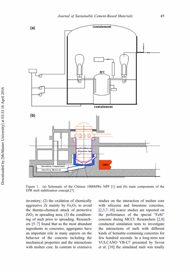
In a nuclear reactor severe accident,molten core will penetrate the reactorpressure vessel (RPV) and spread over theconcrete basemat which is the ultimatebarrier for most current nuclear powerplants, as shown in Figure 1(a).[1] Thiscauses a molten core–concrete interaction(MCCI) which will lead to failure of con-tainment and release of radioactive materi-als to the environment.[2] To enclose meltand guarantee long-term heat removal soas to preserve the containment integrity, acore catcher device is thus implementedin advanced nuclear power plants, such asthe European Pressurized Water Reactor
(EPR),[3] as shown in Figure 1(b). Inparticular, as a part of the core catcher,the sacrificial concrete, which is designedto react with the molten core to adjust theproperties of the melt so as to sustain theintegrity of containment, is very impor-tant. In practice, siliceous and limestoneconcretes are commonly used to fulfillsuch purpose. Moreover, in the EPR reac-tor pit, a special “FeSi” concrete cast fromboth hematite (Fe2O3) and siliceousaggregates has been developed. The“FeSi” concrete shows advantages inachieving an intermediate retention of themelt released from the RPV, including[4]: (1) the accumulation of core melt
*Corresponding author. Email: [email protected]
© 2015 Taylor & Francis
Journal of Sustainable Cement-Based Materials, 2015Vol. 4, No. 1, 44–53, http://dx.doi.org/10.1080/21650373.2014.966169
Dow
nloa
ded
by [
McM
aste
r U
nive
rsity
] at
03:
33 1
6 A
pril
2016
inventory; (2) the oxidation of chemicallyaggressive Zr mainly by Fe2O3 to avoidthe thermo-chemical attack of protectiveZrO2 in spreading area; (3) the condition-ing of melt prior to spreading. Research-ers [5–7] found that as the most abundantingredients in concretes, aggregates havean important role in many aspects on thebehavior of the concrete including themechanical properties and the interactionswith molten core. In contrast to extensive
studies on the interaction of molten corewith siliceous and limestone concretes,[2,3,7–10] scarce studies are reported onthe performance of the special “FeSi”concrete during MCCI. Researchers [2,8]conducted simulation tests to investigatethe interactions of melt with differentkinds of hematite-containing concretes forfew hundred seconds. In a long-term testVULCANO VB-U7 presented by Sevonet al. [10] the simulated melt was totally
Figure 1. (a) Schematic of the Chinese 1000MWe NPP [1] and (b) main components of theEPR melt stabilization concept.[7]
Journal of Sustainable Cement-Based Materials 45
Dow
nloa
ded
by [
McM
aste
r U
nive
rsity
] at
03:
33 1
6 A
pril
2016
oxidic, which is in fact composed of bothmetal and oxide. As a result, rare experi-mental information is available about thebehavior of “FeSi” concrete duringMCCI.
In this paper, we intend to presentsome results about the behaviour of thespecial “FeSi” concrete interacting withmolten core during MCCI, while sili-ceous and limestone concretes areadopted as well for the sake of compari-son. With respect to the extreme com-plexity of the simulated MCCIexperiments and the high requirement ofMCCI simulation test, we choose to sim-ulate MCCI by the computer codeMELCOR. The interaction induced by atypical small break loss of coolant severeaccident sequence (SBLOCA) of the1000 MW EPR nuclear power plant wasassumed. Since there are mainly threefactors that may lead to failure of thecontainment: overpressure, hydrogenexplosion or melt through of the basematconcrete driven by the high temperatureof the melt and decay heat generatedby the fission products.[2,10] we calcu-lated various parameters, includingconcrete ablation depth and rate, hydro-gen generation mass and rate andtemperature.
2. Numerical approach
2.1. Computer code MELCOR
We choose to simulate the MCCI in EPRreator pit by the computer code MEL-COR which consists of a series of mod-ules because of its systems-levelapproach, detailed codes and fast-run-ning. One of the modules, i.e. CAV pack-age, is based on the code CROCONwhich can be applied in a wide range ofsevere accidents for reactor plants. Thecode CROCON, which was validated bythe simulation tests SURC, BETA,SWISS and ACE, can predict main phe-nomena during MCCI, including heattransfer, concrete ablation, cavity shapechange, temperature and gas genera-tion.[11] In terms of EPR reactor pit, thecode CROCON can meet the basicrequirements, though modeling of theFe–O system is not so sufficient as somespecific codes, like COSACO,[4].
There are many models that can beselected by the users in the codeMELCOR. A modified version of theKutateladze correlation is used for heattransfer between the melt and concrete.[7]Based on the density of the melt, thereare three models to select for the meltconfiguration: enforced mixing, enforced
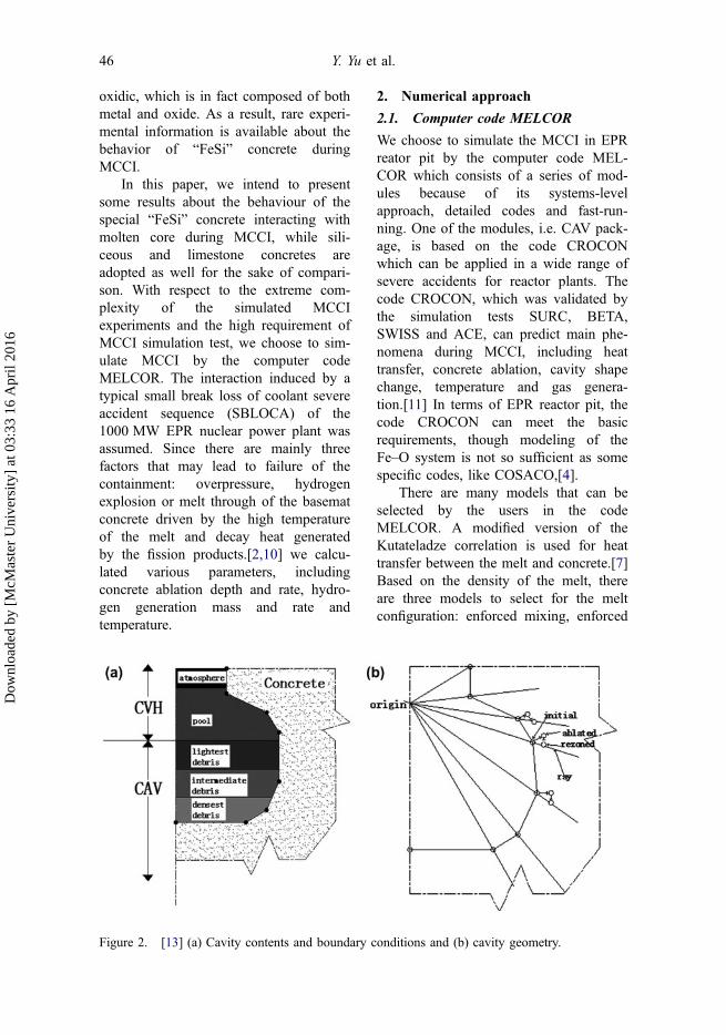
Figure 2. [13] (a) Cavity contents and boundary conditions and (b) cavity geometry.
46 Y. Yu et al.
Dow
nloa
ded
by [
McM
aste
r U
nive
rsity
] at
03:
33 1
6 A
pril
2016
stratification and mechanistic mixing. Inaddition, the thermal resistance betweenthe concrete and the melt has two mod-els:slag model and gas model. Moreover,the interface temperature between themelt and concrete is defined as the soli-dus temperature of the melt which cannot be changed.[11]
The shape of concrete cavity isdescribed by a series of so-called bodypoints lying in vertical cross-section ofthe concrete surface. To maintain the sta-bility of numerical calculation, the CAS-CET model [12] written by ACUREX/Aerotherm Corporation is implemented.As illustrated in Figure 2(b),[13] theablated point is rezoned onto a series ofguiding lines called rays. The point on therays parallel to the axis keeps removing
vertically downward to ensure that theflat bottom remains flat.
2.2. Initial condition of calculation
A typical SBLOCA of the 1000 MWEPR nuclear power plant is assumed inthis study. Before the accident, the EPRoperates at the full power with the ther-mal power of 3426 MW and the averagecoolant temperature of 293 °C. Upon astable calculation, i.e. −550 to 0 s, thebreak initiates. No security intervention isapplied during the accident process.
2.3. The main inputs
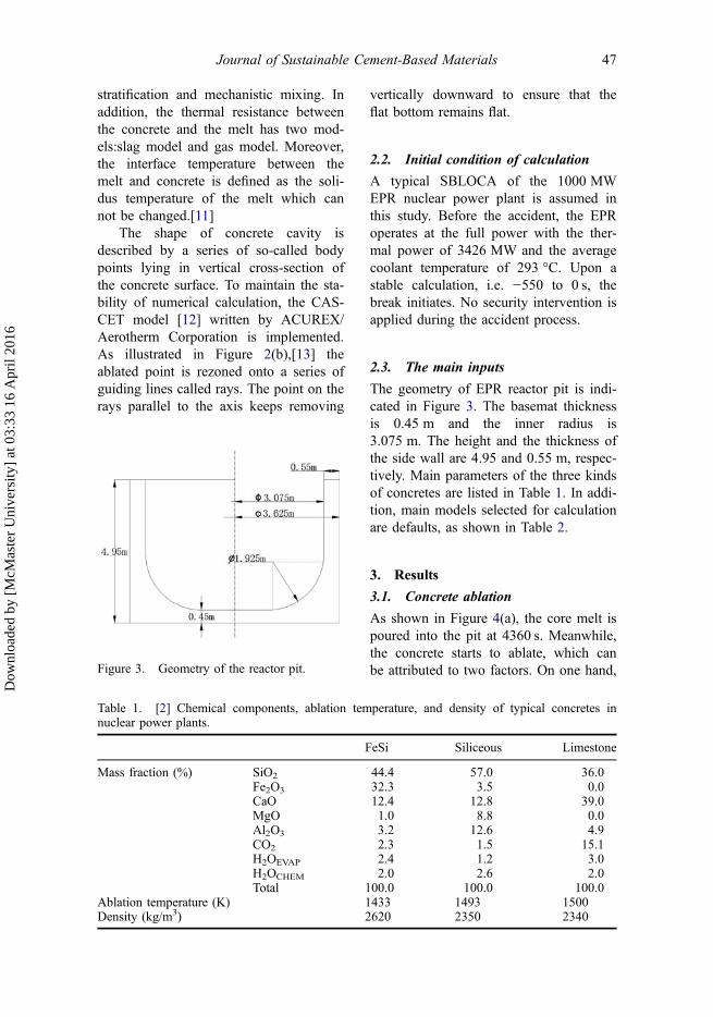
The geometry of EPR reactor pit is indi-cated in Figure 3. The basemat thicknessis 0.45 m and the inner radius is3.075 m. The height and the thickness ofthe side wall are 4.95 and 0.55 m, respec-tively. Main parameters of the three kindsof concretes are listed in Table 1. In addi-tion, main models selected for calculationare defaults, as shown in Table 2.
3. Results
3.1. Concrete ablation
As shown in Figure 4(a), the core melt ispoured into the pit at 4360 s. Meanwhile,the concrete starts to ablate, which canbe attributed to two factors. On one hand,Figure 3. Geometry of the reactor pit.
Table 1. [2] Chemical components, ablation temperature, and density of typical concretes innuclear power plants.
FeSi Siliceous Limestone
Mass fraction (%) SiO2 44.4 57.0 36.0Fe2O3 32.3 3.5 0.0CaO 12.4 12.8 39.0MgO 1.0 8.8 0.0Al2O3 3.2 12.6 4.9CO2 2.3 1.5 15.1H2OEVAP 2.4 1.2 3.0H2OCHEM 2.0 2.6 2.0Total 100.0 100.0 100.0
Ablation temperature (K) 1433 1493 1500Density (kg/m3) 2620 2350 2340
Journal of Sustainable Cement-Based Materials 47
Dow
nloa
ded
by [
McM
aste
r U
nive
rsity
] at
03:
33 1
6 A
pril
2016
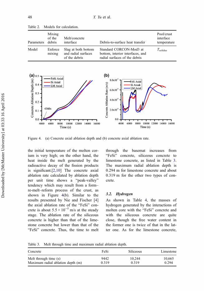
the initial temperature of the molten cor-ium is very high; on the other hand, theheat inside the melt generated by theradioactive decay of the fission productsis significant.[2,10] The concrete axialablation rate calculated by ablation depthper unit time shows a “peak-valley”tendency which may result from a form–re-melt–reform process of the crust, asshown in Figure 4(b). Similar to theresults presented by Nie and Fischer [4]the axial ablation rate of the “FeSi” con-crete is about 5.5 × 10⁻⁵ m/s at the steadystage. The ablation rate of the siliceousconcrete is higher than that of the lime-stone concrete but lower than that of the“FeSi” concrete. Thus, the time to melt
through the basemat increases from“FeSi” concrete, siliceous concrete tolimestone concrete, as listed in Table 3.The maximum radial ablation depth is0.294 m for limestone concrete and about0.319 m for the other two types of con-crete.
3.2. Hydrogen
As shown in Table 4, the masses ofhydrogen generated by the interactions ofmolten core with the “FeSi” concrete andwith the siliceous concrete are quiteclose, though the free water content inthe former one is twice of that in the lat-ter one. As for the limestone concrete,
Table 2. Models for calculation.
Parameters
Mixingof thedebris
Melt/concreteinterface Debris-to-surface heat transfer
Pool/crustinterfacetemperature
Model Enforcemixing
Slag at both bottomand radial surfacesof the debris
Standard CORCON-Mod3 atbottom, interior interfaces, andradial surfaces of the debris
Tsolidus
Figure 4. (a) Concrete axial ablation depth and (b) concrete axial ablation rate.
Table 3. Melt through time and maximum radial ablation depth.
Concrete FeSi Siliceous Limestone
Melt through time (s) 9442 10,244 10,665Maximum radial ablation depth (m) 0.319 0.319 0.294
48 Y. Yu et al.
Dow
nloa
ded
by [
McM
aste
r U
nive
rsity
] at
03:
33 1
6 A
pril
2016
the mass of generated hydrogen is 30%lower when compared with the other twotypes. The total mass of generated gasdecreases from limestone concrete and“FeSi” concrete to siliceous concrete. Inparticular, the total mass of generated gasof the “FeSi” or the siliceous concretes isaround 14–21% in comparison to that ofthe limestone concrete.
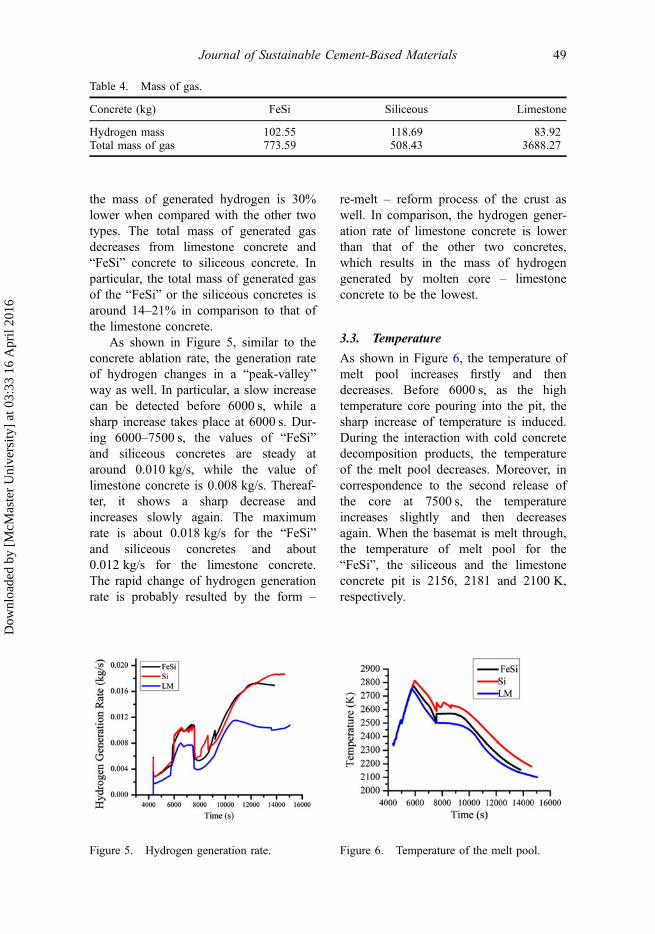
As shown in Figure 5, similar to theconcrete ablation rate, the generation rateof hydrogen changes in a “peak-valley”way as well. In particular, a slow increasecan be detected before 6000 s, while asharp increase takes place at 6000 s. Dur-ing 6000–7500 s, the values of “FeSi”and siliceous concretes are steady ataround 0.010 kg/s, while the value oflimestone concrete is 0.008 kg/s. Thereaf-ter, it shows a sharp decrease andincreases slowly again. The maximumrate is about 0.018 kg/s for the “FeSi”and siliceous concretes and about0.012 kg/s for the limestone concrete.The rapid change of hydrogen generationrate is probably resulted by the form –
re-melt – reform process of the crust aswell. In comparison, the hydrogen gener-ation rate of limestone concrete is lowerthan that of the other two concretes,which results in the mass of hydrogengenerated by molten core – limestoneconcrete to be the lowest.
3.3. Temperature
As shown in Figure 6, the temperature ofmelt pool increases firstly and thendecreases. Before 6000 s, as the hightemperature core pouring into the pit, thesharp increase of temperature is induced.During the interaction with cold concretedecomposition products, the temperatureof the melt pool decreases. Moreover, incorrespondence to the second release ofthe core at 7500 s, the temperatureincreases slightly and then decreasesagain. When the basemat is melt through,the temperature of melt pool for the“FeSi”, the siliceous and the limestoneconcrete pit is 2156, 2181 and 2100 K,respectively.
Table 4. Mass of gas.
Concrete (kg) FeSi Siliceous Limestone
Hydrogen mass 102.55 118.69 83.92Total mass of gas 773.59 508.43 3688.27
Figure 5. Hydrogen generation rate. Figure 6. Temperature of the melt pool.
Journal of Sustainable Cement-Based Materials 49
Dow
nloa
ded
by [
McM
aste
r U
nive
rsity
] at
03:
33 1
6 A
pril
2016
4. Discussion
In a severe accident for nuclear powerplants, the molten core will penetrate theRPV if it can’t be cooled inside the reac-tor and flow into the concrete cavityunder the reactor, which then initiates theMCCI. Early simulation tests indicatethat the concrete ablation rate, whichcharacterizes the ratio of the heat fluxover the enthalpy to ablate per unit massof concrete, can be expressed as follows[7]:
t ¼ Q�
qADH(1)
where Q�is the heat flux to concrete, ρ is
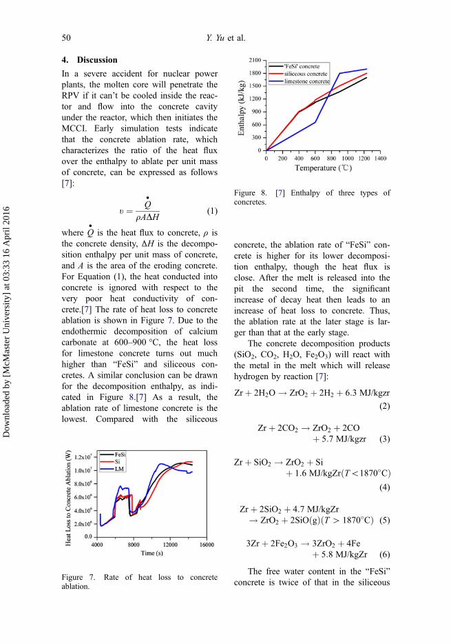
the concrete density, ΔH is the decompo-sition enthalpy per unit mass of concrete,and A is the area of the eroding concrete.For Equation (1), the heat conducted intoconcrete is ignored with respect to thevery poor heat conductivity of con-crete.[7] The rate of heat loss to concreteablation is shown in Figure 7. Due to theendothermic decomposition of calciumcarbonate at 600–900 °C, the heat lossfor limestone concrete turns out muchhigher than “FeSi” and siliceous con-cretes. A similar conclusion can be drawnfor the decomposition enthalpy, as indi-cated in Figure 8.[7] As a result, theablation rate of limestone concrete is thelowest. Compared with the siliceous
concrete, the ablation rate of “FeSi” con-crete is higher for its lower decomposi-tion enthalpy, though the heat flux isclose. After the melt is released into thepit the second time, the significantincrease of decay heat then leads to anincrease of heat loss to concrete. Thus,the ablation rate at the later stage is lar-ger than that at the early stage.
The concrete decomposition products(SiO2, CO2, H2O, Fe2O3) will react withthe metal in the melt which will releasehydrogen by reaction [7]:
Zr þ 2H2O ! ZrO2 þ 2H2 þ 6:3 MJ/kgzr
(2)
Zr þ 2CO2 ! ZrO2 þ 2COþ 5:7 MJ/kgzr (3)
Zr þ SiO2 ! ZrO2 þ Siþ 1:6 MJ/kgZrðT\1870�CÞ
(4)
Zr þ 2SiO2 þ 4:7 MJ/kgZr! ZrO2 þ 2SiOðgÞðT [ 1870�CÞ (5)
3Zr þ 2Fe2O3 ! 3ZrO2 þ 4Feþ 5:8 MJ/kgZr (6)
The free water content in the “FeSi”concrete is twice of that in the siliceous
Figure 7. Rate of heat loss to concreteablation.
Figure 8. [7] Enthalpy of three types ofconcretes.
50 Y. Yu et al.
Dow
nloa
ded
by [
McM
aste
r U
nive
rsity
] at
03:
33 1
6 A
pril
2016
concrete. Thus, a larger total gas mass iscalculated for the “FeSi” concrete. How-ever, the mass of hydrogen generated bythe interaction of molten core with the“FeSi” concrete is about 13% less thansiliceous concrete. In fact, as one of thedecomposition products of “FeSi” con-crete, Fe2O3 oxidizes partial Zr, whichcauses the less mass of hydrogen byreducing the mass of Zr reacting withH2O. The mass of hydrogen generated bythe limestone concrete is the lowest,though the free water content is the high-est. It seems that the lowest mass of H2Ogenerated by limestone concrete canaccount for this. Moreover, CO2 gener-ated by the decomposition of limestoneconcrete can oxidize partial Zr.
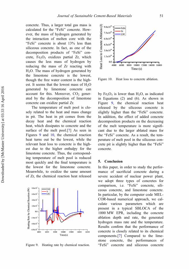
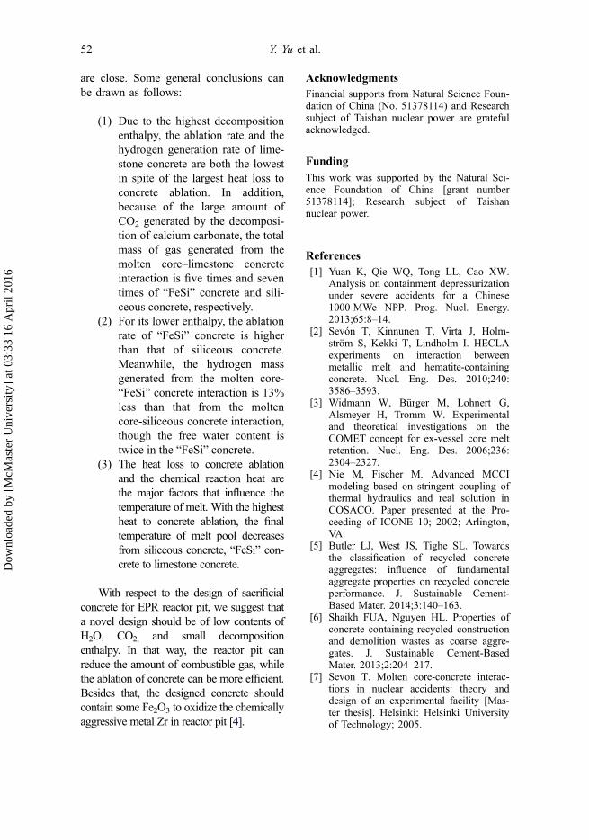
The temperature of melt pool is clo-sely related to the heat and mass changein pit. The heat in pit comes from thedecay heat and the chemical reactionheat, which dissipates to concrete and thesurface of the melt pool.[7] As seen inFigures 9 and 10, the chemical reactionheat turns out be the lowest, while therelevant heat loss to concrete is the high-est due to the higher enthalpy for thelimestone concrete. Thus, the correspond-ing temperature of melt pool is reducedmost quickly and the final temperature isthe lowest for the limestone concrete.Meanwhile, to oxidize the same amountof Zr, the chemical reaction heat released
by Fe2O3 is lower than H2O, as indicatedin Equations (2) and (6). As shown inFigure 9, the chemical reaction heatreleased by the siliceous concrete isslightly higher than the “FeSi” concrete.In addition, the effect of added concretedecomposition products on the decreasingof the melt temperature is more signifi-cant due to the larger ablated mass forthe “FeSi” concrete. As a result, the tem-perature of melt pool in the siliceous con-crete pit is slightly higher than the “FeSi”concrete.
5. Conclusion
In this paper, in order to study the perfor-mance of sacrificial concrete during asevere accident of nuclear power plant,we adopt three types of concretes forcomparison, i.e. “FeSi” concrete, sili-ceous concrete, and limestone concrete.In particular, by the computer code MEL-COR-based numerical approach, we cal-culate various parameters which arepresent in a typical SBLOCA of the1000 MW EPR, including the concreteablation depth and rate, the generatedhydrogen mass rate and the temperature.Results confirm that the performance ofconcrete is closely related to its chemicalcomponents.[7] Compared to the lime-stone concrete, the performances of“FeSi” concrete and siliceous concreteFigure 9. Heating rate by chemical reaction.
Figure 10. Heat loss to concrete ablation.
Journal of Sustainable Cement-Based Materials 51
Dow
nloa
ded
by [
McM
aste
r U
nive
rsity
] at
03:
33 1
6 A
pril
2016
are close. Some general conclusions canbe drawn as follows:
(1) Due to the highest decompositionenthalpy, the ablation rate and thehydrogen generation rate of lime-stone concrete are both the lowestin spite of the largest heat loss toconcrete ablation. In addition,because of the large amount ofCO2 generated by the decomposi-tion of calcium carbonate, the totalmass of gas generated from themolten core–limestone concreteinteraction is five times and seventimes of “FeSi” concrete and sili-ceous concrete, respectively.
(2) For its lower enthalpy, the ablationrate of “FeSi” concrete is higherthan that of siliceous concrete.Meanwhile, the hydrogen massgenerated from the molten core-“FeSi” concrete interaction is 13%less than that from the moltencore-siliceous concrete interaction,though the free water content istwice in the “FeSi” concrete.
(3) The heat loss to concrete ablationand the chemical reaction heat arethe major factors that influence thetemperature of melt. With the highestheat to concrete ablation, the finaltemperature of melt pool decreasesfrom siliceous concrete, “FeSi” con-crete to limestone concrete.
With respect to the design of sacrificialconcrete for EPR reactor pit, we suggest thata novel design should be of low contents ofH2O, CO2, and small decompositionenthalpy. In that way, the reactor pit canreduce the amount of combustible gas, whilethe ablation of concrete can be more efficient.Besides that, the designed concrete shouldcontain some Fe2O3 to oxidize the chemicallyaggressive metal Zr in reactor pit [4].
AcknowledgmentsFinancial supports from Natural Science Foun-dation of China (No. 51378114) and Researchsubject of Taishan nuclear power are gratefulacknowledged.
FundingThis work was supported by the Natural Sci-ence Foundation of China [grant number51378114]; Research subject of Taishannuclear power.
References[1] Yuan K, Qie WQ, Tong LL, Cao XW.
Analysis on containment depressurizationunder severe accidents for a Chinese1000 MWe NPP. Prog. Nucl. Energy.2013;65:8–14.
[2] Sevón T, Kinnunen T, Virta J, Holm-ström S, Kekki T, Lindholm I. HECLAexperiments on interaction betweenmetallic melt and hematite-containingconcrete. Nucl. Eng. Des. 2010;240:3586–3593.
[3] Widmann W, Bürger M, Lohnert G,Alsmeyer H, Tromm W. Experimentaland theoretical investigations on theCOMET concept for ex-vessel core meltretention. Nucl. Eng. Des. 2006;236:2304–2327.
[4] Nie M, Fischer M. Advanced MCCImodeling based on stringent coupling ofthermal hydraulics and real solution inCOSACO. Paper presented at the Pro-ceeding of ICONE 10; 2002; Arlington,VA.
[5] Butler LJ, West JS, Tighe SL. Towardsthe classification of recycled concreteaggregates: influence of fundamentalaggregate properties on recycled concreteperformance. J. Sustainable Cement-Based Mater. 2014;3:140–163.
[6] Shaikh FUA, Nguyen HL. Properties ofconcrete containing recycled constructionand demolition wastes as coarse aggre-gates. J. Sustainable Cement-BasedMater. 2013;2:204–217.
[7] Sevon T. Molten core-concrete interac-tions in nuclear accidents: theory anddesign of an experimental facility [Mas-ter thesis]. Helsinki: Helsinki Universityof Technology; 2005.
52 Y. Yu et al.
Dow
nloa
ded
by [
McM
aste
r U
nive
rsity
] at
03:
33 1
6 A
pril
2016
[8] Eppinger B, Fellmoser F, Fieg G,Massier H, Stern G. (2000). Experimentson concrete erosion by a Corium melt inthe EPR reactor cavity: KAPOOL 6–8.Karlsruhe, Forschungszentrum Karlsruhe.
[9] Cranga M, Spindler B, Dufour E, DimovD, Atkhen K, Foit J, Garcia-Martin M,Sevon T, Schmidt W, Spengler C. Simu-lation of corium concrete interaction in2D geometry. Prog. Nucl. Energy.2010;52:76–83.
[10] Sevón T, Journeau C, Ferry L. VUL-CANO VB-U7 experiment on interactionbetween oxidic corium and hematite-containing concrete. Ann. Nucl. Energy.2013;59:224–229.
[11] Bradley D.R., Gardner D.R., BrockmannJ.E., Griffith R.O. CORCON-MOD3: An
Integrated Computer Model for Analysisof Molten Core-Concrete Interactions.Users Manual, NUREG/CR-5843,SAND92-0167, Sandia National Labora-tories, Albuquerque, NM (October 1993).
[12] Kwong KC, Beck RAS, Derbidge TC.CORCON Program Assistance, FR-79-10/AS. Mountain View (CA): ACUREXCorporation/Aerotherm Aerospace Divi-sion; 1979.
[13] Gauntt R.O., Cole R.K., Erickson C.M.,Rodriguez S.B., Gido R.G., Gasser R.D.,Young M.F., MELCOR computer codemanuals: cavity (CAV) package refer-ence manual. Version 1.8.5, NUNUREG/CR-6119, SAND2000-2417/2.
Journal of Sustainable Cement-Based Materials 53
Dow
nloa
ded
by [
McM
aste
r U
nive
rsity
] at
03:
33 1
6 A
pril
2016

本文献由“学霸图书馆-文献云下载”收集自网络,仅供学习交流使用。
学霸图书馆(www.xuebalib.com)是一个“整合众多图书馆数据库资源,
提供一站式文献检索和下载服务”的24 小时在线不限IP
图书馆。
图书馆致力于便利、促进学习与科研,提供最强文献下载服务。
图书馆导航:
图书馆首页 文献云下载 图书馆入口 外文数据库大全 疑难文献辅助工具