Embed Size (px)
Citation preview
We Built Better Supports
THE JOINTED PRECASTCONCRETE PILES
(TECHNICAL DATA FOR PRODUCTION & INSTALLATION)
Contents01 INTRODUCTION
ADVANTAGES
PILE FABRICATION
DESIGN GUIDELINE
020304050607
2
2
3
5
6
10
17
TECHNICAL DATA
08 18
PILE LOAD TEST
09 18
SAFETY PLAN
PROJECT EXPERIENCES
PILE INSTALLATION
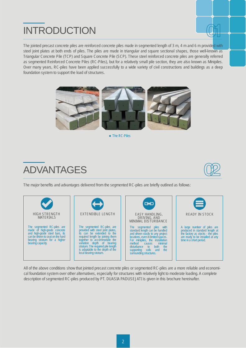
The jointed precast concrete piles are reinforced concrete piles made in segmented length of 3 m, 4 m and 6 m provided with steel joint plates at both ends of piles. The piles are made in triangular and square sectional shapes, those well-known as Triangular Concrete Pile (TCP) and Square Concrete Pile (SCP). These steel reinforced concrete piles are generally referred as segmented Reinforced Concrete Piles (RC-Piles), but for a relatively small pile section, they are also known as Minipiles. Over many years, RC-piles have been applied successfully to a wide variety of civil constructions and buildings as a deep foundation system to support the load of structures.
2
HIGH STRENGTH MATERIALS
The segmented RC-piles are made of high-grade concrete and high-grade steel bars, its can be driven to seat on the hard bearing stratum for a higher bearing capacity.
EXTENDIBLE LENGTH
The segmented RC-piles are provided with steel joint plates, its can be extended to the required length by joining them together to accommodate the variation depth of bearing stratum. The required pile length is adaptable to the depth of the local bearing stratum.
EASY HANDLING,DRIVING, AND
MINIMAL DISTURBANCE The segmented piles with standard length can be handled and driven easily to any project locations, even in limited spaces. For minipiles, the installation method causes minimal disturbance to both the supporting soils and the surrounding structures.
READY IN STOCK
A large number of piles are produced in standard length at the factory as stocks - the piles are ready to be installed at any time in a short period.
The RC-Piles
INTRODUCTION
The major benefits and advantages delivered from the segmented RC-piles are briefly outlined as follows:
ADVANTAGES
All of the above conditions show that jointed precast concrete piles or segmented RC-piles are a more reliable and economi-cal foundation system over other alternatives, especially for structures with relatively light to moderate loading. A complete description of segmented RC-piles produced by PT. DUASIA PADUSEJATI is given in this brochure hereinafter.
01
02
03
3
3.1 Standard ComplianceThe standard compliance of the segmented RC-piles are SNI 2847-2013 (Indonesia National Standard Code of Practice for Concrete Structures), SNI 2052-2014 (Indonesia National Standard Code of Practice for Concrete Reinforcement Steel Bars), ACI 318-14 (Building Code Requirements for Structural Concrete) and AWS (American Welding Society).
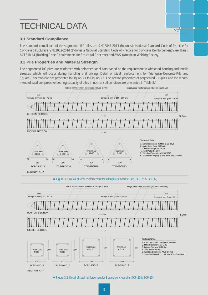
3.2 Pile Properties and Material StrengthThe segmented RC-piles are reinforced with deformed steel bars based on the requirement to withstand bending and tensile stresses which will occur during handling and driving. Detail of steel reinforcement for Triangular-Concrete-Pile and Square-Concrete-Pile are presented in Figure-3.1 to Figure-3.3. The section properties of segmented RC-piles and the recom-mended axial compressive bearing capacity of piles in normal soil condition are presented in Table-3.1.
TECHNICAL DATA
3
Figure-3.2: Detail of steel reinforcement for Square-concrete-pile (SCP-20 & SCP-25)
Stirrups 6 mm @ 150 - 200 crs Stirrups 6 mm @ 60 - 75 crs
longitudinal reinforcement (deform steel bars)lateral reinforcement (continuos stirrups 6 mm)
500Stirrups 6 mm @ 60 - 75 crs
500
Technical Data
1. Concrete cubes: 45Mpa at 28 days2. Main Steel Bars: BjTD-403. Lateral Stirrups: BjTP-244. Joint Plate: Fe-3605. Welding Electrode: AWS E60136. Standard Length (L): 3m, 4m & 6m / section
BOTTOM SECTION
MIDDLE SECTION
PL 6mmA
SECTION A - A
A
TCP-28/3D13 TCP-28/3D10
Main bars3 D13
3030280
30 30280
30 30
Main bars3 D13
Main bars3 D10
320
3 D16Main bars
TCP-32/3D16
30 30320
TCP-32/3D13
Figure-3.1: Detail of steel reinforcement for Triangular-Concrete-Pile (TCP-28 & TCP-32)
Stirrups 6 mm @ 150 - 200 crs Stirrups 6 mm @ 60 - 75 crs
longitudinal reinforcement (deform steel bars)lateral reinforcement (continuos stirrups 6 mm)
500Stirrups 6 mm @ 60 - 75 crs
500
Technical Data
1. Concrete cubes: 45Mpa at 28 days2. Main Steel Bars: BjTD-403. Lateral Stirrups: BjTP-244. Joint Plate: Fe-3605. Welding Electrode: AWS E60136. Standard Length (L): 3m, 4m & 6m / section
200
200
4 D13Main bars
SCP-20/4D13
BOTTOM SECTION
MIDDLE SECTION
PL 6mm
200
200
4 D10Main bars
SCP-20/4D10
250
250
4 D16Main bars
SCP-25/4D16
250
250
4 D13Main bars
SCP-25/4D13
A
SECTION A - A
A
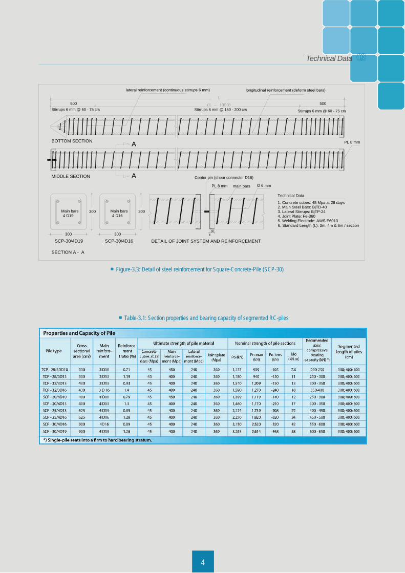
Table-3.1: Section properties and bearing capacity of segmented RC-piles
44
Figure-3.3: Detail of steel reinforcement for Square-Concrete-Pile (SCP-30)
main bars O 6 mm
Technical Data
1. Concrete cubes: 45 Mpa at 28 days2. Main Steel Bars: BjTD-403. Lateral Stirrups: BjTP-244. Joint Plate: Fe-3605. Welding Electrode: AWS E60136. Standard Length (L): 3m, 4m & 6m / section
308
Center pin (shear connector D16)
A
SECTION A - A
DETAIL OF JOINT SYSTEM AND REINFORCEMENT
300
300
4 D16Main bars
SCP-30/4D16
AMIDDLE SECTION
BOTTOM SECTION PL 8 mm
Stirrups 6 mm @ 150 - 200 crs Stirrups 6 mm @ 60 - 75 crs
longitudinal reinforcement (deform steel bars)lateral reinforcement (continuous stirrups 6 mm)
500Stirrups 6 mm @ 60 - 75 crs
500
300
300
PL 8 mm
4 D19Main bars
SCP-30/4D19
03Technical Data
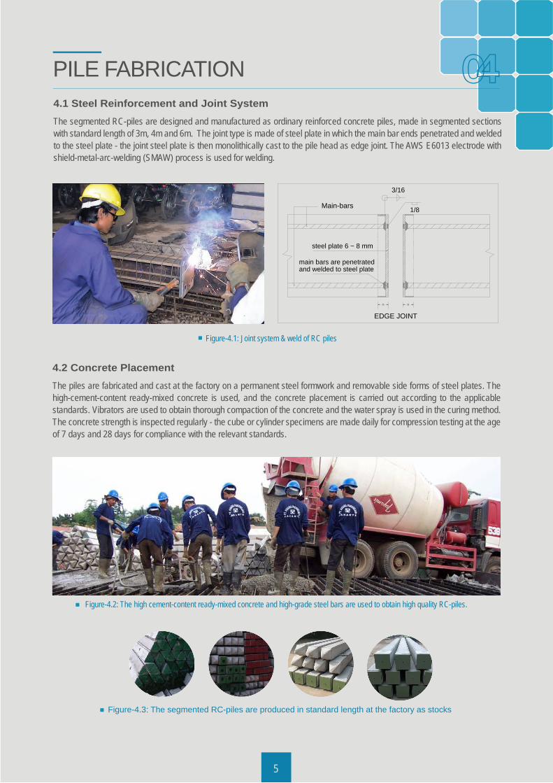
4.1 Steel Reinforcement and Joint SystemThe segmented RC-piles are designed and manufactured as ordinary reinforced concrete piles, made in segmented sections with standard length of 3m, 4m and 6m. The joint type is made of steel plate in which the main bar ends penetrated and welded to the steel plate - the joint steel plate is then monolithically cast to the pile head as edge joint. The AWS E6013 electrode with shield-metal-arc-welding (SMAW) process is used for welding.
PILE FABRICATION
Figure-4.1: Joint system & weld of RC piles
4.2 Concrete PlacementThe piles are fabricated and cast at the factory on a permanent steel formwork and removable side forms of steel plates. The high-cement-content ready-mixed concrete is used, and the concrete placement is carried out according to the applicable standards. Vibrators are used to obtain thorough compaction of the concrete and the water spray is used in the curing method. The concrete strength is inspected regularly - the cube or cylinder specimens are made daily for compression testing at the age of 7 days and 28 days for compliance with the relevant standards.
Figure-4.2: The high cement-content ready-mixed concrete and high-grade steel bars are used to obtain high quality RC-piles.
Figure-4.3: The segmented RC-piles are produced in standard length at the factory as stocks
45
04
EDGE JOINT
steel plate 6 ~ 8 mm
25 25
Main-bars
3/16
1/8
and welded to steel platemain bars are penetrated
3
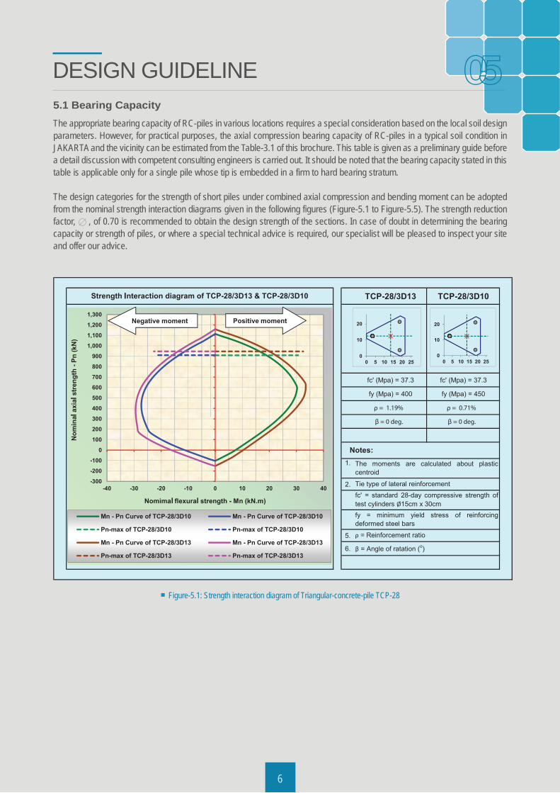
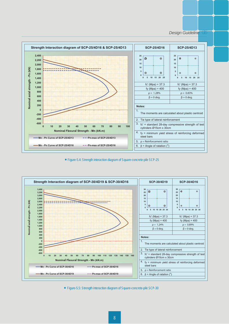
5.1 Bearing CapacityThe appropriate bearing capacity of RC-piles in various locations requires a special consideration based on the local soil design parameters. However, for practical purposes, the axial compression bearing capacity of RC-piles in a typical soil condition in JAKARTA and the vicinity can be estimated from the Table-3.1 of this brochure. This table is given as a preliminary guide before a detail discussion with competent consulting engineers is carried out. It should be noted that the bearing capacity stated in this table is applicable only for a single pile whose tip is embedded in a firm to hard bearing stratum.
The design categories for the strength of short piles under combined axial compression and bending moment can be adopted from the nominal strength interaction diagrams given in the following figures (Figure-5.1 to Figure-5.5). The strength reduction factor, , of 0.70 is recommended to obtain the design strength of the sections. In case of doubt in determining the bearing capacity or strength of piles, or where a special technical advice is required, our specialist will be pleased to inspect your site and offer our advice.
DESIGN GUIDELINE
6
Figure-5.1: Strength interaction diagram of Triangular-concrete-pile TCP-28
05
I
l
l l
l
l
ll
l
l
l l l
l
37
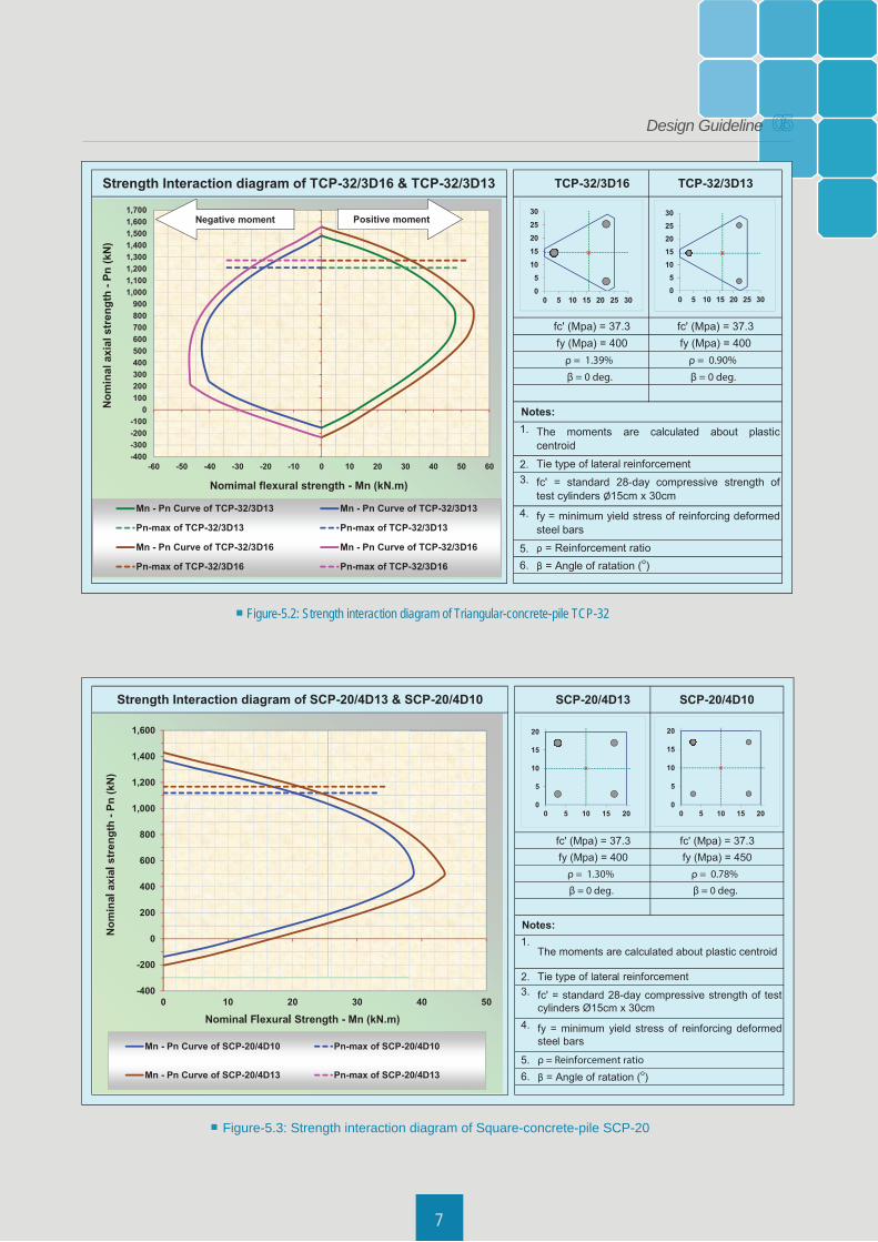
Figure-5.2: Strength interaction diagram of Triangular-concrete-pile TCP-32
Figure-5.3: Strength interaction diagram of Square-concrete-pile SCP-20
l
l l
ll
l
ll
l
l l l
l
05Design Guideline
All of the above conditions show that jointed precast concrete piles or segmented RC-piles are a more reliable and economi-cal foundation system over other alternatives, especially for structures with relatively light to moderate loading. A complete description of segmented RC-piles produced by PT. DUASIA PADUSEJATI is given in this brochure hereinafter.
38
Figure-5.4: Strength interaction diagram of Square-concrete-pile SCP-25
Figure-5.5: Strength interaction diagram of Square-concrete-pile SCP-30
l
l
ll
l l
ll
l l
l
ll
l
l
l
l
l
l
l l l
l
l
l l l
l
05Design Guideline
9
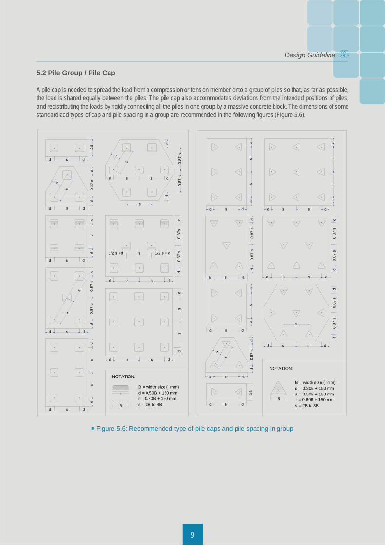
Figure-5.6: Recommended type of pile caps and pile spacing in group
5.2 Pile Group / Pile Cap
A pile cap is needed to spread the load from a compression or tension member onto a group of piles so that, as far as possible, the load is shared equally between the piles. The pile cap also accommodates deviations from the intended positions of piles, and redistributing the loads by rigidly connecting all the piles in one group by a massive concrete block. The dimensions of some standardized types of cap and pile spacing in a group are recommended in the following figures (Figure-5.6).
s dd
2d
s dd
s dd
s dd
s dd
d0.
87 s
d
s
r
ds
dd
0.87
s0.
87 s
d
s
s
dd
ss
d s s d
s
s
r
d
0.87
s
d
0.87
s
d s s d
d0.
87 s
0.87
sd
1/2 s +d s 1/2 s + d
d s s d
ds
sd
B
B = width size ( mm)d = 0.50B + 150 mmr = 0.70B + 150 mms = 3B to 4B
NOTATION:
Bs dd
2a
s aa
d0.
87 s
d
s
r
s dd
as
a
s aa
d0.
87 s
0.87
sd
s dd
sa
sa
sa
sa
s s dd
a s s a
d0.
87 s
0.87
sd
d0.
87 s
0.87
sd
s s dd
s
NOTATION:
B = width size ( mm)d = 0.30B + 150 mma = 0.50B + 150 mm
s = 2B to 3Br = 0.60B + 150 mm
05Design Guideline
103
The knowledge of piling process and sufficient information of site conditions are essentials for an accurate assessment of pile installation system and selection of suitable piling equipment. A successful achievement of pile installation is always supported by a range of good preparation steps, reliable equipment and methods of installation. The necessary preparation steps shall include: suitable site access, ground levelling, adequate ground compaction, temporary drains and sumps, surveying and obtaining information about the geotechnical data.
There are two categories of pile installation system proposed for installing RC-piles, i.e. dynamic impact system (well-known as impact hammer system) and static pressing system (well-known as hydraulic static system). The selection of pile installation system depends on the environmental concerns of the construction area. If the noise and vibration effects from pile driving are not an issue to the surrounding area, the impact hammer system is a preferable system for installing RC-piles (Figure-6.1). However, if the control of noise and vibration disturbance in project site is an important matter, the hydraulic static piling system is the most appropriate piling technique to be proposed (Figure-6.7).
For cases with difficult site conditions or limited access in which normal equipment cannot operate, specific equipment is required to overcome such conditions. Usually this specific equipment is specially developed and modified from hammer system or hydraulic system to fit the site requirement (Figure-6.11).
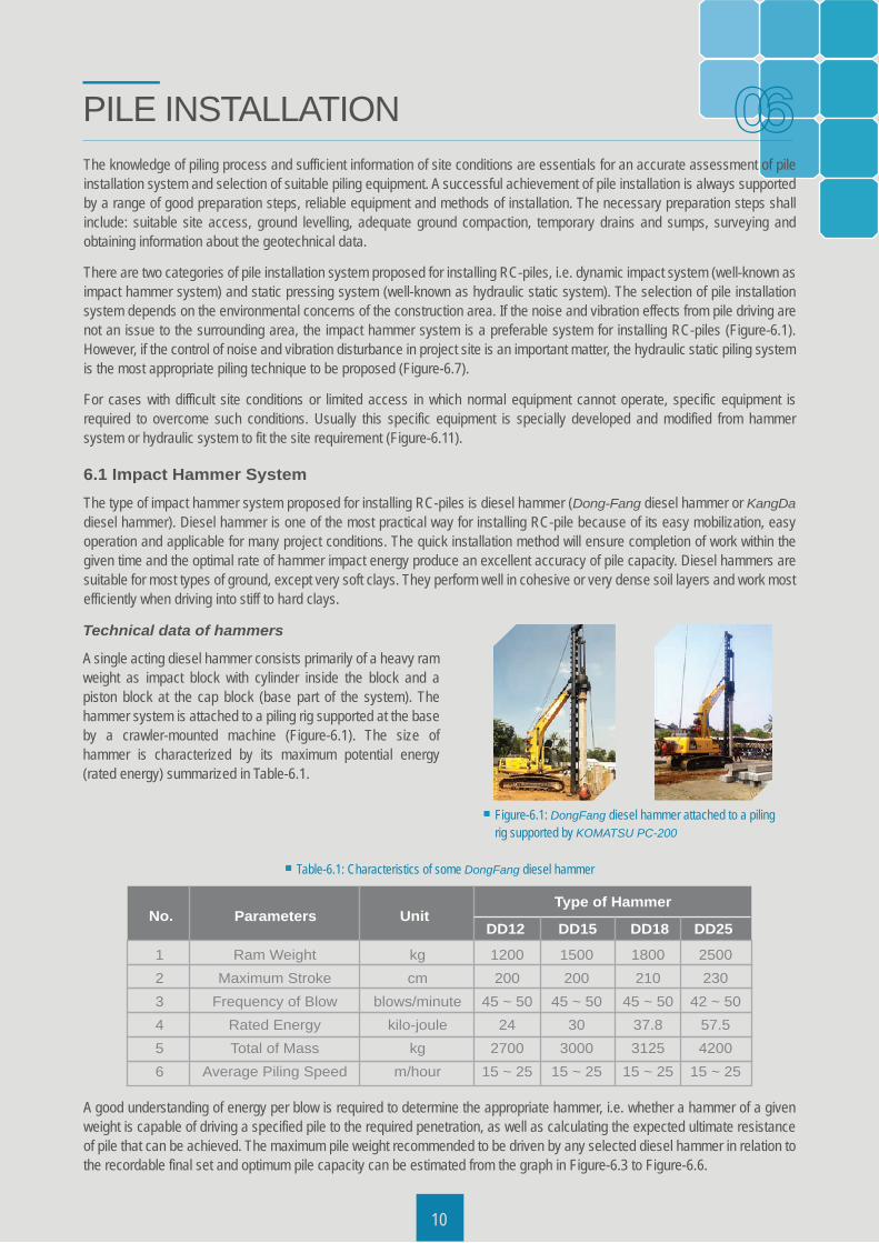
6.1 Impact Hammer SystemThe type of impact hammer system proposed for installing RC-piles is diesel hammer (Dong-Fang diesel hammer or KangDa diesel hammer). Diesel hammer is one of the most practical way for installing RC-pile because of its easy mobilization, easy operation and applicable for many project conditions. The quick installation method will ensure completion of work within the given time and the optimal rate of hammer impact energy produce an excellent accuracy of pile capacity. Diesel hammers are suitable for most types of ground, except very soft clays. They perform well in cohesive or very dense soil layers and work most efficiently when driving into stiff to hard clays.
PILE INSTALLATION
Figure-6.1: DongFang diesel hammer attached to a piling rig supported by KOMATSU PC-200
Table-6.1: Characteristics of some DongFang diesel hammer
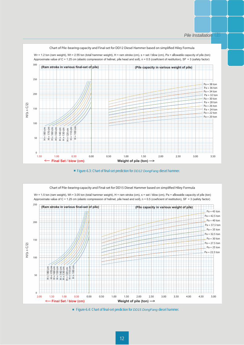
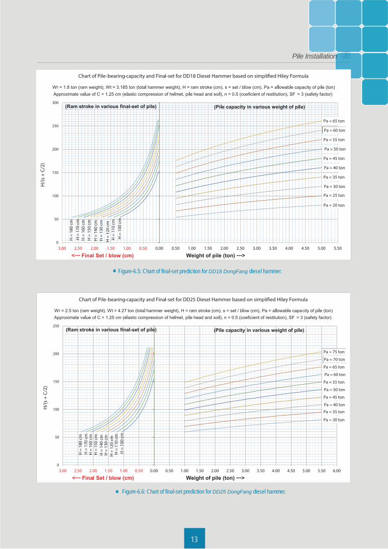
A good understanding of energy per blow is required to determine the appropriate hammer, i.e. whether a hammer of a given weight is capable of driving a specified pile to the required penetration, as well as calculating the expected ultimate resistance of pile that can be achieved. The maximum pile weight recommended to be driven by any selected diesel hammer in relation to the recordable final set and optimum pile capacity can be estimated from the graph in Figure-6.3 to Figure-6.6.
No.
123456
Ram WeightMaximum Stroke
Frequency of BlowRated EnergyTotal of Mass
Average Piling Speed
Parameters
kgcm
blows/minutekilo-joule
kgm/hour
UnitType of Hammer
DD12 DD15 DD18 DD25
1200200
45 ~ 5024
270015 ~ 25
1500200
45 ~ 5030
300015 ~ 25
1800210
45 ~ 5037.83125
15 ~ 25
2500230
42 ~ 5057.54200
15 ~ 25
Technical data of hammers
A single acting diesel hammer consists primarily of a heavy ram weight as impact block with cylinder inside the block and a piston block at the cap block (base part of the system). The hammer system is attached to a piling rig supported at the base by a crawler-mounted machine (Figure-6.1). The size of hammer is characterized by its maximum potential energy (rated energy) summarized in Table-6.1.
10
06
11103
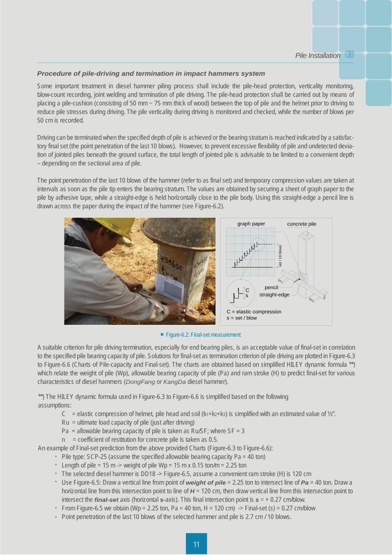
Figure-6.2: Final-set measurement
Procedure of pile-driving and termination in impact hammers system
Some important treatment in diesel hammer piling process shall include the pile-head protection, verticality monitoring, blow-count recording, joint welding and termination of pile driving. The pile-head protection shall be carried out by means of placing a pile-cushion (consisting of 50 mm ~ 75 mm thick of wood) between the top of pile and the helmet prior to driving to reduce pile stresses during driving. The pile verticality during driving is monitored and checked, while the number of blows per 50 cm is recorded.
Driving can be terminated when the specified depth of pile is achieved or the bearing stratum is reached indicated by a satisfac-tory final set (the point penetration of the last 10 blows). However, to prevent excessive flexibility of pile and undetected devia-tion of jointed piles beneath the ground surface, the total length of jointed pile is advisable to be limited to a convenient depth – depending on the sectional area of pile.
The point penetration of the last 10 blows of the hammer (refer to as final set) and temporary compression values are taken at intervals as soon as the pile tip enters the bearing stratum. The values are obtained by securing a sheet of graph paper to the pile by adhesive tape, while a straight-edge is held horizontally close to the pile body. Using this straight-edge a pencil line is drawn across the paper during the impact of the hammer (see Figure-6.2).
11
A suitable criterion for pile driving termination, especially for end bearing piles, is an acceptable value of final-set in correlation to the specified pile bearing capacity of pile. Solutions for final-set as termination criterion of pile driving are plotted in Figure-6.3 to Figure-6.6 (Charts of Pile-capacity and Final-set). The charts are obtained based on simplified HILEY dynamic formula **) which relate the weight of pile (Wp), allowable bearing capacity of pile (Pa) and ram stroke (H) to predict final-set for various characteristics of diesel hammers (DongFang or KangDa diesel hammer).
**) The HILEY dynamic formula used in Figure-6.3 to Figure-6.6 is simplified based on the following assumptions: C = elastic compression of helmet, pile head and soil (k1+k2+k3) is simplified with an estimated value of ½”. Ru = ultimate load capacity of pile (just after driving) Pa = allowable bearing capacity of pile is taken as Ru/SF; where SF = 3 n = coefficient of restitution for concrete pile is taken as 0.5.An example of Final-set prediction from the above provided Charts (Figure-6.3 to Figure-6.6): Pile type: SCP-25 (assume the specified allowable bearing capacity Pa = 40 ton) Length of pile = 15 m -> weight of pile Wp = 15 m x 0.15 ton/m = 2.25 ton The selected diesel hammer is DD18 -> Figure-6.5, assume a convenient ram stroke (H) is 120 cm Use Figure-6.5: Draw a vertical line from point of weight of pile = 2.25 ton to intersect line of Pa = 40 ton. Draw a horizontal line from this intersection point to line of H = 120 cm, then draw vertical line from this intersection point to intersect the final-set axis (horizontal s-axis). This final intersection point is s = + 0.27 cm/blow. From Figure-6.5 we obtain (Wp = 2.25 ton, Pa = 40 ton, H = 120 cm) -> Final-set (s) = 0.27 cm/blow Point penetration of the last 10 blows of the selected hammer and pile is 2.7 cm / 10 blows.
set /
10
blow
s
Cs
graph paper concrete pile
straight-edgepencil
C = elastic compressions = set / blow
06Pile Installation
103
Figure-6.3: Chart of final-set prediction for DD12 DongFang diesel hammer.
12
Figure-6.4: Chart of final-set prediction for DD15 DongFang diesel hammer.
l l
l l
l
l
l
l
l l ll
l
l l
l
l
ll l
l
l
llll
l l l
ll
l l
ll
ll
l
l
l
l
l
lll
l
l
06Pile Installation
10313
Figure-6.5: Chart of final-set prediction for DD18 DongFang diesel hammer.
Figure-6.6: Chart of final-set prediction for DD25 DongFang diesel hammer.
l
l
l
l l l
l l
lll
l
l
l
l l ll
l
l l
l
l
l
llll
l l l
ll l
l
ll
l l l
l
l
llll
06Pile Installation
10
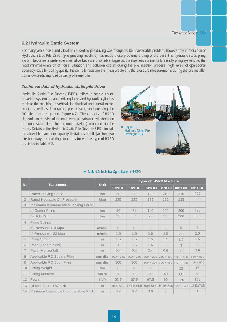
Figure-6.7: Hydraulic Static Pile Driver (HSPD)
6.2 Hydraulic Static SystemFor many years noise and vibration caused by pile driving was thought to be unavoidable problem, however the introduction of Hydraulic Static Pile Driver (pile pressing machine) has made these problems a thing of the past. The hydraulic static piling system becomes a preferable alternative because of its advantages as the most environmentally friendly piling system, i.e. the most minimal emission of noise, vibration and pollution occurs during the pile injection process, high levels of operational accuracy, excellent piling quality, the soil-pile resistance is measurable and the pressure measurements during the pile installa-tion allow predicting load capacity of every pile.
3
14
Technical data of hydraulic static pile driver
Hydraulic Static Pile Driver (HSPD) utilizes a stable count-er-weight system as static driving force and hydraulic cylinders to drive the machine in vertical, longitudinal and lateral move-ment, as well as in rotation, pile hoisting and pressing the RC-piles into the ground (Figure-6.7). The capacity of HSPD depends on the size of the main vertical hydraulic cylinders and the total static dead load (counter-weight) mounted on the frame. Details of the Hydraulic Static Pile Driver (HSPD), includ-ing allowable maximum capacity, limitations for pile jacking near site boundary and existing structures for various type of HSPD are listed in Table-6.2.
No.
123
4
5
67
8
910
1112
1314
60235
5038
52.51.5
10.4
200 ~ 250
3003
1052.5
6x4.5x40.7
90235
8157
52.51.5
1.50.4
200 ~ 250
3004
1567.5
7x4.5x4.50.7
120235
11075
52.51.5
1.60.4
200 ~ 300
300 ~ 350
5
2067.5
9x4.5x50.8
240235
220150
52.51.5
30.6
250 ~ 400
300 ~ 450
8
4096
10x6.2x61
320235
300200
5
2.51.5
30.6
300 ~ 450
350 ~ 500
12
60120
12x6.5x71
460235
420275
52.51.5
30.6
350 ~ 550
400 ~ 600
16
80150
12.5x7x81
tonMpa
tonton
m/min.m/min.
m
mm
mm dia.
mm dia.ton
ton.mKVA
mm
Rated Jacking ForceRated Hydraulic Oil PressureMaximum recommended Jacking Forcea) Center Pilingb) Side Piling
Piling Speeda) Pressure <13 Mpab) Pressure = 23 MpaPiling Stroke
Pace (Longitudinal)Pace (Horizontal)
Applicable RC Square Piles
Applicable RC Spun PilesLifting Weight
Lifting MomentPower
Dimension (L x W x H)Minimum Clearance From Existing Wall
Parameters UnitType of HSPD Machine
HSPD-60 HSPD-90 HSPD-120 HSPD-240 HSPD-320 HSPD-460
Table-6.2: Technical Specification of HSPD
06Pile Installation
Procedure of pile-driving and termination in hydraulic static system
Pile installation process includes: equipment set up over pile pin position, inserting pile to clamping box and pile clamping, pile injection, control of verticality, pressure reading, joining by welding and termination of pile injection. The procedure shall be carried out according to the acceptable and applicable piling standards.
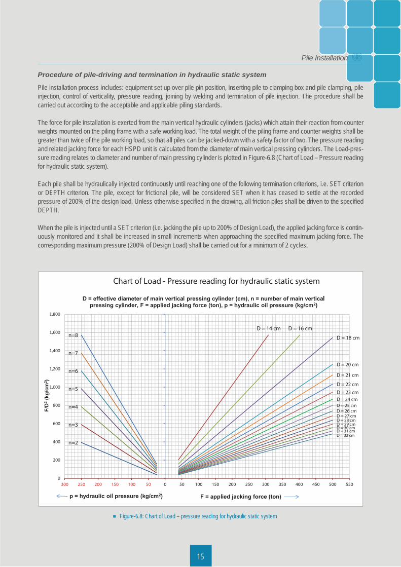
The force for pile installation is exerted from the main vertical hydraulic cylinders (jacks) which attain their reaction from counter weights mounted on the piling frame with a safe working load. The total weight of the piling frame and counter weights shall be greater than twice of the pile working load, so that all piles can be jacked-down with a safety factor of two. The pressure reading and related jacking force for each HSPD unit is calculated from the diameter of main vertical pressing cylinders. The Load-pres-sure reading relates to diameter and number of main pressing cylinder is plotted in Figure-6.8 (Chart of Load – Pressure reading for hydraulic static system). Each pile shall be hydraulically injected continuously until reaching one of the following termination criterions, i.e. SET criterion or DEPTH criterion. The pile, except for frictional pile, will be considered SET when it has ceased to settle at the recorded pressure of 200% of the design load. Unless otherwise specified in the drawing, all friction piles shall be driven to the specified DEPTH.
When the pile is injected until a SET criterion (i.e. jacking the pile up to 200% of Design Load), the applied jacking force is contin-uously monitored and it shall be increased in small increments when approaching the specified maximum jacking force. The corresponding maximum pressure (200% of Design Load) shall be carried out for a minimum of 2 cycles.
15
Figure-6.8: Chart of Load – pressure reading for hydraulic static system
06Pile Installation
l
ll ll l
l l l
ll
An example of Load - Pressure reading from the above provided Chart (Figure-6.8): Type of machine = HSPD-240 with main pressing cylinder = 4 x D18 (n = 4 and D = 18 cm) Assume design load capacity = 100 ton, applied jacking force (F) = 200 ton (assume F = 200% of design load) Use Figure-6.8: Draw a vertical line from point of F = 200 ton to intersect line of D = 18 cm. Draw a horizontal line from this intersection point to line of n = 4, then draw vertical line from this intersection point to intersect the pressure axis (horizontal p-axis). This final intersection point is p = + 196 kg/cm2. The applied jacking force of F = 200 ton for HSPD-240 should be obtained at pressure reading of p = 196 kg/cm2. Since 1 Pascal = 1 N/m and 1 kg = 9.8 N, then 1 kg/cm = 0.102 Mpa -> p = + 196 kg/cm = + 20 Mpa.
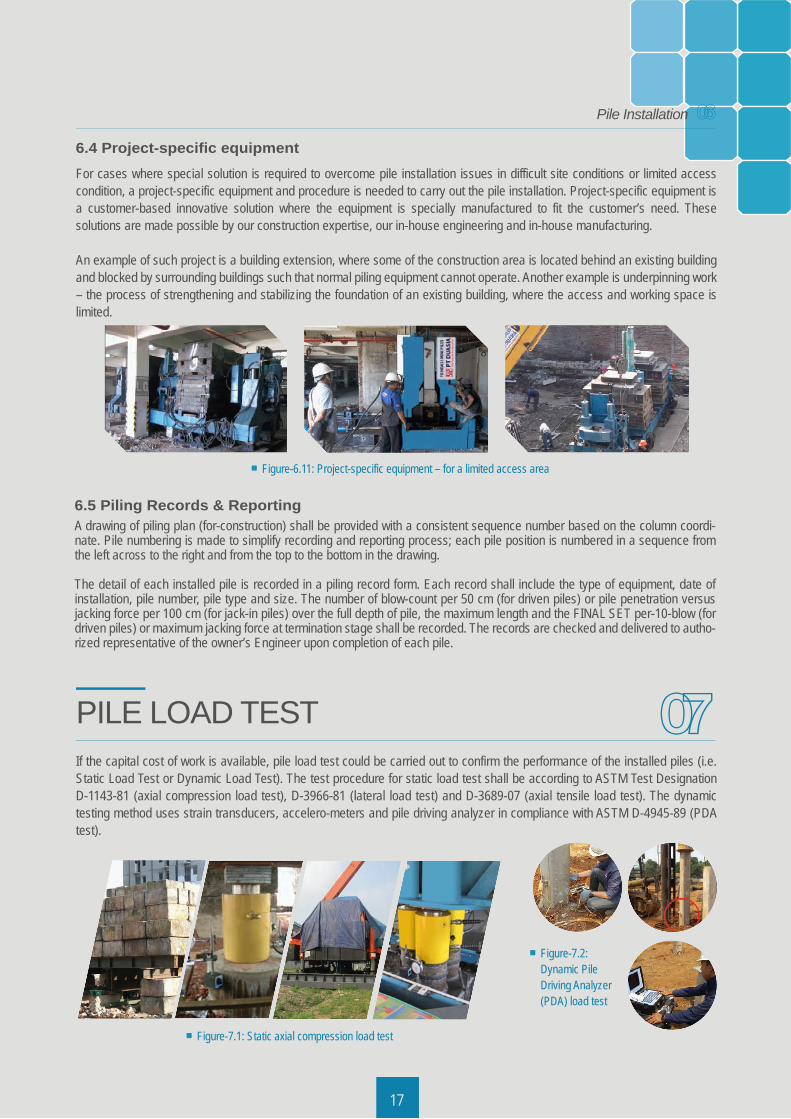
6.3 Joint WeldingWhen the specified depth of bearing layer is greater than the standard length of segmented pile or where pile lengthening is required, the additional pile section can be welded on using steel joint plate with butt-welding to extend the pile to meet penetration requirement. The shield metal arc welding (SMAW) process with AWS E6013, Ø3.2 mm ~ Ø4 mm coated electrode or manual stick electrode process is used to develop a full strength of welded butt joints. A coating treatment is then painted onto the welded butt joint to give additional protection from the possibility of corrosion.
16
Figure-6.10: Joint welding process
Electric arc welding - AWS-E6013
JOINT CONNECTION & WELD
3/16
Concrete pile
butt-weld
steel plate
06Pile Installation
2 2 2
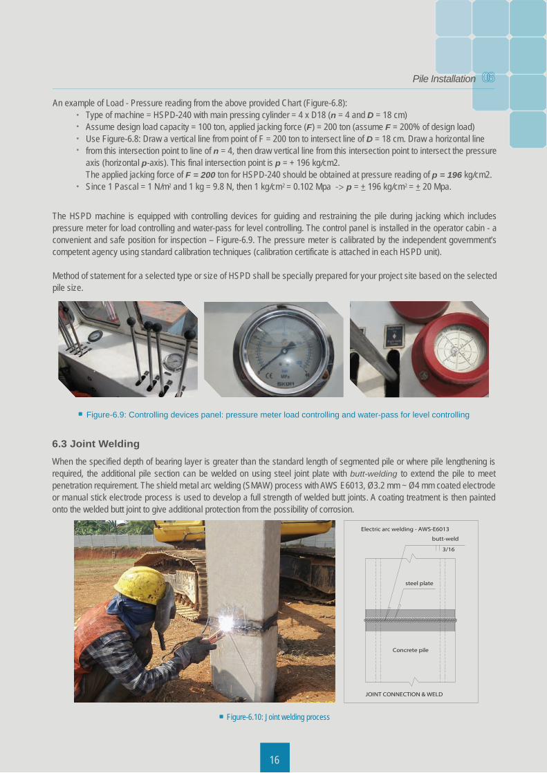
The HSPD machine is equipped with controlling devices for guiding and restraining the pile during jacking which includes pressure meter for load controlling and water-pass for level controlling. The control panel is installed in the operator cabin - a convenient and safe position for inspection – Figure-6.9. The pressure meter is calibrated by the independent government’s competent agency using standard calibration techniques (calibration certificate is attached in each HSPD unit).
Method of statement for a selected type or size of HSPD shall be specially prepared for your project site based on the selected pile size.
Figure-6.9: Controlling devices panel: pressure meter load controlling and water-pass for level controlling
A good understanding of energy per blow is required to determine the appropriate hammer, i.e. whether a hammer of a given weight is capable of driving a specified pile to the required penetration, as well as calculating the expected ultimate resistance of pile that can be achieved. The maximum pile weight recommended to be driven by any selected diesel hammer in relation to the recordable final set and optimum pile capacity can be estimated from the graph in Figure-6.3 to Figure-6.6.
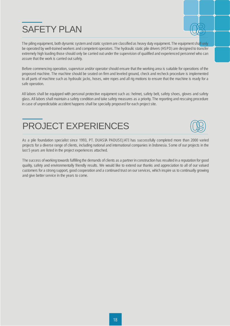
6.4 Project-specific equipmentFor cases where special solution is required to overcome pile installation issues in difficult site conditions or limited access condition, a project-specific equipment and procedure is needed to carry out the pile installation. Project-specific equipment is a customer-based innovative solution where the equipment is specially manufactured to fit the customer’s need. These solutions are made possible by our construction expertise, our in-house engineering and in-house manufacturing.
An example of such project is a building extension, where some of the construction area is located behind an existing building and blocked by surrounding buildings such that normal piling equipment cannot operate. Another example is underpinning work – the process of strengthening and stabilizing the foundation of an existing building, where the access and working space is limited.
Figure-6.11: Project-specific equipment – for a limited access area
17
06Pile Installation
6.5 Piling Records & ReportingA drawing of piling plan (for-construction) shall be provided with a consistent sequence number based on the column coordi-nate. Pile numbering is made to simplify recording and reporting process; each pile position is numbered in a sequence from the left across to the right and from the top to the bottom in the drawing.
The detail of each installed pile is recorded in a piling record form. Each record shall include the type of equipment, date of installation, pile number, pile type and size. The number of blow-count per 50 cm (for driven piles) or pile penetration versus jacking force per 100 cm (for jack-in piles) over the full depth of pile, the maximum length and the FINAL SET per-10-blow (for driven piles) or maximum jacking force at termination stage shall be recorded. The records are checked and delivered to autho-rized representative of the owner’s Engineer upon completion of each pile.
If the capital cost of work is available, pile load test could be carried out to confirm the performance of the installed piles (i.e. Static Load Test or Dynamic Load Test). The test procedure for static load test shall be according to ASTM Test Designation D-1143-81 (axial compression load test), D-3966-81 (lateral load test) and D-3689-07 (axial tensile load test). The dynamic testing method uses strain transducers, accelero-meters and pile driving analyzer in compliance with ASTM D-4945-89 (PDA test).
PILE LOAD TEST
Figure-7.1: Static axial compression load test
07
Figure-7.2: Dynamic Pile Driving Analyzer(PDA) load test
A suitable criterion for pile driving termination, especially for end bearing piles, is an acceptable value of final-set in correlation to the specified pile bearing capacity of pile. Solutions for final-set as termination criterion of pile driving are plotted in Figure-6.3 to Figure-6.6 (Charts of Pile-capacity and Final-set). The charts are obtained based on simplified HILEY dynamic formula **) which relate the weight of pile (Wp), allowable bearing capacity of pile (Pa) and ram stroke (H) to predict final-set for various characteristics of diesel hammers (DongFang or KangDa diesel hammer).
**) The HILEY dynamic formula used in Figure-6.3 to Figure-6.6 is simplified based on the following assumptions: C = elastic compression of helmet, pile head and soil (k1+k2+k3) is simplified with an estimated value of ½”. Ru = ultimate load capacity of pile (just after driving) Pa = allowable bearing capacity of pile is taken as Ru/SF; where SF = 3 n = coefficient of restitution for concrete pile is taken as 0.5.An example of Final-set prediction from the above provided Charts (Figure-6.3 to Figure-6.6): Pile type: SCP-25 (assume the specified allowable bearing capacity Pa = 40 ton) Length of pile = 15 m -> weight of pile Wp = 15 m x 0.15 ton/m = 2.25 ton The selected diesel hammer is DD18 -> Figure-6.5, assume a convenient ram stroke (H) is 120 cm Use Figure-6.5: Draw a vertical line from point of weight of pile = 2.25 ton to intersect line of Pa = 40 ton. Draw a horizontal line from this intersection point to line of H = 120 cm, then draw vertical line from this intersection point to intersect the final-set axis (horizontal s-axis). This final intersection point is s = + 0.27 cm/blow. From Figure-6.5 we obtain (Wp = 2.25 ton, Pa = 40 ton, H = 120 cm) -> Final-set (s) = 0.27 cm/blow Point penetration of the last 10 blows of the selected hammer and pile is 2.7 cm / 10 blows.
18
The piling equipment, both dynamic system and static system are classified as heavy duty equipment. The equipment shall only be operated by well-trained workers and competent operators. The hydraulic static pile drivers (HSPD) are designed to transfer extremely high loading those should only be carried out under the supervision of qualified and experienced personnel who can assure that the work is carried out safely.
Before commencing operation, supervisor and/or operator should ensure that the working area is suitable for operations of the proposed machine. The machine should be seated on firm and leveled ground, check and recheck procedure is implemented to all parts of machine such as hydraulic jacks, hoses, wire ropes and all rig motions to ensure that the machine is ready for a safe operation.
All labors shall be equipped with personal protective equipment such as: helmet, safety belt, safety shoes, gloves and safety glass. All labors shall maintain a safety condition and take safety measures as a priority. The reporting and rescuing procedure in case of unpredictable accident happens shall be specially proposed for each project site.
SAFETY PLAN
As a pile foundation specialist since 1993, PT. DUASIA PADUSEJATI has successfully completed more than 2000 varied projects for a diverse range of clients, including national and international companies in Indonesia. Some of our projects in the last 5 years are listed in the project experiences attached.
The success of working towards fulfilling the demands of clients as a partner in construction has resulted in a reputation for good quality, safety and environmentally friendly results. We would like to extend our thanks and appreciation to all of our valued customers for a strong support, good cooperation and a continued trust on our services, which inspire us to continually growing and give better service in the years to come.
PROJECT EXPERIENCES
08
09

www.duasia.co.idwww.duasiapadusejati.com
PT. DUASIA PADUSEJATIJl. Raya Jatake (Jaha-Jatake) No.99
Pagedangan, Legok, Tangerang - Banten 15820
Phone : +62 21 5977030, 5979447Telkomsel : +62 81 117756 88/89/90HP : +62 81 1154591Email : [email protected] [email protected]


