Embed Size (px)
Citation preview

Fourth American Nuclear Society International Topical Meeting on Nuclear Plant Instrumentation, Controls and Human-Machine Interface Technologies (NPIC&HMIT 2004), Columbus, Ohio, September
2004 THE OASIS BASED QUALIFIED DISPLAY SYSTEM
V. David, C. Aussaguès and S. Louise Technologies and Systems Integration Laboratory
(CEA – Technology Research Directorate) CEA/Saclay, F91191 Gif sur Yvette Cedex, FRANCE
Ph. Hilsenkopf+, B. Ortolo+, C. Hessler*
+FRAMATOME-ANP, FRANCE / *FANP-GmbH I&C DIVISION
AREVA Tower, F92084 Paris la Défense, FRANCE [email protected]
Keywords: safety critical system, display system, real-time, determinism, tools ABSTRACT
OASIS is a real time system software package with integrated development tool chain. It proposes a new rigorous and reliable method to design and implement safety critical applications compound of advanced real-time functionalities. The execution model, based on a time-triggered architecture, is to guarantee responses in specified times using a safety-oriented multitasking execution, and to have predictable and reproducible behaviors. Framatome ANP selected OASIS as system software for the qualified display system (QDS) package which allows developing user-friendly screen-based graphical HMI for safety applications. This package consists of a dedicated rugged off-the-shelf PC-AT board hardware configuration, a set of development tools and a generic system software. This paper introduces the main features of the OASIS model, its system determinism and the produced effort for industrialization. It gives an overview of the QDS design, provides a description of the first implementation of a Teleperm XS TM / QDS configuration and shows some typical displays.
1. INTRODUCTION
The design and implementation of efficient and safety-critical real-time systems still constitute today a true scientific, technical and economical challenge (Stankovic, 1988). The difficulty is to implement, not only critical real-time systems that include more complex functions, but also to have an easier development, including verification and validation (Stankovic, 1990) (Halang, 2004). The new solutions must be as safe as those already existing and be in accordance with international and national standards in the nuclear domain, such as ISO/IEC-880 and RFS (French Fundamental Safety Rules). The OASIS package has been developed by the CEA and Framatome ANP, in co-operation with EDF It proposes rules, methods and tools for the needs of the nuclear power plants domain. The development chain is portable and available for 68040/68060 and IA32/PC-AT targets for a complete version. A simulated version is also available on POSIX targets. OASIS package has been in use in an industrial crane anti-collision
system since February 2002 and has been selected in 2003 by Framatome ANP for the safety classified Qualified Display System QDS.
2. OASIS CONCEPT AND TOOLS
2.1 Fundamental principles
In the OASIS approach, an application is viewed as a static set of communicating agents (real-time tasks) that interact in order to achieve their functionality. An agent is compounded of elementary processing ordered in a sequence according to logical conditions. Each elementary processing of each agent has a temporal window of execution which is automatically deduced from the temporal information contained in the source code’s agent. The execution of elementary processing is time-triggered (TT). The decomposition into agents corresponds exactly to the processing which should be executed in parallel, and their rhythms could be periodic or not, regular or not. OASIS makes the conception easier because it doesn’t introduce constraints on the manner an application will be decomposed into agents. A process and its data are associated and encapsulated. The data are generated by only one producer (the owner agent) but may have several consulting agents. The read operation of a past value of any data is strictly managed so that the communications would be deterministic and therefore independent of the implementation (see 2.3 below). In a time-triggered approach (Kopetz, 1995), the system observes its environment and initiates its processing at predetermined instants. In OASIS, these instants can be viewed as points of the globally synchronized time of the TT system. Each agent of an application has an associated real-time clock where the input and output data are or can be observed. All these clocks are deduced from a unique global real-time clock.
2.2 Tasks management
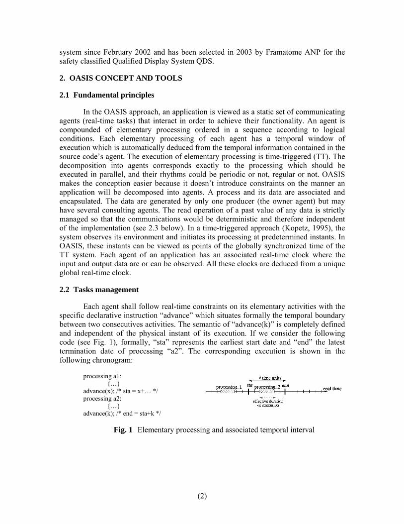
Each agent shall follow real-time constraints on its elementary activities with the specific declarative instruction “advance” which situates formally the temporal boundary between two consecutives activities. The semantic of “advance(k)” is completely defined and independent of the physical instant of its execution. If we consider the following code (see Fig. 1), formally, “sta” represents the earliest start date and “end” the latest termination date of processing “a2”. The corresponding execution is shown in the following chronogram:
processing a1: {…} advance(x); /* sta = x+… */ processing a2: {…} advance(k); /* end = sta+k */
Fig. 1 Elementary processing and associated temporal interval
(2)

We define also the formal duration of the processing a2 as being the value “end”-“sta” in time units. This formal duration is constant and is different from the effective duration. This contributes to ensure at the same time the independence from the target computer’s system, and the absolute predictability of the real-time system.
Tasks management in OASIS takes its roots in multitasking techniques but aims system determinism. Therefore, there is no asynchronism that could have impacts on the results of any OASIS application, even in case of applicative faults. As processing real-time constraints are all known at the design stage, the scheduling of the processing only needs to be led by their start and termination dates. Processing effective durations have no impact on system determinism: the data exchanges are realized at the beginning and at the end of each processing (i.e. at their temporal boundaries) and have a dedicated implementation. The execution is actually a time-triggered one, without external or asynchronous events. Only the real time triggers the whole application.
2.3 Communication mechanisms
There are two modes of communication between agents. The first mode is implicit with temporal variable which corresponds to real-time data flows: past values, available for each agent that deals with them, are stored and updated by the unique writer, the owner agent, at a predetermined temporal rhythm. The system layer is in charge of updating (i.e. copying) the available values of these variables. If we consider a temporal variable X owned by the agent introduced in the previous example, and a second agent that want to access the last value of X (see Fig 2.), then it will observe the past value X(t0)=X(sta). The rationale is quite simple: during processing b1, only the value at the formal start date is observable, and at t0, processing a2 may be not terminated, so the last coherent observable value of X is X(sta).
Fig. 2 Observable values of a temporal variable
The second communication mechanism which is explicit, is the sending of messages. All message attributes (content, recipient id, type, …) of the sending messages are formally checked by the compiler. A visibility date specifies the date after which the message can be observed and read by the recipient. This date allows to give a validity duration to the receiving message. The system also verifies if the recipient consumes the message before it expires, else a specific exception is raised. To achieve determinism, the order of messages induced by the visibility dates is made to be total. For example, if a message M is sent by the second agent with visibility date t1, it could not be observed (and therefore consumed) before the end date, because t1 > sta, see below:
(3)

Fig. 3 Send of message
2.4 Sizing, scheduling and timeliness
Timeliness is verified if and only if all the processing of agents are always executed with a coherent real time behavior. This feature includes the satisfaction of three properties: each processing is executed during its allocated formal duration; no processing starts before its earliest activity date; each processing respects its deadline. By construction, OASIS is a complete solution for the two first points: all the temporal constraints of all agent processing are clearly expressed in the design step. All these constraints are computed on the same global real-time clock. The temporal rhythm of processing, expressed in the design, is used to manage the scheduling. In opposition to most of the current systems, the execution’s asynchronisms do not have any impact on the determinism of OASIS. In the safety domain, each processing must have a bounded duration and an upper bound can be calculated. In OASIS, the knowledge of upper bounds of time execution isn’t used to tune the real-time behavior of the system but to the sizing of the target architecture. That’s why the behavior is unique, unvarying and independent of the implementation and why OASIS is a true formal approach to the design of deterministic and parallel real-time applications (David, 1998) (Chabrol, 2004).
2.5 Chain of development
All the necessary tools have been developed in order to apply the OASIS approach. The chain of code generation is fully operational and automated. In the OASIS approach, a language PsyC allows the developer to express the complete and formal code of an agent where the pure algorithmic parts are written in the ANSI C language. The goal of the PsyC language is to allow a formal description of the elements of the OASIS approach (parallelism, temporal synchronizations, communications) without breaking the algorithm coding rules of the developer. The chain of development is operational since March 2000 and includes:
• the complete compilation of the agents;
• the interface of the agents with the system layer (parameters of calls to the system layer, communication buffers);
• the link edition for each agent, between the agents and with the system layer;
• the generation of static memory tables to enable the protection of the whole application and the run-time (that is the code resulting from the sizing).
(4)

Particular care has been taken for the quality of the tools (size of test cases, modularity of compilation, generation of documentation and execution traces), and to have portable and perennial developments.
2.6 Verification and validation
In order to test an OASIS application, two fundamental aspects have to be taken into account. As an objective for the validation of an application, we can first, seek to take maximum advantages of the static information extracted during compilation to validate the dynamic behavior of the application (via for example the knowledge of all the feasible dynamic behaviors). In a complementary manner, we can seek to execute or simulate the application in order to observe its behavior. If we observe the dynamic behavior, we can dispose or not of the target equipments. Since we have the invariability and singleness of behavior guaranteed by the OASIS approach, it is possible to execute the applications independently of the target machine. Then the obtained results dealing with temporal properties (formal activation dates, message deadlines, etc.) are correct.
2.7 Safety embedded run-time
In order to achieve safety for execution, it is necessary to use all possible mechanisms in a computer system. This has been done in the OASIS system. Indeed, a rigorous spatial segmentation is realized at three levels (micro-kernel, system layer and agents) by using a particular memory segmentation (of the data, the bridge between the context and the executable) based on the two following mechanisms: the privileged mode of processors which are limited only to critical run-time sections; and the MMU which allows to enable a memory protection between agents, system layer and micro-kernel. The kernel and the run-time are segmented and put in place according to a patented process (see below).
The compilation deduced criteria like correct processing chaining or deadline checks are performed by the OASIS run-time environment, thus enabling to accurately ensure that all agents behaviors are nominal and that any faulting activity can not have any incidence on the other. From run-time to execution of the application, all possible mechanisms allowing an early fault detection are implemented, therefore the deterministic behavior of an OASIS application is also ensured when anomalous behavior appears within activities. This also ensures data coherence and copies of messages or data flow between agents. This design guarantees that all the applicative errors, whatever their localization, would have a deterministic impact. The mechanisms that make use of ensuring the fault detection and confinement are included into a patent (David, 2000).
2.8 Current R&D works
The current research works aim at extending the OASIS solution to distributed architectures. Two major objectives are on one hand to make the underlying hardware architecture as transparent as possible for the application designers and on the other hand, to preserve the deterministic property of the OASIS solution.
(5)

3. QDS OVERVIEW
In 2003, Framatome-ANP and CEA carried out a first implementation of the OASIS-based Qualified Display System (QDS). This first implementation allows to demonstrate the feasibility of the safety-classified Qualified Display System and to refine the functional features that such a system must provide. Its main objectives and the whole system architecture are described in these following chapters.
3.1 Objectives
In a typical application, the QDS is used to:
• acquire data transmitted by one or several Teleperm XS TM units,
• process these input data (e.g. for taking into account redundant signals)
• display the elaborated information to users through a project specific provided HMI
• process operator inputs such as setpoints or other parameters.
This equipment requires strong safety features dealing with the detection and confinement of faults. This is achieved by OASIS concepts and methodology supported by system software tools, and by additional hardware self-tests.
The main requirement is to achieve HMI functionalities with high dependability. Real time performances deal with the data storage capacities and rhythms, the response times of the display and the validity of displayed information. Hence, up to few thousands analog or binary values can be recorded each second during 30 minutes or 24 hours. The time between the acquisition of data and its subsequent display on the screen shall not exceed one second and the HMI response times have to be less than 200 milliseconds. All information on a screen must be time consistent. Finally, design tools have to be embedded in an user friendly development environment.
3.2 System architecture and design
The QDS software is organised in two main layers: an applicative one and a generic system one. The OASIS method ensures some important features for the safety: the modularity of the developed software, the temporal and logical determinism of the application execution (see 2.6). The QDS software applicative layer consists of user agents that manage the application displaying policy (e.g. the redundancy management, some graphical item representations, answers to operator requests, …). It is related to functional treatments that have to be done to the acquired data before displaying them. It is also compound of static tables that describe both the HMI screens and the acquired data disposition, in order to allow extensive off-line verification and validation and to avoid intricate HMI behaviour through dynamic creation of objects (see 3.4). The QDS system software layer executes the HMI application and particularly implements the hardware management of the displaying. This layer consists of system agents (called
(6)

“generic”) that manages the main physical devices (keyboard, pointing device, graphic processor, Ethernet chip) and the communication interface with the applicative layer.
The hardware architecture is a standard, widespread and portable one, selected from series equipment for large scale rugged industrial application. The CPU is based on an Intel IA-32 architecture and on a PC-AT board. The target is at least a Pentium III architecture, with DDRAM that could implement hardware error-check-and-correction (ECC) mechanisms, with a graphic processing unit (GPU), Ethernet-based communication devices. OASIS system software ensures all system functions, and the BIOS system is totally removed.
3.3 Software organization
The figure 4 gives the description of the QDS software in terms of OASIS agents and their interfaces.
The software compounds the following agents:
• appliNAg is the applicative agent that implement the functional treatments on the acquired data;
• HMIdisAg performs the screen display management that prepare and display all defined screen pages;
• HMImkAg for the keyboard and pointing devices management;
• netAg for the low-level network management, including Ethernet chip management and protocol implementation (to receive data from the Teleperm XS TM units and to send them specific applicative data and QDS self monitoring results);
• updAg for the high-level network management for building functional dataflows;
• netMUAg for maintenance management;
• selfTestAg for additional hardware self-tests and collection of those performed by agents that manage hardware components.
(7)

There are two kinds of exchanges: data “continuously” or cyclically needed (such as values of information to be displayed) represented by plain lines beginning with a dot, and with their names in italic; and data that are exchanged when they are available (such as HMI actions and commands), represented by plain lines ending with an arrow. Bold-arrowed lines represent the interactions with hardware components.
netMUAg
updAg
appliNAg
selfTestAg
netAg STATUS
ALLDATA
SFRESULTS
DATAtoTXS0
1
0
1
EthernetNetwork
FlashMem.
*P1->24h, P2->30min, P3->last value
Graphic cardKeyboard
HMIdisAgHMImkAg
COMMAND
DISPLAYDATA
0
P1, P2, P3*
1ECHO
ACTION
POSITION 01
OASIS Safety-oriented
Kernel
Pointing dev.
DATAfromTXS
NET_SELFTEST
0
0
MK_SELFTEST
TXS EthernetNetwork
1
1
netMUAgnetMUAg
updAgupdAg
appliNAgappliNAg
selfTestAgselfTestAg
netAgnetAg STATUS
ALLDATA
SFRESULTS
DATAtoTXS0
1
0
1
EthernetNetworkEthernetNetwork
FlashMem.
*P1->24h, P2->30min, P3->last value
Graphic cardKeyboard
HMIdisAgHMImkAg
COMMAND
DISPLAYDATA
0
P1, P2, P3*
1ECHO
ACTION
POSITION 01
OASIS Safety-oriented
Kernel
Pointing dev.
DATAfromTXS
NET_SELFTEST
0
0
MK_SELFTEST
TXS EthernetNetwork
TXS EthernetNetwork
1
1
Fig. 4 System architecture (multi Ethernet port configuration) 3.4 Display principles
HMI screens display is managed by only one agent, HMIdisAg which builds and sends the whole screen memory bitmap to the video memory at one time. This guarantees the coherency of the graphic elements that are displayed in one single screen.
HMI definition is based on high-level graphic objects that have static features (defined once for all, e.g. the position of a bar graph in the screen) and dynamic ones (that can change during the execution, e.g. the level of a bargraph). HMIdisAg finds the graphic items description in two locations: one in C-file(s) that define static parts and the other in the communication interfaces (temporal variables) between the applicative agent that updates cyclically the values of the dynamic parts and HMIdisAg.
(8)

For the preparation of the screen memory bitmap, high-level functions are provided in a dedicated library. These functions take the static and dynamic parts of a high-level item and update in accordance the screen memory bitmap
The displaying of text area, button, curve, bar graph, graphic area, geometric figure (rectangle, circle), graphic symbol is allowed. A graphic area is a bitmap that can move in real time. E.g. the position of a graphic threshold could be defined from a parameter. A geometric figure allows defining circle or rectangle as vector item (dimension, colour). The colour can be modified during the run-time. A graphic symbol is a set of bitmaps, displayed in relation to a variable. So, the QDS can display mimic diagrams, e.g. valves, pumps, thresholds.
The QDS tool allows to define each HMI screen, the application processing and to generate all C files and ΨC files in relation to the application. This tool defines each HMI screen as a static background and a set of complex objects. A complex object is a set of graphic items with a functional purpose, a specific disposition and attributes, and associated processing. The complex objects library includes :
• Analog indicator, with description, value, unit. E.g.: SG2 : 2.00 m
• Logic indicator, with description, value. E.g.: RCV001VP : open
• Bar graph, with title, current value, range, out of range indicator, bar, thresholds
• Curves, with title, current value, unit, range, curve, and time range definition
Bar graph Curves
Cold temperature 1
320
280
290
300
310
308.25 °C
hours-24 -12
0
100
50
75
25
%
0
RCP
0
100
50
75
25
%
Pressurizer level m-1.1 -6 3.8
Cold temperature loop 1 °C305 280 320
Time rangeOrigin
Delta t
Fig. 5 : Sample of complex graphical objects
(9)

3.5 Typical screen
Figures 6 & 7 show some typical HMI that can be developed with the QDS tools.
Primary Data Monitoring
Loop 1 Temperatures
Loop 2 Temperatures
Next
Previous
ScreenList
Screen 2
Steam generator levels Reactor BuildingPressurizer Temperature
QDS_
-1.25e-01
SG1 : m 002.00SG2 : m
75Pz : bar TXS
74Pz : bar TXS
75Pz : bar QDS_
37 °CRB : TXS
TXS35 °CRB : QDS_35 °CRB :
RCP Flow rate : 0
0-30 t (mn)
5
2.5
5.0
7.5
10
-1
flowratem3/h
0
2.5
5.0
7.5
10
m3/h
QDS_
106.0
TXS_
Cold Leg Hot L
200
100
50
150
0
107.0eg
°C °C
200
TXS_
100
150
50
0
105.9
TXS_
Cold Leg
200
100
50
150
0
108.0 °C
TXS_
Hot Leg
200
100
50
150
0
°C
m3/h 7
Fig 6: Typical
monitoring screen
Monitoring and Command
Screen 3
RCV 001MD
TXS
%
TXS
E H TXS
RCV 001BA
TXS
TXS
TXSTXS% 0 - 100 %
TXSStarted - StoppedTXS_ 0 - 10 3/h mm3/h
100.0
Started
7
RCV 001VP :
Time base
gnalsRCV si
t (mn)
%
0
25
50
75
100%
0
25
50
75
100
RCV 001MD :
RCV 001PO :
TXS
RCV 001PO 01VP RCV 0
Stop Start Valid
100
RCV 002VP
03VP
RCV 0
Valid Close Open
Next
Previous
Valid
+ -
Cancel
30 min
10 min
0 5
Raz
TXS
5.2
0
RCV 001BA
m
10
5.0
2.5
7.5
100RCV 0
F Open
losed
01VP%
F C0
75
25
50
100
High
ScreenList
-1-3 0
coc
(10)
Fig 7: Typical ntrol and ommand
HMI

3.6 Qualification work
The QDS is dedicated to safety classified application. It means that all the components (hardware and software) that make it up must be qualified with regard to safety qualification requirements. However, for a specific project, the qualification effort is strongly reduced as a result of the high generic aspect of such a product. The hardware equipment and the QDS system software (including OASIS-kernel and all system agents) must be qualified only once. Then for a specific project, efforts can be concentrated on the applicative agent (appliNAg) and on the complete system. Let us also note that a set of tools allow to reduce this effort by :
• Excluding hand-written source code for all standard graphical applications, by supplying graphical and script language interfaces and automatic C code generation
• Providing means to have a correct and representative execution on the host platform.
4. CONCLUSIONS & PERSPECTIVES
The concepts and methodology presented in this paper ensure the most important safety properties as the data coherency, an unvarying and deterministic real time behavior, and in-depth fault-detecting and fault-confining hardened mechanisms. The absolute determinism is necessary to the pertinence of the tests of any application, and OASIS meets this goal to make easier V&V works to qualify a safety-critical system. This formal approach of real-time design avoids many difficulties and traps encountered with standard multitasking ideas. It allows implementing efficient advanced real-time functionalities without any safety loss, compared to traditional loop-based programming techniques.
The Qualified Display System QDS is the second industrial project which puts to good use the high safety level of the OASIS concept and software package. It ensures that the requirements for safety applications are met without difficulty. Taking some precautions concerning the pre-existing embedded firmware of the hardware target, the QDS software package can be easily ported, and thus facilitates support of the QDS implementation in the very long term, with minimal dependency of the qualification from the selected hardware.
REFERENCES
Stankovic, J.A., 1988. Misconceptions about real-time: a serious problem for next-generation systems. IEEE Computer. 21, 10-19.
Stankovic, J.A., Ramamritham, K., 1990. What is predictability for real-time systems ? Real-Time Systems, Vol. 2, n°4, 247-254.
Kopetz, H., 1995. The time-triggered approach to real-time system design In: Predictability Dependable Computing Systems, Springer-Verlag, pp. 53-78.
(11)
David, V., Delcoigne, J., Leret, E., Ourghanlian, A., Hilsenkopf, Ph., Paris, Ph., 1998. Safety properties ensured by the OASIS model for safety critical real time systems. IFIP-SAFECOMP’98 Conf., Heidelberg, Germany.
David V., Delcoigne J., 2000. Security Method Making Deterministic Real-Time Execution Of Multitasking Applications Of Control And Command Type With Error Confinement. In: Patent CEA/Framatome-ANP WO 02/39277 A1.
Chabrol, D., Vidal-Naquet, G., David, V. et al., 2004. OASIS: A Chain of Development for Safety-Critical Embedded Real-Time Systems. In: 2nd European Congress Embedded Real-Time Systems (ERTS'04), Toulouse, France.
Halang, W.A., 2004. Contemporary research on real-time scheduling considered obsolete. In: Annual Reviews in Control, vol. 28, issue 1, pp. 107-113.
(12)


