Embed Size (px)
Citation preview

Date: 30th June 2021
The RICA Project
Report WP3 – Preliminary Design Considerations

2 THE RICA PROJECT – Preliminary Design Considerations
Contents
INTRODUCTION 5
TECHNOLOGY GAP ANALYSIS FROM FULL STAGE PROPOSAL (FSP) 8
RICA UPRATED SYSTEM 10
3.1 Visual Amenity 10
3.2 Foundations 11
3.3 Towers 12
3.3.1 Tower Family 15
3.3.2 Tower Steelwork modifications 16
3.4 Clearances 19
3.5 Phase conductor offset 22
3.6 Conductors 24
3.6.1 Conductor / bundle choice 24
3.6.2 Line Dynamics 25
3.7 Failure Coordination 26
3.7.1 Structural 26
3.7.2 Insulation Coordination 27
3.8 System Dynamics 27
3.8.1 Vibration control 27
3.8.2 Galloping 28
3.8.3 Conductor attachment Assembly 29
3.9 Work Procedures 31
3.9.1 Health and Safety 32
3.9.2 Logistics and storage 33
3.9.3 Quality assurance 33
3.9.4 Single circuit outages 34
3.9.5 Removing the existing conductors 34
3.9.6 Conductor Stringing 35
3.10 Construction and Maintenance and Disposal of the RICAs 36
3.10.1 Temporary Earthing Techniques 36
3.10.2 Temporary Platform 36
3.10.3 Condition Monitoring 37
3.10.4 Insulator Removal and Replacement 37
3.11 RICA Lifecycle Analysis 37
RICA DESIGN 39
4.1 Insulating Cross-arm Types 40
4.2 Polymeric Tension insulators 43
4.3 Compression insulators 43
4.3.1 Pultruded Core Material Damage limit 44
4.4 Tower Attachment Hardware 48
4.5 RICA ‘Nose Yoke’ Fitting 48
4.5.1 Load Line orientation 49

3 THE RICA PROJECT – Preliminary Design Considerations
4.5.2 Conductor attachment points 51
4.5.3 Nose / Yoke Maintenance Features 52
4.6 Electrical Stress Management 53
4.7 Arcing Hardware Requirements 54
4.8 Materials 54
CONCLUSION 55

4 THE RICA PROJECT – Preliminary Design Considerations
Report Title : Preliminary Design Considerations
Report Status : Version 1.0
Project Reference : Retrofit Insulated Cross-arms (RICA)
Date : 30th June 2021
Document Control
Name Date
Prepared by : David Chambers 30th June 2021
Reviewed by : James Deas 30th June 2021
Approved by : Technical Advisory Group 30th June 2021
Revision History
Date Version Status Comment
v0.1 First draft
v0.2 Second draft
v1.0 Final document

5 THE RICA PROJECT – Preliminary Design Considerations
Introduction
This report is the third of a suite of five work packages to provide insight into the full
range of implications associated with the introduction of Retrofit Insulated Cross-arms
(RICAs) on the 400kV National Grid (NG) Network. Work Packages 1 to 4 deliver
reports covering the following RICA aspects. Report 1 presents an in-depth overview of
RICAs and their service history globally. Report 2 presents a discussion around existing
National Grid Technical Specifications and existing RICA related gaps that will need to
be filled prior to business as usual (BaU) adoption on the NG network. Finally, Report 4
provides and overview of the NG asset design and development process (ADD) and
associated testing that will be required to ensure that RICAs can operate safely and
reliably on the UK ET network. This report (3) presents design related considerations
associated with the introduction of RICA equipment that have been identified by NG.
This knowledge base is based on the completion of feasibility projects looking at
different aspects of RICA technology. The fifth work package is a functional specification
that outlines all RICA specific requirements that are not covered within existing NG
Technical Specifications.
It is proposed to convert existing 275 kV double circuit lines to 400 kV by replacing metal
lattice cross-arms of the tower structures with an alternative configuration. This new
configuration would utilise structural insulated cross-arms in place of the existing steel
work to enable the removal of the existing suspension insulators (Figure 1). Within
National Grid (NG), the composite cross-arms have been named RICAs, standing for
‘Retro-fit Insulating Cross-arms’. The aim of this report is to provide insight into the
existing state of knowledge relating to RICA technology and the associated gaps and
challenges that should be addressed through the process of introducing RICAs as a
Business as Usual (BaU) tool.

6 THE RICA PROJECT – Preliminary Design Considerations
Figure 1 - On the right-hand side of the tower shown, the RICAs provide support and insulation, removing
the need for suspension insulators.
The feasibility of RICAs as a viable tool for voltage uprating has been proved through
several innovation projects run by NG and Scottish and Southern Energy Networks
(SSEN) since 2010. These projects have individually assessed RICA mechanical
performance in exposed high-altitude locations, electrical performance in high salt fog
pollution areas and construction and maintenance viability within a 132 kV network
uprate trial. While these trials were pivotal in demonstrating the feasibility of the concept,
they have not been sufficient to validate the business case and finalise the full range of
technical solutions that would be necessary to integrate RICAs as a BaU tool. They
have, however, provided a wealth of design considerations and questions to be
resolved, and these are considered within this report.
RICAs are the enabling technology necessary to achieve voltage up-rate on existing
towers. However, their introduction onto an existing tower carries wide-ranging
implications throughout the new product’s lifecycle. These implications have been
defined as Technology ‘Gaps’ in the context of the RICA project. This report identifies
these gaps and provides background information to support activities to close the gaps
during the NG RICA NIC project. This report therefore provides a starting point for the
innovation supplier who will lead the development phase of the project and reviews the
existing State of the Art (SoA).
Following a review of the Technology Gaps in Section 3, this report has been structured
into two major sections as follows:
4.1m Suspension insulators required for 400kV routes
Horizontal RICAs raise conductors and prevent swing towards the tower
Close up view of RICA

7 THE RICA PROJECT – Preliminary Design Considerations
1. System: Section 4 considers system requirements and RICAs that need to be
installed on existing 275kV routes. This section addresses all aspects of their
installation, structural impact on the existing towers and foundations, operation
and maintenance procedures and lifecycle analysis. Effectively it assumes the
RICA technology is established and seeks to ensure that it can be safely,
effectively, and efficiently installed on the network.
2. RICA Design: Section 5 considers RICA assemblies as a standalone unit. The
RICAs fall into a novel space in network engineering which lies somewhere
between the tower design, and insulator design. They form structures that need
to coordinate the mechanical and electrical loads from the conductors to the
tower. This section addresses remaining questions that will be asked relating to
the application of the RICAs onto the tower. RICAs are formed from a range of
components. In particular, the horizontal compression insulators are not currently
used on the UK OHL network, and so the requirements for validation testing are
discussed. RICAs also comprise of multiple metallic hardware fittings at the high
voltage end, and so electrical stress management around the insulators also
needs careful assessment.
RICAs are formed from a range of components. In particular, the horizontal
compression insulators are not currently used on the UK OHL network, and so the
requirements for validation testing are discussed. RICAs also comprise of multiple
metallic hardware fittings convening at the high voltage end, and so electrical stress
management within the insulator assembly also needs careful assessment.
In this document, key aspects and learning points are addressed in detail for illustration
and to impart as much prior know how as possible to stakeholders. Illustrations are given
to highlight previous experience, not to prescribe solutions. As such innovation is
welcomed and further considerations are expected to arise throughout the duration of
project RICA.

8 THE RICA PROJECT – Preliminary Design Considerations
Technology Gap Analysis from Full Stage Proposal
(FSP)
Several technology gaps were identified during preparation of the Full Stage Proposal
(Appendix V of the FSP submission) for the NIC application. These are introduced at a
cursory level in this section, and more detail is provided within Sections 4 and 5 of this
report.
1. Mechanical design – Understanding of the conflicts in established standards and
new guidance documents are needed. There is also a need to investigate an appropriate
ICA form that suits different applications and dynamic system performance
requirements, for example: pivoted RICA vee vs. rigid-fixed RICA. Specifically, the drive
to maximise line rating will lead to increased tower loading and solutions to manage the
increase in mechanical forces through the towers need to be investigated. Examples
could include the use of mechanical fuses of limited slip conductor shoes.
2. Tower modifications – As per the mechanical design point above, some towers may
be difficult to reinforce to achieve a minimum required rating increase. Alternative tower
strengthening methodologies / procedures should be investigated prior to elimination of
these towers as an option for voltage up-rating. Opportunities exist to design new anchor
points for access and temporary lifting equipment and platforms, and to design
modifications for condition monitoring stations to collect whole-life performance data for
RICA (subject to benefit case justification).
3. Electrical design – Development of conductor specifications for optimal system
performance is needed. This includes identification of any dynamic related clearance
issues from conductor galloping or similar, any electrical noise implications of RICA
towers, and review of electrical tracking / insulator creepage distance requirements.
Consideration needs to be given to the electrical clearance at tension\angle towers,
which don’t benefit from removal of suspension insulators. This consideration is valid for
both ground and phase to tower clearances.
4. RICA hardware – Maintenance activities might be supported with new design
features built into the towers and RICAs. Consideration is also required of how
conductor jumpers will be managed at angle and strain tower locations (if RICAs are

9 THE RICA PROJECT – Preliminary Design Considerations
used for these structures), and how the design of hardware meets structural and visual
amenity requirements.
5. Health and Safety – All tower climbing must be done safely in consideration of the
new insulator proximity to the tower body. Safe climbing and working practices under
single-circuit outage conditions with RICAs must be established, including what safe
earthing strategies look like.
6. Lightning protection – Assessment of the impact of the phase conductor positions
on lightning strike performance is needed. Depending on the level of protection required,
mitigation through raising the earth wire or multiple shield wires might be considered.
7. Installation methods – Understanding of the work that can be done energised (i.e.,
while observing electrical safety clearances) vs. work that requires outages is required.
Minimising outage requirements is desirable, perhaps by development of temporary
support structures. Load cases are required to ensure there is no risk of cascade failure
from tower or RICA overloading during conductor installation etc.
8. Operation and maintenance – Post installation visual inspection checks, access and
egress solutions, and hardware replacement methodologies etc. are needed.
9. Lifecycle analysis – Calculations are required for embedded CO2 for different
insulator technologies. A comparison between technologies is needed for predicted life,
embedded CO2, reliability, recycling options, condition monitoring, etc.

10 THE RICA PROJECT – Preliminary Design Considerations
RICA Uprated System
The system comprises the main elements of the OHL transmission system, including all
physical, procedural, and operational aspects of the line. System issues are listed below
with a brief introduction into the implications associated with a voltage uprate achieved
by use of RICA. These include towers, cross-arms and conductors, and the design
impact on installation, maintenance processes and the environment.
A key driver of this technology is that RICAs enable reduced planning burden as they
increase line rating with optimal visual amenity. However, it may be necessary to slightly
increase the overall tower dimensions to maintain existing shielding angles as the phase
conductors are raised to cross-arm height. A primary environmental consideration
associated with the RICA system design will be achieving acceptable audible noise
levels with a conductor (bundle) that does not impart overly onerous loads on the towers.
Additionally, the electromagnetic fields produced by the overhead line must be managed
to acceptable levels.
RICAs are designed to increase the voltage of towers that have been sighted for 275 kV
operation. This means that in some cases, the RICAs may be too close to existing
structures (e.g., buildings) to allow safe 400 kV operation, have electromagnetic fields
within acceptable levels or result in unacceptable audible noise disruption. Similar
scenarios occur in the event of line crossings, where the higher voltage could result in
clearance infringements. Aspects such as this must be considered on a case-by-case
basis.
3.1 Visual Amenity
Discussions have been held with internal NG stakeholders responsible for planning of
new assets on the National Grid ET network. Advice was that the uprating of existing
structures will always be preferable to building new lines, however there is no definitive
approach to evaluating the impact of given solutions on the planning process. The
consents process for any given network reinforcement scheme will be determined on a
case-by-case basis, dependent on local factors such as existing consents (e.g., 275kV
or 400kV ready) and landowner wayleave access agreements.

11 THE RICA PROJECT – Preliminary Design Considerations
The final RICA solution will vary by tower type, and the following principles should be
observed for all tower alteration options.
1. If height increase is needed, an increase tower height is allowable up to 10% of
the tallest standard structure on a given circuit (ie, not including special structures
such as river crossings).
2. ICAs can occupy space that would have been allowed for suspension insulator
swing on traditional suspension structures.
3. If items 1 and 2 are not achievable the requirement for further footprint increases
will be highlighted to the RICA project manager with an explanation for why the
increased distances are needed.
4. Extent of refurbishment. Tower strengthening will ideally be constrained to
replacement of existing non-primary bars with larger sections. This may not be
sufficient however, for example where leg members need strengthening, or if an
external superstructure is deemed the most practical solution to structurally
reinforce the tower. In all cases, the introduction of additional members should
as-close-as-possible, blend into the existing structure.
5. Alternative RICA geometric arrangements to the existing steel Cross-arms can
be investigated to optimise the solution. These may include varying the angles
of the component insulators or utilizing pivoting RICAs.
3.2 Foundations
Solutions exist for uprating foundation capacity as described in TS3.04.15.
Due to the need for larger conductors, increasing line voltage will almost certainly impart
an increased physical load on the footings. For the RICA project, new foundation
designs should be developed based on the finalised conductor selection, however this
will be on the assumption that the existing footings are in as-built condition and
according to current standard requirements.
Should foundation upgrades be needed to enable the preferred tower capable conductor
solutions, then commentary will be needed into the technical and commercial feasibility
of the works.
In practice, the concrete foundations in the towers intended for uprating may be
deteriorated or not have poured to the required standards. This may introduce further

12 THE RICA PROJECT – Preliminary Design Considerations
implications on the suitability of the existing footings to be employed, however this will
be considered on a route-by-route basis following completion of the RICA project.
3.3 Towers
Three tower types operate on the NG UK network at 275 kV. These are the L3 and L66
double circuit structures, and the L34, which is a horizontal single circuit structure.
Because the towers were designed to different mechanical design criteria and with
different lattice arrangements, the towers will each require individual solutions for
strengthening and adaptation for mounting the RICAs. This should be completed for the
new conductors in accordance with the mechanical loading design criteria as defined in
section 3.6 of the relevant type-specific design transmission plan standards (TPS range
of documents).
In addition to supporting the RICAs to enable the requisite ground clearance increase,
the existing towers will need to provide sufficient phase-to-tower clearances and phase-
to-phase clearances that ensure that conductor clashing or flashover does not occur
during galloping events.
The towers to be uprated will need to achieve an appropriate ‘equivalent age’ to ensure
that the uprated route will have a sufficient remaining life to satisfy investment
requirements. The primary causes of failure of the tower, as defined within TGN(AR)
004 issue 7, are corrosion, ground movement and third-party damage. In practice, these
issues will be investigated on a route-basis as determined by network planning
requirements during the RICA roll out phase which follows the current RICA project.
Tower condition assessment is therefore out of the scope of the existing project.
However, certain questions should be reviewed within the project which will help inform
the investment case and maintenance of the uprated assets:
• What minimum grade should all towers on the route be prior to installation of
RICAs?
• What end-of-life modifier is applied to a RICA uprated tower?
• When structures are re-lifed, what is the extended period that they are expected to achieve prior to re-evaluation?
Figure 2, Figure 3, and

13 THE RICA PROJECT – Preliminary Design Considerations
Figure 4 below provide additional detail on the dimensions for the towers concerned. The use of RICAs reduces blowout so the sideways (swing) movement of suspension insulators no longer needs to be considered. This effectively reduces the maximum width taken by the structures in their right-of-way. This is likely to be an important facilitator in achieving the necessary insulation levels in the RICA insulators.
Figure 2 - Schematics of L3 towers. All dimensions in m. From TGN166.
Existing Structure Up-rated Structure

14 THE RICA PROJECT – Preliminary Design Considerations
Figure 3 - Schematics of L66 towers. All dimensions in m. From TGN166.
Figure 4 - Schematics of L34 towers. All dimensions in m. From TGN166.
Existing Structure Up-rated Structure
Existing Structure Up-rated Structure

15 THE RICA PROJECT – Preliminary Design Considerations
3.3.1 Tower Family
RICA voltage up-rate is achieved by the elimination of the suspension insulator on
275kV suspension structures which enables the line height to be increased by 2.5m,
while simultaneously increasing the insulator length to around 4.1m as required for
400kV electrical coordination. It should be noted that this capability is only possible for
suspension structures, however, it is essential to have a solution for the full family of
tower structures in order to enable voltage up-rate from 275 to 400kV.
The fundamental requirement of a RICA uprated line is that it must provide a minimum
increase of 0.7m1 to the ground clearance over the full route (further increases may be
required to manage issues associated with electromagnetic fields). Solutions will also
be required for spans involving tension and angle structures which do not benefit wholly
or partially from a clearance gain from the removal of vertical insulator strings.
The ability for unmodified tension and angle structure to achieve the required voltage
up-rate will rely on a combination of topological factors and spans to ensure adequate
clearances. If these features are not available to achieve the minimum 0.7m conductor
clearance increase, then tower modifications, or potentially new structures will be
needed.
Further to the ground clearance height increase, it is also necessary to consider the
phase to earth clearances of the conductors to angle structures (see Figure 5Figure 6).
Figure 5 – Tower Clearance Schematic
______________________________________________________ 1 ENATS 43-8 details a 0.7m clearance increase in all scenarios when moving from 275kV to 400kV

16 THE RICA PROJECT – Preliminary Design Considerations
Figure 6 – Plan View of Angle Tower
3.3.2 Tower Steelwork modifications
As with the foundations, it is unlikely that the original towers will be able to withstand the
increased loading from 400 kV operation. Tower strengthening will be achieved through
replacement of the existing steel bars on the tower. A judgement will be required relating
to what level of bar replacement is practical while still achieving commercial viability of
the RICA solution when compared to other solutions such as a new compact line, or an
underground cable option.
Replacing the conductor as part of a voltage uprate scheme will typically cause a
consequent increase in applied loads to the tower. Towers rarely have spare capacity
for such an increase in applied loads, therefore modifications will be required to
strengthen the tower. One technique that can be used to achieve this is to allow a level
of bar member replacement with larger sections to strengthen the towers. The
extensiveness and complexity of these bar replacements will be a careful balance of the
value of the future line capacity and the cost and time associated with making the
changes. Novel methods to manage the maximum mechanical load transmitted into the
towers can also be considered to achieve optimum OHL load ratings.
Previous work has shown that in some cases it is feasible to increase the capacity of
tower legs by adding ‘doubler’ members. Unlike with leg members, it is possible to
replace diagonal and redundant members individually with those of larger section or
higher-grade steel, rather than by adding doublers. If this approach were to be pursued,

17 THE RICA PROJECT – Preliminary Design Considerations
the members which need to be removed from the tower for replacement should be
considered.
Furthermore, some level of tower steelwork modification may be needed to enable
attachment of the RICAs to ensure the necessary electrical safety clearances and
maintenance points are available.
Requirements associated with the fabrication and erection of tower steelwork are
addressed within NG TS 3.04.16.
The flow chart overleaf provides a conceptual framework for optimising the possible load
rating for each tower variant (Figure 7) to provide a structural solution for a 275kV to
400kV up-rate. The adoption of this high level, iterative process will require the following
technical provisions:
• A range of PLS CADD outputs using different conductor systems to
demonstrate the maximum load rating potential for each tower type.
• Development of uprated load cases for each tower type, based on existing line
span data. i.e., worst load case for all L3 towers
• Commentary should be provided into the extent of bar replacement for each
conductor option. Recommendations surrounding the practical feasibility of
making the bar replacement will be required to inform a final commercial viability
decision.
Note. This process does not consider the cost of making such an upgrade, but will provide the
necessary technical background information to support the investment case and future
commercial decision making.

18 THE RICA PROJECT – Preliminary Design Considerations
Figure 7 – Steelwork modifications flow chart
Existing suspension towers achieve load and environmental
requirements
Apply Conductor loads to remaining tower family
structures
Yes
1. No
Identify reduced conductor bundle for
reduced structural loads
RICAs attached to existing tower positions
achieve functional specification
requirements on tower family
RICA solutions for full tower family meet
functional specification requirements
Alternative RICA configurations achieve
functional spec requirements
275kV – 400kV up-rate solution for full tower
family to meet functional specification requirements
Identify alternative for non-RICA tower
structures
Extensive or novel strengthening solutions, or load control measures, achieve load
requirements
Re-evaluate RICA concept feasibility and consolidate learnings
for a future project (e.g. new compact
lines solution)
No
2. No – Min. viable conductor identified
Yes
Generate initial loadcase for preferred 400kV conductor
bundle
No
Yes
Yes No
Start / finish Process
Decision
Process
Close project RICA and return remaining funds to
taxpayer
Flow Chart Legend

19 THE RICA PROJECT – Preliminary Design Considerations
Note, in the evaluation above, the minimum viable conductor bundle is based on
electrical analysis to ensure an effective voltage up-rate to 400kV. This will involve an
iterative assessment of several issues. Is the noise level acceptable? Then the required
sag-tension must be assessed to ensure that minimum clearances can be achieved,
and electromagnetic fields managed. Finally, a view is required on what level of current
can be passed down the line – a lower tension may be good mechanically but will restrict
amps. A line at higher voltage, with limited current capacity may not deliver sufficient
boundary upgrade requirements.
3.4 Clearances
The positioning of conductors must deliver the required phase to ground and phase to
phase electrical clearances both at the tower and at mid-span where the likely
movement of conductors is considered. BS EN 50341-1 details a methodology to
calculate the values of electrical clearances both in steady-state and under impulse
conditions.
The methodology described in Annex E yields the required electrical clearances for use
at 400 kV. Resulting clearances are listed in Table 1. These are derived from the gap
factors given in Table 3 for an altitude of 400m and a deviation factor of 1.05. As an
example, the table shows the phase to ground switching impulse clearance increases
from 2.30m to 3.16m for the internal tower-conductor type of gap.
Table 1 – Comparison of Voltages and Resulting Electrical Clearances for use at 275kV and 400kV
275kV System 400kV System
AC Highest System Voltage (kV RMS) 300 420
Switching Impulse Voltage (kV) 850 1050
Phase-Phase Switching Impulse Voltage (kV) 1275 1575
Lightning Impulse Level (kV) 1050 1425
20 THE RICA PROJECT – Preliminary Design Considerations
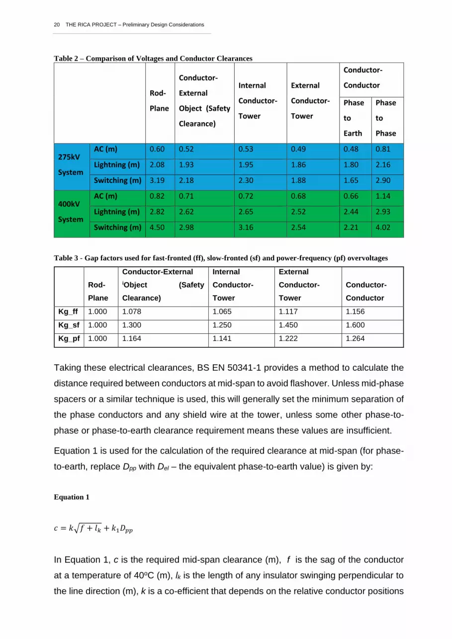
Table 2 – Comparison of Voltages and Conductor Clearances
Rod-
Plane
Conductor-
External
Object (Safety
Clearance)
Internal
Conductor-
Tower
External
Conductor-
Tower
Conductor-
Conductor
Phase
to
Earth
Phase
to
Phase
275kV
System
AC (m) 0.60 0.52 0.53 0.49 0.48 0.81
Lightning (m) 2.08 1.93 1.95 1.86 1.80 2.16
Switching (m) 3.19 2.18 2.30 1.88 1.65 2.90
400kV
System
AC (m) 0.82 0.71 0.72 0.68 0.66 1.14
Lightning (m) 2.82 2.62 2.65 2.52 2.44 2.93
Switching (m) 4.50 2.98 3.16 2.54 2.21 4.02
Table 3 - Gap factors used for fast-fronted (ff), slow-fronted (sf) and power-frequency (pf) overvoltages
Rod-
Plane
Conductor-External
iObject (Safety
Clearance)
Internal
Conductor-
Tower
External
Conductor-
Tower
Conductor-
Conductor
Kg_ff 1.000 1.078 1.065 1.117 1.156
Kg_sf 1.000 1.300 1.250 1.450 1.600
Kg_pf 1.000 1.164 1.141 1.222 1.264
Taking these electrical clearances, BS EN 50341-1 provides a method to calculate the
distance required between conductors at mid-span to avoid flashover. Unless mid-phase
spacers or a similar technique is used, this will generally set the minimum separation of
the phase conductors and any shield wire at the tower, unless some other phase-to-
phase or phase-to-earth clearance requirement means these values are insufficient.
Equation 1 is used for the calculation of the required clearance at mid-span (for phase-
to-earth, replace Dpp with Del – the equivalent phase-to-earth value) is given by:
Equation 1
𝑐 = 𝑘√𝑓 + 𝑙𝑘 + 𝑘1𝐷𝑝𝑝
In Equation 1, c is the required mid-span clearance (m), f is the sag of the conductor
at a temperature of 40oC (m), lk is the length of any insulator swinging perpendicular to
the line direction (m), k is a co-efficient that depends on the relative conductor positions

21 THE RICA PROJECT – Preliminary Design Considerations
as defined in Table F of Annex F and k1 is a value provided in project works information.
Dpp is the required phase-to-phase clearance (m) and can be substituted for the phase-
to-earth clearance when calculated the required phase-to-earth spacing.
In this case, presented as an example, the following have been assumed:
• Sag (f): For the Curlew conductor given a stringing tension of 36.2 kN at 15oC, a
mass of 1979 kg/km, a coefficient of thermal expansion of 1.9 x 10⁻⁵K-1 and an
operating temperature of 40oC, the calculated sag for a span of 300 m is 7.2 m. For
a 500m span this increases to 18.0 m.
• Insulator length (lk): Whilst there is no suspension insulator in the case of a RICA,
this has been set to 0.2 m given that fixed attachment points from structural
composite members will still require conductor fittings, reducing ground clearance.
The 0.2 m represents the conductor fitting length.
• Conductor position factor (k): For phase conductors, this is given as 0.85 on the
basis of having conductor arrangements at the tower that are largely in the vertical
plane (i.e. 0 to 30o). This is valid for wind speeds that do not cause a swing angle
exceeding 65o. For the phase / shield wire system this has been taken as 0.70 on
the basis of a shielding angle in the order of 36o.
Considering Equation 1, the clearance values given in Table 3 (conductor-conductor
spacings being based on phase-to-phase voltages) and assuming k1=0.75, the required
spacing between conductors can be determined as shown in Figure 8. The figure
accounts for the minimum required spacing between conductors, Dpp.

22 THE RICA PROJECT – Preliminary Design Considerations
Figure 8 – Determination of spacing between conductors
3.5 Phase conductor offset
Vertical and horizontal offsets are included on some tower specifications, e.g. L6, and
particularly on more recently designed towers. These offsets have been introduced to
refine certain aspects of system performance, including:
1. Prevent ice shedding from falling on lower conductors
2. Maintain minimum mid-span clearances during abnormal events such as
galloping
3. Reduce the probability of conductor clashing during abnormal events such as
galloping
4. Reduce the possibility of upper conductors contacting lower conductors in the
event of a broken wire or shackle failure
The use of ellipse simulations (a feature available in PLS CAD) can be used to evaluate
the potential for conductor phase clashing during galloping or other extreme climatic
occurrences. This concept is illustrated schematically in Figure 9 below:

23 THE RICA PROJECT – Preliminary Design Considerations
Figure 9 – Galloping Ellipses Illustration based on L3 Tower
Horizontal offsets are not present in either of the twin circuit 275 kV towers, and their
introduction will provide an opportunity to increase phase separations under upset
conditions such as galloping, should they be insufficient for 400 kV operation. The
phase spacings of the 275 kV towers, compared to a 400 kV L2 structure are shown in
Table 4 below. To qualitatively identify the likelihood that the existing phase separations
will be sufficient, the maximum single span length for each tower has been included.
Table 4 – Phase Spacings of the existing 275kV towers, compared to a 400kV L2 structure
Tower Nominal Voltage Vertical phase
separation
Max. single span
length
L2 400 kV 7.85 m TBC
L3 275 kV 6.10 m 537 m
L66 275 kV 7.16 m 457 m
As well as weighing up the benefit of an offset on the suspension structures, it is a
consideration that the introduction of a horizontal offset on the central phase will
need to be reflected in modifications to angle structures.

24 THE RICA PROJECT – Preliminary Design Considerations
3.6 Conductors
3.6.1 Conductor / bundle choice
The choice of conductor and bundle is a critical element in the RICA uprate as a
compromise is required to balance the often-confounding conductor factors or conductor
diameter, material type, geometry, and bundle size. For example, increasing conductor
diameter or the number of conductors in a bundle, both reduces audible noise and
increases line rating / decreases line impedance; however, these benefits are balanced
against increasing loads imparted onto the tower. The optimum selection will be that
which achieves the greatest possible line rating with an acceptable noise level, while
minimising the necessary strengthening modifications to the tower. This compromise
will be achieved through iterative load case development and design processes with
cooperation from both asset management and system planning teams.
For each of the 275 kV towers there may be a different conductor configuration required
to enable the uprate. The use of ACCC conductors should be considered to keep weight
down to a minimum.
The different impacts of the conductor properties have been summarised in the info-
graphic shown in Figure 10.
Figure 10 - Noise factors schematic illustrating the different aspects of the conductor properties on acoustic
noise and mechanical load.

25 THE RICA PROJECT – Preliminary Design Considerations
The heaviest conductors installed on the existing tower structures are as shown below.
L3: 1 x 700mm2 AAAC (Araucaria) = 2266 kg/km
L34: 2 x 175mm6 ACSR (Lynx) = 2 x 842 = 1684 kg/km
L66: 2 x 300mm2 AAAC (Upas) = 2 x 997 = 1994 kg/km
3.6.2 Line Dynamics
Network operators have experience operating lines primarily comprising of steel Cross-
arms with suspension insulators. Technical specifications mandate the use of dampers
attached to the conductors which are intended to minimise vibrations and extreme cases
such as galloping occurring on the line which can cause catastrophic damage over time.
The dynamic performance of the line will need to be fully understood for each RICA
variant. RICAs impart different mechanical constraints on the system which will have an
impact on the harmonic profile that affects both conductor and tower behaviour.
The possible dynamic load transfer route for different insulator types is shown below in
Figure 11. It’s not currently known if the different RICA variants will naturally improve or
exacerbate dynamic performance and this should be considered as part of the RICA
project.
Figure 11 – Possible Dynamic Load Transfer Route for Different Insulator Types
This topic is discussed in more detail in section 3.8.
Large transverse movement possible
Small Transverse movement possible

26 THE RICA PROJECT – Preliminary Design Considerations
3.7 Failure Coordination
All components must be developed to ensure that failures cannot occur at loads below
the ultimate structural ratings of the line. Typically, this will be on components towards
the extremity of the structure, however, RICAs introduce an increased level of
mechanical complexity and so a full understanding of the different failure mechanisms
will be required.
Failure coordination is the process by which failures are managed to ensure that in the
event of occurrences that are outside the ultimate operational design window, the
systems fails in a way that enables the fastest possible return to service. In these events,
failures can be used as a method of alleviating mechanical or electrical stress on
adjacent components to prevent more significant damage from occurring on the
network. This will include understanding preferable failure modes and ensuring that
failures cannot result in knock-on damage to the main tower structures. The WP2 report
on standards describes that this is dealt with in, Appendix A of the BS 50341-1. It
highlights the need to include low reliability components in a design that will be the first
points of failure, typically being suspension supports, to manage the loads on other parts
of the overhead line and prevent cascading failures.
More detail on this is provided in the following sub-sections.
3.7.1 Structural
RICAs combine both electrical needs of the insulation system and structural functionality
required of the tower. To avoid material wastage by over-engineering, it is important to
correctly identify preferred failure sequences and to set component overload factors
accordingly. Additionally, once a component has failed, it is then necessary to identify
any subsequent implications of that failure that may exacerbate the level of damage in
the overall system. For example, in the event of a tension insulator failure, a rigid
connection between the compression insulator(s) and the tower would result in
excessive bending imparted onto the tower steelwork. This would result in damage to
the lattice structure that would prohibit rapid re-instatement of the RICA by re-
attachment of a new tension insulator. For this reason, it is recommended that a double
articulated attachment is specified between the compression insulators and the tower
(Figure 12).
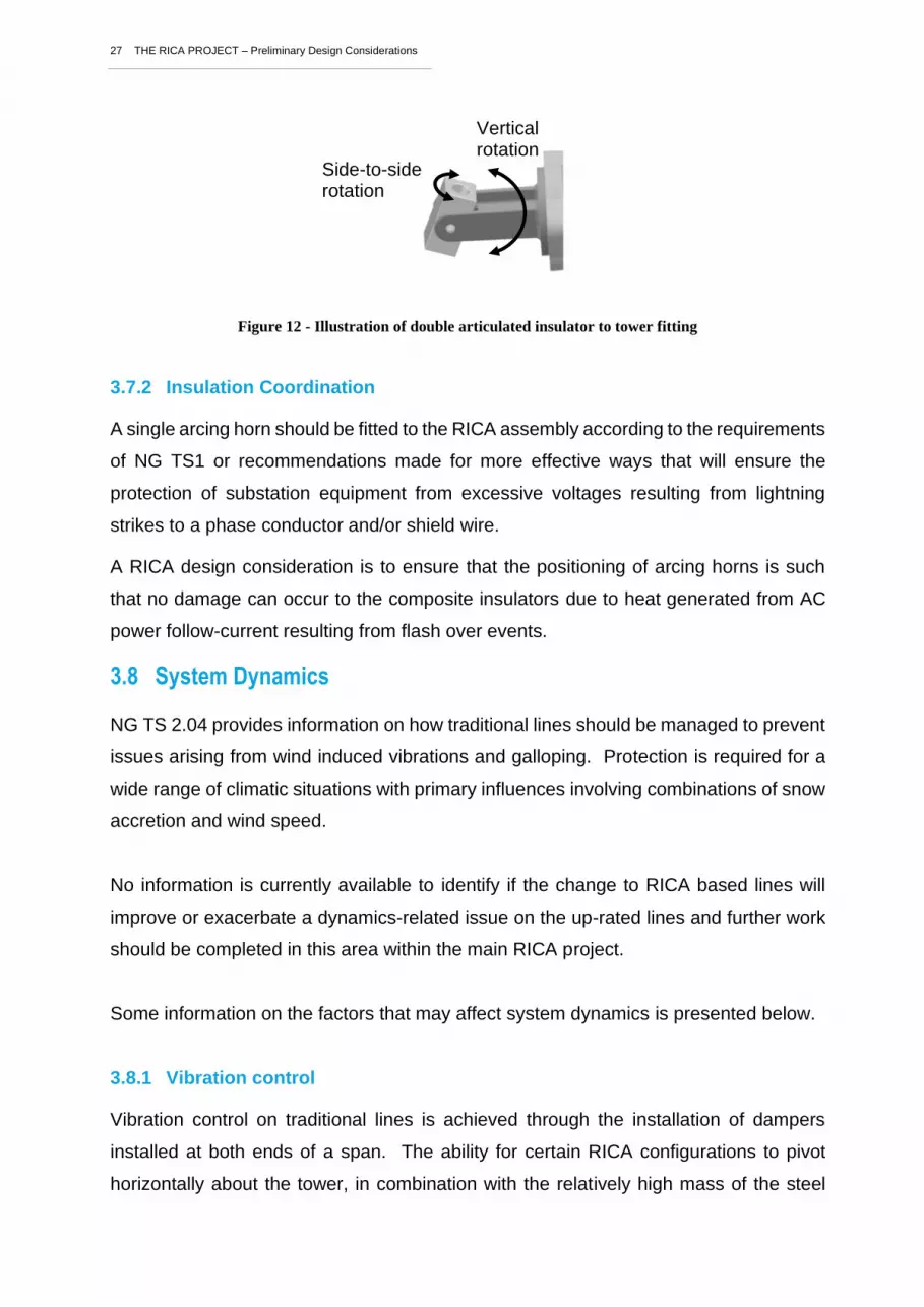
27 THE RICA PROJECT – Preliminary Design Considerations
Figure 12 - Illustration of double articulated insulator to tower fitting
3.7.2 Insulation Coordination
A single arcing horn should be fitted to the RICA assembly according to the requirements
of NG TS1 or recommendations made for more effective ways that will ensure the
protection of substation equipment from excessive voltages resulting from lightning
strikes to a phase conductor and/or shield wire.
A RICA design consideration is to ensure that the positioning of arcing horns is such
that no damage can occur to the composite insulators due to heat generated from AC
power follow-current resulting from flash over events.
3.8 System Dynamics
NG TS 2.04 provides information on how traditional lines should be managed to prevent
issues arising from wind induced vibrations and galloping. Protection is required for a
wide range of climatic situations with primary influences involving combinations of snow
accretion and wind speed.
No information is currently available to identify if the change to RICA based lines will
improve or exacerbate a dynamics-related issue on the up-rated lines and further work
should be completed in this area within the main RICA project.
Some information on the factors that may affect system dynamics is presented below.
3.8.1 Vibration control
Vibration control on traditional lines is achieved through the installation of dampers
installed at both ends of a span. The ability for certain RICA configurations to pivot
horizontally about the tower, in combination with the relatively high mass of the steel
Side-to-side rotation
Vertical rotation

28 THE RICA PROJECT – Preliminary Design Considerations
nose connection may alleviate the requirement for dampers. This would enable cost
saving and the need to access the conductor adjacent to each RICA, which currently
presents operational challenges.
No information is available on the ability for RICAs to reduce the requirement for line
dampers, but this should be considered within the main RICA project.
3.8.2 Galloping
Galloping is a vibration effect that arises in the presence of ice accretion on conductors.
It is a not a forced condition, but a self-excited phenomenon occurring in both steady
and turbulent winds. Bundled conductors, are particularly susceptible to aeroelastic
instability because their natural frequency in vertical, horizontal and torsional motion
tend to be very close together. For more information relating to the galloping
mechanism, including the impact of different types of conductor bundle, please refer to
CIGRE Technical Brochure 3223.
The occurrence of galloping may commonly occur under the following conditions2:
• Ice accretion is commonly present
• Moderate to high wind speeds (5-15 m/sec)
• Steady low-turbulence winds transverse to the line typically over open terrain, along
lakes and river crossings.
Galloping generally requires sustained cold weather (below 0°C) to permit strong ice
adhesion which is typical of in-cloud icing conditions. It may persist for hours or even
days while the conditions are conducive (wind and ice present).
In addition to line faults which can arise, damage to conductors and fittings can be
severe since dynamic loads (vertical and longitudinal) may be multiple times (2-3) the
normal line loadings. Damage can range from moderate (broken hardware and fittings,
conductor wear) through to severe (tower/structure damage including broken cross-
arms, leg members etc.).
To understand the implications of the phase arrangements in a 400 kV setting, a
galloping study should be performed, based on the existing 275 kV lines at a range of
spans from the shortest to the maximum for each of the three tower types above. The
______________________________________________________ 2 Havard, D.G., Conductor Galloping Tutorial, IEEE ESMOL & TP&C, 2008.

29 THE RICA PROJECT – Preliminary Design Considerations
output of this study will be a series of galloping ellipse overlaps that will illustrate the risk
of clashing on each of the lines. Further, a review of galloping on the UK network should
be undertaken to understand the likelihood of the occurrence of this risk. Ideally this
study would be geographically focused to further refine the risk to the location of the
lines in question.
If the galloping assessment presents an unacceptable risk, then it will be necessary to
develop alternative conductor phase arrangements to increase the separation between
conductors outside their potential clashing range.
A risk assessment has been performed by NG on all UK lines relating to their likelihood
for dynamic instability. This information will be made available when evaluating the need
for galloping design mitigations on the L3 and L66 towers.
3.8.3 Conductor attachment Assembly
The conductor attachment assembly is the final interface of the transmission system and
is responsible for connecting the transmission conductor/bundle to the tower.
Traditional steel Cross-arms typically utilise a fabrication comprising two back-to-back
steel angle sections which attach to an insulator, either in a horizontal or a vertical
arrangement, depending on the structure type. These insulators provide flexibility
between the conductor and the tower and attach to the conductor in the following ways:
• Suspension: Conductors sit in a ‘shoe’ which is connected to an insulator string,
either directly, or in the case of a bundled conductor, via a yoke plate. The
suspension insulator arrangement enables considerable freedom for the conductor
to move in the longitudinal and transverse directions as well as providing articulation
within the insulator string.
• Tension: A traditional tension arrangement is similar to a suspension arrangement,
only in this case, rather than running through the insulator shoe, the conductors
usually terminate to the live end of the insulator via an anchor or dead-end clamp.
Examples where tension insulator sets are used, include managing cascade failure
events, and changes of line direction.
One benefit of the traditional suspension arrangement is the allowable swing of the
insulator and conductor, which enables the alleviation of un-balanced loads from the
cross-arm and tower structure. This gives a 30% load alleviation factor to be included in

30 THE RICA PROJECT – Preliminary Design Considerations
PLS CADD design software. However, by rigidly attaching the conductor to the cross-
arm, this load alleviation method is prevented, resulting in higher loads on the cross-arm
in the case of a conductor failure for example.
When developing RICA solutions, consideration will be required as to how the
conductors will attach to the RICA nose connection point. The primary point of concern
relates to the elimination of the articulation that is inherently present within a traditional
insulator assembly and its attachment to the cross-arm. This is typically via a ball ended
eye link and shackle, nominally 200mm in length. While, in practice, load alleviation is
achieved by the swing the entire insulator string assembly, only a small proportion of
this length is necessary to provide the 30% load alleviation allowable by standards. The
swing length required by the conductor connection to the RICAs should be quantified
during the project as this could provide a useful metric when considering the conductor
attachment arrangement.
Further to consideration of the load alleviation detail discussed above, a secondary
decision will be how exactly to connect the proposed conductors to the cross-arm nose.
This is pertinent in the case of a bundled conductor where the two or more conductors
can be attached either individually to the nose via multiple locations, or via a single
connection point through a yoke plate fitting. These are discussed below and illustrated
in Figure 13:
1. Integrated nose attachment yoke plate: In this instance, the conductor shoes
are attached directly into holes positioned within the yoke. This enables the shoes
to rotate about an axis normal to the line, but no rotation will be permitted towards
the tower. An advantage of this is that a maximum conductor ground clearance
increase is achieved, thereby maximising the uprated line rating.
2. Single cross-arm nose attachment point with external yoke plate: Here,
hardware would be used to connect a traditional twin bundle yoke plate and
conductor shoes. Additional straps could be incorporated to enable increased
swing and load alleviation. This arrangement however uses up ground clearance
which could otherwise be used for increased sag and therefore line current
operating headroom.

31 THE RICA PROJECT – Preliminary Design Considerations
Figure 13 – Illustrations of different options for RICA nose fittings
Each of these two options needs to be reviewed in conjunction with the full array of
different tower and RICA configurations to determine the full structural implications and
preferred design for the final design.
3.9 Work Procedures
Changes to established working practices will need to be drafted resulting from the
introduction of the composite insulators in place of the existing steel cross-arms. This
introduces several complications that arise throughout the refurbishment process and
beyond into in-service maintenance of the uprated line.
Foundation uprating may be required; however, this is an established practice as
detailed in TS3.04.15 and is not discussed further within this report.
The works that have been identified as typically relating to the RICA upgrade process
include:
• Removal of existing conductors
• Changes to tower steelwork
• Installation of the RICAs
• Re-stringing of the circuit
• Conductor access and egress

32 THE RICA PROJECT – Preliminary Design Considerations
Some indicative considerations have been highlighted in the following sub-sections;
however, these will need development as the project progresses, leading to final
validation within a representative trial environment.
The following sub-sections highlight some further points for consideration (not
exhaustive), in addition to the above work procedure list.
3.9.1 Health and Safety
Health and Safety consideration for the implementation of the upgraded RICA lines
described in this document will be implicitly included in the design activity. However,
design consideration must be given the ongoing operation of the network with the new
assets in place. Example in changes in working practices, that might impact health and
safety include:
• Clearances associated with the changed position of the conductors and
insulators with respect to the tower body and the ability of workers to climb the
tower without an outage / with a single circuit outage.
• Managing the 300mm clearance required from the end of a live insulator to any
person climbing the tower.
• Reduced availability of locations for fall-arrest equipment previously afforded by
the steel cross-arms.
• Even with an outage, walking on the horizontal insulators will not be acceptable
because of the risk of resulting damage to the polymer surfaces.
An opportunity will exist during the tower design phase to engineer in health and safety
benefits such as integrated lanyard attachment points.
The above considerations will require solutions which may depart from existing
practices. A review of risk assessments associated with towers bearing RICA upgrades
will be necessary to avoid the risk of injury resulting from linesmen encountering a new
environment.

33 THE RICA PROJECT – Preliminary Design Considerations
3.9.2 Logistics and storage
A transport and storage plan will be required for all components and subassemblies. In
some ways, composite insulators are not as physically robust as their ceramic
counterparts thus, appropriate packaging and handling procedures are necessary. This
includes keeping the insulators dry and off the ground when stored.
3.9.3 Quality assurance
Control and documentation of all materials, manufacturing processes and installation
processes is a key requirement. Quality control should be embedded in the design and
testing regimes.
For utilities, this will generally be an established practice, however the introduction of
the novel arrangement of composite insulators will require the development of new
procedures to eliminate the potential for damage to the insulators at through their
lifecycle.
A material control checklist is shown below for as an example of quality control checks
that could be completed for the composite compression insulators during manufacture.
This was generated under a previous NIA research project and would need review and
development for integration within NG technical specifications. It would also need
updating to include aspects of material handling, transportation, installation,
commissioning, and on-going maintenance.
Illustrative compression member quality control check list:
Composite Core
1. Dye penetration test on 10 mm sample, no penetration after 15 minutes
2. Fit between pair of end fittings on compression jig, check length at top
(as orientated on jig) and each side
End fittings
1. Ensure part is free of casting defects, especially any spikes / lumps
around area which will be overlapped with silicone
Core – End fitting Assembly
1. Measure length
2. Ensure end fittings – core are correctly aligned
34 THE RICA PROJECT – Preliminary Design Considerations
3. Ensure end fittings are correctly pinned to core – no under length or
damaged pins
4. Remove any dust / swarf using compressed air
5. Wipe assembly with acetone to remove dirt or other contamination
6. Stamp serial number onto end fitting, record respective core piece
number
Before Over-moulding
1. Cross check core-end fitting assembly checks.
2. Wipe assembly with acetone as soon as possible before applying
primer.
3. Record time primer was applied.
4. Record material type used and batch reference.
After Over-moulding
1. Record time moulding was completed
2. Ensure silicone is free of voids, give particular attention to moulding
interfaces and the top of each shed as oriented in the injection moulding
machine
3. Ensure all sprue material is removed
4. Ensure parting line is not excessively prominent
3.9.4 Single circuit outages
A decision will be required regarding whether both circuits will be uprated
simultaneously, or via single circuit outages. The latter will reduce the network burden
however it may have significant implications on the efficiency of the steelwork
refurbishment.
Safe working practices must be developed in the event that circuits are uprated in
separate operations, with one circuit live. Careful consideration would be required to
ensure that all operations could be completed while observing safe electrical clearances.
3.9.5 Removing the existing conductors
The existing conductors need to be detached from the existing steel Cross-arms to
enable tower strengthening activities and the installation of the replacement RICAs. A

35 THE RICA PROJECT – Preliminary Design Considerations
conductor removal strategy will ultimately be based on a holistic work programme to
complete the overall uprate in the most efficient way possible.
The following aspects should be considered within a conductor removal strategy:
1. Return to Service: To allow quick reinstatement of the line, it may be appropriate
to maintain the existing conductors close to the tower for a period of time. To
achieve this, the conductors can either be strapped to the tower body, or a
temporary mast could be employed to support the existing conductors. It is
possible that such a system could enable the line to be re-energised during the
refurbishment process, or immediately following the RICA installation. In this
situation, the circuit would continue to operate at 275 kV until the whole line had
been uprated, at which point a further re-stringing operation would be needed with
another extended outage requirement.
2. Utilisation of existing conductors for tension stringing the new conductor:
One option to be considered in the conductor removal process is to determine if
the old conductor could be used as a feed line with which would pull through the
new conductor bundle.
3.9.6 Conductor Stringing
Stringing activities, as defined in IEC 50341, can place significant loads on towers and
RICA hardware that would otherwise not be experienced in service. One aim of an
installation trial will be to demonstrate that stringing activities can be completed safely
and that the overall line integrity and stability is maintained throughout the process. The
Rigid and Pivoting RICAs (RICA and PRICA as discussed in Section 4.7.2) will behave
very differently in this context.
The PRICAs will be required to be stabilised against longitudinal rotation during stringing
operations since it is pivoted to the tower body. This may be achieved by either
anchoring the PRICAs to the tower body or to ground anchors during stringing
operations. Alternatively, PRICAs could be installed within an external frame for
removal following the stringing process. This external frame could provide additional
constructability benefits that may improve health and safety and expedite the construction
phase.

36 THE RICA PROJECT – Preliminary Design Considerations
3.10 Construction and Maintenance and Disposal of the RICAs
RICAs present new challenges for operational teams associated with all aspects of the
product lifecycle. New procedures will need to be developed to ensure safe installation
and assurance that the RICAs are fitted without damage occurring. During services,
routine maintenance will require methods to enable safe earthing to all phases from the
tower body; something that is traditionally performed by dropping drain earthing
equipment down from the steel cross-arm above. To prevent damage from walking on,
or slinging to the composite insulators, alternative means of conductor access will be
required. Finally, methodologies for swapping out individual RICA components will be
needed. It is likely that hardware that is new to NG will be required for some, if not all,
of the above practices. It’s important to note that the opportunity to engineer integrated
maintenance features into the uprated tower structures should not be missed. The
above considerations are discussed in more detail within the following sub-sections.
3.10.1 Temporary Earthing Techniques
It is necessary to apply a drain earth to the conductor prior to starting work on de-
energised lines. This is typically achieved by lowering an earth pole down from the steel
cross-arm to the conductor below or raising the pole upwards to the conductor above.
However, this operation will not be possible when RICAs are installed, as it would result
in an infringement of electrical safety clearances.
The development of new equipment for earthing the conductor from the tower body
should be considered to facilitate this operation. Integrated features should be
considered within the tower to facilitate this operation.
3.10.2 Temporary Platform
For towers where a steel cross-arm is present, a ladder can be used to access the
insulators and conductors from above. However, the upgraded towers will be designed
without steel cross-arms, so the existing ladders cannot be used here, and a platform
may be required which is supported directly from the tower body.
The upgraded towers should consider the incorporation of integrated attachment points
for temporary platforms under each insulator for maintenance.

37 THE RICA PROJECT – Preliminary Design Considerations
3.10.3 Condition Monitoring
Techniques for condition monitoring and enhanced inspection cycles should be
developed during the RICA project for when they are used in service.
The list below highlights RICA specific aspects to consider during inspections:
• Check sheds for external damage
• Check dirt and/or algae accretion - focusing on HV interfaces and corners of
profile
• Check wear on conductor – nose connection
• Check hydrophobicity of sheds
3.10.4 Insulator Removal and Replacement
During construction and maintenance of the RICA assemblies, the conductors will be
required to be temporarily supported to facilitate replacement and removal of the
composite insulators or other components. These conductors can only be supported
from the tower in the absence of any anchor points above the insulators.
The upgraded towers should be designed with dedicated attachment points to attach
maintenance items which can be used to support the conductor temporarily during
construction and maintenance of the RICAs.
3.11 RICA Lifecycle Analysis
Whole life analysis is required for the system. Calculations are required for embedded
CO2 for different insulator technologies and a comparison will be needed for predicted
life, embedded CO2, reliability, recycling options, condition monitoring, etc. for different
technical solutions.
Composite materials are not readily recyclable. Therefore, sustainable routes need to
be investigated for the disposal of RICAs. A concept recycling route was investigated
during a previous NG NIA project. This is highlighted below; however, it should be noted
that new options are likely to have been developed subsequently, which should be
investigated within project RICA:

38 THE RICA PROJECT – Preliminary Design Considerations
1) The metal work will be removed and sold to a metal recycler.
2) Silicone resin from the insulators can be cut off leaving the composite pultruded
profiles. The silicone rubber will be collected and shipped to silicone rubber recycling
plants in UK, Europe and the USA where it will be cryogenically ground into crumb
and added as a plasticiser in plastics / rubber or concrete.
3) The pultruded composite insulator profiles can then be shipped to a number of
composite recycling companies who will grind the profiles up and utilise the waste
in uses such as:
a. Limited use of ground recyclate by roofing sheet manufacturers (UK)
b. Dry fibre waste in ceramic tiles (UK)
c. Cement kiln route, e.g. Zajons ‘Compocycle’ process (Germany)
d. Ground GFRP waste in moulding compounds for car parts, Plastic Omnium,
Lorenz (France, Germany)
e. ReFiber APS, recover glass fibres by pyrolysis and bind with PP into insulation
slabs (Denmark)
f. Dry fibre waste - 3B / Reprocover manhole covers, 95% recycled (Belgium)

39 THE RICA PROJECT – Preliminary Design Considerations
RICA Design
While the RICA voltage uprate project will provide a whole system design to enable
275kV to 400kV voltage uprate, the RICAs form the primary innovative product that are
being introduced onto the network, and are hence discussed in detail within this section.
Compared to a traditional suspension or tension insulator string attached to a steel
cross-arm, a RICA forms a relatively complex arrangement, but equally provides scope
to tailor structural and electrical properties.
A range of different RICA configurations may be developed to suit the end-to-end needs
of a full line. In all cases, the RICAs will assume mechanical loading design criteria for
the L3, L66 and L34 tower variants as defined in sections 3.6 of the associated type
specific design transmission plant standards (TPS) with the following RICA related
considerations:
• The objective is to minimise the family of RICA assemblies while achieving
functional requirements.
• Where possible, steelwork modifications should be used to provide common
attachment layouts between different structures.
• If pivoting RICAs are utilised, the supplier should ensure that stability is maintained
in to prevent a longitudinal cascade of the RICAs swinging into the tower bodies
during normal operation.
• The supplier should ensure that suitable run off angles are provided to prevent water
pooling and pollution accretion on any part of the assembly.
• Large flat areas should be minimised to avoid bird-nesting
• Development of TS 3.04.36 will be required to include mechanical requirements for
insulators in compression.
• The assembly that connects the RICA to the conductor bundle should be designed
and demonstrated to allow a load alleviation factor of 0.7 as described in section
3.6 of NG TS 2.04. Innovative solutions such as limited slip load conductor shoes,
or mechanical fuses could be investigated to achieve, and possibly exceed this
requirement which could have a beneficial impact on the tower loadings.
40 THE RICA PROJECT – Preliminary Design Considerations
This section will highlight design considerations that will influence the final RICA design
and present a technical description of the individual components that form the RICAs. It
should be noted that illustrations are given to highlight knowledge born from previous
experience. It is not intended to prescribe solutions, but more to inspire discussion and
ensure that key aspects of the RICA are identified and further refined during the project
where innovation is welcomed.
4.1 Insulating Cross-arm Types
RICAs can be divided into three basic designs which are differentiated by their
attachment to the tower: Rigid RICA, Rigid Vee RICA, and Pivoted Vee RICA (PRICA).
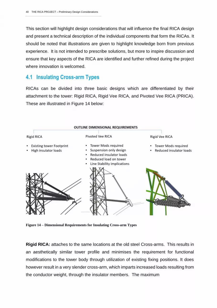
These are illustrated in Figure 14 below:
Figure 14 – Dimensional Requirements for Insulating Cross-arm Types
Rigid RICA: attaches to the same locations at the old steel Cross-arms. This results in
an aesthetically similar tower profile and minimises the requirement for functional
modifications to the tower body through utilization of existing fixing positions. It does
however result in a very slender cross-arm, which imparts increased loads resulting from
the conductor weight, through the insulator members. The maximum

41 THE RICA PROJECT – Preliminary Design Considerations
Rigid Vee RICA: the raking angle of the cross-arm is increased. This reduces the
resultant loads transmitted through the insulators from the conductor to the tower.
However, the increased raking angle requires that new attachment locations are formed
on the towers which will significantly change the load paths within the tower. It is likely
that significant new steel work will be required beyond that needed to strengthen the
tower to resist the increased conductor load.
Pivoting RICA (PRICA).
These can pivot on a vertical axis on the face of the tower. One benefit offered by
PRICAs is that they half the number of insulators needed. However, it is noted that the
insulators must be larger as the load is not divided between 2 members. Further benefits
could be considered within the installation and maintenance cycle as they occupy less
space on the tower face, leaving room for temporary cross-arms to be installed for
access purposes, and to pick up the conductor to allow for PRICA member replacement
in the event of failure or end-of-life.
PRICAs can pivot on the tower face which can help to alleviate torsional loads on the
tower in the event of out-of-balance conditions, such as a broken wire situation. They
also eliminate the presence of high compression forces on the RICA under broken wire
conditions.
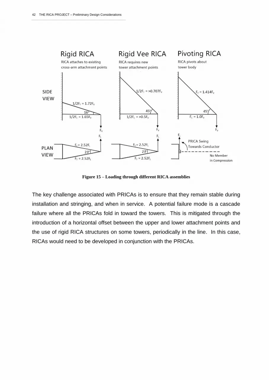
The different RICA arrangements each impose different mechanical requirements on
the composite insulators used within the assembly. These forces are illustrated
schematically in Figure 15.
42 THE RICA PROJECT – Preliminary Design Considerations
Figure 15 – Loading through different RICA assemblies
The key challenge associated with PRICAs is to ensure that they remain stable during
installation and stringing, and when in service. A potential failure mode is a cascade
failure where all the PRICAs fold in toward the towers. This is mitigated through the
introduction of a horizontal offset between the upper and lower attachment points and
the use of rigid RICA structures on some towers, periodically in the line. In this case,
RICAs would need to be developed in conjunction with the PRICAs.

43 THE RICA PROJECT – Preliminary Design Considerations
Image showing horizontal offset to ensure swing back to centre and also stay wires used
during stringing.
Figure 16 – Offset PRICA ensures route stability
To summarise, the rigid RICA is a simple structure with no additional moving parts to
wear, and differential longitudinal loads are transferred to the tower in cases of, for
example, broken wire conditions or unbalanced wind or ice loading. In a pivoted RICA
design (PRICA) the single articulation balances the load on the tower, however moving
parts may need increased management or even lead to reduced longevity.
4.2 Polymeric Tension insulators
Polymeric tension insulators are widely deployed throughout the world and can be
considered a mature technology and can be sourced from established suppliers.
Quality control in their manufacture is a key factor in their reliability and a NG policy will
be required to ensure the long-term consistency and quality of product supplied.
National Grid has some experience of polymeric tension insulators from an installation
on the Indian-Queens OHL route and are also deploying these on the T-pylon.
Whilst there is commonality in the materials used in tension and compression insulators,
they have very different mechanical requirements, especially in the end fittings, as
discussed in the following section.
4.3 Compression insulators
Insulators swing about tower body
To
we
r B
ody
Offset angle affects PRICA restoring force. This should be determined to mitigate risk of line instability which will be based on topological and route design factors
44 THE RICA PROJECT – Preliminary Design Considerations
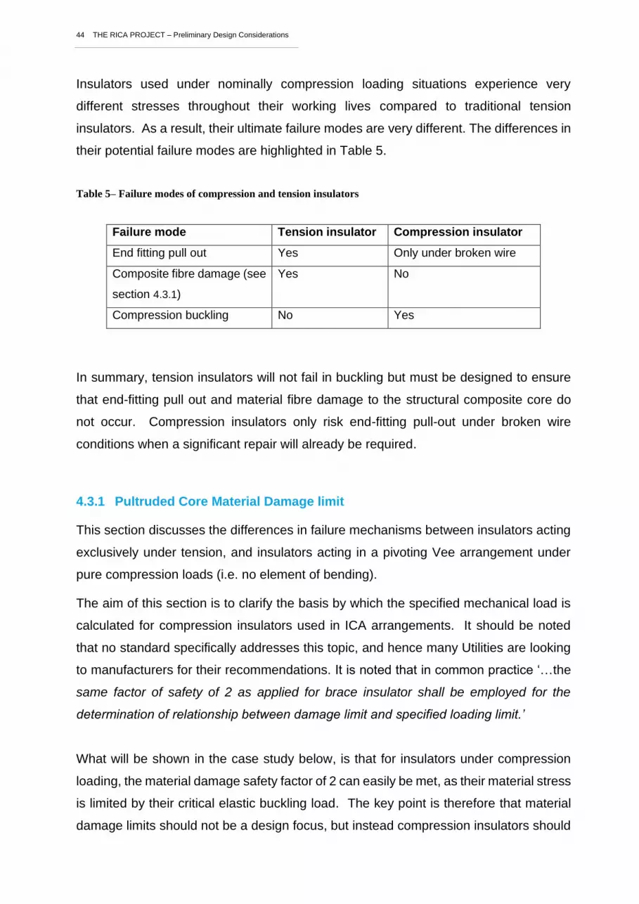
Insulators used under nominally compression loading situations experience very
different stresses throughout their working lives compared to traditional tension
insulators. As a result, their ultimate failure modes are very different. The differences in
their potential failure modes are highlighted in Table 5.
Table 5– Failure modes of compression and tension insulators
Failure mode Tension insulator Compression insulator
End fitting pull out Yes Only under broken wire
Composite fibre damage (see
section 4.3.1)
Yes No
Compression buckling No Yes
In summary, tension insulators will not fail in buckling but must be designed to ensure
that end-fitting pull out and material fibre damage to the structural composite core do
not occur. Compression insulators only risk end-fitting pull-out under broken wire
conditions when a significant repair will already be required.
4.3.1 Pultruded Core Material Damage limit
This section discusses the differences in failure mechanisms between insulators acting
exclusively under tension, and insulators acting in a pivoting Vee arrangement under
pure compression loads (i.e. no element of bending).
The aim of this section is to clarify the basis by which the specified mechanical load is
calculated for compression insulators used in ICA arrangements. It should be noted
that no standard specifically addresses this topic, and hence many Utilities are looking
to manufacturers for their recommendations. It is noted that in common practice ‘…the
same factor of safety of 2 as applied for brace insulator shall be employed for the
determination of relationship between damage limit and specified loading limit.’
What will be shown in the case study below, is that for insulators under compression
loading, the material damage safety factor of 2 can easily be met, as their material stress
is limited by their critical elastic buckling load. The key point is therefore that material
damage limits should not be a design focus, but instead compression insulators should

45 THE RICA PROJECT – Preliminary Design Considerations
be developed around a careful understanding of the Euler buckling load for the
insulators within their specific RICA arrangements.
Case Study:
The case study presented is based on the Arago Technology profile (ref. ‘Development
of insulating cross-arms for compact HV lattice tower structures’ S. M. Rowland et al,
CIGRE, Paris, B2-107, 2014) as shown in Figure 17, and based on a pivoted Vee
insulator arrangement of Figure 18 that was developed by the Irish Electrical
transmission Utility, EirGrid. This compression insulator requires a length of 4024 mm
from the conductor attachment to base pivot.
It should be noted that the material data and calculations provided are for illustration
only and should not be used for the basis of any future engineering requirements.
Figure 17 - Diagram of Arago non-circular compression profile. All dimensions mm.

46 THE RICA PROJECT – Preliminary Design Considerations
Figure 18 - Eirgrid ICA arrangement
Buckling loads have been calculated based on two methods: the Euler buckling
calculation gives 256kN, and a Finite Element Analysis computer simulation of the
overall assembly which predicts a buckling failure load of 325kN.
The difference between the answers from each technique is likely to be due to different
end constraint assumptions and slight load eccentricities that could exist within the
computer model.
As an aside, this illustrates the importance of accurate modelling or empirical data to
provide confidence in any final designs. For this illustration, the lower result of 256kN
has been be used to demonstrate the significant of the material damage safety factor as
a design consideration.
Material Damage limit calculation at the point of buckling:
This section highlights why a material damage limit is not applicable to the failure mode
assessment, when considering compression-only insulator members.
A load of 256kN is the point at which the insulator profile will start to bend and shortly
after this load, it will snap. Prior to this point, a well-designed compression member
should present a straight line on a graph of load vs deflection. If we assume that the
bending strength of the fibres within the composite pultrusion is 400 MPa, for the

47 THE RICA PROJECT – Preliminary Design Considerations
damage limit threshold not to have been breached at the point just below buckling, the
stress in the member must remain below 200 MPa at the point of buckling initiation. That
is, at this point, the member should be nominally straight to achieve the dimensional
tolerance requirements of the insulated cross-arm.
Thus, the stress in the member = Force applied (N) / cross-sectional area (mm2)
= 256000 N / 6024 mm2
= 42 N/mm2 = 42 MPa
Hence, the damage limit safety factor, at the point of buckling is 400 / 42 = 9.5x
It can therefore be demonstrated that assuming the cross-arm assembly remains
nominally straight at the point of ultimate load application, there will be no long-term risk
of damage to the composite material through the life of the insulator structural core.
What safety factor should be applied to the ultimate loads?
The two failure mechanisms that could be experienced by a compression insulator in a
RICA assembly are:
1. End fitting pull out: this is a rare load situation as it will only occur under a
broken wire failure mode, so fatigue effects are not a consideration. However,
as it is an impact event, there could be up to 3x load factor seen on the hardware.
It is important to ensure that the end fitting will not pull out in this situation, and
the test methodology described by IEC61109 is appropriate in this case.
2. Elastic buckling in insulator under heavy vertical loading from conductors:
The critical failure load will be determined by using the Euler buckling equation,
multiplied by a factor to account for the end conditions (n) (Equation 2). This factor
will be very specific to the particular RICA assembly geometry, relative elasticity
of the brace and compression members, and articulation of the end fittings.
Equation 2
F = n π2 E I / L2 (2)

48 THE RICA PROJECT – Preliminary Design Considerations
This buckling capability will be further reduced by any bending forces applied to
the member which could result from a misalignment of the lines of forces from the
conductor attachment point, tension insulator and compression insulator. This
bending stress should be deducted from the Euler buckling stress previously
calculated (42 MPa).
Ultimately, any given arrangement should in theory present repeatable failure
loads, however, variability will result depending on the dimensional assembly
tolerances that can be achieved in real tower installations.
The successful specification of composite cross-arm compression insulators depends
on focusing on the correct causes of failure. While calculations and FEA will provide a
good indication of what this may be, full-scale real-world testing is critical to understand
the actual buckling factor for each RICA arrangement. The applied safety factor should
be based on the geometrical tolerances of the RICA and be appropriate to ensure failure
load coordination in accordance with NG requirements to be defined during project
RICA.
4.4 Tower Attachment Hardware
The use of pivoted fittings between tower and RICA is important for two main reasons:
1. To prevent bending moments being imparted into the compression insulator as
the unit deflects under varying load.
2. To prevent secondary damage to the tower in the event of RICA failure, by
allowing the compression member to rotate down, relative to the tower body.
4.5 RICA ‘Nose Yoke’ Fitting
In RICA terminology, the ‘nose yoke’ fitting is a metal component that connects the
multiple insulators that form the cross-arm, to the conductors, via standard OHL fittings.
Nose yokes could be made from flat steel sections for pivoting RICAs but in the case of
rigid RICAs they will be 3D steel fabrications or forgings.
The following sub-sections provide some considerations relating to the design of Nose
Yoke fittings for RICAs.

49 THE RICA PROJECT – Preliminary Design Considerations
4.5.1 Load Line orientation
The design of steel Cross-arms is carefully considered to ensure that the point of
connection of the insulators coincides with the point where the load lines meet as close
as possible to the end of the cross-arm. This ensures that bending moments are
minimised under all service loading conditions, i.e., normal vertical load, uplift and
broken wire conditions. Correct and improper load alignments are demonstrated
schematically in Figure 19. This requirement can present limitations relating to the
position of other features such as service attachment points and so it is important that
the supplier demonstrates that it has been satisfactorily accounted for, or that any
bending moments are provisioned within the final insulator specification.
Figure 19 - Load line alignment schematic
The importance of load-line orientation is simulated through an FEA simulation that was
generated within a previous Innovation Funding Initiative (IFI) research project with NG
and SSEN (Figure 20). Figure 18a) shows that with an improperly located conductor
attachment point, a bending moment is introduced causing the nose of the crossarm to
twist up, introducing additional stress in the buckling members. This additional stress
must be subtracted from the Euler buckling strength of the compression insulator
resulting in a significant reduction in compression capacity. The nose of Figure 18b) is
correctly aligned and the insulator bends down as would be expected for a triangulated
system of this type.
NO
NO
YES
YES
Bending Moment Distance
Bending Moment Distance

50 THE RICA PROJECT – Preliminary Design Considerations
The FEA results for the broken wire loading conditions are shown below for a poorly
aligned nose attachment location (a & b) and a properly aligned nose attachment (c &
d) (Figure 21). These results are presented at the same deformation scale and it can
be seen that by attaching the insulators below the point of load line intersection, a
twisting moment is imposed on the assembly.
The simulation also illustrates the requirement for vertical articulation of the insulation /
tower connection interface, in order to further mitigate bending moments.
a) A misaligned nose fitting
b) A correctly aligned nose fitting
Figure 20 - Normal loading (deformation scale x6)
a) Incorrectly aligned nose: side view
b) Incorrectly aligned (end view)
c) Correctly aligned nose: side view
d) Correctly aligned nose: end view
Figure 21 - Broken wire FEA (deformation scale x16).

51 THE RICA PROJECT – Preliminary Design Considerations
4.5.2 Conductor attachment points
Two options exist for the attachment of the conductors to the RICA Nose or Nose Yoke
fitting and both concepts may be equally satisfactory. Ultimately, the chosen design of
the end yoke is the responsibility of the innovation supplier, but some design related
implications of each concept are discussed below. A consideration common to all
conductor attachment designs is to ensure that no clashing can occur between
components under high wind conditions.
1. Nose Yoke Fitting: In this configuration each conductor transmits its load
through a dedicated hole in the Nose Yoke fitting. This could result in unbalanced
forces in the event of snow shedding from a single conductor. Additionally, in
heavy wind conditions it is possible that one conductor could see higher
transverse loading than the other which may also change the alignment of the
loading lines within the crossarm. This arrangement is shown in Figure 22.
Figure 22 - An example of a double yoke fitting
2. Nose Fitting: In this configuration the total load of each conductor is transmitted
through a single point on the RICA. Such an arrangement is shown in Figure 23.

52 THE RICA PROJECT – Preliminary Design Considerations
Figure 23 - An example of an arrangement giving a single point of connection to a RICA (left) and a PRICA
(right)
4.5.3 Nose / Yoke Maintenance Features
As part of an earlier NIA project, a National Grid development session was held to review
design features that could be included on the insulated cross-arm designed within that
project. The session was held with a focus on facilitating maintenance procedures and
the applicability of recommendation within a wider context was not considered. These
suggestions were based on a rigid RICA, which will be superseded withing Project RICA,
and so should only be used as a prompt for future design activities.
• A flat area should be present on the end yoke above the loading points to enable
a lifting beam to be placed and bolted to it for raising and lowering conductors
(See Figure 24).
• The nose design should allow a lifting beam to be attached, extending
approximately 250 mm beyond the conductor attachment point, and vertically
above the outer conductor.
• The bolting holes on the top surface need to be as wide apart as possible, ideally
on the outer edge of the nose.
• Horizontal electrical field grading rings (see electrical design) to be split into two
to allow access to the nose connection in the centre.
• There is little space available for lifting equipment because of the size of the
insulators comprising the RICA. All fittings need to be designed alongside and
compatible with working practices developed.
Fv
Fl
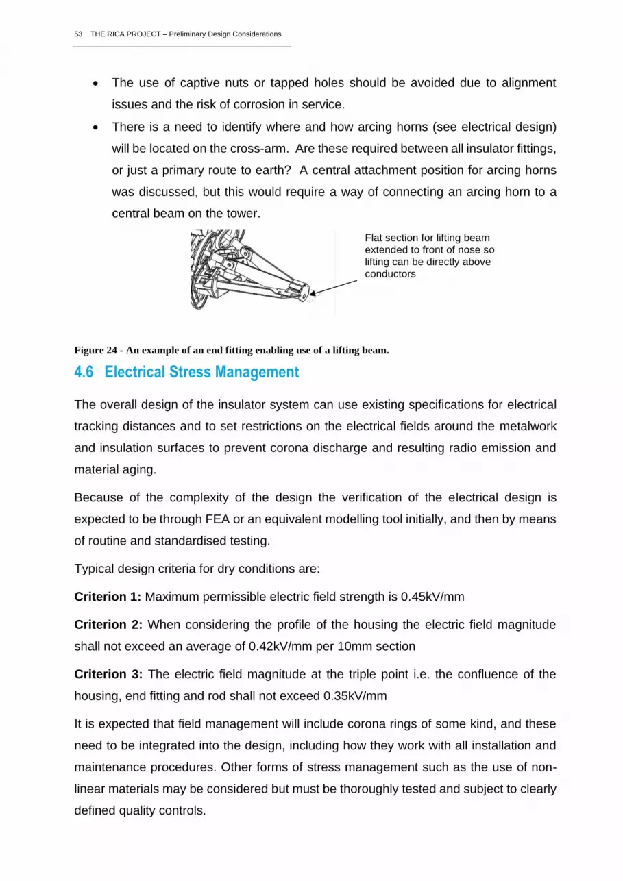
53 THE RICA PROJECT – Preliminary Design Considerations
• The use of captive nuts or tapped holes should be avoided due to alignment
issues and the risk of corrosion in service.
• There is a need to identify where and how arcing horns (see electrical design)
will be located on the cross-arm. Are these required between all insulator fittings,
or just a primary route to earth? A central attachment position for arcing horns
was discussed, but this would require a way of connecting an arcing horn to a
central beam on the tower.
Figure 24 - An example of an end fitting enabling use of a lifting beam.
4.6 Electrical Stress Management
The overall design of the insulator system can use existing specifications for electrical
tracking distances and to set restrictions on the electrical fields around the metalwork
and insulation surfaces to prevent corona discharge and resulting radio emission and
material aging.
Because of the complexity of the design the verification of the electrical design is
expected to be through FEA or an equivalent modelling tool initially, and then by means
of routine and standardised testing.
Typical design criteria for dry conditions are:
Criterion 1: Maximum permissible electric field strength is 0.45kV/mm
Criterion 2: When considering the profile of the housing the electric field magnitude
shall not exceed an average of 0.42kV/mm per 10mm section
Criterion 3: The electric field magnitude at the triple point i.e. the confluence of the
housing, end fitting and rod shall not exceed 0.35kV/mm
It is expected that field management will include corona rings of some kind, and these
need to be integrated into the design, including how they work with all installation and
maintenance procedures. Other forms of stress management such as the use of non-
linear materials may be considered but must be thoroughly tested and subject to clearly
defined quality controls.
Flat section for lifting beam extended to front of nose so lifting can be directly above conductors

54 THE RICA PROJECT – Preliminary Design Considerations
Test regimes need to specify tests for components and tests for the assembled RICA
(including stress management devices and arcing horns). The latter includes: Radio
Interference tests, corona testing, wet/dry lightning impulse testing, switching surge
testing, and power frequency testing. These are referred to in Section 4.6.2. Test
regimes for the composite insulators will include dye penetration tests, water diffusion
tests, and arc resistance tests.
More information on testing is provided within RICA project report 4 – Asset design and
development.
4.7 Arcing Hardware Requirements
The electrical requirements of the arcing horns applied to RICAs are discussed in
section 3.4.
Additionally, the design must be integrated with installation and maintenance
procedures.
An important consideration of the arcing horn design is to ensure that high temperatures
resulting from current load following during surge events are not transferred into the
composite insulator fittings so that they may result in damage.
4.8 Materials
The materials utilised in RICAs are all extensively used within existing products on the
network. Therefore, if correctly used, existing material standards can be relied upon to
ensure safe and reliable operation. There are a few areas where material selection can
influence performance, and these are discussed below:
Glass reinforced plastic (GRP) structural profile:
The composite structural rod is the component within a composite insulator that provides
the structure necessary to hold the insulation material in place and the conductor in the
air.
Composite materials are widely used in industrial and consumer applications and
different constituent materials are combined to achieve the required end properties. For
composite insulators, the only certified combination is to combine boron free electrical
corrosion resistant (ECR) glass fibres and epoxy resin. The challenge for compression
member manufacture is managing the production of large cross-sectional areas while

55 THE RICA PROJECT – Preliminary Design Considerations
maintaining straightness and porosity tolerances. Quality control is therefore a critical
procurement aspect in this product.
Silicone dielectric material:
It is assumed that for RICAs, polymeric insulators as described above are used, rather
than glass, or porcelain insulators. These composite profiles are coated with silicone
rubber sheaths and moulded sheds to give the required electrical performance.
Within the silicone material family, 2 primary genres exist, being which are liquid silicone
rubber (LSR) and High Temperature Vulcanizing rubber.
Extrusion/injection of the silicone rubber requires excellent adhesion to the underlying
strength member and to the metal end fittings. This sometimes utilizes adhesives. The
industry now understands design practices which can successfully exclude water
penetration at the silicone / end fitting interface, but this remains a key feature of any
composite insulator design, which will require extensive testing.
Consideration is needed regarding the applicability of these materials to the RICA
insulators, as well as detailed quality plans for continuity and control of supply.
End Fittings to Steel hardware:
Manufacturers frequently employ aluminium to facilitate the machining operations
associated with the large end fittings of compression post insulators. Aluminium is also
considerably lighter than steel which is an important consideration when considering the
already high weight of the compression insulators. A consideration in the insulator to
nose yoke, or tower end fittings is to evaluate any potential risks that may arise from
galvanic corrosion associated with contact from dissimilar metals.
Conclusion
This document has attempted to summarise the experience to date and has identified a
range of considerations that may help contribute to a robust design development
process for the RICA project. It is not intended as a design guide, or specification and
all aspects discussed should be independently reviewed and evaluated within the
OFGEM NIC RICA project.


