Embed Size (px)
Citation preview

U.S. Food and Drug Administration
Public Workshop
Reprocessing of Reusable Medical Devices
June 8-9, 2011
3-A Sanitary Standards, Inc.
Designing for Cleanability
Lessons from the Food Industry

Topics
Introduction and Overview: 3-A SSI
The Role and Value of 3-A Sanitary
Standards
Design Criteria for 3-A Sanitary Standards
Oversight of Conformance to 3-A Sanitary
Standards

The Origin of 3-A Sanitary Standards
1920s: Dairying and milk distribution
Regulatory world characterized by
conflicting jurisdictional requirements
International Association of Dairy and Milk
Inspectors formed Committee on Dairy and
Milk Plant Equipment
Purpose: “…to confer with manufacturers
and gradually develop standards which
would generally be accepted.”

The Origin of 3-A Sanitary Standards
First standard developed in 1929 for
sanitary fittings
Work slowly broadened throughout the
1930s
After WW II, stakeholders gained
momentum in formulating and publishing
standards formally identified as „3-A‟
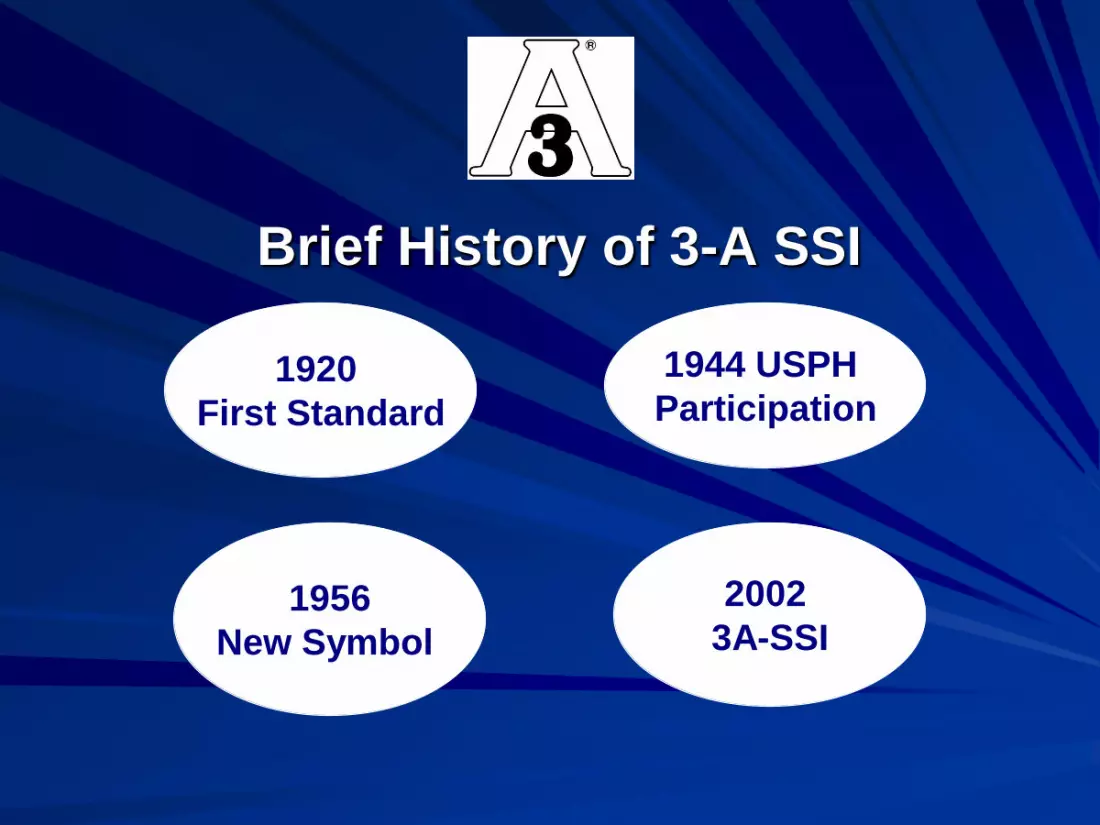
Brief History of 3-A SSI
1920
First Standard
1944 USPH
Participation
1956
New Symbol
2002
3A-SSI
The 3-A SSI Stakeholders
Regulatory Sanitarians
Processors (Users)
Fabricators
3-A Sanitary Standards, Inc.

3A Sanitary Standards, Inc. Today
Not-for-profit corporation: 501 (c) (3)
Governed by Board of Directors representing
the three stakeholder groups with a long
history of collaboration on sanitary
equipment design
Dedicated, independent staff

What is a 3-A Sanitary Standard?
3-A Sanitary Standards
specify the criteria for the
design and fabrication of
equipment that comes into
contact with food.

3-A Sanitary Standards
Vessels
Fillers
Valves and Fittings
Pumps and Mixers
Heat Exchangers
Conveyors and
Feeders
Instruments
Concentrating
Equipment
Farm/Raw Milk
Cheese and Butter
Equipment
Materials and Materials
Testing


USPHS/FDA Pasteurized Milk
Ordinance (PMO)
Equipment manufactured in
conformity with 3-A Sanitary
Standards complies with the sanitary
design and construction standards of
this Ordinance.
The Role of „3-A‟ in Commerce

USDA – General Specifications for Dairy Plants Approved for USDA Inspection
and Grading Service
All new, replacement or modified equipment and all processing systems, cleaning systems, utensils, or replacement parts shall comply with the most current, appropriate 3-A Sanitary Standards or 3-A Accepted Practices.
The Role of „3-A‟ in Commerce

3-A Value: Regulatory Sanitarians
3-A Sanitary Standards embody decades of expert knowledge about equipment design from inspection authorities and others.
3-A Sanitary Standards streamline the equipment inspection process and help ensure the safety of food.
The 3-A Symbol signifies equipment is compatible with regulatory requirements and guidelines.

3-A Value: Processors and
Fabricators
The 3-A Sanitary Standards and 3-A Accepted Practices are written to conform to regulatory requirements and guidelines.
Buyers and sellers rely on 3-A because it signifies equipment that’s easier to clean, inspect, and maintain.

Key Elements of 3-A Sanitary
Standards and Accepted Practices
Definitions of Terms Used
Description of Permitted Materials
Details of Fabrication

Format and Style Manual
Document Preparation Guide for Document
Writers
Explains the Intent of Each Section of the
Document
Standardization of:
– Abbreviations
– Dual Dimensioning (Inch-Pound followed by Metric)
– Rules for Conversion between I-P and Metric
– Number of Significant Digits
Boilerplate Wording

Available at: www.3-a.org

Definitions
For consistent and uniform interpretation
and application of standards.
To define special or unusual terms used in
the document.
Definitions not used in the document
should not be included.
As appropriate, new definitions can be
created.

Definitions
Examples and Notes for Drafters
Properties of Design
Cleaning
Fittings

Bond: The adhesive or cohesive forces holding
materials together. This definition excludes press and
shrink fits.
Mechanical Force Seal: The seal established between
a flexible rubber, rubber-like, or plastic material when
pressed into a special groove in a metal or glass
component using a combination of compression,
pressure, and the unique geometrical shapes of the
joined materials to create a tight seal at the interface of
the materials joined during conditions of intended use
including processing, cleaning, sanitizing, or
sterilization. A mechanical force seal is not intended
for routine disassembly for cleaning.

Clean-in-Place Cleaning: (CIP): The removal of soil
from product contact surfaces in their process position
by circulating, spraying, or flowing chemical solutions
and water rinses onto and over the surfaces to be
cleaned. Components of the equipment, which are not
designed to be cleaned in place, are removed from the
equipment to be COP or manually cleaned.
Drafters Note: Insert one of the following statements as the
last sentence of C3.1.
Product contact surfaces to be CIP cleaned are inspectable.
(or)
Product contact surfaces to be CIP are inspectable except as
specified in E1.5.2.2

Other methods of cleaning are also defined:
Clean-Out-of Place (COP)
Manual Cleaning
Dry Cleaning
Other Key Terminology defined:
Cleanable or Cleanability
CIPable
Close Coupled

Readily Accessible: A location that can be safely
reached by personnel from the floor, other permanent
work area or stable platform (permanent or moveable).
Readily Removable: Designed, fabricated, and installed
to be quickly separated from the equipment with or
without the use of simple hand tools.
Simple Hand Tools: A screwdriver, wrench, mallet, or
readily available dedicated tool(s) normally used by
operating and cleaning personnel.

Product Contact Surfaces: All surfaces which are exposed
to the product and surfaces from which splashed product,
liquids or material may drain, drop, diffuse {Where
Applicable}, or be drawn into the product or onto product
contact surfaces. {Surfaces That Come Into Contact
With Product Contact Surfaces Of Packaging Materials
May Be Included In This Definition For Some
Equipment.}
Nonproduct Contact Surfaces: All exposed surfaces from
which splashed product, liquids, or other materials cannot
drain, drop, diffuse {Where Applicable} or be drawn into
or onto the product, product contact surfaces, open
packages, or the product contact surfaces of package
components.
Fittings Definitions:
CIP Fittings – Fittings to be cleaned while fully
assembled. If such a fitting has a removable
joint, the joint is self-centering, employs a gasket,
and the resulting gasketed joint forms a
substantially flush interior surface.
Manually Cleaned Fittings – Removable joint
fittings of which the design requires dismantling
for manual cleaning.

Materials
To identify what materials can be used to
fabricate the equipment.
Product Contact Surfaces
– Metals
– Nonmetals
Nonproduct Contact Surfaces

Product contact surfaces shall be of stainless steel of the American
Iron and Steel Institute (AIST) 300 Series, excluding 301, 302, and
303, (Refer to B4, Reference No. 5) or corresponding Alloy Cast
Institute (ACI) types (Refer to B4, Reference No. 6) or metal which
under conditions of intended use is at least as corrosion resistant as
304 stainless steel, and is nontoxic and nonabsorbent. (Refer to
Appendix, Section H.) Where welding is involved, the carbon
content of the stainless steel shall not exceed 0.08%.
Rubber and rubber-like materials may be used for {All Required
Application(s) Including Coatings} and when used for the
specified application(s), shall conform to the applicable provisions of
3-A Sanitary Standard, Number 18-.
Plastic materials may be used for {All Required Application(s)
Including Coatings} and when used for the above-specified
application(s), shall conform to the applicable provisions of 3-A
Sanitary Standard, Number 20-.

Carbon and ceramic materials (including tungsten carbide)
may be used for {List Applications} and when used, shall be
inert, nonporous, nontoxic, nonabsorbent, insoluble, resistant
to scratching, scoring, and distortion when exposed to the
conditions encountered in the environment of intended use,
including cleaning and sanitizing treatment (or sterilization).
{If the Optional Parenthetical Words are Used, Refer to
D1.3 and E1.16.}
All nonproduct contact surfaces shall be of corrosion-resistant
material or material that is rendered corrosion resistant. If the
surfaces are coated, including painted surfaces, the coating
shall adhere. All nonproduct contact surfaces shall be
relatively nonabsorbent, durable, and cleanable. Parts
removable for cleaning having both product contact and
nonproduct contact surfaces shall not be painted.

Fabrication
Equipment is to be designed to be 100% cleanable.
The design must preclude contamination of the product.
Fabrication to 3-A criteria DOES NOT automatically imply compatibility with CIP cleaning methods.
Illustrations are not to be interpreted as engineering drawings.

Product Contact Surfaces
Surfaces, including fabricated, welded and soldered
joints, shall be at least as smooth as a 32 min. (0.8
mm) Ra finish and shall be free of pits, folds, crevices,
and cracks in the final fabricated form. (Refer to
Appendix, Section I.), except that;
Sanitary tubing joints, welded in accordance with
E1.2.2, and free of pits, folds, crevices, and cracks,
and misalignments, may have an as-welded interior
surface finish.

All permanent joints in metallic surfaces shall be continuously
welded, except that:
Press-fits, force-fits, or shrink-fits may be used to produce crevice-
free permanent joints only when neither welding nor soldering is
practical. Joints of these types may only be used to assemble
metallic parts having circular cross sections, free of shoulders or
relieved areas. Press-fitting, force-fitting, or shrink-fitting may be used
for {List all Application(s)}. (Refer to B4, Reference No.15.) (See
the following illustrations of acceptable press-fits, force-fits, or shrink-
fits.)
If press-fit or shrink-fit procedures are to be used for metal to plastic
or plastic to plastic joints, supporting documentation shall be
available to demonstrate the joints suitability. The tightness of the
press-fit or shrink-fit seal shall be validated to demonstrate that there
is no migration past the seal under the intended conditions of use.
This shall be accomplished using the EHEDG Document No. 7, Test
for Bacterial Tightness or other equally effective test(s).


A mechanical force seal may be used for {List all
Application(s)}. The tightness of the seal shall be validated to
demonstrate that there is no migration past the seal. The interior
of the gasket groove shall be designed so the groove is
inspectable and cleanable when the gasket is removed.
The manufacturer shall provide a field replacement procedure for
the mechanical force seal that has been validated to the original
installation tightness to prevent liquid penetration past the seal.
The surfaces behind mechanical force seals shall be easily
cleanable and inspectable or the impermeability of the seal shall
be established by an appropriate test.

Rubber and rubber-like materials, and plastic materials, and
carbon or ceramic seal component materials may be bonded.
The bond shall be continuous and mechanically sound. The
rubber and rubber-like material, the plastic material, and
carbon or ceramic seal component materials shall not separate
from the base material to which it is bonded when exposed to
the conditions encountered in the environment of intended use,
including cleaning and sanitizing treatment (or sterilization).
{If the Optional Parenthetical Words are Used, Refer to
D1.3 and E1.16.}
Coatings, when used, shall be free of delamination, pitting,
flaking, spalling, blistering, or distortion when exposed to the
conditions encountered in the environment of intended use,
including cleaning and sanitizing treatment (or sterilization).
{If the Optional Parenthetical Words are Used, Refer to
D1.3 and E1.16.}

Cleaning and Inspectability
Equipment intended for COP or manual cleaning shall be
designed and fabricated so all product contact surfaces are
readily accessible and inspectable either when in an installed
position or when removed. Junctures between components may
or may not be gasketed or sealed. All demountable
appurtenances shall be readily removable.
Equipment intended for CIP cleaning shall be designed and
fabricated so all product contact surfaces, including all non-
removed appurtenance, can be CIP cleaned. Junctures between
components shall be sealed or designed for manual or COP
cleaning.

Surfaces shall be self-draining except for typical clingage or
adherence.
Surfaces shall be drainable and provided with sufficient drain
points so the equipment can be drained.
When components are close coupled, the intervening product
contact surfaces shall be the lesser of:
1. Twice the nominal diameter or cross section of the mating
surfaces, or
2. A maximum of 5.0 in. (127 mm) as measured from the outer
shell of the vessel to the point at which product is stopped by
a valve seat or fitting cap.
The fitting for a temperature-sensing device intended for sensing
processing or holding temperature in a vessel shall be located no higher
than the 20% capacity level of the vessel.
Gaskets shall be removable or bonded.
Gasket retaining grooves for removable gaskets shall not exceed 1/4 in.
(6.35 mm) in depth or be less than 1/4 in. (6.35 mm) wide except those
for O-rings with cross-section dimensions 1/4 in. (6.35 mm) or smaller,
and those provided for in the 3-A Sanitary Standards referenced in
Section B, Normative References (except that:)
Gaskets between flat sealing surfaces shall be substantially flush with
the product contact surfaces. The juncture shall create a crevice free
joint, without any unsupported gasket material.

Surfaces with two or more O-rings or seals in a row between
product contact and nonproduct contact surfaces shall have a
leak-detection port between them that is open to the
atmosphere and visible to the operator, unless this area is
designed for manual or COP cleaning. The leak-detection port
shall be a minimum of 1/8 in. (3.18 mm) in diameter.
Gasketed joints employing recessed 0-rings or seals which are
intended for CIP shall be substantially flush so that some of the
0-ring or seal surface will be partially exposed to cleaning
solutions (See following illustrations of examples)
The surfaces behind removable gaskets under compression
shall be easily cleanable and inspectable.


All angles of less than 135° shall have radii of at least
{Provide suitable numbers, 1/4 in. (6.35 mm) or 1/8
in. (3.18 mm)}, except that:
Allowance for smaller radii down to 1/32 in.
Grooves in gaskets and gasket retaining grooves.
Smaller radii for standard and nonstandard O-ring
grooves

There are no minimum radii requirements for soldered
joints or for the product contact junctures of press or
shrink fits.

There are no
minimum radii
requirements for the
product contact
junctures of flat
sealing surfaces.

There are no minimum radii requirements for exposed
sanitary threads except for the knuckle thread, DIN
405, provided for by Section E1.13.1.1.
Gasket retaining grooves for bonded gaskets are not
subject to width, depth, or minimum radii
requirements.
There are no minimum radius requirements for
retaining grooves for mechanical force seals defined
in C1.1, or for the juncture between product contact
surfaces and the exposed part of an O-ring.

In such case on a machined component when a radius in a 90°
corner is replaced with a pair of 135° angles, the distance between
the corners (the hypotenuse of the resulting isosceles right triangle)
shall be no less than 1/32 in. (0.794 mm) inches for the dimension
“A” in the illustration below.
There shall be no exposed or enclosed threads on
product contact surfaces.
Or
Use of threads is not recommended and threads
should not be used when other means of
attachment is available. When no acceptable
alternative is available and threads are required for
essential functional reasons, the following criteria
shall apply:
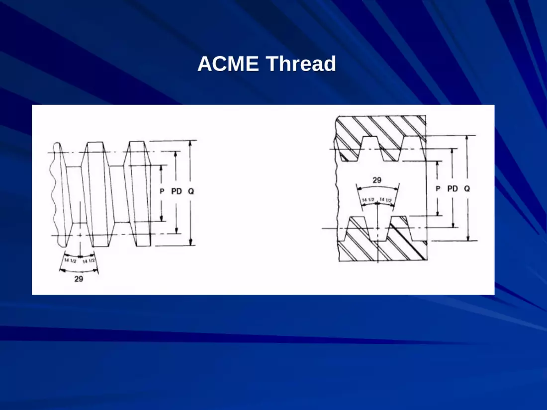
ACME Thread

American Standard Stub Acme Thread


Nonproduct Contact
Surfaces
Joints
Coatings
Cleanability and inspectability
Draining
Exposed threads
Service Lines

Panels, Doors, or Access Ports
Guards and safety Devices
Supports
Catwalks, stairs handrails
Name and Information Plates

Oversight of Conformance
The 3-A Symbol is a registered mark
to used show conformance to a 3-A
Sanitary Standard.
3-A SSI was created to implement a
new Third Party Verification (TPV)
inspection program for all users of the
mark.

Why a New TPV Requirement?
TPV brings added assurance that
equipment showing the 3-A symbol fully
conforms to the applicable 3-A Sanitary
Standard.

More Details on 3-A SSI
Contact us at:
6888 Elm Street, Suite 2D
McLean, Virginia, 22101
PH: 703-790-0295
FAX: 703-761-6284
Contact Timothy Rugh or Nate Wall

Visit us at: www.3-a.org


Consensus Process - Overview
3-A Steering
Committee
Work Group Work Group Work Group
Canvass Group
Management
Development
Approval


