Embed Size (px)
Citation preview
WinwickPaperv104.docx 1 22 May 2020 Copyright © 2015 Winwick Business Solutions P/L
THE WINWICK CONCEPT
William S. Clarke
ABSTRACT Few studies prescribe how to move to a sustainable, low-carbon economy. Yet, to avoid various disaster scenarios, this needs to be done within two decades. There needs to be less talkfest and more action – provided that each action shows real promise and can be integrated into an overall, renewable energy context. This paper describes not only what needs to be done, but how to do it, using a mix of traditional and novel technology. Furthermore, it indicates how existing industries might adapt their processes and investments to make the transition happen with least cost and disruption. The prescription is the Winwick concept.
INTRODUCTION This paper describes the technology for a new and integrated, renewable energy industry.
It discloses processes, methods and designs to grow and harvest algal biomass and those to process it into biofuels, as well as generating solar electricity and chemicals as co-products. Central to the concept is the use of organic waste and purpose-grown biomass, including that from the cultivation of microalgae in sealed, water-conserving photobioreactors of low capital and operating cost. However, of equal importance is the validation and refinement of the sustainable processing technologies, together with the development of associated support systems & logistics, of funding, and of community acceptance or social licence.
What Winwick promises is to replace our unsustainable use of fossil fuels with renewable biofuels and co-produced chemicals, food, bio-actives and photovoltaic power. These are to be generated mainly in the flat or terraced, temperate deserts or wastelands of the world, preferably on land having no better use. The production operation requires no fossil-fueled power, no commercial fertilizer, and negligible water - which can itself be salty, polluted or seasonal. It takes flue gas or carbon dioxide from stationary producers by utility pipeline and turns it into biomass (vegetable matter, including oils, proteins and carbohydrates) and oxygen for industry. Virtually all wastes, including old Winwick plant and equipment, are recycled, usually indefinitely by the same, or similar, processes that process the biomass. Such an industry is key to the formation of a sustainable economy.
The drillhole reactors which process the algal biomass can also process most other organic waste, such as that from weed species, crop, forestry and many industrial wastes. Thus, the processing technology is suited to all regions.
Deriving biochar from diverse, major biomass sources and distributing it where plant roots can access it, means that we can improve soil fertility, increase its water- and nutrient-holding ability, and remove greenhouse gases from both sea and atmosphere. This is a safe, an economical, and a permanent solution to carbon sequestration. It is one that can be done to whatever scale is required. Performed extensively, it could help prevent the world from overheating, at the same time as it improves agricultural productivity and turns desert, marginal and degraded land productive.
Whilst biochar can be produced from hydrothermal reactions in drillhole reactors, without further treatment it does not have such a high surface area as biochar produced by pyrolysis. On the other hand, pyrolysis tends to destroy many valuable compounds, particularly those found in green biomass. Pyrolysis also requires dry and
WinwickPaperv104.docx 2 22 May 2020 Copyright © 2015 Winwick Business Solutions P/L
typically finely-divided fuel which are both energy-intensive to prepare. Moreover, it tends to produce polluting particulates, tars and noxious chemicals. Winwick drillhole processes suffer no such disadvantages.
In order to save on relatively expensive transportation costs for low value biomass feedstocks, there are now transportable pyrolysis plants that may be moved to where forestry operations are occurring. Although drillhole reactors are not portable, sizeable forests or farming regions could justify establishing them at economic spacings in the forest or region, or at distribution nodes, or on transportation routes.
What differentiates Winwick’s algaculture and processing technology from others is that it theoretically solves all of the problems that have so far prevented profitable algal biofuel production.
Most current algaculture technologies suffer from more than one of the following disadvantages: requires land that typically has a high cost for a facility of viable size; critical siting restrictions; substantial site preparation costs; high capital equipment cost per square metre of growing space; low algal productivity; high net energy cost; reliance on costly commercial chemical inputs, utilities and services; logistic costs; batch operation; non-scalability; contamination by algal predators and wild strains; high maintenance costs; excessive downtime; regulatory hurdles; product limitations; dependence on large volumes of low-cost water; blowdown issues; inflexible biomass inputs; respiratory loss; evaporative loss; sterilization; strain change; seasonal dependence, including non-optimal growing temperatures in large parts of the year; very poor ambient light usage; photo and algal inhibition; self-shading; uneconomic harvesting and processing operations; a lack of valuable co-products; and slow rollout due to lack of automation and/or portability to remote sites.
The economics of algal cultivation are improved by means of several novel steps, including the use of: adaptive-aperture photovoltaic strips to control insolation; light/dark flashing; thixotropic gel media; low agitation; passive convective turnover; differential sparging; nutrient recycling; heat, light and salinity control; and active, fine control of algal growing conditions, growth media and strain change. In addition, innovative methods are described for: processing virtually any biomass economically and ecologically into biofuels and chemicals; for mechanical handling; for bioreactor access, construction, security and surveillance; for logistics; and for the automated and/or remote control of operations.
The algal cultivation process typically involves the use of sunlight and water, together with waste carbon dioxide sourced from oil/gas wells, industry and/or carbon dioxide captured from the atmosphere by other means. Dark-time growth is maintained with the use of organic food, typically sugars, glycerine or other soluble organics derived from cheap and plentiful sources. Other nutrients and energy values incorporated by the algae are typically recovered and recycled, with some being produced on-site using Winwick’s drillhole, or gravity pressure vessel, reactor technology. Algal processing is made economical by: the avoidance of traditional de-watering and drying steps; the creative use of geothermal heat and geopressures; and an innovative combination of processing technologies.
The Winwick concept incorporates that of an integrated biorefinery, where not only the waste products from individual processes are re-used, but also the heat from processing operations and the materials from which the plant and associated structures are built when they are worn out or made obsolete. The biorefinery is designed to accept most other forms of biomass besides algae, for processing into biofuels. These include biomass from: crop and forestry waste; harvested, regenerative species such as eucalypts, saltbush, poplar, perennial native grasses and weed species; lignite and coal; pulp and sugar mill wastes (including bagasse, tops, and trash (only a part thereof)); other agribusiness wastes, such as food processing wastes or manure; garden wastes; weed species for destruction; sewage; waste fats, oils, paints, solvents and organic chemicals; waste paper and polymers; or almost any other
WinwickPaperv104.docx 3 22 May 2020 Copyright © 2015 Winwick Business Solutions P/L
reasonably clean organic waste. These can all be processed in the same facility, which has a small footprint. Such processing can even be performed in locations or climates where algal bioreactors themselves may not be economical to run all year round, such as in some cold climates. Thus, the biorefinery operation is not seasonally-bound and can run continuously using a wide variety of feedstock.
Biomass processing utilising a supercritical water partial oxidation (SCWPO) process completely destroys otherwise dangerous or intractable pollutants such as dioxins, viruses, hazardous organic chemicals and all plastics. At the end of the SCWPO process, syngas is obtained and most of the remaining biomass nutrients can be recycled and valuable metals and inorganics can be recovered. Water from sewage, pulpmill and industrial wastes can be upgraded by the process to a quality that is typically suitable for irrigation and/or many industrial uses. Depending on the salinity of the feedstock, it may even produce potable water at less cost than many other forms of water treatment. Only low concentrations of nutrients and soluble salts will typically remain (typically mainly sodium chloride and plant-nutritive salts) in the sanitised water. If not used directly as dilute, liquid fertiliser for agriculture or to nutrify algal bioreactors, this water can become an input to desalination plants that is both more cost-effective and more resource-efficient than is seawater. The concentrated, nutrient-laden brine from the desal plant, after the extraction of any valuable but hazardous heavy metals, may then be piped to a bioreactor farm for productive use, instead of causing possible ecological problems by being sent by channel to the sea.
Thus, it may be economical to locate Winwick SCWPO treatment plants or biorefineries to treat waste biomass wherever the resource availability reaches a certain minimum, yearly volume. Such plants may use various Winwick drillhole reactor processes described later on, these being clean, efficient and of low physical and ecological footprint. The economics of such plants can be improved wherever there is access to additional sources of biomass. The outputs of such plants are typically syngas, transport biofuels, industrial chemicals, possibly food, nutraceuticals and stockfeed, and organics-free, lightly nutrified, but possibly slightly brackish, water.
Existing power stations that depend on coal, especially moist brown coal (lignite), or new ones that use more recently fixed biomass (perhaps bagasse, lignocellulosic pellets, woodchips, crop or forestry wastes), can improve their profitability, asset life, water use, product range and emissions by forming Winwick drillhole reactors on-site to produce valuable syngas, biofuels, chemicals, fertilisers, polymers, biochar and coolant water, as well as reducing their greenhouse gas (GHG) emissions, and improving their power generation efficiency.
Extracting geothermal heat from hot fractured rock (HFR) typically requires making deep, and consequently high-pressure drillholes into rock formations. The same pressure, even when present only in drillholes that have been sealed off from the HFR or extractable mineral resource, and when combined with heat from HFR heat exchangers, input reactants, suitable catalysts and processing steps, can be utilised to produce desirable physical and chemical changes in feedstock materials, such as algae, sewage, coal, lignocellulose, lipids & syngas.
Methods are divulged how piggy-backing on the existing infrastructure and under-utilised resources of associated industries can be used to improve markedly the economics and reduce the developmental risks of establishing operations at bioreactor and biorefinery sites.
The construction and operation of each algal bioreactor farm is designed such that its deployment and extension (scale-up) is relatively easy and carries low cost and risk. This is so because the actual bioreactor units are simply replicated as many times as are required, on a contour-following dendritic layout, that is akin to that of leaves on a tree or, more accurately, on a ground-hugging vine. Only the size of the vine stem and processing plant require scaling.
Bioreactor farm construction and operation have been designed to have minimal impact on the environment. Whilst the bioreactor design has been crafted to suit flat, temperate desert locations, it is also designed to be adaptable to many other environments, including flat: mid-
WinwickPaperv104.docx 4 22 May 2020 Copyright © 2015 Winwick Business Solutions P/L
latitude, arid tropical, high plain, rangeland, salt or clay pan, barren, degraded or highly polluted ones. Production may even be possible using Winwick bioreactors floating on calm water, with fish, shrimp, molluscs or other forms of aquaculture occurring beneath or beside them. Indeed, the algae from the bioreactors can be used as a secure and plentiful source of premium-quality food for the other creatures, particularly their juvenile forms, thereby possibly avoiding the algal concentration and processing costs.
Provided the temperature is within their growing range, most microalgae require only modest amounts of insolation – typically 10-25% of the incident insolation (sunlight or solar radiation) in mid latitudes in summer. Moreover, many microalgal strains use angled and sub-second flashing light more efficiently than they use near-vertical, strong and continuous light. The Winwick photobioreactor design makes use of both these effects to increase the efficiency and to extend the latitudes and altitudes suitable for the commercial production of algae using its cheap, closed bioreactors in the field.
Using the Winwick system, some of what have until now been regarded as unsuitable climatic and insolation conditions for growing algae no longer pose insuperable constraints. With suitable adaptations to the standard Winwick system, microalgae may now be grown commercially at higher altitudes and in cooler and hotter climates than ever before. Cooler temperatures are addressed using bed heating, chiefly from parasitic (virtually free) sources, larger units, and/or additional, insulating envelopes. At the other extreme, excessive insolation and temperature are addressed: by increasing the proportion of the bioreactor covered by photovoltaics to provide increased solar shading and energy conversion; by using gold and silver nanoparticles embedded in the envelope to reflect or absorb wavelengths that are not used by algae; by using fluorophores in the bubblemix to convert the same unusable wavelengths into usable ones; by providing passive, air-cooled transparent, fluting on the upper surface of the bioreactor envelope; by using photo-antenna-reduced algae to increase the light path into the algal soup; by controlling the amount of insulation provided by a temporary foam ‘blanket’; by using algal adaptation, acclimation, and algal extremophiles; by varying the cross-section of the bioreactor; and/or by using selection, breeding and/or modification of algal, cyanobacterial and diatomic strains to suit different operating conditions. A similar technique may be to employ algal selection, breeding or genetic modification to increase the number of reaction centres of photosynthesis in each alga, so that the bottleneck of the rate at which the reaction centres can transform light’s component photons into chemical energy at higher than low insolation is overcome. Indeed, implementing such a transformation may be another way to overcome the dissonance between maximal solar conversion efficiency and maximal growth rate.
The novel methods of processing the algal biomass are equally important to viable Winwick operations, though they may equally well be applied to processing industrial organic wastes. Key to these is the use of deep (up to 5km) drillholes. Such drillholes are typically drilled for exploration purposes or to extract geothermal heat or hydrocarbons. These drillholes tend to be lined with a thick, steel drill casing inside a subsequently-injected concrete sleeve. When no longer useful for resource extraction, these drillholes can be sealed at the bottom and transformed into hyperbaric (high-pressure) reactors for processing industrial-scale biomass into biofuels and other useful chemicals with unparalleled economy and no emissions. Alternatively, new drillholes may be drilled specifically for Winwick purposes.
Winwick technology (WT) is an umbrella term that incorporates many different processes and methods. Some of these are novel, some are developments on, or variants of, current and even old technology. For ease of reference, each of the sixteen different technologies is given a name and a Winwick acronym as follows:
- Winwick Microalgal Growth (WMG) technology - Winwick Solar Power (WSP) technology - Winwick Cell Rupture (WCR) process
WinwickPaperv104.docx 5 22 May 2020 Copyright © 2015 Winwick Business Solutions P/L
- Winwick Fibre Release (WFR) process - Winwick Lipid Esterification (WLE) process - Winwick Oil Fractionation (WOF) process - Winwick Syngas Synthesis (WSS) - Winwick Methanol Synthesis (WMS) - Winwick DME Synthesis (WDS) - Winwick Dimethyl Carbonate Synthesis (WDMCS) - Winwick Ammonia Synthesis (WAS) - Winwick Nitric Acid Synthesis (WNAS) - Winwick Hydrothermal Liquefaction (WHL) - Winwick Hydrothermal Carbonization (WHC) - Winwick Fischer-Tropsch Alkane Synthesis (WFTAS) - Winwick Subcritical Extraction (WSX) - Winwick Sub/Supercritical Conversion (WSC)
DESCRIPTION OF THE INVENTED INDUSTRY When linked, these inventions provide an integrated process by which microalgae can be
grown on low-cost land, then be harvested, transported and processed economically to produce carbon-neutral biofuels and co-products. Co-products include nutraceuticals, glycerine, methanol, ammonia, nitric acid, oxygen, chemical & pharmaceutical feedstock, food, fodder, biochar, heat and solar electricity, for which the bioreactors form an economical, low, highly-accessible and standardised platform for thin-film, photovoltaic (PV) strips covering potentially thousands of square kilometres of otherwise unproductive land.
Although novel concepts are proposed for several processes and structures, the single most inventive step lies in the novel combination of several, hitherto unrelated, resources and methods.
Excepting perhaps the thin-film PV, nano-texturisation, and possible genetic modification to algal strains, none of the technology involves more advanced technology than is used in standard engineering practice. The above three advanced technologies proposed for use are now in commercial production and under further rapid development in a number of organizations. Thus, the level of technical risk in Winwick technology development is not that high, though the integration risk lies between moderate and high. Nor is there substantial social or environmental risk. Indeed, insofar as the technology, if deployed successfully, reduces the risk of oil and soil depletion, global warming and biodiversity loss, it should reduce the overall risk to life on Earth.
As far as global equity is concerned, excepting developed nations possessing flat, temperate deserts, most of the countries to benefit most from deploying all Winwick technologies are those belonging to the less-developed world, including many of the poorest nations. Once a reference site is shown to be operating profitably, the level of financial risk is thought to be low for many site locations and markets; and anyway is manageable using standard business techniques. Sovereign risk is another matter, but one that may best be addressed via franchising that includes on-going shared development, logistic support and marketing arrangements, rather than by reliance upon facility ownership, proprietary knowledge, diplomacy, dollars, negotiation, force, patent law, or territory licensing.
Whilst the initial aim of Winwick technology is to produce biofuels, power and chemicals, it can equally well be applied to the production of algal biomass for other purposes. The main difference is that more nutrients need to be added for non-biofuel production, as biomass produced for food takes its nutrients with it, whereas biofuel production allows most of them to be recycled endlessly. Biomass can be used to produce many different products and services, including: human food, stockfeed for a wide variety of organisms, nutraceuticals, vitamins, pharmaceuticals, chemicals, fertilisers, plastics, water/waste water sanitization,
WinwickPaperv104.docx 6 22 May 2020 Copyright © 2015 Winwick Business Solutions P/L
industrial decarbonisation, and other raw materials. Some of these materials, such as biochar, can biosequester carbon in the soil for thousands of years without risk and with additional beneficial results upon soil fertility, ecology, nutrient capture and moisture retention.
Winwick technology may also be employed to reduce emissions of methane, CO2 and other acidic gases (chiefly NOx and SOx), and thereby to mitigate climate change. Weeds, crop waste, forest litter and forestry wastes are typically degraded by fungi, microfauna and microbes, using a combination of aerobic and anaerobic processes, into the emitted end products of methane, NOx, CO2 and water. However, by feeding biomass material from these sources into Winwick drillhole reactors and bioreactors, it may be converted into foods, feedstocks, transport biofuels and valuable chemicals, without there being any greenhouse gas emissions. Considering that methane has a global warming potential 21 times greater than CO2 when averaged over 100 years, processing these wastes through Winwick processes might reduce the materials’ natural contribution to global warming by a factor of perhaps fivefold. Thus, for every dry tonne of organic waste processed by Winwick facilities, the global warming effect of perhaps three tonnes of CO2e (carbon dioxide equivalent) might be avoided.
As Winwick technology is both land extensive and intensive, it is best located on land with little in the way of alternative, productive use and hence value. Whilst the production of biofuels from algae by Winwick processes is likely to be most economic when located beside, or on top of, a geothermal resource, the production of food biomass from algae using Winwick processes may best be located sufficiently near (or, for non-gases, not much higher in elevation than) sources of cheap macronutrients, such as sewage plants, agribusiness, harvestable biomass, or power and other plants generating usable chemical emissions. Macronutrients and biomass for conversion into biofuel may also be sourced from any waste biomass, such as macroalgae (seaweed), weed species, nearby regenerative vegetation, crop and forestry wastes, or dedicated crops and plantations. Plants are excellent, widespread and low-cost concentrators of macronutrients, including CO2, that occur at low and very low concentrations in the environment. Acceptable proximity (which may be up to a thousand or so kilometres in some cases) to plant biomass sources or industrial wastes means that the waste macronutrients they contain can be piped (as the most efficient transport means) to the bioreactors at modest or negative, net triple-bottom-line cost. Where this material is in solid form, slurry or containerised piping may be used to transport it efficiently and without ongoing disruption to other activities.
Winwick operations may also be advantaged by being placed near to other facilities producing by-product low-grade, waste heat or to those requiring cooling for, or remediation, decontamination or recovery of materials from, their wastewater, organic or gaseous emissions. Such facilities would include power plants (fossil or biomass fuelled, geothermal or nuclear), refineries, mining operations, chemical producers, pulp mills and food processors. Even low-grade heat can improve algal productivity in cooler times and Winwick drillhole reactors are able economically to turn many types of waste product into valuable material, such as macronutrients.
Provision of the macronutrient CO2 is a somewhat different case, as gases can be piped economically over very long distances, and even over mountainous terrain or underwater, without incurring high cost, due to frictional losses and the gravity effects of differences in elevation being much less important. Thus, Winwick facilities producing biofuels may still be highly profitable even when remote from cheap sources of CO2; whereas those facilities which produce products that incorporate the other macronutrients are more favourably sited where cheap sources of these can be piped to them economically as liquids, slurries, or in pipeline-borne containers. Macronutrient transportation by ship or rail may be economical enough to some facilities, but long-distance trucking is likely to be prohibitively expensive, even when good road links exist. Distance, elevation variations over the pipeline route, topography, climate and political boundaries can all affect the economics of transporting most
WinwickPaperv104.docx 7 22 May 2020 Copyright © 2015 Winwick Business Solutions P/L
macronutrients adversely. Of course, some remote sites may have local access to cheap sources of macronutrients, either in the form of mineral deposits (even quite low-grade ones may often be usable), mineralised bore water, wastes from local (typically mining, forestry or farming) industry, or macronutrients derivable from nearby vegetation, possibly via the WSS process (in this case the facility would typically produce biofuels, chemicals, food and fodder). Pipelines are also likely to be important for the transportation of Winwick products to market, possibly extending to ones for: live algae; a slurry of algal cellwall biomass, algal carbohydrate (made up of previously-unseparated storage polysaccharides (starches, glycogen, chrysolaminarin and sugar polymers)), loose proteins, minerals, and metabolites – provided these could be transported without incurring undue product degradation); syngas; methanol/ethanol; DME; other biofuels; oxygen; chemicals; and aqueous slurries of biomass for processing at the biorefinery that are piped in from other, typically rural, regions or industry. Note, it will usually be more economical for raw, city sewage and industrial organic waste to be processed using the WSS process at possibly limited-scope biorefineries, located near the point of the biomass’ origin, rather than to distant, but possibly more comprehensive, biofarm biorefineries. In such cases, the sterilised, nutriated and slightly salty product water would tend to find use in nearby irrigation, for cooling, or for other industrial and domestic purposes (via recycled and non-potable, purple water piping), rather than for algaculture. The syngas product might either be used by the organisation itself or distributed and sold via a natural gas or syngas pipeline system.
CO2 for biosequestration might also be sourced from backloaded, LNG cryotanker ships delivering to the coastal end of connecting pipelines or grids. By this means, even countries without suitable areas or climates for Winwick bioreactor farms would also benefit from Winwick’s low-cost, carbon biosequestration capability. This is particularly so, as Winwick technology is likely to be commercially-ready and widely deployed long before more costly geosequestration using carbon capture and storage (CCS) from burning coal is sufficiently well-proven, economically viable and substantially deployed - if it ever is.
When we no longer extract and burn large amounts of fossil fuel, and may even have run short of mined CO2, sourcing relatively concentrated CO2 for use in bioreactors from fossil fuel deposits might become more difficult, even though algae, crop and forestry wastes may eventually produce the bulk of the fuel for oxidation (Note, not necessarily by relatively inefficient combustion) in stationary facilities, where it produces readily capturable CO2 as a by-product. Winwick technology gets around this future problem by the ability of its drillhole reactors to process terrestrial plant matter into biofuel, such as syngas or biochar. As plants and algae are excellent at capturing atmospheric and marine CO2, there need never be a dearth of biomass from which to generate relatively pure CO2 with which to feed algae in bioreactors. Similarly, when various macronutrients, such as phosphorus or potash, become in short supply, plants can supply these too. This is so, as plants are very good at extracting these macronutrients from their typically very low concentrations in soil and water. Harvesting plant biomass for processing in Winwick facilities makes their nutrients and carbohydrates available to nutriate ever larger amounts of algae, or to replenish those nutrients that are incorporated in Winwick products when these are removed from the algal bioreactors for sale. Weed species, thinnings, crop and forestry wastes are, and should remain, perennial and large-scale sources of carbohydrates (mainly from plant lignocellulose) and macronutrients.
Many countries already have pipeline networks carrying methane or natural gas, often piped from distant sources, sometimes passing through several countries and going undersea or across mountain ranges. Sometimes the gases are transported by cryotanker (where gases are cooled and compressed to a compact, easily-pumped liquid form). CO2 pipelines that transport supercritical CO2 are also already in use to enhance hydrocarbon recovery from reserves and for geosequestration. Recently, geosequestration protagonists in several countries have suggested that there be developed national networks of pipelines carrying CO2 for
WinwickPaperv104.docx 8 22 May 2020 Copyright © 2015 Winwick Business Solutions P/L
sequestration. This concept is hereby extended and complemented to include separate pipeline networks for CO2 for algal bioreactor farms. Eventually it may even become economic to develop pipeline networks for fluegas, oxygen and syngas, together with trunklines, loops or grids for the biofuel/chemicals methanol/ethanol, DME, hydrogen and ammonia, for biomass slurry, for mini-containerised traffic, goods and liquid fertilisers.
These pipeline networks would typically be laid in a common trench or else a common, underground tunnel or conduit for locations where it is desirable to minimise surface disturbance or footprint, or to avoid irregular surface features. Such arrangements would tend to minimise long-run cost and to facilitate access for maintenance and replacement. However, for safety reasons it may sometimes be prudent to separate either the fuel or the oxygen pipelines from the rest to minimise the risk of fire and explosion. Pipelines for other materials, such as treated sewage, industrial waste, water, polymer slurries, powerlines and fibre-optic communications might also be laid advantageously in the same trenches or conduits.
Due to the likely flow rate of flue gas and CO2 to be stored and treated, pipe diameters of up to several and a few metres respectively could well be necessary. The lesser-diameter pipes of the other materials to be transported might use one of the larger pipelines as the backbone or conduit for their pipes and support structures. Arcing under a city’s industrial zones, or linking them to its carbon consuming power plants, a single, 100km stretch of flue gas conduit of the equivalent capacity of a 7m internal diameter pipeline contains nearly four million cubic metres which, when pressurised and vented (see below), could cool, store, transport and process the daily flue gas emissions of more than one power plant and city. The fluegas conduit could be laid at a shallow, accessible level. Thus, it need not usually incur the high cost of underground drilling and could probably be trenched economically over most of its route, or even laid in a dredged riverbed, a lake, or on the sea bed, where its disruption to an existing city or other infrastructure might be lowest.
Depending on the type of fuel and combustion-emitting plant, raw flue gas volume composition tends to approximate: N2 77%, O2 9%, CO2/CO (~90:10) 9%, H2O 5%, with the residual of less than 0.2% comprised of acidic gases (NOx, SOx, etc.) and argon, plus the principally non-gaseous components of fly ash and unburned or partly-burned fuel (soot). Condensing, the water can be made to extract the acids and solids for use, perhaps as fertiliser feedstock when combined with limestone, from which reaction more CO2 might be extracted for algal use. After extraction by ZIFs (see later) or other means, the CO2 component of the flue gas would then be released and transferred to an adjacent supercritical CO2 pipeline, leaving behind a large volume of gas that would be some 89% N2 with a little O2, CO and argon. These gases could be vented, thereby saving long-distance piping and pumping costs. The venting might be done via sintered catalytic converters that converted residual CO into less harmful CO2, possibly extracting useful power in the process. Oxygen from a nearby oxygen pipeline might be used to increase the extracted power. Controlling the rate of the venting could also serve to moderate the flue gas pipeline pressure to maintain it within the desirable range. Controlled venting could be arranged by having the separating stations in short, off-take pipes from the flue gas main. Activating a station would take a portion of the flue gas, extract its CO2, pressurise this to a supercritical fluid, send this to the CO2 main, and vent the remaining gases. The higher the pressure in the flue gas main, the more stations would be activated to reduce it to an appropriate level.
For reasons of efficiency, the CO2 pipelines would generally be operated at supercritical conditions, that is to say at above 310C and 73atm pressure. To maintain the temperature in excess of this, each pipeline might need to be very well-insulated – possibly by jacketing it with thick, lengthwise-split jacket sections of cheap, polystyrene foam, secured by long cable ties, and probably buried. Booster pumps, valves and possibly heaters would maintain supercritical conditions at intervals along the pipeline or grid. Due to the typically long distance (~100-1,300kms) between major CO2 emitter and algal biofarm, gasoil field (that uses
WinwickPaperv104.docx 9 22 May 2020 Copyright © 2015 Winwick Business Solutions P/L
CO2 injection to improve hydrocarbon extraction), or geosequestration site, the substantial pipe diameter, and the time it takes at a velocity of around 3m/s (0.4-5 days) for the gas to traverse the pipeline, the pipe volume itself, by active redirection in the grid, and variable-power boosters would even out pressure differences caused by algae being unable to use CO2 at night-time, by short-term interruptions, or by additional supply caused by the unloading of an LPG tanker backloaded with CO2.
There exist already international gas, oil, communications and electric power networks spanning continents. Soon, large quantities of oxygen may be produced as a by-product of hydrogen fuel production from the direct splitting of water by solar and other means. Even larger quantities may be produced of the roughly 90:10 O2:CO2 mixture generated by microalgae in bioreactors using mined and industrial CO2 waste. Now, to limit climate change, carbon emissions, carbon taxes and costs, the worldwide community, governments and industry are going to wish to collect and sequester whatever CO2 emissions are easiest and cheapest to collect in bulk. As well, industry will want to improve the burning efficiency of fossil fuels by burning them in oxygen (if it can be provided cheaply enough), rather than in air. Plus, there is an increasing need for large amounts of oxygen for use in underground coal gasification (UCG) to produce relatively clean syngas (with a low nitrogen content). Both of the aforementioned uses are unlikely to be troubled by the presence of a 10% CO2 component in Winwick-generated oxygen. However, such uses will not in the future be able to accept the inefficiency of using air that has 78% of its content as deadweight nitrogen (N2). The more we can keep nitrogen apart from oxidation operations, the more efficient they will be, and the less greenhouse gases (GHG) and pollutants (NOx) will they emit per unit of beneficial output. A complementary network of pipes for a mixture of predominantly oxygen and a little CO2,, possibly laid in the same trench and complementing the existing supply of hydrocarbon gas, would address this concern. Thus, a firm would draw on its fuel source and the oxygen pipe for burning, and send the resulting, relatively pure, CO2 output to the other pipeline for sequestration (of either bio or geo type). At the biofarm end of the pipeline, filters and intense UV irradiation would ensure that no viable microorganisms entered the bioreactors with the CO2 to contaminate their contents.
Fuel sources would be drawn upon for heating, for ore reduction and refining. The oxygen source would be drawn on for steel-making and other forms of oxidation. Some types of mining, fertiliser, fermentation, waste processing and refinery plants, and processes using oxygen rather than air for combustion can produce gaseous emissions with a relatively high proportion of CO2. Other sources are natural and coal seam gas treatment plants, oil wells, ammonia production facilities and ethanol biorefineries. Separated, their CO2 emissions might be pumped directly into the CO2 pipeline network. Unless they had their own separation plant, facilities using air for combustion, such as most current, fossil fuel power plants and cement works, would need to use the flue gas network, so that the principal other components of nitrogen, oxygen, CO and acidulated water could be separated out, prior to the CO2 being pumped into the CO2 network.
By these means, stationary CO2 emitters could share in the carbon sequestration and/or combustion benefits of the system, or at least to reduce their escalating carbon emission costs. Algal bioreactor farms would do the reverse, producing oxygen from the CO2 whilst biosequestering the carbon – thus completing the cycle. Each pipeline network would double as a pressurised, gas storage system. Time- or demand-set price change management (smart metering) for each resource, pumps, and exchanges with non-pipeline storage systems would be used to keep each gas pressure within the preferred range.
A simplistic analysis might indicate that saving the cost of heating the 78% deadweight nitrogen component of air in a burning operation would save 78% of the cost. In fact, many other factors come into the equation. Amongst these are included: the cost of the oxygen; the amortisation and operating costs of the pipelines; some carbon costs; taxes; metering &
WinwickPaperv104.docx 10 22 May 2020 Copyright © 2015 Winwick Business Solutions P/L
inspection costs; gas analysis, gas impurity premiums; exhaust gas handling and cooling costs; pressurisation costs; contaminant allowances & penalties; process efficiency benefits; and pollution reduction credits (particularly of the GHG oxides of nitrogen, which would be virtually eliminated). The actual savings to industry might still be a useful 20-40% of fuel costs.
Regarding gas cooling costs in transporting gases, considerable economies may be achieved at one or both ends of cryotanker voyages when there is backloading of CO2. These can be achieved by using the low temperature of one liquefied gas in the cycle to help chill an ambient or warm temperature gas via a heat exchanger, and vice versa. Thus, methane/natural gas coming from an oil/gas well or extracted from a coal seam could be chilled by the cold, liquid CO2 being off-loaded from a ship coming from the other direction and before, or as, the methane enters the cryotanker as LNG (liquefied natural gas or ~methane). At the other end, the cold LNG might be used to chill outbound CO2, depending on whether the LNG and CO2 were to be piped overland as gases, rather than to be transported as cryogenic liquids. As the various gases liquefy at different temperatures and are of different density and mass, sometimes additional energy would be required to complete the liquefaction. Nevertheless, considerable dollar and emissions savings would be made. However, care would need to be taken regarding the loading capacity of the ships, as the liquid CO2 is more than twice as dense as is LPG.
There are several challenges regarding transport logistics to be met to create the new algaculture industry. Flue gas from coal-fired power plants has the approximate composition of: N2 72%; O2 13%; H2O 8%; CO2 5%; CO 1%; and SOx/NOx 1% (source: EngSoft). Cement works and gas/oil fired power plants typically produce higher proportions of CO2. Given the volume of flue gas produced daily by each nation and the large number and variety of sources, in many circumstances it may well be worthwhile developing a separate utility service or pipeline grid cum temporary storage and in-line processing system for flue gas. Unlike the CO2 pipelines, this system would not need to extend to the possibly very remote bioreactor farms, as there would be no economic advantage in transporting its 70-80% nitrogen content there, when air with 78% nitrogen is available on-site. Instead, the flue gas pipeline would only need to extend far enough: to have the necessary storage capacity; to cool the flue gas to temperatures at which most of its water content could condense out, taking with it the acidic gases (NOx/SOx), fly ash and soot; and to cool it to a temperature at which the CO2 could be extracted cost-effectively from it.
Now, many producers, such as power plants, produce hot, flue gas around the clock and in large volume. However, although algae can only use CO2 during daylight hours, the volume of gas needing to be stored as CO2 may be reduced by around 95% by cooling and by the separation and removal of the valuable dilute acids, minerals and unwanted gases. These unwanted gases are mainly N2, CO and argon. They may be passed through a catalytic filter to oxidise the CO to less-harmful CO2, and the resultant mix vented. After possible processing to remove the solid minerals, including those containing harmful heavy metals, the dilute acids and macronutrients may then either be used locally or transported by pipeline to the biorefinery. The extracted CO2 is pumped into the CO2 pipeline for transportation to the bioreactor farms as a supercritical fluid.
The pipeline grid system for flue gas is designed to take in high temperature flue gas from stationary sources, where the cost of processing it on-site would not be as economical when done as a utility service. Now, cooling by heat to power conversion, by the use of heat exchangers, or by natural conductance of the flue gas heat to the pipe walls and thence to the surrounding earth and atmosphere over tens or hundreds of kilometres does not appear to be particularly problematical. Moreover, near power stations, additional electric power (usable for pumping the flue gas) might be generated by the use of Stirling or Rankine engines or of half-buried, J-shaped, air-cooling towers mounting turbine generators acting as heat exchangers
WinwickPaperv104.docx 11 22 May 2020 Copyright © 2015 Winwick Business Solutions P/L
along the pipeline. The cooling would tend to condense the water vapour that would then absorb the acidic flue gases to form an aqueous liquid. The result being that a combination of more or less dilute acids, with principal components of nitrous, nitric, phosphoric, sulphurous, sulphuric and hydrochloric acids, plus possibly various alkaline fly ash constituents, would tend to collect in the bottom of the pipe. These materials would need to be collected at low points along the pipeline for reclamation, piping and processing into useful products. Should that processing utilise the addition of limestone to neutralise any excess acidity and/or precipitate valuable minerals and fertilisers, then the CO2 so released could be returned to the CO2 pipeline for biosequestration.
Alternatively, or as a pre-treatment, the hot flue gas might undergo Norwegian company, RCO2’s Catalytic CO2 Recycle (CCR) process to cool the flue gas to below 3000C, whilst generating methane from the reaction between the CO2 and water, then use Winwick’s flue gas pipe system to cool it further and extract the residual 40+% of the CO2.
Cooled and semi-purified flue gas might be exposed to zeolite imidazolate frameworks (ZIFs) or zeolite-like metal organic frameworks (ZMOF) that would adsorb most of its CO2. As water can destroy some types of zeolitic structure and hydrogen sulphide (H2S) can be irreversibly be adsorbed on them, these compounds may need to be removed before the CO2 is. Alternatively, activated charcoal or molecular sieves may be used to extract the CO2. Where pressure changes are used, instead of temperature-based ones, to extract the CO2, the process is termed Pressure Swing Adsorption (PSA). The two methods are often used in tandem. ZIF assemblies with a full load of CO2 would be sealed off and gently heated to drive off their CO2, thereby regenerating the ZIFs adsorptive power for re-use and re-exposure to the flue gas. The resulting CO2 would then also be pumped to an adjacent or nearby CO2 pipeline for biosequestration.
A ZIF material recently discovered by Omar Yaghi’s team at UCLA, ZIF-69, acts as a highly-selective CO2 trap. Moreover, it is thermally stable to 3900C and releases the gas captured at high pressure by simple decompression, needing no additional energy input.
Some emitters generate CO2 of sufficient purity and temperature that it may be pumped directly into the supercritical CO2 main. Others may do so only if they heat their gas to a sufficient temperature and compress it. Different others may care to process their emissions so that they become suitable.
There is an alternative to using ZIFs that is typically even a better way of capturing CO2 from stationary emitters that emit CO2 at modest temperatures and do not emit it contaminated with hazardous chemicals. Amongst other CO2 emitting sources, this method may serve to reduce the minor proportion of the CO2 in the O2/CO2 gas generated by the algae in the bioreactors and to extract the CO2 even more economically. It is also useful for emissions containing a large proportion of nitrogen and/or oxygen with the CO2.
For substantial emitters, this process may be performed on-site and at considerably less operating cost than is likely to be involved in the contaminated fluegas treatment. Best of all, it requires no access to a fluegas main, only access to the likely much more extensive and cheaper to build and to operate CO2 pipeline network. If this process can be performed on-site, then substantial costs can be saved or benefits gained. For instance, extracting the CO2 on-site from the O2/CO2 issuing from the bioreactors means that less gas needs to be pumped to distant oxygen consumers. Moreover, they will benefit from receiving a product that is closer to pure oxygen and the CO2 reclaimed can be recycled immediately to the algae.
The same means can be used on their sites by other generators of CO2-rich gas streams that have not the contaminants of some sources, yet do not produce sufficiently pure CO2 emissions. Such generators may belong to industries involved in such activities as natural gas treatment plants, oil wells, ammonia production facilities, breweries, cement and brickworks, petroleum refining, ore reduction plants, sewage & wastewater treatment plants, municipal solid waste (MSW), fermentation facilities, agribusiness, gas, biomass & oil-fired power
WinwickPaperv104.docx 12 22 May 2020 Copyright © 2015 Winwick Business Solutions P/L
plants, chemical & pharmaceutical plants, some furnaces, boilers & ovens. These may even use the treatment to clean their valuable gaseous emissions of CO2 thereby improving its value. Upgrading methane product by removing its CO2 is an example.
To employ such a method, all that is required for a facility is an on-site or nearby drillhole reactor having a link to a CO2 pipeline network. The drillhole reactor needs to be wide enough to take all of the exhaust gas in bubble form, but it needs only be relatively shallow, perhaps 200m deep. Water is the carrier liquid, pumped sufficiently fast as to carry the sparged bubbles of CO2-rich gas with it down the central drillhole passage. As the pressure increases down the passage, the gases tend to dissolve in the carrier water. However, as CO2 is around 36 times more soluble than oxygen and around 60 times more soluble than nitrogen, in both hot and cold water, it is the CO2 that preferentially dissolves in the carrier, along with the minor components of the gas that may typically comprise SOx, H2S, HCl, POx and/or NOx. At the pressure of a nearly 200m depth of bubble-water slurry, virtually all of the CO2 has dissolved from the bubbles into the carrier water, leaving behind less massive bubbles that are now typically comprised mainly of nitrogen, with possible admixtures of oxygen, carbon monoxide, methane, hydrogen and argon.
Prior to reaching the 200m depth, vanes transform the downward slurry into a helical vortex centrifuge or hydroclone. This concentrates the remaining gas at the centre of the passage, from which an axially central pipe, possibly with something like a steam trap attachment, takes it via a controllable valve system to the surface. The remaining carbonated water then is returned to the surface via an outer, annular pipe. On its passage upwards, the decreasing pressure allows the dissolved CO2 to come out of solution in bubble form. A second system of helical vanes then spins the mixed gas and liquid contents to separate them. The somewhat purified CO2 is then led off by a system designed to admit only gas. Maintaining most of its momentum, the liquid flow and pipe then turn 1800 whereupon the liquid is recycled back to the start of the process. The separated CO2 gas is then converted to its supercritical form and is sent to the CO2 utility grid, in which it is distributed to algal biofarms, to other domestic consumers or converters, or is prepared for shipping.
Whenever the process water in the drillhole becomes sufficiently replete with acids, minerals and/or soot, or becomes simply too hot to dissolve sufficient CO2, it is replaced with new or recycled water. The outgoing hot, mineralised water may be used in an Organic Rankine Cycle engine to generate electricity or put through a heat exchanger to produce clean, hot water for heating or process use. The cooled, mineralised water then is sent for neutralisation, gas, soot and mineral recovery and possible recycling or water mining. If only lightly salted with common salt, once most of any heavy metals and particulates have been extracted, the mineralised water may be useful as liquid fertiliser for use either in hydroponics, traditional agriculture, or in algal biofarms. The replacement water for the drillhole process may itself be non-potable, brackish or recycled from industry.
The acidic, mineralised and possibly sooty water taken from the drillhole is typically treated with limestone to neutralise it and to turn it into useful chemicals (typically extracted metals and fertiliser) and recycle water. When it becomes too salty, it may be sent to sewer or solar ponds. The CO2 resulting from the neutralisation process is also reclaimed and is sent to the CO2 main. Any soot may be hydrocloned off early, dried and treated pyrolytically to form agrichar. An alternative to the drillhole method of extracting CO2 from industrial gaseous emissions is to use the ZIF technology described elsewhere in this document.
Many industries use oxygen in their processes. Typically, the majority content of nitrogen in air reduces the efficiency, creates polluting nitrogen oxides, and increases the cost of these processes markedly. Using air-burned, moist brown coal to generate power is a notorious example of such inefficiency. Those processes that are sought to improve their efficiency by first extracting oxygen from air, typically by membrane separation techniques, pay a substantial cost penalty. However, if algae are provided with nearly pure carbon dioxide,
WinwickPaperv104.docx 13 22 May 2020 Copyright © 2015 Winwick Business Solutions P/L
such as is available as a waste product from several industries, including hydrocarbon extraction ones, algae can produce very low-cost, carbon-negative oxygen. The Winwick process may be the first to be registered as a process designed to do this on an industrial scale.
The great variety of organisms that are supportable from food chains that start with very large volumes of cheap, pumpable, microalgal slurry at bioreactor farm locations on otherwise unproductive land, when combined with the co-production of cheap, clean, solar electric power and Winwick drillhole reactor technology, leads to opportunities for integration with large-scale agribusinesses, refineries and chemical engineering plants. Moreover, when collocated, these could benefit from vertical and cross-industry flows of recyclable waste, heat, water, chemicals, energy and by-products.
BIOREACTOR DESIGN Winwick bioreactors and their associated impeller/harvestor (I/H) units are designed to
be mass-produced cheaply as complete assemblies in a factory environment. A material flow design for bioreactor construction has been drafted. The bioreactor bodies (separate from their boxlike end pieces, the I/H units) are designed to be transported in flattened form on large reels, together with their enclosed, but collapsed tubing, piping, PV fluting, wiring and groundsheet assemblies. Reels are unwound or rewound in the field using high-wheel-base tractors with reel management attachments.
To a reasonable maximum extent possible, the bioreactor plant and other constructed elements are designed to be made from one or two cheap, available, adaptable, easily-formed, long-lasting and non-reactive thermoplastics. This maximises opportunities for economical re-use, recycling and transportation – and minimises material separation, environmental problems and costs. Most plastic elements forming the bioreactor farm are designed to be made of nearly-endlessly-recyclable and cheap polythene (PE), PET (polyethylene terephthalate) or the upcoming PET replacement polymer from Avantium, PEF. This can be made from the carbohydrates of plants and is called polyethylene furanoate (PEF). It is derived from one of the many furanics monomers having great potential. However, other polymers may end up replacing any of these three, without adversely affecting the concept.
A bioreactor body comprises four, suitably separated, clear plastic film phytotubes (the tubular containers for growing the microalgae, diatoms, cyanobacteria or other phytoplankton in aqueous, growth media with room for gas above), within a protective and insulating, outer tube called the envelope. All the tubes and pipes are produced by standard blow-moulding or extrusion techniques. Subsequent calendering, nanoimprint lithography and/or vapour deposition produces the various coatings and textures of the envelope, fluting, phytotubes, groundsheets and reflectors. Some tubes are coated with anti-condensation coatings, the phytotubes being coated both inside and out. The blown envelope tube is temporarily sliced open lengthwise to facilitate the placement and fixing of the tubular contents, together with possibly the fluting, the photovoltaic (PV) strips and the protective/reflective groundsheets, prior to re-sealing.
In between bioreactors are curved reflective surfaces (aluminised, rigid plastic film mirror reflectors) that direct additional sunlight into the algal soup contained by the phytotubes. The reflectors are of two shapes, depending on whether they are to reflect concavely on one or both sides.
Reflectors sited in the narrow space between two bioreactors in the same quad are designed to reflect both ways. These are shaped somewhat like a railway rail, but with a narrow top and a widely-flaring, flat base, each curve of which directs sunlight into the lowest third of the nearest phytotube on its side. The reflectors also incorporate bands of reflective, Fresnel lenses that focus light into the phytotubes in wedges or bands, adding to the banding produced by the transparent Fresnel lenses on the phytotube uppers. These curve-sided, roughly triangular reflectors have approximate dimensions of: height 310mm and base width
WinwickPaperv104.docx 14 22 May 2020 Copyright © 2015 Winwick Business Solutions P/L
900mm. Reflector sections are 3m long and butt up against each other, possibly having connectors something like centreline hooks and rings (possibly by the heat/vacuum formation of pegs with matching indentations in the thin sheeting), or those of railway carriages, to maintain the correct distance between them. Their flatter parts may be walked on in bare feet or in specially-designed, externally-soft footwear, perhaps surf slippers or kadaitchas (externally feathered or fluffy-fibred footwear), with little damage.
The type of reflector located on the outside of each quad of bioreactors has a cross-sectional outline shape akin to that of a medieval boot or shoe, the kind which has hugely elongated, pointed toes. In this case, the curved, reflective area runs from the top front of the shoe down to the top of the flattened toe. As in the other type of reflector, this surface directs sunlight into the lowest third of the nearest phytotube. This kind of reflector has approximate dimensions: height 310mm, width at the flared base of 600mm, and length 3m, with similar connectors as above. The shoe toe tucks under the inwards curve of the envelope at its base. Spaced holes (each supported by spaced, stumpy feet around the bottom of each hole and formed from the same sheet) along the toe edge of reflector sections allow for dirt to be flushed away.
Each reflector unit is a sealed tube that can be filled through a plug with antibiotically-treated water (use sodium nitrite or another biocide) or brine so that it is stable in storms and under minor flooding. Plugs at the base at either end of each section allow for emptying or to retrieve the contents by pumping out. The tube material consists of ~0.5mm transparent PET film. The upper surface of reflecting sheet is embossed with nanodomes by calendering or nanoimprint lithography (NIL) in order to shed water. Little able to adhere to the nanodome surface, water droplets roll down, taking with them dust and grime that would otherwise reduce the reflectivity of each silvered reflector. The under side of the reflecting area is heat-embossed (possibly in the same pass as the one forming the nanodomes) with reflective, Fresnel lens bands. After coating with aluminium vapour to form the reflective surface, then a protective polymer coating, these bands focus sunlight in tranverse bands or wedges in the algal soup. The bands are separated by interlacing, darkened wedges. The total effect is designed to add to the banding effect of the nearly-horizontal, transparent Fresnel lenses on top of each phytotube. Both types of reflector are made concave on one or more of their sides in order to reflect light strongly into the lower half of the phytotube nearest them.
The initially-flat, thin reflector material is heat-formed and heat-sealed into its two types of tubular shape. Before the tube ends of each section are sealed onto polymer end-forms, in order to allow the protrusions nearest to the envelope to be walked on with least damage, warm-melt polymer is made to fill the thinner parts, inner edges and corners, thereby sealing them. Care is taken that no lens is formed such that its focussed rays will deleteriously affect people, plant, algae, plants or aircraft. However, it may be beneficial if birds and insects can be discouraged from approaching by some of the light reflections.
The bioreactors and reflectors will concentrate dew and rainfall runoff to narrow strips on each side of each bioreactor. The degree of concentration could be as high as sixfold and, due to their being covered by water-filled polymer containers, would include a marked degree of protection from evaporative loss. Particularly in arid climes, but also more generally, this would have the effect of providing strips of concentrated, soil moisture sufficient to grow (designedly) low-growing, valuable plants, such as root, leaf, stem or seed vegetables, tubers, flowers, nuts and fruits, or native species, that otherwise could not grow there well. A constraint might well be that only hand cultivation and harvesting might be feasible, with only the aid of small machines, vehicles and equipment. Indeed, row gardens might flourish between the rows of bioreactors, provided that they did not interfere too much with bioreactor operations. These plants in rows could be fertilised with local fertilisers brought by the facility’s pipelines and soaker hoses located under the plants. The fertilisers would typically be derived from those produced by the drillhole reactors. Hydroponics is another option.

WinwickPaperv104.docx 15 22 May 2020 Copyright © 2015 Winwick Business Solutions P/L
The gardening soil might also be improved with biochar produced locally by the WHC process. The biochar might be mixed with the soil around and under the reflectors (before their placement), so that it formed a wick to draw the stored soil moisture to the plants from where it accumulated at the intersection of the reflector and the bioreactor envelope.
Organic waste from the gardens could be transformed into biofuel, fodder or nutriceuticals by the biorefinery. Moreover, the return, external pipelines from the facility, if containerised (made to transport sealed containers, or slugs), might be used to deliver the resulting produce to ports and cities at low cost and with high reliability. Such a variety of sustainable industries, based on the biofarms and biorefineries, could well form a solid, diverse and long-term economic basis for townships and regional development.
The bioreactors are initially designed as being 100m long, 2.5m wide and 0.55m high at the slightly curved apex and to sit on the land’s gentle contours with a minimum of grading. Their parts and produce are thus easily accessible. Where land is too steep or uneven to lay bioreactors on the undisturbed surface directly, sinuous, levelled tracks may be graded along selected contours, on which the bioreactors may then be laid. Such grading might be performed by remotely-piloted vehicles, possibly piloted around the clock from low-labour cost zones. Pilots’ activity would be monitored via sensors and artificial intelligence software to minimise undesirable effects and to reward work of good quality and quantity. Robotically piloted vehicles are probably contra-indicated, as these would be likely not to have the intelligence to cope with all circumstances.
The briney bubblemix liquid in the envelope is normally only around 0.13m deep, but this can be increased to as much as 0.35m in order to cope with less-level terrain, or to help resist overheating or damaging bioreactor movement by way of low-level floodwater or cyclone. The depth of the bubblemix is what allows the phytotubes to be filled as deep as they are with algal soup, and to become as round in cross-section as they are, without the enclosing membrane coming under unnecessarily high stress. It also means that the phytotube membrane only has to withstand a pressure of water from 0.27 less 0.13 equals 0.14m depth, rather than the full 0.27m depth of the algal soup in the phytotube.
Should the bioreactors be located in a region where summer temperatures are likely to overheat them, despite the other cooling measures they incorporate, then nanoparticles of silver, gold, or other less-expensive but suitable material may be incorporated into the polymer of the reflectors, fluting and/or envelope to act as light filters. The composition, size and distribution of the nanoparticles would be layered and selected to exclude the non-PAR and green wavelengths that cannot be utilised by algae. The filters might therefore be designed to reflect as much of this potentially harmful solar energy as is possible, absorbing the rest of it as heat that might then largely be radiated and convected by air away from the phytotubes and algae.
Each phytotube has a similar, though rounder, cross-sectional shape to the envelope and has dimensions approximately 100x0.5x0.4m. When partially filled with algal growth media and inflated somewhat more with gas, phytotubes have spacing between them of around 0.12m, and somewhat less to the envelope at the outside edges. These spaces allow sunlight to penetrate between the phytotubes and sideways into them. Some rays are reflected from the underlying, aluminised groundsheet and penetrate into the lower, outer levels of the algal soup on both sides and internally. Normal operating depth for the algal soup in the phytotubes is 0.27m. However, they can still operate from between depths ranging from 0.15-0.35m. The normal operating depth has sufficient leeway as to be able to accommodate minor land surface irregularities that occur along the contour of the relatively flat, natural (or locally levelled) contour surface on which the bioreactor is laid, whilst still providing an adequate channel depth for soup and for gas transport above the soup. The extended range of depth allows accommodation to somewhat greater landform variations. At normal operating depth, there is a space of around 0.13m above the algal soup in the phytotube for gas accumulation and
WinwickPaperv104.docx 16 22 May 2020 Copyright © 2015 Winwick Business Solutions P/L
transport. The gas in both envelope and phytotubes is lightly pressurised to create the desired, roughly-elliptical cross-section by means of the gas pumps in the impeller/harvestor unit or that of the pressure in the main CO2 inlet pipe, mediated by the solenoid-operated entry valve. Outlet valves, pipes and pumps relieve excess pressure, possibly backed up by passive, emergency relief valves to the envelope and environment. Should these be opened by excess pressure, a temporary, fluorescing coloured marker fluid might be released at the same time, thereby locating the leak for maintenance attention. The pressure in the phytotubes is maintained slightly higher than that of the envelope, in order to maintain the desired, rounder cross-sectional shape. This also serves slightly to increase the CO2 concentration in the soup, thereby possibly resulting in increased algal productivity.
The volume of gas in each type of tube can be altered temporarily to allow easier, or less potentially damaging, access for repairs, maintenance and replacement. On partly deflating the envelope and/or phytotubes, weighted bars placed across them are usually sufficient to isolate the bulk of their contents, with little chance of rupture or wrinkle formation. When replacing a bioreactor body, the tubes may be rolled up from the far end, pumping off the contents to the paired bioreactor or mains piping, until they can be tied and cut like umbilical cords. Apart from patch repairs, the whole of the bioreactor body would typically be replaced each time, rather than individual tubes separately. The replacement tubes of the replacing, whole assembly can then be attached by long cable ties over the nubs of the previous ones, or replacing them, whereupon the nubs can mainly be cut away and removed from inside the impeller/harvestor unit. Temporary, elasticised bands around the tubes can aid this operation. Typically, an I/H unit would last for several changes of the attached, bioreactor body assemblies.
Four types of tube reside within the envelope: the phytotubes, distillation tube channels, bubblers and warming tubes. Residing also within the envelope or phytotubes is/are the sonic transducer string or strings and their wiring that provide the rapid, flashing light regime to the algae, though it may be that these can optimally be attached to the inside of the envelope, under the phytotubes, or even be placed underneath, or be attached to, the groundsheet. The three, porous bubbler tubes are used to produce masses of bubbles from the briny bubblemix in order to create a semi-stable foam that fills the envelope, thereby insulating the algal soup from excessive heat, cold or insolation. The warming tubes bring (typically waste) warm water from either: industry; from recirculating water that has been indirectly heated by hot fractured rock (HFR) geothermal sources (typically, after its steamy, higher temperatures have already been used for other purposes); from ordinary geothermoclines; process heat; warm bores; solar ponds; or ordinary dam water. When the warm (or else cold, if bioreactor cooling is required) water pumps and/or valves are actuated, water flows in two pipes lying in the bubblemix in the envelope, one between each of the two pairs of phytotubes. This warms (or cools) part of the bed of the bioreactor to maintain algal, temperature-dependent activation levels. At the same time, it sets up slow, circumferential convection currents in the algal soup, thereby replicating the beneficial effect of warm-season, angled sunlight during cold or overcast times.
If profitable, at each end of a phytotube, the helical flow may be assisted by the insertion of a polymer annulus just inside and pressing against the phytotube wall. The annulus bears short, helically-directing vanes, baffles, curving strips or projecting rifling, that project a few to several centimetres into the flowing algal soup. The slant of the vanes in each phytotube may be adjustable via software, so that their slant adds to the circumferential flow of the algal soup contributed by other means, such as the changing angle of the sunlight or pipe heating, rather than opposing it.
The helical flow serves to keep both microbubbles and algae dispersed, in suspension, and moving between different depth levels. The two warming tubes are joined at their far ends, to form a U-shaped bend. Local, microcomputer controls can reverse the flow periodically to ensure that the different pairs and sections of phytotube are warmed approximately equally.
WinwickPaperv104.docx 17 22 May 2020 Copyright © 2015 Winwick Business Solutions P/L
Afterwards, the now-cooled water is pumped by return pipe to the original heating facility for re-use. Such artificial warming may be used in the early mornings, or in overcast or cold times, when there is insufficient warming by sunlight alone to generate algal warmth and helical flow.
The phytotubes contain the growing microalgae, nutrient media and gases. They are encased by a clear, outer plastic film tube, the envelope, that lies on, and is affixed to, the reflective groundsheet. Bonding of polymer films is achieved typically by the application of heat and pressure (thermal bonding), ultrasonic welding, plasma activation or hotmelt glue. The outer surfaces of both envelope and phytotubes are also formed into nanodomes that reduce light reflection from them and induce self-cleaning via water droplets rolling off them gathering up loose, solid deposits or encrustation. However, as nanodome-textured surfaces may not be as effective at passive self-cleaning in conditions of high humidity, their introduction may not be warranted inside the envelope unless justified by the second consideration that the inner surfaces of the various, transparent tubes and fluting through which light passes before it reaches the algae tends to reflect undesirably large amounts of light. However, the cross-sectional shape of underside of these anti-reflection nanodomes may need to differ somewhat from the top surfaces, due to the refraction being opposite in effect and the light-pipe and end-effects different.
Winwick phytotubes are of substantially greater cross-section relative to most other closed bioreactor designs. Therefore they incur less wall friction losses. This, together with laminar flow of the contents and no aeration/turbulence requirement (except at one end), contributes to Winwick’s extremely low power usage. The recently discovered algal antenna-reduction effect helps make the unusually large cross-section of the Winwick phytotubes efficient and effective at biomass production, without requiring high turbulence or high power input.
The materials of the bioreactor body are mainly transparent, thermoplastic polymers. The fluting that encloses the PVs is typically made of PET, as are the phytotubes. These are UV-stabilized with standard additives, such as benzophenones. The envelope is typically made from PET, PEF or from low-density polythene (LDPE), all of which are typically UV-stabilized with hindered amine light stabilizers (HALS, especially HALS-3) and possibly with UV absorbers (UVA-5) for UV wavelengths unusable by algae and which are not transformable into usable wavelengths by the use of fluorophores. A balance may need to be struck between damage to polymer and usefulness to algae. The piping and channels are of polyethylene or polythene (PE) or PET, and the groundsheet may be of aluminised polymer mix that can be of recycled polymer from the more transparent uses.
The gas in the envelope is chosen from CO2, O2/CO2, nitrogen, argon or other gas or mix of gases, whichever represents the best site choice when the factors of: heat retention, fire risk, maintenance workers’ safety, pests, vermin, lichen/mould growth and bubblemix contamination are considered together. The envelope encloses, and is fixed to, the phytotubes and to the internal piping, to keep them, as well as the transducers and wiring in place. Following field deployment, the envelope also encloses the bubblemix, other tubes, gases, algae and algal growth media.
The separation distance between the inflated phytotubes, within the inflated envelope, is important for two reasons. First, it allows sunlight to penetrate the algal media from several directions, thereby permitting the algal soup to be either denser in algae or the soup deeper. Second, as it allows sunlight (or the bed heating mechanism in cooler times) to warm one or other side of each phytotube, this results in slow, convective, circumferential flow in the soup. Combined with the gentle, low-energy, laminar flow lengthwise in the phytotubes that is provided by the energy-efficient, rotating impeller blades, the resulting slow, helical flow along the bioreactor results in all the algae being periodically exposed to suitable amounts of photosynthetically active radiation (PAR). The periodicity, when combined with the striping and other flashing light effects and possibly antennae-reduction, is designed to be sufficient for
WinwickPaperv104.docx 18 22 May 2020 Copyright © 2015 Winwick Business Solutions P/L
most algae in the soup to survive, grow and reproduce optimally, without the need for rapid, energy-intensive agitation, turbulent flow, costly artificial illumination, or the high, pipewall resistance involved in small-bore tubular or thin-film bioreactors.
Heat reflecting materials, such as nanocomposites containing gold nanoparticles, may be added to the material of the top of the envelope and the PV fluting or PV upper surface, in order to reduce the potential for the bioreactor contents and PVs to overheat. The nanocomposite materials might need to be constructed differently for each use, as PVs, particularly ones with different layers able to utilise different wave bands, and algae might be able to use different bands in the near infra-red frequency range. Unusable IR frequencies would best be reflected in both cases, except those on the sides of the envelope. The warming value of these could be useful when the main insolation enters more horizontally than vertically, such as in cooler seasons, in the early morning and late afternoon.
Commercial, anti-condensation (AC) coatings are provided to appropriate surfaces of the envelope, phytotubes and fluting to reduce solar reflection by water droplets or films, the coatings being selected from ones having little affect on PAR transmission and (for the internal surface of the phytotubes) do not encourage algal adhesion. A TeflonÔ–PFA or FEP coating may be used to reduce such adhesion where a given algal strain in use or prospect has that tendency. If such a coating reduces insolation transmission markedly, then it could just be applied to the film that would be in contact with the soup.
The impeller/harvestor box may also have its inside surface treated to form a nanotextured, anti-condensation, self-cleaning surface. Furthermore, in order to assist any algal splatters on the walls to slip back into the algal soup, the LiquiGlide technique developed by Varanasi et al. (2012) at MIT might be employed, using the released algal lipids as the self-replenishing lubricant between the nanotextured bumps or posts arrayed on the box’s inner surface. Similar, non-stick coatings might be given to the harvesting apparatus and around the threshing blades.
The far end of the bioreactor is made of hollow, rotomoulded polythene, PET or recycled PE/PET mix, possibly with an admixture of carbon black, stabiliser and/or colorant to improve its shelf life under prolonged UV insolation. Its form is roughly that of a sagging ellipsoid, freestanding on its long, flatter edge and supported on stability supports projecting from its lower, long edge. Its cross-section resembles a thin “witches hat” with five extra, roughly elliptical protrusions on one side, by which to attach the envelope and the four, phytotube ends. Subsequent to the rotomoulding operation, the centres of the phytotube formers on the rotomoulded item are cut out to allow lengthwise and transverse passage of the algal soup.
An improvement on this design for the end-piece would be to have a sealed end-piece having two vertical, hollow and slightly flattened rotomoulded hoops projecting from the end-piece in order to secure transparent, rigid, U-shaped pipes by which to attach the phytotubes. There would also be moulded indentations in the end-piece into which may be clipped another rigid pipe to connect the two heating tubes. This indentation would pass above each phytotube connector, so as not to interfere. Connections for envelope, phytotubes and heating tubes would all use cable ties. Each tube made of polymer film would have marked on it a ring where it should be located to match up with an annular indentation on the attaching rigid pipe or protrusion. In this way all tubes could be attached to the end-piece whilst the tubes had some slack. When all were attached, the end-piece might be dragged to its proper position, then filled with brine through a screw-capped fitting to maintain that position, together with the tautness of the tubing and piping. Such a design for the (far) end-piece of the bioreactor would also ensure that no dead spots to flow occurred inside the phytotubes.
The barcode of the impeller/harvestor unit, plus an endpiece code, are heat embossed with large, paint or metal foil characters on the exposed side of the bioreactor endpiece for identification and navigation purposes. The central database associates each barcode with the farm, access road, rectangle, layout, kytail (see Farm Layout section if present), sequence
WinwickPaperv104.docx 19 22 May 2020 Copyright © 2015 Winwick Business Solutions P/L
number, impeller/harvestor, bioreactor, GPS location, age, contents, history and status of the unit. This information is remotely available to maintenance workers, as are their team members’ GPS positions, schedules, timing, tech information, guidance and communications.
Inside, attached to each side of the envelope and sloping down towards the bottom of the impeller/harvestor unit are narrow, open plastic channels to collect and conduct water that condenses on the internal, upper surface of the envelope to (as a less-preferred alternative to central storage) the storage area in the double hull of the I/H unit. This surface may also be formed into nanodomes to discourage water drop adhesion, though it may well be less effective than on an external, raindrop-prone surface and could interfere with the effectiveness of the anti-condensation coating. Some sterilised or briny water ballast in the I/H unit would serve to stabilise it when otherwise empty. It might also be useful when new bioreactors were being set up, as water ballast might avoid undesirable movement of the impeller/harvestor unit when a bioreactor was being unrolled from it. Captured condensing water is typically either pumped back to the sterilised freshwater main or is redeployed in the bioreactor. Depending upon the distillation capacity required, the channels may need only to go partway along the envelope, perhaps only 10m from the I/H unit on each side. Freshwater may be pumped into the algal soup or bubblemix at any time, or be tapped by the system or maintenance workers for other purposes.
Water from the fresh/distilled mains pipe can be used to increase or replace phytotube liquid volume removed by harvesting and/or to reduce the salinity of the algal media or the bubblemix. The envelope, condensate channels and pumping control system therefore act as essentially passive, solar-powered salinity controllers and as economical producers of sterilised, distilled water for the algal soup and other purposes. The system can also be used for internal evaporative cooling, as the warm, condensing water vapour, once it has given up part of its heat to the air-cooled envelope, can be removed and replaced with cooler dam or bore water.
Water for the original bubblemix mixture will usually be sourced from local, brackish bore water, seasonal stream flows, weirs or dams. This, like the water for the algal media itself, is sterilised by one of the heat sources, such as geothermal or solar pond, to ensure that no unwanted, living organisms or spores remain viable. The bubblemix develops its wildlife-repellant, briny nature from the distillation process that concentrates the brine. Its long-lasting, bubble-forming properties are given it by the addition of bubblemix concentrate, which may be a form of detergent and/or gel. A biocide will normally be another component of the bubblemix, to help keep it transparent and free of living organisms.
Any excess bubblemix brine from the distillation operation may be used in transparent-film, covered solar ponds to generate either process heat, algal-bed warming fluid and/or electricity. Such a source has the advantage of being available at night and at over-clouded times. The electricity might be generated using Stirling or Organic Rankine Cycle engines. The large amounts of heat that could be stored in an extensive system of solar ponds might thus act as a backup process heat reserve, or, as already noted, as a ready energy resource for all-hours power generation, or to meet customers’ power demand surges.
Salts from the harvested algal slurry may also end up in the solar ponds by way of the WSS process. This is one of the means by which the build-up of salts in the algal media may be counteracted, or their concentration reduced as much as is required. This salty water extraction is called blowdown. Its sterilisation prior to ponding, should that be necessary, would simply require the use of one or more of the low-cost, local, high temperature heat sources, followed possibly by heat recovery. Being held in black-polymer-lined and covered, solar ponds largely prevents the salt’s release to the environment and any consequential harm. The salt may even become a mine-able resource when it is made open to the air and allowed to dry out, thereby becoming suitable for harvesting.
WinwickPaperv104.docx 20 22 May 2020 Copyright © 2015 Winwick Business Solutions P/L
In order to conserve heat and to avoid the solar ponds from becoming polluted or hazardous to wildlife, each will typically be covered by two, different, transparent polymer covers, each of which may be treated with anti-reflective coatings. The first, which floats on the pond surface by its low density or contained bubbles (possibly as in bubblewrap, but with many fewer bubbles to reflect insolation), reduces heat loss to evaporation – unless it is rolled up specifically to allow evaporation, thereby to concentrate the brine and to produce distilled water, as with the bioreactor envelopes. The second is an inflated, or an inflated-rib, dome designed to keep out dust, rainfall, debris and wildlife. Typically, it would have a nanodome-textured exterior surface, to help maintain its cleanliness and transparency, and a non-fogging interior surface. Water condensing on the interior would run down the sides and be harvested and transferred to a potable water storage system. The bottom of the solar ponds would be sheeted in a black, high-melting point polymer or carbon fibre material designed to absorb heat. Sets of heat exchange pipes, probably near the bottom would harvest the heat as required, one converting it into electricity via closed-cycle Stirling or Rankine engines, the other set or sets (probably located at lesser depths) producing hot water of selected temperatures for various biomass heating or processing requirements. The solar pond heat bank would act as large and ready energy stores for the cheap and rapid conversion into power to cover overnight power to the whole facility, to accommodate retail power demand peaks, or to make up the power difference when intermittent energy sources, such as wind or solar, fail or are insufficient to meet demand.
Fluorophores (fluorescent materials) may also be added to convert green/yellow and selected ultraviolet light into frequencies more usable by algae for photosynthesis. It has been conjectured by others that pre-algal species, using purple photosynthetic dyes, may have absorbed green-yellow light, leaving the algal latecomers having to develop dyes for the other wavelengths, and by progression down this evolutionary route, making it virtually impossible for algae to evolve to capture yellow-green light when they became dominant. We may eventually be able to give some algae this ancient capability by means of genetic modification. If so, then fluorophores could become redundant. This might mean that the bioreactor contents would become a less attractive, though more productive, near-black colour (thereby creating a new meaning for ‘black gold’, previously reserved for oil) should the different-wavelength-absorbing species be mixed to maximise solar uptake.
Algae tend to be able to utilise some of the longer ultraviolet wavelengths but not so much the middle or shorter ones. Some of the ultraviolet light frequencies would tend to be absorbed and possibly transformed into usable frequencies by the UV stabilisers in the tube materials. Selective transformation of the these and the remainder may be able to increase PAR to the algae. Used most effectively by involving the fewest step-downs in frequency, such fluorophores in the bubblemix might tend to make it emit a mixture of orange and violet light. It may even be possible to incorporate such fluorophores in coatings on the reflectors, so that reflected insolation is converted to frequencies usable by algae before it impinges on the phytotubes. A fluorophore coating on the reflectors might also be used to convert IR insolation to even lower frequencies that are absorbed or reflected by the material of the envelope, thereby reducing the non-PAR insolation (in particular the infra-red rays that cannot be utilised by algae for photosynthesis) entering the envelope. Any frequency step-down involves the excess energy being transformed into heat. Thus, similar but subimposed (placed underneath the other coating), semi-transparent fluorophore coatings on the reflectors and on the underside of the lower third of each phytotube might be used to convert UV light of unusable frequencies into ones usable by algae for photosynthesis – thereby also avoiding another effect that might otherwise heat the phytotubes undesirably.
Most plants and many microalgal species look green because they are unable to utilise light in green-yellow wavelengths for photosynthesis. Now, there are many minerals, such as fluorite, and some organic, fluorescing dyes that transform light of one or more bands of
WinwickPaperv104.docx 21 22 May 2020 Copyright © 2015 Winwick Business Solutions P/L
wavelengths into one or more longer, less energetic wavelength bands. Thus, it is possible to transform unusable ultraviolet or green-yellow light into lower wavelength light that is usable by algae. Several transformational steps (hence several dyes or minerals concatenating the overall light wavelength change) may be required as each step may be too small to accomplish, say, the green to orange-red transformation in just one step. Presently, organic, fluorescing, designer dyes are both expensive and unstable under prolonged illumination. However, it may be that ground up fluorite of a certain kind and/or the invention of more stable and economic dyes will enable utilisation of this additional source of energy by the algae in the bioreactors. The more insolation that can be transformed into PAR, the less is the possible overheating problem and the greater the potential algal productivity gain. As with the algae, a thixotropic gel may be a useful bubblemix additive to keep the fluorite in suspension and hence near the algae. The gel and the suspended mineral might together also serve to retard leakage from any pinholes. Bubbler operation would tend to keep the fluorite in suspension and the bubblemix mixed. Of course in cold climates, at least for much of the year, any heating effect may be a boon.
The design of the Winwick bioreactors allows the typically toxic (to algae) dyes to be incorporated safely into the bubblemix, which is separate from the algae, thereby potentially providing an additional, useful light source that is adjacent to the darker, lower part of the phytotubes at the precise time that this portion of the total insolation is transformed from a potentially harmful heat source into a beneficial, additional photosynthetic energy source for the algae.
Including or modifying algae to have the newly-discovered chlorophyll f pigment may be yet another way whereby Winwick bioreactors might be empowered to utilise more of the solar spectrum to generate biomass. This could be important as over half of the light from the sun comes in at infrared wavelengths. The in-vitro absorption (706nm) and fluorescence (722nm) maxima of algae possessing this chlorophyll f pigment are red-shifted compared to all other chlorophylls from oxygenic phototrophs. It has recently (2016) been shown possible to transfer the genes for the production of chlorophyll f from one algal species (a cyanobacterium) to function in an algal species that lacks them. Genes for the production of chlorophyll d that is used by the cyanobacterium Acaryochloris marina (see Miyashita et al (1996)), that efficiently uses light wavelengths from the visible up to the near infra-red wavelength of 740nm to perform oxygenic photosynthesis, might also be used to improve performance, particularly that at low sun angles when near IR (NIR) wavelengths dominate. This might be done either by using strains producing chlorophyll d or by genetic insertion into other strains. Likewise, melanin might possibly be employed to extract photosynthetic energy from gamma rays in the ultraviolet range. This mechanism would be more useful at higher altitudes where UV wavelengths are more prevalent. Any melanin content in the algae would also tend to minimise photodamage to the algae there.
The groundsheet, or inflatable, reflective ‘mattress’, is in transverse, fluted form that is deflated in transport. It is composed of a set of parallel, joined ‘sausages’ made of PE or PET film bonded to a base of protective foam PE or PET having raised edges to support the edge of the envelope. Sausages run the width of the bioreactor and are bonded together, typically by the application of an outer PET or PE casing. The area of each sausage-edge sealed by the casing, and by being squashed together, gives it its rough shape of a plank on its side. Each sausage has two small orifices near the top of the sausage’s sides, one near each end of the sausage on opposite sides of it. Matching orifices are aligned and glued together, typically with hotmelt polymer that also serves to strengthen the orifice. For redundancy purposes, twin, PET or PE collapsible pipes are hotmelt-glued to each of the serried ends of the sausages to convey water to the far end of the groundsheet from the I/H unit. The orifices permit water or air to be pumped slowly into the flattened fluting or ribbing so that, as the fluting fills and expands upwards, the envelope and phytotubes are raised sufficiently, starting from the far end of the
WinwickPaperv104.docx 22 22 May 2020 Copyright © 2015 Winwick Business Solutions P/L
bioreactor, to move their liquid contents by gravity into the I/H unit, from whence it may be pumped away. Once emptied, the groundsheet fluting may be pumped out and collapsed again. A special pipe connects the twin bioreactors, so that soup from one may be pumped directly into the other. Typical uses for this arrangement are when one bioreactor is requiring downtime or replacement, or when one is providing the stressing conditions for the algal contents of the other. After use, the inflating fluid might be pumped to the bubblemix in the envelope to reduce the admittedly small chance of contamination by unwanted microorganisms.
Should the inflatable part of the groundsheet become damaged or dysfunctional over time, a remotely-controlled, battery-powered vehicle could be used to move just under the bioreactor endpiece and groundsheet from the far end, thereby pushing the algal soup ahead of it. It would look rather like a wide beetle, tortoise or gunless, battle tank with dimensions roughly 2.6x1.0x0.25m high. It would have four, wide, powered belts or tracks, two of them as caterpillar treads mounted on the base, the other two powering twin, parallel, triangular cross-section, rounded-lengthwise, turret-forming belts. The separate drives of the four belts propel and are used to steer the tortoise along, between ground and groundsheet.
For operation in cooler or more variable climates, several modifications may readily be applied to the construction of a Winwick bioreactor or farm. These follow. First, more than one concentric envelope (or else a thick, removable bubblewrap blanket) may be used with the bioreactors to insulate the phytotubes, the outer envelope of which may require an antifreeze bubblemix and/or be made from a polymer better suited to low-temperatures and possibly one with greater solar transparency than PET or polythene. The PV shading might also be made less in proportion to clear envelope. And for times of very low insolation, such as at night, when heavily overcast, or in winter at high latitudes, mixotrophic or even heterotrophic feeding may be provided to maintain algal, diatomic or cyanobacterial productivity. Conversely, at high altitudes where the insolation is over strong, more PV coverage may be useful and the velocity of the algal soup in the bioreactor could be increased, together with the rate of carbonation, in order to compensate for the faster rate of photosynthesis and the possibly less viscous, warmer algal media. Cross-sectionally larger dimensions for the bioreactor would help to reduce heat loss in cool climates and to even out algaculture temperatures where day to night ones vary greatly. Denser packing of bioreactors on the farm might have a similar effect. Amongst ways, this could be done by levelling the land prior to positioning the bioreactors. Algal strains active at lower temperatures or requiring greater salinity or sodicity might be selected, bred or created, as the algal soup of these would be less likely to freeze at the edges or in pipes overnight. In more extreme climates, the impeller/harvestor units, pipes and pipe bundles would require better insulation, which might be achieved with earth berming or burying and/or polymer foam coatings or blankets. In cooler climates, bed heating would be required for longer periods each year. For this to happen, the sources of waste heat for bed heating might need to be widened to include geothermal heating from tapping ordinary geothermoclines, or using heat from any biomass or industrial waste heat source that is locally available. On the credit side, less investment would be required for heat dissipation; there would be less chance of photo-inhibition (caused probably by photo-oxidative stress and damage due to the over-production of free oxygen radicals) occurring; and cooler, probably wetter climates would tend to provide better sources of organic waste nutrients for growing algae than do arid ones.
For very hot climates or seasons, adaptability takes more the form of using thermophilic algal species and using greater proportions of PV on the envelope. Insulation, or the burying of some pipes, may also be used against external heat and diurnal variation. Bed heating would probably not be required. This in turn might suggest a reduction in the cross-section of the phytotubes and envelope. Cold water from a dam, deep lake or shallow aquifer could be used both to cool the algae and to induce circumferential motion in the phytotubes. Evaporative cooling of structure or contents could be considered, but might only be economical near a large
WinwickPaperv104.docx 23 22 May 2020 Copyright © 2015 Winwick Business Solutions P/L
body of water, such as a lake, the sea, or a major, not fully committed aquifer. Industrial waste water might also be used for cooling. In regions where there are great differences between summer and winter temperatures, or indeed diurnally in deserts where there are strong temperature differences, water moving in buried pipes might be used to store and extract daily or seasonal heat or coolth for use in the opposite time or season via heat exchange.
For location on terrain that is less level or flat, and at some increase to capital and operating costs, bioreactors may be made shorter than 100m and possibly wider to hold more phytotubes; whereas on extremely flat terrain their length might be increased. However, changes in length might tend to require offsetting changes in soup velocity and other factors.
PHOTOVOLTAIC DESIGN Using the bioreactors as a platform for the generation of photovoltaic power, whilst using
the photovoltaic strips to optimise light to the algae, provides an elegant solution to two problems.
Attached to the top of the envelope are bands or (broken) strips of typically semi-flexible photovoltaic film, mounted in the airspace between flutes (separators) inside two lengths of transparent polymer film. The slightly inclined fluting, running in centrally-broken strips across each bioreactor, serves passively to cool the PV, thereby increasing its solar conversion efficiency. What energy is not converted into biomass or electricity, the air-cooled fluting helps convect as hot air away from the PV and algae, thereby increasing the efficiency of the PV and helping to maintain the algae in their most productive temperature range.
Should potential external conditions make it advisable, the open ends of the flutes may be covered with strips of transparent, thermoplastic flywire mesh, the better to secure the fluting to the adjacent fluting and to the envelope at the other open end, and also to hinder the ingress of detritus, birds, animals and insects. Cleaning the fluting and PVs may be effected either by streams of high-pressure air or water, and/or by light rollers mounted on tubular supports that transmit backpack-powered ultrasonic cleaning. Distilled water for cleaning can be sourced from outlets on the impeller/harvestor units by maintenance personnel with backpack-mounted powerpacks and water containers.
There are several types of thin-film PVs now available. Typically, PVs reflect around 35% of light back into the sky. However, if the manufacturing technique can be adapted to produce fluting and PV surfaces comprised of nanodomes of mixed diameter of around 100nm and set at 450nm intervals, then Cui has found that the reflection loss can be reduced to 6% (per surface). An important, secondary benefit of the domes is that they encourage an inclined PV or other surface to shed water. This action takes with it dust that has fallen onto the surface, thereby cleaning it. The water-shedding effect is caused by the bumpy nanodome surface preventing droplets landing on the surface from achieving a contact angle that breaks their surface tension, so they form beads on the surface rather than wetting it. This effect has been demonstrated for silicon-based PVs. However, it is likely to be applicable to all surfaces that can be formed into nanodome-textured sheets. Thus, nanodome upper surfaces would be useful for fluting, envelope, reflector, PV and phytotube upper surfaces. If they are of too fine a structure to be made by the preferred method of calendering using heated rollers in a partial vacuum (to reduce viscosity effects), then either by one of the standard methods of nanoimprint lithography or one of four alternative methods may be tried. The first is by dusting transparent nanospheres over a surface prepared with adhesive. The second is by mixing transparent nanospheres of a different polymer, glass or ceramic with a compatible (adheres to) transparent polymer matrix, that either coats or forms the fluting, PV or phytotube material. A matrix material is chosen that dissolves in a solvent and this solvent is used to dissolve that part of the matrix material that covers the upper third of the top layer of nanospheres, thereby forming a nanodome surface. A third method is that the surface might be formed by passing the film through a ‘calendering’ machine that focuses streams of charged particles or electric discharges
WinwickPaperv104.docx 24 22 May 2020 Copyright © 2015 Winwick Business Solutions P/L
into patterns onto the film such that they erode the film surface into a honeycomb pattern of nanodomes. Letting the nanospheres fall sparsely and evenly onto a heat-softened or solvated polymer film (such as a drying glue) might be a fourth feasible method, and one that is likely to be even more economical. If the nanospheres absorb radiation at a frequency different to the polymer matrix, then nanospheres resting on a solid polymer matrix might be differentially heated by radiation of that frequency, so that they partially sink into the matrix and bond to it, thereby forming the required nanodome surface.
Assuming that nanodome structured film may be formed by passing thermoplastic film through hot rollers in a calendering process, two problems may need to be addressed. First, that deeply-indented nanotextures, such as massed nanodomes where the height of the domes or fingers may be several times that of their tapering diameter, may be difficult to form due to the formation of gas pockets at the fingertips. Second, that such nanotextured film may be difficult to separate from the forming roller(s).
The first problem may be addressed by conducting the calendering in a gaseous atmosphere, where the gas and conditions are chosen such that on compression, the gas turns supercritical, thereby minimising gas pocketing and allowing capillary action to be used to aid, deep texturisation. The second problem may require a combination of solutions, including the use of non-stick surfaces, differential heating, and a popgun effect to blow the textured film off the surface-textured roller. Whilst there are more complex solutions to providing the latter two effects, it may be sufficient for a carefully-selected gas, trapped within the nanotexture by the calender-entering PET film and heated by the heated textured roller, to turn supercritical, thereby allowing the melted, surface portion of the PET film to be squeezed deeply into the nanotexture of the roller, thereby trapping the now-supercritical fluid in the deeper parts of the texture. The non-textured roller might need to be chilled to ensure that sufficient integrity remained with the film. Exiting from the calendering process, the depressurised supercritical fluid turns gaseous, thereby both cooling the nanotextured film and blowing it away from its rollers. N-Heptane (critical point 2670C and 27atm) might be selected as the gas and release agent, as it’s critical temperature is just above the melting point of PET, 2600C, and it has a critical pressure that, together with pre-roller gas pressurisation, could readily be exceeded by the additional compressive action of the rollers. Exiting the calendering process, the liberated gas would then be captured, recompressed, reheated and recycled.
The performance of the PVs may also be enhanced by using transparent electrodes made of graphene to coat the upper surface of the PV (see New Scientist magazine, 28 Nov 2009). Other prospective methods of improving PV performance include: nanotextured PV surfaces; multiple layer PVs, each layer utilising a different solar wavelength range; and PVs that use nano-imprinting lithography to insert nantenna (tiny antennae) of varying lengths and shapes into large, flexible plastic sheets. The nantenna are typically made of tiny amounts of metal (gold and aluminium) instead of semiconductor material and can absorb and convert into electricity a much broader spectrum of solar radiation, encompassing those from UV to IR wavelengths, or process heat (Scheuer et al, 2011 and also Pinhero et al, 2011). Wang & Melosh (2011) achieve a similar effect using surface plasmon excitation within a metal-insulator-metal device. Any or possibly all these techniques might be used to convert a greater proportion of the insolation incident on the bioreactors into electricity, thereby cooling them to advantage.
The performance of individual PV strips can be readily monitored from the air using IR thermography and the barcodes on each bioreactor. Being relatively small, standardised and readily accessible, faulty or degraded PV strips can easily be identified and replaced.
The PV film or sheet is formed into centrally-vented (to permit the exit of cooling air), transverse bands or strips of PV running inside fluting, crosswise along the bioreactor. The strips have a lateral edge attached to springy, polymer laminate, shaped in cross-section like an S on its side, with a curving vertical support running through the upper third of the S. When
WinwickPaperv104.docx 25 22 May 2020 Copyright © 2015 Winwick Business Solutions P/L
cold, the strips forming the top and bottom parts of the S are curled to expose more of the algal medium to insolation. When warmed by progressively more intense sunlight or temperature, the laminate uncurls to shade more of the medium. The vertical support also uncurls, thereby increasing the thickness of the fluting and encouraging greater airflow. The uncurling is mediated by differential thermal expansion of the two sides of each PV laminate strip, one side being composed perhaps of metal foil and/or dense, polymer foam with higher expansion coefficients than that of the nanopolymer PV film.
Each PV strip is attached by one edge to the springy extrusion or strip. When cold, the PV is furled or curled up to a fraction of its width. However, in the ‘S’ formation, as its inside laminate surface is a material (a dense, foam polymer or metal foil) of high thermal expansion coefficient, when it is warmed by the sun, it uncurls proportionately to the heating, thereby causing the PV to shade more of the algal media from excessive insolation and heat, and to produce more PV electric power.
Alternatively and usually preferably, for economic reasons or if multiple flexing is deleterious to the selected PV material (a likelihood), two PV strips might sprout as wings from either side of the top of the long, strut walls running inside the fluting and separating its two sheets. Struts are of hexagonal cross-section in elevation view and are typically made of clear, PET polymer. Each strut or spacer (made by plastic extrusion or joined sheet) runs approximately halfway across the top of each bioreactor, before it approaches the end of its paired strut on the other side. The two narrow sides of each hollow, collapsible strut hexagon are heat-sealed or ultrasonically welded to one or other sheet, joining them by the strut body. The PV wings are attached to the top of each strut, sandwiched between film and strut, by a curved, laminated, preferably-transparent strip that uncoils on warming (is thermo-active). This action spreads the planar wings so that they intercept more sunlight the hotter it is. The spreading wings thereby narrow the aperture slot by which sunlight reaches the algal soup. As the PV strips or wings may well have lifetimes different to the transparent-film bioreactor components, and as individual PV wings that develop faults may need to be replaced during the life of the bioreactor, or be re-usable after it, each wing has one long edge thickened that slots into a ‘keyhole-shaped’ slot running inside both long edges of the laminate. Replacement or recovery is effected by disconnecting the wiring to the wing, pulling the wing out, and possibly replacing it with a good wing and reconnecting the wiring. Better still, the wiring may be incorporated inside each slot, so that it makes the correct connections to those on the wing, when the wing is fully inserted. Old but good PV wings from defunct bioreactors may be used as spares. The wiring, or other form of electrical connection, connecting each laminate strip to the same-sided others and thence to the outside world might be built into the fluting.
Faulty PV strips can be detected most efficaciously by thermal photography from the air – possibly by unpiloted airborne vehicles (UAV). However, to identify the faulty strip it will be helpful not only to photograph the barcode on the bioreactor, but also to record on which side is the fault and to provide an indication of its sequential number from the I/H unit. For this purpose, every fifth broken strip of PV has printed its sequence number from the I/H unit (5, 10, 15…) on the centreline break of each strip. So that this interferes minimally with PAR transmission, the number may itself be in a visible, but PAR-transmitting, transparent dye, possibly with a black dot on either side to mark each fifth, broken or double, strip more precisely. Each strip would be one of the wings on a dual-wing, PV sub-assembly and each sub-assembly would have its twin on the other side of the bioreactor.
The ratio of light transmitted to that intercepted by the PVs can be determined at manufacture by changing either the spacing of the struts, the length of the wings, the length of laminate, or the degree of unfurling mediated by the thermal expansion coefficient differentials of materials comprising the laminate. Typical light to dark ratios might vary in a range from 2:1 to 0.1:1 to provide roughly a twentyfold light-passing variation factor (this will be reduced by the effect of the unshielded reflectors to perhaps sevenfold). Should it be economically
WinwickPaperv104.docx 26 22 May 2020 Copyright © 2015 Winwick Business Solutions P/L
beneficial, the width of the struts may be increased and their end-assemblies kept transparent so that they form a set of additional, fixed-width PAR apertures, thereby doubling the frequency of flashing light to the algal soup moving under the strips.
As sunlight will tend to fall more on left or right wings, depending on time of day and PV orientation, wings of each type are separately connected electrically. Typically, one type of wing on a given bioreactor will generate a higher voltage than the other at a given time of day. The orientation of one set of wings will tend to intercept more sunlight at low angles than would a near-horizontal, fixed PV receptor. And at low angles, more light will tend to enter the phytotubes from the side, thereby avoiding shading by the PVs above.
The elongated hexagon shapes of the struts are transported in flattened form on reels, usually already attached to the fluting and thence to the envelope and other tubular bioreactor sub-assemblies and groundsheet. The initial roll-up onto reel operation may be facilitated by warming the whole assembly so that the PV wings flatten out. The top of the bioreactor envelope forms the lower sheet of the PV fluting.
At deployment, the reels are unrolled and each bioreactor is attached to its impeller/harvestor unit and its opposite end-piece. The effect of cooling on the PV wings will by itself tend to expand the fluting. After attachment and inflation of the envelope and phytotubes, gusting wind action over the curved bioreactor envelope expands the flattened-strut hexagons of the fluting vertically by an aerofoil effect until each resembles a wall bulging on both sides of its midline. Thus, the PV fluting is effectively self-erecting. The expansion is effected by means of cable tie look-alikes having strut-mounted heads and ratcheting, sawtooth-lined ties that run through the strut wall at intervals along its horizontal middle line. Ratcheting ceases when a tube encasing the cable tie section that is located inside the hexagon butts up against both walls. The cable tie tail is left extending between the struts.
An alternative to having the PVs bonded in the factory to the bioreactor envelope, that generates more electricity, is to have the PV strip wings made longer so that they span the parallel reflectors, and are deployed from a separate roll, the fluting assembly, that unrolls over the deployed bioreactor envelope. However, as this introduces additional reflective layers that reduce insolation to the algae, perhaps a composite solution may be best that bonds the PV fluting where it meets the envelope, but has an unbonded extension that attaches at its end to the top of the reflector.
The fluting or fluted board is partially cut through along its centre line so that it forms an inverted V-shaped roof spanning the bioreactor envelope and reflectors. It is formed from two, bonded sheets of ~0.2mm thick, transparent PET film, joined by the fluting walls that, when ratcheted together, in cross-section resemble narrow, hexagonal pillars. The fluted board containing the PVs is roughly 4m wide and 100m long. Roughly, the central 2m of it is bonded to the envelope, the free ends projecting to just sit on, and extend slightly beyond, the upper rail-like part of each reflector. Metal or plastic clips join the fluting to the reflector. These clip over the top of the reflector and over the lower sheet of the fluted board, thereby anchoring both. Both of these anchor points have somewhat fattened edges, that prevent each tensioned clip, that spans the fattened part, from slipping. The fluted board edges are left open for air to proceed up the gently inclined fluting. Such an arrangement cools both the PVs and the fluting. It permits ultrasonic, air-blast or water-jet cleaning of the fluting interior and PVs. It also permits the PVs to be inspected and replaced at need.
The thickness of the clips provides a sufficient gap to let heated air out of the space enclosed by the envelope, reflector and fluted board. However, to minimise entry to the space by lifeforms, the top rail of the reflector has a double barrier of plastic flywire hooped and fixed over it sufficient to span the gap.
The electrical connections of each PV wing may be made either by the keyhole slot by which it is attached to the thermo-active laminate, by imprinted wiring running along its edges, and/or by the accessible ends of each wing. The PV wing assemblies may be inserted and
WinwickPaperv104.docx 27 22 May 2020 Copyright © 2015 Winwick Business Solutions P/L
removed as one would a long key in a keyhole. To avoid undesirable sliding down of the wings if the insertion becomes too loose, a soft polymer plug may possibly be found necessary to be inserted at the lower end of each keyhole. To avoid undue exposure to weather, each PV wing commences a short distance inside each fluting vent.
The PET sheets may have their upper surfaces nanotextured so that water droplets do not adhere to them, thereby permitting rain and sprayed water to clean them. Nanotexturing may be used on the bioreactor’s surfaces only when and where its use does not adversely affect light transmission to the PVs and algae. However, nanotexturing can also reduce light reflectance by PV surfaces, thereby improving the power output. If nanotexturing of the film is made via passing the blown film through heated, textured, possibly non-stick-coated rollers, then, due to the depth and fineness of its prickly texturisation, its release may still require gas to be blown through pores in the roller that coincide with the peaks of the texturisation. These pore holes might be opened by means of the relative rotation or contraction of an inner roller.
If found to be economical, projecting spray nozzles may be attached to a pipe running along inside each reflector to assist cleaning of the reflecting surface with distilled water. This water then runs off under the bioreactor, between it and the reflector’s toe, where it is protected from evaporation and thus forms a store of moisture for a low-growing, cropline growing beside the bioreactor. Water from rain and dew collects and is also concentrated on the other side of each reflector, nearer the crop line. Thus, soil moisture is concentrated where it may be of most use in an arid climate. Soil moisture might thus locally be increased several-fold, thereby permitting crops to flourish there that otherwise would not. Beside and under the bioreactor and reflector, moisture might least-adversely affect bioreactor operation and any produce would be highly accessible. Moreover, organic waste from any such crops might readily be converted into biofuel, fertiliser or chemicals via on-site Winwick processes.
IMPELLER/HARVESTOR (I/H) DESIGN Each impeller/harvestor unit, or central head, has a bioreactor body or arm attached to
each side, rather like a spreadeagled, two-tentacled octopus. There are four, distinct, internal chambers in the I/H unit, two of which share the algal soup and gases with each of the separate bioreactor bodies, a third for the drive box containing shared machinery, and a fourth as the internal conduit located over the external pipe bundle that transports external fluids and which is sealed by a plastic board embossed with the unit’s barcode for easy aerial and ground-level identification and automated recording. The unit also has a trapezium-shaped hollow or tunnel running under its middle. This straddles the pipe bundle. Pipe-bundle offtakes typically lead through holes in the tunnel roof then sideways to the relevant chamber and item of equipment. The tunnel is also used to connect services to the surveillance pole and computer post that represent respectively the octopus’s eyes and brain.
The impeller/harvestor body is made of rotomoulded, hollow, or double-hulled, polythene or other polymer. It is tank-like and has a rectangular base and a curved, openable top which is covered by the barcode plank and twin, separately removable, clear plastic, vacuum-formed, low domes, made of PET polymer and sealed at their edges by strapping, clips and seals. The domes have curled-over edges to aid in forming a reasonably airtight seal. The positive pressure in the tubes and I/H unit tend to preserve the whole system from microbial contamination from the external environment. The impeller/harvestor’s outer dimensions are approximately 2.5x2.2x0.9m.
Each I/H chamber that connects directly to a bioreactor body has two injection moulded or rotomoulded polythene, drive shafts. Each of which mounts two multi-bladed axles made of polythene. The axles are of two kinds. One, the impeller, is designed to propel the newly-recarbonated, algal soup gently into two of the phytotubes. The gentle action is preferable to most traditional methods that require turbulent action that algae do not prefer, and which can damage them. The impeller has curved blades designed to cause neither splashing nor
WinwickPaperv104.docx 28 22 May 2020 Copyright © 2015 Winwick Business Solutions P/L
significant waves. They only cause ripples. The other axle, the agitator or thresher one, is designed to destroy the structure of the thixotropic gel temporarily, so that for a short period it forms a non-viscous liquid that releases its contained microbubbles, allowing them to rise to the surface, combine and burst. The threshing action also helps to break up algal colonies and agglomerations, thereby improving the algal growth rate. The thresher axle has short, radially-aligned, possibly backwards-curving blades attached circumferentially to a wide-diameter shaft. The blades narrowly slice the soup along its direction of flow. They are designed less to propel the soup than to agitate it locally and so to dethixotropise or liquefy it. The blades cause moderate, local turbulence with minimal splashing and act partly to separate the microbubbles from any adhering algae. Thus, they are designed to rotate faster than the impeller type. They slice and disrupt the gelatinous bonds and the small eddies they create prolong both the disruption and liquefaction. It is just possible that such blades might also serve to sever the longer strands and break up some strains of filamentous and clustering algae, such that they might be cultivatable in Winwick bioreactors without clogging the works.
One axle type in the bioreactor is slaved to the other type by polythene cogwheels built into their shafts. Each of the two threshers on the one axle is located non-adjacently at the inlet of two of the four phytotubes to the I/H unit. Each of the two impellers is located at the outlet of one of the adjacent phytotubes. Thus, in the I/H unit, the threshed algal soup moves slowly from one phytotube to another (some of it via the harvesting zone), releasing its oxygen-rich gas on the way. This is pumped out of the I/H unit to the mains oxygen pipe. It should be noted that the lengthy and well-disseminated presence of the slowly ascending microbubbles in the algal media serves not only as a slow-release mechanism for CO2 but also as an efficient capture mechanism for oxygen released into solution by the algae. Thus, may the adverse effect of oxygen inhibition on the illuminated algae be minimised.
Underneath almost the entire length of the impeller drive shaft or axle is a flat, sparge plate made of stainless steel. This provides tiny, carbonating bubbles (microbubbles) to the outgoing algal soup. Baffles permit only soup from the lower half of the soup column to reach the impellers. This ensures that little of the produced by the harvesting sparger set further back, is destroyed before it can bubble over into the open Archimedes screw channel above, which does the harvesting.
Should the algal foam in the screw channel not be sufficiently amenable to being drawn into its transmission pipe by the action of the screw, then an alternate means is possible. This would take the form of a cylindrical pipe placed in the channel that had a longitudinal opening slot in it that allowed the foam to fill it. On half rotation, the pipe would seal, aided by a spring-loaded panel below that would form a temporary but complete pipe. Inside this pipe would be a piston held in place by a thin cable running all the way through the short pipe section. Moving either way, as drawn by the electric-motor-driven cable, the piston would compress the algal foam through one of two valves and feeder pipes into the common offtake pipe. Once the piston had delivered its stroke, the pipe in the channel would be again half rotated to reveal its opening in order to receive a new slug of foam. The foam reaching the drillhole reactor for its algae to be lysed might be introduced either by the pressure in the delivery pipe, from a pressurised bladder, or from a storage tank or unpressurised bladder or balloon via a large capacity diaphragm pump.
The size of bubbles used to separate mined minerals from crushed rock by froth flotation (FF) are typically of diameter of the order of 7mm. However, the variety of froth flotation processes used to harvest algae are typically much smaller, possibly because microalgae tend to be much smaller than are most mineral ore particles. The variants include: dissolved air flotation (DAF) that uses decompressing gas in water or ultrasonics to produce microbubbles; suspended air flotation (SAF) that uses surfactant-aided frothing; and systems that produce microbubbles by other means, such as fluidic oscillation within, or vibration of, a sparging device.
WinwickPaperv104.docx 29 22 May 2020 Copyright © 2015 Winwick Business Solutions P/L
FF processes used to harvest microalgae tend to use bubbles of diameter within an order of magnitude of 100µm or 100 microns (where one micron = a millionth of a metre), a diameter that lies within the range of that of human hair, 17-180µm. In their fluidic oscillation method of generating microbubbles, Hanotu et al (2012) use a pore diameter of 2x38=76µm and an average bubble diameter of 2x86=172µm to effect cost-effective harvesting of algae using the process they call microflotation. It is to be noted that Hanotu et al. used flocculant chemicals and marine Dunaliella salina in their experiments. These are some of the smallest algae, as are both the marine and freshwater strains of Chlorella vulgaris. Hanotu et al. claim that their method is around a thousand times more energy efficient than are earlier methods, presumably meaning DAF/SAF. They also claim the much higher capture rate of 99.2%, compared to prior estimates for DAF (85%) and SAF (77%) made by Wiley et al. (2009).
Whilst bubble diameters of the order of 10µm are typical for DAF, and probably considerably larger ones for SAF, the bubble size diameter range for Winwick harvesting is likely to fall within the range 30-100µm, more probably near the lower end. Where in this range is optimal will depend in part upon the size and shape of the algae to be harvested and the technoeconomics of microbubble generation by this method. Smaller algae may typically require smaller microbubbles to harvest them efficiently. In the case of Chlorella vulgaris the optimal size of microbubbles might be around three times the diameter of the mature algae, or 30-60µm (say 50 if a single measure is required).
To produce microbubbles of 50µm diameter, the pores in the spargeplate would probably need to be as small as 35µm in diameter and the sparging gas pressurised sufficiently highly to produce a fairly rapid succession of microbubbles from such small orifices. Drilling regularly spaced arrays of holes down to 30µm diameter is already within the capability of some, common UV laser systems. This leaves room to reduce the pore diameter, and indirectly the microbubble size, still further, in case effective microflotation without a flocculant requires smaller bubbles. Dense plumes of regularly-spaced microbubbles, each of nearly the same diameter, can be produced using fluidic oscillator technology, of which more later.
The harvesting spargeplate only requires pore arrays at the two phytotubes where the algal soup enters the manifold of the I/H unit. Moreover, as only a minor part of the algae is to be harvested at each cycle through the bioreactor, only a small portion of the spargeplate requires poration. That portion might perhaps be as small as a sliver of the top surface of the spargeplate adjacent to each inflowing phytotube. The optimal dimensions of the sliver might be the width of the spargeplate (~30cm) by one eighth of that of the phytotube (~6cm). Microbubbles issuing from such a sliver width will tend to harvest around 12% of the algae issuing from a cycle through two phytotubes, less that fraction of algae that are not captured by the rising microbubbles passing over each pore array. Assuming that this fraction is 50% and that a cycle takes around 17 minutes, this means that some 6% of the algae would be harvested every 17 minutes that the harvesting system is in operation. For desirable turbistat conditions to be maintained, this implies an algal reproductive rate of doubling every 4.7hrs. As few algal strains can achieve such a high productivity, this means that one or more of the controlling parameters would need to be adjusted, or the harvesting process be made suitably intermittent. One way of doing this would be to activate the harvestor via sensor and actuator when the algal density reaches a given value, and to deactivate it when the density (measured by turbidity or light absorption) falls below a given value.
To ensure the maximum distance path for the harvesting microbubbles before they meet the harvesting box’s elevated wall or baffle, the sliver nearer the centreline of the bioreactor envelope should be offset outwards a further 5cm. That of the farther sliver should be offset outwards by about 12cm. These differential offsets take account of the fact that algal soup exiting each harvesting box will tend to divide unevenly, if it has two exits to adjacent phytotubes available to take the flow. On the other hand, the exiting flow of an outer phytotube
WinwickPaperv104.docx 30 22 May 2020 Copyright © 2015 Winwick Business Solutions P/L
can only be in the direction of the inner ones. This means that if it has a sliver, that sliver should be located near, but not at, the outside, in order both to maximise the harvesting microbubble path length, whilst avoiding possibly undesirable edge effects. The shape of the typical, harvesting microbubble path would be something close to that of a vertically tilted and inverted J-shape or its longitudinal mirror image.
Having narrow slivers of porated spargeplate wherein microbubbles are generated, rather than that of the entire width of the phytotube, has a further and beneficial effect upon the otherwise probably too slow ascent rate of the microbubbles – the generation of an upward current. The mass of bubble-rich water above a sliver has a bulk density lower than that of the surrounding algal soup. This generates a significant, upward current of algal soup and microbubbles, the velocity of which is many times greater than that of the ascent of such tiny bubbles in a static medium of such viscosity. This means that far fewer microbubbles and their possibly attached algae will escape the harvestor. Furthermore, fewer escapes means less concern with scum formation on the algal soup surface in the phytotubes.
The effect of Winwick’s horizontal and vertical vibrations of the appropriate frequency, magnitude and waveform applied sequentially to the harvesting spargeplate by the attached transducers is to tear each microbubble away from the spargeplate before it grows undesirably large. In order to facilitate bubble release still further, the holes might be drilled into a thin, stainless steel sheet at the peaks of low, flared cones or domes pressed into the sheet, so that each little ‘volcano’ provides a low-energy release point for a string of microbubbles. Such textured surfaces, when vibrated by two sets of piezoelectric transducers operating synchronously to create minute alternate vertical and horizontal movements in the spargeplate’s upper surface, and aided by water drag, would tend to create both pulls on the forming microbubbles and micro eddies that together would tend to tear each microbubble from its pore hole whilst the microbubble is still very small and to move the released microbubble clear of the next-forming one. These minute pores on the harvestor spargeplate’s upper surface would be close-packed in a hexagonal array, with spacing of perhaps 1.5-2mm, or whatever minimum distance is sufficient to keep the released strings of microbubbles separate, yet which provide a bubble distribution that harvests a suitable proportion of the algae present. To improve sparger (or membrane gas diffuser) performance, it is helpful if it has, or can be given a coating of, a hydrophilic material. Zimmerman et al. (2011) note that this allows each pore hole to have a thin water film between it and the hydrophobic gas issuing from it, thereby allowing the bubbles to “shoot” out like bullets from the pores, rather than being held back by adhesion to the pore material.
Whilst bubbles in many aqueous solutions tend to be negatively charged, this effect can be reversed by various means. One such means is by the addition of a sufficient concentration of a multivalent metal, such as Al3+ and with MgCl2, possibly too with cations such as Fe2+ and Fe3+ all under pH control. Such effects can also be produced by certain head groups on some surfactants. However, as such chemical additions might well adversely affect other Winwick processes, a better way may be to apply a small positive charge onto the spargeplate during harvesting, so as to charge each forming microbubble more positively, thereby making it more attractive to typically-negatively charged algae, hence harvesting them more effectively, as well as ensuring better microbubble distribution through mutual repulsion. A thin layer of an electrically insulating, non-stick polymer may help to direct the positive charge distribution most productively to the exposed pore edges and hence to be readily transferred to each microbubble. The layer would be applied to the surfaces of each potential spargeplate before any pores are drilled. After harvesting is ended, a negative charge applied periodically to the spargeplates may help to keep them clean of algal build-up. A similar charge may beneficially be applied to the carbonating spargeplates.
For the most effective harvesting, a key factor is that the microbubbles should be close to a uniform size. This ensures that they ascend at roughly the same velocity and thus maintain a
WinwickPaperv104.docx 31 22 May 2020 Copyright © 2015 Winwick Business Solutions P/L
vertical separation from their predecessor and successor microbubbles issuing from the same pore and from those of nearby pores. Such separations ensure that microbubbles have a low probability of attaching to each other until they have attracted some neutralising charged algae or else the surface is reached. Agglomeration at or near the surface becomes desirable for the separation of excess water from the algal foam. As pH influences the degree of attraction and adhesion between bubbles and negatively charged algae, it may be useful to adjust the pH just prior to the harvesting process. A pH of 5 has been found to be most suitable for microflotation, which might be adjusted either by the addition of ammonia to increase the pH or excess carbonation to decrease it. Alternatively, acidification may be achieved by ensuring that the sparging gas for harvesting, that is normally comprised of oxygen and CO2, has enough CO2 content to render it sufficiently acidic. This may well occur naturally under the operation of Winwick bioreactors where there is a roughly 10% residual proportion of CO2 in the harvesting gas and maybe a somewhat higher proportion in the dissolved gas, depending on the operation of the bioreactor.
Bubble size is of the order of half a centimetre in some wastewater FF treatments. The Winwick carbonation process would tend to employ considerably smaller bubbles, possibly those in the diameter range of 0.3-1mm. This would tend to ensure that the tenuous gel would retard bubbles upward progress sufficiently much during the passage of the carbonated algal soup through the phytotubes that few bubbles reached the surface prematurely, whilst their being of a small enough size as to permit nearly complete gas exchange, and as well to ensure the bubbles reasonably rapid ascent to the surface, once the algal soup had been dethixotropised at the manifold.
It should be noted that Winwick processes do not require the high-energy input necessary to produce DAF-sized bubbles. A quick and partial harvest is desirable, and rapid gel reformation holds the recarbonation microbubbles entrained until the next cycle. Note, that the gelator selected for use in Winwick systems might also be selected for its SAF capability, the threshing action of the backward curving blades that disrupt the gel structure just prior to harvesting possibly doing the double duty of producing SAF bubbles. For this purpose the blades may have their surfaces textured or their hind-blade edge notched, fluted and/or bristled in ways that maximise fleeting gas entrapment and releases microbubbles of the right size range into the liquid medium. Levin et al (1962) noted that a high-temperature (390C) and fast-reproducing strain of Chlorella produced its own effective frothing surfactant at the normal culturing pH level. Note also, that the SAF process may tend to have the secondary beneficial effects of both removing or flushing out some of the dissolved oxygen from the newly-dethixotropised medium and of postponing gel reformation until both harvesting and gas exchange have occurred.
Due to: the energy-efficient means that Winwick uses to produce bubbles of very small size; the absence of flocculant, the gel-slowed upward movement of the microbubbles that maximises capture of the algae by the bubble surfaces; the long residence time in the algal soup of the microbubbles; and the relatively long duration of the algae-rich foam above the soup (that permits excess water to percolate back to the soup), the microalgae are cost-effectively harvested in a relatively concentrated form by the Winwick harvesting process.
An additional benefit of the combined effect of microbubbles, gelation and laminar flow is that there is minimal spattering of algae-water mixtures caused by bubble rupture or wavelet action. Thus, the transparency of the polymer surfaces by which insolation penetrates the algal soup is not compromised and the need for internal cleaning is minimised.
The algal-capturing action of the sparged microbubbles is improved by their large number and small size. In order to capture the tiny microalgae most effectively, bubbles much smaller than are used in typical, mineral-capturing froth flotation processes are used. The bubbles used here are of their designed sizes for several reasons: to maximise the capturing surface area; to minimise bubble detachment during ascent; to optimise the ascent time for
WinwickPaperv104.docx 32 22 May 2020 Copyright © 2015 Winwick Business Solutions P/L
capture to be effected; to ensure that most bubbles reach the surface before gel reformation; and to minimise shear damage. Grammatika and Zimmerman (2001) reported that particle-bubble pairs must be within an order of magnitude of each other’s size for collection (by froth flotation) to be possible, irrespective of the flocculation surfactant chemistry. Thus, using such prospective small algal species as Chlorella vulgaris or Nannochloropsis oculata, of respective diameters 2-10µm (modal 3µm) and 3µm, bubbles in the range 0.3-30µm are required. As the time for each Winwick algae-harvesting microbubble to rise and attach to itself one or more algae is limited before it passes below the baffles and out of the harvesting zone is limited, microbubble sizes will be selected near the top of this range, that is to say from 20-30µm. Notionally however, as the larger and probably older algae in the soup may well tend to have a larger proportion of valuable lipid content, these might preferentially be harvested over smaller, younger ones and algal spores by using somewhat larger microbubbles.
Major improvements of generating microbubbles (diameter range 1-999µm) and nanobubbles (diameter range 1-999nm) are now being developed, as may be seen from the publications of Tesar and Zimmerman. Their innovations involve the use of no-moving-part, fluidic oscillators to produce bubbles of smaller and more-even diameter and spacing, and at something like 7% of the energy cost of the best non-oscillated systems. The oscillators are robust, having no moving parts, and derive their functionality from their precise internal shaping that causes a gaseous stream to oscillate rapidly between two bi-stable states, thereby producing two streams of pulsating gas. When such a stream enters a diffuser, gaseous hemisphere being projected like bullets into the liquid beyond the diffuser are cast loose by the retreating gas pulse, thereby producing bubbles that are much smaller than those that would otherwise detach themselves from such a pore size. The effects of diffuser vibration, bubble recoil and liquid flow also help with early bubble separation, bubble and spacing uniformity, and hence non-coalescence thereafter during the ascent. The fluidic oscillation method is being adopted both for bubbles generated in Winwick bioreactors and drillhole reactors. Such bubbles, though perhaps of the more-persistent nanobubble size, may also be employed to reduce the drag resistance of, and surge protection in, liquid, slurried or containerised Winwick materials being transported by pipeline.
Winwick diffusers take two distinct forms, one for use in the bioreactors, the other in the drillhole reactors. The bioreactor diffusers are made almost entirely from cheap and easily-recyclable, transparent and tough PET polymer. They are designed to operate at little more than atmospheric pressure, using gases that are not highly pressurised. Their shape is not much different to the stainless steel spargers described elsewhere in this document, that is to say roughly board-like. Each fluidic oscillator that powers each section of a diffuser board or sparger is built into the board. The internal part of the hollow diffuser is strengthened by internal panels that commence a short distance from the gas entry port and radiate to the edge of the rectangular diffuser, thereby providing the least barrier to the pulses. The top of each diffuser box is made of transparent PET film, possibly around 0.3mm thick. In areas where diffusing is required, the voids are formed into wedges between each two panels that widen horizontally whilst they narrow vertically as their distance from the inlet pipe increases. In these areas, the film is thermoformed into away-sloping, upwardly-coned dimples that focus pulse energy at their tips. Each cone tip is perforated with a laser-drilled pore of approximately 30µm diameter (the smallest diameter currently achieved using commercial lasers), though it may be useful to use slightly larger perforations the further away from the gas entry port that the cone is located, in order to compensate partially for decreasing pulse amplitude. Wider, or better focussing, dimples may also be used to aid the compensation process, though possibly at the expense of reduced pore density. Should they improve diffuser performance, piezoelectric transducers might also be built into each sparger in order to aid bubble release by horizontal vibration. The transducer vibrations would be given such frequency, amplitude, waveform and
WinwickPaperv104.docx 33 22 May 2020 Copyright © 2015 Winwick Business Solutions P/L
phase as to optimise bubble release. The gas pipe attachment mechanism might be in the form of a slightly-tapering, rubber-coated tube that frictionally adheres to a similar, rubberised sheath in the diffuser box. A clip could secure the attachment. Each exit port on either side of the tube would line up with a short, curved, rounded-rectangular cross-sectioned pipe leading into the diffuser void, each wedge of which might have its own, specially-shaped and angled, exit pipe from the larger port. A splitter in the sheath would ensure smooth gas flow into each diffuser box. Should gas entry into the diffuser box not remove sufficient of any liquid that has managed to percolate into the diffuser box, then an internal float valve may be added to do so through the lowest part of the diffuser box. Weights and/or clips may also be required to keep the diffuser box submerged and in place.
The fluidic oscillator and diffuser design for the harsher conditions and often much higher pressures in the WDRs is very different. These may have to cope with partial combinations of coarse, abrasive, compressing, twisting and/or fast flowing slurries, possibly containing high concentrations of densifiers, promoters, reactants and catalysts, together with sub and supercritical temperatures and pressures, corrosive chemicals, and the high energies of decavitating and cavitating bubbles.
The gas delivery pipe, bubble oscillator and diffuser assembly needs to fit into one passage of a WDR pipe. This may be either the central passage or the annular one, depending on the specific drillhole process. Assuming that it is the central passage, the assembly will typically be made from sintered titanium, the non-diffusing parts of which will be sealed. It may be formed from layers of sinter and disposable adhesive formed on a disposable former. When sufficient thickness has been built up, the assembly is first heated enough for the disposable material to be burnt off, then at sintering temperature to form a strong structure. Areas to be sealed may then be heat-sealed or sealed with another suitable substance, possibly using capillary effects to ensure a deep seal.
On the assembly axis that is part of the gas-delivery pipe, hollow gas-delivery spokes radiate. Each set of three or more spokes meet a diffuser in the shape of a fat, annularly-hollow napkin ring, arranged at a radial distance from the axis. Different diffusers may be set at different depths and radii from the main gas-delivery pipe. Each diffuser delivers microbubbles at different radii, thereby ensuring that the volume immediately beneath the assembly and filling that length of drillhole is suffused with microbubbles. The upper, tapered half of each diffuser is sealed, leaving only bubbles coming out of the lower, tapering half. Each fluidic oscillator may be inserted inside the main gas-delivery pipe, but so that it allows some of the gas to bypass it to go to the next oscillator. The spokes themselves may also have an elliptical cross-section to minimise their obstruction to the main, WDR fluid flow. In some circumstances, the main gas-delivery pipe may only reach a short way down the WDR. Alternatively, it may be required to reach nearly to the bottom, depending on the process it serves. The force of the liquid flowing down through the WDR will tend to detach and carry away the roughly horizontal emissions of bubbles from the diffuser. Where there are diffuser assemblies at very different depths, it may well be necessary to have them served by separate gas-delivery pipes that deliver gas at very different pressures. Alternatively, the higher ones may employ pressure-reduction valves in their off-takes.
Both types of diffuser, together with their associated configurations, gas feeds, fluidic oscillators, transducers, frequencies, waveforms, dimples, pores, operating pressures and target slurries are to be so constructed and tuned so that optimal bubble regimes for the relevant process and stage are produced. In most cases these will be at fairly low gas flow rates and at frequencies of oscillation from 5-150Hz, with a typical value of, perhaps, around 20Hz. The gas flow rate will typically be related to the Stokes rise velocity of bubbles in the bioreactor prior to gel reformation, or to the downward flow rate of the liquid carrier in the drillhole reactor.
WinwickPaperv104.docx 34 22 May 2020 Copyright © 2015 Winwick Business Solutions P/L
Returning to the topic of microbubbles generated in Winwick bioreactors, in order not to stress the algae with abrupt pH changes, the addition of the basic ammonia nutrient should occur at the same time and place as the acidifying processes of carbonation and the addition of acidic nutrients. This would offset the otherwise dramatic pH changes that each addition would have on its own. The acidic nutrients, including CO2 and mineral acids, would typically be sourced from CO2 pipelines, from Winwick’s fluegas treatment processes, or from the drillhole reactors that produce dilute nitric acid via the WNAS process. Froth flotation can produce algal harvests of up to 6% dry weight, though considerably less (1-3%) is more typical. To achieve close to the higher value, a dense, thick foam is required and one that is maintained for a sufficient time to allow excess water to percolate through the bubble mass back to the main body of the algal soup. The basic nutrient to offset the acidifying effect of carbonation (carbonic acid formation) would most likely be ammonia produced on-site or regionally by the WAS process. Such pH-offsetting effects, together with the osmosis-slowing effects of the gel, would tend to minimise any harmful effects upon the algae from prolonged exposure to high levels of acidity or basicity.
When not required for inoculation purposes, the algal soup mains pipeline may be used to transfer mutated, contaminated or otherwise not required algal soup to a central processing station that concentrates the algae for transportation to fish farms or which concentrates the algae by froth flotation, prior to sending them to the WCR process. In between such runs, the transporting pipes may need to be sterilised via a chemical flush.
The wide, harvesting screw channel assembly is designed to accept froth from any of the acceptable operating depths for the soup, though one depth may be optimal. The screw channel sits in a loose, semi-flexible, polymer-film trough. The ends of the trough are fixed to the I/H wall, some way above each open end of the screw channel, but the upper edges of the trough (except at the very ends) are buoyed, so that they are always just above the variable soup-surface. To keep the central, buoyed edges of the trough from curving inwards and downwards, a thin, rigid, hollow boom is attached to each of them on either side of the screw. These provide the lips over which the algal froth cascades. They are Teflon coated to reduce algal adhesion. To reduce algal loss, the trough material is bonded to its adjacent casing material of the screw channel. This is also of thermoplastic polymer. This arrangement allows froth to cascade into the screw channel whenever it is produced, but prevents the soup itself from entering.
There is an alternative method to froth-flotation that may be used in Winwick I/H units to harvest freshwater and possibly brackish water algae, though probably not marine algae. This takes the form of twin conveyor belts with a single-side coating of non-porous, anion exchange resin that attracts and adsorbs any passing-nearby negatively-charged algae. Because of ionic shielding, such electrical charge mutual attachment is much less effective in salty or highly acid or alkaline solutions or other solutions having high ionic strength. When the pH of the algal soup is in the nearly neutral range of pH 6-9 the attraction is strong. However, this attraction diminishes markedly when the pH is raised to above about pH 10. Thus, algae in the soup attaching themselves to a moving conveyor belt will lose most of their surrounding water as they ascend out of the soup and the less-attracted, unbound water drains away. The level of algal concentration thus achieved may well be more than two orders of magnitude, or more than 100-fold greater, than when in the soup. When that part of the belt enters a widened part of the trough that encloses the lower portion of the horizontal Archimedes screw, and that is partly filled with replenishable, high-pH ammonia solution, the algae are thereby released and are thence removed in a dense slurry by the Archimedes screw to a pipeline. Each conveyor belt loop is in the shape of an inverted J. Rollers maintain its shape, one roller of which powers the belt via sprocket holes in its edges, similar to an old-fashioned cinema projector and film. To increase the catchment surface area of the outer, resinated side of the belt, many small, short, and possibly-flexible, finger-like protrusions may extend orthogonally from the surface
WinwickPaperv104.docx 35 22 May 2020 Copyright © 2015 Winwick Business Solutions P/L
of the belt, though without a corresponding indentation on the other side of the belt that might otherwise trap material permanently or cause undesirable splashing.
To improve the flow of algae-rich soup across the front-facing portion of each belt, they may be slightly mutually inclined to form a wide V, with space between, on either side, and underneath to allow the soup to flow around them. Amberlite CG-400 is one such anion exchange resin that might be used, though it is likely that better resins may be selected or devised for the specific purpose, as is suggested in an Energies 2012 paper by Jones et al. The ammonia in the exiting slurry would typically be recycled as algal nutrient after the more valuable algal components were processed into separate products and removed.
Using this method for harvesting would avoid the higher energy cost of operating the harvesting sparge plates. The main downside of such an arrangement is that marine algae and some extremophiles would not be able to be harvested by such means. They could, however, be pumped in dilute form to a central froth-flotation unit for concentration there.
Turning to the design of the overall I/H unit, two drive belts, powered by either or both of twin electric motors in the drive box power all drive shafts in the unit. Solenoids controlled by the unit’s microcomputer, and over-rideable by central control, engage individual valves, pumps, drives and devices.
The carbonating sparge plate type has dimensions approximately 2.3x0.6x0.018m. The harvesting one has dimensions approximately 2.3x0.3x0.018m. Both types are constructed of two sheets of approximately 0.5mm thick stainless steel sheet, welded together at the down-tapered edges and spot welded at points where the lower sheet is dimpled upwards to touch the upper sheet in order to maintain a separation of 15-20mm between the plates.
For given conformations of sparge plate, gas pressure, and possibly media viscosity and depth, there is likely to be a narrow band of sonic frequencies and amplitude that will produce the bubbles of the closest to optimal size for each task, these being harvesting and carbonation. These sizes may well be the smallest bubbles that are achievable in relatively large number by this method. It may also be useful to have transducers vibrating each type of sparge plate both horizontally and vertically, and at different frequencies and amplitudes, in order to produce forced vibrations in each growing microbubble, such that necking and separation occur at the lowest practical bubble size. For each task, these two frequencies may need to be selected such that one is a whole number multiple of the other. This, and their phase relationship, might be used to ensure that as one of the vertical vibrations caused an emerging bubble to neck, the horizontal frequency slightly moved the sparge plate relative to the more stable bubble, so that the movement chopped off the neck, thereby releasing the bubble before its neck thickened again on the next upstroke of the sparge plate.
For the carbonating sparger, one or more reinforced plugholes admit a removable nozzle that is joined to a valve and an inlet pipe containing pressurised carbon dioxide gas. The harvesting sparger has unscrewable pipe and fittings connecting it to the gas pump and thence to the airspace above the sparger. The carbonating sparger is connected via a solenoid valve directly to the CO2 main, so that both sparging operations may be carried out at the same time. Prior to forming and welding, the upper sheet of each sparge plate has many holes of controlled diameter and pattern made in its surface, preferably with raised and smoothed edges round the holes. This is done so as to minimise the chance of algae and grit clogging the holes and to facilitate early bubble release. Each type of sparge plate is perforated only on its upper surface and only where its bubbles are required.
In addition to its two sets of transducers that produce the horizontal and vertical vibrations in the harvesting sparge plate, this has a third set of electrically-driven ultrasonic (probably piezoelectric ones vibrating at 42k5) generators or transducers that perform brief, regular, computer-controlled cleaning of plates, turbines and impeller box. The carbonating sparge plate has fourth set of less-damaging-to-algae, ordinary sonic frequency transducers attached. This or these transducer settings serve to facilitate the egress and detachment of
WinwickPaperv104.docx 36 22 May 2020 Copyright © 2015 Winwick Business Solutions P/L
smaller, sparged bubbles (microbubbles), thereby helping to maximise gas exchange with the algal soup by increasing the total surface area of bubbles and by reducing their speed of ascent.
A fifth set of transducers is typically attached along the two warming tubes that are immersed in the bubblemix. These transducers are for the purpose of producing an optimally-high-frequency, flashing light regime to the algal soup. The frequency range chosen for maximum profitability is likely to be in the range 0.1-15kHz, depending on the average insolation present in the lighted portion of the algal soup, the degree of antenna reduction, the increase in the number of photosynthetic reaction centres in each alga, and other factors, but with the frequency chosen to avoid damage or discomfort to the particular strains and sizes of algae being cultivated and to the staff. The local vibrations that these low-power transducers produce, travel upwards and outwards hemispherically into the nearby algal soup in the phytotubes on either side. As the strings of transducers lie on top of the bottom sheet of the envelope, most of their energy is directed roughly upwards where the resistance is less. This is somewhat advantageous, as bubbles deformed vertically provide flashing light and dark to a larger volume under them to slanted vertical sunlight than do bubbles deformed horizontally. What actually happens is that the hollow cone of darkness under a bubble, its corresponding, outer hollow cone of intensified light, and the inner, non-hollow cone that is moderately-well lighted, expand and contract in circumference at the frequency of the sound wave (within limits). Any bubble’s deformation will actually reflect the interference result of many overlapping sound waves from the different sources and reflections. As a result of all these effects, a greater proportion of the algae in the medium will benefit from the flashing light regime in any given second. In addition, the more intense, but fleeting, beams generated by the bubbles will tend to penetrate deeper and more effectively into the medium than does ordinary sunlight.
Explained a different way, the sound waves cause the microbubbles in the algal soup to vibrate and change shape, thereby successively brightening and shading the sunlight to the soup that is optically below them for a distance.
Interference patterns and standing waves caused when vibrations of adjacent transducers interfere will add to the effect, as will the consequent rippling of the surface soup that results in water-lens effects and dappling.
Care is taken that the vibrational energy is not sufficient to break or seriously weaken the tenuous gel structure in the phytotubes and that the energy input returns a dividend. With a moderately dense concentration of microbubbles, and a relatively long light path, this high-frequency flashing light effect will be present in a substantial volume of the soup. It will add to the lower-frequency, flashing light regimes caused by: the helical soup motion; the soup movement under the PV strips and lenses; and the temporary shading of one alga to those near and optically beneath it.
It may be that microbubbles of the otherwise optimal size do not deform or oscillate effectively at frequencies as high as in the kilohertz range in such a medium. That may not matter for a combination of two reasons. First, even much lower vibrational frequencies may send almost instantaneous beams of light out at many directions as the bubble is deformed and as its position oscillates. Second, any one alga may intercept beams from any of the many neighbouring microbubbles. Thus, the frequency of an alga’s light-gathering antenna being hit by a somewhat concentrated light beam, or stream of photons, may be orders of magnitude greater than the frequency of the transducers’ sonic vibration. Hence, it may be sufficient to have the transducers vibrating at less than 350Hz in order to produce the flashing light effect for optimal biomass productivity. It should also be noted that interference effects, the amplitude and the partly-selectable waveform produced by the transducers may also be used to optimise further the flashing light effect. In addition, there may be a range of viscosity of the gel, that suits the other requirements of Winwick algaculture, but within which a viscosity may be selected that improves the flashing light effect.
WinwickPaperv104.docx 37 22 May 2020 Copyright © 2015 Winwick Business Solutions P/L
A cost-effective alternative to piezoelectric transducers may be the new, carbon nanotube speakers developed for underwater use by Aliev et al. The sheets of carbon nanotube material can generate a wide range of frequencies, including those in the multikilohertz range. They are powered by passing alternating current through them, which probably means that the frequency can readily be adjusted to suit prevailing conditions and algal requirements. Being an areal, rather than a nearly point source of vibration, would also tend to mean that even small regions of possibly damaging power intensity, such as those adjacent to the transducers, can be avoided. Moreover, if the film were effectively continuous along or under the warming tubes and, separately, under each type of sparge plate, then there would be more even and better controllable vibrational energy throughout each active zone. The sheet material and its electrical connections might be bonded to the material of the envelope or spargeplate for ease of deployment and to hold them in place.
In the drive box of the I/H unit are located motors, pumps, and valves. If feasible using commercially-available equipment, gases excepting probably that from the CO2 main, are to be directed through a universal gas valve and pumped, if pumping is necessary to increase the pressure, by a single gas pump. Similarly, all liquids, except the algal slurry, are to be directed through a universal liquid valve and pumped, preferably through a single liquid pump. The flushing of liquid pumps and valves to keep them clean and the materials they convey uncontaminated is controlled by the microcomputer. The gas pump requires no flushing.
Although sparging (generating bubbles of gas to travel up the soup column) happens at two places, at different rates, and for two different purposes in a Winwick impeller/harvestor unit, they both affect the productivity of the algae, as well as the dispersion of algae, nutrients and waste products travelling in the soup in the phytotubes and in the I/H unit.
High gas exit velocities from a sparger have been shown to cause algal cell death. The large number (hundreds or thousands) of perforations, their separation in large-area Winwick spargeplates, and low, overall gas requirement and velocity reduces this threat to negligible.
The use of sonics and ultrasonics to ensure microbubble detachment from the sparger, harvesting and periodic cleaning of surfaces in the impeller/harvestor unit is another matter. As high-energy ultrasonics can damage microalgal cell walls, algal gas vacuoles and photosynthetic antennae by decavitation and free radical formation, the frequency, energy level and timing of these processes are carefully selected to optimise the two, somewhat conflicting, requirements. Non-damaging sonics are used to facilitate microbubble detachment on a continuous basis and to produce a sub-second flashing light regime, whereas ultrasonics for cleaning purposes are used only for periods of less than a minute, probably about once or twice day, and only at the less damaging power levels and frequencies that are still consistent with cleansing action. These cleaning periods will normally be arranged to fall within harvesting periods, so that many damaged algae will tend to be harvested at that time. Ultrasonic barriers and sound absorbants may also be employed to reduce the algal soup volume affected deleteriously to a minimum.
Carbonation sparging is done in the impeller box under the impeller shaft to provide the algal stock with a sufficient amount of carbon dioxide nutrient to feed it amply during its passage through the length of two phytotubes (until another active spargeplate is reached). The sparging (assisted by the temporary, viscosity-lowering effect of the thresher’s agitation on the thixotropic gel) also helps to remove the photosynthetic waste product of oxygen, which can otherwise retard algal growth.
A gel that slows upward bubble movement to almost any desired extent, also helps to ensure that there is high utilisation of the (initially nearly pure) carbon dioxide content of the sparged microbubbles by the algae, before the gas is largely lost to that above the soup, which is pumped off (typically, as a 90:10 oxygen:carbon dioxide mixture). Slow, microbubble movement upwards in the weak gel also helps to ensure that, in the absence of turbulence,
WinwickPaperv104.docx 38 22 May 2020 Copyright © 2015 Winwick Business Solutions P/L
there are continuous micro-exchanges for each alga for nutrition and waste material removal, thereby contributing to heightened productivity.
Harvest sparging may only occur at intervals when algal harvesting is required, though continuous harvesting is also possible. Increasing the rate of harvesting just before dawn would, if there were heterotrophic feeding overnight that favours it, ensure an elevated triglyceride content in the harvested algae, provided that they had heterotrophic capability. Mixotrophic feeding during the day or under low-light conditions would have the same effect for mixotrophic and amphitrophic algae. Continuous harvesting may be indicated when algae, possibly under the influence of bubble attachment, rise to form a light-obscuring skin over the surface of the soup or to maintain the optimal population of algae. Whilst carbonation sparging uses CO2, harvest sparging will recycle the O2/CO2 mix above the algal soup for its gas supply. This serves five purposes: it enables the algae to extract more of the CO2 from the gas mix by passing it through the medium a second time; it conserves CO2; it ensures an adequate gas supply for harvesting for all bioreactors, even when many are harvesting at once; it maintains the relative purity of the gases; and it means that correct gas pressures are easier to maintain in the system. Harvest sparging only has a minor effect upon the microbubbles remaining in the soup after dethixotropisation. And as carbonation sparging occurs just after the soup passes the harvesting chamber, so only minimal CO2 is ‘lost’ due to harvesting. Thus, as a result of gel reformation immediately after carbonation and by slow and localised diffusion, the carbonating microbubbles continue to nutrify the algae throughout their passage along the phytotubes. Typically, by the time the microbubbles reach the surface and burst, the algae and aqueous soup solution will have extracted in excess of 90% of their total CO2 content, replacing it with oxygen.
Should the harvesting process eventually result in the evolution of algae that are resistant to being harvested by this means, algal communities in a given bioreactor may need to be replaced every so often. The controls on each bioreactor permit this to be effected automatically, once the new condition has been detected. A flush or spray with an excess of ammonia, of brine, of hydrogen peroxide or of biocide, possibly using the bubblemix pipe to supply this latter solution, may be required to kill the aberrant algal strain and/or other contaminant species, prior to replacement by an inoculum of the desired strain of algae. The need for such actions may be delayed or possibly even avoided by using algal strains, such as Chlorella, that lack a sexual cycle and hence are probably less capable of evolving defences against being harvesting by froth flotation.
It will probably be advantageous to use some bioreactors exclusively for the production of inoculum, that is to say the algal starter strains that include amongst their desirable characteristics no evolved capability to avoid being harvested by froth microflotation. These inoculum-producing bioreactors would typically employ mixotrophic growth, due to it both producing faster growth and resulting in much more dense algal populations. The inoculum bioreactors would not use microflotation, thereby avoiding this as an evolutionary pressure. Instead, their algae would be harvested simply by pumping a portion of the algal soup to the bioreactors that harvest algae via microflotation when it is required to start a new culture after removal and sterilisation of a contaminated culture, or as a seasonal or other kind of replacement culture. Cultures being replaced might be harvested by a combination of microflotation and pump-out of the main part of the residuum. The very dilute pump-out material might find its best use in the local aquaculture of brine shrimp, fish larvae and molluscs.
Harvest sparging is more violent than carbonation sparging. This is so because, complementing the action of the thresher blades that liberate the microbubbles to ascend, it is designed to prolong the breakdown of the somewhat crystalline or ordered, thixotropic soup structure into a thin fluid. A thin harvesting fluid is desirable to allow bubbles to move upwards easily and so that the algae are thus exposed to frequent gas-liquid bubble interfaces,
WinwickPaperv104.docx 39 22 May 2020 Copyright © 2015 Winwick Business Solutions P/L
to which they may loosely adhere and thus be carried upwards with the bubbles to form a froth or algae-rich slurry that can readily be harvested. Another beneficial effect of this froth-flotation process is that the algae to liquid content of the froth, after the larger bubbles have preferentially burst, is many times greater than that in the original algal soup. Harvest sparging also has the effects: of breaking up undesirable agglomerations of algae, of algal mucous, and of lipid; of providing macro-scale mixing; and even of partially cleaning the equipment.
In metallurgical froth-flotation, surfactants are usually needed to ensure that the valuable mineral particles are selectively captured by the bubble surfaces, leaving behind the dross. As algae tend to have a natural attraction to bubble surfaces, the addition of surfactant may not be required. However, if its use does deliver a net benefit for harvesting a given algal strain, then the surfactant(s) chosen may be able to be one that has a secondary use as an algal nutrient or catalyst. The occasional use of one or more surfactants may be useful, should algae in the bioreactor evolve to avoid harvesting without them.
Similar spargeplate designs in stainless steel are used to produce both small and large bubble spargers. The main differences being: the internal diameter and number of the sparge holes; the location of perforation zones; the pressure and composition of the gas; the sonic capabilities of the attached transducers; plate dimensions; and spargeplate location. Ultrasonic cleaning transducers are attached only to the harvest spargeplate. Sonic, bubble-freeing transducers acting in two, orthogonal dimensions are attached to the carbonation spargeplate.
The universal valve and pump system for liquids and the separate one for gases have the following design. Inlet pipes connect through one-way and solenoid-activated valves to one half of a length of pipe in the drive-box chamber of the I/H unit. A one-way valve and solenoid-activated pump are located at the centre of the pipe. The outlet pipes, each with its own one-way, solenoid-activated valve, are connected to the other half of the pipe. There is also attached a distilled water inlet valve at the end of the outlet side for flushing purposes. Pressure relief valves to the external environment, whose activation triggers an equipment fault signal concerning excessive pressure to the computer post and central command are located on each half of the pipe. Fluid flows when an instruction activates the selected valves and pumps. For the liquid system, a flushing action with fresh/distilled water occurs after each liquid transfer, first from the far end of the inlet end, then, overlapping in time, from far end of the ‘outlet’ end. This tends to clear active ingredients from the universal liquid valve and pump system. Gas residues can be ignored in the gas universal valve and pump system. Passages between chambers of the I/H unit, to the envelope, and to the external environment are formed by drilling holes and using tubular attachments in the rotomoulded partition linking the twin hulls at I/H construction time.
Changing the salinity, sodicity, pH, temperature, level, pressure, algal strain or nutrient concentration of the algal media or bubblemix may be done by normal, operational depletion or by pumping the relevant material from or to a mains pipe - an action that is usually mediated by the local microcomputer and implemented by equipment in the impeller/harvestor unit. Initiation for this is directed by locally-stored program or is done remotely from the campus control centre, either by pre-set computer program or over-riding human intervention, possibly requested on location by the installation or maintenance staff.
Winwick Microalgal Growth (WMG) Method The shading caused by the PV strips means that each alga in the algal soup, moving
along the phytotubes, under the motivational force of the slowly rotating impeller blades, experiences frequent changes of dark and light. When the frequency of flashing light occurs for sub-second periods, with possibly longer dark-recovery periods, the algae use the incident light
WinwickPaperv104.docx 40 22 May 2020 Copyright © 2015 Winwick Business Solutions P/L
more efficiently for photosynthesis1 and are less subject to photo-inhibition caused by excessive and prolonged light. Apparently, in the kHz flashing range, “light energy stored in the photo-systems during the passage through the bright zones of the reactor can be used further in metabolism during passage through the dark zones”. The flashing effect is reported to increase light-usage efficiency by nearly double, though a (probably unjustified) extrapolation of a growth rate graph produced by Rosello-Sastre and cited by Posten (2009) suggests that a fourfold increase might even be possible, using higher flashing light frequencies combined with a likely fixed, optimal dark time in each flashing cycle for metabolic processing of the photonic energies and recovery. The optimal dark time might comprise the time it takes for roughly half of the algal antennae in the bioreactor to capture a photon or photons, plus the time it takes the algal metabolism to process it/them to the next stage and to recover or reset in time for the next set of captures. Each alga may have many antennae or their photon-harvesting subcomponents, each of which may be capable of independently capturing photons in parallel. Optimal dark time in Winwick bioreactors is likely to be less than a millisecond. The ideal may be, on average, to have each harvesting unit reset just a little before the next photon arrives, so that perhaps 95% of intercepted photons are not wasted as heat, fluorescence, or in cellular damage, yet there is little wait time by each sunlit, harvesting unit.
Using flashing light means that less light is required for photosynthesis, less is wasted as heat, there is little excess to cause photodamage, and more can be diverted to daytime solar power generation. The PV striping solution may be novel, as the Barbosa paper only refers to obtaining flashing light by other, far less economical means.
The PV striping solution is also one that is adaptable to different conditions and algal strains. Given flexibility in PV assembly dimensions, both the PV strips or wings and the spacings between them can easily be set differently at assembly time, whilst the frequency of flashing to each alga can be varied for a given spacing simply by changing the variable impeller speed. The dark recovery period that is useful in maximising light usage efficiency may be optimal when it is a few to several times that of the subsecond lighted period. Though more likely, the dark recovery period will be a fixed period, irrespective of the lighted period. This lighted period may be as short as 40µsec, but is probably here of the order of 0.2sec, or 0.1sec if the strut plus thermo-active laminate area is made sufficiently transparent to PAR. The lighted period may again be reduced by the insertion of a narrow, double-sided PV supported by a curved, thermo-active laminate sited between adjacent sets of wings. These could act in a fashion similar to venetian blinds to moderate algal insolation under intense sunlight and to increase the flashing frequency. The optimal ratio of light to dark is probably algal strain and light intensity dependent, but may also be constrained by the minimum effective width of the PVs and the velocity of the algal soup under laminar flow conditions. Algal acclimation may also play a part, as, amongst other changes, it can change the number and size of the light absorbing antennae as well as influence the mechanisms that convert light into biomass. The extent of light dispersion and the average length of light path in the algal soup may also affect the ratio of these factors giving maximum productivity under a given set of conditions.
An important aspect of the shading and flashing innovations is due to the fact that algae cannot use strong, continuous insolation efficiently. Therefore, using PVs to reduce excessive heating and to provide intermittent shade to the algae are both effects beneficial to algal productivity, whilst the diverted sunlight is used to generate substantial amounts of power as a valuable co-product. Confirmatory proof as to how shading can improve plant growth lies in the fact that many greenhouses are covered with shade-cloth or slats. These help the plants to
1 Barbosa, M.J.G. V. (2003) Microalgal photobioreactors: Scale-up and optimisation Ph.D. Thesis, Wageningen University, Wageningen, The Netherlands. library.wur.nl/wda/dissertations/dis3423.pdf
WinwickPaperv104.docx 41 22 May 2020 Copyright © 2015 Winwick Business Solutions P/L
grow by ensuring that they do not to suffer from excessive heat stress, photo-oxidation or sunburn (over-strong sunlight) amongst other things.
There are other ways that Winwick technology makes more efficient use of solar energy than do other algacultural methods or is better economically. Selected, thixotropic (becomes less viscous upon agitation) gels or gelators added to the soup mean that the algae are grown in a thin, tenuous thixotropic gel. The thixotropic gel selected to suspend a particular algal species would need to be harmless to, and preferably unassimilable by, that species. This or these gel additions have several major benefits. First, suspension in even a weak gel means that a far wider range of algal strains can be used – not just the few that remain well-dispersed and suspended in agitated aqueous media. Therefore, algal strains with superior growth and/or lipid-producing capabilities can be used, without the need for the turbulent flow and costly agitation required by most other methods. Second, even a weak gel will tend to prevent dead or flocculating algae from either scumming at the surface, flocculating (clumping together), or precipitating (sinking), under which actions they may become less available for harvesting and a nuisance. It should be noted here that the mucilage, gels and lipids excreted by some algal strains are unlikely to interact with the applied thixotropic gel in any significantly adverse way. Moreover, most algae can be grown on agar gel plates, that is done for the purpose of isolating pure strains. Nor does a gel seem likely adversely to affect algal germination unduly. Third, it means that individual algae are less likely to be occluded (shielded) by other algae from nutrients, sunlight and the effective exchange of gases that is necessary for their optimal growth. Fourth, use of a gel means that the energy used for agitation and propulsion can be very significantly reduced, principally because agitation for the purposes of aeration, carbonation, suspension, mixing and dispersion is much less required. Fifth, because violent agitation is no longer required to ensure that algae: receive adequate light and nutrients and do not plate or scum out on interfaces, the system avoids, or at least minimises, costly expenditure on energy and material losses, downtime and/or cleaning operations. This suspensive action of the gel is even more important overnight, when agitation can be minimal or non-existent in a Winwick system – unlike most others. Sixth, because the presence of even a weak gel substantially retards the diffusion of excessively acidifying CO2 from the microbubbles into all parts of the solution and therefore into otherwise over-concentrated contact with the algae. Hence, most algae are enabled to metabolise the small amount of weak carbonic acid slowly diffusing into their immediate vicinity before it can reduce the pH to levels harmful to them. Thus, there is little or no need for the addition of neutralising, costly and complicating alkali to elevate the media’s pH so it becomes more neutral and less harmful. Seventh, because using a gel and allowing additional, sunset-time oxidation of the soup, by means of reducing carbonation and/or aeration activity just before sunset, means that the high energy cost of impulsion, agitation and sparging at night-time, required by some other methods, may be omitted entirely, or else very significantly reduced (it also beneficially reduces overnight acidity levels). This only-daytime power requirement also fits in nicely with the timing of solar electric power delivery from the local PVs. Eighth, because the presence of the gel smoothes out the otherwise harmfully rapid changes of partial pressures of CO2 and O2 that would otherwise be experienced by an alga each time it passed through the I/H unit. Whilst Pirt & Pirt (1980) have shown that algae can readily adapt over time, possibly by phenotypic change, to tolerate high partial pressures of either or both gases without losing productivity, rapidly changing partial pressures adversely affect their productivity. The researchers found that adapted or acclimated cultures tolerated 0.6atm CO2 or 0.8atm O2 without any growth inhibition. The osmotic retardation effect of a gel would tend to reduce the 90:10 progressing to 10:90 CO2:O2 gas concentrations in the microbubbles to those in the benign range within the algae themselves. Furthermore, as CO2 is on average thirty-six times more soluble in both cold and hot water than is O2, the actual utilisation by the algae of the 90% CO2 nutrient input gas mixture might be closer to 99% than would the amount suggested by the 90:10 to 10:90
WinwickPaperv104.docx 42 22 May 2020 Copyright © 2015 Winwick Business Solutions P/L
transformation of which algae are normally thought capable. It would also mean that the oxygen product might well be closer to 99% pure, rather than only 90%. This would improve both its market value and the level of carbon biosequestration achieved. An alternative method of increasing CO2 utilisation may be found under the WSX heading. And ninth, because the slow, helical motion of the algal soup offsets the tendency of the microbubbles of nutrient CO2 to rise to the surface, thereby keeping them in suspension and maximising their gas exchanges with the soup and hence with the algae.
The gelator to be used requires careful selection to find the optimal one for the purpose. When comminuted to colloidal (µm to nm, or micron to nanometre) scale, very many compounds, and some elements, exhibit the required gelling, suspensive, and thixotropic properties. However, several other properties are required for a compound to be useful in Winwick bioreactors. These include: optical transparency from the near infra-red to ultraviolet (UV) frequencies; stability and effectiveness, preferably for years, under the PBR operating conditions of pH ranging from 4-10, UV radiation, and temperatures ranging from 10-400C, or possibly even higher when thermophilic algae are to be used. In addition, it would be desirable were the thixotropic gelator to be cheap; non-toxic; effective at low concentrations; be not consumed by any algae or other microorganisms present; be recyclable; be little affected by modest intensities of sonic or ultrasonic frequencies (<15kHz), such as are used to deform the microbubbles in the PBR; and not to have any undesirable effects upon either growing algae, workers, the nutrient media, the PBR, the impeller-harvesting unit, or subsequent processing conditions. Most adult workers are unable to hear sounds above 13kHz, some much less. Workers with such hearing impairment might be selected if other factors suggest the use of a frequency that could be irritating or harmful to others.
As one source has allocated to amorphous silica an operational gelling pH range of 0-7.5, care may need to be taken that if alkaline ammonia nutrient is added (rather than more neutral nitrogenous compounds), it should be just after the injection of acidifying carbon dioxide into the algal media, in order to keep the pH from exceeding the upper limit of this range by too much. Perhaps the CO2 and ammonia gases might even be combined beforehand and thus be sparged together, or else the aqueous ammonia be sufficiently diluted as to pose no problem.
The most prospective gelator may well be fumed silica particles in the diameter range 2-9nm. This range is mainly just below the wavelengths of the near UV that can, together with some longer wavelengths, be metabolised by algae. Larger colloidal particles can be used, though at the undesirable expense of light dispersion. Thus, when using smaller colloidal particles, in either a sol (a colloidal solution) or a gel (a semi-continuous solid skeleton, or collection of loose-packed flocs, each made of colloidal particles or polymers enclosing a continuous fluid phase), a Winwick sol or gel is approximately as transparent as the enclosed fluid, algae, and microbubbles will allow. Relatively small proportions (0.2-5% by weight) of colloidal silica are expected to produce sufficient viscosity, thixotropy and gel reformation speed (preferably in the range of 20-90 seconds to achieve half the long-term gel viscosity) required for optimal effectiveness in a Winwick PBR under most conditions. However, considerably higher proportions can also be employed, if required.
Being negatively charged, colloidal silica particles do attach themselves, albeit loosely, to cations which are positively charged ions, such as those of metals, particularly so to large cations. Colloidal silica also possesses catalytic properties. However, these are unlikely to be deleterious to living microalgae. Colloidal silica particles have also been used to bind or adsorb microorganisms onto their intricately-structured surfaces, pores and cavities, though microalgae may be less subject to such binding than other microorganisms because of algae’s similar, and thus repulsive, negative charge.
Whilst various forms and compounds of nanocellulose, such as carboxymethylcellulose (CMC), alginates, vegetable gums, other organics and organic salts, might be used as effective and efficient gelators, these are not proposed here, because some algal strains, including those
WinwickPaperv104.docx 43 22 May 2020 Copyright © 2015 Winwick Business Solutions P/L
of the proposed Chlorella vulgaris, have the capacity to consume one or more of these, either mixotropically or heterotropically. Nor are other thixotropic minerals, organically-modified silica gels, or silicones proposed, as these would not seem to be justified on cost or possibly on interference terms.
It should be noted that the selection and preparation of a colloidal silica sol-gel from a commercial powder source requires great care. Some of the aspects of the care may be gleaned from the book: Colloidal Silica: Fundamentals and Applications (2006), edited by Bergna and Roberts. A good general review of thixotropy may be found in Thixotropy – a review by Barnes (1997). Of particular importance are the shear rates given to the mixture as powder is progressively added to the water, the time for which it is blended, the relative dimensions and location of the toothed blender blade in the mixing bowl. The tightness of the preparation conditions is explored at http://www.pcimag.com/articles/successful-use-of-fumed-silica-in-liquid-systems. The resulting sol-gel should have the consistency of warm honey, with sufficient gel structure as greatly to retard the upward movement of microbubbles in it, yet with the ability to become nearly as thin as water upon thixotropic agitation (shear thinning).
After WCR treatment, most of the colloidal silica gelator is expected to remain in the aqueous fraction, from which the more valuable molecular types are then extracted. The residuum may be suitable to be returned as organically-nutritious, gelated media to the PBRs.
Chinnasamy et al (2009) have found in flue gas studies that Chlorella vulgaris grows best at 300C and in a range of 6-11% CO2, preferably nearer the lower level, though some algal strains can grow very rapidly at levels of more than 40%, even 60%. For instance, the marine Chlorococcum littorale readily tolerates 40% CO2 at STP; Chlorella strains from some hot springs show tolerance to 40% CO2 and 420C temperature; and Galdieria sulphuria shows even higher CO2 tolerance as well as tolerance to acidity as low as pH2, even though it is thought that the toxicity of very high levels of CO2 may be caused by its effect on lowering the pH. That being the case, the addition of alkaline ammonia may be able to offset it, whilst retaining the benefits of a high level of CO2.
Now, Winwick bioreactors are intended to be used with even higher bulk concentrations of dissolved CO2. However, due to the laminar flow conditions in the algal soup; the presence of the gel that retards both mixing and osmosis; and localised CO2 conversion by the algae, the actual concentration of CO2 immediately adjacent to each alga is likely to be much less – perhaps even being arranged to be within the optimal range of 6-11%. These effects are important for another reason - because the Chinnasamy study also found that elevated CO2 levels tended to reduce the lipid content by nearly half. However, even more importantly, they also found that incubation for periods of up to ten-plus days under such conditions: doubled the biomass and chlorophyll productivity; doubled the valuable carotenoid content; and more than doubled the quantity of protein, intracellular and extracellular carbohydrates, as against what the values found under atmospheric CO2 concentration (0.036%) and the same temperature. Thus, acclimation can be of substantial value to overall algal productivity.
The study also found that elevated levels of CO2 substantially reduced the adverse effect of higher temperatures (even at 500C) on algal growth. As shading of the algae in Winwick bioreactors by PV strips and other measures may not be sufficient to prevent bioreactor temperatures from exceeding the optimal range for a given strain, the protective effect of elevated CO2 levels could be a useful, additional one in peak summertime. Moreover, it has a doubly beneficial effect as elevated CO2 levels reduce the increase in deleterious photorespiration (which causes deletion in intracellular CO2 and other algal carbon reserves) as temperature becomes excessive.
Winwick bioreactors may also be able to take advantage of Martin Spalding’s work at Iowa State University. He found that increasing the expression of two genes, LCIA and LCIB, or ensuring that they do not shut down when CO2 is prevalent, resulted in increasing algal biomass or lipid productivity under CO2-rich conditions by 50-80%.
WinwickPaperv104.docx 44 22 May 2020 Copyright © 2015 Winwick Business Solutions P/L
Although cooling the algal soup at sunset would reduce the loss of biomass due to overnight algal respiration, it is likely that few sites could justify the expense of artificial cooling (of course some natural cooling will occur at night). Moreover, a cooled algal soup might take that much longer in the morning to achieve optimal activation temperature, unless warmed just before dawn by HFR or other stored heat (which may itself be both possible and desirable using Winwick bioreactors). However, it is conceivable that algal selection (such as for marine diatoms that use the C4 pathway for photosynthesis and consequently generally have both enhanced photosynthetic efficiency over the alternative C3 pathway used by other microalgae and reduced photorespiration), acclimation, breeding or genetic engineering might be able to reduce respiration without the need for cooling. Furthermore, such a ‘hibernation or sporulation (algal spore formation)’ effect might be induced in the algae by some change in conditions that is less costly than temperature to change, both to implement and to reverse quickly. It may even be possible to shut down respirational activity almost entirely for several hours without damaging the algae overmuch. To this end, research might be done into the effects of reducing the oxygen requirement overnight as well as into the genetic switching of algal metabolism. Alternatively, and probably a better solution, mixotrophic (can feed either on light and/or organics) algal species (Note, there are not that many species that can use either one or the other energy source, though more might conceivably be created via adaptation, breeding, genetic or transgenic modification. Most mixotrophs require light, using the organic feed as but a useful supplement. For instance, supplementation causes Chlorella protothecoides to increase its growth rate and lipid production to more than 50% dry weight lipid) may be selected and provided with organic food during overcast times and/or ones with a heterotrophic capability for overnight growth. For those that are, or can be made capable, of switching from mainly autotrophic (use light) growth in daytime to heterotrophic (use organics) at night, the carbonation pipes might need to switch commensurately to oxygenation ones, and vice versa, in order to assure the algae of sufficient night-time oxygen to maintain respiration and for the produced CO2 to be captured and stored in the CO2 pipeline system for daytime re-use. This diurnal change should not be too difficult to program. Mixotrophic feeding might be organised to occur, in an analogous fashion, during times when insolation is insufficient to maintain optimal algal growth, provided there is sufficient and suitable, low-cost organic fodder for algae available. Economics would determine when to use this feeding method. Typical sources of such organic fodder might include: glycerine, sugars and other by- or co-products from processing algae or other biomass, such as that from regionally-harvested (and stored) plant matter (including that from weed species, crop & forestry wastes), from local agribusinesses, sewage and/or industrial wastes. Another organic fodder type includes the algal-digestible volatile fatty acids (VFA), with acetate, lactate, propionate and butyrate anions, that might be sourced from crop, weed or forest silage.
Moist plant biomass might not need to be dried for storage, but could be chipped and stored as silage. Process, solar and/or geothermal heating could ensure that feedstocks were suitably sterilised for subsequent algal use. The biomass may not have to be broken down into individual monomers, as many heterotrophs are able to assimilate oligomeric (a few, linked monomeric) sugars, carbohydrates, proteins, carboxylic acids and small, organic fragments. Indeed, Blifernez-Klassen et al. (2012) have found that Chlamydomonas reinhardtii and probably some other algae, in a low carbon dioxide environment, are able to secrete enzymes that allow them to break down, absorb and digest neighbouring cellulose as sugars. However, monomers may be the better food source on an energy transformation basis, if available.
Some 32 types of heterotrophic algae have been identified to date. However, this is likely to be only a small fraction of those that are, or could be, capable of heterotrophy, mixotrophy or amphitrophy. This is likely to be the case for several reasons. First, we have only classified a very small percentage of microalgal, diatomic and cyanobacterial strains that exist. Various estimates of this number have been made, ranging from 30,000, to 300,000 to some millions.
WinwickPaperv104.docx 45 22 May 2020 Copyright © 2015 Winwick Business Solutions P/L
Second, it is thought that a good proportion of those that have been classified possess undiscovered trophic capabilities. And third, it appears not too difficult to add additional metabolic and trophic capabilities to some strains now lacking them.
It has been found that for some species, the addition of supplemental, organic carbon compounds results in increased lipid accumulation (Xu et al. 2006) even under mixotrophic conditions where the substrate is not known to be transported into the cell (Ceron Garcia et al. 2006). Such mixotrophic or heterotrophic feed may economically be provided from the substantial glycerine co-product of the WLE process (sometimes quite high concentrations, such as 0.25M, are required for heterotrophic growth in the dark (Rahat & Spira 1967)); from harvested and locally-processed, lower-value algal components; or sourced from other, sterilised organic wastes, residues or products derived therefrom (such as sugars), thereby avoiding or minimising respirative loss. It may even be possible to use the waste material from the WCR process directly.
As algae can lose up to 25% of their dry mass due to overnight respiration, the benefits of heterotrophic feeding (either overnight or all the time) to any of the few species that have the dual feeding capability may be substantial, even though some overnight addition of ammonia and/or oxygen may be necessary to maximise the beneficial effect. Overnight feeding with oxygenation replacing carbonation in many cases may be the most productive arrangement, as, whilst excess CO2 tends to stimulate photosynthesis, it can also inhibit heterotrophic growth in some species (Sforza et al., 2011). There are exceptions to this rule, as some strains of Chlorella are only able to metabolise pentose sugars when grown in the light (Hawkins 1999). It appears likely that the optimal feeding regime of soluble carbohydrates to algae by day and night is both species and nutrient dependent and subject to acclimation. Feeding with sugars can also induce gigantism in some species, such as Chlorella vulgaris. This may sometimes be beneficial.
Assuming a 25% overnight loss to respiration and comparing it with, say, a 15% increase due to overnight heterotrophic growth, this leads to a 53% algal productivity improvement per day for a relatively minor cost.
There are additional benefits of overnight, heterotrophic feeding. First is that this produces higher levels of alkanes in the algae than does autotrophic growth. Second is that heterotrophic growth tends to be much faster. And third is that valuable TAG energy stores are not then mobilized in the dark to supply the energy needed for cell division and metabolic maintenance. Thus, desirable, higher levels of TAGs should be achieved by this strategy, at the minor cost of the consumption of less valuable, and possibly quite impure or mixed, glycerine, acetate or sugars.
TAG levels may be boosted even higher. Jin Liu et al (in press) have shown that heterotrophic growth results in a sevenfold higher overall TAG content for Chlorella zofingiensis over photoautrotrophic growth. If, as is likely, this effect applies more generally as is suggested (even better results may possibly be obtained from Chlorella protothecoides), then arranging for harvesting to occur mainly around sunrise might well raise the TAG content of the harvest still further, as well as providing more, early morning light for each remaining alga, due to the dilution of the algal soup and increase in light path. Such harvesting would be able to take advantage of the much greater algal densities achievable under heterotrophic feeding, compared to autotrophic feeding. Early morning harvesting to lower than optimal concentration under full sunlight would enable the remaining algae to make best use of the low intensity and angled light of early morning. The algae would be permitted to increase in concentration as morning progressed, until they attained optimal concentration for maximum productivity at any given light intensity percolating into the algal soup.
The use of heterotrophic feeding any more extensively than overnight would probably require moderation and the optimisation of its use with other factors and metabolic pathways, as increased lipid content typically, though perhaps not always, corresponds to a reduction in
WinwickPaperv104.docx 46 22 May 2020 Copyright © 2015 Winwick Business Solutions P/L
growth rate and cell division. The encyclopedic, secondary source of this and several other concepts mentioned here is: Greenwell et al, 2009 (electronic) and 2010, Placing microalgae on the biofuels priority list: a review of the technological challenges Royal Society Publishing.
Reviews by Brenan & Owende (2009), Bumbak et al (2011), and Mata et al (2011) report the effect of several ways by which algal productivity may be increased or the proportions of algal products improved by different light, strain, nutrient and other culturing conditions. Mata adds a fourth means of nutrition, photoheterotrophy, to the standard three of photoautrophy, heterotrophy and mixotrophy. Photoheterotrophy differs from mixotrophy (requires light, CO2 and organics) and its subtype, amphitrophy (can use light and/or organics, depending on what is most available) in that in photoheterotrophy, light is required to utilise the organics. The different organic feed types typically require different amounts of feed concentration and light intensity before they can be assimilated. Usually, an alga will adjust its metabolism so that it consumes the most ready (the easiest to metabolise for it that is in high enough concentration) organic food type until it is forced to move on to the next most ready one. Note, some algae possess natural metabolic plasticity. This capability may be increased for these, or extended to other strains, by adaptation, selection, breeding or genetic modification. For most algae able to metabolise dissolved organics, the easiest organic foods to metabolise range down roughly in order from glucose, to carboxylic acids (such as acetic acid or its acetate salt), to other hexose sugars, to glycerol and some other sugar or polyhydric alcohols, to pentose sugars (such as xylose), to sugar phosphates, to disaccharides, to monohydric alcohols, to amino acids and polyphenols (the list is doubtless incomplete). Some algae are even able to ingest or assimilate large organic molecules and particles, such as proteins or chloroplasts, in a process called pinocytosis or fagocytosis. Different algae, and possibly some diatomic and cyanobacterial species, may have preferences that differ somewhat from this trophic preference sequence, depending in part on the suitability of any available light source, as well as upon the relative and absolute concentrations of the available organics, and on prior algal metabolic adjustment. Organic feed preferences are predominantly a function of the energies required by a given algal type, at its current stage of development, to metabolise a given type of organic food source through different stages, and of the net energy delivered to the alga by that organic source. Non-energy nutritional needs may also play a part, such as the availability or otherwise of inorganic nitrogenous nutrients. Heredia-Arroyo et al (2011) have shown that the UTEX strain of Chlorella vulgaris 2714 exhibits the greatest biomass productivity when an 80:20 mixture of glucose:glycerol is used mixotrophically at a combined concentration that is gradually built up to between 1.5 and 3%. Other studies on different strains of Chlorella have suggested 1-5% is a better range option, with the algal slowly being acclimated from a low base to the optimally productive 5% level (or ~50g/L) of glucose and/or glycerol. One of the best new strains of Chlorella to be identified is the US DOE1412 strain. This is reported to have a robust ability to produce good oil yield under a variety of conditions. Whilst this strain may suit producers in the United States best, producers in other nations may prefer to identify their local Chlorella equivalents to avoid the difficulties, delays and costs for strain importation and use-approval.
For those organisations prepared to countenance using genetically modified organisms (GMO), further productivity improvements might be made to Chlorella, similar to the two-fold increase in biomass accumulation that has been reported by the US National Alliance for Advanced Biofuels and BioProducts (NAABB) Consortia in Chlamydomonas reinhardtii by engineering the trait of self-adjusting photosynthetic antennae in them too. Likewise, NAABB’s identification of antimicrobial peptides that kill bacteria and rotifers without harming algae may be of preventive use in Winwick photobioreactors, even though the likelihood of contamination is much less in them than in open systems.
Returning to the subject of mixotrophic feeding, xylose tends give half the rate of heterotrophic growth for Chlorella sp. that glucose or glycerol does. Nonetheless, as xylose and other pentose sugars form a large proportion of lignocellulosic sugars, and as some algae
WinwickPaperv104.docx 47 22 May 2020 Copyright © 2015 Winwick Business Solutions P/L
appear to be able to metabolise (poly)phenols derivable from lignin, these low-cost, non-food sources of heterotrophic, mixotrophic and amphitrophic algal nutrients may well be used to speed the growth of algae.
It is noteworthy that, under cyclic cultures of autotrophic/ heterotrophic conditions, cell production of biomass of Chlorella is about 5.5 times higher than under autotrophic cycles alone (Perez-Garcia et al. 2011). For such a cyclic change in metabolism, it appears that some Chlorella algae may be able to make the switch in a matter of minutes. However, the presence of blue light may act as an inhibitor (and, presumably, as an initiator or facilitator for the reverse phase) in some cases. As glucose appears to be the preferred substrate for most heterotrophic and mixotrophic growth, algal cells grown on other substrates may require a lag period (an acclimation period) to activate or develop the specific transport systems for the uptake of other substances. Consumption of less preferred substrates may be aborted because the enzymes that catalyse uptake of an alternative substrate cannot be synthesised in the presence of the preferred substrate. This may be a reason to separate different nutrient types before offering them to some algae, though other algae are capable of metabolising multiple nutrient types concurrently, sometimes with a semi-cumulative effect upon growth. Similarly, mixotrophy, where algae utilise both light and organic fodder, will often provide much faster growth than either light or organics on their own.
Where live, amphitrophic or heterotrophic algae are to be stored or transported in the dark over more than several minutes, consideration should be given to the addition of glucose or glycerol, and oxygen to reverse or minimise respiratory loss that utilises internal energy stores.
Algae have evolved many different metabolic strategies and some individual strains possess an armoury of several such strategies. Each strategy will have its own strengths and weaknesses. Some strategies can be employed coincidentally, but most tend to be employed singly, or in small numbers, in response to the environmental conditions and change. Acclimatisation and adaptation by algae to changed or rapidly changing environmental conditions may take milliseconds, minutes, days, months or years. Awakening of dormant genes, sexual and interspecies exchanges of genetic material, breeding/selection, mutation, and directed genetic modification can all contribute to different metabolic strategies becoming available to be deployed. As well as environmental conditions, a strategy chosen by some members of a given algal strain in a given environment can inhibit or facilitate the use of other strategies, for instance that of chemical messaging or inhibition. Chemical inhibition, in the form of the release of specifically-secreted protein molecules into the water, may also result from the concentration of a messaging chemical reaching a threshold that tells algae they are getting too concentrated and therefore to reduce or stop their growth. Similarly, the growth rate of fish is controlled, in part, by such secretions. The treatment of algal foam harvested from the bioreactors needs to be such that such messaging chemicals are destroyed, removed or deactivated before the media residual to processing the harvested algae into products is recycled to the bioreactors. Winwick bioreactors have an advantage here in the respect that the concentration of their algae is much less than in most other systems, and that the media is progressively or periodically refreshed throughout the day and night, albeit quite slowly.
The effects of co-habiting strains, those of predators, diseases and parasites, together with changing food and chemical concentrations can also affect the strategy/ies chosen at a particular time. As well as affecting the algal population, due to the complexity of factors affecting productivity, plus logistics, weather, markets and other relevant factors, operators of Winwick biofarms would benefit from sophisticated modelling assistance to determine conditionally winning strategies at any given time. As in an ecology, even similar entities are likely to adopt somewhat different strategies to improve their competitiveness. A winning strategy might typically involve using different Winwick bioreactors for complementary, different market, experimental, or risk-mitigating purposes at the one time. Sometimes the twin
WinwickPaperv104.docx 48 22 May 2020 Copyright © 2015 Winwick Business Solutions P/L
bioreactors of the Winwick system might be used to house two different and complementary strategies. One such combination would be to use one of each twin to stress its algae, thereby increasing lipid production, though at the likely expense of growth, stored starch, lipids from the plastidial membrane, chlorophyll and protein, and their accumulation. As Siaut et al (2011) also mention in a study on Chlamydomonas reinhardtii, algal stressors may include nutrient deprivation (notably that of available nitrogen and/or phosphorus or other essential components such as silica for diatoms), high pH, salinity, light or extreme temperatures. It is usual that under stress conditions, growth is either slowed or stopped. What also tends to happen is that algal stores of starch may first increase under stress, but under prolonged stress are used up (catabolised to support growth) first, or are converted into TAG lipids. It is now thought that the syntheses for starch and lipid do not compete, though one will typically be somewhat preferred under a given set of conditions. In algae, starch tends to be treated as a short-term energy store, whereas TAGs are treated as a long-term energy store, having 2.25 times greater energy content than does starch on a weight basis. As starch tends to be metabolised first, and is transformed into TAG under stress, these facts might be employed to increase the TAG content of algal product, should that be profitable. There is another ecological factor, something akin to a symbiont, adjuvant or environmental stress reducer, that can improve algal growth. It is that close proximity to a microalgal growth-promoting bacteria, Azospirillum brasilense, has been known to enhance the metabolic performance of Chlorella vulgaris. Whether this effect would still be seen in an algal medium replete with useful nutrients and hormones is unknown, but that should be tested in case it might lift net productivity.
The different forms of trophism, different nutrients, different conditions, and different stressings all tend to produce different concentrations of algal components, such as lipids, pigments, proteins and polyunsaturated fatty acids (PUFA) from the same algal strain in the same or a different bioreactor. This fact may be used to produce a different balance of algal products when the algae are harvested at different times. Thus for instance, maximising the yield of selected products may be achieved by separating the algae harvested sometime after nightfall from those harvested after the day has well begun, or more generally, from those that have been grown for a while under different conditions. Valenzuela et al (2012) have shown that the presence of dissolved inorganic carbon (DIC) can also help maximise photoautotrophic carbon to lipid accumulation, as can the presence of high concentrations of organic carbon feedstuff, such as acetate, (Fan et al (2011 & 2012) and Xu et al (2012)). This last finding is claimed to overturn the previously held dogma that algae growth and increased oil production are mutually exclusive. The related teams found that rapid oil synthesis occurs only when (organic) carbon supply exceeds the capacity of (the) starch synthesis (metabolism). They suggest that carbon availability is a key factor controlling oil biosynthesis between starch and oil in Chlamydomonas (species) – and, presumably or possibly, in many other species of algae.
Moving algae produced in one Winwick bioreactor to its twin, that has a level of acetate concentration sufficiently high as to maximise oil production, may well be a good way to increase TAG production without the growth-restricting downside of algal stressing. Moreover, as the effect of high acetate (and possibly some other organic feeds to be determined) concentration occurs under autotrophic, mixotrophic and heterotrophic conditions, the time taken to reach optimal TAG concentration is not constrained by the duration of the dark time. The duration required may well be as long as several days for some algal strains. In an acetate-rich bioreactor medium that is being given additional algae periodically, the soup will contain a mixture of TAG-poor and TAG-rich algae. However, it may be possible to so adjust the harvesting regime that TAG-rich algae are preferentially harvested, particularly as these will tend to be both larger and more buoyant than the others.
Turning back to the processing of algal biomass, solid, algal cell wall residues resulting from the separation of TAGs and aqueous proteins from them after the WCR process would
WinwickPaperv104.docx 49 22 May 2020 Copyright © 2015 Winwick Business Solutions P/L
tend to be heavier than water. Although the gel structure would hinder their sinking overnight, it might be necessary to homogenise them to a finer consistency, both to diminish their sinking tendency and to make their fragmented pieces more available for consumption by living algae.
The overnight alternative assumes that the chosen or bred algal strain is able to adjust its metabolism in timeframes adequate to match the diurnal cycle, and that such adjustment does not come at excessive cost to biomass productivity. Alternatively, one set of bioreactors might house algae acclimatised to consuming such fodder. Should the best autotrophic algal strains not include those with mixotrophic capability, then a mix of algal strains may be worthwhile countenancing, even though this would make growing condition and harvesting optimisation less achievable. The prospective net benefits of mixotrophy require validation. Furthermore, research into the effects of both sexual and parthenogenic (asexual) algal reproduction may also be pertinent. Unless the cost of local, night-time power is extremely low, using artificial (even efficient LED) light to maintain a level of algal photosynthesis at night is a most unlikely, alternative solution as one can never recover anything like the full energy expended in generating the light.
Winwick technology only utilises macro-turbulence patterns important to the supply of nutrients to and the removal of waste products from the algal cells during the sparging, harvesting and threshing-agitation processes. For a given alga, this tends to occur each time it traverses the I/H unit (approximately every 17 minutes). At other times, (apart from algae that are loosely attached to CO2-containing microbubbles) only the nutrients that are dissolved in the gel structure that is in immediate physical, or diffusibly-close, contact with each alga are available to it. Thus, to obtain the benefits of continuously replacing this nutrient microsupply and of avoiding the build-up nearby of oxygen and other waste products, it is important that the concentration, and hence the structural rigidity, of the gel be maintained at a level that allows microbubbles to ascend slowly enough through the (slowly helically and horizontally twisting) soup column to expose algae to adequate nutrient supplies and waste removal processes, whilst not being fast enough for a significant proportion of the microbubbles to reach, scum and form a light-obscuring layer on the surface before they are returned to the agitator. As the retarding strength of the gel will typically vary with temperature, the gel concentration may need to be altered accordingly at times by adding gelator or by adding or removing water. Altering the temperature is also an option, but will usually be an uneconomic one. The size distribution of sparged microbubbles is also a key variable in controlling the scumming effect, though with the use of Zimmerman’s standardised mass and evenly spaced microbubbles, generated by the new fluidic oscillator technology, this should be less of a problem.
It should be noted that the pulsating action of sonically-bathed, bubble-rich algal soup, combined with what restricted locomotion is possible in the gel by motile (self-propelling) algae, will both also tend to bring new nutrients into contact with the algae. However, against these positive effects, the structure of the tenuous gel will tend to reduce the rate of diffusion of nutrients to nutrient-deleted zones (an effect offset by the use of higher nutrient concentrations). Similarly, will reduced diffusivity retard the rate of the removal of waste products and communal messages, such as oxygen and chemo-inhibitors (produced by some algae when in high concentration, presumably as a mechanism to avoid population collapse), from the immediate vicinity of each alga. Due to the low algal concentrations used by Winwick bioreactors, this last effect is most unlikely to occur. The potentially harmful effect of excessive oxygen concentration adjacent to each alga is also unlikely to occur due to five factors: Winwick light rationing to each alga; gaseous diffusion; harvesting of dissolved oxygen into nearby microbubbles; minor physical exchanges of liquid media adjacent to each alga; and frequent, periodic purging of oxygen each time a portion of algal soup passes through the I/H unit.
Part of the nutrient sufficiency requirement may also be addressed simply by having an excess of nutrients in the medium. These levels may be kept higher than in non-gelated media,
WinwickPaperv104.docx 50 22 May 2020 Copyright © 2015 Winwick Business Solutions P/L
because the gel structure serves to limit nutrient flux to and from it to rates that can be metabolised by an alga, thereby avoiding the nutrient concentration impinging upon each alga from reaching harmful levels (too much of a good thing can be harmful). Ammonium and carbon dioxide nutrient concentrations, and their effects on pH, are those most usefully ameliorated by the presence of a gel.
As it has recently been found by Croft et al that over half of all algal species require an exogenous source of one or more vitamins, for instance B12, which in nature are typically provided by symbiotic associations with bacterial cells, it may be advisable to add such bacterial strains to the algal soup – in which case their performance and requirements in gel and under Winwick conditions will need to be established.
Winwick bioreactors are designed to grow algae at low and most-areally-productive, steady-state (turbidostat) concentrations. Consequently, large phytotubes, low algal concentrations, long light paths and low, light gradients are provided that allow sufficient PAR to penetrate to the bottom of the phytotubes for algae there to maintain some photosynthetic activity. This, combined with the shading effect of the photovoltaic strips, means that virtually all PAR entering the soup is used to produce biomass, rather than heat. Algae can waste up to 90% of PAR in light conversion to heat, rather than to biomass – though perhaps a 70% figure may better reflect the average, yearly wastage figure in most bioreactors. Winwick systems waste very little PAR. The low algal concentration in Winwick systems means that less of the light is diffused into the darkened zones and that therefore a more effective, light-dark regime can be maintained. It is Winwick’s periodic shading of the moving algal soup by the PV strips, aided by shorter-lived shading of one alga by a microbubble or another alga just above it and between it and the sun, together with sonic effects on bubbles that provide the flashing light regime necessary for efficient light usage and for minimal diversion of excess PAR by algal protective mechanisms into heat, a process known as non-photochemical quenching (NPQ). These effects make for the highest, areal (per unit of land area) photosynthetic activity necessary for maximum algal productivity.
Light rays encountering a microbubble in the soup are affected differently by which part of the microbubble they encounter. Striking near the centre of the bubble, they pass with little diversion of energy nearly straight through. Striking the bubble at an oblique angle causes almost complete reflection. Striking somewhat off-centre causes a mixture of refraction, external and internal reflection. The net effect is that most light is passed through or else around the bubble with but modest deviation. Some is deflected at various angles as intensified shafts of light, but there is also a slanting, hollow tube, or truncated cone of darkness, formed immediately below the bubble of approximately the diameter of the bubble. Each cone is of a size to shade very many algae below. There is also a similar cone of intensified light formed just outside and inside the dark cone. The inner, lighted cone is not hollow. Should the microbubble move, pulsate, wobble, compress or temporarily deform under the influence of a pressure wave, sound or vibration, then algae beneath it will typically be subject to a flashing light regime of the same frequency as the lighted zones come and go. Thus, the sonic (125-8000Hz in the human-audible range) waves from small-bubble sparging operations; from the transducers set along the heating tubes; and from other forms of sound or vibration travelling in the phytotubes, provide a flashing light regime to a substantial portion of the algal soup. A frequency value of 1000Hz would result in a 1ms flashing light cycle, and one of 5000Hz a cycle time of 0.2ms. There would be an overall flashing light regime that is the sum of all the different effects upon the incoming light. This will vary somewhat, depending upon where an alga is located in relation to all the many sources, blockages, wavelengths, directions and intensities of light illuminating its position at any instant.
Now, short-cycle flashing exposure is reported to be the only way that algae can efficiently utilise high intensities of solar insolation. Grobbelaar et al (1996) report that microalgal photosynthetic rates increase exponentially with increasing light/dark frequencies
WinwickPaperv104.docx 51 22 May 2020 Copyright © 2015 Winwick Business Solutions P/L
from 0.05 to 5000Hz. They also found that longer, dark recovery to lighted times are unnecessary, though this is challenged by some other studies. Thus, a possibly optimal sonic frequency of around 5-10kHz might be chosen to optimise the flashing light regime in the soup. However, for the biofarm workers’ comfort, and in case the increasing benefits to overall algal productivity exceed the 5kHz value reported, investigation into using frequencies higher than this, and indeed higher than the 8kHz maximum of standard human hearing range, should be conducted. Should the optimum frequency be somewhat higher than that of the human range, then discomfort to workers with normal hearing may be avoided. Such a high frequency might also usefully serve to repel some kinds of vermin from the bioreactor farm. There may also be other physiological effects of such sound upon diverse organisms to be taken into account. Should some frequencies be inadvisable for some reason, then having adjacent transducers set at selected, different frequencies, or having different phases or waveforms, may be a means of using interference effects to provide better deformation in the microbubbles.
It is likely that the optimal frequency of flashing light, and hence by inference the optimal sonic frequency or frequencies to be used, will also depend partly upon algal strain, the antenna size, and the size range of algae within each strain. The amplitude, or energy level at a given frequency, together with the waveform and separation used, may also be key parameters in determining the optimal waveforms to be used in Winwick bioreactors for a given crop, mix, or species range of algae. Furthermore, it is not inconceivable that the waveform chosen in a particular period could be used to control the intrusion or proliferation of undesirable species, such as algal competitors and predators, though probably not the alga’s fungal and viral pathogens. Microbial predators, that are typically somewhat larger than the algae, may have components or vacuoles subject to harm from waveforms that are not harmful to the algae. This may be a useful technique for prolonging the productive time before contamination with undesirable species occurs.
The best combination of waveform, frequency and interference effect may well be the one that causes the modal size of microbubbles in the soup to oscillate laterally the most, thereby causing the maximum volume of the soup to be subject to the flashing light regime caused by the sound waves. Regarding the sonics, an additional constraint may be to select the energy level, the waveform and frequency to be such that they do not destroy the tenuous, gel structure.
A regular flashing light regime at an optimal frequency might be analogous to a strong, stable heartbeat pattern versus a fibrillating or erratic heartbeat. If the frequency can be made variable, then it might be varied with insolation intensity to make best use of the current light energy available at a given time. It should also be noted that particularly fragile algal strains may not be suited to some forms of sonic treatment. Fogg and Than-Tun (1960) found that, whilst increasing the frequency at which culture flasks were shaken (Note, not vibrated with sound) from 65 to 90 oscillations per minute doubled the growth rate, whilst increasing it to 140 prevented growth entirely, due to adverse mechanical effects on the algal filaments of filamentous species. Nuclear division in some species can also be inhibited by agitation, even causing high mortality if continued (Pollingher and Zemel (1981)).
Because of the light-dispersive presence of microbubbles and algae in the algal soup, and possibly to the formation of sonically-driven, lensing surface ripples, a flashing light regime may be most effective where insolation is strongest, near the upper or sunward surface of the soup – just where it is most needed to give protection from photoinhibition. Deep in the soup, conditions nearer to continuous insolation may occur. However, as the insolation is attenuated there, photoinhibition is less of a problem.
Algae are able partly to adapt to new insolation conditions by a process termed photoacclimation. This process takes between minutes and hours, though it may also be said to continue much longer via the processes of mutation, generation and natural selection. Under conditions of increased insolation, algae will adapt by reducing the size of their pigmented,
WinwickPaperv104.docx 52 22 May 2020 Copyright © 2015 Winwick Business Solutions P/L
photosynthetic antennae. This has the effect of making each alga more transparent, thereby increasing the light path in the soup for a given algal concentration. Giving algae near-perfect lighting by the above mechanisms will tend both to let them acclimate faster and to breed out by natural means those of them that do not reduce the size of their antennae to the optimum for the pervading conditions. The same effects, but possibly faster and possibly even more effectively, can be achieved via human-mediated genetic selection, modification or strain change.
Unacclimatised algae cannot produce optimally. Therefore, productivity will tend to be improved when growing conditions are maintained fairly stable, or at least do not change rapidly. An exception to this is a flashing light regime in the frequency range of preferably microseconds to under a second, or at least not more than a few seconds. Some of the literature suggests a maximum cycle time of four seconds. Other text suggests that maximal photosynthetic efficiency is approached when the light/dark cycle time is close to the dark-reaction time of 1-15ms. Janssen et al (2001) recommend light exposure times as short as 10ms, representing full cycle times of perhaps 20-50ms to maintain high photosynthetic efficiency. Experimentation will determine which is the most productive flashing-light regime for strains of algae growing in Winwick bioreactors under various insolation conditions.
Movement of a slow-moving algal soup under a series of PV strips and spaces of combined width around 215mm cannot produce flashing cycles of the order of 10ms that are supposedly necessary for high algal photosynthetic efficiency. Movement under the PV strips and the spaces between will only produce a flashing light regime of the order of 1Hz. Moreover, the flashing effect is reduced in intensity deep in the soup due to absorption and diffusion.
One method of improving both parameters is to bond a sheet of transparent, patterned polymer to the top and sides of each phytotube, or to emboss the pattern on the phytotube material itself. The outer surface of the polymer would be shaped to form a series of Fresnel lens bands running transverse to the soup flow. These lenses are designed to focus sunlight deep in the soup, to a depth only a few centimetres above the bottom. The resulting converging solar rays would therefore form roughly vertical walls of relative light and dark banding in the soup column, with the increasing, convergent light intensity being more or less offset by light absorption by the algae and light diffusion. The downwards-converging light bands near the surface would be wider (and the dark bands less wide) than those deeper in the column, but all algae could then experience flashing light regimes, wherever they were located. If the lighted gaps between PV strips were 100mm and each, touching Fresnel lens band were, say, 14mm wide, then the frequency of flashing would be increased some sevenfold. However, as typically 8-10 photon captures are required to process one molecule of CO2 and as the spacing between opening PV strips may vary from 80 to 126mm, it would be useful to experiment with lens band widths varying from 7 to 28mm (say 7, 11, 14, 21 & 28mm) to find out which gave optimal, algal photosynthetic productivity for the algal concentration, algal strain and seasonal insolation regimes at typical sites. Should the chosen, serrated Fresnel lens tend to clog or become obscured with material, then a transparent polymer of lower refractive index than the lens might be used to coat it smooth, whilst still maintaining a somewhat reduced lensing effect. The profile of the Fresnel lens could be made to offset the reduction in concentrating power due to the coating.
Regarding the construction of the Fresnel lens sheets, these might be calendered from a higher melting point polymer than that of the phytotubes, so that when the two were sealed together (possibly by heat calendering), the lenses remained intact.
The re-sealing of the lengthwise-opened envelope and phytotubes, and the attachment of each phytotube (and possibly the other tubes, channels and groundsheet) to the envelope would be accomplished at the same time, in a single pass, typically by the use of rollers heated or with
WinwickPaperv104.docx 53 22 May 2020 Copyright © 2015 Winwick Business Solutions P/L
the use of sonics or infra-red light. Acting as ribs, the lens bands would also serve to strengthen the phytotubes where it was most needed and to help retain their desired tubular shape.
The net result is three superimposed, flashing light regimes of different character: PV strip, lens, and the sonically-driven shading of an alga temporarily by microbubble or another (possibly motile) alga. These regimes may be so arranged as to approach the ideal flashing light regime far more closely than it is in either open raceway ponds or most other types of closed bioreactor. It should be noted that wavelets and ripples in open or stirred systems probably contribute something akin to lens-induced algal productivity improvement that may not previously have been appreciated. However, the flashing there would typically be far from being at the optimally productive frequency.
Winwick bioreactors are designed to maintain reasonably even insolation conditions. Insolation variation throughout the day and over weather and seasonal change is smoothed by the adaptive actions of the PVs and their supports and the structural arrangement of bioreactor components. Insolation excess over timeframes under a second is controlled by flashing and by virtue of an alga’s location in the phytotube relative to the illuminated surfaces. Deep in the soup, insolation is reduced to somewhat productive and non-harmful levels by light dispersion, wavelength conversion and attenuation. These external and internal effects, together with operational changes made to algal concentration and soup velocity, make it easier for algae in a given Winwick bioreactor to maintain an acclimated or acclimatised and optimally-productive state with antennae of stable size. The above factors, amongst others, cause the near maximum of insolation to be converted into biomass – which translates into near maximal light-usage efficiency.
Sonic waves, particularly those of regular frequency and in a fairly wide range of frequencies, bathing the algal soup may generate an additional effect – they cause ripples. Following the laws of light reflection and refraction when applied to a rippled surface, the presence of the ripples moderates the insolation entering the soup in such ways that they increase the solar transmission into the soup at high and middling angles of incidence. This is so, because at high incidence angles to the bulk liquid surface, ripples provide local incidence angles that do not almost wholly reflect the insolation away from the soup. At low angles of incidence, ripples provide at least some surfaces that undesirably reflect the insolation away from the soup, typically somewhat horizontally – so it may be prudent to avoid surface rippling when low angles of incidence occur. At 150, perhaps 13% less light is transmitted to the soup. At a high incidence angle, say 750, of the order of three times the light may be transmitted into the soup by a rippled surface as does a smooth surface. This is highly desirable. At 450, roughly an additional 50% of light may be transmitted into the soup by rippling, though possibly only, or best, when the ripples are approximately transverse to the incoming light). The extra transmission at high and medium incidence angles means that more light is provided to the algae when they most need it, near sunrise and sunset and also in cool seasons away from the equator where the sun does not rise high in the sky. Should the wavelength of the induced ripples from the existing sonic transducers not fall in the productive band for beneficial effects to occur, then transducers of different frequency may be added, so as to produce the desired ripples either directly or via their interference effects with the transducers that vibrate the microbubbles. It may be advisable to arrange that the interference patterns form standing waves, so as to interfere least with the structure of the gel.
As previously stated, for Winwick bioreactors it is the efficient areal utilisation of PAR that is important, not the volume utilisation. Moreover, employing a low-concentration soup minimises problems associated with adequacies of insolation, nutrition and waste removal. It also minimises potential problems with congestion, clumping and chemo-suppression, where the proximity to many other algae and the chemical concentrations that they together release when so concentrated, tends to reduce algal growth generally.
WinwickPaperv104.docx 54 22 May 2020 Copyright © 2015 Winwick Business Solutions P/L
Individual control by software in Winwick bioreactors provides for backup in the event of, say, one harvesting unit becoming temporarily less-effective or inoperable or otherwise requiring shut-down, as algal soup could simply be pumped from one bioreactor to its twin, rather than being left poorly controlled or unharvested in the first one.
To maximise the utilisation of CO2 and to minimise its wastage, the rate that it is sparged into the soup is typically varied by the amount of insolation received by the bioreactor. Similarly, as excess CO2 would lead to undesirable acidity, additional ammonia and other nutrients are added at the same time, both to raise the pH and to provide the additional nutrients needed for the increased algal growth resulting from the additional insolation – and vice versa.
The WAS process produces ammonia as the main nitrogenous nutrient required by the algae. It may be supplemented by those nitrogenous nutrients recycled from the WSS process (using biomass of any type) and/or from the anaerobic bacterial digestion of the ruptured algal cell walls and residual cell contents. Now, Fogg & Thake (1987) and others report that most algae use ammonium (ions) preferentially and can grow 10-30% faster on ammonium than on nitrate nutrient. This is probably the case as nitrate requires energy to reduce it to the –NH2 form which is found in cell constituents. Ammonium is already in that reduced form and so is more readily metabolised. However, as Banerjee et al (2002) report, at least one algal species, (Botryococcus braunii), finds ammonia (strictly speaking, ammonium ion, or possibly also the accompanying hydroxide ion) toxic at anything above the 5mM NH4+ level. Thus, for some algal species, or other fertilisation uses, this may need to be converted via the Ostwald process to nitric acid (HNO3), possibly utilising algal-produced oxygen and neutralised to, say, calcium nitrate tetrahydrate (Ca(NO3)2.4H2O) with limestone. The resulting CO2 might be recycled to the bioreactors. Alternatively, and probably much better, the ammonium concentration might be kept below the toxic level for the given strain of algae, provided that using ammonium did not significantly reduce the strain’s productivity. It should be noted that controlling the pH to below pH8 can also help avoid ammonium toxicity. The dilute acids from the WSS process may also be combined with the alkaline ammonia from the WAS process to produced nutrient ammonium salts of more neutral pH for the algae. However, using this method, care will need to taken that the relevant (and nutriating in itself) anion does not build up to toxic levels with repeated use.
Stressing microalgae with nutrient deficiency (typically of nitrogenous nutrients, but sometimes with phosphate, sulphate, iron, silicon or other nutrient deficiency) is known in the literature to cause them to reproduce less rapidly and to modify their metabolic pathways to favour the production of TAG lipids rather than proteins and carbohydrates – even to convert some of their carbohydrate and/or protein content into lipid. Stressing to produce excess lipids may also occur using high concentrations of salt or of iron cations with some algal strains. As Winwick bioreactors use sensors and software to vary growing conditions and algal strains, it is a simple matter for individual bioreactors to be programmed, or remotely re-set at will, to cause nitrogen or other nutrient deficiency or other stressful conditions favourable to lipid production. Thus, algal soup from nutrient-sufficient bioreactors may be pumped to nutrient-deficient and/or ones with stressful conditions, such as altered temperature or concentration, to produce harvestable algae of higher lipid content, after allowing the necessary extra photosynthetic time (ranging from 0.1-12 days, with most strains taking 3 to 4 days to reach maximum lipid content) for the metabolic change to occur and the oil accumulation phase to be fully effective. Thus, unlike most batch production or hybrid (open and closed bioreactor combinations) systems, Winwick bioreactors can maintain optimally-growing and reproducing algal cultures under nutrient-sufficient conditions with an algal concentration that is just sufficiently high as to use the available insolation most efficiently; or can maintain optimally lipid-producing algal concentrations under stressed conditions.
WinwickPaperv104.docx 55 22 May 2020 Copyright © 2015 Winwick Business Solutions P/L
Separate, stressing regimes are easy to achieve in a Winwick system due to two factors. First, the pairing of Winwick bioreactors off a single, shared impeller/harvestor unit provides a ready, neighbouring bioreactor for algal stressing. Second, because each regime and bioreactor is separately controllable by remotely-adjustable parameters and software, reprogramming is easy.
Algae for stressing are moved from one bioreactor to its pair by means of a diversion from the Archimedes screw offtake. This is done, rather than by simply pumping the soup across, because removing such a volume of water from the paired bioreactor would be costly and difficult. In such transfers, precautions may be required so that the algae do not suffer a harmful level of shock. After each diversion, the diversion passageway is flushed, first by ordinary algal soup from the donating bioreactor, then by distilled water.
Such means may also be employed when feeding is to be supplemented with high levels of organic carbon, perhaps prior to harvesting. Siaut et al (2011) provide some indications of the time required for the accumulation of different metabolites under stressing conditions.
In Biofuels journal (2010) 1(1) Stephenson et al report that TAG lipid production is maximised when a two-stage process is used: fast growth under nitrogen-sufficiency to produce maximum algal biomass, followed by an intermediate level of nitrogen limitation in the nutrients provided. That is to say, that the nitrogenous nutrient concentration is best allowed to tail off naturally by algal uptake of nitrogenous nutrients, not sudden replacement with nitrogenous-free nutrient media. Such beneficially-slow changes in growing, turbidostat (maintains the same cell density by harvesting the excess) conditions are readily provided by paired, Winwick bioreactors. It should be noted that only TAG lipids and the less-saturated fatty acids can readily be transformed into good-quality transport biofuels, whereas the lipids helping to form the algal cell walls, which contain the undesirable biofuel contaminants of nitrogen, phosphorus and sulphur, are difficult and costly to transform into standards-meeting transport biofuels.
Scarsella et al (2010) in a study on the optimal growing conditions of Chlorella vulgaris report that the best stressing option appears to be under mixotrophic conditions, combined with nitrogen limitation and phosphorus deprivation. These conditions maximise both lipid concentration (at ~39%) and that fraction of lipids which is most valuable for transport biofuels, the non-polar, phosphorus-poor ones (at ~80%). However, it takes a few (possibly several) days for the effect to be at its most dramatic.
An alternative to nutritive stressing may be to use the chemical trigger, discovered and patented recently by Montana State University, of a well-timed dose of bicarbonate at a specific point in the algae’s growth cycle. It is claimed that this doubles or trebles the rate of production of TAGs and shortens the time it takes to reach high lipid yields. However, for Winwick’s continuous growth system, and unlike a batch system, the algal population will probably never be all at the same growth stage at the same time. Therefore, the benefit of this technique is likely not to be so great.
The Scarsella study showed that the (biomass) growth curve for mixotrophic conditions commenced immediately to be superior to those for both autotrophic and heterotrophic conditions. Thus, whilst night-time-only feeding might be a useful biomass productivity aid for some species in the non-stressing bioreactors, the more dramatic effect may be seen by providing, (possibly continuous) mixotrophic conditions to the stressing bioreactors. Both feedings might be done with glycerol, sugars and/or other organic nutrients derived from algal residues after extracting the more valuable components or from other biomass. In turn, these nutrients might be generated economically and on-site by a WSX, or a curtailed WSS, process that is interrupted just after the early depolymerisation stage. Thus, the reaction of the polymerised sugars of the starches/complex carbohydrates, hemicellulose, cellulose and lignin in the biomass might be interrupted when they have been transformed (at least partially) into simple sugars and other compounds that are digestible, mixotrophically or heterotrophically, by
WinwickPaperv104.docx 56 22 May 2020 Copyright © 2015 Winwick Business Solutions P/L
algae. Where cellulosic material in massive form, such as chipped forestry waste, woody weed species or crop residues, are to be the source of the sugars, then pre-treatment to break up the mass may be economically justified, using the WCR or WFR methods both to separate the fibres and to explode the cells. This process may be aided by the addition of ammonia to the input materials, as described in the AFEX process.
A second effect may be induced by the addition of sugars to the Chlorella vulgaris, algal soup, namely gigantism. This induction results in a cyclic transformation between the giant cell stage and the subsequent, palmelloid body stage that is composed of many conjoined autospores (nonmotile, asexually reproductive cells or nonmotile spores that are miniatures of the cell that produces them), without return to the normal state of small, single cells. It is not yet known whether this has positive or negative effects either upon biomass or lipid productivity. The addition of low concentrations of an auxin (a plant growth hormone) also produces enlarged cells, together with improving the rate of chlorophyll formation and algal photosynthesis, which are in turn possibly due to auxins being essential for both cell division and cellular expansion. If positive and without deleterious side effects, then it might usefully be included in the algal nutrient media, provided there is net economic benefit.
It should be noted that heterotrophic feeding might also be used to increase the algal biomass within a transportation pipeline. Pipelines could be employed as an efficient method of transporting live, relatively-dense, algal cultures to possibly far distant mariculture facilities, where the algae, or grazers on them, are used as premium fodder for molluscs (particularly their juvenile forms), crustaceans and fish. Moreover, if the time in the pipeline were not too long, ordinary autotrophic and mixotrophic algae would be able to survive the journey. Closer destinations for piped, live algae might include aquaculture facilities located on regional salt or clay pans (probably covered with mesh or fabric to protect the stock from waterbird predation) or to constructed facilities at which such commercial organisms might be grown in water of any suitable degree of salinity for the specific organism.
Heterotrophic feeding may also be used on-site in fermentors at the Winwick biofarm or biorefinery if the value of algal biomass produced is significantly greater than that of the glycerol and other inputs and than the added value of other glycerol-transforming processes or for glycerol used directly as a nutraceutical or to power fuel cells. However, a significant restriction to the use of alternating autotrophic with heterotrophic feeding is that very few species can at different times be either purely autotrophic or purely heterotrophic. Thus, unless one of these is used, there may be little net benefit. However, Zaslavskaia et al. (2001) have shown that it is possible to genetically transform an obligate phototroph (meaning one completely dependent upon light for food) into a heterotroph, so the limitation may not be a serious one for certain species.
Several researchers, including recently Sivasubramanian et al. (2010) and Wankei Wan (2011), have reported substantial beneficial effects on algal biomass productivity from the application of pulsed electromagnetic fields or static or pulsed magnetic fields, the discipline being called magnetobiologics. Although several mechanisms have been proposed for the various beneficial effects, none have yet been confirmed. However, enough independent studies confirming the nature of the effects have been made that they are not in any real doubt. For Chlorella kessleri, Wan established that maximum, additional algal growth occurs when the magnetic field strength is 10 milliteslas (mT), which is about 1,000 times that of Earth. Whereas, for Chlorella vulgaris, Takahaski Fugio et al. (1985) found that facilitative growth almost doubled both growth rate and lipid content (a fourfold benefit) using a dual-yoke electromagnet at 40mT. Li et al. (2007) found benefits at 250mT for magnetic field treatments. However, vitamin supplementation, possibly by the use of bio-active-rich algal residues, may be required to achieve these benefits. Moreover, excessive field strength decreases productivity and has been claimed to kill algae. Moreover, water pipes encompassing reasonably intense, permanent magnetic fields are being marketed with the claims that they starve algae, bacteria
WinwickPaperv104.docx 57 22 May 2020 Copyright © 2015 Winwick Business Solutions P/L
and fungi in the water through trace element sequestration (binding) and prevent scale formation (see Algarid).
If fluctuating magnetic fields of selected strength actually help algae to grow, it should be possible to incorporate statically-pulsed magnetic fields in the design of one or more of the impellers. The easiest way to do this might be to incorporate spaced and shaped permanent magnets inside the subsequently-filled-with-resin, fat, hollow, impeller vanes of the sealed, hollow, rotating drum of the impeller. This way, the algal soup would pass directly and closely over the magnets at speed, thereby creating magnetic pulses in each alga. The opposite poles of the magnets on each vane would add to the pulsation, as would the movement of the soup between vanes. A daytime-only, fluctuating magnetic field of 10mT seems to be a good place at which to start optimising experimentation for a given algal strain, noting that some of the improvements can apparently take over ten days to manifest themselves.
Optimally growing cultures are ones that involve exponential growth and maximal light utilisation under turbidostat conditions. As there are trade-offs between the value of total products produced per day under the various different conditions, economics will determine whether and when separate, algal stressing or nutrient change regimes are warranted in some bioreactors.
Whether to make the tradeoffs between the unstressed and stressed regimes previously referred to, will depend on a number of factors. Principal amongst these are: the WSS and WFTAS conversion efficiencies and the costs of converting algal cell wall material into syngas and thence into fuels; the relative value of the different fuels produced by each regime; the time taken (several days) and the efficiency of algae in stressed conditions to do the same; and the algal doublings lost by using bioreactor-days to produce TAG lipid concentration instead of more algae and algal biomass. Changing market conditions may well see one or other regime being more profitable for a period, only for it to be replaced with the alternative when market conditions change sufficiently much. Having such flexibility could be a very useful Winwick attribute, particularly when it also encompasses the flexibility to produce gaseous fuels, food, stockfeed (both live algae and processed feeds) and/or a wide variety of chemical feedstocks.
Using WSS technology, the best value presently seems to lie with producing more algal biomass, rather than with ones delivering higher TAG lipid content. However, this could change. If it does not, then the search for better algal strains for use in Winwick bioreactors and biorefineries is much less critical than for other methods. Moreover, it should focus more on finding strains that are fast growing, rather than on ones with high lipid content or expression. This would simplify the research and possibly avoid some genetic modification and strain importation problems. Under both Winwick unstressed and stressed scenarios, a good strain to use may well be the common, robust, widespread and fast-growing Chlorella vulgaris – though with antennae reduction through either selection from wild strains (as long-cultured strains tend to lose their vitality), adaptation, breeding and/or genetic modification. Nannochloropsis spp. may also be useful to try, as these are some of the few strains that produce and store substantial amounts of triglycerides whilst actively growing and without stressing.
A diatom, Cyclotella, may also be useful to experiment with, due to its amenability to mass-culturing and its productivity – even though the protection given by its siliceous shell, and the energy investment in it, is unlikely to be required in a closed bioreactor; and the shell may make processing more difficult.
A second reason to prefer the use of fast-growing algal strains (which tend to be typically lipid-poor and carbohydrate-rich, though there are exceptions such as some strains of Chlorella vulgaris which can be relatively lipid-rich) and the WFTAS process to produce alkane-rich biofuels, is that the alkanes produced tend to be saturated ones (where there are no carbon-to-carbon double bonds) that comply better with European biodiesel standards. The lipids produced naturally by algae are partly unsaturated (possess some carbon-to-carbon double bonds). Where they have in excess of four such double bonds per molecule, they typically
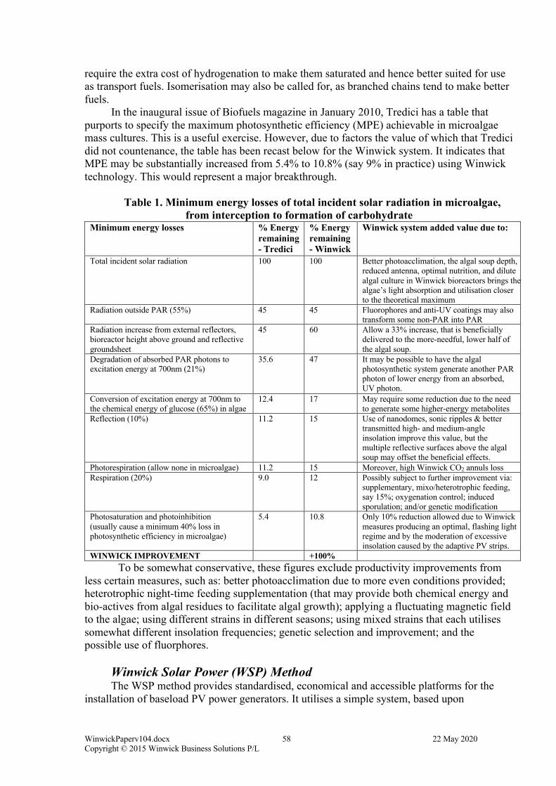
WinwickPaperv104.docx 58 22 May 2020 Copyright © 2015 Winwick Business Solutions P/L
require the extra cost of hydrogenation to make them saturated and hence better suited for use as transport fuels. Isomerisation may also be called for, as branched chains tend to make better fuels.
In the inaugural issue of Biofuels magazine in January 2010, Tredici has a table that purports to specify the maximum photosynthetic efficiency (MPE) achievable in microalgae mass cultures. This is a useful exercise. However, due to factors the value of which that Tredici did not countenance, the table has been recast below for the Winwick system. It indicates that MPE may be substantially increased from 5.4% to 10.8% (say 9% in practice) using Winwick technology. This would represent a major breakthrough.
Table 1. Minimum energy losses of total incident solar radiation in microalgae, from interception to formation of carbohydrate
Minimum energy losses % Energy remaining - Tredici
% Energy remaining - Winwick
Winwick system added value due to:
Total incident solar radiation 100 100 Better photoacclimation, the algal soup depth, reduced antenna, optimal nutrition, and dilute algal culture in Winwick bioreactors brings the algae’s light absorption and utilisation closer to the theoretical maximum
Radiation outside PAR (55%) 45 45 Fluorophores and anti-UV coatings may also transform some non-PAR into PAR
Radiation increase from external reflectors, bioreactor height above ground and reflective groundsheet
45 60 Allow a 33% increase, that is beneficially delivered to the more-needful, lower half of the algal soup.
Degradation of absorbed PAR photons to excitation energy at 700nm (21%)
35.6 47 It may be possible to have the algal photosynthetic system generate another PAR photon of lower energy from an absorbed, UV photon.
Conversion of excitation energy at 700nm to the chemical energy of glucose (65%) in algae
12.4 17 May require some reduction due to the need to generate some higher-energy metabolites
Reflection (10%) 11.2 15 Use of nanodomes, sonic ripples & better transmitted high- and medium-angle insolation improve this value, but the multiple reflective surfaces above the algal soup may offset the beneficial effects.
Photorespiration (allow none in microalgae) 11.2 15 Moreover, high Winwick CO2 annuls loss Respiration (20%) 9.0 12 Possibly subject to further improvement via:
supplementary, mixo/heterotrophic feeding, say 15%; oxygenation control; induced sporulation; and/or genetic modification
Photosaturation and photoinhibition (usually cause a minimum 40% loss in photosynthetic efficiency in microalgae)
5.4 10.8 Only 10% reduction allowed due to Winwick measures producing an optimal, flashing light regime and by the moderation of excessive insolation caused by the adaptive PV strips.
WINWICK IMPROVEMENT +100% To be somewhat conservative, these figures exclude productivity improvements from less certain measures, such as: better photoacclimation due to more even conditions provided; heterotrophic night-time feeding supplementation (that may provide both chemical energy and bio-actives from algal residues to facilitate algal growth); applying a fluctuating magnetic field to the algae; using different strains in different seasons; using mixed strains that each utilises somewhat different insolation frequencies; genetic selection and improvement; and the possible use of fluorphores.
Winwick Solar Power (WSP) Method The WSP method provides standardised, economical and accessible platforms for the
installation of baseload PV power generators. It utilises a simple system, based upon
WinwickPaperv104.docx 59 22 May 2020 Copyright © 2015 Winwick Business Solutions P/L
thermally-moderated, laminated strips that adjust the coverage of the PV progressively to optimise insolation between the algae and the PVs.
The PV fluting system serves a fivefold purpose: shielding the algae from excessive or damaging heat and insolation (sunlight); facilitating optimal algal acclimation by moderating insolation to the algae across day, weather and season; producing solar electric power to run the machinery and to generate substantial excess power for sale; strengthening the envelope around its area of prime, near-horizontal exposure to degradative, solar radiation and weathering; and to provide the alternation of light and dark to the moving algal soup that is necessary to gain optimal PAR usage, without photoinhibition. As far as is technically possible and is most economical for the thin-film PV material and fluting dimensions to be used, the width of the strips and the intervals between them is to be calculated so as to provide sub-second light and possibly longer dark-recovery intervals between light exposures that result from the modest velocity of the soup along the bioreactor that is, in turn, provided by the relatively slow-spinning impeller blades.
Any of several existing commercial or near-commercial brands of flexible, thin-film, PVs may be employed. PVs using CIGS material (Copper, Indium, Gallium Selenide) set in nanopolymer dots, or the newer, cheaper and less hazardous CZTS (copper zinc tin sulphide, Cu2ZnSnS4) or Cd/Te (cadmium/tellurium) or organic polymer PV technologies that may use quantum dot technology to capture more of the insolation energy are possible options, providing the use of glass can be replaced by polymer for location inside Winwick’s protective fluting. The quantum dot effect is able to capture more photonic energy than is an ordinary PV system as it is the quantum crystalline structure that resonates incrementally with virtually the whole energy of a captured photon, rather than the photon either having insufficient energy to displace an electron from the molecule or wasting its excess energy as heat from so doing. Quantum resonation is apparently capable of knocking off more electrons than there were recent photons captured, thereby substantially increasing the efficiency of photonic energy capture and thus producing both more PV power and less heat – both desirable consequences. It is said that there is reason to believe that you can (eventually) get efficiencies between forty and sixty percent by this means.
There is advantage with using any PV system that uses a highly reflective lower electrode (such as a thin layer of stainless steel), as this would tend to re-reflect light insolation reflected by the various layers in the bioreactor back to the algae. Acute solar angle reflection from the upper PV surface layers would also tend to be reflected into the algal soup. The width and spacing of PV strips along the envelope would be selected at assembly time in order to suit the climatic conditions of the site and the algal strains for which the bioreactor is being built.
FERTILISER FOR THE BIOREACTORS Particularly in remote locations, and possibly even before the pipelines to the outside
world have been laid, it may be advantageous to process local biomass using the WSS process to produce initial biofuel and the recyclable fertiliser (nutrients) with which to charge the bioreactors. Sources of local biomass might include: chipped-up weed species or accessible and regeneratable vegetation (coppicing); crop, forestry or agribusiness waste; or raw sewage and other wastes from workers installing the biofarm and biorefinery or from nearby agribusiness, towns and mining camps. Fertiliser minerals may also be sourced from nearby mines or mineral processing operations (possibly from their waste products); from local hydrocarbon or mineral deposits (leaching technology can utilise quite low-grade minerals); from mineralised ground water; or as a last resort be transported-in, in the form of commercial, bulk fertiliser. Longer term sources of cheap fertiliser and trace elements may include locally-produced, WAS nitrogenous fertiliser, mined minerals, piped in sewage, flue gas components, and other agribusiness and industrial wastes.
WinwickPaperv104.docx 60 22 May 2020 Copyright © 2015 Winwick Business Solutions P/L
The following text, highlighted in rose, relates to the design and operation of the bioreactor farm, which some readers may prefer to skip. The items are not included in Winwick patent claims, though they are published in the accompanying published text, so are notionally not legally patentable by others.
MICROCOMPUTER AND POST Each impeller/harvestor unit has its own controlling microcomputer and communications
system. These are located in a hollow, sealed (but openable) polythene post, standing buried, except for its insulated cap, just outside the impeller unit and located in the narrow corridor between pairs of impeller/harvestor units.
Proprietary lightning rods protect the whole system electrically. To save cost and minimise shrapnel damage to the nearby bioreactors when hit by lightning, these rods are made from aluminium-coated, hollow polymer fibres, resin-bonded over polymer pipe in the shape of a feather-topped javelin, the feathers being the unbound ends of the metallised fibres. The exposed javelin shape fits over a lower, part-buried part made of hollow, injection-moulded, aluminised polymer, anodised aluminium, other metal or metal-coated ceramic. This has a coarse screw thread ending in a point and a hexagonal top, by which rotational and downward pressure may be applied to drive the screw deep (~450mm) into hard ground. The feathered top of the rod is comprised of conductive fibres that emit electrical charges into the air, thereby preferentially attracting lightning strike. Inside the hollow screw, which has designed-in, vertically weakened lines, is an amount of harmless, coloured powder or dye that, when dispersed by a lightning strike and/or water, shows up on aerial inspection as requiring rod replacement and inspection.
The temperature-sensitive microcomputer is buried sufficiently deeply as not to require temperature control. Being of low power, it should not require cooling beyond that provided by the soil. However, if necessary this earth-cooling can be augmented by a conductive rod, screwed or driven into the soil of the posthole and linked thermally or thermodynamically to the microcomputer.
Sensors gather data about conditions and the operation of each quad of four bioreactors, passing it to the microcomputer for action and/or forwarding via fibre-optic cable to central control. Similarly, the microcomputer stores a revolving log on itself, its two (or four if acting as backup) bioreactors, its impeller/harvestor unit(s), its production, sensor readings and external conditions, including pipeline pressures. Some of the more, regionally-specific data, such as weather, particulates and insolation, are gathered by several area microcomputers, each linked to appropriate sensors. Microcomputers recording both types of data send it progressively to the central controller using intranet technology and the fibre-optic network. In the event of communications breakdown, each microcomputer is programmed to operate as best it can, without guidance. To ensure power continuity in the event of powerlines going down, each microcomputer might be given its own PV power source, perhaps mounted on the I/H barcode plank and feeding a rechargeable battery in the microcomputer post.
Software in the central system receiving the data, analyses it online and directs the attention of the staff to interesting events or states. This activity includes displaying the data in real time and in historical and statistical context, so that immediate action can be taken, probably guided by an expert system and/or an expert who is online and may be located anywhere in the world, to take advantage of time zones, disabilities and wage rates. A colour-coded map of bioreactor states is displayed at central control, together with the program of planned activity.
Communications capabilities of and to each microcomputer and surveillance pole would include the ability of field staff near a pole to communicate directly with campus staff, via
WinwickPaperv104.docx 61 22 May 2020 Copyright © 2015 Winwick Business Solutions P/L
more than one sense, without the need of any personal, communications equipment. A key word, such as “Help”, would be recognised instantly by the central computer, allowing it to patch a conversation through to a human operator. So, for instance, when in aural (hearing) range of a surveillance pole described below, rookie field staff could be guided by campus-based, experienced staff, remote advisors or suppliers, or an expert system in a difficult or unusual diagnostic and repair task or activity.
FARM SECURITY SYSTEM As well as multiple, perimeter security fences, mobile regional surveillance, and the
aforementioned, passive means of protecting the bioreactor farm, active local measures are also included. The centre of every cluster of four bioreactors (quad) has its own surveillance pole. This is a combined, pole-mounted, centrally-controllable, and directable: video camera (with zoom lens), motion-detector, directional microphone & loudspeaker, LED spotlight, mirror, and pressure hose with various nozzle settings and liquid content options, including ammonia. For instance, a nozzle that has been elsewhere designed for fire-fighting that reduces liquid jet dispersion and increases the throw distance might be used to project liquid to most parts of each bioreactor and its environs for the purposes of deterrence, cleaning, cooling or watering. Surveillance poles on nearby quads may be sited at different distances along each quad, so that together they control the full length of all the bioreactors concerned.
Night vision capabilities of the security system would only be included if they are economic, and possibly then only included for a minor proportion of quads. Routine operation of the surveillance pole security system will be controlled by one of a quad’s two microcomputers, with failsafe backup from the other, for both bioreactor operation and security purposes. Pole units also have one or more direct current outlets for use by maintenance staff when servicing each quad of bioreactors. These can be used to charge (possibly backpack-mounted) powerpacks and electric vehicles, or to power tools directly.
PIPING For purposes of easier management, neatness, standardisation, mutual protection, cost
and insulation, the different pipes, fibres and wires required to service the bioreactors are combined in their own cluster or pipe bundle. Bundles are made from thermoplastic polymer, typically polythene. They are formed thus: the hot water pipe is produced first, then its insulating foam and protective skin covering. This composite pipe is then drawn through a complex extrusion die that adds the other pipes, voids, conduit channel and possibly an outer, protective skin or insulation. A separate strip is extruded that clips into the conduit channel to seal it, accessibly. Any water that manages to pass the seal is drained off at junctions.
The cross-section of the pipe bundle is shaped akin to the phytotubes in cross-section and can fit, with spare space above, under the trapezium-shaped tunnel of the impeller/harvestor unit. The different sized pipes and conduit are so arranged within the bundle as to minimise construction material required and to optimise space usage, insulation requirement, protection and accessibility. Some of the pipes in the bundle are able to serve different purposes at different times, thereby providing for future requirements and backups. This provision may be particularly useful as algal cultivation at bioreactor farms becomes more diverse and sophisticated, and as it requires different strains and additives for different sets of bioreactors at different times.
The pipe bundle comprises: fifteen pipes; many voids to save material and improve insulation; a conduit duct and its clip-in cover; and possibly an outer, protective skin. The pipes come in three standard sizes having diameter ratios 3:5:8. Of these sizes, there are 4, 8
WinwickPaperv104.docx 62 22 May 2020 Copyright © 2015 Winwick Business Solutions P/L
and 3 of each pipe, respectively. One of the largest, that for the hot (60-800C) HFR water (or cooling water in hot times), has insulating, polymer foam sandwiched between a thin, outer polymer skin (spirally wrapped on the foam) and the inner pipe wall. Otherwise, where two pipe walls merge in the bundle, their combined wall thickness is that of the larger pipe. This saves on material. The lower, outer sides of the pipe bundle are slightly thickened for additional protection.
The pipe bundle system has three additional components – an offtake bundle section; a multiple, male-male connector plate; and a similar plate connector incorporating remotely-controlled valves for each pipe for isolation purposes. Pressure reduction valves ensure that the high pressure in the larger mains is not fully transmitted to pipe bundle PE mains, thereby reducing the likelihood of blowout. The special offtake bundle section is needed to make the task easy of linking individual mains pipes, which are often buried inside the bundle, to their respective piping in the bioreactor. This requires a bundle that alters pipe and void shapes, and possibly sizes, at locations where an offtake is to be made. For connection purposes, each smaller offtake pipe is long enough that it will extend beyond the bundle of mains pipes to which it is attached at the other end. This, special, sinuous, complicated offtake bundle section is standardised for all bioreactors. Such a complex shape is not suited to moulding techniques, possibly not even to those formed from combinable slices. Instead, to form the offtake bundle, fifteen separate pipes, laid together, are conveyed lengthwise on conveyor belt along a production line.
At precise spacings, smaller T-junctions are inserted in each colour-coded mains pipe and short, similarly colour-coded offtake pipes are attached. These pipes typically have strategically placed and shaped, flattened bulges, at least within the part of their lengths that will end up within the offtake bundle, so as to avoid increasing pipe resistance overmuch, while at the same time as making it easier to thread them past outer pipes. The cross-sections of such bulges will typically be roughly elliptical. At both ends, offtake pipes are circular in cross-section to permit ready connection. When all smaller offtakes for a given section of offtake bundle are connected to mains offtakes, all mains pipes in that section are cut at the same point and each pipe end is fitted onto its matching male connector plate projection. After these connections have been made, the offtake pipes are threaded upwards, between any pipes above, to come out at standardised places on the top surface of the offtake bundle. The bundle is then bound together either by long cable ties and/or tough PET or carbon-filled polythene (possibly shrink-wrapped) wrapping. The shape of the resultant bundle is made as to fit inside the impeller/harvestor’s trapezium-shaped tunnel running underneath its mid-section. Due to the offtakes, the offtake bundle is taller than the ordinary pipe bundle.
Holes are provided in each impeller/harvestor unit for each of the offtake pipes or connections. Typically, these holes are located at roughly equal intervals along the base of the chamber connecting the impeller halves. After the colour-coded pipes threading these holes are threaded and attached to their colour-coded mates inside the impeller/harvestor unit, the hole edges are sealed with formed polymer seals, polymer putty and/or hot melt polymer to prevent unwanted passage.
The general-purpose bundle connector plate mentioned above is used to connect both standard pipe bundle lengths together, as well as offtake bundles to standard pipe bundles. The connector takes the form of a connection plate having some fifteen, joined, hollow, male, pipe connectors on either side. It is formed by injection moulding high-density polythene (HDPE). The ordinary pipe bundles are simply pushed over their matching plate, male connectors, the whole bundle then being secured by long cable tie or ties. The projections are slightly tapered at their outer end to make it easy to fit them into the matching pipes. They are also ribbed with annular, backward-pointing ribs or barbs to make the connection stronger. As the bundles, pipes and connectors are somewhat flexible, the lower connections can be seen to be correctly begun, thereby assisting the middle and upper linkages to be accurately made.
WinwickPaperv104.docx 63 22 May 2020 Copyright © 2015 Winwick Business Solutions P/L
The contents of the fifteen pipes in the pipe bundle are as follows. The three largest diameters contain either: hot water, cooled return water, or algal slurry. At suitable intervals, adequate slurry flow is maintained by additional pumps. The eight middle-sized pipes contain either: algal soup; cyanobacterial soup; sterilised, typically-brackish bore water; carbon dioxide (CO2) gas; 90:10 oxygen O2/CO2 gas mix; distilled or sterilised fresh water; mixed nutrient water from the anaerobic digestor, ammonia plant, and/or the supercritical water reactor (that partly oxidises lipid-depleted algal biomass to syngas, thereby also releasing its macronutrients) that may have subsequently been sterilised; and bubblemix brine. The four smallest diameter pipes contain either: nutrient mixes #1, 2, 3 or 4; or inoculants of seasonal or replacement algal strains that temporarily replace the contents of one or more of the nutrient mixes. The nutrient mixes themselves are so specified that they can be combined in various ways to make many different, algal media, nutrient mixes. Each can also be temporarily replaced to address a particular situation. Any replacement will typically be preceded by a flushing operation. The contents of the conduit include any wire, fibreoptic or other cable that is necessary to conduct power or communications.
Due to the proximity of parallel bioreactor pairs, it will be convenient to make a single length of offtake bundle serve two impeller/harvestor units and hence four bioreactors. The wider distance between neighbouring parallel bioreactors, not in the same quad (two pairs), will use standard, pipe bundle, as will the attached end of each kytail.
When polymer-based pipe bundles reach the first road on the bioreactor farm, their component pipes are typically separated and joined to larger diameter polymer, composite or steel pipes carrying similar contents. Isolating valves, controllable remotely, occur periodically along most pipes. The type and size of pipe used depends on the physical capacities of each and the relative economics. These pipes are laid at roadsides, sometimes on sleepers, themselves laid directly upon virgin gibber or sandy surface, with little disturbance. Where these pipes cross roads, they may either be elevated or covered by gibber/gravel under hooked-together-plastic-hexagon mats that adjust to the surface contours and permit light traffic to pass over them without damage and with little erosion. Each hexagon is formed by injection-moulding polythene into a waffle-sided mould containing the central part of an assembly of six radial, anti-corrosion-treated steel wires that end in a broken ring or crook with springy opening. The hexagons can be linked to each other in an open-weave mat. The internal diameter of the rings is sufficient to permit the mat to adjust its contours to moderately uneven surfaces.
The access problem and cost is minimised if transverse access ways are divided into alternate vehicle access ways and pipe access ways, the latter not permitting side access by heavy vehicles, due to the presence of pipes lying on the ground along both sides of the access way. However, access by light vehicles such as quad bikes and hovercraft is made possible by the mat technology. Thus, an access way crossing a pipe access way would have two “speed bumps” over where the pipe sets lay, with a half height level joining the two sets, all covered by the one, flexible mat of roughly 10x4m dimensions over gravel or sand mounds covering the pipes. The gravel may consist of gibber stones swept up, raked, or graded along, from the access ways.
The remaining problem of pipes entering the main arterial road is solved by elevating the pipes on supports, so that traffic passes under them. These larger diameter pipes are likely to be of steel and fixed in parallel on elevated, transverse supports, rather than bundled. Some may need to be insulated. Where necessary, additional pumps along the pipelines help push material through the pipes. Occasional, transverse links and remotely-controlled valves joining the matching set of pipes on each side of the main arterial road deliver an extra measure of backup for similar-content pipes in each set. All mains pipes are in the form of loops, so that a blockage, breakage or interruption at any one place need not prevent service delivery elsewhere.
WinwickPaperv104.docx 64 22 May 2020 Copyright © 2015 Winwick Business Solutions P/L
PIPELINE TRANSPORTATION External piping systems to ports, cities and other industries can be highly advantageous
to Winwick operations. They are also typically the most efficient and reliable means of transporting bulk fluids. However, with good design they may also be employed to transport solids – either as slurries in liquids or by the use of neutrally-buoyant containers carried by the fluid within the pipeline. One of the additional benefits of containerised transport in a pipeline carrying containers immersed in a fluid, that may itself require transportation, is that the containers may contain any one of many different goods or materials, and may be in the form of assemblies, solids, liquids or even compressed gas.
Being typically located in temperate deserts, Winwick bioreactor farms are likely to be remote from transportation corridors and that those services that do reach the site will tend to be expensive, uncertain (due to weather and lengthy breakdowns that are common in harsh conditions), possibly infrequent, and that each trip (unless by air) would tend to take a long time. The facility’s construction, operation, staff and communities will require much in the way of materials and the processing facilities will produce possibly a wide variety of products. Therefore, it would be most useful, were as much as is reasonably possible of these material movements be done by way of pipelines.
Pumping specially-designed containers, termed slugs or capsules, by pipeline adds challenges to the pumping technology used, but nothing that is unachievable. The key to high functionality and efficiency lies mainly in the design of the slugs. One feasible design involves a plastic, metal or composite material hollow slug or capsule in the shape of an elongated doughnut, of slightly less diameter than the enclosing pipe, with a separate container core. If in plastic or metal (an aluminium alloy perhaps), except for their caps, both containers might be moulded in the one operation. The somewhat rounded shape of the slugs might be similar in external shape to the multi-sized, blue plastic drums with openable ends, that are now used to hold and transport granular and liquid chemicals. The doughnut typically would contain the main, liquid or granular contents. The central hole or core is in fact a separate container, designed to contain material of sufficient weight as to make the slug and its contents of neutral buoyancy in the relevant carrier liquid – its function being akin to that of a fish’s swim bladder. The weighting material may be goods requiring transportation in their own right or else cylinders of varying length, made out of a very dense material, such as depleted uranium, immersed in either gas or liquid, possibly water or a hydrocarbon. Such would allow the most flexibility in the choice of carrier liquid and slug contents. The weights would be secured centrally to ensure an even keel and thus minimal frictional contact between the capsule and the pipe’s walls. Water or air might be used as trade-balancing materials for weights building up undesirably at one end of a pipeline.
Movement of refrigerated materials might be effected by the insertion of dry ice (frozen carbon dioxide) packs in the cores, with the excess pressure from the evolved gas being vented at a given quite-high pressure into the carrier fluid and thence to an external pipe for recycling.
As well as possible external colour-coding, the capsules, or insertions for them, would have internal, distantly readable and reprogrammable electronic tags, possibly similar to some RFID tags used in shops, vehicles and warehouses. Separate ones of these would identify barrel identity, doughnut and core contents. Some tags might be programmable as goods manifests, bills of lading or delivery dockets. The capsules would probably be returned to the facility via a different pipeline, one probably using a different carrier fluid. The network of such pipelines and their interchange nodes and transfer stations might well eventually form another common carrier delivery system, like that of the post office, shipping companies or internet.
WinwickPaperv104.docx 65 22 May 2020 Copyright © 2015 Winwick Business Solutions P/L
Both types of container in a capsule would require both effective sealing and seals that could be quickly released and their contents removed by automated equipment. The surfaces of the capsules would also need to be readily and thoroughly cleansed of carrier fluid or material that might be as penetrating as light organics or of hazardous material. Different caps, seals, nozzles or apertures might be required for different types of content.
FARM LAYOUT Each bioreactor foursome (quad) is attached to its pipe bundle rather as decorative
material is attached in a regular pattern on the tail of a kite (call it a kytail here, for future brevity). There may be many such ‘dragonfly wing’ or quad attachments on a given kytail.
On the bioreactor farm, kytails are laid out inside rectangles, each measuring 1x2km (or standard variants thereof), with access ways separating them. Formed access ways are of three kinds: arterial, heavy vehicular, and pipeline/light vehicle. Only the first two are likely to be sealed. There are two levels below these of unmade access ways. The first of these types is the irregular-width paths or areas between adjacent kytails. The second type is the irregular-width access ways between bioreactors, which themselves have two variants, only the wider of which is accessible to full-width vehicles. The other is accessible typically by foot or by the wheels of one side of a special vehicle that can straddle a bioreactor and is used to lay and replace them.
The pattern, individual length, curvature and spacing of the kytails within each rectangle are controlled by the topography and access requirements. One end of each kytail is at one of the pipeline-access edges of the rectangle. The other depends on: how far the kytail and its bioreactor quad “dragonfly wings” can extend before they interfere with either: other wings; rectangle edges; with allowing vehicular accessibility to the far ends of the bioreactors; with other farm structures; or with meeting with unsuitable topography, land surface or vegetation.
Each bioreactor is laid on the contour line at which it intersects its kytail. Bioreactors will begin to be laid out approximately orthogonal (at right angles to) to the direction of their kytail at the junction point. They have some, but very limited ability, to follow gentle horizontal curves in the contour. Topography with tight contours is not suitable for Winwick bioreactors without significant modification to their structure, layout and support. However, as the preferred location for Winwick bioreactor farms is flat, gibber plain (typically wind-polished or eroded, sometimes flat, smallish stones over clay, sand or gravel), pan, desert or flat areas with similar, barren topography, relatively little space should be lost because of topography. Note, that whilst sand and gibber plain can both offer suitable terrain for Winwick bioreactors, gibber stones of a type that have a very rough, unpolished surface to them or which do not form an even layer, and sand that is in the form of dunes, particularly mobile ones, are less suitable.
Although Winwick bioreactors are designed to be laid on undisturbed surfaces, this may not always be possible. In such cases, grading to provide flat, clean surfaces along contour lines for the bioreactors may be advisable. Any soil, plants or surface debris would simply be shifted slightly to the down-slope side of the low terrace. No compaction would be required.
Flat, barren land, with gradients of two degrees or less is most suitable for Winwick biofarms. However, smooth gradients of up to four degrees inclination are also feasible, though they may require light grading on the contours along which the bioreactors are to be laid in terraced form. Such grading might be done most cost-effectively by the use of robotic or remotely controlled graders (unmanned ground vehicles or UGVs) utilising three-dimensional GPS and programmed paths. Similar grading may also be required when there is vegetative cover or overlarge stones that need to be pushed aside from the planned bioreactor beds. The terracing might need to be the width of one, or possibly a quad of bioreactors, which is about three to seven metres wide and 204 metres long. The grader might go in elongated loops to
WinwickPaperv104.docx 66 22 May 2020 Copyright © 2015 Winwick Business Solutions P/L
form these terraces using the least distance. A downside of grading may be disturbance to any topsoil crust that could be holding the soil in place. Spraying with a temporary binder may occasionally be required.
Detailed aerial or satellite mapping, using global positioning systems (GPS) accurate to within a few centimetres vertically and within half a metre horizontally, together with computer software and algorithms to determine the densest practical kytail pattern would be used to plan and populate the layout of each rectangle’s kytails and bioreactors. Triangle-overlaid worldwide topography from the following free database may be adequate for the task: http://www.gdem.aster.ersdac.or.jp/feature.jsp
Pipe bundles, impeller/harvestor units and bioreactors are typically laid directly onto flat, virgin, gibber plain, bare sand, clay, limestone plain, salt pan (or equivalent) surfaces.
ACCESS WAYS The immediate access ways to bioreactors are typically by sand plain or virgin gibber
surface, typically using vehicles with soft, balloon tyres to minimise disturbance and jolting. In areas where travelling dunes occur, known methods of dune stabilisation may be required.
When necessary, any small, normally dry rivulets meandering across the plain may be spanned with one of a range of mass-produced, expanded and reinforced, metal-mesh plates, wired over similarly mass-produced inverted, triangular cross-section, skeletonised, metal bearers and possibly transverse pipes of various, selectable dimensions. The number and type of these components required for a given area may also be estimated by software, using the digitally-mapped satellite or aerially-mapped topography and plans.
The main road artery and every alternate side branch are either sealed or covered with polymer-based ‘carpet’. This means that, for a bioreactor farm of 30x34km (~1000km2), there are some 34+17x30=544km of mainly single-lane, sealed road, laid typically directly onto virgin, gibber surface, though perhaps with a preparation of some dilute, sprayed adhesive (possibly cheap polyvinyl alcohol (PVA)) and wetting agent to bind the sand beneath, thereby strengthening the road bed economically. Where the gibbers are exceptionally large, rough and separated, it may be useful to ‘steamroll’ or ‘thumper’ them in to the ground to form a more even base for the bitumen. Additional rock base might also be raked in from either side.
FARM INFRASTRUCTURE Besides roads, pipes and fences, a bioreactor farm has located on it powerlines,
electricity transformers, communications lines and concentrators, and possibly power storage mechanisms (typically batteries). It might also be possible to collocate wind turbines on any area of a biofarm that was unsuitable for bioreactors, such as raised, rocky outcrops or hills. The power from the wind turbines could share the powerline infrastructure needed for the PVs.
FERTILISER FOR THE BIOREACTORS Particularly in remote locations, and possibly before the pipelines to the outside world
have been laid, it may be advantageous to process local biomass using the WSS process to produce initial biofuel and the recyclable fertiliser with which to charge the bioreactors. Sources of local biomass might include: chipped-up weed species or any accessible, possibly regenerant, vegetation; crop, forestry or agribusiness waste; raw sewage and other wastes from construction, biofarm and biorefinery workers; or from regional agribusiness, towns and mining camps. Fertiliser minerals may also be sourced from nearby mines or mineral processing operations (possibly from their waste products); from local hydrocarbon or mineral deposits (leaching technology can utilise quite low-grade minerals); from mineralised ground
WinwickPaperv104.docx 67 22 May 2020 Copyright © 2015 Winwick Business Solutions P/L
water; or as a last resort be transported-in, in the form of commercial, bulk fertiliser. Longer term sources of cheap fertiliser and trace elements may include locally-produced, WAS nitrogenous fertiliser, mined minerals, piped in sewage, flue gas, and other agribusiness and industrial wastes.
ADVANTAGES OF WINWICK ALGACULTURE TECHNOLOGY The particular advantage of Winwick algaculture technology overall, beyond its simple
economy, its relatively low capital cost, its minimal ecological footprint, its production of baseload solar electricity, its high productivity and scalability, is that it frees algal strain selection, breeding and modification from concentrating solely on those few species that give high proportions of lipids. It is to be noted that robust algal strains, having the highest biomass productivity per time period, which are often several times that of lipid-rich strains, tend to be those with low or modest lipid content. Prolific, fast-growing and robust species that tend to produce carbohydrate rather than lipids may now be seriously considered for oil production, as their carbohydrates may now be converted efficiently and economically into oils and other feedstock chemicals. The only minor downside of carbohydrate conversion appears to be that more of the nitrogenous content might possibly be lost than would be the case when the biomass is anaerobically digested to release the nutrients. However, any loss can easily be replaced by one of several means, such as: using a higher proportion of Winwick bioreactors to grow nitrogen-fixing blue-green algae/cyanobacteria (these do not accumulate storage lipids, but produce bounteous carbohydrate); by employing the WAS process; by bringing in commercial, nitrogenous fertiliser (not preferred); or by processing local (e.g. vegetation) or other biomass (e.g. sewage) in the WSS to release its nitrogenous nutrients for use in growing algae.
PROCESSING PLANT Traditional processing plant at Winwick facilities includes various, relatively standard,
chemical engineering units, such as liquid, slurry and gas pipes, heat exchangers, filtration plant, centrifuges, pumps, valves, sensors, actuators, fractional distillation towers, storage reservoirs, tanks, ponds, and possibly, but not necessarily, anaerobic digestors.
Novel processing plant includes: profiled drillhole reactors for WCR, WMS, WFTAS, WSX, WSS, WSC, WDS, WAS, WNAS, WHL, WHC and WLE purposes, together with possibly WOF units to separate the biofuel products. The novel WMG and WSP plant is located in the bioreactor farm areas, the others at campus processing facilities.
Process breakthroughs come from three, newly perceived opportunities: • to use the clean, heat energy and power obtainable from geothermal resources
and bioreactor-mounted, thin-film PVs to power a biorefinery and to use the waste heat therefrom to warm the bioreactors in cold periods to algal activation temperatures. Waste heat from the hot water produced as a by-product of functioning oil and gas wells, or from solar ponds may also be used to keep algae activated;
• to use the pressures available from pumping fluids (including entrained gases) down deep (sometimes pre-existing) drillholes to drive a wide range of physical and chemical engineering processes most economically and sustainably, including those of:
o organic cell rupture o lipid esterification o biomass breakup, depolymerisation and dissolution o hydrocracking large organic molecules into smaller ones o deoxidation and upgrading of bio-oils o molecular fraction separation
WinwickPaperv104.docx 68 22 May 2020 Copyright © 2015 Winwick Business Solutions P/L
o sub and supercritical water gasification (SCWG) of biomass o supercritical water partial-oxidation (SCWPO) of hydrocarbons and
organic waste (including gassy slurries of algal cell walls left over after lipid extraction, or similar organics ranging from forest and agribusiness wastes, bagasse, weed species, organic rubbish, mixed plastic waste, lignite and/or sewage) to produce syngas
o Fischer-Tropsch (F-T) reactions to produce fuels and chemicals from inputs such as syngas, utilising catalysts and promoters disseminated throughout heavy oil, wax or other carriers, that are liquid at the operating temperatures, and into which have been introduced bubbles of reactant gases that are adiabatically compressed or otherwise heated and cooled so that they react together, in the presence of catalysts, as they are pumped down and up the parallel, drillhole reactor pipes and annular passages
o Other similar, pressure/temperature-driven reactions, such as methanol, DME, ammonia, and nitric acid (precursor) syntheses
• to use the cultivation of algae to biosequester CO2 and to produce a 90:10 O2:CO2 gas mix that can be used locally to produce syngas from algal biomass, or methanol from methane, or be transported by pipeline and used by industry for combustion, refining, water remediation, and/or chemical synthesis operations.
WDR BENEFITS The benefits of using a fast-moving, carrier liquid, in a continuous process, to conduct
reactant gases, materials and catalysts down a deep, pipe-in-pipe drillhole reactor to regions of high pressure and sub or supercritical conditions are ninefold. First, the extreme pressurisation achievable and the controllable subsequent depressurisation require almost no energy as gravity does the work, except principally for turbulence and pipe wall resistance pumping energy losses. Furthermore, the extreme pressurisation and harsh conditions cause minimal hazard to operators, as they occur deep underground in a rockbound, sealed container. Second, the decavitation and formation of gas bubbles (cavitation) that occurs during the two-way passage can produce many desirable physical and chemical changes in the slurry. Third, the length of the pipe-in-pipe drillhole can deliver exceptional heat exchange efficiencies and related opportunities. Fourth, the ability of Desai-Zimmerman Fluidic Oscillators (DZFO) to generate monodisperse (same sized) bubbles using close to the minimum energy to do so, means that bubbles of either an inert gas such as nitrogen or a gas that participates in the reactions which are introduced into the downflowing slurry of a Winwick Drillhole Reactor (WDR) will first heat up due to adiabatic compression and then decavitate, all together, at a given depth under the increasing pressure. As the bubbles are attracted to the solid surfaces of the material in the slurry, this means that when they decavitate, the micro-energetics generated by each decavitation (high pressure micro shock waves, twin micro-jets, and instantaneous temperatures in the micro-location of around 5,0000C) are well-placed to effect both physical and chemical changes that would not otherwise occur, unless possibly at much greater bulk temperature and depth. This means that the depth and capital cost of the WDR might be substantially reduced in many circumstances. Fifth, because many of the beneficial chemical reactions are reversible ones, the short interval in which the energetics of a given decavitation occurs may mean that there may be insufficient time for the reverse reaction to occur and for equilibrium to be established, thereby leading to higher product yields. Sixth, because the microjets and micro shock waves will tend to occur at the solid-liquid interface, they will tend to erode the solid, surface material of the slurry, thereby requiring less comminution of it, which in turn saves money and makes installation scale-up easier. Seventh, the pipe-within-
WinwickPaperv104.docx 69 22 May 2020 Copyright © 2015 Winwick Business Solutions P/L
pipe structure of the WDR means that the heat generated adiabatically, by decavitation and chemical reaction is readily available for further heating of a downflowing slurry (possibly that of the same or a different WDR process) to bulk reaction temperature by heat exchange between different, but intimately associated, passages. Eighth, cavitation (bubble formation) and adiabatic cooling on the upwards passage means that less energy is likely to be wasted on unnecessarily hot or phase-changed product. Ninth, because WDR processes can readily be made continuously recirculating ones that require minimal additional energy for their recycling, this means that even chemical reactions that give a low initial yield can be made to give a high yield just by recycling the slurry many times (with progressive bleed offtakes, typically by centrifugal action, the separation of product, and the return of the rest of the material plus reactant additions to the WDR) until virtually all the reactants have been transformed into product. And Tenth, because any deficiency in processing temperature near the base of the WDR, or at the start of processing, might be made up by means of electrical heating elements and sensors encapsulated in gently-helical conduits welded onto the outside of the inner WDR pipe that serves two purposes: to bring the WDR contents to the appropriate reaction temperature; and to apply a centrifugal flow to the slurry that serves to separate the heavier and lighter fractions, the gaseous ones congregating more towards the WDR axis, from whence they can flow unimpeded to the surface, and the heavier solid and liquid fractions being concentrated towards inner side of the outer WDR pipe wall, whence they might selectively be separated and extracted.
Moreover, as decavitation, cavitation and sub/supercritical reactions are harsh on most pipeline wall materials at the depth and conditions at which they occur, it should be possible to give those locations an equivalent of the extruded mucus layer that protects the stomach and gut lining from digestive acid and enzyme attack. The equivalent might be for the pipe walls in these regions to be given porosity whereby microbubbles or benign liquids, such as hot water, could be introduced to provide a barrier to attack on the walls.
Aggregations of heavy sludge at the base of the WDR might periodically be removed by a separate pumping operation.
Operating pressure may be increased almost as much as is desired, simply by either increasing the depth of the WDR or by adding an inert, high density powder (and possibly a gelator) to the slurry to increase its density.
Some Winwick hydrothermal processes can be classified either as carbonization, liquefaction or gasification. On page 24 of this reference https://www-gs.llnl.gov/content/assets/docs/energy/Getting_to_Neutral.pdf it says that hydrothermal processing consists of three sequential stages with different operating conditions. This roughly translates to my description of tuning the operating conditions to produce different results. The paper goes on to say that “Hydrothermal carbonization occurs at temperature below 2500C and forms a hydro-char similar to low rank coal. The process at an intermediate temperature of 250-3700C is hydrothermal liquefaction that produces liquid oil known as biocrude. Hydrothermal gasification reactions dominate the process at temperatures higher than 3700C, and gaseous products are formed. Hydrothermal liquefaction processes can take place both in batch and continuous flow reactors.” And “One of the advantages of hydrothermal liquefaction is that unlike gasification and pyrolysis it can readily process a wide range of moisture content biomass, saving energy that would normally be required for biomass drying and size reduction.”
However, my WDR tuning process encompasses not only temperature change, but also pressure changes, duration, catalysts, promoters, densifiers, solvents and carriers other than water, pH, combustion, adiabatics, turbulence, the energetics of bubble decavitation and cavitation, reactants, separations, condensation, precipitation, heat exchange, slurries, comminution, and processing material successively through multiple WDR processes to achieve the desired outcomes.
WinwickPaperv104.docx 70 22 May 2020 Copyright © 2015 Winwick Business Solutions P/L
DRILLHOLE REACTOR CONSTRUCTION As already discussed, the outer part of Winwick drillhole reactors (WDR) is formed
typically from disused, in-situ drillhole casings – though in some instances new drillholes may be drilled at sites of existing other industries or resources, specifically for reactor purposes. Whilst most useful when drilled into a geothermal resource, they can still serve their reactor purposes drilled anywhere else. Their small footprint and zero operational emissions would allow them to be drilled in locations most suited to obtaining access to input materials or markets, such as beside factories, power plants or agribusinesses, in forests or on transportation corridors. The laser drilling and material expulsion technologies of the Archimedes Project of Geoternity Corporation are claimed to reduce deep, well construction costs by as much as 75%. If/when achieved, they could make purpose-built, Winwick drillholes economic at virtually all sites. Foro Energy has a similar laser-based system that crumbles rock through thermal shock using a commercial 20kW laser firing bursts through 1.5km of optical fibre, and Potter Drilling has spallation technology to drill holes in rock, but uses superheated water instead.
Whilst it has been shown that current lasers have the necessary power to dig into rock rapidly (at rates of up to several cm/sec) and highly efficiently using spallation (causing chips of rock to explode off its surface), remaining problems, such as material removal, power delivery and clear beam access are being addressed. These are likely to be easier to solve for the larger-diameter drillholes required by Winwick and geothermal power requirements.
One solution might well be an oscillating (perhaps 900 rotation back and forth) assembly that can be lowered down the drillhole, mounting one or more lasers. The intermittent laser beams would be directed by mirrors successively into many different quartz waveguides. The wave and gas guides might be a combination, the somewhat retracted waveguides being of solid silica quartz that are both cooled and protected from flying object impact by angled, enclosing, hollow pipes in the metal assembly, down which the pressurised gas flows. The angles determine where each beam hits radially. The beams are angled to spall the rock face evenly as the assembly rotates. The assembly backswing would allow the necessary time for the rock face to cool, prior to new spalling. The waveguides would form passages for both the laser beam and high-pressure, recycling argon gas. The gas would tend to keep clear of debris the path of each beam to the rock face. The slurry of used gas and rock particles would be drawn into a round pipe or annulus and conveyed to a pressurised, sub-surface (for safety) tank that would allow the rock particles to settle into a water bath and be drawn off as in a revolving door that exchanges contents without opening the building fully. Water would be sprayed to capture and settle the fine rock dust. The cleaned, cooled and then filtered argon gas would then be pumped down the drillhole for re-use. A series of gas pumps on the downward gas pipe would progressively increase the gas pressure, thereby reducing the need for very strong gas pipe. The high pressure in the upward gas pipe would ensure that the rock waste slurry did not settle and would be borne upwards. A heavy drilling mud would separate the gas and gas/slurry pipes from the drillhole casing to reduce the chance of drillhole casing fracture or implosion. Annular seals near the top of the laser assembly would separate the gas chamber and spalling/extraction operations from the mud. On drillhole completion or before maintenance, the pipes would be sealed off from the drilling chamber by rotating a lower part of the assembly so that the pipe holes no longer matched, and the annular seals would be released to permit passage of the laser assembly. Between drilling stages, the pipes would be sealed off and the annular seals would be released, thereby allowing the assembly to be lowered before commencing drilling the next section. Water would be introduced into the assembly prior to opening the tubes and using water followed by gas to expel the drilling mud that had entered
WinwickPaperv104.docx 71 22 May 2020 Copyright © 2015 Winwick Business Solutions P/L
the drilling chamber during the relocation. Water from the water and mud entering the surface rock would tend to improve the spallation effect for a time via explosive steam creation.
It is also reported that a variant of Geoternity’s technology can be used to fuse the sides of the drillhole it makes. Should the fusing of the rock be significant and reasonably seamless, then it may be possible to do away with most of the drillhole casing and external concrete lining (perhaps all that except possibly that in the actual, and quite narrow, harsh reaction zone) and to use the drillhole’s fused wall as the low-reactive barrier inside which Winwick processes can take place. The rock type, its fracturing and fluid contents would probably all be important factors regarding the feasibility of this variant. If proven feasible, this method would have substantial cost advantages. It might not matter much if the sides of the drillhole were eaten away slowly by supercritical reactions, particularly if the rock strata there were relatively impermeable, as the main result would be simply an enlarged reaction chamber or passage and some additional, but possibly minor and unimportant, mineralisation of the product fluids. Dissolved rock components in the products would not appear likely to cause later separation difficulty or other serious problems. Large, old reaction chambers might even find uses for storing seasonal water, resource gas, input liquid waste, or output biofuels and chemicals.
Although WDR can work using simple piping, the central WDR pipe, and sometimes one or more of the concentric outer pipes, is typically profiled. That is to say, it or they will often have one or more constrictions inserted, beyond those that secure an inner pipe to an outer one. Constrictions first compress then decompress the reactants, as well as contributing to their mixing. When constrictions and deconstrictions are formed in series along the drillhole reactor passages, the capability is constructed of having successive zones where decavitation of bubbles is followed by cavitation to form many more sets of them. Thus, the beneficial effects of decavitation on physical and chemical reactions may be multiplied manyfold. To ensure this effect, the deeper deconstrictions may need to be more extreme than shallower ones, in order to overcome the additional pressure before cavitation can take place. Constriction may be achieved by varying the pipe cross-section at locations along it by means of insertions. Care will need to be taken that the constrictions do not result in an undesirable amount of pipe hammer (knocking and vibration).
Should a given reaction benefit from having serial constrictions and deconstrictions at a given pressure range, then the drillhole reactor may take the form of a U-tube. Drilling technology can now drill curved holes in rock with great control. Thus, a drillhole might be angled down to, say, a kilometre depth, then level out for three kilometres, then curve up to the surface. Should the drillhole casing include a constriction every three metres along the horizontal section, there would be a thousand of them. This in turn would mean that large populations of microbubbles would appear by cavitation and disappear by decavitation a thousand times during the passage. As each decavitation, with its associated highly-localised temperature spike, jet and shock wave effects, would be likely to convert some of the reactants into products, the overall reaction might proceed quite rapidly – even when the bulk temperature of the mix was not nearly high enough under other circumstances to progress it.
The nature of the constrictions and deconstrictions is likely to be important. It is suggested that these be of a smooth and relatively gradual nature, so as not to cause much energy-consuming turbulence or pipe hammer. Tapered-wall, sleeve-like constrictions may be inserted later into a drillhole casing having an even, internal diameter. The changing velocity (and hence pressure by Bernouilli’s equation) of the fluid caused by these cross-sectional differences, their magnitude and separation, the bulk temperature, the presence and quality of nucleation sites and materials, and the lowest boiling point of the various (and changing) chemical constituents of the mix, would ensure that each cavitation event was followed by decavitation. However, in order to optimise these events and their effect on progressing the desired reactions, the pressure, temperature, gas mix and proportional mass will need to be controlled. Methods of fine control include changing: the amount or type of densifier or
WinwickPaperv104.docx 72 22 May 2020 Copyright © 2015 Winwick Business Solutions P/L
catalyst in the reaction mix, the concentration of reactants, the overpressure, the gas content, the individual mass of each bubble, and/or the initial temperature of the mix.
An alternative method of creating a series of decavitation/cavitation events in a drillhole reactor, and one that may be more effective, more economical and better controllable, may be to use sonics to effect them. Thus, in the depth range where cavitation occurs under a given set of conditions, sonic waves generated by piezoelectric transducers could produce the series of pressure waves and rarefactions that would cause many such decavitation/cavitation sequences. Combined with a modicum of turbulent mixing, this would tend to ensure that all parts of the reaction mix experienced decavitation effects sufficient to cause nearly complete reaction, or at least as much as is allowed in a given and effectively quenched equilibrium reaction. There is already a substantial body of literature dealing with sonically-mediated reactions, called sonochemistry.
The Winwick method of joining sections of pipe and supporting them using frictional pressure against the next outermost pipe (which is eventually the drillhole casing or rockwall itself) provides another means of constricting the flow. Pipe sections may be some 15m long, this being about the maximum rigid length that can be easily transported, is approved by regulation, and can be handled by drilling rigs. Unless made by a complex, rotary casting process, each (typically steel or titanium) pipe has welded to it special joining end-pieces. The male end has a coarse, half-round, helical thread on its outside. This would begin a short distance from its end. Overall, the male end is slightly tapered, but with a uniform internal diameter. The pipe wall at the end is also tapered to help guide it in.
The receiving female end-piece is divided into three, evenly-spaced, longitudinal prongs. The prongs are threaded on the inside to match those of the male end. Each prong is thickened radially outwards enough, so that when expanded slightly by the male end as it is screwed in, it bridges the gap between its own pipe and the inside of the next outermost pipe, and so on to the concreted-in drillhole casing. Each prong is long enough and slightly arched so that its partial straightening can accommodate slight changes in pipe diameter and to ensure that the pipe ends butt together tightly. Together, the cross-sectional area of the three prongs is about 30% that of the annular space between the two concentric pipes.
In order to improve the annular passage’s flow characteristics, the outer portion of each prong is lanceolate-shaped, being pointed at both ends and with an outer surface whose curve matches that of the inside of the outer pipe. When expanded, the prongs are shaped such that they are in tight, frictional contact with the inside surface of the outer pipe to make a strong yet reversible attachment. When a greater degree of passage constriction is required, the percentage of annular space taken up can be increased as much as is desired. The end of each prong is pointed, the points being made from its generally lanceolate shape and have planes at each end that slope outwards. The upper plane serves to guide the placement of the male end being lowered down onto the female end of the lower pipe segment. The attached end of each prong is thus pointed in its part that sits in the annular space. The female pipe end is flared to partly accommodate the slightly conical male one. The remainder of the accommodation is made by the bending outwards of each prong, under the screwing insertion of the male end. When screwed together, the two types of endpiece butt-seal firmly together. Powdered graphite and titania, mixed to a paste with siloxane may be a suitable thread lubricant, sealant and release agent for the attachment of pipes vertically.
A seating ring at the base of the prongs prevents further turning of the upper pipe and seals the join. As all but the topmost pipe segment is wedged to the outer pipe, any topmost pipe may be screwed or unscrewed without affecting the lower segments. It is probably advantageous to have the joins of all concentric pipe segments occurring at the same places, so that inner and outer prongs will deform the pipes least. All screw threads may also be best if they are of the same pitch. Purchase on each pipe to rotate it may be arranged by the use of expanding sleeves inside each, attached to narrower pipes powered from a drilling rig at the
WinwickPaperv104.docx 73 22 May 2020 Copyright © 2015 Winwick Business Solutions P/L
surface to rotate. Two of these may be inserted in parallel or concentrically at the same time, one for clockwise and one for counter-clockwise screwing.
A similar mechanism may be used to insert a moveable constriction into the central pipe. In this case, the prongs on the female part are formed from a pipe section that is divided by thin cuts running most of the way lengthwise. The male part is a hollow, threaded, short pipe section with possibly a flange at the upper end to help seal the splayed prongs from the flowing contents. To minimise the likelihood of the male part sticking in the pipe, the flange may be in the form of a separate ring that sits on or screws into the larger part. Both male and female parts have pipe ends whose walls are sloped to the external wall to minimise flow resistance through the middle passageway. The parts may be as short or long as to ensure the compression lasts for a sufficient time for the required reaction to occur. As the whole assembly is able to be disassembled, relocated and reassembled within the pipe using attachments on long, concentric, narrower pipes (or robotic tools), different portions of the drillhole, or different reactions may be enabled, as well as extending the life of the drillhole reactor. Should the parts become dysfunctional, corroded on to the walls, or are not able to be separated, they may be trisected lengthwise by a robotic cutting tool and either retrieved or let fall to the unused bottom of the drillhole reactor.
The constrictions of various types result in the pipe being profiled into zones where there is relative compression or decompression. In addition, where an inner pipe opens to an outer, annular one, there can be arranged to be decompression of large amount and an effective mixing zone created. Such can occur when an inner pipe stops short of the end of an outer pipe, sealed at that end creating a passage from one to the other.
Due to the harshness of the conditions in some zones of the pipe, pipe sections and end assemblies there will typically be constructed of, or coated with, material that is resistant to the conditions expected to pertain there in the drillhole. Where those conditions approach those of the harshness of supercritical water ones, the materials are required to be extremely resistant. Titania coated titanium, graded together, is one of the best composites in such circumstances.
As titanium will burn in oxygenated material at near supercritical water conditions, it should be possible to treat ordinary titanium pipe in-situ with low and gradually increasing amounts of oxidant in such a fashion that a thick coating of protective titania grading into titanium is progressively built up on the inside of the pipe. This could save on costs.
Regarding drillhole reactor emplacement, in the simplest case, sections of pipe with male and female ends are lowered and secured successively at predetermined levels into a drillhole casing. When secured some distance above the bottom of the sealed drillhole, this forms a link between the internal pipe and the surrounding drillhole casing. Through the central pipe and annular passage a carrier fluid and reactants (often in the form of mixed-gas bubbles), catalysts, additives, promoters, neutralisers, gelators and/or densifiers can be pumped around the system at minimal energy cost in pumping and pressurisation. Pumping may be in either direction, but will typically use the central, inner pipe for the downward passage to provide widest passage for possibly coarse input material. The WCR process is an exception to this, in order to allow for upward passage velocities of orders of magnitude greater than that in the downward passage. Moreover, the upward passage here is tapered inwards in order that the Bernouilli effect that reduces the pressure in a fluid as its velocity increases as the cross-section of the passage decreases adds to the effect of gravity in reducing the pressure up the passage, thus ensuring that the decompression rate is increased, such that near-explosive decompression occurs, thereby rupturing the cells and separating any fibres and components more effectively. The most dramatic decompression may occur just as the slurry exits the upward passage, possibly as an enclosed fountain of which the emergent flow, or multiply-divided flows, may or may not strike transverse barriers to increase the shear stress on constituents and bubbles in the flow.
WinwickPaperv104.docx 74 22 May 2020 Copyright © 2015 Winwick Business Solutions P/L
Compression of gas bubbles results in adiabatic heating and eventually in their decavitation (bubble implosion or dissolution) and its energetic concomitants. Chemical reactions will tend to take place either in gas phase, in solution, adsorbed on catalytic surfaces, or where gaseous or liquid reactants interface with homogeneous catalysts, and possibly with other reactants at bubble surfaces.
Total bubble reactive surface area is larger when the introduced bubbles are small and many. However, bubble size at the land surface will typically be chosen such that decavitation and its beneficial concomitants will occur at the most suitable depth. Products may be partially shielded from further reaction, or from the equilibrium reaction going in the other direction, by phase separation or product dissolution in the carrier liquid that may be used to limit further reaction by removing valuable, intermediate products from further reaction. Reactions and physical or phase changes can occur in both downward and upward passages.
Bubbles, of different mass and containing single or mixed gases in a given liquid under increasing pressure, disappear or decavitate similarly – except where supercritical conditions are encountered. However, the reverse process, bubble formation or cavitation, tends to require a bubble nucleation site. Typically, this is a solid, often a microscopic particle or a surface irregularity, or else bubble creation may be facilitated by a sound wave, disturbance or turbulence. When such nucleation sites are absent, cavitation may be delayed. Cavitation may be regarded as boiling. As such it is dependent upon the partial vapour pressure of a given type of molecule that is dissolved in, and bound, possibly only loosely, to the molecular matrix of the given liquid. When delayed cavitation does occur, it is typically a bulk-convulsive event. These are usually to be avoided by means of providing a wealth of nucleation sites.
When a bubble containing mixed gases is being compressed in a liquid, its size reduces and the atoms or molecules of each gas within it speed up, become more congested, and undergo more collisions with their neighbours and with the bubble surface. The effect is to heat up the gas or gases adiabatically. Now, it is thought that bubbles do not endlessly compress. They probably have a minimum, but appreciable size, that is probably dependent on the molecular types involved and temperature. At some point in compression, the gas molecules of a given type in a bubble no longer continue to ‘ricochet’ off the bubble surface. Instead, they enter the liquid matrix, which can be regarded as them condensing. However, as one type’s condensation leads to a partial implosion of bubble, causing the surrounding liquid to move towards the centre of the diminishing bubble, the additional compressive kinetics of this tends to cause concatenating condensations to appear as one. Thus, bubbles of a certain, appreciable size may appear to decavitate almost instantaneously, when otherwise it may have been expected that they would compress much further before decavitating. Furthermore, the high-intensity pressure waves and microjets resulting from one bubble decavitating can cause nearby ones to decavitate before they otherwise would. This may result in wholesale, almost instantaneous, decavitation of all bubbles, when the bubbles are nearly of the same mass and composition. Wholesale cavitation may occur by a similar process in reverse, as pressure is relaxed – for instance in both the deconstrictive and upward passages of a drillhole reactor. Such mass, discontinuous processes or step jumps can facilitate a reaction or cause one to stop at a given point – each of which type can offer a useful controlling function to produce desired molecular species.
The processes resulting from Winwick’s decavitating microbubbles and the nature of the bubbles themselves are different in both kind, intent and controllability to those produced by some other methods - for instance, the cavitation patents of Arisdyne (inventor Kozyuk) that relate mainly to conducting sonochemical reactions and to producing fine emulsions, mixtures or material homogenization using hydrodynamic cavitation.
The processes are different in kind for several reasons. First, the Arisdyne microbubbles have very short lives, typically of the order of pico- to milliseconds. Only a tiny proportion of this type of bubble last over a second. On the other hand, Winwick microbubbles are typically
WinwickPaperv104.docx 75 22 May 2020 Copyright © 2015 Winwick Business Solutions P/L
designed to last from under a minute, to many minutes, thereby allowing sufficient time for the various drillhole processes to occur. Indeed, in some Winwick processes, whilst possibly changing the molecular character and/or mass of their contents, some of the bubbles may remain as bubbles throughout the entire process. Second, the Arisdyne and Winwick bubbles are produced by different processes. Arisdyne bubbles are generated typically by passing a liquid through a nozzle, constriction or chamber at high velocity, the liquid in the resulting stream, that also may be made to encounter the shock of obstacles or baffles in its path, suffers violent decompression that has the effect of causing cavitation (the formation of tiny bubbles or voids), which subsequently, and almost instantaneously, decavitate (disappear), thereby creating very large pressure impulses (that may reach 10,000atm) or shock waves. On the other hand in Winwick processes, either gas bubbles of the correct size range are already present in the liquid or slurry, or they can be blended to the correct size, or they are sparged at relatively low pressure into the smoothly-flowing liquid or slurry in a way that requires relatively little energy. Third, the size ranges of the bubbles in the Arisdyne and Winwick systems are typically very different. Arisdyne bubbles formed by cavitation are typically much smaller than are Winwick bubbles. Fourth, Arisdyne ‘bubbles’ are either voids (temporary partial vacuums) or contain gas or vapours, formed from whatever volatile substances are dissolved in the original liquid and are brought to boiling point by the very short term pressure reduction. Winwick bubbles typically have their gaseous contents and mix precisely determined in advance by the requirements of the required process or reaction, or by the predetermined nature of the slurry’s gases. Fifth, the effectiveness and efficiency of Winwick processes typically depend on the ability to select not only the mass of each input bubble fairly precisely, within one or more mass ranges (so that each will decavitate at predetermined depths, pressures and temperatures in the drillhole reactor), but also depends on the proportion input of gas mass to liquid mass. Sixth, where Winwick processes often depend on catalyzation, the amount of catalyst or the catalytic area presented at the bubble surfaces, or on the drillhole reactor walls, or inside the bubbles, the liquid or solid/liquid slurry, and the duration of the exposure, can all be controlled tightly under Winwick processes – but not so well under those of Arisdyne’s and similar processes. Seventh, Arisdyne processes are far more energy intensive than are most Winwick ones. Eighth, Winwick drillhole processes, being passively pressurised, are readily scalable over scales of around 108 or by a factor of 100 million or more. For instance, using Winwick processes, one can produce outputs ranging from less than a gm/sec to many tonnes/sec of product. Whereas, being based on active pressurisation, Arisdyne’s sonochemical processes cannot be nearly so scalable. They are therefore less useful at large industrial scale.
When a liquid (possibly with solid or gaseous inclusions) or supercritical fluid fills the drillhole passages, gravity ensures that the pressure increases with depth. Depending on the average density of the fluid slurry, in a 5km deep drillhole the pressure may reach 500atm, and pressures well in excess of 1,000atm are not unachievable with the use of densifiers and/or greater depth. However, most drillhole reactions can be made to occur quickly and effectively at depths and pressures a fraction of these.
The density of the fluid may also need to be increased by the addition of heavy, often powdered or granular solid materials (densifiers), in order to offset part of the tremendous pressure of the surrounding rock and fluids, or so that reactions can take place in drillholes of lesser depth. This density requirement can be an advantage, as solid catalysts often take the form of transition metals, or their oxides, that both tend to be of high, specific gravity (density). In a liquid carrier, they can be highly concentrated, yet dispersed for easy access, provided that the presence of carrier fluid at active catalytic sites does not hinder reactant access or reaction overmuch. Such ‘drilling mud’ fluids are often made up with a component of thixotropic or other gelator to ensure that the densifying solids do not separate. Drilling mud, made from water, bentonite clay and heavy-mineral powders is an example of the liquid’s pressure-balancing and lubricating effects. However, for Winwick purposes, a combination of
WinwickPaperv104.docx 76 22 May 2020 Copyright © 2015 Winwick Business Solutions P/L
powdered titanium dioxide (TiO2) and gel-forming aluminium hydroxide (Al(OH)3) may be more preferable – at least for the WSS process, and possibly for some others as well.
The deeper, drillhole processes may also require the addition of an even heavier, powdered material to offset the very high geopressures and the typically low density of supercritical fluids. Besides using titanium dioxide (density 4.23 g/cm3) as a densifier and potential catalyst, another dense, powdered material to use might be pitchblende (U3O8) of density 8.3 g/cm3. This, although very toxic like other uranic ores, particularly when particles are <3 microns in diameter, is stable under oxidative conditions. Another candidate densifier, depleted uranium dioxide (DUO2) of density 10.97 g/cm3, has the additional, potentially useful, properties of catalysing the degradation of volatile organic compounds in gaseous phase, such as the oxidation of methane to methanol, and of having long-term, catalytic stability, unlike titanium dioxide. Magnetite (Fe3O4) of density 5.15 g/cm3 is another Winwick densifier candidate having (possibly temporary) catalytic properties but which has no toxicity and is cheap. Heavy sulphides that are sometimes used as densifiers may not be good to use here, due to their own possible oxidation and the consequent release of acid gases and acidity.
When the pressure at any given deep level in both linked drillhole pipes is approximately equal, it takes very little energy to pump material through them both. Thus, hyperbaric pressures that assist chemical reactions or desirable physical changes to occur can be achieved at very little energy (and typically modest capital) cost – far less than those of surface-mounted pressure vessels.
Whereas suitable, gross reaction temperatures may be achieved: by the use of heat exchangers on the surface (typically making use of low-cost, geothermal heat); by heat exchange between products and reactants along adjacent passages; or by the adiabatic heating effect of gas bubbles in the fluid being compressed, fine control of fluid temperature may be achieved by the use of superheated steam introduced to the fluid by means of a long, hollow metal pipe or lance. Typically, this or these will run from the surface someway down the centre of the inner pipe, perhaps 30-300m. The lance(s) may be inserted to adjustable depths or have openable vents at several depths, should different reactions benefit from these capabilities. The selected depth of the lance’s nozzle opening could be used: to minimise the chance of blowout; to ensure that reactant bubbles in the fluid had been suitably compressed to facilitate their transport downwards in the liquid carrier; to minimise bubble coalescence with the steam; and to help determine at what depth reaction conditions are reached.
Alternatively, or when a central lance would overmuch constrict the flow of fluid, the steam may be introduced by means of one or more hollow, split collars set around the drillhole casing at one of several, selected depths. Typically, these external collars would be welded onto the casing after accessing it via a second, shallow, access drillhole or mineshaft, drilled parallel, or possibly curved or angled to the first. Access drillholes might be filled with water between uses. The sideways excavation, drilling holes through the casing, collar placement and welding back might be done with remotely operated tools able to be lowered down the access drillhole. An insulated pipe would carry the superheated steam to the correct depth, where electrically-operated valves would open a nozzle to the required amount to heat the drillhole contents at the location to the required temperature. Potential downsides to this collar alternative may be that it would be somewhat more difficult to arrange for heat exchanges amongst different, concurrent processes occurring in concentric pipes, as there would need to be inserted crosswise pipes spanning the annular gap to the inner, downwards passage. Alternatively, the direction of flow could be reversed, though this might reduce heat exchange efficiency. A third alternative that overcomes both problems, is to insert a piping structure that moved an outer, downwards flow to an inner one and vice versa, once the collar had been passed on the way down. This may be termed a passage inversion exchanger or (PIE) - see later. It exchanges an inner flow for an outer one and vice versa.
WinwickPaperv104.docx 77 22 May 2020 Copyright © 2015 Winwick Business Solutions P/L
The main factors determining the heating effect of steam on the carrier and its reactants are its temperature, relative steam pressure, and the degree to which its valves are opened. Maximum bulk temperatures in drillhole reactors may be constrained by the temperature at which the carrier (usually a heavy oil, wax, water, non-ionic fluid, or liquid metal such as gallium) degrades, oxidises, vaporises or turns into a supercritical fluid at a particular pressure. However, as much higher, highly-localised temperatures occur at the instant of bubble decavitation, it may promote some desired reactions even in the absence of the bulk temperature reaching the necessary level.
When cooling of an exothermic reaction is required, possibly on the upward leg, additional pipes containing cool fluid may be used to form a heat exchange or cooling system. However, it will usually be possible to arrange that the incoming reactants provide any required cooling effect – thereby improving overall process efficiency.
The construction, installation and maintenance of the inner pipings of a Winwick drillhole reactor require careful design. The design needs to address several problems. The first is that of suspending one or more concentric internal pipes up to five kilometres in length, some or many metres above the sealed base of a drillhole. A second is that, despite the substantial velocity of the fluid in the pipes, settling or deposition of salts and oxides in the bottom of the reactor may well occur. A third is that the profiled pipe, or its profiling constriction(s), may occasionally need to be removed from the drillhole for cleaning, inspection, maintenance, relocation, alteration or replacement. A fourth is how to ensure the pipes remain centred within the drillhole. A fifth is that it may be advisable periodically to shift the locus along the pipe at which most deposition, abrasion, cavitation attack or corrosion takes place. And a sixth is how to minimise corrosion and embrittlement in SCW environments.
The first, third and fourth problems are addressed by having each pipe section fit into those above and below it and each section to be supported independently. To minimise cost and the number of joints, the length of each pipe section is chosen as the maximum that can readily be transported by road and erected vertically prior to lowering it into the drillhole. Some fifteen metres appears to be optimal or close to it.
Most WDR processes result in fluid pressures within adjacent pipes or annuli at a given depth being essentially equal. Thus, leakage through the pipe joints is not a problem. However, this is not the case for the WSS and WSS/WFTAS processes, as the upflowing product gases may be at considerably higher pressures than those of the downflowing and upflowing liquid slurries. WSX may require different pipe diameters at different stages by virtue of some upward constituents being extracted on the way up. To prevent leakages in the WSS instance, these joints may need to be more strongly sealed. This may be effected by the placement of a ring of solder nestled at the butted end of the female coupling, at the base of the prongs. Such solders can be compounded to melt at a wide variety of temperatures. Once a new pipe section is resting on top of the previous one emplaced, local heat (provided by electrical induction or heat conduction delivered via a robotic tool) can be made to melt the solder that then fills the space between the male and female threads by capillary action to provide a strong seal, when combined with extra torsion to butt the two ends more closely together. The seal may be released by a similar heating process. Titanium powder may be added to the solder composition wherever conditions are sufficiently harsh as to require the extra protection from corrosion. This titanium and the tin and other solder metals will tend to oxidise to form a resistant coating at the exposed edges of the soldered seal.
The second problem is addressed two ways. First, the reactor is let cool to subcritical temperature. Then a double pipe, possibly with robotic attachments, is lowered down the inside pipe until their ends meet the bottom detritus. Then a high-pressure liquid is made to issue from one pipe and the swirling detritus resulting is sucked up the other pipe. The issuing liquid may contain successive chemical additives or abrasives that would help dissolve or abrade any adhering or coalesced deposits. A second way of addressing the problem is if the detritus has
WinwickPaperv104.docx 78 22 May 2020 Copyright © 2015 Winwick Business Solutions P/L
become difficult to remove economically by the previous method and its level is rising uncomfortably close to the bottom of the last, inner pipe section. In this case, an ultrasonically-visioned robot or tool under human control cuts up the unwanted pipe at an appropriate place. Bits of the pipe can either be removed or let fall to the bottom. If the robotic tool is light-visioned, then to control the cuts and handling, clear water, or a heavier, mineral brine, may be required to replace the murky contents. Any pipe portion that is cut and let fall has the effect of slightly shortening the drillhole reactor, but probably affects the SCWPO reaction very little. Typically, the drillhole reactor would be deep enough to allow this strategy to be repeated perhaps 50-150 times before other, more costly measures would be required to maintain production – such as drilling another hole or the piecemeal extraction of cut parts.
The fifth problem can be addressed by one or more of the following steps: changing the pumping velocity; the biomass to oxidant concentration; the overpressure in one or more of the pipes; the additive-catalyst combination; or by means of changing the vertical location of the reaction. This last may be done by insertion of additional constriction; and/or by slightly changing the pressure at that point in the drillhole either by altering the overpressure or by changing the density of the fluid in the column with a different concentration or type of densifier material.
The sixth problem is addressed by finding materials, internal sheaths and/or coatings that are resistant to attack in sub and SCW environments and by finding cost-effective ways to apply them. Steel does not resist SCW oxidation or even dilute acid attack at high temperature well under these conditions. Corrosion-resistant metal alloys, such as those comprising blends of nickel, chromium, aluminium, iron, vanadium, molybdenum and manganese, tend to embrittle near 5000C, even those of normally corrosion resistant alloys such as Hastelloy C-276, and Inconel 625. They also tend to pit and craze under SCW conditions. Metals such as titanium, zirconium and yttrium perform much better, though they are more or less costly. Noble metals, such as iridium, that has been shown to have high resistance to SCWO conditions, are even more costly, though plating them on may be an acceptable solution in some circumstances. The oxides of aluminium and silicon do reasonably well when dense, though they perform best at sub-critical temperatures and in the absence of strong alkali. Some ceramics are very resistant, particularly the oxides of zirconium, yttrium, hafnium and titanium. However, most ceramics tend to be somewhat brittle, though are less so when in sintered form or grade-coated onto the respective metal.
Now, embrittlement is even more likely when thermal cycling occurs and when high concentrations of hydrogen are present (hydrogen embrittlement). However, it should be noted that embrittlement is not likely to be a serious problem with WDR, as the drillhole casing has countervailing pressure from the outside concrete, rock and fluids, and the inner, profiled pipe usually has countervailing pressure both inside and out – except high up in the pipe where SCW conditions do not apply and where the gas in the outer annulus may be at a much higher pressure (possibly 200-400atm more) than are the liquids further inside. This difference may curiously require the upper, inner piping wall to be thicker and stronger than that lower down, where pressures, although higher, are more equal.
Steel piping may be protected at moderate cost in non-extreme, drillhole environments by being treated with activating titanium salts, then a combination of phosphoric acid, sodium nitrite and phosphate (iron, zinc or manganese) salts to form a resistant microcrystalline structure. For extra resistance and to reduce the phosphate coating’s porosity, it may then be sealed, perhaps with a polymethylphenylsiloxane resin (say Kremnypolymer KO-08K) that in addition incorporates aluminium powder to form a heat-resistant varnish or enamel able to stand an operating temperature of over 6000C. At the SCW interface, the siloxane, aluminium (or better, titanium) powder and oxygen may react at the siloxane surface to form an impermeable mineral layer, rather like aluminium does in air or when anodised.
WinwickPaperv104.docx 79 22 May 2020 Copyright © 2015 Winwick Business Solutions P/L
Alternatively, one or more cermets of aluminium, nickel, chromium, vanadium, zirconium, yttrium or titanium oxides may be used as coatings. Moderate SCW environments may call for either steel with multiple coatings built up from titanium (to ensure better bonding) grading into titania (TiO2) or others of the above ceramics. The coatings might be applied via thermal or plasma spraying, diffusion or sol-gel processes, depending on the requirement. Harsh SCW environments require graded titania/titanium coatings on solid titanium (or on an alloy of titanium, vanadium and aluminium) pipe and fittings. The most cost-effective results come possibly from using combinations of the above at the drillhole locations for which they are most suited.
In several of the Winwick Drillhole Reactor (WDR) processes, the product is in the form of gas bubbles or foam in a slurry in the upward passage. Whilst these bubbles may eventually separate naturally from the carrier liquid when transferred to a large container, as this takes time, and as such separation may be incomplete, and as foams are typically hard to deal with, it will usually be preferable to arrange that separation takes place within the upward passage before a foam has time to form. This can usually be done by having a fixed, helical screw thread, or helix, spin the moving slurry so that gases contained in it move towards, and aggregate at, the central axis and the heavier solids and liquids move to the passage perimeter. The upward passage of the drillhole reactor thus becomes a centrifuge or hydroclone that tends to prevent nascent foam from forming and helps to burst bubbles when they do reach the near-vertical surface, whilst ensuring phase and some component separation.
When the product gas has a strong tendency to dissolve in the carrier fluid, a partial vacuum may be applied at or below the termination level of the upward passage. This has seven, potentially beneficial effects: it aids bubble rupture; it helps ensure that more of the product gas is extracted on each pass; its degree of energisation can act as an additional control mechanism; it concentrates the different components of the slurry (including solids) for easier extraction; it cools the hot product gases to more manageable temperatures; it cools the carrier liquid, the better for recycling; and it also helps offset the density increase caused by bubble extraction that tends to unbalance the average densities of the upward and downward passages which otherwise might require additional, downward pumping pressure.
Should the yield from one or more of the WDR processes be low, there are ways in which it may be improved. First, the size of the bubbles introduced into the entry to the WDR may be reduced, thereby increasing the number of decavitations that will occur. This may be effected either by introducing them to the down-flowing carrier fluid in the WDR in the form of a finer foam, or by breaking up the introduced bubbles by means of fast-rotating blades in a blending operation within the WDR. Second, a large fraction of the material exiting near the top of the upward passage in the WDR might be recycled, so that most input materials were subject to several passages through the WDR. Third, as well as being subject to static pressure decavitation as the reactants moved down the WDR, together possibly with some hydrodynamic decavitation as a result of turbulence and impacts within the WDR, it should be feasible to introduce zones where acoustic decavitation takes place, resulting in sonochemical reactions. This might be achieved by suspending one or more ultrasound generators, called transducers, by powered cable at selected places down the WDR. If located on the central axis of a wide downflow WDR pipe, the sonic vibrations generated by the transducers would tend to be damped by the other bubbles sufficiently that their energy would be insufficient to generate acoustic decavitation bubbles close enough to the pipe wall to pit it much within a reasonable time period. The cabling and power lines for the transducers would need to be encased in their own protective, titanium conduit. Titanium spacers might need to be added to ensure that each transducer remained at the central axis. Should the transducers be of a design that does not radiate their vibrations equally radially, then successive ones down the WDR might need to be angled so that the entire central portion of the flowing material was roughly equally irradiated, with the acoustic irradiation decreasing towards the wall.
WinwickPaperv104.docx 80 22 May 2020 Copyright © 2015 Winwick Business Solutions P/L
In order to prevent pitting of the pipe wall by all types of bubble cavitation and decavitation, it may be advisable to insert replaceable titanium sleeves at all places where these destructive processes are expected. To do this, the sleeves might be designed with three longitudinal pieces that fitted together to form a tubular sleeve. One of the pieces might have on it a slight taper, so that inserting it from one end against the other two pieces would wedge them all tightly up against the wall. Springy broken rings made of titanium at either end of the sleeve might be used to prevent vibration from allowing the three pieces either to slide down or apart. Alternatively, locking pins set into the rings might be used as well, or in place of springiness, to secure the ends of the sleeve until the assembly required replacement. Each of the sub-units might have points, indentations, rings or lugs by which it could be handled with minimal chance of slippage. Handling might be done by means analogous to keyhole surgery or human-guided robotic arms and sensors.
Where all the WDR inputs are liquid, gaseous, or in finely divided solid state, it should also be possible to insert one or more orifice plates into the WDR flow in order to induce hydrodynamic cavitation. Kumar et al. (2000) have shown that dynamic cavitation is some three times more efficient at producing iodine from potassium iodide (KI) solution than is acoustic cavitation. It is also of relevance to note that Suslick et al. (1997) showed that both acoustic and hydrodynamic cavitation showed increase in their chemical effect the lower was the bulk temperature of the solution. The nature of the dissolved gas also affected the chemical effect, a lower solvent vapour pressure being more beneficial to promoting the decavitationally-induced chemical reaction. Increased thermal conductivity of the dissolved gas tended to decrease the rate of cavitation reaction.
WDR systems may also be emplaced in the ocean, possibly at less cost than drilling their boreholes on land. For them to work in water, additional tubes are required to enclose the basic WDR to provide for insulation and possibly heat recovery. To cope with the extreme pressure at depth and the high temperatures involved, the basic pipe-within-a-pipe construction of a WDR needs to be enclosed in one or more additional enclosing pipes. The first of these would typically be a pipe that contained in its annular section insulation made from sintered or bonded small spheres or particles, possibly themselves being hollow, and made of ceramic, glass or quartz. These, together with the air gaps between them, could provide both sufficient structural integrity to resist pressure and insulation that is able to withstand supercritical water temperatures. Should this outer pipe be considerably wider than the next one in, then heat recovery or temperature control pipes might be located in a radial band, roughly equidistant from the two enclosing pipe walls. Such an arrangement would provide for temperature gradients to separate both the typically hot WDR contents and the cold seawater outside, whilst being capable of generating steam or hot fluid within the heat recovery/temperature control system of pipes. Alternatively, other WDR processes in other neighbouring, enclosed or enclosing WDRs might be used to utilise each other’s exothermic or endothermic heat flows even more productively.
Such a WDR system might be constructed from a floating platform in sections. As each section was constructed and attached to top of the previous one, the joined sections could be lowered into the ocean until the required length of WDR was obtained. To maintain a near-neutral buoyancy, the sections might progressively be filled with insulant or fluid, and possibly individually-buoyed with lighter-than-seawater submarine buoys (possibly made of buoyant plastic), as they were lowered to allow the next section to be attached. Should undersea currents be likely to be encountered by the WDR, then circular collars might be attached to the outer pipe and cables attached between the collars’ outer perimeter and attachment points along the pipe in order to provide the necessary rigidity. Mooring of the WDR to the seabed might also be required when currents were particularly strong. The floating platform could then house a biorefinery having several such WDRs. It would probably resemble today’s floating oil and
WinwickPaperv104.docx 81 22 May 2020 Copyright © 2015 Winwick Business Solutions P/L
gas extraction platforms. In shallow water, such platforms might be settled on the seabed, with the extra needed depth of WDR drilled beneath them into the seabed.
Such oceanic WDRs might be ideal for processing biomass from: seaweed or flotsam harvesting (such as plastic waste that may collect in gyres and harms marine life), other marine organic sources, oil spills, drilling and mining operations, or terrestrial biomass offloaded from shipping. They could also be used to transform methane and CO2 from offshore gas wells into products such as methanol, fertilisers and liquid transport fuels.
Drillhole Reactor Technology Prospects There are potentially many uses for WDR technology. For instance, it would find
profitable use wherever industrial chemical reactions use catalysts, high pressures (10-1,000+atm) and temperatures up to the degradation point of heavy oil or wax, circa 1,0000C, or where large-scale, just sub- or supercritical fluid reactions are beneficial, such as in the generation from organics of valuable fuels, chemicals and energy. Even higher temperatures may be achieved when using liquid carriers made of ionic liquids or metals that are liquid within the range of the reaction. Furthermore, because bubble decavitation results in highly localised temperature spikes of up to 5,0000C, even reactions requiring such temperatures may not be unachievable in WDRs. Reactions occurring under such a wide range of conditions comprise a large number of industrial, chemical engineering processes. Hence the technology may benefit many current industrial processes. In particular, supercritical fluid reactions and reactions utilising many different reactant gas mixtures and carrier combinations might be investigated quickly and economically using either a benchtop pressure-temperature reactor or one of several experimental drillhole reactors, each designed for different conditions. In addition, technologies such as Virent’s BioForming process for the production of biofuels from plant biomass via sugars and alcohols may be able to take advantage of WDR’s more economical methods of obtaining moderate temperatures (150-3000C) and pressures (10-90atm) in a continuous, rather than a batch, process. WDR may also find use in ‘cracking’ biomass residues and hydrocarbons to form more valuable chemicals. The mechanism for this is the formation of free radicals as a result of decavitation. These lead to chain reactions that break and recombine organic molecules in many different ways. Using WDR, these reactions can be made to occur in aqueous solution – thereby avoiding expensive drying operations where biomass is the feedstock. Typically, the longer organic molecules are broken down by these processes into smaller, more valuable ones. The process can also form many, varied organic structures from a single organic input. Thus, transforming naphtha forms the basis of much of the chemicals and plastics industries. Hence, WDR may be used in a similar fashion to make abundant, but otherwise intransigent, biomass molecules, such as cellwall glycoproteins, hemicellulose, cellulose and lignin, into feedstock for the emerging biorefinery industry.
As a bonus, WDR technology could end up unifying, by means of establishing a multifactorial matrix, many disparate chemical engineering processes. It could do this by providing both a common and an economical, high-pressure reaction vessel, at a useful scale, together with a means of economically experimenting with many reaction factors. As pressure-dependent reactions usually depend on a certain minimum pressure being reached before reasonably fast reaction occurs, a drillhole reactor having a zone of much higher pressure usually would not deleteriously affect reactant conversion into product, whilst its results would cover the range. The likelihood of very high, instant decavitation temperatures might also mean that bulk temperature effects would be less controlling than in standard reactions. These factors mean that different-depth and width drillhole reactors could all contribute to filling in the matrix of possible valuable reactions, rather than being just isolated experiments.
Decavitation effects have potential to allow gas reactions to take place in bubbles of reactants, or where they have just decavitated, in oil or other liquid carriers that are bulk-heated to well below normal reaction temperature. Decavitation produces very high, very short, and
WinwickPaperv104.docx 82 22 May 2020 Copyright © 2015 Winwick Business Solutions P/L
very localised temperatures at decavitation sites. Due to the speed of catalytic reactions, particularly when assisted by the high Winwick pressures that are readily available, it is likely that temperatures well above that which are required for reaction would be produced at decavitation sites. Thus, the desired reactions might be found to proceed, even though the bulk temperature of the carrier oil never reached near to reaction, degradation or auto-ignition temperatures.
Likely, and possibly better for some purposes, alternative carrier candidates to water or the Residual Fuel Oil (RFO) by-product of algal lipid fractionation that have relatively high auto-ignition temperatures (compared to the 4070C of RFO) and reasonable cost include: coal tar oil 5800C, benzene 5600C, naphtha 5500C, toluene 5300C isobutane 4620C, cyclohexanone 4200C or various hydrocarbon waxes. Amongst these, cyclohexanone or RFO are possibly the best for oxidative temperatures of 300-4050C, whereas coal tar oil or benzene may be best for higher oxidative temperatures. Cyclohexanone is not particularly cheap, is liquid at ambient temperatures, boils at 1560C, is not carcinogenic and is only moderately toxic. Coal tar oil is cheap, but can only be pumped when warm or hot. It is both carcinogenic and toxic. RFO is a cheap, thick, oily liquid or tarry semisolid that boils, at ambient pressure, in a range from 204-7000C. At higher pressure, the boiling range is increased. RFO is somewhat toxic and carcinogenic. However, unlike normal RFO derived from coal, RFO from algal lipids should not contain much sulphur and may be altogether more benign – plus it is available on-site. Therefore, it may be the best general, liquid hydrocarbon carrier of reactant gases to use in many, if not most, Winwick reactions. One of the exceptions to this is possibly the WFTAS reaction where one fraction or a mixture of product FT waxes may be an even better option. Such an arrangement would markedly reduce the cost of separating carrier from product, and catalyst from the rest. Product wax and catalyst would be continuously removed and replaced with (possibly regenerated) catalyst and part of the wax product after it had been partly or fully hydrocracked. However, as the FT waxes tend to be much less toxic than most alternatives described here, including RFO, it may be that the waxes may become the preferred carrier for most Winwick reactions. As mentioned before, ionic liquids, plus some metalloids and metals, may also form useful WDR carriers at even much higher temperatures, though oxidative reactions might need to be excluded for most common metals and some metalloids.
Operators of Winwick drillhole reactors will tend to employ oxidative temperatures in the range 374-4900C to ensure the partial oxidation of carbon and organics, whilst avoiding the wasteful further oxidation of ammonium and oxy-anions (such as nitrates) that can occur at temperatures over 5000C.
An alternative method of producing biofuels from biomass is supercritical water gasification, SCWG, or liquefaction of biomass. This employs reaction temperatures varying from 350-6000C in the absence of additional oxidant, but, typically, may be performed with one or more catalysts. In this case, the temperature may be slightly below supercritical, whilst typically the pressure is above the supercritical point. This method may produce tars and carbon char as by-products, unless countered as indicated elsewhere in this paper.
The size, or more precisely the size range, distribution and concentration, of the reactant bubbles introduced into the carrier oil column, prior to its deep descent in the drillhole reactor, are important variables in most WDR processes. They can be controlled in a manner analogous to the sparging of microbubbles into the algal bioreactors. Providing two or more sizes of bubbles allows more complex, typically successive, reactions to occur that can produce a wider, or a more valuable, product range from a single drillhole pass. Each bubble size might even contain a different mix of gases for reaction. Small bubbles do not tend to coalesce in their passage through such drillhole reactors, particularly when gelators and additives may be employed to limit their relative movement and adhesion.
As large bubbles tend to coalesce easily and are often difficult to pump, it may be best to introduce relatively small bubbles into the downward-flowing carrier at a modest depth and
WinwickPaperv104.docx 83 22 May 2020 Copyright © 2015 Winwick Business Solutions P/L
pressure, by means of the collar attachment previously described, where the energy cost to inject a pressurised mix of gaseous reactants is still low and can be balanced against a desirable bubble size for pumping and to ensure that bubble decavitation takes place at optimal, designated depths.
This document relates how such different processes as: algal rupture; transesterification; biomass liquefaction; syngas synthesis; various F-T reactions, including the synthesis of methanol, DME and alkanes; together with ammonia and nitric oxide/acid syntheses and similar high-pressure reactions might be placed in a multifactorial matrix using WDR. However, there are potentially many more, both known and as yet unknown reactions, that might be identified, unified, selected and made more economical by employing WDR technology.
Some of the many factors affecting reactions that might readily be explored under WDR standardisation could include: reactant concentrations; phases; different carriers and their effect on catalysis and product removal; catalyst mixes, forms, sizes, shapes and concentrations; densifiers; promoters; surfactants; solvents; temperature gradients and intensities; pressures; durations; decavitation; compression/decompression regimes; turbulence; sub- and supercritical fluids; bubble size; fluid velocity; additives; and catalytic adsorption, diffusion, desorption, conversion, reaction rate and separation. Typically, the easier to change variables would be changed early on and the optima determined from them be used in the more difficult changes of variables. Such an approach would not cover all combinations of variables, but should deliver valuable results in many cases. It has the major benefit of vastly reducing the number of experimental combinations, whilst detecting all but anomalous optima.
Why WDR could become an efficient means of finding better reaction conditions, quicker, is not only due to the ease and relatively low cost of testing new combinations, but because with WDR it is relatively easy in most cases to use a research technique called acceleration-stat (A-stat). This is an experimental method that can be used as a fast and accurate tool to determine kinetic parameters to optimise conditions – in our case the optimal physicochemical reaction conditions. It was used to good effect in the Barbosa study. Basically, what it does is to change experimental conditions slowly enough so that new equilibria are closely approached, but rarely reached, whilst the results are periodically measured on-line, but without the need for separate or batch-type experiments. This allows optima to be plotted and determined far more quickly than otherwise, and with negligible error. It therefore allows far wider experimentation for a given cost. WDRs may therefore become useful tools for Winwick technology developers and extenders, and for the integration of chemical engineering processes in place of the current, almost cookbook, approaches.
Similarly, WDR might be used to re-optimise reasonably well-known chemical reactions falling within the WDR zone, as well as for discovering useful, new reactions. Such new reactions might even be suggested by observing the developing multifactorial matrix population of viable and optimised reactions. For instance, it might be a profitable way to search for new catalysts and catalytic forms and to trial them. Additional catalyst and promoter candidates might progressively be added to the carrier with jumps in product concentration reflecting a good, new catalyst or interaction amongst catalysts. Similarly, might other reaction conditions be progressively changed and the effects measured at any desired intervals, without batch-type interruption. It also means that given drillhole reaction conditions and reactor contents may often be progressively changed, without significant cleanout or downtime, until the required new reaction conditions and reactor contents are achieved. The sequence and nature of a set of A-stat experiments might even be left to programmed controls and artificial intelligence that determined the next experiment from the results of ones just run, whilst the sequence was still underway.
In WDRs where gaseous products are less in volume and/or temperature than are the reactants, then energy would need to be input to overcome the difference in fluid column
WinwickPaperv104.docx 84 22 May 2020 Copyright © 2015 Winwick Business Solutions P/L
weights between the up and down columns plus frictional losses. This may be done either by increasing pumping energy and/or by increasing the overhead pressure or by having the inlet column reaching significantly above ground level. For the converse case, pumping might not be required except perhaps to initiate the reaction.
As previously discussed, where foaming is a likely prospect with products of the reaction in their carrier, this may be addressed by means of hydrocycloning, centrifuging, pressure reduction, cooling the product and/or by having a sufficiently large receiving container in which the resulting foam may separate into phases, possibly assisted by known, pressure-reduction and other bubble-bursting and coalescence techniques. Gas-liquid cycloning may take place at pressure and in series to limit the amount of foaming that occurs at any one point.
Drillhole Reactor Uses In Winwick Biorefineries Drillhole reactors may be used to produce syngas via partial oxidation using
hydrothermal or supercritical water processes. Input biomass may include: the algal cell walls left over after lipid and selective protein and metabolite extraction from algae; biomass from farm and forestry waste; from sewage, plastics, or virtually any other form of pure or mixed, but otherwise unadulterated biomass, at almost any dilution. Insufficient or excess biomass concentration may readily be adjusted by the addition of the relevant constituent – possibly from a different source of biomass. Thus, pulpmill liquid wastes might be adjusted to the desired biomass concentration by the addition of crop or forestry waste; unrecyclable, plastics/paper waste; and even coal or lignite (even of otherwise-unusable low grades) might be paired with used, cooling water from power plants. Methane from isolated wells may also be thus partially oxidised to form syngas. From syngas may be produced DME, methanol and various F-T-fuels and chemicals, also using Winwick processes. Of these, DME production in a drillhole reactor and using a new, dual-action catalyst may be employed most extensively.
Processing steps using WDR for pressurisation and temperature control are likely to be far more economical and friendly to the environment than are traditional methods that rely on fossil fuel and high-pressure pumps to achieve elevated temperatures and/or pressures. In such ways methanol, DME, ammonia and nitric oxide (a nitric acid precursor) may be produced by efficient, economical and sustainable drillhole reactors. Each of these chemicals, as well as syngas itself, can be used to produce very many other downstream products, including nitrogenous fertilisers and explosives.
There are other benefits to drillhole reactors. The up and down passages of the drillhole reactors can total up to several kilometres in length. They can therefore act as highly efficient heat exchangers. Savings may be as much as 90% of process heat used, when a typical industry value for surface-mounted, liquid-liquid heat exchangers is 75%. This apparently modest difference translates into major savings in energy – ten-fold versus four-fold savings. Furthermore, the countervailing pressure of the surrounding rock also tends to ensure that the capital cost of pressure vessel containment is minimised and that pressure vessel wall failures do not occur. Safety is therefore improved. Moreover, as WDR can utilise ‘dry wells’, depleted ones, or non-functional HFR ones, much of the otherwise expensive drilling cost may often be avoided.
Processing microalgal cells to produce biofuels involves overcoming several physical and economic problems. These include the high costs involved in: rupturing the tiny, often tough and slippery, algal cell walls; heating; dewatering; chemically transforming the viscous, algal lipids into methyl esters; and separating, refining and recombining the various fractions into valuable transport fuels, other products and recyclable nutrients. Brute force methods have traditionally been used to address these problems. However, these are increasingly costly, unsustainable and typically involve damaging greenhouse gas and other emissions. The novel method proposed, bypasses the step of removing water from the algae by processing the algae in aqueous phase, thereby saving energy and facilitating oil, water, and solid phase separation.
WinwickPaperv104.docx 85 22 May 2020 Copyright © 2015 Winwick Business Solutions P/L
It also rationalises the number of separate processing steps, making use of low-carbon and economical drillhole processes.
For some algal species, particularly those low in lipids, it may actually be more profitable to bypass one or more of the nutrient-stressing and lipid/protein extraction stages and to pump the extracted algal froth directly (though possibly after heating and material additions) into a WSS or WSX drillhole reactor.
An HFR drillhole resource has two components in addition to the drillhole casing of thick steel (that often has an external, injected concrete cladding): pressure and heat. These components can separately be replicated away from a drilled, HFR or other mineral resource, but at typically greater financial and environmental cost. In the Winwick process, pressure and heat are used successively: to produce the desired transformations in the algal slurry (to rupture the algae); to transesterify the lipids; to separate (fractionate or condense) the individual oil fractions; and to produce syngas, methanol, ammonia, nitric acid, and various other F-T fuels and chemicals.
A geothermal drillhole often has three diameters, narrowing from the surface. When this occurs, the different diameters may be exploited to allow a number of different WDR processes to take place, concurrently or separately, in a single drillhole – albeit one with a number of pipes inserted to different depths to cater for the different processes. Otherwise, separate drillholes or pressure vessels may be used. For a three-diameter drillhole, either parallel or concentric pipes may be inserted inside the drillhole casing. One shallow pipe loop (or else a separate drillhole) might separate the up and down flows of the transesterification process, as this may require least pressure. The next deeper set of pipes might provide the algal cell rupture process. A third set might partially oxidise the biomass to syngas. A fourth set to gasify or liquefy biomass in the absence of added oxidants to lighter hydrocarbons, tar and char. The upward leg of the syngas set might also be used to convert syngas to alkanes via a F-T process. A fifth might produce methanol. A sixth, possibly the deepest, might be used to produce ammonia. A seventh to produce NOx. An eighth to hydrolyse, deoxidate and hydrogenate bio-oils. And a ninth progressively to depolymerise, dissolve and separate the various molecular components of biomass. When two or more of these sets of pipes shared the same drillhole, there will frequently be opportunities for utilising heat exchanges amongst them to mutual advantage.
As the supercritical water, F-T and ammonia synthesis processes require the greatest pressures, these are the pipes requiring great depth. Of these, the WSS one involving supercritical water partial oxidation (SCWPO) of biomass may go least deep as it only requires pressure just above the supercritical pressure for water of around 220atm (22.1MPa). Depending on the average density of the fluid in the column, this pressure could occur at a drillhole depth of the order of 3km, given the relatively low densities of the fluid portions of the column. Somewhat greater pressures are contra-indicated, as these favour the reverse equilibrium reaction, there being more moles of gas on the right hand side of the equation than on the left. However, most F-T processes, the Winwick variant of the Haber ammonia synthesis process, and many other reactions are typically favoured by very high pressure for the opposite reason. Hence, they will tend to use the deeper zones (3-5km) of Winwick drillhole reactors. The entire length of drillhole reactors may be used for a wide variety of physico-chemical reactions. These may occur concurrently and often may be so arranged as to produce mutually beneficial exchanges of heating and cooling.
In a number of cases, a single drillhole may be able to accommodate multiple uses. Two examples of these are combining the WSS and WFTAS processes, and combining the WMS, WAS and possibly the WLE processes. Combining different processes in the one drillhole typically requires additional piping. In the former, an extra annular pipe is required and several, special assemblies. In the latter, a frictionally-supported, central coolant downpipe has one or more U-shaped pipes lowered circumferentially around it. These do not need to be strongly
WinwickPaperv104.docx 86 22 May 2020 Copyright © 2015 Winwick Business Solutions P/L
supported, as each U-tube can be filled with a fluid to make it of only slightly positive buoyancy when immersed in the upflowing coolant liquid or high-density ‘mud’ that surrounds all the pipes inside the casing. This means that any one of the U-tubes may be extracted independently, without disturbing the others. An additional benefit from this arrangement is that the changing buoyancy of a U-tube, as indicated by a stress or strain gauge, could be used to derive information regarding downhole reaction conditions, densities, products and temperatures. Should the buoyancy tend to vary too much from neutral, then the composition, velocity and/or temperature of one or other of the fluids might need to be adjusted to offset it to prevent damage to the system.
The central, downward-flowing coolant pipe does need supports. These are located periodically along it to carry its weight, as it cannot easily be made neutral in buoyancy. Each of these supports is in the form of three prongs on the female end of a pipe join that splay radially when a new, tapered male pipe end is screwed tightly into it. The prongs support the pipe frictionally by pressing against the drillhole casing. They also serve to separate the various other U-tubes when these are later lowered down the drillhole. Additional guidance and stability for these is provided by pulleys fixed to the base of the drillhole. Tension in the pulley cables offsets the slight, positive buoyancy of the U-tube. Vertical support for the U-tubes is provided by varying the density of the fluids contained within them and of that of the surrounding coolant liquid. To avoid possible implosion due to external pressure, emplaced U-tubes are never left evenly-partly empty of fluid of sufficient density or pressure to counter excessive external pressure. U-tubes are progressively inserted or removed from the drillhole by a process that combines adding or subtracting pipe lengths, with pulley action and fluid content changes. Pipe lengths comprising the U-tubes are typically screwed into one another progressively at the surface. Desired differential cooling at different drillhole depths may be achieved by opening directional, horizontal valves off the main coolant pipe by different amounts at different depths, and by changing the pumping rate or coolant temperature. Heated coolant is cooled in heat exchangers at the surface and recycled. The recovered heat from it can then be used in a variety of Winwick processes, depending on its temperature.
Winwick Cell Rupture (WCR) For the first process, Winwick Cell Rupture, the aqueous algal slurry, from the froth-
flotation harvesting process of the Winwick impeller/harvestor units, with its oxygen content largely replaced with more soluble CO2, is pumped down a blank-ended drill-hole to super-saturation, typically via the annular passage between the drillhole casing and an inner pipe that carries the compressed, gassy algal slurry upwards at such a velocity that explosive decompression ruptures the algal cell walls and inner cell vesicles (containers). Just prior to pumping the slurry down the WCR drillhole, it will likely be worthwhile to degas the algal foam slurry of different sized bubbles. Furthermore, it may be found necessary to add additional gelator to those algae-produced gelators already contained in the slurry, so as to help keep bubbles introduced later separate and less able to coalesce. Predominantly CO2 gas is then sparged in, in the form of a dense stream of roughly equal mass microbubbles with consistent separation from each other. These bubbles are designed to decavitate at a suitable depth. In doing so, the decavitational effects and acidity help to rupture the algal cell walls and vesicles. Modal bubble mass may be selected to produce microjets and shockwaves designed either to be most effective at rupturing the greatest proportion of algae of the particular algal strain used, or else the ones most resistant to subsequent explosive decompression, or the best combination of the two. Other gases or gas mixes may also be tried as CO2 on its own may be too soluble.
Should the input slurry be lumpy, then the input slurry might also first be coarsely filtered and the filter scraped continuously on the incoming side to comminute any agglomerations of algae. Large bubbles are to be avoided here as smaller ones result in there being many more useful decavitations and hence probably a better yield of rupturant. The use
WinwickPaperv104.docx 87 22 May 2020 Copyright © 2015 Winwick Business Solutions P/L
of dense, even-sized and spaced microbubbles generated by Perlemax’s fluidic oscillator mechanism are particularly apposite. When recycled to the bioreactor, the remaining gelator in the recycled media should not be so much as to cause excessive gelator concentration in the bioreactor.
The external diameter of industrial scale WCR drillhole reactors will typically lie within an order of magnitude around two metres, that is to say from 0.63-6.3m and be around 400m deep, though smaller diameters will still work. In order for there to be efficient and smooth acceleration of the content materials, the inner pipe will be in a slightly conical shape, so that the material in the outer and downward passage may be gently accelerated, whereas the material in the much narrower, inner and upwards passage will be dramatically accelerated to such an extent that nearly explosive decompression is achieved near to, and at, the exit. In WDRs, the difference in cross-sectional area between entering and exiting passages may be in excess of a factor of a hundred. Thus, a four-metre diameter WDR might have an entry cross-section of around 12m2 and an exit diameter of around 0.4m with cross-section of around 0.12m2. With such an arrangement, a slurry entry velocity of 1km/hr would translate to an exit velocity of newly-foaming slurry of around 100km/hr. Doubling the downward pumping rate at entry would double the exiting rate and halve the time in both passages, whilst bringing the decompression rate even closer to an explosive one. However, increasing the velocity would need to pay off in energy terms with increased yield of rupturant. Alternatively, a reducing valve, or a smoothly-reducing extension nozzle, would increase the exit velocity and hence the decompression rate at the exit, though probably at severe cost to the pumping energy required.
Should reasonably complete rupture of more resistant cells require stronger measures and in-reactor separation of phases not be required, then intense shearing stresses may be applied to the exiting material if a transverse barrier or target is placed in its way a short distance beyond the exit. The exiting foaming slurry might require a relatively large containment vessel to accommodate it, prior to degassing and further processing. It is likely that the shearing and content-expelling effects on the algae of the transverse barriers may be enhanced if the exiting stream is divided into many smaller streams, each hitting such an obstruction or multiple ones in turn.
As they do not involve harsh conditions, excepting mechanical and decavitational ones, WCR reactors may be made from much less expensive materials than titania-coated titanium used for deeper WDRs and more corrosive slurries. Stainless steel, or even mild steel with anti-corrosion coatings, should usually suffice for WCR.
The increasing pressure on the slow, downward journey progressively provides an effect of compressing the bubbles and of dissolving most of the bubble contents into the algal media. By osmosis, and possibly aided by the cell transfer mechanisms that conveys nutritive CO2 or other gas into the cell, the gas then percolates into the algal cells and thence into their inner vesicles (internal compartments containing separated contents, sometimes organised into structures. Some of these ‘vesicles’ may be in the form of gas vacuoles and lipid stores, not all of which will necessarily have walls to be ruptured).
A second, and possibly also net beneficial, effect of increasing pressurisation is that the progressive dissolution of large amounts of CO2 into the water, and thence into the algal cells, causes the production of carbonic acid. The sudden increase in acidity from this effect may itself be fatal to many strains of algae, thereby weakening their defences. It is also reasonably likely to disrupt the active mechanisms by which algae regulate their gas balances. Thus, when the pressure is released in the upward passage, the dying algae should increasingly be unable to cope with the increasing pressure difference, causing them to burst open.
A third effect of the increasing pressure down the drillhole is decavitation. As the increasing pressure compresses the gas bubbles ever smaller, they eventually implode as their last vestiges dissolve in the media water. When this happens, tiny and highly-localised, but highly energetic shock waves and microjets occur, and very high, very localised, and very
WinwickPaperv104.docx 88 22 May 2020 Copyright © 2015 Winwick Business Solutions P/L
short-term temperatures result. Such microjets tend to be directed towards any adjacent solid surface, such as an alga, see van Wijngaarden https://arxiv.org/pdf/1706.03972.pdf. The effect should be enhanced because of the electrostatic attraction that bubbles have for differently charged algal cells. All these effects should serve further to damage the cell walls. The sudden appearance of bubbles (cavitation) on the upward passage may also have useful lysing effects as cavitation is known to blast and slowly erode solid surfaces, such as those on ship propellers.
Decavitational effects can thus rupture nearby algal cell walls. They can also be employed to progress chemical reactions, even when the bulk temperature of the material is much less than that normally required for the reactions to occur. However, as these decavitations will in this case typically occur in the media outside the algal cells, little chemical reaction is expected to occur under WCR conditions, except that which might result from temporary acidification, from micro-local temperature spikes and shockwaves, and from the intimate mixing of algal chemicals.
When gases are involved, compression and decompression also result in significant local, adiabatic (internally-generated due to gas compression) heating and equivalent cooling on decompression. To ensure rapid overall decompression on the upward journey, and particularly that at pipe exit, the outer annular pipe will normally have a substantially greater cross-section (and hence a much slower flow rate) than does the lesser cross-section of the inner pipe. However, the difference is preferably not made so large as to involve excessive wall-frictional losses in the narrower cross-section pipe. One means of achieving this is to use a large capacity WDR. However, there exist other means of reducing pipe wall friction and turbulence.
As the slurry moves upwards to regions of lower pressure, gas comes out of solution as bubbles. When it comes out of solution rapidly within a vesicle or alga, at a rate that the alga cannot wholly offset by its normal means of gas transmission through the cell wall, the sudden increase in relative gas pressure inside tends to rupture the container (the vesicle or algal cell wall) with great efficiency and completeness, explosively releasing its contents into the main, aqueous slurry. Thus, the algal lipids and other vesicle and cell contents are freed to take part in separation and in further transformational processes. Happily, as the rupturing force comes from expanding the contents of each alga or vesicle with gas, little damage is likely to be caused to their more fragile contents, such as the intricately-folded proteins. Furthermore, as heating is not required for rupture, and is indeed contra-indicated for high gas solubility, high bulk temperatures are preferably to be avoided during the rupture process. On some occasions there may even be justification for chilling the slurry before WCR treatment in order to increase gas solubility. High bulk temperatures can also harm other heat-sensitive molecules, such as vitamins, hormones and other bio-actives. Should high temperatures be likely in a drillhole that combines several processes, then a separate, relatively shallow and cool, drillhole reactor may be used instead for the WCR process.
The incoming algal slurry may range in temperature from about 5-400C, depending on the season, weather conditions, residence time in the conveying pipeline, and the time of day it is harvested. It will include some gelator content from the bioreactors, as well as possibly some natural ones from the algae themselves, but may still tend to separate into different phases inside the transporting pipe, unless this provides mixing. The gas may be comprised of a roughly 90:10 oxygen:carbon dioxide mixture, sourced from the Winwick bioreactors, though the ratio would tend slowly to decrease over time, due to respiration in the dark inside of the pipe by the algae.
As carbon dioxide dissolves 38.6 times more in water than does oxygen at ambient temperature (200C) and given partial pressure, should the volume of gas (produced in an alga of a given strain and caused by the sudden release of pressure by fast upwards passage in a WCR drillhole reactor from, say, thirty to one atmosphere of pressure) be insufficient to rupture the alga strain in question, then additional gas might be added to the slurry to provide
WinwickPaperv104.docx 89 22 May 2020 Copyright © 2015 Winwick Business Solutions P/L
the extra gas needed for effective lysis (rupture). A better way to avoid this might be to increase the depth of the WCR drillhole reactor, thereby increasing the amount of gas that osmosed into each alga. It is doubtful whether the short-term increase in acidity by CO2 of algal contents caused by the carbonic acid produced by the compression would have any significantly adverse effect. However, this should be investigated. If found adverse, then air or a recyclable gas, such as hydrogen, nitrogen, xenon or argon, might be used to replace or supplement the CO2 gas, or else ammonia might be added to neutralise the excess acidity.
For algal species that are particularly resistant to rupture via fast decompression, seven additional techniques may be applied, either separately or in a variety of combinations. Some of these have already been mentioned. The first is simply to increase the proportion of the gas present to that of water and algae. This might increase the volume of gas cavitating in each alga as the outside pressure decreases. The second is to increase the depth and hence the maximum pressure and decompression experienced by the algae. Passive pressures up to 1,000atm and more are readily achievable in deep WDRs. The third is to increase the pumping rate, so that decompression occurs faster. The fourth is to increase the number of decavitation cycles, so that more algae experience a violent decavitation event in their immediate vicinity. The fifth is to reduce the outlet aperture of the upward passage exit, so that the last part of the upward pressure drop is virtually instantaneous. The sixth is to place a transverse plate just beyond the exit, so that that exiting algae experience intense shear stress on hitting it. The seventh technique is to use either xenon on its own, or a combination of xenon and CO2, as the gas(es) to rupture the algae. At high pressure, osmosis of gases tends to enlarge the pores in the algal cell walls, thereby weakening them. Furthermore, as xenon can readily be made to pass its critical point (58atm & 170C) in a somewhat deeper (~700m) WDR to form a strong, organic solvent, this would tend to dissolve in, and actually weaken, soften or dissolve, the cell wall material and other cellular elements, thereby weakening, softening, dissolving and solubilising them. This makes them easier to rupture by decompressive and other stresses. It also interferes with the cell’s binding forces, thereby helping to free its molecular components. The rapid evolution of the gas within the cell and cell wall on decompression would also tend effectively to expel, and possibly to fragment, comminute and emulsify, the cellular contents into particles that are more readily separated and refined into their valuable, molecular constituents. In addition, xenon is highly soluble in both water and in such organic materials as albumen and albumen-like algal cell components. Xenon (radius 108pm or picometres) is also a much smaller atom than is CO2 (radius 330pm) a molecule, and it has somewhat different affinities, being non-polar. Xenon may thus permeate and suffuse some of the material content of an alga even more effectively than does CO2 or many other gases. Moreover, by employing the two gases in tandem, a greater volume of gas could be absorbed by an alga under given conditions. When an alga is rapidly decompressed from moderately high gaseous pressure, the combined volumes of xenon and CO2 coming out of solution together tend to stress the containing cell wall as a whole, its own internal structure, the internal vesicles and larger structures within each alga to well beyond their breaking points.
The escaping gas or gases from the ruptured cells would endlessly be recycled, using a partial vacuum to extract them from a thin but wide streams of the rupturant. There would be no need to separate the gases before re-use, at least until the natural algal gases, such as oxygen, had built up enough to require their removal. This might be done cheaply by dissolving the xenon and CO2 components under pressure in water, then hydrocloning the liquid-undissolved gas mixture under pressure to remove the bulk of the oxygen and the other less soluble gases.
A sample of a single, pure strain of algae (an axenic culture) may contain quite a large size range of organisms, particularly when algal spores and juveniles are considered. It may be useful to exclude the smaller cells from the harvesting operation. The specific parameters to effect this can be determined by experiment. Amongst these may be their size, their relative
WinwickPaperv104.docx 90 22 May 2020 Copyright © 2015 Winwick Business Solutions P/L
attractiveness to microbubbles of a certain size, their charge density, or their specific gravity. Many of the less mature and valuable organisms may be excluded by careful choice of harvesting conditions.
Taking account of harvesting selection and the various methods of rupture that might be applied, conditions sufficiently severe to rupture the great bulk of those algae that are harvested should be able to be established for all strains and maturities of microalgae, possibly utilising tailored approaches.
The four main phases of algal biomass rupturant (the product of the rupturing process) comprise: the solid components (chiefly the ruptured cell walls that in most microalgae are comprised of glycoproteins and polysaccharides); the aqueous phase (which may contain some fine, hydrophilic solids and well as water soluble components, gels and colloids); the immiscible (incompatible or non-mixing), oily lipid phase (which may contain some fine, lipophilic solids); and the gaseous phase. These can be coarsely separated either by means of letting stand (gravitational separation) or by centrifuging, using either a three (or four) phase centrifuge, an inline hydroclone or vortex centrifuge and near ambient pressure, or by a machine similar to a milk separator, but one that is possibly more complex, so as to provide for the separation of solids and gases as well.
Even passing through a hydroclone may not ensure that all the bubbles burst soon enough to result in an acceptable level of phase separation. Moreover, foam could cause other difficulties. Therefore, it may be necessary to apply other measures. These could include: inserting a vacuum pump to extract gas above the separating foam/liquid/solid slurry, thereby inducing the remaining bubbles to expand and burst; designing a succession of centrifuges to spin faster or for the fluid to travel in tighter, helically spiralled pipe further along; and/or by successively removing liquid/solid slurry from the gas/bubble component, thereby making room for more intensive treatment of the remaining proto-foam. Use may also be made of thin films of product slurry/foam to release gas faster. The liquid/solid slurry might itself be passed through one or more separate vortex centrifuges to separate its two components. Rinsing the solids partway through this process, possibly between centrifuges to encourage the rinse water better to enter the flaccid, ruptured cells, with sprays of warm to hot water would be an efficient means of extracting most of the residual lipids, aqueous proteins and metabolites from the solids. The resulting lipid and aqueous fractions would then be separated using one or more other vortex centrifuges. Alternatively, the rupturant might simply be passed through a milk-cream-solids separator device, called simply a milk separator. Variations on such a traditional device have already been designed to separate gaseous, lipid, aqueous or solid fractions. One such type of variation is called a three phase centrifuge.
Centrifuging also serves to expel most of the residual cell contents from the ruptured cell sacs. It should be noted that it is far easier to separate, relatively dense, ruptured cell walls from water than it is to separate complete algae, having almost neutral buoyancy, from water – particularly when the deflated cell sacs can themselves remain moist. The WCR and centrifuging technique also has the benefit of tending to separate the liquid lipids suitable for conversion into nutraceuticals or transport biofuels from those lipids comprising the cell walls that may include fuel-undesirable phosphorus, nitrogen, sulphur, calcium and silicon. Lipids less desirable for biofuel production, due to their degree of unsaturation or lack of branching, also tend to reside mainly in the proteins and phospholipids of the cell wall and the semi-solid components of the thylakoid (photochemical-processing) system.
Most other forms of (preferably fresh, not dried) cellular biomass may also be ruptured and separated by WCR means. Thus, as the WCR process has low energy requirements as it requires neither high bulk temperatures nor finely divided nor dry input materials, and as it has excellent scalability, it could well become a preferred industrial method for extracting valuable compounds from many types of biomass. Such compounds include lipids, essential oils, proteins, bioactives, gums, sugars, and vitamins.
WinwickPaperv104.docx 91 22 May 2020 Copyright © 2015 Winwick Business Solutions P/L
The main, non-cell-wall, lipid portion of algae comprises algal triglycerides and triacylglycerides or TAGs. These are well suited to be converted into stockfeed or biodiesel. Other lipid fractions include glycerols, free fatty acids, carotenoids, lipophilic vitamins and other hydrophobic chemical feedstocks useful for the production of bioplastics, surfactants, urethanes, epoxies and lubricants, some of all of which it may be desirable to extract from the WCR rupturant.
As TAGs are somewhat viscous at ambient temperature, if sufficient temperature has not been reached by the rupturant, it may first be passed through a heat exchanger, using waste HFR or other heat energy, to bring its temperature up to a modest 600C. This is sufficient to reduce the viscosity of the lipids significantly, if temporarily, making physical separation easier, less costly and more complete, whilst not usually being high enough to damage fragile co-products.
The released lipids are hydrophobic (water-repelling) and thus tend naturally to aggregate and to separate from the aqueous phase with only minimal subsequent de-watering effort being necessary. The solids, being typically denser than both water and free lipids, will also tend to separate from the other fractions by gravity, the process being aided by vortex centrifuging.
An alternative means of separating, not only the separate phases of the WCR product but the molecular types as well, can be seen in the section on WSX.
As Winwick’s rupturing, warming, drying, transesterification, fractionating, reaction initiation and bed-heating processes sometimes require heating, this can be obtained from the heat produced by the oxidation, WAS and F-T processes, or from heat from solar ponds, or from heat that might be available from an HFR resource. Rarely should it be necessary to burn algal hydrocarbons (typically the least-valuable RFO fraction or local methane) in algal-generated oxygen to produce high temperatures.
Drillhole Reactor Overview At its most basic, a drillhole reactor is a long pipe that reaches nearly to the bottom of a cased drillhole, both of which contain fluid. This arrangement forms an up and down passage, through which slurries may be pumped, heated, and gas injected. Because the pressure in both passages tends to be roughly equal, little energy is required to pump a slurry through the system, provided that the pipes are neither narrow nor unduly constricted. The hydrostatic effect of the slurry column generates pressures of up to a thousand atmospheres (1,000atm), the actual pressure being achieved at any point depending on the depth of the drillhole and the average density of the fluid above it in each passage.
Drillhole, or gravity well, reactors have been around for a long time. However, they have mostly been applied to the oxidative destruction of organic waste. Some have been designed to promote other physical and chemical transformations. Some may be used for the extraction of valuable components from biomass.
Most fluids, including water and carbon dioxide, have critical points of pressure and temperature at which they go supercritical. In their supercritical phase, they are neither a liquid nor a gas, but something in between, having very different properties. For instance, supercritical water will dissolve anything organic but will not dissolve salts. Moreover, as supercritical water has a superabundance of hydrogen and hydroxide ions, it tends to break carbon-to-carbon bonds, thereby breaking down organic compounds into simpler molecules or even gasifying them. The presence of an oxidant in a sub/supercritical, fluid will oxidise most materials, including metals and organics. Limited oxidant with biomass will tend to produce syngas, a mixture of
WinwickPaperv104.docx 92 22 May 2020 Copyright © 2015 Winwick Business Solutions P/L
hydrogen and carbon monoxide, from which many organic compounds, including biofuels, plastics and other chemicals can be made. Slightly less harsh subcritical conditions can progressively depolymerise biomass or plastic into oligomers, then to their component minerals, sugars, amino acids, and other monomers.
Winwick technology uses entrained gas bubbles, each of pre-determined mass in special drillhole reactors to effect desired physical & chemical changes in reactants. The mass of each gas bubble is critical, as this predominantly determines whether and when a bubble will decavitate (dissolve in its carrier) under increasing pressure. When it decavitates, there are three effects: a shock wave; two microjets; and a fleeting, highly-localised temperature spike that can reach up to 5,0000C. This means that, even though the bulk temperature of the carrier fluid is well below the reaction temperature for a given chemical reaction, the reaction may still occur as a result of the spike. Moreover, it means that frequently the products of an equilibrium reaction (one that can go in both directions) do not have time to revert, thereby giving better yields – particularly when the products migrate to a different phase or can be separately removed. Where the reactants are the gases in the bubbles, the adiabatic increase in temperature inside the bubbles, caused as a result of the increase in pressure with depth, may also have a similar effect. The carrier fluid used in a drillhole reactor, and/or the large surface area of the reactor, can both be used to hold a catalyst and for efficient, heat exchange purposes.
Winwick reactors have been conceptually designed for the following purposes: to rupture cellular material (typically microalgae or plant material) by shock waves and near-explosive decompression, thereby releasing their valuable contents; to extract sugar from sugarcane and oils from oil-rich biomass without using harsh chemicals or producing pollution; to expose or extract the individual cellulose fibres from lignocellulosic material, thereby making them available for transformation into paper, tissue and board products, or, by hydrothermal or enzymatic means, into its component sugars; to transesterify lipids without the use of contaminating catalysts, such as in the production of biodiesel; to depolymerise and separate biomass components cost-effectively; to oxidise biomass to syngas without requiring the energy to dry and/or grind it up first; and to transform syngas into various drop-in biofuels, fertilisers or chemical feedstocks.
Some Drillhole Variants The Winwick Cell Rupture (WCR) technique used to rupture the tiny, tough and slippery
algal cell walls is also adaptable to extracting economically the valuable components from the cells of many other organisms and of organic, cellular materials besides micro-organisms. Employing deeper drillhole reactors than the WCR process (that are able to deliver passive pressures as high as 300atm, rather than the ~30atm for WCR) and a reasonably benign, low-boiling point solvent, the technique may be applied to separating the cellulose fibres and other valuables in leafage, bagasse, hemp, miscanthus/reed, flax, pineapple leaves, straw, twigs, bark, bamboo, woodchips, woody weed species (e.g. mimosa pigra, lantana, kudzu, knotweed, casuarina, water hyacinth & gorse) and the like in order to use them for pulp and paper-making or other purposes in a process termed Winwick Fibre Release (WFR). Desirable species, such as agave and oil palm, may also be so processed. As the process can utilise virtually all of the above-ground lignocellulosic material to produce fibre, rather than just the trunk or stem, around twice as much fibre could be derived from most plants than with conventional methods.
The technique (possibly without the need of an organic solvent) might also find uses in paper and cardboard recycling, as it should be a particularly economical way of separating the
WinwickPaperv104.docx 93 22 May 2020 Copyright © 2015 Winwick Business Solutions P/L
fibres from the inks, binding agents, coatings and fillers. It might also be useful for covering removal (including seed husks and some nut shells), and for similar separation and rupture purposes.
Employing a drillhole reactor that operated at subcritical conditions could also find use in removing polymeric insulation and carbonaceous material economically, and in an environmentally benign way, from wire, cable and devices that are being recycled.
Winwick Fibre Release (WFR) In addition, a WCR variant using a volatile acetaldehyde, or alternatively a supercritical
xenon solvent, called the Winwick Fibre Release (WFR) process, might be employed as a low-energy, high-yield method for extracting residual sugar and other valuable chemicals and materials from raw sugarcane or its bagasse residue after its juice has been partially extracted by crushing. This last might be accomplished simply by pumping a slurry of chopped bagasse, acetaldehyde and CO2 through a large-diameter, drillhole reactor using a combination of solvation and rapid decompression to free the fibres in a way analogous to the standard steam or alcohol explosion method. The highly- pressurised CO2 temporarily forms carbonic acid that helps with the acid-catalysed delignification process. Acetaldehyde is used here as an optional full or partial replacement for the alcohol solvents typically used in Organosolv methods for liberating fibres (and here residual sugar) left over from the cane crushing process. As acetaldehyde has a boiling point of only 200C, it tends to be much less energetically-expensive to remove from fibre and sugars than is methanol of boiling point 650C or water.
Following explosion, the liberated fibres are then freed of sugary solvated material by wringing, rinsing in more acetaldehyde and re-wringing, thereby improving the yields and separation. A concentrated sugar-water-lignin slurry is then obtained by letting the acetaldehyde boil off from it at ambient temperature, the acetaldehyde being reclaimed. The dissolved, low molecular weight lignin may be precipitated by decreasing the pH of the liquor and centrifuging off, or the sugar fermented to alcohol with the lignin still present. Valuable hemicellulose saccharides, furfural and acetic acid will also be present for extraction and separation. The separated, cellulosic fibres are dried similarly and may be used for papermaking and similar purposes, or else be depolymerised, along with the hemicellulose and lignin content of the bagasse, into their component sugars, alcohols or phenols by acid hydrolysis, enzymes or hydrothermal treatment, preferably that of WSX (see later). As raw bagasse contains around 45% water, this could make the WFR process potentially a far more economical one than are current methods of making dry, separated fibre.
Alternatively, and probably more economically than traditional sugarcane milling and refining processes or the above method, cut but uncrushed cane sections (billets) of sugarcane could be cut transversely into thin slices and made to form a slurry with the common, low boiling point (200C) reasonably benign, organic liquid acetaldehyde, (CH3CHO) of density 0.79g/cm3. This slurry can then be pumped through a 300atm drillhole reactor with CO2 gas, together with a gelator to deter the bubbles, each of predetermined initial mass, from coalescing. The acetaldehyde has a moderate dielectric constant of 22 at 50C that allows it to dissolve both the strongly polar water and the sugar molecules released from the sugarcane, yet be able to dissolve some non-polar components of the sugarcane or oil crop as well. Due to its low boiling point, volatilisation of the acetaldehyde may also contribute to the effect of CO2 in separating the fibres. Another gas may be mixed with the CO2 to ensure useful decavitation.
As with other WDR processes that utilise the effects of bubble decavitation, WFR drillhole reactors may benefit from having a series of passage constrictions placed in the zone where decavitation is to occur. This ensures that many separate sets of decavitations and cavitations occur, thereby multiplying the effect of a set many times over. This should mean
WinwickPaperv104.docx 94 22 May 2020 Copyright © 2015 Winwick Business Solutions P/L
that the microjets and shock wave caused by each decavitation, together with the formation and explosive expansion of the microbubbles, nucleated and formed on the cellulose and hemicellulose fibres, help progressively to separate them from their matrix and from each other.
A minor downside of acetaldehyde is that it may, under certain conditions, typically those of high temperature and in the presence of a catalyst, bind to proteins that might adversely affect their subsequent market value, unless subsequently separated. Such temperatures would not be reached for the bulk slurry in the proposed process, whereas the temperature spikes caused by decavitating bubbles might be too short-lived to cause much bonding to the large, and relatively immobile, protein molecules.
As acetaldehyde is a fairly reactive molecule, should the localised and fleeting temperatures caused by decavitating bubbles result in too much undesirable product being formed, then the initial bubble size may be increased so that bubble decavitation is avoided, whilst partial gas dissolution and osmosis into the fibrous mass proceeds. This would leave the cell rupturing to the explosive decompression effect and the solvation and separation engendered by the pressurised acetaldehyde – but these should still be adequate to the task.
This process, aided by the presence of the solvent acetaldehyde or xenon, not only ruptures the cell walls of the sugarcane and liberates the sucrose (or the oils from oil-rich biomass, if that is being processed by this method) and water from it, but also tends to separate the sugarcane’s cellulose fibres from their protective matrix of hemicellulose and lignin, and from each other. As in the methanol Organosolv process, anthraquinone may also be added as a catalyst, at the rate of 0.05-0.1% by weight of fibrous material, in order to stabilise the polysaccharides and to accelerate the dissolution of lignin (Sundquist, 2000). The addition of traditional but contaminating NaOH to aid in fibre separation is avoided by the use of acetaldehyde and much higher pressures that are available economically using a WDR.
The typical lignin content of dried sugarcane bagasse varies from around 18-22%, depending on its age, environment and breeding, with hemicellulose content ranging from 21-27%, with the main component being cellulose 45-52%, the residuals being mainly minerals 1-4%, other organics and waxes 1-3%. In wood, the lignin content can exceed 30%. Now, the fibre lengths of microfibrils (bundles of bonded cellulose fibres) used for making most paper, newsprint and cardboard are typically around 1- 2.5mm, whereas those for many tissue products and high quality paper tend to be somewhat longer at 1.5-4mm. Specialty uses can require much longer fibres. Natural cellulose fibre lengths in grasses, including sugarcane, tend to be <2mm; in wood, fibre lengths range from 2-10mm, with tropical wood typically having shorter lengths than temperate and cold climate wood; hardwood typically has fibre lengths of 0.5-1.5mm, whereas softwood has fibre lengths of 2-4mm; and cotton, hemp and flax have fibre lengths >10mm.
The WFR process may be particularly well-suited to the production of low-cost, low-emissions and chemical-waste-free, off-white or buff coloured tissue and other paper products. This is because it does not require harsh chemicals, energy-intensive grinding or elevated temperatures to separate and/or abrade the fibres and to dissolve the lignin and hemicellulose. Because they are finely-divided and partially separated from the cellulose microfibrils by the WFR process, the portion of small particles of lignin and the threads of hemicellulose that remain attached to cellulose fibres after the treatment can remain to contribute their bulk to the tissue product, instead of becoming low or negative-value by-products. Yet, because they no longer tightly bind the biomass together, they should not unduly adversely affect tissue formation, function or sewage disposal and treatment. In newsprint production, the lignin anyway tends not to be removed.
To form the tissue, the ~300mm long billets of sugarcane are aligned lengthwise on a conveyor belt. They are then held together in a bundle or plank shape and fed into a chipper that cuts them into 3-5mm transverse slices. Due to the average length of individual cellulose
WinwickPaperv104.docx 95 22 May 2020 Copyright © 2015 Winwick Business Solutions P/L
fibres in sugarcane (1.7mm), this ensures that the average fibre length produced is around 1.5mm. The resulting slurry of chopped, fibrous slices of sugarcane and the sugar water that oozes out is then lightly pressurised (preferably by gravity), mixed with acetaldehyde, sparged CO2 bubbles of pre-determined mass, and (possibly and previously) a gelator (should one be economically advisable), and is conveyed to the drillhole for treatment. Some biomass feedstocks and products may benefit from the replacement of acetaldehyde by xenon in the WFR process.
After drillhole reactor treatment, most of the exiting gas separates under gravity, whilst the bulk of the liquids are drained off. The moist, fibrous mat is then put through a wringer, or a machine with a similar function, to release most of the remaining liquid. The slightly damp fibres may then be rinsed with more acetaldehyde and wrung out again to recover the remaining sugar and water. Rinsing and wringing continue until the most economical degree of separation has been achieved for the desired end-products. [Note that, should the fibres be too short to allow the liquids to drain off readily, then a variant of AlgaeVenture/Univenture’s algae dewatering system that uses a capillary belt running in the reverse direction, in contact with, and just under, a superabsorbent polymer membrane or a woven/non-woven, non-stick fabric belt that carries the slurry, or an alternative system, might effect the separation economically to a sufficient degree as to permit multiple wringing and rinsing with acetaldehyde to complete the separation. Wringing and rinsing might occur whilst the fibres remain on the membrane belt, or sandwiched between two such belts, thereby keeping them well dispersed yet contained. When so enclosed, rinsing may be effected either by sprayed solvent moving through the porous fabric into, then out from, the fibrous slurry or via a sparge plate running transversely inside a temporary gap, caused by suction and/or edge guides to appear, between the two enclosing membrane belts. This whole separation unit would be lightly pressurised to keep most of the acetaldehyde in liquid form]. Lipids from oil crops may be extracted in similar fashion to sugars, possibly omitting the fine comminution stage.
The acetaldehyde-sugar-water (or oily solution) solution may then have its acetaldehyde content removed for recycling by the simple process of letting droplets of it fall down inside a tall, counter-current flow (warm air and vapour up, residual sugary or oily liquid down) cylinder under lowered pressure or partial vacuum. Due to the low boiling point of the acetaldehyde, this evaporates and is drawn off. The acetaldehyde vapour in air is then lightly compressed and cooled in an air-cooled heat exchanger to form a liquid again. The warm air produced at the surface of the heat exchanger is used to evaporate the acetaldehyde in the tall cylinder. Any additionally-required warmth may be provided from solar ponds or low-grade process heat. The sugar or oil solution is then collected from the base of the cylinder and is piped away to be processed by traditional means into sugar (or purified oil), water and an other-solubles fraction (molasses, in the sugarcane example) from which other valuables may be produced or which may be fed to heterotrophic or mixotrophic algae. The WFR treatment means that the 1.5-4% of sugar otherwise remaining in multiply-water-rinsed and additionally-macerated and sugar-extracted bagasse can be reclaimed. In primitive mills, where there is only a single crushing step, the unextracted sugar content can run as high as 40%. Alternatively, volatiles may be removed using Perlemax’s fluidic oscillator-mediated isothermal distillation method.
Employing the WFR system means that the energy cost of evaporating the added rinse water can be avoided. The bagasse pith, or its oil crop equivalent, and some of the dust and grit accompanying the sugarcane billets would tend to remain in the fibrous portion, unless otherwise reclaimed. Some of the grit would separate out naturally by gravity, whilst dry dust and some of the loose lignin particles might be vibrated out of a thin layer of fibrous material passing along a conveyor belt with two sandwiching meshes to constrain it.
The dried fibre should both store and transport well, either: vacuum-packed in large, plastic bags (reusable or not); compressed into shipping containers; piped as a slurry in
WinwickPaperv104.docx 96 22 May 2020 Copyright © 2015 Winwick Business Solutions P/L
possibly aqueous form; or transported in loose, bulk form after being blown pneumatically, screwed, or conveyor-belted to the conveyance. However, it is expected that most would be converted directly into other saleable products.
Other types of fibrous biomass, such as other crop & forestry wastes, rushes or weed species, may be treated in a similar fashion to extract their valuable components (in this case typically mainly lipids, proteins, carbohydrates and bio-actives) and to produce partially-separated, dry fibre. When biomass fibre from less-woody species is to be used for purposes other than pulp and paper-making, it may require little or no chopping or slicing. When it is to be used to make fabric, fibres up to several centimetres long may indeed be beneficial. Additional co-solvents, adsorption and fractionation may also be useful in separating the different, extracted components. Product fibre may also require treatment to remove any still-attached lignin, hemicellulose, pithy material and grit, where their presence would be undesirable in the final product.
Two such other crops to produce fibre or yarn for fabric are bamboo and hemp, that is to say industrial hemp, not the psychoactive variety – though that too might be utilised when legalised. Fibre can be produced from the cellulose in bamboo via two routes, either by freeing the fibres or by dissolving the bamboo in harsh chemicals (sodium hydroxide and carbon disulphide) then extruding the resulting solution as viscose into acid. Only the former method is considered here. This alone produces fabric that is as soft as silk, yet durable and has excellent appearance and feel. It drapes well, has anti-UV & anti-bacterial properties, and has moisture-wicking & air-breathing properties that make it comfortable to wear in hot or humid climates. The work by Tarannum Afrin at Deakin University has shown the benefits of fine, free-fibre bamboo fabric, produced without harsh chemicals. She notes that, typically, bamboo needs little or no irrigation, pesticides, insecticides or fungicides. Thus, its cultivation is eco-friendly. Moreover, bamboo gives areal yields around ten times that of cotton fibre, whilst hemp produces only 1.1 times as much.
WFR may readily be adapted to extracting thin bundles of cellulose fibres from bamboo and hemp that are suitable for spinning or weaving. Natural bamboo yarn can be made in a process similar to that for producing linen from flax or hemp – by crushing and enzymatic retting (or rotting). However, WFR should be able to replace this weeks-long, batch process with one that is continuous and that takes only minutes. With hemp however, the outer fibres (the bast), surrounding the woody interior are the most valuable. As the fibre types might not readily be separable afterwards, they may require separation beforehand. Modern processes use thermo-mechanical pulping to separate the valuable hemp fibre. WFR might possibly be adapted to simulate this process for hemp. The processes may or may not be readily adaptable to processing bamboo fibre.
Other grasses, reeds and rushes, such as miscanthus and switchgrass, may be processed in a similar fashion using WFR, though some uses of the fibre resulting from such processing may require treatment to remove small particles of lignin still adhering to the liberated cellulose and hemicellulose fibres.
Another major benefit of the WFR process is that, instead of a low-value bagasse (the crushed sugarcane stalk material) by-product, there is produced a clean (of sticky sugars and resins) and dry, finely-divided mat of largely-separated fibres, interspersed with, and possibly still residually attached to, threads of hemicellulose and particles of lignin. This mixed material will usually be suitable for direct transformation into many products, including: high-quality board (via thermoforming or microwaving and pressing, as the proposed raw lignin binder softens at 1220C and liquefies at 1760C); cardboard; paper; and various moulded items. Other resins or binders, such as PVA (polyvinyl alcohol), may also be employed that may not require heating. The fibrous material may also be used directly as a filler and strengthener for plastics or concrete.
WinwickPaperv104.docx 97 22 May 2020 Copyright © 2015 Winwick Business Solutions P/L
Yet another advantage of the material is that its finely-divided state makes it particularly susceptible to depolymerisation by enzymes, hydrothermal treatment or chemical hydrolysis into its component sugars, phenols and amino acids. These in turn can be transformed into fodder, feedstock, chemicals and biofuels, including ethanol, butanol, petrol (gasoline) and biodiesel.
Now, in harvesting sugarcane, typically the leafy tops and dry leaves are cut or blown off and are left to form a deep mulch on the canefield. Some are even still burned, thereby unnecessarily releasing greenhouse gases. Under a carbon tax or emissions trading scheme (ETS), burning any part of the sugarcane plant in the open is likely to become an unattractive option. And, whilst mulching has some benefit in weed suppression, soil, nutrient and water retention, it is also wasteful of valuable biomass and can produce undesirable methane emissions. Various Winwick technologies are able to process harvested tops and leaves, and indeed most oil crops, into valuable lipids, food, chemicals, fibre and biofuels. The extraction process for the leafy tops is similar to the WFR one. It also should readily handle high-silica content biomass, such as is found in the inflorescences (flower heads), leaves, leaf sheaths and seed coverings of many grasses. There is typically relatively little silica content in their fibre-rich stems.
On cell rupture and fibre liberation of green material, the valuable materials carried in the fluid that is drained and squeezed off the biomass may be separated, whilst the cellulose fibres, hemicellulose, lignin and any residual material may then be treated however is most profitable. Most crop & forestry wastes, weed species and many cellular, organic industrial wastes may be processed similarly, or by the Winwick Subcritical Extraction process (WSX) that depolymerises and separates biomass into its monomeric components that constitute most of its basic, molecular building blocks.
Sugarcane tends to be a seasonal crop and one that does not store well, even for a few days, because of fermentation. In Australia, the harvesting season runs from June to December. However, in any given region the season may only last for around three months. Therefore, any biorefinery that is to process sugarcane via this process would be greatly advantaged were it made capable of processing other biomass in the off-season. Now, most grasses and reeds, fibrous waste from many crops, woody weeds, and twigs, limbs, bark and sawmill wastes that are unsuitable for processing into timber or pulp are prospective, alternative fibre feeds for the WFR or WSX processes. Even (preferably fresh cut) tree foliage may be a worthwhile resource, particularly as the valuable lipids, resins, carbohydrates, proteins and bio-actives therein will have had little chance to degrade or evaporate. The baled straw of most grasses is particularly prospective, as these are easily harvested and transported, and can be stored at low cost for long periods. Stored on-site or by contract, these could form a fairly secure source of biomass feedstock when others are not readily available, or are in insufficient supply or quality, due to seasonality, weather, price or transport interruption.
Now, sugarcane grows best in moist, tropical regions. Crops with major, fibrous components that are grown in the same or neighbouring regions, or may be in economical rail, shipping, pipeline or trucking distance of a sugarcane biorefinery, include: sorghum, millet, oil palm, jute, jatropha, miscanthus, hemp, sisal, giant reed, rice, cotton, maize, switchgrass, aquatic plants, coppiced acacias & eucalypts. Any combination of these, or non-cropped biomass, might together form a year-round resource for a sugarcane biorefinery. Crops, crop, forestry and agribusiness wastes, or indeed weed species, in cool and temperate regions could likewise provide sources of biomass to biorefineries there that use Winwick processes.
For most terrestrial crops, depletion of humus in the soil is usually deleterious to productivity. As humus is produced typically by the degradation of waste biomass by fungi, fauna and bacteria, a way needs to be found to offset this loss if the waste biomass is to be turned into products for human use. Now, humus typically degrades and then is oxidised to CO2 and water in soil over a small number of years. Under anaerobic conditions it forms
WinwickPaperv104.docx 98 22 May 2020 Copyright © 2015 Winwick Business Solutions P/L
methane. Soil organic content therefore tends to reduce over time unless it is replaced. But biochar has been shown to remain in, and improve, soils for many hundreds of years. Winwick’s sub and supercritical carbonization processes can produce biochar from biomass cheaply and other Winwick processes can absorb any potential greenhouse gas (GHG) emissions.
Biochar also has many of the beneficial properties of humus, such as: improving water & fertiliser retention; improving soil aeration and root penetration; in providing a habitat for beneficial micro-organisms; plus other benefits not provided by humus, such as reducing methane and NOx emissions. It is therefore postulated that the carbon equivalent in biochar of the bagasse and tops from around five sugarcane harvests, when mixed into canefield soil through much of the root zone (1.5-2m deep), would be more than sufficient to offset the reduction of surface vegetable mulch and soil organic matter caused by its removal and use, except possibly in the extent of its erosion-reducing properties. However, as most sugarcane farms are on flat land, and as the soil moisture retained by biochar reduces water and wind erosion anyway, in most instances this loss will not be significant. Other crops similarly benefit from biochar application, but some will benefit more from it when applied at shallower depths. Tree crops may be an exception, as their roots often go deeper even than those of sugarcane. Thus, introducing biochar to croplands might permit full use of their biomass potential. Biochar may be produced economically and sustainably from many sources of biomass by the WHC process.
Winwick Lipid Esterification ( ) As the presence of water deleteriously affects the transesterification of lipids (it can
cause undesirable saponification – soap sudsing), the separated lipid-rich component of the rupturant liquid is heated and any residual water is allowed to boil off as steam at atmospheric pressure when the lipid-rich mixture is heated to slightly over 1000C. The resulting steam itself is condensed and returned to the system, minus any light, organic components that might have been present in the condensate and which are subsequently extracted. After the steam has been removed from the lipids, they are pumped through a heat exchanger (maybe the same one but possibly using either narrower pipes for faster heat exchange or longer or ones with slower moving contents for longer residence time) to bring them to 1070C and are thence transferred into a sealed reaction vessel or drillhole reactor where relatively shallow depths (~70m) can produce 5atm pressure.
Whilst boiling off the water from the lipids is a standard method of water removal, a better method has recently been invented by Zimmerman. This involves using microbubbles of hot gas injected into a thin film of the liquid to be dried. The effect of this is to extract the more volatile material, water, without noticeably increasing the temperature of the input liquid. This is the method to be used in the WLE process to dry the lipids, prior to their transesterification.
Deeper drillhole reactors and higher temperatures may also be employed at little extra cost under Winwick conditions, should they be seen to improve the economics of the overall process. They might do this when use is made of supercritical methanol that can be provided simply by heating the materials to around 2400C and employing a much deeper drillhole reactor. Japanese researchers have found that the high pressure and high temperature of supercritical methanol can physically catalyse the reaction without added, and contaminating, catalyst. With hotter-content drillholes, a water-methanol mix superheated to partial dissociation at 270-3000C and at 70-80atm pressure might also be used to hydrolyse triglycerides to free fatty acids and glycerol. On separation of the fatty acids, these are esterified with methanol to produce biofuel.
Where process or HFR heat is not available, the necessary heating may be produced by any other economical means. In warm to hot climates, most of this temperature elevation may be provided by using covered, black-lined, differentially-saline solar ponds. Otherwise,
WinwickPaperv104.docx 99 22 May 2020 Copyright © 2015 Winwick Business Solutions P/L
ordinary geothermal heat may be used, or waste heat from industry, or combustion. Because the triglycerides that make up most free algal lipids have boiling points well above these temperatures, they are typically not lost earlier on.
This supercritical process is fast, continuous, requires less water removal, and, importantly, avoids the use of expensive and contaminating catalysts. Moreover, if a helical, upward passage is used, the heavier glycerol can effectively be separated from the reaction by the centrifugal effect, thereby improving the yield of the reversible reaction.
Small bubbles of a non-reactive gas may also be added to the reactants by sparging, should their adiabatic effects (heating then cooling), decavitation and subsequent cavitation on the upward passage improve the FAME yield, energy use, speed of reaction, or reduce the quantity of less-desirable co-products. This additional element to the WLE process may have similarly beneficial effects to those of the ultrasound reactor and microwave methods of transesterification facilitation, but at much less cost.
The triglycerides in the lipid-rich liquid are thus transesterified in the reaction vessel or drillhole reactor to make them even less viscous and thus usable as transport fuels. This can also be done by mixing one or more of the many recognised catalysts (if required), together with six to nine moles of methanol for every mole of triglyceride in the lipids to be transesterified and adding the mixture to the lipids. Although only three moles of methanol are required to react stoichiometrically (by fixed proportion) with one of triglyceride, the excess methanol is added so as to drive the equilibrium reaction to transform methanol and triglycerides into methyl esters (hence esterification) and glycerine. Due to the pressure applied, the methanol at these temperatures and pressures remains either liquid or in a supercritical state, so that it reacts in close contact with the lipids to produce fatty acid methyl esters (FAMEs, which combined in different proportions constitute several different types of transport biofuel) and glycerine. With the possible use of decavitation or ultrasonics to hasten the reaction, and the right selection of vessels, pumping and (possibly, but probably not) catalysts, the whole process can be made a continuous one, rather than a batch one. Alternatively, and probably more cost-effectively for this purpose, the mixing, cavitation and decavitation produced when the reactants plus non-reactant gas microbubbles are pumped hot through a modestly deep, pressurised, profiled drillhole pipe as above, may be used to replace the function and high cost of contaminating catalysts and/or ultrasonic irradiation in transesterification, or else the reaction can just be left to take its time (several hours) at ambient conditions.
As some traditional, transesterification catalysts, such as sodium or potassium hydroxides and acids, including heteropolyacids, tend to cause the product FAMEs and glycerine to require extra processing before they become sufficiently pure to be valuable, other processes, such as the Saka-Dadan process that uses the lipase method, an ion-exchange resin catalyst, and treatment with subcritical water, followed by supercritical methanol have been successfully tried. Alternatively, methyl acetate (CH3COOCH3) can be used under supercritical conditions in place of methanol to produce FAMEs and more valuable triacetin instead of glycerine. The critical point for methyl acetate occurs at 2330C and 4.7MPa. Saka et al (2010) report the production of triacetin and biodiesel from methyl acetate and any of several types of oil at 3500C with 20MPa pressure and no catalyst. Moreover, a mathematical model developed by Kok Tat Tan et al (2010) suggests that more complete conversion (97.6%) may be achieved at a temperature of 3990C. These are all conditions readily achievable in Winwick drillhole reactors. Furthermore, separation of the FAMEs from triacetin may not be required, as this mix forms an excellent biodiesel transport fuel.
Alternatively again, dimethyl carbonate ((CH3O)2CO), or DMC, may be used in place of methanol or methyl acetate. The critical point for DMC is 2750C and 4.6MPa. Its reaction with TAGs and similar lipids occurs at 3500C and 20MPa without a catalyst. Its products are FAMEs, glycerol carbonate and citramalic acid - all valuable products.
WinwickPaperv104.docx 100 22 May 2020 Copyright © 2015 Winwick Business Solutions P/L
The economics of all three processes would be improved by the use of Winwick drillhole reactors, due to: ‘free’ gravity pressurisation; the beneficial effects of serial decavitation on reaction dynamics when gas bubbles of selected mass, distribution and possibly composition are included, together with serial chokes, to produce multiple series of decavitation and cavitation; a continuous rather than a batch process; ready scalability; efficient heat exchanges; and the high level of safety provided by underground reactor vessels.
Should the presence of a solid catalyst and/or harsher conditions improve the yield and reaction speed, then the catalyst might be coated onto the long, inner pipe and/or the casing of a deeper drillhole reactor. Such solid catalysts might include recognised ones derived from titanium, such as TiVO4, HTiNbO3 or from some mixed metal oxides (MMO), possibly doped with metals such as iron (Fe) or gallium (Ga), or catalysts formed from the oxides of transition metals such as europium, Eu2O3/Al2O3. However, the plain, supercritical methanol reaction, in a drillhole, in the absence of any catalyst, may by itself be sufficient for a sufficiently fast reaction under Winwick conditions.
Excess reactant methanol drives the reaction forwards. In order to drive the reaction even further forwards, thereby increasing the yield, the lower part of the downward passage and the entirety of the upward passage of the drillhole reactor can be formed into helices. By this simple means, the heavier glycerine (density 1.261g/cm3) may be partly separated from the lighter TAGs (av.1.006g/cm3), FAMEs (av. 0.886g/cm3) and methanol (0.792g/cm3). This is a form of density-based fractionation. Despite the undesirable tendency to separate the two reactants, the centrifugal separation could well cause the equilibrium reaction to move to the right – particularly as the undesirable tendency might be offset by baffles in the helices that continue to mix the inner, lighter three fractions, whilst leaving the heaviest one, that of the glycerine, relatively undisturbed. On exiting the drillhole reactor, each rough fraction may be captured and led off separately, probably to stronger vortex centrifuges or hydroclones, for more effective separation.
As the oxygenated oils produced by the transesterification of algal lipids cannot sometimes be used as a direct replacement for fossil fuels; as the deoxygenation of oils via ketonic decarboxylation and hydrogenation reactions does provide such a replacement; and as the conditions for such reactions resemble WLE conditions, it may be possible to combine the three processes, successively, in a single drillhole reactor pass. Suggested catalysts are Pd/C for decarboxylation and Pt/Al2O3 for hydrogenation – though the material of the TiO2/Ti pipe might by itself suffice for one or more of the catalysts. The microbubbles of hydrogen (the element being generated by the WSS process and subsequent water shift reaction) would be produced and carried down the drillhole in a fashion similar to some other Winwick drillhole processes. The result would be a mix of ‘green diesel’ and other drop-in transport fuels.
Winwick Oil Fractionation (WOF) When the transesterification reaction has occurred, the heavier glycerine may be drawn
off from the bottom of the containing vessel, or vortex centrifuged off like the other components (they may all usually be separated in the one pass). The lighter lipid fractions may then be fractionally distilled (fractionation) using process, solar pond, solar concentrator, or HFR heat and then mixed in certain proportions to produce the various fuel products: methanol (the excess), petrol, jet turbine fuel, biodiesel and residual fuel oil (RFO). Now, HFR temperatures of 2500C are not unknown. However, as only the C8:0 and C10:0 FAMES have lower boiling points than this at atmospheric pressure, the C12, 14 and 16 FAMES will require either partial-vacuum distillation, or else the application of higher temperatures from a different, hotter heat source.
The partial vacuum distillation route is probably the most economical one here, as it can use cheap, Winwick solar electricity to power it and cheap, HFR or solar heat to heat it. The bulk of the methanol and FAMES can be separated using atmospheric pressure distillation at
WinwickPaperv104.docx 101 22 May 2020 Copyright © 2015 Winwick Business Solutions P/L
less than maximum HFR temperatures. As most of the remaining FAMES can be separated using vacuum distillation at these temperatures, no extra high temperature heat source should be required. The smallest, least valuable, fraction is the RFO that is left behind undistilled, together with possibly some catalysts and other impurities. Unless catalyst recovery is economical, this RFO/catalyst mixture may be: used as the carrier in other Winwick processes; hydrocracked (thermochemically broken into smaller, more valuable hydrocarbons); sold as fuel oil; or become raw material to other conversion processes. It and any other biomass might perhaps also be treated with supercritical water, in the absence of oxygen in a Winwick variant reaction of liquefaction, hydrocracking and/or gasification in a drillhole reactor to form smaller hydrocarbons, volatiles (including methane) and syngas. The proportion of less-valuable tar in gasification and liquefaction may be minimised by the addition of reactant CO2, which is thus an additional way of sequestering CO2. The syngas may be converted, via WFTAS, into more valuable, liquid fuels, oils, or waxes. Tar may be used to make bitumen to form the sealed roads of the campus, biofarm, regional roads and airstrips; or it may be transformed by hydrocracking into other, more valuable products, or sold.
The catalysts from the transesterification process, if loose catalysts were required (unlikely), may be recovered from the RFO residue after fractionation. The separation may be facilitated by the earlier use of decavitational energy to produce free radicals and thence lighter hydrocarbons, by hydrocracking, gasification or pyrolysis. The catalysts may or may not be reusable as catalysts or otherwise be recyclable, depending on their nature and whether or not they have been neutralised, poisoned or otherwise affected. The methanol is recycled, transformed or sold.
Should high temperature distillation be desirable, the availability of gas/oil well methane and oxygen, or the development of solar concentrators for this and other purposes at some facilities, makes these obvious and reasonably economical sources of such heat energy.
Any heat recovered from these processes might be: fully utilised in the lower temperature processes of Winwick technology; used to generate power; or used in nearby agribusiness, factories, heat stores, industrial campuses and towns. Waste heat from the higher temperature processes is re-used in the lower temperature ones in cascade. The heat waste from the lowest temperature process may be employed to warm the bioreactors during cold or dark periods or for growing thermophilic strains of algae. Otherwise, it might be used in a Stirling or Rankine engine to generate electric power, or sent to a solar or cooling pond.
The above methods of distillation may not be required if the syngas is produced by the combined WSS/WFTAS process. This is so, because both processes are exothermic and it may well be that the alkanes are recovered at temperatures in excess of 4000C. Should this be the case, then the various fractions can be separated by fractional condensation, followed by heat recovery and re-use from each fraction.
Due to the availability of economical heat sources at the facility, the crude glycerine will usually be: distilled to pharmaceutical grade; fed to the algae; used as raw material to produce more fuel; or used elsewhere in the biorefinery or in associated agribusinesses. Should a separate pipeline for glycerine not be justifiable, then glycerine and other low-volume co-products may be able to be piped together in separately-identifiable, neutral-buoyancy, special containers carried by the pipe flow of one of the larger-volume liquid products. A separate, return pipeline would, however, be required, to take the return containers and other materials to the facility. This might usefully be one containing decarbonised or treated sewage (possibly employing drillhole technology to treat it before transportation) or industrial waste nutrients and water for the algal bioreactors. Sewage from the local campus and regional towns, farms and facilities might also be so used, thereby saving separate treatment costs and facilities.
At cool times, the waste heat resulting from the cascading of heat reuse and production in these processing steps, and/or other HFR heat, is used to improve algal insolation (exposure to sunlight) by convection and to warm the algae sufficiently to keep them at high activation and
WinwickPaperv104.docx 102 22 May 2020 Copyright © 2015 Winwick Business Solutions P/L
productivity. Cool times may also be a signal to introduce cool-climate algal inoculant into the bioreactors, and vice versa in warm or hot times.
Winwick Subcritical Extraction (WSX) There are many ways whereby biomass, lignocellulose, other polymeric complexes, or
mixed organic substances may be broken down into their constituent molecular species and separated. However, it may be that none can be performed as satisfactorily as by progressive condensation, precipitation and centrifugal separation from a subcritical solution of dissolved and depolymerised organics in the upward passage of a WDR. This operates in a way analogous to the reverse of the fractional distillation of petroleum. In fact, it is more akin to a condensation or precipitation process. The supercritical/subcritical fluid from which the various molecular species may progressively be precipitated may be virtually any supercritical fluid or mixture of sub and supercritical fluids. However, some of the most useful are likely to be xenon-in-water, acetaldehyde-in-water, just water, or with an alcohol added to these to improved dissolution. As the xenon and acetaldehyde components turn supercritical at near-ambient temperatures and modest pressures, these are likely to deliver economical methods of separating a wide diversity of different, organic molecular types as they precipitate out and are drawn off progressively along an upward, helically-centrifuging passage of the WDR. Xenon and acetaldehyde are also readily reclaimable and recyclable from all partitions of the output fluids by means of the application of a partial vacuum at ambient temperature. Each partition would typically form an aqueous gel or colloid, some of which might be composed of a mixture of molecular types where these precipitated subcritically at closely-related conditions. Molecular types that are soluble in water at STP would tend to remain in the main water body residual after the less soluble types had precipitated. These might need to be separated by more traditional means, such as chromatography or resin adsorption.
In WSX, many molecular species precipitate out in turn as pressure and temperature decrease in the upward passage of the drillhole reactor from just below the supercritical point of the carrier fluid. The fluid may contain one or more molecular species in states around their individual supercritical points, each of which may affect the solubility of analytes of interest under progressively relaxing conditions. When such a fluid is spinning inside a helical passage, centrifugal effects tend to move the, usually-denser precipitating solid or liquid, to the outer, radial part of the pipe’s contents, from whence it may be collected and separated from the bulk of the remaining fluid solution. By means of WSX, the large-scale mass production of low molecular weight organic chemicals from lignocellulose, algae and other forms of biomass may at last be able to compete with petrochemical refining (See thesis by ECN researcher Paul de Wild comparing pyrolysis techniques (2011)).
The proposed system is putatively elegant for several reasons. Being a passively pressurised method, it requires very little energy input compared to other subcritical methods of dissolution and separation. It is a continuous process. It scales easily from pilot to any industrial size required. It is quite flexible as regards the input, organic material and its water content. It does not require that the biomass be finely comminuted to a powder, as chipped or granular material may well be of an acceptable size. It causes few undesirable or destructive auto-reactions, such as are common in pyrolysis, and it does not result in the formation of large masses of intractable and nearly worthless, heavy oligomeric material. If the carrier fluid is a substance such as subcritical water, it can provide the H+ and OH- ions and radicals to assist in breaking the hydrogen and polymeric bonds of the biomass. It is inherently a safely-pressurised process, as its high pressures are achieved by gravity deep underground and the pressurised reactants are surrounded by rock-bound titanium/titania piping, or steel piping so coated. Finally, it consumes virtually no non-sustainable chemicals or materials and results in negligible polluting emissions.
WinwickPaperv104.docx 103 22 May 2020 Copyright © 2015 Winwick Business Solutions P/L
WSX compares well against other methods. Actively pressurised methods of sub and supercritical extraction are energetically expensive and may be hazardous when using large containers (surrogate bombs) containing highly corrosive sub and supercritical water near staff. Enzymatic breakdown of biomass tends to be slow and expensive, whereas pyrolysis is essentially a wasteful process. Pyrolysis tends to be wasteful both of heat energy and of the yield of valuable chemicals. Moreover, it makes far more difficult and costly the separation of products, in part because it produces so many of them. WSX is theoretically a far better process as it: uses less energy; emits less pollution; produces higher yields of most, more valuable products; and separates many of these cleanly and cost-effectively. Pyrolysis can lose the value of up to 24% of lignin biomass as oligomeric, phenolic gunk that converts into mainly the low-value uses of poor quality boiler fuel and char. Only with good quality lignin can one readily make high-value carbon fibre. However with WSX, even such gunk, as well as the impure mixture of largely oxy-chemicals that is bio-oil produced from pyrolysis, may partially be depolymerised and separated into their more valuable components.
Sub- and supercritical extraction (WSX) can be a scalable and cost-effective method of generating and separating many different organic chemicals from biomass using WDRs. As WSX methods are both tunable to the desired extractants and to their subsequent separation by successive, pressure-based precipitation or other means, they can be put to good use when applied to such rich and varied sources of valuable organic chemicals as algae, duckweed and other organic materials, such as forest materials, weeds, crops, food & polymer waste, manure or even sewage sludge. Subcritical conditions will generally be most suitable, as supercritical ones for too long a period can result in too much hydrolytic cleavage, leading to less valuable products.
Biomass that is depolymerised and dissolved by degassed, sub/supercritical water will contain many different organic molecules, oligomers and monomers, as well as gases and minerals. Typically, cellulose may be broken down into its component glucose units; hemicellulose into its mainly xylose sugar units; lignin into phenols; proteins and other bioactives (unless the reaction is stopped earlier) into, typically, amino acids; and oily components into free lipids or fatty acids. The fate of the extractive components of biomass (extractives), particularly cyclic or heterocyclic ones, would depend on the strength of their molecular bonds and their affinity for the different phases. Only some of the various components will come out of solution as subcritical water conditions, or subcritical other fluids or mixtures, come closer to ambient conditions. Some will stay in solution until otherwise extracted. Some components may tend to combine or repolymerise to form intransigent solids unless prevented, but this will be less likely, the more dilute is the solution. Emulsions or suspensions may form, but again are unlikely when there are more attractive phases present. Hydrophobic components will tend to form a mixed, lipid fraction that is lighter than water.
The amount of solid material that can be extracted by the centrifugal effect of the drillhole’s helical passage at different depths may be decidedly limited as many small organic molecules are soluble in water near ambient conditions. Nor might the centrifugal effect be sufficient to have a substantial enough effect to separate the different lipids or fractions within them from each other. The sugars and smaller, phenolic components would tend to remain in aqueous solution unless they are otherwise induced to form solids or separate fractions.
The oil, water and residual solid phases coming together out of the WSX reactor might be separated easily via a three-phase, in-line centrifuge or via milk separation technology. The oil phase components might be separated by one or more of several technologies, including fractional distillation (fractionation). If so desired, the aqueous phase components might be separated by one or more of various forms of crystallisation, adsorption, chromatography such as high pressure liquid chromatography (HPLC), or electrophoresis, by thermal means, including freezing, or by individual reaction and removal of molecular species.
WinwickPaperv104.docx 104 22 May 2020 Copyright © 2015 Winwick Business Solutions P/L
WSX may become a cost and energy-efficient industrial method of depolymerising, dissolving and separating organic molecular types from any form of biomass. It applies sub or supercritical water, or other sub and supercritical solvents and conditions to dissolve organic material. These conditions are then progressively relaxed as the material ascends the upward passage of the drillhole reactor, thereby tending to precipitate out successive solid fractions that are usually more dense than when in dissolved form. These precipitating solids are extracted successively by molecular type by passing the slurry through a progressive, in-line WSX hydroclone or centrifuge system that is created by a axial, titanium helix forming a helical passage with the addition of offtake structures and pipes. Precipitating solid fractions, being generally of different and typically (though not necessarily always) greater density to the remaining fluid, are diverted into separate pipes along the helical passage. Any solids lighter than the liquid might be skimmed off the inner parts of the helix. Any fraction that happens to include more than one (rarely more than a low number) molecular species would usually be relatively easy to separate later by other, known means. Thus, might all the different molecular types be separated individually, and thereby increased in value by what is effectively a single process – one made particularly economical and scalable due to its occurring in a Winwick drillhole reactor where sub and supercritical solvent conditions can be achieved without the expenditure of substantial energy for active pressurisation. The only avoidable downside of such sub/supercritical processing is that, except when using low-temperature supercritical components in the fluids, the high temperatures sometimes involved could damage or denature some of the more fragile molecules, such as some proteins and bio-actives.
Where the diseconomic effect of this would be large, then fluids or mixes of lower supercritical temperature than water (3740C) should be considered. These include the fluids with supercritical temperatures of: cyclohexanol 3560C, ethanol 2410C, methanol 2400C, acetone 2350C, n-pentane 1960C, isopentene 1870C, acetaldehyde 183-1880C, neopentane 1600C, n-butane 1520C, isobutane 1340C, ammonia 1320C, DME 1270C, propane 970C, nitrous oxide 370C, ethane 320C, carbon dioxide 310C, chlorotrifluoromethane (Freon 13) 280C, xenon 170C and ethylene 90C. Both solvent polarity and critical pressure are other factors to be taken into consideration in the selection of supercritical solvent or mix. A combination of polar and non-polar solvents may sometimes be particularly useful. Also, supercritical fluids may be given increased solubilising effect by the addition of entrainers or modifiers, such as alcohol and/or water. The entrainers do not need to be in a supercritical state themselves. Thus, an admixture of methanol and water entrainers adds substantially to the dissolving power of both supercritical xenon and CO2 for low molecular weight, organic materials. However, it is only when these entrainers themselves approach their supercritical points that their dissolving power is massively increased by a strong, hydrolytic capability that is strong enough to break the internal bonds, hydrolyse and dissolve recalcitrant, polymeric and high molecular weight substances such as algal cell walls, lignocellulose and plastics.
Of the above supercritical solvents, xenon may singly be the most useful one to employ. It has the highest critical density, 1.105g/cm3, which is a useful factor in obtaining supercritical pressures using cheaper, relatively shallow Winwick drillhole reactors. Xenon is also the least reactive supercritical solvent in the list. Using it tends to avoid side-reaction complications. Xenon can also be used as a sub or supercritical co-solvent with solvents, such as water and acetaldehyde, which have not approached their supercritical points. CO2 (of density 0.469) may a good choice in some circumstances where its moderate solvating power is less important. The other supercritical solvents, typically being significantly less in critical density, may require much deeper drillholes. The critical density of water is 0.322.
Xenon may be the best overall sub/supercritical solvent for use in WSX, however it is quite costly, being around USD$10/litre in 2007. Combinations of these solvents with water or drilling mud, possibly with a thin gelator to help keep their bubbles from coalescing into undesirable macro (as opposed to desirable micro) bubbles and separations, may be used to
WinwickPaperv104.docx 105 22 May 2020 Copyright © 2015 Winwick Business Solutions P/L
provide both the low-temperature solvent and the heavy liquid to provide the necessary gravitational pressure in the drillhole. Xenon bubbles in a water/acetaldehyde (a desirable combination of highly polar, nearly non-polar and non-polar fluids, two of which boil off at somewhat different conditions just below ambient temperature and pressure, thereby saving energy and leaving behind only the aqueous component) or a water/methanol mix might offer the combination to become the optimal sub/supercritical solvent at around xenon’s supercritical point at depth in the drillhole reactor.
A supercritical fluid dissolved in a subcritical one still manifests much of its high capacity to dissolve material. In some combinations it may be even greater than on its own, due to the combined effect of the two or more solvents.
Now, the critical point of a mixture of supercritical fluids is roughly the weighted (by mole fraction or proportionally) arithmetic mean of the supercritical components. And as solubility in a supercritical fluid tends to increase with temperature, density and pressure (with strongly anomalous behaviour around the critical point), it will be seen that conditions along the two passages (downward and upward) of a drillhole reactor are somewhat ‘tunable’. This tunability, combined with the selection and proportions of the fluids that become critical at different conditions and have different solubilizing properties for different solids at subcritical conditions, allows conditions to be selected that are effective at both dissolving (possibly the somewhat massive, or at least not necessarily finely divided) organic material on the downward passage in a drillhole and then progressively precipitating different molecular types (in particular, the very many different, organic molecular types) from the fluid as conditions ameliorate as the mixture rises in the upward drillhole passage.
In some cases, such a method may be used as an alternative to separation of the lipid and solid fractions by other, more traditional, means. It can sometimes be used to separate different types of molecule from lipid, aqueous and slurried solid fractions. Furthermore, it is known that Supercritical Fluid Chromatography (SFC), and hence probably WSX, can produce separated products of high purity and of highly specific sizing and shape, such as is used in micronising or nanoising pharmaceuticals for optimal delivery.
Winwick drillhole reactor plant for both high and low temperature WSX is almost identical. Water, acetone, methanol and ethanol, or mixtures thereof, may be among the best supercritical fluids to use for relatively high temperature WSX separation. For low temperature separation, xenon, acetaldehyde, n-butane, DME, propane, ethane, ethylene, krypton or CO2 or mixtures of various such fluids, often with a densified, economical water carrier, could be used. Many of these supercritical fluids may only solubilise a limited range of organics. It is possible that only the stronger ones, that also generate superabundant concentrations of H+ and OH- ions, such as supercritical water and methanol, will be capable of dissolving all organics. It may also be useful to selectively extract some of the organics using the lesser-solvating supercritical fluids first, before using the stronger ones for the residual organics.
Whilst xenon may be generally the best of the supercritical solvents having a low critical point, butane may also be a good, general purpose, moderate supercritical temperature single fluid to use for WSX. This may be so as it is cheap, relatively unreactive, has a critical temperature of 1520C, a critical pressure of 37atm, and a moderate boiling point of -10C @ 1atm, and 330C @ 3atm pressure, though DME, isobutane, ammonia or CO2 may be better in some instances. However, as DME, ammonia, CO2 and possibly acetaldehyde are available on-site at Winwick installations, one or more of these may be preferable for some applications, possibly using subcritical water as both a carrier and as the prime means to produce gravitational pressurisation.
The material to be separated would be pumped down the central shaft of a drillhole reactor with the carrier/co-solvent/supercritical fluid. After the desired sub- or supercritical pressure has been reached by depth and density, and the biomass material partially or wholly dissolved, the fluid is directed to the outer, annular, upward passage. This is formed into a
WinwickPaperv104.docx 106 22 May 2020 Copyright © 2015 Winwick Business Solutions P/L
helix by a titanium screw thread or stationary auger. The centrifugal action of the spinning slurry serves to separate most of the low-density, subcritical fluid carrier from the undissolved solids. The main, fluid fraction is directed into one upward passage and the still-slurried solids into another. The slurried solids are then conducted via a pipe in the outer rim of the reactor to the surface. The subcritical fluid is directed to another, helical passage section, from which a slurry of precipitating solids and/or a gaseous or liquid fraction, such as a lipid, are separated by centrifugal action as pressure and temperature reduce due to progressively lesser depth in the upward, helical passage of the drillhole. In most cases, gaseous and lipid fractions will not require separate, inner-helix offtake pipes, as they may be drawn off with the undissolved, solid slurry, their subsequent separation being likely to be relatively easy.
The offtake pipes from the main bulk of the subcritical fluid are directed so that they also are located between the outer rim of the grooved pipe and the drillhole casing, thereby maintaining a relatively smooth helical passage. Additional room for the additional, higher offtake pipes may, if necessary, be made by reducing the width of the annular helix at one or more upward sectional nodes. Each section of helical passage may have an offtake pipe, with the major part of its contents entering separately the helical passage of the next highest section. Enough sections are built into in the upward, helical drillhole passage to provide a rough separation of the key, precipitating fractions expected from the feedstock. Typically, this might be around thirty, separate fractions, but many more or less are possible. More fractions may require more than one layer of offtake pipes or else a wider reactor. Offtake pipes expected to take a much greater flow than others may need to be non-spherical in cross-section, in order not to take up too much radial space. Alternatively, more than one offtake pipe may carry a similar content.
Controllable valves, located at the surface, control the flow rate of each offtake pipe, as well as those of the topmost helix and the initial, slurried solids. Adjusting the downward pumping rate, the input mix, the outputs, or the aperture of one valve may require adjusting those of all the other valves. This may best be done under computer control.
Once out of the ground, the main slurry and each of the offtake pipes may be led through separate cyclones, hydroclones, vortex centrifuges or three-phase centrifuges to provide additional separation of materials. Waste fractions from these processes may be fed back into the WSX reactor to reclaim more valuable product.
The rapid passage of the fluid through the linked helices thus forms something akin to a continuous and progressive centrifuge that concentrates any (typically) heavier, precipitating material towards the outside, and any gas or lighter liquid towards the axis of the reactor. Where the offtake of heavier, precipitating material is required, the outer pipe wall of the helix may be formed of interlocking sections of thick-walled, titanium/titania pipe. Successive sets of smooth, narrow grooves, deepening upwards, run up the inside of each section. Each groove gathers and transports any heavier-than-carrier-fluid precipitate in a slurry. At the upper end of each set of grooves there is a ring or collar arrangement to collect the precipitated slurry and to take it to the relevant, titanium offtake pipe. The grooves are short enough to allow them to angle outwards enough to maintain a reasonable slurry flow and to deter clogging. They are also flared a little in width as they deepen, again to deter bridging. The average width of the grooves is narrow enough to minimise turbulence in their depths from the fast, helical flow above. The whole pipe may itself vibrate or be vibrated to improve the flow and to break up any incipient blockages or bridging.
Having excess sections ensures flexibility in the number of separations that can be made. Residual turbulence in the grooves and vibration of the assembly aids in keeping the grooves unblocked and their contents moving. Furthermore, as the process of nucleation from the super and subcritical states promotes the formation of very small, regularly sized particles, over that of jagged or interlocking crystal growth, there is no great chance of the grooves blocking up.

WinwickPaperv104.docx 107 22 May 2020 Copyright © 2015 Winwick Business Solutions P/L
The downward carrier fluid or mix is given an appropriate temperature and pressure at the surface to liquefy (at least part of it) it, so that it provides substantially increasing pressure with depth. At the surface, or up to some considerable distance below, the (possibly pre-temperature-conditioned) material for separation into its various molecular types is mixed with the carrier fluid, and its possibly separate, supercritical solvent, by injection.
It is the combination of reducing pressure, density and temperature of the ascending sub/supercritical fluid that causes serial product separations to occur during the upward passage. Some or all components of the input biomass may depolymerise or dissolve in the forming super/subcritical fluid mixture on the downward passage, aided possibly by an increasing number of hydrogen and hydroxide ions and free radicals from typically the subcritical water component of the carrier, and the individual molecular fractions precipitate out on the upward passage from the carrier fluids. The tightness of the helix in individual sections may be varied so as to vary the centrifugal force operating on the different components of the mix. A tight helical passage may be necessary to separate fractions having fairly similar densities under the conditions pertaining at a given depth. This however involves greater flow resistance.
The spacing of the offtake pipes or sections will typically need to be much closer around the critical point of each supercritical fluid in the carrier mix, due to the solubility of materials varying so dramatically in the vicinity of critical points. Alternatively and possibly better, offtakes might occur frequently and the grouping of their contents into a much smaller number of separate, vertical pipes be made controllable by the use of electrically-operated valves. Such an arrangement would allow for flexibility of inputs, outputs and conditions. Occasional backflushing or chemical flushing for some of the offtake pipes may be needed to improve the flow if the relevant fraction has clogging or depositional tendencies.
To reduce the heating costs for some biomass reactants and carriers, it may be advisable to remove much of the water from particularly dilute biomass material for separation via ordinary filtration, counter-current, porous belt filtration, or nanofiltration prior to the operation.
This SFC or WSX form of separation may be performed on each of three of the four separated WCR product phases: those of the lipid, aqueous and solid fractions (the gases are recycled). Amongst other benefits, the method might be applicable as an economical way to separate TAGs, alkanes and fatty acids from lipids that are less immediately suitable for use as transport biofuels, such as phospholipids from algal cell walls. It might also be used to separate the diverse components of pyrolysis oil. It might even be able to separate individual proteins, bioactives, and vitamins; chiral (left and right handed) isomers; terpenes; furans; sugars; different, lignin-derived monolignols and/or oligomeric phenols from each other; and poly-unsaturated fatty acids (PUFA) from other lipids – all done economically and at low temperature (provided a solvent component of the carrier fluid has a low critical temperature), thereby possibly greatly improving their market value.
Using Winwick drillhole reactors may well eventually replace high performance (or pressure) liquid chromatography (HPLC) as the standard industrial means of separating molecular fractions – with substantial economic benefit. Drillhole reactors may also deliver more economical ways: of producing nano and micro particles (micronisation); of generating pharmaceutical co-crystals (to improve drug delivery); of supercritical drying (for instance, in the production of fragile aerogels); of depositing functional, nanostructured films and particles of substances such as metals onto surfaces; and even of improving dye impregnation.
Low-temperature variants of the WSX process may not provide sufficiently harsh conditions to achieve the dissolution of less-transigent materials, such as cellulose and lignin - or these may require harsher environments or the addition of specific enzymes to assist in the process. However, as many algae do not have lignocellulosic material in their cellwalls, these may be amenable to dissolution by solvent/carrier mixes such as a sub/supercritical mix of
WinwickPaperv104.docx 108 22 May 2020 Copyright © 2015 Winwick Business Solutions P/L
xenon or acetaldehyde in non-supercritical water and methanol. Such treatment should be able to extract most low molecular weight organic molecules present in algae without damaging any of them by excessive temperature or harsh chemicals. However, solid biomass that is resistant to this mix, including some types of cell wall and internal cellular components, lignocellulosics, and other less-transigent materials such as polymers (mixed, chipped plastics, rubbers and fibres for instance) require the even harsher conditions and higher concentrations of hydrogen ions (H+), hydronium ions (H3O+), hydroxide ions (OH-) and radicals that are provided by sub/supercritical alcohol and/or water.
Substantial portions of algal nutrients are held in the solid fraction of the algal rupturant. These include some of the carbohydrate energy stores, the chloroplasts, internal structural elements and principally the algal cell walls. The amino acid (glycoprotein)- and carbohydrate (polysaccharide)-rich algal cell walls and other semi-solids may be treated to release valuable components such as polyunsaturated fatty acids (PUFAs), including Omega 3 and 6 ones. After extraction and separation of these and other valuable components, the remaining materials may be fed directly to the algae as a feed supplement, possibly after some further treatment to make them more assimilable, or be hydrogenated into biofuel.
To enable inspection, maintenance, repair and replacement, the whole WSX assembly of central pipe, grooved pipe and offtake pipes may be immersed in a ‘drilling mud’ or fluid of appropriate density to offset the weight of the assembly and contents. As the assembly is floated and secured loosely inside the drillhole casing, it may thus be removed relatively easily.
The WSX processes may begin after the mainly TAG lipids have been extracted from the WCR rupturant. For other cellular material, such as seeds or foliage, the WSX process may begin after liberation of essential oils, flavonoids, antioxidants, proteins and bioactives. However with cellular material, more non-cellwall material should first be recovered from the ruptured cells by washing and settling. These processes remove most of the remaining free materials (lipid, solid and aqueous) from inside the ruptured cells. Hydrocloning or vortex centrifuging can then be used to separate these materials, which may then be combined with their equivalent fractions, prior to further treatment. Similar treatment may be given to ruptured, cellular material from non-algal sources, such as foliage, bark, chipped twigs and branches, vegetable and animal offcuts, spent fermentation mixes, bones, gut contents, sewage and other organic, industrial waste. WSX conditions will usually be sufficiently severe as to destroy viruses, pathogens and dangerous organisms.
The mixed lipids may then be separated into individual, molecular fractions either by supercritical fluid chromatography (SFC), WSX, WOF or other methods. Of these, WSX is a valuable option for the separation of the molecular components from each of the three fractions – lipid, aqueous and moist solid. The Winwick variant of SFC is WSX. It is different from SFC in that it does not require the movement of a solvent fluid through a close-packed column of solid substrate that differentially retards the movement of each molecular type. Instead, WSX uses the tunable dissolving power of sub- and supercritical fluids and a special type of sequential centrifugation to precipitate and separate the various molecular types.
The lipid phase will generally contain more lipid types than the TAGs that are readily transformed by WLE into transport fuels. Some of the other types, including lipid-soluble pigments, vitamins and omega oils, are particularly valuable. Now, the most cost-effective, industrial method of separating these may be by WSX using a solvent such as sub- or supercritical xenon, n-butane or DME. These fluids are relatively easy to use in WDRs and both xenon and DME extract both neutral and some polar lipids. As all are gases at standard temperature and pressure (STP), they are readily separated from the lipid fractions that they capture. When WSX is used on the recombined, lipid fraction, pure or minimally-mixed lipids are separated, as well as are some lipid-soluble but non-lipid components. It is likely that WSX will be a more cost-effective process than is WOF or other methods, but that awaits industrial-scale confirmation.
WinwickPaperv104.docx 109 22 May 2020 Copyright © 2015 Winwick Business Solutions P/L
The recombined, aqueous phase from the WCR process contains a large portion of the nutrients, including proteins, hormones and vitamins. This phase may be treated to extract its more valuable components by low-temperature WSX, by electrophoresis, adsorption, HPLC or other standard methods. Once the molecular components have been separated, the more valuable ones can be marketed individually for their increased value after purification. If some of the residual, less-valuable ones are already in a form able to be ingested by an algal strain in use, then they may be sent directly back to the bioreactors, together with the recycled water and minerals, either to some or all of the photobioreactors as a mixotrophic feed supplement; or as night-time heterotrophic fodder; or to fermenters where heterotrophic algae and/or bacteria use them to grow and reproduce. Each of these uses will tend to be more remunerative than sending the residual material for anaerobic digestion, as this wastes considerable chemical energy and is typically a slow process, taking days or weeks to complete.
The aqueous mixture contains a high proportion of water-soluble molecules and finely-divided solids. The solids and any remaining lipids are separated from the main aqueous fraction by an in-line, three-phase centrifuge. They may then be combined with the main solids fraction or be separated by traditional means and marketed, whichever is most profitable. The remaining aqueous fraction may then be concentrated by extracting most of its water, together with most of its mineral salts (which are much smaller in size than are virtually all of the organic components) either by counter-rotating absorbent belts and wringers, by nanofiltration, or by large-pore, reverse osmosis. This mineral-rich water is returned to the algal bioreactors.
Some of the more valuable components in the aqueous phase (such as proteins, vitamins, and bioactive substances) can be damaged by high temperature, so most supercritical fluids are inadvisable to use here. However, there are some suitable fluids with boiling and critical points with acceptably low values. Of these, CO2 has been regarded as possibly the best. However, CO2 is somewhat more costly to use in the WDR method than are many other supercritical fluids (as it requires the density of liquefied gases, liquids or supercritical fluids for it to work), so processing with CO2 should be restricted to where there are no better alternatives. One such alternative may be to mix two carriers as described above. DME, isobutane, propane, ethane and methane are all acceptable, alternative supercritical fluids with low critical temperatures, but they also have low boiling points that are more difficult and/or costly to handle under WDR conditions – unless mixed as above. It is noted that liquid CO2 is already in use to improve the extraction of oil from reservoirs, for geosequestration and for industrial SFC.
For processing the aqueous phase, either xenon, or xenon and methanol, or an 85:15 combination of CO2 and methanol co-solvent, added to the water-reduced, aqueous mixture may be close to an optimal sub- and supercritical fluid. The methanol component is useful as a co-solvent, able to dissolve some molecular types with which xenon, water or CO2 individually on their own have difficulty. In this case, methanol and water are not brought to even near their supercritical points, whilst the xenon gas or CO2 is.
After the addition of one or more of these low-temperature, supercritical solvents, the aqueous WCR mix is treated to WSX conditions of a temperature from 50-800C and a maximum pressure selected from within the range of 120-460atm, but typically one in the vicinity of 250atm for most types of input material and desired output chemicals. When sequentially condensed out by the WSX process, typical products may include: proteins or their constituent amino acids, flavonoids, vitamins, pigments, carotenoids, hormones, enzymes, polyphenols and minerals. Sugars will tend to remain in solution. Towards the end of the WSX process, the xenon or CO2 is allowed to decompress just enough to boil off and is then recycled, whereas the method of extraction from each water/methanol fraction is determined by the nature of the valuable component and its future market use. Most fractions will tend to be either vacuum dried or extracted onto tailored adsorbants.
The recombined solids fraction of algal cellwalls and other solids may be treated similarly to the aqueous and lipid phase materials, that is to say by WSX. This will tend both to
WinwickPaperv104.docx 110 22 May 2020 Copyright © 2015 Winwick Business Solutions P/L
free and to separate the individual types of the molecular components of the cellwall material and other solids into the subcomponents of their component phospholipids, glycoproteins, polysaccharides (sulphonated and otherwise), sporopollenin components and mineralised elements. By choosing the right treatment conditions, some of the polymeric materials may also be partially broken down into oligomers (short chains of monomers), then into their respective monomers, typically fatty acids, sugars and amino acids. As with the other-phase materials, these components will tend to have more value when separated. Those that do not, may anyway have, through the treatment, become more digestible to algae or more easily fermentable into alcohol than in their massive or polymerised forms, or at least have become more amenable to conversion into valuable products by other means.
Typically, the solids fraction from the WCR process is in the form of a watery sludge, comprising 93-98% water. This is heated with waste process or HFR heat to around 1000C then is pumped down the WSX drillhole reactor, possibly with a gelator. At a depth where the pressure is sufficient to prevent volatilisation, xenon or DME, together possibly with methanol are introduced to produce a mixture ranging from 3-7% and 5-13% concentration, respectively. Still further down, superheated steam may be introduced to increase the temperature of the mix to around 1350C (or to just above the critical temperature of the fluid). The combined action of the sub and supercritical solvents tends to penetrate, open and dismember the solid matrices of the biomass. As conditions intensify further down the drillhole, progressively more of the molecules in the biomass are freed from their solid matrix, are depolymerised, or otherwise react with other chemicals present, and the products of this dissolve in the xenon-in-water, DME or water/methanol fractions, depending on their degree of hydrophobia. The hydrophobic substances tend to dissolve in the xenon or DME, the hydrophilic molecules in the water/methanol mix. Released minerals tend to dissolve in the aqueous fraction.
Yet further down the drillhole, heat exchange, adiabatic heating, decavitation, hydrolysis and/or possibly oxygen or more introduced steam serve to release, break and dissolve further molecules from the solid feed. By the time that supercritical conditions for the chosen mix of xenon (170C and 58atm) or DME (1270C and 53atm) and methanol (2400C and 80atm) have been attained, most, if not all, of the solids have been dissolved and most of the rest has at least been freed from its denser matrix.
At around this point, the material exits the central, downward WSX passage and enters the annular upward one. This is formed into a helix, so that a centrifugal separation forms in the passage by relative density. As pressure, density and temperature decrease up the passage, solids precipitate. Typically being heavier than their carrier fluids, these tend to migrate outwards, centrifugally. Still further upward, the condensing liquids and remaining gas similarly separate by density, the gas moving to the more central position.
According to the design of the WSX WDR, each discrete, centrifugal fraction is removed by its own, separate pipe and is conveyed to the surface. Along the way, the DME, methanol, and some of the water boil off from their various fractions and are recycled. Some of the product heat goes to warm the incoming material.
The various, aqueous fractions, each typically containing a single, pure, organic component or a limited mixture of organics, together with some minerals, have their more valuable components separated by known means for individual sale of the purified product. The balance, together with any remaining solid material, is recycled, either by way of the bioreactors, the fermenters, or the WSS process. However, released sugars and starches may instead be fermented on-site by yeast, or by algae, or by bacteria with yeast transgenes inserted so that they can generate ethanol or butanol by fermentation.
Depending on the severity of the WSX conditions (they may even be made to approach the critical point of water, 3740C and 221atm), the largely separated products could include: carotenoids, chlorophyll and other pigments, phospholipids, glycoproteins, various sugars, erythrose and other carbohydrates, other organics, gases and minerals.
WinwickPaperv104.docx 111 22 May 2020 Copyright © 2015 Winwick Business Solutions P/L
An alternative to treating the solid, algal fraction with WSX, and one that may be particularly attractive if more economical sources of nutrients can be made available to the algae (e.g. from WSX or WSS treated crop and forestry wastes, woody weeds, sewage, agribusiness, or by on-site ammonia production, or from industrial waste or rock leaching), the algal cell wall solids can readily be turned into high-protein, human food or stockfeed, including stockfeed for molluscs, worms, crustaceans such as brine shrimp, zooplankton (rotifers, copepods, etc.), tadpoles, fish larvae, fish, farmed birds and land animals. Some of these may even be farmed locally.
There are yet more alternatives. Of the various processes to process the residual, solid algal fraction from the WCR process, anaerobic digestion is not favoured as it degrades the chemical energy value of the biomass significantly and takes a relatively long time. Use as a combustion fuel or supplement to generate power in most cases is also entirely too wasteful of a valuable, organic chemical resource. Use of the cellwall material for human, fish or animal nutrition or medication may well have the highest economic value; followed closely by those of: algal feed supplementation; use as heterotrophic feed in algal fermenters; or for supercritical water partial oxidation (SCWPO) to produce syngas, its downstream biofuels and chemicals, and recyclable, algal nutrients.
A WSX drillhole reactor may also be designed to include both sub- and possibly supercritical water (including variants and mixes with other co-solvents) processes to separate and sometimes transform algal molecular constituents. In such cases, the lower part of the downward passage would include a helix and offtake system, but the offtake may instead or as well be taken from the inner part of the spinning fluid where the dissolving lipids would tend to concentrate in the minor, typically lighter, hydrophobic carrier. In the literature this is now termed subcritical water extraction (SCWE) or hydrothermal liquefaction. Further down the WDR, stronger sub- and then possibly supercritical dissolution and hydrolysis would progressively depolymerise and pull apart the more intransigent organic materials, such as some polysaccharides, glycoproteins, glycolipids, phospholipids and cellulose, as well as freeing some of the nitrogenous and inorganic nutrients. Using methanol as the co-solvent has the additional effect of transesterifying some of the lipids, such as TAGs, into biofuels and glycerol. Although sodium carbonate has been used as a catalyst in the liquefaction of algal biomass, added catalysts will not generally be required for WSX in this instance, as heat, pressure, decavitation and centrifugal separation are all available cheaply, and algae typically contain no intransigent lignin.
Winwick Sub/Supercritical Conversion (WSC) Besides breaking down biomass into its various monomeric constituents, as in the WHL,
WHC and WSX processes, sub and supercritical processes in WDRs can be so designed as to generate a wide variety of other useful fuels and chemicals from reactions of biomass feedstock with itself, other reagents, promoters and carriers. Such conversion may usually be performed sustainably, at remarkably low cost, and with ready scalability. They will usually be mediated catalytically, with the specific and changing WSC conditions, and chemical and physical states of the ingredients, contributing in roughly equal measure to the output yields. These conversion processes are to be grouped under the general WSC heading, though they are likely to proliferate to high diversity. Due to most enzymes in current use operating at lower temperatures than are typical of sub and supercritical reactions, the application of enzymatic means to WSC, particularly those of enzymes now being investigated that operate at relatively high temperatures, has yet to be investigated. These may have useful potential.
Some early examples of WSC-adaptable reactions have been noted by Shiro Saka (2006). He found that cellulose and hemicellulose could be converted by supercritical water into
WinwickPaperv104.docx 112 22 May 2020 Copyright © 2015 Winwick Business Solutions P/L
formic, pyruvic, glycolic, acetic and lactic acids by employing temperatures around 3800C, with pressures from 100-1,000atm, and with dwell times ranging from several seconds to minutes – all very suited to use in WDRs. Relatively low density (pressure) conditions favoured the production from cellulose-derived monosaccharides of carboxylic acids by a fragmentation process, whereas high density (pressure) ones favoured aromatic furanic compounds as intermediate, dehydration products. The Saka-Dadan process, that can also be adapted to WSC methods, produces biodiesel from TAGs using supercritical methanol without requiring a separate catalyst.
The effects of changing conditions under which sub and supercritical water transforms biomass into different fuels and chemicals may be seen in the review by Moller et al (2011). This indicates just how powerful the WSC technique might become when fully developed. Amongst the products derivable from biomass by such means is the platform chemical and fuel precursor 5-(hydroxymethyl)furfural (5-HMF) and the important chemical feedstock, levulinic acid. The review summary states that subcritical water represents a promising reaction medium for the valorization of biomass. The work by Holliday et al (1998) confirms the utility of other organic syntheses using sub/supercritical water, in this case the oxidation of alkyl aromatics.
It is likely that, when properly tuned, the WSC process might be used to depolymerise and convert chitin into chitosan that has useful food, chemical, bioplastic and pharmaceutical properties. Key sources of chitin are in fungal cell walls, in the shells of molluscs, crustaceans and other arthropods, in fish scales, and in insect exoskeletons, the hard parts of which are chitin combined with calcium carbonate or sclerotin.
Winwick Syngas Synthesis (WSS) This WSS, or the biomass SCWG, SCWL and SCWPO reactions are different from some
other Winwick drillhole chemical reactions in that they do not use a heavy oil or wax to carry the bubbles of mixed, gaseous reactants down with it to regions of high pressure and temperature. Instead, the carrier is the water (or possibly an ionic liquid for dry biomass) in which the slurry of comminuted low-grade lignocellulose, lignite, carbonaceous polymer, or other organic material is carried, and of which a threshhold concentration of biomass is necessary to maintain the reaction. The slurry is introduced to the drillhole where it is combined with the ever-recycling, heavy titania or other densifier, possibly carboxymethyl cellulose (CMC), hydrated silica, or aluminium hydroxide as gelator, other additives and promoters previously noted. Some of these additives may be re-used as is, or recovered from the by-product water, the titania by filtration or centrifugation, and the hydroxide by partial concentration, crystallisation, gravity separation (settling) and/or treatment with alcohol.
The biomass slurry may have water content ranging from 70-98% (excluding gases and being typically at the upper end of the range), depending on the degree of concentration it has undergone and what additions have been made to it. To it is typically added a large volume of blended or sparged microbubbles of a gaseous mixture of 90:10 oxygen to carbon dioxide (excess CO2 rarely matters adversely and may indeed participate usefully in the reaction) deriving typically (and cheaply) from the algal bioreactors to the desired stoichiometric proportions for the intended product. The oxygen content of the slurry at STP (standard temperature and pressure) required to partially oxidise the biomass in, say, a 5% biomass by weight slurry to syngas is such that the slurry as it enters the drillhole may more resemble a dense foam than a typical liquid. However, after this foam is pumped down the drillhole a few hundred metres and the bubbles compress, it acquires the properties more resemblant of a normal liquid. If it makes pumping easier early on, some or all of the gas may be added partway down the reactor. Should even a dense foam be unduly difficult to handle, then the biomass content may be reduced so that less gas is required. It has been shown that foam
WinwickPaperv104.docx 113 22 May 2020 Copyright © 2015 Winwick Business Solutions P/L
containing more than 64% gas becomes more difficult to handle due to bubble bridging. Thus, it may be important to keep the gas portion below this. However, bridging is most unlikely in a large WDR.
The pumping energy input needs to be sufficient to overcome pipe resistance, osmotic requirements, and turbulence losses. The effect of gas removal in the upper part of the upward passage due to the insertion of a helical phase separator may reduce the pumping energy required as it could help balance the weight of material in downward and upward passages. The difference between the average densities of the two passages may be substantial. The process of oxidising non-gaseous biomass typically produces between 2-5 times as much syngas as is input in the form of oxygen (excluding steam and adiabatic effects), so once sufficient velocity has been achieved, no further pumping energy may be required, due to the siphonic effect.
Once the slurry is moving in the WDR, it may be continually recycled down and up the WDR, with more microbubbles of oxygen and a little extra biomass being added to the downward passage as syngas product and possibly some CO2 is extracted from the top of the upward passage. In this way, all the biomass may be converted, even though the initial biomass charge takes a large amount of oxygen to start the hydrothermal process. The extraction of the syngas may be implemented by using a helix or helical vanes to spin the slurry, thereby concentrating the gaseous product at the axis of the pipe, from whence it may be extracted without taking any of the solid or liquid contents.
Surface level, possibly separate, heating of biomass and gas by means of heat exchangers could be made sufficient to start and/or maintain the reactions, after allowance has been made for later supplementary heating: by the subterranean, superheated steam lance or collar; by heat exchange; by oxidation; by reformative reaction; by adiabatic, by decavitational, and/or by frictional heating – less any cooling effects and heat losses.
Catalysts are not usually necessary at the biomass concentrations used in WSS to ensure hydrolysis or partial oxidation, but water may be added to the slurry for pumpability or to ensure more complete, desired reactions. However, as Li reports in US Patent 5565616, additives such as NaOH, Na2B4O7 and Na2CO3 (which may well act catalytically in its own right) may well be useful in varying the output product ratios in SCWPO to produce a better value mix. Li’s tables provide the useful indication that, in the supercritical range, most salts and oxides tend to have lower solubility, the higher is the temperature and the lower the pressure. For the complete gasification of biomass, Sascha reports that in SCW conditions, ruthenium on a TiO2 carrier (Ru/TiO2) catalyst is able to gasify aqueous biomass concentrations from 1-17% by weight; whilst Xiaohong Hao et al report that a 5.0 wt.% ruthenium on activated carbon (Ru/C) catalyst produces hydrogen best under SCWG conditions. However, carbon substrate catalysts would probably be contra-indicated for a SCWPO process, due to their tendency to oxidise. Finely divided, heterogeneous catalysts such as Ru/TiO2 may readily be carried in the WSS fluid slurry and/or be attached to the reactor walls. Sascha also reports that, once supercritical conditions have been achieved, additional pressure has no effect on the conversion to gas, or on product yields; however temperature, reaction time and concentration of feedstock do.
The reactants are pumped down a central pipe in the drillhole reactor, to return to the surface via one or more separate routes, typically one or more outer concentric pipes. Super-heated steam may be injected into the reaction mixture a suitable way down the drillhole to ensure that the correct reaction temperature is reached even further down the drillhole, after allowing for the temperature increments caused by further heat exchanges and the compressing gases adiabatically heating up the slurry even more until they reach fast reaction temperature further down the drillhole. If necessary, cooling may be accomplished by injecting coolants (typically chilled water) on the upward journey or (better) via heat exchange processes with incoming reactants. Factors that ensure the desired reactions are: biomass and oxidant
WinwickPaperv104.docx 114 22 May 2020 Copyright © 2015 Winwick Business Solutions P/L
concentration, temperature, pumping velocity, catalysts, and the increasing pressure in the liquid on the downward journey. These ensure that the supercritical conditions and the duration of them are sufficient partially to oxidise the biomass into principally CO + H2 (that together comprise syngas) and possibly some, somewhat less-desirable CO2, CH4 and NH3. For SCWG, similar conditions ensure hydrolytic gasification of the biomass. In SCWPO, methane formation is favoured at sub-critical temperatures, whereas syngas is favoured at high temperatures and high dilution. Steam will also participate in the reaction, to a controllable degree, by means of the water-gas shift reaction to produce hydrogen:
CO + H2O ® CO2 + H2 Undesirable destruction of nutrient nitrates and ammonia formed from the oxidation of
nitrogenous material is minimised by the choice and concentration of oxidising and reducing agents and by the time and conditions provided for the various reactions to occur. After subsequent separation, the now freed nutrients and water could be returned to the bioreactors, together with make-up nitrogenous nutrients processed from the cyanobacteria bioreactors, digestor or the WAS plant.
Supercritical conditions are also used in Winwick drillhole reactors to oxidise, or (with limited oxidant) to partially oxidise, all other hydrocarbons, carbohydrates, proteins and other organics held in the aqueous solution or slurry. These include the common organic compounds such as cellulose, lignocellulose, coal (especially brown coal or lignite), shale oil, tar sand, plastics, rubber, fibres, synthetic organics, organometallic treated pine waste, sewage and/or other hazardous organic waste. Due to the extraordinary dissolving power of supercritical water and the supercharged oxidative powers of oxidants under supercritical conditions, even material that is not finely divided, such as chunks of plastic waste (say from discarded consumer goods), or material that is otherwise intractable or hazardous, such as carcinogenic dioxins, infective agents and poisonous organics can all be turned into syngas.
WSS may thus be used to convert the polymerics in discarded electronic equipment, wiring and cabling into syngas, leaving behind the metals, glass and silica for separate recovery by other means. As the input material will typically be in relatively large pieces, a wide diameter drillhole may be required. Furthermore, as it will require a high concentration of oxidant and CO2 for its partial oxidation into syngas, much of this may best be introduced into the WDR by means of sparging it in at depth and at modestly high pressure.
As the metal and silicon-based components of some input materials are typically of high density, unless the carrier liquid is to be pumped at high velocity, it should be chosen to have a density roughly commensurate with what is being carried. Therefore, in this case water may not be the optimal carrier fluid, unless it is heavily densified with high-density, probably gelated, mineral particles or drilling mud.
According to UNEP, the approximate composition of electronic waste, e-waste, is: non-ferrous metals such as copper, aluminium, tin, nickel, lead, lithium and heavy metals (~31%), polymers (~30%), glass & ceramics (~30%), ferrous metal (~8%), and other (1%), which includes some toxic organics, such as PCBs and CFCs. Typical densities are copper 8.92, iron 7.87, aluminium 2.70, glass 2.60 and plastic 1.20gm/cm3. Thus, a carrier fluid having a density of around 3-5 might be most effective in carrying both the heavy and light materials. Now, xenon at its liquid boiling point has a density of 3.06 that lies just within this range, though the density of supercritical xenon is less than this. Xenon’s critical point occurs at 310C and 58atm. Thus, comminuted e-waste would need to be pressurised by, say, a column of water some 600m deep before it entered the somewhat heavier xenon carrier.
In this case, the drillhole reactor would comprise a U-tube within a U-tube. The denser fluid, xenon, would fill the lower levels of the inner tube, whereas water would fill the upper ones. This time a conveyor ‘belt’ made of titanium links with mesh compartments would carry small parcels of e-waste around the loop. The outer tube would carry cooling water, so that neither carrier overheated. Once the e-waste reached the zone of supercritical xenon,
WinwickPaperv104.docx 115 22 May 2020 Copyright © 2015 Winwick Business Solutions P/L
dissolution of the polymers might commence, provided that some components were soluble in it. Following that, an oxygen/carbon dioxide oxidant could be injected into the inner tube just after the bend. As supercritical xenon is miscible with these gases, the mixture might continue dissolving and commence the partial oxidisation of the polymers to produce syngas as soon as they reached the heated combustion zone. Subsequent cooling would ensure that most of the xenon returned to a density greater than that of the cooled water. The little xenon that reached the surface with the syngas and the de-hydrocarboned e-waste would be cooled and recompressed in a separate drillhole reactor, separated by gravity from the syngas, and returned to the base of the tube. This system avoids the highly-polluting and hazardous method of reclaiming e-waste by burning off the plastic. The cleaned e-waste might then be further comminuted and coarsely separated into its constituent minerals and metals by passing it through a series of baths containing fluids of increasing density or by other known means of separating particles of different density.
Beside algae, other prospective sources of biomass for use in drillhole reactors include cyanobacteria, aquatic plants such as water hyacinth and seaweed; sugarcane bagasse, sawdust, pine tree thinnings or offcuts, coppiced willows, poplars and eucalypts from high-rainfall areas; crop and forest wastes, eucalypts, miscanthus and switchgrass from modestly to well-watered areas; and native grasses, woody weeds, succulents, saltbush, scrub and mallee, eucalypt or acacia trees from marginal land. Of these, all but most microalgae, seaweed and cyanobacteria have as principal components, hemicellulose, cellulose and lignin.
As cellulosic materials tend to pyrolyse, or hydrothermally transform, in the range of 1500-3250C, tar and char may form temporarily, even in aqueous solution in a drillhole reactor. However, these will tend to oxidise to CO and H2 further down the reactor under SCWPO, particularly if sufficient CO2 is added to the initial gas mix. Thus, lignocellulosic materials, algae and their like present little or no problem in being transformed into syngas, provided the pipes are reasonably wide and where possibly (try to avoid this on economic grounds) a little excess oxidant may be used just prior to the active termination of supercritical conditions. It should be noted that using SCWG (without any additional oxidant) tends to produce more of the difficult to handle tar and char, as well as the more desirable light organics. However, it has recently been found (Castaldi et al, 2009) that the addition of carbon dioxide and steam will readily convert char, and presumably tar, into syngas under pyrolytic and hydrothermal conditions. Thus, the formation of undesirable tars and char, and/or their reconversion to more desirable products, may be controlled by the addition of the appropriate gas mix in the WSS process. The technique is applicable to the conversion of most forms of biomass, including coal and lignite, as well as to synthetic organic products, such as waste plastics.
The WSS process can also be used to process waste material from the bioreactor farm itself. Thus, polymeric material that can no longer be recycled into new capital equipment can be transformed into biofuel, chemicals or new polymers instead. Such might be the case for the PE and PET plastics forming the groundsheets and reflectors that have an aluminium component and thus are of doubtful utility in most new plant recycled from it. The aluminium content would be converted to alumina and recovered periodically.
Unlike most other types of SCWPO and SCWG reactor, the organic material fed into Winwick reactors fortunately does not need to be comminuted to fines. It can be as large and uneven as will flow down the wide, profiled drillhole without bridging. And a drillhole can be made almost any reasonable diameter wide. This flexibility both saves on comminution (chopping, chipping and grinding) costs and allows almost any mix of relatively pure (low in inorganic content), organic fuel or biomass to be used to produce syngas and thence biofuels and chemicals. Thus, seasonal changes in biomass or its water content, as well as multiple types of organic waste, may be used as feedstock. Furthermore, by careful selection of the amount of oxidant, reaction time, catalyst and conditions, the reaction may be stopped virtually at any desired point. For instance, if polymerised plastic or rubber waste were the feedstock, a
WinwickPaperv104.docx 116 22 May 2020 Copyright © 2015 Winwick Business Solutions P/L
SCWG reaction might be stopped just after depolymerisation, devulcanisation or deconstruction had occurred and before further degradation or oxidation of the monomer intermediate product happens. Thus, valuable intermediate chemicals might be retrieved, without incurring the cost of all the stages of forming them anew from syngas. This could provide significant economic advantages and be of environmental benefit – particularly where less or unadulterated source materials are available, such as from manufacturing industry wastes. Polysaccharides (polymerised sugars) may be treated similarly. However, where depolymerisation is desired, the material may need to be comminuted in order to limit the further reaction of desired intermediates.
Winwick technology can readily be used for the direct, partial oxidation of algal cell walls, which are composed mainly of carbohydrate and protein, or other, typically cellulosic, biomass using oxygen derived from algal photosynthesis to produce syngas and free nutrients. Using the Winwick drillhole method, the syngas in turn can be converted by supercritical and Fischer-Tropsch (F-T) processes into various biofuels or chemicals.
When algal cell wall or cellulosic biomass is used to produce sugars by these methods, conditions of ever increasing severity may be advisable via a sequence of five, separate drillhole reactors. Each of the five would be targeted to depolymerise or deconstruct a different component. After each deconstruction process, the products would be run through hydroclones or vortex centrifuges, in order substantially to separate, firstly the liquid components from the solids, then the hydrophobic ones from the hydrophilic ones. Water would then be added to the slurry of solids, prior to the next drillhole process.
Winwick depolymerisation reactions are typically performed at subcritical conditions. However, to ensure optimal separation of molecular species, a WCR or WFR operation might be used to pre-prepare and open up the different materials for depolymerisation. Some can occur in water at temperatures as low as 2500C. The first and mildest deconstructing process, might be targeted to depolymerise to their sugar monomers any starches and less-complex carbohydrates that may be present in feedstocks from sources such as: industrial wastes from flour mills, sugar mills, breweries, distilleries, feedlots, or starch-containing crop residues. The second might be targeted to free and/or partially deconstruct the phospholipids and glycolipids contained in algal cell walls or plant proteins, transforming them into free fatty acids (FFA), lipids and other components, such as choline, glycerol, amines, proteins and phosphate. The third might be targeted to depolymerise any hemicellulose content into its component sugars. The fourth might be targeted to do the same to any cellulose content. And the fifth, to do the same to any lignin and otherwise-resistant or recalcitrant polymeric or tightly-bound material. This last might produce monomers of the various plastics, as well as phenolics from the lignin. To improve the yield of the latter process, it has been shown that adding p-cresol to the reaction mix can be beneficial, leading to lower, more valuable, molecular weight products (typically aromatics, such as phenols) and much less char. Methanol and/or p-cresol may be added to the former reaction mixes in order to open out dense biomass matrices to attack.
Feedstock for the processes after the first might include material from pulp and saw mills, comminuted (in this case, chipped up) crop and forestry wastes, sludge from sewage farms or agribusiness, other relatively-uncontaminated organic industrial waste, comminuted weed species and energy crops. Each successive process would tend to open the remaining integral, solid material to more direct and stronger attack later on.
As WDR facilities would tend to be sited at the industrial sites producing or handling their feedstock, nearby firms would tend to find it profitable to transport their own and/or other’s biomass feedstock to the WDR facility. Thus, would new, local enterprise flourish; would less biomass be wasted or put to inferior use; would the volume of long distance transport be reduced; and would distributed WDR facilities spread across the land, even to some specially favoured, maritime locations.
WinwickPaperv104.docx 117 22 May 2020 Copyright © 2015 Winwick Business Solutions P/L
As deconstruction, depolymerisation, liquefaction, gasification and partial oxidation under WDR sub and supercritical water conditions are not entirely separable processes, some syngas and CO2 might be expected to be produced at each stage, requiring their own separation by hydrocloning.
Together, the deconstruction processes might be expected to retain high values from the biomass input. Typically, the lipids and fatty acids would be channelled to the WSX or WOF processes; the sugars and glycerol to either the mixotrophic feedstock, to fermentation into ethanol, to stockfeed, or to other chemical transformation processes; the amines, choline and protein to their highest value use, possibly after further separation; and the ammonia, phosphate and other minerals to the algal bioreactors as replacement nutrients. Polythene might result in the production of ethylene, whilst the fate of other plastics would depend on their additives, the presence of hydrogen or oxygen donors and the nature of their own monomers. By this means, the use and recycling of active nitrogen is maximised and its release to the environment, where in excess it can do great harm by eutrophication, is minimised.
Acids produced by supercritical water partial oxidation (SCWPO) may be neutralised by bases added beforehand to the reaction mix, or better, by the ammonia that is co-produced by SCWPO from nitrogenous protein, such as algal cell walls or by the WAS process. Wasteful ammonia destruction by oxidation into nitrate and then possibly into nitrogen can be minimised by keeping temperatures below 5500C, as reported by Webley et al. (1991).
As supercritical water reactions are harmful even to a thick, steel drillhole casing or profiled pipe, it will usually be necessary to coat, sheath, plasma spray or otherwise deposit on the pipes a protective layer or layers, at least in the zones of strongest likely attack. With the right feedstock material, supercritical conditions themselves may be made to provide part of the required non-reactive coatings, and refurbishments thereof, in-situ. Some oxy-anion salts (for instance some phosphates, chromates and aluminosilicates) and metal oxides (for instance yttria, titania and zirconia) may be sufficiently ‘sticky’ as to form additional protective coatings on passivated or rust-coated steel and on other protective coatings formed during construction or operation.
Although temperatures at any one point in the reactor will tend to remain constant, and thus not be subject to thermal stress during normal operation, the periodic salt/oxide-scale removal cycles, where the temperature at a point will change somewhat, may make it advisable for the protective layer to be refurbished after each cycle or so, leading to the sealing of any thermally-induced cracks or crazing in any protective ceramic coating. Thus, a special commissioning run of the drillhole reactor, and separate runs after each salt-flushing run, might be useful in refurbishing the overall corrosion protection system of the piping. Thus, dissolved phosphates and chromates, or their acids, might be flushed through the drillhole, thereby forming protective layers on the sides after they had reacted with the steel or when supercritical conditions had made them insoluble. Similarly, powdered metal slurries might be flushed down in catalysed and oxygenated water, later to form protective oxides on the sides. These oxides would tend to fill the slightly porous structure of the foregoing phosphate treatment. Such treatment might substantially reduce pipe protection costs, whilst extending pipe life.
Previous, gravity pressure vessel (drillhole) reactors suffered from two key problems. The first was clogging by somewhat intransigent organic material, caused by the premature decomposition and deposition of newly-polymerised biomass at sub-critical temperatures. The second is pipe and equipment corrosion by acids that occurs typically underneath any porous mineral depositions at temperatures between 300 and 3740C, where there is a transitional stage at which corrosion by dissociated acids is most intense. Above 3740C (and presumably at supercritical pressures) it is reported that no further acidic corrosion takes place, because there is no acid dissociation.
Employing Winwick technology, both problems are addressed using different combinations of the following techniques or factors. First, the narrowest commercial Winwick
WinwickPaperv104.docx 118 22 May 2020 Copyright © 2015 Winwick Business Solutions P/L
drillhole reactors would tend to be of greater diameter than are most other gravity pressure, pipe reactors, the inner pipe typically having an internal radius in excess of 170mm and the outer annulus typically having a radius in excess of 240mm – giving an annular gap of some 65mm or more. Thus, to affect pipe resistance seriously, any deposition must be thick indeed (>7mm). And the thicker the deposition, the more it is likely to break down under Winwick’s high-velocity fluid (typically 5-100km/hr), shearing conditions and often, large biomass particle sizes (up to 50mm diameter in the case of woody waste or bagasse, somewhat less for lignite). Also, due to the deep depth of the reactor (typically 3-5km), the reduction in heat exchange efficiency due to insulating salt, oxide or biomass deposition on the reactor walls is of relatively minor significance for anything less than thick layers. In addition, using an admixture of coarse biomass to the reactant mix may ensure that its scouring action early on limits the build-up of tar and char on the drillhole reactor components from premature oxidisation and polymerisation of the biomass.
Second, where finely divided biomass (non-scouring) is used, such as are ruptured algal cell walls, pulp mill waste or coarsely-filtered sewage or sludge, strong, near-neutral density, small spheres of some 2-6mm diameter of inert, or useful additive, material may be introduced as part of the slurry to scour the reactor walls gently on a continuous basis. Though a bit heavy (density ~3 g/cm3) small, free bauxite (principally Al(OH)3) nodules might fit the bill economically.
The third technique results from the designed-in, partial choking of the Winwick reactor pipe that minimises the duration of the highly corrosive period. This intentional choking causes a sudden increase in temperature from adiabatic heating of the prevalent gas bubbles being compressed there. As this effect can be made to initiate the decavitation of a significant portion of the microbubbles, the instantaneous local heating to very high temperatures caused by this effect, combined with the sudden increase in pressure, will in its turn tend to initiate rapid partial oxidation of the biomass, which in turn will increase the bulk temperature still further, leading to a spike in the consumption rate of available oxidant and a sudden, step jump in temperature – thereby jumping through the dangerous period. Thus, it may be so arranged that corrosion-prone and auto-degradative temperatures are of too short a duration and are of too little zonal extent to cause undue clogging or deposition, or to do significant corrosive damage, particularly if the reactor metal is made of, or sheathed additionally, with titanium/titania in that narrow zone. Moreover, by the time the reactants reach the lesser-cross-sectional upwards passage, the biomass will have been dissolved and transformed into non-clogging syngas, SCW, salts and oxides (the dilute acids having been typically partly neutralised by the hydroxides), by the calibrated oxygen oxidant content and supercritical water conditions.
The temperature variation of the fluid moving through the drillhole reactor is controlled by several factors, most of which are subject to individual control during the process, through good maintenance, or in construction. The main, fine-control factors are: the temperature to which the various input fluids are brought by surface-based heat exchangers; the additional heat provided at a little distance below the surface due to the introduction of superheated steam; the contribution of adiabatic heating and cooling along the passages; the contribution from decavitational heating and its presumed inverse; bubble size range which influences the depth of later, depth-specific heating by decavitation; bubble size distribution and concentration; frictional heating contributed by the pumps, chokes and walls; mixing; densification; heat exchange effects between reactants and products in different pipes; heat derived from partial combustion of the biomass; catalysts and additives (if any); phase change heating and cooling; and heat exchanges (principally losses) with the surrounding rock.
The principal means of finely controlling the reaction temperature in a given drillhole reactor are: the ability to vary separately the concentration of oxidant, additive/catalyst, and biomass; to vary the degree of pre-heating given to each material; bubble populations; outlet overhead pressures; and pumping velocity. With biomass of such even composition as single-
WinwickPaperv104.docx 119 22 May 2020 Copyright © 2015 Winwick Business Solutions P/L
strain, algal cell walls of given concentration and oxidant of known composition (90:10 O2:CO2), reaction temperature may be controlled quite closely – provided the necessary sensors, communication lines and automated program controls are installed and operating correctly.
To initiate the oxidation reaction (ignition) in the drillhole reactor, it may be necessary to increase the concentrations of biomass, additive/catalyst and oxidant initially quite substantially, together with their initial temperatures. However, once ignition has occurred and the system has sufficiently warmed up, these may be progressively reduced to levels just sufficient to maintain the reaction. This technique is analogous to using a rich mixture to start an internal combustion engine, then making it lean for normal operation.
A positive aspect of WSS is that it will tend to use aqueous fluids of low biomass concentration, thereby leading to greatly diluted acids being produced. In addition, the consistency and finely-divided state of the algal feedstock, the relatively low concentration of oxidant applied, and the controllability of reaction time and conditions can be used to ensure that oxidation of nitrogenous material does not unnecessarily waste nitrogenous nutrients by conversion into nitrogen. Most such reaction can be stopped at the intermediate reaction product of ammonia, which can then be used to neutralise the acids, or of nitrate production. The resulting nutrient salts can be recycled to the bioreactors as make-up nutrients. Excess alkalinity does not appear likely to occur or to cause problems. Moreover, any formation of amine chelates (metal-amine/NH2 complexes in this case) might be beneficial in a number of ways, for instance to form readily-available algal micronutrients and trace elements.
Diverse biomass feeds may be processed selectively and continuously under reasonably well-controlled conditions by Winwick drillhole reactors. Feeds with low concentrations of salts are particularly suitable. However, as algae are frequently grown in solutions with high concentrations of minerals, particularly sodium chloride (NaCl) or calcium carbonate (CaCO3), employing WSS to convert their residual material left after lipid extraction may require careful planning – particularly if no washing in fresh or distilled water is used.
Syngas may also be fermented by certain bacteria into ethanol and possibly into other even more desirable alcohols, such as butanol, or other chemicals. However, fermentation processes typically involve lower yields than do straight chemical reactions, as they involve the loss of the chemical energy needed to support the metabolic functions of the bacteria.
Besides possible corrosion of untreated, drillhole or pipe reactor walls and embrittlement, the chief problem of previous SCW reactors has been clogging with polymerised material and the deposition of salts and oxides onto the reactor and pipe walls. As discussed previously, polymerised material and tars are unlikely to cause significant problems for WDRs.
Most WSS units will simply output a fast stream of steamy water, syngas and titania, together with minor amounts of dissolved salts, oxides, acids and solid oxides, CO2 and CH4. Typically, these will reach the surface in a slurry, from which it is easy to separate the gases, liquids and solids. Some salts and oxides will plate out on the reactor walls, from which they are removed periodically by flushing.
In the less common instances where salt cannot so easily be managed, there are at least three solutions: removal of the salt prior to WSS; removal during WSS; and removal after WSS. Note, that another solution to the general deposition problem, a transpiring wall reactor, does not appear to be suitable or economically viable for WSS drillhole reactors.
Removal of the salt prior to WSS is feasible by washing and letting settle the heavy, empty cell walls in fresh water one or more times, as multiple, high-velocity centrifuging would be unnecessarily expensive and an uneconomical process for low-value biofuel production. This may be the simplest and best overall option. It is thought that the settled, heavy cell walls at the bottom of a deep settling tank would have sufficient fuel density (7-17% hydrocarbon) as to be capable of self-perpetuating, partial combustion in the WSS process, after initiation and when combined with heating from parallel Winwick process sources. This
WinwickPaperv104.docx 120 22 May 2020 Copyright © 2015 Winwick Business Solutions P/L
would save on fuel and the cost of other methods of concentration. The reasonably fresh water required for washing might come from the WSS process output itself, from reservoirs, from bores, and/or from the distilled water produced as a by-product by the Winwick bioreactors. A mildly, salty wash, using perhaps brackish bore water might be followed by one or more using distilled water for optimal effect.
Removal of syngas from liquid-borne salts and heavy oxides during WSS is feasible by means of passive (non-motorised) centrifuging or cycloning using a hydrocyclone or hydroclone. This is a liquid and solids separator that, with a slightly different design, can also be used to separate gas from liquid from solids. Combining the designs, hydrocloning can even be used to separate all three phases in the one pass. Cyclonic separation may be used under supercritical conditions roughly to separate slurried solids from gases, liquids and supercritical fluids.
If washing the empty cell walls to remove salt is not used, depending on relative economics and technical ramifications, solids separation may be achieved by one of three or more paths in a drillhole reactor. Path A uses supercritical hydrocloning to separate salts and oxides in a supercritical slurry from the bulk of the supercritical fluid. This may or may not be followed by subcritical hydrocloning to separate gas from liquid. Path B uses subcritical cycloning to separate the bulk of the gas from the solid-liquid, briny slurry mix. Path C is Path B followed or accompanied by the separation of suspended solids from the brine.
Path A removes the great majority of salts and oxides on their own, but results in the technically difficult problems associated with bringing them to the surface. Path B leaves the (less-soluble or sticky) salts and oxides that have not plated out on the reactor walls in the briny, liquid slurry. Path C successively removes the gas from the less soluble oxides and from the liquid, but then has the technical problems associated with bringing the solids to the surface. Making no separation could result in difficult foaming problems. On balance, Path B appears to be the best choice.
The cyclone separator structure that is to effect the separation of syngas from liquid-solid slurry under Path B would need to be located at an appropriate depth in the drillhole, probably somewhat after the supercritical boundary had been passed for the second time (downwards then upwards) so that the majority steam content of the fluid had by then condensed to a highly-pressurised liquid. As the environment there is still one that is harsh on machinery, separation is best achieved using cycloning (which is akin to vortex centrifuging) rather than active centrifuging. Cycloning may be implemented by the insertion into a short length of the annular pipe space of a cyclonic structure made of corrosion-resistant titanium, possibly coated with titania. This would be designed to form passages that continued the upward fluid flow but that curl them helically to separate it centrifugally into its gas and liquid-solid slurry fractions by density. The lowest part of the structure divides the flow into several channels using vertical, radial dividing walls. Slightly further up, these channels or tubes are made to twist into increasingly numerous spirals per length of drillhole, around the central downpipe. The surface pumps driving the flow cause the heavier, slurry component to concentrate furthest from the central axis and the gases to concentrate nearest the axis. Each fraction from each helical pipe is captured by pipe content splitters, or other essentially-passive mechanisms in the structure, and then be combined with its like fraction from the other pipes.
As the cycloned gas is drawn off at an annular pipe inner to that of the liquid slurry, the previously mentioned PIE structure or assembly would be useful to bring the gas to the outermost annular pipe, where its low heat conductivity can be used to reduce heat loss to the surrounding rock. Such a structure can be provided by a tubing assembly inserted in the drillhole. It may be convenient if the assembly is incorporated in a pipe of the same length as a standard pipe section. The PIE consists of two annular pipes, each of which is divided radially into, say, a multiple of three tubes of equal number, three of which adjoin three thickened spacers. At a number of places along the assembly, a set three inner tubes lead into matching
WinwickPaperv104.docx 121 22 May 2020 Copyright © 2015 Winwick Business Solutions P/L
tubes opening into the thickened spacers. At the same time, three outer tubes lead into tubes formed in the inner, thickened spacers. At each place of transference, tubes not transferring move slightly circumferentially to accommodate the new arrangement. At the end of the assembly, the inner and outer tubes and their contents will have changed places radially.
Additional hydroclones and/or liquid traps may be provided further up the drillhole, should condensing steam or hydrocarbons at times provide too much liquid to be transported further upwards easily by the remaining syngas. As the dedicated, upward gas passage, when contained by controlled pressurisation from above, will tend to be at very high pressure, only somewhat less than those of its deep origin, this relatively higher pressure can be used to drive condensate into the slurry passage that is now at lower pressure due to its elevation in the gravity pressure well. The separating structure might in some way be said to resemble a steam trap.
The dedicated gas passage allows gases to move, relatively unencumbered by liquid, at controlled, possibly high velocity upwards. It also provides a level of gaseous insulation between the inner, high heat content (enthalpy), liquid contents of the drillhole and the surrounding rock – thereby helping to conserve the heat energy that warms the downward-flowing biomass slurry in the kilometres-long, heat exchange apparatus.
The slurry fraction is directed to an inner, annular pipe from whence it proceeds to the surface, probably as a three-phase mixture. Its velocity, which is controlled by the inlet pumps on the surface, although generally slower than that of the gas, is made sufficiently high as to prevent any solids or liquids from sinking before the slurry reaches the surface. It does not, however, necessarily prevent wall deposition. The slurry now also contains: water; partly dissolved salts and oxides, possibly some residual acids or alkali, and some gas.
Control of the pressure in the gas-receiving vessel on the surface and in the overlying gas of the vessel on the surface receiving the three-phase slurry are separately used to ensure that the gas and liquid separation underground is made as complete as is economically feasible. On reaching the surface, the less soluble oxides and salts from the slurry, including the titania and possibly some aluminium oxide/salt powders are let settle out, leaving above them a mixture of soluble salts in the possibly briny liquid, and some residual gases above that, to be separated by various known means.
Separating the gaseous fraction far down the gravity pressure (drillhole) reactor is a means of controlling the quantity or formation of foam that may otherwise be difficult to handle. It is also a means of providing insulation to the drillhole liquids and of maintaining the syngas at a usefully-high pressure and temperature.
In SCWPO of biomass in a Winwick drillhole reactor, the volume of product gases (mainly syngas and steam) reaching the surface is typically many times the volume of the input reactant gases. Therefore, bleeding off the bulk of them to a dedicated gas pipe, and thus reducing the density in the three phase column (which may be cooled to about 450C by the time it reaches the surface) should not cause the pumping cost to become uneconomic. Any chance of this may be prevented simply by separating less of the gas during hydrocloning. Indeed, once the reaction has commenced and the warm fluids have circulated to the surface and their heat exchange rates have stabilised in the drillhole, it may be possible to avoid pumping cost entirely, due to the ‘inverted siphonic’ effect of the process, where the heavier, input fluid column pushes up on the lighter, hotter, exiting one.
Removal of salts periodically, after some have been deposited on the drillhole reactor walls, is also feasible. This is so because the drillhole and pipe inserts can both be relatively wide in diameter and both are of great length - typically of the order of kilometres. Thus, there is a large area on which deposits may form and rather less constraint over heating, cooling and agitation elements than is required in ordinary pipe reactors or other reaction vessels. Once salt deposits have reached an unacceptable thickness, the WSS operation may be transferred to a twinned, drillhole reactor and the first one may be de-salted and made ready again simply by
WinwickPaperv104.docx 122 22 May 2020 Copyright © 2015 Winwick Business Solutions P/L
passing distilled, fresh or brackish water through it at subcritical temperatures. The resulting brine might be returned to the bioreactors or used in solar ponds, after recovery of its more valuable nutrients by known means, including the use of hypersaline algal species. Less-soluble carbonate deposits may be removed by passing dilute acids through the drillhole reactor, possibly followed by either stronger acids or else alkaline, ammoniated water, without any of the flushes (after a sufficient volume to cool the pipe and immediate surrounds has been passed) being heated sufficiently to turn them supercritical. A source of the dilute acids might be that from the flue gas treatment system proposed later or from the WNAS process. This encrusted salt removal solution can also be applied to the option where the entire WSS product is brought to the surface before any separation is attempted.
Unlike most other biomass oxidation and partial oxidation processes, the WSS is designed to accept salt deposition on the reactor walls and to use this positively as a means of separating some of the salts from the bulk of the water and syngas. When the salts and readily soluble oxides are periodically flushed from the system, they are in fairly concentrated form, from which it is easy either selectively to precipitate or adsorb valuable minerals for extraction, or else to recycle the nutrients in their aqueous form directly back to the algal bioreactors.
Depending on input conditions and subsequent controls, WSS temperatures going down the drillhole reactor might vary as follows. The algal cellwall slurry or other biomass might arrive at 15-300C. If required, surface heat exchangers using heat either from biorefinery processes, solar ponds, hot water from the drillhole reactor or HFR heat might be used to heat both the ingoing biomass and the oxygen to around 900C. The bubble-filled slurry would be pumped down to around 70m at which level the additional 90:10 oxygen (possibly itself heated) would be blended or sparged into the bubble-compressed slurry that would be at a pressure of around 5atm. Heat from the rising, exiting fluids would continue to warm the slurry until at 300m depth the temperature might have reached perhaps 1100C. From 300-2500m, heat from heat exchange and adiabatic heating would help heat the slurry to a bulk temperature of nearly 1500C. During this stage, temperature would also increase due to adiabatic heating and decavitation. At around the supercritical boundary, somewhere between the depths of 2500 and 3000m, one or more constrictions would initiate decavitation of the bubbles of pre-determined mass, thereby activating partial oxidation. This would step-jump the temperature to a new plateau of around 400-5000C as the biomass rapidly consumed all the remaining oxygen and as the biomass’ own oxygen content was reconfigured, both reactions producing mainly syngas. After the supercritical boundary had been passed, salts and oxides would come out of solution and a portion of them would plate out on the sides of the reactor. After the now supercritical fluid had moved into the upwards passage and reached subcritical conditions again, the gases present under such conditions would be cycloned off and the liquid would continue upwards to the containing vessel on or near the surface, losing most of its heat to the adjacent, downflowing biomass slurry in the inner pipe. After the hydrocloning separation processes, the separate gas and liquid/solid slurry fractions would pass through a piping mechanism that moved the gas to the outer passage and, at the same time, the slurry to an inner passage. The still-pressurised slurry might exit at perhaps 1050C, then pass through a settling tank or vortex centrifuge (to remove the less soluble salts and oxides), then the clarified liquid would transit to a surface-mounted heat exchanger to exit at perhaps 500C. This exchanger would also require occasional desalting.
The WSS process may be beneficially integrated with the WFTAS process, or kept separate. Integration typically offers a number of benefits, but is more complex to arrange. Thus, making use of the high pressure and temperature of the syngas coming up the upward passage, one or more open-matrix, possibly sintered catalytic filters might be inserted into the passage at intervals, progressively to convert most of the syngas into alkanes and steam by a Fischer-Tropsch (F-T) reaction. Separate filter modules would be set in an annular frame in two layers. In cross section each module would resemble a filled hat with a thick brim. The
WinwickPaperv104.docx 123 22 May 2020 Copyright © 2015 Winwick Business Solutions P/L
modules would be set in two intermeshing layers, one with the hats right-side up, the other with them down. This arrangement reduces the tendency for gases to flow in the fine gap between modules, forcing them to move through the sintered, catalytic material. Each module would have protruding metal rings to aid in their handling. Securing rings would prevent modules lifting or tilting under gas pressure. These rings would also seal the radial ends of the modules from gas passage.
Each hat module could be reconditioned and replaced separately. Each, curved upper surface of the filter assembly frame would be given a low point from which any heavier alkanes that condensed or flowed there might be drawn off in a pipe, separated from the gases. The heavy alkanes would be pumped off by a mechanism similar to a water-pumping windmill’s long and envalved pumping rod. The entrance to this pipe might require a mechanism similar to that of a steam trap to prevent gases from entering.
As the F-T reaction is exothermic, the additional heat would be transferred to the slurry (with some losses to the rock or to steam formation), and thence to the downflowing biomass slurry. However, due to the high velocity of the gas, these heat exchanges might not be large. On reaching the surface, the very hot, alkane-rich gases would be progressively condensed into their various fractions in a fractionation tower or similar device. The heat from this condensation might be used to generate most of that required for any required superheated steam for additional process heating, and the residual heat used to warm the incoming reaction materials. For accessibility, maintenance and control purposes, some catalytic filter reactors might best be located at or somewhat below the surface. However, either pressure reducing or controlling mechanisms, or additional filter reactors much lower down may well be required, in order to reduce the pressure difference between the otherwise very high pressure syngas and the down-flowing biomass in the inner, sectioned pipe that is at relatively low pressure near the surface. Unconverted syngas left over from the condensation process might either be returned to the WSS steam inlet or sent to the WFTAS, pre-WAS or other process.
With the right selection of catalysts, reactants and conditions, syngas may be made to produce: hydrogen; ammonia (using CaCN, see Magrini, 2012); i-C4; mixed alcohols (catalyst alternatives Cu-Zn, Cu-Co or Co-Mo); olefins (catalysts H3PO4 or Cr2O3); Fischer-Tropsch liquids (FTL) such as LPG, naphtha, kerosene, diesel, lubes, and waxes (catalysts Fe or Co/K); gasoline via conversion to methanol (catalyst Cu-ZnO) then a zeolite catalyst; ketones (catalyst of mixed bases Na and Ca); and also to produce aldehydes, MTBE, acetic acid, and DME. Many of these reactions may well be performed more economically than can present methods by replacing them with their Winwick drillhole reactor variants.
Should the diameter of the upper part of a geothermal or other drillhole, which is re-employed for WSS purposes, be unnecessarily wide, then its outer annulus might be used to turn any excess heat-exchanged energy into useful process steam.
For dry biomass, it may be possible to use an ambient liquid ionic liquid, such as C8mimPF6, (1-octyl-3-methylimidazolium+hexafluorophosphate) or C4mimBF4, (1-Butyl-3-methylimidazolium tetrafluoroborate) as the carrier in the WSS WDR to advantage.
Winwick Hydrothermal Liquefaction (WHL) WHL treatment is suitable for most agribusiness and forestry wastes, including stalk material, bark, branches and twigs, though it is also suitable for higher value material, such as woodchips. It combines hydrothermal cracking, depolymerisation and hydrogenation in one or more drillhole operations. The principal organic feedstock is typically biomass from which possibly most of the more valuable, and possibly fuel-contaminating, molecular components may have previously been removed by the WCR or WFR processes, followed by separation of liquids from solids. WHL will typically neither use microalgae nor green foliage nor any high
WinwickPaperv104.docx 124 22 May 2020 Copyright © 2015 Winwick Business Solutions P/L
lipid or high protein materials as its feedstock, these having higher-value uses for their contents. Lignocellulose liquefaction by means of WHL may be achieved either in a single hydrothermal step to produce bio-oil, or in a three-step, hydrothermal process to produce four different fractions. This last has the additional benefit of maximising monomeric yields and of broadly separating the three, main lignocellulosic product components of: pentose sugars derived from hemicellulose; hexose sugars from cellulose; and phenolics from lignin. The single step variant may employ supercritical 1-Butanol (supercritical point 2900C and 44atm) and subcritical water as co-solvents. Octanol, decanol and other alcohols are alternatives to butanol, as may several other sub and supercritical solvents, but these may be either less available from biomass sources, more costly, or more hazardous – though some may prove more effective as solvents. At a temperature of 3500C and a pressure (preferably substantially) above its critical pressure in a WDR, supercritical butanol dissolves typically 80% of finely comminuted beech wood feed within 5min, 95% within 10min, and 99% within 30min. Without them being matrix-expanded by other Winwick processes, wood chips take considerably longer to dissolve, but the amount longer may be reduced by the use of near-explosive decompression (see WFR) to separate the fibres and decavitation in the WDR using a relatively inert gas, such as nitrogen. The resultant mix of bio-oil and butanol in water may then be upgraded by hydrogenation and then fractionation and mixing to form various transport biofuels. Alternatively, using the three-step process, three, successive WDR processes, each with increasingly harsh conditions, and spinning off most of the liquid component between each of them, results in a pentose-rich liquor, a hexose-rich liquor, a phenolic-rich liquor, and some minor, intransigent, solid residue. Each of the sugar solutions may then be fermented by an appropriate microorganism strain into alcohol, or otherwise transformed into useful biofuels or other products.
Chipped biomass is somewhat resistant to hydrolytic attack due to the presence of gas in the lignocellulosic matrix and the protection given the inner material by that nearer the surface. Pre-treatments may include WCR or WFR matrix expansion and/or exposure to a partial vacuum, followed by flushing with superheated steam to remove much of the gas, whilst bringing the biomass closer to reaction temperature. This is typically in the vicinity of 1400C, but may be taken as high as 2200C depending on the feedstock. A hot and largely-recycled 70:30 water:methanol mixture is then added to the biomass, sufficient to make a pumpable slurry that is then pumped into the WDR. When highly pressurised, this fluid mixture helps to open up the lignocellulosic matrix still further and to hydrolyse the hemicellulose content. Should the biomass be particularly dense or coarse, then 2-5% by biomass weight of DME or xenon may be sparged in at a depth of around 50m in order to weaken the internal bonds of the biomass still further and to lubricate and separate the individual polymer strands and fibres.
The materials are then heated (probably with super-heated steam) to a temperature of around 1600C, depending on the nature of the biomass. For the more difficult types of biomass or for a faster reaction, a 0.1-3% acid solution can be added to catalyse the desired hydrolytic reaction, though its removal or neutralisation in the product, sugary liquid, should such be necessary, may cause additional cost or difficulty. One suitable hydrolytic catalyst for use in supercritical water is ZrO2 mediated with NaOH. Zakzeski et al (2009) note many others, including ones for lignin: reduction, oxidation, hydrogenation, hydrodeoxygenation, and cracking. As alumina is metastable under hydrothermal conditions, catalysts having an alumina (Al2O3) component should possibly be excluded for WHL purposes. An applicable, bifunctional catalyst for cracking lignin is cobalt on the zeolite H-ZSM-5 at high temperature and pressure. Lignin reduction can be achieved using Ni-Mo, FeS with Sn, or Rh/C as the catalyst. Lignin oxidation is achieved using an oxidant such as oxygen with catalyst TiO2,
WinwickPaperv104.docx 125 22 May 2020 Copyright © 2015 Winwick Business Solutions P/L
Ni/MgO, Co(salen) plus methanol, or a LaFeCu oxide. And hydrogenation and hydrodeoxygenation of wood meal or lignin can be achieved using a hydrogen donor catalysed by nickel boride, Ni-Cu/ZrO2 or Pt/C. The resulting monomers can then be further hydrogenated over Pd/C to produce saturated hydrocarbons suitable for application in transport biofuels. In many cases, water may be the only subcritical solvent required and the addition of a catalyst will not be necessary (see Liu and Wyman, 2003).
As DME becomes supercritical at 1270C and 54atm, this point should occur at a depth of about 600m in the WDR. After relatively slow pressurisation in the WDR to perhaps 250atm and increasingly severe hydrolytic conditions in the downward passage of the WHL drillhole reactor, rapid depressurisation occurs in the narrower, high velocity, upward passage, whereby the biomass that has been penetrated and attacked by the pressurised fluids is opened up to further, physical and hydrolytic attack. By the time it reaches the surface, the aqueous mix contains most of the valuable sugars that derive from the hydrolysis of hemicellulose and the fraction of the cellulose that is more easily hydrolysed. The sugar solution, together with some of the soluble salts and low molecular weight organics, such as acetic acid, that have also been extracted or created, is then centrifuged off from the moist solids and gases. The DME (having a b.p. of -230C) and some of the methanol:water mix boil off and are recovered. The gaseous mixture is then cooled in a heat exchange, and separated by condensation, prior to recycling. Most of the methanol-water mix and possibly some of the smaller ions are then recovered from the main liquid fraction by membrane filtration. This too is recycled, leaving behind the valuable sugar solution, together with the released oils, phenolics, other soluble light organics and larger or highly-charged ions. The moist, slurry solids, comprising mainly cellulose, lignin and water, are then sent for processing in the second WDR. This second step is designed to depolymerise and release the hexose sugars from the remaining cellulose and lignin. Here and afterwards, the use of methanol, or indeed any alcohol, as a solvent is contra-indicated, due to their tendency to inhibit high-temperature hydrolysis or to cause undesirable reactions under the applied conditions. Instead, subcritical water is the solvent, the catalyst and a reactant. In the WDR, the moist slurry of biomass is re-watered with hot water, rapidly heated via superheated steam to between 315 and 3500C, and pressurised in the WDR by gravity to up to 250atm, but normally to around 200atm, again depending on the nature of the biomass. These conditions can deliver a yield of >90% in less than a minute, though this again depends on the nature of the biomass and the size of the particles of biomass. The bulk temperature range may actually be well below the range specified, as introduced and subsequently decavitating bubbles of a relatively inert gas (possibly nitrogen or argon) can be employed to cause the reaction to occur at a considerably lower, and hence cheaper, bulk temperature. As the bubbles tend to attach themselves to solid surfaces, this means that their decavitation and subsequent cavitation will tend to abrade those surfaces, thereby comminuting the solids and opening their deeper layers up to attack. Decavitating microbubbles have recently been shown to drill into solid materials, in this case blood clots, leaving holes for further attack. The same action may occur in lignocellulosic material.
The WHL method also serves to cool the products so that they may be less likely to continue to react or to repolymerise into a more intransigent material. Under such conditions, nearly complete cellulosic depolymerisation occurs in less than a minute, most of it in the first few seconds. The resultant sugar solution is then removed as before and the moist, ligniniferous solids are sent to the third step.
Lignin is highly resistant to attack, either thermal, thermochemical or enzymatic. It forms a complex of multiply-interlinked phenolics or tangled phenylpropane units, rather than being composed of polymerised sugars like cellulose and hemicellulose. However, under certain conditions it may be hydrolysed into phenols, alkoxybenzenes and hydrocarbons at modest to reasonable yields. Recently improved methods have been developed in her doctoral
WinwickPaperv104.docx 126 22 May 2020 Copyright © 2015 Winwick Business Solutions P/L
dissertation Homogeneous and heterogeneous catalysed hydrolysis of lignin by Virginia M. Roberts of Munich Technical University (2008). This study contributes to the basis of the third WHL process step. Whilst discussing the depolymerisation of lignin in supercritical water, she prefers the method of base-catalysis in sub-critical water, mediated by the use of K2CO3 on ZrO2 catalyst, with promoter NaOH and boric acid (H3BO3) to limit product re-polymerisation by capping. A likely set of reaction conditions are: 3200C, 250atm, 0.5% by weight of catalyst, 2.5% NaOH, 1.5% boric acid, a dilute biomass feedstock, and a reaction time of ~20min for a yield of ~85% by weight of input biomass of low molecular weight phenolics.
Also contributing to the conformation of this third WHL process step are the findings of the research report Hydrothermal Conversion of Biomass (2009) by Dragan Knezevic at Twente University. These are particularly useful in establishing optimal conditions for the WHL process. Particularly pleasing is that the otherwise hard to achieve requirement for minimizing the formation of secondary char in a large scale continuous plant by rapid heating and cooling appears readily achievable using Winwick’s decavitational method in a drillhole reactor. Knezevic was also able to utilise biomass concentrations as high as 9% by weight in his reactions, an improvement upon most previous attempts that were able to use only much more dilute biomass slurries.
Further processing of the solid, ligniniferous residuum occurs in a third WDR. This can be made to produce either phenolics or biofuel feedstock, termed bio-oil, depending on the conditions employed. The latter process is described below, along with alternatives. Here a 2.5-9% wt. of ligniniferous solids, syngas bubbles, a Ru/C (ruthenium on carbon) or Ru/TiO2 catalyst, and a gelator to facilitate bubble non-coalescence are added to water. A review on the catalytic valorization of lignin by Zakzeski et al (2009) also suggests the use of selective catalysts such as Pt/C, Pt/TiO2, Pd/C, rhodium nanoparticles, colloidal rhodium complexes, tungsten carbide, or nickel boride are effective, the latter being an easy to prepare, nonpyrophoric and a cheaper alternative to noble metal catalysts. Typically, to break down lignin catalytically, these catalysts above required a moderate to high partial pressure of hydrogen of around 100atm, pH control, and temperatures ranging from 130-4000C. Syngas or methanol may also provide the necessary hydrogen. Saisu et al. (2003) have found that the addition of phenol to the supercritical reaction mix (desirably) suppressed cross-linking reactions among reactive sites of large fragments, thereby promoting the decomposition of lignin to lower-molecular-weight compounds.
Hydrogenation of released phenols can also be catalysed by the addition of a Pd/Al2O3 catalyst, or one made of Pt/C, Pd/C, Ru/C or Ru/TiO2, should the alumina substrate be unstable in water at the conditions used. As de Wild et al. have found that some such catalysts are too effective, resulting in the undesirable full reduction of aromatic compounds from pyrolytic lignin, the choice of catalyst may be critical to the yield of desired lignin breakdown products.
The resultant slurry is then brought to a subcritical water condition. The syngas microbubbles may act in two ways, both as decavitation agents and as reducing agents to de-oxygenate the depolymerised products of biomass, should it be desired to produce biofuels rather than phenolics. Sodium carbonate, Na2CO3, may also be added as a basic co-catalyst to improve oil formation, though this may incur a cost to remove it later from the products.
Insoluble or heterogeneous catalysts are sometimes to be preferred. Alternatives to Na2CO3 are K2CO3 on ZrO2 (provides phenolic selectivity) and NaOH. Boric acid (H3BO3) and/or substantial amounts of p-cresol or phenol can be used with an alkali to cap or block the reaction at a given point so that: undesirable further reactions including re-polymerisation to a particularly intransigent state are inhibited; char formation is prevented; and yields of desirable, lower molecular weight and monomeric products increase (Roberts, 2008). Addition of these additives tends to prevent cross-linking of lignin decomposition fragments.
As well as by cracking (fragmentation), hydrolysis, and reduction (hydrogenation), lignin can also be converted to useful chemicals by oxidation. This is typically facilitated by the
WinwickPaperv104.docx 127 22 May 2020 Copyright © 2015 Winwick Business Solutions P/L
presence of catalysts with pH control. Whilst catalysts such as simple metal salts (such as CuSO4/FeCl3), TiO2, Cu-Mn/Al2O3, Pd/Al2O3, CH3ReO3, Schiff-base, metalloporphyrin and polyoxometalate ones have been used with oxygen or hydrogen peroxide as the oxidant, Zhang et al. have reported good results from perovskite-type oxides that include the elements lanthanum, iron and copper. All the above appear to be suitable oxidative catalysts for processing lignin in a Winwick drillhole reactor (WDR). Lignin oxidation results in the formation of quinones, phenols, aromatic aldehydes, and other platform chemicals.
At high pressures and with water as the sub/supercritical solvent, formation of tar tends to be suppressed and cleavage into small products preferred. The addition of CO2 may also help. A bulk temperature of around 3150C (likely range 270-3800C), decavitational energy, drillhole reactor pressurisation of the sub/supercritical water column in the range from 200-600atm (product distribution can be influenced by adjusting the density of the solvent), and the presence of a catalyst at the syngas bubble surfaces ensure that hydrothermal liquefaction of the biomass is followed by hydrocracking of the released, but still undesirably-oxygenated, bio-oils to form an acceptable refinery feedstock for the production of drop-in biofuels. The intermediate products of lignin depolymerisation include alkylated phenols, alkoxybenzenes, alkoxyphenols and hydrocarbons. On hydrogenation these tend to convert to branched and cyclic hydrocarbons. Both components of the syngas provide hydrogen for hydrotreating, or the even harsher hydrocracking process, the CO by way of the water gas shift reaction. Hydrocracking tends to produce smaller fuel molecules. The formation of CO2 also limits the formation of both tar and char as it reacts with these to form low molecular weight organics. As any organic gelator is typically suitable as a refinery feedstock, it need not be removed.
All three steps may be facilitated by the use of Winwick’s bubble decavitational energies to occur at otherwise less harsh bulk conditions than those suggested by Roberts, though indeed actually being much harsher, but only instantaneously and in highly localised zones, as each microbubble decavitates. This effect would also ensure the rapid thermal quenching of products, as Roberts recommends. Should any biomass material be unusually resistant, decavitating bubbles of xenon may be added to increase the level of attack.
WHL might also be used to address the increasing problem of marine plastic and nanoparticle pollution. It is known that the main contributor to marine plastic pollution is the plastic waste carried into the ocean by rivers. Should WHL installations be built at the mouth of the rivers, storm drains and raw sewage outlets that contribute substantial amounts to marine pollution, then it should be possible, using even rudimentary means such as buoyed nets and barges mounted with rotating ‘paddle-nets’, to sieve out most of the larger, semi-buoyant plastic items. These could then be transported to WHL installations built at the water’s edge and transformed into their original monomers or other useful products. These might then be piped or shipped to industrial sites for separation and re-use. Power and fuel for the harvesting, transformation and pumping processes might be derived from the wet, waste plastics and other organic material by other WDR processes, such as WSS, WSX and WSC. Widely deployed, this integrated process should greatly reduce the amount of plastic pollution entering the ocean, though it might not help much with what had already entered the ocean, this being a much more difficult harvesting problem.
WHL should be able to depolymerise plastic waste that is either already separated by type or else is in mixed form, which probably would also have some water and other contaminants. The eleven most important plastics are: PET = polyethylene terephthalate, PE = polyethylene, PVC = polyvinyl chloride, PP = polypropylene, PS = polystyrene, PLA = polylactic acid, PC = polycarbonate, PMMA = acrylic, POM = acetal, PA = nylon, and ABS = acrylonitrile butadiene styrene. Many of the monomers that are likely to result from their depolymerisation are either gases or liquids at ambient conditions or could be fractionated off at higher temperatures. In ascending boiling point order, some key resultant monomers are: ethylene -1040C, propylene -480C, formaldehyde -190C, vinyl chloride -130C, butadiene -40C,
WinwickPaperv104.docx 128 22 May 2020 Copyright © 2015 Winwick Business Solutions P/L
lactic acid 1220C, acrylic acid 1410C, styrene 1450C, ethylene glycol 1980C, hexamethylenediamine 2040C, and bisphenol 2200C. The remaining high boiling point monomers and other materials might need to be separated or treated by other means.
Winwick Hydrothermal Carbonization (WHC) Hydrothermal carbonization occurs when an aqueous, possibly gelated, slurry of biomass and gas bubbles is pumped down a WDR and is heated by various means. Slow heating over several hours has usually been required to maximise carbonization. However, the means used in WHC should greatly hasten the process. As carbonization occurs, much of the oxygen content of the biomass is turned into water and CO2, in ways analogous to pyrolysis, but without the necessity to dry the biomass first, or usually to consume free oxidant to provide the necessary temperature through partial combustion. The process also occurs without the production of smoke, noxious or GHG emissions.
It is thought likely that by 2030, pyrolysis, torrefaction, and the inefficient and polluting generation of power by burning carbon-based fuels in a boiler will have become contra-indicated or even banned in some precincts. Power will still be generated from carbon-based (preferably renewable) fuels, including biochar, but this will be done using efficient, fuel cell technologies. Facilities for these are likely to be much more widely distributed than are today’s typically-centralised power generation plants, thereby saving on transmission losses and improving system resilience and responsiveness. The distribution may well get down to vehicle and household levels, as is suggested by today’s pioneering Bloom box units that use natural gas to produce combined power and heating. Smart metering and high voltage direct current (HVDC) lines will allow control systems to integrate both distant and intermittent power sources, and to permit extensive user preference regarding power cost, price, source, sureness and evenness of supply, storage, timing, season, weather conditions, duration, event, cumulative effect per appliance, circuit or site, and usage.
Pyrolysis is wasteful of both biomass and energy. This is particularly the case when it requires comminution to a finely divided state (as is required for fast pyrolysis), dewatering and/or drying, such as when the feedstock is in an aqueous slurry, is fresh biomass, or is peat or lignite which can have up to 60% water content. Even efficiently-run pyrolysis of dry feedstock consumes from 5-10% of the fuel value. The Winwick hydrothermal carbonization process suffers from none of these wastes and inefficiencies, nor does it produce the airborne pollutants that many pyrolytic processes do.
It may even be the case that Winwick methods could allow brown coal (lignite) to be utilised in ways that are actually carbon-negative. How this might be accomplished follows. First, by using the WHC process, very little of the chemical energy value of the lignite would be lost due to the costs of drying, water use and pollution reduction mechanisms, or the inefficencies of using air combustion to generate power and heat. The high oxygen content of the lignite would be removed from the aqueous lignite slurry as water, together with some recoverable CO and CO2. Residual hydrogen would be extracted as fluid, hydrocarbon fuel stock. And most of the ash content would be separated from the biochar by the downstream elements of the WHC process.
Now, were the main biochar product to be divided roughly equally between direct carbon fuel cell (DCFC) and agrichar uses, the net result over a period greater than about ten years would be carbon negative. This would be achieved in two ways. First, using nearly pure oxygen from the algal biofarms, the biochar would be transformed by DCFCs into power and nearly pure CO2 which itself would easily be captured from medium and large, stationary installations and sent back to the biofarms by pipeline for biosequestration. Second, the biochar that became agrichar, when applied to the subsoil of appropriate crops and plantations, would
WinwickPaperv104.docx 129 22 May 2020 Copyright © 2015 Winwick Business Solutions P/L
tend to engender several beneficial effects that, together, result in a major and enduring increase in biomass productivity of that land. It would also tend to result in there being fewer methane emissions from the soil, less erosion, and less runoff of both water and nutrients. Over a period in excess of perhaps ten years, the carbon harvested from the additional biomass formed could well exceed that in the original lignite. Over a hundred or a thousand years, with careful husbandry, the excess could well be manyfold. The net material effect would be to use Winwick technologies to multiply or better distribute, soil carbon including lignite, at the same time as shifting harmful atmospheric and marine CO2 to long-term, beneficial sequestration in the soil.
Until the distributed infrastructure to gather both wild and cultivated biomass is widely deployed, it may be that Winwick’s lignite route is one of the more readily available ones to reduce, or limit the increase in, atmospheric GHG concentrations. Should pilot projects confirm the overall beneficial effect, transformation of mining and power generation operations using lignite from combustion over to Winwick technology might well become both profitable and sustainable, thereby saving the economies of such regions, whilst benefitting the world. Of course, using weed species, straw, or crop and forest waste to generate Winwick biochar would be even better.
In a typical hydrothermal carbonization process, in this case using sugar as a simple analogue for more complex biomass, the reaction takes place at 180-2000C over a period of 4-16 hours. It has been done using pressures from 1-20atm. However, as pressure costs little in the WHC process, using much higher pressures and increasing the temperature considerably towards the end of the process, might be used to hasten it considerably, as well as producing a much purer carbon product.
The hydrothermal carbonization process works via the progressive dehydration and decarboxylation of carbohydrates. By contrast, the WHC process is designed to take place in minutes. It employs bulk temperatures, initially in the lower half of the range 180-4500C, then possibly reaching the upper half of the range (but with much higher, transient and highly-localised temperature spikes due to decavitation), and pressures in the range 50-600 atm. Under high pressure and over a relatively long time, carbonization may be sufficiently complete at a temperature well below 4500C, possibly even as low as 200-2750C. For the WHC process within the operating range, it is better to trade pressure for temperature, as pressure is more economically obtained and causes fewer undesirable reactions. WHC will very rarely be used with microalgae, because there are many less-valuable input materials, such as noxious weed species, nut shells, lignite, chipped branches, bark and twigs, that are all more suitable. Volatilising sugar-rich straw, clean wood chips, or edible protein that can readily be extracted is just wasteful.
Of the main lignocellulosic (wood) constituents, as temperature increases, hemicellulose commences to degrade first, followed soon by lignin and then cellulose, despite lignin being the more intransigent material at STP. Each constituent goes through several different stages of decomposition as conditions intensify and durations increase. Minowa states that hydrolysis is the first reaction that occurs during the liquefaction or decomposition of cellulose, leading at first to its partial depolymerisation. Midgett suggests that later carbonization tends to occur via the intermediate formation of oil- and water-soluble hydrothermal products. Water-solubles are preferentially formed at temperatures below 2400C, oil-soluble ones at above 2400C, and char at above 2600C. The decomposition of cellulose commences at or below 2000C, depending in part on the pressure. Should the harsh conditions of subcritical water be necessary for effective carbonization of a given biomass input, these would tend to hasten the degradation processes. Harsher conditions may be required the more dense and massive (less-comminuted) is the biomass feed and the less time is allowed for the carbonization. All these factors help determine the slowly, but increasingly severe conditions,

WinwickPaperv104.docx 130 22 May 2020 Copyright © 2015 Winwick Business Solutions P/L
necessary to produce an optimal yield of hydrochar, which is char produced by hydrothermal means.
The liquid and adsorbed co-product of the biochar production process can be termed bio-oil. In WHC, the use of catalysts is contra-indicated, not only because they tend to be expensive, become deactivated or coked up, and may become a product contaminant themselves, but also because many tend to reduce or inhibit the amount of biochar produced in favour of liquid and gaseous products. In this respect, modest coking of the possibly catalytic Ti/TiO2 drillhole piping material may be beneficial as a doubly-protective coating to its degradation and to ensure that minimal catalytic activity occurs, due to the presence of metal/oxide catalyst. However, excessive such coking would require periodic, remedial action, such as the relatively simple and low cost means as the addition of oxygen to convert the coke into syngas under supercritical water conditions. When exposed to serial decavitation in subcritical water, the surfaces of even quite large pieces of biomass, such as wood chips, tend to be rapidly abraded by the combination of charring and the microjets and shock waves caused by decavitations on and near the weakening biomass’ surface. Adding to the degradative effect, the newly-exposed, molecular strands of the biomass are hydrolysed; polymers are depolymerised; and much of the oxygen content of the biomass is converted to water, CO and CO2. Regrettably, as it diminishes the hydrochar yield and makes product gas separation more difficult, some minor by-product methane and hydrogen is also produced as a result of parallel gasification reactions. However, the production of these gases may be minimised by the careful control of reaction conditions. Whilst authorities disagree as to whether pyrolysis of cellulose is an endothermic process (absorbs heat energy) or an exothermic (gives out heat) process, the hydropyrolysis or hydrothermal carbonization of woody biomass or sugar is stated to be mildly exothermic, according to the Max Planck Institute of Colloids and Interfaces. This is likely to be the case for a number of reasons. First, less heat goes into vaporization than it does in pyrolysis. Second, due to the greater yield of char (exothermic sub-process) from hydropyrolysis, more heat is available to offset the endothermic sub-processes. Third, lesser amounts of volatiles and liquid bio-oil are produced in hydropyrolysis, both of which tend to result from endothermic sub-processes. Fourth, lower temperatures can be used in hydropyrolysis. Fifth, catalysts, if they are used at all, may be more effective when used in the fluid environment of hydropyrolysis. Sixth, most deadweight nitrogen in and around the woodchips or other biomass is removed from them prior to their entry into the WDR by means of flushing them with steam and/or the use of a mild vacuum. And seventh, overall the WHC process is likely to recover and re-use effectively more of any heat that is produced than in pyrolysis.
Once commenced using external heat, possibly in the form of injected superheated steam, the WHC process should be self-perpetuating from a heat perspective, provided that heat losses are made up for by the exothermicity of the overall reaction. In case this notional make-up is infeasible, heat energy would need to be provided to keep it going. Any of several WDR processes are sufficiently exothermic to provide this heat, HFR or WSS heating possibly being the most prospective options. For reasons of efficiency, using WSS the two reactions should share the same drillhole, but may use separate passages within it. Alternatively, a small amount of oxidant may be added to the main WHC process to make it a combined WHC/WSS process. Using WHC, it has been estimated that the maximum energy cost of this would be considerably less than the ~8% of a representative oxidation enthalpy of lignocellulose feedstock used in pyrolysis. Given the intense, local temperature spikes caused by decavitation, the hydrolytic, gasification and carbonization processes may commence at bulk temperatures well below what is traditionally regarded as that necessary for them to occur. Such an effect reduces the energy expenditure required to heat the biomass to carbonization temperatures. It allows more of the exothermic heat of the reaction to be applied to bond breaking, than might otherwise be wasted
WinwickPaperv104.docx 131 22 May 2020 Copyright © 2015 Winwick Business Solutions P/L
as excess heat. In the WHC drillhole reactor process, virtually no energy is required for pressurisation and relatively little for heating, mixing or comminution. Furthermore, due to the relatively low bulk temperature required, more of the biomass is converted into solid and liquid form, rather than gaseous, than is typical of pyrolysis. Hence, the yields of the desired products are increased. Now, hydrothermal carbonization typically results in a biochar or hydrochar product that incorporates more hydrocarbon content and less surface area than do both slow and fast forms of carbonization by pyrolysis. For some, but not all, purposes this is undesirable.
Hydrochars have been converted to high-surface area char, similar to that produced by pyrolysis, typically by pyrolysing it in oxygen-deficient air at a temperature above 4500C in order that they not form the less-desirable, hydrophobic char. However, this process suffers from some of the disadvantages of pyrolysis, albeit fewer, as some of the oxygenates have been removed and water and tar removal is less of a problem.
A better way is to employ supercritical means to dissolve most of the remaining organic molecules left in the hydrochar, leaving behind a microfine of carbon nanosponge or aerogel. The brittle hydrochar structure is first made more open to chemical attack by wringing and/or wet-grinding in a ball mill. With wringing, the hydrochar is thinly and evenly spread between two porous belts, the assembly then being passed through one or more wringers or sets of rollers. The resulting crushed hydrochar is then scraped off, or is washed off the belts with a calculated portion of one or more polar solvents. These may include methanol or acetaldehyde (not both) and/or water. Addition of a small amount (~1%) of gelating agent, such as carboxymethylcellulose (CMC), may also be necessary to keep the bubbles in the following WDR process from coalescing too readily, thereby reducing their beneficial, decavitational effects.
Recyclable xenon gas is then sparged as microbubbles into the slurry of hydrochar, solvents and gelator as it is pumped down a WDR until the conditions approach or exceed that of the supercritical point of xenon (170C and 58atm). Aided by the complementary polarity and extractive power of the other solvents, the supercritical xenon dissolves and extracts most lighter organic molecules from the hydrochar matrix. The polar liquid solvent removes more of any remaining ash. To remove any larger organic molecules, the conditions may be increased, possibly in steps, towards that of subcritical water or methanol. After progressive, stepwise dissolutions and extractions, there is left behind a finely-divided, insoluble, inorganic, char sponge. These poration and dissolution effects are much improved if the organic fraction in the hydrochar is sufficiently large that its removal results in an open, spongelike structure rather than a closed one, as a closed structure of inorganic, mineral carbon does not allow deep penetration of the solvents. Thus, somewhat counter-intuitively, a purer carbon biochar may result from processing a hydrochar that has, initially, a less-pure and sufficiently high organic content such that its removal results in an open, porous carbon matrix within each resulting biochar particle.
After each successive dissolution step, the released organic molecules can then be hydrocloned off from the residue. This has now much less organic matter (carbon on its own being inorganic) and has a greatly enhanced surface area, due to the etching and porating (hole inducing) effects of the supercritical xenon and other solvents as they dissolve the organic inclusions. Assuming that a substantial volume of the hydrochar is comprised of organic molecules, something close to a nanosponge or an aerogel (an open, tenuous, sponge-like material) may result that has possibly even greater surface area than biochar produced by pyrolysis, due to its pores being of molecular diameter and above.
By further repeated washing in a readily-extractable solvent, such as methanol, most of the organics in the slurry might then be extracted by hydrocloning. Washing is followed by evaporation of the residual solvent under partial vacuum and possibly slightly elevated temperature, depending upon the economics. The components of the washings, many of which
WinwickPaperv104.docx 132 22 May 2020 Copyright © 2015 Winwick Business Solutions P/L
are useful chemicals, would be in a good form for separation and individual extraction of each chemical species by WSX or traditional means. Should very dry, solvent-free biochar be required, then a final rinse with sub or supercritical xenon may be required, followed by hydrocloning under pressure and treatment of the solid product with a partial vacuum to reclaim the xenon.
Following extraction of the organics, the refined biochar has many uses. It can be used to power direct carbon fuel cells, as a boiler or furnace fuel, as a hydrocarbon fuel extender, as activated carbon, as carbon black pigment or filler, in industrial waste and wastewater remediation, or as a soil improver and carbon-sequestering agent, termed agrichar. Agrichar may be used to upgrade storm, sewage or industrial wastewater to higher quality, after which service it may, possibly after further treatment, still be useful as a soil conditioner. It may also be used as an absorbant or concentrator for heavy metals, salts, organics, microorganisms and other potentially-polluting, but possibly valuable, material – after it has been concentrated and refined. Agrichar may also be used as a cost-effective covering to landfills that traps methane sufficiently long for it to be converted into CO2, thereby minimising methane’s particularly harmful off-gassing into the atmosphere. Whilst bagged agrichar may be used domestically, biochar in bulk form may be mixed with water, gelator, fertilisers, beneficial microorganisms and soil conditioners (such as powdered limestone and gypsum) to form a pumpable slurry for soil injection.
It has been shown that diminishing returns from the application of agrichar only occur after 10% of the soil has been replaced with agrichar. Hence, the amount of carbon that can be safely and productively biosequestrated in soil is virtually unlimited. This is a much better solution than is Carbon Sequestration and Storage (CCS) as carbon dioxide, or even that of Bio-energy CCS (BECCS) that divides the carbon from biomass between biofuel and geologically stored gas.
Biochar could also be combined with sewage sludge, abattoir waste, slurried manure from cattle feedlots, pigs, poultry or aquaculture, to form a nutriated slurry that, when injected underground, minimised the emission of noxious odours and greenhouse gases, whilst providing an ideal environment for the retention of water, nutrients and soil microorganisms to the benefit of agriculture, forestry and the transformation of poor, dry, polluted or degraded soils into productive ones. An important corollary is that an aqueous mixture of biochar has been shown by Hockaday et al. not to have adverse effects on earthworms that the application of dry biochar to soil has. The subsurface application of a nutriated, biochar slurry will usually have long-term, positive effects on root penetration, vegetative growth, drought resistance, runoff, soil organism diversity and abundance. It should also facilitate no-till farming and reduce the amount of GHGs that are produced from the degradation of soil and surface biomass.
Wetting biochar before transport or application has benefits of reducing the risks of explosion, combustion, inhalation or dirtying. The slurry may be injected into soil as a long slug of material behind the tine of a ripper. Deep ripping may be used to ensure that trees, rather than grass or weeds, benefit most from the application. Plantation trees may be planted at the intersections of cross-hatched ripping. This helps roots to grow preferentially in the four directions that provide greatest all-round support to the young trees. Later tree generations may be planted in offset grids that tend to avoid old stumps and root masses and thus end up beneficiating the entire subsoil root zone.
A slurry of just biochar, water and gelator may be used to transport (by pipe, rail, truck or tanker) powdered carbon cheaply as a pumpable liquid that is also in a benign, safe and storable form to factories and markets. Alternatively, biochar might be transported in an easily-separated, though somewhat more hazardous, slurry with DME or an alcohol, in order to deliver two products at once, with no deadweight carrier, both liquid and solid components being acceptable as fuel for fuel cells. Biochar in the form of pellets, briquettes, rods or large
WinwickPaperv104.docx 133 22 May 2020 Copyright © 2015 Winwick Business Solutions P/L
blocks are alternative, reasonably safe and economical forms for its transport and storage, though fines may cause problems unless sealed in. Most minor spillages of such forms of biochar can be left to become part of the local soil, rather than requiring costly collection or remediation. In the WHC process, whilst trade-offs must be made due to the various, and sometimes conflicting, reaction kinetics, the bulk temperature of the reactions, the heating rate, the time allowed for reaction, the mass of each bubble, the degree of biomass comminution, the depth of the WDR, the density of the biomass, the number of decavitation zones or cycles, and the relative proportions of components in the initial slurry can be separately controlled. Thus, the conditions that generate the biochar may be altered to some degree to produce the best balance of products for the intended purpose. Carbon char can be produced from almost any source of biomass, including those of crop and forestry wastes, weed species, algae, sewage, recovered plastics, organic industrial wastes, natural gas, lignite, coal, oil, and domestic refuse. However for several reasons, biochar of a quality suitable for use as transport fuel or in high-efficiency, low-emissions power generation may best be sourced from wood waste. Provided most of the outer bark is excluded, wood waste tends to be relatively low in sulphur, phosphorus, nitrogen and ash-forming minerals. These materials tend to cause problems in making fuel of good quality. Although processes to remove them from biomass are available, they tend to be costly and polluting and are often wasteful of valuable nutrients. On the other hand, wood is a plentiful, renewable resource that is widely available. Growing wood is one of the best ways of removing small, but threatening, concentrations of CO2 from the atmosphere. As trees are being harvested and processed for other purposes, garnering wood waste tends to be a low cost operation. It may also have side benefits in improving forest access and in reducing wildfire intensity. Moreover, provided that most of the nutrients in the harvested trees, shrubs and weeds are returned to the forest, and that part of the forestry carbon from the harvested trees is geosequestered in the forest soil as biochar/agrichar, the productivity of the forest will not diminish. Indeed, it may well improve substantially. Provided that there is the further precaution taken of sustainable forestry and biodiversity management, including leaving behind some of those trees and leaf litter that are most useful as habitats for wildlife, there need be no unacceptable diminution of biodiversity. As is discussed elsewhere in this section, possibly the best method of producing biochar from biomass is the WHC process. It is likely to become the least costly in energy terms, produce the highest yield, be least wasteful of resources, and produce the best range of products. The most efficient carbon-based fuel, and one of the more adaptable, is likely to be biochar. Whilst internal combustion engines have lamentably low efficiencies, and static power plants (without heat recovery) have typical efficiencies not much better (~30-45%), Direct Carbon Fuel Cells (DCFC) have theoretical efficiencies close to 100% and actual, commercial efficiencies in the approximate range of 70-85%, and considerably more if there is heat recovery and re-use. This efficiency range is much greater than fuel cells using hydrogen (~45%) or methane (~57%) as feedstock, due in part to the use of carbon involving almost zero entropy change and the gaseous CO2 product being in a separate and self-removing phase to the solid carbon reactant. Biochar when used as the fuel for DCFCs has many other advantages. It:
• has the highest energy density of any carbonaceous fuel • has the highest fuel to power conversion efficiency • lends itself to low-noise, low-vibration propulsion systems • has no toxic fumes or explosive vapours, though it does burn • is non-polluting, giving rise to no noxious emissions or harmful particulates
WinwickPaperv104.docx 134 22 May 2020 Copyright © 2015 Winwick Business Solutions P/L
• can be totally consumed in a single pass in a DCFC • delivers a constant voltage • provides superior load-following capability • escalates from zero to full power output in less than 0.0001 seconds • has a peaking power capability of greater than 100% capacity for short durations • is a fault tolerant, low-maintenance system • provides a safe power source, involving only low pressures and temperatures <8000C,
possibly as low as 6000C, with minimal risk of explosion or of spreading conflagration • can be produced with carbon of such purity as not to affect fuel cell longevity • can be used in power-producing systems of simple, modular design • lends itself to modular scale-up to almost any power level • lends itself to heat reclaim, thereby permitting boosting the efficiency close to 100% • is a compact power source, with a 3Gw plant fitting inside a large, two-storey building • is suited to systems having low capital and operating costs • can be used with a variety of solid oxide and molten salt electrolytes • can act as a rechargeable battery or as a fuel cell • is not a corrosive material • stores well, over a long period, in most environments, without degradation • produces only pure CO2 that is readily recovered for other use or sequestration • may be transported cost-effectively as either a solid, a powder, or a (possibly gelated)
slurry that can be bulk transported in tankers or by pipeline • can be fed to the reaction site as a solid, as a pneumatically-blown powder, or even in
liquid form with an aqueous or a carbonaceous liquid carrier • in aqueous slurry form, the parasitic heat from the DCFC action might be used to
remove the water from the incoming fuel by evaporation, at the same time as producing possibly useful steam
• transports pumped in slurry form with carrier fluid of either water, a hydrocarbon, a carbohydrate or other suitable carrier. From an aqueous slurry form, by hydrocloning and washing the moist cake with acetaldehyde reconstitutes it as a dry powder at low cost. It could also be transported in powder, pellet, briquette or massive form.
• It may also find use in DCFC power generation under conditions of high temperature • However, its DCFC uses are likely not to extend to powering small devices, where it is
difficult to maintain an operating temperature in excess of 6000C. These are more suited to fuel cells using hydrogen, ammonia, fluid carbohydrates or hydrocarbons as their fuel, together with maybe lower operating temperatures.
Biochar also has many other uses. For instance: it can be used as a versatile fuel to power furnaces, boilers, gas turbine engines and perhaps even jet engines and scramjets; it can be used as an adsorbant, a filler, a pigment, an electrode, a reactant, a reductant, a catalyst, a conductor, a substrate, a soil conditioner, a darkening agent, or as a source of carbon nanostructure material. Biochar may also be used as a component of asymmetric capacitors, electrical storage devices that are half battery and half capacitor. These can store twice the energy density of a capacitor, whilst charging and discharging more rapidly than a normal battery, thereby making them useful for regenerative braking. The carbon component also makes them light and cheap. Studies have shown that DCFC efficiency is greatest when extremely fine carbon (10-1,000µm diameter particles) is used. Electrochemical reactivity of the fuel is optimal when the structural disorder of the biochar (turbistratic carbon) is on the scale of 30-100nm (Heydorn & Crouch-Baker, 2006) and when there are oxygen-containing functional groups on the surfaces, particularly the edges, of the biochar (Xiang Lee, 2008). DCFC fuel with these characteristics
WinwickPaperv104.docx 135 22 May 2020 Copyright © 2015 Winwick Business Solutions P/L
is readily achievable using minor modifications to the WHC process. DCFCs are likely to find early use in static facilities, to provide auxiliary, then possibly main propulsive power in large, reasonably stable platforms, such as large ships, trains, light rail vehicles, large trucks, submarines (that may use membranes to extract the necessary oxygen from seawater), and as trailer-mounted or shipping container power packs. They may possibly find use as power units in smaller vessels and for auxiliary or main power in large aircraft. However, their high operating temperatures, their modest power to weight ratio and slow start-up may restrict their use for some functions. The high energy density of DCFC fuel may allow DCFCs to replace mains-electricity and its high-cost infrastructure for railway uses. They would be ideal for recharging power storage mechanisms in remote, moving or relocatable locations. They may also be invaluable if locally-produced biochar can be used as their fuel. The initial carbonization of wood produced by the WHC process, being from a hydrothermal process, does not produce as much poration as does pyrolysis. None or less carbon is required to provide heat from its oxidation than in pyrolysis and more oxygen-containing functional groups may tend to form throughout the ex-wood matrix. As a result of these effects, the biochar produced initially tends to be denser and less porous than that of pyrolytic biochar, even though the hot, aqueous environment of the WHC process tends to dissolve and remove from the biochar many of the salts and oxides that form from the small amount of their dense predecessor materials in the wood feedstock. In pyrolysis, many of these salts and oxides remain in the biochar, thereby contributing to higher ash residue when the fuel is consumed. As ash is both corrosive and clogging and tends to have a deleterious effect upon the desired electrochemical reactions, and as pyrolysis decreases reactivity and may increase the undesirable graphitic structure of biochar, WHC has advantages over pyrolysis for DCFC purposes.
The one advantage of greater surface area (due to higher porosity) that pyrolysis has over the initial part of the WHC process may be neutralised, or even reversed, by secondary beneficiation of the WHC biochar. This is done by comminuting the structurally weakened biochar in the slurry by various standard means, such as putting it through a blender, then separating the biochar from most of the hot water and dissolved minerals via an in-line centrifuge. As mentioned before, the resulting moist biochar can then be mixed with gelated water to a suitable consistency and be pumped down another WDR wherein small bubbles of xenon are sparged and a light, organic solvent, such as methanol, DME or acetaldehyde, may be added to improve the extraction yield of organic materials and to ensure that they do not immediately redeposit on the biochar. As depth, and hence pressure, increases in the WDR, the xenon turns supercritical and dissolves in the mixture. The mixed solvents then dissolve as much of the hydrocarbon and carbohydrate (oxygenated) species that remain in the biochar as their calculated concentrations and the operating conditions permit. This process tends to create small particles of carbon mineral aerogel (open sponge carbon) with possibly a few remaining, inclusions of hydrocarbon and oxygenated functional groups that are still surrounded by mineral carbon. Returning to the surface, and after using progressively depressurised, in-line, three-phase centrifuges to separate the phases and molecular species, the now further weakened, aerogel-form biochar may be washed, centrifuged and possibly further comminuted to micro- or nanocarbon size. This would tend to bring most of the remaining inclusions to the surface, where their extra electrochemical reactivity is useful. Should more reactivity be required of the biochar fuel, then the microcarbon aerogel cake might be rinsed with the solution of oxygenates previously extracted, after any excess minerals have been removed from it. On spray drying in a column of warm air, the microcarbon product, now coated with more, reactive, oxygenated surface material, would be ready for DCFC use.
Wood-derived minerals are mainly salts and oxides of calcium, potassium and magnesium. As these show catalytic effects on carbon oxidation, their minor presence can be
WinwickPaperv104.docx 136 22 May 2020 Copyright © 2015 Winwick Business Solutions P/L
beneficial in DCFCs. On the other hand, minerals such as the oxides of aluminium and silicon, that are prevalent in many other types of biomass, have undesirable passivating effects upon carbon oxidation reactions, as well as leading to slag-clogging and destructive effects upon turbine engines and blades. Intermediate biochar products from the WHC process may also be transformed into activated carbon, diesel extender, carbon black or various nanocarbon structures. Agrichar soil conditioner may be formed from a portion of the biochar mixed with the mineral extracts, plus some make-up nitrogenous material, and possibly any still-missing trace elements, a microbial starter population and a gelator. However, agrichar is optimally produced from bark, husk or twig biomass, where their high ash content is not detrimental, but instead may be beneficial. Wood biochar that is very low in mineral content, such as is achievable using the WHC process, may be particularly useful as a fuel or fuel extender in gas turbines and some other engines. However, such fuel may best be sourced from trees growing in cool and temperate regions, as tropical and sub-tropical wood tends (Ragland & Baker, 1987) to have significant silica content (~2-4%) that is harmful to most engines and some power plants and may not be substantially removed in the WHC process. Because most lignites (brown coal) have significant ash content and in particular because these are often high in silicon, aluminium and iron oxides, most lignites will not be suitable for the WHC (except for agrichar purposes), WHL or WSS processes. Fuel cells are already powering fleets of forklift trucks, backup power systems, and building combined power/heating systems. Soon many stationary power plants will move to DCFC usage, due to its much higher power conversion rates and its ability to utilise both fossil and non-fossil biomass energy sources. DCFC-powered vehicles are taking longer to be developed due to warm-up time and the somewhat hazardous high temperatures typically required in their fuel cell stacks. Large ships and trains, particularly greenfield, Very Fast Trains (VFT) systems, are likely to be amongst the early DCFC vehicle types onto the market. This is so for several reasons: the stability of the platform; the low operating and maintenance costs; the energy density of the biomass or coal/lignite-derived fuel; the typically long journeys; the scheduling that allows time for the DCFCs to be brought up to operating temperature via their battery-capacitor combinations (which are also ideal for regenerative braking in some transport systems); the fuel savings possible with such power regeneration; the ease of refuelling at stations, yards and ports; and the increasing pressure and cost on transport companies to move from fossil-fuelled or distribution loss-prone mains electric power sources.
DCFC use for medium to large ships could have additional appeal, as it would be relatively easy for such vessels to capture and store the resulting CO2 emissions via ZIF or other technology. Storage for it might be in the ballast. In port, the gas could be extracted and piped into the CO2 grid for biosequestration or conversion into other goods. Fleets might therefore become carbon-neutral.
The business case for VFTs to use DCFC power is likely to be particularly strong as it avoids the large, upfront capital cost of powerline infrastructure along the entire system, as well as the adverse effects of regional infrastructure power outages. Smaller shipping and light rail installations are likely to be later adoptees of DCFC or other fuel cell powered vehicles, followed by industry generally. Exceptions to this progression are facilities or households located in regions with no, or intermittent, or unreliable power supply. These are already taking up fuel cell power enthusiastically, though they typically use natural gas or hydrogen as the fuel. Sometimes, the power supplied is actually cheaper than that supplied by the electricity retailer. DCFC fuel is both more efficient in use and easier to store than is natural gas, hydrogen or ammonia, though biochar delivery charges will typically be somewhat higher, even when piped as a slurry. There again, its carbon storage potential would be both cheaper, denser, and provide greater resilience than gas.
WinwickPaperv104.docx 137 22 May 2020 Copyright © 2015 Winwick Business Solutions P/L
Aviation, short and long-haul trucking, van delivery, domestic vehicles and portable devices are more likely, at least initially, to adopt liquid fuels before DCFC carbon as their fuel cell fuel of choice. Such liquid fuels can power fuel cells and electric motors that are much more efficient and are less polluting than internal combustion engines or gas turbines. In combination with relatively small battery-capacitors, they are likely to replace both hybrid and pure battery-electric vehicles in time, due to their advantages in cost and range, their readier compatibility with existing infrastructure, and their multiple-option refuelling convenience. Warm-up and short-run power for fuel cell vehicles would typically be provided by their batteries and capacitors alone. These could also be recharged from electric outlets. Electricity from fuel cell systems may also find use in laser, fan, propeller, ion-driven and magnetohydrodynamic propulsion systems.
Specially treated Winwick biochar, with a polyvinylidene fluoride (PVDF) binder, is also likely to find a significant use as salt-absorbing, activated carbon electrodes used to extract energy from the salinity gradient between riverine fresh water and seawater. According to Boonstra & Buisman (2012), this power source has a global potential of 1,680GW using reversed electrodialysis (RED) technology. The costs of such a facility may be even less than that estimated by the Dutch scientists, as the presence of a near-shore ocean current might be able to replace some of the infrastructure and pumping costs required by their proposed plant in many instances. Winwick technology could also be used to recycle electrode material or to convert spent electrodes into fuel or agrichar.
Winwick DME Synthesis (WDS) It has recently been reported by Kaoru Takeishi in Biofuels (2010) 1(1) journal, that a
single, multifunction, catalyst has been developed that converts syngas first to methanol and then to dimethyl ether (DME) in an economical, one-step process. Thus, it may be possible to combine this with the WMS process using the multifunction catalyst in a WDS drillhole reactor. This could share the same drillhole casing and cooling system with WMS and WAS reactors. Indeed, it may be possible to have any of the three processes run in any of the three drillhole reactors, thereby improving output flexibility greatly.
The Takeishi catalyst is a sol-gel one, made of Cu-Zn(19-25wt%)/Al2O3. It works even when the feed is contaminated with oxygen. The reaction conditions used were: a H2/CO ratio of 1.0, a 220-2600C temperature range and 16atm pressure. However, as the conversion rate appears to improve markedly when the pressure is higher, much higher, yet still economical, pressure would be used in the Winwick variant of the reaction conditions. Experimentation will be needed to determine what are the reactor conditions most favourable for the reaction to proceed optimally in a WDS reactor.
This methanol synthesis catalyst is virtually identical to the one developed by Chem Systems that uses Cu/Zn/Al2O3 dispersed in an inert oil medium (Witco-40). However, an advance on this is to incorporate a methanol dehydration catalyst (gamma-Alumina). Sunggyu Lee notes that this single-stage, liquid phase DME synthesis process from syngas has several advantages. As the intermediate product methanol is progressively removed as DME, its presence does not hinder the forward reaction. Hence, methanol productivity is greater. Furthermore, the liquid phase reaction allows better heat transfer, better control of exothermicity, higher syngas conversion, and lesser dual catalyst deactivation and crystal growth.
Conditions used for these reactions are 2500C and 69atm. However, given the economy of achieving high pressures that favour conversion, the pressure used in a WDS variant of the process might be selected to be around 150atm. Employing such a high pressure and with the benefits of decavitational temperature spikes, the bulk temperature of the reactants might be
WinwickPaperv104.docx 138 22 May 2020 Copyright © 2015 Winwick Business Solutions P/L
able to be substantially reduced, thereby probably saving cost and reducing, or even eliminating, exothermic problems.
The syngas and any non-deleterious, gaseous contaminants would be formed as bubbles in the catalyst-rich carrier oil or wax. The fluid would then be pumped through the drillhole reactor, being affected by the changing conditions there that cause virtually-complete (~97%) DME conversion. A series of relatively simple, phase separation and distillation processes would be used on the outputs to separate the DME from the other materials. Most of these would be recycled.
Although the overall reaction is: 5H2 + CO + CO2 -> CH3OCH3 + 2H2O
Peng et al (1999) have found that optimal DME productivity and best material usage occurs when there are equal proportions of hydrogen and carbon monoxide, whereas Gogate et al prefer a CO-rich mix to minimise catalyst-deactivation problems caused by excess water. The mass ratio of the two catalysts also has a profound effect upon the ratio of methanol and DME end-products formed (the proportions being selectable from 5 to 95% of DME), with co-production increasing productivity by as much as 80% (Sunggyu Lee). As this effect is likely to be due to the presence of water affecting both catalysts (Hak-Ju Kim et al, 2001), reaction parameters might well be selected to minimise these effects, or else a dehydrating agent might be added prior to reaction.
As DME is such a superb and flexible fuel (it can be used for power generation, in diesel engines, in fuel cells, for cooking and as a benign aerosol propellant); as it is compatible with the existing LPG distribution systems; and as Winwick process losses and costs would appear to be less for WDS than for the WFTAS process, and as the conversion rate is higher, it is thought that most Winwick facilities will eventually produce DME from biomass-derived syngas (derived from algal and other biomass sources) as their dominant biofuel product. A gaseous product may have additional benefits regarding its distribution via pipeline as a high pressure gas, as for gases and supercritical fluids major surface irregularities and elevation differences tend to be less restricting than for a liquid.
The WDS process has another major advantage over synthesising diesel or ethanol from syngas – the yield. IEA Bioenergy update 47 for Task 39 indicates that the bio-DME conversion efficiency is around 55%, whereas that for the other two products is only about 14% each.
In areas that lack cheap and reliable distribution systems for power or gas, domestic or locally-distributed solar and wind power, or fuel cells running on biomass-produced biochar or fluids, may offer optimal solutions for the provision of lighting (LED-preferred), heating, refrigeration and power. However, some of these sources tend to be less useful for vehicular transportation. For this, locally-produced biogas, or regionally-produced DME, ethanol, compressed natural gas (CNG), LPG, ammonia or biochar may provide better alternatives. Except in a few special cases, hydrogen as a fuel continues to look unattractive for many reasons.
Cooking, without the health risks of traditional fuels or kerosene, may use either local electricity or one of the cleaner fluid fuels, such as biogas or bottled gas (LPG or DME). For cooking, bottled alcohols are technically possible, but come with socio-cultural hazards. Many of the benefits of such sustainable, non-fossil fuels and power, that can be produced on-site, locally or regionally, will also apply to developed areas and nations.
DME may be the best overall fluid fuel, as it: can be used safely in most engines and appliances; is reasonably energy-dense; stores and transports well; can use existing infrastructures for its distribution; is non-corrosive; is not particularly poisonous or carcinogenic; can be generated from non-fossil sources; and provides rapid refuelling.
WinwickPaperv104.docx 139 22 May 2020 Copyright © 2015 Winwick Business Solutions P/L
Winwick Dimethyl Carbonate Synthesis (WDMCS) Dimethyl carbonate (DMC) is a useful ‘green’ solvent, a methylating and carbonylating agent, and a fuel or fuel additive to replace MTBE. It is also likely to be a particularly useful methylating agent to keep newly-freed lignin molecules from recondensing or polymerising to such a degree that they lose their hot-melt adhesive properties. DMC’s industrial production appears well-suited to being produced in a WDR. The exothermic equilibrium reaction between liquid methanol and dissolved carbon dioxide is: 2MeOH + CO2 ® MeO-CO-OMe + H2O It should be noted that other alkyl carbonates may be made by very similar processes. A highly selective catalyst, such as cerium/monoclinic zirconium oxide (CeO2-ZrO2) or Mo2C on an Al2O3 support, will improve the yield, as does an excess of methanol, increasing the pressure, and adding type 3A powdered zeolite dessicant that selectively adsorbs water (though it acts best at low temperatures), whilst the narrowness of the pores in the zeolite excludes both methanol and CO2. Silica gel and activated alumina are best at removing large concentrations of moisture at temperatures below 300C, whereas zeolite molecular sieves remove a far greater proportion of moisture overall (achieving the lowest dew points), as well as moisture at higher temperatures. Both the acidic and basic properties of the catalyst are used in the reaction (Tomishige et al. 2001), the basic sites are required to activate methanol and CO2 and the acidic sites are required to supply methyl groups from methanol in the last step of the reaction mechanism (Almusaiteer et al., Patent App. No. 20110196167). Whilst Tomishige’s team used a temperature of only 1100C, pressures from 60-210atm and a relatively long reaction time, the ‘free’ use of additional pressure in a WDR, going perhaps as high as 350atm, together with the effects of decavitating microbubbles of CO2 in the WDR, should reduce the reaction time to a few minutes. Other teams have used temperatures up to 2000C and catalytic combinations from amongst: alkyltin oxide (dibutyltin dimethoxide), CuO/ZrO2, Pd, Mo2C, H3PO4/V2O5, activated carbon, copper chloride, sodium hydroxide, calcium and zinc oxides, alumina, Bu2SnO with triflate salts such as (Ph2NH2)OTf, Rh/Al2O3, Rh/ZSM-5, chloride-free zeolites, sulphonated mesoporous silica, and porous cationic exchange resins. However, given the exothermic nature of the reaction, the risk of DMC degradation or its replacement by a DME product at moderately high temperatures, and the desirability of keeping the methanol in liquid form in a WDR, down-hole bulk temperatures in the reactive zone of 80-1150C are initially proposed. Although these are modest temperatures, decavitation of CO2 microbubbles may provide instantaneous nanoscale temperature spikes much higher than this range, but whose net effect is to be determined. Enhancement may be found by the addition of a small quantity of ‘inert’ gas, such as nitrogen, to the CO2. Whilst the reagents may require heating to get the reaction started, as the desired reaction is exothermic, it should not require external heating to continue. Indeed, heat may need to be removed. New input and recycled materials will be heated in four ways: by counter-current heat exchange, adiabatically, decavitationally at nanoscale, and by the heat of reaction. The WDMCS process is likely to be particularly cost-effective because it lends itself to multiple circulations around the Winwick Drillhole Reactor (WDR) that cost little. This is advantageous because, whilst the DMC generation step requires the higher
WinwickPaperv104.docx 140 22 May 2020 Copyright © 2015 Winwick Business Solutions P/L
pressure and warmer temperatures that occur in the lower half of the WDR, the dessicative step requires temperatures, preferably below 600C, that occur in the upper half of the WDR. The steps in the WDMCS process are these. The solids and liquids are mixed to form a slurry under pressure sufficient to keep the warm methanol in liquid phase. If found desirable, a gelating agent such as cetyltrimethylammonium bromide (CTAB) and/or Type A silica gel may also be added. A tenuous CTAB gelator would help deter the microbubbles from coalescing and the solids from aggregating, yet not interfere unduly with subsequent processing, whilst the silica gel powder would lend catalytic, dessicating and gelating functions. Whilst the slurry is pumped down the WDR, microbubbles of gas are sparged into the flowing slurry by means of fluidic oscillators. At the same time, the slurry is heated by heat exchange from the hotter, up-flowing slurry in the surrounding outer pipe, as well as adiabatically by bubble compression, and later by the exothermic reaction itself. When the portion of the CO2 that has by now dissolved in the methanol reaches a temperature and pressure sufficient to begin the reaction, liquid DMC and water form as products. The water is dispersed into the excess methanol, thereby increasing the yield of DMC. When the slurry cools on its upward passage (by heat exchange, heat loss to the surrounding rock, and adiabatically) this dissolved water is removed from solution by the action of the dessicants, thereby allowing an even greater yield of DMC on each subsequent pass as more CO2 is sparged in. At each pass, part of the slurry is bled off in order for the DMC and water to be separately extracted and the residual materials recycled to the WDR. Methanol, catalysts and dessicants are added to make up for the DMC, water, catalysts and dessicants that are extracted. At the surface, the bled-off slurry is vortex-centrifuged to separate the various phases. The gas is typically recycled. The solids are filtered from the liquids. The liquid fraction is further centrifuged to provide two streams, one rich in relatively heavy liquid DMC (density 1.07g/ml), the other rich in methanol (density 0.79g/ml). The DMC-rich stream is then refined by vacuum-assisted or isothermal distillation (using fluidic oscillator-produced microbubbles), whilst the methanol-rich stream is recycled unprocessed. Should a DMC-rich fraction not separate sufficiently well from the methanol, then separation may be achieved by further isothermal distillation. The solids are washed in methanol, then are heated sufficiently to drive off the adsorbed water from them. The resulting mixed solids are then mixed with new or recycled reagents and the resulting slurry is returned to the WDR.
Winwick Fischer-Tropsch Alkane Synthesis (WFTAS) Syngas resulting from the WSS process may also be converted in a separate drillhole
reactor into controllably-long alkanes that go to make petrol, diesel and jet fuel via a similar Fischer-Tropsch (F-T) process variant that utilises a Winwick drillhole reactor another way. This process is termed the Winwick Fischer-Tropsch Alkane Synthesis (WFTAS).
Fischer-Tropsch synthesis reactions can also use synthesis gas, or syngas, resulting from the partial combustion of wellhead methane and algal-produced oxygen in the following reaction:
2CH4 + O2 ® 4H2 + 2CO Of the competing reactions in the Fischer-Tropsch process, important ones comprise the
general set: (2n+1)H2 + nCO ® CnH(2n+2) + nH2O Such reactions are highly exothermic.
WinwickPaperv104.docx 141 22 May 2020 Copyright © 2015 Winwick Business Solutions P/L
The low temperature Fischer-Tropsch (LTFT) reactions that produce the most valuable, long-chain alkanes occur from 200-2800C in the presence of catalysts made typically from iron and/or cobalt and which often are deposited in thin films upon a non-reactive, high surface area base, such as some ceramics, zeolites or treated minerals may form. The high temperature (HTFT) process occurs from 300-4000C and uses an iron catalyst. However, possibly the best catalyst may be the zeolite H-ZSM-5 on its own. This has suitable pore sizes and shapes, together with the necessary acidity caused by the high, 150:1, ratio of SiO2/Al2O3 for maximum olefin selectivity and minimum catalyst deactivation by coking, see Sunggyu Lee. The olefins are then converted to fuel-suitable aromatics and paraffins. Both LTFT and HTFT reactions can be performed by Winwick F-T variants. Nanoparticle catalysts are being discovered that are far more efficient and selective in the conversion of syngas into the lower olefins, such as ethylene and polypropylene, see de Jong et al, 2011. Comprised of nanoparticles of iron treated with sulphur and sodium on a substrate of carbon nanofibres, this catalyst is particularly effective due to the way it maximises the number of catalytic sites that are produced typically at substrate edges. Such nanofibres may be dispersed throughout the WFTAS media, where they would preferentially attach to syngas microbubbles.
In these Winwick variants, the catalyst is typically dispersed in a gas-bubble-carrier liquid, rather than being fixed on a solid-matrix catalyst or slurry bed. Thus, in this Winwick variant, the catalysed reactions take place on solid, finely-divided, catalytic surfaces typically located at or within a few molecular distances of each bubble surface. The reaction occurs as each bubble is carried down and up the drillhole, the heavier, higher boiling point products dissolving into the, typically hydrocarbon, carrier for later release by fractionation or WOF. This dissolving action desirably partially shields them from further carbon-chain addition reactions. Thus, the absorption of desirable, middle-boiling point alkane fractions into the carrier, before they become too long and heavy, may provide an additional means for ensuring that the production of the more valuable alkane fractions is favoured. By typically remaining as gases at these temperatures and pressures, the lighter fractions tend to remain inside the bubbles until they add sufficient CH2 segments to become desirable-length alkanes. The carrier may however require selection or chemical treatment so that it is prevented, or at least hindered, from adding such segments.
F-T waxes are currently more valuable than fuels. Therefore, producing longer alkanes to form waxes may be an alternative for some WFTAS drillhole reactors. However, as the demand for waxes is unlikely ever to exceed that of 1% by weight of fuel, it may be considered to be out of the main game (except when used as the carrier), whilst still being able to add flexibility to the product range and to improve the profitability of the overall system. However, as the production of F-T waxes, followed by hydrocracking, tends to maximise transport fuel production, they may still form a central part of the fuel production process using Winwick processes.
Typically, LTFT reactions are carried out at pressures from 20 – 60atm. Even higher pressures would be even more favourable, but are usually not cost effective. However, using Winwick technology these more favourable conditions are available economically from existing geothermal or other drillholes. As the F-T reactions are highly exothermic, it will be convenient for the drillhole used to also be the site for Winwick processes that require heat. Balancing the volumes used in each process can, possibly with some additional surface-based or near-surface thermal processes, be used to obtain the right temperature band for each process to occur in. Using Winwick variants of F-T processes, pressures of up to and exceeding 1000atm may well be cheaper to achieve than ones a hundred times less (~10atm) on the surface, thereby delivering superior economics of production.
Use of somewhat higher pressures also speeds up the formation time of the synthesis gas from possibly hours to minutes and may, as well, improve the yield considerably. Furthermore, combinations of higher pressure and reduced reaction time can be so chosen as to produce
WinwickPaperv104.docx 142 22 May 2020 Copyright © 2015 Winwick Business Solutions P/L
alkanes of the most valuable carbon-chain lengths, which are C12 to C20 – those comprising diesel and jet fuel. Evidence for these claims may be derived from Latin American applied research conducted at the Universidade Federal do Ceara in Brazil2.
In Winwick’s F-T process variation, the finely-divided iron, or iron on ceramic, or ZSM-5 catalyst is distributed in the carrier oil that is pumped down the central, profiled pipe and up inside the enclosing drillhole casing. The carrier oil or wax may vary in weight from relatively light diesel to heavy, residual fuel oil, coal tar oil, wax or passivated hydrocarbon. The chosen carrier oil carries the small, injected bubbles of stoichiometrically-mixed synthesis gas (CO + H2), some of which hydrogen may have been produced by the water shift reaction. These bubbles are carried down and up the drillhole by the velocity of the circulating, pumped, carrier oil. The only pumping costs are those to offset pipe wall friction, turbulence and fluid density differentials. Energy is not required to compress gas. The reaction gases come into contact with the catalyst, typically at the bubble-carrier interface, their reactivity possibly being increased at the interface by the addition of an appropriate promoter or surfactant, as in froth flotation for mineral separation. As froth flotation is known to work particularly well in polar, aqueous solutions, an emulsion of oil and a high-boiling point polar solvent, possibly an ionic liquid, or a chemically-shielded (passivated) hydrocarbon may possibly be used instead for some purposes as the carrier.
In the production of diesel by this means, the carrier would normally be an ionic liquid, a wax, RFO, or coal tar oil, but may itself be diesel (unless this has too low boiling and degradation points), thereby possibly simplifying the subsequent separation process. For the production of other products such as methanol, ionic liquids, residual fuel oil or coal tar oil are similarly appropriate carriers. Although for the latter ones, the carrier may itself contain long-chain alkanes, these may react less readily with CO and H2 to lengthen their chains than do shorter alkanes, as they are both less mobile and possibly attach less readily to the catalytic surface. Nonetheless, an organic carrier may need to be replaced periodically, though it may also be regenerated or transformed into more valuable hydrocarbons via cracking. A short chain carrier may also be usefully transformed into one of somewhat longer chains and thus not require cracking or reforming.
By the above means, transport-fuel hydrocarbons produced by Winwick versions of F-T synthesis may be made considerably more profitably than those undertaken at traditionally lower pressures on the surface. In many circumstances, the improvement in economics will be sufficiently strong as to overcome the otherwise superior economics of piping natural gas to city consumers. The business case is likely to be even more compelling when “stranded gas” or stranded biomass sites are considered. One such stranded biomass site type might be seaweed that is harvested and converted to syngas and thence liquid biofuels far offshore, using floating WDRs immersed in the ocean.
The synthesis of methanol, diesel and other biofuels and chemicals under Winwick conditions is akin to other supercritical, fluid chemical reactions. Indeed, methanol can also be synthesised from syngas under supercritical conditions. One such synthesis uses n-hexane as an additional solvent, temperatures from 200-2100C, and pressure in excess of 80atm. Using this method to produce methanol, or one analogous to it, the Winwick transesterification process can be freed of dependence upon a source of fossil methane or expensive, bought-in methanol.
2 Farias, Silva, Cartaxo, Fernandes and Sales (2007). Effect of operating conditions on Fischer-Tropsch liquid products. Latin American Applied Research, 37 (4), www.scielo.org.ar/pdf/laar/v37n4/v37n4a09.pdf
WinwickPaperv104.docx 143 22 May 2020 Copyright © 2015 Winwick Business Solutions P/L
Winwick Methanol Synthesis (WMS) The optimal CO:H2 ratio in syngas for the production of methanol, CH3OH, is 1:2. Under
certain conditions of temperature, pressure or supercritical water density, and catalyst, this ratio may be produced from biomass using a residence time of around 5 minutes (much less with higher pressure) and a concentration of 9% biomass or methane by weight. In Winwick operations, the syngas for conversion into methanol will usually be produced by a combination of the WSS process and the water shift reaction.
Due to the relative economics of transportation, methanol production may be particularly useful where methane is found in stranded deposits. Should methanol be chosen to be produced otherwise than from syngas, the methane and CO2 from the digestor or methane from other sources (typically from local gas/oil wells, coal fields or refineries) can be reacted with the O2/CO2 mix from the bioreactors and steam to form methanol in a Winwick drillhole reactor. There may be additional benefits from thermally linking the various drillhole processes. The methanol-producing and similar F-T reactions are exothermic and will thus benefit from exchanging heat with heat-requiring, Winwick processes.
As methanol is typically produced by employing pressures of up to 1,000 atm and modest to high temperatures (80-8000C), depending on the intermediates and catalysts used (typically a mixture of Cu, ZnO and Al2O3 at 2500C and 50-100atm for the ICI variant), it may also be produced, with very substantial economies, using geothermal or other drillholes, where the passive pressures can exceed 1000atm and the temperatures can exceed 2500C (or much more using superheated steam supplementation, followed by partial combustion, adiabatic and decavitational heating) at depths from 2,500-5,000 or more metres. Of course, as the reaction is exothermic, a geothermal source of heat is not really necessary, once the reaction commences.
Furthermore, it may well be profitable to drill or establish drillhole reactors at remote, and/or offshore gas/oil wells in order to convert the methane and carbon dioxide extracted by the wells to methanol or DME that are more easily stored and transported. Using such a process would tend to eliminate GHG emissions from the wells. If the sea were deep enough there, it might even be possible to install a Winwick Methanol Synthesis facility there that required no drilling - simply by lowering buoyed pipes into the sea. Such systems might even be mounted on a mobile platform that would be able to move between oil/gas wells. Of course, the pipes would need to be well insulated to conserve heat and be designed for neutral or just slightly positive buoyancy. An alternative to insulation would be to have one or more outer heat exchanging pipes and using the heat provided for other purposes. The same ocean-located processing system might also be applied with benefit to WCR, WLE, WSX, WDS, WSS, WFTAS, WAS and WNAS processes.
It should be noted that methanol powers high-performance racing cars and is likely to become an increasingly popular fuel to power fuel cells powering electric vehicles and portable devices. The particular advantages of methanol, ethanol, and even more so DME (dimethyl ether) derived from methanol is that they can use the existing supply chain and service station outlets with little or no modification. DME can also be sold in re-usable pressure packs or other gas containers and the alcohols in bottles or cans. Methanol can also be converted into petrol, plastics and important industrial chemicals – possibly again via cost-effective Winwick drillhole reactions.
Dimethyl ether (DME) can also probably be made directly from syngas using an economical Winwick variant of the Semelsberger process, using a bifunctional catalyst.
Likewise, acetaldehyde may be produced in a drillhole reactor either from syngas directly, or from the reaction of newly-produced methanol with syngas in a WMS reactor, by means of the addition of a bimetallic catalyst of ruthenium and cobalt (Ru-Co), along lines described by Knifton & Lin, or by using multipurpose rhodium/iodide or iridium-based catalysts. Even the older catalyst combination of copper, zinc oxide and alumina developed by ICI may be employed. This requires a temperature of 2500C and 50-100atm pressure. Should
WinwickPaperv104.docx 144 22 May 2020 Copyright © 2015 Winwick Business Solutions P/L
there be excess hydrogen in the syngas mix, this may be offset by the addition of CO2. Thus, a Winwick biorefinery is able to be independent of imported acetaldehyde that might otherwise be required for some of the processes.
Parallel reactors in the one drillhole casing may be used for WMS, WDS, WAS and other purposes.
Winwick Ammonia Synthesis (WAS) Using a Winwick variant of the Haber-Bosch process, it should also be possible to utilise
the high pressures available in a drillhole reactor to produce ammonia (NH3) and to use this directly in its aqueous NH4OH form, or its salts, to provide metabolically-available nitrogenous nutrient to the algae; or from the ammonia gas to produce other nitrogenous nutrients, such as ammonium nitrate (NH4NO3) or urea ((NH2)2CO) for the algae, or for sale as pelletised or flaked fertiliser, or as a liquid fuel for engines, as a convenient hydrogen storage compound for hydrogen fuel cells, or as chemical feedstock.
The Haber process reacts nitrogen and hydrogen in the presence of a catalyst derived from the partial reduction of magnetite (Fe3O4) with hot hydrogen (osmium is a far better catalyst but is very expensive). A substantial proportion of heavy, magnetite catalyst in the Winwick carrier would serve a secondary purpose of increasing the carrier density – a useful function in deep drillholes both to increase the pressures or reduce the WDR depth, and to help prevent crushed pipes and blowouts.
Before reaction with hot hydrogen, small quantities of calcium, potassium and aluminium oxides are added to the magnetite to improve subsequent catalytic performance. The resulting catalyst is highly porous and adsorbs onto its surface individual atoms from the molecular reactant gases that then can react to form ammonia. The actual reaction is complex requiring adsorption, diffusion, intermediate species and the radical formation of reactant molecules’ atoms on the catalytic surface.
In the standard, exothermic Haber process the: N2(g) + 3H2(g) ó 2NH3(g)
reaction occurs from 300-5500C and at 150-250atm. Under these conditions, a yield of 15% ammonia is achievable at each pass. However, as four molecules of reactant gases react to produce only two of ammonia gas in the equilibrium reaction, it will be seen that the forward reaction is favoured more strongly, the higher is the pressure. It is even more favoured if some of the product ammonia dissolves in water that may be present – as it does in the WAS process. However, this benefit is likely to be partially offset by the pumping energy needing to be input to the WAS process to overcome the average density difference between passages.
Different carriers and mixes will need to be tried to ascertain which works best. There are other options, however water with a magnetite densifier might well be best, and would usefully dissolve the ammonia product leading to much higher yield. However, where the bulk conditions in the WDR came close to, or exceeded, the critical point of water (3740C and 220atm) or wherever water vapour forms, the bubbles of hydrogen-nitrogen mixture would no longer be bubbles but free gases. These would not react to form ammonia nearly as readily as would decavitating bubbles. Thus, the slurry moving down the WDR should never be allowed to reach a point where water becomes vapour. Hence, for instance, at the critical point temperature of water, 3740C, the pressure at that depth in the WDR must exceed 220atm, probably by a reasonable margin. Furthermore, the bulk slurry temperature (as opposed to that of the much higher temperatures in the decavitating microbubbles) should never exceed perhaps 3640C. Happily, because of the very high and instantaneous temperature spikes occurring within the bubbles at decavitation, the bulk temperature of the slurry might be quite low. Theory and experimentation will determine what is the economically optimal slurry temperature, or temperature range, to be used. This might well be close to the ambient temperatures where ammonia dissolves well in water. All might depend upon how fast is the
WinwickPaperv104.docx 145 22 May 2020 Copyright © 2015 Winwick Business Solutions P/L
reaction forming ammonia (and its back reaction when still in the gaseous state) compared to the duration of the ‘instantaneous’ temperature spike caused by the decavitation.
Should other carrier liquids need to be considered for the WAS process, care would need to be given to the reactivity of hydrogen, nitrogen and ammonia with them under WDR conditions – particularly if traces of oxygen were present. Ionic liquids, low melting point salt mixtures, modest melting point metals and solders, and sulphur-free waxes and oils might all be considered.
The Haber reaction does occur, but is very slow at room temperature. Fast reaction at much higher pressure may be feasible at temperatures from 20-2800C, thereby removing the need for one, more, or all of the expensive, between-pass cooling stages and multiple re-passages of the standard Haber process. Furthermore, with Winwick drillhole pressures of up to 1,000atm being easily and economically achievable, it may be that a much higher, single-pass conversion rate is possible – even making just a single pass economically feasible.
The initial, validating field test might use drillhole conditions giving a maximum pressure of, say, 750atm and a selected maximum temperature of ~2000C. The necessary heating may be provided by the hot hydrogen from the WSS and water shift reactions, from heat exchange heating of the nitrogen at the surface using process or HFR heat sources, by heat exchange with the hot, upflowing WAS material, and from adiabatic and exothermic reaction heating down the WAS drillhole.
As there is a temperature trade-off required between rate of reaction and yield, the Winwick optimum can be selected. Under such conditions, virtually complete reaction (~98%) may occur within the time that the fast moving (15-50km/hr) carrier liquid and contents transits one cycle within the drillhole reactor.
The product ammonia gas and unreacted hydrogen and nitrogen might best be recovered from the exiting slurry by means of a partial vacuum. This gaseous mixture, when (possibly FO micro-) bubbled into water would remove most of the ammonia, leaving the other gases to be returned to the WDR. The ammoniated water could then be sent to (typically by pipeline) the algaculture facilities, or to storage, for sale or further processing.
As the Haber reaction is exothermic, unless this excess heat were absorbed (preferably by endothermic reactions or heating other material in a multi-process WDR), or else as heat loss to the rock or atmosphere, any necessary coolant water is likely to need to be pumped at a considerable velocity to cool the WDR.
The feasibility of the desired catalytic reaction still occurring when the catalyst is carried in water, heavy oil, wax, ionic liquid, or other liquid carrier, and is exposed principally to the reactant gases at bubble surfaces, will only be proven by experimentation. However, the mass transfer characteristics of supercritical reactions make success likely. If it indeed becomes proven, then the Winwick variant might well replace the standard Haber process that uses coal or methane as its hydrogen source, as well as outperforming both the hydroelectrolytic-based process and the new, Solid State Ammonia Synthesis (SSAS) process (SSAS acts as a solid-oxide fuel cell in reverse) - with profitable economic and beneficial environmental ramifications. Besides, at high enough WDR pressures, the reaction may take place sufficiently fast even without catalyst or promoter, or else with a gaseous or liquid catalyst, or with catalyst coated onto the inside of the drillhole reactor.
For long distance transportation purposes, the product ammonia gas would typically be liquefied under moderate pressure (~12atm at normal temperature) and pumped via a mild steel pipeline network to ports and major users. It is to be noted that anhydrous ammonia can be used as a practical and efficient storage medium of its contained hydrogen. It can also fuel: spark-ignition engines; fuel cells; fuel diesel engines when mixed with 5% of diesel oil; and be used as burner fuel when mixed with 5% of hydrogen, the hydrogen being generated by an in-line reformer (see SSAS paper by Beach, 2010). However, it may not be quite as convenient, flexible and safe a multi-purpose fuel as is DME.
WinwickPaperv104.docx 146 22 May 2020 Copyright © 2015 Winwick Business Solutions P/L
Ionic liquids (IL) may be particularly well-suited to acting as carriers for several types of WDR reaction. These could possibly include those for the production of syngas, ammonia, WNAS, DME, F-T liquids and urea. The WAS process may be particularly apposite as ammonia is highly soluble in ILs, whilst hydrogen is not. As the densities of ionic liquids range from around 1-2.3gm/cm3 they would for this reason suit WDRs. However, it is uncertain whether many ILs might not be too reactive for use therein. Different ones would need to be tried for each WDR reaction. Furthermore, many ILs are water soluble which also might make products somewhat difficult separate from their carriers, unless they were gases such as syngas.
One or more WAS reactors might also be adapted to produce urea ((NH2)2CO efficiently in the same pass, taking advantage of the generated temperatures and pressures, by means of adding CO2 gas, partway down the reactor. However, this might require a different separation technology to be used, and possibly by the addition of a different catalyst. Contrary to ammonia, urea is denser (1.32gm/cm3) than the carrier wax (F-T wax has density ~0.8gm/cm3) or oil, but still might be separated by hydrocloning, provided it did not dissolve in the carrier. Most algae are able to use urea as a nutrient in place of ammonia. Indeed, there may be some advantages in using urea as the, or one of the, nitrogenous nutrients, as: it is not so alkaline; is not a hazardous gas at ambient conditions; and does not contribute to possibly excessive CO2 partial pressure; yet it also dissolves easily in water.
At Winwick sites, the hydrogen to produce the ammonia or urea is readily generated from methane, biomass or (rather more wastefully) algal cell walls reacted supercritically with water and oxygen. It can also be retrieved from syngas using membrane filtration techniques to separate the hydrogen from the carbon monoxide (CO). The CO left over may then be reacted with water to produce even more hydrogen via the water-gas shift reaction.
Both nitrogen for the ammonia synthesis and oxygen for the syngas synthesis might be obtained on-site at the biorefinery via membrane filtration of air, using the cheap, local PV power to effect the separation.
Whilst WAS facilities are useful when located beside algaculture farms for the nitrogenous nutrients they provide, and because syngas from the WSS process can provide the hydrogen feedstock they need, they may also have potential located near to other biomass sources, such as crop and forestry wastes, sewer mains, solid waste processing facilities, natural gas or lignite deposits. These resources can equally use WSS technology to produce syngas, and thence hydrogen, in a clean and cost-effective way. They would also often be closer: to industries using ammonia gas as their primary feedstock; and to ports and markets for the products of these industries. Major users of ammonia include algal biofarms, fertiliser/agribusinesses, explosives and chemical industries.
For the WAS, and possibly also the WSS, WNAS, WMS, WDS and urea-producing drillhole reactions, it may also be possible to use much shallower drillholes with a much heavier, carrier fluid. However, finding a very dense carrier is not easy as anhydrous ammonia reacts with many metals, with halogens, mineral acids and oxidising agents. Care should also be taken to avoid potentially explosive mixtures of hydrocarbon, ammonia and oxygen, though mixtures are safe without the oxidant component. An IL or a wax carrier fluid densified with a metal oxide such as titanium dioxide (density 4.23g/cm3) powder are reasonable options.
The WAS process is likely to have one or more major advantages over other processes to synthesise ammonia. First, it does not require the use of fossil fuel, either as a source of hydrogen or energy. Second, it does not require substantial amounts of energy to produce the high pressures needed by many methods. Third, it does not require massive amounts of high-grade energy in the form of electricity to split hydrogen from water or methane to generate hydrogen. Fourth, it scales readily. Fifth, it uses cheap and renewable catalysts. Sixth, it can utilise a wide variety of biomass feedstocks. Seventh, secure access and distributed production are not problems, as for WAS these do not depend on shipping or on production locations having access to very low cost power sources, such as hydro or wind power. Eighth,
WinwickPaperv104.docx 147 22 May 2020 Copyright © 2015 Winwick Business Solutions P/L
production and distribution processes are not subject to interruption due to the vagaries of some renewable energy sources. And ninth, other WDR processes and the biofarms themselves can make good use of the exothermic heat produced by WAS.
Winwick Nitric Acid Synthesis (WNAS) In the Ostwald process, ammonia is first burnt with oxygen at 9000C at 4-10atm in the
presence of a 90:10 Pt/Rh catalyst to produce nitric oxide (NO). In the presence of water in an absorption apparatus, a second stage oxidises the NO to NO2 that then reacts with the water to form nitric acid (HNO3) and more NO, which is recycled.
Now, it has been estimated that temperatures in decavitating bubbles reach as high as 5,0000C. Thus, a Winwick variant of the first stage of the Ostwald process, using an IL, wax, residual fuel oil, or metallic galinstan carrier, that also carries powdered or dissolved Pt/Rh catalyst, in a drillhole reactor, should be able, when aided by decavitation effects, to convert a mixture of ammonia and oxygen gas in bubble form, into NO and water by the strongly exothermic reaction:
4NH3 + 5O2 ® 4NO + 6H2O (D = -950kJ/mol) Provided that the highly-localised and short-lived decavitation temperatures were still
sufficient to progress the reaction, the carrier might be maintained at a low, bulk temperature. The Winwick variant saves much of the cost of pressurising the reactant gases and retains the excess heat produced in a recycling liquid, thereby making its energy more re-usable. The higher reaction pressure may also discourage a countervailing reaction that might otherwise reduce yield, which is: 4NH3 + 6NO ® 5N2 + 6H2O
Winwick reactors may fairly readily, and at negligible operating cost, attain pressures up to 1,000atm.
It is even conceivable that the bulk temperature of the system might be maintained at <1000C, thereby allowing the instantaneous steam product to condense or dissolve in the carrier, whereby the higher operating pressure of the Winwick variant might have the effect of favouring the forward reaction, due to nine moles of reactant gas producing only four moles of product gas, rather than ten.
Stage two of the traditional, Ostwald process involves two reaction steps, on neither of which Winwick is likely to improve. The first is typically carried out in an oxidation chamber at 500C, the second at ordinary temperatures in a large absorption column packed with quartz and involving countercurrent flows of water and gases:
2NO (g) + O2 (g) ® 2NO2 (g) (D-114kJ/mol) and 2NO2 (g) + H2O (l) + 1/2O2® 2HNO3 (aq) The last reaction can involve greater complexity than is depicted and may produce NO.
This is simply recycled to the previous step. Sodium nitrate (NaNO3) salt, that is useful to store concentrated solar power (CSP) heat
energy in molten form, or be used as fertiliser, may readily be produced from nitric acid, simply by reacting it with soda ash (Na2CO3), produced from table salt and limestone by the Solvay process, and using solar or geothermal energy to evaporate off the (reclaimable) water. The pure CO2 by-product of the reaction may then be fed to the algal bioreactors. In fact, should a large and economical source of CO2 not be available near otherwise-desirable locations for biofarms, then it may be produced regionally by calcining limestone with concentrated solar heat, provided there is a source of limestone within economical piping distance of either the NO or NO2 gases or the liquid nitric acid. Ammonium nitrate (NH4NO3) for use by the algae as a crop fertiliser, or in explosives, may also be produced using the products of the WAS and WNAS processes, together with hot microbubbled, solar or
WinwickPaperv104.docx 148 22 May 2020 Copyright © 2015 Winwick Business Solutions P/L
geothermal evaporation. Both salts may best be transported long distances in the aqueous solution in which they are produced, or a concentrated version of the same, by pipeline. The same pipeline might be used to transport different aqueous products at different times, thereby saving both capital cost and increasing pipeline utilisation. The one pipeline might even be designed to transport products in different directions at different times, possibly separated only by a flushing operation with water.
Concentrated solar power/solar thermal (CSP/CST) systems, particularly those using molten nitrate/nitrite salts for energy storage, along with battery storage systems, including those of electric/fuel cell vehicles (EFCV), form natural complements to PV solar, wind, tidal and other intermittent power sources, as well as for less-responsive systems, such as coal-fired boilers. They may even complement power derived from geothermal systems that typically perform best under even load. These can all be linked using high voltage direct current (HVDC) power lines that are transmission-efficient over long distances. In an integrated and sustainable system, the intermittent renewable sources would provide most of the baseload power, when they are together generating enough of it. Utility-scale batteries, being capital expensive but having very low energy conversion cost and being highly responsive, would store perhaps a few hours worth of power demand, in order to cover short-term, diurnal power gaps.
Only a comparatively small number of CSP/CST facilities would be needed. In order to keep their generators ticking over and the salt inside them molten (or else use an ambient liquid IL, such as the C8mimPF6 recommended by Reddy for this that does not require night-time heating to keep it liquid), these might provide a small portion of baseload power in normal times. They would store most of their thermal output as medium to long term, cheap energy storage in very large, molten salt heat stores. Power generators for these do not have a highly efficient energy conversion ratio, but the huge amount of energy that this storage system can store cheaply, and with little loss, more than makes up for their moderate conversion efficiency.
Stored heat facilities are not quite as responsive as are battery sources for power generation, yet they can still respond in minutes to high demand, such as may be caused by high winds causing regional wind power systems to be powered down, or for power when there is insufficient solar power available. However, for such an integrated system to work, there would need to be sufficient molten salt or IL energy storage to cope with possibly weeks of demand.
A developing, cost-effective battery technology to use for instant power response may be that being developed by Liquid Metal Battery Corporation. This uses an anode of molten magnesium, sitting on a molten MgCl2 electrolyte, sitting on a molten antimony cathode, the separation being maintained by the differing densities. As such batteries operate at ~7000C, they might economically be located inside the giant, molten salt heat storage system of the CSP facility, thereby minimising the heat loss of both.
There may therefore be a strong demand for sodium and potassium nitrate salts suppliable by Winwick technology that can store sufficient solar energy efficiently as molten salt as to be equal to several times the total daily energy produced by these intermittent sources. Such a storage system can be used even when the working fluid of the CSP process is efficient and versatile supercritical CO2, as is proposed by Zhiwen Ma of NREL. CSP is also a useful way to generate peak loads that baseload power plants, such as coal and geothermal, are found less practical to meet. Furthermore, large stores would be favoured, as molten salt storage tends to become even more cost-effective when storage size increases, as the energy stored at a given temperature increases by the cubed power (volume), whilst energy losses increase only by the squared power (surface area).

WinwickPaperv104.docx 149 22 May 2020 Copyright © 2015 Winwick Business Solutions P/L
Conclusion This document outlines how a new, clean, efficient, scalable, sustainable and profitable fuel, food, chemical and power industry might be created. It is based on the biorefinery concept and employs key elements from the algal, photovoltaic, geothermal and chemical engineering industries. The technology it propounds provides transition paths to a low-carbon future and benefits for many other industries, including those involved with fossil fuel extraction, petroleum refining, forestry, agribusiness, chemical, plastics, sewage treatment, water reclamation, pipeline, pharmaceutical, waste management, carbon sequestration and power generation.


