Embed Size (px)
Citation preview
Article
Thermal Insulating and Mechanical Properties ofCellulose Nanofibrils Modified Polyurethane FoamComposite as Structural Insulated Material
Weiqi Leng and Biao Pan *
College of Materials Science and Engineering, Nanjing Forestry University, Nanjing 210037, China;[email protected]* Correspondence: [email protected]; Tel.: +86-13852917467
Received: 3 February 2019; Accepted: 19 February 2019; Published: 25 February 2019�����������������
Abstract: Cellulose nanofibrils (CNF) modified polyurethane foam (PUF) has great potential asa structural insulated material in wood construction industry. In this study, PUF modified withspray-dried CNF was fabricated and the physical and mechanical performance were studied. Resultsshowed that CNF had an impact on the foam microstructure by increasing the precursor viscosityand imposing resistant strength upon foaming. In addition, the intrinsic high mechanical strength ofCNF imparted an extra resistant force against cells expansion during the foaming process and formedsmaller cells which reduced the chance of creating defective cells. The mechanical performance of thefoam composite was significantly improved by introducing CNF into the PUF matrix. Comparedwith the PUF control, the specific bending strength, specific tensile strength, and specific compressionstrength increased up to three-fold for the CNF modified PUF. The thermal conductivity of PUFcomposite was mainly influenced by the closed cell size. The introduction of CNF improved thermalinsulating performance, with a decreased thermal conductivity from 0.0439 W/mK to 0.02724 W/mK.
Keywords: cellulose nanofibrils; thermal conductivity; structural insulated panel
1. Introduction
Structural insulated panels (SIP) have drawn extensive attention in North America and Europe forboth residential and commercial constructions due to their excellent performance, such as light-weight,strong mechanical properties, and thermal insulation [1–4]. SIP consists of two face layers and onecore layer which is usually made of expanded polystyrene foam (EPS), extruded polystyrene (XPS),and polyurethane foam (PUF), of which PUF has over 50% market share [5]. Rigid PUF, invented andcommercialized during the 1950s, attracts much attention due to its low density, strong mechanicalproperties, great thermal properties, and low thermal conductivity [6–9]. Traditional PUF is usuallyfabricated by the two-part reaction which consists of isocyanate as part A and petroleum-based polyols(polyol polyether or polyol polyester) and additives as part B. Nevertheless, the petroleum-basedpolyols had an adverse impact on the environment due to their non-renewability and difficulty todegrade in the environment [10]. Recently, considerable effort has been made to find bio-renewable rawmaterials to replace the petroleum-based raw materials. The derivatives of various natural materialsincluding starch and soy flour were intensively investigated. In addition, vegetable oil-based polyolswere reported as a substitute for the manufacture of PUF [11,12]. However, it involved complicatedchemical modification of the vegetable oil. To the best of our knowledge, there are few studies that havebeen reported to use spray-dried cellulose nanofibrils (CNF) to substitute petroleum-based polyols [13].Nevertheless, no paper has been reported to apply the novel CNF modified PUF composite as structuralinsulated material.
Forests 2019, 10, 200; doi:10.3390/f10020200 www.mdpi.com/journal/forests
Forests 2019, 10, 200 2 of 12
Recently, cellulose and its derivatives have been widely studied as an alternative feedstock forthe synthesis of PUF due to their abundancy and prominent properties [10,14–19]. CNF, a smallerform of cellulose, consists of nano-grade cellulose whiskers with a high Young’s modulus, lowthermal expansion coefficient, and high flexibility [20]. CNF is considered a promising substituteto conventional polyols, since it has highly reactive surfaces containing a huge number of hydroxylgroups at C2, C3, and C6 positions [19,21–28]. As is known that there are two main reactions involvedin the fabrication of PUF: the essential polymerization reaction between hydroxyl group in polyols andisocyanate group forms the skeleton of PUF; and the reaction between foaming agent (e.g., water) andisocyanate group generates blowing gas (e.g., carbon dioxide) that produce the cellular structure ofPUF [29]. The hydroxyl groups in CNF are readily reactive to isocyanate groups and form a crosslinkingfoam matrix. There were several studies investigating CNF as a reinforcing agent in different forms ofpolymers [30–33]. Studies of dispersing fillers into PUF matrix have also been reported to improvemechanical and thermal performances of the foam [34]. However, there was no study on using CNFas a direct precursor to form chemical bond with isocyanate and improving mechanical and thermalproperties of SIP. CNF could be dispersed in water, freeze dried as CNF aerogels, and spray driedas CNF powders, depending on different applications [35]. Spray-dried CNF was selected as thepetroleum-based polyol substitute in this work, since water is also a popular feedstock to produceblown agent during the synthesis of PUF and only a small amount is needed. On the other hand, sinceCNF aerogel could not be mixed uniformly with petroleum-based polyols, only spray-dried CNF wassuitable to replace petroleum-based polyols.
In this study, our objective was to develop a simple method to fabricate CNF modified PUFcomposite. A weight ratio of up to 30% (based on total parts per weight (Pbw) of polyols) of CNFwas added to replace the petroleum-based polyol (i.e., PEG-400). The microstructural, mechanical,and thermal properties of the CNF modified PUF composite were studied and compared with thePUF control by scanning electron microscopy (SEM), Fourier transform infrared spectroscopy (FTIR),thermal constants analyzer, and universal mechanical testing. In addition, the mechanism of CNF onthe property improvement of the foam composite was discussed.
2. Materials and Methods
2.1. Materials
The traditional two-part reaction was adopted to synthesize PUF [36]. Part A consists of isocyanate(i.e., polymethylene polyphenylisocyanate) (PAPI™27 Polymeric MDI) (Dow Chemical, Midland, MI,USA). Part B not only contains polyols (i.e., polyethylene glycol (PEG-400) (Sigma Aldrich, St. Louis,MO, USA), spray-dried CNF (the process development center at University of Maine, Orono, ME,USA), but also catalyst (DABCO T12 (Air Products, Allentown, PA, USA), deionized water, andsurfactant (DABCO DC5357 (Air Products, Allentown, PA, USA). Part A and B were mixed up duringthe synthesis of PUF.
2.2. Fabrication of PUF
Table 1 lists foaming formulation with various replacement ratios of CNF. PUF0 denominates thePUF control without replacement of CNF, PUF20, and PUF30 denominates PUF modified with 20%and 30% CNF (based on the total Pbw of polyols), respectively. For the production of PUF, all materialsin part B were first mixed up and mechanically stirred for about 15 min in a 1000 mL polypropylenebeaker until homogeneous mixture was obtained. Then, part A was added into the mixture andvigorously stirred for 30 s, after which the mixture was poured into a 355 × 64 × 100 mm reaction boxwhere the foaming process started. The final products were cured overnight in a vacuum oven at 50 ◦C.The cured foams were then cut into standard sizes and density was defined as mass by unit volume of
Forests 2019, 10, 200 3 of 12
the foam. Then the foams were conditioned at 20 ◦C and 50% relative humidity before testing. In thisstudy, the Pbw of PAPI27 was calculated based on Equation (1)
PbwPAPI27 =
(PbwPEG400
Eq.wt.PEG400+
PbwCNFEq.wt.CNF
+PbwH2O
Eq.wt.H2O
)∗ IndexNCO/OH ∗ Eq.wt.PAPI27 (1)
where the −NCO/−OH index was set at 1.1 to ensure complete reaction of −OH groups. Eq.wt. is theabbreviation of equivalent weight. The Eq.wt. is used to calculate the grams of an ingredient neededfor one equivalent of reactive groups. The eq.wt. of polyols was defined by Equation (2)
Eq.wt.polyol =56.1 × 1000
hydroxyl number(2)
where 56.1 is the atomic weight of potassium hydroxide and 1000 is the number of milligrams in onegram of sample, and the hydroxyl number of PEG-400 and CNF, was determined according to ASTMstandard D4274-05D. The eq.wt. of water was 9, and that of PAPI27 was expressed by Equation (3)
Eq.wt.PAPI27 =42
weight percentNCO%(3)
where 42 is the atomic weight of −NCO and weight percent NCO was provided by the manufacture.
Table 1. Foaming formulation.
ChemicalsParts by Weight (Pbw) Equivalent
Weight (Eq.wt.) RolePUF0 PUF20 PUF30
PEG-400 100 80 70 198 Polyol
Spray-dried CNF 0 20 30 186 Polyol,reinforcing agent
DABCO T12 3 3 3 0 Catalyst
DABCO DC5357 1 1 1 100 Surfactant
Deionized water 0.8 0.8 0.8 9 Blowing agent
PAPITM 27 88 89 90 133 Reactiveprepolymer
2.3. Microstructure Characterization
The microstructure of PUF and CNF-PUF samples was analyzed by a scanning electron microscopeFEI Quanta 200 SEM (Thermo Fisher, Hillsboro, OR, USA). The operational voltage was set at 5 kV.The foam samples were cut into a size of 10 mm × 10 mm × 3 mm and placed onto carbon tapes, andthen sputter coated with gold using a denton high vacuum coating system (Moorestown, NJ, USA)for 1 min under vacuum. ImageJ (https://imagej.nih.gov/ij/) was used to obtain the cell dimension.The closed cell content was determined according to ASTM standard (ASTM D6226-15).
2.4. Fourier Transform Infrared Spectroscopy (FT-IR)
The Fourier transform infrared spectroscopy of foam samples were performed by a ThermoNicolet iS10 FTIR spectrometer (Thermo Scientific, Verona, WI, USA). An attenuated total reflection(ATR) probe with a Smart iTR Basic accessory was adopted in the spectra scan. A total 64 scans wereutilized for the absorbance spectra, and the scanning range was set between 4000 and 400 cm−1 withresolution of 4 cm−1. After the scan, the spectra were automated processed with baseline correction,average, and normalization using an internal software.
Forests 2019, 10, 200 4 of 12
2.5. Mechanical Test
The compression test of the foam samples was performed by a universal testing machine (Instron5869, Norwood, MA, USA) according to ASTM C365M-16. A 1 kN loading cell and a speed of1.27 mm/min were selected. Samples measuring 12.7 × 12.7 × 12.7 mm were cut from the fabricatedfoams. The foam rising direction was marked as the compression direction. The four-point bending testwas conducted according to ASTM D7250M-16 using the same universal testing machine (Instron 5869,Norwood, MA, USA) and the same loading cell. The speed of the crosshead was set at 6.35 mm/min.The span was 304.8 mm. The tensile test was performed according to ASTM D695-10 using the sameuniversal testing machine (Instron 55566, Norwood, MA, USA) and the same loading cell. The speedof the crosshead was set at 5.08 mm/min. For all tests, 10 samples were tested for each group.
2.6. Thermal Conductivity Test
The thermal conductivity of CNF-PUF was measured using a Hot Disk TPS 1500 thermal constantsanalyzer (ThermTest, Fredericton, Canada) following the ISO/DIS 22007-2.2 standard, Kapton 8563sensor was used for the analysis. Measurement time ranged from 40 to 80 s, depending on the testresults. The laboratory temperature was maintained at 20 ± 1 ◦C and the relative humidity was65 ± 2% during the measurements. Three measurements were made for each group, then the averagevalue and the standard deviation were calculated.
3. Results and Discussions
3.1. Microstructure of PUF
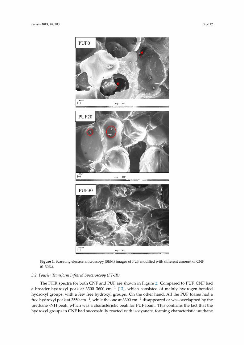
The mechanical strength of PUF was mainly ascribed to the closed-cells [37]. The defects on theclosed-cells would greatly impair the mechanical performance of PUF. The closed cell content and cellsize are listed in Table 2. The SEM images of PUF modified with different amount of CNF are shownin Figure 1. The PUF control consisted of larger closed cells than those modified with CNF (741 µmversus 634 and 589 µm). In addition, there were a few defects (red arrows in Figure 1) of the cells inPUF control. It is well known that rigid PUF is made of closed-cell [38], and the closed cell content isassociated with thermal insulating performance [39]. The replacement of PEG400 with CNF resultedin closed-cells with smaller size and fewer defects. The introduction of CNF increased the mediumviscosity, which hindered the cells’ coalescence and expansion [40]. In addition, due to its high strength,the introduction of CNF also imparted a resistance during the foaming process, which impeded thecell expansion and rendered smaller cells. Smaller closed cell size in CNF modified PUF indicated ahigher amount of cells in a given mass, resulting in more homogeneous load distribution in the foamand greater mechanical strength [38]. At the replacement ratio of 20%, there was only a few CNFdeposited on the closed-cells (red circles in Figure 1), while further increasing the replacement ratio to30%, a large amount of CNF entangled and encompassed the closed-cells, acting as a reinforcing layer.The double-layer structure could contribute to an increase of mechanical strength to the composite dueto the synergistic effect of CNF shell and PUF basic unit.
Table 2. Foam structure and physical properties.
Sample IDDensity Closed Cell
Content Mean Cell Size ThermalConductivity
g/cm3 % µm W/mK
PUF0 0.059 ± 0.0009 89.1 ± 1.01 741 ± 98 0.04390 ± 0.0015
PUF20 0.050 ± 0.0008 91.2 ± 0.63 634 ± 79 0.03014 ± 0.00089
PUF30 0.051 ± 0.0011 91.9 ± 0.54 589 ± 73 0.02724 ± 0.00087
Forests 2019, 10, 200 5 of 12Forests 2019, 10, x FOR PEER REVIEW 5 of 12
Figure 1. Scanning electron microscopy (SEM) images of PUF modified with different amount of CNF (0–30%).
3.2. Fourier Transform Infrared Spectroscopy (FT-IR)
The FTIR spectra for both CNF and PUF are shown in Figure 2. Compared to PUF, CNF had a broader hydroxyl peak at 3300–3600 cm-1 [13], which consisted of mainly hydrogen-bonded hydroxyl groups, with a few free hydroxyl groups. On the other hand, All the PUF foams had a free hydroxyl peak at 3550 cm-1, while the one at 3300 cm-1 disappeared or was overlapped by the urethane -NH peak, which was a characteristic peak for PUF foam. This confirms the fact that the hydroxyl groups in CNF had successfully reacted with isocyanate, forming characteristic urethane carbonyl group at 1720 cm-1, -NH bending vibration at 1524 cm-1, and C-N bond at 1240 cm-1, respectively [41–43]. Interestingly, the characteristic isocyanate peak at 2275 cm-1 was not observed in all PUF foams, since
PUF20
PUF30
PUF0
Figure 1. Scanning electron microscopy (SEM) images of PUF modified with different amount of CNF(0–30%).
3.2. Fourier Transform Infrared Spectroscopy (FT-IR)
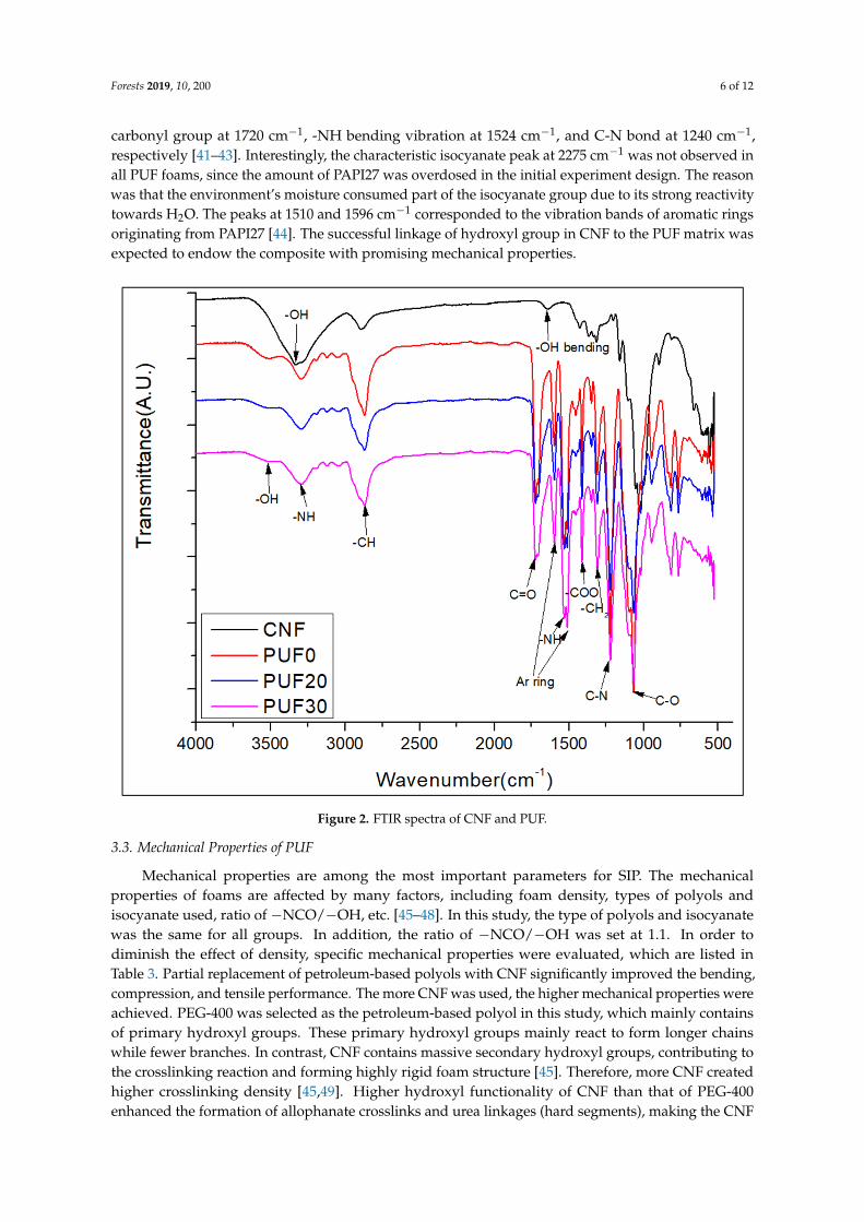
The FTIR spectra for both CNF and PUF are shown in Figure 2. Compared to PUF, CNF hada broader hydroxyl peak at 3300–3600 cm−1 [13], which consisted of mainly hydrogen-bondedhydroxyl groups, with a few free hydroxyl groups. On the other hand, All the PUF foams had afree hydroxyl peak at 3550 cm−1, while the one at 3300 cm−1 disappeared or was overlapped by theurethane -NH peak, which was a characteristic peak for PUF foam. This confirms the fact that thehydroxyl groups in CNF had successfully reacted with isocyanate, forming characteristic urethane
Forests 2019, 10, 200 6 of 12
carbonyl group at 1720 cm−1, -NH bending vibration at 1524 cm−1, and C-N bond at 1240 cm−1,respectively [41–43]. Interestingly, the characteristic isocyanate peak at 2275 cm−1 was not observed inall PUF foams, since the amount of PAPI27 was overdosed in the initial experiment design. The reasonwas that the environment’s moisture consumed part of the isocyanate group due to its strong reactivitytowards H2O. The peaks at 1510 and 1596 cm−1 corresponded to the vibration bands of aromatic ringsoriginating from PAPI27 [44]. The successful linkage of hydroxyl group in CNF to the PUF matrix wasexpected to endow the composite with promising mechanical properties.
Forests 2019, 10, x FOR PEER REVIEW 6 of 12
the amount of PAPI27 was overdosed in the initial experiment design. The reason was that the environment’s moisture consumed part of the isocyanate group due to its strong reactivity towards H2O. The peaks at 1510 and 1596 cm-1 corresponded to the vibration bands of aromatic rings originating from PAPI27 [44]. The successful linkage of hydroxyl group in CNF to the PUF matrix was expected to endow the composite with promising mechanical properties.
Figure 1. FTIR spectra of CNF and PUF.
3.3. Mechanical Properties of PUF
Mechanical properties are among the most important parameters for SIP. The mechanical properties of foams are affected by many factors, including foam density, types of polyols and isocyanate used, ratio of -NCO/-OH, etc. [45–48]. In this study, the type of polyols and isocyanate was the same for all groups. In addition, the ratio of -NCO/-OH was set at 1.1. In order to diminish the effect of density, specific mechanical properties were evaluated, which are listed in Table 3. Partial replacement of petroleum-based polyols with CNF significantly improved the bending, compression, and tensile performance. The more CNF was used, the higher mechanical properties were achieved. PEG-400 was selected as the petroleum-based polyol in this study, which mainly contains of primary hydroxyl groups. These primary hydroxyl groups mainly react to form longer chains while fewer branches. In contrast, CNF contains massive secondary hydroxyl groups, contributing to the crosslinking reaction and forming highly rigid foam structure [45]. Therefore, more CNF created higher crosslinking density [45,49]. Higher hydroxyl functionality of CNF than that of PEG-400 enhanced the formation of allophanate crosslinks and urea linkages (hard segments), making the CNF modified PUF more difficult to compress. In addition, as mentioned in the microstructure section, more closed-cells were generated due to the introduction of CNF and higher resistance pressure against external compression force was created. The smaller closed-cell size and double-
Figure 2. FTIR spectra of CNF and PUF.
3.3. Mechanical Properties of PUF
Mechanical properties are among the most important parameters for SIP. The mechanicalproperties of foams are affected by many factors, including foam density, types of polyols andisocyanate used, ratio of −NCO/−OH, etc. [45–48]. In this study, the type of polyols and isocyanatewas the same for all groups. In addition, the ratio of −NCO/−OH was set at 1.1. In order todiminish the effect of density, specific mechanical properties were evaluated, which are listed inTable 3. Partial replacement of petroleum-based polyols with CNF significantly improved the bending,compression, and tensile performance. The more CNF was used, the higher mechanical properties wereachieved. PEG-400 was selected as the petroleum-based polyol in this study, which mainly containsof primary hydroxyl groups. These primary hydroxyl groups mainly react to form longer chainswhile fewer branches. In contrast, CNF contains massive secondary hydroxyl groups, contributing tothe crosslinking reaction and forming highly rigid foam structure [45]. Therefore, more CNF createdhigher crosslinking density [45,49]. Higher hydroxyl functionality of CNF than that of PEG-400enhanced the formation of allophanate crosslinks and urea linkages (hard segments), making the CNF
Forests 2019, 10, 200 7 of 12
modified PUF more difficult to compress. In addition, as mentioned in the microstructure section,more closed-cells were generated due to the introduction of CNF and higher resistance pressureagainst external compression force was created. The smaller closed-cell size and double-layer likestructure of CNF modified PUF also contributed to greater mechanical strength due to more uniformload distribution.
Table 3. Specific mechanical properties of PUF.
Sample ID
SpecificBendingModulus
SpecificBendingStrength
SpecificCompression
Modulus
SpecificCompression
Strength
SpecificTensile
Modulus
SpecificTensile
Strength
Gpa*cm3/g MPa*cm3/g MPa*cm3/g MPa*cm3/g MPa*cm3/g MPa*cm3/g
PUF0 9.38 ± 0.95 103.07 ± 4.44 11.90 ± 0.99 1.52 ± 0.10 12.62 ± 0.57 1.41 ± 0.089
PUF20 18.95 ± 0.88 177.38 ± 6.30 37.05 ± 1.35 3.67 ± 0.18 29.14 ± 1.19 1.62 ± 0.073
PUF30 34.95 ± 0.93 319.00 ± 10.37 51.25 ± 0.58 4.55 ± 0.14 127.31 ± 3.81 3.4 ± 0.072
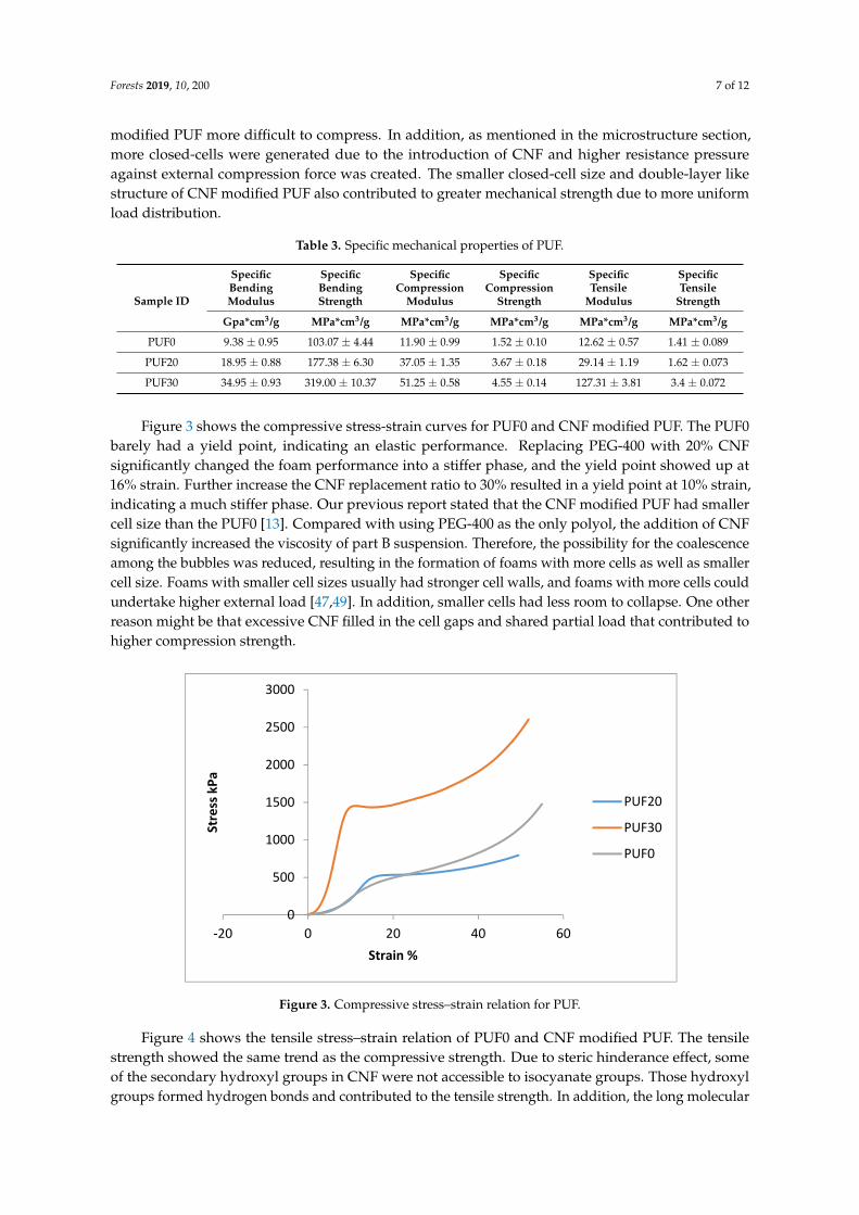
Figure 3 shows the compressive stress-strain curves for PUF0 and CNF modified PUF. The PUF0barely had a yield point, indicating an elastic performance. Replacing PEG-400 with 20% CNFsignificantly changed the foam performance into a stiffer phase, and the yield point showed up at16% strain. Further increase the CNF replacement ratio to 30% resulted in a yield point at 10% strain,indicating a much stiffer phase. Our previous report stated that the CNF modified PUF had smallercell size than the PUF0 [13]. Compared with using PEG-400 as the only polyol, the addition of CNFsignificantly increased the viscosity of part B suspension. Therefore, the possibility for the coalescenceamong the bubbles was reduced, resulting in the formation of foams with more cells as well as smallercell size. Foams with smaller cell sizes usually had stronger cell walls, and foams with more cells couldundertake higher external load [47,49]. In addition, smaller cells had less room to collapse. One otherreason might be that excessive CNF filled in the cell gaps and shared partial load that contributed tohigher compression strength.Forests 2019, 10, x FOR PEER REVIEW 8 of 12
Figure 2. Compressive stress–strain relation for PUF.
Figure 4. Tensile stress–strain relation for PUF.
3.4. Thermal Conductivity of PUF and CNF-PUF
The thermal conductivity of PUF0 and CNF modified PUF is listed in Table 2. Compared to the conventional value of commercial PUF (0.023-0.030 W/mK), the one without addition of CNF had a higher thermal conductivity due to defective cells and cell morphology [34,36,37,53,54]. However, introducing CNF into the PUF significantly reduced thermal conductivity to commercially required range, although slightly higher than those produced with modified bio-based polyols [40,55]. The thermal conductivity (λ) of a foam is comprised of the gas convection, gas conductivity, solid conductivity, and radiant heat transfer, as expressed in Equation 4 [56], of which the gas conductivity accounts for up to 80% of the total heat transfer, and the gas convection, solid conductivity, and radiant heat transfer only account for 20% [37,56,57]. The gas conductivity is illustrated in Wassiljewa Equation (Equation 5), where 𝑦 is the molar fraction of the specific gas, 𝜆 is the thermal conductivity of the specific gas, and 𝐴 is the coefficients in Lindsay–Bromley equation. The PUF control contained more defective cells, which were filled by air, instead of carbon dioxide. As the carbon dioxide has a much lower thermal conductivity than air (0.018 versus 0.028 W·m-1·K-1), the
0
500
1000
1500
2000
2500
3000
-20 0 20 40 60
Stre
ss k
Pa
Strain %
PUF20
PUF30
PUF0
0
100
200
300
400
500
600
0 5 10 15
Stre
ss k
Pa
Strain %
PUF20
PUF30
PUF0
Figure 3. Compressive stress–strain relation for PUF.
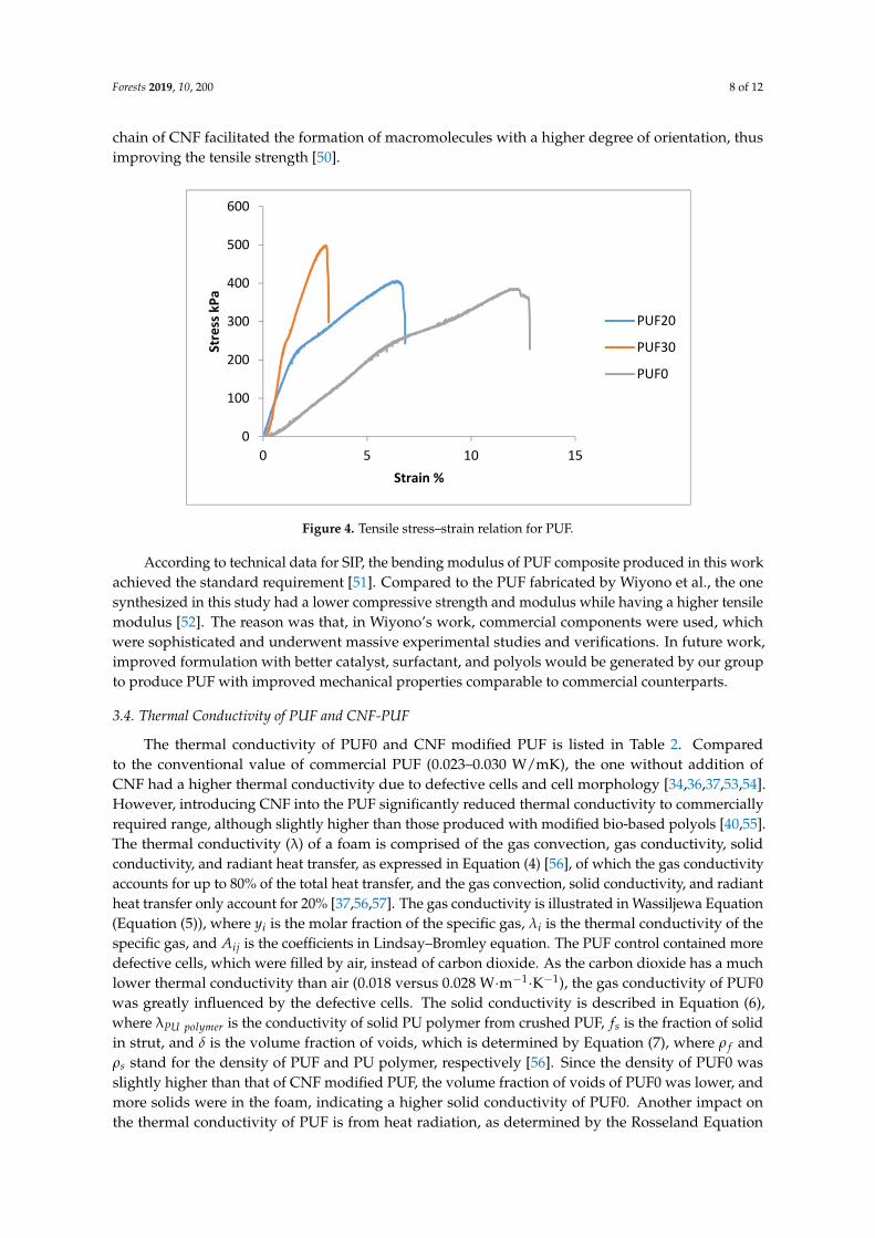
Figure 4 shows the tensile stress–strain relation of PUF0 and CNF modified PUF. The tensilestrength showed the same trend as the compressive strength. Due to steric hinderance effect, someof the secondary hydroxyl groups in CNF were not accessible to isocyanate groups. Those hydroxylgroups formed hydrogen bonds and contributed to the tensile strength. In addition, the long molecular
Forests 2019, 10, 200 8 of 12
chain of CNF facilitated the formation of macromolecules with a higher degree of orientation, thusimproving the tensile strength [50].
Forests 2019, 10, x FOR PEER REVIEW 8 of 12
Figure 2. Compressive stress–strain relation for PUF.
Figure 4. Tensile stress–strain relation for PUF.
3.4. Thermal Conductivity of PUF and CNF-PUF
The thermal conductivity of PUF0 and CNF modified PUF is listed in Table 2. Compared to the conventional value of commercial PUF (0.023-0.030 W/mK), the one without addition of CNF had a higher thermal conductivity due to defective cells and cell morphology [34,36,37,53,54]. However, introducing CNF into the PUF significantly reduced thermal conductivity to commercially required range, although slightly higher than those produced with modified bio-based polyols [40,55]. The thermal conductivity (λ) of a foam is comprised of the gas convection, gas conductivity, solid conductivity, and radiant heat transfer, as expressed in Equation 4 [56], of which the gas conductivity accounts for up to 80% of the total heat transfer, and the gas convection, solid conductivity, and radiant heat transfer only account for 20% [37,56,57]. The gas conductivity is illustrated in Wassiljewa Equation (Equation 5), where 𝑦 is the molar fraction of the specific gas, 𝜆 is the thermal conductivity of the specific gas, and 𝐴 is the coefficients in Lindsay–Bromley equation. The PUF control contained more defective cells, which were filled by air, instead of carbon dioxide. As the carbon dioxide has a much lower thermal conductivity than air (0.018 versus 0.028 W·m-1·K-1), the
0
500
1000
1500
2000
2500
3000
-20 0 20 40 60
Stre
ss k
Pa
Strain %
PUF20
PUF30
PUF0
0
100
200
300
400
500
600
0 5 10 15
Stre
ss k
Pa
Strain %
PUF20
PUF30
PUF0
Figure 4. Tensile stress–strain relation for PUF.
According to technical data for SIP, the bending modulus of PUF composite produced in this workachieved the standard requirement [51]. Compared to the PUF fabricated by Wiyono et al., the onesynthesized in this study had a lower compressive strength and modulus while having a higher tensilemodulus [52]. The reason was that, in Wiyono’s work, commercial components were used, whichwere sophisticated and underwent massive experimental studies and verifications. In future work,improved formulation with better catalyst, surfactant, and polyols would be generated by our groupto produce PUF with improved mechanical properties comparable to commercial counterparts.
3.4. Thermal Conductivity of PUF and CNF-PUF
The thermal conductivity of PUF0 and CNF modified PUF is listed in Table 2. Comparedto the conventional value of commercial PUF (0.023–0.030 W/mK), the one without addition ofCNF had a higher thermal conductivity due to defective cells and cell morphology [34,36,37,53,54].However, introducing CNF into the PUF significantly reduced thermal conductivity to commerciallyrequired range, although slightly higher than those produced with modified bio-based polyols [40,55].The thermal conductivity (λ) of a foam is comprised of the gas convection, gas conductivity, solidconductivity, and radiant heat transfer, as expressed in Equation (4) [56], of which the gas conductivityaccounts for up to 80% of the total heat transfer, and the gas convection, solid conductivity, and radiantheat transfer only account for 20% [37,56,57]. The gas conductivity is illustrated in Wassiljewa Equation(Equation (5)), where yi is the molar fraction of the specific gas, λi is the thermal conductivity of thespecific gas, and Aij is the coefficients in Lindsay–Bromley equation. The PUF control contained moredefective cells, which were filled by air, instead of carbon dioxide. As the carbon dioxide has a muchlower thermal conductivity than air (0.018 versus 0.028 W·m−1·K−1), the gas conductivity of PUF0was greatly influenced by the defective cells. The solid conductivity is described in Equation (6),where λPU polymer is the conductivity of solid PU polymer from crushed PUF, fs is the fraction of solidin strut, and δ is the volume fraction of voids, which is determined by Equation (7), where ρ f andρs stand for the density of PUF and PU polymer, respectively [56]. Since the density of PUF0 wasslightly higher than that of CNF modified PUF, the volume fraction of voids of PUF0 was lower, andmore solids were in the foam, indicating a higher solid conductivity of PUF0. Another impact onthe thermal conductivity of PUF is from heat radiation, as determined by the Rosseland Equation
Forests 2019, 10, 200 9 of 12
(Equation (8)) [37,56], where σ is the Stephan Boltzman constant (5.7 × 10⁻⁸), T is the temperature,and K is the extinction coefficient, expressed by Equation (9), where d is the cell diameter, and Kw
is the extinction coefficient of cell wall material. It was confirmed that the decrease of cell size inthe CNF modified PUF had a stronger influence on the extinction coefficient than the decrease ofthe volume fraction of the solid did. So according to Equation (9), the overall extinction coefficientwas increased, resulting in a decrease in radiation conductivity. It is well known that the thermalproperties of rigid foam are ascribed to the closed cell content, the morphology, and the entrappedgases [58]. As mentioned above, the introduction of CNF generated smaller and stronger cells, whichwas beneficial during the foaming process, since it was less prone to form defective cells. Consequently,the thermal insulating performance was improved [55]. Moreover, the introduction of CNF renderedmore cell walls within the foam structure, to some extent impeding the thermal radiation [47].
λtotal = λgas + λconvection + λsolid + λradiation (4)
λgas =n
∑i=1
yi × λi
∑nj=1 yi × Aij
(5)
λsolid =13λPU polymer × fs × (1 − δ) +
23λPU polymer × (1 − fs)× (1 − δ) (6)
δ = 1 −ρ f
ρs(7)
λradiation =16 × σ × T3
3 × K(8)
K = 4.1 ×
√fs×ρ f
ρs
d+
[(1 − fs)× ρ f
ρs
]× Kw (9)
4. Conclusions
CNF modified PUF has shown great potential as a structural insulated material in woodconstruction industry. The introduction of CNF affected the foam microstructure from two aspects:firstly, the addition of spray-dried CNF increased the precursor viscosity and hindered the cellscoalescence. In addition, the intrinsic high strength of CNF imparted an extra resistant force againstcells expansion during the foaming process and formed smaller cells and reduced the chance ofcreating defective cells. The massive secondary hydroxyl groups located in CNF backbone facilitatedthe crosslinking reaction and formed strong rigid foam structure. Moreover, the smaller closed cell sizein CNF modified PUF rendered more homogeneous load distribution in the foam, and larger amountof closed cells provided higher resistant pressure against external force and led to greater mechanicalstrength. Consequently, the mechanical performance of the foam was significantly improved byintroducing CNF into the PUF matrix. The thermal conductivity of PUF composite was mainlyinfluenced by the closed cell size and closed cell content. The introduction of CNF not only createdsmaller closed cells with fewer defects which filled with comparably low thermal conductive carbondioxide, but also generated more cell walls, imposing more obstacles against heat transfer.
Author Contributions: W.L. contributed to the overall process of the experiment design, characterization, dataanalysis, and the manuscript drafting. B.P. supervised the whole project, reviewed the draft, and made comments.
Funding: The APC was funded by the College of Materials Science and Engineering, Nanjing Forestry University.
Acknowledgments: The authors would like to acknowledge the financial support by NJFU start-up funding(163020128).
Conflicts of Interest: The authors declare no conflict of interest.
Forests 2019, 10, 200 10 of 12
References
1. Meng, Q.; Chen, W.; Hao, H. Numerical and experimental study of steel wire mesh and basalt fibre meshstrengthened structural insulated panel against projectile impact. Adv. Struct. Eng. 2018, 21, 1183–1196.[CrossRef]
2. Chen, W.; Hao, H.; Chen, S.; Hernandez, F. Performance of composite structural insulated panel with metalskin subjected to blast loading. Mater. Des. 2015, 84, 194–203. [CrossRef]
3. Kayello, A.; Ge, H.; Athienitis, A.; Rao, J. Experimental study of thermal and airtightness performance ofstructural insulated panel joints in cold climates. Build. Environ. 2017, 115, 345–357. [CrossRef]
4. Purasinghe, R.; Dusicka, P.; Garth, J.S.; Dedek, G.; Lum, H. In-plane cyclic behavior of structural insulatedpanel wood walls including slit steel connectors. Eng. Struct. 2018, 174, 178–197. [CrossRef]
5. Polymer Foams Market Forecast to 2019| Smithers Rapra. Available online: https://www.smithersrapra.com/news/2014/may/polymer-foam-market-to-consume-25-3-million-tonnes (accessed on 14 February 2019).
6. Efstathiou, K. Synthesis and Characterization of a Polyurethane Prepolymer for the Development of a NovelAcrylate-Based Polymer Foam; Budapest University of Technology and Economics (BME): Budapest,Hungary, 2011.
7. Szycher, M. Szycher’s Handbook of Polyurethanes, 2nd ed.; CRC Press: Boca Raton, FL, USA, 2012; ISBN9780439839584.
8. Seydibeyoglu, M.O.; Misra, M.; Mohanty, A.; Blaker, J.J.; Lee, K.-Y.; Bismarck, A.; Kazemizadeh, M. Greenpolyurethane nanocomposites from soy polyol and bacterial cellulose. J. Mater. Sci. 2013, 48, 2167–2175.[CrossRef]
9. Yang, J.; Li, Z.; Du, Q. An Experimental Study on Material and Structural Properties of Structural InsulatedPanels (SIPs). Appl. Mech. Mater. 2011, 147, 127–131. [CrossRef]
10. Zhou, X.; Sain, M.M.; Oksman, K. Semi-rigid biopolyurethane foams based on palm-oil polyol and reinforcedwith cellulose nanocrystals. Compos. Part Appl. Sci. Manuf. 2016, 83, 56–62. [CrossRef]
11. Narine, S.S.; Kong, X.; Bouzidi, L.; Sporns, P. Physical Properties of Polyurethanes Produced from Polyolsfrom Seed Oils: II. Foams. J. Am. Oil Chem. Soc. 2007, 84, 65–72. [CrossRef]
12. Petrovic, Z.S. Polyurethanes from Vegetable Oils. Polym. Rev. 2008, 48, 109–155. [CrossRef]13. Leng, W.; Li, J.; Cai, Z. Synthesis and Characterization of Cellulose Nanofibril-Reinforced Polyurethane
Foam. Polymers 2017, 9, 597. [CrossRef]14. Chen, W.; Yu, H.; Li, Q.; Liu, Y.; Li, J. Ultralight and highly flexible aerogels with long cellulose I nanofibers.
Soft Matter 2011, 7, 10360. [CrossRef]15. Klemm, D.; Heublein, B.; Fink, H.-P.; Bohn, A. Cellulose: Fascinating biopolymer and sustainable raw
material. Angew. Chem. Int. Ed. 2005, 44, 3358–3393. [CrossRef] [PubMed]16. Liu, Q.; Jing, S.; Wang, S.; Zhuo, H.; Zhong, L.; Peng, X.; Sun, R. Flexible nanocomposites with ultrahigh
specific areal capacitance and tunable properties based on a cellulose derived nanofiber-carbon sheetframework coated with polyaniline. J. Mater. Chem. A 2016, 4, 13352–13362. [CrossRef]
17. Silva, T.C.F.; Habibi, Y.; Colodette, J.L.; Elder, T.; Lucia, L.A. A fundamental investigation of themicroarchitecture and mechanical properties of tempo-oxidized nanofibrillated cellulose (NFC)-basedaerogels. Cellulose 2012, 19, 1945–1956. [CrossRef]
18. Zanini, M.; Lavoratti, A.; Lazzari, L.K.; Galiotto, D.; Pagnocelli, M.; Baldasso, C.; Zattera, A.J. Producingaerogels from silanized cellulose nanofiber suspension. Cellulose 2017, 24, 769–779. [CrossRef]
19. Zhao, J.; Zhang, X.; He, X.; Xiao, M.; Zhang, W.; Lu, C. A super biosorbent from dendrimerpoly(amidoamine)-grafted cellulose nanofibril aerogels for effective removal of Cr(VI). J. Mater. Chem. A2015, 3, 14703–14711. [CrossRef]
20. Chen, W.; Yu, H.; Liu, Y.; Chen, P.; Zhang, M.; Hai, Y. Individualization of cellulose nanofibers from woodusing high-intensity ultrasonication combined with chemical pretreatments. Carbohydr. Polym. 2011, 83,1804–1811. [CrossRef]
21. Barari, B.; Ellingham, T.K.; Ghamhia, I.I.; Pillai, K.M.; El-Hajjar, R.; Turng, L.-S.; Sabo, R. Mechanicalcharacterization of scalable cellulose nano-fiber based composites made using liquid composite moldingprocess. Compos. Part B Eng. 2016, 84, 277–284. [CrossRef]
22. Chen, B.; Zheng, Q.; Zhu, J.; Li, J.; Cai, Z.; Chen, L.; Gong, S. Mechanically strong fully biobased anisotropiccellulose aerogels. RSC Adv. 2016, 6, 96518–96526. [CrossRef]
Forests 2019, 10, 200 11 of 12
23. Chen, W.; Li, Q.; Wang, Y.; Yi, X.; Zeng, J.; Yu, H.; Liu, Y.; Li, J. Comparative Study of Aerogels Obtainedfrom Differently Prepared Nanocellulose Fibers. ChemSusChem 2014, 7, 154–161. [CrossRef] [PubMed]
24. Meng, Y.; Young, T.M.; Liu, P.; Contescu, C.I.; Huang, B.; Wang, S. Ultralight carbon aerogel fromnanocellulose as a highly selective oil absorption material. Cellulose 2015, 22, 435–447. [CrossRef]
25. Meng, Y.; Wang, X.; Wu, Z.; Wang, S.; Young, T.M. Optimization of cellulose nanofibrils carbon aerogelfabrication using response surface methodology. Eur. Polym. J. 2015, 73, 137–148. [CrossRef]
26. Olsson, R.T.; Azizi Samir, M.A.S.; Salazar-Alvarez, G.; Belova, L.; Ström, V.; Berglund, L.A.; Ikkala, O.;Nogués, J.; Gedde, U.W. Making flexible magnetic aerogels and stiff magnetic nanopaper using cellulosenanofibrils as templates. Nat. Nanotechnol. 2010, 5, 584–588. [CrossRef] [PubMed]
27. Wang, M.; Anoshkin, I.V.; Nasibulin, A.G.; Ras, R.H.A.; Nonappa, N.; Laine, J.; Kauppinen, E.I.; Ikkala, O.Electrical behaviour of native cellulose nanofibril/carbon nanotube hybrid aerogels under cyclic compression.RSC Adv. 2016, 6, 89051–89056. [CrossRef] [PubMed]
28. Zhai, T.; Zheng, Q.; Cai, Z.; Turng, L.-S.; Xia, H.; Gong, S. Poly(vinyl alcohol)/Cellulose Nanofibril HybridAerogels with an Aligned Microtubular Porous Structure and Their Composites with Polydimethylsiloxane.ACS Appl. Mater. Interfaces 2015, 7, 7436–7444. [CrossRef] [PubMed]
29. Sharmin, E.; Zafar, F. Polyurethane: An Introduction. In Polyurethane; Zafar, F., Ed.; InTech: Rijeka, Croatia,2012; ISBN 978-953-51-0726-2.
30. Li, Y.; Ragauskas, A.J. Cellulose nano whiskers as a reinforcing filler in polyurethanes. Algae 2011, 75, 10–15.31. Xu, X.; Liu, F.; Jiang, L.; Zhu, J.Y.; Haagenson, D.; Wiesenborn, D.P. Cellulose Nanocrystals vs. Cellulose
Nanofibrils: A Comparative Study on Their Microstructures and Effects as Polymer Reinforcing Agents.ACS Appl. Mater. Interfaces 2013, 5, 2999–3009. [CrossRef] [PubMed]
32. Srithep, Y.; Turng, L.-S.; Sabo, R.; Clemons, C. Nanofibrillated cellulose (NFC) reinforced polyvinyl alcohol(PVOH) nanocomposites: Properties, solubility of carbon dioxide, and foaming. Cellulose 2012, 19, 1209–1223.[CrossRef]
33. Li, Y.; Ren, H.; Ragauskas, A.J. Rigid polyurethane foam reinforced with cellulose whiskers: Synthesis andcharacterization. Nano-Micro Lett. 2010, 2, 89–94. [CrossRef]
34. Santiago-Calvo, M.; Tirado-Mediavilla, J.; Rauhe, J.C.; Jensen, L.R.; Ruiz-Herrero, J.L.; Villafañe, F.;Rodríguez-Pérez, M.Á. Evaluation of the thermal conductivity and mechanical properties of water blownpolyurethane rigid foams reinforced with carbon nanofibers. Eur. Polym. J. 2018, 108, 98–106. [CrossRef]
35. Fu, J.; He, C.; Huang, J.; Chen, Z.; Wang, S. Cellulose nanofibril reinforced silica aerogels: Optimization ofthe preparation process evaluated by a response surface methodology. RSC Adv. 2016, 6, 100326–100333.[CrossRef]
36. Gama, N.; Ferreira, A.; Barros-Timmons, A. Polyurethane Foams: Past, Present, and Future. Materials 2018,11, 1841. [CrossRef] [PubMed]
37. Furtwengler, P.; Matadi Boumbimba, R.; Sarbu, A.; Avérous, L. Novel Rigid Polyisocyanurate Foams fromSynthesized Biobased Polyester Polyol with Enhanced Properties. ACS Sustain. Chem. Eng. 2018, 6,6577–6589. [CrossRef]
38. Mariappan, T.; Khastgir, D.; Singha, N.; Manjunath, B.S.; Naik, Y.P. Mechanical, Morphological and ThermalProperties of Rigid Polyurethane Foam: Effect of the Fillers. Cell. Polym. 2007, 26, 245–259.
39. Hejna, A.; Kirpluks, M.; Kosmela, P.; Cabulis, U.; Haponiuk, J.; Piszczyk, Ł. The influence of crude glyceroland castor oil-based polyol on the structure and performance of rigid polyurethane-polyisocyanurate foams.Ind. Crops Prod. 2017, 95, 113–125. [CrossRef]
40. Tan, S.; Abraham, T.; Ference, D.; Macosko, C.W. Rigid polyurethane foams from a soybean oil-based Polyol.Polymer 2011, 52, 2840–2846. [CrossRef]
41. Strankowski, M.; Włodarczyk, D.; Piszczyk, Ł.; Strankowska, J. Polyurethane Nanocomposites ContainingReduced Graphene Oxide, FTIR, Raman, and XRD Studies. J. Spectrosc. 2016, 2016, 1–6. [CrossRef]
42. Szymanska-Chargot, M.; Zdunek, A. Use of FT-IR Spectra and PCA to the Bulk Characterization of CellWall Residues of Fruits and Vegetables Along a Fraction Process. Food Biophys. 2013, 8, 29–42. [CrossRef][PubMed]
43. Zhang, C.; Ren, Z.; Yin, Z.; Qian, H.; Ma, D. Amide II and Amide III Bands in Polyurethane Model Soft andHard Segments. Polym. Bull. 2008, 60, 97–101. [CrossRef]
Forests 2019, 10, 200 12 of 12
44. Huang, X.; De Hoop, C.F.; Xie, J.; Wu, Q.; Boldor, D.; Qi, J. High bio-content polyurethane (PU) foam madefrom bio-polyol and cellulose nanocrystals (CNCs) via microwave liquefaction. Mater. Des. 2018, 138, 11–20.[CrossRef]
45. Yusuf, A.K.; Mamza, P.A.P.; Ahmed, A.S.; Agunwa, U. Physico-Mechanical Properties of Rigid PolyurethaneFoams Synthesized From Modified Castor Oil Polyols. Int. J. Sci. Res. Publ. 2016, 6, 9.
46. Ali, E.S.; Zubir, S.A. The Mechanical Properties of Medium Density Rigid Polyurethane Biofoam. MATECWeb Conf. 2016, 39, 01009. [CrossRef]
47. Ugarte, L.; Gómez-Fernández, S.; Peña-Rodríuez, C.; Prociak, A.; Corcuera, M.A.; Eceiza, A. TailoringMechanical Properties of Rigid Polyurethane Foams by Sorbitol and Corn Derived Biopolyol Mixtures.ACS Sustain. Chem. Eng. 2015, 3, 3382–3387. [CrossRef]
48. Goods, S.H.; Neuschwanger, C.L.; Whinnery, L.L. Mechanical Properties of a Structural Polyurethane Foamand the Effect of Particulate Loading. MRS Proc. 1998, 521. [CrossRef]
49. Fan, H.; Tekeei, A.; Suppes, G.J.; Hsieh, F.-H. Properties of Biobased Rigid Polyurethane Foams Reinforcedwith Fillers: Microspheres and Nanoclay. Int. J. Polym. Sci. 2012, 2012, 1–8. [CrossRef]
50. Stirna, U.; Beverte, I.; Yakushin, V.; Cabulis, U. Mechanical properties of rigid polyurethane foams at roomand cryogenic temperatures. J. Cell. Plast. 2011, 47, 337–355. [CrossRef]
51. Technical Data for Structural Insulated Panels | Foard Panel. Available online: https://www.foardpanel.com/technical-data/ (accessed on 13 February 2019).
52. Wiyono, P.; Suprobo, P.; Kristijanto, H. Characterization of physical and mechanical properties of rigidpolyurethane foam. ARPN J. Eng. Appl. Sci. 2016, 11, 8.
53. Kirpluks, M.; Cabulis, U.; Zeltins, V.; Stiebra, L.; Avots, A. Rigid Polyurethane Foam Thermal InsulationProtected with Mineral Intumescent Mat. Autex Res. J. 2014, 14. [CrossRef]
54. Wu, J.-W.; Sung, W.-F.; Chu, H.-S. Thermal conductivity of polyurethane foams. Int. J. Heat Mass Transf. 1999,42, 2211–2217. [CrossRef]
55. Beltrán, A.A.; Boyacá, L.A. Production of rigid polyurethane foams from soy-based polyols. Lat. Am.Appl. Res. 2011, 41, 75–80.
56. Jarfelt, U.; Ramnäs, O. Thermal conductivity of polyurethane foam Best performance. In Proceedings of the10th International Symposium on District Heating and Cooling, Hannover, Germany, 3–5 September 2006;pp. 1–12.
57. Traeger, R.K. Physical Properties of Rigid Polyurethane Foams. J. Cell. Plast. 1967, 3, 405–418. [CrossRef]58. Fleurent, H.; Thijs, S. The Use of Pentanes as Blowing Agent in Rigid Polyurethane Foam. J. Cell. Plast. 1995,
31, 580–599. [CrossRef]
© 2019 by the authors. Licensee MDPI, Basel, Switzerland. This article is an open accessarticle distributed under the terms and conditions of the Creative Commons Attribution(CC BY) license (http://creativecommons.org/licenses/by/4.0/).


