Embed Size (px)
Citation preview
Original article
Thermal protective performance ofprotective clothing used for low radiantheat protection
Guowen Song, Stephen Paskaluk, Rohit Sati,Elizabeth M Crown, J Doug Dale and Mark Ackerman
Abstract
A laboratory simulation was performed to study the thermal protective performance of fabric systems under low level
thermal hazards in the range of 6.3–8.3 kW/m2. Two approaches were used. The first used a method similar to the ASTM
F 1939, radiant heat resistance test, while the second used a modification designed to capture the contribution to skin
burn injury due to energy stored in the test specimens being released after the direct exposure had ended. Both dry and
wet specimens were tested. In order to accommodate the prolonged exposure time a water cooled heat flux sensor was
used to calibrate the radiant heat source and measure the energy directly transmitted through during the exposure and
discharged later from the fabric systems. The Henriques Burn Integral (HBI) was adopted and programmed with a three
layer skin model to predict the time required to achieve a second degree skin burn injury. The study investigated the
thermal protection provided by the clothing with different layering and examined the effect of moisture under low level
radiant heat exposures. In addition, the physiological burden associated with wearing the clothing was predicted and
compared. The results obtained show the difference in measured protection level under low radiant heat from these two
approaches and demonstrate that the stored thermal energy released from the clothing system significantly lowers the
measured thermal protective performance.
Keywords
Low radiation, burn injury, thermal hazards, protective clothing
Introduction
Thermal protective clothing is primarily designed toprovide protection from thermal hazards which includeexposure to high temperature radiant sources, flameimpingement, hot liquids and gases, molten substances,hot solids and surfaces. It is difficult to completelydefine the nature and characteristics of these thermalhazards, because of the many environmental and phys-ical factors involved. Three general categories are usedto identify common thermal environmental conditions.These are routine, hazardous, and emergency.1–3 Heattransfer from the thermal hazards can be by radiation,convection or conduction, or a combination.
A great amount of research has been performed onemergency conditions.4–9 These conditions are charac-terized by high intensity, short duration exposures. Theexposure level among these emergency conditions
ranges from 20–160 kW/m2 and can be encounteredduring large fires and explosions. Severe thermal prob-lems and life threatening injuries are associated withthese conditions. For the existing protective clothing,the tolerance time for people in these exposures is in therange of 5 to 20 seconds.3 Barker, Shalev and Lee4,6,7
have reported extensively on the use of the TPP (NFPA1971) test to understand the thermal response of singlelayered fabrics in high heat exposures. The researchdemonstrated that changes in exposure intensity and
University of Alberta, Edmonton, Canada.
Corresponding author:
Guowen Song, Department of Human Ecology, University of Alberta,
Edmonton T6G 2N1, Canada.
Email: [email protected]
Textile Research Journal
0(00) 1–13
! The Author(s) 2010
Reprints and permissions:
sagepub.co.uk/journalsPermissions.nav
DOI: 10.1177/0040517510380108
trj.sagepub.com
at PENNSYLVANIA STATE UNIV on September 13, 2016trj.sagepub.comDownloaded from
the mix of radiant to convective heat transfer at thespecimen surface, and the fabric properties affectedthe overall thermal protective performance. Radiantprotective performance of single layer fabrics hasbeen assessed using a RPP tester by Sun.5 The resultsshowed that the thermal resistance of the fabrics wasfundamentally related to chemical and physical struc-tures of fabrics. In Sun’s study, some physical proper-ties, such as evaporative resistance, wicking ability,relevant to comfort were also examined and their rela-tions to fiber type, thickness and layering wereexplored.
Studies of protection of clothing systems under flashfire exposures were conducted using instrumented flashfire manikin evaluation systems.8,9 The study per-formed by Crown et al. showed that style, fit and clo-sure system all affected the thermal protection providedby flightsuits.8 Song developed a numerical model forsimulating the flash fire manikin evaluation system. Theheat transfer from the simulated flash fire, the clothingsystem and the air gap between clothing and manikinbody were characterized and the clothing performancewas predicted under the flash fire exposure conditions.9
These latter studies indicated that the air gap developedbetween the clothing and the human body plays a crit-ical role in the thermal protective performance underthe intense exposure conditions. In the early 1970s,Perkins performed studies on heat transfer values ofsome single layer fabrics when exposed on low radia-tion thermal hazards. The retention of the integrity forthese fabrics under various heat intensities was alsoexamined.10 Perkins study showed the effect of fabricweight on the protection provided by the fabric underlow flux level exposure and some characteristics dem-onstrated from exposure to high level heat flux.
Thermal radiation exposure is frequently encoun-tered among all the thermal hazards, especially in rou-tine and hazardous conditions. Exposure to low levelthermal radiation ranging from 5kW/m2 to 20 kW/m2
is one of the most common thermal hazards that couldcause skin burn injuries.3 Data produced by decades offire research on structural fires shows that most burninjuries sustained by firefighters occurred in the lowlevel thermal environments.11,12 Firefighters can receiveburns in thermal exposures that are considerably lowerthan flashover conditions. These burns occur as a resultof prolonged exposure in thermal environments classi-fied as routine or hazardous conditions. These expo-sures are usually several minutes in duration, and theexposure levels are generally not sufficient to degradethe turnout shell fabric. The energy stored in the fabricsystem during the exposure can contribute to skin burninjury due to the discharge after the exposure and thepresence of the moisture could significantly change thethermal protective performance.13
Several prominent issues that remain in the area ofprotective clothing that may affect the overall clothingperformance are the moisture in the clothing, storedthermal energy and heat stress applied when wearingthe clothing. The presence of moisture in clothing sys-tems is common and has a complex effect on clothingthermal protective performance. There have beenextensive studies on the effects of moisture in protec-tive clothing.14–17 The moisture distribution and thequantity, the structure of fabric system and exposureintensity each affect clothing thermal protective perfor-mance. Accumulated moisture in fabrics or fabric sys-tems influences the thermal properties and changesthe heat transfer characteristics. When a garment isexposed to thermal hazards, either low or high inten-sity, the mechanisms associated with heat and masstransfer, energy storage and moisture phase change(which could potentially cause ‘steam burns’) becomeextremely complicated as they are interconnected. Thisis extremely important when the protective clothing isthick or multi-layered. Normally thick fabrics andfabric systems provide better thermal insulation, butthey also store a greater amount of thermal energywhich could discharge after the exposure.13 Theenergy stored within the garment system can be dis-charged naturally or by compression of the garmentdue to motion or contact with a solid object. The dis-charge of this stored energy after an exposure can causeor increase a burn injury. Heat stress associated withwearing protective clothing is a topic of active research.Normally the protective clothing, while providing pro-tection against hazards, impedes heat and moistureexchange between the human body and environmentand therefore affects achieving a human comfort bal-ance. As a result, an added physiological load is gener-ated and wearers’ performance is significantly reduced,particularly in a hot environment.18,19 Effective protec-tive clothing should minimize heat stress while provid-ing protection. The impact of protective clothing onheat stress depends on the extent to which the clothingaffects the heat and moisture transfer between thewearer and the environment. The two main propertiesof the clothing which affect the thermal balancebetween the wearer and environment are the thermalresistance (Rct) and the evaporative resistance (Ret).
Only a few studies have been conducted on thermalprotective performance with prolonged exposure to lowlevel radiant heat, the effect of absorbed energy andmoisture contained in fabric systems on burn protec-tion in these conditions. Lack of full understanding ofthe performance of thermal protective clothing exposedto low level radiation and of the relevant contributingparameters associated with clothing is the main factorthat contributes to develop skin burn injuries. In thisstudy, a laboratory simulation of a low intensity
2 Textile Research Journal 0(00)
at PENNSYLVANIA STATE UNIV on September 13, 2016trj.sagepub.comDownloaded from
thermal hazard was developed that aimed to evaluatethe thermal protective performance of protective cloth-ing that were made of different fabric systems. Twoapproaches were used. The first used a method similarto the ASTM Standard Test Method for Radiant HeatResistance of Flame Resistant Clothing Materials,while the second used a modification designed to cap-ture the contribution to skin burn injury due to energystored in the test specimens being released after thedirect exposure had ended. The traditional TPP/RPP(applied in NFPA 1971 and ASTM F 1939) approachand a stored-energy approach were applied and theresults obtained were compared and analyzed. Thestudy includes the examination of the performance pro-vided under low level thermal radiation in standard aswell as wet conditions. The effect of methods, moistureand different layering were analyzed. The physiologicalburden that would be applied to the wearer was esti-mated by measuring thermal resistance, evaporativeresistance and total heat loss (THL). The technicaldata generated under these laboratory simulations willfacilitate selection of appropriate protective clothingsystems to prevent thermal injuries under the specifiedthermal hazards while minimizing heat strain at work.The criteria for these protective system selections willbe a balance of maximizing protective performance andminimizing heat strain when wearing these protectivesystems.
Experimental
Fabric Materials
The selected fabrics and their technical properties areprovided in Table 1. The fabrics were chosen to includecommercially available, commonly used, and high per-formance fabrics in the thermal protective clothingfield. Several protective fabric systems were constructedwith expected different levels of protective perfor-mance. The fabric systems were constructed as single
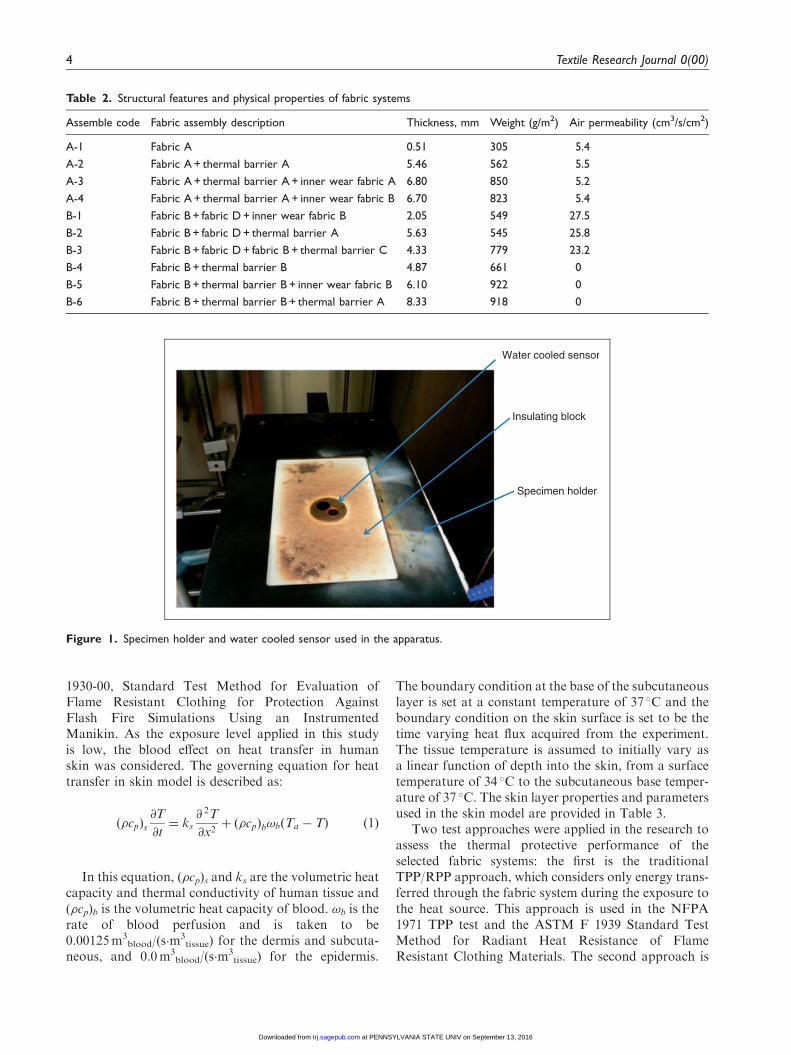
layer fabric (used for coveralls), two layer systems, andmultilayer composite systems. The purpose of thesefabric systems was to represent actual protectivegarments worn by industrial workers, firefighters, andmilitary personnel, etc. Fabrics commonly used forunderwear, wool and Carbon X (an oxidized polyacry-lonitrile blend), were incorporated in some of thesefabric systems and evaluated as a whole system. Thedetails of the fabric system construction and physicalproperties are described in Table 2. No air permeabilitywas observed in fabric systems B-4, B-5, and B-6 due tothe incorporation of a membrane in these systems.
Test Apparatus and Methods
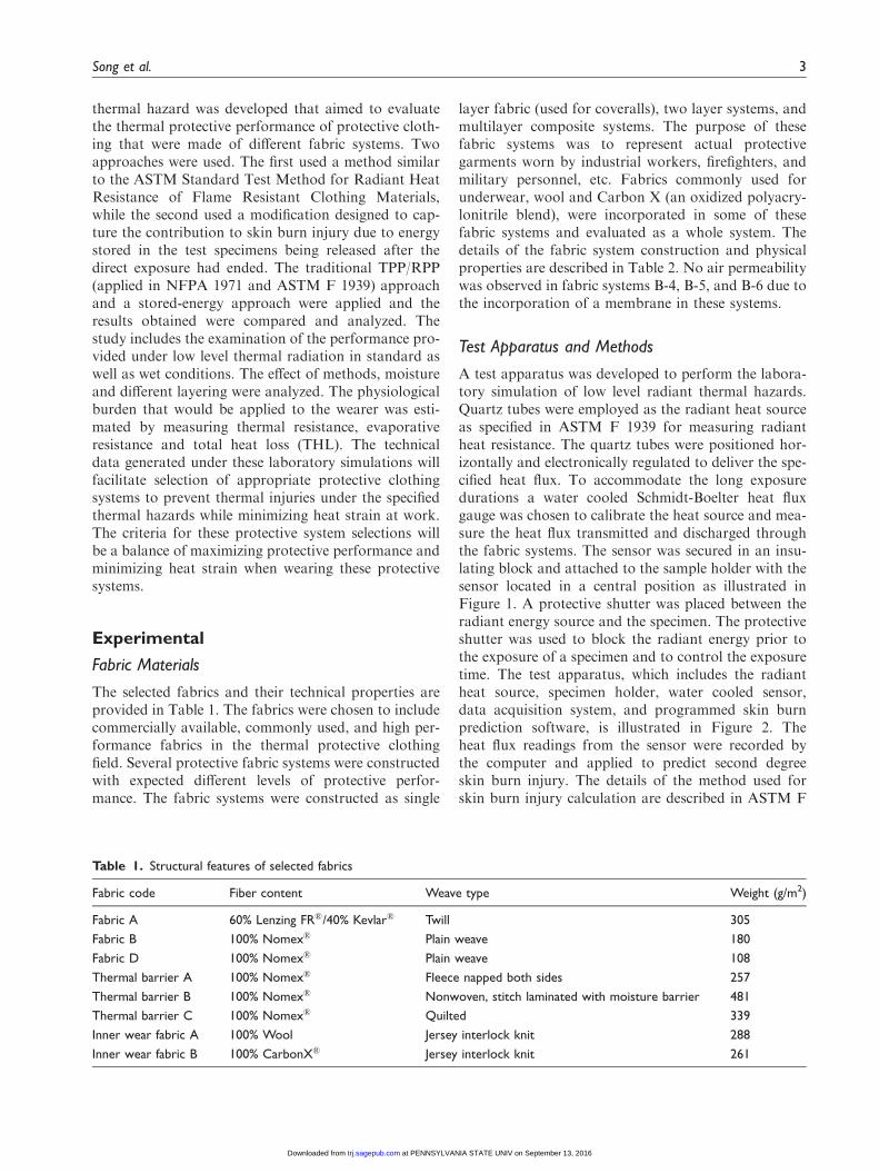
A test apparatus was developed to perform the labora-tory simulation of low level radiant thermal hazards.Quartz tubes were employed as the radiant heat sourceas specified in ASTM F 1939 for measuring radiantheat resistance. The quartz tubes were positioned hor-izontally and electronically regulated to deliver the spe-cified heat flux. To accommodate the long exposuredurations a water cooled Schmidt-Boelter heat fluxgauge was chosen to calibrate the heat source and mea-sure the heat flux transmitted and discharged throughthe fabric systems. The sensor was secured in an insu-lating block and attached to the sample holder with thesensor located in a central position as illustrated inFigure 1. A protective shutter was placed between theradiant energy source and the specimen. The protectiveshutter was used to block the radiant energy prior tothe exposure of a specimen and to control the exposuretime. The test apparatus, which includes the radiantheat source, specimen holder, water cooled sensor,data acquisition system, and programmed skin burnprediction software, is illustrated in Figure 2. Theheat flux readings from the sensor were recorded bythe computer and applied to predict second degreeskin burn injury. The details of the method used forskin burn injury calculation are described in ASTM F
Table 1. Structural features of selected fabrics
Fabric code Fiber content Weave type Weight (g/m2)
Fabric A 60% Lenzing FR�/40% Kevlar� Twill 305
Fabric B 100% Nomex� Plain weave 180
Fabric D 100% Nomex� Plain weave 108
Thermal barrier A 100% Nomex� Fleece napped both sides 257
Thermal barrier B 100% Nomex� Nonwoven, stitch laminated with moisture barrier 481
Thermal barrier C 100% Nomex� Quilted 339
Inner wear fabric A 100% Wool Jersey interlock knit 288
Inner wear fabric B 100% CarbonX� Jersey interlock knit 261
Song et al. 3
at PENNSYLVANIA STATE UNIV on September 13, 2016trj.sagepub.comDownloaded from
1930-00, Standard Test Method for Evaluation ofFlame Resistant Clothing for Protection AgainstFlash Fire Simulations Using an InstrumentedManikin. As the exposure level applied in this studyis low, the blood effect on heat transfer in humanskin was considered. The governing equation for heattransfer in skin model is described as:
ð�cpÞs@T
@t¼ ks
@ 2T
@x2þ ð�cpÞb!bðTa � TÞ ð1Þ
In this equation, (�cp)s and ks are the volumetric heatcapacity and thermal conductivity of human tissue and(�cp)b is the volumetric heat capacity of blood. !b is therate of blood perfusion and is taken to be0.00125m3
blood/(s�m3tissue) for the dermis and subcuta-
neous, and 0.0m3blood/(s�m
3tissue) for the epidermis.
The boundary condition at the base of the subcutaneouslayer is set at a constant temperature of 37 �C and theboundary condition on the skin surface is set to be thetime varying heat flux acquired from the experiment.The tissue temperature is assumed to initially vary asa linear function of depth into the skin, from a surfacetemperature of 34 �C to the subcutaneous base temper-ature of 37 �C. The skin layer properties and parametersused in the skin model are provided in Table 3.
Two test approaches were applied in the research toassess the thermal protective performance of theselected fabric systems: the first is the traditionalTPP/RPP approach, which considers only energy trans-ferred through the fabric system during the exposure tothe heat source. This approach is used in the NFPA1971 TPP test and the ASTM F 1939 Standard TestMethod for Radiant Heat Resistance of FlameResistant Clothing Materials. The second approach is
Water cooled sensor
Insulating block
Specimen holder
Figure 1. Specimen holder and water cooled sensor used in the apparatus.
Table 2. Structural features and physical properties of fabric systems
Assemble code Fabric assembly description Thickness, mm Weight (g/m2) Air permeability (cm3/s/cm2)
A-1 Fabric A 0.51 305 5.4
A-2 Fabric A + thermal barrier A 5.46 562 5.5
A-3 Fabric A + thermal barrier A + inner wear fabric A 6.80 850 5.2
A-4 Fabric A + thermal barrier A + inner wear fabric B 6.70 823 5.4
B-1 Fabric B + fabric D + inner wear fabric B 2.05 549 27.5
B-2 Fabric B + fabric D + thermal barrier A 5.63 545 25.8
B-3 Fabric B + fabric D + fabric B + thermal barrier C 4.33 779 23.2
B-4 Fabric B + thermal barrier B 4.87 661 0
B-5 Fabric B + thermal barrier B + inner wear fabric B 6.10 922 0
B-6 Fabric B + thermal barrier B + thermal barrier A 8.33 918 0
4 Textile Research Journal 0(00)
at PENNSYLVANIA STATE UNIV on September 13, 2016trj.sagepub.comDownloaded from
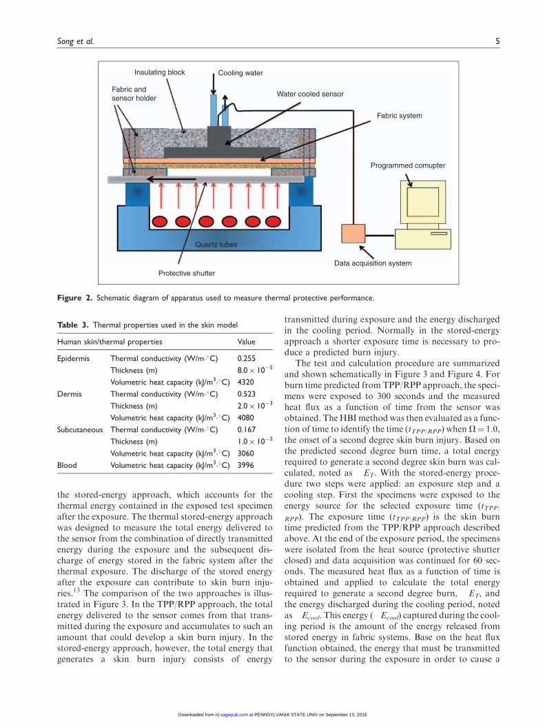
the stored-energy approach, which accounts for thethermal energy contained in the exposed test specimenafter the exposure. The thermal stored-energy approachwas designed to measure the total energy delivered tothe sensor from the combination of directly transmittedenergy during the exposure and the subsequent dis-charge of energy stored in the fabric system after thethermal exposure. The discharge of the stored energyafter the exposure can contribute to skin burn inju-ries.13 The comparison of the two approaches is illus-trated in Figure 3. In the TPP/RPP approach, the totalenergy delivered to the sensor comes from that trans-mitted during the exposure and accumulates to such anamount that could develop a skin burn injury. In thestored-energy approach, however, the total energy thatgenerates a skin burn injury consists of energy
transmitted during exposure and the energy dischargedin the cooling period. Normally in the stored-energyapproach a shorter exposure time is necessary to pro-duce a predicted burn injury.
The test and calculation procedure are summarizedand shown schematically in Figure 3 and Figure 4. Forburn time predicted from TPP/RPP approach, the speci-mens were exposed to 300 seconds and the measuredheat flux as a function of time from the sensor wasobtained. TheHBImethod was then evaluated as a func-tion of time to identify the time (tTPP/RPP) when V¼ 1.0,the onset of a second degree skin burn injury. Based onthe predicted second degree burn time, a total energyrequired to generate a second degree skin burn was cal-culated, noted as �ET. With the stored-energy proce-dure two steps were applied: an exposure step and acooling step. First the specimens were exposed to theenergy source for the selected exposure time (tTPP/RPP). The exposure time (tTPP/RPP) is the skin burntime predicted from the TPP/RPP approach describedabove. At the end of the exposure period, the specimenswere isolated from the heat source (protective shutterclosed) and data acquisition was continued for 60 sec-onds. The measured heat flux as a function of time isobtained and applied to calculate the total energyrequired to generate a second degree burn, �ET, andthe energy discharged during the cooling period, notedas �Ecool. This energy (�Ecool) captured during the cool-ing period is the amount of the energy released fromstored energy in fabric systems. Base on the heat fluxfunction obtained, the energy that must be transmittedto the sensor during the exposure in order to cause a
Insulating block
Fabric andsensor holder
Cooling water
Water cooled sensor
Fabric system
Programmed comupter
Quartz tubes
Protective shutterData acquisition system
Figure 2. Schematic diagram of apparatus used to measure thermal protective performance.
Table 3. Thermal properties used in the skin model
Human skin/thermal properties Value
Epidermis Thermal conductivity (W/m��C) 0.255
Thickness (m) 8.0� 10�5
Volumetric heat capacity (kJ/m3��C) 4320
Dermis Thermal conductivity (W/m��C) 0.523
Thickness (m) 2.0� 10�3
Volumetric heat capacity (kJ/m3��C) 4080
Subcutaneous Thermal conductivity (W/m��C) 0.167
Thickness (m) 1.0� 10�2
Volumetric heat capacity (kJ/m3��C) 3060
Blood Volumetric heat capacity (kJ/m3��C) 3996
Song et al. 5
at PENNSYLVANIA STATE UNIV on September 13, 2016trj.sagepub.comDownloaded from
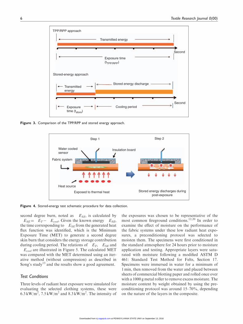
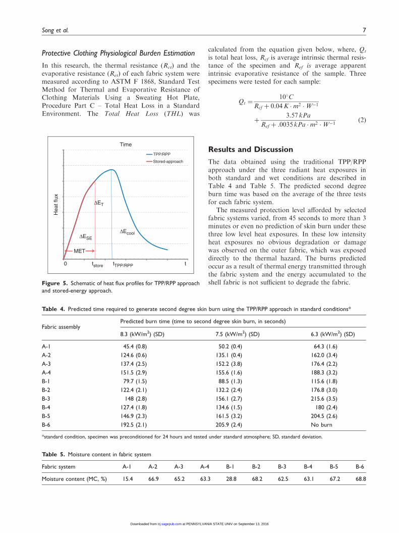
second degree burn, noted as �ESE, is calculated by�ESE¼�ET��Ecool. Given the known energy �ESE,the time corresponding to �ESE from the generated heatflux function was identified, which is the MinimumExposure Time (MET) to generate a second degreeskin burn that considers the energy storage contributionduring cooling period. The relations of �ET, �ESE and�Ecool are illustrated in Figure 5. The calculated METwas compared with the MET determined using an iter-ative method (without compression) as described inSong’s study13 and the results show a good agreement.
Test Conditions
Three levels of radiant heat exposure were simulated forevaluating the selected clothing systems, these were6.3 kW/m2, 7.5 kW/m2 and 8.3 kW/m2. The intensity of
the exposures was chosen to be representative of themost common fireground conditions.12,20 In order toexamine the effect of moisture on the performance ofthe fabric systems under these low radiant heat expo-sures, a preconditioning protocol was selected tomoisten them. The specimens were first conditioned inthe standard atmosphere for 24 hours prior to moistureapplication and testing. Appropriate layers were satu-rated with moisture following a modified ASTM D461: Standard Test Method for Felts, Section 17.Specimens were immersed in water for a minimum of1min, then removed from the water and placed betweensheets of commercial blotting paper and rolled once overwith a 1000 gmetal roller to remove excess moisture. Themoisture content by weight obtained by using the pre-conditioning protocol was around 15–70%, dependingon the nature of the layers in the composite.
TPP/RPP approach
Transmitted energy
Exposure time(tTPP/RPP)
Stored-energy approach
Transmittedenergy
Stored energy discharge
Exposuretime (tstore)
Cooling periodSecond
Second
Figure 3. Comparison of the TPP/RPP and stored energy approach.
Step 1
Water cooledsensor
Fabric system
Heat source
Exposed to thermal heat
Insulation board
Step 2
Stored energy discharges duringpost-exposure
Figure 4. Stored-energy test schematic procedure for data collection.
6 Textile Research Journal 0(00)
at PENNSYLVANIA STATE UNIV on September 13, 2016trj.sagepub.comDownloaded from
Protective Clothing Physiological Burden Estimation
In this research, the thermal resistance (Rct) and theevaporative resistance (Ret) of each fabric system weremeasured according to ASTM F 1868, Standard TestMethod for Thermal and Evaporative Resistance ofClothing Materials Using a Sweating Hot Plate,Procedure Part C – Total Heat Loss in a StandardEnvironment. The Total Heat Loss (THL) was
calculated from the equation given below, where, Qt
is total heat loss, Rcf is average intrinsic thermal resis-tance of the specimen and Ref is average apparentintrinsic evaporative resistance of the sample. Threespecimens were tested for each sample:
Qt ¼10�C
Rcf þ 0:04K �m2 �W�1
þ3:57 kPa
Ref þ :0035 kPa �m2 �W�1ð2Þ
Results and Discussion
The data obtained using the traditional TPP/RPPapproach under the three radiant heat exposures inboth standard and wet conditions are described inTable 4 and Table 5. The predicted second degreeburn time was based on the average of the three testsfor each fabric system.
The measured protection level afforded by selectedfabric systems varied, from 45 seconds to more than 3minutes or even no prediction of skin burn under thesethree low level heat exposures. In these low intensityheat exposures no obvious degradation or damagewas observed on the outer fabric, which was exposeddirectly to the thermal hazard. The burns predictedoccur as a result of thermal energy transmitted throughthe fabric system and the energy accumulated to theshell fabric is not sufficient to degrade the fabric.
Table 4. Predicted time required to generate second degree skin burn using the TPP/RPP approach in standard conditions*
Fabric assemblyPredicted burn time (time to second degree skin burn, in seconds)
8.3 (kW/m2) (SD) 7.5 (kW/m2) (SD) 6.3 (kW/m2) (SD)
A-1 45.4 (0.8) 50.2 (0.4) 64.3 (1.6)
A-2 124.6 (0.6) 135.1 (0.4) 162.0 (3.4)
A-3 137.4 (2.5) 152.2 (3.8) 176.4 (2.2)
A-4 151.5 (2.9) 155.6 (1.6) 188.3 (3.2)
B-1 79.7 (1.5) 88.5 (1.3) 115.6 (1.8)
B-2 122.4 (2.1) 132.2 (2.4) 176.8 (3.0)
B-3 148 (2.8) 156.1 (2.7) 215.6 (3.5)
B-4 127.4 (1.8) 134.6 (1.5) 180 (2.4)
B-5 146.9 (2.3) 161.5 (3.2) 204.5 (2.6)
B-6 192.5 (2.1) 205.9 (2.4) No burn
*standard condition, specimen was preconditioned for 24 hours and tested under standard atmosphere; SD, standard deviation.
Hea
t flu
x
Time
TPP/RPP
Stored-approach
tTPP/RPP
DET
0 t
DESE
DEcool
MET
tstore
Figure 5. Schematic of heat flux profiles for TPP/RPP approach
and stored-energy approach.
Table 5. Moisture content in fabric system
Fabric system A-1 A-2 A-3 A-4 B-1 B-2 B-3 B-4 B-5 B-6
Moisture content (MC, %) 15.4 66.9 65.2 63.3 28.8 68.2 62.5 63.1 67.2 68.8
Song et al. 7
at PENNSYLVANIA STATE UNIV on September 13, 2016trj.sagepub.comDownloaded from
The lowest protection times were observed on thethinnest fabric systems, in particular the single layersystems. With one layer of fabric, the protection timewas predicted to be around 45 to 64 seconds underthese low intensity radiant heat exposures. Theobserved difference in protection time between8.3 kW/m2 and 6.3 kW/m2 exposures was about 20 sec-onds. As more layers were added to the system, thethermal protective performance increased significantly,specifically the addition of a thermal barrier (insula-tion) layer, as shown in A-3, A-4, B-5 and B-6. Forsystem B-6, the protection time was predicted to bemore than 3 minutes for exposures of 8.3 and 7.5 kW/m2, and no burn was predicted for a 6.3 kW/m2 expo-sure. The observed difference of the predicted seconddegree skin burn time in multilayer systems between 8.3and 6.3 kW/m2 exposures was up to 58 seconds. Thestructure of multi-layer fabric systems increase theoverall thickness of the assembly, and consequentlyprotection against low level radiant heat exposureimproves significantly.
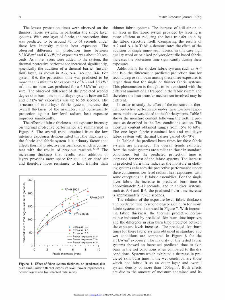
The effects of fabric thickness and exposure intensityon thermal protective performance are summarized inFigure 6. The overall trend obtained from the lowintensity exposures demonstrated that the thickness ofthe fabric and fabric system is a primary factor thataffects thermal protective performance, which is consis-tent with the results of previous research.13,21 Theincreasing thickness that results from addition oflayers provides more space for still air or dead airand therefore more resistance to heat transfer than
thinner fabric systems. The increase of still air or anair layer in the fabric system provided by layering ismore efficient at reducing the heat transfer than bythe fabric structure itself. Comparing the results ofA-2 and A-4 in Table 4 demonstrates the effect of theaddition of single inner-wear fabrics, in this case highquality wool or oxidized polyacrylonitrile based fabric,increases the protection time significantly during theseexposures.
Additionally for thicker fabric systems such as A-4and B-6, the difference in predicted protection time forsecond degree skin burn among these three exposures islarger than that for single or thinner fabric systems.This phenomenon is thought to be associated with thedifferent amount of air trapped in the fabric system andtherefore the heat transfer mechanism involved may bedifferent.
In order to study the effect of the moisture on ther-mal protective performance under these low level expo-sures, moisture was added to the fabric systems. Table 5shows the moisture content following the wetting pro-tocol as described in the Test conditions section. Themoisture content obtained ranges from 15% to 69%.The one layer fabric contained less and multilayerfabric system with thermal barrier gained 60–70%.
In Table 6 the predicted burn times for these fabricsystems are presented. The overall trends exhibitedfrom the moist systems are similar to those in standardconditions, but the predicted protection time isincreased for most of the fabric systems. The increasein predicted burn time indicates the moisture in cloth-ing systems enhances the protective performance underthese continuous low level radiant heat exposures, withsome exceptions in B fabric assemblies. For the singlelayer fabric the increase in predicted burn time isapproximately 5–17 seconds, and in thicker systems,such as A-4 and B-6, the predicted burn time increaseis approximately 77–83 seconds.
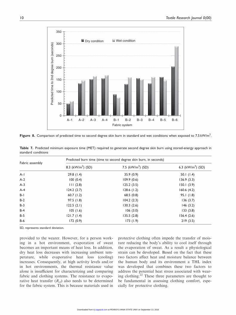
The relation of the exposure level, fabric thicknessand predicted time to second degree skin burn for moistfabric systems are illustrated in Figure 7. With increas-ing fabric thickness, the thermal protective perfor-mance indicated by predicted skin burn time improvesand the difference in skin burn time predicted betweenthe exposure levels increases. The predicted skin burntimes for these fabric systems obtained in standard andwet conditions are compared in Figure 8 for the7.5 kW/m2 exposure. The majority of the tested fabricsystems showed an increased predicted time to skinburn in the wet conditions when compared to the dryconditions. Systems which exhibited a decrease in pre-dicted skin burn time in the wet condition are thosewhich had fabric B as an outer layer and overallsystem density of more than 150 kg/m3. Both effectsare due to the amount of moisture contained and its
R2=0.9355
R2=0.9417
R2=0.9001
0
50
100
150
200
250
0 2 4 6 8 10
Pre
dict
ed ti
me
to 2
nd d
egre
e sk
in b
urn
(sec
onds
)
Fabric thickness (mm)
Exposure: 8.3 Exposure: 7.5Exposure: 6.3Power (exposure: 8.3)Power (exposure: 7.5)Power (exposure: 6.3)
Figure 6. Effect of fabric system thickness on predicted skin
burn time under different exposure level. Power represents a
power regression for selected data series.
8 Textile Research Journal 0(00)
at PENNSYLVANIA STATE UNIV on September 13, 2016trj.sagepub.comDownloaded from
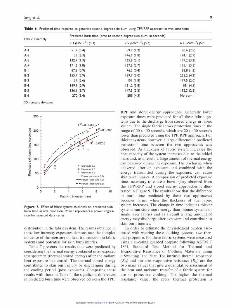
distribution in the fabric system. The results obtained inthese low intensity exposures demonstrate the complexinfluence of the moisture on heat transmission in fabricsystems and potential for skin burn injuries.
Table 7 presents the results that were predicted byconsidering the thermal energy contained in an exposedtest specimen (thermal stored energy) after the radiantheat exposure has ceased. The thermal stored energycontributes to skin burn injury by discharging duringthe cooling period (post exposure). Comparing theseresults with those in Table 4, the significant differencesin predicted burn time were observed between the TPP/
RPP and stored-energy approaches. Generally lowerexposure times were predicted for all these fabric sys-tems due to the discharge from stored energy in fabricsystem. The single fabric shows protection times in therange of 30 to 50 seconds, which are 20 to 30 secondslower than predicted using the TPP/RPP approach. Forthicker systems, however, a large difference in predictedprotection time between the two approaches wasobserved. As thickness of fabric system increases theheat capacity of the system increases due to the addedmass and, as a result, a large amount of thermal energycan be stored during the exposure. The discharge, whendelivered after an exposure and combined with theenergy transmitted during the exposure, can causeskin burn injuries. A comparison of predicted exposuretimes necessary to cause a burn injury obtained fromthe TPP/RPP and stored energy approaches is illus-trated in Figure 9. The results show that the differencein burn time predicted by these two approachesbecomes larger when the thickness of the fabricsystem increases. The change in time indicates thickersystems can store more energy than thinner systems orsingle layer fabrics and as a result a large amount ofenergy may discharge after exposure and contribute toskin burn injuries.
In order to estimate the physiological burden asso-ciated with wearing these clothing systems, two ther-mal properties for these fabric systems were measuredusing a sweating guarded hotplate following ASTM F1861, Standard Test Method for Thermal andEvaporative Resistance of Clothing Materials Usinga Sweating Hot Plate. The intrinsic thermal resistance(Rcf) and intrinsic evaporative resistance (Ref) are thetwo main values that give a quantitative assessment ofthe heat and moisture transfer of a fabric system foruse in protective clothing. The higher the thermalresistance value, the more thermal protection is
Table 6. Predicted time required to generate second degree skin burn using TPP/RPP approach in wet conditions
Fabric assemblyPredicted burn time (time to second degree skin burn, in seconds)
8.3 (kW/m2) (SD) 7.5 (kW/m2) (SD) 6.3 (kW/m2) (SD)
A-1 51.7 (0.4) 59.9 (1.2) 80.6 (2.8)
A-2 133 (2.3) 146.9 (1.8) 174.1 (2.9)
A-3 132.4 (1.3) 165.6 (2.1) 199.2 (3.2)
A-4 171.6 (1.8) 167.6 (2.7) 195.1 (3.8)
B-1 67.8 (0.9) 76.5 (0.4) 88.8 (1.2)
B-2 155.7 (2.9) 159.7 (3.0) 255.2 (4.2)
B-3 137 (2.6) 151 (1.8) 177.5 (2.0)
B-4 149.9 (2.9) 161.2 (3.8) 181 (4.5)
B-5 136.1 (3.7) 147.5 (3.2) 192.3 (2.6)
B-6 270 (3.4) 289 (4.3) No burn
SD, standard deviation.
R2=0.8233
R2=0.8332
R2=0.8033
0
50
100
150
200
250
0 2 4 6 8 10
Pre
dict
ed s
kin
burn
tim
e (s
econ
ds)
Fabric thickness (mm)
Exposure 8.3Exposure 7.5Exposure 6.3
Power (exposure 8.3)
Power (exposure 7.5)
Power (exposure 6.3)
Figure 7. Effect of fabric system thickness on predicted skin
burn time in wet condition. Power represents a power regres-
sion for selected data series.
Song et al. 9
at PENNSYLVANIA STATE UNIV on September 13, 2016trj.sagepub.comDownloaded from
provided to the wearer. However, for a person work-ing in a hot environment, evaporation of sweatbecomes an important means of heat loss. In addition,dry heat loss decreases with increasing ambient tem-perature, while evaporative heat loss (cooling)increases. Consequently, at high activity levels and/orin hot environments, the thermal resistance valuealone is insufficient for characterizing and comparingfabric and clothing systems. The resistance to evapo-rative heat transfer (Ref) also needs to be determinedfor the fabric system. This is because materials used in
protective clothing often impede the transfer of mois-ture reducing the body’s ability to cool itself throughthe evaporation of sweat. As a result a physiologicalstrain can be developed. Based on the fact that thesetwo factors affect heat and moisture balance betweenthe human body and its environment a THL indexwas developed that combines these two factors toaddress the potential heat stress associated with wear-ing clothing.22 These three parameters are thought tobe fundamental in assessing clothing comfort, espe-cially for protective clothing.
0
50
100
150
200
250
300
350
A–1 A–2 A–3 A–4 B–1 B–2 B–3 B–4 B–5 B–6
Pre
dict
ed ti
me
to 2
nd d
egre
e bu
rn (
seco
nds)
Fabric system
Dry condition Wet condition
Figure 8. Comparison of predicted time to second degree skin burn in standard and wet conditions when exposed to 7.5 kW/m2.
Table 7. Predicted minimum exposure time (MET) required to generate second degree skin burn using stored-energy approach in
standard conditions
Fabric assemblyPredicted burn time (time to second degree skin burn, in seconds)
8.3 (kW/m2) (SD) 7.5 (kW/m2) (SD) 6.3 (kW/m2) (SD)
A-1 29.8 (1.4) 35.9 (0.9) 50.1 (1.4)
A-2 100 (0.4) 109.9 (0.6) 136.9 (3.3)
A-3 111 (2.8) 125.2 (3.5) 150.1 (3.9)
A-4 124.2 (2.7) 128.6 (1.2) 160.6 (4.2)
B-1 60.7 (1.2) 68.5 (0.8) 95.1 (1.8)
B-2 97.5 (1.8) 104.2 (2.3) 136 (3.7)
B-3 122.5 (2.1) 130.3 (2.6) 146 (3.2)
B-4 105 (1.6) 106 (3.0) 133 (3.8)
B-5 121.7 (1.4) 135.5 (2.8) 156.4 (2.6)
B-6 172 (0.9) 173 (1.9) 219 (3.5)
SD, represents standard deviation.
10 Textile Research Journal 0(00)
at PENNSYLVANIA STATE UNIV on September 13, 2016trj.sagepub.comDownloaded from
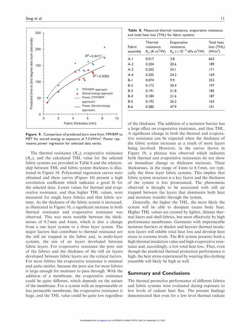
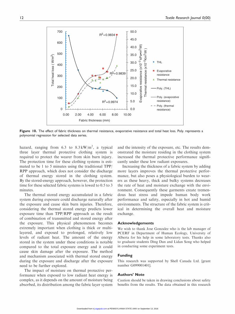
The thermal resistance (Rcf), evaporative resistance(Ref), and the calculated THL value for the selectedfabric systems are provided in Table 8 and the relation-ship between THL and fabric system thickness is illus-trated in Figure 10. Polynomial regression curves wereobtained and these curves (Figure 10) present a highcorrelation coefficient which indicates a good fit forthe selected data. Lower values for thermal and evap-orative resistance, and thus higher THL values, weremeasured for single layer fabrics and thin fabric sys-tems. As the thickness of the fabric system is increased,as illustrated in Figure 10, a significant increase in boththermal resistance and evaporative resistance wasobserved. This was most notable between the thick-nesses of 0.5mm and 4mm, which is also a changefrom a one layer system to a three layer system. Themajor factors that contribute to thermal resistance arethe still air trapped in the fabric and, in multi-layersystems, the size of air layers developed betweenfabric layers. For evaporative resistance the pore sizeof the fabrics and the thickness of the still air layersdeveloped between fabric layers are the critical factors.For most fabrics the evaporative resistance is minimaland quite similar, because the pore size for most fabricsis large enough for moisture to pass through. With theaddition of a membrane, the evaporative resistancecould be quite different, which depends on the natureof the membrane. For a system with an impermeable orless permeable membrane, the evaporative resistance ishuge, and the THL value could be quite low regardless
of the thickness. The addition of a moisture barrier hasa large effect on evaporative resistance, and thus THL.A significant change in both the thermal and evapora-tive resistance can be expected when the thickness ofthe fabric system increases as a result of more layersbeing involved. However, in the curves shown inFigure 10, a plateau was observed which indicatesboth thermal and evaporative resistances do not showan immediate change as thickness increases. Thesethicknesses, in the range of 4mm to 6.5mm, are typi-cally the three layer fabric systems. This implies thatfabric system structure is a key factor and the thicknessof the system is less pronounced. The phenomenaobserved is thought to be associated with still airtrapped between the layers that dominates both heatand moisture transfer through the system.
Generally, the higher the THL, the more likely thesystem will be able to dissipate excess body heat.Higher THL values are created by lighter, thinner ther-mal liners and shell fabrics, but most effectively by highperformance membranes. Garments with impermeablemoisture barriers or thicker and heavier thermal insula-tion layers will inhibit total heat loss and develop heatstress to extreme levels. The B-6 system presents both ahigh thermal insulation value and high evaporative resis-tance and, accordingly, a low total heat loss. Thus, eventhough the predicted thermal protection performance ishigh, the heat stress experienced by wearing this clothingensemble will likely be high as well.
Summary and Conclusions
The thermal protective performance of different fabricsand fabric systems were evaluated during exposure tolow levels of radiant heat flux. The present findingsdemonstrated that even for a low level thermal radiant
0
50
100
150
200
250
0 2 4 6 8 10
Pre
dict
ed ti
me
to 2
nd d
egre
e sk
in b
urn
(sec
onds
)
Fabric thickness (mm)
TPP/RPP approachStored energy approachPower (TPP/RPP
approach)Power (Stored energy
approach)
R2=0.9362
R2=0.9417
Figure 9. Comparison of predicted burn time from TPP/RPP to
MET for stored energy at exposure of 7.5 kW/m2. Power rep-
resents power regression for selected data series.
Table 8. Measured thermal resistance, evaporative resistance
and total heat loss (THL) for fabric systems
Fabric
assembly
Thermal
resistance,
Rcf (K�m2/W)
Evaporative
resistance,
Ref (�10�3 kPa�m2/W)
Total heat
loss (THL)
(W/m2)
A-1 0.017 3.8 663
A-2 0.204 20.6 189
A-3 0.202 24.1 171
A-4 0.205 24.2 169
B-1 0.074 9.9 353
B-2 0.172 20.4 197
B-3 0.191 21.8 185
B-4 0.184 21.6 187
B-5 0.192 26.2 163
B-6 0.280 47.9 101
Song et al. 11
at PENNSYLVANIA STATE UNIV on September 13, 2016trj.sagepub.comDownloaded from
hazard, ranging from 6.3 to 8.3 kW/m2, a typicalthree layer thermal protective clothing system isrequired to protect the wearer from skin burn injury.The protection time for these clothing systems is esti-mated to be 1 to 5 minutes using the traditional TPP/RPP approach, which does not consider the dischargeof thermal energy stored in the clothing system.By the stored-energy approach, however, the protectiontime for these selected fabric systems is lowed to 0.5 to 3minutes.
The thermal stored energy accumulated in a fabricsystem during exposure could discharge naturally afterthe exposure and cause skin burn injuries. Therefore,considering the thermal stored energy predicts lowerexposure time than TPP/RPP approach as the resultof combination of transmitted and stored energy afterthe exposure. This physical phenomenon becomesextremely important when clothing is thick or multi-layered, and exposed to prolonged, relatively lowlevels of radiant heat. The amount of the energystored in the system under these conditions is notablecompared to the total exposure energy and it couldcause skin damage after the exposure. The methodand mechanism associated with thermal stored energyduring the exposure and discharge after the exposureneed to be further explored.
The impact of moisture on thermal protective per-formance when exposed to low radiant heat energy iscomplex, as it depends on the amount of moisture beingabsorbed, its distribution among the fabric layer system
and the intensity of the exposure, etc. The results dem-onstrated the moisture residing in the clothing systemincreased the thermal protective performance signifi-cantly under these low radiant exposures.
Increasing the thickness of a fabric system by addingmore layers improves the thermal protective perfor-mance, but also poses a physiological burden to wear-ers as these heavy, thick and bulky systems decreasesthe rate of heat and moisture exchange with the envi-ronment. Consequently these garments create tremen-dous heat stress and impede human body workperformance and safety, especially in hot and humidenvironments. The structure of the fabric system is crit-ical in determining the overall heat and moistureexchange.
Acknowledgements
We wish to thank Jose Gonzalez who is the lab manager ofPCERF in Department of Human Ecology, University of
Alberta for his help in some laboratory tests. Thanks alsoto graduate students Ding Dan and Lidan Song who helpedin conducting some experiment tests.
Funding
This research was supported by Shell Canada Ltd. [grantnumber G099001401].
Authors’ Note
Caution should be taken in drawing conclusions about safety
benefits from the results. The data obtained in this research
0.0
5.0
10.0
15.0
20.0
25.0
30.0
35.0
40.0
45.0
50.0
0
100
200
300
400
500
600
700
0.00 2.00 4.00 6.00 8.00 10.00
Eva
pora
tive
resi
stan
ce (
x10–3
kP
a•m
2 /W
)
The
rmal
res
ista
nce
(x10
–2K
m2 /
W )
Tot
al h
eat l
oss
( W
/m2 )
Fabric thickness (mm)
THL
Evaporative resistance
Thermal resistance
Poly. (THL)
Poly. (evaporative resistance)
Poly. (thermal resistance)
R2=0.9839
R2=0.9974
R2=0.9834
Figure 10. The effect of fabric thickness on thermal resistance, evaporative resistance and total heat loss. Poly. represents a
polynomial regression for selected data series.
12 Textile Research Journal 0(00)
at PENNSYLVANIA STATE UNIV on September 13, 2016trj.sagepub.comDownloaded from
are from laboratory simulations under controlled laboratoryexposure and specified conditions. These performance predic-tions do not represent clothing performance in actual field
conditions where the nature of thermal exposure, clothingcondition, human body response can be physically compli-cated and unqualified. We wish to emphasize that it is notour intention to recommend, exclude, or predict the suitabil-
ity of any commercial product for a particular end-use.
References
1. Foster JA and Roberts GV. Measurements of the fire-fighter environment - summary report. Fire Engineers
Journal 1995; 55(178): 30–55.2. Abbott NJ and Schulman S. Protection from fire:
Nonflammable fabrics and coatings. J Coated Fabrics
1976; 6: 48–62.3. Hoschke BN. Standards and specifications for fire-
fighters’ clothing. Fire Safety Journal 1981; 4: 125–137.
4. Lee YM and Barker RL. Thermal protective performanceof heat-resistance fabrics in various high intensity heatexposures. Textile Res J 1987; 57(3): 123.
5. Sun G, Yoo HS, Zhang XS and Pan N. Radiant protec-tive and transport properties of fabrics used by wildlandfirefighters. Textile Res J 2000; 70: 567–573.
6. Shalev I and Barker RL. A comparison of laboratory
methods for evaluating thermal protective performancein convective/radiant exposures. Textile Res J 1984; 54:648–654.
7. Shalev I and Barker RL. Analysis of heat transfer char-acteristics of fabrics in an open flame exposure. TextileRes J 1983; 53: 475–482.
8. Crown EM, Ackerman MY, Dale JD and Tan Y. Designand evaluation of thermal protective flightsuits Part 2:Instrumented mannequin evaluation. Cloth Textile ResJ 1998; 16(2): 79–87.
9. Song G, Barker RL, Hamouda H, Kuznetsov AV,Chitrphiromsri P and Grimes RV. Modeling the thermalprotective performance of heat resistant garment in flash
fire exposures. Textile Res J 2004; 74(12): 1033.10. Perkins RM. Insulative values of single-layer fabrics
for thermal protective clothing. Textile Res J 1979;
49(4): 202.11. Utech HP. High temperatures vs. fire equipment.
International Fire Chief 1973; 39: 26–27.
12. Lawson JR. Fire fighters protective clothing and thermal
environments of structural fire fighting, performance of
protective clothing. In: Stull JO and Schwope AD (eds)
Performance of protective clothing, ASTM STP 1273,
6th Volume West Conshohocken, PA: American Society
for Testing and Materials, 1997, pp.334–352.13. Song G and Barker RL. Analyzing thermal stored
energy and clothing thermal protective performance.
Proceedings of 4th International Conference on Safety
& Protective Fabrics, Pittsburgh, PA, Sept. 26–27, 2004.14. Barker RL, Guerth-Schacher C, Grimes RV and
Hamouda H. Effects of moisture on the thermal protec-
tive performance of firefighter protective clothing in low-
level radiant heat exposures. Textile Res J 2006; 76(1):
27–31.
15. Lee YM and Barker RL. Effect of moisture on the ther-
mal protective performance of heat-resistant fabrics.
J Fire Sciences 1986; 4(5): 315–331.16. Stull JO. The effect of moisture on firefighter protec-
tive clothing thermal insulation: A review of industry
research. In: Nelson CN and Henry NW (eds)
Performance of protective clothing, ASTM STP 1386,
7th Volume West Conshohocken, PA: American Society
for Testing and Materials, 2000, pp.557–576.17. Keiser C, Becker C and Rossi RM. Moisture transport
and absorption in multilayer protective clothing fabrics.
Textile Res J 2008; 78(7): 604.18. Selkirk GA and McLellan TM. Physical work limits for
toronto firefighters in warm environments. J Occup
Environ Hyg 2004; 1: 199–212.19. Havenith G. Heat balance when wearing protective cloth-
ing. Ann Occup Hyg 1999; 43(5): 289–292.20. Gempel RF and Burgess WA. Thermal environment
during structural fire fighting Final Report, NFPA
Grant 76010, prepared for the National Fire Prevention
and Control Administration, July 1977.
21. Torvi DA and Dale JD. Effects of variations in thermal
properties on the performance of flame resistant fabrics
for flash fires. Textile Res J 1998; 68(11): 787–796.
22. Gohlke DJ. History of the Development of the Total
Heat Loss Test Method. In: Stull JO and Schwope AD
(eds) Performance of protective clothing, ASTM STP
1273, 6th Volume West Conshohocken, PA: American
Society for Testing and Materials, 1997, pp.190–206.
Song et al. 13
at PENNSYLVANIA STATE UNIV on September 13, 2016trj.sagepub.comDownloaded from