Embed Size (px)
Citation preview


Acknowledgements 2
Acknowledgements
I would first like to thank my advisor, Marsha Rolle, for her endless support and guidance over
the past 5 years. I would also like to thank my committee, Kris Billiar, Glenn Gaudette, Suzanne
Scarlata, and Eben Alsberg for their feedback and guidance on this project.
I would like to thank our many collaborators over the years. I would like to thank Monica, Ben,
and Marco for designing our bioreactors and for continued assistance with setup and
troubleshooting. I would also like to thank Anna and Rui from the Alsberg lab at Case Western
Reserve University for fabricating the gelatin microspheres that are critical to this project, Yibing
and Jiesi from Yale University for providing iPSCs, and Tabby Ahsan from RoosterBio for
providing hMSCs.
I would like to thank the many graduate students who have helped me throughout my time at
WPI, especially Dalia Shendi, Jennifer Cooper, Zoe Reidinger, Beth Calamari, Joni Grosha,
Emily Caron, David Dolivo, Lindsay Lozeau, and Katrina Hansen. Your technical assistance
proved invaluable, and your support was greatly appreciated.
I would also like to thank the countless undergraduate students who have assisted with this
project, often doing endless staining, imaging, and image analysis. I would like to thank our
histology technicians Hans Snyder and Jyotsna Patel for their assistance with histology and
training undergraduate students.
Finally, I would like to thank my friends and family for their support throughout my time at
WPI, especially my husband Michael, for his patience with my many late nights and long
weekends in the lab.
Table of Contents 3
Table of Contents
Acknowledgements ...................................................................................................................... 2
Table of Contents ......................................................................................................................... 3
Abstract ...................................................................................................................................... 10
Abbreviations ............................................................................................................................. 11
Table of Figures ......................................................................................................................... 13
Table of Tables........................................................................................................................... 18
Chapter 1: Executive Summary .................................................................................................. 19
1.1. Introduction ..................................................................................................................... 19
1.2. Overview of aims ............................................................................................................. 20
Aim 1: Develop a system to locally deliver bioactive factors within tissue rings. ............... 20
Aim 2: Fuse human SMC rings into tissue tubes and evaluate the effects of dynamic culture.
............................................................................................................................................ 21
Aim 3: Create vascular tissue tubes with spatially distinct regions ..................................... 22
1.3. Summary ......................................................................................................................... 23
1.4. References ....................................................................................................................... 24
Chapter 2: Background ............................................................................................................... 26
2.1. Smooth muscle phenotype ............................................................................................... 26
2.2. Intimal hyperplasia .......................................................................................................... 27
2.3. Treatments for IH ............................................................................................................ 28
2.4. Model systems for studying IH ........................................................................................ 29
2.5. Tissue engineered blood vessels as in vitro human vascular models. ............................... 30
2.6. Modular fabrication of vascular tissue constructs from self-assembled cell ring units. .... 31
2.7. Engineering custom agarose molds for self-assembled tissue ring fabrication ................. 31
2.8. Microsphere incorporation and modular assembly to create focal regions of IH .............. 34
2.9. Bioactive molecule release from tissue engineered blood vessels .................................... 34
2.10. Microsphere-mediated growth factor delivery in engineered vascular tissue ................. 35
2.11. Platelet-derived growth factor ........................................................................................ 35
2.12. Gelatin microspheres for controlled delivery of PDGF .................................................. 36

Table of Contents 4
2.13. Summary ....................................................................................................................... 37
2.14. References ..................................................................................................................... 38
Chapter 3: Cellular self-assembly with microsphere incorporation for growth factor delivery
within engineered vascular tissue rings ...................................................................................... 50
3.1. Introduction ..................................................................................................................... 50
3.2. Materials and methods ..................................................................................................... 52
3.2.1. Gelatin microsphere preparation ................................................................................ 52
3.2.2. Human smooth muscle cell culture ............................................................................ 52
3.2.3. Smooth muscle cell ring self-assembly and unloaded microsphere incorporation ..... 52
3.2.4. TGF-β1-loaded microsphere preparation and incorporation within tissue rings ........ 53
3.2.5. Histology and immunohistochemistry ....................................................................... 53
3.2.6. SMC ring thickness and diameter measurements ...................................................... 54
3.2.7. Mechanical testing .................................................................................................... 54
3.2.8. Western blot analysis ................................................................................................ 54
3.2.9. Statistical analysis ..................................................................................................... 55
3.3. Results ............................................................................................................................. 55
3.3.1. Gelatin microsphere characterization ........................................................................ 55
3.3.2. Effects of microsphere incorporation on self-assembled SMC rings cultured in growth
medium ............................................................................................................................... 56
3.3.3. Effects of microsphere incorporation on self-assembled SMC rings cultured in
differentiation medium ........................................................................................................ 57
3.3.4. TGF-β1 delivery from incorporated microspheres within self-assembled SMC rings 57
3.4. Discussion ....................................................................................................................... 62
3.5. References ....................................................................................................................... 66
Chapter 4: Fabrication and characterization of electrospun polycaprolactone cuffs for self-
assembled vascular tissue ........................................................................................................... 72
4.1. Introduction ..................................................................................................................... 72
4.2. Methods ........................................................................................................................... 74
4.2.2. Fabrication of PCL electrospun cuffs ........................................................................ 74
4.2.3. Fiber diameter measurement ..................................................................................... 75
4.2.4. Tensile testing of electrospun cuffs ........................................................................... 75
4.2.5. Cell culture ................................................................................................................ 75

Table of Contents 5
4.2.6. TEBV fabrication from self-assembled tissue rings................................................... 75
4.2.7. Longitudinal pull to failure testing ............................................................................ 76
4.2.8. Hoechst staining ........................................................................................................ 76
4.3. Results ............................................................................................................................. 76
4.3.1. Characterization of electrospun PCL cuffs ................................................................ 76
4.4. Discussion ....................................................................................................................... 78
4.5. References ....................................................................................................................... 79
Chapter 5: Generate modular vascular tissue tubes with luminal flow ....................................... 83
5.1. Introduction ..................................................................................................................... 83
5.2 Methods ............................................................................................................................ 85
5.2.2. Tissue ring fabrication ............................................................................................... 85
5.2.3. Tissue tube fusion with varying pre-culture time....................................................... 85
5.2.4. Fusion angle, length, and thickness measurements .................................................... 86
5.2.5. CellTracker labeling .................................................................................................. 87
5.2.6. Polycaprolactone (PCL) cannulation cuff fabrication ................................................ 87
5.2.7. Bioreactor culture ...................................................................................................... 87
5.2.8 Histology and immunohistochemistry ........................................................................ 88
5.2.9. Statistics .................................................................................................................... 89
5.3. Results ............................................................................................................................. 89
5.3.1. Effect of ring pre-culture time on human SMC tube fusion rate ................................ 89
5.3.2. Structure and morphology of fused human SMC tubes ............................................. 90
5.3.3. Spatial positioning of SMCs within rings during fusion ............................................ 90
5.3.4. PCL cannulation cuffs and dynamic tube culture .................................................. 92
5.4. Discussion ....................................................................................................................... 94
5.5 References ........................................................................................................................ 98
Chapter 6: Create vascular tissue tubes with spatially distinct regions ..................................... 103
6.1. Introduction ................................................................................................................... 103
6.2. Methods ......................................................................................................................... 104
6.2.1. Cell culture .............................................................................................................. 104
6.2.2. Ring fabrication ....................................................................................................... 105
6.2.3. Tube fabrication for fusion comparison ................................................................... 105

Table of Contents 6
6.2.4. Fabricating tubes with spatially defined regions of microsphere incorporation ....... 106
6.2.5. PDGF treatment of 2D cell cultures ........................................................................ 106
6.2.6. PDGF treatment of self-assembled SMC rings ........................................................ 106
6.2.7. Histology and immunohistochemistry ..................................................................... 106
6.2.8. Statistical analysis ................................................................................................... 107
6.3. Results ........................................................................................................................... 108
6.3.1. Effect of microspheres on tube fusion ..................................................................... 108
6.3.2. Fabrication of a focal region of microsphere incorporation ..................................... 109
6.3.3. Effect of PDGF on proliferation of 2D SMC cultures ............................................. 110
6.3.4. Effect of microsphere-mediated PDGF release on SMC rings ................................. 110
6.4. Discussion ..................................................................................................................... 111
6.5. References ..................................................................................................................... 114
Chapter 7: Induced pluripotent stem cells as an alternative human smooth muscle cell source for
vascular tissue engineering ....................................................................................................... 117
7.1. Introduction ................................................................................................................... 117
7.2. Methods ......................................................................................................................... 118
7.2.1. Ring culture ............................................................................................................. 118
7.2.2. Tube culture ............................................................................................................ 118
7.2.3. iPSC-vSMC response to PDGF in 2D ..................................................................... 119
7.2.4. iPSC-vSMC response to PDGF in 3D ..................................................................... 119
7.2.5. Mechanical testing .................................................................................................. 120
7.2.6. Histological analysis and immunohistochemistry .................................................... 120
7.2.7. Western blotting ...................................................................................................... 120
7.3. Results ........................................................................................................................... 120
7.3.1. Ring formation and characterization ........................................................................ 120
7.3.2. iPSC-vSMC response to PDGF ............................................................................... 121
7.3.3. Tube fabrication ...................................................................................................... 122
7.4. Discussion ..................................................................................................................... 123
7.5. References ..................................................................................................................... 125
Chapter 8: Growth factor delivery for phenotypic modulation of human mesenchymal stem cell
rings ......................................................................................................................................... 129

Table of Contents 7
8.1. Introduction ................................................................................................................... 129
8.2. Methods ......................................................................................................................... 130
8.2.1. Cell culture .............................................................................................................. 130
8.2.2. Ring culture ............................................................................................................. 130
8.2.3. Ring thickness measurements .................................................................................. 132
8.2.4. Histology and immunohistochemistry ..................................................................... 132
8.2.5. DNA quantification ................................................................................................. 132
8.2.6. PDGF loading efficiency ......................................................................................... 133
8.2.7. Statistical analysis ................................................................................................... 133
8.3. Results ........................................................................................................................... 133
8.3.1. Effects of microsphere-mediated PDGF release on hMSC rings ............................. 133
8.3.2. Effect of microsphere-mediated FGF release on hMSC rings .................................. 137
8.3.3. Effect of microsphere-mediated TGF-β1 release on hMSC rings ............................ 141
8.4. Discussion ..................................................................................................................... 144
8.5. References ..................................................................................................................... 149
Chapter 9: Vascular tissue tubes with distinct phenotypic and structural regions ..................... 154
9.1. Introduction ................................................................................................................... 154
9.2. Methods ......................................................................................................................... 155
9.2.1. Cell culture .............................................................................................................. 155
9.2.2. Ring fabrication ....................................................................................................... 155
9.2.3. hMSC tube fabrication ............................................................................................ 155
9.2.5. Histology and immunohistochemistry ..................................................................... 156
9.3. Results ........................................................................................................................... 157
9.3.1. Fabrication of tissue tubes from hMSC rings .......................................................... 157
9.3.4. Focal region of synthetic SMCs .............................................................................. 158
9.4. Discussion ..................................................................................................................... 158
9.5. References ..................................................................................................................... 161
Chapter 10: Conclusions and future work ................................................................................ 163
10.1. Summary ..................................................................................................................... 163
10.2. Other applications of the ring system ........................................................................... 164
10.3. Limitations ................................................................................................................... 165

Table of Contents 8
10.4. Future work ................................................................................................................. 166
10.5. References ................................................................................................................... 168
Appendix A: Reprint permission for Chapter 2.7 ..................................................................... 172
Appendix B: Reprint permission for Chapter 3 ........................................................................ 173
Appendix C: Chapter 3 supplemental data ............................................................................... 174
Supplemental methods .......................................................................................................... 174
Cell culture ........................................................................................................................ 174
Supplemental figures ............................................................................................................ 174
Appendix D: Reprint permission for Chapter 4 ........................................................................ 177
Appendix E: Chapter 4 supplemental data ................................................................................ 183
Appendix F: Chapter 5 supplemental data ................................................................................ 184
Supplemental methods .......................................................................................................... 184
Cell culture ........................................................................................................................ 184
Supplemental figures ............................................................................................................ 184
Appendix G: Microsphere characterization .............................................................................. 187
Appendix H: Supplemental data for Chapter 8 ......................................................................... 188
Supplemental methods .......................................................................................................... 188
Supplemental figures ............................................................................................................ 188
Appendix I: Automation and scale-up of tissue tube production .............................................. 191
Abstract ................................................................................................................................ 191
I.1. Introduction .................................................................................................................... 192
I.2. Methods .......................................................................................................................... 195
I.2.1. Mold design ............................................................................................................. 195
I.2.2. Cell culture .............................................................................................................. 195
I.2.3. Agarose gel preparation ........................................................................................... 196
I.2.4. Ring fabrication ....................................................................................................... 196
I.2.5. Mechanical testing ................................................................................................... 196
I.2.6. Histology ................................................................................................................. 197
I.2.7. Robotic punch design ............................................................................................... 197
I.2.8. Tube fabrication ....................................................................................................... 198
I.2.9. Statistics ................................................................................................................... 199

Table of Contents 9
I.3. Results ............................................................................................................................ 199
I.3.1. Ring fabrication in PEI-MED610 plate system ........................................................ 199
I.3.2. Automation system .................................................................................................. 200
I.3.3. Tube fusion following automated ring stacking ....................................................... 201
I.4. Discussion ...................................................................................................................... 202
I.5. References ...................................................................................................................... 205

Abstract 10
Abstract
Tissue engineered blood vessels (TEBVs) have great potential as tools for disease
modeling and drug screening. However, existing methods for fabricating TEBVs create
homogenous tissue tubes, which may not be conducive to modeling focal vascular diseases such
as intimal hyperplasia or aneurysm. In contrast, our lab has a unique modular system for
fabricating TEBVs. Smooth muscle cells (SMCs) are seeded into an annular agarose mold,
where they aggregate into vascular tissue rings, which can be stacked and fused into small
diameter TEBVs. Our goal is to create a platform technology that may be used for fabricating
focal vascular disease models, such as intimal hyperplasia. Because tubes are fabricated from
individual ring units, each ring can potentially be customized, enabling the creation of focal
changes or regions of disease along the tube length. In these studies, we first demonstrated our
ability to modulate cell phenotype within individual SMC ring units using incorporated growth
factor-loaded degradable gelatin microspheres. Next, we evaluated fusion of ring subunits to
form composite tissue tubes, and demonstrated that cells retain their spatial positioning within
individual rings during fusion. By incorporating electrospun polycaprolactone cannulation cuffs
at each end, tubes were mounted on bioreactors after only 7 days of fusion to impart luminal
medium flow for 7 days at a physiological shear stress of 12 dyne/cm2. We then created focal
heterogeneities along the tube length by fusing microsphere-containing rings in the central region
of the tube between rings without microspheres. In the future, microspheres may be used to
deliver growth factors to this localized region of microsphere incorporation and induce disease
phenotypes. Due to the challenges of working with primary human SMCs, we next evaluated
human mesenchymal stem cells (hMSCs) as an alternative cell source to generate vascular
SMCs. We evaluated the effects of microsphere-mediated platelet-derived growth factor
(PDGF), fibroblast growth factor (FGF), and transforming growth factor beta-1 (TGF-β1)
delivery on ring thickness, proliferation, and contractile protein expression over a 14 day period.
Finally, we created a structurally distinct region of smooth muscle within tissue tubes by fusing
human aortic SMCs in a central region between hMSC rings. In summary, we developed a
platform technology for creating modular tubular tissues that may be further developed into an in
vitro intimal hyperplasia model. It may also be modified to model other focal vascular diseases,
such as aneurysm, or to create other types of multi-tissue tubular structures, such as trachea.

Abbreviations 11
Abbreviations
ANOVA – Analysis of variance
BCA – Bicinchoninic acid
DMEM – Dulbecco’s modified eagle medium
CALP – Calponin
CAM – Computer-aided manufacturing
CNC – Computer numerical control
ECM – Extracellular matric
ECs – Endothelial cells
EDTA – Ethylenediaminetetraacetic acid
EdU – 5-ethynyl-2’-deoxyuridine
EGF – Epidermal growth factor
FBS – Fetal bovine serum
FGF – Fibroblast growth factor
H&E – Hematoxylin and Eosin
hMSC – Human mesenchymal stem cell
HRP – Horse radish peroxidase
IGF – Insulin-like growth factor
IH – Intimal hyperplasia
IHC – Immunohistochemistry
IL-1 – Interleukin 1
IL-6 – Interleukin 6
iPSC-vSMCs – Induced pluripotent stem cell-derived vascular smooth muscle cells
ITS – Insulin transferrin selenium
MAPK – Mitogen activated protein kinase
MS – Microspheres
MTM – Maximum tangent modulus
NBF – Neutral buffered formalin
NGS – Normal goat serum
NO – Nitric oxide
NRS – Normal rabbit serum
PBS – Phosphate buffered saline
PCL – Polycaprolactone
PDGF – Platelet derived growth factor
PDMS – Polydimethylsiloxane
PGA – Poly-glycolic acid
PLA – Poly-lactic acid
PLGA – poly(lactic-co-glycolic) acid
SDS – Sodium dodecyl sulfate

Abbreviations 12
SEM – Scanning electron microscopy
SMA – Smooth muscle alpha actin
SM-22α – Smooth muscle protein 22 alpha
SMC – Smooth muscle cell
SVAS – Supravalvular aortic stenosis
TBST – Tris buffered saline plus tween
TEBV – Tissue engineered blood vessel
TFE – Tri-fluoroethanol
TGF-β1 – Transforming growth factor beta 1
UTS – Ultimate tensile strength
VEGF – Vascular endothelial growth factor

Table of Figures 13
Table of Figures
Figure 1.1: Aim 1 overview: Develop a system to locally deliver bioactive factors
within tissue rings ………………………………………………………………………... 20
Figure 1.2: Aim 2 overview: Fuse human SMC rings into tissue tubes and evaluate the
effects of dynamic culture………………………………………………………………... 21
Figure 1.3: Aim 3 overview: create vascular tubes with distinct regions………………… 22
Figure 2.1: Characteristics of IH model lesion …………………………………………... 30
Figure 2.2: Cross-sectional view of 3D printed mold ……………………………………. 33
Figure 2.3: Fabrication of self-assembled tissue rings …………………………………... 33
Figure 2.4: Fabrication of vascular tissue tubes …………………………………………. 34
Figure 2.5: Schematic of method for fabricating TEBV with intimal lesion ……………. 34
Figure 3.1: Schematic of microsphere incorporation within self-assembled tissue rings... 52
Figure 3.2: Gelatin microsphere incorporation within rings …………………………….. 56
Figure 3.3: Effects of microsphere incorporation on thickness of rings cultured in
growth medium …………………………………………………………………………... 56
Figure 3.4: Mechanical properties of 14 day-old rings cultured in growth medium……... 57
Figure 3.5: Microsphere incorporation in rings cultured in differentiation medium……... 58
Figure 3.6: Effects of microsphere incorporation on thickness of rings cultured in
differentiation medium …………………………………………………………………... 58
Figure 3.7: Mechanical properties of 14 day rings with incorporated microspheres
cultured in differentiation medium ………………………………………………………. 59
Figure 3.8: Microsphere incorporation in TGF-β1-treated rings ………………………… 59
Figure 3.9: Effect of TGF-β1 treatment on ring morphology ……………………………. 60
Figure 3.10: Smooth muscle contractile protein expression in rings treated with TGF-β1. 61
Figure 4.1: SEM image of electrospun PCL material ………………………………......... 77
Figure 4.2: Longitudinal pull to failure testing of fused tubes …………………………... 77

Table of Figures 14
Figure 4.3: Cellular infiltration within cuff materials …………………………………… 77
Figure 5.1: Schematic of tube fabrication process, and tissue tube culture experimental
groups for the ring pre-culture duration experiment ……………………………………... 86
Figure 5.2: Fusion kinetics of human SMC rings ………………………………………... 90
Figure 5.3: Histological assessment of human SMC tubes …………………………........ 91
Figure 5.4: Spatial position of rings during fusion ………………………………………. 92
Figure 5.5: Cell proliferation during fusion …………………………………………........ 92
Figure 5.6: PCL cannulation cuff incorporation for bioreactor culture ………………….. 93
Figure 5.7: Histological images of tubes cultured in a luminal flow bioreactor ………… 94
Figure 5.8: Matrix deposition in fused tissue tubes …………………………………........ 94
Figure 6.1: Fabrication of modular tissue tubes with focal heterogeneities ……………... 104
Figure 6.2: Effect of microspheres on ring fusion ……………………………………….. 108
Figure 6.3: Fusion of rings with and without microspheres ……………………………... 108
Figure 6.4: Focal region of microsphere incorporation …………………………………. 109
Figure 6.5: Coronary artery SMC tubes with a focal region of microsphere incorporation 109
Figure 6.6: Effect of PDGF on 2D cell culture proliferation ……………………………. 110
Figure 6.7: Morphology of PDGF treated rings …………………………………………. 111
Figure 6.8: Ki67 staining of rings with PDGF treatment ………………………………... 112
Figure 6.9: Contractile protein expression in SMC rings ………………………………... 112
Figure 6.10: Schematic of future IH model ……………………………………………… 113
Figure 7.1: Images of 14 day iPSC-vSMC rings ………………………………………… 121
Figure 7.2: iPSC-vSMC ring morphology and collagen deposition ……………………... 121
Figure 7.3: Effect of PDGF on 2D iPSC-vSMC cultures ……………………………....... 122
Figure 7.4: Effect of PDGF on iPSC-vSMC ring contractile protein expression ….......... 122
Figure 7.5: Effect of PDGF on ring smooth muscle alpha actin expression …………….. 123

Table of Figures 15
Figure 7.6: Fusion of iPSC-vSMC rings …………………………………………………. 123
Figure 7.7: Fusion rate of iPSC-vSMC rings ……………………………………………. 123
Figure 8.1: Schematic of growth-factor induced focal lesion……………………………. 130
Figure 8.2: Effect of PDGF treatment on ring thickness ………………………………… 134
Figure 8.3: Effect of PDGF on total DNA content ………………………………………. 134
Figure 8.4: Cellular proliferation in rings treated with PDGF ………………………….... 135
Figure 8.5: Collagen deposition in rings with PDGF treatment …………………………. 136
Figure 8.6: Morphology of rings with PDGF treatment …………………………............. 137
Figure 8.7: Contractile protein expression in PDGF treated rings ………………………. 137
Figure 8.8: Effect of FGF treatment on ring thickness …………………………………... 138
Figure 8.9: Collagen deposition in rings with FGF treatment …………………………… 139
Figure 8.10: Morphology of FGF treated rings …………………………………….......... 139
Figure 8.11: Proliferation in rings with FGF treatment …………………………………. 140
Figure 8.12: Cellular proliferation in FGF treated rings ……………………………........ 140
Figure 8.13: Effect of FGF on total DNA content ……………………………………….. 140
Figure 8.14: Contractile protein expression in FGF treated rings ……………………….. 141
Figure 8.15: Effect of TGF-β1 and BMP-4 on ring thickness ………………………........ 142
Figure 8.16: Collagen deposition in TGF-β1 treated rings …………………………......... 142
Figure 8.17: Cellular proliferation in TGF-β1 treated rings ……………………………... 143
Figure 8.18: Proliferation in hMSC rings treated with TGF-β1 …………………............. 143
Figure 8.19: Effect of TGF-β1 on total DNA content …………………………………… 144
Figure 8.20: Contractile protein expression in rings treated with TGF-β1 ………………. 145
Figure 9.1: Schematic of focal lesion experimental setup ………………………….......... 156
Figure 9.2: Tubes fabricated from hMSCs after 7 days of fusion………………………... 157
Figure 9.3: Contractile protein expression in fused hMSC tubes ………………………... 157

Table of Figures 16
Figure 9.4: Alignment of hMSCs within hMSC tubes …………………………………... 158
Figure 9.5: hMSC tube with hole ………………………………………………………... 158
Figure 9.6: Morphology and matrix deposition of vascular tissue tubes ………………… 159
Figure 9.7: Contractile protein expression in hMSC and human aortic SMC tubes……... 160
Figure 10.1: Luminal flow bioreactor in custom stand for endothelialization ……........... 166
Figure 10.2: Endothelialization of SMC tubes ………………………………………....... 166
Figure C.1: Mechanical properties of rings treated with TGF-β1 ………………….......... 174
Figure C.2. Effects of TGF-β1 treatment in smooth muscle cell rings sourced from a
different donor ………………………………………………………………………........ 175
Figure C.3: Effects of TGF-β1 treatment on smooth muscle cell protein expression in
rings self-assembled from human SMCs from a different donor ………………………... 176
Figure E.1: Assembly of custom grips for longitudinal pull to failure test ……………… 183
Figure F.1: Fusion of human SMC rings ……………………………………………....... 184
Figure F.2: Fusion of human coronary artery SMC rings ………………………….......... 185
Figure F.3: Fluorescent images of human coronary artery SMC ring fusion …………… 185
Figure F.4: Contractile protein expression in aortic SMC tubes ………………………… 186
Figure H.1: Effect of FGF treatment on ring thickness…………………………………... 188
Figure H.2: Collagen deposition in rings with FGF treatment…………………………… 189
Figure H.3: Proliferation in rings with FGF treatment…………………………………… 189
Figure H.4: Contractile protein expression in FGF treated rings………………………… 190
Figure I.1: Manual method for fabrication of self-assembled vascular tissue rings and
tubes ……………………………………………………………………………………… 193
Figure I.2: Overview of proposed method of automated assembly of TEBVs fabricated
from self-assembled vascular tissue rings ……………………………………………….. 194
Figure I.3: PEI-MED610 plate system ………………………………………………....... 195
Figure I.4: Schematic of robotic process to remove tissue rings from a PEI-MED610
plate ………………………………………………………………………………………. 197

Table of Figures 17
Figure I.5: Robotic assembly system in cell culture hood ………………………………. 198
Figure I.6: Structure and strength of tissue rings grown in PEI-MED610 plates
compared to control agarose gels ………………………………………………………... 200
Figure I.7: Morphology of self-assembled tissue rings cultured in agarose gels or PEI-
MED610 plates …………………………………………………………………………... 201
Figure I.8: Fusion of automatically or manually fabricated tissue tubes …………............ 202

Table of Tables 18
Table of Tables
Table 7.1: Mechanical characterization of iPSC-vSMC rings, compared to previously
published primary cell rings …………………………………………………………... 121
Table 8.1: Exogenous growth factor concentrations in culture medium for
microsphere (MS)-mediated growth factor delivery experiments ……………............. 131
Table G.1 Characterization of gelatin microspheres used for each experiment……….. 187
Table I.1: Failure rates of tissues rings stacked manually or automatically …………... 201

Chapter 1: Executive Summary 19
Chapter 1: Executive Summary
1.1. Introduction
Every 40 seconds an American dies from cardiovascular disease, the leading cause of
death in the US. Within 15 years, 43.9% of Americans will be living with some form of
cardiovascular disease [1]. Many of these diseases lead to blood vessel occlusion, requiring
bypass procedures utilizing autologous or synthetic grafts, balloon angioplasty, or stent
placement. A side effect of these procedures is intimal hyperplasia (IH), an over-proliferation of
vascular smooth muscle cells following vascular injury that can lead to vessel occlusion. Up to
15-50% of angioplasties, 16-30% of saphenous vein bypass grafts, and up to 90% of synthetic
coronary bypass grafts fail due to IH within 1-3 years [2-6]. IH can reduce blood flow to vital
organs such as the heart and brain, causing chest pain, shortness of breath, and dizziness, which
adversely impact patient quality of life [7, 8]. Severe occlusion may lead to ischemia (oxygen
deprivation) and permanent tissue damage. If this occurs in vessels of the heart or brain, it can be
fatal. While some preventative treatments for IH are available, there are no drugs to reverse
existing intimal growth [9]. Thus, there is a strong need to develop new treatments.
A major obstacle to the development of new, effective drugs is the lack of models that
mimic human IH initiation and progression. Vascular disease research predominantly depends on
mouse models, which do not accurately mimic the progression of IH in humans [10]. As a result,
approximately 90% of drugs that succeeded in animal studies failed in clinical trials [11-13].
Human 2D cell culture and 3D cadaveric tissues have been used as in vitro and ex vivo models to
test vascular therapies. However, cadaveric vessels are limited in supply, and 2D cultures fail to
replicate the complex 3D cell-cell, cell-ECM, and mechanical interactions in human vessels with
IH lesions.
The overall goal of this project is to engineer 3D human vascular tissue with spatially
distinct regions that may serve as a platform for creating an IH model. Existing vascular tissue
engineering approaches are designed to create homogenous tubes not conducive to inducing local
regions of cell hyper-proliferation. In contrast, our lab developed a unique system to fabricate
tissue from modular ring units of self-assembled cells. These rings can be fused to form tubes

Chapter 1: Executive Summary 20
with spatially defined regions [14, 15]. We have also shown that gelatin microspheres (MS) can
be incorporated within tissue rings during self-assembly for growth factor delivery [16] . To
create IH lesions, growth factor-loaded microspheres may be incorporated within rings to
stimulate SMC proliferation. Ring units with growth factor-loaded MS may be fused with control
SMC rings to form tubes with localized regions of growth factor delivery and thus intimal
growth.
This innovative, modular tissue fabrication approach allows spatial customization of tube
structure and function, which may ultimately lead to the creation of a 3D human IH model for
drug screening.
1.2. Overview of aims
Aim 1: Develop a system to locally deliver bioactive factors within tissue rings.
The goal of this aim was to evaluate the effects of gelatin microsphere incorporation on
ring morphology and mechanical properties, and to demonstrate the feasibility of using growth
factor-loaded microspheres to modulate SMC phenotype (Figure 1.1). Cellular self-assembly has
been used to generate living tissue constructs as an alternative to seeding cells on or within
exogenous scaffold materials. However, high cell and extracellular matrix density in self-
assembled constructs may impede diffusion of growth factors during engineered tissue culture.
We first assessed the feasibility of incorporating gelatin microspheres within vascular tissue
rings during cellular self-assembly to achieve growth factor delivery. To assess microsphere
incorporation and distribution within vascular tissue rings, gelatin microspheres were mixed with
a suspension of human smooth muscle cells at 0, 0.2 or 0.6 mg per million cells and seeded into
agarose wells to form self-assembled cell rings. Microspheres were distributed throughout the
rings, and were mostly
degraded within 14 days in
culture. Rings with
microspheres were cultured in
both smooth muscle cell
growth medium and
differentiation medium, with
Figure 1.1: Aim 1 overview: Develop a system to locally deliver
bioactive factors within tissue rings. Gelatin microspheres (purple dots)
are co-suspended with SMCs (pink dots) in agarose molds. Cells aggregate
to form rings with incorporated microspheres. Arrows point to individual
rings with incorporated microspheres. Microspheres can be pre-loaded with
growth factors.

Chapter 1: Executive Summary 21
no adverse effects on ring structure or mechanical properties. Incorporated gelatin microspheres
loaded with transforming growth factor beta 1 (TGF-β1) stimulated smooth muscle contractile
protein expression in tissue rings. These findings demonstrate that microsphere incorporation can
be used as a delivery vehicle for growth factors within self-assembled vascular tissue rings [16].
Aim 2: Fuse human SMC rings into tissue tubes and evaluate the effects of dynamic culture.
The goal of this aim was to evaluate ring fusion kinetics and develop a system for
dynamically culturing modular tissue tubes (Figure 1.2). This was divided into three primary
objectives. Our first objective was to evaluate ring fusion kinetics, with the goal of reducing
fusion time and culture duration to generate cohesive tissue tubes. Our lab has previously
published our ability to fuse rings into tubes, however ring boundaries were still visible. To
address this, we hypothesized that decreasing ring pre-culture time prior to fusion would
accelerate and improve fusion. It was determined that while ring pre-culture time did not affect
fusion rate, rings cultured for less time prior to fusion appeared more cohesive and had less
distinct ring boundaries [17].
Next, we aimed to
determine if cells maintained
their spatial positioning along
the tube length during fusion,
with the goal of fusing rings
into tissue tubes with distinct
tissue regions along the tube
length. This is important for
creating focal lesions within
the tissue, as diseased cells
must maintain their position in the diseased region of the tube, and not spread along the tube
length. Otherwise, the model cannot mimic the focal nature of the disease. Cells were pre-loaded
with red or green CellTracker dye and seeded into rings. Rings with alternating colors were fused
for 7 days. It was determined that rings maintain their spatial position within rings, with minimal
“mixing” of green and red cells between adjacent rings [17].
Figure 1.2: Aim 2 overview: Fuse human SMC rings into tissue tubes
and evaluate the effects of dynamic culture. After 3 days of culture, rings
are threaded onto silicone tubing and fused into a tube with PCL cuffs on
ends. After 7 days of fusion, tubes are mounted onto a luminal flow
bioreactor for dynamic culture.

Chapter 1: Executive Summary 22
The final objective was to develop a system for dynamically culturing vascular tissue
tubes with luminal fluid flow at physiological shear stresses. To do this, we first had to develop a
method to reliably handle and cannulate tissue tubes. Self-assembled tissues such as ours are
fragile at early time-points in culture, and may not be able withstand forces from forceps or
suture material necessary to handle and secure them to bioreactors. To address this, we designed
and fabricated an electrospun PCL cuff material that incorporates onto tube ends via cellular
attachment and infiltration [18]. This provides a reinforced extension of the tube to aid handling
and cannulation. We then cannulated tissue tubes into custom designed luminal flow bioreactors,
and demonstrated that they remained intact for 7 days of dynamic culture at physiologically
relevant shear stresses [17]. Overall, Aim 2 resulted in the accelerated fabrication of spatially-
controlled, fused tissue tubes that can be dynamically cultured on custom flow bioreactors and
endothelialized.
Aim 3: Create vascular tissue tubes with spatially distinct regions
The primary goal of this aim was
to create spatially distinct regions along
the length of vascular tissue tubes that may
potentially be used for modeling focal
vascular diseases (Figure 1.3). Towards
this goal, we first created a focal region of
microsphere incorporation within tissue
tubes. Degradable, cross-linked gelatin
microspheres were incorporated into select
rings and fused in a central region of a
tube, with rings without incorporated
microspheres on either side. This
demonstrated that we can create distinct
tissue regions along the length of the tissue
tube [17]. Ultimately, microspheres may
be utilized to locally deliver growth factors within these regions.
Figure 1.3: Aim 3 overview: create vascular tubes with
distinct regions. Rings with incorporated microspheres are
fused between rings without microspheres, with PCL cuffs on
either end. The resulting construct is a fused tissue tube with
focal region of microsphere incorporation [17].

Chapter 1: Executive Summary 23
The second objective of this aim was to evaluate the effects of microsphere-mediated
growth factor delivery on SMC phenotype and proliferation, with the goal of selectively de-
differentiating smooth muscle rings. However, we observed that primary human aortic SMCs in
self-assembled cell rings failed to produce contractile proteins, even with TGF-β1 treatment.
Thus, we evaluated human mesenchymal stem cells (hMSCs) as an alternative cell source of
SMCs for ring self-assembly. We observed that hMSCs successfully formed rings and expressed
smooth muscle contractile proteins. PDGF-loaded microspheres increased hMSC ring thickness
but did not appear to reduce contractile protein expression. We next evaluated the effects of FGF
treatment on hMSC rings, as FGF is another potent SMC mitogen. However, FGF-loaded
microspheres appeared to have minimal effects on ring thickness or contractile protein
expression. Following this, we incorporated TGF-β1-loaded microspheres into tissue rings as in
Aim 1, to determine if it would be more effective to selectively differentiate, rather than de-
differentiate, hMSC rings. TGF-β1-loaded microspheres caused only a small increase in
contractile protein expression. Microspheres in these experiments may have degraded too rapidly
to provide a sustained growth factor release and modulate cell phenotype. Modifications to
microspheres may be necessary for future growth factor delivery experiments.
Our final goal was to demonstrate spatial control over smooth muscle phenotype.
Because of the challenges observed with localized growth factor delivery, we instead used
human aortic SMCs to create a focal region of synthetic smooth muscle, as human aortic SMCs
do not express contractile proteins. These rings were fused between hMSC rings, which we have
observed to express smooth muscle contractile proteins in response to TGF-β1 and BMP-4.
However, contractile protein expression was limited throughout tubes in this experiment. Still,
the region of aortic SMCs remained distinctly visible due to a clear increase in collagen
deposition compared to hMSC ring regions. Overall, Aim 3 demonstrated our ability to create
distinct structural regions along the length of vascular tissue tubes.
1.3. Summary
The following chapters describe the background, rationale, methodology and results of
experiments conducted to develop a platform technology for modular construction of tubular
tissues using customized cell ring building units. Our modular system for fabricating TEBVs
enables us to introduce focal heterogeneities along the tube length that may be used to model

Chapter 1: Executive Summary 24
focal vascular diseases. This may be done by incorporating growth factor-loaded microspheres
within select rings prior to fusion, to locally control SMC phenotype and create a diseased state.
For example, microsphere-mediated delivery of growth factors to increase SMC proliferation
may result in the formation of a focal lesion resembling intimal hyperplasia. Ultimately, such
disease models may accelerate the development of new, lifesaving treatments for cardiovascular
diseases.
1.4. References
1. Go, A.S., D. Mozaffarian, V.L. Roger, E.J. Benjamin, J.D. Berry, M.J. Blaha, S. Dai, E.S.
Ford, C.S. Fox, S. Franco, et al., Heart disease and stroke statistics--2014 update: a
report from the American Heart Association. Circulation, 2014. 129(3): p. e28-e292.
2. Kennealey, P.T., N. Elias, M. Hertl, D.S. Ko, R.F. Saidi, J.F. Markmann, E.E. Smoot,
D.A. Schoenfeld, and T. Kawai, A prospective, randomized comparison of bovine carotid
artery and expanded polytetrafluoroethylene for permanent hemodialysis vascular
access. J Vasc Surg, 2011. 53(6): p. 1640-8.
3. Siracuse, J.J., K.A. Giles, F.B. Pomposelli, A.D. Hamdan, M.C. Wyers, E.L. Chaikof,
A.E. Nedeau, and M.L. Schermerhorn, Results for primary bypass versus primary
angioplasty/stent for intermittent claudication due to superficial femoral artery occlusive
disease. J Vasc Surg, 2012. 55(4): p. 1001-7.
4. Lemson, M.S., J.H. Tordoir, M.J. Daemen, and P.J. Kitslaar, Intimal hyperplasia in
vascular grafts. Eur J Vasc Endovasc Surg, 2000. 19(4): p. 336-50.
5. Marmagkiolis, K., A. Hakeem, N. Choksi, M. Al-Hawwas, M.M. Edupuganti, M.A.
Leesar, and M. Cilingiroglu, 12-month primary patency rates of contemporary
endovascular device therapy for femoro-popliteal occlusive disease in 6,024 patients:
beyond balloon angioplasty. Catheter Cardiovasc Interv, 2014. 84(4): p. 555-64.
6. Goldman, S., G.K. Sethi, W. Holman, and et al., Radial artery grafts vs saphenous vein grafts in coronary artery bypass surgery: A randomized trial. JAMA, 2011. 305(2): p.
167-174.
7. Montalescot, G., U. Sechtem, S. Achenbach, F. Andreotti, C. Arden, A. Budaj, R.
Bugiardini, F. Crea, T. Cuisset, C. Di Mario, et al., 2013 ESC guidelines on the
management of stable coronary artery disease: the Task Force on the management of
stable coronary artery disease of the European Society of Cardiology. Eur Heart J, 2013.
34(38): p. 2949-3003.
8. Tendera, M., V. Aboyans, M.L. Bartelink, I. Baumgartner, D. Clement, J.P. Collet, A.
Cremonesi, M. De Carlo, R. Erbel, F.G. Fowkes, et al., ESC Guidelines on the diagnosis
and treatment of peripheral artery diseases. Eur Heart J, 2011. 32(22): p. 2851-2906.
Chapter 1: Executive Summary 25
9. Kim, F.Y., G. Marhefka, N.J. Ruggiero, S. Adams, and D.J. Whellan, Saphenous vein
graft disease: review of pathophysiology, prevention, and treatment. Cardiol Rev, 2013.
21(2): p. 101-9.
10. Hui, D.Y., Intimal Hyperplasia in Murine Models. Curr Drug Targets, 2008. 9(3): p. 251-
260.
11. Alexander, J.H., G. Hafley, R.A. Harrington, E.D. Peterson, T.B.F. Jr, T.J. Lorenz, A.
Goyal, M. Gibson, M.J. Mack, D. Gennevois, et al., Efficacy and Safety of Edifoligide, an
E2F Transcription Factor Decoy, for Prevention of Vein Graft Failure Following Coronary Artery Bypass Graft Surgery: PREVENT IV: A Randomized Controlled Trial.
JAMA, 2005. 294: p. 2446-2454.
12. Mann, M.J., G.H. Gibbons, P.S. Tsao, H.E.v.d. Leyen, J.P. Cooke, R. Buitrago, R.
Kernoff, and V.J. Dzau, Cell Cycle Inhibition Preserves Endothelial Function in
Genetically Engineered Rabbit Vein Grafts. J. Clin. Invest., 1997. 99: p. 1295–1301.
13. Kola, I. and J. Landis, Can the pharmaceutical industry reduce attrition rates? Nature
Reviews Drug Discovery, 2004. 3: p. 711-715.
14. Gwyther, T.A., J.Z. Hu, A.G. Christakis, J.K. Skorinko, S.M. Shaw, K.L. Billiar, and
M.W. Rolle, Engineered vascular tissue fabricated from aggregated smooth muscle cells.
Cells Tissues Organs, 2011. 194(1): p. 13-24.
15. Dikina, A.D., H.A. Strobel, B.P. Lai, M.W. Rolle, and E. Alsberg, Engineered
cartilaginous tubes for tracheal tissue replacement via self-assembly and fusion of human
mesenchymal stem cell constructs. Biomaterials, 2015. 52: p. 452-62.
16. Strobel, H.A., A.D. Dikina, K. Levi, L.D. Solorio, E. Alsberg, and M.W. Rolle, Cellular
self-assembly with microsphere incorporation for growth factor delivery within
engineered vascular tissue rings. Tissue Eng Part A, 2017. 23(3-4): p. 143-155.
17. Strobel, H.A., T.A. Hookway, M. Piola, G.B. Fiore, M. Soncini, E. Alsberg, and M.W.
Rolle, Assembly of tissue engineered blood vessels with spatially-controlled
heterogeneities. Tissue Eng Part A, 2018. In Press.
18. Strobel, H.A., E.L. Calamari, A. Beliveau, A. Jain, and M.W. Rolle, Fabrication and
characterization of electrospun polycaprolactone and gelatin composite cuffs for tissue
engineered blood vessels. JBMR Part B, 2018. 106B(2): p. 817-826.

Chapter 2: Background 26
Chapter 2: Background
Section 2.7 modified from: H. A. Strobel, E. L. Calamari, B. Alphonse, T. A. Hookway, and M. W. Rolle,
“Fabrication of Custom Agarose Wells for Cell Seeding and Tissue Ring Self-assembly Using 3D-Printed
Molds” Journal of Visualized Experiments, 2018. 134: e56618. Reprinted with permission (Appendix A.)
Authorship contributions: HAS performed the experiments shown in the manuscript and video, made all figures,
wrote and revised the manuscript, prepared and edited the video shot list and script, and prepared the materials and
performed the demonstrations in the video. ELC and BA re-designed the mold system and edited the manuscript.
TAH supervised mold re-design and edited the manuscript. MWR contributed to experimental design, supervised
data collection, data analysis, and preparation of the manuscript, and edited the manuscript.
Section 2.9 and 2.10 taken from: H. A. Strobel, E. I. Qendro, E. Alsberg, M. W. Rolle, “Targeted delivery
of bioactive molecules for vascular intervention and tissue engineering.” In Review.
Authorship contributions: HAS is the primary author and wrote the manuscript. EIQ created the figures (not
included in the chapter) and assisted with literature searches. EA revised the structure and content and edited the
final manuscript. MWR advised HAS and EIQ on structure and content and edited the manuscript.
In this Chapter, we discuss the structure and function of blood vessels in both normal and
diseased arteries. Specifically, we review the prevalence of intimal hyperplasia, the mechanisms
of lesion initiation and progression, and current therapies. Finally, we discuss clinical gaps in
treatment options, and the potential of tissue engineering for fabricating intimal hyperplasia
disease models.
2.1. Smooth muscle phenotype
Arteries are comprised of three primary layers: the adventitia, media, and intima. The
outer adventitial layer contains primarily fibroblasts and collagen, and imparts tensile strength to
the vessel at high pressures [2, 3]. The medial layer consists mainly of smooth muscle cells
(SMCs) and elastin. SMCs respond to mechanical and biochemical stimuli by contracting and
dilating to regulate blood flow [2]. The intima is comprised of a layer of endothelial cells (ECs)
on the luminal surface of the vessel, which prevent platelet adhesion and thrombosis [2].
Healthy or “contractile” SMCs are less proliferative, secrete little collagen, and express
contractile proteins such as smooth muscle alpha actin, calponin, and smooth muscle myosin
heavy chain, which allow SMCs to contract or relax to regulate blood flow [4]. In contrast,
SMCs in diseased and injured vessels exhibit a “synthetic” phenotype, characteristic of SMCs

Chapter 2: Background 27
observed in IH [4]. Synthetic SMCs proliferate, synthesize collagen and other extracellular
matrix molecules, and downregulate expression of contractile proteins [4].
ECs play critical roles in maintaining blood vessel health and homeostasis. Healthy ECs
prevent platelet aggregation and activation and secrete NO, which inhibits SMC proliferation [5-
7]. In contrast to injured or “activated” ECs, healthy ECs have increased expression of the NO-
producing enzyme, nitric oxide synthase (eNOS) [8]. When ECs become activated following
injury, there is a decrease in eNOS and NO, increase in EC proliferation, and increased
expression of pro-thrombogenic cell surface proteins such as VCAM and ICAM [9, 10].
When ECs become activated due to injury or disease, the endothelium decreases NO
production, which attenuates the preventative effects on SMC proliferation and migration, and
SMCs become less contractile and more synthetic [6, 11, 12]. In addition to measuring
expression of proteins characteristic of normal and diseased phenotypes, EC and SMC function
can be assessed by measuring contraction or relaxation of vessels in response to acetylcholine
[13-15]. Acetylcholine causes different effects on SMCs depending on the presence or absence
of functional ECs. In the absence of endothelium, acetylcholine binds to muscarinic receptors on
SMCs and triggers contraction [15, 16]. In the presence of functional ECs, acetylcholine
stimulates NO production, stimulating guanylate cyclase to form cyclic guanine monophosphate
(cGMP) and triggering SMC relaxation [15, 16]. cGMP production can be measured directly to
assess EC function [17].
2.2. Intimal hyperplasia
Intimal hyperplasia (IH) typically begins with damage to the endothelial layer [18]. This
is often caused by physical injury such as vascular bypass surgery, angioplasty, or stenting.
These procedures can also indirectly damage endothelium by creating alterations in fluid flow
and thus changes in wall shear stress, which may worsen as intimal growth progresses [19-23].
High shear stress (greater than 70 dyne/cm2) can also damage the endothelial layer [24, 25],
thereby reducing secretion of molecules such as nitric oxide (NO) and prostacyclin, which inhibit
SMC proliferation [26]. Additionally, endothelial damage can activate platelets, resulting in the
release of platelet-derived growth factor (PDGF), transforming growth factor beta (TGF-β),
interleukin 1 (IL-1), interleukin 6 (IL-6) and thrombin [27]. These factors then stimulate SMC
Chapter 2: Background 28
proliferation and migration into the intimal layer [27]. Low shear (less than 6 dyne/cm2) can
reduce flow-induced EC secretion of molecules that inhibit SMC proliferation [24, 28], and can
also upregulate PDGF expression in ECs [28]. PDGF is especially known to stimulate the SMC
proliferation, migration, and collagen deposition that contribute to IH [29-34].
SMC proliferation can begin as early as 24 hours after injury, and migration can begin in as
soon as 4 days [22]. Significant reductions in lumen area can be seen within 4-6 weeks of the
initial injury and may progress for up to 1 year before growth stabilizes [20, 35]. Lesion size
varies considerably, but the average surface area is approximately 7.4 mm2 [19]. Intimal lesions
may further progress to form atherosclerotic plaques, which have potential to rupture and trigger
a life-threatening thrombosis [20].
2.3. Treatments for IH
There are a limited number of approved drugs available to prevent IH [20]. Antiplatelet
medications such as aspirin prevent platelet aggregation, thus inhibiting platelet activation and
PDGF release, which prevents SMC proliferation associated with IH [31, 36]. However, aspirin
increases the risk of bleeding and is not appropriate for all patients [37]. Statins are prescribed
for their cholesterol-lowering effects, which prevent atherosclerosis. Statins also independently
inhibit SMC proliferation by inhibiting the MAPK (mitogen activated protein kinase) signaling
pathway [38-40], and may also improve endothelial function and accelerate re-endothelialization
[38, 41-43]. However, statins can cause side effects (e.g., muscle weakness) and may not be
tolerated by all patients [37]. These treatments are typically given to patients receiving bypass
surgery, as vascular grafts have a high rate of IH.
In cases where intimal growth becomes symptomatic, invasive procedures may be
required, such as balloon angioplasty, stent placement, or bypass surgery to restore blood flow.
Intervention is recommended for stenoses greater than 50%, although the criteria vary from
patient to patient [37]. Bypass surgery generally has better long term outcomes for patients, but
is much more invasive [44-47]. These interventions do not solve the problem, as they also trigger
endothelial injury and can stimulate the re-formation of IH, thus requiring future interventions.
Stents that elute drugs such as Paclitaxel and Sirolimus can reduce the incidence of IH by

Chapter 2: Background 29
inhibiting SMC proliferation locally. However, they may impede re-endothelialization and
endothelial function of the stented area, increasing the risk of late thrombosis [48-50].
Other drugs have been tested that directly inhibit SMC proliferation. E2F transcription
factor inhibitors such as Edifoligide, for example, directly interrupt the cell cycle [51-53].
However, these drugs were shown to be ineffective in clinical trials [51, 52]. Most potential
therapies under investigation target platelet activation or SMC proliferation, including PDGF
receptor inhibitors. PDGF is a potent stimulator of SMC migration and proliferation, thus
inhibiting PDGF receptors has been shown to prevent IH in pre-clinical trials [54, 55]. These
drugs are also advantageous because they do not inhibit EC proliferation, as macrovascular ECs
do not have PDGF receptors [56, 57]. However, many of these drugs have not been tested in
clinical trials [54, 55]. Despite the continued advancement of IH treatment, existing therapies are
not ideal for all patients, and invasive procedures are still often necessary as there are no
approved drugs that reverse existing IH.
2.4. Model systems for studying IH
Mouse models are most commonly used for studying intimal hyperplasia, due to their
well-characterized genetics, and because procedures for stimulating IH in mice are well
established and reproducible. IH is initiated in animal models by inducing a significant
endothelial injury, by arterial ligation or mechanical denudation [58, 59]. However, the time
course for IH progression following injury is significantly faster in animals than humans [60,
61]. Additionally, shear stresses are much higher in small animals, and not comparable to
humans. Thus, results from animal studies do not always accurately predict how human subjects
will respond to a particular treatment. Even experiments in larger animals do not always predict
outcomes in humans; many drugs have successfully treated IH in large animals but failed in
clinical trials [20, 51]. Thus, there is a strong need for vascular disease models that provide a
more realistic pre-clinical drug screening platform that mimics human diseases.
A number of alternatives to animals have been explored as experimental models of
human IH. Ex-vivo human arteries have been used for studying IH progression and treatment,
however there is a limited supply of cadaver vessels that are available for testing [62]. Testing on
2D human cell cultures is also not a good predictor of treatment success, as a 2D culture cannot

Chapter 2: Background 30
simulate the cell-cell and cell-matrix interactions in 3D tissue [63]. For these reasons,
development of a 3D human co-culture model for studying IH is critical. Such models may also
reduce the use of animals, and could potentially reduce the time and costs associated with pre-
clinical drug screening [64, 65].
The characteristics of an ideal model system for studying IH in vitro are shown
schematically in Figure 2.1. IH is a localized disease, and so a model must demonstrate localized
intimal growth, as shown in the center region of Figure 2.1. EC-SMC interactions also play an
important role in maintaining a healthy blood vessel,
so creating a SMC-EC co-culture environment is also
important. Fluid flow must also be applied to
maintain healthy EC phenotype, as shear stresses
promote production of NO, which affects both EC
and SMC phenotype and function. Model validation
should include testing current IH preventative
therapies for prevention of intimal growth.
2.5. Tissue engineered blood vessels as in vitro human vascular models.
Tissue engineered blood vessels (TEBVs) have potential for use as disease models and
tools for drug screening [64-66]. They can be fabricated from human cells, and are more
representative of the 3D environment than 2D cell cultures [63]. TEBVs can be fabricated using
a variety of approaches, including seeding cells on polymer scaffolds, incorporating cells in
hydrogels, or using scaffold-free cellular self-assembly approaches [67-71]. Many of these
TEBVs contract when stimulated with vasoactive substances, suggesting their potential as tools
for drug screening [67, 68, 70, 71]. However, some of these TEBVs rely on cell types such as
fibroblasts instead of SMCs [71], limiting their use as IH models. Other TEBVs rely on synthetic
polymers [67], which degrade into fragments that may weaken vessels and create acidic
degradation environment, thus de-differentiating SMCs independently of IH triggers [67, 72-74].
Most importantly, all of these tubes are homogenous in nature, and are not conducive to
developing the focal changes in SMC phenotype characteristic of IH.
Figure 2.1:
Characteristics of IH
model lesion. Local SMC
proliferation and matrix
deposition, and fluid flow.

Chapter 2: Background 31
2.6. Modular fabrication of vascular tissue constructs from self-assembled cell ring units.
Cellular self-assembly approaches to fabricating tissue engineered blood vessels are an
alternative to scaffold-based approaches. Self-assembled, scaffold-free tissues may have greater
cell density, enhanced matrix deposition and strength, and improved biological function
compared to scaffold-based tissues [75-78]. However, forming 3D tissues without the use of
exogenous scaffold support with specific sizes and shapes remains a challenge. Some methods
fuse together layers of cell sheets to form thicker constructs, although this process can be time
consuming and labor intensive [79]. Alternatively, cells can be seeded into non-adhesive molds
and allowed to aggregate into spheroids, rings, and other tissue shapes [80-82].
Self-assembled tissue ring units require fewer cells, shorter culture times, and less
reagents than larger tubular engineered tissues, but can still be mechanically tested, examined
histologically, or used for contractility and other functional testing [81, 83-85]. Because they can
be rapidly fabricated and easily tested, tissue rings are ideal for screening large numbers of
culture parameters, and have potential for use as disease models [85] or tools for drug screening
[68]. Additionally, rings can be fused into more complex tissue structures such as blood vessels
or trachea [81, 86], and rings may fuse more completely than other shapes such as spheroids [87,
88].
2.7. Engineering custom agarose molds for self-assembled tissue ring fabrication [1]
We previously reported a system for fabricating custom annular agarose cell-seeding
wells from a polydimethylsiloxane (PDMS) negative cast in a milled polycarbonate mold [69,
81]. Agarose was poured into the PDMS negative and allowed to set [69, 81]. Cells were then
seeded into agarose wells, where they aggregated to form self-assembled, scaffold-free tissue
rings in less than 24 hours [69, 81]. PDMS negatives are autoclavable, can be reused many times,
and are soft and flexible, making it easy to remove the solidified agarose wells. When this
system was initially reported in Gwyther et. al. [81], PDMS negatives were cast from milled
polycarbonate molds. After agarose casting, the cell seeding wells were individually cut out and
placed into wells of a 12-well plate [69, 81]. The design was more recently modified such that a
single agarose mold produces 5 rings and fits in a well of a 6-well plate, eliminating the need to
cut out individual wells and reducing the amount of PDMS and agarose required to produce each

Chapter 2: Background 32
ring. A smaller cell seeding trough width was used to reduce the number of seeded cells required
to achieve ring formation. Despite these changes, the resolution and customization of molds were
restricted to available standard endmill dimensions, and micromilling can be prohibitively
expensive. Additionally, computer numerical control (CNC) machining can be time consuming
and cumbersome due to the need to reserve time on heavily utilized custom equipment,
additional computer-aided manufacturing (CAM) software to convert the computer-aided design
(CAD) file to a programmable tool path, and reliable fixturing of the polycarbonate part during
machining.
To address these limitations, we examined the use of 3D printing as an alternative to
CNC machining to create the ring-shaped cell seeding well templates. 3D printing is widely used
for engineering custom implants, fabricating scaffold materials, and for direct printing of cells
and tissue spheroids [88-90]. We used a high resolution 3D printer, and specialized 3D printing
material that enabled us to print a rigid mold with a smooth, glossy surface finish. Our technique
allows for fabrication of highly customizable, high resolution plastic molds that can be used for
casting PDMS negatives and agarose wells. The mold design was further modified in the 3D
printed mold version to include tapered outer walls and center hole in order to ease removal of
both PDMS negatives from 3D printed molds and agarose wells from PDMS negatives. These
tapered features cannot be achieved with standard machining processes. The distance from the
bottom of the wells to the bottom of the mold was increased in this iteration, resulting in a
thicker agarose base below the posts to reduce the risk of posts breaking during agarose well
removal. A cross-sectional view of the 3D printed mold, and dimensions of our current design
compared to previous designs, is shown in Figure 2.2.
The current, modified mold and ring fabrication procedure is shown schematically in
Figure 2.3 [1]. Human SMCs are seeded into a ring-shaped agarose mold, where the cells
aggregate together to form a self-assembled ring within 24 hours of cell seeding. Rings can then
be stacked onto a silicone tube, where they fuse together to form a tissue tube (schematic shown

Chapter 2: Background 33
in
in
in
in
in
in
in
in
in
in
in
in
in
in
in
in
in
in
Figure 2.3: Fabrication of self-assembled tissue rings. A 3D printed mold is used to cast a PDMS
negative, which is then used to cast the agarose wells (A). Cells are then seeded directly into the
agarose wells, where they aggregate in less than 24 h to form tissue rings (B). Dashed lines in (B)
show the well outline. [1]
Figure 2.2: Cross-sectional view of 3D printed mold. Dimensions for trough width (A), trough
height (B), center hole (C), total diameter (D), outer lip (E), and outer wall height (F) are shown. The
center hole and outer walls are tapered to improve ease of removal. [1]

Chapter 2: Background 34
in Figure 2.4) [69]. This modular
system is unique because it provides
spatial control over the cellular and
molecular composition of each
segment of the tissue tube, with the
ability to customize each ring segment.
2.8. Microsphere incorporation and
modular assembly to create focal
regions of IH.
Our overall goal is to use our
modular TEBV assembly system to
create focal regions within the tube that mimic human IH. To achieve this, we elected to
incorporate growth-factor loaded microspheres into select rings during self-assembly. This
would allow us to create ring segments with microsphere-mediated growth factor delivery, and
fabricate tubes with localized regions of increased SMC proliferation and ECM synthesis
characteristic of IH. A schematic of this concept is shown in Figure 2.5.
2.9. Bioactive molecule release from tissue engineered blood
vessels
TEBVs can be fabricated in a variety of ways. A
common approach is to seed cells onto natural or synthetic
polymer scaffolds and allow the construct to mature and
remodel in a bioreactor [91, 92]. Alternatively, TEBVs can
be fabricated via cellular self-assembly approaches, where
constructs are fabricated entirely from cells and their
secreted extracellular matrix [75, 81]. While these
approaches have had some success, many challenges remain,
such as establishing a healthy, contractile SMC phenotype,
optimizing graft strength and compliance, and achieving
complete endothelialization. Localized and controlled
Figure 2.4: Fabrication of vascular tissue tubes. Tissue rings
are threaded over silicone tubing, where they fuse together to
form a modular vascular tissue tube. PCL cuffs can also be
placed over tube ends to serve as reinforced material for handling
and cannulation.
PCL Tissue PCL
Figure 2.5: Schematic of method for
fabricating TEBV with intimal
lesion. Rings with growth factor-
loaded microspheres are fused
between rings containing microspheres
with no growth factors.

Chapter 2: Background 35
bioactive factor delivery may be able to address some of these problems.
2.10. Microsphere-mediated growth factor delivery in engineered vascular tissue
Microsphere (MS)-mediated growth factor delivery has been used for years to mature and
differentiate many engineered tissues, including cartilage [93], bone [94], and stem cell
aggregates [93, 95, 96]. MS incorporation alone can increase tissue strength [86, 97], oxygen
diffusion [77, 98], cell viability [98, 99], and uniformity of matrix deposition [100]. However,
their application in vascular tissue engineering has been limited. Others have incorporated
gelatin MS into cell spheroids, which were fused into vascular tissue, but the MS primarily
served to stabilize the construct and were not used for growth factor delivery [87]. Our group has
demonstrated that MS loaded with TGF-β1 can be used to increase SMC contractile protein
expression within self-assembled SMC rings [101]. This approach may be well-suited for
applications where systemic or exogenous delivery of a growth factors may be harmful or not
possible, or for thick, high cell density engineered tissues where growth factors cannot diffuse
through the entire construct.
2.11. Platelet-derived growth factor
Many growth factors are associated with IH, including PDGF, TGF-β, IL-1, IL-6, and
fibroblast growth factor (FGF). PDGF is released from platelets upon activation, and has potent
stimulatory effects on SMC proliferation, migration, and collagen production [29, 102-105].
Inhibiting PDGF receptors has been shown to prevent IH in animals, and PDGF treatment alone
has triggered IH in ex-vivo and in vivo models [54, 62, 106]. Other growth factors such as TGF-β
stimulate collagen production but may inhibit SMC proliferation [4]. FGF also stimulates SMC
proliferation and collagen deposition, but most potential therapies target PDGF and its receptors
[20]. For these reasons, PDGF was selected as the ideal growth factor to stimulate IH in our
model system.
PDGF is a dimeric protein most commonly made up of two A or B chains linked by a
disulfide bond; PDGF-BB, PDGF-AA, or PDGF-AB [107]. PDGF-BB is the isoform most
implicated in SMC proliferation and migration associated with IH [102, 103], and was therefore
used to stimulate SMC proliferation and de-differentiation in vascular tissue rings in Aim 3
(Chapter 7). PDGF-BB is primarily released from activated platelets, although it can be secreted

Chapter 2: Background 36
by other cell types, including ECs and SMCs in their diseased states [30, 108-111]. It increases
SMC proliferation by binding to PDGF receptor beta (PDGFRβ) and activating the MAPK
signaling pathway [33]. PDGF-BB is well known to de-differentiate SMCs to synthetic
phenotype by downregulating contractile protein expression [112, 113]. However, PDGF-BB is
not known to have significant effects on ECs. While activated or angiogenic ECs may express
low levels of PDGFRβ and have some mitogenic response, quiescent ECs in healthy vessels do
not express PDGFRβ [56, 57, 110]. PDGF-BB can also be incorporated within biomaterials
[114-116], which may allow for spatially controlled PDGF-BB delivery.
2.12. Gelatin microspheres for controlled delivery of PDGF
Microspheres (MS) have been used to deliver growth factors for a wide range of tissue
engineering applications, and can be made from a variety of synthetic and natural polymer
materials. Gelatin is manufactured from animal collagen, which is denatured with an acidic or
basic treatment [117, 118]. Gelatin has several key advantages over other biomaterials for MS
fabrication. Gelatin is naturally derived, has tunable degradation rates, does not produce harmful
degradation products, and is cell adhesive [118-120]. In contrast, synthetic polymer MS such as
poly(lactic-co-glycolic) acid (PLGA), must be dissolved in organic solvents which can denature
the growth factors they are designed to release, their degradation products can cause SMC de-
differentiation, and they are generally non-cell adhesive [73, 118, 120].
Gelatin MS are typically manufactured using an oil in water emulsion process [97, 121],
and are crosslinked to prevent swelling and to control degradation [122, 123]. Crosslinking can
be achieved with several different chemicals, including glutaraldehyde, carbodiimide, and
genipin [117, 124, 125]. Genipin is derived from the gardenia plant, and has low cytotoxicity
compared to other cross-linkers [117, 124]. Gelatin MS can be soaked in a solution of growth
factors, which bind electrostatically to gelatin. Growth factors are then released during the
proteolytic degradation of the MS [97, 118]. Gelatin degradation rates and growth factor release
kinetics can be controlled by altering crosslink density [97, 117, 118]. Growth factor release
from MS has been shown to improve differentiation within tissue constructs compared to
exogenous growth factor treatment [100]. MS incorporation has also been shown to improve
differentiation in some constructs, even without growth factor loading [98, 99, 126]. In addition,
MS incorporation can increase tissue strength [86, 97], oxygen diffusion [77, 98], cell viability

Chapter 2: Background 37
[98, 99], and uniformity of matrix deposition [100]. We used gelatin MS to achieve localized
delivery of PDGF to spatially control stimulation of SMC proliferation to create model IH
lesions.
Tissue maturation may further be enhanced by adjustments to growth factor release
kinetics. Release of multiple growth factors sequentially may be beneficial for vascular tissue
engineering. Gong et al. developed an optimized procedure for fabricating TEBVs by treating
them in vitro with exogenous PDGF for 4 weeks to stimulate new tissue growth, and then TGF-
β1 for 4 weeks to promote differentiation [105]. This sequential delivery could also be obtained
by designing biomaterials for controlled dual-delivery, an approach that is already being used to
create microvasculatures within other engineered tissues [127, 128].
Spatiotemporal control of the release of multiple growth factors may also be applied to
modeling focal vascular diseases. Because many vascular diseases such as atherosclerosis,
intimal hyperplasia, and aneurysm affect only one region of the vessel, delivering growth factors
or other molecules specifically within a focal region within TEBVs may enable the creation of
such models. This could potentially be accomplished with modular TEBV approaches and
controlled release systems. Spatially controlled release may also be advantageous for culturing
and maintaining distinct tissue phenotypes in multi-tissue constructs such as trachea, which have
alternating smooth muscle and cartilage regions [86, 129].
2.13. Summary
Intimal hyperplasia is an injury that frequently occurs following treatments for invasive
vascular diseases. There are few treatment options, and limited model systems for evaluating
new therapeutics. TEBVs have potential as models for screening new therapies, but most are
homogenous in nature and not conducive to modeling focal vascular diseases. As a step toward
addressing the need for an in vitro IH model, we have developed a modular system for
fabricating TEBVs from self-assembled ring units. With this method, we can incorporate
biomaterials such as gelatin microspheres into select ring sub-units. This may enable growth
factor delivery in a localized region of the TEBV, potentially creating a focal region of vascular
disease. In the following chapters, we evaluate microsphere incorporation within tissue rings,

Chapter 2: Background 38
microsphere-mediated growth factor delivery, ring fusion, and the fabrication of tubes with
distinct regions. This work is a critical step towards the fabrication of an in vitro IH model.
2.14. References
1. Strobel, H.A., E.L. Calamari, B. Alphonse, T.A. Hookway, and M.W. Rolle, Fabrication
of Custom Agarose Wells for Cell Seeding and Tissue Ring Self-assembly Using 3D-
Printed Molds. JoVE, 2018. 134: p. e56618.
2. Wagenseil, J.E. and R.P. Mecham, Vascular Extracellular Matrix and Arterial
Mechanics. Physiol Rev, 2009. 89: p. 957-989.
3. Holzapfel, G.A., G. Sommer, C.T. Gasser, and P. Regitnig, Determination of layer-
specific mechanical properties of human coronary arteries with nonatherosclerotic
intimal thickening and related constitutive modeling. Am J Physiol Heart Circ Physiol,
2005. 289(2048-2058).
4. Owens, G.K., M.S. Kumar, and B.R. Wamhoff, Molecular Regulation of Vascular Smooth Muscle Cell Differentiation in Development and Disease. Physiological Reviews,
2004. 84: p. 767-801.
5. Boo, Y.C. and H. Jo, Flow-dependent regulation of endothelial nitric oxide synthase:
role of protein kinases. Am J Physiol Cell Physiol, 2003. 285: p. C499–C508.
6. Lei, J., Y. Vodovotz, E. Tzeng, and T.R. Billiar, Nitric oxide, a protective molecule in the
cardiovascular system. Nitric Oxide, 2013. 35: p. 175-85.
7. Kader, K.N., R. Akella, N.P. Ziats, L.A. Lakey, H. Harasaki, J. Ranieri, and R.V.
Bellamkonda, eNOS-Overexpressing Endothelial Cells Inhibit Platelet Aggregation and
Smooth Muscle Cell Proliferation in Vitro. Tissue Engineering: Part A, 2000. 6: p. 241-
251.
8. Chiu, J.J., L.J. Chen, P.L. Lee, C.I. Lee, L.W. Lo, S. Usami, and S. Chien, Shear stress
inhibits adhesion molecule expression in vascular endothelial cells induced by coculture
with smooth muscle cells. Blood, 2003. 101(7): p. 2667-74.
9. Szmitko, P.E., C.H. Wang, R.D. Weisel, J.R. de Almeida, T.J. Anderson, and S. Verma,
New markers of inflammation and endothelial cell activation: Part I. Circulation, 2003.
108(16): p. 1917-23.
10. Ando, J., H. Tsubi, R. Korenaga, Y. Takada, N. Toyama-Sorimachi, M. Miyasaka, and A.
Kamiya, Shear stress inhibits adhesion of cultured mouse endothelial cells to lymhocytes
by downregulating VCAM-1 expression. Am J Physiol, 1994. 267: p. 679-687.
11. Mooradin, D.L., T.C. Hutsell, and L.K. Keefer, Nitric Oxide (NO) Donor Molecules:
Effect of NO Release Rate on Vascular Smooth Muscle Cell Proliferation in Vitro. J
Cardiovasc Pharm, 1995. 25: p. 674-678.

Chapter 2: Background 39
12. Ando, J. and K. Yamamoto, Vascular Mechanobiology Endothelial Cell Responses to
Fluid Shear Stress. Circ J, 2009. 73: p. 1983-1992.
13. Lakin, R.O., W. Zhu, L. Feiten, and V.S. Kashyap, Techniques to harvest diseased
human peripheral arteries and measure endothelial function in an ex vivo model. J Vasc
Surg, 2013. 58(2): p. 470-7.
14. Hoenicka, M., K. Lehle, V.R. Jacobs, F.X. Schmid, and D.E. Birnbaum, Properties of the
human umbilical vein as a living scaffold for a tissue-engineered vessel graft. Tissue
Eng, 2007. 13(1): p. 219-29.
15. Deanfield, J.E., J.P. Halcox, and T.J. Rabelink, Endothelial function and dysfunction:
testing and clinical relevance. Circulation, 2007. 115(10): p. 1285-95.
16. Ahanchi, S.S., N.D. Tsihlis, and M.R. Kibbe, The role of nitric oxide in the
pathophysiology of intimal hyperplasia. J Vasc Surg, 2007. 45 Suppl A: p. A64-73.
17. Craige, S.M., K. Chen, Y. Pei, C. Li, X. Huang, C. Chen, R. Shibata, K. Sato, K. Walsh,
and J.F. Keaney, Jr., NADPH oxidase 4 promotes endothelial angiogenesis through
endothelial nitric oxide synthase activation. Circulation, 2011. 124(6): p. 731-40.
18. Newby, A.C. and A.B. Zaltsman, Molecular mechanisms in intimal hyperplasia. J Pathol,
2000. 190: p. 300-309.
19. Meirson, T., E. Orion, C. Di Mario, C. Webb, N. Patel, K.M. Channon, Y. Ben Gal, and
D.P. Taggart, Flow patterns in externally stented saphenous vein grafts and development
of intimal hyperplasia. J Thorac Cardiovasc Surg, 2015. 150(4): p. 871-9.
20. Kim, F.Y., G. Marhefka, N.J. Ruggiero, S. Adams, and D.J. Whellan, Saphenous vein
graft disease: review of pathophysiology, prevention, and treatment. Cardiol Rev, 2013.
21(2): p. 101-9.
21. Selvarasu, N.K., D.K. Tafti, and P.P. Vlachos, Hydrodynamic effects of compliance
mismatch in stented arteries. J Biomech Eng, 2011. 133(2): p. 021008.
22. Lemson, M.S., J.H. Tordoir, M.J. Daemen, and P.J. Kitslaar, Intimal hyperplasia in
vascular grafts. Eur J Vasc Endovasc Surg, 2000. 19(4): p. 336-50.
23. Stewart, S.F.C. and D.J. Lyman, Effects of a Vascular Graft/Natural Artery Compliance
Mismatch on Pulstile Flow. J Biomech, 1992. 25(3): p. 297-310.
24. Feldman, C.L. and P.H. Stone, Intravascular hemodynamic factors responsible for
progression of coronary atherosclerosis and development of vulnerable plaque. Curr
Opin Cardiol, 2000. 15: p. 430-440.
25. Chiu, J.-J. and S. Chien, Effects of Disturbed Flow on Vascular Endothelium:
Pathophysiological Basis and Clinical Perspectives. Physiol Rev, 2011. 97: p. 327-387.

Chapter 2: Background 40
26. Mitra, A.K., D.M. Gangahar, and D.K. Agrawal, Cellular, molecular and immunological
mechanisms in the pathophysiology of vein graft intimal hyperplasia. Immunol Cell Biol,
2006. 84(2): p. 115-24.
27. Ishiwata, S., T. Tukada, S. Nakanishi, S. Nishiyama, and A. Seki, Postangioplasty
restenosis: Platelet activation and the coagulation-fibrinolysis system as possible factors
in the pathogenesis of restenosis. Am Heart J, 1997. 133: p. 387-392.
28. Chatzizisis, Y.S., A.U. Coskun, M. Jonas, E.R. Edelman, C.L. Feldman, and P.H. Stone,
Role of endothelial shear stress in the natural history of coronary atherosclerosis and vascular remodeling: molecular, cellular, and vascular behavior. J Am Coll Cardiol,
2007. 49(25): p. 2379-93.
29. Amento, E.P., N. Ehsani, H. Palmer, and P. Libby, Cytokines and growth factors
positively and negatively regulate interstitial collagen gene expression in human vascular
smooth muscle cells. Arteriosclerosis, Thrombosis, and Vascular Biology, 1991. 11(5): p.
1223-1230.
30. Absood, A., A. Furutani, T. Kawamura, and L.M. Graham, A comparison of oxidized
LDL-induced collagen secretion by graft and aortic SMCs: role of PDGF. Am J Physiol
Heart Circ Physiol, 2004. 287: p. H1200–H1206.
31. Millette, E., B.H. Rauch, R.D. Kenagy, G. Daum, and A.W. Clowes, Platelet-derived
growth factor-BB transactivates the fibroblast growth factor receptor to induce proliferation in human smooth muscle cells. Trends Cardiovasc Med, 2006. 16(1): p. 25-
8.
32. Jiang, B., S. Yamamura, P.R. Nelson, L. Mureebe, and K.C. Kent, Differential effects of
platelet-derived growth factor isotypes on human smooth muscle cell proliferation and
migration are mediated by distinct signaling pathways. Surgery, 1996. 120: p. 427-32.
33. Hollenbeck, S.T., H. Itoh, O. Louie, P.L. Faries, B. Liu, and K.C. Kent, Type I collagen
synergistically enhances PDGF-induced smooth muscle cell proliferation through
pp60src-dependent crosstalk between the alpha2beta1 integrin and PDGF-beta receptor.
Biochem Biophys Res Commun, 2004. 325(1): p. 328-37.
34. Leppanen, O., N. Janjic, M.-A. Carlsson, K. Pietras, M. Levin, C. Vargeese, L.S. Green,
D. Bergqvist, A. Ostman, and C.-H. Heldin, Intimal Hyperplasia Recurs After Removal of PDGF-AB and -BB Inhibition in the Rat Carotid Artery Injury Model. Arterioscler
Thromb Vasc Biol, 2000. 20: p. 89-95.
35. Chesebro, J. and V. Fuster, Platelet-inhibitor drugs before and after coronary artery
bypass surgery and coronary angioplasty: the basis of their use, data from animal
studies, clinical trial data, and current recommendations. Cardiology, 1986. 73: p. 292-
305.

Chapter 2: Background 41
36. Gavaghan, T.P., V. Gebski, and D.W. Baron, Immediate Postoperative Aspirin Improves
Vein Graft Patency Early and Late After Coronary Artery Bypass Graft Surgery.
Circulation, 1991. 83: p. 1526-1533.
37. Montalescot, G., U. Sechtem, S. Achenbach, F. Andreotti, C. Arden, A. Budaj, R.
Bugiardini, F. Crea, T. Cuisset, C. Di Mario, et al., 2013 ESC guidelines on the
management of stable coronary artery disease: the Task Force on the management of
stable coronary artery disease of the European Society of Cardiology. Eur Heart J, 2013.
34(38): p. 2949-3003.
38. Yang, Z., T. Kozai, B.v.d. Loo, H. Viswambharan, M. Lachat, M.I. Turina, T. Malinski,
and T.F. Luscher, HMG-CoA Reductase Inhibition Improves Endothelial Cell Function
and Inhibits Smooth Muscle Cell Proliferation in Human Saphenous Veins. Journal of the
American College of Cardiology, 2000. 36(5): p. 1691–7.
39. Gan, J., P. Li, Z. Wang, J. Chen, X. Liang, M. Liu, W. Xie, R. Yin, and F. Huang,
Rosuvastatin suppresses platelet-derived growth factor-BB-induced vascular smooth
muscle cell proliferation and migration via the MAPK signaling pathway. Exp Ther Med,
2013. 6(4): p. 899-903.
40. Porter, K.E., J. Naik, N.A. Turner, T. Dickinson, M.M. Thompson, and N.J.M. London,
Simvastatin inhibits human saphenous vein neointima formation via inhibition of smooth
muscle cell proliferation and migration. Journal of Vascular Surgery, 2002. 36(1): p.
150-157.
41. Wassmann, S., A. Faul, B. Hennen, B. Scheller, M. Bohm, and G. Nickenig, Rapid effect
of 3-hydroxy-3-methylglutaryl coenzyme a reductase inhibition on coronary endothelial
function. Circ Res, 2003. 93(9): p. e98-103.
42. Laufs, U., V.L. Fata, J. Plutzky, and J.K. Liao, Upregulation of Endothelial Nitric Oxide
Synthase by HMG CoA Reductase Inhibitors. Circulation, 1998. 97: p. 1129-1135.
43. Fukuda, D., S. Enomoto, I. Shirakawa, R. Nagai, and M. Sata, Fluvastatin accelerates re-
endothelialization impaired by local sirolimus treatment. Eur J Pharmacol, 2009. 612(1-
3): p. 87-92.
44. Malenka, D.J., B.J. Leavitt, M.J. Hearne, J.F. Robb, Y.R. Baribeau, T.J. Ryan, R.E.
Helm, M.A. Kellett, H.L. Dauerman, L.J. Dacey, et al., Comparing long-term survival of patients with multivessel coronary disease after CABG or PCI: analysis of BARI-like
patients in northern New England. Circulation, 2005. 112(9 Suppl): p. I371-6.
45. Hueb, W., N. Lopes, B.J. Gersh, P.R. Soares, E.E. Ribeiro, A.C. Pereira, D. Favarato,
A.S. Rocha, A.C. Hueb, and J.A. Ramires, Ten-year follow-up survival of the Medicine,
Angioplasty, or Surgery Study (MASS II): a randomized controlled clinical trial of 3
therapeutic strategies for multivessel coronary artery disease. Circulation, 2010.
122(10): p. 949-57.
Chapter 2: Background 42
46. Taggart, D.P., Thomas B. Ferguson Lecture. Coronary artery bypass grafting is still the
best treatment for multivessel and left main disease, but patients need to know. Ann
Thorac Surg, 2006. 82(6): p. 1966-75.
47. Mohr, F.W., M.-C. Morice, A.P. Kappetein, T.E. Feldman, E. Ståhle, A. Colombo, M.J.
Mack, D.R. Holmes, M.A. Morel, N.V. Dyck, et al., Coronary artery bypass graft
surgery versus percutaneous coronary intervention in patients with three-vessel disease
and left main coronary disease: 5-year follow-up of the randomised, clinical SYNTAX
trial. The Lancet, 2013. 381(9867): p. 629-638.
48. Hofma, S.H., W.J.v.d. Giessen, B.M.v. Dalen, P.A. Lemos, E.P. McFadden, G. Sianos,
J.M.R. Ligthart, D.v. Essen, P.J.d. Feyter, and P.W. Serruys, Indication of long-term
endothelial dysfunction after sirolimus-eluting stent implantation. European Heart
Journal, 2006. 27: p. 166-170.
49. Joner, M., G. Nakazawa, A.V. Finn, S.C. Quee, L. Coleman, E. Acampado, P.S. Wilson,
K. Skorija, Q. Cheng, X. Xu, et al., Endothelial cell recovery between comparator
polymer-based drug-eluting stents. J Am Coll Cardiol, 2008. 52(5): p. 333-42.
50. Guagliumi, G., V. Sirbu, G. Musumeci, R. Gerber, G. Biondi-Zoccai, H. Ikejima, E.
Ladich, N. Lortkipanidze, A. Matiashvili, O. Valsecchi, et al., Examination of the in vivo
mechanisms of late drug-eluting stent thrombosis: findings from optical coherence
tomography and intravascular ultrasound imaging. JACC Cardiovasc Interv, 2012. 5(1):
p. 12-20.
51. Alexander, J.H., G. Hafley, R.A. Harrington, E.D. Peterson, T.B.F. Jr, T.J. Lorenz, A.
Goyal, M. Gibson, M.J. Mack, D. Gennevois, et al., Efficacy and Safety of Edifoligide, an
E2F Transcription Factor Decoy, for Prevention of Vein Graft Failure Following
Coronary Artery Bypass Graft Surgery: PREVENT IV: A Randomized Controlled Trial.
JAMA, 2005. 294: p. 2446-2454.
52. Conte, M.S., D.F. Bandyk, A.W. Clowes, G.L. Moneta, L. Seely, T.J. Lorenz, H. Namini,
A.D. Hamdan, S.P. Roddy, M. Belkin, et al., Results of PREVENT III: a multicenter,
randomized trial of edifoligide for the prevention of vein graft failure in lower extremity
bypass surgery. J Vasc Surg, 2006. 43(4): p. 742-751; discussion 751.
53. Ehsan, A., M.J. Mann, G. Dell'Acqua, and V.J. Dzau, Long-term stabilization of vein
graft wall architecture and prolonged resistance to experimental atherosclerosis after
E2F decoy oligonucleotide gene therapy. J Thorac Cardiovasc Surg, 2001. 121(4): p.
714-22.
54. Banai, S., M. Chorny, S.D. Gertz, I. Fishbein, J. Gao, L. Perez, G. Lazarovichi, A. Gazit,
A. Levitzki, and G. Golomb, Locally delivered nanoencapsulated tyrphostin (AGL-2043)
reduces neointima formation in balloon-injured rat carotid and stented porcine coronary
arteries. Biomaterials, 2005. 26(4): p. 451-61.
55. Levitzki, A., PDGF receptor kinase inhibitors for the treatment of restenosis. Cardiovasc
Res, 2005. 65(3): p. 581-6.

Chapter 2: Background 43
56. Lindner, V. and M.A. Reidy, Platelet-Derived Growth Factor Ligand and Receptor
Expression by Large Vessel Endothelium In Vivo. American Journal of Pathology, Vol.
146, No. 6, June 1995, 1995. 146(6): p. 1488-1497.
57. Battegay, E.J., J. Rupp, L. Iruela-Arispe, E.H. Sage, and M. Pech, PDGF-BB Modulates
Endothelial Proliferation and Angiogenesis In Vitro via PDGF B-Receptors. The Journal
of Cell Biology, 1994. 125: p. 917-928.
58. Hui, D.Y., Intimal Hyperplasia in Murine Models. Curr Drug Targets, 2008. 9(3): p. 251-
260.
59. Tao, M., C.R. Mauro, P. Yu, J.T. Favreau, B. Nguyen, G.R. Gaudette, and C.K. Ozaki, A
simplified murine intimal hyperplasia model founded on a focal carotid stenosis. Am J
Pathol, 2013. 182(1): p. 277-87.
60. Sun, Y., P. Ye, J. Wu, Z. Liu, A. Zhang, L. Ren, C. Cheng, X. Huang, K. Wang, P. Deng,
et al., Inhibition of intimal hyperplasia in murine aortic allografts by the oral
administration of the transforming growth factor-beta receptor I kinase inhibitor SD-208.
J Heart Lung Transplant, 2014. 33(6): p. 654-61.
61. Geary, R.L., J.K. Williams, D. Golden, D.G. Brown, M.E. Benjamin, and M.R. Adams,
Time Course of Cellular Proliferation, Intimal Hyperplasia, and Remodeling Following
Angioplasty in Monkeys With Established Atherosclerosis: A Nonhuman Primate Model
of Restenosis. Arteriosclerosis, Thrombosis, and Vascular Biology, 1996. 16(1): p. 34-43.
62. Huang, B., T. Dreyer, M. Heidt, J.C.M. Yud, M. Philipp, F.W. Hehrlein, N. Katz, and N.
Al-Fakhri, Insulin and local growth factor PDGF induce intimal hyperplasia in bypass
graft culture models of saphenous vein and internal mammary artery. European Journal
of Cardio-thoracic Surgery, 2002. 21: p. 1002-1008.
63. Stegemann, J.P. and R.M. Nerem, Altered response of vascular smooth muscle cells to
exogenous biochemical stimulation in two- and three-dimensional culture. Experimental
Cell Research, 2003. 283(2): p. 146-155.
64. Gibbons, M.C., M.A. Foley, and K.O. Cardinal, Thinking inside the box: keeping tissue-
engineered constructs in vitro for use as preclinical models. Tissue Eng Part B Rev,
2013. 19(1): p. 14-30.
65. Benam, K.H., S. Dauth, B. Hassell, A. Herland, A. Jain, K.J. Jang, K. Karalis, H.J. Kim,
L. MacQueen, R. Mahmoodian, et al., Engineered in vitro disease models. Annu Rev
Pathol, 2015. 10: p. 195-262.
66. Truskey, G.A. and C.E. Fernandez, Tissue-engineered blood vessels as promising tools
for testing drug toxicity. Expert Opin. Drug Metab. Toxicol., 2015. 11(7): p. 1021-1024.
67. Dahl, S.L., C. Rhim, Y.C. Song, and L.E. Niklason, Mechanical properties and
compositions of tissue engineered and native arteries. Ann Biomed Eng, 2007. 35(3): p.
348-55.

Chapter 2: Background 44
68. L'Heureux, N., J.-C. Stoclet, F.A. Auger, G.J.-L. Lagaud, L. Germain, and R.
Andriantsitohaina, A human tissue-engineered vascular media: a new model for
pharmacological studies of contractile responses. FASEB J, 2001. 15: p. 515-524.
69. Gwyther, T.A., J.Z. Hu, K.L. Billiar, and M.W. Rolle, Directed cellular self-assembly to
fabricate cell-derived tissue rings for biomechanical analysis and tissue engineering. J
Vis Exp, 2011(57): p. e3366.
70. Yao, L., D.D. Swartz, S.F. Gugino, J.A. Russel, and S.T. Andreadis, Fibrin-Based
Tissue-Engineered Blood Vessels: Differential Effects of Biomaterial and Culture Parameters on Mechanical Strength and Vascular Reactivity. Tissue Eng, 2005. 11: p.
991-1003.
71. Fernandez, C.E., R.W. Yen, S.M. Perez, H.W. Bedell, T.J. Povsic, W.M. Reichert, and
G.A. Truskey, Human Vascular Microphysiological System for in vitro Drug Screening.
Sci Rep, 2016. 6: p. 21579.
72. Gui, L., L. Zhao, R.W. Spencer, A. Burghouwt, M.S. Taylor, S.W. Shalaby, and L.E.
Niklason, Development of novel biodegradable polymer scaffolds for vascular tissue
engineering. Tissue Eng Part A, 2011. 17(9-10): p. 1191-200.
73. Higgins, S.P., A.K. Solan, and L.E. Niklason, Effects of polyglycolic acid on porcine
smooth muscle cell growth and differentiation. J Biomed Mater Res, 2003. 67A: p. 295-
302.
74. Fu, K., D.W. Pack, A.M. Klibanov, and R. Langer, Visual Evidence of Acidic
Environment Within Degrading Poly(lactic-co-glycolic acid) (PLGA) Microspheres.
Pharmaceutical Research, 2000. 17(1): p. 100-106.
75. L'Heureux, N., S. Paquet, R. Labbe, L. Germain, and F.A. Auger, A completely biological
tissue-engineered human blood vessel. FASEB J, 1998. 12(1): p. 47-56.
76. Adebayo, O., T.A. Hookway, J.Z. Hu, K.L. Billiar, and M.W. Rolle, Self-assembled
smooth muscle cell tissue rings exhibit greater tensile strength than cell-seeded fibrin or
collagen gel rings. J Biomed Mater Res A, 2013. 101(2): p. 428-37.
77. Hayashi, K. and Y. Tabata, Preparation of stem cell aggregates with gelatin
microspheres to enhance biological functions. Acta Biomater, 2011. 7(7): p. 2797-803.
78. Kelm, J.M., V. Lorber, J.G. Snedeker, D. Schmidt, A. Broggini-Tenzer, M. Weisstanner,
B. Odermatt, A. Mol, G. Zund, and S.P. Hoerstrup, A novel concept for scaffold-free
vessel tissue engineering: self-assembly of microtissue building blocks. J Biotechnol,
2010. 148(1): p. 46-55.
79. McAllister, T.N., M. Maruszewski, S.A. Garrido, W. Wystrychowski, N. Dusserre, A.
Marini, K. Zagalski, A. Fiorillo, H. Avila, X. Manglano, et al., Effectiveness of
haemodialysis access with an autologous tissue-engineered vascular graft: a multicentre
cohort study. Lancet, 2009. 373: p. 1440-46.

Chapter 2: Background 45
80. Svoronos, A.A., N. Tejavibulya, J.Y. Schell, V.B. Shenoy, and J.R. Morgan, Micro-mold
design controls the 3D morphological evolution of self-assembling multicellular
microtissues. Tissue Eng Part A, 2014. 20(7-8): p. 1134-44.
81. Gwyther, T.A., J.Z. Hu, A.G. Christakis, J.K. Skorinko, S.M. Shaw, K.L. Billiar, and
M.W. Rolle, Engineered vascular tissue fabricated from aggregated smooth muscle cells.
Cells Tissues Organs, 2011. 194(1): p. 13-24.
82. Mehesz, A.N., J. Brown, Z. Hajdu, W. Beaver, J.V. da Silva, R.P. Visconti, R.R.
Markwald, and V. Mironov, Scalable robotic biofabrication of tissue spheroids.
Biofabrication, 2011. 3(2): p. 025002.
83. Laterreur, V., J. Ruel, F.A. Auger, K. Vallieres, C. Tremblay, D. Lacroix, M. Tondreau,
J.M. Bourget, and L. Germain, Comparison of the direct burst pressure and the ring
tensile test methods for mechanical characterization of tissue-engineered vascular
substitutes. J Mech Behav Biomed Mater, 2014. 34: p. 253-63.
84. L'Heureux, N., N. Dusserre, G. Konig, B. Victor, P. Keire, T.N. Wight, N.A. Chronos,
A.E. Kyles, C.R. Gregory, G. Hoyt, et al., Human tissue-engineered blood vessels for
adult arterial revascularization. Nat Med, 2006. 12(3): p. 361-5.
85. Dash, B.C., K. Levi, J. Schwan, J. Luo, O. Bartulos, H. Wu, C. Qiu, T. Yi, Y. Ren, S.
Campbell, et al., Tissue-Engineered Vascular Rings from Human iPSC-Derived Smooth
Muscle Cells. Stem Cell Reports, 2016. 7(1): p. 19-28.
86. Dikina, A.D., H.A. Strobel, B.P. Lai, M.W. Rolle, and E. Alsberg, Engineered
cartilaginous tubes for tracheal tissue replacement via self-assembly and fusion of human
mesenchymal stem cell constructs. Biomaterials, 2015. 52: p. 452-62.
87. Twal, W.O., S.C. Klatt, K. Harikrishnan, E. Gerges, M.A. Cooley, T.C. Trusk, B. Zhou,
M.G. Gabr, T. Shazly, S.M. Lessner, et al., Cellularized microcarriers as adhesive
building blocks for fabrication of tubular tissue constructs. Ann Biomed Eng, 2014.
42(7): p. 1470-81.
88. Norotte, C., F.S. Marga, L.E. Niklason, and G. Forgacs, Scaffold-free vascular tissue
engineering using bioprinting. Biomaterials, 2009. 30(30): p. 5910-7.
89. Zhu, W., X. Ma, M. Gou, D. Mei, K. Zhang, and S. Chen, 3D printing of functional
biomaterials for tissue engineering. Curr Opin Biotechnol, 2016. 40: p. 103-12.
90. Jakab, K., C. Norotte, F. Marga, K. Murphy, G. Vunjak-Novakovic, and G. Forgacs,
Tissue engineering by self-assembly and bio-printing of living cells. Biofabrication, 2010.
2(2): p. 022001.
91. Niklason, L.E., J. Gao, W.M. Abbott, K.K. Hirschi, S. Houser, R. Marini, and R.
Langer7, Functional Arteries Grown in Vitro. Science, 1999. 284.

Chapter 2: Background 46
92. Grassl, E.D., T.R. Oegema, and R.T. Tranquillo, A fibrin-based arterial media
equivalent. J Biomed Res, 2002. 66A: p. 550-561.
93. Solorio, L.D., A.S. Fu, R. Hernandez-Irizarry, and E. Alsberg, Chondrogenic
differentiation of human mesenchymal stem cell aggregates via controlled release of
TGF-beta1 from incorporated polymer microspheres. J Biomed Mater Res A, 2010.
92(3): p. 1139-44.
94. Wang, X., E. Wenk, X. Zhang, L. Meinel, G. Vunjak-Novakovic, and D.L. Kaplan,
Growth factor gradients via microsphere delivery in biopolymer scaffolds for
osteochondral tissue engineering. J Control Release, 2009. 134(2): p. 81-90.
95. Bratt-Leal, A.M., A.H. Nguyen, K.A. Hammersmith, A. Singh, and T.C. McDevitt, A
microparticle approach to morphogen delivery within pluripotent stem cell aggregates.
Biomaterials, 2013. 34(30): p. 7227-35.
96. Carpenedo, R.L., A.M. Bratt-Leal, R.A. Marklein, S.A. Seaman, N.J. Bowen, J.F.
McDonald, and T.C. McDevitt, Homogeneous and organized differentiation within
embryoid bodies induced by microsphere-mediated delivery of small molecules.
Biomaterials, 2009. 30(13): p. 2507-15.
97. Solorio, L.D., E.L. Vieregge, C.D. Dhami, P.N. Dang, and E. Alsberg, Engineered
cartilage via self-assembled hMSC sheets with incorporated biodegradable gelatin
microspheres releasing transforming growth factor-beta1. J Control Release, 2012.
158(2): p. 224-32.
98. Tajima, S. and Y. Tabata, Preparation and functional evaluation of cell aggregates
incorporating gelatin microspheres with different degradabilities. J Tissue Eng Regen
Med, 2013. 7(10): p. 801-11.
99. Garcia Cruz, D.M., V. Sardinha, J.L. Escobar Ivirico, J.F. Mano, and J.L. Gomez
Ribelles, Gelatin microparticles aggregates as three-dimensional scaffolding system in
cartilage engineering. J Mater Sci Mater Med, 2013. 24(2): p. 503-13.
100. Solorio, L.D., C.D. Dhami, P.N. Dang, E.L. Vieregge, and E. Alsberg, Spatiotemporal
regulation of chondrogenic differentiation with controlled delivery of transforming
growth factor-beta1 from gelatin microspheres in mesenchymal stem cell aggregates.
Stem Cells Transl Med, 2012. 1(8): p. 632-9.
101. Strobel, H.A., A.D. Dikina, K. Levi, L.D. Solorio, E. Alsberg, and M.W. Rolle, Cellular
self-assembly with microsphere incorporation for growth factor delivery within
engineered vascular tissue rings. Tissue Eng Part A, 2017. 23(3-4): p. 143-155.
102. Ucuzian, A.A., L.P. Brewster, A.T. East, Y. Pang, A.A. Gassman, and H.P. Greisler,
Characterization of the chemotactic and mitogenic response of SMCs to PDGF-BB and
FGF-2 in fibrin hydrogels. J Biomed Mater Res A, 2010. 94(3): p. 988-96.

Chapter 2: Background 47
103. Li, L., D.K. Blumenthal, C.M. Terry, Y. He, M.L. Carlson, and A.K. Cheung, PDGF-
induced proliferation in human arterial and venous smooth muscle cells: molecular basis
for differential effects of PDGF isoforms. J Cell Biochem, 2011. 112(1): p. 289-98.
104. Brown, X.Q., E. Bartolak-Suki, C. Williams, M.L. Walker, V.M. Weaver, and J.Y.
Wong, Effect of substrate stiffness and PDGF on the behavior of vascular smooth muscle
cells: implications for atherosclerosis. J Cell Physiol, 2010. 225(1): p. 115-22.
105. Gong, Z. and L.E. Niklason, Small-diameter human vessel wall engineered from bone
marrow-derived mesenchymal stem cells (hMSCs). FASEB J, 2008. 22(6): p. 1635-48.
106. Jawien, A., D.F. Bowen-Pope, V. Lindner, S.M. Schwartz, and A.W. Clowes, Platelet-
derived Growth Factor Promotes Smooth Muscle Migration and Intimal Thickening in a
Rat Model of Balloon Angioplasty. J. Clin. Invest., 1992. 89: p. 507-511.
107. Heldin, C.-H. and B. Westermark, Mechanism of Action and In Vivo Role of Platelet-
Derived Growth Factor. Physiol Rev, 1999. 79(4): p. 1284-1300.
108. Hajjar, K.A., D.P. Hajjar, R.L. Silverstein, and R.L. Nachman, Tumor necrosis facor-
mediated release of platelet-derived growth factor from cultured endothelial cells. J Exp
Med, 1987. 166: p. 235-245.
109. Raines, E.W., PDGF and cardiovascular disease. Cytokine Growth Factor Rev, 2004.
15(4): p. 237-54.
110. Perros, F., D. Montani, P. Dorfmuller, I. Durand-Gasselin, C. Tcherakian, J. Le Pavec,
M. Mazmanian, E. Fadel, S. Mussot, O. Mercier, et al., Platelet-derived growth factor
expression and function in idiopathic pulmonary arterial hypertension. Am J Respir Crit
Care Med, 2008. 178(1): p. 81-8.
111. Absood, A., A. Furutani, T. Kawamura, and L.M. Graham, Differential PDGF secretion
by graft and aortic SMC in response to oxidized LDL. Am J Physiol Heart Circ Physiol,
2002. 283: p. H725–H732.
112. Alexander, M.R. and G.K. Owens, Epigenetic control of smooth muscle cell
differentiation and phenotypic switching in vascular development and disease. Annu Rev
Physiol, 2012. 74: p. 13-40.
113. Cheng, Y., X. Liu, J. Yang, Y. Lin, D.Z. Xu, Q. Lu, E.A. Deitch, Y. Huo, E.S. Delphin,
and C. Zhang, MicroRNA-145, a novel smooth muscle cell phenotypic marker and
modulator, controls vascular neointimal lesion formation. Circ Res, 2009. 105(2): p. 158-
66.
114. Chang, P.C., M.C. Chung, C. Lei, L.Y. Chong, and C.H. Wang, Biocompatibility of
PDGF-simvastatin double-walled PLGA (PDLLA) microspheres for dentoalveolar
regeneration: a preliminary study. J Biomed Mater Res A, 2012. 100(11): p. 2970-8.

Chapter 2: Background 48
115. Craft, R.O., J. Rophael, W.A. Morrison, A.V. Vashi, G.M. Mitchell, and A.J. Penington,
Effect of local, long-term delivery of platelet-derived growth factor (PDGF) on injected
fat graft survival in severe combined immunodeficient (SCID) mice. J Plast Reconstr
Aesthet Surg, 2009. 62(2): p. 235-43.
116. Wei, G., Q. Jin, W.V. Giannobile, and P.X. Ma, Nano-fibrous scaffold for controlled
delivery of recombinant human PDGF-BB. J Control Release, 2006. 112(1): p. 103-10.
117. Solorio, L., C. Zwolinski, A.W. Lund, M.J. Farrell, and J.P. Stegemann, Gelatin
microspheres crosslinked with genipin for local delivery of growth factors. J Tissue Eng
Regen Med, 2010. 4(7): p. 514-23.
118. Young, S., M. Wong, Y. Tabata, and A.G. Mikos, Gelatin as a delivery vehicle for the
controlled release of bioactive molecules. J Control Release, 2005. 109(1-3): p. 256-74.
119. Santoro, M., A.M. Tatara, and A.G. Mikos, Gelatin carriers for drug and cell delivery in
tissue engineering. J Control Release, 2014. 190: p. 210-8.
120. Bratt-Leal, A.M., R.L. Carpenedo, M.D. Ungrin, P.W. Zandstra, and T.C. McDevitt,
Incorporation of biomaterials in multicellular aggregates modulates pluripotent stem cell
differentiation. Biomaterials, 2011. 32(1): p. 48-56.
121. Tabata, Y. and Y. Ikada, Surfactant-Free Preparation of Biodegradable Hydrogel
Microspheres for Protein Release. Journal of Bioactive and Compatible Polymers, 1999.
14: p. 371-384.
122. Peng, Z., Z. Li, and Y. Shen, Influence of Chemical Cross-Linking on Properties of
Gelatin/Chitosan Microspheres. Polymer-Plastics Technology and Engineering, 2012.
51(4): p. 381-385.
123. Dinu-Pirvu, C. and S. Ivana, A study of the influence of crosslinking degree on the
physicochemical properties of gelatin microparticles. Cellulose Chemistry and
Technology, 2013. 47: p. 721-726.
124. Liang, H.-C., W.-H. Chang, H.-F. Liang, M.-H. Lee, and H.-W. Sung, Crosslinking
Structures of Gelatin Hydrogels Crosslinked with Genipin or a Water-Soluble
Carbodiimide. J Appl Polym Sci, 2004. 91: p. 4017-4026.
125. Serban, M.A., T. Knight, R.G. Payne, J. Basu, E.A. Rivera, N. Robbins, D. McCoy, C.
Halberstadt, D. Jain, and T.A. Bertram, Cross-linked gelatin microspheres with
continuously tunable degradation profiles for renal tissue regeneration. Biotechnol Appl
Biochem, 2014. 61(2): p. 75-81.
126. Kodali, A., T.C. Lim, D.T. Leong, and Y.W. Tong, Cell-microsphere constructs formed
with human adipose-derived stem cells and gelatin microspheres promotes stemness,
differentiation, and controlled pro-angiogenic potential. Macromol Biosci, 2014. 14(10):
p. 1458-68.

Chapter 2: Background 49
127. Chen, R.R., E.A. Silva, W.W. Yuen, and D.J. Mooney, Spatio-temporal VEGF and
PDGF delivery patterns blood vessel formation and maturation. Pharm Res, 2007. 24(2):
p. 258-64.
128. Freeman, I. and S. Cohen, The influence of the sequential delivery of angiogenic factors
from affinity-binding alginate scaffolds on vascularization. Biomaterials, 2009. 30(11): p.
2122-31.
129. Dikina, A., D. Alt, S. Herberg, A. McMillan, H. Strobel, Z. Zheng, M. Cao, B. Lai, O.
Jeon, V.I. Petsinger, et al., A Modular Strategy to Engineer Complex Tissues and Organs.
Advanced Science, 2017.

Chapter 3: Cellular self-assembly with microsphere incorporation for growth factor delivery within engineered
vascular tissue rings 50
Chapter 3: Cellular self-assembly with microsphere
incorporation for growth factor delivery within engineered
vascular tissue rings
H. A. Strobel, A. D. Dikina, K. Levi., L. D. Solorio, E. Alsberg, and M. W. Rolle, “Cellular self-assembly
with microsphere incorporation for growth factor delivery within engineered vascular tissue rings.”
Tissue Engineering Part A, 2017. 23:(3-4), p. 143-155. Reprinted with permission (Appendix B).
Supplemental figures presented in Appendix C.
Authorship contributions: HAS designed and performed the experiments, collected and analyzed the data presented,
prepared the figures and wrote the manuscript; ADD prepared and characterized microspheres for the growth
factor release study, provided feedback on experimental design and data analysis, and edited the manuscript. KL
contributed to initial study design. LDS prepared and characterized microspheres used in microsphere
incorporation experiments and contributed to the initial study design. EA and MWR contributed to experimental
design, supervised data collection, data analysis, and preparation of the manuscript, and edited the manuscript.
3.1. Introduction
Vascular tissue engineering has become a viable approach to meet the growing clinical
need for blood vessel substitutes [1-4]. In addition to meeting the need for transplantable grafts,
functional vascular constructs could also serve as in vitro models to screen potential therapies [5,
6]. There are a variety of approaches currently employed for development of tissue engineered
blood vessels, including use of cell-seeded degradable synthetic polymer scaffolds [2, 3, 7] and
hydrogels [8, 9], as well as scaffold-free cellular self-assembly strategies [1, 4, 10, 11].
Our lab developed a cellular self-assembly system to fabricate living engineered human
vascular tissue constructs entirely from smooth muscle cells (SMCs) [10]. Briefly, SMCs were
seeded into annular agarose wells, where they aggregated and self-assembled to form tissue
rings. The rings were then stacked together and fused in culture to form 2mm diameter tissue
tubes [10, 12]. In addition to SMC rings and tubes, this versatile cellular self-assembly system
may enable fabrication of rings and tubes of other tissue types, including human cartilage [13].
Cellular self-assembly may have advantages over scaffold-based approaches for vascular
tissue engineering. Compared to cells seeded on scaffold materials, self-assembled cellular
constructs may have greater cell density, enhanced ECM production and tissue strength,
improved biological function, and lower susceptibility to degradation and infection [11, 14-16],
and thus may be more similar in structure and function to native tissue. However, existing

Chapter 3: Cellular self-assembly with microsphere incorporation for growth factor delivery within engineered
vascular tissue rings 51
methods for fabricating self-assembled blood vessels create homogenous tubes not conducive to
creating focal heterogeneities characteristic of certain diseases such as aneurysm or intimal
hyperplasia. Our self-assembled cell rings can be used as building units to fabricate tubes by
modular assembly of ring subunits. This allows introduction of spatial heterogeneity along the
length of the tube may enable customization of distinct regions at the anastomoses, or within the
tubes to model focal changes characteristic of disease. To create these changes within rings, we
proposed the incorporation of degradable gelatin microspheres within the tissue constructs
during self-assembly. Microspheres have been used to deliver growth factors such as
transforming growth factor beta 1 (TGF-β1) within dense tissue constructs, to help overcome
diffusion limitations and permit spatiotemporal control over growth factor release [17-19].
Degradable gelatin microspheres were used as the delivery vehicle for TGF-β1, as gelatin
microspheres are naturally biocompatible and cell adhesive [18, 20], and have been well-
characterized [19, 21, 22]. Gelatin degradation, and therefore growth factor release rate, can be
controlled by modifying the polymer cross-link density [21, 23-26].
The first goal of this study was to test the feasibility of incorporating microspheres into
self-assembled human SMC rings, and evaluate the effects on ring structure and mechanical
properties. We first tested microsphere incorporation in rings cultured in a commercially
available SMC growth medium, which supports SMC proliferation and self-assembly into tissue
rings. However, growth medium contains EGF and FGF, which have been shown to interfere
with TGF-β1-mediated differentiation to a healthy “contractile” SMC phenotype [27-29]. Thus,
we also tested incorporation in a differentiation medium, which does not contain growth factors,
and supports SMC differentiation to a healthy “contractile” phenotype [30]. The second goal of
this work was to evaluate the feasibility of utilizing gelatin microspheres to deliver TGF-β1 to
3D self-assembled SMC constructs to improve ring structure and function. TGF-β1 is important
in vascular tissue engineering because it stimulates ECM synthesis (e.g., collagen and elastin
[31-36]) induces contractile protein expression in SMCs (e.g., smooth muscle alpha actin and
calponin [27, 28, 37, 38]) and enhances vascular graft contractility [39, 40]. These studies may
be essential for future work aimed at modelling focal changes in the vascular wall characteristic
of disease.

Chapter 3: Cellular self-assembly with microsphere incorporation for growth factor delivery within engineered
vascular tissue rings 52
3.2. Materials and methods
3.2.1. Gelatin microsphere preparation
Microspheres were formed and characterized using methods described previously [13].
Briefly, a water-in-oil emulsion was created with 11.1 w/v % Type A gelatin (Sigma-Aldrich)
and olive oil (GiaRussa). Gelatin microspheres were cross-linked with 1 % w/v genipin (Wako)
for 3 hours at room temperature. Ninhydrin assay was used to quantify the degree of polymer
cross-linking. Images of microspheres were taken on a TMS microscope (Nikon) with Coolpix
995 camera (Nikon). Microsphere diameters were measured using ImageJ software.
3.2.2. Human smooth muscle cell culture
Human coronary artery smooth muscle cells (Lifeline) were cultured in Lifeline complete
growth medium (Lifeline Vasculife Growth Medium) supplemented with 0.2% penicillin-
streptomycin (Mediatech) and 1% amphotericin B (Corning Cellgro). Differentiation medium
(adapted from [30]) consisted of a 1:1 ratio of Dulbecco’s Modified Eagle Medium (DMEM;
Mediatech) and Ham’s F-12 (Mediatech) with 1% insulin-transferrin-selenium (ITS), 1% FBS
(PAA Laboratories), 1% L-glutamine (Mediatech, glutaGro supplement), 1% penicillin-
streptomycin (Mediatech), 1% amphotericin B (Mediatech) and 50 µg/ml ascorbic acid (Wako).
3.2.3. Smooth muscle cell ring self-assembly and unloaded microsphere incorporation
Agarose molds were prepared using methods described previously [10, 12] with some
modifications to the mold design. Briefly, a solution of 2% agarose in DMEM (w/v) was
autoclaved, pipetted into molds made from cured polydimethylsiloxane (PDMS; Sylgard 184;
Dow Corning), and cooled to room temperature to solidify. Agarose wells were transferred into a
6 well plate and equilibrated
overnight in growth medium.
Each mold consisted of 5
wells, each with a 2mm
diameter center post (Fig.
3.1D).
Figure 3.1: Schematic of microsphere incorporation within self-
assembled tissue rings. (A), Gelatin microspheres (purple circles) were
mixed in suspension with SMCs (black dots) at 0, 0.2 or 0.6mg/106 cells. (B),
Cells and microspheres were seeded into agarose molds. (C), Cells aggregate
to form self-assembled rings with incorporated microspheres. (D),
Photograph of an agarose mold with aggregated human SMC-microsphere
rings. Arrowheads point to rings on agarose posts.

Chapter 3: Cellular self-assembly with microsphere incorporation for growth factor delivery within engineered
vascular tissue rings 53
Prior to ring seeding, microspheres were UV sterilized for 10 minutes. The unloaded
(growth factor free) microspheres were hydrated in phosphate buffered saline (PBS) for two
hours at 37ºC. Then, microspheres were diluted to twice the desired concentration (9.6mg
microspheres per ml for 0.6mg/106 cells, and 3.2mg microspheres per ml for 0.2mg/106 cells) in
serum free growth medium. SMCs were resuspended at a concentration of 16x106 cells/ml, and
mixed 1:1 with microspheres to achieve final concentrations of 0mg, 0.2mg, or 0.6mg
microspheres per million cells. The cell-microsphere suspension was seeded into the agarose
wells (shown schematically in Fig. 3.1) with 400,000 cells per ring. All rings were seeded in
growth medium, then cultured in growth medium or switched to differentiation medium after one
day. Rings were cultured for a total of 7 or 14 days.
3.2.4. TGF-β1-loaded microsphere preparation and incorporation within tissue rings
UV-sterilized microspheres were incubated in a solution of 80ng/µl TGF-β1 (Peprotech;
400ng/mg microspheres; 5µl/mg microspheres) in PBS for two hours at 37 ºC [21]. Rings were
seeded with 0.6mg microspheres per million SMCs (as described above) in growth medium, and
switched to differentiation medium after 24 hours. In the designated control groups, 10ng/ml
exogenous TGF-β1 was added to differentiation medium on day 1 and continued until day 14.
3.2.5. Histology and immunohistochemistry
Tissue rings were fixed for 1 hour in 10% neutral buffered formalin, embedded in
paraffin, sectioned in 5µm slices, and adhered to charged slides (Superfrost Plus; VWR).
Hematoxylin and Eosin staining was used to examine ring morphology and Picrosirius Red/Fast
Green (Sigma) was used to visualize collagen.
To examine contractile protein expression, deparaffinized slides were blocked with 1.5%
normal rabbit serum (NRS, Vector) in PBS for 45 minutes at room temperature. Antigen retrieval
was performed on samples stained for calponin by incubating slides in 10 mM Tris, 1 mM
EDTA, 0.05 % Tween-20, (pH 9.0) in a pressure cooker for 5 minutes. Samples were incubated
at 4ºC overnight with the primary antibodies calponin (Dako, monoclonal mouse anti-human
clone CALP) or smooth muscle alpha actin (Dako, monoclonal mouse anti-human clone 1A4)
diluted 1:100 in 1.5% NRS. Control slides were incubated with mouse IgG (Vector). Samples
were incubated in secondary antibody (Invitrogen, Alexa Fluor 488 rabbit anti-mouse) at a 1:400

Chapter 3: Cellular self-assembly with microsphere incorporation for growth factor delivery within engineered
vascular tissue rings 54
dilution in NRS for one hour at room temperature, and stained with Hoechst 33342 (Invitrogen;
1:6000 dilution in DI water for 6 minutes) to visualize cell nuclei.
3.2.6. SMC ring thickness and diameter measurements
Rings were removed from the agarose wells and placed in a PBS filled dish under a
machine vision system (model 630; DVT Corporation). Ring thickness was averaged from
measurements in four locations around the circumference of each sample using edge detection
software as described previously (Framework 2.4.6; DVT; [10]). For microsphere incorporation
experiments, these thicknesses were used to calculate cross sectional area and ultimate tensile
stress.
For the TGF-β1 treatment experiments, rings treated with TGF-β1 contracted upon
removal from agarose posts, causing changes in thickness. To control for this, thickness was
calculated from images taken prior to removing rings from molds using ImageJ. After removal,
additional images of rings were taken using a stereoscope (Leica EZ4D). Final diameter (two
measurements per ring) and thickness (four measurements per ring) were measured using ImageJ
to determine changes after contraction.
3.2.7. Mechanical testing
After 14 days, rings were pulled to failure with a uniaxial testing system (ElectroPuls
E1000; Instron) as described previously [10, 12]. Ring cross-sectional areas were calculated from
thickness measurements, and samples were mounted over two stainless steel wires. After
applying a tare load, each ring was subjected to 8 pre-cycles and pulled to failure at 10mm/min
[12]. Data were analyzed in a custom MATLAB (The MathWorks Inc) program to calculate
ultimate tensile stress (UTS; failure load/cross-sectional area), maximum load, maximum strain,
and maximum tangent modulus (MTM; maximum slope of stress/strain curve) of each ring [10,
12].
3.2.8. Western blot analysis
Western blotting was performed with samples flash frozen in liquid nitrogen following
mechanical testing. Samples were lysed for 30 minutes in lysis buffer (diluted from 5X solution
of 200mM Tris at pH of 7.5, 750mM NaCl, 40% glycerol, 0.0635% Triton X-100, 0.025%

Chapter 3: Cellular self-assembly with microsphere incorporation for growth factor delivery within engineered
vascular tissue rings 55
Tween-20, and 0.01% NP-40) containing protease inhibitors (Thermo Fisher), mechanically
homogenized, and briefly sonicated. A BCA assay (Thermo Fisher) was then used to determine
protein concentration in each sample, to allow equal amounts of protein to be loaded into each
lane. Samples were boiled for 5 minutes in sample buffer (5X solution of 60mM pH 6.8 Tris-
HCl, 25% glycerol, 2% SDS, 14.4mM β-mercaptoethanol, and 0.1% bromphenol blue) prior to
loading. 15µg of protein per sample was loaded into lanes of polyacrylamide gels with a 10%
resolving and 5% stacking gel. After transfer, PVDF membranes were blocked with 5% nonfat
dry milk powder (BioRad) in Tris Buffer Saline plus Tween 20 (TBST) for 1 hour at room
temperature. Membranes were incubated in smooth muscle alpha actin (1:1,000, Dako,
monoclonal mouse anti-human clone 1A4) or calponin (1:500, Dako, monoclonal mouse anti-
human clone CALP) antibodies diluted in 1% milk powder in TBST overnight at 4ᴼC.
Membranes were incubated for 1 hour at room temperature in secondary antibody (1:3,000 goat
anti-mouse, BioRad). Antibodies were detected using an HRP substrate kit (Thermo Fisher) and
imaged using a BioRad gel documentation system. After imaging, membranes were incubated
overnight at 4ᴼC with anti-Histone (1:250, H3, Santa Cruz) primary antibody as a loading
control, and then one hour at RT with goat anti-rabbit HRP conjugate (1:5000, BioRad) before
imaging. Blots were analyzed using ImageJ. Smooth muscle alpha actin and calponin were both
normalized to histone in each blot.
3.2.9. Statistical analysis
Mechanically tested samples that failed during loading or pre-cycling were omitted from
analysis. Statistical analysis was performed using SigmaPlot software (version 12.5, Systat
Software Inc.). One way ANOVA tests with Holm-Sidak post-hoc analysis were used to
determine statistical significance (p < 0.05) of normal datasets. For datasets that failed a
normality test, a one way ANOVA on ranks test was performed with a Dunn’s multiple
comparison test. Data is represented as mean ± SD.
3.3. Results
3.3.1. Gelatin microsphere characterization
Two batches of cross-linked gelatin microspheres were prepared for microsphere
incorporation and growth factor delivery studies, with average microsphere diameters of 47.5 ±

Chapter 3: Cellular self-assembly with microsphere incorporation for growth factor delivery within engineered
vascular tissue rings 56
42.7µm and 48.4 ± 41.9µm (mean ± SD) and
cross-link densities of 32.6 ± 6.1% and 35.7 ±
15.4%, respectively. Previous reports have
characterized degradation and TGF-β1 release
profiles from similarly sized gelatin microspheres
prepared using the same protocol and materials as
this study [21, 22].
3.3.2. Effects of microsphere incorporation on
self-assembled SMC rings cultured in growth
medium
Microspheres were incorporated during ring
self-assembly as shown schematically in Fig. 3.1.
Microspheres appeared incorporated within rings,
with better distribution around the rings when
seeded with 0.6mg/106 cells compared to
0.2mg/106 cells (Fig. 3.2 A-C; G-I). Microspheres
were clearly
visible
within 7-day
rings, but were difficult to discern after 14 days (Fig. 3.2
D-F; J-L), suggesting degradation between 7 and 14 days.
Inclusion of 0.6mg/106 cells significantly
increased ring thickness at 14 days compared to rings with
0.2 or 0mg/106 cells (Fig. 3.3). Microsphere incorporation
caused a significant decrease in ring UTS (Fig. 3.4A) and
MTM (Fig. 3.4B). Significant changes in failure load (Fig.
3.4C) and strain (Fig. 3.4D) were not observed, however
there was a slight decrease in failure load in rings with
0.6mg/106 cells.
Figure 3.2: Gelatin microsphere incorporation
within rings. SMC rings were seeded with 0, 0.2,
or 0.6mg/106 cells and cultured for 7 or 14 days in
growth medium before harvesting for histological
analysis. Hematoxylin and eosin (A-F) and
Picrosirius Red/Fast Green stain (G-L,
red=collagen). Example microspheres marked with
asterisks. Scale = 100µm.
Figure 3.3: Effects of microsphere
incorporation on thickness of rings
cultured in growth medium. Images of
rings seeded with (A) 0, (B) 0.2, or (C)
0.6mg/106 cells and cultured in growth
medium for 14 days and (D) their average
wall thicknesses. Scale = 1mm, n = 6,
*p<0.05. Values are mean ± SD.

Chapter 3: Cellular self-assembly with microsphere incorporation for growth factor delivery within engineered
vascular tissue rings 57
3.3.3. Effects of microsphere
incorporation on self-assembled
SMC rings cultured in
differentiation medium
Similarly, histological
analysis of rings cultured in
differentiation medium showed
that microspheres were
incorporated on day 7, with clear
evidence of degradation by day
14 (Fig. 3.5). Rings without
microspheres were significantly
thinner than with 0.6mg/106 cells,
whereas 0.2mg/106 cells did not
significantly increase ring thickness (Fig. 3.6). Overall, rings cultured in differentiation medium
were thinner than rings cultured in growth medium (0.25-0.31mm v. 0.59-0.72mm; Fig. 3.6 and
Fig. 3.3, respectively).
Uniaxial tensile testing of rings cultured in differentiation medium with 0.6mg/106 cells
showed a significant increase in failure load (Fig. 3.7C) and failure strain (Fig. 3.7D). No
significant changes in UTS (Fig. 3.7A) or MTM (Fig. 3.7B) were observed, although a slight
increase in UTS and decrease in MTM was observed in the 0.6mg/106 cells group compared to
rings without microspheres.
3.3.4. TGF-β1 delivery from incorporated microspheres within self-assembled SMC rings
To assess the effects of microsphere-mediated TGF-β1 delivery within rings,
microspheres were loaded with TGF-β1 and incorporated into rings. Unloaded gelatin
microspheres (0.6mg/106 cells) were incorporated into control rings to assess the effects of
microspheres alone on rings with or without exogenously added TGF-β1. Control rings without
microspheres were prepared with and without TGF-β1 supplementation to assess the effects of
exogenous TGF-β1 on SMC contractile protein expression.
Figure 3.4: Mechanical properties of 14 day-old rings cultured in
growth medium. Mean values for (A) UTS, (B) MTM, (C) failure load
and (D) failure strain were calculated for each ring sample. n = 6,
*p<0.05. Values are mean ± SD.

Chapter 3: Cellular self-assembly with microsphere incorporation for growth factor delivery within engineered
vascular tissue rings 58
Histological analysis at day 14
showed that microspheres are well
incorporated and still visible at day 14. They
did not appear degraded (Fig. 3.8 C-E, H-J) to
the same extent as observed in initial microsphere incorporation experiments (Fig. 3.5).
Representative images of 14-day rings are shown in Fig. 3.9 A-E. Samples treated with
either exogenous TGF-β1 (Fig. 3.9B, D), or TGF-β1-loaded microspheres (Fig. 3.9E) appeared
to spontaneously contract upon release from the agarose wells to a greater extent than rings that
were not exposed to TGF-β1 (Fig. 3.9A-E). To quantify contraction, the inner diameter of each
ring was measured and the change in diameter was calculated (Fig. 3.9F). Change in ring
thickness was also calculated (Fig. 3.9G). Rings treated with TGF-β1 exhibited a greater
reduction in diameter (Fig. 3.9F) and a greater increase in thickness (Fig. 3.9G) compared to
rings that were not exposed to TGF-β1. In this experiment, before removal from agarose posts,
rings treated with TGF-β1, either exogenously or via microspheres, were significantly thicker
compared to unloaded microspheres without TGF-β1. Specifically, rings had average thicknesses
Figure 3.5: Microsphere incorporation in rings
cultured in differentiation medium. Rings were seeded
with 0, 0.2, or 0.6mg/106 cells, harvested at 7 or 14 days
and stained with (A-F) Hematoxylin and Eosin and (G-L)
Picrosirius Red/Fast Green stain (red = collagen, green =
counterstain). Example microspheres marked with
asterisks. Scale = 100µm.
Figure 3.6: Effects of microsphere
incorporation on thickness of rings cultured
in differentiation medium. Images of rings
seeded with (A) 0, (B) 0.2, or (C) 0.6mg/106
cells and cultured for 14 days and (D) their
average wall thicknesses. Scale = 1 mm; n = 8
for the 0mg group; n = 9 for the 0.2 and
0.6mg/106 cells groups, *p<0.05. Values are
mean ± SD.

Chapter 3: Cellular self-assembly with microsphere incorporation for growth factor delivery within engineered
vascular tissue rings 59
(± SD) of 0.14 ± 0.02mm without
microspheres or TGF-β1, 0.12 ±
0.02mm with exogenous TGF-β1 but
no microspheres, 0.25 ± 0.03mm
with microspheres but no TGF-β1,
0.19 ± 0.03mm with microspheres
and exogenous TGF-β1, and 0.21 ±
0.05mm with TGF-β1 loaded
microspheres. A small number of
samples failed during culture or
removal from molds, resulting in the
varying sample sizes in Figure 3.9F
(8 rings per group were originally
seeded). An additional two rings
were excluded from Figure 3.9G, because there was insufficient contrast between the ring and
agarose mold to obtain an initial thickness using the DVT.
Figure 3.7: Mechanical properties of 14 day rings with
incorporated microspheres cultured in differentiation medium.
Mean values for (A) UTS, (B) MTM, (C) failure load and (D) failure
strain were calculated from stress-strain curves for each ring sample.
n = 6, *p<0.05. Values are mean ± SD.
Figure 3.8: Microsphere incorporation in TGF-β1-treated rings. (A,F) Control (untreated) rings. (B,G)
Rings without microspheres cultured with exogenous TGF-β1 (10ng/ml). Rings with unloaded
microspheres are (C,H) untreated or (D,I) treated with exogenous TGF-β1. (E,J) Rings with TGF-β1-
loaded microspheres but without exogenous TGF-β1. (A-E) Hematoxylin and Eosin stain and (F-J)
Picrosirius Red/Fast Green stain, (F-J; red = collagen, green = counterstain). Example microspheres
marked with asterisks. Scale =100µm.

Chapter 3: Cellular self-assembly with microsphere incorporation for growth factor delivery within engineered
vascular tissue rings 60
Contractile protein expression was visible in rings from all three TGF-β1-treated groups
(Fig. 3.10B, D, E; G, I, J). While positive staining could be seen throughout the TGF-β1-treated
rings, the strongest signal was observed around ring edges (Fig. 3.10). Smaller amounts of
smooth muscle α-actin and calponin were also observed around the outer edges of rings cultured
without added TGF-β1 (Fig. 3.10 A, C; F, H). Similar observations of ring contraction
(Appendix C, Fig C.2) and contractile protein expression (Appendix C, Fig C.3) with TGF-β1
treatment were observed when the experiment was repeated with SMCs from a different
manufacturer.
These trends were also apparent when contractile protein expression was quantified with
western blotting (Fig 3.10K). Smooth muscle alpha actin expression was significantly higher in
rings with loaded microspheres and rings with unloaded microspheres and exogenous TGF-β1
than in rings without microspheres or TGF-β1 (Fig 3.10L). There were also increases in groups
with exogenous TGF-β1, although the difference was not significant. A small increase was also
seen in the group with microspheres but without TGF-β1. Calponin expression also increased in
Figure 3.9: Effect of TGF-β1 treatment on ring morphology. (A) Untreated control ring with
no microspheres. (B) Ring treated with 10ng/ml exogenous (exo) TGF-β1. (C, D) Ring with
unloaded gelatin microspheres either (C) untreated or (D) treated with exogenous TGF-β1. (E)
Ring with TGF-β1 loaded microspheres. Change in (F) inner diameter and (G) ring thickness
after removal from agarose posts. Scale = 1 mm, *p<0.05. Values are mean ± SD, sample size for
each group shown on bars.

Chapter 3: Cellular self-assembly with microsphere incorporation for growth factor delivery within engineered
vascular tissue rings 61
groups treated with TGF-β1 either exogenously or via microspheres, although this was only
significant in the group with microspheres and exogenous TGF-β1 delivery (Fig 3.10M).
When uniaxial tensile testing was performed on rings, several rings failed during loading
or pre-cycling, resulting in low sample sizes (Appendix C, Fig C.1). There were no significant
differences between sample groups (Appendix C, Fig. C.1 A, B, D), except that rings cultured
with unloaded microspheres and no exogenous TGF-β1 had a higher failure load than rings
without microspheres but with exogenous TGF-β1 (Appendix C, Fig. C.1 C). A total of 7 rings
were tested for the group without microspheres or exogenous TGF-β1 and the group with
microspheres but without TGF-β1, 8 rings for the group with microspheres and exogenous TGF-
β1 and the group without microspheres but with exogenous TGF-β1, and 6 rings were tested for
Figure 3.10: Smooth muscle contractile protein expression in rings treated with TGF-β1. (A, F) Control
(untreated) rings. (B, G) Rings without microspheres cultured with exogenous TGF-β1 (10ng/ml). Rings
with unloaded microspheres (C, H) untreated or (D, I) treated with exogenous TGF-β1. (E, J), Rings with
TGF-β1-loaded microspheres. Rings were stained for either (A-E) smooth muscle alpha actin (green) or (F-
J) calponin (green). Nuclei are shown in blue (Hoechst). Scale = 100µm. Corresponding western blots are
shown below (K), with histone (H) loading control shown below each protein. Densitometry analysis is
shown of smooth muscle alpha actin (L) and calponin (M) normalized to histone. Lanes are marked as with
or without exogenous TGF-β1 (Tβ) and with or without microspheres (MS). Loaded MS are marked as with
Tβ. N=4, *P<0.05 (One Way ANOVA on Ranks, Dunn’s Post hoc analysis).

Chapter 3: Cellular self-assembly with microsphere incorporation for growth factor delivery within engineered
vascular tissue rings 62
the loaded microsphere group. Rings that failed during pre-cycle or loading were not included in
analysis, resulting in the varying sample sizes.
3.4. Discussion
The goal of this work was to determine the feasibility of microsphere incorporation
within self-assembled SMC rings for the purpose of growth factor delivery, and evaluate effects
on ring mechanical properties and morphology. Microsphere incorporation was tested in two
medium types that have been shown to have different effects on SMC growth and differentiation,
respectively. Therefore, this medium was not used in TGF-β1 delivery experiments. Ring tissue
assembly and microsphere incorporation was successfully demonstrated independent of the
medium in which the tissue rings were cultured.
The effects of microsphere incorporation on mechanical strength were evaluated, as
polymer fragments within tissue engineered constructs can create focal weaknesses [41]. When
rings were cultured in growth medium, a decrease in UTS was measured, which may be due to
the increase in ring thickness and cross-sectional area (given that stress is calculated as force
divided by cross-sectional area). However, the load at failure was not significantly different
between groups. Interestingly, when rings were grown in differentiation medium, significant
increases in failure load were observed in rings with microspheres, although UTS only slightly
increased. This suggests microspheres will not adversely affect ring mechanical strength when
grown in differentiation medium. Others have reported increases in tissue strength and stiffness
with gelatin microsphere incorporation [13, 21], which may be due to improved oxygen and
nutrient diffusion in dense tissues [16, 42]. The decrease in ring MTM was unexpected, as
microsphere incorporation has been shown to increase tissue stiffness [21, 43]. However,
microspheres in this experiment appear to be degraded by 14 days, and may no longer be directly
contributing to stiffness.
It may be noted in this study that there was a large variation in microsphere size,
however, the size distribution between batches are relatively consistent, and there is precedent
for the use of similarly sized microspheres with large size variations [13, 16, 19, 22, 44, 45]. A
large size variation could potentially result in ring failure due to presence of some large
microspheres, as any remaining fragments may create local stress concentrations [41]. However,
Chapter 3: Cellular self-assembly with microsphere incorporation for growth factor delivery within engineered
vascular tissue rings 63
standard deviations in failure load were relatively small, suggesting rings were failing
consistently despite the variation in microsphere size. Additionally, the majority of microspheres
in these studies were degraded before mechanical testing. In the few groups where microsphere
fragments were still apparent, ring failure load was not negatively impacted. In future studies, we
may utilize a sieve to obtain microspheres of a consistent size and assess the effect of
microsphere size on tissue ring structure and mechanics.
A second batch of gelatin microspheres was prepared for the TGF-β1 delivery
experiments. It was apparent from histological images that microspheres used for the TGF-β1
studies did not appear completely degraded at day 14 as in the initial microsphere incorporation
experiments. This may be due to differences in cross-link density between the two microsphere
batches, as increased cross-link density has been shown to slow degradation [21, 26].
In vivo, SMCs in healthy blood vessels exhibit a “contractile” phenotype and contract or
relax to regulate blood flow in response to stimuli [38]. Following vascular injury or disease,
SMCs shift to a “synthetic” phenotype characterized by increased proliferation and ECM
deposition, and decreased contractile protein expression [38, 46]. SMCs in culture typically
adopt this synthetic phenotype, making it necessary to differentiate cells in vascular constructs
by switching to a differentiation medium with TGF-β1 [30, 38, 46, 47]. TGF-β1 is well known to
stimulate differentiation to a contractile phenotype and increase contractile protein expression
[27, 28, 37, 38]. Our results are consistent with these observations, as rings supplemented with
TGF-β1, either exogenously or through microspheres, displayed visible increases in expression
of the contractile proteins smooth muscle alpha actin and calponin (Fig 3.10,). These results were
confirmed when contractile protein expression was quantified with western blotting. Smooth
muscle alpha actin was significantly increased compared to untreated controls without
microspheres in the TGF-β1 loaded microsphere group and unloaded microspheres with
exogenous TGF-β1 (Fig 3.10L). Calponin was significantly increased with unloaded
microspheres and TGF-β1 treatment, although trends were visible in all three TGF-β1 groups
(Fig 3.10M). This suggests that microspheres successfully delivered TGF-β1 within tissue rings,
and the bioactivity of TGF-β1 was maintained. Interestingly, there was also a notable, though not
significant, increase in smooth muscle alpha actin in rings with unloaded microspheres but
without exogenous TGF-β1, suggesting microspheres alone may stimulate contractile protein

Chapter 3: Cellular self-assembly with microsphere incorporation for growth factor delivery within engineered
vascular tissue rings 64
expression. This is not entirely surprising, as microsphere incorporation alone has been shown to
increase differentiation of other cell types, such as pluripotent stem cells, chondrocytes, and
adipose derived stem cells [17, 48, 49].
Controlling SMC phenotype and ring contractility is an important step for developing in
vitro vascular disease models. In addition to increased contractile protein expression, rings
treated with TGF-β1 visibly contracted when removed from agarose posts, resulting in
significant decreases in diameter (Fig. 3.9), which is an expected outcome of the increased
contractile protein expression. Others have also reported increases in vascular graft contractility
in response to TGF-β1 treatment [39, 40]. Future work will include quantification of active
contraction in response to vasoactive substances, compared to passive tension on the ECM
released upon ring harvest from the agarose posts.
In the TGF-β1 delivery study, TGF-β1 treatment appeared to reduce ring thickness,
although this difference was only significant between unloaded microsphere groups with and
without TGF-β1 supplementation. This may be due to reduced proliferation and matrix
deposition, or increased tissue compaction [50]. While no significant differences in UTS were
observed, the group with the highest failure load contained unloaded microspheres and no TGF-
β1. However, the low sample sizes in some groups limit the conclusions that can be drawn from
this experiment. It also should be noted that fewer rings in the unloaded microsphere groups
failed prior to testing. This supports our conclusion that microspheres alone do not adversely
affect ring strength, and may in fact increase failure load, which is an important criteria for
implantation.
While TGF-β1 release from the gelatin microspheres reported herein has already been
well-characterized for cartilage differentiation [21], delivery may need to be optimized
specifically for SMC differentiation. Future studies will include testing different types and
concentrations of growth factors to increase ring strength and contractility. The effects of TGF-
β1 may be dependent on microsphere distribution within ring tissues, delivery rate, cell density
and the amount of growth factor available per cell [27, 51]. Due to the high cell density of our
constructs, a higher dosage of TGF-β1 or delayed release may be necessary to further enhance
contractility and strength, as TGF-β1 responses have been shown to be dose dependent [28, 35,
37, 52]. It may be possible to delay TGF-β1 supplementation or deliver additional growth

Chapter 3: Cellular self-assembly with microsphere incorporation for growth factor delivery within engineered
vascular tissue rings 65
factors, such as platelet-derived growth factor (PDGF) and fibroblast growth factor (FGF) to
promote SMC proliferation and collagen deposition [53, 54]. Gong et al. created a culture system
for growing tissue engineered blood vessels with human mesenchymal stem cells, where grafts
were initially grown in medium supplemented with PDGF to encourage proliferation and
collagen deposition, and then switched to TGF-β1 [28]. This resulted in increased cell number
and collagen deposition, as well as increased contractile protein expression [28]. Modifications
to microspheres, such as increased cross-link density, may be used to slow degradation, resulting
in a longer growth factor delivery period [24]. Others have also demonstrated the use of
polymeric microsphere coatings to reduce burst release and delay growth factor delivery [55].
Published studies have reported that microsphere-mediated delivery of cytokines results
in more homogenous delivery throughout dense tissue constructs and improved cell
differentiation, compared to exogenous treatment [56, 57]. While these data do not include direct
measurements of TGF-β1 diffusion, contractile protein expression is an important outcome of
TGF-β1 delivery. Within rings, exogenous TGF-β1 supplementation and microsphere mediated
delivery resulted in contractile protein expression (Fig. 3.10), which were visible primarily
around ring edges. These increases were uniform around the entire circumference of the rings.
Thus, we have concluded that any slight heterogeneity of microsphere distribution and TGF-β1
delivery does not affect our control over SMC phenotype within each individual ring. This is
consistent with the observation that diffusion limits within dense tissues are typically 100-200µm
[58, 59]. Since rings cultured in differentiation medium with or without TGF-β1 were 200-
300µm thick, and microspheres were in the central portion of the ring, it is expected that TGF-β1
can diffuse throughout the ring.
We have demonstrated that degradable gelatin microspheres can be incorporated into
self-assembled vascular tissue constructs without adversely affecting ring strength, and even
increase ring failure load, supporting the use of microspheres in future studies. Since gelatin is
cell adhesive, it may provide tissue stability at early time points, which will be beneficial when
rings are harvested for tube formation. This stability was evident when commercially available
cross-linked gelatin beads were used by Twal et. al. as microcarriers for forming vascular tissue
constructs [20]. SMCs and endothelial cells were cultured on the beads, which were then seeded
into a mold and fused to form small tissue tubes. In contrast to our ring constructs, there was

Chapter 3: Cellular self-assembly with microsphere incorporation for growth factor delivery within engineered
vascular tissue rings 66
lower cell density, gelatin appeared to make up the bulk of the construct, and gelatin bead
degradation was minimal over a 17 day culture period [20]. In our system, microspheres
appeared to be mostly degraded and replaced by ECM within 14 days, and successfully
demonstrated delivery of bioactive TGF-β1 as indicated by induction of SMC differentiation.
One critical advantage of microsphere-mediated delivery is the spatial control over
growth factor release. Microsphere-mediated growth factor delivery stimulated cell
differentiation within self-assembled vascular tissue rings. This will be essential in future studies
aimed at fabricating more complex tubular structures where spatial control of growth factor
delivery may be required. After rings are fused together to form tubes, we may be able to create
localized phenotypic changes by delivering TGF-β1 or other growth factors to specific ring
segments within the tube. This could be applied to modeling diseases such as intimal
hyperplasia, which is characterized by a localized de-differentiation and increased proliferation
of SMCs [60]. Using this system, we may be able to spatially control growth factor release and
differentiation of multiple tissue types within a single tissue construct in order to fabricate more
complex multicellular tissues. Modular fabrication of vascular tissue from microsphere-
incorporated cell rings may enable spatial and temporal regulation of tissue structure and
function, and has the potential to address the need for functional human vascular tissue as model
systems for screening therapies in vitro.
3.5. References
1. Wystrychowski, W., T.N. McAllister, K. Zagalski, N. Dusserre, L. Cierpka, and N.
L'Heureux, First human use of an allogeneic tissue-engineered vascular graft for
hemodialysis access. J Vasc Surg, 2014. 60(5): p. 1353-7.
2. Hibino, N., E. McGillicuddy, G. Matsumura, Y. Ichihara, Y. Naito, C. Breuer, and T.
Shinoka, Late-term results of tissue-engineered vascular grafts in humans. J Thorac
Cardiovasc Surg, 2010. 139(2): p. 431-6.
3. Lawson, J., S. Dahl, H. Prichard, R. Manson, S. Gage, A. Kypson, J. Blum, A. Pilgrim,
W. Tente, and L. Niklason, Human Tissue-Engineered Grafts for Hemodialysis: Development, Preclinical Data, and Early Investigational Human Implant Experience.
Journal of Vascular Surgery, 2014. 59(6): p. 32S-33S.
4. McAllister, T.N., M. Maruszewski, S.A. Garrido, W. Wystrychowski, N. Dusserre, A.
Marini, K. Zagalski, A. Fiorillo, H. Avila, X. Manglano, et al., Effectiveness of

Chapter 3: Cellular self-assembly with microsphere incorporation for growth factor delivery within engineered
vascular tissue rings 67
haemodialysis access with an autologous tissue-engineered vascular graft: a multicentre
cohort study. Lancet, 2009. 373: p. 1440-46.
5. Truskey, G.A. and C.E. Fernandez, Tissue-engineered blood vessels as promising tools
for testing drug toxicity. Expert Opin. Drug Metab. Toxicol., 2015. 11(7): p. 1021-1024.
6. L'Heureux, N., J.-C. Stoclet, F.A. Auger, G.J.-L. Lagaud, L. Germain, and R.
Andriantsitohaina, A human tissue-engineered vascular media: a new model for
pharmacological studies of contractile responses. FASEB J, 2001. 15: p. 515-524.
7. Dahl, S.L., A.P. Kypson, J.H. Lawson, J.L. Blum, J.T. Strader, Y. Li, R.J. Manson, W.E.
Tente, L. DiBernardo, M.T. Hensley, et al., Readily available tissue-engineered vascular
grafts. Sci Transl Med, 2011. 3(68): p. 1-11.
8. Syedain, Z.H., L.A. Meier, M.T. Lahti, S.L. Johnson, and R.T. Tranquillo, Implantation
of completely biological engineered grafts following decellularization into the sheep
femoral artery. Tissue Eng Part A, 2014. 20(11-12): p. 1726-34.
9. Gui, L., M.J. Boyle, Y.M. Kamin, A.H. Huang, B.C. Starcher, C.A. Miller, M.J.
Vishnevetsky, and L.E. Niklason, Construction of tissue-engineered small-diameter
vascular grafts in fibrin scaffolds in 30 days. Tissue Eng Part A, 2014. 20(9-10): p. 1499-
507.
10. Gwyther, T.A., J.Z. Hu, K.L. Billiar, and M.W. Rolle, Directed cellular self-assembly to
fabricate cell-derived tissue rings for biomechanical analysis and tissue engineering. J
Vis Exp, 2011(57): p. e3366.
11. Kelm, J.M., V. Lorber, J.G. Snedeker, D. Schmidt, A. Broggini-Tenzer, M. Weisstanner,
B. Odermatt, A. Mol, G. Zund, and S.P. Hoerstrup, A novel concept for scaffold-free
vessel tissue engineering: self-assembly of microtissue building blocks. J Biotechnol,
2010. 148(1): p. 46-55.
12. Gwyther, T.A., J.Z. Hu, A.G. Christakis, J.K. Skorinko, S.M. Shaw, K.L. Billiar, and
M.W. Rolle, Engineered vascular tissue fabricated from aggregated smooth muscle cells.
Cells Tissues Organs, 2011. 194(1): p. 13-24.
13. Dikina, A.D., H.A. Strobel, B.P. Lai, M.W. Rolle, and E. Alsberg, Engineered
cartilaginous tubes for tracheal tissue replacement via self-assembly and fusion of human
mesenchymal stem cell constructs. Biomaterials, 2015. 52: p. 452-62.
14. L'Heureux, N., S. Paquet, R. Labbe, L. Germain, and F.A. Auger, A completely biological
tissue-engineered human blood vessel. FASEB J, 1998. 12(1): p. 47-56.
15. Adebayo, O., T.A. Hookway, J.Z. Hu, K.L. Billiar, and M.W. Rolle, Self-assembled
smooth muscle cell tissue rings exhibit greater tensile strength than cell-seeded fibrin or
collagen gel rings. J Biomed Mater Res A, 2013. 101(2): p. 428-37.

Chapter 3: Cellular self-assembly with microsphere incorporation for growth factor delivery within engineered
vascular tissue rings 68
16. Hayashi, K. and Y. Tabata, Preparation of stem cell aggregates with gelatin
microspheres to enhance biological functions. Acta Biomater, 2011. 7(7): p. 2797-803.
17. Garcia Cruz, D.M., V. Sardinha, J.L. Escobar Ivirico, J.F. Mano, and J.L. Gomez
Ribelles, Gelatin microparticles aggregates as three-dimensional scaffolding system in
cartilage engineering. J Mater Sci Mater Med, 2013. 24(2): p. 503-13.
18. Young, S., M. Wong, Y. Tabata, and A.G. Mikos, Gelatin as a delivery vehicle for the
controlled release of bioactive molecules. J Control Release, 2005. 109(1-3): p. 256-74.
19. Solorio, L.D., C.D. Dhami, P.N. Dang, E.L. Vieregge, and E. Alsberg, Spatiotemporal
regulation of chondrogenic differentiation with controlled delivery of transforming
growth factor-beta1 from gelatin microspheres in mesenchymal stem cell aggregates.
Stem Cells Transl Med, 2012. 1(8): p. 632-9.
20. Twal, W.O., S.C. Klatt, K. Harikrishnan, E. Gerges, M.A. Cooley, T.C. Trusk, B. Zhou,
M.G. Gabr, T. Shazly, S.M. Lessner, et al., Cellularized microcarriers as adhesive
building blocks for fabrication of tubular tissue constructs. Ann Biomed Eng, 2014.
42(7): p. 1470-81.
21. Solorio, L.D., E.L. Vieregge, C.D. Dhami, P.N. Dang, and E. Alsberg, Engineered
cartilage via self-assembled hMSC sheets with incorporated biodegradable gelatin
microspheres releasing transforming growth factor-β1. J Control Release, 2012. 158(2):
p. 224-32.
22. Dang, P.N., N. Dwivedi, L.M. Phillips, X. Yu, S. Herberg, C. Bowerman, L.D. Solorio,
W.L. Murphy, and E. Alsberg, Controlled Dual Growth Factor Delivery From
Microparticles Incorporated Within Human Bone Marrow-Derived Mesenchymal Stem
Cell Aggregates for Enhanced Bone Tissue Engineering via Endochondral Ossification.
Stem Cells Transl Med, 2016. 5(2): p. 206-17.
23. Nguyen, A.H., J. McKinney, T. Miller, T. Bongiorno, and T.C. McDevitt, Gelatin
methacrylate microspheres for controlled growth factor release. Acta Biomater, 2015.
13: p. 101-10.
24. Iwanaga, K., T. Yabuta, M. Kakemit, K. Morimoto, Y. Tabatas, and Y. Ikadas,
Usefulness of microspheres composed of gelatin with various cross-linking density. J.
Microencapsulation, 2003. 20(6): p. 767-776.
25. Patel, Z.S., M. Yamamoto, H. Ueda, Y. Tabata, and A.G. Mikos, Biodegradable gelatin
microparticles as delivery systems for the controlled release of bone morphogenetic
protein-2. Acta Biomater, 2008. 4(5): p. 1126-38.
26. Solorio, L., C. Zwolinski, A.W. Lund, M.J. Farrell, and J.P. Stegemann, Gelatin
microspheres crosslinked with genipin for local delivery of growth factors. J Tissue Eng
Regen Med, 2010. 4(7): p. 514-23.

Chapter 3: Cellular self-assembly with microsphere incorporation for growth factor delivery within engineered
vascular tissue rings 69
27. Bjorkerud, S., Effects of transforming growth factor-beta 1 on human arterial smooth
muscle cells in vitro. Arteriosclerosis, Thrombosis, and Vascular Biology, 1991. 11(4): p.
892-902.
28. Gong, Z. and L.E. Niklason, Small-diameter human vessel wall engineered from bone
marrow-derived mesenchymal stem cells (hMSCs). FASEB J, 2008. 22(6): p. 1635-48.
29. Kawai-Kowase, K., H. Sato, Y. Oyama, H. Kanai, M. Sato, H. Doi, and M. Kurabayashi,
Basic fibroblast growth factor antagonizes transforming growth factor-beta1-induced
smooth muscle gene expression through extracellular signal-regulated kinase 1/2
signaling pathway activation. Arterioscler Thromb Vasc Biol, 2004. 24(8): p. 1384-90.
30. Lavender, M.D., Z. Pang, C.S. Wallace, L.E. Niklason, and G.A. Truskey, A system for
the direct co-culture of endothelium on smooth muscle cells. Biomaterials, 2005. 26(22):
p. 4642-53.
31. Davidson, J.M., P.A. LuValle, O. Zoia, D.Q. Jr., and M. Giro, Ascorbate Differentially
Regulates Elastin and Collagen Biosynthesis in Vascular Smooth Muscle Cells and Skin
Fibroblasts by Pretranslational Mechanisms. Journal of Biological Chemistry, 1997.
272(1): p. 345-352.
32. Mann, B.K., R.H. Schmedlen, and J.L. West, Tethered-TGF beta increases extracellular
matrix production of vascular smooth muscle cells. Biomaterials, 2000. 22: p. 439-444.
33. Liu, J.-M. and J.M. Davidson, The Elastogenic Effect of Recombinant Transforming
Growth Factor Beta on Porcine Aortic Smooth Muscle Cells. Biochemical and
Biophysical Research Communications, 1988. 154(3): p. 895-901.
34. Long, J.L. and R.T. Tranquillo, Elastic Fiber Production in Cardiovascular Tissue-
Equivalents. Matrix Biology, 2003. 22: p. 339-350.
35. Kubota, K., J. Okazaki, O. Louie, K.C. Kent, and B. Liu, TGF-beta Stimulates Collagen
(I) in Vascular Smooth Muscle Cells via a Short Element in the Proximal Collagen
Promoter. Journal of Surgical Research, 2003. 109: p. 43-50.
36. Ross, J.J. and R.T. Tranquillo, ECM gene expression correlates with in vitro tissue
growth and development in fibrin gel remodeled by neonatal smooth muscle cells. Matrix
Biology, 2003. 22: p. 477-490.
37. Tang, Y., S. Urs, J. Boucher, T. Bernaiche, D. Venkatesh, D.B. Spicer, C.P. Vary, and L.
Liaw, Notch and transforming growth factor-beta (TGFbeta) signaling pathways
cooperatively regulate vascular smooth muscle cell differentiation. J Biol Chem, 2010.
285(23): p. 17556-63.
38. Owens, G.K., M.S. Kumar, and B.R. Wamhoff, Molecular Regulation of Vascular
Smooth Muscle Cell Differentiation in Development and Disease. Physiological Reviews,
2004. 84: p. 767-801.

Chapter 3: Cellular self-assembly with microsphere incorporation for growth factor delivery within engineered
vascular tissue rings 70
39. Yao, L., D.D. Swartz, S.F. Gugino, J.A. Russel, and S.T. Andreadis, Fibrin-Based
Tissue-Engineered Blood Vessels: Differential Effects of Biomaterial and Culture
Parameters on Mechanical Strength and Vascular Reactivity. Tissue Eng, 2005. 11: p.
991-1003.
40. Han, J., J.Y. Liu, D.D. Swartz, and S.T. Andreadis, Molecular and functional effects of
organismal ageing on smooth muscle cells derived from bone marrow mesenchymal stem
cells. Cardiovasc Res, 2010. 87(1): p. 147-55.
41. Dahl, S.L., C. Rhim, Y.C. Song, and L.E. Niklason, Mechanical properties and compositions of tissue engineered and native arteries. Ann Biomed Eng, 2007. 35(3): p.
348-55.
42. Tajima, S. and Y. Tabata, Preparation and functional evaluation of cell aggregates
incorporating gelatin microspheres with different degradabilities. J Tissue Eng Regen
Med, 2013. 7(10): p. 801-11.
43. Baraniak, P.R., M.T. Cooke, R. Saeed, M.A. Kinney, K.M. Fridley, and T.C. McDevitt,
Stiffening of human mesenchymal stem cell spheroid microenvironments induced by
incorporation of gelatin microparticles. J Mech Behav Biomed Mater, 2012. 11: p. 63-
71.
44. Habraken, W.J., O.C. Boerman, J.G. Wolke, A.G. Mikos, and J.A. Jansen, In vitro
growth factor release from injectable calcium phosphate cements containing gelatin
microspheres. J Biomed Mater Res A, 2009. 91(2): p. 614-22.
45. Patel, Z.S., H. Ueda, M. Yamamoto, Y. Tabata, and A.G. Mikos, In vitro and in vivo
release of vascular endothelial growth factor from gelatin microparticles and
biodegradable composite scaffolds. Pharm Res, 2008. 25(10): p. 2370-8.
46. Worth, N.F., B.E. Rolfe, J. Song, and G.R. Campbell, Vascular Smooth Muscle Cell
Phenotypic Modulation in Culture Is Associated With Reorganisation of Contractile and
Cytoskeletal Proteins. Cell Motility and the Cytoskeleton, 2001. 49: p. 130-145.
47. Beamish, J.A., P. He, K. Kottke-Marchant, and R.E. Marchant, Molecular Regulation of
Contractile Smooth Muscle Cell Phenotype: Implications for Vascular Tissue
Engineering. Tissue Eng Part B, 2010. 16(5).
48. Bratt-Leal, A.M., R.L. Carpenedo, M.D. Ungrin, P.W. Zandstra, and T.C. McDevitt,
Incorporation of biomaterials in multicellular aggregates modulates pluripotent stem cell
differentiation. Biomaterials, 2011. 32(1): p. 48-56.
49. Kodali, A., T.C. Lim, D.T. Leong, and Y.W. Tong, Cell-microsphere constructs formed with human adipose-derived stem cells and gelatin microspheres promotes stemness,
differentiation, and controlled pro-angiogenic potential. Macromol Biosci, 2014. 14(10):
p. 1458-68.

Chapter 3: Cellular self-assembly with microsphere incorporation for growth factor delivery within engineered
vascular tissue rings 71
50. Liu, J.Y., H.F. Peng, and S.T. Andreadis, Contractile smooth muscle cells derived from
hair-follicle stem cells. Cardiovasc Res, 2008. 79(1): p. 24-33.
51. Goodman, L.V. and R.A. Majack, Vascular Smooth Muscle Cells Express Distinct
Transforming Growth Factor-Beta Receptor Phenotypes as a Function of Cell Density in
Culture. Journal of Biological Chemistry, 1989. 264(9): p. 5241-5244.
52. Majack, R.A., Beta-Type Transforming Growth Factor Specifies Organizational
Behavior in Vascular Smooth Muscle Cell Cultures. Journal of Cell Biology, 1987. 105:
p. 465-471.
53. Amento, E.P., N. Ehsani, H. Palmer, and P. Libby, Cytokines and growth factors
positively and negatively regulate interstitial collagen gene expression in human vascular
smooth muscle cells. Arteriosclerosis, Thrombosis, and Vascular Biology, 1991. 11(5): p.
1223-1230.
54. Ucuzian, A.A., L.P. Brewster, A.T. East, Y. Pang, A.A. Gassman, and H.P. Greisler,
Characterization of the chemotactic and mitogenic response of SMCs to PDGF-BB and
FGF-2 in fibrin hydrogels. J Biomed Mater Res A, 2010. 94(3): p. 988-96.
55. Bian, L., D.Y. Zhai, E. Tous, R. Rai, R.L. Mauck, and J.A. Burdick, Enhanced MSC
chondrogenesis following delivery of TGF-beta3 from alginate microspheres within
hyaluronic acid hydrogels in vitro and in vivo. Biomaterials, 2011. 32(27): p. 6425-34.
56. Carpenedo, R.L., A.M. Bratt-Leal, R.A. Marklein, S.A. Seaman, N.J. Bowen, J.F.
McDonald, and T.C. McDevitt, Homogeneous and organized differentiation within
embryoid bodies induced by microsphere-mediated delivery of small molecules.
Biomaterials, 2009. 30(13): p. 2507-15.
57. Ferreira, L., T. Squier, H. Park, H. Choe, D.S. Kohane, and R. Langer, Human Embryoid
Bodies Containing Nano- and Microparticulate Delivery Vehicles. Advanced Materials,
2008. 20(12): p. 2285-2291.
58. Curcio, E., S. Salerno, G. Barbieri, L. De Bartolo, E. Drioli, and A. Bader, Mass transfer
and metabolic reactions in hepatocyte spheroids cultured in rotating wall gas-permeable
membrane system. Biomaterials, 2007. 28(36): p. 5487-97.
59. Lovett, M., K. Lee, A. Edwards, and D. Kaplan, Vascularization Strategies for Tissue
Engineering. Tissue Engineering: Part B, 2009. 15(3).
60. Lemson, M.S., J.H. Tordoir, M.J. Daemen, and P.J. Kitslaar, Intimal hyperplasia in
vascular grafts. Eur J Vasc Endovasc Surg, 2000. 19(4): p. 336-50.

Chapter 4: Fabrication and characterization of electrospun polycaprolactone cuffs for self-assembled vascular tissue
72
Chapter 4: Fabrication and characterization of electrospun
polycaprolactone cuffs for self-assembled vascular tissue
Taken from part of: H. A. Strobel, E. L. Calamari, A. Beliveau, A. Jain, and M. W. Rolle, “Fabrication
and characterization of electrospun polycaprolactone and gelatin composite cuffs for tissue engineered
blood vessels.” JBMR Part B, 2018. 106B(2): p. 817-826. Reprinted with permission (Appendix D)
Supplemental figures in Appendix E
Authorship contributions: HAS fabricated material, performed all experiments and data analysis except for porosity
measurements, and wrote and revised the manuscript. ELC developed and optimized all protocols and assays during
her Master’s thesis project, performed porosity measurements, and designed experiments. AB and AJ contributed to
experimental design and protocol development, particularly regarding electrospinning parameters. MWR
contributed to experimental design, supervised data collection, data analysis, and preparation of the manuscript,
and edited the manuscript.
4.1. Introduction
Tissue engineered blood vessels (TEBVs) are being evaluated in clinical trials as vascular
grafts for dialysis access [1-3] and pediatric cardiovascular surgery [4], with the potential to treat
millions of patients requiring blood vessel repair or replacement. In addition, TEBVs are being
developed to serve as in vitro tools for disease modeling and drug screening [5-7]. Several
approaches for fabricating TEBVs have been reported, including seeding cells on synthetic
polymer scaffolds [8, 9], seeding cells in natural hydrogels [10, 11], or facilitating cells to self-
assemble and produce their own extracellular matrix (ECM) without artificial scaffold materials
[12, 13]. These “scaffold-free”, self-assembled tissues are advantageous due to their natural
biocompatibility, lack of synthetic or xenogeneic components, and enhanced cell signaling and
ECM deposition compared to scaffold-based approaches [14, 15].
A disadvantage of cellular self-assembly is that scaffold-free TEBVs may be fragile in
the early stages of fabrication and culture, before deposition of sufficient cell-derived ECM to
support tissue structure and strength. Because of this, securing tissues to cannulas or other
mechanical testing apparatus may result in failures, as suturing is likely to tear the tissue.
Extensions or “cuffs” integrated into the ends of the TEBVs allow tissue to be secured and
handled, without damaging the tissue itself. Previous studies report the use of sewing cuffs
attached at each end of the TEBV to facilitate suturing in vivo [16], and for mounting samples
onto bioreactors in vitro [17, 18]. For example, Huang et al. report using Dacron cuffs fastened

Chapter 4: Fabrication and characterization of electrospun polycaprolactone cuffs for self-assembled vascular tissue
73
to the ends of TEBVs comprised of poly-glycolic acid (PGA) scaffolds seeded with cells to
cannulate the vessel for dynamic culture [17]. Poly-lactic acid (PLA) cuffs were integrated into
the ends of fibrin gel-based constructs by Syedain et al. [18] to mount TEBVs in a bioreactor.
Sewing cuffs made from polyurethane sponges have also been used to provide a reinforced
interface for graft anastomosis with native vessels in vivo [16]. For each of these studies, cuffs
were sutured to the TEBV, encapsulated by the tissue during graft maturation, or embedded
within the TEBV scaffold [16-18]. Integration of cuffs with scaffold-free TEBVs has not been
reported, and may require a different approach. Scaffold-free TEBVs do not utilize hydrogel
materials that facilitate cuff embedding, and unlike polymer scaffold-based constructs, suturing
to cuffs may tear cell-derived tissues in the first several days or even weeks following self-
assembly. Although scaffold-free TEBVs created by cellular self-assembly may ultimately
develop mechanical strength equivalent to saphenous vein grafts [19], suturing or embedding the
cuff material may not be possible in the early stages of graft maturation.
To create materials that allow cell and tissue integration during scaffold-free TEBV
maturation, we fabricated custom cuff materials using electrospinning. Electrospinning enables
fabrication of porous, nanofiber materials conducive to cellular infiltration. The high surface area
to volume ratio allows improved cellular attachment and proliferation compared to polymer films
[20, 21]. Additionally, variables such as porosity, which affects cellular infiltration, can easily be
controlled by altering electrospinning parameters [22-24].
We selected poly-caprolactone (PCL) as the electrospun cuff material for use in these
studies. The use of PCL in electrospinning is well-established, including for vascular
applications [25, 26]. Additionally, PCL is biocompatible and FDA-approved as a drug delivery
and suture material [27]. Although PCL is biodegradable, degradation can take 1-2 years, and
thus will maintain its integrity during culture periods of weeks to months [26].
The goal of this study was to develop an electrospun cuff material that promotes cellular
infiltration and creates a strong interface with scaffold-free TEBVs. We incorporated cuffs into
TEBVs using a modular cellular self-assembly and fusion approach developed in our laboratory
([13]). Cuff materials were placed at each end, and tubes were cultured for 7 days to allow fusion
between cell rings and tissue integration with cuffs. We hypothesized that cell migration into
cuffs from adjacent tissue rings would result in cuff integration with the TEBVs. To evaluate the

Chapter 4: Fabrication and characterization of electrospun polycaprolactone cuffs for self-assembled vascular tissue
74
strength of the tissue-cuff interface, we developed a custom system to cannulate and grip TEBVs
and longitudinally pull them to failure. To our knowledge, this is the first report describing
design and integration of electrospun cuffs in scaffold-free self-assembled TEBVs.
In addition to the work discussed here, the incorporation of gelatin within electrospun
cuffs was evaluated and compared to PCL alone. Preliminary experiments for the comparison
were discussed in the Master’s thesis of Elizabeth Mayor [28], with additional results of gelatin
incorporation experiments presented in Strobel et al. [29], which demonstrated that gelatin did
not have any significant effects on cellular attachment or strength of the cuff-tissue interface. In
this chapter, we discuss the development and characterization of electrospun PCL cuffs (without
gelatin), which were used for all subsequent experiments in Chapters 5, 6, and 7.
4.2. Methods
4.2.1. Electrospinning setup
A custom setup was fabricated with a syringe pump (SP200i, World Precision
Instruments), high voltage power supply, and a stainless steel collecting mandrel (2mm diameter)
attached to a variable speed motor (2Z846, Grainger) via a series of custom-machined couples. A
3cc syringe with 19-gauge blunt needle was used for dispensing polymer solution from the
syringe pump at a rate of 5 ml/hour for 12 minutes. The collecting mandrel was rotated at
approximately 265 rpm, with a tip-to-collector distance of 15 cm and applied voltage of 15-20
kV. To spin flat sheets used for cell attachment assays, a custom aluminum drum (5cm diameter)
was used instead of the collecting mandrel, with a spin time of 6 minutes instead of 12. Collector
distance, voltage, and flow rate were optimized in preliminary experiments, described in the
Master’s thesis of Elizabeth Mayor [28].
4.2.2. Fabrication of PCL electrospun cuffs
Poly-ε-caprolactone (PCL; 440744, Sigma Aldrich) was dissolved in 2,2,2 Tri-fluoro-
ethanol (TFE, T63002, Sigma Aldrich) at 12% (w/v) and mixed overnight on a stir plate at room
temperature. All electrospun materials were sterilized with ethylene oxide and allowed to degas
for 24 hours prior to cell culture experiments.

Chapter 4: Fabrication and characterization of electrospun polycaprolactone cuffs for self-assembled vascular tissue
75
4.2.3. Fiber diameter measurement
Scanning electron microscopy (SEM) was performed at the University of Massachusetts
Medical School (UMMS) Core Electron Microscopy Facility. Three samples from each of three
batches of the three material types were sputter-coated with gold/palladium (80:20, thickness 8
nm) and imaged using an FEI Quanta 200 EFEG MKII scanning electron microscope. Fiber
diameter then was measured using a plugin for ImageJ, DiameterJ, as detailed in Hotaling et al.
[30]. The program maps fibers visible in SEM images and measures the diameter at multiple
locations along each fiber. Two SEM images taken at 2,500X were analyzed per batch of
material, with greater than 13,000 measurements per image.
4.2.4. Tensile testing of electrospun cuffs
Materials were hydrated in phosphate-buffered saline for 30 minutes prior to mechanical
testing. Thickness (average of 4 measurements) and length (average of 2 measurements) of cuffs
were measured using calipers and used to calculate cross sectional area. Samples were loaded
over the tips of two wires (bent 90º) and pulled to failure at 10 mm/min using a uniaxial testing
system (Instron, ElectroPuls E1000) with a 50N load cell. The cuff load at failure, ultimate
tensile stress (UTS, calculated from load/cross sectional area), elastic modulus, and strain at
failure were measured. Three batches per group and three samples per batch were tested.
4.2.5. Cell culture
Rat aortic smooth muscle cells (RaSMCs, WKY 3M-22) were cultured in DMEM
(VWR) supplemented with 10% fetal bovine serum (Atlanta Biologicals), 1%
penicillin/streptomycin (VWR), 1% nonessential amino acid solution (VWR), 1mM sodium
pyruvate (VWR) and 2mM L-glutamine (VWR). Cells were passaged at 70% confluence.
4.2.6. TEBV fabrication from self-assembled tissue rings
Rings and tubes were grown as described previously [13] with slight modifications to
mold design. Briefly, 500,000 RaSMCs per ring were seeded into custom agarose wells with a 2
mm central post and ring-shaped, round-bottomed seeding channel. Rings were cultured for 3
days prior to harvesting for tube formation. Three rings per tube were threaded over a beveled
piece of silicone tubing (2 mm outer diameter, Specialty Manufacturing Inc.), and electrospun

Chapter 4: Fabrication and characterization of electrospun polycaprolactone cuffs for self-assembled vascular tissue
76
cuffs were stacked onto either end of the tube. The tubes were then mounted into a custom
polycarbonate holding device as described previously [13, 31], and cultured for 7 days prior to
longitudinal pull to failure testing. Culture medium was changed every 3 days.
4.2.7. Longitudinal pull to failure testing
A custom grip was designed for longitudinal pull-to-failure tests based on Berry et al.
[32] with modifications. A detailed photographic description of grip assembly is given in
Appendix E (Fig E.1). Briefly, tubes were cannulated and clamped between two pieces of 3D
printed ABS plastic (Dimension SST 1200es 3D printer), which are mounted onto a support base
until testing. PDMS spacers threaded over a screw maintained the distance between the two sides
of the support base during loading. Once the sample and grip assembly were loaded onto the
uniaxial tensile testing system (Instron, ElectroPuls E1000), the support base was removed, and
tubes were pulled to failure at 1 mm/min using a 1N load cell (Instron). Tubes remained
submerged in PBS while being secured in the grip assembly. After clamping grips onto the
Instron, samples were hydrated by applying PBS onto the tissue using a pipet until the start of the
test. The maximum load at failure and failure location for each tube was recorded. Three samples
per batch were tested, with three batches per material. Tubes that failed during loading were
excluded from analysis.
4.2.8. Hoechst staining
After mechanical testing, tubes were fixed for 1 hour in 10% neutral buffered formalin.
Tubes were incubated in 30% sucrose overnight, and embedded in OCT. Tubes were sectioned
on a cryostat (Leica CM3050) at -18ºC, 10 µm per section. Sections were stained with Hoechst
33342 (Invitrogen, 1:6000 dilution in DI water) for 6 minutes. Images were acquired using an
upright microscope (Leica DMLB2) with a digital camera (Leica DFC 480).
4.3. Results
4.3.1. Characterization of electrospun PCL cuffs
We successfully fabricated electrospun materials from PCL. Representative SEM images
of flat sheets of electrospun materials are shown in Fig. 4.1. PCL sheets had an average fiber
diameter of 0.50 ± 0.01 µm (mean ± SEM, n = 3). To determine the mechanical strength and

Chapter 4: Fabrication and characterization of electrospun polycaprolactone cuffs for self-assembled vascular tissue
77
stiffness of electrospun cuffs, cuff samples were pulled
uniaxially to failure. Cuffs had an average failure load of 4.96 ±
0.18 N, UTS of 2.32 ± 0.53 MPa, failure strain of 2.29 ± 0.21
mm/mm, and elastic modulus of 1.34 ± 0.32 MPa.
The ultimate test of cuff materials is the strength of their
integration with scaffold-free TEBVs. To test this, we fabricated
TEBVs with integrated cuffs, cannulated and gripped the cuffs in
a custom grip system, and longitudinally pulled tubes to failure.
Tubes failed at 105 ± 0.47 mN, and failed an approximately even
number of times at either the tissue-cuff
interface or within the tissue. Figure 4.2
shows representative time-lapse images of
tube failure within the tissue (top) and at
the tissue-cuff interface (bottom). Several
tubes with PCL cuffs failed during the
loading procedure, which required some
refinement.
After mechanical testing, tubes
were sectioned and stained with Hoechst
dye to visualize cell migration into the
material (Fig. 4.3). Cells appeared to
migrate along the outside of the cuff
material to form a coating several cell
layers thick. A thinner cell layer was
visible along the lumen, where cuffs
were in contact with silicone tubing.
Additionally, cells appeared to migrate
into the material.
Figure 4.2: Longitudinal pull to failure testing of fused
tubes. PCL tubes failed at either the cuff-tissue interface or
within the tissue (A). Representative time-lapse images of
tubes in custom grips failing at the cuff-tissue interface (B,
top), and within the tissue (B, bottom)
A B
Figure 4.3: Cellular infiltration within cuff materials. Tubes
were stained with Hoechst dye following pull to failure testing
(A). Higher magnification image of tube (B) are shown to
visualize cellular ingrowth. Blue = nuclei. Scale = 100 µm. Images
representative of 3 samples.
Figure 4.1: SEM image of
electrospun PCL material. Scale
= 10µm. Representative of 3
samples, 3 images per sample.

Chapter 4: Fabrication and characterization of electrospun polycaprolactone cuffs for self-assembled vascular tissue
78
4.4. Discussion
Many factors affect the pore size, fiber diameter, and porosity of electrospun materials,
including the viscosity of the polymer solution (affected by polymer concentration and solvent),
flow rate, applied voltage, and collector distance [22, 33-35]. We selected electrospinning
parameters based on optimization experiments to test the effects of these factors on Taylor cone
formation and fiber morphology, with the goal of obtaining a material with mean pore size to
allow cellular ingrowth and integration of the cuff material with the self-assembled vascular
tissue. Based on optimization studies, we chose a collector distance of 15cm, voltage of 15-
20kV, and flow rate of 5 ml/hr. This allowed for a pore size that allowed cellular infiltration of
rat aortic SMCs, as is visible in Hoechst staining of samples.
It is important that electrospun cuffs have a strong tissue-cuff interface to prevent damage
or leakage when handling and cannulating TEBVs. Thus, we developed a custom system for
cannulating and gripping tubes on a uniaxial tensile testing machine and pulling them
longitudinally to failure to test the strength of the cuff-tissue interface. Longitudinal pull-to-
failure testing is typically performed on rectangular or dog-bone tissue sections secured with
clamps [9, 36, 37]. Early in culture, self-assembled tissue may be too fragile to be secured using
a clamp system without tearing. Our method is advantageous because tubular tissues retain their
shape and structure during testing. This procedure can be applied broadly to test fusion of tissue
constructs, or integration of electrospun materials with other types of engineered tissues.
Vascular tissue tubes with PCL cuffs failed approximately equally at the cuff-tissue interface and
within tissue tubes. These results suggest that the cuff-tissue interface is as strong as the tissue
itself.
Cuffs may also have broader applications as a reinforced interface for suturing TEBVs in
in vivo studies. While the strength of PCL is favorable, its higher stiffness compared to native
vessels [26] could be problematic if cuffs are used as reinforced interfaces for in vivo
transplantation, as compliance mismatch between graft and native vessel can trigger intimal
hyperplasia [38].
We previously determined that there are no significant advantages to using PCL blended
or coated with gelatin compared to PCL alone [29]. Thus, we will continue to use pure PCL cuffs

Chapter 4: Fabrication and characterization of electrospun polycaprolactone cuffs for self-assembled vascular tissue
79
fabricated using the above protocol due to the simplicity of fabrication and the greater stability of
PCL alone during storage. Overall, the incorporation of electrospun cuffs may be a critical step
in the fabrication and testing of scaffold-free tubular tissues, by allowing cannulation at early
time points in tissue culture and maturation. We further explore this possibility in Chapter 5,
where cannulation cuffs are used to aid in dynamic tissue tube culture.
4.5. References
1. Lawson, J.H., M.H. Glickman, M. Ilzecki, T. Jakimowicz, A. Jaroszynski, E.K. Peden,
A.J. Pilgrim, H.L. Prichard, M. Guziewicz, S. Przywara, et al., Bioengineered human
acellular vessels for dialysis access in patients with end-stage renal disease: two phase 2
single-arm trials. The Lancet, 2016. 387(10032): p. 2026-2034.
2. Wystrychowski, W., T.N. McAllister, K. Zagalski, N. Dusserre, L. Cierpka, and N.
L'Heureux, First human use of an allogeneic tissue-engineered vascular graft for
hemodialysis access. J Vasc Surg, 2014. 60(5): p. 1353-7.
3. McAllister, T.N., M. Maruszewski, S.A. Garrido, W. Wystrychowski, N. Dusserre, A.
Marini, K. Zagalski, A. Fiorillo, H. Avila, X. Manglano, et al., Effectiveness of
haemodialysis access with an autologous tissue-engineered vascular graft: a multicentre
cohort study. Lancet, 2009. 373: p. 1440-46.
4. Hibino, N., E. McGillicuddy, G. Matsumura, Y. Ichihara, Y. Naito, C. Breuer, and T.
Shinoka, Late-term results of tissue-engineered vascular grafts in humans. J Thorac
Cardiovasc Surg, 2010. 139(2): p. 431-6.
5. Truskey, G.A. and C.E. Fernandez, Tissue-engineered blood vessels as promising tools
for testing drug toxicity. Expert Opin. Drug Metab. Toxicol., 2015. 11(7): p. 1021-1024.
6. Fernandez, C.E., R.W. Yen, S.M. Perez, H.W. Bedell, T.J. Povsic, W.M. Reichert, and
G.A. Truskey, Human Vascular Microphysiological System for in vitro Drug Screening.
Sci Rep, 2016. 6: p. 21579.
7. L'Heureux, N., J.-C. Stoclet, F.A. Auger, G.J.-L. Lagaud, L. Germain, and R.
Andriantsitohaina, A human tissue-engineered vascular media: a new model for
pharmacological studies of contractile responses. FASEB J, 2001. 15: p. 515-524.
8. Dahl, S.L., A.P. Kypson, J.H. Lawson, J.L. Blum, J.T. Strader, Y. Li, R.J. Manson, W.E.
Tente, L. DiBernardo, M.T. Hensley, et al., Readily available tissue-engineered vascular
grafts. Sci Transl Med, 2011. 3(68): p. 1-11.
9. Soletti, L., Y. Hong, J. Guan, J.J. Stankus, M.S. El-Kurdi, W.R. Wagner, and D.A. Vorp,
A bilayered elastomeric scaffold for tissue engineering of small diameter vascular grafts.
Acta Biomater, 2010. 6(1): p. 110-22.

Chapter 4: Fabrication and characterization of electrospun polycaprolactone cuffs for self-assembled vascular tissue
80
10. Syedain, Z.H., L.A. Meier, M.T. Lahti, S.L. Johnson, and R.T. Tranquillo, Implantation
of completely biological engineered grafts following decellularization into the sheep
femoral artery. Tissue Eng Part A, 2014. 20(11-12): p. 1726-34.
11. Swartz, D.D., J.A. Russell, and S.T. Andreadis, Engineering of fibrin-based functional
and implantable small-diameter blood vessels. Am J Physiol Heart Circ Physiol, 2005.
288.
12. L'Heureux, N., N. Dusserre, G. Konig, B. Victor, P. Keire, T.N. Wight, N.A. Chronos,
A.E. Kyles, C.R. Gregory, G. Hoyt, et al., Human tissue-engineered blood vessels for
adult arterial revascularization. Nat Med, 2006. 12(3): p. 361-5.
13. Gwyther, T.A., J.Z. Hu, A.G. Christakis, J.K. Skorinko, S.M. Shaw, K.L. Billiar, and
M.W. Rolle, Engineered vascular tissue fabricated from aggregated smooth muscle cells.
Cells Tissues Organs, 2011. 194(1): p. 13-24.
14. Adebayo, O., T.A. Hookway, J.Z. Hu, K.L. Billiar, and M.W. Rolle, Self-assembled
smooth muscle cell tissue rings exhibit greater tensile strength than cell-seeded fibrin or
collagen gel rings. J Biomed Mater Res A, 2013. 101(2): p. 428-37.
15. Kelm, J.M., V. Lorber, J.G. Snedeker, D. Schmidt, A. Broggini-Tenzer, M. Weisstanner,
B. Odermatt, A. Mol, G. Zund, and S.P. Hoerstrup, A novel concept for scaffold-free
vessel tissue engineering: self-assembly of microtissue building blocks. J Biotechnol,
2010. 148(1): p. 46-55.
16. Watanabe, T., K. Kanda, H. Ishibashi-Ueda, H. Yaku, and Y. Nakayama, Development of
biotube vascular grafts incorporating cuffs for easy implantation. J Artif Organs, 2007.
10(1): p. 10-5.
17. Huang, A.H. and L.E. Niklason, Engineering biological-based vascular grafts using a
pulsatile bioreactor. J Vis Exp, 2011(52).
18. Syedain, Z.H., L.A. Meier, J.W. Bjork, A. Lee, and R.T. Tranquillo, Implantable arterial
grafts from human fibroblasts and fibrin using a multi-graft pulsed flow-stretch
bioreactor with noninvasive strength monitoring. Biomaterials, 2011. 32(3): p. 714-22.
19. Konig, G., T.N. McAllister, N. Dusserre, S.A. Garrido, C. Iyican, A. Marini, A. Fiorillo,
H. Avila, W. Wystrychowski, K. Zagalski, et al., Mechanical properties of completely
autologous human tissue engineered blood vessels compared to human saphenous vein
and mammary artery. Biomaterials, 2009. 30(8): p. 1542-50.
20. Guarino, V., M. Alvarez-Perez, V. Cirillo, and L. Ambrosio, hMSC interaction with PCL
and PCL/gelatin platforms: A comparative study on films and electrospun membranes.
Journal of Bioactive and Compatible Polymers, 2011. 26(2): p. 144-160.
21. Wu, S.-C., W.-H. Chang, G.-C. Dong, K.-Y. Chen, Y.-S. Chen, and C.-H. Yao, Cell
adhesion and proliferation enhancement by gelatin nanofiber scaffolds. Journal of
Bioactive and Compatible Polymer, 2011. 26(6): p. 565-577.
Chapter 4: Fabrication and characterization of electrospun polycaprolactone cuffs for self-assembled vascular tissue
81
22. Nottelet, B., E. Pektok, D. Mandracchia, J.C. Tille, B. Walpoth, R. Gurny, and M.
Moller, Factorial design optimization and in vivo feasibility of poly(epsilon-
caprolactone)-micro- and nanofiber-based smhall diameter vascular grafts. J Biomed
Mater Res A, 2009. 89(4): p. 865-75.
23. Lee, J., G. Tae, Y.H. Kim, I.S. Park, S.H. Kim, and S.H. Kim, The effect of gelatin
incorporation into electrospun poly(L-lactide-co-epsilon-caprolactone) fibers on
mechanical properties and cytocompatibility. Biomaterials, 2008. 29(12): p. 1872-9.
24. Zhang, Y., H. Ouyang, C.T. Lim, S. Ramakrishna, and Z.M. Huang, Electrospinning of gelatin fibers and gelatin/PCL composite fibrous scaffolds. J Biomed Mater Res B Appl
Biomater, 2005. 72(1): p. 156-65.
25. Ma, Z., W. He, T. Yong, and S. Ramakrishna, Grafting of Gelatin on Electrospun
Poly(caprolactone) Nanofibers to Improve Endothelial Cell Spreading and Proliferation
and to Control Cell Orientation. Tissue Eng, 2005. 11: p. 1149-1158.
26. de Valence, S., J.C. Tille, D. Mugnai, W. Mrowczynski, R. Gurny, M. Moller, and B.H.
Walpoth, Long term performance of polycaprolactone vascular grafts in a rat abdominal
aorta replacement model. Biomaterials, 2012. 33(1): p. 38-47.
27. Cipitria, A., A. Skelton, T.R. Dargaville, P.D. Dalton, and D.W. Hutmacher, Design,
fabrication and characterization of PCL electrospun scaffolds—a review. Journal of
Materials Chemistry, 2011. 21(26): p. 9419.
28. Mayor, E., Fabrication and characterization of electrospun poly-caprolactone-gelatin
compoosite cuffs for tissue engineered blood vessels, in Biomedical Engineering. 2015,
Worcester Polytechnic Institute.
29. Strobel, H.A., E.L. Calamari, A. Beliveau, A. Jain, and M.W. Rolle, Fabrication and
characterization of electrospun polycaprolactone and gelatin composite cuffs for tissue
engineered blood vessels. JBMR Part B, 2018. 106B(2): p. 817-826.
30. Hotaling, N.A., K. Bharti, H. Kriel, and C.G. Simon, Jr., DiameterJ: A validated open
source nanofiber diameter measurement tool. Biomaterials, 2015. 61: p. 327-38.
31. Gwyther, T.A., J.Z. Hu, K.L. Billiar, and M.W. Rolle, Directed cellular self-assembly to
fabricate cell-derived tissue rings for biomechanical analysis and tissue engineering. J
Vis Exp, 2011(57): p. e3366.
32. Berry, C.R., Design and Development of Two Test Fixtures to Test the Longitudinal and
Transverse Tensile Properties of Smal Diameter Tubular Polymers, in Biomedical
Engineering. 2011, California Polytechnic State University: DigitalCommons.
33. Pham, Q.P., U. Sharma, and A.G. Mikos, Electrospinning of Polymeric Nanofibers for
Tissue Engineering Applications: A Review. Tissue Eng, 2006. 12(5): p. 1197-1211.

Chapter 4: Fabrication and characterization of electrospun polycaprolactone cuffs for self-assembled vascular tissue
82
34. Sisson, K., C. Zhang, M.C. Farach-Carson, D.B. Chase, and J.F. Rabolt, Fiber diameters
control osteoblastic cell migration and differentiation in electrospun gelatin. J Biomed
Mater Res A, 2010. 94(4): p. 1312-20.
35. Panzavolta, S., M. Gioffre, M.L. Focarete, C. Gualandi, L. Foroni, and A. Bigi,
Electrospun gelatin nanofibers: optimization of genipin cross-linking to preserve fiber
morphology after exposure to water. Acta Biomater, 2011. 7(4): p. 1702-9.
36. McClure, M.J., S.A. Sell, D.G. Simpson, B.H. Walpoth, and G.L. Bowlin, A three-
layered electrospun matrix to mimic native arterial architecture using polycaprolactone,
elastin, and collagen: a preliminary study. Acta Biomater, 2010. 6(7): p. 2422-33.
37. McKenna, K.A., M.T. Hinds, R.C. Sarao, P.C. Wu, C.L. Maslen, R.W. Glanville, D.
Babcock, and K.W. Gregory, Mechanical property characterization of electrospun
recombinant human tropoelastin for vascular graft biomaterials. Acta Biomater, 2012.
8(1): p. 225-33.
38. Lemson, M.S., J.H. Tordoir, M.J. Daemen, and P.J. Kitslaar, Intimal hyperplasia in
vascular grafts. Eur J Vasc Endovasc Surg, 2000. 19(4): p. 336-50.

Chapter 5: Generate modular vascular tissue tubes with luminal flow 83
Chapter 5: Generate modular vascular tissue tubes with luminal
flow
Modified from: H. A. Strobel, T. A. Hookway, M. Piola, M. Soncini, G. B. Fiore, E. Alsberg, and M. W.
Rolle. “Assembly of tissue engineered blood vessels with spatially-controlled heterogeneities”. Tissue
Engineering Part A. In Press.
Supplemental figures presented in Appendix F.
Authorship contributions: HAS designed and performed experiments, collected and analyzed all data, made all
figures and wrote and revised the manuscript. TAH contributed to experimental design and data analysis and edited
the manuscript. MP, MS, and GBF designed and fabricated bioreactors, contributed to experimental design and
data analysis, and edited the manuscript. EA provided gelatin microspheres, contributed to experimental design and
analysis, and edited the manuscript. MWR contributed to experimental design, supervised data collection, data
analysis, and preparation of the manuscript, and edited the manuscript.
5.1. Introduction
Cardiovascular disease is the leading cause of death in the United States [1]. By 2030,
43.9% of Americans will be living with some form cardiovascular disease [1]. Prior to clinical
testing, new treatments for cardiovascular diseases are tested in 2D cell cultures and animal
models. However, 2D cultures are not representative of the 3D mechanical environment and cell-
matrix interactions found in vivo [2], and animal studies do not accurately predict the success of
drugs in humans; many drugs that are successful in animals fail in human clinical trials [3, 4].
Thus, there is a strong need for 3D human tissues to model vascular diseases and serve as tools
to screen potential therapies [5-10]. Testing drugs on functional human tissues in vitro may allow
researchers to eliminate ineffective drugs earlier in the testing process, and accelerate the
development of new, lifesaving treatments.
Several approaches have been reported for fabricating functional 3D human vascular
tissue for drug screening and disease modeling [10-14]. For example, Fernandez et al. developed
a functional smooth muscle cell (SMC)-endothelial cell co-culture tube for drug testing by
seeding cells in collagen gels, which reacted to vasoactive stimuli [11]. There are also many
existing approaches for fabricating functional human tissue engineered blood vessels (TEBVs)
for implantation, including seeding cells on polymer scaffolds [15, 16], seeding cells in
hydrogels [11, 17], and using scaffold-free cellular self-assembly approaches [10]. However,
most TEBV approaches use cells seeded on or within tubular scaffolds, or use rolled cell sheets,

Chapter 5: Generate modular vascular tissue tubes with luminal flow 84
to create a homogenous tissue tube. In contrast, many vascular diseases, such as aneurysm and
intimal hyperplasia, create focal changes in SMC phenotype or matrix composition in localized
regions of the blood vessel wall, not the entire length of the vessel [18, 19].
Alternatively, bioprinting can be used to create complex, modular, tubular tissue
structures, which is typically done by fusing spheroidal subunits [20-22]. However, tissue
spheroids do not fuse as effectively as other cell aggregate shapes, because even tightly packed
spheroids have limited surface area where spheres are in contact with one another, compared to
other shapes such as rings [20]. Thus, TEBVs fabricated from spheroids often have distinct
fusion boundaries or gaps where spheroids were not in close contact [20, 23, 24].
While some existing homogenous TEBVs may be effective for screening drugs on
healthy tissues, they are not conducive to creating focal regions of pathological tissue.
Regardless of the tissue engineering method used, the creation of localized heterogeneities
within human TEBVs has not been previously reported. Thus, the primary goal of this study was
to establish a model system that achieves spatial control of cell position and tissue structure
within human TEBVs in order to introduce focal heterogeneities. To achieve this goal, we
utilized a unique modular system developed in our laboratory for fabricating self-assembled
vascular tissue from individual ring units [25]. Human SMCs were seeded into ring-shaped
agarose molds, where they aggregated in less than 24 hours to form self-assembled tissue rings
[25]. Within 3 days, rings can be threaded onto silicone tubing, stacked together, and fused to
form vascular tissue tubes. Unlike spheroids, rings can be pushed into close contact and fuse
without gaps between tissue units [26].
Here, we present a novel approach for fabricating spatially controlled 3D vascular tissue
from human cells, which may ultimately serve as a platform technology to introduce focal
regions of pathological tissue within TEBVs. To aid in handling and cannulation, electrospun
polycaprolactone (PCL) cannulation cuffs can be fused onto tube ends as reinforced extensions.
We then validated that after 7 days of fusion culture, tubes with PCL cuffs could be cannulated
and dynamically cultured on a custom luminal flow bioreactor.
Chapter 5: Generate modular vascular tissue tubes with luminal flow 85
In summary, we demonstrated a technology for creating TEBVs that allows for
customization of tissue structure and composition along the vessel length. In future studies, this
system may be modified to model focal human vascular diseases.
5.2 Methods
The first goal of the study was to enhance ring fusion and reduce fusion time. This was
accomplished by evaluating the effects of ring pre-culture time on ring fusion. The next goal was
to evaluate if rings maintain spatial positioning during fusion, to determine the feasibility of
creating focal heterogeneities. The third goal of this study was to demonstrate that tissue tubes
can be cannulated and dynamically cultured. PCL cannulation cuffs were incorporated on tube
ends as reinforced extensions for cannulation, and the use of a custom luminal flow bioreactor
for dynamic tube culture was demonstrated. The final goal was to create focal heterogeneities
within tubes, which was accomplished by creating localized regions of microsphere
incorporation.
5.2.1. Cell culture
Human aortic SMCs (Lifeline) were cultured in Lifeline VascuLife complete growth
medium containing 10mM L-glutamine, 5% FBS, 5µg/ml insulin, 5ng/ml fibroblast growth
factor-basic, 50µg/ml ascorbic acid, 5ng/ml epidermal growth factor, 30mg/ml gentamicin, and
15µg/ml amphotericin B.
5.2.2. Tissue ring fabrication
Agarose wells (2mm post diameter) were prepared as described previously from 2%
agarose (Lonza) dissolved in DMEM and autoclaved [27]. Human aortic SMC rings were seeded
into agarose molds designed to fit 5 rings in a well of a 6-well plate [27], at a density of 400,000
cells/ring. Molds were equilibrated overnight in growth medium before use. All seeded rings
were incubated overnight to allow cell aggregation, then wells were flooded with fresh growth
medium.
5.2.3. Tissue tube fusion with varying pre-culture time

Chapter 5: Generate modular vascular tissue tubes with luminal flow 86
To generate tissue tubes, rings
fabricated from human aortic SMCs
were removed from agarose molds at 3,
5, or 7 days in culture and threaded onto
silicone tubing mandrels (Specialty
Manufacturing Inc., O.D. 2 mm) [26].
Three rings per tube were gently pushed
together on the mandrel to ensure rings
were in contact with each other (Fig
5.1B), and the mandrel was secured in
custom polycarbonate holders, which
were placed in a 10 cm dish with 45 ml
medium [26]. The tubes were then
allowed to fuse for an additional 7 days
of static culture on the silicone mandrels.
The experiment was duplicated once
more with the same human aortic SMCs,
and once again with human coronary
artery SMCs from a different donor
(Appendix F Figures F.1-3).
5.2.4. Fusion angle, length, and thickness measurements
A Leica inverted microscope (DMIL) with a digital camera (Leica DFC 480) was used to
take brightfield images of tubes daily for one week. Image J software (NIH) was used to measure
the angle between rings (fusion angle, ɵ), tube thickness (T), and tube length (L). Four fusion
angle measurements, six thickness measurements, and two length measurements were obtained
for each tube sample at each time point and averaged to yield a single mean for each parameter
per tube per time point. Three independent tube samples were averaged for each of the three pre-
culture conditions. After 7 days of culture, tissue samples were fixed for 1 hour in 10% neutral
buffered formalin for histological analysis. Data is represented as mean ± SD.
Figure 5.1: Schematic of tube fabrication process, and
tissue tube culture experimental groups for the ring pre-
culture duration experiment. Rings are formed by seeding
SMCs into ring-shaped agarose molds, where cells
aggregate around 2 mm diameter posts and form rings in
less than 24 hours (A). Rings are then removed from molds
and threaded onto silicone tubing, where they are pushed
together and cultured for 7 additional days to allow fusion
(B). To test the effects of varying ring culture duration, rings
were cultured for 3, 5, or 7 days (“ring culture”), followed
by 7 days of “fusion culture” for all groups (C). Groups are
labeled as: days in ring culture – days in fusion culture (ex.
Group 3-7 = 3 days in ring culture followed by 7 days in
fusion culture). Black dots = SMCs.

Chapter 5: Generate modular vascular tissue tubes with luminal flow 87
5.2.5. CellTracker labeling
CellTracker red and green (CMTPX and CMFDA, Invitrogen) were reconstituted to
10mM in DMSO and diluted to a final concentration of 5µM in DMEM (Corning). Plates of
human aortic SMCs were rinsed with PBS and incubated with either red or green CellTracker
solution at 37°C for 45 minutes. The plates were rinsed with PBS, and growth medium was
added for an additional 30 minutes at 37°C. Cells were then passaged and seeded into ring molds
as described in section 5.2.2. After 3 days of culture, tubes were fabricated with alternating red-
and green-labeled rings and imaged with an inverted fluorescent microscope (Leica DMIL) daily
for 7 days. The experiment was duplicated with human coronary artery SMCs from a different
donor (Appendix F, Supplemental Methods). In a separate experiment examining cell
proliferation, rings were loaded with CellTracker Red dye only, pre-cultured for 3 days, and then
fused into tubes with 3 rings per tube. Tubes were fixed after 1 or 2 days of fusion, to evaluate
proliferation at earlier time points with Ki67 staining.
5.2.6. Polycaprolactone (PCL) cannulation cuff fabrication
Electrospun PCL cuffs were prepared as described previously ([28], Chapter 4). Briefly,
PCL was dissolved in 2,2,2 tri-fluoro-ethanol (TFE, T63002, Sigma) to form a 12% solution.
The solution was then electrospun onto a 2 mm diameter mandrel using a 5 ml/hour flow rate, 15
cm collector distance, and a voltage of 15-20 kV ([28], Chapter 4). Cuffs were cut into segments
approximately 3-4 mm in length, sterilized with ethylene oxide, and allowed to de-gas for a
minimum of 48 hours before use.
5.2.7. Bioreactor culture
Rings were fabricated with human aortic SMCs (Lifeline) as described above in section
5.2.2, and threaded onto silicone tubing after 3 days of ring pre-culture, with PCL cuffs adjacent
to rings on either end. Tubes were allowed to fuse for 7 days on silicone mandrels in static
culture prior to removal from the silicone tubing mandrel and cannulation onto a custom
bioreactor modified from Piola et al. [29]. Each bioreactor fits in its own individual 15 ml
conical tube, which allows for multiple units to be cultured independently, with minimal culture
medium (approximately 19 ml medium to fill each bioreactor unit and its tubing). The inner
cannulas are adjustable, to accommodate tubes with lengths ranging from a few millimeters up to

Chapter 5: Generate modular vascular tissue tubes with luminal flow 88
3 cm. Medium flows from a peristaltic pump (Watson Marlow, Model 323Du), equipped with a
multichannel pump head (Watson Marlow, Model 318MC). A syringe with 2 ml of medium and
3 ml of air is positioned between the pump and vessel, to dampen oscillations in medium flow
between the pump and the tissue tube. The medium then flows back into the culture chamber,
before returning to the pump. For these experiments, the bioreactor was set up to apply luminal
flow, but not pressure. We verified that pressures between cannulas are approximately zero in
benchtop experiments (not shown) prior to beginning these studies. Cannulated tubes (n=5) were
cultured with 35 ml/min applied luminal flow (corresponding to an estimated 12 dyne/cm2 wall
shear stress) for 7 days prior to fixing for histology. Two control tubes were left on silicone
mandrels in static conditions for a total of 14 days (same total culture time as tube exposed to 7
days of flow).
5.2.8 Histology and immunohistochemistry
After fixing for 1 hour in 10% neutral buffered formalin, samples were processed and
embedded in paraffin. Longitudinal sections 5 µm thick were adhered to positively-charged
slides. Hematoxylin and Eosin staining was used to examine tube morphology. Picrosirius
red/fast green and orcein stains were used examine collagen and elastin deposition, respectively.
Antigen retrieval was performed on samples to be stained for Ki67, smooth muscle alpha
actin (SMA), smooth muscle protein 22 alpha (SM22-α), and calponin by incubating slides in
10mM Tris, 1mM EDTA, and 0.05% Tween-20 (pH 9.0) in a pressure cooker for 5 minutes.
Slides were blocked in 5% normal goat serum (Ki67) or 1.5% normal rabbit serum (SMA,
SM22-α, and calponin) for 30 minutes, and were incubated overnight at 4ºC in anti-Ki67 (Abcam
Ab16667; 1:100), SMA (Dako, clone 1A4, 1:100), SM22-α (BioRad VPA00048, 1:100), or
calponin (Dako, CALP, 1:100) antibodies. Negative control samples were incubated with rabbit,
mouse, or goat immunoglobulin G (Vector). Samples were incubated in a secondary antibody
(Invitrogen; Alexa Fluor 488 goat anti-rabbit, rabbit anti-mouse, or mouse anti-goat) at a 1:400
dilution for 1 hour at room temperature. Samples with CellTracker labeling or antibody stains
were stained with Hoescht dye to visualize nuclei (Invitrogen, 1:6000 in DI water for 6 minutes).
Images were acquired using an epifluorescent microscope (Leica DMLB2) with a digital camera
(Leica DFC 480).

Chapter 5: Generate modular vascular tissue tubes with luminal flow 89
5.2.9. Statistics
Statistical tests were performed using SigmaPlot software (Version 11.0 Systat Software,
Inc.). A two-way analysis of variance (ANOVA) with Holm-Sidak post hoc analysis was used to
compare fusion angles, thicknesses, and lengths of tissue tubes. A p-value of less than 0.05 was
considered significant. A sample size of n=3 was used in statistically analyzed ring pre-culture
experiments.
5.3. Results
5.3.1. Effect of ring pre-culture time on human SMC tube fusion rate
The first goal of this study was to accelerate production of tissue tubes and enhance ring
fusion by examining how ring “pre-culture” time prior to tube fabrication affects fusion. In
previous studies, we observed cohesive tubes after fusion, but ring boundaries remained visible
after a total 14 day culture period (7 days as rings, 7 as tubes) [25]. By decreasing ring pre-
culture duration prior to fusion, we aimed to decrease the length of time required to generate
tissue tubes, and generate a more seamless ring fusion. Other published studies also suggest that
less mature cell aggregates fuse together more rapidly than more mature tissues [30, 31].
Therefore, we hypothesized that decreasing the ring pre-culture duration prior to fusion would
decrease the length of time required to generate tissue tubes, and lead to more seamless ring
fusion.
Human aortic SMC rings were removed from agarose molds after 3, 5, or 7 days of ring
pre-culture and cultured as tubes for 7 days, resulting in groups 3-7, 5-7, and 7-7, respectively
(shown schematically in Figure 5.1). Fusion was measured daily as the angle between adjacent
rings, to determine the time course for tissue fusion [30, 32] (Fig 5.2A). When human aortic
SMC tubes were fused, there was a significant difference in fusion angle only at day 2 between
the 7-7 group vs 5-7 group, and day 3 between the 5-7 group vs 7-7 and 3-7 groups (Fig 5.2B).
In all groups, the fusion angle appeared to plateau by day 3, with only slight increases after this
point. Tube length (Fig 5.2C) remained relatively constant over time, although tubes in the 3-7
group were significantly longer overall, and the 5-7 group was significantly shorter than the
other 2 groups. Significant differences were not observed in tube thickness (Fig 5.2D), although
tubes appear to thin slightly over time. These results are consistent with duplicate studies

Chapter 5: Generate modular vascular tissue tubes with luminal flow 90
performed both with human aortic
SMCs and human coronary artery
SMCs (Appendix F Figures F.1-
2).
5.3.2. Structure and morphology
of fused human SMC tubes
To evaluate fusion of
SMC ring units, tissue tube
sections were stained with
Hematoxylin and Eosin to
compare morphology of the 3-7,
5-7, and 7-7 tubes. Tubes
appeared well fused after a 7 day
fusion period, although ring
boundaries remained detectable in
all groups (Fig 5.3). Ring
boundaries are most distinct in the 7-7 group. Nearly seamless fusion was observed in the 3-7
group, although ridges at ring boundaries were still slightly visible on the tube exterior (Fig 5.3).
This suggests that rings pre-cultured for a shorter duration prior to tube fabrication may allow for
more complete tissue fusion.
5.3.3. Spatial positioning of SMCs within rings during fusion
To assess the feasibility of creating tubes with distinct tissue regions along the tube
length, we next evaluated whether cells within ring units maintain their spatial position along
tissue tubes after ring fusion. Three-day-old human aortic SMC rings were created from green or
red CellTracker-labeled cells. Alternating red and green fluorescently-labeled rings were fused in
culture for 7 days, and images were acquired daily. We did not observe “mixing” of cells at the
ring borders over the culture period (Fig 5.4A). This observation was confirmed when tubes
fused for 7 days were examined histologically and stained with Hoechst (Fig 5.4B-E). Similar
results were observed when the experiment was repeated with coronary artery SMCs (Appendix
F Fig F.3). Although some tissue compaction was visible, Hoechst-stained sections clearly show
Figure 5.2: Fusion kinetics of human SMC rings. Three human SMC
rings were threaded onto silicone tubing mandrels (A). The angle
between rings (ө), tube length (L), and thickness (T) were measured for
each sample on each day of culture (A). Fusion angles (B), tube length
(C) and thickness (D) as a function of time for tubes fabricated from
rings cultured for 3 (3-7), 5 (5-7) or 7 (7-7) days prior to 7 days of fusion
culture. N = 3 tubes per group. Data points are mean ± SD. # p<0.05 for
5-7 vs 3-7 and 7-7, ** p<0.05 for 5-7 vs 7-7, * p<0.05. Scale = 0.5mm.
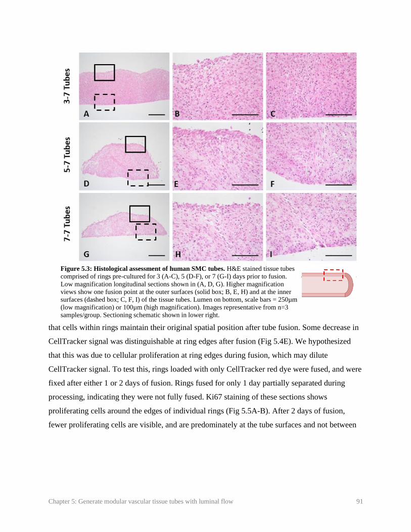
Chapter 5: Generate modular vascular tissue tubes with luminal flow 91
that cells within rings maintain their original spatial position after tube fusion. Some decrease in
CellTracker signal was distinguishable at ring edges after fusion (Fig 5.4E). We hypothesized
that this was due to cellular proliferation at ring edges during fusion, which may dilute
CellTracker signal. To test this, rings loaded with only CellTracker red dye were fused, and were
fixed after either 1 or 2 days of fusion. Rings fused for only 1 day partially separated during
processing, indicating they were not fully fused. Ki67 staining of these sections shows
proliferating cells around the edges of individual rings (Fig 5.5A-B). After 2 days of fusion,
fewer proliferating cells are visible, and are predominately at the tube surfaces and not between
Figure 5.3: Histological assessment of human SMC tubes. H&E stained tissue tubes
comprised of rings pre-cultured for 3 (A-C), 5 (D-F), or 7 (G-I) days prior to fusion.
Low magnification longitudinal sections shown in (A, D, G). Higher magnification
views show one fusion point at the outer surfaces (solid box; B, E, H) and at the inner
surfaces (dashed box; C, F, I) of the tissue tubes. Lumen on bottom, scale bars = 250µm
(low magnification) or 100µm (high magnification). Images representative from n=3
samples/group. Sectioning schematic shown in lower right.

Chapter 5: Generate modular vascular tissue tubes with luminal flow 92
individual rings (Fig 5.5 C-D). This suggests that cell proliferation at the edges of the rings may
cause the decrease in CellTracker signal, and may play a role in initial ring fusion.
5.3.4. PCL cannulation cuffs and dynamic tube culture
The next step in generating an in vitro TEBV model is applying luminal flow, which is
critical for maintaining
blood vessel function
[33-35]. However, self-
assembled tissues can
be fragile at early time
points in culture, and
may not withstand
handling or suturing
forces necessary to load
the tissue into a flow
bioreactor. Thus, our
modular system for
vascular tissue
fabrication includes
electrospun PCL
Figure 5.5: Cell proliferation during fusion. Human aortic SMCs were pre-loaded
with red CellTracker dye prior to ring seeding. Rings were allowed to fuse for 1 (A,
B) or 2 (C, D) days. Tubes were then sectioned and stained for Ki67 to examine
proliferation. Green = Ki67, red = CellTracker Red, blue = nuclei. Scale = 100µm.
Images representative of n = 2 samples.
Figure 5.4: Spatial position of rings during fusion. Human aortic SMCs were pre-loaded with red or green
CellTracker dye prior to ring seeding. Rings with alternating dyes were then stacked and allowed to fuse for 7 days
(A). Tubes were then sectioned and stained with Hoechst dye. Red = CellTracker Red (B), green = CellTracker
Green (C), and blue = nuclei (D). Merged image shown in (E). Scale = 1mm (A) or 100µm (B-E). Lumen on bottom
(B-E). Images representative from n = 3 samples.
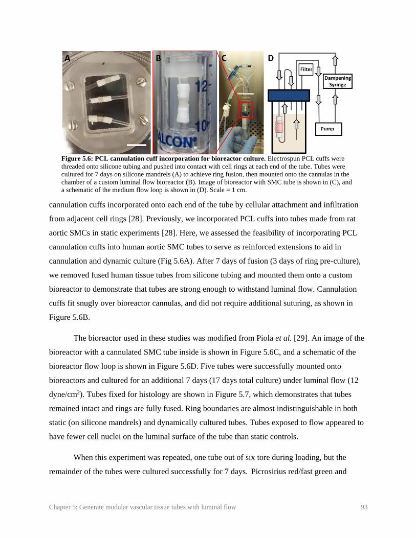
Chapter 5: Generate modular vascular tissue tubes with luminal flow 93
cannulation cuffs incorporated onto each end of the tube by cellular attachment and infiltration
from adjacent cell rings [28]. Previously, we incorporated PCL cuffs into tubes made from rat
aortic SMCs in static experiments [28]. Here, we assessed the feasibility of incorporating PCL
cannulation cuffs into human aortic SMC tubes to serve as reinforced extensions to aid in
cannulation and dynamic culture (Fig 5.6A). After 7 days of fusion (3 days of ring pre-culture),
we removed fused human tissue tubes from silicone tubing and mounted them onto a custom
bioreactor to demonstrate that tubes are strong enough to withstand luminal flow. Cannulation
cuffs fit snugly over bioreactor cannulas, and did not require additional suturing, as shown in
Figure 5.6B.
The bioreactor used in these studies was modified from Piola et al. [29]. An image of the
bioreactor with a cannulated SMC tube inside is shown in Figure 5.6C, and a schematic of the
bioreactor flow loop is shown in Figure 5.6D. Five tubes were successfully mounted onto
bioreactors and cultured for an additional 7 days (17 days total culture) under luminal flow (12
dyne/cm2). Tubes fixed for histology are shown in Figure 5.7, which demonstrates that tubes
remained intact and rings are fully fused. Ring boundaries are almost indistinguishable in both
static (on silicone mandrels) and dynamically cultured tubes. Tubes exposed to flow appeared to
have fewer cell nuclei on the luminal surface of the tube than static controls.
When this experiment was repeated, one tube out of six tore during loading, but the
remainder of the tubes were cultured successfully for 7 days. Picrosirius red/fast green and
Figure 5.6: PCL cannulation cuff incorporation for bioreactor culture. Electrospun PCL cuffs were
threaded onto silicone tubing and pushed into contact with cell rings at each end of the tube. Tubes were
cultured for 7 days on silicone mandrels (A) to achieve ring fusion, then mounted onto the cannulas in the
chamber of a custom luminal flow bioreactor (B). Image of bioreactor with SMC tube is shown in (C), and
a schematic of the medium flow loop is shown in (D). Scale = 1 cm.

Chapter 5: Generate modular vascular tissue tubes with luminal flow 94
orcein stains were used to
examine extracellular matrix
deposition of fused tubes
following static (Fig 5.8 A, B)
or dynamic (Fig 5.8 C, D)
culture. Collagen deposition is
visible throughout tubes (Fig
5.8 A, C). Elastic fibers were
not visible (Fig 5.8 B, D).
5.4. Discussion
The long-term goal of
these studies is to develop a
platform for fabricating 3D
human vascular tissue that may
potentially be used for in vitro
modeling of focal vascular
diseases such as intimal
hyperplasia or aneurysm. We
previously described a method
to rapidly generate vascular
tissue tubes from individual
self-assembled SMC ring units
[25, 26]. Here, we reduced the
total time needed to create
cohesive tissue tubes from self-
assembled rings, and utilized
the modular nature of this
system to create focal
heterogeneities within the tube
wall. Further, we incorporated
Figure 5.7: Histological images of tubes cultured in a luminal flow
bioreactor. Hematoxylin and Eosin stain of longitudinal section of tissue
tubes cultured as rings for 3 days, fused as tubes for 7 days, and then
cultured on silicone mandrels in static conditions (A, B) or with
approximately 12 dyne/cm2 shear stress (C, D) for an additional 7 days.
Lumen at bottom of image. Scale = 100µm.
Figure 5.8: Matrix deposition in fused tissue tubes. Longitudinal
sections of tubes cultured in static conditions for 14 days (A, B), or in
static conditions for 7 days followed by 7 days of dynamic culture with
approximately 12 dyne/cm2 of applied shear (C, D). Picrosirius red fast
green stain shown in (A, C; red = collagen, green = counterstain), orcein
stain shown in (C, D; dark pink = elastic fibers, purple = nuclei). Lumen
on bottom of image. Scale = 100 µm.

Chapter 5: Generate modular vascular tissue tubes with luminal flow 95
PCL cannulation cuffs [28] on each end, making the tubes amenable for cannulation and
dynamic culture within a custom designed luminal flow bioreactor. In future studies, this unique
modular platform may be modified to model a variety of vascular diseases.
The first goal of this study was to improve and accelerate tissue fusion. In our studies,
fusion is defined as an increase in fusion angle (angle between adjacent rings) to approximately
180ᴼ [30, 32]. While we did not observe significant differences in fusion rate with varying pre-
culture time, histological images suggest more complete fusion in the 3-7 group. This is
consistent with other reports, which suggest tissues fuse more rapidly and more completely when
pre-cultured for less time prior to fusion [30]. Others have suggested that tissues with increased
extracellular matrix (such as collagen) are generally more cohesive and difficult to remodel [36].
It is possible that increased matrix deposition at later time-points may be a reason why more
mature tissues fuse less completely than less mature tissues.
In addition to fusion angle, parameters such as thickness and length of constructs can be
used to assess fusion [30]. We did not observe significant changes in length over time, which is
contrary to previous reports of spheroid fusion [30, 37]. This may be due to differences in tissue
size or geometry, which are known to affect fusion [20, 30, 32], or due to differences in cell type.
Overall, 3-7 tubes were significantly longer than the 5-7 and 7-7 groups, and the 5-7 tubes were
significantly shorter. This may due to ring remodeling, compaction, and thinning over time
during ring-culture, resulting in the 5-7 and 7-7 groups being constructed from thinner rings.
A primary goal of varying pre-culture time was to determine a time course for ring
fusion, and develop cohesive tissue tubes in a minimal amount of time. In all experiments, fusion
angles plateaued after 3-4 days, which is consistent with other reports [20, 23, 32]. In
preliminary studies, we aimed to begin dynamic culture at this point, based on the observation
that tubes are fully fused. However, when tubes were fused for only 4 days, 66% of the tubes
tore during the cannulation procedure (data not shown). Thus, we increased fusion time to 7 days
to allow for increased ECM deposition, which improved our ability to cannulate tubes and
substantially reduced tube failure rates to an average of 8%. Importantly, this is still less time
than described in most other published reports, where engineered vascular tissue is typically
matured 2 weeks to several months in static culture prior to mounting on bioreactors for dynamic
culture [12, 38, 39], compared to the 3 days of ring pre-culture and 7 days of fusion culture used

Chapter 5: Generate modular vascular tissue tubes with luminal flow 96
in this study. This may be because cell-derived tissues can have enhanced ECM production and
tissue strength compared to tissue fabricated using degradable scaffold materials [40-44].
Additionally, PCL cannulation cuffs aided in handling and cannulation of tissue tubes at early
time points.
To further evaluate fusion, we examined if cells maintain spatial positioning within rings
during fusion. We observed that rings with red and green CellTracker dye are still spatially
distinct after 7 days of fusion. This result is consistent with previous reports examining fusion of
tissue sheets and spheroids, which showed that limited cellular migration or “mixing” is evident
between most fusing tissues, despite some tissue remodeling and compaction [20, 32, 45-48].
Because cells within ring units maintained their spatial positioning along tubes, we can
customize individual rings and place them in distinct regions of the tube prior to fusion. This
feature may enable us to model focal disease pathologies in future studies, by engineering
regions of tissue that contain a diseased cell phenotype in the middle of an otherwise healthy
vascular tissue tube. CellTracker dye signal was less visible around individual ring edges,
possibly due to the dye diluting as cells proliferate. We verified this by staining tubes for Ki67
after 1 or 2 days of fusion. Ki67 staining was visible predominantly around individual ring edges
after 1 day of fusion. This was also evident at day 2, although fewer cells were Ki67 positive,
likely due to contact inhibition of SMC proliferation. This suggests that proliferation may play a
role in tissue fusion.
Shear forces created from fluid flow are important for the progression of many vascular
diseases [49, 50]. Thus, it is critical to incorporate luminal flow during early culture of
engineered vascular disease models. However, self-assembled, scaffold-free tissues may be too
fragile at early time points in culture to be sutured onto cannulas for dynamic culture. The
modular nature of our system is conducive to adding biomaterial units on either end of the tissue
tube to serve as reinforced extensions, without affecting tissue structure. Previously, we
evaluated the incorporation of PCL cannulation cuffs with tubes fabricated from rat aortic SMCs
in static culture ([28], Chapter 4). Here, we applied this technology to human TEBV constructs,
enabling the successful cannulation of vascular tissue tubes in a custom bioreactor for dynamic
culture within 10 days of cell seeding. In these studies, human aortic SMC tubes remained intact
in a proof-of-concept experiment for 7 days of dynamic culture under physiologically relevant

Chapter 5: Generate modular vascular tissue tubes with luminal flow 97
wall shear stress. It was not surprising that fewer nuclei were observed on the luminal surface of
the dynamically cultured tube, as the endothelium typically prevents SMCs from being exposed
directly to shear forces. Others have reported that direct exposure to shear stress can trigger SMC
apoptosis [51]. Future studies will focus on establishing a functional endothelial layer by
developing a luminal cell seeding system for our custom bioreactor.
Additionally, the bioreactor chamber can also be easily modified to separate the luminal
vessel compartment from the external medium compartment [52]. In future studies, this will
allow endothelialization of cannulated tissue tubes, and enable us to flow vasoactive substances
through the tube lumen for endothelial and SMC functional testing. Alternatively, this bioreactor
can also be modified to apply cyclic stretch to tissue tubes [29] to enable mechanical
conditioning during tissue tube culture and maturation.
In studies with primary aortic SMCs, we did not observe contractile smooth muscle
markers such as smooth muscle alpha actin (Appendix F Fig F.4), or elastin deposition (Fig 5.8).
This is not surprising, since cells were cultured in a growth medium designed to support SMC
proliferation and ECM deposition consistent with a synthetic SMC phenotype. Creating a
healthy, contractile SMC phenotype will be critical for fabricating functional vascular tissue in
the future.
In future studies, we will use growth factor-loaded microspheres, different cell types, or
genetically-modified cells, in order to generate vessels with regions of cells that are
compositionally distinct from adjacent regions. For example, growth factor-loaded microspheres
may be able to create a hyper-proliferative region for modeling intimal hyperplasia. Our ability
to fabricate rings and tubes from a variety of SMC sources demonstrates the potential of this
system to model focal diseases that manifest in various types of vessels. We have shown that we
can produce rings using induced-pluripotent stem cell derived vascular SMCs (iPSC-VSMCs)
both from healthy patients (that produce elastin) and from patients with genetic disorders leading
to elastin deficiencies [13]. Using iPSC-VSMC rings to create a localized region of elastin
deficiency may allow us to model aneurysm. We have also applied this modular tube fabrication
system to create engineered cartilage rings and connective tissue rings with immature vascular
structures, and fused these rings to engineer tracheal tissue that anastomosed with host
vasculature upon subcutaneous implantation in a mouse model [47]. The controlled release of

Chapter 5: Generate modular vascular tissue tubes with luminal flow 98
growth factors via microsphere incorporation within individual rings may be ideal for such
multi-tissue tubular structures, where different tissue regions may require different biochemical
stimuli to maintain their differentiation and function. The ability to create high fidelity in vitro
human tissue models may provide an invaluable tool for high-throughput drug screening, and
potentially accelerate the development of new therapeutics.
In this study, we developed a modular system for fabricating vascular tissue tubes, which
may be modified in the future to model focal pathologies. Rings maintained their spatial position
within tubes, which may allow us to generate localized heterogeneities within tubes. After only 7
days of fusion, tubes were cohesive enough to be cannulated and cultured on a luminal flow
bioreactor. Overall, this work will serve as a platform technology for fabricating engineered
blood vessels with localized vascular diseases such as intimal hyperplasia, aneurysm, and
atherosclerosis. Such in vitro disease models may serve as tools for high throughput drug
screening, and accelerate the development of new treatments for vascular diseases.
5.5. References
1. Go, A.S., D. Mozaffarian, V.L. Roger, E.J. Benjamin, J.D. Berry, M.J. Blaha, S. Dai, E.S.
Ford, C.S. Fox, S. Franco, et al., Heart disease and stroke statistics--2014 update: a
report from the American Heart Association. Circulation, 2014. 129(3): p. e28-e292.
2. Stegemann, J.P. and R.M. Nerem, Altered response of vascular smooth muscle cells to
exogenous biochemical stimulation in two- and three-dimensional culture. Experimental
Cell Research, 2003. 283(2): p. 146-155.
3. Alexander, J.H., G. Hafley, R.A. Harrington, E.D. Peterson, T.B.F. Jr, T.J. Lorenz, A.
Goyal, M. Gibson, M.J. Mack, D. Gennevois, et al., Efficacy and Safety of Edifoligide, an
E2F Transcription Factor Decoy, for Prevention of Vein Graft Failure Following
Coronary Artery Bypass Graft Surgery: PREVENT IV: A Randomized Controlled Trial.
JAMA, 2005. 294: p. 2446-2454.
4. Kim, F.Y., G. Marhefka, N.J. Ruggiero, S. Adams, and D.J. Whellan, Saphenous vein
graft disease: review of pathophysiology, prevention, and treatment. Cardiol Rev, 2013.
21(2): p. 101-9.
5. Wystrychowski, W., T.N. McAllister, K. Zagalski, N. Dusserre, L. Cierpka, and N.
L'Heureux, First human use of an allogeneic tissue-engineered vascular graft for
hemodialysis access. J Vasc Surg, 2014. 60(5): p. 1353-7.
Chapter 5: Generate modular vascular tissue tubes with luminal flow 99
6. Hibino, N., E. McGillicuddy, G. Matsumura, Y. Ichihara, Y. Naito, C. Breuer, and T.
Shinoka, Late-term results of tissue-engineered vascular grafts in humans. J Thorac
Cardiovasc Surg, 2010. 139(2): p. 431-6.
7. Lawson, J., S. Dahl, H. Prichard, R. Manson, S. Gage, A. Kypson, J. Blum, A. Pilgrim,
W. Tente, and L. Niklason, Human Tissue-Engineered Grafts for Hemodialysis:
Development, Preclinical Data, and Early Investigational Human Implant Experience.
Journal of Vascular Surgery, 2014. 59(6): p. 32S-33S.
8. McAllister, T.N., M. Maruszewski, S.A. Garrido, W. Wystrychowski, N. Dusserre, A.
Marini, K. Zagalski, A. Fiorillo, H. Avila, X. Manglano, et al., Effectiveness of
haemodialysis access with an autologous tissue-engineered vascular graft: a multicentre
cohort study. Lancet, 2009. 373: p. 1440-46.
9. Truskey, G.A. and C.E. Fernandez, Tissue-engineered blood vessels as promising tools
for testing drug toxicity. Expert Opin. Drug Metab. Toxicol., 2015. 11(7): p. 1021-1024.
10. L'Heureux, N., J.-C. Stoclet, F.A. Auger, G.J.-L. Lagaud, L. Germain, and R.
Andriantsitohaina, A human tissue-engineered vascular media: a new model for
pharmacological studies of contractile responses. FASEB J, 2001. 15: p. 515-524.
11. Fernandez, C.E., R.W. Yen, S.M. Perez, H.W. Bedell, T.J. Povsic, W.M. Reichert, and
G.A. Truskey, Human Vascular Microphysiological System for in vitro Drug Screening.
Sci Rep, 2016. 6: p. 21579.
12. Jung, Y., H. Ji, Z. Chen, H. Fai Chan, L. Atchison, B. Klitzman, G. Truskey, and K.W.
Leong, Scaffold-free, Human Mesenchymal Stem Cell-Based Tissue Engineered Blood
Vessels. Sci Rep, 2015. 5: p. 15116.
13. Dash, B.C., K. Levi, J. Schwan, J. Luo, O. Bartulos, H. Wu, C. Qiu, T. Yi, Y. Ren, S.
Campbell, et al., Tissue-Engineered Vascular Rings from Human iPSC-Derived Smooth
Muscle Cells. Stem Cell Reports, 2016. 7(1): p. 19-28.
14. Robert, J., B. Weber, L. Frese, M.Y. Emmert, D. Schmidt, A. von Eckardstein, L. Rohrer,
and S.P. Hoerstrup, A three-dimensional engineered artery model for in vitro
atherosclerosis research. PLoS One, 2013. 8(11): p. e79821.
15. Niklason, L.E., J. Gao, W.M. Abbott, K.K. Hirschi, S. Houser, R. Marini, and R.
Langer7, Functional Arteries Grown in Vitro. Science, 1999. 284.
16. Roh, J.D., R. Sawh-Martinez, M.P. Brennan, S.M. Jay, L. Devine, D.A. Rao, T. Yi, T.L.
Mirensky, A. Nalbandian, B. Udelsman, et al., Tissue-engineered vascular grafts
transform into mature blood vessels via an inflammation-mediated process of vascular
remodeling. Proc Natl Acad Sci U S A, 2010. 107(10): p. 4669-74.
17. Swartz, D.D., J.A. Russell, and S.T. Andreadis, Engineering of fibrin-based functional
and implantable small-diameter blood vessels. Am J Physiol Heart Circ Physiol, 2005.
288.

Chapter 5: Generate modular vascular tissue tubes with luminal flow 100
18. Homme, J.L., M.C. Aubry, W.D. Edwards, S.M. Bagniewski, V. Shane Pankratz, C.A.
Kral, and H.D. Tazelaar, Surgical pathology of the ascending aorta: a clinicopathologic
study of 513 cases. Am J Surg Pathol, 2006. 30(9): p. 1159-68.
19. Nesi, G., C. Anichini, S. Tozzini, V. Boddi, G. Calamai, and F. Gori, Pathology of the
thoracic aorta: a morphologic review of 338 surgical specimens over a 7-year period.
Cardiovasc Pathol, 2009. 18(3): p. 134-9.
20. Norotte, C., F.S. Marga, L.E. Niklason, and G. Forgacs, Scaffold-free vascular tissue
engineering using bioprinting. Biomaterials, 2009. 30(30): p. 5910-7.
21. Mironov, V., R.P. Visconti, V. Kasyanov, G. Forgacs, C.J. Drake, and R.R. Markwald,
Organ printing: tissue spheroids as building blocks. Biomaterials, 2009. 30(12): p. 2164-
74.
22. Jakab, K., C. Norotte, F. Marga, K. Murphy, G. Vunjak-Novakovic, and G. Forgacs,
Tissue engineering by self-assembly and bio-printing of living cells. Biofabrication, 2010.
2(2): p. 022001.
23. Tan, Y., D.J. Richards, T.C. Trusk, R.P. Visconti, M.J. Yost, M.S. Kindy, C.J. Drake,
W.S. Argraves, R.R. Markwald, and Y. Mei, 3D printing facilitated scaffold-free tissue
unit fabrication. Biofabrication, 2014. 6(2): p. 1-11.
24. Twal, W.O., S.C. Klatt, K. Harikrishnan, E. Gerges, M.A. Cooley, T.C. Trusk, B. Zhou,
M.G. Gabr, T. Shazly, S.M. Lessner, et al., Cellularized microcarriers as adhesive
building blocks for fabrication of tubular tissue constructs. Ann Biomed Eng, 2014.
42(7): p. 1470-81.
25. Gwyther, T.A., J.Z. Hu, A.G. Christakis, J.K. Skorinko, S.M. Shaw, K.L. Billiar, and
M.W. Rolle, Engineered vascular tissue fabricated from aggregated smooth muscle cells.
Cells Tissues Organs, 2011. 194(1): p. 13-24.
26. Gwyther, T.A., J.Z. Hu, K.L. Billiar, and M.W. Rolle, Directed cellular self-assembly to
fabricate cell-derived tissue rings for biomechanical analysis and tissue engineering. J
Vis Exp, 2011(57): p. e3366.
27. Strobel, H.A., E.L. Calamari, B. Alphonse, T.A. Hookway, and M.W. Rolle, Fabrication
of Custom Agarose Wells for Cell Seeding and Tissue Ring Self-assembly Using 3D-
Printed Molds. JoVE, 2018. 134: p. e56618.
28. Strobel, H.A., E.L. Calamari, A. Beliveau, A. Jain, and M.W. Rolle, Fabrication and
characterization of electrospun polycaprolactone and gelatin composite cuffs for tissue
engineered blood vessels. JBMR Part B, 2018. 106B(2): p. 817-826.
29. Piola, M., F. Prandi, N. Bono, M. Soncini, E. Penza, M. Agrifoglio, G. Polvani, M. Pesce,
and G.B. Fiore, A compact and automated ex vivo vessel culture system for the pulsatile
pressure conditioning of human saphenous veins. J Tissue Eng Regen Med, 2016. 10(3):
p. E204-E215.

Chapter 5: Generate modular vascular tissue tubes with luminal flow 101
30. Rago, A.P., D.M. Dean, and J.R. Morgan, Controlling cell position in complex
heterotypic 3D microtissues by tissue fusion. Biotechnol Bioeng, 2009. 102(4): p. 1231-
41.
31. Bhumiratana, S., R.E. Eton, S.R. Oungoulian, L.Q. Wan, G.A. Ateshian, and G. Vunjak-
Novakovic, Large, stratified, and mechanically functional human cartilage grown in
vitro by mesenchymal condensation. PNAS, 2014. 111(19): p. 6940-6945.
32. Livoti, C.M. and J.R. Morgan, Self-Assembly and Tissue Fusion of Toroid-Shaped
Minimal Building Units. Tissue Engineering: Part A, 2010. 16(6): p. 2051-2061.
33. Chatzizisis, Y.S., A.U. Coskun, M. Jonas, E.R. Edelman, C.L. Feldman, and P.H. Stone,
Role of endothelial shear stress in the natural history of coronary atherosclerosis and
vascular remodeling: molecular, cellular, and vascular behavior. J Am Coll Cardiol,
2007. 49(25): p. 2379-93.
34. Rzucidlo, E.M., K.A. Martin, and R.J. Powell, Regulation of vascular smooth muscle cell
differentiation. J Vasc Surg, 2007. 45 Suppl A: p. A25-32.
35. Hirschi, K.K., S.A. Rohovsky, and P.A. D’Amore, PDGF, TGF-beta, and Heterotypic
Cell–Cell Interactions Mediate Endothelial Cell–induced Recruitment of 10T1/2 Cells
and Their Differentiation to a Smooth Muscle Fate. The Journal of Cell Biology, 1998.
141(3): p. 805-814.
36. Hajdu, Z., V. Mironov, A.N. Mehesz, R.A. Norris, R.R. Markwald, and R.P. Visconti,
Tissue spheroid fusion-based in vitro screening assays for analysis of tissue maturation. J
Tissue Eng Regen Med, 2010. 4(8): p. 659-64.
37. Dean, D.M., A.P. Napolitano, J. Youssef, and J.R. Morgan, Rods, tori, and honeycombs:
the directed self-assembly of microtissues with prescribed microscale geometries. The
FASEB Journal, 2007. 21(14): p. 4005-4012.
38. Syedain, Z.H., L.A. Meier, J.W. Bjork, A. Lee, and R.T. Tranquillo, Implantable arterial
grafts from human fibroblasts and fibrin using a multi-graft pulsed flow-stretch
bioreactor with noninvasive strength monitoring. Biomaterials, 2011. 32(3): p. 714-22.
39. Gong, Z. and L.E. Niklason, Small-diameter human vessel wall engineered from bone
marrow-derived mesenchymal stem cells (hMSCs). FASEB J, 2008. 22(6): p. 1635-48.
40. L'Heureux, N., S. Paquet, R. Labbe, L. Germain, and F.A. Auger, A completely biological
tissue-engineered human blood vessel. FASEB J, 1998. 12(1): p. 47-56.
41. Adebayo, O., T.A. Hookway, J.Z. Hu, K.L. Billiar, and M.W. Rolle, Self-assembled
smooth muscle cell tissue rings exhibit greater tensile strength than cell-seeded fibrin or
collagen gel rings. J Biomed Mater Res A, 2013. 101(2): p. 428-37.
42. Hayashi, K. and Y. Tabata, Preparation of stem cell aggregates with gelatin
microspheres to enhance biological functions. Acta Biomater, 2011. 7(7): p. 2797-803.
Chapter 5: Generate modular vascular tissue tubes with luminal flow 102
43. Kelm, J.M., V. Lorber, J.G. Snedeker, D. Schmidt, A. Broggini-Tenzer, M. Weisstanner,
B. Odermatt, A. Mol, G. Zund, and S.P. Hoerstrup, A novel concept for scaffold-free
vessel tissue engineering: self-assembly of microtissue building blocks. J Biotechnol,
2010. 148(1): p. 46-55.
44. Ahlfors, J.E. and K.L. Billiar, Biomechanical and biochemical characteristics of a human
fibroblast-produced and remodeled matrix. Biomaterials, 2007. 28(13): p. 2183-91.
45. Sasagawa, T., T. Shimizu, S. Sekiya, Y. Haraguchi, M. Yamato, Y. Sawa, and T. Okano,
Design of prevascularized three-dimensional cell-dense tissues using a cell sheet stacking
manipulation technology. Biomaterials, 2010. 31(7): p. 1646-54.
46. Shimizu, T., M. Yamato, T. Akutsu, T. Shibata, Y. Isoi, A. Kikuchi, M. Umezu, and T.
Okano, Electrically communicating three-dimensional cardiac tissue mimic fabricated by
layered cultured cardiomyocyte sheets. J Biomed Mater Res, 2002. 60(1): p. 110-7.
47. Dikina, A., D. Alt, S. Herberg, A. McMillan, H. Strobel, Z. Zheng, M. Cao, B. Lai, O.
Jeon, V.I. Petsinger, et al., A Modular Strategy to Engineer Complex Tissues and Organs.
Advanced Science, 2017.
48. Solorio, L.D., L.M. Phillips, A. McMillan, C.W. Cheng, P.N. Dang, J.E. Samorezov, X.
Yu, W.L. Murphy, and E. Alsberg, Spatially organized differentiation of mesenchymal
stem cells within biphasic microparticle-incorporated high cell density osteochondral
tissues. Adv Healthc Mater, 2015. 4(15): p. 2306-13.
49. Samady, H., P. Eshtehardi, M.C. McDaniel, J. Suo, S.S. Dhawan, C. Maynard, L.H.
Timmins, A.A. Quyyumi, and D.P. Giddens, Coronary artery wall shear stress is
associated with progression and transformation of atherosclerotic plaque and arterial
remodeling in patients with coronary artery disease. Circulation, 2011. 124(7): p. 779-
88.
50. Gusic, R.J., R. Myung, M. Petko, J.W. Gaynor, and K.J. Gooch, Shear stress and
pressure modulate saphenous vein remodeling ex vivo. J Biomech, 2005. 38(9): p. 1760-
9.
51. Apenberg, S., M.A. Freyberg, and P. Friedl, Shear stress induces apoptosis in vascular
smooth muscle cells via an autocrine Fas/FasL pathway. Biochemical and Biophysical
Research Communications, 2003. 310(2): p. 355-359.
52. Piola, M., F. Prandi, G.B. Fiore, M. Agrifoglio, G. Polvani, M. Pesce, and M. Soncini,
Human Saphenous Vein Response to Trans-wall Oxygen Gradients in a Novel Ex Vivo
Conditioning Platform. Ann Biomed Eng, 2016. 44(5): p. 1449-61.
Chapter 6: Create vascular tissue tubes with spatially distinct regions 103
Chapter 6: Create vascular tissue tubes with spatially distinct
regions
Focal lesion experiment from: H. A. Strobel, T. A. Hookway, M. Piola, M. Soncini, G. B. Fiore,
E. Alsberg, and M. W. Rolle, “Assembly of tissue engineered blood vessels with spatially-
controlled heterogeneities.” Tissue Engineering Part A. In Press.
Authorship contributions: HAS designed and performed experiments, collected and analyzed all data, made all
figures and wrote and revised the manuscript. TAH contributed to experimental design and data analysis and edited
the manuscript. MP, MS, and GBF designed and fabricated bioreactors, contributed to experimental design and
data analysis, and edited the manuscript. EA provided gelatin microspheres, contributed to experimental design and
analysis, and edited the manuscript. MWR contributed to experimental design, supervised data collection, data
analysis, and preparation of the manuscript, and edited the manuscript.
6.1. Introduction
While tissue engineered blood vessels (TEBVs) have enormous potential as tools for
disease modeling and drug screening, most existing approaches for TEBV fabrication create
homogenous tissue tubes [1-3]. These homogenous tubes may not be conducive to modeling
focal vascular diseases, such as intimal hyperplasia and aneurysm. To address this need, our lab
developed a modular system for fabricating tubes from individual ring subunits, which is more
conducive to introducing focal heterogeneities along the length of the tube. Our overall goal is to
develop this system into a platform technology for modeling focal vascular diseases, particularly
intimal hyperplasia (IH). In Chapter 3, we demonstrated our ability to incorporate degradable
cross-linked gelatin microspheres within tissue rings, and that these microspheres can be used to
customize cell phenotype [4]. In Chapter 5, we fused vascular tissue rings into cohesive tissue
tubes that were strong enough for dynamic culture after only 7 days of fusion with the aid of
electrospun cannulation cuffs. Here, we combine microsphere incorporation and tube fusion to
demonstrate that we can create TEBVs with focal heterogeneities along the length of our tissue
tubes (shown conceptually in Figure 6.1).
The first goal of this chapter was to create a focal region of microsphere incorporation, to
demonstrate our ability to create focal heterogeneities. To do this, we first evaluated the effect of
gelatin microspheres on ring fusion. We then tested whether modular building units comprised of
self-assembled primary human SMC rings (with or without incorporated gelatin microspheres)

Chapter 6: Create vascular tissue tubes with spatially distinct regions 104
can be fused together into a
contiguous and heterogeneous
tissue tube with distinct structural
regions.
Toward our goal of
creating an IH model, we next
performed preliminary
experiments evaluating the effect
of PDGF on human aortic smooth
muscle cells (SMCs). PDGF is
well established to increase SMC
proliferation and matrix
deposition and decrease
contractile protein expression, and
strongly associated with IH
initiation and progression [5-13].
Thus, we hypothesized that PDGF
would increase SMC proliferation and matrix deposition within self-assembled cell rings, and
consequently increase ring thickness. Ultimately, we aim to use these rings to create a focal
region of IH within tissue tubes. This Chapter describes the fabrication of tubes with spatially
controlled regions of microsphere incorporation, and the potential of gelatin microspheres for
PDGF delivery. Both of these are keys steps towards our ultimate goal of fabricating an in vitro
IH model.
6.2. Methods
6.2.1. Cell culture
Human aortic SMCs (Lifeline) were cultured according to manufacturer instructions, in
commercially available growth medium (Lifeline VascuLife SMC medium). Human coronary
artery SMCs (Lifeline) were used to repeat the focal region of microsphere incorporation
experiment, and were cultured according to the manufacturer’s instructions (Lifeline).
Figure 6.1: Fabrication of modular tissue tubes with focal
heterogeneities. Rings with incorporated microspheres are fused
between rings without microspheres, with PCL cuffs on either end.
The resulting construct is a fused tissue tube with focal region of
microsphere incorporation.

Chapter 6: Create vascular tissue tubes with spatially distinct regions 105
6.2.2. Ring fabrication
Rings were fabricated as previously described ([14], Chapter 3), with 400,000 human
aortic SMCs cells per well. After seeding, cells were allowed to aggregate 24 hours before
flooding wells with culture medium. Rings were cultured in Lifeline VascuLife growth medium
for the duration of culture unless otherwise specified.
Microspheres were incorporated within tissue rings as described in Chapter 3.2.3 and
3.2.4 [4]. Briefly, microspheres for non-growth factor experiments and unloaded control groups
were hydrated with 25µl per ml of PBS for 2 hours at 37ºC. Microspheres were then resuspended
thoroughly, combined with the cell suspension, and seeded with cells into agarose molds.
Microspheres to be loaded with PDGF were soaked in a solution of PBS containing 400
or 800 ng PDGF-BB (Peprotech) per mg microspheres (total volume of 25µl per mg), for 2 hours
at 37ºC prior to combining with cells. For fabrication of tubes with a focal lesion, and for the
PDGF release study, 0.6 mg microspheres per million cells were used (Appendix G, Batch 3).
When comparing fusion of rings with and without microsphere, 0.3 mg microspheres per million
cells was used (Appendix G, Batch 4). All microspheres were fabricated by the Alsberg Lab at
Case Western Reserve University. Diameters and cross-link densities for all batches used are
described in Appendix G.
When repeating the focal lesion experiment, coronary artery SMC rings were fabricated
as described above, with unloaded microspheres incorporated at 0.6mg per million cells. Cells
were loaded with CellTracker Red of CellTracker Green prior to ring seeding, as described in
Chapter 5.2.5. Rings with microspheres were seeded with red labelled cells, and rings without
microspheres were seeded with green labelled cells.
6.2.3. Tube fabrication for fusion comparison
Tubes were fabricated after 3 days of ring culture as described in Chapter 5.2.3. For
fusion studies, 3 rings with or without microspheres were used per tube. Brightfield images were
acquired daily, and fusion angles were calculated as described in Chapter 5.2.4.

Chapter 6: Create vascular tissue tubes with spatially distinct regions 106
6.2.4. Fabricating tubes with spatially defined regions of microsphere incorporation
Rings were fabricated from human aortic SMCs (Lifeline), with or without incorporated
microspheres ([4], Batch 3, Appendix G). Cells in rings with microspheres were pre-labelled
with CellTracker Red dye (Chapter 5.2.5). After 3 days of pre-culture, rings were threaded onto
silicone tubing mandrels with three microsphere-incorporated rings in the center of the tube, and
two outer regions with eight rings without microspheres per side (Fig 6.1). Cannulation cuffs
were placed adjacent to rings at each end of the tube. Tubes were cultured for 4 days on silicone
mandrels in static conditions prior to fixation and paraffin embedding. When the experiment was
repeated with coronary artery SMCs, the same procedure was followed, except rings without
microspheres were pre-labelled with CellTracker Green dye.
6.2.5. PDGF treatment of 2D cell cultures
Human aortic SMCs were seeded in wells of a 24 well plate at a density of 10,000 cells
per well in growth medium. After 24 hours, cells were switched to differentiation medium
containing a 1:1 ratio of DMEM and HAM’s F12 medium with 1% FBS, 1% L-glutamine, 1%
ITS, 1% penicillin-streptomycin, and 50µg/ml ascorbate. Four wells per group were
supplemented with PDGF-BB (Peprotech) at concentrations of 0, 1, 10, or 100 ng/ml. Cells were
fixed after 2 days of treatment for 15 minutes in 10% neutral buffered formalin (NBF) and stored
in PBS at 4ºC until staining.
6.2.6. PDGF treatment of self-assembled SMC rings
To evaluate the effects of PDGF on tissue rings, rings were seeded either with unloaded
microspheres, or with microspheres loaded with PDGF as described in section 6.2.2, with 400 or
800 ng PDGF/mg microspheres. Rings were seeded in growth medium. After 24 hours, medium
was switched to differentiation medium (described in section 6.2.4). Control rings with unloaded
microspheres were either cultured with or without the addition of 10 ng/ml exogenous PDGF.
Medium was changed daily. Rings were fixed at 3, 7, or 14 days.
6.2.7. Histology and immunohistochemistry
Tissues were fixed for 1 hour in 10% NBF, processed, paraffin embedded, and cut into
5µm sections adhered to charged glass slides. A Hematoxylin and Eosin stain was used visualize

Chapter 6: Create vascular tissue tubes with spatially distinct regions 107
ring and tube morphology, and a Picrosirius Red/Fast Green stain was used to visualize collagen
deposition and gelatin microsphere degradation.
Sections to be stained for the contractile protein smooth muscle alpha actin were blocked
in 1.5% normal rabbit serum (NRS) for 45 minutes. Then, slides were incubated at 4ºC overnight
in primary anti-smooth muscle alpha actin antibody (Dako, 1:100 in 1.5% NRS). Samples were
then incubated at RT with rabbit anti-mouse AlexaFluor 488 secondary antibody (Invitrogen)
prior to counterstaining with Hoechst dye (1:6000 in DI water, 6 min). Sections of tubes
containing CellTracker were counterstained with Hoechst.
Sections stained for Ki67 were first subjected to antigen retrieval by boiling for 5 minutes
in Tris-EDTA buffer (see section 3.2.5) in a pressure cooker. Samples were blocked in 5%
normal goat serum (NGS) for 45 minutes, and incubated overnight in anti-Ki67 antibody
(Abcam, 1:100 in 3% NGS) at 4ºC. Negative controls were instead incubated with a rabbit IgG
protein (Vector). Slides were then incubated in secondary antibody (Invitrogen, AlexaFluor 488
goat anti-rabbit, 1:400 in 3% NGS) for 1 hour at RT prior to counterstaining with Hoechst.
Coverslips were adhered to slides with aqueous mounting medium, and images were taken using
an upright microscope (Leica DMLB2).
For 2D cell cultures, the same Ki67 staining procedure was followed, but cells were
permeabilized with 0.025% TritonX-100 instead of undergoing antigen retrieval. Samples were
imaged in wells using an inverted fluorescent microscope (Leica DMIL).
6.2.8. Statistical analysis
For fusion angle measurements, four measurements were obtained per tube, and averaged
to calculate one fusion angle per sample per time point. N = 3 samples were used for each group.
A Two-Way ANOVA test with Holm-Sidak post hoc analysis was used to determine statistically
significant differences between groups. When comparing Ki67 positive cells in response to
PDGF, the percentage of positive cells were averaged from two images per well to obtain one
measurement. Measurements from three wells per group were imaged to obtain N = 3 per group.
A One Way ANOVA test was used to calculate significance, with Holm-Sidak post-hoc analysis.
For all tests, P < 0.05 was considered significant.

Chapter 6: Create vascular tissue tubes with spatially distinct regions 108
6.3. Results
6.3.1. Effect of microspheres on tube fusion
To determine if microspheres would impact ring fusion, tubes were fabricated from rings
with or without microspheres and allowed to fuse for 7 days. Fusion angles (Fig 6.2 A) were
measured daily from phase contrast images (Fig 6.2 B). As shown in Figure 6.2 A, tubes with
microspheres have significantly lower fusion angles compared with tubes without microspheres.
This can also be seen in
Figure 6.2 B, where tubes
with microspheres still have
distinguishable ridges after
7 days, and rings without
microspheres do not. This is
likely due to the gelatin
microsphere material in the
ring composition
maintaining the original ring
shape.
Longitudinal sections were
stained for H&E to examine tube
morphology (Fig 6.3 A-B), and
Picrosirius Red/Fast Green to
examine collagen deposition and
presence of gelatin microspheres (Fig
6.3 C-D). Rings appear well fused in
both groups, and rings boundaries are
barely distinguishable. Collagen
Figure 6.2: Effect of microspheres on ring fusion. Fusion angles between
rings were measured daily for 7 days (A). Phase contrast images at day 0
compared to day 7 shown in (B). Scale = 1mm. Two-way ANOVA with Holm-
Sidak post hoc test (A). *P < 0.05. N = 3. Data is shown as mean ± SEM.
Figure 6.3: Fusion of rings with and without microspheres.
Hematoxylin and Eosin (A, B; H&E) and Picrosirius Red/Fast
Green (C, D; PRFG, red = collagen or gelatin, green =
counterstain) stains of tubes without (A, C) or with (B, D)
incorporated microspheres. Lumen on bottom. Scale = 100µm.
Asterisks (*) mark sample microspheres.

Chapter 6: Create vascular tissue tubes with spatially distinct regions 109
deposition is visible in both groups. Microsphere
degradation appears limited, as large amounts of
gelatin are still visible.
6.3.2. Fabrication of a focal region of microsphere
incorporation
An important step towards modeling focal
vascular diseases is the ability to create spatially
controlled heterogeneities within engineered vessel
walls. To do this, we incorporated degradable
gelatin microspheres within three rings (with
CellTracker Red dye) and positioned them in a
central region of the tube, between rings without
microspheres (8 per side, Fig 6.4 A). The region
with incorporated microspheres is clearly visible
due to
CellTracker Red dye and genipin cross-linked
microspheres, which both impart a purple hue to the
tissue in these regions (Fig 6.4 A). Histological
analysis demonstrated fully fused tubes with regions
of microsphere incorporation within a localized
region of the tube (Fig 6.4 B, C). This experiment
was repeated with human coronary artery SMCs.
With these cells, CellTracker Green dye was
incorporated into rings without microspheres, and
CellTracker Red dye was incorporated into rings
with microspheres, to demonstrate that cells within
each region maintain their spatial positioning along
the length of the tube during fusion (Fig 6.5)
Figure 6.5: Coronary artery SMC tubes with a
focal region of microsphere incorporation. A
central region of microsphere incorporation is
clearly visible after 7 days of fusion (A).
Fluorescent images of tubes with red and green
CellTracker show that cells within rings maintain
their spatial positioning during 7 days of fusion
(B, C), which can also be seen in Hoechst stained
sections (D). Green = CellTracker Green, red =
CellTracker Red, blue = Hoechst. Scale in mm
(A), bar = 1mm (B, C) or 100 µm (D).
Figure 6.4: Focal region of microsphere
incorporation. Rings with microspheres were
fused between rings without microspheres. Tube
after 4 days of fusion shown in (A). Hematoxylin
and Eosin stain of interface between rings with
and without microspheres shown in (B, C).
Sectioning schematic shown below figure. Lumen
on bottom. Scale in mm (A) or scale = 100µm (B,
C).

Chapter 6: Create vascular tissue tubes with spatially distinct regions 110
6.3.3. Effect of PDGF on proliferation of 2D SMC cultures
To create a focal disease model, we
aimed to use PDGF to locally stimulate
SMC proliferation. Prior to seeding rings
with PDGF-loaded microspheres, we first
needed to verify that human aortic SMCs
respond to PDGF in 2D cell cultures. After
2 days of PDGF treatment with varying
concentrations, 2D SMC cultures were
stained for Ki67 to evaluate the effect on
proliferation. We observed that both 10 and
100 ng/ml of exogenous PDGF significantly
increased the percentage of Ki67-positive
cells (Fig 6.6).
6.3.4. Effect of microsphere-mediated PDGF release on SMC rings
Next, we incorporated PDGF-loaded microspheres into SMC rings, to evaluate the effects
on proliferation. However, SMCs aggregated very loosely around gelatin microspheres, possibly
due to the larger size of microspheres in this batch (Batch 3, Appendix G). Microspheres in this
batch were also especially “clumpy” and difficult to break apart during resuspension. H&E
images are shown in Figure 6.7. Because there appeared to be such a large amount of
microspheres, ring edges were uneven, and ring thickness could not be reliably measured.
Despite this, rings could still be stained for Ki67 to examine cellular proliferation in response to
PDGF (Fig 6.8). It appeared at days 3 and 7 that groups treated with PDGF, either exogenously
or via microspheres, had a larger quantity of Ki67 positive cells. However, the number of Ki67
positive cells varied within and between samples of each group, making it challenging
toquantitatively assess trends in proliferating cells. Since most rings were loose in structure and
broken apart, it was not possible to quantify the total number of positive Ki67 cells per cross
sectional area. No clear differences were visible between groups at the 14 day time point. No
positive staining for the contractile protein smooth muscle alpha actin was visible in any groups
(Fig 6.9).
Figure 6.6: Effect of PDGF on 2D cell culture
proliferation. Cultures were treated with 0, 1, 10, or 100
ng/ml PDGF for 2 days. One Way ANOVA with Holm-
Sidak post hoc test. * P < 0.05 compared to 0 and 1 ng/ml.
Bars are mean ± SEM.

Chapter 6: Create vascular tissue tubes with spatially distinct regions 111
6.4. Discussion
This study demonstrates our ability to customize individual regions of vascular tissue
tubes through microsphere incorporation, which may ultimately enable us to create focal
vascular disease models. To do this, we first evaluated the effects of microsphere incorporation
on ring fusion. Fusion angles between stacked rings were measured daily for 7 days. When using
this method, complete fusion is defined as a fusion angle of 180º [15, 16]. We observed
significantly lower fusion angles in tubes with incorporated microspheres than in tubes without
microspheres. The reduced fusion angles are likely due to the non-degraded gelatin microspheres
maintaining the original ridges in the tissue, which are clearly visible in brightfield images (Fig
6.2 B). Despite this, histological sections showed nearly seamless fusion in both groups,
indicating that fusion angle measurements may not be the most effective means for measuring
fusion in this case. While microspheres did reduce fusion angles, they do not appear to have
affected overall tube fusion and cohesivity.
Figure 6.7: Morphology of PDGF treated rings. Rings were fixed at 3 (A-D), 7 (E-H), or 14 (I-L) days. Rings
contained unloaded microspheres were treated with no PDGF (A, E, I) or 10 ng/ml exogenous PDGF (B, F, J), or
contained microspheres loaded with 400 (C, G, K) or 800 (D, H, L) ng of PDGF per mg of microspheres.
Hematoxylin and eosin stain. Scale = 100µm

Chapter 6: Create vascular tissue tubes with spatially distinct regions 112
We reported previously that incorporated gelatin microspheres can be used to locally
deliver growth factors within SMC rings, for the purpose of controlling SMC phenotype ([4],
Chapter 3). The gelatin microspheres degrade within approximately 2 weeks, and do not
adversely affect ring mechanical strength ([4], Chapter 3). Here, we demonstrated that rings
containing microspheres can be localized to a central region of the tissue tubes, and successfully
Figure 6.9: Contractile protein expression in SMC rings. Rings either contained unloaded microspheres and were
treated with no PDGF (A) or 10 ng/ml exogenous PDGF (B), or contained microspheres loaded with 400 (C) or 800
(D) ng/ml PDGF. Rings were cultured for 14 days. Green = smooth muscle alpha actin, blue = Hoechst. Scale =
100µm.
Figure 6.8: Ki67 staining of rings with PDGF treatment. Rings were fixed at 3 (A-D), 7 (E-H) or 14 (I-L)
days. Rings were treated with unloaded microspheres and no PDGF (A, E, I) or exogenous 10 ng/ml PDGF (B,
F, J), or contained microspheres loaded with 400 or 800 ng PDGF per mg microsphere. Green = Ki67, blue =
nuclei. Scale = 100µm.

Chapter 6: Create vascular tissue tubes with spatially distinct regions 113
fuse with unmodified rings, to create a focal heterogeneity (Fig 6.4). This ability to create focal
changes is a unique attribute of our system, as other methods for fabricating self-assembled
TEBVs only create homogenous tubes.
Our overall goal is to use these microspheres to deliver growth factors to a central region
of the tube, as shown schematically in Figure 6.10. We predict that growth factors delivered from
microspheres will stimulate the formation of an intimal lesion by locally stimulating SMC
proliferation and matrix deposition. Towards our goal
of creating an IH model, we performed preliminary
experiments examining the effect of PDGF on human
aortic SMCs. PDGF is a potent SMC mitogen, that is
known to strongly contribute to IH initiation and
progression [5-13]. We observed that in 2D culture,
SMC proliferation significantly increased in response
to PDGF. PDGF also appeared to increase the number of Ki67-positive cells in 3D tissue rings.
However, some variation was visible within groups, making it challenging to quantitatively
assess trends in number of positive cells. Additionally, rings were very loosely formed in this
experiment and broke apart during histological analysis, preventing quantification of cross
sectional area to calculate the number of positive cells per unit area. For this experiment, we
switched to Batch 3 of microspheres (Appendix G), which are larger in size and tended to clump
more than previous batches. Additionally, human aortic SMCs are smaller in size than the
coronary artery SMCs used in Chapter 3. Thus, the concentration of 0.6 mg microspheres per
million cells used in earlier experiments (Chapter 3) may be too high. A lower concentration of
microspheres was used in subsequent experiments (Chapter 8). Though PDGF appeared to have
some effect on proliferation in 3D, we also observed an overall lack of contractile proteins such
as smooth muscle alpha actin, even in control groups with no PDGF. IH lesions are characterized
by a de-differentiation of SMCs. Without contractile protein expression in control, “normal”
rings without PDGF that will model healthy regions of the blood vessel, it will not be possible to
discern PDGF-mediated effects on SMC phenotype in 3D. Based on the lack of contractile
protein expression in primary human SMC lots we used to fabricate SMC rings, we decided to
re-evaluate our SMC cell source in subsequent experiments (discussed further in Chapters 7 and
8).
Figure 6.10: Schematic of future IH model.
Growth factor loaded-microspheres (purple
dots with yellow) are fused between regions
with unloaded microspheres (purple dots) to
create a focal region of growth factor delivery
and stenosis.

Chapter 6: Create vascular tissue tubes with spatially distinct regions 114
Future work may also include optimization of PDGF release from microspheres. When
IH occurs in vivo, SMC proliferation can begin as early as 24 hours after injury, and migration
can begin in as soon as 4 days [17]. Significant reductions in lumen area can be seen within 4-6
weeks of the initial injury [18, 19]. Thus, PDGF should be delivered from microspheres for a
minimum of 4 weeks to create a physiologically relevant IH model. The microspheres used in
this study are clearly visible at day 14, which is longer than we previously reported ([4], Chapter
3). This suggests we may have a more sustained growth factor release, but this must be verified
by determining the PDGF release curve over a minimum of 4 weeks. If needed, microsphere
cross-link density may be increased to further prolong growth factor delivery [20].
Overall, we demonstrated that we can create a focal region of microsphere incorporation
within vascular tissue tubes, that may be further developed to create an intimal lesion. This
platform technology could be modified to model other vascular diseases as well, such as
aneurysm. The controlled release of growth factors via microsphere incorporation within
individual rings may also be conducive to fabricating multi-tissue tubular structures, such as
trachea [21], where different tissue regions may require different biochemical stimuli to maintain
their differentiation and function.
6.5. References
1. Atchison, L., H. Zhang, K. Cao, and G.A. Truskey, A Tissue Engineered Blood Vessel
Model of Hutchinson-Gilford Progeria Syndrome Using Human iPSC-derived Smooth
Muscle Cells. Sci Rep, 2017. 7(1): p. 8168.
2. Dahl, S.L., A.P. Kypson, J.H. Lawson, J.L. Blum, J.T. Strader, Y. Li, R.J. Manson, W.E.
Tente, L. DiBernardo, M.T. Hensley, et al., Readily available tissue-engineered vascular
grafts. Sci Transl Med, 2011. 3(68): p. 1-11.
3. Wystrychowski, W., T.N. McAllister, K. Zagalski, N. Dusserre, L. Cierpka, and N.
L'Heureux, First human use of an allogeneic tissue-engineered vascular graft for
hemodialysis access. J Vasc Surg, 2014. 60(5): p. 1353-7.
4. Strobel, H.A., A.D. Dikina, K. Levi, L.D. Solorio, E. Alsberg, and M.W. Rolle, Cellular
self-assembly with microsphere incorporation for growth factor delivery within
engineered vascular tissue rings. Tissue Eng Part A, 2017. 23(3-4): p. 143-155.
5. Amento, E.P., N. Ehsani, H. Palmer, and P. Libby, Cytokines and growth factors
positively and negatively regulate interstitial collagen gene expression in human vascular

Chapter 6: Create vascular tissue tubes with spatially distinct regions 115
smooth muscle cells. Arteriosclerosis, Thrombosis, and Vascular Biology, 1991. 11(5): p.
1223-1230.
6. Absood, A., A. Furutani, T. Kawamura, and L.M. Graham, A comparison of oxidized
LDL-induced collagen secretion by graft and aortic SMCs: role of PDGF. Am J Physiol
Heart Circ Physiol, 2004. 287: p. H1200–H1206.
7. Millette, E., B.H. Rauch, R.D. Kenagy, G. Daum, and A.W. Clowes, Platelet-derived
growth factor-BB transactivates the fibroblast growth factor receptor to induce
proliferation in human smooth muscle cells. Trends Cardiovasc Med, 2006. 16(1): p. 25-
8.
8. Jiang, B., S. Yamamura, P.R. Nelson, L. Mureebe, and K.C. Kent, Differential effects of
platelet-derived growth factor isotypes on human smooth muscle cell proliferation and
migration are mediated by distinct signaling pathways. Surgery, 1996. 120: p. 427-32.
9. Hollenbeck, S.T., H. Itoh, O. Louie, P.L. Faries, B. Liu, and K.C. Kent, Type I collagen
synergistically enhances PDGF-induced smooth muscle cell proliferation through
pp60src-dependent crosstalk between the alpha2beta1 integrin and PDGF-beta receptor.
Biochem Biophys Res Commun, 2004. 325(1): p. 328-37.
10. Leppanen, O., N. Janjic, M.-A. Carlsson, K. Pietras, M. Levin, C. Vargeese, L.S. Green,
D. Bergqvist, A. Ostman, and C.-H. Heldin, Intimal Hyperplasia Recurs After Removal of
PDGF-AB and -BB Inhibition in the Rat Carotid Artery Injury Model. Arterioscler
Thromb Vasc Biol, 2000. 20: p. 89-95.
11. Ucuzian, A.A., L.P. Brewster, A.T. East, Y. Pang, A.A. Gassman, and H.P. Greisler,
Characterization of the chemotactic and mitogenic response of SMCs to PDGF-BB and
FGF-2 in fibrin hydrogels. J Biomed Mater Res A, 2010. 94(3): p. 988-96.
12. Li, L., D.K. Blumenthal, C.M. Terry, Y. He, M.L. Carlson, and A.K. Cheung, PDGF-
induced proliferation in human arterial and venous smooth muscle cells: molecular basis
for differential effects of PDGF isoforms. J Cell Biochem, 2011. 112(1): p. 289-98.
13. Brown, X.Q., E. Bartolak-Suki, C. Williams, M.L. Walker, V.M. Weaver, and J.Y.
Wong, Effect of substrate stiffness and PDGF on the behavior of vascular smooth muscle
cells: implications for atherosclerosis. J Cell Physiol, 2010. 225(1): p. 115-22.
14. Strobel, H.A., E.L. Calamari, B. Alphonse, T.A. Hookway, and M.W. Rolle, Fabrication
of Custom Agarose Wells for Cell Seeding and Tissue Ring Self-assembly Using 3D-
Printed Molds. JoVE, 2018. 134: p. e56618.
15. Livoti, C.M. and J.R. Morgan, Self-Assembly and Tissue Fusion of Toroid-Shaped
Minimal Building Units. Tissue Engineering: Part A, 2010. 16(6): p. 2051-2061.
16. Rago, A.P., D.M. Dean, and J.R. Morgan, Controlling cell position in complex
heterotypic 3D microtissues by tissue fusion. Biotechnol Bioeng, 2009. 102(4): p. 1231-
41.

Chapter 6: Create vascular tissue tubes with spatially distinct regions 116
17. Lemson, M.S., J.H. Tordoir, M.J. Daemen, and P.J. Kitslaar, Intimal hyperplasia in
vascular grafts. Eur J Vasc Endovasc Surg, 2000. 19(4): p. 336-50.
18. Kim, F.Y., G. Marhefka, N.J. Ruggiero, S. Adams, and D.J. Whellan, Saphenous vein
graft disease: review of pathophysiology, prevention, and treatment. Cardiol Rev, 2013.
21(2): p. 101-9.
19. Chesebro, J. and V. Fuster, Platelet-inhibitor drugs before and after coronary artery
bypass surgery and coronary angioplasty: the basis of their use, data from animal
studies, clinical trial data, and current recommendations. Cardiology, 1986. 73: p. 292-
305.
20. Solorio, L.D., E.L. Vieregge, C.D. Dhami, P.N. Dang, and E. Alsberg, Engineered
cartilage via self-assembled hMSC sheets with incorporated biodegradable gelatin
microspheres releasing transforming growth factor-beta1. J Control Release, 2012.
158(2): p. 224-32.
21. Dikina, A., D. Alt, S. Herberg, A. McMillan, H. Strobel, Z. Zheng, M. Cao, B. Lai, O.
Jeon, V.I. Petsinger, et al., A Modular Strategy to Engineer Complex Tissues and Organs.
Advanced Science, 2017.

Chapter 7: Induced pluripotent stem cells as an alternative human smooth muscle cell source for vascular tissue
engineering 117
Chapter 7: Induced pluripotent stem cells as an alternative
human smooth muscle cell source for vascular tissue engineering
7.1. Introduction
Cell sourcing is a critical issue in vascular tissue engineering, as there are several
challenges to working with primary human smooth muscle cells (SMCs). Primary SMCs are
difficult to obtain and are limited in supply due to the need to source them from human arteries
and veins. Primary SMCs also have a limited proliferative capacity, and do not readily
differentiate or may lose contractile protein expression in culture. In our experience, donor-to-
donor variation, the limited number of vials from each donor lot, and the low availability of
SMCs from human subjects younger than 30 are also problematic. A unique challenge for tissue
rings studies is that SMC differentiation and proliferation in 2D culture does not predict
successful self-assembly and ring formation, or SMC differentiation within tissue rings in 3D.
We found in Chapters 5 and 6 that certain lots of human SMCs do not express contractile
proteins in 3D culture. This observation motivated our lab to explore alternative sources of
human vascular SMCs for vascular tissue engineering.
Induced pluripotent stem cells (iPSCs) have been used as a cell source in vascular tissue
engineering [1-5]. iPSCs are reprogrammed from fibroblasts or other cell types into a pluripotent
stem cell state. Then, they are differentiated into iPSC-derived vascular SMCs (iPSC-vSMCs)
[6-9]. This method is advantageous because it may allow for the development of patient-specific
TEBVs, which may be used as implantable grafts [2], or as disease models [1, 10-12]. Protocols
for culturing and differentiating iPSCs have progressed in recent years, allowing for the
production of large numbers of iPSC-vSMCs with high purities [10]. Their high proliferative
capacity makes them ideal for vascular tissue engineering, which often requires large cell
numbers.
In collaboration with the Qyang lab at Yale University, the Rolle lab published a study in
which tissue rings were fabricated from iPSC-vSMCs using the same mold system described in
this dissertation [1]. We successfully fabricated functional tissue rings that express contractile
proteins, including the late-stage differentiation marker myosin heavy chain, and can contract in

Chapter 7: Induced pluripotent stem cells as an alternative human smooth muscle cell source for vascular tissue
engineering 118
response to vasoactive substances. Rings were also fabricated from iPSC-vSMCs obtained from
a patient with supravalvular aortic stenosis (SVAS). SMCs from these patients are known to be
less contractile than cells from healthy patients [10]. In a direct comparison, rings fabricated
from SVAS patients contracted significantly less when stimulated with carbachol and had a
higher percentage of proliferating cells than rings fabricated with cells from healthy patients [1].
This suggests that iPSC-vSMCs have great potential as tools for creating patient-specific disease
models. Additionally, iPSC-vSMCs successfully formed vascular tissue rings, which is
promising for our work fabricating ring-based tissue tubes.
Based on these promising results, we decided to evaluate the potential of iPSC-vSMCs to
create tissue tubes for focal disease modeling using our ring-tube system. Here, we describe
preliminary studies examining ring mechanical properties, fusion kinetics, and microsphere-
mediated growth factor delivery.
7.2. Methods
7.2.1. Ring culture
iPSC-vSMCs were provided by the Qyang lab at Yale University, where they were
differentiated according to their established protocol [1]. Cells were then expanded using
commercially available complete growth medium (Lonza) on Matrigel- (Corning) coated plates.
Rings were seeded as described previously, with 600,000 cells per ring [1]. After aggregating
overnight, rings were switched to a custom “Ring Medium” developed by the Qyang lab for ring
culture, containing DMEM (Corning), 20% FBS (Thermo Fisher), 20 µg/ml L-Alanine (Sigma),
50 µg/ml L-Proline (Sigma), 50 µg/ml Glycine (Sigma), 50 µg/ml Ascorbate (Wako), 3 ng/ml
CuSO4 (Sigma), 1 ng/ml TGF-β1 (Peprotech), 10 ng/ml PDGF-BB (Peprotech), and 1% Pen-
strep (Corning) [1]. Medium was changed daily for the duration of culture. After 7 or 14 days,
rings were fixed for histological analysis. At 14 days, additional rings were used for mechanical
testing.
7.2.2. Tube culture
Cells were labelled with CellTracker Red or Green dye (Life Technologies) as described
in Chapter 5.2.5. Rings were threaded over silicone tubing with alternating red and green colors.

Chapter 7: Induced pluripotent stem cells as an alternative human smooth muscle cell source for vascular tissue
engineering 119
Both fluorescent and brightfield images were taken daily for 7 days. Fusion angles were
measured from phase contrast images as described in Chapter 5.2.4.
7.2.3. iPSC-vSMC response to PDGF in 2D
iPSC-vSMCs were plated in a Matrigel-coated 24 well plate in growth medium (Lonza)
and allowed to attach for 24 hours. Wells were then switched to differentiation medium
containing a 1:1 ratio of DMEM:HAM’s F12 with 1% FBS, 1% l-glutamine, 1% ITS, 1%
penicillin-streptomycin, and 50 µg/ml ascorbate. Wells were supplemented with 0, 1, 10, or 100
ng/ml PDGF-BB (Peprotech).
After 2 days, a Click-iT EdU AlexaFluor 488 Kit (Invitrogen) was used to evaluate
cellular proliferation. EdU reagent was diluted in complete culture medium (with supplemented
PDGF) to a concentration of 20µM. Half of the culture medium was removed from each well and
replaced with the fresh medium containing EdU reagent. Cells were incubated for 6 hours, then
fixed for 15 minutes in 10% NBF at RT. Samples were permeabilized in 0.5% Triton X-100 for
20 minutes, and then incubated for 30 minutes in the EdU Click-iT reaction buffer, which was
prepared according to manufacturer instructions. A Hoechst 3342 (Invitrogen) counterstain was
used to visualize cell nuclei (1:6000 in DI water for 6 minutes). Images were taken with an
inverted microscope (Leica DMIL) and total number of nuclei and EdU positive nuclei were
counted per image. Percentage of EdU positive cells was counted from two images per well, to
get a value for each well. Averages were then taken from three wells per group.
7.2.4. iPSC-vSMC response to PDGF in 3D
UV-sterilized microspheres were soaked in a solution of 400 ng PDGF-BB (Peprotech)
per mg microspheres (25 µl growth factor solution per mg microsphere) for 2 hours at 37 ºC.
Control unloaded microspheres were soaked in phosphate-buffered saline (PBS) at a
concentration of 25 µl per mg microspheres. Rings were seeded with 600,000 iPSC-vSMCs per
ring and 0.6 mg microspheres per million cells. Rings were seeded in growth medium, and then
switched to the differentiation medium described in section 7.2.3 after 24 hours. Medium was
then changed daily. After 14 days, rings were fixed for histological analysis or flash frozen for
biochemical analysis.

Chapter 7: Induced pluripotent stem cells as an alternative human smooth muscle cell source for vascular tissue
engineering 120
7.2.5. Mechanical testing
Rings were imaged and mechanically tested at day 14 as described in sections 3.2.6 and
3.2.7. Briefly, thicknesses were calculated from images taken with a machine vision system
(model 630; DVT Corporation). Rings were then mounted onto a tensile testing apparatus
(ElectroPuls E1000; Instron), subjected to 8 pre-cycles and then pulled to failure at 10 mm/min.
7.2.6. Histological analysis and immunohistochemistry
At 7 and 14 days rings were fixed for 1 hour in 10% neutral buffered formalin (NBF),
processed, and paraffin embedded. Sections with a thickness of 5µm were adhered to charged
slides. H&E and Picrosirius red/fast green staining were used to visualize ring morphology and
collagen deposition. IHC for smooth muscle alpha actin and calponin was performed as
described in section 3.2.5.
7.2.7. Western blotting
Western blotting was performed on frozen 14 day-old samples as described in section
3.2.8, to quantify smooth muscle alpha actin expression. Three samples per group were tested,
except in the group without microspheres or PDGF, which had only one sample due to several
ring failures during culture.
7.2.8. Statistics
Statistics were performed on the number of proliferating cells in the 2D EdU
quantification experiment. A One Way ANOVA with Dunn’s post hoc analysis was used to
determine statistical differences between groups. Measurements were taken from 2 images per
well, which were averaged into one measurement per well. Three wells per group were used to
calculate the group average. A P value less than 0.05 was considered significant.
7.3. Results
7.3.1. Ring formation and characterization
iPSC-vSMCs successfully self-assembled into vascular tissue rings. By day 14,
approximately half of rings were uniform in thickness, while half had experienced thinning on
one side of the ring (Fig 7.1). Despite this, rings fabricated from iPSC-vSMCs had an average

Chapter 7: Induced pluripotent stem cells as an alternative human smooth muscle cell source for vascular tissue
engineering 121
ultimate tensile stress of 1823.3 ± 359.0 kPa, which is
higher than we have previously reported for human
coronary artery SMCs (871.0 ± 251.9 kPa) [13]. iPSC-
vSMC rings also had a higher failure load, failure strain,
and maximum tangent modulus, and a lower thickness than
previously tested SMC rings (Table 7.1). Histological
analysis of fixed rings at 7 and 14 days showed large
amounts of collagen visible at both 7 and 14 days (Fig 7.2).
7.3.2. iPSC-vSMC
response to PDGF
To determine if
PDGF will increase
iPSC-vSMC
proliferation, 2D
cultures were treated with different
concentrations of PDGF, and an EdU
incorporation assay was performed to
measure the percentage of cells in S-
phase (as an indicator of proliferation).
Cells treated with PDGF had visibly
more EdU-positive nuclei (Fig 7.3),
indicating increased proliferation. Cells
treated with 10 or 100 ng/ml PDGF had
significantly higher percentages of EdU
positive cells than cells without PDGF
treatment, and the 10 ng/ml group was
also significantly higher than cells
treated with 1 ng/ml PDGF (Fig 7.3E).
We evaluated the effect of PDGF
on contractile protein expression of
14 days
H&
E
PR
FG
7 days
Figure 7.2: iPSC-vSMC ring morphology and collagen
deposition. Hematoxylin and Eosin stain (A, B; purple =
nuclei, pink = counterstain) and Picrosirius Red/Fast Green
stain (C, D; red = collagen, green = counterstain) of 7 (A, C)
and 14 (B, D) day rings. Lumen on bottom/left. Scale =
100µm
A B
C D
Figure 7.1: Images of 14 day iPSC-
vSMC rings. Approximately half of rings
were uniform in thickness (A), while half
of rings displayed visible necking (B).
Scale = 1mm.
Table 7.1: Mechanical characterization of iPSC-vSMC rings, compared to
previously published primary cell rings.

Chapter 7: Induced pluripotent stem cells as an alternative human smooth muscle cell source for vascular tissue
engineering 122
iPSC-vSMC in 3D by
immunohistochemical
analysis of tissue rings.
IHC suggests decreased
expression of smooth
muscle alpha actin in
rings treated with 10ng/ml
exogenous PDGF, or
rings with incorporated
PDGF loaded MS (Fig
7.4). Smooth muscle α-
actin expression in iPSC-
vSMC rings was also
measured with western blotting (Fig 7.5), although sample sizes were not high enough to
perform statistical analysis.
7.3.3. Tube fabrication
Next, we tested the potential of iPSC-vSMC rings to form modular tissue tubes. To do
this, we stacked rings together on silicone tubing mandrels, measured fusion angles over time,
and used CellTracker dye to evaluate spatial positioning of cells within rings along the length of
the tube (using methods described in Chapter 5, sections 5.2.4 – 5.2.5). Red- and green-labelled
No MS
No PDGF
No MS
+ PDGF
+ MS
No PDGF
+ MS
+ PDGF
+ PDGF
Loaded MS
SM
A
Ca
lp
Figure 7.4: Effect of PDGF on iPSC-vSMC ring contractile protein expression. Rings were stained for either
smooth muscle alpha actin (SMA; A-E) or calponin (Calp; F-J). Green = SMA or calp, blue = nuclei. Scale =
100µm. Lumen on left.
A B C D
F H G I
E
J
Figure 7.3: Effect of PDGF on 2D
iPSC-vSMC cultures. iPSC-vSMCs
treated with 0 (A), 1 (B), 10 (C), or
100 (D) ng/ml PDGF-BB. Total
percent of proliferating cells shown in
(D). Red = proliferating cell, Blue =
Hoechst, scale = 100µm. Percent
positive cells shown in (E). *P<0.05,
One Way ANOVA on Ranks with
Dunn’s Post Hoc test. Bars are mean ±
SD. N=3.

Chapter 7: Induced pluripotent stem cells as an alternative human smooth muscle cell source for vascular tissue
engineering 123
cells appeared to largely maintain their spatial
positioning along the length of the tube over
the 7 day fusion period (Fig 7.6 A). This is
also visible with Hoechst staining of a
longitudinal tube section (Fig 7.6 B). Fusion
angle measurements greatly increase between
day 0 and day 1, with smaller increases
observed between days 2 and 7 of fusion
culture (Fig 7.7).
7.4. Discussion
iPSC-vSMCs have potential for use in
vascular tissue engineering, due to their high
proliferative capacity and because cells can be
obtained from living patients, enabling the
fabrication of patient-specific TEBVs. Here, we presented preliminary data demonstrating the
ability of iPSC-vSMCs to be used for vascular tissue ring and tube formation. In our initial
testing, we observed that approximately 50% of rings were uniform in thickness, although on
average, iPSC-vSMCs still had a higher mechanical
strength than previously tested human coronary artery
smooth muscle rings. This may be due to their dense
collagen deposition, which is visible in Figure 7.3.
Mechanical strength is critical, as it enables us to
Figure 7.7: Fusion rate of iPSC-vSMC rings. Fusion angles
are measured daily. Schematic of fusion angle measurement
shown on left. N = 2 tubes (5-8 measurements per tube).
Figure 7.6: Fusion of iPSC-vSMC rings. Ring
fusion between day 0 and 7 (A). Longitudinal
cross-section shown in (B). Green =
CellTracker Green, red = CellTracker Red, blue
= nuclei. Scale = 1mm (A) or 100µm (B).
Lumen on bottom in (B).
Figure 7.5: Effect of PDGF on ring smooth muscle
alpha actin expression. Smooth muscle alpha actin was
normalized to histone protein (as a loading control).
Lanes labeled “L” indicates microspheres loaded with
PDGF. N = 1-3
+

Chapter 7: Induced pluripotent stem cells as an alternative human smooth muscle cell source for vascular tissue
engineering 124
handle rings at early time points, and potentially subject tubes to dynamic culture. Still, having
so many rings with non-uniform thickness may make tube fabrication challenging in future
experiments.
Our overall goal is to fabricate an in vitro intimal hyperplasia (IH) model, using
customized “diseased” rings, fused between healthy contractile rings. Focal regions of growth
factor-loaded microsphere incorporation may allow us to locally stimulate SMC hyper-
proliferation and de-differentiation within a tissue tube. PDGF is strongly associated with IH
initiation and progression, and is known to increase SMC proliferation and decrease contractile
protein expression [14-22]. Because of this, PDGF was proposed as the model growth factor for
stimulating SMC growth within vascular tissue tubes. Here, we first evaluated if iPSC-vSMCs
proliferate in response to PDGF in 2D cell cultures. We observed significant increases in
proliferating cells at concentrations of 10 ng/ml and 100 ng/ml, suggesting the potential of PDGF
for stimulating IH formation in vitro.
Next, we evaluated the effects of PDGF on 3D vascular tissue rings, both by exogenous
and microsphere-mediated delivery. Staining for smooth muscle alpha actin and calponin
suggested PDGF caused decreases in contractile protein expression, regardless of delivery
mechanism (Fig 7.4, 7.5). This also indicates that gelatin microspheres are an effective means to
deliver bioactive PDGF within tissue rings. Decreased contractile protein is a key indicator of
diseased SMCs. Thus, it is promising for our IH model that microsphere-mediated PDGF
delivery successfully decreased contractile protein expression in iPSC-vSMC rings.
Microsphere-mediated delivery may enable us to spatially control PDGF delivery long the length
of fused tissue tubes, in order to create a focal lesion.
Our next goal was to evaluate iPSC-vSMC ring fusion. To create an intimal lesion, we
must be able to place microsphere-loaded or disease phenotype rings within a focal region of the
tissue tube, to ensure that diseased cells stay in the diseased region of the tube. To verify that
cells retain their spatial positioning, we fused rings fabricated from red and green-labelled cells.
Although tubes did appear to contract and thin as they remodeled, fluorescently-labelled cells
largely maintained their positioning within original rings. This is consistent with our evaluation
of other cell types (Chapter 5), and work published by others on tissue fusion [23-28]. We also
evaluated fusion rate by measuring fusion angle between iPSC-vSMC rings. Fusion angles

Chapter 7: Induced pluripotent stem cells as an alternative human smooth muscle cell source for vascular tissue
engineering 125
showed the largest increase between day 0 and 1, followed by a slow incline to approximately
180º. This is consistent with our studies on primary SMCs, which indicated fusion was largely
complete within the first few days of fusion culture, although the initial increase in fusion angles
was more rapid with iPSC-vSMC rings. It is possible that this is due to increased proliferation
early in fusion culture compared to primary cells, as iPSC-vSMCs are highly proliferative. We
have observed that proliferation plays a role in tissue fusion (Chapter 5), as have others [23].
In summary, iPSC-vSMCs are a promising cell type for modular tissue tube assembly
from cell ring subunits, and creation of model intimal hyperplastic regions within human
TEBVs. iPSC-vSMCs self-assembled to form rings, expressed contractile proteins in 3D ring
culture, and proliferated and de-differentiated in response to PDGF delivered from incorporated
gelatin microspheres. The ability to create patient-specific disease models from fibroblast cells,
which are highly accessible compared to primary vascular SMCs, may be highly beneficial.
However, we observed significant batch-to-batch variation in the cells’ ability to form rings and
differentiate into SMCs that express contractile proteins in subsequent batches of iPSC-vSMCs
we received. This highlights the challenges associated with differentiating iPSCs reliably and
repeatedly in 3D cultures for fabrication of engineered tissues. In the future, more optimization
of iPSC differentiation protocols, and development of additional resources in the Rolle lab to
support iPSC culture and differentiation may allow us to continue utilizing iPSC-vSMCs to build
TEBVs in future studies.
Due to these challenges, we elected to explore an additional alternative source of human
SMCs, mesenchymal stem cells, which is discussed in Chapter 8.
7.5. References
1. Dash, B.C., K. Levi, J. Schwan, J. Luo, O. Bartulos, H. Wu, C. Qiu, T. Yi, Y. Ren, S.
Campbell, et al., Tissue-Engineered Vascular Rings from Human iPSC-Derived Smooth
Muscle Cells. Stem Cell Reports, 2016. 7(1): p. 19-28.
2. Gui, L., B.C. Dash, J. Luo, L. Qin, L. Zhao, K. Yamamoto, T. Hashimoto, H. Wu, A.
Dardik, G. Tellides, et al., Implantable tissue-engineered blood vessels from human
induced pluripotent stem cells. Biomaterials, 2016. 102: p. 120-129.
3. Eoh, J.H., N. Shen, J.A. Burke, S. Hinderer, Z. Xia, K. Schenke-Layland, and S. Gerecht,
Enhanced elastin synthesis and maturation in human vascular smooth muscle tissue
derived from induced-pluripotent stem cells. Acta Biomater, 2017. 52: p. 49-59.

Chapter 7: Induced pluripotent stem cells as an alternative human smooth muscle cell source for vascular tissue
engineering 126
4. Wang, Y., J. Hu, J. Jiao, Z. Liu, Z. Zhou, C. Zhao, L.J. Chang, Y.E. Chen, P.X. Ma, and
B. Yang, Engineering vascular tissue with functional smooth muscle cells derived from
human iPS cells and nanofibrous scaffolds. Biomaterials, 2014. 35(32): p. 8960-9.
5. Sundaram, S., J. One, J. Siewert, S. Teodosescu, L. Zhao, S. Dimitrievska, H. Qian, A.H.
Huang, and L. Niklason, Tissue-engineered vascular grafts created from human induced
pluripotent stem cells. Stem Cells Transl Med, 2014. 3(12): p. 1535-43.
6. Lee, T.H., S.H. Song, K.L. Kim, J.Y. Yi, G.H. Shin, J.Y. Kim, J. Kim, Y.M. Han, S.H.
Lee, S.H. Lee, et al., Functional recapitulation of smooth muscle cells via induced pluripotent stem cells from human aortic smooth muscle cells. Circ Res, 2010. 106(1): p.
120-8.
7. Takahashi, K. and S. Yamanaka, Induction of pluripotent stem cells from mouse
embryonic and adult fibroblast cultures by defined factors. Cell, 2006. 126(4): p. 663-76.
8. Bajpai, V.K., P. Mistriotis, Y.H. Loh, G.Q. Daley, and S.T. Andreadis, Functional
vascular smooth muscle cells derived from human induced pluripotent stem cells via
mesenchymal stem cell intermediates. Cardiovasc Res, 2012. 96(3): p. 391-400.
9. Patsch, C., L. Challet-Meylan, E.C. Thoma, E. Urich, T. Heckel, J.F. O'Sullivan, S.J.
Grainger, F.G. Kapp, L. Sun, K. Christensen, et al., Generation of vascular endothelial
and smooth muscle cells from human pluripotent stem cells. Nat Cell Biol, 2015. 17(8): p.
994-1003.
10. Ge, X., Y. Ren, O. Bartulos, M.Y. Lee, Z. Yue, K.Y. Kim, W. Li, P.J. Amos, E.C.
Bozkulak, A. Iyer, et al., Modeling supravalvular aortic stenosis syndrome with human
induced pluripotent stem cells. Circulation, 2012. 126(14): p. 1695-704.
11. Atchison, L., H. Zhang, K. Cao, and G.A. Truskey, A Tissue Engineered Blood Vessel
Model of Hutchinson-Gilford Progeria Syndrome Using Human iPSC-derived Smooth
Muscle Cells. Sci Rep, 2017. 7(1): p. 8168.
12. Granata, A., F. Serrano, W.G. Bernard, M. McNamara, L. Low, P. Sastry, and S. Sinha,
An iPSC-derived vascular model of Marfan syndrome identifies key mediators of smooth
muscle cell death. Nat Genet, 2017. 49(1): p. 97-109.
13. Strobel, H.A., A.D. Dikina, K. Levi, L.D. Solorio, E. Alsberg, and M.W. Rolle, Cellular
self-assembly with microsphere incorporation for growth factor delivery within
engineered vascular tissue rings. Tissue Eng Part A, 2017. 23(3-4): p. 143-155.
14. Amento, E.P., N. Ehsani, H. Palmer, and P. Libby, Cytokines and growth factors
positively and negatively regulate interstitial collagen gene expression in human vascular smooth muscle cells. Arteriosclerosis, Thrombosis, and Vascular Biology, 1991. 11(5): p.
1223-1230.

Chapter 7: Induced pluripotent stem cells as an alternative human smooth muscle cell source for vascular tissue
engineering 127
15. Absood, A., A. Furutani, T. Kawamura, and L.M. Graham, A comparison of oxidized
LDL-induced collagen secretion by graft and aortic SMCs: role of PDGF. Am J Physiol
Heart Circ Physiol, 2004. 287: p. H1200–H1206.
16. Millette, E., B.H. Rauch, R.D. Kenagy, G. Daum, and A.W. Clowes, Platelet-derived
growth factor-BB transactivates the fibroblast growth factor receptor to induce
proliferation in human smooth muscle cells. Trends Cardiovasc Med, 2006. 16(1): p. 25-
8.
17. Jiang, B., S. Yamamura, P.R. Nelson, L. Mureebe, and K.C. Kent, Differential effects of platelet-derived growth factor isotypes on human smooth muscle cell proliferation and
migration are mediated by distinct signaling pathways. Surgery, 1996. 120: p. 427-32.
18. Hollenbeck, S.T., H. Itoh, O. Louie, P.L. Faries, B. Liu, and K.C. Kent, Type I collagen
synergistically enhances PDGF-induced smooth muscle cell proliferation through
pp60src-dependent crosstalk between the alpha2beta1 integrin and PDGF-beta receptor.
Biochem Biophys Res Commun, 2004. 325(1): p. 328-37.
19. Leppanen, O., N. Janjic, M.-A. Carlsson, K. Pietras, M. Levin, C. Vargeese, L.S. Green,
D. Bergqvist, A. Ostman, and C.-H. Heldin, Intimal Hyperplasia Recurs After Removal of
PDGF-AB and -BB Inhibition in the Rat Carotid Artery Injury Model. Arterioscler
Thromb Vasc Biol, 2000. 20: p. 89-95.
20. Ucuzian, A.A., L.P. Brewster, A.T. East, Y. Pang, A.A. Gassman, and H.P. Greisler,
Characterization of the chemotactic and mitogenic response of SMCs to PDGF-BB and
FGF-2 in fibrin hydrogels. J Biomed Mater Res A, 2010. 94(3): p. 988-96.
21. Li, L., D.K. Blumenthal, C.M. Terry, Y. He, M.L. Carlson, and A.K. Cheung, PDGF-
induced proliferation in human arterial and venous smooth muscle cells: molecular basis
for differential effects of PDGF isoforms. J Cell Biochem, 2011. 112(1): p. 289-98.
22. Brown, X.Q., E. Bartolak-Suki, C. Williams, M.L. Walker, V.M. Weaver, and J.Y.
Wong, Effect of substrate stiffness and PDGF on the behavior of vascular smooth muscle
cells: implications for atherosclerosis. J Cell Physiol, 2010. 225(1): p. 115-22.
23. Livoti, C.M. and J.R. Morgan, Self-Assembly and Tissue Fusion of Toroid-Shaped
Minimal Building Units. Tissue Engineering: Part A, 2010. 16(6): p. 2051-2061.
24. Sasagawa, T., T. Shimizu, S. Sekiya, Y. Haraguchi, M. Yamato, Y. Sawa, and T. Okano,
Design of prevascularized three-dimensional cell-dense tissues using a cell sheet stacking
manipulation technology. Biomaterials, 2010. 31(7): p. 1646-54.
25. Norotte, C., F.S. Marga, L.E. Niklason, and G. Forgacs, Scaffold-free vascular tissue
engineering using bioprinting. Biomaterials, 2009. 30(30): p. 5910-7.
26. Shimizu, T., M. Yamato, T. Akutsu, T. Shibata, Y. Isoi, A. Kikuchi, M. Umezu, and T.
Okano, Electrically communicating three-dimensional cardiac tissue mimic fabricated by
layered cultured cardiomyocyte sheets. J Biomed Mater Res, 2002. 60(1): p. 110-7.

Chapter 7: Induced pluripotent stem cells as an alternative human smooth muscle cell source for vascular tissue
engineering 128
27. Dikina, A., D. Alt, S. Herberg, A. McMillan, H. Strobel, Z. Zheng, M. Cao, B. Lai, O.
Jeon, V.I. Petsinger, et al., A Modular Strategy to Engineer Complex Tissues and Organs.
Advanced Science, 2017.
28. Solorio, L.D., L.M. Phillips, A. McMillan, C.W. Cheng, P.N. Dang, J.E. Samorezov, X.
Yu, W.L. Murphy, and E. Alsberg, Spatially organized differentiation of mesenchymal
stem cells within biphasic microparticle-incorporated high cell density osteochondral
tissues. Adv Healthc Mater, 2015. 4(15): p. 2306-13.

Chapter 8: Growth factor delivery for phenotypic modulation of human mesenchymal stem cell rings 129
Chapter 8: Growth factor delivery for phenotypic modulation of
human mesenchymal stem cell rings
8.1. Introduction
The overall goal of this thesis was to develop a platform technology that could be used
for modeling focal vascular diseases such as intimal hyperplasia (IH). Before we can stimulate
the formation of an IH lesion, we must also have healthy, functional SMC rings. As discussed in
Chapter 7, primary SMCs are well-known to be challenging to differentiate, especially in 3D
culture. We observed previously that even with transforming growth factor-beta one (TGF-β1)
treatment, which is well-established to stimulate SMC differentiation to a contractile phenotype
[1, 2], our human aortic SMCs did not differentiate in 3D ring culture (not shown). Additionally,
primary SMCs have a limited proliferative capacity, and substantial lot-to-lot variability. Induced
pluripotent stem cells (iPSCs) have potential as source of differentiated SMCs, but as discussed
in Chapter 7, lot-to-lot variation is still poses a substantial challenge. For these reasons, we
decided to further evaluate alternative cell sources for fabrication of an in vitro IH model.
Human mesenchymal stem cells (hMSCs) are highly proliferative and can be
differentiated into contractile SMCs in the presence of stimuli such as TGF-β1 and BMP-4 [3-5].
hMSCs can also be collected from living patients, from either bone marrow or adipose tissue.
This may ultimately allow for the fabrication of patient-specific tissues for disease modeling and
drug testing. Others have also utilized hMSCs for TEBV fabrication, as an alternative to SMCs
[3, 6-8]. Because of these advantages, we decided to use hMSCs instead of primary SMCs for
the next experiments towards our goal of fabricating an in vitro IH model.
IH is a complex disease triggered by arterial injury. This injury causes numerous
cytokines to be released, including platelet derived growth factor (PDGF), fibroblast growth
factor (FGF), interleukins 1 and 6 (IL-1, IL-6), TGF-β1, and many other signaling factors [9, 10].
Upon arterial injury, the inflammatory response is activated, further contributing to the release of
cytokines. These growth factors interact in complex ways to cause SMC proliferation, migration
to the lumen, and deposition of extracellular matrix proteins. Our goal is to use degradable
gelatin microspheres to deliver growth factors to regulate SMC phenotype, thus creating regions

Chapter 8: Growth factor delivery for phenotypic modulation of human mesenchymal stem cell rings 130
of healthy and diseased tissue. By fusing rings with growth factor-loaded microspheres between
rings with unloaded microspheres, we aimed to focally stimulate SMC proliferation and de-
differentiation.
PDGF-BB (PDGF) is released from activated platelets following injury, and is a potent
SMC mitogen that is well-established to trigger SMC migration, proliferation, collagen
deposition, and decrease contractile protein expression [11-
19]. Thus, our original hypothesis was that PDGF would
increase ring thickness and decrease ring contractile protein
expression in SMC ring units (shown schematically in Figure
8.1). Additionally, we evaluated the effect of FGF delivery,
another potent SMC mitogen [13, 17, 20]. Then, we evaluated
TGF-β1 delivery to selectively differentiate rings, rather than
selectively de-differentiate them.
8.2. Methods
8.2.1. Cell culture
Bone marrow-derived hMSCs were provided by RoosterBio. Cells were cultured
according to manufacturer instructions, in a proprietary growth medium (RoosterBio). hMSCs
were used for growth factor release studies and for fabricating the growth factor-induced focal
lesion.
8.2.2. Ring culture
Rings fabricated from hMSCs were seeded as described previously [21], but with
600,000 cells per ring. Culture conditions varied between experiments as medium conditions
were optimized. Microspheres were incorporated at a concentration of 0.3 mg microspheres per
106 cells. In the PDGF release experiment, microspheres had an average diameter of 51 ± 16 µm,
and 15% cross-link density. Following this experiment, it was decided that microspheres with a
higher cross-link density were needed, and Batch 4 was fabricated with an average size of 50 ±
36 µm and cross-link density of 60 ± 7% (microsphere batch characterizations listed in Appendix
G). These microspheres were used in both FGF-2 and TGF-β1 experiments. For growth factor-
Figure 8.1: Schematic of growth-
factor induced focal lesion.

Chapter 8: Growth factor delivery for phenotypic modulation of human mesenchymal stem cell rings 131
loaded microspheres, a solution of PDGF-BB (Peprotech), FGF-2 (Cell Signaling Technologies),
or TGF-β1 (Peprotech), was made with 400 ng growth factor per mg microspheres, in a volume
of 25 µl solution per mg microsphere. Microspheres were hydrated for 2 hours in growth factor
solution, or in PBS for unloaded control groups. For all experiments, one group was seeded with
growth factor-loaded microspheres, and two groups were seeded with unloaded microspheres.
One of the unloaded control groups served as a control with exogenous treatment of the growth
factor being evaluated, and one was not treated with the growth factor being evaluated.
Agarose wells were flooded with growth medium 2 hours after seeding. Medium was
then switched to the designated differentiation medium after 24 hours. All differentiation
medium contained DMEM (Corning), 5% FBS (Thermo Fisher) 1% L-glutamine (Corning), 1%
ITS (Corning), 1% penicillin-streptomycin (Corning), and 50µg/ml ascorbate (Wako). Growth
factors added to the medium varied depending on the experiment. A complete list of
concentrations of growth factors for each group is shown in Table 8.1 below. Rings were
cultured for 3, 7, or 14 days for PDGF and FGF experiments, or 10 days for TGF-β1 delivery
experiments, prior to fixing for histology or flash freezing for biochemical analysis.
Unloaded MS Unloaded MS-
Exogenous control
Growth factor-
loaded MS
PDGF Experiment 5 ng/ml TGF-β1
2.5 ng/ml BMP-4
5 ng/ml TGF-β1
2.5 ng/ml BMP-4
10 ng/ml PDGF
5 ng/ml TGF-β1
2.5 ng/ml BMP-4
FGF Experiment 5 ng/ml TGF-β1
2.5 ng/ml BMP-4
10 ng/ml PDGF
5 ng/ml TGF-β1
2.5 ng/ml BMP-4
10 ng/ml PDGF
10 ng/ml FGF
5 ng/ml TGF-β1
2.5 ng/ml BMP-4
10 ng/ml PDGF
TGF-β1 Experiment 2.5 ng/ml BMP-4
10 ng/ml PDGF
10 ng/ml FGF
2.5 ng/ml BMP-4
10 ng/ml PDGF
10 ng/ml FGF
5 ng/ml TGF-β1
2.5 ng/ml BMP-4
10 ng/ml PDGF
10 ng/ml FGF
10 ng/ml PDGF
10 ng/ml FGF
10 ng/ml PDGF
10 ng/ml FGF
5 ng/ml TGF-β1
10 ng/ml PDGF
10 ng/ml FGF
Table 8.1: Exogenous growth factor concentrations in culture medium for microsphere (MS)-mediated
growth factor delivery experiments

Chapter 8: Growth factor delivery for phenotypic modulation of human mesenchymal stem cell rings 132
8.2.3. Ring thickness measurements
Images of rings in agarose molds were taken using a DVT imaging system (Framework).
Ring thickness was measured from DVT images using ImageJ (NIH).
8.2.4. Histology and immunohistochemistry
Tissues were fixed for 4-6 hours in 10% neutral buffered formalin, processed, paraffin
embedded, and cut into 5µm sections adhered to charged glass slides. A Hematoxylin and Eosin
stain was used visualize ring and tube morphology, and a Picrosirius Red/Fast Green stain was
used to visualized collagen deposition.
All slides to be used for immunohistochemistry were subjected to antigen retrieval as
described in section 3.2.5. Briefly, slides were left for 5 minutes in boiling Tris-EDTA solution
in a pressure cooker. Slides to be stained for smooth muscle alpha actin (SMA; Dako), calponin
(calp; Dako), and smooth muscle protein 22 alpha (SM22-α; Bio-Rad) were blocked for 45
minutes in 1.5% normal rabbit serum (NRS, Vector) in PBS, then incubated overnight at 4ºC in
primary antibody (1:100 in 1.5% NRS). Negative controls were incubated in either mouse (SMA,
calp) or goat (SM22-α) immunoglobulin protein (Vector) instead of primary antibody. Slides
were then incubated in the appropriate secondary antibody (AlexaFluor 488 rabbit anti-mouse for
SMA and calp, and AlexaFluor 488 mouse anti-goat for SM22-α) at a 1:400 ratio with 1.5%
NRS for 1 hour. Samples were then counterstained with Hoechst dye (1:6000 in DI water, 6
minutes) prior to mounting in aqueous mounting medium.
Following antigen retrieval, slides to be stained for Ki67 were quenched for 30 minutes
in 0.3% hydrogen peroxide, prior to blocking in 5% normal goat serum (NGS, Vector). Slides
were incubated in anti-Ki67 antibody (Abcam, 1:100 in 3% NGS) overnight at 4ºC. Negative
controls were instead incubated in a rabbit immunoglobulin protein (Vector). Samples were then
incubated in rabbit ImmPress reagent (Vector), prior to developing with a DAB kit (Vector)
according to the manufacturer instructions. Meyer’s Hematoxylin was used as a counterstain to
visualize nuclei prior to mounting coverslips on slides with aqueous mounting medium.
8.2.5. DNA quantification

Chapter 8: Growth factor delivery for phenotypic modulation of human mesenchymal stem cell rings 133
Total DNA in tissue rings was quantified using a CYQUANT assay kit (Thermo Fisher).
Frozen tissue rings were lysed and homogenized as described in Chapter 3.2.8. After
homogenization, samples were diluted 1:64 or 1:128 in HBSS. A known number of hMSCs were
also lysed and used to create a standard curve. CYQUANT reagent was prepared according to
manufacturer instructions. 50µl of either sample or standard was pipetted into each well of a 96
well plate with 50µl of the CYQUANT reagent. Two replicates were used per sample. After a
one-hour incubation at 37ºC, the plate was read on a Victor3 Plate Reader, and total number of
cells was calculated from the standard curve.
8.2.6. PDGF loading efficiency
The loading efficiency of PDGF in gelatin microspheres was determined using an
enzyme-linked immunosorbent assay (ELISA; Thermo Fisher). Gelatin microspheres were
soaked in a solution of 400 ng per mg microspheres (total volume of 25 µl per mg microsphere)
for two hours at 37ºC. The microspheres were then gently rinsed in an ELISA buffer prepared
according to the manufacturer’s instructions. Buffer from three separate samples (with three
replicates per sample) was read using a Victor3 plate reader. A standard curve of known PDGF
concentrations was used to calculate the concentration and total amount of PDGF in the
supernatant from each sample.
8.2.7. Statistical analysis
Statistical analysis was performed for all quantifications, with a One or Two-Way
ANOVA test as appropriate, and a Holm-Sidak post-hoc analysis where applicable. A P value
less than 0.05 was considered significant for all tests. Sample sizes are specified in captions,
ranging from 3-8 samples per group.
8.3. Results
8.3.1. Effects of microsphere-mediated PDGF release on hMSC rings
Our first goal was to evaluate the effects of microsphere-mediated PDGF delivery on
hMSC rings, in order to create hyper-proliferative rings with a synthetic phenotype that may be
used for creating an intimal lesion. First, we tested the loading efficiency of PDGF in gelatin
microspheres. Using an ELISA kit, we determined that microspheres had a 51.4 ± 7.9% loading

Chapter 8: Growth factor delivery for phenotypic modulation of human mesenchymal stem cell rings 134
efficiency, which is comparable to previous studies evaluating TGF-β1 release from gelatin
microspheres [22].
To evaluate the effects of PDGF
release on tissue rings, three groups were
tested. Rings had either unloaded
microspheres and no PDGF, unloaded
microspheres with exogenous PDGF, or
PDGF-loaded microspheres. Rings without
any PDGF and rings with PDGF-loaded
microspheres had comparable thicknesses at
both 3, 7, and 14 days (Fig 8.2 A). At days 7
and 14, rings with exogenous PDGF had
significantly greater thicknesses than the
other two groups (Fig 8.2 A). At 14 days, it is
clear the PDGF-treated rings are constricting the agarose posts, resulting in a smaller lumen
Figure 8.2: Effect of PDGF treatment on ring thickness. Thickness measurements of rings at 3, 7, and 14 days
with unloaded microspheres and no PDGF treatment or 10 ng/ml exogenous PDGF, or containing microspheres
loaded with 400 ng PDGF per mg microspheres (A). Representative DVT images of rings in each group shown in
(B). * P<0.05 compared to no PDGF and PDGF MS groups within time point. Two-way ANOVA with Holm-
Sidak Post Hoc test. N = 5. Bars are mean ± SD. Scale bar = 1 mm.
Figure 8.3: Effect of PDGF on total DNA content.
Rings containing unloaded microspheres were treated
with no PDGF (No PDGF) or 10ng/ml exogenous PDGF
(Ex PDGF), or contained microspheres loaded with 400
ng PDGF per mg microspheres (PDGF MS). Bars are
mean ± SD. One Way ANOVA with Holm-Sidak post
hoc test. * P<0.05 compared to Ex PDGF and PDGF MS.
N = 4. Rings are 14 days old.

Chapter 8: Growth factor delivery for phenotypic modulation of human mesenchymal stem cell rings 135
diameter (Fig 8.2 B). It is unclear if the increased thickness is a result of increased ring diameter
Figure 8.4: Cellular proliferation in rings treated with PDGF. Rings were stained for Ki67 to
examine proliferation at day 3 (A-C), 7 (D-F), or 14 (G-I) days. Rings containing unloaded
microspheres were treated with no PDGF (A, D, G), 10ng/ml exogenous PDGF (B, E, H), or
contained microspheres loaded with 400 ng PDGF per mg microspheres (G-I). Rings were
stained at day 3 (C, F, I). Green = Ki67, blue = Hoechst. Top panels are Ki67, bottom panels are
Ki67 merged with Hoechst. Lumen on bottom/right. Scale = 100µm.

Chapter 8: Growth factor delivery for phenotypic modulation of human mesenchymal stem cell rings 136
diameter (Fig 8.2 B). It is unclear if the increased thickness is a result of increased ring
proliferation and matrix deposition, or if the reduced inner diameter of the ring is causing only an
apparent increase in ring volume. It was also noted that tissue rings in all groups had some
degree of outgrowth up the side of the agarose posts, although this effect was slightly less in the
exogenous PDGF group.
To determine if this increase in thickness was due to an increase in total cell number, a
CYQUANT assay was used to quantify total DNA. This showed that rings treated with PDGF
both exogenously and via microspheres had significantly higher DNA content than control rings
(Fig 8.3), suggesting that the increased thickness could be due to increased cell number. A Ki67
stain was used to further evaluate if rings treated with PDGF had increased proliferation.
However, no clear differences between groups were observed, and there was considerable
variation both between and within samples of each group (Figure 8.4).
A Picrosirius Red/Fast Green stain was used to examine collagen deposition and the
presence of gelatin microspheres (Fig 8.5). Microspheres are clearly visible at day 3, but not at
days 7 or 14, suggesting that they had been degraded by this time. Large amounts of collagen are
visible in all groups at all
time points, with increasing
density over time. At 14
days, it appeared that
collagen in the exogenous
PDGF group was more
densely concentrated near the
ring lumen compared to the
other groups. Hematoxylin
and Eosin (H&E) staining is
shown in Figure 8.6.
Samples stained for
the contractile proteins SMA,
SM22-α, and calponin are
shown in Figure 8.7. While
Figure 8.5: Collagen deposition in rings with PDGF treatment. Rings
containing unloaded microspheres were treated with no PDGF (No PDGF, A-
C), 10ng/ml exogenous PDGF (Ex PDGF, D-F), or contained microspheres
loaded with 400 ng PDGF per mg microspheres (PDGF MS, G-I). Rings were
stained at day 3 (A, D, G), 7 (B, E, H), or 14 (C, F, I). Picrosirius Red/Fast
Green stain (red = collagen, green = counterstain). Lumen on bottom/right.
Scale = 100µm.

Chapter 8: Growth factor delivery for phenotypic modulation of human mesenchymal stem cell rings 137
no clear differences
are observed between
groups, the increased
constriction shown in
Figure 8.2 B suggests
that rings with
exogenous PDGF
may be more
contractile, although
more analysis is
needed to verify this.
More SMA is
observed than SM22-
α, and only small
amounts of calponin
are visible. It was
also noted in all groups that
particularly thick regions of
rings expressed contractile
proteins on the inner and
outer edges, but not in the
middle region of the tissue.
8.3.2. Effect of microsphere-
mediated FGF release on
hMSC rings
Because PDGF did
not substantially decrease
contractile protein
expression, we next
evaluated the effects of FGF
Figure 8.7: Contractile protein expression in PDGF treated rings. Rings
containing unloaded microspheres were treated with no PDGF (No PDGF, A-
C) or 10ng/ml exogenous PDGF (Ex PDGF, D-F), or contained microspheres
loaded with 400 ng PDGF per mg microspheres (PDGF MS, G-I). Rings were
stained at day 14 for SMA (A, D, G), SM22-α (B, E, H), or calponin (C, F, I).
Green = contractile protein, blue = nuclei. Lumen on bottom/right. Scale =
100µm. Rings are 14 days old.
Figure 8.6: Morphology of rings with PDGF treatment. Rings containing unloaded
microspheres were treated with no PDGF (A-C), 10ng/ml exogenous PDGF (D-F), or
contained microspheres loaded with 400 ng PDGF per mg microspheres (G-I). Rings
were stained at day 3 (A, D, G), 7 (B, E, H), or 14 (C, F, I). Hematoxylin and Eosin stain
(purple = nuclei, pink = counterstain). Lumen on bottom/right. Scale = 100µm.

Chapter 8: Growth factor delivery for phenotypic modulation of human mesenchymal stem cell rings 138
treatment on hMSC rings. FGF is a potent TGF-β antagonist and SMC mitogen. Rings were
cultured with unloaded microspheres, without or with exogenous 10 ng/ml FGF treatment, or
with microspheres loaded with 400 ng FGF per mg microsphere. Previously, we tested 5 ng/ml
exogenous FGF compared to 200 ng per mg of microsphere-mediated FGF delivery, as FGF is
typically used at lower concentrations than PDGF and TGF-β1. This is still higher than the
concentration of FGF2 in some commercial culture mediums (Lonza, 2 ng/ml) designed to
stimulate proliferation. However, we observed limited effects with 5 ng/mL FGF treatment
(Appendix H), and decided to test 10 ng/ml instead, as the effects of FGF increase with
increasing concentration [23].
At day 3, we observed significant increases in ring thickness with FGF loaded
microspheres compared to rings with exogenous FGF treatment (Fig 8.8 A). This may be
partially due to uneven thicknesses observed in rings with exogenous FGF treatment at this time
point (Fig 8.8 B). Over time, however, rings remodeled and thicknesses later became uniform in
all groups. No significant differences were observed in ring thickness at 7 days, although at day
14 rings without FGF treatment were significantly thinner (Fig 8.8 A). Additionally, some small
bumps were observed around ring edges in both FGF-treated groups (Fig 8.8 B)
Figure 8.8: Effect of FGF treatment on ring thickness. Thickness measurements of rings at 3, 7, and 14 days
with unloaded microspheres and no FGF treatment (No FGF) or 10 ng/ml exogenous FGF (Ex FGF), or containing
microspheres loaded with 400 ng FGF per mg microspheres (FGF MS, A). Representative DVT images of rings in
each group shown in (B). * P<0.05 compared to no FGF and FGF MS groups within time point. Two-way ANOVA
with Holm-Sidak Post Hoc test. N = 3-4 for days 3 and 7, n = 7-8 for day 14. Bars are mean ± SEM. Scale bar = 1
mm

Chapter 8: Growth factor delivery for phenotypic modulation of human mesenchymal stem cell rings 139
Collagen deposition
was clearly visible in all groups
(Fig 8.9). However, in rings
treated with FGF more
collagen was observed around
ring edges, with less in the
middle region. H&E staining is
shown in Figure 8.10. Notably,
microspheres were not visible
in any of the stained samples,
suggesting complete
degradation by day 3.
Samples were immuno-
stained for Ki67 to evaluate
changes in cellular proliferation
(Fig 8.11). No clear
differences in number of
positive cells were visible
between groups. When
quantified, the number of
positive cells per cross-
sectional area showed no
significant differences,
except for 7-day rings with
FGF loaded microspheres
compared to 14 day rings
treated with exogenous FGF
(Fig 8.12). This may be due
to the large variation in the
number of positive cells
among samples within each
Figure 8.9: Collagen deposition in rings with FGF treatment. Rings
containing unloaded microspheres were treated with no FGF (No FGF, A-
C), 10ng/ml exogenous FGF (Ex PDGF, D-F), or contained microspheres
loaded with 400 ng FGF per mg microspheres (FGF MS, G-I). Rings were
stained at day 3 (A, D, G), 7 (B, E, H), or 14 (C, F, I). Picrosirius Red/Fast
Green stain (red = collagen, green = counterstain). Lumen on bottom/right.
Scale = 100µm.
Figure 8.10: Morphology of FGF treated rings. Rings containing unloaded
microspheres were treated with no PDGF (A-C), 10ng/ml exogenous PDGF
(D-F), or contained microspheres loaded with 400 ng PDGF per mg
microspheres (G-I). Rings were stained at day 3 (A, D, G), 7 (B, E, H), or 14
(C, F, I). Hematoxylin and Eosin stain (purple = nuclei, pink = counterstain).
Lumen on bottom/right. Scale = 100µm.

Chapter 8: Growth factor delivery for phenotypic modulation of human mesenchymal stem cell rings 140
group. No significant
differences were found in total
DNA content. However, there
was a trend of decreased total
DNA in the exogenous FGF
group, which is consistent with
the decreased ring thickness
(Fig 8.13).
Samples were then
stained for the contractile
proteins SMA, SM22-α, and
calponin (Fig 8.14). It was
clear that rings with exogenous
FGF only had contractile
protein expression around ring
edges, with dense nuclei and no contractile proteins in the middle regions. These regions with
dense nuclei and minimal contractile proteins were also visible in the other two groups, but only
in particularly thick regions of the ring, whereas the effect was uniform in rings treated with
exogenous FGF. It did not appear that
Figure 8.13: Effect of FGF on total DNA content.
Rings containing unloaded microspheres were
treated with no FGF (No FGF), 10ng/ml exogenous
FGF (Ex FGF), or contained microspheres loaded
with 400 ng FGF per mg microspheres (FGF MS).
Bars are mean ± SD. One Way ANOVA, P > 0.05,
N = 4. Rings are 14 days old.
Figure 8.12: Cellular proliferation in FGF treated rings.
The number of Ki67 positive cells per image was counted,
and normalized to ring cross-sectional area for each group at
each time point. One way ANOVA with Tukey’s post-hoc
analysis. *P <0.05. N = 4. Bars are mean ± SD
Figure 8.11: Proliferation in rings with FGF treatment. Rings containing
unloaded microspheres were treated with no FGF (No FGF, A-C), 10ng/ml
exogenous FGF (Ex FGF, D-F), or contained microspheres loaded with 400
ng FGF per mg microspheres (FGF MS, G-I). Rings were stained at day 3
(A, D, G), 7 (B, E, H), or 14 (C, F, I). Ki67 immunostain stain (brown =
Ki67, purple = nuclei). Lumen on bottom/right. Scale = 100µm.

Chapter 8: Growth factor delivery for phenotypic modulation of human mesenchymal stem cell rings 141
FGF-loaded microspheres
visibly reduced
contractile protein
expression compared to
rings without FGF
treatment.
8.3.3. Effect of
microsphere-mediated
TGF-β1 release on hMSC
rings
Since FGF-loaded
microspheres had a
limited ability to decrease
ring contractile protein
expression, we instead
decided to add PDGF and
FGF to the base medium
and remove TGF-β1, to prevent differentiation. We then evaluated the effect of TGF-β1 loaded
microspheres on hMSC rings, as in Chapter 3. This would allow us to selectively differentiate,
rather than de-differentiate, hMSC rings, towards the same goal of controlling ring phenotype
with microsphere-mediated growth factor delivery. Within each group, half of the rings were
treated with BMP-4 and half were not, to evaluate the necessity of BMP-4 for MSC
differentiation into SMCs. Rings treated with exogenous TGF-β1 demonstrated slight increases
in ring thickness (Fig 8.15 A) compared to rings with no TGF-β1 or with TGF-β1-loaded
microspheres, regardless of BMP-4 treatment, although this was not significant.
Picrosirius Red/Fast Green staining showed large amounts of collagen in all groups (Fig
8.16). Collagen appeared slightly more dense with exogenous TGF-β1 treatment compared to
groups without TGF-β1 or with TGF-β1-loaded microspheres, especially on the inner luminal
side. Additionally, groups without BMP-4 appeared to have slightly looser and less organized
collagen. Microspheres were not visible in any stained sections at any time points.
Figure 8.14: Contractile protein expression in FGF treated rings. Rings
containing unloaded microspheres were treated with no FGF (No FGF, A-C),
10ng/ml exogenous FGF (Ex FGF, D-F), or contained microspheres loaded with
400 ng FGF per mg microspheres (FGF MS, G-I). Rings were stained at day 14
for SMA (A, D, G), SM22-α (B, E, H), or calponin (C, F, I). Green = contractile
protein, blue = nuclei. Lumen on bottom/right. Scale = 100µm. Rings are 14 days
old.

Chapter 8: Growth factor delivery for phenotypic modulation of human mesenchymal stem cell rings 142
Next, we evaluated cellular proliferation using Ki67 staining (Fig 8.17). There appeared
to be almost no Ki67 positive cells in groups without TGF-β1, or with TGF-β1 loaded
microspheres (Fig 8.17 A, D, C, F). However, groups treated with exogenous TGF-β1 appeared
to have more Ki67 positive cells (Fig 8.17 B, E). More Ki67 positive cells were visible with both
TGF-β1 and BMP-4 than with TGF-β1 alone. When quantified, there are clearly more Ki67
positive cells in
rings with
exogenous TGF-
β1. However,
there was
significant
variation within
each sample,
leading to very
high standard
deviations and
consequently no
significant
Figure 8.16: Collagen deposition in TGF-β1 treated rings. Rings in all groups were
treated with (A-C) or without (D-F) exogenous BMP-4. Within those groups, rings
contained unloaded microspheres and TGF-β1 (No TGF, A, D) or with exogenous TGF-β1
(Ex TGF, B, E), or contained microspheres loaded with 400 ng TGF-β1 per mg
microspheres (TGF MS, C, F). Picrosirius Red/Fast Green stain (red = collagen, green =
counterstain). Lumen on bottom/right of image. Scale = 100µm. Rings are 10 days old.
Figure 8.15: Effect of TGF-β1 and BMP-4 on ring thickness. Rings were seeded either with unloaded
microspheres with (Ex TGF) or without (No TGF) 5 ng/ml TGF-β1, or with microspheres loaded with 400 ng TGF-
β1 per mg microspheres (TGF MS). Within each group, rings were treated with or without exogenous BMP-4.
Average thickness measurements of 10 day old rings shown in (A), with representative DVT images shown in (B).
Bars are mean ± SEM. One Way ANOVA, P > 0.05, n = 6-8. Scale bar = 1mm. Rings are 10 days old.
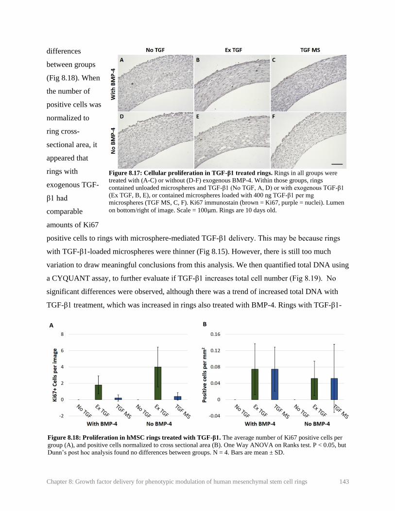
Chapter 8: Growth factor delivery for phenotypic modulation of human mesenchymal stem cell rings 143
differences
between groups
(Fig 8.18). When
the number of
positive cells was
normalized to
ring cross-
sectional area, it
appeared that
rings with
exogenous TGF-
β1 had
comparable
amounts of Ki67
positive cells to rings with microsphere-mediated TGF-β1 delivery. This may be because rings
with TGF-β1-loaded microspheres were thinner (Fig 8.15). However, there is still too much
variation to draw meaningful conclusions from this analysis. We then quantified total DNA using
a CYQUANT assay, to further evaluate if TGF-β1 increases total cell number (Fig 8.19). No
significant differences were observed, although there was a trend of increased total DNA with
TGF-β1 treatment, which was increased in rings also treated with BMP-4. Rings with TGF-β1-
Figure 8.17: Cellular proliferation in TGF-β1 treated rings. Rings in all groups were
treated with (A-C) or without (D-F) exogenous BMP-4. Within those groups, rings
contained unloaded microspheres and TGF-β1 (No TGF, A, D) or with exogenous TGF-β1
(Ex TGF, B, E), or contained microspheres loaded with 400 ng TGF-β1 per mg
microspheres (TGF MS, C, F). Ki67 immunostain (brown = Ki67, purple = nuclei). Lumen
on bottom/right of image. Scale = 100µm. Rings are 10 days old.
Figure 8.18: Proliferation in hMSC rings treated with TGF-β1. The average number of Ki67 positive cells per
group (A), and positive cells normalized to cross sectional area (B). One Way ANOVA on Ranks test. P < 0.05, but
Dunn’s post hoc analysis found no differences between groups. N = 4. Bars are mean ± SD.

Chapter 8: Growth factor delivery for phenotypic modulation of human mesenchymal stem cell rings 144
loaded microspheres appeared to have
more total DNA than rings treated with
exogenous TGF-β1. It is possible that the
high burst release of TGF-β1 when
microspheres degraded sharply increased
proliferation early in culture, resulting in a
higher total cell number, despite the
apparent fewer actively proliferating cells
by day 10.
Rings were then stained for SMA,
SM22, and calponin to assess the effect of
TGF-β1 on hMSC ring differentiation to a
contractile phenotype (Fig 8.20). Very
limited contractile protein expression was
observed in rings with no TGF-β1, and almost none was visible in rings without TGF-β1 or
BMP-4. Rings treated with exogenous TGF-β1 exhibited higher levels of SMA and SM22
expression, except for in the middle region of the tissue, regardless of BMP-4 treatment. This is
consistent in the previous experiment, where the same combination of TGF-β1, FGF, BMP-4,
and PDGF were added exogenously. Limited amounts of calponin were visible. In the TGF-β1-
loaded microsphere group, SMA and SM22 expression was observed around ring edges, which
was more than rings without no TGF-β1, but substantially less than rings with exogenous TGF-
β1. The presence of exogenous BMP-4 seemed to slightly increase SMA and SM22 expression
within the TGF-β1-loaded microsphere group.
8.4. Discussion
IH is characterized by a focal region of SMC proliferation, migration to the vessel lumen,
and increased matrix deposition. To develop an in vitro IH disease model, it is important to have
spatial control over SMC phenotype within an engineered vessel. Such models will require SMC
rings that are of a healthy, contractile phenotype, to simulate healthy regions of the tissue, in
addition to SMC rings of a synthetic phenotype, in order to simulate diseased regions of the
Figure 8.19 Effect of TGF-β1 on total DNA content.
Rings containing unloaded microspheres were treated with
no TGF-β1 (No TGF-β1) or 5 ng/ml exogenous TGF-β1
(Ex TGF-β1), or contained microspheres loaded with 400
ng TGF-β1 per mg microspheres (TGF-β1 MS). All groups
were further divided into rings with or without 2.5 ng/ml
exogenous BMP-4 treatment. Bars are mean ± SD. One
Way ANOVA, P > 0.05, N = 3-4. Rings are 10 days old.

Chapter 8: Growth factor delivery for phenotypic modulation of human mesenchymal stem cell rings 145
tissue. Due to the challenges of differentiating primary human aortic SMCs to a contractile
Figure 8.20: Contractile protein expression in rings treated with TGF-β1. Ring sections were stained
for SMA (A-F), SM22 (G-L), or calp (M-R). Rings in all groups were treated with (A-C, G-I, M-O) or
without (D-F, J-L, P-R) exogenous BMP-4. Within those groups, rings contained unloaded microspheres
and TGF-β1 (No TGF, left) or with exogenous TGF-β1 (Ex TGF, middle), or contained microspheres
loaded with 400 ng TGF-β1 per mg microspheres (TGF MS, right). Green = contractile protein, blue =
nuclei. Lumen on bottom/right of image. Scale = 100µm.

Chapter 8: Growth factor delivery for phenotypic modulation of human mesenchymal stem cell rings 146
tissue. Due to the challenges of differentiating primary human aortic SMCs to a contractile
phenotype, we decided to perform these experiments with hMSCs, which more readily express
contractile proteins than primary human SMCs.
To achieve this, we aimed to use growth factor-loaded microspheres to prevent
differentiation of select rings, and maintain a hyper-proliferative state with limited contractile
protein expression. PDGF is well established to de-differentiate SMCs into a synthetic phenotype
by reducing contractile protein expression and increasing proliferation and matrix deposition,
and is strongly associated with the initiation and progression of intimal hyperplasia [6, 11, 16-
19]. Thus, PDGF seemed like the optimal growth factor to create “diseased” rings with a
synthetic phenotype. However, we observed no clear differences in contractile protein expression
with exogenous or microsphere-mediated PDGF delivery. We even observed that rings treated
with exogenous PDGF constrict more tightly around agarose posts than rings without PDGF,
suggesting that PDGF may have enhanced ring contractility.
While the effects of PDGF on primary SMCs are well established, there have been mixed
reports of its effects on hMSCs. Some reports show that PDGF has similar effects on hMSCs as
it does on SMCs, decreasing contractile protein expression and increasing proliferation [5, 24,
25]. Others reports suggest that PDGF may instead increase contractile protein expression, rather
than decrease it [26, 27]. Other stem cell types, such as embryonic stem cells, require PDGF to
differentiate into vascular precursor cells [28]. It is possible that the effect of PDGF on hMSCs
may depend on how differentiated they are. Prior to switching our cell source from primary
SMCs to hMSCs, our proposed culture medium did not contain TGF-β1. TGF-β1 is well-
established to promote SMC [1, 2] and hMSC [4, 5, 24] differentiation to a contractile SMC
phenotype, and its effects may not be strongly inhibited by PDGF [6, 29, 30]. PDGF is
sometimes used in combination with TGF-β1 to promote both proliferation and matrix
deposition and hMSC differentiation of vascular constructs [6].
For these reasons, it was unsurprising that we did not observe clear decreases in
contractile protein expression with PDGF treatment. Some rings in this experiment did thin
unevenly and neck over time, although this was observed in fewer rings and to a lesser extent in
the group treated with exogenous PDGF. Additionally, all rings treated with PDGF had a
significantly higher DNA content, suggesting increased proliferation. For these reasons, we

Chapter 8: Growth factor delivery for phenotypic modulation of human mesenchymal stem cell rings 147
decided to add PDGF to our base hMSC differentiation medium in all experiments moving
forward.
As an alternative to PDGF to induce a diseased state, we decided to evaluate the effects
of FGF-2 on ring differentiation and proliferation. FGF is a potent antagonist of TGF-β1 and is
well-established to reduce contractile protein expression and increase proliferation in SMCs [13,
17, 20]. In hMSCs, FGF is known to maintain an undifferentiated state [31, 32], prevent cellular
senescence [31, 32], and reduce contractile protein expression [6]. When used together, FGF and
PDGF have been shown to more strongly stimulate SMC proliferation than either growth factor
alone [17]. Thus, we anticipated that with PDGF in our base differentiation medium, FGF
treatment would significantly increase cellular proliferation and prevent contractile protein
expression.
While rings treated with FGF still clearly exhibited SMA and SM22-α expression, it was
notably less than rings that were not treated with exogenous FGF. This decrease was not visible
in rings with FGF-loaded microspheres. It was also noted that microspheres were not visible in
histological sections at 3, 7, or 14 days. While cross-linking of gelatin microspheres does help
slow degradation, it does not prevent it. If MSCs are secreting high amounts of proteinases, it is
possible that they had degraded in this short period of time. This would have limited FGF
treatment to a short burst release early in culture, which may have hindered its ability to prevent
TGF-β1-induced increases in contractile protein expression. In the future, additional
modifications to microspheres may be needed to prolong FGF release. It is clear though that this
burst release still had some effect on hMSC rings, as evidenced by the significantly lower ring
thicknesses at day 14, which were comparable to the exogenous FGF group. Rings with
exogenous FGF treatment also had slightly lower total DNA content. This is contrary to our
hypothesis that FGF would increase proliferation and consequently increase ring thickness.
As an alternative to FGF delivery, we next decided to evaluate the effect of microsphere-
mediated TGF-β1 delivery on hMSC rings. The release of TGF-β1 from the gelatin microspheres
used in this study is well-characterized [22, 33], and we already demonstrated in Chapter 3 that
TGF-β1 loaded microspheres can increase contractile protein expression in human coronary
artery SMCs comparably to exogenous TGF-β1 [34]. Our goal would then be to fuse rings with
unloaded microspheres between rings with TGF-β1-loaded microspheres, to selectively
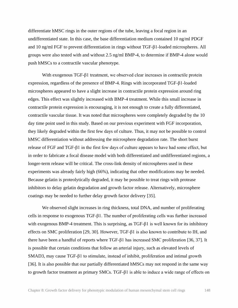
Chapter 8: Growth factor delivery for phenotypic modulation of human mesenchymal stem cell rings 148
differentiate hMSC rings in the outer regions of the tube, leaving a focal region in an
undifferentiated state. In this case, the base differentiation medium contained 10 ng/ml PDGF
and 10 ng/ml FGF to prevent differentiation in rings without TGF-β1-loaded microspheres. All
groups were also tested with and without 2.5 ng/ml BMP-4, to determine if BMP-4 alone would
push hMSCs to a contractile vascular phenotype.
With exogenous TGF-β1 treatment, we observed clear increases in contractile protein
expression, regardless of the presence of BMP-4. Rings with incorporated TGF-β1-loaded
microspheres appeared to have a slight increase in contractile protein expression around ring
edges. This effect was slightly increased with BMP-4 treatment. While this small increase in
contractile protein expression is encouraging, it is not enough to create a fully differentiated,
contractile vascular tissue. It was noted that microspheres were completely degraded by the 10
day time point used in this study. Based on our previous experiment with FGF incorporation,
they likely degraded within the first few days of culture. Thus, it may not be possible to control
hMSC differentiation without addressing the microsphere degradation rate. The short burst
release of FGF and TGF-β1 in the first few days of culture appears to have had some effect, but
in order to fabricate a focal disease model with both differentiated and undifferentiated regions, a
longer-term release will be critical. The cross-link density of microspheres used in these
experiments was already fairly high (66%), indicating that other modifications may be needed.
Because gelatin is proteolytically degraded, it may be possible to treat rings with protease
inhibitors to delay gelatin degradation and growth factor release. Alternatively, microsphere
coatings may be needed to further delay growth factor delivery [35].
We observed slight increases in ring thickness, total DNA, and number of proliferating
cells in response to exogenous TGF-β1. The number of proliferating cells was further increased
with exogenous BMP-4 treatment. This is surprising, as TGF-β1 is well known for its inhibitory
effects on SMC proliferation [29, 30]. However, TGF-β1 is also known to contribute to IH, and
there have been a handful of reports where TGF-β1 has increased SMC proliferation [36, 37]. It
is possible that certain conditions that follow an arterial injury, such as elevated levels of
SMAD3, may cause TGF-β1 to stimulate, instead of inhibit, proliferation and intimal growth
[36]. It is also possible that our partially differentiated hMSCs may not respond in the same way
to growth factor treatment as primary SMCs. TGF-β1 is able to induce a wide range of effects on

Chapter 8: Growth factor delivery for phenotypic modulation of human mesenchymal stem cell rings 149
hMSCs, including differentiation to a chondrogenic [38] or a vascular [4] phenotype, suppression
of differentiation to an osteogenic phenotype [39], or an increase in proliferation [39]. It has also
been shown that the combination of PDGF, FGF, and TGF-β1 can support undifferentiated
hMSC growth comparably to FBS, while maintaining them in an undifferentiated state [40].
With our MSC rings, cells have partially differentiated into SMCs, suggesting they may have
either SMC-like and MSC-like responses to different growth factors.
Our goal with these studies was to focally control SMC phenotype, so that certain regions
of the tube could be differentiated into a contractile phenotype, and some regions would maintain
a diseased state. However, because FGF is known to maintain MSCs in an undifferentiated state
[31, 32], even in combination with TGF-β1 and PDGF [40], we may not truly be achieving a
diseased SMC state with FGF treatment. Thus, it may be necessary to remove FGF from culture
medium. Undifferentiated hMSCs may not respond to potential therapeutics in the same way as
synthetic SMCs, just as they do not always respond to growth factors in the same way as SMCs.
It may be necessary to fully differentiate SMC rings prior to releasing growth factors such as
PDGF or FGF, and then to de-differentiate cells from a contractile to a synthetic SMC
phenotype. However, we have already observed rapid microsphere degradation in hMSC rings,
even with high cross-link densities. Thus, even further delaying growth factor release will likely
require significant modifications to microspheres.
In this chapter, we demonstrated that microsphere-mediated growth factor delivery had
small but measurable effects on hMSC rings. PDGF caused increases in ring thickness and total
DNA, FGF caused slight decreases in ring thickness, and TGF-β1 slightly increased contractile
protein expression. While this demonstrates the potential of microsphere-mediated growth factor
delivery for controlling ring phenotype, more modifications to microspheres may needed to
achieve larger changes in contractile protein expression.
8.5. References
1. Owens, G.K., M.S. Kumar, and B.R. Wamhoff, Molecular Regulation of Vascular
Smooth Muscle Cell Differentiation in Development and Disease. Physiological Reviews,
2004. 84: p. 767-801.
2. Tang, Y., S. Urs, J. Boucher, T. Bernaiche, D. Venkatesh, D.B. Spicer, C.P. Vary, and L.
Liaw, Notch and transforming growth factor-beta (TGFbeta) signaling pathways

Chapter 8: Growth factor delivery for phenotypic modulation of human mesenchymal stem cell rings 150
cooperatively regulate vascular smooth muscle cell differentiation. J Biol Chem, 2010.
285(23): p. 17556-63.
3. Liu, J.Y., D.D. Swartz, H.F. Peng, S.F. Gugino, J.A. Russell, and S.T. Andreadis,
Functional tissue-engineered blood vessels from bone marrow progenitor cells.
Cardiovasc Res, 2007. 75(3): p. 618-28.
4. Wang, C., S. Yin, L. Cen, Q. Liu, W. Liu, Y. Cao, and L. Cui, Differentiation of Adipose-
Derived Stem Cells into Contractile Smooth Muscle Cells Induced by Transforming
Growth Factor-β1 and Bone Morphogenetic Protein-4. Tissue Eng Part A, 2010. 16(4):
p. 1202-1213.
5. Narita, Y., A. Yamawaki, H. Kagami, M. Ueda, and Y. Ueda, Effects of transforming
growth factor-beta 1 and ascorbic acid on differentiation of human bone-marrow-derived
mesenchymal stem cells into smooth muscle cell lineage. Cell Tissue Res, 2008. 333(3):
p. 449-59.
6. Gong, Z. and L.E. Niklason, Small-diameter human vessel wall engineered from bone
marrow-derived mesenchymal stem cells (hMSCs). FASEB J, 2008. 22(6): p. 1635-48.
7. Liang, M.S. and S.T. Andreadis, Engineering fibrin-binding TGF-beta1 for sustained
signaling and contractile function of MSC based vascular constructs. Biomaterials, 2011.
32(33): p. 8684-93.
8. Cho, S.-W., S.H. Lim, I.-K. Kim, Y.S. Hong, S.-S. Kim, K.J. Yoo, H.-Y. Park, Y. Jang,
B.C. Chang, C.Y. Choi, et al., Small-Diameter Blood Vessels Engineered With Bone
Marrow Derived Cells. Annals of Surgery, 2005. 241(3): p. 506-515.
9. Ishiwata, S., T. Tukada, S. Nakanishi, S. Nishiyama, and A. Seki, Postangioplasty
restenosis: Platelet activation and the coagulation-fibrinolysis system as possible factors
in the pathogenesis of restenosis. Am Heart J, 1997. 133: p. 387-392.
10. Newby, A.C. and A.B. Zaltsman, Molecular mechanisms in intimal hyperplasia. J Pathol,
2000. 190: p. 300-309.
11. Amento, E.P., N. Ehsani, H. Palmer, and P. Libby, Cytokines and growth factors
positively and negatively regulate interstitial collagen gene expression in human vascular
smooth muscle cells. Arteriosclerosis, Thrombosis, and Vascular Biology, 1991. 11(5): p.
1223-1230.
12. Absood, A., A. Furutani, T. Kawamura, and L.M. Graham, A comparison of oxidized
LDL-induced collagen secretion by graft and aortic SMCs: role of PDGF. Am J Physiol
Heart Circ Physiol, 2004. 287: p. H1200–H1206.
13. Millette, E., B.H. Rauch, R.D. Kenagy, G. Daum, and A.W. Clowes, Platelet-derived
growth factor-BB transactivates the fibroblast growth factor receptor to induce
proliferation in human smooth muscle cells. Trends Cardiovasc Med, 2006. 16(1): p. 25-
8.
Chapter 8: Growth factor delivery for phenotypic modulation of human mesenchymal stem cell rings 151
14. Jiang, B., S. Yamamura, P.R. Nelson, L. Mureebe, and K.C. Kent, Differential effects of
platelet-derived growth factor isotypes on human smooth muscle cell proliferation and
migration are mediated by distinct signaling pathways. Surgery, 1996. 120: p. 427-32.
15. Hollenbeck, S.T., H. Itoh, O. Louie, P.L. Faries, B. Liu, and K.C. Kent, Type I collagen
synergistically enhances PDGF-induced smooth muscle cell proliferation through
pp60src-dependent crosstalk between the alpha2beta1 integrin and PDGF-beta receptor.
Biochem Biophys Res Commun, 2004. 325(1): p. 328-37.
16. Leppanen, O., N. Janjic, M.-A. Carlsson, K. Pietras, M. Levin, C. Vargeese, L.S. Green,
D. Bergqvist, A. Ostman, and C.-H. Heldin, Intimal Hyperplasia Recurs After Removal of
PDGF-AB and -BB Inhibition in the Rat Carotid Artery Injury Model. Arterioscler
Thromb Vasc Biol, 2000. 20: p. 89-95.
17. Ucuzian, A.A., L.P. Brewster, A.T. East, Y. Pang, A.A. Gassman, and H.P. Greisler,
Characterization of the chemotactic and mitogenic response of SMCs to PDGF-BB and
FGF-2 in fibrin hydrogels. J Biomed Mater Res A, 2010. 94(3): p. 988-96.
18. Li, L., D.K. Blumenthal, C.M. Terry, Y. He, M.L. Carlson, and A.K. Cheung, PDGF-
induced proliferation in human arterial and venous smooth muscle cells: molecular basis
for differential effects of PDGF isoforms. J Cell Biochem, 2011. 112(1): p. 289-98.
19. Brown, X.Q., E. Bartolak-Suki, C. Williams, M.L. Walker, V.M. Weaver, and J.Y.
Wong, Effect of substrate stiffness and PDGF on the behavior of vascular smooth muscle
cells: implications for atherosclerosis. J Cell Physiol, 2010. 225(1): p. 115-22.
20. Chen, P.Y., L. Qin, G. Li, G. Tellides, and M. Simons, Fibroblast growth factor (FGF)
signaling regulates transforming growth factor beta (TGFbeta)-dependent smooth muscle
cell phenotype modulation. Sci Rep, 2016. 6: p. 33407.
21. Strobel, H.A., E.L. Calamari, B. Alphonse, T.A. Hookway, and M.W. Rolle, Fabrication
of Custom Agarose Wells for Cell Seeding and Tissue Ring Self-assembly Using 3D-
Printed Molds. JoVE, 2018. 134: p. e56618.
22. Dang, P.N., N. Dwivedi, L.M. Phillips, X. Yu, S. Herberg, C. Bowerman, L.D. Solorio,
W.L. Murphy, and E. Alsberg, Controlled Dual Growth Factor Delivery From
Microparticles Incorporated Within Human Bone Marrow-Derived Mesenchymal Stem
Cell Aggregates for Enhanced Bone Tissue Engineering via Endochondral Ossification.
Stem Cells Transl Med, 2016. 5(2): p. 206-17.
23. Horton Jr., W.E., J.D. Higginbotham, and S. Chandrasekhar, Transforming Growth
Factor-Beta and Fibroblast Growth Factor Act Synergistically To Inhibit Collagen II
Synthesis Through a Mechanism Involving Regulatory DNA Sequences. Journal of
Cellular Physiology, 1989. 141: p. 8-15.
24. Kinner, B., J.M. Zaleskas, and M. Spector, Regulation of Smooth Muscle Actin
Expression and Contraction in Adult Human Mesenchymal Stem Cells. Experimental Cell
Research, 2002. 278(1): p. 72-83.

Chapter 8: Growth factor delivery for phenotypic modulation of human mesenchymal stem cell rings 152
25. Tamama, K., C.K. Sen, and A. Wells, Differentiation of bone marrow mesenchymal stem
cells into the smooth muscle lineage by blocking ERK/MAPK signaling pathway. Stem
Cells Dev, 2008. 17(5): p. 897-908.
26. Ball, S.G., C.A. Shuttleworth, and C.M. Kielty, Platelet-derived growth factor receptor-
alpha is a key determinant of smooth muscle alpha-actin filaments in bone marrow-
derived mesenchymal stem cells. Int J Biochem Cell Biol, 2007. 39(2): p. 379-91.
27. Simper, D., Smooth Muscle Progenitor Cells in Human Blood. Circulation, 2002.
106(10): p. 1199-1204.
28. Yamashita, J., H. Itoh, M. Hirashima, M. Ogawa, S. Nishikawa, T. Yurugi, M. Naito, K.
Nakao, and S.-I. Nishikawa, Flk1-positive cells derived from embryonic stem cells serve
as vascular progenitors. Nature, 2000. 408: p. 92-95.
29. Bjorkerud, S., Effects of transforming growth factor-beta 1 on human arterial smooth muscle cells in vitro. Arteriosclerosis, Thrombosis, and Vascular Biology, 1991. 11(4): p.
892-902.
30. Engel, L. and U. Ryan, TGF-beta1 reverses PDGF-stimulated migration of human aortic
smooth muscle cells in vitro. In Vitro Cell. Dev. Biol., 1997. 33: p. 443-451.
31. Bianchi, G., A. Banfi, M. Mastrogiacomo, R. Notaro, L. Luzzatto, R. Cancedda, and R.
Quarto, Ex vivo enrichment of mesenchymal cell progenitors by fibroblast growth factor
2. Experimental Cell Research, 2003. 287(1): p. 98-105.
32. Tsutsumi, S., A. Shimazu, K. Miyazaki, H. Pan, C. Koike, E. Yoshida, K. Takagishi, and
Y. Kato, Retention of Multilineage Differentiation Potential of Mesenchymal Cells during
Proliferation in Response to FGF. Biochemical and Biophysical Research
Communications, 2001. 288(2): p. 413-419.
33. Solorio, L.D., E.L. Vieregge, C.D. Dhami, P.N. Dang, and E. Alsberg, Engineered
cartilage via self-assembled hMSC sheets with incorporated biodegradable gelatin
microspheres releasing transforming growth factor-beta1. J Control Release, 2012.
158(2): p. 224-32.
34. Strobel, H.A., A.D. Dikina, K. Levi, L.D. Solorio, E. Alsberg, and M.W. Rolle, Cellular
self-assembly with microsphere incorporation for growth factor delivery within
engineered vascular tissue rings. Tissue Eng Part A, 2017. 23(3-4): p. 143-155.
35. Bian, L., D.Y. Zhai, E. Tous, R. Rai, R.L. Mauck, and J.A. Burdick, Enhanced MSC
chondrogenesis following delivery of TGF-beta3 from alginate microspheres within
hyaluronic acid hydrogels in vitro and in vivo. Biomaterials, 2011. 32(27): p. 6425-34.
36. Suwanabol, P.A., S.M. Seedial, X. Shi, F. Zhang, D. Yamanouchi, D. Roenneburg, B.
Liu, and K.C. Kent, Transforming growth factor-beta increases vascular smooth muscle
cell proliferation through the Smad3 and extracellular signal-regulated kinase mitogen-
activated protein kinases pathways. J Vasc Surg, 2012. 56(2): p. 446-54.

Chapter 8: Growth factor delivery for phenotypic modulation of human mesenchymal stem cell rings 153
37. Chen, G. and N. Khalil, TGF-beta1 increases proliferation of airway smooth muscle cells
by phosphorylation of map kinases. Respir Res, 2006. 7: p. 2.
38. Solorio, L.D., C.D. Dhami, P.N. Dang, E.L. Vieregge, and E. Alsberg, Spatiotemporal
regulation of chondrogenic differentiation with controlled delivery of transforming
growth factor-beta1 from gelatin microspheres in mesenchymal stem cell aggregates.
Stem Cells Transl Med, 2012. 1(8): p. 632-9.
39. Jian, H., X. Shen, I. Liu, M. Semenov, X. He, and X.-F. Wang, Smad3-dependent nuclear
translocation of beta-catenin is required for TGF-beta1- induced proliferation of bone marrow- derived adult human mesenchymal stem cells. Genes Dev, 2006. 20(1): p. 666-
674.
40. Ng, F., S. Boucher, S. Koh, K.S. Sastry, L. Chase, U. Lakshmipathy, C. Choong, Z.
Yang, M.C. Vemuri, M.S. Rao, et al., PDGF, TGF-beta, and FGF signaling is important
for differentiation and growth of mesenchymal stem cells (MSCs): transcriptional
profiling can identify markers and signaling pathways important in differentiation of
MSCs into adipogenic, chondrogenic, and osteogenic lineages. Blood, 2008. 112(2): p.
295-307.

Chapter 9: Vascular tissue tubes with distinct phenotypic and structural regions 154
Chapter 9: Vascular tissue tubes with distinct phenotypic and
structural regions
Figure 9.3 from: H.A. Strobel, T.A. Hookway, M. Piola, M. Soncini, G.B. Fiore, E. Alsberg, and M.W.
Rolle. “Assembly of tissue engineered blood vessels with spatially-controlled heterogeneities”. Tissue
Engineering Part A. In Press.
Authorship contributions: HAS designed and performed experiments, collected and analyzed all data, made all
figures and wrote and revised the manuscript. TAH contributed to experimental design and data analysis and edited
the manuscript. MP, MS, and GBF designed and fabricated bioreactors, contributed to experimental design and
data analysis, and edited the manuscript. EA provided gelatin microspheres, contributed to experimental design and
analysis, and edited the manuscript. MWR contributed to experimental design, supervised data collection, data
analysis, and preparation of the manuscript, and edited the manuscript.
9.1. Introduction
Human mesenchymal stem cells (MSCs) may be an alternative source of vascular smooth
muscle cells (SMCs). They are highly proliferative, easier to obtain from adult allogenetic and
autologous sources than primary human vascular SMCs, express contractile proteins in 3D
culture, and have been used in vascular tissue engineering [1-4]. In Chapter 8, we demonstrated
our ability to culture self-assembled cell rings fabricated from hMSCs. Rings expressed the
contractile proteins smooth muscle alpha actin (SMA), smooth muscle protein 22 alpha (SM22-
α), and calponin (Calp). Here, we evaluated the potential of hMSC rings for modular vascular
tissue tube fabrication.
Our ultimate goal is to create a focal region of smooth muscle de-differentiation and
increased proliferation and thickness characteristic of intimal hyperplasia (IH). We originally
intended to achieve this by delivering growth factors to a focal region of tissue tubes via
microspheres. While this approach is promising, further optimization of medium conditions and
microsphere design are needed (Chapter 8). As an alternative, we evaluated here if different cell
types can be fused to create a focal region of SMCs in a synthetic state. Human aortic SMCs do
not express contractile proteins in 3D culture (Chapter 6), which may allow us to create a focal
region of synthetic SMCs within an otherwise contractile tube. In contrast, hMSCs readily
expressed contractile proteins when treated with TGF-β1 and BMP-4 (Chapter 8). Thus, we

Chapter 9: Vascular tissue tubes with distinct phenotypic and structural regions 155
evaluated if a region of synthetic SMCs could be created by fusing rings fabricated from human
aortic SMCs in a central region of the tube, with differentiated hMSCs on either side.
9.2. Methods
9.2.1. Cell culture
Bone marrow-derived human mesenchymal stem cells (hMSCs) were purchased from
RoosterBio, Inc. and expanded according to the manufacturer’s instructions in a propriety growth
medium (RoosterBio, Inc.).
Human aortic smooth muscle cells (SMCs) were purchased from Lifeline Cell
Technologies and expanded in VascuLife growth medium (Lifeline) according to manufacturer
instructions.
9.2.2. Ring fabrication
hMSCs were seeded in agarose molds (2 mm i.d. posts) at a concentration of 600,000
cells/ring. Wells were flooded after 2 hours of cell aggregation with growth medium
(RoosterBio, Inc.), then switched to a custom medium after 24 hours containing DMEM, 5%
FBS, 1% l-glutamine, 1% ITS, 1% penicillin-streptomycin, and 50 µg/ml ascorbic acid.
Human aortic SMCs were pre-loaded with CellTracker Red dye as described in Chapter
5.2.5. Cells were then seeded at a concentration of 400,000 cells/ring in growth medium
(Lifeline). After 24 hours, rings were flooded with growth medium. Rings were kept in growth
medium until tube fabrication. Medium for both hMSC and aortic SMC rings was changed daily.
9.2.3. hMSC tube fabrication
For preliminary hMSC tube fabrication experiments, hMSCs rings were threaded over
silicone mandrels after 3 days of culture. Rings were pushed into contact with one another, and
polycaprolactone (PCL) cuffs ([5], Chapter 4) were pushed onto tube ends. hMSC rings were
cultured in hMSC differentiation medium described in section 9.2.2. After 4 days of fusion
culture (7 days total), 5 ng/ml TGF-β1 and 2.5 ng/ml BMP-4 were added to the medium to
stimulate differentiation to a SMC phenotype. Tubes were fixed after 7 days of fusion culture (10
days total) for immunohistochemistry and histology.

Chapter 9: Vascular tissue tubes with distinct phenotypic and structural regions 156
9.2.4. Fabrication of tubes with focal regions of
human aortic SMCs
To fabricate tubes with localized SMC
regions, 3-day old rings were threaded over
silicone mandrels with a central region of 3 human
aortic SMC rings and 4 hMSC rings on either side.
Control tubes were fabricated from human aortic
SMC rings (8 rings per tube), or hMSC rings (5
rings per tube). Three tubes per group were
fabricated with polycaprolactone (PCL) cuffs [5]
on tube ends. A schematic of experimental groups
is shown in Figure 9.1.
All tubes were cultured in hMSC differentiation medium as described in section 9.2.2,
but with added 5 ng/ml FGF for the first 4 days of fusion culture. After 4 days of fusion (3-4
tubes; 3 days of ring culture – 4 days of fusion culture), 5 ng/ml TGF-β1 and 10 ng/ml PDGF
were added to culture medium in all groups, and FGF supplementation was stopped. After 7 days
total of fusion (3-7), tubes were fixed for histological analysis.
9.2.5. Histology and immunohistochemistry
After fixing for 1 hour in 10% neutral buffered formalin, samples were processed and
embedded in paraffin. Longitudinal sections 5 µm thick were adhered to positively-charged
slides. Hematoxylin and Eosin staining was used to examine tube morphology and Picrosirius
red/fast green was used to examine collagen deposition.
Immunohistochemistry was performed as described in Chapter 5.2.8. Briefly, antigen
retrieval was performed on samples to be stained for smooth muscle alpha actin (SMA), smooth
muscle protein 22 alpha (SM22-α), and calponin. Slides were blocked in 1.5% normal rabbit
serum for 30 minutes, and were incubated overnight at 4ºC in SMA (Dako, clone 1A4, 1:100),
SM22-α (BioRad VPA00048, 1:100), or calponin (Dako, CALP, 1:100) antibodies. Negative
control samples were incubated with mouse or goat immunoglobulin G (Vector). Samples were
incubated in a secondary antibody (Invitrogen; Alexa Fluor 488 goat anti-rabbit, rabbit anti-
Figure 9.1: Schematic of focal lesion
experimental setup. Pink = hMSC rings, Red =
human aortic SMC rings. Tubes of each cell type,
and hMSC tubes with focal region of aortic SMCs,
were cultured in static conditions on silicone tubing
mandrels for 7 days.
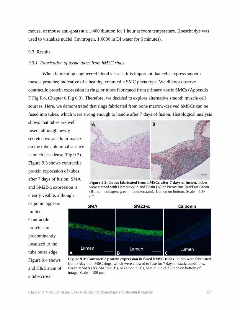
Chapter 9: Vascular tissue tubes with distinct phenotypic and structural regions 157
mouse, or mouse anti-goat) at a 1:400 dilution for 1 hour at room temperature. Hoescht dye was
used to visualize nuclei (Invitrogen, 1:6000 in DI water for 6 minutes).
9.3. Results
9.3.1. Fabrication of tissue tubes from hMSC rings
When fabricating engineered blood vessels, it is important that cells express smooth
muscle proteins; indicative of a healthy, contractile SMC phenotype. We did not observe
contractile protein expression in rings or tubes fabricated from primary aortic SMCs (Appendix
F Fig F.4, Chapter 6 Fig 6.9). Therefore, we decided to explore alternative smooth muscle cell
sources. Here, we demonstrated that rings fabricated from bone marrow-derived hMSCs can be
fused into tubes, which were strong enough to handle after 7 days of fusion. Histological analysis
shows that tubes are well
fused, although newly
secreted extracellular matrix
on the tube abluminal surface
is much less dense (Fig 9.2).
Figure 9.3 shows contractile
protein expression of tubes
after 7 days of fusion. SMA
and SM22-α expression is
clearly visible, although
calponin appears
limited.
Contractile
proteins are
predominantly
localized to the
tube outer edge.
Figure 9.4 shows
and H&E stain of
a tube cross
Figure 9.3: Contractile protein expression in fused hMSC tubes. Tubes were fabricated
from 3-day old hMSC rings, which were allowed to fuse for 7 days in static conditions.
Green = SMA (A), SM22-α (B), or calponin (C), blue = nuclei. Lumen on bottom of
image. Scale = 100 µm.
Figure 9.2: Tubes fabricated from hMSCs after 7 days of fusion. Tubes
were stained with Hematoxylin and Eosin (A) or Picrosirius Red/Fast Green
(B; red = collagen, green = counterstain). Lumen on bottom. Scale = 100
µm.

Chapter 9: Vascular tissue tubes with distinct phenotypic and structural regions 158
section. Cells appear circumferentially aligned on
the outer edge, but not in the middle region of the
tissue.
9.3.4. Focal region of synthetic SMCs
As a proof-of-
concept experiment, we
fused human aortic SMCs
in a central region of tubes,
between regions of
hMSCs. We have previously observed that human aortic SMCs do not
express contractile proteins in 3D, even with TGF-β1 treatment (not
shown). These tubes were compared to tubes fabricated entirely from
human aortic SMC rings, or entirely from hMSC rings. A schematic of
the groups is shown in Figure 9.1. Tubes were allowed to fuse for 7 days
prior to fixing for histology. We observed that holes began to form in hMSC tubes and regions of
hMSCs in tubes with aortic SMC lesions after 3 days of fusion (Figure 9.5). Despite this, we
continued to culture tubes for the full 7 day fusion period.
Histological analysis shows a high nuclear density in all groups. Picrosirius red/fast green
staining showed very limited collagen deposition in hMSC tubes (Figure 9.6) compared to our
previous experiments, and compared to human aortic SMC tubes. This was also apparent in the
human aortic SMC lesion group, where a region of slightly more dense collagen deposition is
clearly visible within the aortic SMC lesion. Contractile protein expression is shown in Figure
9.7. A thin layer of SM22-α was visible on the abluminal surface of all groups, with slightly
more in the hMSC only group. Almost no SMA or calponin was visible, with no clear
differences between groups.
9.4. Discussion
In Chapter 8, we demonstrated the potential of hMSCs as an alternative cells source for
fabricating vascular tissue rings. Here, we demonstrated in preliminary studies the potential of
hMSC rings for fabricating modular tissue tubes. Tubes fabricated from hMSCs expressed the
Figure 9.4: Alignment of hMSCs within hMSC
tubes. Radial cross-section of hMSC tube after 4
days of fusion. Hematoxylin and Eosin stain.
Lumen on bottom of image. Scale = 100 µm.
Figure 9.5: hMSC tube
with hole. Image at 3
days of fusion culture.
Arrow points to hole.

Chapter 9: Vascular tissue tubes with distinct phenotypic and structural regions 159
contractile proteins SMA and SM22-α (Fig 9.3 A, B), although calponin is not visible. The
absence of late- stage differentiation markers is unsurprising, due to the short duration of the
experiment. In an earlier study, we found that when TGF-β1 and BMP-4 were added at the
beginning of ring and tube culture, rings did not fuse successfully and formed holes (not shown).
Thus, we developed the protocol presented in here, where the differentiation factors TGF-β1 and
BMP-4 were added after 4 days of fusion. However, this resulted in only 3 days total of growth
factor treatment for tubes in this experiment, which may explain the limited SMA and SM22 and
absence of calponin (Fig 9.3 C, D).
Cell alignment is also important for creating functional vessels, as radially aligned cells
give tubes the ability to constrict and dilate to regulate blood flow in vivo. In an hMSC tube
cross-section, it is apparent that nuclei are radially aligned around tube outer edges, but not the
middle region of the tissues (Fig 9.4). Alignment may improve in future studies with mechanical
stimulation [6].
Figure 9.6: Morphology and matrix deposition of vascular tissue tubes. Tubes were fabricated from
hMSC rings (A, B) human aortic SMC rings (hAoSMC; C, D), or from hMSC rings with a central region
of human aortic SMCs (E, F). Tubes were allowed to fuse for 7 days prior to fixing and staining for H&E
(A, C, E) or Picrosirius Red/Fast Green (red = collagen, green = counterstain; B, D, F). Scale = 100µm.
Lumen on bottom.

Chapter 9: Vascular tissue tubes with distinct phenotypic and structural regions 160
Our ultimate goal is to
create focal regions of a
synthetic SMC phenotype
within vascular tissue tubes,
in order to create a focal
region of vascular disease.
Our original approach was to
utilize gelatin microspheres to
locally deliver growth factors
within the tube. However, due
to the challenges of
microsphere-mediated growth
factor delivery discussed in
Chapter 8, we evaluated an
alternative approach. We
fused primary aortic SMC
rings between hMSC rings,
with the same goal of creating
a focal region of synthetic
SMCs. We have not observed contractile proteins in aortic SMC rings in 3D despite treatment
with TGF-β1. Thus, these rings may also serve as the region of synthetic SMC phenotype,
between contractile protein-expressing hMSC rings. This method may be advantageous for
creating an intimal hyperplasia model, because it ensures that the focal lesion consists of SMCs
with a diseased synthetic phenotype, rather than un-differentiated hMSCs, which may not
respond to therapeutics in the same way as synthetic SMCs.
In these experiments, hMSC and hMSC-lesion tubes began to form holes on day 3. This
is surprising, as our modified protocol with delayed growth factor treatment worked successfully
in preliminary experiments (additional replicate of initial experiment not shown). Despite this,
tubes remained in culture until day 7 of fusion (3-7 tubes), when they were fixed and analyzed
histologically. hMSC tubes produced very limited collagen based on Picrosirius Red/Fast Green
staining. This is highly unusual, as we typically observe large amounts of collagen, even with
Figure 9.7: Contractile protein expression in hMSC and human aortic
SMC tubes. Tubes were fabricated from hMSC rings (A-C), human aortic
SMC rings (hAoSMC; D-F), or from hMSC rings with a central region of
human aortic SMCs (G-I). Tubes were allowed to fuse for 7 days prior to
fixing and staining for SMA (A, D, G), SM22 (B, E, H), or calp (C, F, I).
Green = contractile protein, red = human aortic SMCs dyed with
CellTracker Red dye, blue = nuclei. Scale = 100µm. Lumen on bottom.

Chapter 9: Vascular tissue tubes with distinct phenotypic and structural regions 161
delayed growth factor treatment. However, the same results were observed when the experiment
was repeated. If tubes did not have sufficient extracellular matrix to support their structure, it
may explain the hole formation.
Contractile protein expression is limited to a thin layer of SM22 along the tube abluminal
edge, which is visible in both aortic SMC and hMSC regions of the tubes. This may be because
tubes were only subjected to 3 days of growth factor treatment, as hole formation prevented
longer culture times. However, the aortic SMC regions can still be distinguished by their larger
amounts of collagen deposition, which is visible by picrosirius red/fast green staining. Thus, we
have still created a distinct region of aortic SMCs within an hMSC tube. However, more tests
may be necessary to determine why hMSCs in these experiments produced so little collagen and
fewer contractile proteins than previous tests. It is possible there is some experimental variation
between batches of frozen hMSCs. If this problem continues to occur, biochemical stimuli such
as increased ascorbate concentration may enhance collagen deposition.
Human MSCs are highly proliferative, reliably differentiate to an SMC phenotype in 3D
cultures. Additionally, hMSCs may allow for the fabrication of patient-specific tissue tubes to
model vascular disease, as shown in principle in previous work with induced pluripotent stem
cell-derived vascular smooth muscle cells [7]. Future work will include optimizing culture
protocols to improve collagen and contractile protein deposition in hMSCs. Overall, these studies
show the feasibility of creating distinct regions within a vascular tissue tube. This work is a
critical step towards fabricating an intimal hyperplasia model.
9.5. References
1. Liu, J.Y., D.D. Swartz, H.F. Peng, S.F. Gugino, J.A. Russell, and S.T. Andreadis,
Functional tissue-engineered blood vessels from bone marrow progenitor cells.
Cardiovasc Res, 2007. 75(3): p. 618-28.
2. Gong, Z. and L.E. Niklason, Small-diameter human vessel wall engineered from bone
marrow-derived mesenchymal stem cells (hMSCs). FASEB J, 2008. 22(6): p. 1635-48.
3. Liang, M.S. and S.T. Andreadis, Engineering fibrin-binding TGF-beta1 for sustained
signaling and contractile function of MSC based vascular constructs. Biomaterials, 2011.
32(33): p. 8684-93.

Chapter 9: Vascular tissue tubes with distinct phenotypic and structural regions 162
4. Cho, S.-W., S.H. Lim, I.-K. Kim, Y.S. Hong, S.-S. Kim, K.J. Yoo, H.-Y. Park, Y. Jang,
B.C. Chang, C.Y. Choi, et al., Small-Diameter Blood Vessels Engineered With Bone
Marrow Derived Cells. Annals of Surgery, 2005. 241(3): p. 506-515.
5. Strobel, H.A., E.L. Calamari, A. Beliveau, A. Jain, and M.W. Rolle, Fabrication and
characterization of electrospun polycaprolactone and gelatin composite cuffs for tissue
engineered blood vessels. JBMR Part B, 2018. 106B(2): p. 817-826.
6. Standley, P.R., A. Camaratta, B.P. Nolan, C.T. Purgason, and M.A. Stanley, Cyclic
stretch induces vascular smooth muscle cell alignment via NO signaling. Am J Physiol
Heart Circ Physiol, 2002. 283: p. H1907–H1914.
7. Dash, B.C., K. Levi, J. Schwan, J. Luo, O. Bartulos, H. Wu, C. Qiu, T. Yi, Y. Ren, S.
Campbell, et al., Tissue-Engineered Vascular Rings from Human iPSC-Derived Smooth
Muscle Cells. Stem Cell Reports, 2016. 7(1): p. 19-28.
Chapter 10: Conclusions and future work 163
Chapter 10: Conclusions and future work
10.1. Summary
Cardiovascular disease is the leading cause of death in the United States [1]. There is a
strong need for new therapeutics to treat these diseases. Tissue engineered bloods vessels
(TEBVs) may serve as tools for disease modeling and high-throughput drug screening, which
may ultimately accelerate the development of lifesaving therapies. Most existing methods for
fabricating TEBVs create homogenous tissue tubes, which are not conducive to modeling focal
vascular diseases, such as intimal hyperplasia or aneurysm. In contrast, our lab has developed a
modular system for fabricating TEBVs from individual tissue ring units. Our ability to customize
individual ring sub-units allows us to introduce spatial heterogeneities along the TEBV length,
and potentially model such focal vascular diseases.
Here, we first demonstrated our ability to incorporate degradable gelatin microspheres in
SMC rings to customize ring properties. Microspheres were loaded with TGF-β1, and caused
increases in contractile protein expression comparable to exogenous TGF-β1 treatment. This
demonstrated our ability to use microspheres to delivery bioactive growth factors within tissue
rings and modulate SMC phenotype.
Next, we fused rings into modular tissue tubes, and verified that cells maintain their
spatial positioning along the length of fused tubes. This is critical for creating focal disease
models, as diseased cells must stay in the diseased region of the tube. We then developed a
custom luminal flow bioreactor, and demonstrated that SMC tubes could be dynamically
cultured, with the aid of PCL cannulation cuffs, at physiological shear stresses. We also
demonstrated that we could create a focal region of microsphere incorporation, by fusing rings
with microspheres between rings without microspheres. This demonstrated our ability to
fabricate tubes with spatially-controlled heterogeneities.
Due to the challenges of differentiating primary human SMCs into a contractile
phenotype, we evaluated induced pluripotent stem cells (iPSCs) as an alternative cell source.
Initial experiments yielded rings that expressed smooth muscle contractile proteins. However,

Chapter 10: Conclusions and future work 164
batch-to-batch variability remained a problem. Next, we evaluated human mesenchymal stem
cells (hMSCs) as an alternative cell source. hMSCs strongly expressed smooth muscle
contractile proteins in response to TGF-β1 and BMP-4. We evaluated the effects of exogenous
and microsphere-mediated delivery of PDGF-BB, FGF-2, and TGF-β1 on hMSC thickness,
proliferation, and contractile protein expression. The effects of microsphere-mediated growth
factor delivery on hMSCs were limited compared to exogenous growth factor treatment, possibly
due to the rapid degradation of microspheres in this system. In the future, modifications to
microspheres will be necessary to achieve a longer degradation time and sustained release.
Our final goal was to create distinct phenotypic regions along the length of tissue tubes.
To do this, we fused human aortic SMC rings, which do not produce contractile proteins, in a
central region of the tube between hMSC rings, which do produce contractile proteins. However,
in this experiment, both cell types produced only very small amounts of contractile proteins.
Still, aortic SMC rings were clearly visible due to increased collagen deposition. This indicates
that we were successful in creating a structurally distinct region within our tissue tubes. Overall,
this work has led to the development of a modular platform technology that may be further
developed to fabricate focal vascular disease models.
10.2. Other applications of the ring system
While the focus of these studies is on ring fusion and the fabrication of modular tubular
structures, rings alone also have great potential as tools for disease modeling and drug screening.
The ISO standard for mechanically testing vascular grafts is to cut them into individual ring-
segments, and test each segment [2]. By fabricating individual rings instead of whole tubular
grafts, we may be able to perform more high-throughput experiments to screen the effects of
culture conditions or potential therapeutics on tissue mechanical properties, contractility,
morphology, and matrix deposition, as rings can be used for mechanical and functional testing,
biochemical analysis, or histological and immunohistochemical analysis. As discussed in
Chapter 7, the Qyang lab at Yale University has used our tissue ring system to create rings from
iPSC-vSMCs derived from patients with SVAS, and showed reduced contractile protein
expression and contractile function with these rings compared to rings made with healthy cells
[3]. Thus, rings alone may be sufficient to model some aspects of vascular diseases, and evaluate
the effects of potential therapeutics.

Chapter 10: Conclusions and future work 165
This modular system serves as a platform technology that can be used to fabricate other
tubular tissues, such as trachea [4, 5]. Trachea consists of alternating cartilage and smooth
muscle tissue, with an inner epithelial layer. Experiments performed in the Alsberg lab at Case
Western Reserve University, in collaboration with our lab, have focused on applying the self-
assembled ring system technology to engineer living human tracheae. Microsphere-mediated
growth factor delivery was used to support the formation of two different tissue ring types,
cartilage and smooth muscle, from hMSCs. ECs were co-seeded with hMSCs in smooth muscle
rings, which formed pre-vasculature structures within the rings. These pre-vascular smooth
muscle rings were alternated and fused with cartilage rings [5]. This work demonstrates the
potential of the ring-microsphere system to create complex multi-tissue constructs with other
tissue types.
10.3. Limitations
The presented work has potential as a tool for disease modeling and high-throughput drug
screening. However, there are several important limitations. The tissue tubes in these studies
consist only of SMCs. Endothelial cells (ECs) play a critical role in maintaining a healthy blood
vessel, and damage to the endothelium is a primary cause of IH [6-8]. ECs secrete nitric oxide
(NO) which prevents SMC proliferation, maintains a contractile SMC phenotype, and serves as a
vasorelaxant [6, 9, 10]. Thus, any vascular disease model is incomplete without both functional
ECs and SMCs.
We also did not include inflammatory or immune cells in this preliminary model, which
play a role in the initiation and progression of intimal hyperplasia [11, 12], and many other
vascular diseases. Following endothelial injury, a cascade of growth factors and inflammatory
cells respond to the injury. Any in vitro model will be limited in its’ ability to evaluate the effect
of these complex interactions and chain reactions. However, this simplicity is also an advantage,
as it may allow researchers to study the effects of single or a controlled number of molecules on
disease progression.
Finally, the model must be validated before it can be used to screen new compounds.
Existing drugs that are known to prevent intimal growth, and drugs that have failed in clinical

Chapter 10: Conclusions and future work 166
trials, must be tested. This is necessary to ensure that the in vitro model will respond in a similar
manner to in vivo human blood vessels.
10.4. Future work
Future work will focus on addressing the above limitations and creating an intimal
hyperplasia model. First, challenges with locally modulating hMSC phenotype must be
addressed. As discussed in Chapter 8, optimizing hMSC differentiation protocols and de-
differentiation protocols, to obtain rings in both contractile and synthetic smooth muscle
phenotypes, will be critical. Modifications to microspheres, such as coatings to delay degradation
and growth factor release, may aid in achieving this goal.
Next, a confluent endothelial layer must be
established. In a preliminary experiment, we demonstrated
attachment of human coronary artery ECs to a tissue tube
fabricated from human aortic SMCs. SMC rings were
cultured for 3 days, then allowed to fuse for 7 days to form
a tube. The tube was mounted onto a luminal flow bioreactor
(described in Chapter 5), and a suspension of ECs was
seeded onto the tube lumen. The bioreactor was mounted
onto a custom hexagonal stand that maintained the horizontal
position of the bioreactor, to prevent ECs from flowing out
of the tube (Figure 10.1). The stand was rotated hourly for 6
hours, then maintained in static conditions overnight in an
incubator to further allow for EC attachment. The tube was
then fixed, processed, sectioned, and stained for the EC
marker von Willebrand Factor. Figure 10.2 shows a layer of
positive staining along the luminal surface of the tube.
However, positive staining was only observed on one side of
the lumen, suggesting uneven attachment around the
circumference of the luminal surface. Further experiments
are needed to optimize cell seeding density and the
frequency of bioreactor rotations in order to achieve a uniform luminal EC coating. Additionally,
Figure 10.2: Endothelialization of
SMC tubes. Green = von Willebrand
Factor, Blue = Hoechst. Lumen on top.
Scale = 100µm.
Figure 10.1: Luminal flow bioreactor
in custom stand for endothelialization.

Chapter 10: Conclusions and future work 167
this experiment was also only performed in static conditions. More experiments are needed to
verify that ECs remain attached in the presence of shear forces, and can form a stable, confluent
monolayer.
After a successful EC layer is established, endothelial and smooth muscle function must
be measured. Smooth muscle tubes must constrict and dilate in response to vasoactive
substances. Molecules such as KCl can be used to assess non-receptor-mediated smooth muscle
contraction, and others such as phenylephrine can be used to measure receptor-mediated
contraction. Acetylcholine testing is a standard method for evaluating endothelial function [13-
15]. In the presence of a healthy endothelial layer, acetylcholine will cause ECs to produce NO,
causing the cells to relax. In the absence of a functional endothelial layer, acetylcholine will bind
to activate muscarinic receptors on SMCs and instead trigger them to contract [15, 16]. We aim
to flow acetylcholine through tissue tube lumens, and measure the change in tube outer diameter.
This will indicate if the tube is constricting or dilating in response to acetylcholine, and
determine if the endothelial layer is functional. SMC function can also be verified with calcium
imaging, to ensure that calcium signaling occurs in response to vasoactive substances.
The system must be further validated by evaluating the effects of known therapeutics on
lesion formation in tissue tubes. Statins (3-Hydroxy-3 methylglutaryl CoA reductase inhibitors)
have been shown in clinical studies to prevent IH, and are one of few drugs approved for this
purpose. While they are commonly prescribed to lower patients’ cholesterol, they also
independently inhibit SMC proliferation, and thus have been shown to prevent excessive intimal
growth [17-21]. We would anticipate that statin treatment would also inhibit proliferation and
lesion formation in our system. Edifoligide is a drug that inhibits the E2F transcription factor,
interrupting the cell cycle and preventing cell proliferation [22]. The drug showed success in a
rabbit model [23] but was not effective in clinical trials when compared to a placebo [24, 25].
Thus, we would anticipate Edifoligide to be ineffective at preventing intimal growth in our tissue
tubes. These are just two examples of drugs that could be tested to validate that our in vitro
intimal hyperplasia model responds to treatment similarly to in vivo human tissues.
The effects of the inflammatory system could be evaluated with the addition of
inflammatory molecules, such as IL-6 or IL-1, or platelets, neutrophils or macrophages to
medium flowing through the isolated vessel lumen. Alternatively, the tube may be implanted into

Chapter 10: Conclusions and future work 168
a mouse model with a human immune system [26], in order to assess lesion initiation and
progression in the context of a fully competent human immune system.
Future work may also include using this system as a platform to create other vascular
diseases, such as aneurysm. Rings may be fabricated from elastin-deficient cells, which may be
fused between rings with normal elastin expression. This could create a localized region of
elastin deficiency, which is a primary cause of aneurysm formation [27]. As discussed earlier, we
have also been using the ring-microsphere system to fabricate engineered trachea [5].
Ultimately, ring and tube production will need to be automated in order to scale up
production for use in high-throughput experiments. Through a collaboration with the Robotics
Engineering Program at WPI, we fabricated a custom well-plate for cell seeding and a robotic
punch, that can automatically remove rings from individual wells and stack them on a mandrel.
This system allows us to fabricate tubes 3.5 times faster than manual tube fabrication. The
custom well-plate and robotic punch are described in detail in Appendix H (manuscript in
review).
The work presented has led to the fabrication of a modular platform technology, that can
be modified in the future to model focal vascular diseases, including intimal hyperplasia or
aneurysm. Such in vitro disease models may serve as tools for screening new therapeutics to treat
cardiovascular diseases, and accelerate the development of new, lifesaving drugs.
10.5. References
1. Go, A.S., D. Mozaffarian, V.L. Roger, E.J. Benjamin, J.D. Berry, M.J. Blaha, S. Dai, E.S.
Ford, C.S. Fox, S. Franco, et al., Heart disease and stroke statistics--2014 update: a
report from the American Heart Association. Circulation, 2014. 129(3): p. e28-e292.
2. ANSI/AAMI/ISO 7198: 1998/2001/(R)2010 Cardiovascular implants- tubular prosthesis,
in American National Standard, A.f.t.A.o.M. Instrumentation, Editor. 2010.
3. Dash, B.C., K. Levi, J. Schwan, J. Luo, O. Bartulos, H. Wu, C. Qiu, T. Yi, Y. Ren, S.
Campbell, et al., Tissue-Engineered Vascular Rings from Human iPSC-Derived Smooth
Muscle Cells. Stem Cell Reports, 2016. 7(1): p. 19-28.

Chapter 10: Conclusions and future work 169
4. Dikina, A.D., H.A. Strobel, B.P. Lai, M.W. Rolle, and E. Alsberg, Engineered
cartilaginous tubes for tracheal tissue replacement via self-assembly and fusion of human
mesenchymal stem cell constructs. Biomaterials, 2015. 52: p. 452-62.
5. Dikina, A., D. Alt, S. Herberg, A. McMillan, H. Strobel, Z. Zheng, M. Cao, B. Lai, O.
Jeon, V.I. Petsinger, et al., A Modular Strategy to Engineer Complex Tissues and Organs.
Advanced Science, 2017.
6. Lei, J., Y. Vodovotz, E. Tzeng, and T.R. Billiar, Nitric oxide, a protective molecule in the
cardiovascular system. Nitric Oxide, 2013. 35: p. 175-85.
7. Mooradin, D.L., T.C. Hutsell, and L.K. Keefer, Nitric Oxide (NO) Donor Molecules:
Effect of NO Release Rate on Vascular Smooth Muscle Cell Proliferation in Vitro. J
Cardiovasc Pharm, 1995. 25: p. 674-678.
8. Ando, J. and K. Yamamoto, Vascular Mechanobiology Endothelial Cell Responses to
Fluid Shear Stress. Circ J, 2009. 73: p. 1983-1992.
9. Boo, Y.C. and H. Jo, Flow-dependent regulation of endothelial nitric oxide synthase:
role of protein kinases. Am J Physiol Cell Physiol, 2003. 285: p. C499–C508.
10. Kader, K.N., R. Akella, N.P. Ziats, L.A. Lakey, H. Harasaki, J. Ranieri, and R.V.
Bellamkonda, eNOS-Overexpressing Endothelial Cells Inhibit Platelet Aggregation and
Smooth Muscle Cell Proliferation in Vitro. Tissue Engineering: Part A, 2000. 6: p. 241-
251.
11. Newby, A.C. and A.B. Zaltsman, Molecular mechanisms in intimal hyperplasia. J Pathol,
2000. 190: p. 300-309.
12. Ishiwata, S., T. Tukada, S. Nakanishi, S. Nishiyama, and A. Seki, Postangioplasty
restenosis: Platelet activation and the coagulation-fibrinolysis system as possible factors
in the pathogenesis of restenosis. Am Heart J, 1997. 133: p. 387-392.
13. Lakin, R.O., W. Zhu, L. Feiten, and V.S. Kashyap, Techniques to harvest diseased
human peripheral arteries and measure endothelial function in an ex vivo model. J Vasc
Surg, 2013. 58(2): p. 470-7.
14. Hoenicka, M., K. Lehle, V.R. Jacobs, F.X. Schmid, and D.E. Birnbaum, Properties of the
human umbilical vein as a living scaffold for a tissue-engineered vessel graft. Tissue
Eng, 2007. 13(1): p. 219-29.
15. Deanfield, J.E., J.P. Halcox, and T.J. Rabelink, Endothelial function and dysfunction:
testing and clinical relevance. Circulation, 2007. 115(10): p. 1285-95.
16. Ahanchi, S.S., N.D. Tsihlis, and M.R. Kibbe, The role of nitric oxide in the
pathophysiology of intimal hyperplasia. J Vasc Surg, 2007. 45 Suppl A: p. A64-73.

Chapter 10: Conclusions and future work 170
17. Porter, K.E., J. Naik, N.A. Turner, T. Dickinson, M.M. Thompson, and N.J.M. London,
Simvastatin inhibits human saphenous vein neointima formation via inhibition of smooth
muscle cell proliferation and migration. Journal of Vascular Surgery, 2002. 36(1): p.
150-157.
18. Yang, Z., T. Kozai, B.v.d. Loo, H. Viswambharan, M. Lachat, M.I. Turina, T. Malinski,
and T.F. Luscher, HMG-CoA Reductase Inhibition Improves Endothelial Cell Function
and Inhibits Smooth Muscle Cell Proliferation in Human Saphenous Veins. Journal of the
American College of Cardiology, 2000. 36(5): p. 1691–7.
19. Kulik, A., P. Voisine, P. Mathieu, R.G. Masters, T.G. Mesana, M.R. Le May, and M.
Ruel, Statin therapy and saphenous vein graft disease after coronary bypass surgery:
analysis from the CASCADE randomized trial. Ann Thorac Surg, 2011. 92(4): p. 1284-
90; discussion 1290-1.
20. Une, D., A. Kulik, P. Voisine, M. Le May, and M. Ruel, Correlates of saphenous vein
graft hyperplasia and occlusion 1 year after coronary artery bypass grafting: analysis
from the CASCADE randomized trial. Circulation, 2013. 128(11 Suppl 1): p. S213-8.
21. Indolfi, C., A. Cioppa, E. Stabile, E.D. Lorenzo, G. Esposito, A. Pisani, A. Leccia, L.
Cavuto, A.M. Stingone, A. Chieffo, et al., Effects of Hydroxymethylglutaryl Coenzyme A
Reductase Inhibitor Simvastatin on Smooth Muscle Cell Proliferation In Vitro and
Neointimal Formation In Vivo After Vascular Injury. Journal of the American College of
Cardiology, 2000. 35: p. 214–21.
22. Ehsan, A., M.J. Mann, G. Dell'Acqua, and V.J. Dzau, Long-term stabilization of vein
graft wall architecture and prolonged resistance to experimental atherosclerosis after
E2F decoy oligonucleotide gene therapy. J Thorac Cardiovasc Surg, 2001. 121(4): p.
714-22.
23. Mann, M.J., G.H. Gibbons, P.S. Tsao, H.E.v.d. Leyen, J.P. Cooke, R. Buitrago, R.
Kernoff, and V.J. Dzau, Cell Cycle Inhibition Preserves Endothelial Function in
Genetically Engineered Rabbit Vein Grafts. J. Clin. Invest., 1997. 99: p. 1295–1301.
24. Alexander, J.H., G. Hafley, R.A. Harrington, E.D. Peterson, T.B.F. Jr, T.J. Lorenz, A.
Goyal, M. Gibson, M.J. Mack, D. Gennevois, et al., Efficacy and Safety of Edifoligide, an
E2F Transcription Factor Decoy, for Prevention of Vein Graft Failure Following
Coronary Artery Bypass Graft Surgery: PREVENT IV: A Randomized Controlled Trial.
JAMA, 2005. 294: p. 2446-2454.
25. Conte, M.S., D.F. Bandyk, A.W. Clowes, G.L. Moneta, L. Seely, T.J. Lorenz, H. Namini,
A.D. Hamdan, S.P. Roddy, M. Belkin, et al., Results of PREVENT III: a multicenter,
randomized trial of edifoligide for the prevention of vein graft failure in lower extremity
bypass surgery. J Vasc Surg, 2006. 43(4): p. 742-751; discussion 751.
26. Brehm, M.A., L.D. Shultz, and D.L. Greiner, Humanized mouse models to study human
diseases. Curr Opin Endocrinol Diabetes Obes, 2010. 17(2): p. 120-5.

Chapter 10: Conclusions and future work 171
27. Campa, J.S., R.M. Greenhalgh, and J.T. Powell, Elastin Degradation in Abdominal
Aortic Aneurysms. Atherosclerosis, 1987. 65.

Appendix A: Reprint permission for Chapter 2.7 172
Appendix A: Reprint permission for Chapter 2.7

Appendix B: Reprint permission for Chapter 3 173
Appendix B: Reprint permission for Chapter 3

Appendix C: Chapter 3 supplemental data 174
Appendix C: Chapter 3 supplemental data
Supplemental methods
Cell culture
For supplementary experiments, testing was repeated with human coronary artery cells
from a different manufacturer (Lonza). These cells were cultured in SmGm-2 complete medium
(Lonza), containing 5% FBS, 0.1% EGF, 0.2% FGF-B, 0.1% Insulin, 0.1% gentamicin sulfate
amphotericin-B, and was also supplemented with 1% penicillin-streptomycin (Mediatech).
Supplemental figures
.
Figure C.1: Mechanical properties of rings treated with TGF-β1. Sample groups included
untreated rings with no microspheres, rings treated with 10ng/ml exogenous TGF-β1, rings with
unloaded gelatin microspheres untreated or treated with exogenous TGF-β1, and rings with
TGF-β1-loaded microsphere incorporation, but no exogenous TGF-β1. Mean values for (A)
UTS, (B) MTM, (C) failure load, and (D) failure strain were calculated from stress-strain curves
for each sample. *p<0.05. Values are mean ± SD, sample size for each group shown on bars

Appendix C: Chapter 3 supplemental data 175
Figure C.2. Effects of TGF-β1 treatment in smooth muscle cell rings sourced from a
different donor. Rings were seeded in growth medium switched to differentiation medium at
day 1 and cultured for a total of 14 days. Rings were photographed (A-E) before and (F-J)
after removal from the agarose posts to measure changes in ring inner diameter and wall
thickness. (A, F) Untreated control ring with no microspheres. (B, G) Tissue rings treated with
10 ng/ml soluble exogenous (exo) TGF-β1 in the culture medium. Tissue rings with unloaded
gelatin microspheres (0.6 mg/million cells) (C, H) untreated or (D, I) treated with 10 ng/ml
exogenous TGF-β1. (E, J) Tissue rings with microspheres loaded with TGF-β1, but no
exogenous TGF-β1 in the medium. Tissue rings contracted after they were removed from
agarose posts, resulting in changes in (K) inner diameter and (L) thickness. Initial images and
thicknesses were measured using the DVT imaging system (A-E), while secondary
measurements were taken with the stereoscope (F-J). Scale = 1mm. *p<0.05. Values are mean
± SEM, sample size for each group shown on bars.

Appendix C: Chapter 3 supplemental data 176
Figure C.3: Effects of TGF-β1 treatment on smooth muscle cell protein expression in rings self-assembled
from human SMCs from a different donor. Rings were seeded in growth medium switched to differentiation
medium at day 1 and cultured for a total of 14 days. (A, F) Control (untreated) rings. (B, G) Rings cultured with
exogenous TGF-β1 (10 ng/ml) added to the medium. Rings with unloaded microspheres (0.6 mg per million cells)
(C, H) untreated or (D, I) treated with 10 ng/ml exogenous TGF-β1. (E, J), Rings with TGF-β1-loaded
microspheres (0.6 mg microspheres per million cells) but without exogenous TGF-β1. Rings were stained for (A-
E) smooth muscle alpha actin and (F-J) calponin (green fluorescence). Nuclei are shown in blue (Hoechst). Scale
= 100µm.

Appendix D: Reprint permission for Chapter 4 177
Appendix D: Reprint permission for Chapter 4

Appendix D: Reprint permission for Chapter 4 178
Appendix D: Reprint permission for Chapter 4 179

Appendix D: Reprint permission for Chapter 4 180
Appendix D: Reprint permission for Chapter 4 181

Appendix D: Reprint permission for Chapter 4 182

Appendix E: Chapter 4 supplemental data 183
Appendix E: Chapter 4 supplemental data
Taken from part of: H. A. Strobel, E. L. Calamari, A. Beliveau, A. Jain, and M. W. Rolle, “Fabrication
and characterization of electrospun polycaprolactone and gelatin composite cuffs for tissue engineered
blood vessels.” JBMR Part B, 2018. 106B(2): p. 817-826. Reprinted with permission (Appendix D)
Figure E.1: Assembly of custom grips for longitudinal pull to failure test. (A) 3D printed base. (B) Base pieces
[1] are connected by a screw with PDMS spacers [2] to maintain stability during loading. (C) Next, the bottom of
the clamp [3] is placed over pins on the base piece [1]. (D) Then a tube (represented here with silicone tubing), [5]
mounted over a custom cannula [4] is set in the grooved clamp bottom [3]. (E) After the top part of the clamp [6] is
put in place, it is tightened to the bottom clamp [3] with screws. (F) C-clamps on the Instron tensile testing machine
are attached to the 3D printed clamps [3, 6] while still mounted on the base piece [1]. (G) Then, the orange base
piece [1] is removed and (H) tubes can be pulled to failure. When using the 1N load cell, a binder clip was fastened
to the load cell instead of a C-clamp, due to the sensitivity of the load cell.
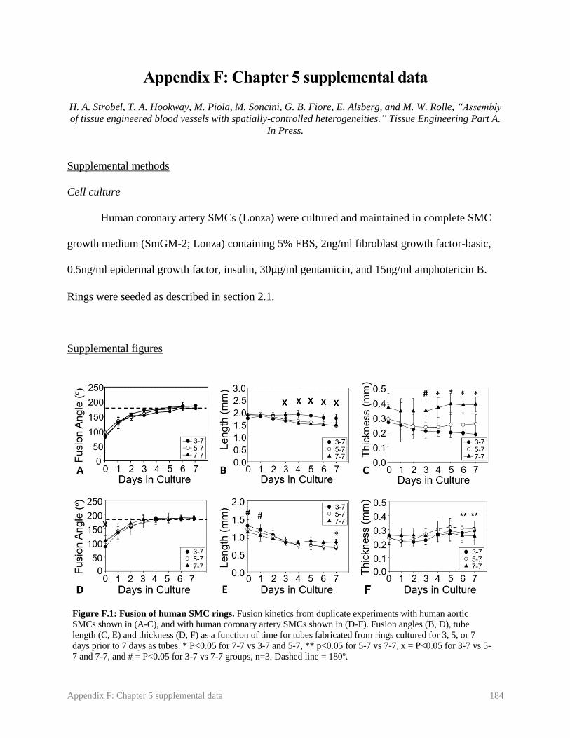
Appendix F: Chapter 5 supplemental data 184
Appendix F: Chapter 5 supplemental data
H. A. Strobel, T. A. Hookway, M. Piola, M. Soncini, G. B. Fiore, E. Alsberg, and M. W. Rolle, “Assembly
of tissue engineered blood vessels with spatially-controlled heterogeneities.” Tissue Engineering Part A.
In Press.
Supplemental methods
Cell culture
Human coronary artery SMCs (Lonza) were cultured and maintained in complete SMC
growth medium (SmGM-2; Lonza) containing 5% FBS, 2ng/ml fibroblast growth factor-basic,
0.5ng/ml epidermal growth factor, insulin, 30µg/ml gentamicin, and 15ng/ml amphotericin B.
Rings were seeded as described in section 2.1.
Supplemental figures
Figure F.1: Fusion of human SMC rings. Fusion kinetics from duplicate experiments with human aortic
SMCs shown in (A-C), and with human coronary artery SMCs shown in (D-F). Fusion angles (B, D), tube
length (C, E) and thickness (D, F) as a function of time for tubes fabricated from rings cultured for 3, 5, or 7
days prior to 7 days as tubes. * P<0.05 for 7-7 vs 3-7 and 5-7, ** p<0.05 for 5-7 vs 7-7, x = P<0.05 for 3-7 vs 5-
7 and 7-7, and # = P<0.05 for 3-7 vs 7-7 groups, n=3. Dashed line = 180º.

Appendix F: Chapter 5 supplemental data 185
Figure F.2: Fusion of human coronary artery SMC rings. Phase contrast images of 3-7 (A), 5-7 (B), and
7-7 (C) tubes over a 7 day fusion period. Scale = 1 mm. Images representative of n=3 samples per group.
Figure F.3: Fluorescent images of human coronary artery SMC ring fusion. Rings with alternating red and green
cell tracker were allowed to fuse for 7 days (A) prior to sectioning and Hoechst staining. Samples were sectioned after
2 (B-E) or 7 (F-I) days to determine whether cells within ring units maintain their spatial position. Blue = nuclei (B,
F). Red = CellTracker Red (C, G), green = CellTracker Green (D, H), and merged image shown in (E, I). Lumen on
left. Scale = 1 mm (A) or 100 µm (B-I). Images representative of n=3 samples per group per time point.

Appendix F: Chapter 5 supplemental data 186
Figure F.4: Contractile protein expression in aortic SMC tubes. Tubes fabricated from
human aortic SMCs were either kept in static conditions for 7 days (A), or kept in static
conditions for 7 days followed by 7 days of dynamic culture with approximately 12 dyne/cm2
of applied shear stress (B). Green = smooth muscle alpha actin, blue = nuclei. Lumen on
bottom of image. Scale = 100 µm.

Appendix G: Microsphere characterization 187
Appendix G: Microsphere characterization
For all experiments presented in this dissertation, cross-linked gelatin microspheres were
prepared and characterized by the Alsberg Lab at Case Western Reserve University. Microsphere
size and crosslink density analysis are presented in Table F.1. Microspheres were prepared and
characterized according to published protocols described in:
Dikina AD, Strobel HA, Lai BP, Rolle MW, Alsberg E. “Engineered cartilaginous tubes for
tracheal tissue replacement via self-assembly and fusion of human mesenchymal stem cell
constructs.” Biomaterials. 2015;52:452-62.
Batch
Average
Diameter (µm) Crosslink Density
(%) Experiments
1 47.5 ± 42.7 32.6 ± 6.1 Chapter 3 (Microsphere incorporation)
2 48.4 ± 41.9 35.7 ± 15.4
Chapter 3 (TGF-β1 delivery), Chapter 6
(Microsphere lesion with coronary artery
SMCs), Chapter 7
3 59.3 ± 28.8 32.3 ± 15.3
Chapter 6 (Microsphere lesion with aortic
SMCs, PDGF release)
4 51 ± 16 15
Chapter 6 (Fusion comparison), Chapter 8
(PDGF release)
5 50 ± 32 60 ± 7 Chapter 8 (FGF and TGF- β1 release)
Table G.1: Characterization of gelatin microspheres used for each experiment

Appendix H: Supplemental data for Chapter 8 188
Appendix H: Supplemental data for Chapter 8
Supplemental methods
Rings were prepared and analyzed as described in Chapter 8. Rings contained either
unloaded microspheres, with or without 5 ng/ml exogenous FGF (Peprotech, instead of Cell
Signaling as in Chapter 8), or with microspheres pre-loaded with 200 ng FGF per mg
microsphere.
Supplemental figures
Figure H.1: Effect of FGF treatment on ring thickness. Thickness measurements of rings at 3, 7, and 14 days
with unloaded microspheres and no FGF treatment (No FGF) or 5 ng/ml exogenous FGF (Ex FGF), or containing
microspheres loaded with 200 ng FGF per mg microspheres (FGF MS, A). Representative DVT images of rings in
each group shown in (B). * P<0.05 compared to no FGF and FGF MS groups within time point. Two-way ANOVA
with Holm-Sidak Post Hoc test. N = 3 for days 3 and 7, n = 5 for day 14. Bars are mean ± SEM. Scale bar = 1 mm

Appendix H: Supplemental data for Chapter 8 189
Figure H.2: Collagen deposition in rings with FGF treatment. Rings were
cultured for 3 (A-C), 7 (D-F), or 14 (G-I) days. Rings containing unloaded
microspheres were treated with no FGF (No FGF, A, D, G), 10ng/ml exogenous
FGF (Ex PDGF, B, E, H), or contained microspheres loaded with 400 ng FGF per
mg microspheres (FGF MS, C, F, I). Picrosirius Red/Fast Green stain (red =
collagen, green = counterstain). Lumen on bottom/right. Scale = 100µm.
Figure H.3: Proliferation in rings with FGF treatment. Rings containing
unloaded microspheres were treated with no FGF (No FGF, A-C), 10ng/ml
exogenous FGF (Ex FGF, D-F), or contained microspheres loaded with 400 ng FGF
per mg microspheres (FGF MS, G-I). Rings were stained at day 3 (A, D, G), 7 (B,
E, H), or 14 (C, F, I). Ki67 immunostain stain (brown = Ki67, purple = nuclei).
Lumen on bottom/right. Scale = 100µm.

Appendix H: Supplemental data for Chapter 8 190
Figure H.4: Contractile protein expression in FGF treated rings. Rings containing
unloaded microspheres were treated with no FGF (No FGF, A-C), 5ng/ml exogenous
FGF (Ex FGF, D-F), or contained microspheres loaded with 200 ng FGF per mg
microspheres (FGF MS, G-I). Rings were stained at day 14 for SMA (A, D, G), SM22-
α (B, E, H), or calponin (C, F, I). Green = contractile protein, blue = nuclei. Lumen on
bottom/right. Scale = 100µm. Rings are 14 days old.

Appendix I: Automation and scale-up of tissue tube production 191
Appendix I: Automation and scale-up of tissue tube production
C. J. Nycz, H. A. Strobel, K. Suqui, G. S. Fischer, M. W. Rolle, “A Method for High-Throughput
Automated Assembly of 3-Dimensional Vascular Tissue.” In Review.
Authorship contributions: CJN designed and built robotic punch, aided in design and fabrication of well-plates,
made schematic figures, co-wrote and edited manuscript. HAS contributed to design of robotic punch and well-
plates, performed fusion experiments, supervised KS and co-wrote manuscript. KS performed ring testing
experiments, contributed to well-plate design, and edited manuscript. GSF and MWR contributed to experimental
design, supervised data collection, data analysis, and preparation of the manuscript, and edited the manuscript.
CJN and HAS share first author credit.
Abstract
An essential step towards commercializing engineered tissues is to scale-up and automate
their production. This presents a challenge for self-assembled tissue systems, which are fragile at
early time points and difficult to handle using automated systems. The goal of this study was to
automate tissue engineered blood vessel (TEBV) fabrication by creating a custom cell seeding
and self-assembly system that is conducive to robotic manipulation, coupled with a robotic
system to assemble smooth muscle cell ring units into tissue tubes. To generate self-assembled
tissue ring units manually, cells are seeded at a high density into custom agarose wells that have
center posts (2 mm inner diameter), around which cells aggregate and contract to form rings.
Agarose is well-suited for cell seeding and ring self-assembly because it is non-cell adhesive, can
be autoclaved, and reproducibly cast to form wells using silicone templates. However, agarose
gel is soft, which makes reliable robotic manipulation challenging. To solve this problem, we
designed a custom ring self-assembly plate utilizing a polyetherimide (PEI) well plate with
MED610 3D-printed center posts and a MED610 well negative that allows the casting of
individual, annular agarose cell-seeding troughs within the PEI plate. Rings cultured in the new
plate system were morphologically similar to rings cultured in control agarose gels, and had a
slightly higher failure load. We created a unique robotic punch system to push tissue rings out of
the PEI-MED610 plate onto a stainless-steel mandrel to enable tube fusion. Tubes fabricated via
manual or automated ring removal and placement demonstrated similar morphology after tube
fusion, and the automated system substantially reduced the time required to fabricate tubes
manually. In summary, we developed a novel robotic assembly system to precisely manipulate
self-assembled tissue rings and enable scale-up and automation of TEBV biofabrication.

Appendix I: Automation and scale-up of tissue tube production 192
I.1. Introduction
Tissue engineered constructs have enormous potential as both implantable grafts, or as
tools for disease modeling and high throughput drug screening. A key step for translating these
technologies into marketable products is automating and scaling-up their production. Automation
can not only significantly reduce production time and increase output, but can also reduce human
error and improve product consistency. Technology has been developed for automated cell
seeding, passaging, and medium changes for 2D cell cultures, which are the first steps to creating
engineered tissue [1]. However, there are limited technologies available for scaling-up and
automating the fabrication of 3D engineered tissues.
Bio-printing is commonly used in additive manufacturing to create 3D tissue units [2-5].
With bio-printing, a wide range of scaffold-based cell-laden bio-inks [5, 6] or scaffold-free cell
spheroids [4] can be precisely patterned directly onto a surface. Layer-by-layer printing
approaches may allow for even more complex shapes, or multi-tissue structures [4, 7]. A major
disadvantage of bio-printing is that most machines have a limited resolution, and may not be able
to print small or micro-tissues [7]. In addition, bio-printing frequently relies on the fusion of
smaller tissue units into larger structures after printing. Spheroids are the most commonly used
tissue sub-units for both bio-printing and other additive manufacturing techniques because they
are relatively simple to fabricate [4, 8, 9]. However, constructs fabricated from even tightly
packed spheroids often have remaining gaps after fusion, as spheroidal units cannot be pushed
into complete contact with one another [4, 10, 11].
A major challenge with additive manufacturing of tissue engineered constructs is the
ability to lift individual tissue units and precisely place them together to build a complex
composite tissue structure. This may be especially challenging at early time points in culture,
when tissue is fragile. However, tissue units harvested at earlier time points are known to have
improved tissue fusion compared to more mature tissue units [12, 13], so it is essential that tissue
building blocks can be manipulated early in culture. Recently, robotic systems have been
developed that can precisely pick up and place self-assembled tissues [14, 15]. However, the
system is not completely automated, and the user must still manually place the tissue using a
series of positioning knobs. Additionally, it was difficult to stack toroidal tissue units precisely

Appendix I: Automation and scale-up of tissue tube production 193
enough for seamless tissue fusion, and individual tissue unit borders were still visible after 3
days of culture [14].
Additive manufacturing may be advantageous for fabrication of scaffold-free, self-
assembled tissues. Without any scaffold material, entirely cell-based tissues may not have the
structure needed to support a large construct, until they have secreted sufficient extracellular
matrix proteins. Creating smaller sub-units, and later fusing those sub-units, may aid in the
production of larger tissues. Cellular self-assembly approaches have advantages over scaffold-
based approaches, due to their biocompatibility, enhanced cell-cell and cell-matrix interactions,
and physiologically relevant mechanical properties [16-19]. These characteristics make cellular
self-assembly ideal for fabricating many different tissue types, including tissue engineered blood
vessels (TEBVs) [19-22]. Our lab has developed a unique system for creating self-assembled
TEBVs from individual tissue-ring subunits [23, 24]. Briefly, cells are seeded into an agarose
well with a center post, where they aggregate together to form vascular tissue rings. Vascular
tissue ring units can then be threaded onto a mandrel, pushed together, and fused into tubes [23,
25], as shown schematically in Figure I.1. Rings may fuse more seamlessly than spheroids, as
greater portions of ring surface area are in contact with one another, making them more
conducive to TEBV
fabrication.
Our overall goal
is to develop a
completely automated
robotic assembly
system to scale up the
fabrication of TEBVs
for commercial
purposes (Figure I.2), for use as either implantable grafts or as tools for high-throughput drug
screening. In this study, we focus on developing a means to automatically remove rings from
agarose gels and thread them onto mandrels for fusion. There are currently no other systems
available that are suitable for this purpose.
To do this, we first re-designed the agarose gels used for ring self-assembly. Agarose is
well-suited for enabling cellular aggregation due to its non-cell-adhesive properties, but the
Figure I.1: Manual method for fabrication of self-assembled vascular tissue
rings and tubes. Cells are seeded into individual ring-shaped agarose wells, where
they aggregate to form self-assembled tissue rings. Tissue rings are manually
harvested and threaded onto silicone tubing mandrels, where they remodel and fuse
together to form a tissue tube.
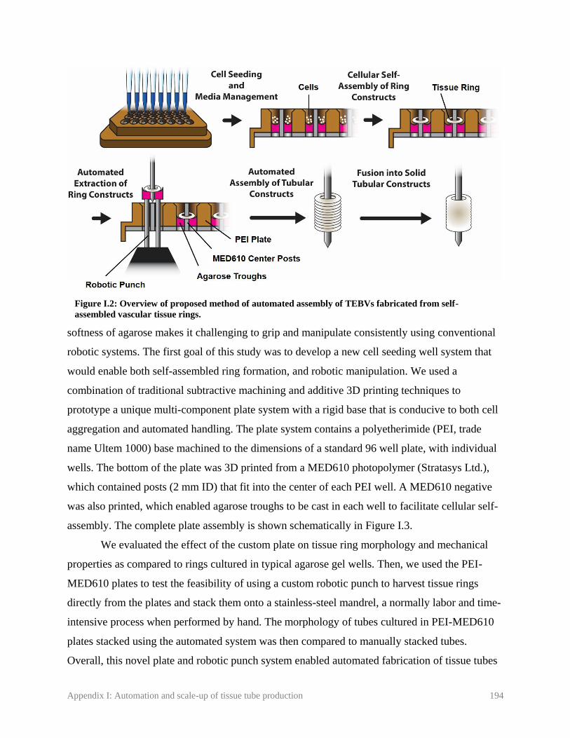
Appendix I: Automation and scale-up of tissue tube production 194
softness of agarose makes it challenging to grip and manipulate consistently using conventional
robotic systems. The first goal of this study was to develop a new cell seeding well system that
would enable both self-assembled ring formation, and robotic manipulation. We used a
combination of traditional subtractive machining and additive 3D printing techniques to
prototype a unique multi-component plate system with a rigid base that is conducive to both cell
aggregation and automated handling. The plate system contains a polyetherimide (PEI, trade
name Ultem 1000) base machined to the dimensions of a standard 96 well plate, with individual
wells. The bottom of the plate was 3D printed from a MED610 photopolymer (Stratasys Ltd.),
which contained posts (2 mm ID) that fit into the center of each PEI well. A MED610 negative
was also printed, which enabled agarose troughs to be cast in each well to facilitate cellular self-
assembly. The complete plate assembly is shown schematically in Figure I.3.
We evaluated the effect of the custom plate on tissue ring morphology and mechanical
properties as compared to rings cultured in typical agarose gel wells. Then, we used the PEI-
MED610 plates to test the feasibility of using a custom robotic punch to harvest tissue rings
directly from the plates and stack them onto a stainless-steel mandrel, a normally labor and time-
intensive process when performed by hand. The morphology of tubes cultured in PEI-MED610
plates stacked using the automated system was then compared to manually stacked tubes.
Overall, this novel plate and robotic punch system enabled automated fabrication of tissue tubes
Figure I.2: Overview of proposed method of automated assembly of TEBVs fabricated from self-
assembled vascular tissue rings.

Appendix I: Automation and scale-up of tissue tube production 195
from individual ring sub-units.
I.2. Methods
I.2.1. Mold design
The new PEI-MED610 plate system consists of a custom 96-well plate, a center-post
plate inserted from the bottom, and a removable well negative for casting agarose cell seeding
troughs (Fig. I.3). The 96-well plate is machined from PEI (UltemTM 1000, SABIC,) plastic, with
dimensions based on
ANSI SLAS 4-2004
(R2012) standards for a
96 well microplate. PEI
plates contain bottomless
wells with a 6mm
diameter to match the
dimension of our control
agarose gel system [23,
24], that flare out to
9mm at the top of the
well to match the 96 well
microplate footprint. An array of 2mm center posts that fit within the wells of the PEI plate was
3D printed from MED610 (Stratasys Ltd.) material using a photopolymer printer (Object Connex
260, Stratasys Ltd.). The well negative is also printed from MED610 material, which, when
inserted in the PEI plate, allows agarose troughs to be cast within the PEI plate wells. For the
prototype testing presented in this study, the 96-well plate format was scaled down to 16 wells (2
rows) to reduce the amount of reagents and cells required.
I.2.2. Cell culture
Rat aortic smooth muscle cells (WKY-3M22 [26]) were cultured in medium comprised of
Dulbecco’s Modified Eagle Medium (DMEM) supplemented with 10% fetal bovine serum, 1%
non-essential amino acids, 1% L-glutamine, 1% sodium pyruvate, and 1% penicillin-
streptomycin.
Figure I.3: PEI-MED610 plate system. A MED610 center post plate fits under
the open-bottomed PEI 96 well plate. A MED610 negative sits on top of the 96
well plate, to allow casting of rounded-bottom agarose troughs in each well.

Appendix I: Automation and scale-up of tissue tube production 196
I.2.3. Agarose gel preparation
For the control configuration in this study, agarose gels were fabricated as described
previously [24]. Two percent agarose (Lonza) in DMEM was autoclaved and poured into PDMS
templates. When cooled, each agarose gel was removed from the PDMS, placed into a well of a
6 well plate, and allowed to equilibrate overnight in culture medium prior to use. Each agarose
gel contained wells for 5 individual rings (2mm ID; Figure I.1) [24].
To prepare PEI-MED610 plates for the proposed automated approach, the assembled
plate was ethylene oxide sterilized and allowed to de-gas 48 hours prior to use. A solution of 3%
Low Melting Temperature Agarose (Lonza) in DMEM was autoclaved and allowed to
equilibrate for 30 minutes in a 45ºC water bath. This allowed the agarose to cool to a temperature
below 52°C to avoid damaging the 3D printed MED610 pieces. Agarose was then carefully
pipetted into the assembled PEI-MED610 plate system and allowed to solidify. The well
negative was removed, and a hydrophobic 1% Pluronic F-127 (Thermo Fisher) solution was
pipetted into wells to reduce cellular adhesion to the PEI components in the plate wells. After
incubating 15 minutes at room temperature, the Pluronic was aspirated and the well plate was
equilibrated overnight in culture medium prior to use.
I.2.4. Ring fabrication
Rings were seeded as described previously [24]. Briefly, cells were trypsinized and
resuspended at a final concentration of 10 million cells per ml. 500,000 cells per ring were
seeded into each well of either control agarose gels or PEI-MED610 plates. On day 1, wells are
flooded with fresh culture medium. Culture medium was changed after two days.
I.2.5. Mechanical testing
After 4 days of culture, rings were removed from molds and placed in a dish filled with
phosphate-buffered saline (PBS). Rings were placed under a machine vision system (DVT series
600-Model 630), and thickness measurements were taken in 4 locations around the ring
circumference with edge detection software (Framework 2.4.6., DVT Corp.) [21]. Average ring
thickness was used to calculate ring cross-sectional area. Rings were then loaded onto a custom
grip setup submerged in PBS, subjected to 8 pre-cycles from 1-5 mN, and then pulled to failure

Appendix I: Automation and scale-up of tissue tube production 197
at a rate of 10mm/min using an ElectroPuls E1000 (Instron). Failure load and ultimate tensile
stress (UTS, failure load/ring cross sectional area) were recorded.
I.2.6. Histology
After 4 days of culture, rings were fixed for 1 hour in 10% neutral buffered formalin,
processed, and paraffin embedded. 5µm sections were prepared and adhered to charged glass
slides. A Hematoxylin and Eosin stain was used to visualize tissue morphology, and a Picrosirius
Red/Fast Green stain was used to visualize extracellular matrix deposition. Images of stained
tissue sections were acquired with an upright microscope (Leica DMLB2 with DFC 480 digital
camera).
I.2.7. Robotic punch design
To extract self-assembled tissue rings from the PEI plates and assemble them into a
tubular construct, we developed an automation platform controlled by a simple graphical user
interface. The system indexes to each well of the PEI-MED610 plate, lowers a 316 stainless steel
mandrel over the well's center post, and punches 4 titanium rods up through the agarose troughs
to thread the ring onto the mandrel. Steel mandrels have a thin coating of USP class VI epoxy
(EP42HT-2MED, Master Bond Inc.) applied to the tip to help prevent rings from sliding off after
automated stacking. A diagrammatic representation of the ring extraction process is shown in
Figure I.4. The platform uses two high resolution linear ball screw stages with ±3μm
repeatability (404100XRMS,
Parker Hannifin Corporation)
to position a bottomless tray
holding the PEI-MED610 plate
between punch and mandrel.
The punch and mandrel are
mounted to two pneumatic
linear slides (13-MXS16-30,
SMC Corporation) allowing
motion in the vertical direction.
To ensure rigidity, the frames
Figure I.4: Schematic of robotic process to remove tissue rings from a
PEI-MED610 plate. A 4-prong punch pushes through a cast agarose
trough and moves self-assembled tissue rings onto a stainless steel mandrel.
As the mandrel is lifted away from the well, an aluminum agarose remover
removes any remaining agarose while the tissue ring stays in place.

Appendix I: Automation and scale-up of tissue tube production 198
supporting the linear slides and PEI-MED610 plate were machined from aluminum with system
components mounted to a thick polycarbonate base. All components fit inside a standard tissue
culture hood. Images of the robotic assembly system are shown in Figure I.5. All components
that come in direct contact with the PEI-MED610 plate system are removable and autoclavable.
After autoclaving, parts are re-attached inside the cell culture hood with sterile surgical gloves.
To control the system, a graphical user interface created in Matlab2016a (Mathworks
Inc.) outputs tray positions and punch commands over RS-232 serial communication to a 2-axis
motion controller (Compumotor 6K2, Parker Hannifin Corp.). Magnetic limit switches are used
for the homing calibration process of the positional stages and for checking the current positions
of the pneumatic slides. Absolute position commands are given to the controller based on a
measured offset between the home position and the first well. Pneumatic slide positions are used
for error checking, locking out the system from indexing while punch or mandrel are not clear of
the PEI-MED610 plate.
I.2.8. Tube fabrication
Smooth muscle cell rings were cultured for 4 days in either control agarose gels or PEI-
Figure I.5: Robotic assembly system in cell culture hood. A positional stage moves the PEI-MED610 plate
over a 4-prong punch. The punch pushes rings out of the well and up onto a stainless steel mandrel. For testing,
a shortened 16-well plate format was used to reduce the amount of reagents and cells required to evaluate
iterative prototype changes.

Appendix I: Automation and scale-up of tissue tube production 199
MED610 plates prior to harvesting for tube fabrication. PEI-MED610 plates were loaded onto
the robotic platform inside a cell culture hood, and automatically punched out of the plate and
onto a stainless-steel mandrel. A brief 10 second dwell period was included between the removal
of each ring from its well and the punch retraction, to allow rings to contract around the mandrel.
Rings in the PEI-MED610 plate and on the mandrels were periodically hydrated with culture
medium using a pipet. Mandrels with stacked rings were then loaded into custom polycarbonate
holders for fusion culture [21]. For control tubes, rings are manually threaded with forceps onto
either silicone mandrels as previously described [21], or onto the stainless steel mandrels that
were used for the automated procedure and secured in custom polycarbonate holders, to evaluate
the effect of mandrel material on ring fusion. All tubes were then allowed to fuse in culture for 4
days prior to fixing 1.5 hours in 10% neutral buffered formalin, followed by processing and
sectioning for histological staining.
I.2.9. Statistics
Statistical analysis was performed using SigmaPlot Software (Systat, version 12.5) on
ring thickness, failure load, and ultimate tensile stress. A student’s t test was performed to
analyze statistical differences between mechanically tested rings on data with a normal
distribution. A Mann-Whitney test was used to compare data that failed a normality test.
I.3. Results
I.3.1. Ring fabrication in PEI-MED610 plate system
Because agarose gels are soft and challenging to manipulate with robotic systems, we
developed a new 3-part plate system utilizing MED610 3D printed posts and plate negative, and
PEI machined 96-well plate. To ensure the change in well material and format did not adversely
affect cellular self-assembly, ring morphology, and tissue mechanical strength, we compared
rings cultured in control agarose gels to rings cultured in the PEI-MED610 plates (Fig I.6A). We
observed no significant differences in ring thickness (0.42 ± 0.02 mm and 0.44 ± 0.04 mm, rings
cultured in agarose vs PEI-MED610 plates, respectively; Fig I.6B). There was a slight increase
in ultimate tensile stress (UTS; 30.5 ± 7.9 and 45.7 ± 14.9 kPa for rings cultured in agarose vs.
PEI-MED610 molds; Fig I.6C) although this was not significant. There was significant increase
in maximum load at failure (failure load) when rings were cultured in the PEI-MED610 plates

Appendix I: Automation and scale-up of tissue tube production 200
(8.6 ± 2.1 and 14.2 ± 4.6 mN for
rings cultured in agarose vs.
PEI-MED610 plates, Fig I.6D).
When examined
morphologically, no visible
differences were observed
between rings cultured in
control agarose gels or PEI-
MED610 plates, either
macroscopically (Fig I.7 A, B)
or by Hematoxylin and Eosin
staining (Fig I.7 C, D). Collagen
deposition was visible in both
groups, with no apparent
differences (Fig I.7 E, F).
I.3.2. Automation system
For testing the robotic punch, two PEI-MED610 plates were used. When preparing PEI-
MED610 plates, 10 out of 16 agarose troughs successfully formed on the first plate, and 14 out
of 16 on the second. Rings were seeded in all plate wells with agarose troughs, although one ring
on each plate broke within 24 hours of seeding. From the first plate, 6 out of 9 self-assembled
tissue rings were successfully pushed onto the mandrel; 5 out of 13 were successfully pushed
onto the mandrel from plate 2. During pilot testing, we determined that a 10 second pause after
pushing the ring onto the mandrel, before retracting the punch, helped prevent rings from sliding
off the mandrel when the remnant agarose gels are removed. Still, some rings did slide off the
mandrel, which contributed to this reduced yield. Additionally, some rings broke during removal
from the PEI-MED610 plate. Four out of 28 rings failed during manual stacking of control rings
and could not be used. Ring failure rates are summarized in Table I.1.
Figure I.6: Structure and strength of tissue rings grown in PEI-
MED610 plates compared to control agarose gels. Images of 4 day-old
rings cultured in agarose gels (left) or PEI-MED610 plates (right) shown
in (A). Comparisons of ring thickness (B), ultimate tensile stress (C), and
maximum load at failure (D). * P<0.05. A non-parametric t-test was used
for (B) and (C), and a Mann Whitney test in (D). Scale bar = 1mm. N = 6
for rings cultured in agarose controls, n = 8 for rings cultured in PEI-
MED610 plates.

Appendix I: Automation and scale-up of tissue tube production 201
Table I.2: Failure rates of tissues rings stacked manually or automatically.
Total rings
seeded
Ring failures
during culture
Ring failures during
stacking
Time required to
stack 96 rings
Control agarose gels 28 0 4 3.49 hours
PEI-MED610 plates 24 2 11 0.45 hours
After initial setup, the robotic assembly system
reduced the time required to remove rings from their
cell seeding molds and thread them onto a mandrel to
fabricate tissue tubes. To manually stack 28 rings onto
2 silicone mandrels (including 4 rings that broke during
manual placement) took approximately 61 minutes,
which averages to approximately 2.2 minutes per ring.
This is compared to 17 seconds per ring to remove and
stack each ring using the automated system. These
times include time lost due to failed rings. For
reference, on a 96-well plate this translates to 0.45
hours for the automated approach and 3.49 hours for
the manual approach. Because of this increased speed,
even when accounting for the observed 54% ring
failure rate, the PEI-MED610 plates can still stack
approximately 3.5 times as many rings as a human in
the same amount of time.
I.3.3. Tube fusion following automated ring stacking
To evaluate if either the automated stacking
procedure or stainless-steel mandrels affected ring fusion, 5-6 rings/tube (n = 2 tubes per group)
were fused for 4 days following automated stacking or manual stacking onto stainless steel or
silicone mandrels. Photographs of tubes after fusion are shown in Figure I.8A-C. Longitudinal
sections of fixed tubes (Fig I.8D-F) show that rings in all three groups have fused, although ring
Figure I.7: Morphology of self-assembled
tissue rings cultured in agarose gels or PEI-
MED610 plates. Photographs of tissue rings
in cell seeding wells (A) and (B), PEI plate has
been removed from (B), so only rings around
MED610 posts are shown. Ring sections were
stained with Hematoxylin and Eosin (C, D) or
Picrosirius Red/Fast Green (E, F; red =
collagen, green = counterstain). Rings in (A)
and (B) are 2mm ID. Scale = 100µm (C-F).
Sections representative of n = 3 rings. Arrows
point to rings (A, B).

Appendix I: Automation and scale-up of tissue tube production 202
boundaries are still distinct. Rings and tubes appeared slightly longer in the PEI-MED610 group.
A slight growth of cells up the PEI posts was observed, causing a slight increase in ring “height,”
which may have contributed to the increased tube length.
I.4. Discussion
Automation is key to scaling up the production of human tissues for commercial use,
either as implantable grafts or as tools for high throughput drug screening. Here, we developed a
unique tissue ring self-assembly plate, and robotic tube assembly system, and demonstrated the
feasibility of automatic assembly of modular TEBVs fabricated from individual ring units.
The first goal of our study was to develop a new well system for seeding smooth muscle
cell rings that both had a rigid frame conducive to robotic manipulation, and enabled cellular
self-assembly. Thus, we developed a 3-part plate system using a PEI plate with individual open-
bottom wells, 3D printed MED610 center posts, and a MED610 well negative that enabled the
casting of agarose troughs in the PEI plate wells. In addition to providing a non-adhesive cell
seeding and ring self-assembly surface, the agarose troughs also enabled ring harvesting by
punching through the agarose well bottoms to push the rings out of the plate and onto the
stainless steel mandrel in the robotic assembly system.
Figure I.8: Fusion of automatically or manually fabricated tissue tubes. Tissue rings were either
automatically stacked onto stainless steel mandrels using the robotic assembly system (A, D), or manually
stacked onto stainless steel (B, E) or silicone (C, F) mandrels. Photographs of tubes after 4 days of fusion
(A-C). Hematoxylin and Eosin stain of fused tube tissue sections (D-F). Scale = 0.5mm. N = 2.

Appendix I: Automation and scale-up of tissue tube production 203
The described PEI-MED610 plate system is a result of several design iterations. Initially,
all parts were fabricated from MED610 photopolymer, due to the one-step 3D printing process,
and its status as a USP plastic class VI, indicating it is safe to be in contact with tissues [27].
After seeding cells in the MED610-only mold, we observed cells failing to self-assemble into
tissue rings, possibly because they adhered to the material. Thus, we developed a hybrid system,
and used a PEI thermoplastic for the bulk of the plate system. PEI was chosen due to its
availability, machinability, and previous use in culture of other cell types [28]. We continued to
use 3D-printing to generate the MED610 post insert plate, as the shape of this piece could be
made easily with other prototyping methods, and the small amount of MED610 in the posts did
not appear to affect ring formation. A 3D-printed MED610 negative that fit over the plate
assembly enabled us to cast agarose troughs in the bottoms of each well in the assembled plate,
which are non-cell adhesive and enable cellular self-assembly. While rings successfully formed
with this method, they still adhered slightly to the MED610 posts, which made it challenging to
remove them from the wells. This issue was addressed by adding a Pluronic coating in our
current prototype, which prevents cell adhesion to materials [29].
After implementing the PEI-MED610 plate system, we evaluated the effects of the new
plate materials on ring formation, morphology, and mechanical strength. Overall, both groups
had a low failure load and UTS, which is likely due to the short 4-day ring culture duration used
in this study (compared to previous mechanical testing studies of 2 mm rat smooth muscle cell
tissue rings, typically cultured for at least 14 days [21, 23]). With the PEI-MED610 plate system,
we observed a significant increase in maximum load at ring failure compared to rings cultured in
agarose gels. It is possible that the larger quantity of culture medium required for the new culture
system contributed to this improvement. The PEI-MED610 plates are placed in a glass dish for
culture, and required approximately 70 ml of medium to cover a plate containing 16 rings. This
is substantially more than our agarose gel system [30], which uses 4.5ml medium in each well of
a 6 well plate, which covers 5 rings in an agarose gel. Most importantly, this indicates that the
PEI-MED610 plates did not adversely affect ring formation or mechanical properties, and can be
used as an alternative to pure agarose gels for culturing tissue rings for automated assembly.
The presented robotic assembly system is advantageous due to its simple design and
compatibility with existing standards for lab automation. The device requires only a

Appendix I: Automation and scale-up of tissue tube production 204
commercially available 2-axis positioning stage and two commercially available linear slides
with no additional moving linkages, degrees of freedom, grippers, or extruders. Other systems
for manipulating engineered tissue are limited, and may be significantly more expensive and
complex to build.
This design was well-suited for the task of tissue ring extraction and stacking, and
substantially reduced the amount of time required to fabricate tubes compared to stacking by
hand. However, some future optimization is still required to reduce failure rates. For example,
despite the thin epoxy layer on the mandrel tip (to slightly increase friction), failures sometimes
resulted when rings slid off the mandrel, and followed the punch back down into its’ original
well. This could be addressed in future work by optimizing the mandrel shape and surface finish
to prevent slipping. A small number of rings also failed during punching. This may be improved
by optimizing culture conditions to increase ring strength. Despite these failures, we were still
able to precisely move 3.5 times as many rings onto mandrels as a human can manually stack in
the same amount of time.
After automated or manual stacking of rings, rings were allowed to fuse for 4 days in
culture. After 4 days, we observed ring fusion regardless of mandrel type or stacking method.
Ring boundaries are still visible in all groups, which is consistent with our previously published
work with rat aortic smooth muscle cells [23]. Fusion may improve with longer culture times, as
tubes were only allowed to fuse for 4 days (following 4 days of ring culture, for 8 days total
culture). Boundaries are primarily visible on the luminal side, which may improve if tubes are
cultured with luminal flow later in culture. In longitudinal tube sections, rings that had been
cultured in the PEI-MED610 plate appeared longer than rings cultured in agarose gels. While we
did not observe differences in ring thickness when viewed from above, rings did appear to grow
out along the length of the MED610 posts, resulting in slightly increased ring height compared to
agarose wells with agarose center posts. However, this does not appear to have negatively
affected ring fusion, mechanical properties, or our ability to remove rings from the PEI-MED610
plate system. Such rings may even enable us to make longer tubes without the need for
additional cells and reagents.
Another challenge to automated tissue fabrication is maintaining sterility. After 4 days of
fusion culture post-automated stacking, there was no visible contamination, indicating that

Appendix I: Automation and scale-up of tissue tube production 205
autoclaving machined parts that came in direct contact with the tissue rings and culture wells was
sufficient to maintain sterility.
Future work will involve automating other components of the tube fabrication process,
such as cell seeding and medium management. PEI-MED610 plates are designed to mimic the
dimensions of a standard 96 well plate, which will enable the use of these existing automation
technologies for this purpose [1]. The stacking procedure presented here is perhaps the most
challenging step in fully automating production of engineered blood vessels from ring modules.
Here, we demonstrated the feasibility of using a robotic punch to push self-assembled tissue
rings up out of a custom designed hybrid PEI-MED610 plate and onto a steel mandrel, where
they fuse to form a tissue tube. This automatic system substantially reduced time required to
fabricate tubes, and is a critical step for creating a fully automated tissue tube fabrication system.
Scaling-up the tube fabrication process allows for increased production and may improve
product consistency, which is an essential step towards commercializing any tissue engineered
product. The PEI-MED610 plate and robotic punch system is a step towards complete
automation and scale-up of vascular graft fabrication, which may be applied more broadly to
biofabrication of other tubular tissues, such as trachea [31, 32].
I.5. References
1. Thomas, R.J., D. Anderson, A. Chandra, N.M. Smith, L.E. Young, D. Williams, and C.
Denning, Automated, scalable culture of human embryonic stem cells in feeder-free
conditions. Biotechnol Bioeng, 2009. 102(6): p. 1636-44.
2. Marga, F., K. Jakab, C. Khatiwala, B. Shepherd, S. Dorfman, B. Hubbard, S. Colbert, and
G. Forgacs, Toward engineering functional organ modules by additive manufacturing.
Biofabrication, 2012. 4(2): p. 022001.
3. Duan, B., State-of-the-Art Review of 3D Bioprinting for Cardiovascular Tissue
Engineering. Ann Biomed Eng, 2016.
4. Norotte, C., F.S. Marga, L.E. Niklason, and G. Forgacs, Scaffold-free vascular tissue
engineering using bioprinting. Biomaterials, 2009. 30(30): p. 5910-7.
5. Bartolo, P., M. Domingos, A. Gloria, and J. Ciurana, BioCell Printing: Integrated
automated assembly system for tissue engineering constructs. CIRP Annals -
Manufacturing Technology, 2011. 60(1): p. 271-274.
6. Gao, G., J.H. Lee, J. Jang, D.H. Lee, J.-S. Kong, B.S. Kim, Y.-J. Choi, W.B. Jang, Y.J.
Hong, S.-M. Kwon, et al., Tissue Engineered Bio-Blood-Vessels Constructed Using a

Appendix I: Automation and scale-up of tissue tube production 206
Tissue-Specific Bioink and 3D Coaxial Cell Printing Technique: A Novel Therapy for
Ischemic Disease. Advanced Functional Materials, 2017. 27(33): p. 1700798.
7. Mekhileri, N.V., K. Lim, G.C.J. Brown, I. Mutreja, B.S. Schon, G.J. Hooper, and T.B.F.
Woodfield, Automated 3D bioassembly of micro-tissues for biofabrication of hybrid
tissue engineered constructs. Biofabrication, 2017.
8. Jakab, K., A. Neagu, V. Mironov, R.R. Markwald, and G. Forgacs, Engineering
biological structures of prescribed shape using self-assembling multicellular systems.
Proceedings of the National Academy of Sciences of the United States of America, 2004.
101(9): p. 2864-2869.
9. Mironov, V., R.P. Visconti, V. Kasyanov, G. Forgacs, C.J. Drake, and R.R. Markwald,
Organ printing: tissue spheroids as building blocks. Biomaterials, 2009. 30(12): p. 2164-
2174.
10. Tan, Y., D.J. Richards, T.C. Trusk, R.P. Visconti, M.J. Yost, M.S. Kindy, C.J. Drake,
W.S. Argraves, R.R. Markwald, and Y. Mei, 3D printing facilitated scaffold-free tissue
unit fabrication. Biofabrication, 2014. 6(2): p. 1-11.
11. Twal, W.O., S.C. Klatt, K. Harikrishnan, E. Gerges, M.A. Cooley, T.C. Trusk, B. Zhou,
M.G. Gabr, T. Shazly, S.M. Lessner, et al., Cellularized microcarriers as adhesive
building blocks for fabrication of tubular tissue constructs. Ann Biomed Eng, 2014.
42(7): p. 1470-81.
12. Rago, A.P., D.M. Dean, and J.R. Morgan, Controlling cell position in complex
heterotypic 3D microtissues by tissue fusion. Biotechnol Bioeng, 2009. 102(4): p. 1231-
41.
13. Bhumiratana, S., R.E. Eton, S.R. Oungoulian, L.Q. Wan, G.A. Ateshian, and G. Vunjak-
Novakovic, Large, stratified, and mechanically functional human cartilage grown in
vitro by mesenchymal condensation. PNAS, 2014. 111(19): p. 6940-6945.
14. Blakely, A.M., K.L. Manning, A. Tripathi, and J.R. Morgan, Bio-Pick, Place, and
Perfuse: A New Instrument for Three-Dimensional Tissue Engineering. Tissue Eng Part
C Methods, 2015. 21(7): p. 737-46.
15. Ip, B.C., F. Cui, A. Tripathi, and J.R. Morgan, The bio-gripper: a fluid-driven micro-
manipulator of living tissue constructs for additive bio-manufacturing. Biofabrication,
2016. 8(2): p. 025015.
16. L'Heureux, N., S. Paquet, R. Labbe, L. Germain, and F.A. Auger, A completely biological
tissue-engineered human blood vessel. FASEB J, 1998. 12(1): p. 47-56.
17. Adebayo, O., T.A. Hookway, J.Z. Hu, K.L. Billiar, and M.W. Rolle, Self-assembled
smooth muscle cell tissue rings exhibit greater tensile strength than cell-seeded fibrin or
collagen gel rings. J Biomed Mater Res A, 2013. 101(2): p. 428-37.
18. Hayashi, K. and Y. Tabata, Preparation of stem cell aggregates with gelatin
microspheres to enhance biological functions. Acta Biomater, 2011. 7(7): p. 2797-803.
Appendix I: Automation and scale-up of tissue tube production 207
19. Kelm, J.M., V. Lorber, J.G. Snedeker, D. Schmidt, A. Broggini-Tenzer, M. Weisstanner,
B. Odermatt, A. Mol, G. Zund, and S.P. Hoerstrup, A novel concept for scaffold-free
vessel tissue engineering: self-assembly of microtissue building blocks. J Biotechnol,
2010. 148(1): p. 46-55.
20. Wystrychowski, W., T.N. McAllister, K. Zagalski, N. Dusserre, L. Cierpka, and N.
L'Heureux, First human use of an allogeneic tissue-engineered vascular graft for
hemodialysis access. J Vasc Surg, 2014. 60(5): p. 1353-7.
21. Gwyther, T.A., J.Z. Hu, K.L. Billiar, and M.W. Rolle, Directed cellular self-assembly to
fabricate cell-derived tissue rings for biomechanical analysis and tissue engineering. J
Vis Exp, 2011(57): p. e3366.
22. McAllister, T.N., M. Maruszewski, S.A. Garrido, W. Wystrychowski, N. Dusserre, A.
Marini, K. Zagalski, A. Fiorillo, H. Avila, X. Manglano, et al., Effectiveness of
haemodialysis access with an autologous tissue-engineered vascular graft: a multicentre
cohort study. Lancet, 2009. 373: p. 1440-46.
23. Gwyther, T.A., J.Z. Hu, A.G. Christakis, J.K. Skorinko, S.M. Shaw, K.L. Billiar, and
M.W. Rolle, Engineered vascular tissue fabricated from aggregated smooth muscle cells.
Cells Tissues Organs, 2011. 194(1): p. 13-24.
24. Strobel, H.A., E.L. Calamari, B. Alphonse, T.A. Hookway, and M.W. Rolle, Fabrication
of Custom Agarose Wells for Cell Seeding and Tissue Ring Self-assembly Using 3D-
Printed Molds. JoVE, 2018. 134: p. e56618.
25. Strobel, H.A., E.L. Calamari, A. Beliveau, A. Jain, and M.W. Rolle, Fabrication and
characterization of electrospun polycaprolactone and gelatin composite cuffs for tissue
engineered blood vessels. JBMR Part B, 2018. 106B(2): p. 817-826.
26. Lemire, J.M., S. Potter-Perigo, K.L. Hall, T.N. Wight, and S.M. Schwartz, Distinct Rat
Aortic Smooth Muscle Cells Differ in Versican/PG-M Expression. Arteriosclerosis,
Thrombosis, and Vascular Biology, 1996. 16(6): p. 821-829.
27. MED610 Polyjet Biocompatible Photopolymer. ForeCast 3D.
28. Tao, C.-T. and T.-H. Young, Polyetherimide membrane formation by the cononsolvent
system and its biocompatibility of MG63 cell line. Journal of Membrane Science, 2006.
269(1-2): p. 66-74.
29. Boxshall, K., M.-H. Wu, Z. Cui, Z. Cui, J.F. Watts, and M.A. Baker, Simple surface
treatments to modify protein adsorption and cell attachment properties within a
poly(dimethylsiloxane) micro-bioreactor. Surface and Interface Analysis, 2006. 38(4): p.
198-201.
30. Strobel, H.A., A.D. Dikina, K. Levi, L.D. Solorio, E. Alsberg, and M.W. Rolle, Cellular
self-assembly with microsphere incorporation for growth factor delivery within
engineered vascular tissue rings. Tissue Eng Part A, 2017. 23(3-4): p. 143-155.

Appendix I: Automation and scale-up of tissue tube production 208
31. Dikina, A.D., H.A. Strobel, B.P. Lai, M.W. Rolle, and E. Alsberg, Engineered
cartilaginous tubes for tracheal tissue replacement via self-assembly and fusion of human
mesenchymal stem cell constructs. Biomaterials, 2015. 52: p. 452-62.
32. Dikina, A., D. Alt, S. Herberg, A. McMillan, H. Strobel, Z. Zheng, M. Cao, B. Lai, O.
Jeon, V.I. Petsinger, et al., A Modular Strategy to Engineer Complex Tissues and Organs.
Advanced Science, 2017.