Embed Size (px)
Citation preview
TOP Server 5.19
Configuration Guide:
Enron Modbus Device
Page 2 of 27
Table of Contents
Introduction 3
Channel Setup 3
Device Setup 10
Further Information 27
Page 3 of 27
Introduction
This document is intended to provide an easy to use reference guide on configuring a connection to a
Enron Modbus device using the TOP Server. It is not intended to be comprehensive, and the help file
should be referenced for any additional information – if needed. This document will describe the channel
and device setup, give a summary of the settings that will be encountered – and when it is appropriate to
change them from the default values.
Channel Setup
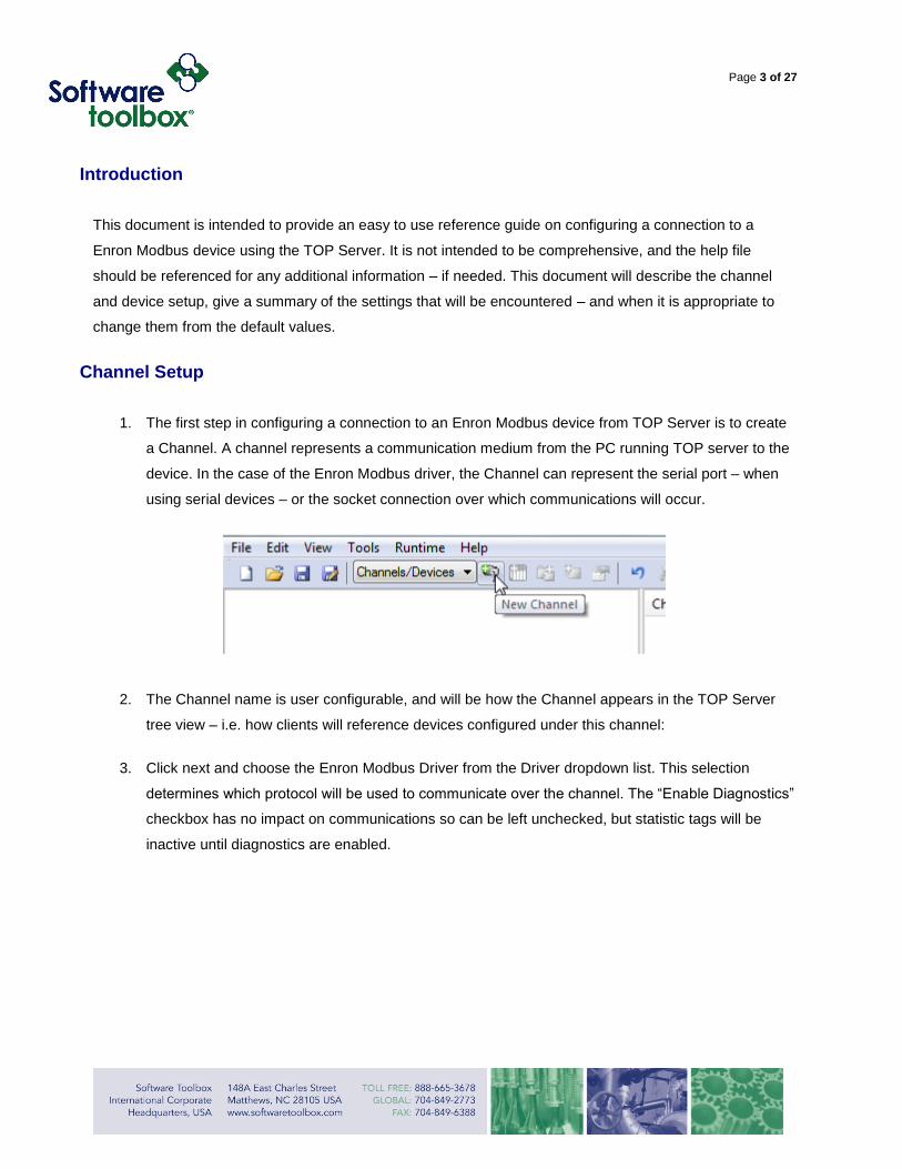
1. The first step in configuring a connection to an Enron Modbus device from TOP Server is to create
a Channel. A channel represents a communication medium from the PC running TOP server to the
device. In the case of the Enron Modbus driver, the Channel can represent the serial port – when
using serial devices – or the socket connection over which communications will occur.
2. The Channel name is user configurable, and will be how the Channel appears in the TOP Server
tree view – i.e. how clients will reference devices configured under this channel:
3. Click next and choose the Enron Modbus Driver from the Driver dropdown list. This selection
determines which protocol will be used to communicate over the channel. The “Enable Diagnostics”
checkbox has no impact on communications so can be left unchecked, but statistic tags will be
inactive until diagnostics are enabled.
Page 4 of 27
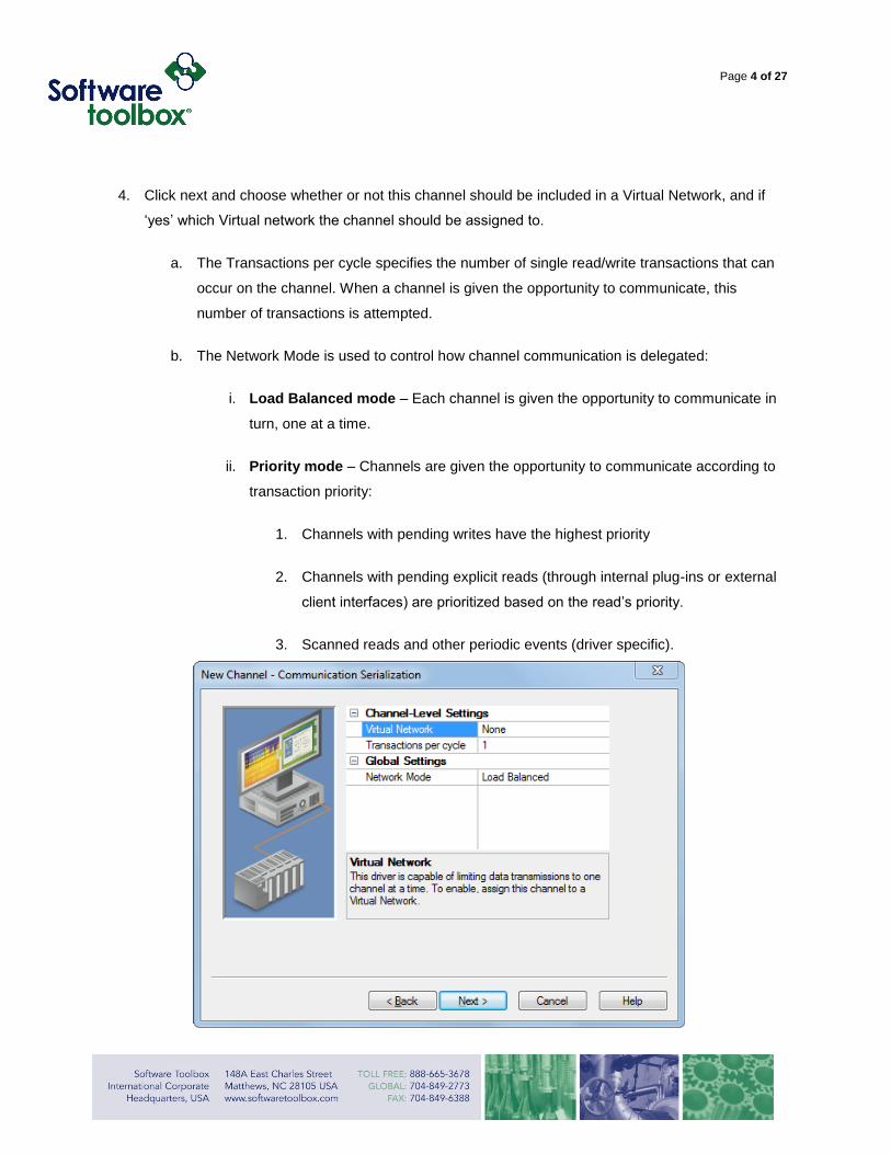
4. Click next and choose whether or not this channel should be included in a Virtual Network, and if
‘yes’ which Virtual network the channel should be assigned to.
a. The Transactions per cycle specifies the number of single read/write transactions that can
occur on the channel. When a channel is given the opportunity to communicate, this
number of transactions is attempted.
b. The Network Mode is used to control how channel communication is delegated:
i. Load Balanced mode – Each channel is given the opportunity to communicate in
turn, one at a time.
ii. Priority mode – Channels are given the opportunity to communicate according to
transaction priority:
1. Channels with pending writes have the highest priority
2. Channels with pending explicit reads (through internal plug-ins or external
client interfaces) are prioritized based on the read’s priority.
3. Scanned reads and other periodic events (driver specific).
Page 5 of 27
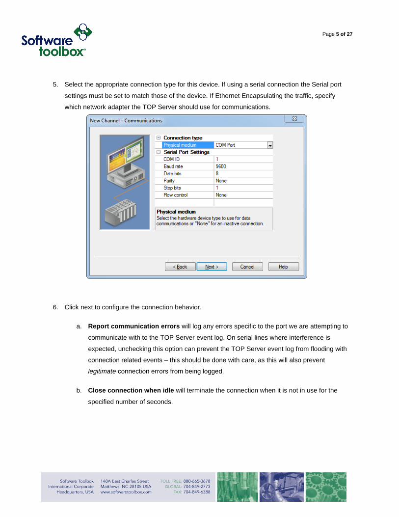
5. Select the appropriate connection type for this device. If using a serial connection the Serial port
settings must be set to match those of the device. If Ethernet Encapsulating the traffic, specify
which network adapter the TOP Server should use for communications.
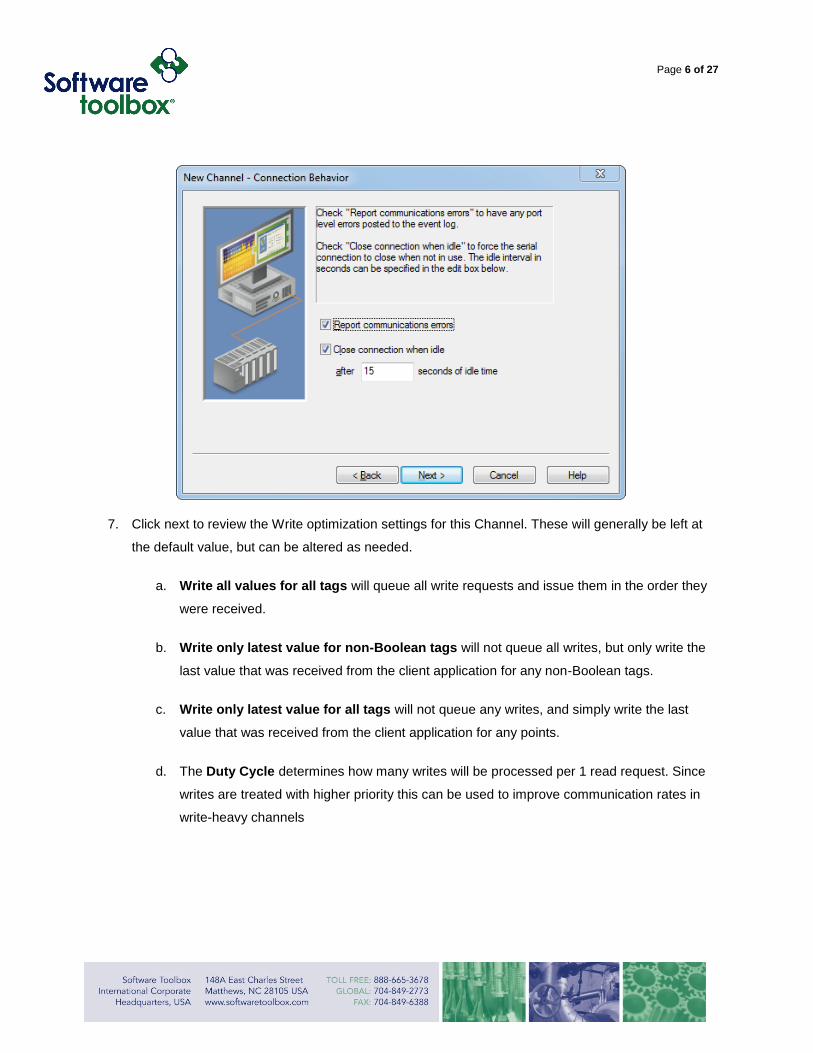
6. Click next to configure the connection behavior.
a. Report communication errors will log any errors specific to the port we are attempting to
communicate with to the TOP Server event log. On serial lines where interference is
expected, unchecking this option can prevent the TOP Server event log from flooding with
connection related events – this should be done with care, as this will also prevent
legitimate connection errors from being logged.
b. Close connection when idle will terminate the connection when it is not in use for the
specified number of seconds.
Page 6 of 27
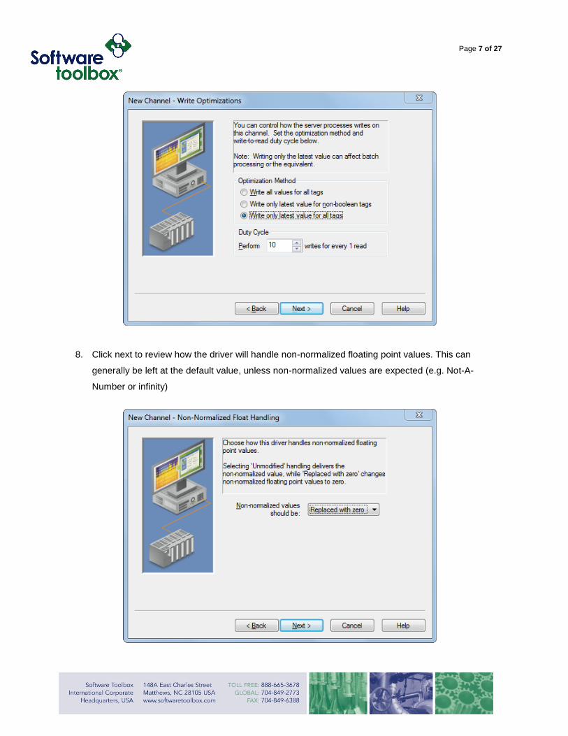
7. Click next to review the Write optimization settings for this Channel. These will generally be left at
the default value, but can be altered as needed.
a. Write all values for all tags will queue all write requests and issue them in the order they
were received.
b. Write only latest value for non-Boolean tags will not queue all writes, but only write the
last value that was received from the client application for any non-Boolean tags.
c. Write only latest value for all tags will not queue any writes, and simply write the last
value that was received from the client application for any points.
d. The Duty Cycle determines how many writes will be processed per 1 read request. Since
writes are treated with higher priority this can be used to improve communication rates in
write-heavy channels
Page 7 of 27
8. Click next to review how the driver will handle non-normalized floating point values. This can
generally be left at the default value, unless non-normalized values are expected (e.g. Not-A-
Number or infinity)
Page 8 of 27
.
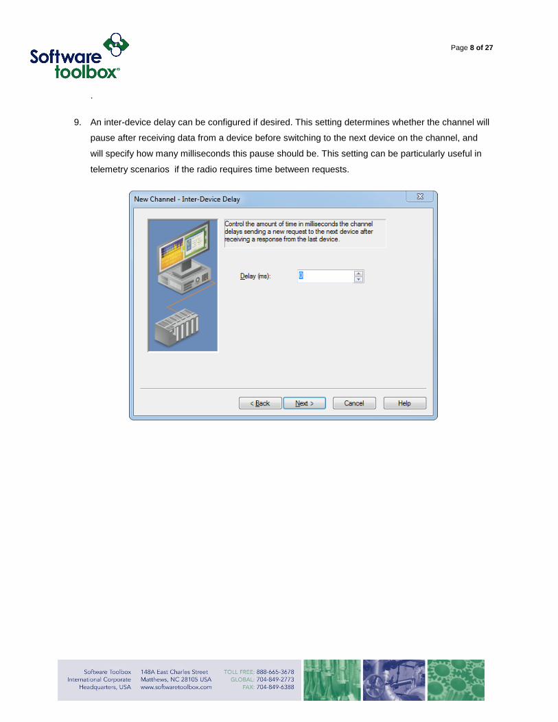
9. An inter-device delay can be configured if desired. This setting determines whether the channel will
pause after receiving data from a device before switching to the next device on the channel, and
will specify how many milliseconds this pause should be. This setting can be particularly useful in
telemetry scenarios if the radio requires time between requests.
Page 9 of 27
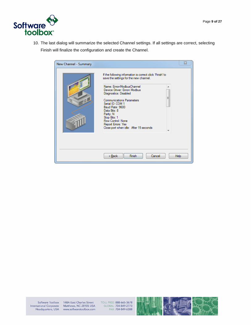
10. The last dialog will summarize the selected Channel settings. If all settings are correct, selecting
Finish will finalize the configuration and create the Channel.
Page 10 of 27
Device Setup
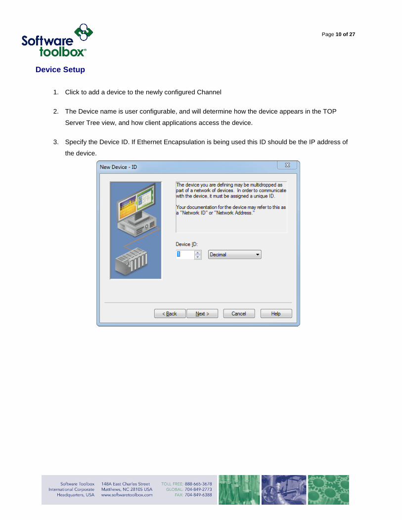
1. Click to add a device to the newly configured Channel
2. The Device name is user configurable, and will determine how the device appears in the TOP
Server Tree view, and how client applications access the device.
3. Specify the Device ID. If Ethernet Encapsulation is being used this ID should be the IP address of
the device.
Page 11 of 27
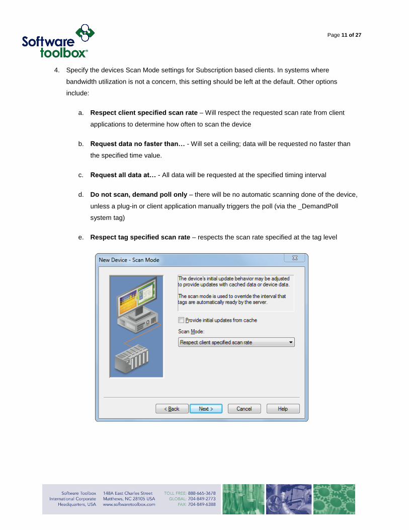
4. Specify the devices Scan Mode settings for Subscription based clients. In systems where
bandwidth utilization is not a concern, this setting should be left at the default. Other options
include:
a. Respect client specified scan rate – Will respect the requested scan rate from client
applications to determine how often to scan the device
b. Request data no faster than… - Will set a ceiling; data will be requested no faster than
the specified time value.
c. Request all data at… - All data will be requested at the specified timing interval
d. Do not scan, demand poll only – there will be no automatic scanning done of the device,
unless a plug-in or client application manually triggers the poll (via the _DemandPoll
system tag)
e. Respect tag specified scan rate – respects the scan rate specified at the tag level
Page 12 of 27
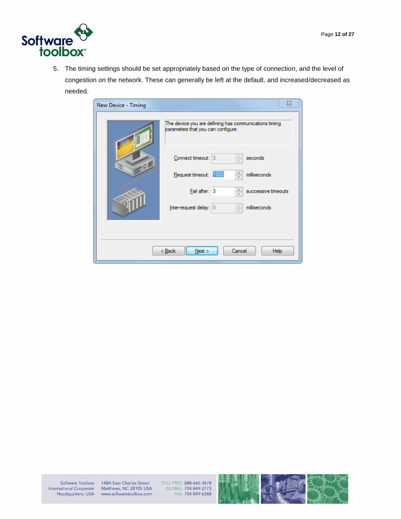
5. The timing settings should be set appropriately based on the type of connection, and the level of
congestion on the network. These can generally be left at the default, and increased/decreased as
needed.
Page 13 of 27
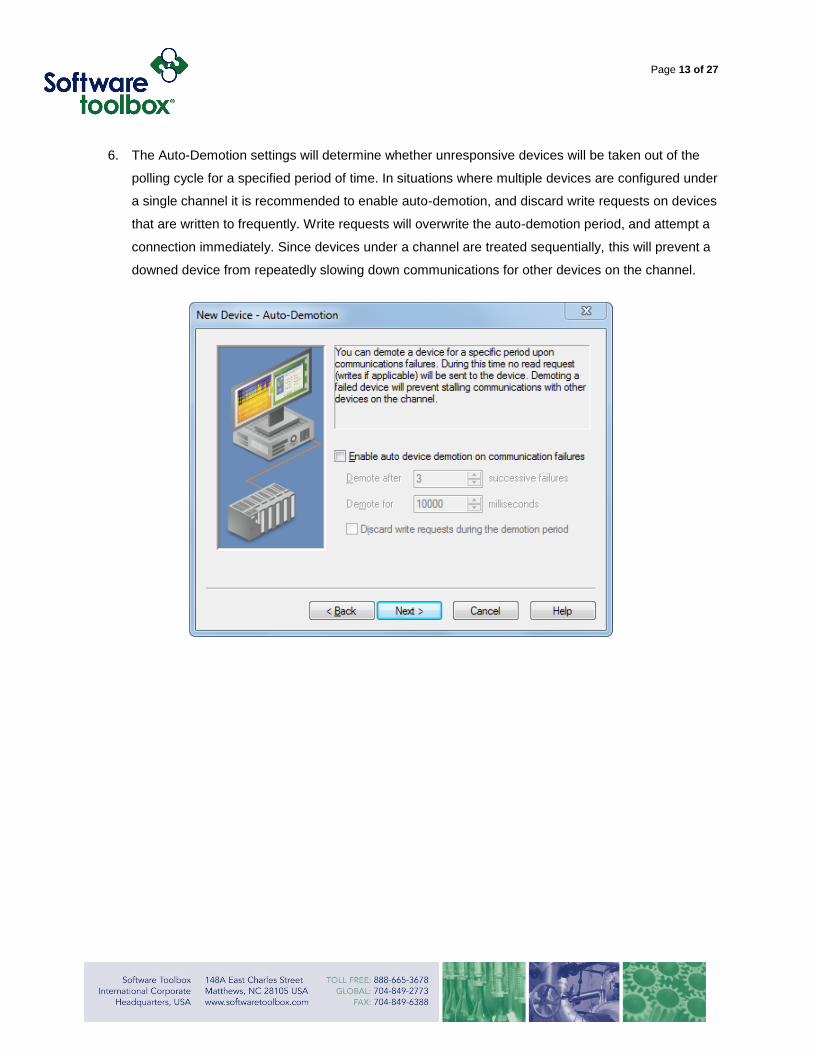
6. The Auto-Demotion settings will determine whether unresponsive devices will be taken out of the
polling cycle for a specified period of time. In situations where multiple devices are configured under
a single channel it is recommended to enable auto-demotion, and discard write requests on devices
that are written to frequently. Write requests will overwrite the auto-demotion period, and attempt a
connection immediately. Since devices under a channel are treated sequentially, this will prevent a
downed device from repeatedly slowing down communications for other devices on the channel.
Page 14 of 27
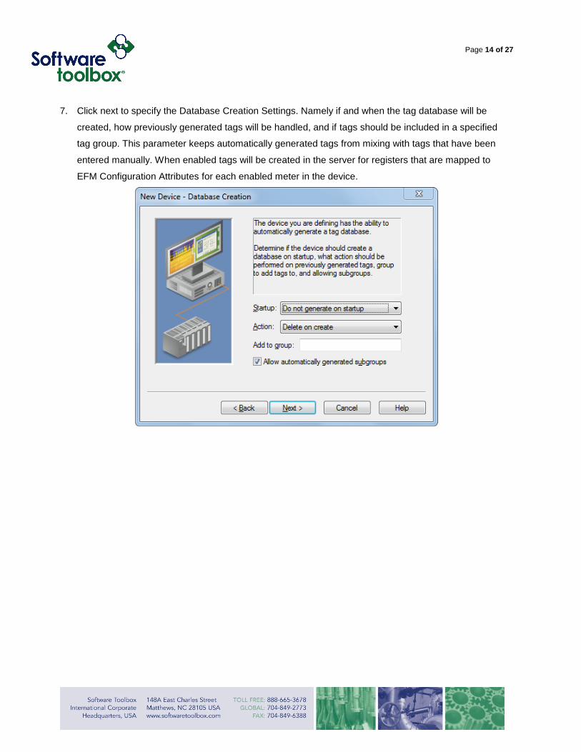
7. Click next to specify the Database Creation Settings. Namely if and when the tag database will be
created, how previously generated tags will be handled, and if tags should be included in a specified
tag group. This parameter keeps automatically generated tags from mixing with tags that have been
entered manually. When enabled tags will be created in the server for registers that are mapped to
EFM Configuration Attributes for each enabled meter in the device.
Page 15 of 27
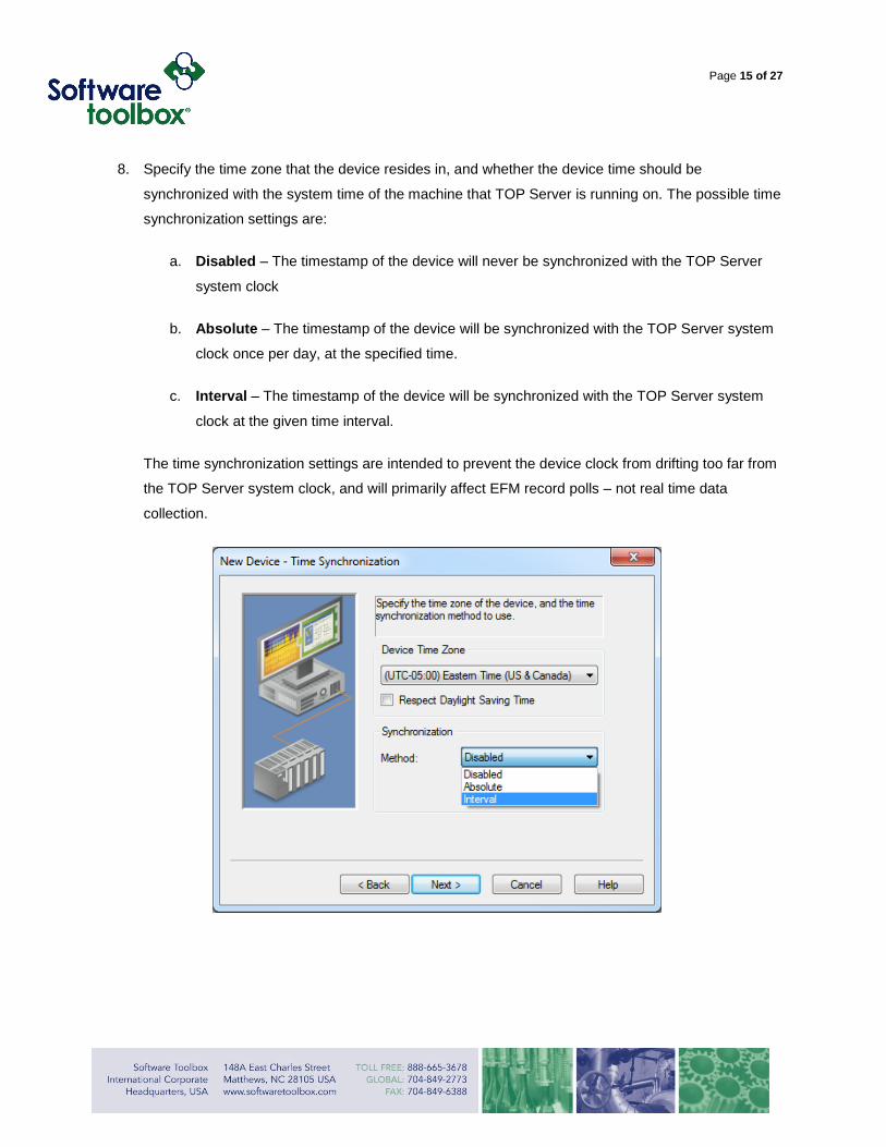
8. Specify the time zone that the device resides in, and whether the device time should be
synchronized with the system time of the machine that TOP Server is running on. The possible time
synchronization settings are:
a. Disabled – The timestamp of the device will never be synchronized with the TOP Server
system clock
b. Absolute – The timestamp of the device will be synchronized with the TOP Server system
clock once per day, at the specified time.
c. Interval – The timestamp of the device will be synchronized with the TOP Server system
clock at the given time interval.
The time synchronization settings are intended to prevent the device clock from drifting too far from
the TOP Server system clock, and will primarily affect EFM record polls – not real time data
collection.
Page 16 of 27
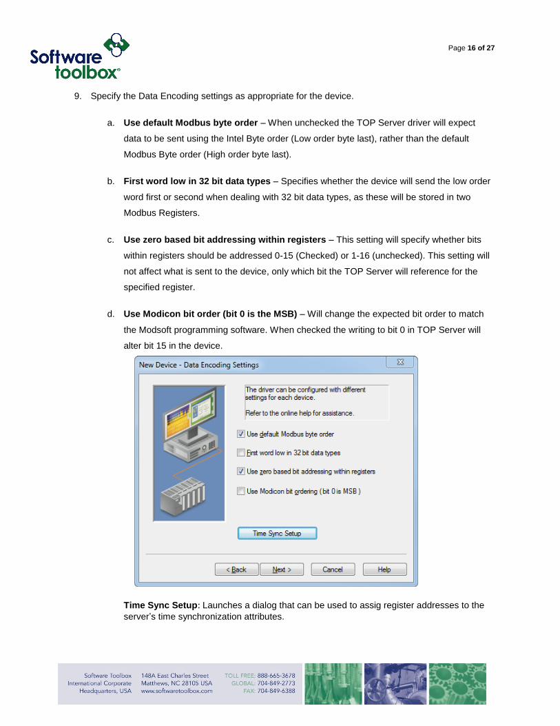
9. Specify the Data Encoding settings as appropriate for the device.
a. Use default Modbus byte order – When unchecked the TOP Server driver will expect
data to be sent using the Intel Byte order (Low order byte last), rather than the default
Modbus Byte order (High order byte last).
b. First word low in 32 bit data types – Specifies whether the device will send the low order
word first or second when dealing with 32 bit data types, as these will be stored in two
Modbus Registers.
c. Use zero based bit addressing within registers – This setting will specify whether bits
within registers should be addressed 0-15 (Checked) or 1-16 (unchecked). This setting will
not affect what is sent to the device, only which bit the TOP Server will reference for the
specified register.
d. Use Modicon bit order (bit 0 is the MSB) – Will change the expected bit order to match
the Modsoft programming software. When checked the writing to bit 0 in TOP Server will
alter bit 15 in the device.
Time Sync Setup: Launches a dialog that can be used to assig register addresses to the
server’s time synchronization attributes.
Page 17 of 27
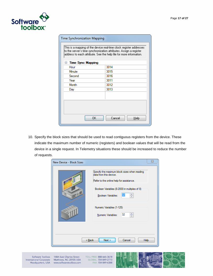
10. Specify the block sizes that should be used to read contiguous registers from the device. These
indicate the maximum number of numeric (registers) and boolean values that will be read from the
device in a single request. In Telemetry situations these should be increased to reduce the number
of requests.
Page 18 of 27
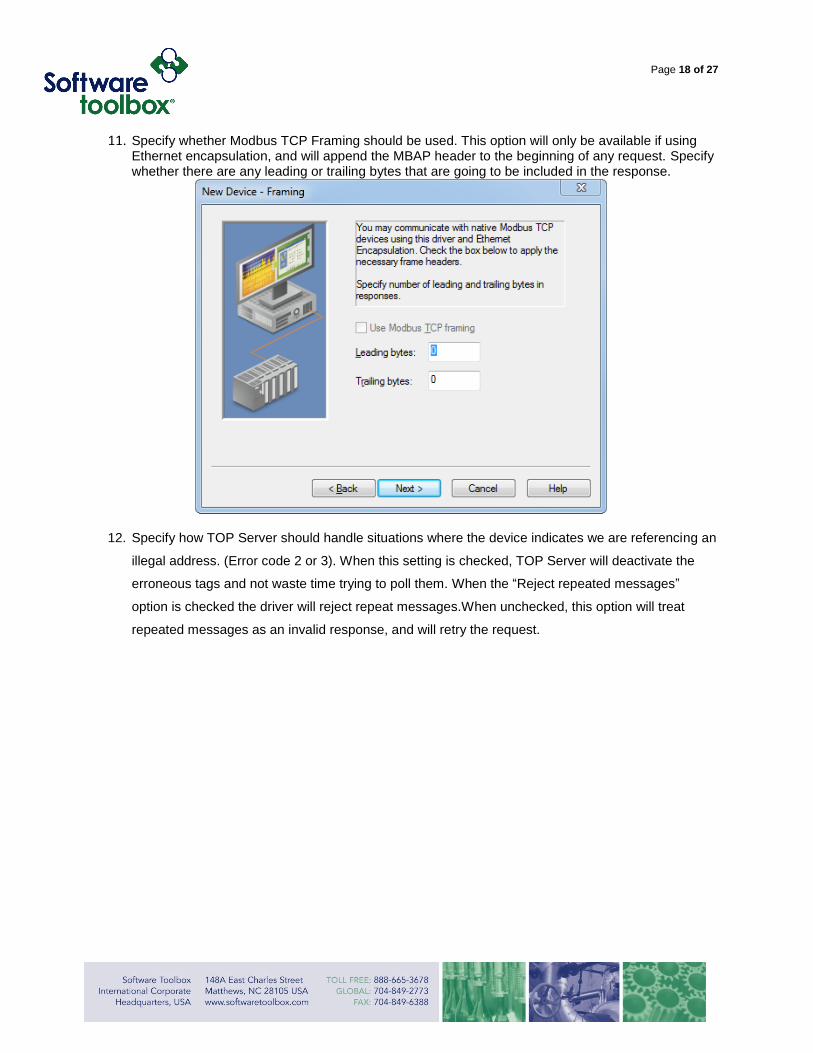
11. Specify whether Modbus TCP Framing should be used. This option will only be available if using Ethernet encapsulation, and will append the MBAP header to the beginning of any request. Specify whether there are any leading or trailing bytes that are going to be included in the response.
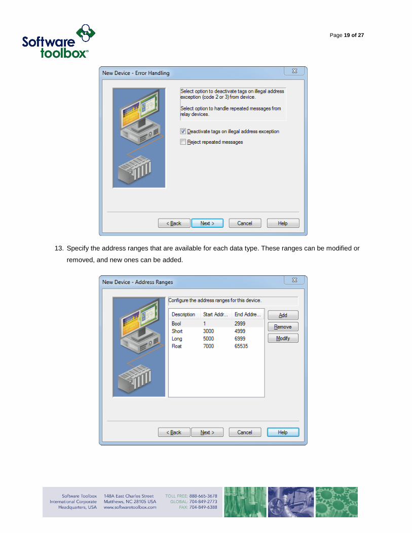
12. Specify how TOP Server should handle situations where the device indicates we are referencing an
illegal address. (Error code 2 or 3). When this setting is checked, TOP Server will deactivate the
erroneous tags and not waste time trying to poll them. When the “Reject repeated messages”
option is checked the driver will reject repeat messages.When unchecked, this option will treat
repeated messages as an invalid response, and will retry the request.
Page 19 of 27
13. Specify the address ranges that are available for each data type. These ranges can be modified or
removed, and new ones can be added.
Page 20 of 27
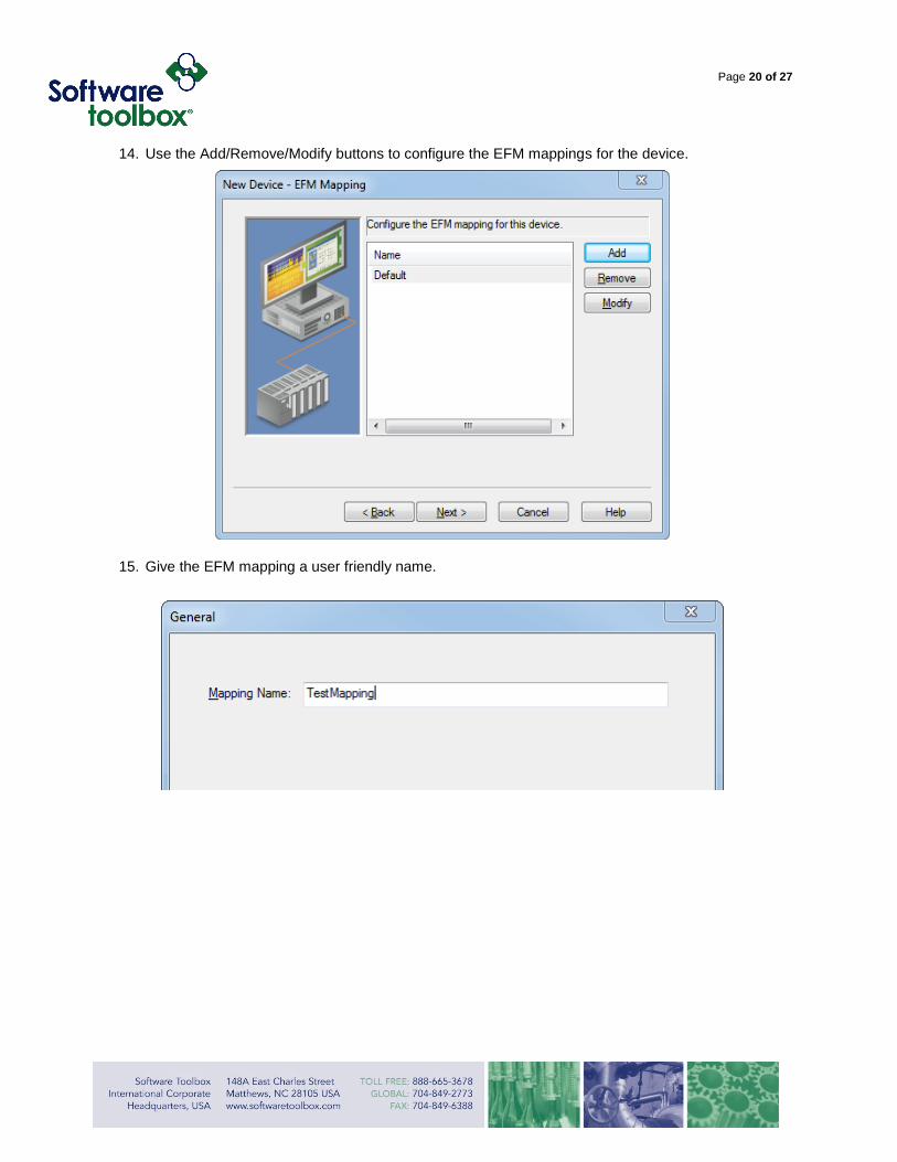
14. Use the Add/Remove/Modify buttons to configure the EFM mappings for the device.
15. Give the EFM mapping a user friendly name.
Page 21 of 27
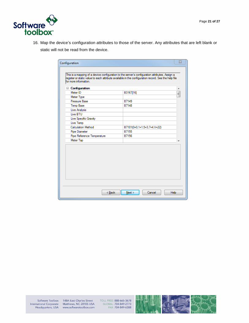
16. Map the device’s configuration attributes to those of the server. Any attributes that are left blank or
static will not be read from the device.
Page 22 of 27
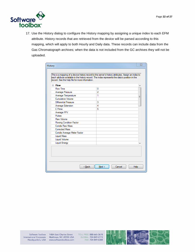
17. Use the History dialog to configure the History mapping by assigning a unique index to each EFM
attribute. History records that are retrieved from the device will be parsed according to this
mapping, which will apply to both Hourly and Daily data. These records can include data from the
Gas Chromatograph archives; when the data is not included from the GC archives they will not be
uploaded.
Page 23 of 27
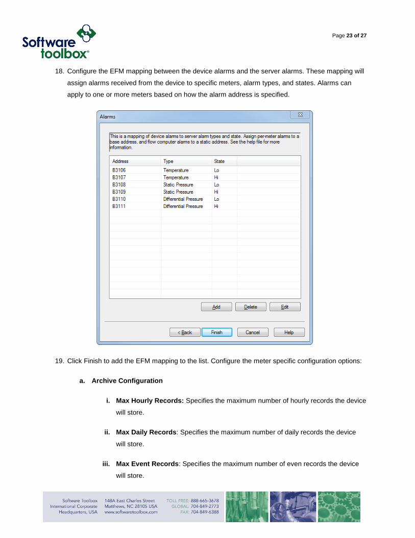
18. Configure the EFM mapping between the device alarms and the server alarms. These mapping will
assign alarms received from the device to specific meters, alarm types, and states. Alarms can
apply to one or more meters based on how the alarm address is specified.
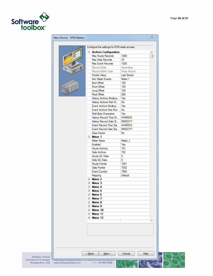
19. Click Finish to add the EFM mapping to the list. Configure the meter specific configuration options:
a. Archive Configuration
i. Max Hourly Records: Specifies the maximum number of hourly records the device
will store.
ii. Max Daily Records: Specifies the maximum number of daily records the device
will store.
iii. Max Event Records: Specifies the maximum number of even records the device
will store.
Page 24 of 27
iv. Record Order: Specifies the order that records will be stored in the device. This
setting is not currently supported and cannot be changed from the default value of
Ascending.
v. Record Buffer Type: Specifies the type of buffer that the device will use to store
records in the device. The setting is not currently supported and cannot be
changed from the default value of Wrap Around.
vi. Pointer Value: Specifies whether the value in the hourly and daily pointer registers
will point to the last stored value, or to the next available register.
vii. Non-meter Events: Specifies how to handle non-meter events. Options are to
ignore them, log them to a specific meter, or log them to all meters.
viii. Bool Offset: Specifies the offset of the Boolean configuration register range for
each successive meter.
ix. Short Offset: Specifies the offset of the Short configuration register range for each
successive meter.
x. Long Offset: Specifies the offset of the Long configuration register range for each
successive meter.
xi. Float Offset: Specifies the offset of the Float configuration register range for each
successive meter.
xii. History Archive Modbus Byte Order: Specifies whether the data in History
archives will be in the standard Modbus byte order
xiii. History Archive First Word Low: Specifies whether the data in the History
archives will be stored with the first word low
xiv. Event Archive Modbus Byte Order: Specifies whether the data in the
Alarm/Event archives will be in the standard Modbus byte order
xv. Event Archive First Word Low: Specifies whether the data in the Alarm/Event
archives will be stored with the first word low
Page 25 of 27
xvi. Multi-Byte Characters: Specifies whether string configuration data will be stored
in two bytes per character format.
xvii. History record Time Stamp Format: The Enron Modbus data type for History
record timestamps is a float. This setting will specify whether the float is stored in
the HHMMSS or HHMM.SS format.
xviii. Clear Cache: When set to Yes, the TOP server will clear all EFM data and reset
the EFM pointer files, which are used to track the EFM uploads. All EFM data will
be re-polled from the device, after which this tag will be reset to “No”
b. Meters
i. Meter Name: A user configurable, descriptive, name for the meter.
ii. Enabled: Specifies whether the meter is enabled for EFM Polling
iii. Hourly Archive: Specifies the meter/run’s hourly archive address.
iv. Daily Archive: Specifies the meter/run’s daily archive address.
v. Hourly GC Data: Specifies the meter/run’s hourly archive address for gas
chromatography.
vi. Daily GC Data: Specifies the meter/run’s daily archive address for gas
chromatography.
vii. Hourly Pointer: Specifies the register that the device will use to indicate the
position of the current (or last) hourly record in the buffer.
viii. Daily Pointer: Specifies the register that the device will use to indicate the position
of the current (or last) daily record in the buffer.
ix. Event Counter: Specifies the register that the device will use to indicate the
number of alarm/event records in the buffer.
x. Mapping: Specifies the type of mapping that will be used for Configuration,
History, and Alarm data.
Page 26 of 27
Page 27 of 27
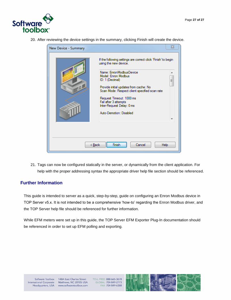
20. After reviewing the device settings in the summary, clicking Finish will create the device.
21. Tags can now be configured statically in the server, or dynamically from the client application. For
help with the proper addressing syntax the appropriate driver help file section should be referenced.
Further Information
This guide is intended to server as a quick, step-by-step, guide on configuring an Enron Modbus device in
TOP Server v5.x. It is not intended to be a comprehensive ‘how-to’ regarding the Enron Modbus driver, and
the TOP Server help file should be referenced for further information.
While EFM meters were set up in this guide, the TOP Server EFM Exporter Plug-In documentation should
be referenced in order to set up EFM polling and exporting.


