Embed Size (px)
Citation preview
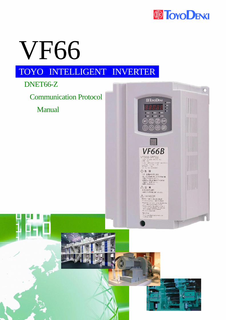
VF66 TOYO INTELLIGENT INVERTER
DNET66-Z
Communication Protocol
Manual
Foreword
Thank you for choosing Optional Circuit Board for Toyo inverter product.
This protocol instruction manual contains information regarding the DNET66-Z Optional Circuit Board
for the VF66B Inverter. For correct use, please carefully read this instruction manual prior to using the
DNET66-Z.
This instruction manual covers the functions, connection procedures for the DNET66-Z, as well as
guidelines for setting up the VF66B inverter.(Regarding DeviceNET communication functions are refer
to the Insutruction Manual of DNET66-Z commucatin protocol.)
In order to accommodate the many special functions to a wide variety of applications in addition to the
basic inverter functions, please thoroughly read the VF66B inverter manual as well as any other
applicable specialized instruction manuals.
DNET66-Z communication specification is based on AC Drive Profile. DeviceNet specification version
applied in DNET66-Z is as follows
Volume1: rerease 3.3
Volume3: rerease 1.5
Please read before use
For safety
Before installing, operating, maintaining and inspecting DNET66-Z option, please read this manual and
all other appendices thoroughly in order to get familiarize with the feature of this option, safely
information and correct handling. For safe operation, be sure to also thoroughly read the VF66Inverter
operating manual. In this instruction manual, the safety instructions are classified in to two levels:
DANGER and CAUTION. These signs have important instructions. Please follow the instructions without
fail.
DANGER Indicates a hazardous situation which may result in death or
serious injury if it is handled improperly.
CAUTION . Indicates a hazardous situation which may result in moderate
or minor injury or only in property damage if it is handled
improperly. However, such a situation may lead to serious
consequences depending on circumstances.
CAUTION [Installation]
Do not use optional circuit board if you discover damage or deformation during unpacking.
Doing so may cause optional circuit board failure or malfunction.
Do not place any flammable materials near the optional circuit board.
Doing so may cause a fire.
Do not allow the optional circuit board to drop, fall over or sustain severe impacts.
Doing so may cause optional circuit board failure or damage
Do not install or operate the optional circuit board if it is damaged or has any of its parts missing.
Doing so may lead to personal injury.
DANGER [Wiring]
Before wiring, make sure the power is OFF.
Failure to do so may cause an electric shock or fire
Wait more than 10 minutes after turning the power OFF before opening the unit case lid.
Failure to do so may cause an electric shock or fire.
Make sure that the unit is correctly earthed.
Failure to do so may cause an electric shock or fire.
Wiring must be done by skilled technicians.
Failure to do so may cause an electric shock or fire.
Wire the unit after it is installed.
Failure to do so may cause an electric shock or fire.
CAUTION [Wiring]
Make sure that communication cables and connectors are properly installed and locked in place.
Failure to do so may cause optional circuit board failure or malfunction.
DANGER [Operation]
Turn the power ON after fitting the inverter front cover.
Do not remove the cover while the power is ON.
Doing so may cause an electric shock.
Do not operate any switch with wet hands.
Doing so may cause an electric shock.
Do not touch the inverter terminals while the power is ON, even if the inverter is in the idle state.
Doing so may cause an electric shock.
If the alarm is reset while the operation signal kept input, the inverter will suddenly restart. Reset
the alarm after making sure that the operation signal is OFF. Failure to do so may lead to personal
injury.
The inverter can be set to operate in a wide range of speed. Operate the inverter after sufficiently
checking the allowable range of the motor and equipment.
Failure to do so may cause personal injury, equipment failure or damage
CAUTION [Operation]
The inverter radiating fin and the radiating resistance are hot. Do not touch them.
Failure to follow this warning may cause burns.
DANGER [Maintenance, inspection and parts replacement]
Always turn the power OFF before inspecting the inverter.
Failure to do so may cause an electric shock, personal injury or fire.
Unauthorized persons shall not perform maintenance, inspection or parts replacement.
Use insulated tools for maintenance and inspection.
Failure to do so may cause electric shock or personal injury.
DANGER [Other]
Never modify the unit. Doing so may cause electric shock or personal injury.
CAUTION [General precautions]
Some illustrations given in this manual show the inverter from which the covers or safety shields have
been removed to illustrate the details. Before operating the inverter, reinstall the covers and shields to
their original positions and the inverter according to this manual.
These safety precautions and specifications stated in this manual are subject to change without notice.
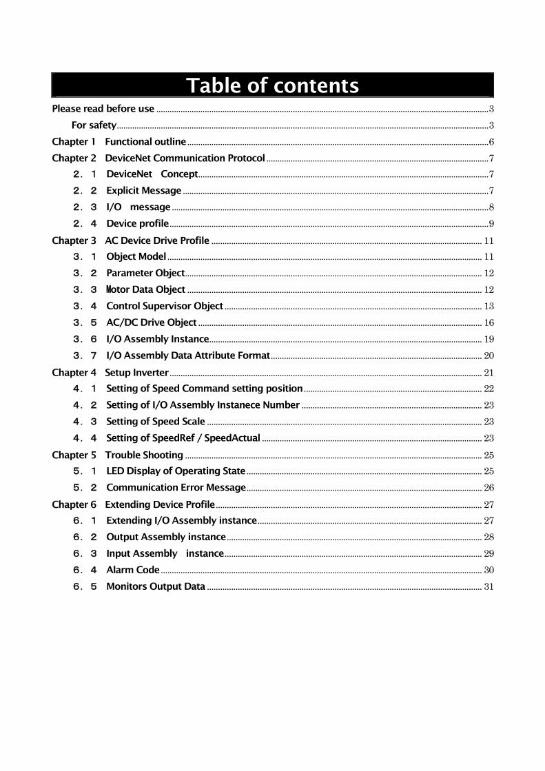
Table of contents
Please read before use ....................................................................................................................................................... 3
For safety ......................................................................................................................................................................... 3
Chapter 1 Functional outline ......................................................................................................................................... 6
Chapter 2 DeviceNet Communication Protocol ..................................................................................................... 7
2.1 DeviceNet Concept .................................................................................................................................... 7
2.2 Explicit Message ........................................................................................................................................... 7
2.3 I/O message ................................................................................................................................................ 8
2.4 Device profile ................................................................................................................................................. 9
Chapter 3 AC Device Drive Profile ........................................................................................................................... 11
3.1 Object Model ............................................................................................................................................... 11
3.2 Parameter Object ....................................................................................................................................... 12
3.3 Motor Data Object ...................................................................................................................................... 12
3.4 Control Supervisor Object ..................................................................................................................... 13
3.5 AC/DC Drive Object ................................................................................................................................. 16
3.6 I/O Assembly Instance ............................................................................................................................ 19
3.7 I/O Assembly Data Attribute Format ................................................................................................ 20
Chapter 4 Setup Inverter .............................................................................................................................................. 21
4.1 Setting of Speed Command setting position ................................................................................. 22
4.2 Setting of I/O Assembly Instanece Number .................................................................................. 23
4.3 Setting of Speed Scale ............................................................................................................................. 23
4.4 Setting of SpeedRef / SpeedActual .................................................................................................... 23
Chapter 5 Trouble Shooting ....................................................................................................................................... 25
5.1 LED Display of Operating State ........................................................................................................... 25
5.2 Communication Error Message ........................................................................................................... 26
Chapter 6 Extending Device Profile ......................................................................................................................... 27
6.1 Extending I/O Assembly instance ...................................................................................................... 27
6.2 Output Assembly instance .................................................................................................................... 28
6.3 Input Assembly instance ..................................................................................................................... 29
6.4 Alarm Code .................................................................................................................................................. 30
6.5 Monitors Output Data ............................................................................................................................. 31
Chapter 1 Functional outline
DNET66-Z is used equipping the connector of the PC board (VFC66-Z) in a VF66B inverter. The functions
with which DNET66-Z is equipped are a DeviceNet Slave communication function, a multifunctional
input/output function, an analog input/output function, and PG input/output function.
DeviceNet is an open network standard, the specification and protocol are opened by Open DeviceNet
Vendor Association Inc.(ODVA), providing interchangeability of similar devices from multiple vendors.
The DeviceNet communication function of DNET66-Z make a possible to input command of operation,
speed, toruque to VF66B inveter and possible to monitaling operation state,protection state,current ,voltage
of inverter. And possible to reading set data, trace back data, monitor data & possible to changing set data.
More over possible to use for input signal of billed PLC function (regarding billed PLC function please refer to
VF66 PC TOOL instruction manual)
In order to reduce an environmental impact, DNET66-Z is designed so that the content of a lead, mercury,
cadmium, hexavalent chrome, PBB, and PBDE may be based on the RoHS instructions which EU defined.
CAUTION [Safety precautions]
Carefully read the instruction manual before use, and use the inverter correctly.
Our inverter and optional circuit board are not designed or manufactured for the purpose of use in life-support
machines or systems.
If you intend to use the product stated in this document for special purposes, such as passenger cars, medical
devices, aerospace devices, nuclear energy controls and submarine relaying machines or systems, consult our
sales department.
This product is manufactured under strict quality control. However, if it is used in critical equipment in which
inverter and optional circuit board failure may result in death or serious damage, provide safeguard to avoid
serious accidents.
If you wish to use this inverter with loads other than three-phase AC traction, please contact us.
To use this product, electrical work is necessary. The electrical work must be done by qualified expert.
Chapter 2 DeviceNet Communication Protocol
2.1 DeviceNet Concept
DeviceNet is described communication service, motion of deviceNet node and internal information of
DeviceNet products, by abstractly Concept said ‘object modelinng’.
DeviceNet node is modeled to assembling of object. The object is express to characteristic factors of product
abstractly. Actual figer of abstractly ofject model is different from each DeviceNet product.
We show the term of object modeloing when we use to explain DeviceNet service & protocol as follows.
・ Object:Expressing the factor elements of products abstractly.
・ Class:Assembling of all objects to express a same kind of system factors.
・ Instance:Definetely& actually exsisting of object,the words OBJECT,INSTANCE&OBJECT INSTANCE
are means The INSTANCE.
・ Attribute:Descrived in a characteristic functions of which object to confirm from outside. Attribute
is submit to statas information & stipulate in motion of object.
・ Instance generation:The case default value is not stipulated in define of object, all Attribute of instance
set to ‘0’ initialized, to generate object instance.
・ Behavier:Stipulated in a motion of object. The motion will be born by various ivent which
detecting by object. The ivent involve receiving service request, detecting internal fault & measuring
time of timer.
・ Service:The function supported by object & object class. The assembling of common service is
defined in DeviceNet. Also possible to define service of objectclass & peculiar service of vender.
・ Communication Object:Several Object class of which exchanging control message in working
through DeviceNet.
・ Application object:Several Object class that carring out characteristic function of products.
2.2 Explicit Message
The Explicit Messaging conection make estabulish general & multi purpose communication rute between
device and device. The conection is called conection 0f sending & receiving data simply, Explict messeage to
be possible to patern net work communication for request /response.
The explicit message communicate a information, using data field of Control Area Network (after say
CAN),defiend on DeviceNet.
Data field (0 to 8 bytes)
CAN header
Protocol field
and
Service fixed data
CAN trailer
Figure 2.2-a
The formart of CAN data field used in Explict is showing as follows figure 2.2-b
Byte
offset
Contents Byte
offset
Contents
7 6 5 4 3 2 1 0 7 6 5 4 3 2 1 0
0 Message header 0 Message header
1
Massage body or
1 Fragmentation protocol
: :
Fragment of massage body : :
: :
7 7
Figure 2.2-b
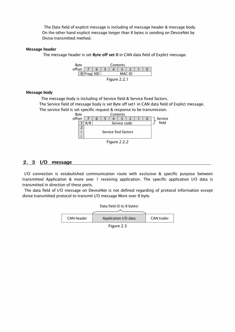
The Data field of explicit message is including of message header & message body.
On the other hand explicit message longer than 8 bytes is sending on DeviceNet by
Divise transmitted methed.
Message header
The message header is set Byte off set 0 in CAN data field of Explict message.
Byte
offset
Contents
7 6 5 4 3 2 1 0
0 Frag XID MAC ID
Figure 2.2.1
Message body
The message body is including of Service field & Service fixed factors.
The Service field of message body is set Byte off set1 in CAN data field of Explict message.
The service field is set specific request & response to be transmission.
Byte
offset
Contents
Service
field
7 6 5 4 3 2 1 0
1 R/R Service code
2
Service fixd factors :
:
Figure 2.2.2
2.3 I/O message
I/O connection is estabulished communication route with exclusive & specific purpose between
transmitted Application & more over 1 receiving application. The specific application I/O data is
transmitted in direction of these ports.
The data field of I/O message on DeviceNet is not defined regarding of protocol information except
divise transmitted protocol to transmit I/O message More over 8 byte.
Data field (0 to 8 bytes)
CAN header Application I/O data CAN trailer
Figure 2.3
2.4 Device profile
About a device profile
In order to realize offer of the compatibility between the same kind of devices, and improvement in mutual
compatibility, unity is required of the same kind of devices. That is, basic "standard" is needed for the type of
each device. Usually, the device same type must satisfy the following conditions.
・Behavier
・Transmission/reception of the basic set of I/O data
・The basic set of the attribute which can be set up is built in.
The formal definition of these information is called a "device profile."
Some objects are contained in all the DeviceNet products, and fundamental behavior of a product is
performed by coordinating these and operating them. Since the behavior of each object is specified, the
group of the same object arranged in specific order operates so that it may coordinate and the same behavior
may be shown in every device.
What made the group the object used by a device is called the "object model" of a device. These devices
must be equipped with the same object model in order that the device of the same kind may show the same
behavior. Therefore, the object model is contained in all the device profiles, and secures the compatibility
between the devices of the same kind on DeviceNet.
Below, an object model is explained.
① Identity object
Generally, DeviceNet products have one instance (instance #1) of Identity object. This instance has an
attribute of vendor ID, a device type, a product code, revision, status, a serial number, a product name, and a
state. The services needed are Get_Attribute_Single and Reset.
② Message Router Object
Generally DeviceNet products have one instance (instance #1) of Message Router object. Message Router
object is a constituent factor of a product which tells an Explicit message to other objects. Usually, a
DeviceNet network cannot be seen from outside.
③ DeviceNet object
Generally, DeviceNet products have one instance (instance #1) of DeviceNet object. There are the following
attributes in this instance. : They are a node address or MAC ID, a baud rate, Bus-off action, a Bus-off counter,
Allocation Choice, and MAC ID of a master. The services needed are Get_Attribute_Single.
④ Assembly object
Generally, DeviceNet products have one or more Assembly object as the option. The main purposes of this
object are to combine a different attribute (data) in different application with one attribute, and to make it
transmit as one message.
⑤ Connection object
Generally, DeviceNet products have at least two Connection objects. Each Connection object expresses the
end point of the actual connection between two nodes on a DeviceNet network. Two kinds of this connection
is called Explicit Messaging and I/O Messaging. Attribute addressing, an attribute value, and the service code
that describes specified action are contained in an Explicit message. Only data is contained in an I/O message.
In the case of an I/O message, all the information about the treatment of data is included in the Connection
object relevant to the I/O message.
⑥ Parameter object
The Parameter object of an option is used by a device with a composition parameter. One instance expresses
each composition parameter. A Parameter object offers the standard method of the configuration tool for
accessing all the parameters. A value, the range, a character string, and full limits are contained in the
composition option which is an attribute of a Parameter object.
⑦ Application object
Ordinary, there is one application object in device except assembly or parameter class at least.
⑧ I/O deta format
The case a several deta (Attribute) is comminucated through single I/O connection, these attribute to be
necessary making a group or a lupping to single block.
The instance of assembly obuject class is perform as above mentions.
I/O deta format of devise of devise profile is based on the following guide line.
・I/O Assembly is input type or output type
・one devise is possible to including several I/O Assembly.
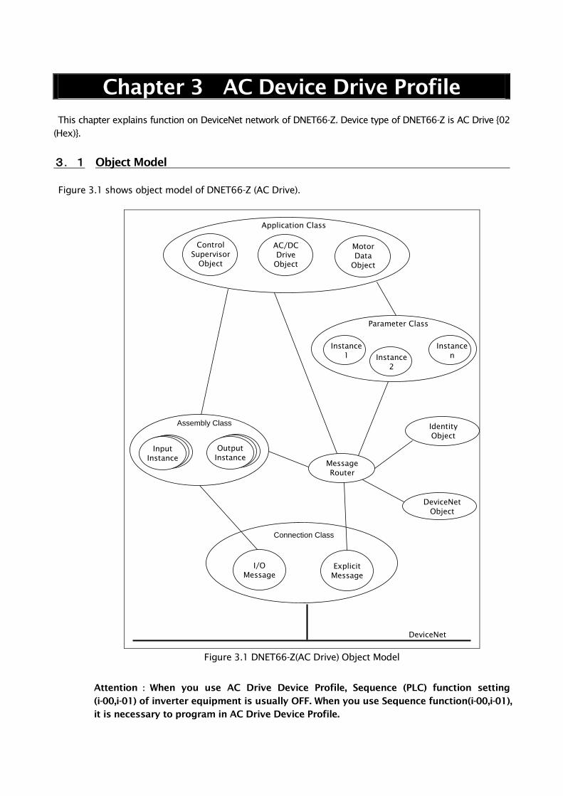
Chapter 3 AC Device Drive Profile
This chapter explains function on DeviceNet network of DNET66-Z. Device type of DNET66-Z is AC Drive {02
(Hex)}.
3.1 Object Model
Figure 3.1 shows object model of DNET66-Z (AC Drive).
Identity
Object
DeviceNet
Object
Message
Router
Application Class
I/O
Message
Explicit
Message
Connection Class
Control
Supervisor
Object
AC/DC
Drive
Object
Motor
Data
Object
DeviceNet
Parameter Class
Instance
1 Instance
2
Instance
n
Assembly Class
Input
Instance
Output
Instance
Figure 3.1 DNET66-Z(AC Drive) Object Model
Attention:When you use AC Drive Device Profile, Sequence (PLC) function setting
(i-00,i-01) of inverter equipment is usually OFF. When you use Sequence function(i-00,i-01),
it is necessary to program in AC Drive Device Profile.
3.2 Parameter Object
DNET66-Z supports Parameter Object Instance shown in a list of the following as a public release
access function for Control Supervisor Object, Motor Data Object and AC/DC Drive Object.
Table 3.2
Instance Number Configuration
Parameter Name
DeviceNet
Data Type Setting Range
1 Motor Type USINT 0~255
2 Rated Current UINT 0~65535
3 Rated Voltage UINT 0~65535
4 Network Control BOOL 0 or 1
5 Drive State USINT 0~255
6 Running Fwd BOOL 0 or 1
7 Running Rev BOOL 0 or 1
8 Ready BOOL 0 or 1
9 Faulted BOOL 0 or 1
10 Warning BOOL 0 or 1
11 Fault Reset BOOL 0 or 1
12 Control From Net BOOL 0 or 1
13 At Reference BOOL 0 or 1
14 Network Ref BOOL 0 or 1
15 Drive Mode USINT 0~255
16 Speed Actual INT -32768~32767
17 Speed Reference INT -32768~32767
18 Speed Scale SINT -128~127
19 Ref From Net BOOL 0 or 1
3.3 Motor Data Object
Class Code:28 (Hex)
Class Atribute, Instance Attribute, Service of Motor Data Object of DNET66-Z are shown in the
following.
*Motor Data Object Class Attribute
Table 3.3.1
Attribute ID Access Rule Name DeviceNet
Data Type Description of Attribute Remarks
1 Get Revision USINT Revision of this object Not Support
2 Get Max Instance USINT Maximum nstance number of an object
currently created in this class level of the device. Not Support
6 Get Max ID Number of
Class Attributes UINT
The attribute ID of the last class attribute of the
class definition implemented in the device. Not Support
7 Get Max ID Number of
Instance Attributes UINT
The attribute ID of the last instance attribute of
the class definition implemented in the device. Not Support
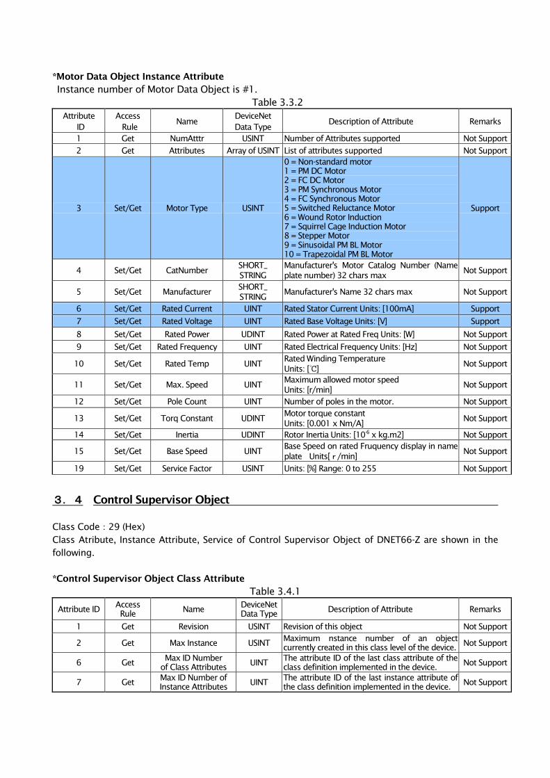
*Motor Data Object Instance Attribute
Instance number of Motor Data Object is #1.
Table 3.3.2
Attribute
ID
Access
Rule Name
DeviceNet
Data Type Description of Attribute Remarks
1 Get NumAtttr USINT Number of Attributes supported Not Support
2 Get Attributes Array of USINT List of attributes supported Not Support
3 Set/Get Motor Type USINT
0 = Non-standard motor
1 = PM DC Motor
2 = FC DC Motor
3 = PM Synchronous Motor
4 = FC Synchronous Motor
5 = Switched Reluctance Motor
6 = Wound Rotor Induction
7 = Squirrel Cage Induction Motor
8 = Stepper Motor
9 = Sinusoidal PM BL Motor
10 = Trapezoidal PM BL Motor
Support
4 Set/Get CatNumber SHORT_
STRING
Manufacturer's Motor Catalog Number (Name
plate number) 32 chars max Not Support
5 Set/Get Manufacturer SHORT_
STRING Manufacturer's Name 32 chars max Not Support
6 Set/Get Rated Current UINT Rated Stator Current Units: [100mA] Support
7 Set/Get Rated Voltage UINT Rated Base Voltage Units: [V] Support
8 Set/Get Rated Power UDINT Rated Power at Rated Freq Units: [W] Not Support
9 Set/Get Rated Frequency UINT Rated Electrical Frequency Units: [Hz] Not Support
10 Set/Get Rated Temp UINT Rated Winding Temperature
Units: [℃] Not Support
11 Set/Get Max. Speed UINT Maximum allowed motor speed
Units: [r/min] Not Support
12 Set/Get Pole Count UINT Number of poles in the motor. Not Support
13 Set/Get Torq Constant UDINT Motor torque constant
Units: [0.001 x Nm/A] Not Support
14 Set/Get Inertia UDINT Rotor Inertia Units: [10-6
x kg.m2] Not Support
15 Set/Get Base Speed UINT Base Speed on rated Fruquency display in name
plate Units[r/min] Not Support
19 Set/Get Service Factor USINT Units: [%] Range: 0 to 255 Not Support
3.4 Control Supervisor Object
Class Code:29 (Hex)
Class Atribute, Instance Attribute, Service of Control Supervisor Object of DNET66-Z are shown in the
following.
*Control Supervisor Object Class Attribute
Table 3.4.1
Attribute ID Access
Rule Name
DeviceNet
Data Type Description of Attribute Remarks
1 Get Revision USINT Revision of this object Not Support
2 Get Max Instance USINT Maximum nstance number of an object
currently created in this class level of the device. Not Support
6 Get Max ID Number
of Class Attributes UINT
The attribute ID of the last class attribute of the
class definition implemented in the device. Not Support
7 Get Max ID Number of
Instance Attributes UINT
The attribute ID of the last instance attribute of
the class definition implemented in the device. Not Support
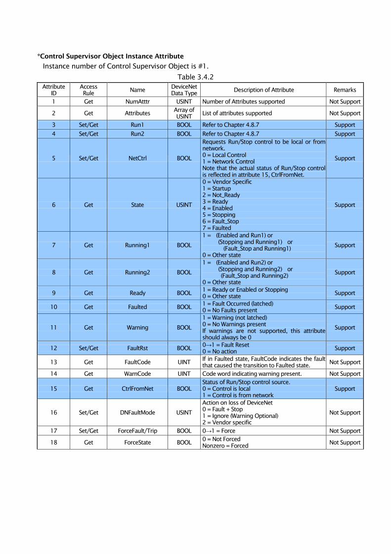
*Control Supervisor Object Instance Attribute
Instance number of Control Supervisor Object is #1.
Table 3.4.2
Attribute
ID
Access
Rule Name
DeviceNet
Data Type Description of Attribute Remarks
1 Get NumAtttr USINT Number of Attributes supported Not Support
2 Get Attributes Array of
USINT List of attributes supported Not Support
3 Set/Get Run1 BOOL Refer to Chapter 4.8.7 Support
4 Set/Get Run2 BOOL Refer to Chapter 4.8.7 Support
5 Set/Get NetCtrl BOOL
Requests Run/Stop control to be local or from
network.
0 = Local Control
1 = Network Control
Note that the actual status of Run/Stop control
is reflected in attribute 15, CtrlFromNet.
Support
6 Get State USINT
0 = Vendor Specific
1 = Startup
2 = Not_Ready
3 = Ready
4 = Enabled
5 = Stopping
6 = Fault_Stop
7 = Faulted
Support
7 Get Running1 BOOL
1 = (Enabled and Run1) or
(Stopping and Running1) or
(Fault_Stop and Running1)
0 = Other state
Support
8 Get Running2 BOOL
1 = (Enabled and Run2) or
(Stopping and Running2) or
(Fault_Stop and Running2)
0 = Other state
Support
9 Get Ready BOOL 1 = Ready or Enabled or Stopping
0 = Other state Support
10 Get Faulted BOOL 1 = Fault Occurred (latched)
0 = No Faults present Support
11 Get Warning BOOL
1 = Warning (not latched)
0 = No Warnings present
If warnings are not supported, this attribute
should always be 0
Support
12 Set/Get FaultRst BOOL 0→1 = Fault Reset
0 = No action Support
13 Get FaultCode UINT If in Faulted state, FaultCode indicates the fault
that caused the transition to Faulted state. Not Support
14 Get WarnCode UINT Code word indicating warning present. Not Support
15 Get CtrlFromNet BOOL
Status of Run/Stop control source.
0 = Control is local
1 = Control is from network
Support
16 Set/Get DNFaultMode USINT
Action on loss of DeviceNet
0 = Fault + Stop
1 = Ignore (Warning Optional)
2 = Vendor specific
Not Support
17 Set/Get ForceFault/Trip BOOL 0→1 = Force Not Support
18 Get ForceState BOOL 0 = Not Forced
Nonzero = Forced Not Support
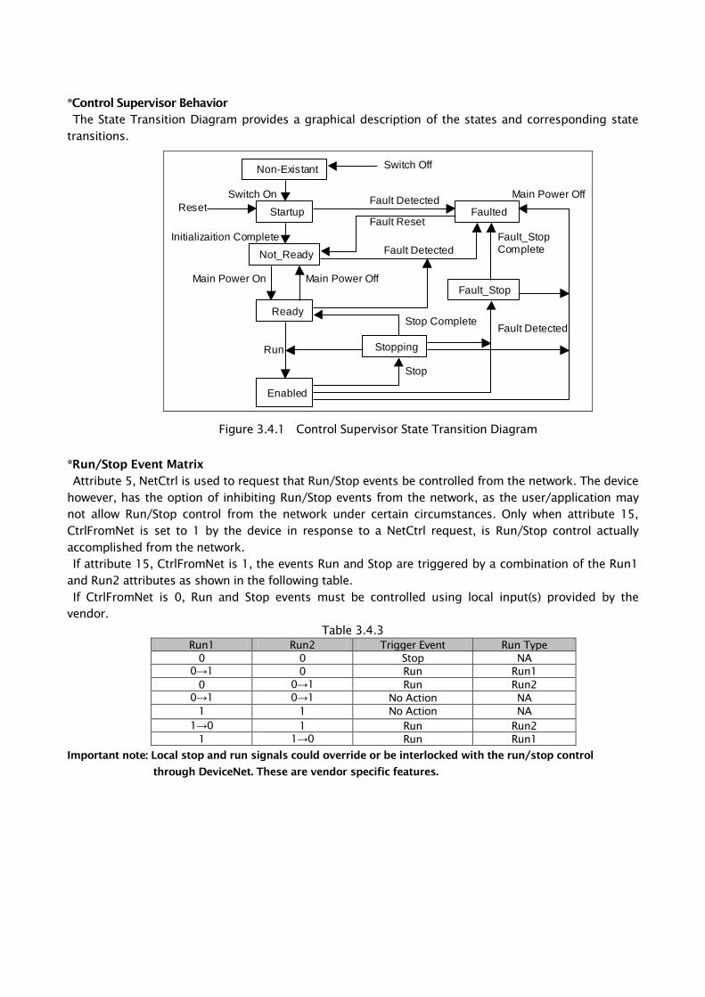
*Control Supervisor Behavior
The State Transition Diagram provides a graphical description of the states and corresponding state
transitions.
Non-Existant
Startup
Not_Ready
Ready
Enabled
Faulted
Fault_Stop
Stopping
Switch Off
Switch On
Reset
Initializaition Complete
Main Power On Main Power Off
Run
Stop
Stop Complete
Fault Detected
Fault Reset
Fault Detected
Fault Detected
Fault_Stop Complete
Main Power Off
Figure 3.4.1 Control Supervisor State Transition Diagram
*Run/Stop Event Matrix
Attribute 5, NetCtrl is used to request that Run/Stop events be controlled from the network. The device
however, has the option of inhibiting Run/Stop events from the network, as the user/application may
not allow Run/Stop control from the network under certain circumstances. Only when attribute 15,
CtrlFromNet is set to 1 by the device in response to a NetCtrl request, is Run/Stop control actually
accomplished from the network.
If attribute 15, CtrlFromNet is 1, the events Run and Stop are triggered by a combination of the Run1
and Run2 attributes as shown in the following table.
If CtrlFromNet is 0, Run and Stop events must be controlled using local input(s) provided by the
vendor.
Table 3.4.3
Run1 Run2 Trigger Event Run Type
0 0 Stop NA
0→1 0 Run Run1
0 0→1 Run Run2
0→1 0→1 No Action NA
1 1 No Action NA
1→0 1 Run Run2
1 1→0 Run Run1
Important note: Local stop and run signals could override or be interlocked with the run/stop control
through DeviceNet. These are vendor specific features.
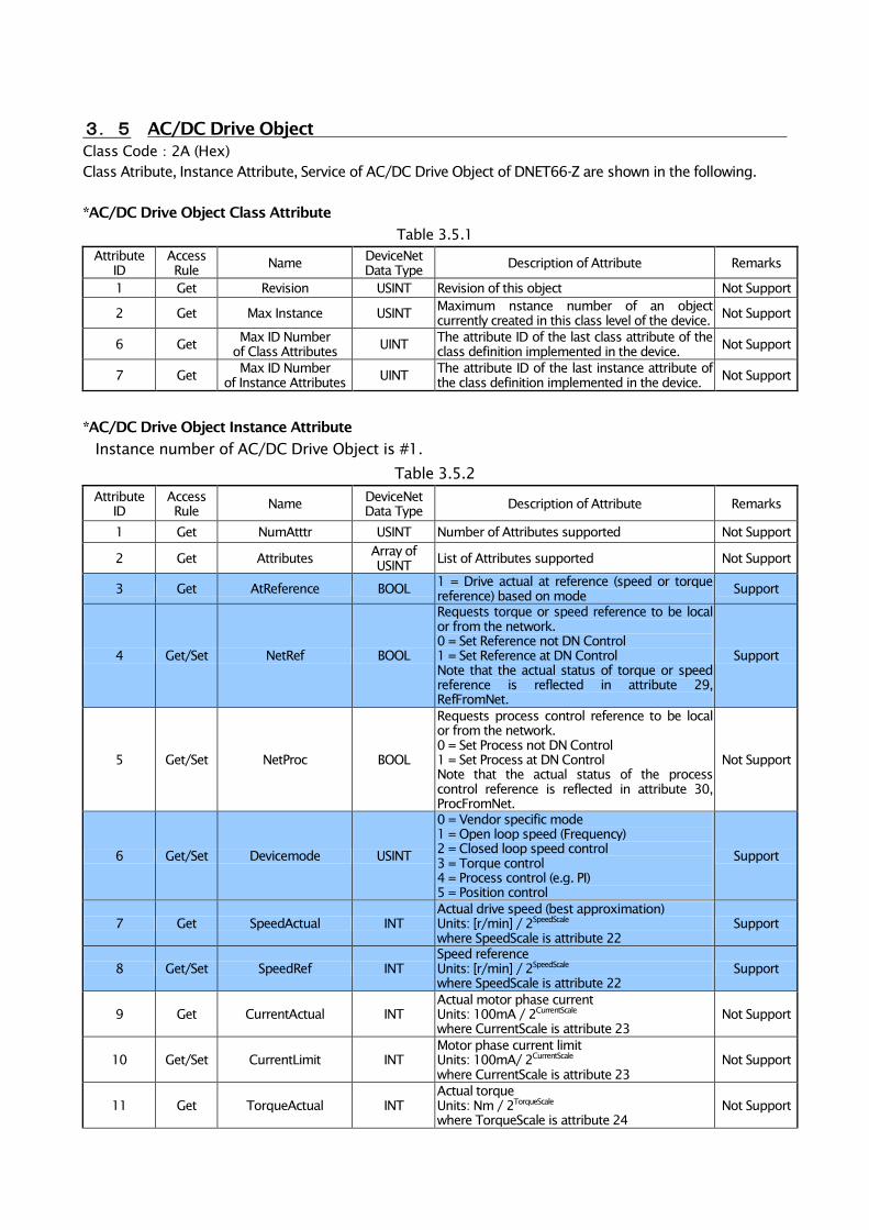
3.5 AC/DC Drive Object
Class Code:2A (Hex)
Class Atribute, Instance Attribute, Service of AC/DC Drive Object of DNET66-Z are shown in the following.
*AC/DC Drive Object Class Attribute
Table 3.5.1
Attribute
ID
Access
Rule Name
DeviceNet
Data Type Description of Attribute Remarks
1 Get Revision USINT Revision of this object Not Support
2 Get Max Instance USINT Maximum nstance number of an object
currently created in this class level of the device. Not Support
6 Get Max ID Number
of Class Attributes UINT
The attribute ID of the last class attribute of the
class definition implemented in the device. Not Support
7 Get Max ID Number
of Instance Attributes UINT
The attribute ID of the last instance attribute of
the class definition implemented in the device. Not Support
*AC/DC Drive Object Instance Attribute
Instance number of AC/DC Drive Object is #1.
Table 3.5.2
Attribute
ID
Access
Rule Name
DeviceNet
Data Type Description of Attribute Remarks
1 Get NumAtttr USINT Number of Attributes supported Not Support
2 Get Attributes Array of
USINT List of Attributes supported Not Support
3 Get AtReference BOOL 1 = Drive actual at reference (speed or torque
reference) based on mode Support
4 Get/Set NetRef BOOL
Requests torque or speed reference to be local
or from the network.
0 = Set Reference not DN Control
1 = Set Reference at DN Control
Note that the actual status of torque or speed
reference is reflected in attribute 29,
RefFromNet.
Support
5 Get/Set NetProc BOOL
Requests process control reference to be local
or from the network.
0 = Set Process not DN Control
1 = Set Process at DN Control
Note that the actual status of the process
control reference is reflected in attribute 30,
ProcFromNet.
Not Support
6 Get/Set Devicemode USINT
0 = Vendor specific mode
1 = Open loop speed (Frequency)
2 = Closed loop speed control
3 = Torque control
4 = Process control (e.g. PI)
5 = Position control
Support
7 Get SpeedActual INT
Actual drive speed (best approximation)
Units: [r/min] / 2SpeedScale
where SpeedScale is attribute 22
Support
8 Get/Set SpeedRef INT
Speed reference
Units: [r/min] / 2SpeedScale
where SpeedScale is attribute 22
Support
9 Get CurrentActual INT
Actual motor phase current
Units: 100mA / 2CurrentScale
where CurrentScale is attribute 23
Not Support
10 Get/Set CurrentLimit INT
Motor phase current limit
Units: 100mA/ 2CurrentScale
where CurrentScale is attribute 23
Not Support
11 Get TorqueActual INT
Actual torque
Units: Nm / 2TorqueScale
where TorqueScale is attribute 24
Not Support
Attribute
ID
Access
Rule Name
DeviceNet
Data Type Description of Attribute Remarks
12 Get/Set TorqueRef INT
Torque reference
Units: Nm / 2TorqueScale
where TorqueScale is attribute 24
Not Support
13 Get ProcessActual INT
Actual process control value
Units: % / 2ProcessScale
where ProcessScale is attribute 25
Not Support
14 Get/Set ProcessRef INT
Process control reference set point
Units: % / 2ProcessScale
where ProcessScale is attribute 25
Not Support
15 Get PowerActual INT
Actual output power
Units: W / 2PowerScale
where PowerScale is attribute 26
Not Support
16 Get InputVoltage INT
Input Voltage
Units: V / 2VoltageScale
where VoltageScale is attribute 27
Not Support
17 Get OutputVoltage INT
Output Voltage
Units: V / 2VoltageScale
where VoltageScale is attribute 27
Not Support
18 Get/Set AccelTime UINT
Acceleration time
Time from 0 to HighSpdLimit
Units: ms / 2TimeScale
where TimeScale is attribute 28
Acceleration time selection for negative
direction is vendor specific.
Not Support
19 Get/Set DecelTime UINT
Deceleration time
Time from 0 to HighSpdLimit
Units: ms / 2TimeScale
where TimeScale is attribute 28
Deceleration time selection for negative
direction is vendor specific.
Not Support
20 Get/Set LowSpdLimit UINT
Minimum speed limit
Units: [r/min] / 2SpeedScale
where SpeedScale is attribute 22
Not Support
21 Get/Set HighSpdLimit UINT
Maximum speed limit
Units: [r/min] / 2SpeedScale
where SpeedScale is attribute 22
Not Support
22 Get/Set SpeedScale SINT
Speed scaling factor. Scaling is accomplished as
follows:
ScaledSpeed = [r/min] / 2SpeedScale
Range: -128 to 127
Support
23 Get/Set CurrentScale SINT
Current scaling factor. Scaling is accomplished
as follows:
ScaledCurrent = A / 2CurrentScale
Range: -128 to 127
Not Support
24 Get/Set TorqueScale SINT
Torque scaling factor. Scaling is accomplished
as follows:
ScaledTorque = Nm / 2TorqueScale
Range: -128 to 127
Not Support
25 Get/Set ProcessScale SINT
Power scaling factor. Scaling is accomplished as
follows:
ScaledProcess = % / 2ProcessScale
Range: -128 to 127
Not Support
26 Get/Set PowerScale SINT
Power scaling factor. Scaling is accomplished as
follows:
ScaledPower = W / 2PowerScale
Range: -128 to 127
Not Support
27 Get/Set VoltageScale SINT
Voltage scaling factor. Scaling is accomplished
as follows:
ScaledVoltage = V / 2VoltageScale
Range: -128 to 127
Not Support
28 Get/Set TimeScale SINT
Time scaling factor. Scaling is accomplished as
follows:
ScaledTime = ms / 2TimeScale
Range: -128 to 127
Not Support
Attribute
ID
Access
Rule Name
DeviceNet
Data Type Description of Attribute Remarks
29 Get RefFromNet BOOL
Status of torque/speed reference
0 = Local torque/speed reference
1 = Devicenet torque/speed reference
Support
30 Get ProcFromNet BOOL
Status of process control reference
0 = Local process reference
1 = DeviceNet process reference
Not Support
31 Get/Set FieldIorV BOOL
Selects Field Voltage or Field Current control for a
DC Drive.
0 = Voltage Control (Open Loop)
1 = Current Control (Magnetizing field for DC
drive)
Not Support
32 Get/Set FieldVoltRatio UINT For voltage control of a DC Drive Not Support
33 Get/Set FieldCurSetPt UINT
DC Drive Field Current set point.
Units: A / 2CurrentScale
where CurrentScale is attribute 23
Not Support
34 Get/Set FieldWkEnable BOOL
Enables/Disables field weakening for a DC Drive
0 = Disabled (DC Drive in current control)
1 = Enabled
Not Support
35 Get FieldCurActual INT
Actual Field Current for a DC Drive.
Units: A / 2CurrentScale
where CurrentScale is attribute 23
Not Support
36 Get/Set FieldMinCur INT
Minimum Field Current for a DC Drive.
Units: A / 2CurrentScale
where CurrentScale is attribute 23
Not Support
*Scaling of Atrribute Values
As part of the AC/DC Drive Object definition, engineeringunits are defined for each physical quantity,
e.g. r/min for Velocity, Nm for Torque etc. To maximize the resolution capable or necessary on some
devices or applications, these values can be normalized using a binary scale factor before transmission
on the bus. A separate scaling factor is specified for each physical quantity. Normally, scaling factors
will be set up once during initialization according to the range of values to be used in the application.
Scaling Factors allow the representation of physical units on the bus to obtain an acceptable resolution
and dynamic range for all applications.
Example: Configuration of a DC Drive to operate with r/min resolution of 0.125 r/min input from
bus to Drive:
SpeedRef (AC/DC Drive Object, Attribute ID 8) = 4567
SpeedScale (AC/DC Drive Object, Attribute ID 22) = 3
→ Actual Commanded Speed
= SpeedRef / 2SpeedScale
= 4567 / 23
= 570.875r/min
Input from Drive to bus:
Actual Drive Operating Speed
SpeedScale (AC/DC Drive Object, Attribute ID 22) = 3
→ SpeedActual (AC/DC Drive Object, Attribute ID 7)
= Actual Operating Speed x 2SpeedScale
= 789.5 x 23
= 6316
In cases where the applicable scaling factor attribute is non-zero, the units are:
Engineering unit / 2Scale Factor Attribute
In the above example, therefore, the units are 0.125r/min.
3.6 I/O Assembly Instance
Through the use of predefined instance definintions, I/O Assemblies support a hierarchy of motor
control devices. Following Table 3.6-a shows an allotment of an Assembly Instance number with a
motor control device hierarchist.
DNET66-Z uses Instance number of AC/DC Drive Profile with following Table 3.6-a.
Table 3.6-a
Profile I/O Type Instance Range Instances within hierarchy that may be
implemented or this paoduct type.
AC Motor Starter
Soft Start Starter
Output 1~19 1~19
Input 50~69 50~69
AC or DC Drive Output 20~29 1~29
Input 70~79 50~79
Servo Drive Output 30~49 1~49
Input 80~99 50~99
The following I/O Assembly Instances are defined for AC and DC Drives.
With following Table 3.6-b, DNET66-Z supports 20, 21 of Output Assembly Instance number and
supports 70, 71 of an Input Assembly Instance number.
Table 3.6-b
Number Required/Optional Type Name
Decimal Hex
20 14 Required Output Basic Speed Control Output
21 15 Optional Output Extended Speed Control Output
70 46 Required Input Basic Speed Control Input
71 47 Optional Input Extended Speed Control Input
3.7 I/O Assembly Data Attribute Format
If a bit is not used in an I/O Assembly, it is reserved for use in other Assemblies. The consuming device
ignores reserved bits in Output Assemblies. Reserved bits in Input Assemblies are set to 0 by the
producing device.
Reserved bits in the I/O Assembly Data Attribute Format Tables are shaded.
The following lists show I/O Assembly Data Attribute Format of DNET66-Z.
*Output Assembly Instance
Data Attribute of Output Assemby Instance is data from master station to DNET66-Z.
Table 3.7.1
Instance Byte Bit7 Bit6 Bit5 Bit4 Bit3 Bit2 Bit1 Bit0
20 0 Fault Reset Run Fwd
1
2 Speed Reference (Low Byte)
3 Speed Reference (High Byte)
21 0 NetRef NetCtrl Fault Reset Run Rev Run Fwd
1
2 Speed Reference (Low Byte)
3 Speed Reference (High Byte)
*Input Assembly Instance
Data Attribute of Input Assemby Instance is data from DNET66-Z to master station.
Table 3.7.2
Instance Byte Bit7 Bit6 Bit5 Bit4 Bit3 Bit2 Bit1 Bit0
70 0 Running1 Faulted
1
2 Speed Actual (Low Byte)
3 Speed Actual (High Byte)
71 0 At
Reference Ref From Net Ctrl form Net Ready
Running2
(Rev)
Running1
(Fwd) Warning Faulted
1 Drive State
2 Speed Actual (Low Byte)
3 Speed Actual (High Byte)
Chapter 4 Setup Inverter
The DeviceNet communication function of DNET66-Z make a possible to input command of operation,
speed, toruque to VF66B inveter and possible to monitaling operation state,protection state,current ,voltage
of inverter. And possible to reading set data,trace back data, monita data & possible to changing set data.
More over possible to use for input signal of billed PLC function (regarding billed PLC function please refer
to VF66 PC TOOL instruction manual)
To communicate to DeviceNet Master station ,set parameter set of VF66B inveter showing following table is
neccecarries. More over please refer to DNET66-Z Instruction manual, VF66B inverter Instruction Manual &
The master station instruction manual.
The expression forword of DeviceNet communication in this chapter ’INPUT’ shows forword from
DNET66-Z to master station Input, OUTPUT’ shows forword from master station to DNET66-Z output. The
explain of Billed PLC function & Multi input function are excluded.
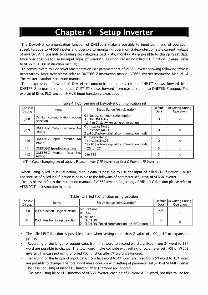
Table 4.1 Concerning of DeviceNet Communication set
Console
Display
Items Set-up Range (Item Selection) Default
Data
Rewriting During
Operation
J-00 Degital communication option
selection
0:Not use communication option
3:Use DNET66-Z
1,2,4 to 7:Set when using other option
0 ×
J-09 DNET66-Z Output instance No
setting
0:Instance No.20
1:Instance No.21
2 to10 :(Factory original communication mode)
0 ×
J-10 DNET66-Z Input instance No
setting
0:InstanceNo.70
1:InstanceNo.71
2 to 10:(Factory original communication mode)
0 ×
J-11 DNET66-Z SpeedScale setting -126 to 127 3 ×
J-12 DNET66-Z Monitor Data No.
setting 0 to 119 3 ×
※The Case changing set of above, Please power OFF Inverter at first & Power oFF Inverter
When using billed in PLC function, output data is possible to use for input of billed PLC function. To set
Use/notuse of billed PLC function is possible to the followins of parameter set(I area) of VF66B inverter.
Details please refer to the instruction manual of VF66B inveter. Regarding of Billed PLC function please refer to
VF66 PC Tool instruction manual.
Table 4.2 Billed PLC function using selection
Console
Display Items Set-up Range (Item Selection)
Default
Data
Rewriting During
Operation
i-00 PLCL function usage selection off:Not use
on:Use off
×
i-01 PLCH function usage selection
0:Not use
1:PLCH ON
2:PLCH ON (Speed command input is PLCH output)
0 ×
・ The billed PLC function is possible to use when setting more than 2 value of J-09, J-10 to expansion
profile.
・ Regarding of the length of output data, from first word to second word are fixed, from 3rd word to 12th
word are possible to change. The total word make coincide with setting of parameter set J-09 of VF66B
inverter. The case not using of billed PLC function after 7th word are ignored.
・ Regarding of the length of input data, from first word to 4th word are fixed,from 5rd word to 18th word
are possible to change. The total word make coincide with setting of parameter set J-10 of VF66B inverter.
The case not using of billed PLC function after 15th word are ignored.
The case using billed PLC function of VF66B inverter, each bit of 1st word & 2nd word, possible to use for
input relay to billed PLC function. And 3rd word to 12th word possible to became input registor of billed
PLC function.
・ Regarding billed PLC function refer to VF66 PC TOOL instruction manual.
・
※The case using PLC-L function, each bit of 1st word & 2nd word is not using for operation control signal &
multifunction .
In these case please make a sequence of operation control signal using with billed PLC function.
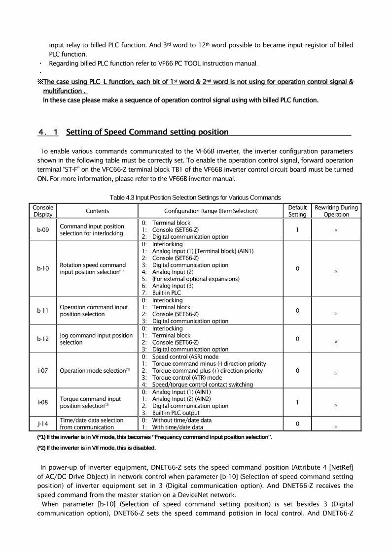
4.1 Setting of Speed Command setting position
To enable various commands communicated to the VF66B inverter, the inverter configuration parameters
shown in the following table must be correctly set. To enable the operation control signal, forward operation
terminal “ST-F” on the VFC66-Z terminal block TB1 of the VF66B inverter control circuit board must be turned
ON. For more information, please refer to the VF66B inverter manual.
Table 4.3 Input Position Selection Settings for Various Commands
Console
Display Contents Configuration Range (Item Selection)
Default
Setting
Rewriting During
Operation
b-09 Command input position
selection for interlocking
0: Terminal block
1: Console (SET66-Z)
2: Digital communication option
1
b-10 Rotation speed command
input position selection(*1)
0: Interlocking
1: Analog Input (1) [Terminal block] (AIN1)
2: Console (SET66-Z)
3: Digital communication option
4: Analog Input (2)
5: (For external optional expansions)
6: Analog Input (3)
7: Built-in PLC
0
b-11 Operation command input
position selection
0: Interlocking
1: Terminal block
2: Console (SET66-Z)
3: Digital communication option
0
b-12 Jog command input position
selection
0: Interlocking
1: Terminal block
2: Console (SET66-Z)
3: Digital communication option
0
i-07 Operation mode selection(*2)
0: Speed control (ASR) mode
1: Torque command minus (-) direction priority
2: Torque command plus (+) direction priority
3: Torque control (ATR) mode
4: Speed/torque control contact switching
0
i-08 Torque command input
position selection(*2)
0: Analog Input (1) (AIN1)
1: Analog Input (2) (AIN2)
2: Digital communication option
3: Built-in PLC output
1
J-14 Time/date data selection
from communication
0: Without time/date data
1: With time/date data 0
(*1) If the inverter is in V/f mode, this becomes “Frequency command input position selection”.
(*2) If the inverter is in V/f mode, this is disabled.
In power-up of inverter equipment, DNET66-Z sets the speed command position (Attribute 4 [NetRef]
of AC/DC Drive Object) in network control when parameter [b-10] (Selection of speed command setting
position) of inverter equipment set in 3 (Digital communication option). And DNET66-Z receives the
speed command from the master station on a DeviceNet network.
When parameter [b-10] (Selection of speed command setting position) is set besides 3 (Digital
communication option), DNET66-Z sets the speed command potision in local control. And DNET66-Z
ignores the speed command of the master station.
When you control inverter equipment with DeviceNet, please set parameter [b-10] (Selection of speed
command setting position) in 3 (Digital communication option)
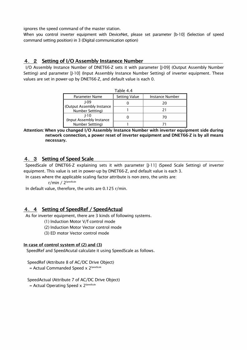
4.2 Setting of I/O Assembly Instanece Number
I/O Assembly Instance Number of DNET66-Z sets it with parameter [J-09] (Output Assembly Number
Setting) and parameter [J-10] (Input Assembly Instance Number Setting) of inverter equipment. These
values are set in power-up by DNET66-Z, and default value is each 0.
Table 4.4
Parameter Name Setting Value Instance Number
J-09
(Output Assembly Instance
Number Settting)
0 20
1 21
J-10
(Input Assembly Instance
Number Settting)
0 70
1 71
Attention: When you changed I/O Assembly Instance Number with inverter equipment side during
network connection, a power reset of inverter equipment and DNET66-Z is by all means
necessary.
4.3 Setting of Speed Scale
SpeedScale of DNET66-Z explaining sets it with parameter [J-11] (Speed Scale Setting) of inverter
equipment. This value is set in power-up by DNET66-Z, and default value is each 3.
In cases where the applicable scaling factor attribute is non-zero, the units are:
r/min / 2SpeedScale
In default value, therefore, the units are 0.125 r/min.
4.4 Setting of SpeedRef / SpeedActual
As for inverter equipment, there are 3 kinds of following systems.
(1) Induction Motor V/f control mode
(2) Induction Motor Vector control mode
(3) ED motor Vector control mode
In case of control system of (2) and (3)
SpeedRef and SpeedAcutal calculate it using SpeedScale as follows.
SpeedRef (Attribute 8 of AC/DC Drive Object)
= Actual Commanded Speed x 2SpeedScale
SpeedActual (Attribute 7 of AC/DC Drive Object)
= Actual Operating Speed x 2SpeedScale

In case of V/f mode control system of (1)
By calculation of SpeedRef, the number of motor pole becomes more necessary. In parameter setting of
inverter equipment, number of motor pole setting is [A-06] (Motor pole selection).
SpeedRef calculation method of V/f mode control system
・Parameter of inverter equipment [A-06] (Motor pole selection) = 4 pole
・Actual Commanded Frequency = 30Hz
・SpeedScale = 3
SpeedRef = { (Actual Commanded Frequency * 6) / ([A-06] / 2) } x 2Speedscale
= { (30Hz x 6) / (4pole/2) } x 23
= 7200
You calculate Speed Actual with a similar method.
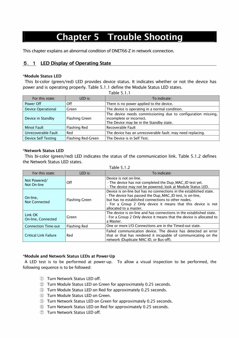
Chapter 5 Trouble Shooting
This chapter explains an abnormal condition of DNET66-Z in network connection.
5.1 LED Display of Operating State
*Module Status LED
This bi-color (green/red) LED provides device status. It indicates whether or not the device has
power and is operating properly. Table 5.1.1 define the Module Status LED states.
Table 5.1.1
For this state: LED is: To indicate:
Power Off Off There is no power applied to the device.
Device Operational Green The device is operating in a normal condition.
Device in Standby Flashing Green
The device needs commissioning due to configuration missing,
incomplete or incorrect.
The Device may be in the Standby state.
Minot Fault Flashing Red Recoverable Fault
Unrecoverable Fault Red The device has an unrecoverable fault; may need replacing.
Device Self Testing Flashing Red-Green The Device is in Self Test.
*Network Status LED
This bi-color (green/red) LED indicates the status of the communication link. Table 5.1.2 defines
the Network Status LED states.
Table 5.1.2
For this state: LED is: To indicate:
Not Powered/
Not On-line Off
Device is not on-line.
- The device has not completed the Dup_MAC_ID test yet.
- The device may not be powered, look at Module Status LED.
On-line,
Not Connected Flashing Green
Device is on-line but has no connections in the established state.
- The device has passed the Dup_MAC_ID test, is on-line,
but has no established connections to other nodes.
- For a Group 2 Only device it means that this device is not
allocated to a master.
Link OK
On-line, Connected Green
The device is on-line and has connections in the established state.
- For a Group 2 Only device it means that the device is allocated to
a Master.
Connection Time-out Flashing Red One or more I/O Connections are in the Timed-out state.
Critical Link Failure Red
Failed communication device. The device has detected an error
that or that has rendered it incapable of communicating on the
network (Duplicate MAC ID, or Bus-off).
*Module and Network Status LEDs at Power-Up
A LED test is to be performed at power-up. To allow a visual inspection to be performed, the
following sequence is to be followed:
① Turn Network Status LED off.
② Turn Module Status LED on Green for approximately 0.25 seconds.
③ Turn Module Status LED on Red for approximately 0.25 seconds.
④ Turn Module Status LED on Green.
⑤ Turn Network Status LED on Green for approximately 0.25 seconds.
⑥ Turn Network Status LED on Red for approximately 0.25 seconds.
⑦ Turn Network Status LED off.
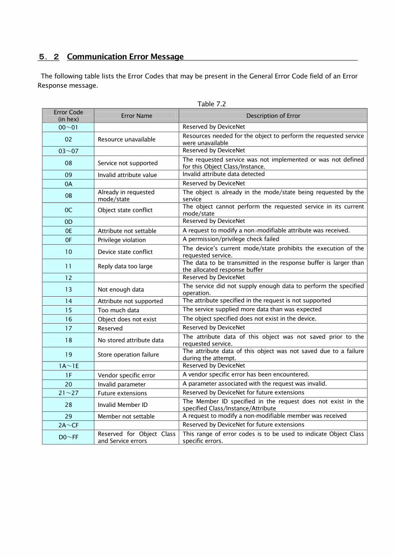
5.2 Communication Error Message
The following table lists the Error Codes that may be present in the General Error Code field of an Error
Response message.
Table 7.2
Error Code
(in hex) Error Name Description of Error
00~01 Reserved by DeviceNet
02 Resource unavailable Resources needed for the object to perform the requested service
were unavailable
03~07 Reserved by DeviceNet
08 Service not supported The requested service was not implemented or was not defined
for this Object Class/Instance.
09 Invalid attribute value Invalid attribute data detected
0A Reserved by DeviceNet
0B Already in requested
mode/state
The object is already in the mode/state being requested by the
service
0C Object state conflict The object cannot perform the requested service in its current
mode/state
0D Reserved by DeviceNet
0E Attribute not settable A request to modify a nonュmodifiable attribute was received.
0F Privilege violation A permission/privilege check failed
10 Device state conflict The device’s current mode/state prohibits the execution of the
requested service.
11 Reply data too large The data to be transmitted in the response buffer is larger than
the allocated response buffer
12 Reserved by DeviceNet
13 Not enough data The service did not supply enough data to perform the specified
operation.
14 Attribute not supported The attribute specified in the request is not supported
15 Too much data The service supplied more data than was expected
16 Object does not exist The object specified does not exist in the device.
17 Reserved Reserved by DeviceNet
18 No stored attribute data The attribute data of this object was not saved prior to the
requested service.
19 Store operation failure The attribute data of this object was not saved due to a failure
during the attempt.
1A~1E Reserved by DeviceNet
1F Vendor specific error A vendor specific error has been encountered.
20 Invalid parameter A parameter associated with the request was invalid.
21~27 Future extensions Reserved by DeviceNet for future extensions
28 Invalid Member ID The Member ID specified in the request does not exist in the
specified Class/Instance/Attribute
29 Member not settable A request to modify a non-modifiable member was received
2A~CF Reserved by DeviceNet for future extensions
D0~FF Reserved for Object Class
and Service errors
This range of error codes is to be used to indicate Object Class
specific errors.
Chapter 6 Extending Device Profile
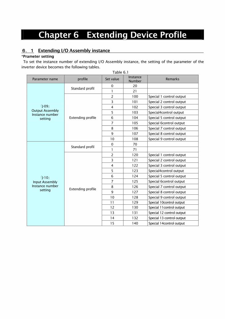
6.1 Extending I/O Assembly instance
*Prameter setting
To set the instance number of extending I/O Assembly instance, the setting of the parameter of the
inverter device becomes the following tables.
Table 6.1
Parameter name profile Set value Instance
Number Remarks
「J-09」
Output Assembly
Instance number
setting
Standard profil
0 20
1 21
Extending profile
2 100 Special 1 control output
3 101 Special 2 control output
4 102 Special 3 control output
5 103 Special4control output
6 104 Special 5 control output
7 105 Special 6control output
8 106 Special 7 control output
9 107 Special 8 control output
10 108 Special 9 control output
「J-10」
Input Assembly
Instance number
setting
Standard profil
0 70
1 71
Extending profile
2 120 Special 1 control output
3 121 Special 2 control output
4 122 Special 3 control output
5 123 Special4control output
6 124 Special 5 control output
7 125 Special 6control output
8 126 Special 7 control output
9 127 Special 8 control output
10 128 Special 9 control output
11 129 Special 10control output
12 130 Special 11control output
13 131 Special 12 control output
14 132 Special 13 control output
15 140 Special 14control output
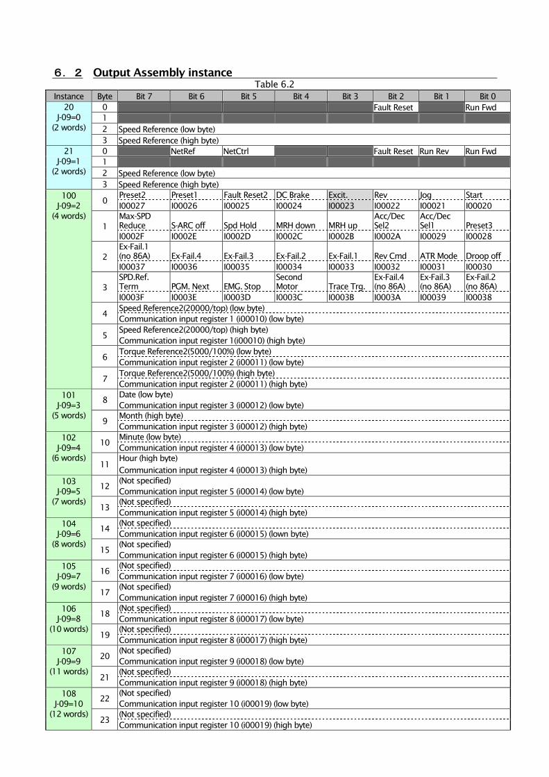
6.2 Output Assembly instance
Table 6.2
Instance Byte Bit 7 Bit 6 Bit 5 Bit 4 Bit 3 Bit 2 Bit 1 Bit 0
20
J-09=0
(2 words)
0 Fault Reset Run Fwd
1
2 Speed Reference (low byte)
3 Speed Reference (high byte)
21
J-09=1
(2 words)
0 NetRef NetCtrl Fault Reset Run Rev Run Fwd
1
2 Speed Reference (low byte)
3 Speed Reference (high byte)
100
J-09=2
(4 words)
0 Preset2 Preset1 Fault Reset2 DC Brake Excit. Rev Jog Start
I00027 I00026 I00025 I00024 I00023 I00022 I00021 I00020
1
Max-SPD
Reduce S-ARC off Spd Hold MRH down MRH up
Acc/Dec
Sel2
Acc/Dec
Sel1 Preset3
I0002F I0002E I0002D I0002C I0002B I0002A I00029 I00028
2
Ex-Fail.1
(no 86A) Ex-Fail.4 Ex-Fail.3 Ex-Fail.2 Ex-Fail.1 Rev Cmd ATR Mode Droop off
I00037 I00036 I00035 I00034 I00033 I00032 I00031 I00030
3
SPD.Ref.
Term PGM. Next EMG. Stop
Second
Motor Trace Trg.
Ex-Fail.4
(no 86A)
Ex-Fail.3
(no 86A)
Ex-Fail.2
(no 86A)
I0003F I0003E I0003D I0003C I0003B I0003A I00039 I00038
4 Speed Reference2(20000/top) (low byte)
Communication input register 1 (i00010) (low byte)
5 Speed Reference2(20000/top) (high byte)
Communication input register 1(i00010) (high byte)
6 Torque Reference2(5000/100%) (low byte)
Communication input register 2 (i00011) (low byte)
7 Torque Reference2(5000/100%) (high byte)
Communication input register 2 (i00011) (high byte)
101
J-09=3
(5 words)
8 Date (low byte)
Communication input register 3 (i00012) (low byte)
9 Month (high byte)
Communication input register 3 (i00012) (high byte)
102
J-09=4
(6 words)
10 Minute (low byte)
Communication input register 4 (i00013) (low byte)
11
Hour (high byte)
Communication input register 4 (i00013) (high byte)
103
J-09=5
(7 words)
12 (Not specified)
Communication input register 5 (i00014) (low byte)
13 (Not specified)
Communication input register 5 (i00014) (high byte)
104
J-09=6
(8 words)
14 (Not specified)
Communication input register 6 (i00015) (lown byte)
15 (Not specified)
Communication input register 6 (i00015) (high byte)
105
J-09=7
(9 words)
16 (Not specified)
Communication input register 7 (i00016) (low byte)
17 (Not specified)
Communication input register 7 (i00016) (high byte)
106
J-09=8
(10 words)
18 (Not specified)
Communication input register 8 (i00017) (low byte)
19 (Not specified)
Communication input register 8 (i00017) (high byte)
107
J-09=9
(11 words)
20 (Not specified)
Communication input register 9 (i00018) (low byte)
21 (Not specified)
Communication input register 9 (i00018) (high byte)
108
J-09=10
(12 words)
22 (Not specified)
Communication input register 10 (i00019) (low byte)
23 (Not specified)
Communication input register 10 (i00019) (high byte)
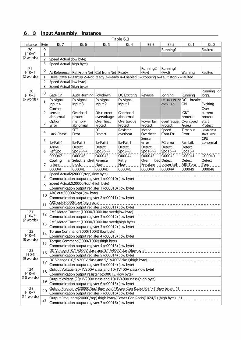
6.3 Input Assembly instance
Table 6.3
Instance Byte Bit 7 Bit 6 Bit 5 Bit 4 Bit 3 Bit 2 Bit 1 Bit 0
70
J-10=0
(2 words)
0 Running1 Faulted
1
2 Speed Actual (low byte)
3 Speed Actual (high byte)
71
J-10=1
(2 words)
0 At Reference Ref From Net Ctrl from Net Ready
Running2
(Rev)
Running1
(Fwd) Warning Faulted
1 Drive State(1=Startup 2=Not Ready 3=Ready 4=Enabled 5=Stopping 6=Fault stop 7=Faulted
2 Speed Actual (low byte)
3 Speed Actual (high byte)
120
J-10=2
(6 words)
0 Gate On Auto -turning Powdown DC Exciting Reverse Jogging Running
Running or
Jogg.
1 Ex-signal
input 4
Ex-signal
input 3
Ex-signal
input 2
Ex-signal
input 1
Ex-DB ON or
comu. ab
DC breake
ON Exciting
2
Current
senser
abnormal
Overload
protect.
Dir.current
overvoltage
Gateboad
abnormal
IGBT
protect
Over
current
protect
3 Option
Error
memory
abnormal
Over heat
Protect
Overtorque
Protect
Power fail
Protect
overfreque.
Protect
Over speed
Protect
Start
Protect
4 Lack Phase
SET
Error
FCL
Protect
Resister
overheat
Motor
Overheat
Speed
Cont.Err.
Timeout
Error
Senserless
start Error
5 Ex-Fail.4 Ex-Fail.3 Ex-Fail.2 Ex-Fail.1
Senser
error PG error Fan fail.
CPU
abnormal
6
Arrive
Ref.Spd
Detect
Spd2(<=)
Detect
Spd2(>=)
Detect
Spd2(=)
Detect
Spd1(<=)
Detect
Spd1(>=)
Detect
Spd1(=)
000047 O00046 O00045 O00044 O00043 O00042 O00041 O00040
7
Cooling fan
failure
Select 2ndset
block
Reverse
Now
Retry
Now
Over load
Pre-alarm
Detect
power fail
Detect
ABS.Torq
Detect
Torq
00004F 00004E 00004D 00004C 00004B 00004A 000049 000048
8 Speed Actual2(20000/top) (low byte)
Communication output register 1 (o00010) (low byte)
9 Speed Actual2(20000/top) (high byte)
Communication output register 1 (o00010) (low byte)
10 ARC out(20000/top) (low byte)
Communication output register 2 (o00011) (low byte)
11 ARC out(20000/top) (high byte)
Communication output register 2 (o00011) (low byte)
121
J-10=3
(7 words)
12 RMS Motor Current (10000/100% Inv.rated)(low byte)
Communication output register 3 (o00012) (low byte)
13 RMS Motor Current (10000/100% Inv.rated)(high byte)
Communication output register 3 (o00012) (low byte)
122
J-10=4
(8 words)
14 Torque Command(5000/100%) (low byte)
Communication output register 4 (o00013) (low byte)
15 Torque Command(5000/100%) (high byte)
Communication output register 4 (o00013) (low byte)
123
J-10-5
(9 words)
16 DC Voltage (10/1V200V class and 5/1V400V class)(low byte)
Communication output register 5 (o00014) (low byte)
17 DC Voltage (10/1V200V class and 5/1V400V class)(high byte)
Communication output register 5 (o00014) (low byte)
124
J-10=6
(10 words)
18 Output Voltage (20/1V200V class and 10/1V400V class)(low byte)
Communication output resister 6(o00015) (low byte)
19 Output Voltage (20/1V200V class and 10/1V400V class)(high byte)
Communication output register 6 (o00015) (low byte)
125
J-10=7
(11 words)
20 Output Frequency(20000/top) (low byte)/ Power Con Racio(1024/1) (low byte) *1
Communication output register 7 (o00016) (low byte)
21 Output Frequency(20000/top) (high byte)/ Power Con Racio(1024/1) (high byte) *1
Communication output register 7 (o00016) (low byte)
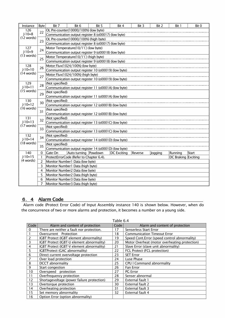
Instance Byte Bit 7 Bit 6 Bit 5 Bit 4 Bit 3 Bit 2 Bit 1 Bit 0
126
J-10=8
(12 words)
22 OL Pre-counter(10000/100%) (low byte)
Communication output register 8 (o00017) (low byte)
23 OL Pre-counter(10000/100%) (high byte)
Communication output register 8 (o00017) (low byte)
127
J-10=9
(13 words)
24 Motor Temperature(10/1℃) (low byte)
Communication output register 9 (o00018) (low byte)
25 Motor Temperature(10/1℃) (high byte)
Communication output register 9 (o00018) (low byte)
128
J-10=10
(14 words)
26 Motor Flux(1024/100%) (low byte)
Communication output register 10 (o00019) (low byte)
27 Motor Flux(1024/100%) (high byte)
Communication output register 10 (o00019) (low byte)
129
J-10=11
(15 words)
28 (Not specified)
Communication output register 11 (o0001A) (low byte)
29 (Not specified)
Communication output register 11 (o0001A) (low byte)
130
J-10=12
(16 words)
30 (Not specified)
Communication output register 12 (o0001B) (low byte)
31 (Not specified)
Communication output register 12 (o0001B) (low byte)
131
J-10=13
(17 words)
32 (Not specified)
Communication output register 13 (o0001C) (low byte)
33 (Not specified)
Communication output register 13 (o0001C) (low byte)
132
J-10=14
(18 words)
34 (Not specified)
Communication output register 14 (o0001D) (low byte)
35 (Not specified)
Communication output register 14 (o0001D) (low byte)
140
J-10=15
(4 words)
0 Gate On Auto turning Powdown DC Exciting Reverse Jogging Running Start
1 ProtectErrorCode (Refer to Chapter 6.4). DC Braking Exciting
2 Monitor Number1 Data (low byte)
3 Monitor Number1 Data (high byte)
4 Monitor Number2 Data (low byte)
5 Monitor Number2 Data (high byte)
6 Monitor Number3 Data (low byte)
7 Monitor Number3 Data (high byte)
6.4 Alarm Code
Alarm code (Protect Error Code) of Input Assembly instance 140 is shown below. However, when do
the concurrence of two or more alarms and protection, it becomes a number on a young side.
Table 6.4
Code Alarm and content of protection Code Alarm and content of protection
0 There are neither a fault nor protection. 17 Senserless Start Error
1 Overcurrent Protection 18 Communication Timeout Error
2 IGBT Protect (IGBT element abnormality) 19 Speed Cont.Error (speed control abnormality)
3 IGBT Protect (IGBT-U element abnormality) 20 Motor Overheat (motor overheating protection)
4 IGBT Protect (IGBT-V element abnormality) 21 Slave Error (slave unit abnormality)
5 IGBTProtect (GAC abnormality) 22 FCL Protect (FCL protection)
6 Direct current overvoltage protection 23 SET Error
7 Over load protection 24 Luse Phase
8 DCCT abnormality 25 CPU l Command abnormality
9 Start congestion 26 Fan Error
10 Overspeed protection 27 PG Error
11 Overfrequency protection 28 Senser abnormal
12 Shortagevoltage (power failure protection) 29 External fault 1
13 Overtorque protection 30 External fault 2
14 Overheating protection 31 External fault 3
15 Set memory abnormality 32 External fault 4
16 Option Error (option abnormality)
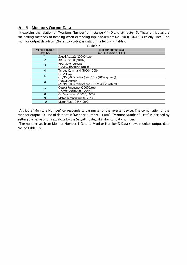
6.5 Monitors Output Data
It explains the relation of "Monitors Number" of instance # 140 and attribute 15. These attributes are
the setting methods of needing when extending Input Assembly No.140 (J-10=15)is chiefly used. The
monitor output data(from 2bytes to 7bytes) is data of the following tables.
Table 6-5
Monitor output
Data No.
Monitor output data
(At HC function OFF. )
1 Speed Actual2 (20000/top)
2 ARC out (5000/100%)
3 RMS Motor Current
(10000/100%(Inv. Rated))
4 Torque Command (5000/100%)
5 DC Voltage
(10/1V (200V faction) and 5/1V (400v system))
6 Output Voltage
(20/1V (200V faction) and 10/1V (400v system))
7 Output Frequency (20000/top)
/ Power Con Racio (1024/1)
8 OL Pre-counter (10000/100%)
9 Motor Temperature (10/1℃)
10 Motor Flux (1024/100%)
Attribute "Monitors Number" corresponds to parameter of the inverter device. The combination of the
monitor output 10 kind of data set in "Monitor Number 1 Data" - "Monitor Number 3 Data" is decided by
setting the value of this attribute by the Set_Attribute_J-12(Monitor data number)
The number set from Monitor Number 1 Data to Monitor Number 3 Data shows monitor output data
No. of Table 6.5.1
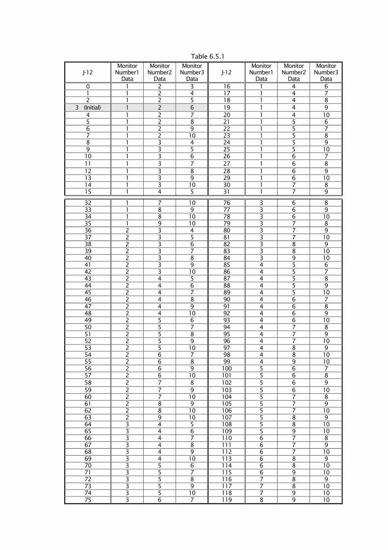
Table 6.5.1
J-12
Monitor
Number1
Data
Monitor
Number2
Data
Monitor
Number3
Data
J-12
Monitor
Number1
Data
Monitor
Number2
Data
Monitor
Number3
Data
0 1 2 3 16 1 4 6
1 1 2 4 17 1 4 7
2 1 2 5 18 1 4 8
3 (Initial) 1 2 6 19 1 4 9
4 1 2 7 20 1 4 10
5 1 2 8 21 1 5 6
6 1 2 9 22 1 5 7
7 1 2 10 23 1 5 8
8 1 3 4 24 1 5 9
9 1 3 5 25 1 5 10
10 1 3 6 26 1 6 7
11 1 3 7 27 1 6 8
12 1 3 8 28 1 6 9
13 1 3 9 29 1 6 10
14 1 3 10 30 1 7 8
15 1 4 5 31 1 7 9
32 1 7 10 76 3 6 8
33 1 8 9 77 3 6 9
34 1 8 10 78 3 6 10
35 1 9 10 79 3 7 8
36 2 3 4 80 3 7 9
37 2 3 5 81 3 7 10
38 2 3 6 82 3 8 9
39 2 3 7 83 3 8 10
40 2 3 8 84 3 9 10
41 2 3 9 85 4 5 6
42 2 3 10 86 4 5 7
43 2 4 5 87 4 5 8
44 2 4 6 88 4 5 9
45 2 4 7 89 4 5 10
46 2 4 8 90 4 6 7
47 2 4 9 91 4 6 8
48 2 4 10 92 4 6 9
49 2 5 6 93 4 6 10
50 2 5 7 94 4 7 8
51 2 5 8 95 4 7 9
52 2 5 9 96 4 7 10
53 2 5 10 97 4 8 9
54 2 6 7 98 4 8 10
55 2 6 8 99 4 9 10
56 2 6 9 100 5 6 7
57 2 6 10 101 5 6 8
58 2 7 8 102 5 6 9
59 2 7 9 103 5 6 10
60 2 7 10 104 5 7 8
61 2 8 9 105 5 7 9
62 2 8 10 106 5 7 10
63 2 9 10 107 5 8 9
64 3 4 5 108 5 8 10
65 3 4 6 109 5 9 10
66 3 4 7 110 6 7 8
67 3 4 8 111 6 7 9
68 3 4 9 112 6 7 10
69 3 4 10 113 6 8 9
70 3 5 6 114 6 8 10
71 3 5 7 115 6 9 10
72 3 5 8 116 7 8 9
73 3 5 9 117 7 8 10
74 3 5 10 118 7 9 10
75 3 6 7 119 8 9 10

http://www.toyodenki.co.jp/ HEAD OFFICE: Tokyo Tatemono Yaesu Bldg, 1-4-16 Yaesu, Chuo-ku,
Tokyo, Japan ZIP CODE 103-0028
TEL: +81-3-5202-8132 - 6
FAX: +81-3-5202-8150
Contents of this manual are subject to change without notice.
2012-09
QG18746B


