Embed Size (px)
Citation preview
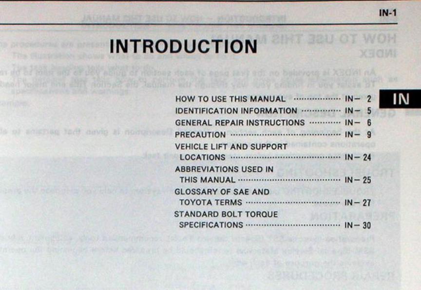
HOW TO USE THIS MANUALINDEXAn INDEX is provided on the first page of each section to guide you to the item to be repaired.To assist you in finding your way through the manual, the Section Title and major heading aregiven at the top of every page.
GENERAL DESCRIPTIONAt the beginning of each section, a General Description is given that pertains to all repairoperations contained in that section.Read these precautions before starting any repair task.
TROUBLESHOOTINGTROUBLESHOOTING tables are included for each system to help you diagnose the problem andfind the cause.
PREPARATIONPreparation lists the SST (Special Service Tools), recommended tools, equipment, lubricant andSSM (Special Service Materials) which should be prepared before beginning the operation andexplains the purpose of each one.
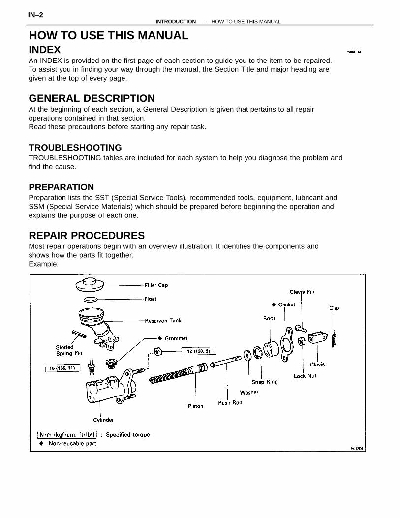
REPAIR PROCEDURESMost repair operations begin with an overview illustration. It identifies the components andshows how the parts fit together.Example:
–INTRODUCTION HOW TO USE THIS MANUALIN–2
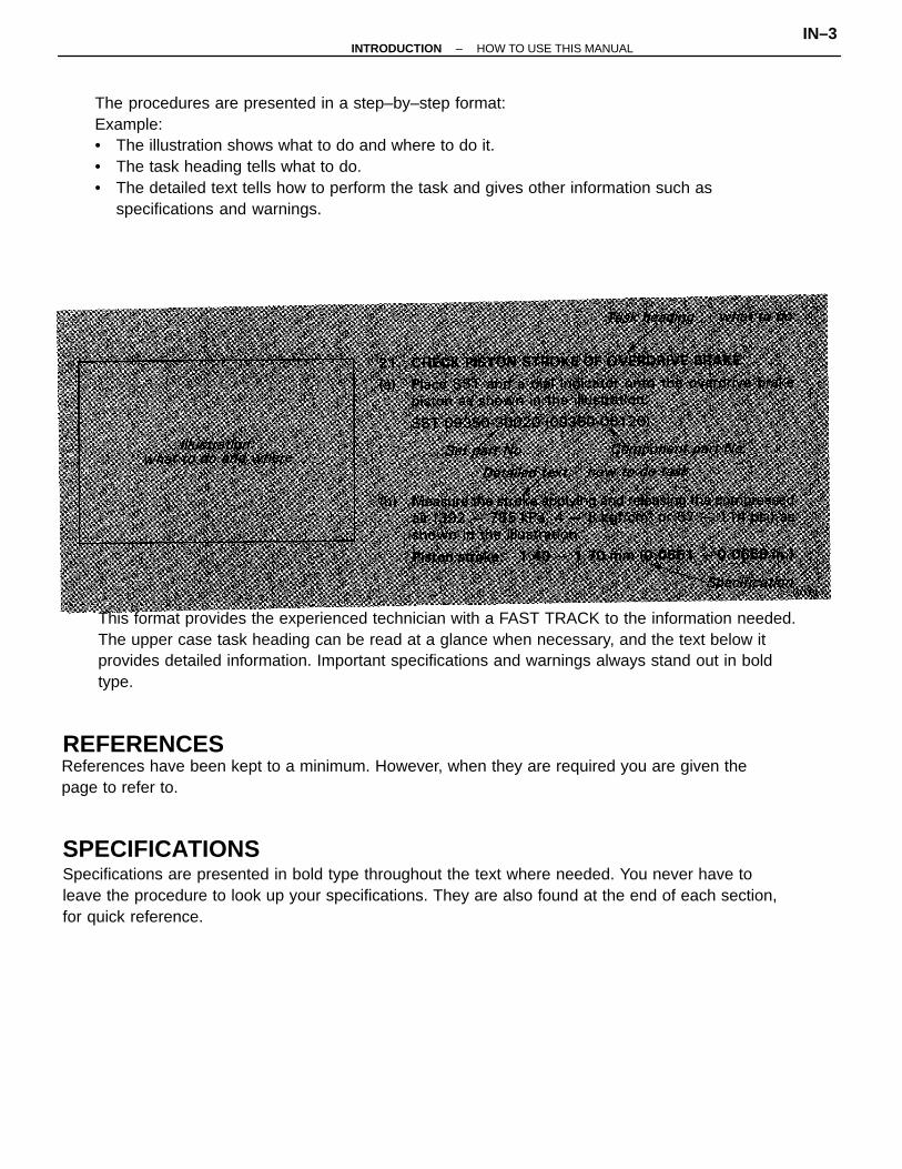
The procedures are presented in a step–by–step format:Example:• The illustration shows what to do and where to do it.• The task heading tells what to do.• The detailed text tells how to perform the task and gives other information such as
specifications and warnings.
SPECIFICATIONSSpecifications are presented in bold type throughout the text where needed. You never have toleave the procedure to look up your specifications. They are also found at the end of each section,for quick reference.
This format provides the experienced technician with a FAST TRACK to the information needed.The upper case task heading can be read at a glance when necessary, and the text below itprovides detailed information. Important specifications and warnings always stand out in boldtype.
References have been kept to a minimum. However, when they are required you are given thepage to refer to.
REFERENCES
–INTRODUCTION HOW TO USE THIS MANUALIN–3
CAUTIONS, NOTICES, HINTS:• CAUTIONS are presented in bold type, and indicate there is a possibility of injury to you or
other people.• NOTICES are also presented in bold type, and indicate the possibility of damage to the
components being repaired.• HINTS are separated from the text but do not appear in bold. They provide additional
information to help you perform the repair efficiently.
The UNITS given in this manual are primarily expressed according to the SI UNIT(InternationalSystem of Unit), and alternately expressed in the metric system and in the English System.Example:
Torque: 30 N–m (310 kgf–cm, 22 ft–lbf)
SIS UNIT
–INTRODUCTION HOW TO USE THIS MANUALIN–4
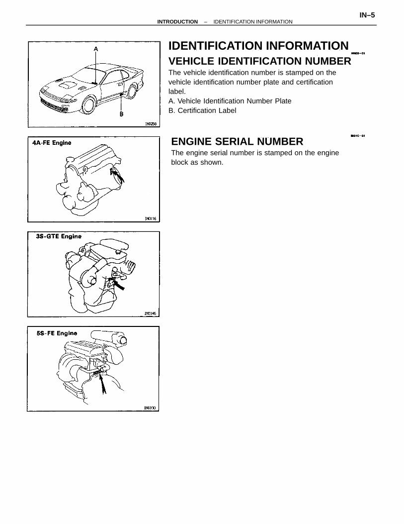
IDENTIFICATION INFORMATIONVEHICLE IDENTIFICATION NUMBERThe vehicle identification number is stamped on thevehicle identification number plate and certificationlabel.A. Vehicle Identification Number PlateB. Certification Label
ENGINE SERIAL NUMBERThe engine serial number is stamped on the engineblock as shown.
–INTRODUCTION IDENTIFICATION INFORMATIONIN–5
(a) Before performing electrical work, disconnectthe negative cable from the battery terminal.
(b) If it is necessary to disconnect the battery forinspection or repair, always disconnect the cablefrom the negative (–) terminal which is groundedto the vehicle body.
(c) To prevent damage to the battery terminal post,loosen the terminal nut and raise the cable str–aight up without twisting or prying it.
(d) Clean the battery terminal posts and cable ter–minals with a clean shop rag. Do not scrape themwith a file or other abrasive objects.
(e) Install the cable terminal to the battery post withthe nut loose, and tighten the nut after installa–tion. Do not use a hammer to tap the terminalonto the post.
(f) Be sure the cover for the positive (+) terminal isproperly in place.
4. Check hose and wiring connectors to make sure thatthey are secure and correct.
5. Non–reusable parts(a) Always replace cotter pins, gaskets, 0–rings and
oil seals etc. with new ones.(b) Non–reusable parts are indicated in the com–
ponent illustrations by the ”♦ ” symbol.
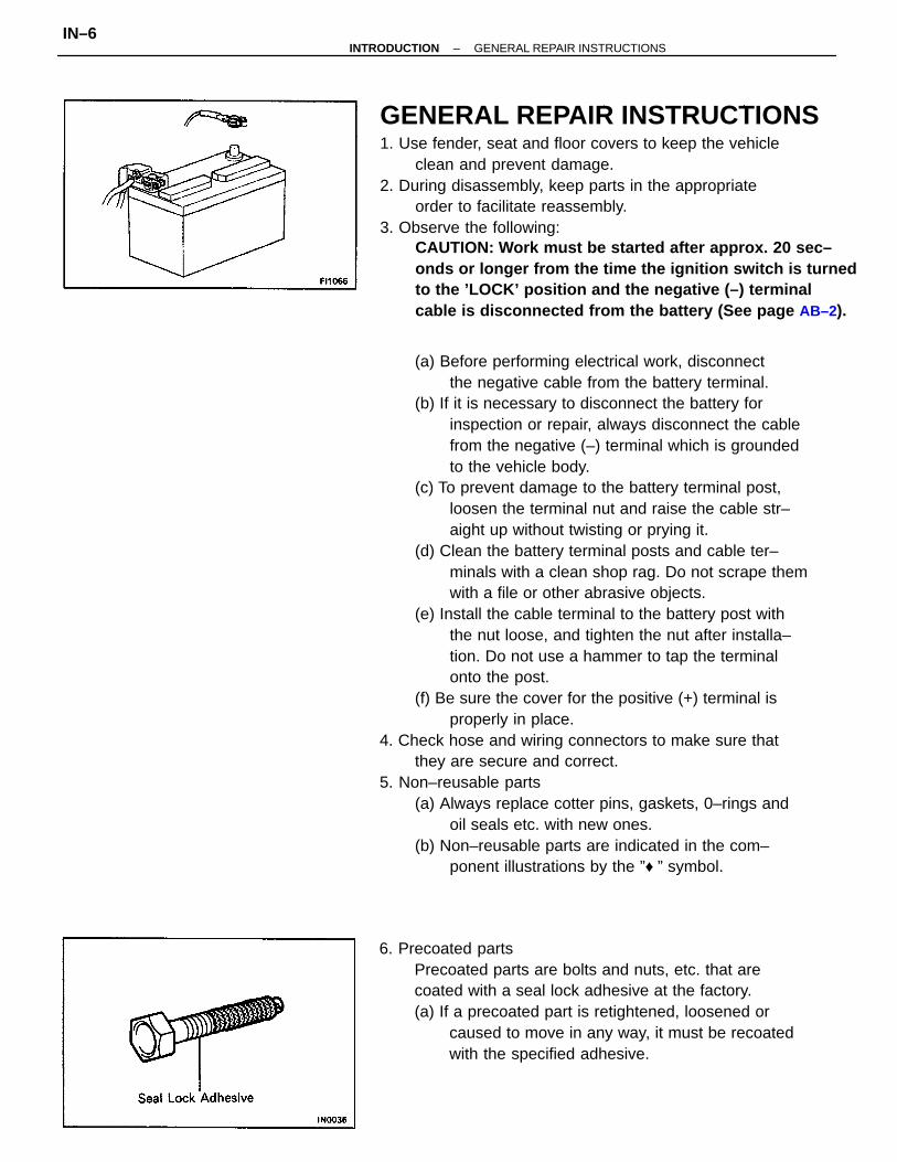
GENERAL REPAIR INSTRUCTIONS1. Use fender, seat and floor covers to keep the vehicle
clean and prevent damage.2. During disassembly, keep parts in the appropriate
order to facilitate reassembly.3. Observe the following:
CAUTION: Work must be started after approx. 20 sec–onds or longer from the time the ignition switch is turnedto the ’LOCK’ position and the negative (–) terminalcable is disconnected from the battery (See page AB–2).
6. Precoated partsPrecoated parts are bolts and nuts, etc. that arecoated with a seal lock adhesive at the factory.(a) If a precoated part is retightened, loosened or
caused to move in any way, it must be recoatedwith the specified adhesive.
–INTRODUCTION GENERAL REPAIR INSTRUCTIONSIN–6
(b) When reusing precoated parts, clean off the oldadhesive and dry with compressed air. Thenapply the specified seal lock adhesive to the bolt,nut or threads.
(c) Precoated parts are indicated in the componentillustrations by the ”” symbol.When necessary, use a sealer on gaskets to preventleaks.
8. Carefully observe all specifications for bolt tighteningtorques. Always use a torque wrench.
9. Use of special service tools (SST) and special servicematerials (SSM) may be required, depending on thenature of the repair. Be sure to use SST and SSMwhere specified and follow the proper work proce–dure. A list of SST and SSM can be found in thepreparation part at the front of each section in thismanual.
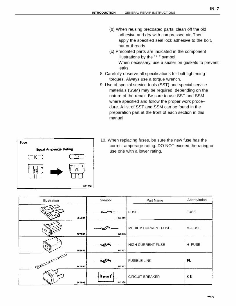
10. When replacing fuses, be sure the new fuse has thecorrect amperage rating. DO NOT exceed the rating oruse one with a lower rating.
MEDIUM CURRENT FUSE
HIGH CURRENT FUSE
CIRCUIT BREAKER
FUSIBLE LINK
AbbreviationIllustration Part NameSymbol
M–FUSE
H–FUSE
FUSEFUSE
–INTRODUCTION GENERAL REPAIR INSTRUCTIONSIN–7
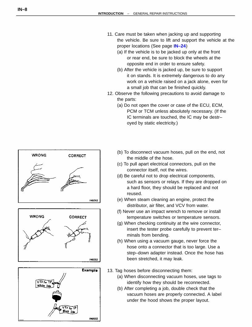
(b) To disconnect vacuum hoses, pull on the end, notthe middle of the hose.
(c) To pull apart electrical connectors, pull on theconnector itself, not the wires.
(d) Be careful not to drop electrical components,such as sensors or relays. If they are dropped ona hard floor, they should be replaced and notreused.
(e) When steam cleaning an engine, protect thedistributor, air filter, and VCV from water.
(f) Never use an impact wrench to remove or installtemperature switches or temperature sensors.
(g) When checking continuity at the wire connector,insert the tester probe carefully to prevent ter–minals from bending.
(h) When using a vacuum gauge, never force thehose onto a connector that is too large. Use astep–down adapter instead. Once the hose hasbeen stretched, it may leak.
13. Tag hoses before disconnecting them:(a) When disconnecting vacuum hoses, use tags to
identify how they should be reconnected.(b) After completing a job, double check that the
vacuum hoses are properly connected. A labelunder the hood shows the proper layout.
11. Care must be taken when jacking up and supportingthe vehicle. Be sure to lift and support the vehicle at theproper locations (See page IN–24)(a) If the vehicle is to be jacked up only at the front
or rear end, be sure to block the wheels at theopposite end in order to ensure safety.
(b) After the vehicle is jacked up, be sure to supportit on stands. It is extremely dangerous to do anywork on a vehicle raised on a jack alone, even fora small job that can be finished quickly.
12. Observe the following precautions to avoid damage tothe parts:(a) Do not open the cover or case of the ECU, ECM,
PCM or TCM unless absolutely necessary. (If theIC terminals are touched, the IC may be destr–oyed by static electricity.)
–INTRODUCTION GENERAL REPAIR INSTRUCTIONSIN–8
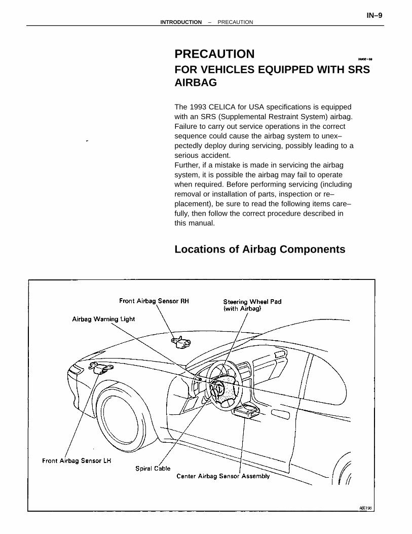
PRECAUTIONFOR VEHICLES EQUIPPED WITH SRSAIRBAG
The 1993 CELICA for USA specifications is equippedwith an SRS (Supplemental Restraint System) airbag.Failure to carry out service operations in the correctsequence could cause the airbag system to unex–pectedly deploy during servicing, possibly leading to aserious accident.Further, if a mistake is made in servicing the airbagsystem, it is possible the airbag may fail to operatewhen required. Before performing servicing (includingremoval or installation of parts, inspection or re–placement), be sure to read the following items care–fully, then follow the correct procedure described inthis manual.
Locations of Airbag Components
–INTRODUCTION PRECAUTIONIN–9
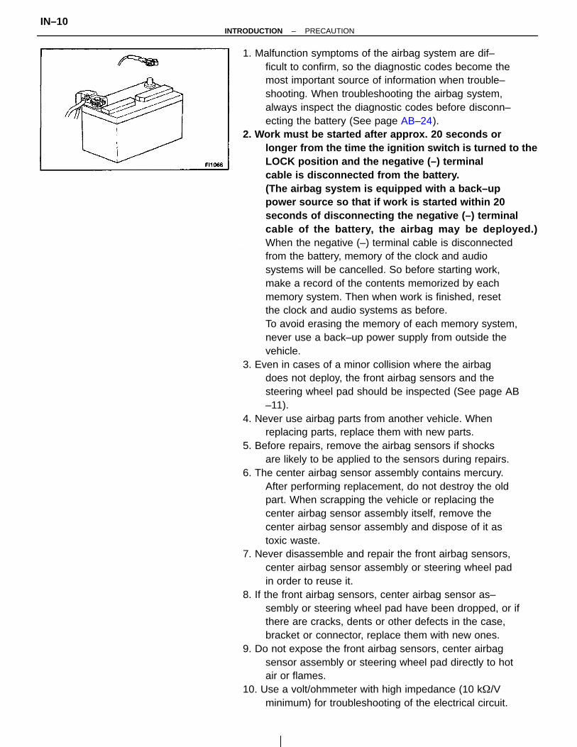
1. Malfunction symptoms of the airbag system are dif–ficult to confirm, so the diagnostic codes become themost important source of information when trouble–shooting. When troubleshooting the airbag system,always inspect the diagnostic codes before disconn–ecting the battery (See page AB–24).
2. Work must be started after approx. 20 seconds orlonger from the time the ignition switch is turned to theLOCK position and the negative (–) terminalcable is disconnected from the battery.(The airbag system is equipped with a back–uppower source so that if work is started within 20seconds of disconnecting the negative (–) terminalcable of the battery, the airbag may be deployed.)When the negative (–) terminal cable is disconnectedfrom the battery, memory of the clock and audiosystems will be cancelled. So before starting work,make a record of the contents memorized by eachmemory system. Then when work is finished, resetthe clock and audio systems as before.To avoid erasing the memory of each memory system,never use a back–up power supply from outside thevehicle.
3. Even in cases of a minor collision where the airbagdoes not deploy, the front airbag sensors and thesteering wheel pad should be inspected (See page AB–11).
4. Never use airbag parts from another vehicle. Whenreplacing parts, replace them with new parts.
5. Before repairs, remove the airbag sensors if shocksare likely to be applied to the sensors during repairs.
6. The center airbag sensor assembly contains mercury.After performing replacement, do not destroy the oldpart. When scrapping the vehicle or replacing thecenter airbag sensor assembly itself, remove thecenter airbag sensor assembly and dispose of it astoxic waste.
7. Never disassemble and repair the front airbag sensors,center airbag sensor assembly or steering wheel padin order to reuse it.
8. If the front airbag sensors, center airbag sensor as–sembly or steering wheel pad have been dropped, or ifthere are cracks, dents or other defects in the case,bracket or connector, replace them with new ones.
9. Do not expose the front airbag sensors, center airbagsensor assembly or steering wheel pad directly to hotair or flames.
10. Use a volt/ohmmeter with high impedance (10 k/Vminimum) for troubleshooting of the electrical circuit.
–INTRODUCTION PRECAUTIONIN–10
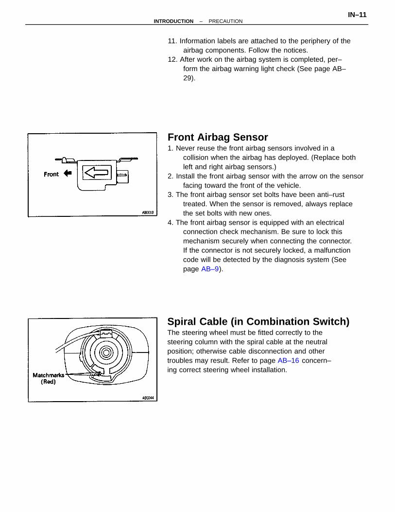
Front Airbag Sensor1. Never reuse the front airbag sensors involved in a
collision when the airbag has deployed. (Replace bothleft and right airbag sensors.)
2. Install the front airbag sensor with the arrow on the sensorfacing toward the front of the vehicle.
3. The front airbag sensor set bolts have been anti–rusttreated. When the sensor is removed, always replacethe set bolts with new ones.
4. The front airbag sensor is equipped with an electricalconnection check mechanism. Be sure to lock thismechanism securely when connecting the connector.If the connector is not securely locked, a malfunctioncode will be detected by the diagnosis system (Seepage AB–9).
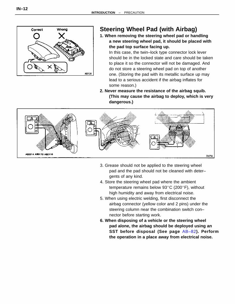
Spiral Cable (in Combination Switch)The steering wheel must be fitted correctly to thesteering column with the spiral cable at the neutralposition; otherwise cable disconnection and othertroubles may result. Refer to page AB–16 concern–ing correct steering wheel installation.
11. Information labels are attached to the periphery of theairbag components. Follow the notices.
12. After work on the airbag system is completed, per–form the airbag warning light check (See page AB–29).
–INTRODUCTION PRECAUTIONIN–11
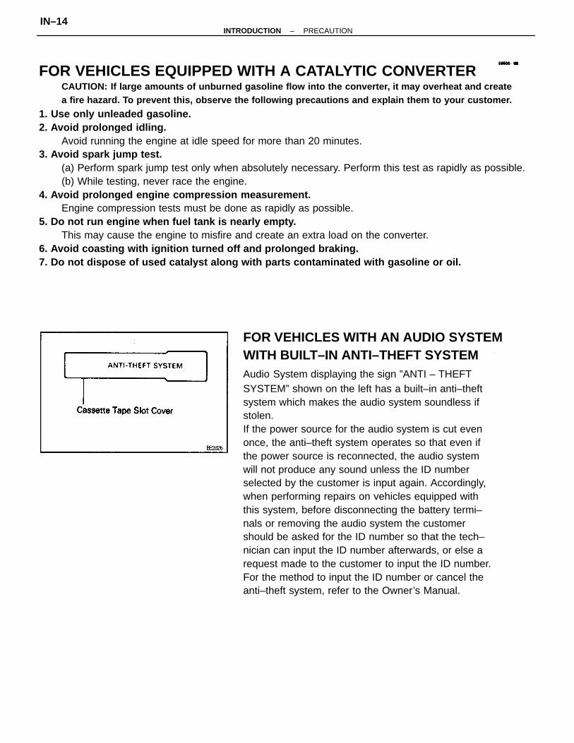
Steering Wheel Pad (with Airbag)1. When removing the steering wheel pad or handling
a new steering wheel pad, it should be placed withthe pad top surface facing up.In this case, the twin–lock type connector lock levershould be in the locked state and care should be takento place it so the connector will not be damaged. Anddo not store a steering wheel pad on top of anotherone. (Storing the pad with its metallic surface up maylead to a serious accident if the airbag inflates forsome reason.)
2. Never measure the resistance of the airbag squib.(This may cause the airbag to deploy, which is verydangerous.)
3. Grease should not be applied to the steering wheelpad and the pad should not be cleaned with deter–gents of any kind.
4. Store the steering wheel pad where the ambienttemperature remains below 93C (200F), withouthigh humidity and away from electrical noise.
5. When using electric welding, first disconnect theairbag connector (yellow color and 2 pins) under thesteering column near the combination switch con–nector before starting work.
6. When disposing of a vehicle or the steering wheelpad alone, the airbag should be deployed using anSST before disposal (See page AB–82). Performthe operation in a place away from electrical noise.
–INTRODUCTION PRECAUTIONIN–12

Wire Harness and ConnectorThe airbag system’s wire harness is integrated withthe cowl wire harness assembly. The wires for theairbag wire harness are encased in a yellow corruga–ted tube. All the connectors for the system are also astandard yellow color. If the airbag system wire har–ness becomes disconnected or the connector bec–omes broken due to an accident, etc., repair or replaceit as shown on page AB–21.
Center Airbag Sensor AssemblyThe connector to the center airbag sensor assemblyshould be connected or disconnected with the sensormounted on the floor. If the connector is connectedor disconnected while the center airbag sensor as–sembly is not mounted to the floor, it could causeundesired ignition of the airbag system.
–INTRODUCTION PRECAUTIONIN–13
FOR VEHICLES EQUIPPED WITH A CATALYTIC CONVERTERCAUTION: If large amounts of unburned gasoline flow into the converter, it may overheat and createa fire hazard. To prevent this, observe the following precautions and explain them to your customer.
1. Use only unleaded gasoline.2. Avoid prolonged idling.
Avoid running the engine at idle speed for more than 20 minutes.3. Avoid spark jump test.
(a) Perform spark jump test only when absolutely necessary. Perform this test as rapidly as possible.(b) While testing, never race the engine.
4. Avoid prolonged engine compression measurement.Engine compression tests must be done as rapidly as possible.
5. Do not run engine when fuel tank is nearly empty.This may cause the engine to misfire and create an extra load on the converter.
6. Avoid coasting with ignition turned off and prolonged braking.7. Do not dispose of used catalyst along with parts contaminated with gasoline or oil.
FOR VEHICLES WITH AN AUDIO SYSTEMWITH BUILT–IN ANTI–THEFT SYSTEMAudio System displaying the sign ”ANTI – THEFTSYSTEM” shown on the left has a built–in anti–theftsystem which makes the audio system soundless ifstolen.If the power source for the audio system is cut evenonce, the anti–theft system operates so that even ifthe power source is reconnected, the audio systemwill not produce any sound unless the ID numberselected by the customer is input again. Accordingly,when performing repairs on vehicles equipped withthis system, before disconnecting the battery termi–nals or removing the audio system the customershould be asked for the ID number so that the tech–nician can input the ID number afterwards, or else arequest made to the customer to input the ID number.For the method to input the ID number or cancel theanti–theft system, refer to the Owner’s Manual.
–INTRODUCTION PRECAUTIONIN–14
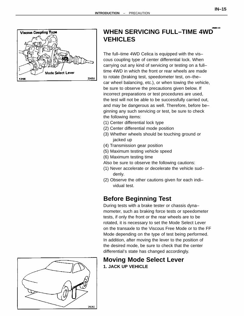
WHEN SERVICING FULL–TIME 4WDVEHICLES
The full–time 4WD Celica is equipped with the vis–cous coupling type of center differential lock. Whencarrying out any kind of servicing or testing on a full–time 4WD in which the front or rear wheels are madeto rotate (braking test, speedometer test, on–the–car wheel balancing, etc.), or when towing the vehicle,be sure to observe the precautions given below. Ifincorrect preparations or test procedures are used,the test will not be able to be successfully carried out,and may be dangerous as well. Therefore, before be–ginning any such servicing or test, be sure to checkthe following items:(1) Center differential lock type(2) Center differential mode position(3) Whether wheels should be touching ground or
jacked up(4) Transmission gear position(5) Maximum testing vehicle speed(6) Maximum testing timeAlso be sure to observe the following cautions:(1) Never accelerate or decelerate the vehicle sud–
denly.(2) Observe the other cautions given for each indi–
vidual test.
Before Beginning TestDuring tests with a brake tester or chassis dyna–mometer, such as braking force tests or speedometertests, if only the front or the rear wheels are to berotated, it is necessary to set the Mode Select Leveron the transaxle to the Viscous Free Mode or to the FFMode depending on the type of test being performed.In addition, after moving the lever to the position ofthe desired mode, be sure to check that the centerdifferential’s state has changed accordingly.
Moving Mode Select Lever1. JACK UP VEHICLE
–INTRODUCTION PRECAUTIONIN–15
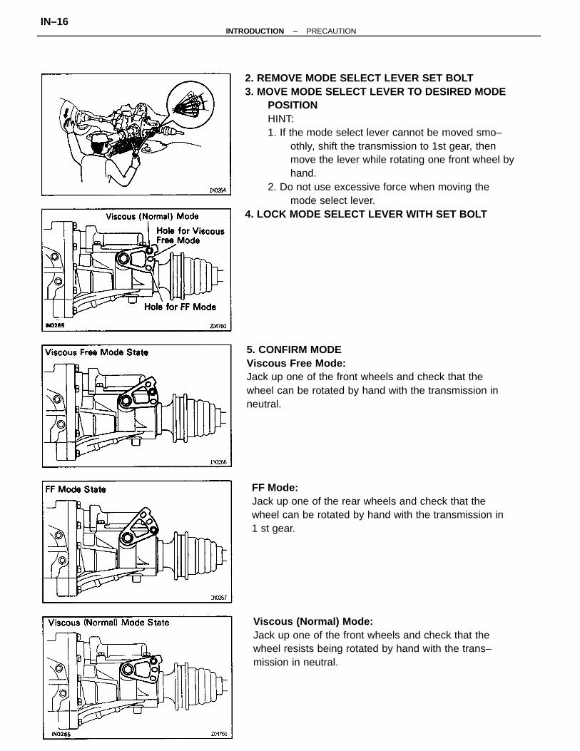
2. REMOVE MODE SELECT LEVER SET BOLT3. MOVE MODE SELECT LEVER TO DESIRED MODE
POSITIONHINT:1. If the mode select lever cannot be moved smo–
othly, shift the transmission to 1st gear, thenmove the lever while rotating one front wheel byhand.
2. Do not use excessive force when moving themode select lever.
4. LOCK MODE SELECT LEVER WITH SET BOLT
5. CONFIRM MODEViscous Free Mode:Jack up one of the front wheels and check that thewheel can be rotated by hand with the transmission inneutral.
Viscous (Normal) Mode:Jack up one of the front wheels and check that thewheel resists being rotated by hand with the trans–mission in neutral.
FF Mode:Jack up one of the rear wheels and check that thewheel can be rotated by hand with the transmission in1 st gear.
–INTRODUCTION PRECAUTIONIN–16
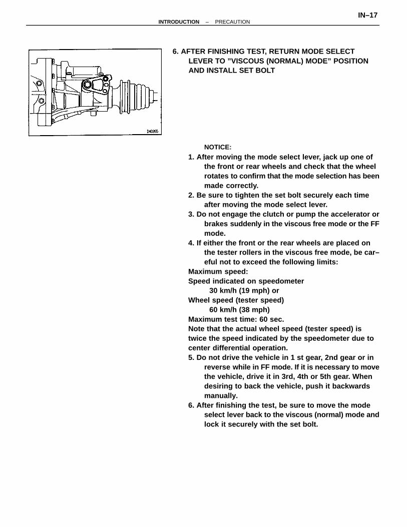
NOTICE:
1. After moving the mode select lever, jack up one ofthe front or rear wheels and check that the wheelrotates to confirm that the mode selection has beenmade correctly.
2. Be sure to tighten the set bolt securely each timeafter moving the mode select lever.
3. Do not engage the clutch or pump the accelerator orbrakes suddenly in the viscous free mode or the FFmode.
4. If either the front or the rear wheels are placed onthe tester rollers in the viscous free mode, be car–eful not to exceed the following limits:
Maximum speed:Speed indicated on speedometer
30 km/h (19 mph) orWheel speed (tester speed)
60 km/h (38 mph)Maximum test time: 60 sec.Note that the actual wheel speed (tester speed) istwice the speed indicated by the speedometer due tocenter differential operation.5. Do not drive the vehicle in 1 st gear, 2nd gear or in
reverse w hile in FF mode. If it is necessary to movethe vehicle, drive it in 3rd, 4th or 5th gear. Whendesiring to back the vehicle, push it backwardsmanually.
6. After finishing the test, be sure to move the modeselect lever back to the viscous (normal) mode andlock it securely with the set bolt.
6. AFTER FINISHING TEST, RETURN MODE SELECTLEVER TO ”VISCOUS (NORMAL) MODE” POSITIONAND INSTALL SET BOLT
–INTRODUCTION PRECAUTIONIN–17
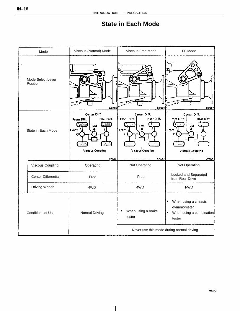
• When using a chassis
dynamometer
• When using a combination
tester
Never use this mode during normal driving
State in Each Mode
• When using a brake
tester
Locked and Separatedfrom Rear Drive
Mode Select LeverPosition
Conditions of Use
Viscous (Normal) Mode
Center Differential
State in Each Mode
Viscous Coupling
Viscous Free Mode
Driving Wheel:
Normal Driving
Not OperatingNot OperatingOperating
FF ModeMode
4WD4WD FWD
Free Free
–INTRODUCTION PRECAUTIONIN–18
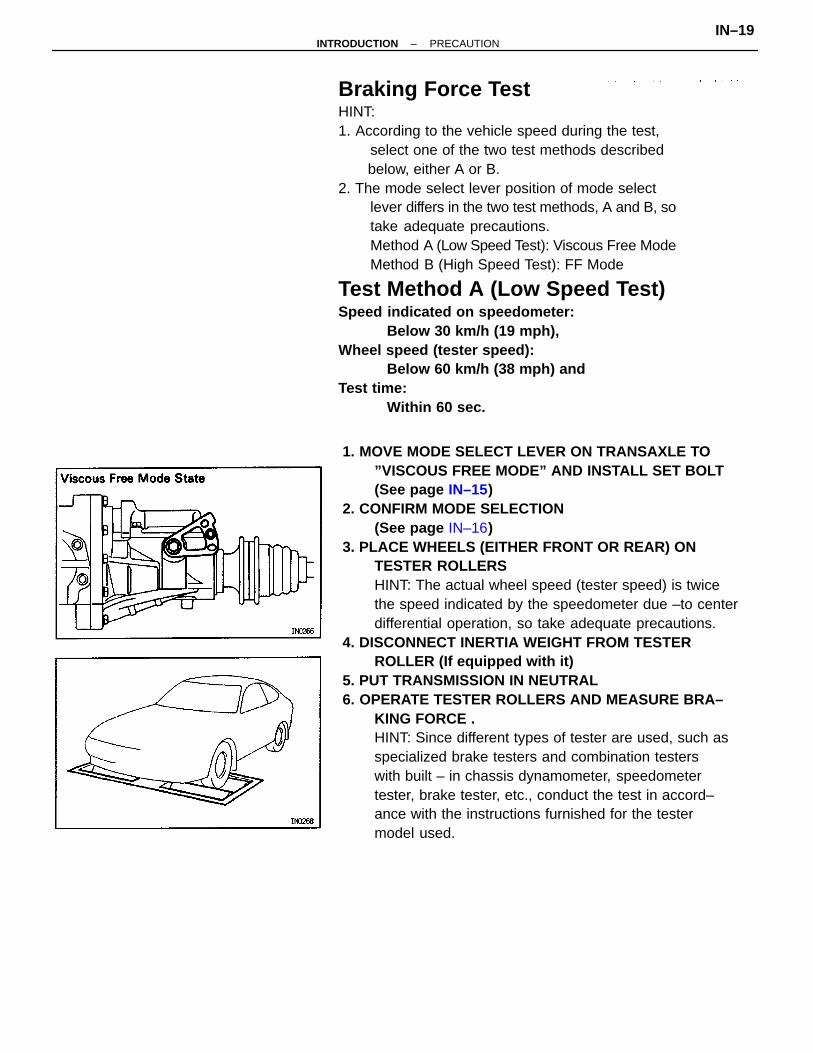
1. MOVE MODE SELECT LEVER ON TRANSAXLE TO”VISCOUS FREE MODE” AND INSTALL SET BOLT(See page IN–15)
2. CONFIRM MODE SELECTION(See page IN–16)
3. PLACE WHEELS (EITHER FRONT OR REAR) ONTESTER ROLLERSHINT: The actual wheel speed (tester speed) is twicethe speed indicated by the speedometer due –to centerdifferential operation, so take adequate precautions.
4. DISCONNECT INERTIA WEIGHT FROM TESTERROLLER (If equipped with it)
5. PUT TRANSMISSION IN NEUTRAL6. OPERATE TESTER ROLLERS AND MEASURE BRA–
KING FORCE .HINT: Since different types of tester are used, such asspecialized brake testers and combination testerswith built – in chassis dynamometer, speedometertester, brake tester, etc., conduct the test in accord–ance with the instructions furnished for the testermodel used.
Braking Force TestHINT:1. According to the vehicle speed during the test,
select one of the two test methods described below, either A or B.2. The mode select lever position of mode select
lever differs in the two test methods, A and B, sotake adequate precautions.Method A (Low Speed Test): Viscous Free ModeMethod B (High Speed Test): FF Mode
Test Method A (Low Speed Test)Speed indicated on speedometer:
Below 30 km/h (19 mph),Wheel speed (tester speed):
Below 60 km/h (38 mph) andTest time:
Within 60 sec.
–INTRODUCTION PRECAUTIONIN–19
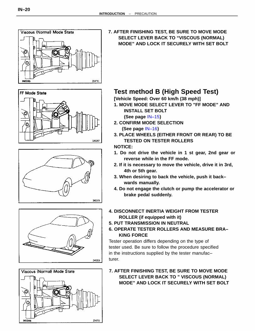
Test method B (High Speed Test)[Vehicle Speed: Over 60 km/h (38 mph)]1. MOVE MODE SELECT LEVER TO ”FF MODE” AND
INSTALL SET BOLT(See page IN–15)
2. CONFIRM MODE SELECTION (See page IN–16)3. PLACE WHEELS (EITHER FRONT OR REAR) TO BE
TESTED ON TESTER ROLLERSNOTICE:1. Do not drive the vehicle in 1 st gear, 2nd gear or
reverse while in the FF mode.2. If it is necessary to move the vehicle, drive it in 3rd,
4th or 5th gear.3. When desiring to back the vehicle, push it back–
wards manually.4. Do not engage the clutch or pump the accelerator or
brake pedal suddenly.
4. DISCONNECT INERTIA WEIGHT FROM TESTERROLLER (if equipped with it)
5. PUT TRANSMISSION IN NEUTRAL6. OPERATE TESTER ROLLERS AND MEASURE BRA–
KING FORCETester operation differs depending on the type oftester used. Be sure to follow the procedure specifiedin the instructions supplied by the tester manufac–turer.
7. AFTER FINISHING TEST, BE SURE TO MOVE MODESELECT LEVER BACK TO ” VISCOUS (NORMAL)MODE” AND LOCK IT SECURELY WITH SET BOLT
7. AFTER FINISHING TEST, BE SURE TO MOVE MODESELECT LEVER BACK TO “VISCOUS (NORMAL)MODE” AND LOCK IT SECURELY WITH SET BOLT
–INTRODUCTION PRECAUTIONIN–20
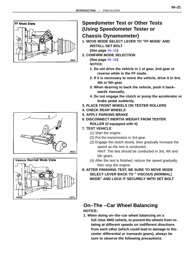
Speedometer Test or Other Tests(Using Speedometer Tester orChassis Dynamometer)1. MOVE MODE SELECT LEVER TO ”FF MODE’ AND
INSTALL SET BOLT(See page IN–15)
2. CONFIRM MODE SELECTION(See page IN–16)NOTICE:
1. Do not drive the vehicle in 1 st gear, 2nd gear orreverse while in the FF mode.
2. If it is necessary to move the vehicle, drive it in 3rd,4th or 5th gear.
3. When desiring to back the vehicle, push it back–wards manually.
4. Do not engage the clutch or pump the accelerator orbrake pedal suddenly.
3. PLACE FRONT WHEELS ON TESTER ROLLERS4. CHECK REAR WHEELS5. APPLY PARKING BRAKE6. DISCONNECT INERTIA WEIGHT FROM TESTER
ROLLER (if equipped with it)7. TEST VEHICLE
(1) Start the engine.(2) Put the transmission in 3rd gear.(3) Engage the clutch slowly, then gradually increase the
speed as the test is conducted.HINT: The test should be conducted in 3rd, 4th and5th gears.
(4) After the test is finished, reduce the speed gradually,then stop the engine.
8. AFTER FINISHING TEST, BE SURE TO MOVE MODESELECT LEVER BACK TO ” VISCOUS (NORMAL)MODE” AND LOCK IT SECURELY WITH SET BOLT
On–The –Car Wheel BalancingNOTICE:1. When doing on–the–car wheel balancing on a
full–time 4WD vehicle, to prevent the wheels from ro-tating at different speeds on indifferent directionsfrom each other (which could lead to damage to the-center differential or transaxle gears), always besure to observe the following precautions:
–INTRODUCTION PRECAUTIONIN–21
(a) All four wheels should be jacked up, clearing theground completely.
(b) The wheels should be driven with both the engineand the wheel balancer.
(e) The mode select lever on the transaxle of the vis–cous coupling type center differential should be inthe viscous (normal) mode position.
(d) The parking brake lever should be fully released.(e) None of the brakes should be allowed to drag.
2. Avoid sudden acceleration, deceleration and bra–king.
3. Carry out the wheel balancing with the transmissionin 3rd or 4th gear.
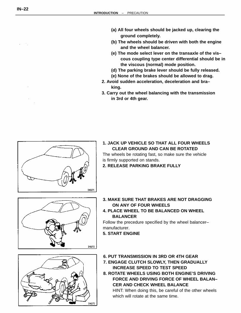
6. PUT TRANSMISSION IN 3RD OR 4TH GEAR7. ENGAGE CLUTCH SLOWLY, THEN GRADUALLY
INCREASE SPEED TO TEST SPEED8. ROTATE WHEELS USING BOTH ENGINE’S DRIVING
FORCE AND DRIVING FORCE OF WHEEL BALAN–CER AND CHECK WHEEL BALANCEHINT: When doing this, be careful of the other wheelswhich will rotate at the same time.
3. MAKE SURE THAT BRAKES ARE NOT DRAGGINGON ANY OF FOUR WHEELS
4. PLACE WHEEL TO BE BALANCED ON WHEELBALANCER
Follow the precedure specified by the wheel balancer–manufacturer.5. START ENGINE
1. JACK UP VEHICLE SO THAT ALL FOUR WHEELSCLEAR GROUND AND CAN BE ROTATED
The wheels be rotating fast, so make sure the vehicleis firmly supported on stands.2. RELEASE PARKING BRAKE FULLY
–INTRODUCTION PRECAUTIONIN–22
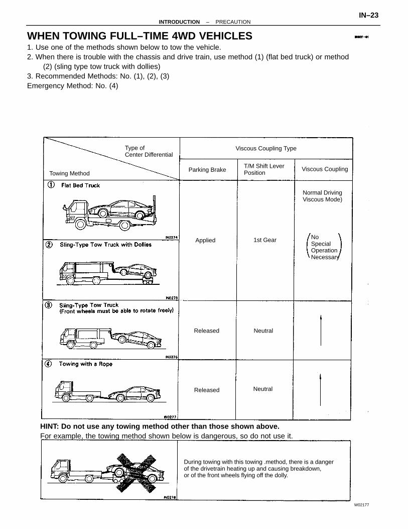
WHEN TOWING FULL–TIME 4WD VEHICLES1. Use one of the methods shown below to tow the vehicle.2. When there is trouble with the chassis and drive train, use method (1) (flat bed truck) or method
(2) (sling type tow truck with dollies)3. Recommended Methods: No. (1), (2), (3)Emergency Method: No. (4)
HINT: Do not use any towing method other than those shown above.For example, the towing method shown below is dangerous, so do not use it.
During towing with this towing .method, there is a dangerof the drivetrain heating up and causing breakdown,or of the front wheels flying off the dolly.
Normal DrivingViscous Mode)
Viscous Coupling
Type ofCenter Differential
NoSpecialOperationNecessary
T/M Shift LeverPosition
Viscous Coupling Type
Released
Towing Method
W02177
Parking Brake
Released
Applied 1st Gear
Neutral
Neutral
–INTRODUCTION PRECAUTIONIN–23
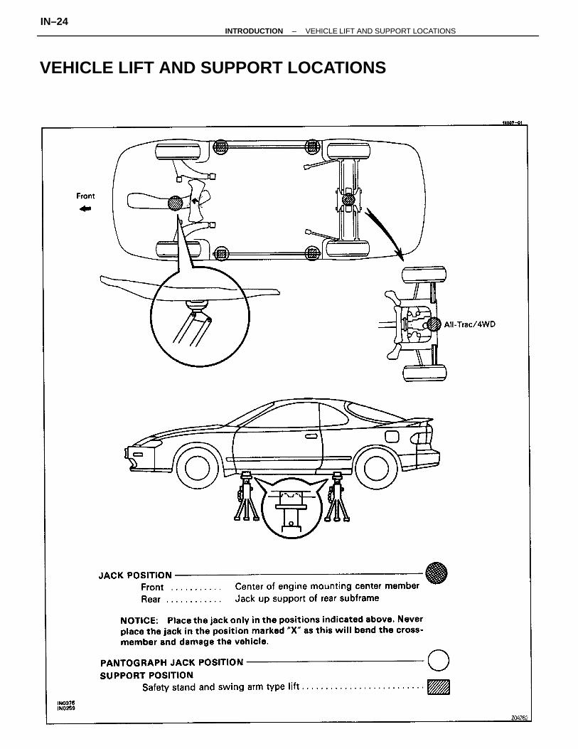
VEHICLE LIFT AND SUPPORT LOCATIONS
–INTRODUCTION VEHICLE LIFT AND SUPPORT LOCATIONSIN–24
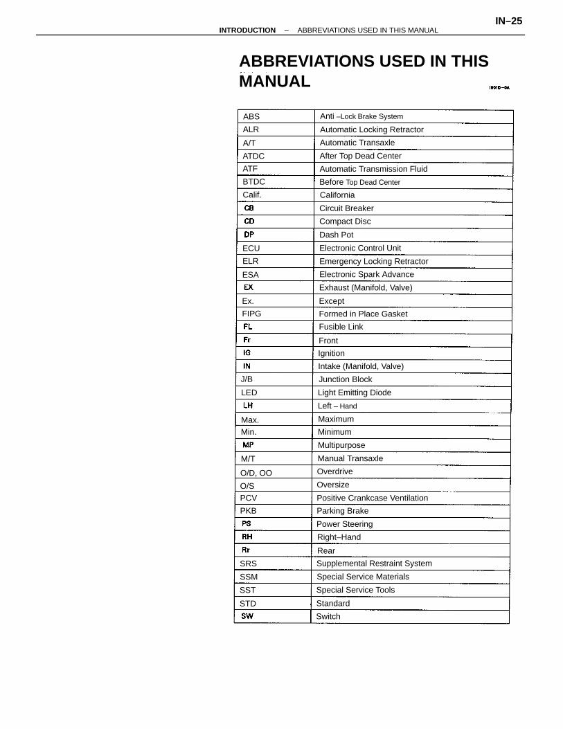
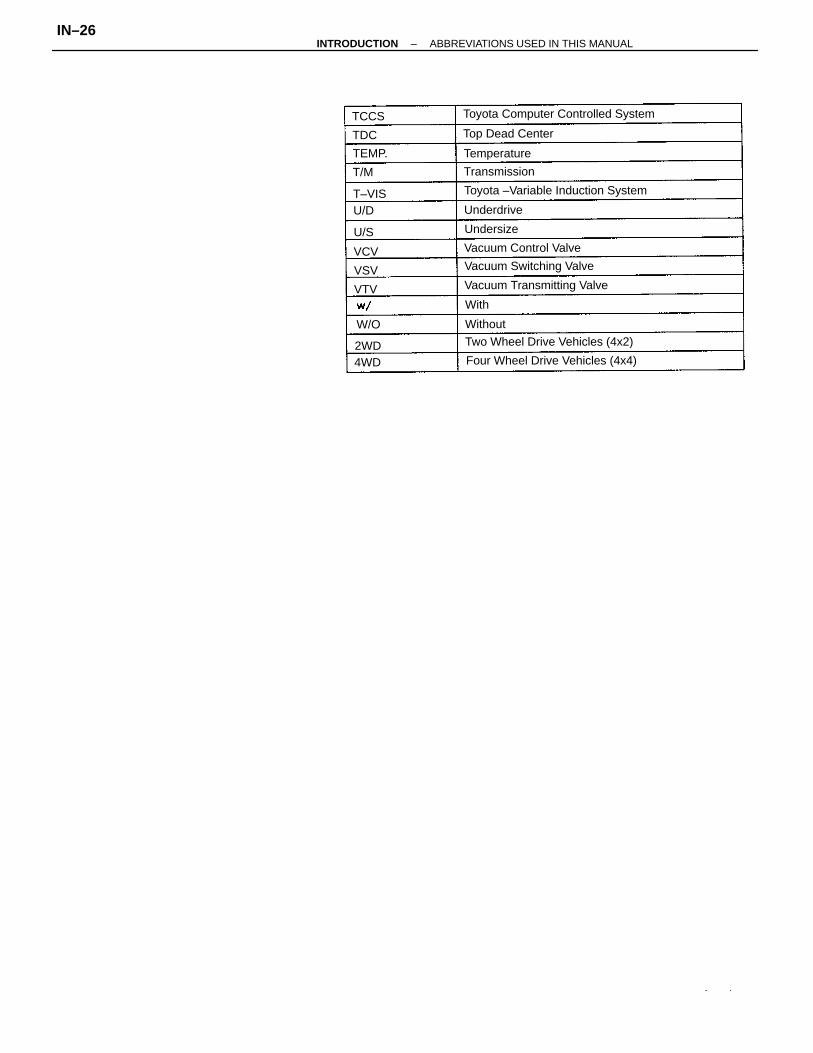
ABBREVIATIONS USED IN THISMANUAL
Supplemental Restraint System
Emergency Locking Retractor
Automatic Locking Retractor
Positive Crankcase Ventilation
Automatic Transmission Fluid
Electronic Spark Advance
Exhaust (Manifold, Valve)
Anti –Lock Brake System
Special Service Materials
Before Top Dead Center
Intake (Manifold, Valve)
After Top Dead Center
Formed in Place Gasket
Special Service Tools
Electronic Control Unit
Light Emitting Diode
Automatic Transaxle
Manual Transaxle
Power Steering
Circuit Breaker
Compact Disc
Junction Block
Parking Brake
Multipurpose
Right–Hand
Fusible Link
Left – Hand
OverdriveO/D, OO
California
Maximum
Dash Pot
Standard
Minimum
Oversize
Ignition
Except
Switch
BTDC
ATDC
Calif.
Front
O/S
J/B
FIPG
M/T
Rear
Min.
PKB
Max.
ALR
PCV
ATF
LED
A/T
SSM
ABS
ELR
STD
ESA
ECU
SRS
SST
Ex.
–INTRODUCTION ABBREVIATIONS USED IN THIS MANUALIN–25
Toyota Computer Controlled System
Toyota –Variable Induction System
Four Wheel Drive Vehicles (4x4)
Two Wheel Drive Vehicles (4x2)
Vacuum Transmitting Valve
Vacuum Switching Valve
Vacuum Control Valve
Top Dead Center
Temperature
Transmission
Underdrive
Undersize
Without
T–VIS
TEMP.
2WD4WD
TCCS
T/M
W/O
U/D
With
U/S
TDC
VCV
VSV
VTV
–INTRODUCTION ABBREVIATIONS USED IN THIS MANUALIN–26
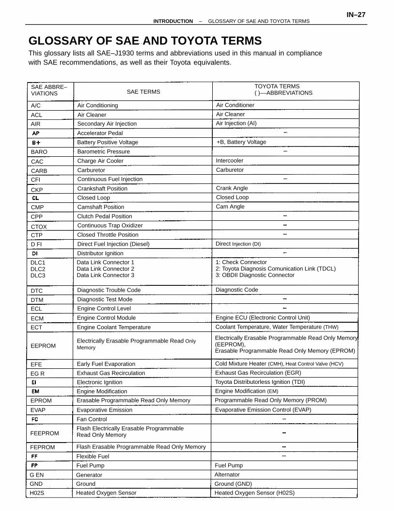
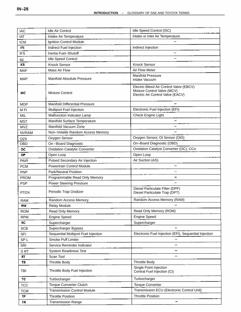
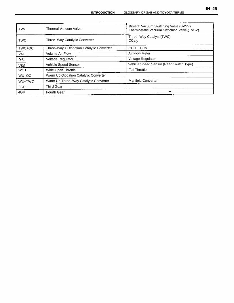
GLOSSARY OF SAE AND TOYOTA TERMSThis glossary lists all SAE–J1930 terms and abbreviations used in this manual in compliancewith SAE recommendations, as well as their Toyota equivalents.
Electrically Erasable Programmable Read Only Memory(EEPROM),Erasable Programmable Read Only Memory (EPROM)
1: Check Connector2: Toyota Diagnosis Comunication Link (TDCL)3: OBDII Diagnostic Connector
Electrically Erasable Programmable Read OnlyMemory
Flash Electrically Erasable ProgrammableRead Only Memory
Data Link Connector 1Data Link Connector 2Data Link Connector 3
Cold Mixture Heater (CMH), Heat Control Valve (HCV)
Coolant Temperature, Water Temperature (THW)
Flash Erasable Programmable Read Only Memory
TOYOTA TERMS( )––ABBREVIATIONS
Programmable Read Only Memory (PROM)Erasable Programmable Read Only Memory
Evaporative Emission Control (EVAP)
Engine ECU (Electronic Control Unit)
Toyota Distributorless Ignition (TDI)
Exhaust Gas Recirculation (EGR)
Heated Oxygen Sensor (H02S)
Direct Fuel Injection (Diesel)
Engine Coolant Temperature
SAE ABBRE–VIATIONS
Continuous Trap Oxidizer
Continuous Fuel Injection
Engine Modification (EM)
Diagnostic Trouble Code
Battery Positive Voltage
Exhaust Gas Recirculation
Secondary Air Injection
Heated Oxygen Sensor
Engine Control Module
Closed Throttle Position
Early Fuel Evaporation
Diagnostic Test Mode
Evaporative Emission
Engine Control Level
Clutch Pedal Position
+B, Battery Voltage
Direct Injection (DI)
Engine Modification
Barometric Pressure
Distributor Ignition
Crankshaft Position
Charge Air Cooler
DLC1DLC2DLC3
Electronic Ignition
Air Injection (AI)
Camshaft Position
Accelerator Pedal
Diagnostic Code
Air Conditioning
Ground (GND)
Air Conditioner
Closed Loop Closed Loop
Crank Angle
Flexible Fuel
Fan Control
Cam Angle
Fuel Pump
SAE TERMS
Fuel Pump
Air CleanerAir Cleaner
Intercooler
Carburetor Carburetor
Alternator
FEEPROM
Generator
FEPROM
EEPROM
EPROM
Ground
BARO
CTOX
H02S
EVAP
CARB
GND
CMP
A/C
ACL
DTM
CKP
CPP
CTP
ECM
ECT
ECL
CAC
G EN
DTC
EG R
AIR
D FI
EFE
CFI
–INTRODUCTION GLOSSARY OF SAE AND TOYOTA TERMSIN–27
Electric Bleed Air Control Valve (EBCV)Mixture Control Valve (MCV)Electric Air Control Valve (EACV)
Diesel Particulate Filter (DPF)Diesel Particulate Trap (DPT)
Electronic Fuel Injection (EFI), Sequential Injection
Single Point InjectionCentral Fuel Injection (Ci)
Transmission ECU (Electronic Control Unit)
Oxidation Catalyst Converter (OC), CCo
Non–Volatile Random Access Memory
Sequential Multiport Fuel Injection
Programmable Read Only Memory
Manifold PressureIntake Vacuum
Oxygen Sensor, Ot Sensor (OtS)
Random Access Memory (RAM)
Intake or Inlet Air Temperature
Pulsed Secondary Air Injection
Manifold Surface Temperature
Electronic Fuel Injection (EFI)
Oxidation Catalytic Converter
On–Board Diagnostic (OBD)
Transmission Control Module
Manifold Differential Pressure
Malfunction Indicator Lamp
Throttle Body Fuel Injection
Manifold Absolute Pressure
Read Only Memory (ROM)
Powertrain Control Module
Service Reminder Indicator
Torque Converter Clutch
Idle Speed Control (ISC)
Ignition Control Module
Power Steering Pressure
Random Access Memory
Multiport Fuel Injection
System Readiness Test
Intake Air Temperature
Periodic Trap Oxidizer
Indirect Fuel Injection
Park/Neutral Position
Manifold Vacuum Zone
On –Board Diagnostic
Supercharger Bypass
Inertia Fuel–Shutoff
Transmission Range
Check Engine Light
Read Only Memory
Idle Speed Control
Smoke Puff Limiter
Torque Converter
Indirect Injection
Air Suction (AS)
Throttle Position Throttle Position
Oxygen Sensor
Mixture Control
Idle Air Control
Air Flow Meter
Engine Speed
Throttle Body
Engine Speed
Relay Module
Throttle Body
Turbocharger
Mass Air Flow
Turbocharger
SuperchargerSupercharger
Knock Sensor Knock Sensor
Open Loop Open Loop
Scan Tool
NVRAM
PROM
PTOX
PAIR
MAP
MDP
ROM
OBD
RPM
PCM
PNP
MAF
RAM
TCM
MVZ
O2S
MST
SCB
PSP
SP L
MIL
M FI
ICM
TCC
SRI
S RT
IAC
IAT
TBI
SFI
sc
IFS
–INTRODUCTION GLOSSARY OF SAE AND TOYOTA TERMSIN–28
Bimetal Vacuum Switching Valve (BVSV)Thermostatic Vacuum Switching Valve (TVSV)
Three–Way Catalyst (TWC)CCRO
Three–Way + Oxidation Catalytic Converter
Warm Up Three–Way Catalytic Converter
Vehicle Speed Sensor (Read Switch Type)
Warm Up Oxidation Catalytic Converter
Three–Way Catalytic Converter
Thermal Vacuum Valve
Vehicle Speed Sensor
Wide Open Throttle
Voltage Regulator
Manifold Converter
Voltage Regulator
Volume Air Flow Air Flow Meter
Full Throttle
Fourth Gear
CCR + CCo
Third Gear
WU–TWC
TWC+OC
WU–OC
WOT
TWC
4GR
VAF
TVV
3GR
VSS
–INTRODUCTION GLOSSARY OF SAE AND TOYOTA TERMSIN–29
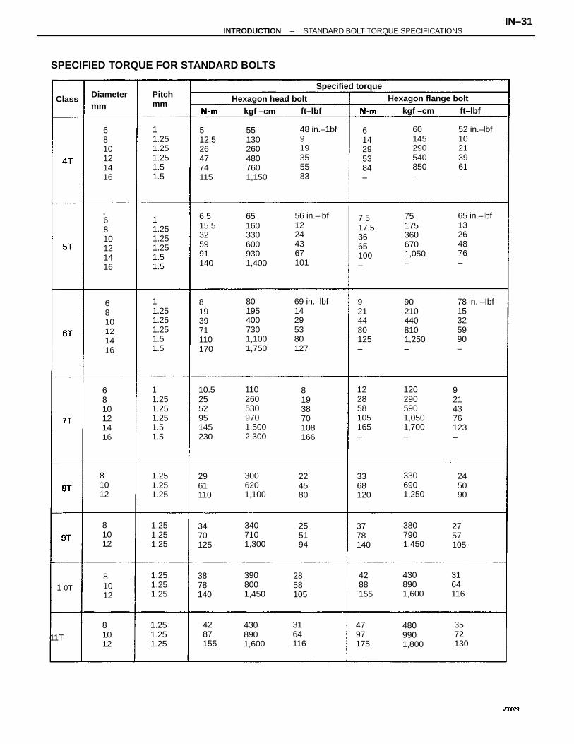
STANDARD BOLT TORQUE SPECIFICATIONS
Hexagonflange boltw! washerhexagon bolt
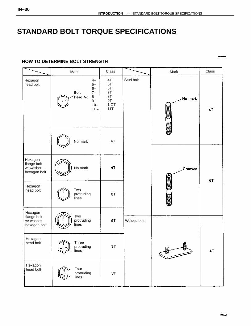
HOW TO DETERMINE BOLT STRENGTH
Hexagonflange boltw/ washerhexagon bolt
4–5–6–7–8–9–10–11 –
4T5T6T7T8T9T1 OT11T
Fourprotrudinglines
Twoprotrudinglines
Twoprotrudinglines
Threeprotrudinglines
Hexagonhead bolt
Hexagonhead bolt
Hexagonhead bolt
Hexagonhead bolt
Welded bolt
Stud bolt
No mark
No mark
Class ClassMark Mark
–INTRODUCTION STANDARD BOLT TORQUE SPECIFICATIONSIN–30
69 in.–lbf14295380127
56 in.–lbf12244367101
78 in. –Ibf15325990–
48 in.–1bf919355583
65 in.–lbf13264876–
52 in.–lbf10213961–
SPECIFIED TORQUE FOR STANDARD BOLTS
512.5264774115
801954007301,1001,750
7.517.53665100–
1102605309701,5002,300
651603306009301,400
551302604807601,150
902104408101,250–
1202905901,0501,700–
751753606701,050–
10.5255295145230
6.515.5325991140
11.251.251.251.51.5
11.251.251.251.51.5
11.251.251.251.51.5
11.251.251.251.51.5
8193971110170
60145290540850–
9214480125–
122858105165–
9214376123–
Hexagon flange bolt
6810121416
6810121416
6
6810121416
Hexagon head bolt
3807901,450
3006201,100
4308901,600
3407101,300
3306901,250
3908001,450
4308901,600
4809901,800
Specified torque
1.251.251.25
1.251.251.25
1.251.251.25
1.251.251.25
Diametermm
3164116
3368120
3878140
3778140
3470125
3164116
2961110
2858105
4797175
2757105
224580
245090
255194
Pitchmm
kgf –cmkgf –cm
11T
ft–lbfft–lbfClass
1 0T
614295384–
8193870108166
4288155
3572130
4287155
6810121416
81012
81012
81012
81012
–INTRODUCTION STANDARD BOLT TORQUE SPECIFICATIONSIN–31
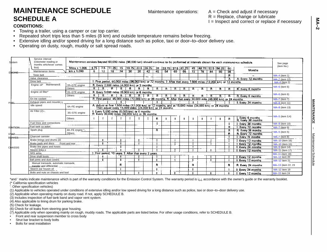
*and ‘ marks indicate maintenance which is part of the warranty conditions for the Emission Control System. The warranty period is i¿¿ accordance with the owner’s guide or the warranty booklet.(* California specification vehicles’: Other specification vehicles)(1) Applicable to vehicles operated under conditions of extensive idling and/or low speed driving for a long distance such as police, taxi or door–to–door delivery use.(2) Applicable when operating mainly on dusty road. If not, apply SCHEDULE B.(3) Includes inspection of fuel tank band and vapor vent system.(4) Also applicable to lining drum for parking brake.(5) Check for leakage.(6) Check for oil leaks from steering gear housing.(7) Applicable only when operating mainly on rough, muddy roads. The applicable parts are listed below. For other usage conditions, refer to SCHEDULE B.• Front and rear suspension member to cross body• Strut bar bracket to body bolts• Bolts for seat installation
MAINTENANCE SCHEDULESCHEDULE ACONDITIONS:• Towing a trailer, using a camper or car top carrier.• Repeated short trips less than 5 miles (8 km) and outside temperature remains below freezing.• Extensive idling and/or speed driving for a long distance such as police, taxi or door–to–door delivery use.• Operating on dusty, rough, muddy or salt spread roads.
Manual transaxle, automatic transaxle,transfer and differential
Service interval(Odometer reading ormonths whichever comesfirst)
Bolts and nuts on chassis and bod
Fuel lines and connections
Exhaust pipes and mountin s
Steerin ear housin oil
Brake linings and drums (d)
Brake line pipes and hoses
Ball joints and dust covers
MaintenancE
Brake pads and discs
MA–13 (item 22, 23
Fuel tank ca asket
MA–5 (item 3,4)
Maintenance items
Engine oil filter*
Charcoal canister
MA–8 (item 13)
Drive shaft boots
3S–GTE engine
Steerin linka e
MA–6 (item 6)
MA–5 (item 5)
See page(item No.)
MA–6 (item 6)
4A–FE engine *,,
3S–GTE engine
3S–GTE engine
Valve clearance
4A–FE engine
En ine coolant
Front and rear
Air Filter (2)–,
Engine oil*
Spark plug
Idle speed
SRS airba,
IGNITION
Drive belt
CHASSIS
BRAKES
ENGINE
System
MA–10 (item 16)
MA–12 item 19
MA–12 item 21
Others
MA–11 (item 17)
Others
Others
MA–15 item 24
Others
MA–11 (item 18)
MA–8 (item 10)
MA–4 (item 2)
MA–4 (item 1)
MA–7 (item 8)
MA–7 (item 7)
FUEL
EVAP
MA–9 (item 14)MA–10 (item 15)
MA–8 (item 11)
MA–7 (item 9)
MA–7 (item 12)
Maintenance operations: A = Check and adjust if necessaryR = Replace, change or lubricateI = Inspect and correct or replace if necessary
MA–12 item 20
Timin belt
–M
AIN
TE
NA
NC
EM
aintenance Schedule
MA
–2
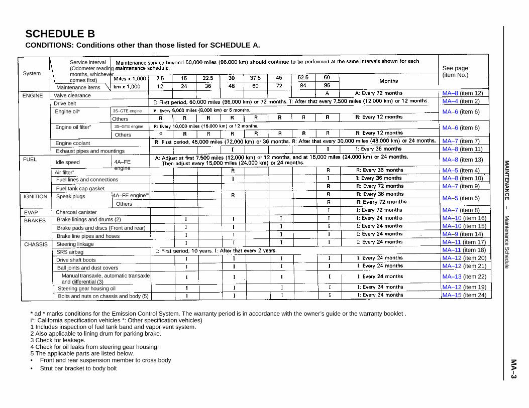
* ad * marks conditions for the Emission Control System. The warranty period is in accordance with the owner’s guide or the warranty booklet .i*: California specification vehicles *: Other specification vehicles)1 Includes inspection of fuel tank band and vapor vent system.2 Also applicable to lining drum for parking brake.3 Check for leakage.4 Check for oil leaks from steering gear housing.5 The applicable parts are listed below.• Front and rear suspension member to cross body• Strut bar bracket to body bolt
SCHEDULE BCONDITIONS: Conditions other than those listed for SCHEDULE A.
Manual transaxle, automatic transaxleand differential (3)
Service interval(Odometer reading ormonths, whichevercomes first)
Bolts and nuts on chassis and body (5)
Brake pads and discs (Front and rear)
Exhaust pipes and mountings
Fuel lines and connections
Steering gear housing oil
Brake linings and drums (2)
Brake line pipes and hoses
Ball joints and dust covers
MA–8 (item 13)
Fuel tank cap gasket
MA–10 (item 16)
MA–12 (item 20)
MA–6 (item 6)
MA–12 (item 19)
MA–13 (item 22)
MA–15 (item 24)
MA–11 (item 18)MA–11 (item 17)
MA–10 (item 15)
Maintenance items
MA–12 (item 21)
MA–8 (item 10)
MA–9 (item 14)
MA–8 (item 12)
MA–8 (item 11)
Charcoal canister
See page(item No.)
Engine oil filter”
Drive shaft boots
Steering linkage
4A–FE engine’” MA–5 (item 5)
MA–6 (item 6)
MA–7 (item 7)
MA–4 (item 2)
MA–7 (item 8)
MA–7 (item 9)
MA–5 (item 4)
Engine coolant
Valve clearance
3S–GTE engine
3S–GTE engine
Speak plugs
4A–FEengine
Others
SRS airbag
Engine oil*
Idle speed
IGNITION
Drive belt
CHASSIS
Air filter”
BRAKES
ENGINE
System
Others
Others
EVAP
FUEL
–M
AIN
TE
NA
NC
EM
aintenance Schedule
MA
–3
MAINTENANCE OPERATIONSENGINECold Engine Operations1. REPLACE TIMING BELT(a) Remove the timing belt.
4A–FE (See pages EM–33 to 37)3S–GTE (See pages EM–46 to 51)5S–FE (See pages EM–67 to 72)(b) Install the timing belt.
4A–FE (See pages EM–40 to 45)3S–GTE (See pages EM–55 to 61)
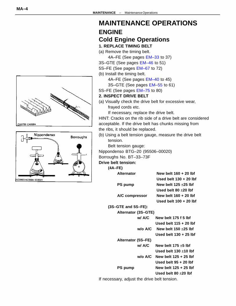
5S–FE (See pages EM–75 to 80)2. INSPECT DRIVE BELT(a) Visually check the drive belt for excessive wear,
frayed cords etc.If necessary, replace the drive belt.
HINT: Cracks on the rib side of a drive belt are consideredacceptable. If the drive belt has chunks missing fromthe ribs, it should be replaced.(b) Using a belt tension gauge, measure the drive belt
tension.Belt tension gauge:
Nippondenso BTG–20 (95506–00020)Borroughs No. BT–33–73FDrive belt tension:
(4A–FE)Alternator New belt 160 + 20 lbf
Used belt 130 + 20 lbfPS pump New belt 125 ±25 lbf
Used belt 80 ±20 lbfA/C compressor New belt 160 + 20 lbf
Used belt 100 + 20 lbf(3S–GTE and 5S–FE):
Alternator (3S–GTE)w/ A/C New belt 175 f 5 lbf
Used belt 115 + 20 lbfw/o A/C New belt 150 ±25 lbf
Used belt 130 + 25 lbfAlternator (5S–FE)
w/ A/C New belt 175 ±5 lbfUsed belt 130 ±10 lbf
w/o A/C New belt 125 + 25 lbfUsed belt 95 + 20 lbf
PS pump New belt 125 + 25 lbfUsed belt 80 ±20 lbf
If necessary, adjust the drive belt tension.
–MAINTENANCE Maintenance OperationsMA–4
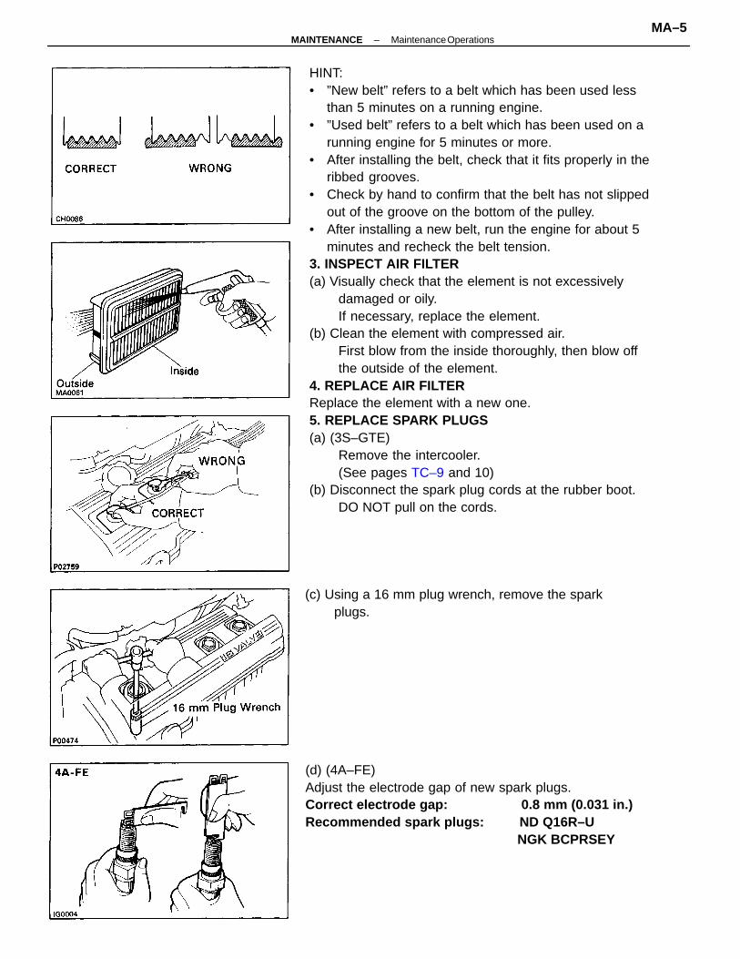
HINT:• ”New belt” refers to a belt which has been used less
than 5 minutes on a running engine.• ”Used belt” refers to a belt which has been used on a
running engine for 5 minutes or more.• After installing the belt, check that it fits properly in the
ribbed grooves.• Check by hand to confirm that the belt has not slipped
out of the groove on the bottom of the pulley.• After installing a new belt, run the engine for about 5
minutes and recheck the belt tension.3. INSPECT AIR FILTER(a) Visually check that the element is not excessively
damaged or oily.If necessary, replace the element.
(b) Clean the element with compressed air.First blow from the inside thoroughly, then blow offthe outside of the element.
4. REPLACE AIR FILTERReplace the element with a new one.5. REPLACE SPARK PLUGS(a) (3S–GTE)
Remove the intercooler.(See pages TC–9 and 10)
(b) Disconnect the spark plug cords at the rubber boot.DO NOT pull on the cords.
(d) (4A–FE)Adjust the electrode gap of new spark plugs.Correct electrode gap: 0.8 mm (0.031 in.)Recommended spark plugs: ND Q16R–U NGK BCPRSEY
(c) Using a 16 mm plug wrench, remove the sparkplugs.
–MAINTENANCE Maintenance OperationsMA–5
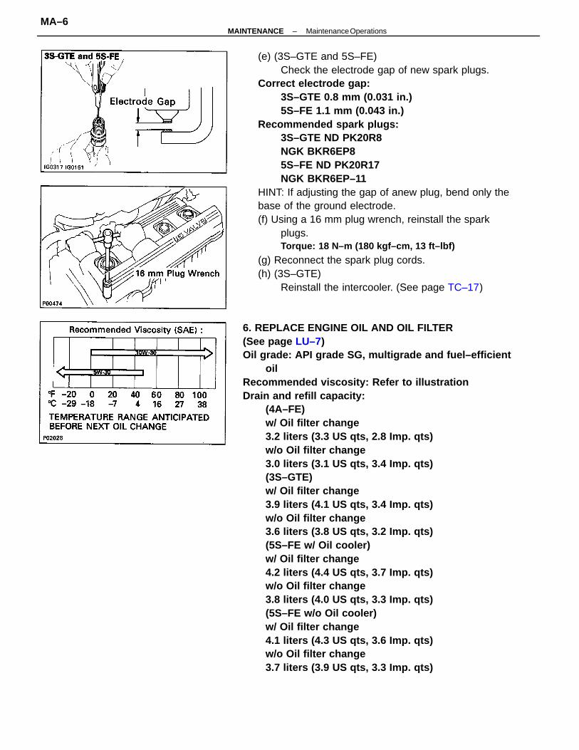
6. REPLACE ENGINE OIL AND OIL FILTER(See page LU–7)Oil grade: API grade SG, multigrade and fuel–efficient
oilRecommended viscosity: Refer to illustrationDrain and refill capacity:
(4A–FE)w/ Oil filter change3.2 liters (3.3 US qts, 2.8 Imp. qts)w/o Oil filter change3.0 liters (3.1 US qts, 3.4 Imp. qts)(3S–GTE)w/ Oil filter change3.9 liters (4.1 US qts, 3.4 Imp. qts)w/o Oil filter change3.6 liters (3.8 US qts, 3.2 Imp. qts)(5S–FE w/ Oil cooler)w/ Oil filter change4.2 liters (4.4 US qts, 3.7 Imp. qts)w/o Oil filter change3.8 liters (4.0 US qts, 3.3 Imp. qts)(5S–FE w/o Oil cooler)w/ Oil filter change4.1 liters (4.3 US qts, 3.6 Imp. qts)w/o Oil filter change3.7 liters (3.9 US qts, 3.3 Imp. qts)
(e) (3S–GTE and 5S–FE)Check the electrode gap of new spark plugs.
Correct electrode gap:3S–GTE 0.8 mm (0.031 in.)5S–FE 1.1 mm (0.043 in.)
Recommended spark plugs:3S–GTE ND PK20R8NGK BKR6EP85S–FE ND PK20R17NGK BKR6EP–11
HINT: If adjusting the gap of anew plug, bend only thebase of the ground electrode.(f) Using a 16 mm plug wrench, reinstall the spark
plugs.Torque: 18 N–m (180 kgf–cm, 13 ft–lbf)
(g) Reconnect the spark plug cords.(h) (3S–GTE)
Reinstall the intercooler. (See page TC–17)
–MAINTENANCE Maintenance OperationsMA–6
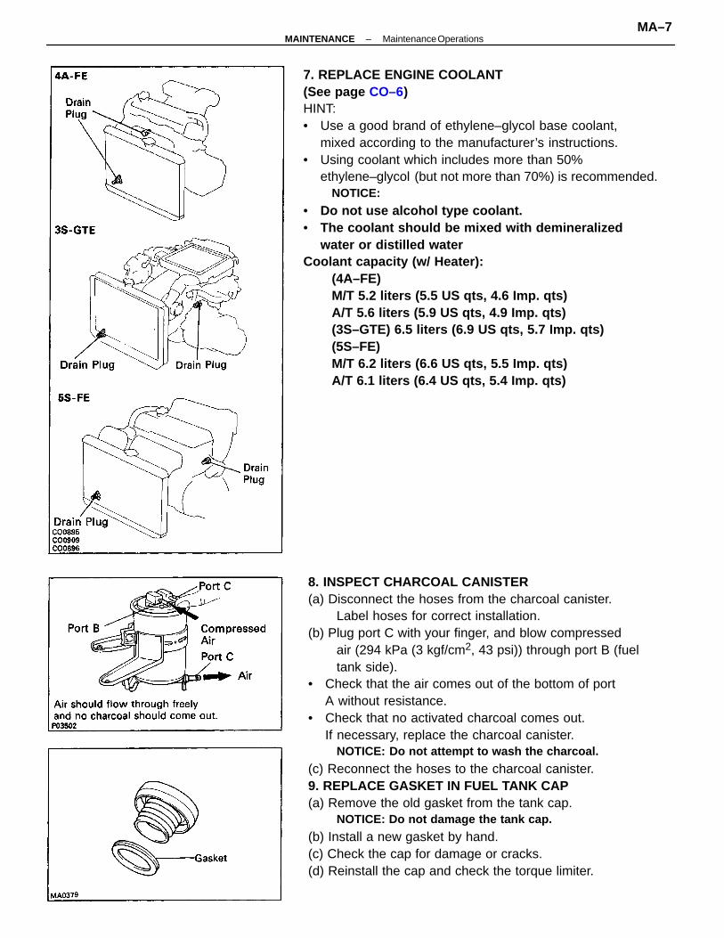
8. INSPECT CHARCOAL CANISTER(a) Disconnect the hoses from the charcoal canister.
Label hoses for correct installation.(b) Plug port C with your finger, and blow compressed
air (294 kPa (3 kgf/cm2, 43 psi)) through port B (fueltank side).
• Check that the air comes out of the bottom of portA without resistance.
• Check that no activated charcoal comes out.If necessary, replace the charcoal canister.
NOTICE: Do not attempt to wash the charcoal.
(c) Reconnect the hoses to the charcoal canister.9. REPLACE GASKET IN FUEL TANK CAP(a) Remove the old gasket from the tank cap.
NOTICE: Do not damage the tank cap.
(b) Install a new gasket by hand.(c) Check the cap for damage or cracks.(d) Reinstall the cap and check the torque limiter.
7. REPLACE ENGINE COOLANT(See page CO–6)HINT:• Use a good brand of ethylene–glycol base coolant,
mixed according to the manufacturer’s instructions.• Using coolant which includes more than 50%
ethylene–glycol (but not more than 70%) is recommended.NOTICE:
• Do not use alcohol type coolant.• The coolant should be mixed with demineralized
water or distilled waterCoolant capacity (w/ Heater):
(4A–FE)M/T 5.2 liters (5.5 US qts, 4.6 Imp. qts)A/T 5.6 liters (5.9 US qts, 4.9 Imp. qts)(3S–GTE) 6.5 liters (6.9 US qts, 5.7 Imp. qts)(5S–FE)M/T 6.2 liters (6.6 US qts, 5.5 Imp. qts)A/T 6.1 liters (6.4 US qts, 5.4 Imp. qts)
–MAINTENANCE Maintenance OperationsMA–7
10. INSPECT FUEL LINES AND CONNECTIONSVisually check the fuel lines for cracks, leakage, looseconnections, deformation or tank band looseness.11. INSPECT EXHAUST PIPES AND MOUNTINGSVisually check the pipes, hangers and connections forsevere corrosion, leaks or damage.12. ADJUST VALVE CLEARANCE4A–FE (See page EM–13)3S–GTE (See page EM–17)5S–FE (See page EM–22)Valve clearance (Cold):
4A–FE Intake 0.15 – 0.25 mm(0.006 – 0.010 in.)Exhaust 0.20 – 0.30 mm(0.008 – 0.012 in.)3S–GTE Intake 0.15 – 0.25 mm(0.006 – 0.010 in.)Exhaust 0.28 – 0.38 mm(0.011 – 0.015 in.)5S–FE Intake 0.19 – 0.29 mm(0.007 – 0.011 in.)Exhaust 0.28 – 0.38 mm(0.011 – 0.015 in.)
Hot Engine Operations13. (4A–FE)
ADJUST IDLE SPEED(a) Preparation• Engine at normal operating temperature• Air cleaner installed• All pipes and hoses of air induction system connected• All vacuum lines connectedHINT: All vacuum hoses for EGR systems, etc. shouldbe properly connected.• EFI system wiring connector fully plugged• All accessories switched OFF• Transmission in neutral position
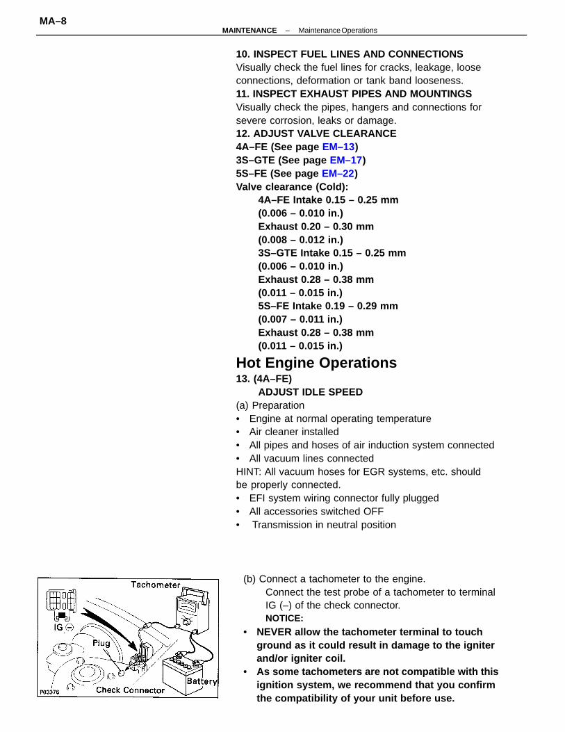
(b) Connect a tachometer to the engine.Connect the test probe of a tachometer to terminalIG (–) of the check connector.NOTICE:
• NEVER allow the tachometer terminal to touchground as it could result in damage to the igniterand/or igniter coil.
• As some tachometers are not compatible with thisignition system, we recommend that you confirmthe compatibility of your unit before use.
–MAINTENANCE Maintenance OperationsMA–8
BRAKES14. INSPECT BRAKE LINE PIPES AND HOSESHINT: Check in a well–lighted area. Check the entirecircumference and length of the brake hoses using amirror as required. Turn the front wheels fully right or leftbefore checking the front brake.(a) Check all brake lines and hoses for:• Damage• Wear• Deformation• Cracks• Corrosion• Leaks• Bends• Twists(b) Check all clamps for tightness and connections for
leakage.(c) Check that the hoses and lines are clear of sharp
edges, moving parts and the exhaust system.(d) Check that the lines installed in grommets pass
through the center of the grommets.
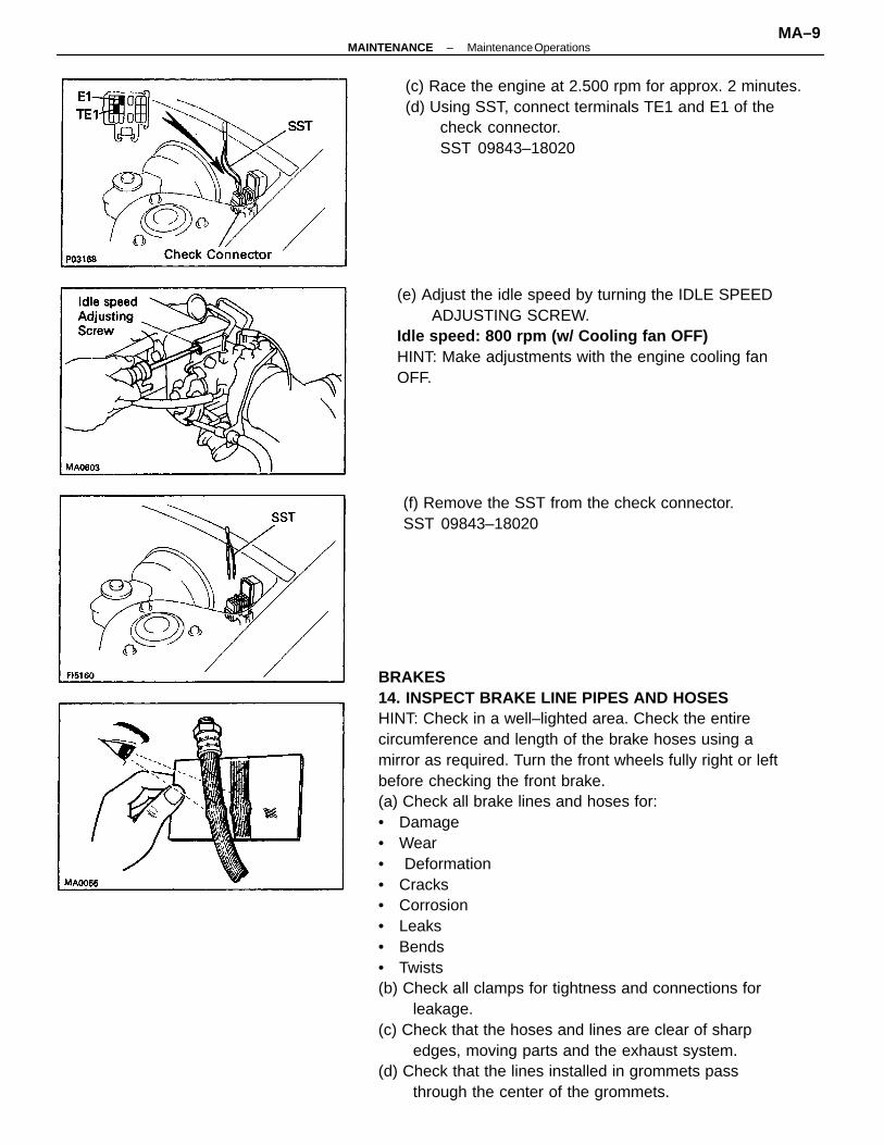
(e) Adjust the idle speed by turning the IDLE SPEEDADJUSTING SCREW.
Idle speed: 800 rpm (w/ Cooling fan OFF)HINT: Make adjustments with the engine cooling fanOFF.
(c) Race the engine at 2.500 rpm for approx. 2 minutes.(d) Using SST, connect terminals TE1 and E1 of the
check connector.SST 09843–18020
(f) Remove the SST from the check connector.SST 09843–18020
–MAINTENANCE Maintenance OperationsMA–9
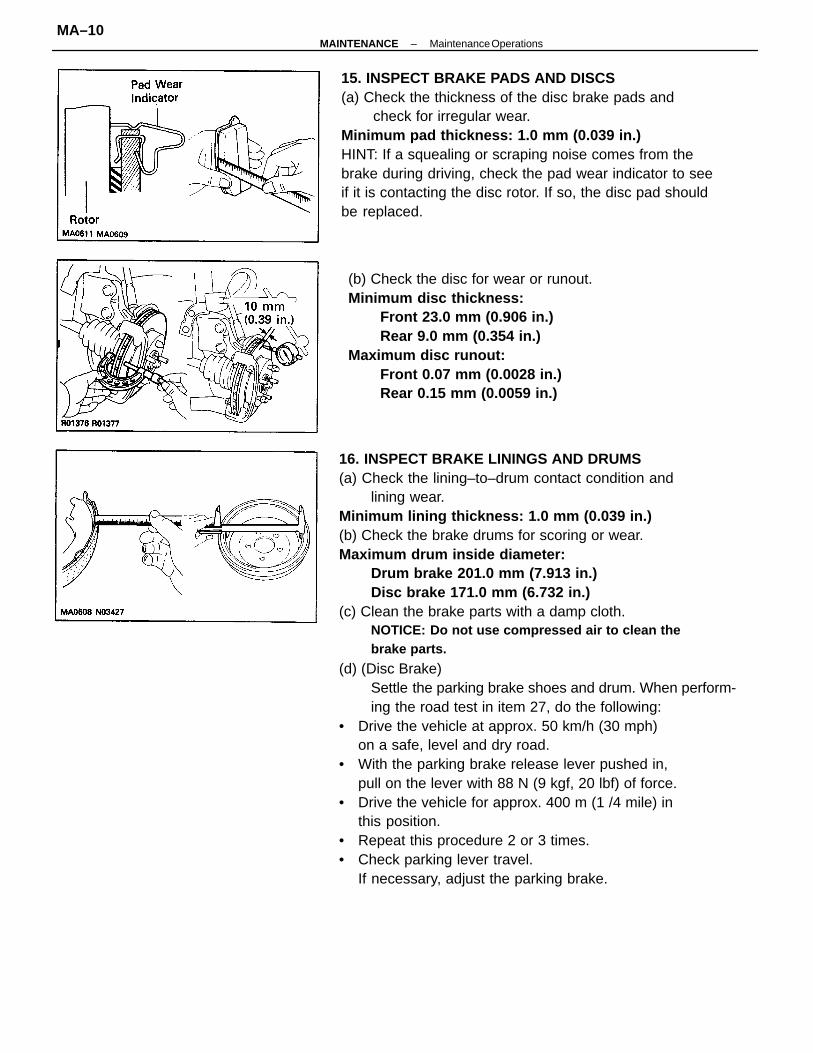
16. INSPECT BRAKE LININGS AND DRUMS(a) Check the lining–to–drum contact condition and
lining wear.Minimum lining thickness: 1.0 mm (0.039 in.)(b) Check the brake drums for scoring or wear.Maximum drum inside diameter:
Drum brake 201.0 mm (7.913 in.)Disc brake 171.0 mm (6.732 in.)
(c) Clean the brake parts with a damp cloth.NOTICE: Do not use compressed air to clean thebrake parts.
(d) (Disc Brake)Settle the parking brake shoes and drum. When perform-ing the road test in item 27, do the following:
• Drive the vehicle at approx. 50 km/h (30 mph)on a safe, level and dry road.
• With the parking brake release lever pushed in,pull on the lever with 88 N (9 kgf, 20 lbf) of force.
• Drive the vehicle for approx. 400 m (1 /4 mile) inthis position.
• Repeat this procedure 2 or 3 times.• Check parking lever travel.
If necessary, adjust the parking brake.
15. INSPECT BRAKE PADS AND DISCS(a) Check the thickness of the disc brake pads and
check for irregular wear.Minimum pad thickness: 1.0 mm (0.039 in.)HINT: If a squealing or scraping noise comes from thebrake during driving, check the pad wear indicator to seeif it is contacting the disc rotor. If so, the disc pad shouldbe replaced.
(b) Check the disc for wear or runout.Minimum disc thickness:
Front 23.0 mm (0.906 in.)Rear 9.0 mm (0.354 in.)
Maximum disc runout:Front 0.07 mm (0.0028 in.)Rear 0.15 mm (0.0059 in.)
–MAINTENANCE Maintenance OperationsMA–10
18. INSPECT SRS AIRBAGVisually check the steering wheel pad (airbag and inflater) .• Use the diagnosis check to check if there are abnormalities.• Check that there are no cuts, cracks or noticeable
color changes on the surface of the steeringwheel pad or in the center groove of the pad.
• Remove the steering wheel pad from the vehicleand check the wiring and steering wheel for damage andcorrosion due to rusting, etc.If necessary, replace the pad.
CAUTION:
• For removal and replacement of the steering wheelpad, see Steering Wheel Pad and Spiral Cable on ABsection and be sure to perform the operation in thecorrect order.
• Before disposing of the steering wheel pad, theairbag must first be deployed by using SST (seeDisposal of Steering Wheel Pad on AB section).
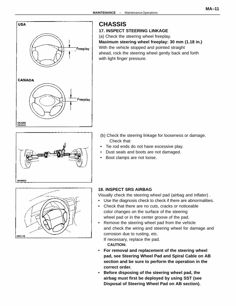
CHASSIS17. INSPECT STEERING LINKAGE(a) Check the steering wheel freeplay.Maximum steering wheel freeplay: 30 mm (1.18 in.)With the vehicle stopped and pointed straightahead, rock the steering wheel gently back and forthwith light finger pressure.
(b) Check the steering linkage for looseness or damage.Check that:
• Tie rod ends do not have excessive play.• Dust seals and boots are not damaged.• Boot clamps are not loose.
–MAINTENANCE Maintenance OperationsMA–11
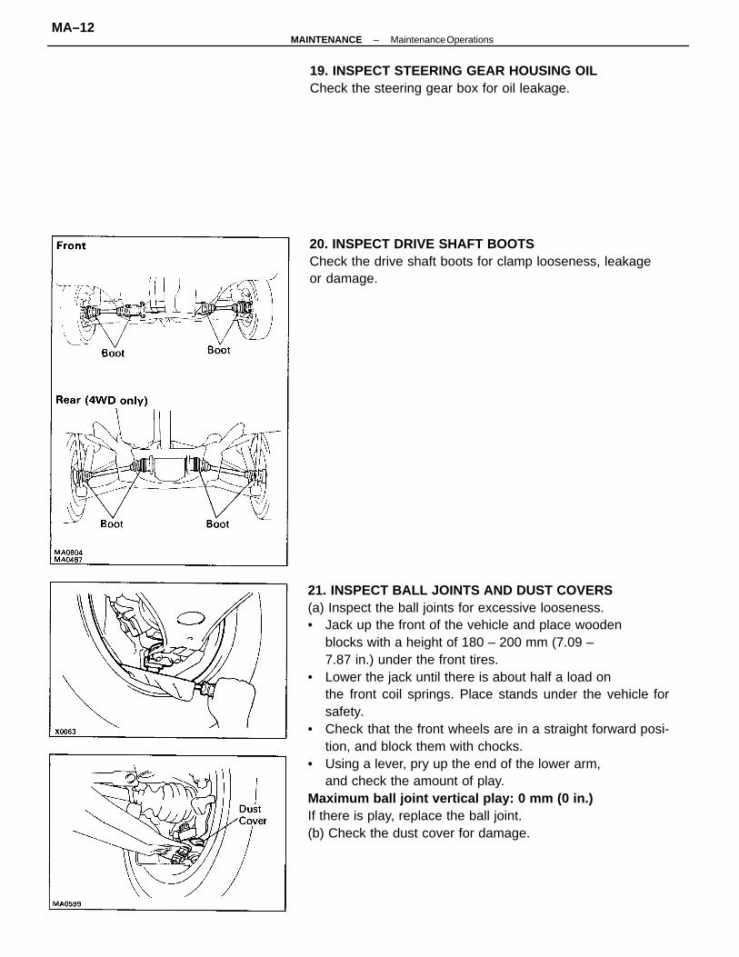
21. INSPECT BALL JOINTS AND DUST COVERS(a) Inspect the ball joints for excessive looseness.• Jack up the front of the vehicle and place wooden
blocks with a height of 180 – 200 mm (7.09 –7.87 in.) under the front tires.
• Lower the jack until there is about half a load onthe front coil springs. Place stands under the vehicle forsafety.
• Check that the front wheels are in a straight forward posi-tion, and block them with chocks.
• Using a lever, pry up the end of the lower arm,and check the amount of play.
Maximum ball joint vertical play: 0 mm (0 in.)If there is play, replace the ball joint.(b) Check the dust cover for damage.
20. INSPECT DRIVE SHAFT BOOTSCheck the drive shaft boots for clamp looseness, leakageor damage.
19. INSPECT STEERING GEAR HOUSING OILCheck the steering gear box for oil leakage.
–MAINTENANCE Maintenance OperationsMA–12
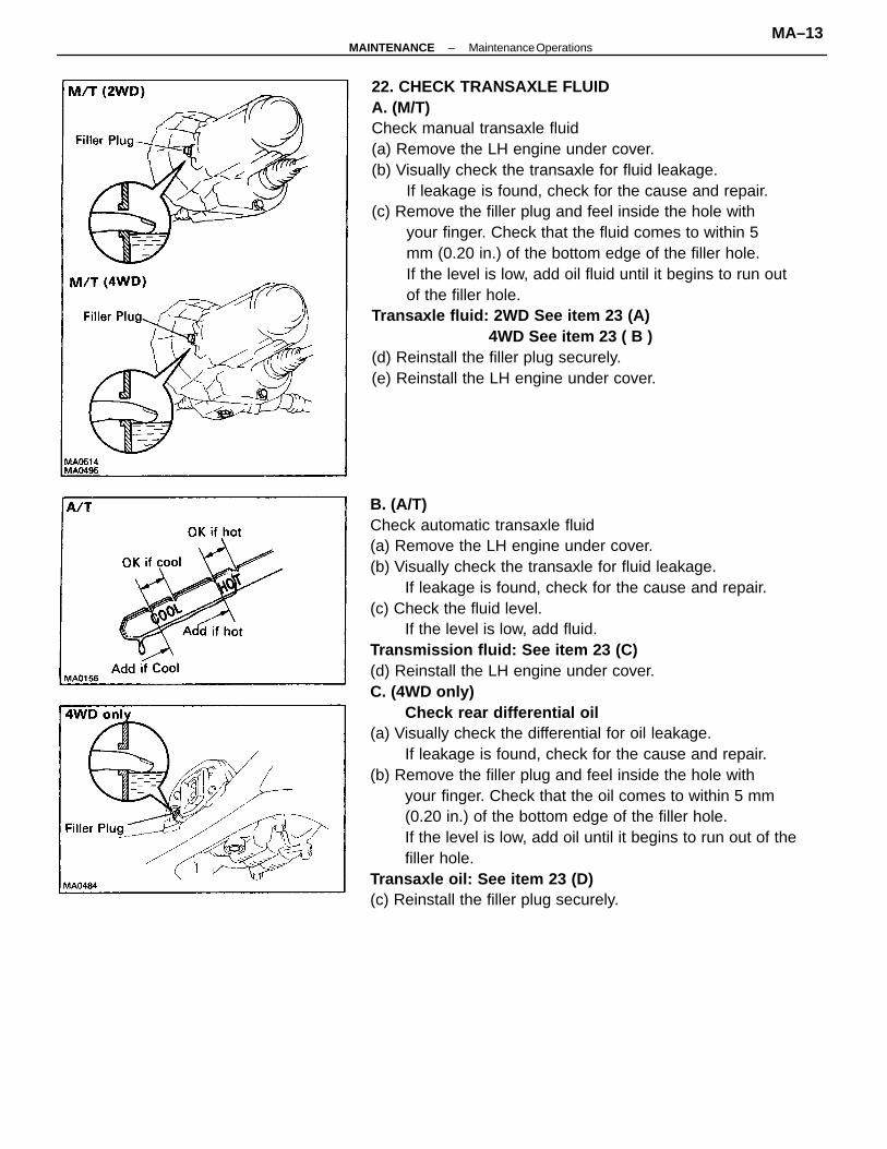
B. (A/T)Check automatic transaxle fluid(a) Remove the LH engine under cover.(b) Visually check the transaxle for fluid leakage.
If leakage is found, check for the cause and repair.(c) Check the fluid level.
If the level is low, add fluid.Transmission fluid: See item 23 (C)(d) Reinstall the LH engine under cover.C. (4WD only)
Check rear differential oil(a) Visually check the differential for oil leakage.
If leakage is found, check for the cause and repair.(b) Remove the filler plug and feel inside the hole with
your finger. Check that the oil comes to within 5 mm(0.20 in.) of the bottom edge of the filler hole.If the level is low, add oil until it begins to run out of thefiller hole.
Transaxle oil: See item 23 (D)(c) Reinstall the filler plug securely.
22. CHECK TRANSAXLE FLUIDA. (M/T)Check manual transaxle fluid(a) Remove the LH engine under cover.(b) Visually check the transaxle for fluid leakage.
If leakage is found, check for the cause and repair.(c) Remove the filler plug and feel inside the hole with
your finger. Check that the fluid comes to within 5mm (0.20 in.) of the bottom edge of the filler hole.If the level is low, add oil fluid until it begins to run outof the filler hole.
Transaxle fluid: 2WD See item 23 (A) 4WD See item 23 ( B )
(d) Reinstall the filler plug securely.(e) Reinstall the LH engine under cover.
–MAINTENANCE Maintenance OperationsMA–13
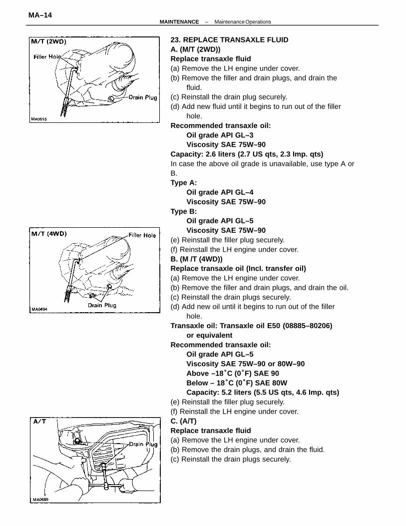
23. REPLACE TRANSAXLE FLUIDA. (M/T (2WD))Replace transaxle fluid(a) Remove the LH engine under cover.(b) Remove the filler and drain plugs, and drain the
fluid.(c) Reinstall the drain plug securely.(d) Add new fluid until it begins to run out of the filler
hole.Recommended transaxle oil:
Oil grade API GL–3Viscosity SAE 75W–90
Capacity: 2.6 liters (2.7 US qts, 2.3 Imp. qts)In case the above oil grade is unavailable, use type A orB.Type A:
Oil grade API GL–4Viscosity SAE 75W–90
Type B:Oil grade API GL–5Viscosity SAE 75W–90
(e) Reinstall the filler plug securely.(f) Reinstall the LH engine under cover.B. (M /T (4WD))Replace transaxle oil (IncI. transfer oil)(a) Remove the LH engine under cover.(b) Remove the filler and drain plugs, and drain the oil.(c) Reinstall the drain plugs securely.(d) Add new oil until it begins to run out of the filler
hole.Transaxle oil: Transaxle oil E50 (08885–80206)
or equivalentRecommended transaxle oil:
Oil grade API GL–5Viscosity SAE 75W–90 or 80W–90Above –18 °C (0°F) SAE 90Below – 18 °C (0°F) SAE 80WCapacity: 5.2 liters (5.5 US qts, 4.6 Imp. qts)
(e) Reinstall the filler plug securely.(f) Reinstall the LH engine under cover.C. (A/T)Replace transaxle fluid(a) Remove the LH engine under cover.(b) Remove the drain plugs, and drain the fluid.(c) Reinstall the drain plugs securely.
–MAINTENANCE Maintenance OperationsMA–14
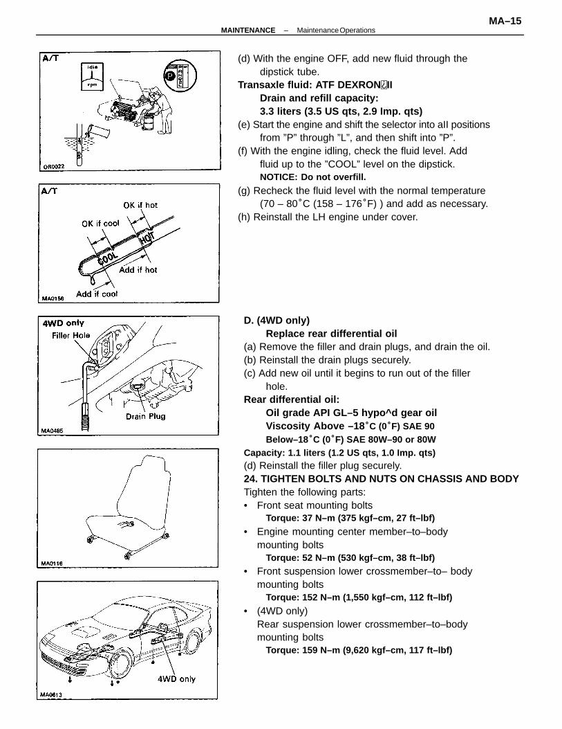
D. (4WD only)Replace rear differential oil
(a) Remove the filler and drain plugs, and drain the oil.(b) Reinstall the drain plugs securely.(c) Add new oil until it begins to run out of the filler
hole.Rear differential oil:
Oil grade API GL–5 hypo^d gear oilViscosity Above –18 °C (0°F) SAE 90Below–18 °C (0°F) SAE 80W–90 or 80W
Capacity: 1.1 liters (1.2 US qts, 1.0 Imp. qts)(d) Reinstall the filler plug securely.24. TIGHTEN BOLTS AND NUTS ON CHASSIS AND BODYTighten the following parts:• Front seat mounting bolts
Torque: 37 N–m (375 kgf–cm, 27 ft–lbf)
• Engine mounting center member–to–bodymounting bolts
Torque: 52 N–m (530 kgf–cm, 38 ft–lbf)
• Front suspension lower crossmember–to– bodymounting bolts
Torque: 152 N–m (1,550 kgf–cm, 112 ft–lbf)
• (4WD only)Rear suspension lower crossmember–to–bodymounting bolts
Torque: 159 N–m (9,620 kgf–cm, 117 ft–lbf)
(d) With the engine OFF, add new fluid through thedipstick tube.
Transaxle fluid: ATF DEXRON IIDrain and refill capacity:3.3 liters (3.5 US qts, 2.9 Imp. qts)
(e) Start the engine and shift the selector into aII positionsfrom ”P” through ”L”, and then shift into ”P”.
(f) With the engine idling, check the fluid level. Addfluid up to the ”COOL” level on the dipstick.NOTICE: Do not overfill.
(g) Recheck the fluid level with the normal temperature(70 – 80°C (158 – 176°F) ) and add as necessary.
(h) Reinstall the LH engine under cover.
–MAINTENANCE Maintenance OperationsMA–15
25. BODY INSPECTION(a) Check the body exterior for dents, scratches and
rust.(b) Check the underbody for rust and damage.26. ROAD TEST(a) Check the engine and chassis for abnormal noises.(b) Check that the vehicle does not wander or pull to
one side.(c) Check that the brakes work properly and do not
drag.(d) Perform setting down of the parking brake shoes
and drum. (See page MA–1 0)27. FINAL INSPECTION(a) Check the operation of the body parts:• Hood
Auxiliary catch operates properlyHood locks securely when closed
• Front and rear doorsDoor locks operate properlyDoors close properly
• Luggage compartment door and back doorDoor lock operates properly
• SeatsSeat adjusts easily and locks securely in any positionFront seat back locks securely in any positionFolding–down rear seat backs lock securely
(b) Be sure to deliver a clean car. Especially check:• Steering wheel• Shift lever knob• All switch knobs• Door handles• Seats
–MAINTENANCE Maintenance operationsMA–16
GENERAL MAINTENANCEThese are the maintenance and inspection itemswhich are considered to be the owner’s responsi-bility. They can be performed by the owner or hecan have them done at a service shop. Theseitems include those which should be checked ona daily basis, those which, in most cases, do notrequire (special) tools and those which are consid-ered to be reasonable for the owner to perform.Items and procedures for general maintenanceare as follows.
OUTSIDE VEHICLE1. TIRES(a) Check the pressure with a gauge. Adjust if neces-
sary.(b) Check for cuts, damage of excessive
wear.2. WHEEL NUTSWhen checking the tires, check the nuts forlooseness or for missing nuts. If necessary,tighten them.3. TIRE ROTATIONIt is recommended that tires be rotated every7,500 miles (12,000 km).4. WINDSHIELD WIPER BLADESCheck for wear or cracks whenever they donot wipe clean. Replace if necessary.5. FLUID LEAKS(a) Check underneath for leaking fuel, oil,
water or other fluid.(b) If you smell gasoline fumes or notice
any leak, have the cause found and corrected.6. DOORS AND ENGINE HOOD(a) Check that all doors including the trunk
lid and back door operate smoothly,and that all latches lock securely.
(b) Check that the engine hood secondarylatch secures the hood from openingwhen the primary latch is released.
INSIDE VEHICLE7. LIGHTS(a) Check that the headlights, stop lights,
taillights, turn signal lights, and otherlights are all working.
(b) Check the headlight aim.
8. WARNING LIGHTS AND BUZZERSCheck that all warning lights and buzzersfunction properly.9. HORNCheck that it is working.10. WINDSHIELD GLASSCheck for scratches, pits or abrasions.11. WINDSHIELD WIPER AND WASHER(a) Check operation of the wipers and
washer.(b) Check that the wipers do not streak.12. WINDSHIELD DEFROSTERCheck that the air comes out from the defrosteroutlet when operating the heater orair conditioner at defroster mode.13. REAR VIEW MIRRORCheck that it is mounted securely.14. SUN VISORSCheck that they move freely and aremounted securely.15. STEERING WHEELCheck that it has specified freeplay. Be alertfor changes in steering condition, such ashard steering, excessive freeplay or strangenoise.16. SEATS(a) Check that all front seat controls such
as seat adjuster, seatback recliner, etc.operate smoothly.
(b) Check that all latches lock securely inany position.
(c) Check that the locks hold securely inany latched position.
(d) Check that the head restraints move upand down smoothly and that the lockshold securely in any latched position.
(e) For folding–down rear backs, checkthat the latches lock securely.
17. SEAT BELTS(a) Check that the seat belt system such as
buckles, retractors and anchors operateproperly and smoothly,.
(b) Check that the belt webbing is not cut,frayed, worn or damaged.
–MAINTENANCE General MaintenanceMA–17
18. ACCELERATOR PEDALCheck the pedal for smooth operation anduneven pedal effort or catching.19. CLUTCH PEDAL (See Check and Adjust-
ment of Clutch Pedal in CL section)Check the pedal for smooth operation.Check that the pedal has the proper freeplay.20. BRAKE PEDAL (See Checks and Adjust-
ments in BR section)(a) Check the pedal for smooth operation.(b) Check that the pedal has the proper reserve
distance and freeplay.(c) Check the brake booster function.21. BRAKESAt a safe place, check that the brakes do notpull to one side when applied.22. PARKING BRAKE (See Check and Adjust–
ment of Parking Brake in BR section)(a) Check that the lever has the proper
travel.(b) On a safe incline, check that the vehicle
is held securely with only the parkingbrake applied.
23. AUTOMATIC TRANSMISSION ”PARK”MECHANISM
(a) Check the lock release button of theselector lever for proper and smoothoperation.
(b) On a safe incline, check that the vehicleis held securely with the selector leverin the ”P” position and all brakes released.
UNDER HOOD24. WINDSHIELD WASHER FLUIDCheck that there is sufficient fluid in thetank.25. ENGINE COOLANT LEVELCheck that the coolant level is between the”FULL” and ”LOW” lines on the see–throughreservoir.26. RADIATOR AND HOSES(a) Check that the front of the radiator is
clean and not blocked with leaves, dirtor bugs.
(b) Check the hoses for cracks, kinks, rot orloose connections.
27. BATTERY ELECTROLYTE LEVELCheck that the electrolyte level of all batterycells is between the upper and lower levellines on the case. If level is low, add distilledwater only.28. BRAKE AND CLUTCH FLUID LEVELS(a) Check that the brake fluid level is near
the upper level line on the see–throughreservoir.
(b) Check that the clutch fluid level iswithin ±5 mm (0.20 in.) of the reservoir hem.
29. ENGINE DRIVE BELTSCheck all drive belts for fraying, cranks, wearor oiliness.30. ENGINE OIL LEVELCheck the level on the dipstick with the engineturned off.31. POWER STEERING FLUID LEVELCheck the level on the dipstick.The level should be in the ”HOT” or ”COLD”range depending on the fluid temperature.32. AUTOMATIC TRANSMISSION FLUID
LEVEL(a) Park the vehicle on a level surface.(b) With the engine idling and the parking
brake applied, shift the selector into allpositions from ”P” to ”L”, and then shiftinto ”P”.
(c) Pull out the dipstick and wipe off thefluid with a clean rag. Re–insert the dipstickand check that the fluid level is inthe HOT range.
(d) Perform this check with the fluid at normal driv-ing temperature (70 – 80°C
(158 – 176°F)).HINT: Wait about 30 minutes beforechecking the fluid level after extended driving athigh speeds in hot weather, driving inheavy traffic or with a trailer.33. EXHAUST SYSTEMVisually inspect for cracks, holes or loosesupports.If any change in the sound of the exhaust orsmell of the exhaust fumes is noticed, havethe cause located and corrected.
–MAINTENANCE General MaintenanceMA–18
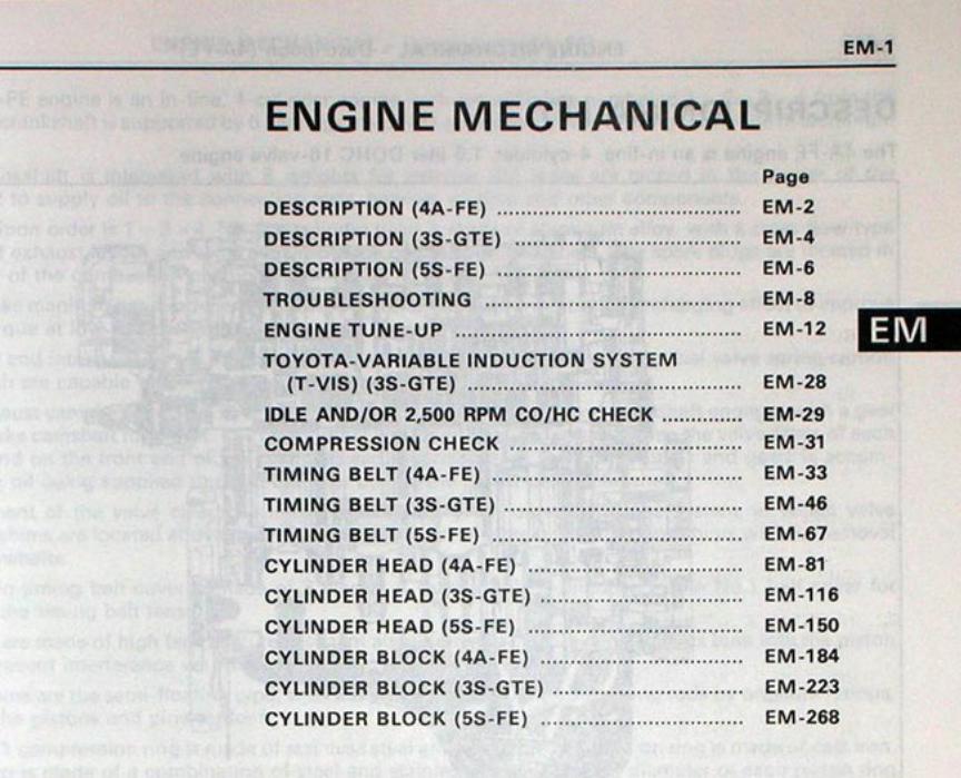
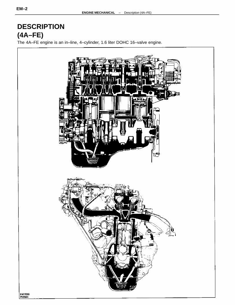
DESCRIPTION (4A–FE)The 4A–FE engine is an in–line, 4–cylinder, 1.6 liter DOHC 16–valve engine.
–ENGINE MECHANICAL Description (4A–FE)EM–2
The 4A–FE engine is an in–line, 4–cylinder engine with the cylinders numbered 1 – 2 – 3 – 4 from thefront. The crankshaft is supported by 5 bearings inside the crankcase. These bearings are made of aluminumalloy. The crankshaft is integrated with 8 weights for balance. Oil holes are placed in the center of thecrankshaft to supply oil to the connecting rods, bearing, pistons and other components.The ignition order is 1 – 3 – 4 – 2. The cylinder head is made of aluminum alloy, with a cross flow typeintake and exhaust layout and with pent–roof type combustion chambers. The spark plugs are located inthe center of the combustion chambers. The intake manifold has 4 independent long ports and utilizes the inertial supercharging effect to improveengine torque at low and medium speeds. Exhaust and intake valves are equipped with irregular pitch springs made of special valve spring carbonsteel which are capable of functioning no matter what the engine speed. The exhaust camshaft is driven by a timing belt, and a gear on the exhaust camshaft engages with a gearon the intake camshaft to drive it. The cam journal is supported at 5 places between the valve lifters of each cylin-der and on the front end of the cylinder head. Lubrication of the cam journals and gears is accomplished by oilbeing supplied through the oiler port in the center of the camshaft. Adjustment of the valve clearance is done by means of an outer shim type system, in which valve adjustingshims are located above the valve lifters. This permits replacement of the shims without removal of the cam-shafts. The resin timing belt cover is made of 3 pieces. A service hole is provided in the No. 1 belt cover for adjustingthe timing belt tension. Pistons are made of high temperature–resistant aluminum alloy, and a depression is built into the piston headto prevent interference with the valves. Piston pins are the semi–floating type, with the pins fastened to the connecting rods by pressure fittings, allow-ing the pistons and pins to float. The No. 1 compression ring is made of stainless steel and the No. 2 compression ring is made of cast iron. Theoil ring is made of a combination of steel and stainless steel. The outer diameter of each piston is slightly largerthan the diameter of the piston and the flexibility of the rings allows them to hug the cylinder walls when they aremounted on the piston. Compression rings No. 1 and N0. 2 work to prevent gas leakage from the cylinder and theoil ring works to scrape oil off the cylinder walls to prevent it from entering the combustion chambers. The cylinder block is made of cast iron. It has 4 cylinders which are approximately twice the length of the pistonstroke. The top of each cylinder is closed off by the cylinder head and the lower end of the cylinders becomesthe crankcase, in which the crankshift is installed. In addition, the cylinder block contains a water jacket, throughwhich coolant is pumped to cool the cylinders. The oil pan is bolted onto the bottom of the cylinder block. The oil pan is an oil reservoir made of pressed steelsheet. A dividing plate is included in side the oil pan to keep sufficient oil in the bottom of the pan even when thevehicle is stopped suddenly and the oil shifts away from the oil pump suction pipe.
–ENGINE MECHANICAL Description (4A–FE)EM–3
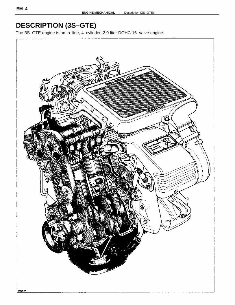
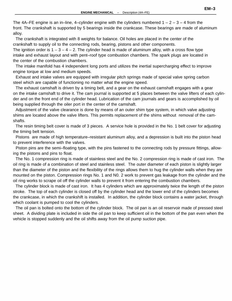
DESCRIPTION (3S–GTE)The 3S–GTE engine is an in–line, 4–cylinder, 2.0 liter DOHC 16–valve engine.
–ENGINE MECHANICAL Description (3S–GTE)EM–4
The 3S–GTE engine is an in–line, 4–cylinder engine with the cylinders numbered 1 – 2 – 3 – 4 from thefront. The crankshaft is supported by 5 bearings inside the crankcase. These bearings are made of aluminumalloy.
The crankshaft is integrated with 8 weights for balance. Oil holes are placed in the center of thecrankshaft to supply oil to the connecting rods, bearing, pistons and other components.The ignition order is 1 – 3 – 4 – 2. The cylinder head is made of aluminum alloy, with a cross flow typeintake and exhaust layout and with pent–roof type combustion chambers. The spark plugs are located inthe center of the combustion chambers.
The intake manifold has 8 independent long ports and utilizes the inertial supercharging effect to improveengine torque at low and medium speeds.
Both the intake camshaft and the exhaust camshaft are driven by a single timing belt. The cam journalis supported at 5 places between the valve lifters of each cylinder and on the front end of the cylinder head.Lubrication of the cam journals and cams is accomplished by oil being supplied through the oiler port inthe center of the camshaft.
Adjustment of the valve clearance is done by means of an outer shim type system, in which valveadjusting shims are located above the valve lifters. This permits replacement of the shims without removalof the camshafts.
Pistons are made of high temperature–resistant aluminum alloy, and a depression is built into the pistonhead to prevent interference with the valves.
Piston pins are the full–floating type, with the pins fastened to neither the piston boss nor the connectingrods. Instead, snap rings are fitted on both ends of the pins, preventing the pins from falling out.
The No.1 compression ring is made of steel and the No.2 compression ring is made of cast iron. The oilring is made of a combination of steel and stainless steel. The outer diameter of each piston ring is slightlylarger than the diameter of the piston and the flexibility of the rings allows them to hug the cylinder wallswhen they are mounted on the piston. Compression rings No.1 and No.2 work to prevent gas leakage fromthe cylinder and the oil ring works to scrape oil off the cylinder walls to prevent it from entering thecombustion chambers.
The cylinder block is made of cast iron. It has 4 cylinders which are approximately twice the length ofthe piston stroke. The top of each cylinder is closed off: by the cylinder head and the lower end of thecylinders becomes the crankcase, in which the crankshaft is installed. In addition, the cylinder blockcontains a water jacket, through which coolant is pumped to cool the cylinders.
The oil pan is bolted onto the bottom of the cylinder block. The oil pan is an oil reservoir made of pressedsteel sheet. A dividing plate is included inside the oil pan to keep sufficient oil in the bottom of the paneven when the vehicle is tilted. This dividing plate also prevents the oil from making waves when thevehicle is stopped suddenly and the oil shifts away from the oil pump suction pipe.
–ENGINE MECHANICAL Description (3S–GTE)EM–5
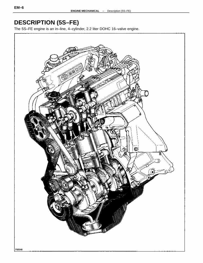
DESCRIPTION (5S–FE)The 5S–FE engine is an in–line, 4–cylinder, 2.2 liter DOHC 16–valve engine.
–ENGINE MECHANICAL Description (5S–FE)EM–6
The 5S–FE engine is an in–line, 4–cylinder engine with the cylinders numbered 1 – 2 – 3 – 4 from thefront. The crankshaft is supported by 5 bearings inside the crankcase. These bearings are made of aluminumalloy.
The crankshaft is integrated with 8 weights for balance. Oil holes are placed in the center of thecrankshaft to supply oil to the connecting rods, bearing, pistons and other components.
The ignition order is ”I – 3 – 4 – 2. The cylinder head is made of aluminum alloy, with a cross flow typeintake and exhaust layout and with pent–roof type combustion chambers. The spark plugs are located inthe center of the combustion chambers.
The intake manifold has 4 independent long ports and utilizes the inertial supercharging effect to improveengine torque at low and medium speeds.
Exhaust and intake valves are equipped with irregular pitch springs made of special valve spring carbonsteel which are capable of functioning no matter what the engine speed.
The intake camshaft is driven by a timing belt, and a gear on the intake camshaft engages with a gearon the exhaust camshaft to drive it. The cam journal is supported at 5 places between the valve lifters ofeach cylinder and on the front end of the cylinder head. Lubrication of the cam journals and gears isaccomplished by oil being supplied through the oiler port in the center of the camshaft.
Adjustment of the valve clearance is done by means of an outer shim type system, in which valveadjusting shims are located above the valve lifters. This permits replacement of the shims without removalof the camshafts.
Pistons are made of high temperature–resistant aluminum alloy, and a depression is built into the pistonhead to prevent interference with the valves.
Piston pins are the full–floating type, with the pins fastened to neither the piston boss nor the connectingrods. Instead, snap rings are fitted on both ends of the pins, preventing the pins from falling out.
The No.1 compression ring is made of steel and the No.2 compression ring is made of cast iron. The oilring is made of a combination of steel and stainless steel. The outer diameter of each piston ring is slightlylarger than the diameter of the piston and the flexibility of the rings allows them to hug the cylinder wallswhen they are mounted on the piston. Compression rings No.1 and No.2 work to prevent gas leakage fromthe cylinder and the oil ring works to scrape oil off the cylinder walls to prevent it from entering thecombustion chambers.
The cylinder block is made of cast iron. It has 4 cylinders which are approximately twice the length ofthe piston stroke. The top of each cylinder is closed off by the cylinder head and the lower end of thecylinders becomes the crankcase, in which the crankshaft is installed. In addition, the cylinder blockcontains a water jacket, through which coolant is pumped to, cool the cylinders.
The oil pan is bolted onto the bottom of the cylinder block. The oil pan is an oil reservoir made of pressedsteel sheet. A dividing plate is included inside the oil pan to keep sufficient oil in the bottom of the paneven when the vehicle is tilted. This dividing plate also prevents the oil from making waves when thevehicle is stopped suddenly and the oil shifts away from the oil pump suction pipe.
–ENGINE MECHANICAL Description (5S–FE)EM–7
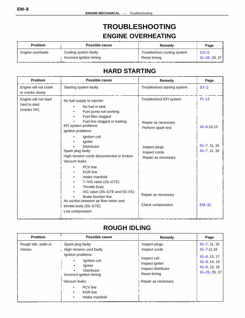
No fuel supply to injector:
• No fuel in tank• Fuel pump not working• Fuel filter clogged• Fuel line clogged or leaking
EFI system problemsIgnition problems:
• Ignition coil• Igniter• Distributor
Spark plug faultyHigh–tension cords disconnected or brokenVacuum leaks:
• PCV line• EGR line• Intake manifold• T–VIS valve (3S–GTE)• Throttle body• ISC valve (3S–GTE and 5S–FE)• Brake booster line
Air suction between air flow meter andthrottle body (3S–GTE)Low compression
Spark plug faultyHigh–tension cord faultyIgnition problems:
• Ignition coil• Igniter• Distributor
Incorrect ignition timing
TROUBLESHOOTINGENGINE OVERHEATING
Inspect coilInspect igniterInspect distributorReset timing
Inspect plugsInspect cordsRepair as necessary
Troubleshoot cooling systemReset timing
Engine will not start/hard to start(cranks OK)
Cooling system faultyIncorrect ignition timing
IG–8, 13, 17IG–9, 14, 19IG–9, 13, 18IG–25, 29, 37
Repair as necessaryPerform spark test
Engine will not crankor cranks slowly
Rough idle, stalls ormisses
HARD STARTING
Troubleshoot starting system
CO–5IG–25, 29, 37
Inspect plugsInspect cords
ROUGH IDLING
Troubleshoot EFI system
IG–7, 11, 16IG–7, 11, 16
IG–7, 11, 16IG–7,11,16
Starting system faulty
Repair as necessary
Check compression
Engine overheats
Possible cause
Possible cause
Possible cause
IG–6,10,15
Problem
RemedyProblem
Problem Remedy
Remedy
EM–31
Page
Page
Page
FI–13
ST–2
Vacuum leaks:
• PCV line• EGR line• Intake manifold
Repair as necessary
–ENGINE MECHANICAL TroubleshootingEM–8
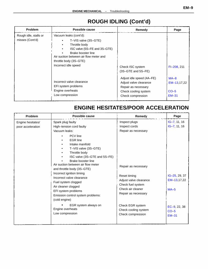
Spark plug faultyHigh–tension cord faultyVacuum leaks:
• PCV line• EGR line• Intake manifold• T–VIS valve (3S–GTE)• Throttle body• ISC valve (3S–GTE and 5S–FE)• Brake booster line
Air suction between air flow meterand throttle body (3S–GTE)Incorrect ignition timingIncorrect valve clearanceFuel system cloggedAir cleaner cloggedEFI system problemsEmission control system problems:(cold engine)
• EGR system always onEngine overheatsLow compression
Vacuum leaks (cont’d):
• T–VIS valve (3S–GTE)• Throttle body• ISC valve (5S–FE and 3S–GTE)• Brake booster line
Air suction between air flow meter andthrottle body (3S–GTE)Incorrect idle speed Check ISC system
(3S–GTE and 5S–FE)
Reset timingAdjust valve clearanceCheck fuel systemCheck air cleanerRepair as necessary
Incorrect valve clearanceEFI system problemsEngine overheatsLow compression
ENGINE HESITATES/POOR ACCELERATION
Check EGR systemCheck cooling systemCheck compression
Inspect plugsInspect cordsRepair as necessary
ROUGH IDLING (Cont’d)
EC–9, 22, 38CO–5EM–31
Rough idle, stalls ormisses (Cont’d)
Engine hesitates/poor acceleration
IG–25, 29, 37EM–13,17,22
MA–8EM–13,17,22
IG–7, 11, 16IG–7, 11, 16
Repair as necessary
Possible cause
Possible cause
CO–5EM–31
FI–208, 211
Problem
RemedyProblem
Remedy
Page
Page
MA–5
Adjust idle speed (4A–FE)Adjust valve clearanceRepair as necessaryCheck cooling systemCheck compression
–ENGINE MECHANICAL TroubleshootingEM–9
EFI system problemsVacuum leaks:
• PCV line• EGR line• Intake manifold• T–VIS valve (3S–GTE)• Throttle body• ISC valve (3S–GTE and 5S–FE)• Brake booster line
Air suction between air flow meterand throttle body (3S–GTE)Insufficient fuel flowIncorrect ignition timingIncorrect valve clearanceCarbon deposits in combustion chambers
Repair as necessaryCheck PCV systemCheck rings
Troubleshoot fuel systemReset timingAdjust valve clearanceInspect cylinder head
Oil leakPCV line cloggedPiston ring worn or damaged
Air cleaner cloggedEFI system problemsIncorrect ignition timing
EFI system problemsIncorrect ignition timingEGR system faulty
Repair as necessaryCheck hoses and repair asnecessary
FI–13IG–25, 29, 37EM–13,17,22EM–92, 127,161
EXCESSIVE OIL CONSUMPTION
Check air cleanerRepair as necessaryReset timing
Repair as necessaryReset timingCheck EGR system
Engine diesels(runs after ignitionswitch is turned off)
EM–94,129,163
AFTER FIRE, BACKFIRE
Muffler explosion(after fire) ondeceleration only
Muffler explosion(after fire) all thetime
Deceleration fuel cut system always off
Valve stem and guide bushing worn
ENGINE DIESELING
Check EFI (fuel cut) system
IG–25, 29, 37EC–9, 22, 38
Valve stem oil seal worn
Excessive oilconsumption
Repair as necessary
Engine backfires
Possible cause
Possible cause
Possible cause
IG–25, 29, 37
Check seals
Problem
Remedy
Remedy
Problem Remedy
Problem Page
Page
Page
MA–5
Check valves and guide bushing
EM–204, 244,289
–ENGINE MECHANICAL TroubleshootingEM–10
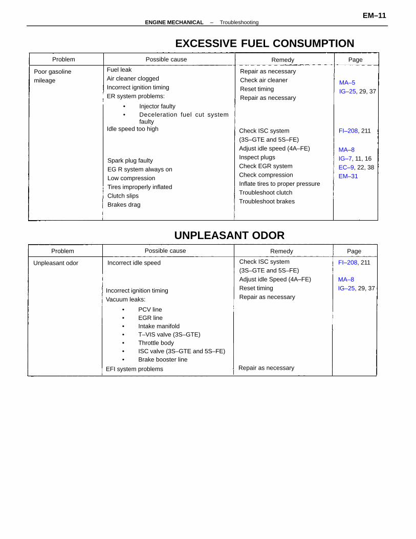
Incorrect ignition timingVacuum leaks:
• PCV line• EGR line• Intake manifold• T–VIS valve (3S–GTE)• Throttle body• ISC valve (3S–GTE and 5S–FE)• Brake booster line
EFI system problems
Fuel leakAir cleaner cloggedIncorrect ignition timingER system problems:
• Injector faulty• Deceleration fuel cut system
faultyIdle speed too high Check ISC system
(3S–GTE and 5S–FE)Adjust idle speed (4A–FE)Inspect plugsCheck EGR systemCheck compressionInflate tires to proper pressureTroubleshoot clutchTroubleshoot brakes
Spark plug faultyEG R system always onLow compressionTires improperly inflatedClutch slipsBrakes drag
Check ISC system(3S–GTE and 5S–FE)Adjust idle Speed (4A–FE)Reset timingRepair as necessary
Repair as necessaryCheck air cleanerReset timingRepair as necessary
EXCESSIVE FUEL CONSUMPTION
MA–8IG–7, 11, 16EC–9, 22, 38EM–31
UNPLEASANT ODOR
MA–8IG–25, 29, 37
MA–5IG–25, 29, 37
Poor gasolinemileage
Incorrect idle speed
Repair as necessary
Unpleasant odor
Possible cause
Possible cause
FI–208, 211
FI–208, 211
Problem
Problem Remedy
Remedy Page
Page
–ENGINE MECHANICAL TroubleshootingEM–11
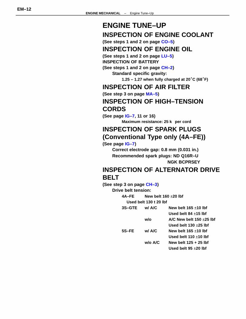
ENGINE TUNE–UPINSPECTION OF ENGINE COOLANT(See steps 1 and 2 on page CO–5)
INSPECTION OF ENGINE OIL(See steps 1 and 2 on page LU–5)INSPECTION OF BATTERY(See steps 1 and 2 on page CH–2)
Standard specific gravity:1.25 – 1.27 when fully charged at 20 °C (68°F)
INSPECTION OF AIR FILTER(See step 3 on page MA–5)
INSPECTION OF HIGH–TENSIONCORDS(See page IG–7, 11 or 16)
Maximum resistance: 25 k per cord
INSPECTION OF SPARK PLUGS(Conventional Type only (4A–FE))(See page IG–7)
Correct electrode gap: 0.8 mm (0.031 in.)Recommended spark plugs: ND Q16R–U
NGK BCPRSEY
INSPECTION OF ALTERNATOR DRIVEBELT(See step 3 on page CH–3)
Drive belt tension:4A–FE New belt 160 ±20 lbf
Used belt 130 t 20 lbf3S–GTE w/ A/C New belt 165 ±10 lbf
Used belt 84 ±15 lbfw/o A/C New belt 150 ±25 lbf
Used belt 130 ±25 lbf5S–FE w/ A/C New belt 165 ±10 lbf
Used belt 110 ±10 lbfw/o A/C New belt 125 + 25 lbf
Used belt 95 ±20 lbf
–ENGINE MECHANICAL Engine Tune–UpEM–12
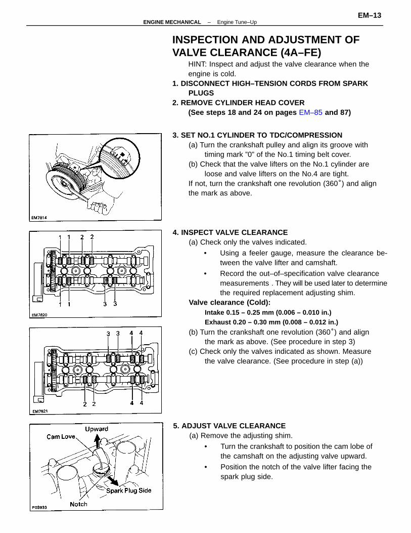
4. INSPECT VALVE CLEARANCE(a) Check only the valves indicated.
• Using a feeler gauge, measure the clearance be-tween the valve lifter and camshaft.
• Record the out–of–specification valve clearancemeasurements . They will be used later to determinethe required replacement adjusting shim.
Valve clearance (Cold):Intake 0.15 – 0.25 mm (0.006 – 0.010 in.)Exhaust 0.20 – 0.30 mm (0.008 – 0.012 in.)
(b) Turn the crankshaft one revolution (360°) and alignthe mark as above. (See procedure in step 3)
(c) Check only the valves indicated as shown. Measurethe valve clearance. (See procedure in step (a))
INSPECTION AND ADJUSTMENT OFVALVE CLEARANCE (4A–FE)
HINT: Inspect and adjust the valve clearance when theengine is cold.
1. DISCONNECT HIGH–TENSION CORDS FROM SPARKPLUGS
2. REMOVE CYLINDER HEAD COVER(See steps 18 and 24 on pages EM–85 and 87)
3. SET NO.1 CYLINDER TO TDC/COMPRESSION(a) Turn the crankshaft pulley and align its groove with
timing mark ”0” of the No.1 timing belt cover.(b) Check that the valve lifters on the No.1 cylinder are
loose and valve lifters on the No.4 are tight.If not, turn the crankshaft one revolution (360°) and alignthe mark as above.
5. ADJUST VALVE CLEARANCE(a) Remove the adjusting shim.
• Turn the crankshaft to position the cam lobe ofthe camshaft on the adjusting valve upward.
• Position the notch of the valve lifter facing thespark plug side.
–ENGINE MECHANICAL Engine Tune–UpEM–13
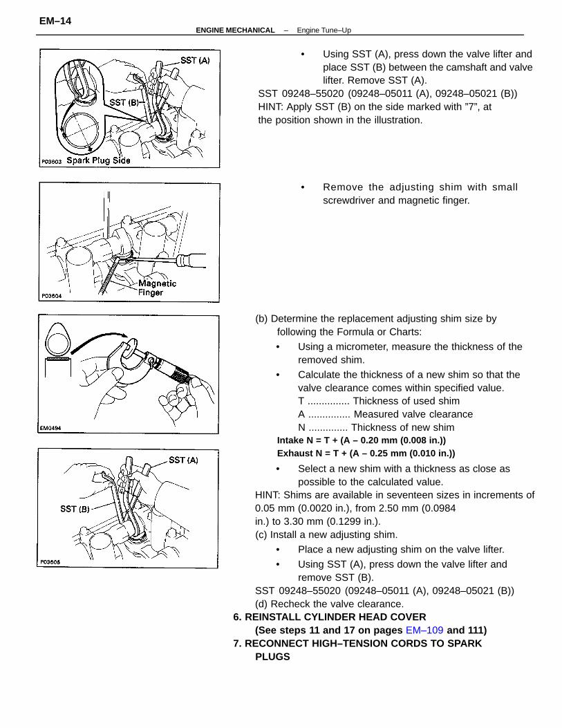
(b) Determine the replacement adjusting shim size byfollowing the Formula or Charts:
• Using a micrometer, measure the thickness of theremoved shim.
• Calculate the thickness of a new shim so that thevalve clearance comes within specified value.T ............... Thickness of used shimA ............... Measured valve clearanceN .............. Thickness of new shim
Intake N = T + (A – 0.20 mm (0.008 in.))Exhaust N = T + (A – 0.25 mm (0.010 in.))
• Select a new shim with a thickness as close aspossible to the calculated value.
HINT: Shims are available in seventeen sizes in increments of0.05 mm (0.0020 in.), from 2.50 mm (0.0984in.) to 3.30 mm (0.1299 in.).(c) Install a new adjusting shim.
• Place a new adjusting shim on the valve lifter.
• Using SST (A), press down the valve lifter andremove SST (B).
SST 09248–55020 (09248–05011 (A), 09248–05021 (B))(d) Recheck the valve clearance.
6. REINSTALL CYLINDER HEAD COVER(See steps 11 and 17 on pages EM–109 and 111)
7. RECONNECT HIGH–TENSION CORDS TO SPARKPLUGS
• Using SST (A), press down the valve lifter andplace SST (B) between the camshaft and valvelifter. Remove SST (A).
SST 09248–55020 (09248–05011 (A), 09248–05021 (B))HINT: Apply SST (B) on the side marked with ”7”, atthe position shown in the illustration.
• Remove the adjusting shim with smallscrewdriver and magnetic finger.
–ENGINE MECHANICAL Engine Tune–UpEM–14
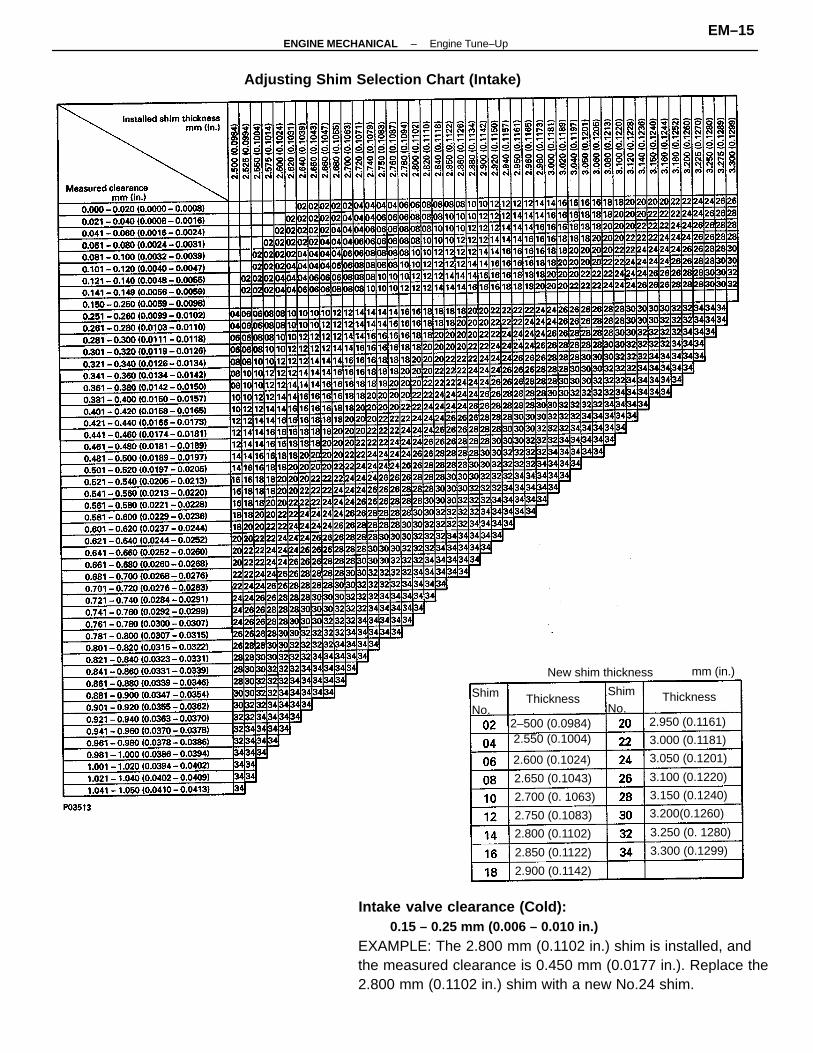
Intake valve clearance (Cold):0.15 – 0.25 mm (0.006 – 0.010 in.)
EXAMPLE: The 2.800 mm (0.1102 in.) shim is installed, andthe measured clearance is 0.450 mm (0.0177 in.). Replace the2.800 mm (0.1102 in.) shim with a new No.24 shim.
Adjusting Shim Selection Chart (Intake)
New shim thickness
2.550 (0.1004).2–500 (0.0984)
2.600 (0.1024) 3.050 (0.1201)
2.950 (0.1161)
3.250 (0. 1280)
2.700 (0. 1063)
2.850 (0.1122)
2.650 (0.1043)
2.800 (0.1102)3.300 (0.1299)
3.150 (0.1240)
3.000 (0.1181)
2.900 (0.1142)
3.200(0.1260)
3.100 (0.1220)
2.750 (0.1083)
Thickness ThicknessShimNo.
ShimNo.
mm (in.)
–ENGINE MECHANICAL Engine Tune–UpEM–15
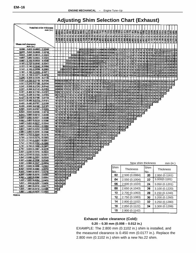
Exhaust valve clearance (Cold):0.20 – 0.30 mm (0.008 – 0.012 in.)
EXAMPLE: The 2.800 mm (0.1102 in.) shim is installed, andthe measured clearance is 0.450 mm (0.0177 in.). Replace the2.800 mm (0.1102 in.) shim with a new No.22 shim.
Adjusting Shim Selection Chart (Exhaust)
New shim thickness
3.000(0.1181)
2.650 (4.1043) 3.100 (0.1220)
2.800 (0.1102)
2.900 (0.1142)
3.150 (0.1240)
2.600 (0.1024) 3.050 (0.1201)
2.550 (0.1004)
2.750 (0.1083)
2.700 (0.1063)
2.850 (0.1122)
3.200 (0.1260)
2.500 (0.0984)
3.300 (0.1299)
2.950 (0.1161)
3.250 (0.1280)
ThicknessThicknessShimNo.
ShimNo.
mm (in.)
–ENGINE MECHANICAL Engine Tune–UpEM–16
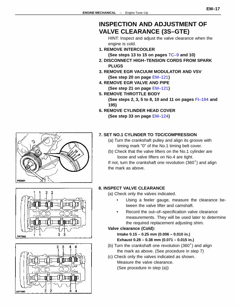
INSPECTION AND ADJUSTMENT OFVALVE CLEARANCE (3S–GTE)
HINT: Inspect and adjust the valve clearance when theengine is cold.
1. REMOVE INTERCOOLER(See steps 13 to 15 on pages TC–9 and 10)
2. DISCONNECT HIGH–TENSION CORDS FROM SPARKPLUGS
3. REMOVE EGR VACUUM MODULATOR AND VSV(See step 20 on page EM–121)
4. REMOVE EGR VALVE AND PIPE(See step 21 on page EM–121)
5. REMOVE THROTTLE BODY(See steps 2, 3, 5 to 8, 10 and 11 on pages FI–194 and195)
6. REMOVE CYLINDER HEAD COVER(See step 33 on page EM–124)
8. INSPECT VALVE CLEARANCE(a) Check only the valves indicated.
• Using a feeler gauge, measure the clearance be-tween the valve lifter and camshaft.
• Record the out–of–specification valve clearancemeasurements. They will be used later to determinethe required replacement adjusting shim.
Valve clearance (Cold):Intake 0.15 – 0.25 mm (0.006 – 0.010 in.)Exhaust 0.28 – 0.38 mm (0.071 – 0.015 in.)
(b) Turn the crankshaft one revolution (360°) and alignthe mark as above. (See procedure in step 7)
(c) Check only the valves indicated as shown.Measure the valve clearance.(See procedure in step (a))
7. SET NO.1 CYLINDER TO TDC/COMPRESSION(a) Turn the crankshaft pulley and align its groove with
timing mark ”0” of the No.1 timing belt cover.(b) Check that the valve lifters on the No.1 cylinder are
loose and valve lifters on No.4 are tight.If not, turn the crankshaft one revolution (360°) and alignthe mark as above.
–ENGINE MECHANICAL Engine Tune–UpEM–17
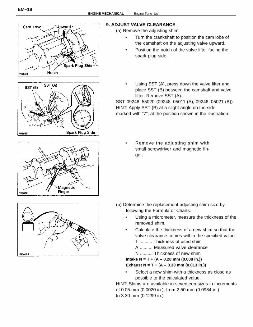
(b) Determine the replacement adjusting shim size byfollowing the Formula or Charts:
• Using a micrometer, measure the thickness of theremoved shim.
• Calculate the thickness of a new shim so that thevalve clearance comes within the specified value.T .......... Thickness of used shimA .......... Measured valve clearanceN .......... Thickness of new shim
Intake N = T + (A – 0.20 mm (0.008 in.))Exhaust N = T + (A – 0.33 mm (0.013 in.))
• Select a new shim with a thickness as close aspossible to the calculated value.
HINT: Shims are available in seventeen sizes in incrementsof 0.05 mm (0.0020 in.), from 2.50 mm (0.0984 in.)to 3.30 mm (0.1299 in.)
9. ADJUST VALVE CLEARANCE(a) Remove the adjusting shim.
• Turn the crankshaft to position the cam lobe ofthe camshaft on the adjusting valve upward.
• Position the notch of the valve lifter facing thespark plug side.
• Using SST (A), press down the valve lifter andplace SST (B) between the camshaft and valvelifter. Remove SST (A).
SST 09248–55020 (09248–05011 (A), 09248–05021 (B))HINT: Apply SST (B) at a slight angle on the sidemarked with ”7”, at the position shown in the illustration.
• Remove the adjusting shim withsmall screwdriver and magnetic fin-ger.
–ENGINE MECHANICAL Engine Tune–UpEM–18
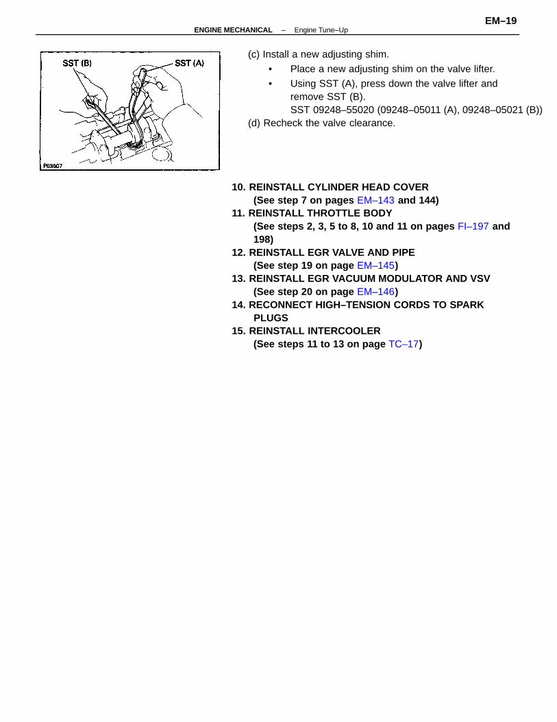
10. REINSTALL CYLINDER HEAD COVER(See step 7 on pages EM–143 and 144)
11. REINSTALL THROTTLE BODY(See steps 2, 3, 5 to 8, 10 and 11 on pages FI–197 and198)
12. REINSTALL EGR VALVE AND PIPE(See step 19 on page EM–145)
13. REINSTALL EGR VACUUM MODULATOR AND VSV(See step 20 on page EM–146)
14. RECONNECT HIGH–TENSION CORDS TO SPARKPLUGS
15. REINSTALL INTERCOOLER(See steps 11 to 13 on page TC–17)
(c) Install a new adjusting shim.
• Place a new adjusting shim on the valve lifter.
• Using SST (A), press down the valve lifter andremove SST (B).SST 09248–55020 (09248–05011 (A), 09248–05021 (B))
(d) Recheck the valve clearance.
–ENGINE MECHANICAL Engine Tune–UpEM–19
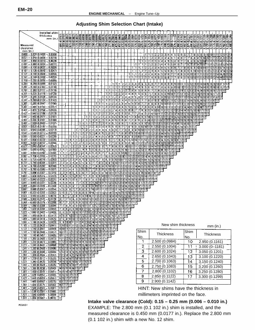
Intake valve clearance (Cold): 0.15 – 0.25 mm (0.006 – 0.010 in.)EXAMPLE: The 2.800 mm (0.1 102 in.) shim is installed, and themeasured clearance is 0.450 mm (0.0177 in.). Replace the 2.800 mm(0.1 102 in.) shim with a new No. 12 shim.
Adjusting Shim Selection Chart (Intake)
New shim thickness
2.900 (0.1142)
3.150 (0.1240)
3.000 (0–1181)2.500 (0.0984)
3.200 (0.1260)
3.300 (0.1299)2.800 (0.1102)2.750 (0.1083)
3.250 (0.1280)
2.700 (0.1063)
2.550 (0.1004)
3.100 (0.1220)3.050 (0.1201)
2.950 (0.1161)
2.600 (0.1024)
2.850 (0.1122)
2.650 (0.1043)
Thickness ThicknessShimNo.
ShimNo.
mm (in.)
HINT: New shims have the thickness inmillimeters imprinted on the face.
–ENGINE MECHANICAL Engine Tune–UpEM–20
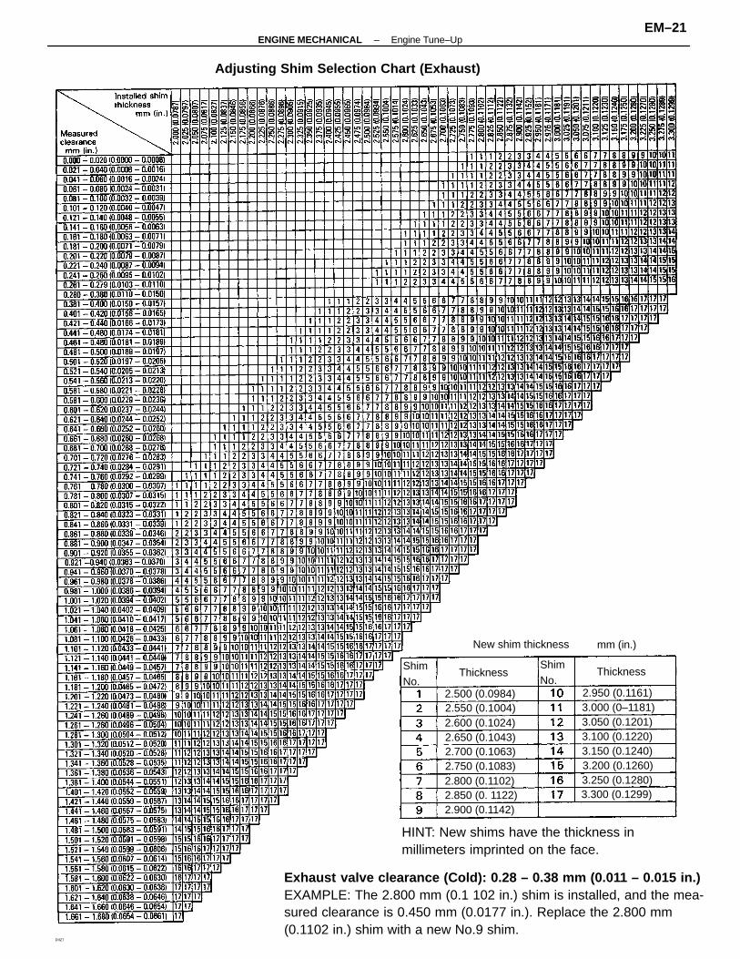
Exhaust valve clearance (Cold): 0.28 – 0.38 mm (0.011 – 0.015 in.)EXAMPLE: The 2.800 mm (0.1 102 in.) shim is installed, and the mea-sured clearance is 0.450 mm (0.0177 in.). Replace the 2.800 mm(0.1102 in.) shim with a new No.9 shim.
Adjusting Shim Selection Chart (Exhaust)
New shim thickness
3.300 (0.1299)
3.150 (0.1240)
2.850 (0. 1122)
3.050 (0.1201)
2.500 (0.0984) 2.950 (0.1161)
2.900 (0.1142)
3.100 (0.1220)
2.800 (0.1102)
2.700 (0.1063)
2.550 (0.1004)
2.650 (0.1043)
3.000 (0–1181)
3.250 (0.1280)3.200 (0.1260)
2.600 (0.1024)
2.750 (0.1083)
ThicknessThicknessShimNo.
ShimNo.
mm (in.)
DIIZ7
HINT: New shims have the thickness inmillimeters imprinted on the face.
–ENGINE MECHANICAL Engine Tune–UpEM–21
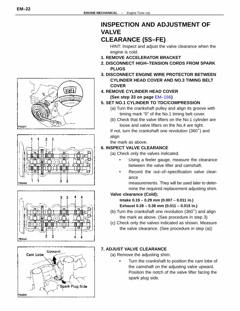
INSPECTION AND ADJUSTMENT OFVALVECLEARANCE (5S–FE)
HINT: Inspect and adjust the valve clearance when theengine is cold.
1. REMOVE ACCELERATOR BRACKET2. DISCONNECT HIGH–TENSION CORDS FROM SPARK
PLUGS3. DISCONNECT ENGINE WIRE PROTECTOR BETWEEN
CYLINDER HEAD COVER AND NO.3 TIMING BELTCOVER
4. REMOVE CYLINDER HEAD COVER(See step 33 on page EM–156)
5. SET NO.1 CYLINDER TO TDC/COMPRESSION(a) Turn the crankshaft pulley and align its groove with
timing mark ”0” of the No.1 timing belt cover.(b) Check that the valve lifters on the No.1 cylinder are
loose and valve lifters on the No.4 are tight.If not, turn the crankshaft one revolution (360°) andalignthe mark as above.
6. INSPECT VALVE CLEARANCE(a) Check only the valves indicated.
• Using a feeler gauge, measure the clearancebetween the valve lifter and camshaft.
• Record the out–of–specification valve clear-ancemeasurements. They will be used later to deter-mine the required replacement adjusting shim.
Valve clearance (Cold):Intake 0.19 – 0.29 mm (0.007 – 0.011 in.)Exhaust 0.28 – 0.38 mm (0.011 – 0.015 in.)
(b) Turn the crankshaft one revolution (360°) and alignthe mark as above. (See procedure in step 3)
(c) Check only the valves indicated as shown. Measurethe valve clearance. (See procedure in step (a))
7. ADJUST VALVE CLEARANCE(a) Remove the adjusting shim.
• Turn the crankshaft to position the cam lobe ofthe camshaft on the adjusting valve upward.Position the notch of the valve lifter facing thespark plug side.
–ENGINE MECHANICAL Engine Tune–UpEM–22
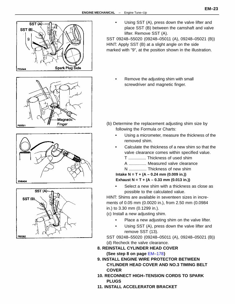
(b) Determine the replacement adjusting shim size byfollowing the Formula or Charts:
• Using a micrometer, measure the thickness of theremoved shim.
• Calculate the thickness of a new shim so that thevalve clearance comes within specified value.T ............... Thickness of used shimA ............... Measured valve clearanceN ............... Thickness of new shim
Intake N = T + (A – 0.24 mm (0.009 in.))Exhaust N = T + (A – 0.33 mm (0.013 in.))
• Select a new shim with a thickness as close aspossible to the calculated value.
HINT: Shims are available in seventeen sizes in incre-ments of 0.05 mm (0.0020 in.), from 2.50 mm (0.0984in.) to 3.30 mm (0.1299 in.).(c) Install a new adjusting shim.
• Place a new adjusting shim on the valve lifter.
• Using SST (A), press down the valve lifter andremove SST (13).
SST 09248–55020 (09248–05011 (A), 09248–05021 (B))(d) Recheck the valve clearance.
8. REINSTALL CYLINDER HEAD COVER(See step 8 on page EM–178)
9. INSTALL ENGINE WIRE PROTECTOR BETWEENCYLINDER HEAD COVER AND NO.3 TIMING BELTCOVER
10. RECONNECT HIGH–TENSION CORDS TO SPARKPLUGS
11. INSTALL ACCELERATOR BRACKET
• Using SST (A), press down the valve lifter andplace SST (B) between the camshaft and valvelifter. Remove SST (A).
SST 09248–55020 (09248–05011 (A), 09248–05021 (B))HINT: Apply SST (B) at a slight angle on the sidemarked with ”9”, at the position shown in the illustration.
• Remove the adjusting shim with smallscrewdriver and magnetic finger.
–ENGINE MECHANICAL Engine Tune–UpEM–23
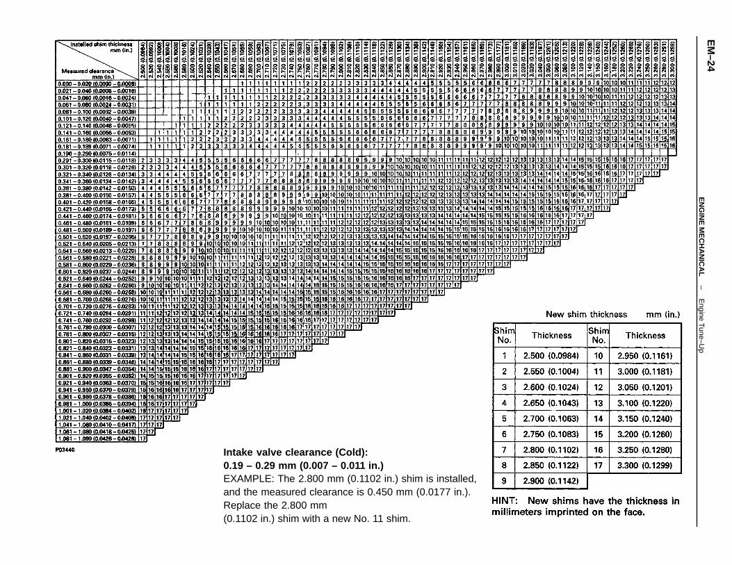
Intake valve clearance (Cold):0.19 – 0.29 mm (0.007 – 0.011 in.)EXAMPLE: The 2.800 mm (0.1102 in.) shim is installed,and the measured clearance is 0.450 mm (0.0177 in.).Replace the 2.800 mm(0.1102 in.) shim with a new No. 11 shim.
–E
NG
INE
ME
CH
AN
ICA
LE
ngine Tune–Up
EM
–24
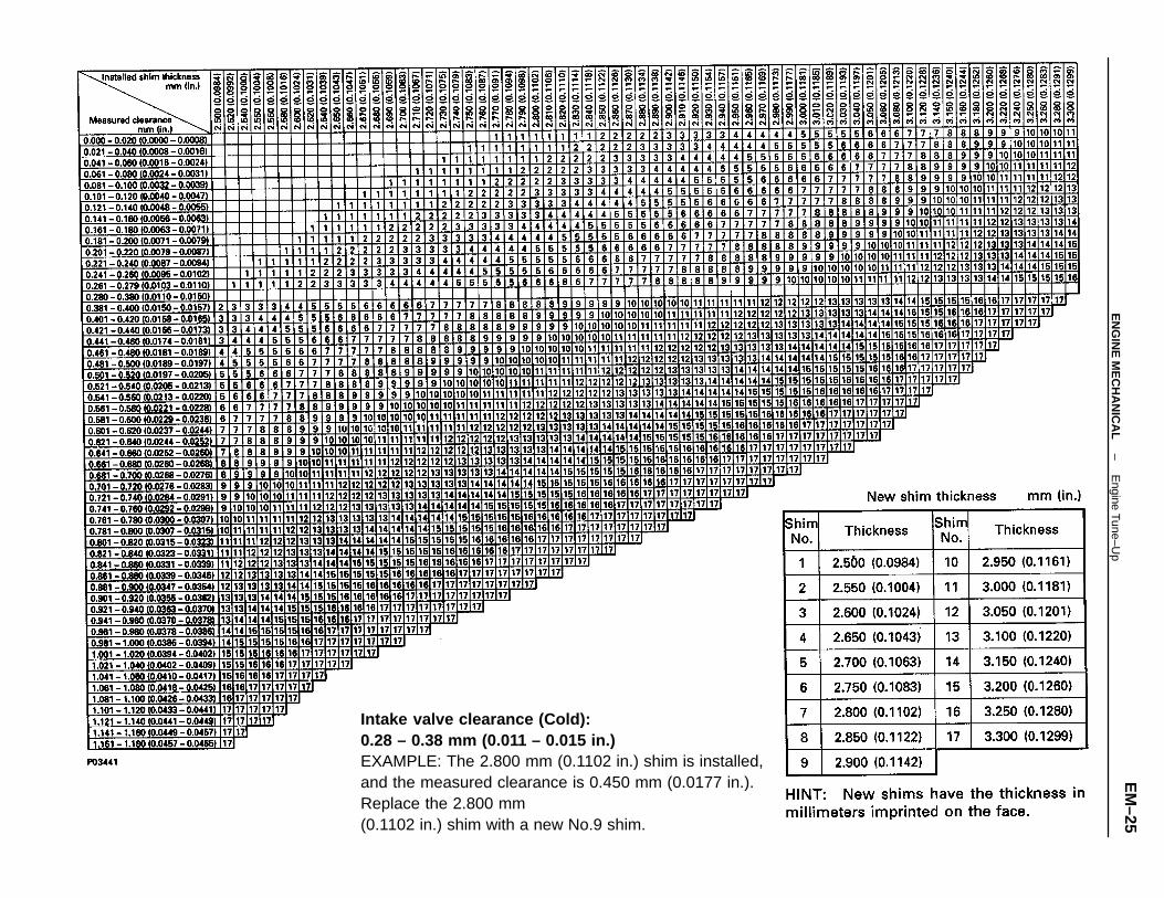
Intake valve clearance (Cold):0.28 – 0.38 mm (0.011 – 0.015 in.)EXAMPLE: The 2.800 mm (0.1102 in.) shim is installed,and the measured clearance is 0.450 mm (0.0177 in.).Replace the 2.800 mm(0.1102 in.) shim with a new No.9 shim.
–E
NG
INE
ME
CH
AN
ICA
LE
ngine Tune–Up
EM
–25
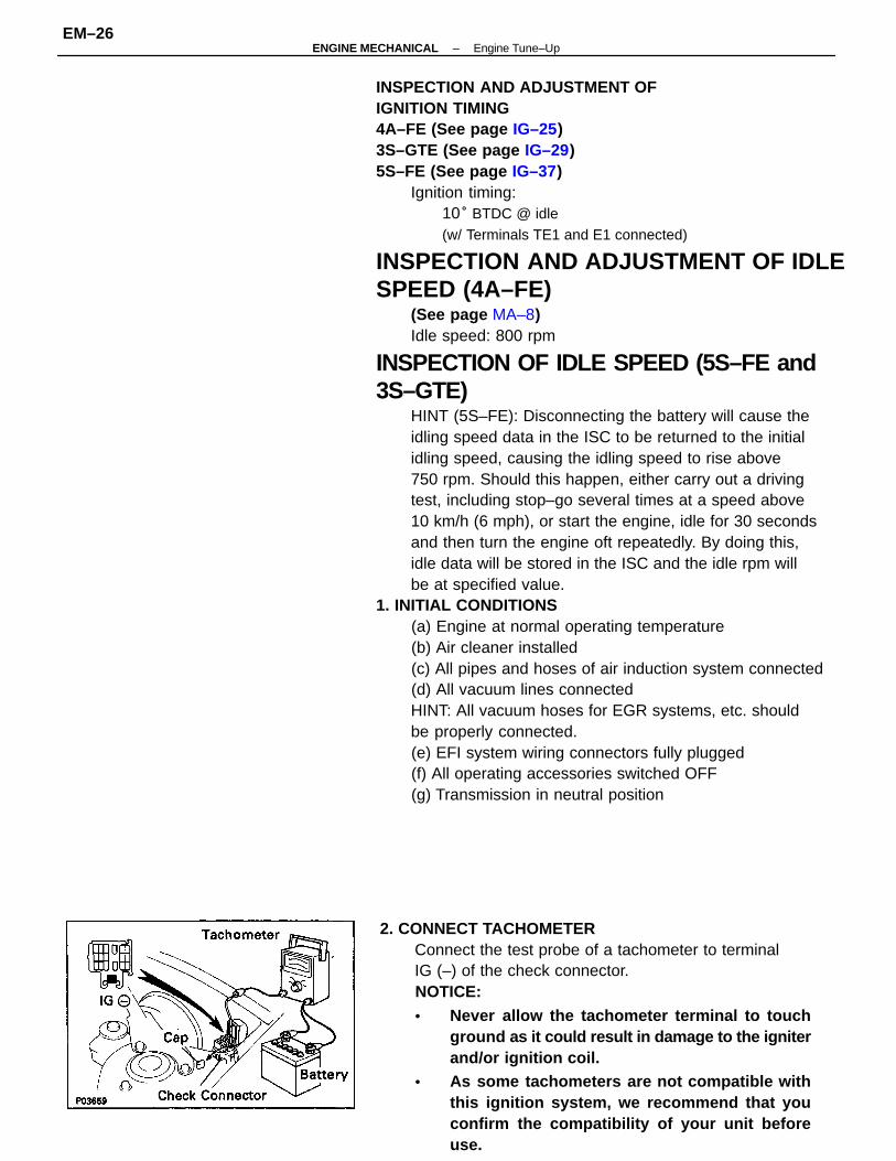
INSPECTION AND ADJUSTMENT OFIGNITION TIMING4A–FE (See page IG–25)3S–GTE (See page IG–29)5S–FE (See page IG–37)
Ignition timing:10° BTDC @ idle(w/ Terminals TE1 and E1 connected)
INSPECTION AND ADJUSTMENT OF IDLESPEED (4A–FE)
(See page MA–8)Idle speed: 800 rpm
INSPECTION OF IDLE SPEED (5S–FE and3S–GTE)
HINT (5S–FE): Disconnecting the battery will cause theidling speed data in the ISC to be returned to the initialidling speed, causing the idling speed to rise above750 rpm. Should this happen, either carry out a drivingtest, including stop–go several times at a speed above10 km/h (6 mph), or start the engine, idle for 30 secondsand then turn the engine oft repeatedly. By doing this,idle data will be stored in the ISC and the idle rpm willbe at specified value.
1. INITIAL CONDITIONS(a) Engine at normal operating temperature(b) Air cleaner installed(c) All pipes and hoses of air induction system connected(d) All vacuum lines connectedHINT: All vacuum hoses for EGR systems, etc. shouldbe properly connected.(e) EFI system wiring connectors fully plugged(f) All operating accessories switched OFF(g) Transmission in neutral position
2. CONNECT TACHOMETERConnect the test probe of a tachometer to terminalIG (–) of the check connector.NOTICE:• Never allow the tachometer terminal to touch
ground as it could result in damage to the igniterand/or ignition coil.
• As some tachometers are not compatible withthis ignition system, we recommend that youconfirm the compatibility of your unit beforeuse.
–ENGINE MECHANICAL Engine Tune–UpEM–26
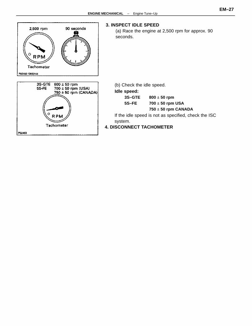
(b) Check the idle speed.Idle speed:
3S–GTE 800 ± 50 rpm5S–FE 700 ± 50 rpm USA
750 ± 50 rpm CANADA
If the idle speed is not as specified, check the ISCsystem.
4. DISCONNECT TACHOMETER
3. INSPECT IDLE SPEED(a) Race the engine at 2,500 rpm for approx. 90seconds.
–ENGINE MECHANICAL Engine Tune–UpEM–27
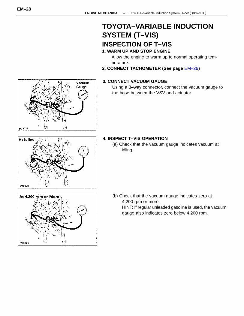
TOYOTA–VARIABLE INDUCTIONSYSTEM (T–VIS)INSPECTION OF T–VIS1. WARM UP AND STOP ENGINE
Allow the engine to warm up to normal operating tem-perature.
2. CONNECT TACHOMETER (See page EM–26)
(b) Check that the vacuum gauge indicates zero at4,200 rpm or more.HINT: If regular unleaded gasoline is used, the vacuumgauge also indicates zero below 4,200 rpm.
4. INSPECT T–VIS OPERATION(a) Check that the vacuum gauge indicates vacuum at
idling.
3. CONNECT VACUUM GAUGEUsing a 3–way connector, connect the vacuum gauge tothe hose between the VSV and actuator.
–ENGINE MECHANICAL TOYOTA–Variable Induction System (T–VIS) (3S–GTE)EM–28
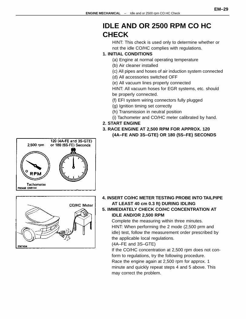
IDLE AND OR 2500 RPM CO HCCHECK
HINT: This check is used only to determine whether ornot the idle CO/HC complies with regulations.
1. INITIAL CONDITIONS(a) Engine at normal operating temperature(b) Air cleaner installed(c) All pipes and hoses of air induction system connected(d) All accessories switched OFF(e) All vacuum lines properly connectedHINT: All vacuum hoses for EGR systems, etc. shouldbe properly connected.(f) EFI system wiring connectors fully plugged(g) Ignition timing set correctly(h) Transmission in neutral position(i) Tachometer and CO/HC meter calibrated by hand.
2. START ENGINE3. RACE ENGINE AT 2,500 RPM FOR APPROX. 120
(4A–FE AND 3S–GTE) OR 180 (5S–FE) SECONDS
4. INSERT CO/HC METER TESTING PROBE INTO TAILPIPEAT LEAST 40 cm 0.3 ft) DURING IDLING
5. IMMEDIATELY CHECK CO/HC CONCENTRATION ATIDLE AND/OR 2,500 RPMComplete the measuring within three minutes.HINT: When performing the 2 mode (2,500 prm andidle) test, follow the measurement order prescribed bythe applicable local regulations.(4A–FE and 3S–GTE)If the CO/HC concentration at 2,500 rpm does not con-form to regulations, try the following procedure.Race the engine again at 2,500 rpm for approx. 1minute and quickly repeat steps 4 and 5 above. Thismay correct the problem.
–ENGINE MECHANICAL Idle and or 2500 rpm CO HC CheckEM–29
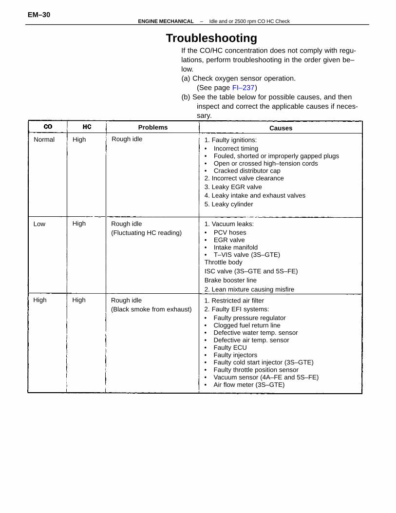
TroubleshootingIf the CO/HC concentration does not comply with regu-lations, perform troubleshooting in the order given be–low.(a) Check oxygen sensor operation.
(See page FI–237)(b) See the table below for possible causes, and then
inspect and correct the applicable causes if neces-sary.
1. Faulty ignitions:• Incorrect timing• Fouled, shorted or improperly gapped plugs• Open or crossed high–tension cords• Cracked distributor cap2. Incorrect valve clearance3. Leaky EGR valve4. Leaky intake and exhaust valves5. Leaky cylinder
1. Restricted air filter2. Faulty EFI systems:• Faulty pressure regulator• Clogged fuel return line• Defective water temp. sensor• Defective air temp. sensor• Faulty ECU• Faulty injectors• Faulty cold start injector (3S–GTE)• Faulty throttle position sensor• Vacuum sensor (4A–FE and 5S–FE)• Air flow meter (3S–GTE)
1. Vacuum leaks:• PCV hoses• EGR valve• Intake manifold• T–VIS valve (3S–GTE)Throttle bodyISC valve (3S–GTE and 5S–FE)Brake booster line2. Lean mixture causing misfire
Rough idle(Black smoke from exhaust)
Rough idle(Fluctuating HC reading)
Rough idle
Problems
Normal
Causes
HighHigh
High
High
Low
–ENGINE MECHANICAL Idle and or 2500 rpm CO HC CheckEM–30
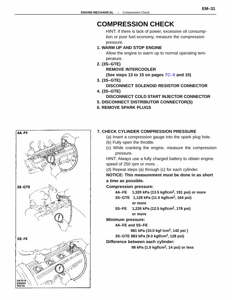
7. CHECK CYLINDER COMPRESSION PRESSURE(a) Insert a compression gauge into the spark plug hole.(b) Fully open the throttle.(c) While cranking the engine, measure the compression
pressure.HINT: Always use a fully charged battery to obtain enginespeed of 250 rpm or more. .(d) Repeat steps (a) through (c) for each cylinder.NOTICE: This measurement must be done in as shorta time as possible.Compression pressure:
4A–FE 1,320 kPa (13.5 kgf/cm 2, 191 psi) or more3S–GTE 1,128 kPa (11.5 kgf/cm 2, 164 psi)
or more5S–FE 1,226 kPa (12.5 kgf/cm 2, 178 psi)
or more
Minimum pressure:4A–FE and 5S–FE
981 kPa (10.0 kgf /cm 2, 142 psi )3S–GTE 883 kPa (9.0 kgf/cm 2, 128 psi)
Difference between each cylinder:98 kPa (1.0 kgf/cm 2, 14 psi) or less
COMPRESSION CHECKHINT: If there is lack of power, excessive oil consump-tion or poor fuel economy, measure the compressionpressure.
1. WARM UP AND STOP ENGINEAllow the engine to warm up to normal operating tem-perature.
2. (3S–GTE)REMOVE INTERCOOLER(See steps 13 to 15 on pages TC–9 and 10)
3. (3S–GTE)DISCONNECT SOLENOID RESISTOR CONNECTOR
4. (3S–GTE)DISCONNECT COLD START INJECTOR CONNECTOR
5. DISCONNECT DISTRIBUTOR CONNECTOR(S)6. REMOVE SPARK PLUGS
–ENGINE MECHANICAL Compression CheckEM–31
(e) If the cylinder compression in one or more cylindersis low, pour a small amount of engine oil into thecylinder through the spark plug hole and repeatsteps (a) through (c) for cylinders with low compres-sion.
• If adding oil helps the compression, chances arethat the piston rings and/or cylinder bore areworn or damaged.
• If pressure stays low, a valve may be sticking orseating is improper, or there may be leakage pastthe gasket.
8. REINSTALL SPARK PLUGSTorque: 18 N–m (180 kgf–cm, 13 ft–lbf)
9. RECONNECT DISTRIBUTOR CONNECTOR(S)10. (3S–GTE)
RECONNECT COLD START INJECTOR CONNECTOR11. (3S–GTE)
RECONNECT SOLENOID RESISTOR CONNECTOR12. (3S–GTE)
REINSTALL INTERCOOLER(See steps 11 to 13 on page TC–17)
–ENGINE MECHANICAL Compression CheckEM–32
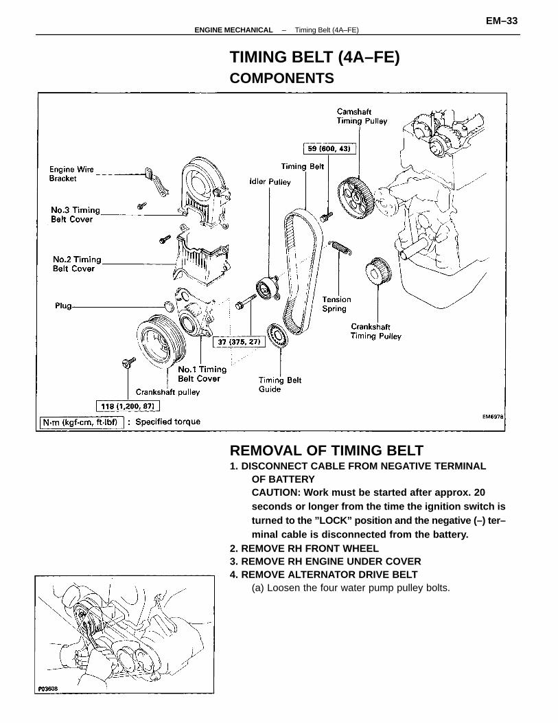
REMOVAL OF TIMING BELT1. DISCONNECT CABLE FROM NEGATIVE TERMINAL
OF BATTERYCAUTION: Work must be started after approx. 20seconds or longer from the time the ignition switch isturned to the ”LOCK” position and the negative (–) ter–minal cable is disconnected from the battery.
2. REMOVE RH FRONT WHEEL3. REMOVE RH ENGINE UNDER COVER4. REMOVE ALTERNATOR DRIVE BELT
(a) Loosen the four water pump pulley bolts.
TIMING BELT (4A–FE)COMPONENTS
–ENGINE MECHANICAL Timing Belt (4A–FE)EM–33
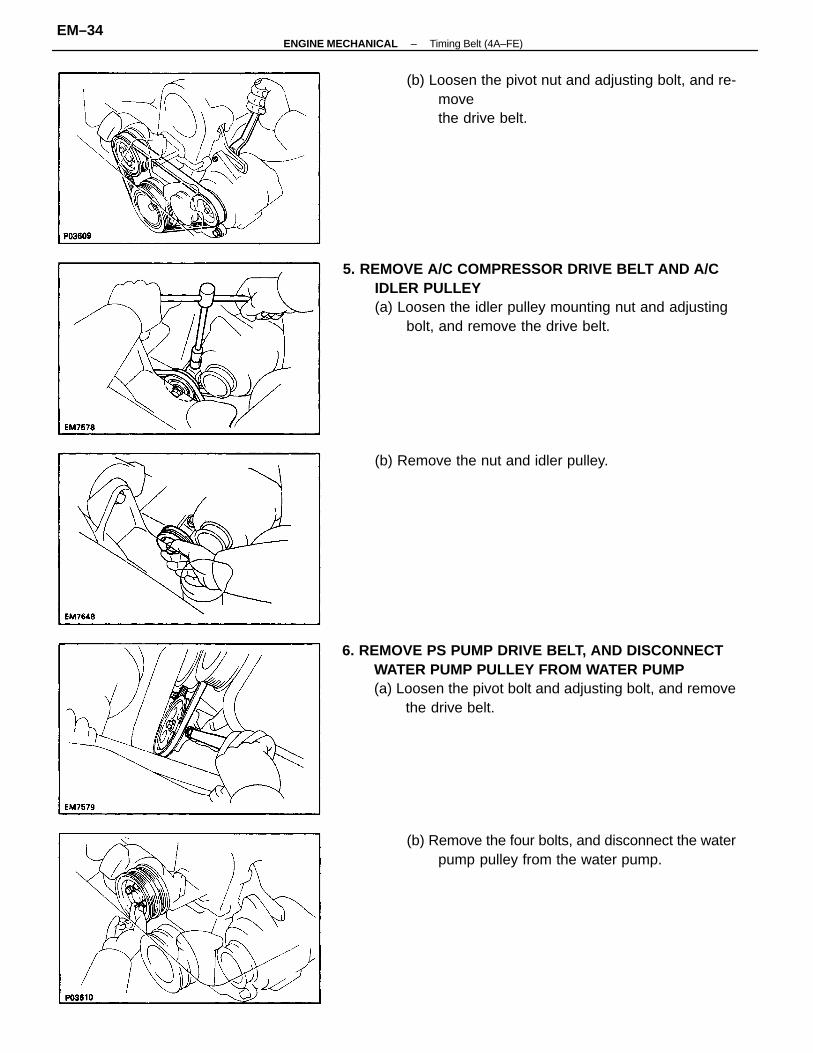
5. REMOVE A/C COMPRESSOR DRIVE BELT AND A/CIDLER PULLEY(a) Loosen the idler pulley mounting nut and adjusting
bolt, and remove the drive belt.
6. REMOVE PS PUMP DRIVE BELT, AND DISCONNECTWATER PUMP PULLEY FROM WATER PUMP(a) Loosen the pivot bolt and adjusting bolt, and remove
the drive belt.
(b) Remove the four bolts, and disconnect the waterpump pulley from the water pump.
(b) Loosen the pivot nut and adjusting bolt, and re-movethe drive belt.
(b) Remove the nut and idler pulley.
–ENGINE MECHANICAL Timing Belt (4A–FE)EM–34
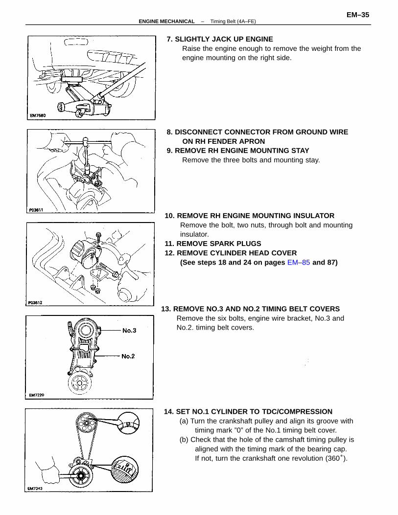
10. REMOVE RH ENGINE MOUNTING INSULATORRemove the bolt, two nuts, through bolt and mountinginsulator.
11. REMOVE SPARK PLUGS12. REMOVE CYLINDER HEAD COVER
(See steps 18 and 24 on pages EM–85 and 87)
14. SET NO.1 CYLINDER TO TDC/COMPRESSION(a) Turn the crankshaft pulley and align its groove with
timing mark ”0” of the No.1 timing belt cover.(b) Check that the hole of the camshaft timing pulley is
aligned with the timing mark of the bearing cap.If not, turn the crankshaft one revolution (360°).
13. REMOVE NO.3 AND NO.2 TIMING BELT COVERSRemove the six bolts, engine wire bracket, No.3 andNo.2. timing belt covers.
8. DISCONNECT CONNECTOR FROM GROUND WIREON RH FENDER APRON
9. REMOVE RH ENGINE MOUNTING STAYRemove the three bolts and mounting stay.
7. SLIGHTLY JACK UP ENGINERaise the engine enough to remove the weight from theengine mounting on the right side.
–ENGINE MECHANICAL Timing Belt (4A–FE)EM–35
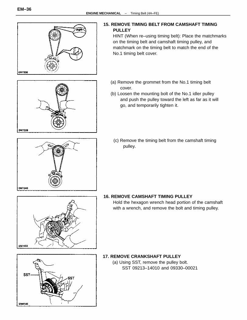
15. REMOVE TIMING BELT FROM CAMSHAFT TIMINGPULLEYHINT (When re–using timing belt): Place the matchmarkson the timing belt and camshaft timing pulley, andmatchmark on the timing belt to match the end of theNo.1 timing belt cover.
(a) Remove the grommet from the No.1 timing beltcover.
(b) Loosen the mounting bolt of the No.1 idler pulleyand push the pulley toward the left as far as it willgo, and temporarily tighten it.
16. REMOVE CAMSHAFT TIMING PULLEYHold the hexagon wrench head portion of the camshaftwith a wrench, and remove the bolt and timing pulley.
17. REMOVE CRANKSHAFT PULLEY(a) Using SST, remove the pulley bolt.
SST 09213–14010 and 09330–00021
(c) Remove the timing belt from the camshaft timingpulley.
–ENGINE MECHANICAL Timing Belt (4A–FE)EM–36
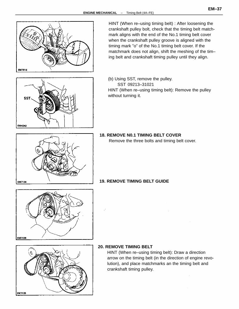
HINT (When re–using timing belt) : After loosening thecrankshaft pulley bolt, check that the timing belt match-mark aligns with the end of the No.1 timing belt coverwhen the crankshaft pulley groove is aligned with thetiming mark ”o” of the No.1 timing belt cover. If thematchmark does not align, shift the meshing of the tim–ing belt and crankshaft timing pulley until they align.
20. REMOVE TIMING BELTHINT (When re–using timing belt): Draw a directionarrow on the timing belt (in the direction of engine revo-lution), and place matchmarks an the timing belt andcrankshaft timing pulley.
(b) Using SST, remove the pulley.SST 09213–31021
HINT (When re–using timing belt): Remove the pulleywithout turning it.
18. REMOVE N0.1 TIMING BELT COVERRemove the three bolts and timing belt cover.
19. REMOVE TIMING BELT GUIDE
–ENGINE MECHANICAL Timing Belt (4A–FE)EM–37
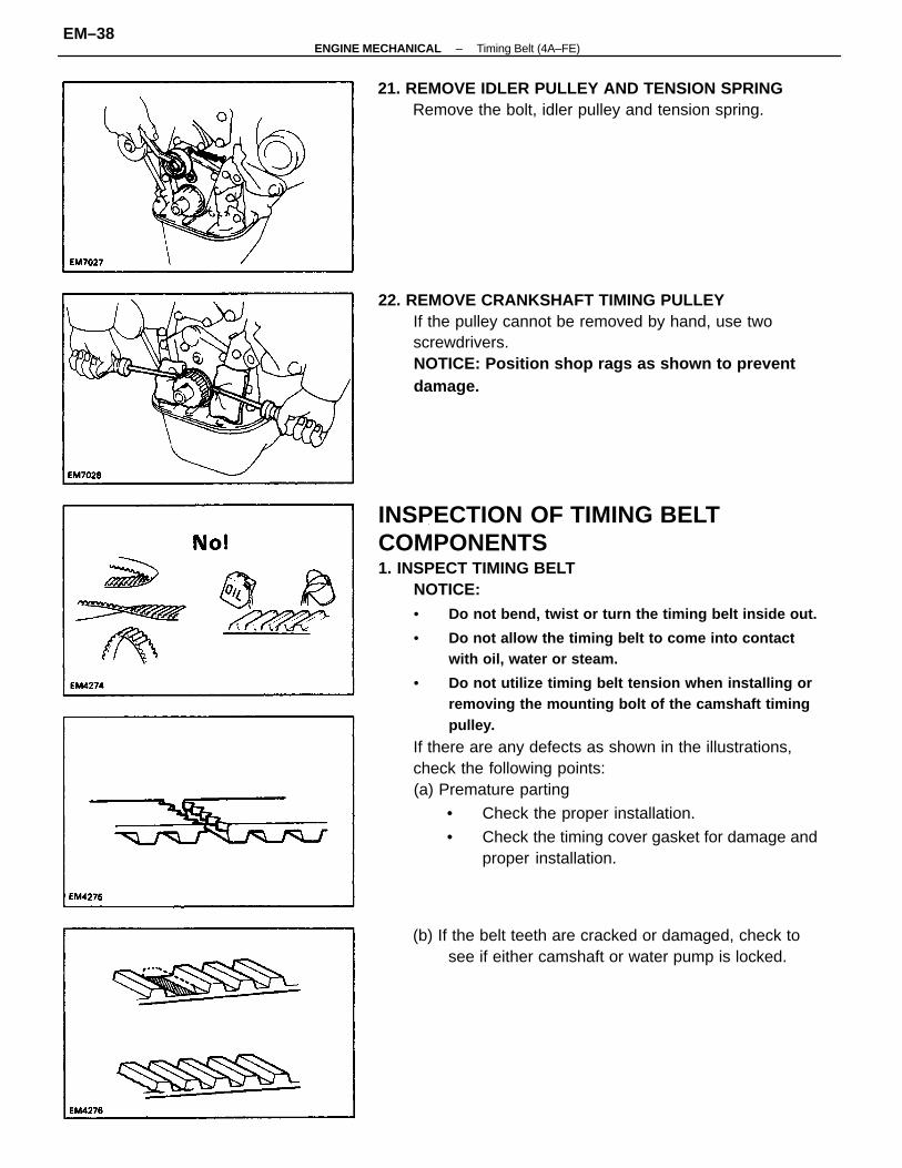
INSPECTION OF TIMING BELTCOMPONENTS1. INSPECT TIMING BELT
NOTICE:• Do not bend, twist or turn the timing belt inside out.
• Do not allow the timing belt to come into contactwith oil, water or steam.
• Do not utilize timing belt tension when installing orremoving the mounting bolt of the camshaft timingpulley.
If there are any defects as shown in the illustrations,check the following points:(a) Premature parting
• Check the proper installation.
• Check the timing cover gasket for damage andproper installation.
22. REMOVE CRANKSHAFT TIMING PULLEYIf the pulley cannot be removed by hand, use twoscrewdrivers.NOTICE: Position shop rags as shown to preventdamage.
21. REMOVE IDLER PULLEY AND TENSION SPRINGRemove the bolt, idler pulley and tension spring.
(b) If the belt teeth are cracked or damaged, check tosee if either camshaft or water pump is locked.
–ENGINE MECHANICAL Timing Belt (4A–FE)EM–38
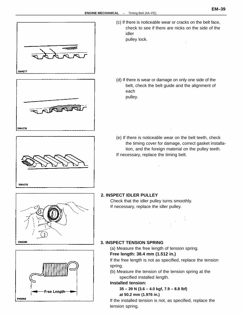
3. INSPECT TENSION SPRING(a) Measure the free length of tension spring.Free length: 38.4 mm (1.512 in.)If the free length is not as specified, replace the tensionspring.(b) Measure the tension of the tension spring at the
specified installed length.Installed tension:
35 – 39 N (3.6 – 4.0 kgf, 7.9 – 8.8 lbf)at 50.2 mm (1.976 in.)
If the installed tension is not, as specified, replace thetension spring.
(e) If there is noticeable wear on the belt teeth, checkthe timing cover for damage, correct gasket installa-tion, and the foreign material on the pulley teeth.
If necessary, replace the timing belt.
(c) If there is noticeable wear or cracks on the belt face,check to see if there are nicks on the side of theidlerpulley lock.
2. INSPECT IDLER PULLEYCheck that the idler pulley turns smoothly.If necessary, replace the idler pulley.
(d) If there is wear or damage on only one side of thebelt, check the belt guide and the alignment ofeachpulley.
–ENGINE MECHANICAL Timing Belt (4A–FE)EM–39

INSTALLATION OF TIMING BELT(See page EM–33)1. INSTALL CRANKSHAFT TIMING PULLEY
(a) Align the pulley set key with the key groove of thepulley.
(b) Slide on the timing pulley, facing the flange sideinward.
(b) Remove any oil or water on the crankshaft timingpulley and idler pulley, and keep them clean.
(c) Install the timing belt on the crankshaft timing pulley andidler pulley.
HINT (When re–using timing belt): Align the matchmarks ofthe crankshaft timing pulley and timing belt, andinstall the belt with the arrow pointing in the direction ofengine revolution.
2. TEMPORARILY INSTALL IDLER PULLEY ANDTENSION SPRING(a) Install the idler pulley with the bolt. Do not tighten
the bolt yet.(b) Install the tension spring.(c) Push the pulley toward the left as far as it will go and
tighten the bolt.
3. TEMPORARILY INSTALL TIMING BELTNOTICE: The engine should be cold.(a) Using the crankshaft pulley bolt, turn the crankshaft
and align the timing marks of the crankshaft timingpulley and oil pump body.
4. INSTALL TIMING BELT GUIDESlide on the timing belt guide, facing the cup side out-ward.
–ENGINE MECHANICAL Timing Belt (4A–FE)EM–40
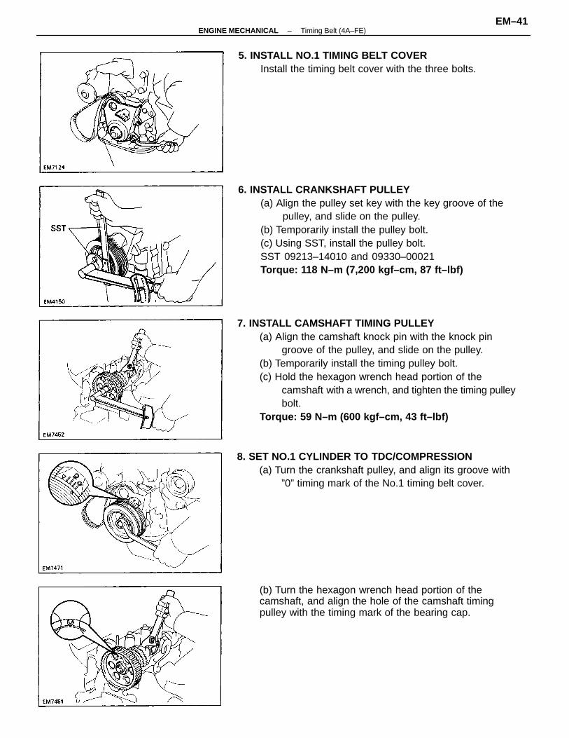
7. INSTALL CAMSHAFT TIMING PULLEY(a) Align the camshaft knock pin with the knock pin
groove of the pulley, and slide on the pulley.(b) Temporarily install the timing pulley bolt.(c) Hold the hexagon wrench head portion of the
camshaft with a wrench, and tighten the timing pulleybolt.
Torque: 59 N–m (600 kgf–cm, 43 ft–lbf)
6. INSTALL CRANKSHAFT PULLEY(a) Align the pulley set key with the key groove of the
pulley, and slide on the pulley.(b) Temporarily install the pulley bolt.(c) Using SST, install the pulley bolt.SST 09213–14010 and 09330–00021Torque: 118 N–m (7,200 kgf–cm, 87 ft–lbf)
8. SET NO.1 CYLINDER TO TDC/COMPRESSION(a) Turn the crankshaft pulley, and align its groove with
”0” timing mark of the No.1 timing belt cover.
(b) Turn the hexagon wrench head portion of thecamshaft, and align the hole of the camshaft timingpulley with the timing mark of the bearing cap.
5. INSTALL NO.1 TIMING BELT COVERInstall the timing belt cover with the three bolts.
–ENGINE MECHANICAL Timing Belt (4A–FE)EM–41
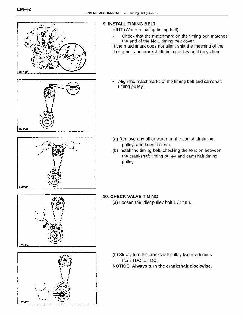
9. INSTALL TIMING BELTHINT (When re–using timing belt):
• Check that the matchmark on the timing belt matchesthe end of the No.1 timing belt cover.
If the matchmark does not align, shift the meshing of thetiming belt and crankshaft timing pulley until they align.
(a) Remove any oil or water on the camshaft timingpulley, and keep it clean.
(b) Install the timing belt, checking the tension betweenthe crankshaft timing pulley and camshaft timingpulley.
(b) Slowly turn the crankshaft pulley two revolutionsfrom TDC to TDC.
NOTICE: Always turn the crankshaft clockwise.
• Align the matchmarks of the timing belt and camshafttiming pulley.
10. CHECK VALVE TIMING(a) Loosen the idler pulley bolt 1 /2 turn.
–ENGINE MECHANICAL Timing Belt (4A–FE)EM–42
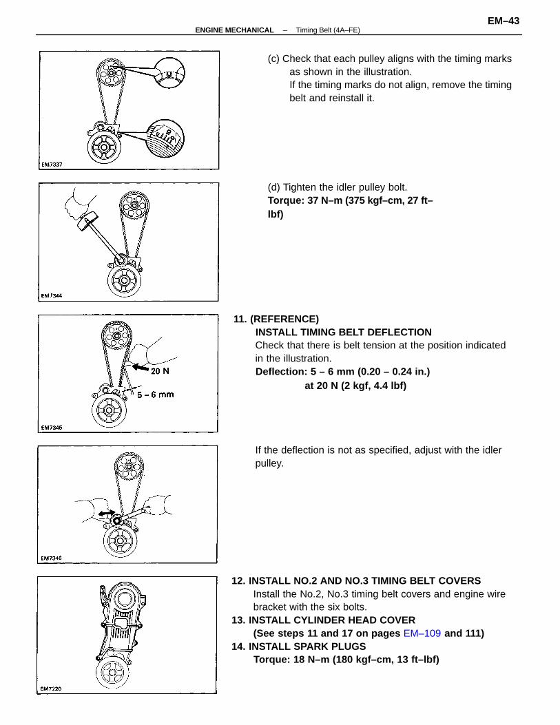
12. INSTALL NO.2 AND NO.3 TIMING BELT COVERSInstall the No.2, No.3 timing belt covers and engine wirebracket with the six bolts.
13. INSTALL CYLINDER HEAD COVER(See steps 11 and 17 on pages EM–109 and 111)
14. INSTALL SPARK PLUGSTorque: 18 N–m (180 kgf–cm, 13 ft–lbf)
11. (REFERENCE)INSTALL TIMING BELT DEFLECTIONCheck that there is belt tension at the position indicatedin the illustration.Deflection: 5 – 6 mm (0.20 – 0.24 in.)
at 20 N (2 kgf, 4.4 lbf)
(c) Check that each pulley aligns with the timing marksas shown in the illustration.If the timing marks do not align, remove the timingbelt and reinstall it.
If the deflection is not as specified, adjust with the idlerpulley.
(d) Tighten the idler pulley bolt.Torque: 37 N–m (375 kgf–cm, 27 ft–lbf)
–ENGINE MECHANICAL Timing Belt (4A–FE)EM–43
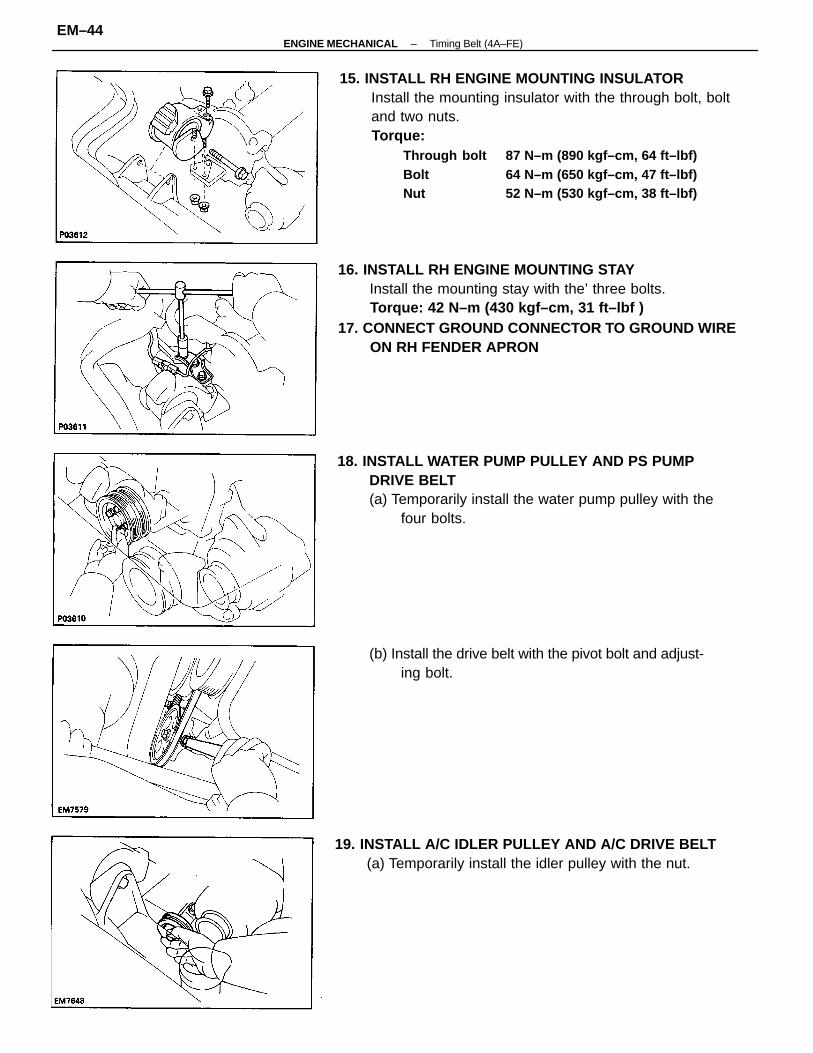
15. INSTALL RH ENGINE MOUNTING INSULATORInstall the mounting insulator with the through bolt, boltand two nuts.Torque:
Through bolt 87 N–m (890 kgf–cm, 64 ft–lbf)Bolt 64 N–m (650 kgf–cm, 47 ft–lbf)Nut 52 N–m (530 kgf–cm, 38 ft–lbf)
16. INSTALL RH ENGINE MOUNTING STAYInstall the mounting stay with the’ three bolts.Torque: 42 N–m (430 kgf–cm, 31 ft–lbf )
17. CONNECT GROUND CONNECTOR TO GROUND WIREON RH FENDER APRON
18. INSTALL WATER PUMP PULLEY AND PS PUMPDRIVE BELT(a) Temporarily install the water pump pulley with the
four bolts.
19. INSTALL A/C IDLER PULLEY AND A/C DRIVE BELT(a) Temporarily install the idler pulley with the nut.
(b) Install the drive belt with the pivot bolt and adjust-ing bolt.
–ENGINE MECHANICAL Timing Belt (4A–FE)EM–44
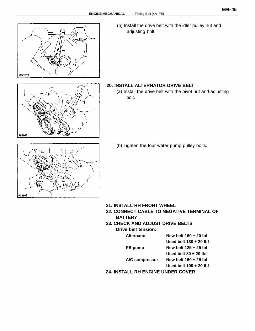
21. INSTALL RH FRONT WHEEL22. CONNECT CABLE TO NEGATIVE TERMINAL OF
BATTERY23. CHECK AND ADJUST DRIVE BELTS
Drive belt tension:Alternator New belt 160 ± 20 lbf
Used belt 130 ± 20 lbfPS pump New belt 125 ± 25 lbf
Used belt 80 ± 20 lbfA/C compressor New belt 160 ± 25 lbf
Used belt 100 ± 20 lbf
24. INSTALL RH ENGINE UNDER COVER
20. INSTALL ALTERNATOR DRIVE BELT(a) Install the drive belt with the pivot nut and adjusting
bolt.
(b) Install the drive belt with the idler pulley nut andadjusting bolt.
(b) Tighten the four water pump pulley bolts.
–ENGINE MECHANICAL Timing Belt (4A–FE)EM–45
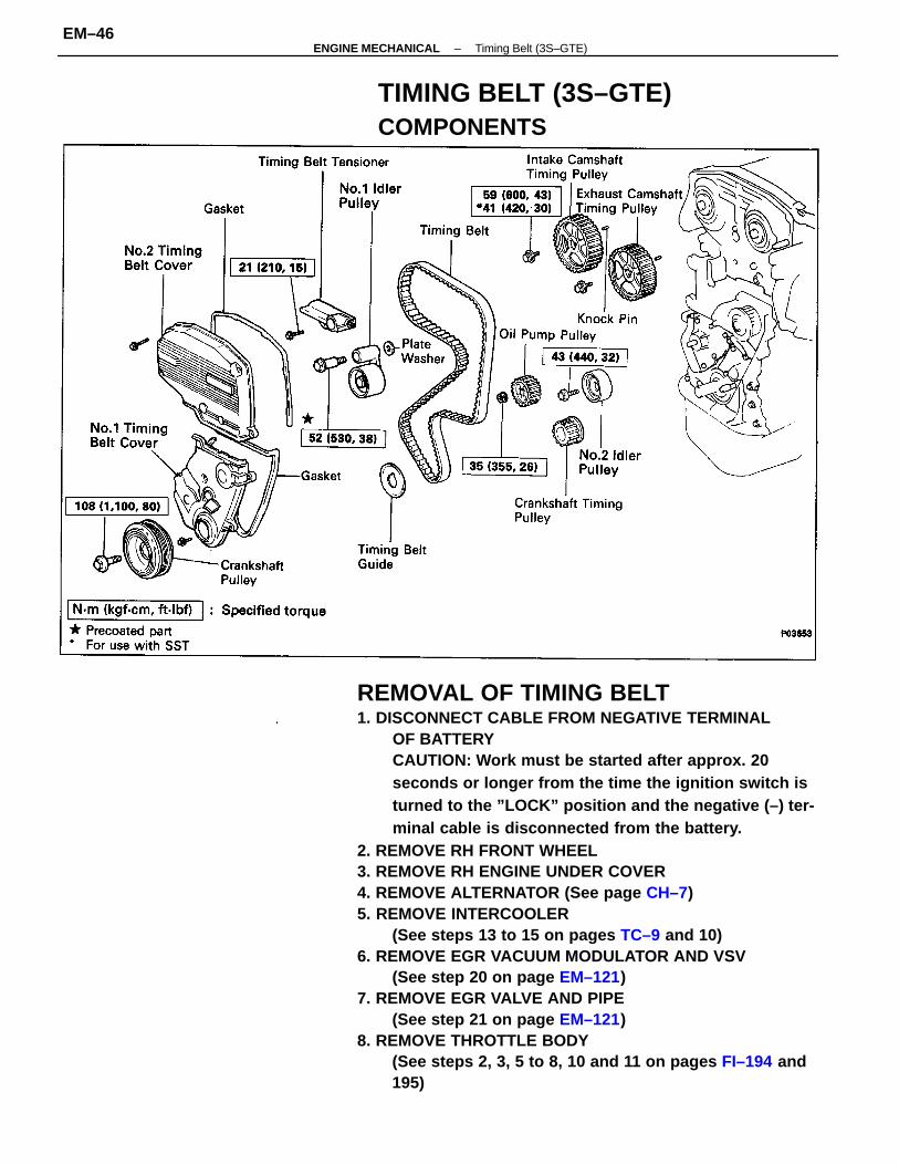
REMOVAL OF TIMING BELT1. DISCONNECT CABLE FROM NEGATIVE TERMINAL
OF BATTERYCAUTION: Work must be started after approx. 20seconds or longer from the time the ignition switch isturned to the ”LOCK” position and the negative (–) ter-minal cable is disconnected from the battery.
2. REMOVE RH FRONT WHEEL3. REMOVE RH ENGINE UNDER COVER4. REMOVE ALTERNATOR (See page CH–7)5. REMOVE INTERCOOLER
(See steps 13 to 15 on pages TC–9 and 10)6. REMOVE EGR VACUUM MODULATOR AND VSV
(See step 20 on page EM–121)7. REMOVE EGR VALVE AND PIPE
(See step 21 on page EM–121)8. REMOVE THROTTLE BODY
(See steps 2, 3, 5 to 8, 10 and 11 on pages FI–194 and195)
TIMING BELT (3S–GTE)COMPONENTS
–ENGINE MECHANICAL Timing Belt (3S–GTE)EM–46
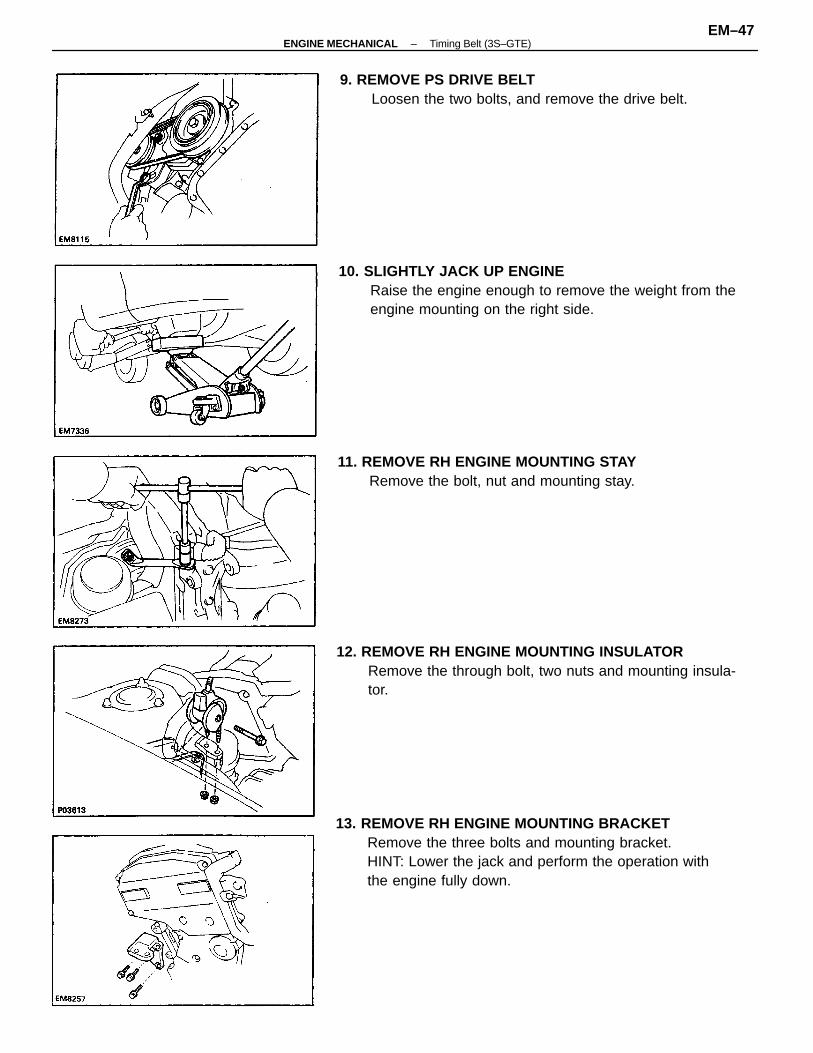
13. REMOVE RH ENGINE MOUNTING BRACKETRemove the three bolts and mounting bracket.HINT: Lower the jack and perform the operation withthe engine fully down.
10. SLIGHTLY JACK UP ENGINERaise the engine enough to remove the weight from theengine mounting on the right side.
12. REMOVE RH ENGINE MOUNTING INSULATORRemove the through bolt, two nuts and mounting insula-tor.
11. REMOVE RH ENGINE MOUNTING STAYRemove the bolt, nut and mounting stay.
9. REMOVE PS DRIVE BELTLoosen the two bolts, and remove the drive belt.
–ENGINE MECHANICAL Timing Belt (3S–GTE)EM–47
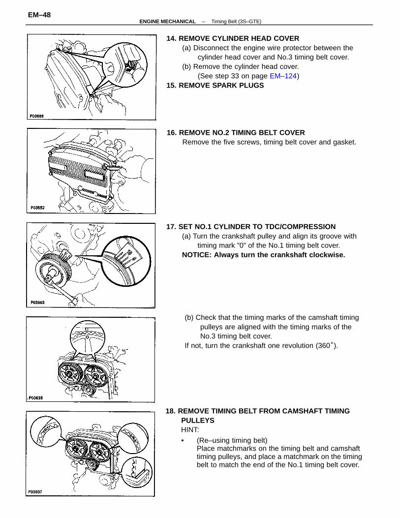
18. REMOVE TIMING BELT FROM CAMSHAFT TIMINGPULLEYSHINT:
• (Re–using timing belt)Place matchmarks on the timing belt and camshafttiming pulleys, and place a matchmark on the timingbelt to match the end of the No.1 timing belt cover.
14. REMOVE CYLINDER HEAD COVER(a) Disconnect the engine wire protector between the
cylinder head cover and No.3 timing belt cover.(b) Remove the cylinder head cover.
(See step 33 on page EM–124)15. REMOVE SPARK PLUGS
(b) Check that the timing marks of the camshaft timingpulleys are aligned with the timing marks of theNo.3 timing belt cover.
If not, turn the crankshaft one revolution (360°).
17. SET NO.1 CYLINDER TO TDC/COMPRESSION(a) Turn the crankshaft pulley and align its groove with
timing mark ”0” of the No.1 timing belt cover.NOTICE: Always turn the crankshaft clockwise.
16. REMOVE NO.2 TIMING BELT COVERRemove the five screws, timing belt cover and gasket.
–ENGINE MECHANICAL Timing Belt (3S–GTE)EM–48
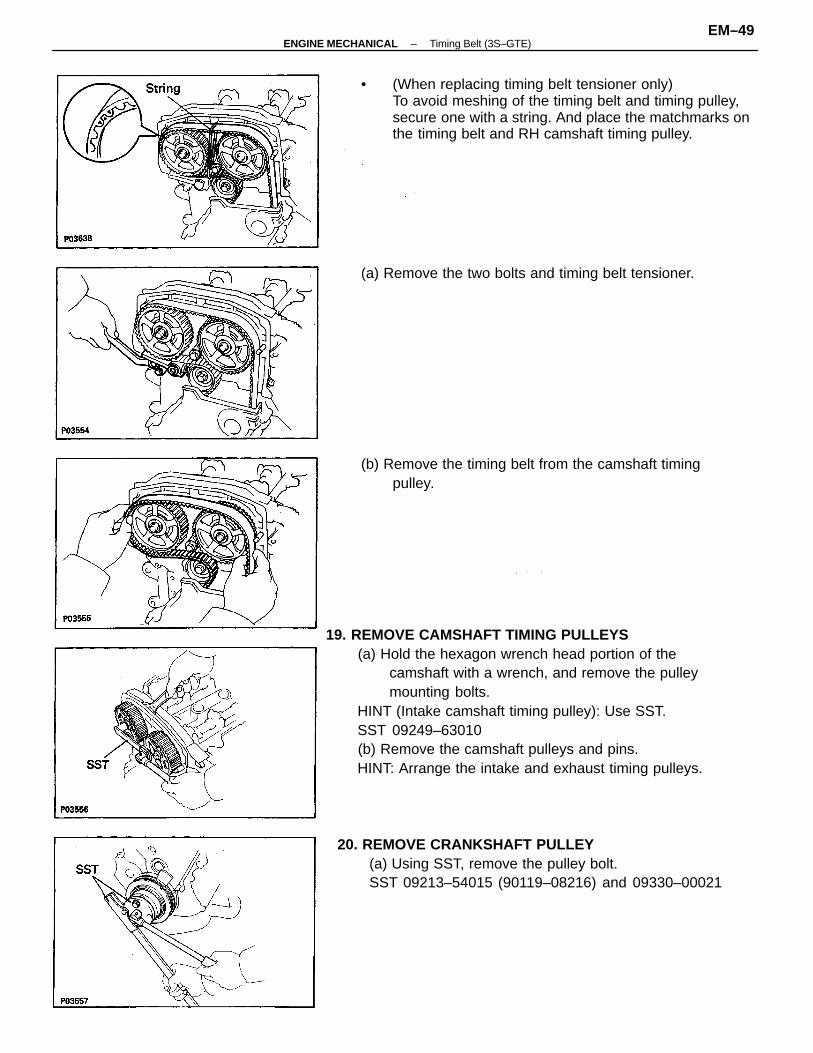
19. REMOVE CAMSHAFT TIMING PULLEYS(a) Hold the hexagon wrench head portion of the
camshaft with a wrench, and remove the pulleymounting bolts.
HINT (Intake camshaft timing pulley): Use SST.SST 09249–63010(b) Remove the camshaft pulleys and pins.HINT: Arrange the intake and exhaust timing pulleys.
• (When replacing timing belt tensioner only)To avoid meshing of the timing belt and timing pulley,secure one with a string. And place the matchmarks onthe timing belt and RH camshaft timing pulley.
20. REMOVE CRANKSHAFT PULLEY(a) Using SST, remove the pulley bolt.SST 09213–54015 (90119–08216) and 09330–00021
(b) Remove the timing belt from the camshaft timingpulley.
(a) Remove the two bolts and timing belt tensioner.
–ENGINE MECHANICAL Timing Belt (3S–GTE)EM–49
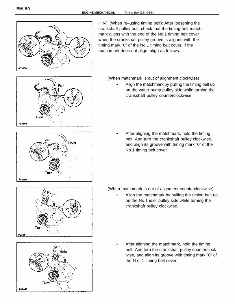
HINT (When re–using timing belt): After loosening thecrankshaft pulley bolt, check that the timing belt match-mark aligns with the end of the No.1 timing belt coverwhen the crankshaft pulley groove is aligned with thetiming mark ”0” of the No.1 timing belt cover. If thematchmark does not align, align as follows:
(When matchmark is out of alignment counterclockwise)
• Align the matchmark by pulling the timing belt upon the No.1 idler pulley side while turning thecrankshaft pulley clockwise.
• After aligning the matchmark, hold the timingbelt. And turn the crankshaft pulley clockwise,and align its groove with timing mark ”0” of theNo.1 timing belt cover.
(When matchmark is out of alignment clockwise)
• Align the matchmark by pulling the timing belt upon the water pump pulley side while turning thecrankshaft pulley counterclockwise.
• After aligning the matchmark, hold the timingbelt. And turn the crankshaft pulley counterclock-wise, and align its groove with timing mark ”0” ofthe N o–1 timing belt cover.
–ENGINE MECHANICAL Timing Belt (3S–GTE)EM–50
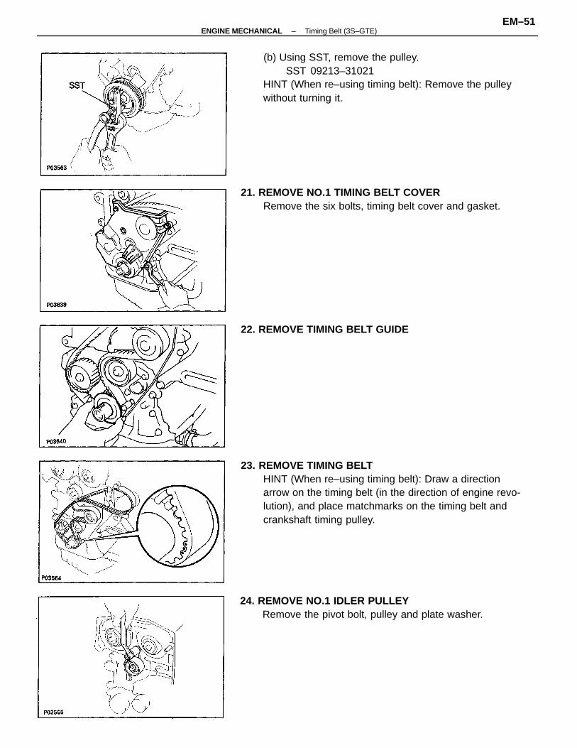
23. REMOVE TIMING BELTHINT (When re–using timing belt): Draw a directionarrow on the timing belt (in the direction of engine revo-lution), and place matchmarks on the timing belt andcrankshaft timing pulley.
(b) Using SST, remove the pulley.SST 09213–31021
HINT (When re–using timing belt): Remove the pulleywithout turning it.
21. REMOVE NO.1 TIMING BELT COVERRemove the six bolts, timing belt cover and gasket.
24. REMOVE NO.1 IDLER PULLEYRemove the pivot bolt, pulley and plate washer.
22. REMOVE TIMING BELT GUIDE
–ENGINE MECHANICAL Timing Belt (3S–GTE)EM–51
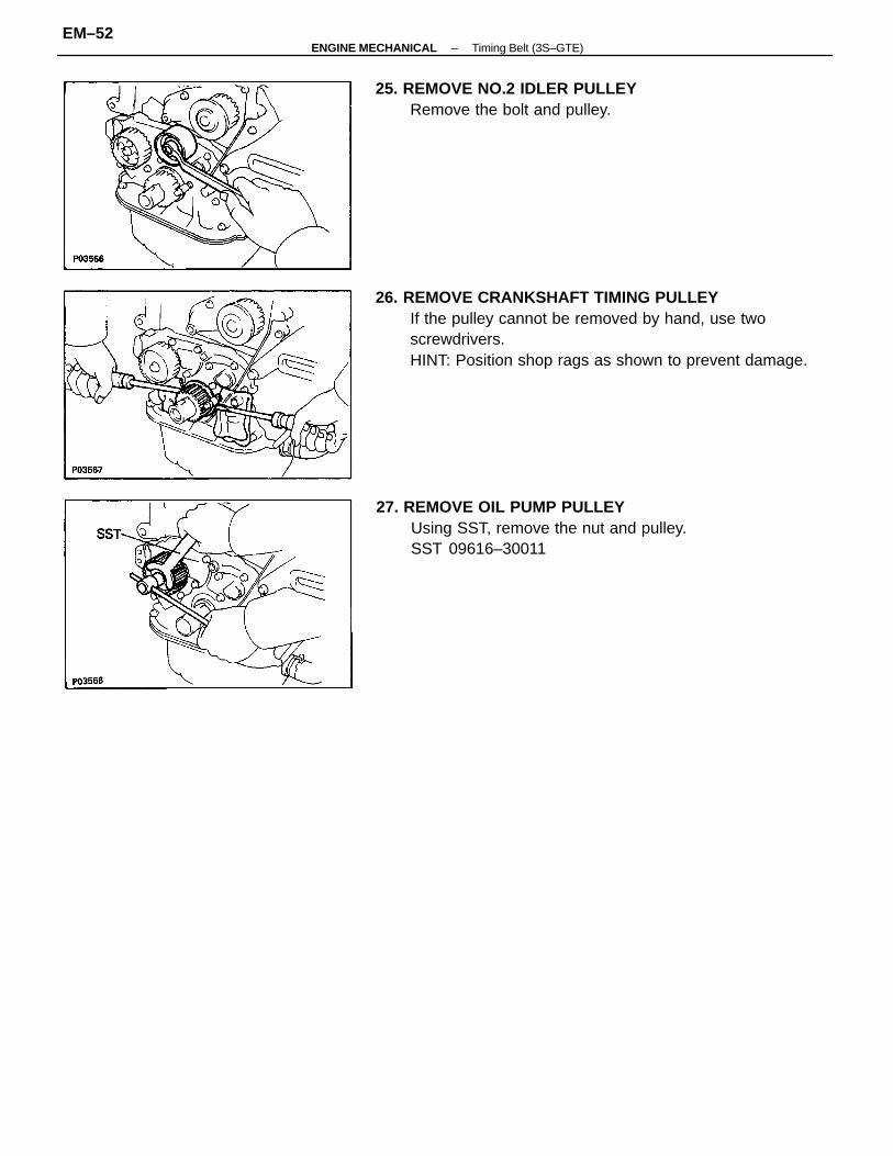
26. REMOVE CRANKSHAFT TIMING PULLEYIf the pulley cannot be removed by hand, use twoscrewdrivers.HINT: Position shop rags as shown to prevent damage.
27. REMOVE OIL PUMP PULLEYUsing SST, remove the nut and pulley.SST 09616–30011
25. REMOVE NO.2 IDLER PULLEYRemove the bolt and pulley.
–ENGINE MECHANICAL Timing Belt (3S–GTE)EM–52
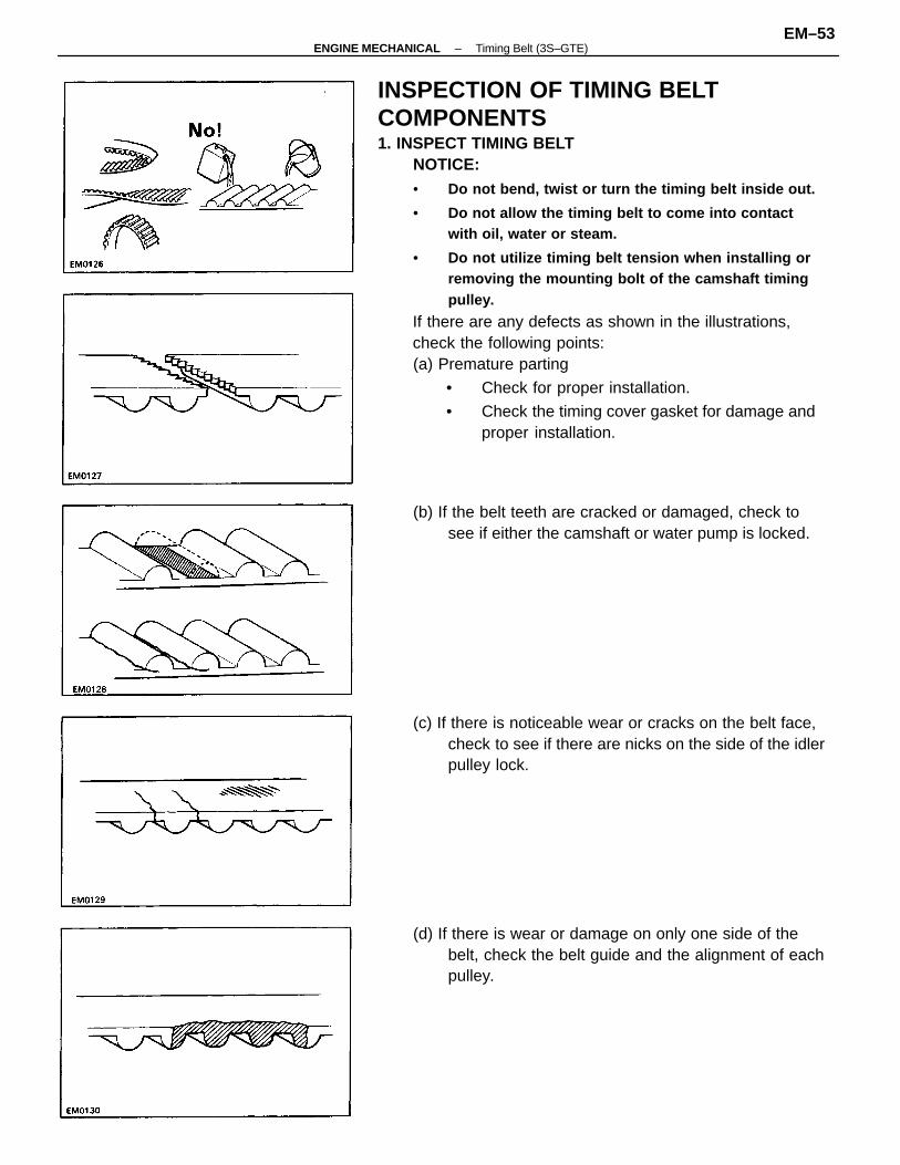
INSPECTION OF TIMING BELTCOMPONENTS1. INSPECT TIMING BELT
NOTICE:• Do not bend, twist or turn the timing belt inside out.
• Do not allow the timing belt to come into contactwith oil, water or steam.
• Do not utilize timing belt tension when installing orremoving the mounting bolt of the camshaft timingpulley.
If there are any defects as shown in the illustrations,check the following points:(a) Premature parting
• Check for proper installation.
• Check the timing cover gasket for damage andproper installation.
(d) If there is wear or damage on only one side of thebelt, check the belt guide and the alignment of eachpulley.
(c) If there is noticeable wear or cracks on the belt face,check to see if there are nicks on the side of the idlerpulley lock.
(b) If the belt teeth are cracked or damaged, check tosee if either the camshaft or water pump is locked.
–ENGINE MECHANICAL Timing Belt (3S–GTE)EM–53
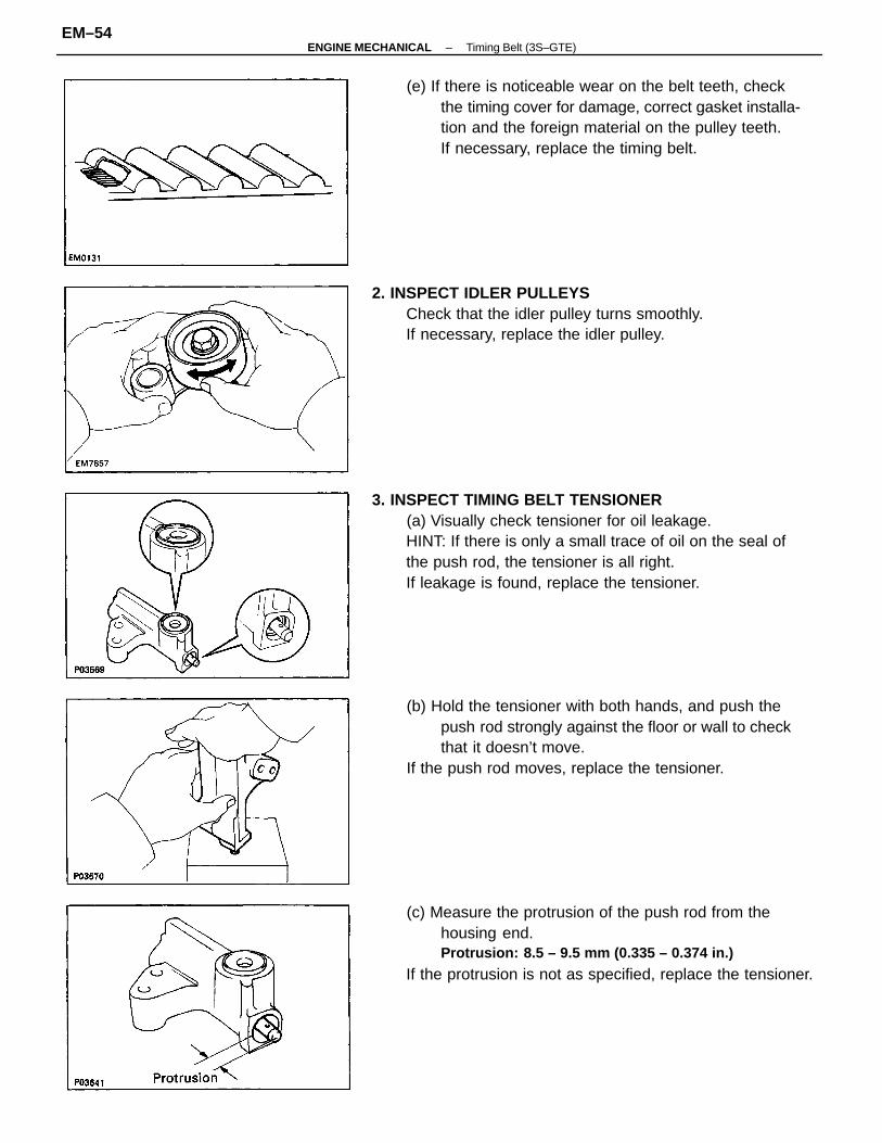
3. INSPECT TIMING BELT TENSIONER(a) Visually check tensioner for oil leakage.HINT: If there is only a small trace of oil on the seal ofthe push rod, the tensioner is all right.If leakage is found, replace the tensioner.
(c) Measure the protrusion of the push rod from thehousing end.Protrusion: 8.5 – 9.5 mm (0.335 – 0.374 in.)
If the protrusion is not as specified, replace the tensioner.
(e) If there is noticeable wear on the belt teeth, checkthe timing cover for damage, correct gasket installa-tion and the foreign material on the pulley teeth.If necessary, replace the timing belt.
(b) Hold the tensioner with both hands, and push thepush rod strongly against the floor or wall to checkthat it doesn’t move.
If the push rod moves, replace the tensioner.
2. INSPECT IDLER PULLEYSCheck that the idler pulley turns smoothly.If necessary, replace the idler pulley.
–ENGINE MECHANICAL Timing Belt (3S–GTE)EM–54
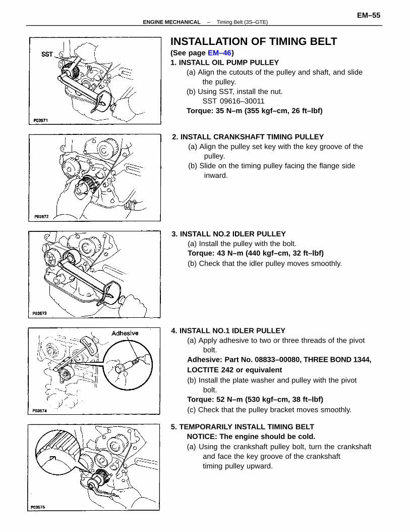
INSTALLATION OF TIMING BELT(See page EM–46)1. INSTALL OIL PUMP PULLEY
(a) Align the cutouts of the pulley and shaft, and slidethe pulley.
(b) Using SST, install the nut.SST 09616–30011
Torque: 35 N–m (355 kgf–cm, 26 ft–lbf)
4. INSTALL NO.1 IDLER PULLEY(a) Apply adhesive to two or three threads of the pivot
bolt.Adhesive: Part No. 08833–00080, T HREE BOND 1344,LOCTITE 242 or equivalent(b) Install the plate washer and pulley with the pivot
bolt.Torque: 52 N–m (530 kgf–cm, 38 ft–lbf)(c) Check that the pulley bracket moves smoothly.
5. TEMPORARILY INSTALL TIMING BELTNOTICE: The engine should be cold.(a) Using the crankshaft pulley bolt, turn the crankshaft
and face the key groove of the crankshafttiming pulley upward.
2. INSTALL CRANKSHAFT TIMING PULLEY(a) Align the pulley set key with the key groove of the
pulley.(b) Slide on the timing pulley facing the flange side
inward.
3. INSTALL NO.2 IDLER PULLEY(a) Install the pulley with the bolt.Torque: 43 N–m (440 kgf–cm, 32 ft–lbf)(b) Check that the idler pulley moves smoothly.
–ENGINE MECHANICAL Timing Belt (3S–GTE)EM–55
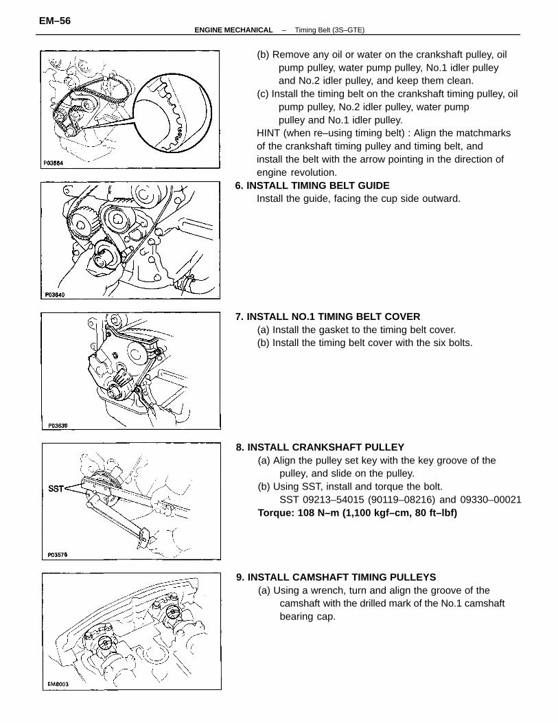
(b) Remove any oil or water on the crankshaft pulley, oilpump pulley, water pump pulley, No.1 idler pulleyand No.2 idler pulley, and keep them clean.
(c) Install the timing belt on the crankshaft timing pulley, oilpump pulley, No.2 idler pulley, water pumppulley and No.1 idler pulley.
HINT (when re–using timing belt) : Align the matchmarksof the crankshaft timing pulley and timing belt, andinstall the belt with the arrow pointing in the direction ofengine revolution.
6. INSTALL TIMING BELT GUIDEInstall the guide, facing the cup side outward.
8. INSTALL CRANKSHAFT PULLEY(a) Align the pulley set key with the key groove of the
pulley, and slide on the pulley.(b) Using SST, install and torque the bolt.
SST 09213–54015 (90119–08216) and 09330–00021Torque: 108 N–m (1,100 kgf–cm, 80 ft–lbf)
9. INSTALL CAMSHAFT TIMING PULLEYS(a) Using a wrench, turn and align the groove of the
camshaft with the drilled mark of the No.1 camshaftbearing cap.
7. INSTALL NO.1 TIMING BELT COVER(a) Install the gasket to the timing belt cover.(b) Install the timing belt cover with the six bolts.
–ENGINE MECHANICAL Timing Belt (3S–GTE)EM–56
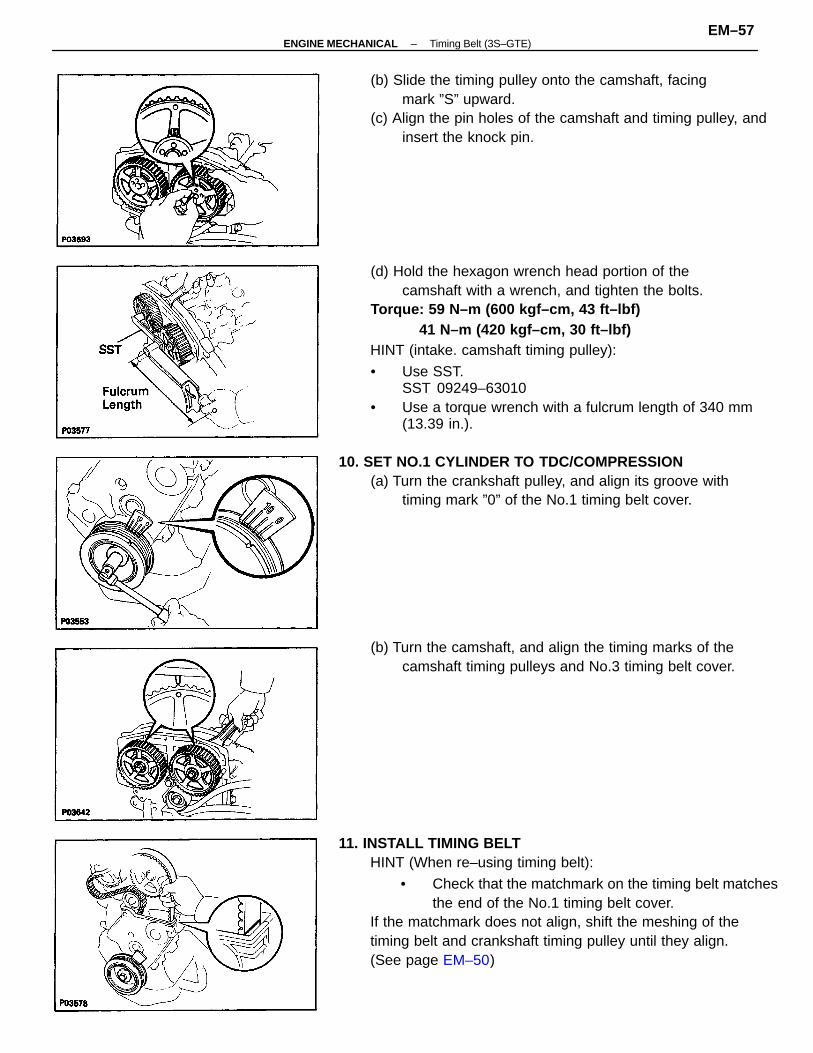
(d) Hold the hexagon wrench head portion of thecamshaft with a wrench, and tighten the bolts.
Torque: 59 N–m (600 kgf–cm, 43 ft–lbf)41 N–m (420 kgf–cm, 30 ft–lbf)
HINT (intake. camshaft timing pulley):
• Use SST.SST 09249–63010
• Use a torque wrench with a fulcrum length of 340 mm(13.39 in.).
11. INSTALL TIMING BELTHINT (When re–using timing belt):
• Check that the matchmark on the timing belt matchesthe end of the No.1 timing belt cover.
If the matchmark does not align, shift the meshing of thetiming belt and crankshaft timing pulley until they align.(See page EM–50)
(b) Slide the timing pulley onto the camshaft, facingmark ”S” upward.
(c) Align the pin holes of the camshaft and timing pulley, andinsert the knock pin.
10. SET NO.1 CYLINDER TO TDC/COMPRESSION(a) Turn the crankshaft pulley, and align its groove with
timing mark ”0” of the No.1 timing belt cover.
(b) Turn the camshaft, and align the timing marks of thecamshaft timing pulleys and No.3 timing belt cover.
–ENGINE MECHANICAL Timing Belt (3S–GTE)EM–57
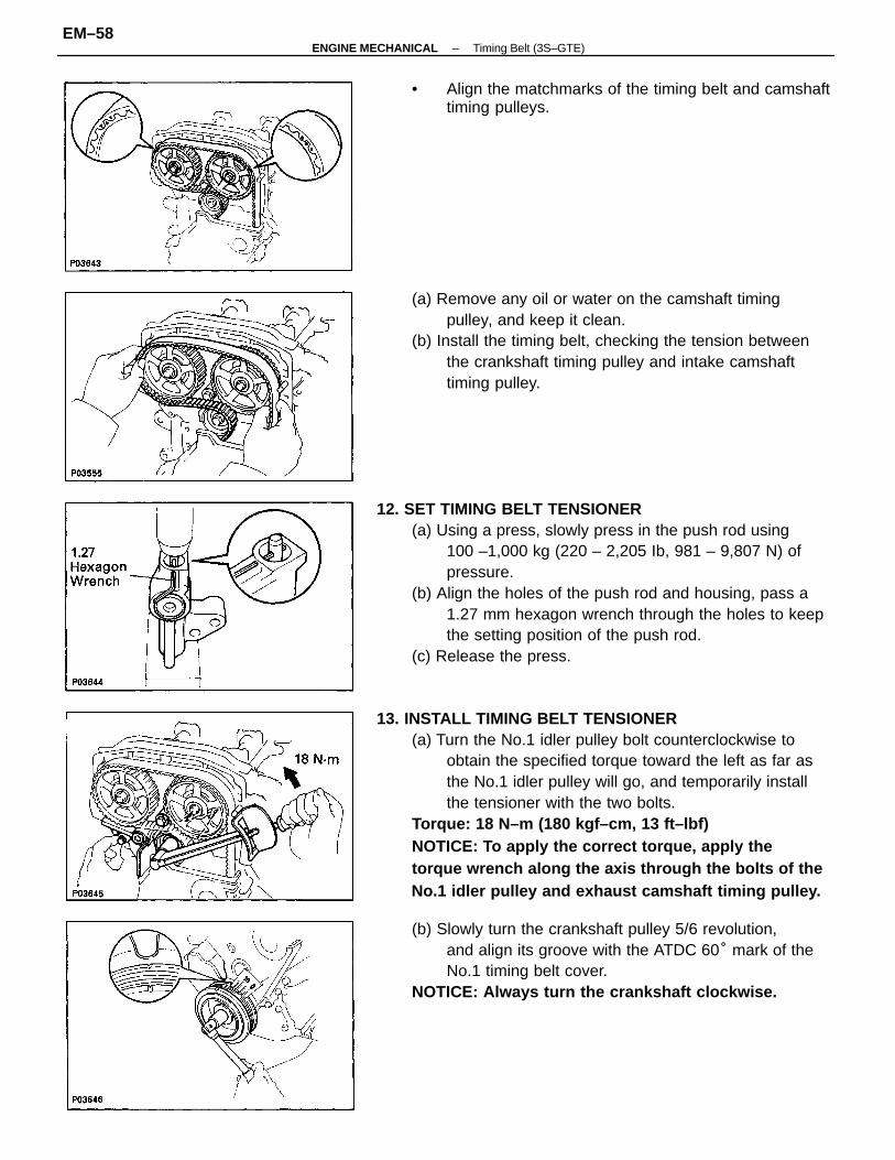
13. INSTALL TIMING BELT TENSIONER(a) Turn the No.1 idler pulley bolt counterclockwise to
obtain the specified torque toward the left as far asthe No.1 idler pulley will go, and temporarily installthe tensioner with the two bolts.
Torque: 18 N–m (180 kgf–cm, 13 ft–lbf)NOTICE: To apply the correct torque, apply thetorque wrench along the axis through the bolts of theNo.1 idler pulley and exhaust camshaft timing pulley.
12. SET TIMING BELT TENSIONER(a) Using a press, slowly press in the push rod using
100 –1,000 kg (220 – 2,205 Ib, 981 – 9,807 N) ofpressure.
(b) Align the holes of the push rod and housing, pass a1.27 mm hexagon wrench through the holes to keepthe setting position of the push rod.
(c) Release the press.
(a) Remove any oil or water on the camshaft timingpulley, and keep it clean.
(b) Install the timing belt, checking the tension betweenthe crankshaft timing pulley and intake camshafttiming pulley.
(b) Slowly turn the crankshaft pulley 5/6 revolution,and align its groove with the ATDC 60° mark of theNo.1 timing belt cover.
NOTICE: Always turn the crankshaft clockwise.
• Align the matchmarks of the timing belt and camshafttiming pulleys.
–ENGINE MECHANICAL Timing Belt (3S–GTE)EM–58
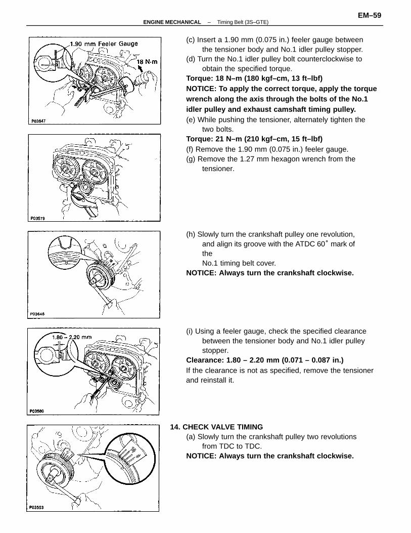
(c) Insert a 1.90 mm (0.075 in.) feeler gauge betweenthe tensioner body and No.1 idler pulley stopper.
(d) Turn the No.1 idler pulley bolt counterclockwise toobtain the specified torque.
Torque: 18 N–m (180 kgf–cm, 13 ft–lbf)NOTICE: To apply the correct torque, apply the torquewrench along the axis through the bolts of the No.1idler pulley and exhaust camshaft timing pulley.(e) While pushing the tensioner, alternately tighten the
two bolts.Torque: 21 N–m (210 kgf–cm, 15 ft–lbf)(f) Remove the 1.90 mm (0.075 in.) feeler gauge.(g) Remove the 1.27 mm hexagon wrench from the
tensioner.
(i) Using a feeler gauge, check the specified clearancebetween the tensioner body and No.1 idler pulleystopper.
Clearance: 1.80 – 2.20 mm (0.071 – 0.087 in.)If the clearance is not as specified, remove the tensionerand reinstall it.
14. CHECK VALVE TIMING(a) Slowly turn the crankshaft pulley two revolutions
from TDC to TDC.NOTICE: Always turn the crankshaft clockwise.
(h) Slowly turn the crankshaft pulley one revolution,and align its groove with the ATDC 60° mark oftheNo.1 timing belt cover.
NOTICE: Always turn the crankshaft clockwise.
–ENGINE MECHANICAL Timing Belt (3S–GTE)EM–59
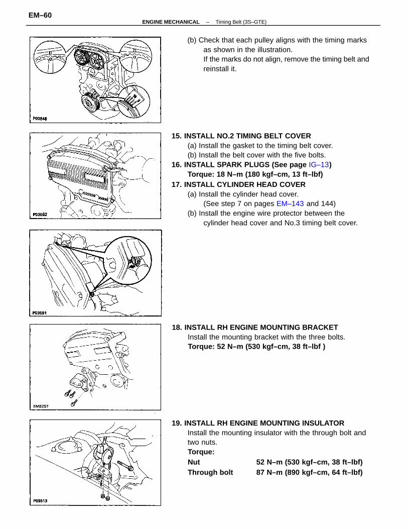
15. INSTALL NO.2 TIMING BELT COVER(a) Install the gasket to the timing belt cover.(b) Install the belt cover with the five bolts.
16. INSTALL SPARK PLUGS (See page IG–13)Torque: 18 N–m (180 kgf–cm, 13 ft–lbf)
17. INSTALL CYLINDER HEAD COVER(a) Install the cylinder head cover.
(See step 7 on pages EM–143 and 144)(b) Install the engine wire protector between the
cylinder head cover and No.3 timing belt cover.
19. INSTALL RH ENGINE MOUNTING INSULATORInstall the mounting insulator with the through bolt andtwo nuts.Torque:Nut 52 N–m (530 kgf–cm, 38 ft–lbf)Through bolt 87 N–m (890 kgf–cm, 64 ft–lbf)
(b) Check that each pulley aligns with the timing marksas shown in the illustration.If the marks do not align, remove the timing belt andreinstall it.
18. INSTALL RH ENGINE MOUNTING BRACKETInstall the mounting bracket with the three bolts.Torque: 52 N–m (530 kgf–cm, 38 ft–lbf )
–ENGINE MECHANICAL Timing Belt (3S–GTE)EM–60
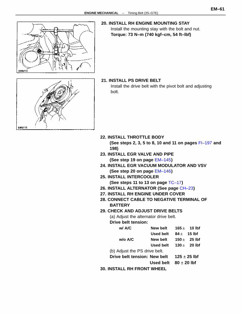
22. INSTALL THROTTLE BODY(See steps 2, 3, 5 to 8, 10 and 11 on pages FI–197 and198)
23. INSTALL EGR VALVE AND PIPE(See step 19 on page EM–145)
24. INSTALL EGR VACUUM MODULATOR AND VSV(See step 20 on page EM–146)
25. INSTALL INTERCOOLER(See steps 11 to 13 on page TC–17)
26. INSTALL ALTERNATOR (See page CH–23)27. INSTALL RH ENGINE UNDER COVER28. CONNECT CABLE TO NEGATIVE TERMINAL OF
BATTERY29. CHECK AND ADJUST DRIVE BELTS
(a) Adjust the alternator drive belt.Drive belt tension:
w/ A/C New belt 165 10 lbfUsed belt 84 15 lbf
w/o A/C New belt 150 25 lbfUsed belt 130 20 lbf
(b) Adjust the PS drive belt.Drive belt tension: New belt 125 ± 25 lbf
Used belt 80 ± 20 lbf30. INSTALL RH FRONT WHEEL
20. INSTALL RH ENGINE MOUNTING STAYInstall the mounting stay with the bolt and nut.Torque: 73 N–m (740 kgf–cm, 54 ft–lbf)
21. INSTALL PS DRIVE BELTInstall the drive belt with the pivot bolt and adjustingbolt.
–ENGINE MECHANICAL Timing Belt (3S–GTE)EM–61
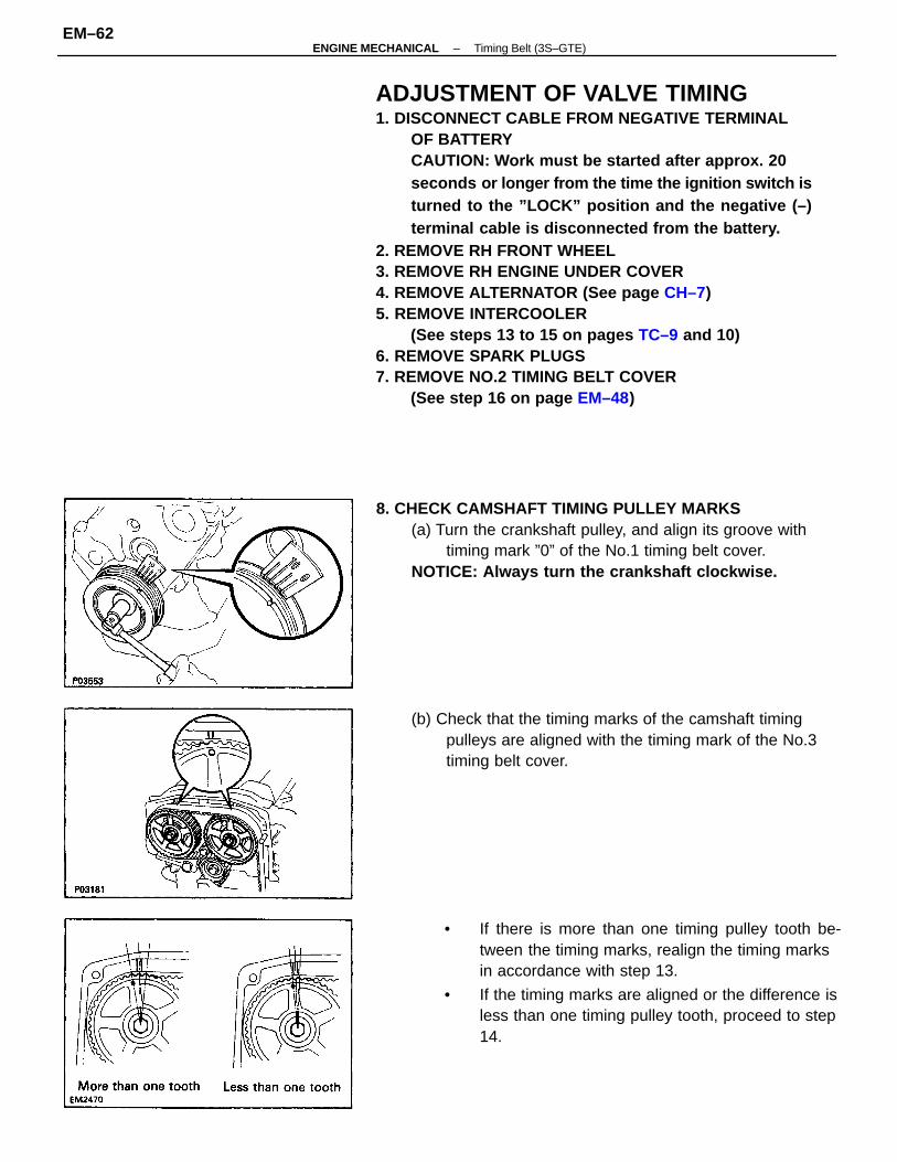
ADJUSTMENT OF VALVE TIMING1. DISCONNECT CABLE FROM NEGATIVE TERMINAL
OF BATTERYCAUTION: Work must be started after approx. 20seconds or longer from the time the ignition switch isturned to the ”LOCK” position and the negative (–)terminal cable is disconnected from the battery.
2. REMOVE RH FRONT WHEEL3. REMOVE RH ENGINE UNDER COVER4. REMOVE ALTERNATOR (See page CH–7)5. REMOVE INTERCOOLER
(See steps 13 to 15 on pages TC–9 and 10)6. REMOVE SPARK PLUGS7. REMOVE NO.2 TIMING BELT COVER
(See step 16 on page EM–48)
• If there is more than one timing pulley tooth be-tween the timing marks, realign the timing marksin accordance with step 13.
• If the timing marks are aligned or the difference isless than one timing pulley tooth, proceed to step14.
8. CHECK CAMSHAFT TIMING PULLEY MARKS(a) Turn the crankshaft pulley, and align its groove with
timing mark ”0” of the No.1 timing belt cover.NOTICE: Always turn the crankshaft clockwise.
(b) Check that the timing marks of the camshaft timingpulleys are aligned with the timing mark of the No.3timing belt cover.
–ENGINE MECHANICAL Timing Belt (3S–GTE)EM–62
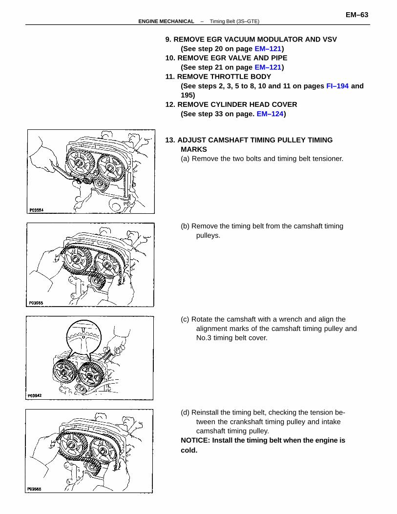
9. REMOVE EGR VACUUM MODULATOR AND VSV(See step 20 on page EM–121)
10. REMOVE EGR VALVE AND PIPE(See step 21 on page EM–121)
11. REMOVE THROTTLE BODY(See steps 2, 3, 5 to 8, 10 and 11 on pages FI–194 and195)
12. REMOVE CYLINDER HEAD COVER(See step 33 on page. EM–124)
(d) Reinstall the timing belt, checking the tension be-tween the crankshaft timing pulley and intakecamshaft timing pulley.
NOTICE: Install the timing belt when the engine iscold.
13. ADJUST CAMSHAFT TIMING PULLEY TIMINGMARKS(a) Remove the two bolts and timing belt tensioner.
(c) Rotate the camshaft with a wrench and align thealignment marks of the camshaft timing pulley andNo.3 timing belt cover.
(b) Remove the timing belt from the camshaft timingpulleys.
–ENGINE MECHANICAL Timing Belt (3S–GTE)EM–63
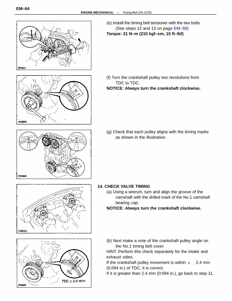
(b) Next make a note of the crankshaft pulley angle onthe No.1 timing belt cover.
HINT: Perform this check separately for the intake andexhaust sides.If the crankshaft pulley movement is within 2.4 mm(0.094 in.) of TDC, it is correct.If it is greater than 2.4 mm (0:094 in.), go back to step 11.
14. CHECK VALVE TIMING(a) Using a wrench, turn and align the groove of the
camshaft with the drilled mark of the No.1 camshaftbearing cap.
NOTICE: Always turn the crankshaft clockwise.
(e) Install the timing belt tensioner with the two bolts.(See steps 12 and 13 on page EM–58)
Torque: 21 N–m (210 kgf–cm, 15 ft–lbf)
(f) Turn the crankshaft pulley two revolutions fromTDC to TDC.
NOTICE: Always turn the crankshaft clockwise.
(g) Check that each pulley aligns with the timing marksas shown in the illustration.
–ENGINE MECHANICAL Timing Belt (3S–GTE)EM–64
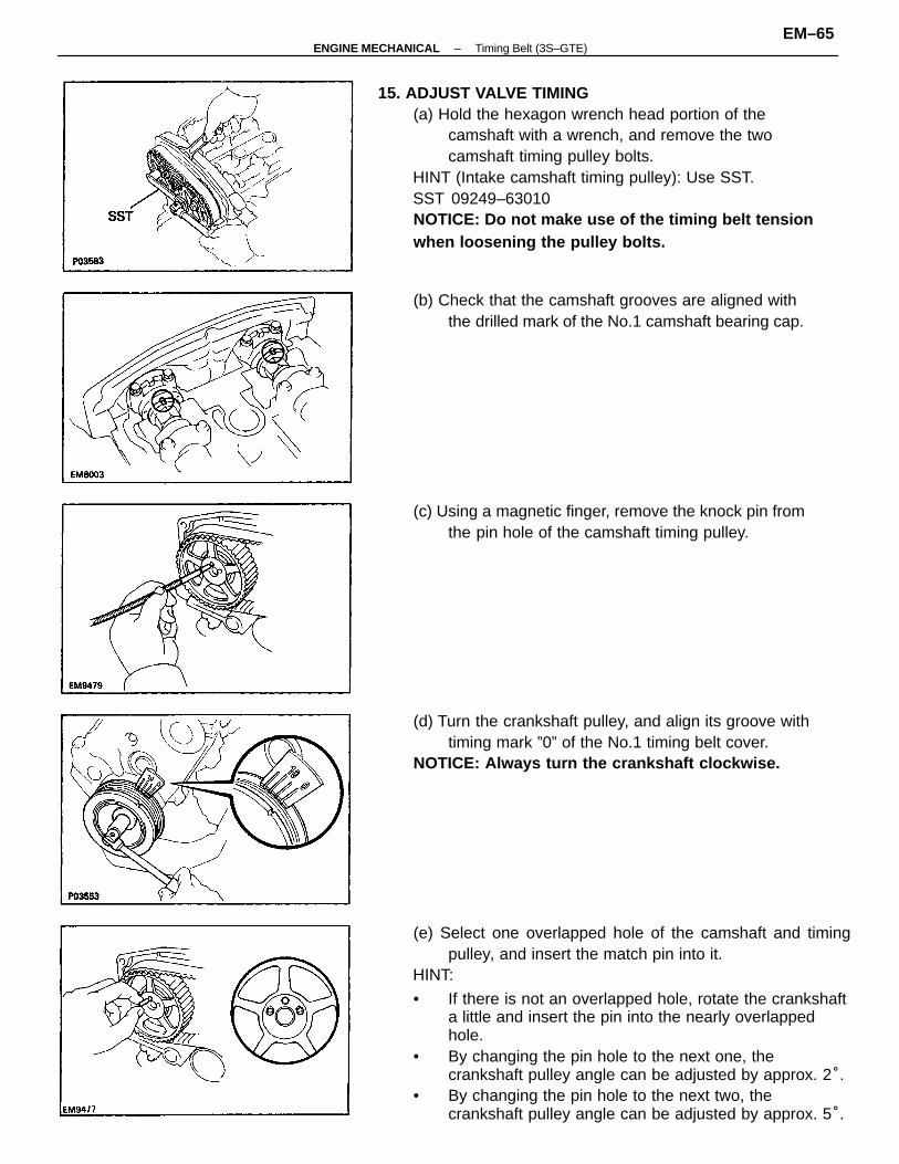
(e) Select one overlapped hole of the camshaft and timingpulley, and insert the match pin into it.
HINT:
• If there is not an overlapped hole, rotate the crankshafta little and insert the pin into the nearly overlappedhole.
• By changing the pin hole to the next one, thecrankshaft pulley angle can be adjusted by approx. 2°.
• By changing the pin hole to the next two, thecrankshaft pulley angle can be adjusted by approx. 5°.
15. ADJUST VALVE TIMING(a) Hold the hexagon wrench head portion of the
camshaft with a wrench, and remove the twocamshaft timing pulley bolts.
HINT (Intake camshaft timing pulley): Use SST.SST 09249–63010NOTICE: Do not make use of the timing belt tensionwhen loosening the pulley bolts.
(d) Turn the crankshaft pulley, and align its groove withtiming mark ”0” of the No.1 timing belt cover.
NOTICE: Always turn the crankshaft clockwise.
(b) Check that the camshaft grooves are aligned withthe drilled mark of the No.1 camshaft bearing cap.
(c) Using a magnetic finger, remove the knock pin fromthe pin hole of the camshaft timing pulley.
–ENGINE MECHANICAL Timing Belt (3S–GTE)EM–65
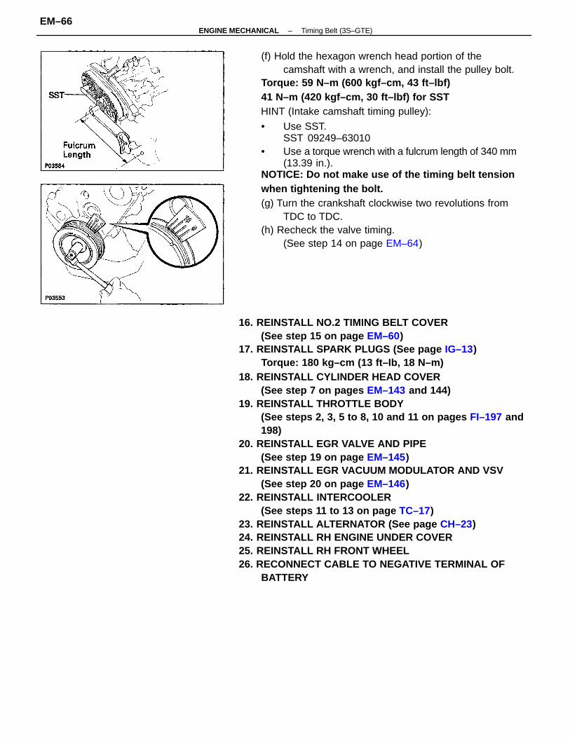
16. REINSTALL NO.2 TIMING BELT COVER(See step 15 on page EM–60)
17. REINSTALL SPARK PLUGS (See page IG–13)Torque: 180 kg–cm (13 ft–Ib, 18 N–m)
18. REINSTALL CYLINDER HEAD COVER(See step 7 on pages EM–143 and 144)
19. REINSTALL THROTTLE BODY(See steps 2, 3, 5 to 8, 10 and 11 on pages FI–197 and198)
20. REINSTALL EGR VALVE AND PIPE(See step 19 on page EM–145)
21. REINSTALL EGR VACUUM MODULATOR AND VSV(See step 20 on page EM–146)
22. REINSTALL INTERCOOLER(See steps 11 to 13 on page TC–17)
23. REINSTALL ALTERNATOR (See page CH–23)24. REINSTALL RH ENGINE UNDER COVER25. REINSTALL RH FRONT WHEEL26. RECONNECT CABLE TO NEGATIVE TERMINAL OF
BATTERY
(f) Hold the hexagon wrench head portion of thecamshaft with a wrench, and install the pulley bolt.
Torque: 59 N–m (600 kgf–cm, 43 ft–lbf)41 N–m (420 kgf–cm, 30 ft–lbf) for SSTHINT (Intake camshaft timing pulley):
• Use SST.SST 09249–63010
• Use a torque wrench with a fulcrum length of 340 mm(13.39 in.).
NOTICE: Do not make use of the timing belt tensionwhen tightening the bolt.(g) Turn the crankshaft clockwise two revolutions from
TDC to TDC.(h) Recheck the valve timing.
(See step 14 on page EM–64)
–ENGINE MECHANICAL Timing Belt (3S–GTE)EM–66
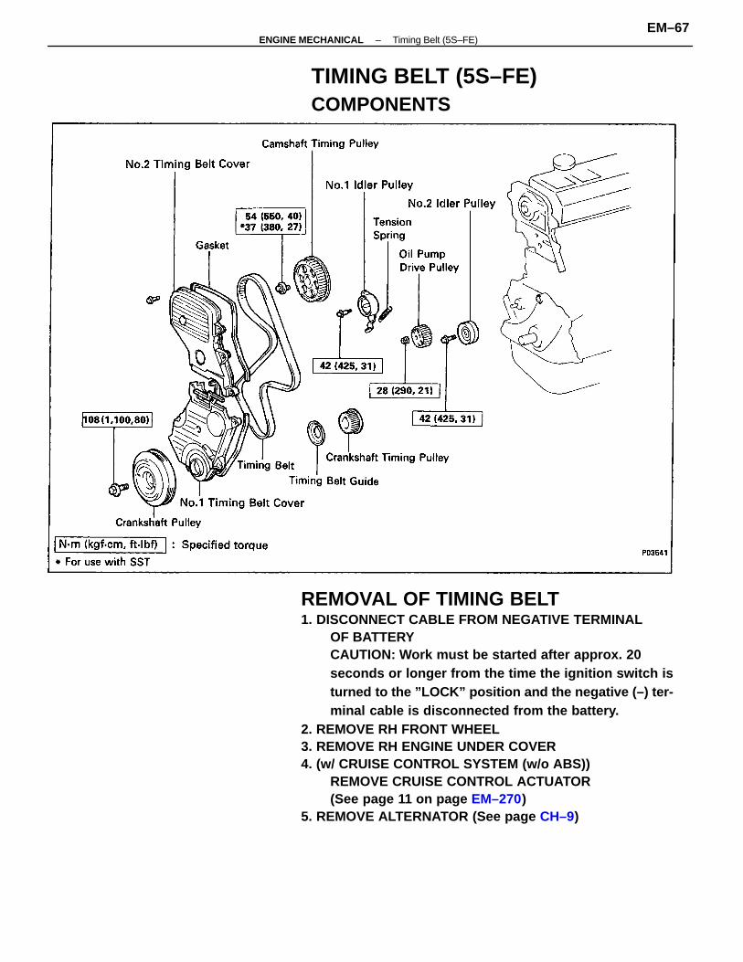
REMOVAL OF TIMING BELT1. DISCONNECT CABLE FROM NEGATIVE TERMINAL
OF BATTERYCAUTION: Work must be started after approx. 20seconds or longer from the time the ignition switch isturned to the ”LOCK” position and the negative (–) ter-minal cable is disconnected from the battery.
2. REMOVE RH FRONT WHEEL3. REMOVE RH ENGINE UNDER COVER4. (w/ CRUISE CONTROL SYSTEM (w/o ABS))
REMOVE CRUISE CONTROL ACTUATOR(See page 11 on page EM–270)
5. REMOVE ALTERNATOR (See page CH–9)
TIMING BELT (5S–FE)COMPONENTS
–ENGINE MECHANICAL Timing Belt (5S–FE)EM–67
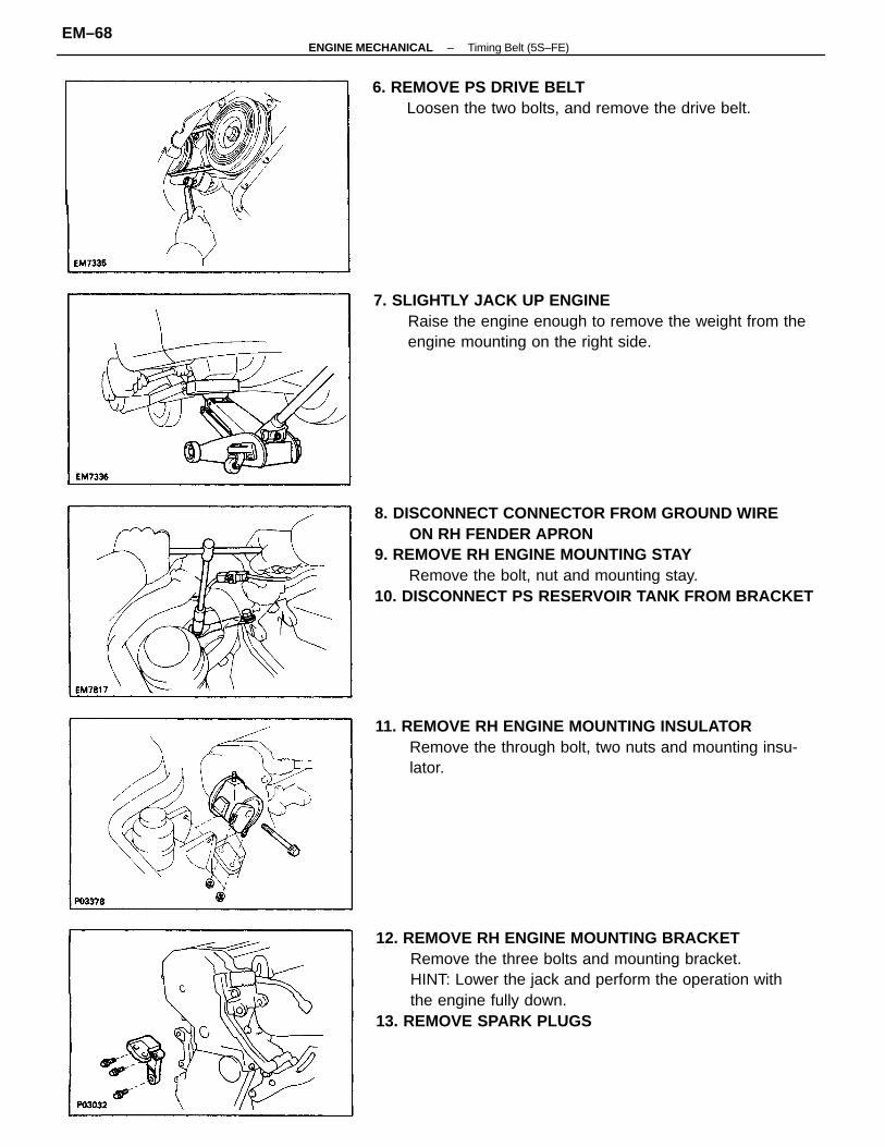
8. DISCONNECT CONNECTOR FROM GROUND WIREON RH FENDER APRON
9. REMOVE RH ENGINE MOUNTING STAYRemove the bolt, nut and mounting stay.
10. DISCONNECT PS RESERVOIR TANK FROM BRACKET
12. REMOVE RH ENGINE MOUNTING BRACKETRemove the three bolts and mounting bracket.HINT: Lower the jack and perform the operation withthe engine fully down.
13. REMOVE SPARK PLUGS
7. SLIGHTLY JACK UP ENGINERaise the engine enough to remove the weight from theengine mounting on the right side.
11. REMOVE RH ENGINE MOUNTING INSULATORRemove the through bolt, two nuts and mounting insu-lator.
6. REMOVE PS DRIVE BELTLoosen the two bolts, and remove the drive belt.
–ENGINE MECHANICAL Timing Belt (5S–FE)EM–68
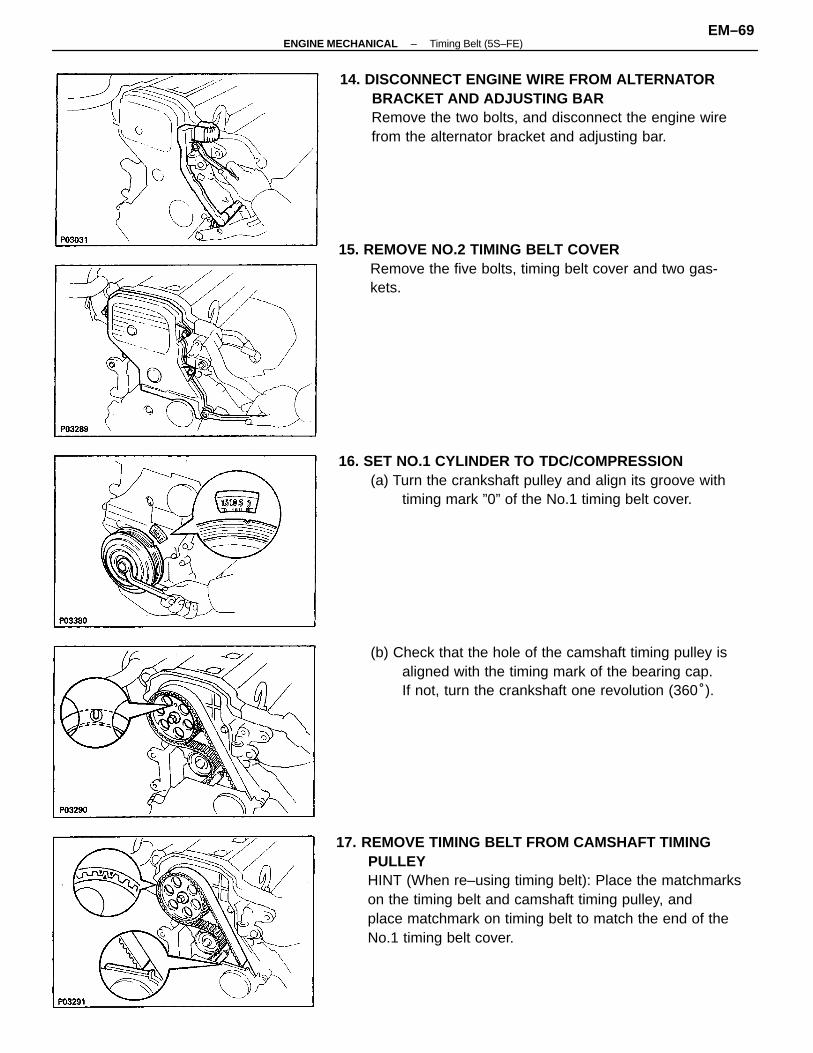
17. REMOVE TIMING BELT FROM CAMSHAFT TIMINGPULLEYHINT (When re–using timing belt): Place the matchmarkson the timing belt and camshaft timing pulley, andplace matchmark on timing belt to match the end of theNo.1 timing belt cover.
14. DISCONNECT ENGINE WIRE FROM ALTERNATORBRACKET AND ADJUSTING BARRemove the two bolts, and disconnect the engine wirefrom the alternator bracket and adjusting bar.
15. REMOVE NO.2 TIMING BELT COVERRemove the five bolts, timing belt cover and two gas-kets.
16. SET NO.1 CYLINDER TO TDC/COMPRESSION(a) Turn the crankshaft pulley and align its groove with
timing mark ”0” of the No.1 timing belt cover.
(b) Check that the hole of the camshaft timing pulley isaligned with the timing mark of the bearing cap.If not, turn the crankshaft one revolution (360°).
–ENGINE MECHANICAL Timing Belt (5S–FE)EM–69
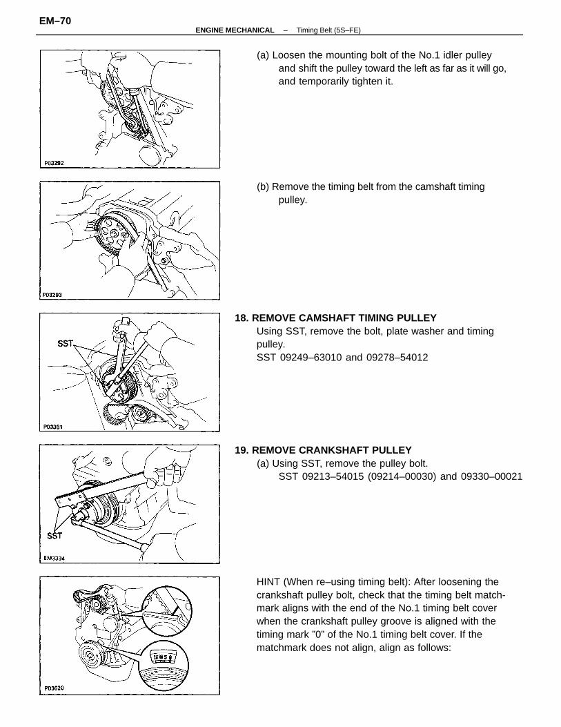
HINT (When re–using timing belt): After loosening thecrankshaft pulley bolt, check that the timing belt match-mark aligns with the end of the No.1 timing belt coverwhen the crankshaft pulley groove is aligned with thetiming mark ”0” of the No.1 timing belt cover. If thematchmark does not align, align as follows:
18. REMOVE CAMSHAFT TIMING PULLEYUsing SST, remove the bolt, plate washer and timingpulley.SST 09249–63010 and 09278–54012
19. REMOVE CRANKSHAFT PULLEY(a) Using SST, remove the pulley bolt.
SST 09213–54015 (09214–00030) and 09330–00021
(a) Loosen the mounting bolt of the No.1 idler pulleyand shift the pulley toward the left as far as it will go,and temporarily tighten it.
(b) Remove the timing belt from the camshaft timingpulley.
–ENGINE MECHANICAL Timing Belt (5S–FE)EM–70
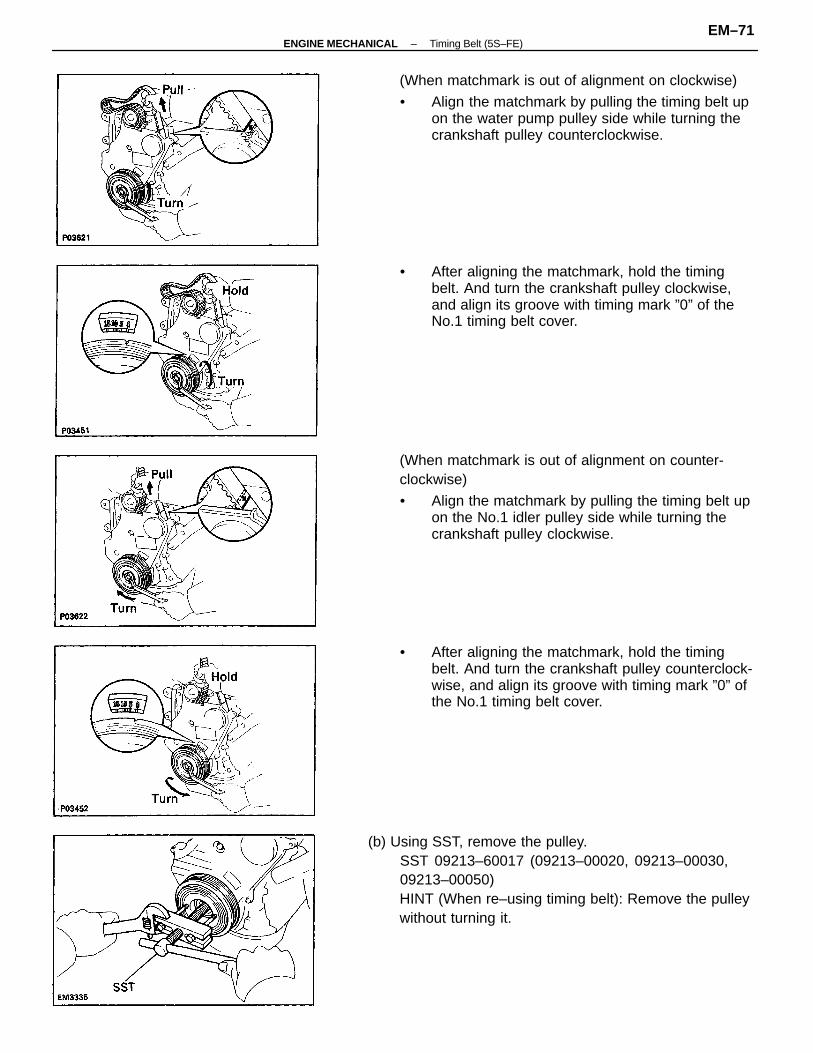
(b) Using SST, remove the pulley.SST 09213–60017 (09213–00020, 09213–00030,09213–00050)HINT (When re–using timing belt): Remove the pulleywithout turning it.
(When matchmark is out of alignment on counter-clockwise)
• Align the matchmark by pulling the timing belt upon the No.1 idler pulley side while turning thecrankshaft pulley clockwise.
(When matchmark is out of alignment on clockwise)
• Align the matchmark by pulling the timing belt upon the water pump pulley side while turning thecrankshaft pulley counterclockwise.
• After aligning the matchmark, hold the timingbelt. And turn the crankshaft pulley clockwise,and align its groove with timing mark ”0” of theNo.1 timing belt cover.
• After aligning the matchmark, hold the timingbelt. And turn the crankshaft pulley counterclock-wise, and align its groove with timing mark ”0” ofthe No.1 timing belt cover.
–ENGINE MECHANICAL Timing Belt (5S–FE)EM–71
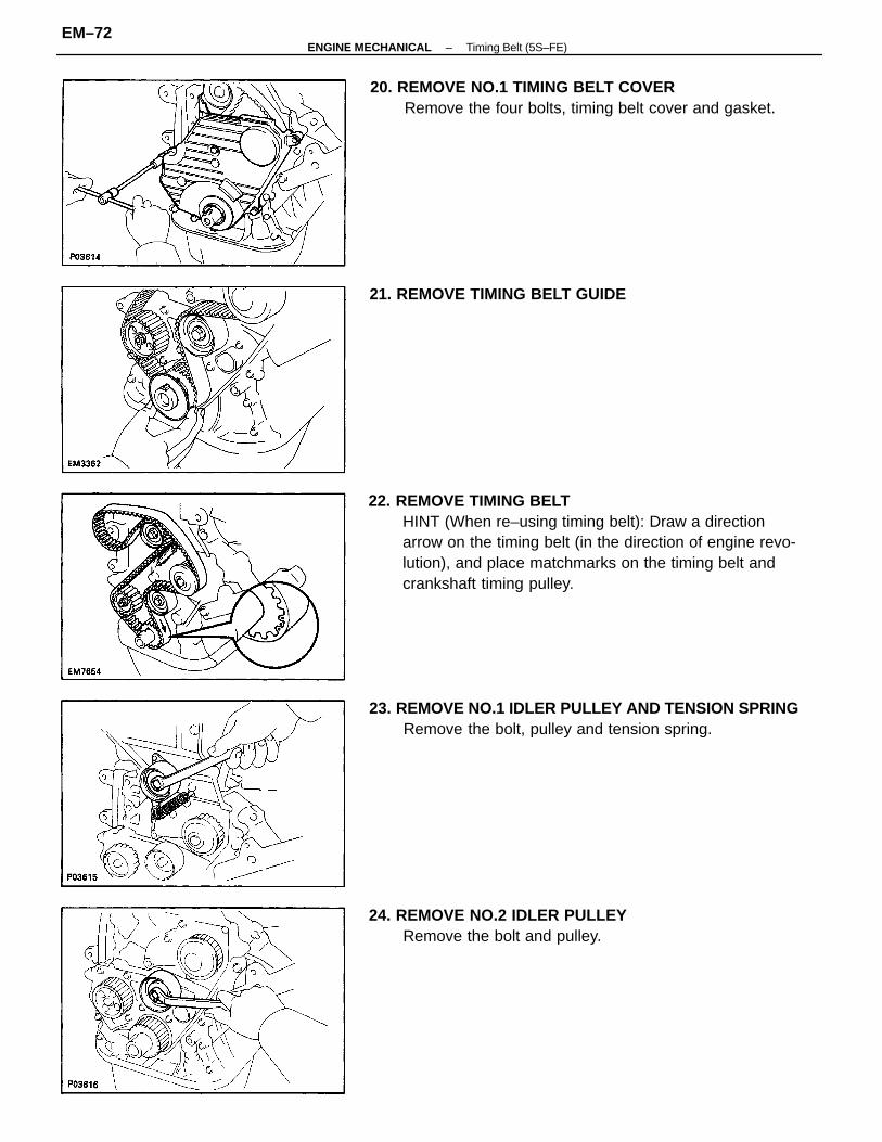
22. REMOVE TIMING BELTHINT (When re–using timing belt): Draw a directionarrow on the timing belt (in the direction of engine revo-lution), and place matchmarks on the timing belt andcrankshaft timing pulley.
23. REMOVE NO.1 IDLER PULLEY AND TENSION SPRINGRemove the bolt, pulley and tension spring.
20. REMOVE NO.1 TIMING BELT COVERRemove the four bolts, timing belt cover and gasket.
24. REMOVE NO.2 IDLER PULLEYRemove the bolt and pulley.
21. REMOVE TIMING BELT GUIDE
–ENGINE MECHANICAL Timing Belt (5S–FE)EM–72
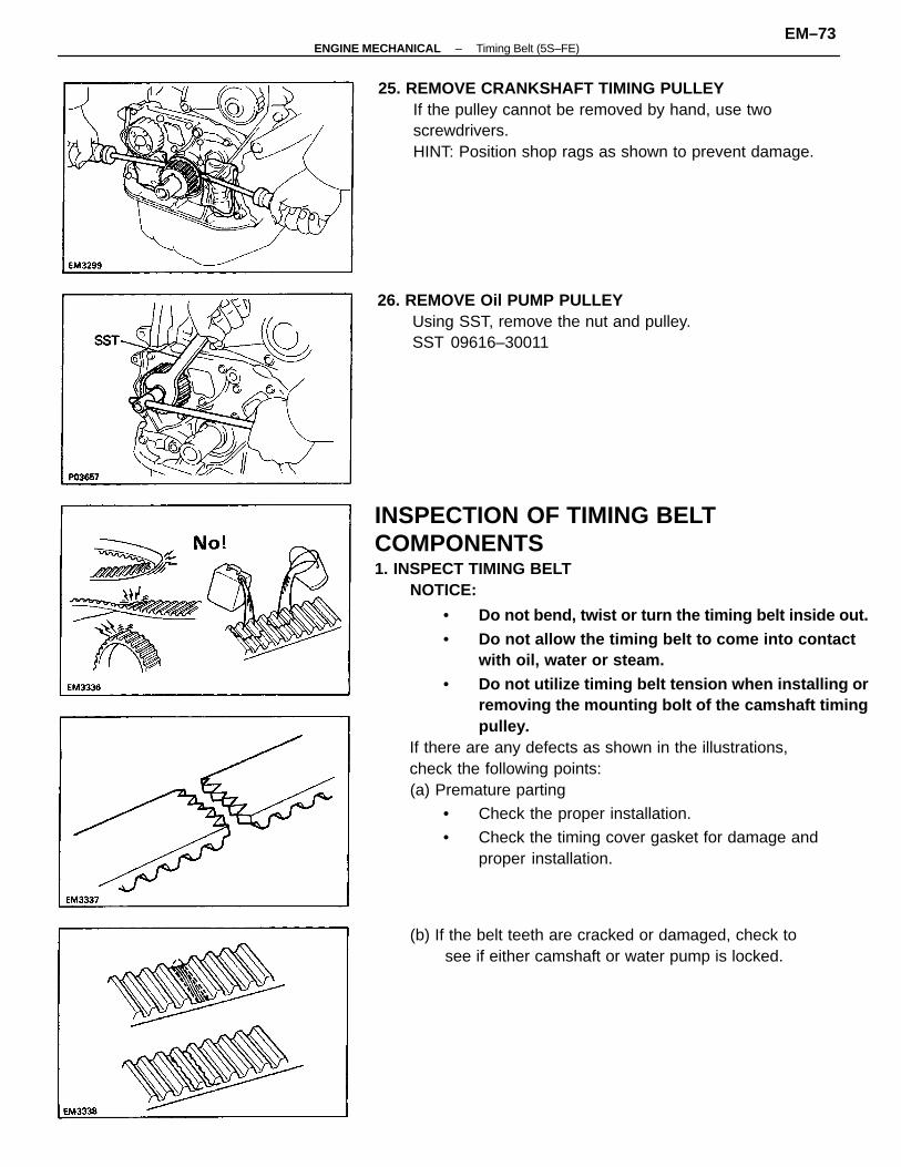
INSPECTION OF TIMING BELTCOMPONENTS1. INSPECT TIMING BELT
NOTICE:
• Do not bend, twist or turn the timing belt inside out.• Do not allow the timing belt to come into contact
with oil, water or steam.• Do not utilize timing belt tension when installing or
removing the mounting bolt of the camshaft timingpulley.
If there are any defects as shown in the illustrations,check the following points:(a) Premature parting
• Check the proper installation.
• Check the timing cover gasket for damage andproper installation.
25. REMOVE CRANKSHAFT TIMING PULLEYIf the pulley cannot be removed by hand, use twoscrewdrivers.HINT: Position shop rags as shown to prevent damage.
26. REMOVE Oil PUMP PULLEYUsing SST, remove the nut and pulley.SST 09616–30011
(b) If the belt teeth are cracked or damaged, check tosee if either camshaft or water pump is locked.
–ENGINE MECHANICAL Timing Belt (5S–FE)EM–73
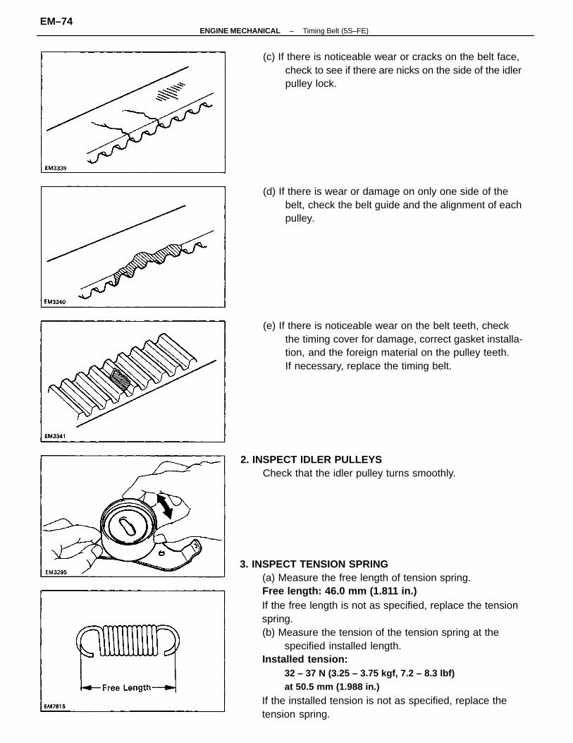
3. INSPECT TENSION SPRING(a) Measure the free length of tension spring.Free length: 46.0 mm (1.811 in.)If the free length is not as specified, replace the tensionspring.(b) Measure the tension of the tension spring at the
specified installed length.Installed tension:
32 – 37 N (3.25 – 3.75 kgf, 7.2 – 8.3 lbf)at 50.5 mm (1.988 in.)
If the installed tension is not as specified, replace thetension spring.
(e) If there is noticeable wear on the belt teeth, checkthe timing cover for damage, correct gasket installa-tion, and the foreign material on the pulley teeth.If necessary, replace the timing belt.
(d) If there is wear or damage on only one side of thebelt, check the belt guide and the alignment of eachpulley.
(c) If there is noticeable wear or cracks on the belt face,check to see if there are nicks on the side of the idlerpulley lock.
2. INSPECT IDLER PULLEYSCheck that the idler pulley turns smoothly.
–ENGINE MECHANICAL Timing Belt (5S–FE)EM–74
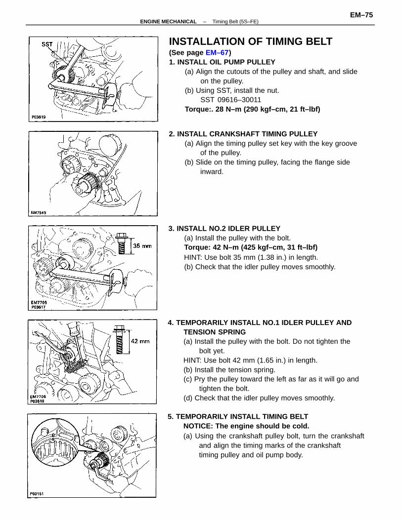
4. TEMPORARILY INSTALL NO.1 IDLER PULLEY ANDTENSION SPRING(a) Install the pulley with the bolt. Do not tighten the
bolt yet.HINT: Use bolt 42 mm (1.65 in.) in length.(b) Install the tension spring.(c) Pry the pulley toward the left as far as it will go and
tighten the bolt.(d) Check that the idler pulley moves smoothly.
INSTALLATION OF TIMING BELT(See page EM–67)1. INSTALL OIL PUMP PULLEY
(a) Align the cutouts of the pulley and shaft, and slideon the pulley.
(b) Using SST, install the nut.SST 09616–30011
Torque:. 28 N–m (290 kgf–cm, 21 ft–lbf)
5. TEMPORARILY INSTALL TIMING BELTNOTICE: The engine should be cold.(a) Using the crankshaft pulley bolt, turn the crankshaft
and align the timing marks of the crankshafttiming pulley and oil pump body.
3. INSTALL NO.2 IDLER PULLEY(a) Install the pulley with the bolt.Torque: 42 N–m (425 kgf–cm, 31 ft–lbf)HINT: Use bolt 35 mm (1.38 in.) in length.(b) Check that the idler pulley moves smoothly.
2. INSTALL CRANKSHAFT TIMING PULLEY(a) Align the timing pulley set key with the key groove
of the pulley.(b) Slide on the timing pulley, facing the flange side
inward.
–ENGINE MECHANICAL Timing Belt (5S–FE)EM–75
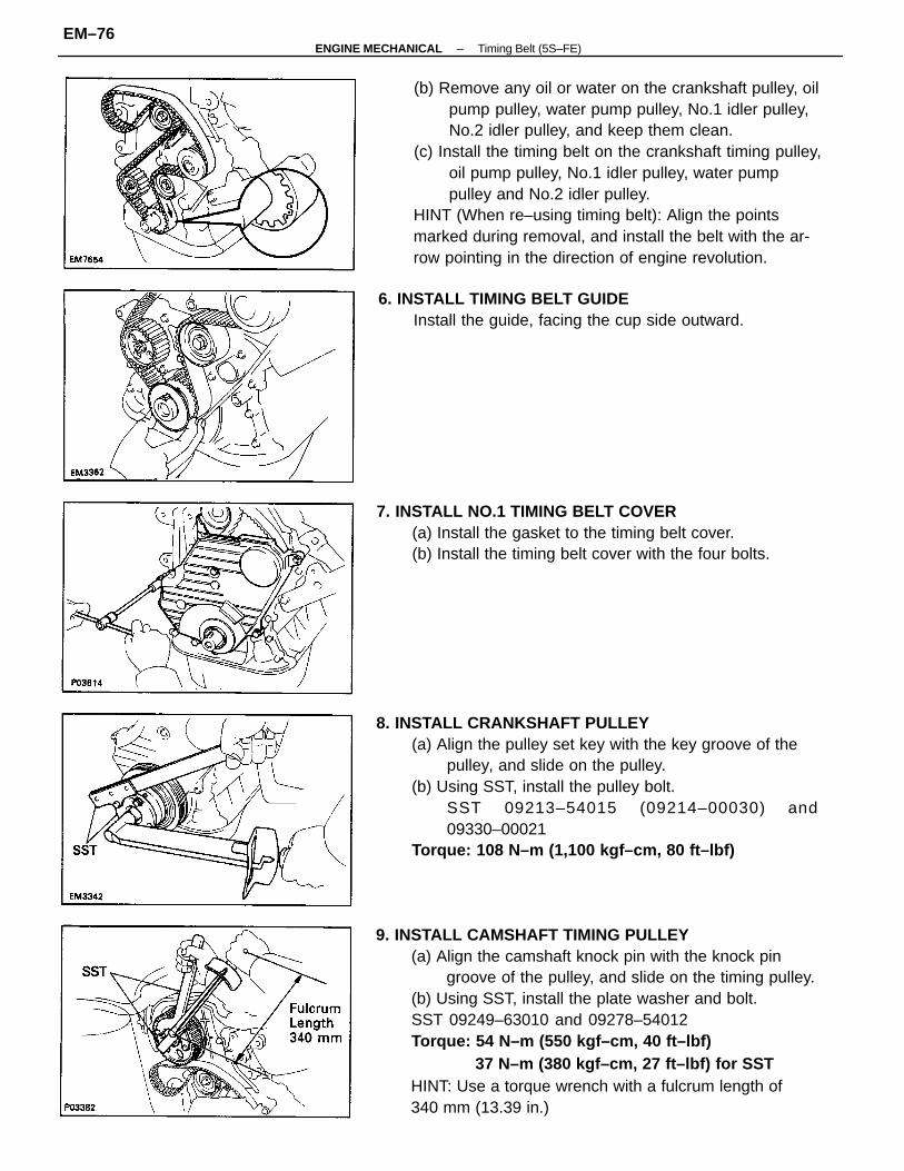
9. INSTALL CAMSHAFT TIMING PULLEY(a) Align the camshaft knock pin with the knock pin
groove of the pulley, and slide on the timing pulley.(b) Using SST, install the plate washer and bolt.SST 09249–63010 and 09278–54012Torque: 54 N–m (550 kgf–cm, 40 ft–lbf)
37 N–m (380 kgf–cm, 27 ft–lbf) for SSTHINT: Use a torque wrench with a fulcrum length of340 mm (13.39 in.)
(b) Remove any oil or water on the crankshaft pulley, oilpump pulley, water pump pulley, No.1 idler pulley,No.2 idler pulley, and keep them clean.
(c) Install the timing belt on the crankshaft timing pulley,oil pump pulley, No.1 idler pulley, water pumppulley and No.2 idler pulley.
HINT (When re–using timing belt): Align the pointsmarked during removal, and install the belt with the ar-row pointing in the direction of engine revolution.
8. INSTALL CRANKSHAFT PULLEY(a) Align the pulley set key with the key groove of the
pulley, and slide on the pulley.(b) Using SST, install the pulley bolt.
SST 09213–54015 (09214–00030) and09330–00021
Torque: 108 N–m (1,100 kgf–cm, 80 ft–lbf)
7. INSTALL NO.1 TIMING BELT COVER(a) Install the gasket to the timing belt cover.(b) Install the timing belt cover with the four bolts.
6. INSTALL TIMING BELT GUIDEInstall the guide, facing the cup side outward.
–ENGINE MECHANICAL Timing Belt (5S–FE)EM–76
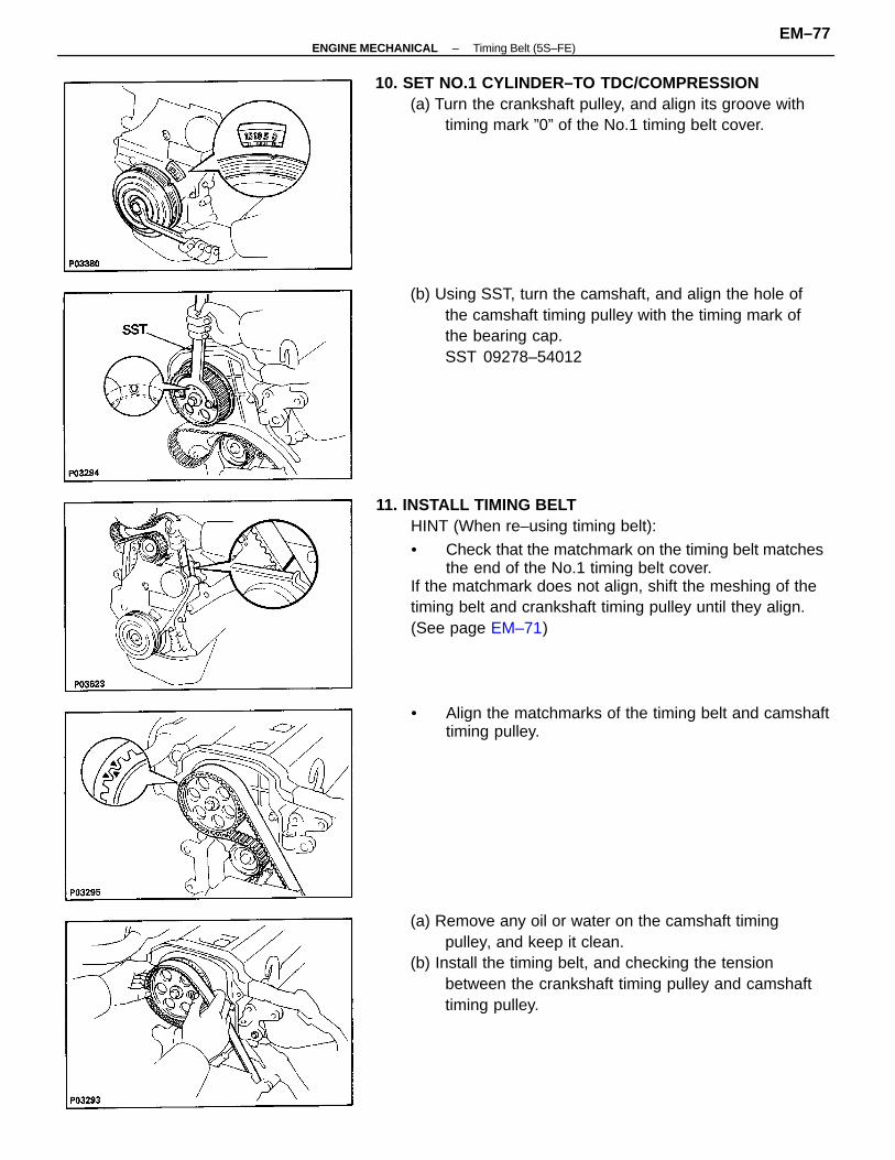
11. INSTALL TIMING BELTHINT (When re–using timing belt):
• Check that the matchmark on the timing belt matchesthe end of the No.1 timing belt cover.
If the matchmark does not align, shift the meshing of thetiming belt and crankshaft timing pulley until they align.(See page EM–71)
(a) Remove any oil or water on the camshaft timingpulley, and keep it clean.
(b) Install the timing belt, and checking the tensionbetween the crankshaft timing pulley and camshafttiming pulley.
(b) Using SST, turn the camshaft, and align the hole ofthe camshaft timing pulley with the timing mark ofthe bearing cap.SST 09278–54012
10. SET NO.1 CYLINDER–TO TDC/COMPRESSION(a) Turn the crankshaft pulley, and align its groove with
timing mark ”0” of the No.1 timing belt cover.
• Align the matchmarks of the timing belt and camshafttiming pulley.
–ENGINE MECHANICAL Timing Belt (5S–FE)EM–77
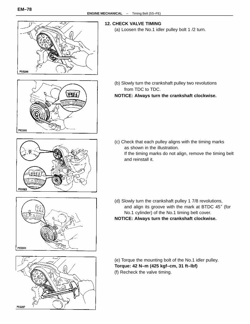
(d) Slowly turn the crankshaft pulley 1 7/8 revolutions,and align its groove with the mark at BTDC 45° (forNo.1 cylinder) of the No.1 timing belt cover.
NOTICE: Always turn the crankshaft clockwise.
(c) Check that each pulley aligns with the timing marksas shown in the illustration.If the timing marks do not align, remove the timing beltand reinstall it.
(e) Torque the mounting bolt of the No.1 idler pulley.Torque: 42 N–m (425 kgf–cm, 31 ft–lbf)(f) Recheck the valve timing.
(b) Slowly turn the crankshaft pulley two revolutionsfrom TDC to TDC.
NOTICE: Always turn the crankshaft clockwise.
12. CHECK VALVE TIMING(a) Loosen the No.1 idler pulley bolt 1 /2 turn.
–ENGINE MECHANICAL Timing Belt (5S–FE)EM–78
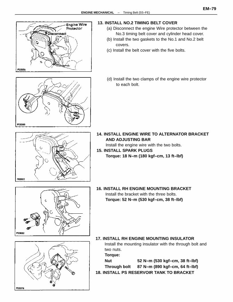
17. INSTALL RH ENGINE MOUNTING INSULATORInstall the mounting insulator with the through bolt andtwo nuts.Torque:Nut 52 N–m (530 kgf–cm, 38 ft–lbf)Through bolt 87 N–m (890 kgf–cm, 64 ft–lbf)
18. INSTALL PS RESERVOIR TANK TO BRACKET
13. INSTALL NO.2 TIMING BELT COVER(a) Disconnect the engine Wire protector between the
No.3 timing belt cover and cylinder head cover.(b) Install the two gaskets to the No.1 and No.2 belt
covers.(c) Install the belt cover with the five bolts.
14. INSTALL ENGINE WIRE TO ALTERNATOR BRACKETAND ADJUSTING BARInstall the engine wire with the two bolts.
15. INSTALL SPARK PLUGSTorque: 18 N–m (180 kgf–cm, 13 ft–lbf)
16. INSTALL RH ENGINE MOUNTING BRACKETInstall the bracket with the three bolts.Torque: 52 N–m (530 kgf–cm, 38 ft–lbf)
(d) Install the two clamps of the engine wire protectorto each bolt.
–ENGINE MECHANICAL Timing Belt (5S–FE)EM–79
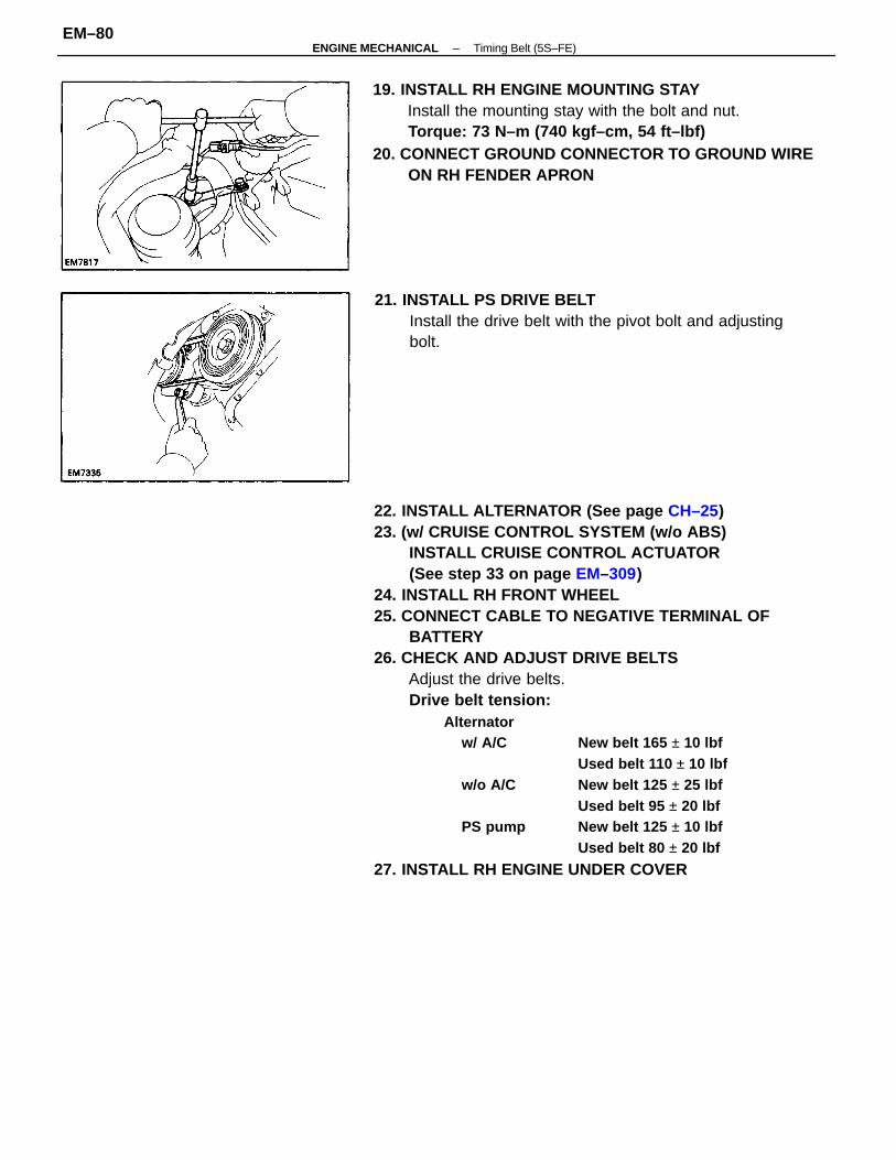
22. INSTALL ALTERNATOR (See page CH–25)23. (w/ CRUISE CONTROL SYSTEM (w/o ABS)
INSTALL CRUISE CONTROL ACTUATOR(See step 33 on page EM–309)
24. INSTALL RH FRONT WHEEL25. CONNECT CABLE TO NEGATIVE TERMINAL OF
BATTERY26. CHECK AND ADJUST DRIVE BELTS
Adjust the drive belts.Drive belt tension:
Alternatorw/ A/C New belt 165 ± 10 lbf
Used belt 110 ± 10 lbfw/o A/C New belt 125 ± 25 lbf
Used belt 95 ± 20 lbfPS pump New belt 125 ± 10 lbf
Used belt 80 ± 20 lbf
27. INSTALL RH ENGINE UNDER COVER
19. INSTALL RH ENGINE MOUNTING STAYInstall the mounting stay with the bolt and nut.Torque: 73 N–m (740 kgf–cm, 54 ft–lbf)
20. CONNECT GROUND CONNECTOR TO GROUND WIREON RH FENDER APRON
21. INSTALL PS DRIVE BELTInstall the drive belt with the pivot bolt and adjustingbolt.
–ENGINE MECHANICAL Timing Belt (5S–FE)EM–80
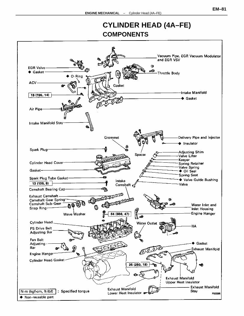
CYLINDER HEAD (4A–FE)COMPONENTS
–ENGINE MECHANICAL Cylinder Head (4A–FE)EM–81
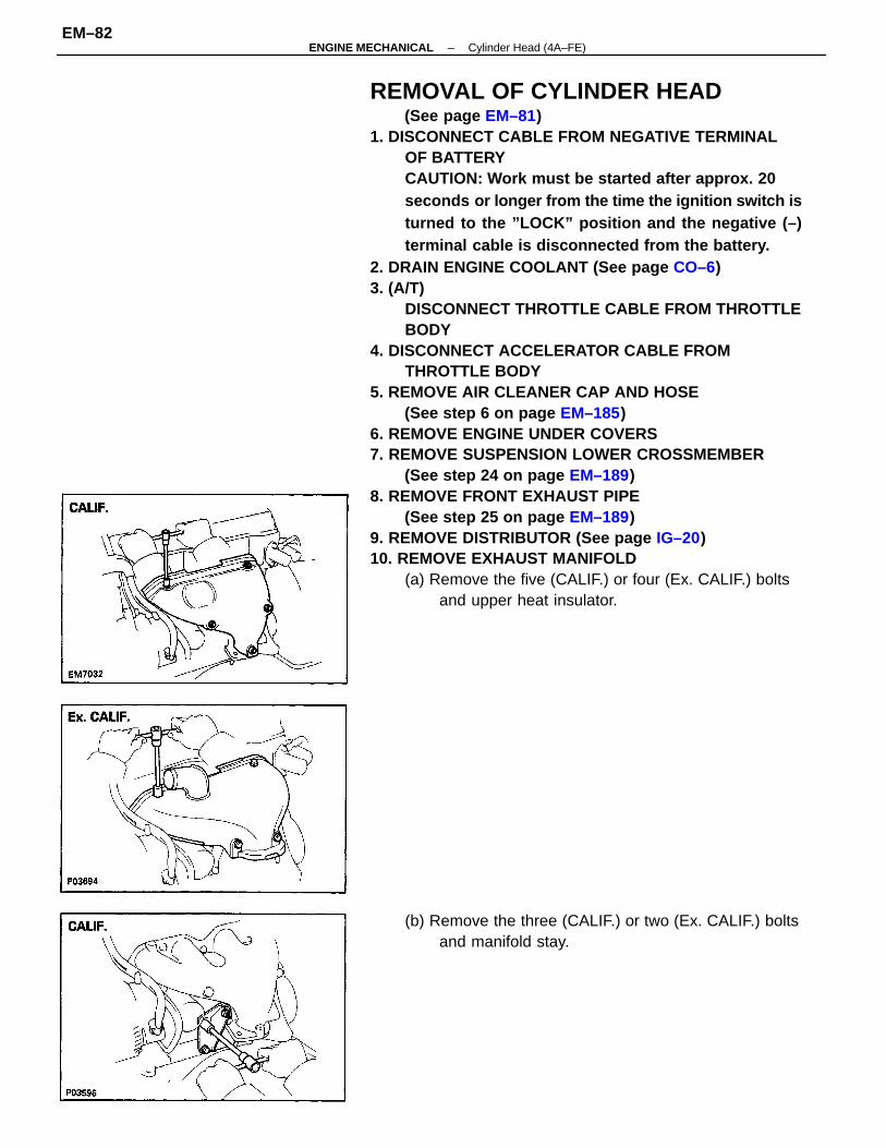
REMOVAL OF CYLINDER HEAD(See page EM–81)
1. DISCONNECT CABLE FROM NEGATIVE TERMINALOF BATTERYCAUTION: Work must be started after approx. 20seconds or longer from the time the ignition switch isturned to the ”LOCK” position and the negative (–)terminal cable is disconnected from the battery.
2. DRAIN ENGINE COOLANT (See page CO–6)3. (A/T)
DISCONNECT THROTTLE CABLE FROM THROTTLEBODY
4. DISCONNECT ACCELERATOR CABLE FROMTHROTTLE BODY
5. REMOVE AIR CLEANER CAP AND HOSE(See step 6 on page EM–185)
6. REMOVE ENGINE UNDER COVERS7. REMOVE SUSPENSION LOWER CROSSMEMBER
(See step 24 on page EM–189)8. REMOVE FRONT EXHAUST PIPE
(See step 25 on page EM–189)9. REMOVE DISTRIBUTOR (See page IG–20)10. REMOVE EXHAUST MANIFOLD
(a) Remove the five (CALIF.) or four (Ex. CALIF.) boltsand upper heat insulator.
(b) Remove the three (CALIF.) or two (Ex. CALIF.) boltsand manifold stay.
–ENGINE MECHANICAL Cylinder Head (4A–FE)EM–82
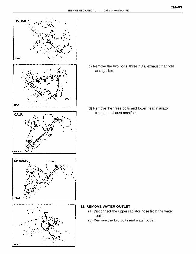
11. REMOVE WATER OUTLET(a) Disconnect the upper radiator hose from the water
outlet.(b) Remove the two bolts and water outlet.
(d) Remove the three bolts and lower heat insulatorfrom the exhaust manifold.
(c) Remove the two bolts, three nuts, exhaust manifoldand gasket.
–ENGINE MECHANICAL Cylinder Head (4A–FE)EM–83
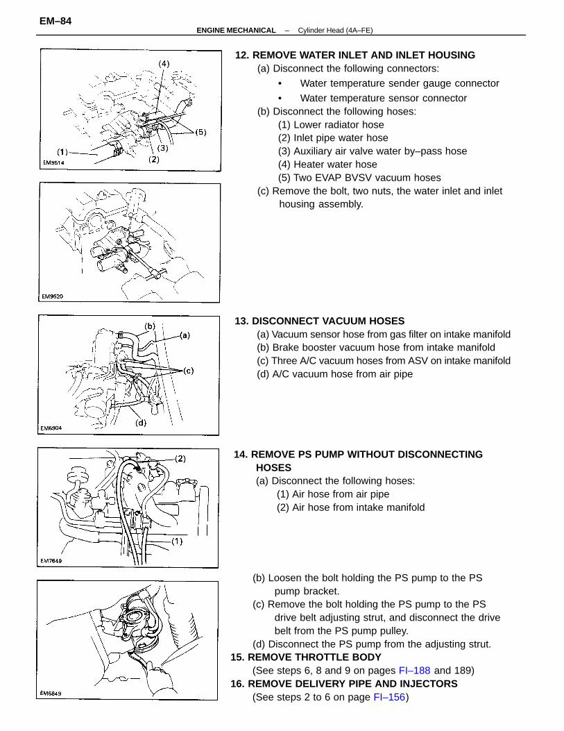
12. REMOVE WATER INLET AND INLET HOUSING(a) Disconnect the following connectors:
• Water temperature sender gauge connector
• Water temperature sensor connector(b) Disconnect the following hoses:
(1) Lower radiator hose(2) Inlet pipe water hose(3) Auxiliary air valve water by–pass hose(4) Heater water hose(5) Two EVAP BVSV vacuum hoses
(c) Remove the bolt, two nuts, the water inlet and inlethousing assembly.
(b) Loosen the bolt holding the PS pump to the PSpump bracket.
(c) Remove the bolt holding the PS pump to the PSdrive belt adjusting strut, and disconnect the drivebelt from the PS pump pulley.
(d) Disconnect the PS pump from the adjusting strut.15. REMOVE THROTTLE BODY
(See steps 6, 8 and 9 on pages FI–188 and 189)16. REMOVE DELIVERY PIPE AND INJECTORS
(See steps 2 to 6 on page FI–156)
13. DISCONNECT VACUUM HOSES(a) Vacuum sensor hose from gas filter on intake manifold(b) Brake booster vacuum hose from intake manifold(c) Three A/C vacuum hoses from ASV on intake manifold(d) A/C vacuum hose from air pipe
14. REMOVE PS PUMP WITHOUT DISCONNECTINGHOSES(a) Disconnect the following hoses:
(1) Air hose from air pipe(2) Air hose from intake manifold
–ENGINE MECHANICAL Cylinder Head (4A–FE)EM–84
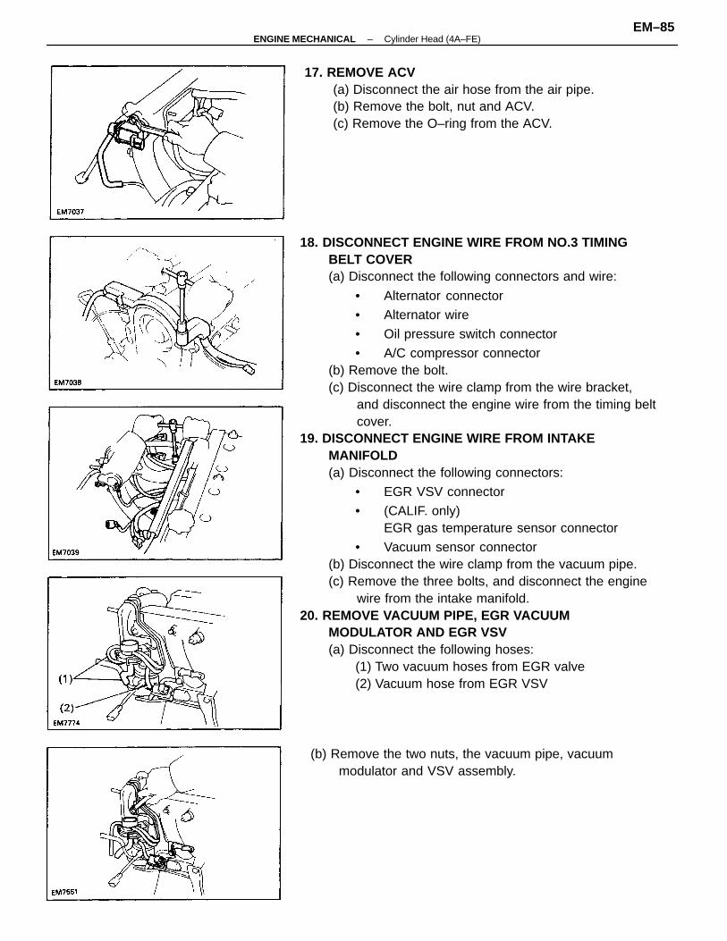
18. DISCONNECT ENGINE WIRE FROM NO.3 TIMINGBELT COVER(a) Disconnect the following connectors and wire:
• Alternator connector
• Alternator wire
• Oil pressure switch connector
• A/C compressor connector(b) Remove the bolt.(c) Disconnect the wire clamp from the wire bracket,
and disconnect the engine wire from the timing beltcover.
19. DISCONNECT ENGINE WIRE FROM INTAKEMANIFOLD(a) Disconnect the following connectors:
• EGR VSV connector
• (CALIF. only)EGR gas temperature sensor connector
• Vacuum sensor connector(b) Disconnect the wire clamp from the vacuum pipe.(c) Remove the three bolts, and disconnect the engine
wire from the intake manifold.20. REMOVE VACUUM PIPE, EGR VACUUM
MODULATOR AND EGR VSV(a) Disconnect the following hoses:
(1) Two vacuum hoses from EGR valve(2) Vacuum hose from EGR VSV
17. REMOVE ACV(a) Disconnect the air hose from the air pipe.(b) Remove the bolt, nut and ACV.(c) Remove the O–ring from the ACV.
(b) Remove the two nuts, the vacuum pipe, vacuummodulator and VSV assembly.
–ENGINE MECHANICAL Cylinder Head (4A–FE)EM–85
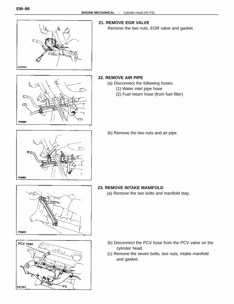
(b) Disconnect the PCV hose from the PCV valve on thecylinder head.
(c) Remove the seven bolts, two nuts, intake manifoldand gasket.
22. REMOVE AIR PIPE(a) Disconnect the following hoses:
(1) Water inlet pipe hose(2) Fuel return hose (from fuel filter)
23. REMOVE INTAKE MANIFOLD(a) Remove the two bolts and manifold stay.
21. REMOVE EGR VALVERemove the two nuts, EGR valve and gasket.
(b) Remove the two nuts and air pipe.
–ENGINE MECHANICAL Cylinder Head (4A–FE)EM–86
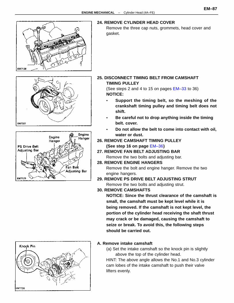
25. DISCONNECT TIMING BELT FROM CAMSHAFTTIMING PULLEY(See steps 2 and 4 to 15 on pages EM–33 to 36)NOTICE:• Support the timing belt, so the meshing of the
crankshaft timing pulley and timing belt does notshift.
• Be careful not to drop anything inside the timingbelt. cover.
• Do not allow the belt to come into contact with oil,water or dust.
26. REMOVE CAMSHAFT TIMING PULLEY(See step 16 on page EM–36)
27. REMOVE FAN BELT ADJUSTING BARRemove the two bolts and adjusting bar.
28. REMOVE ENGINE HANGERSRemove the bolt and engine hanger. Remove the twoengine hangers.
29. REMOVE PS DRIVE BELT ADJUSTING STRUTRemove the two bolts and adjusting strut.
30. REMOVE CAMSHAFTSNOTICE: Since the thrust clearance of the camshaft issmall, the camshaft must be kept level while it isbeing removed. If the camshaft is not kept level, theportion of the cylinder head receiving the shaft thrustmay crack or be damaged, causing the camshaft toseize or break. To avoid this, the following stepsshould be carried out.
A. Remove intake camshaft(a) Set the intake camshaft so the knock pin is slightly
above the top of the cylinder head.HINT: The above angle allows the No.1 and No.3 cylindercam lobes of the intake camshaft to push their valvelifters evenly.
24. REMOVE CYLINDER HEAD COVERRemove the three cap nuts, grommets, head cover andgasket.
–ENGINE MECHANICAL Cylinder Head (4A–FE)EM–87
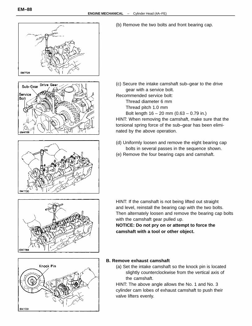
(c) Secure the intake camshaft sub–gear to the drivegear with a service bolt.
Recommended service bolt:Thread diameter 6 mmThread pitch 1.0 mmBolt length 16 – 20 mm (0.63 – 0.79 in.)
HINT: When removing the camshaft, make sure that thetorsional spring force of the sub–gear has been elimi-nated by the above operation.
B. Remove exhaust camshaft(a) Set the intake camshaft so the knock pin is located
slightly counterclockwise from the vertical axis ofthe camshaft.
HINT: The above angle allows the No. 1 and No. 3cylinder cam lobes of exhaust camshaft to push theirvalve lifters evenly.
HINT: If the camshaft is not being lifted out straightand level, reinstall the bearing cap with the two bolts.Then alternately loosen and remove the bearing cap boltswith the camshaft gear pulled up.NOTICE: Do not pry on or attempt to force thecamshaft with a tool or other object.
(d) Uniformly loosen and remove the eight bearing capbolts in several passes in the sequence shown.
(e) Remove the four bearing caps and camshaft.
(b) Remove the two bolts and front bearing cap.
–ENGINE MECHANICAL Cylinder Head (4A–FE)EM–88
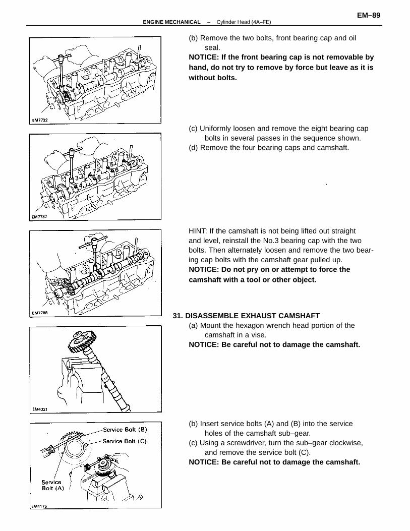
HINT: If the camshaft is not being lifted out straightand level, reinstall the No.3 bearing cap with the twobolts. Then alternately loosen and remove the two bear-ing cap bolts with the camshaft gear pulled up.NOTICE: Do not pry on or attempt to force thecamshaft with a tool or other object.
31. DISASSEMBLE EXHAUST CAMSHAFT(a) Mount the hexagon wrench head portion of the
camshaft in a vise.NOTICE: Be careful not to damage the camshaft.
(b) Insert service bolts (A) and (B) into the serviceholes of the camshaft sub–gear.
(c) Using a screwdriver, turn the sub–gear clockwise,and remove the service bolt (C).
NOTICE: Be careful not to damage the camshaft.
(b) Remove the two bolts, front bearing cap and oilseal.
NOTICE: If the front bearing cap is not removable byhand, do not try to remove by force but leave as it iswithout bolts.
(c) Uniformly loosen and remove the eight bearing capbolts in several passes in the sequence shown.
(d) Remove the four bearing caps and camshaft.
–ENGINE MECHANICAL Cylinder Head (4A–FE)EM–89
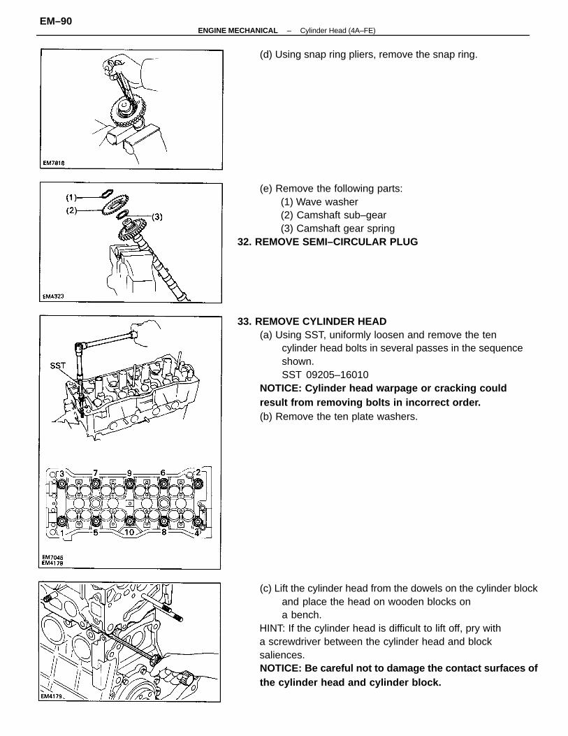
33. REMOVE CYLINDER HEAD(a) Using SST, uniformly loosen and remove the ten
cylinder head bolts in several passes in the sequenceshown.SST 09205–16010
NOTICE: Cylinder head warpage or cracking couldresult from removing bolts in incorrect order.(b) Remove the ten plate washers.
(c) Lift the cylinder head from the dowels on the cylinder blockand place the head on wooden blocks ona bench.
HINT: If the cylinder head is difficult to lift off, pry witha screwdriver between the cylinder head and blocksaliences.NOTICE: Be careful not to damage the contact surfaces ofthe cylinder head and cylinder block.
(e) Remove the following parts:(1) Wave washer(2) Camshaft sub–gear(3) Camshaft gear spring
32. REMOVE SEMI–CIRCULAR PLUG
(d) Using snap ring pliers, remove the snap ring.
–ENGINE MECHANICAL Cylinder Head (4A–FE)EM–90
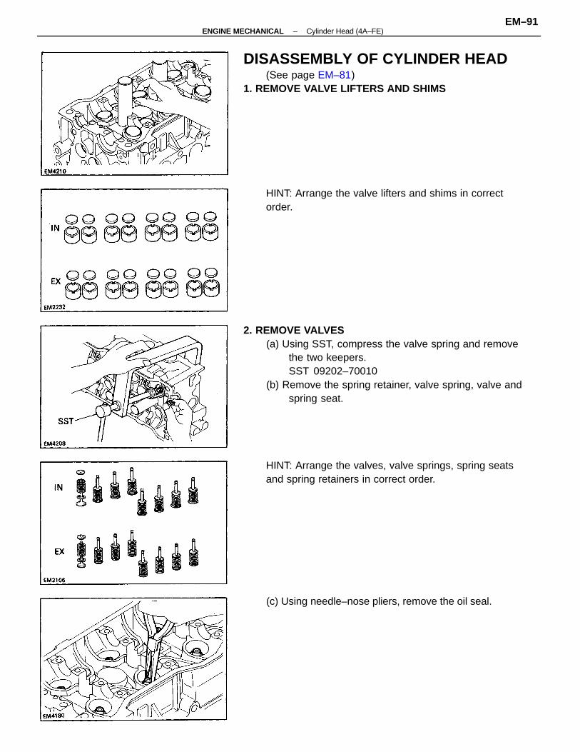
2. REMOVE VALVES(a) Using SST, compress the valve spring and remove
the two keepers.SST 09202–70010
(b) Remove the spring retainer, valve spring, valve andspring seat.
DISASSEMBLY OF CYLINDER HEAD(See page EM–81)
1. REMOVE VALVE LIFTERS AND SHIMS
HINT: Arrange the valves, valve springs, spring seatsand spring retainers in correct order.
HINT: Arrange the valve lifters and shims in correctorder.
(c) Using needle–nose pliers, remove the oil seal.
–ENGINE MECHANICAL Cylinder Head (4A–FE)EM–91
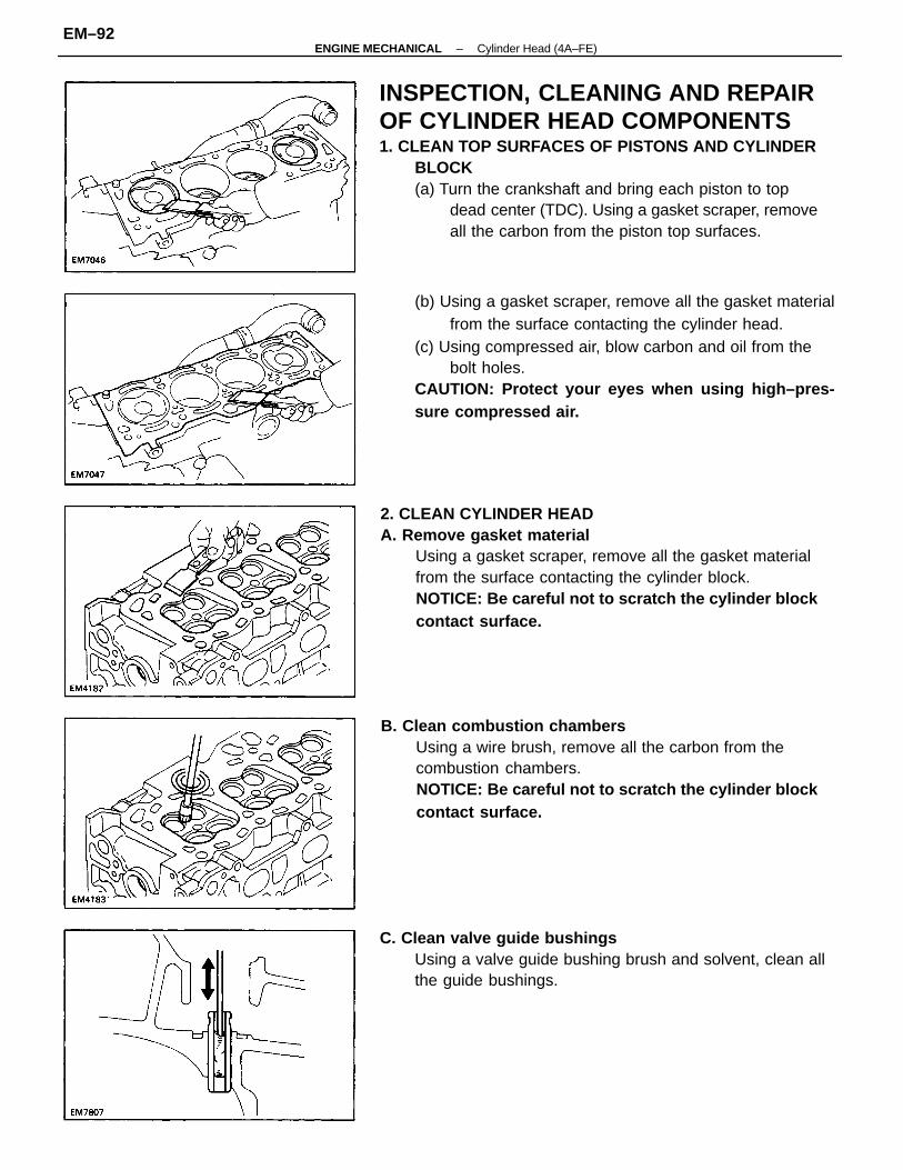
INSPECTION, CLEANING AND REPAIROF CYLINDER HEAD COMPONENTS1. CLEAN TOP SURFACES OF PISTONS AND CYLINDER
BLOCK(a) Turn the crankshaft and bring each piston to top
dead center (TDC). Using a gasket scraper, removeall the carbon from the piston top surfaces.
2. CLEAN CYLINDER HEADA. Remove gasket material
Using a gasket scraper, remove all the gasket materialfrom the surface contacting the cylinder block.NOTICE: Be careful not to scratch the cylinder blockcontact surface.
(b) Using a gasket scraper, remove all the gasket materialfrom the surface contacting the cylinder head.
(c) Using compressed air, blow carbon and oil from thebolt holes.
CAUTION: Protect your eyes when using high–pres-sure compressed air.
B. Clean combustion chambersUsing a wire brush, remove all the carbon from thecombustion chambers.NOTICE: Be careful not to scratch the cylinder blockcontact surface.
C. Clean valve guide bushingsUsing a valve guide bushing brush and solvent, clean allthe guide bushings.
–ENGINE MECHANICAL Cylinder Head (4A–FE)EM–92
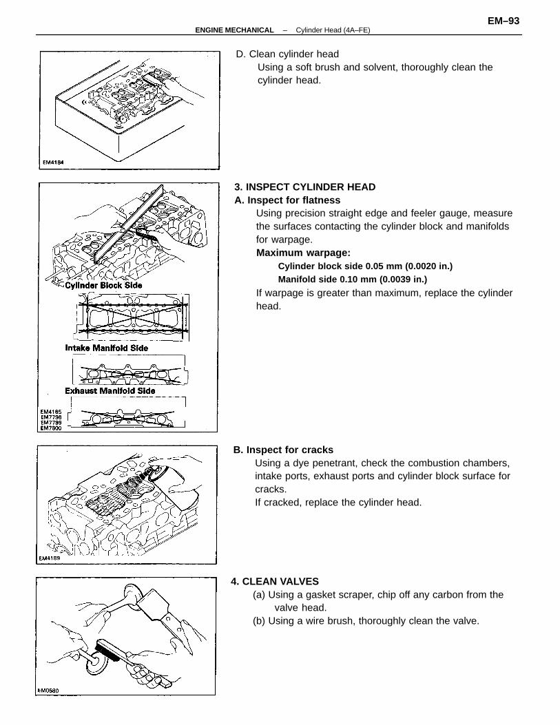
3. INSPECT CYLINDER HEADA. Inspect for flatness
Using precision straight edge and feeler gauge, measurethe surfaces contacting the cylinder block and manifoldsfor warpage.Maximum warpage:
Cylinder block side 0.05 mm (0.0020 in.)Manifold side 0.10 mm (0.0039 in.)
If warpage is greater than maximum, replace the cylinderhead.
B. Inspect for cracksUsing a dye penetrant, check the combustion chambers,intake ports, exhaust ports and cylinder block surface forcracks.If cracked, replace the cylinder head.
D. Clean cylinder headUsing a soft brush and solvent, thoroughly clean thecylinder head.
4. CLEAN VALVES(a) Using a gasket scraper, chip off any carbon from the
valve head.(b) Using a wire brush, thoroughly clean the valve.
–ENGINE MECHANICAL Cylinder Head (4A–FE)EM–93
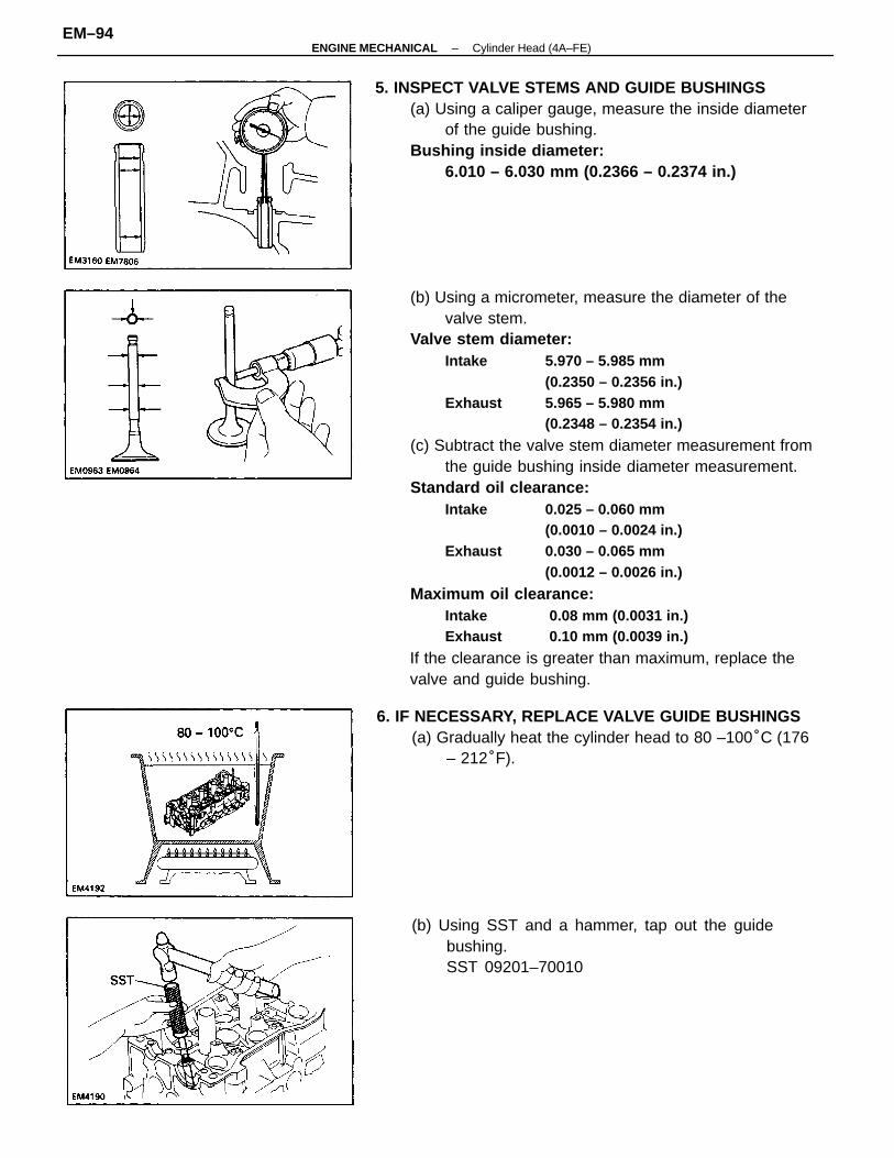
(b) Using a micrometer, measure the diameter of thevalve stem.
Valve stem diameter:Intake 5.970 – 5.985 mm
(0.2350 – 0.2356 in.)Exhaust 5.965 – 5.980 mm
(0.2348 – 0.2354 in.)
(c) Subtract the valve stem diameter measurement fromthe guide bushing inside diameter measurement.
Standard oil clearance:Intake 0.025 – 0.060 mm
(0.0010 – 0.0024 in.)Exhaust 0.030 – 0.065 mm
(0.0012 – 0.0026 in.)
Maximum oil clearance:Intake 0.08 mm (0.0031 in.)Exhaust 0.10 mm (0.0039 in.)
If the clearance is greater than maximum, replace thevalve and guide bushing.
5. INSPECT VALVE STEMS AND GUIDE BUSHINGS(a) Using a caliper gauge, measure the inside diameter
of the guide bushing.Bushing inside diameter:
6.010 – 6.030 mm (0.2366 – 0.2374 in.)
6. IF NECESSARY, REPLACE VALVE GUIDE BUSHINGS(a) Gradually heat the cylinder head to 80 –100°C (176
– 212°F).
(b) Using SST and a hammer, tap out the guidebushing.SST 09201–70010
–ENGINE MECHANICAL Cylinder Head (4A–FE)EM–94
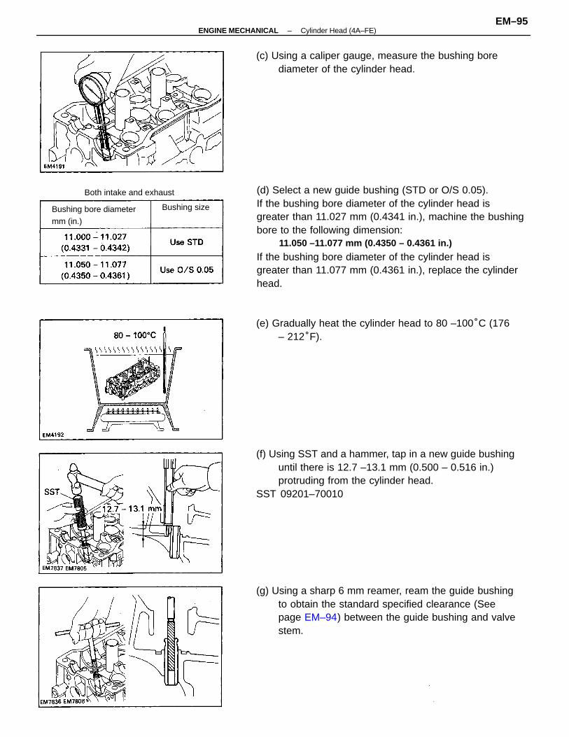
(d) Select a new guide bushing (STD or O/S 0.05).If the bushing bore diameter of the cylinder head isgreater than 11.027 mm (0.4341 in.), machine the bushingbore to the following dimension:
11.050 –11.077 mm (0.4350 – 0.4361 in.)
If the bushing bore diameter of the cylinder head isgreater than 11.077 mm (0.4361 in.), replace the cylinderhead.
(f) Using SST and a hammer, tap in a new guide bushinguntil there is 12.7 –13.1 mm (0.500 – 0.516 in.)protruding from the cylinder head.
SST 09201–70010
(g) Using a sharp 6 mm reamer, ream the guide bushingto obtain the standard specified clearance (Seepage EM–94) between the guide bushing and valvestem.
(e) Gradually heat the cylinder head to 80 –100°C (176– 212°F).
(c) Using a caliper gauge, measure the bushing borediameter of the cylinder head.
Bushing bore diametermm (in.)
Both intake and exhaust
Bushing size
–ENGINE MECHANICAL Cylinder Head (4A–FE)EM–95
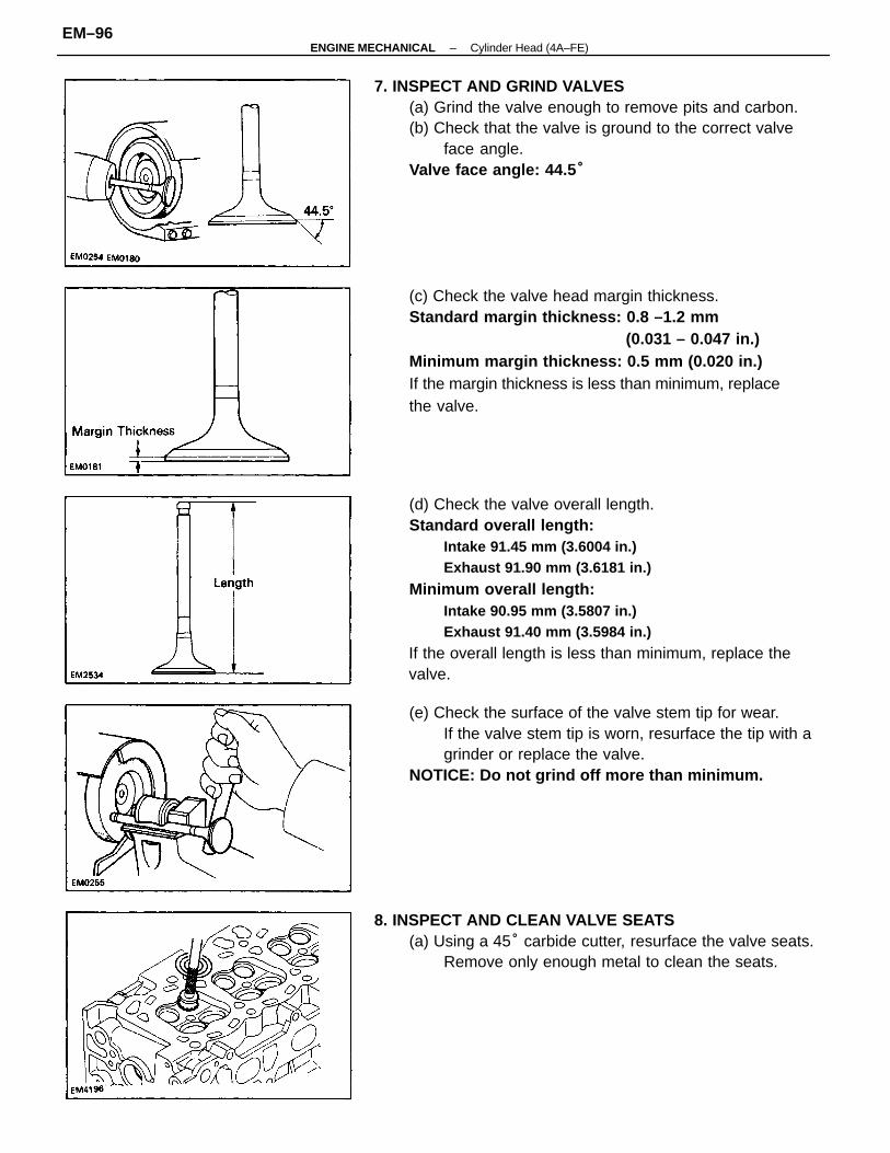
(d) Check the valve overall length.Standard overall length:
Intake 91.45 mm (3.6004 in.)Exhaust 91.90 mm (3.6181 in.)
Minimum overall length:Intake 90.95 mm (3.5807 in.)Exhaust 91.40 mm (3.5984 in.)
If the overall length is less than minimum, replace thevalve.
(c) Check the valve head margin thickness.Standard margin thickness: 0.8 –1.2 mm
(0.031 – 0.047 in.)Minimum margin thickness: 0.5 mm (0.020 in.)If the margin thickness is less than minimum, replacethe valve.
7. INSPECT AND GRIND VALVES(a) Grind the valve enough to remove pits and carbon.(b) Check that the valve is ground to the correct valve
face angle.Valve face angle: 44.5 °
(e) Check the surface of the valve stem tip for wear.If the valve stem tip is worn, resurface the tip with agrinder or replace the valve.
NOTICE: Do not grind off more than minimum.
8. INSPECT AND CLEAN VALVE SEATS(a) Using a 45° carbide cutter, resurface the valve seats.
Remove only enough metal to clean the seats.
–ENGINE MECHANICAL Cylinder Head (4A–FE)EM–96
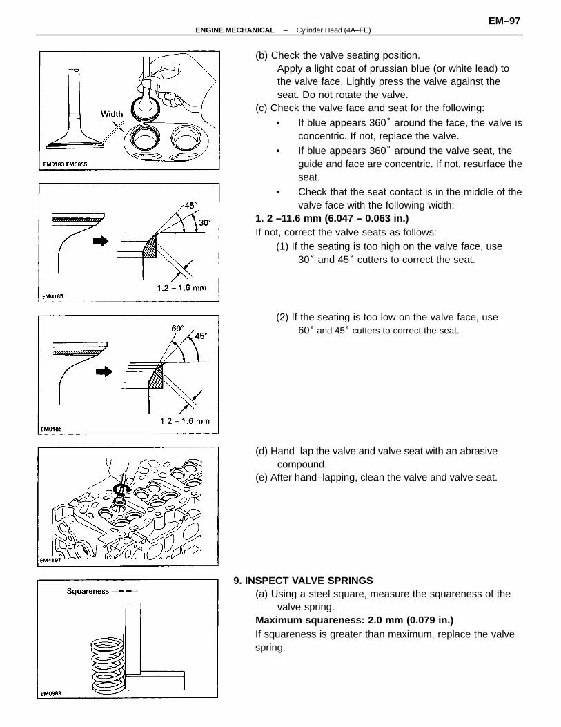
(b) Check the valve seating position.Apply a light coat of prussian blue (or white lead) tothe valve face. Lightly press the valve against theseat. Do not rotate the valve.
(c) Check the valve face and seat for the following:
• If blue appears 360° around the face, the valve isconcentric. If not, replace the valve.
• If blue appears 360° around the valve seat, theguide and face are concentric. If not, resurface theseat.
• Check that the seat contact is in the middle of thevalve face with the following width:
1. 2 –11.6 mm (6.047 – 0.063 in.)If not, correct the valve seats as follows:
(1) If the seating is too high on the valve face, use30° and 45° cutters to correct the seat.
9. INSPECT VALVE SPRINGS(a) Using a steel square, measure the squareness of the
valve spring.Maximum squareness: 2.0 mm (0.079 in.)If squareness is greater than maximum, replace the valvespring.
(d) Hand–lap the valve and valve seat with an abrasivecompound.
(e) After hand–lapping, clean the valve and valve seat.
(2) If the seating is too low on the valve face, use60° and 45° cutters to correct the seat.
–ENGINE MECHANICAL Cylinder Head (4A–FE)EM–97
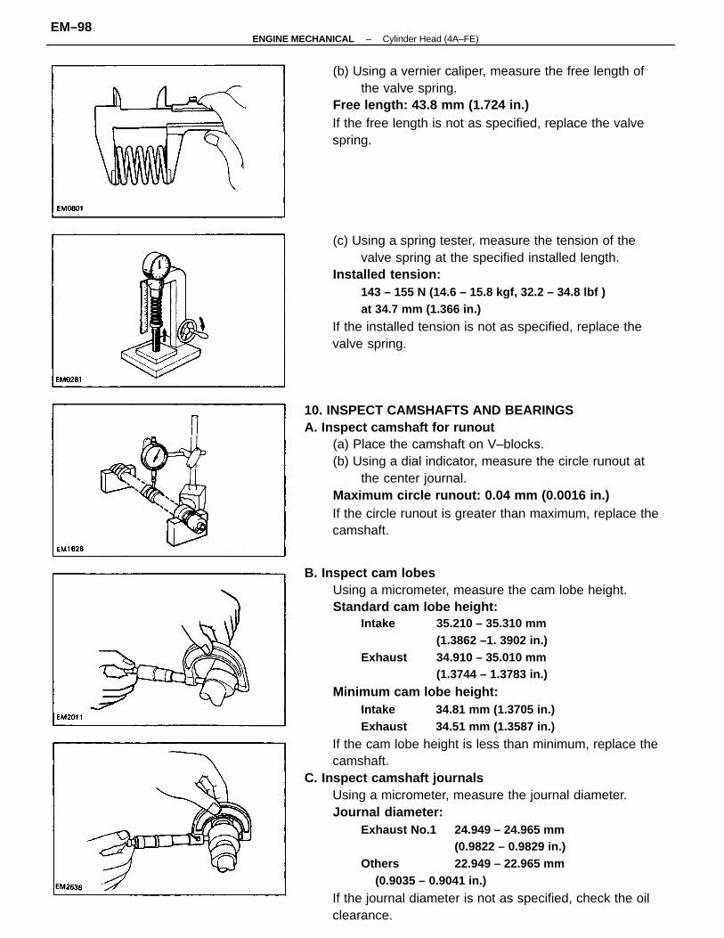
B. Inspect cam lobesUsing a micrometer, measure the cam lobe height.Standard cam lobe height:
Intake 35.210 – 35.310 mm(1.3862 –1. 3902 in.)
Exhaust 34.910 – 35.010 mm(1.3744 – 1.3783 in.)
Minimum cam lobe height:Intake 34.81 mm (1.3705 in.)Exhaust 34.51 mm (1.3587 in.)
If the cam lobe height is less than minimum, replace thecamshaft.
C. Inspect camshaft journalsUsing a micrometer, measure the journal diameter.Journal diameter:
Exhaust No.1 24.949 – 24.965 mm(0.9822 – 0.9829 in.)
Others 22.949 – 22.965 mm(0.9035 – 0.9041 in.)
If the journal diameter is not as specified, check the oilclearance.
10. INSPECT CAMSHAFTS AND BEARINGSA. Inspect camshaft for runout
(a) Place the camshaft on V–blocks.(b) Using a dial indicator, measure the circle runout at
the center journal.Maximum circle runout: 0.04 mm (0.0016 in.)If the circle runout is greater than maximum, replace thecamshaft.
(c) Using a spring tester, measure the tension of thevalve spring at the specified installed length.
Installed tension:143 – 155 N (14.6 – 15.8 kgf, 32.2 – 34.8 lbf )at 34.7 mm (1.366 in.)
If the installed tension is not as specified, replace thevalve spring.
(b) Using a vernier caliper, measure the free length ofthe valve spring.
Free length: 43.8 mm (1.724 in.)If the free length is not as specified, replace the valvespring.
–ENGINE MECHANICAL Cylinder Head (4A–FE)EM–98
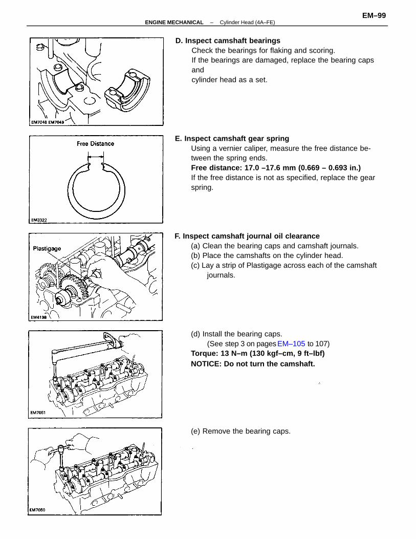
E. Inspect camshaft gear springUsing a vernier caliper, measure the free distance be-tween the spring ends.Free distance: 17.0 –17.6 mm (0.669 – 0.693 in.)If the free distance is not as specified, replace the gearspring.
F. Inspect camshaft journal oil clearance(a) Clean the bearing caps and camshaft journals.(b) Place the camshafts on the cylinder head.(c) Lay a strip of Plastigage across each of the camshaft
journals.
D. Inspect camshaft bearingsCheck the bearings for flaking and scoring.If the bearings are damaged, replace the bearing capsandcylinder head as a set.
(d) Install the bearing caps.(See step 3 on pages EM–105 to 107)
Torque: 13 N–m (130 kgf–cm, 9 ft–lbf)NOTICE: Do not turn the camshaft.
(e) Remove the bearing caps.
–ENGINE MECHANICAL Cylinder Head (4A–FE)EM–99
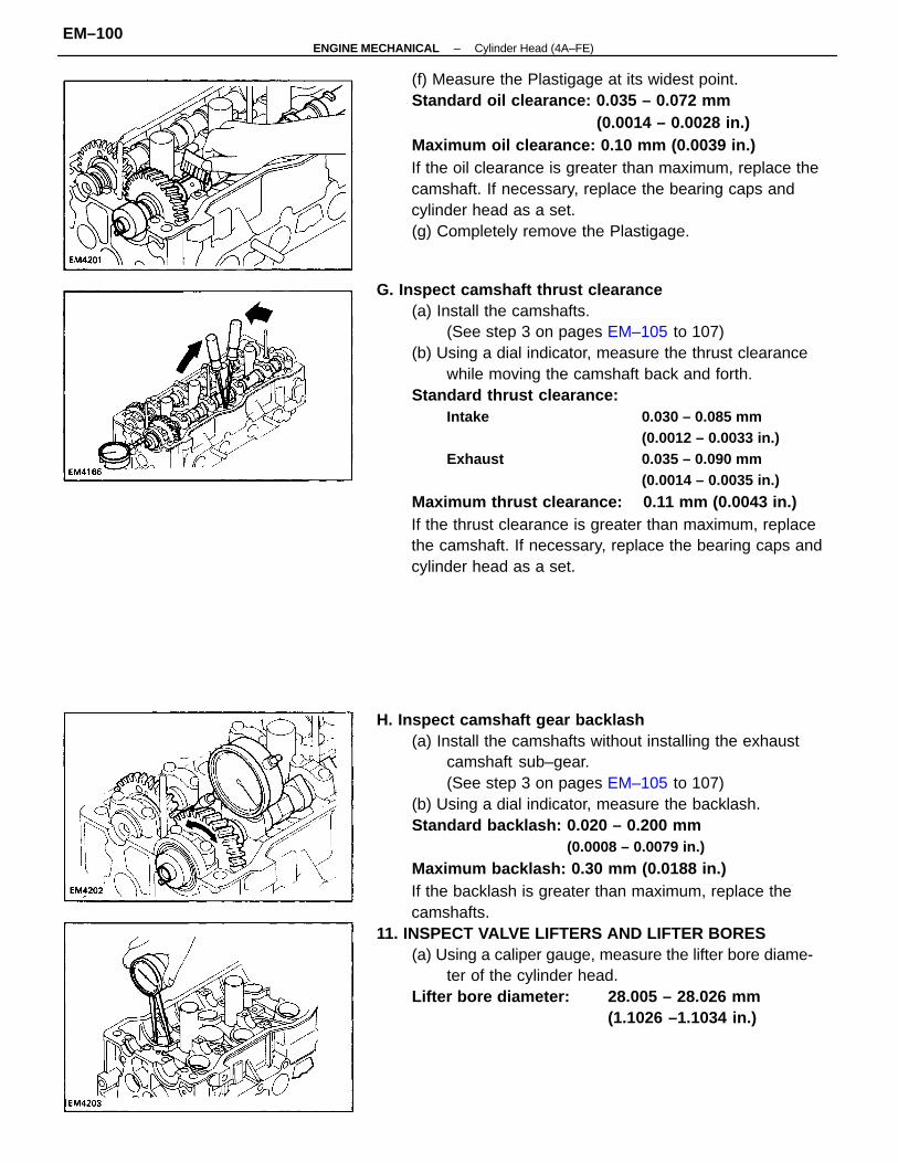
H. Inspect camshaft gear backlash(a) Install the camshafts without installing the exhaust
camshaft sub–gear.(See step 3 on pages EM–105 to 107)
(b) Using a dial indicator, measure the backlash.Standard backlash: 0.020 – 0.200 mm
(0.0008 – 0.0079 in.)
Maximum backlash: 0.30 mm (0.0188 in.)If the backlash is greater than maximum, replace thecamshafts.
11. INSPECT VALVE LIFTERS AND LIFTER BORES(a) Using a caliper gauge, measure the lifter bore diame-
ter of the cylinder head.Lifter bore diameter: 28.005 – 28.026 mm
(1.1026 –1.1034 in.)
G. Inspect camshaft thrust clearance(a) Install the camshafts.
(See step 3 on pages EM–105 to 107)(b) Using a dial indicator, measure the thrust clearance
while moving the camshaft back and forth.Standard thrust clearance:
Intake 0.030 – 0.085 mm(0.0012 – 0.0033 in.)
Exhaust 0.035 – 0.090 mm(0.0014 – 0.0035 in.)
Maximum thrust clearance: 0.11 mm (0.0043 in.)If the thrust clearance is greater than maximum, replacethe camshaft. If necessary, replace the bearing caps andcylinder head as a set.
(f) Measure the Plastigage at its widest point.Standard oil clearance: 0.035 – 0.072 mm
(0.0014 – 0.0028 in.)Maximum oil clearance: 0.10 mm (0.0039 in.)If the oil clearance is greater than maximum, replace thecamshaft. If necessary, replace the bearing caps andcylinder head as a set.(g) Completely remove the Plastigage.
–ENGINE MECHANICAL Cylinder Head (4A–FE)EM–100
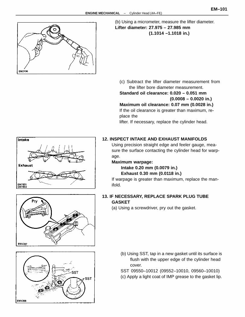
12. INSPECT INTAKE AND EXHAUST MANIFOLDSUsing precision straight edge and feeler gauge, mea-sure the surface contacting the cylinder head for warp-age.Maximum warpage:
Intake 0.20 mm (0.0079 in.)Exhaust 0.30 mm (0.0118 in.)
If warpage is greater than maximum, replace the man-ifold.
(c) Subtract the lifter diameter measurement fromthe lifter bore diameter measurement.
Standard oil clearance: 0.020 – 0.051 mm(0.0008 – 0.0020 in.)
Maximum oil clearance: 0.07 mm (0.0028 in.)If the oil clearance is greater than maximum, re-place thelifter. If necessary, replace the cylinder head.
(b) Using SST, tap in a new gasket until its surface isflush with the upper edge of the cylinder headcover.
SST 09550–10012 (09552–10010, 09560–10010)(c) Apply a light coat of IMP grease to the gasket lip.
(b) Using a micrometer, measure the lifter diameter.Lifter diameter: 27.975 – 27.985 mm
(1.1014 –1.1018 in.)
13. IF NECESSARY, REPLACE SPARK PLUG TUBEGASKET(a) Using a screwdriver, pry out the gasket.
–ENGINE MECHANICAL Cylinder Head (4A–FE)EM–101
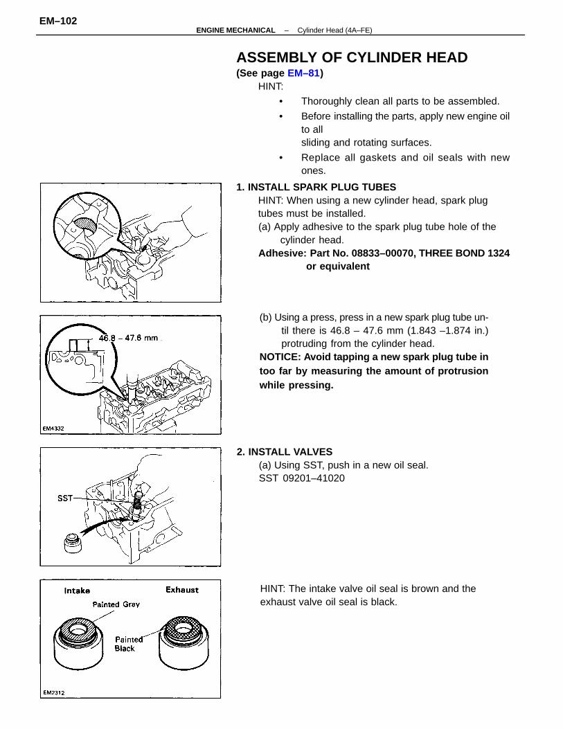
ASSEMBLY OF CYLINDER HEAD(See page EM–81)
HINT:
• Thoroughly clean all parts to be assembled.
• Before installing the parts, apply new engine oilto allsliding and rotating surfaces.
• Replace all gaskets and oil seals with newones.
1. INSTALL SPARK PLUG TUBESHINT: When using a new cylinder head, spark plugtubes must be installed.(a) Apply adhesive to the spark plug tube hole of the
cylinder head.Adhesive: Part No. 08833–00070, THREE BOND 1324
or equivalent
(b) Using a press, press in a new spark plug tube un-til there is 46.8 – 47.6 mm (1.843 –1.874 in.)protruding from the cylinder head.
NOTICE: Avoid tapping a new spark plug tube intoo far by measuring the amount of protrusionwhile pressing.
2. INSTALL VALVES(a) Using SST, push in a new oil seal.SST 09201–41020
HINT: The intake valve oil seal is brown and theexhaust valve oil seal is black.
–ENGINE MECHANICAL Cylinder Head (4A–FE)EM–102
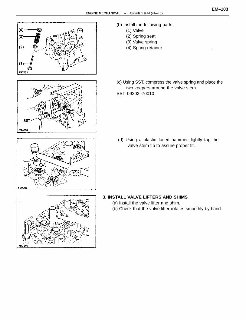
(c) Using SST, compress the valve spring and place thetwo keepers around the valve stem.
SST 09202–70010
3. INSTALL VALVE LIFTERS AND SHIMS(a) Install the valve lifter and shim.(b) Check that the valve lifter rotates smoothly by hand.
(b) Install the following parts:(1) Valve(2) Spring seat(3) Valve spring(4) Spring retainer
(d) Using a plastic–faced hammer, lightly tap thevalve stem tip to assure proper fit.
–ENGINE MECHANICAL Cylinder Head (4A–FE)EM–103
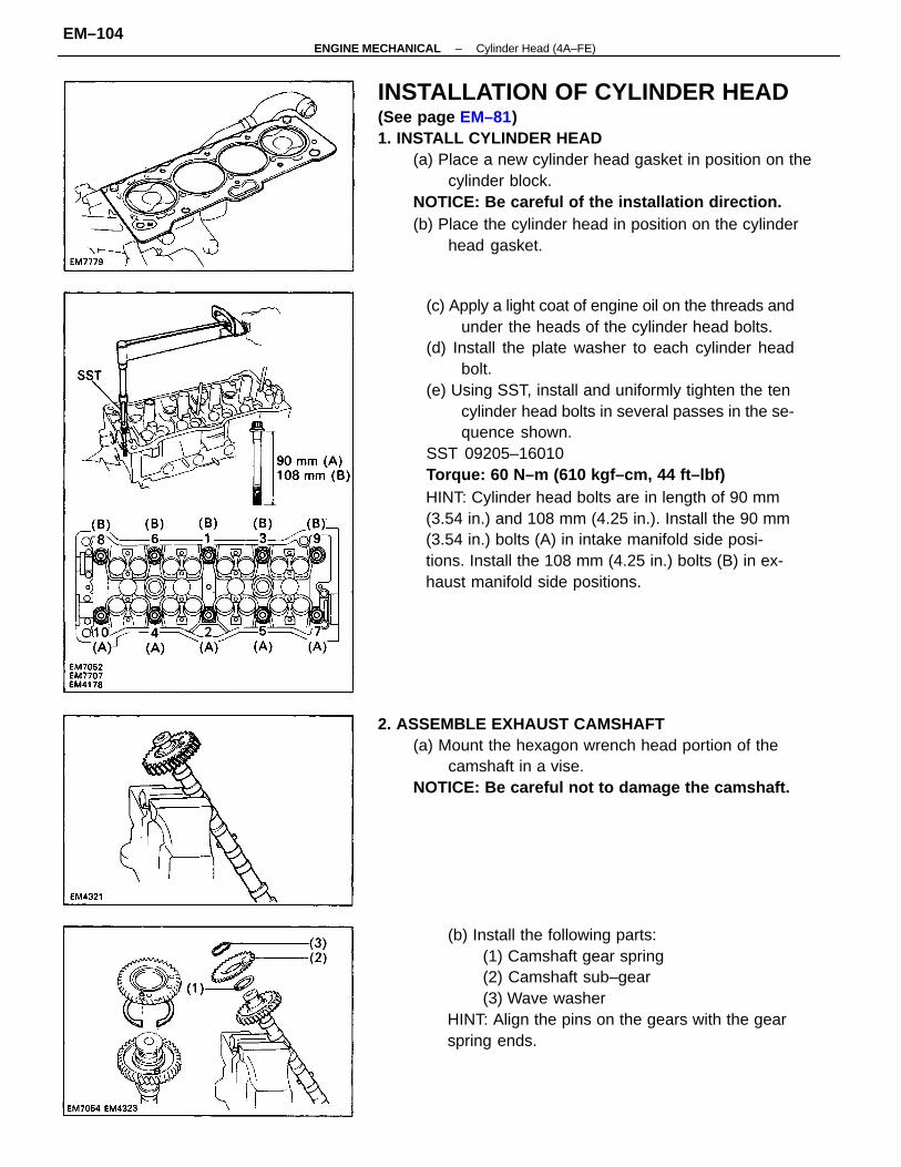
(c) Apply a light coat of engine oil on the threads andunder the heads of the cylinder head bolts.
(d) Install the plate washer to each cylinder headbolt.
(e) Using SST, install and uniformly tighten the tencylinder head bolts in several passes in the se-quence shown.
SST 09205–16010Torque: 60 N–m (610 kgf–cm, 44 ft–lbf)HINT: Cylinder head bolts are in length of 90 mm(3.54 in.) and 108 mm (4.25 in.). Install the 90 mm(3.54 in.) bolts (A) in intake manifold side posi-tions. Install the 108 mm (4.25 in.) bolts (B) in ex-haust manifold side positions.
INSTALLATION OF CYLINDER HEAD(See page EM–81)1. INSTALL CYLINDER HEAD
(a) Place a new cylinder head gasket in position on thecylinder block.
NOTICE: Be careful of the installation direction.(b) Place the cylinder head in position on the cylinder
head gasket.
(b) Install the following parts:(1) Camshaft gear spring(2) Camshaft sub–gear(3) Wave washer
HINT: Align the pins on the gears with the gearspring ends.
2. ASSEMBLE EXHAUST CAMSHAFT(a) Mount the hexagon wrench head portion of the
camshaft in a vise.NOTICE: Be careful not to damage the camshaft.
–ENGINE MECHANICAL Cylinder Head (4A–FE)EM–104
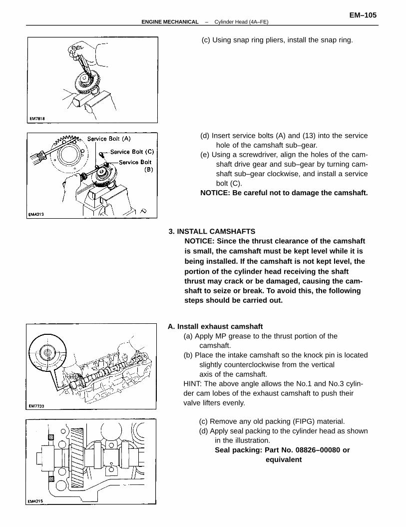
A. Install exhaust camshaft(a) Apply MP grease to the thrust portion of the
camshaft.(b) Place the intake camshaft so the knock pin is located
slightly counterclockwise from the verticalaxis of the camshaft.
HINT: The above angle allows the No.1 and No.3 cylin-der cam lobes of the exhaust camshaft to push theirvalve lifters evenly.
3. INSTALL CAMSHAFTSNOTICE: Since the thrust clearance of the camshaftis small, the camshaft must be kept level while it isbeing installed. If the camshaft is not kept level, theportion of the cylinder head receiving the shaftthrust may crack or be damaged, causing the cam-shaft to seize or break. To avoid this, the followingsteps should be carried out.
(d) Insert service bolts (A) and (13) into the servicehole of the camshaft sub–gear.
(e) Using a screwdriver, align the holes of the cam-shaft drive gear and sub–gear by turning cam-shaft sub–gear clockwise, and install a servicebolt (C).
NOTICE: Be careful not to damage the camshaft.
(c) Remove any old packing (FIPG) material.(d) Apply seal packing to the cylinder head as shown
in the illustration.Seal packing: Part No. 08826–00080 or
equivalent
(c) Using snap ring pliers, install the snap ring.
–ENGINE MECHANICAL Cylinder Head (4A–FE)EM–105
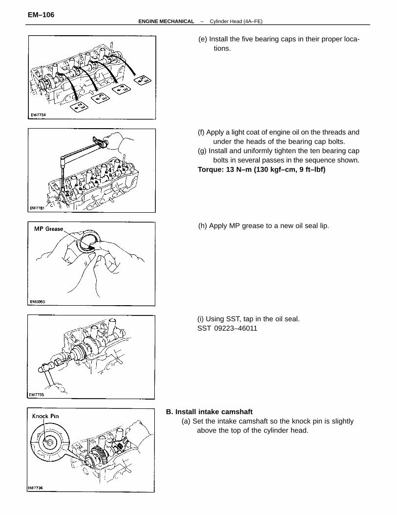
(f) Apply a light coat of engine oil on the threads andunder the heads of the bearing cap bolts.
(g) Install and uniformly tighten the ten bearing capbolts in several passes in the sequence shown.
Torque: 13 N–m (130 kgf–cm, 9 ft–lbf)
B. Install intake camshaft(a) Set the intake camshaft so the knock pin is slightly
above the top of the cylinder head.
(i) Using SST, tap in the oil seal.SST 09223–46011
(e) Install the five bearing caps in their proper loca-tions.
(h) Apply MP grease to a new oil seal lip.
–ENGINE MECHANICAL Cylinder Head (4A–FE)EM–106
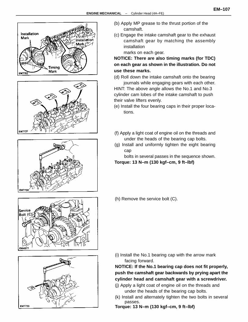
(b) Apply MP grease to the thrust portion of thecamshaft.
(c) Engage the intake camshaft gear to the exhaustcamshaft gear by matching the assemblyinstallationmarks on each gear.
NOTICE: There are also timing marks (for TDC)on each gear as shown in the illustration. Do notuse these marks.(d) Roll down the intake camshaft onto the bearing
journals while engaging gears with each other.HINT: The above angle allows the No.1 and No.3cylinder cam lobes of the intake camshaft to pushtheir valve lifters evenly.(e) Install the four bearing caps in their proper loca-
tions.
(i) Install the No.1 bearing cap with the arrow markfacing forward.
NOTICE: If the No.1 bearing cap does not fit properly,push the camshaft gear backwards by prying apart thecylinder head and camshaft gear with a screwdriver.(j) Apply a light coat of engine oil on the threads and
under the heads of the bearing cap bolts.(k) Install and alternately tighten the two bolts in several
passes.Torque: 13 N–m (130 kgf–cm, 9 ft–lbf)
(f) Apply a light coat of engine oil on the threads andunder the heads of the bearing cap bolts.
(g) Install and uniformly tighten the eight bearingcapbolts in several passes in the sequence shown.
Torque: 13 N–m (130 kgf–cm, 9 ft–lbf)
(h) Remove the service bolt (C).
–ENGINE MECHANICAL Cylinder Head (4A–FE)EM–107
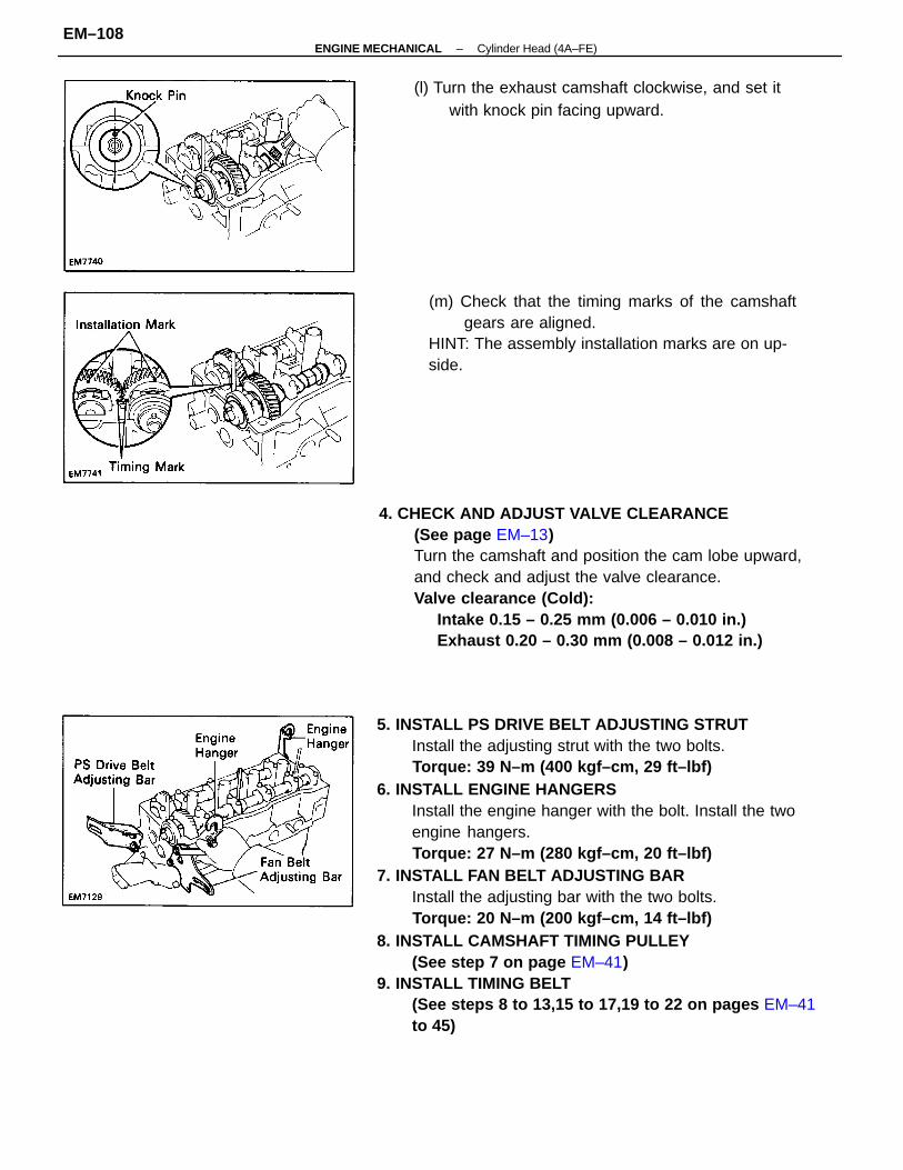
5. INSTALL PS DRIVE BELT ADJUSTING STRUTInstall the adjusting strut with the two bolts.Torque: 39 N–m (400 kgf–cm, 29 ft–lbf)
6. INSTALL ENGINE HANGERSInstall the engine hanger with the bolt. Install the twoengine hangers.Torque: 27 N–m (280 kgf–cm, 20 ft–lbf)
7. INSTALL FAN BELT ADJUSTING BARInstall the adjusting bar with the two bolts.Torque: 20 N–m (200 kgf–cm, 14 ft–lbf)
8. INSTALL CAMSHAFT TIMING PULLEY(See step 7 on page EM–41)
9. INSTALL TIMING BELT(See steps 8 to 13,15 to 17,19 to 22 on pages EM–41to 45)
4. CHECK AND ADJUST VALVE CLEARANCE(See page EM–13)Turn the camshaft and position the cam lobe upward,and check and adjust the valve clearance.Valve clearance (Cold):
Intake 0.15 – 0.25 mm (0.006 – 0.010 in.)Exhaust 0.20 – 0.30 mm (0.008 – 0.012 in.)
(m) Check that the timing marks of the camshaftgears are aligned.
HINT: The assembly installation marks are on up-side.
(l) Turn the exhaust camshaft clockwise, and set itwith knock pin facing upward.
–ENGINE MECHANICAL Cylinder Head (4A–FE)EM–108
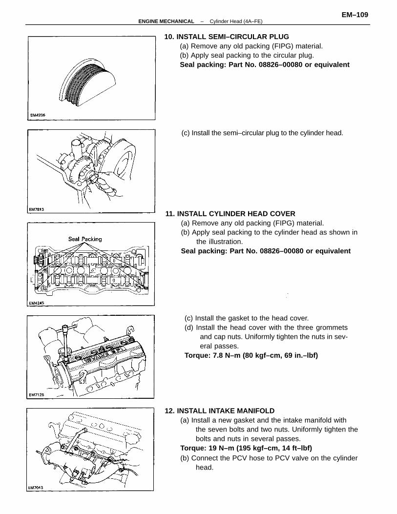
11. INSTALL CYLINDER HEAD COVER(a) Remove any old packing (FIPG) material.(b) Apply seal packing to the cylinder head as shown in
the illustration.Seal packing: Part No. 08826–00080 or equivalent
12. INSTALL INTAKE MANIFOLD(a) Install a new gasket and the intake manifold with
the seven bolts and two nuts. Uniformly tighten thebolts and nuts in several passes.
Torque: 19 N–m (195 kgf–cm, 14 ft–lbf)(b) Connect the PCV hose to PCV valve on the cylinder
head.
(c) Install the gasket to the head cover.(d) Install the head cover with the three grommets
and cap nuts. Uniformly tighten the nuts in sev-eral passes.
Torque: 7.8 N–m (80 kgf–cm, 69 in.–lbf)
10. INSTALL SEMI–CIRCULAR PLUG(a) Remove any old packing (FIPG) material.(b) Apply seal packing to the circular plug.Seal packing: Part No. 08826–00080 or equivalent
(c) Install the semi–circular plug to the cylinder head.
–ENGINE MECHANICAL Cylinder Head (4A–FE)EM–109
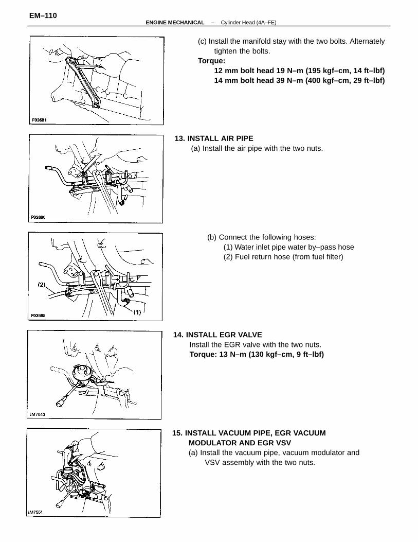
(c) Install the manifold stay with the two bolts. Alternatelytighten the bolts.
Torque:12 mm bolt head 19 N–m (195 kgf–cm, 14 ft–lbf)14 mm bolt head 39 N–m (400 kgf–cm, 29 ft–lbf)
15. INSTALL VACUUM PIPE, EGR VACUUMMODULATOR AND EGR VSV(a) Install the vacuum pipe, vacuum modulator and
VSV assembly with the two nuts.
14. INSTALL EGR VALVEInstall the EGR valve with the two nuts.Torque: 13 N–m (130 kgf–cm, 9 ft–lbf)
(b) Connect the following hoses:(1) Water inlet pipe water by–pass hose(2) Fuel return hose (from fuel filter)
13. INSTALL AIR PIPE(a) Install the air pipe with the two nuts.
–ENGINE MECHANICAL Cylinder Head (4A–FE)EM–110
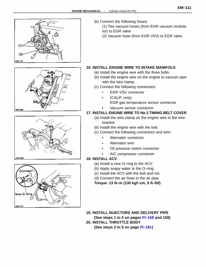
16. INSTALL ENGINE WIRE TO INTAKE MANIFOLD(a) Install the engine wire with the three bolts.(b) Install the engine wire on the engine to vacuum pipe
with the wire clamp.(c) Connect the following connectors:
• EGR VSV connector
• (CALIF. only)EGR gas temperature sensor connector
• Vacuum sensor connector17. INSTALL ENGINE WIRE TO No.3 TIMING BELT COVER
(a) Install the wire clamp on the engine wire to the wirebracket.
(b) Install the engine wire with the bolt.(c) Connect the following connectors and wire:
• Alternator connector.
• Alternator wire
• Oil pressure switch connector
• A/C compressor connector18. INSTALL ACV
(a) Install a new O–ring to the ACV.(b) Apply soapy water to the O–ring.(c) Install the ACV with the bolt and nut.(d) Connect the air hose to the air pipe.Torque: 13 N–m (130 kgf–cm, 9 ft–lbf)
19. INSTALL INJECTORS AND DELIVERY PIPE(See steps 1 to 5 on pages FI–158 and 159)
20. INSTALL THROTTLE BODY(See steps 2 to 5 on page FI–191)
(b) Connect the following hoses:(1) Two vacuum hoses (from EGR vacuum modula-tor) to EGR valve(2) Vacuum hose (from EGR VSV) to EGR valve
–ENGINE MECHANICAL Cylinder Head (4A–FE)EM–111
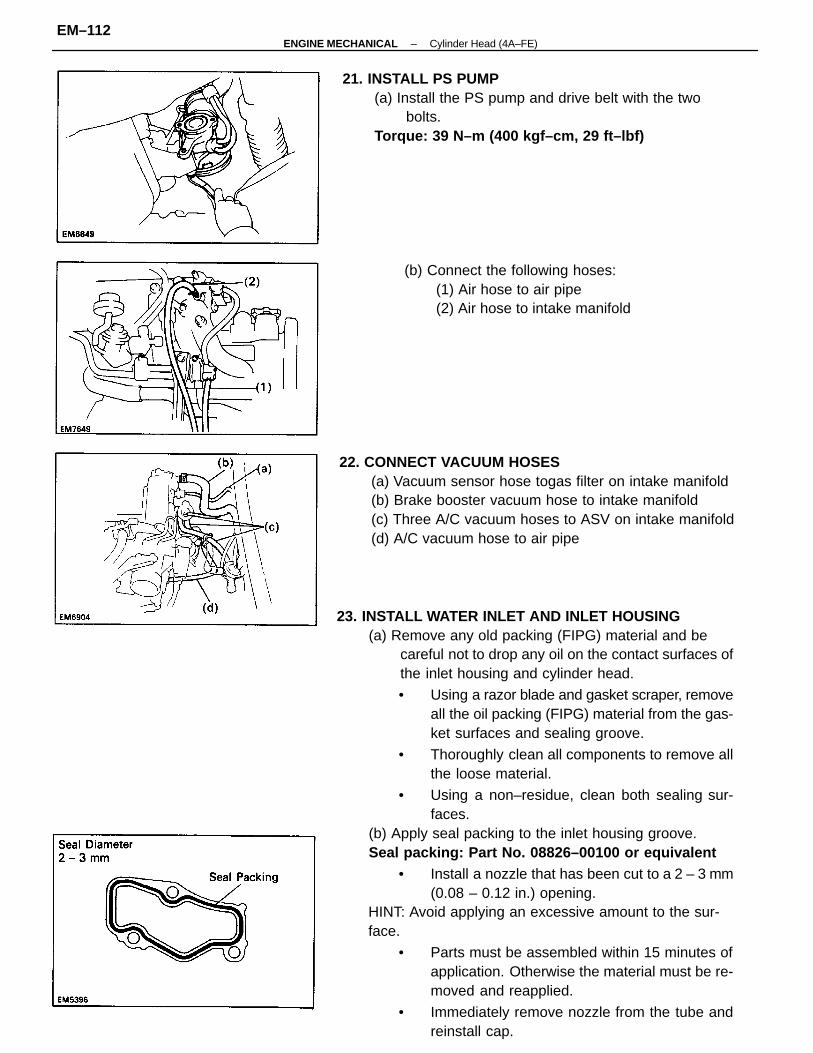
23. INSTALL WATER INLET AND INLET HOUSING(a) Remove any old packing (FIPG) material and be
careful not to drop any oil on the contact surfaces ofthe inlet housing and cylinder head.
• Using a razor blade and gasket scraper, removeall the oil packing (FIPG) material from the gas-ket surfaces and sealing groove.
• Thoroughly clean all components to remove allthe loose material.
• Using a non–residue, clean both sealing sur-faces.
(b) Apply seal packing to the inlet housing groove.Seal packing: Part No. 08826–00100 or equivalent
• Install a nozzle that has been cut to a 2 – 3 mm(0.08 – 0.12 in.) opening.
HINT: Avoid applying an excessive amount to the sur-face.
• Parts must be assembled within 15 minutes ofapplication. Otherwise the material must be re-moved and reapplied.
• Immediately remove nozzle from the tube andreinstall cap.
22. CONNECT VACUUM HOSES(a) Vacuum sensor hose togas filter on intake manifold(b) Brake booster vacuum hose to intake manifold(c) Three A/C vacuum hoses to ASV on intake manifold(d) A/C vacuum hose to air pipe
21. INSTALL PS PUMP(a) Install the PS pump and drive belt with the two
bolts.Torque: 39 N–m (400 kgf–cm, 29 ft–lbf)
(b) Connect the following hoses:(1) Air hose to air pipe(2) Air hose to intake manifold
–ENGINE MECHANICAL Cylinder Head (4A–FE)EM–112
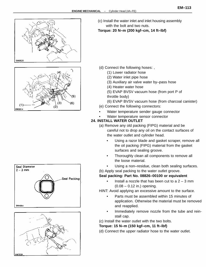
(d) Connect the following hoses: ,(1) Lower radiator hose(2) Water inlet pipe hose(3) Auxiliary air valve water by–pass hose(4) Heater water hose(5) EVAP BVSV vacuum hose (from port P ofthrottle body)(6) EVAP BVSV vacuum hose (from charcoal canister)
(e) Connect the following connectors:
• Water temperature sender gauge connector• Water temperature sensor connector
24. INSTALL WATER OUTLET(a) Remove any old packing (FIPG) material and be
careful not to drop any oil on the contact surfaces ofthe water outlet and cylinder head.
• Using a razor blade and gasket scraper, remove allthe oil packing (FIPG) material from the gasketsurfaces and sealing groove.
• Thoroughly clean all components to remove allthe loose material.
• Using a non–residue, clean both sealing surfaces.(b) Apply seal packing to the water outlet groove.Seal packing: Part No. 08826–00100 or equivalent
• Install a nozzle that has been cut to a 2 – 3 mm(0.08 – 0.12 in.) opening.
HINT: Avoid applying an excessive amount to the surface.
• Parts must be assembled within 15 minutes ofapplication. Otherwise the material must be removedand reapplied.
• Immediately remove nozzle from the tube and rein-stall cap.
(c) Install the water outlet with the two bolts.Torque: 15 N–m (150 kgf–cm, 11 ft–lbf)(d) Connect the upper radiator hose to the water outlet.
(c) Install the water inlet and inlet housing assemblywith the bolt and two nuts.
Torque: 20 N–m (200 kgf–cm, 14 ft–lbf)
–ENGINE MECHANICAL Cylinder Head (4A–FE)EM–113
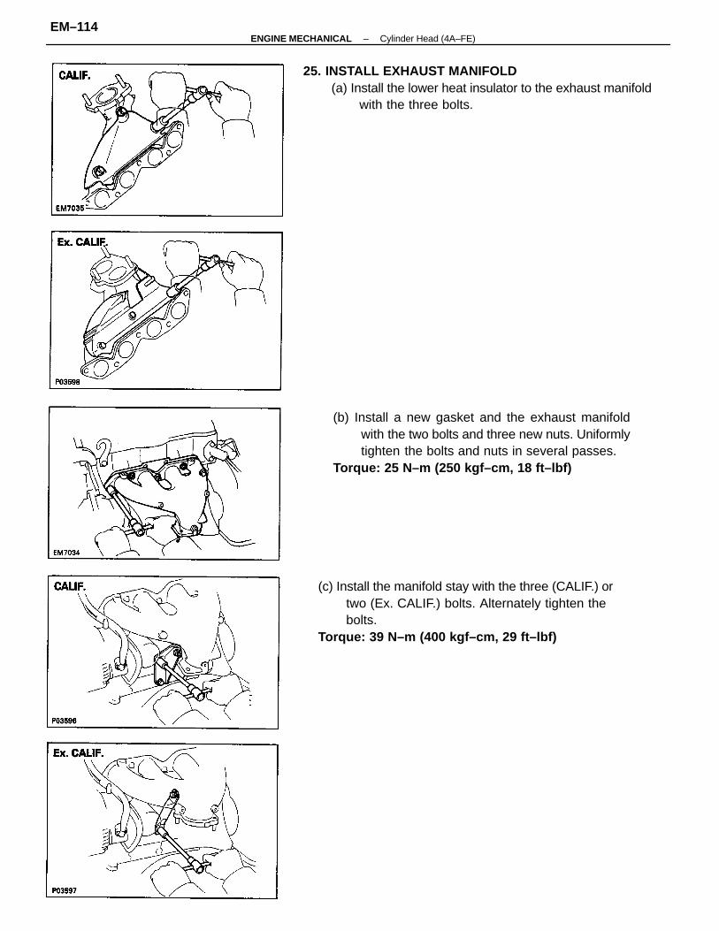
(c) Install the manifold stay with the three (CALIF.) ortwo (Ex. CALIF.) bolts. Alternately tighten thebolts.
Torque: 39 N–m (400 kgf–cm, 29 ft–lbf)
(b) Install a new gasket and the exhaust manifoldwith the two bolts and three new nuts. Uniformlytighten the bolts and nuts in several passes.
Torque: 25 N–m (250 kgf–cm, 18 ft–lbf)
25. INSTALL EXHAUST MANIFOLD(a) Install the lower heat insulator to the exhaust manifold
with the three bolts.
–ENGINE MECHANICAL Cylinder Head (4A–FE)EM–114
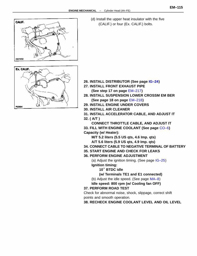
26. INSTALL DISTRIBUTOR (See page IG–24)27. INSTALL FRONT EXHAUST PIPE
(See step 17 on page EM–217)28. INSTALL SUSPENSION LOWER CROSSM EM BER
(See page 18 on page EM–218)29. INSTALL ENGINE UNDER COVERS30. INSTALL AIR CLEANER31. INSTALL ACCELERATOR CABLE, AND ADJUST IT32. ( A/T )
CONNECT THROTTLE CABLE, AND ADJUST IT33. FILL WITH ENGINE COOLANT (See page CO–6)Capacity (w/ Heater):
M/T 5.2 liters (5.5 US qts, 4.6 Imp. qts)A/T 5.6 liters (5.9 US qts, 4.9 Imp. qts)
34. CONNECT CABLE TO NEGATIVE TERMINAL OF BA TTERY35. START ENGINE AND CHECK FOR LEAKS36. PERFORM ENGINE ADJUSTMENT
(a) Adjust the ignition timing. (See page IG–25)Ignition timing:
10° BTDC idle(w/ Terminals TE1 and E1 connected)
(b) Adjust the idle speed. (See page MA–8)Idle speed: 800 rpm (w/ Cooling fan OFF)
37. PERFORM ROAD TESTCheck for abnormal noise, shock, slippage, correct shiftpoints and smooth operation.38. RECHECK ENGINE COOLANT LEVEL AND OIL LEVEL
(d) Install the upper heat insulator with the five(CALIF.) or four (Ex. CALIF.) bolts.
–ENGINE MECHANICAL Cylinder Head (4A–FE)EM–115
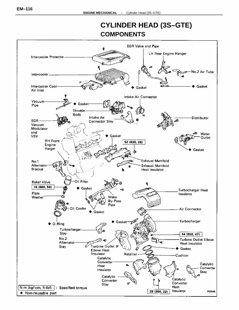
CYLINDER HEAD (3S–GTE)COMPONENTS
–ENGINE MECHANICAL Cylinder Head (3S–GTE)EM–116
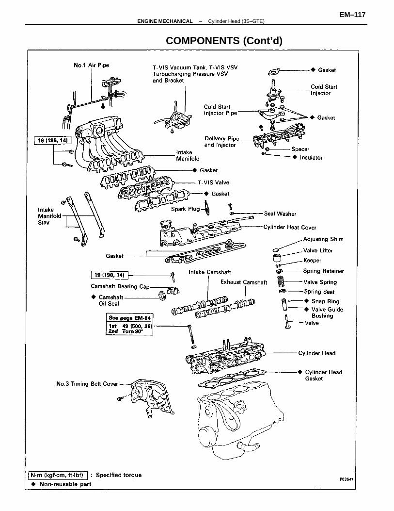
COMPONENTS (Cont’d)
–ENGINE MECHANICAL Cylinder Head (3S–GTE)EM–117
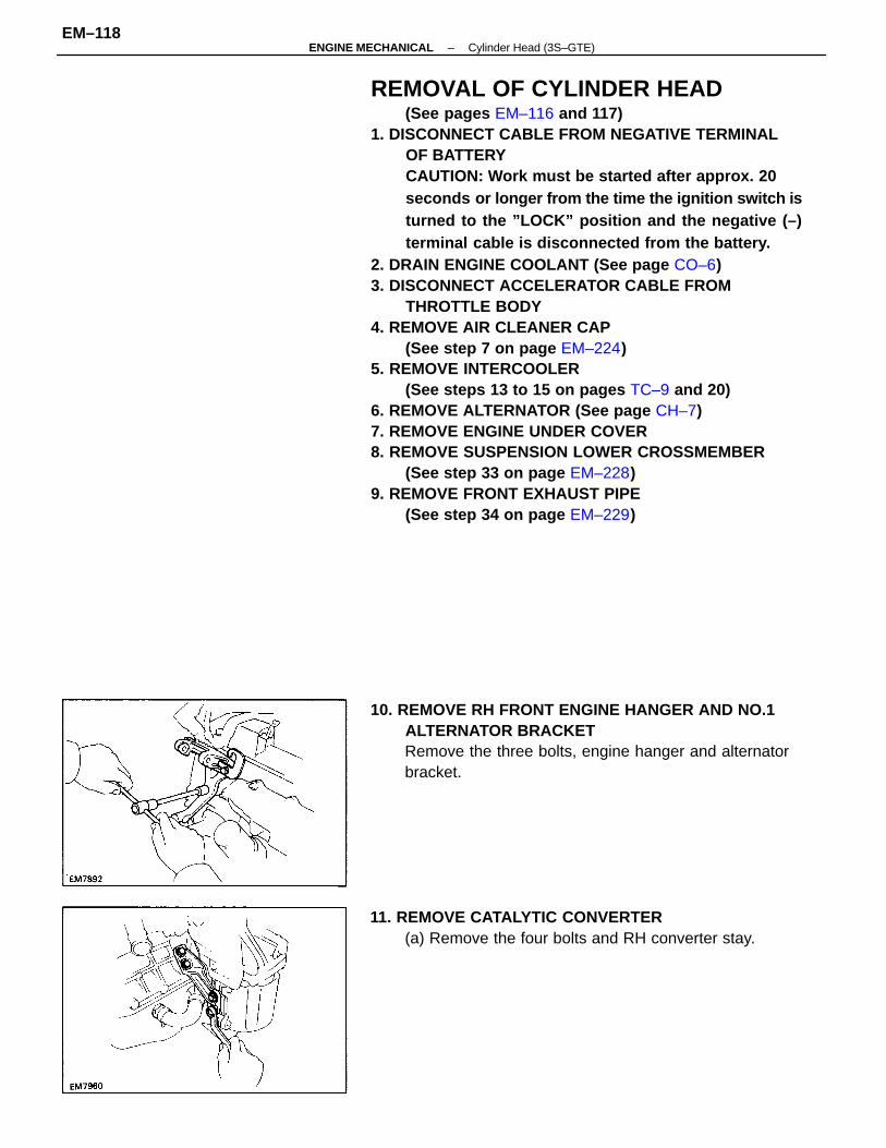
REMOVAL OF CYLINDER HEAD(See pages EM–116 and 117)
1. DISCONNECT CABLE FROM NEGATIVE TERMINALOF BATTERYCAUTION: Work must be started after approx. 20seconds or longer from the time the ignition switch isturned to the ”LOCK” position and the negative (–)terminal cable is disconnected from the battery.
2. DRAIN ENGINE COOLANT (See page CO–6)3. DISCONNECT ACCELERATOR CABLE FROM
THROTTLE BODY4. REMOVE AIR CLEANER CAP
(See step 7 on page EM–224)5. REMOVE INTERCOOLER
(See steps 13 to 15 on pages TC–9 and 20)6. REMOVE ALTERNATOR (See page CH–7)7. REMOVE ENGINE UNDER COVER8. REMOVE SUSPENSION LOWER CROSSMEMBER
(See step 33 on page EM–228)9. REMOVE FRONT EXHAUST PIPE
(See step 34 on page EM–229)
10. REMOVE RH FRONT ENGINE HANGER AND NO.1ALTERNATOR BRACKETRemove the three bolts, engine hanger and alternatorbracket.
11. REMOVE CATALYTIC CONVERTER(a) Remove the four bolts and RH converter stay.
–ENGINE MECHANICAL Cylinder Head (3S–GTE)EM–118
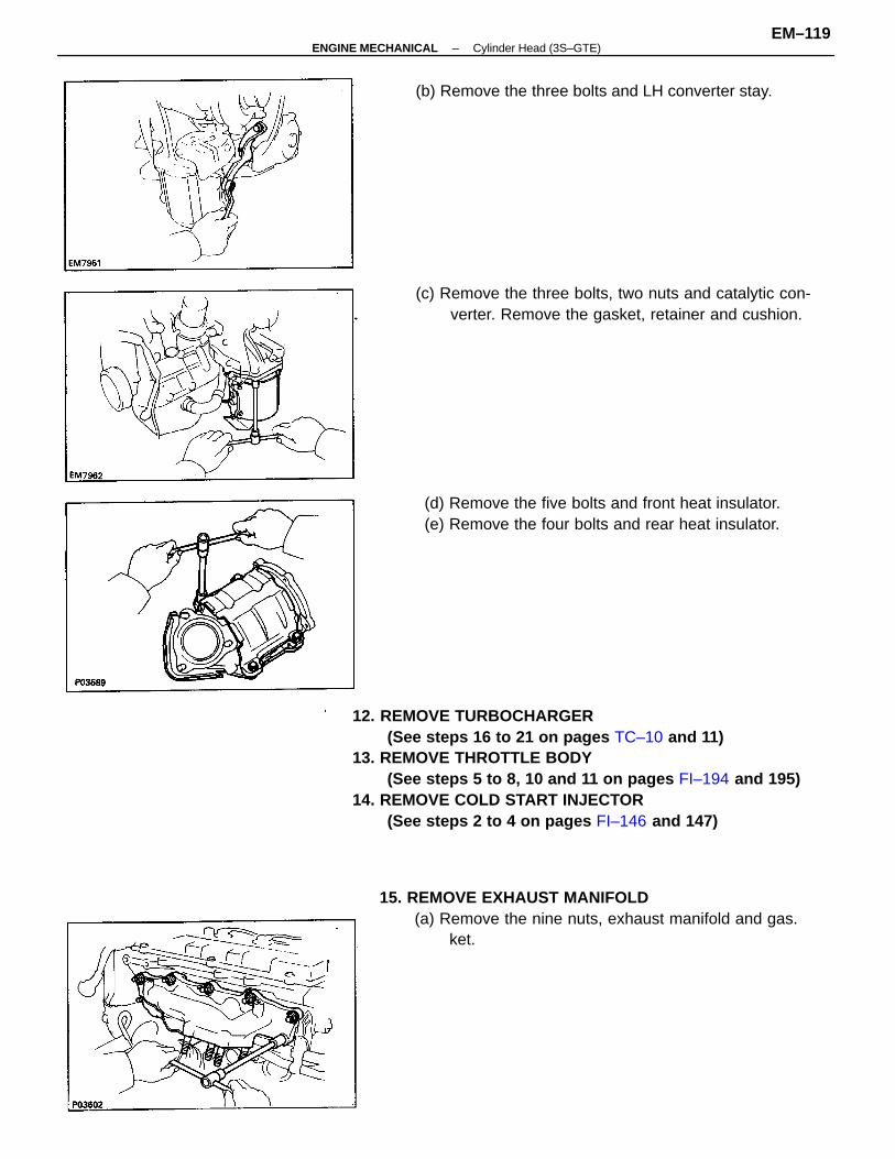
12. REMOVE TURBOCHARGER(See steps 16 to 21 on pages TC–10 and 11)
13. REMOVE THROTTLE BODY(See steps 5 to 8, 10 and 11 on pages FI–194 and 195)
14. REMOVE COLD START INJECTOR(See steps 2 to 4 on pages FI–146 and 147)
15. REMOVE EXHAUST MANIFOLD(a) Remove the nine nuts, exhaust manifold and gas.
ket.
(c) Remove the three bolts, two nuts and catalytic con-verter. Remove the gasket, retainer and cushion.
(d) Remove the five bolts and front heat insulator.(e) Remove the four bolts and rear heat insulator.
(b) Remove the three bolts and LH converter stay.
–ENGINE MECHANICAL Cylinder Head (3S–GTE)EM–119
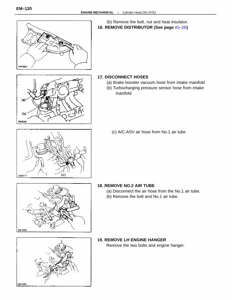
17. DISCONNECT HOSES(a) Brake booster vacuum hose from intake manifold(b) Turbocharging pressure sensor hose from intake
manifold
18. REMOVE NO.2 AIR TUBE(a) Disconnect the air hose from the No.1 air tube.(b) Remove the bolt and No.1 air tube.
(b) Remove the bolt, nut and heat insulator.16. REMOVE DISTRIBUTOR (See page IG–26)
19. REMOVE LH ENGINE HANGERRemove the two bolts and engine hanger.
(c) A/C ASV air hose from No.1 air tube
–ENGINE MECHANICAL Cylinder Head (3S–GTE)EM–120
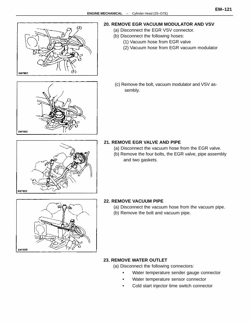
20. REMOVE EGR VACUUM MODULATOR AND VSV(a) Disconnect the EGR VSV connector.(b) Disconnect the following hoses:
(1) Vacuum hose from EGR valve(2) Vacuum hose from EGR vacuum modulator
23. REMOVE WATER OUTLET(a) Disconnect the following connectors:
• Water temperature sender gauge connector
• Water temperature sensor connector
• Cold start injector time switch connector
21. REMOVE EGR VALVE AND PIPE(a) Disconnect the vacuum hose from the EGR valve.(b) Remove the four bolts, the EGR valve, pipe assembly
and two gaskets.
22. REMOVE VACUUM PIPE(a) Disconnect the vacuum hose from the vacuum pipe.(b) Remove the bolt and vacuum pipe.
(c) Remove the bolt, vacuum modulator and VSV as-sembly.
–ENGINE MECHANICAL Cylinder Head (3S–GTE)EM–121
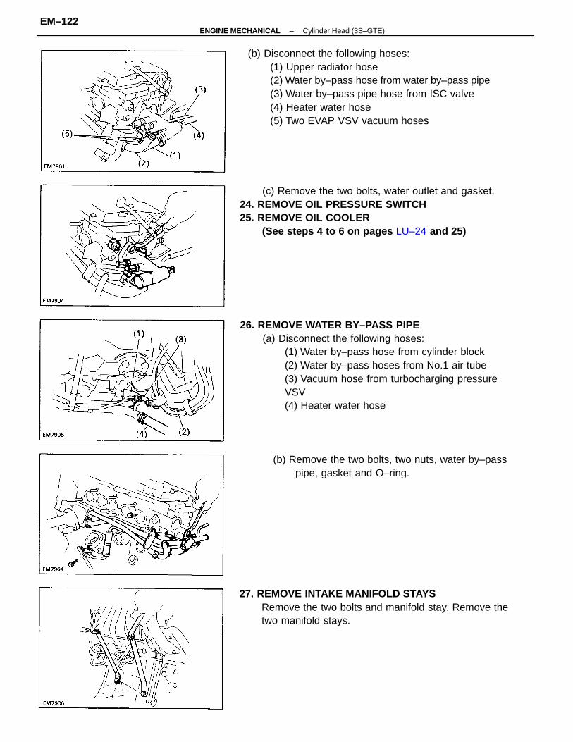
26. REMOVE WATER BY–PASS PIPE(a) Disconnect the following hoses:
(1) Water by–pass hose from cylinder block(2) Water by–pass hoses from No.1 air tube(3) Vacuum hose from turbocharging pressureVSV(4) Heater water hose
(b) Disconnect the following hoses:(1) Upper radiator hose(2) Water by–pass hose from water by–pass pipe(3) Water by–pass pipe hose from ISC valve(4) Heater water hose(5) Two EVAP VSV vacuum hoses
(c) Remove the two bolts, water outlet and gasket.24. REMOVE OIL PRESSURE SWITCH25. REMOVE OIL COOLER
(See steps 4 to 6 on pages LU–24 and 25)
27. REMOVE INTAKE MANIFOLD STAYSRemove the two bolts and manifold stay. Remove thetwo manifold stays.
(b) Remove the two bolts, two nuts, water by–passpipe, gasket and O–ring.
–ENGINE MECHANICAL Cylinder Head (3S–GTE)EM–122
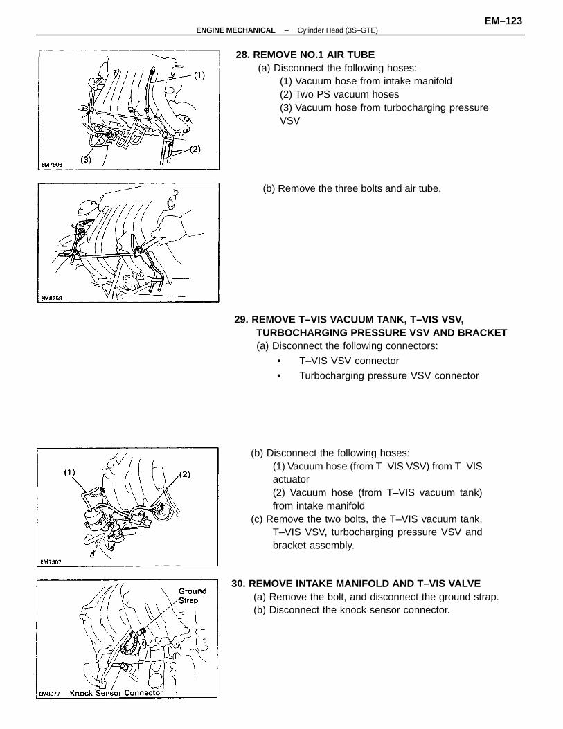
(b) Disconnect the following hoses:(1) Vacuum hose (from T–VIS VSV) from T–VISactuator(2) Vacuum hose (from T–VIS vacuum tank)from intake manifold
(c) Remove the two bolts, the T–VIS vacuum tank,T–VIS VSV, turbocharging pressure VSV andbracket assembly.
28. REMOVE NO.1 AIR TUBE(a) Disconnect the following hoses:
(1) Vacuum hose from intake manifold(2) Two PS vacuum hoses(3) Vacuum hose from turbocharging pressureVSV
29. REMOVE T–VIS VACUUM TANK, T–VIS VSV,TURBOCHARGING PRESSURE VSV AND BRACKET(a) Disconnect the following connectors:
• T–VIS VSV connector
• Turbocharging pressure VSV connector
30. REMOVE INTAKE MANIFOLD AND T–VIS VALVE(a) Remove the bolt, and disconnect the ground strap.(b) Disconnect the knock sensor connector.
(b) Remove the three bolts and air tube.
–ENGINE MECHANICAL Cylinder Head (3S–GTE)EM–123
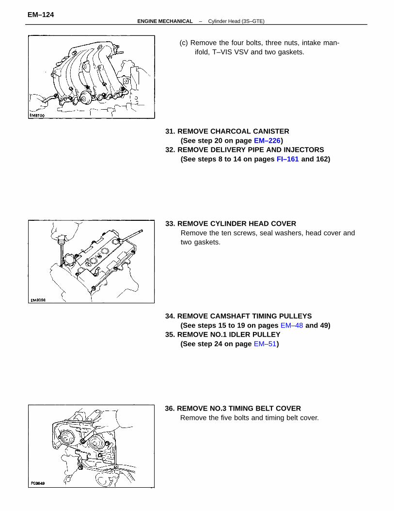
31. REMOVE CHARCOAL CANISTER(See step 20 on page EM–226)
32. REMOVE DELIVERY PIPE AND INJECTORS(See steps 8 to 14 on pages FI–161 and 162)
34. REMOVE CAMSHAFT TIMING PULLEYS(See steps 15 to 19 on pages EM–48 and 49)
35. REMOVE NO.1 IDLER PULLEY(See step 24 on page EM–51)
33. REMOVE CYLINDER HEAD COVERRemove the ten screws, seal washers, head cover andtwo gaskets.
(c) Remove the four bolts, three nuts, intake man-ifold, T–VIS VSV and two gaskets.
36. REMOVE NO.3 TIMING BELT COVERRemove the five bolts and timing belt cover.
–ENGINE MECHANICAL Cylinder Head (3S–GTE)EM–124
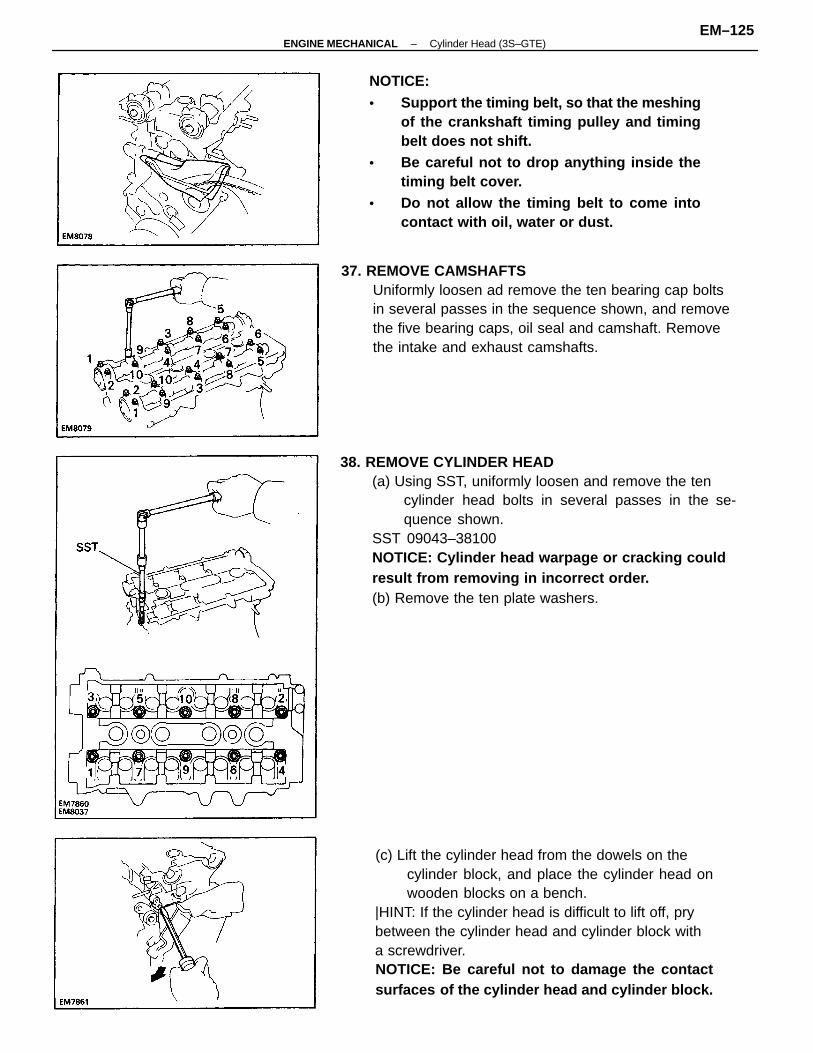
38. REMOVE CYLINDER HEAD(a) Using SST, uniformly loosen and remove the ten
cylinder head bolts in several passes in the se-quence shown.
SST 09043–38100NOTICE: Cylinder head warpage or cracking couldresult from removing in incorrect order.(b) Remove the ten plate washers.
(c) Lift the cylinder head from the dowels on thecylinder block, and place the cylinder head onwooden blocks on a bench.
|HINT: If the cylinder head is difficult to lift off, prybetween the cylinder head and cylinder block witha screwdriver.NOTICE: Be careful not to damage the contactsurfaces of the cylinder head and cylinder block.
NOTICE:• Support the timing belt, so that the meshing
of the crankshaft timing pulley and timingbelt does not shift.
• Be careful not to drop anything inside thetiming belt cover.
• Do not allow the timing belt to come intocontact with oil, water or dust.
37. REMOVE CAMSHAFTSUniformly loosen ad remove the ten bearing cap boltsin several passes in the sequence shown, and removethe five bearing caps, oil seal and camshaft. Removethe intake and exhaust camshafts.
–ENGINE MECHANICAL Cylinder Head (3S–GTE)EM–125
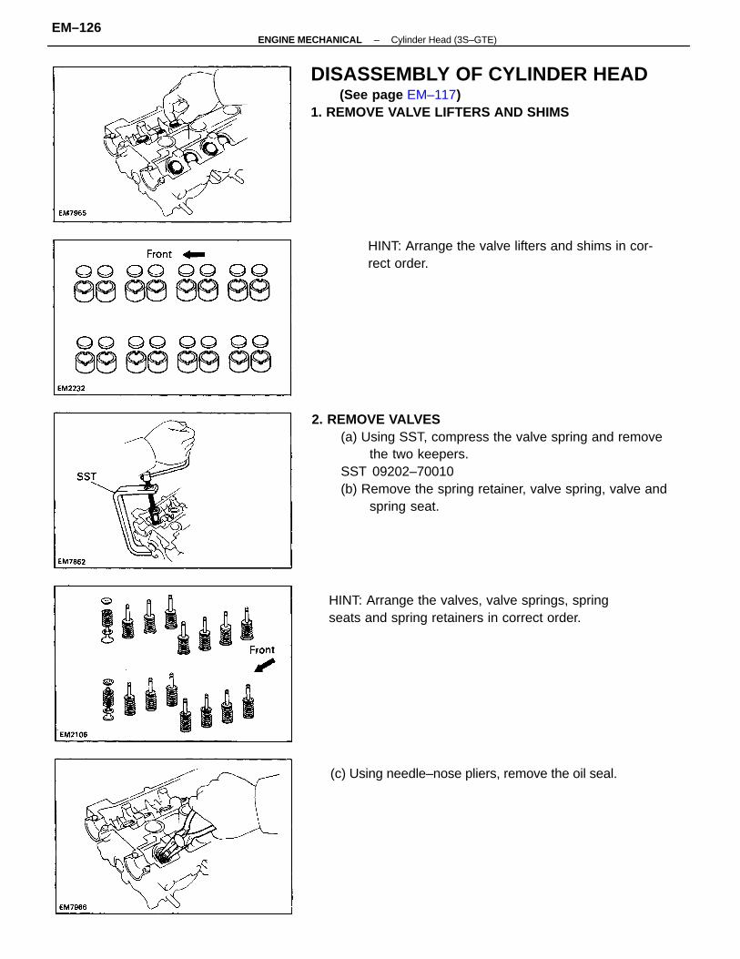
2. REMOVE VALVES(a) Using SST, compress the valve spring and remove
the two keepers.SST 09202–70010(b) Remove the spring retainer, valve spring, valve and
spring seat.
DISASSEMBLY OF CYLINDER HEAD(See page EM–117)
1. REMOVE VALVE LIFTERS AND SHIMS
HINT: Arrange the valves, valve springs, springseats and spring retainers in correct order.
HINT: Arrange the valve lifters and shims in cor-rect order.
(c) Using needle–nose pliers, remove the oil seal.
–ENGINE MECHANICAL Cylinder Head (3S–GTE)EM–126
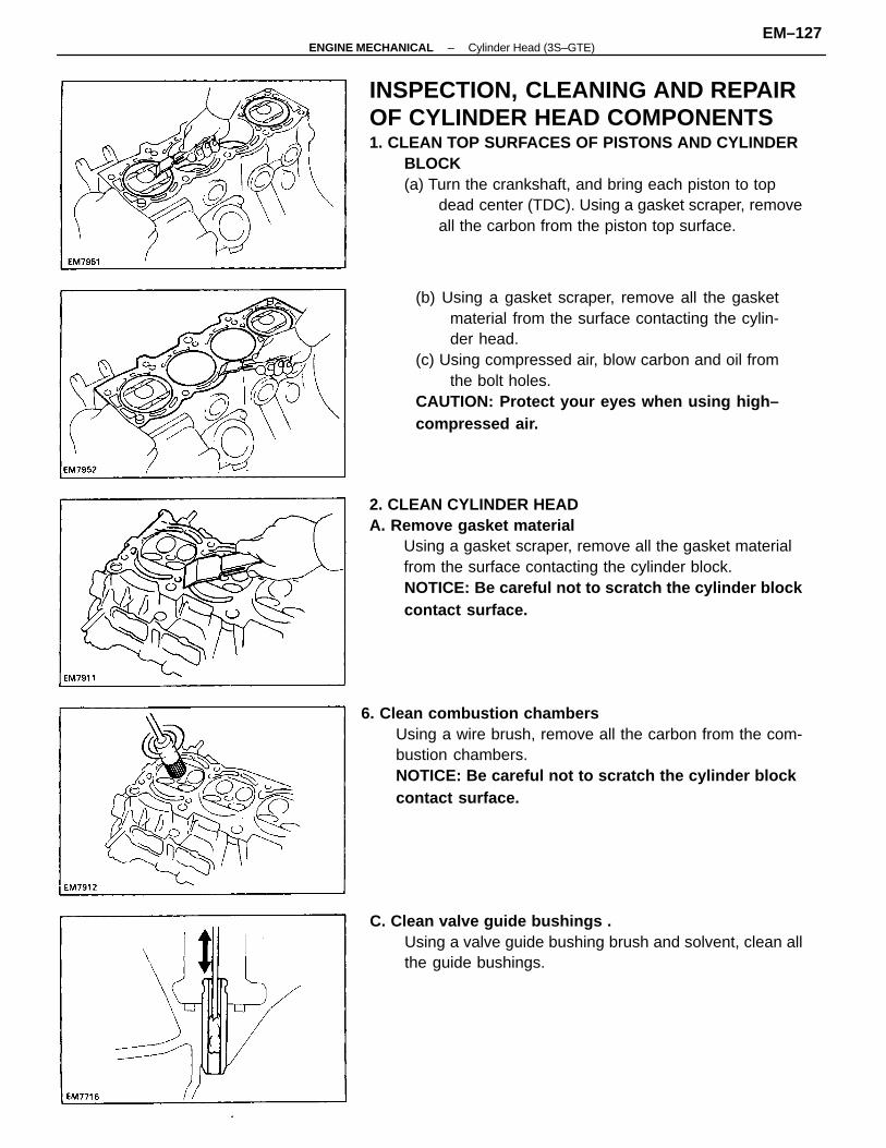
INSPECTION, CLEANING AND REPAIROF CYLINDER HEAD COMPONENTS1. CLEAN TOP SURFACES OF PISTONS AND CYLINDER
BLOCK(a) Turn the crankshaft, and bring each piston to top
dead center (TDC). Using a gasket scraper, removeall the carbon from the piston top surface.
2. CLEAN CYLINDER HEADA. Remove gasket material
Using a gasket scraper, remove all the gasket materialfrom the surface contacting the cylinder block.NOTICE: Be careful not to scratch the cylinder blockcontact surface.
(b) Using a gasket scraper, remove all the gasketmaterial from the surface contacting the cylin-der head.
(c) Using compressed air, blow carbon and oil fromthe bolt holes.
CAUTION: Protect your eyes when using high–compressed air.
6. Clean combustion chambersUsing a wire brush, remove all the carbon from the com-bustion chambers.NOTICE: Be careful not to scratch the cylinder blockcontact surface.
C. Clean valve guide bushings .Using a valve guide bushing brush and solvent, clean allthe guide bushings.
–ENGINE MECHANICAL Cylinder Head (3S–GTE)EM–127
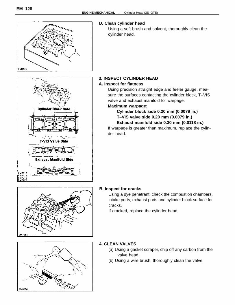
3. INSPECT CYLINDER HEADA. Inspect for flatness
Using precision straight edge and feeler gauge, mea-sure the surfaces contacting the cylinder block, T–VISvalve and exhaust manifold for warpage.Maximum warpage:
Cylinder block side 0.20 mm (0.0079 in.)T–VIS valve side 0.20 mm (0.0079 in.)Exhaust manifold side 0.30 mm (0.0118 in.)
If warpage is greater than maximum, replace the cylin-der head.
B. Inspect for cracksUsing a dye penetrant, check the combustion chambers,intake ports, exhaust ports and cylinder block surface forcracks.If cracked, replace the cylinder head.
4. CLEAN VALVES(a) Using a gasket scraper, chip off any carbon from the
valve head.(b) Using a wire brush, thoroughly clean the valve.
D. Clean cylinder headUsing a soft brush and solvent, thoroughly clean thecylinder head.
–ENGINE MECHANICAL Cylinder Head (3S–GTE)EM–128
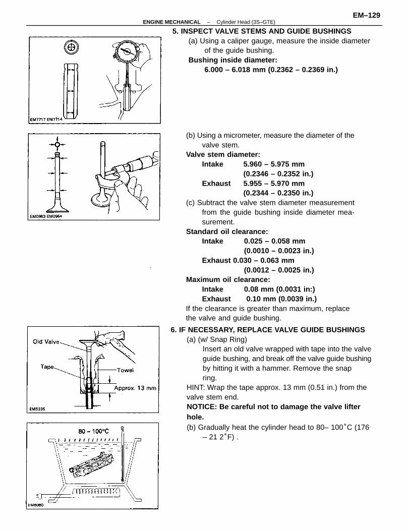
(b) Using a micrometer, measure the diameter of thevalve stem.
Valve stem diameter:Intake 5.960 – 5.975 mm
(0.2346 – 0.2352 in.)Exhaust 5.955 – 5.970 mm
(0.2344 – 0.2350 in.)(c) Subtract the valve stem diameter measurement
from the guide bushing inside diameter mea-surement.
Standard oil clearance:Intake 0.025 – 0.058 mm
(0.0010 – 0.0023 in.)Exhaust 0.030 – 0.063 mm
(0.0012 – 0.0025 in.)Maximum oil clearance:
Intake 0.08 mm (0.0031 in:)Exhaust 0.10 mm (0.0039 in.)
If the clearance is greater than maximum, replacethe valve and guide bushing.
6. IF NECESSARY, REPLACE VALVE GUIDE BUSHINGS(a) (w/ Snap Ring)
Insert an old valve wrapped with tape into the valveguide bushing, and break off the valve guide bushingby hitting it with a hammer. Remove the snapring.
HINT: Wrap the tape approx. 13 mm (0.51 in.) from thevalve stem end.NOTICE: Be careful not to damage the valve lifterhole.(b) Gradually heat the cylinder head to 80– 100°C (176
– 21 2°F) .
5. INSPECT VALVE STEMS AND GUIDE BUSHINGS(a) Using a caliper gauge, measure the inside diameter
of the guide bushing.Bushing inside diameter:
6.000 – 6.018 mm (0.2362 – 0.2369 in.)
–ENGINE MECHANICAL Cylinder Head (3S–GTE)EM–129
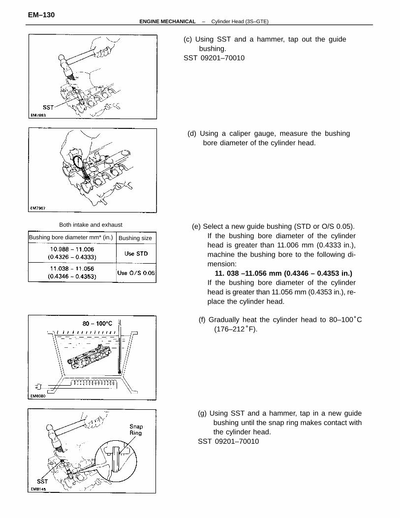
(e) Select a new guide bushing (STD or O/S 0.05).If the bushing bore diameter of the cylinderhead is greater than 11.006 mm (0.4333 in.),machine the bushing bore to the following di-mension:
11. 038 –11.056 mm (0.4346 – 0.4353 in.)If the bushing bore diameter of the cylinderhead is greater than 11.056 mm (0.4353 in.), re-place the cylinder head.
(g) Using SST and a hammer, tap in a new guidebushing until the snap ring makes contact withthe cylinder head.
SST 09201–70010
(c) Using SST and a hammer, tap out the guidebushing.
SST 09201–70010
(d) Using a caliper gauge, measure the bushingbore diameter of the cylinder head.
(f) Gradually heat the cylinder head to 80–100°C(176–212°F).
Bushing bore diameter mm* (in.)
Both intake and exhaust
Bushing size
–ENGINE MECHANICAL Cylinder Head (3S–GTE)EM–130
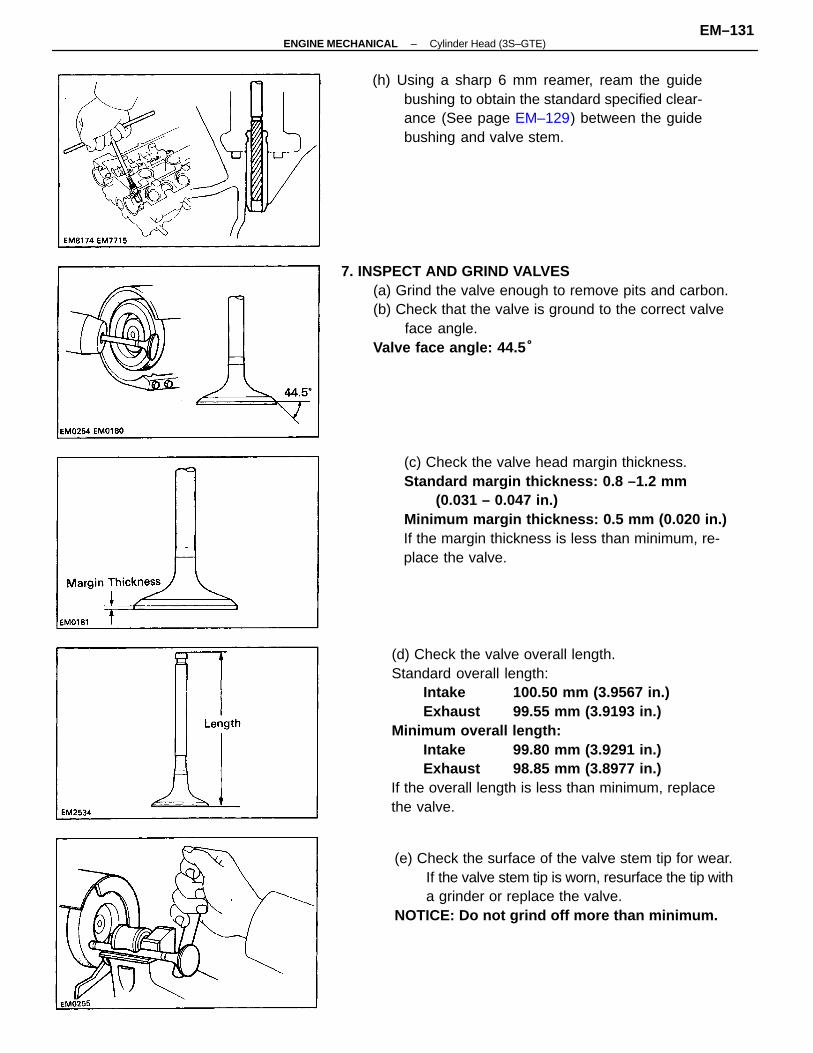
(d) Check the valve overall length.Standard overall length:
Intake 100.50 mm (3.9567 in.)Exhaust 99.55 mm (3.9193 in.)
Minimum overall length:Intake 99.80 mm (3.9291 in.)Exhaust 98.85 mm (3.8977 in.)
If the overall length is less than minimum, replacethe valve.
(c) Check the valve head margin thickness.Standard margin thickness: 0.8 –1.2 mm
(0.031 – 0.047 in.)Minimum margin thickness: 0.5 mm (0.020 in.)If the margin thickness is less than minimum, re-place the valve.
7. INSPECT AND GRIND VALVES(a) Grind the valve enough to remove pits and carbon.(b) Check that the valve is ground to the correct valve
face angle.Valve face angle: 44.5 °
(e) Check the surface of the valve stem tip for wear.If the valve stem tip is worn, resurface the tip witha grinder or replace the valve.
NOTICE: Do not grind off more than minimum.
(h) Using a sharp 6 mm reamer, ream the guidebushing to obtain the standard specified clear-ance (See page EM–129) between the guidebushing and valve stem.
–ENGINE MECHANICAL Cylinder Head (3S–GTE)EM–131
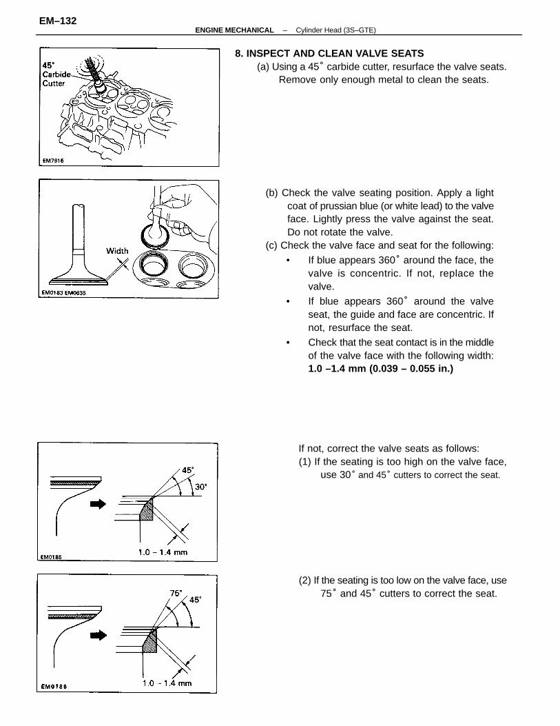
(b) Check the valve seating position. Apply a lightcoat of prussian blue (or white lead) to the valveface. Lightly press the valve against the seat.Do not rotate the valve.
(c) Check the valve face and seat for the following:
• If blue appears 360° around the face, thevalve is concentric. If not, replace thevalve.
• If blue appears 360° around the valveseat, the guide and face are concentric. Ifnot, resurface the seat.
• Check that the seat contact is in the middleof the valve face with the following width:1.0 –1.4 mm (0.039 – 0.055 in.)
8. INSPECT AND CLEAN VALVE SEATS(a) Using a 45° carbide cutter, resurface the valve seats.
Remove only enough metal to clean the seats.
If not, correct the valve seats as follows:(1) If the seating is too high on the valve face,
use 30° and 45° cutters to correct the seat.
(2) If the seating is too low on the valve face, use75° and 45° cutters to correct the seat.
–ENGINE MECHANICAL Cylinder Head (3S–GTE)EM–132
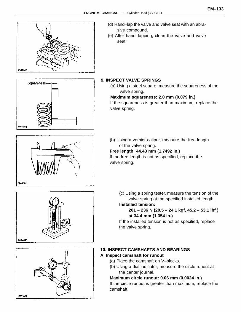
10. INSPECT CAMSHAFTS AND BEARINGSA. Inspect camshaft for runout
(a) Place the camshaft on V–blocks.(b) Using a dial indicator; measure the circle runout at
the center journal.Maximum circle runout: 0.06 mm (0.0024 in.)If the circle runout is greater than maximum, replace thecamshaft.
(c) Using a spring tester, measure the tension of thevalve spring at the specified installed length.
Installed tension:201 – 236 N (20.5 – 24.1 kgf, 45.2 – 53.1 lbf )at 34.4 mm (1.354 in.)
If the installed tension is not as specified, replacethe valve spring.
9. INSPECT VALVE SPRINGS(a) Using a steel square, measure the squareness of the
valve spring.Maximum squareness: 2.0 mm (0.079 in.)If the squareness is greater than maximum, replace thevalve spring.
(b) Using a vemier caliper, measure the free lengthof the valve spring.
Free length: 44.43 mm (1.7492 in.)If the free length is not as specified, replace thevalve spring.
(d) Hand–lap the valve and valve seat with an abra-sive compound.
(e) After hand–lapping, clean the valve and valveseat.
–ENGINE MECHANICAL Cylinder Head (3S–GTE)EM–133
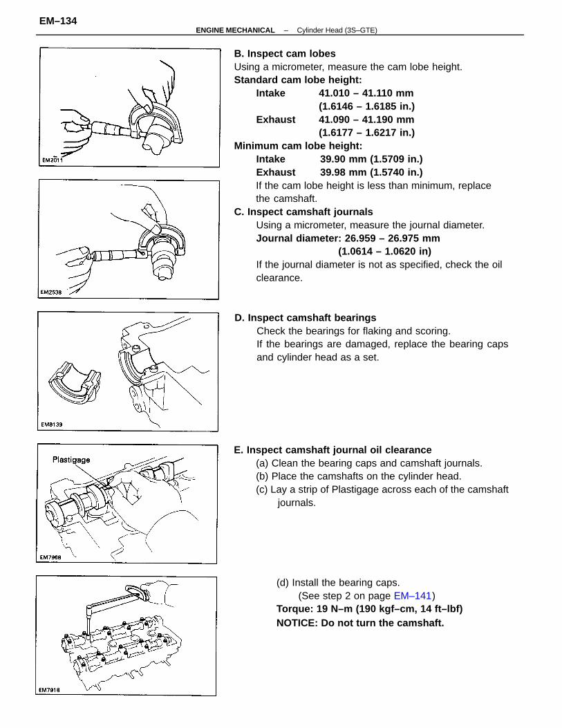
B. Inspect cam lobesUsing a micrometer, measure the cam lobe height.Standard cam lobe height:
Intake 41.010 – 41.110 mm(1.6146 – 1.6185 in.)
Exhaust 41.090 – 41.190 mm(1.6177 – 1.6217 in.)
Minimum cam lobe height:Intake 39.90 mm (1.5709 in.)Exhaust 39.98 mm (1.5740 in.)If the cam lobe height is less than minimum, replacethe camshaft.
C. Inspect camshaft journalsUsing a micrometer, measure the journal diameter.Journal diameter: 26.959 – 26.975 mm
(1.0614 – 1.0620 in)If the journal diameter is not as specified, check the oilclearance.
E. Inspect camshaft journal oil clearance(a) Clean the bearing caps and camshaft journals.(b) Place the camshafts on the cylinder head.(c) Lay a strip of Plastigage across each of the camshaft
journals.
D. Inspect camshaft bearingsCheck the bearings for flaking and scoring.If the bearings are damaged, replace the bearing capsand cylinder head as a set.
(d) Install the bearing caps.(See step 2 on page EM–141)
Torque: 19 N–m (190 kgf–cm, 14 ft–lbf) NOTICE: Do not turn the camshaft.
–ENGINE MECHANICAL Cylinder Head (3S–GTE)EM–134
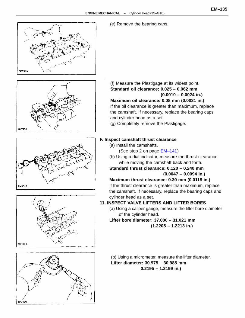
F. Inspect camshaft thrust clearance(a) Install the camshafts.
(See step 2 on page EM–141)(b) Using a dial indicator, measure the thrust clearance
while moving the camshaft back and forth.Standard thrust clearance: 0.120 – 0.240 mm
(0.0047 – 0.0094 in.)Maximum thrust clearance: 0.30 mm (0.0118 in.)If the thrust clearance is greater than maximum, replacethe camshaft. If necessary, replace the bearing caps andcylinder head as a set.
11. INSPECT VALVE LIFTERS AND LIFTER BORES(a) Using a caliper gauge, measure the lifter bore diameter
of the cylinder head.Lifter bore diameter: 37.000 – 31.021 mm
(1.2205 – 1.2213 in.)
(f) Measure the Plastigage at its widest point.Standard oil clearance: 0.025 – 0.062 mm
(0.0010 – 0.0024 in.)Maximum oil clearance: 0.08 mm (0.0031 in.)If the oil clearance is greater than maximum, replacethe camshaft. If necessary, replace the bearing capsand cylinder head as a set.(g) Completely remove the Plastigage.
(b) Using a micrometer, measure the lifter diameter.Lifter diameter: 30.975 – 30.985 mm
0.2195 – 1.2199 in.)
(e) Remove the bearing caps.
–ENGINE MECHANICAL Cylinder Head (3S–GTE)EM–135
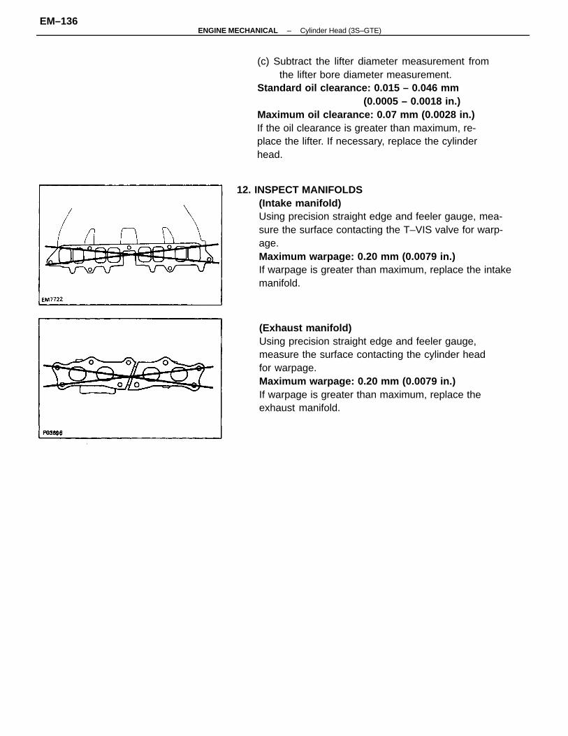
12. INSPECT MANIFOLDS(Intake manifold)Using precision straight edge and feeler gauge, mea-sure the surface contacting the T–VIS valve for warp-age.Maximum warpage: 0.20 mm (0.0079 in.)If warpage is greater than maximum, replace the intakemanifold.
(c) Subtract the lifter diameter measurement fromthe lifter bore diameter measurement.
Standard oil clearance: 0.015 – 0.046 mm(0.0005 – 0.0018 in.)
Maximum oil clearance: 0.07 mm (0.0028 in.)If the oil clearance is greater than maximum, re-place the lifter. If necessary, replace the cylinderhead.
(Exhaust manifold)Using precision straight edge and feeler gauge,measure the surface contacting the cylinder headfor warpage.Maximum warpage: 0.20 mm (0.0079 in.)If warpage is greater than maximum, replace theexhaust manifold.
–ENGINE MECHANICAL Cylinder Head (3S–GTE)EM–136
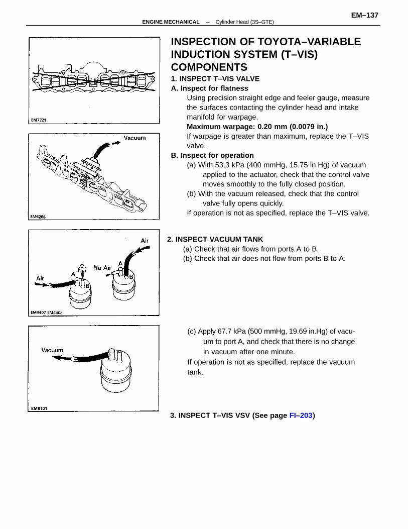
INSPECTION OF TOYOTA–VARIABLEINDUCTION SYSTEM (T–VIS)COMPONENTS1. INSPECT T–VIS VALVEA. Inspect for flatness
Using precision straight edge and feeler gauge, measurethe surfaces contacting the cylinder head and intakemanifold for warpage.Maximum warpage: 0.20 mm (0.0079 in.)If warpage is greater than maximum, replace the T–VISvalve.
B. Inspect for operation(a) With 53.3 kPa (400 mmHg, 15.75 in.Hg) of vacuum
applied to the actuator, check that the control valvemoves smoothly to the fully closed position.
(b) With the vacuum released, check that the controlvalve fully opens quickly.
If operation is not as specified, replace the T–VIS valve.
2. INSPECT VACUUM TANK(a) Check that air flows from ports A to B.(b) Check that air does not flow from ports B to A.
(c) Apply 67.7 kPa (500 mmHg, 19.69 in.Hg) of vacu-um to port A, and check that there is no changein vacuum after one minute.
If operation is not as specified, replace the vacuumtank.
3. INSPECT T–VIS VSV (See page FI–203)
–ENGINE MECHANICAL Cylinder Head (3S–GTE)EM–137
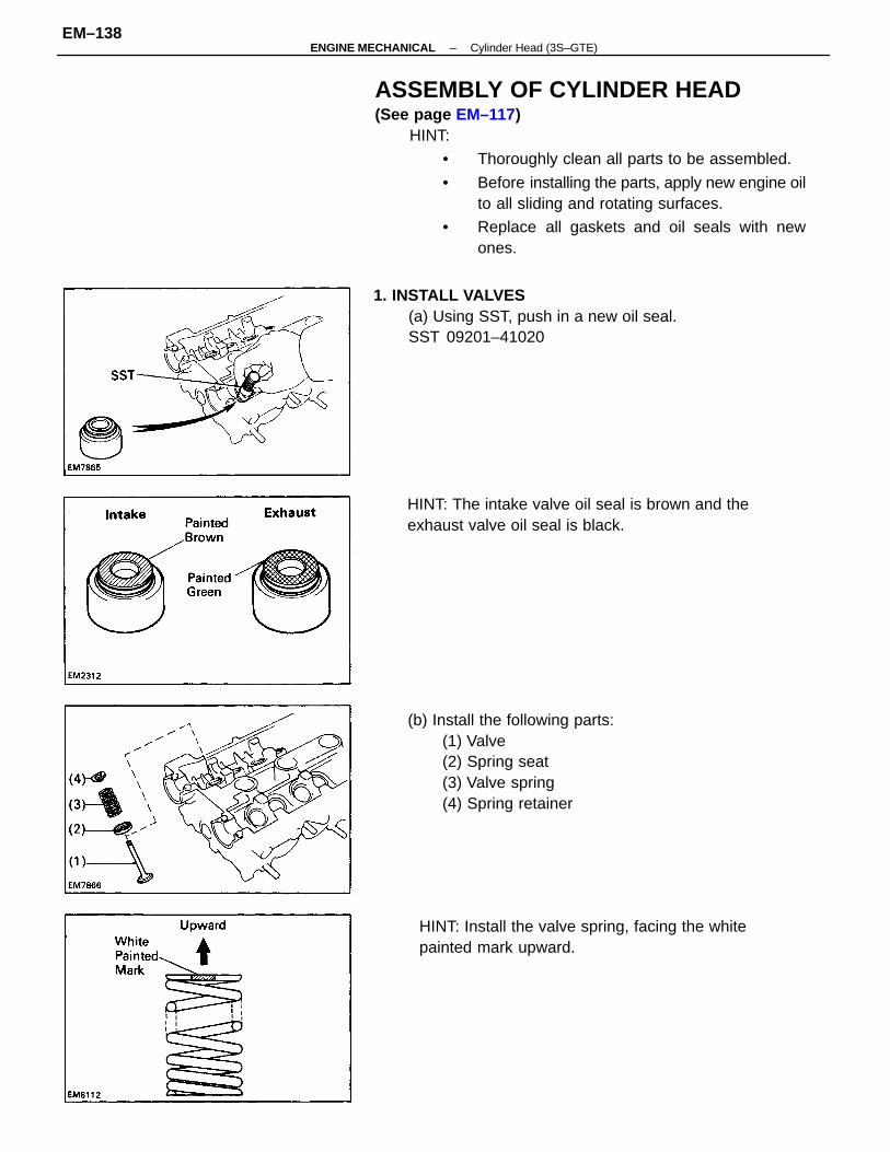
ASSEMBLY OF CYLINDER HEAD(See page EM–117)
HINT:
• Thoroughly clean all parts to be assembled.
• Before installing the parts, apply new engine oilto all sliding and rotating surfaces.
• Replace all gaskets and oil seals with newones.
(b) Install the following parts:(1) Valve(2) Spring seat(3) Valve spring(4) Spring retainer
1. INSTALL VALVES(a) Using SST, push in a new oil seal.SST 09201–41020
HINT: Install the valve spring, facing the whitepainted mark upward.
HINT: The intake valve oil seal is brown and theexhaust valve oil seal is black.
–ENGINE MECHANICAL Cylinder Head (3S–GTE)EM–138
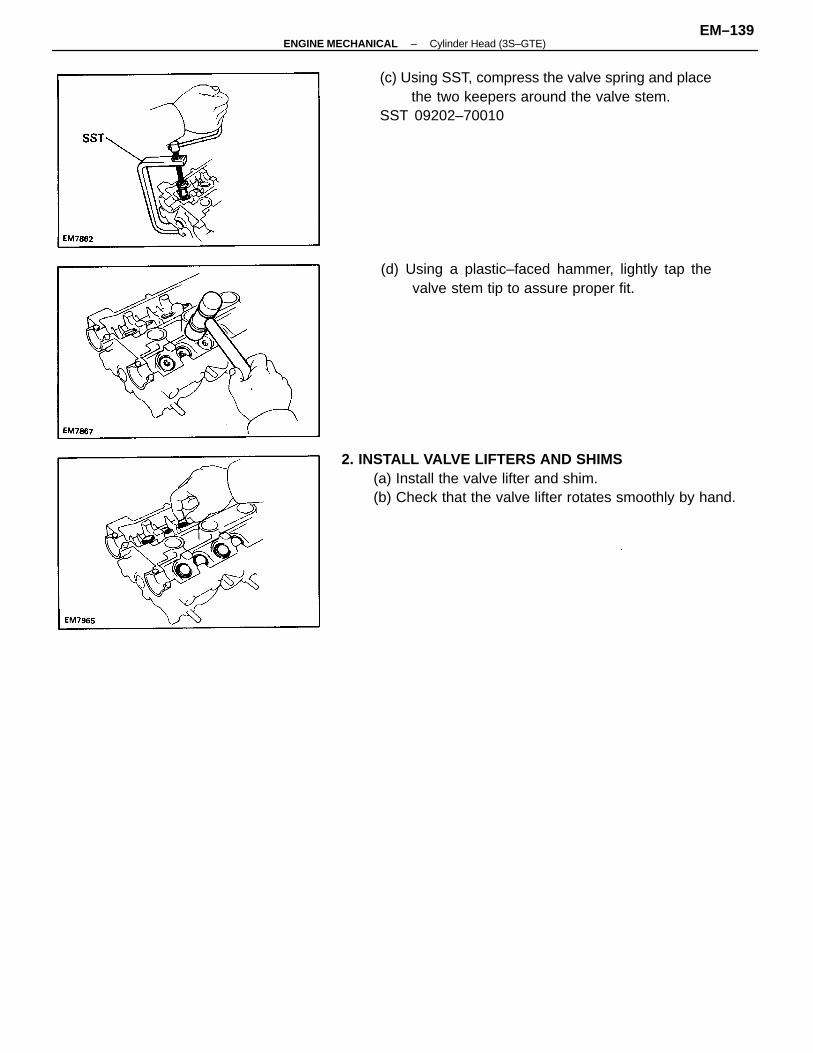
2. INSTALL VALVE LIFTERS AND SHIMS(a) Install the valve lifter and shim.(b) Check that the valve lifter rotates smoothly by hand.
(c) Using SST, compress the valve spring and placethe two keepers around the valve stem.
SST 09202–70010
(d) Using a plastic–faced hammer, lightly tap thevalve stem tip to assure proper fit.
–ENGINE MECHANICAL Cylinder Head (3S–GTE)EM–139
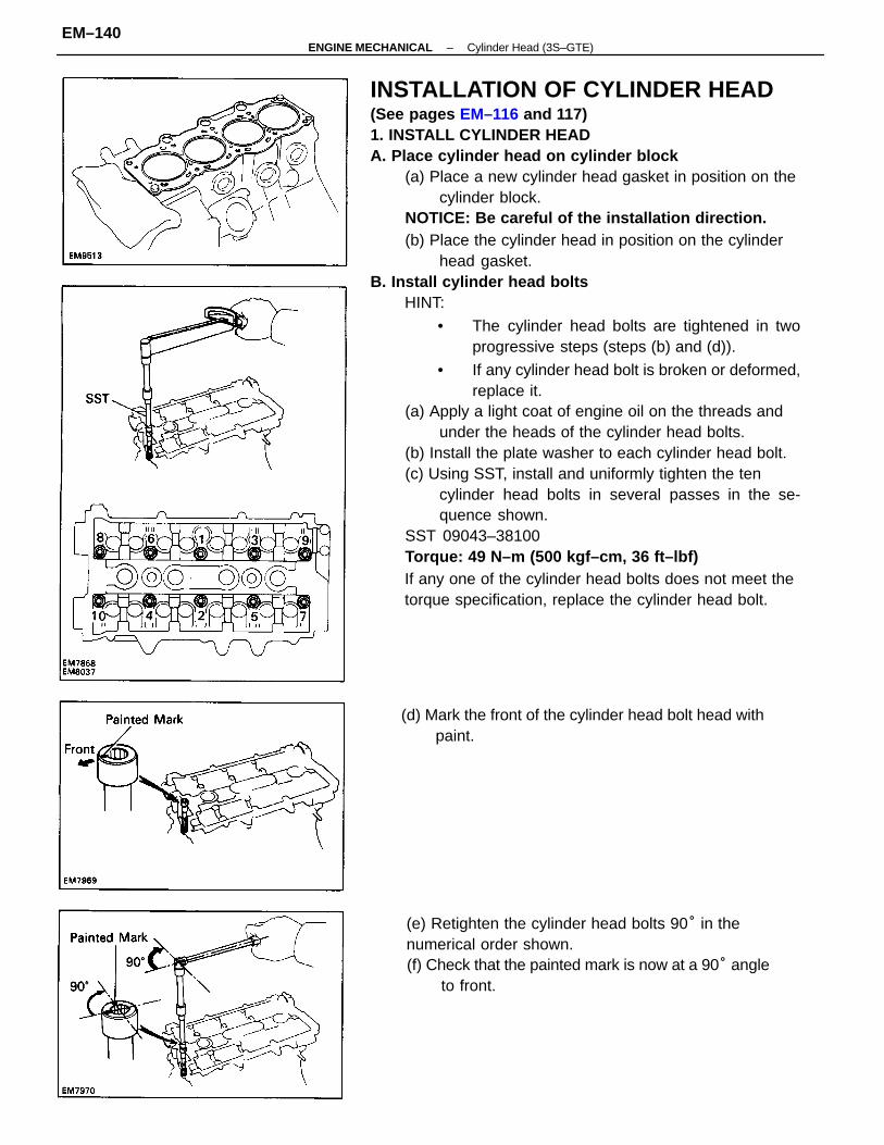
INSTALLATION OF CYLINDER HEAD(See pages EM–116 and 117)1. INSTALL CYLINDER HEADA. Place cylinder head on cylinder block
(a) Place a new cylinder head gasket in position on thecylinder block.
NOTICE: Be careful of the installation direction.(b) Place the cylinder head in position on the cylinder
head gasket.B. Install cylinder head bolts
HINT:
• The cylinder head bolts are tightened in twoprogressive steps (steps (b) and (d)).
• If any cylinder head bolt is broken or deformed,replace it.
(a) Apply a light coat of engine oil on the threads andunder the heads of the cylinder head bolts.
(b) Install the plate washer to each cylinder head bolt.(c) Using SST, install and uniformly tighten the ten
cylinder head bolts in several passes in the se-quence shown.
SST 09043–38100Torque: 49 N–m (500 kgf–cm, 36 ft–lbf)If any one of the cylinder head bolts does not meet thetorque specification, replace the cylinder head bolt.
(e) Retighten the cylinder head bolts 90° in thenumerical order shown.(f) Check that the painted mark is now at a 90° angle
to front.
(d) Mark the front of the cylinder head bolt head withpaint.
–ENGINE MECHANICAL Cylinder Head (3S–GTE)EM–140
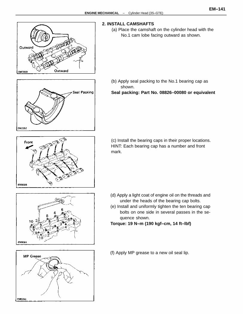
(d) Apply a light coat of engine oil on the threads andunder the heads of the bearing cap bolts.
(e) Install and uniformly tighten the ten bearing capbolts on one side in several passes in the se-quence shown.
Torque: 19 N–m (190 kgf–cm, 14 ft–lbf)
2. INSTALL CAMSHAFTS(a) Place the camshaft on the cylinder head with the
No.1 cam lobe facing outward as shown.
(b) Apply seal packing to the No.1 bearing cap asshown.
Seal packing: Part No. 08826–00080 or equivalent
(c) Install the bearing caps in their proper locations.HINT: Each bearing cap has a number and frontmark.
(f) Apply MP grease to a new oil seal lip.
–ENGINE MECHANICAL Cylinder Head (3S–GTE)EM–141
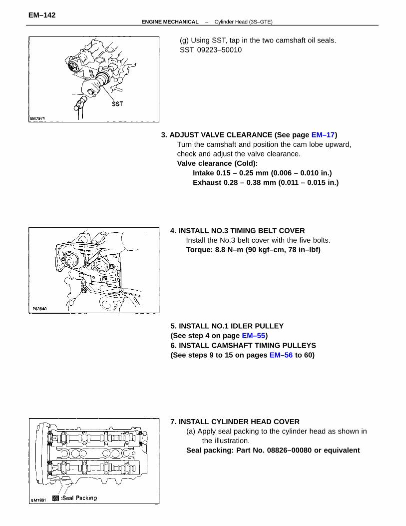
3. ADJUST VALVE CLEARANCE (See page EM–17)Turn the camshaft and position the cam lobe upward,check and adjust the valve clearance.Valve clearance (Cold):
Intake 0.15 – 0.25 mm (0.006 – 0.010 in.)Exhaust 0.28 – 0.38 mm (0.011 – 0.015 in.)
7. INSTALL CYLINDER HEAD COVER(a) Apply seal packing to the cylinder head as shown in
the illustration.Seal packing: Part No. 08826–00080 or equivalent
5. INSTALL NO.1 IDLER PULLEY(See step 4 on page EM–55)6. INSTALL CAMSHAFT TIMING PULLEYS(See steps 9 to 15 on pages EM–56 to 60)
4. INSTALL NO.3 TIMING BELT COVERInstall the No.3 belt cover with the five bolts.Torque: 8.8 N–m (90 kgf–cm, 78 in–lbf)
(g) Using SST, tap in the two camshaft oil seals.SST 09223–50010
–ENGINE MECHANICAL Cylinder Head (3S–GTE)EM–142
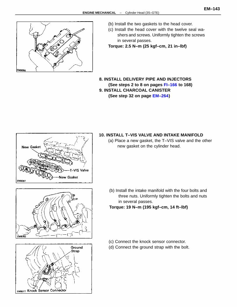
(b) Install the two gaskets to the head cover.(c) Install the head cover with the twelve seal wa-
shers and screws. Uniformly tighten the screwsin several passes.
Torque: 2.5 N–m (25 kgf–cm, 21 in–lbf)
(b) Install the intake manifold with the four bolts andthree nuts. Uniformly tighten the bolts and nutsin several passes.
Torque: 19 N–m (195 kgf–cm, 14 ft–lbf)
8. INSTALL DELIVERY PIPE AND INJECTORS(See steps 2 to 8 on pages FI–166 to 168)
9. INSTALL CHARCOAL CANISTER(See step 32 on page EM–264)
10. INSTALL T–VIS VALVE AND INTAKE MANIFOLD(a) Place a new gasket, the T–VIS valve and the other
new gasket on the cylinder head.
(c) Connect the knock sensor connector.(d) Connect the ground strap with the bolt.
–ENGINE MECHANICAL Cylinder Head (3S–GTE)EM–143
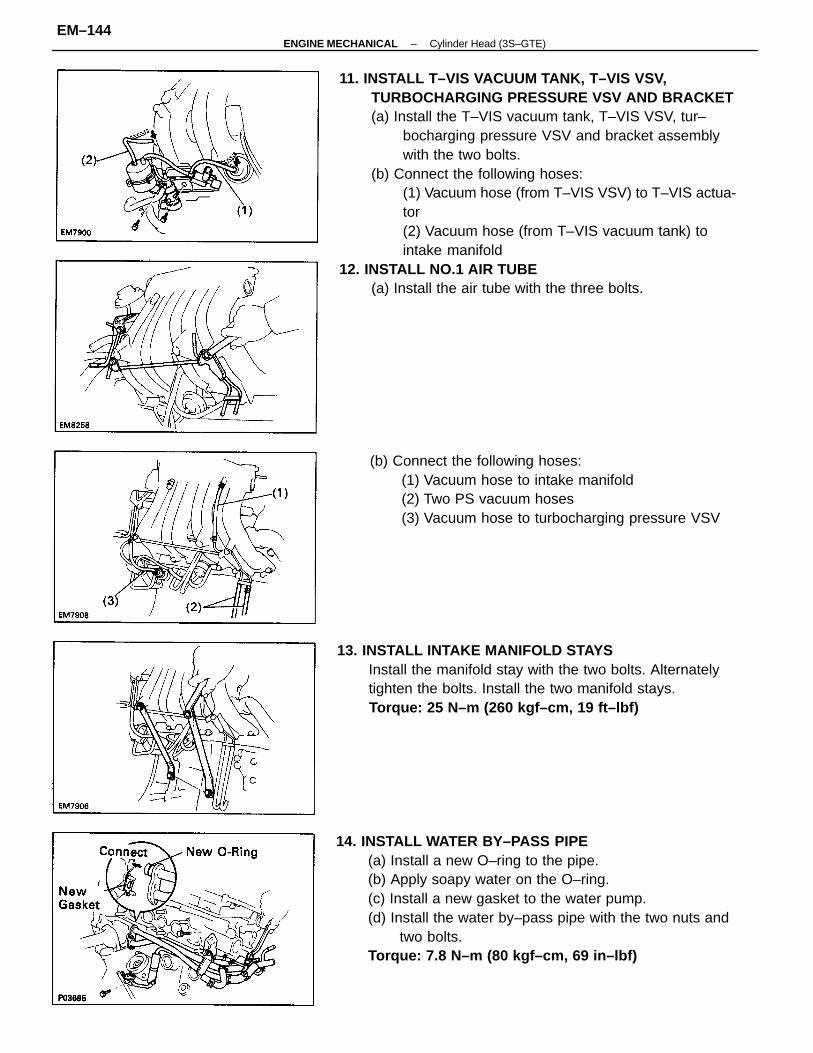
11. INSTALL T–VIS VACUUM TANK, T–VIS VSV,TURBOCHARGING PRESSURE VSV AND BRACKET(a) Install the T–VIS vacuum tank, T–VIS VSV, tur–
bocharging pressure VSV and bracket assemblywith the two bolts.
(b) Connect the following hoses:(1) Vacuum hose (from T–VIS VSV) to T–VIS actua-tor(2) Vacuum hose (from T–VIS vacuum tank) tointake manifold
12. INSTALL NO.1 AIR TUBE(a) Install the air tube with the three bolts.
14. INSTALL WATER BY–PASS PIPE(a) Install a new O–ring to the pipe.(b) Apply soapy water on the O–ring.(c) Install a new gasket to the water pump.(d) Install the water by–pass pipe with the two nuts and
two bolts.Torque: 7.8 N–m (80 kgf–cm, 69 in–lbf)
13. INSTALL INTAKE MANIFOLD STAYSInstall the manifold stay with the two bolts. Alternatelytighten the bolts. Install the two manifold stays.Torque: 25 N–m (260 kgf–cm, 19 ft–lbf)
(b) Connect the following hoses:(1) Vacuum hose to intake manifold(2) Two PS vacuum hoses(3) Vacuum hose to turbocharging pressure VSV
–ENGINE MECHANICAL Cylinder Head (3S–GTE)EM–144
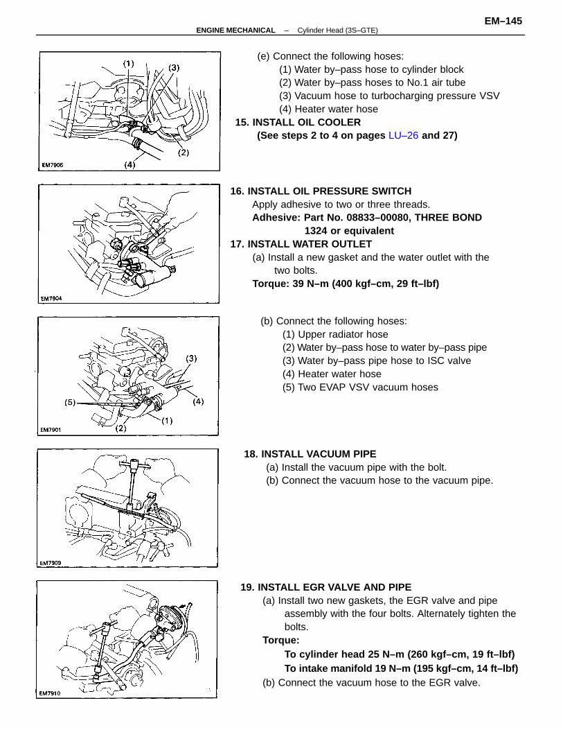
16. INSTALL OIL PRESSURE SWITCHApply adhesive to two or three threads.Adhesive: Part No. 08833–00080, THREE BOND
1324 or equivalent17. INSTALL WATER OUTLET
(a) Install a new gasket and the water outlet with thetwo bolts.
Torque: 39 N–m (400 kgf–cm, 29 ft–lbf)
19. INSTALL EGR VALVE AND PIPE(a) Install two new gaskets, the EGR valve and pipe
assembly with the four bolts. Alternately tighten thebolts.
Torque:To cylinder head 25 N–m (260 kgf–cm, 19 ft–lbf)To intake manifold 19 N–m (195 kgf–cm, 14 ft–lbf)
(b) Connect the vacuum hose to the EGR valve.
(e) Connect the following hoses:(1) Water by–pass hose to cylinder block(2) Water by–pass hoses to No.1 air tube(3) Vacuum hose to turbocharging pressure VSV(4) Heater water hose
15. INSTALL OIL COOLER(See steps 2 to 4 on pages LU–26 and 27)
(b) Connect the following hoses:(1) Upper radiator hose(2) Water by–pass hose to water by–pass pipe(3) Water by–pass pipe hose to ISC valve(4) Heater water hose(5) Two EVAP VSV vacuum hoses
18. INSTALL VACUUM PIPE(a) Install the vacuum pipe with the bolt.(b) Connect the vacuum hose to the vacuum pipe.
–ENGINE MECHANICAL Cylinder Head (3S–GTE)EM–145
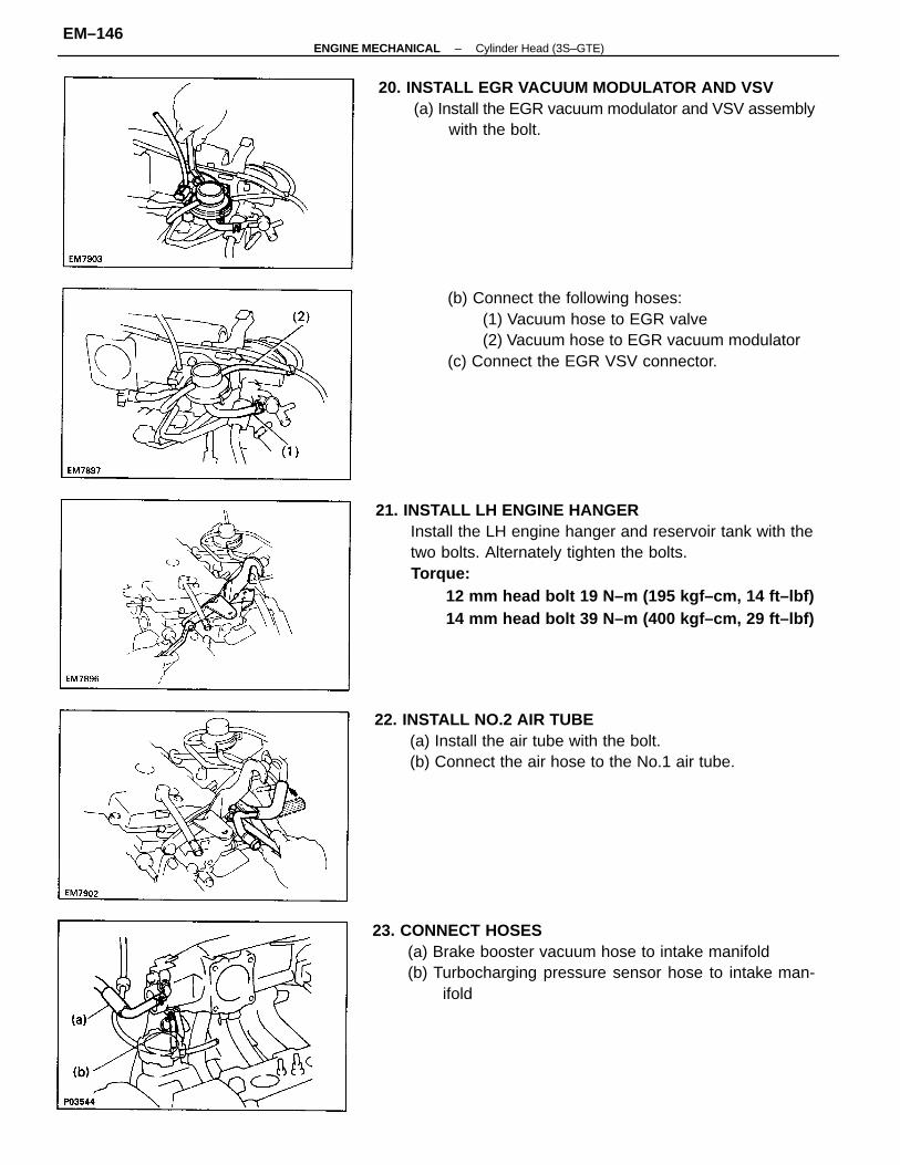
21. INSTALL LH ENGINE HANGERInstall the LH engine hanger and reservoir tank with thetwo bolts. Alternately tighten the bolts.Torque:
12 mm head bolt 19 N–m (195 kgf–cm, 14 ft–lbf)14 mm head bolt 39 N–m (400 kgf–cm, 29 ft–lbf)
23. CONNECT HOSES(a) Brake booster vacuum hose to intake manifold(b) Turbocharging pressure sensor hose to intake man-
ifold
(b) Connect the following hoses:(1) Vacuum hose to EGR valve(2) Vacuum hose to EGR vacuum modulator
(c) Connect the EGR VSV connector.
20. INSTALL EGR VACUUM MODULATOR AND VSV(a) Install the EGR vacuum modulator and VSV assembly
with the bolt.
22. INSTALL NO.2 AIR TUBE(a) Install the air tube with the bolt.(b) Connect the air hose to the No.1 air tube.
–ENGINE MECHANICAL Cylinder Head (3S–GTE)EM–146
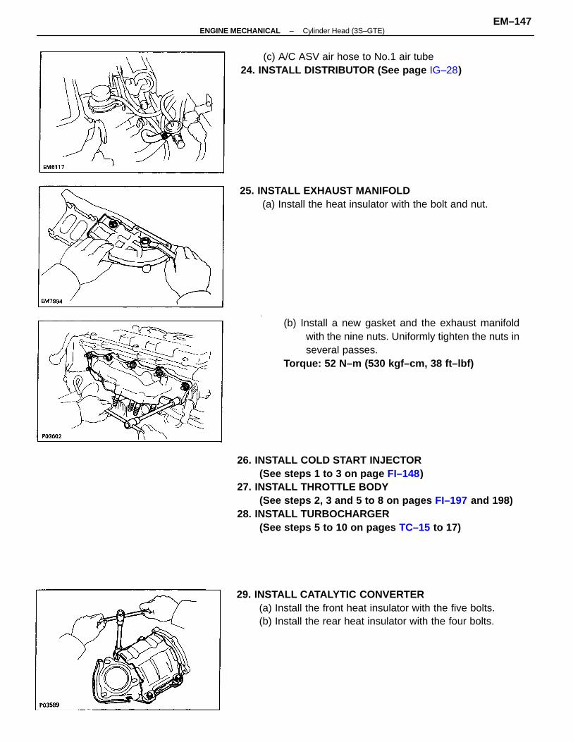
26. INSTALL COLD START INJECTOR(See steps 1 to 3 on page FI–148)
27. INSTALL THROTTLE BODY(See steps 2, 3 and 5 to 8 on pages FI–197 and 198)
28. INSTALL TURBOCHARGER(See steps 5 to 10 on pages TC–15 to 17)
i
(b) Install a new gasket and the exhaust manifoldwith the nine nuts. Uniformly tighten the nuts inseveral passes.
Torque: 52 N–m (530 kgf–cm, 38 ft–lbf)
29. INSTALL CATALYTIC CONVERTER(a) Install the front heat insulator with the five bolts.(b) Install the rear heat insulator with the four bolts.
25. INSTALL EXHAUST MANIFOLD(a) Install the heat insulator with the bolt and nut.
(c) A/C ASV air hose to No.1 air tube24. INSTALL DISTRIBUTOR (See page IG–28)
–ENGINE MECHANICAL Cylinder Head (3S–GTE)EM–147
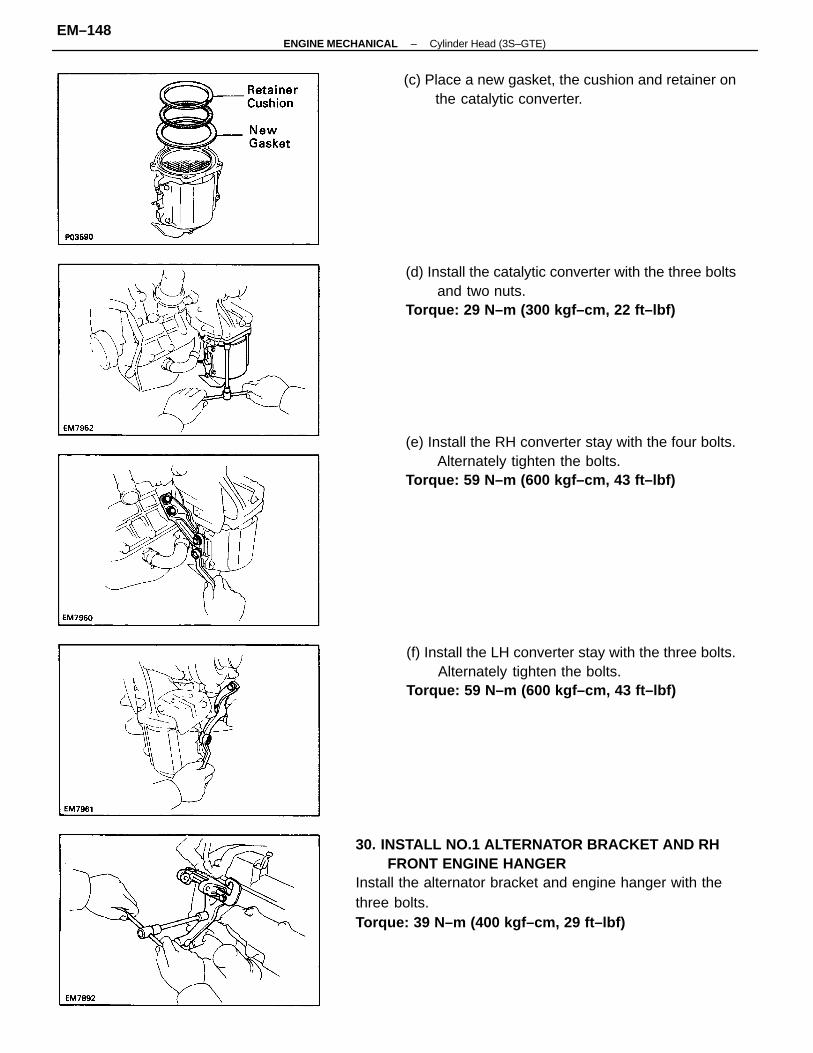
30. INSTALL NO.1 ALTERNATOR BRACKET AND RHFRONT ENGINE HANGER
Install the alternator bracket and engine hanger with thethree bolts.Torque: 39 N–m (400 kgf–cm, 29 ft–lbf)
(e) Install the RH converter stay with the four bolts.Alternately tighten the bolts.
Torque: 59 N–m (600 kgf–cm, 43 ft–lbf)
(f) Install the LH converter stay with the three bolts.Alternately tighten the bolts.
Torque: 59 N–m (600 kgf–cm, 43 ft–lbf)
(d) Install the catalytic converter with the three boltsand two nuts.
Torque: 29 N–m (300 kgf–cm, 22 ft–lbf)
(c) Place a new gasket, the cushion and retainer onthe catalytic converter.
–ENGINE MECHANICAL Cylinder Head (3S–GTE)EM–148
31. INSTALL FRONT EXHAUST PIPE(See step 18 on page EM–261)
32. INSTALL SUSPENSION LOWER CROSSMEMBER(See step 19 on page EM–262)
33. INSTALL ALTERNATOR (See page CH–23)34. INSTALL INTERCOOLER
(See steps 11 to 13 on page TC–17)35. INSTALL AIR CLEANER CAP
(See step 44 on page EM–117)36. INSTALL ACCELERATOR CABLE, AND ADJUST IT37. FILL WITH ENGINE COOLANT (See page CO–6)Capacity (w/ Heater):
6.5 liters (6.9 US qts, 5.7 Imp. qts)38. START ENGINE AND CHECK FOR LEAKS39. ADJUST IGNITION TIMING (See page IG–29)Ignition timing:
10° BTDC @ idle(w/ Terminals TO and E1 connected)
40. PERFORM ROAD TESTCheck for abnormal noise, shock, slippage, correct shiftpoints and smooth operation.
41. RECHECK ENGINE COOLANT AND OIL LEVELS
–ENGINE MECHANICAL Cylinder Head (3S–GTE)EM–149
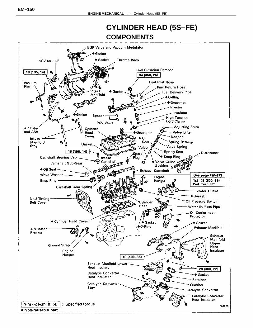
CYLINDER HEAD (5S–FE)COMPONENTS
–ENGINE MECHANICAL Cylinder Head (5S–FE)EM–150
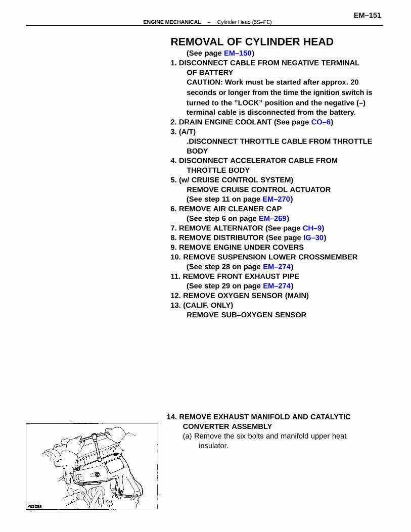
REMOVAL OF CYLINDER HEAD(See page EM–150)
1. DISCONNECT CABLE FROM NEGATIVE TERMINALOF BATTERYCAUTION: Work must be started after approx. 20seconds or longer from the time the ignition switch isturned to the ”LOCK” position and the negative (–)terminal cable is disconnected from the battery.
2. DRAIN ENGINE COOLANT (See page CO–6)3. (A/T)
.DISCONNECT THROTTLE CABLE FROM THROTTLEBODY
4. DISCONNECT ACCELERATOR CABLE FROMTHROTTLE BODY
5. (w/ CRUISE CONTROL SYSTEM)REMOVE CRUISE CONTROL ACTUATOR(See step 11 on page EM–270)
6. REMOVE AIR CLEANER CAP(See step 6 on page EM–269)
7. REMOVE ALTERNATOR (See page CH–9)8. REMOVE DISTRIBUTOR (See page IG–30)9. REMOVE ENGINE UNDER COVERS10. REMOVE SUSPENSION LOWER CROSSMEMBER
(See step 28 on page EM–274)11. REMOVE FRONT EXHAUST PIPE
(See step 29 on page EM–274)12. REMOVE OXYGEN SENSOR (MAIN)13. (CALIF. ONLY)
REMOVE SUB–OXYGEN SENSOR
14. REMOVE EXHAUST MANIFOLD AND CATALYTICCONVERTER ASSEMBLY(a) Remove the six bolts and manifold upper heat
insulator.
–ENGINE MECHANICAL Cylinder Head (5S–FE)EM–151
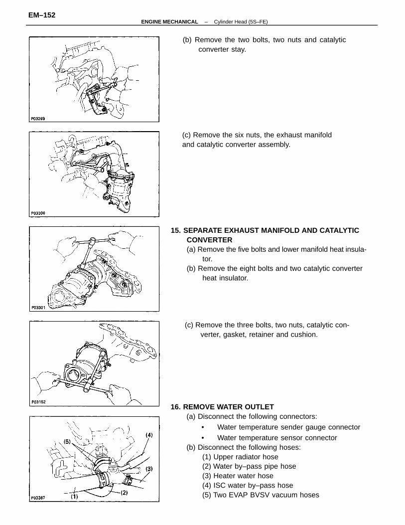
16. REMOVE WATER OUTLET(a) Disconnect the following connectors:
• Water temperature sender gauge connector
• Water temperature sensor connector(b) Disconnect the following hoses:
(1) Upper radiator hose(2) Water by–pass pipe hose(3) Heater water hose(4) ISC water by–pass hose(5) Two EVAP BVSV vacuum hoses
15. SEPARATE EXHAUST MANIFOLD AND CATALYTICCONVERTER(a) Remove the five bolts and lower manifold heat insula-
tor.(b) Remove the eight bolts and two catalytic converter
heat insulator.
(c) Remove the three bolts, two nuts, catalytic con-verter, gasket, retainer and cushion.
(b) Remove the two bolts, two nuts and catalyticconverter stay.
(c) Remove the six nuts, the exhaust manifoldand catalytic converter assembly.
–ENGINE MECHANICAL Cylinder Head (5S–FE)EM–152
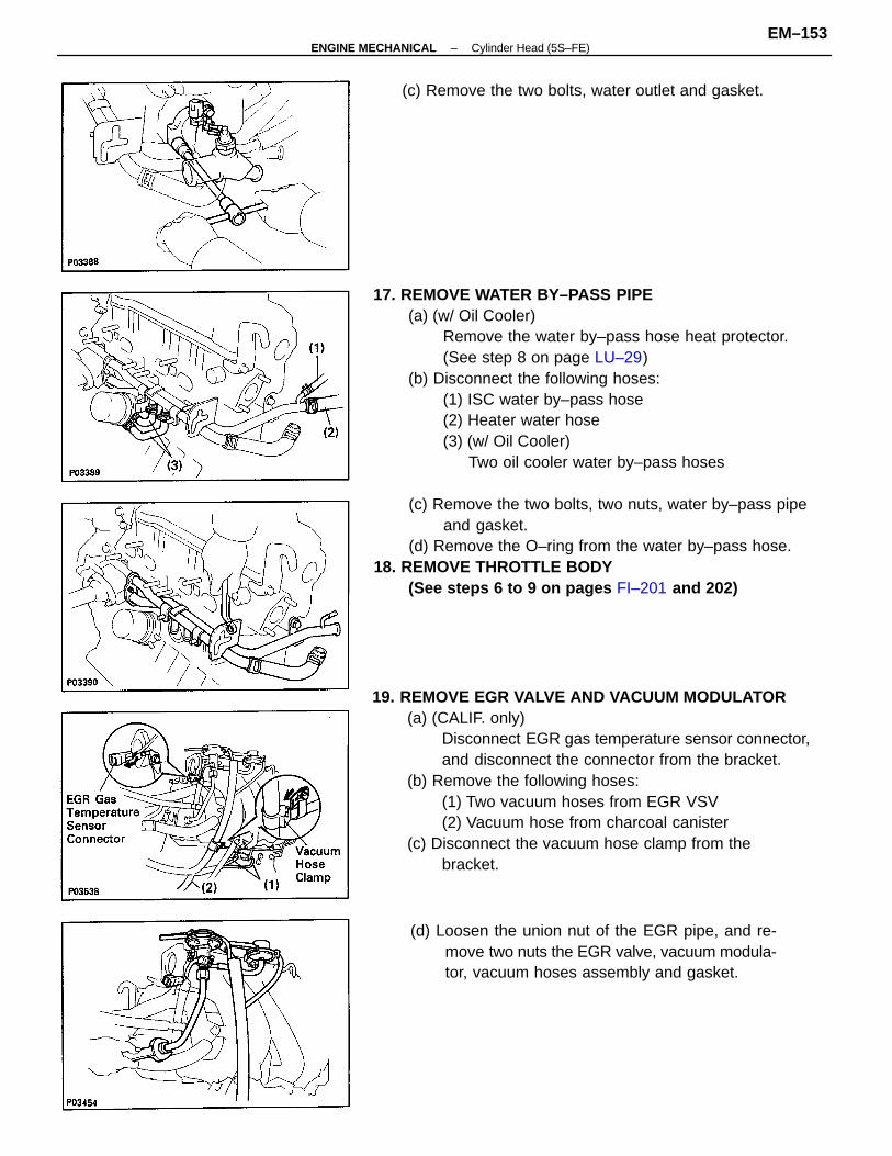
19. REMOVE EGR VALVE AND VACUUM MODULATOR(a) (CALIF. only)
Disconnect EGR gas temperature sensor connector,and disconnect the connector from the bracket.
(b) Remove the following hoses:(1) Two vacuum hoses from EGR VSV(2) Vacuum hose from charcoal canister
(c) Disconnect the vacuum hose clamp from thebracket.
17. REMOVE WATER BY–PASS PIPE(a) (w/ Oil Cooler)
Remove the water by–pass hose heat protector.(See step 8 on page LU–29)
(b) Disconnect the following hoses:(1) ISC water by–pass hose(2) Heater water hose(3) (w/ Oil Cooler)
Two oil cooler water by–pass hoses
(c) Remove the two bolts, two nuts, water by–pass pipeand gasket.
(d) Remove the O–ring from the water by–pass hose.18. REMOVE THROTTLE BODY
(See steps 6 to 9 on pages FI–201 and 202)
(d) Loosen the union nut of the EGR pipe, and re-move two nuts the EGR valve, vacuum modula-tor, vacuum hoses assembly and gasket.
(c) Remove the two bolts, water outlet and gasket.
–ENGINE MECHANICAL Cylinder Head (5S–FE)EM–153
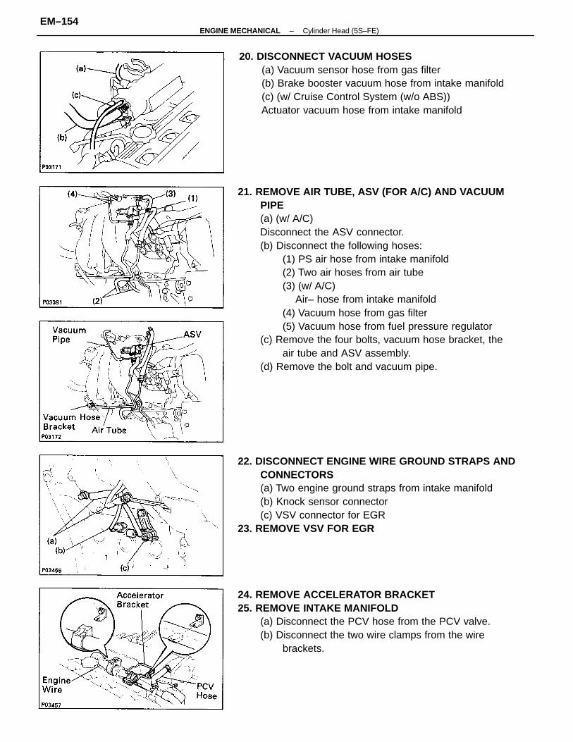
21. REMOVE AIR TUBE, ASV (FOR A/C) AND VACUUMPIPE(a) (w/ A/C)Disconnect the ASV connector.(b) Disconnect the following hoses:
(1) PS air hose from intake manifold(2) Two air hoses from air tube(3) (w/ A/C)
Air– hose from intake manifold(4) Vacuum hose from gas filter(5) Vacuum hose from fuel pressure regulator
(c) Remove the four bolts, vacuum hose bracket, theair tube and ASV assembly.
(d) Remove the bolt and vacuum pipe.
22. DISCONNECT ENGINE WIRE GROUND STRAPS ANDCONNECTORS(a) Two engine ground straps from intake manifold(b) Knock sensor connector(c) VSV connector for EGR
23. REMOVE VSV FOR EGR
24. REMOVE ACCELERATOR BRACKET25. REMOVE INTAKE MANIFOLD
(a) Disconnect the PCV hose from the PCV valve.(b) Disconnect the two wire clamps from the wire
brackets.
20. DISCONNECT VACUUM HOSES(a) Vacuum sensor hose from gas filter(b) Brake booster vacuum hose from intake manifold(c) (w/ Cruise Control System (w/o ABS))Actuator vacuum hose from intake manifold
–ENGINE MECHANICAL Cylinder Head (5S–FE)EM–154
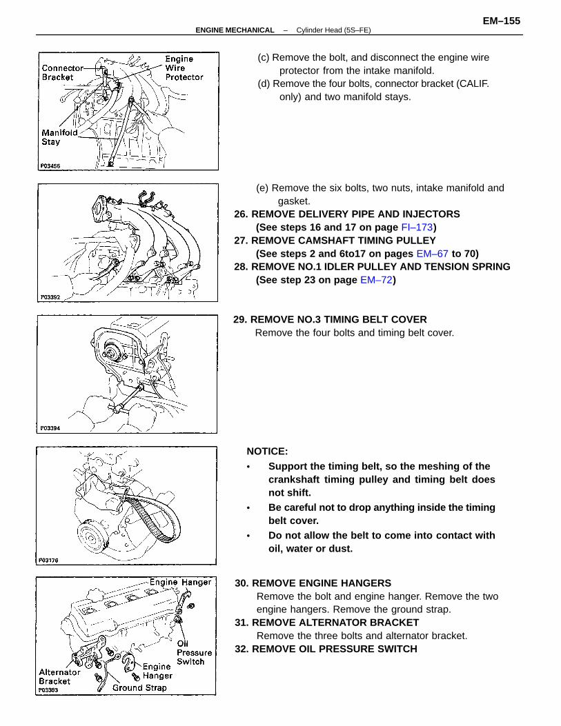
(e) Remove the six bolts, two nuts, intake manifold andgasket.
26. REMOVE DELIVERY PIPE AND INJECTORS(See steps 16 and 17 on page FI–173)
27. REMOVE CAMSHAFT TIMING PULLEY(See steps 2 and 6to17 on pages EM–67 to 70)
28. REMOVE NO.1 IDLER PULLEY AND TENSION SPRING(See step 23 on page EM–72)
30. REMOVE ENGINE HANGERSRemove the bolt and engine hanger. Remove the twoengine hangers. Remove the ground strap.
31. REMOVE ALTERNATOR BRACKETRemove the three bolts and alternator bracket.
32. REMOVE OIL PRESSURE SWITCH
NOTICE:• Support the timing belt, so the meshing of the
crankshaft timing pulley and timing belt doesnot shift.
• Be careful not to drop anything inside the timingbelt cover.
• Do not allow the belt to come into contact withoil, water or dust.
(c) Remove the bolt, and disconnect the engine wireprotector from the intake manifold.
(d) Remove the four bolts, connector bracket (CALIF.only) and two manifold stays.
29. REMOVE NO.3 TIMING BELT COVERRemove the four bolts and timing belt cover.
–ENGINE MECHANICAL Cylinder Head (5S–FE)EM–155
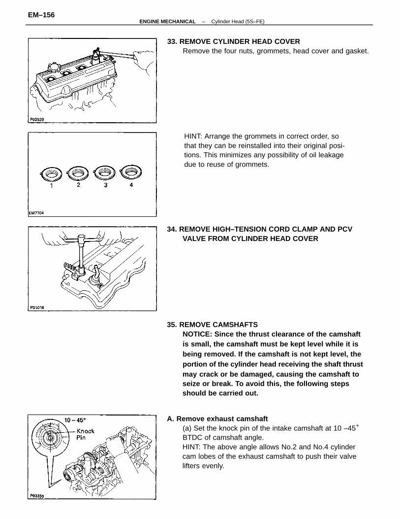
35. REMOVE CAMSHAFTSNOTICE: Since the thrust clearance of the camshaftis small, the camshaft must be kept level while it isbeing removed. If the camshaft is not kept level, theportion of the cylinder head receiving the shaft thrustmay crack or be damaged, causing the camshaft toseize or break. To avoid this, the following stepsshould be carried out.
A. Remove exhaust camshaft(a) Set the knock pin of the intake camshaft at 10 –45°BTDC of camshaft angle.HINT: The above angle allows No.2 and No.4 cylindercam lobes of the exhaust camshaft to push their valvelifters evenly.
HINT: Arrange the grommets in correct order, sothat they can be reinstalled into their original posi-tions. This minimizes any possibility of oil leakagedue to reuse of grommets.
33. REMOVE CYLINDER HEAD COVERRemove the four nuts, grommets, head cover and gasket.
34. REMOVE HIGH–TENSION CORD CLAMP AND PCVVALVE FROM CYLINDER HEAD COVER
–ENGINE MECHANICAL Cylinder Head (5S–FE)EM–156
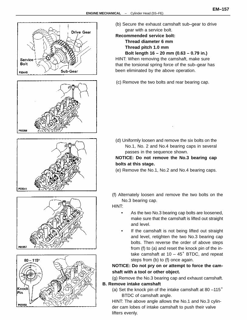
(f) Alternately loosen and remove the two bolts on theNo.3 bearing cap.
HINT:
• As the two No.3 bearing cap bolts are loosened,make sure that the camshaft is lifted out straightand level.
• If the camshaft is not being lifted out straightand level, retighten the two No.3 bearing capbolts. Then reverse the order of above stepsfrom (f) to (a) and reset the knock pin of the in-take camshaft at 10 – 45° BTDC, and repeatsteps from (b) to (f) once again.
NOTICE: Do not pry on or attempt to force the cam-shaft with a tool or other object.(g) Remove the No.3 bearing cap and exhaust camshaft.
B. Remove intake camshaft(a) Set the knock pin of the intake camshaft at 80 –115°
BTDC of camshaft angle.HINT: The above angle allows the No.1 and No.3 cylin-der cam lobes of intake camshaft to push their valvelifters evenly.
(b) Secure the exhaust camshaft sub–gear to drivegear with a service bolt.
Recommended service bolt:Thread diameter 6 mmThread pitch 1.0 mmBolt length 16 – 20 mm (0.63 – 0.79 in.)
HINT: When removing the camshaft, make surethat the torsional spring force of the sub–gear hasbeen eliminated by the above operation.
(d) Uniformly loosen and remove the six bolts on theNo.1, No. 2 and No.4 bearing caps in severalpasses in the sequence shown.
NOTICE: Do not remove the No.3 bearing capbolts at this stage.(e) Remove the No.1, No.2 and No.4 bearing caps.
(c) Remove the two bolts and rear bearing cap.
–ENGINE MECHANICAL Cylinder Head (5S–FE)EM–157
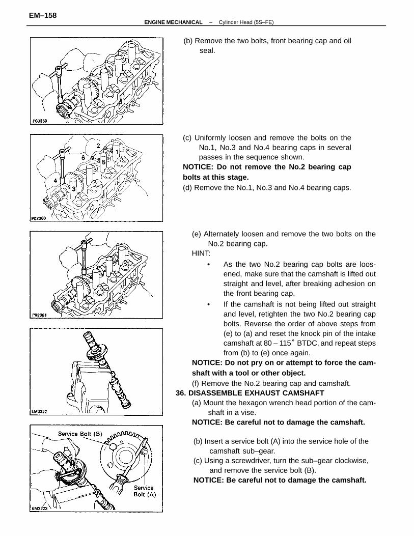
(e) Alternately loosen and remove the two bolts on theNo.2 bearing cap.
HINT:
• As the two No.2 bearing cap bolts are loos-ened, make sure that the camshaft is lifted outstraight and level, after breaking adhesion onthe front bearing cap.
• If the camshaft is not being lifted out straightand level, retighten the two No.2 bearing capbolts. Reverse the order of above steps from(e) to (a) and reset the knock pin of the intakecamshaft at 80 – 115° BTDC, and repeat stepsfrom (b) to (e) once again.
NOTICE: Do not pry on or attempt to force the cam-shaft with a tool or other object.(f) Remove the No.2 bearing cap and camshaft.
36. DISASSEMBLE EXHAUST CAMSHAFT(a) Mount the hexagon wrench head portion of the cam-
shaft in a vise.NOTICE: Be careful not to damage the camshaft.
(c) Uniformly loosen and remove the bolts on theNo.1, No.3 and No.4 bearing caps in severalpasses in the sequence shown.
NOTICE: Do not remove the No.2 bearing capbolts at this stage.(d) Remove the No.1, No.3 and No.4 bearing caps.
(b) Insert a service bolt (A) into the service hole of thecamshaft sub–gear.
(c) Using a screwdriver, turn the sub–gear clockwise,and remove the service bolt (B).
NOTICE: Be careful not to damage the camshaft.
(b) Remove the two bolts, front bearing cap and oilseal.
–ENGINE MECHANICAL Cylinder Head (5S–FE)EM–158
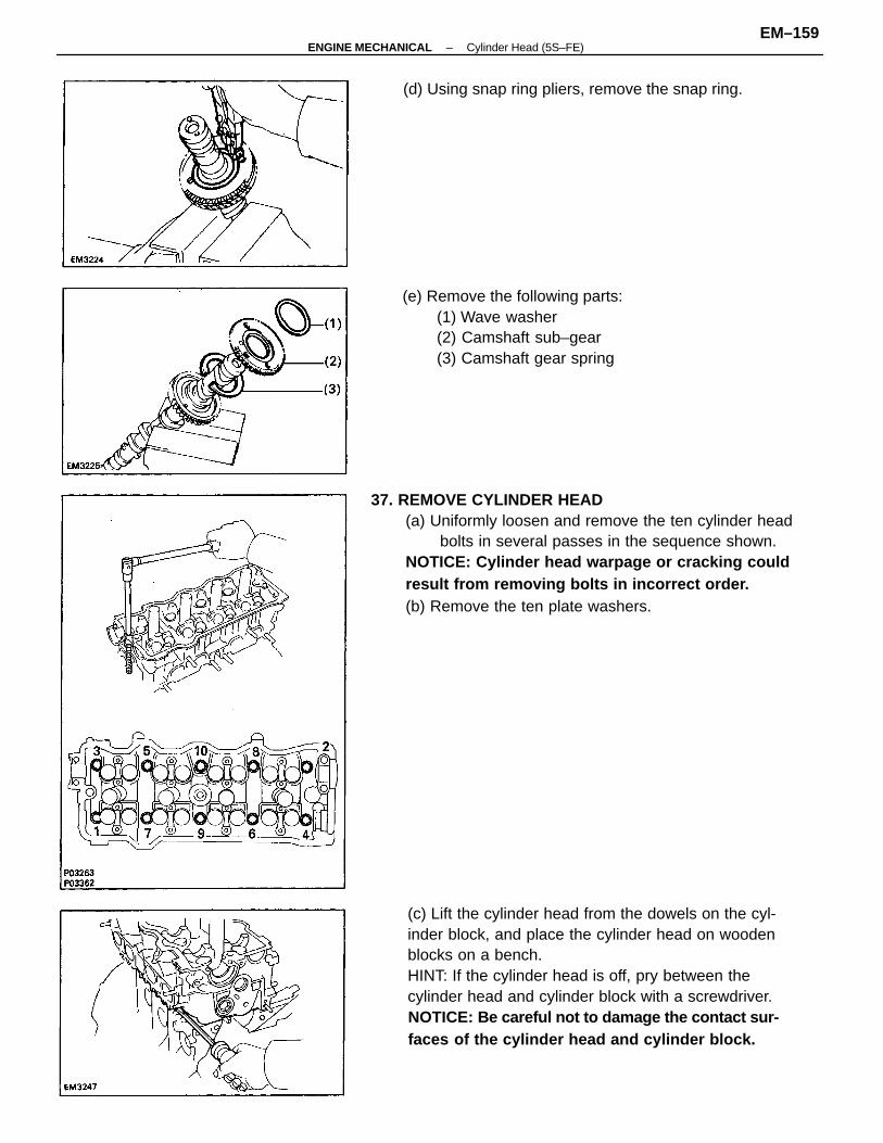
(c) Lift the cylinder head from the dowels on the cyl-inder block, and place the cylinder head on woodenblocks on a bench.HINT: If the cylinder head is off, pry between thecylinder head and cylinder block with a screwdriver.NOTICE: Be careful not to damage the contact sur-faces of the cylinder head and cylinder block.
37. REMOVE CYLINDER HEAD(a) Uniformly loosen and remove the ten cylinder head
bolts in several passes in the sequence shown.NOTICE: Cylinder head warpage or cracking couldresult from removing bolts in incorrect order.(b) Remove the ten plate washers.
(e) Remove the following parts:(1) Wave washer(2) Camshaft sub–gear(3) Camshaft gear spring
(d) Using snap ring pliers, remove the snap ring.
–ENGINE MECHANICAL Cylinder Head (5S–FE)EM–159
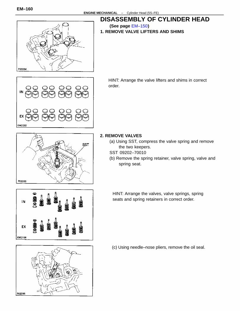
2. REMOVE VALVES(a) Using SST, compress the valve spring and remove
the two keepers.SST 09202–70010(b) Remove the spring retainer, valve spring, valve and
spring seat.
DISASSEMBLY OF CYLINDER HEAD(See page EM–150)
1. REMOVE VALVE LIFTERS AND SHIMS
HINT: Arrange the valves, valve springs, springseats and spring retainers in correct order.
HINT: Arrange the valve lifters and shims in correctorder.
(c) Using needle–nose pliers, remove the oil seal.
–ENGINE MECHANICAL Cylinder Head (5S–FE)EM–160
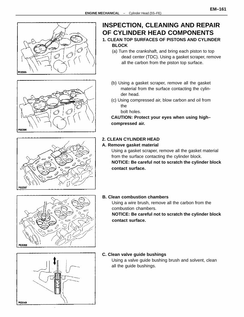
INSPECTION, CLEANING AND REPAIROF CYLINDER HEAD COMPONENTS1. CLEAN TOP SURFACES OF PISTONS AND CYLINDER
BLOCK(a) Turn the crankshaft, and bring each piston to top
dead center (TDC). Using a gasket scraper, removeall the carbon from the piston top surface.
2. CLEAN CYLINDER HEADA. Remove gasket material
Using a gasket scraper, remove all the gasket materialfrom the surface contacting the cylinder block.NOTICE: Be careful not to scratch the cylinder blockcontact surface.
(b) Using a gasket scraper, remove all the gasketmaterial from the surface contacting the cylin-der head.
(c) Using compressed air, blow carbon and oil fromthebolt holes.
CAUTION: Protect your eyes when using high–compressed air.
B. Clean combustion chambersUsing a wire brush, remove all the carbon from thecombustion chambers.NOTICE: Be careful not to scratch the cylinder blockcontact surface.
C. Clean valve guide bushingsUsing a valve guide bushing brush and solvent, cleanall the guide bushings.
–ENGINE MECHANICAL Cylinder Head (5S–FE)EM–161
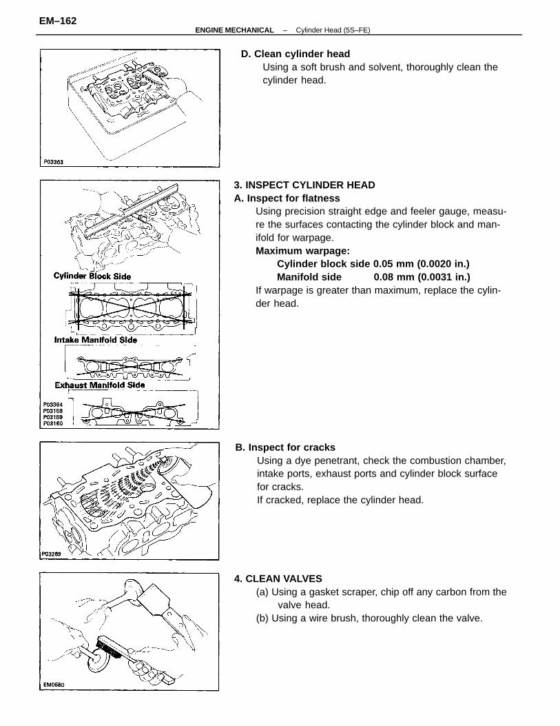
3. INSPECT CYLINDER HEADA. Inspect for flatness
Using precision straight edge and feeler gauge, measu-re the surfaces contacting the cylinder block and man-ifold for warpage.Maximum warpage:
Cylinder block side 0.05 mm (0.0020 in.) Manifold side 0.08 mm (0.0031 in.)
If warpage is greater than maximum, replace the cylin-der head.
B. Inspect for cracksUsing a dye penetrant, check the combustion chamber,intake ports, exhaust ports and cylinder block surfacefor cracks.If cracked, replace the cylinder head.
4. CLEAN VALVES(a) Using a gasket scraper, chip off any carbon from the
valve head.(b) Using a wire brush, thoroughly clean the valve.
D. Clean cylinder headUsing a soft brush and solvent, thoroughly clean thecylinder head.
–ENGINE MECHANICAL Cylinder Head (5S–FE)EM–162
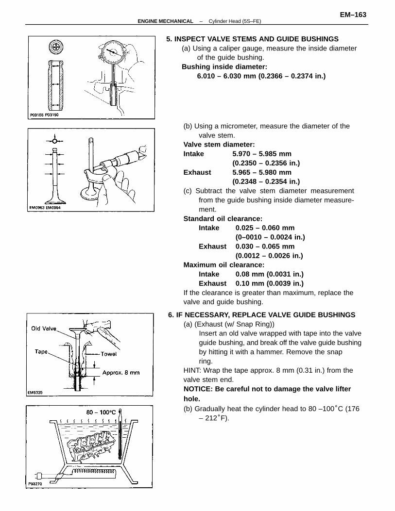
(b) Using a micrometer, measure the diameter of thevalve stem.
Valve stem diameter:Intake 5.970 – 5.985 mm
(0.2350 – 0.2356 in.)Exhaust 5.965 – 5.980 mm
(0.2348 – 0.2354 in.)(c) Subtract the valve stem diameter measurement
from the guide bushing inside diameter measure-ment.
Standard oil clearance:Intake 0.025 – 0.060 mm
(0–0010 – 0.0024 in.)Exhaust 0.030 – 0.065 mm
(0.0012 – 0.0026 in.)Maximum oil clearance:
Intake 0.08 mm (0.0031 in.)Exhaust 0.10 mm (0.0039 in.)
If the clearance is greater than maximum, replace thevalve and guide bushing.
6. IF NECESSARY, REPLACE VALVE GUIDE BUSHINGS(a) (Exhaust (w/ Snap Ring))
Insert an old valve wrapped with tape into the valveguide bushing, and break off the valve guide bushingby hitting it with a hammer. Remove the snapring.
HINT: Wrap the tape approx. 8 mm (0.31 in.) from thevalve stem end.NOTICE: Be careful not to damage the valve lifterhole.(b) Gradually heat the cylinder head to 80 –100°C (176
– 212°F).
5. INSPECT VALVE STEMS AND GUIDE BUSHINGS(a) Using a caliper gauge, measure the inside diameter
of the guide bushing.Bushing inside diameter:
6.010 – 6.030 mm (0.2366 – 0.2374 in.)
–ENGINE MECHANICAL Cylinder Head (5S–FE)EM–163
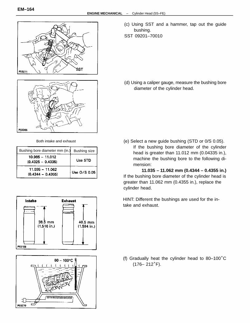
(e) Select a new guide bushing (STD or 0/S 0.05).If the bushing bore diameter of the cylinderhead is greater than 11.012 mm (0.04335 in.),machine the bushing bore to the following di-mension:
11.035 – 11.062 mm (0.4344 – 0.4355 in.)If the bushing bore diameter of the cylinder head isgreater than 11.062 mm (0.4355 in.), replace thecylinder head.
(c) Using SST and a hammer, tap out the guidebushing.
SST 09201–70010
(d) Using a caliper gauge, measure the bushing borediameter of the cylinder head.
(f) Gradually heat the cylinder head to 80–100°C(176– 212°F).
HINT: Different the bushings are used for the in-take and exhaust.
Bushing bore diameter mm (in.)
Both intake and exhaust
Bushing size
–ENGINE MECHANICAL Cylinder Head (5S–FE)EM–164
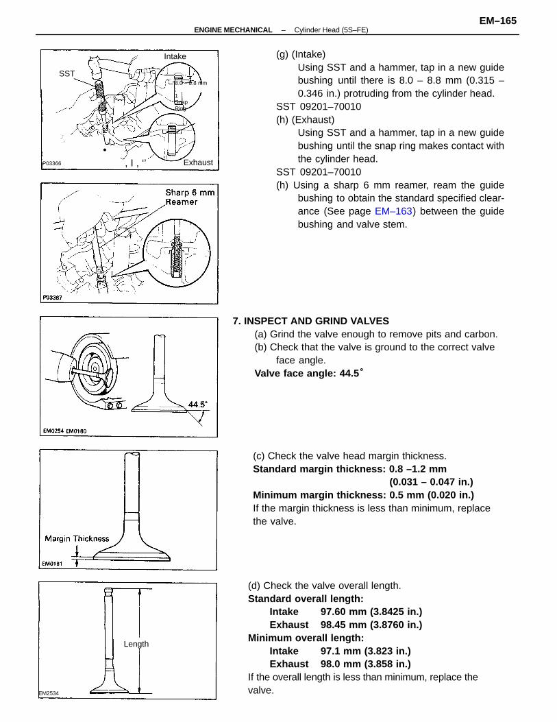
(g) (Intake)Using SST and a hammer, tap in a new guidebushing until there is 8.0 – 8.8 mm (0.315 –0.346 in.) protruding from the cylinder head.
SST 09201–70010(h) (Exhaust)
Using SST and a hammer, tap in a new guidebushing until the snap ring makes contact withthe cylinder head.
SST 09201–70010(h) Using a sharp 6 mm reamer, ream the guide
bushing to obtain the standard specified clear-ance (See page EM–163) between the guidebushing and valve stem.
(d) Check the valve overall length.Standard overall length:
Intake 97.60 mm (3.8425 in.)Exhaust 98.45 mm (3.8760 in.)
Minimum overall length:Intake 97.1 mm (3.823 in.)Exhaust 98.0 mm (3.858 in.)
If the overall length is less than minimum, replace thevalve.
(c) Check the valve head margin thickness.Standard margin thickness: 0.8 –1.2 mm
(0.031 – 0.047 in.)Minimum margin thickness: 0.5 mm (0.020 in.)If the margin thickness is less than minimum, replacethe valve.
7. INSPECT AND GRIND VALVES(a) Grind the valve enough to remove pits and carbon.(b) Check that the valve is ground to the correct valve
face angle.Valve face angle: 44.5 °
. _–” , . r
•, I , ‘’
8.0 – 8.8 mm;1SnapRing
_,J.,.
Exhaust
Length
Intake
EM2534
P03366
SST
–ENGINE MECHANICAL Cylinder Head (5S–FE)EM–165
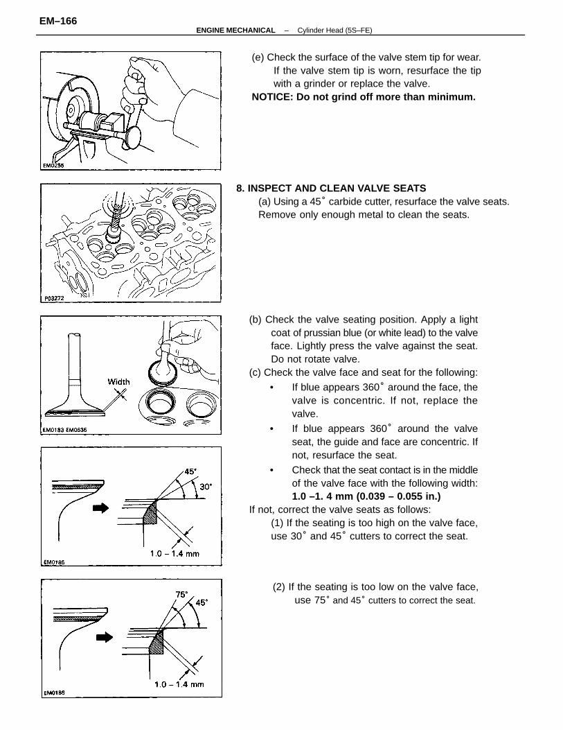
(b) Check the valve seating position. Apply a lightcoat of prussian blue (or white lead) to the valveface. Lightly press the valve against the seat.Do not rotate valve.
(c) Check the valve face and seat for the following:
• If blue appears 360° around the face, thevalve is concentric. If not, replace thevalve.
• If blue appears 360° around the valveseat, the guide and face are concentric. Ifnot, resurface the seat.
• Check that the seat contact is in the middleof the valve face with the following width:1.0 –1. 4 mm (0.039 – 0.055 in.)
If not, correct the valve seats as follows:(1) If the seating is too high on the valve face,use 30° and 45° cutters to correct the seat.
(e) Check the surface of the valve stem tip for wear.If the valve stem tip is worn, resurface the tipwith a grinder or replace the valve.
NOTICE: Do not grind off more than minimum.
8. INSPECT AND CLEAN VALVE SEATS(a) Using a 45° carbide cutter, resurface the valve seats.Remove only enough metal to clean the seats.
(2) If the seating is too low on the valve face,use 75° and 45° cutters to correct the seat.
–ENGINE MECHANICAL Cylinder Head (5S–FE)EM–166
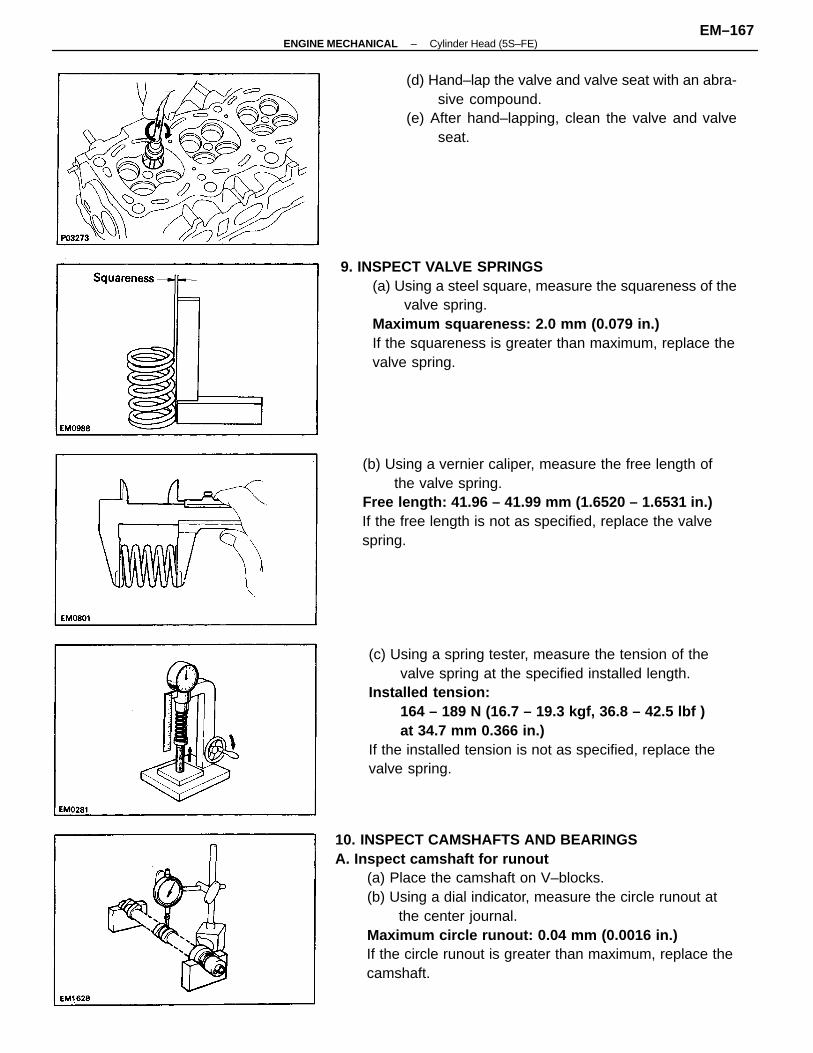
10. INSPECT CAMSHAFTS AND BEARINGSA. Inspect camshaft for runout
(a) Place the camshaft on V–blocks.(b) Using a dial indicator, measure the circle runout at
the center journal.Maximum circle runout: 0.04 mm (0.0016 in.)If the circle runout is greater than maximum, replace thecamshaft.
(c) Using a spring tester, measure the tension of thevalve spring at the specified installed length.
Installed tension:164 – 189 N (16.7 – 19.3 kgf, 36.8 – 42.5 lbf )at 34.7 mm 0.366 in.)
If the installed tension is not as specified, replace thevalve spring.
9. INSPECT VALVE SPRINGS(a) Using a steel square, measure the squareness of the
valve spring.Maximum squareness: 2.0 mm (0.079 in.)If the squareness is greater than maximum, replace thevalve spring.
(b) Using a vernier caliper, measure the free length ofthe valve spring.
Free length: 41.96 – 41.99 mm (1.6520 – 1.6531 in.)If the free length is not as specified, replace the valvespring.
(d) Hand–lap the valve and valve seat with an abra-sive compound.
(e) After hand–lapping, clean the valve and valveseat.
–ENGINE MECHANICAL Cylinder Head (5S–FE)EM–167
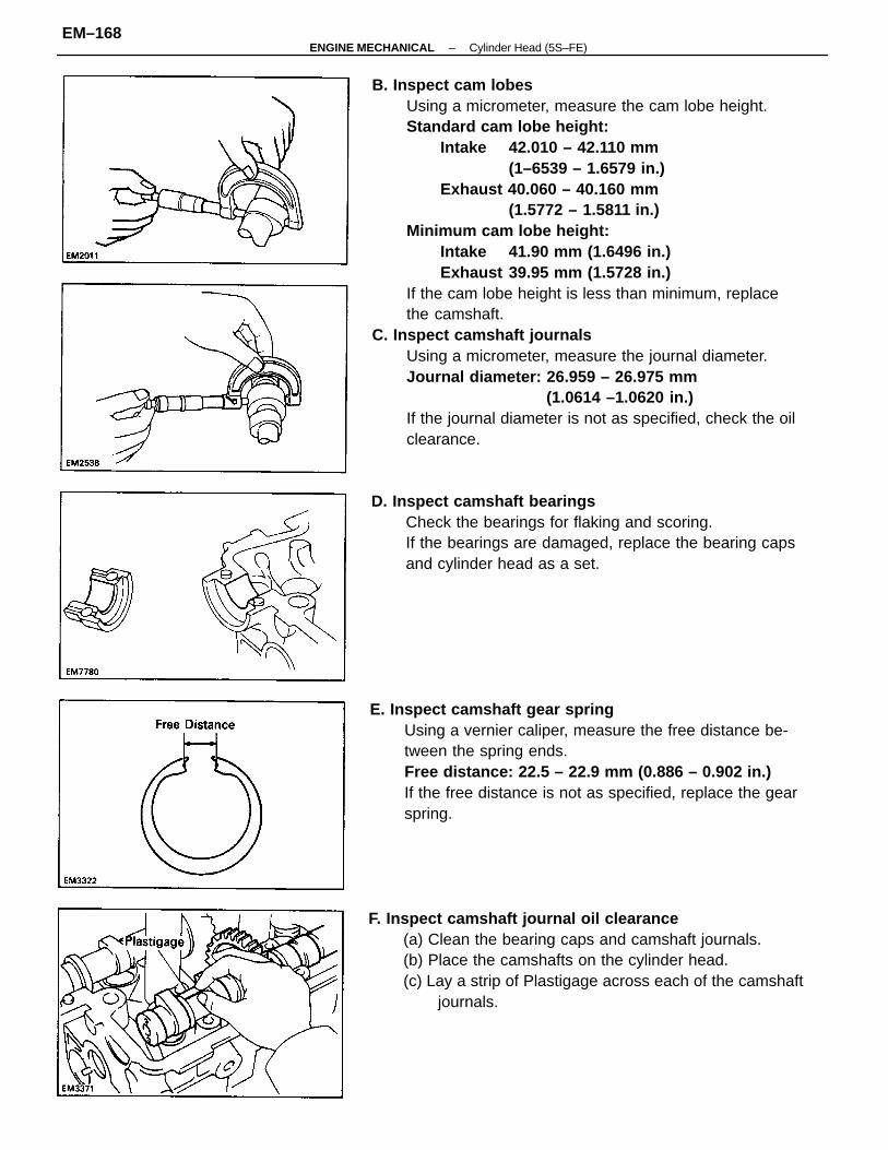
B. Inspect cam lobesUsing a micrometer, measure the cam lobe height.Standard cam lobe height:
Intake 42.010 – 42.110 mm(1–6539 – 1.6579 in.)
Exhaust 40.060 – 40.160 mm(1.5772 – 1.5811 in.)
Minimum cam lobe height:Intake 41.90 mm (1.6496 in.)Exhaust 39.95 mm (1.5728 in.)
If the cam lobe height is less than minimum, replacethe camshaft.
C. Inspect camshaft journalsUsing a micrometer, measure the journal diameter.Journal diameter: 26.959 – 26.975 mm
(1.0614 –1.0620 in.)If the journal diameter is not as specified, check the oilclearance.
E. Inspect camshaft gear springUsing a vernier caliper, measure the free distance be-tween the spring ends.Free distance: 22.5 – 22.9 mm (0.886 – 0.902 in.)If the free distance is not as specified, replace the gearspring.
F. Inspect camshaft journal oil clearance(a) Clean the bearing caps and camshaft journals.(b) Place the camshafts on the cylinder head.(c) Lay a strip of Plastigage across each of the camshaft
journals.
D. Inspect camshaft bearingsCheck the bearings for flaking and scoring.If the bearings are damaged, replace the bearing capsand cylinder head as a set.
–ENGINE MECHANICAL Cylinder Head (5S–FE)EM–168
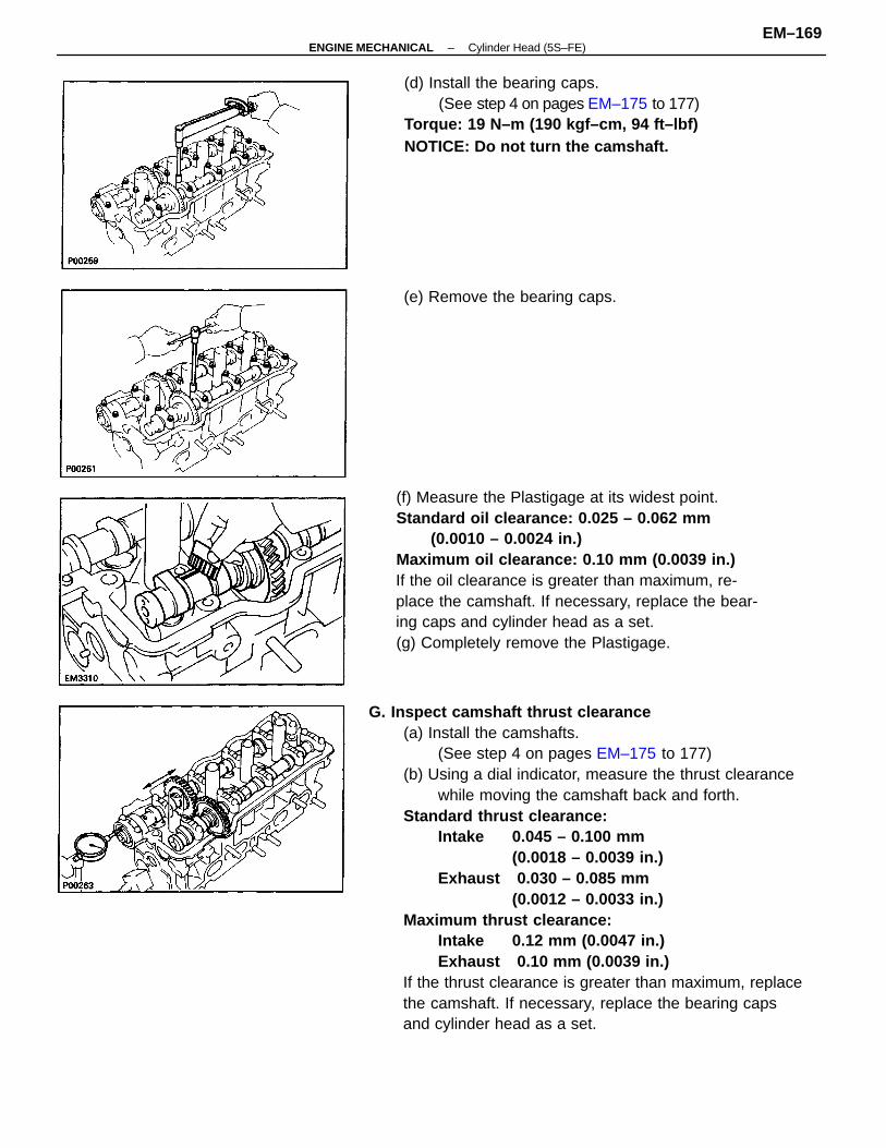
G. Inspect camshaft thrust clearance(a) Install the camshafts.
(See step 4 on pages EM–175 to 177)(b) Using a dial indicator, measure the thrust clearance
while moving the camshaft back and forth.Standard thrust clearance:
Intake 0.045 – 0.100 mm(0.0018 – 0.0039 in.)
Exhaust 0.030 – 0.085 mm(0.0012 – 0.0033 in.)
Maximum thrust clearance:Intake 0.12 mm (0.0047 in.)Exhaust 0.10 mm (0.0039 in.)
If the thrust clearance is greater than maximum, replacethe camshaft. If necessary, replace the bearing capsand cylinder head as a set.
(f) Measure the Plastigage at its widest point.Standard oil clearance: 0.025 – 0.062 mm
(0.0010 – 0.0024 in.)Maximum oil clearance: 0.10 mm (0.0039 in.)If the oil clearance is greater than maximum, re-place the camshaft. If necessary, replace the bear-ing caps and cylinder head as a set.(g) Completely remove the Plastigage.
(d) Install the bearing caps.(See step 4 on pages EM–175 to 177)
Torque: 19 N–m (190 kgf–cm, 94 ft–lbf)NOTICE: Do not turn the camshaft.
(e) Remove the bearing caps.
–ENGINE MECHANICAL Cylinder Head (5S–FE)EM–169
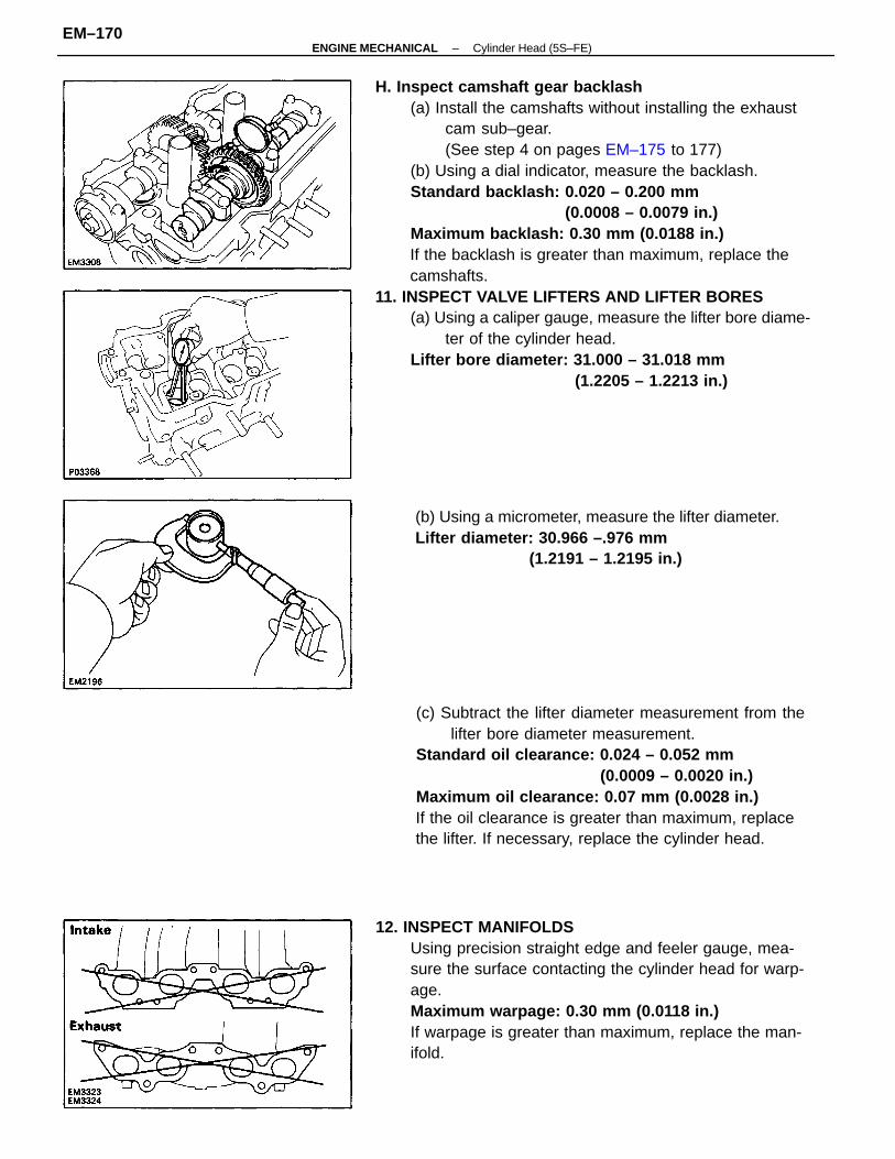
H. Inspect camshaft gear backlash(a) Install the camshafts without installing the exhaust
cam sub–gear.(See step 4 on pages EM–175 to 177)
(b) Using a dial indicator, measure the backlash.Standard backlash: 0.020 – 0.200 mm
(0.0008 – 0.0079 in.)Maximum backlash: 0.30 mm (0.0188 in.)If the backlash is greater than maximum, replace thecamshafts.
11. INSPECT VALVE LIFTERS AND LIFTER BORES(a) Using a caliper gauge, measure the lifter bore diame-
ter of the cylinder head.Lifter bore diameter: 31.000 – 31.018 mm
(1.2205 – 1.2213 in.)
(c) Subtract the lifter diameter measurement from thelifter bore diameter measurement.
Standard oil clearance: 0.024 – 0.052 mm(0.0009 – 0.0020 in.)
Maximum oil clearance: 0.07 mm (0.0028 in.)If the oil clearance is greater than maximum, replacethe lifter. If necessary, replace the cylinder head.
12. INSPECT MANIFOLDSUsing precision straight edge and feeler gauge, mea-sure the surface contacting the cylinder head for warp-age.Maximum warpage: 0.30 mm (0.0118 in.)If warpage is greater than maximum, replace the man-ifold.
(b) Using a micrometer, measure the lifter diameter.Lifter diameter: 30.966 –.976 mm
(1.2191 – 1.2195 in.)
–ENGINE MECHANICAL Cylinder Head (5S–FE)EM–170
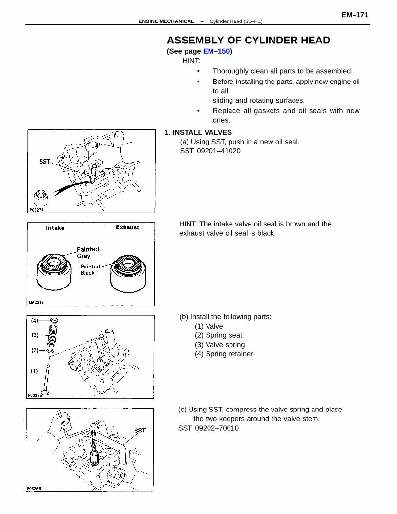
ASSEMBLY OF CYLINDER HEAD(See page EM–150)
HINT:
• Thoroughly clean all parts to be assembled.
• Before installing the parts, apply new engine oilto allsliding and rotating surfaces.
• Replace all gaskets and oil seals with newones.
(b) Install the following parts:(1) Valve(2) Spring seat(3) Valve spring(4) Spring retainer
(c) Using SST, compress the valve spring and placethe two keepers around the valve stem.
SST 09202–70010
1. INSTALL VALVES(a) Using SST, push in a new oil seal.SST 09201–41020
HINT: The intake valve oil seal is brown and theexhaust valve oil seal is black.
–ENGINE MECHANICAL Cylinder Head (5S–FE)EM–171
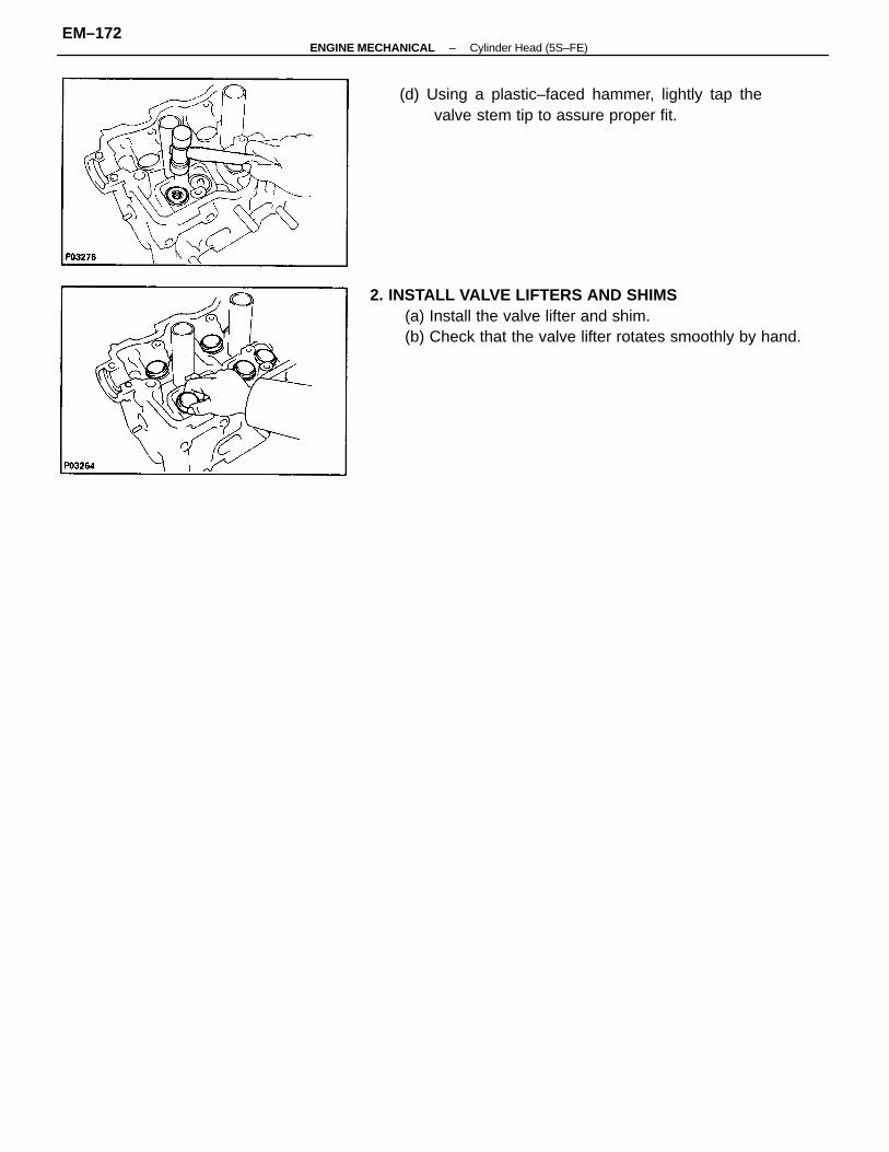
2. INSTALL VALVE LIFTERS AND SHIMS(a) Install the valve lifter and shim.(b) Check that the valve lifter rotates smoothly by hand.
(d) Using a plastic–faced hammer, lightly tap thevalve stem tip to assure proper fit.
–ENGINE MECHANICAL Cylinder Head (5S–FE)EM–172
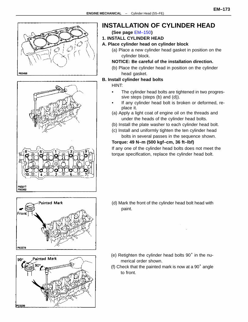
INSTALLATION OF CYLINDER HEAD(See page EM–150)
1. INSTALL CYLINDER HEADA. Place cylinder head on cylinder block
(a) Place a new cylinder head gasket in position on thecylinder block.
NOTICE: Be careful of the installation direction.(b) Place the cylinder head in position on the cylinder
head gasket.B. Install cylinder head bolts
HINT:
• The cylinder head bolts are tightened in two progres-sive steps (steps (b) and (d)).
• If any cylinder head bolt is broken or deformed, re-place it.
(a) Apply a light coat of engine oil on the threads andunder the heads of the cylinder head bolts.
(b) Install the plate washer to each cylinder head bolt.(c) Install and uniformly tighten the ten cylinder head
bolts in several passes in the sequence shown.Torque: 49 N–m (500 kgf–cm, 36 ft–lbf)If any one of the cylinder head bolts does not meet thetorque specification, replace the cylinder head bolt.
(e) Retighten the cylinder head bolts 90° in the nu-merical order shown.
(f) Check that the painted mark is now at a 90° angleto front.
(d) Mark the front of the cylinder head bolt head withpaint.
–ENGINE MECHANICAL Cylinder Head (5S–FE)EM–173
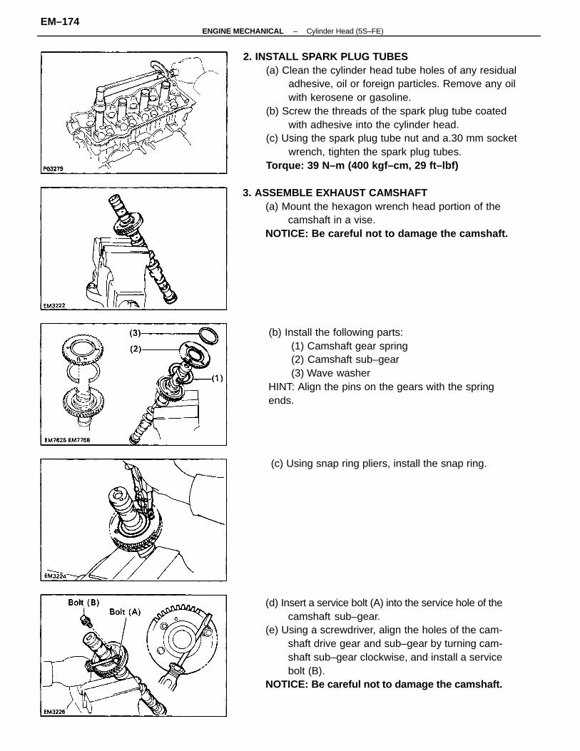
2. INSTALL SPARK PLUG TUBES(a) Clean the cylinder head tube holes of any residual
adhesive, oil or foreign particles. Remove any oilwith kerosene or gasoline.
(b) Screw the threads of the spark plug tube coatedwith adhesive into the cylinder head.
(c) Using the spark plug tube nut and a.30 mm socketwrench, tighten the spark plug tubes.
Torque: 39 N–m (400 kgf–cm, 29 ft–lbf)
(d) Insert a service bolt (A) into the service hole of thecamshaft sub–gear.
(e) Using a screwdriver, align the holes of the cam-shaft drive gear and sub–gear by turning cam-shaft sub–gear clockwise, and install a servicebolt (B).
NOTICE: Be careful not to damage the camshaft.
(b) Install the following parts:(1) Camshaft gear spring(2) Camshaft sub–gear(3) Wave washer
HINT: Align the pins on the gears with the springends.
3. ASSEMBLE EXHAUST CAMSHAFT(a) Mount the hexagon wrench head portion of the
camshaft in a vise.NOTICE: Be careful not to damage the camshaft.
(c) Using snap ring pliers, install the snap ring.
–ENGINE MECHANICAL Cylinder Head (5S–FE)EM–174
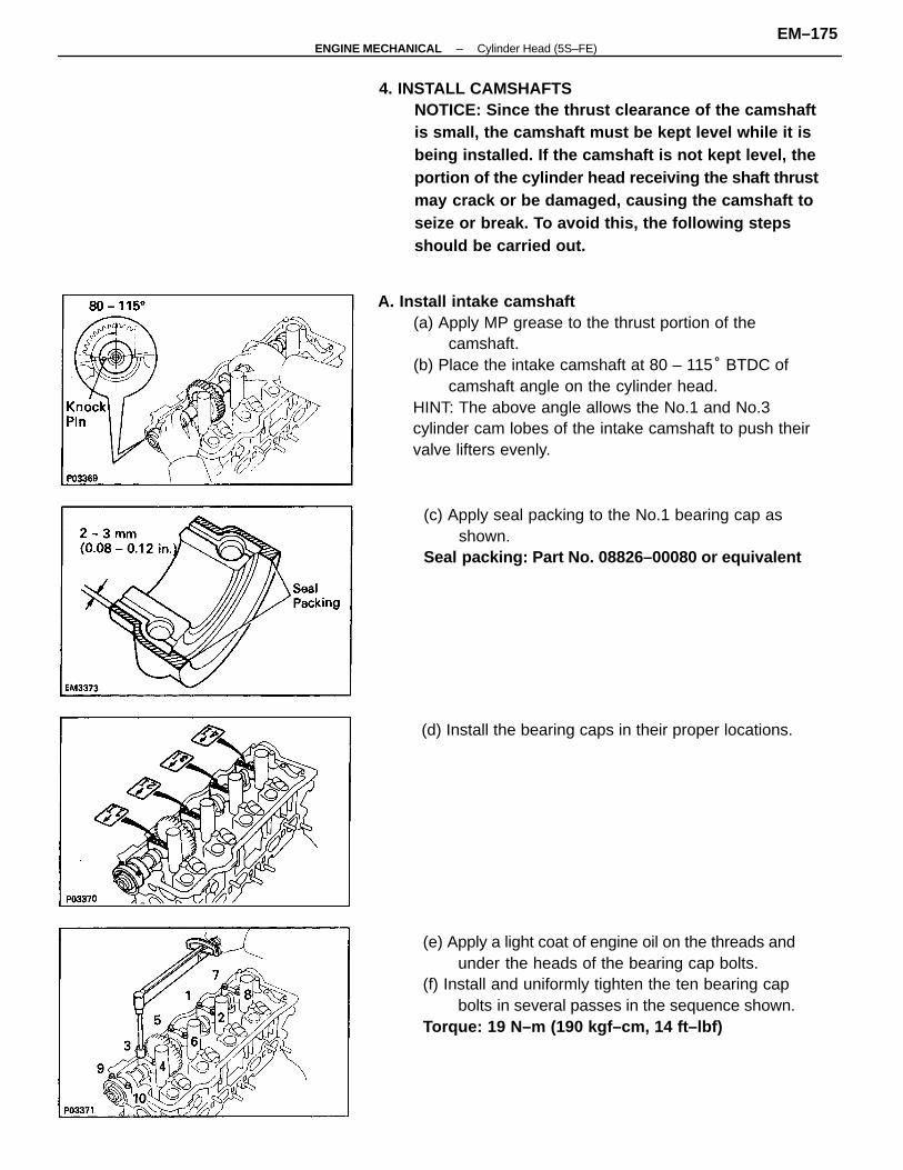
A. Install intake camshaft(a) Apply MP grease to the thrust portion of the
camshaft.(b) Place the intake camshaft at 80 – 115° BTDC of
camshaft angle on the cylinder head.HINT: The above angle allows the No.1 and No.3cylinder cam lobes of the intake camshaft to push theirvalve lifters evenly.
4. INSTALL CAMSHAFTSNOTICE: Since the thrust clearance of the camshaftis small, the camshaft must be kept level while it isbeing installed. If the camshaft is not kept level, theportion of the cylinder head receiving the shaft thrustmay crack or be damaged, causing the camshaft toseize or break. To avoid this, the following stepsshould be carried out.
(e) Apply a light coat of engine oil on the threads andunder the heads of the bearing cap bolts.
(f) Install and uniformly tighten the ten bearing capbolts in several passes in the sequence shown.
Torque: 19 N–m (190 kgf–cm, 14 ft–lbf)
(c) Apply seal packing to the No.1 bearing cap asshown.
Seal packing: Part No. 08826–00080 or equivalent
(d) Install the bearing caps in their proper locations.
–ENGINE MECHANICAL Cylinder Head (5S–FE)EM–175
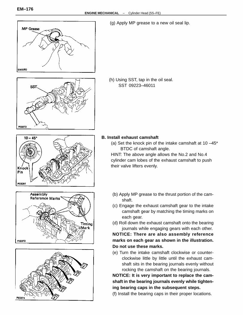
(b) Apply MP grease to the thrust portion of the cam-shaft.
(c) Engage the exhaust camshaft gear to the intakecamshaft gear by matching the timing marks oneach gear.
(d) Roll down the exhaust camshaft onto the bearingjournals while engaging gears with each other.
NOTICE: There are also assembly referencemarks on each gear as shown in the illustration.Do not use these marks.(e) Turn the intake camshaft clockwise or counter-
clockwise little by little until the exhaust cam-shaft sits in the bearing journals evenly withoutrocking the camshaft on the bearing journals.
NOTICE: It is very important to replace the cam-shaft in the bearing journals evenly while tighten-ing bearing caps in the subsequent steps.(f) Install the bearing caps in their proper locations.
B. Install exhaust camshaft(a) Set the knock pin of the intake camshaft at 10 –45*
BTDC of camshaft angle.HINT: The above angle allows the No.2 and No.4cylinder cam lobes of the exhaust camshaft to pushtheir valve lifters evenly.
(h) Using SST, tap in the oil seal.SST 09223–46011
(g) Apply MP grease to a new oil seal lip.
–ENGINE MECHANICAL Cylinder Head (5S–FE)EM–176
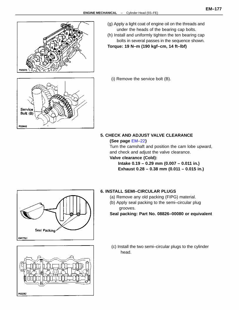
5. CHECK AND ADJUST VALVE CLEARANCE(See page EM–22)Turn the camshaft and position the cam lobe upward,and check and adjust the valve clearance.Valve clearance (Cold):
Intake 0.19 – 0.29 mm (0.007 – 0.011 in.)Exhaust 0.28 – 0.38 mm (0.011 – 0.015 in.)
6. INSTALL SEMI–CIRCULAR PLUGS(a) Remove any old packing (FIPG) material.(b) Apply seal packing to the semi–circular plug
grooves.Seal packing: Part No. 08826–00080 or equivalent
(g) Apply a light coat of engine oil on the threads andunder the heads of the bearing cap bolts.
(h) Install and uniformly tighten the ten bearing capbolts in several passes in the sequence shown.
Torque: 19 N–m (190 kgf–cm, 14 ft–lbf)
(c) Install the two semi–circular plugs to the cylinderhead.
(i) Remove the service bolt (B).
–ENGINE MECHANICAL Cylinder Head (5S–FE)EM–177
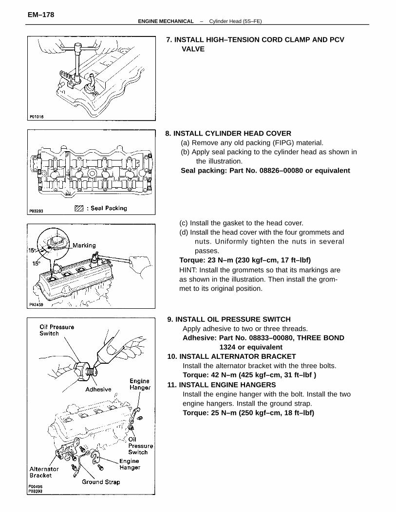
9. INSTALL OIL PRESSURE SWITCHApply adhesive to two or three threads.Adhesive: Part No. 08833–00080, THREE BOND
1324 or equivalent10. INSTALL ALTERNATOR BRACKET
Install the alternator bracket with the three bolts.Torque: 42 N–m (425 kgf–cm, 31 ft–lbf )
11. INSTALL ENGINE HANGERSInstall the engine hanger with the bolt. Install the twoengine hangers. Install the ground strap.Torque: 25 N–m (250 kgf–cm, 18 ft–lbf)
(c) Install the gasket to the head cover.(d) Install the head cover with the four grommets and
nuts. Uniformly tighten the nuts in severalpasses.
Torque: 23 N–m (230 kgf–cm, 17 ft–lbf)HINT: Install the grommets so that its markings areas shown in the illustration. Then install the grom-met to its original position.
8. INSTALL CYLINDER HEAD COVER(a) Remove any old packing (FIPG) material.(b) Apply seal packing to the cylinder head as shown in
the illustration.Seal packing: Part No. 08826–00080 or equivalent
7. INSTALL HIGH–TENSION CORD CLAMP AND PCVVALVE
–ENGINE MECHANICAL Cylinder Head (5S–FE)EM–178
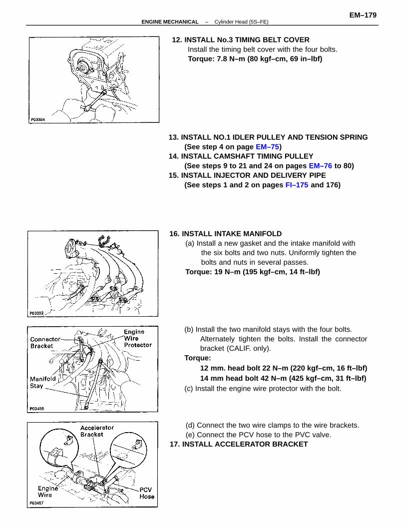
13. INSTALL NO.1 IDLER PULLEY AND TENSION SPRING(See step 4 on page EM–75)
14. INSTALL CAMSHAFT TIMING PULLEY(See steps 9 to 21 and 24 on pages EM–76 to 80)
15. INSTALL INJECTOR AND DELIVERY PIPE(See steps 1 and 2 on pages FI–175 and 176)
(b) Install the two manifold stays with the four bolts.Alternately tighten the bolts. Install the connectorbracket (CALIF. only).
Torque:12 mm. head bolt 22 N–m (220 kgf–cm, 16 ft–lbf)14 mm head bolt 42 N–m (425 kgf–cm, 31 ft–lbf)
(c) Install the engine wire protector with the bolt.
16. INSTALL INTAKE MANIFOLD(a) Install a new gasket and the intake manifold with
the six bolts and two nuts. Uniformly tighten thebolts and nuts in several passes.
Torque: 19 N–m (195 kgf–cm, 14 ft–lbf)
12. INSTALL No.3 TIMING BELT COVERInstall the timing belt cover with the four bolts.Torque: 7.8 N–m (80 kgf–cm, 69 in–lbf)
(d) Connect the two wire clamps to the wire brackets.(e) Connect the PCV hose to the PVC valve.
17. INSTALL ACCELERATOR BRACKET
–ENGINE MECHANICAL Cylinder Head (5S–FE)EM–179
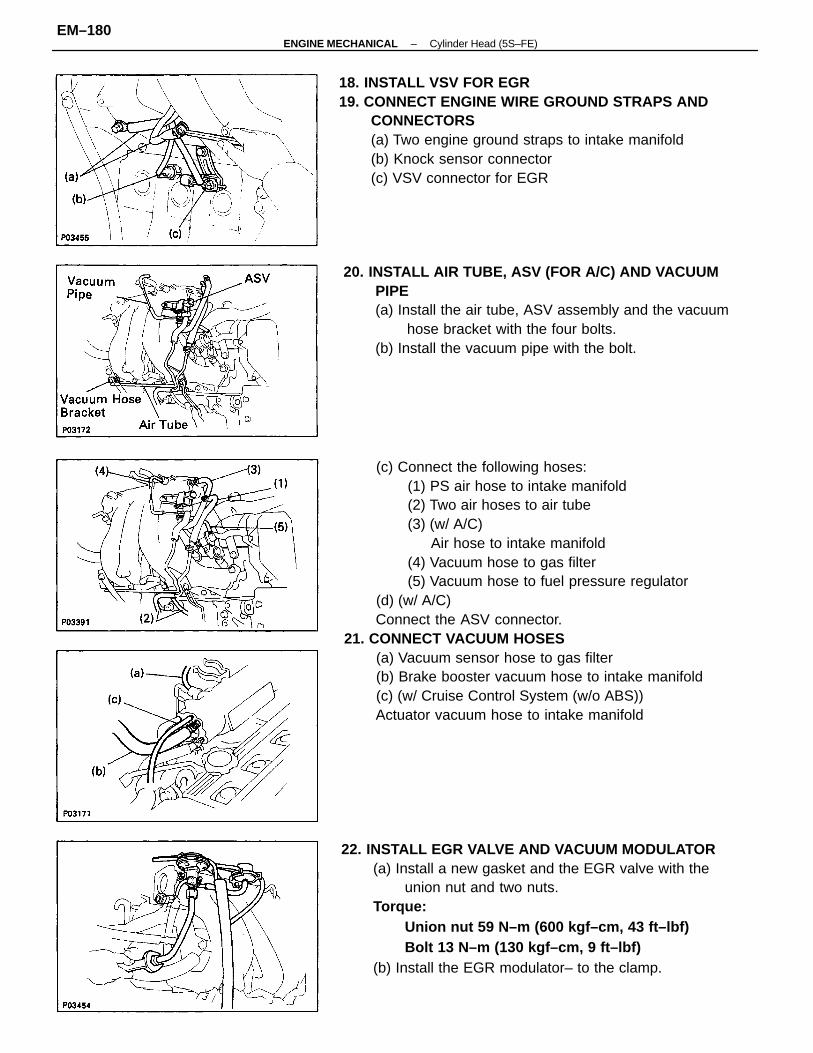
(c) Connect the following hoses:(1) PS air hose to intake manifold(2) Two air hoses to air tube(3) (w/ A/C)
Air hose to intake manifold(4) Vacuum hose to gas filter(5) Vacuum hose to fuel pressure regulator
(d) (w/ A/C)Connect the ASV connector.
21. CONNECT VACUUM HOSES(a) Vacuum sensor hose to gas filter(b) Brake booster vacuum hose to intake manifold(c) (w/ Cruise Control System (w/o ABS))Actuator vacuum hose to intake manifold
22. INSTALL EGR VALVE AND VACUUM MODULATOR(a) Install a new gasket and the EGR valve with the
union nut and two nuts.Torque:
Union nut 59 N–m (600 kgf–cm, 43 ft–lbf)Bolt 13 N–m (130 kgf–cm, 9 ft–lbf)
(b) Install the EGR modulator– to the clamp.
18. INSTALL VSV FOR EGR19. CONNECT ENGINE WIRE GROUND STRAPS AND
CONNECTORS(a) Two engine ground straps to intake manifold(b) Knock sensor connector(c) VSV connector for EGR
20. INSTALL AIR TUBE, ASV (FOR A/C) AND VACUUMPIPE(a) Install the air tube, ASV assembly and the vacuum
hose bracket with the four bolts.(b) Install the vacuum pipe with the bolt.
–ENGINE MECHANICAL Cylinder Head (5S–FE)EM–180
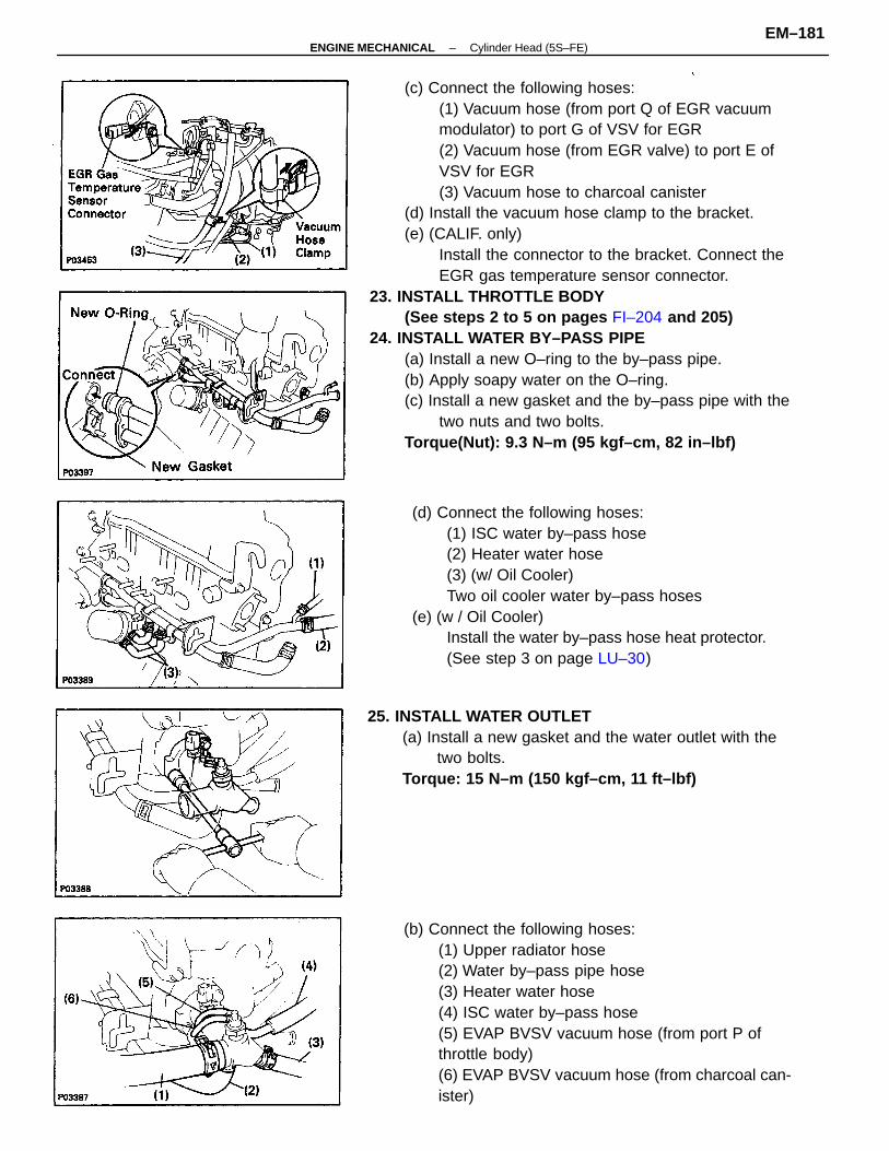
(c) Connect the following hoses:(1) Vacuum hose (from port Q of EGR vacuummodulator) to port G of VSV for EGR(2) Vacuum hose (from EGR valve) to port E ofVSV for EGR(3) Vacuum hose to charcoal canister
(d) Install the vacuum hose clamp to the bracket.(e) (CALIF. only)
Install the connector to the bracket. Connect theEGR gas temperature sensor connector.
23. INSTALL THROTTLE BODY(See steps 2 to 5 on pages FI–204 and 205)
24. INSTALL WATER BY–PASS PIPE(a) Install a new O–ring to the by–pass pipe.(b) Apply soapy water on the O–ring.(c) Install a new gasket and the by–pass pipe with the
two nuts and two bolts.Torque(Nut): 9.3 N–m (95 kgf–cm, 82 in–lbf)
(b) Connect the following hoses:(1) Upper radiator hose(2) Water by–pass pipe hose(3) Heater water hose(4) ISC water by–pass hose(5) EVAP BVSV vacuum hose (from port P ofthrottle body)(6) EVAP BVSV vacuum hose (from charcoal can-ister)
(d) Connect the following hoses:(1) ISC water by–pass hose(2) Heater water hose(3) (w/ Oil Cooler)Two oil cooler water by–pass hoses
(e) (w / Oil Cooler)Install the water by–pass hose heat protector.(See step 3 on page LU–30)
25. INSTALL WATER OUTLET(a) Install a new gasket and the water outlet with the
two bolts.Torque: 15 N–m (150 kgf–cm, 11 ft–lbf)
–ENGINE MECHANICAL Cylinder Head (5S–FE)EM–181
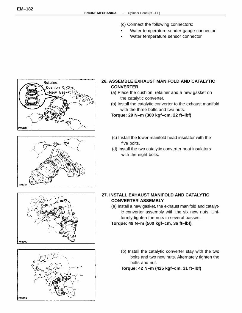
26. ASSEMBLE EXHAUST MANIFOLD AND CATALYTICCONVERTER(a) Place the cushion, retainer and a new gasket on
the catalytic converter.(b) Install the catalytic converter to the exhaust manifold
with the three bolts and two nuts.Torque: 29 N–m (300 kgf–cm, 22 ft–lbf)
27. INSTALL EXHAUST MANIFOLD AND CATALYTICCONVERTER ASSEMBLY(a) Install a new gasket, the exhaust manifold and catalyt-
ic converter assembly with the six new nuts. Uni-formly tighten the nuts in several passes.
Torque: 49 N–m (500 kgf–cm, 36 ft–lbf)
(c) Install the lower manifold head insulator with thefive bolts.
(d) Install the two catalytic converter heat insulatorswith the eight bolts.
(b) Install the catalytic converter stay with the twobolts and two new nuts. Alternately tighten thebolts and nut.
Torque: 42 N–m (425 kgf–cm, 31 ft–lbf)
(c) Connect the following connectors:
• Water temperature sender gauge connector• Water temperature sensor connector
–ENGINE MECHANICAL Cylinder Head (5S–FE)EM–182
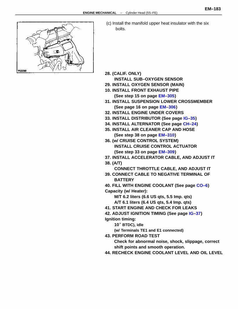
28. (CALIF. ONLY)INSTALL SUB–OXYGEN SENSOR
29. INSTALL OXYGEN SENSOR (MAIN)10. INSTALL FRONT EXHAUST PIPE
(See step 15 on page EM–305)31. INSTALL SUSPENSION LOWER CROSSMEMBER
(See page 16 on page EM–306)32. INSTALL ENGINE UNDER COVERS33. INSTALL DISTRIBUTOR (See page IG–35)34. INSTALL ALTERNATOR (See page CH–24)35. INSTALL AIR CLEANER CAP AND HOSE
(See step 38 on page EM–310)36. (w/ CRUISE CONTROL SYSTEM)
INSTALL CRUISE CONTROL ACTUATOR(See step 33 on page EM–309)
37. INSTALL ACCELERATOR CABLE, AND ADJUST IT38. (A/T)
CONNECT THROTTLE CABLE, AND ADJUST IT39. CONNECT CABLE TO NEGATIVE TERMINAL OF
BATTERY40. FILL WITH ENGINE COOLANT (See page CO–6)Capacity (w/ Heater):
M/T 6.2 liters (6.6 US qts, 5.5 Imp. qts)A/T 6.1 liters (6.4 US qts, 5.4 Imp. qts)
41. START ENGINE AND CHECK FOR LEAKS42. ADJUST IGNITION TIMING (See page IG–37)Ignition timing:
10° BTDC), idle(w/ Terminals TE1 and E1 connected)
43. PERFORM ROAD TESTCheck for abnormal noise, shock, slippage, correctshift points and smooth operation.
44. RECHECK ENGINE COOLANT LEVEL AND OIL LEVEL
(c) Install the manifold upper heat insulator with the sixbolts.
–ENGINE MECHANICAL Cylinder Head (5S–FE)EM–183
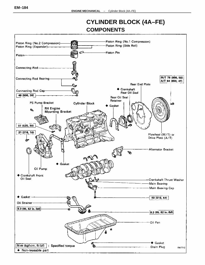
CYLINDER BLOCK (4A–FE)COMPONENTS
–ENGINE MECHANICAL Cylinder Block (4A–FE)EM–184
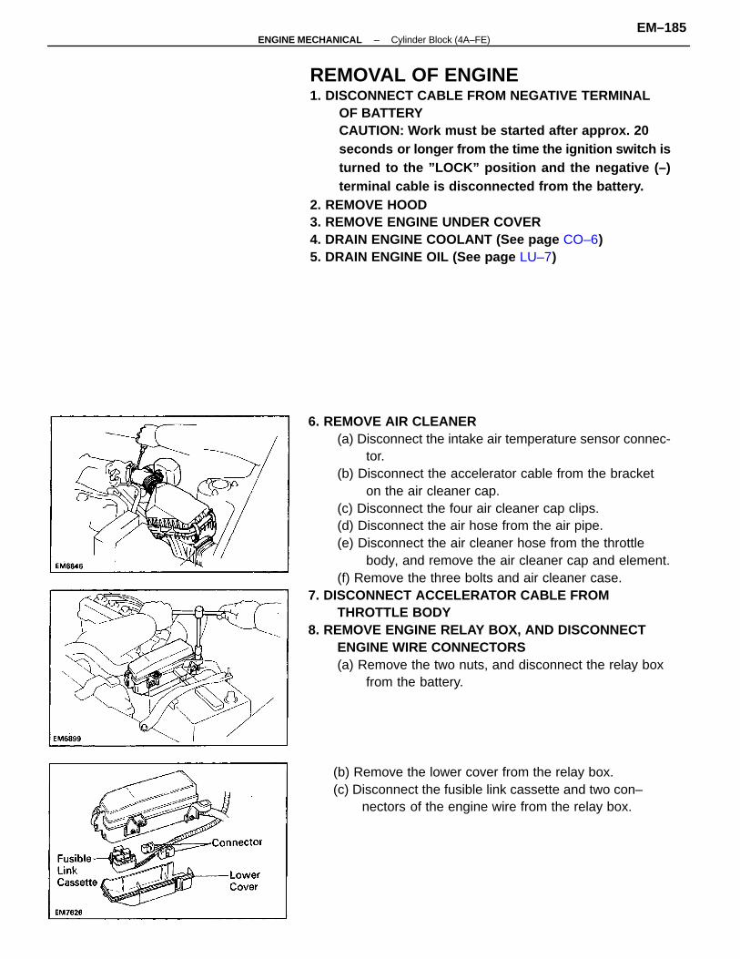
6. REMOVE AIR CLEANER(a) Disconnect the intake air temperature sensor connec-
tor.(b) Disconnect the accelerator cable from the bracket
on the air cleaner cap.(c) Disconnect the four air cleaner cap clips.(d) Disconnect the air hose from the air pipe.(e) Disconnect the air cleaner hose from the throttle
body, and remove the air cleaner cap and element.(f) Remove the three bolts and air cleaner case.
7. DISCONNECT ACCELERATOR CABLE FROMTHROTTLE BODY
8. REMOVE ENGINE RELAY BOX, AND DISCONNECTENGINE WIRE CONNECTORS(a) Remove the two nuts, and disconnect the relay box
from the battery.
REMOVAL OF ENGINE1. DISCONNECT CABLE FROM NEGATIVE TERMINAL
OF BATTERYCAUTION: Work must be started after approx. 20seconds or longer from the time the ignition switch isturned to the ”LOCK” position and the negative (–)terminal cable is disconnected from the battery.
2. REMOVE HOOD3. REMOVE ENGINE UNDER COVER4. DRAIN ENGINE COOLANT (See page CO–6)5. DRAIN ENGINE OIL (See page LU–7)
(b) Remove the lower cover from the relay box.(c) Disconnect the fusible link cassette and two con–
nectors of the engine wire from the relay box.
–ENGINE MECHANICAL Cylinder Block (4A–FE)EM–185
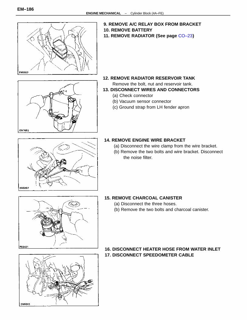
12. REMOVE RADIATOR RESERVOIR TANKRemove the bolt, nut and reservoir tank.
13. DISCONNECT WIRES AND CONNECTORS(a) Check connector(b) Vacuum sensor connector(c) Ground strap from LH fender apron
14. REMOVE ENGINE WIRE BRACKET(a) Disconnect the wire clamp from the wire bracket.(b) Remove the two bolts and wire bracket. Disconnect
the noise filter.
9. REMOVE A/C RELAY BOX FROM BRACKET10. REMOVE BATTERY11. REMOVE RADIATOR (See page CO–23)
16. DISCONNECT HEATER HOSE FROM WATER INLET17. DISCONNECT SPEEDOMETER CABLE
15. REMOVE CHARCOAL CANISTER(a) Disconnect the three hoses.(b) Remove the two bolts and charcoal canister.
–ENGINE MECHANICAL Cylinder Block (4A–FE)EM–186
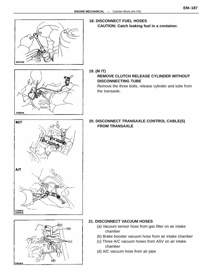
21. DISCONNECT VACUUM HOSES(a) Vacuum sensor hose from gas filter on air intake
chamber(b) Brake booster vacuum hose from air intake chamber(c) Three A/C vacuum hoses from ASV on air intake
chamber(d) A/C vacuum hose from air pipe
19. (M /T)REMOVE CLUTCH RELEASE CYLINDER WITHOUTDISCONNECTING TUBERemove the three bolts, release cylinder and tube fromthe transaxle.
18. DISCONNECT FUEL HOSESCAUTION: Catch leaking fuel in a container.
20. DISCONNECT TRANSAXLE CONTROL CABLE(S)FROM TRANSAXLE
–ENGINE MECHANICAL Cylinder Block (4A–FE)EM–187
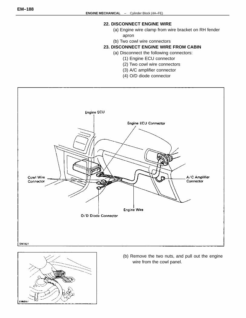
22. DISCONNECT ENGINE WIRE(a) Engine wire clamp from wire bracket on RH fender
apron(b) Two cowl wire connectors
23. DISCONNECT ENGINE WIRE FROM CABIN(a) Disconnect the following connectors:
(1) Engine ECU connector(2) Two cowl wire connectors(3) A/C amplifier connector(4) O/D diode connector
(b) Remove the two nuts, and pull out the enginewire from the cowl panel.
–ENGINE MECHANICAL Cylinder Block (4A–FE)EM–188
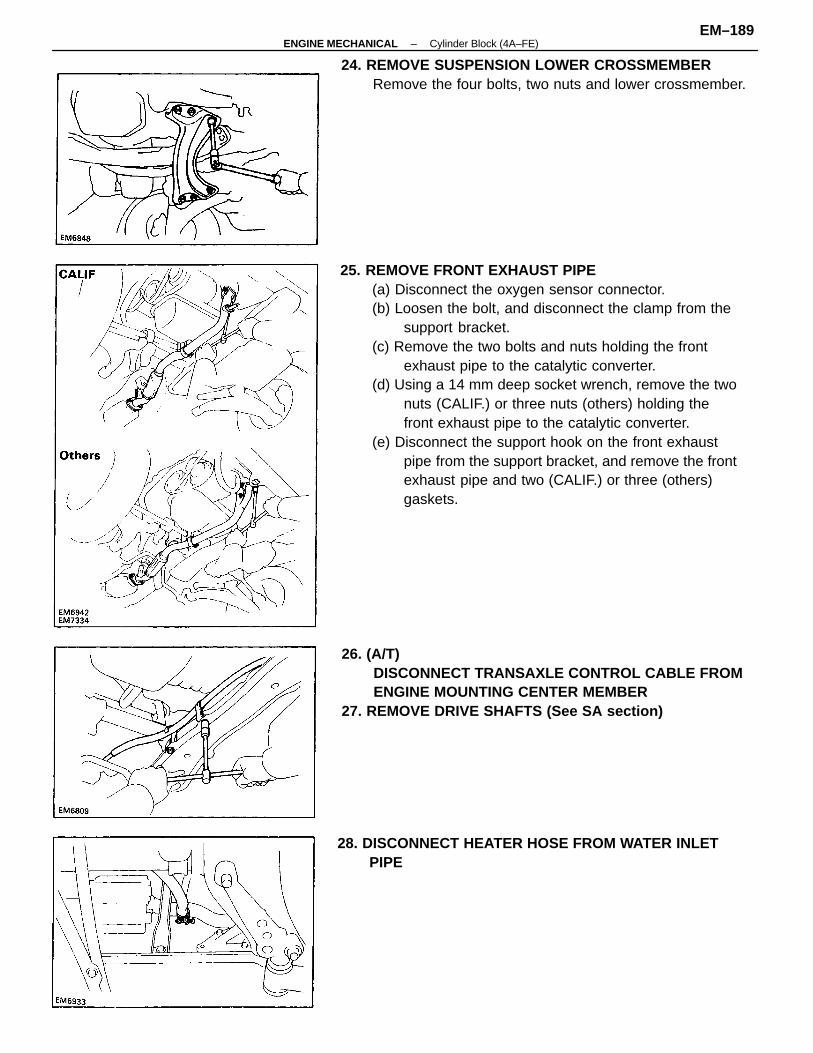
25. REMOVE FRONT EXHAUST PIPE(a) Disconnect the oxygen sensor connector.(b) Loosen the bolt, and disconnect the clamp from the
support bracket.(c) Remove the two bolts and nuts holding the front
exhaust pipe to the catalytic converter.(d) Using a 14 mm deep socket wrench, remove the two
nuts (CALIF.) or three nuts (others) holding thefront exhaust pipe to the catalytic converter.
(e) Disconnect the support hook on the front exhaustpipe from the support bracket, and remove the frontexhaust pipe and two (CALIF.) or three (others)gaskets.
26. (A/T)DISCONNECT TRANSAXLE CONTROL CABLE FROMENGINE MOUNTING CENTER MEMBER
27. REMOVE DRIVE SHAFTS (See SA section)
24. REMOVE SUSPENSION LOWER CROSSMEMBERRemove the four bolts, two nuts and lower crossmember.
28. DISCONNECT HEATER HOSE FROM WATER INLETPIPE
–ENGINE MECHANICAL Cylinder Block (4A–FE)EM–189
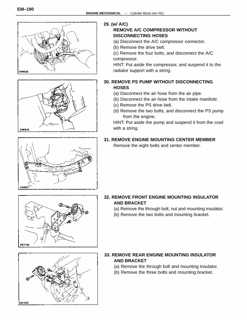
30. REMOVE PS PUMP WITHOUT DISCONNECTINGHOSES(a) Disconnect the air hose from the air pipe.(b) Disconnect the air hose from the intake manifold.(c) Remove the PS drive belt.(d) Remove the two bolts, and disconnect the PS pump
from the engine.HINT: Put aside the pump and suspend it from the cowlwith a string.
29. (w/ A/C)REMOVE A/C COMPRESSOR WITHOUTDISCONNECTING HOSES(a) Disconnect the A/C compressor connector.(b) Remove the drive belt.(c) Remove the four bolts, and disconnect the A/Ccompressor.HINT: Put aside the compressor, and suspend it to theradiator support with a string.
32. REMOVE FRONT ENGINE MOUNTING INSULATORAND BRACKET(a) Remove the through bolt, nut and mounting insulator.(b) Remove the two bolts and mounting bracket.
33. REMOVE REAR ENGINE MOUNTING INSULATORAND BRACKET(a) Remove the through bolt and mounting insulator.(b) Remove the three bolts and mounting bracket.
31. REMOVE ENGINE MOUNTING CENTER MEMBERRemove the eight bolts and center member.
–ENGINE MECHANICAL Cylinder Block (4A–FE)EM–190
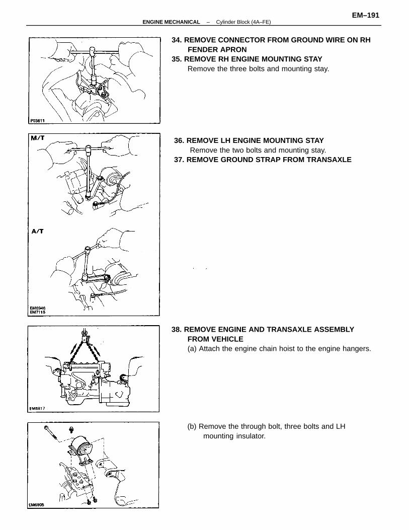
34. REMOVE CONNECTOR FROM GROUND WIRE ON RHFENDER APRON
35. REMOVE RH ENGINE MOUNTING STAYRemove the three bolts and mounting stay.
38. REMOVE ENGINE AND TRANSAXLE ASSEMBLYFROM VEHICLE(a) Attach the engine chain hoist to the engine hangers.
36. REMOVE LH ENGINE MOUNTING STAYRemove the two bolts and mounting stay.
37. REMOVE GROUND STRAP FROM TRANSAXLE
(b) Remove the through bolt, three bolts and LHmounting insulator.
–ENGINE MECHANICAL Cylinder Block (4A–FE)EM–191
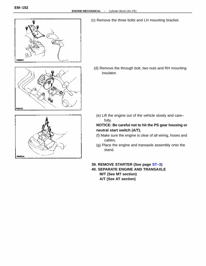
(e) Lift the engine out of the vehicle slowly and care–fully.
NOTICE: Be careful not to hit the PS gear housing orneutral start switch (A/T).(f) Make sure the engine is clear of all wiring, hoses and
cables.(g) Place the engine and transaxle assembly onto the
stand.
39. REMOVE STARTER (See page ST–3)40. SEPARATE ENGINE AND TRANSAXLE
M/T (See MT section)A/T (See AT section)
(d) Remove the through bolt, two nuts and RH mountinginsulator.
(c) Remove the three bolts and LH mounting bracket.
–ENGINE MECHANICAL Cylinder Block (4A–FE)EM–192
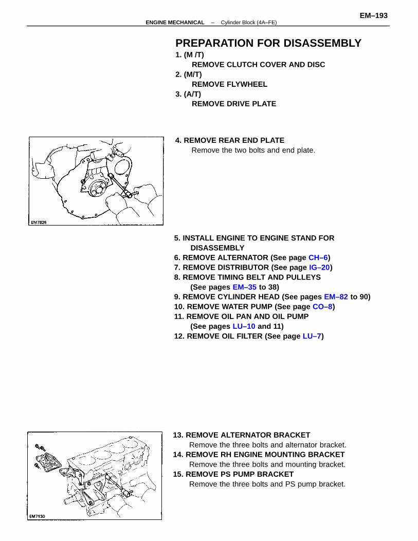
5. INSTALL ENGINE TO ENGINE STAND FORDISASSEMBLY
6. REMOVE ALTERNATOR (See page CH–6)7. REMOVE DISTRIBUTOR (See page IG–20)8. REMOVE TIMING BELT AND PULLEYS
(See pages EM–35 to 38)9. REMOVE CYLINDER HEAD (See pages EM–82 to 90)10. REMOVE WATER PUMP (See page CO–8)11. REMOVE OIL PAN AND OIL PUMP
(See pages LU–10 and 11)12. REMOVE OIL FILTER (See page LU–7)
PREPARATION FOR DISASSEMBLY1. (M /T)
REMOVE CLUTCH COVER AND DISC2. (M/T)
REMOVE FLYWHEEL3. (A/T)
REMOVE DRIVE PLATE
13. REMOVE ALTERNATOR BRACKETRemove the three bolts and alternator bracket.
14. REMOVE RH ENGINE MOUNTING BRACKETRemove the three bolts and mounting bracket.
15. REMOVE PS PUMP BRACKETRemove the three bolts and PS pump bracket.
4. REMOVE REAR END PLATERemove the two bolts and end plate.
–ENGINE MECHANICAL Cylinder Block (4A–FE)EM–193
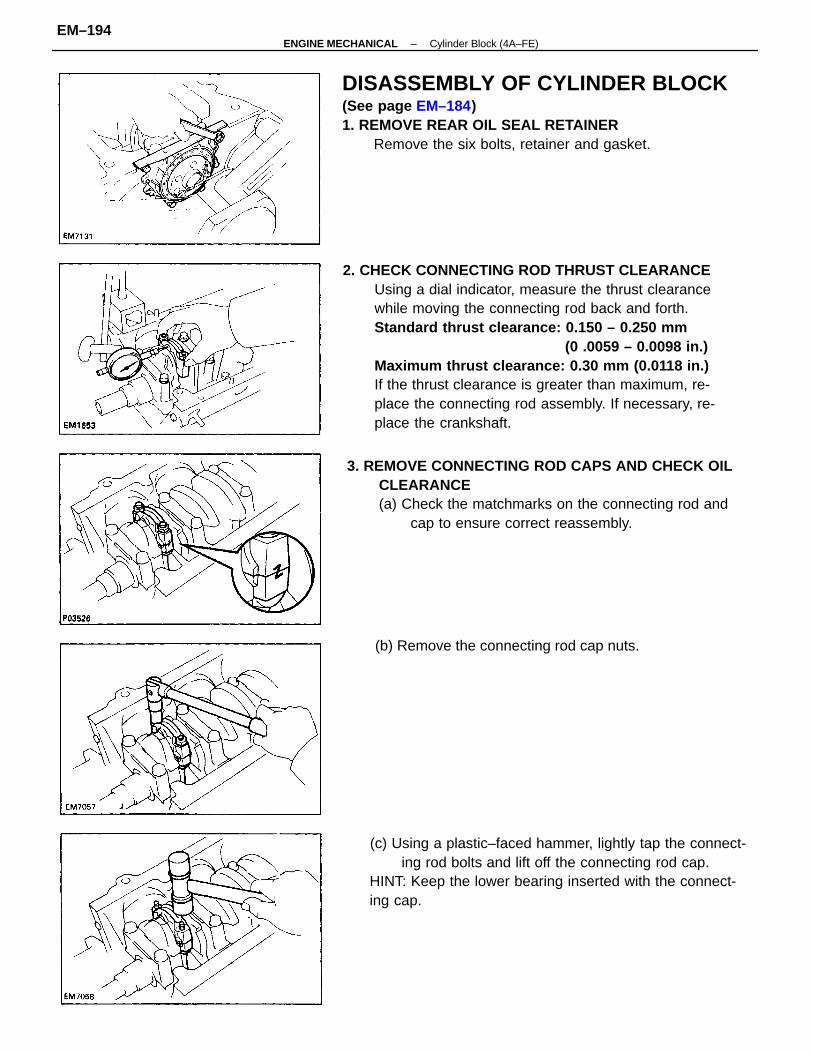
2. CHECK CONNECTING ROD THRUST CLEARANCEUsing a dial indicator, measure the thrust clearancewhile moving the connecting rod back and forth.Standard thrust clearance: 0.150 – 0.250 mm
(0 .0059 – 0.0098 in.)Maximum thrust clearance: 0.30 mm (0.0118 in.)If the thrust clearance is greater than maximum, re-place the connecting rod assembly. If necessary, re-place the crankshaft.
DISASSEMBLY OF CYLINDER BLOCK(See page EM–184)1. REMOVE REAR OIL SEAL RETAINER
Remove the six bolts, retainer and gasket.
3. REMOVE CONNECTING ROD CAPS AND CHECK OILCLEARANCE(a) Check the matchmarks on the connecting rod and
cap to ensure correct reassembly.
(c) Using a plastic–faced hammer, lightly tap the connect-ing rod bolts and lift off the connecting rod cap.
HINT: Keep the lower bearing inserted with the connect-ing cap.
(b) Remove the connecting rod cap nuts.
–ENGINE MECHANICAL Cylinder Block (4A–FE)EM–194
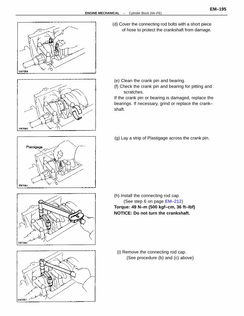
(e) Clean the crank pin and bearing.(f) Check the crank pin and bearing for pitting and
scratches.If the crank pin or bearing is damaged, replace thebearings. If necessary, grind or replace the crank–shaft.
(h) Install the connecting rod cap.(See step 6 on page EM–212)
Torque: 49 N–m (500 kgf–cm, 36 ft–lbf)NOTICE: Do not turn the crankshaft.
(d) Cover the connecting rod bolts with a short pieceof hose to protect the crankshaft from damage.
(i) Remove the connecting rod cap.(See procedure (b) and (c) above)
(g) Lay a strip of Plastigage across the crank pin.
–ENGINE MECHANICAL Cylinder Block (4A–FE)EM–195
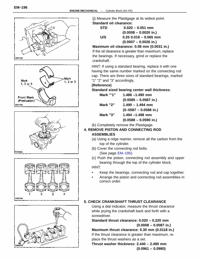
HINT: If using a standard bearing, replace it with onehaving the same number marked on the connecting rodcap. There are three sizes of standard bearings, marked“1” ”2” and ”3” accordingly.(Reference)Standard sized bearing center wall thickness:
Mark ”’1” 1.486 –1.490 mm(0.0585 – 0.0587 in.)
Mark ”2” 1.490 – 1.494 mm(0–0587 – 0.0588 in.)
Mark ”3” 1.494 –1.498 mm(0.0588 – 0.0590 in.)
(k) Completely remove the Plastigage.4. REMOVE PISTON AND CONNECTING ROD
ASSEMBLIES(a) Using a ridge reamer, remove all the carbon from the
top of the cylinder.(b) Cover the connecting rod bolts.
(See page EM–195)(c) Push the piston, connecting rod assembly and upper
bearing through the top of the cylinder block.HINT:
• Keep the bearings, connecting rod and cap together.• Arrange the piston and connecting rod assemblies in
correct order.
5. CHECK CRANKSHAFT THRUST CLEARANCEUsing a dial indicator, measure the thrust clearancewhile prying the crankshaft back and forth with ascrewdriver.Standard thrust clearance: 0.020 – 0.220 mm
(0.0008 – 0.0087 in.)Maximum thrust clearance: 0.30 mm (0.0118 in.)If the thrust clearance is greater than maximum, re-place the thrust washers as a set.Thrust washer thickness: 2.440 – 2.490 mm
(0.0961 – 0.0980)
(j) Measure the Plastigage at its widest point.Standard oil clearance:
STD 0.020 – 0.051 mm(0.0008 – 0.0020 in.)
U/S 0.25 0.019 – 0.065 mm(0.0007 – 0.0026 in.)
Maximum oil clearance: 0.08 mm (0.0031 in.)If the oil clearance is greater than maximum, replacethe bearings. If necessary, grind or replace thecrankshaft.
–ENGINE MECHANICAL Cylinder Block (4A–FE)EM–196
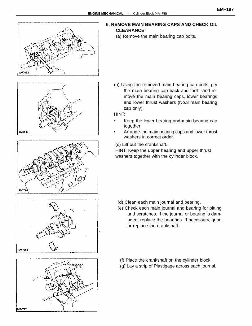
(b) Using the removed main bearing cap bolts, prythe main bearing cap back and forth, and re-move the main bearing caps, lower bearingsand lower thrust washers (No.3 main bearingcap only).
HINT:
• Keep the lower bearing and main bearing captogether.
• Arrange the main bearing caps and lower thrustwashers in correct order.
(d) Clean each main journal and bearing.(e) Check each main journal and bearing for pitting
and scratches. If the journal or bearing is dam-aged, replace the bearings. If necessary, grindor replace the crankshaft.
(c) Lift out the crankshaft.HINT: Keep the upper bearing and upper thrustwashers together with the cylinder block.
6. REMOVE MAIN BEARING CAPS AND CHECK OILCLEARANCE(a) Remove the main bearing cap bolts.
(f) Place the crankshaft on the cylinder block.(g) Lay a strip of Plastigage across each journal.
–ENGINE MECHANICAL Cylinder Block (4A–FE)EM–197
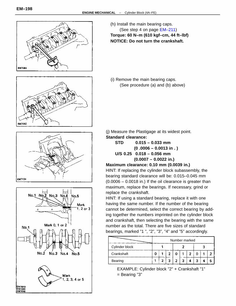
(j) Measure the Plastigage at its widest point.Standard clearance:
STD 0.015 – 0.033 mm(0 .0006 – 0.0013 in . )
U/S 0.25 0.018 – 0.056 mm(0.0007 – 0.0022 in.)
Maximum clearance: 0.10 mm (0.0039 in.)HINT: If replacing the cylinder block subassembly, thebearing standard clearance will be: 0.015–0.045 mm(0.0006 – 0.0018 in.) If the oil clearance is greater thanmaximum, replace the bearings. If necessary, grind orreplace the crankshaft.HINT: If using a standard bearing, replace it with onehaving the same number. If the number of the bearingcannot be determined, select the correct bearing by add-ing together the numbers imprinted on the cylinder blockand crankshaft, then selecting the bearing with the samenumber as the total. There are five sizes of standardbearings, marked ”1 ”, ”2”, ”3”, ”4” and ”5” accordingly.
(h) Install the main bearing caps.(See step 4 on page EM–211)
Torque: 60 N–m (610 kgf–cm, 44 ft–lbf)NOTICE: Do not turn the crankshaft.
EXAMPLE: Cylinder block ”2” + Crankshaft ”1”= Bearing ”3”
(i) Remove the main bearing caps.(See procedure (a) and (b) above)
Cylinder block
Number marked
Crankshaft
Bearing
–ENGINE MECHANICAL Cylinder Block (4A–FE)EM–198
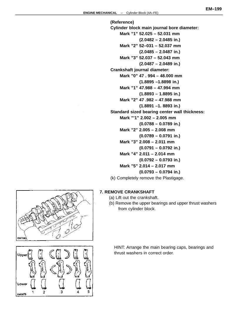
(Reference)Cylinder block main journal bore diameter:
Mark ”1” 52.025 – 52.031 mm(2.0482 – 2.0485 in.)
Mark ”2” 52–031 – 52.037 mm(2.0485 – 2.0487 in.)
Mark ”3” 52.037 – 52.043 mm (2.0487 – 2.0489 in.)
Crankshaft journal diameter:Mark ”0” 47 . 994 – 48.000 mm
(1.8895 –1.8898 in.) Mark ”1” 47.988 – 47.994 mm
(1.8893 – 1.8895 in.) Mark ”2” 47 .982 – 47.988 mm
(1.8891 –1. 8893 in.)Standard sized bearing center wall thickness:
Mark ”’1” 2.002 – 2.005 mm (0.0788 – 0.0789 in.)
Mark ”2” 2.005 – 2.008 mm(0.0789 – 0.0791 in.)
Mark ”3” 2.008 – 2.011 mm (0.0791 – 0.0792 in.)
Mark ”4” 2.011 – 2.014 mm(0.0792 – 0.0793 in.)
Mark ”5” 2.014 – 2.017 mm(0.0793 – 0.0794 in.)
(k) Completely remove the Plastigage.
7. REMOVE CRANKSHAFT(a) Lift out the crankshaft.(b) Remove the upper bearings and upper thrust washers
from cylinder block.
HINT: Arrange the main bearing caps, bearings andthrust washers in correct order.
–ENGINE MECHANICAL Cylinder Block (4A–FE)EM–199
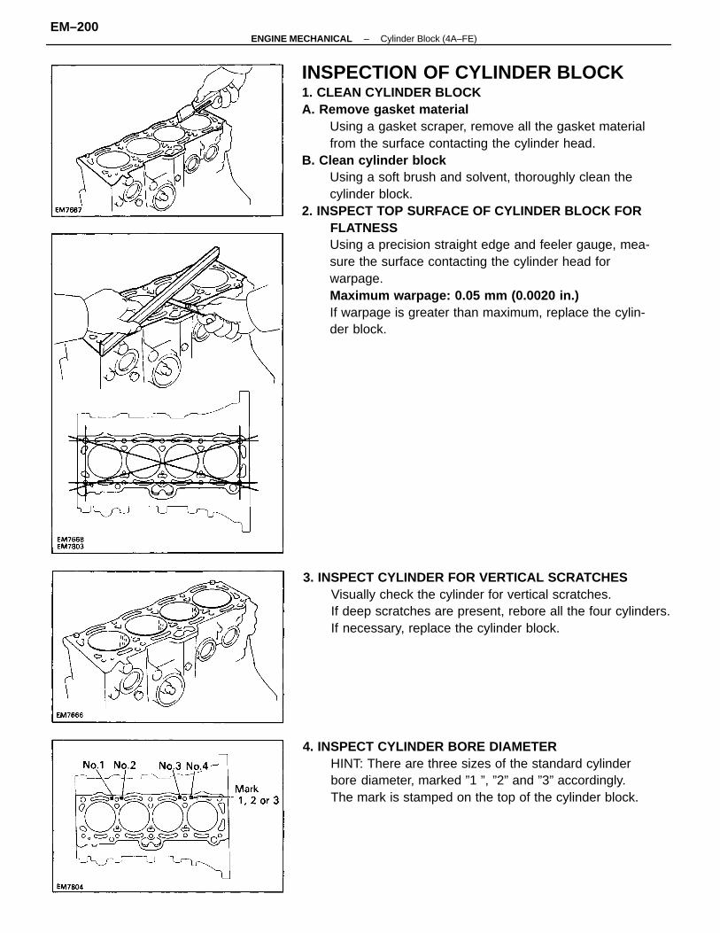
INSPECTION OF CYLINDER BLOCK1. CLEAN CYLINDER BLOCKA. Remove gasket material
Using a gasket scraper, remove all the gasket materialfrom the surface contacting the cylinder head.
B. Clean cylinder blockUsing a soft brush and solvent, thoroughly clean thecylinder block.
2. INSPECT TOP SURFACE OF CYLINDER BLOCK FORFLATNESSUsing a precision straight edge and feeler gauge, mea-sure the surface contacting the cylinder head forwarpage.Maximum warpage: 0.05 mm (0.0020 in.)If warpage is greater than maximum, replace the cylin-der block.
3. INSPECT CYLINDER FOR VERTICAL SCRATCHESVisually check the cylinder for vertical scratches.If deep scratches are present, rebore all the four cylinders.If necessary, replace the cylinder block.
4. INSPECT CYLINDER BORE DIAMETERHINT: There are three sizes of the standard cylinderbore diameter, marked ”1 ”, ”2” and ”3” accordingly.The mark is stamped on the top of the cylinder block.
–ENGINE MECHANICAL Cylinder Block (4A–FE)EM–200
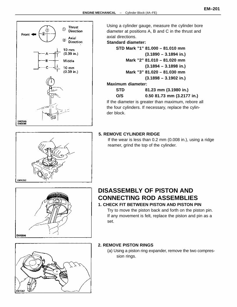
Using a cylinder gauge, measure the cylinder borediameter at positions A, B and C in the thrust andaxial directions.Standard diameter:
STD Mark ”1” 81.000 – 81.010 mm(3.1890 – 3.1894 in.)
Mark ”2” 81.010 – 81.020 mm(3.1894 – 3.1898 in.)
Mark ”3” 81.020 – 81.030 mm(3.1898 – 3.1902 in.)
Maximum diameter:STD 81.23 mm (3.1980 in.)O/S 0.50 81.73 mm (3.2177 in.)
If the diameter is greater than maximum, rebore allthe four cylinders. If necessary, replace the cylin-der block.
DISASSEMBLY OF PISTON ANDCONNECTING ROD ASSEMBLIES1. CHECK FIT BETWEEN PISTON AND PISTON PIN
Try to move the piston back and forth on the piston pin.If any movement is felt, replace the piston and pin as aset.
5. REMOVE CYLINDER RIDGEIf the wear is less than 0.2 mm (0.008 in.), using a ridgereamer, grind the top of the cylinder.
2. REMOVE PISTON RINGS(a) Using a piston ring expander, remove the two compres-
sion rings.
–ENGINE MECHANICAL Cylinder Block (4A–FE)EM–201
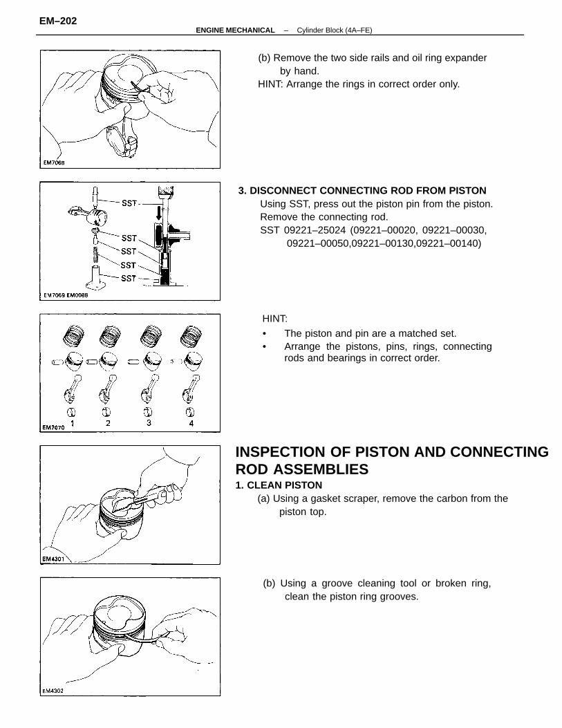
INSPECTION OF PISTON AND CONNECTINGROD ASSEMBLIES1. CLEAN PISTON
(a) Using a gasket scraper, remove the carbon from thepiston top.
3. DISCONNECT CONNECTING ROD FROM PISTONUsing SST, press out the piston pin from the piston.Remove the connecting rod.SST 09221–25024 (09221–00020, 09221–00030,
09221–00050,09221–00130,09221–00140)
HINT:
• The piston and pin are a matched set.• Arrange the pistons, pins, rings, connecting
rods and bearings in correct order.
(b) Remove the two side rails and oil ring expanderby hand.
HINT: Arrange the rings in correct order only.
(b) Using a groove cleaning tool or broken ring,clean the piston ring grooves.
–ENGINE MECHANICAL Cylinder Block (4A–FE)EM–202
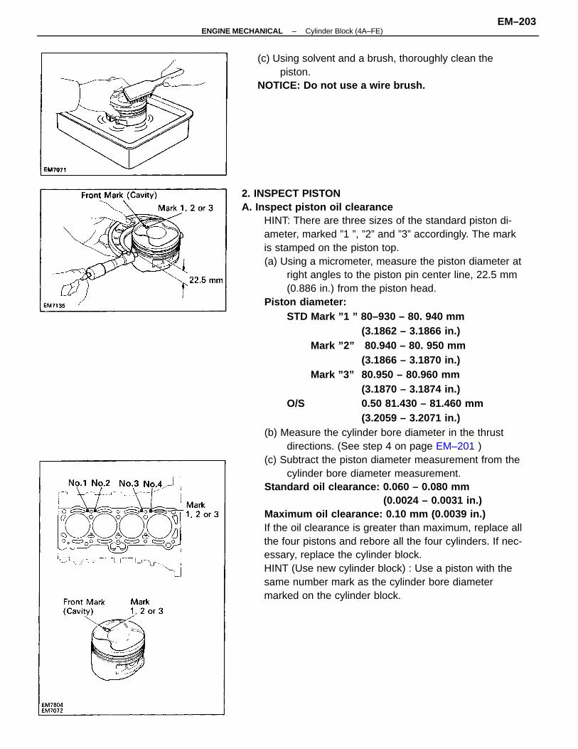
2. INSPECT PISTONA. Inspect piston oil clearance
HINT: There are three sizes of the standard piston di-ameter, marked ”1 ”, ”2” and ”3” accordingly. The markis stamped on the piston top.(a) Using a micrometer, measure the piston diameter at
right angles to the piston pin center line, 22.5 mm(0.886 in.) from the piston head.
Piston diameter:STD Mark ”1 ” 80–930 – 80. 940 mm
(3.1862 – 3.1866 in.)Mark ”2” 80.940 – 80. 950 mm
(3.1866 – 3.1870 in.)Mark ”3” 80.950 – 80.960 mm
(3.1870 – 3.1874 in.)O/S 0.50 81.430 – 81.460 mm
(3.2059 – 3.2071 in.)(b) Measure the cylinder bore diameter in the thrust
directions. (See step 4 on page EM–201 )(c) Subtract the piston diameter measurement from the
cylinder bore diameter measurement.Standard oil clearance: 0.060 – 0.080 mm
(0.0024 – 0.0031 in.)Maximum oil clearance: 0.10 mm (0.0039 in.)If the oil clearance is greater than maximum, replace allthe four pistons and rebore all the four cylinders. If nec-essary, replace the cylinder block.HINT (Use new cylinder block) : Use a piston with thesame number mark as the cylinder bore diametermarked on the cylinder block.
(c) Using solvent and a brush, thoroughly clean thepiston.
NOTICE: Do not use a wire brush.
–ENGINE MECHANICAL Cylinder Block (4A–FE)EM–203
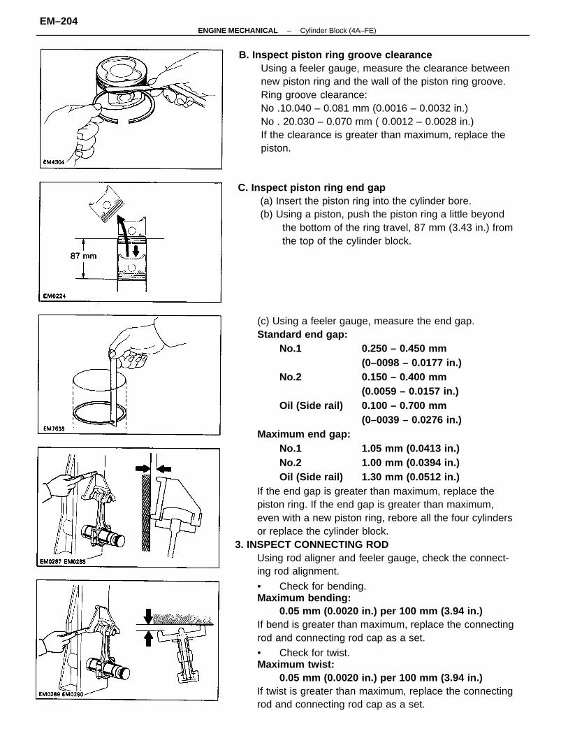
(c) Using a feeler gauge, measure the end gap.Standard end gap:
No.1 0.250 – 0.450 mm(0–0098 – 0.0177 in.)
No.2 0.150 – 0.400 mm(0.0059 – 0.0157 in.)
Oil (Side rail) 0.100 – 0.700 mm(0–0039 – 0.0276 in.)
Maximum end gap:No.1 1.05 mm (0.0413 in.)No.2 1.00 mm (0.0394 in.)Oil (Side rail) 1.30 mm (0.0512 in.)
If the end gap is greater than maximum, replace thepiston ring. If the end gap is greater than maximum,even with a new piston ring, rebore all the four cylindersor replace the cylinder block.
3. INSPECT CONNECTING RODUsing rod aligner and feeler gauge, check the connect-ing rod alignment.
• Check for bending.Maximum bending:
0.05 mm (0.0020 in.) per 100 mm (3.94 in.)If bend is greater than maximum, replace the connectingrod and connecting rod cap as a set.
• Check for twist.Maximum twist:
0.05 mm (0.0020 in.) per 100 mm (3.94 in.)If twist is greater than maximum, replace the connectingrod and connecting rod cap as a set.
B. Inspect piston ring groove clearanceUsing a feeler gauge, measure the clearance betweennew piston ring and the wall of the piston ring groove.Ring groove clearance:No .10.040 – 0.081 mm (0.0016 – 0.0032 in.)No . 20.030 – 0.070 mm ( 0.0012 – 0.0028 in.)If the clearance is greater than maximum, replace thepiston.
C. Inspect piston ring end gap(a) Insert the piston ring into the cylinder bore.(b) Using a piston, push the piston ring a little beyond
the bottom of the ring travel, 87 mm (3.43 in.) fromthe top of the cylinder block.
–ENGINE MECHANICAL Cylinder Block (4A–FE)EM–204
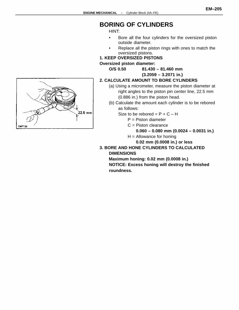
BORING OF CYLINDERSHINT:
• Bore all the four cylinders for the oversized pistonoutside diameter.
• Replace all the piston rings with ones to match theoversized pistons.
1. KEEP OVERSIZED PISTONSOversized piston diameter:
O/S 0.50 81.430 – 81.460 mm(3.2059 – 3.2071 in.)
2. CALCULATE AMOUNT TO BORE CYLINDERS(a) Using a micrometer, measure the piston diameter at
right angles to the piston pin center line, 22.5 mm(0.886 in.) from the piston head.
(b) Calculate the amount each cylinder is to be reboredas follows:Size to be rebored = P + C – H
P = Piston diameterC = Piston clearance
0.060 – 0.080 mm (0.0024 – 0.0031 in.)H = Allowance for honing
0.02 mm (0.0008 in.) or less3. BORE AND HONE CYLINDERS TO CALCULATED
DIMENSIONSMaximum honing: 0.02 mm (0.0008 in.)NOTICE: Excess honing will destroy the finishedroundness.
–ENGINE MECHANICAL Cylinder Block (4A–FE)EM–205
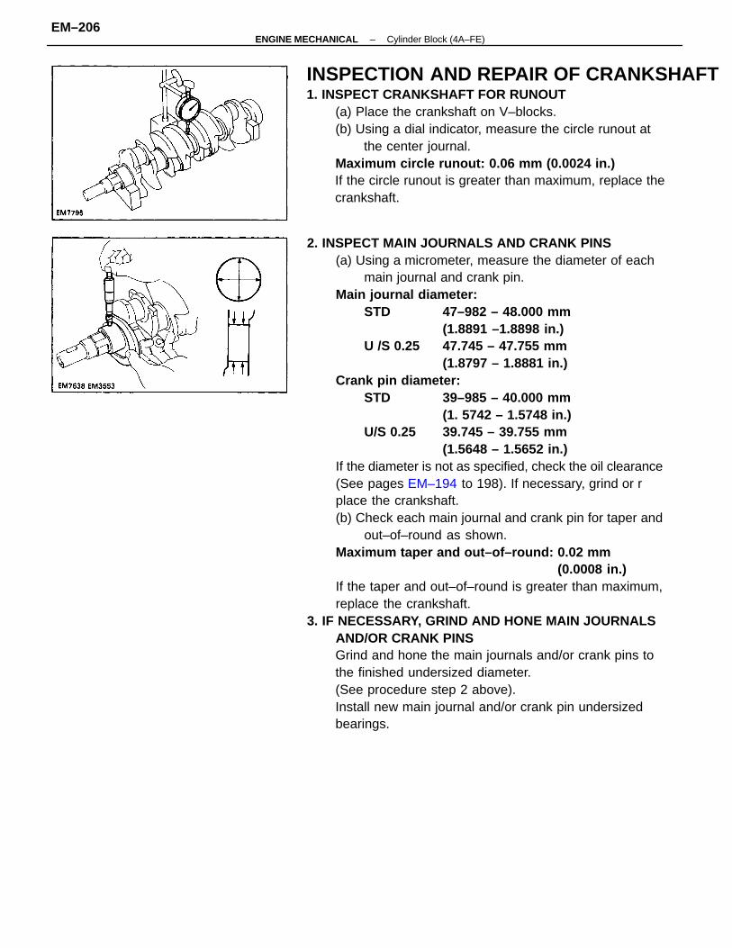
2. INSPECT MAIN JOURNALS AND CRANK PINS(a) Using a micrometer, measure the diameter of each
main journal and crank pin.Main journal diameter:
STD 47–982 – 48.000 mm(1.8891 –1.8898 in.)
U /S 0.25 47.745 – 47.755 mm(1.8797 – 1.8881 in.)
Crank pin diameter:STD 39–985 – 40.000 mm
(1. 5742 – 1.5748 in.)U/S 0.25 39.745 – 39.755 mm
(1.5648 – 1.5652 in.)If the diameter is not as specified, check the oil clearance(See pages EM–194 to 198). If necessary, grind or rplace the crankshaft.(b) Check each main journal and crank pin for taper and
out–of–round as shown.Maximum taper and out–of–round: 0.02 mm
(0.0008 in.)If the taper and out–of–round is greater than maximum,replace the crankshaft.
3. IF NECESSARY, GRIND AND HONE MAIN JOURNALSAND/OR CRANK PINSGrind and hone the main journals and/or crank pins tothe finished undersized diameter.(See procedure step 2 above).Install new main journal and/or crank pin undersizedbearings.
INSPECTION AND REPAIR OF CRANKSHAFT1. INSPECT CRANKSHAFT FOR RUNOUT
(a) Place the crankshaft on V–blocks.(b) Using a dial indicator, measure the circle runout at
the center journal.Maximum circle runout: 0.06 mm (0.0024 in.)If the circle runout is greater than maximum, replace thecrankshaft.
–ENGINE MECHANICAL Cylinder Block (4A–FE)EM–206
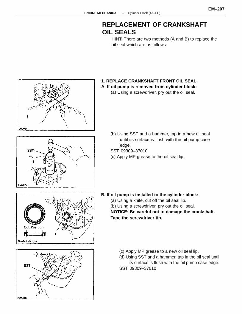
(b) Using SST and a hammer, tap in a new oil sealuntil its surface is flush with the oil pump caseedge.
SST 09309–37010(c) Apply MP grease to the oil seal lip.
B. If oil pump is installed to the cylinder block:(a) Using a knife, cut off the oil seal lip.(b) Using a screwdriver, pry out the oil seal.NOTICE: Be careful not to damage the crankshaft.Tape the screwdriver tip.
(c) Apply MP grease to a new oil seal lip.(d) Using SST and a hammer, tap in the oil seal until
its surface is flush with the oil pump case edge.SST 09309–37010
REPLACEMENT OF CRANKSHAFTOIL SEALS
HINT: There are two methods (A and B) to replace theoil seal which are as follows:
1. REPLACE CRANKSHAFT FRONT OIL SEALA. If oil pump is removed from cylinder block:
(a) Using a screwdriver, pry out the oil seal.
–ENGINE MECHANICAL Cylinder Block (4A–FE)EM–207
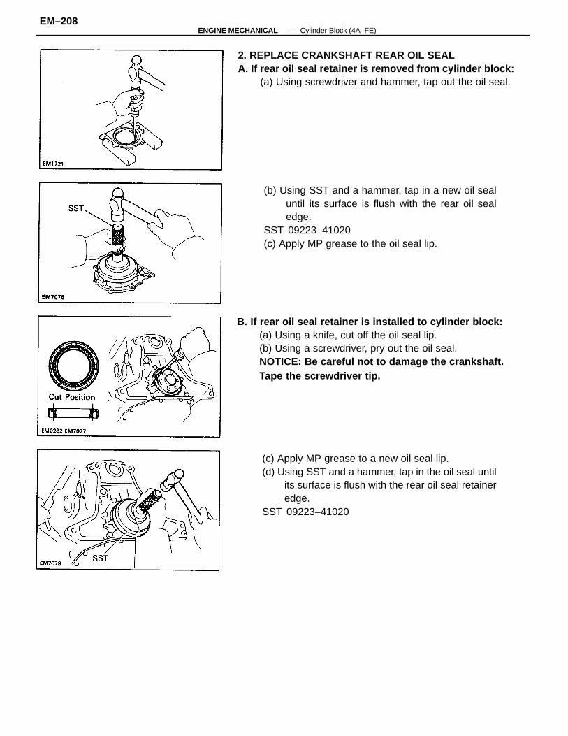
B. If rear oil seal retainer is installed to cylinder block:(a) Using a knife, cut off the oil seal lip.(b) Using a screwdriver, pry out the oil seal.NOTICE: Be careful not to damage the crankshaft.Tape the screwdriver tip.
(b) Using SST and a hammer, tap in a new oil sealuntil its surface is flush with the rear oil sealedge.
SST 09223–41020(c) Apply MP grease to the oil seal lip.
(c) Apply MP grease to a new oil seal lip.(d) Using SST and a hammer, tap in the oil seal until
its surface is flush with the rear oil seal retaineredge.
SST 09223–41020
2. REPLACE CRANKSHAFT REAR OIL SEALA. If rear oil seal retainer is removed from cylinder block:
(a) Using screwdriver and hammer, tap out the oil seal.
–ENGINE MECHANICAL Cylinder Block (4A–FE)EM–208
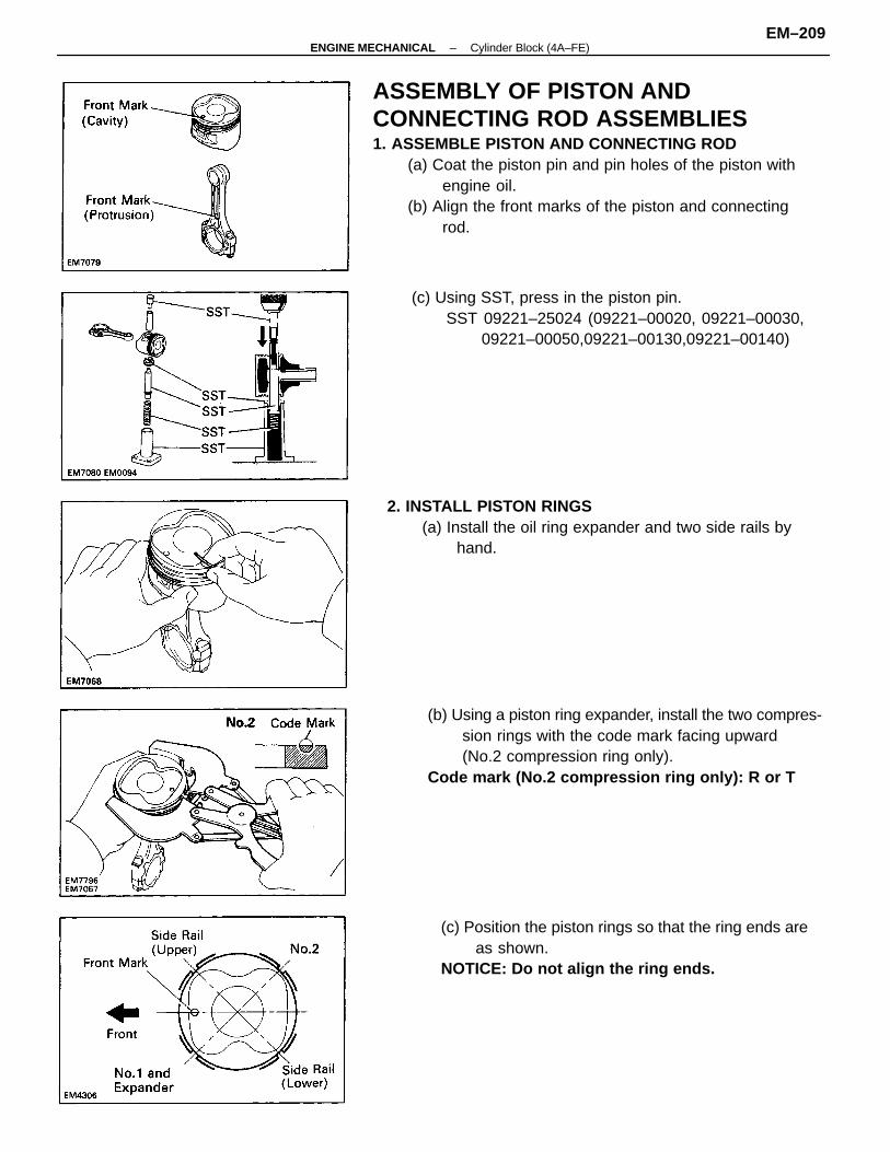
ASSEMBLY OF PISTON ANDCONNECTING ROD ASSEMBLIES1. ASSEMBLE PISTON AND CONNECTING ROD
(a) Coat the piston pin and pin holes of the piston withengine oil.
(b) Align the front marks of the piston and connectingrod.
(c) Position the piston rings so that the ring ends areas shown.
NOTICE: Do not align the ring ends.
(b) Using a piston ring expander, install the two compres-sion rings with the code mark facing upward(No.2 compression ring only).
Code mark (No.2 compression ring only): R or T
2. INSTALL PISTON RINGS(a) Install the oil ring expander and two side rails by
hand.
(c) Using SST, press in the piston pin.SST 09221–25024 (09221–00020, 09221–00030,
09221–00050,09221–00130,09221–00140)
–ENGINE MECHANICAL Cylinder Block (4A–FE)EM–209
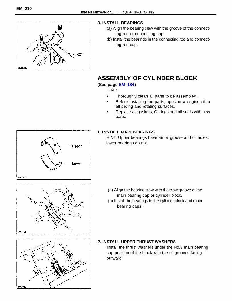
ASSEMBLY OF CYLINDER BLOCK(See page EM–184)
HINT:
• Thoroughly clean all parts to be assembled.• Before installing the parts, apply new engine oil to
all sliding and rotating surfaces.• Replace all gaskets, O–rings and oil seals with new
parts.
3. INSTALL BEARINGS(a) Align the bearing claw with the groove of the connect-
ing rod or connecting cap.(b) Install the bearings in the connecting rod and connect-
ing rod cap.
2. INSTALL UPPER THRUST WASHERSInstall the thrust washers under the No.3 main bearingcap position of the block with the oil grooves facingoutward.
(a) Align the bearing claw with the claw groove of themain bearing cap or cylinder block.
(b) Install the bearings in the cylinder block and mainbearing caps.
1. INSTALL MAIN BEARINGSHINT: Upper bearings have an oil groove and oil holes;lower bearings do not.
–ENGINE MECHANICAL Cylinder Block (4A–FE)EM–210
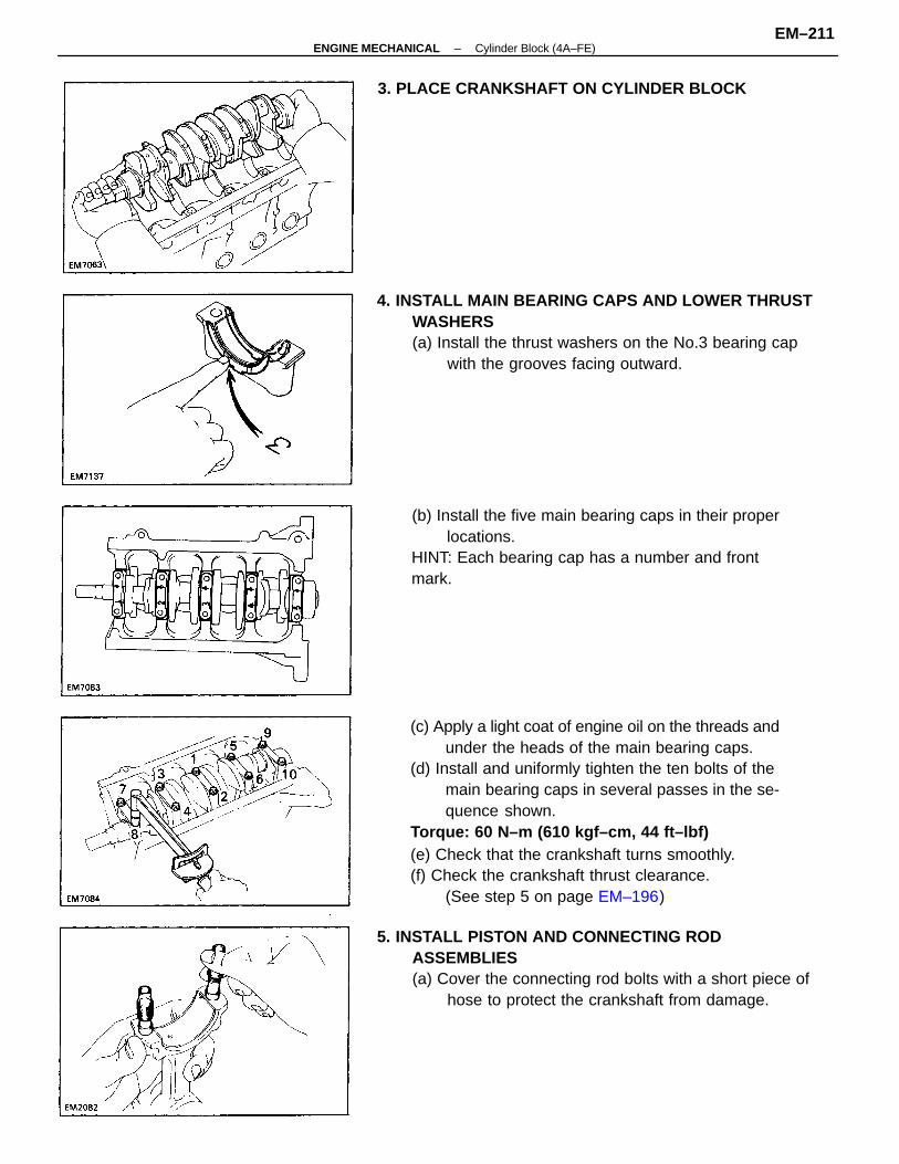
(c) Apply a light coat of engine oil on the threads andunder the heads of the main bearing caps.
(d) Install and uniformly tighten the ten bolts of themain bearing caps in several passes in the se-quence shown.
Torque: 60 N–m (610 kgf–cm, 44 ft–lbf)(e) Check that the crankshaft turns smoothly.(f) Check the crankshaft thrust clearance.
(See step 5 on page EM–196)
4. INSTALL MAIN BEARING CAPS AND LOWER THRUSTWASHERS(a) Install the thrust washers on the No.3 bearing cap
with the grooves facing outward.
5. INSTALL PISTON AND CONNECTING RODASSEMBLIES(a) Cover the connecting rod bolts with a short piece of
hose to protect the crankshaft from damage.
(b) Install the five main bearing caps in their properlocations.
HINT: Each bearing cap has a number and frontmark.
3. PLACE CRANKSHAFT ON CYLINDER BLOCK
–ENGINE MECHANICAL Cylinder Block (4A–FE)EM–211
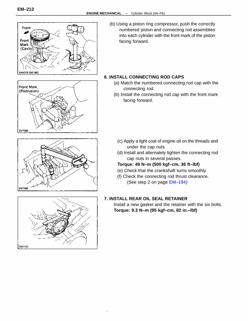
(c) Apply a light coat of engine oil on the threads andunder the cap nuts.
(d) Install and alternately tighten the connecting rodcap nuts in several passes.
Torque: 49 N–m (500 kgf–cm, 36 ft–lbf)(e) Check that the crankshaft turns smoothly.(f) Check the connecting rod thrust clearance.
(See step 2 on page EM–194)
6. INSTALL CONNECTING ROD CAPS(a) Match the numbered connecting rod cap with the
connecting rod.(b) Install the connecting rod cap with the front mark
facing forward.
(b) Using a piston ring compressor, push the correctlynumbered piston and connecting rod assembliesinto each cylinder with the front mark of the pistonfacing forward.
7. INSTALL REAR OIL SEAL RETAINERInstall a new gasket and the retainer with the six bolts.Torque: 9.3 N–m (95 kgf–cm, 82 in.–lbf)
–ENGINE MECHANICAL Cylinder. Block (4A–FE)EM–212
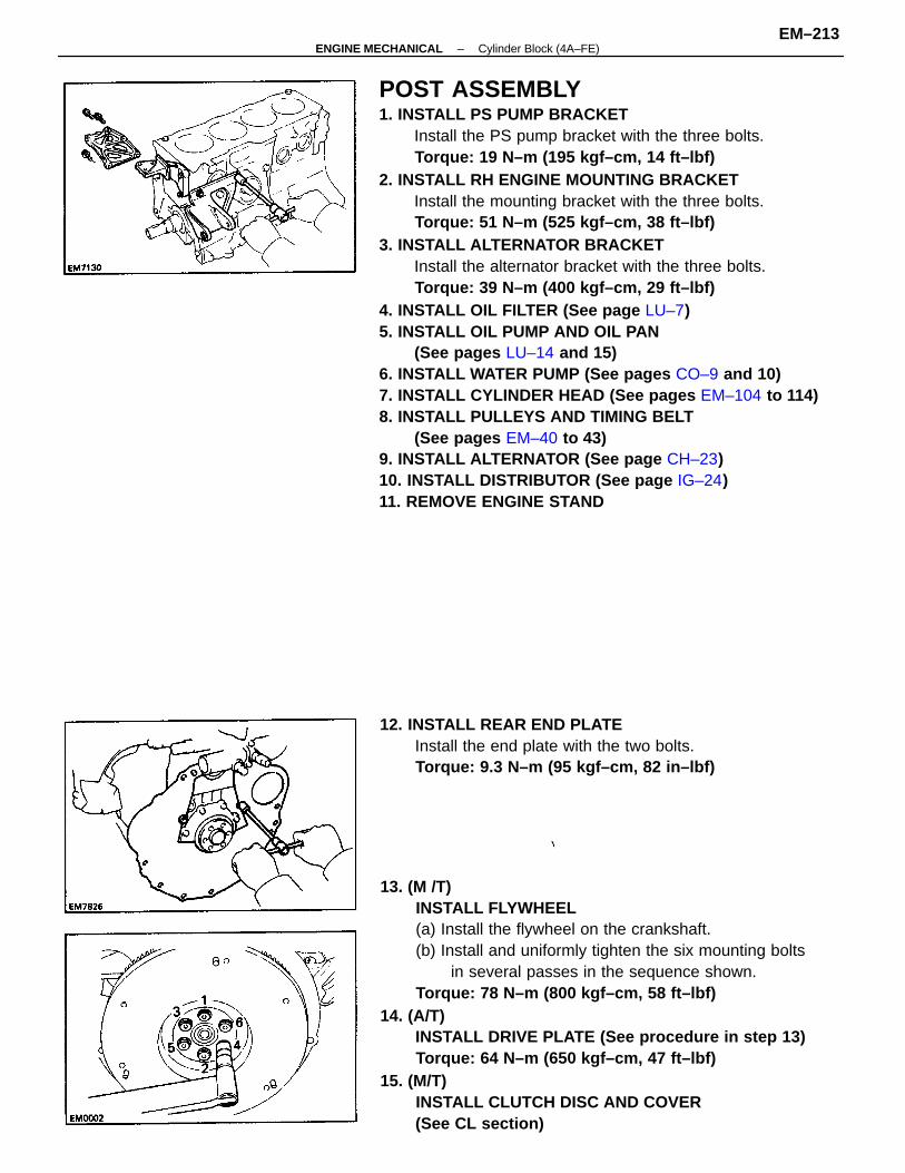
POST ASSEMBLY1. INSTALL PS PUMP BRACKET
Install the PS pump bracket with the three bolts.Torque: 19 N–m (195 kgf–cm, 14 ft–lbf)
2. INSTALL RH ENGINE MOUNTING BRACKETInstall the mounting bracket with the three bolts.Torque: 51 N–m (525 kgf–cm, 38 ft–lbf)
3. INSTALL ALTERNATOR BRACKETInstall the alternator bracket with the three bolts.Torque: 39 N–m (400 kgf–cm, 29 ft–lbf)
4. INSTALL OIL FILTER (See page LU–7)5. INSTALL OIL PUMP AND OIL PAN
(See pages LU–14 and 15)6. INSTALL WATER PUMP (See pages CO–9 and 10)7. INSTALL CYLINDER HEAD (See pages EM–104 to 114)8. INSTALL PULLEYS AND TIMING BELT
(See pages EM–40 to 43)9. INSTALL ALTERNATOR (See page CH–23)10. INSTALL DISTRIBUTOR (See page IG–24)11. REMOVE ENGINE STAND
13. (M /T)INSTALL FLYWHEEL(a) Install the flywheel on the crankshaft.(b) Install and uniformly tighten the six mounting bolts
in several passes in the sequence shown.Torque: 78 N–m (800 kgf–cm, 58 ft–lbf)
14. (A/T)INSTALL DRIVE PLATE (See procedure in step 13)Torque: 64 N–m (650 kgf–cm, 47 ft–lbf)
15. (M/T)INSTALL CLUTCH DISC AND COVER(See CL section)
12. INSTALL REAR END PLATEInstall the end plate with the two bolts.Torque: 9.3 N–m (95 kgf–cm, 82 in–lbf)
–ENGINE MECHANICAL Cylinder Block (4A–FE)EM–213
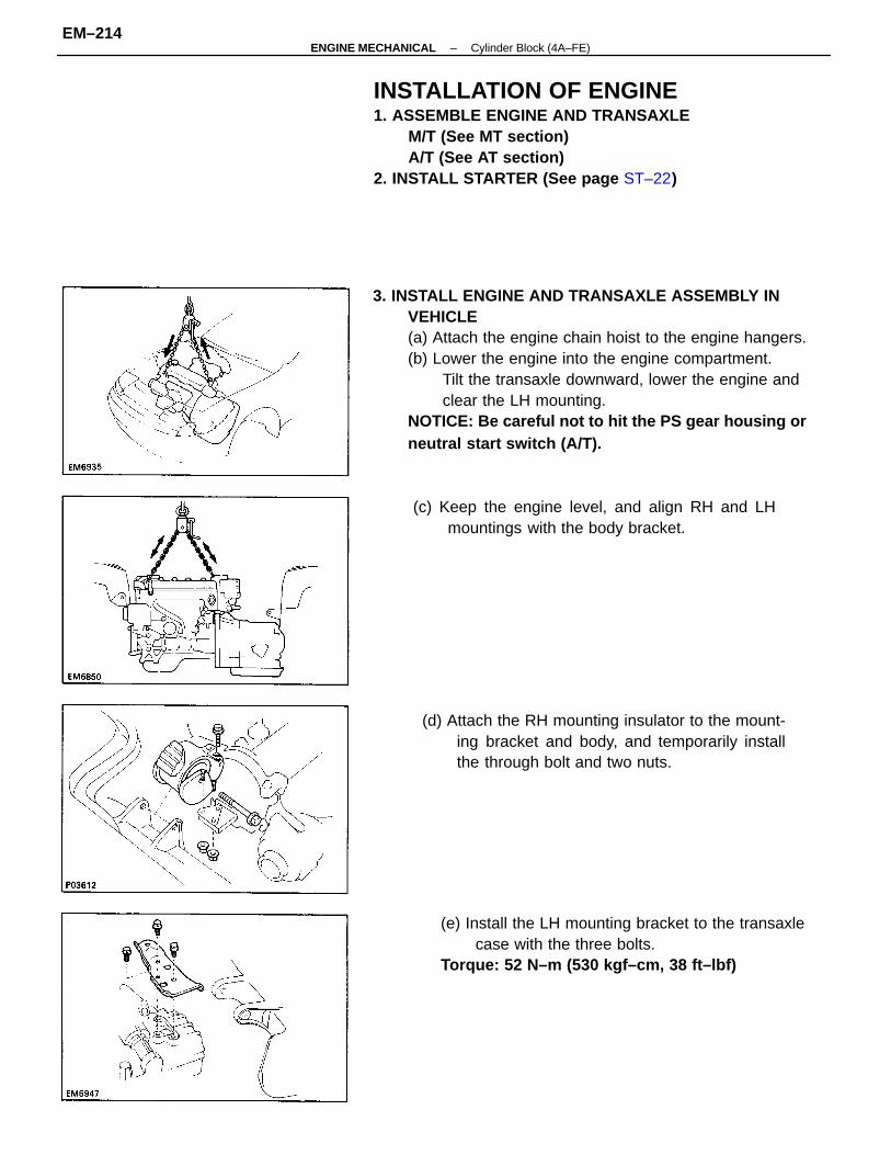
3. INSTALL ENGINE AND TRANSAXLE ASSEMBLY INVEHICLE(a) Attach the engine chain hoist to the engine hangers.(b) Lower the engine into the engine compartment.
Tilt the transaxle downward, lower the engine andclear the LH mounting.
NOTICE: Be careful not to hit the PS gear housing orneutral start switch (A/T).
INSTALLATION OF ENGINE1. ASSEMBLE ENGINE AND TRANSAXLE
M/T (See MT section)A/T (See AT section)
2. INSTALL STARTER (See page ST–22)
(e) Install the LH mounting bracket to the transaxlecase with the three bolts.
Torque: 52 N–m (530 kgf–cm, 38 ft–lbf)
(d) Attach the RH mounting insulator to the mount-ing bracket and body, and temporarily installthe through bolt and two nuts.
(c) Keep the engine level, and align RH and LHmountings with the body bracket.
–ENGINE MECHANICAL Cylinder Block (4A–FE)EM–214
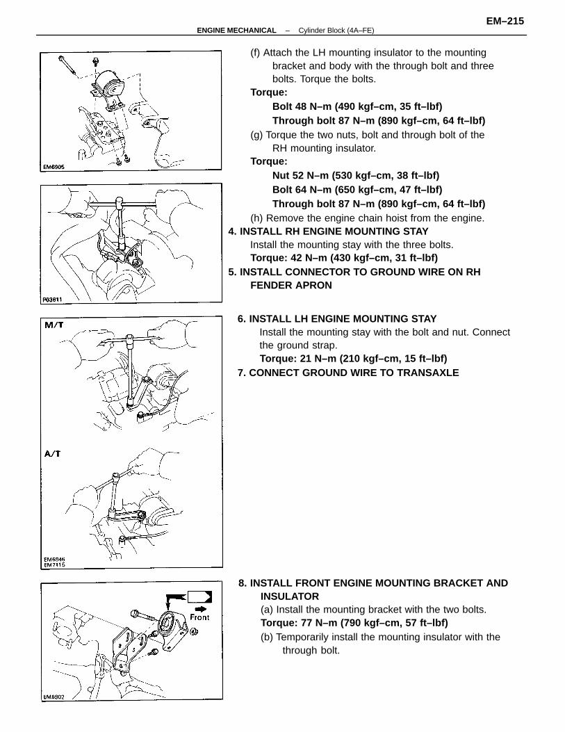
(f) Attach the LH mounting insulator to the mountingbracket and body with the through bolt and threebolts. Torque the bolts.
Torque:Bolt 48 N–m (490 kgf–cm, 35 ft–lbf)Through bolt 87 N–m (890 kgf–cm, 64 ft–lbf)
(g) Torque the two nuts, bolt and through bolt of theRH mounting insulator.
Torque:Nut 52 N–m (530 kgf–cm, 38 ft–lbf)Bolt 64 N–m (650 kgf–cm, 47 ft–lbf)Through bolt 87 N–m (890 kgf–cm, 64 ft–lbf)
(h) Remove the engine chain hoist from the engine.4. INSTALL RH ENGINE MOUNTING STAY
Install the mounting stay with the three bolts.Torque: 42 N–m (430 kgf–cm, 31 ft–lbf)
5. INSTALL CONNECTOR TO GROUND WIRE ON RHFENDER APRON
8. INSTALL FRONT ENGINE MOUNTING BRACKET ANDINSULATOR(a) Install the mounting bracket with the two bolts.Torque: 77 N–m (790 kgf–cm, 57 ft–lbf)(b) Temporarily install the mounting insulator with the
through bolt.
6. INSTALL LH ENGINE MOUNTING STAYInstall the mounting stay with the bolt and nut. Connectthe ground strap.Torque: 21 N–m (210 kgf–cm, 15 ft–lbf)
7. CONNECT GROUND WIRE TO TRANSAXLE
–ENGINE MECHANICAL Cylinder Block (4A–FE)EM–215
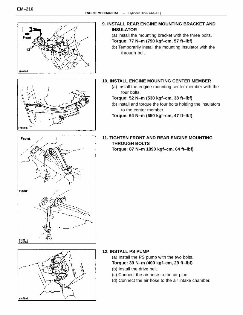
10. INSTALL ENGINE MOUNTING CENTER MEMBER(a) Install the engine mounting center member with the
four bolts.Torque: 52 N–m (530 kgf–cm, 38 ft–lbf)(b) Install and torque the four bolts holding the insulators
to the center member.Torque: 64 N–m (650 kgf–cm, 47 ft–lbf)
12. INSTALL PS PUMP(a) Install the PS pump with the two bolts.Torque: 39 N–m (400 kgf–cm, 29 ft–lbf)(b) Install the drive belt.(c) Connect the air hose to the air pipe.(d) Connect the air hose to the air intake chamber.
9. INSTALL REAR ENGINE MOUNTING BRACKET ANDINSULATOR(a) install the mounting bracket with the three bolts.Torque: 77 N–m (790 kgf–cm, 57 ft–lbf)(b) Temporarily install the mounting insulator with the
through bolt.
11. TIGHTEN FRONT AND REAR ENGINE MOUNTINGTHROUGH BOLTSTorque: 87 N–m 1890 kgf–cm, 64 ft–lbf)
–ENGINE MECHANICAL Cylinder Block (4A–FE)EM–216
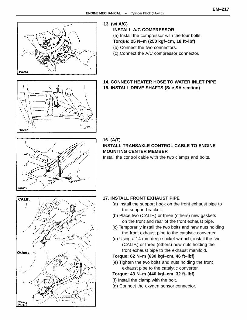
17. INSTALL FRONT EXHAUST PIPE(a) Install the support hook on the front exhaust pipe to
the support bracket.(b) Place two (CALIF.) or three (others) new gaskets
on the front and rear of the front exhaust pipe.(c) Temporarily install the two bolts and new nuts holding
the front exhaust pipe to the catalytic converter.(d) Using a 14 mm deep socket wrench, install the two
(CALIF.) or three (others) new nuts holding thefront exhaust pipe to the exhaust manifold.
Torque: 62 N–m (630 kgf–cm, 46 ft–lbf)(e) Tighten the two bolts and nuts holding the front
exhaust pipe to the catalytic converter.Torque: 43 N–m (440 kgf–cm, 32 ft–lbf)(f) Install the clamp with the bolt.(g) Connect the oxygen sensor connector.
13. (w/ A/C)INSTALL A/C COMPRESSOR(a) Install the compressor with the four bolts.Torque: 25 N–m (250 kgf–cm, 18 ft–lbf)(b) Connect the two connectors.(c) Connect the A/C compressor connector.
16. (A/T)INSTALL TRANSAXLE CONTROL CABLE TO ENGINEMOUNTING CENTER MEMBERInstall the control cable with the two clamps and bolts.
14. CONNECT HEATER HOSE TO WATER INLET PIPE15. INSTALL DRIVE SHAFTS (See SA section)
–ENGINE MECHANICAL Cylinder Block (4A–FE)EM–217
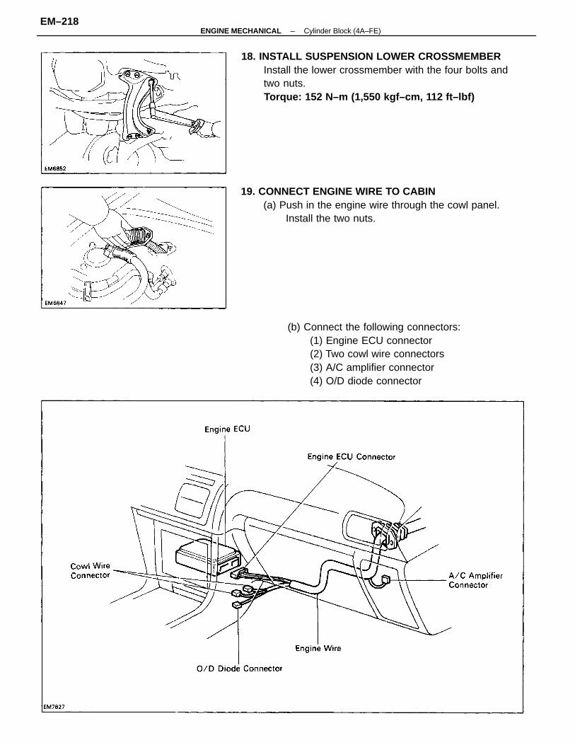
18. INSTALL SUSPENSION LOWER CROSSMEMBERInstall the lower crossmember with the four bolts andtwo nuts.Torque: 152 N–m (1,550 kgf–cm, 112 ft–lbf)
(b) Connect the following connectors:(1) Engine ECU connector(2) Two cowl wire connectors(3) A/C amplifier connector(4) O/D diode connector
19. CONNECT ENGINE WIRE TO CABIN(a) Push in the engine wire through the cowl panel.
Install the two nuts.
–ENGINE MECHANICAL Cylinder Block (4A–FE)EM–218
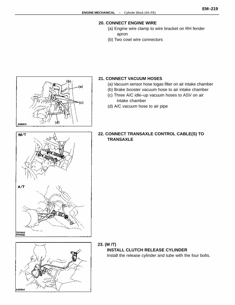
21. CONNECT VACUUM HOSES(a) Vacuum sensor hose togas filter on air intake chamber(b) Brake booster vacuum hose to air intake chamber(c) Three A/C idle–up vacuum hoses to ASV on air
intake chamber(d) A/C vacuum hose to air pipe
20. CONNECT ENGINE WIRE(a) Engine wire clamp to wire bracket on RH fender
apron(b) Two cowl wire connectors
23. (M /T)INSTALL CLUTCH RELEASE CYLINDERInstall the release cylinder and tube with the four bolts.
22. CONNECT TRANSAXLE CONTROL CABLE(S) TOTRANSAXLE
–ENGINE MECHANICAL Cylinder Block (4A–FE)EM–219
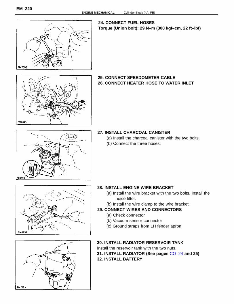
28. INSTALL ENGINE WIRE BRACKET(a) Install the wire bracket with the two bolts. Install the
noise filter.(b) Install the wire clamp to the wire bracket.
29. CONNECT WIRES AND CONNECTORS(a) Check connector(b) Vacuum sensor connector(c) Ground straps from LH fender apron
30. INSTALL RADIATOR RESERVOIR TANKInstall the reservoir tank with the two nuts.31. INSTALL RADIATOR (See pages CO–24 and 25)32. INSTALL BATTERY
27. INSTALL CHARCOAL CANISTER(a) Install the charcoal canister with the two bolts.(b) Connect the three hoses.
25. CONNECT SPEEDOMETER CABLE26. CONNECT HEATER HOSE TO WATER INLET
24. CONNECT FUEL HOSESTorque (Union bolt): 29 N–m (300 kgf–cm, 22 ft–lbf)
–ENGINE MECHANICAL Cylinder Block (4A–FE)EM–220
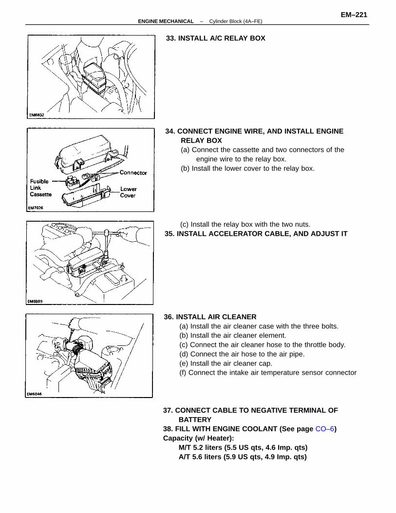
36. INSTALL AIR CLEANER(a) Install the air cleaner case with the three bolts.(b) Install the air cleaner element.(c) Connect the air cleaner hose to the throttle body.(d) Connect the air hose to the air pipe.(e) Install the air cleaner cap.(f) Connect the intake air temperature sensor connector
37. CONNECT CABLE TO NEGATIVE TERMINAL OFBATTERY
38. FILL WITH ENGINE COOLANT (See page CO–6)Capacity (w/ Heater):
M/T 5.2 liters (5.5 US qts, 4.6 Imp. qts)A/T 5.6 liters (5.9 US qts, 4.9 Imp. qts)
34. CONNECT ENGINE WIRE, AND INSTALL ENGINERELAY BOX(a) Connect the cassette and two connectors of the
engine wire to the relay box.(b) Install the lower cover to the relay box.
(c) Install the relay box with the two nuts.35. INSTALL ACCELERATOR CABLE, AND ADJUST IT
33. INSTALL A/C RELAY BOX
–ENGINE MECHANICAL Cylinder Block (4A–FE)EM–221
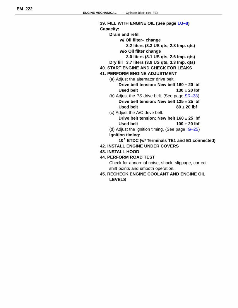
39. FILL WITH ENGINE OIL (See page LU–8)Capacity:
Drain and refillw/ Oil filter– change
3.2 liters (3.3 US qts, 2.8 Imp. qts)w/o Oil filter change
3.0 liters (3.1 US qts, 2.6 Imp. qts)Dry fill 3.7 liters (3.9 US qts, 3.3 Imp. qts)
40. START ENGINE AND CHECK FOR LEAKS41. PERFORM ENGINE ADJUSTMENT
(a) Adjust the alternator drive belt.Drive belt tension: New belt 160 ± 20 lbfUsed belt 130 ± 20 lbf
(b) Adjust the PS drive belt. (See page SR–38)Drive belt tension: New belt 125 ± 25 lbfUsed belt 80 ± 20 lbf
(c) Adjust the A/C drive belt.Drive belt tension: New belt 160 ± 25 lbfUsed belt 100 ± 20 lbf
(d) Adjust the ignition timing. (See page IG–25)Ignition timing:
10° BTDC (w/ Terminals TE1 and E1 connected)42. INSTALL ENGINE UNDER COVERS43. INSTALL HOOD44. PERFORM ROAD TEST
Check for abnormal noise, shock, slippage, correctshift points and smooth operation.
45. RECHECK ENGINE COOLANT AND ENGINE OILLEVELS
–ENGINE MECHANICAL Cylinder Block (4A–FE)EM–222
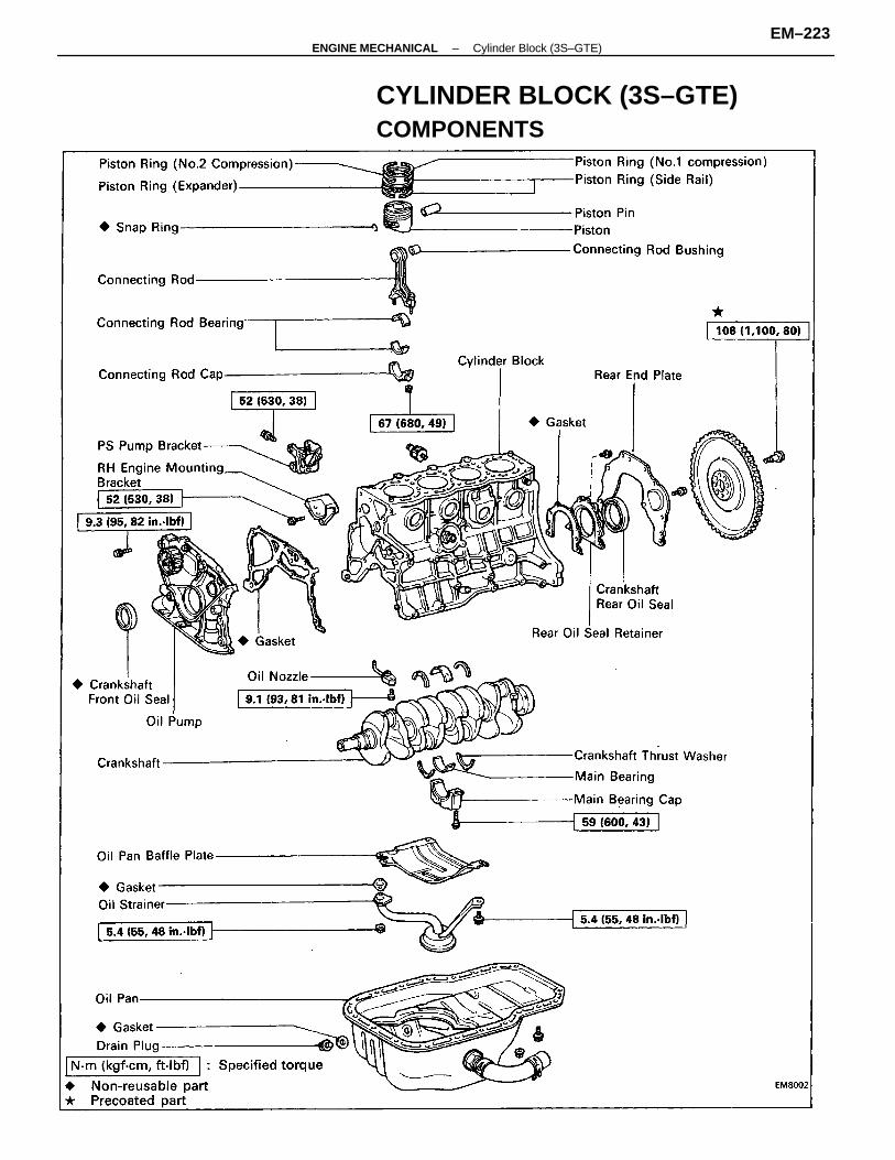
CYLINDER BLOCK (3S–GTE)COMPONENTS
–ENGINE MECHANICAL Cylinder Block (3S–GTE)EM–223
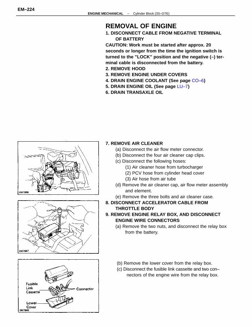
7. REMOVE AIR CLEANER(a) Disconnect the air flow meter connector.(b) Disconnect the four air cleaner cap clips.(c) Disconnect the following hoses:
(1) Air cleaner hose from turbocharger(2) PCV hose from cylinder head cover(3) Air hose from air tube
(d) Remove the air cleaner cap, air flow meter assemblyand element.
(e) Remove the three bolts and air cleaner case.8. DISCONNECT ACCELERATOR CABLE FROM
THROTTLE BODY9. REMOVE ENGINE RELAY BOX, AND DISCONNECT
ENGINE WIRE CONNECTORS(a) Remove the two nuts, and disconnect the relay box
from the battery.
REMOVAL OF ENGINE1. DISCONNECT CABLE FROM NEGATIVE TERMINAL
OF BATTERYCAUTION: Work must be started after approx. 20seconds or longer from the time the ignition switch isturned to the ”LOCK” position and the negative (–) ter-minal cable is disconnected from the battery.2. REMOVE HOOD3. REMOVE ENGINE UNDER COVERS4. DRAIN ENGINE COOLANT (See page CO–6)5. DRAIN ENGINE OIL (See page LU–7)6. DRAIN TRANSAXLE OIL
(b) Remove the lower cover from the relay box.(c) Disconnect the fusible link cassette and two con–
nectors of the engine wire from the relay box.
–ENGINE MECHANICAL Cylinder Block (3S–GTE)EM–224
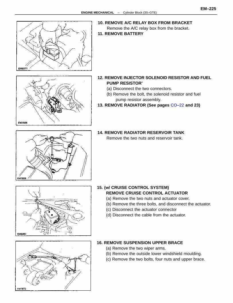
15. (w/ CRUISE CONTROL SYSTEM)REMOVE CRUISE CONTROL ACTUATOR(a) Remove the two nuts and actuator cover.(b) Remove the three bolts, and disconnect the actuator.(c) Disconnect the actuator connector(d) Disconnect the cable from the actuator.
12. REMOVE INJECTOR SOLENOID RESISTOR AND FUELPUMP RESISTOR’(a) Disconnect the two connectors.(b) Remove the bolt, the solenoid resistor and fuel
pump resistor assembly.13. REMOVE RADIATOR (See pages CO–22 and 23)
16. REMOVE SUSPENSION UPPER BRACE(a) Remove the two wiper arms.(b) Remove the outside lower windshield moulding.(c) Remove the two bolts, four nuts and upper brace.
10. REMOVE A/C RELAY BOX FROM BRACKETRemove the A/C relay box from the bracket.
11. REMOVE BATTERY
14. REMOVE RADIATOR RESERVOIR TANKRemove the two nuts and reservoir tank.
–ENGINE MECHANICAL Cylinder Block (3S–GTE)EM–225
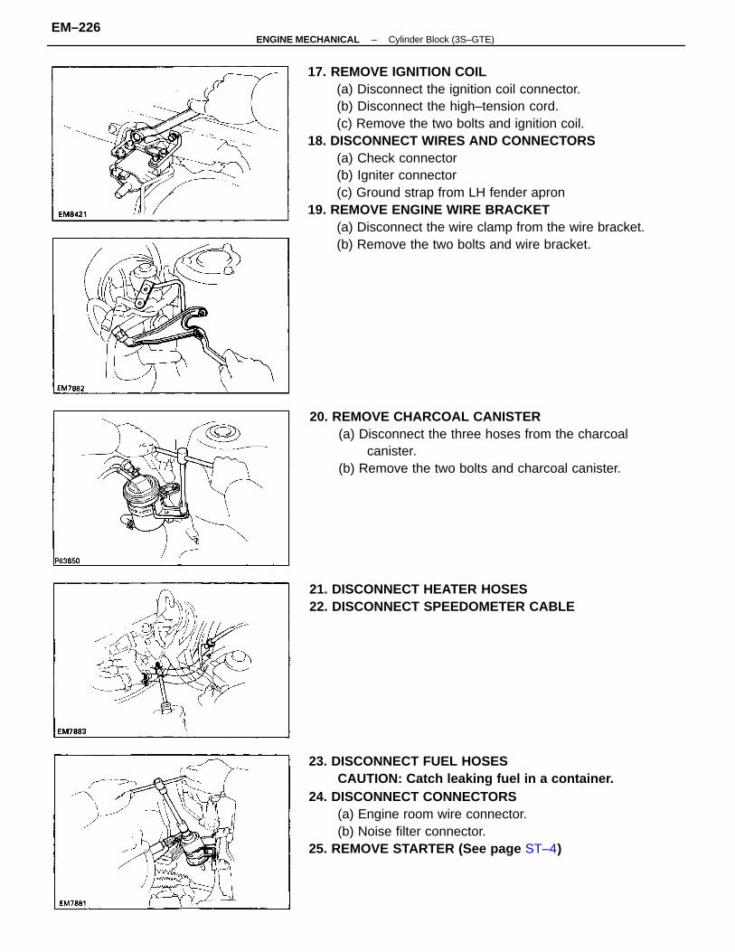
17. REMOVE IGNITION COIL(a) Disconnect the ignition coil connector.(b) Disconnect the high–tension cord.(c) Remove the two bolts and ignition coil.
18. DISCONNECT WIRES AND CONNECTORS(a) Check connector(b) Igniter connector(c) Ground strap from LH fender apron
19. REMOVE ENGINE WIRE BRACKET(a) Disconnect the wire clamp from the wire bracket.(b) Remove the two bolts and wire bracket.
23. DISCONNECT FUEL HOSESCAUTION: Catch leaking fuel in a container.
24. DISCONNECT CONNECTORS(a) Engine room wire connector.(b) Noise filter connector.
25. REMOVE STARTER (See page ST–4)
20. REMOVE CHARCOAL CANISTER(a) Disconnect the three hoses from the charcoal
canister.(b) Remove the two bolts and charcoal canister.
21. DISCONNECT HEATER HOSES22. DISCONNECT SPEEDOMETER CABLE
–ENGINE MECHANICAL Cylinder Block (3S–GTE)EM–226
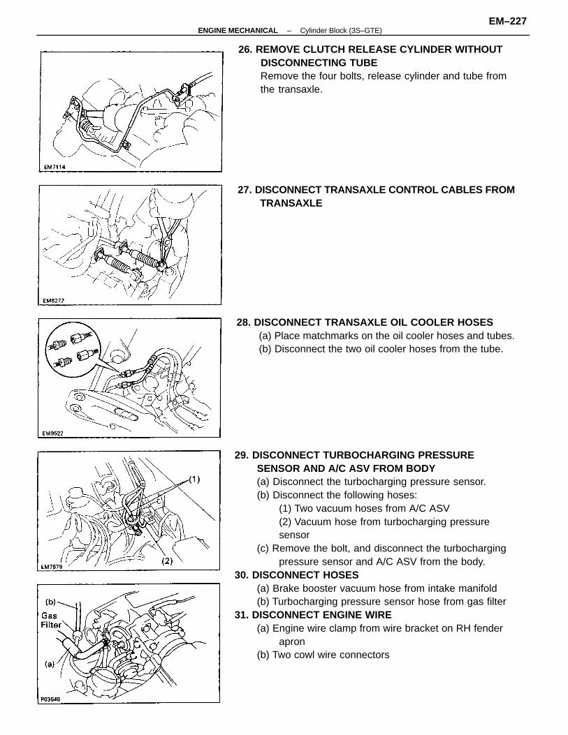
29. DISCONNECT TURBOCHARGING PRESSURESENSOR AND A/C ASV FROM BODY(a) Disconnect the turbocharging pressure sensor.(b) Disconnect the following hoses:
(1) Two vacuum hoses from A/C ASV(2) Vacuum hose from turbocharging pressuresensor
(c) Remove the bolt, and disconnect the turbochargingpressure sensor and A/C ASV from the body.
30. DISCONNECT HOSES(a) Brake booster vacuum hose from intake manifold(b) Turbocharging pressure sensor hose from gas filter
31. DISCONNECT ENGINE WIRE(a) Engine wire clamp from wire bracket on RH fender
apron(b) Two cowl wire connectors
26. REMOVE CLUTCH RELEASE CYLINDER WITHOUTDISCONNECTING TUBERemove the four bolts, release cylinder and tube fromthe transaxle.
28. DISCONNECT TRANSAXLE OIL COOLER HOSES(a) Place matchmarks on the oil cooler hoses and tubes.(b) Disconnect the two oil cooler hoses from the tube.
27. DISCONNECT TRANSAXLE CONTROL CABLES FROMTRANSAXLE
–ENGINE MECHANICAL Cylinder Block (3S–GTE)EM–227
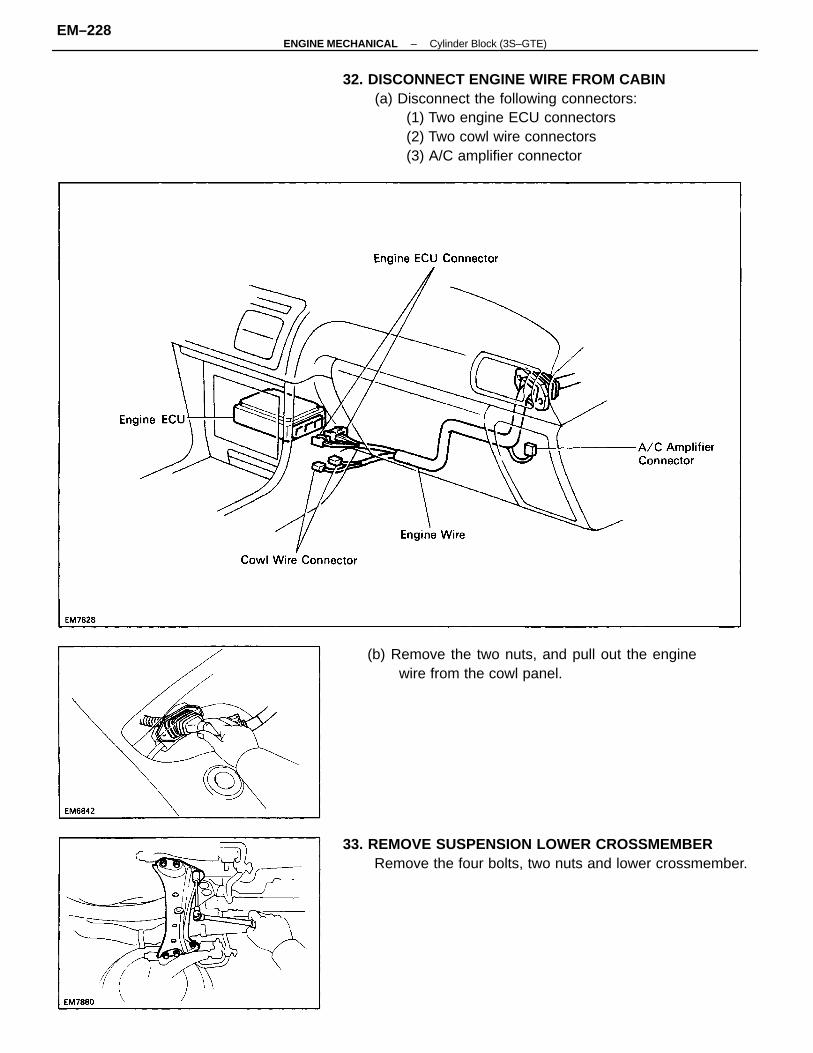
32. DISCONNECT ENGINE WIRE FROM CABIN(a) Disconnect the following connectors:
(1) Two engine ECU connectors(2) Two cowl wire connectors(3) A/C amplifier connector
33. REMOVE SUSPENSION LOWER CROSSMEMBERRemove the four bolts, two nuts and lower crossmember.
(b) Remove the two nuts, and pull out the enginewire from the cowl panel.
–ENGINE MECHANICAL Cylinder Block (3S–GTE)EM–228
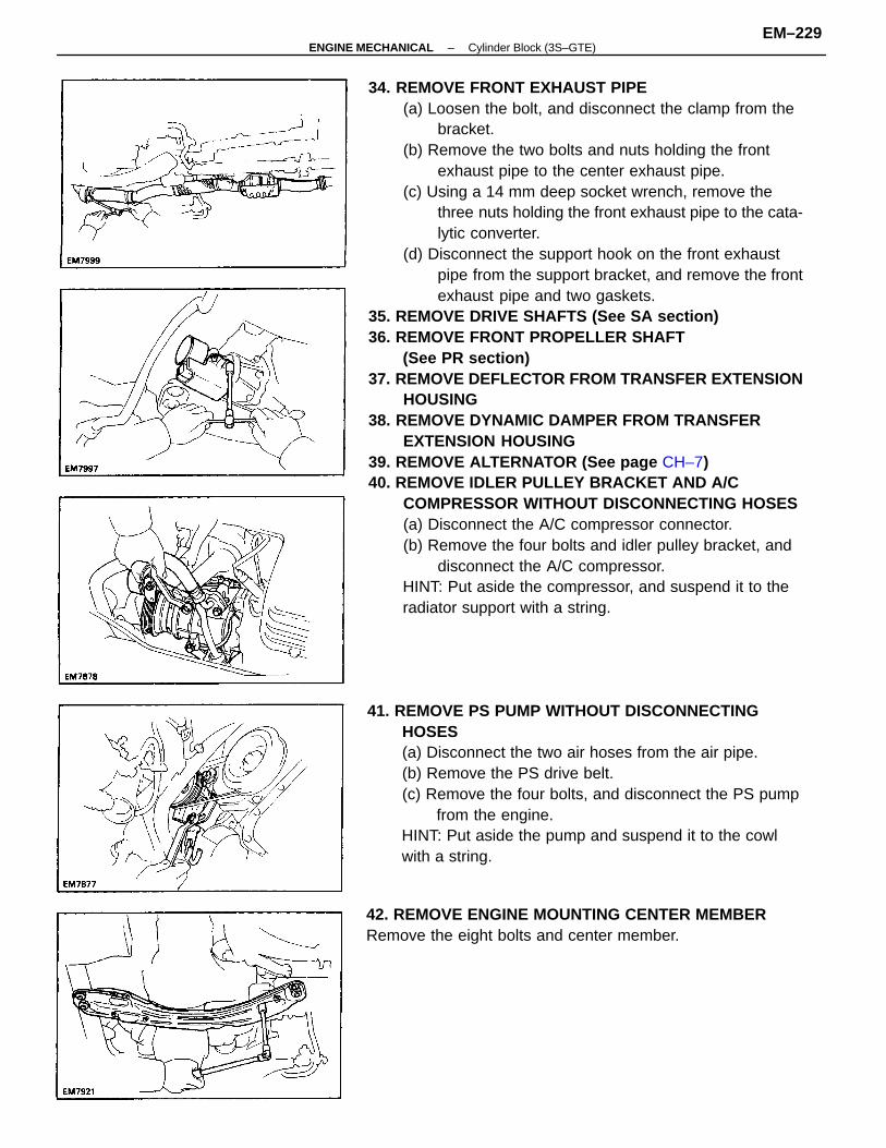
34. REMOVE FRONT EXHAUST PIPE(a) Loosen the bolt, and disconnect the clamp from the
bracket.(b) Remove the two bolts and nuts holding the front
exhaust pipe to the center exhaust pipe.(c) Using a 14 mm deep socket wrench, remove the
three nuts holding the front exhaust pipe to the cata-lytic converter.
(d) Disconnect the support hook on the front exhaustpipe from the support bracket, and remove the frontexhaust pipe and two gaskets.
35. REMOVE DRIVE SHAFTS (See SA section)36. REMOVE FRONT PROPELLER SHAFT
(See PR section)37. REMOVE DEFLECTOR FROM TRANSFER EXTENSION
HOUSING38. REMOVE DYNAMIC DAMPER FROM TRANSFER
EXTENSION HOUSING39. REMOVE ALTERNATOR (See page CH–7)40. REMOVE IDLER PULLEY BRACKET AND A/C
COMPRESSOR WITHOUT DISCONNECTING HOSES(a) Disconnect the A/C compressor connector.(b) Remove the four bolts and idler pulley bracket, and
disconnect the A/C compressor.HINT: Put aside the compressor, and suspend it to theradiator support with a string.
41. REMOVE PS PUMP WITHOUT DISCONNECTINGHOSES(a) Disconnect the two air hoses from the air pipe.(b) Remove the PS drive belt.(c) Remove the four bolts, and disconnect the PS pump
from the engine.HINT: Put aside the pump and suspend it to the cowlwith a string.
42. REMOVE ENGINE MOUNTING CENTER MEMBERRemove the eight bolts and center member.
–ENGINE MECHANICAL Cylinder Block (3S–GTE)EM–229
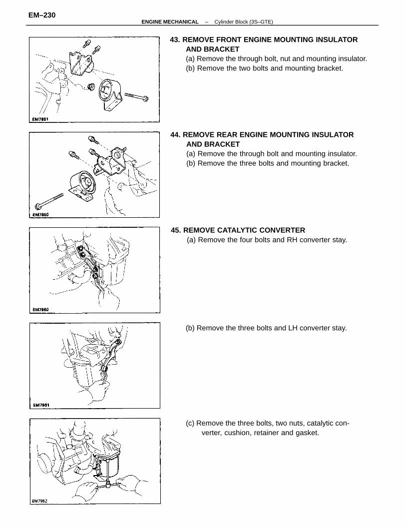
43. REMOVE FRONT ENGINE MOUNTING INSULATORAND BRACKET(a) Remove the through bolt, nut and mounting insulator.(b) Remove the two bolts and mounting bracket.
44. REMOVE REAR ENGINE MOUNTING INSULATORAND BRACKET(a) Remove the through bolt and mounting insulator.(b) Remove the three bolts and mounting bracket.
45. REMOVE CATALYTIC CONVERTER(a) Remove the four bolts and RH converter stay.
(c) Remove the three bolts, two nuts, catalytic con-verter, cushion, retainer and gasket.
(b) Remove the three bolts and LH converter stay.
–ENGINE MECHANICAL Cylinder Block (3S–GTE)EM–230
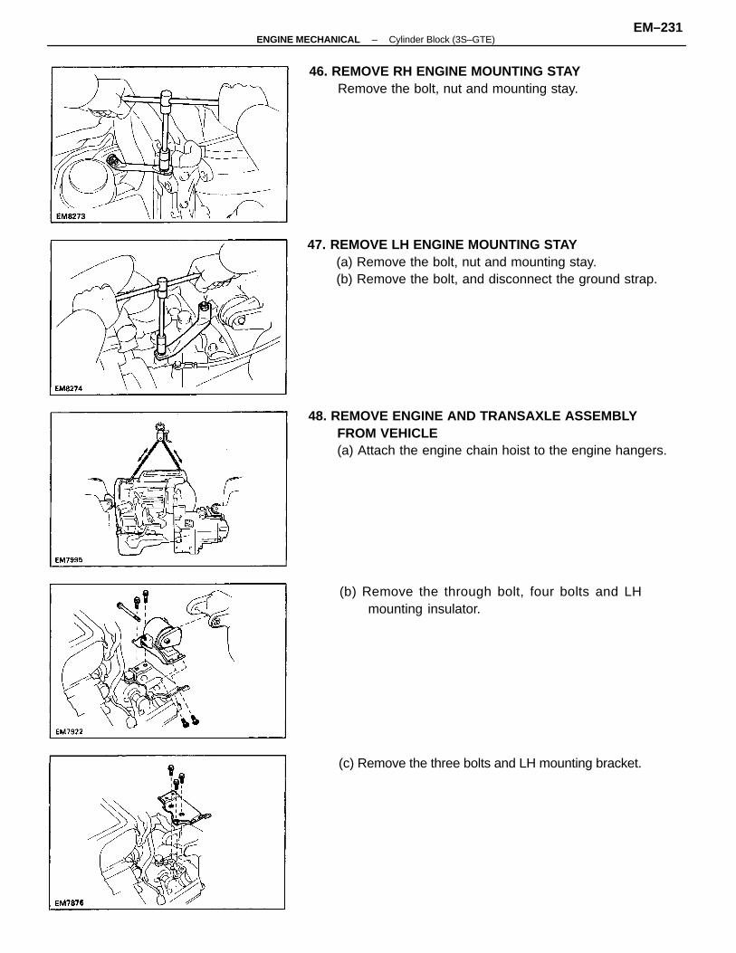
47. REMOVE LH ENGINE MOUNTING STAY(a) Remove the bolt, nut and mounting stay.(b) Remove the bolt, and disconnect the ground strap.
48. REMOVE ENGINE AND TRANSAXLE ASSEMBLYFROM VEHICLE(a) Attach the engine chain hoist to the engine hangers.
(b) Remove the through bolt, four bolts and LHmounting insulator.
46. REMOVE RH ENGINE MOUNTING STAYRemove the bolt, nut and mounting stay.
(c) Remove the three bolts and LH mounting bracket.
–ENGINE MECHANICAL Cylinder Block (3S–GTE)EM–231
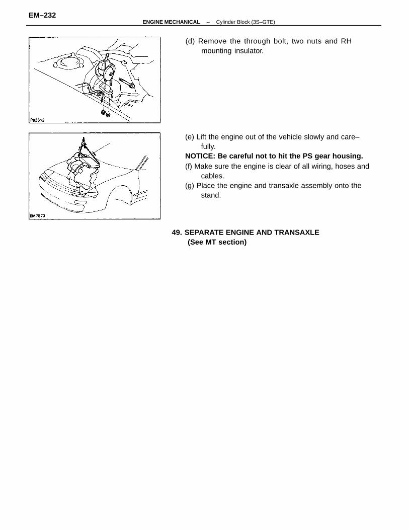
(e) Lift the engine out of the vehicle slowly and care–fully.
NOTICE: Be careful not to hit the PS gear housing.(f) Make sure the engine is clear of all wiring, hoses and
cables.(g) Place the engine and transaxle assembly onto the
stand.
(d) Remove the through bolt, two nuts and RHmounting insulator.
49. SEPARATE ENGINE AND TRANSAXLE(See MT section)
–ENGINE MECHANICAL Cylinder Block (3S–GTE)EM–232
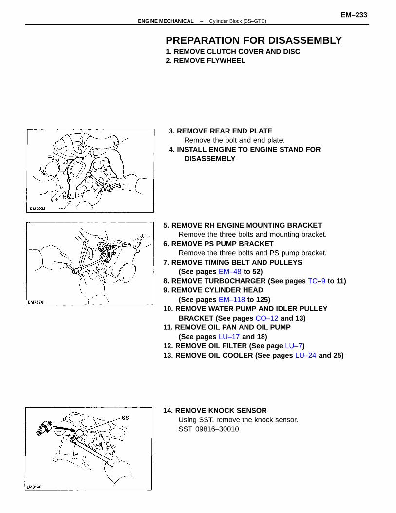
5. REMOVE RH ENGINE MOUNTING BRACKETRemove the three bolts and mounting bracket.
6. REMOVE PS PUMP BRACKETRemove the three bolts and PS pump bracket.
7. REMOVE TIMING BELT AND PULLEYS(See pages EM–48 to 52)
8. REMOVE TURBOCHARGER (See pages TC–9 to 11)9. REMOVE CYLINDER HEAD
(See pages EM–118 to 125)10. REMOVE WATER PUMP AND IDLER PULLEY
BRACKET (See pages CO–12 and 13)11. REMOVE OIL PAN AND OIL PUMP
(See pages LU–17 and 18)12. REMOVE OIL FILTER (See page LU–7)13. REMOVE OIL COOLER (See pages LU–24 and 25)
3. REMOVE REAR END PLATERemove the bolt and end plate.
4. INSTALL ENGINE TO ENGINE STAND FORDISASSEMBLY
PREPARATION FOR DISASSEMBLY1. REMOVE CLUTCH COVER AND DISC2. REMOVE FLYWHEEL
14. REMOVE KNOCK SENSORUsing SST, remove the knock sensor.SST 09816–30010
–ENGINE MECHANICAL Cylinder Block (3S–GTE)EM–233
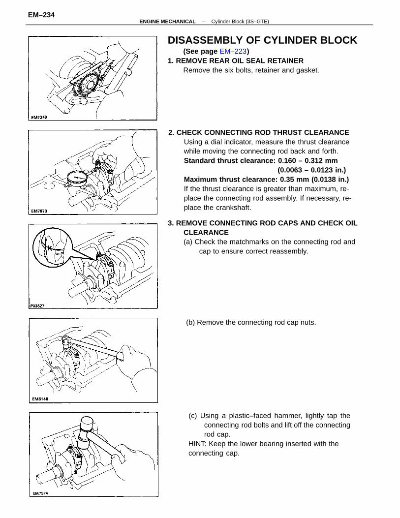
2. CHECK CONNECTING ROD THRUST CLEARANCEUsing a dial indicator, measure the thrust clearancewhile moving the connecting rod back and forth.Standard thrust clearance: 0.160 – 0.312 mm
(0.0063 – 0.0123 in.)Maximum thrust clearance: 0.35 mm (0.0138 in.)If the thrust clearance is greater than maximum, re-place the connecting rod assembly. If necessary, re-place the crankshaft.
3. REMOVE CONNECTING ROD CAPS AND CHECK OILCLEARANCE(a) Check the matchmarks on the connecting rod and
cap to ensure correct reassembly.
DISASSEMBLY OF CYLINDER BLOCK(See page EM–223)
1. REMOVE REAR OIL SEAL RETAINERRemove the six bolts, retainer and gasket.
(c) Using a plastic–faced hammer, lightly tap theconnecting rod bolts and lift off the connectingrod cap.
HINT: Keep the lower bearing inserted with theconnecting cap.
(b) Remove the connecting rod cap nuts.
–ENGINE MECHANICAL Cylinder Block (3S–GTE)EM–234
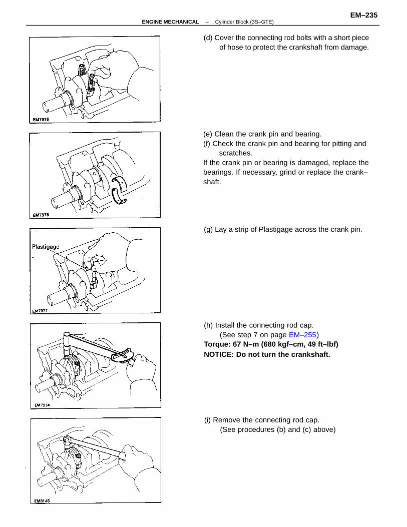
(e) Clean the crank pin and bearing.(f) Check the crank pin and bearing for pitting and
scratches.If the crank pin or bearing is damaged, replace thebearings. If necessary, grind or replace the crank–shaft.
(h) Install the connecting rod cap.(See step 7 on page EM–255)
Torque: 67 N–m (680 kgf–cm, 49 ft–lbf)NOTICE: Do not turn the crankshaft.
(d) Cover the connecting rod bolts with a short pieceof hose to protect the crankshaft from damage.
(i) Remove the connecting rod cap.(See procedures (b) and (c) above)
(g) Lay a strip of Plastigage across the crank pin.
–ENGINE MECHANICAL Cylinder Block (3S–GTE)EM–235
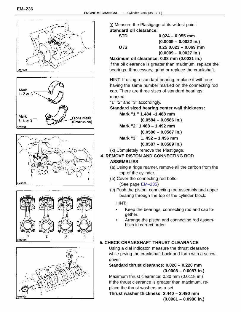
HINT: If using a standard bearing, replace it with onehaving the same number marked on the connecting rodcap. There are three sizes of standard bearings,marked“1” ”2” and ”3” accordingly.Standard sized bearing center wall thickness:
Mark ”1 ” 1.484 –1.488 mm(0.0584 – 0.0586 in.)
Mark ”2” 1.488 – 1.492 mm(0.0586 – 0.0587 in.)
Mark ”3” 1. 492 – 1.496 mm(0.0587 – 0.0589 in.)
(k) Completely remove the Plastigage.4. REMOVE PISTON AND CONNECTING ROD
ASSEMBLIES(a) Using a ridge reamer, remove all the carbon from the
top of the cylinder.(b) Cover the connecting rod bolts.
(See page EM–235)(c) Push the piston, connecting rod assembly and upper
bearing through the top of the cylinder block.
5. CHECK CRANKSHAFT THRUST CLEARANCEUsing a dial indicator, measure the thrust clearancewhile prying the crankshaft back and forth with a screw-driver.Standard thrust clearance: 0.020 – 0.220 mm
(0.0008 – 0.0087 in.)Maximum thrust clearance: 0.30 mm (0.0118 in.)If the thrust clearance is greater than maximum, re-place the thrust washers as a set.Thrust washer thickness: 2.440 – 2.490 mm
(0.0961 – 0.0980 in.)
(j) Measure the Plastigage at its widest point.Standard oil clearance:
STD 0.024 – 0.055 mm(0.0009 – 0.0022 in.)
U /S 0.25 0.023 – 0.069 mm(0.0009 – 0.0027 in.)
Maximum oil clearance: 0.08 mm (0.0031 in.)If the oil clearance is greater than maximum, replace thebearings. If necessary, grind or replace the crankshaft.
HINT:
• Keep the bearings, connecting rod and cap to-gether.
• Arrange the piston and connecting rod assem-blies in correct order.
–ENGINE MECHANICAL Cylinder Block (3S–GTE)EM–236
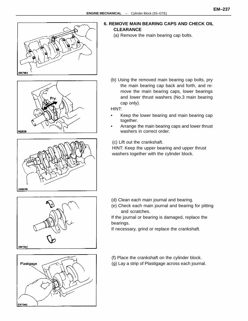
(b) Using the removed main bearing cap bolts, prythe main bearing cap back and forth, and re-move the main bearing caps, lower bearingsand lower thrust washers (No.3 main bearingcap only).
HINT:
• Keep the lower bearing and main bearing captogether.
• Arrange the main bearing caps and lower thrustwashers in correct order.
(d) Clean each main journal and bearing.(e) Check each main journal and bearing for pitting
and scratches.If the journal or bearing is damaged, replace thebearings.If necessary, grind or replace the crankshaft.
6. REMOVE MAIN BEARING CAPS AND CHECK OILCLEARANCE(a) Remove the main bearing cap bolts.
(c) Lift out the crankshaft.HINT: Keep the upper bearing and upper thrustwashers together with the cylinder block.
(f) Place the crankshaft on the cylinder block.(g) Lay a strip of Plastigage across each journal.
–ENGINE MECHANICAL Cylinder Block (3S–GTE)EM–237
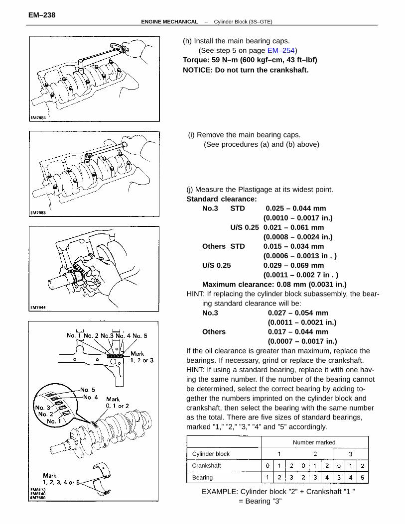
(j) Measure the Plastigage at its widest point.Standard clearance:
No.3 STD 0.025 – 0.044 mm(0.0010 – 0.0017 in.)
U/S 0.25 0.021 – 0.061 mm(0.0008 – 0.0024 in.)
Others STD 0.015 – 0.034 mm(0.0006 – 0.0013 in . )
U/S 0.25 0.029 – 0.069 mm(0.0011 – 0.002 7 in . )
Maximum clearance: 0.08 mm (0.0031 in.)HINT: If replacing the cylinder block subassembly, the bear-
ing standard clearance will be: No.3 0.027 – 0.054 mm
(0.0011 – 0.0021 in.) Others 0.017 – 0.044 mm
(0.0007 – 0.0017 in.)If the oil clearance is greater than maximum, replace thebearings. If necessary, grind or replace the crankshaft.HINT: If using a standard bearing, replace it with one hav-ing the same number. If the number of the bearing cannotbe determined, select the correct bearing by adding to-gether the numbers imprinted on the cylinder block andcrankshaft, then select the bearing with the same numberas the total. There are five sizes of standard bearings,marked ”1,” ”2,” ”3,” ”4” and ”5” accordingly.
(h) Install the main bearing caps.(See step 5 on page EM–254)
Torque: 59 N–m (600 kgf–cm, 43 ft–lbf)NOTICE: Do not turn the crankshaft.
EXAMPLE: Cylinder block ”2” + Crankshaft ”1 ”= Bearing ”3”
(i) Remove the main bearing caps.(See procedures (a) and (b) above)
Number marked
Cylinder block
Crankshaft
Bearing
–ENGINE MECHANICAL Cylinder Block (3S–GTE)EM–238
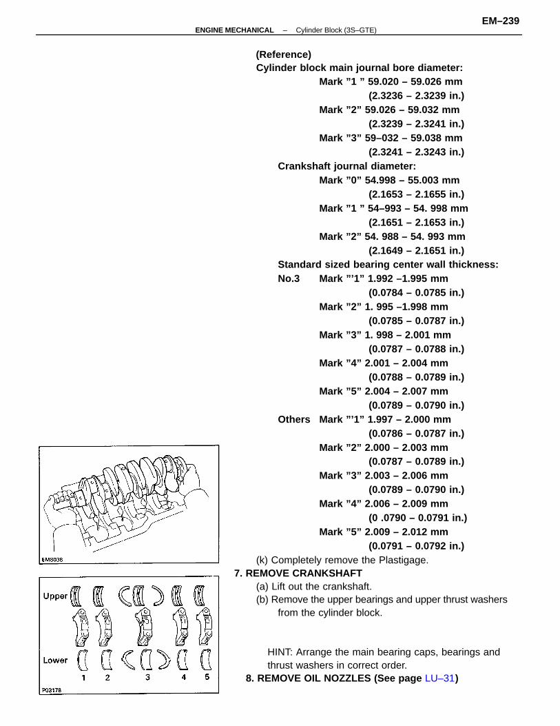
(Reference)Cylinder block main journal bore diameter:
Mark ”1 ” 59.020 – 59.026 mm(2.3236 – 2.3239 in.)
Mark ”2” 59.026 – 59.032 mm(2.3239 – 2.3241 in.)
Mark ”3” 59–032 – 59.038 mm(2.3241 – 2.3243 in.)
Crankshaft journal diameter:Mark ”0” 54.998 – 55.003 mm
(2.1653 – 2.1655 in.)Mark ”1 ” 54–993 – 54. 998 mm
(2.1651 – 2.1653 in.)Mark ”2” 54. 988 – 54. 993 mm
(2.1649 – 2.1651 in.)Standard sized bearing center wall thickness:No.3 Mark ”’1” 1.992 –1.995 mm
(0.0784 – 0.0785 in.)Mark ”2” 1. 995 –1.998 mm
(0.0785 – 0.0787 in.)Mark ”3” 1. 998 – 2.001 mm
(0.0787 – 0.0788 in.)Mark ”4” 2.001 – 2.004 mm
(0.0788 – 0.0789 in.)Mark ”5” 2.004 – 2.007 mm
(0.0789 – 0.0790 in.)Others Mark ”’1” 1.997 – 2.000 mm
(0.0786 – 0.0787 in.)Mark ”2” 2.000 – 2.003 mm
(0.0787 – 0.0789 in.)Mark ”3” 2.003 – 2.006 mm
(0.0789 – 0.0790 in.)Mark ”4” 2.006 – 2.009 mm
(0 .0790 – 0.0791 in.)Mark ”5” 2.009 – 2.012 mm
(0.0791 – 0.0792 in.)(k) Completely remove the Plastigage.
7. REMOVE CRANKSHAFT(a) Lift out the crankshaft.(b) Remove the upper bearings and upper thrust washers
from the cylinder block.
HINT: Arrange the main bearing caps, bearings andthrust washers in correct order.
8. REMOVE OIL NOZZLES (See page LU–31)
–ENGINE MECHANICAL Cylinder Block (3S–GTE)EM–239
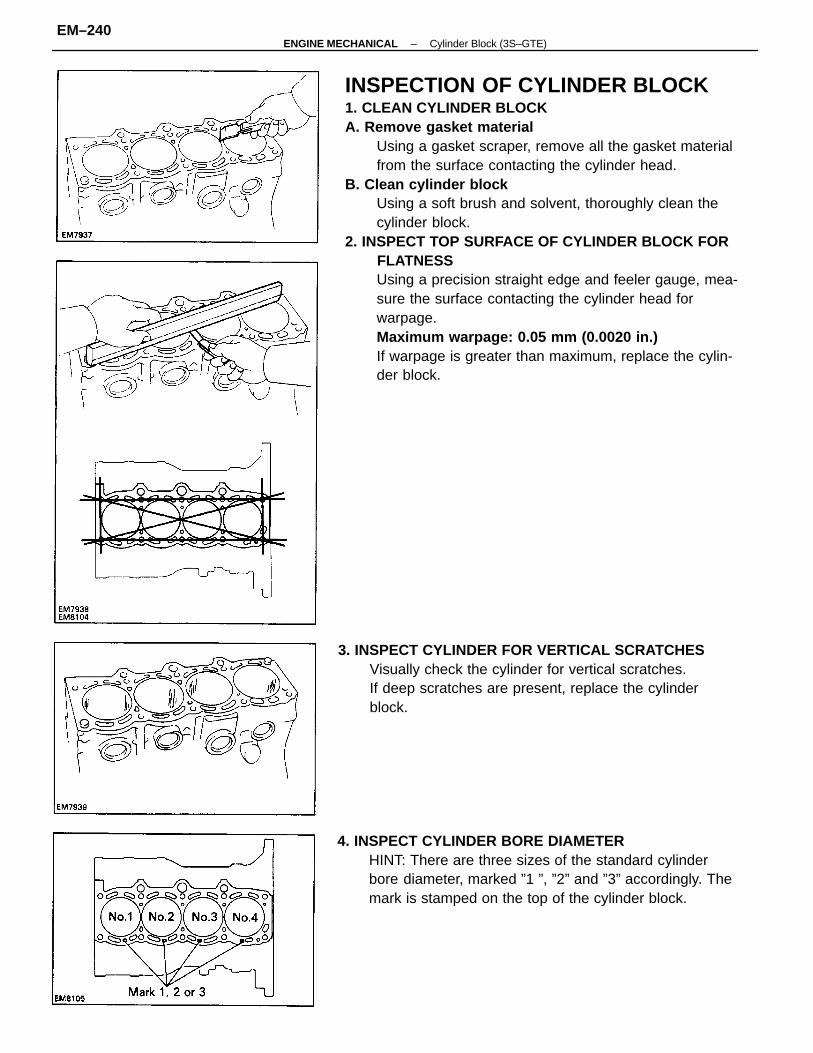
INSPECTION OF CYLINDER BLOCK1. CLEAN CYLINDER BLOCKA. Remove gasket material
Using a gasket scraper, remove all the gasket materialfrom the surface contacting the cylinder head.
B. Clean cylinder blockUsing a soft brush and solvent, thoroughly clean thecylinder block.
2. INSPECT TOP SURFACE OF CYLINDER BLOCK FORFLATNESSUsing a precision straight edge and feeler gauge, mea-sure the surface contacting the cylinder head forwarpage.Maximum warpage: 0.05 mm (0.0020 in.)If warpage is greater than maximum, replace the cylin-der block.
4. INSPECT CYLINDER BORE DIAMETERHINT: There are three sizes of the standard cylinderbore diameter, marked ”1 ”, ”2” and ”3” accordingly. Themark is stamped on the top of the cylinder block.
3. INSPECT CYLINDER FOR VERTICAL SCRATCHESVisually check the cylinder for vertical scratches.If deep scratches are present, replace the cylinderblock.
–ENGINE MECHANICAL Cylinder Block (3S–GTE)EM–240
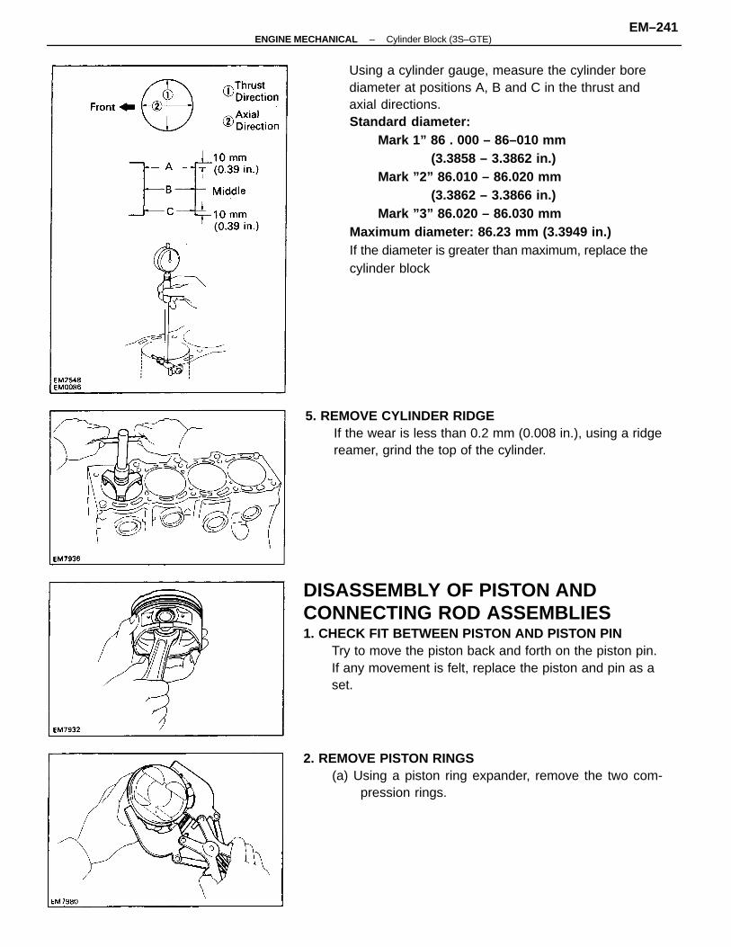
Using a cylinder gauge, measure the cylinder borediameter at positions A, B and C in the thrust andaxial directions.Standard diameter:
Mark 1” 86 . 000 – 86–010 mm(3.3858 – 3.3862 in.)
Mark ”2” 86.010 – 86.020 mm(3.3862 – 3.3866 in.)
Mark ”3” 86.020 – 86.030 mmMaximum diameter: 86.23 mm (3.3949 in.)If the diameter is greater than maximum, replace thecylinder block
DISASSEMBLY OF PISTON ANDCONNECTING ROD ASSEMBLIES1. CHECK FIT BETWEEN PISTON AND PISTON PIN
Try to move the piston back and forth on the piston pin.If any movement is felt, replace the piston and pin as aset.
2. REMOVE PISTON RINGS(a) Using a piston ring expander, remove the two com-
pression rings.
5. REMOVE CYLINDER RIDGEIf the wear is less than 0.2 mm (0.008 in.), using a ridgereamer, grind the top of the cylinder.
–ENGINE MECHANICAL Cylinder Block (3S–GTE)EM–241
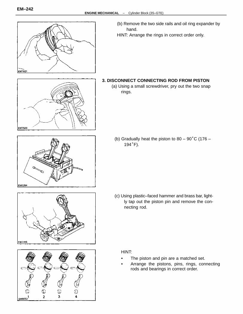
(b) Remove the two side rails and oil ring expander byhand.
HINT: Arrange the rings in correct order only.
HINT:
• The piston and pin are a matched set.• Arrange the pistons, pins, rings, connecting
rods and bearings in correct order.
3. DISCONNECT CONNECTING ROD FROM PISTON(a) Using a small screwdriver, pry out the two snap
rings.
(c) Using plastic–faced hammer and brass bar, light-ly tap out the piston pin and remove the con-necting rod.
(b) Gradually heat the piston to 80 – 90°C (176 –194°F).
–ENGINE MECHANICAL Cylinder Block (3S–GTE)EM–242
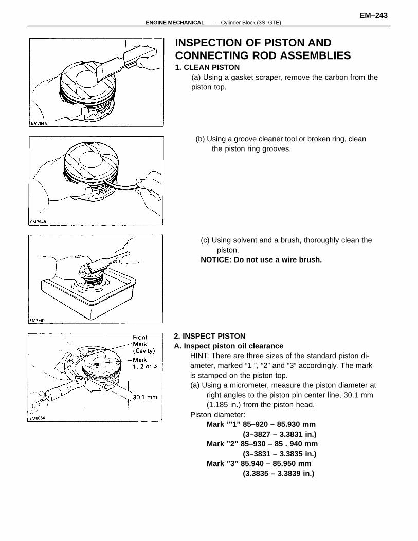
2. INSPECT PISTONA. Inspect piston oil clearance
HINT: There are three sizes of the standard piston di-ameter, marked ”1 ”, ”2” and ”3” accordingly. The markis stamped on the piston top.(a) Using a micrometer, measure the piston diameter at
right angles to the piston pin center line, 30.1 mm(1.185 in.) from the piston head.
Piston diameter:Mark ”’1” 85–920 – 85.930 mm
(3–3827 – 3.3831 in.)Mark ”2” 85–930 – 85 . 940 mm
(3–3831 – 3.3835 in.)Mark ”3” 85.940 – 85.950 mm
(3.3835 – 3.3839 in.)
INSPECTION OF PISTON ANDCONNECTING ROD ASSEMBLIES1. CLEAN PISTON
(a) Using a gasket scraper, remove the carbon from thepiston top.
(c) Using solvent and a brush, thoroughly clean thepiston.
NOTICE: Do not use a wire brush.
(b) Using a groove cleaner tool or broken ring, cleanthe piston ring grooves.
–ENGINE MECHANICAL Cylinder Block (3S–GTE)EM–243
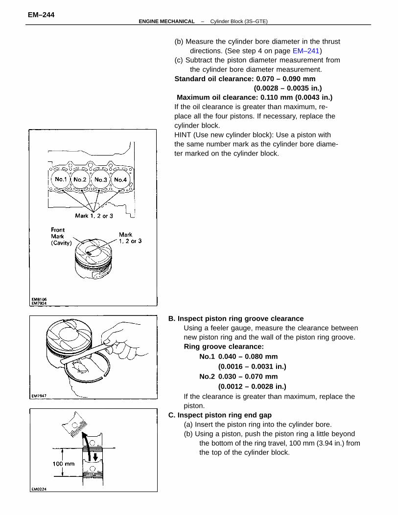
B. Inspect piston ring groove clearanceUsing a feeler gauge, measure the clearance betweennew piston ring and the wall of the piston ring groove.Ring groove clearance:
No.1 0.040 – 0.080 mm(0.0016 – 0.0031 in.)
No.2 0.030 – 0.070 mm(0.0012 – 0.0028 in.)
If the clearance is greater than maximum, replace thepiston.
C. Inspect piston ring end gap(a) Insert the piston ring into the cylinder bore.(b) Using a piston, push the piston ring a little beyond
the bottom of the ring travel, 100 mm (3.94 in.) fromthe top of the cylinder block.
(b) Measure the cylinder bore diameter in the thrustdirections. (See step 4 on page EM–241)
(c) Subtract the piston diameter measurement fromthe cylinder bore diameter measurement.
Standard oil clearance: 0.070 – 0.090 mm (0.0028 – 0.0035 in.)
Maximum oil clearance: 0.110 mm (0.0043 in.)If the oil clearance is greater than maximum, re-place all the four pistons. If necessary, replace thecylinder block.HINT (Use new cylinder block): Use a piston withthe same number mark as the cylinder bore diame-ter marked on the cylinder block.
–ENGINE MECHANICAL Cylinder Block (3S–GTE)EM–244
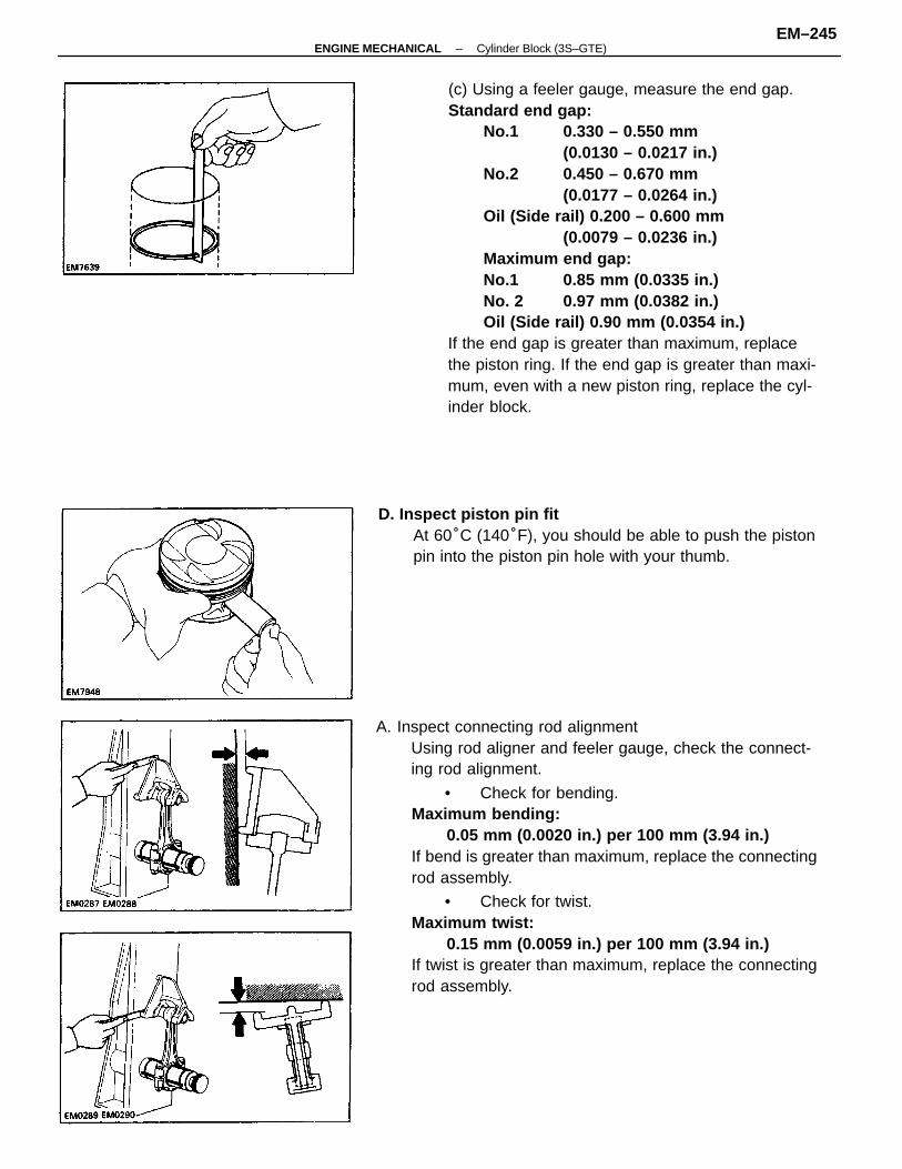
A. Inspect connecting rod alignmentUsing rod aligner and feeler gauge, check the connect-ing rod alignment.
• Check for bending.Maximum bending:
0.05 mm (0.0020 in.) per 100 mm (3.94 in.)If bend is greater than maximum, replace the connectingrod assembly.
• Check for twist.Maximum twist:
0.15 mm (0.0059 in.) per 100 mm (3.94 in.)If twist is greater than maximum, replace the connectingrod assembly.
(c) Using a feeler gauge, measure the end gap.Standard end gap:
No.1 0.330 – 0.550 mm(0.0130 – 0.0217 in.)
No.2 0.450 – 0.670 mm(0.0177 – 0.0264 in.)
Oil (Side rail) 0.200 – 0.600 mm(0.0079 – 0.0236 in.)
Maximum end gap:No.1 0.85 mm (0.0335 in.)No. 2 0.97 mm (0.0382 in.)Oil (Side rail) 0.90 mm (0.0354 in.)
If the end gap is greater than maximum, replacethe piston ring. If the end gap is greater than maxi-mum, even with a new piston ring, replace the cyl-inder block.
D. Inspect piston pin fitAt 60°C (140°F), you should be able to push the pistonpin into the piston pin hole with your thumb.
–ENGINE MECHANICAL Cylinder Block (3S–GTE)EM–245
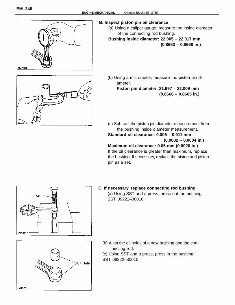
(c) Subtract the piston pin diameter measurement fromthe bushing inside diameter measurement.
Standard oil clearance: 0.005 – 0.011 mm(0.0002 – 0.0004 in.)
Maximum oil clearance: 0.05 mm (0.0020 in.)If the oil clearance is greater than maximum, replacethe bushing. If necessary, replace the piston and pistonpin as a set.
B. Inspect piston pin oil clearance(a) Using a caliper gauge, measure the inside diameter
of the connecting rod bushing.Bushing inside diameter: 22.005 – 22.017 mm
(0.8663 – 0.8668 in.)
(b) Align the oil holes of a new bushing and the con-necting rod.
(c) Using SST and a press, press in the bushing.SST 09222–30010
(b) Using a micrometer, measure the piston pin di-ameter.Piston pin diameter: 21.997 – 22.009 mm
(0.8660 – 0.8665 in.)
C. If necessary, replace connecting rod bushing(a) Using SST and a press, press out the bushing.SST 09222–30010
–ENGINE MECHANICAL Cylinder Block (3S–GTE)EM–246
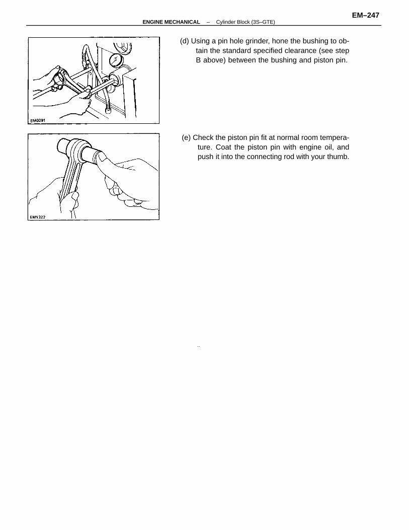
(d) Using a pin hole grinder, hone the bushing to ob-tain the standard specified clearance (see stepB above) between the bushing and piston pin.
(e) Check the piston pin fit at normal room tempera-ture. Coat the piston pin with engine oil, andpush it into the connecting rod with your thumb.
–ENGINE MECHANICAL Cylinder Block (3S–GTE)EM–247
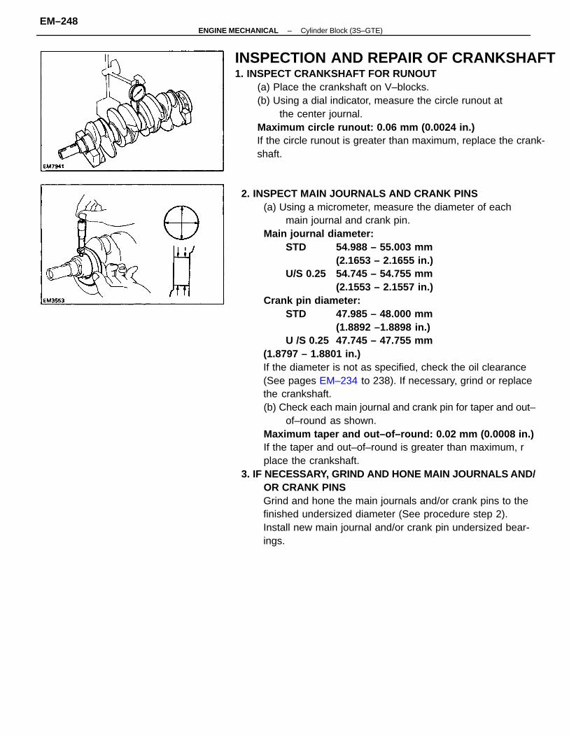
2. INSPECT MAIN JOURNALS AND CRANK PINS(a) Using a micrometer, measure the diameter of each
main journal and crank pin.Main journal diameter:
STD 54.988 – 55.003 mm(2.1653 – 2.1655 in.)
U/S 0.25 54.745 – 54.755 mm(2.1553 – 2.1557 in.)
Crank pin diameter:STD 47.985 – 48.000 mm
(1.8892 –1.8898 in.)U /S 0.25 47.745 – 47.755 mm
(1.8797 – 1.8801 in.)If the diameter is not as specified, check the oil clearance(See pages EM–234 to 238). If necessary, grind or replacethe crankshaft.(b) Check each main journal and crank pin for taper and out–
of–round as shown.Maximum taper and out–of–round: 0.02 mm (0.0008 in.)If the taper and out–of–round is greater than maximum, rplace the crankshaft.
3. IF NECESSARY, GRIND AND HONE MAIN JOURNALS AND/OR CRANK PINSGrind and hone the main journals and/or crank pins to thefinished undersized diameter (See procedure step 2).Install new main journal and/or crank pin undersized bear-ings.
INSPECTION AND REPAIR OF CRANKSHAFT1. INSPECT CRANKSHAFT FOR RUNOUT
(a) Place the crankshaft on V–blocks.(b) Using a dial indicator, measure the circle runout at
the center journal.Maximum circle runout: 0.06 mm (0.0024 in.)If the circle runout is greater than maximum, replace the crank-shaft.
–ENGINE MECHANICAL Cylinder Block (3S–GTE)EM–248
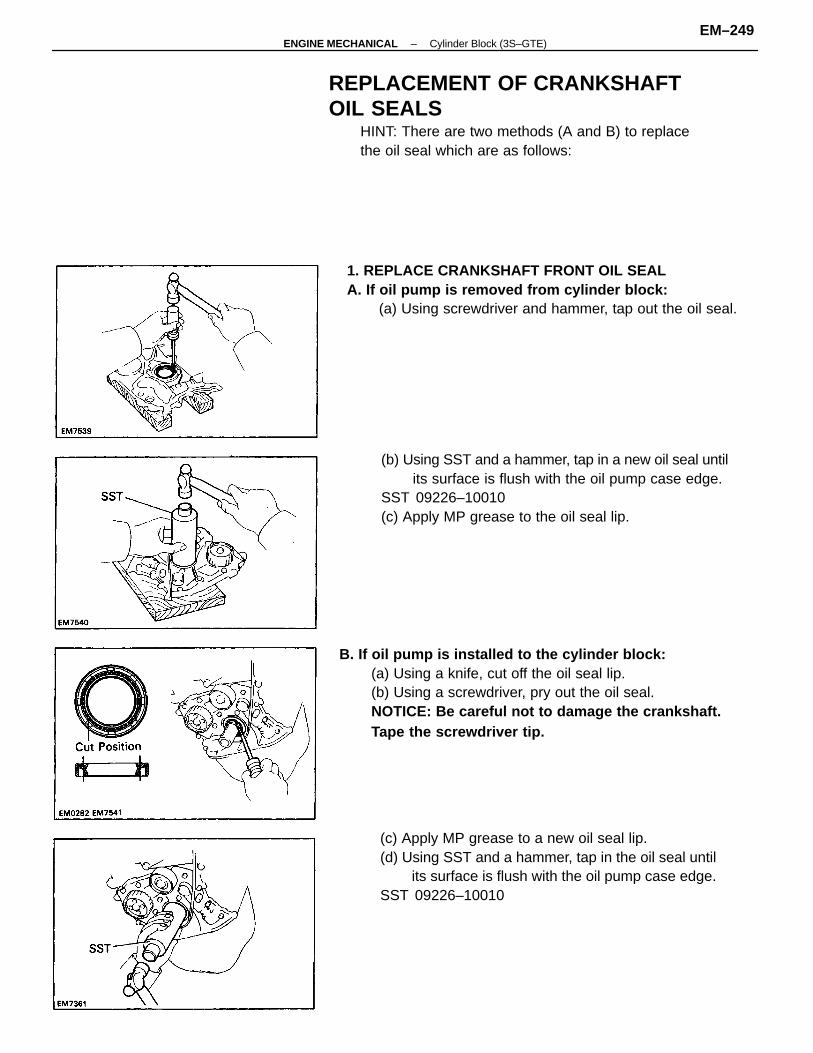
B. If oil pump is installed to the cylinder block:(a) Using a knife, cut off the oil seal lip.(b) Using a screwdriver, pry out the oil seal.NOTICE: Be careful not to damage the crankshaft.Tape the screwdriver tip.
(c) Apply MP grease to a new oil seal lip.(d) Using SST and a hammer, tap in the oil seal until
its surface is flush with the oil pump case edge.SST 09226–10010
(b) Using SST and a hammer, tap in a new oil seal untilits surface is flush with the oil pump case edge.
SST 09226–10010(c) Apply MP grease to the oil seal lip.
1. REPLACE CRANKSHAFT FRONT OIL SEALA. If oil pump is removed from cylinder block:
(a) Using screwdriver and hammer, tap out the oil seal.
REPLACEMENT OF CRANKSHAFTOIL SEALS
HINT: There are two methods (A and B) to replacethe oil seal which are as follows:
–ENGINE MECHANICAL Cylinder Block (3S–GTE)EM–249
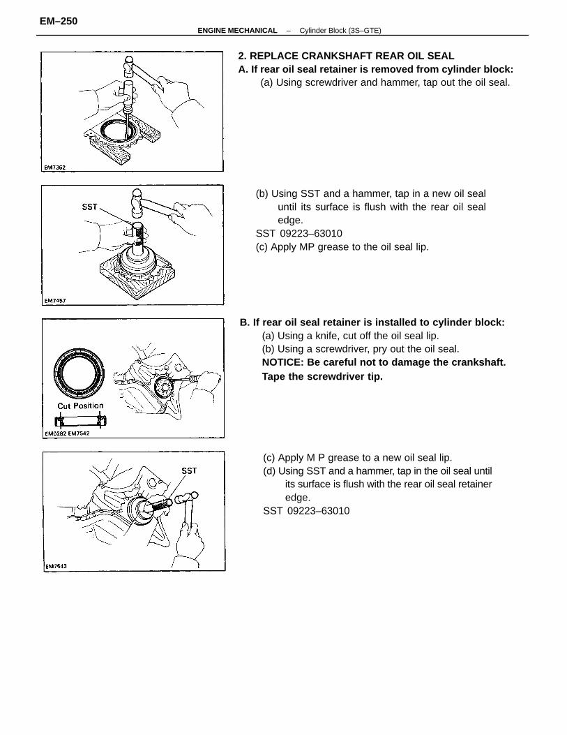
B. If rear oil seal retainer is installed to cylinder block:(a) Using a knife, cut off the oil seal lip.(b) Using a screwdriver, pry out the oil seal.NOTICE: Be careful not to damage the crankshaft.Tape the screwdriver tip.
(b) Using SST and a hammer, tap in a new oil sealuntil its surface is flush with the rear oil sealedge.
SST 09223–63010(c) Apply MP grease to the oil seal lip.
(c) Apply M P grease to a new oil seal lip.(d) Using SST and a hammer, tap in the oil seal until
its surface is flush with the rear oil seal retaineredge.
SST 09223–63010
2. REPLACE CRANKSHAFT REAR OIL SEALA. If rear oil seal retainer is removed from cylinder block:
(a) Using screwdriver and hammer, tap out the oil seal.
–ENGINE MECHANICAL Cylinder Block (3S–GTE)EM–250
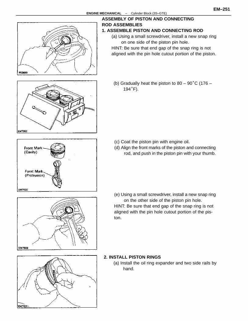
ASSEMBLY OF PISTON AND CONNECTINGROD ASSEMBLIES1. ASSEMBLE PISTON AND CONNECTING ROD
(a) Using a small screwdriver, install a new snap ringon one side of the piston pin hole.
HINT: Be sure that end gap of the snap ring is notaligned with the pin hole cutout portion of the piston.
(e) Using a small screwdriver, install a new snap ringon the other side of the piston pin hole.
HINT: Be sure that end gap of the snap ring is notaligned with the pin hole cutout portion of the pis-ton.
2. INSTALL PISTON RINGS(a) Install the oil ring expander and two side rails by
hand.
(c) Coat the piston pin with engine oil.(d) Align the front marks of the piston and connecting
rod, and push in the piston pin with your thumb.
(b) Gradually heat the piston to 80 – 90°C (176 –194°F).
–ENGINE MECHANICAL Cylinder Block (3S–GTE)EM–251
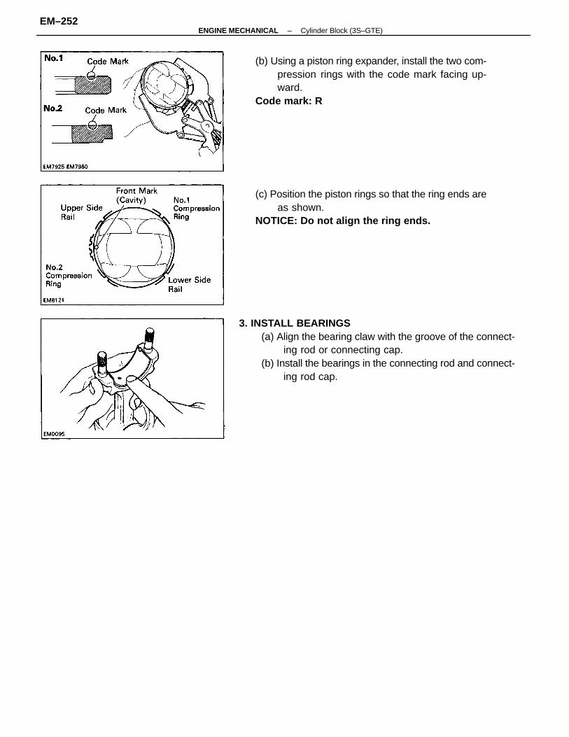
3. INSTALL BEARINGS(a) Align the bearing claw with the groove of the connect-
ing rod or connecting cap.(b) Install the bearings in the connecting rod and connect-
ing rod cap.
(c) Position the piston rings so that the ring ends areas shown.
NOTICE: Do not align the ring ends.
(b) Using a piston ring expander, install the two com-pression rings with the code mark facing up-ward.
Code mark: R
–ENGINE MECHANICAL Cylinder Block (3S–GTE)EM–252
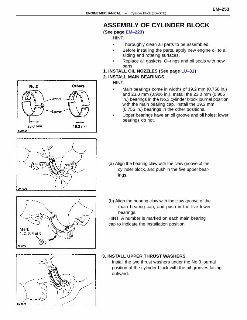
ASSEMBLY OF CYLINDER BLOCK(See page EM–223)
HINT:
• Thoroughly clean all parts to be assembled.• Before installing the parts, apply new engine oil to all
sliding and rotating surfaces.• Replace all gaskets, O–rings and oil seals with new
parts.1. INSTALL OIL NOZZLES (See page LU–31)2. INSTALL MAIN BEARINGS
HINT:
• Main bearings come in widths of 19.2 mm (0.756 in.)and 23.0 mm (0.906 in.). Install the 23.0 mm (0.906in.) bearings in the No.3 cylinder block journal positionwith the main bearing cap. Install the 19.2 mm(0.756 in.) bearings in the other positions.
• Upper bearings have an oil groove and oil holes; lowerbearings do not.
(b) Align the bearing claw with the claw groove of themain bearing cap, and push in the five lowerbearings.
HINT: A number is marked on each main bearingcap to indicate the installation position.
3. INSTALL UPPER THRUST WASHERSInstall the two thrust washers under the No.3 journalposition of the cylinder block with the oil grooves facingoutward.
(a) Align the bearing claw with the claw groove of thecylinder block, and push in the five upper bear-ings.
–ENGINE MECHANICAL Cylinder Block (3S–GTE)EM–253
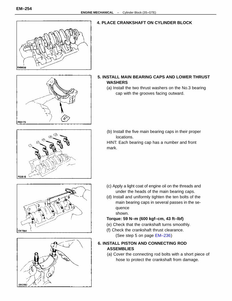
(c) Apply a light coat of engine oil on the threads andunder the heads of the main bearing caps.
(d) Install and uniformly tighten the ten bolts of themain bearing caps in several passes in the se-quenceshown.
Torque: 59 N–m (600 kgf–cm, 43 ft–lbf)(e) Check that the crankshaft turns smoothly.(f) Check the crankshaft thrust clearance.
(See step 5 on page EM–236)
5. INSTALL MAIN BEARING CAPS AND LOWER THRUSTWASHERS(a) Install the two thrust washers on the No.3 bearing
cap with the grooves facing outward.
6. INSTALL PISTON AND CONNECTING RODASSEMBLIES(a) Cover the connecting rod bolts with a short piece of
hose to protect the crankshaft from damage.
(b) Install the five main bearing caps in their properlocations.
HINT: Each bearing cap has a number and frontmark.
4. PLACE CRANKSHAFT ON CYLINDER BLOCK
–ENGINE MECHANICAL Cylinder Block (3S–GTE)EM–254
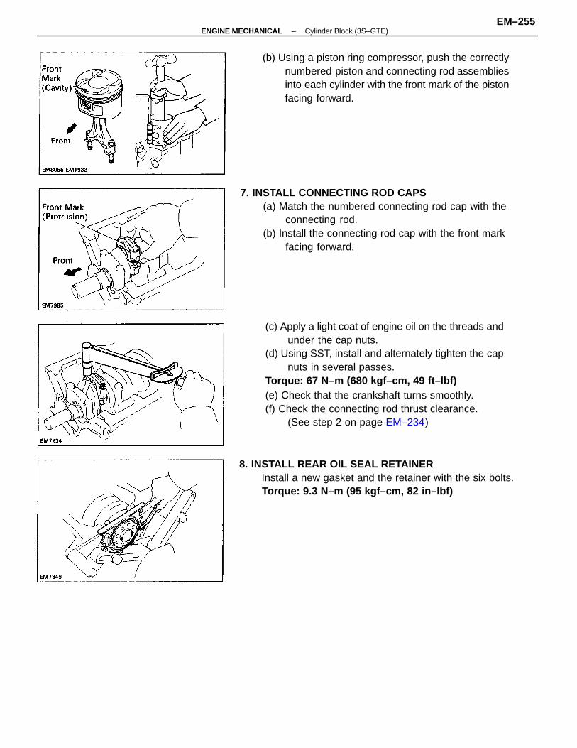
(c) Apply a light coat of engine oil on the threads andunder the cap nuts.
(d) Using SST, install and alternately tighten the capnuts in several passes.
Torque: 67 N–m (680 kgf–cm, 49 ft–lbf)(e) Check that the crankshaft turns smoothly.(f) Check the connecting rod thrust clearance.
(See step 2 on page EM–234)
7. INSTALL CONNECTING ROD CAPS(a) Match the numbered connecting rod cap with the
connecting rod.(b) Install the connecting rod cap with the front mark
facing forward.
(b) Using a piston ring compressor, push the correctlynumbered piston and connecting rod assembliesinto each cylinder with the front mark of the pistonfacing forward.
8. INSTALL REAR OIL SEAL RETAINERInstall a new gasket and the retainer with the six bolts.Torque: 9.3 N–m (95 kgf–cm, 82 in–lbf)
–ENGINE MECHANICAL Cylinder Block (3S–GTE)EM–255
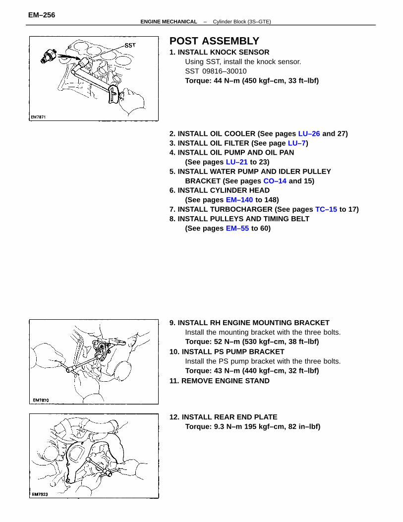
2. INSTALL OIL COOLER (See pages LU–26 and 27)3. INSTALL OIL FILTER (See page LU–7)4. INSTALL OIL PUMP AND OIL PAN
(See pages LU–21 to 23)5. INSTALL WATER PUMP AND IDLER PULLEY
BRACKET (See pages CO–14 and 15)6. INSTALL CYLINDER HEAD
(See pages EM–140 to 148)7. INSTALL TURBOCHARGER (See pages TC–15 to 17)8. INSTALL PULLEYS AND TIMING BELT
(See pages EM–55 to 60)
9. INSTALL RH ENGINE MOUNTING BRACKETInstall the mounting bracket with the three bolts.Torque: 52 N–m (530 kgf–cm, 38 ft–lbf)
10. INSTALL PS PUMP BRACKETInstall the PS pump bracket with the three bolts.Torque: 43 N–m (440 kgf–cm, 32 ft–lbf)
11. REMOVE ENGINE STAND
POST ASSEMBLY1. INSTALL KNOCK SENSOR
Using SST, install the knock sensor.SST 09816–30010Torque: 44 N–m (450 kgf–cm, 33 ft–lbf)
12. INSTALL REAR END PLATETorque: 9.3 N–m 195 kgf–cm, 82 in–lbf)
–ENGINE MECHANICAL Cylinder Block (3S–GTE)EM–256
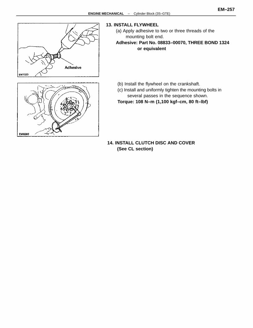
13. INSTALL FLYWHEEL(a) Apply adhesive to two or three threads of the
mounting bolt end.Adhesive: Part No. 08833–00070, THREE BOND 1324
or equivalent
(b) Install the flywheel on the crankshaft.(c) Install and uniformly tighten the mounting bolts in
several passes in the sequence shown.Torque: 108 N–m (1,100 kgf–cm, 80 ft–lbf)
14. INSTALL CLUTCH DISC AND COVER(See CL section)
–ENGINE MECHANICAL Cylinder Block (3S–GTE)EM–257
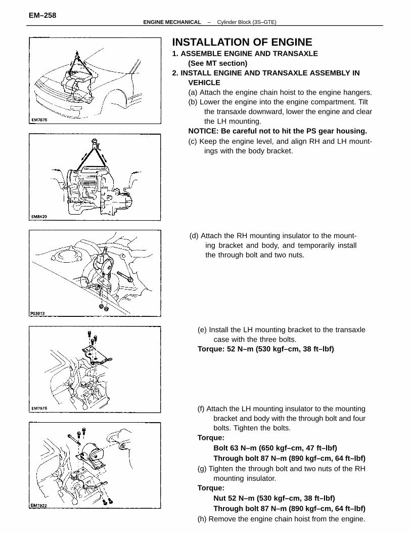
INSTALLATION OF ENGINE1. ASSEMBLE ENGINE AND TRANSAXLE
(See MT section)2. INSTALL ENGINE AND TRANSAXLE ASSEMBLY IN
VEHICLE(a) Attach the engine chain hoist to the engine hangers.(b) Lower the engine into the engine compartment. Tilt
the transaxle downward, lower the engine and clearthe LH mounting.
NOTICE: Be careful not to hit the PS gear housing.(c) Keep the engine level, and align RH and LH mount-
ings with the body bracket.
(f) Attach the LH mounting insulator to the mountingbracket and body with the through bolt and fourbolts. Tighten the bolts.
Torque:Bolt 63 N–m (650 kgf–cm, 47 ft–lbf)Through bolt 87 N–m (890 kgf–cm, 64 ft–lbf)
(g) Tighten the through bolt and two nuts of the RHmounting insulator.
Torque:Nut 52 N–m (530 kgf–cm, 38 ft–lbf)Through bolt 87 N–m (890 kgf–cm, 64 ft–lbf)
(h) Remove the engine chain hoist from the engine.
(e) Install the LH mounting bracket to the transaxlecase with the three bolts.
Torque: 52 N–m (530 kgf–cm, 38 ft–lbf)
(d) Attach the RH mounting insulator to the mount-ing bracket and body, and temporarily installthe through bolt and two nuts.
–ENGINE MECHANICAL Cylinder Block (3S–GTE)EM–258
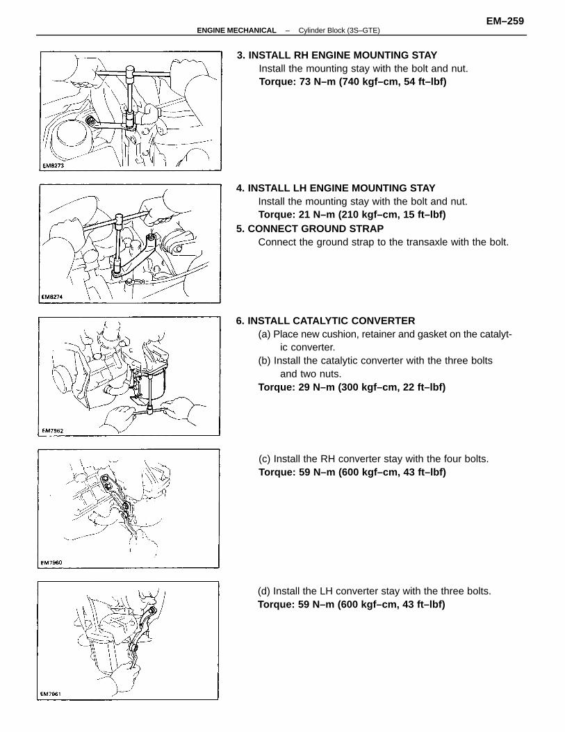
6. INSTALL CATALYTIC CONVERTER(a) Place new cushion, retainer and gasket on the catalyt-
ic converter.(b) Install the catalytic converter with the three bolts
and two nuts.Torque: 29 N–m (300 kgf–cm, 22 ft–lbf)
4. INSTALL LH ENGINE MOUNTING STAYInstall the mounting stay with the bolt and nut.Torque: 21 N–m (210 kgf–cm, 15 ft–lbf)
5. CONNECT GROUND STRAPConnect the ground strap to the transaxle with the bolt.
3. INSTALL RH ENGINE MOUNTING STAYInstall the mounting stay with the bolt and nut.Torque: 73 N–m (740 kgf–cm, 54 ft–lbf)
(d) Install the LH converter stay with the three bolts.Torque: 59 N–m (600 kgf–cm, 43 ft–lbf)
(c) Install the RH converter stay with the four bolts.Torque: 59 N–m (600 kgf–cm, 43 ft–lbf)
–ENGINE MECHANICAL Cylinder Block (3S–GTE)EM–259
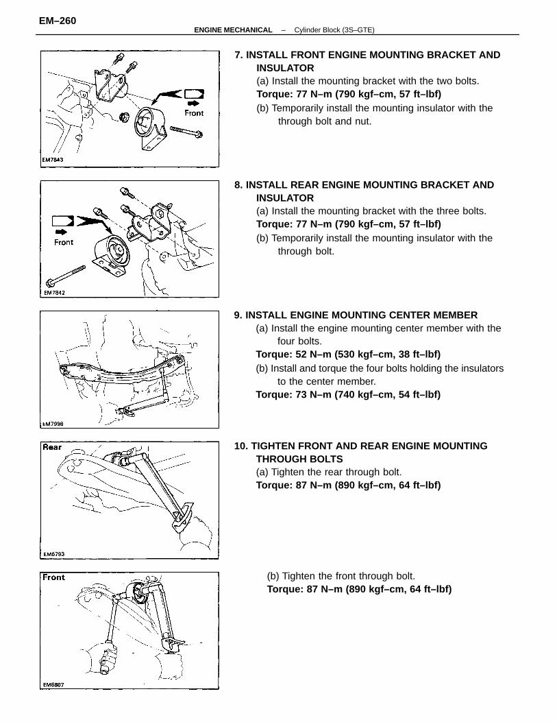
9. INSTALL ENGINE MOUNTING CENTER MEMBER(a) Install the engine mounting center member with the
four bolts.Torque: 52 N–m (530 kgf–cm, 38 ft–lbf)(b) Install and torque the four bolts holding the insulators
to the center member.Torque: 73 N–m (740 kgf–cm, 54 ft–lbf)
8. INSTALL REAR ENGINE MOUNTING BRACKET ANDINSULATOR(a) Install the mounting bracket with the three bolts.Torque: 77 N–m (790 kgf–cm, 57 ft–lbf)(b) Temporarily install the mounting insulator with the
through bolt.
7. INSTALL FRONT ENGINE MOUNTING BRACKET ANDINSULATOR(a) Install the mounting bracket with the two bolts.Torque: 77 N–m (790 kgf–cm, 57 ft–lbf)(b) Temporarily install the mounting insulator with the
through bolt and nut.
10. TIGHTEN FRONT AND REAR ENGINE MOUNTINGTHROUGH BOLTS(a) Tighten the rear through bolt.Torque: 87 N–m (890 kgf–cm, 64 ft–lbf)
(b) Tighten the front through bolt.Torque: 87 N–m (890 kgf–cm, 64 ft–lbf)
–ENGINE MECHANICAL Cylinder Block (3S–GTE)EM–260
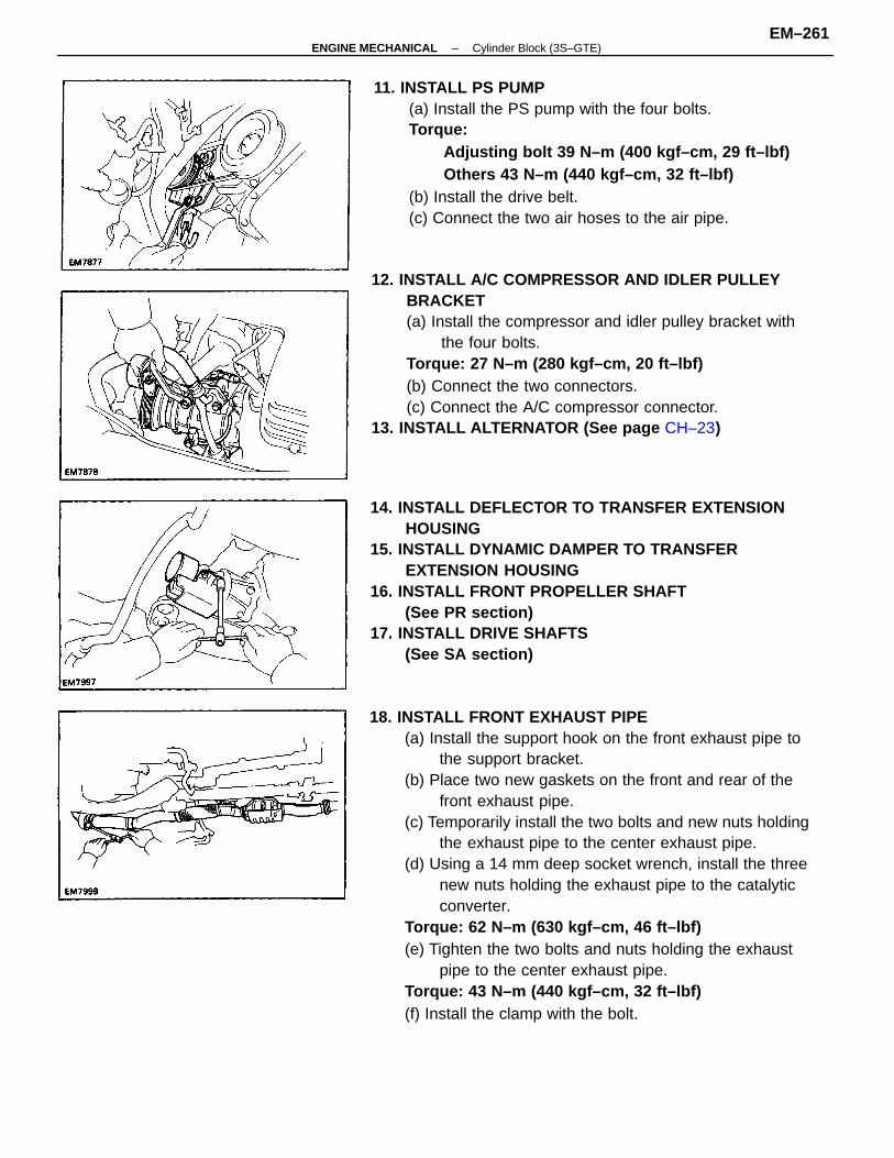
18. INSTALL FRONT EXHAUST PIPE(a) Install the support hook on the front exhaust pipe to
the support bracket.(b) Place two new gaskets on the front and rear of the
front exhaust pipe.(c) Temporarily install the two bolts and new nuts holding
the exhaust pipe to the center exhaust pipe.(d) Using a 14 mm deep socket wrench, install the three
new nuts holding the exhaust pipe to the catalyticconverter.
Torque: 62 N–m (630 kgf–cm, 46 ft–lbf)(e) Tighten the two bolts and nuts holding the exhaust
pipe to the center exhaust pipe.Torque: 43 N–m (440 kgf–cm, 32 ft–lbf)(f) Install the clamp with the bolt.
12. INSTALL A/C COMPRESSOR AND IDLER PULLEYBRACKET(a) Install the compressor and idler pulley bracket with
the four bolts.Torque: 27 N–m (280 kgf–cm, 20 ft–lbf)(b) Connect the two connectors.(c) Connect the A/C compressor connector.
13. INSTALL ALTERNATOR (See page CH–23)
14. INSTALL DEFLECTOR TO TRANSFER EXTENSIONHOUSING
15. INSTALL DYNAMIC DAMPER TO TRANSFEREXTENSION HOUSING
16. INSTALL FRONT PROPELLER SHAFT(See PR section)
17. INSTALL DRIVE SHAFTS(See SA section)
11. INSTALL PS PUMP(a) Install the PS pump with the four bolts.Torque:
Adjusting bolt 39 N–m (400 kgf–cm, 29 ft–lbf)Others 43 N–m (440 kgf–cm, 32 ft–lbf)
(b) Install the drive belt.(c) Connect the two air hoses to the air pipe.
–ENGINE MECHANICAL Cylinder Block (3S–GTE)EM–261
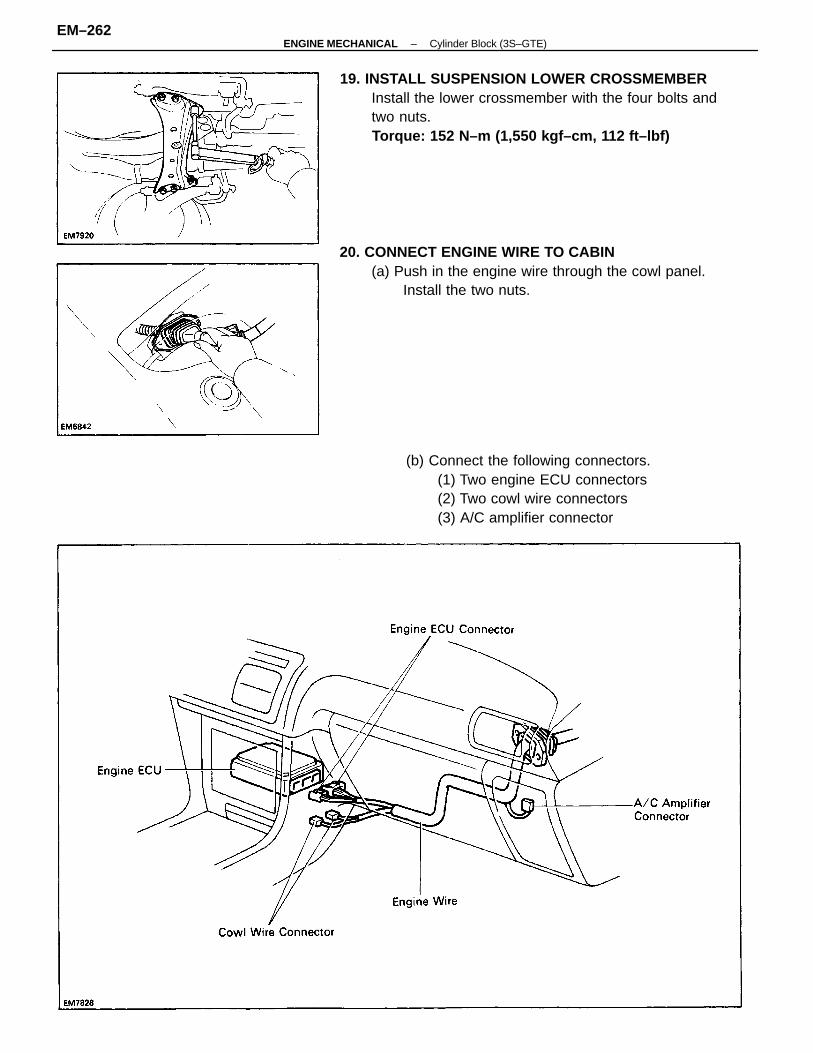
19. INSTALL SUSPENSION LOWER CROSSMEMBERInstall the lower crossmember with the four bolts andtwo nuts.Torque: 152 N–m (1,550 kgf–cm, 112 ft–lbf)
20. CONNECT ENGINE WIRE TO CABIN(a) Push in the engine wire through the cowl panel.
Install the two nuts.
(b) Connect the following connectors.(1) Two engine ECU connectors(2) Two cowl wire connectors(3) A/C amplifier connector
–ENGINE MECHANICAL Cylinder Block (3S–GTE)EM–262
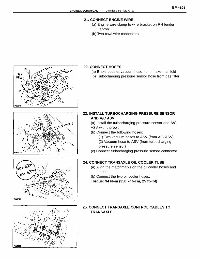
23. INSTALL TURBOCHARGING PRESSURE SENSORAND A/C ASV(a) Install the turbocharging pressure sensor and A/CASV with the bolt.(b) Connect the following hoses:
(1) Two vacuum hoses to ASV (from A/C ASV)(2) Vacuum hose to ASV (from turbochargingpressure sensor)
(c) Connect turbocharging pressure sensor connector.
24. CONNECT TRANSAXLE OIL COOLER TUBE(a) Align the matchmarks on the oil cooler hoses and
tubes.(b) Connect the two oil cooler hoses.Torque: 34 N–m (350 kgf–cm, 25 ft–lbf)
21. CONNECT ENGINE WIRE(a) Engine wire clamp to wire bracket on RH fender
apron(b) Two cowl wire connectors
22. CONNECT HOSES(a) Brake booster vacuum hose from intake manifold(b) Turbocharging pressure sensor hose from gas filter
25. CONNECT TRANSAXLE CONTROL CABLES TOTRANSAXLE
–ENGINE MECHANICAL Cylinder Block (3S–GTE)EM–263
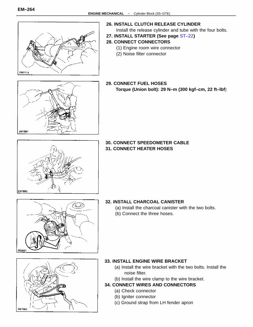
33. INSTALL ENGINE WIRE BRACKET(a) Install the wire bracket with the two bolts. Install the
noise filter.(b) Install the wire clamp to the wire bracket.
34. CONNECT WIRES AND CONNECTORS(a) Check connector(b) Igniter connector(c) Ground strap from LH fender apron
26. INSTALL CLUTCH RELEASE CYLINDERInstall the release cylinder and tube with the four bolts.
27. INSTALL STARTER (See page ST–22)28. CONNECT CONNECTORS
(1) Engine room wire connector(2) Noise filter connector
32. INSTALL CHARCOAL CANISTER(a) Install the charcoal canister with the two bolts.(b) Connect the three hoses.
29. CONNECT FUEL HOSESTorque (Union bolt): 29 N–m (300 kgf–cm, 22 ft–lbf )
30. CONNECT SPEEDOMETER CABLE31. CONNECT HEATER HOSES
–ENGINE MECHANICAL Cylinder Block (3S–GTE)EM–264
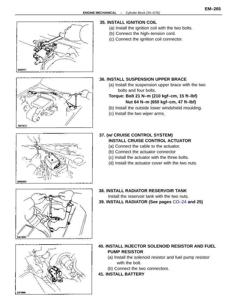
36. INSTALL SUSPENSION UPPER BRACE(a) Install the suspension upper brace with the two
bolts and four bolts.Torque: Bolt 21 N–m (210 kgf–cm, 15 ft–lbf)
Nut 64 N–m (650 kgf–cm, 47 ft–lbf)(b) Install the outside lower windshield moulding.(c) Install the two wiper arms.
40. INSTALL INJECTOR SOLENOID RESISTOR AND FUELPUMP RESISTOR(a) Install the solenoid resistor and fuel pump resistor
with the bolt.(b) Connect the two connectors.
41. INSTALL BATTERY
37. (w/ CRUISE CONTROL SYSTEM)INSTALL CRUISE CONTROL ACTUATOR(a) Connect the cable to the actuator.(b) Connect the actuator connector(c) install the actuator with the three bolts.(d) Install the actuator cover with the two nuts.
35. INSTALL IGNITION COIL(a) Install the ignition coil with the two bolts.(b) Connect the high–tension cord.(c) Connect the ignition coil connector.
38. INSTALL RADIATOR RESERVOIR TANKInstall the reservoir tank with the two nuts.
39. INSTALL RADIATOR (See pages CO–24 and 25)
–ENGINE MECHANICAL Cylinder Block (3S–GTE)EM–265
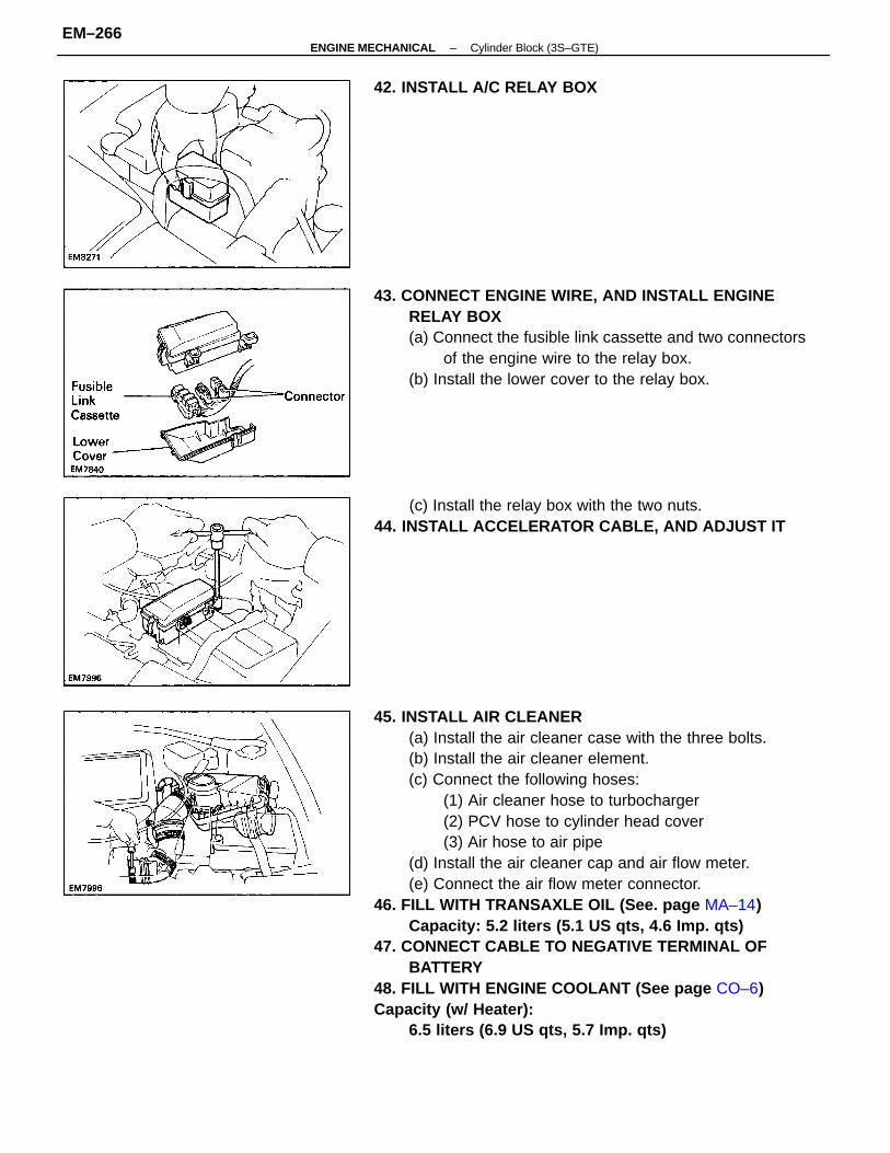
45. INSTALL AIR CLEANER(a) Install the air cleaner case with the three bolts.(b) Install the air cleaner element.(c) Connect the following hoses:
(1) Air cleaner hose to turbocharger(2) PCV hose to cylinder head cover(3) Air hose to air pipe
(d) Install the air cleaner cap and air flow meter.(e) Connect the air flow meter connector.
46. FILL WITH TRANSAXLE OIL (See. page MA–14)Capacity: 5.2 liters (5.1 US qts, 4.6 Imp. qts)
47. CONNECT CABLE TO NEGATIVE TERMINAL OFBATTERY
48. FILL WITH ENGINE COOLANT (See page CO–6)Capacity (w/ Heater):
6.5 liters (6.9 US qts, 5.7 Imp. qts)
43. CONNECT ENGINE WIRE, AND INSTALL ENGINERELAY BOX(a) Connect the fusible link cassette and two connectors
of the engine wire to the relay box.(b) Install the lower cover to the relay box.
(c) Install the relay box with the two nuts.44. INSTALL ACCELERATOR CABLE, AND ADJUST IT
42. INSTALL A/C RELAY BOX
–ENGINE MECHANICAL Cylinder Block (3S–GTE)EM–266
49. FILL WITH ENGINE OIL (See page LU–8)Capacity:
Drain and refill .w/ Oil filter change
3.9 liters (4.1 US qts, 3.4 Imp. qts)w/o Oil filter change
3.6 liters (3.8 US qts, 3.2 Imp. qts)Dry fill 4.3 liters (4.5 US qts, 3.8 Imp. qts)
50. START ENGINE AND CHECK FOR LEAKS51. PERFORM ENGINE ADJUSTMENT
(a) Adjust the alternator drive belt.Drive belt tension:
w/ A/C New belt 165 ± 10 lbfUsed belt 84 ± 15 lbf
w/o A/C New belt 150 ± 25 lbfUsed belt 130 ± 20 lbf
(b) Adjust the PS drive belt.Drive belt tension: New belt 125 ± 25 lbfUsed belt 80 ± 20 lbf
(c) Adjust the ignition timing. (See page IG–29)Ignition timing:
10° BTDC @ idle(w/ Terminals TO and E1 connected)
52. INSTALL ENGINE UNDER COVERS53. INSTALL HOOD54. PERFORM ROAD TEST
Check for abnormal noise, shock, slippage, correct shiftpoints and smooth operation.
55. RECHECK ENGINE COOLANT AND OIL LEVELS
–ENGINE MECHANICAL Cylinder Block (3S–GTE)EM–267
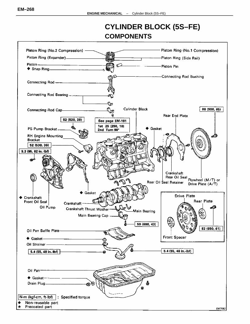
CYLINDER BLOCK (5S–FE)COMPONENTS
–ENGINE MECHANICAL Cylinder Block (5S–FE)EM–268
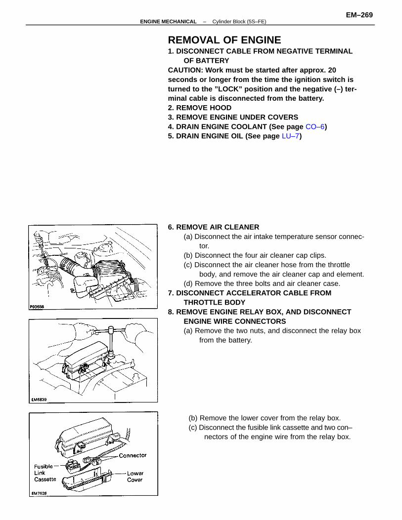
6. REMOVE AIR CLEANER(a) Disconnect the air intake temperature sensor connec-
tor.(b) Disconnect the four air cleaner cap clips.(c) Disconnect the air cleaner hose from the throttle
body, and remove the air cleaner cap and element.(d) Remove the three bolts and air cleaner case.
7. DISCONNECT ACCELERATOR CABLE FROMTHROTTLE BODY
8. REMOVE ENGINE RELAY BOX, AND DISCONNECTENGINE WIRE CONNECTORS(a) Remove the two nuts, and disconnect the relay box
from the battery.
REMOVAL OF ENGINE1. DISCONNECT CABLE FROM NEGATIVE TERMINAL
OF BATTERYCAUTION: Work must be started after approx. 20seconds or longer from the time the ignition switch isturned to the ”LOCK” position and the negative (–) ter-minal cable is disconnected from the battery.2. REMOVE HOOD3. REMOVE ENGINE UNDER COVERS4. DRAIN ENGINE COOLANT (See page CO–6)5. DRAIN ENGINE OIL (See page LU–7)
(b) Remove the lower cover from the relay box.(c) Disconnect the fusible link cassette and two con–
nectors of the engine wire from the relay box.
–ENGINE MECHANICAL Cylinder Block (5S–FE)EM–269
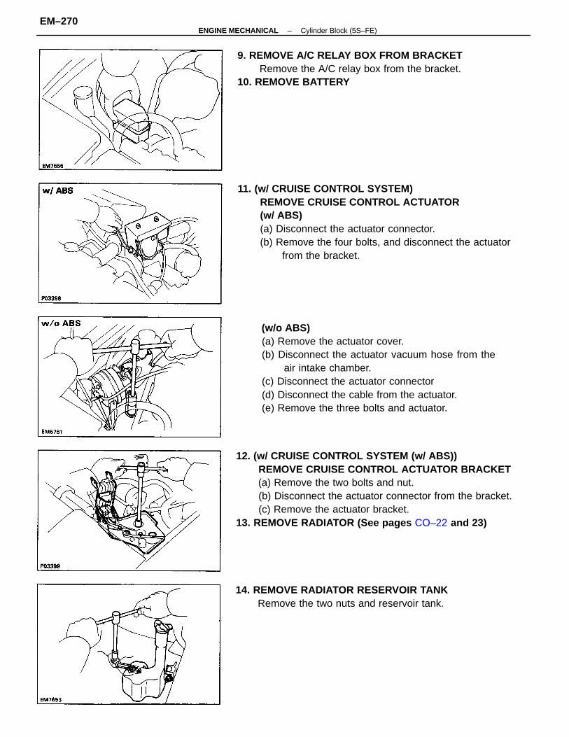
(w/o ABS)(a) Remove the actuator cover.(b) Disconnect the actuator vacuum hose from the
air intake chamber.(c) Disconnect the actuator connector(d) Disconnect the cable from the actuator.(e) Remove the three bolts and actuator.
12. (w/ CRUISE CONTROL SYSTEM (w/ ABS))REMOVE CRUISE CONTROL ACTUATOR BRACKET(a) Remove the two bolts and nut.(b) Disconnect the actuator connector from the bracket.(c) Remove the actuator bracket.
13. REMOVE RADIATOR (See pages CO–22 and 23)
11. (w/ CRUISE CONTROL SYSTEM)REMOVE CRUISE CONTROL ACTUATOR(w/ ABS)(a) Disconnect the actuator connector.(b) Remove the four bolts, and disconnect the actuator
from the bracket.
9. REMOVE A/C RELAY BOX FROM BRACKETRemove the A/C relay box from the bracket.
10. REMOVE BATTERY
14. REMOVE RADIATOR RESERVOIR TANKRemove the two nuts and reservoir tank.
–ENGINE MECHANICAL Cylinder Block (5S–FE)EM–270
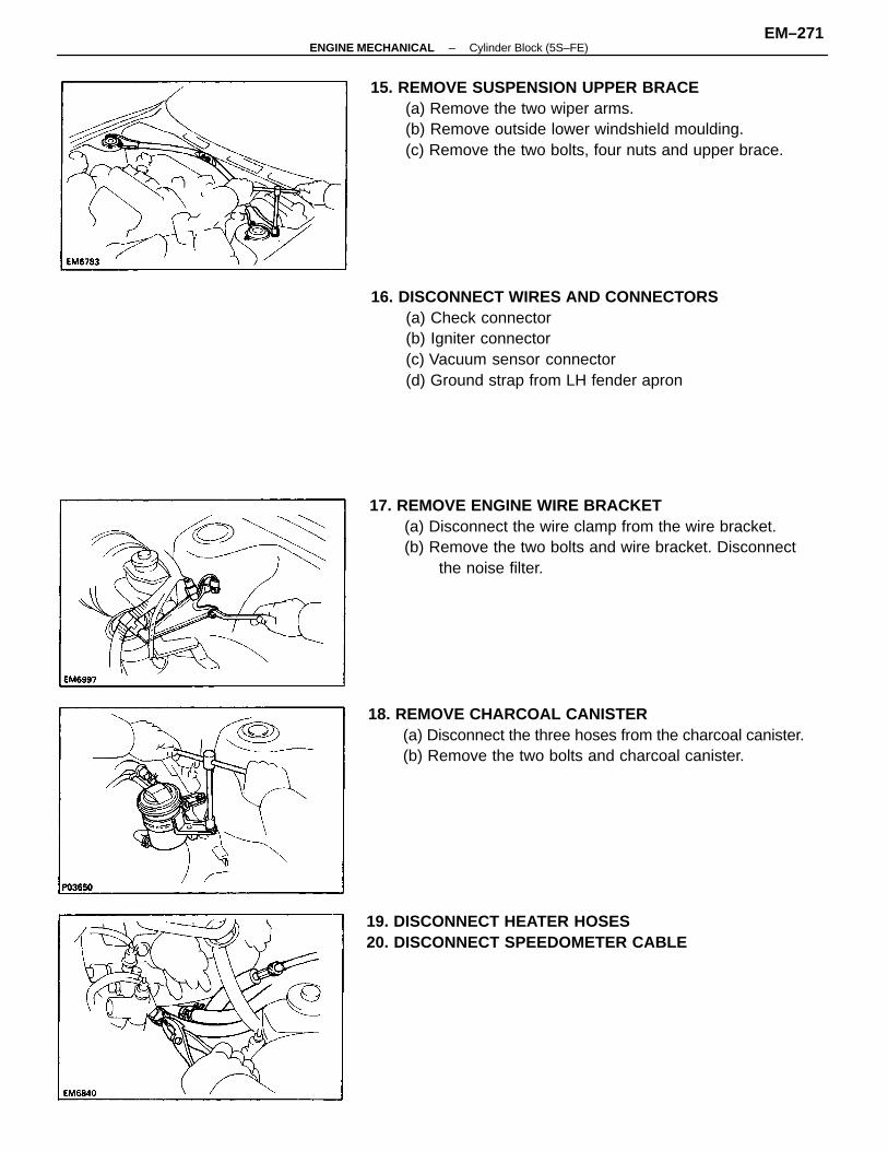
16. DISCONNECT WIRES AND CONNECTORS(a) Check connector(b) Igniter connector(c) Vacuum sensor connector(d) Ground strap from LH fender apron
15. REMOVE SUSPENSION UPPER BRACE(a) Remove the two wiper arms.(b) Remove outside lower windshield moulding.(c) Remove the two bolts, four nuts and upper brace.
18. REMOVE CHARCOAL CANISTER(a) Disconnect the three hoses from the charcoal canister.(b) Remove the two bolts and charcoal canister.
17. REMOVE ENGINE WIRE BRACKET(a) Disconnect the wire clamp from the wire bracket.(b) Remove the two bolts and wire bracket. Disconnect
the noise filter.
19. DISCONNECT HEATER HOSES20. DISCONNECT SPEEDOMETER CABLE
–ENGINE MECHANICAL Cylinder Block (5S–FE)EM–271
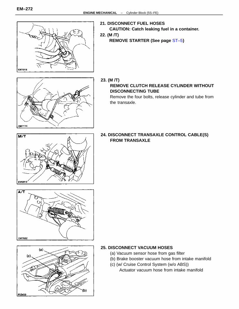
25. DISCONNECT VACUUM HOSES(a) Vacuum sensor hose from gas filter(b) Brake booster vacuum hose from intake manifold(c) (w/ Cruise Control System (w/o ABS))
Actuator vacuum hose from intake manifold
23. (M /T)REMOVE CLUTCH RELEASE CYLINDER WITHOUTDISCONNECTING TUBERemove the four bolts, release cylinder and tube fromthe transaxle.
21. DISCONNECT FUEL HOSESCAUTION: Catch leaking fuel in a container.
22. (M /T)REMOVE STARTER (See page ST–5)
24. DISCONNECT TRANSAXLE CONTROL CABLE(S)FROM TRANSAXLE
–ENGINE MECHANICAL Cylinder Block (5S–FE)EM–272
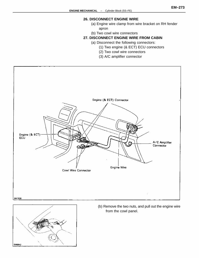
26. DISCONNECT ENGINE WIRE(a) Engine wire clamp from wire bracket on RH fender
apron(b) Two cowl wire connectors
27. DISCONNECT ENGINE WIRE FROM CABIN(a) Disconnect the following connectors:
(1) Two engine (& ECT) ECU connectors(2) Two cowl wire connectors(3) A/C amplifier connector
(b) Remove the two nuts, and pull out the engine wirefrom the cowl panel.
–ENGINE MECHANICAL Cylinder Block (5S–FE)EM–273
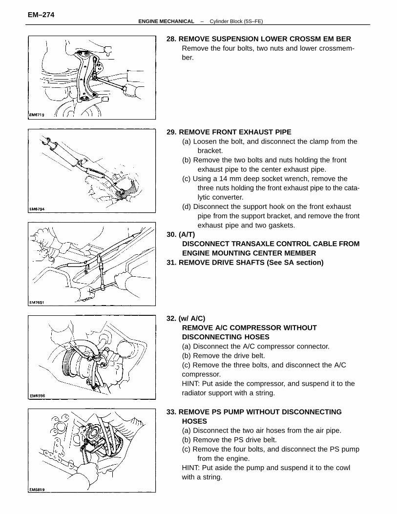
29. REMOVE FRONT EXHAUST PIPE(a) Loosen the bolt, and disconnect the clamp from the
bracket.(b) Remove the two bolts and nuts holding the front
exhaust pipe to the center exhaust pipe.(c) Using a 14 mm deep socket wrench, remove the
three nuts holding the front exhaust pipe to the cata-lytic converter.
(d) Disconnect the support hook on the front exhaustpipe from the support bracket, and remove the frontexhaust pipe and two gaskets.
30. (A/T)DISCONNECT TRANSAXLE CONTROL CABLE FROMENGINE MOUNTING CENTER MEMBER
31. REMOVE DRIVE SHAFTS (See SA section)
32. (w/ A/C)REMOVE A/C COMPRESSOR WITHOUTDISCONNECTING HOSES(a) Disconnect the A/C compressor connector.(b) Remove the drive belt.(c) Remove the three bolts, and disconnect the A/Ccompressor.HINT: Put aside the compressor, and suspend it to theradiator support with a string.
33. REMOVE PS PUMP WITHOUT DISCONNECTINGHOSES(a) Disconnect the two air hoses from the air pipe.(b) Remove the PS drive belt.(c) Remove the four bolts, and disconnect the PS pump
from the engine.HINT: Put aside the pump and suspend it to the cowlwith a string.
28. REMOVE SUSPENSION LOWER CROSSM EM BERRemove the four bolts, two nuts and lower crossmem-ber.
–ENGINE MECHANICAL Cylinder Block (5S–FE)EM–274
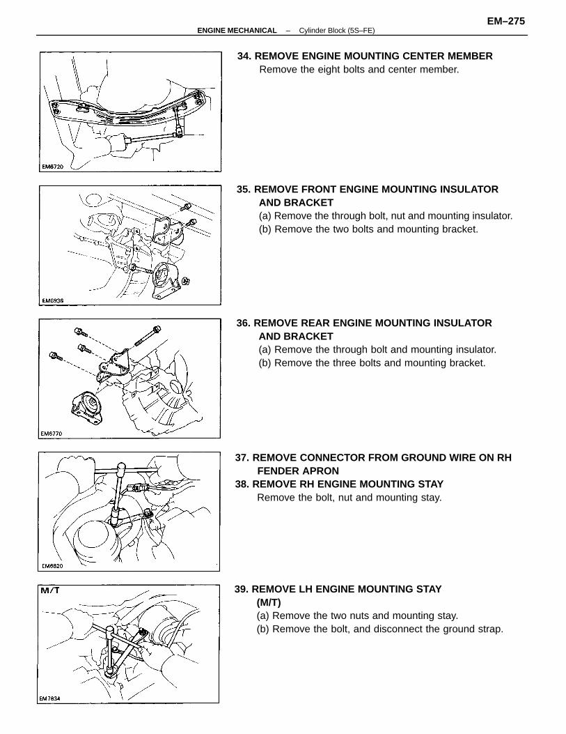
35. REMOVE FRONT ENGINE MOUNTING INSULATORAND BRACKET(a) Remove the through bolt, nut and mounting insulator.(b) Remove the two bolts and mounting bracket.
37. REMOVE CONNECTOR FROM GROUND WIRE ON RHFENDER APRON
38. REMOVE RH ENGINE MOUNTING STAYRemove the bolt, nut and mounting stay.
39. REMOVE LH ENGINE MOUNTING STAY(M/T)(a) Remove the two nuts and mounting stay.(b) Remove the bolt, and disconnect the ground strap.
36. REMOVE REAR ENGINE MOUNTING INSULATORAND BRACKET(a) Remove the through bolt and mounting insulator.(b) Remove the three bolts and mounting bracket.
34. REMOVE ENGINE MOUNTING CENTER MEMBERRemove the eight bolts and center member.
–ENGINE MECHANICAL Cylinder Block (5S–FE)EM–275
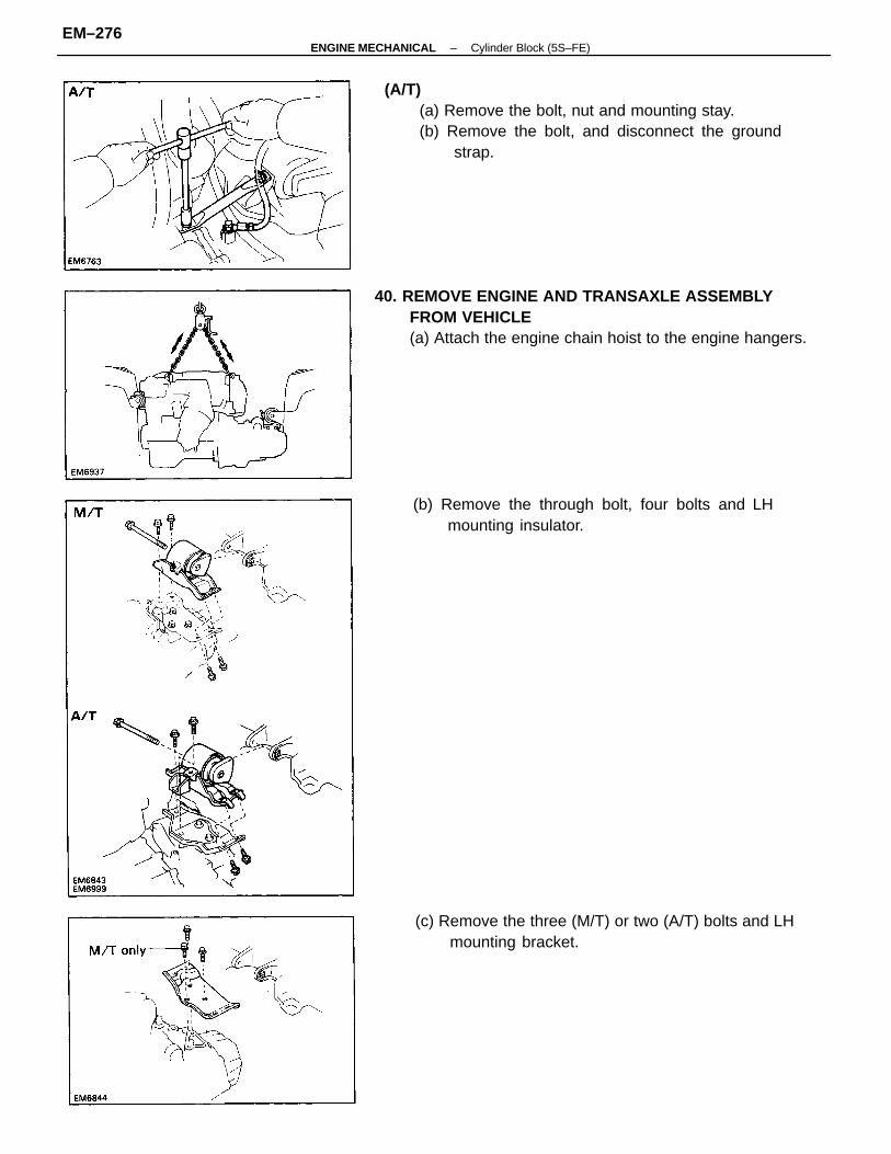
40. REMOVE ENGINE AND TRANSAXLE ASSEMBLYFROM VEHICLE(a) Attach the engine chain hoist to the engine hangers.
(A/T)(a) Remove the bolt, nut and mounting stay.(b) Remove the bolt, and disconnect the ground
strap.
(c) Remove the three (M/T) or two (A/T) bolts and LHmounting bracket.
(b) Remove the through bolt, four bolts and LHmounting insulator.
–ENGINE MECHANICAL Cylinder Block (5S–FE)EM–276
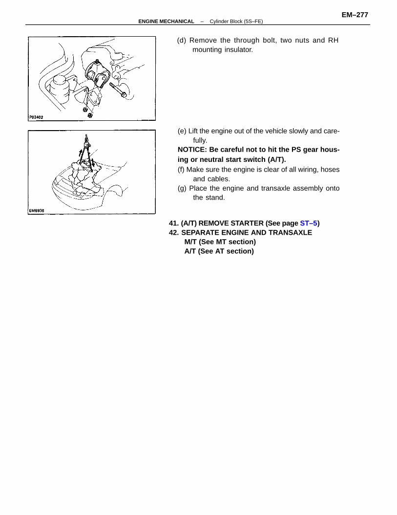
(e) Lift the engine out of the vehicle slowly and care-fully.
NOTICE: Be careful not to hit the PS gear hous-ing or neutral start switch (A/T).(f) Make sure the engine is clear of all wiring, hoses
and cables.(g) Place the engine and transaxle assembly onto
the stand.
41. (A/T) REMOVE STARTER (See page ST–5)42. SEPARATE ENGINE AND TRANSAXLE
M/T (See MT section)A/T (See AT section)
(d) Remove the through bolt, two nuts and RHmounting insulator.
–ENGINE MECHANICAL Cylinder Block (5S–FE)EM–277
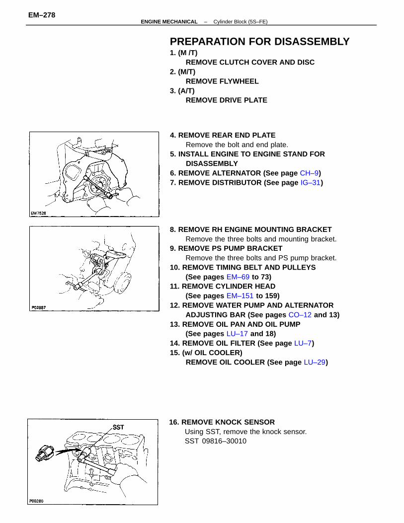
8. REMOVE RH ENGINE MOUNTING BRACKETRemove the three bolts and mounting bracket.
9. REMOVE PS PUMP BRACKETRemove the three bolts and PS pump bracket.
10. REMOVE TIMING BELT AND PULLEYS(See pages EM–69 to 73)
11. REMOVE CYLINDER HEAD(See pages EM–151 to 159)
12. REMOVE WATER PUMP AND ALTERNATORADJUSTING BAR (See pages CO–12 and 13)
13. REMOVE OIL PAN AND OIL PUMP(See pages LU–17 and 18)
14. REMOVE OIL FILTER (See page LU–7)15. (w/ OIL COOLER)
REMOVE OIL COOLER (See page LU–29)
PREPARATION FOR DISASSEMBLY1. (M /T)
REMOVE CLUTCH COVER AND DISC2. (M/T)
REMOVE FLYWHEEL3. (A/T)
REMOVE DRIVE PLATE
4. REMOVE REAR END PLATERemove the bolt and end plate.
5. INSTALL ENGINE TO ENGINE STAND FORDISASSEMBLY
6. REMOVE ALTERNATOR (See page CH–9)7. REMOVE DISTRIBUTOR (See page IG–31)
16. REMOVE KNOCK SENSORUsing SST, remove the knock sensor.SST 09816–30010
–ENGINE MECHANICAL Cylinder Block (5S–FE)EM–278
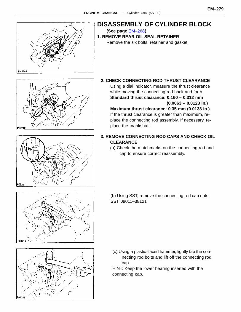
2. CHECK CONNECTING ROD THRUST CLEARANCEUsing a dial indicator, measure the thrust clearancewhile moving the connecting rod back and forth.Standard thrust clearance: 0.160 – 0.312 mm
(0.0063 – 0.0123 in.)Maximum thrust clearance: 0.35 mm (0.0138 in.)If the thrust clearance is greater than maximum, re-place the connecting rod assembly. If necessary, re-place the crankshaft.
3. REMOVE CONNECTING ROD CAPS AND CHECK OILCLEARANCE(a) Check the matchmarks on the connecting rod and
cap to ensure correct reassembly.
DISASSEMBLY OF CYLINDER BLOCK(See page EM–268)
1. REMOVE REAR OIL SEAL RETAINERRemove the six bolts, retainer and gasket.
(c) Using a plastic–faced hammer, lightly tap the con-necting rod bolts and lift off the connecting rodcap.
HINT: Keep the lower bearing inserted with theconnecting cap.
(b) Using SST, remove the connecting rod cap nuts.SST 09011–38121
–ENGINE MECHANICAL Cylinder Block–(5S–FE)EM–279
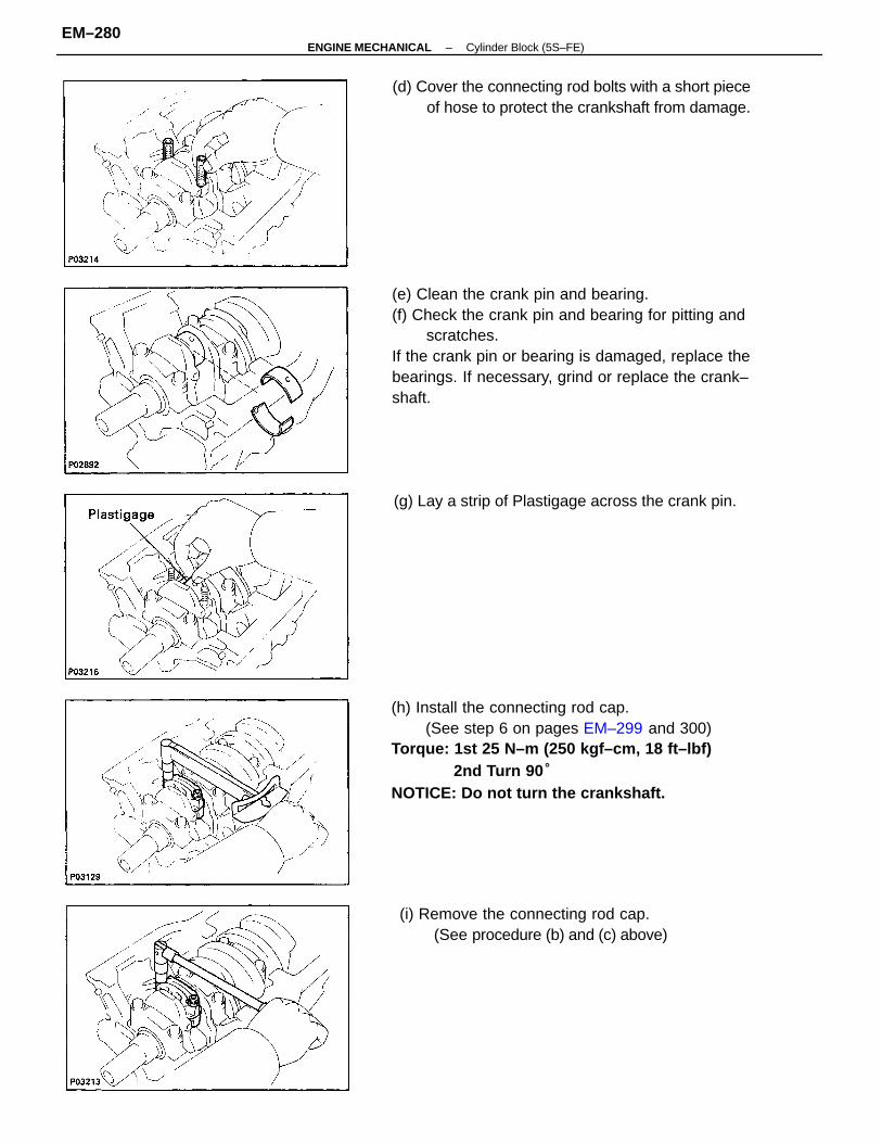
(e) Clean the crank pin and bearing.(f) Check the crank pin and bearing for pitting and
scratches.If the crank pin or bearing is damaged, replace thebearings. If necessary, grind or replace the crank–shaft.
(h) Install the connecting rod cap.(See step 6 on pages EM–299 and 300)
Torque: 1st 25 N–m (250 kgf–cm, 18 ft–lbf)2nd Turn 90 °
NOTICE: Do not turn the crankshaft.
(d) Cover the connecting rod bolts with a short pieceof hose to protect the crankshaft from damage.
(i) Remove the connecting rod cap.(See procedure (b) and (c) above)
(g) Lay a strip of Plastigage across the crank pin.
–ENGINE MECHANICAL Cylinder Block (5S–FE)EM–280
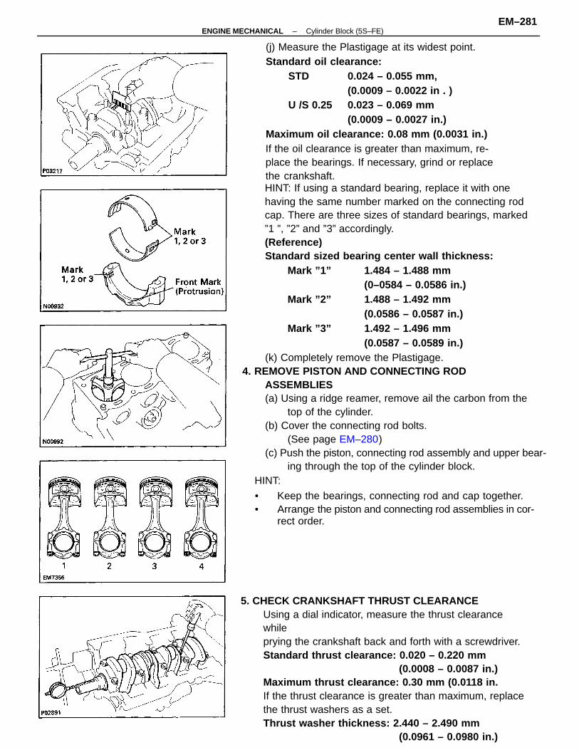
HINT: If using a standard bearing, replace it with onehaving the same number marked on the connecting rodcap. There are three sizes of standard bearings, marked”1 ”, ”2” and ”3” accordingly.(Reference)Standard sized bearing center wall thickness:
Mark ”1” 1.484 – 1.488 mm(0–0584 – 0.0586 in.)
Mark ”2” 1.488 – 1.492 mm(0.0586 – 0.0587 in.)
Mark ”3” 1.492 – 1.496 mm(0.0587 – 0.0589 in.)
(k) Completely remove the Plastigage.4. REMOVE PISTON AND CONNECTING ROD
ASSEMBLIES(a) Using a ridge reamer, remove ail the carbon from the
top of the cylinder.(b) Cover the connecting rod bolts.
(See page EM–280)(c) Push the piston, connecting rod assembly and upper bear-
ing through the top of the cylinder block.
(j) Measure the Plastigage at its widest point.Standard oil clearance:
STD 0.024 – 0.055 mm,(0.0009 – 0.0022 in . )
U /S 0.25 0.023 – 0.069 mm(0.0009 – 0.0027 in.)
Maximum oil clearance: 0.08 mm (0.0031 in.)If the oil clearance is greater than maximum, re-place the bearings. If necessary, grind or replacethe crankshaft.
5. CHECK CRANKSHAFT THRUST CLEARANCEUsing a dial indicator, measure the thrust clearancewhileprying the crankshaft back and forth with a screwdriver.Standard thrust clearance: 0.020 – 0.220 mm
(0.0008 – 0.0087 in.)Maximum thrust clearance: 0.30 mm (0.0118 in.If the thrust clearance is greater than maximum, replacethe thrust washers as a set.Thrust washer thickness: 2.440 – 2.490 mm
(0.0961 – 0.0980 in.)
HINT:
• Keep the bearings, connecting rod and cap together.• Arrange the piston and connecting rod assemblies in cor-
rect order.
–ENGINE MECHANICAL Cylinder Block (5S–FE)EM–281
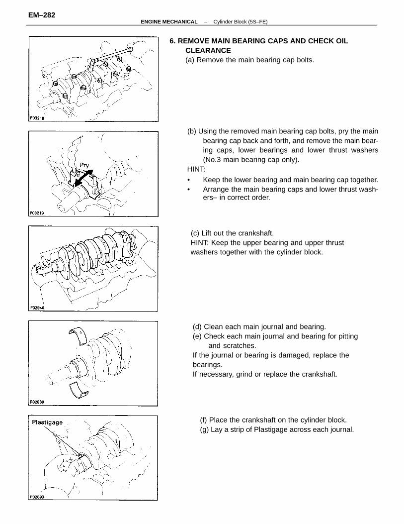
(b) Using the removed main bearing cap bolts, pry the mainbearing cap back and forth, and remove the main bear-ing caps, lower bearings and lower thrust washers(No.3 main bearing cap only).
HINT:
• Keep the lower bearing and main bearing cap together.• Arrange the main bearing caps and lower thrust wash-
ers– in correct order.
(d) Clean each main journal and bearing.(e) Check each main journal and bearing for pitting
and scratches.If the journal or bearing is damaged, replace thebearings.If necessary, grind or replace the crankshaft.
(c) Lift out the crankshaft.HINT: Keep the upper bearing and upper thrustwashers together with the cylinder block.
6. REMOVE MAIN BEARING CAPS AND CHECK OILCLEARANCE(a) Remove the main bearing cap bolts.
(f) Place the crankshaft on the cylinder block.(g) Lay a strip of Plastigage across each journal.
–ENGINE MECHANICAL Cylinder Block (5S–FE)EM–282
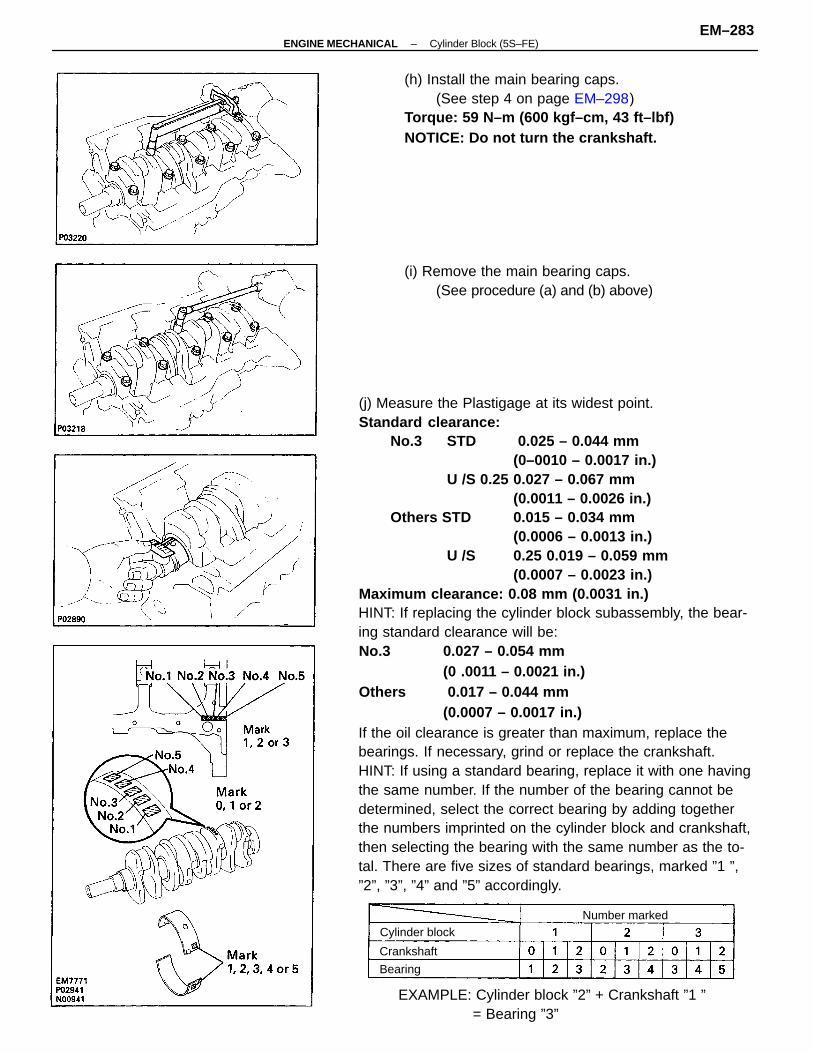
(j) Measure the Plastigage at its widest point.Standard clearance:
No.3 STD 0.025 – 0.044 mm(0–0010 – 0.0017 in.)
U /S 0.25 0.027 – 0.067 mm(0.0011 – 0.0026 in.)
Others STD 0.015 – 0.034 mm(0.0006 – 0.0013 in.)
U /S 0.25 0.019 – 0.059 mm(0.0007 – 0.0023 in.)
Maximum clearance: 0.08 mm (0.0031 in.)HINT: If replacing the cylinder block subassembly, the bear-ing standard clearance will be:No.3 0.027 – 0.054 mm
(0 .0011 – 0.0021 in.)Others 0.017 – 0.044 mm
(0.0007 – 0.0017 in.)If the oil clearance is greater than maximum, replace thebearings. If necessary, grind or replace the crankshaft.HINT: If using a standard bearing, replace it with one havingthe same number. If the number of the bearing cannot bedetermined, select the correct bearing by adding togetherthe numbers imprinted on the cylinder block and crankshaft,then selecting the bearing with the same number as the to-tal. There are five sizes of standard bearings, marked ”1 ”,”2”, ”3”, ”4” and ”5” accordingly.
(h) Install the main bearing caps.(See step 4 on page EM–298)
Torque: 59 N–m (600 kgf–cm, 43 ft–lbf)NOTICE: Do not turn the crankshaft.
EXAMPLE: Cylinder block ”2” + Crankshaft ”1 ”= Bearing ”3”
(i) Remove the main bearing caps.(See procedure (a) and (b) above)
Cylinder blockNumber marked
Crankshaft
Bearing
–ENGINE MECHANICAL Cylinder Block (5S–FE)EM–283
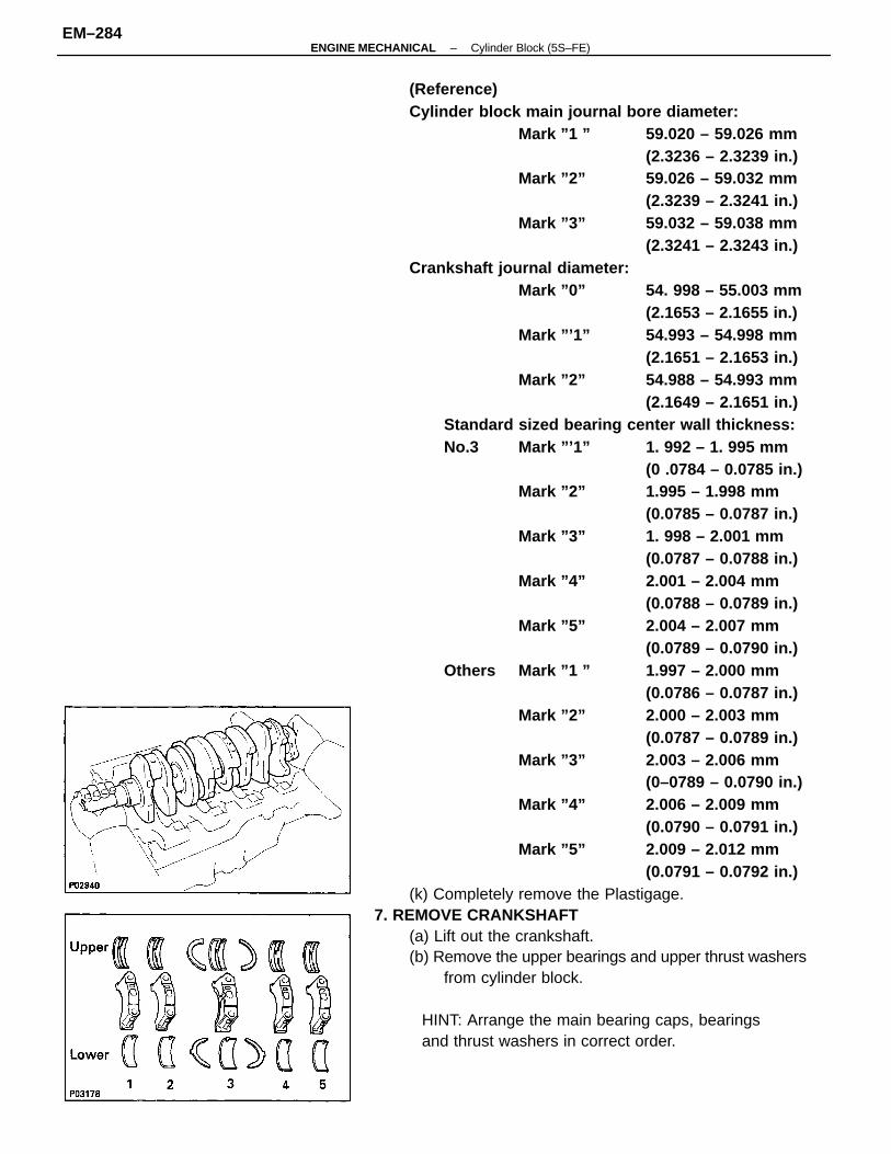
(Reference)Cylinder block main journal bore diameter:
Mark ”1 ” 59.020 – 59.026 mm(2.3236 – 2.3239 in.)
Mark ”2” 59.026 – 59.032 mm(2.3239 – 2.3241 in.)
Mark ”3” 59.032 – 59.038 mm(2.3241 – 2.3243 in.)
Crankshaft journal diameter:Mark ”0” 54. 998 – 55.003 mm
(2.1653 – 2.1655 in.) Mark ”’1” 54.993 – 54.998 mm
(2.1651 – 2.1653 in.)Mark ”2” 54.988 – 54.993 mm
(2.1649 – 2.1651 in.)Standard sized bearing center wall thickness:No.3 Mark ”’1” 1. 992 – 1. 995 mm
(0 .0784 – 0.0785 in.)Mark ”2” 1.995 – 1.998 mm
(0.0785 – 0.0787 in.)Mark ”3” 1. 998 – 2.001 mm
(0.0787 – 0.0788 in.)Mark ”4” 2.001 – 2.004 mm
(0.0788 – 0.0789 in.)Mark ”5” 2.004 – 2.007 mm
(0.0789 – 0.0790 in.)Others Mark ”1 ” 1.997 – 2.000 mm
(0.0786 – 0.0787 in.)Mark ”2” 2.000 – 2.003 mm
(0.0787 – 0.0789 in.)Mark ”3” 2.003 – 2.006 mm
(0–0789 – 0.0790 in.)Mark ”4” 2.006 – 2.009 mm
(0.0790 – 0.0791 in.)Mark ”5” 2.009 – 2.012 mm
(0.0791 – 0.0792 in.)(k) Completely remove the Plastigage.
7. REMOVE CRANKSHAFT(a) Lift out the crankshaft.(b) Remove the upper bearings and upper thrust washers
from cylinder block.
HINT: Arrange the main bearing caps, bearingsand thrust washers in correct order.
–ENGINE MECHANICAL Cylinder Block (5S–FE)EM–284
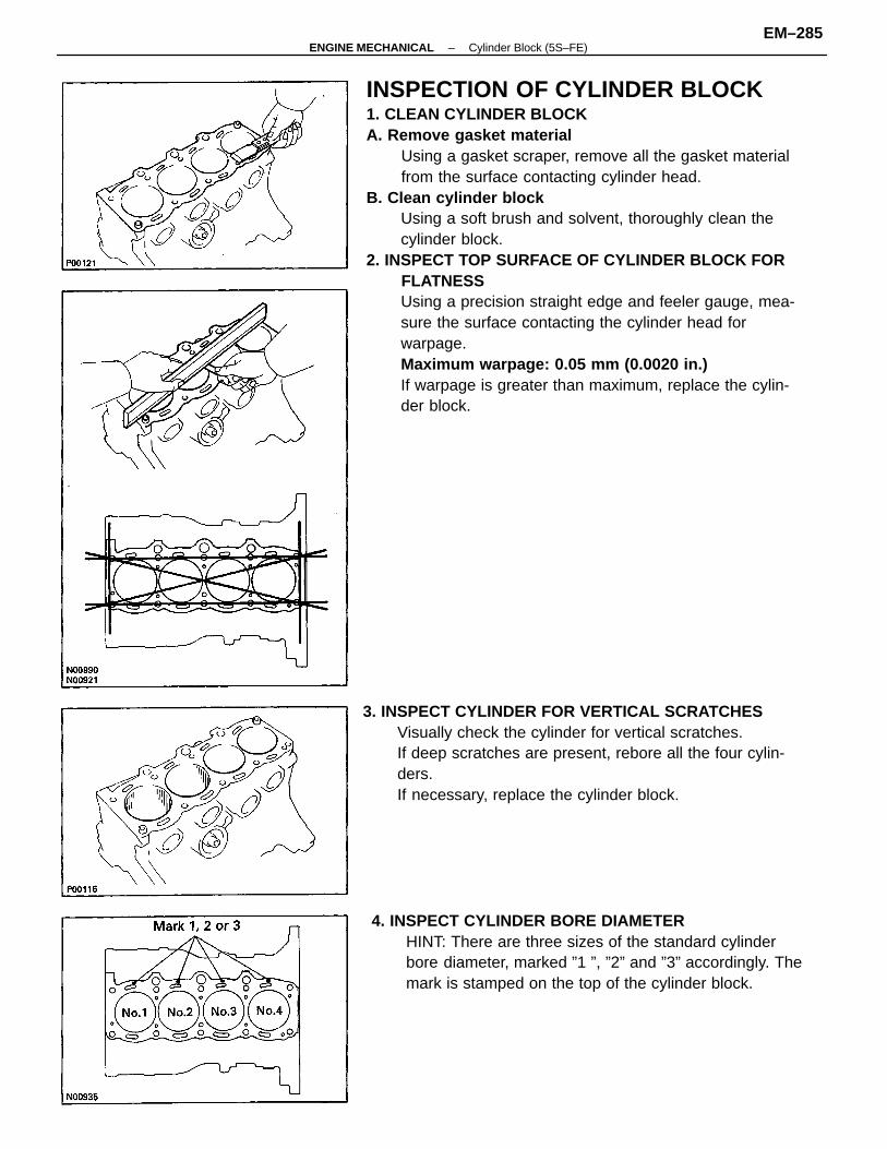
INSPECTION OF CYLINDER BLOCK1. CLEAN CYLINDER BLOCKA. Remove gasket material
Using a gasket scraper, remove all the gasket materialfrom the surface contacting cylinder head.
B. Clean cylinder blockUsing a soft brush and solvent, thoroughly clean thecylinder block.
2. INSPECT TOP SURFACE OF CYLINDER BLOCK FORFLATNESSUsing a precision straight edge and feeler gauge, mea-sure the surface contacting the cylinder head forwarpage.Maximum warpage: 0.05 mm (0.0020 in.)If warpage is greater than maximum, replace the cylin-der block.
3. INSPECT CYLINDER FOR VERTICAL SCRATCHESVisually check the cylinder for vertical scratches.If deep scratches are present, rebore all the four cylin-ders.If necessary, replace the cylinder block.
4. INSPECT CYLINDER BORE DIAMETERHINT: There are three sizes of the standard cylinderbore diameter, marked ”1 ”, ”2” and ”3” accordingly. Themark is stamped on the top of the cylinder block.
–ENGINE MECHANICAL Cylinder Block (5S–FE)EM–285
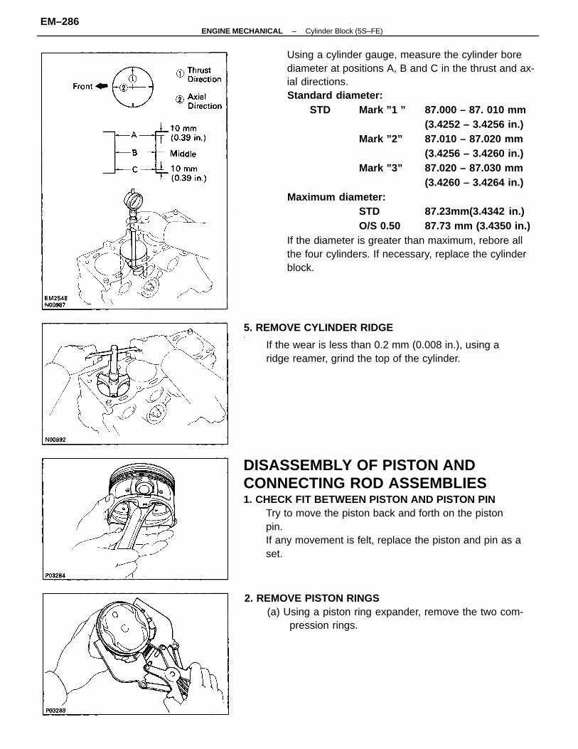
Using a cylinder gauge, measure the cylinder borediameter at positions A, B and C in the thrust and ax-ial directions.Standard diameter:
STD Mark ”1 ” 87.000 – 87. 010 mm(3.4252 – 3.4256 in.)
Mark ”2” 87.010 – 87.020 mm(3.4256 – 3.4260 in.)
Mark ”3” 87.020 – 87.030 mm(3.4260 – 3.4264 in.)
Maximum diameter:STD 87.23mm(3.4342 in.)O/S 0.50 87.73 mm (3.4350 in.)
If the diameter is greater than maximum, rebore allthe four cylinders. If necessary, replace the cylinderblock.
DISASSEMBLY OF PISTON ANDCONNECTING ROD ASSEMBLIES1. CHECK FIT BETWEEN PISTON AND PISTON PIN
Try to move the piston back and forth on the pistonpin.If any movement is felt, replace the piston and pin as aset.
5. REMOVE CYLINDER RIDGE^
If the wear is less than 0.2 mm (0.008 in.), using aridge reamer, grind the top of the cylinder.
2. REMOVE PISTON RINGS(a) Using a piston ring expander, remove the two com-
pression rings.
–ENGINE MECHANICAL Cylinder Block (5S–FE)EM–286
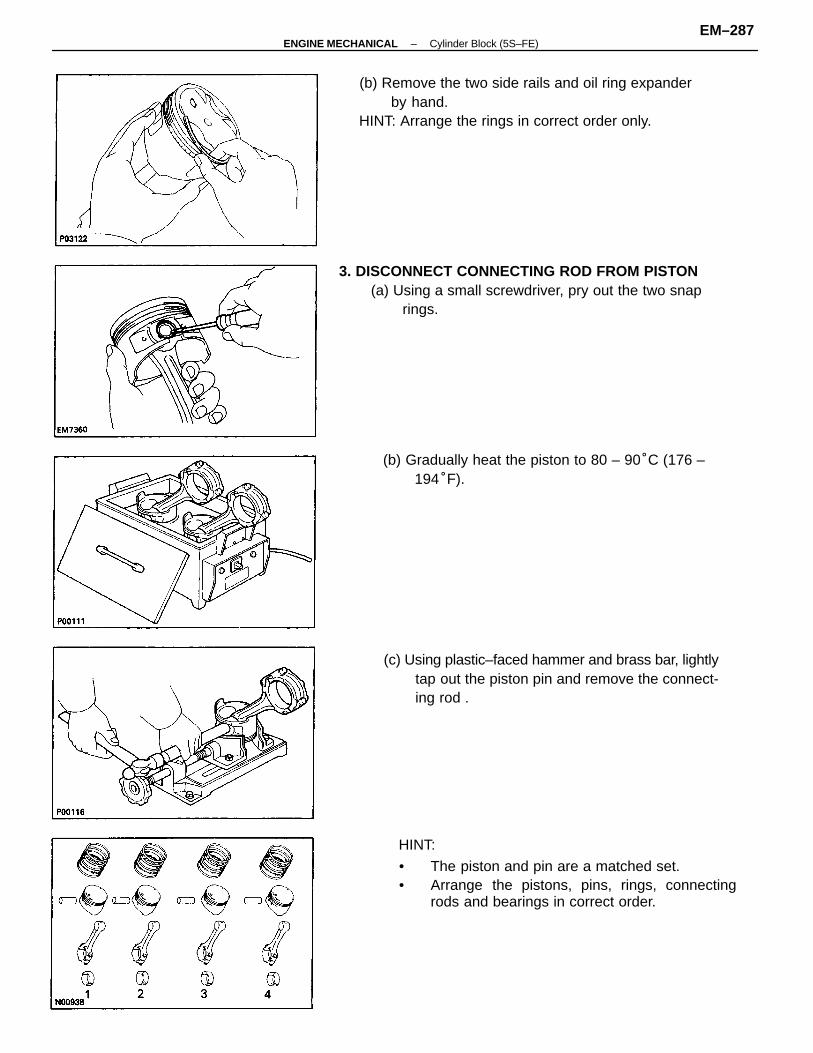
HINT:
• The piston and pin are a matched set.• Arrange the pistons, pins, rings, connecting
rods and bearings in correct order.
(b) Remove the two side rails and oil ring expanderby hand.
HINT: Arrange the rings in correct order only.
3. DISCONNECT CONNECTING ROD FROM PISTON(a) Using a small screwdriver, pry out the two snap
rings.
(c) Using plastic–faced hammer and brass bar, lightlytap out the piston pin and remove the connect-ing rod .
(b) Gradually heat the piston to 80 – 90°C (176 –194°F).
–ENGINE MECHANICAL Cylinder Block (5S–FE)EM–287
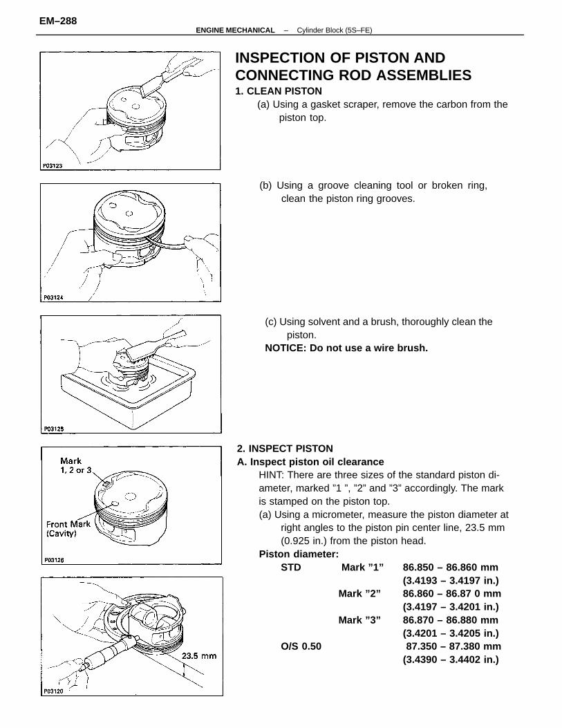
2. INSPECT PISTONA. Inspect piston oil clearance
HINT: There are three sizes of the standard piston di-ameter, marked ”1 ”, ”2” and ”3” accordingly. The markis stamped on the piston top.(a) Using a micrometer, measure the piston diameter at
right angles to the piston pin center line, 23.5 mm(0.925 in.) from the piston head.
Piston diameter:STD Mark ”1” 86.850 – 86.860 mm
(3.4193 – 3.4197 in.)Mark ”2” 86.860 – 86.87 0 mm
(3.4197 – 3.4201 in.)Mark ”3” 86.870 – 86.880 mm
(3.4201 – 3.4205 in.)O/S 0.50 87.350 – 87.380 mm
(3.4390 – 3.4402 in.)
INSPECTION OF PISTON ANDCONNECTING ROD ASSEMBLIES1. CLEAN PISTON
(a) Using a gasket scraper, remove the carbon from thepiston top.
(c) Using solvent and a brush, thoroughly clean thepiston.
NOTICE: Do not use a wire brush.
(b) Using a groove cleaning tool or broken ring,clean the piston ring grooves.
–ENGINE MECHANICAL Cylinder Block (5S–FE)EM–288
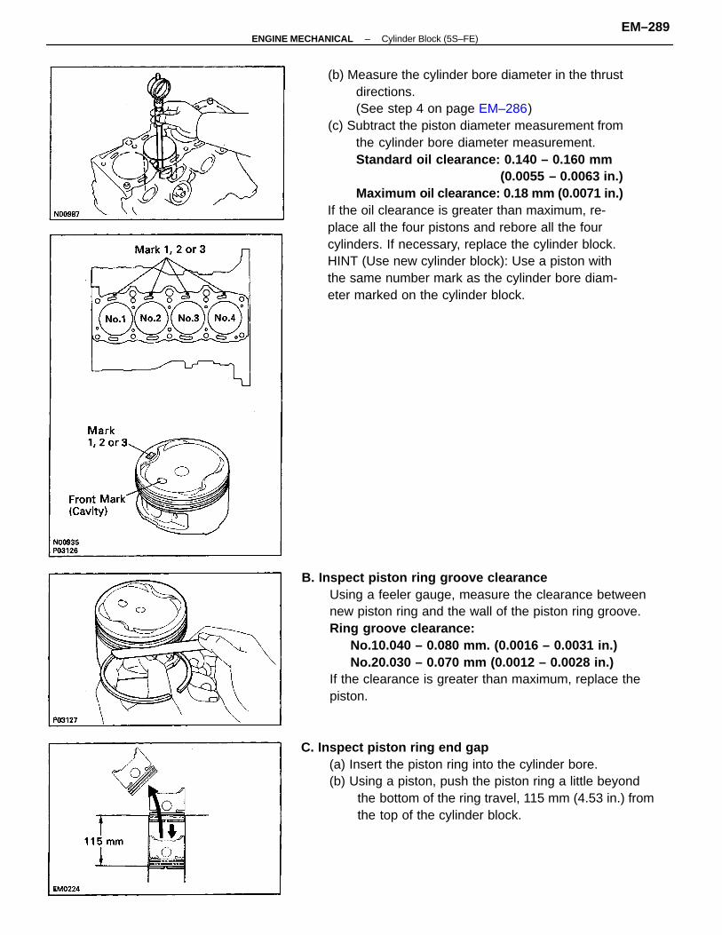
(b) Measure the cylinder bore diameter in the thrustdirections.(See step 4 on page EM–286)
(c) Subtract the piston diameter measurement fromthe cylinder bore diameter measurement.Standard oil clearance: 0.140 – 0.160 mm
(0.0055 – 0.0063 in.)Maximum oil clearance: 0.18 mm (0.0071 in.)
If the oil clearance is greater than maximum, re-place all the four pistons and rebore all the fourcylinders. If necessary, replace the cylinder block.HINT (Use new cylinder block): Use a piston withthe same number mark as the cylinder bore diam-eter marked on the cylinder block.
B. Inspect piston ring groove clearanceUsing a feeler gauge, measure the clearance betweennew piston ring and the wall of the piston ring groove.Ring groove clearance:
No.10.040 – 0.080 mm. (0.0016 – 0.0031 in.)No.20.030 – 0.070 mm (0.0012 – 0.0028 in.)
If the clearance is greater than maximum, replace thepiston.
C. Inspect piston ring end gap(a) Insert the piston ring into the cylinder bore.(b) Using a piston, push the piston ring a little beyond
the bottom of the ring travel, 115 mm (4.53 in.) fromthe top of the cylinder block.
–ENGINE MECHANICAL Cylinder Block (5S–FE)EM–289
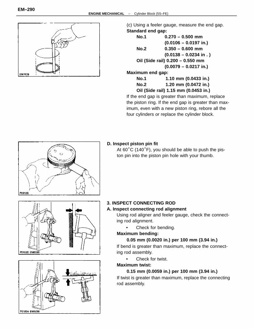
3. INSPECT CONNECTING RODA. Inspect connecting rod alignment
Using rod aligner and feeler gauge, check the connect-ing rod alignment.
• Check for bending.Maximum bending:
0.05 mm (0.0020 in.) per 100 mm (3.94 in.)If bend is greater than maximum, replace the connect-ing rod assembly.
• Check for twist.Maximum twist:
0.15 mm (0.0059 in.) per 100 mm (3.94 in.)If twist is greater than maximum, replace the connectingrod assembly.
(c) Using a feeler gauge, measure the end gap.Standard end gap:
No.1 0.270 – 0.500 mm(0.0106 – 0.0197 in.)
No.2 0.350 – 0.600 mm(0.0138 – 0.0234 in . )
Oil (Side rail) 0.200 – 0.550 mm(0.0079 – 0.0217 in.)
Maximum end gap:No.1 1.10 mm (0.0433 in.)No.2 1.20 mm (0.0472 in.)Oil (Side rail) 1.15 mm (0.0453 in.)
If the end gap is greater than maximum, replacethe piston ring. If the end gap is greater than max-imum, even with a new piston ring, rebore all thefour cylinders or replace the cylinder block.
D. Inspect piston pin fitAt 60°C (140°F), you should be able to push the pis-ton pin into the piston pin hole with your thumb.
–ENGINE MECHANICAL Cylinder Block (5S–FE)EM–290
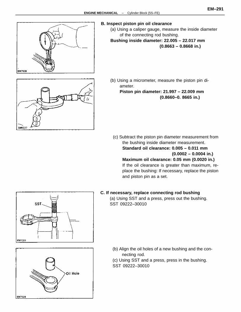
(c) Subtract the piston pin diameter measurement fromthe bushing inside diameter measurement.Standard oil clearance: 0.005 – 0.011 mm
(0.0002 – 0.0004 in.)Maximum oil clearance: 0.05 mm (0.0020 in.)If the oil clearance is greater than maximum, re-place the bushing: If necessary, replace the pistonand piston pin as a set.
B. Inspect piston pin oil clearance(a) Using a caliper gauge, measure the inside diameter
of the connecting rod bushing.Bushing inside diameter: 22.005 – 22.017 mm
(0.8663 – 0.8668 in.)
(b) Align the oil holes of a new bushing and the con-necting rod.
(c) Using SST and a press, press in the bushing.SST 09222–30010
(b) Using a micrometer, measure the piston pin di-ameter.Piston pin diameter: 21.997 – 22.009 mm
(0.8660–0. 8665 in.)
C. If necessary, replace connecting rod bushing(a) Using SST and a press, press out the bushing.SST 09222–30010
–ENGINE MECHANICAL Cylinder Block (5S–FE)EM–291
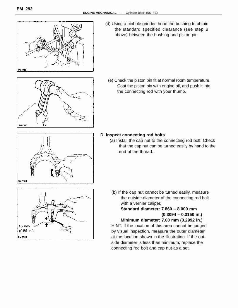
(b) If the cap nut cannot be turned easily, measurethe outside diameter of the connecting rod boltwith a vernier caliper.Standard diameter: 7.860 – 8.000 mm
(0.3094 – 0.3150 in.) Minimum diameter: 7.60 mm (0.2992 in.)
HINT: If the location of this area cannot be judgedby visual inspection, measure the outer diameterat the location shown in the illustration. If the out-side diameter is less than minimum, replace theconnecting rod bolt and cap nut as a set.
D. Inspect connecting rod bolts(a) Install the cap nut to the connecting rod bolt. Check
that the cap nut can be turned easily by hand to theend of the thread.
(e) Check the piston pin fit at normal room temperature.Coat the piston pin with engine oil, and push it intothe connecting rod with your thumb.
(d) Using a pinhole grinder, hone the bushing to obtainthe standard specified clearance (see step Babove) between the bushing and piston pin.
–ENGINE MECHANICAL Cylinder Block (5S–FE)EM–292
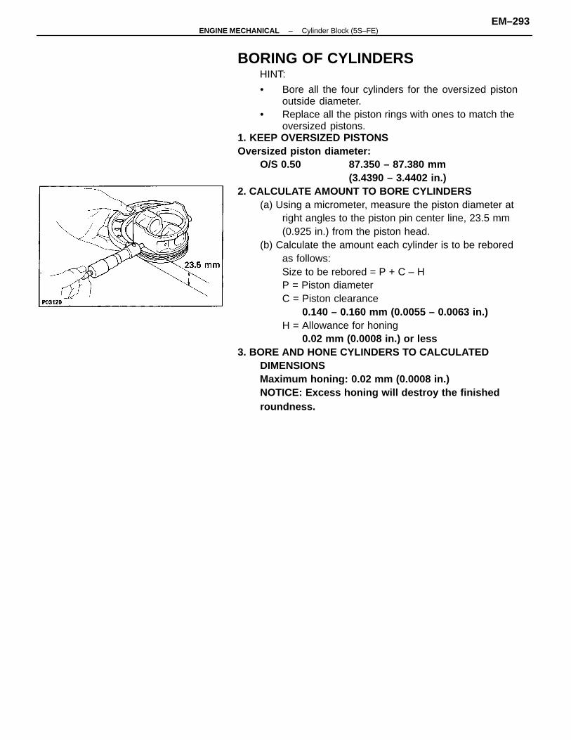
BORING OF CYLINDERSHINT:
• Bore all the four cylinders for the oversized pistonoutside diameter.
• Replace all the piston rings with ones to match theoversized pistons.
1. KEEP OVERSIZED PISTONSOversized piston diameter:
O/S 0.50 87.350 – 87.380 mm(3.4390 – 3.4402 in.)
2. CALCULATE AMOUNT TO BORE CYLINDERS(a) Using a micrometer, measure the piston diameter at
right angles to the piston pin center line, 23.5 mm(0.925 in.) from the piston head.
(b) Calculate the amount each cylinder is to be reboredas follows:Size to be rebored = P + C – HP = Piston diameterC = Piston clearance
0.140 – 0.160 mm (0.0055 – 0.0063 in.)H = Allowance for honing
0.02 mm (0.0008 in.) or less3. BORE AND HONE CYLINDERS TO CALCULATED
DIMENSIONSMaximum honing: 0.02 mm (0.0008 in.)NOTICE: Excess honing will destroy the finishedroundness.
–ENGINE MECHANICAL Cylinder Block (5S–FE)EM–293
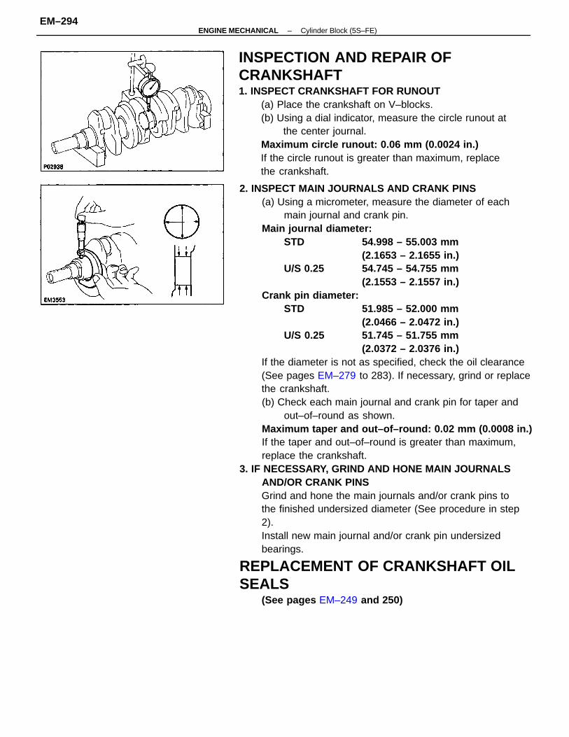
2. INSPECT MAIN JOURNALS AND CRANK PINS(a) Using a micrometer, measure the diameter of each
main journal and crank pin.Main journal diameter:
STD 54.998 – 55.003 mm(2.1653 – 2.1655 in.)
U/S 0.25 54.745 – 54.755 mm(2.1553 – 2.1557 in.)
Crank pin diameter:STD 51.985 – 52.000 mm
(2.0466 – 2.0472 in.)U/S 0.25 51.745 – 51.755 mm
(2.0372 – 2.0376 in.)If the diameter is not as specified, check the oil clearance(See pages EM–279 to 283). If necessary, grind or replacethe crankshaft.(b) Check each main journal and crank pin for taper and
out–of–round as shown.Maximum taper and out–of–round: 0.02 mm (0.0008 in.)If the taper and out–of–round is greater than maximum,replace the crankshaft.
3. IF NECESSARY, GRIND AND HONE MAIN JOURNALSAND/OR CRANK PINSGrind and hone the main journals and/or crank pins tothe finished undersized diameter (See procedure in step2). Install new main journal and/or crank pin undersizedbearings.
REPLACEMENT OF CRANKSHAFT OILSEALS
(See pages EM–249 and 250)
INSPECTION AND REPAIR OFCRANKSHAFT1. INSPECT CRANKSHAFT FOR RUNOUT
(a) Place the crankshaft on V–blocks.(b) Using a dial indicator, measure the circle runout at
the center journal.Maximum circle runout: 0.06 mm (0.0024 in.)If the circle runout is greater than maximum, replacethe crankshaft.
–ENGINE MECHANICAL Cylinder Block (5S–FE)EM–294
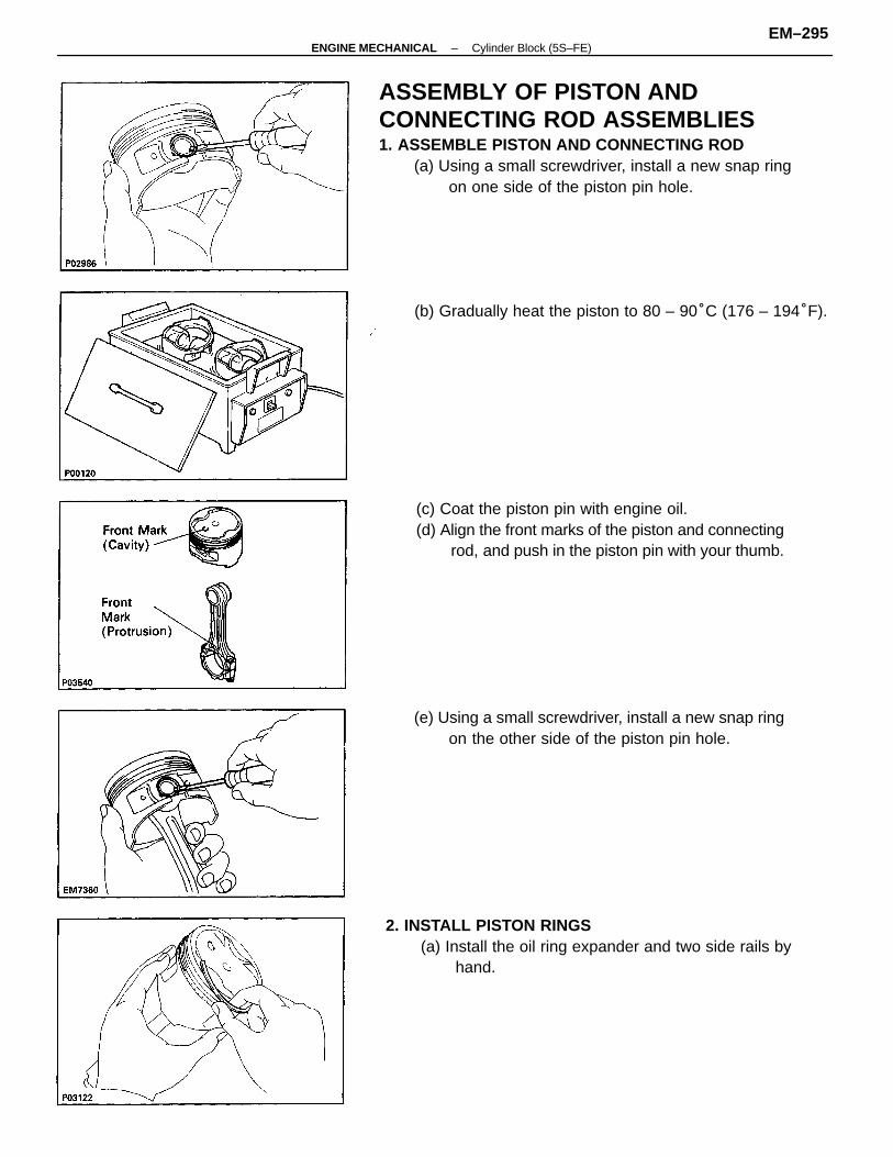
ASSEMBLY OF PISTON ANDCONNECTING ROD ASSEMBLIES1. ASSEMBLE PISTON AND CONNECTING ROD
(a) Using a small screwdriver, install a new snap ringon one side of the piston pin hole.
2. INSTALL PISTON RINGS(a) Install the oil ring expander and two side rails by
hand.
(c) Coat the piston pin with engine oil.(d) Align the front marks of the piston and connecting
rod, and push in the piston pin with your thumb.
(b) Gradually heat the piston to 80 – 90°C (176 – 194°F).
(e) Using a small screwdriver, install a new snap ringon the other side of the piston pin hole.
–ENGINE MECHANICAL Cylinder Block (5S–FE)EM–295
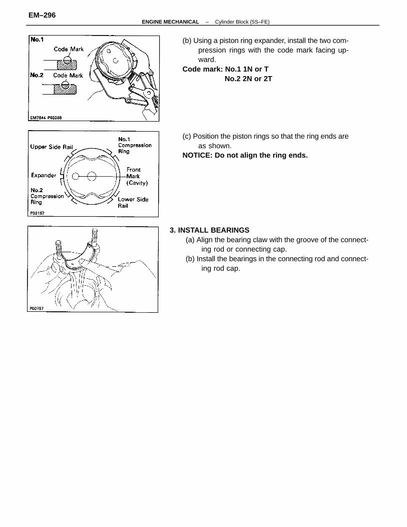
3. INSTALL BEARINGS(a) Align the bearing claw with the groove of the connect-
ing rod or connecting cap.(b) Install the bearings in the connecting rod and connect-
ing rod cap.
(b) Using a piston ring expander, install the two com-pression rings with the code mark facing up-ward.
Code mark: No.1 1N or TNo.2 2N or 2T
(c) Position the piston rings so that the ring ends areas shown.
NOTICE: Do not align the ring ends.
–ENGINE MECHANICAL Cylinder Block (5S–FE)EM–296
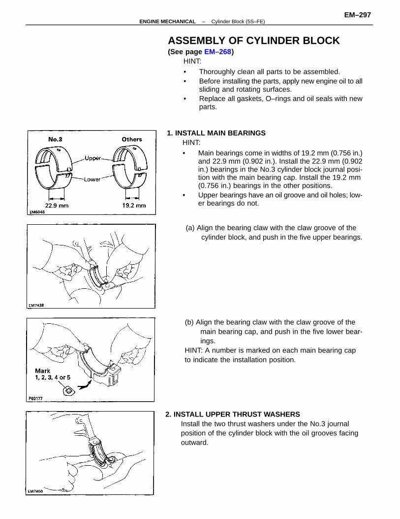
1. INSTALL MAIN BEARINGSHINT:
• Main bearings come in widths of 19.2 mm (0.756 in.)and 22.9 mm (0.902 in.). Install the 22.9 mm (0.902in.) bearings in the No.3 cylinder block journal posi-tion with the main bearing cap. Install the 19.2 mm(0.756 in.) bearings in the other positions.
• Upper bearings have an oil groove and oil holes; low-er bearings do not.
ASSEMBLY OF CYLINDER BLOCK(See page EM–268)
HINT:
• Thoroughly clean all parts to be assembled.• Before installing the parts, apply new engine oil to all
sliding and rotating surfaces.• Replace all gaskets, O–rings and oil seals with new
parts.
(b) Align the bearing claw with the claw groove of themain bearing cap, and push in the five lower bear-ings.
HINT: A number is marked on each main bearing capto indicate the installation position.
2. INSTALL UPPER THRUST WASHERSInstall the two thrust washers under the No.3 journalposition of the cylinder block with the oil grooves facingoutward.
(a) Align the bearing claw with the claw groove of thecylinder block, and push in the five upper bearings.
–ENGINE MECHANICAL Cylinder Block (5S–FE)EM–297
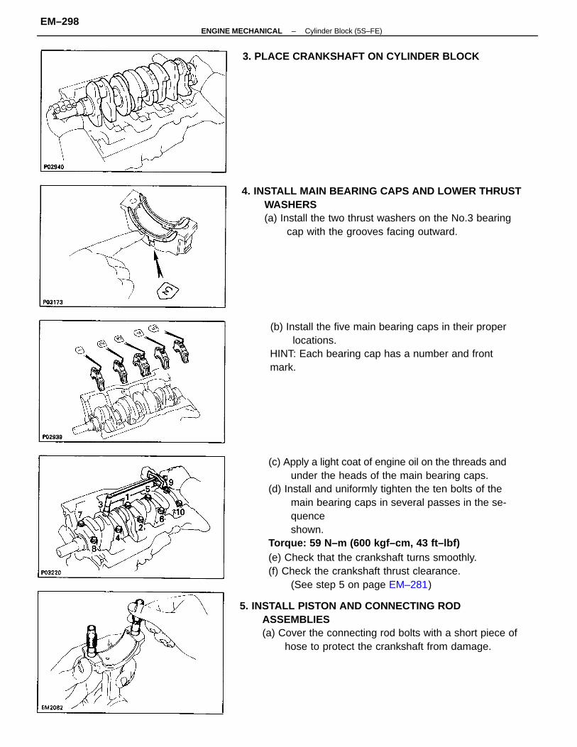
(c) Apply a light coat of engine oil on the threads andunder the heads of the main bearing caps.
(d) Install and uniformly tighten the ten bolts of themain bearing caps in several passes in the se-quenceshown.
Torque: 59 N–m (600 kgf–cm, 43 ft–lbf)(e) Check that the crankshaft turns smoothly.(f) Check the crankshaft thrust clearance.
(See step 5 on page EM–281)
5. INSTALL PISTON AND CONNECTING RODASSEMBLIES(a) Cover the connecting rod bolts with a short piece of
hose to protect the crankshaft from damage.
4. INSTALL MAIN BEARING CAPS AND LOWER THRUSTWASHERS(a) Install the two thrust washers on the No.3 bearing
cap with the grooves facing outward.
(b) Install the five main bearing caps in their properlocations.
HINT: Each bearing cap has a number and frontmark.
3. PLACE CRANKSHAFT ON CYLINDER BLOCK
–ENGINE MECHANICAL Cylinder Block (5S–FE)EM–298
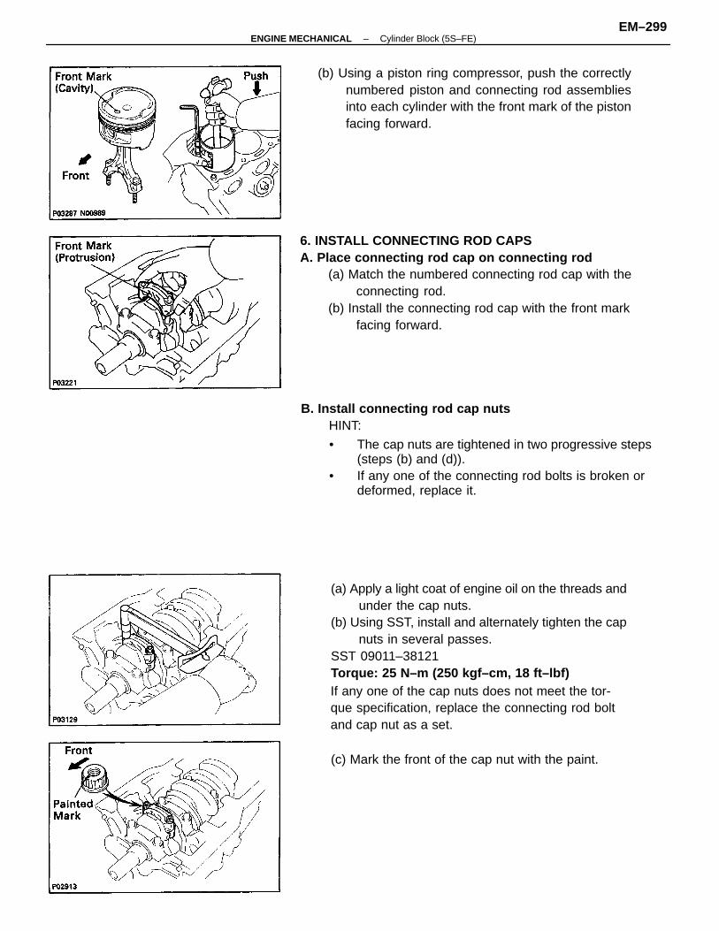
(a) Apply a light coat of engine oil on the threads andunder the cap nuts.
(b) Using SST, install and alternately tighten the capnuts in several passes.
SST 09011–38121Torque: 25 N–m (250 kgf–cm, 18 ft–lbf)If any one of the cap nuts does not meet the tor-que specification, replace the connecting rod boltand cap nut as a set.
6. INSTALL CONNECTING ROD CAPSA. Place connecting rod cap on connecting rod
(a) Match the numbered connecting rod cap with theconnecting rod.
(b) Install the connecting rod cap with the front markfacing forward.
B. Install connecting rod cap nutsHINT:
• The cap nuts are tightened in two progressive steps(steps (b) and (d)).
• If any one of the connecting rod bolts is broken ordeformed, replace it.
(b) Using a piston ring compressor, push the correctlynumbered piston and connecting rod assembliesinto each cylinder with the front mark of the pistonfacing forward.
(c) Mark the front of the cap nut with the paint.
–ENGINE MECHANICAL Cylinder Block (5S–FE)EM–299
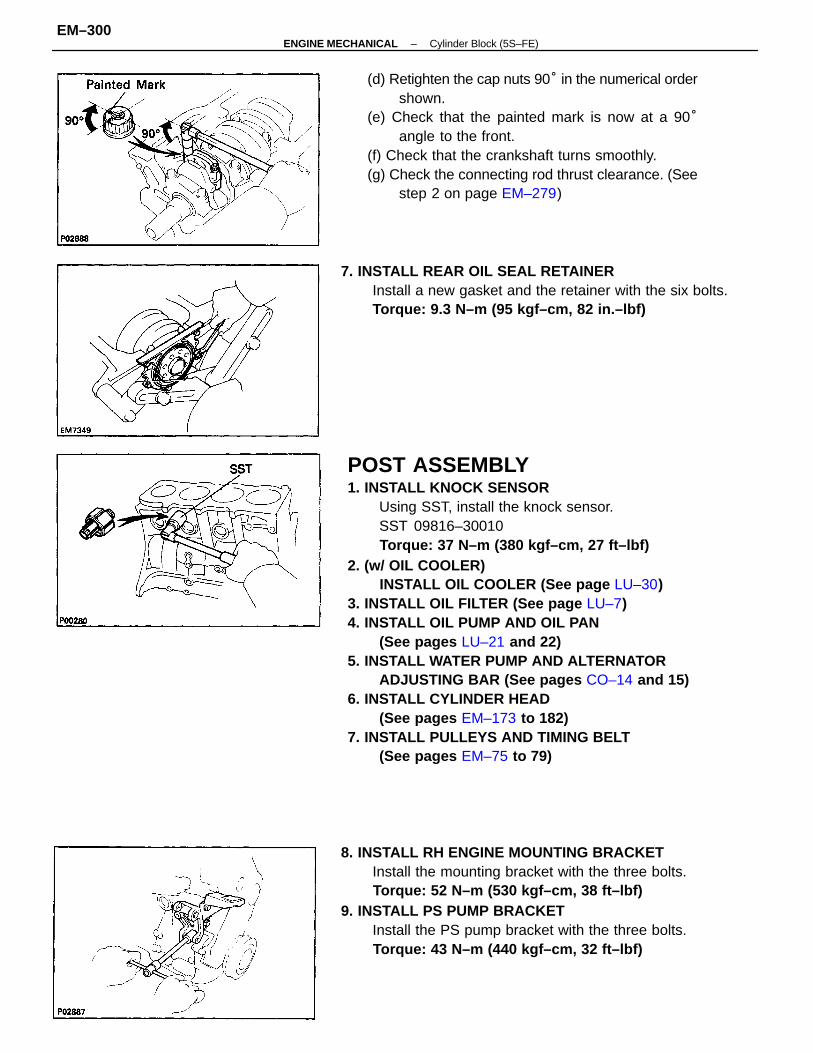
POST ASSEMBLY1. INSTALL KNOCK SENSOR
Using SST, install the knock sensor.SST 09816–30010Torque: 37 N–m (380 kgf–cm, 27 ft–lbf)
2. (w/ OIL COOLER)INSTALL OIL COOLER (See page LU–30)
3. INSTALL OIL FILTER (See page LU–7)4. INSTALL OIL PUMP AND OIL PAN
(See pages LU–21 and 22)5. INSTALL WATER PUMP AND ALTERNATOR
ADJUSTING BAR (See pages CO–14 and 15)6. INSTALL CYLINDER HEAD
(See pages EM–173 to 182)7. INSTALL PULLEYS AND TIMING BELT
(See pages EM–75 to 79)
(d) Retighten the cap nuts 90° in the numerical ordershown.
(e) Check that the painted mark is now at a 90°angle to the front.
(f) Check that the crankshaft turns smoothly.(g) Check the connecting rod thrust clearance. (See
step 2 on page EM–279)
8. INSTALL RH ENGINE MOUNTING BRACKETInstall the mounting bracket with the three bolts.Torque: 52 N–m (530 kgf–cm, 38 ft–lbf)
9. INSTALL PS PUMP BRACKETInstall the PS pump bracket with the three bolts.Torque: 43 N–m (440 kgf–cm, 32 ft–lbf)
7. INSTALL REAR OIL SEAL RETAINERInstall a new gasket and the retainer with the six bolts.Torque: 9.3 N–m (95 kgf–cm, 82 in.–lbf)
–ENGINE MECHANICAL Cylinder Block (5S–FE)EM–300
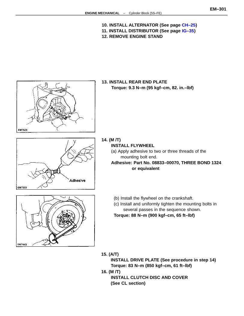
14. (M /T)INSTALL FLYWHEEL(a) Apply adhesive to two or three threads of the
mounting bolt end.Adhesive: Part No. 08833–00070, THREE BOND 1324
or equivalent
15. (A/T)INSTALL DRIVE PLATE (See procedure in step 14)Torque: 83 N–m (850 kgf–cm, 61 ft–lbf)
16. (M /T)INSTALL CLUTCH DISC AND COVER(See CL section)
(b) Install the flywheel on the crankshaft.(c) Install and uniformly tighten the mounting bolts in
several passes in the sequence shown.Torque: 88 N–m (900 kgf–cm, 65 ft–lbf)
10. INSTALL ALTERNATOR (See page CH–25)11. INSTALL DISTRIBUTOR (See page IG–35)12. REMOVE ENGINE STAND
13. INSTALL REAR END PLATETorque: 9.3 N–m (95 kgf–cm, 82. in.–lbf)
–ENGINE MECHANICAL Cylinder Block (5S–FE)EM–301
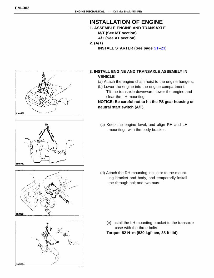
3. INSTALL ENGINE AND TRANSAXLE ASSEMBLY INVEHICLE(a) Attach the engine chain hoist to the engine hangers,(b) Lower the engine into the engine compartment.
Tilt the transaxle downward, lower the engine andclear the LH mounting.
NOTICE: Be careful not to hit the PS gear housing orneutral start switch (A/T).
INSTALLATION OF ENGINE1. ASSEMBLE ENGINE AND TRANSAXLE
M/T (See MT section)A/T (See AT section)
2. (A/T)INSTALL STARTER (See page ST–23)
(e) Install the LH mounting bracket to the transaxlecase with the three bolts.
Torque: 52 N–m (530 kgf–cm, 38 ft–lbf)
(d) Attach the RH mounting insulator to the mount-ing bracket and body, and temporarily installthe through bolt and two nuts.
(c) Keep the engine level, and align RH and LHmountings with the body bracket.
–ENGINE MECHANICAL Cylinder Block (5S–FE)EM–302
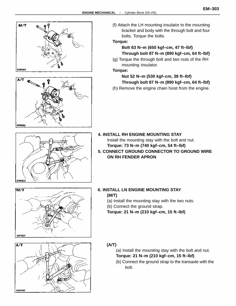
(f) Attach the LH mounting insulator to the mountingbracket and body with the through bolt and fourbolts. Torque the bolts.
Torque:Bolt 63 N–m (650 kgf–cm, 47 ft–lbf)Through bolt 87 N–m (890 kgf–cm, 64 ft–lbf)
(g) Torque the through bolt and two nuts of the RHmounting insulator.
Torque:Nut 52 N–m (530 kgf–cm, 38 ft–lbf)Through bolt 87 N–m (890 kgf–cm, 64 ft–lbf)
(h) Remove the engine chain hoist from the engine.
4. INSTALL RH ENGINE MOUNTING STAYInstall the mounting stay with the bolt and nut.Torque: 73 N–m (740 kgf–cm, 54 ft–lbf)
5. CONNECT GROUND CONNECTOR TO GROUND WIREON RH FENDER APRON
6. INSTALL LN ENGINE MOUNTING STAY(M/T)(a) Install the mounting stay with the two nuts.(b) Connect the ground strap.Torque: 21 N–m (210 kgf–cm, 15 ft–lbf)
(A/T)(a) Install the mounting stay with the bolt and nut.Torque: 21 N–m (210 kgf–cm, 15 ft–lbf)(b) Connect the ground strap to the transaxle with the
bolt.
–ENGINE MECHANICAL Cylinder Block (5S–FE)EM–303
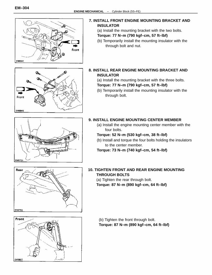
9. INSTALL ENGINE MOUNTING CENTER MEMBER(a) Install the engine mounting center member with the
four bolts.Torque: 52 N–m (530 kgf–cm, 38 ft–lbf)(b) Install and torque the four bolts holding the insulators
to the center member.Torque: 73 N–m (740 kgf–cm, 54 ft–lbf)
7. INSTALL FRONT ENGINE MOUNTING BRACKET ANDINSULATOR(a) Install the mounting bracket with the two bolts.Torque: 77 N–m (790 kgf–cm, 57 ft–lbf)(b) Temporarily install the mounting insulator with the
through bolt and nut.
8. INSTALL REAR ENGINE MOUNTING BRACKET ANDINSULATOR(a) Install the mounting bracket with the three bolts.Torque: 77 N–m (790 kgf–cm, 57 ft–lbf)(b) Temporarily install the mounting insulator with the
through bolt.
10. TIGHTEN FRONT AND REAR ENGINE MOUNTINGTHROUGH BOLTS(a) Tighten the rear through bolt.Torque: 87 N–m (890 kgf–cm, 64 ft–lbf)
(b) Tighten the front through bolt.Torque: 87 N–m (890 kgf–cm, 64 ft–lbf)
–ENGINE MECHANICAL Cylinder Block (5S–FE)EM–304
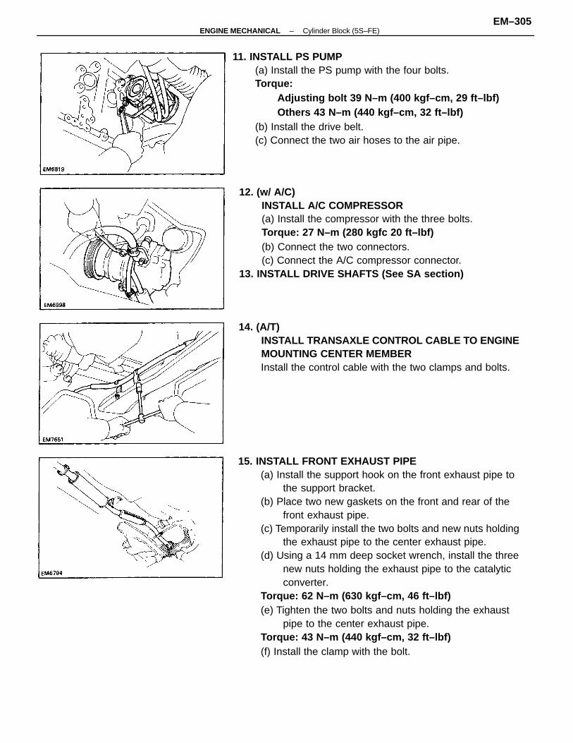
15. INSTALL FRONT EXHAUST PIPE(a) Install the support hook on the front exhaust pipe to
the support bracket.(b) Place two new gaskets on the front and rear of the
front exhaust pipe.(c) Temporarily install the two bolts and new nuts holding
the exhaust pipe to the center exhaust pipe.(d) Using a 14 mm deep socket wrench, install the three
new nuts holding the exhaust pipe to the catalyticconverter.
Torque: 62 N–m (630 kgf–cm, 46 ft–lbf)(e) Tighten the two bolts and nuts holding the exhaust
pipe to the center exhaust pipe.Torque: 43 N–m (440 kgf–cm, 32 ft–lbf)(f) Install the clamp with the bolt.
11. INSTALL PS PUMP(a) Install the PS pump with the four bolts.Torque:
Adjusting bolt 39 N–m (400 kgf–cm, 29 ft–lbf)Others 43 N–m (440 kgf–cm, 32 ft–lbf)
(b) Install the drive belt.(c) Connect the two air hoses to the air pipe.
12. (w/ A/C)INSTALL A/C COMPRESSOR(a) Install the compressor with the three bolts.Torque: 27 N–m (280 kgfc 20 ft–lbf)(b) Connect the two connectors.(c) Connect the A/C compressor connector.
13. INSTALL DRIVE SHAFTS (See SA section)
14. (A/T)INSTALL TRANSAXLE CONTROL CABLE TO ENGINEMOUNTING CENTER MEMBERInstall the control cable with the two clamps and bolts.
–ENGINE MECHANICAL Cylinder Block (5S–FE)EM–305
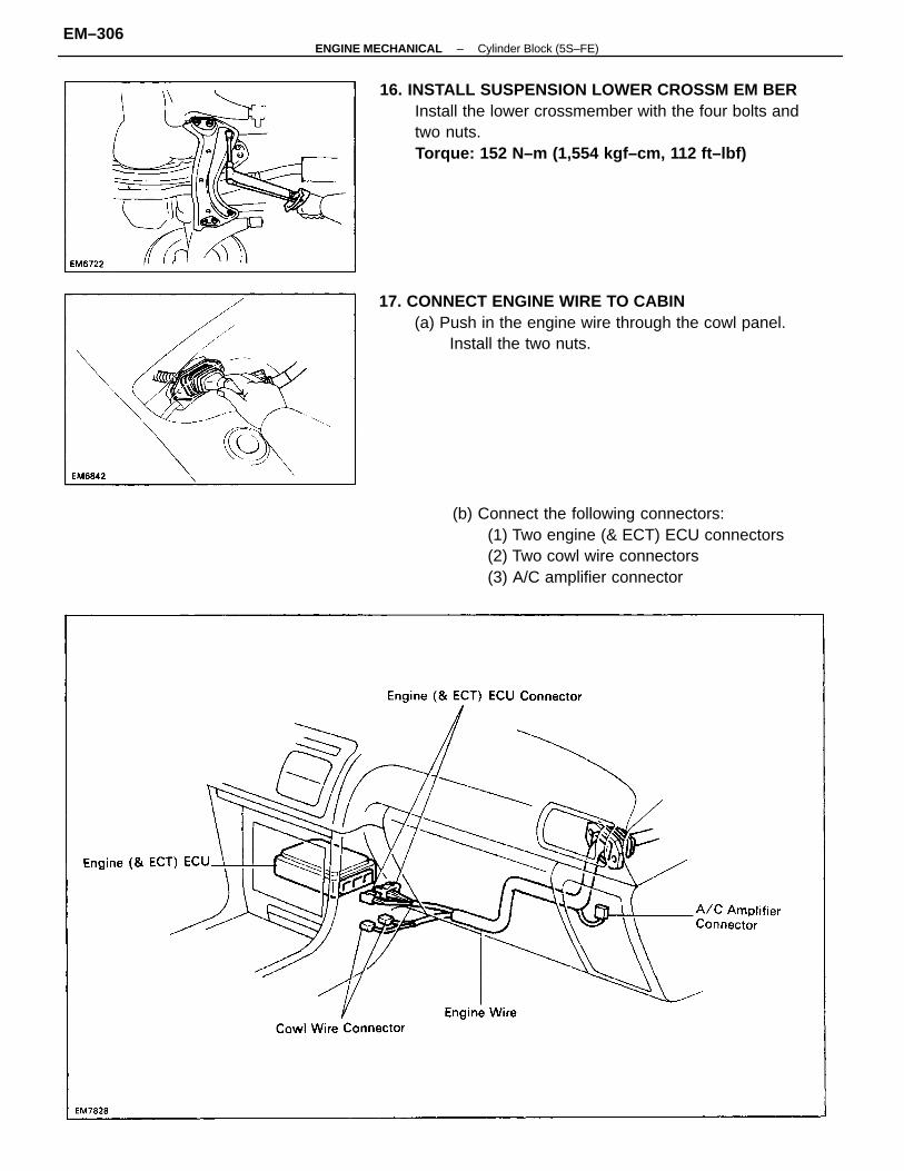
16. INSTALL SUSPENSION LOWER CROSSM EM BERInstall the lower crossmember with the four bolts andtwo nuts.Torque: 152 N–m (1,554 kgf–cm, 112 ft–lbf)
(b) Connect the following connectors:(1) Two engine (& ECT) ECU connectors(2) Two cowl wire connectors(3) A/C amplifier connector
17. CONNECT ENGINE WIRE TO CABIN(a) Push in the engine wire through the cowl panel.
Install the two nuts.
–ENGINE MECHANICAL Cylinder Block (5S–FE)EM–306
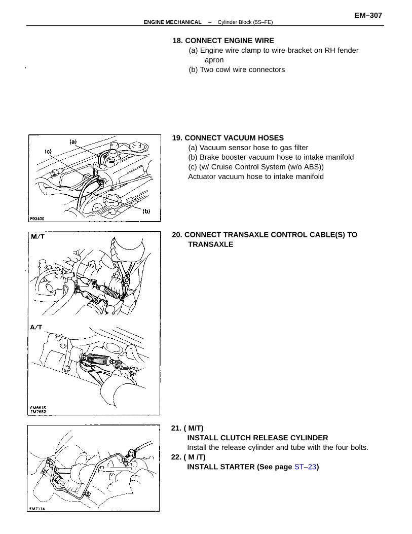
21. ( M/T)INSTALL CLUTCH RELEASE CYLINDERInstall the release cylinder and tube with the four bolts.
22. ( M /T)INSTALL STARTER (See page ST–23)
19. CONNECT VACUUM HOSES(a) Vacuum sensor hose to gas filter(b) Brake booster vacuum hose to intake manifold(c) (w/ Cruise Control System (w/o ABS))Actuator vacuum hose to intake manifold
18. CONNECT ENGINE WIRE(a) Engine wire clamp to wire bracket on RH fender
apron(b) Two cowl wire connectors
20. CONNECT TRANSAXLE CONTROL CABLE(S) TOTRANSAXLE
–ENGINE MECHANICAL Cylinder Block (5S–FE)EM–307
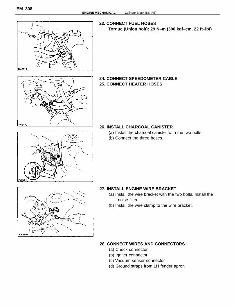
26. INSTALL CHARCOAL CANISTER(a) Install the charcoal canister with the two bolts.(b) Connect the three hoses.
28. CONNECT WIRES AND CONNECTORS(a) Check connector(b) Igniter connector(c) Vacuum sensor connector(d) Ground straps from LH fender apron
27. INSTALL ENGINE WIRE BRACKET(a) Install the wire bracket with the two bolts. Install the
noise filter.(b) Install the wire clamp to the wire bracket.
23. CONNECT FUEL HOSESTorque (Union bolt): 29 N–m (300 kgf–cm, 22 ft–lbf)
24. CONNECT SPEEDOMETER CABLE25. CONNECT HEATER HOSES
–ENGINE MECHANICAL Cylinder Block (5S–FE)EM–308
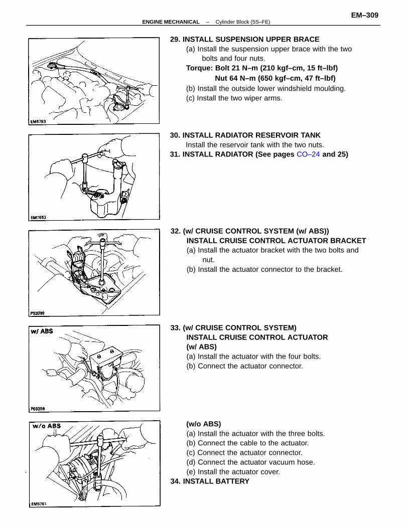
29. INSTALL SUSPENSION UPPER BRACE(a) Install the suspension upper brace with the two
bolts and four nuts.Torque: Bolt 21 N–m (210 kgf–cm, 15 ft–lbf)
Nut 64 N–m (650 kgf–cm, 47 ft–lbf)(b) Install the outside lower windshield moulding.(c) Install the two wiper arms.
(w/o ABS)(a) Install the actuator with the three bolts.(b) Connect the cable to the actuator.(c) Connect the actuator connector.(d) Connect the actuator vacuum hose.(e) Install the actuator cover.
34. INSTALL BATTERY
32. (w/ CRUISE CONTROL SYSTEM (w/ ABS))INSTALL CRUISE CONTROL ACTUATOR BRACKET(a) Install the actuator bracket with the two bolts and
nut.(b) Install the actuator connector to the bracket.
33. (w/ CRUISE CONTROL SYSTEM)INSTALL CRUISE CONTROL ACTUATOR(w/ ABS)(a) Install the actuator with the four bolts.(b) Connect the actuator connector.
30. INSTALL RADIATOR RESERVOIR TANKInstall the reservoir tank with the two nuts.
31. INSTALL RADIATOR (See pages CO–24 and 25)
–ENGINE MECHANICAL Cylinder Block (5S–FE)EM–309
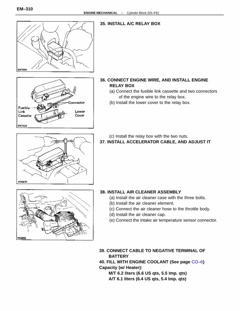
38. INSTALL AIR CLEANER ASSEMBLY(a) Install the air cleaner case with the three bolts.(b) Install the air cleaner element.(c) Connect the air cleaner hose to the throttle body.(d) Install the air cleaner cap.(e) Connect the intake air temperature sensor connector.
39. CONNECT CABLE TO NEGATIVE TERMINAL OFBATTERY
40. FILL WITH ENGINE COOLANT (See page CO–6)Capacity (w/ Heater):
M/T 6.2 liters (6.6 US qts, 5.5 Imp. qts)A/T 6.1 liters (6.4 US qts, 5.4 Imp. qts)
36. CONNECT ENGINE WIRE, AND INSTALL ENGINERELAY BOX(a) Connect the fusible link cassette and two connectors
of the engine wire to the relay box.(b) Install the lower cover to the relay box.
(c) Install the relay box with the two nuts.37. INSTALL ACCELERATOR CABLE, AND ADJUST IT
35. INSTALL A/C RELAY BOX
–ENGINE MECHANICAL Cylinder Block (5S–FE)EM–310
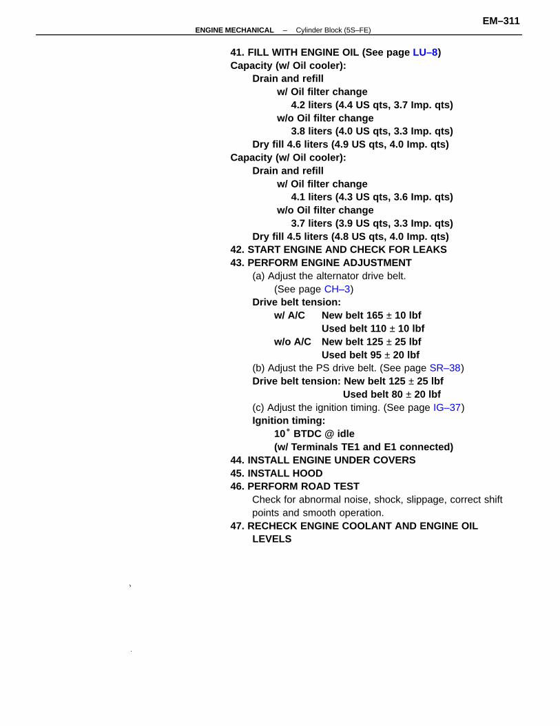
41. FILL WITH ENGINE OIL (See page LU–8)Capacity (w/ Oil cooler):
Drain and refillw/ Oil filter change
4.2 liters (4.4 US qts, 3.7 Imp. qts)w/o Oil filter change
3.8 liters (4.0 US qts, 3.3 Imp. qts)Dry fill 4.6 liters (4.9 US qts, 4.0 Imp. qts)
Capacity (w/ Oil cooler):Drain and refill
w/ Oil filter change4.1 liters (4.3 US qts, 3.6 Imp. qts)
w/o Oil filter change3.7 liters (3.9 US qts, 3.3 Imp. qts)
Dry fill 4.5 liters (4.8 US qts, 4.0 Imp. qts)42. START ENGINE AND CHECK FOR LEAKS43. PERFORM ENGINE ADJUSTMENT
(a) Adjust the alternator drive belt.(See page CH–3)
Drive belt tension:w/ A/C New belt 165 ± 10 lbf
Used belt 110 ± 10 lbfw/o A/C New belt 125 ± 25 lbf
Used belt 95 ± 20 lbf(b) Adjust the PS drive belt. (See page SR–38)Drive belt tension: New belt 125 ± 25 lbf
Used belt 80 ± 20 lbf(c) Adjust the ignition timing. (See page IG–37)Ignition timing:
10° BTDC @ idle(w/ Terminals TE1 and E1 connected)
44. INSTALL ENGINE UNDER COVERS45. INSTALL HOOD46. PERFORM ROAD TEST
Check for abnormal noise, shock, slippage, correct shiftpoints and smooth operation.
47. RECHECK ENGINE COOLANT AND ENGINE OILLEVELS
–ENGINE MECHANICAL Cylinder Block (5S–FE)EM–311
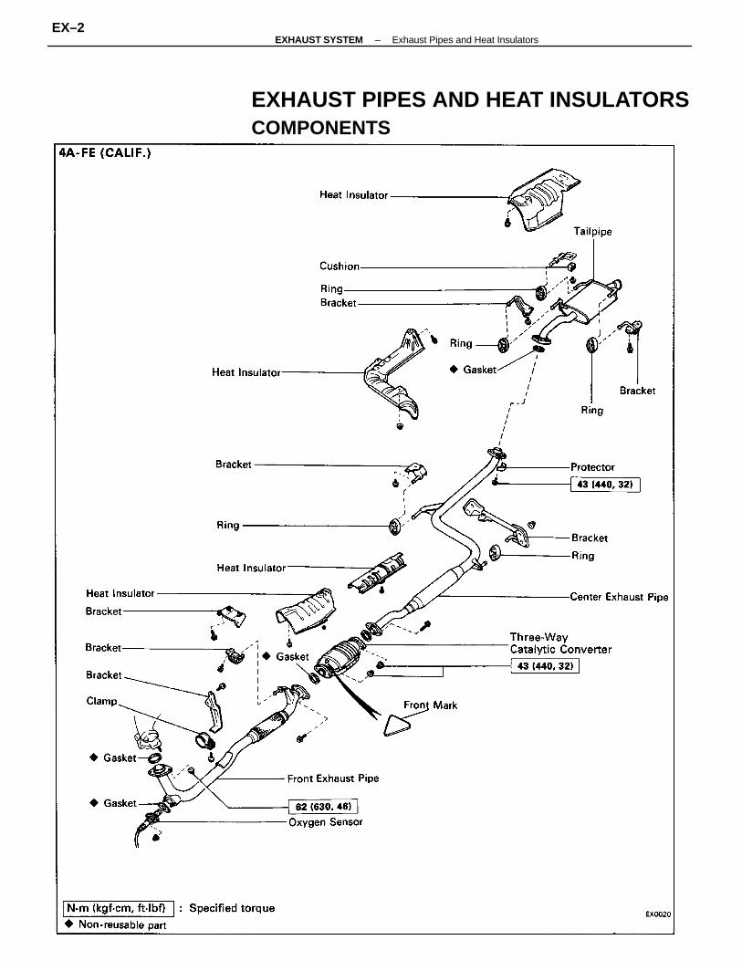
EXHAUST PIPES AND HEAT INSULATORSCOMPONENTS
–EXHAUST SYSTEM Exhaust Pipes and Heat InsulatorsEX–2
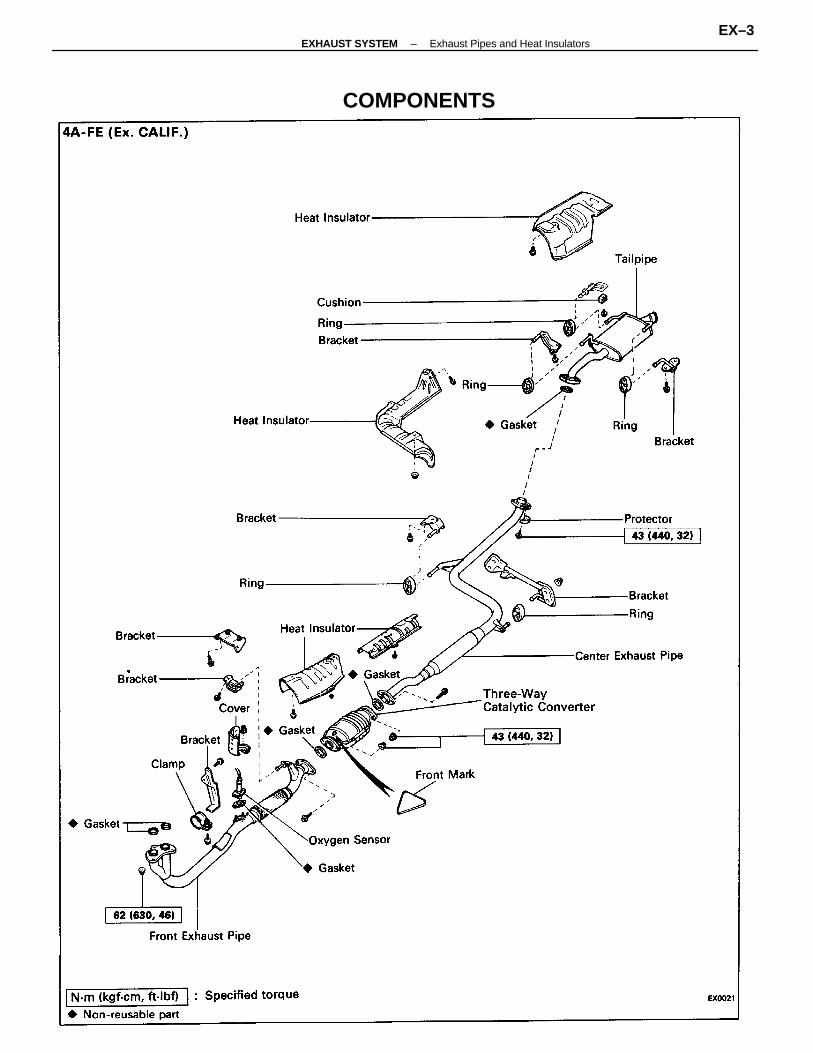
COMPONENTS
–EXHAUST SYSTEM Exhaust Pipes and Heat InsulatorsEX–3
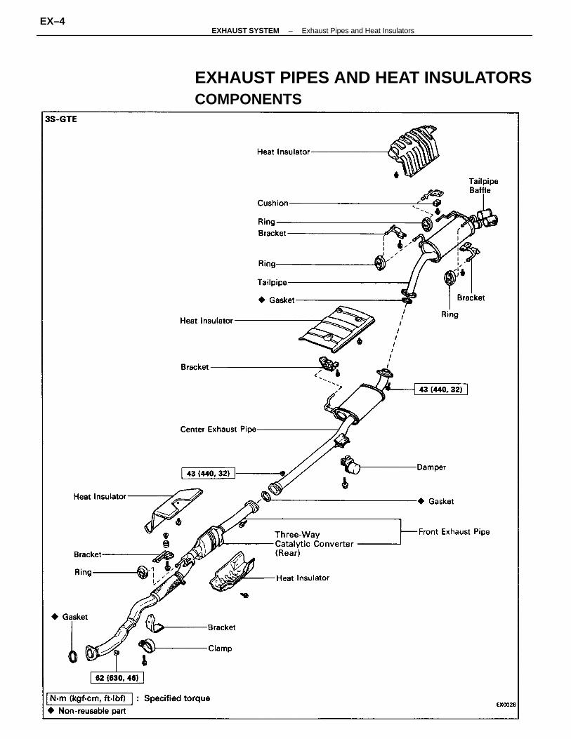
EXHAUST PIPES AND HEAT INSULATORSCOMPONENTS
–EXHAUST SYSTEM Exhaust Pipes and Heat InsulatorsEX–4
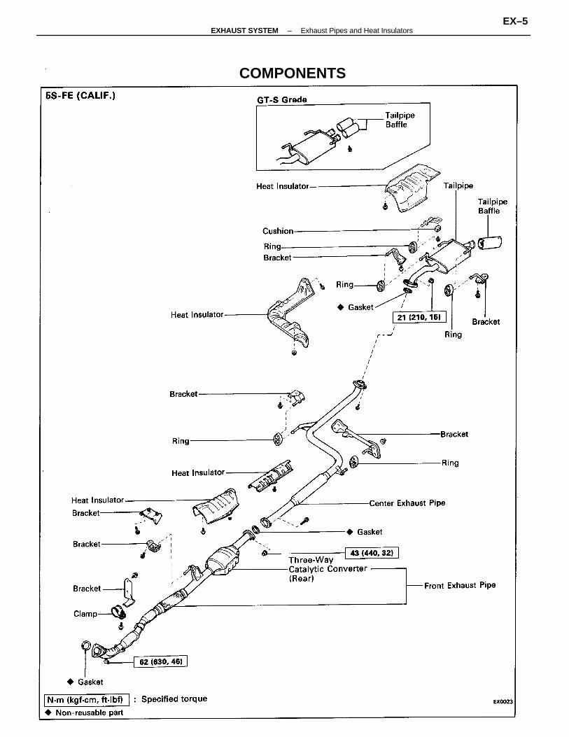
COMPONENTS
–EXHAUST SYSTEM Exhaust Pipes and Heat InsulatorsEX–5
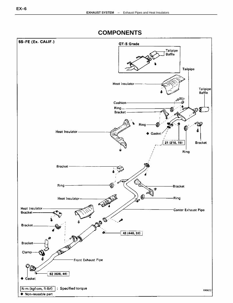
COMPONENTS
–EXHAUST SYSTEM Exhaust Pipes and Heat InsulatorsEX–6
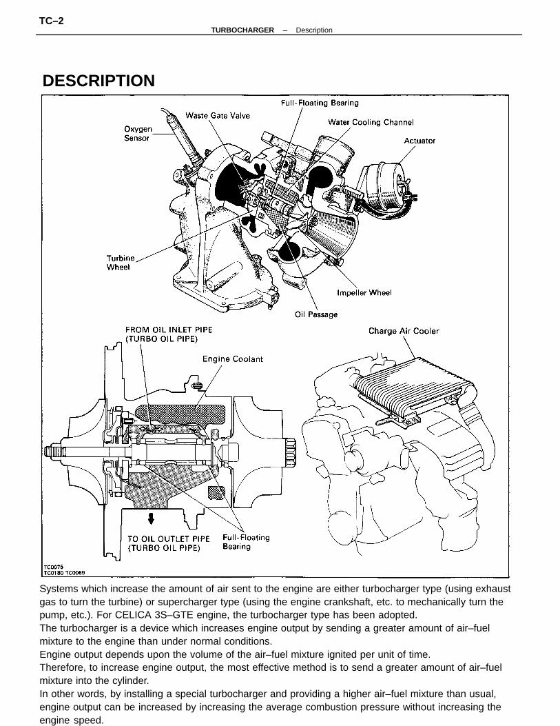
Systems which increase the amount of air sent to the engine are either turbocharger type (using exhaustgas to turn the turbine) or supercharger type (using the engine crankshaft, etc. to mechanically turn thepump, etc.). For CELICA 3S–GTE engine, the turbocharger type has been adopted.The turbocharger is a device which increases engine output by sending a greater amount of air–fuelmixture to the engine than under normal conditions.Engine output depends upon the volume of the air–fuel mixture ignited per unit of time.Therefore, to increase engine output, the most effective method is to send a greater amount of air–fuelmixture into the cylinder.In other words, by installing a special turbocharger and providing a higher air–fuel mixture than usual,engine output can be increased by increasing the average combustion pressure without increasing theengine speed.
DESCRIPTION
–TURBOCHARGER DescriptionTC–2
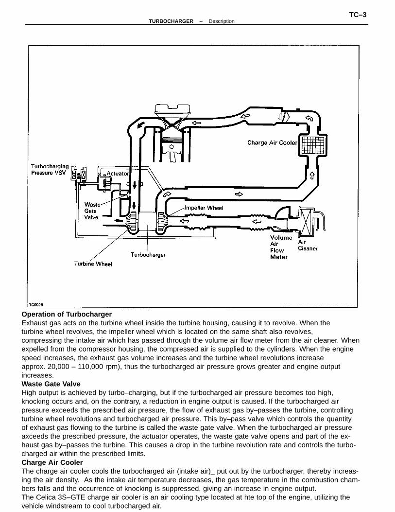
Operation of TurbochargerExhaust gas acts on the turbine wheel inside the turbine housing, causing it to revolve. When theturbine wheel revolves, the impeller wheel which is located on the same shaft also revolves,compressing the intake air which has passed through the volume air flow meter from the air cleaner. Whenexpelled from the compressor housing, the compressed air is supplied to the cylinders. When the enginespeed increases, the exhaust gas volume increases and the turbine wheel revolutions increaseapprox. 20,000 – 110,000 rpm), thus the turbocharged air pressure grows greater and engine outputincreases.Waste Gate ValveHigh output is achieved by turbo–charging, but if the turbocharged air pressure becomes too high,knocking occurs and, on the contrary, a reduction in engine output is caused. If the turbocharged airpressure exceeds the prescribed air pressure, the flow of exhaust gas by–passes the turbine, controllingturbine wheel revolutions and turbocharged air pressure. This by–pass valve which controls the quantityof exhaust gas flowing to the turbine is called the waste gate valve. When the turbocharged air pressureaxceeds the prescribed pressure, the actuator operates, the waste gate valve opens and part of the ex-haust gas by–passes the turbine. This causes a drop in the turbine revolution rate and controls the turbo-charged air within the prescribed limits.Charge Air CoolerThe charge air cooler cools the turbocharged air (intake air)_ put out by the turbocharger, thereby increas-ing the air density. As the intake air temperature decreases, the gas temperature in the combustion cham-bers falls and the occurrence of knocking is suppressed, giving an increase in engine output.The Celica 3S–GTE charge air cooler is an air cooling type located at hte top of the engine, utilizing thevehicle windstream to cool turbocharged air.
–TURBOCHARGER DescriptionTC–3
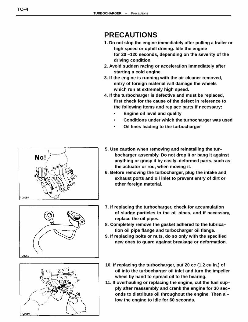
PRECAUTIONS1. Do not stop the engine immediately after pulling a trailer or
high speed or uphill driving. Idle the enginefor 20 –120 seconds, depending on the severity of thedriving condition.
2. Avoid sudden racing or acceleration immediately afterstarting a cold engine.
3. If the engine is running with the air cleaner removed,entry of foreign material will damage the wheelswhich run at extremely high speed.
4. If the turbocharger is defective and must be replaced,first check for the cause of the defect in reference tothe following items and replace parts if necessary:• Engine oil level and quality• Conditions under which the turbocharger was used• Oil lines leading to the turbocharger
7. If replacing the turbocharger, check for accumulationof sludge particles in the oil pipes, and if necessary,replace the oil pipes.
8. Completely remove the gasket adhered to the lubrica–tion oil pipe flange and turbocharger oil flange.
9. If replacing bolts or nuts, do so only with the specifiednew ones to guard against breakage or deformation.
5. Use caution when removing and reinstalling the tur–bocharger assembly. Do not drop it or bang it againstanything or grasp it by easily–deformed parts, such asthe actuator or rod, when moving it.
6. Before removing the turbocharger, plug the intake andexhaust ports and oil inlet to prevent entry of dirt orother foreign material.
10. If replacing the turbocharger, put 20 cc (1.2 cu in.) ofoil into the turbocharger oil inlet and turn the impellerwheel by hand to spread oil to the bearing.
11. If overhauling or replacing the engine, cut the fuel sup–ply after reassembly and crank the engine for 30 sec–onds to distribute oil throughout the engine. Then al–low the engine to idle for 60 seconds.
–TURBOCHARGER PrecautionsTC–4
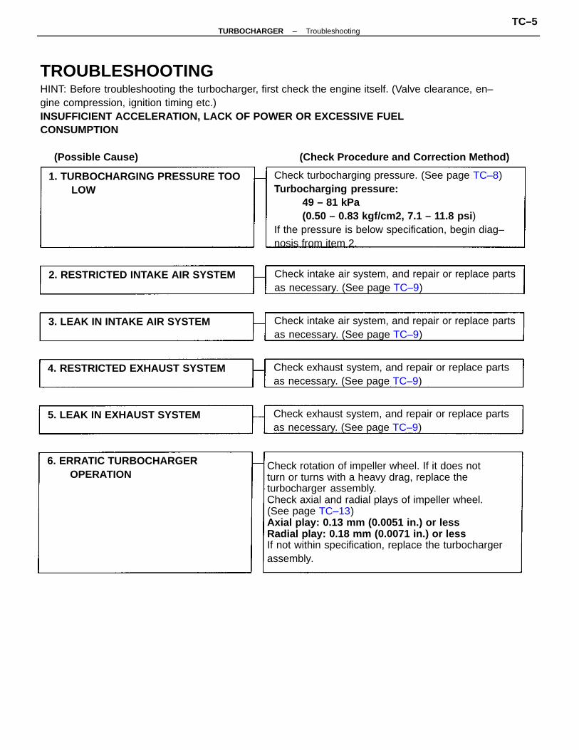
TROUBLESHOOTINGHINT: Before troubleshooting the turbocharger, first check the engine itself. (Valve clearance, en–gine compression, ignition timing etc.)INSUFFICIENT ACCELERATION, LACK OF POWER OR EXCESSIVE FUELCONSUMPTION
Check rotation of impeller wheel. If it does notturn or turns with a heavy drag, replace theturbocharger assembly.Check axial and radial plays of impeller wheel.(See page TC–13)Axial play: 0.13 mm (0.0051 in.) or lessRadial play: 0.18 mm (0.0071 in.) or lessIf not within specification, replace the turbochargerassembly.
Check turbocharging pressure. (See page TC–8)Turbocharging pressure:
49 – 81 kPa(0.50 – 0.83 kgf/cm2, 7.1 – 11.8 psi )
If the pressure is below specification, begin diag–nosis from item 2.
Check intake air system, and repair or replace partsas necessary. (See page TC–9)
Check intake air system, and repair or replace partsas necessary. (See page TC–9)
Check exhaust system, and repair or replace partsas necessary. (See page TC–9)
Check exhaust system, and repair or replace partsas necessary. (See page TC–9)
1. TURBOCHARGING PRESSURE TOOLOW
6. ERRATIC TURBOCHARGEROPERATION
2. RESTRICTED INTAKE AIR SYSTEM
4. RESTRICTED EXHAUST SYSTEM
3. LEAK IN INTAKE AIR SYSTEM
5. LEAK IN EXHAUST SYSTEM
(Possible Cause) (Check Procedure and Correction Method)
–TURBOCHARGER TroubleshootingTC–5
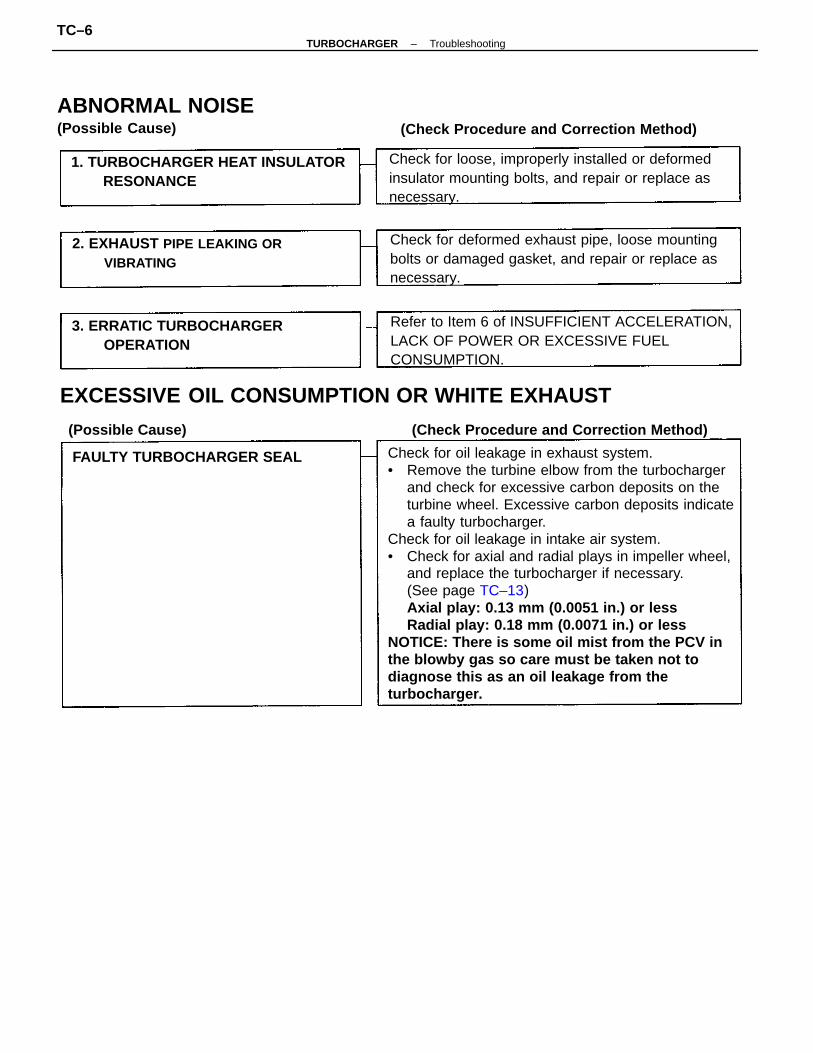
Check for oil leakage in exhaust system.• Remove the turbine elbow from the turbocharger
and check for excessive carbon deposits on theturbine wheel. Excessive carbon deposits indicatea faulty turbocharger.
Check for oil leakage in intake air system.• Check for axial and radial plays in impeller wheel,
and replace the turbocharger if necessary.(See page TC–13)Axial play: 0.13 mm (0.0051 in.) or lessRadial play: 0.18 mm (0.0071 in.) or less
NOTICE: There is some oil mist from the PCV inthe blowby gas so care must be taken not todiagnose this as an oil leakage from theturbocharger.
EXCESSIVE OIL CONSUMPTION OR WHITE EXHAUST
Refer to Item 6 of INSUFFICIENT ACCELERATION,LACK OF POWER OR EXCESSIVE FUELCONSUMPTION.
Check for deformed exhaust pipe, loose mountingbolts or damaged gasket, and repair or replace asnecessary.
Check for loose, improperly installed or deformedinsulator mounting bolts, and repair or replace asnecessary.
1. TURBOCHARGER HEAT INSULATORRESONANCE
ABNORMAL NOISE(Possible Cause)
2. EXHAUST PIPE LEAKING ORVIBRATING
3. ERRATIC TURBOCHARGEROPERATION
(Check Procedure and Correction Method)
FAULTY TURBOCHARGER SEAL
(Possible Cause) (Check Procedure and Correction Method)
–TURBOCHARGER TroubleshootingTC–6
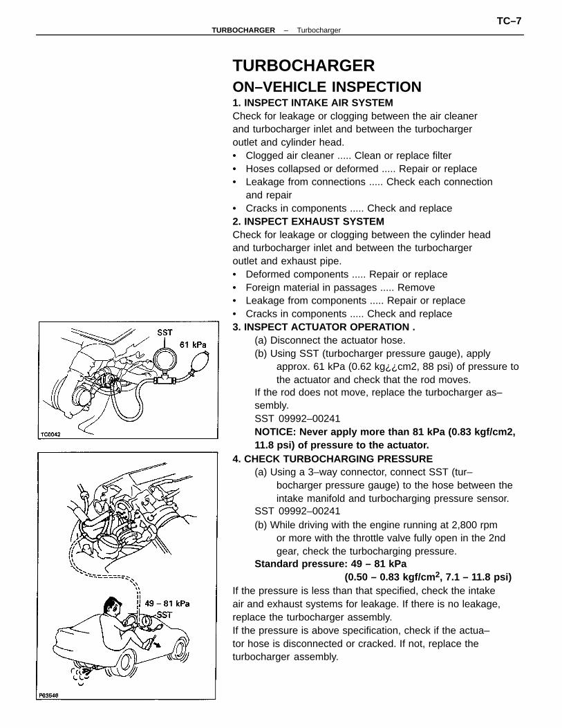
TURBOCHARGERON–VEHICLE INSPECTION1. INSPECT INTAKE AIR SYSTEMCheck for leakage or clogging between the air cleanerand turbocharger inlet and between the turbochargeroutlet and cylinder head.• Clogged air cleaner ..... Clean or replace filter• Hoses collapsed or deformed ..... Repair or replace• Leakage from connections ..... Check each connection
and repair• Cracks in components ..... Check and replace2. INSPECT EXHAUST SYSTEMCheck for leakage or clogging between the cylinder headand turbocharger inlet and between the turbochargeroutlet and exhaust pipe.• Deformed components ..... Repair or replace• Foreign material in passages ..... Remove• Leakage from components ..... Repair or replace• Cracks in components ..... Check and replace3. INSPECT ACTUATOR OPERATION .
(a) Disconnect the actuator hose.(b) Using SST (turbocharger pressure gauge), apply
approx. 61 kPa (0.62 kg¿¿cm2, 88 psi) of pressure tothe actuator and check that the rod moves.
If the rod does not move, replace the turbocharger as–sembly.SST 09992–00241NOTICE: Never apply more than 81 kPa (0.83 kgf/cm2,11.8 psi) of pressure to the actuator.
4. CHECK TURBOCHARGING PRESSURE(a) Using a 3–way connector, connect SST (tur–
bocharger pressure gauge) to the hose between theintake manifold and turbocharging pressure sensor.
SST 09992–00241(b) While driving with the engine running at 2,800 rpm
or more with the throttle valve fully open in the 2ndgear, check the turbocharging pressure.
Standard pressure: 49 – 81 kPa(0.50 – 0.83 kgf/cm 2, 7.1 – 11.8 psi)
If the pressure is less than that specified, check the intakeair and exhaust systems for leakage. If there is no leakage,replace the turbocharger assembly.If the pressure is above specification, check if the actua–tor hose is disconnected or cracked. If not, replace theturbocharger assembly.
–TURBOCHARGER TurbochargerTC–7
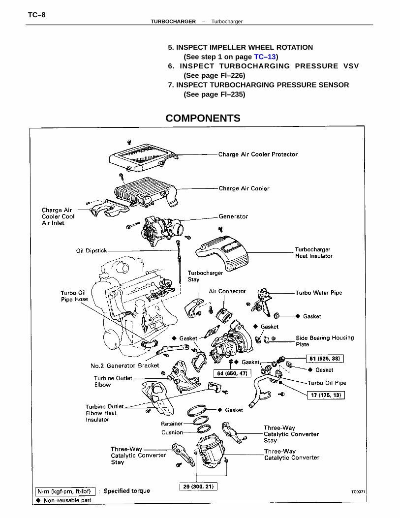
5. INSPECT IMPELLER WHEEL ROTATION(See step 1 on page TC–13)
6. INSPECT TURBOCHARGING PR ESSURE VSV(See page Fl–226)
7. INSPECT TURBOCHARGING PRESSURE SENSOR(See page Fl–235)
COMPONENTS
–TURBOCHARGER TurbochargerTC–8
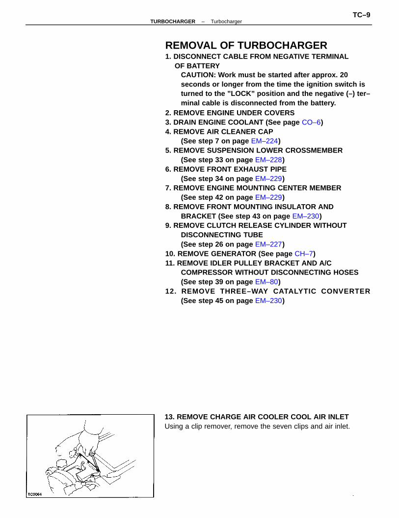
REMOVAL OF TURBOCHARGER1. DISCONNECT CABLE FROM NEGATIVE TERMINAL
OF BATTERYCAUTION: Work must be started after approx. 20seconds or longer from the time the ignition switch isturned to the ”LOCK” position and the negative (–) ter–minal cable is disconnected from the battery.
2. REMOVE ENGINE UNDER COVERS3. DRAIN ENGINE COOLANT (See page CO–6)4. REMOVE AIR CLEANER CAP
(See step 7 on page EM–224)5. REMOVE SUSPENSION LOWER CROSSMEMBER
(See step 33 on page EM–228)6. REMOVE FRONT EXHAUST PIPE
(See step 34 on page EM–229)7. REMOVE ENGINE MOUNTING CENTER MEMBER
(See step 42 on page EM–229)8. REMOVE FRONT MOUNTING INSULATOR AND
BRACKET (See step 43 on page EM–230)9. REMOVE CLUTCH RELEASE CYLINDER WITHOUT
DISCONNECTING TUBE(See step 26 on page EM–227)
10. REMOVE GENERATOR (See page CH–7)11. REMOVE IDLER PULLEY BRACKET AND A/C
COMPRESSOR WITHOUT DISCONNECTING HOSES(See step 39 on page EM–80)
12. REMOVE THREE–WAY CATALYTIC CONVERTER(See step 45 on page EM–230)
13. REMOVE CHARGE AIR COOLER COOL AIR INLETUsing a clip remover, remove the seven clips and air inlet.
–TURBOCHARGER TurbochargerTC–9
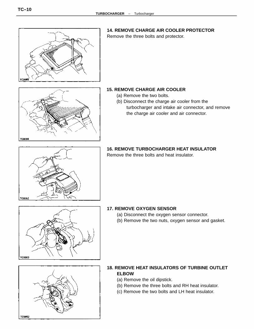
18. REMOVE HEAT INSULATORS OF TURBINE OUTLETELBOW(a) Remove the oil dipstick.(b) Remove the three bolts and RH heat insulator.(c) Remove the two bolts and LH heat insulator.
15. REMOVE CHARGE AIR COOLER(a) Remove the two bolts.(b) Disconnect the charge air cooler from the
turbocharger and intake air connector, and removethe charge air cooler and air connector.
17. REMOVE OXYGEN SENSOR(a) Disconnect the oxygen sensor connector.(b) Remove the two nuts, oxygen sensor and gasket.
16. REMOVE TURBOCHARGER HEAT INSULATORRemove the three bolts and heat insulator.
14. REMOVE CHARGE AIR COOLER PROTECTORRemove the three bolts and protector.
–TURBOCHARGER TurbochargerTC–10
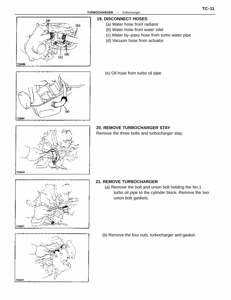
19. DISCONNECT HOSES(a) Water hose from radiator(b) Water hose from water inlet(c) Water by–pass hose from turbo water pipe(d) Vacuum hose from actuator
21. REMOVE TURBOCHARGER(a) Remove the bolt and union bolt holding the No.1
turbo oil pipe to the cylinder block. Remove the twounion bolt gaskets.
20. REMOVE TURBOCHARGER STAYRemove the three bolts and turbocharger stay.
(b) Remove the four nuts, turbocharger and gasket.
(e) Oil hose from turbo oil pipe
–TURBOCHARGER TurbochargerTC–11
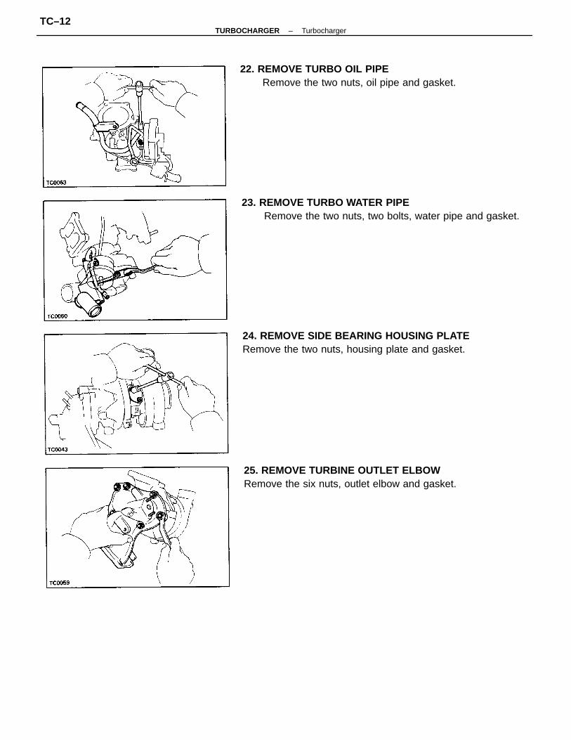
23. REMOVE TURBO WATER PIPERemove the two nuts, two bolts, water pipe and gasket.
24. REMOVE SIDE BEARING HOUSING PLATERemove the two nuts, housing plate and gasket.
25. REMOVE TURBINE OUTLET ELBOWRemove the six nuts, outlet elbow and gasket.
22. REMOVE TURBO OIL PIPERemove the two nuts, oil pipe and gasket.
–TURBOCHARGER TurbochargerTC–12
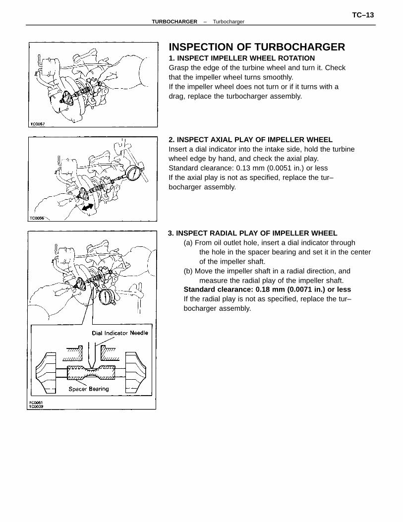
3. INSPECT RADIAL PLAY OF IMPELLER WHEEL(a) From oil outlet hole, insert a dial indicator through
the hole in the spacer bearing and set it in the centerof the impeller shaft.
(b) Move the impeller shaft in a radial direction, andmeasure the radial play of the impeller shaft.
Standard clearance: 0.18 mm (0.0071 in.) or lessIf the radial play is not as specified, replace the tur–bocharger assembly.
INSPECTION OF TURBOCHARGER1. INSPECT IMPELLER WHEEL ROTATIONGrasp the edge of the turbine wheel and turn it. Checkthat the impeller wheel turns smoothly.If the impeller wheel does not turn or if it turns with adrag, replace the turbocharger assembly.
2. INSPECT AXIAL PLAY OF IMPELLER WHEELInsert a dial indicator into the intake side, hold the turbinewheel edge by hand, and check the axial play.Standard clearance: 0.13 mm (0.0051 in.) or lessIf the axial play is not as specified, replace the tur–bocharger assembly.
–TURBOCHARGER TurbochargerTC–13
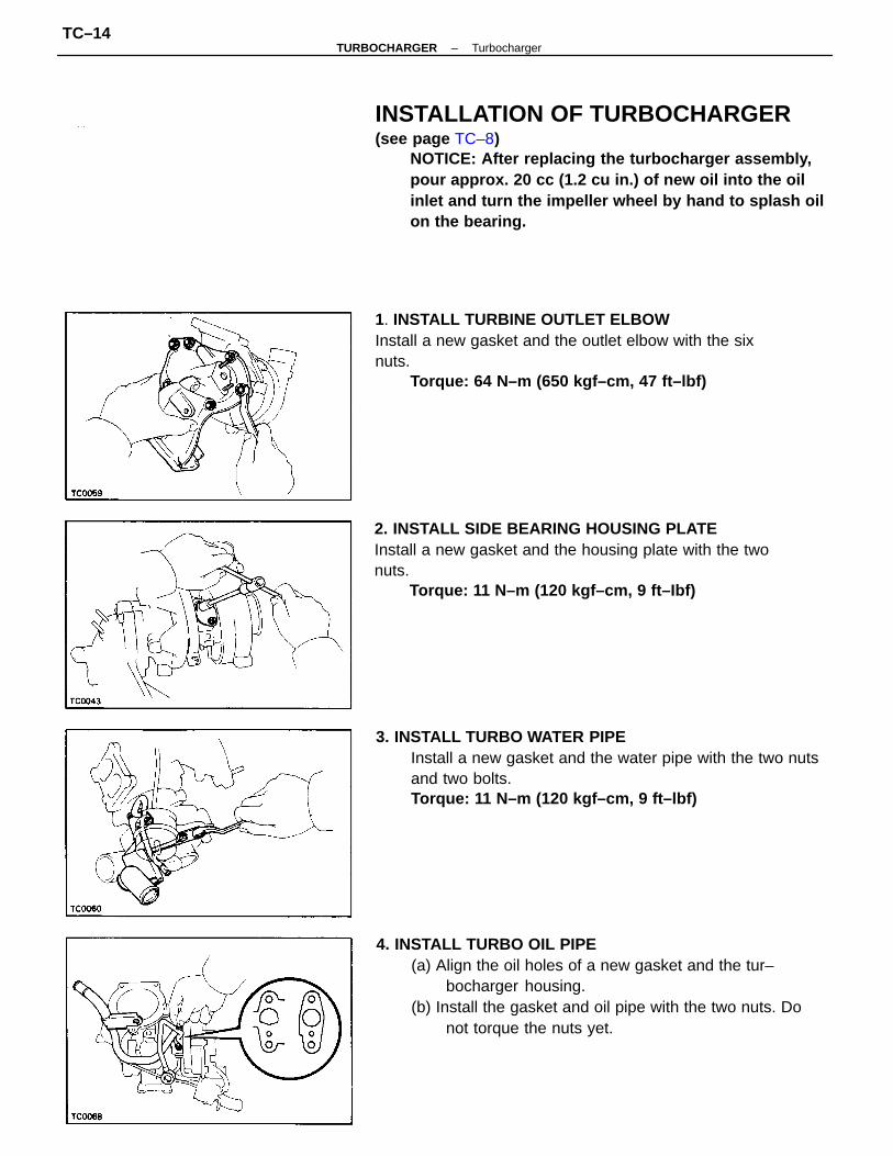
INSTALLATION OF TURBOCHARGER(see page TC–8)
NOTICE: After replacing the turbocharger assembly,pour approx. 20 cc (1.2 cu in.) of new oil into the oilinlet and turn the impeller wheel by hand to splash oilon the bearing.
4. INSTALL TURBO OIL PIPE(a) Align the oil holes of a new gasket and the tur–
bocharger housing.(b) Install the gasket and oil pipe with the two nuts. Do
not torque the nuts yet.
3. INSTALL TURBO WATER PIPEInstall a new gasket and the water pipe with the two nutsand two bolts.Torque: 11 N–m (120 kgf–cm, 9 ft–lbf)
2. INSTALL SIDE BEARING HOUSING PLATEInstall a new gasket and the housing plate with the twonuts.
Torque: 11 N–m (120 kgf–cm, 9 ft–Ibf)
1. INSTALL TURBINE OUTLET ELBOWInstall a new gasket and the outlet elbow with the sixnuts.
Torque: 64 N–m (650 kgf–cm, 47 ft–lbf)
–TURBOCHARGER TurbochargerTC–14
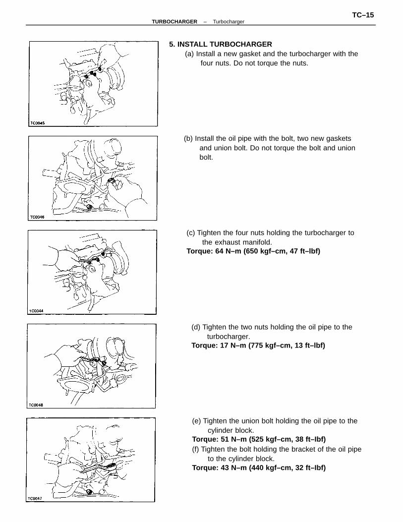
(e) Tighten the union bolt holding the oil pipe to thecylinder block.
Torque: 51 N–m (525 kgf–cm, 38 ft–Ibf)(f) Tighten the bolt holding the bracket of the oil pipe
to the cylinder block.Torque: 43 N–m (440 kgf–cm, 32 ft–Ibf)
5. INSTALL TURBOCHARGER(a) Install a new gasket and the turbocharger with the
four nuts. Do not torque the nuts.
(c) Tighten the four nuts holding the turbocharger tothe exhaust manifold.
Torque: 64 N–m (650 kgf–cm, 47 ft–lbf)
(d) Tighten the two nuts holding the oil pipe to theturbocharger.
Torque: 17 N–m (775 kgf–cm, 13 ft–lbf)
(b) Install the oil pipe with the bolt, two new gasketsand union bolt. Do not torque the bolt and unionbolt.
–TURBOCHARGER TurbochargerTC–15
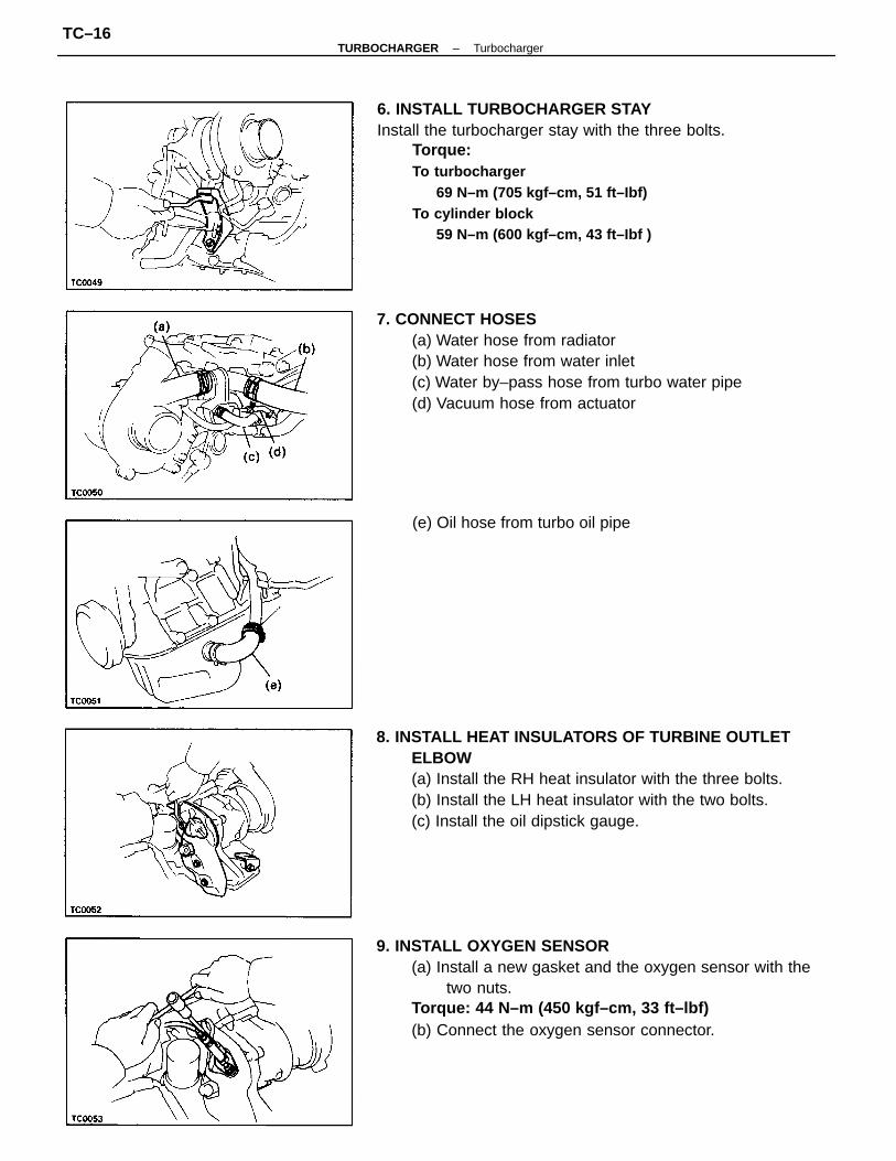
6. INSTALL TURBOCHARGER STAYInstall the turbocharger stay with the three bolts.
Torque:To turbocharger
69 N–m (705 kgf–cm, 51 ft–Ibf)To cylinder block
59 N–m (600 kgf–cm, 43 ft–Ibf )
9. INSTALL OXYGEN SENSOR(a) Install a new gasket and the oxygen sensor with the
two nuts.Torque: 44 N–m (450 kgf–cm, 33 ft–lbf)(b) Connect the oxygen sensor connector.
8. INSTALL HEAT INSULATORS OF TURBINE OUTLETELBOW(a) Install the RH heat insulator with the three bolts.(b) Install the LH heat insulator with the two bolts.(c) Install the oil dipstick gauge.
7. CONNECT HOSES(a) Water hose from radiator(b) Water hose from water inlet(c) Water by–pass hose from turbo water pipe(d) Vacuum hose from actuator
(e) Oil hose from turbo oil pipe
–TURBOCHARGER TurbochargerTC–16
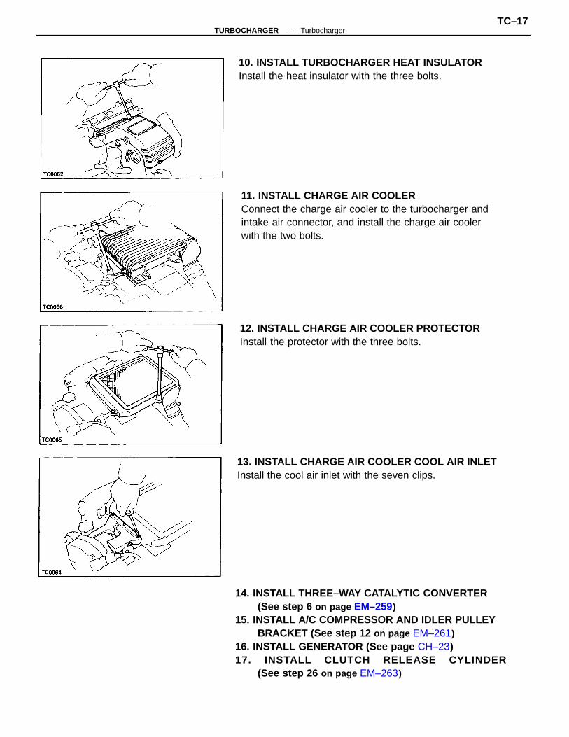
14. INSTALL THREE–WAY CATALYTIC CONVERTER(See step 6 on page EM–259)
15. INSTALL A/C COMPRESSOR AND IDLER PULLEYBRACKET (See step 12 on page EM–261)
16. INSTALL GENERATOR (See page CH–23)17. INSTALL CLUTCH RELEASE CYLINDER
(See step 26 on page EM–263)
11. INSTALL CHARGE AIR COOLERConnect the charge air cooler to the turbocharger andintake air connector, and install the charge air coolerwith the two bolts.
13. INSTALL CHARGE AIR COOLER COOL AIR INLETInstall the cool air inlet with the seven clips.
10. INSTALL TURBOCHARGER HEAT INSULATORInstall the heat insulator with the three bolts.
12. INSTALL CHARGE AIR COOLER PROTECTORInstall the protector with the three bolts.
–TURBOCHARGER TurbochargerTC–17
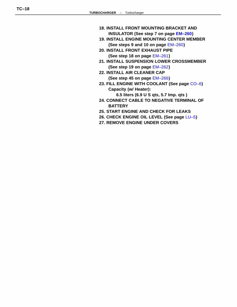
18. INSTALL FRONT MOUNTING BRACKET ANDINSULATOR (See step 7 on page EM–260)
19. INSTALL ENGINE MOUNTING CENTER MEMBER(See steps 9 and 10 on page EM–260)
20. INSTALL FRONT EXHAUST PIPE(See step 18 on page EM–261)
21. INSTALL SUSPENSION LOWER CROSSMEMBER(See step 19 on page EM–262)
22. INSTALL AIR CLEANER CAP(See step 45 on page EM–266)
23. FILL ENGINE WITH COOLANT (See page CO–6)Capacity (w/ Heater):
6.5 liters (6.9 U S qts, 5.7 Imp. qts )24. CONNECT CABLE TO NEGATIVE TERMINAL OF
BATTERY25. START ENGINE AND CHECK FOR LEAKS26. CHECK ENGINE OIL LEVEL (See page LU–5)27. REMOVE ENGINE UNDER COVERS
–TURBOCHARGER TurbochargerTC–18
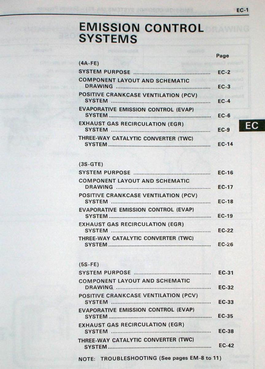
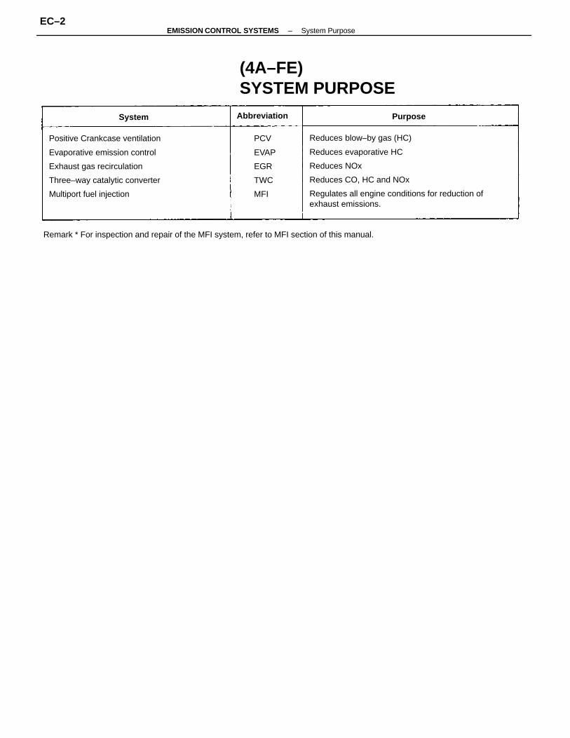
Reduces blow–by gas (HC)
Reduces evaporative HC
Reduces NOx
Reduces CO, HC and NOx
Regulates all engine conditions for reduction ofexhaust emissions.
Positive Crankcase ventilation
Evaporative emission control
Exhaust gas recirculation
Three–way catalytic converter
Multiport fuel injection
Remark * For inspection and repair of the MFI system, refer to MFI section of this manual.
(4A–FE)SYSTEM PURPOSE
PCV
EVAP
EGR
TWC
MFI
Abbreviation PurposeSystem
–EMISSION CONTROL SYSTEMS System PurposeEC–2
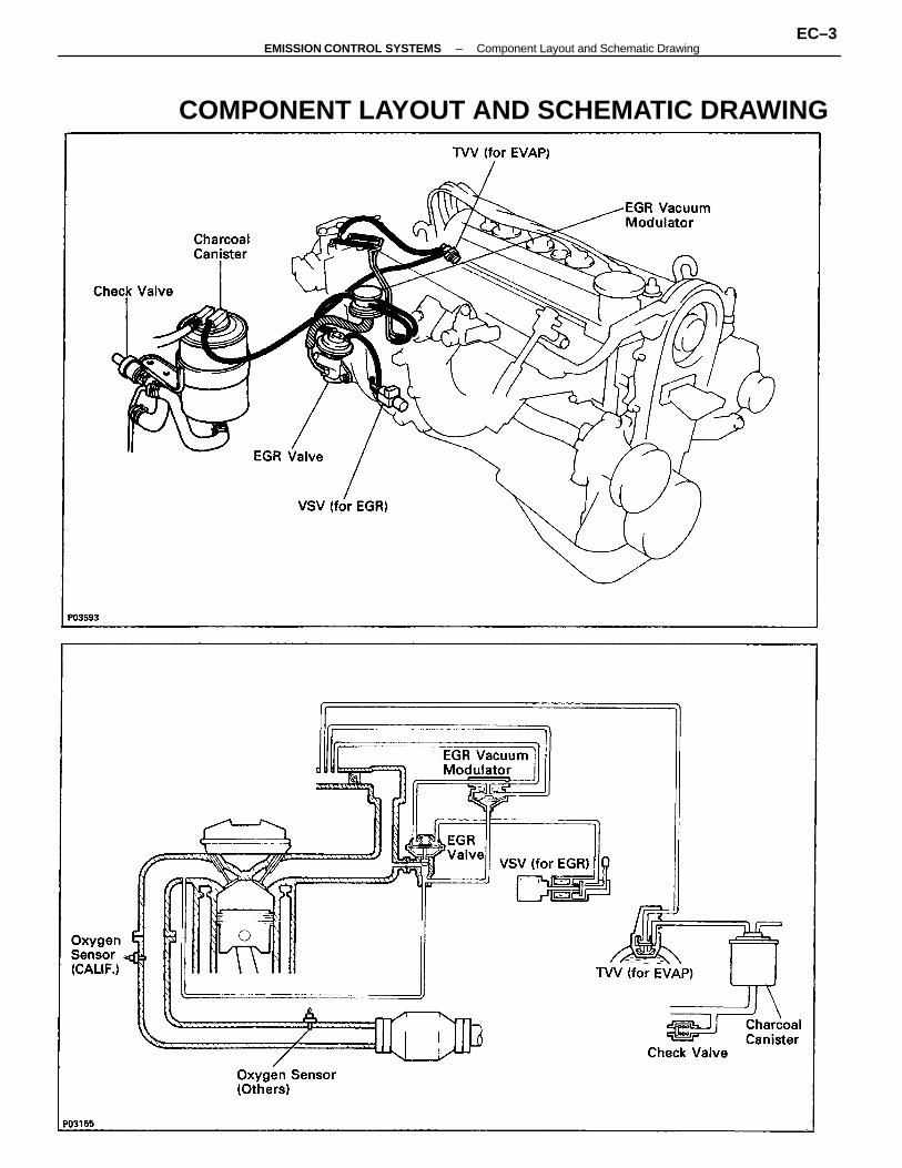
COMPONENT LAYOUT AND SCHEMATIC DRAWING
–EMISSION CONTROL SYSTEMS Component Layout and Schematic DrawingEC–3
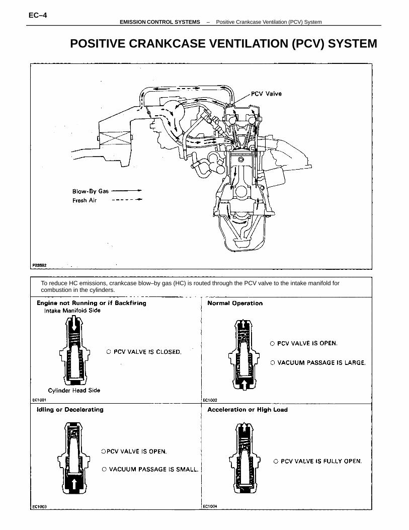
POSITIVE CRANKCASE VENTILATION (PCV) SYSTEM
To reduce HC emissions, crankcase blow–by gas (HC) is routed through the PCV valve to the intake manifold forcombustion in the cylinders.
–EMISSION CONTROL SYSTEMS Positive Crankcase Ventilation (PCV) SystemEC–4
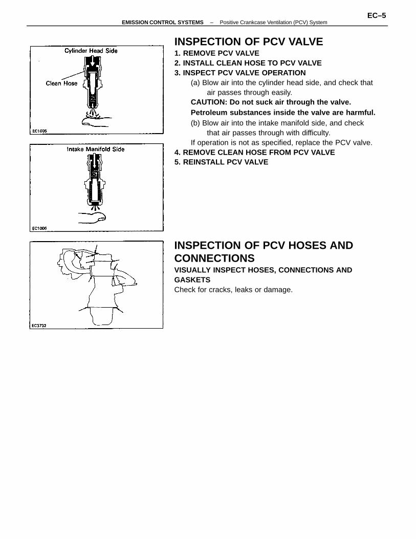
INSPECTION OF PCV VALVE1. REMOVE PCV VALVE2. INSTALL CLEAN HOSE TO PCV VALVE3. INSPECT PCV VALVE OPERATION
(a) Blow air into the cylinder head side, and check thatair passes through easily.
CAUTION: Do not suck air through the valve.Petroleum substances inside the valve are harmful.(b) Blow air into the intake manifold side, and check
that air passes through with difficulty.If operation is not as specified, replace the PCV valve.
4. REMOVE CLEAN HOSE FROM PCV VALVE5. REINSTALL PCV VALVE
INSPECTION OF PCV HOSES ANDCONNECTIONSVISUALLY INSPECT HOSES, CONNECTIONS ANDGASKETSCheck for cracks, leaks or damage.
–EMISSION CONTROL SYSTEMS Positive Crankcase Ventilation (PCV) SystemEC–5
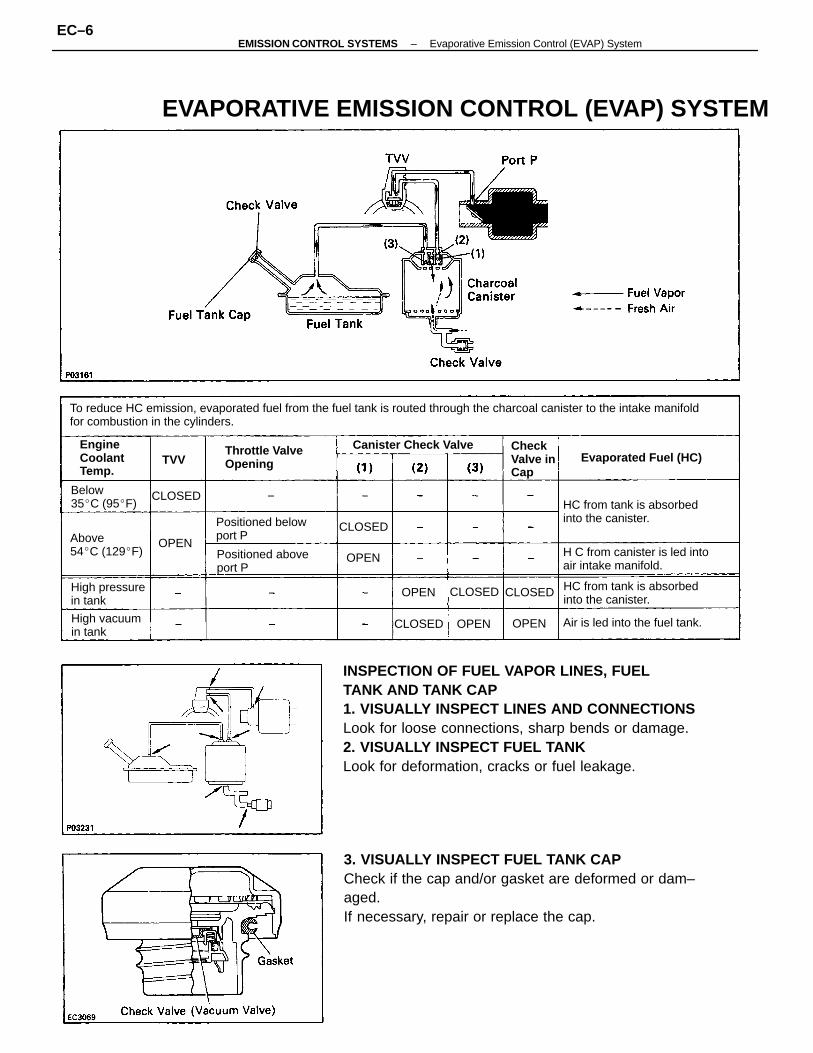
INSPECTION OF FUEL VAPOR LINES, FUELTANK AND TANK CAP1. VISUALLY INSPECT LINES AND CONNECTIONSLook for loose connections, sharp bends or damage.2. VISUALLY INSPECT FUEL TANKLook for deformation, cracks or fuel leakage.
3. VISUALLY INSPECT FUEL TANK CAPCheck if the cap and/or gasket are deformed or dam–aged.If necessary, repair or replace the cap.
To reduce HC emission, evaporated fuel from the fuel tank is routed through the charcoal canister to the intake manifoldfor combustion in the cylinders.
EVAPORATIVE EMISSION CONTROL (EVAP) SYSTEM
H C from canister is led intoair intake manifold.
HC from tank is absorbedinto the canister.
HC from tank is absorbedinto the canister.
Positioned belowport P
Positioned aboveport P
Air is led into the fuel tank.
Throttle ValveOpening Evaporated Fuel (HC)
Canister Check Valve
Above54C (129F)
High pressurein tank
High vacuumin tank
CheckValve inCap
Below35C (95F)
EngineCoolantTemp.
CLOSED
CLOSED
CLOSED
CLOSED
CLOSED
OPENOPEN
OPEN
OPEN
OPEN
TVV
–EMISSION CONTROL SYSTEMS Evaporative Emission Control (EVAP) SystemEC–6
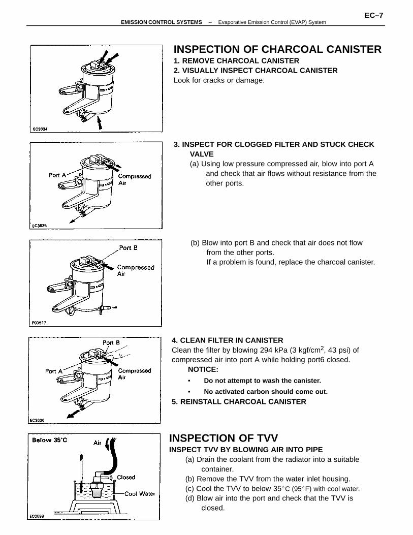
INSPECTION OF TVVINSPECT TVV BY BLOWING AIR INTO PIPE
(a) Drain the coolant from the radiator into a suitablecontainer.
(b) Remove the TVV from the water inlet housing.(c) Cool the TVV to below 35C (95F) with cool water.(d) Blow air into the port and check that the TVV is
closed.
4. CLEAN FILTER IN CANISTERClean the filter by blowing 294 kPa (3 kgf/cm2, 43 psi) ofcompressed air into port A while holding port6 closed.
NOTICE:• Do not attempt to wash the canister.
• No activated carbon should come out.
5. REINSTALL CHARCOAL CANISTER
3. INSPECT FOR CLOGGED FILTER AND STUCK CHECKVALVE(a) Using low pressure compressed air, blow into port A
and check that air flows without resistance from theother ports.
INSPECTION OF CHARCOAL CANISTER1. REMOVE CHARCOAL CANISTER2. VISUALLY INSPECT CHARCOAL CANISTERLook for cracks or damage.
(b) Blow into port B and check that air does not flowfrom the other ports.If a problem is found, replace the charcoal canister.
–EMISSION CONTROL SYSTEMS Evaporative Emission Control (EVAP) SystemEC–7
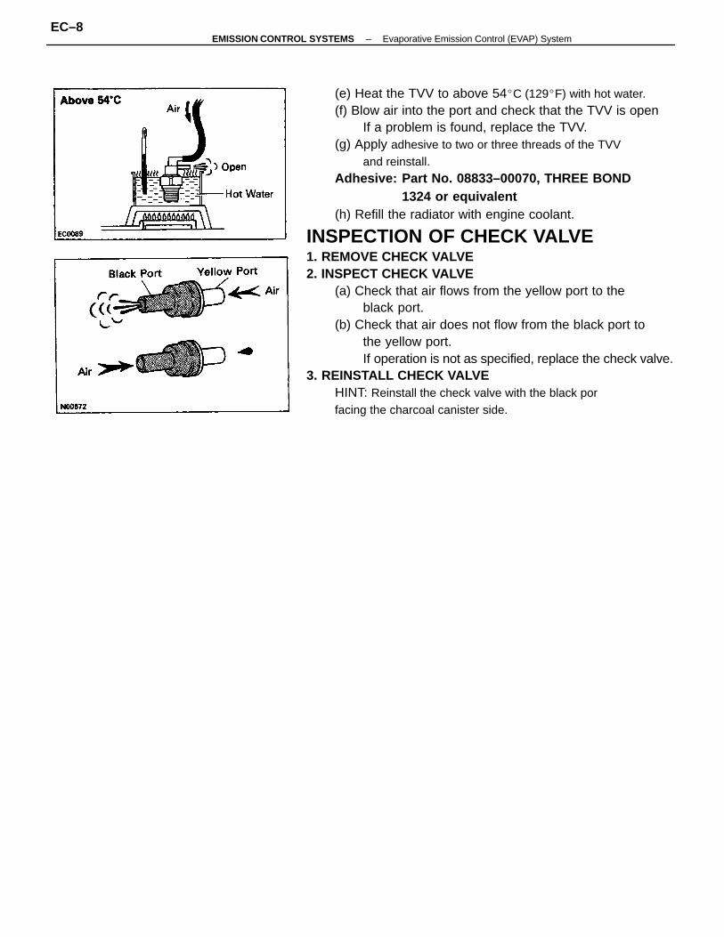
(e) Heat the TVV to above 54C (129F) with hot water.(f) Blow air into the port and check that the TVV is open
If a problem is found, replace the TVV.(g) Apply adhesive to two or three threads of the TVV
and reinstall.Adhesive: Part No. 08833–00070, THREE BOND
1324 or equivalent(h) Refill the radiator with engine coolant.
INSPECTION OF CHECK VALVE1. REMOVE CHECK VALVE2. INSPECT CHECK VALVE
(a) Check that air flows from the yellow port to theblack port.
(b) Check that air does not flow from the black port tothe yellow port.If operation is not as specified, replace the check valve.
3. REINSTALL CHECK VALVEHINT: Reinstall the check valve with the black porfacing the charcoal canister side.
–EMISSION CONTROL SYSTEMS Evaporative Emission Control (EVAP) SystemEC–8
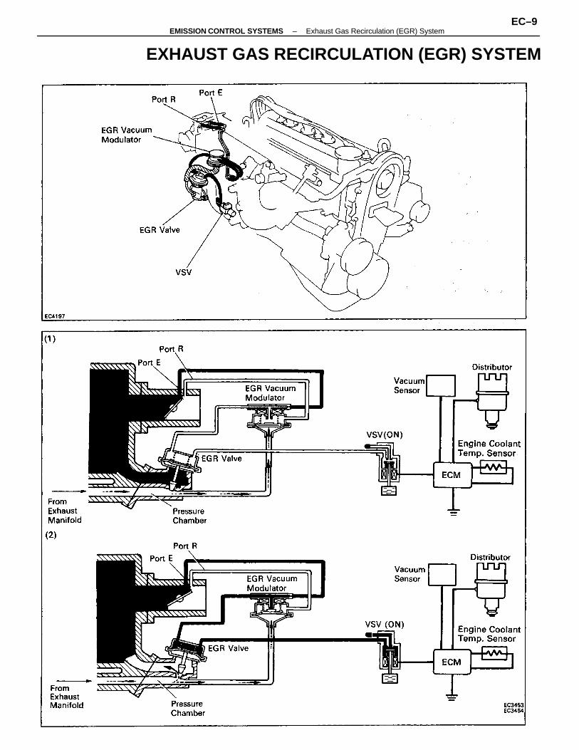
EXHAUST GAS RECIRCULATION (EGR) SYSTEM
–EMISSION CONTROL SYSTEMS Exhaust Gas Recirculation (EGR) SystemEC–9
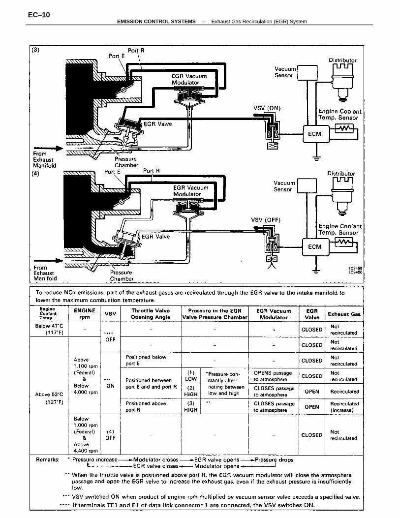
–EMISSION CONTROL SYSTEMS Exhaust Gas Recirculation (EGR) SystemEC–10
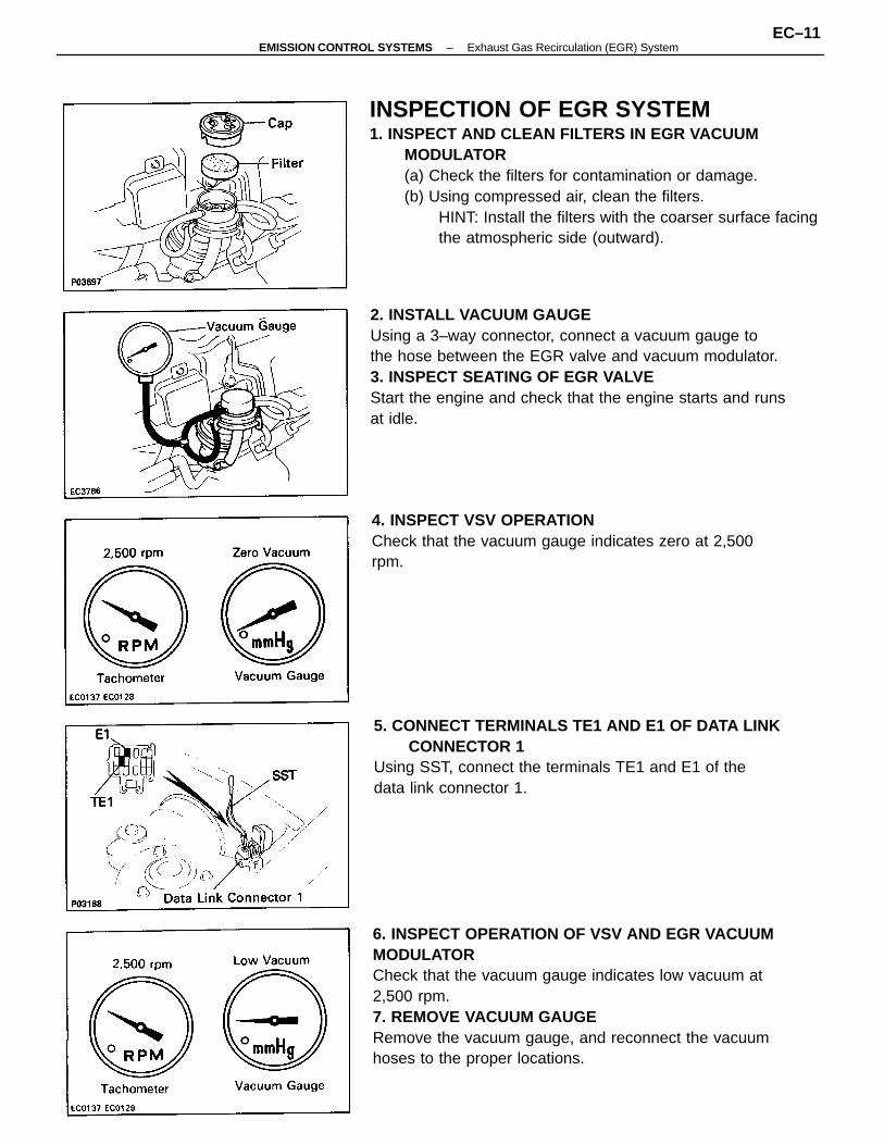
INSPECTION OF EGR SYSTEM1. INSPECT AND CLEAN FILTERS IN EGR VACUUM
MODULATOR(a) Check the filters for contamination or damage.(b) Using compressed air, clean the filters.
HINT: Install the filters with the coarser surface facingthe atmospheric side (outward).
6. INSPECT OPERATION OF VSV AND EGR VACUUMMODULATORCheck that the vacuum gauge indicates low vacuum at2,500 rpm.7. REMOVE VACUUM GAUGERemove the vacuum gauge, and reconnect the vacuumhoses to the proper locations.
2. INSTALL VACUUM GAUGEUsing a 3–way connector, connect a vacuum gauge tothe hose between the EGR valve and vacuum modulator.3. INSPECT SEATING OF EGR VALVEStart the engine and check that the engine starts and runsat idle.
5. CONNECT TERMINALS TE1 AND E1 OF DATA LINKCONNECTOR 1
Using SST, connect the terminals TE1 and E1 of thedata link connector 1.
4. INSPECT VSV OPERATIONCheck that the vacuum gauge indicates zero at 2,500rpm.
–EMISSION CONTROL SYSTEMS Exhaust Gas Recirculation (EGR) SystemEC–11
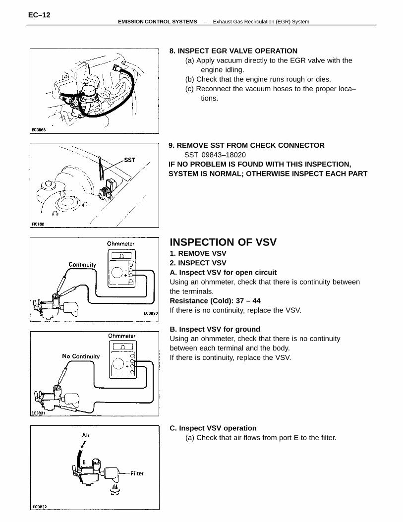
INSPECTION OF VSV1. REMOVE VSV2. INSPECT VSVA. Inspect VSV for open circuitUsing an ohmmeter, check that there is continuity betweenthe terminals.Resistance (Cold): 37 – 44
If there is no continuity, replace the VSV.
B. Inspect VSV for groundUsing an ohmmeter, check that there is no continuitybetween each terminal and the body.If there is continuity, replace the VSV.
8. INSPECT EGR VALVE OPERATION(a) Apply vacuum directly to the EGR valve with the
engine idling.(b) Check that the engine runs rough or dies.(c) Reconnect the vacuum hoses to the proper loca–
tions.
9. REMOVE SST FROM CHECK CONNECTORSST 09843–18020
IF NO PROBLEM IS FOUND WITH THIS INSPECTION,SYSTEM IS NORMAL; OTHERWISE INSPECT EACH PART
C. Inspect VSV operation(a) Check that air flows from port E to the filter.
–EMISSION CONTROL SYSTEMS Exhaust Gas Recirculation (EGR) SystemEC–12
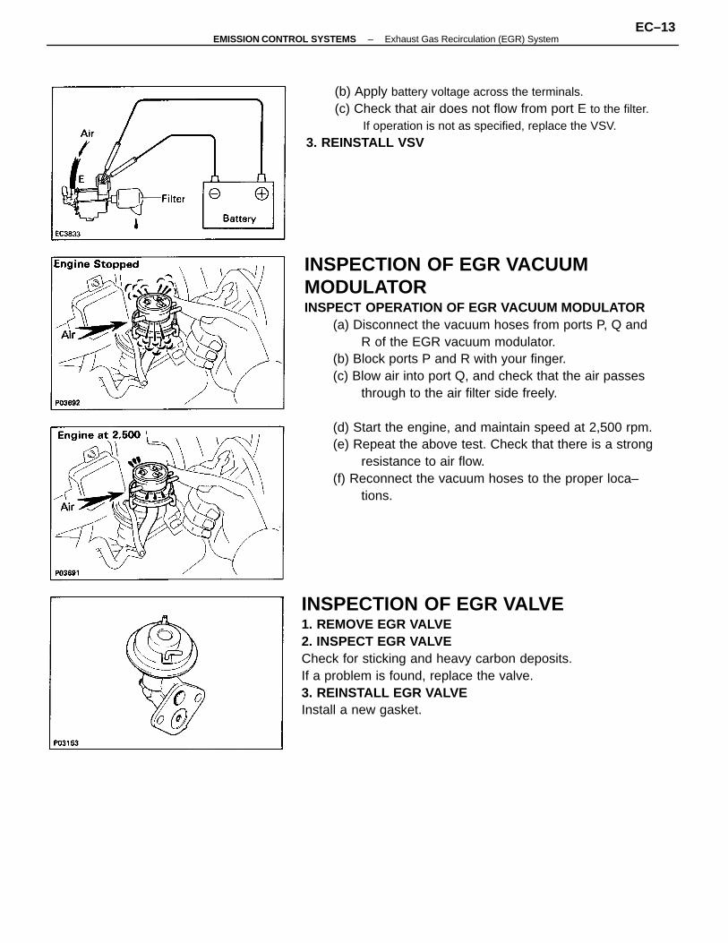
INSPECTION OF EGR VACUUMMODULATORINSPECT OPERATION OF EGR VACUUM MODULATOR
(a) Disconnect the vacuum hoses from ports P, Q andR of the EGR vacuum modulator.
(b) Block ports P and R with your finger.(c) Blow air into port Q, and check that the air passes
through to the air filter side freely.
(d) Start the engine, and maintain speed at 2,500 rpm.(e) Repeat the above test. Check that there is a strong
resistance to air flow.(f) Reconnect the vacuum hoses to the proper loca–
tions.
INSPECTION OF EGR VALVE1. REMOVE EGR VALVE2. INSPECT EGR VALVECheck for sticking and heavy carbon deposits.If a problem is found, replace the valve.3. REINSTALL EGR VALVEInstall a new gasket.
(b) Apply battery voltage across the terminals.(c) Check that air does not flow from port E to the filter.
If operation is not as specified, replace the VSV.3. REINSTALL VSV
–EMISSION CONTROL SYSTEMS Exhaust Gas Recirculation (EGR) SystemEC–13
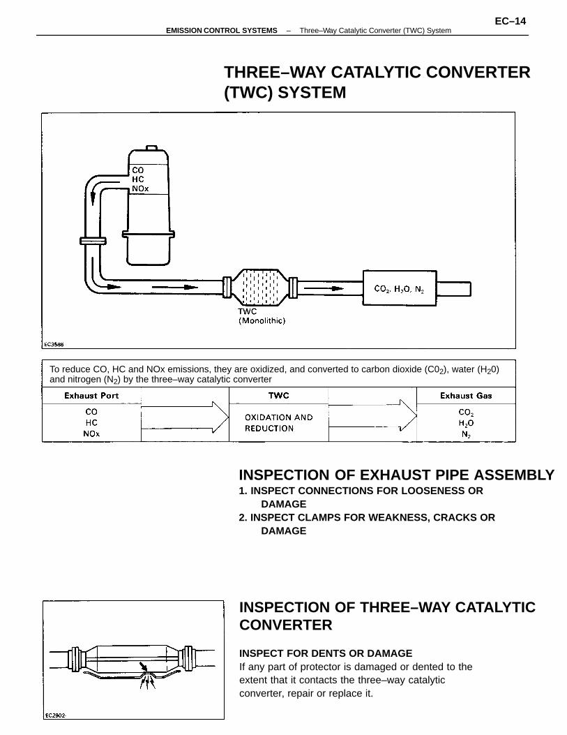
INSPECTION OF THREE–WAY CATALYTICCONVERTER
INSPECT FOR DENTS OR DAMAGEIf any part of protector is damaged or dented to theextent that it contacts the three–way catalyticconverter, repair or replace it.
INSPECTION OF EXHAUST PIPE ASSEMBLY1. INSPECT CONNECTIONS FOR LOOSENESS OR
DAMAGE2. INSPECT CLAMPS FOR WEAKNESS, CRACKS OR
DAMAGE
To reduce CO, HC and NOx emissions, they are oxidized, and converted to carbon dioxide (C02), water (H20)and nitrogen (N2) by the three–way catalytic converter
THREE–WAY CATALYTIC CONVERTER(TWC) SYSTEM
–EMISSION CONTROL SYSTEMS Three–Way Catalytic Converter (TWC) SystemEC–14
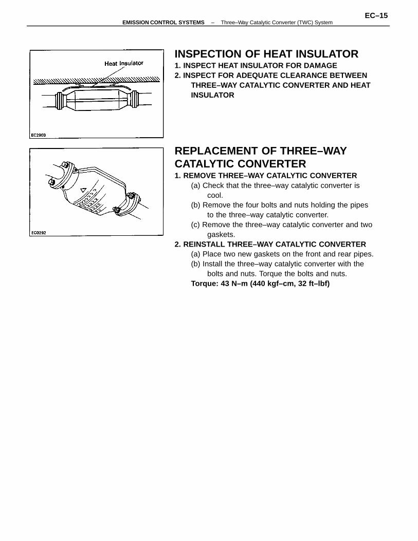
REPLACEMENT OF THREE–WAYCATALYTIC CONVERTER1. REMOVE THREE–WAY CATALYTIC CONVERTER
(a) Check that the three–way catalytic converter iscool.
(b) Remove the four bolts and nuts holding the pipesto the three–way catalytic converter.
(c) Remove the three–way catalytic converter and twogaskets.
2. REINSTALL THREE–WAY CATALYTIC CONVERTER(a) Place two new gaskets on the front and rear pipes.(b) Install the three–way catalytic converter with the
bolts and nuts. Torque the bolts and nuts.Torque: 43 N–m (440 kgf–cm, 32 ft–lbf)
INSPECTION OF HEAT INSULATOR1. INSPECT HEAT INSULATOR FOR DAMAGE2. INSPECT FOR ADEQUATE CLEARANCE BETWEEN
THREE–WAY CATALYTIC CONVERTER AND HEATINSULATOR
–EMISSION CONTROL SYSTEMS Three–Way Catalytic Converter (TWC) SystemEC–15
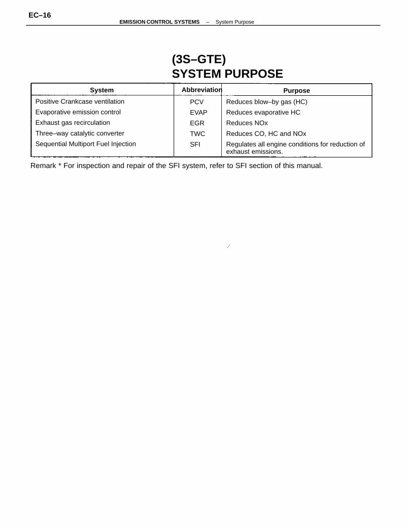
Reduces blow–by gas (HC)
Reduces evaporative HC
Reduces NOx
Reduces CO, HC and NOx
Regulates all engine conditions for reduction ofexhaust emissions.
Positive Crankcase ventilation
Evaporative emission control
Exhaust gas recirculation
Three–way catalytic converter
Sequential Multiport Fuel Injection
Remark * For inspection and repair of the SFI system, refer to SFI section of this manual.
(3S–GTE)SYSTEM PURPOSE
PCV
EVAP
EGR
TWC
SFI
Abbreviation PurposeSystem
–EMISSION CONTROL SYSTEMS System PurposeEC–16
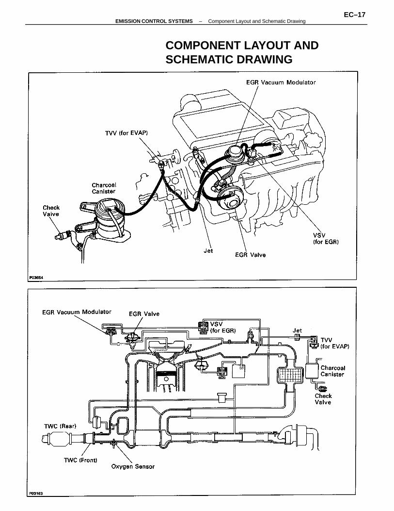
COMPONENT LAYOUT ANDSCHEMATIC DRAWING
–EMISSION CONTROL SYSTEMS Component Layout and Schematic DrawingEC–17
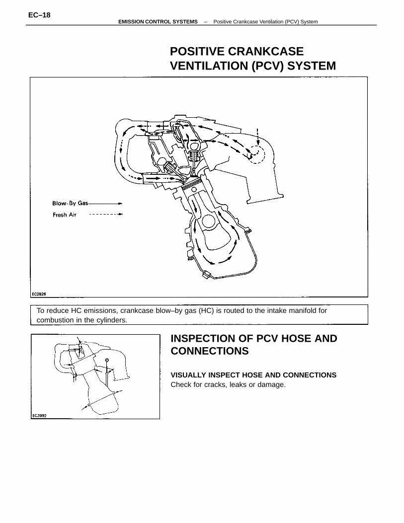
INSPECTION OF PCV HOSE ANDCONNECTIONS
VISUALLY INSPECT HOSE AND CONNECTIONSCheck for cracks, leaks or damage.
To reduce HC emissions, crankcase blow–by gas (HC) is routed to the intake manifold forcombustion in the cylinders.
POSITIVE CRANKCASEVENTILATION (PCV) SYSTEM
–EMISSION CONTROL SYSTEMS Positive Crankcase Ventilation (PCV) SystemEC–18
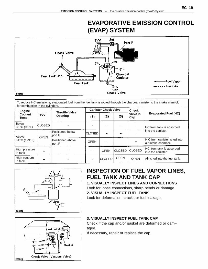
INSPECTION OF FUEL VAPOR LINES,FUEL TANK AND TANK CAP1. VISUALLY INSPECT LINES AND CONNECTIONSLook for loose connections, sharp bends or damage.2. VISUALLY INSPECT FUEL TANKLook for deformation, cracks or fuel leakage.
3. VISUALLY INSPECT FUEL TANK CAPCheck if the cap and/or gasket are deformed or dam–aged.If necessary, repair or replace the cap.
To reduce HC emissions, evaporated fuel from the fuel tank is routed through the charcoal canister to the intake manifoldfor combustion in the cylinders.
EVAPORATIVE EMISSION CONTROL(EVAP) SYSTEM
H C from canister is led intoair intake chamber.
HC from tank is absorbedinto the canister.
HC from tank is absorbedinto the canister.Positioned below
port P
Positioned aboveport P
Air is led into the fuel tank.
Throttle ValveOpening
Evaporated Fuel (HC)Canister Check Valve
Above54C (129F)
High pressurein tank
High vacuumin tank
EngineCoolantTemp.
Below35C (95F)
Checkvalve inCap
CLOSED
CLOSED
CLOSED
CLOSED
CLOSED
OPEN
OPEN
OPENOPEN
OPEN
TVV
–EMISSION CONTROL SYSTEMS Evaporative Emission Control (EVAP) SystemEC–19
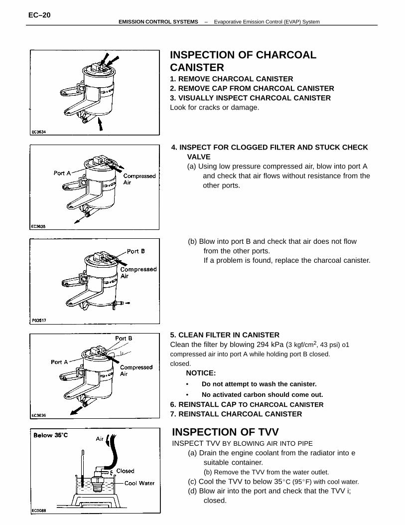
5. CLEAN FILTER IN CANISTERClean the filter by blowing 294 kPa (3 kgf/cm2, 43 psi) o1compressed air into port A while holding port B closed.closed.
NOTICE:• Do not attempt to wash the canister.
• No activated carbon should come out.
6. REINSTALL CAP TO CHARCOAL CANISTER7. REINSTALL CHARCOAL CANISTER
INSPECTION OF TVVINSPECT TVV BY BLOWING AIR INTO PIPE
(a) Drain the engine coolant from the radiator into esuitable container.(b) Remove the TVV from the water outlet.
(c) Cool the TVV to below 35C (95F) with cool water.(d) Blow air into the port and check that the TVV i;
closed.
INSPECTION OF CHARCOALCANISTER1. REMOVE CHARCOAL CANISTER2. REMOVE CAP FROM CHARCOAL CANISTER3. VISUALLY INSPECT CHARCOAL CANISTERLook for cracks or damage.
4. INSPECT FOR CLOGGED FILTER AND STUCK CHECKVALVE(a) Using low pressure compressed air, blow into port A
and check that air flows without resistance from theother ports.
(b) Blow into port B and check that air does not flowfrom the other ports.If a problem is found, replace the charcoal canister.
–EMISSION CONTROL SYSTEMS Evaporative Emission Control (EVAP) SystemEC–20
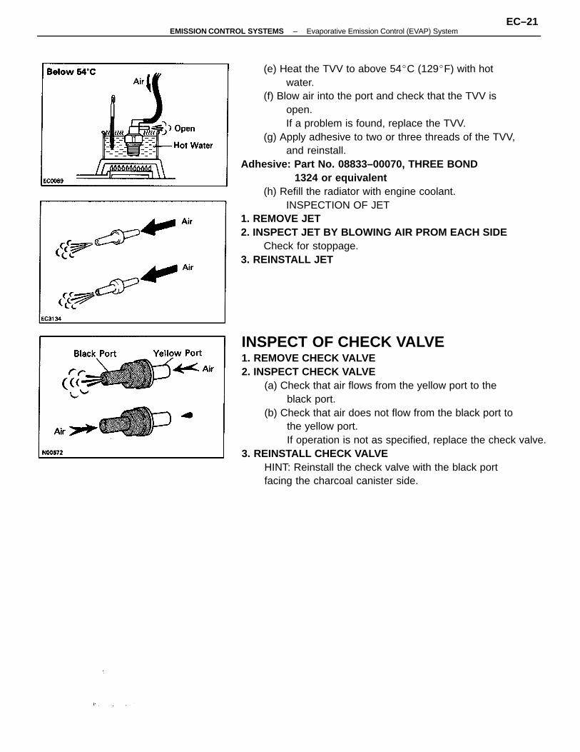
(e) Heat the TVV to above 54C (129F) with hotwater.
(f) Blow air into the port and check that the TVV isopen.If a problem is found, replace the TVV.
(g) Apply adhesive to two or three threads of the TVV,and reinstall.
Adhesive: Part No. 08833–00070, THREE BOND1324 or equivalent
(h) Refill the radiator with engine coolant.INSPECTION OF JET
1. REMOVE JET2. INSPECT JET BY BLOWING AIR PROM EACH SIDE
Check for stoppage.3. REINSTALL JET
INSPECT OF CHECK VALVE1. REMOVE CHECK VALVE2. INSPECT CHECK VALVE
(a) Check that air flows from the yellow port to theblack port.
(b) Check that air does not flow from the black port tothe yellow port.If operation is not as specified, replace the check valve.
3. REINSTALL CHECK VALVEHINT: Reinstall the check valve with the black portfacing the charcoal canister side.
–EMISSION CONTROL SYSTEMS Evaporative Emission Control (EVAP) SystemEC–21
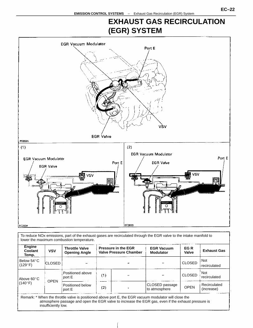
Remark: * When the throttle valve is positioned above port E, the EGR vacuum modulator will close theatmosphere passage and open the EGR valve to increase the EGR gas, even if the exhaust pressure isinsufficiently low.
To reduce NOx emissions, part of the exhaust gases are recirculated through the EGR valve to the intake manifold tolower the maximum combustion temperature.
EXHAUST GAS RECIRCULATION(EGR) SYSTEM
Pressure in the EGRValve Pressure Chamber
CLOSED passageto atmosphere
Positioned belowport E
Positioned aboveport E
Throttle ValveOpening Angle
EGR VacuumModulator
Above 60C(140F) Recirculated
(increase)
Below 54C(129F)
EngineCoolantTemp.
Notrecirculated
Notrecirculated
Exhaust GasEG RValve
CLOSED
CLOSED
CLOSED
OPEN
OPEN
VSV
–EMISSION CONTROL SYSTEMS Exhaust Gas Recirculation (EGR) SystemEC–22
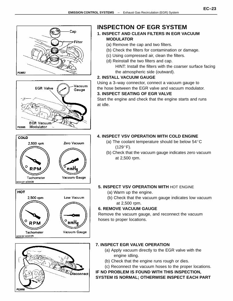
INSPECTION OF EGR SYSTEM1. INSPECT AND CLEAN FILTERS IN EGR VACUUM
MODULATOR(a) Remove the cap and two filters.(b) Check the filters for contamination or damage.(c) Using compressed air, clean the filters.(d) Reinstall the two filters and cap.
HINT: Install the filters with the coarser surface facingthe atmospheric side (outward).
2. INSTALL VACUUM GAUGEUsing a 3–way connector, connect a vacuum gauge tothe hose between the EGR valve and vacuum modulator.3. INSPECT SEATING OF EGR VALVEStart the engine and check that the engine starts and runsat idle.
5. INSPECT VSV OPERATION WITH HOT ENGINE(a) Warm up the engine.(b) Check that the vacuum gauge indicates low vacuum
at 2,500 rpm.6. REMOVE VACUUM GAUGERemove the vacuum gauge, and reconnect the vacuumhoses to proper locations.
7. INSPECT EGR VALVE OPERATION(a) Apply vacuum directly to the EGR valve with the
engine idling.(b) Check that the engine runs rough or dies.(c) Reconnect the vacuum hoses to the proper locations.
IF NO PROBLEM IS FOUND WITH THIS INSPECTION,SYSTEM IS NORMAL; OTHERWISE INSPECT EACH PART
4. INSPECT VSV OPERATION WITH COLD ENGINE(a) The coolant temperature should be below 54C
(129F).(b) Check that the vacuum gauge indicates zero vacuum
at 2,500 rpm.
–EMISSION CONTROL SYSTEMS Exhaust Gas Recirculation (EGR) SystemEC–23
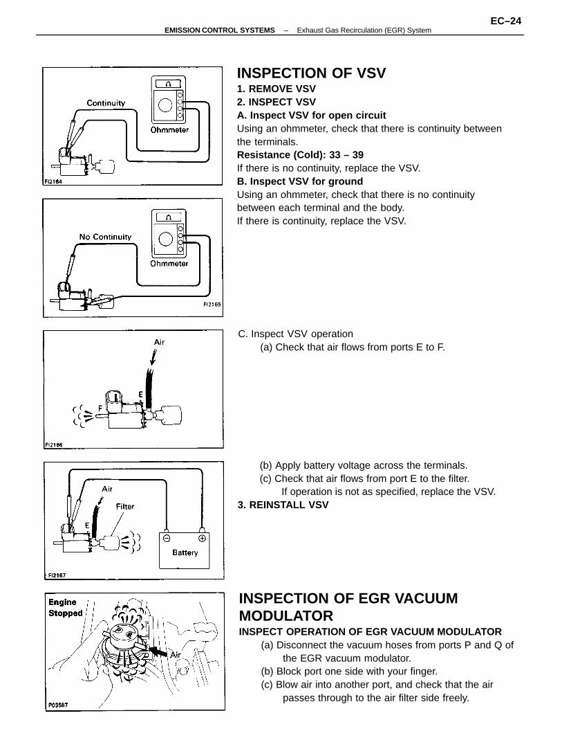
INSPECTION OF VSV1. REMOVE VSV2. INSPECT VSVA. Inspect VSV for open circuitUsing an ohmmeter, check that there is continuity between the terminals.Resistance (Cold): 33 – 39
If there is no continuity, replace the VSV.B. Inspect VSV for groundUsing an ohmmeter, check that there is no continuitybetween each terminal and the body.If there is continuity, replace the VSV.
INSPECTION OF EGR VACUUMMODULATORINSPECT OPERATION OF EGR VACUUM MODULATOR
(a) Disconnect the vacuum hoses from ports P and Q ofthe EGR vacuum modulator.
(b) Block port one side with your finger.(c) Blow air into another port, and check that the air
passes through to the air filter side freely.
(b) Apply battery voltage across the terminals.(c) Check that air flows from port E to the filter.
If operation is not as specified, replace the VSV.3. REINSTALL VSV
C. Inspect VSV operation(a) Check that air flows from ports E to F.
–EMISSION CONTROL SYSTEMS Exhaust Gas Recirculation (EGR) SystemEC–24
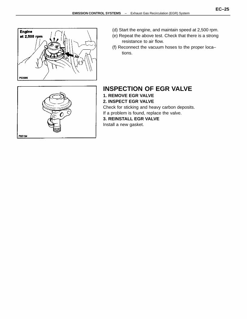
INSPECTION OF EGR VALVE1. REMOVE EGR VALVE2. INSPECT EGR VALVECheck for sticking and heavy carbon deposits.If a problem is found, replace the valve.3. REINSTALL EGR VALVEInstall a new gasket.
(d) Start the engine, and maintain speed at 2,500 rpm.(e) Repeat the above test. Check that there is a strong
resistance to air flow.(f) Reconnect the vacuum hoses to the proper loca–
tions.
–EMISSION CONTROL SYSTEMS Exhaust Gas Recirculation (EGR) SystemEC–25
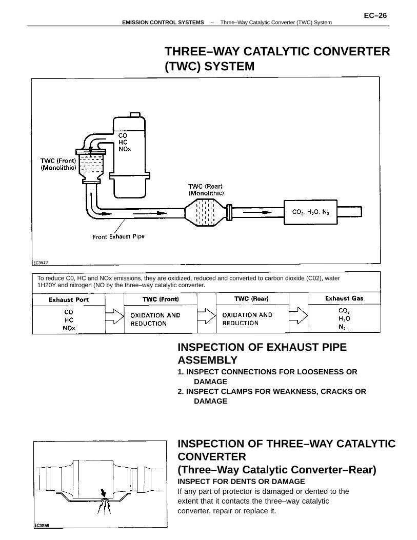
INSPECTION OF THREE–WAY CATALYTICCONVERTER(Three–Way Catalytic Converter–Rear)INSPECT FOR DENTS OR DAMAGEIf any part of protector is damaged or dented to theextent that it contacts the three–way catalyticconverter, repair or replace it.
INSPECTION OF EXHAUST PIPEASSEMBLY1. INSPECT CONNECTIONS FOR LOOSENESS OR
DAMAGE2. INSPECT CLAMPS FOR WEAKNESS, CRACKS OR
DAMAGE
To reduce C0, HC and NOx emissions, they are oxidized, reduced and converted to carbon dioxide (C02), water1H20Y and nitrogen (NO by the three–way catalytic converter.
THREE–WAY CATALYTIC CONVERTER(TWC) SYSTEM
–EMISSION CONTROL SYSTEMS Three–Way Catalytic Converter (TWC) SystemEC–26
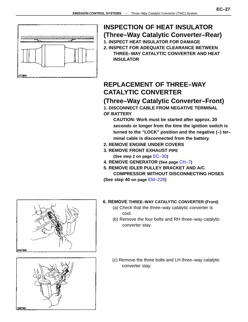
REPLACEMENT OF THREE–WAYCATALYTIC CONVERTER(Three–Way Catalytic Converter–Front)1. DISCONNECT CABLE FROM NEGATIVE TERMINALOF BATTERY
CAUTION: Work must be started after approx. 20seconds or longer from the time the ignition switch isturned to the “LOCK” position and the negative (–) ter–minal cable is disconnected from the battery.
2. REMOVE ENGINE UNDER COVERS3. REMOVE FRONT EXHAUST PIPE
(See step 2 on page EC–30)4. REMOVE GENERATOR (See page CH–7)5. REMOVE IDLER PULLEY BRACKET AND A/C
COMPRESSOR WITHOUT DISCONNECTING HOSES(See step 40 on page EM–229)
INSPECTION OF HEAT INSULATOR(Three–Way Catalytic Converter–Rear)1. INSPECT HEAT INSULATOR FOR DAMAGE2. INSPECT FOR ADEQUATE CLEARANCE BETWEEN
THREE–WAY CATALYTIC CONVERTER AND HEATINSULATOR
6. REMOVE THREE–WAY CATALYTIC CONVERTER (Front)(a) Check that the three–way catalytic converter is
cool.(b) Remove the four bolts and RH three–way catalytic
converter stay.
(c) Remove the three bolts and LH three–way catalyticconverter stay.
–EMISSION CONTROL SYSTEMS Three–Way Catalytic Converter (TWC) SystemEC–27
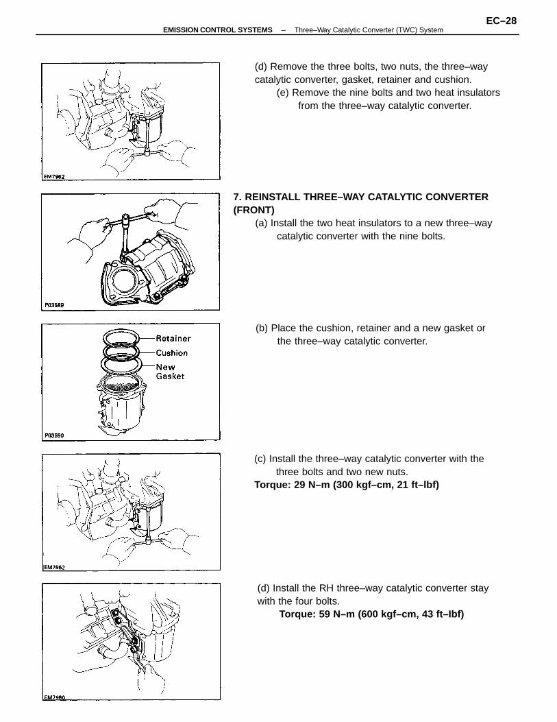
7. REINSTALL THREE–WAY CATALYTIC CONVERTER(FRONT)
(a) Install the two heat insulators to a new three–waycatalytic converter with the nine bolts.
(d) Remove the three bolts, two nuts, the three–waycatalytic converter, gasket, retainer and cushion.
(e) Remove the nine bolts and two heat insulatorsfrom the three–way catalytic converter.
(c) Install the three–way catalytic converter with thethree bolts and two new nuts.
Torque: 29 N–m (300 kgf–cm, 21 ft–lbf)
(d) Install the RH three–way catalytic converter staywith the four bolts.
Torque: 59 N–m (600 kgf–cm, 43 ft–Ibf)
(b) Place the cushion, retainer and a new gasket orthe three–way catalytic converter.
–EMISSION CONTROL SYSTEMS Three–Way Catalytic Converter (TWC) SystemEC–28
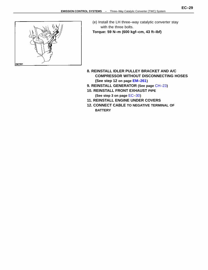
8. REINSTALL IDLER PULLEY BRACKET AND A/CCOMPRESSOR WITHOUT DISCONNECTING HOSES(See step 12 on page EM–261)
9. REINSTALL GENERATOR (See page CH–23)10. REINSTALL FRONT EXHAUST PIPE
(See step 3 on page EC–30)11. REINSTALL ENGINE UNDER COVERS12. CONNECT CABLE TO NEGATIVE TERMINAL OF
BATTERY
(e) Install the LH three–way catalytic converter staywith the three bolts.
Torque: 59 N–m (600 kgf–cm, 43 ft–Ibf)
–EMISSION CONTROL SYSTEMS Three–Way Catalytic Converter (TWC) SystemEC–29
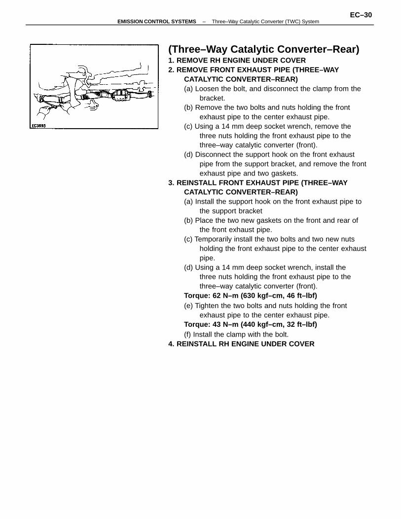
(Three–Way Catalytic Converter–Rear)1. REMOVE RH ENGINE UNDER COVER2. REMOVE FRONT EXHAUST PIPE (THREE–WAY
CATALYTIC CONVERTER–REAR)(a) Loosen the bolt, and disconnect the clamp from the
bracket.(b) Remove the two bolts and nuts holding the front
exhaust pipe to the center exhaust pipe.(c) Using a 14 mm deep socket wrench, remove the
three nuts holding the front exhaust pipe to thethree–way catalytic converter (front).
(d) Disconnect the support hook on the front exhaustpipe from the support bracket, and remove the frontexhaust pipe and two gaskets.
3. REINSTALL FRONT EXHAUST PIPE (THREE–WAYCATALYTIC CONVERTER–REAR)(a) Install the support hook on the front exhaust pipe to
the support bracket(b) Place the two new gaskets on the front and rear of
the front exhaust pipe.(c) Temporarily install the two bolts and two new nuts
holding the front exhaust pipe to the center exhaustpipe.
(d) Using a 14 mm deep socket wrench, install thethree nuts holding the front exhaust pipe to thethree–way catalytic converter (front).
Torque: 62 N–m (630 kgf–cm, 46 ft–lbf)(e) Tighten the two bolts and nuts holding the front
exhaust pipe to the center exhaust pipe.Torque: 43 N–m (440 kgf–cm, 32 ft–lbf)(f) Install the clamp with the bolt.
4. REINSTALL RH ENGINE UNDER COVER
–EMISSION CONTROL SYSTEMS Three–Way Catalytic Converter (TWC) SystemEC–30
Reduces blow–by gas (HC)
Reduces evaporative HC
Reduces NOx
Reduces CO, HC and NOx
Regulates all engine conditions for reduction ofexhaust emissions.
Positive Crankcase ventilation
Evaporative emission control
Exhaust gas recirculation
Three–way catalytic converter
Multiport fuel injection
Remark * For inspection and repair of the MFI system, refer to MFI section of this manual.
(5S–FE)SYSTEM PURPOSE
PCV
EVAP
EGR
TWC
MFI
AbbreviationSystem Purpose
–EMISSION CONTROL SYSTEMS System PurposeEC–31
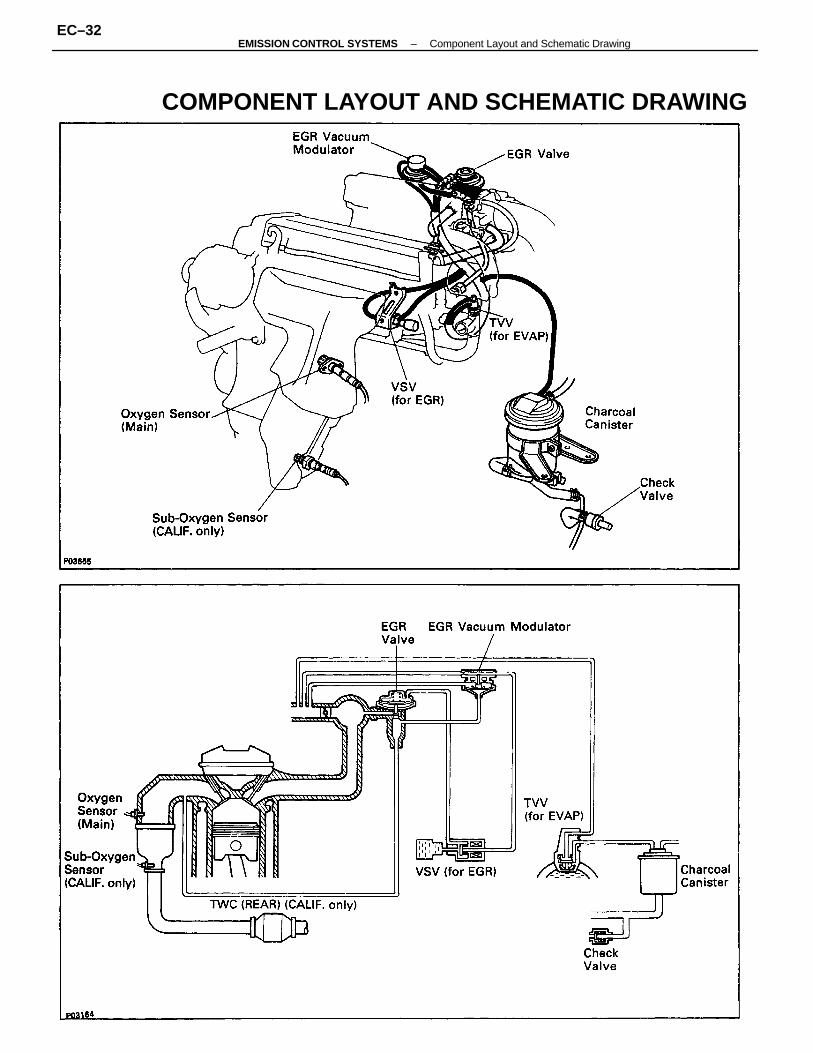
COMPONENT LAYOUT AND SCHEMATIC DRAWING
–EMISSION CONTROL SYSTEMS Component Layout and Schematic DrawingEC–32
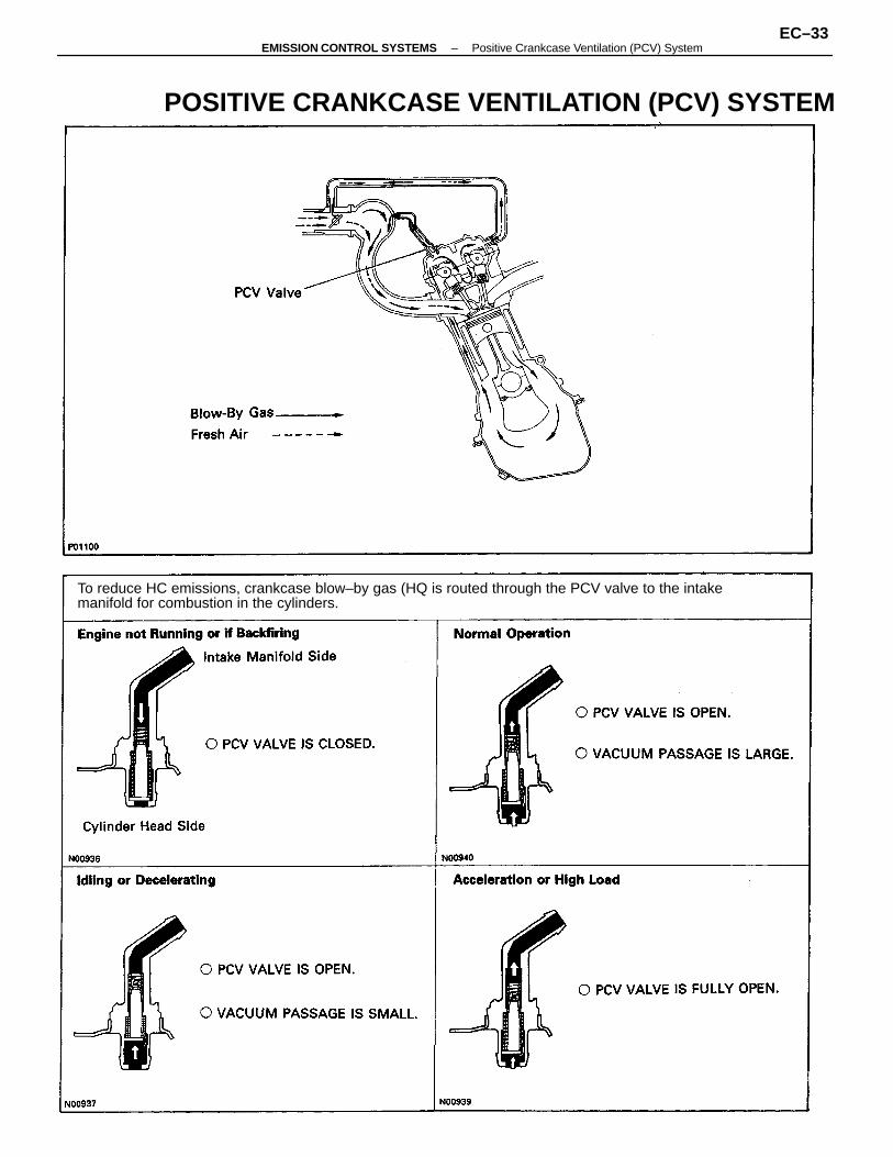
To reduce HC emissions, crankcase blow–by gas (HQ is routed through the PCV valve to the intakemanifold for combustion in the cylinders.
POSITIVE CRANKCASE VENTILATION (PCV) SYSTEM
–EMISSION CONTROL SYSTEMS Positive Crankcase Ventilation (PCV) SystemEC–33
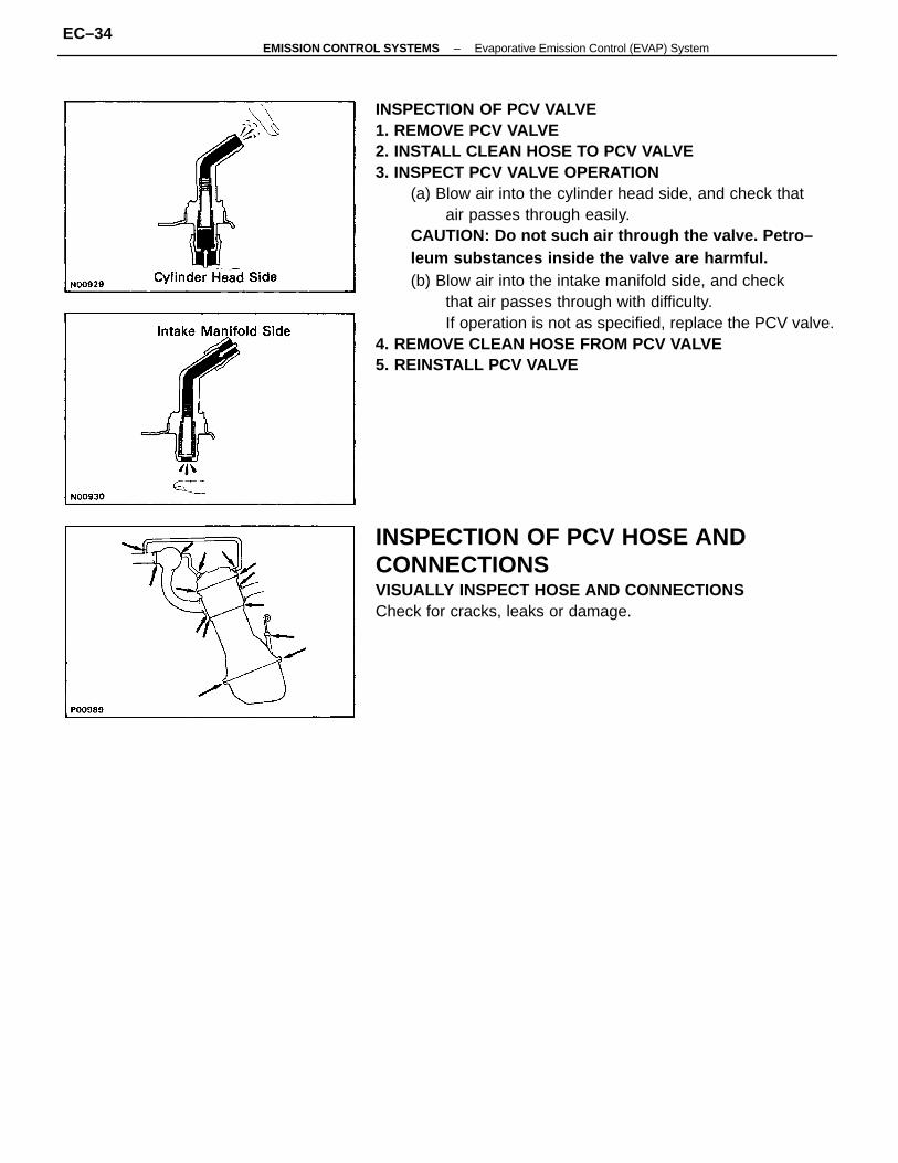
INSPECTION OF PCV VALVE1. REMOVE PCV VALVE2. INSTALL CLEAN HOSE TO PCV VALVE3. INSPECT PCV VALVE OPERATION
(a) Blow air into the cylinder head side, and check thatair passes through easily.
CAUTION: Do not such air through the valve. Petro–leum substances inside the valve are harmful.(b) Blow air into the intake manifold side, and check
that air passes through with difficulty.If operation is not as specified, replace the PCV valve.
4. REMOVE CLEAN HOSE FROM PCV VALVE5. REINSTALL PCV VALVE
INSPECTION OF PCV HOSE ANDCONNECTIONSVISUALLY INSPECT HOSE AND CONNECTIONSCheck for cracks, leaks or damage.
–EMISSION CONTROL SYSTEMS Evaporative Emission Control (EVAP) SystemEC–34
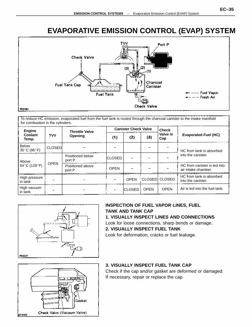
INSPECTION OF FUEL VAPOR LINES, FUELTANK AND TANK CAP1. VISUALLY INSPECT LINES AND CONNECTIONSLook for loose connections, sharp bends or damage.2. VISUALLY INSPECT FUEL TANKLook for deformation, cracks or fuel leakage.
3. VISUALLY INSPECT FUEL TANK CAPCheck if the cap and/or gasket are deformed or damaged.If necessary, repair or replace the cap.
To reduce HC emission, evaporated fuel from the fuel tank is routed through the charcoal canister to the intake manifoldfor combustion in the cylinders.
EVAPORATIVE EMISSION CONTROL (EVAP) SYSTEM
HC from canister is led intoair intake chamber.
HC from tank is absorbedinto the canister.
HC from tank is absorbedinto the canister.
Throttle ValveOpening
Positioned belowport P
Positioned aboveport P
Air is led into the fuel tank.
Evaporated Fuel (HC)
Canister Check ValveEngineCoolantTemp.
CheckValve inCap
Above54C (129F)
High pressurein tank
High vacuumin tank
Below35C (95F)
CLOSED
CLOSED
CLOSED
CLOSEDCLOSED
OPENOPEN
OPENOPEN
OPEN
TVV
–EMISSION CONTROL SYSTEMS Evaporative Emission Control (EVAP) SystemEC–35
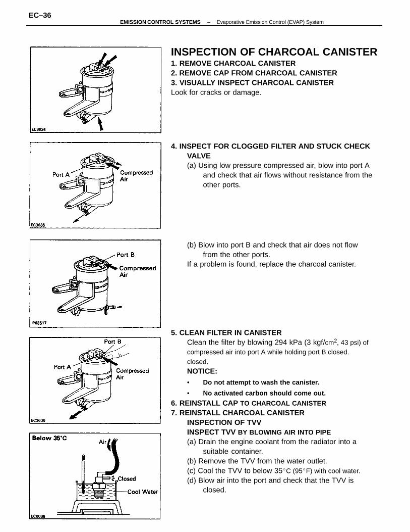
5. CLEAN FILTER IN CANISTERClean the filter by blowing 294 kPa (3 kgf/cm2, 43 psi) ofcompressed air into port A while holding port B closed.closed.NOTICE:• Do not attempt to wash the canister.
• No activated carbon should come out.
6. REINSTALL CAP TO CHARCOAL CANISTER7. REINSTALL CHARCOAL CANISTER
INSPECTION OF TVVINSPECT TVV BY BLOWING AIR INTO PIPE(a) Drain the engine coolant from the radiator into a
suitable container.(b) Remove the TVV from the water outlet.(c) Cool the TVV to below 35C (95F) with cool water.(d) Blow air into the port and check that the TVV is
closed.
INSPECTION OF CHARCOAL CANISTER1. REMOVE CHARCOAL CANISTER2. REMOVE CAP FROM CHARCOAL CANISTER3. VISUALLY INSPECT CHARCOAL CANISTERLook for cracks or damage.
4. INSPECT FOR CLOGGED FILTER AND STUCK CHECKVALVE(a) Using low pressure compressed air, blow into port A
and check that air flows without resistance from theother ports.
(b) Blow into port B and check that air does not flowfrom the other ports.
If a problem is found, replace the charcoal canister.
–EMISSION CONTROL SYSTEMS Evaporative Emission Control (EVAP) SystemEC–36
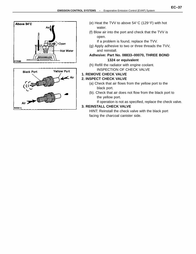
(e) Heat the TVV to above 54C (129F) with hotwater.
(f) Blow air into the port and check that the TVV isopen.If a problem is found, replace the TVV.
(g) Apply adhesive to two or three threads the TVV,and reinstall.
Adhesive: Part No. 08833–00070, THREE BOND1324 or equivalent
(h) Refill the radiator with engine coolant.INSPECTION OF CHECK VALVE
1. REMOVE CHECK VALVE2. INSPECT CHECK VALVE
(a) Check that air flows from the yellow port to theblack port.
(b). Check that air does not flow from the black port tothe yellow port.If operation is not as specified, replace the check valve.
3. REINSTALL CHECK VALVEHINT: Reinstall the check valve with the black portfacing the charcoal canister side.
–EMISSION CONTROL SYSTEMS Evaporative Emission Control (EVAP) SystemEC–37
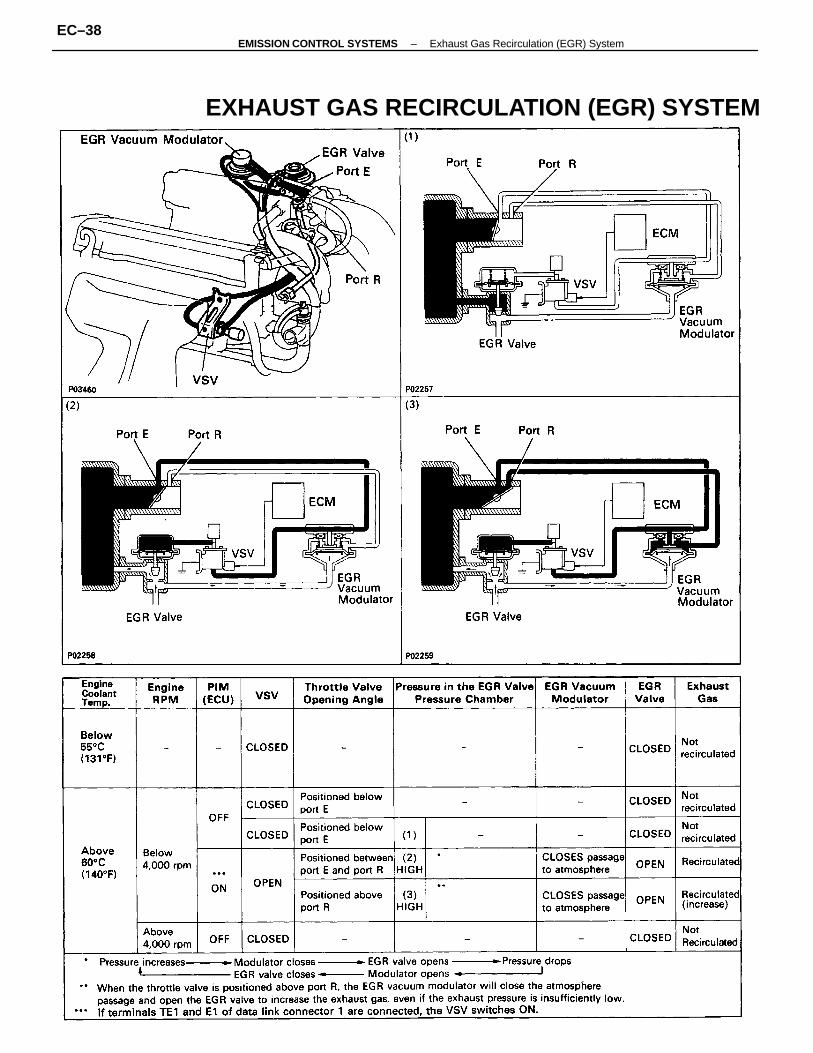
EXHAUST GAS RECIRCULATION (EGR) SYSTEM
–EMISSION CONTROL SYSTEMS Exhaust Gas Recirculation (EGR) SystemEC–38
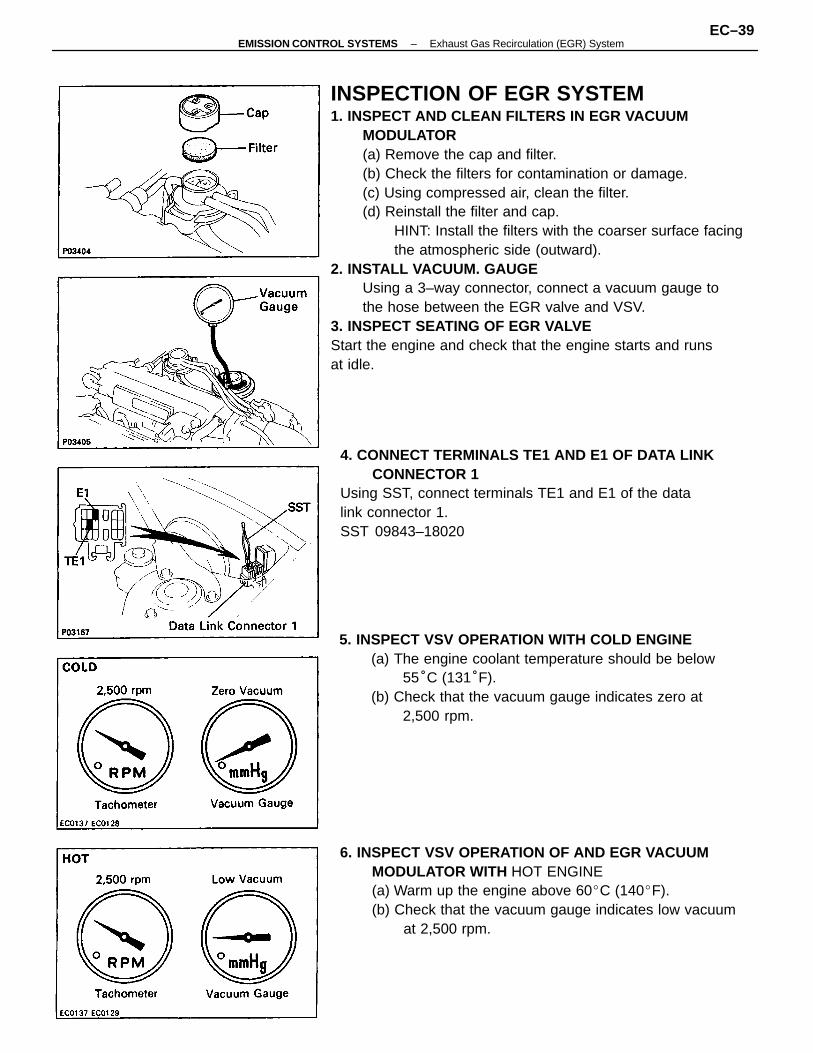
INSPECTION OF EGR SYSTEM1. INSPECT AND CLEAN FILTERS IN EGR VACUUM
MODULATOR(a) Remove the cap and filter.(b) Check the filters for contamination or damage.(c) Using compressed air, clean the filter.(d) Reinstall the filter and cap.
HINT: Install the filters with the coarser surface facingthe atmospheric side (outward).
2. INSTALL VACUUM. GAUGEUsing a 3–way connector, connect a vacuum gauge tothe hose between the EGR valve and VSV.
3. INSPECT SEATING OF EGR VALVEStart the engine and check that the engine starts and runsat idle.
5. INSPECT VSV OPERATION WITH COLD ENGINE(a) The engine coolant temperature should be below
55°C (131°F).(b) Check that the vacuum gauge indicates zero at
2,500 rpm.
4. CONNECT TERMINALS TE1 AND E1 OF DATA LINKCONNECTOR 1
Using SST, connect terminals TE1 and E1 of the datalink connector 1.SST 09843–18020
6. INSPECT VSV OPERATION OF AND EGR VACUUMMODULATOR WITH HOT ENGINE(a) Warm up the engine above 60C (140F).(b) Check that the vacuum gauge indicates low vacuum
at 2,500 rpm.
–EMISSION CONTROL SYSTEMS Exhaust Gas Recirculation (EGR) SystemEC–39
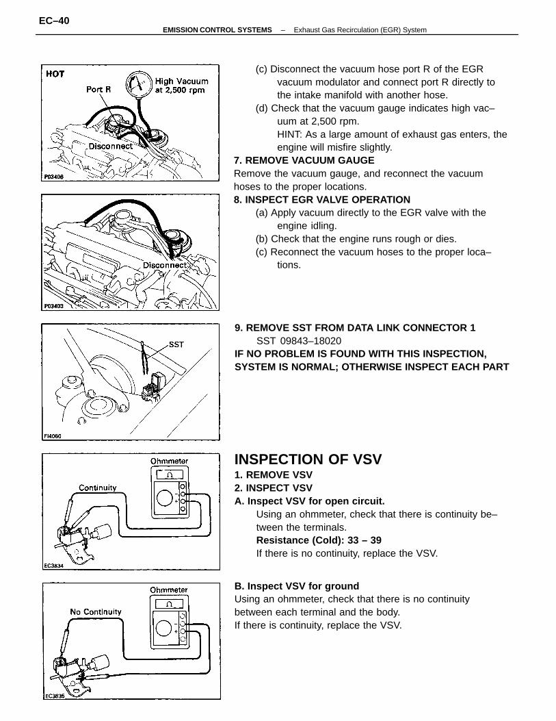
(c) Disconnect the vacuum hose port R of the EGRvacuum modulator and connect port R directly tothe intake manifold with another hose.
(d) Check that the vacuum gauge indicates high vac–uum at 2,500 rpm.HINT: As a large amount of exhaust gas enters, theengine will misfire slightly.
7. REMOVE VACUUM GAUGERemove the vacuum gauge, and reconnect the vacuumhoses to the proper locations.8. INSPECT EGR VALVE OPERATION
(a) Apply vacuum directly to the EGR valve with theengine idling.
(b) Check that the engine runs rough or dies.(c) Reconnect the vacuum hoses to the proper loca–
tions.
INSPECTION OF VSV1. REMOVE VSV2. INSPECT VSVA. Inspect VSV for open circuit.
Using an ohmmeter, check that there is continuity be–tween the terminals.Resistance (Cold): 33 – 39
If there is no continuity, replace the VSV.
B. Inspect VSV for groundUsing an ohmmeter, check that there is no continuitybetween each terminal and the body.If there is continuity, replace the VSV.
9. REMOVE SST FROM DATA LINK CONNECTOR 1SST 09843–18020
IF NO PROBLEM IS FOUND WITH THIS INSPECTION,SYSTEM IS NORMAL; OTHERWISE INSPECT EACH PART
–EMISSION CONTROL SYSTEMS Exhaust Gas Recirculation (EGR) SystemEC–40
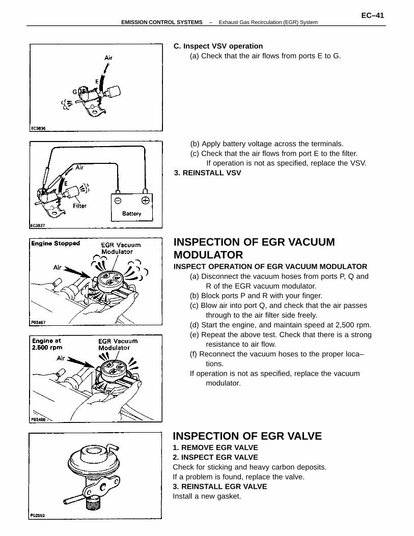
INSPECTION OF EGR VACUUMMODULATORINSPECT OPERATION OF EGR VACUUM MODULATOR
(a) Disconnect the vacuum hoses from ports P, Q andR of the EGR vacuum modulator.
(b) Block ports P and R with your finger.(c) Blow air into port Q, and check that the air passes
through to the air filter side freely.(d) Start the engine, and maintain speed at 2,500 rpm.(e) Repeat the above test. Check that there is a strong
resistance to air flow.(f) Reconnect the vacuum hoses to the proper loca–
tions.If operation is not as specified, replace the vacuum
modulator.
INSPECTION OF EGR VALVE1. REMOVE EGR VALVE2. INSPECT EGR VALVECheck for sticking and heavy carbon deposits.If a problem is found, replace the valve.3. REINSTALL EGR VALVEInstall a new gasket.
(b) Apply battery voltage across the terminals.(c) Check that the air flows from port E to the filter.
If operation is not as specified, replace the VSV.3. REINSTALL VSV
C. Inspect VSV operation(a) Check that the air flows from ports E to G.
–EMISSION CONTROL SYSTEMS Exhaust Gas Recirculation (EGR) SystemEC–41
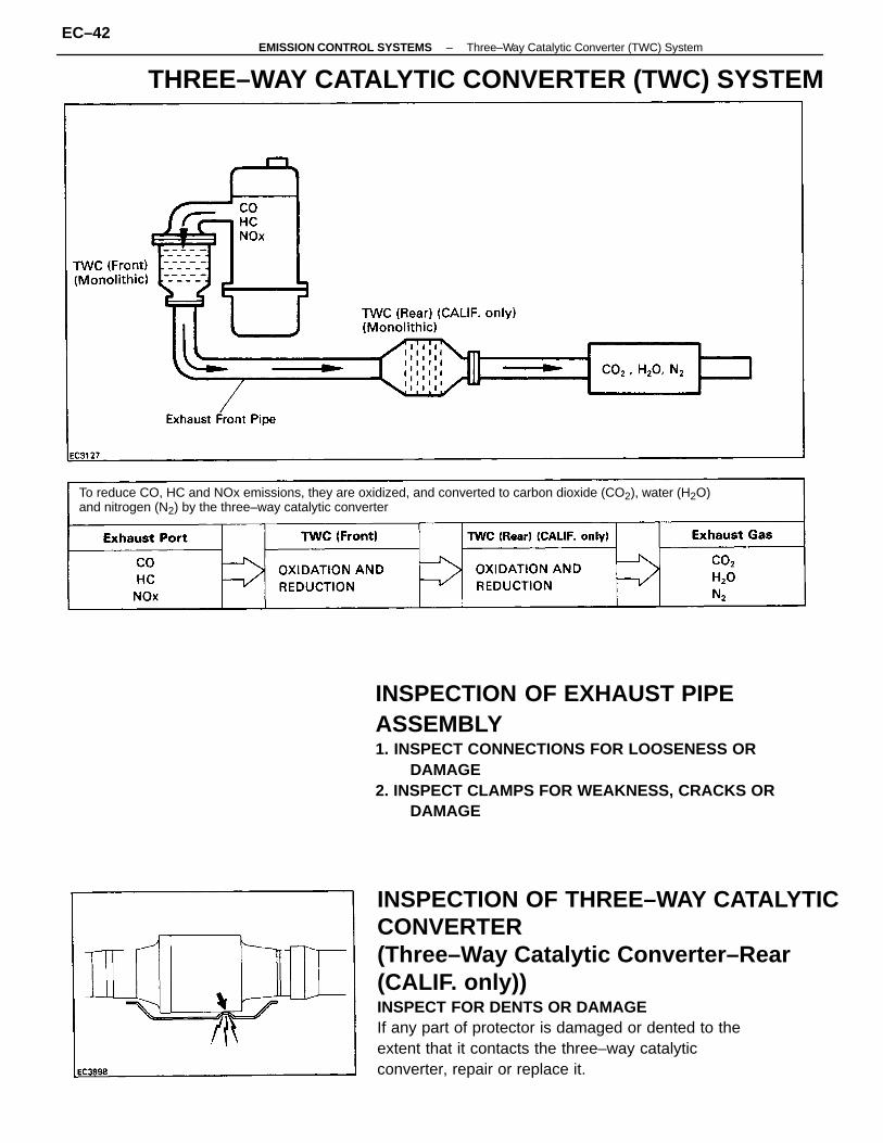
INSPECTION OF THREE–WAY CATALYTICCONVERTER(Three–Way Catalytic Converter–Rear (CALIF. only))INSPECT FOR DENTS OR DAMAGEIf any part of protector is damaged or dented to theextent that it contacts the three–way catalytic converter, repair or replace it.
INSPECTION OF EXHAUST PIPEASSEMBLY1. INSPECT CONNECTIONS FOR LOOSENESS OR
DAMAGE2. INSPECT CLAMPS FOR WEAKNESS, CRACKS OR
DAMAGE
To reduce CO, HC and NOx emissions, they are oxidized, and converted to carbon dioxide (CO2), water (H2O)and nitrogen (N2) by the three–way catalytic converter
THREE–WAY CATALYTIC CONVERTER (TWC) SYSTEM–EMISSION CONTROL SYSTEMS Three–Way Catalytic Converter (TWC) System
EC–42
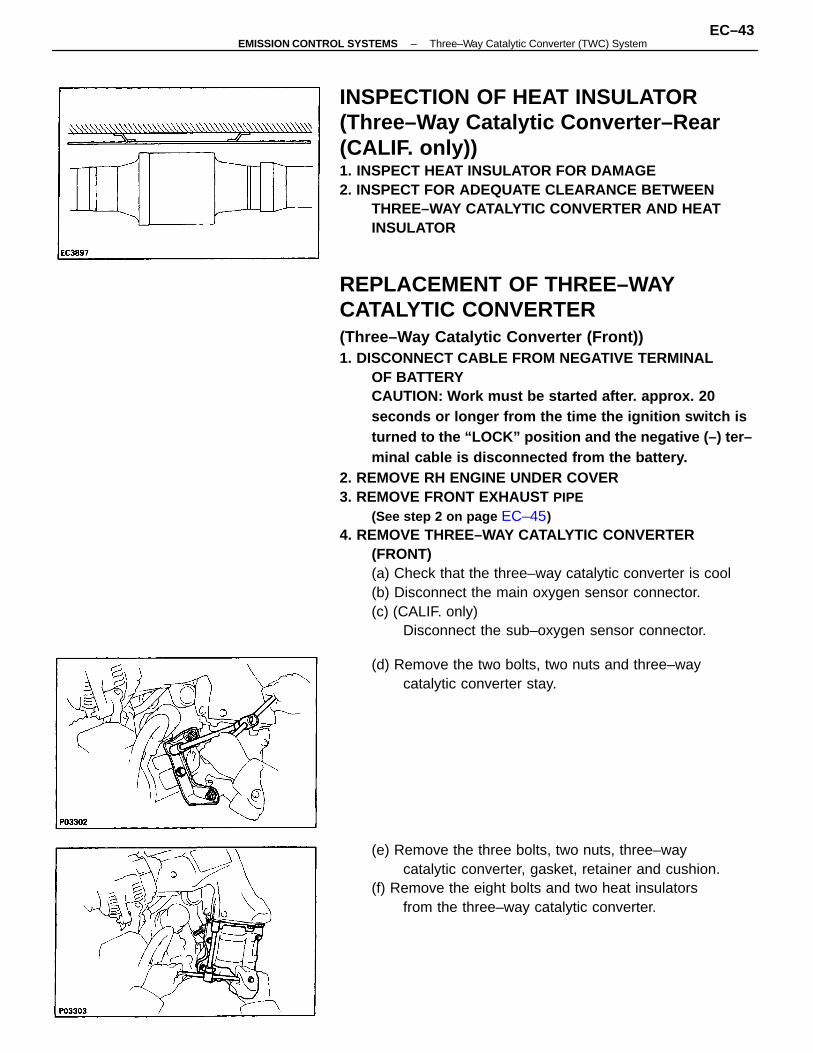
REPLACEMENT OF THREE–WAYCATALYTIC CONVERTER(Three–Way Catalytic Converter (Front))1. DISCONNECT CABLE FROM NEGATIVE TERMINAL
OF BATTERYCAUTION: Work must be started after. approx. 20seconds or longer from the time the ignition switch isturned to the “LOCK” position and the negative (–) ter–minal cable is disconnected from the battery.
2. REMOVE RH ENGINE UNDER COVER3. REMOVE FRONT EXHAUST PIPE
(See step 2 on page EC–45)4. REMOVE THREE–WAY CATALYTIC CONVERTER
(FRONT)(a) Check that the three–way catalytic converter is cool(b) Disconnect the main oxygen sensor connector.(c) (CALIF. only)
Disconnect the sub–oxygen sensor connector.
INSPECTION OF HEAT INSULATOR(Three–Way Catalytic Converter–Rear(CALIF. only))1. INSPECT HEAT INSULATOR FOR DAMAGE2. INSPECT FOR ADEQUATE CLEARANCE BETWEEN
THREE–WAY CATALYTIC CONVERTER AND HEATINSULATOR
(e) Remove the three bolts, two nuts, three–waycatalytic converter, gasket, retainer and cushion.
(f) Remove the eight bolts and two heat insulatorsfrom the three–way catalytic converter.
(d) Remove the two bolts, two nuts and three–waycatalytic converter stay.
–EMISSION CONTROL SYSTEMS Three–Way Catalytic Converter (TWC) SystemEC–43
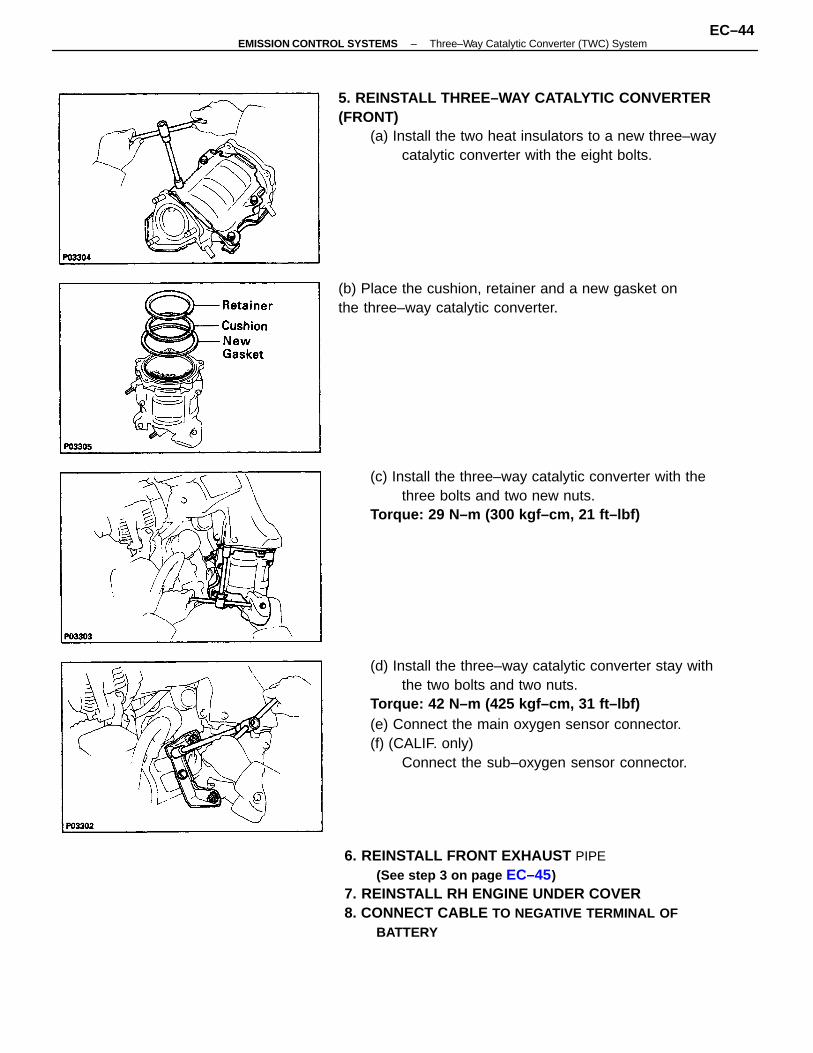
(d) Install the three–way catalytic converter stay withthe two bolts and two nuts.
Torque: 42 N–m (425 kgf–cm, 31 ft–lbf)(e) Connect the main oxygen sensor connector.(f) (CALIF. only)
Connect the sub–oxygen sensor connector.
6. REINSTALL FRONT EXHAUST PIPE(See step 3 on page EC–45)
7. REINSTALL RH ENGINE UNDER COVER8. CONNECT CABLE TO NEGATIVE TERMINAL OF
BATTERY
5. REINSTALL THREE–WAY CATALYTIC CONVERTER(FRONT)
(a) Install the two heat insulators to a new three–waycatalytic converter with the eight bolts.
(c) Install the three–way catalytic converter with thethree bolts and two new nuts.
Torque: 29 N–m (300 kgf–cm, 21 ft–lbf)
(b) Place the cushion, retainer and a new gasket onthe three–way catalytic converter.
–EMISSION CONTROL SYSTEMS Three–Way Catalytic Converter (TWC) SystemEC–44
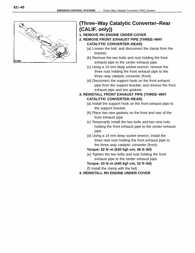
(Three–Way Catalytic Converter–Rear (CALIF. only))1. REMOVE RH ENGINE UNDER COVER2. REMOVE FRONT EXHAUST PIPE (THREE–WAY
CATALYTIC CONVERTER–REAR)(a) Loosen the bolt, and disconnect the clamp from the
bracket.(b) Remove the two bolts and nuts holding the front
exhaust pipe to the center exhaust pipe.(c) Using a 14 mm deep socket wrench, remove the
three nuts holding the front exhaust pipe to thethree–way catalytic converter (front).
(d) Disconnect the support hook on the front exhaustpipe from the support bracket, and remove the frontexhaust pipe and two gaskets.
3. REINSTALL FRONT EXHAUST PIPE (THREE–WAYCATALYTIC CONVERTER–REAR)(a) Install the support hook on the front exhaust pipe to
the support bracket.(b) Place two new gaskets on the front and rear of the
front exhaust pipe.(c) Temporarily install the two bolts and two new nuts
holding the front exhaust pipe to the center exhaustpipe.
(d) Using a 14 mm deep socket wrench, install thethree new nuts holding the front exhaust pipe tothe three–way catalytic converter (front).
Torque: 62 N–m (630 kgf–cm, 46 ft–lbf)(e) Tighten the two bolts and nuts holding the front
exhaust pipe to the center exhaust pipe.Torque: 43 N–m (440 kgf–cm, 32 ft–lbf)(f) Install the clamp with the bolt.
4. REINSTALL RH ENGINE UNDER COVER
–EMISSION CONTROL SYSTEMS Three–Way Catalytic Converter (TWC) SystemEC–45
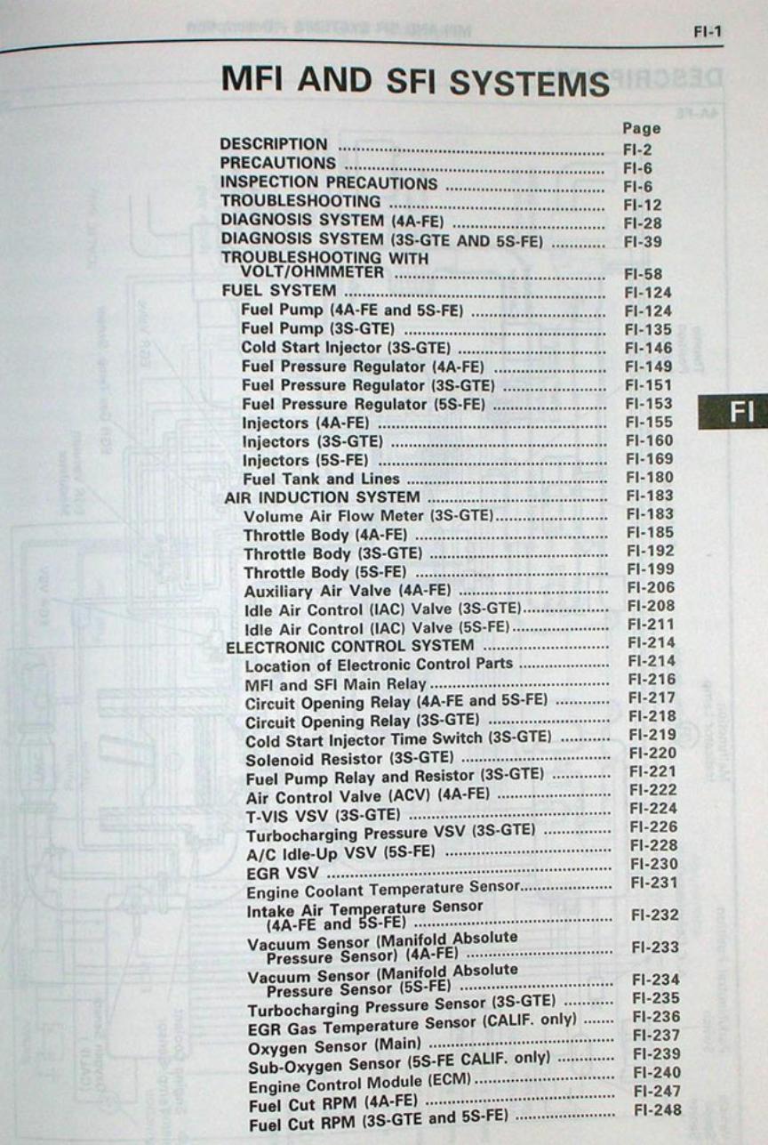
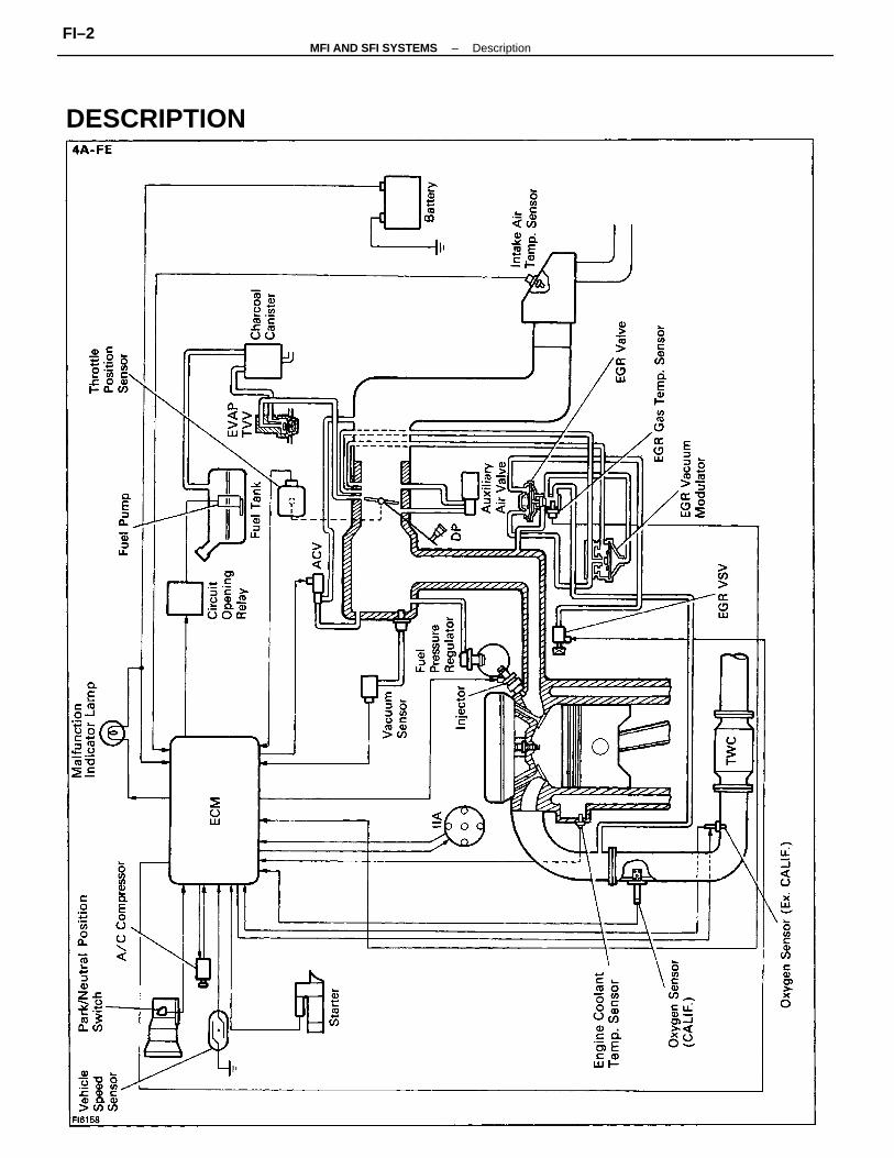
DESCRIPTION
–MFI AND SFI SYSTEMS DescriptionFI–2
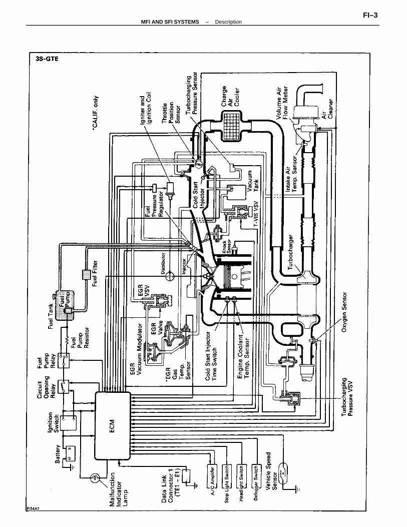
–MFI AND SFI SYSTEMS DescriptionFI–3
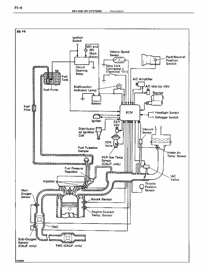
–MFI AND SFI SYSTEMS DescriptionFI–4
The MFI and SFI systems are composed of three basic sub–systems: Fuel, Air Induction andElectronic Control Systems.
FUEL SYSTEMFuel is supplied under constant pressure to the MFI and SFI injectors by an electric fuel pump. Theinjectors inject a metered quantity of fuel into the intake port in accordance with signals from the ECM(Engine Control Module).
AIR INDUCTION SYSTEMThe air induction system provides sufficient air for engine operation.
ELECTRONIC CONTROL SYSTEMThe CELICA 4A–FE, 3S–GTE and 5S–FE engines are equipped with a TOYOTA Computer ControlledSystem (TCCS) which centrally controls the MFI and SFI, ESA, IAC, diagnosis systems etc. by means ofan Engine Control Module (ECM–formerly MFI and SFI computer) employing a microcomputer.The ECM controls the following functions:1. Multiport Fuel Injection and Sequential Multiport Fuel Injection (MFI and SFI)
The ECM receives signals from various sensors indicating changing engine operation conditions suchas:
Intake manifold pressure (4A–FE and 5S–FE)Intake air volume (3S–GTE)Intake air temperatureEngine coolant temperatureEngine rpmThrottle valve opening angleExhaust oxygen content etc.
The signals are utilized by the ECM to determine the injection duration necessary for an optimumair–fuel ratio.
2. Electronic Spark Advance (ESA)The ECM is programmed with data for optimum ignition timing under any and all operatingconditions. Using data provided by sensors which monitor various engine functions (rpm, enginecoolant temperature, etc.), the microcomputer (ECM) triggers the spark at the precisely right instant.(See IG section)
3. Idle Air Control (IAC)The ECM is programmed with target idling speed values to respond to different engine conditions (Engine coolant temperature, air conditioning ON/OFF (3S–GTE and 5S–FE), etc.). Sensors transmit
signals to the ECM which controls the flow of air through the by–pass of the throttle valve and adjust idle speed to the target value.
4. DiagnosisThe ECM detects any malfunctions and abnormalities in the sensor network and lights a malfunction indicator lamp on the combination meter. At the same time, the trouble is identified and a diagnostic trouble code is recorded by the ECM. The diagnostic trouble code can be read by the number of blinks of the malfunction indicator lamp when terminals TE1 and E1 are connected. The diagnostic trouble codes are referred to the later page. (See page FI–31, 44 or 50)
5. Fail–Safe FunctionIn the event of the sensor malfunctioning, a back–up circuit will take over to provide minimal drivability, and the malfunction indicator lamp will illuminate.
–MFI AND SFI SYSTEMS DescriptionFI–5
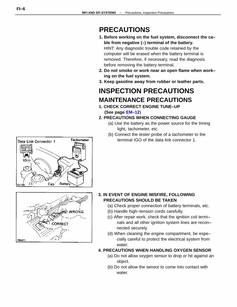
3. IN EVENT OF ENGINE MISFIRE, FOLLOWINGPRECAUTIONS SHOULD BE TAKEN
(a) Check proper connection of battery terminals, etc.(b) Handle high–tension cords carefully.(c) After repair work, check that the ignition coil termi–
nals and all other ignition system lines are recon–nected securely.
(d) When cleaning the engine compartment, be espe–cially careful to protect the electrical system fromwater.
4. PRECAUTIONS WHEN HANDLING OXYGEN SENSOR(a) Do not allow oxygen sensor to drop or hit against an
object.(b) Do not allow the sensor to come into contact with
water.
INSPECTION PRECAUTIONSMAINTENANCE PRECAUTIONS1. CHECK CORRECT ENGINE TUNE–UP
(See page EM–12)2. PRECAUTIONS WHEN CONNECTING GAUGE
(a) Use the battery as the power source for the timinglight, tachometer, etc.
(b) Connect the tester probe of a tachometer to theterminal IGO of the data link connector 1.
PRECAUTIONS1. Before working on the fuel system, disconnect the ca–
ble from negative (–) terminal of the battery.HINT: Any diagnostic trouble code retained by thecomputer will be erased when the battery terminal isremoved. Therefore, if necessary, read the diagnosisbefore removing the battery terminal.
2. Do not smoke or work near an open flame when work–ing on the fuel system.
3. Keep gasoline away from rubber or leather parts.
–MFI AND SFI SYSTEMS Precautions, Inspection PrecautionsFI–6
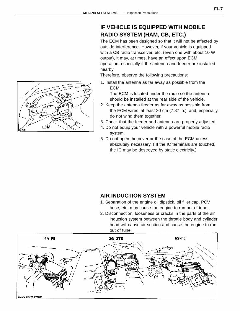
1. Install the antenna as far away as possible from theECM.The ECM is located under the radio so the antennashould be installed at the rear side of the vehicle.
2. Keep the antenna feeder as far away as possible fromthe ECM wires–at least 20 cm (7.87 in.)–and, especially,do not wind them together.
3. Check that the feeder and antenna are properly adjusted.4. Do not equip your vehicle with a powerful mobile radio
system.5. Do not open the cover or the case of the ECM unless
absolutely necessary. ( If the IC terminals are touched,the IC may be destroyed by static electricity.)
IF VEHICLE IS EQUIPPED WITH MOBILERADIO SYSTEM (HAM, CB, ETC.)The ECM has been designed so that it will not be affected byoutside interference. However, if your vehicle is equippedwith a CB radio transceiver, etc. (even one with about 10 Woutput), it may, at times, have an effect upon ECMoperation, especially if the antenna and feeder are installednearby.Therefore, observe the following precautions:
AIR INDUCTION SYSTEM1. Separation of the engine oil dipstick, oil filler cap, PCV
hose, etc. may cause the engine to run out of tune.2. Disconnection, looseness or cracks in the parts of the air
induction system between the throttle body and cylinderhead will cause air suction and cause the engine to runout of tune.
–MFI AND SFI SYSTEMS Inspection PrecautionsFI–7
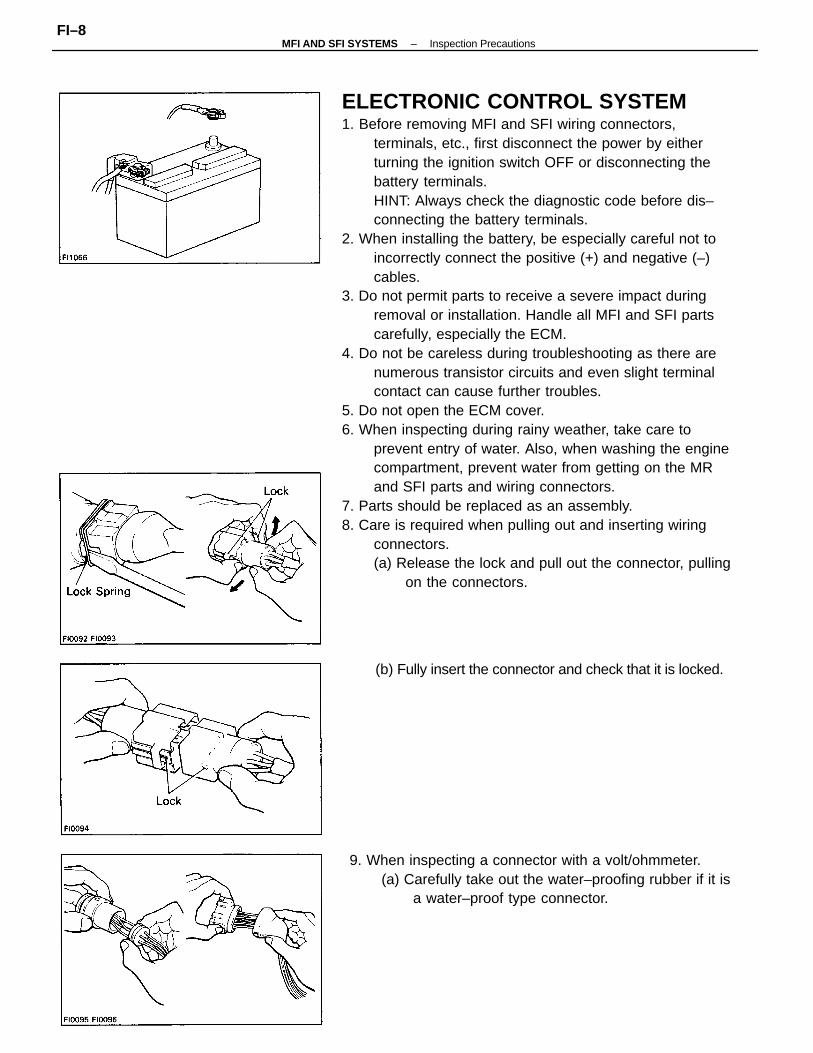
ELECTRONIC CONTROL SYSTEM1. Before removing MFI and SFI wiring connectors,
terminals, etc., first disconnect the power by eitherturning the ignition switch OFF or disconnecting thebattery terminals.HINT: Always check the diagnostic code before dis–connecting the battery terminals.
2. When installing the battery, be especially careful not toincorrectly connect the positive (+) and negative (–)cables.
3. Do not permit parts to receive a severe impact duringremoval or installation. Handle all MFI and SFI partscarefully, especially the ECM.
4. Do not be careless during troubleshooting as there arenumerous transistor circuits and even slight terminalcontact can cause further troubles.
5. Do not open the ECM cover.6. When inspecting during rainy weather, take care to
prevent entry of water. Also, when washing the enginecompartment, prevent water from getting on the MRand SFI parts and wiring connectors.
7. Parts should be replaced as an assembly.8. Care is required when pulling out and inserting wiring
connectors.(a) Release the lock and pull out the connector, pulling
on the connectors.
9. When inspecting a connector with a volt/ohmmeter.(a) Carefully take out the water–proofing rubber if it is
a water–proof type connector.
(b) Fully insert the connector and check that it is locked.
–MFI AND SFI SYSTEMS Inspection PrecautionsFI–8
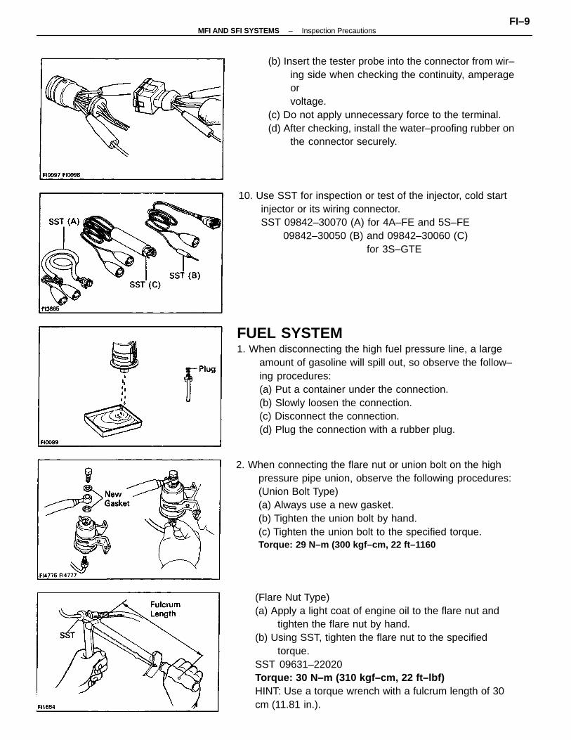
FUEL SYSTEM1. When disconnecting the high fuel pressure line, a large
amount of gasoline will spill out, so observe the follow–ing procedures:(a) Put a container under the connection.(b) Slowly loosen the connection.(c) Disconnect the connection.(d) Plug the connection with a rubber plug.
(Flare Nut Type)(a) Apply a light coat of engine oil to the flare nut and
tighten the flare nut by hand.(b) Using SST, tighten the flare nut to the specified
torque.SST 09631–22020Torque: 30 N–m (310 kgf–cm, 22 ft–lbf)HINT: Use a torque wrench with a fulcrum length of 30cm (11.81 in.).
2. When connecting the flare nut or union bolt on the highpressure pipe union, observe the following procedures:(Union Bolt Type)(a) Always use a new gasket.(b) Tighten the union bolt by hand.(c) Tighten the union bolt to the specified torque.Torque: 29 N–m (300 kgf–cm, 22 ft–1160
(b) Insert the tester probe into the connector from wir–ing side when checking the continuity, amperageorvoltage.
(c) Do not apply unnecessary force to the terminal.(d) After checking, install the water–proofing rubber on
the connector securely.
10. Use SST for inspection or test of the injector, cold startinjector or its wiring connector.SST 09842–30070 (A) for 4A–FE and 5S–FE
09842–30050 (B) and 09842–30060 (C)for 3S–GTE
–MFI AND SFI SYSTEMS Inspection PrecautionsFI–9
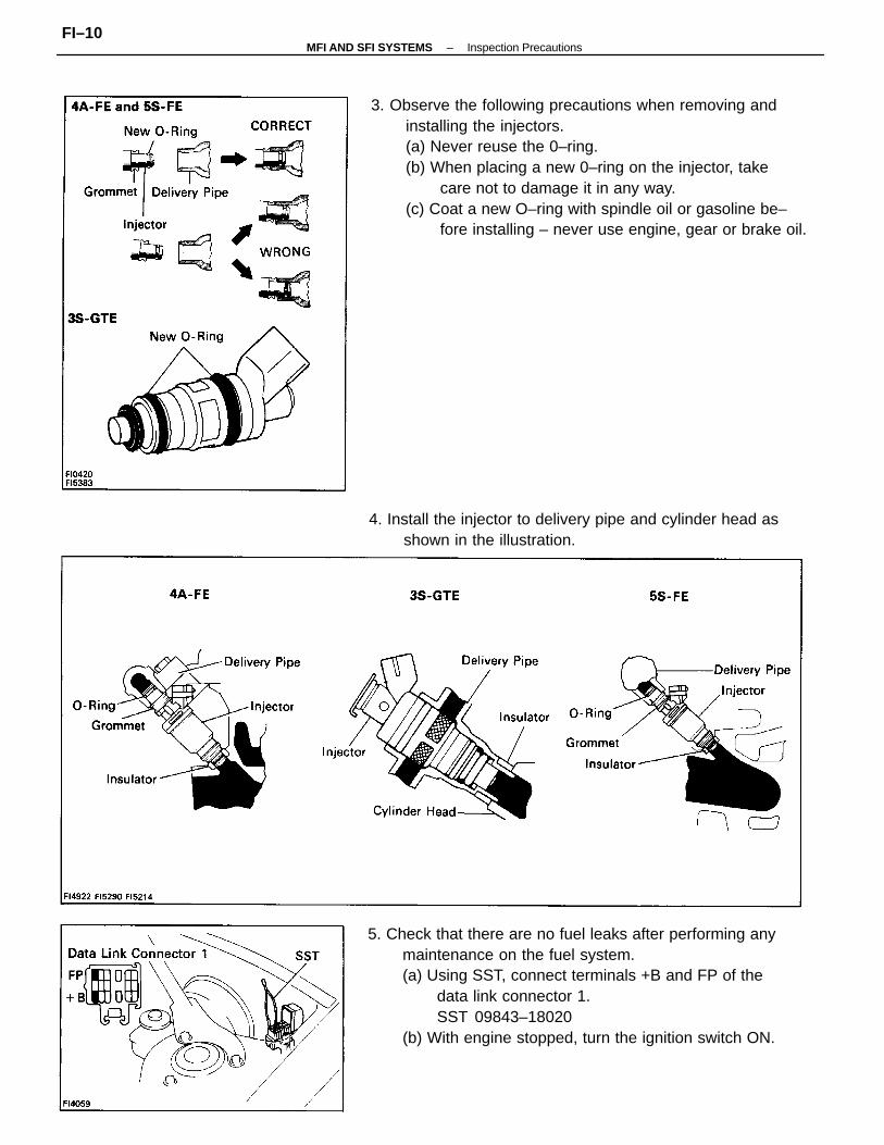
3. Observe the following precautions when removing andinstalling the injectors.(a) Never reuse the 0–ring.(b) When placing a new 0–ring on the injector, take
care not to damage it in any way.(c) Coat a new O–ring with spindle oil or gasoline be–
fore installing – never use engine, gear or brake oil.
5. Check that there are no fuel leaks after performing anymaintenance on the fuel system.(a) Using SST, connect terminals +B and FP of the
data link connector 1.SST 09843–18020
(b) With engine stopped, turn the ignition switch ON.
4. Install the injector to delivery pipe and cylinder head asshown in the illustration.
–MFI AND SFI SYSTEMS Inspection PrecautionsFI–10
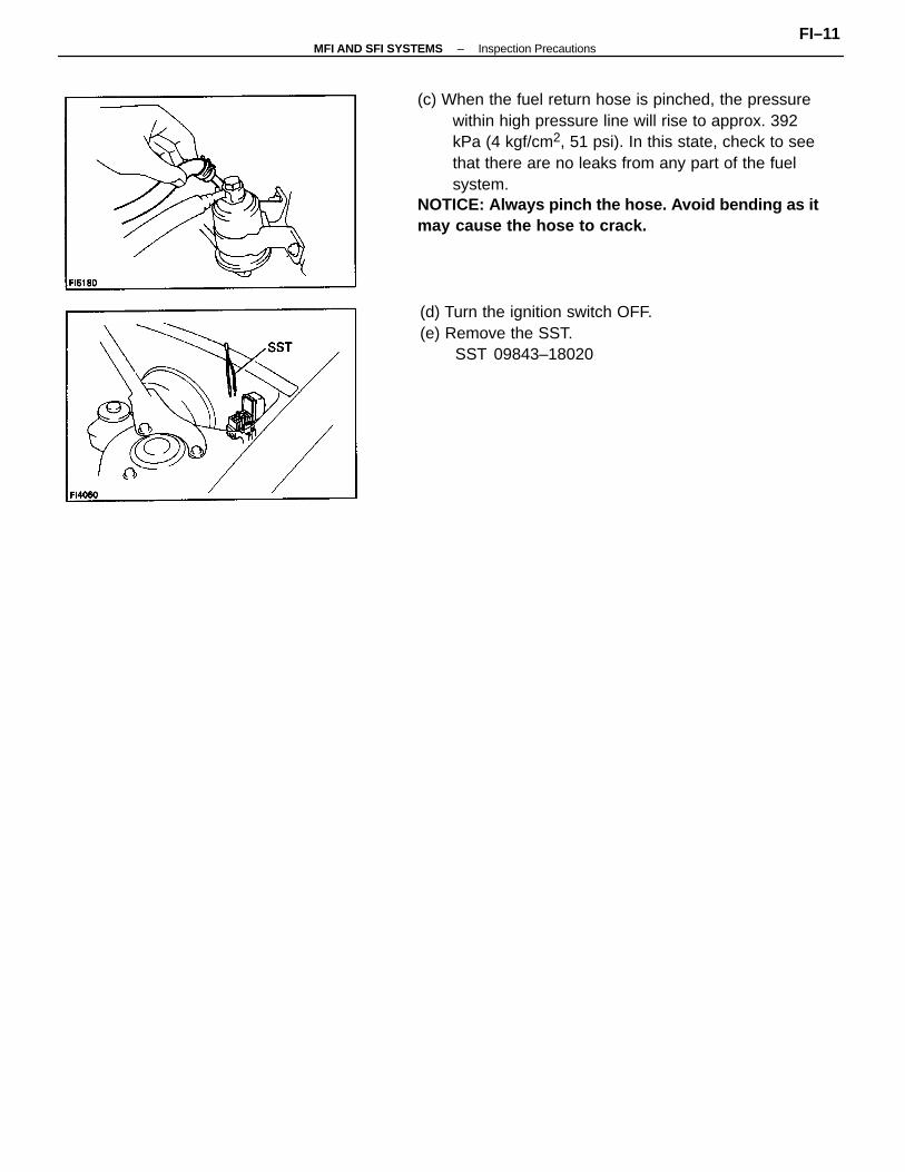
(c) When the fuel return hose is pinched, the pressurewithin high pressure line will rise to approx. 392kPa (4 kgf/cm2, 51 psi). In this state, check to seethat there are no leaks from any part of the fuelsystem.
NOTICE: Always pinch the hose. Avoid bending as itmay cause the hose to crack.
(d) Turn the ignition switch OFF.(e) Remove the SST.
SST 09843–18020
–MFI AND SFI SYSTEMS Inspection PrecautionsFI–11
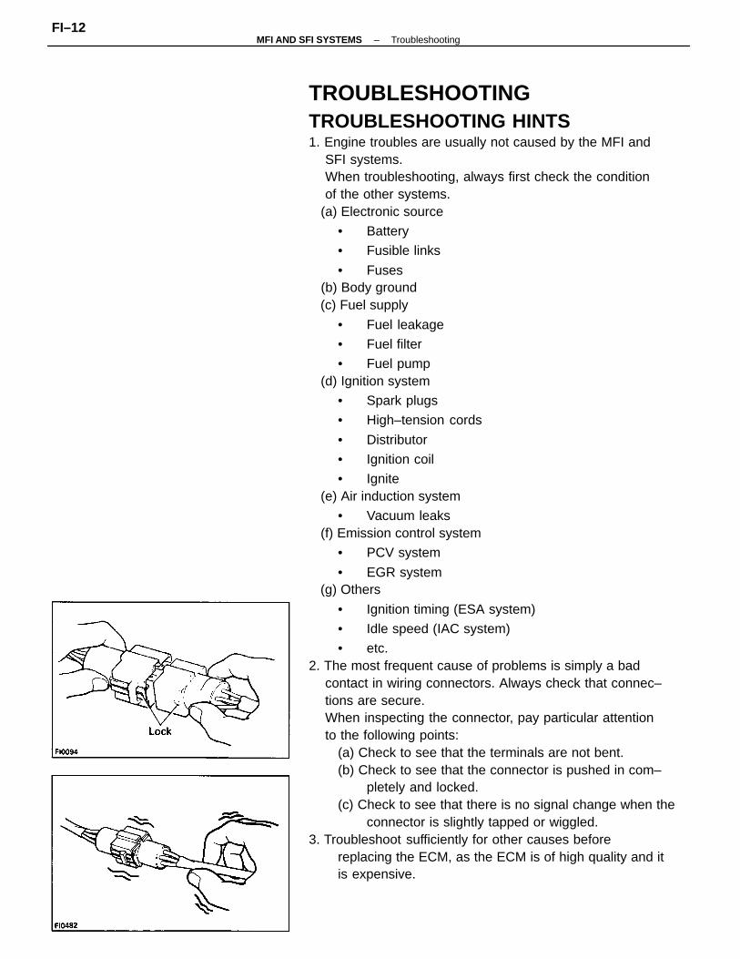
TROUBLESHOOTINGTROUBLESHOOTING HINTS1. Engine troubles are usually not caused by the MFI and
SFI systems.When troubleshooting, always first check the conditionof the other systems.
(a) Electronic source
• Battery
• Fusible links
• Fuses (b) Body ground (c) Fuel supply
• Fuel leakage
• Fuel filter
• Fuel pump (d) Ignition system
• Spark plugs
• High–tension cords
• Distributor
• Ignition coil
• Ignite (e) Air induction system
• Vacuum leaks (f) Emission control system
• PCV system
• EGR system (g) Others
• Ignition timing (ESA system)
• Idle speed (IAC system)
• etc.2. The most frequent cause of problems is simply a bad
contact in wiring connectors. Always check that connec–tions are secure.When inspecting the connector, pay particular attentionto the following points:
(a) Check to see that the terminals are not bent.(b) Check to see that the connector is pushed in com–
pletely and locked.(c) Check to see that there is no signal change when the
connector is slightly tapped or wiggled.3. Troubleshoot sufficiently for other causes before
replacing the ECM, as the ECM is of high quality and itis expensive.
–MFI AND SFI SYSTEMS TroubleshootingFI–12
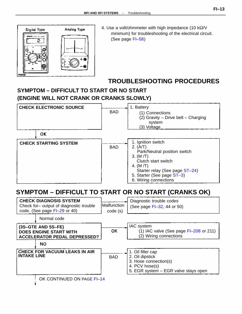
SYMPTOM – DIFFICULT TO START OR NO START(ENGINE WILL NOT CRANK OR CRANKS SLOWLY)
1. Ignition switch2. (A/T)
Park/Neutral position switch3. (M /T)
Clutch start switch4. (M /T)
Starter relay (See page ST–24)5. Starter (See page ST–3)6. Wiring connections
4. Use a volt/ohmmeter with high impedance (10 k/Vminimum) for troubleshooting of the electrical circuit.(See page FI–58)
1. Oil filler cap2. Oil dipstick3. Hose connection(s)4. PCV hose(s)5. EGR system – EGR valve stays open
1. Battery(1) Connections(2) Gravity – Drive belt – Charging
system(3) Voltage
SYMPTOM – DIFFICULT TO START OR NO START (CRANKS OK)
IAC system(1) IAC valve (See page FI–208 or 211)(2) Wiring connections
CHECK DIAGNOSIS SYSTEMCheck for– output of diagnostic troublecode. (See page FI–29 or 40)
(3S–GTE AND 5S–FE)DOES ENGINE START WITHACCELERATOR PEDAL DEPRESSED?
CHECK FOR VACUUM LEAKS IN AIRINTAKE LINE
Diagnostic trouble codes(See page FI–32, 44 or 50)
OK CONTINUED ON PAGE FI–14
CHECK ELECTRONIC SOURCE
CHECK STARTING SYSTEM
Malfunction code (s)
Normal code
BAD
BAD
BAD
TROUBLESHOOTING PROCEDURES
–MFI AND SFI SYSTEMS TroubleshootingFI–13
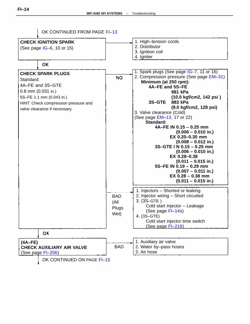
1. Spark plugs (See page IG–7, 11 or 16)2. Compression pressure (See page EM–31)
Minimum (at 250 rpm):4A–FE and 5S–FE
981 kPa(10.0 kgf/cm2, 142 psi )
3S–GTE 883 kPa(9.0 kgf/cm2, 128 psi)
3. Valve clearance (Cold)(See page EM–13, 17 or 22)
Standard:4A–FE IN 0.15 – 0.25 mm
(0.006 – 0.010 in.)EX 0.20–0.30 mm
(0.008 – 0.012 in.)3S–GTE I N 0.15 – 0.25 mm
(0.006 – 0.010 in.)EX 0.28–0.38
(0.011 – 0.015 in.)5S–FE IN 0.19 – 0.29 mm
(0.007 – 0.011 in.)EX 0.28 – 0.38 mm
(0.011 – 0.015 in.)
CHECK SPARK PLUGSStandard:4A–FE and 3S–GTE0.8 mm (0.031 in.)5S–FE 1.1 mm (0.043 in.)HINT: Check compression pressure andvalve clearance if necessary.
1. Injectors – Shorted or leaking2. Injector wiring – Short circuited3. (3S–GTE )
Cold start injector – Leakage(See page FI–14s)
4. (3S–GTE)Cold start injector time switch(See page FI–219)
(4A–FE)CHECK AUXILIARY AIR VALVE(See page FI–206)
1. High–tension cords2. Distributor3. Ignition coil4. Igniter
1. Auxiliary air valve2. Water by–pass hoses3. Air hose
CHECK IGNITION SPARK(See page IG–6, 10 or 15)
OK CONTINUED FROM PAGE FI–13
OK CONTINUED ON PAGE FI–15
BAD(AllPlugsWet)
BAD
–MFI AND SFI SYSTEMS TroubleshootingFI–14
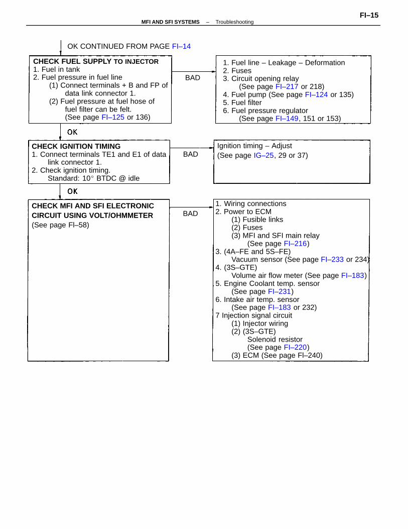
1. Wiring connections2. Power to ECM
(1) Fusible links(2) Fuses(3) MFI and SFI main relay
(See page FI–216)3. (4A–FE and 5S–FE)
Vacuum sensor (See page FI–233 or 234)4. (3S–GTE)
Volume air flow meter (See page FI–183)5. Engine Coolant temp. sensor
(See page FI–231)6. Intake air temp. sensor
(See page FI–183 or 232)7 Injection signal circuit
(1) Injector wiring(2) (3S–GTE)
Solenoid resistor(See page FI–220)
(3) ECM (See page Fl–240)
CHECK FUEL SUPPLY TO INJECTOR1. Fuel in tank2. Fuel pressure in fuel line
(1) Connect terminals + B and FP ofdata link connector 1.
(2) Fuel pressure at fuel hose offuel filter can be felt.(See page FI–125 or 136)
1. Fuel line – Leakage – Deformation2. Fuses3. Circuit opening relay
(See page FI–217 or 218)4. Fuel pump (See page FI–124 or 135)5. Fuel filter6. Fuel pressure regulator
(See page FI–149, 151 or 153)
CHECK IGNITION TIMING1. Connect terminals TE1 and E1 of data
link connector 1.2. Check ignition timing.
Standard: 10 BTDC @ idle
CHECK MFI AND SFI ELECTRONICCIRCUIT USING VOLT/OHMMETER(See page Fl–58)
Ignition timing – Adjust(See page IG–25, 29 or 37)
OK CONTINUED FROM PAGE FI–14
BAD
BAD
BAD
–MFI AND SFI SYSTEMS TroubleshootingFI–15
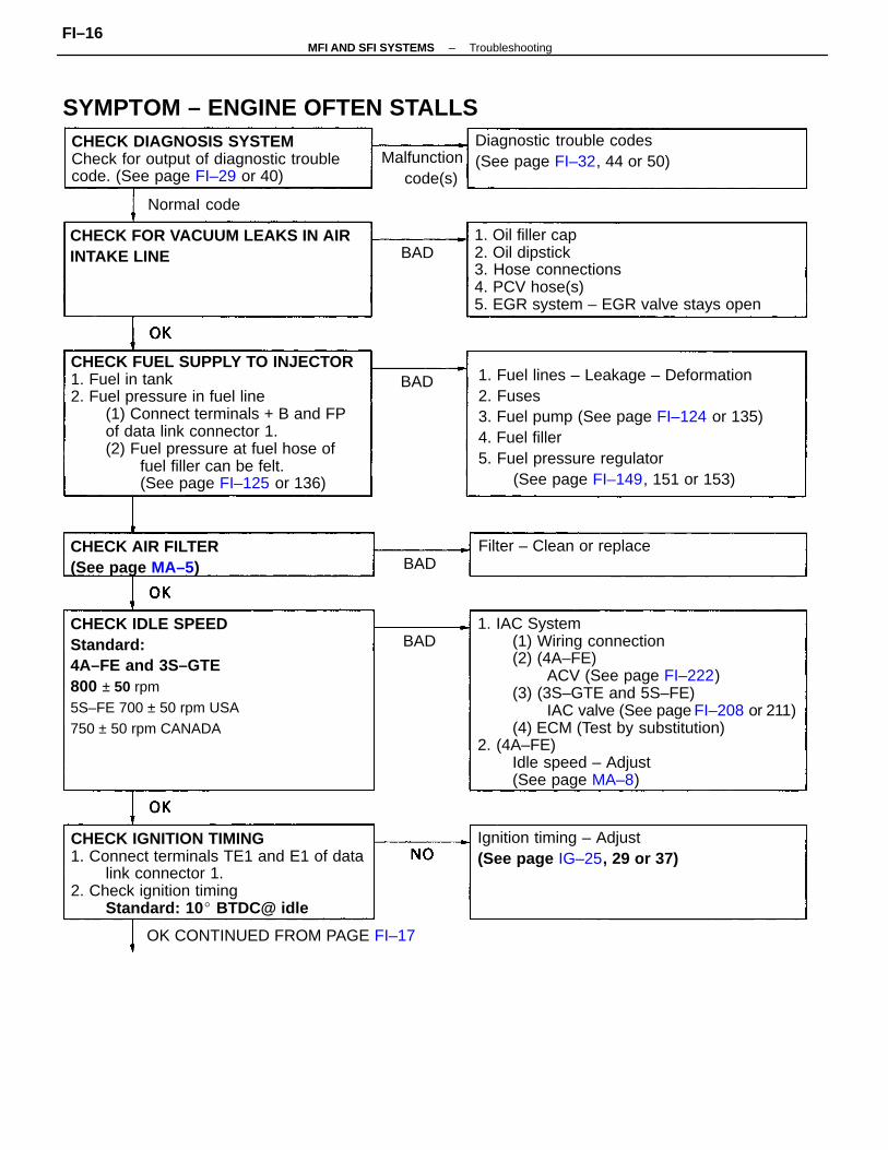
1. IAC System(1) Wiring connection(2) (4A–FE)
ACV (See page FI–222)(3) (3S–GTE and 5S–FE)
IAC valve (See page FI–208 or 211)(4) ECM (Test by substitution)
2. (4A–FE)Idle speed – Adjust(See page MA–8)
CHECK FUEL SUPPLY TO INJECTOR1. Fuel in tank2. Fuel pressure in fuel line
(1) Connect terminals + B and FPof data link connector 1.(2) Fuel pressure at fuel hose of
fuel filler can be felt.(See page FI–125 or 136)
1. Fuel lines – Leakage – Deformation2. Fuses3. Fuel pump (See page FI–124 or 135)4. Fuel filler5. Fuel pressure regulator
(See page FI–149, 151 or 153)
CHECK IDLE SPEEDStandard:4A–FE and 3S–GTE800 ± 50 rpm5S–FE 700 ± 50 rpm USA750 ± 50 rpm CANADA
CHECK IGNITION TIMING1. Connect terminals TE1 and E1 of data
link connector 1.2. Check ignition timing
Standard: 10 BTDC@ idle
1. Oil filler cap2. Oil dipstick3. Hose connections4. PCV hose(s)5. EGR system – EGR valve stays open
CHECK DIAGNOSIS SYSTEMCheck for output of diagnostic troublecode. (See page FI–29 or 40)
CHECK FOR VACUUM LEAKS IN AIRINTAKE LINE
SYMPTOM – ENGINE OFTEN STALLSDiagnostic trouble codes(See page FI–32, 44 or 50)
Ignition timing – Adjust(See page IG–25, 29 or 37)
OK CONTINUED FROM PAGE FI–17
CHECK AIR FILTER(See page MA–5)
Filter – Clean or replace
Malfunction code(s)
NormaI code
BAD
BAD
BAD
BAD
–MFI AND SFI SYSTEMS TroubleshootingFI–16
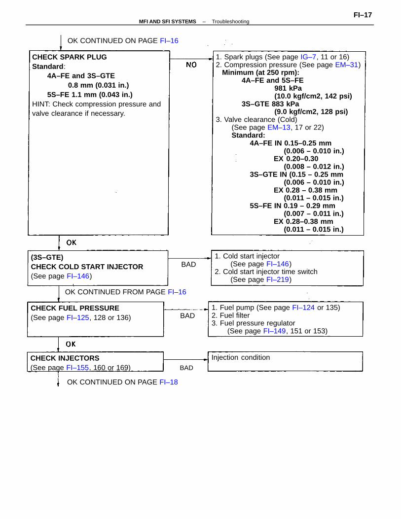
1. Spark plugs (See page IG–7, 11 or 16)2. Compression pressure (See page EM–31) Minimum (at 250 rpm):
4A–FE and 5S–FE981 kPa(10.0 kgf/cm2, 142 psi)
3S–GTE 883 kPa(9.0 kgf/cm2, 128 psi)
3. Valve clearance (Cold)(See page EM–13, 17 or 22)Standard:
4A–FE IN 0.15–0.25 mm(0.006 – 0.010 in.)
EX 0.20–0.30(0.008 – 0.012 in.)
3S–GTE IN (0.15 – 0.25 mm(0.006 – 0.010 in.)
EX 0.28 – 0.38 mm(0.011 – 0.015 in.)
5S–FE IN 0.19 – 0.29 mm(0.007 – 0.011 in.)
EX 0.28–0.38 mm(0.011 – 0.015 in.)
CHECK SPARK PLUGStandard :
4A–FE and 3S–GTE0.8 mm (0.031 in.)
5S–FE 1.1 mm (0.043 in.)HINT: Check compression pressure andvalve clearance if necessary.
1. Fuel pump (See page FI–124 or 135)2. Fuel filter3. Fuel pressure regulator
(See page FI–149, 151 or 153)
1. Cold start injector(See page FI–146)
2. Cold start injector time switch(See page FI–219)
(3S–GTE)CHECK COLD START INJECTOR(See page FI–146)
CHECK INJECTORS(See page FI–155, 160 or 169)
CHECK FUEL PRESSURE(See page FI–125, 128 or 136)
OK CONTINUED FROM PAGE FI–16
OK CONTINUED ON PAGE FI–16
Injection condition
BAD
BAD
BAD
OK CONTINUED ON PAGE FI–18
–MFI AND SFI SYSTEMS TroubleshootingFI–17
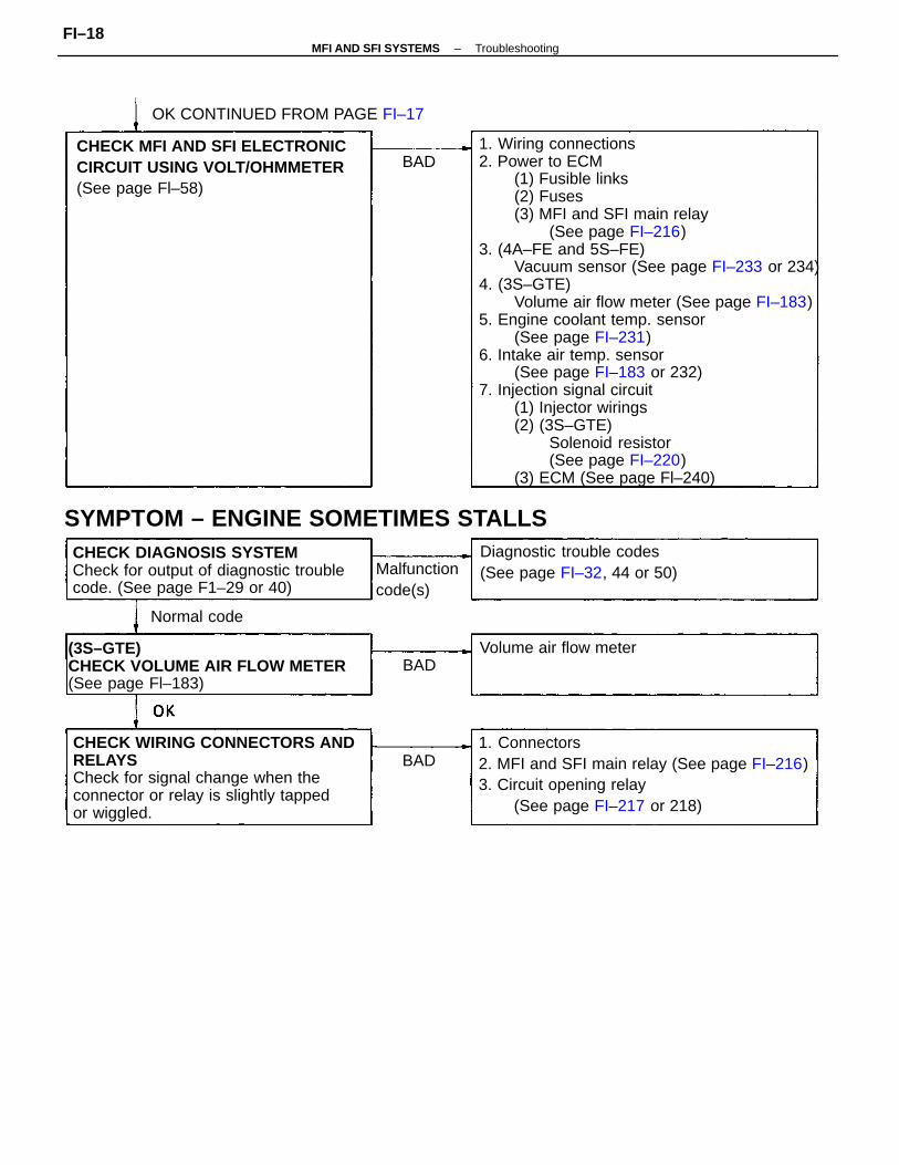
1. Wiring connections2. Power to ECM
(1) Fusible links(2) Fuses(3) MFI and SFI main relay
(See page FI–216)3. (4A–FE and 5S–FE)
Vacuum sensor (See page FI–233 or 234)4. (3S–GTE)
Volume air flow meter (See page FI–183)5. Engine coolant temp. sensor
(See page FI–231)6. Intake air temp. sensor
(See page FI–183 or 232)7. Injection signal circuit
(1) Injector wirings(2) (3S–GTE)
Solenoid resistor(See page FI–220)
(3) ECM (See page Fl–240)
CHECK WIRING CONNECTORS ANDRELAYSCheck for signal change when theconnector or relay is slightly tappedor wiggled.
1. Connectors2. MFI and SFI main relay (See page FI–216)3. Circuit opening relay
(See page FI–217 or 218)
CHECK DIAGNOSIS SYSTEMCheck for output of diagnostic troublecode. (See page F1–29 or 40)
(3S–GTE)CHECK VOLUME AIR FLOW METER(See page Fl–183)
CHECK MFI AND SFI ELECTRONICCIRCUIT USING VOLT/OHMMETER(See page Fl–58)
OK CONTINUED FROM PAGE FI–17
SYMPTOM – ENGINE SOMETIMES STALLSDiagnostic trouble codes(See page FI–32, 44 or 50)
Volume air flow meter
Malfunctioncode(s)
Normal code
BAD
BAD
BAD
–MFI AND SFI SYSTEMS TroubleshootingFI–18
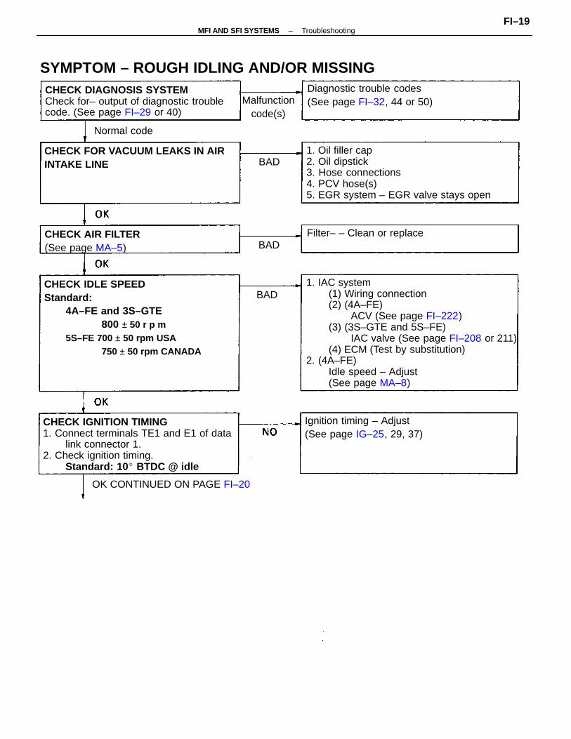
1. IAC system(1) Wiring connection(2) (4A–FE)
ACV (See page FI–222)(3) (3S–GTE and 5S–FE)
IAC valve (See page FI–208 or 211)(4) ECM (Test by substitution)
2. (4A–FE)Idle speed – Adjust(See page MA–8)
CHECK IDLE SPEEDStandard:
4A–FE and 3S–GTE800 ± 50 r p m
5S–FE 700 ± 50 rpm USA750 ± 50 rpm CANADA
CHECK IGNITION TIMING1. Connect terminals TE1 and E1 of data
link connector 1.2. Check ignition timing.
Standard: 10 BTDC @ idle
1. Oil filler cap2. Oil dipstick3. Hose connections4. PCV hose(s)5. EGR system – EGR valve stays open
CHECK DIAGNOSIS SYSTEMCheck for– output of diagnostic troublecode. (See page FI–29 or 40)
SYMPTOM – ROUGH IDLING AND/OR MISSING
CHECK FOR VACUUM LEAKS IN AIRINTAKE LINE
Diagnostic trouble codes(See page FI–32, 44 or 50)
Ignition timing – Adjust(See page IG–25, 29, 37)
OK CONTINUED ON PAGE FI–20
CHECK AIR FILTER(See page MA–5)
Filter– – Clean or replace
Malfunction code(s)
Normal code
BAD
BAD
BAD
–MFI AND SFI SYSTEMS TroubleshootingFI–19
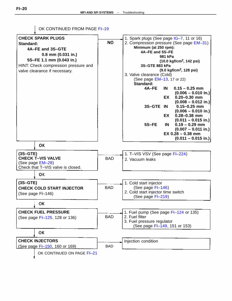
1. Spark plugs (See page IG–7, 11 or 16)2. Compression pressure (See page EM–31)
Minimum (at 250 rpm):4A–FE and 5S–FE
981 kPa(10.0 kgf/cm 2, 142 psi)
3S–GTE 883 kPa(9.0 kgf/cm 2, 128 psi)
3. Valve clearance (Cold)(See page EM–13, 17 or 22)Standard:
4A–FE IN 0.15 – 0.25 mm(0.006 – 0.010 In.)
EX 0.20–0.30 mm(0.008 – 0.012 in.)
3S–GTE IN 0.15–0.25 mm(0.006 – 0.010 in.)
EX 0.28–0.38 mm(0.011 – 0.015 in.)
5S–FE IN 0.19 – 0.29 mm(0.007 – 0.011 in.)
EX 0.28 – 0.38 mm(0.011 – 0.015 in.)
CHECK SPARK PLUGSStandard:
4A–FE and 3S–GTE0.8 mm (0.031 in.)
5S–FE 1.1 mm (0.043 in.)HINT: Check compression pressure andvalve clearance if necessary.
1. Fuel pump (See page FI–124 or 135)2. Fuel filter3. Fuel pressure regulator
(See page FI–149, 151 or 153)
1. Cold start injector(See page FI–146)
2. Cold start injector time switch(See page FI–219)
(3S–GTE)CHECK T–VIS VALVE(See page EM–28)Check that T–VIS valve is closed.
OK CONTINUED ON PAGE FI–21
(3S–GTE)CHECK COLD START INJECTOR(See page Fl–146)
1. T–VIS VSV (See page FI–224)2. Vacuum leaks
CHECK INJECTORS(See page FI–150, 160 or 169)
CHECK FUEL PRESSURE(See page FI–125, 128 or 136)
OK CONTINUED FROM PAGE FI–19
Injection condition
BAD
BAD
BAD
BAD
–MFI AND SFI SYSTEMS TroubleshootingFI–20
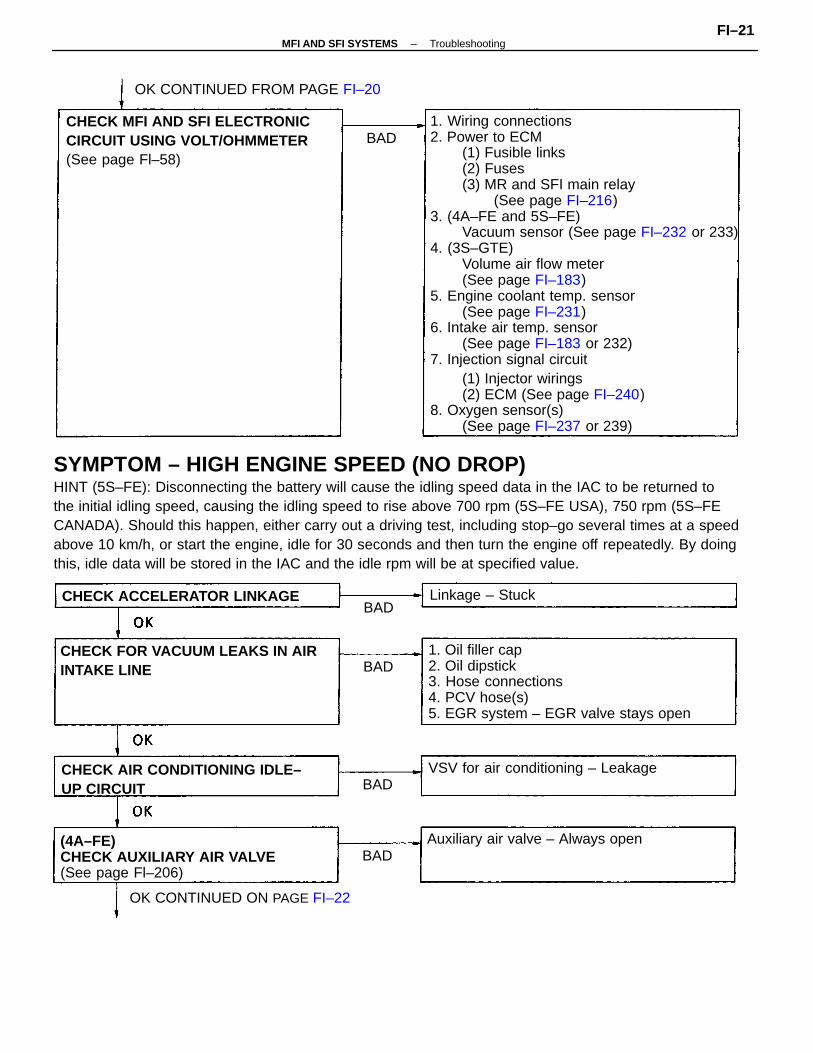
1. Wiring connections2. Power to ECM
(1) Fusible links(2) Fuses(3) MR and SFI main relay
(See page FI–216)3. (4A–FE and 5S–FE)
Vacuum sensor (See page FI–232 or 233)4. (3S–GTE)
Volume air flow meter(See page FI–183)
5. Engine coolant temp. sensor(See page FI–231)
6. Intake air temp. sensor(See page FI–183 or 232)
7. Injection signal circuit(1) Injector wirings(2) ECM (See page FI–240)
8. Oxygen sensor(s)(See page FI–237 or 239)
SYMPTOM – HIGH ENGINE SPEED (NO DROP)HINT (5S–FE): Disconnecting the battery will cause the idling speed data in the IAC to be returned tothe initial idling speed, causing the idling speed to rise above 700 rpm (5S–FE USA), 750 rpm (5S–FECANADA). Should this happen, either carry out a driving test, including stop–go several times at a speedabove 10 km/h, or start the engine, idle for 30 seconds and then turn the engine off repeatedly. By doingthis, idle data will be stored in the IAC and the idle rpm will be at specified value.
1. Oil filler cap2. Oil dipstick3. Hose connections4. PCV hose(s)5. EGR system – EGR valve stays open
CHECK MFI AND SFI ELECTRONICCIRCUIT USING VOLT/OHMMETER(See page Fl–58)
(4A–FE)CHECK AUXILIARY AIR VALVE(See page Fl–206)
CHECK FOR VACUUM LEAKS IN AIRINTAKE LINE
CHECK AIR CONDITIONING IDLE–UP CIRCUIT
OK CONTINUED FROM PAGE FI–20
VSV for air conditioning – Leakage
Auxiliary air valve – Always open
OK CONTINUED ON PAGE FI–22
CHECK ACCELERATOR LINKAGE Linkage – Stuck
BAD
BAD
BAD
BAD
BAD
–MFI AND SFI SYSTEMS TroubleshootingFI–21
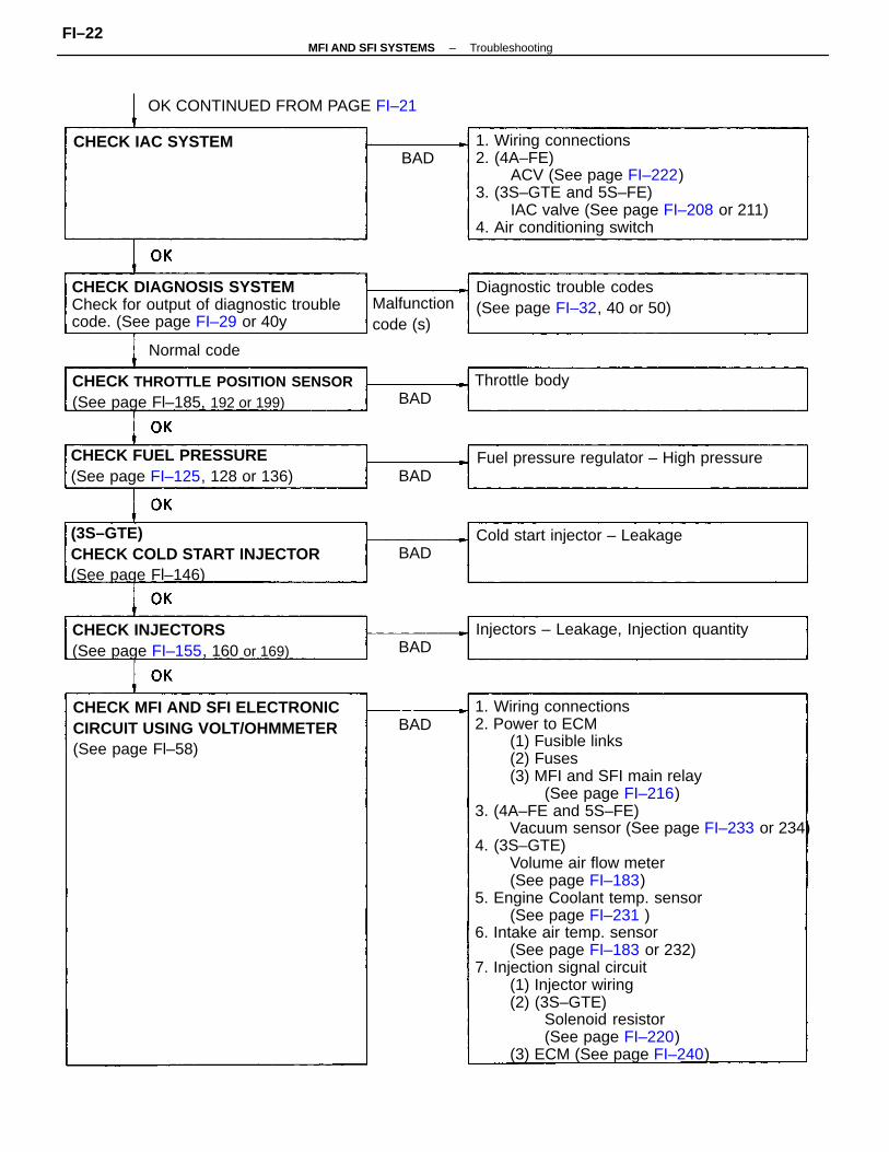
1. Wiring connections2. Power to ECM
(1) Fusible links(2) Fuses(3) MFI and SFI main relay
(See page FI–216)3. (4A–FE and 5S–FE)
Vacuum sensor (See page FI–233 or 234)4. (3S–GTE)
Volume air flow meter(See page FI–183)
5. Engine Coolant temp. sensor(See page FI–231 )
6. Intake air temp. sensor(See page FI–183 or 232)
7. Injection signal circuit(1) Injector wiring(2) (3S–GTE)
Solenoid resistor(See page FI–220)
(3) ECM (See page FI–240)
1. Wiring connections2. (4A–FE)
ACV (See page FI–222)3. (3S–GTE and 5S–FE)
IAC valve (See page FI–208 or 211)4. Air conditioning switch
CHECK DIAGNOSIS SYSTEMCheck for output of diagnostic troublecode. (See page FI–29 or 40y
CHECK MFI AND SFI ELECTRONICCIRCUIT USING VOLT/OHMMETER(See page Fl–58)
(3S–GTE)CHECK COLD START INJECTOR(See page Fl–146)
CHECK THROTTLE POSITION SENSOR(See page Fl–185, 192 or 199)
CHECK FUEL PRESSURE(See page FI–125, 128 or 136)
CHECK INJECTORS(See page FI–155, 160 or 169)
Diagnostic trouble codes(See page FI–32, 40 or 50)
Fuel pressure regulator – High pressure
Injectors – Leakage, Injection quantity
OK CONTINUED FROM PAGE FI–21
Cold start injector – Leakage
Malfunctioncode (s)
CHECK IAC SYSTEM
Throttle body
Normal code
BAD
BAD
BAD
BAD
BAD
BAD
–MFI AND SFI SYSTEMS TroubleshootingFI–22
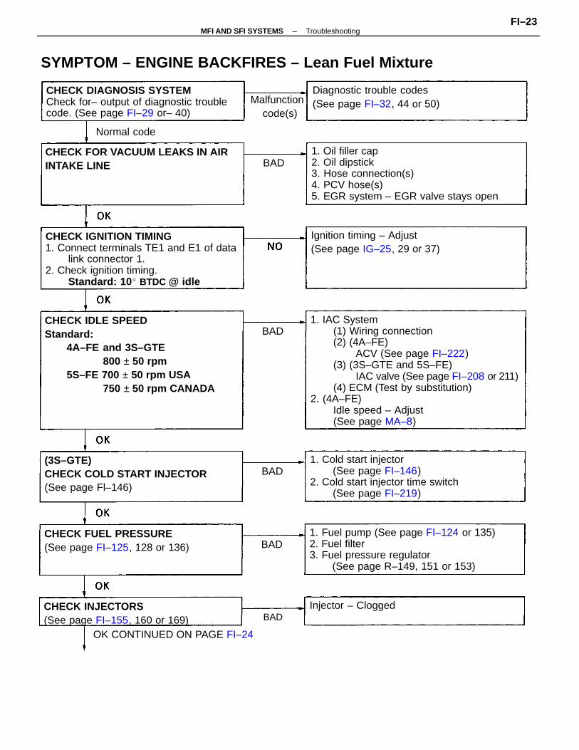
1. IAC System(1) Wiring connection(2) (4A–FE)
ACV (See page FI–222)(3) (3S–GTE and 5S–FE)
IAC valve (See page FI–208 or 211)(4) ECM (Test by substitution)
2. (4A–FE)Idle speed – Adjust(See page MA–8)
CHECK IDLE SPEEDStandard:
4A–FE and 3S–GTE800 ± 50 rpm
5S–FE 700 ± 50 rpm USA750 ± 50 rpm CANADA
CHECK IGNITION TIMING1. Connect terminals TE1 and E1 of data
link connector 1.2. Check ignition timing.
Standard: 10 BTDC @ idle
1. Oil filler cap2. Oil dipstick3. Hose connection(s)4. PCV hose(s)5. EGR system – EGR valve stays open
SYMPTOM – ENGINE BACKFIRES – Lean Fuel Mixture
1. Fuel pump (See page FI–124 or 135)2. Fuel filter3. Fuel pressure regulator
(See page R–149, 151 or 153)
1. Cold start injector(See page FI–146)
2. Cold start injector time switch(See page FI–219)
CHECK DIAGNOSIS SYSTEMCheck for– output of diagnostic troublecode. (See page FI–29 or– 40)
OK CONTINUED ON PAGE FI–24
(3S–GTE)CHECK COLD START INJECTOR(See page Fl–146)
CHECK FOR VACUUM LEAKS IN AIRINTAKE LINE
CHECK INJECTORS(See page FI–155, 160 or 169)
CHECK FUEL PRESSURE(See page FI–125, 128 or 136)
Ignition timing – Adjust(See page IG–25, 29 or 37)
Diagnostic trouble codes(See page FI–32, 44 or 50)Malfunction
code(s)
Injector – Clogged
Normal code
BAD
BAD
BAD
BAD
BAD
–MFI AND SFI SYSTEMS TroubleshootingFI–23
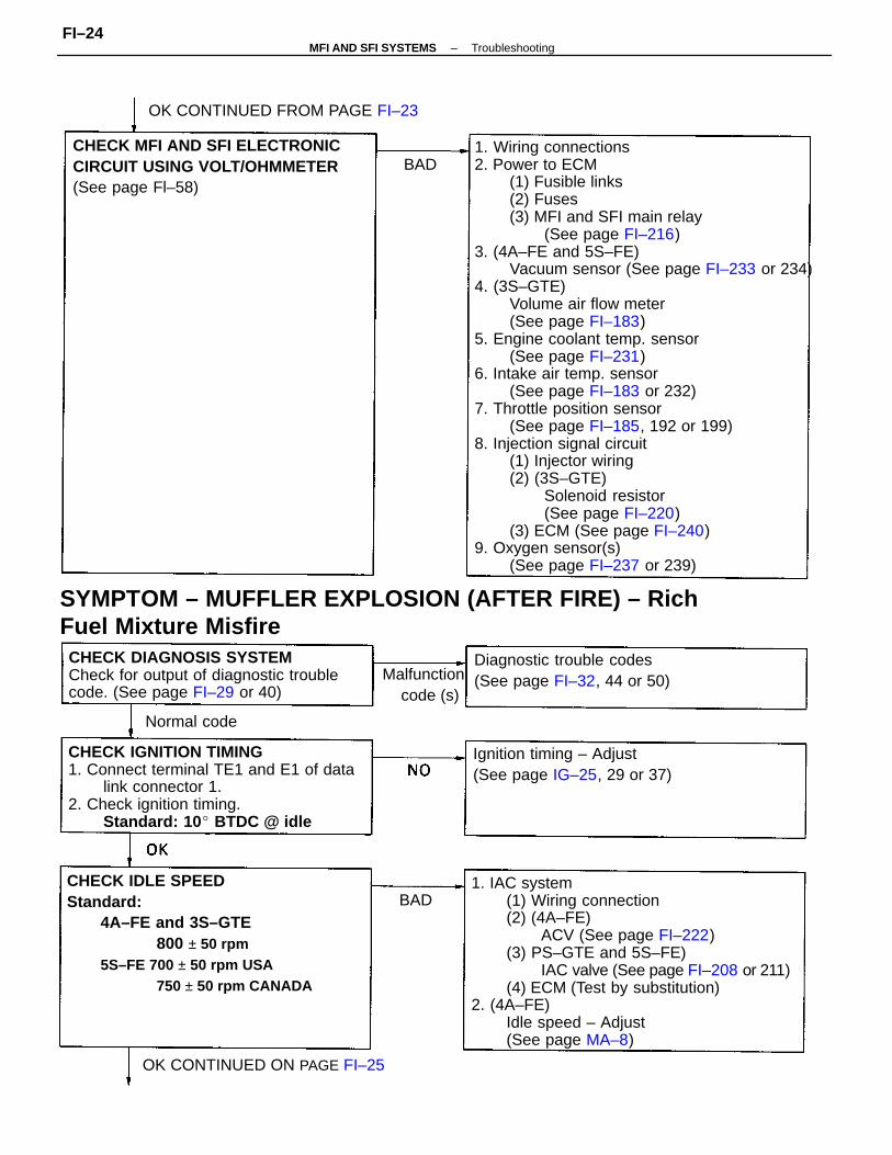
1. Wiring connections2. Power to ECM
(1) Fusible links(2) Fuses(3) MFI and SFI main relay
(See page FI–216)3. (4A–FE and 5S–FE)
Vacuum sensor (See page FI–233 or 234)4. (3S–GTE)
Volume air flow meter(See page FI–183)
5. Engine coolant temp. sensor(See page FI–231)
6. Intake air temp. sensor(See page FI–183 or 232)
7. Throttle position sensor(See page FI–185, 192 or 199)
8. Injection signal circuit(1) Injector wiring(2) (3S–GTE)
Solenoid resistor(See page FI–220)
(3) ECM (See page FI–240)9. Oxygen sensor(s)
(See page FI–237 or 239)
1. IAC system(1) Wiring connection(2) (4A–FE)
ACV (See page FI–222)(3) PS–GTE and 5S–FE)
IAC valve (See page FI–208 or 211)(4) ECM (Test by substitution)
2. (4A–FE)Idle speed – Adjust(See page MA–8)
SYMPTOM – MUFFLER EXPLOSION (AFTER FIRE) – Rich Fuel Mixture Misfire
CHECK IDLE SPEEDStandard:
4A–FE and 3S–GTE800 ± 50 rpm
5S–FE 700 ± 50 rpm USA750 ± 50 rpm CANADA
CHECK IGNITION TIMING1. Connect terminal TE1 and E1 of data
link connector 1.2. Check ignition timing.
Standard: 10 BTDC @ idle
CHECK DIAGNOSIS SYSTEMCheck for output of diagnostic troublecode. (See page FI–29 or 40)
CHECK MFI AND SFI ELECTRONICCIRCUIT USING VOLT/OHMMETER(See page Fl–58)
Ignition timing – Adjust(See page IG–25, 29 or 37)
Diagnostic trouble codes(See page FI–32, 44 or 50)
OK CONTINUED FROM PAGE FI–23
OK CONTINUED ON PAGE FI–25
Malfunction code (s)
Normal code
BAD
BAD
–MFI AND SFI SYSTEMS TroubleshootingFI–24
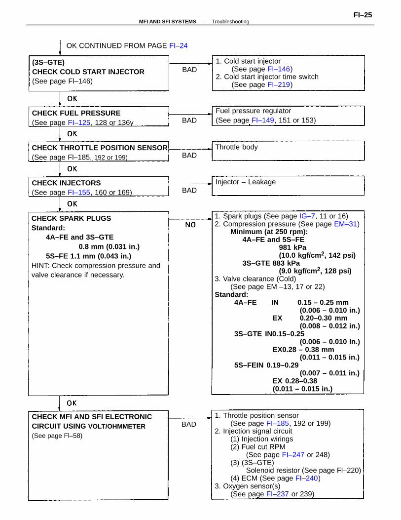
1. Spark plugs (See page IG–7, 11 or 16)2. Compression pressure (See page EM–31)
Minimum (at 250 rpm):4A–FE and 5S–FE
981 kPa(10.0 kgf/cm 2, 142 psi)
3S–GTE 883 kPa(9.0 kgf/cm 2, 128 psi)
3. Valve clearance (Cold)(See page EM –13, 17 or 22)
Standard:4A–FE IN 0.15 – 0.25 mm
(0.006 – 0.010 in.)EX 0.20–0.30 mm
(0.008 – 0.012 in.)3S–GTE IN0.15–0.25
(0.006 – 0.010 In.)EX0.28 – 0.38 mm
(0.011 – 0.015 in.)5S–FEIN 0.19–0.29
(0.007 – 0.011 in.)EX 0.28–0.38(0.011 – 0.015 in.)
1. Throttle position sensor(See page FI–185, 192 or 199)
2. Injection signal circuit(1) Injection wirings(2) Fuel cut RPM
(See page FI–247 or 248)(3) (3S–GTE)
Solenoid resistor (See page Fl–220)(4) ECM (See page FI–240)
3. Oxygen sensor(s)(See page FI–237 or 239)
CHECK SPARK PLUGSStandard:
4A–FE and 3S–GTE0.8 mm (0.031 in.)
5S–FE 1.1 mm (0.043 in.)HINT: Check compression pressure andvalve clearance if necessary.
1. Cold start injector(See page FI–146)
2. Cold start injector time switch(See page FI–219)
CHECK MFI AND SFI ELECTRONICCIRCUIT USING VOLT/OHMMETER(See page Fl–58)
(3S–GTE)CHECK COLD START INJECTOR(See page Fl–146)
CHECK THROTTLE POSITION SENSOR(See page Fl–185, 192 or 199)
Fuel pressure regulator(See page FI–149, 151 or 153)
CHECK INJECTORS(See page FI–155, 160 or 169)
CHECK FUEL PRESSURE(See page FI–125, 128 or 136y
OK CONTINUED FROM PAGE FI–24
Throttle body
Injector – Leakage
BAD
BAD
BAD
BAD
BAD
–MFI AND SFI SYSTEMS TroubleshootingFI–25
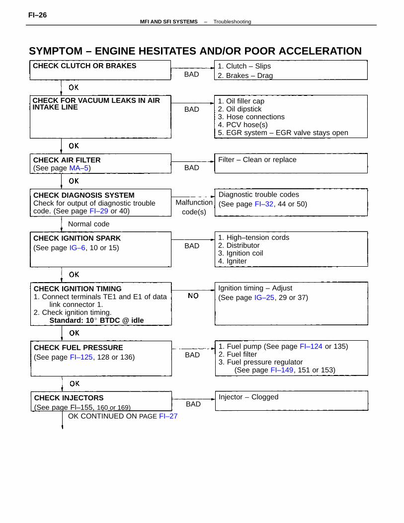
CHECK IGNITION TIMING1. Connect terminals TE1 and E1 of data
link connector 1.2. Check ignition timing.
Standard: 10 BTDC @ idle
1. Oil filler cap2. Oil dipstick3. Hose connections4. PCV hose(s)5. EGR system – EGR valve stays open
1. Fuel pump (See page FI–124 or 135)2. Fuel filter3. Fuel pressure regulator
(See page FI–149, 151 or 153)
SYMPTOM – ENGINE HESITATES AND/OR POOR ACCELERATION
CHECK DIAGNOSIS SYSTEMCheck for output of diagnostic troublecode. (See page FI–29 or 40)
OK CONTINUED ON PAGE FI–27
1. High–tension cords2. Distributor3. Ignition coil4. Igniter
CHECK FOR VACUUM LEAKS IN AIRINTAKE LINE
CHECK INJECTORS(See page Fl–155, 160 or 169)
CHECK FUEL PRESSURE(See page FI–125, 128 or 136)
Ignition timing – Adjust(See page IG–25, 29 or 37)
CHECK IGNITION SPARK(See page IG–6, 10 or 15)
Diagnostic trouble codes(See page FI–32, 44 or 50)
CHECK AIR FILTER(See page MA–5)
1. Clutch – Slips2. Brakes – Drag
CHECK CLUTCH OR BRAKES
Filter – Clean or replace
Malfunction code(s)
Injector – Clogged
Normal code
BAD
BAD
BAD
BAD
BAD
BAD
–MFI AND SFI SYSTEMS TroubleshootingFI–26
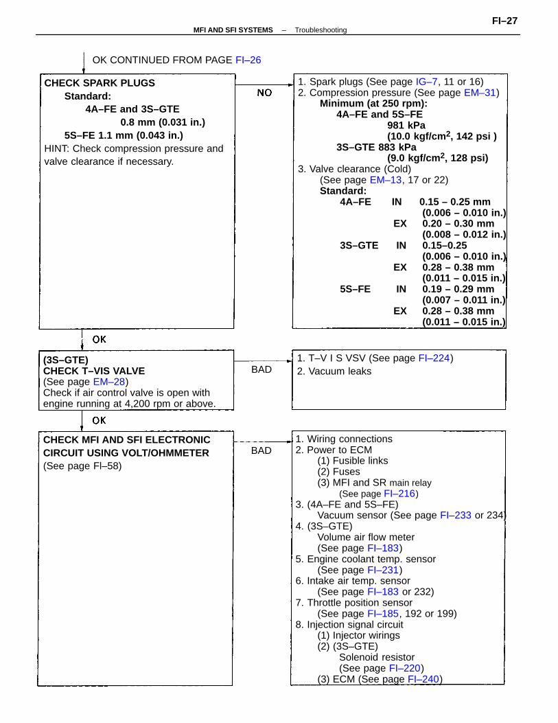
1. Spark plugs (See page IG–7, 11 or 16)2. Compression pressure (See page EM–31)
Minimum (at 250 rpm):4A–FE and 5S–FE
981 kPa(10.0 kgf/cm 2, 142 psi )
3S–GTE 883 kPa(9.0 kgf/cm 2, 128 psi)
3. Valve clearance (Cold)(See page EM–13, 17 or 22)Standard:
4A–FE IN 0.15 – 0.25 mm(0.006 – 0.010 in.)
EX 0.20 – 0.30 mm(0.008 – 0.012 in.)
3S–GTE IN 0.15–0.25(0.006 – 0.010 in.)
EX 0.28 – 0.38 mm(0.011 – 0.015 in.)
5S–FE IN 0.19 – 0.29 mm(0.007 – 0.011 in.)
EX 0.28 – 0.38 mm(0.011 – 0.015 in.)
1. Wiring connections2. Power to ECM
(1) Fusible links(2) Fuses(3) MFI and SR main relay
(See page FI–216)3. (4A–FE and 5S–FE)
Vacuum sensor (See page FI–233 or 234)4. (3S–GTE)
Volume air flow meter(See page FI–183)
5. Engine coolant temp. sensor(See page FI–231)
6. Intake air temp. sensor(See page FI–183 or 232)
7. Throttle position sensor(See page FI–185, 192 or 199)
8. Injection signal circuit(1) Injector wirings(2) (3S–GTE)
Solenoid resistor(See page FI–220)
(3) ECM (See page FI–240)
CHECK SPARK PLUGSStandard:
4A–FE and 3S–GTE0.8 mm (0.031 in.)
5S–FE 1.1 mm (0.043 in.)HINT: Check compression pressure andvalve clearance if necessary.
(3S–GTE)CHECK T–VIS VALVE(See page EM–28)Check if air control valve is open withengine running at 4,200 rpm or above.
CHECK MFI AND SFI ELECTRONICCIRCUIT USING VOLT/OHMMETER(See page Fl–58)
1. T–V I S VSV (See page FI–224)2. Vacuum leaks
OK CONTINUED FROM PAGE FI–26
BAD
BAD
–MFI AND SFI SYSTEMS TroubleshootingFI–27
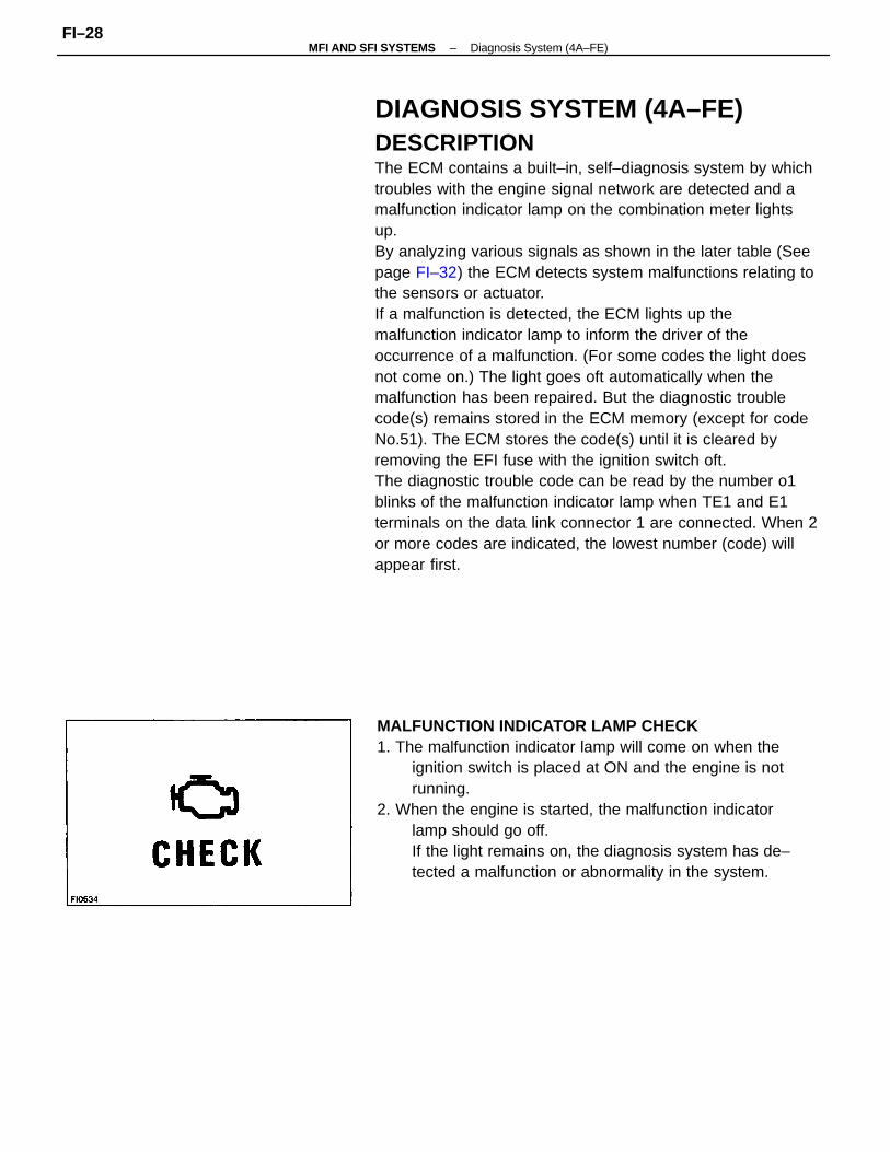
DIAGNOSIS SYSTEM (4A–FE)DESCRIPTIONThe ECM contains a built–in, self–diagnosis system by whichtroubles with the engine signal network are detected and amalfunction indicator lamp on the combination meter lightsup.By analyzing various signals as shown in the later table (Seepage FI–32) the ECM detects system malfunctions relating tothe sensors or actuator.If a malfunction is detected, the ECM lights up themalfunction indicator lamp to inform the driver of theoccurrence of a malfunction. (For some codes the light doesnot come on.) The light goes oft automatically when themalfunction has been repaired. But the diagnostic troublecode(s) remains stored in the ECM memory (except for codeNo.51). The ECM stores the code(s) until it is cleared byremoving the EFI fuse with the ignition switch oft.The diagnostic trouble code can be read by the number o1blinks of the malfunction indicator lamp when TE1 and E1terminals on the data link connector 1 are connected. When 2or more codes are indicated, the lowest number (code) willappear first.
MALFUNCTION INDICATOR LAMP CHECK1. The malfunction indicator lamp will come on when the
ignition switch is placed at ON and the engine is notrunning.
2. When the engine is started, the malfunction indicatorlamp should go off.If the light remains on, the diagnosis system has de–tected a malfunction or abnormality in the system.
–MFI AND SFI SYSTEMS Diagnosis System (4A–FE)FI–28
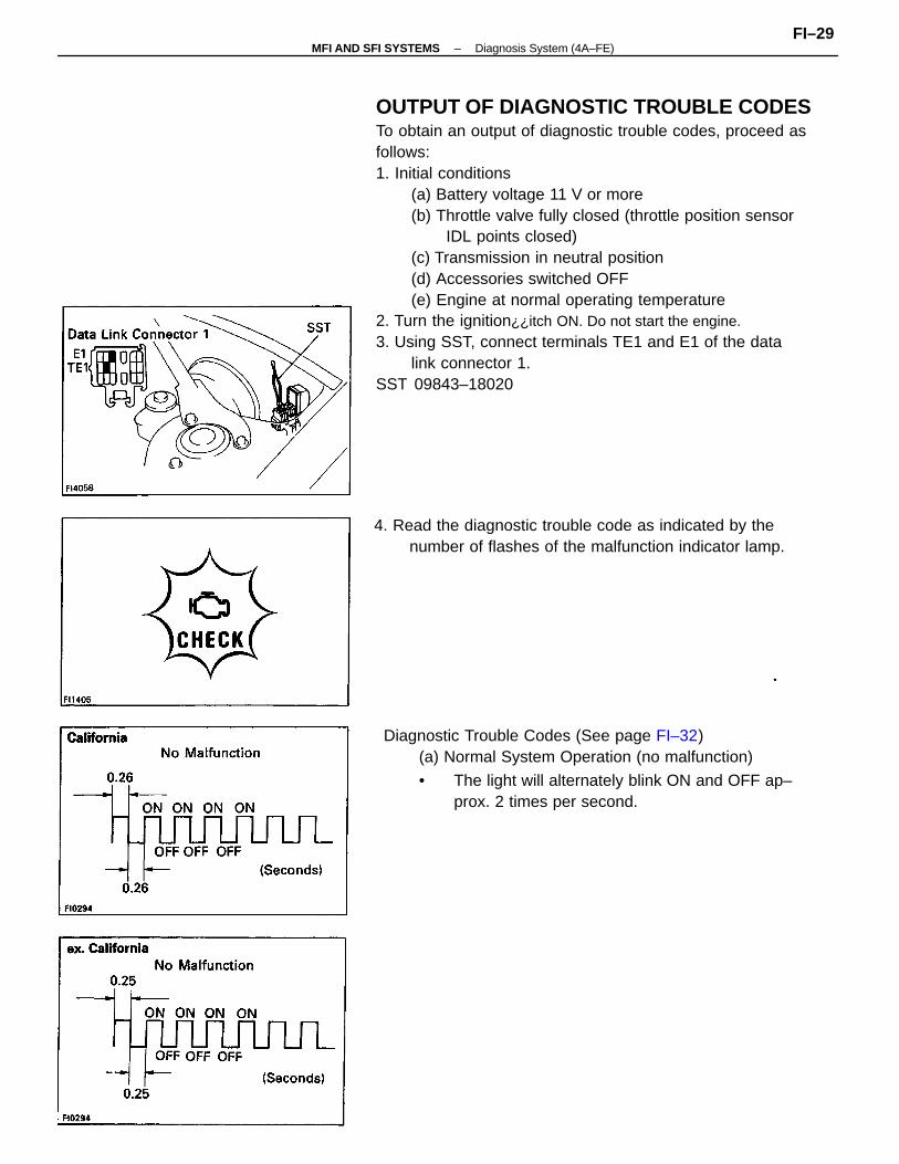
OUTPUT OF DIAGNOSTIC TROUBLE CODESTo obtain an output of diagnostic trouble codes, proceed asfollows:1. Initial conditions
(a) Battery voltage 11 V or more(b) Throttle valve fully closed (throttle position sensor
IDL points closed)(c) Transmission in neutral position(d) Accessories switched OFF(e) Engine at normal operating temperature
2. Turn the ignition¿¿itch ON. Do not start the engine.3. Using SST, connect terminals TE1 and E1 of the data
link connector 1.SST 09843–18020
Diagnostic Trouble Codes (See page FI–32)(a) Normal System Operation (no malfunction)
• The light will alternately blink ON and OFF ap–prox. 2 times per second.
4. Read the diagnostic trouble code as indicated by thenumber of flashes of the malfunction indicator lamp.
–MFI AND SFI SYSTEMS Diagnosis System (4A–FE)FI–29
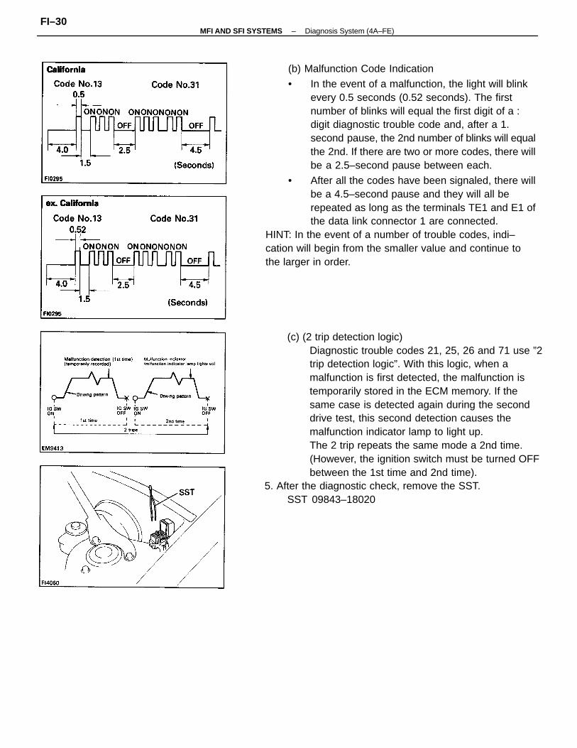
(b) Malfunction Code Indication
• In the event of a malfunction, the light will blinkevery 0.5 seconds (0.52 seconds). The firstnumber of blinks will equal the first digit of a :digit diagnostic trouble code and, after a 1.second pause, the 2nd number of blinks will equalthe 2nd. If there are two or more codes, there willbe a 2.5–second pause between each.
• After all the codes have been signaled, there willbe a 4.5–second pause and they will all berepeated as long as the terminals TE1 and E1 ofthe data link connector 1 are connected.
HINT: In the event of a number of trouble codes, indi–cation will begin from the smaller value and continue tothe larger in order.
(c) (2 trip detection logic)Diagnostic trouble codes 21, 25, 26 and 71 use ”2trip detection logic”. With this logic, when amalfunction is first detected, the malfunction istemporarily stored in the ECM memory. If thesame case is detected again during the seconddrive test, this second detection causes themalfunction indicator lamp to light up.The 2 trip repeats the same mode a 2nd time.(However, the ignition switch must be turned OFFbetween the 1st time and 2nd time).
5. After the diagnostic check, remove the SST.SST 09843–18020
–MFI AND SFI SYSTEMS Diagnosis System (4A–FE)FI–30
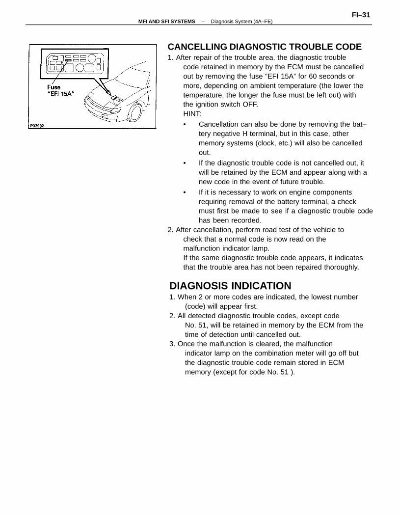
CANCELLING DIAGNOSTIC TROUBLE CODE1. After repair of the trouble area, the diagnostic trouble
code retained in memory by the ECM must be cancelledout by removing the fuse ”EFI 15A” for 60 seconds ormore, depending on ambient temperature (the lower thetemperature, the longer the fuse must be left out) withthe ignition switch OFF.HINT:
• Cancellation can also be done by removing the bat–tery negative H terminal, but in this case, othermemory systems (clock, etc.) will also be cancelledout.
• If the diagnostic trouble code is not cancelled out, itwill be retained by the ECM and appear along with anew code in the event of future trouble.
• If it is necessary to work on engine componentsrequiring removal of the battery terminal, a checkmust first be made to see if a diagnostic trouble codehas been recorded.
2. After cancellation, perform road test of the vehicle tocheck that a normal code is now read on themalfunction indicator lamp.If the same diagnostic trouble code appears, it indicatesthat the trouble area has not been repaired thoroughly.
DIAGNOSIS INDICATION1. When 2 or more codes are indicated, the lowest number
(code) will appear first.2. All detected diagnostic trouble codes, except code
No. 51, will be retained in memory by the ECM from thetime of detection until cancelled out.
3. Once the malfunction is cleared, the malfunctionindicator lamp on the combination meter will go off butthe diagnostic trouble code remain stored in ECMmemory (except for code No. 51 ).
–MFI AND SFI SYSTEMS Diagnosis System (4A–FE)FI–31
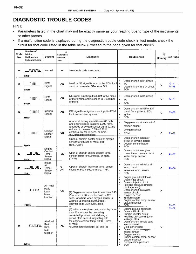
DIAGNOSTIC TROUBLE CODESHINT:• Parameters listed in the chart may not be exactly same as your reading due to type of the instruments
or other factors.• If a malfunction code is displayed during the diagnostic trouble code check in test mode, check the
circuit for that code listed in the table below (Proceed to the page given for that circuit).
(1) Oxygen sensor output in less than 0.45V for at least 90 secs. for Calif. or 120secs. for others when oxygen sensor iswarmed up (racing at 2,000 rpm).(only for code 25 in Calif. spec.)*4(2) When the engine speed varies by morethan 50 rpm over the precedingcrankshaft position period during aperiod of 50 secs. during idling withthe engine coolant temp. 50C (122F)or more*6(2 trip detection logic) (1) and (2)
• Engine ground bolt loose• Open in E1 circuit• Short in injector circuit• Fuel line pressure (Injector
leakage, etc.)• Open or short in cold start
injector circuit• Cold start injector• Open or short in oxygen
sensor circuit• Oxygen sensor• Engine coolant temp. sensor• Vacuum sensor• Compression pressure• ECM
• Engine ground bolt loose• Open in E1 circuit• Open in injector circuit• Fuel line pressure (Injector
blockage, etc.)• Open or short in oxygen
sensor circuit• Oxygen sensor• Ignition system• Engine coolant temp. sensor• Vacuum sensor• ECM
At normal driving speed (below 60 mphand engine speed is above 1,900 rpm),amplitude of oxygen sensor signal (0X) isreduced to between 0.35 – 0.70 Vcontinuously for 60 secs. or more.*6 (2 trip detection logic)
NE signal is not input to ECM for 50 msec.or more when engine speed is 1,000 rpmor more.
Open or short in heater circuit of oxygensensor for 0.5 sec or more. (HT)(Exc.. Calif.)
Open or short in engine coolant temp.sensor circuit for 500 msec. or more.(THW)
• Open or short in heater circuit of oxygen sensor
• Oxygen sensor heater• ECM
• Oxygen or short in circuit ofoxygen sensor
• Oxygen sensor• ECM
• Open or short in IIA circuit• IIA• Open or short in STA circuit• ECM
• Open or short in enginecoolant temp. sensor circuit
• Water temp. sensor• ECM
• Open or short in IGF or IGTcircuit from igniter to ECM
• Igniter• ECM
• Open or short in intake airtemp. circuit
• Intake air temp. sensor• ECM
IGF signal from igniter is not input to ECMfor 4 consecutive ignition.
No G or NE signal is input to the ECM for 2secs. or more after STA turns ON.
Open or short in intake air temp. sensorcircuit for 500 msec. or more. (THA)
• Open or short in IIA circuit• IIA• ECM
Number ofblinksMalfunctionIndicator Lamp
Air–FuelRatioRichMal–function
Air–FuelRatioLeanMal–function
EngineCoolantTemp.SensorSignal
No trouble code is recorded.
IntakeAirTemp.SensorSignal
.1MalfunctionIndicatorLamp
OxygenSensorSignal
*2MemoryTrouble Area
IgnitionSignal
RPMSignal
RPMSignal
Diagnosis See PageCode No.
*3ON
IG–4FI–68
FI–65FI–72
System
Normal
FI–67
FI–69
FI–66
FI–72
IG–4
–MFI AND SFI SYSTEMS Diagnosis System (4A–FE)FI–32
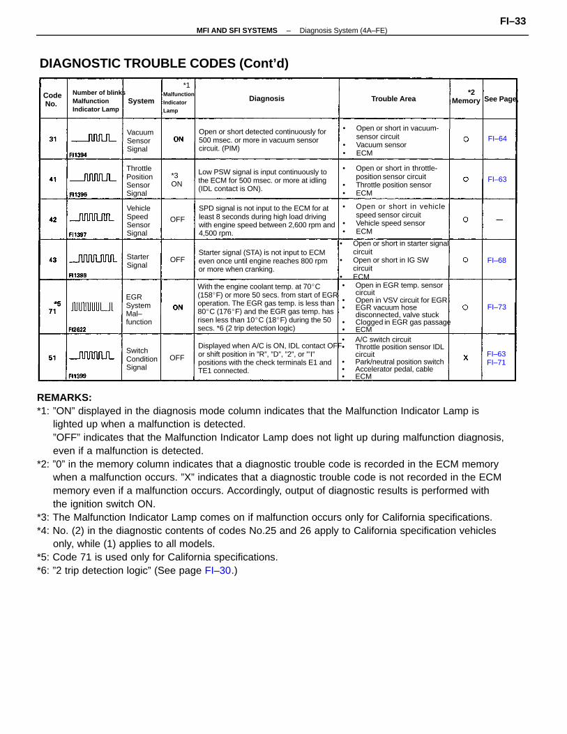
REMARKS:*1: ”ON” displayed in the diagnosis mode column indicates that the Malfunction Indicator Lamp is
lighted up when a malfunction is detected.”OFF” indicates that the Malfunction Indicator Lamp does not light up during malfunction diagnosis,even if a malfunction is detected.
*2: ”0” in the memory column indicates that a diagnostic trouble code is recorded in the ECM memorywhen a malfunction occurs. ”X” indicates that a diagnostic trouble code is not recorded in the ECMmemory even if a malfunction occurs. Accordingly, output of diagnostic results is performed withthe ignition switch ON.
*3: The Malfunction Indicator Lamp comes on if malfunction occurs only for California specifications.*4: No. (2) in the diagnostic contents of codes No.25 and 26 apply to California specification vehicles
only, while (1) applies to all models.*5: Code 71 is used only for California specifications.*6: ”2 trip detection logic” (See page FI–30.)
With the engine coolant temp. at 70C(158F) or more 50 secs. from start of EGRoperation. The EGR gas temp. is less than80C (176F) and the EGR gas temp. hasrisen less than 10C (18F) during the 50secs. *6 (2 trip detection logic)
• Open in EGR temp. sensorcircuit
• Open in VSV circuit for EGR• EGR vacuum hose
disconnected, valve stuck• Clogged in EGR gas passage• ECM
SPD signal is not input to the ECM for atleast 8 seconds during high load drivingwith engine speed between 2,600 rpm and4,500 rpm.
Displayed when A/C is ON, IDL contact OFFor shift position in ”R”, ”D”, ”2”, or ”’I”positions with the check terminals E1 andTE1 connected.
• A/C switch circuit• Throttle position sensor IDL
circuit• Park/neutral position switch• Accelerator pedal, cable• ECM
• Open or short in starter signalcircuit
• Open or short in IG SWcircuit
• ECM
DIAGNOSTIC TROUBLE CODES (Cont’d)
• Open or short in vehiclespeed sensor circuit
• Vehicle speed sensor• ECM
Open or short detected continuously for500 msec. or more in vacuum sensorcircuit. (PIM)
Low PSW signal is input continuously tothe ECM for 500 msec. or more at idling(IDL contact is ON).
Starter signal (STA) is not input to ECMeven once until engine reaches 800 rpmor more when cranking.
• Open or short in vacuum-sensor circuit
• Vacuum sensor• ECM
• Open or short in throttle-position sensor circuit
• Throttle position sensor• ECM
Number of blinksMalfunctionIndicator Lamp
ThrottlePositionSensorSignal
*1MalfunctionIndicatorLamp
EGRSystemMal–function
VehicleSpeedSensorSignal
SwitchConditionSignal
VacuumSensorSignal
*2MemoryTrouble Area
StarterSignal
Diagnosis See Page,Code No.
*3ON
System
FI–63FI–71
FI–64
FI–73
FI–63
FI–68
OFF
OFF
OFF
–MFI AND SFI SYSTEMS Diagnosis System (4A–FE)FI–33
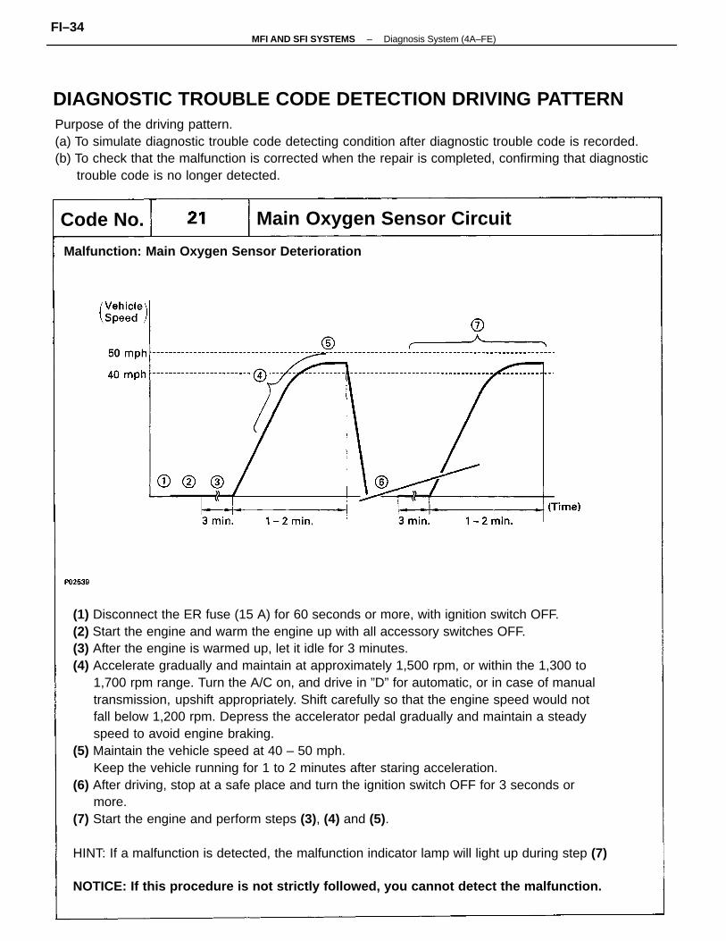
(1) Disconnect the ER fuse (15 A) for 60 seconds or more, with ignition switch OFF.(2) Start the engine and warm the engine up with all accessory switches OFF.(3) After the engine is warmed up, let it idle for 3 minutes.(4) Accelerate gradually and maintain at approximately 1,500 rpm, or within the 1,300 to
1,700 rpm range. Turn the A/C on, and drive in ”D” for automatic, or in case of manualtransmission, upshift appropriately. Shift carefully so that the engine speed would notfall below 1,200 rpm. Depress the accelerator pedal gradually and maintain a steadyspeed to avoid engine braking.
(5) Maintain the vehicle speed at 40 – 50 mph.Keep the vehicle running for 1 to 2 minutes after staring acceleration.
(6) After driving, stop at a safe place and turn the ignition switch OFF for 3 seconds ormore.
(7) Start the engine and perform steps (3), (4) and (5).
HINT: If a malfunction is detected, the malfunction indicator lamp will light up during step (7)
NOTICE: If this procedure is not strictly followed, you cannot detect the malfunction.
Purpose of the driving pattern.(a) To simulate diagnostic trouble code detecting condition after diagnostic trouble code is recorded.(b) To check that the malfunction is corrected when the repair is completed, confirming that diagnostic
trouble code is no longer detected.
Main Oxygen Sensor Circuit
Malfunction: Main Oxygen Sensor Deterioration
Code No.
DIAGNOSTIC TROUBLE CODE DETECTION DRIVING PATTERN
–MFI AND SFI SYSTEMS Diagnosis System (4A–FE)FI–34
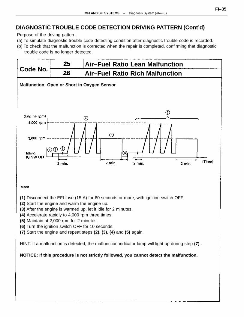
(1) Disconnect the EFI fuse (15 A) for 60 seconds or more, with ignition switch OFF.(2) Start the engine and warm the engine up.(3) After the engine is warmed up, let it idle for 2 minutes.(4) Accelerate rapidly to 4,000 rpm three times.(5) Maintain at 2,000 rpm for 2 minutes.(6) Turn the ignition switch OFF for 10 seconds.(7) Start the engine and repeat steps (2), (3), (4) and (5) again.
HINT: If a malfunction is detected, the malfunction indicator lamp will light up during step (7) .
NOTICE: If this procedure is not strictly followed, you cannot detect the malfunction.
Purpose of the driving pattern.(a) To simulate diagnostic trouble code detecting condition after diagnostic trouble code is recorded.(b) To check that the malfunction is corrected when the repair is completed, confirming that diagnostic
trouble code is no longer detected.
Air–Fuel Ratio Rich MalfunctionAir–Fuel Ratio Lean Malfunction
Malfunction: Open or Short in Oxygen Sensor
Code No.
DIAGNOSTIC TROUBLE CODE DETECTION DRIVING PATTERN (Cont’d)
–MFI AND SFI SYSTEMS Diagnosis System (4A–FE)FI–35
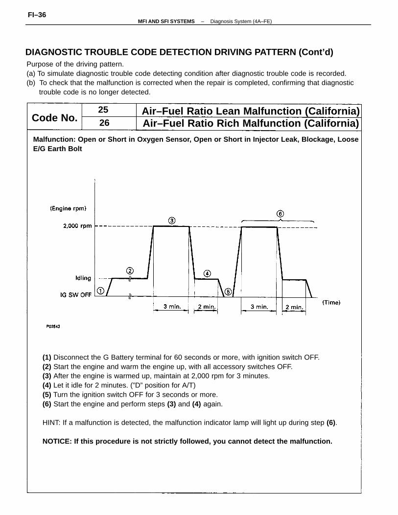
(1) Disconnect the G Battery terminal for 60 seconds or more, with ignition switch OFF.(2) Start the engine and warm the engine up, with all accessory switches OFF.(3) After the engine is warmed up, maintain at 2,000 rpm for 3 minutes.(4) Let it idle for 2 minutes. (”D” position for A/T)(5) Turn the ignition switch OFF for 3 seconds or more.(6) Start the engine and perform steps (3) and (4) again.
HINT: If a malfunction is detected, the malfunction indicator lamp will light up during step (6).
NOTICE: If this procedure is not strictly followed, you cannot detect the malfunction.
Purpose of the driving pattern.(a) To simulate diagnostic trouble code detecting condition after diagnostic trouble code is recorded.(b) To check that the malfunction is corrected when the repair is completed, confirming that diagnostic
trouble code is no longer detected.
Malfunction: Open or Short in Oxygen Sensor, Open or Short in Injector Leak, Blockage, LooseE/G Earth Bolt
Air–Fuel Ratio Lean Malfunction (California)Air–Fuel Ratio Rich Malfunction (California)Code No.
DIAGNOSTIC TROUBLE CODE DETECTION DRIVING PATTERN (Cont’d)
2526
–MFI AND SFI SYSTEMS Diagnosis System (4A–FE)FI–36
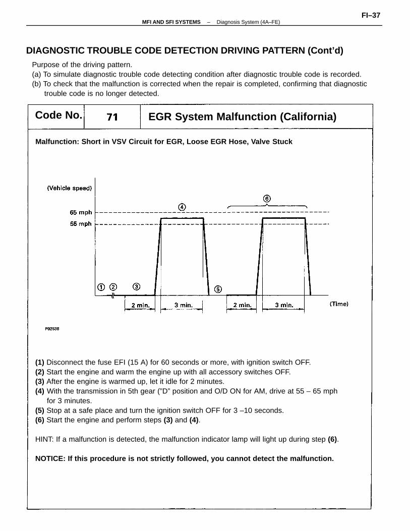
(1) Disconnect the fuse EFI (15 A) for 60 seconds or more, with ignition switch OFF.(2) Start the engine and warm the engine up with all accessory switches OFF.(3) After the engine is warmed up, let it idle for 2 minutes.(4) With the transmission in 5th gear (”D” position and O/D ON for AM, drive at 55 – 65 mph
for 3 minutes.(5) Stop at a safe place and turn the ignition switch OFF for 3 –10 seconds.(6) Start the engine and perform steps (3) and (4).
HINT: If a malfunction is detected, the malfunction indicator lamp will light up during step (6).
NOTICE: If this procedure is not strictly followed, you cannot detect the malfunction.
Purpose of the driving pattern.(a) To simulate diagnostic trouble code detecting condition after diagnostic trouble code is recorded.(b) To check that the malfunction is corrected when the repair is completed, confirming that diagnostic
trouble code is no longer detected.
Malfunction: Short in VSV Circuit for EGR, Loose EGR Hose, Valve Stuck
EGR System Malfunction (California)Code No.
DIAGNOSTIC TROUBLE CODE DETECTION DRIVING PATTERN (Cont’d)
–MFI AND SFI SYSTEMS Diagnosis System (4A–FE)FI–37
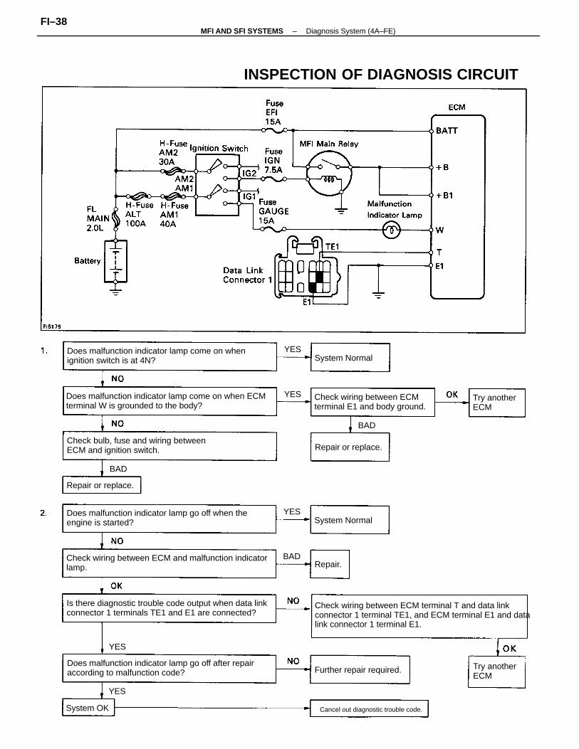
Check wiring between ECM terminal T and data linkconnector 1 terminal TE1, and ECM terminal E1 and datalink connector 1 terminal E1.
Check wiring between ECM and malfunction indicatorlamp.
Is there diagnostic trouble code output when data linkconnector 1 terminals TE1 and E1 are connected?
Does malfunction indicator lamp come on when ECMterminal W is grounded to the body?
Does malfunction indicator lamp go off after repairaccording to malfunction code?
Does malfunction indicator lamp go off when theengine is started?
Does malfunction indicator lamp come on whenignition switch is at 4N?
INSPECTION OF DIAGNOSIS CIRCUIT
Check bulb, fuse and wiring betweenECM and ignition switch.
Check wiring between ECMterminal E1 and body ground.
Further repair required.
Cancel out diagnostic trouble code.
Repair or replace.
Try anotherECM
Try anotherECM
Repair or replace.
System Normal
System Normal
System OK
Repair.
BAD
BAD
BAD
YES
YES
YES
YES
YES
–MFI AND SFI SYSTEMS Diagnosis System (4A–FE)FI–38

DIAGNOSIS SYSTEM(3S–GTE and 5S–FE)DESCRIPTIONThe ECM contains a built–in, self–diagnosis system by whichtroubles with the engine signal network are detected and amalfunction indicator lamp on the combination meter lightsup.By analyzing various signals shown in the later table (Seepage FI–44 or 50) the ECM detects system malfunctionsrelating to the sensors or actuators.The self–diagnosis system has two modes, a normal modeand a test mode.If a malfunction is detected when in the normal mode, theECM lights up the malfunction indicator lamp to inform thedriver of the occurrence of a malfunction. (For some codesthe lamp does not come on.) The lamp goes oft automaticallywhen the malfunction has been repaired. But the diagnostictrouble code(s) remains stored in the ECM memory. The ECMstores the code(s) until it is cleaned by removing the EFI fusewith the ignition switch oft.The diagnostic trouble code can be read by the number ofblinks of the malfunction indicator lamp when TE1 and E1terminals of the data link connector 1 are connected. When 2or more codes are indicated, the lowest number (code) willappear first.If a malfunction is detected when in the test mode, the ECMlights up the malfunction indicator lamp to inform thetechnician of the occurrence of a malfunction (except forcode Nos.42, 43 and 51). In this case, TE2 and E1 terminals ofthe data link connector 1 should be connected as shownlater. (See page FI–42)In the test mode, even if the malfunction is corrected, themalfunction code is stored in the ECM memory even whenthe ignition switch is oft (except code Nos.42, 43 and 51).This also applies in the normal mode. The diagnostic mode(normal or test) and the output of the malfunction indicatorlamp can be selected by connecting the TE1, TE2 and E1terminals of the data link connecter 1, as shown later.A test mode function has been added to the functions of theself–diagnosis system of the normal mode for the purpose ofdetecting malfunctions such as poor contact, which are diffi–cult to detect in the normal mode. This function fills up theself–diagnosis system. The test mode can be implemented bythe technician following the appropriate procedures of checkterminal connection and operation described later. (See pageFI–44 or 50)
–MFI AND SFI SYSTEMS Diagnosis System (3S–GTE and 5S–FE)FI–39
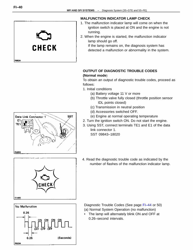
OUTPUT OF DIAGNOSTIC TROUBLE CODES(Normal mode )To obtain an output of diagnostic trouble codes, proceed asfollows:1. Initial conditions
(a) Battery voltage 11 V or more(b) Throttle valve fully closed (throttle position sensor
IDL points closed)(c) Transmission in neutral position(d) Accessories switched OFF.(e) Engine at normal operating temperature
2. Turn the ignition switch ON. Do not start the engine.3. Using SST, connect terminals TE1 and E1 of the data
link connector 1.SST 09843–18020
MALFUNCTION INDICATOR LAMP CHECK1. The malfunction indicator lamp will come on when the
ignition switch is placed at ON and the engine is notrunning.
2. When the engine is started, the malfunction indicatorlamp should go off.If the lamp remains on, the diagnosis system hasdetected a malfunction or abnormality in the system.
Diagnostic Trouble Codes (See page FI–44 or 50)(a) Normal System Operation (no malfunction)• The lamp will alternately blink ON and OFF at
0.26–second intervals.
4. Read the diagnostic trouble code as indicated by thenumber of flashes of the malfunction indicator lamp.
–MFI AND SFI SYSTEMS Diagnosis System (3S–GTE and 5S–FE)FI–40
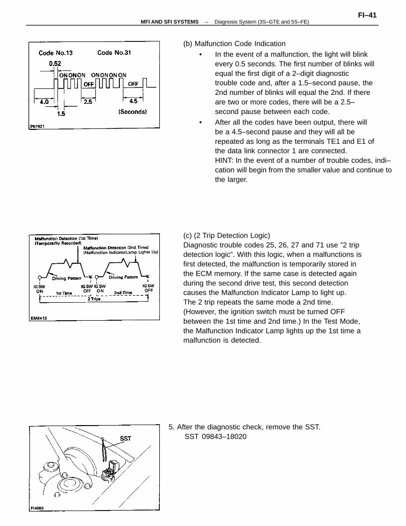
(b) Malfunction Code Indication
• In the event of a malfunction, the light will blinkevery 0.5 seconds. The first number of blinks willequal the first digit of a 2–digit diagnostictrouble code and, after a 1.5–second pause, the2nd number of blinks will equal the 2nd. If thereare two or more codes, there will be a 2.5–second pause between each code.
• After all the codes have been output, there willbe a 4.5–second pause and they will all berepeated as long as the terminals TE1 and E1 ofthe data link connector 1 are connected.HINT: In the event of a number of trouble codes, indi–cation will begin from the smaller value and continue tothe larger.
(c) (2 Trip Detection Logic)Diagnostic trouble codes 25, 26, 27 and 71 use ”2 tripdetection logic”. With this logic, when a malfunctions isfirst detected, the malfunction is temporarily stored inthe ECM memory. If the same case is detected againduring the second drive test, this second detectioncauses the Malfunction Indicator Lamp to light up.The 2 trip repeats the same mode a 2nd time.(However, the ignition switch must be turned OFFbetween the 1st time and 2nd time.) In the Test Mode,the Malfunction Indicator Lamp lights up the 1st time amalfunction is detected.
5. After the diagnostic check, remove the SST.SST 09843–18020
–MFI AND SFI SYSTEMS Diagnosis System (3S–GTE and 5S–FE)FI–41
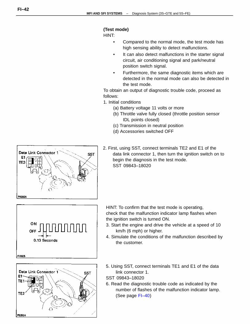
(Test mode)HINT:
• Compared to the normal mode, the test mode hashigh sensing ability to detect malfunctions.
• It can also detect malfunctions in the starter signalcircuit, air conditioning signal and park/neutralposition switch signal.
• Furthermore, the same diagnostic items which aredetected in the normal mode can also be detected inthe test mode.
To obtain an output of diagnostic trouble code, proceed asfollows:1. Initial conditions
(a) Battery voltage 11 volts or more(b) Throttle valve fully closed (throttle position sensor
IDL points closed)(c) Transmission in neutral position(d) Accessories switched OFF
HINT: To confirm that the test mode is operating,check that the malfunction indicator lamp flashes whenthe ignition switch is turned ON.3. Start the engine and drive the vehicle at a speed of 10
km/h (6 mph) or higher.4. Simulate the conditions of the malfunction described by
the customer.
5. Using SST, connect terminals TE1 and E1 of the datalink connector 1.
SST 09843–180206. Read the diagnostic trouble code as indicated by the
number of flashes of the malfunction indicator lamp.(See page FI–40)
2. First, using SST, connect terminals TE2 and E1 of thedata link connector 1, then turn the ignition switch on tobegin the diagnosis in the test mode.SST 09843–18020
–MFI AND SFI SYSTEMS Diagnosis System (3S–GTE and 5S–FE)FI–42
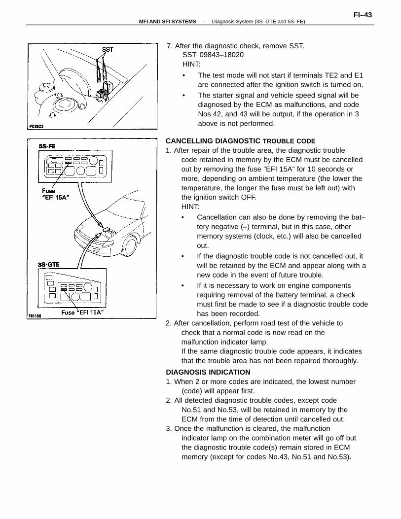
CANCELLING DIAGNOSTIC TROUBLE CODE1. After repair of the trouble area, the diagnostic trouble
code retained in memory by the ECM must be cancelledout by removing the fuse ”EFI 15A” for 10 seconds ormore, depending on ambient temperature (the lower thetemperature, the longer the fuse must be left out) withthe ignition switch OFF.HINT:
• Cancellation can also be done by removing the bat–tery negative (–) terminal, but in this case, othermemory systems (clock, etc.) will also be cancelledout.
• If the diagnostic trouble code is not cancelled out, itwill be retained by the ECM and appear along with anew code in the event of future trouble.
• If it is necessary to work on engine componentsrequiring removal of the battery terminal, a checkmust first be made to see if a diagnostic trouble codehas been recorded.
2. After cancellation, perform road test of the vehicle tocheck that a normal code is now read on themalfunction indicator lamp.If the same diagnostic trouble code appears, it indicatesthat the trouble area has not been repaired thoroughly.
DIAGNOSIS INDICATION1. When 2 or more codes are indicated, the lowest number
(code) will appear first.2. All detected diagnostic trouble codes, except code
No.51 and No.53, will be retained in memory by theECM from the time of detection until cancelled out.
3. Once the malfunction is cleared, the malfunctionindicator lamp on the combination meter will go off butthe diagnostic trouble code(s) remain stored in ECMmemory (except for codes No.43, No.51 and No.53).
7. After the diagnostic check, remove SST.SST 09843–18020HINT:
• The test mode will not start if terminals TE2 and E1are connected after the ignition switch is turned on.
• The starter signal and vehicle speed signal will bediagnosed by the ECM as malfunctions, and codeNos.42, and 43 will be output, if the operation in 3above is not performed.
–MFI AND SFI SYSTEMS Diagnosis System (3S–GTE and 5S–FE)FI–43
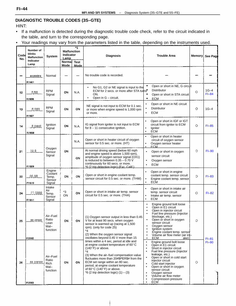
HINT:• If a malfunction is detected during the diagnostic trouble code check, refer to the circuit indicated in
the table, and turn to the corresponding page.• Your readings may vary from the parameters listed in the table, depending on the instruments used.
(1) Oxygen sensor output in less than 0.45V for at least 90 secs. when oxygensensor is warmed up (racing at 1,500rpm). (only for code 25)*4(2) When the oxygen sensor signaloscillates beyond 0.45 V more than 15times within a 4 sec, period at idle andat engine coolant temperature of 60C(140F) or above.*4(3) When the air–fuel compensation valuefluctuates more than 20#$PER$# from theECM set range within an 80 sec.period, at engine coolant temperatureof 60C (140F) or above.*6 (2 trip detection logic) (1) – (3)
• Engine ground bolt loose• Open in E1 circuit• Short in injector circuit• Fuel line pressure (Injector
leakage, etc.)• Open or short in cold start
injector circuit• Cold start injector• Open or short in oxygen
sensor circuit• Oxygen sensor• Volume air flow meter• Compression pressure• ECM
• Engine ground bolt loose• Open in E1 circuit• Open in injector circuit• Fuel line pressure (Injector
blockage, etc.)• Open or short in oxygen
sensor circuit• Oxygen sensor• Ignition system• Engine coolant temp. sensor• Volume air flow meter (air int–• ECM ake)
At normal driving speed (below 60 mphand engine speed is above 1,500 rpm),amplitude of oxygen sensor signal (OX1)is reduced to between 0.35 – 0.70 Vcontinuously for 60 secs. or more.*6 (2 trip detection logic) (Exc. Calif.)
• No G1, G2 or NE signal is input to theECM for 2 secs. or more after STA turnsON.
• Open in G – circuit.
NE signal is not input to ECM for 0.1 sec.or more when engine speed is 1,000 rpmor more.
• Open or short in heater circuit of oxygen sensor
• Oxygen sensor heater• ECM
• Open or short in NE, G circuit• Distributor• Open or short in STA circuit• ECM
• Open or short in enginecoolant temp. sensor circuit
• Engine coolant temp. sensor• ECM
• Open or short in IGF or IGTcircuit from igniter to ECM
• Igniter• ECM
• Open or short in intake airtemp. sensor circuit
• Intake air temp. sensor• ECM
• Open or short in oxygensensor circuit
• Oxygen sensor• ECM
IG signal from igniter is not input to ECMfor 8 – 11 consecutive ignition.
Open or short in heater circuit of oxygensensor for 0.5 sec. or more. (HT)
Open or short in intake air temp. sensorcircuit for 0.5 sec. or more. (THA)
Open or short in engine coolant temp.sensor circuit for 0.5 sec. or more. (THW)
• Open or short in NE circuit• Distributor• ECM
Number ofblinksMalfunctionIndicatorLamp
No trouble code is recorded.
Air–FuelRatioLeanMal–function
Air–FuelRatioRichMal–function
EngineCoolantTemp.SensorSignal
*1MalfunctionIndicatorLamp
IntakeAirTemp.SensorSignal
OxygenSensorSignal
MemoryTrouble Area
IgnitionSignal
NormalMode
RPMSignal
RPMSignal
Diagnosis See Page
TestMode
Code No.
*3ON
1G–4FI–84
FI–81FI–90
System
Normal
FI–90
FI–83
FI–82
FI–85
N.A.
N.A.
N.A.
1G–4
DIAGNOSTIC TROUBLE CODES (3S–GTE)
–MFI AND SFI SYSTEMS Diagnosis System (3S–GTE and 5S–FE)FI–44
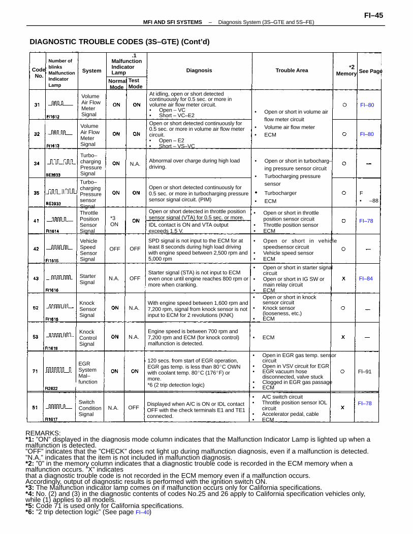
REMARKS:*1: ”ON” displayed in the diagnosis mode column indicates that the Malfunction Indicator Lamp is lighted up when amalfunction is detected.”OFF” indicates that the ”CHECK” does not light up during malfunction diagnosis, even if a malfunction is detected.”N.A.” indicates that the item is not included in malfunction diagnosis.*2: ”0” in the memory column indicates that a diagnostic trouble code is recorded in the ECM memory when amalfunction occurs. ”X” indicatesthat a diagnostic trouble code is not recorded in the ECM memory even if a malfunction occurs.Accordingly, output of diagnostic results is performed with the ignition switch ON.*3: The Malfunction indicator lamp comes on if malfunction occurs only for California specifications.*4: No. (2) and (3) in the diagnostic contents of codes No.25 and 26 apply to California specification vehicles only,while (1) applies to all models.*5: Code 71 is used only for California specifications.*6: ”2 trip detection logic” (See page FI–40)
• Open in EGR gas temp. sensorcircuit
• Open in VSV circuit for EGR• EGR vacuum hose
disconnected, valve stuck• Clogged in EGR gas passage• ECM
Open or short detected continuously for0.5 sec. or more in volume air flow metercircuit.• Open – E2• Short – VS–VC
120 secs. from start of EGR operation,EGR gas temp. is less than 80C OWNwith coolant temp. 80C (176F) ormore.*6 (2 trip detection logic)
At idling, open or short detectedcontinuously for 0.5 sec. or more involume air flow meter circuit.• Open – VC• Short – VC–E2
• Open or short in turbocharg–ing pressure sensor circuit
• Turbocharging pressuresensor
• Turbocharger
• ECM
SPD signal is not input to the ECM for atleast 8 seconds during high load drivingwith engine speed between 2,500 rpm and5,000 rpm
DIAGNOSTIC TROUBLE CODES (3S–GTE) (Cont’d)
• Open or short in starter signalcircuit
• Open or short in IG SW ormain relay circuit
• ECM• Open or short in knock
sensor circuit• Knock sensor
(looseness, etc.)• ECM
• A/C switch circuit• Throttle position sensor IOL
circuit• Accelerator pedal, cable• ECM
Open or short detected continuously for0.5 sec. or more in turbocharging pressuresensor signal circuit. (PIM)
With engine speed between 1,600 rpm and7,200 rpm, signal from knock sensor is notinput to ECM for 2 revolutions (KNK)
Starter signal (STA) is not input to ECMeven once until engine reaches 800 rpm ormore when cranking.
Displayed when A/C is ON or IDL contactOFF with the check terminals E1 and TE1connected.
• Open or short in vehiclespeedsensor circuit
• Vehicle speed sensor• ECM
Engine speed is between 700 rpm and7,200 rpm and ECM (for knock control)malfunction is detected.
• Open or short in volume airflow meter circuit
• Volume air flow meter• ECM
Open or short detected in throttle positionsensor signal (VTA) for 0.5 sec. or more.
• Open or short in throttleposition sensor circuit
• Throttle position sensor• ECM
Abnormal over charge during high loaddriving.
IDL contact is ON and VTA outputexceeds 1.5 V.
Number ofblinksMalfunctionIndicatorLamp
Turbo–chargingPressuresensorSignal
.1MalfunctionIndicatorLamp
Turbo–chargingPressureSignal
VolumeAir FlowMeterSignal
ThrottlePositionSensorSignal
VolumeAir FlowMeterSignal
EGRSystemMal–function
SwitchConditionSignal
VehicleSpeedSensorSignal
KnockControlSignal
KnockSensorSignal
*2Memory
Trouble Area
Normal Mode
StarterSignal
Diagnosis
TestMode
See PageCode No.
*3ON
System
FI–78
• ECM
FI–80
FI–80
FI–84
FI–78
Fl–91
F• –88
N.A.
N.A.
N.A.
N.A.
N.A. OFF
OFF
OFF OFF
–MFI AND SFI SYSTEMS Diagnosis System (3S–GTE and 5S–FE)FI–45
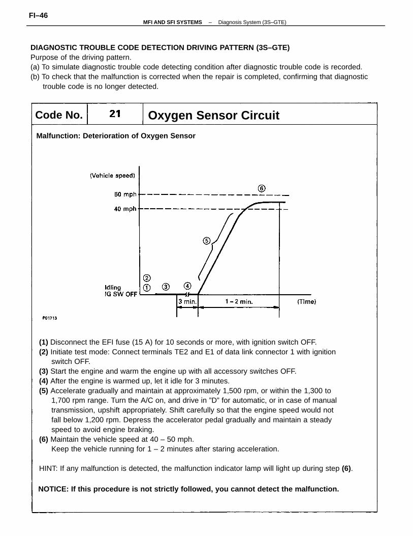
(1) Disconnect the EFI fuse (15 A) for 10 seconds or more, with ignition switch OFF.(2) Initiate test mode: Connect terminals TE2 and E1 of data link connector 1 with ignition
switch OFF.(3) Start the engine and warm the engine up with all accessory switches OFF.(4) After the engine is warmed up, let it idle for 3 minutes.(5) Accelerate gradually and maintain at approximately 1,500 rpm, or within the 1,300 to
1,700 rpm range. Turn the A/C on, and drive in ”D” for automatic, or in case of manualtransmission, upshift appropriately. Shift carefully so that the engine speed would notfall below 1,200 rpm. Depress the accelerator pedal gradually and maintain a steadyspeed to avoid engine braking.
(6) Maintain the vehicle speed at 40 – 50 mph.Keep the vehicle running for 1 – 2 minutes after staring acceleration.
HINT: If any malfunction is detected, the malfunction indicator lamp will light up during step (6).
DIAGNOSTIC TROUBLE CODE DETECTION DRIVING PATTERN (3S–GTE)Purpose of the driving pattern.(a) To simulate diagnostic trouble code detecting condition after diagnostic trouble code is recorded.(b) To check that the malfunction is corrected when the repair is completed, confirming that diagnostic
trouble code is no longer detected.
NOTICE: If this procedure is not strictly followed, you cannot detect the malfunction.
Malfunction: Deterioration of Oxygen Sensor
Oxygen Sensor CircuitCode No.
–MFI AND SFI SYSTEMS Diagnosis System (3S–GTE)FI–46
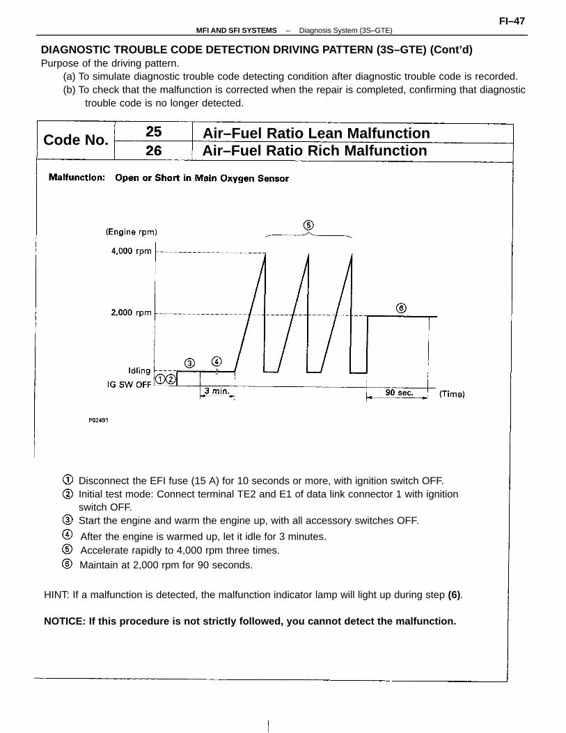
Disconnect the EFI fuse (15 A) for 10 seconds or more, with ignition switch OFF.Initial test mode: Connect terminal TE2 and E1 of data link connector 1 with ignitionswitch OFF.Start the engine and warm the engine up, with all accessory switches OFF.
DIAGNOSTIC TROUBLE CODE DETECTION DRIVING PATTERN (3S–GTE) (Cont’d)Purpose of the driving pattern.
(a) To simulate diagnostic trouble code detecting condition after diagnostic trouble code is recorded.(b) To check that the malfunction is corrected when the repair is completed, confirming that diagnostic
trouble code is no longer detected.
Air–Fuel Ratio Lean MalfunctionAir–Fuel Ratio Rich Malfunction
Code No.
After the engine is warmed up, let it idle for 3 minutes.Accelerate rapidly to 4,000 rpm three times.Maintain at 2,000 rpm for 90 seconds.
HINT: If a malfunction is detected, the malfunction indicator lamp will light up during step (6).
NOTICE: If this procedure is not strictly followed, you cannot detect the malfunction.
–MFI AND SFI SYSTEMS Diagnosis System (3S–GTE)FI–47
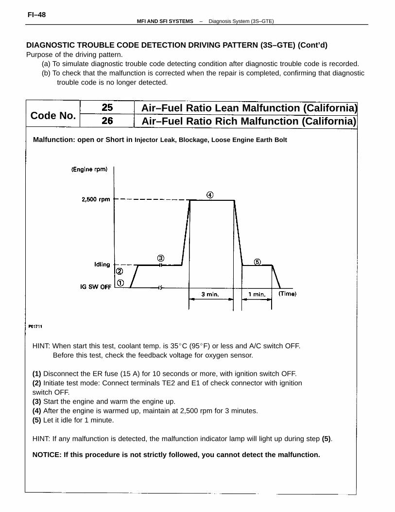
HINT: When start this test, coolant temp. is 35C (95F) or less and A/C switch OFF.Before this test, check the feedback voltage for oxygen sensor.
(1) Disconnect the ER fuse (15 A) for 10 seconds or more, with ignition switch OFF.(2) Initiate test mode: Connect terminals TE2 and E1 of check connector with ignitionswitch OFF.(3) Start the engine and warm the engine up.(4) After the engine is warmed up, maintain at 2,500 rpm for 3 minutes.(5) Let it idle for 1 minute.
HINT: If any malfunction is detected, the malfunction indicator lamp will light up during step (5).
DIAGNOSTIC TROUBLE CODE DETECTION DRIVING PATTERN (3S–GTE) (Cont’d)Purpose of the driving pattern.
(a) To simulate diagnostic trouble code detecting condition after diagnostic trouble code is recorded.(b) To check that the malfunction is corrected when the repair is completed, confirming that diagnostic
trouble code is no longer detected.
NOTICE: If this procedure is not strictly followed, you cannot detect the malfunction.
Malfunction: open or Short in Injector Leak, Blockage, Loose Engine Earth Bolt
Air–Fuel Ratio Lean Malfunction (California)Air–Fuel Ratio Rich Malfunction (California)Code No.
–MFI AND SFI SYSTEMS Diagnosis System (3S–GTE)FI–48
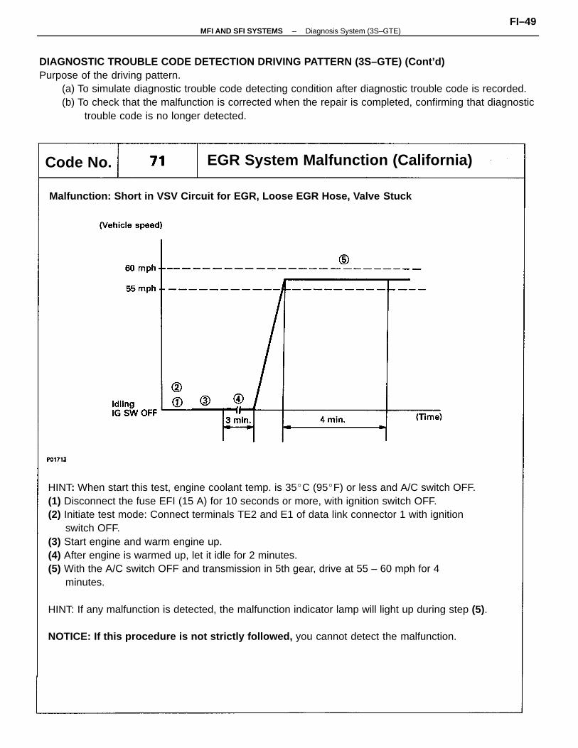
HINT: When start this test, engine coolant temp. is 35C (95F) or less and A/C switch OFF.(1) Disconnect the fuse EFI (15 A) for 10 seconds or more, with ignition switch OFF.(2) Initiate test mode: Connect terminals TE2 and E1 of data link connector 1 with ignition
switch OFF.(3) Start engine and warm engine up.(4) After engine is warmed up, let it idle for 2 minutes.(5) With the A/C switch OFF and transmission in 5th gear, drive at 55 – 60 mph for 4
minutes.
HINT: If any malfunction is detected, the malfunction indicator lamp will light up during step (5).
NOTICE: If this procedure is not strictly followed, you cannot detect the malfunction.
DIAGNOSTIC TROUBLE CODE DETECTION DRIVING PATTERN (3S–GTE) (Cont’d)Purpose of the driving pattern.
(a) To simulate diagnostic trouble code detecting condition after diagnostic trouble code is recorded.(b) To check that the malfunction is corrected when the repair is completed, confirming that diagnostic
trouble code is no longer detected.
Malfunction: Short in VSV Circuit for EGR, Loose EGR Hose, Valve Stuck
EGR System Malfunction (California)Code No.
–MFI AND SFI SYSTEMS Diagnosis System (3S–GTE)FI–49
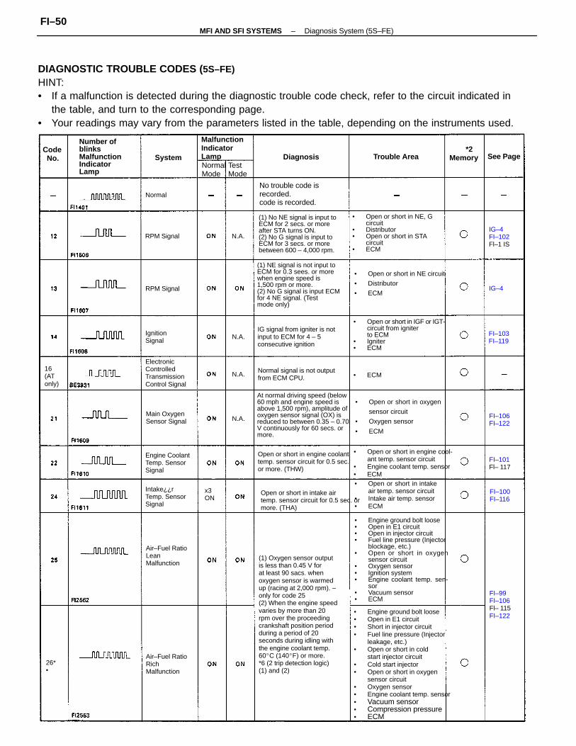
DIAGNOSTIC TROUBLE CODES ( 5S–FE)HINT:• If a malfunction is detected during the diagnostic trouble code check, refer to the circuit indicated in
the table, and turn to the corresponding page.• Your readings may vary from the parameters listed in the table, depending on the instruments used.
(1) Oxygen sensor outputis less than 0.45 V forat least 90 sacs. whenoxygen sensor is warmedup (racing at 2,000 rpm). –only for code 25(2) When the engine speedvaries by more than 20rpm over the proceedingcrankshaft position periodduring a period of 20seconds during idling withthe engine coolant temp.60C (140F) or more.*6 (2 trip detection logic)(1) and (2)
• Engine ground bolt loose• Open in E1 circuit• Short in injector circuit• Fuel line pressure (Injector
leakage, etc.)• Open or short in cold
start injector circuit• Cold start injector• Open or short in oxygen
sensor circuit• Oxygen sensor• Engine coolant temp. sensor• Vacuum sensor• Compression pressure• ECM
• Engine ground bolt loose• Open in E1 circuit• Open in injector circuit• Fuel line pressure (Injector
blockage, etc.)• Open or short in oxygen
sensor circuit• Oxygen sensor• Ignition system• Engine coolant temp. sen-
sor• Vacuum sensor• ECM
At normal driving speed (below 60 mph and engine speed isabove 1,500 rpm), amplitude ofoxygen sensor signal (OX) isreduced to between 0.35 – 0.70V continuously for 60 secs. ormore.
(1) NE signal is not input toECM for 0.3 sees. or morewhen engine speed is1,500 rpm or more.(2) No G signal is input ECMfor 4 NE signal. (Testmode only)
(1) No NE signal is input toECM for 2 secs. or moreafter STA turns ON.(2) No G signal is input toECM for 3 secs. or morebetween 600 – 4,000 rpm.
• Open or short in IGF or IGT-circuit from igniterto ECM
• Igniter• ECM
• Open or short in NE, G circuit
• Distributor• Open or short in STA
circuit• ECM
• Open or short in engine cool-ant temp. sensor circuit
• Engine coolant temp. sensor• ECM
• Open or short in oxygen
sensor circuit
• Oxygen sensor
• ECM
Open or short in engine coolanttemp. sensor circuit for 0.5 sec.or more. (THW)
• Open or short in intakeair temp. sensor circuit
• Intake air temp. sensor• ECM
Open or short in intake airtemp. sensor circuit for 0.5 sec. ormore. (THA)
• Open or short in NE circuit
• Distributor
• ECM
IG signal from igniter is notinput to ECM for 4 – 5consecutive ignition
ElectronicControlledTransmissionControl Signal
Number ofblinksMalfunctionIndicatorLamp
No trouble code isrecorded.code is recorded.
Normal signal is not outputfrom ECM CPU.
Engine CoolantTemp. SensorSignal
Intake¿¿rTemp. SensorSignal
MalfunctionIndicatorLamp
Air–Fuel RatioRichMalfunction
Air–Fuel RatioLeanMalfunction
Main OxygenSensor Signal
16(ATonly)
FI–99FI–106Fl– 115FI–122
*2MemoryTrouble Area
NormalMode
IG–4FI–102Fl–1 IS
IgnitionSignal
Diagnosis
RPM Signal
RPM Signal
TestMode
See PageCode No.
FI–103FI–119
FI–100FI–116
FI–101Fl– 117
FI–106FI–122
System
x3ON
Normal
• ECM
26*•
N.A.
N.A.
N.A.
N.A.
IG–4
–MFI AND SFI SYSTEMS Diagnosis System (5S–FE)FI–50
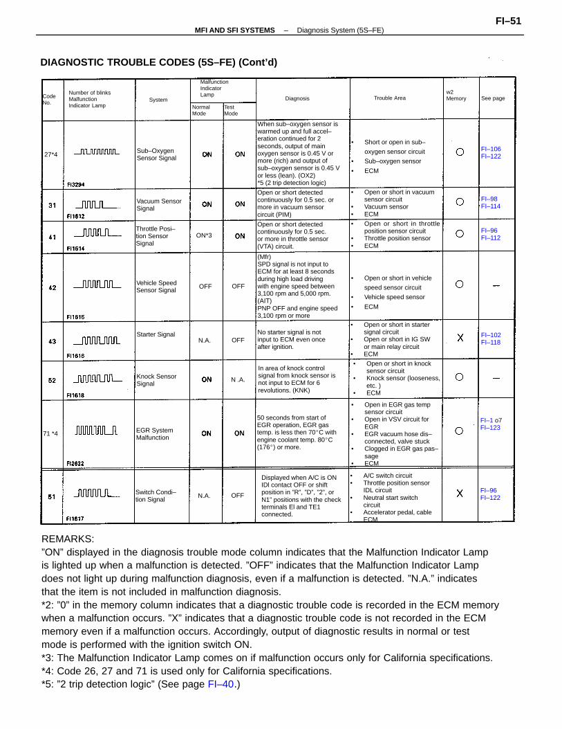
REMARKS:”ON” displayed in the diagnosis trouble mode column indicates that the Malfunction Indicator Lampis lighted up when a malfunction is detected. ”OFF” indicates that the Malfunction Indicator Lampdoes not light up during malfunction diagnosis, even if a malfunction is detected. ”N.A.” indicatesthat the item is not included in malfunction diagnosis.*2: ”0” in the memory column indicates that a diagnostic trouble code is recorded in the ECM memorywhen a malfunction occurs. ”X” indicates that a diagnostic trouble code is not recorded in the ECMmemory even if a malfunction occurs. Accordingly, output of diagnostic results in normal or testmode is performed with the ignition switch ON.*3: The Malfunction Indicator Lamp comes on if malfunction occurs only for California specifications.*4: Code 26, 27 and 71 is used only for California specifications.*5: ”2 trip detection logic” (See page FI–40.)
When sub–oxygen sensor iswarmed up and full accel–eration continued for 2seconds, output of mainoxygen sensor is 0.45 V ormore (rich) and output ofsub–oxygen sensor is 0.45 Vor less (lean). (OX2)*5 (2 trip detection logic)
(Mfr)SPD signal is not input toECM for at least 8 secondsduring high load drivingwith engine speed between3,100 rpm and 5,000 rpm.(AIT)PNP OFF and engine speed3,100 rpm or more
• Open in EGR gas tempsensor circuit
• Open in VSV circuit forEGR
• EGR vacuum hose dis–connected, valve stuck
• Clogged in EGR gas pas–sage
• ECM
• A/C switch circuit• Throttle position sensor
IDL circuit• Neutral start switch
circuit• Accelerator pedal, cable
ECM
DIAGNOSTIC TROUBLE CODES (5S–FE) (Cont’d)
Displayed when A/C is ONIDl contact OFF or shiftposition in ”R”, ”D”, ”2”, orN1” positions with the checkterminals El and TE1connected.
• Open or short in knocksensor circuit
• Knock sensor (looseness,etc. )
• ECM
50 seconds from start ofEGR operation, EGR gastemp. is less then 70C withengine coolant temp. 80C(176) or more.
• Open or short in startersignal circuit
• Open or short in IG SWor main relay circuit
• ECM
• Open or short in throttleposition sensor circuit
• Throttle position sensor• ECM
Open or short detectedcontinuously for 0.5 sec. ormore in vacuum sensorcircuit (PIM)
• Open or short in vacuumsensor circuit
• Vacuum sensor• ECM
In area of knock controlsignal from knock sensor isnot input to ECM for 6revolutions. (KNK)
Open or short detectedcontinuously for 0.5 sec.or more in throttle sensor(VTA) circuit.
• Open or short in vehicle
speed sensor circuit
• Vehicle speed sensor
• ECM
• Short or open in sub–
oxygen sensor circuit
• Sub–oxygen sensor
• ECM
No starter signal is notinput to ECM even onceafter ignition.
Number of blinksMalfunctionIndicator Lamp
MalfunctionIndicatorLamp
Throttle Posi–tion SensorSignal
EGR SystemMalfunction
Vacuum SensorSignal
Diagnosis
Vehicle SpeedSensor Signal
Switch Condi–tion Signal
Sub–OxygenSensor Signal
Knock SensorSignal
Starter Signal
FI–1 o7FI–123
Systemw2MemoryTrouble Area
NormalMode
TestMode
FI–102FI–118
FI–98FI–114
FI–106FI–122
FI–96FI–112
CodeNo.
FI–96FI–122
See page
ON*3
71 *4
27*4
N.A.
N.A.
N .A.
OFF
OFF OFF
OFF
–MFI AND SFI SYSTEMS Diagnosis System (5S–FE)FI–51
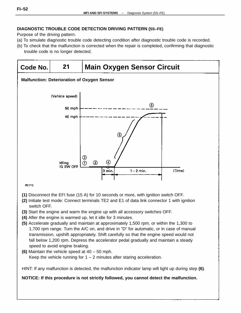
(1) Disconnect the EFI fuse (15 A) for 10 seconds or more, with ignition switch OFF.(2) Initiate test mode: Connect terminals TE2 and E1 of data link connector 1 with ignition
switch OFF.(3) Start the engine and warm the engine up with all accessory switches OFF.(4) After the engine is warmed up, let it idle for 3 minutes.(5) Accelerate gradually and maintain at approximately 1,500 rpm, or within the 1,300 to
1,700 rpm range. Turn the A/C on, and drive in ”D” for automatic, or in case of manualtransmission, upshift appropriately. Shift carefully so that the engine speed would notfall below 1,200 rpm. Depress the accelerator pedal gradually and maintain a steadyspeed to avoid engine braking.
(6) Maintain the vehicle speed at 40 – 50 mph.Keep the vehicle running for 1 – 2 minutes after staring acceleration.
HINT: If any malfunction is detected, the malfunction indicator lamp will light up during step (6).
DIAGNOSTIC TROUBLE CODE DETECTION DRIVING PATTERN ( 5S–FE)Purpose of the driving pattern.(a) To simulate diagnostic trouble code detecting condition after diagnostic trouble code is recorded.(b) To check that the malfunction is corrected when the repair is completed, confirming that diagnostic
trouble code is no longer detected.
NOTICE: If this procedure is not strictly followed, you cannot detect the malfunction.
Main Oxygen Sensor Circuit
Malfunction: Deterioration of Oxygen Sensor
Code No.
–MFI AND SFI SYSTEMS Diagnosis System (5S–FE)FI–52
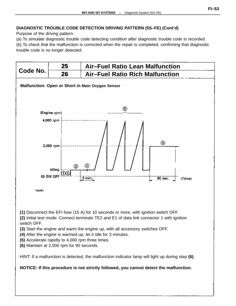
(1) Disconnect the EFI fuse (15 A) for 10 seconds or more, with ignition switch OFF.(2) Initial test mode: Connect terminals TE2 and E1 of data link connector 1 with ignitionswitch OFF.(3) Start the engine and warm the engine up, with all accessory switches OFF.(4) After the engine is warmed up, let it idle for 3 minutes.(5) Accelerate rapidly to 4,000 rpm three times.(6) Maintain at 2,000 rpm for 90 seconds.
HINT: If a malfunction is detected, the malfunction indicator lamp will light up during step (6).
NOTICE: If this procedure is not strictly followed, you cannot detect the malfunction.
DIAGNOSTIC TROUBLE CODE DETECTION DRIVING PATTERN (5S–FE) (Cont’d)Purpose of the driving pattern.(a) To simulate diagnostic trouble code detecting condition after diagnostic trouble code is recorded.(b) To check that the malfunction is corrected when the repair is completed, confirming that diagnostictrouble code is no longer detected.
Malfunction: Open or Short in Main Oxygen Sensor
Air–Fuel Ratio Rich MalfunctionAir–Fuel Ratio Lean Malfunction
Code No.
–MFI AND SFI SYSTEMS Diagnosis System (5S–FE)FI–53
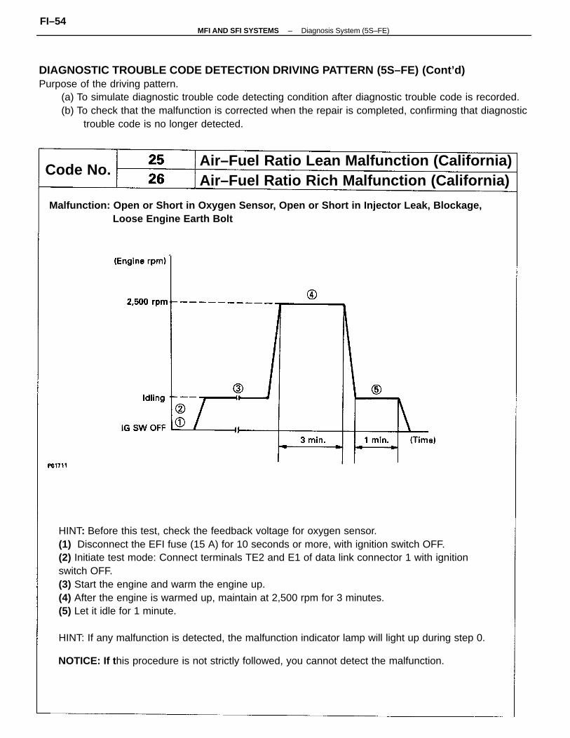
HINT: Before this test, check the feedback voltage for oxygen sensor.(1) Disconnect the EFI fuse (15 A) for 10 seconds or more, with ignition switch OFF.(2) Initiate test mode: Connect terminals TE2 and E1 of data link connector 1 with ignitionswitch OFF.(3) Start the engine and warm the engine up.(4) After the engine is warmed up, maintain at 2,500 rpm for 3 minutes.(5) Let it idle for 1 minute.
HINT: If any malfunction is detected, the malfunction indicator lamp will light up during step 0.
DIAGNOSTIC TROUBLE CODE DETECTION DRIVING PATTERN (5S–FE) (Cont’d)Purpose of the driving pattern.
(a) To simulate diagnostic trouble code detecting condition after diagnostic trouble code is recorded.(b) To check that the malfunction is corrected when the repair is completed, confirming that diagnostic
trouble code is no longer detected.
Malfunction: Open or Short in Oxygen Sensor, Open or Short in Injector Leak, Blockage, Loose Engine Earth Bolt
NOTICE: If t his procedure is not strictly followed, you cannot detect the malfunction.
Air–Fuel Ratio Lean Malfunction (California)Air–Fuel Ratio Rich Malfunction (California)
Code No.
–MFI AND SFI SYSTEMS Diagnosis System (5S–FE)FI–54
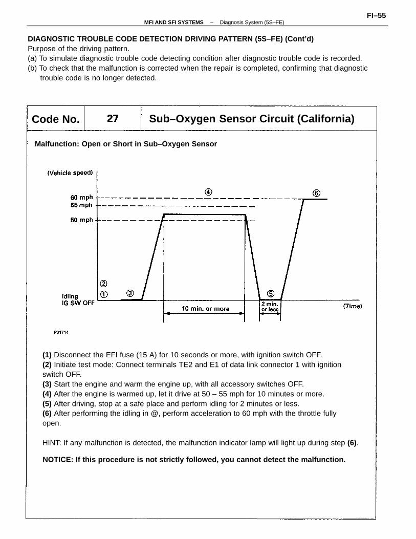
(1) Disconnect the EFI fuse (15 A) for 10 seconds or more, with ignition switch OFF.(2) Initiate test mode: Connect terminals TE2 and E1 of data link connector 1 with ignitionswitch OFF.(3) Start the engine and warm the engine up, with all accessory switches OFF.(4) After the engine is warmed up, let it drive at 50 – 55 mph for 10 minutes or more.(5) After driving, stop at a safe place and perform idling for 2 minutes or less.(6) After performing the idling in @, perform acceleration to 60 mph with the throttle fullyopen.
HINT: If any malfunction is detected, the malfunction indicator lamp will light up during step (6).
DIAGNOSTIC TROUBLE CODE DETECTION DRIVING PATTERN (5S–FE) (Cont’d)Purpose of the driving pattern.(a) To simulate diagnostic trouble code detecting condition after diagnostic trouble code is recorded.(b) To check that the malfunction is corrected when the repair is completed, confirming that diagnostic
trouble code is no longer detected.
NOTICE: If this procedure is not strictly followed, you cannot detect the malfunction.
Sub–Oxygen Sensor Circuit (California)
Malfunction: Open or Short in Sub–Oxygen Sensor
Code No.
–MFI AND SFI SYSTEMS Diagnosis System (5S–FE)FI–55
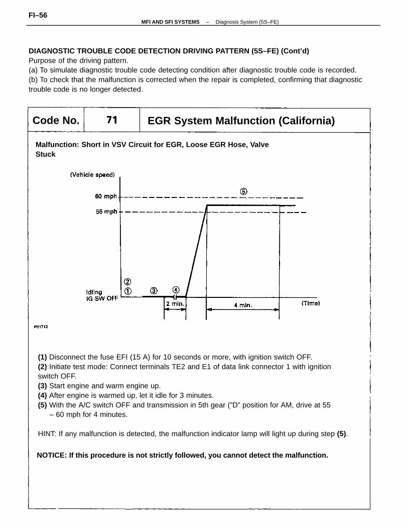
(1) Disconnect the fuse EFI (15 A) for 10 seconds or more, with ignition switch OFF.(2) Initiate test mode: Connect terminals TE2 and E1 of data link connector 1 with ignitionswitch OFF.(3) Start engine and warm engine up.(4) After engine is warmed up, let it idle for 3 minutes.(5) With the A/C switch OFF and transmission in 5th gear (”D” position for AM, drive at 55
– 60 mph for 4 minutes.
HINT: If any malfunction is detected, the malfunction indicator lamp will light up during step (5).
DIAGNOSTIC TROUBLE CODE DETECTION DRIVING PATTERN (5S–FE) (Cont’d)Purpose of the driving pattern.(a) To simulate diagnostic trouble code detecting condition after diagnostic trouble code is recorded.(b) To check that the malfunction is corrected when the repair is completed, confirming that diagnostictrouble code is no longer detected.
NOTICE: If this procedure is not strictly followed, you cannot detect the malfunction.
Malfunction: Short in VSV Circuit for EGR, Loose EGR Hose, ValveStuck
EGR System Malfunction (California)Code No.
–MFI AND SFI SYSTEMS Diagnosis System (5S–FE)FI–56
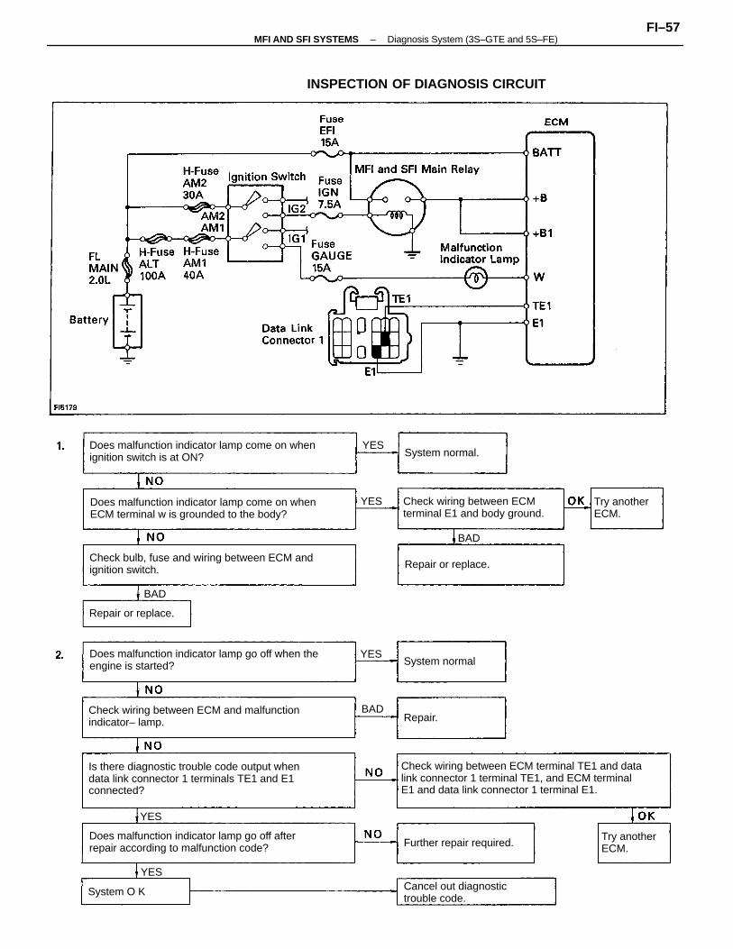
Check wiring between ECM terminal TE1 and datalink connector 1 terminal TE1, and ECM terminalE1 and data link connector 1 terminal E1.
Is there diagnostic trouble code output whendata link connector 1 terminals TE1 and E1connected?
Does malfunction indicator lamp go off when theengine is started?
Does malfunction indicator lamp come on whenignition switch is at ON?
Does malfunction indicator lamp come on whenECM terminal w is grounded to the body?
Check bulb, fuse and wiring between ECM andignition switch.
Check wiring between ECM and malfunctionindicator– lamp.
Does malfunction indicator lamp go off afterrepair according to malfunction code?
INSPECTION OF DIAGNOSIS CIRCUIT
Check wiring between ECMterminal E1 and body ground.
Cancel out diagnostictrouble code.
Further repair required.
Try anotherECM.
Try anotherECM.
Repair or replace.
Repair or replace.
System normal.
System normal
System O K
Repair.BAD
BAD
BAD
YES
YES
YES
YES
YES
–MFI AND SFI SYSTEMS Diagnosis System (3S–GTE and 5S–FE)FI–57
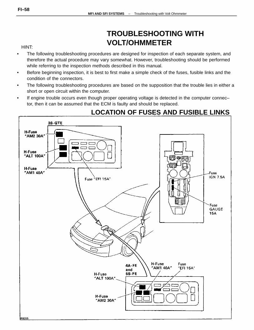
HINT:
• The following troubleshooting procedures are designed for inspection of each separate system, andtherefore the actual procedure may vary somewhat. However, troubleshooting should be performedwhile referring to the inspection methods described in this manual.
• Before beginning inspection, it is best to first make a simple check of the fuses, fusible links and thecondition of the connectors.
• The following troubleshooting procedures are based on the supposition that the trouble lies in either ashort or open circuit within the computer.
• If engine trouble occurs even though proper operating voltage is detected in the computer connec–tor, then it can be assumed that the ECM is faulty and should be replaced.
TROUBLESHOOTING WITHVOLT/OHMMETER
LOCATION OF FUSES AND FUSIBLE LINKS
–MFI AND SFI SYSTEMS Troubleshooting with Volt OhmmeterFI–58
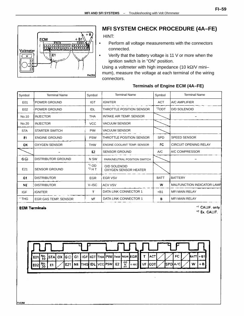
HINT:
• Perform all voltage measurements with the connectorsconnected.
• Verify that the battery voltage is 11 V or more when theignition switch is in ”ON” position.
O/D SOLENOIDOXYGEN SENSOR HEATER
PARK/NEUTRAL POSITION SWITCH
ENGINE COOLANT TEMP. SENSOR
THROTTLE POSITION SENSOR
MALFUNCTION INDICATOR LAMP
THROTTLE POSITION SENSOR
DATA LINK CONNECTOR 1
INTAKE AIR TEMP. SENSOR
DATA LINK CONNECTOR 1
CIRCUIT OPENING RELAY
EGR GAS TEMP. SENSOR
DISTRIBUTOR GROUND
A/C COMPRESSORSENSOR GROUND
MFI MAIN RELAY
SENSOR GROUND
VACUUM SENSOR
VACUUM SENSOR
STARTER SWITCH
MFI MAIN RELAY
POWER GROUND
ENGINE GROUND
POWER GROUND
OXYGEN SENSOR
O/D SOLENOID
SPEED SENSOR
Terminal NameTerminal NameTerminal Name
A/C AMPLIFIER
DISTRIBUTOR
DISTRIBUTOR
*1 OD*2 H T
INJECTOR
INJECTOR
BATTERY
Symbol SymbolSymbol
ACV VSV
EGR VSV
IGNITER
IGNITER
‘’ THG
*2ODT
No.10
No.20
V–ISC
BATT
N SW
PSW
THA
A/C
THW
ACT
SPD
+B1
STA
VCC
PIM
EGR
IGT
IDLE02
IGF
E01
E21
MFI SYSTEM CHECK PROCEDURE (4A–FE)
Using a voltmeter with high impedance (10 k/V mini–mum), measure the voltage at each terminal of the wiringconnectors.
Terminals of Engine ECM (4A–FE)
–MFI AND SFI SYSTEMS Troubleshooting with Volt OhmmeterFI–59
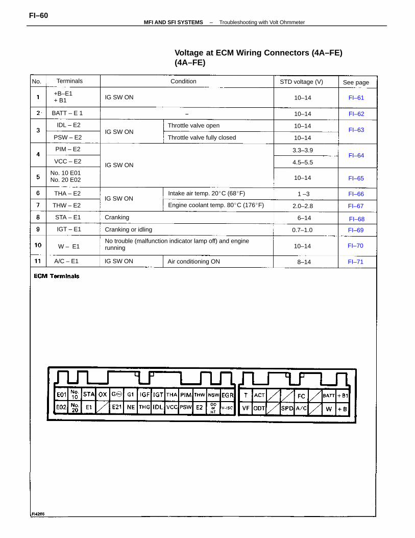
Voltage at ECM Wiring Connectors (4A–FE)(4A–FE)
No trouble (malfunction indicator lamp off) and enginerunning
Engine coolant temp. 80C (176F)
Intake air temp. 20C (68F)
Throttle valve fully closed
No. 10 E01No. 20 E02
Air conditioning ON
Throttle valve open
STD voltage (V)
Cranking or idling
+B–E1+ B1
ConditionTerminals
IG SW ON
IG SW ON
See page
IG SW ON
IG SW ON
IG SW ON
BATT – E 1
THW – E2
Cranking
PSW – E2
A/C – E1
VCC – E2
THA – E2
PIM – E2
0.7–1.0
3.3–3.9
STA – E1
2.0–2.8
IDL – E2
IGT – E1
4.5–5.5
10–14
10–14
10–14
10–14
10–14
10–14W – E1
8–14
6–14
FI–70
FI–64
FI–68
FI–69
FI–65
FI–66
FI–61
FI–62
FI–63
FI–67
1 –3
FI–71
No.
–MFI AND SFI SYSTEMS Troubleshooting with Volt OhmmeterFI–60
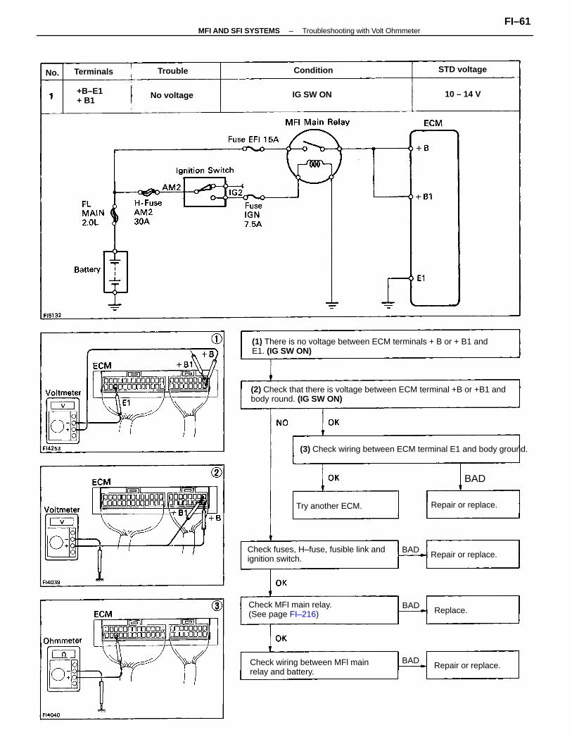
(2) Check that there is voltage between ECM terminal +B or +B1 andbody round. (IG SW ON)
(1) There is no voltage between ECM terminals + B or + B1 andE1. (IG SW ON)
(3) Check wiring between ECM terminal E1 and body ground.
Check fuses, H–fuse, fusible link andignition switch.
Check wiring between MFl mainrelay and battery.
Check MFI main relay.(See page FI–216)
Try another ECM.
Repair or replace.
Repair or replace.
Repair or replace.
+B–E1+ B1
STD voltage
No voltage IG SW ON
ConditionTerminals
10 – 14 V
Replace.
Trouble
BAD
BAD
BAD
BAD
No.
–MFI AND SFI SYSTEMS Troubleshooting with Volt OhmmeterFI–61
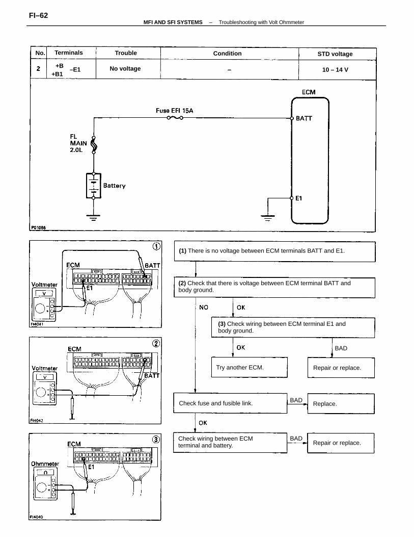
(2) Check that there is voltage between ECM terminal BATT andbody ground.
(3) Check wiring between ECM terminal E1 andbody ground.
(1) There is no voltage between ECM terminals BATT and E1.
Check wiring between ECMterminal and battery.
Check fuse and fusible link.
Try another ECM. Repair or replace.
Repair or replace.
STD voltage
No voltage
ConditionTerminals
+B10 – 14 V
Replace.
Trouble
BAD
BAD
BAD
No.
+B1–E1
–MFI AND SFI SYSTEMS Troubleshooting with Volt OhmmeterFI–62
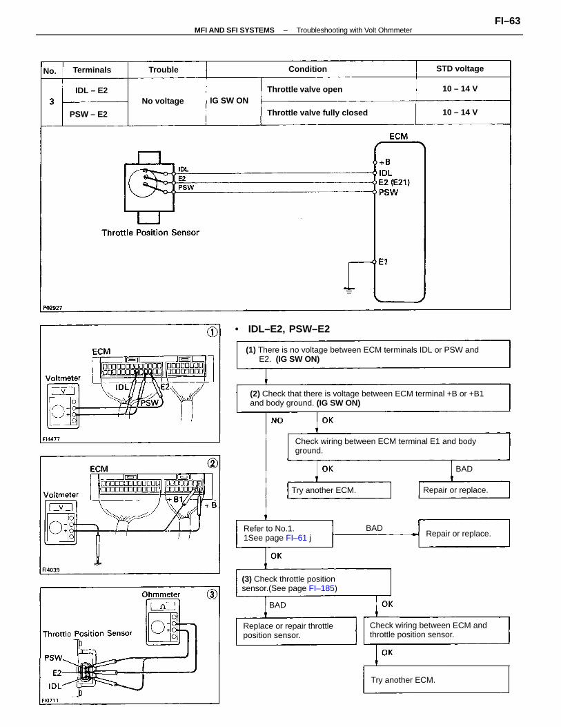
(2) Check that there is voltage between ECM terminal +B or +B1and body ground. (IG SW ON)
(1) There is no voltage between ECM terminals IDL or PSW andE2. (IG SW ON)
Check wiring between ECM terminal E1 and bodyground.
Check wiring between ECM andthrottle position sensor.
(3) Check throttle positionsensor.(See page FI–185)
Replace or repair throttleposition sensor.
Refer to No.1.1See page FI–61 j
Throttle valve fully closed
• IDL–E2, PSW–E2
Throttle valve open
Try another ECM.
Try another ECM. Repair or replace.
Repair or replace.
STD voltage
No voltage IG SW ON
ConditionTerminals
10 – 14 V
10 – 14 V
PSW – E2
IDL – E2
Trouble
BAD
BAD
BAD
No.
–MFI AND SFI SYSTEMS Troubleshooting with Volt OhmmeterFI–63
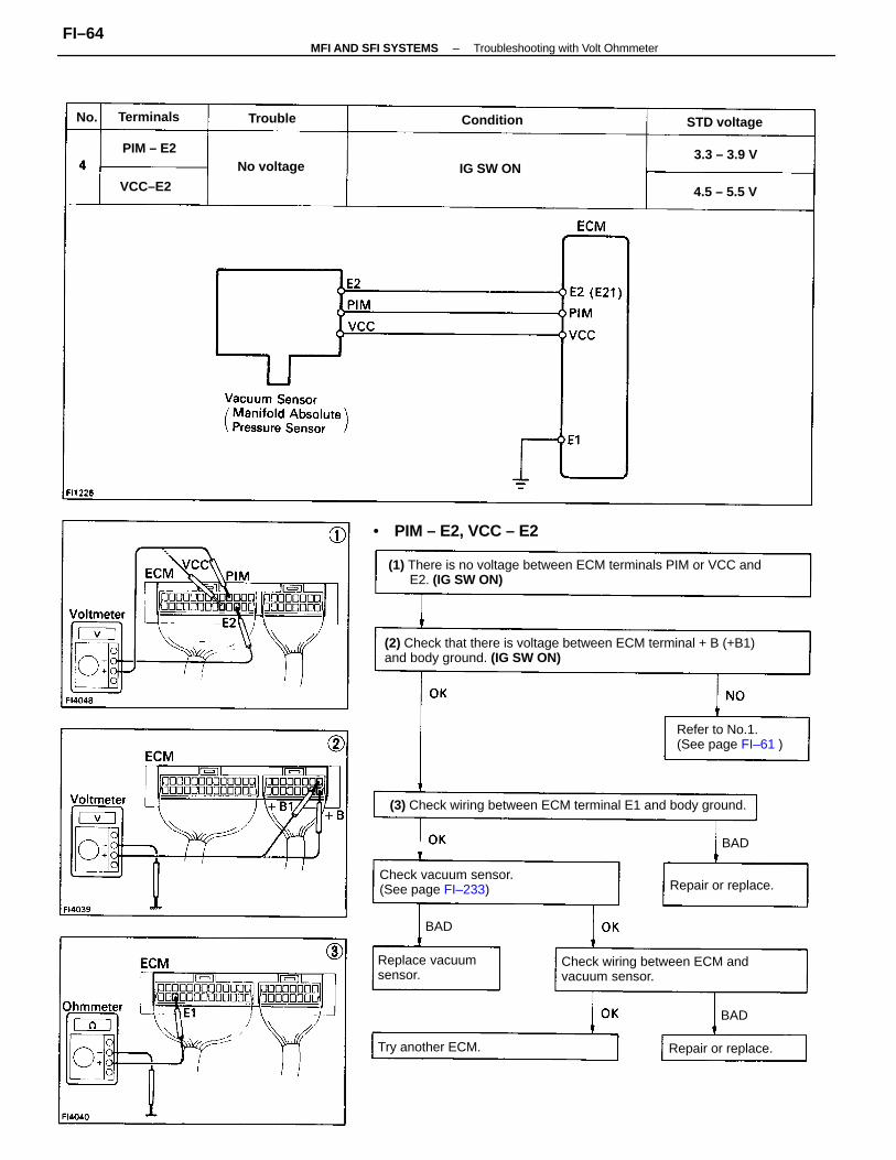
(2) Check that there is voltage between ECM terminal + B (+B1)and body ground. (IG SW ON)
(1) There is no voltage between ECM terminals PIM or VCC and E2. (IG SW ON)
(3) Check wiring between ECM terminal E1 and body ground.
Check wiring between ECM andvacuum sensor.
Check vacuum sensor.(See page FI–233)
Refer to No.1.(See page FI–61 )
Replace vacuumsensor.
• PIM – E2, VCC – E2
Try another ECM.
Repair or replace.
Repair or replace.
STD voltage
No voltage IG SW ON
ConditionTerminals
4.5 – 5.5 V
3.3 – 3.9 V
VCC–E2
PIM – E2
Trouble
BAD
BAD
BAD
No.
–MFI AND SFI SYSTEMS Troubleshooting with Volt OhmmeterFI–64
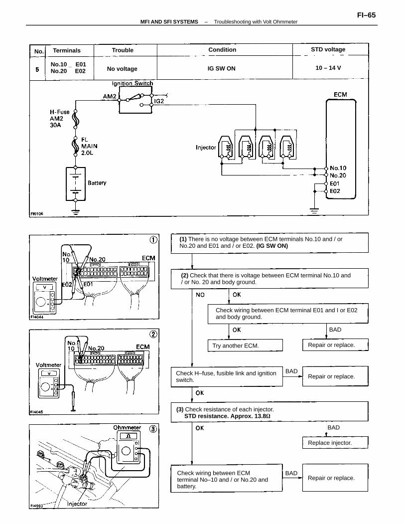
(2) Check that there is voltage between ECM terminal No.10 and/ or No. 20 and body ground.
(1) There is no voltage between ECM terminals No.10 and / orNo.20 and E01 and / or E02. (IG SW ON)
Check wiring between ECM terminal E01 and I or E02and body ground.
Check wiring between ECMterminal No–10 and / or No.20 andbattery.
(3) Check resistance of each injector. STD resistance. Approx. 13.8
Check H–fuse, fusible link and ignitionswitch.
No.10 _ E01No.20 E02
Try another ECM.
Repair or replace.
Repair or replace.
Repair or replace.
Replace injector.
STD voltage
No voltage IG SW ON
ConditionTerminals
10 – 14 V
Trouble
BAD
BAD
BAD
BAD
No.
–MFI AND SFI SYSTEMS Troubleshooting with Volt OhmmeterFI–65
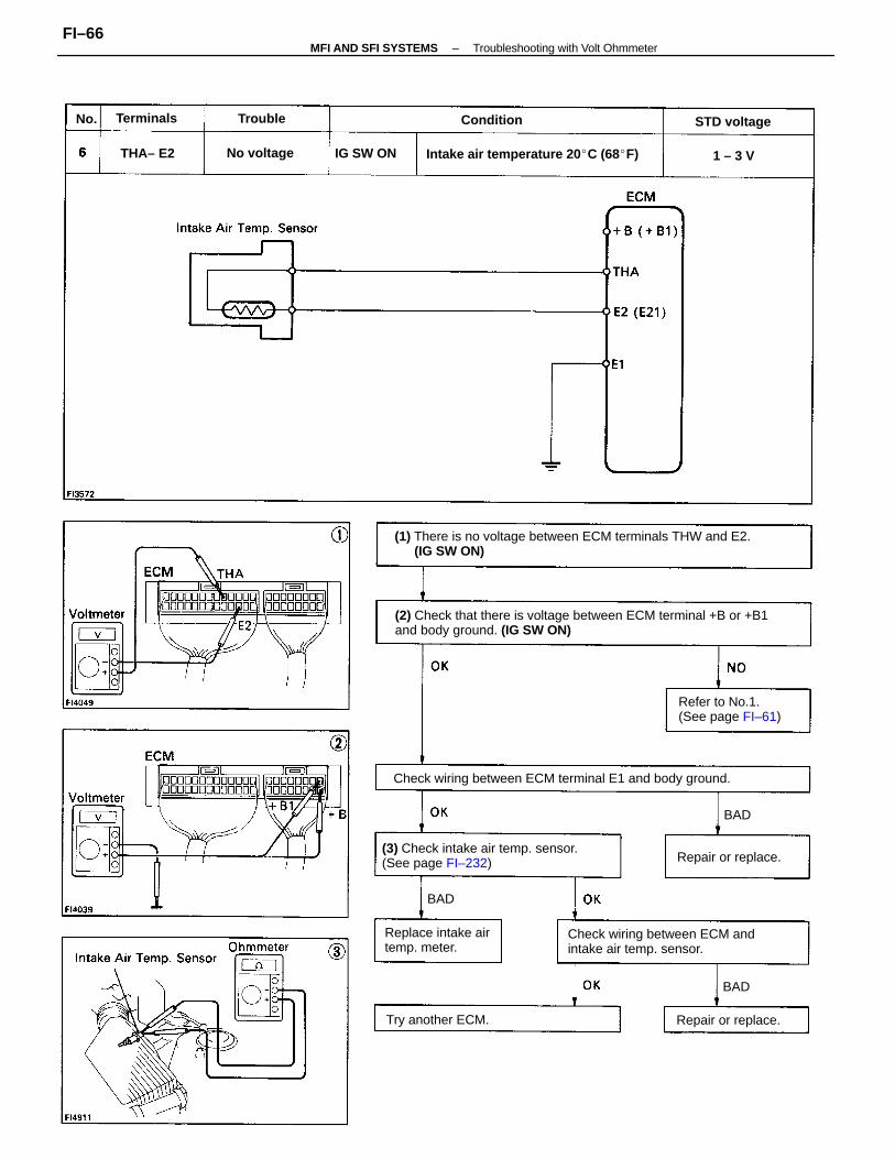
(2) Check that there is voltage between ECM terminal +B or +B1and body ground. (IG SW ON)
(1) There is no voltage between ECM terminals THW and E2.(IG SW ON)
Check wiring between ECM terminal E1 and body ground.
Check wiring between ECM andintake air temp. sensor.
(3) Check intake air temp. sensor.(See page FI–232)
Intake air temperature 20 C (68F)
Refer to No.1.(See page FI–61)
Replace intake airtemp. meter.
Try another ECM. Repair or replace.
Repair or replace.
STD voltage
No voltage IG SW ON
ConditionTerminals
THA– E2
Trouble
1 – 3 V
BAD
BAD
BAD
No.
–MFI AND SFI SYSTEMS Troubleshooting with Volt OhmmeterFI–66
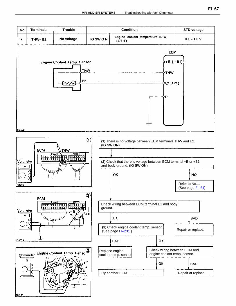
(2) Check that there is voltage between ECM terminal +B or +B1and body ground. (IG SW ON)
(1) There is no voltage between ECM terminals THW and E2.(IG SW ON)
Check wiring between ECM terminal E1 and bodyground.
(3) Check engine coolant temp. sensor.(See page FI–231 )
Check wiring between ECM andengine coolant temp. sensor.
Engine coolant temperature 80 C (176F)
Refer to No.1.(See page FI–61)
Replace enginecoolant temp. sensor
Try another ECM.
Repair or replace.
Repair or replace.
STD voltage
No voltage 0.1 – 1.0 VIG SW O N
ConditionTerminals
THW– E2
Trouble
BAD
BAD
BAD
No.
–MFI AND SFI SYSTEMS Troubleshooting with Volt OhmmeterFI–67
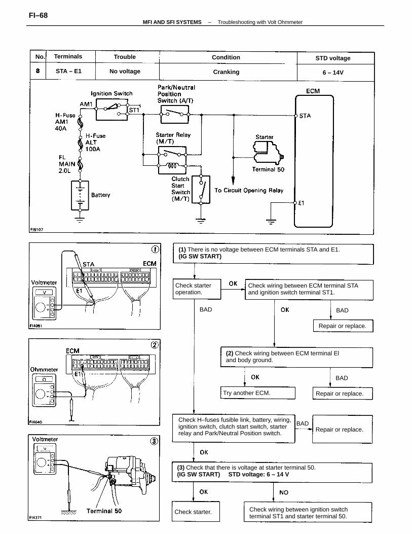
(1) There is no voltage between ECM terminals STA and E1.(IG SW START)
Check H–fuses fusible link, battery, wiring,ignition switch, clutch start switch, starterrelay and Park/Neutral Position switch.
(3) Check that there is voltage at starter terminal 50.(IG SW START) STD voltage: 6 – 14 V
Check wiring between ECM terminal STAand ignition switch terminal ST1.
(2) Check wiring between ECM terminal Eland body ground.
Check wiring between ignition switchterminal ST1 and starter terminal 50.
Check starteroperation.
Try another ECM. Repair or replace.
Repair or replace.
Repair or replace.
STD voltage
Check starter.
No voltage
ConditionTerminals
CrankingSTA – E1
Trouble
6 – 14V
BAD
BAD
BAD BAD
No.
–MFI AND SFI SYSTEMS Troubleshooting with Volt OhmmeterFI–68
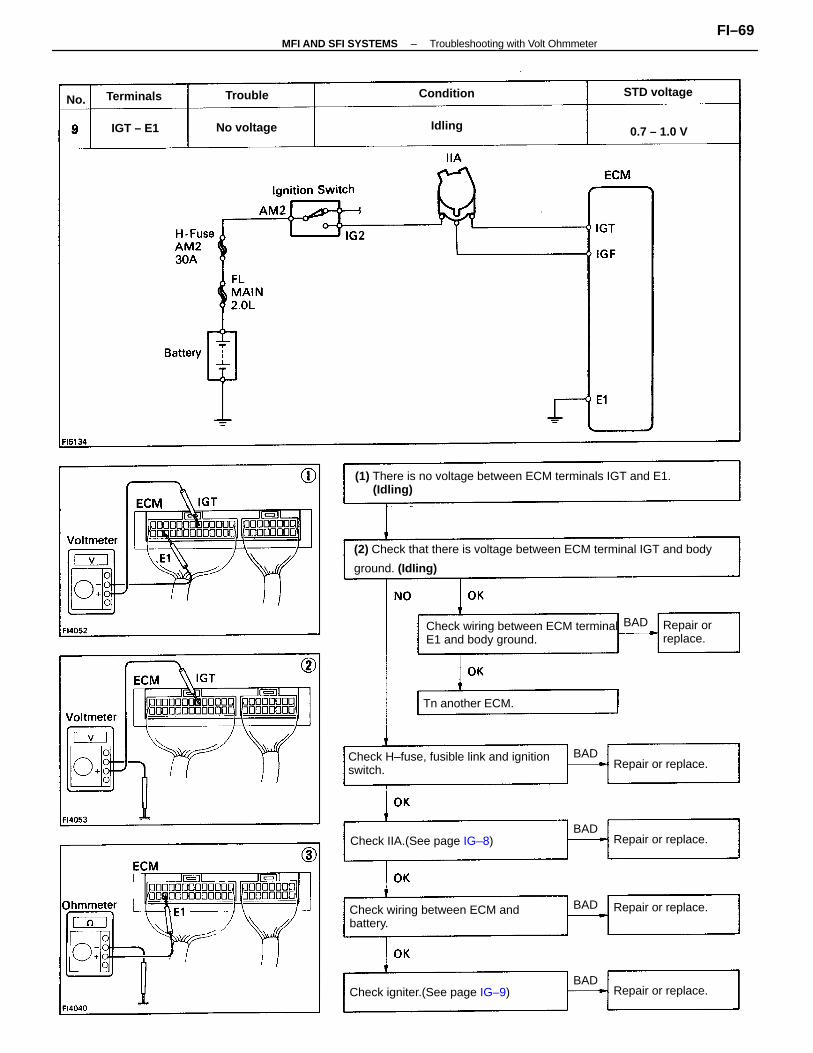
(2) Check that there is voltage between ECM terminal IGT and body
ground. (IdIing)
(1) There is no voltage between ECM terminals IGT and E1.(Idling)
Check H–fuse, fusible link and ignitionswitch.
Check wiring between ECM terminalE1 and body ground.
Check wiring between ECM andbattery.
Check IIA.(See page IG–8)
Check igniter.(See page IG–9)
Tn another ECM.
Repair or replace.
Repair or replace.
Repair or replace.
Repair or replace.
Repair orreplace.
STD voltage
No voltage 0.7 – 1.0 V
Terminals Condition
IGT – E1
Trouble
Idling
BAD
BAD
BAD
BAD
BAD
No.
–MFI AND SFI SYSTEMS Troubleshooting with Volt OhmmeterFI–69
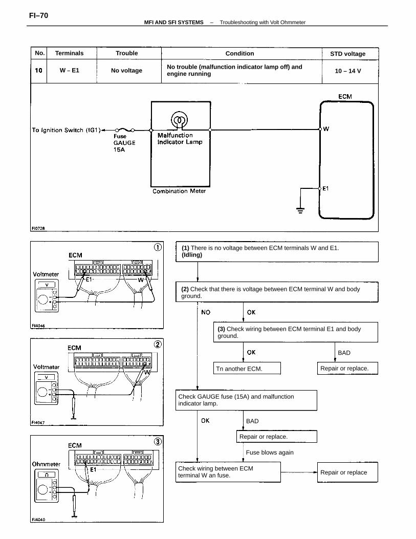
(2) Check that there is voltage between ECM terminal W and bodyground.
(1) There is no voltage between ECM terminals W and E1.(Idling)
(3) Check wiring between ECM terminal E1 and bodyground.
No trouble (malfunction indicator lamp off) andengine running
Check GAUGE fuse (15A) and malfunctionindicator lamp.
Check wiring between ECMterminal W an fuse.
Fuse blows again
Tn another ECM. Repair or replace.
Repair or replace.
Repair or replace
STD voltage
No voltage
ConditionTerminals
10 – 14 V
Trouble
W – E1
BAD
BAD
No.
–MFI AND SFI SYSTEMS Troubleshooting with Volt OhmmeterFI–70
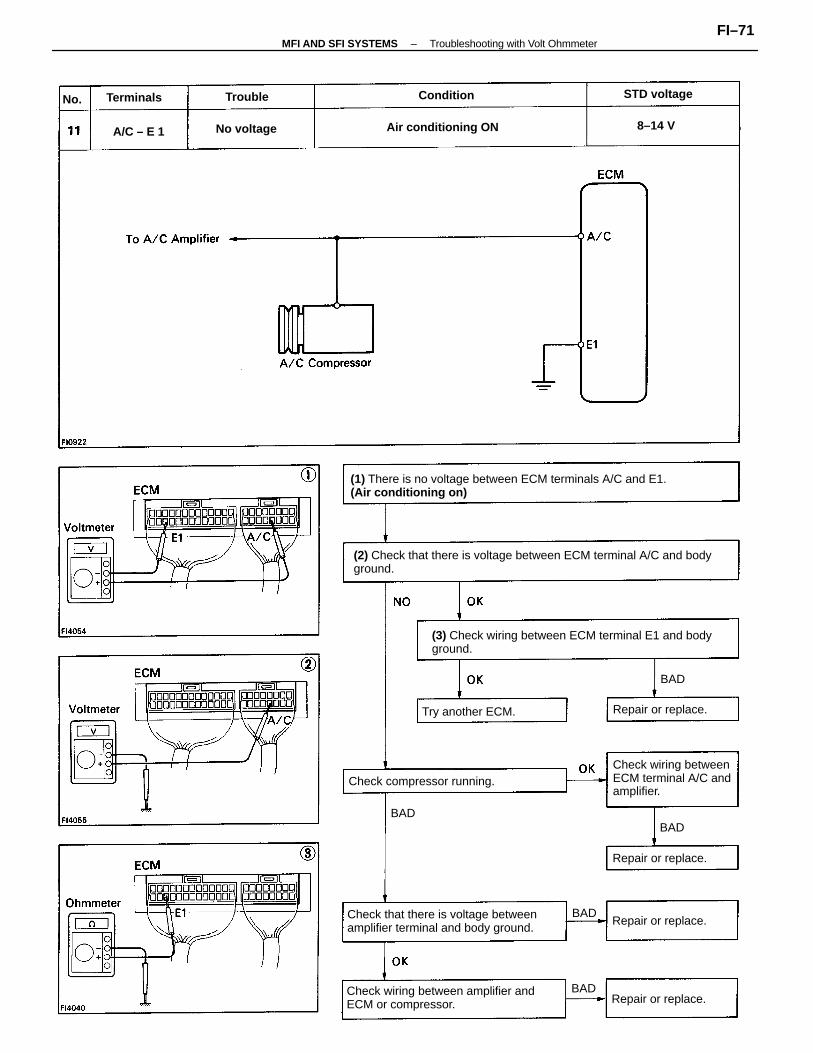
(1) There is no voltage between ECM terminals A/C and E1.(Air conditioning on)
(2) Check that there is voltage between ECM terminal A/C and bodyground.
(3) Check wiring between ECM terminal E1 and bodyground.
Check wiring between amplifier andECM or compressor.
Check that there is voltage betweenamplifier terminal and body ground.
Check wiring betweenECM terminal A/C andamplifier.
Check compressor running.
Air conditioning ON
Repair or replace.
Repair or replace.
Repair or replace.
Repair or replace.
Try another ECM.
STD voltage
No voltage
Terminals Condition
A/C – E 1 8–14 V
Trouble
BAD
BAD
BAD
BAD
BAD
No.
–MFI AND SFI SYSTEMS Troubleshooting with Volt OhmmeterFI–71
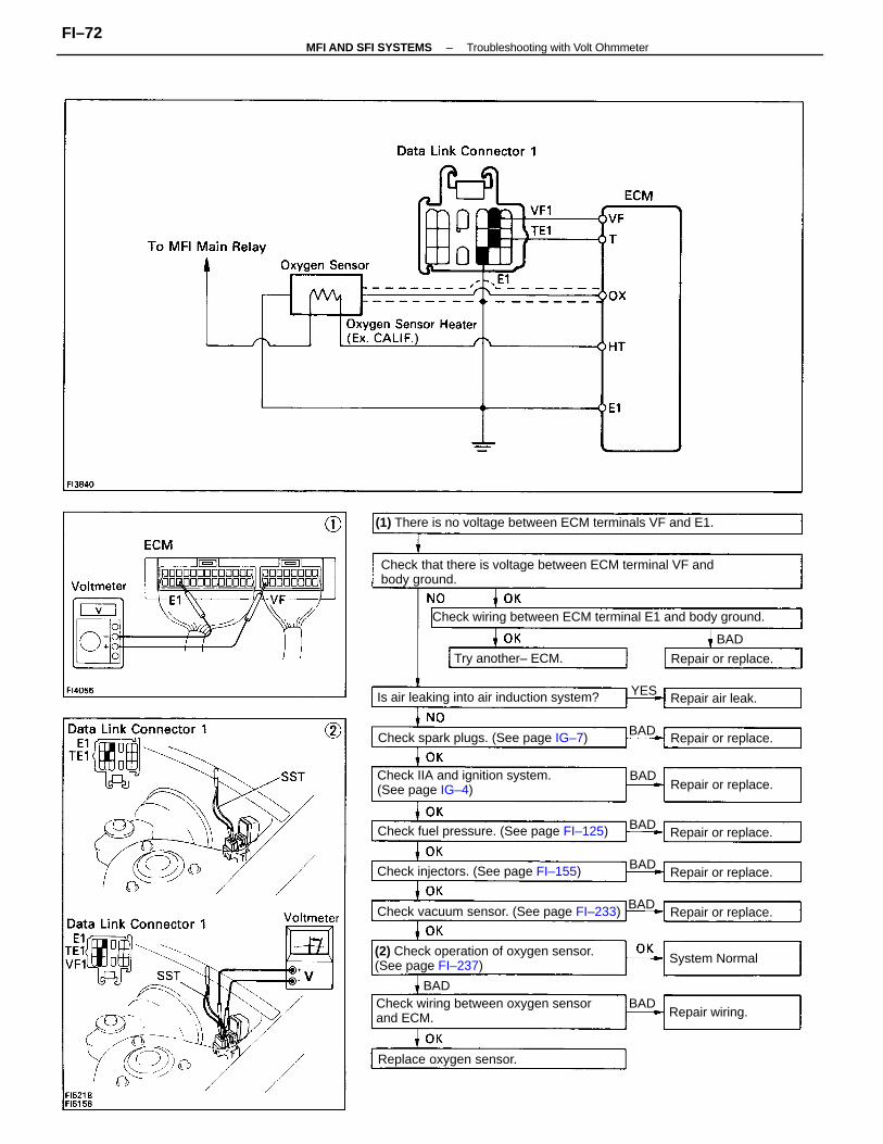
Check that there is voltage between ECM terminal VF andbody ground.
(1) There is no voltage between ECM terminals VF and E1.
Check wiring between ECM terminal E1 and body ground.
Check wiring between oxygen sensorand ECM.
(2) Check operation of oxygen sensor.(See page FI–237)
Check IIA and ignition system.(See page IG–4)
Check vacuum sensor. (See page FI–233)
Check fuel pressure. (See page FI–125)
Is air leaking into air induction system?
Check spark plugs. (See page IG–7)
Check injectors. (See page FI–155)
Replace oxygen sensor.
Try another– ECM.
Repair or replace.
Repair or replace.
Repair or replace.
Repair or replace.
Repair or replace.
Repair or replace.
System Normal
Repair air leak.
Repair wiring.
BAD
BAD
BAD
BADBAD
BAD
BAD
BAD
YES
–MFI AND SFI SYSTEMS Troubleshooting with Volt OhmmeterFI–72
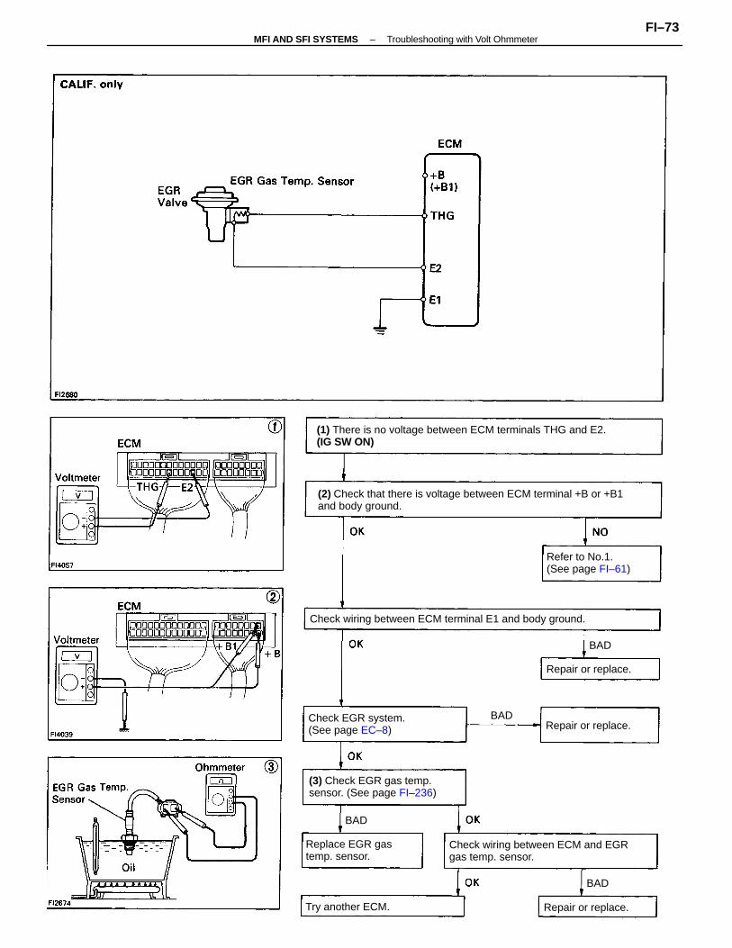
(2) Check that there is voltage between ECM terminal +B or +B1and body ground.
(1) There is no voltage between ECM terminals THG and E2.(IG SW ON)
Check wiring between ECM terminal E1 and body ground.
Check wiring between ECM and EGRgas temp. sensor.
(3) Check EGR gas temp.sensor. (See page FI–236)
Refer to No.1.(See page FI–61)
Check EGR system.(See page EC–8)
Replace EGR gastemp. sensor.
Try another ECM.
Repair or replace.
Repair or replace.
Repair or replace.
BAD
BAD
BAD
BAD
–MFI AND SFI SYSTEMS Troubleshooting with Volt OhmmeterFI–73
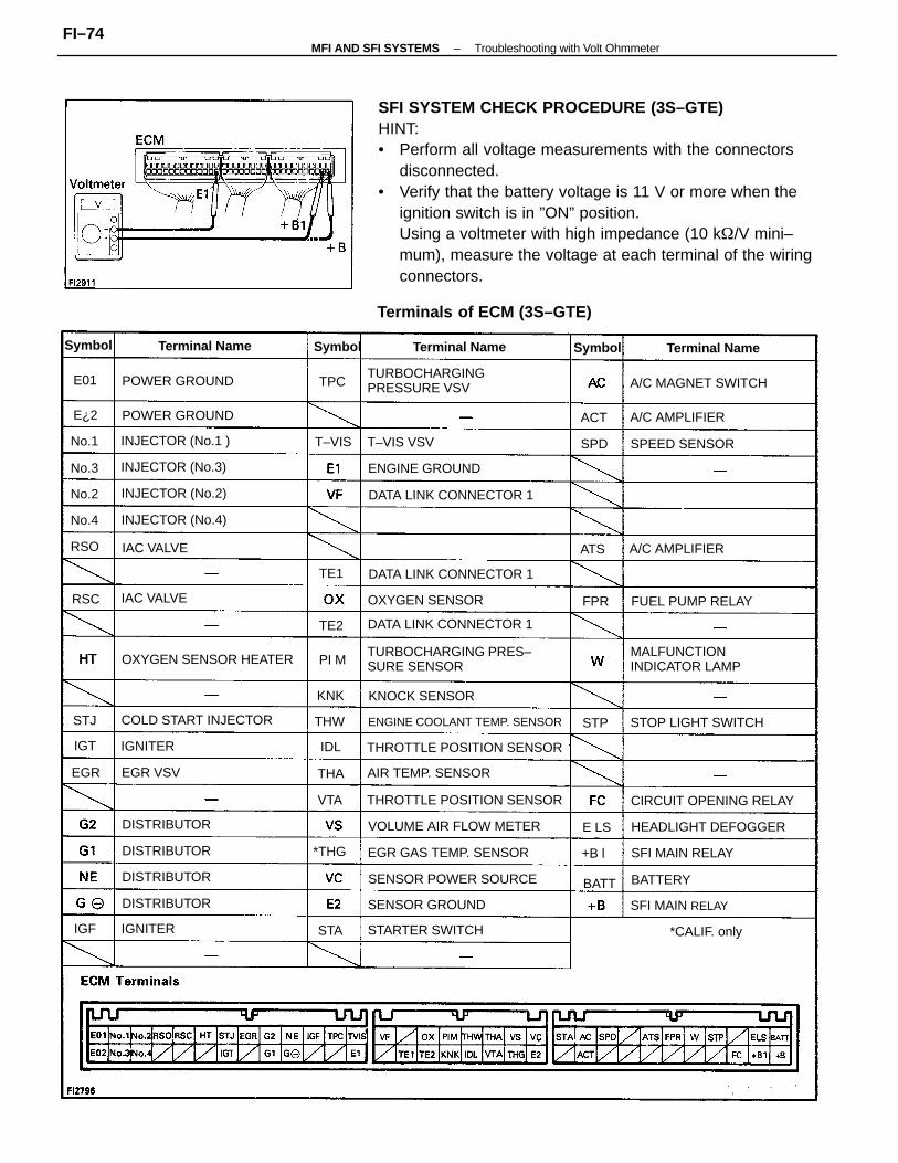
SFI SYSTEM CHECK PROCEDURE (3S–GTE)HINT:• Perform all voltage measurements with the connectors
disconnected.• Verify that the battery voltage is 11 V or more when the
ignition switch is in ”ON” position.Using a voltmeter with high impedance (10 k/V mini–mum), measure the voltage at each terminal of the wiringconnectors.
TURBOCHARGING PRES–SURE SENSOR
Terminals of ECM (3S–GTE)
TURBOCHARGINGPRESSURE VSV
MALFUNCTIONINDICATOR LAMP
THROTTLE POSITION SENSOR
THROTTLE POSITION SENSOR
VOLUME AIR FLOW METER
DATA LINK CONNECTOR 1
OXYGEN SENSOR HEATER
DATA LINK CONNECTOR 1
DATA LINK CONNECTOR 1
SENSOR POWER SOURCE
ENGINE COOLANT TEMP. SENSOR
CIRCUIT OPENING RELAY
EGR GAS TEMP. SENSOR
HEADLIGHT DEFOGGER
COLD START INJECTOR
A/C MAGNET SWITCH
STOP LIGHT SWITCH
AIR TEMP. SENSOR
ENGINE GROUND
SENSOR GROUND
INJECTOR (No.2)
INJECTOR (No.3)
INJECTOR (No.1 )
INJECTOR (No.4)
FUEL PUMP RELAYOXYGEN SENSOR
STARTER SWITCH
POWER GROUND
POWER GROUND
SFI MAIN RELAY
SFI MAIN RELAY
KNOCK SENSOR
SPEED SENSOR
Terminal NameTerminal Name
A/C AMPLIFIER
Terminal Name
A/C AMPLIFIER
DISTRIBUTOR
DISTRIBUTOR
DISTRIBUTOR
DISTRIBUTOR
IAC VALVE
*CALIF. only
IAC VALVE
T–VIS VSV
EGR VSV
BATTERY
IGNITER
IGNITER
Symbol SymbolSymbol
*THG
T–VIS
BATT
No.4
THW
No.3
No.1
No.2
KNK
RSO
THA
SPD
EGR
ACT
ATS
PI M
VTA
RSC
+B l
STA
FPR
TPC
TE1
IGT
STP
E01
IGF
E¿2
TE2
E LS
IDL
STJ
–MFI AND SFI SYSTEMS Troubleshooting with Volt OhmmeterFI–74
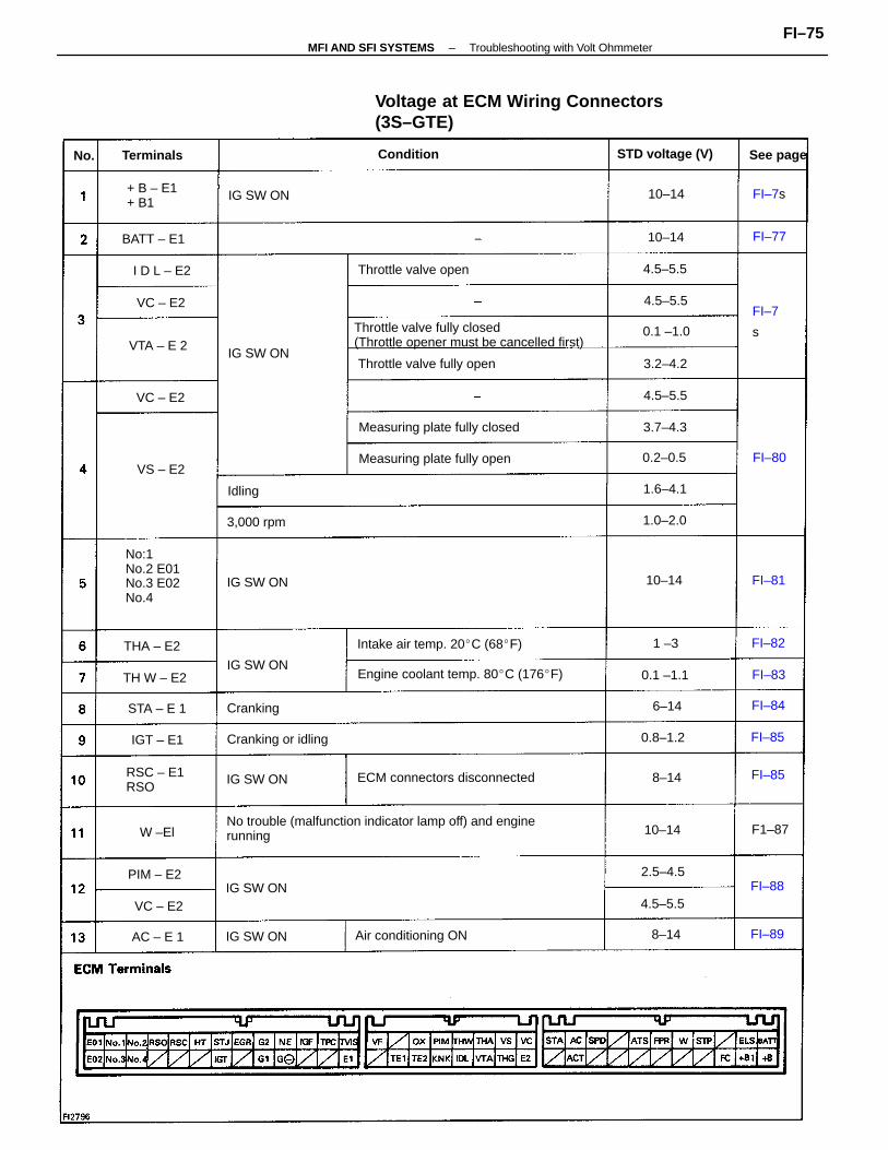
No trouble (malfunction indicator lamp off) and enginerunning
Voltage at ECM Wiring Connectors(3S–GTE)
Throttle valve fully closed(Throttle opener must be cancelled first)
No:1No.2 E01No.3 E02No.4
Engine coolant temp. 80C (176F)
ECM connectors disconnected
Intake air temp. 20C (68F)
Measuring plate fully closed
Measuring plate fully open
Throttle valve fully open
Air conditioning ON
Throttle valve open
STD voltage (V)
+ B – E1+ B1
Cranking or idling
RSC – E1RSO
3,000 rpm
Terminals Condition
BATT – E1
IG SW ON
IG SW ON
IG SW ON
See page
IG SW ON
IG SW ON
IG SW ON
IG SW ON
THA – E2
TH W – E2
PIM – E2
CrankingSTA – E 1
0.1 –1.0VTA – E 2
I D L – E2
0.2–0.5
IGT – E1
1.0–2.0
0.8–1.2
AC – E 1
4.5–5.5
0.1 –1.1
1.6–4.1
2.5–4.5
4.5–5.5
4.5–5.5
3.2–4.2
4.5–5.5
3.7–4.3
VC – E2
VC – E2
VC – E2
VS – E2
10–14
10–14
10–14
10–14
W –El
6–14
8–14
8–14
Idling
FI–80
FI–85
FI–89
FI–84
FI–83
FI–7s
1 –3
FI–7
s
FI–85
FI–77
FI–82
FI–88
FI–81
F1–87
No.
–MFI AND SFI SYSTEMS Troubleshooting with Volt OhmmeterFI–75
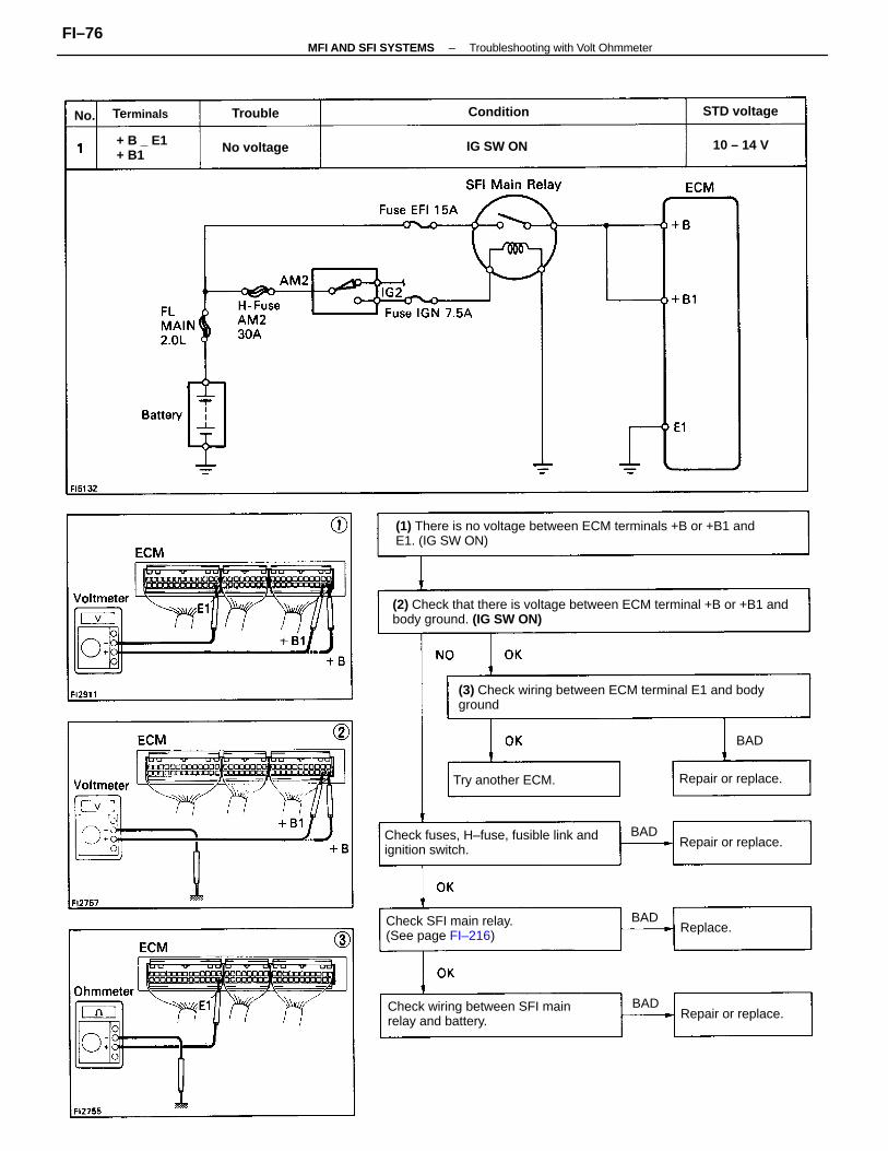
(2) Check that there is voltage between ECM terminal +B or +B1 andbody ground. (IG SW ON)
(1) There is no voltage between ECM terminals +B or +B1 andE1. (IG SW ON)
(3) Check wiring between ECM terminal E1 and bodyground
Check fuses, H–fuse, fusible link andignition switch.
Check wiring between SFI mainrelay and battery.
Check SFI main relay.(See page FI–216)
Try another ECM. Repair or replace.
Repair or replace.
Repair or replace.
+ B _ E1+ B1
STD voltage
No voltage IG SW ON
ConditionTerminals
10 – 14 V
Replace.
Trouble
BAD
BAD
BAD
BAD
No.
–MFI AND SFI SYSTEMS Troubleshooting with Volt OhmmeterFI–76
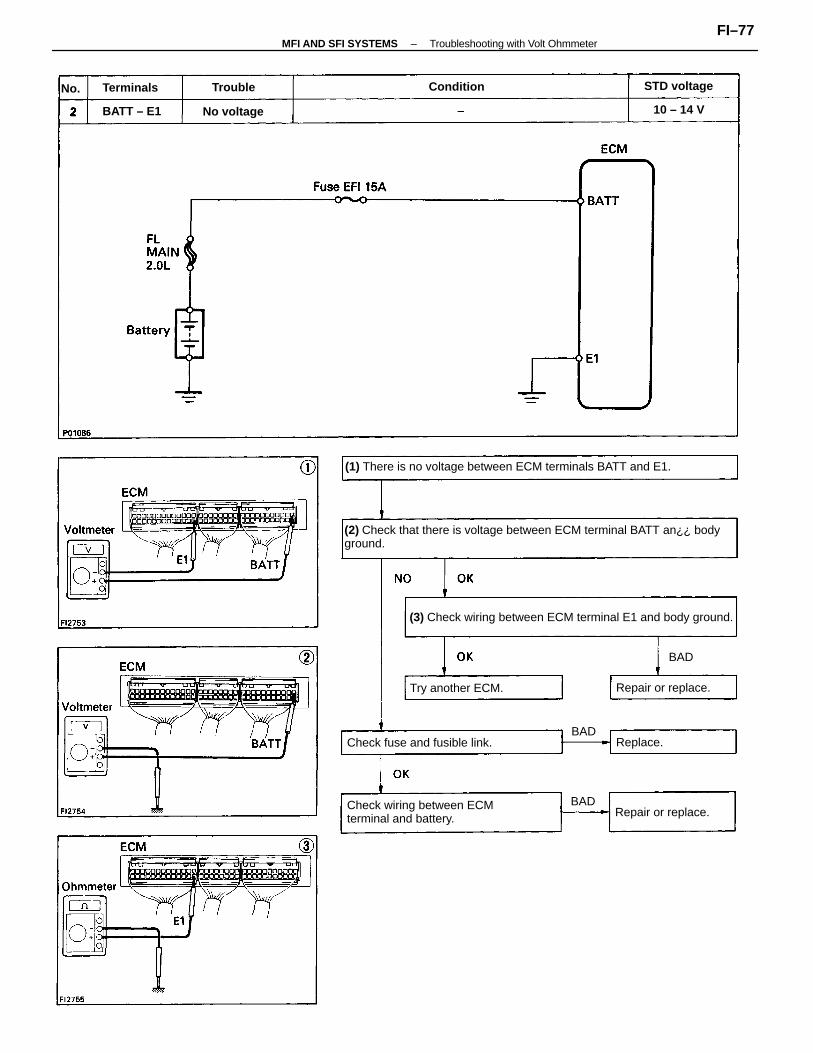
(2) Check that there is voltage between ECM terminal BATT an¿¿ bodyground.
(3) Check wiring between ECM terminal E1 and body ground.
(1) There is no voltage between ECM terminals BATT and E1.
Check wiring between ECMterminal and battery.
Check fuse and fusible link.
Try another ECM. Repair or replace.
Repair or replace.
STD voltage
No voltage
Condition
BATT – E1
Terminals
10 – 14 V
Replace.
Trouble
BAD
BAD
BAD
No.
–MFI AND SFI SYSTEMS Troubleshooting with Volt OhmmeterFI–77
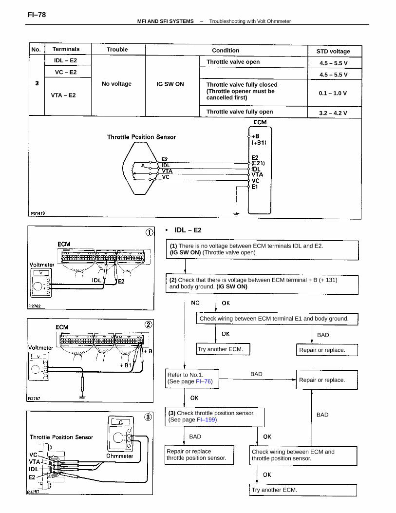
(2) Check that there is voltage between ECM terminal + B (+ 131)and body ground. (IG SW ON)
(1) There is no voltage between ECM terminals IDL and E2.(IG SW ON) (Throttle valve open)
Throttle valve fully closed(Throttle opener must becancelled first)
Check wiring between ECM terminal E1 and body ground.
(3) Check throttle position sensor.(See page FI–199)
Check wiring between ECM andthrottle position sensor.
Repair or replacethrottle position sensor.
Refer to No.1.(See page FI–76)
Throttle valve fully open
Throttle valve open
Try another ECM.
Try another ECM.
Repair or replace.
Repair or replace.
STD voltage
• IDL – E2
No voltage
0.1 – 1.0 V
Terminals
IG SW ON
VTA – E2
4.5 – 5.5 VIDL – E2
4.5 – 5.5 V
3.2 – 4.2 V
Condition
VC – E2
Trouble
BAD
BAD
BAD
BAD
No.
–MFI AND SFI SYSTEMS Troubleshooting with Volt OhmmeterFI–78
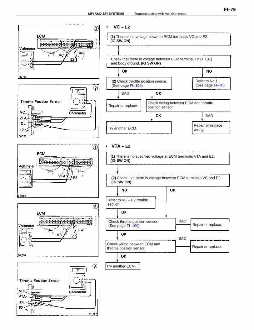
(2) Check that there is voltage between ECM terminals VC and E2.(IG SW ON)
(1) There is no specified voltage at ECM terminals VTA and E2.(IG SW ON)
Check that there is voltage between ECM terminal +B (+ 131)and body ground. (IG SW ON)
(1) There is no voltage between ECM terminals VC and E2.(IG SW ON)
Check wiring between ECM and throttleposition sensor.
Check throttle position sensor.(See page FI–199)
Check wiring between ECM andthrottle position sensor.
(2) Check throttle position sensor.(See page FI–199)
Refer to VC – E2 troublesection.
Refer to No.1.(See page FI–76)
Repair or replacewiringTry another ECM.
Try another ECM.
Repair or replace.
Repair or replace.
Repair or replace.
• VTA – E2
BAD
• VC – E2
BAD
BAD
BAD
–MFI AND SFI SYSTEMS Troubleshooting with Volt OhmmeterFI–79
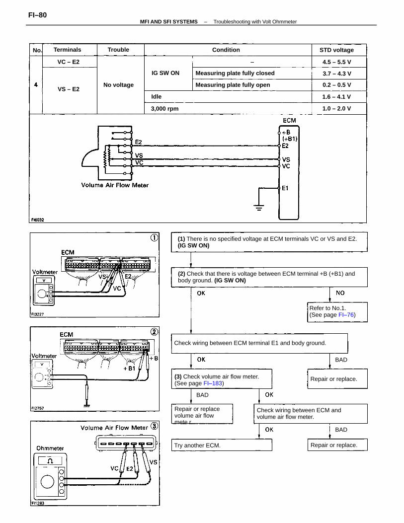
(2) Check that there is voltage between ECM terminal +B (+B1) andbody ground. (IG SW ON)
(1) There is no specified voltage at ECM terminals VC or VS and E2.(IG SW ON)
Check wiring between ECM terminal E1 and body ground.
(3) Check volume air flow meter.(See page FI–183)
Check wiring between ECM andvolume air flow meter.
Measuring plate fully closed
Repair or replacevolume air flowmete r.
Measuring plate fully open
Refer to No.1.(See page FI–76)
Try another ECM. Repair or replace.
Repair or replace.
STD voltage
No voltage
1.0 – 2.0 V
0.2 – 0.5 V
IG SW ON
1.6 – 4.1 V
3,000 rpm
ConditionTerminals
3.7 – 4.3 V
4.5 – 5.5 V
Trouble
VC – E2
VS – E2Idle
BAD
BAD
BAD
No.
–MFI AND SFI SYSTEMS Troubleshooting with Volt OhmmeterFI–80
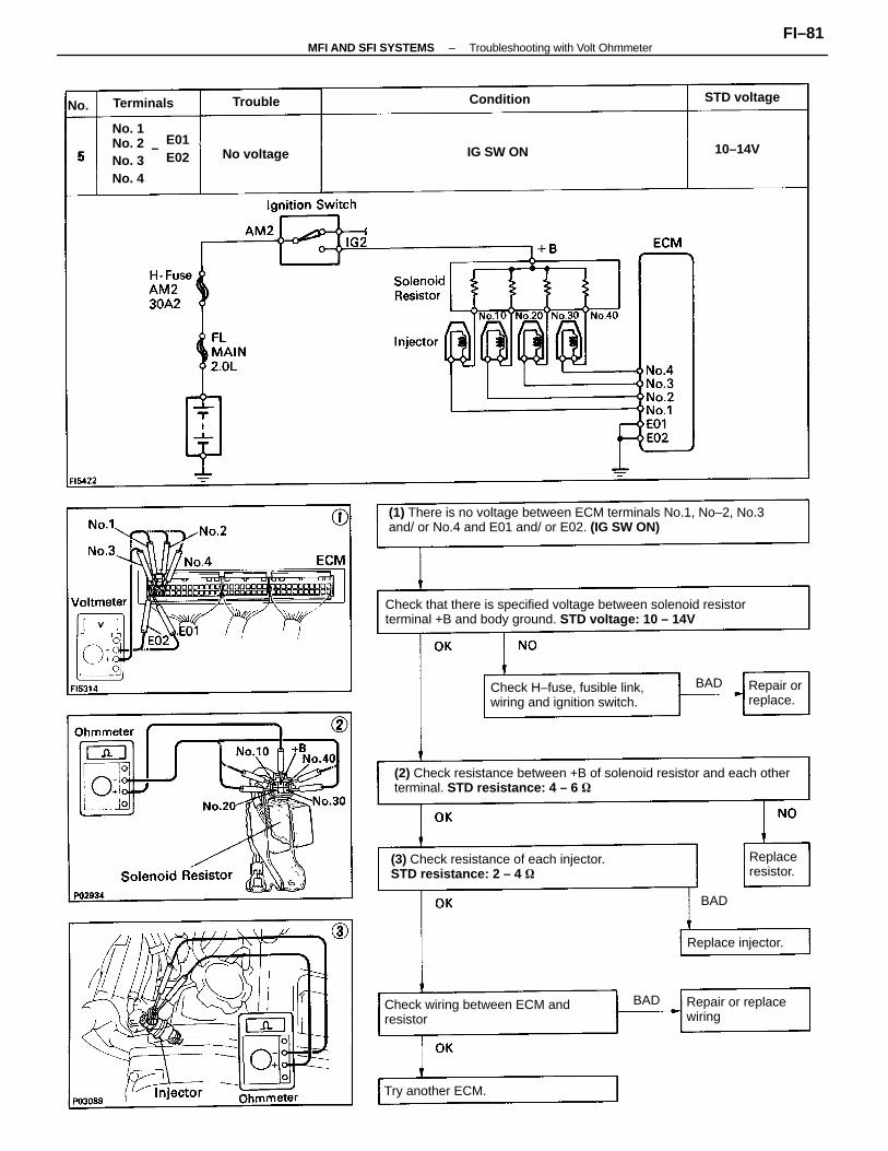
(1) There is no voltage between ECM terminals No.1, No–2, No.3and/ or No.4 and E01 and/ or E02. (IG SW ON)
Check that there is specified voltage between solenoid resistorterminal +B and body ground. STD voltage: 10 – 14V
(2) Check resistance between +B of solenoid resistor and each otherterminal. STD resistance: 4 – 6
(3) Check resistance of each injector.STD resistance: 2 – 4
Check wiring between ECM andresistor
Check H–fuse, fusible link,wiring and ignition switch.
No. 1No. 2No. 3No. 4
Repair or replacewiring
Try another ECM.
Replace injector.
Repair orreplace.
STD voltage
Replaceresistor.
No voltage IG SW ON
ConditionTerminals
10–14V
BAD
Trouble
BAD
BAD
No.
E01 E02
–
–MFI AND SFI SYSTEMS Troubleshooting with Volt OhmmeterFI–81
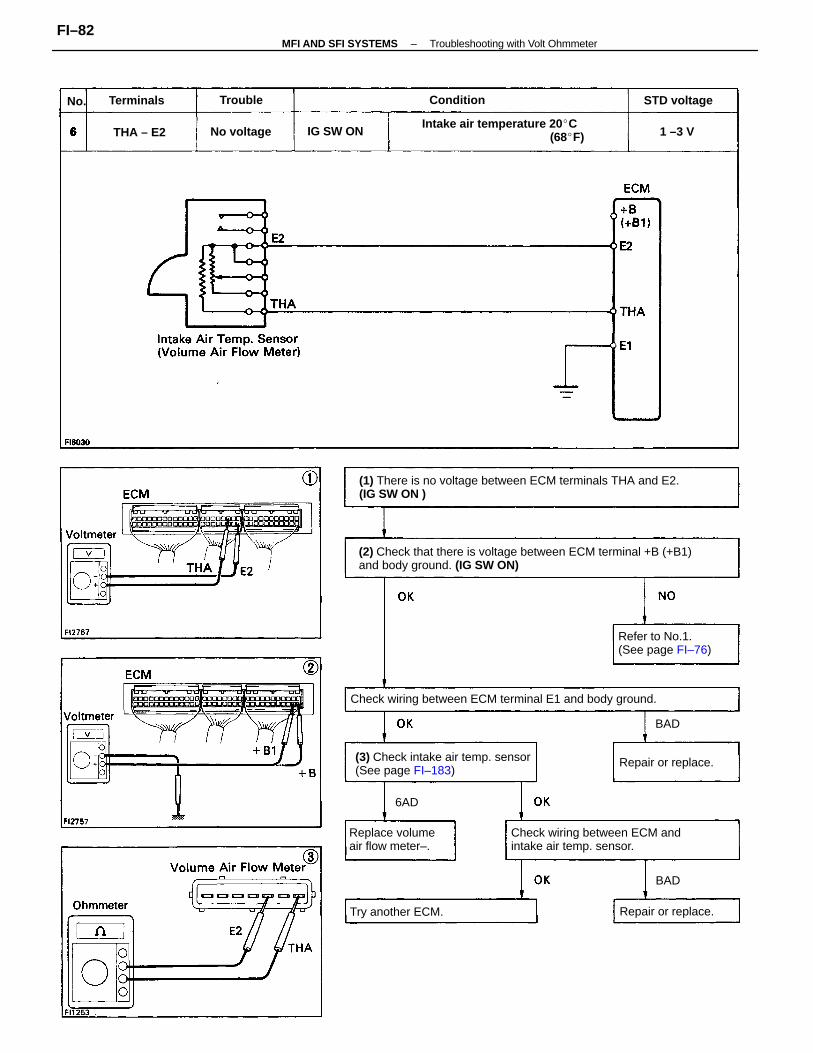
(2) Check that there is voltage between ECM terminal +B (+B1)and body ground. (IG SW ON)
(1) There is no voltage between ECM terminals THA and E2.(IG SW ON )
Check wiring between ECM terminal E1 and body ground.
(3) Check intake air temp. sensor(See page FI–183)
Check wiring between ECM andintake air temp. sensor.
Intake air temperature 20 C (68F)
Refer to No.1.(See page FI–76)
Replace volumeair flow meter–.
Try another ECM.
Repair or replace.
Repair or replace.
STD voltage
No voltage IG SW ON
ConditionTerminals
THA – E2
Trouble
1 –3 V
6AD
BAD
BAD
No.
–MFI AND SFI SYSTEMS Troubleshooting with Volt OhmmeterFI–82
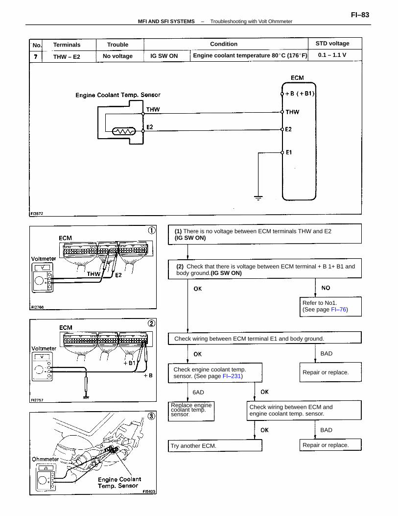
(2) Check that there is voltage between ECM terminal + B 1+ B1 andbody ground.(IG SW ON)
(1) There is no voltage between ECM terminals THW and E2(IG SW ON)
Check wiring between ECM terminal E1 and body ground.
Check engine coolant temp.sensor. (See page FI–231)
Check wiring between ECM andengine coolant temp. sensor.
Engine coolant temperature 80 C (176F)
Refer to No1.(See page FI–76)
Replace enginecoolant temp.sensor.
Try another ECM.
Repair or replace.
Repair or replace.
STD voltage
No voltage 0.1 – 1.1 VIG SW ON
Terminals Condition
THW – E2
Trouble
6AD
BAD
BAD
No.
–MFI AND SFI SYSTEMS Troubleshooting with Volt OhmmeterFI–83
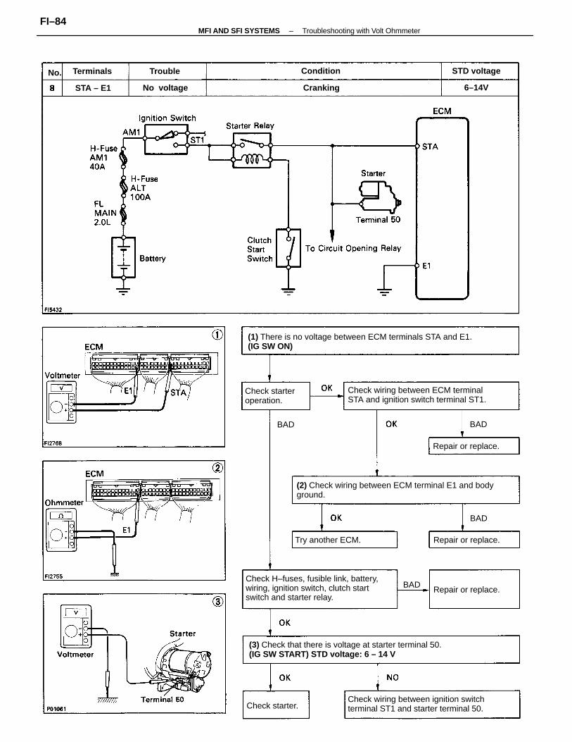
(1) There is no voltage between ECM terminals STA and E1.(IG SW ON)
(3) Check that there is voltage at starter terminal 50.(IG SW START) STD voltage: 6 – 14 V
(2) Check wiring between ECM terminal E1 and bodyground.
Check H–fuses, fusible link, battery,wiring, ignition switch, clutch startswitch and starter relay.
Check wiring between ECM terminalSTA and ignition switch terminal ST1.
Check wiring between ignition switchterminal ST1 and starter terminal 50.
Check starteroperation.
Try another ECM.
Repair or replace.
Repair or replace.
Repair or replace.
STD voltage
No voltage
Check starter.
ConditionTerminals
CrankingSTA – E1
Trouble
6–14V
BAD
BAD BAD
BAD
No.
–MFI AND SFI SYSTEMS Troubleshooting with Volt OhmmeterFI–84
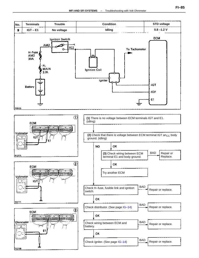
(2) Check that there is voltage between ECM terminal IGT an¿¿ bodyground. (idling)
(1) There is no voltage between ECM terminals IGT and E1.(idling)
Check H–fuse, fusible link and ignitionswitch.
Check wiring between ECM andbattery.
(3) Check wiring between ECMterminal E1 and body ground.
Check distributor. (See page IG–14)
Check igniter. (See page IG–14)
Try another ECM
Repair or replace.
Repair or replace.
Repair or replace.
Repair or replace.
Repair orReplace.
0.8 –1.2 V
STD voltage
No voltage
Terminals Condition
IGT – E1
Trouble
Idling
BAD
BAD
BAD
BAD
BAD
No.
–MFI AND SFI SYSTEMS Troubleshooting with Volt OhmmeterFI–85
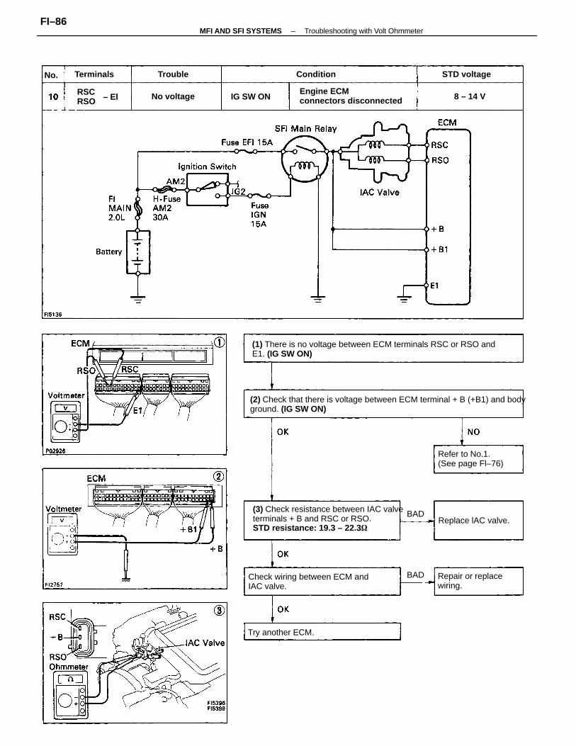
(2) Check that there is voltage between ECM terminal + B (+B1) and bodyground. (IG SW ON)
(1) There is no voltage between ECM terminals RSC or RSO andE1. (IG SW ON)
(3) Check resistance between IAC valveterminals + B and RSC or RSO.STD resistance: 19.3 – 22.3
Check wiring between ECM andIAC valve.
Engine ECMconnectors disconnected
Refer to No.1.(See page Fl–76)
Repair or replacewiring.
Replace lAC valve.
Try another ECM.
RSCRSO
STD voltage
No voltage
ConditionTerminals
IG SW ON 8 – 14 V
Trouble
BAD
BAD
No.
– El
–MFI AND SFI SYSTEMS Troubleshooting with Volt OhmmeterFI–86
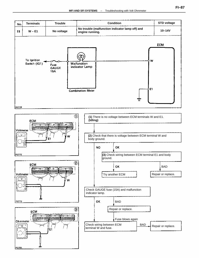
(2) Check that there is voltage between ECM terminal W andbody ground.
(1) There is no voltage between ECM terminals W and E1.(Idling)
(3) Check wiring between ECM terminal E1 and bodyground.
No trouble (malfunction indicator lamp off) andengine running.
Check GAUGE fuse (15A) and malfunctionindicator lamp.
Fuse blows again
Check wiring between ECMterminal W and fuse.
Try another ECM
Repair or replace.
Repair or replace.
Repair or replace.
STD voltage
No voltage
Terminals Condition
10–14V
Trouble
W – E1
BAD
BAD
No.
BAD
–MFI AND SFI SYSTEMS Troubleshooting with Volt OhmmeterFI–87
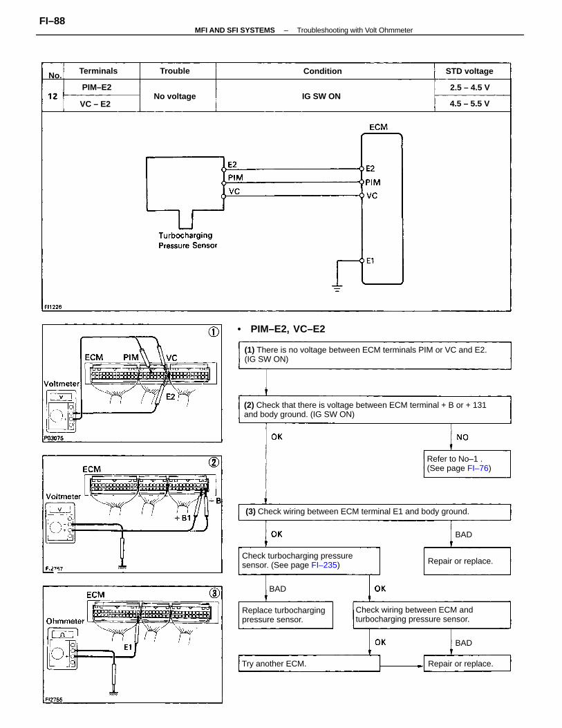
(1) There is no voltage between ECM terminals PIM or VC and E2.(IG SW ON)
(2) Check that there is voltage between ECM terminal + B or + 131and body ground. (IG SW ON)
(3) Check wiring between ECM terminal E1 and body ground.
Check wiring between ECM andturbocharging pressure sensor.
Check turbocharging pressuresensor. (See page FI–235)
Replace turbochargingpressure sensor.
Refer to No–1 .(See page FI–76)
• PIM–E2, VC–E2
Try another ECM.
Repair or replace.
Repair or replace.
STD voltage
No voltage IG SW ON4.5 – 5.5 V
2.5 – 4.5 V
ConditionTerminals
PIM–E2
Trouble
VC – E2
BAD
BAD
BAD
No.
–MFI AND SFI SYSTEMS Troubleshooting with Volt OhmmeterFI–88
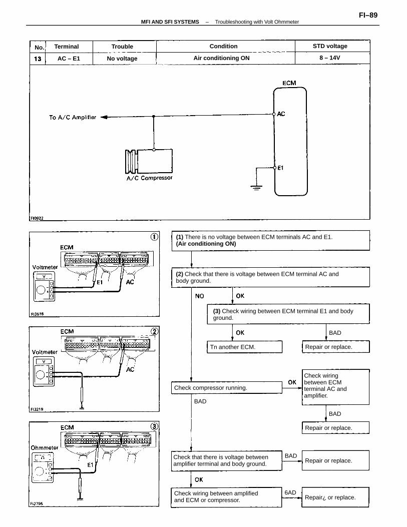
(2) Check that there is voltage between ECM terminal AC andbody ground.
(1) There is no voltage between ECM terminals AC and E1.(Air conditioning ON)
(3) Check wiring between ECM terminal E1 and bodyground.
Check that there is voltage betweenamplifier terminal and body ground.
Check wiring between amplifiedand ECM or compressor.
Check wiringbetween ECMterminal AC andamplifier.
Check compressor running.
Air conditioning ON
Tn another ECM.
Repair or replace.
Repair or replace.
Repair¿ or replace.
Repair or replace.
STD voltage
No voltage
ConditionTerminal
8 – 14VAC – E1
Trouble
BAD
6AD
BAD
BAD
BAD
No.
–MFI AND SFI SYSTEMS Troubleshooting with Volt OhmmeterFI–89
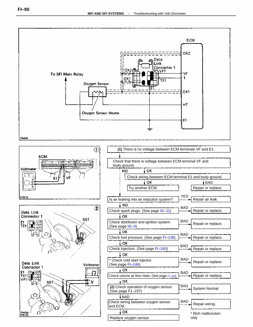
Check that there is voltage between ECM terminal VF andbody ground.
(1) There is no voltage between ECM terminals VF and E1.
Check wiring between ECM terminal E1 and body ground.
Check wiring between oxygen sensorand ECM.
Check distributor and ignition system.(See page IG–4)
(2) Check operation of oxygen sensor.(See page F1–237)
* Check cold start injector.(See page FI–146)
Check fuel pressure. (See page FI–136)
Is air leaking into air induction system?
Check volume air flow meter. (See page FI–183)
Check spark plugs. (See page IG–11)
Check injectors. (See page FI–160)
* Rich malfunctiononlyReplace oxygen sensor.
Try another ECM.
Repair or replace.
Repair or replace.
Repair or replace.
Repair or replace.
Repair or replace.
Repair or replace.
Repair or replace.
System Normal
Repair air leak.
Repair wiring.
BAD
BAD
BAD
BAD
BAD
BAD
BAD
BAD
BAD
BAD
YES
–MFI AND SFI SYSTEMS Troubleshooting with Volt OhmmeterFI–90
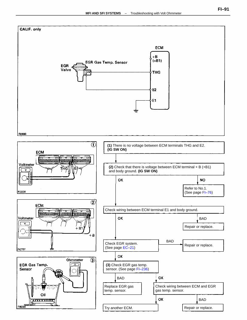
(2) Check that there is voltage between ECM terminal + B (+B1)and body ground. (IG SW ON)
(1) There is no voltage between ECM terminals THG and E2.(IG SW ON)
Check wiring between ECM and EGRgas temp. sensor.
Check wiring between ECM terminal E1 and body ground.
(3) Check EGR gas temp.sensor. (See page FI–236)
Check EGR system.(See page EC–21)
Refer to No.1.(See page FI–76)
Replace EGR gastemp. sensor.
Try another ECM. Repair or replace.
Repair or replace.
Repair or replace.
BAD
BAD
BAD
BAD
–MFI AND SFI SYSTEMS Troubleshooting with Volt OhmmeterFI–91
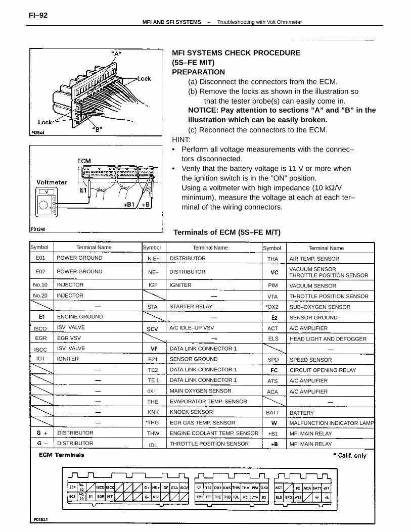
MFI SYSTEMS CHECK PROCEDURE(5S–FE MIT)PREPARATION
(a) Disconnect the connectors from the ECM.(b) Remove the locks as shown in the illustration so
that the tester probe(s) can easily come in.NOTICE: Pay attention to sections ”A” and ”B” in theillustration which can be easily broken.(c) Reconnect the connectors to the ECM.
HINT:• Perform all voltage measurements with the connec–
tors disconnected.• Verify that the battery voltage is 11 V or more when
the ignition switch is in the ”ON” position.Using a voltmeter with high impedance (10 k/Vminimum), measure the voltage at each at each ter–minal of the wiring connectors.
Terminals of ECM (5S–FE M/T)
VACUUM SENSORTHROTTLE POSITION SENSOR
EVAPORATOR TEMP. SENSOR
ENGINE COOLANT TEMP. SENSOR
THROTTLE POSITION SENSOR
THROTTLE POSITION SENSOR
HEAD LIGHT AND DEFOGGER
MALFUNCTION INDICATOR LAMP
DATA LINK CONNECTOR 1
DATA LINK CONNECTOR 1
DATA LINK CONNECTOR 1
CIRCUIT OPENING RELAY
EGR GAS TEMP. SENSOR
MAIN OXYGEN SENSOR
SUB–OXYGEN SENSOR
AIR TEMP. SENSOR
SENSOR GROUND
SENSOR GROUND
VACUUM SENSOR
POWER GROUND
ENGINE GROUND
MFI MAIN RELAY
MFI MAIN RELAY
POWER GROUND
A/C IDLE–UP VSV
STARTER RELAY
KNOCK SENSOR
Terminal Name
SPEED SENSOR
Terminal Name
A/C AMPLIFIER
A/C AMPLIFIER
Terminal Name
A/C AMPLIFIER
DISTRIBUTOR
DISTRIBUTOR
DISTRIBUTOR
DISTRIBUTOR
ISV VALVE
ISV VALVE
INJECTOR
INJECTOR
EGR VSV
BATTERY
Symbol Symbol
IGNITER
IGNITER
Symbol
No.20
No.10
*OX2
*THG
BATT
ISCO
ISCC
scv
ox i
THW
ACA
THA
KNK
SPD
N E+
ACT
PIM
THE
ELS
+B1
VTA
ATS
STA
EGR
NE–
IDL
TE 1
E02
E01
IGF
E21IGT
TE2
–MFI AND SFI SYSTEMS Troubleshooting with Volt OhmmeterFI–92
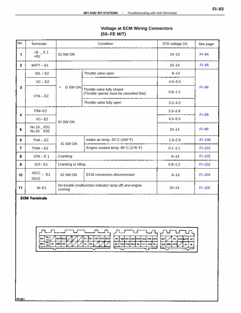
No trouble (malfunction indicator lamp off) and enginerunning
Voltage at ECM Wiring Connectors(5S–FE M/T)
Throttle valve fully closed(Throttle opener must be cancelled first)
Engine coolant temp. 80C (176F)
ECM connectors disconnected
Intake air temp. 20C (168F)
Throttle valve fully open
No.10 _ E01No.20 E02
Throttle valve open
Cranking or idling
STD voltage (V)
ISCC _
ISCO
+B _ E 1+B1 IG SW ON
IG SW ON
IG SW ON
IG SW ON
Terminals
• G SW ON
BATT – E1
Cranking
Condition See page
THW – E2
THA – E2
STA – E 1
PIM–E2
0.8–1.2VTA – E2
0.8–1.2
0.1–1.1
IGT– E1
1.9–2.9
4.5–5.5
3.3–3.9
3.2–4.2
IDL – E2
4.5–5.5
10–14
10–14
10–14
VC– E2
VC – E2
10–14W–E1
FI–100
FI–104
FI–105
FI–102
FI–101
FI–103
6–14
8–14
8–14
FI–94
FI–99
FI–96
FI–95
FI–98
No.
E1
–MFI AND SFI SYSTEMS Troubleshooting with Volt OhmmeterFI–93
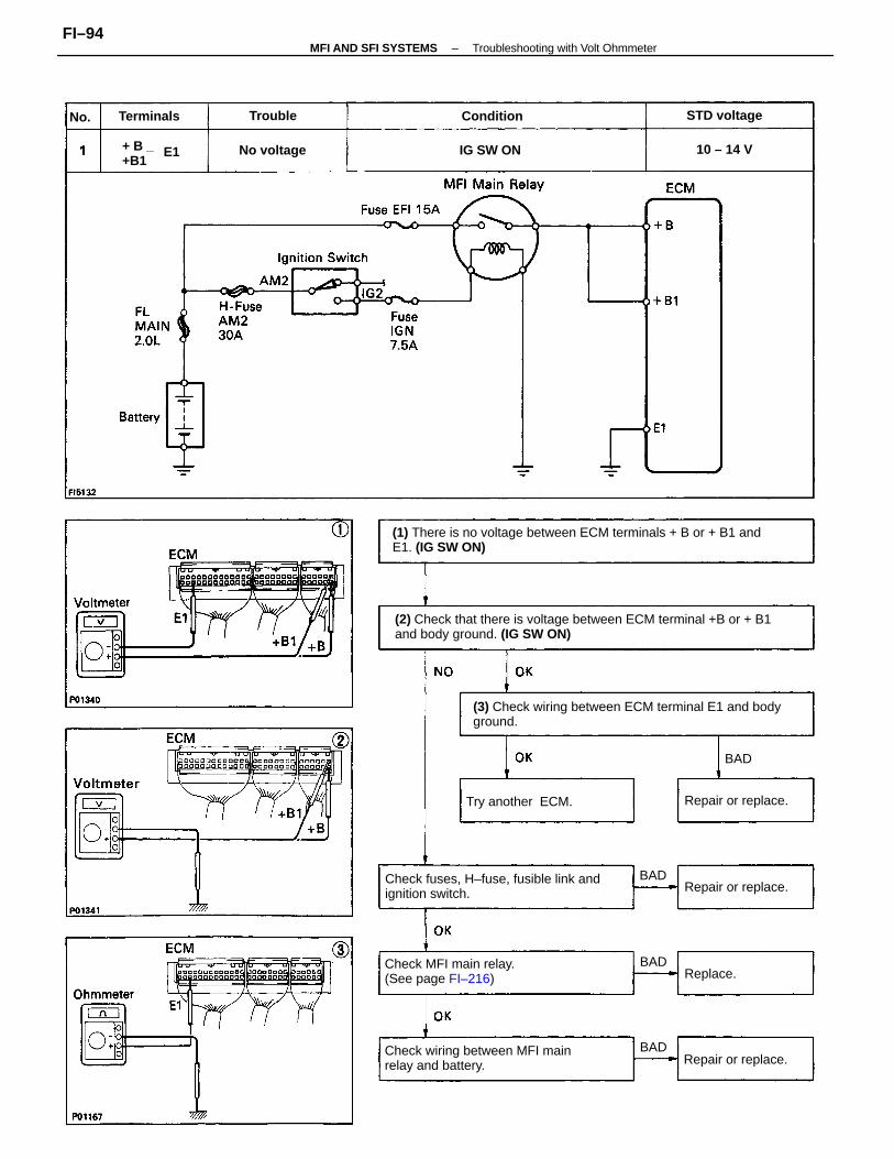
(2) Check that there is voltage between ECM terminal +B or + B1and body ground. (IG SW ON)
(1) There is no voltage between ECM terminals + B or + B1 andE1. (IG SW ON)
(3) Check wiring between ECM terminal E1 and bodyground.
Check fuses, H–fuse, fusible link andignition switch.
Check wiring between MFI mainrelay and battery.
Check MFI main relay.(See page FI–216)
Try another ECM. Repair or replace.
Repair or replace.
Repair or replace.
+ B _+B1
STD voltage
No voltage IG SW ON
Terminals Condition
10 – 14 V
Replace.
Trouble
BAD
BAD
BAD
BAD
No.
E1
–MFI AND SFI SYSTEMS Troubleshooting with Volt OhmmeterFI–94
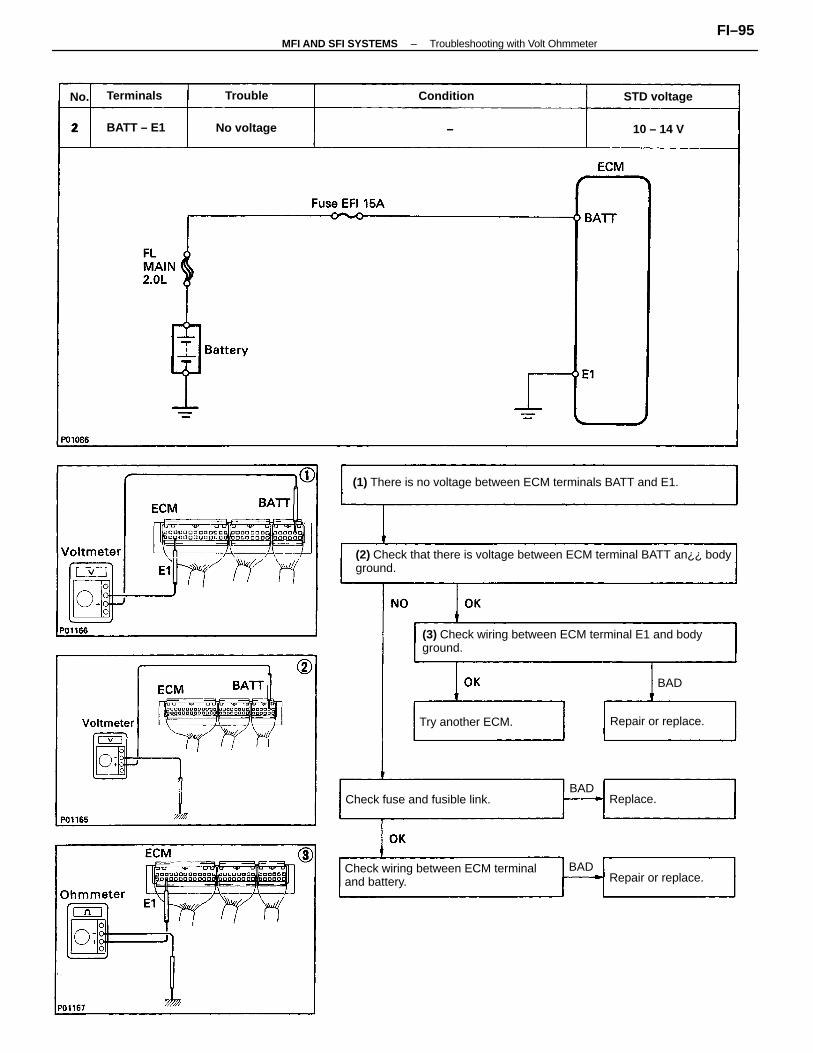
(2) Check that there is voltage between ECM terminal BATT an¿¿ bodyground.
(3) Check wiring between ECM terminal E1 and bodyground.
(1) There is no voltage between ECM terminals BATT and E1.
Check wiring between ECM terminaland battery.
Check fuse and fusible link.
Try another ECM. Repair or replace.
Repair or replace.
STD voltage
No voltage
Terminals
BATT – E1
Condition
10 – 14 V
Replace.
Trouble
BAD
BAD
BAD
No.
–MFI AND SFI SYSTEMS Troubleshooting with Volt OhmmeterFI–95
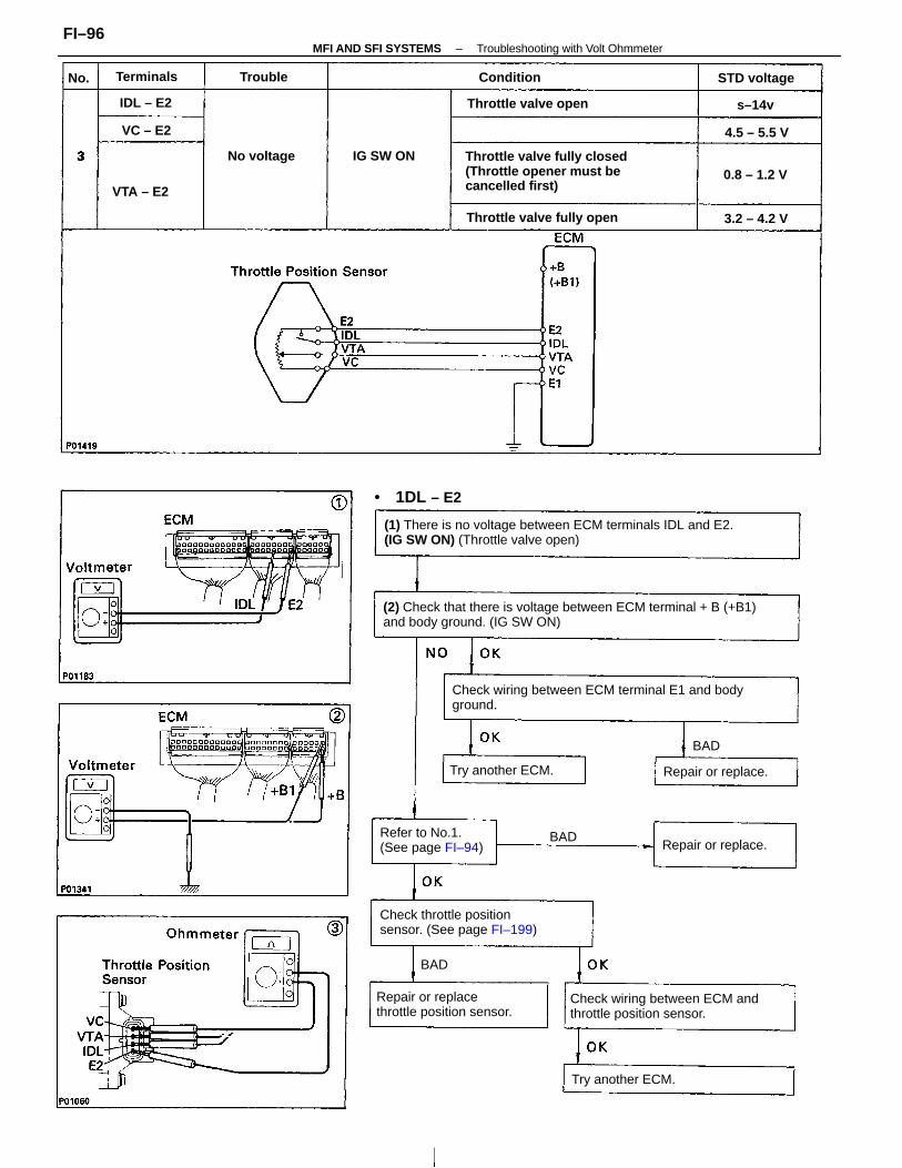
(2) Check that there is voltage between ECM terminal + B (+B1)and body ground. (IG SW ON)
(1) There is no voltage between ECM terminals IDL and E2.(IG SW ON) (Throttle valve open)
Check wiring between ECM terminal E1 and bodyground.
Throttle valve fully closed(Throttle opener must becancelled first)
Check wiring between ECM andthrottle position sensor.
Check throttle positionsensor. (See page FI–199)
Repair or replacethrottle position sensor.
Refer to No.1.(See page FI–94)
Throttle valve fully open
Throttle valve open
Repair or replace.
Repair or replace.
Try another ECM.
Try another ECM.
STD voltage
• 1DL – E2
No voltage IG SW ON
Terminals
0.8 – 1.2 V
IDL – E2
VTA – E2
3.2 – 4.2 V
Condition
4.5 – 5.5 VVC – E2
s–14v
Trouble
BAD
BAD
BAD
No.
–MFI AND SFI SYSTEMS Troubleshooting with Volt OhmmeterFI–96
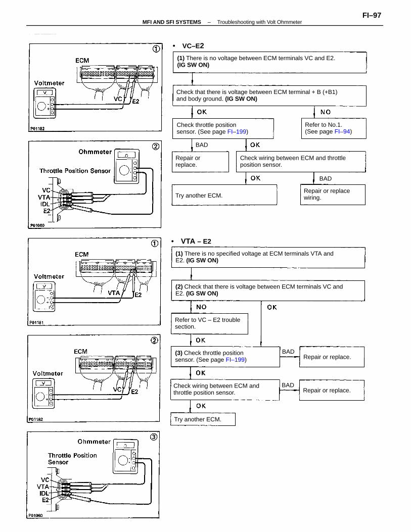
(2) Check that there is voltage between ECM terminals VC andE2. (IG SW ON)
Check that there is voltage between ECM terminal + B (+B1)and body ground. (IG SW ON)
(1) There is no voltage between ECM terminals VC and E2.(IG SW ON)
(1) There is no specified voltage at ECM terminals VTA andE2. (IG SW ON)
Check wiring between ECM and throttleposition sensor.
Check wiring between ECM andthrottle position sensor.
Check throttle positionsensor. (See page FI–199)
(3) Check throttle positionsensor. (See page FI–199)
Refer to VC – E2 troublesection.
Repair or replacewiring.
Refer to No.1.(See page FI–94)
Repair or replace.
Repair or replace.
Try another ECM.
Try another ECM.
Repair orreplace.
• VTA – E2
• VC–E2
BAD
BAD
BAD
BAD
–MFI AND SFI SYSTEMS Troubleshooting with Volt OhmmeterFI–97
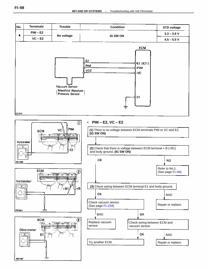
(1) There is no voltage between ECM terminals PIM or VC and E2.(IG SW ON)
(2) Check that there is voltage between ECM terminal + B (+B1)and body ground. (IG SW ON)
(3) Check wiring between ECM terminal E1 and body ground.
Check wiring between ECM andvacuum sensor.
Check vacuum sensor.(See page FI–234)
Refer to No.1.(See page FI–94)
Replace vacuumsensor.
• PIM – E2, VC – E2
Try another ECM. Repair or replace.
Repair or replace.
STD voltage
No voltage IG SW ON
Condition
4.5 – 5.5 V
Terminals
3.3 – 3.9 VPIM – E2
Trouble
VC – E2
BAD
BAD
BAD
No.
–MFI AND SFI SYSTEMS Troubleshooting with Volt OhmmeterFI–98
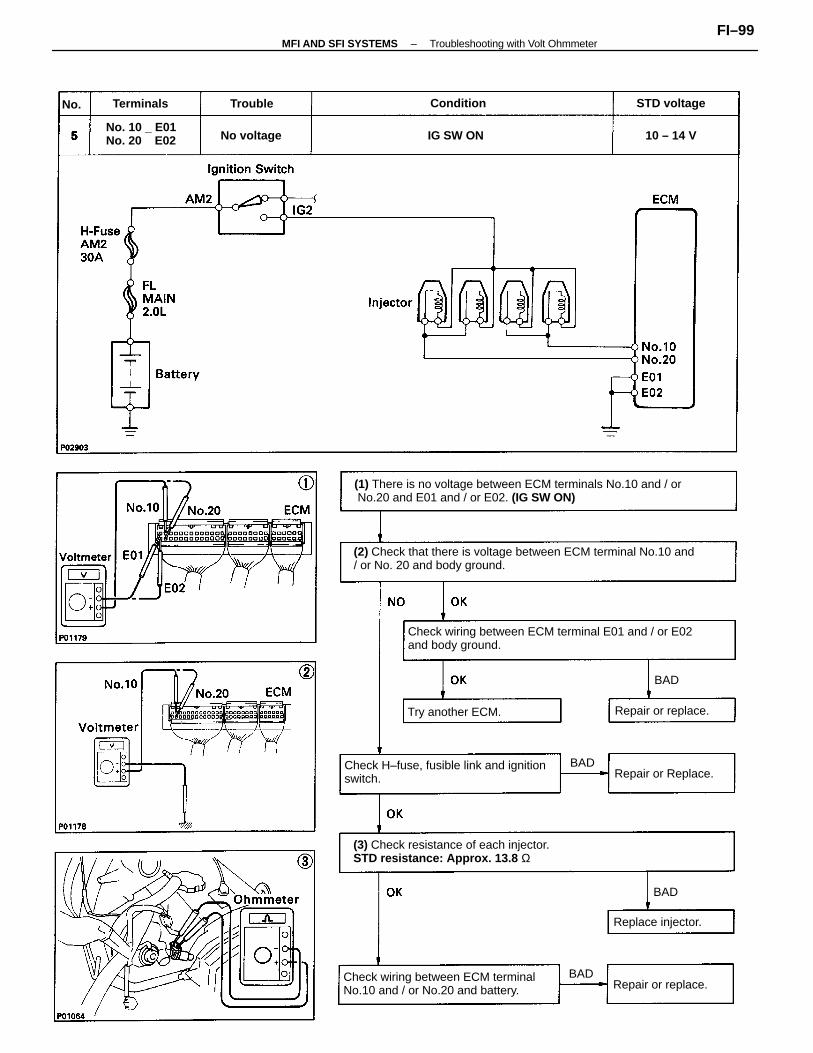
(2) Check that there is voltage between ECM terminal No.10 and/ or No. 20 and body ground.
(1) There is no voltage between ECM terminals No.10 and / or No.20 and E01 and / or E02. (IG SW ON)
Check wiring between ECM terminal E01 and / or E02and body ground.
(3) Check resistance of each injector. STD resistance: Approx. 13.8 Ω
Check H–fuse, fusible link and ignitionswitch.
Check wiring between ECM terminalNo.10 and / or No.20 and battery.
No. 10 _ E01No. 20 E02
Try another ECM.
Repair or Replace.
Repair or replace.
Repair or replace.
Replace injector.
STD voltage
No voltage
Terminals
IG SW ON
Condition
10 – 14 V
Trouble
BAD
BAD
BAD
BAD
No.
–MFI AND SFI SYSTEMS Troubleshooting with Volt OhmmeterFI–99
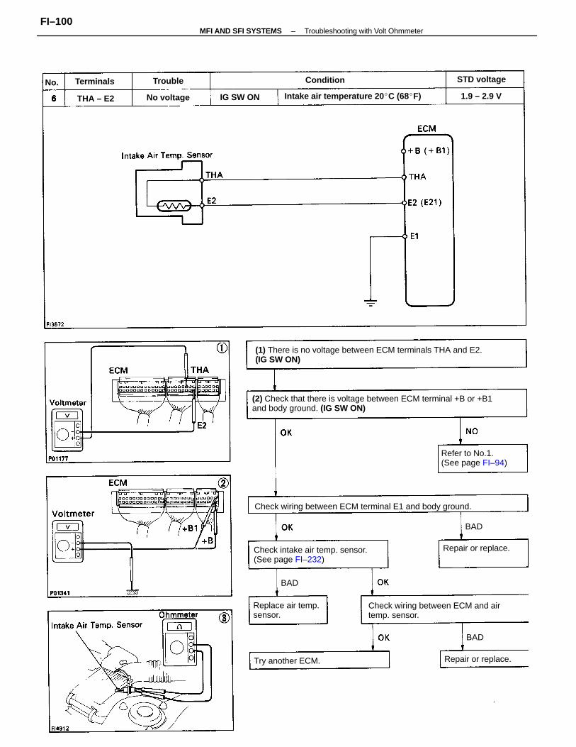
(2) Check that there is voltage between ECM terminal +B or +B1and body ground. (IG SW ON)
(1) There is no voltage between ECM terminals THA and E2.(IG SW ON)
Check wiring between ECM terminal E1 and body ground.
Check wiring between ECM and airtemp. sensor.
Check intake air temp. sensor.(See page FI–232)
Intake air temperature 20 C (68F)
Refer to No.1.(See page FI–94)
Replace air temp.sensor.
Try another ECM.
Repair or replace.
Repair or replace.
STD voltage
No voltage IG SW ON 1.9 – 2.9 V
ConditionTerminals
THA – E2
Trouble
BAD
BAD
BAD
No.
–MFI AND SFI SYSTEMS Troubleshooting with Volt OhmmeterFI–100
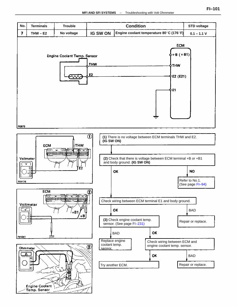
(2) Check that there is voltage between ECM terminal +B or +B1and body ground. (IG SW ON)
(1) There is no voltage between ECM terminals THW and E2.(IG SW ON)
Check wiring between ECM andengine coolant temp. sensor.
(3) Check engine coolant temp.sensor. (See page FI–231)
Check wiring between ECM terminal E1 and body ground.
Engine coolant temperature 80 C (176F)
Refer to No.1.(See page FI–94)
Replace enginecoolant temp.sensor.
Try another ECM.
Repair or replace.
Repair or replace.
STD voltage
No voltage
Condition
0.1 – 1.1 VIG SW ON
Terminals
THW – E2
Trouble
BAD
BAD
BAD
No.
–MFI AND SFI SYSTEMS Troubleshooting with Volt OhmmeterFI–101
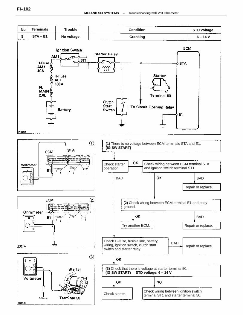
(1) There is no voltage between ECM terminals STA and E1.(IG SW START)
(2) Check wiring between ECM terminal E1 and bodyground.
(3) Check that there is voltage at starter terminal 50.(IG SW START) STD voltage: 6 – 14 V
Check H–fuse, fusible link, battery,wiring, ignition switch, clutch startswitch and starter relay.
Check wiring between ECM terminal STAand ignition switch terminal ST1.
Check wiring between ignition switchterminal ST1 and starter terminal 50.
Check starteroperation.
Repair or replace.
Try another ECM.
Repair or replace.
Repair or replace.
STD voltage
No voltage
Check starter.
Terminals
Cranking
Condition
STA – E1
Trouble
6 – 14 V
BAD
BAD
BAD
BAD
No.
–MFI AND SFI SYSTEMS Troubleshooting with Volt OhmmeterFI–102
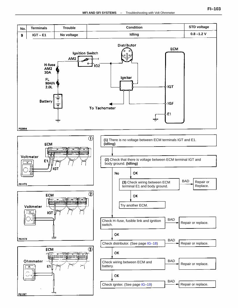
(2) Check that there is voltage between ECM terminal IGT andbody ground. (Idling)
(1) There is no voltage between ECM terminals IGT and E1.(idling)
Check H–fuse, fusible link and ignitionswitch.
(3) Check wiring between ECMterminal E1 and body ground.
Check wiring between ECM andbattery.
Check distributor. (See page IG–18)
Check igniter. (See page IG–19)
Try another ECM.
Repair or replace.
Repair or replace.
Repair or replace.
Repair or replace.
Repair orReplace.
STD voltage
No voltage 0.8 –1.2 V
ConditionTerminals
IGT – E1
Trouble
Idling
BAD
BAD
BAD
BAD
BAD
No.
–MFI AND SFI SYSTEMS Troubleshooting with Volt OhmmeterFI–103
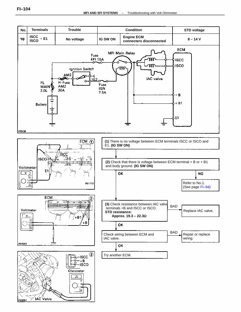
(2) Check that there is voltage between ECM terminal + B or + B1and body ground. (IG SW ON)
(3) Check resistance between IAC valve terminals +B and ISCC or ISCO.STD resistance:
Approx. 19.3 – 22.3
(1) There is no voltage between ECM terminals ISCC or ISCO andE1. (IG SW ON)
Check wiring between ECM andIAC valve.
Engine ECMconnecters disconnected
Refer to No.1.(See page FI–94)
Repair or replacewiring.
Replace IAC valve.
Try another ECM.
ISCC ISCO
STD voltage
No voltage IG SW ON
Terminals ConditionTrouble
8 – 14 V
BAD
BAD
No.
– E1
–MFI AND SFI SYSTEMS Troubleshooting with Volt OhmmeterFI–104
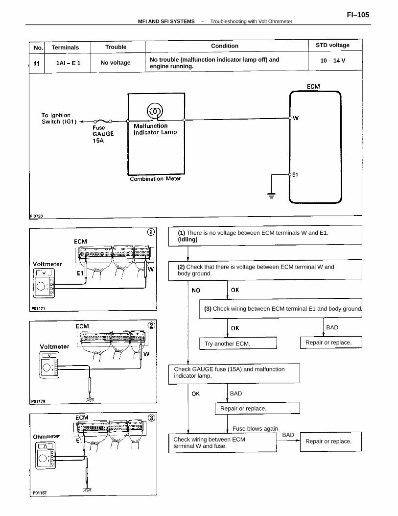
(2) Check that there is voltage between ECM terminal W andbody ground.
(1) There is no voltage between ECM terminals W and E1.(Idling)
(3) Check wiring between ECM terminal E1 and body ground.
No trouble (malfunction indicator lamp off) andengine running.
Check GAUGE fuse (15A) and malfunctionindicator lamp.
Check wiring between ECMterminal W and fuse.
Fuse blows again
Try another ECM.
Repair or replace.
Repair or replace.
Repair or replace.
STD voltage
No voltage
Terminals Condition
10 – 14 V
Trouble
1AI – E 1
BAD
BAD
No.
BAD
–MFI AND SFI SYSTEMS Troubleshooting with Volt OhmmeterFI–105
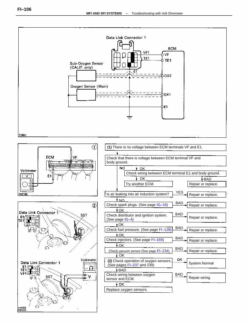
Check that there is voltage between ECM terminal VF andbody ground.
(1) There is no voltage between ECM terminals VF and E1.
(2) Check operation of oxygen sensors.(See pages FI–237 and 239)
Check distributor and ignition system.(See page IG–4)
Check wiring between ECM terminal E1 and body ground.
Check wiring between oxygensensor and ECM.
Is air leaking into air induction system?
Check fuel pressure. (See page FI–128)
Check vacuum sensor (See page FI–234)
Check spark plugs. (See page IG–16)
Check injectors. (See page FI–169)
OK
Replace oxygen sensors.
Try another ECM.
Repair or replace.
Repair or replace.
Repair or replace.
Repair or replace.
Repair or replace.
Repair or replace.
Repair or replace.
System Normal
Repair wiring.
NO
OK
BAD
BAD
BAD
BAD
BAD
BAD
BAD
BAD
YES
OK
OK
OK
OK
OK
–MFI AND SFI SYSTEMS Troubleshooting with Volt OhmmeterFI–106
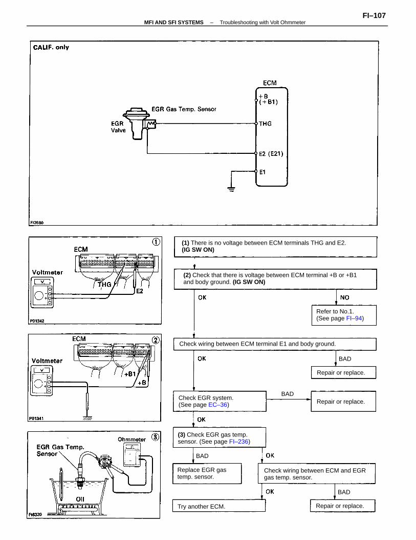
(2) Check that there is voltage between ECM terminal +B or +B1and body ground. (IG SW ON)
(1) There is no voltage between ECM terminals THG and E2.(IG SW ON)
Check wiring between ECM and EGRgas temp. sensor.
Check wiring between ECM terminal E1 and body ground.
(3) Check EGR gas temp.sensor. (See page FI–236)
Check EGR system.(See page EC–36)
Replace EGR gastemp. sensor.
Refer to No.1.(See page FI–94)
Try another ECM. Repair or replace.
Repair or replace.
Repair or replace.
BAD
BAD
BAD
BAD
–MFI AND SFI SYSTEMS Troubleshooting with Volt OhmmeterFI–107
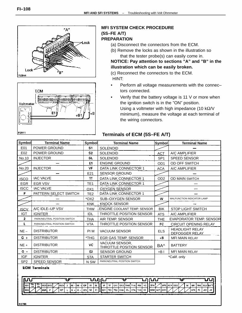
MFI SYSTEM CHECK PROCEDURE(5S–FE A/T)PREPARATION
(a) Disconnect the connectors from the ECM.(b) Remove the locks as shown in the illustration so
that the tester probe(s) can easily come in.NOTICE: Pay attention to sections ”A” and ”B” in theillustration which can be easily broken.(c) Reconnect the connectors to the ECM.
HINT:
• Perform all voltage measurements with the connec–tors connected.
• Verify that the battery voltage is 11 V or more whenthe ignition switch is in the ”ON” position.Using a voltmeter with high impedance (10 k/Vminimum), measure the voltage at each terminal ofthe wiring connectors.
Terminals of ECM (5S–FE A/T)
VACUUM SENSOR,THROTTLE POSITION SENSOR
ENGINE COOLANT TEMP. SENSOR
THROTTLE POSITION SENSORPARK/NEUTRAL POSITION SWITCH
PARK/NEUTRAL POSITION SWITCH THROTTLE POSITION SENSOR
HEADLIGHT RELAYDEFOGGER RELAY
PARK/NEUTRAL POSITION SWITCH
EVAPORATOR TEMP. SENSOR
MALFUNCTION INDICATOR LAMP
DATA LINK CONNECTOR 1
DATA LINK CONNECTOR 1DATA LINK CONNECTOR 1
DATA LINK CONNECTOR 1
PATTERN SELECT SWITCH
EGR GAS TEMP. SENSOR
CIRCUIT OPENING RELAY
SUB–OXYGEN SENSOR
STOP LIGHT SWITCH
AIR TEMP. SENSOR
VACUUM SENSOR
SENSOR GROUND
SENSOR GROUND
OD MAIN SWITCH
ENGINE GROUND
POWER GROUND
STARTER SWITCHMFI MAIN RELAY
POWER GROUND
MFI MAIN RELAY
A/C IDLE–UP VSV
OXYGEN SENSOR
KNOCK SENSOR
OD OFF SWITCHSPEED SENSOR
SPEED SENSOR
Terminal Name Terminal Name Terminal Name
A/C AMPLIFIER
A/C AMPLIFIER
A/C AMPLIFIER
DISTRIBUTOR
DISTRIBUTOR
DISTRIBUTOR
DISTRIBUTOR
INJECTOR
*Calif. only
SOLENOID
IAC VALVE
IAC VALVE
SOLENOID
SOLENOIDINJECTOR
BATTERY
EGR VSV
Symbol SymbolSymbol
IGNITER
IGNITER
No.20
No.10
*THG
*OX2
ISCO
NE + BA^
NE –
ISCC
ISCV
N SW
THW
OD2
OX1
ACAOD1
ACT
THA
KNK
+B l
VTA
SP2
ELS
ATSTHE
PI M
STA
EGR
SP1
IDL
TE1
E02
BIK
E01
IGT
E21
TE2
IGF
–MFI AND SFI SYSTEMS Troubleshooting with Volt OhmmeterFI–108
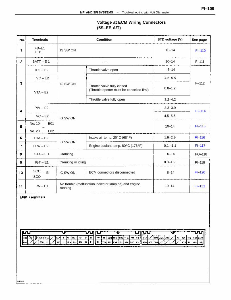
No trouble (malfunction indicator lamp off) and enginerunning
Voltage at ECM Wiring Connectors(5S–EE A/T)
Throttle valve fully closed(Throttle opener must be cancelled first)
Engine coolant temp. 80C (176F)
ECM connectors disconnected
Intake air temp. 20C (68F)
Throttle valve fully open
No. 10 E01 –No. 20 E02
Throttle valve open
STD voltage (V)
ISCC _
ISCO
Cranking or idling
+B–E1+ B1
Terminals Condition
IG SW ON
See page
IG SW ON
IG SW ON
IG SW ON
IG SW ON
BATT – E 1
THW – E2
Cranking
THA – E2
STA – E 1
0.8–1.2
PIM – E2
0.8–1.2
4.5–5.5
1.9–2.9
0.1 –1.1
VTA – E2
IDL – E2
IGT – E1
4.5–5.5
3.2–4.2
3.3–3.9
10–14
10–14
10–14
VC – E2
10–14
VC – E2
W – E1
FI–110
FI–116
FI–1208–14
6–14
Fl–119
FI–115
FO–118
FI–121
F–111
FI–117
F–112
8–14
FI–114
No.
El
–MFI AND SFI SYSTEMS Troubleshooting with Volt OhmmeterFI–109
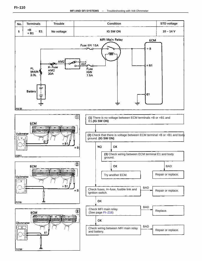
(2) Check that there is voltage between ECM terminal +B or +B1 and bodyground. (IG SW ON)
(1) There is no voltage between ECM terminals +B or +B1 andE1.(IG SW ON)
(3) Check wiring between ECM terminal E1 and bodyground.
Check fuses, H–fuse, fusible link andignition switch.
Check wiring between MFI main relayand battery.
Check MFI main relay.(See page FI–216)
Try another ECM.
Repair or replace.
Repair or replace.
Repair or replace.
+B _+ B1
STD voltage
No voltage IG SW ON
ConditionTerminals
10 – 14 V
Replace.
Trouble
BAD
BAD
BAD
BAD
No.
E1
–MFI AND SFI SYSTEMS Troubleshooting with Volt OhmmeterFI–110
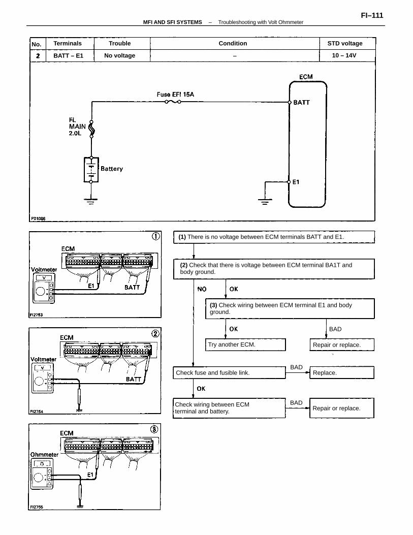
(2) Check that there is voltage between ECM terminal BA1T andbody ground.
(3) Check wiring between ECM terminal E1 and bodyground.
(1) There is no voltage between ECM terminals BATT and E1.
Check wiring between ECMterminal and battery.
Check fuse and fusible link.
Try another ECM.
Repair or replace.
Repair or replace.
STD voltage
No voltage
Terminals
BATT – E1
Condition
10 – 14V
Replace.
Trouble
BAD
BAD
BAD
No.
–MFI AND SFI SYSTEMS Troubleshooting with Volt OhmmeterFI–111
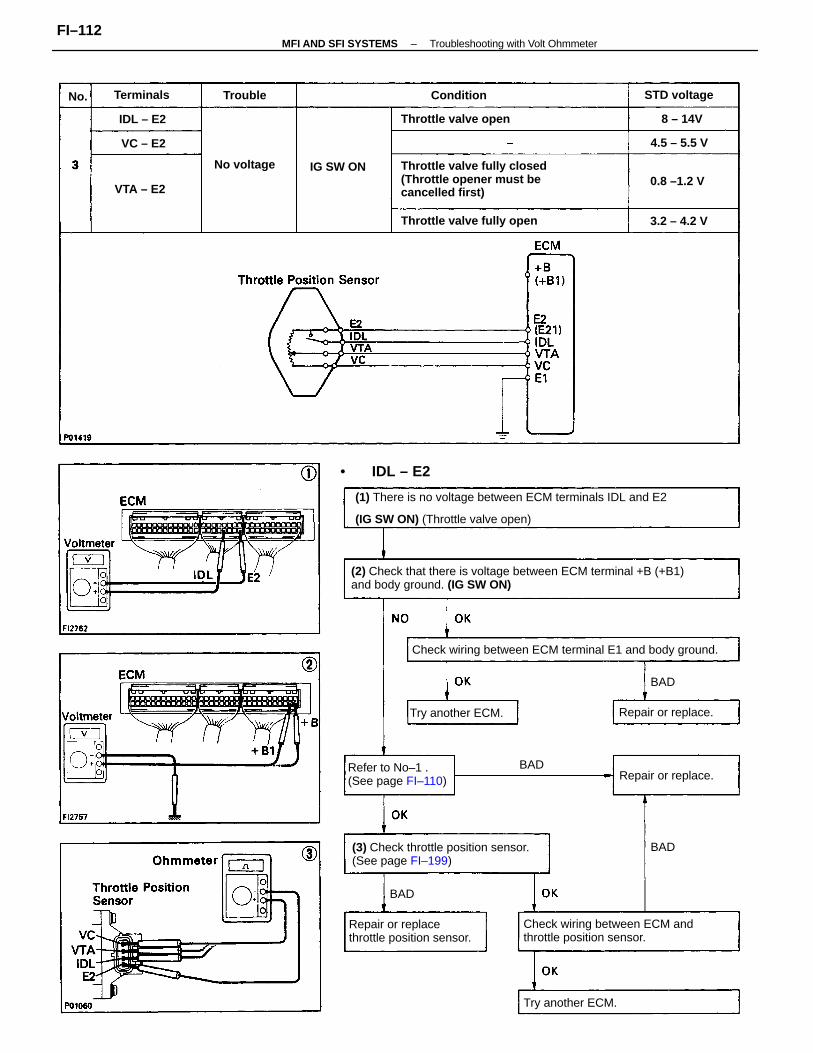
(2) Check that there is voltage between ECM terminal +B (+B1)and body ground. (IG SW ON)
(1) There is no voltage between ECM terminals IDL and E2
(IG SW ON) (Throttle valve open)
Throttle valve fully closed(Throttle opener must becancelled first)
(3) Check throttle position sensor.(See page FI–199)
Check wiring between ECM andthrottle position sensor.
Check wiring between ECM terminal E1 and body ground.
Repair or replacethrottle position sensor.
Refer to No–1 .(See page FI–110)
Throttle valve fully open
Throttle valve open
Try another ECM.
Try another ECM. Repair or replace.
Repair or replace.
STD voltage
No voltage
IDL – E2
0.8 –1.2 VIG SW ON
Terminals
• IDL – E2
3.2 – 4.2 V
Condition
4.5 – 5.5 V
VTA – E2
Trouble
8 – 14V
VC – E2
BAD
BAD
BAD
BAD
No.
–MFI AND SFI SYSTEMS Troubleshooting with Volt OhmmeterFI–112
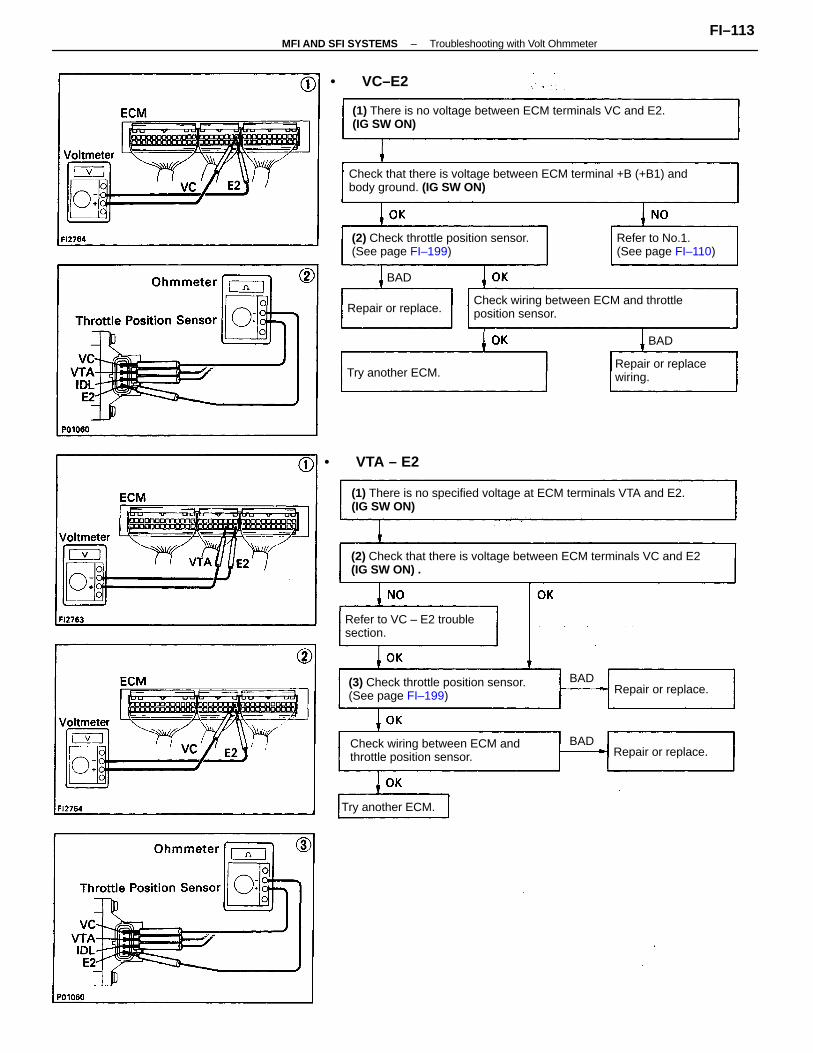
(2) Check that there is voltage between ECM terminals VC and E2(IG SW ON) .
(1) There is no specified voltage at ECM terminals VTA and E2.(IG SW ON)
Check that there is voltage between ECM terminal +B (+B1) andbody ground. (IG SW ON)
(1) There is no voltage between ECM terminals VC and E2.(IG SW ON)
Check wiring between ECM and throttleposition sensor.
(3) Check throttle position sensor. (See page FI–199)
Check wiring between ECM andthrottle position sensor.
(2) Check throttle position sensor.(See page FI–199)
Refer to VC – E2 troublesection.
Refer to No.1.(See page FI–110)
Repair or replacewiring.
Repair or replace.
Repair or replace.
• VTA – E2
Try another ECM.
Try another ECM.
Repair or replace.
• VC–E2
BAD
BAD
BAD
BAD
–MFI AND SFI SYSTEMS Troubleshooting with Volt OhmmeterFI–113
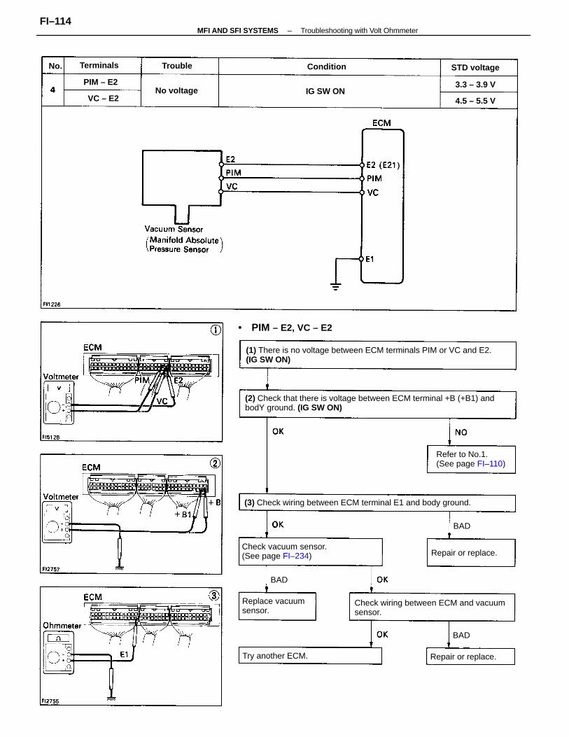
(2) Check that there is voltage between ECM terminal +B (+B1) andbodY ground. (IG SW ON)
(1) There is no voltage between ECM terminals PIM or VC and E2.(IG SW ON)
(3) Check wiring between ECM terminal E1 and body ground.
Check wiring between ECM and vacuumsensor.
Check vacuum sensor.(See page FI–234)
Refer to No.1.(See page FI–110)
Replace vacuumsensor.
• PIM – E2, VC – E2
Try another ECM.
Repair or replace.
Repair or replace.
STD voltage
No voltage
Condition
IG SW ON
Terminals
3.3 – 3.9 V
4.5 – 5.5 V
PIM – E2
Trouble
VC – E2
BAD
BAD
BAD
No.
–MFI AND SFI SYSTEMS Troubleshooting with Volt OhmmeterFI–114
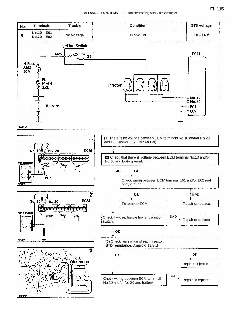
(1) There is no voltage between ECM terminals No.10 and/or No.20and E01 and/or E02. (IG SW ON)
(2) Check that there is voltage between ECM terminal No.10 and/orNo.20 and body ground.
Check wiring between ECM terminal E01 and/or E02 andbody ground.
(3) Check resistance of each injector.STD resistance: Approx. 13.8 Ω
Check wiring between ECM terminal!No.10 and/or No.20 and battery.
Check H–fuse, fusible link and ignitionswitch.
No.10 _ E01No.20 E02
Tn another ECM. Repair or replace.
Repair or replace.
Repair or replace.
Replace injector.
STD voltage
No voltage IG SW ON
ConditionTerminals
10 – 14 V
Trouble
BAD
BAD
BAD
No.
–MFI AND SFI SYSTEMS Troubleshooting with Volt OhmmeterFI–115
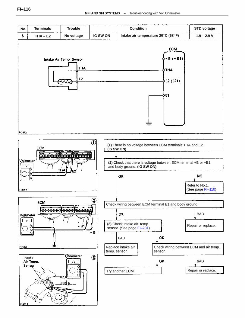
(2) Check that there is voltage between ECM terminal +B or +B1and body ground. (IG SW ON)
(1) There is no voltage between ECM terminals THA and E2(IS SW ON)
Check wiring between ECM and air temp.sensor.
(3) Check intake air temp.sensor. (See page FI–231)
Check wiring between ECM terminal E1 and body ground.
Intake air temperature 20 C (68F)
Refer to No.1.(See page FI–110)
Replace intake airtemp. sensor.
Repair or replace.
Repair or replace.Try another ECM.
STD voltage
No voltage IG SW ON
Terminals
1.9 – 2.9 V
Condition
THA – E2
Trouble
6AD
BAD
6AD
No.
–MFI AND SFI SYSTEMS Troubleshooting with Volt OhmmeterFI–116
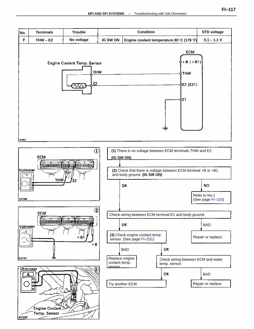
(2) Check that there is voltage between ECM terminal +B or +B1and body ground. (IG SW ON)
(1) There is no voltage between ECM terminals THW and E2.
(IG SW ON)
Check wiring between ECM and water temp. sensor.
Check wiring between ECM terminal E1 and body ground.
(3) Check engine coolant temp.sensor. (See page FI–231)
Engine coolant temperature 80 C (176F)
Refer to No.1(See page FI–110)
Replace enginecoolant temp.sensor.
Try another ECM. Repair or replace.
Repair or replace.
STD voltage
No voltage 0.1 – 1.1 VIG SW ON
ConditionTerminals
THW – E2
Trouble
BAD
BAD
BAD
No.
–MFI AND SFI SYSTEMS Troubleshooting with Volt OhmmeterFI–117
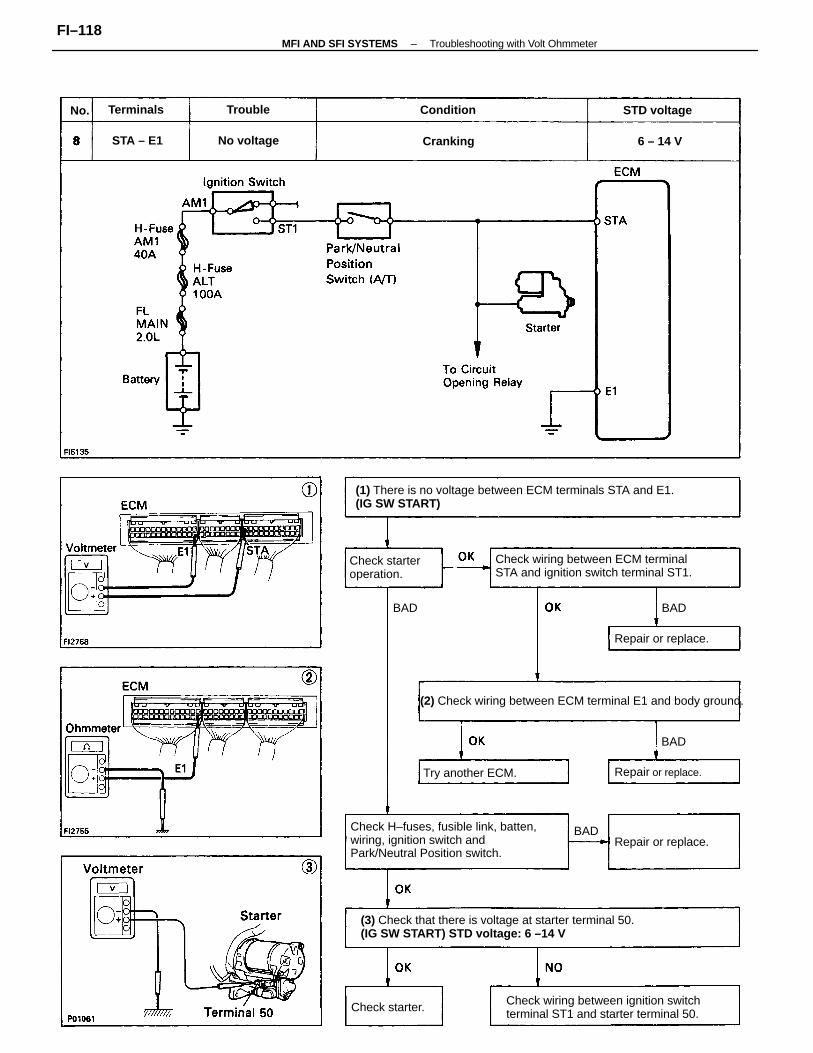
(1) There is no voltage between ECM terminals STA and E1.(IG SW START)
(2) Check wiring between ECM terminal E1 and body ground.
(3) Check that there is voltage at starter terminal 50.(IG SW START) STD voltage: 6 –14 V
Check H–fuses, fusible link, batten,wiring, ignition switch andPark/Neutral Position switch.
Check wiring between ECM terminalSTA and ignition switch terminal ST1.
Check wiring between ignition switchterminal ST1 and starter terminal 50.
Check starteroperation.
Try another ECM. Repair or replace.
Repair or replace.
Repair or replace.
STD voltage
No voltage
Check starter.
ConditionTerminals
CrankingSTA – E1
Trouble
6 – 14 V
BAD
BAD
BAD BAD
No.
–MFI AND SFI SYSTEMS Troubleshooting with Volt OhmmeterFI–118
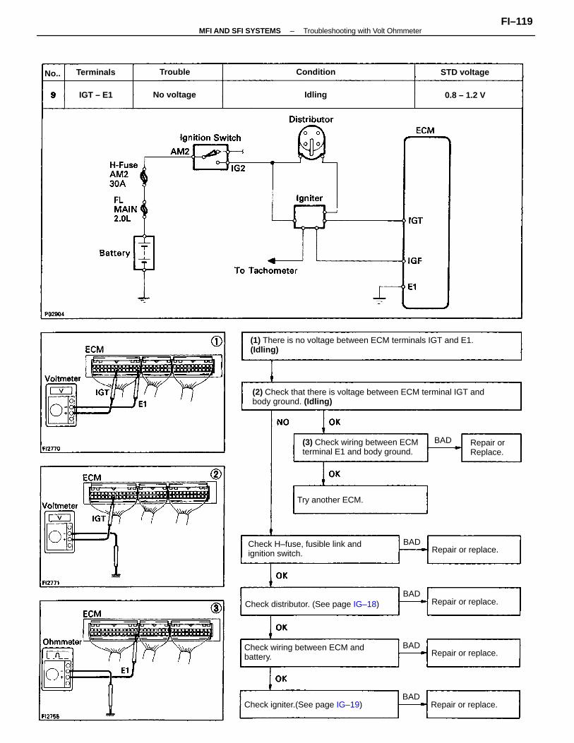
(2) Check that there is voltage between ECM terminal IGT andbody ground. (Idling)
(1) There is no voltage between ECM terminals IGT and E1.(Idling)
Check wiring between ECM andbattery.
Check H–fuse, fusible link andignition switch.
Check distributor. (See page IG–18)
(3) Check wiring between ECMterminal E1 and body ground.
Check igniter.(See page IG–19)
Try another ECM.
Repair or replace.
Repair or replace.
Repair or replace.
Repair or replace.
Repair orReplace.
STD voltage
No voltage 0.8 – 1.2 V
ConditionTerminals Trouble
IGT – E1 Idling
BAD
BAD
BAD
BAD
BAD
No..
–MFI AND SFI SYSTEMS Troubleshooting with Volt OhmmeterFI–119
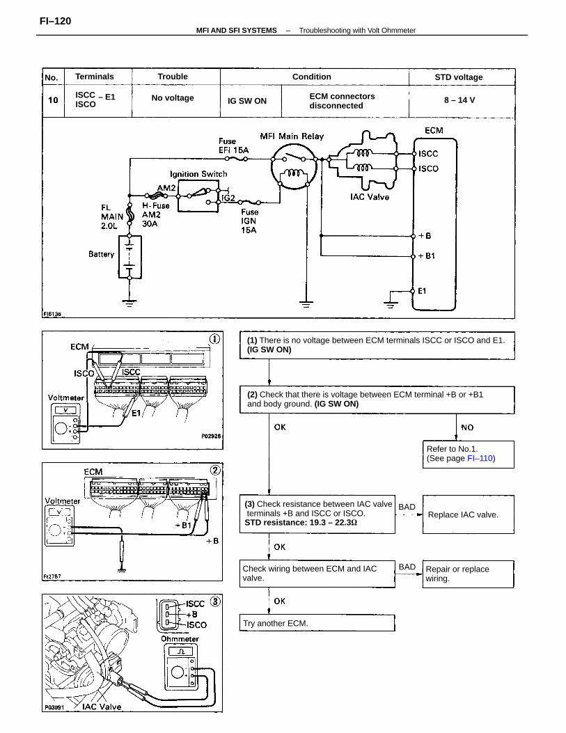
(1) There is no voltage between ECM terminals ISCC or ISCO and E1.(IG SW ON)
(2) Check that there is voltage between ECM terminal +B or +B1and body ground. (IG SW ON)
(3) Check resistance between IAC valve terminals +B and ISCC or ISCO.STD resistance: 19.3 – 22.3
Check wiring between ECM and IACvalve.
Refer to No.1.(See page FI–110)
ECM connectorsdisconnected
Repair or replacewiring.
Replace IAC valve.
Try another ECM.
ISCC ISCO
No voltage
STD voltage
IG SW ON
Terminals Condition
8 – 14 V
Trouble
BAD
BAD
No.
– E1
–MFI AND SFI SYSTEMS Troubleshooting with Volt OhmmeterFI–120
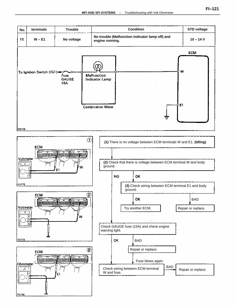
(2) Check that there is voltage between ECM terminal W and bodyground.
(1) There is no voltage between ECM terminals W and E1. (Idling)
(3) Check wiring between ECM terminal E1 and bodyground.
No trouble (Malfunction indicator lamp off) andengine running.
Check GAUGE fuse (15A) and check enginewarning light.
Check wiring between ECM terminalW and fuse.
Fuse blows again
Repair or replace.
Try another ECM.
Repair or replace.
Repair or replace.
STD voltage
No voltage
Conditionterminals
10 – 14 V
BAD
Trouble
W – E1
BAD
No.
BAD
–MFI AND SFI SYSTEMS Troubleshooting with Volt OhmmeterFI–121
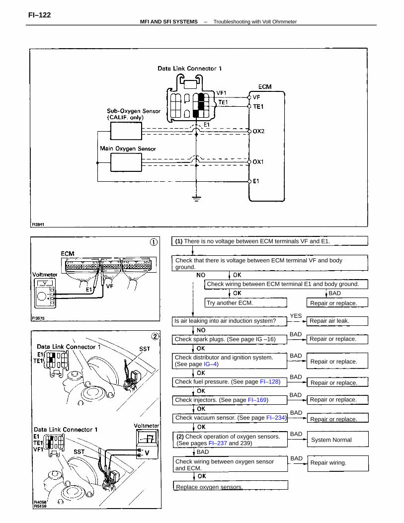
Check that there is voltage between ECM terminal VF and bodyground.
(2) Check operation of oxygen sensors.(See pages FI–237 and 239)
Check distributor and ignition system.(See page IG–4)
(1) There is no voltage between ECM terminals VF and E1.
Check wiring between ECM terminal E1 and body ground.
Check wiring between oxygen sensorand ECM.
Check vacuum sensor. (See page FI–234)
Check fuel pressure. (See page FI–128)
Is air leaking into air induction system?
Check spark plugs. (See page IG –16)
Check injectors. (See page FI–169)
Replace oxygen sensors.
Repair or replace.
Repair or replace.
Repair or replace.
Repair or replace.
Repair or replace.
Repair or replace.
Try another ECM.
System Normal
Repair air leak.
Repair wiring.
BAD
BAD
BAD
BAD
BAD
BAD
BAD
BAD
BAD
YES
–MFI AND SFI SYSTEMS Troubleshooting with Volt OhmmeterFI–122
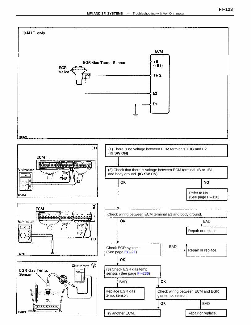
(2) Check that there is voltage between ECM terminal +B or +B1and body ground. (IG SW ON)
(1) There is no voltage between ECM terminals THG and E2.(IG SW ON)
Check wiring between ECM and EGRgas temp. sensor.
Check wiring between ECM terminal E1 and body ground.
(3) Check EGR gas temp.sensor. (See page FI–236)
Refer to No.1.(See page Fl–110)
Check EGR system.(See page EC–21)
Replace EGR gastemp. sensor.
Try another ECM.
Repair or replace.
Repair or replace.
Repair or replace.
BAD
BAD
BAD
BAD
–MFI AND SFI SYSTEMS Troubleshooting with Volt OhmmeterFI–123
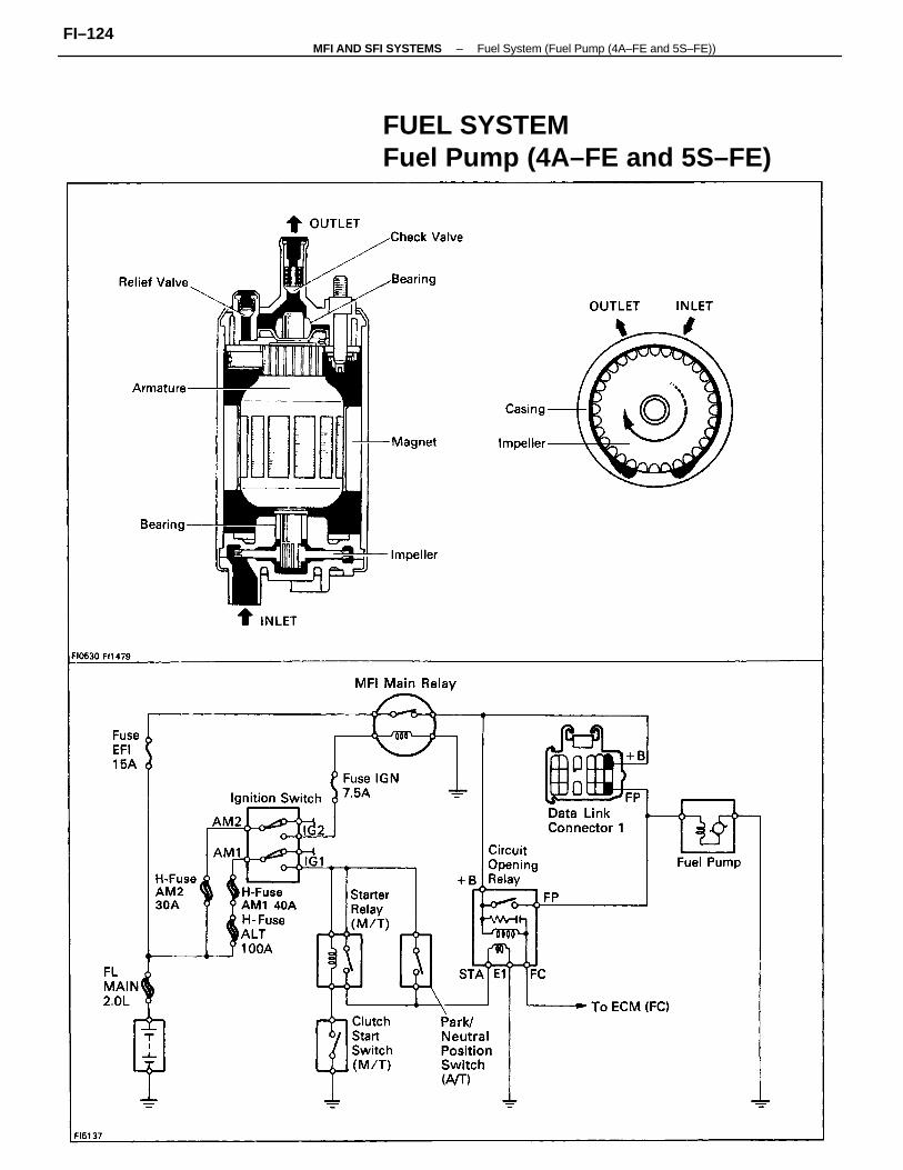
FUEL SYSTEMFuel Pump (4A–FE and 5S–FE)
–MFI AND SFI SYSTEMS Fuel System (Fuel Pump (4A–FE and 5S–FE))FI–124
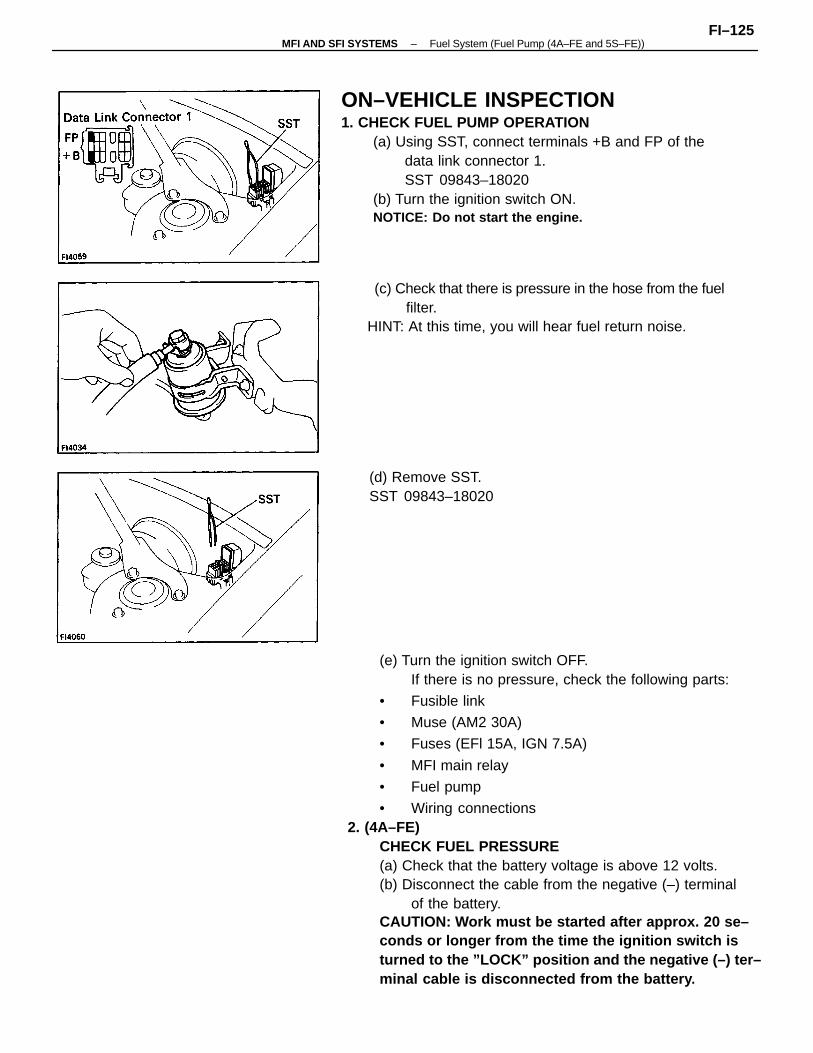
(e) Turn the ignition switch OFF.If there is no pressure, check the following parts:
• Fusible link
• Muse (AM2 30A)
• Fuses (EFl 15A, IGN 7.5A)
• MFI main relay
• Fuel pump
• Wiring connections2. (4A–FE)
CHECK FUEL PRESSURE(a) Check that the battery voltage is above 12 volts.(b) Disconnect the cable from the negative (–) terminal
of the battery.CAUTION: Work must be started after approx. 20 se–conds or longer from the time the ignition switch isturned to the ”LOCK” position and the negative (–) ter–minal cable is disconnected from the battery .
ON–VEHICLE INSPECTION1. CHECK FUEL PUMP OPERATION
(a) Using SST, connect terminals +B and FP of thedata link connector 1.SST 09843–18020
(b) Turn the ignition switch ON.NOTICE: Do not start the engine.
(c) Check that there is pressure in the hose from the fuelfilter.
HINT: At this time, you will hear fuel return noise.
(d) Remove SST.SST 09843–18020
–MFI AND SFI SYSTEMS Fuel System (Fuel Pump (4A–FE and 5S–FE))FI–125
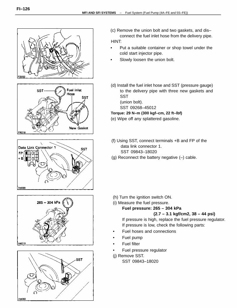
(h) Turn the ignition switch ON.(i) Measure the fuel pressure.
Fuel pressure: 265 – 304 kPa(2.7 – 3.1 kgf/cm2, 38 – 44 psi)
If pressure is high, replace the fuel pressure regulator.If pressure is low, check the following parts:
• Fuel hoses and connections
• Fuel pump
• Fuel filter
• Fuel pressure regulator(j) Remove SST.
SST 09843–18020
(d) Install the fuel inlet hose and SST (pressure gauge)to the delivery pipe with three new gaskets andSST(union bolt).SST 09268–45012
Torque: 29 N–m (300 kgf–cm, 22 ft–lbf)
(e) Wipe off any splattered gasoline.
(c) Remove the union bolt and two gaskets, and dis–connect the fuel inlet hose from the delivery pipe.
HINT:
• Put a suitable container or shop towel under thecold start injector pipe.
• Slowly loosen the union bolt.
(f) Using SST, connect terminals +B and FP of thedata link connector 1.SST 09843–18020
(g) Reconnect the battery negative (–) cable.
–MFI AND SFI SYSTEMS Fuel System (Fuel Pump (4A–FE and 5S–FE))FI–126
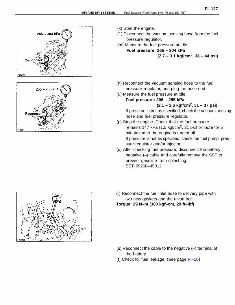
(n) Reconnect the vacuum sensing hose to the fuelpressure regulator, and plug the hose end.
(0) Measure the fuel pressure at idle.Fuel pressure: 206 – 255 kPa
(2.1 – 2.6 kgf/cm 2, 31 – 37 psi)If pressure is not as specified, check the vacuum sensinghose and fuel pressure regulator.
(p) Stop the engine. Check that the fuel pressureremains 147 kPa (1.5 kgf/cm2, 21 psi) or more for 5minutes after the engine is turned off.If pressure is not as specified, check the fuel pump, pres–sure regulator and/or injector.
(q) After checking fuel pressure, disconnect the batterynegative (–) cable and carefully remove the SST toprevent gasoline from splashing.SST 09268–45012
(k) Start the engine.(1) Disconnect the vacuum sensing hose from the fuel
pressure regulator.(m) Measure the fuel pressure at idle.
Fuel pressure: 265 – 304 kPa(2.7 – 3.1 kgf/cm 2, 38 – 44 psi)
(s) Reconnect the cable to the negative (–) terminal ofthe battery.
(t) Check for fuel leakage. (See page FI–10)
(r) Reconnect the fuel inlet hose to delivery pipe withtwo new gaskets and the union bolt.
Torque: 29 N–m (300 kgf–cm, 29 ft–lbf)
–MFI AND SFI SYSTEMS Fuel System (Fuel Pump (4A–FE and 5S–FE))FI–127
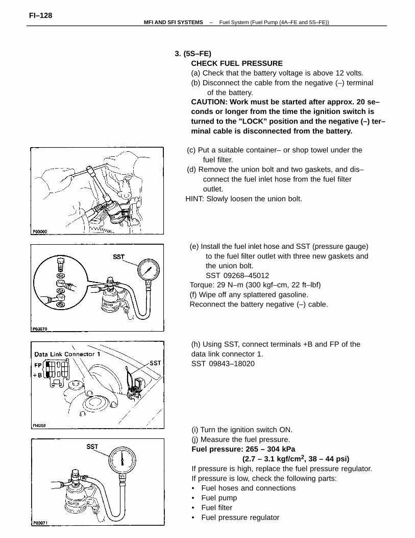
(i) Turn the ignition switch ON.(j) Measure the fuel pressure.Fuel pressure: 265 – 304 kPa
(2.7 – 3.1 kgf/cm 2, 38 – 44 psi)If pressure is high, replace the fuel pressure regulator.If pressure is low, check the following parts:• Fuel hoses and connections• Fuel pump• Fuel filter• Fuel pressure regulator
3. (5S–FE)CHECK FUEL PRESSURE(a) Check that the battery voltage is above 12 volts.(b) Disconnect the cable from the negative (–) terminal
of the battery.CAUTION: Work must be started after approx. 20 se–conds or longer from the time the ignition switch isturned to the ”LOCK” position and the negative (–) ter–minal cable is disconnected from the battery.
(e) Install the fuel inlet hose and SST (pressure gauge)to the fuel filter outlet with three new gaskets andthe union bolt.SST 09268–45012
Torque: 29 N–m (300 kgf–cm, 22 ft–lbf)(f) Wipe off any splattered gasoline.Reconnect the battery negative (–) cable.
(c) Put a suitable container– or shop towel under thefuel filter.
(d) Remove the union bolt and two gaskets, and dis–connect the fuel inlet hose from the fuel filteroutlet.
HINT: Slowly loosen the union bolt.
(h) Using SST, connect terminals +B and FP of thedata link connector 1.SST 09843–18020
–MFI AND SFI SYSTEMS Fuel System (Fuel Pump (4A–FE and 5S–FE))FI–128
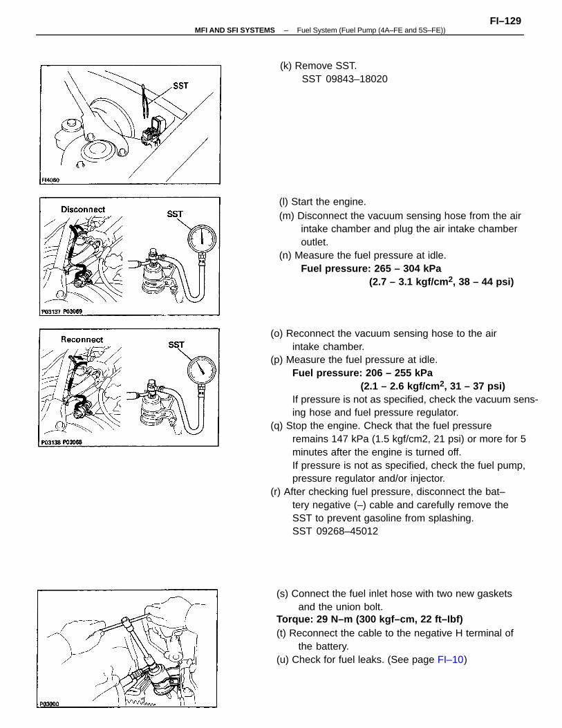
(o) Reconnect the vacuum sensing hose to the airintake chamber.
(p) Measure the fuel pressure at idle.Fuel pressure: 206 – 255 kPa
(2.1 – 2.6 kgf/cm 2, 31 – 37 psi)If pressure is not as specified, check the vacuum sens-ing hose and fuel pressure regulator.
(q) Stop the engine. Check that the fuel pressureremains 147 kPa (1.5 kgf/cm2, 21 psi) or more for 5minutes after the engine is turned off.If pressure is not as specified, check the fuel pump,pressure regulator and/or injector.
(r) After checking fuel pressure, disconnect the bat–tery negative (–) cable and carefully remove theSST to prevent gasoline from splashing.SST 09268–45012
(l) Start the engine.(m) Disconnect the vacuum sensing hose from the air
intake chamber and plug the air intake chamberoutlet.
(n) Measure the fuel pressure at idle.Fuel pressure: 265 – 304 kPa
(2.7 – 3.1 kgf/cm 2, 38 – 44 psi)
(s) Connect the fuel inlet hose with two new gasketsand the union bolt.
Torque: 29 N–m (300 kgf–cm, 22 ft–Ibf)(t) Reconnect the cable to the negative H terminal of
the battery.(u) Check for fuel leaks. (See page FI–10)
(k) Remove SST.SST 09843–18020
–MFI AND SFI SYSTEMS Fuel System (Fuel Pump (4A–FE and 5S–FE))FI–129
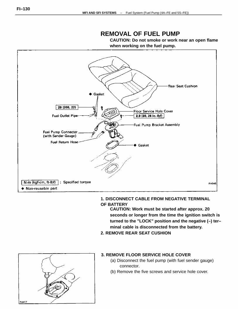
1. DISCONNECT CABLE FROM NEGATIVE TERMINALOF BATTERY
CAUTION: Work must be started after approx. 20seconds or longer from the time the ignition switch isturned to the ”LOCK” position and the negative (–) ter–minal cable is disconnected from the battery.
2. REMOVE REAR SEAT CUSHION
3. REMOVE FLOOR SERVICE HOLE COVER(a) Disconnect the fuel pump (with fuel sender gauge)
connector.(b) Remove the five screws and service hole cover.
REMOVAL OF FUEL PUMPCAUTION: Do not smoke or work near an open flamewhen working on the fuel pump.
–MFI AND SFI SYSTEMS Fuel System (Fuel Pump (4A–FE and 5S–FE))FI–130
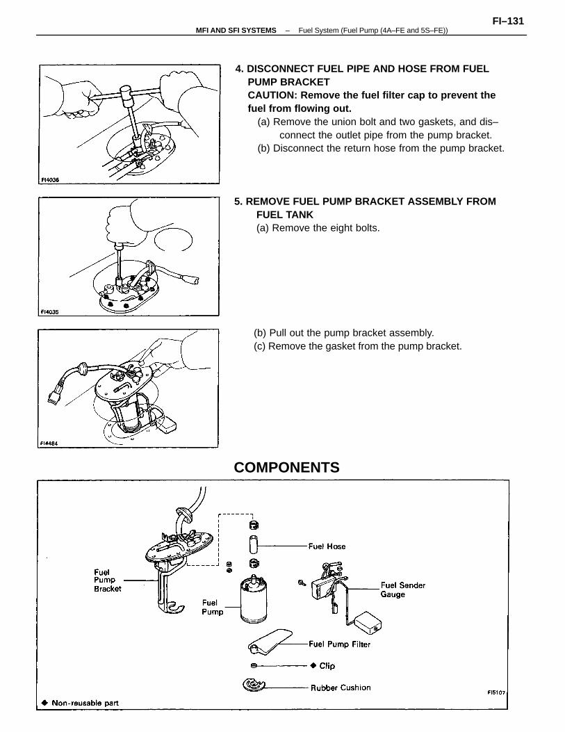
4. DISCONNECT FUEL PIPE AND HOSE FROM FUELPUMP BRACKETCAUTION: Remove the fuel filter cap to prevent thefuel from flowing out.
(a) Remove the union bolt and two gaskets, and dis–connect the outlet pipe from the pump bracket.
(b) Disconnect the return hose from the pump bracket.
5. REMOVE FUEL PUMP BRACKET ASSEMBLY FROMFUEL TANK(a) Remove the eight bolts.
(b) Pull out the pump bracket assembly.(c) Remove the gasket from the pump bracket.
COMPONENTS
–MFI AND SFI SYSTEMS Fuel System (Fuel Pump (4A–FE and 5S–FE))FI–131
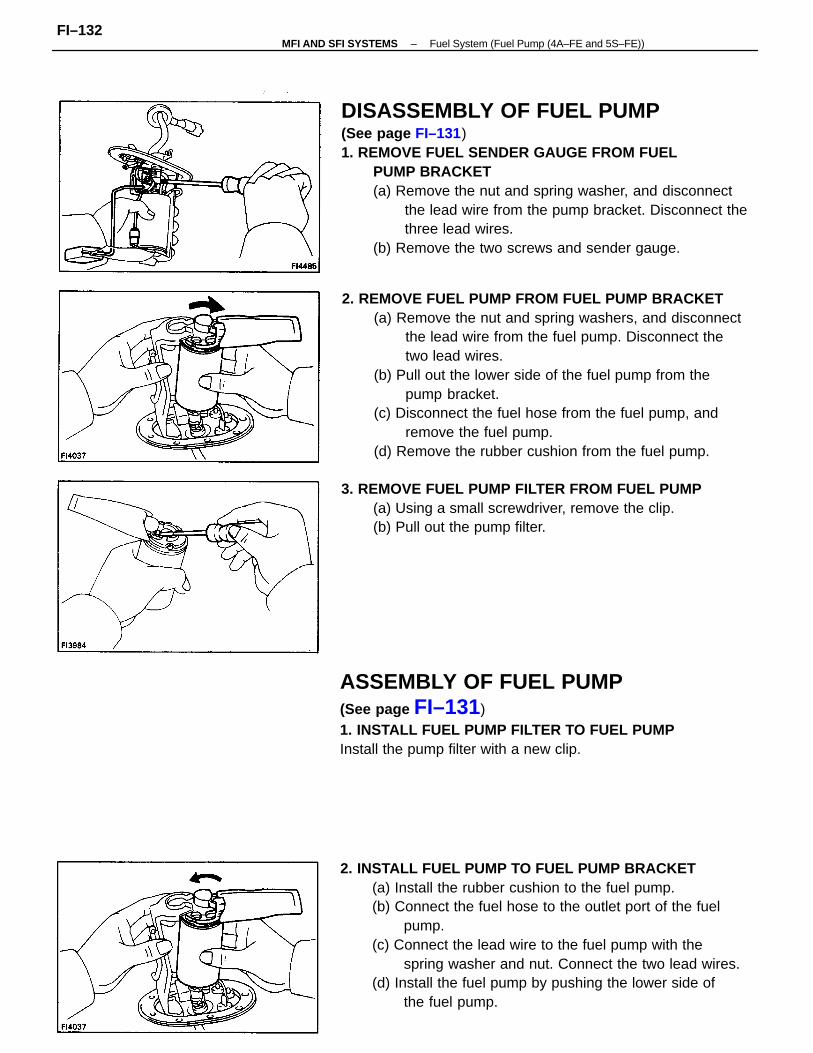
2. REMOVE FUEL PUMP FROM FUEL PUMP BRACKET(a) Remove the nut and spring washers, and disconnect
the lead wire from the fuel pump. Disconnect thetwo lead wires.
(b) Pull out the lower side of the fuel pump from thepump bracket.
(c) Disconnect the fuel hose from the fuel pump, andremove the fuel pump.
(d) Remove the rubber cushion from the fuel pump.
DISASSEMBLY OF FUEL PUMP(See page FI–131)1. REMOVE FUEL SENDER GAUGE FROM FUEL
PUMP BRACKET(a) Remove the nut and spring washer, and disconnect
the lead wire from the pump bracket. Disconnect thethree lead wires.
(b) Remove the two screws and sender gauge.
2. INSTALL FUEL PUMP TO FUEL PUMP BRACKET(a) Install the rubber cushion to the fuel pump.(b) Connect the fuel hose to the outlet port of the fuel
pump.(c) Connect the lead wire to the fuel pump with the
spring washer and nut. Connect the two lead wires.(d) Install the fuel pump by pushing the lower side of
the fuel pump.
ASSEMBLY OF FUEL PUMP(See page FI–131)1. INSTALL FUEL PUMP FILTER TO FUEL PUMPInstall the pump filter with a new clip.
3. REMOVE FUEL PUMP FILTER FROM FUEL PUMP(a) Using a small screwdriver, remove the clip.(b) Pull out the pump filter.
–MFI AND SFI SYSTEMS Fuel System (Fuel Pump (4A–FE and 5S–FE))FI–132
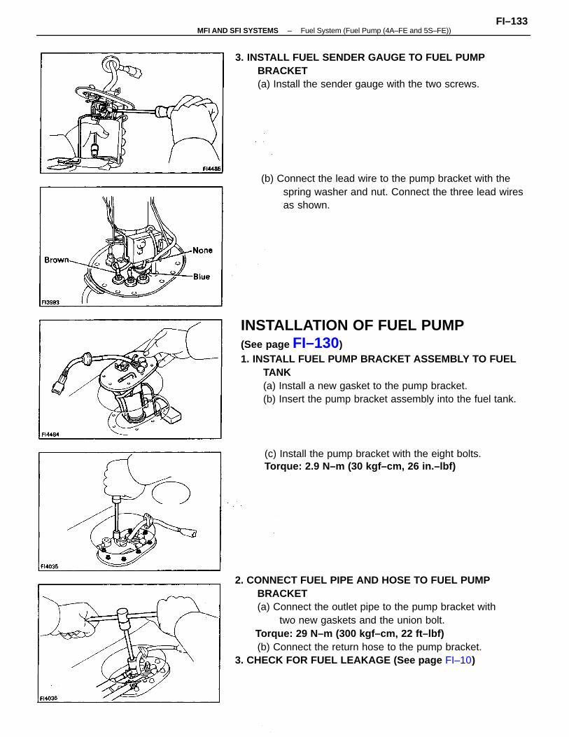
INSTALLATION OF FUEL PUMP(See page FI–130)1. INSTALL FUEL PUMP BRACKET ASSEMBLY TO FUEL
TANK(a) Install a new gasket to the pump bracket.(b) Insert the pump bracket assembly into the fuel tank.
2. CONNECT FUEL PIPE AND HOSE TO FUEL PUMPBRACKET(a) Connect the outlet pipe to the pump bracket with
two new gaskets and the union bolt. Torque: 29 N–m (300 kgf–cm, 22 ft–lbf)
(b) Connect the return hose to the pump bracket.3. CHECK FOR FUEL LEAKAGE (See page FI–10)
3. INSTALL FUEL SENDER GAUGE TO FUEL PUMPBRACKET(a) Install the sender gauge with the two screws.
(b) Connect the lead wire to the pump bracket with thespring washer and nut. Connect the three lead wiresas shown.
(c) Install the pump bracket with the eight bolts.Torque: 2.9 N–m (30 kgf–cm, 26 in.–lbf)
–MFI AND SFI SYSTEMS Fuel System (Fuel Pump (4A–FE and 5S–FE))FI–133
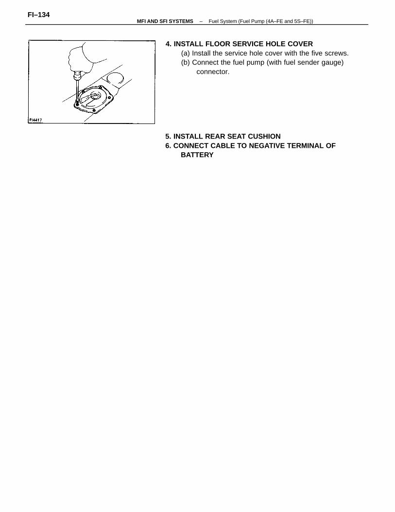
4. INSTALL FLOOR SERVICE HOLE COVER(a) Install the service hole cover with the five screws.(b) Connect the fuel pump (with fuel sender gauge)
connector.
5. INSTALL REAR SEAT CUSHION6. CONNECT CABLE TO NEGATIVE TERMINAL OF
BATTERY
–MFI AND SFI SYSTEMS Fuel System (Fuel Pump (4A–FE and 5S–FE))FI–134
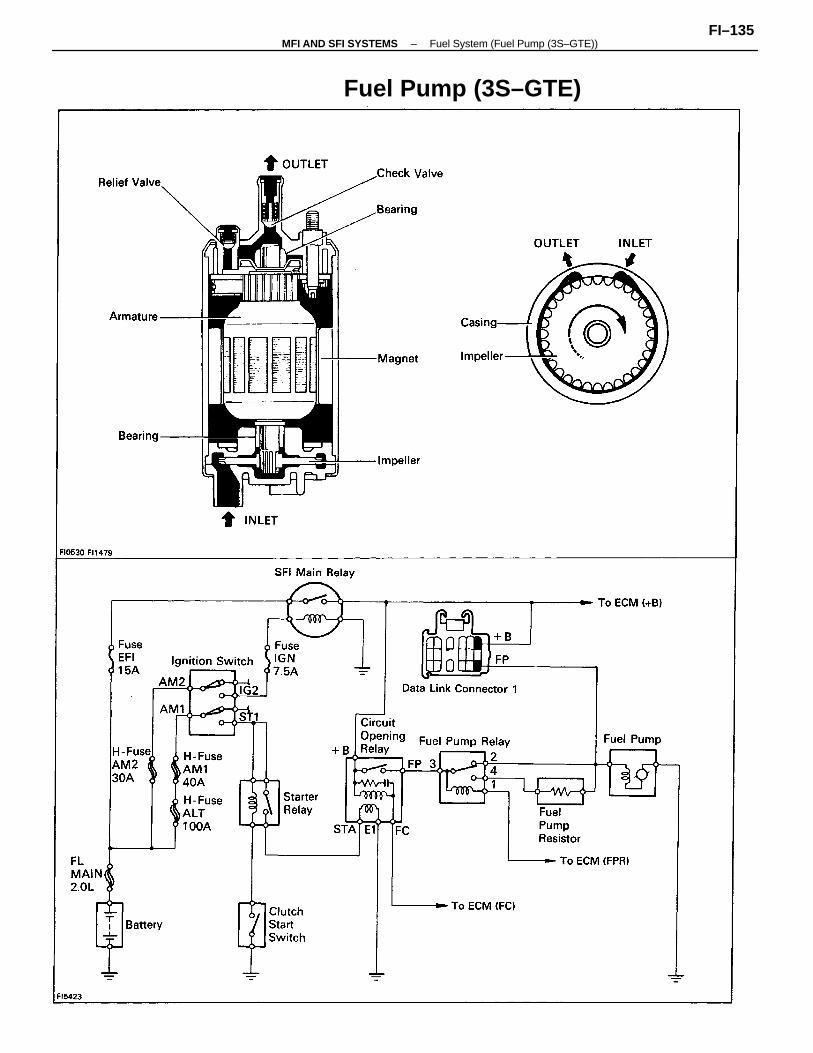
Fuel Pump (3S–GTE)
–MFI AND SFI SYSTEMS Fuel System (Fuel Pump (3S–GTE))FI–135
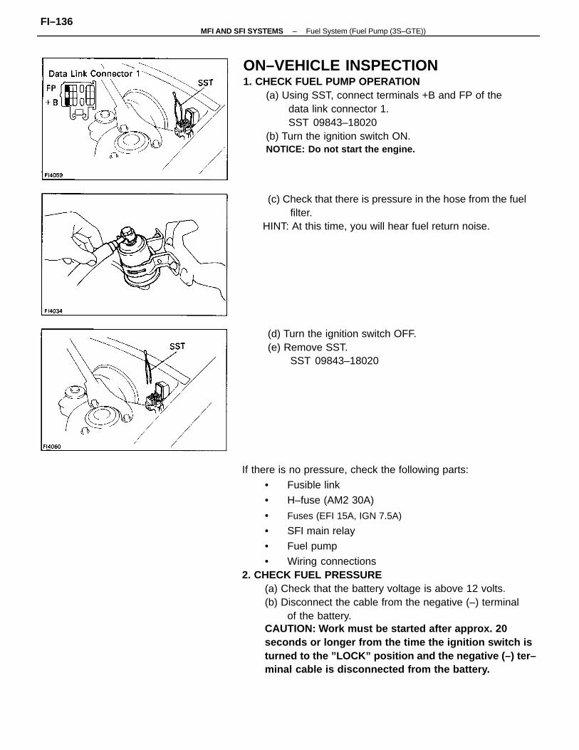
If there is no pressure, check the following parts:
• Fusible link
• H–fuse (AM2 30A)
• Fuses (EFI 15A, IGN 7.5A)
• SFI main relay
• Fuel pump
• Wiring connections2. CHECK FUEL PRESSURE
(a) Check that the battery voltage is above 12 volts.(b) Disconnect the cable from the negative (–) terminal
of the battery.CAUTION: Work must be started after approx. 20seconds or longer from the time the ignition switch isturned to the ”LOCK” position and the negative (–) ter–minal cable is disconnected from the battery.
ON–VEHICLE INSPECTION1. CHECK FUEL PUMP OPERATION
(a) Using SST, connect terminals +B and FP of thedata link connector 1.SST 09843–18020
(b) Turn the ignition switch ON.NOTICE: Do not start the engine.
(c) Check that there is pressure in the hose from the fuelfilter.
HINT: At this time, you will hear fuel return noise.
(d) Turn the ignition switch OFF.(e) Remove SST.
SST 09843–18020
–MFI AND SFI SYSTEMS Fuel System (Fuel Pump (3S–GTE))FI–136
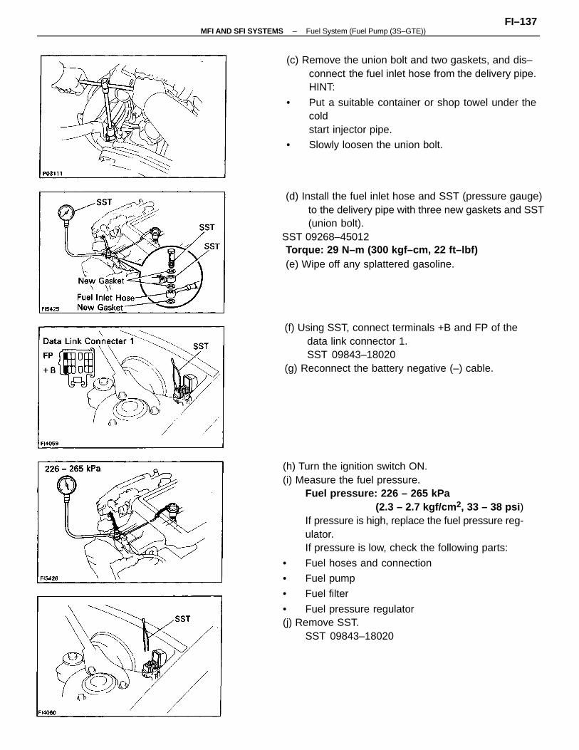
(h) Turn the ignition switch ON.(i) Measure the fuel pressure.
Fuel pressure: 226 – 265 kPa(2.3 – 2.7 kgf/cm 2, 33 – 38 psi )
If pressure is high, replace the fuel pressure reg-ulator.If pressure is low, check the following parts:
• Fuel hoses and connection
• Fuel pump
• Fuel filter
• Fuel pressure regulator(j) Remove SST.
SST 09843–18020
(d) Install the fuel inlet hose and SST (pressure gauge)to the delivery pipe with three new gaskets and SST(union bolt).
SST 09268–45012Torque: 29 N–m (300 kgf–cm, 22 ft–lbf)(e) Wipe off any splattered gasoline.
(c) Remove the union bolt and two gaskets, and dis–connect the fuel inlet hose from the delivery pipe.HINT:
• Put a suitable container or shop towel under thecoldstart injector pipe.
• Slowly loosen the union bolt.
(f) Using SST, connect terminals +B and FP of thedata link connector 1.SST 09843–18020
(g) Reconnect the battery negative (–) cable.
–MFI AND SFI SYSTEMS Fuel System (Fuel Pump (3S–GTE))FI–137
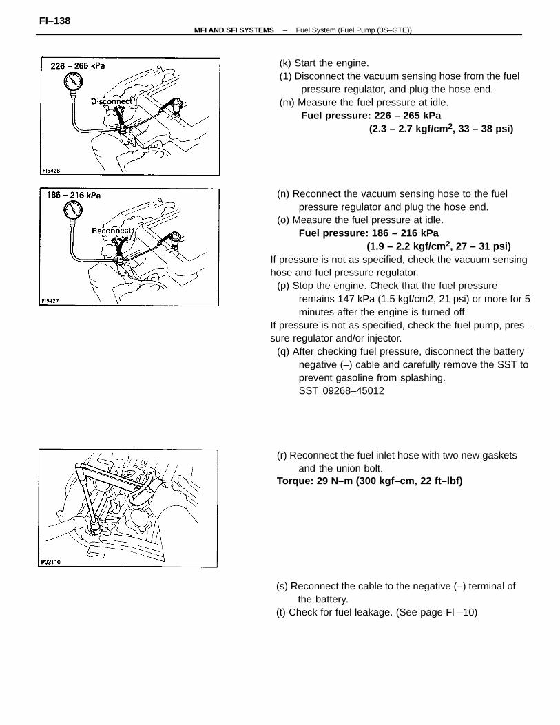
(n) Reconnect the vacuum sensing hose to the fuelpressure regulator and plug the hose end.
(o) Measure the fuel pressure at idle.Fuel pressure: 186 – 216 kPa
(1.9 – 2.2 kgf/cm 2, 27 – 31 psi) If pressure is not as specified, check the vacuum sensing hose and fuel pressure regulator.
(p) Stop the engine. Check that the fuel pressureremains 147 kPa (1.5 kgf/cm2, 21 psi) or more for 5minutes after the engine is turned off.
If pressure is not as specified, check the fuel pump, pres– sure regulator and/or injector.
(q) After checking fuel pressure, disconnect the batterynegative (–) cable and carefully remove the SST toprevent gasoline from splashing.SST 09268–45012
(k) Start the engine.(1) Disconnect the vacuum sensing hose from the fuel
pressure regulator, and plug the hose end.(m) Measure the fuel pressure at idle.
Fuel pressure: 226 – 265 kPa(2.3 – 2.7 kgf/cm 2, 33 – 38 psi)
(s) Reconnect the cable to the negative (–) terminal ofthe battery.
(t) Check for fuel leakage. (See page Fl –10)
(r) Reconnect the fuel inlet hose with two new gasketsand the union bolt.
Torque: 29 N–m (300 kgf–cm, 22 ft–lbf)
–MFI AND SFI SYSTEMS Fuel System (Fuel Pump (3S–GTE))FI–138
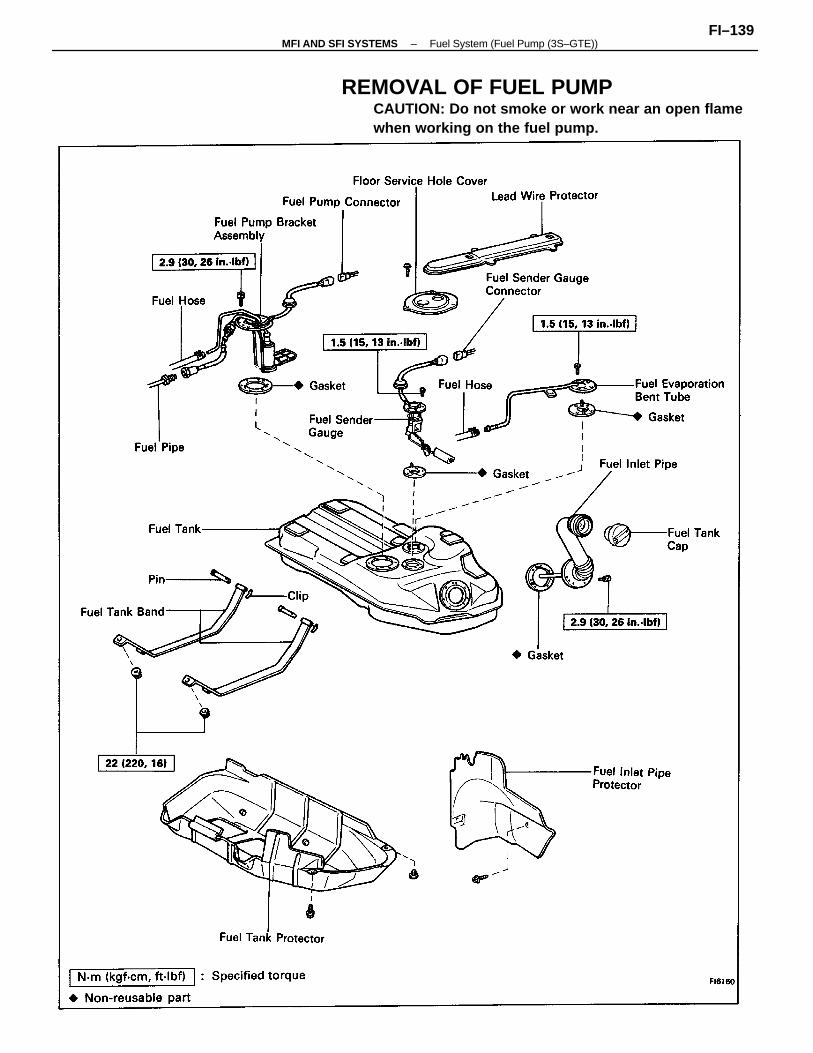
REMOVAL OF FUEL PUMPCAUTION: Do not smoke or work near an open flamewhen working on the fuel pump.
–MFI AND SFI SYSTEMS Fuel System (Fuel Pump (3S–GTE))FI–139
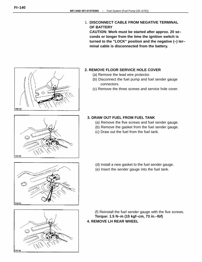
1. DISCONNECT CABLE FROM NEGATIVE TERMINALOF BATTERYCAUTION: Work must be started after approx. 20 se–conds or longer from the time the ignition switch isturned to the ”LOCK” position and the negative (–) ter–minal cable is disconnected from the battery.
2. REMOVE FLOOR SERVICE HOLE COVER(a) Remove the lead wire protector.(b) Disconnect the fuel pump and fuel sender gauge
connectors.(c) Remove the three screws and service hole cover.
3. DRAW OUT FUEL FROM FUEL TANK(a) Remove the five screws and fuel sender gauge.(b) Remove the gasket from the fuel sender gauge.(c) Draw out the fuel from the fuel tank.
(f) Reinstall the fuel sender gauge with the five screws.Torque: 1.5 N–m (15 kgf–cm, 73 in.–lbf)
4. REMOVE LH REAR WHEEL
(d) Install a new gasket to the fuel sender gauge.(e) Insert the sender gauge into the fuel tank.
–MFI AND SFI SYSTEMS Fuel System (Fuel Pump (3S–GTE))FI–140
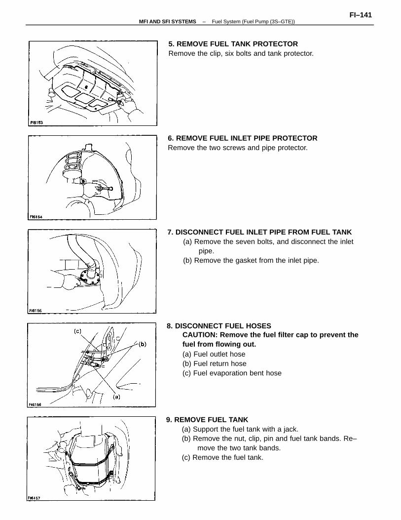
8. DISCONNECT FUEL HOSESCAUTION: Remove the fuel filter cap to prevent thefuel from flowing out.(a) Fuel outlet hose(b) Fuel return hose(c) Fuel evaporation bent hose
9. REMOVE FUEL TANK(a) Support the fuel tank with a jack.(b) Remove the nut, clip, pin and fuel tank bands. Re–
move the two tank bands.(c) Remove the fuel tank.
7. DISCONNECT FUEL INLET PIPE FROM FUEL TANK(a) Remove the seven bolts, and disconnect the inlet
pipe.(b) Remove the gasket from the inlet pipe.
5. REMOVE FUEL TANK PROTECTORRemove the clip, six bolts and tank protector.
6. REMOVE FUEL INLET PIPE PROTECTORRemove the two screws and pipe protector.
–MFI AND SFI SYSTEMS Fuel System (Fuel Pump (3S–GTE))FI–141
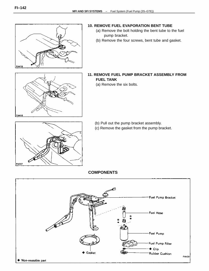
10. REMOVE FUEL EVAPORATION BENT TUBE(a) Remove the bolt holding the bent tube to the fuel
pump bracket.(b) Remove the four screws, bent tube and gasket.
11. REMOVE FUEL PUMP BRACKET ASSEMBLY FROMFUEL TANK(a) Remove the six bolts.
(b) Pull out the pump bracket assembly.(c) Remove the gasket from the pump bracket.
COMPONENTS
–MFI AND SFI SYSTEMS Fuel System (Fuel Pump (3S–GTE))FI–142
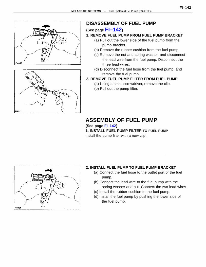
DISASSEMBLY OF FUEL PUMP(See page FI–142)1. REMOVE FUEL PUMP FROM FUEL PUMP BRACKET
(a) Pull out the lower side of the fuel pump from thepump bracket.
(b) Remove the rubber cushion from the fuel pump.(c) Remove the nut and spring washer, and disconnect
the lead wire from the fuel pump. Disconnect thethree lead wires.
(d) Disconnect the fuel hose from the fuel pump, andremove the fuel pump.
2. REMOVE FUEL PUMP FILTER FROM FUEL PUMP(a) Using a small screwdriver, remove the clip.(b) Pull out the pump filter.
2. INSTALL FUEL PUMP TO FUEL PUMP BRACKET(a) Connect the fuel hose to the outlet port of the fuel
pump.(b) Connect the lead wire to the fuel pump with the
spring washer and nut. Connect the two lead wires.(c) Install the rubber cushion to the fuel pump.(d) Install the fuel pump by pushing the lower side of
the fuel pump.
ASSEMBLY OF FUEL PUMP(See page FI–142)1. INSTALL FUEL PUMP FILTER TO FUEL PUMPinstall the pump filter with a new clip.
–MFI AND SFI SYSTEMS Fuel System (Fuel Pump (3S–GTE))FI–143
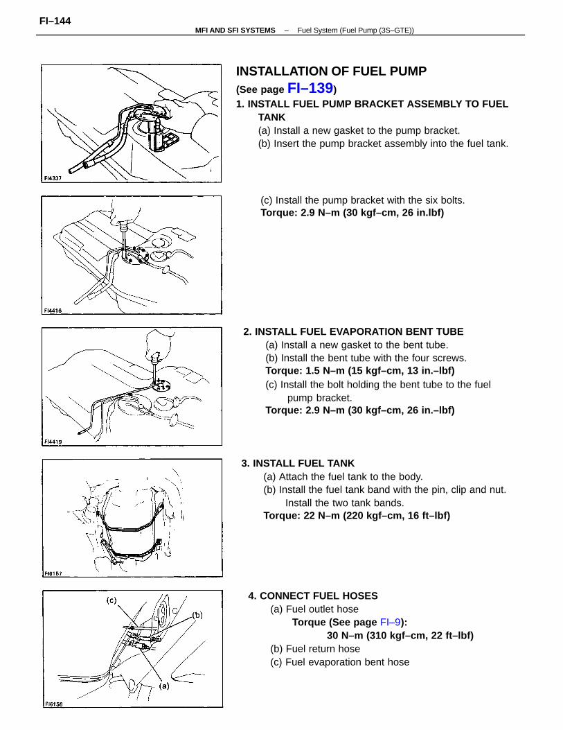
2. INSTALL FUEL EVAPORATION BENT TUBE(a) Install a new gasket to the bent tube.(b) Install the bent tube with the four screws.Torque: 1.5 N–m (15 kgf–cm, 13 in.–lbf)(c) Install the bolt holding the bent tube to the fuel
pump bracket.Torque: 2.9 N–m (30 kgf–cm, 26 in.–lbf)
INSTALLATION OF FUEL PUMP(See page FI–139)1. INSTALL FUEL PUMP BRACKET ASSEMBLY TO FUEL
TANK(a) Install a new gasket to the pump bracket.(b) Insert the pump bracket assembly into the fuel tank.
3. INSTALL FUEL TANK(a) Attach the fuel tank to the body.(b) Install the fuel tank band with the pin, clip and nut.
Install the two tank bands.Torque: 22 N–m (220 kgf–cm, 16 ft–lbf)
4. CONNECT FUEL HOSES(a) Fuel outlet hose
Torque (See page FI–9):30 N–m (310 kgf–cm, 22 ft–lbf)
(b) Fuel return hose(c) Fuel evaporation bent hose
(c) Install the pump bracket with the six bolts.Torque: 2.9 N–m (30 kgf–cm, 26 in.lbf)
–MFI AND SFI SYSTEMS Fuel System (Fuel Pump (3S–GTE))FI–144
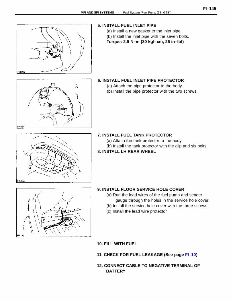
9. INSTALL FLOOR SERVICE HOLE COVER(a) Run the lead wires of the fuel pump and sender
gauge through the holes in the service hole cover.(b) Install the service hole cover with the three screws.(c) Install the lead wire protector.
7. INSTALL FUEL TANK PROTECTOR(a) Attach the tank protector to the body.(b) Install the tank protector with the clip and six bolts.
8. INSTALL LH REAR WHEEL
10. FILL WITH FUEL
11. CHECK FOR FUEL LEAKAGE (See page FI–10)
12. CONNECT CABLE TO NEGATIVE TERMINAL OFBATTERY
5. INSTALL FUEL INLET PIPE(a) Install a new gasket to the inlet pipe.(b) Install the inlet pipe with the seven bolts.Torque: 2.9 N–m (30 kgf–cm, 26 in–lbf)
6. INSTALL FUEL INLET PIPE PROTECTOR(a) Attach the pipe protector to the body.(b) Install the pipe protector with the two screws.
–MFI AND SFI SYSTEMS Fuel System (Fuel Pump (3S–GTE))FI–145
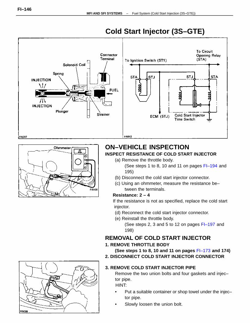
ON–VEHICLE INSPECTIONINSPECT RESISTANCE OF COLD START INJECTOR
(a) Remove the throttle body.(See steps 1 to 8, 10 and 11 on pages FI–194 and195)
(b) Disconnect the cold start injector connector.(c) Using an ohmmeter, measure the resistance be–
tween the terminals. Resistance: 2 – 4
If the resistance is not as specified, replace the cold start injector.
(d) Reconnect the cold start injector connector.(e) Reinstall the throttle body.
(See steps 2, 3 and 5 to 12 on pages FI–197 and198)
REMOVAL OF COLD START INJECTOR1. REMOVE THROTTLE BODY
(See steps 1 to 8, 10 and 11 on pages FI–173 and 174)2. DISCONNECT COLD START INJECTOR CONNECTOR
3. REMOVE COLD START INJECTOR PIPERemove the two union bolts and four gaskets and injec–tor pipe.
HINT:
• Put a suitable container or shop towel under the injec–tor pipe.
• Slowly loosen the union bolt.
Cold Start Injector (3S–GTE)
–MFI AND SFI SYSTEMS Fuel System (Cold Start Injection (3S–GTE))FI–146
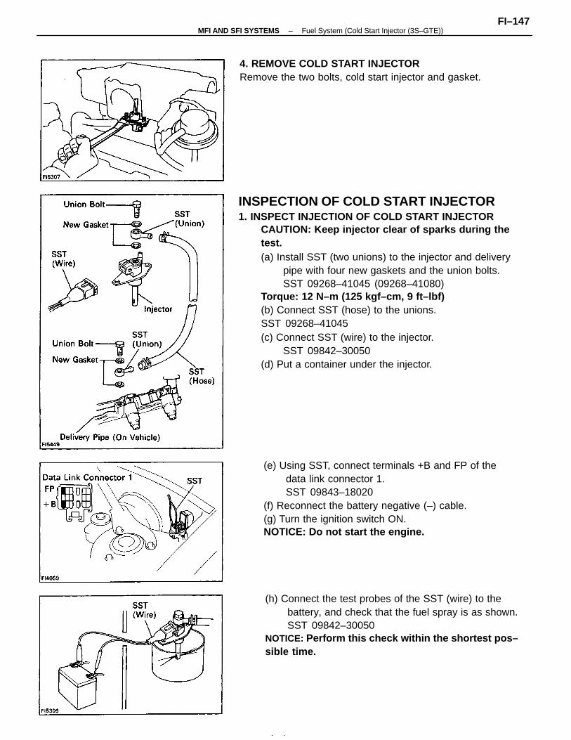
INSPECTION OF COLD START INJECTOR1. INSPECT INJECTION OF COLD START INJECTOR
CAUTION: Keep injector clear of sparks during thetest.(a) Install SST (two unions) to the injector and delivery
pipe with four new gaskets and the union bolts.SST 09268–41045 (09268–41080)
Torque: 12 N–m (125 kgf–cm, 9 ft–lbf)(b) Connect SST (hose) to the unions.SST 09268–41045(c) Connect SST (wire) to the injector.
SST 09842–30050(d) Put a container under the injector.
(e) Using SST, connect terminals +B and FP of thedata link connector 1.SST 09843–18020
(f) Reconnect the battery negative (–) cable.(g) Turn the ignition switch ON.NOTICE: Do not start the engine.
(h) Connect the test probes of the SST (wire) to thebattery, and check that the fuel spray is as shown.SST 09842–30050
NOTICE: Perform this check within the shortest pos–sible time.
4. REMOVE COLD START INJECTORRemove the two bolts, cold start injector and gasket.
–MFI AND SFI SYSTEMS Fuel System (Cold Start Injector (3S–GTE))FI–147
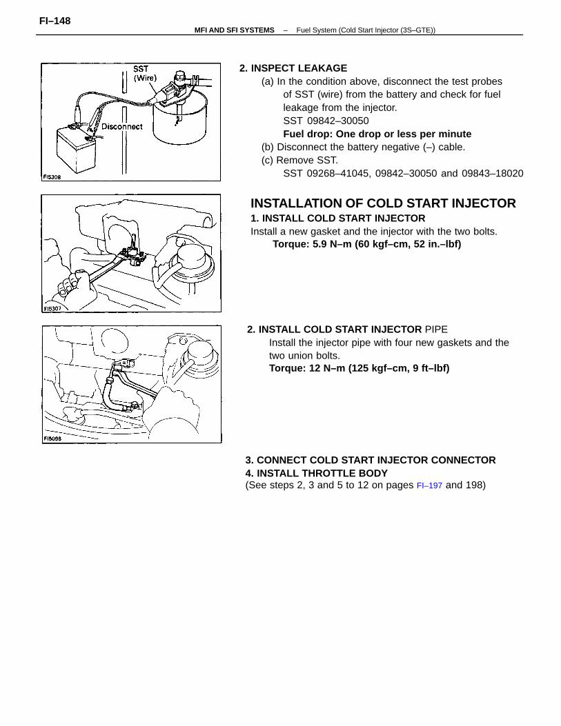
2. INSPECT LEAKAGE(a) In the condition above, disconnect the test probes
of SST (wire) from the battery and check for fuelleakage from the injector.SST 09842–30050Fuel drop: One drop or less per minute
(b) Disconnect the battery negative (–) cable.(c) Remove SST.
SST 09268–41045, 09842–30050 and 09843–18020
2. INSTALL COLD START INJECTOR PIPEInstall the injector pipe with four new gaskets and thetwo union bolts.Torque: 12 N–m (125 kgf–cm, 9 ft–lbf)
3. CONNECT COLD START INJECTOR CONNECTOR4. INSTALL THROTTLE BODY(See steps 2, 3 and 5 to 12 on pages FI–197 and 198)
INSTALLATION OF COLD START INJECTOR1. INSTALL COLD START INJECTORInstall a new gasket and the injector with the two bolts.
Torque: 5.9 N–m (60 kgf–cm, 52 in.–lbf)
–MFI AND SFI SYSTEMS Fuel System (Cold Start Injector (3S–GTE))FI–148
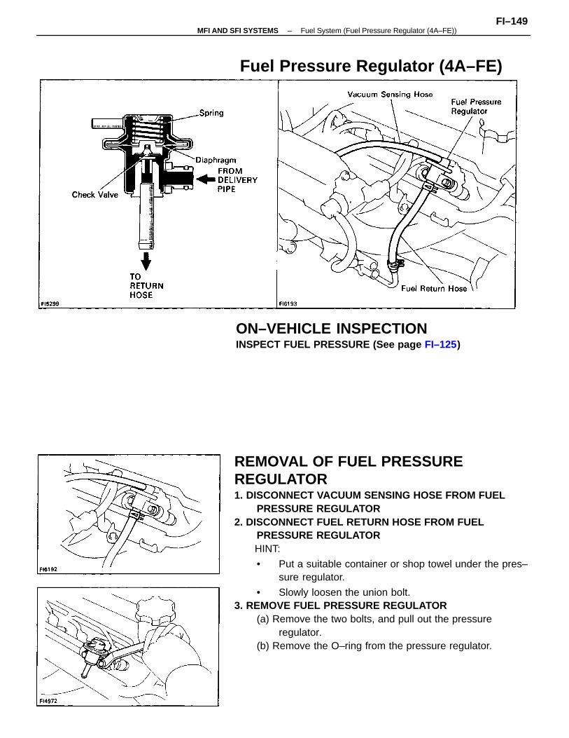
REMOVAL OF FUEL PRESSUREREGULATOR1. DISCONNECT VACUUM SENSING HOSE FROM FUEL
PRESSURE REGULATOR2. DISCONNECT FUEL RETURN HOSE FROM FUEL
PRESSURE REGULATOR HINT:
• Put a suitable container or shop towel under the pres–sure regulator.
• Slowly loosen the union bolt.3. REMOVE FUEL PRESSURE REGULATOR
(a) Remove the two bolts, and pull out the pressureregulator.
(b) Remove the O–ring from the pressure regulator.
ON–VEHICLE INSPECTIONINSPECT FUEL PRESSURE (See page FI–125)
Fuel Pressure Regulator (4A–FE)
–MFI AND SFI SYSTEMS Fuel System (Fuel Pressure Regulator (4A–FE))FI–149
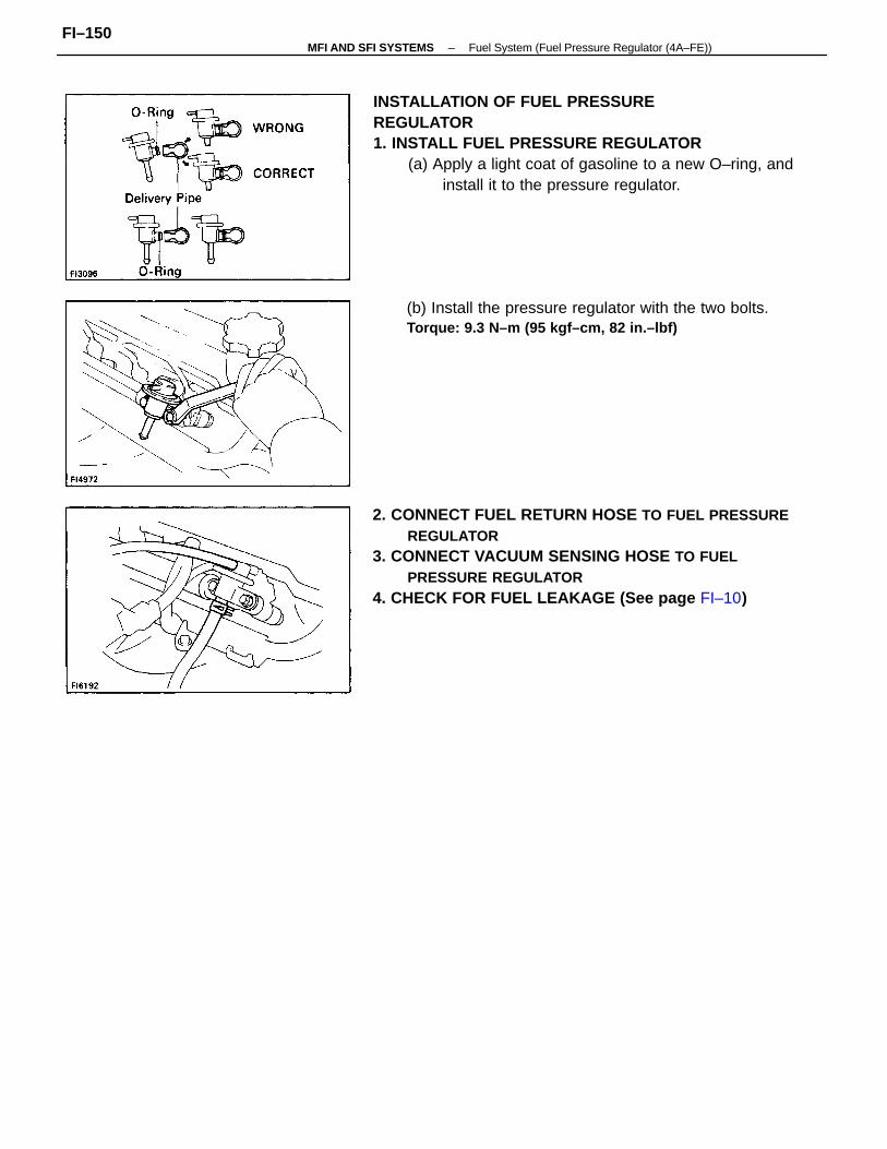
2. CONNECT FUEL RETURN HOSE TO FUEL PRESSUREREGULATOR
3. CONNECT VACUUM SENSING HOSE TO FUELPRESSURE REGULATOR
4. CHECK FOR FUEL LEAKAGE (See page FI–10)
INSTALLATION OF FUEL PRESSUREREGULATOR1. INSTALL FUEL PRESSURE REGULATOR
(a) Apply a light coat of gasoline to a new O–ring, andinstall it to the pressure regulator.
(b) Install the pressure regulator with the two bolts.Torque: 9.3 N–m (95 kgf–cm, 82 in.–lbf)
–MFI AND SFI SYSTEMS Fuel System (Fuel Pressure Regulator (4A–FE))FI–150
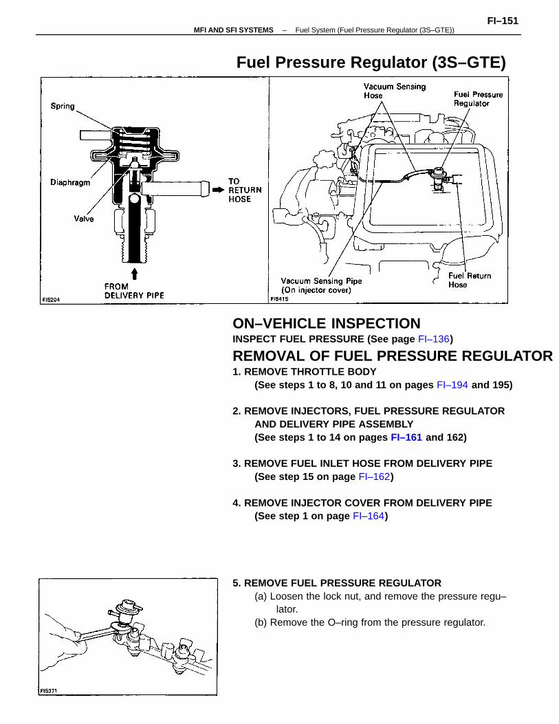
ON–VEHICLE INSPECTIONINSPECT FUEL PRESSURE (See page FI–136)
REMOVAL OF FUEL PRESSURE REGULATOR1. REMOVE THROTTLE BODY
(See steps 1 to 8, 10 and 11 on pages FI–194 and 195)
2. REMOVE INJECTORS, FUEL PRESSURE REGULATORAND DELIVERY PIPE ASSEMBLY(See steps 1 to 14 on pages FI–161 and 162)
3. REMOVE FUEL INLET HOSE FROM DELIVERY PIPE(See step 15 on page FI–162)
4. REMOVE INJECTOR COVER FROM DELIVERY PIPE(See step 1 on page FI–164)
5. REMOVE FUEL PRESSURE REGULATOR(a) Loosen the lock nut, and remove the pressure regu–
lator.(b) Remove the O–ring from the pressure regulator.
Fuel Pressure Regulator (3S–GTE)
–MFI AND SFI SYSTEMS Fuel System (Fuel Pressure Regulator (3S–GTE))FI–151
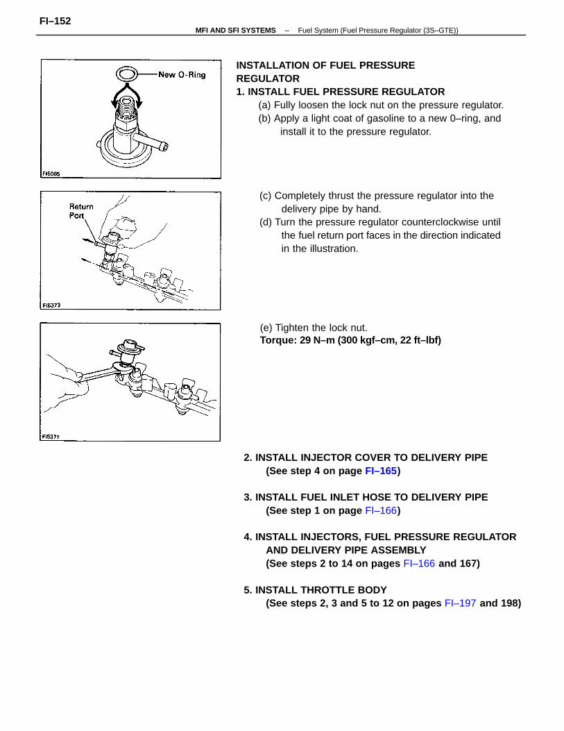
2. INSTALL INJECTOR COVER TO DELIVERY PIPE(See step 4 on page FI–165)
3. INSTALL FUEL INLET HOSE TO DELIVERY PIPE(See step 1 on page FI–166)
4. INSTALL INJECTORS, FUEL PRESSURE REGULATORAND DELIVERY PIPE ASSEMBLY(See steps 2 to 14 on pages FI–166 and 167)
5. INSTALL THROTTLE BODY(See steps 2, 3 and 5 to 12 on pages FI–197 and 198)
INSTALLATION OF FUEL PRESSUREREGULATOR1. INSTALL FUEL PRESSURE REGULATOR
(a) Fully loosen the lock nut on the pressure regulator.(b) Apply a light coat of gasoline to a new 0–ring, and
install it to the pressure regulator.
(c) Completely thrust the pressure regulator into thedelivery pipe by hand.
(d) Turn the pressure regulator counterclockwise untilthe fuel return port faces in the direction indicatedin the illustration.
(e) Tighten the lock nut.Torque: 29 N–m (300 kgf–cm, 22 ft–lbf)
–MFI AND SFI SYSTEMS Fuel System (Fuel Pressure Regulator (3S–GTE))FI–152
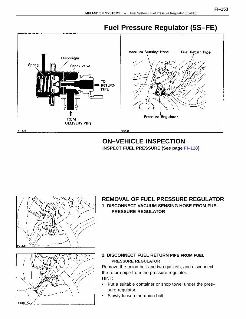
2. DISCONNECT FUEL RETURN PIPE FROM FUELPRESSURE REGULATOR
Remove the union bolt and two gaskets, and disconnectthe return pipe from the pressure regulator.HINT:• Put a suitable container or shop towel under the pres–
sure regulator.• Slowly loosen the union bolt.
REMOVAL OF FUEL PRESSURE REGULATOR1. DISCONNECT VACUUM SENSING HOSE FROM FUEL
PRESSURE REGULATOR
ON–VEHICLE INSPECTIONINSPECT FUEL PRESSURE (See page FI–128)
Fuel Pressure Regulator (5S–FE)
–MFI AND SFI SYSTEMS Fuel System (Fuel Pressure Regulator (5S–FE))FI–153
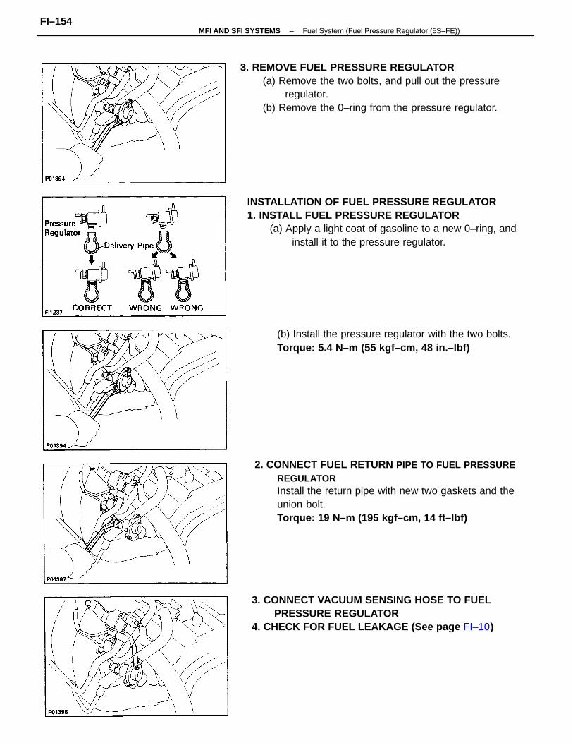
INSTALLATION OF FUEL PRESSURE REGULATOR1. INSTALL FUEL PRESSURE REGULATOR
(a) Apply a light coat of gasoline to a new 0–ring, andinstall it to the pressure regulator.
2. CONNECT FUEL RETURN PIPE TO FUEL PRESSUREREGULATORInstall the return pipe with new two gaskets and theunion bolt.Torque: 19 N–m (195 kgf–cm, 14 ft–lbf)
3. REMOVE FUEL PRESSURE REGULATOR(a) Remove the two bolts, and pull out the pressure
regulator.(b) Remove the 0–ring from the pressure regulator.
3. CONNECT VACUUM SENSING HOSE TO FUELPRESSURE REGULATOR
4. CHECK FOR FUEL LEAKAGE (See page FI–10)
(b) Install the pressure regulator with the two bolts.Torque: 5.4 N–m (55 kgf–cm, 48 in.–lbf)
–MFI AND SFI SYSTEMS Fuel System (Fuel Pressure Regulator (5S–FE))FI–154
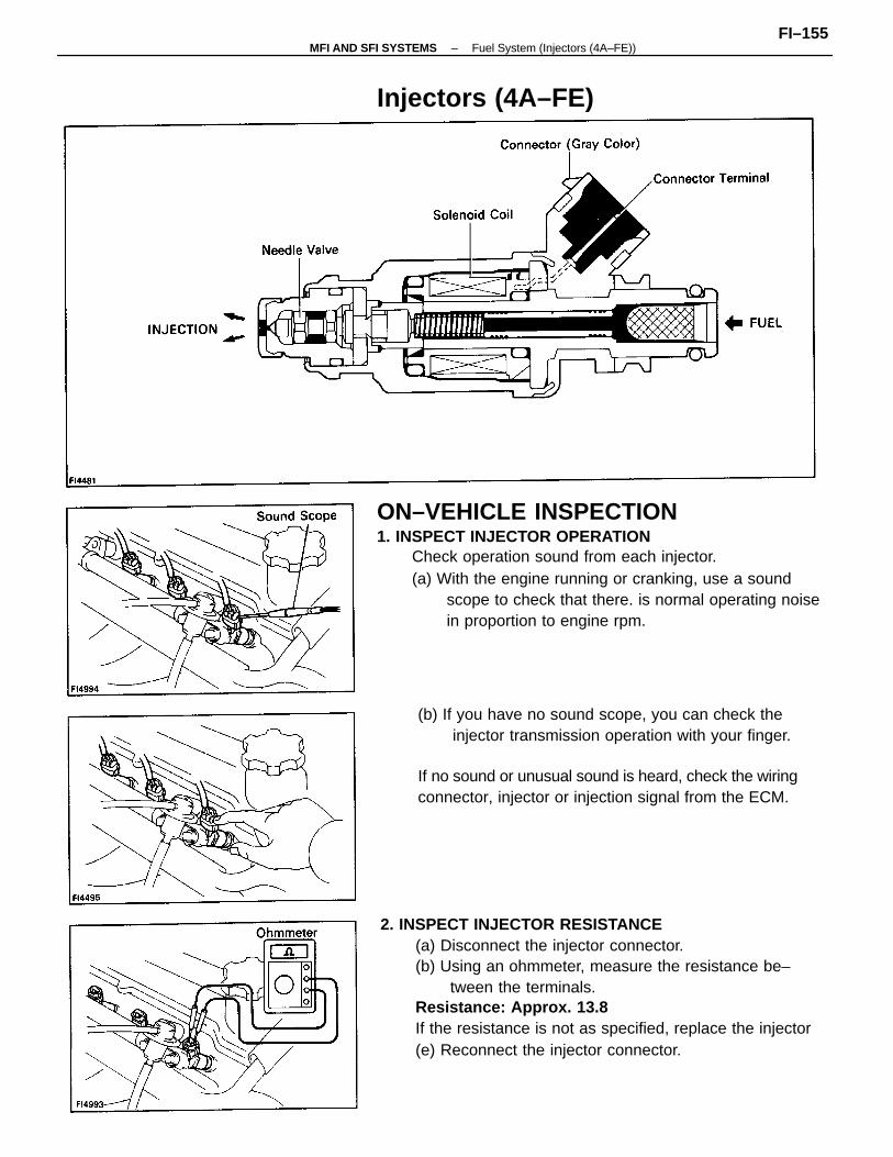
2. INSPECT INJECTOR RESISTANCE(a) Disconnect the injector connector.(b) Using an ohmmeter, measure the resistance be–
tween the terminals.Resistance: Approx. 13.8
If the resistance is not as specified, replace the injector(e) Reconnect the injector connector.
ON–VEHICLE INSPECTION1. INSPECT INJECTOR OPERATION
Check operation sound from each injector.(a) With the engine running or cranking, use a sound
scope to check that there. is normal operating noisein proportion to engine rpm.
(b) If you have no sound scope, you can check theinjector transmission operation with your finger.
If no sound or unusual sound is heard, check the wiringconnector, injector or injection signal from the ECM.
Injectors (4A–FE)
–MFI AND SFI SYSTEMS Fuel System (Injectors (4A–FE))FI–155
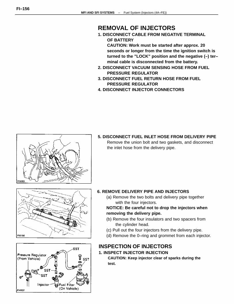
6. REMOVE DELIVERY PIPE AND INJECTORS(a) Remove the two bolts and delivery pipe together
with the four injectors.NOTICE: Be careful not to drop the injectors whenremoving the delivery pipe.(b) Remove the four insulators and two spacers from
the cylinder head.(c) Pull out the four injectors from the delivery pipe.(d) Remove the 0–ring and grommet from each injector.
REMOVAL OF INJECTORS1. DISCONNECT CABLE FROM NEGATIVE TERMINAL
OF BATTERYCAUTION: Work must be started after approx. 20seconds or longer from the time the ignition switch isturned to the ”LOCK” position and the negative (–) ter–minal cable is disconnected from the battery.
2. DISCONNECT VACUUM SENSING HOSE FROM FUELPRESSURE REGULATOR
3. DISCONNECT FUEL RETURN HOSE FROM FUELPRESSURE REGULATOR
4. DISCONNECT INJECTOR CONNECTORS
5. DISCONNECT FUEL INLET HOSE FROM DELIVERY PIPERemove the union bolt and two gaskets, and disconnectthe inlet hose from the delivery pipe.
INSPECTION OF INJECTORS1. INSPECT INJECTOR INJECTION
CAUTION: Keep injector clear of sparks during thetest.
–MFI AND SFI SYSTEMS Fuel System (Injectors (4A–FE))FI–156
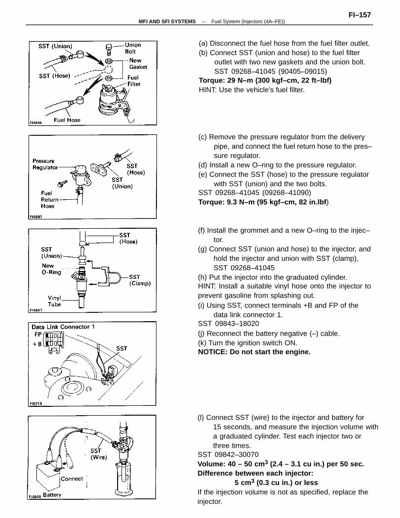
(f) Install the grommet and a new O–ring to the injec–tor.
(g) Connect SST (union and hose) to the injector, andhold the injector and union with SST (clamp),SST 09268–41045
(h) Put the injector into the graduated cylinder.HINT: Install a suitable vinyl hose onto the injector toprevent gasoline from splashing out.(i) Using SST, connect terminals +B and FP of the
data link connector 1.SST 09843–18020(j) Reconnect the battery negative (–) cable.(k) Turn the ignition switch ON.NOTICE: Do not start the engine.
(l) Connect SST (wire) to the injector and battery for15 seconds, and measure the injection volume witha graduated cylinder. Test each injector two orthree times.
SST 09842–30070Volume: 40 – 50 cm 3 (2.4 – 3.1 cu in.) per 50 sec.Difference between each injector:
5 cm3 (0.3 cu in.) or lessIf the injection volume is not as specified, replace theinjector.
(c) Remove the pressure regulator from the deliverypipe, and connect the fuel return hose to the pres–sure regulator.
(d) Install a new O–ring to the pressure regulator.(e) Connect the SST (hose) to the pressure regulator
with SST (union) and the two bolts.SST 09268–41045 (09268–41090)Torque: 9.3 N–m (95 kgf–cm, 82 in.lbf )
(a) Disconnect the fuel hose from the fuel filter outlet.(b) Connect SST (union and hose) to the fuel filter
outlet with two new gaskets and the union bolt.SST 09268–41045 (90405–09015)
Torque: 29 N–m (300 kgf–cm, 22 ft–lbf)HINT: Use the vehicle’s fuel filter.
–MFI AND SFI SYSTEMS Fuel System (Injectors (4A–FE))FI–157
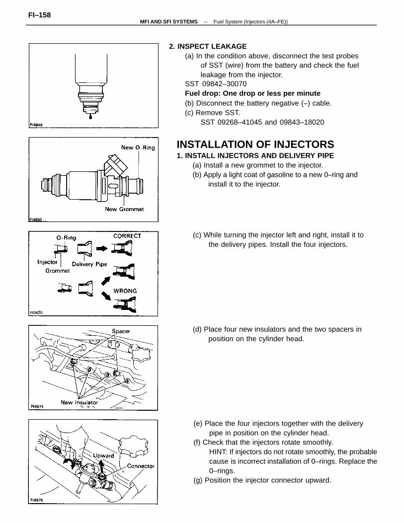
2. INSPECT LEAKAGE(a) In the condition above, disconnect the test probes
of SST (wire) from the battery and check the fuelleakage from the injector.
SST 09842–30070Fuel drop: One drop or less per minute(b) Disconnect the battery negative (–) cable.(c) Remove SST.
SST 09268–41045 and 09843–18020
(e) Place the four injectors together with the deliverypipe in position on the cylinder head.
(f) Check that the injectors rotate smoothly.HINT: If injectors do not rotate smoothly, the probablecause is incorrect installation of 0–rings. Replace the0–rings.
(g) Position the injector connector upward.
(c) While turning the injector left and right, install it tothe delivery pipes. Install the four injectors.
(d) Place four new insulators and the two spacers inposition on the cylinder head.
INSTALLATION OF INJECTORS1. INSTALL INJECTORS AND DELIVERY PIPE
(a) Install a new grommet to the injector.(b) Apply a light coat of gasoline to a new 0–ring and
install it to the injector.
–MFI AND SFI SYSTEMS Fuel System (Injectors (4A–FE))FI–158
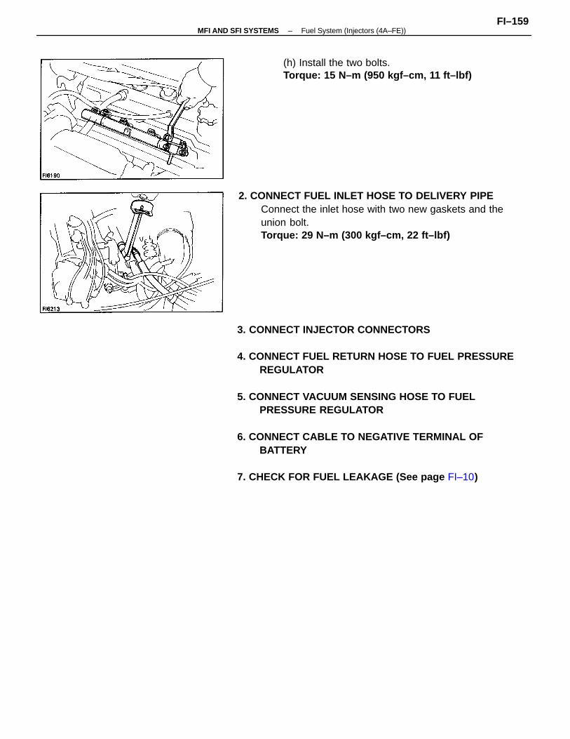
3. CONNECT INJECTOR CONNECTORS
4. CONNECT FUEL RETURN HOSE TO FUEL PRESSUREREGULATOR
5. CONNECT VACUUM SENSING HOSE TO FUELPRESSURE REGULATOR
6. CONNECT CABLE TO NEGATIVE TERMINAL OFBATTERY
7. CHECK FOR FUEL LEAKAGE (See page FI–10)
2. CONNECT FUEL INLET HOSE TO DELIVERY PIPEConnect the inlet hose with two new gaskets and theunion bolt.Torque: 29 N–m (300 kgf–cm, 22 ft–lbf)
(h) Install the two bolts.Torque: 15 N–m (950 kgf–cm, 11 ft–lbf)
–MFI AND SFI SYSTEMS Fuel System (Injectors (4A–FE))FI–159
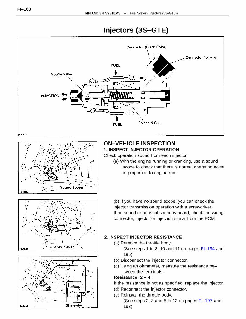
2. INSPECT INJECTOR RESISTANCE(a) Remove the throttle body.
(See steps 1 to 8, 10 and 11 on pages FI–194 and195)
(b) Disconnect the injector connector.(c) Using an ohmmeter, measure the resistance be–
tween the terminals.Resistance: 2 – 4
If the resistance is not as specified, replace the injector.(d) Reconnect the injector connector.(e) Reinstall the throttle body.
(See steps 2, 3 and 5 to 12 on pages FI–197 and198)
ON–VEHICLE INSPECTION1. INSPECT INJECTOR OPERATIONCheck operation sound from each injector.
(a) With the engine running or cranking, use a soundscope to check that there is normal operating noisein proportion to engine rpm.
(b) If you have no sound scope, you can check theinjector transmission operation with a screwdriver.If no sound or unusual sound is heard, check the wiringconnector, injector or injection signal from the ECM.
Injectors (3S–GTE)
–MFI AND SFI SYSTEMS Fuel System (Injectors (3S–GTE))FI–160
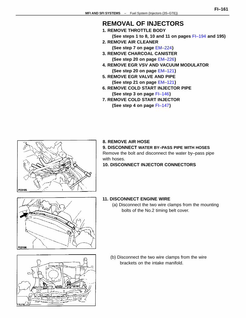
REMOVAL OF INJECTORS1. REMOVE THROTTLE BODY
(See steps 1 to 8, 10 and 11 on pages FI–194 and 195)2. REMOVE AIR CLEANER
(See step 7 on page EM–224)3. REMOVE CHARCOAL CANISTER
(See step 20 on page EM–226)4. REMOVE EGR VSV AND VACUUM MODULATOR
(See step 20 on page EM–121)5. REMOVE EGR VALVE AND PIPE
(See step 21 on page EM–121)6. REMOVE COLD START INJECTOR PIPE
(See step 3 on page FI–146)7. REMOVE COLD START INJECTOR
(See step 4 on page FI–147)
8. REMOVE AIR HOSE9. DISCONNECT WATER BY–PASS PIPE WITH HOSESRemove the bolt and disconnect the water by–pass pipewith hoses.10. DISCONNECT INJECTOR CONNECTORS
11. DISCONNECT ENGINE WIRE(a) Disconnect the two wire clamps from the mounting
bolts of the No.2 timing belt cover.
(b) Disconnect the two wire clamps from the wirebrackets on the intake manifold.
–MFI AND SFI SYSTEMS Fuel System (Injectors (3S–GTE))FI–161
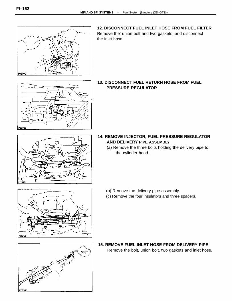
14. REMOVE INJECTOR, FUEL PRESSURE REGULATORAND DELIVERY PIPE ASSEMBLY(a) Remove the three bolts holding the delivery pipe to
the cylinder head.
12. DISCONNECT FUEL INLET HOSE FROM FUEL FILTERRemove the’ union bolt and two gaskets, and disconnectthe inlet hose.
15. REMOVE FUEL INLET HOSE FROM DELIVERY PIPERemove the bolt, union bolt, two gaskets and inlet hose.
(b) Remove the delivery pipe assembly.(c) Remove the four insulators and three spacers.
13. DISCONNECT FUEL RETURN HOSE FROM FUELPRESSURE REGULATOR
–MFI AND SFI SYSTEMS Fuel System (Injectors (3S–GTE))FI–162
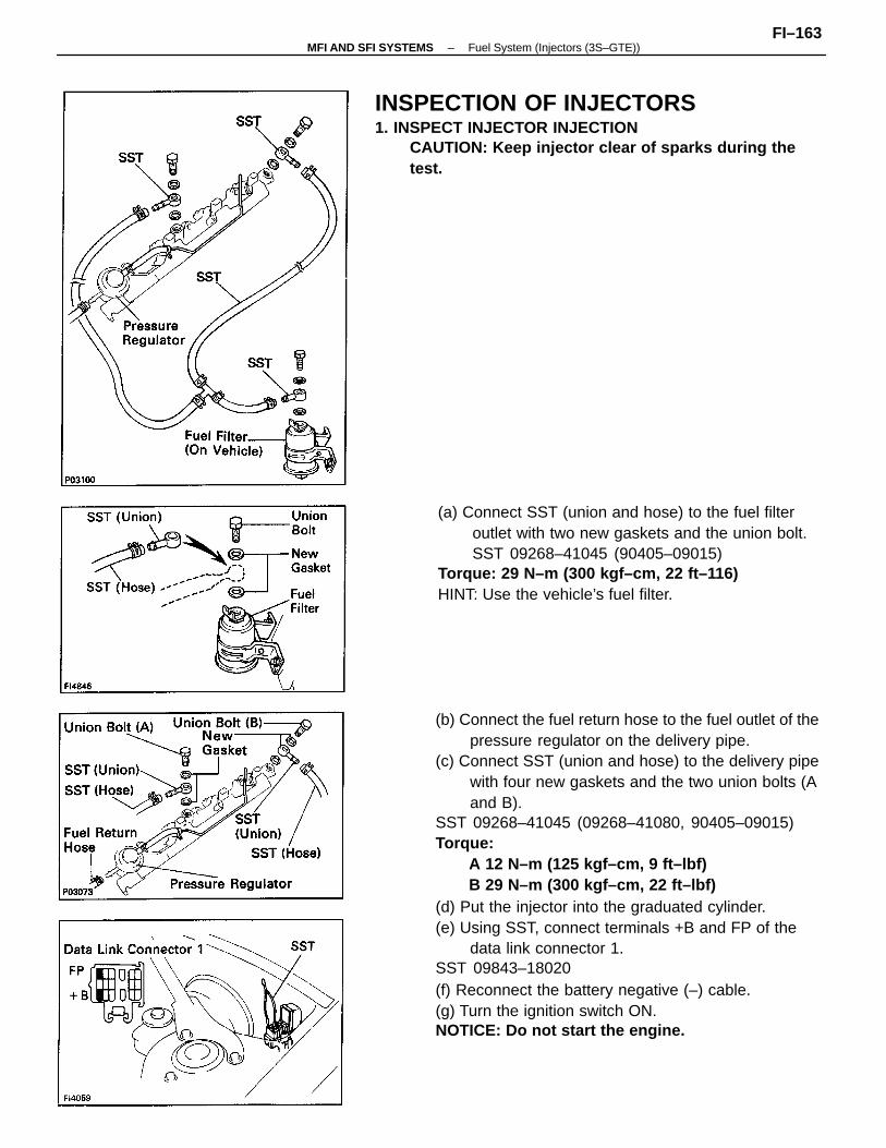
(b) Connect the fuel return hose to the fuel outlet of thepressure regulator on the delivery pipe.
(c) Connect SST (union and hose) to the delivery pipewith four new gaskets and the two union bolts (Aand B).
SST 09268–41045 (09268–41080, 90405–09015)Torque:
A 12 N–m (125 kgf–cm, 9 ft–lbf)B 29 N–m (300 kgf–cm, 22 ft–lbf)
(d) Put the injector into the graduated cylinder.(e) Using SST, connect terminals +B and FP of the
data link connector 1.SST 09843–18020(f) Reconnect the battery negative (–) cable.(g) Turn the ignition switch ON.NOTICE: Do not start the engine.
INSPECTION OF INJECTORS1. INSPECT INJECTOR INJECTION
CAUTION: Keep injector clear of sparks during thetest.
(a) Connect SST (union and hose) to the fuel filteroutlet with two new gaskets and the union bolt.SST 09268–41045 (90405–09015)
Torque: 29 N–m (300 kgf–cm, 22 ft–116)HINT: Use the vehicle’s fuel filter.
–MFI AND SFI SYSTEMS Fuel System (Injectors (3S–GTE))FI–163
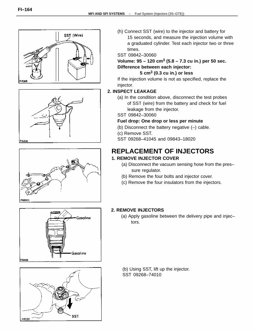
(h) Connect SST (wire) to the injector and battery for15 seconds, and measure the injection volume witha graduated cylinder. Test each injector two or threetimes.
SST 09842–30060Volume: 95 – 120 cm 3 (5.8 – 7.3 cu in.) per 50 sec.Difference between each injector:
5 cm3 (0.3 cu in.) or lessIf the injection volume is not as specified, replace theinjector.
2. INSPECT LEAKAGE(a) In the condition above, disconnect the test probes
of SST (wire) from the battery and check for fuelleakage from the injector.
SST 09842–30060Fuel drop: One drop or less per minute(b) Disconnect the battery negative (–) cable.(c) Remove SST.SST 09268–41045 and 09843–18020
2. REMOVE INJECTORS(a) Apply gasoline between the delivery pipe and injec–
tors.
(b) Using SST, lift up the injector.SST 09268–74010
REPLACEMENT OF INJECTORS1. REMOVE INJECTOR COVER
(a) Disconnect the vacuum sensing hose from the pres–sure regulator.
(b) Remove the four bolts and injector cover.(c) Remove the four insulators from the injectors.
–MFI AND SFI SYSTEMS Fuel System (Injectors (3S–GTE))FI–164
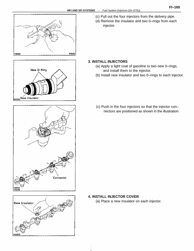
3. INSTALL INJECTORS(a) Apply a light coat of gasoline to two new 0–rings,
and install them to the injector.(b) Install new insulator and two 0–rings to each injector.
(c) Pull out the four injectors from the delivery pipe.(d) Remove the insulator and two 0–rings from each
injector.
(c) Push in the four injectors so that the injector con–nectors are positioned as shown in the illustration.
4. INSTALL INJECTOR COVER(a) Place a new insulator on each injector.
–MFI AND SFI SYSTEMS Fuel System (Injectors (3S–GTE))FI–165
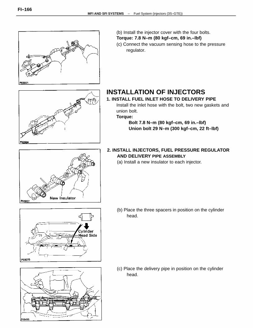
INSTALLATION OF INJECTORS1. INSTALL FUEL INLET HOSE TO DELIVERY PIPE
Install the inlet hose with the bolt, two new gaskets andunion bolt.Torque:
Bolt 7.8 N–m (80 kgf–cm, 69 in.–lbf)Union bolt 29 N–m (300 kgf–cm, 22 ft–lbf)
(b) Install the injector cover with the four bolts.Torque: 7.8 N–m (80 kgf–cm, 69 in.–lbf)(c) Connect the vacuum sensing hose to the pressure
regulator.
2. INSTALL INJECTORS, FUEL PRESSURE REGULATORAND DELIVERY PIPE ASSEMBLY(a) Install a new insulator to each injector.
(b) Place the three spacers in position on the cylinderhead.
(c) Place the delivery pipe in position on the cylinderhead.
–MFI AND SFI SYSTEMS Fuel System (injectors (3S–GTE))FI–166
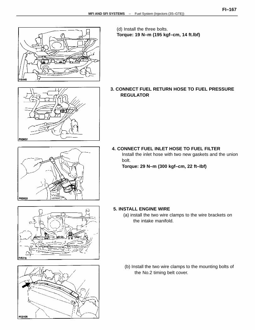
4. CONNECT FUEL INLET HOSE TO FUEL FILTERInstall the inlet hose with two new gaskets and the unionbolt.Torque: 29 N–m (300 kgf–cm, 22 ft–Ibf)
5. INSTALL ENGINE WIRE(a) install the two wire clamps to the wire brackets on
the intake manifold.
3. CONNECT FUEL RETURN HOSE TO FUEL PRESSUREREGULATOR
(b) Install the two wire clamps to the mounting bolts ofthe No.2 timing belt cover.
(d) Install the three bolts.Torque: 19 N–m (195 kgf–cm, 14 ft.lbf)
–MFI AND SFI SYSTEMS Fuel System (Injectors (3S–GTE))FI–167
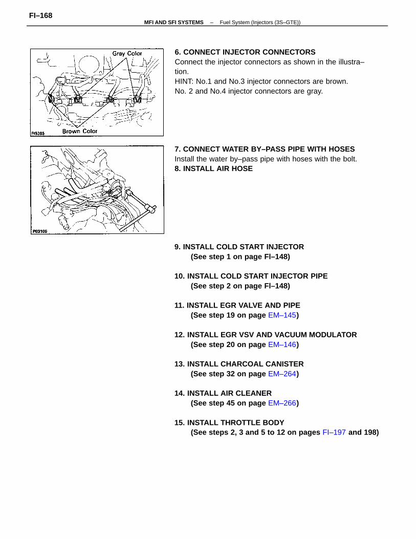
9. INSTALL COLD START INJECTOR(See step 1 on page Fl–148)
10. INSTALL COLD START INJECTOR PIPE(See step 2 on page Fl–148)
11. INSTALL EGR VALVE AND PIPE(See step 19 on page EM–145)
12. INSTALL EGR VSV AND VACUUM MODULATOR(See step 20 on page EM–146)
13. INSTALL CHARCOAL CANISTER(See step 32 on page EM–264)
14. INSTALL AIR CLEANER(See step 45 on page EM–266)
15. INSTALL THROTTLE BODY(See steps 2, 3 and 5 to 12 on pages FI–197 and 198)
6. CONNECT INJECTOR CONNECTORSConnect the injector connectors as shown in the illustra–tion.HINT: No.1 and No.3 injector connectors are brown.No. 2 and No.4 injector connectors are gray.
7. CONNECT WATER BY–PASS PIPE WITH HOSESInstall the water by–pass pipe with hoses with the bolt.8. INSTALL AIR HOSE
–MFI AND SFI SYSTEMS Fuel System (Injectors (3S–GTE))FI–168
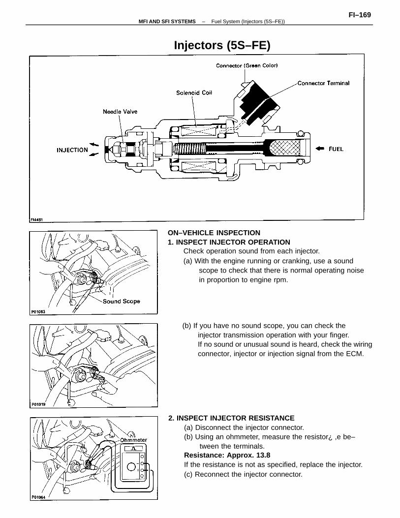
2. INSPECT INJECTOR RESISTANCE(a) Disconnect the injector connector.(b) Using an ohmmeter, measure the resistor¿ ,e be–
tween the terminals.Resistance: Approx. 13.8
If the resistance is not as specified, replace the injector.(c) Reconnect the injector connector.
ON–VEHICLE INSPECTION1. INSPECT INJECTOR OPERATION
Check operation sound from each injector.(a) With the engine running or cranking, use a sound
scope to check that there is normal operating noisein proportion to engine rpm.
(b) If you have no sound scope, you can check theinjector transmission operation with your finger.If no sound or unusual sound is heard, check the wiringconnector, injector or injection signal from the ECM.
Injectors (5S–FE)
–MFI AND SFI SYSTEMS Fuel System (Injectors (5S–FE))FI–169
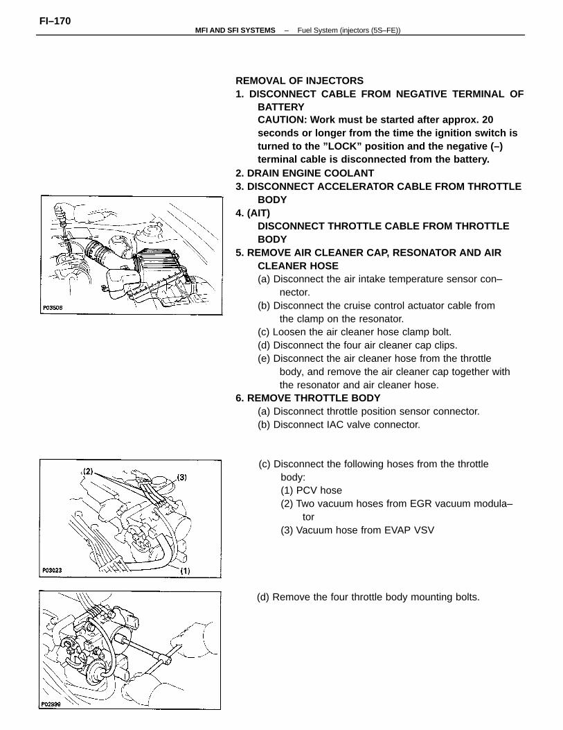
REMOVAL OF INJECTORS1. DISCONNECT CABLE FROM NEGATIVE TERMINAL OF
BATTERYCAUTION: Work must be started after approx. 20seconds or longer from the time the ignition switch isturned to the ”LOCK” position and the negative (–)terminal cable is disconnected from the battery.
2. DRAIN ENGINE COOLANT3. DISCONNECT ACCELERATOR CABLE FROM THROTTLE
BODY4. (AIT)
DISCONNECT THROTTLE CABLE FROM THROTTLEBODY
5. REMOVE AIR CLEANER CAP, RESONATOR AND AIRCLEANER HOSE(a) Disconnect the air intake temperature sensor con–
nector.(b) Disconnect the cruise control actuator cable from
the clamp on the resonator.(c) Loosen the air cleaner hose clamp bolt.(d) Disconnect the four air cleaner cap clips.(e) Disconnect the air cleaner hose from the throttle
body, and remove the air cleaner cap together withthe resonator and air cleaner hose.
6. REMOVE THROTTLE BODY(a) Disconnect throttle position sensor connector.(b) Disconnect IAC valve connector.
(c) Disconnect the following hoses from the throttlebody:(1) PCV hose(2) Two vacuum hoses from EGR vacuum modula–
tor(3) Vacuum hose from EVAP VSV
(d) Remove the four throttle body mounting bolts.
–MFI AND SFI SYSTEMS Fuel System (injectors (5S–FE))FI–170
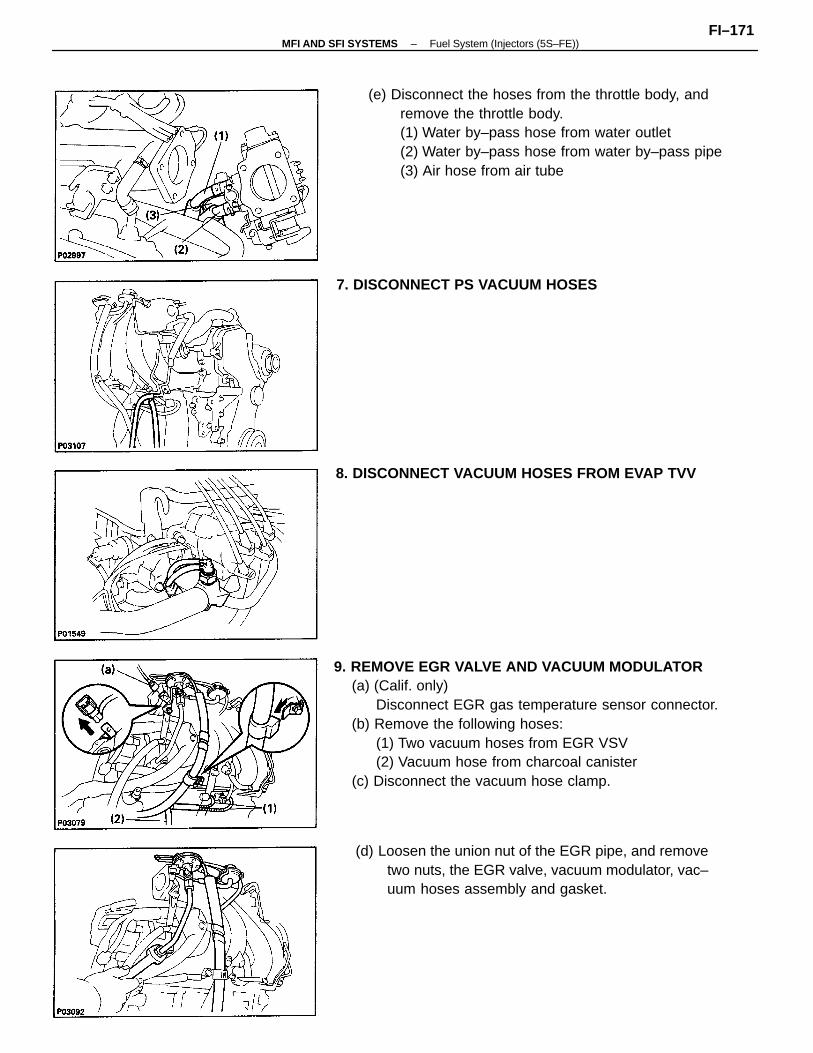
9. REMOVE EGR VALVE AND VACUUM MODULATOR(a) (Calif. only)
Disconnect EGR gas temperature sensor connector.(b) Remove the following hoses:
(1) Two vacuum hoses from EGR VSV(2) Vacuum hose from charcoal canister
(c) Disconnect the vacuum hose clamp.
(e) Disconnect the hoses from the throttle body, andremove the throttle body.(1) Water by–pass hose from water outlet(2) Water by–pass hose from water by–pass pipe(3) Air hose from air tube
(d) Loosen the union nut of the EGR pipe, and removetwo nuts, the EGR valve, vacuum modulator, vac–uum hoses assembly and gasket.
8. DISCONNECT VACUUM HOSES FROM EVAP TVV
7. DISCONNECT PS VACUUM HOSES
–MFI AND SFI SYSTEMS Fuel System (Injectors (5S–FE))FI–171
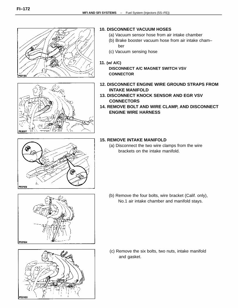
10. DISCONNECT VACUUM HOSES(a) Vacuum sensor hose from air intake chamber(b) Brake booster vacuum hose from air intake cham–
ber(c) Vacuum sensing hose
11. (w/ A/C)DISCONNECT A/C MAGNET SWITCH VSVCONNECTOR
12. DISCONNECT ENGINE WIRE GROUND STRAPS FROMINTAKE MANIFOLD
13. DISCONNECT KNOCK SENSOR AND EGR VSVCONNECTORS
14. REMOVE BOLT AND WIRE CLAMP, AND DISCONNECTENGINE WIRE HARNESS
15. REMOVE INTAKE MANIFOLD(a) Disconnect the two wire clamps from the wire
brackets on the intake manifold.
(c) Remove the six bolts, two nuts, intake manifoldand gasket.
(b) Remove the four bolts, wire bracket (Calif. only),No.1 air intake chamber and manifold stays.
–MFI AND SFI SYSTEMS Fuel System (Injectors (5S–FE))FI–172
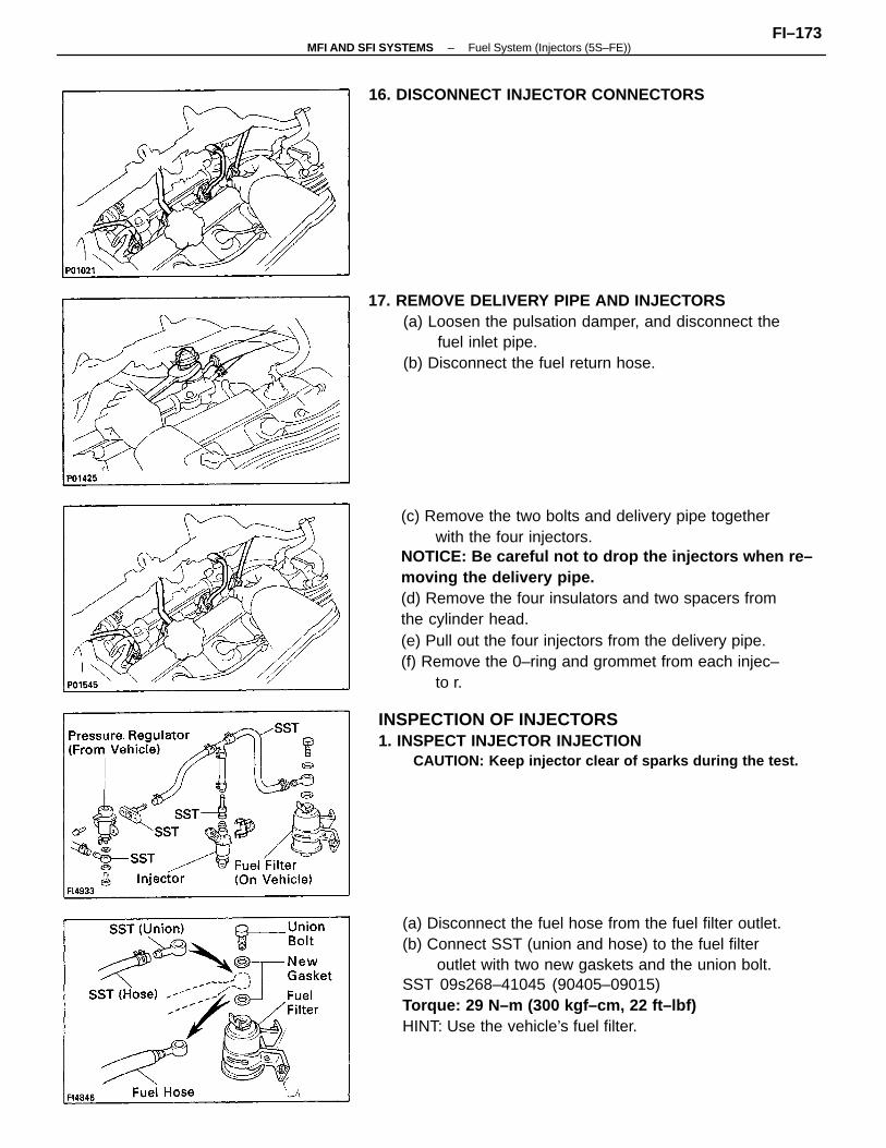
(c) Remove the two bolts and delivery pipe togetherwith the four injectors.
NOTICE: Be careful not to drop the injectors when re–moving the delivery pipe.(d) Remove the four insulators and two spacers fromthe cylinder head.(e) Pull out the four injectors from the delivery pipe.(f) Remove the 0–ring and grommet from each injec–
to r.
(a) Disconnect the fuel hose from the fuel filter outlet.(b) Connect SST (union and hose) to the fuel filter
outlet with two new gaskets and the union bolt.SST 09s268–41045 (90405–09015)Torque: 29 N–m (300 kgf–cm, 22 ft–lbf)HINT: Use the vehicle’s fuel filter.
INSPECTION OF INJECTORS1. INSPECT INJECTOR INJECTION
CAUTION: Keep injector clear of sparks during the test.
17. REMOVE DELIVERY PIPE AND INJECTORS(a) Loosen the pulsation damper, and disconnect the
fuel inlet pipe.(b) Disconnect the fuel return hose.
16. DISCONNECT INJECTOR CONNECTORS
–MFI AND SFI SYSTEMS Fuel System (Injectors (5S–FE))FI–173
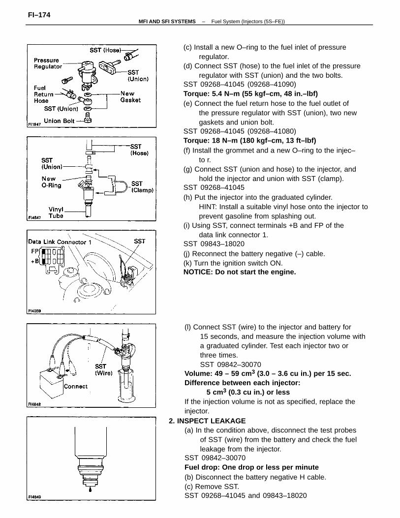
(c) Install a new O–ring to the fuel inlet of pressureregulator.
(d) Connect SST (hose) to the fuel inlet of the pressureregulator with SST (union) and the two bolts.
SST 09268–41045 (09268–41090)Torque: 5.4 N–m (55 kgf–cm, 48 in.–lbf)(e) Connect the fuel return hose to the fuel outlet of
the pressure regulator with SST (union), two newgaskets and union bolt.
SST 09268–41045 (09268–41080)Torque: 18 N–m (180 kgf–cm, 13 ft–lbf)(f) Install the grommet and a new O–ring to the injec–
to r.(g) Connect SST (union and hose) to the injector, and
hold the injector and union with SST (clamp).SST 09268–41045(h) Put the injector into the graduated cylinder.
HINT: Install a suitable vinyl hose onto the injector toprevent gasoline from splashing out.
(i) Using SST, connect terminals +B and FP of thedata link connector 1.
SST 09843–18020(j) Reconnect the battery negative (–) cable.(k) Turn the ignition switch ON.NOTICE: Do not start the engine.
(l) Connect SST (wire) to the injector and battery for15 seconds, and measure the injection volume witha graduated cylinder. Test each injector two orthree times.SST 09842–30070
Volume: 49 – 59 cm 3 (3.0 – 3.6 cu in.) per 15 sec.Difference between each injector:
5 cm3 (0.3 cu in.) or lessIf the injection volume is not as specified, replace theinjector.
2. INSPECT LEAKAGE(a) In the condition above, disconnect the test probes
of SST (wire) from the battery and check the fuelleakage from the injector.
SST 09842–30070Fuel drop: One drop or less per minute(b) Disconnect the battery negative H cable.(c) Remove SST.SST 09268–41045 and 09843–18020
–MFI AND SFI SYSTEMS Fuel System (Injectors (5S–FE))FI–174
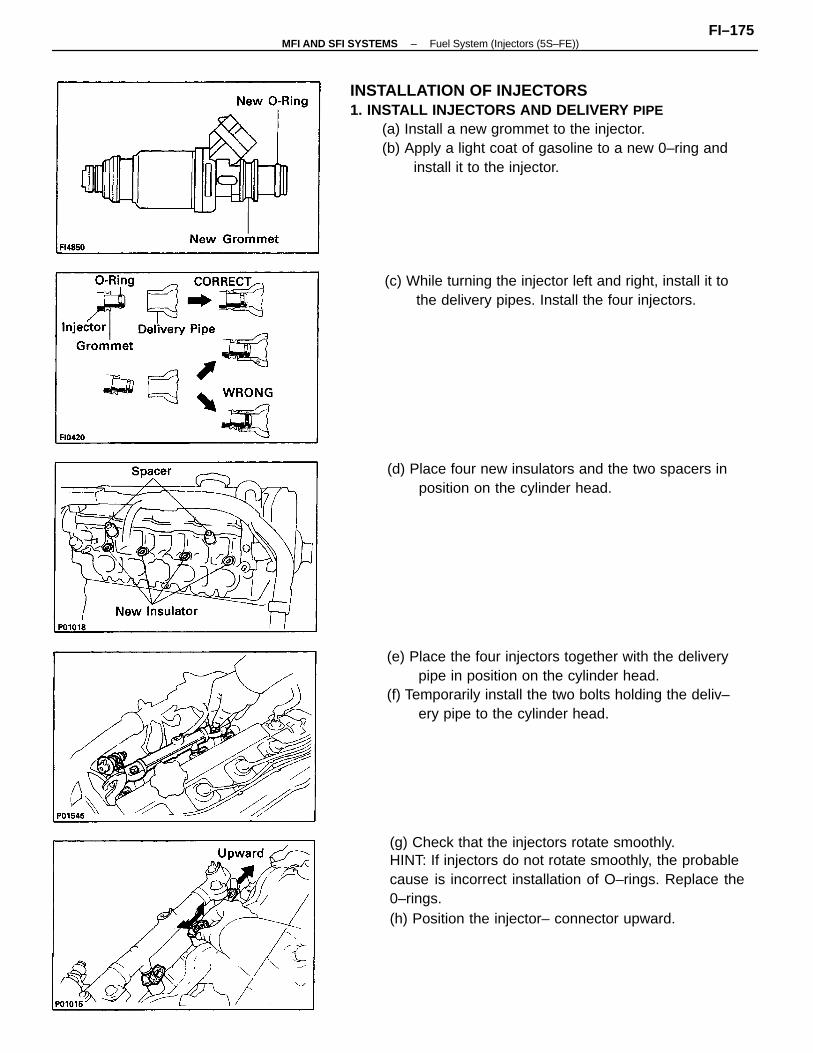
INSTALLATION OF INJECTORS1. INSTALL INJECTORS AND DELIVERY PIPE
(a) Install a new grommet to the injector.(b) Apply a light coat of gasoline to a new 0–ring and
install it to the injector.
(g) Check that the injectors rotate smoothly.HINT: If injectors do not rotate smoothly, the probablecause is incorrect installation of O–rings. Replace the0–rings.(h) Position the injector– connector upward.
(e) Place the four injectors together with the deliverypipe in position on the cylinder head.
(f) Temporarily install the two bolts holding the deliv–ery pipe to the cylinder head.
(c) While turning the injector left and right, install it tothe delivery pipes. Install the four injectors.
(d) Place four new insulators and the two spacers inposition on the cylinder head.
–MFI AND SFI SYSTEMS Fuel System (Injectors (5S–FE))FI–175
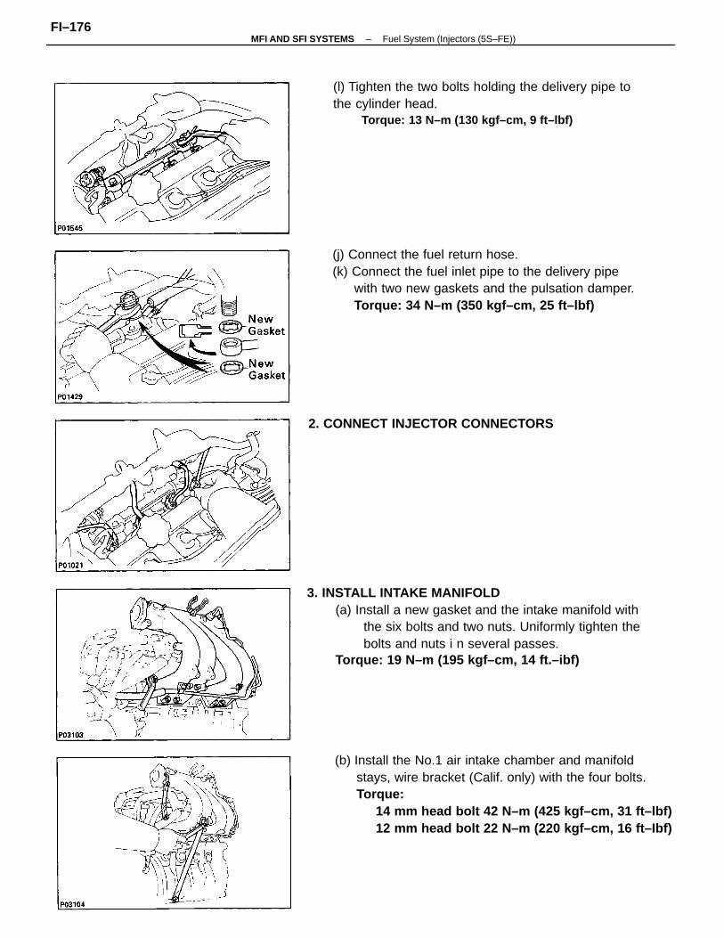
3. INSTALL INTAKE MANIFOLD(a) Install a new gasket and the intake manifold with
the six bolts and two nuts. Uniformly tighten thebolts and nuts i n several passes.
Torque: 19 N–m (195 kgf–cm, 14 ft.–ibf)
(b) Install the No.1 air intake chamber and manifoldstays, wire bracket (Calif. only) with the four bolts.Torque:
14 mm head bolt 42 N–m (425 kgf–cm, 31 ft–lbf)12 mm head bolt 22 N–m (220 kgf–cm, 16 ft–Ibf)
(j) Connect the fuel return hose.(k) Connect the fuel inlet pipe to the delivery pipe
with two new gaskets and the pulsation damper.Torque: 34 N–m (350 kgf–cm, 25 ft–lbf)
(l) Tighten the two bolts holding the delivery pipe tothe cylinder head.
Torque: 13 N–m (130 kgf–cm, 9 ft–lbf)
2. CONNECT INJECTOR CONNECTORS
–MFI AND SFI SYSTEMS Fuel System (Injectors (5S–FE))FI–176
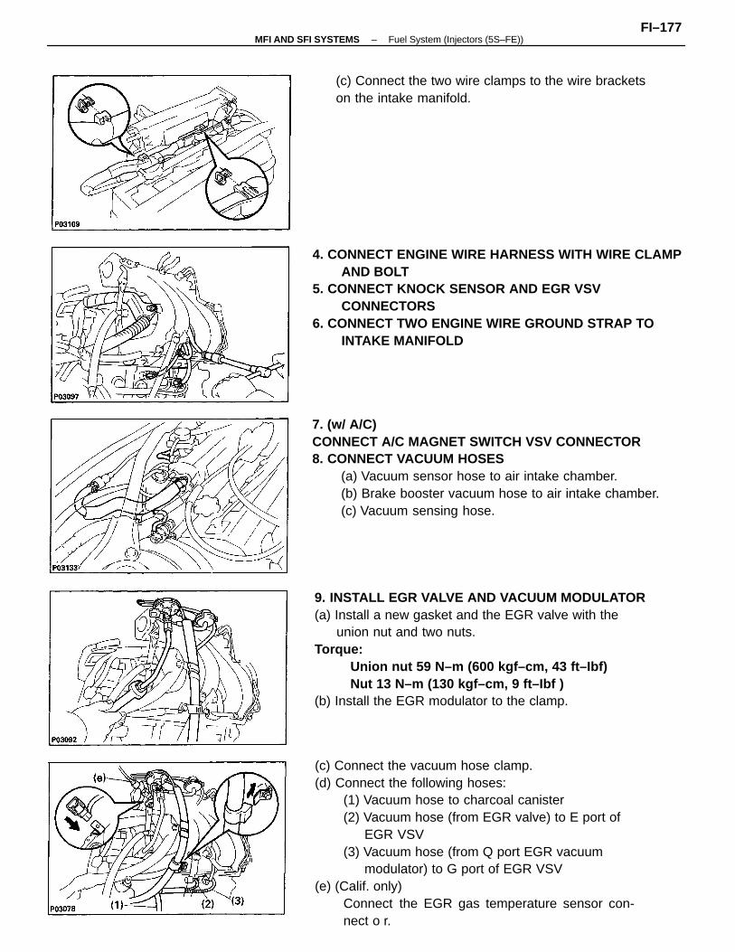
(c) Connect the vacuum hose clamp.(d) Connect the following hoses:
(1) Vacuum hose to charcoal canister(2) Vacuum hose (from EGR valve) to E port of
EGR VSV(3) Vacuum hose (from Q port EGR vacuum
modulator) to G port of EGR VSV(e) (Calif. only)
Connect the EGR gas temperature sensor con-nect o r.
9. INSTALL EGR VALVE AND VACUUM MODULATOR(a) Install a new gasket and the EGR valve with the
union nut and two nuts.Torque:
Union nut 59 N–m (600 kgf–cm, 43 ft–Ibf)Nut 13 N–m (130 kgf–cm, 9 ft–Ibf )
(b) Install the EGR modulator to the clamp.
7. (w/ A/C)CONNECT A/C MAGNET SWITCH VSV CONNECTOR8. CONNECT VACUUM HOSES
(a) Vacuum sensor hose to air intake chamber.(b) Brake booster vacuum hose to air intake chamber.(c) Vacuum sensing hose.
4. CONNECT ENGINE WIRE HARNESS WITH WIRE CLAMPAND BOLT
5. CONNECT KNOCK SENSOR AND EGR VSVCONNECTORS
6. CONNECT TWO ENGINE WIRE GROUND STRAP TOINTAKE MANIFOLD
(c) Connect the two wire clamps to the wire bracketson the intake manifold.
–MFI AND SFI SYSTEMS Fuel System (Injectors (5S–FE))FI–177
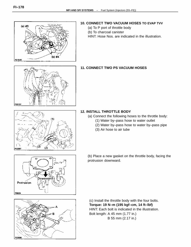
12. INSTALL THROTTLE BODY(a) Connect the following hoses to the throttle body:
(1) Water by–pass hose to water outlet(2) Water by–pass hose to water by–pass pipe(3) Air hose to air tube
(c) Install the throttle body with the four bolts.Torque: 19 N–m (195 kgf–cm, 14 ft–lbf)HINT: Each bolt is indicated in the illustration.Bolt length: A 45 mm (1.77 in.)
B 55 mm (2.17 in.)
10. CONNECT TWO VACUUM HOSES TO EVAP TVV(a) To P port of throttle body(b) To charcoal canisterHINT: Hose Nos. are indicated in the illustration.
(b) Place a new gasket on the throttle body, facing theprotrusion downward.
11. CONNECT TWO PS VACUUM HOSES
–MFI AND SFI SYSTEMS Fuel System (Injectors (5S–FE))FI–178
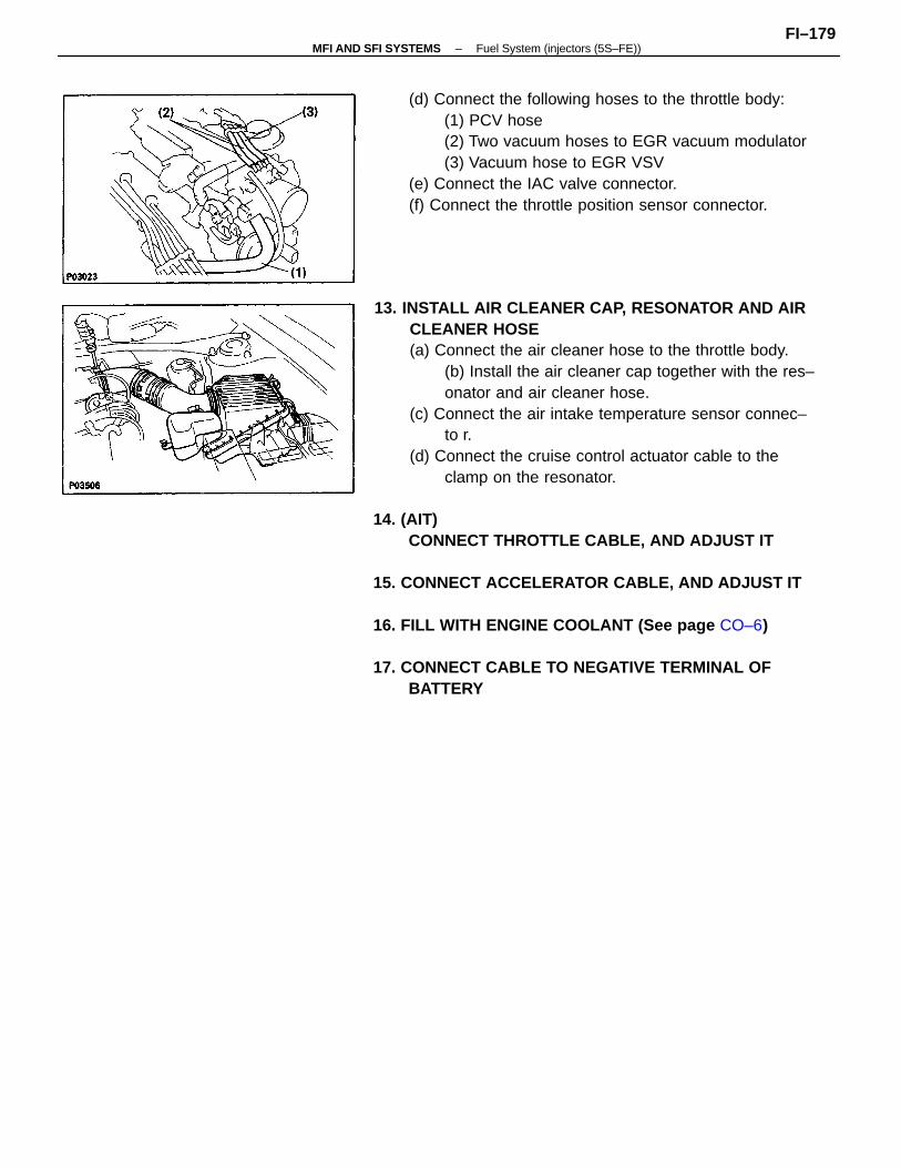
13. INSTALL AIR CLEANER CAP, RESONATOR AND AIRCLEANER HOSE(a) Connect the air cleaner hose to the throttle body.
(b) Install the air cleaner cap together with the res–onator and air cleaner hose.
(c) Connect the air intake temperature sensor connec–to r.
(d) Connect the cruise control actuator cable to theclamp on the resonator.
14. (AIT)CONNECT THROTTLE CABLE, AND ADJUST IT
15. CONNECT ACCELERATOR CABLE, AND ADJUST IT
16. FILL WITH ENGINE COOLANT (See page CO–6)
17. CONNECT CABLE TO NEGATIVE TERMINAL OFBATTERY
(d) Connect the following hoses to the throttle body:(1) PCV hose(2) Two vacuum hoses to EGR vacuum modulator(3) Vacuum hose to EGR VSV
(e) Connect the IAC valve connector.(f) Connect the throttle position sensor connector.
–MFI AND SFI SYSTEMS Fuel System (injectors (5S–FE))FI–179
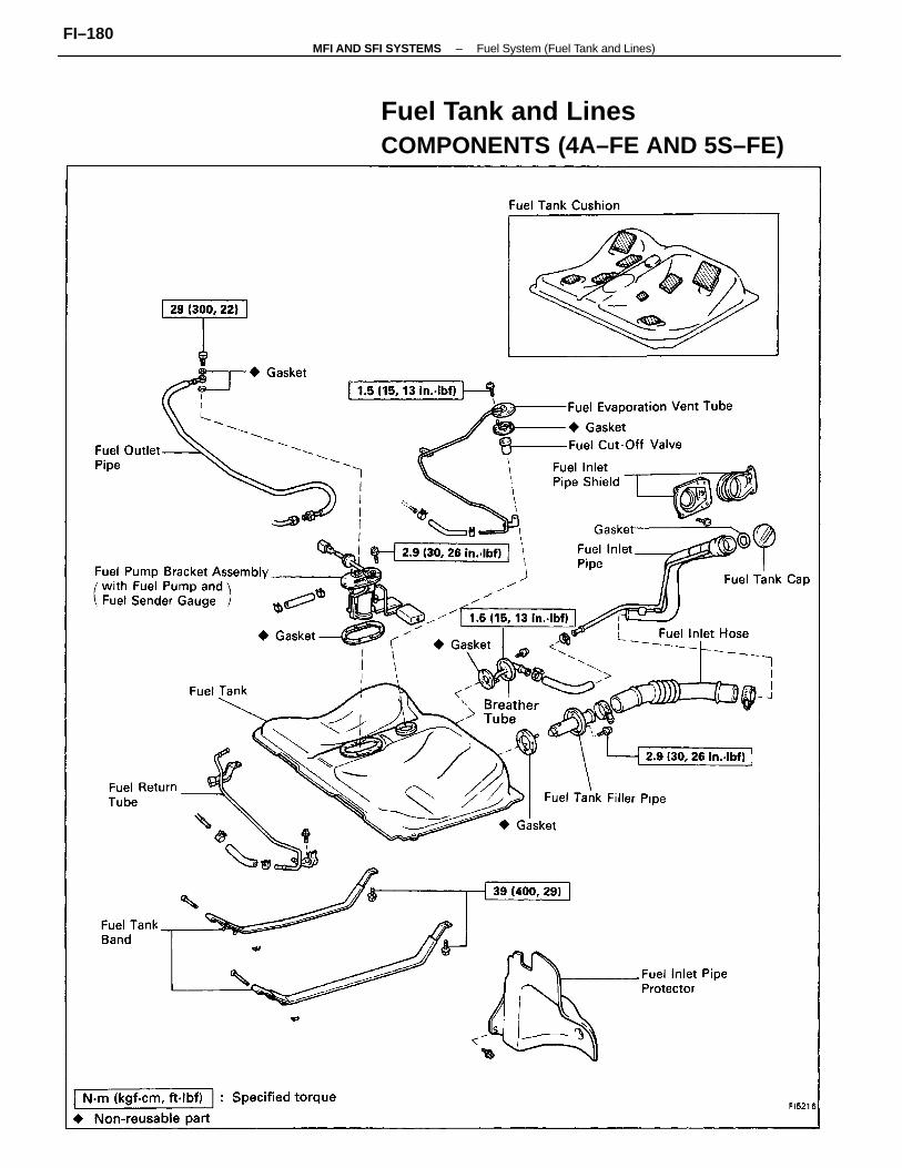
Fuel Tank and LinesCOMPONENTS (4A–FE AND 5S–FE)
–MFI AND SFI SYSTEMS Fuel System (Fuel Tank and Lines)FI–180
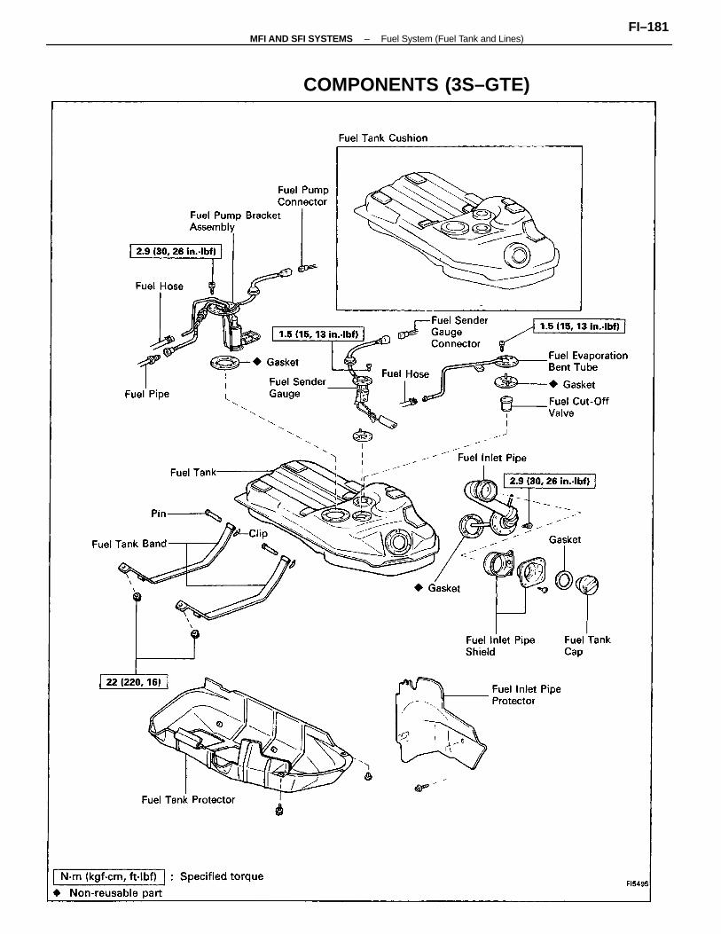
COMPONENTS (3S–GTE)
–MFI AND SFI SYSTEMS Fuel System (Fuel Tank and Lines)FI–181
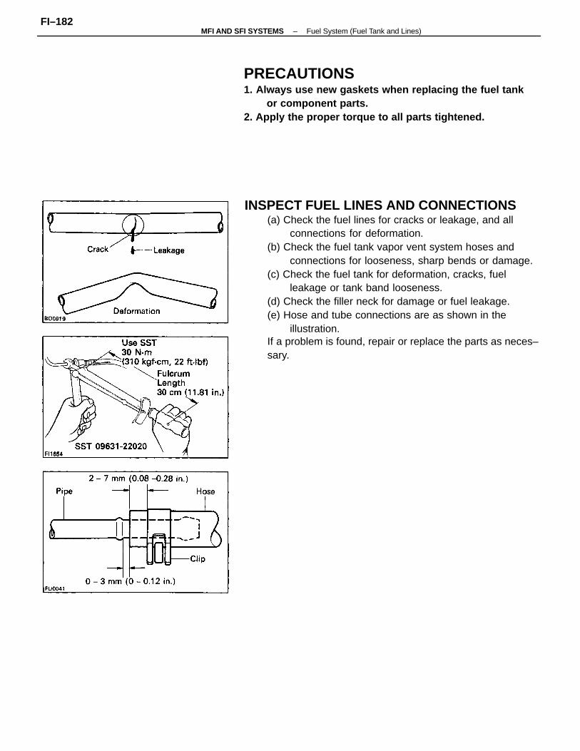
INSPECT FUEL LINES AND CONNECTIONS(a) Check the fuel lines for cracks or leakage, and all
connections for deformation.(b) Check the fuel tank vapor vent system hoses and
connections for looseness, sharp bends or damage.(c) Check the fuel tank for deformation, cracks, fuel
leakage or tank band looseness.(d) Check the filler neck for damage or fuel leakage.(e) Hose and tube connections are as shown in the
illustration.If a problem is found, repair or replace the parts as neces–sary.
PRECAUTIONS1. Always use new gaskets when replacing the fuel tank
or component parts.2. Apply the proper torque to all parts tightened.
–MFI AND SFI SYSTEMS Fuel System (Fuel Tank and Lines)FI–182
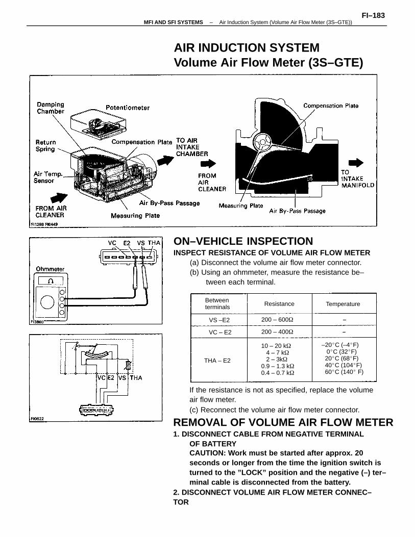
If the resistance is not as specified, replace the volumeair flow meter.(c) Reconnect the volume air flow meter connector.
REMOVAL OF VOLUME AIR FLOW METER1. DISCONNECT CABLE FROM NEGATIVE TERMINAL
OF BATTERYCAUTION: Work must be started after approx. 20seconds or longer from the time the ignition switch isturned to the ”LOCK” position and the negative (–) ter–minal cable is disconnected from the battery.
2. DISCONNECT VOLUME AIR FLOW METER CONNEC–TOR
ON–VEHICLE INSPECTIONINSPECT RESISTANCE OF VOLUME AIR FLOW METER
(a) Disconnect the volume air flow meter connector.(b) Using an ohmmeter, measure the resistance be–
tween each terminal.
AIR INDUCTION SYSTEMVolume Air Flow Meter (3S–GTE)
–20C (–4F) 0C (32F) 20C (68F) 40C (104F) 60C (140 F)
10 – 20 k 4 – 7 k 2 – 3k0.9 – 1.3 k0.4 – 0.7 k
Betweenterminals Temperature
200 – 600
200 – 400
Resistance
THA – E2
VS –E2
VC – E2
–MFI AND SFI SYSTEMS Air Induction System (Volume Air Flow Meter (3S–GTE))FI–183
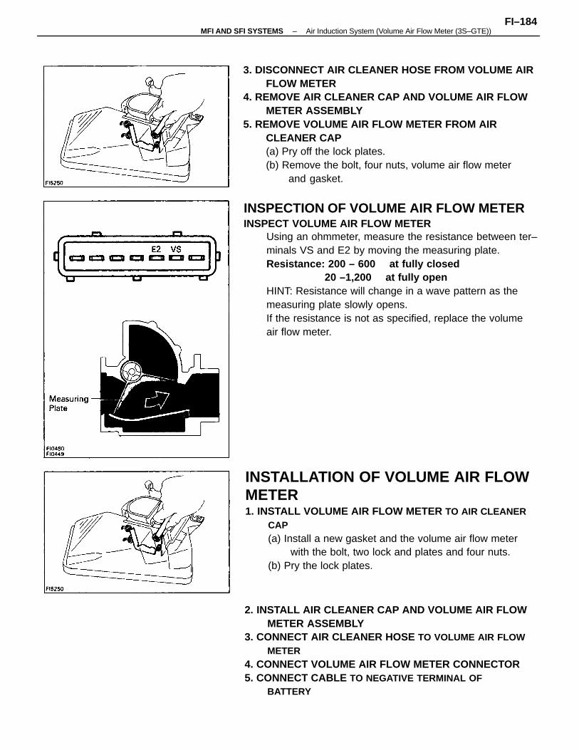
INSPECTION OF VOLUME AIR FLOW METERINSPECT VOLUME AIR FLOW METER
Using an ohmmeter, measure the resistance between ter–minals VS and E2 by moving the measuring plate.Resistance: 200 – 600 at fully closed
20 –1,200 at fully openHINT: Resistance will change in a wave pattern as themeasuring plate slowly opens.If the resistance is not as specified, replace the volumeair flow meter.
3. DISCONNECT AIR CLEANER HOSE FROM VOLUME AIRFLOW METER
4. REMOVE AIR CLEANER CAP AND VOLUME AIR FLOWMETER ASSEMBLY
5. REMOVE VOLUME AIR FLOW METER FROM AIRCLEANER CAP(a) Pry off the lock plates.(b) Remove the bolt, four nuts, volume air flow meter
and gasket.
2. INSTALL AIR CLEANER CAP AND VOLUME AIR FLOWMETER ASSEMBLY
3. CONNECT AIR CLEANER HOSE TO VOLUME AIR FLOWMETER
4. CONNECT VOLUME AIR FLOW METER CONNECTOR5. CONNECT CABLE TO NEGATIVE TERMINAL OF
BATTERY
INSTALLATION OF VOLUME AIR FLOWMETER1. INSTALL VOLUME AIR FLOW METER TO AIR CLEANER
CAP(a) Install a new gasket and the volume air flow meter
with the bolt, two lock and plates and four nuts.(b) Pry the lock plates.
–MFI AND SFI SYSTEMS Air Induction System (Volume Air Flow Meter (3S–GTE))FI–184
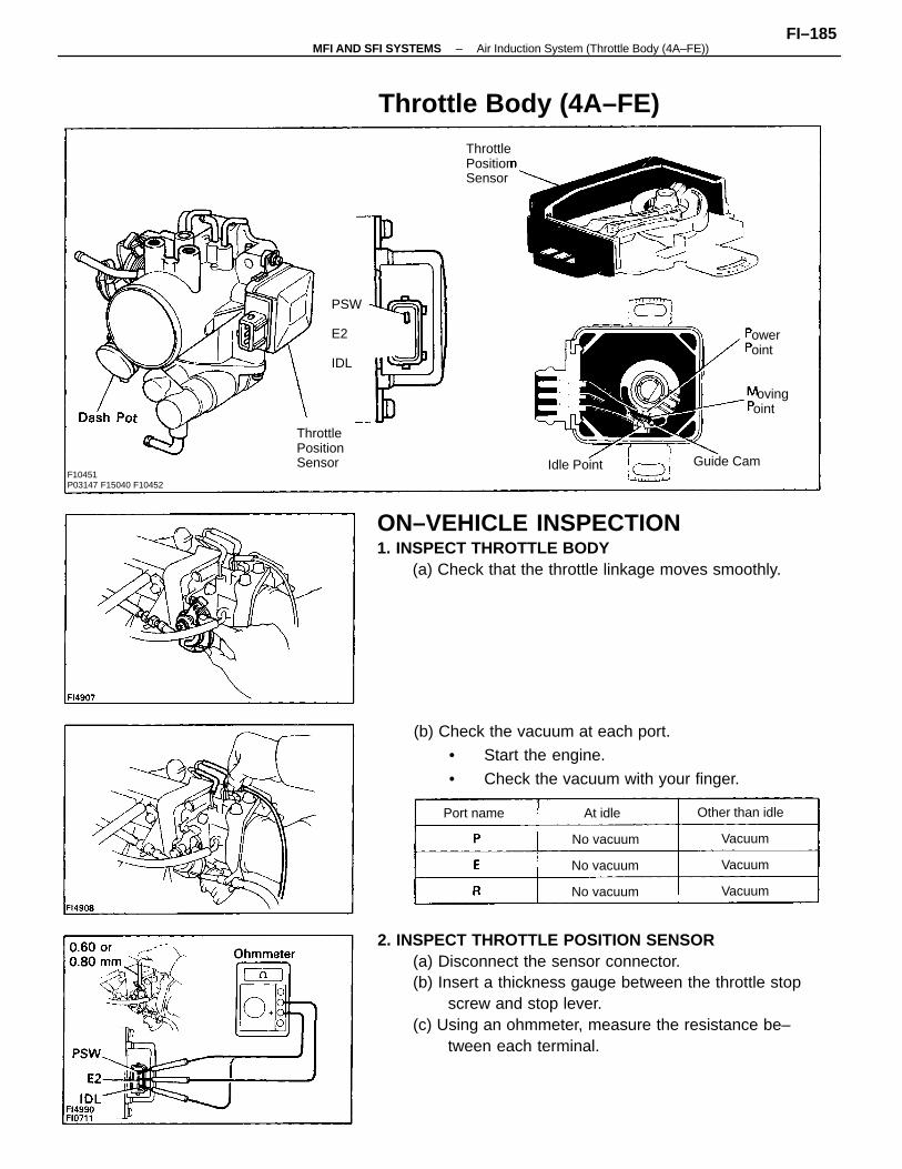
2. INSPECT THROTTLE POSITION SENSOR(a) Disconnect the sensor connector.(b) Insert a thickness gauge between the throttle stop
screw and stop lever.(c) Using an ohmmeter, measure the resistance be–
tween each terminal.
ON–VEHICLE INSPECTION1. INSPECT THROTTLE BODY
(a) Check that the throttle linkage moves smoothly.
(b) Check the vacuum at each port.
• Start the engine.
• Check the vacuum with your finger.
Throttle Body (4A–FE)
F10451P03147 F15040 F10452
ThrottlePositionSensor
Other than idle
Guide Cam
ovingoint
No vacuum
No vacuum
No vacuum
Idle Point
Port name
ower oint
Vacuum
Vacuum
Vacuum
At idle
PSW
E2
IDL
ThrottlePositionSensor
–MFI AND SFI SYSTEMS Air Induction System (Throttle Body (4A–FE))FI–185
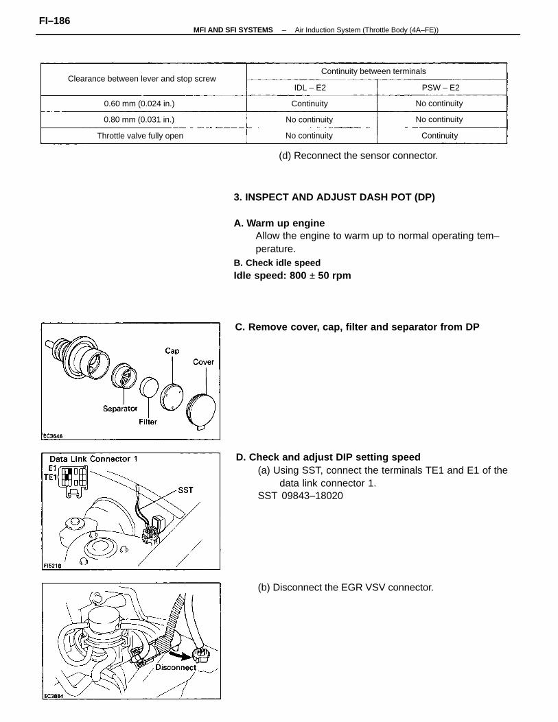
3. INSPECT AND ADJUST DASH POT (DP)
A. Warm up engineAllow the engine to warm up to normal operating tem–perature.
B. Check idle speedIdle speed: 800 ± 50 rpm
D. Check and adjust DIP setting speed(a) Using SST, connect the terminals TE1 and E1 of the
data link connector 1.SST 09843–18020
C. Remove cover, cap, filter and separator from DP
(b) Disconnect the EGR VSV connector.
(d) Reconnect the sensor connector.
Clearance between lever and stop screwContinuity between terminals
Throttle valve fully open
0.80 mm (0.031 in.)
0.60 mm (0.024 in.)
No continuity
No continuity
No continuity
No continuity
Continuity
Continuity
PSW – E2IDL – E2
–MFI AND SFI SYSTEMS Air Induction System (Throttle Body (4A–FE))FI–186
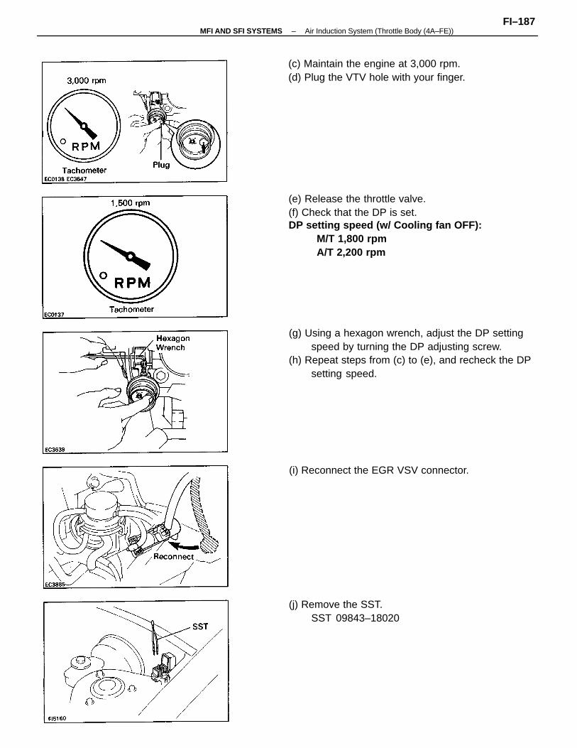
(g) Using a hexagon wrench, adjust the DP settingspeed by turning the DP adjusting screw.
(h) Repeat steps from (c) to (e), and recheck the DPsetting speed.
(e) Release the throttle valve.(f) Check that the DP is set.DP setting speed (w/ Cooling fan OFF):
M/T 1,800 rpmA/T 2,200 rpm
(c) Maintain the engine at 3,000 rpm.(d) Plug the VTV hole with your finger.
(i) Reconnect the EGR VSV connector.
(j) Remove the SST.SST 09843–18020
–MFI AND SFI SYSTEMS Air Induction System (Throttle Body (4A–FE))FI–187
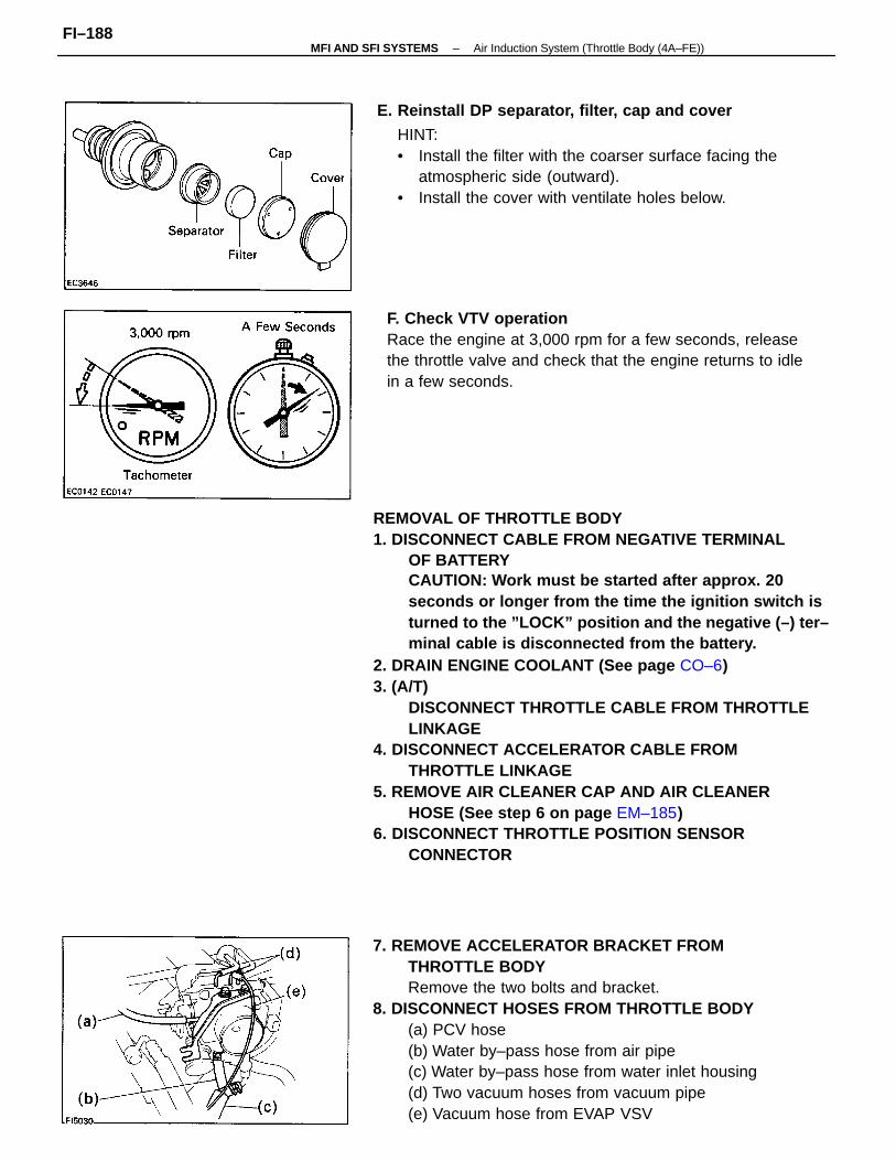
REMOVAL OF THROTTLE BODY1. DISCONNECT CABLE FROM NEGATIVE TERMINAL
OF BATTERYCAUTION: Work must be started after approx. 20seconds or longer from the time the ignition switch isturned to the ”LOCK” position and the negative (–) ter–minal cable is disconnected from the battery.
2. DRAIN ENGINE COOLANT (See page CO–6)3. (A/T)
DISCONNECT THROTTLE CABLE FROM THROTTLELINKAGE
4. DISCONNECT ACCELERATOR CABLE FROMTHROTTLE LINKAGE
5. REMOVE AIR CLEANER CAP AND AIR CLEANERHOSE (See step 6 on page EM–185)
6. DISCONNECT THROTTLE POSITION SENSORCONNECTOR
7. REMOVE ACCELERATOR BRACKET FROMTHROTTLE BODYRemove the two bolts and bracket.
8. DISCONNECT HOSES FROM THROTTLE BODY(a) PCV hose(b) Water by–pass hose from air pipe(c) Water by–pass hose from water inlet housing(d) Two vacuum hoses from vacuum pipe(e) Vacuum hose from EVAP VSV
E. Reinstall DP separator, filter, cap and cover
F. Check VTV operationRace the engine at 3,000 rpm for a few seconds, releasethe throttle valve and check that the engine returns to idlein a few seconds.
HINT:• Install the filter with the coarser surface facing the
atmospheric side (outward).• Install the cover with ventilate holes below.
–MFI AND SFI SYSTEMS Air Induction System (Throttle Body (4A–FE))FI–188
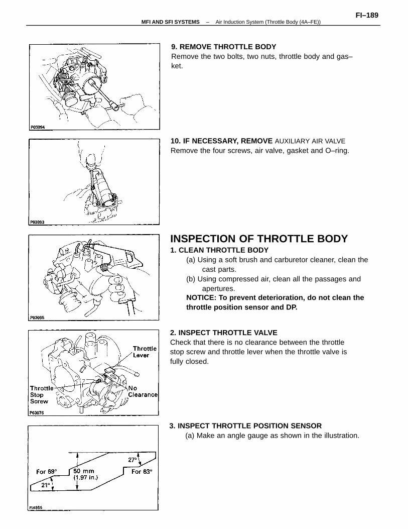
INSPECTION OF THROTTLE BODY1. CLEAN THROTTLE BODY
(a) Using a soft brush and carburetor cleaner, clean thecast parts.
(b) Using compressed air, clean all the passages andapertures.
NOTICE: To prevent deterioration, do not clean thethrottle position sensor and DP.
2. INSPECT THROTTLE VALVECheck that there is no clearance between the throttlestop screw and throttle lever when the throttle valve isfully closed.
3. INSPECT THROTTLE POSITION SENSOR(a) Make an angle gauge as shown in the illustration.
9. REMOVE THROTTLE BODYRemove the two bolts, two nuts, throttle body and gas–ket.
10. IF NECESSARY, REMOVE AUXILIARY AIR VALVERemove the four screws, air valve, gasket and O–ring.
–MFI AND SFI SYSTEMS Air Induction System (Throttle Body (4A–FE))FI–189
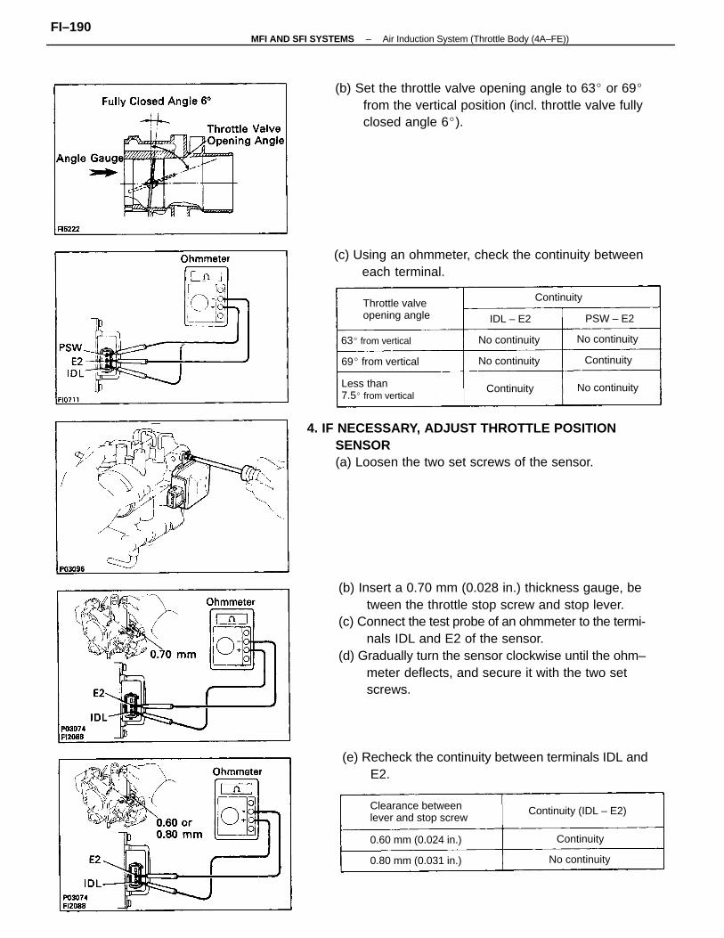
(b) Insert a 0.70 mm (0.028 in.) thickness gauge, between the throttle stop screw and stop lever.
(c) Connect the test probe of an ohmmeter to the termi-nals IDL and E2 of the sensor.
(d) Gradually turn the sensor clockwise until the ohm–meter deflects, and secure it with the two setscrews.
4. IF NECESSARY, ADJUST THROTTLE POSITIONSENSOR(a) Loosen the two set screws of the sensor.
(b) Set the throttle valve opening angle to 63 or 69from the vertical position (incl. throttle valve fullyclosed angle 6).
(e) Recheck the continuity between terminals IDL andE2.
(c) Using an ohmmeter, check the continuity betweeneach terminal.
Clearance betweenlever and stop screw
Less than7.5 from vertical
Throttle valveopening angle
Continuity (IDL – E2)
0.80 mm (0.031 in.)
0.60 mm (0.024 in.)
69 from vertical
63 from vertical
No continuity
No continuity
No continuity No continuity
No continuity
Continuity
Continuity
Continuity
Continuity
PSW – E2IDL – E2
–MFI AND SFI SYSTEMS Air Induction System (Throttle Body (4A–FE))FI–190
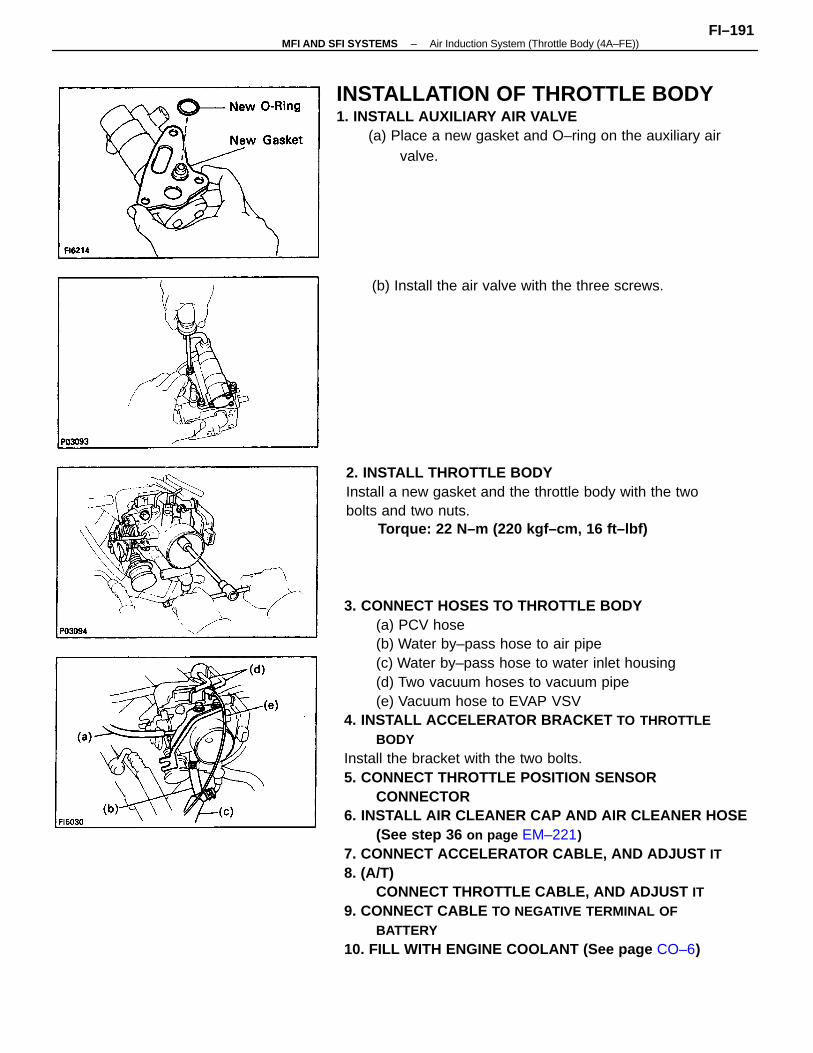
3. CONNECT HOSES TO THROTTLE BODY(a) PCV hose(b) Water by–pass hose to air pipe(c) Water by–pass hose to water inlet housing(d) Two vacuum hoses to vacuum pipe(e) Vacuum hose to EVAP VSV
4. INSTALL ACCELERATOR BRACKET TO THROTTLEBODY
Install the bracket with the two bolts.5. CONNECT THROTTLE POSITION SENSOR
CONNECTOR6. INSTALL AIR CLEANER CAP AND AIR CLEANER HOSE
(See step 36 on page EM–221)7. CONNECT ACCELERATOR CABLE, AND ADJUST IT8. (A/T)
CONNECT THROTTLE CABLE, AND ADJUST IT9. CONNECT CABLE TO NEGATIVE TERMINAL OF
BATTERY10. FILL WITH ENGINE COOLANT (See page CO–6)
INSTALLATION OF THROTTLE BODY1. INSTALL AUXILIARY AIR VALVE
(a) Place a new gasket and O–ring on the auxiliary airvalve.
2. INSTALL THROTTLE BODYInstall a new gasket and the throttle body with the twobolts and two nuts.
Torque: 22 N–m (220 kgf–cm, 16 ft–lbf)
(b) Install the air valve with the three screws.
–MFI AND SFI SYSTEMS Air Induction System (Throttle Body (4A–FE))FI–191
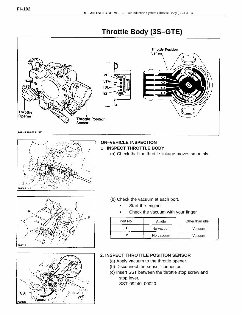
2. INSPECT THROTTLE POSITION SENSOR(a) Apply vacuum to the throttle opener.(b) Disconnect the sensor connector.(c) Insert SST between the throttle stop screw and
stop lever.SST 09240–00020
ON–VEHICLE INSPECTION1 . INSPECT THROTTLE BODY
(a) Check that the throttle linkage moves smoothly.
(b) Check the vacuum at each port.
• Start the engine.
• Check the vacuum with your finger.
Throttle Body (3S–GTE)
Other than idle
No vacuum
No vacuum
Port No.
Vacuum
Vacuum
At idle
–MFI AND SFI SYSTEMS Air Induction System (Throttle Body (3S–GTE))FI–192
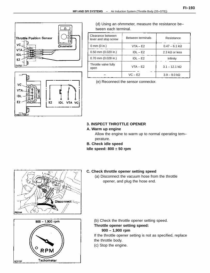
3. INSPECT THROTTLE OPENERA. Warm up engine
Allow the engine to warm up to normal operating tem–perature.
B. Check idle speedIdle speed: 800 ± 50 rpm
(b) Check the throttle opener setting speed.Throttle opener setting speed:
900 – 1,900 rpmIf the throttle opener setting is not as specified, replacethe throttle body.(c) Stop the engine.
C. Check throttle opener setting speed(a) Disconnect the vacuum hose from the throttle
opener, and plug the hose end.
(d) Using an ohmmeter, measure the resistance be–tween each terminal.
(e) Reconnect the sensor connector.
Clearance betweenlever and stop screw
Throttle valve fullyopen
0.50 mm (0.020 in.)
0.70 mm (0.028 in.)
Between terminals
0 mm (0 in.) 0.47 – 6.1 k
2.3 k or less
VC – E2
3.1 – 12.1 k
3.9 – 9.0 k
Resistance
VTA – E2
VTA – E2
IDL – E2
IDL – E2
Infinity
–MFI AND SFI SYSTEMS Air Induction System (Throttle Body (3S–GTE))FI–193
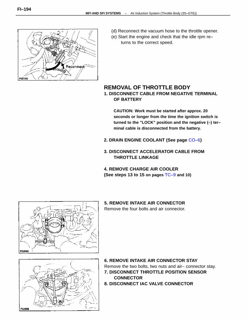
REMOVAL OF THROTTLE BODY1. DISCONNECT CABLE FROM NEGATIVE TERMINAL
OF BATTERY
CAUTION: Work must be started after approx. 20seconds or longer from the time the ignition switch isturned to the ”LOCK” position and the negative (–) ter–minal cable is disconnected from the battery.
2. DRAIN ENGINE COOLANT (See page CO–6)
3. DISCONNECT ACCELERATOR CABLE FROMTHROTTLE LINKAGE
4. REMOVE CHARGE AIR COOLER(See steps 13 to 15 on pages TC–9 and 10)
6. REMOVE INTAKE AIR CONNECTOR STAYRemove the two bolts, two nuts and air– connector stay.7. DISCONNECT THROTTLE POSITION SENSOR
CONNECTOR8. DISCONNECT IAC VALVE CONNECTOR
(d) Reconnect the vacuum hose to the throttle opener.(e) Start the engine and check that the idle rpm re–
turns to the correct speed.
5. REMOVE INTAKE AIR CONNECTORRemove the four bolts and air connector.
–MFI AND SFI SYSTEMS Air Induction System (Throttle Body (3S–GTE))FI–194
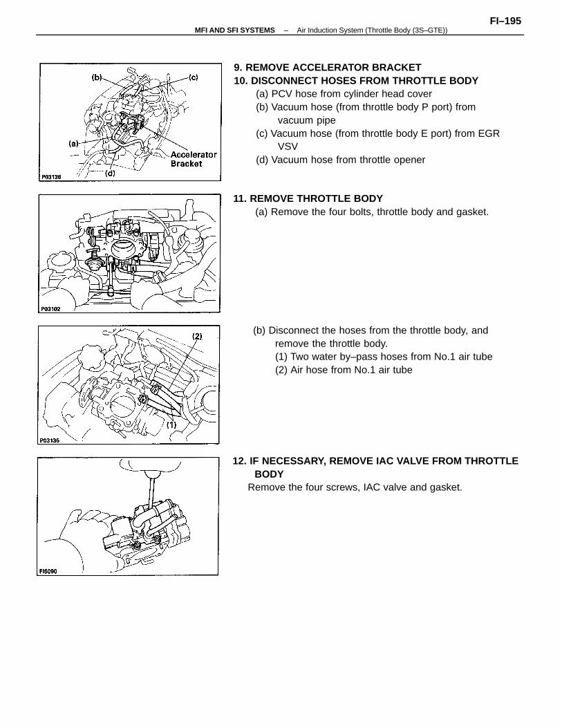
9. REMOVE ACCELERATOR BRACKET10. DISCONNECT HOSES FROM THROTTLE BODY
(a) PCV hose from cylinder head cover(b) Vacuum hose (from throttle body P port) from
vacuum pipe(c) Vacuum hose (from throttle body E port) from EGR
VSV(d) Vacuum hose from throttle opener
(b) Disconnect the hoses from the throttle body, andremove the throttle body.(1) Two water by–pass hoses from No.1 air tube(2) Air hose from No.1 air tube
12. IF NECESSARY, REMOVE IAC VALVE FROM THROTTLEBODY
Remove the four screws, IAC valve and gasket.
11. REMOVE THROTTLE BODY(a) Remove the four bolts, throttle body and gasket.
–MFI AND SFI SYSTEMS Air Induction System (Throttle Body (3S–GTE))FI–195
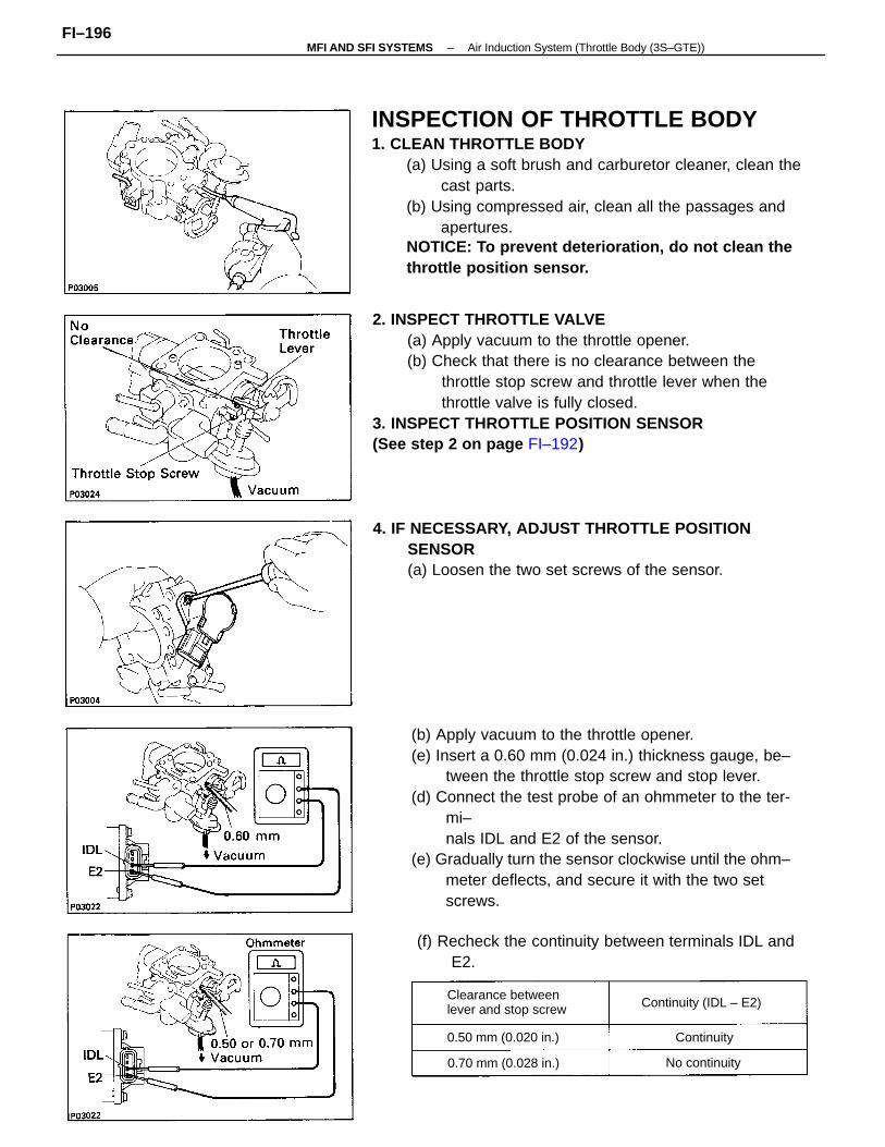
INSPECTION OF THROTTLE BODY1. CLEAN THROTTLE BODY
(a) Using a soft brush and carburetor cleaner, clean thecast parts.
(b) Using compressed air, clean all the passages andapertures.
NOTICE: To prevent deterioration, do not clean thethrottle position sensor.
2. INSPECT THROTTLE VALVE(a) Apply vacuum to the throttle opener.(b) Check that there is no clearance between the
throttle stop screw and throttle lever when thethrottle valve is fully closed.
3. INSPECT THROTTLE POSITION SENSOR(See step 2 on page FI–192)
(b) Apply vacuum to the throttle opener.(e) Insert a 0.60 mm (0.024 in.) thickness gauge, be–
tween the throttle stop screw and stop lever.(d) Connect the test probe of an ohmmeter to the ter-
mi–nals IDL and E2 of the sensor.
(e) Gradually turn the sensor clockwise until the ohm–meter deflects, and secure it with the two setscrews.
4. IF NECESSARY, ADJUST THROTTLE POSITIONSENSOR(a) Loosen the two set screws of the sensor.
(f) Recheck the continuity between terminals IDL andE2.
Clearance betweenlever and stop screw Continuity (IDL – E2)
0.70 mm (0.028 in.)
0.50 mm (0.020 in.)
No continuity
Continuity
–MFI AND SFI SYSTEMS Air Induction System (Throttle Body (3S–GTE))FI–196
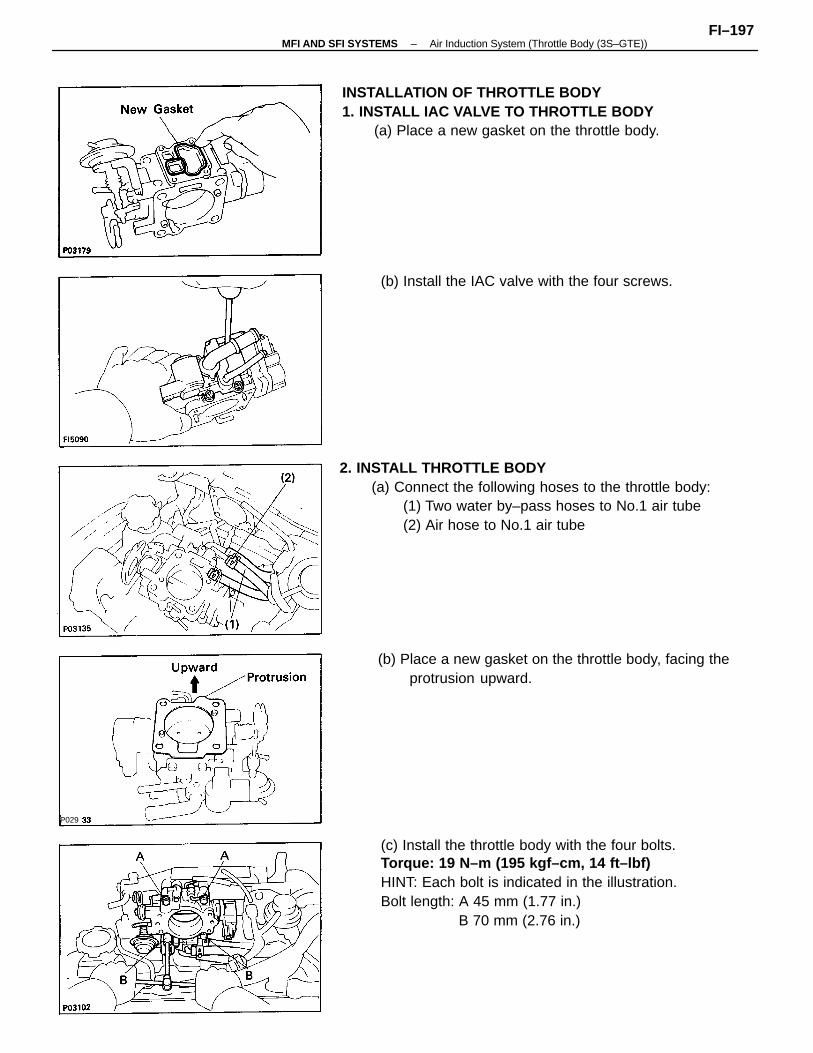
2. INSTALL THROTTLE BODY(a) Connect the following hoses to the throttle body:
(1) Two water by–pass hoses to No.1 air tube(2) Air hose to No.1 air tube
(c) Install the throttle body with the four bolts.Torque: 19 N–m (195 kgf–cm, 14 ft–lbf)HINT: Each bolt is indicated in the illustration.Bolt length: A 45 mm (1.77 in.)
B 70 mm (2.76 in.)
INSTALLATION OF THROTTLE BODY1. INSTALL IAC VALVE TO THROTTLE BODY
(a) Place a new gasket on the throttle body.
(b) Place a new gasket on the throttle body, facing theprotrusion upward.
(b) Install the IAC valve with the four screws.
P029
–MFI AND SFI SYSTEMS Air Induction System (Throttle Body (3S–GTE))FI–197
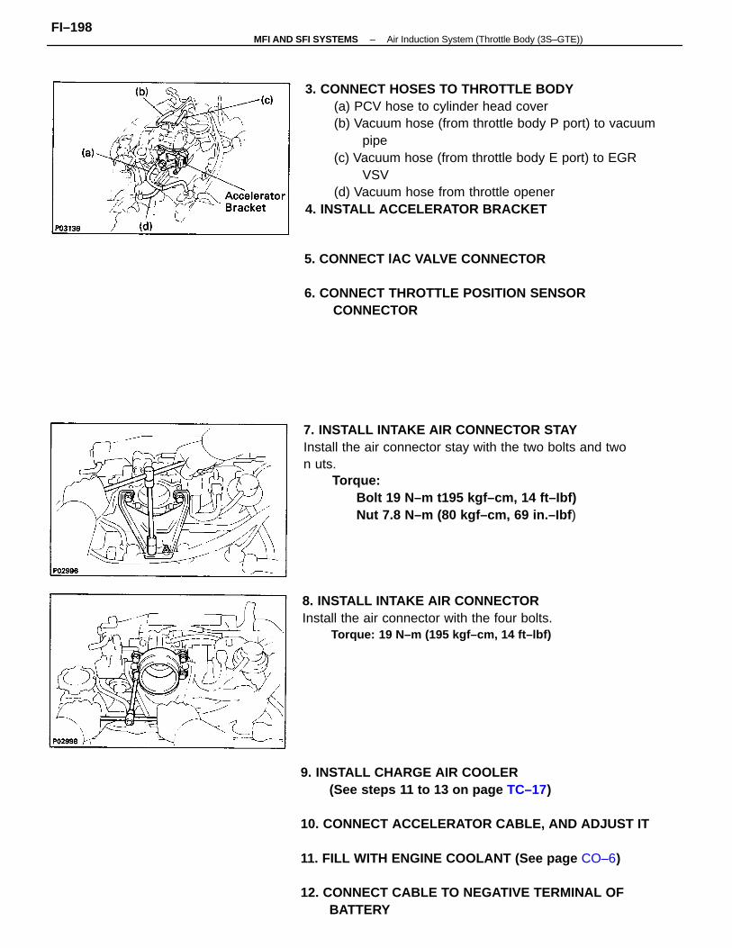
3. CONNECT HOSES TO THROTTLE BODY(a) PCV hose to cylinder head cover(b) Vacuum hose (from throttle body P port) to vacuum
pipe(c) Vacuum hose (from throttle body E port) to EGR
VSV(d) Vacuum hose from throttle opener
4. INSTALL ACCELERATOR BRACKET
9. INSTALL CHARGE AIR COOLER(See steps 11 to 13 on page TC–17)
10. CONNECT ACCELERATOR CABLE, AND ADJUST IT
11. FILL WITH ENGINE COOLANT (See page CO–6)
12. CONNECT CABLE TO NEGATIVE TERMINAL OFBATTERY
7. INSTALL INTAKE AIR CONNECTOR STAYInstall the air connector stay with the two bolts and twon uts.
Torque:Bolt 19 N–m t195 kgf–cm, 14 ft–Ibf)Nut 7.8 N–m (80 kgf–cm, 69 in.–Ibf )
8. INSTALL INTAKE AIR CONNECTORInstall the air connector with the four bolts.
Torque: 19 N–m (195 kgf–cm, 14 ft–lbf)
5. CONNECT lAC VALVE CONNECTOR
6. CONNECT THROTTLE POSITION SENSORCONNECTOR
–MFI AND SFI SYSTEMS Air Induction System (Throttle Body (3S–GTE))FI–198
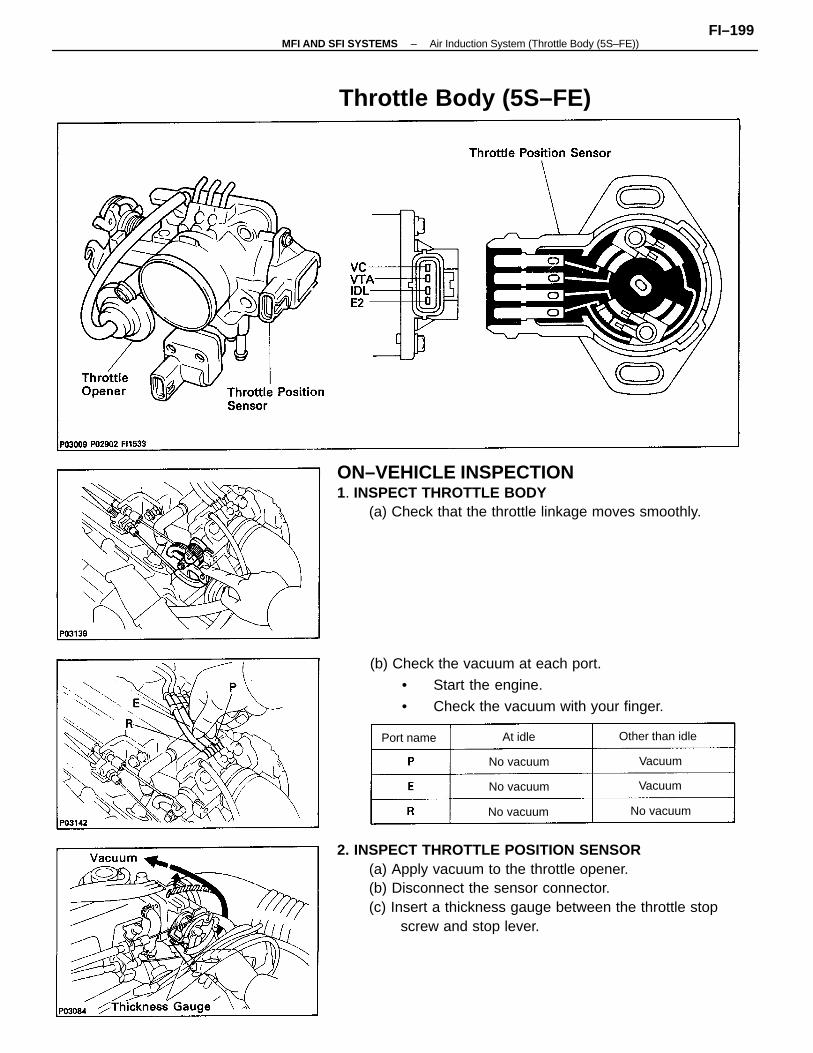
2. INSPECT THROTTLE POSITION SENSOR(a) Apply vacuum to the throttle opener.(b) Disconnect the sensor connector.(c) Insert a thickness gauge between the throttle stop
screw and stop lever.
ON–VEHICLE INSPECTION1. INSPECT THROTTLE BODY
(a) Check that the throttle linkage moves smoothly.
(b) Check the vacuum at each port.
• Start the engine.
• Check the vacuum with your finger.
Throttle Body (5S–FE)
Other than idle
No vacuum
No vacuum
No vacuum
No vacuum
Port name
Vacuum
Vacuum
At idle
–MFI AND SFI SYSTEMS Air Induction System (Throttle Body (5S–FE))FI–199
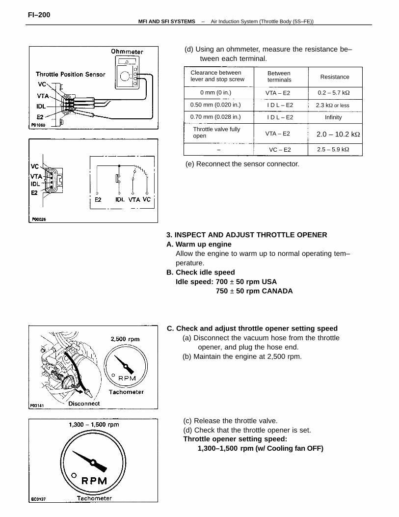
3. INSPECT AND ADJUST THROTTLE OPENERA. Warm up engine
Allow the engine to warm up to normal operating tem–perature.
B. Check idle speedIdle speed: 700 ± 50 rpm USA
750 ± 50 rpm CANADA
C. Check and adjust throttle opener setting speed(a) Disconnect the vacuum hose from the throttle
opener, and plug the hose end.(b) Maintain the engine at 2,500 rpm.
(c) Release the throttle valve.(d) Check that the throttle opener is set.Throttle opener setting speed:
1,300–1,500 rpm (w/ Cooling fan OFF)
(d) Using an ohmmeter, measure the resistance be–tween each terminal.
(e) Reconnect the sensor connector.
Clearance betweenlever and stop screw
Throttle valve fullyopen
0.70 mm (0.028 in.)
0.50 mm (0.020 in.)
Betweenterminals
0 mm (0 in.)
2.0 – 10.2 k
2.3 k or less
0.2 – 5.7 k
2.5 – 5.9 k
Resistance
VTA – E2
VTA – E2
I D L – E2
I D L – E2 Infinity
VC – E2
–MFI AND SFI SYSTEMS Air Induction System (Throttle Body (5S–FE))FI–200
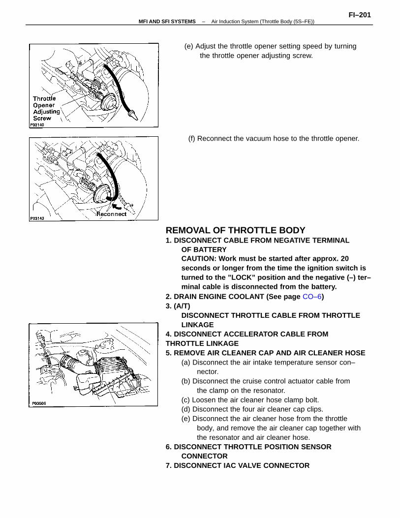
REMOVAL OF THROTTLE BODY1. DISCONNECT CABLE FROM NEGATIVE TERMINAL
OF BATTERYCAUTION: Work must be started after approx. 20seconds or longer from the time the ignition switch isturned to the ”LOCK” position and the negative (–) ter–minal cable is disconnected from the battery.
2. DRAIN ENGINE COOLANT (See page CO–6)3. (A/T)
DISCONNECT THROTTLE CABLE FROM THROTTLELINKAGE
4. DISCONNECT ACCELERATOR CABLE FROMTHROTTLE LINKAGE5. REMOVE AIR CLEANER CAP AND AIR CLEANER HOSE
(a) Disconnect the air intake temperature sensor con–nector.
(b) Disconnect the cruise control actuator cable fromthe clamp on the resonator.
(c) Loosen the air cleaner hose clamp bolt.(d) Disconnect the four air cleaner cap clips.(e) Disconnect the air cleaner hose from the throttle
body, and remove the air cleaner cap together withthe resonator and air cleaner hose.
6. DISCONNECT THROTTLE POSITION SENSORCONNECTOR
7. DISCONNECT IAC VALVE CONNECTOR
(e) Adjust the throttle opener setting speed by turningthe throttle opener adjusting screw.
(f) Reconnect the vacuum hose to the throttle opener.
–MFI AND SFI SYSTEMS Air Induction System (Throttle Body (5S–FE))FI–201
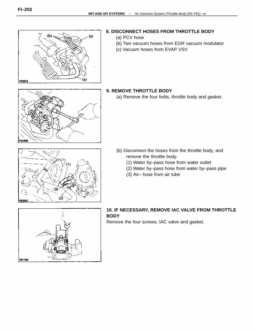
(b) Disconnect the hoses from the throttle body, andremove the throttle body.(1) Water by–pass hose from water outlet(2) Water by–pass hose from water by–pass pipe(3) Air– hose from air tube
8. DISCONNECT HOSES FROM THROTTLE BODY(a) PCV hose(b) Two vacuum hoses from EGR vacuum modulator(c) Vacuum hoses from EVAP VSV
10. IF NECESSARY, REMOVE IAC VALVE FROM THROTTLEBODYRemove the four screws, IAC valve and gasket.
9. REMOVE THROTTLE BODY(a) Remove the four bolts, throttle body and gasket.
–MFI AND SFI SYSTEMS Air Induction System (Throttle Body (5S–FE)) ~wFI–202
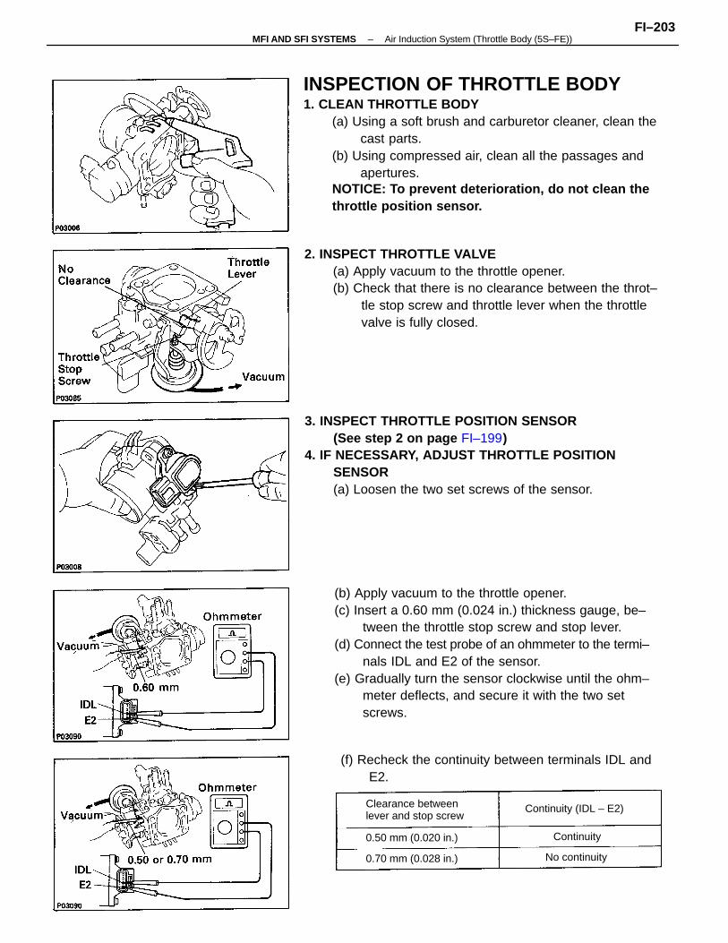
INSPECTION OF THROTTLE BODY1. CLEAN THROTTLE BODY
(a) Using a soft brush and carburetor cleaner, clean thecast parts.
(b) Using compressed air, clean all the passages andapertures.
NOTICE: To prevent deterioration, do not clean thethrottle position sensor.
(b) Apply vacuum to the throttle opener.(c) Insert a 0.60 mm (0.024 in.) thickness gauge, be–
tween the throttle stop screw and stop lever.(d) Connect the test probe of an ohmmeter to the termi–
nals IDL and E2 of the sensor.(e) Gradually turn the sensor clockwise until the ohm–
meter deflects, and secure it with the two setscrews.
2. INSPECT THROTTLE VALVE(a) Apply vacuum to the throttle opener.(b) Check that there is no clearance between the throt–
tle stop screw and throttle lever when the throttlevalve is fully closed.
3. INSPECT THROTTLE POSITION SENSOR(See step 2 on page FI–199)
4. IF NECESSARY, ADJUST THROTTLE POSITIONSENSOR(a) Loosen the two set screws of the sensor.
(f) Recheck the continuity between terminals IDL andE2.
Clearance betweenlever and stop screw
Continuity (IDL – E2)
0.70 mm (0.028 in.)
0.50 mm (0.020 in.)
No continuity
Continuity
–MFI AND SFI SYSTEMS Air Induction System (Throttle Body (5S–FE))FI–203
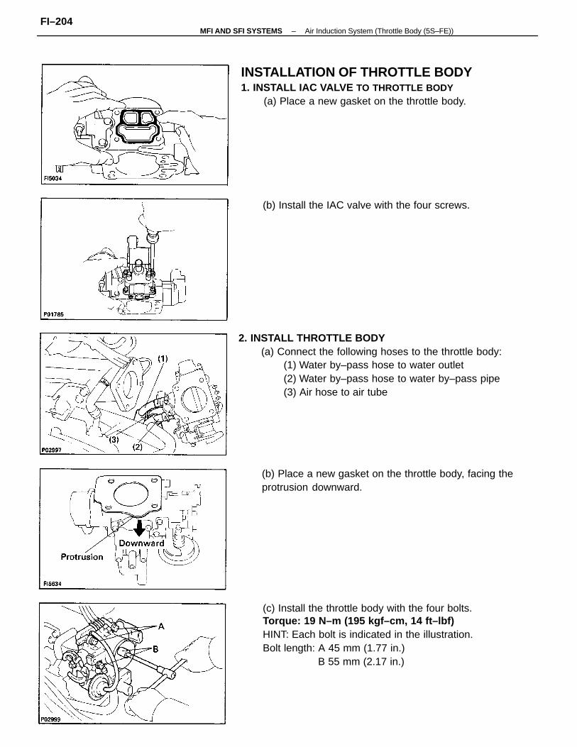
2. INSTALL THROTTLE BODY(a) Connect the following hoses to the throttle body:
(1) Water by–pass hose to water outlet(2) Water by–pass hose to water by–pass pipe(3) Air hose to air tube
(c) Install the throttle body with the four bolts.Torque: 19 N–m (195 kgf–cm, 14 ft–lbf)HINT: Each bolt is indicated in the illustration.Bolt length: A 45 mm (1.77 in.)
B 55 mm (2.17 in.)
INSTALLATION OF THROTTLE BODY1. INSTALL IAC VALVE TO THROTTLE BODY
(a) Place a new gasket on the throttle body.
(b) Place a new gasket on the throttle body, facing theprotrusion downward.
(b) Install the IAC valve with the four screws.
–MFI AND SFI SYSTEMS Air Induction System (Throttle Body (5S–FE))FI–204
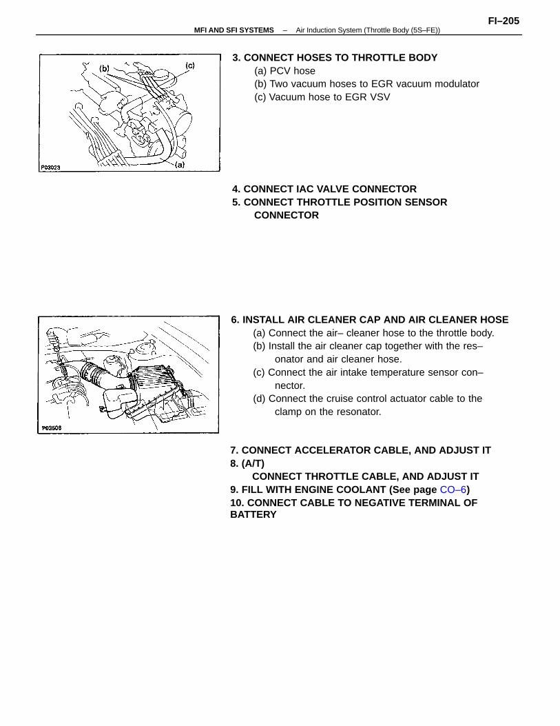
6. INSTALL AIR CLEANER CAP AND AIR CLEANER HOSE(a) Connect the air– cleaner hose to the throttle body.(b) Install the air cleaner cap together with the res–
onator and air cleaner hose.(c) Connect the air intake temperature sensor con–
nector.(d) Connect the cruise control actuator cable to the
clamp on the resonator.
7. CONNECT ACCELERATOR CABLE, AND ADJUST IT8. (A/T)
CONNECT THROTTLE CABLE, AND ADJUST IT9. FILL WITH ENGINE COOLANT (See page CO–6)10. CONNECT CABLE TO NEGATIVE TERMINAL OFBATTERY
3. CONNECT HOSES TO THROTTLE BODY(a) PCV hose(b) Two vacuum hoses to EGR vacuum modulator(c) Vacuum hose to EGR VSV
4. CONNECT IAC VALVE CONNECTOR5. CONNECT THROTTLE POSITION SENSOR
CONNECTOR
–MFI AND SFI SYSTEMS Air Induction System (Throttle Body (5S–FE))FI–205
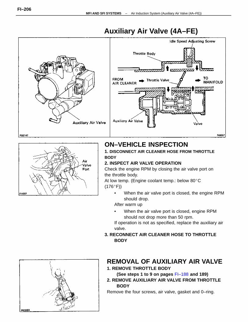
ON–VEHICLE INSPECTION1. DISCONNECT AIR CLEANER HOSE FROM THROTTLEBODY2. INSPECT AIR VALVE OPERATIONCheck the engine RPM by closing the air valve port onthe throttle body.At low temp. (Engine coolant temp.: below 80C(176F))
• When the air valve port is closed, the engine RPMshould drop.
After warm up
• When the air valve port is closed, engine RPMshould not drop more than 50 rpm.
If operation is not as specified, replace the auxiliary airvalve.
3. RECONNECT AIR CLEANER HOSE TO THROTTLEBODY
Auxiliary Air Valve (4A–FE)
REMOVAL OF AUXILIARY AIR VALVE1. REMOVE THROTTLE BODY
(See steps 1 to 9 on pages FI–188 and 189)2. REMOVE AUXILIARY AIR VALVE FROM THROTTLE
BODYRemove the four screws, air valve, gasket and 0–ring.
–MFI AND SFI SYSTEMS Air Induction System (Auxiliary Air Valve (4A–FE))FI–206
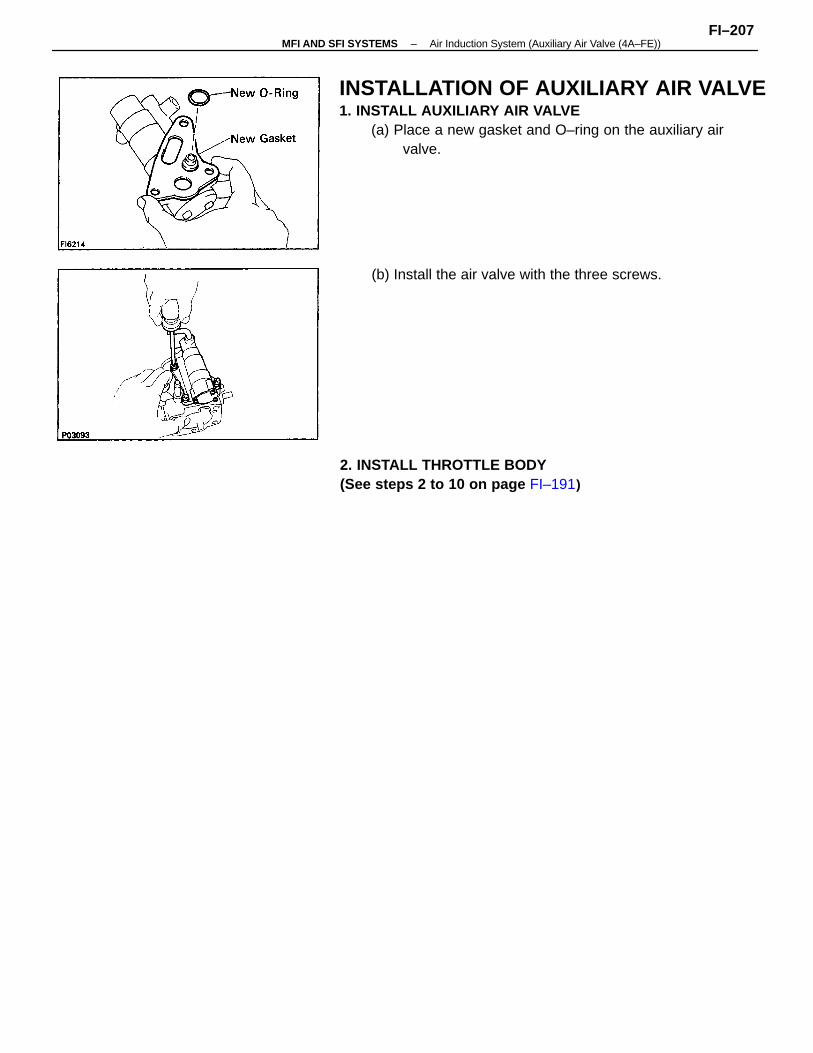
INSTALLATION OF AUXILIARY AIR VALVE1. INSTALL AUXILIARY AIR VALVE
(a) Place a new gasket and O–ring on the auxiliary airvalve.
2. INSTALL THROTTLE BODY(See steps 2 to 10 on page FI–191)
(b) Install the air valve with the three screws.
–MFI AND SFI SYSTEMS Air Induction System (Auxiliary Air Valve (4A–FE))FI–207
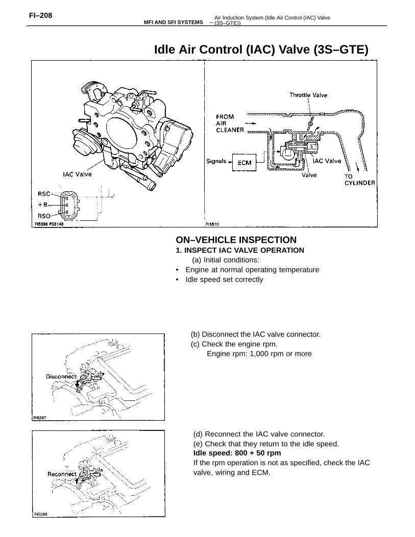
ON–VEHICLE INSPECTION1. INSPECT IAC VALVE OPERATION
(a) Initial conditions:• Engine at normal operating temperature• Idle speed set correctly
(d) Reconnect the IAC valve connector.(e) Check that they return to the idle speed.Idle speed: 800 + 50 rpmIf the rpm operation is not as specified, check the IACvalve, wiring and ECM.
(b) Disconnect the IAC valve connector.(c) Check the engine rpm.
Engine rpm: 1,000 rpm or more
Idle Air Control (IAC) Valve (3S–GTE)
–MFI AND SFI SYSTEMSFI–208 Air Induction System (Idle Air Control (IAC) Valve
(3S–GTE))
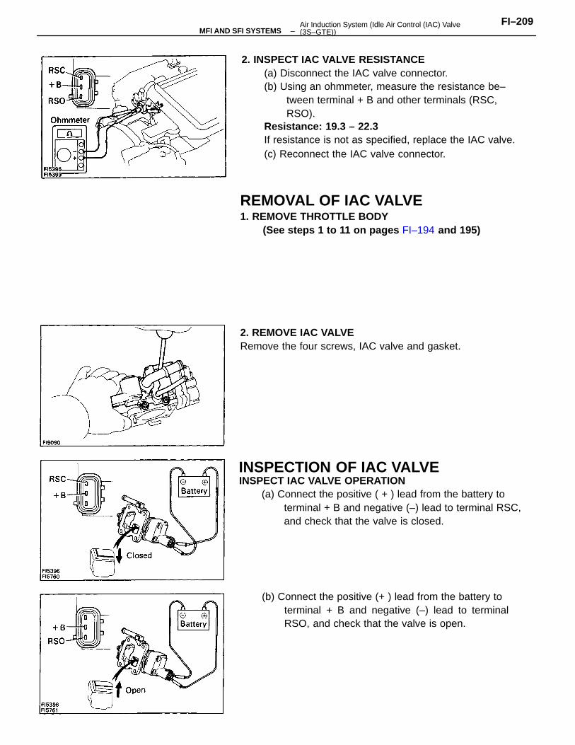
2. INSPECT IAC VALVE RESISTANCE(a) Disconnect the IAC valve connector.(b) Using an ohmmeter, measure the resistance be–
tween terminal + B and other terminals (RSC,RSO).
Resistance: 19.3 – 22.3
If resistance is not as specified, replace the IAC valve.(c) Reconnect the IAC valve connector.
INSPECT IAC VALVE OPERATION(a) Connect the positive ( + ) lead from the battery to
terminal + B and negative (–) lead to terminal RSC,and check that the valve is closed.
REMOVAL OF IAC VALVE1. REMOVE THROTTLE BODY
(See steps 1 to 11 on pages FI–194 and 195)
(b) Connect the positive (+ ) lead from the battery toterminal + B and negative (–) lead to terminalRSO, and check that the valve is open.
2. REMOVE IAC VALVERemove the four screws, IAC valve and gasket.
INSPECTION OF IAC VALVE
–MFI AND SFI SYSTEMSFI–209Air Induction System (Idle Air Control (IAC) Valve
(3S–GTE))
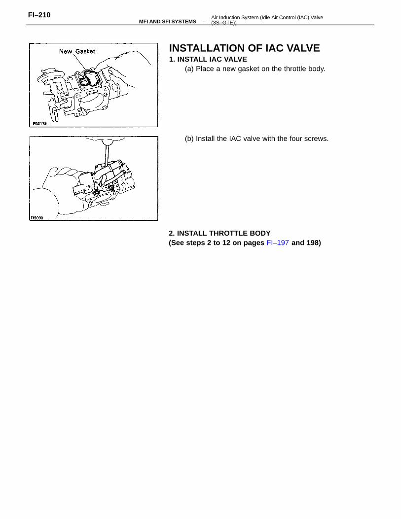
INSTALLATION OF IAC VALVE1. INSTALL IAC VALVE
(a) Place a new gasket on the throttle body.
2. INSTALL THROTTLE BODY(See steps 2 to 12 on pages FI–197 and 198)
(b) Install the IAC valve with the four screws.
–MFI AND SFI SYSTEMSFI–210 Air Induction System (Idle Air Control (IAC) Valve
(3S–GTE))
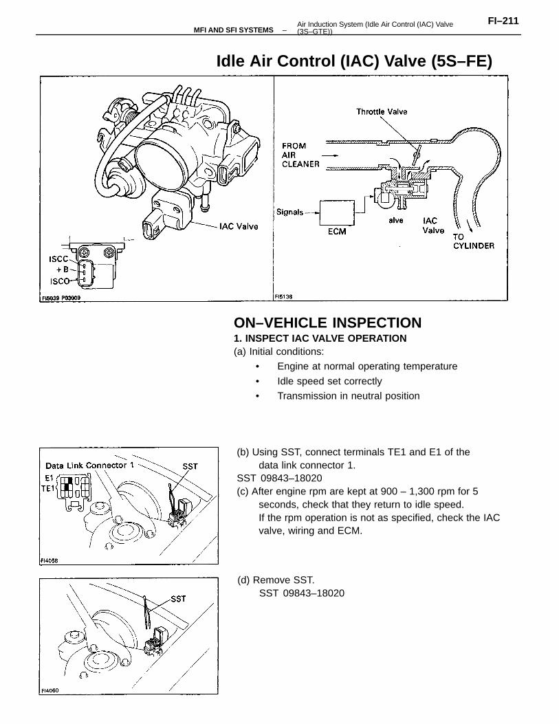
(b) Using SST, connect terminals TE1 and E1 of thedata link connector 1.
SST 09843–18020(c) After engine rpm are kept at 900 – 1,300 rpm for 5
seconds, check that they return to idle speed.If the rpm operation is not as specified, check the IACvalve, wiring and ECM.
ON–VEHICLE INSPECTION1. INSPECT IAC VALVE OPERATION(a) Initial conditions:
• Engine at normal operating temperature
• Idle speed set correctly
• Transmission in neutral position
Idle Air Control (IAC) Valve (5S–FE)
(d) Remove SST.SST 09843–18020
–MFI AND SFI SYSTEMSFI–211Air Induction System (Idle Air Control (IAC) Valve
(3S–GTE))
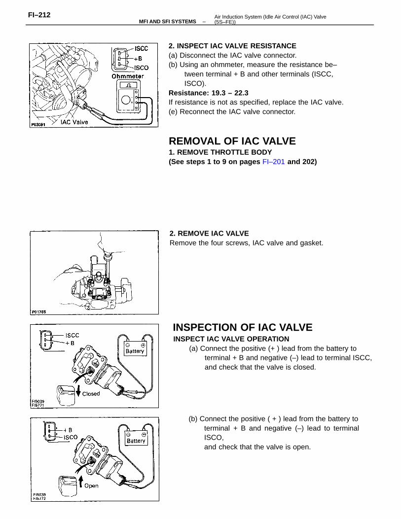
2. INSPECT IAC VALVE RESISTANCE(a) Disconnect the IAC valve connector.(b) Using an ohmmeter, measure the resistance be–
tween terminal + B and other terminals (ISCC,ISCO).
Resistance: 19.3 – 22.3
If resistance is not as specified, replace the IAC valve.(e) Reconnect the IAC valve connector.
INSPECT IAC VALVE OPERATION(a) Connect the positive (+ ) lead from the battery to
terminal + B and negative (–) lead to terminal ISCC,and check that the valve is closed.
REMOVAL OF IAC VALVE1. REMOVE THROTTLE BODY(See steps 1 to 9 on pages FI–201 and 202)
(b) Connect the positive ( + ) lead from the battery toterminal + B and negative (–) lead to terminalISCO,and check that the valve is open.
2. REMOVE IAC VALVERemove the four screws, IAC valve and gasket.
INSPECTION OF IAC VALVE
–MFI AND SFI SYSTEMSFI–212 Air Induction System (Idle Air Control (IAC) Valve
(5S–FE))
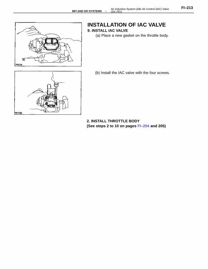
INSTALLATION OF IAC VALVE9. INSTALL IAC VALVE
(a) Place a new gasket on the throttle body.
2. INSTALL THROTTLE BODY(See steps 2 to 10 on pages FI–204 and 205)
(b) Install the IAC valve with the four screws.
–MFI AND SFI SYSTEMSFI–213Air Induction System (Idle Air Control (IAC) Valve
(5S–FE))
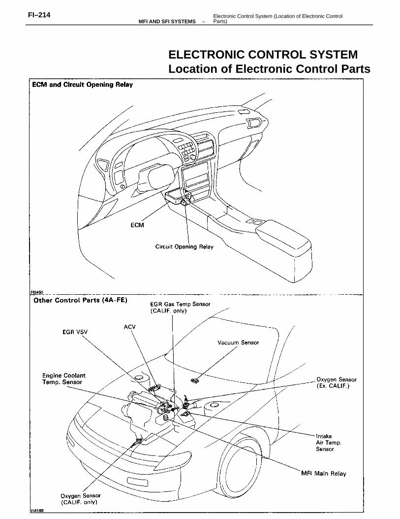
ELECTRONIC CONTROL SYSTEMLocation of Electronic Control Parts
–MFI AND SFI SYSTEMSFI–214 Electronic Control System (Location of Electronic Control
Parts)
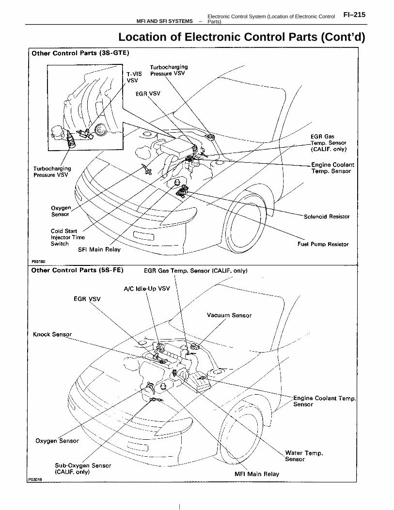
Location of Electronic Control Parts (Cont’d)
–MFI AND SFI SYSTEMSFI–215Electronic Control System (Location of Electronic Control
Parts)
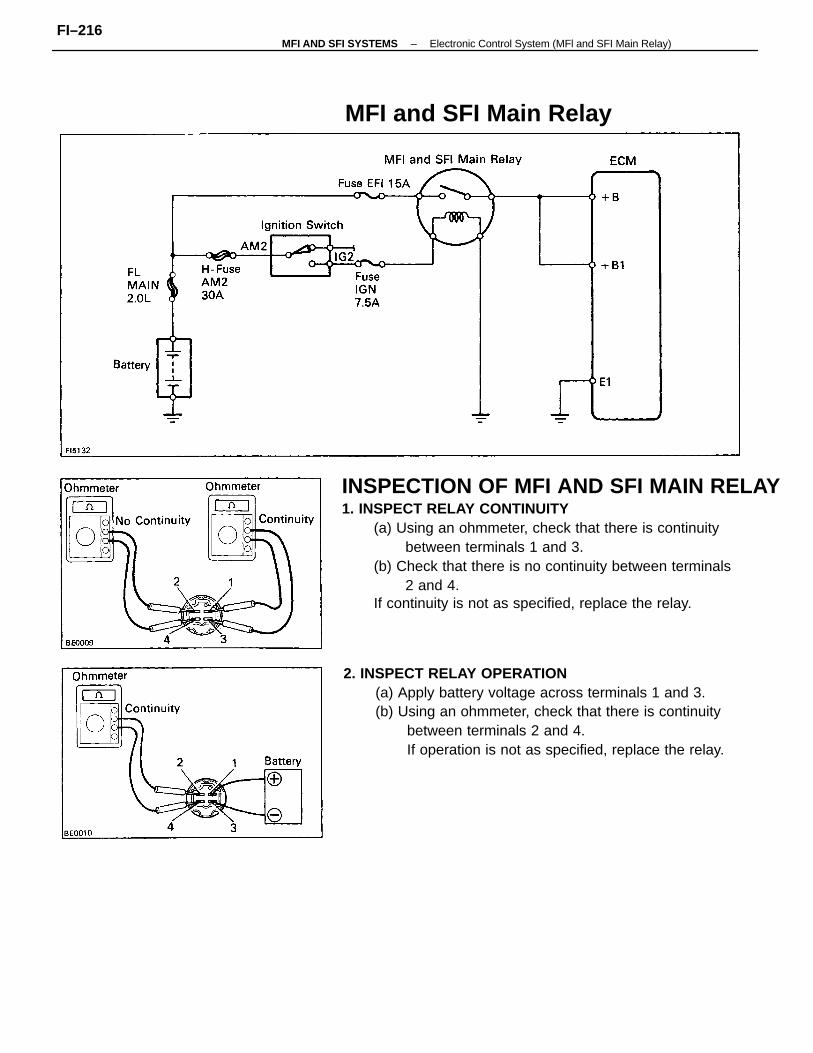
INSPECTION OF MFI AND SFI MAIN RELAY1. INSPECT RELAY CONTINUITY
(a) Using an ohmmeter, check that there is continuitybetween terminals 1 and 3.
(b) Check that there is no continuity between terminals2 and 4.
If continuity is not as specified, replace the relay.
2. INSPECT RELAY OPERATION(a) Apply battery voltage across terminals 1 and 3.(b) Using an ohmmeter, check that there is continuity
between terminals 2 and 4.If operation is not as specified, replace the relay.
MFI and SFI Main Relay
–MFI AND SFI SYSTEMS Electronic Control System (MFl and SFI Main Relay)FI–216
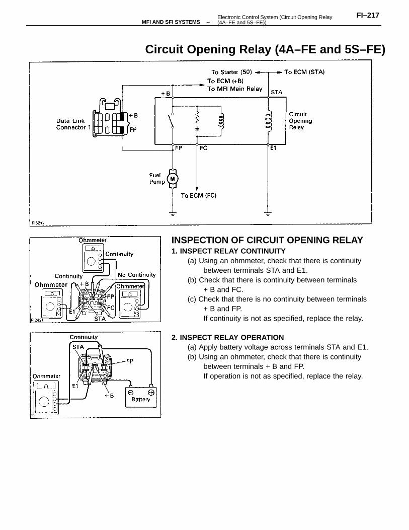
INSPECTION OF CIRCUIT OPENING RELAY1. INSPECT RELAY CONTINUITY
(a) Using an ohmmeter, check that there is continuitybetween terminals STA and E1.
(b) Check that there is continuity between terminals+ B and FC.
(c) Check that there is no continuity between terminals+ B and FP.If continuity is not as specified, replace the relay.
2. INSPECT RELAY OPERATION(a) Apply battery voltage across terminals STA and E1.(b) Using an ohmmeter, check that there is continuity
between terminals + B and FP.If operation is not as specified, replace the relay.
Circuit Opening Relay (4A–FE and 5S–FE)
F12422
–MFI AND SFI SYSTEMSFI–217Electronic Control System (Circuit Opening Relay
(4A–FE and 5S–FE))
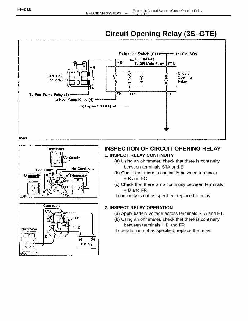
INSPECTION OF CIRCUIT OPENING RELAY1. INSPECT RELAY CONTINUITY
(a) Using an ohmmeter, check that there is continuitybetween terminals STA and El.
(b) Check that there is continuity between terminals+ B and FC.
(c) Check that there is no continuity between terminals+ B and FP.
If continuity is not as specified, replace the relay.
2. INSPECT RELAY OPERATION(a) Apply battery voltage across terminals STA and E1.(b) Using an ohmmeter, check that there is continuity
between terminals + B and FP.If operation is not as specified, replace the relay.
Circuit Opening Relay (3S–GTE)
–MFI AND SFI SYSTEMSFI–218 Electronic Control System (Circuit Opening Relay
(3S–GTE))
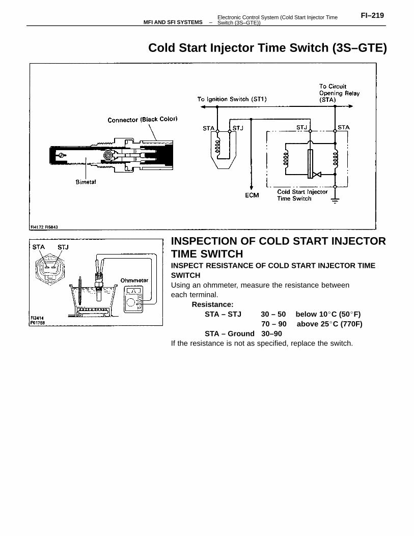
INSPECTION OF COLD START INJECTORTIME SWITCHINSPECT RESISTANCE OF COLD START INJECTOR TIMESWITCHUsing an ohmmeter, measure the resistance betweeneach terminal.
Resistance:STA – STJ 30 – 50 below 10 C (50F)
70 – 90 above 25 C (770F)STA – Ground 30–90
If the resistance is not as specified, replace the switch.
Cold Start Injector Time Switch (3S–GTE)
–MFI AND SFI SYSTEMSFI–219Electronic Control System (Cold Start Injector Time
Switch (3S–GTE))
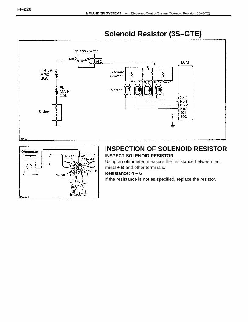
INSPECTION OF SOLENOID RESISTORINSPECT SOLENOID RESISTORUsing an ohmmeter, measure the resistance between ter–minal + B and other terminals.Resistance: 4 – 6
If the resistance is not as specified, replace the resistor.
Solenoid Resistor (3S–GTE)
–MFI AND SFI SYSTEMS Electronic Control System (Solenoid Resistor (3S–GTE)FI–220
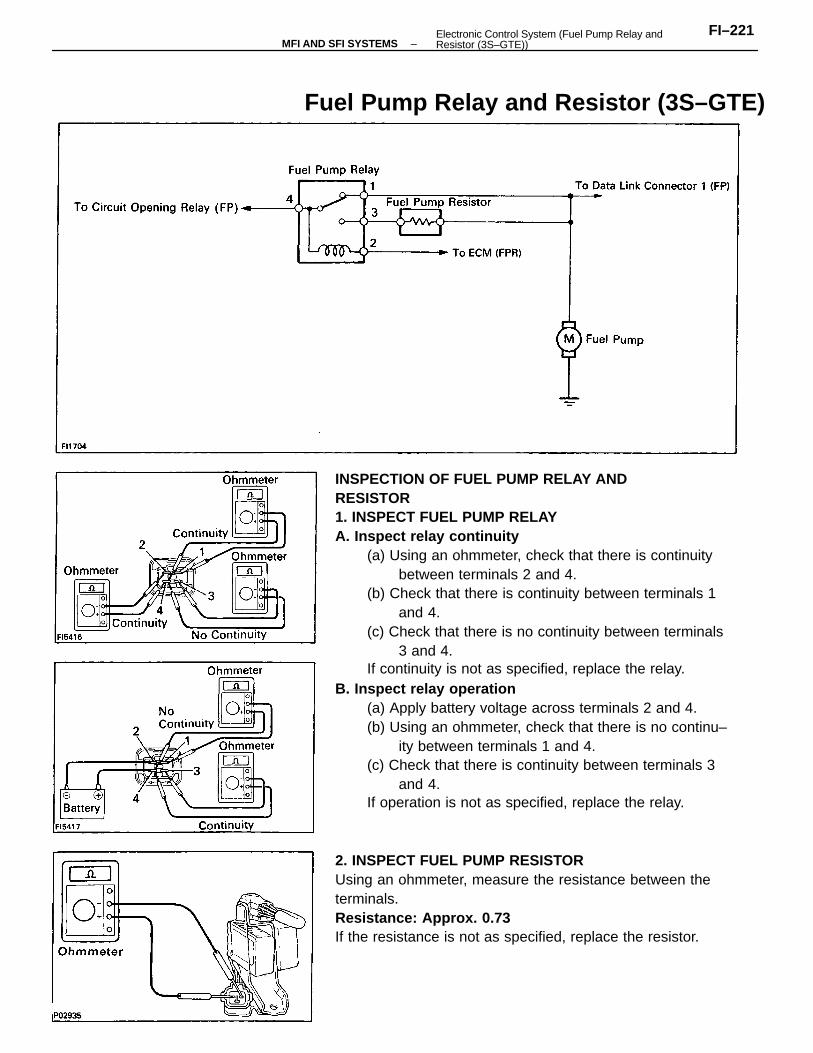
INSPECTION OF FUEL PUMP RELAY ANDRESISTOR1. INSPECT FUEL PUMP RELAYA. Inspect relay continuity
(a) Using an ohmmeter, check that there is continuitybetween terminals 2 and 4.
(b) Check that there is continuity between terminals 1and 4.
(c) Check that there is no continuity between terminals3 and 4.
If continuity is not as specified, replace the relay.B. Inspect relay operation
(a) Apply battery voltage across terminals 2 and 4.(b) Using an ohmmeter, check that there is no continu–
ity between terminals 1 and 4.(c) Check that there is continuity between terminals 3
and 4.If operation is not as specified, replace the relay.
2. INSPECT FUEL PUMP RESISTORUsing an ohmmeter, measure the resistance between theterminals.Resistance: Approx. 0.73
If the resistance is not as specified, replace the resistor.
Fuel Pump Relay and Resistor (3S–GTE)
–MFI AND SFI SYSTEMSFI–221Electronic Control System (Fuel Pump Relay and
Resistor (3S–GTE))
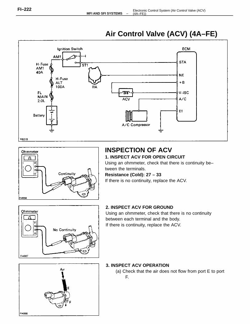
INSPECTION OF ACV1. INSPECT ACV FOR OPEN CIRCUITUsing an ohmmeter, check that there is continuity be–tween the terminals.Resistance (Cold): 27 – 33
If there is no continuity, replace the ACV.
2. INSPECT ACV FOR GROUNDUsing an ohmmeter, check that there is no continuitybetween each terminal and the body.If there is continuity, replace the ACV.
3. INSPECT ACV OPERATION(a) Check that the air does not flow from port E to port
F.
Air Control Valve (ACV) (4A–FE)
–MFI AND SFI SYSTEMSFI–222 Electronic Control System (Air Control Valve (ACV)
(4A–FE))
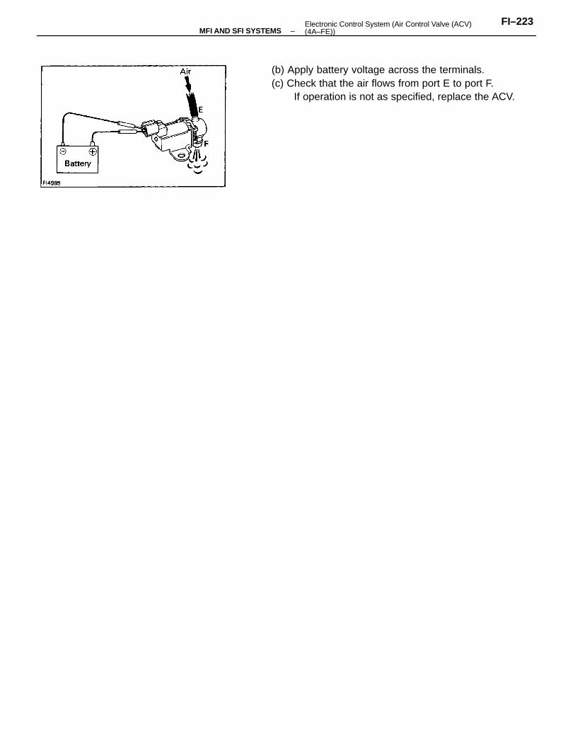
(b) Apply battery voltage across the terminals.(c) Check that the air flows from port E to port F.
If operation is not as specified, replace the ACV.
–MFI AND SFI SYSTEMSFI–223Electronic Control System (Air Control Valve (ACV)
(4A–FE))
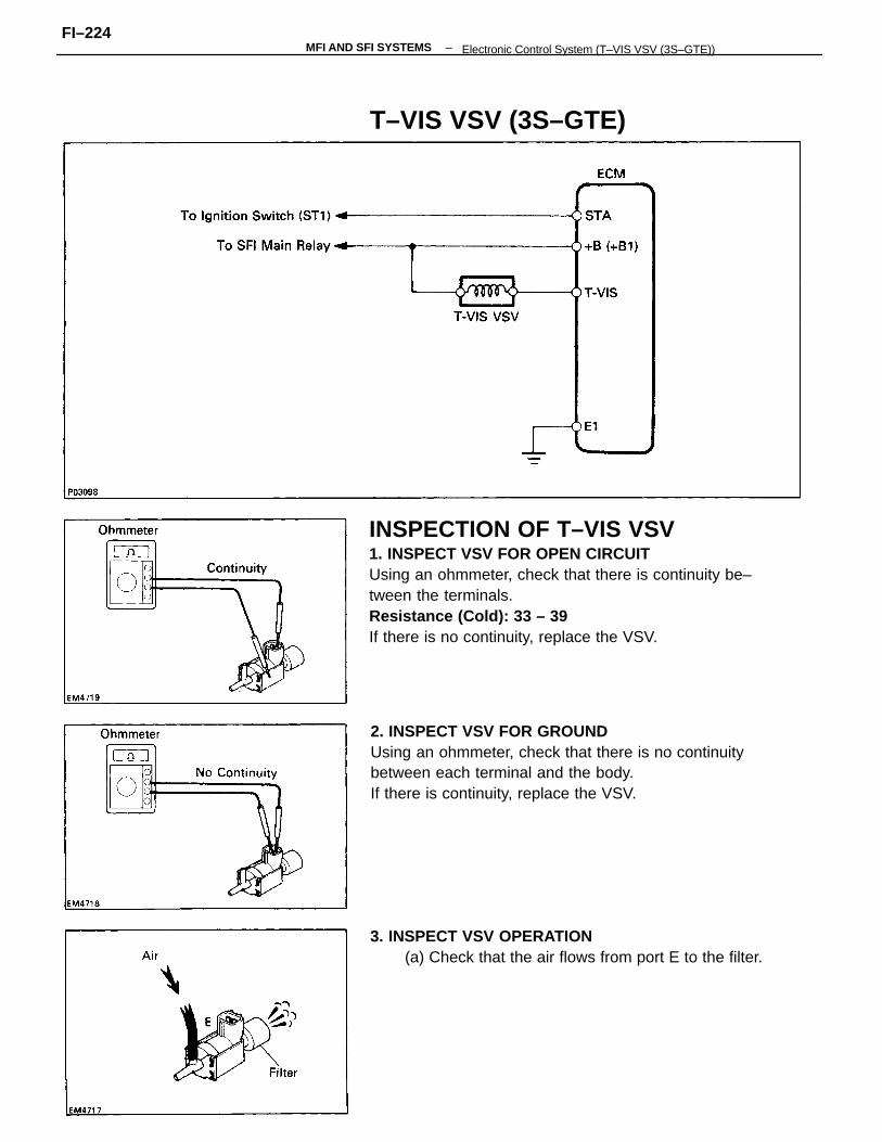
INSPECTION OF T–VIS VSV1. INSPECT VSV FOR OPEN CIRCUITUsing an ohmmeter, check that there is continuity be–tween the terminals.Resistance (Cold): 33 – 39
If there is no continuity, replace the VSV.
2. INSPECT VSV FOR GROUNDUsing an ohmmeter, check that there is no continuitybetween each terminal and the body.If there is continuity, replace the VSV.
3. INSPECT VSV OPERATION(a) Check that the air flows from port E to the filter.
T–VIS VSV (3S–GTE)
–MFI AND SFI SYSTEMSFI–224
Electronic Control System (T–VIS VSV (3S–GTE))
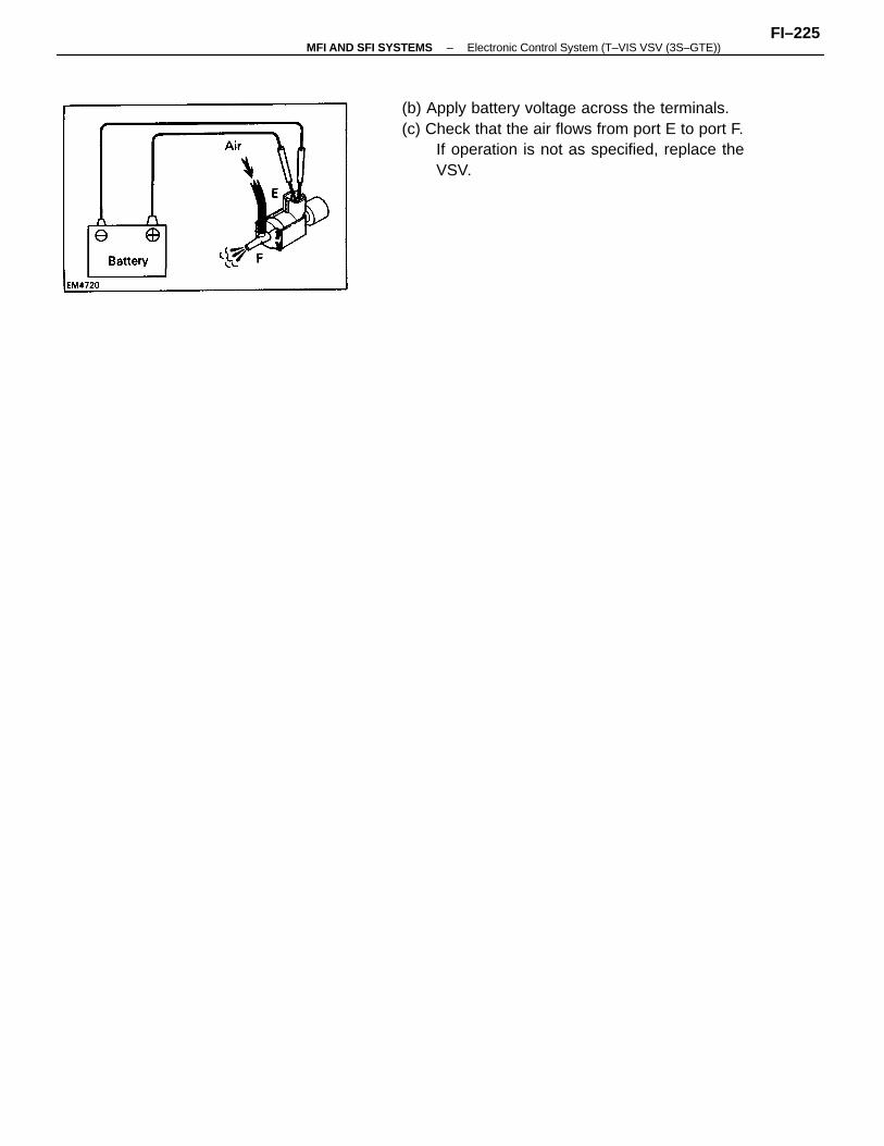
(b) Apply battery voltage across the terminals.(c) Check that the air flows from port E to port F.
If operation is not as specified, replace theVSV.
–MFI AND SFI SYSTEMS Electronic Control System (T–VIS VSV (3S–GTE))FI–225
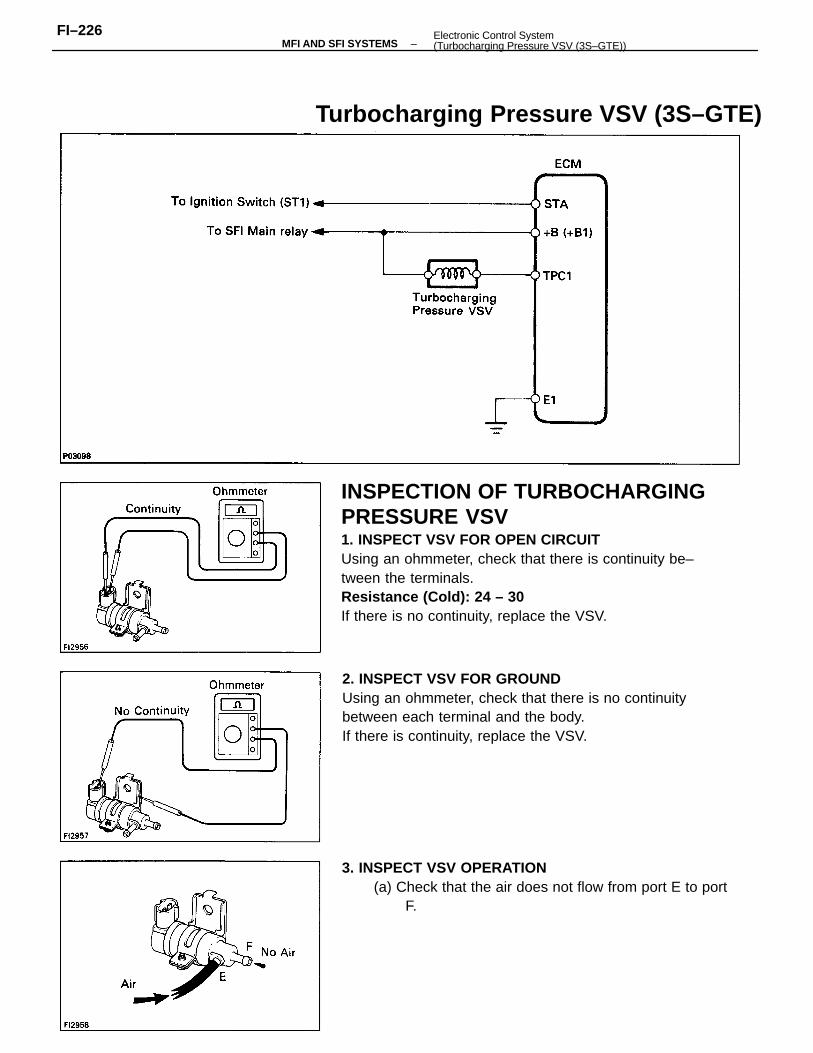
INSPECTION OF TURBOCHARGINGPRESSURE VSV1. INSPECT VSV FOR OPEN CIRCUITUsing an ohmmeter, check that there is continuity be–tween the terminals.Resistance (Cold): 24 – 30
If there is no continuity, replace the VSV.
2. INSPECT VSV FOR GROUNDUsing an ohmmeter, check that there is no continuitybetween each terminal and the body.If there is continuity, replace the VSV.
3. INSPECT VSV OPERATION(a) Check that the air does not flow from port E to port
F.
Turbocharging Pressure VSV (3S–GTE)
–MFI AND SFI SYSTEMSFI–226 Electronic Control System
(Turbocharging Pressure VSV (3S–GTE))
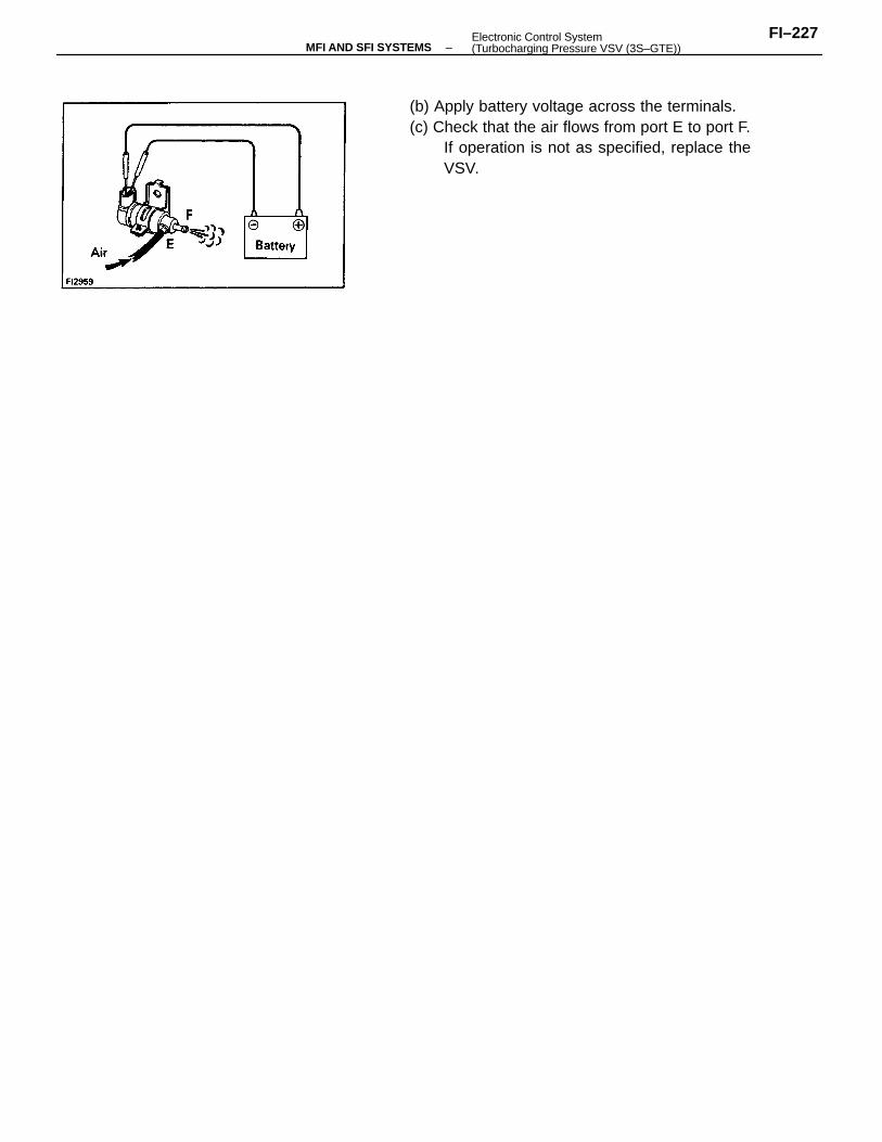
(b) Apply battery voltage across the terminals.(c) Check that the air flows from port E to port F.
If operation is not as specified, replace theVSV.
–MFI AND SFI SYSTEMSFI–227Electronic Control System
(Turbocharging Pressure VSV (3S–GTE))
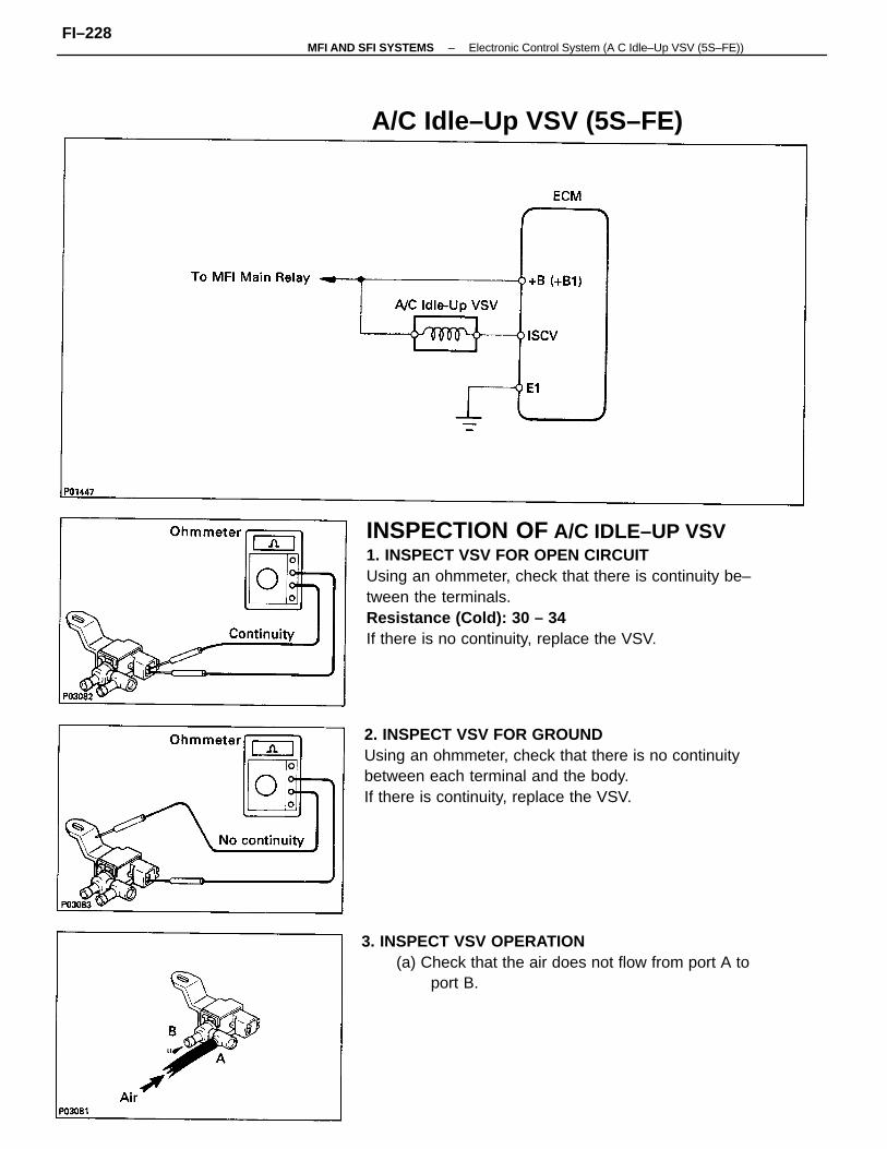
INSPECTION OF A/C IDLE–UP VSV1. INSPECT VSV FOR OPEN CIRCUITUsing an ohmmeter, check that there is continuity be–tween the terminals.Resistance (Cold): 30 – 34
If there is no continuity, replace the VSV.
2. INSPECT VSV FOR GROUNDUsing an ohmmeter, check that there is no continuitybetween each terminal and the body.If there is continuity, replace the VSV.
3. INSPECT VSV OPERATION(a) Check that the air does not flow from port A to
port B.
A/C Idle–Up VSV (5S–FE)
–MFI AND SFI SYSTEMS Electronic Control System (A C Idle–Up VSV (5S–FE))FI–228
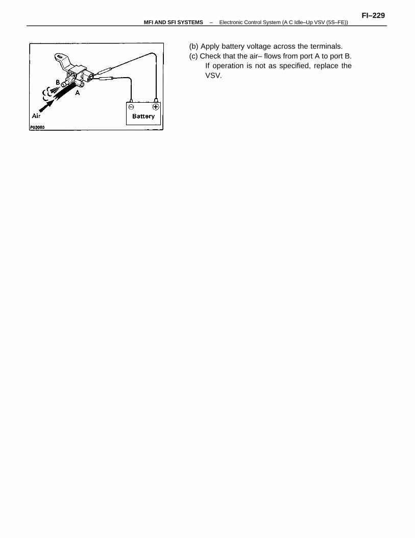
(b) Apply battery voltage across the terminals.(c) Check that the air– flows from port A to port B.
If operation is not as specified, replace theVSV.
–MFI AND SFI SYSTEMS Electronic Control System (A C Idle–Up VSV (5S–FE))FI–229
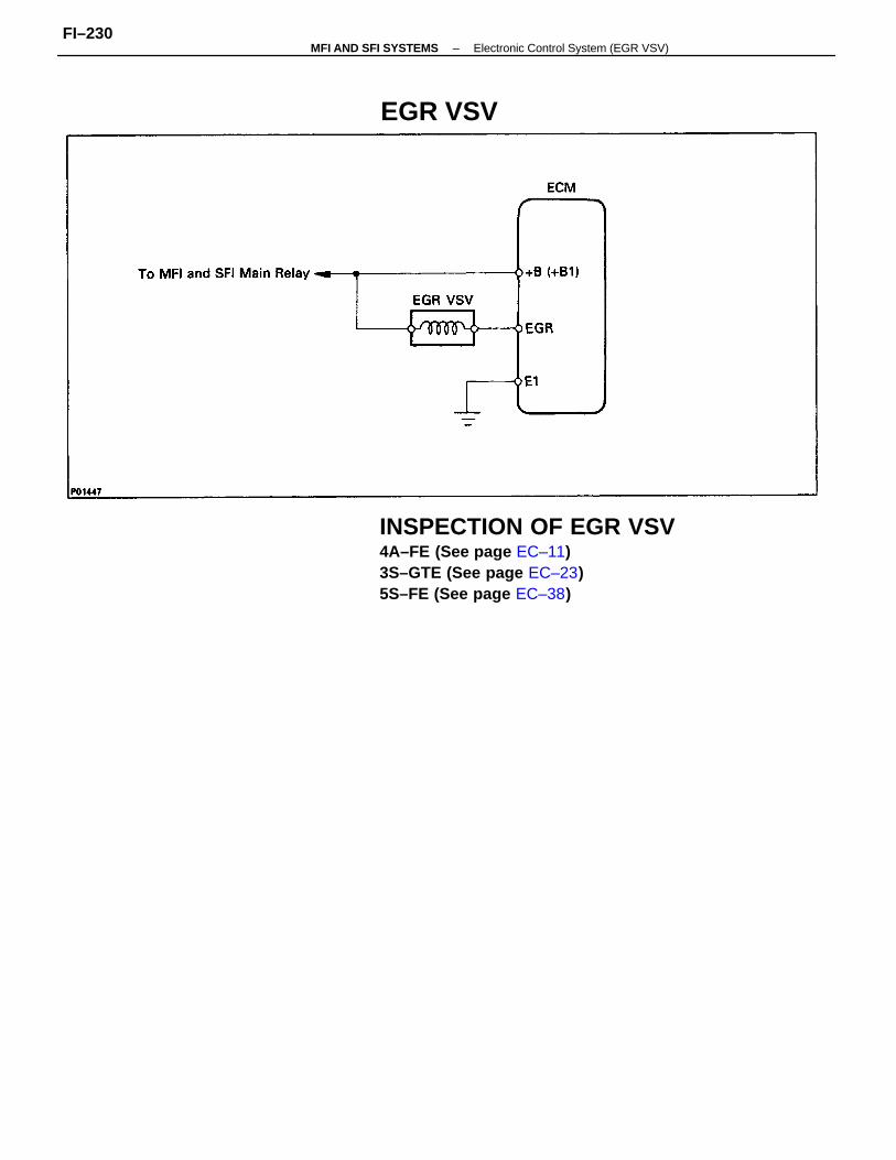
INSPECTION OF EGR VSV4A–FE (See page EC–11)3S–GTE (See page EC–23)5S–FE (See page EC–38)
EGR VSV
–MFI AND SFI SYSTEMS Electronic Control System (EGR VSV)FI–230
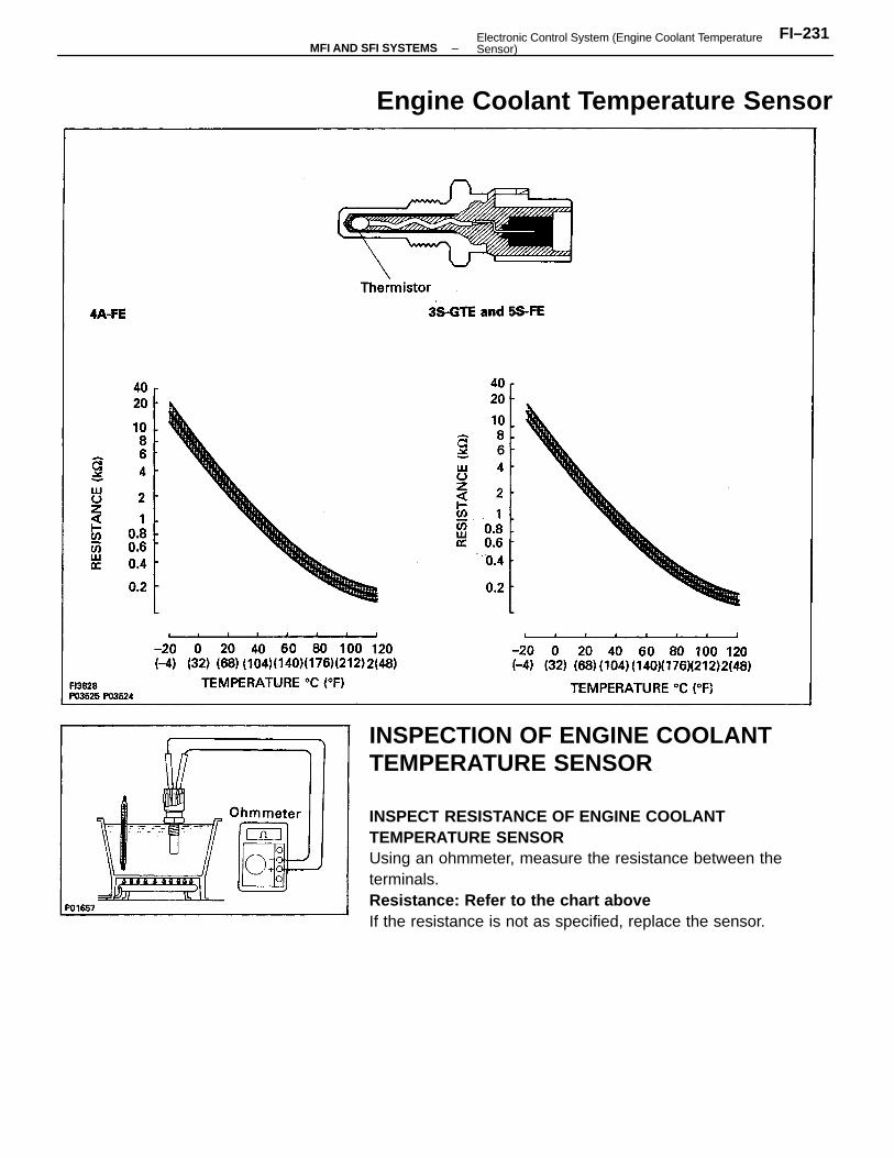
INSPECTION OF ENGINE COOLANTTEMPERATURE SENSOR
INSPECT RESISTANCE OF ENGINE COOLANTTEMPERATURE SENSORUsing an ohmmeter, measure the resistance between theterminals.Resistance: Refer to the chart aboveIf the resistance is not as specified, replace the sensor.
Engine Coolant Temperature Sensor
–MFI AND SFI SYSTEMSFI–231Electronic Control System (Engine Coolant Temperature
Sensor)
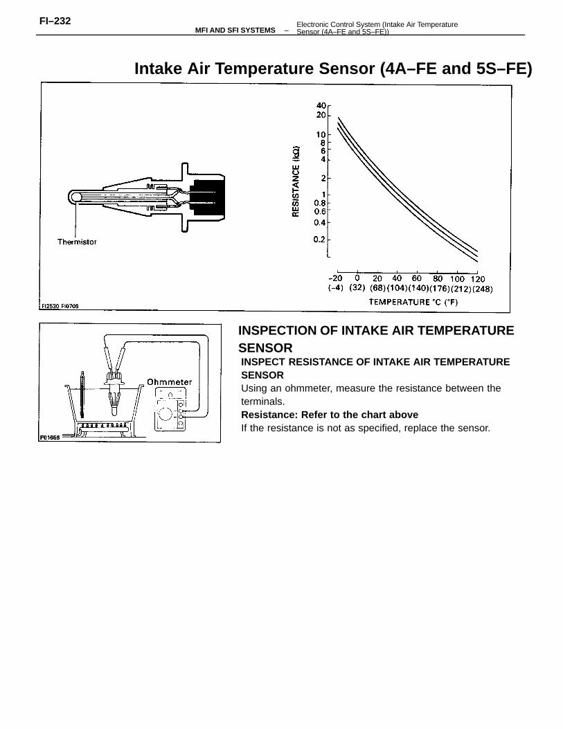
INSPECT RESISTANCE OF INTAKE AIR TEMPERATURESENSORUsing an ohmmeter, measure the resistance between theterminals.Resistance: Refer to the chart aboveIf the resistance is not as specified, replace the sensor.
Intake Air Temperature Sensor (4A–FE and 5S–FE)
INSPECTION OF INTAKE AIR TEMPERATURESENSOR
–MFI AND SFI SYSTEMSFI–232 Electronic Control System (Intake Air Temperature
Sensor (4A–FE and 5S–FE))
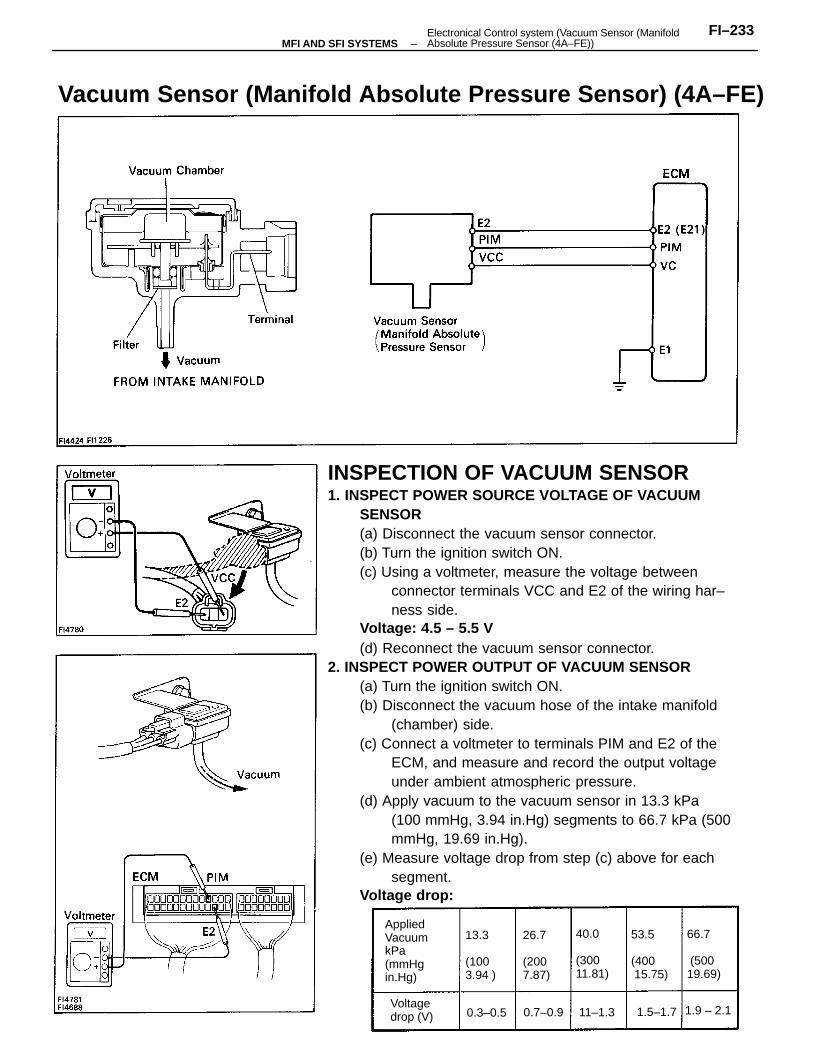
INSPECTION OF VACUUM SENSOR1. INSPECT POWER SOURCE VOLTAGE OF VACUUM
SENSOR(a) Disconnect the vacuum sensor connector.(b) Turn the ignition switch ON.(c) Using a voltmeter, measure the voltage between
connector terminals VCC and E2 of the wiring har–ness side.
Voltage: 4.5 – 5.5 V(d) Reconnect the vacuum sensor connector.
2. INSPECT POWER OUTPUT OF VACUUM SENSOR(a) Turn the ignition switch ON.(b) Disconnect the vacuum hose of the intake manifold
(chamber) side.(c) Connect a voltmeter to terminals PIM and E2 of the
ECM, and measure and record the output voltageunder ambient atmospheric pressure.
(d) Apply vacuum to the vacuum sensor in 13.3 kPa(100 mmHg, 3.94 in.Hg) segments to 66.7 kPa (500mmHg, 19.69 in.Hg).
(e) Measure voltage drop from step (c) above for eachsegment.
Voltage drop:
Vacuum Sensor (Manifold Absolute Pressure Sensor) (4A–FE)
AppliedVacuumkPa(mmHgin.Hg)
53.5
(400 15.75)
40.0
(300 11.81)
66.7
(50019.69)
13.3
(1003.94 )
26.7
(2007.87)
Voltagedrop (V) 0.3–0.5 0.7–0.9 11–1.3 1.9 – 2.11.5–1.7
–MFI AND SFI SYSTEMSFI–233Electronical Control system (Vacuum Sensor (Manifold
Absolute Pressure Sensor (4A–FE))
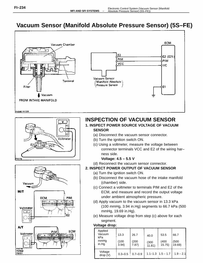
INSPECTION OF VACUUM SENSOR1. INSPECT POWER SOURCE VOLTAGE OF VACUUM
SENSOR(a) Disconnect the vacuum sensor connector.(b) Turn the ignition switch ON.(c) Using a voltmeter, measure the voltage between
connector terminals VCC and E2 of the wiring har–ness side.Voltage: 4.5 – 5.5 V
(d) Reconnect the vacuum sensor connector.2. INSPECT POWER OUTPUT OF VACUUM SENSOR
(a) Turn the ignition switch ON.(b) Disconnect the vacuum hose of the intake manifold
(chamber) side.(c) Connect a voltmeter to terminals PIM and E2 of the
ECM, and measure and record the output voltageunder ambient atmospheric pressure.
(d) Apply vacuum to the vacuum sensor in 13.3 kPa(100 mmHg, 3.94 in.Hg) segments to 66.7 kPa (500mmHg, 19.69 in.Hg).
(e) Measure voltage drop from step (c) above for eachsegment.
Voltage drop:
Vacuum Sensor (Manifold Absolute Pressure Sensor) (5S–FE)
AppliedVacuumkPammHgin.Hg
66.7
(50019.69)
40.0
(30011.81)
53.5
(40015.75)
13.3
(1003.94)
26.7
(2007.87)
Voltagedrop (V) 0.3–0.5 0.7–0.9 1.1–1.3 1.9 – 2.11.5 – 1.7
–MFI AND SFI SYSTEMSFI–234 Electronic Control System (Vacuum Sensor (Manifold
Absolute Pressure Sensor) (5S–FE))
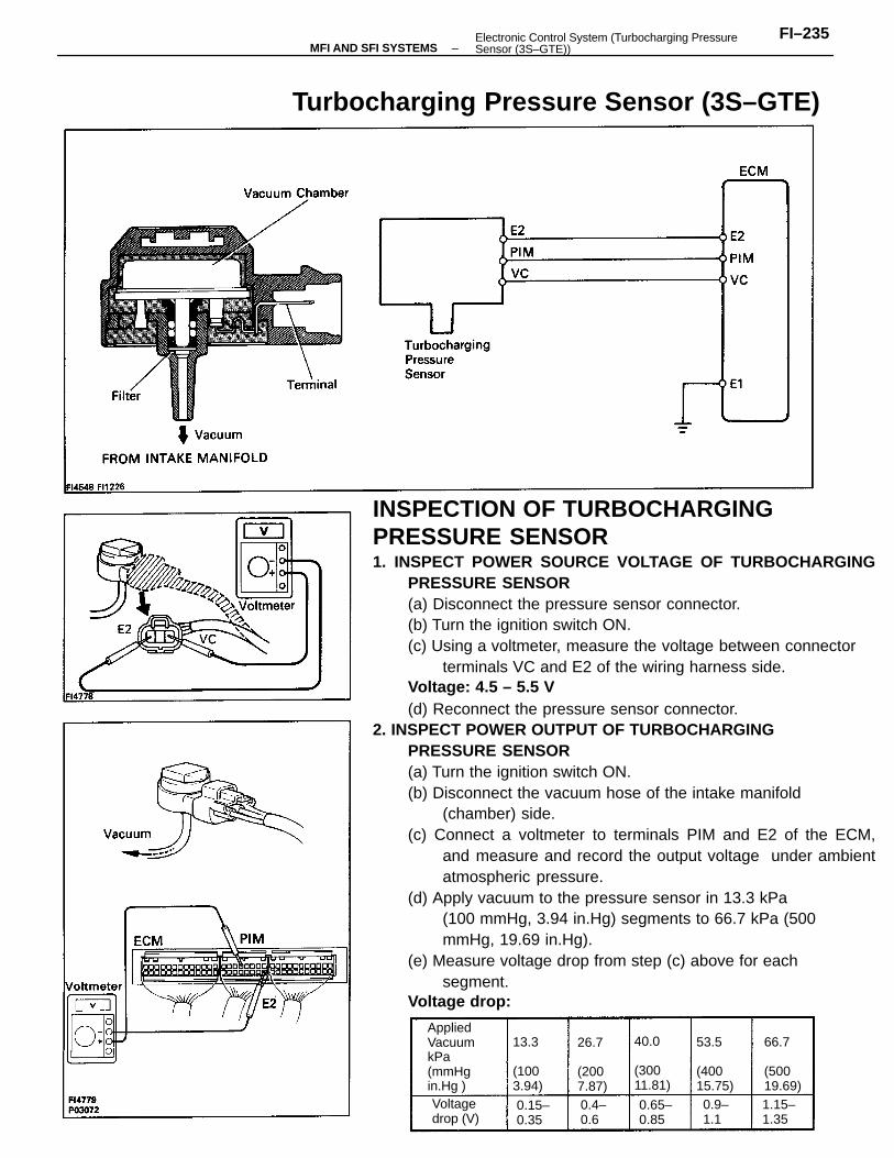
INSPECTION OF TURBOCHARGINGPRESSURE SENSOR1. INSPECT POWER SOURCE VOLTAGE OF TURBOCHARGING
PRESSURE SENSOR(a) Disconnect the pressure sensor connector.(b) Turn the ignition switch ON.(c) Using a voltmeter, measure the voltage between connector
terminals VC and E2 of the wiring harness side.Voltage: 4.5 – 5.5 V(d) Reconnect the pressure sensor connector.
2. INSPECT POWER OUTPUT OF TURBOCHARGINGPRESSURE SENSOR(a) Turn the ignition switch ON.(b) Disconnect the vacuum hose of the intake manifold
(chamber) side.(c) Connect a voltmeter to terminals PIM and E2 of the ECM,
and measure and record the output voltage under ambientatmospheric pressure.
(d) Apply vacuum to the pressure sensor in 13.3 kPa(100 mmHg, 3.94 in.Hg) segments to 66.7 kPa (500mmHg, 19.69 in.Hg).
(e) Measure voltage drop from step (c) above for eachsegment.
Voltage drop:
Turbocharging Pressure Sensor (3S–GTE)
AppliedVacuumkPa(mmHg in.Hg )
66.7
(50019.69)
40.0
(30011.81)
53.5
(40015.75)
13.3
(1003.94)
26.7
(2007.87)
Voltagedrop (V)
0.65–0.85
0.15–0.35
1.15–1.35
0.4–0.6
0.9–1.1
–MFI AND SFI SYSTEMSFI–235Electronic Control System (Turbocharging Pressure
Sensor (3S–GTE))
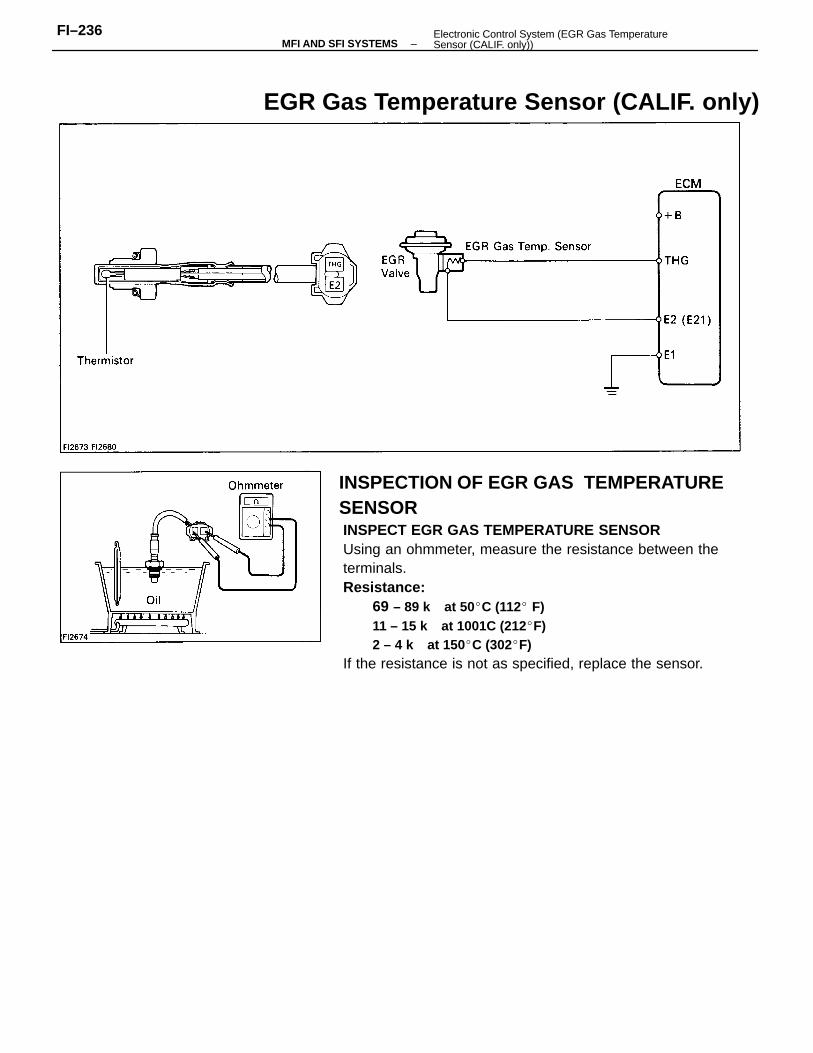
INSPECT EGR GAS TEMPERATURE SENSORUsing an ohmmeter, measure the resistance between theterminals.Resistance:
69 – 89 k at 50C (112 F)11 – 15 k at 1001C (212F)2 – 4 k at 150C (302F)
If the resistance is not as specified, replace the sensor.
EGR Gas Temperature Sensor (CALIF. only)
INSPECTION OF EGR GAS TEMPERATURESENSOR
–MFI AND SFI SYSTEMSFI–236 Electronic Control System (EGR Gas Temperature
Sensor (CALIF. only))
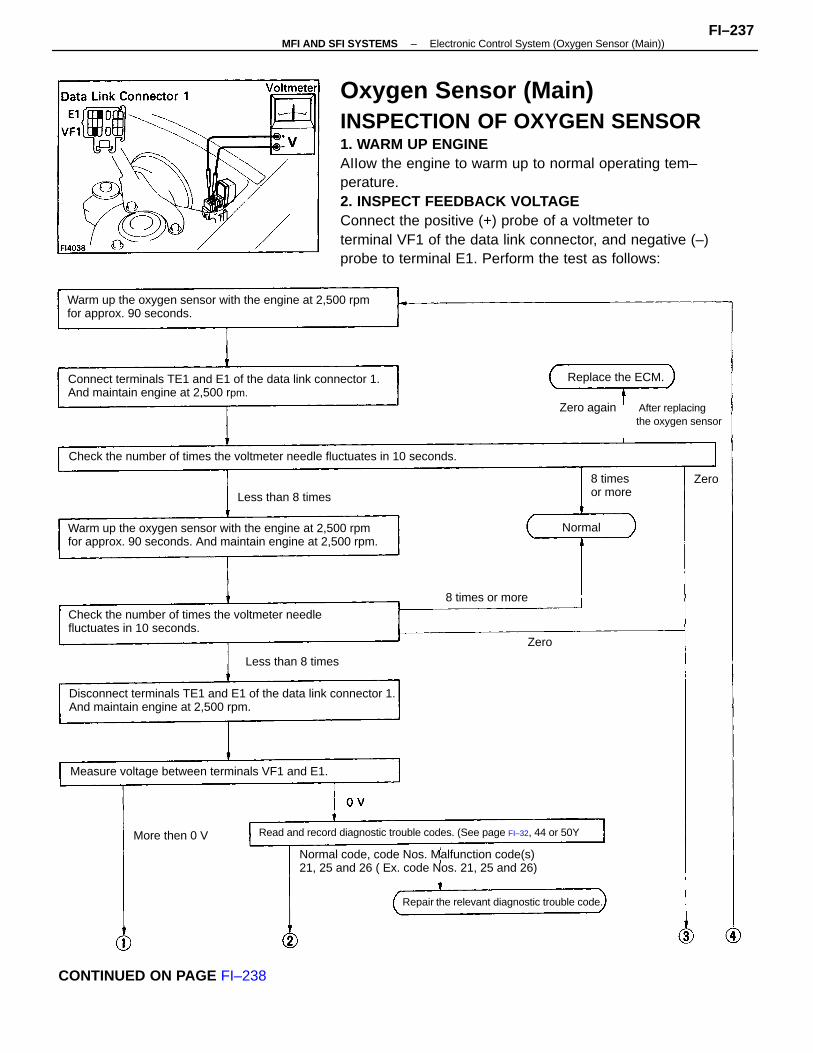
Oxygen Sensor (Main)INSPECTION OF OXYGEN SENSOR1. WARM UP ENGINEAIIow the engine to warm up to normal operating tem–perature.2. INSPECT FEEDBACK VOLTAGEConnect the positive (+) probe of a voltmeter toterminal VF1 of the data link connector, and negative (–)probe to terminal E1. Perform the test as follows:
Warm up the oxygen sensor with the engine at 2,500 rpmfor approx. 90 seconds. And maintain engine at 2,500 rpm.
Normal code, code Nos. Malfunction code(s)21, 25 and 26 ( Ex. code Nos. 21, 25 and 26)
Warm up the oxygen sensor with the engine at 2,500 rpmfor approx. 90 seconds.
Disconnect terminals TE1 and E1 of the data link connector 1.And maintain engine at 2,500 rpm.
Connect terminals TE1 and E1 of the data link connector 1.And maintain engine at 2,500 rpm.
Check the number of times the voltmeter needlefluctuates in 10 seconds.
Check the number of times the voltmeter needle fluctuates in 10 seconds.
Zero again After replacing the oxygen sensor
Read and record diagnostic trouble codes. (See page FI–32, 44 or 50Y
Measure voltage between terminals VF1 and E1.
CONTINUED ON PAGE FI–238
Repair the relevant diagnostic trouble code.
Replace the ECM.
Less than 8 times
Less than 8 times
8 times or more
More then 0 V
8 timesor more
Normal
Zero
Zero
–MFI AND SFI SYSTEMS Electronic Control System (Oxygen Sensor (Main))FI–237
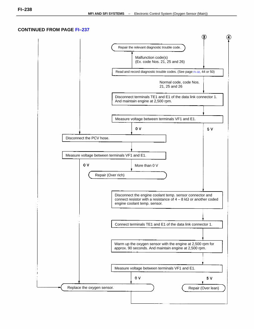
Disconnect the engine coolant temp. sensor connector andconnect resistor with a resistance of 4 – 8 k or another codedengine coolant temp. sensor.
Warm up the oxygen sensor with the engine at 2,500 rpm forapprox. 90 seconds. And maintain engine at 2,500 rpm.
Disconnect terminals TE1 and E1 of the data link connector 1.And maintain engine at 2,500 rpm.
CONTINUED FROM PAGE FI–237
Read and record diagnostic trouble codes. (See page FI–32, 44 or 50)
Connect terminals TE1 and E1 of the data link connector 1.
Malfunction code(s)(Ex. code Nos. 21, 25 and 26)
Measure voltage between terminals VF1 and E1.
Measure voltage between terminals VF1 and E1.
Measure voltage between terminals VF1 and E1.
Normal code, code Nos.21, 25 and 26
Repair the relevant diagnostic trouble code.
Replace the oxygen sensor.
Disconnect the PCV hose.
Repair (Over lean)
Repair (Over rich)
More than 0 V
–MFI AND SFI SYSTEMS Electronic Control System (Oxygen Sensor (Main))FI–238
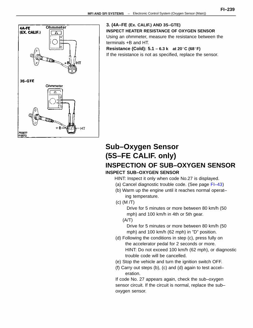
Sub–Oxygen Sensor(5S–FE CALIF. only)INSPECTION OF SUB–OXYGEN SENSORINSPECT SUB–OXYGEN SENSOR HINT: Inspect it only when code No.27 is displayed.
(a) Cancel diagnostic trouble code. (See page FI–43)(b) Warm up the engine until it reaches normal operat–
ing temperature. (c) (M /T)
Drive for 5 minutes or more between 80 km/h (50 mph) and 100 km/h in 4th or 5th gear.(A/T)
Drive for 5 minutes or more between 80 km/h (50 mph) and 100 km/h (62 mph) in ”D” position.
(d) Following the conditions in step (c), press fully onthe accelerator pedal for 2 seconds or more.HINT: Do not exceed 100 km/h (62 mph), or diagnostictrouble code will be cancelled.
(e) Stop the vehicle and turn the ignition switch OFF.(f) Carry out steps (b), (c) and (d) again to test accel–
eration.If code No. 27 appears again, check the sub–oxygensensor circuit. If the circuit is normal, replace the sub–oxygen sensor.
3. (4A–FE (Ex. CALIF.) AND 3S–GTE)INSPECT HEATER RESISTANCE OF OXYGEN SENSORUsing an ohmmeter, measure the resistance between theterminals +B and HT.Resistance (Cold): 5.1 – 6.3 k at 20C (68F)If the resistance is not as specified, replace the sensor.
–MFI AND SFI SYSTEMSFI–239
Electronic Control System (Oxygen Sensor (Main))
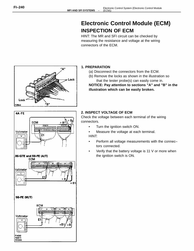
2. INSPECT VOLTAGE OF ECMCheck the voltage between each terminal of the wiringconnectors.
• Turn the ignition switch ON.
• Measure the voltage at each terminal.HINT:
• Perform all voltage measurements with the connec–tors connected.
• Verify that the battery voltage is 11 V or more whenthe ignition switch is ON.
1. PREPARATION(a) Disconnect the connectors from the ECM.(b) Remove the locks as shown in the illustration so
that the tester probe(s) can easily come in.NOTICE: Pay attention to sections ”A” and ”B” in theillustration which can be easily broken.
Electronic Control Module (ECM)INSPECTION OF ECMHINT: The MR and SFI circuit can be checked bymeasuring the resistance and voltage at the wiringconnectors of the ECM.
–MFI AND SFI SYSTEMSFI–240 Electronic Control System (Electronic Control Module
(ECM))
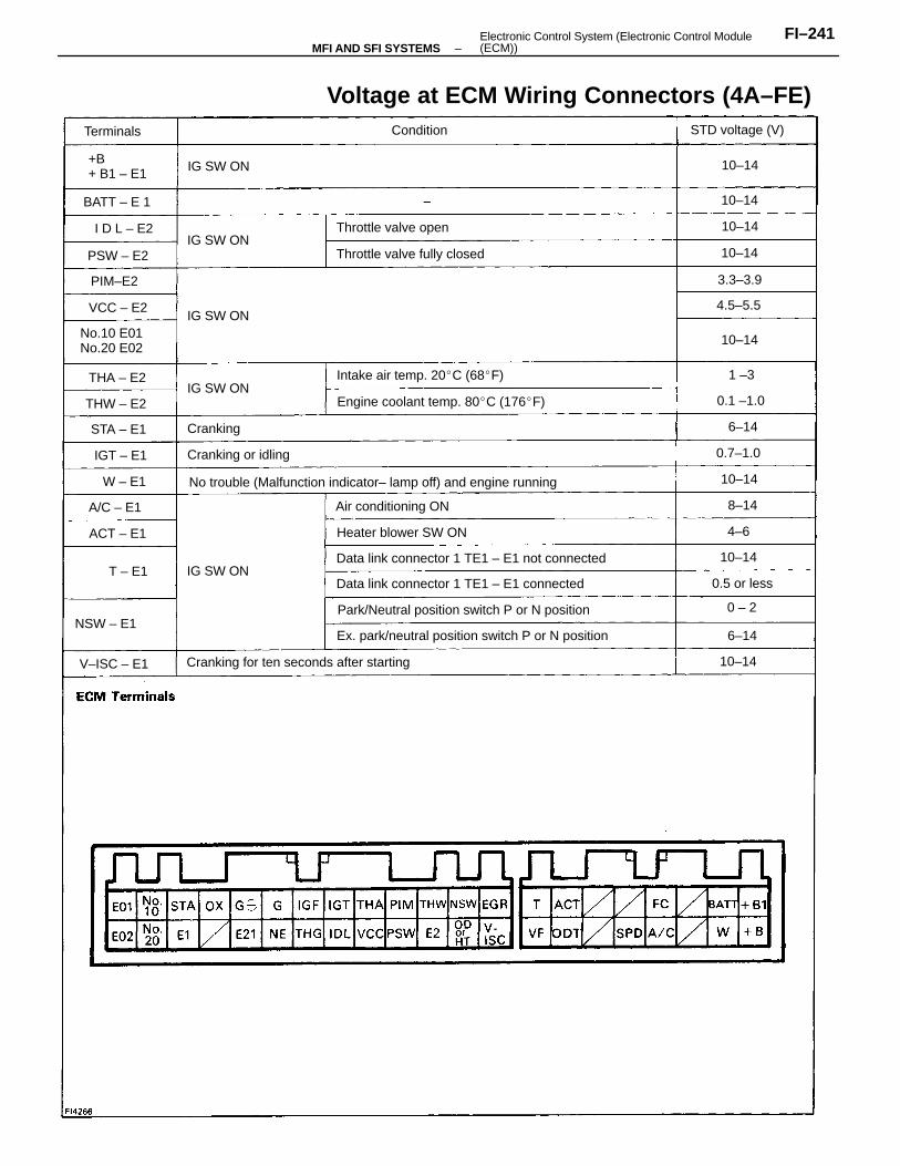
Voltage at ECM Wiring Connectors (4A–FE)
No trouble (Malfunction indicator– lamp off) and engine running
Ex. park/neutral position switch P or N position
Park/Neutral position switch P or N position
Data link connector 1 TE1 – E1 not connected
Cranking for ten seconds after starting
Data link connector 1 TE1 – E1 connected
Engine coolant temp. 80C (176F)
Intake air temp. 20C (68F)
Throttle valve fully closed
Heater blower SW ON
No.10 E01No.20 E02
Air conditioning ON
Throttle valve open
STD voltage (V)
NSW – E1
Cranking or idling
+B+ B1 – E1
Terminals Condition
V–ISC – E1
IG SW ON
IG SW ON
IG SW ON
0.5 or less
IG SW ON
IG SW ON
BATT – E 1
Cranking
THW – E2
PSW – E2
A/C – E1
PIM–E2
0.1 –1.0
ACT – E1
0.7–1.0
VCC – E2
THA – E2
STA – E1
4.5–5.5
I D L – E2
3.3–3.9
IGT – E1
10–14
10–14
10–14
10–14
10–14
10–14
10–14
0 – 2
10–14
W – E1
6–14
8–14
6–14
T – E1
4–6
1 –3
–MFI AND SFI SYSTEMSFI–241Electronic Control System (Electronic Control Module
(ECM))
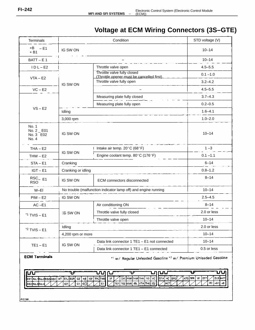
Voltage at ECM Wiring Connectors (3S–GTE)
No trouble (malfunction indicator lamp off) and engine running
Throttle valve fully closed(Throttle opener must be cancelled first)
Data link connector 1 TE1 – E1 not connected
Data link connector 1 TE1 – E1 connected
Engine coolant temp. 80C (176F)
No. 1No. 2 _ E01No. 3 E02No. 4
ECM connectors disconnected
Intake air temp. 20C (68F)
Measuring plate fully closed
Measuring plate fully open
Throttle valve fully open
Throttle valve fully closed
Air conditioning ON
Throttle valve open
4,200 rpm or more
Throttle valve open
Cranking or idling
STD voltage (V)
RSCRSO
+B+ B1
*2 TVIS – E1
*1 TVIS – E1
3,000 rpm
Terminals Condition
IG SW ON
IG SW ON
IG SW ON
IG SW ON
IG SW ON
IG SW ON
0.5 or less
G SW ON
IG SW ON
2.0 or less
2.0 or less
BATT – E 1
Cranking
THW – E2
THA – E2
0.1 –1.0
PIM – E2
VTA – E2
STA – E1
1.0–2.0
0.2–0.5
0.8–1.2
3.2–4.2
4.5–5.5
0.1 –1.1
4.5–5.5
3.7–4.3
TE1 – E1
2.5–4.5
I D L – E2
1.6–4.1
IGT – E1
10–14
10–14
10–14
AC –E1
10–14
10–14
10–14
VS – E2
VC – E2
10–14
W–El
8–14
6–14
8–14
Idling
Idling
1 –3
– E1
– E1
–MFI AND SFI SYSTEMSFI–242 Electronic Control System (Electronic Control Module
(ECM))
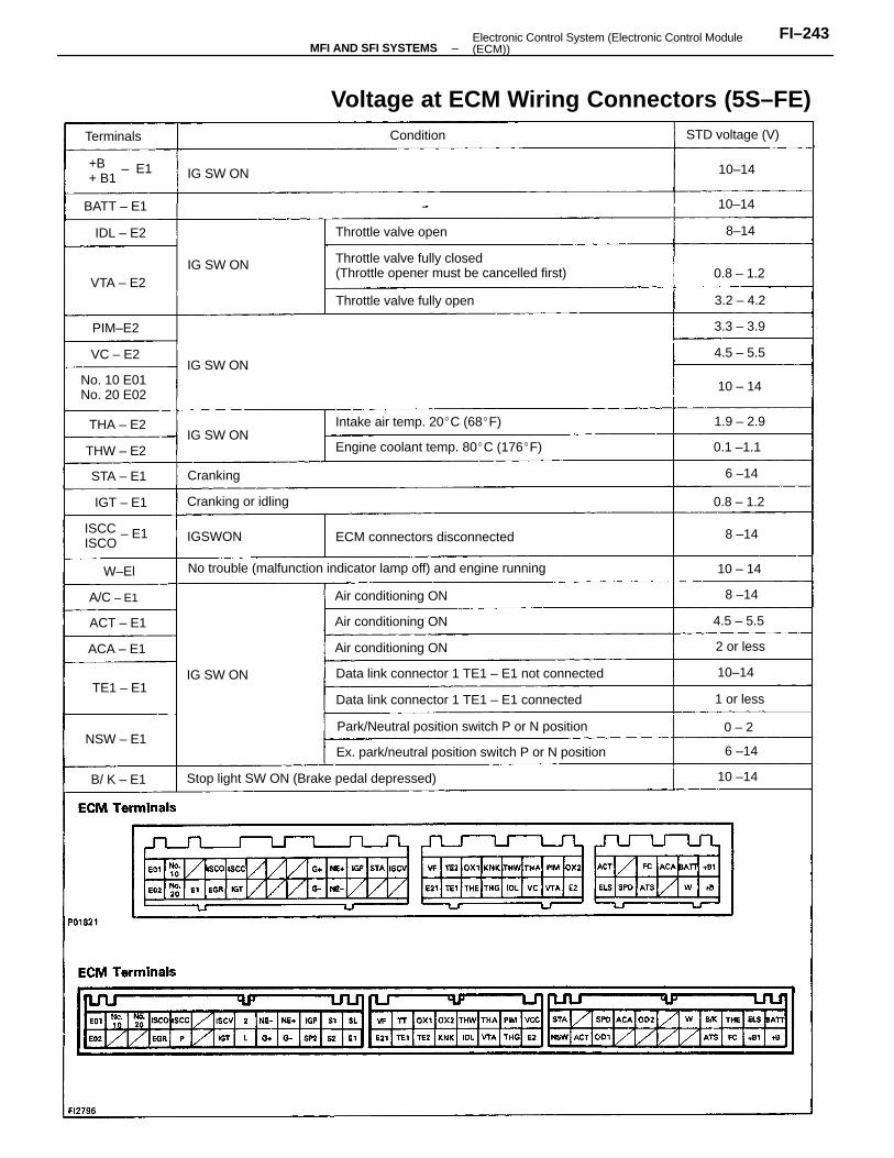
Voltage at ECM Wiring Connectors (5S–FE)
No trouble (malfunction indicator lamp off) and engine running
Throttle valve fully closed(Throttle opener must be cancelled first)
Ex. park/neutral position switch P or N position
Park/Neutral position switch P or N position
Data link connector 1 TE1 – E1 not connected
Stop light SW ON (Brake pedal depressed)
Data link connector 1 TE1 – E1 connected
Engine coolant temp. 80C (176F)
ECM connectors disconnected
Intake air temp. 20C (68F)
Throttle valve fully open
No. 10 E01No. 20 E02
Air conditioning ON
Air conditioning ON
Air conditioning ON
Throttle valve open
STD voltage (V)
Cranking or idling
ISCCISCO
+B + B1
ConditionTerminals
IG SW ON
IG SW ON
IG SW ON
IG SW ON
IGSWON
BATT – E1
IG SW ON
NSW – E1
THW – E2
ACA – E1
Cranking
PIM–E2
A/C – E1
ACT – E1
0.8 – 1.2
THA – E2
B/ K – E1
STA – E1
0.8 – 1.2
0.1 –1.1
VTA – E2
TE1 – E1
IDL – E2
4.5 – 5.5
1.9 – 2.9
3.2 – 4.2
4.5 – 5.5
3.3 – 3.9
IGT – E1
2 or less
1 or less
10 –14
10–14
10 – 14
10–14
10 – 14
10–14
VC – E2
W–El
6 –14
8 –14
8–14
8 –14
6 –14
0 – 2
– E1
– E1
–MFI AND SFI SYSTEMSFI–243Electronic Control System (Electronic Control Module
(ECM))
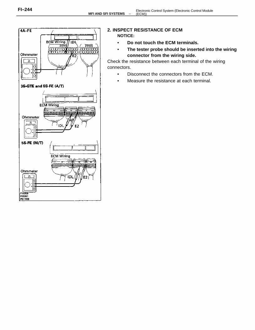
2. INSPECT RESISTANCE OF ECMNOTICE:
• Do not touch the ECM terminals.• The tester probe should be inserted into the wiring
connector from the wiring side.Check the resistance between each terminal of the wiringconnectors.
• Disconnect the connectors from the ECM.
• Measure the resistance at each terminal.
–MFI AND SFI SYSTEMSFI–244 Electronic Control System (Electronic Control Module
(ECM))
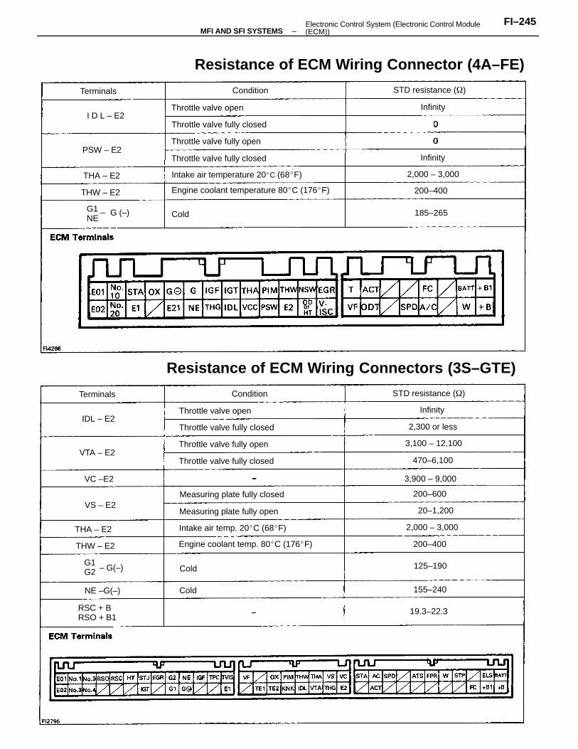
Resistance of ECM Wiring Connectors (3S–GTE)
Resistance of ECM Wiring Connector (4A–FE)
Engine coolant temperature 80C (176F)
Engine coolant temp. 80C (176F)
Intake air temperature 20C (68F)
Intake air temp. 20C (68F)
Measuring plate fully closed
Measuring plate fully open
Throttle valve fully closed
Throttle valve fully closed
Throttle valve fully closed
Throttle valve fully closed
Throttle valve fully open
Throttle valve fully open
STD resistance ()
STD resistance ()
Throttle valve open
RSC + BRSO + B1
Throttle valve open
G1 _NE
G1G2
3,100 – 12,100
3,900 – 9,000
2,000 – 3,000
2,000 – 3,000
2,300 or less
470–6,100
20–1,200
Condition
19.3–22.3
ConditionTerminals
Terminals
200–600
200–400
200–400
155–240NE –G(–)
125–190
THA – E2
185–265
THW – E2
THW – E2
PSW – E2
THA – E2
IDL – E2
VTA – E2
I D L – E2
VC –E2
VS – E2
Infinity
Infinity
Infinity
Cold
Cold
ColdG (–)
– G(–)
–MFI AND SFI SYSTEMSFI–245Electronic Control System (Electronic Control Module
(ECM))
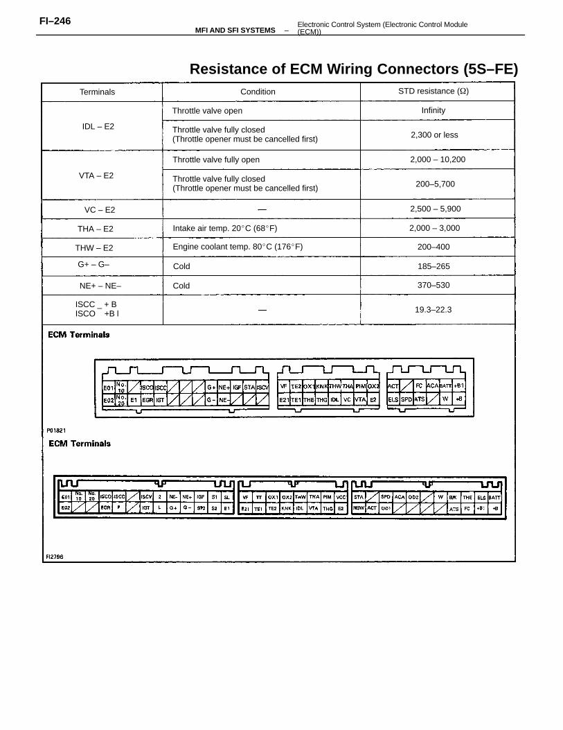
Resistance of ECM Wiring Connectors (5S–FE)
Throttle valve fully closed(Throttle opener must be cancelled first)
Throttle valve fully closed(Throttle opener must be cancelled first)
Engine coolant temp. 80C (176F)
Intake air temp. 20C (68F)
Throttle valve fully open
ISCC _ + BISCO +B l
Throttle valve open
STD resistance ()
2,000 – 10,200
2,000 – 3,000
2,500 – 5,900
2,300 or less
200–5,700
NE+ – NE–
THW – E2
THA – E2
19.3–22.3
VTA – E2
Terminals
G+ – G–
IDL – E2
200–400
370–530
Condition
185–265
VC – E2
Infinity
Cold
Cold
–MFI AND SFI SYSTEMSFI–246 Electronic Control System (Electronic Control Module
(ECM))
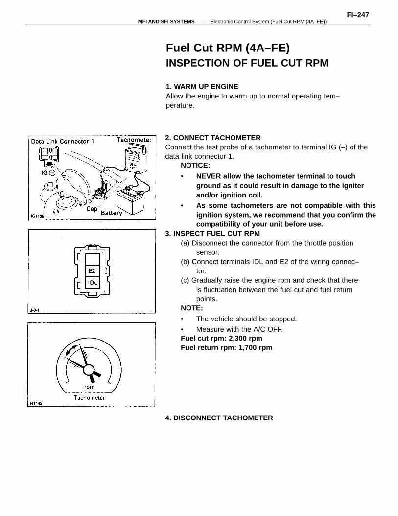
2. CONNECT TACHOMETERConnect the test probe of a tachometer to terminal IG (–) of thedata link connector 1.
NOTICE:
• NEVER allow the tachometer terminal to touchground as it could result in damage to the igniterand/or ignition coil.
• As some tachometers are not compatible with thisignition system, we recommend that you confirm thecompatibility of your unit before use.
3. INSPECT FUEL CUT RPM(a) Disconnect the connector from the throttle position
sensor.(b) Connect terminals IDL and E2 of the wiring connec–
tor.(c) Gradually raise the engine rpm and check that there
is fluctuation between the fuel cut and fuel returnpoints.
NOTE:
• The vehicle should be stopped.
• Measure with the A/C OFF.Fuel cut rpm: 2,300 rpmFuel return rpm: 1,700 rpm
Fuel Cut RPM (4A–FE)INSPECTION OF FUEL CUT RPM
1. WARM UP ENGINEAllow the engine to warm up to normal operating tem–perature.
4. DISCONNECT TACHOMETER
–MFI AND SFI SYSTEMS Electronic Control System (Fuel Cut RPM (4A–FE))FI–247
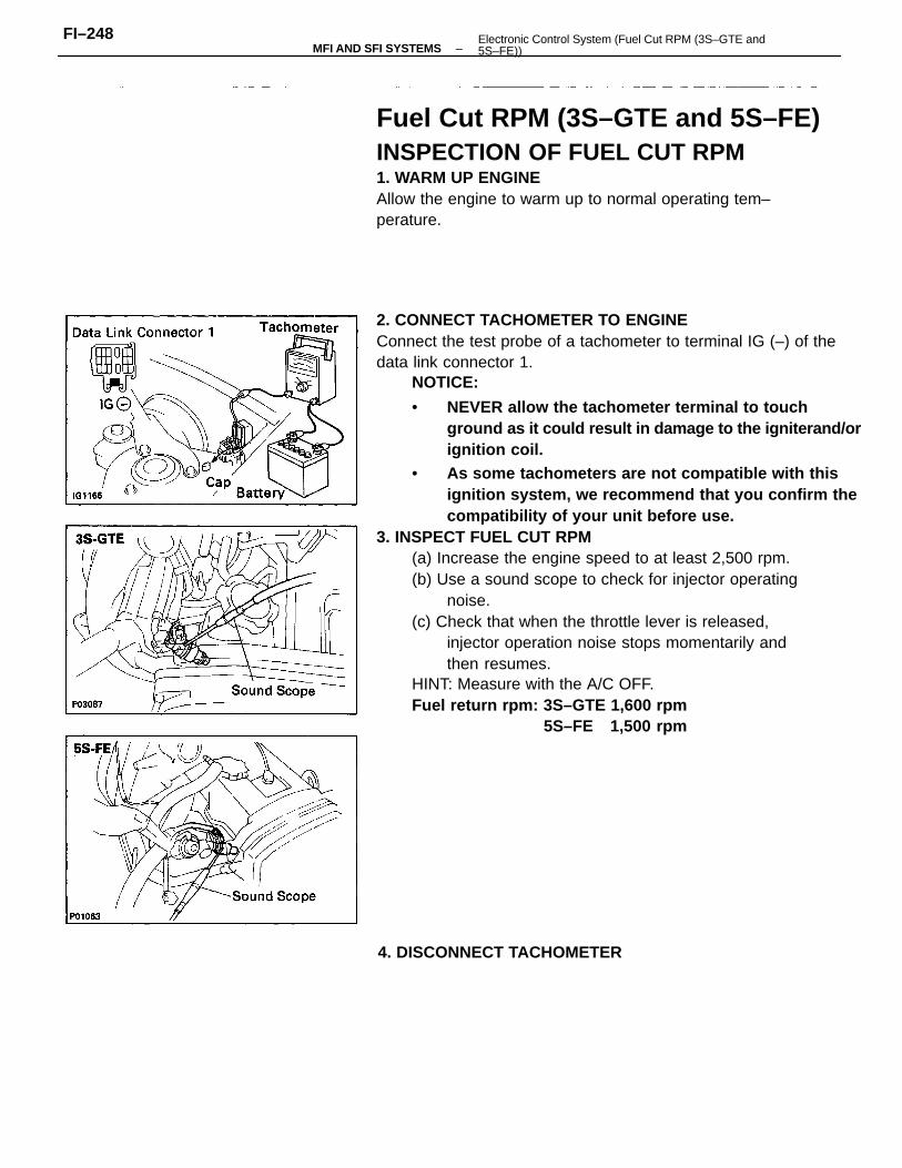
2. CONNECT TACHOMETER TO ENGINEConnect the test probe of a tachometer to terminal IG (–) of thedata link connector 1.
NOTICE:
• NEVER allow the tachometer terminal to touchground as it could result in damage to the igniterand/orignition coil.
• As some tachometers are not compatible with thisignition system, we recommend that you confirm thecompatibility of your unit before use.
3. INSPECT FUEL CUT RPM(a) Increase the engine speed to at least 2,500 rpm.(b) Use a sound scope to check for injector operating
noise.(c) Check that when the throttle lever is released,
injector operation noise stops momentarily andthen resumes.
HINT: Measure with the A/C OFF.Fuel return rpm: 3S–GTE 1,600 rpm
5S–FE 1,500 rpm
Fuel Cut RPM (3S–GTE and 5S–FE)INSPECTION OF FUEL CUT RPM1. WARM UP ENGINEAllow the engine to warm up to normal operating tem–perature.
4. DISCONNECT TACHOMETER
–MFI AND SFI SYSTEMSFI–248 Electronic Control System (Fuel Cut RPM (3S–GTE and
5S–FE))
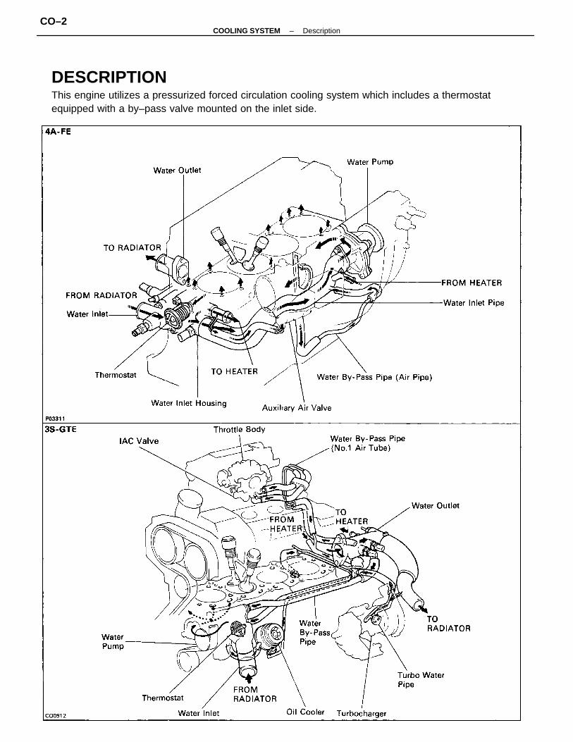
DESCRIPTIONThis engine utilizes a pressurized forced circulation cooling system which includes a thermostatequipped with a by–pass valve mounted on the inlet side.
–COOLING SYSTEM DescriptionCO–2
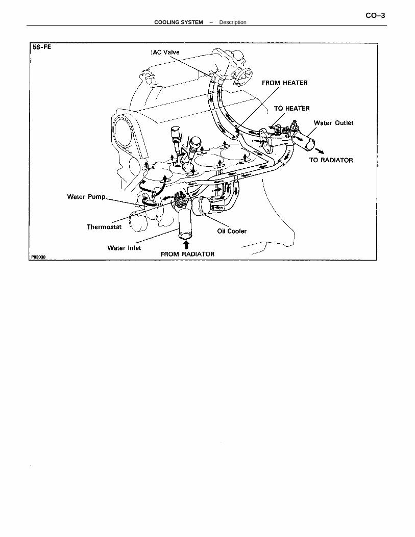
–COOLING SYSTEM DescriptionCO–3
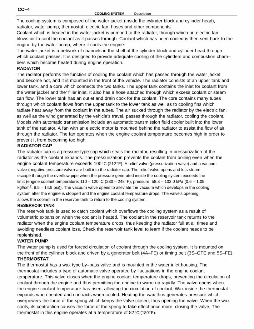
RADIATOR CAPThe radiator cap is a pressure type cap which seals the radiator, resulting in pressurization of theradiator as the coolant expands. The pressurization prevents the coolant from boiling even when theengine coolant temperature exceeds 100C (212F). A relief valve (pressurization valve) and a vacuumvalve (negative pressure valve) are built into the radiator cap. The relief valve opens and lets steamescape through the overflow pipe when the pressure generated inside the cooling system exceeds thelimit (engine coolant temperature: 110 – 120C (230 – 248F), pressure; 58.8 – 103.0 kPa (0.6 – 1.05kgf/cm2, 8.5 – 14.9 psi)). The vacuum valve opens to alleviate the vacuum which develops in the coolingsystem after the engine is stopped and the engine coolant temperature drops. The valve’s openingallows the coolant in the reservoir tank to return to the cooling system.RESERVOIR TANKThe reservoir tank is used to catch coolant which overflows the cooling system as a result ofvolumetric expansion when the coolant is heated. The coolant in the reservoir tank returns to theradiator when the engine coolant temperature drops, thus keeping the radiator full at all times andavoiding needless coolant loss. Check the reservoir tank level to learn if the coolant needs to bereplenished.WATER PUMPThe water pump is used for forced circulation of coolant through the cooling system. It is mounted onthe front of the cylinder block and driven by a generator belt (4A–FE) or timing belt (3S–GTE and 5S–FE).THERMOSTATThe thermostat has a wax type by–pass valve and is mounted in the water inlet housing. Thethermostat includes a type of automatic valve operated by fluctuations in the engine coolanttemperature. This valve closes when the engine coolant temperature drops, preventing the circulation ofcoolant through the engine and thus permitting the engine to warm up rapidly. The valve opens whenthe engine coolant temperature has risen, allowing the circulation of coolant. Wax inside the thermostatexpands when heated and contracts when cooled. Heating the wax thus generates pressure whichoverpowers the force of the spring which keeps the valve closed, thus opening the valve. When the waxcools, its contraction causes the force of the spring to take effect once more, closing the valve. Thethermostat in this engine operates at a temperature of 82C (180F).
The cooling system is composed of the water jacket (inside the cylinder block and cylinder head),radiator, water pump, thermostat, electric fan, hoses and other components.Coolant which is heated in the water jacket is pumped to the radiator, through which an electric fanblows air to cool the coolant as it passes through. Coolant which has been cooled is then sent back to theengine by the water pump, where it cools the engine.The water jacket is a network of channels in the shell of the cylinder block and cylinder head throughwhich coolant passes. It is designed to provide adequate cooling of the cylinders and combustion cham–bers which become heated during engine operation.RADIATORThe radiator performs the function of cooling the coolant which has passed through the water jacketand become hot, and it is mounted in the front of the vehicle. The radiator consists of an upper tank andlower tank, and a core which connects the two tanks. The upper tank contains the inlet for coolant fromthe water jacket and the’ filler inlet. It also has a hose attached through which excess coolant or steamcan flow. The lower tank has an outlet and drain cock for the coolant. The core contains many tubesthrough which coolant flows from the upper tank to the lower tank as well as to cooling fins whichradiate heat away from the coolant in the tubes. The air sucked through the radiator by the electric fan,as well as the wind generated by the vehicle’s travel, passes through the radiator, cooling the coolant.Models with automatic transmission include an automatic transmission fluid cooler built into the lowertank of the radiator. A fan with an electric motor is mounted behind the radiator to assist the flow of airthrough the radiator. The fan operates when the engine coolant temperature becomes high in order toprevent it from becoming too high.
–COOLING SYSTEM DescriptionCO–4
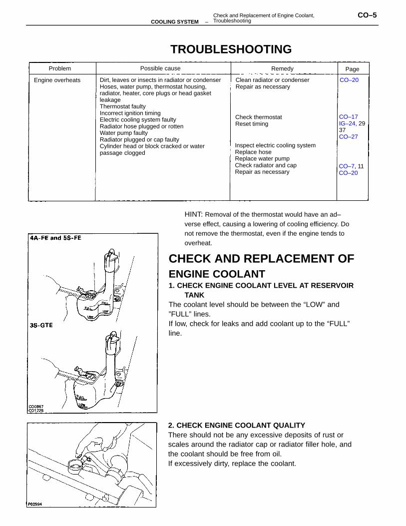
CHECK AND REPLACEMENT OFENGINE COOLANT1. CHECK ENGINE COOLANT LEVEL AT RESERVOIR
TANKThe coolant level should be between the “LOW” and”FULL” lines.If low, check for leaks and add coolant up to the “FULL”line.
Dirt, leaves or insects in radiator or condenserHoses, water pump, thermostat housing,radiator, heater, core plugs or head gasketleakageThermostat faultyIncorrect ignition timingElectric cooling system faultyRadiator hose plugged or rottenWater pump faultyRadiator plugged or cap faultyCylinder head or block cracked or waterpassage clogged
2. CHECK ENGINE COOLANT QUALITYThere should not be any excessive deposits of rust orscales around the radiator cap or radiator filler hole, andthe coolant should be free from oil.If excessively dirty, replace the coolant.
HINT: Removal of the thermostat would have an ad–verse effect, causing a lowering of cooling efficiency. Donot remove the thermostat, even if the engine tends tooverheat.
Inspect electric cooling systemReplace hoseReplace water pumpCheck radiator and capRepair as necessary
Clean radiator or condenserRepair as necessary
TROUBLESHOOTING
CO–17IG–24, 2937CO–27
Check thermostatReset timing
CO–7, 11CO–20
Engine overheats
Possible causeProblem Remedy
CO–20
Page
–COOLING SYSTEMCheck and Replacement of Engine Coolant,Troubleshooting
CO–5
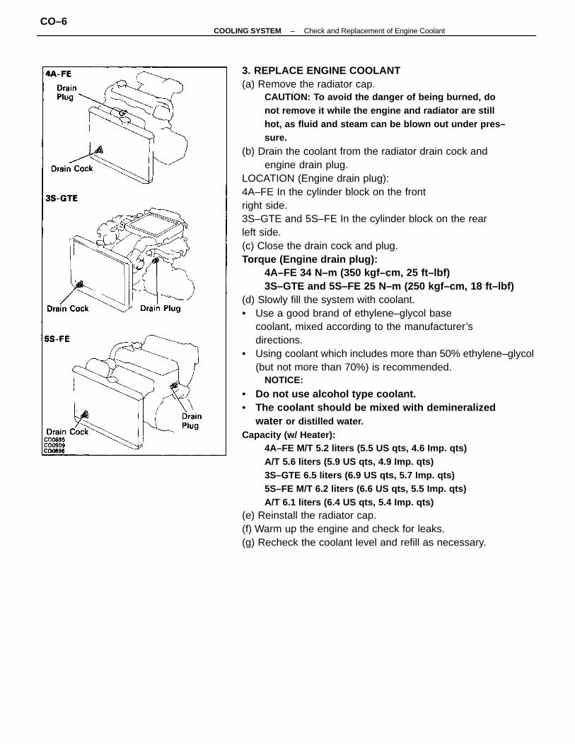
3. REPLACE ENGINE COOLANT(a) Remove the radiator cap.
CAUTION: To avoid the danger of being burned, donot remove it while the engine and radiator are stillhot, as fluid and steam can be blown out under pres–sure.
(b) Drain the coolant from the radiator drain cock andengine drain plug.
LOCATION (Engine drain plug):4A–FE In the cylinder block on the frontright side.3S–GTE and 5S–FE In the cylinder block on the rearleft side.(c) Close the drain cock and plug.Torque (Engine drain plug):
4A–FE 34 N–m (350 kgf–cm, 25 ft–lbf)3S–GTE and 5S–FE 25 N–m (250 kgf–cm, 18 ft–lbf)
(d) Slowly fill the system with coolant.• Use a good brand of ethylene–glycol base
coolant, mixed according to the manufacturer’sdirections.
• Using coolant which includes more than 50% ethylene–glycol(but not more than 70%) is recommended.
NOTICE:
• Do not use alcohol type coolant.• The coolant should be mixed with demineralized
water or distilled water.Capacity (w/ Heater):
4A–FE M/T 5.2 liters (5.5 US qts, 4.6 Imp. qts)A/T 5.6 liters (5.9 US qts, 4.9 Imp. qts)3S–GTE 6.5 liters (6.9 US qts, 5.7 Imp. qts)5S–FE M/T 6.2 liters (6.6 US qts, 5.5 Imp. qts)A/T 6.1 liters (6.4 US qts, 5.4 Imp. qts)
(e) Reinstall the radiator cap.(f) Warm up the engine and check for leaks.(g) Recheck the coolant level and refill as necessary.
–COOLING SYSTEM Check and Replacement of Engine CoolantCO–6
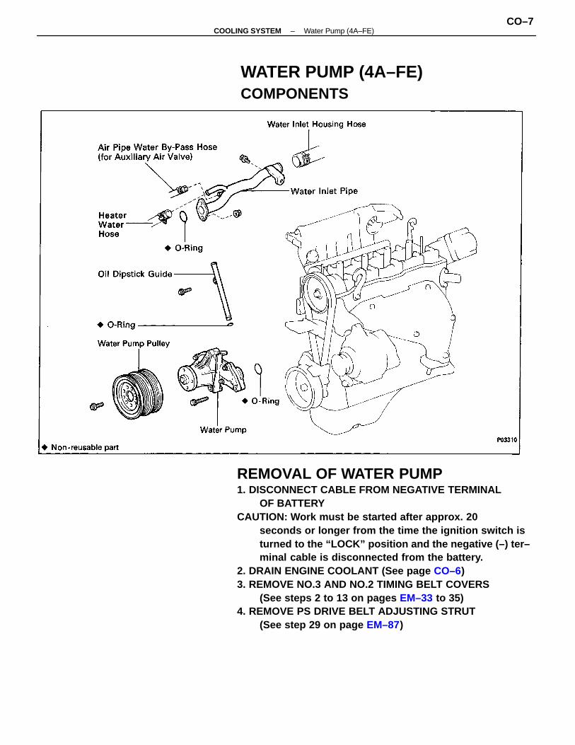
REMOVAL OF WATER PUMP1. DISCONNECT CABLE FROM NEGATIVE TERMINAL
OF BATTERYCAUTION: Work must be started after approx. 20
seconds or longer from the time the ignition switch isturned to the “LOCK” position and the negative (–) ter–minal cable is disconnected from the battery.
2. DRAIN ENGINE COOLANT (See page CO–6)3. REMOVE NO.3 AND NO.2 TIMING BELT COVERS
(See steps 2 to 13 on pages EM–33 to 35)4. REMOVE PS DRIVE BELT ADJUSTING STRUT
(See step 29 on page EM–87)
WATER PUMP (4A–FE)COMPONENTS
–COOLING SYSTEM Water Pump (4A–FE)CO–7
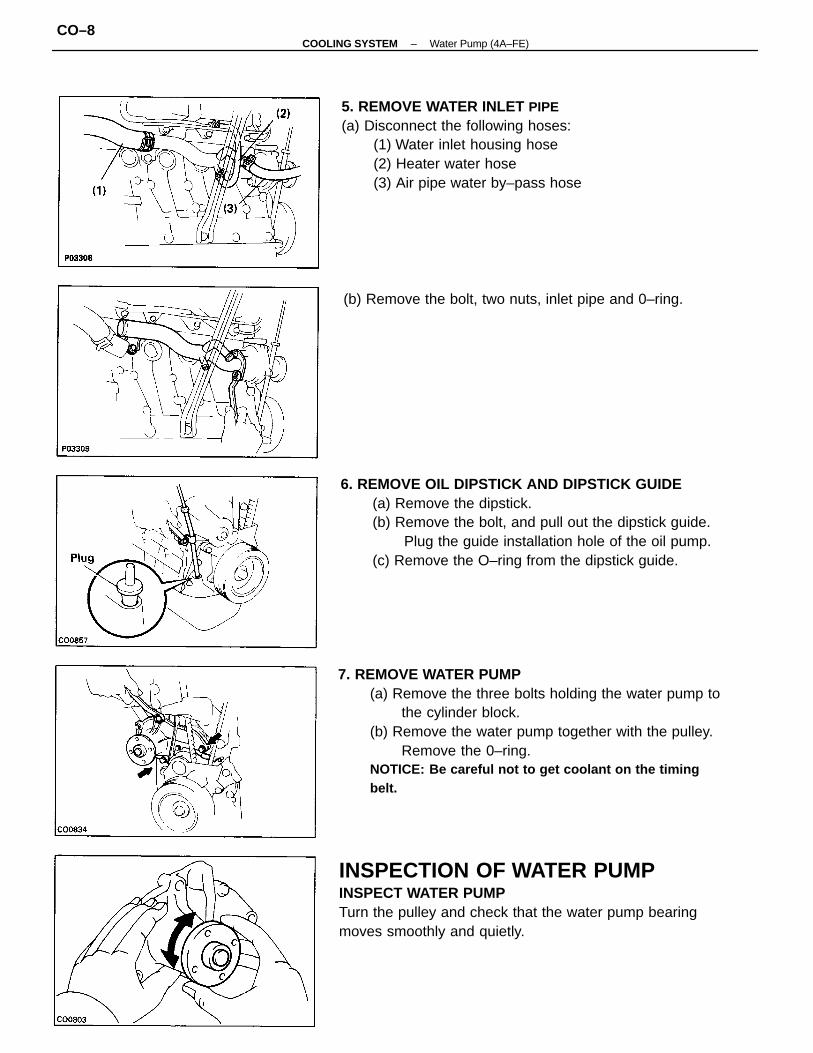
7. REMOVE WATER PUMP(a) Remove the three bolts holding the water pump to
the cylinder block.(b) Remove the water pump together with the pulley.
Remove the 0–ring.NOTICE: Be careful not to get coolant on the timingbelt.
6. REMOVE OIL DIPSTICK AND DIPSTICK GUIDE(a) Remove the dipstick.(b) Remove the bolt, and pull out the dipstick guide.
Plug the guide installation hole of the oil pump.(c) Remove the O–ring from the dipstick guide.
INSPECTION OF WATER PUMPINSPECT WATER PUMPTurn the pulley and check that the water pump bearingmoves smoothly and quietly.
5. REMOVE WATER INLET PIPE(a) Disconnect the following hoses:
(1) Water inlet housing hose(2) Heater water hose(3) Air pipe water by–pass hose
(b) Remove the bolt, two nuts, inlet pipe and 0–ring.
–COOLING SYSTEM Water Pump (4A–FE)CO–8
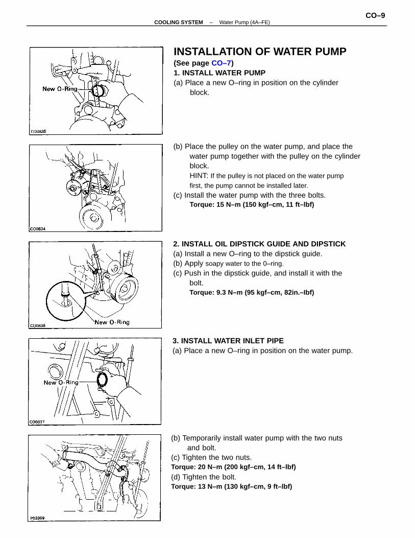
(b) Place the pulley on the water pump, and place thewater pump together with the pulley on the cylinderblock.HINT: If the pulley is not placed on the water pumpfirst, the pump cannot be installed later.
(c) Install the water pump with the three bolts.Torque: 15 N–m (150 kgf–cm, 11 ft–lbf)
2. INSTALL OIL DIPSTICK GUIDE AND DIPSTICK(a) Install a new O–ring to the dipstick guide.(b) Apply soapy water to the 0–ring.(c) Push in the dipstick guide, and install it with the
bolt.Torque: 9.3 N–m (95 kgf–cm, 82in.–Ibf)
(b) Temporarily install water pump with the two nutsand bolt.
(c) Tighten the two nuts.Torque: 20 N–m (200 kgf–cm, 14 ft–lbf)
(d) Tighten the bolt.Torque: 13 N–m (130 kgf–cm, 9 ft–lbf)
INSTALLATION OF WATER PUMP(See page CO–7)1. INSTALL WATER PUMP(a) Place a new O–ring in position on the cylinder
block.
3. INSTALL WATER INLET PIPE(a) Place a new O–ring in position on the water pump.
–COOLING SYSTEM Water Pump (4A–FE)CO–9
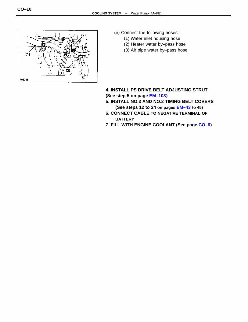
4. INSTALL PS DRIVE BELT ADJUSTING STRUT(See step 5 on page EM–108)5. INSTALL NO.3 AND NO.2 TIMING BELT COVERS
(See steps 12 to 24 on pages EM–43 to 45)6. CONNECT CABLE TO NEGATIVE TERMINAL OF
BATTERY7. FILL WITH ENGINE COOLANT (See page CO–6)
(e) Connect the following hoses:(1) Water inlet housing hose(2) Heater water by–pass hose(3) Air pipe water by–pass hose
–COOLING SYSTEM Water Pump (4A–FE)CO–10
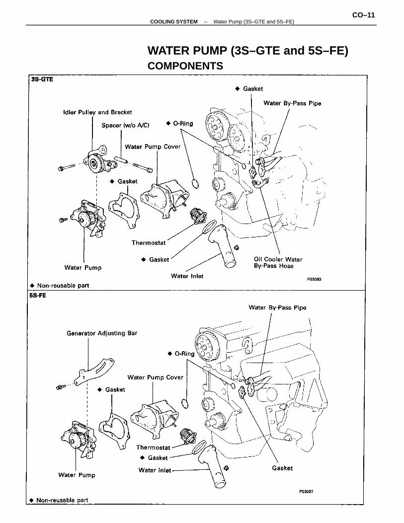
WATER PUMP (3S–GTE and 5S–FE)COMPONENTS
–COOLING SYSTEM Water Pump (3S–GTE and 5S–FE)CO–11
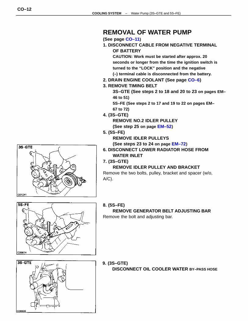
REMOVAL OF WATER PUMP(See page CO–11)1. DISCONNECT CABLE FROM NEGATIVE TERMINAL
OF BATTERYCAUTION: Work must be started after approx. 20seconds or longer from the time the ignition switch isturned to the “LOCK” position and the negative(–) terminal cable is disconnected from the battery.
2. DRAIN ENGINE COOLANT (See page CO–6)3. REMOVE TIMING BELT
3S–GTE (See steps 2 to 18 and 20 to 23 on pages EM–46 to 51)5S–FE (See steps 2 to 17 and 19 to 22 on pages EM–67 to 72)
4. (3S–GTE)REMOVE NO.2 IDLER PULLEY(See step 25 on page EM–52)
5. (5S–FE)REMOVE IDLER PULLEYS(See steps 23 to 24 on page EM–72)
6. DISCONNECT LOWER RADIATOR HOSE FROMWATER INLET
7. (3S–GTE)REMOVE IDLER PULLEY AND BRACKET
Remove the two bolts, pulley, bracket and spacer (w/o,A/C).
8. (5S–FE)REMOVE GENERATOR BELT ADJUSTING BAR
Remove the bolt and adjusting bar.
9. (3S–GTE)DISCONNECT OIL COOLER WATER BY–PASS HOSE
–COOLING SYSTEM Water Pump (3S–GTE and 5S–FE)CO–12
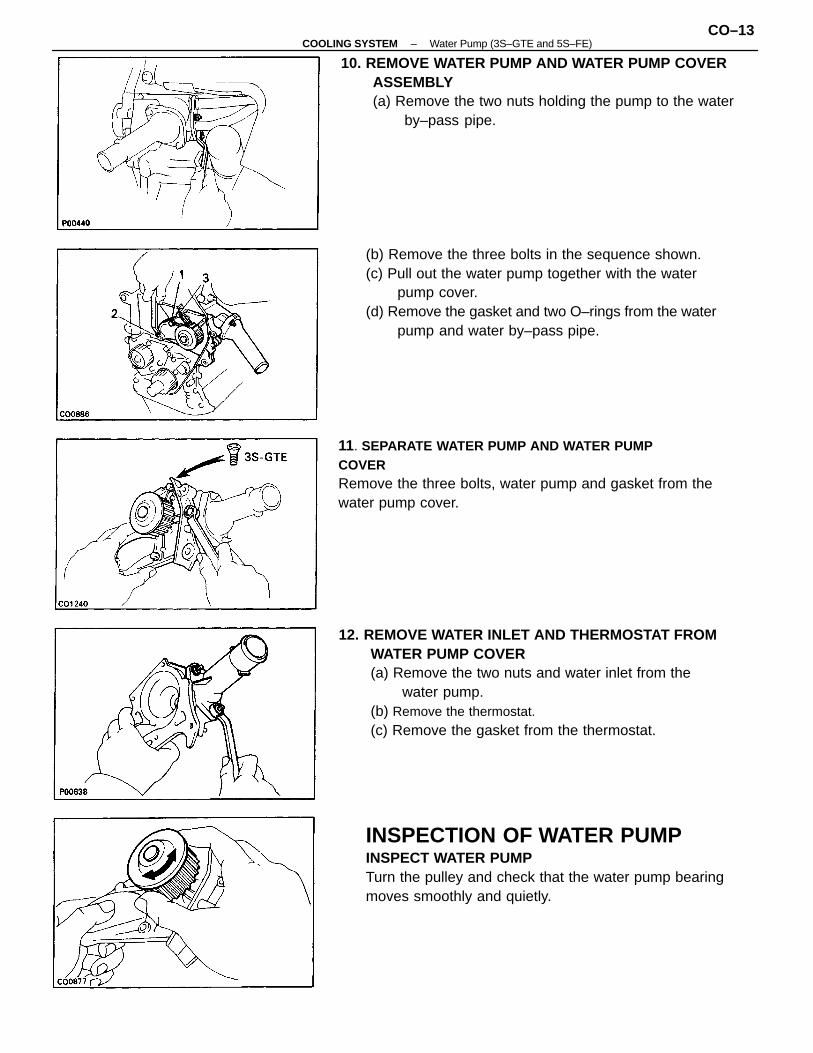
12. REMOVE WATER INLET AND THERMOSTAT FROMWATER PUMP COVER(a) Remove the two nuts and water inlet from the
water pump.(b) Remove the thermostat.(c) Remove the gasket from the thermostat.
(b) Remove the three bolts in the sequence shown.(c) Pull out the water pump together with the water
pump cover.(d) Remove the gasket and two O–rings from the water
pump and water by–pass pipe.
INSPECTION OF WATER PUMPINSPECT WATER PUMPTurn the pulley and check that the water pump bearingmoves smoothly and quietly.
10. REMOVE WATER PUMP AND WATER PUMP COVERASSEMBLY(a) Remove the two nuts holding the pump to the water
by–pass pipe.
11. SEPARATE WATER PUMP AND WATER PUMPCOVERRemove the three bolts, water pump and gasket from thewater pump cover.
–COOLING SYSTEM Water Pump (3S–GTE and 5S–FE)CO–13
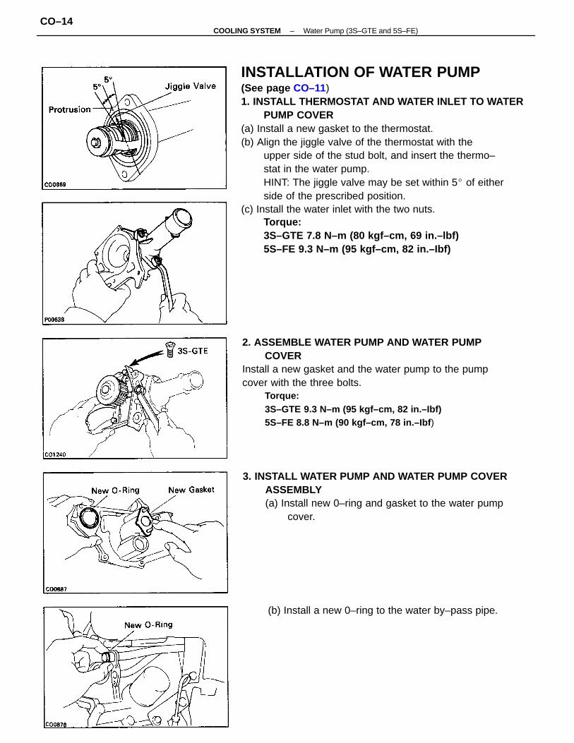
INSTALLATION OF WATER PUMP(See page CO–11)1. INSTALL THERMOSTAT AND WATER INLET TO WATER
PUMP COVER(a) Install a new gasket to the thermostat.(b) Align the jiggle valve of the thermostat with the
upper side of the stud bolt, and insert the thermo–stat in the water pump.HINT: The jiggle valve may be set within 5 of eitherside of the prescribed position.
(c) Install the water inlet with the two nuts.Torque:3S–GTE 7.8 N–m (80 kgf–cm, 69 in.–lbf)5S–FE 9.3 N–m (95 kgf–cm, 82 in.–Ibf)
2. ASSEMBLE WATER PUMP AND WATER PUMPCOVER
Install a new gasket and the water pump to the pumpcover with the three bolts.
Torque:3S–GTE 9.3 N–m (95 kgf–cm, 82 in.–Ibf)5S–FE 8.8 N–m (90 kgf–cm, 78 in.–Ibf )
3. INSTALL WATER PUMP AND WATER PUMP COVERASSEMBLY(a) Install new 0–ring and gasket to the water pump
cover.
(b) Install a new 0–ring to the water by–pass pipe.
–COOLING SYSTEM Water Pump (3S–GTE and 5S–FE)CO–14
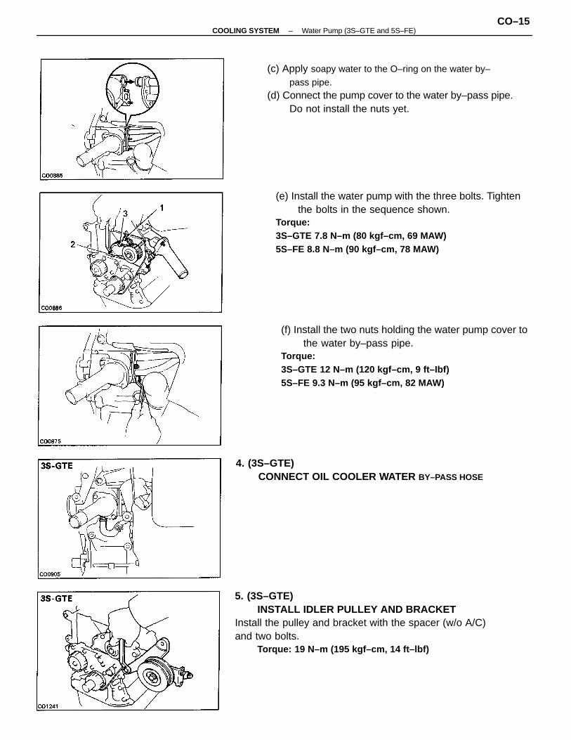
5. (3S–GTE)INSTALL IDLER PULLEY AND BRACKET
Install the pulley and bracket with the spacer (w/o A/C)and two bolts.
Torque: 19 N–m (195 kgf–cm, 14 ft–lbf)
(e) Install the water pump with the three bolts. Tightenthe bolts in the sequence shown.
Torque:3S–GTE 7.8 N–m (80 kgf–cm, 69 MAW)5S–FE 8.8 N–m (90 kgf–cm, 78 MAW)
(f) Install the two nuts holding the water pump cover tothe water by–pass pipe.
Torque:3S–GTE 12 N–m (120 kgf–cm, 9 ft–Ibf)5S–FE 9.3 N–m (95 kgf–cm, 82 MAW)
(c) Apply soapy water to the O–ring on the water by–pass pipe.
(d) Connect the pump cover to the water by–pass pipe.Do not install the nuts yet.
4. (3S–GTE)CONNECT OIL COOLER WATER BY–PASS HOSE
–COOLING SYSTEM Water Pump (3S–GTE and 5S–FE)CO–15
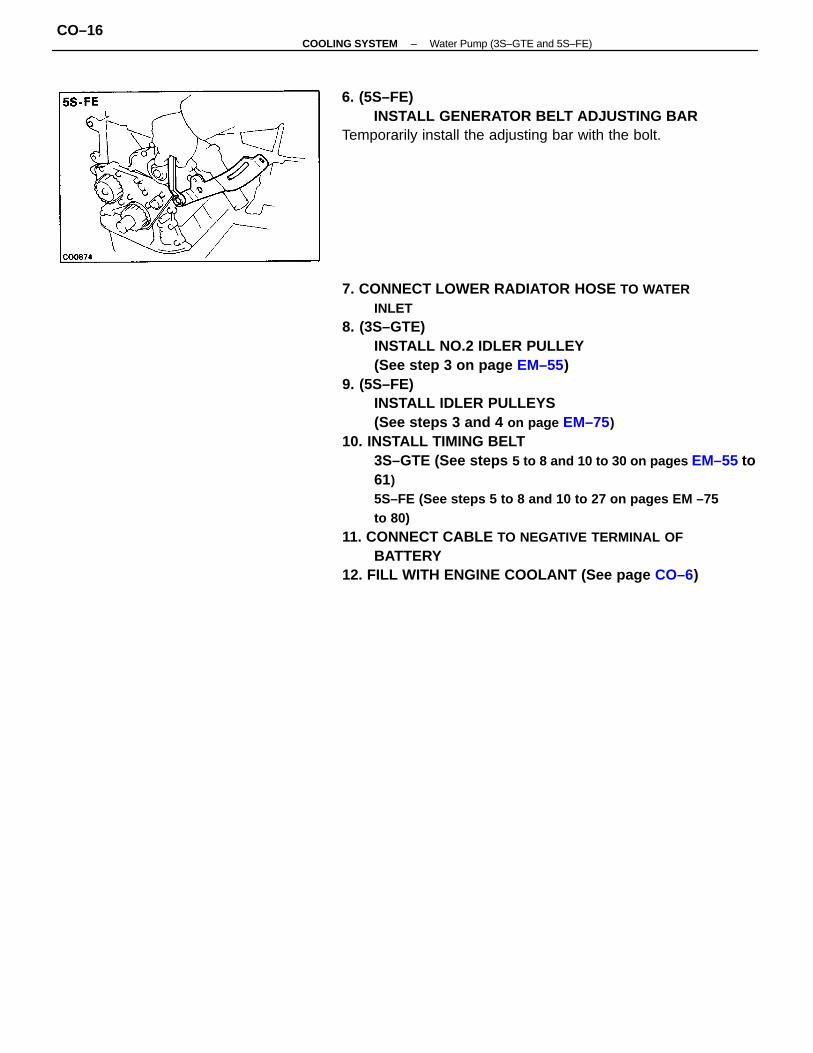
7. CONNECT LOWER RADIATOR HOSE TO WATERINLET
8. (3S–GTE)INSTALL NO.2 IDLER PULLEY(See step 3 on page EM–55)
9. (5S–FE)INSTALL IDLER PULLEYS(See steps 3 and 4 on page EM–75)
10. INSTALL TIMING BELT3S–GTE (See steps 5 to 8 and 10 to 30 on pages EM–55 to61)5S–FE (See steps 5 to 8 and 10 to 27 on pages EM –75to 80)
11. CONNECT CABLE TO NEGATIVE TERMINAL OFBATTERY
12. FILL WITH ENGINE COOLANT (See page CO–6)
6. (5S–FE)INSTALL GENERATOR BELT ADJUSTING BAR
Temporarily install the adjusting bar with the bolt.
–COOLING SYSTEM Water Pump (3S–GTE and 5S–FE)CO–16
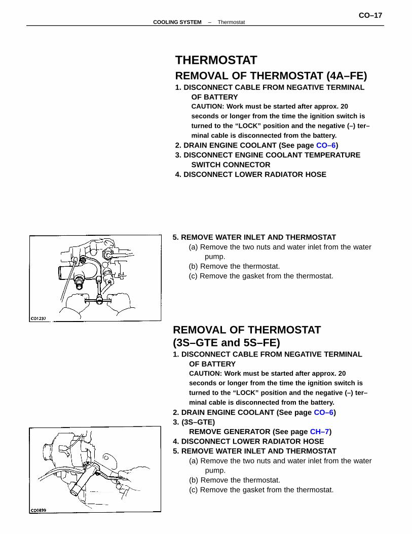
REMOVAL OF THERMOSTAT(3S–GTE and 5S–FE)1. DISCONNECT CABLE FROM NEGATIVE TERMINAL
OF BATTERYCAUTION: Work must be started after approx. 20seconds or longer from the time the ignition switch isturned to the “LOCK” position and the negative (–) ter–minal cable is disconnected from the battery.
2. DRAIN ENGINE COOLANT (See page CO–6)3. (3S–GTE)
REMOVE GENERATOR (See page CH–7)4. DISCONNECT LOWER RADIATOR HOSE5. REMOVE WATER INLET AND THERMOSTAT
(a) Remove the two nuts and water inlet from the waterpump.
(b) Remove the thermostat.(c) Remove the gasket from the thermostat.
THERMOSTATREMOVAL OF THERMOSTAT (4A–FE)1. DISCONNECT CABLE FROM NEGATIVE TERMINAL
OF BATTERYCAUTION: Work must be started after approx. 20seconds or longer from the time the ignition switch isturned to the “LOCK” position and the negative (–) ter–minal cable is disconnected from the battery.
2. DRAIN ENGINE COOLANT (See page CO–6)3. DISCONNECT ENGINE COOLANT TEMPERATURE
SWITCH CONNECTOR4. DISCONNECT LOWER RADIATOR HOSE
5. REMOVE WATER INLET AND THERMOSTAT(a) Remove the two nuts and water inlet from the water
pump.(b) Remove the thermostat.(c) Remove the gasket from the thermostat.
–COOLING SYSTEM ThermostatCO–17
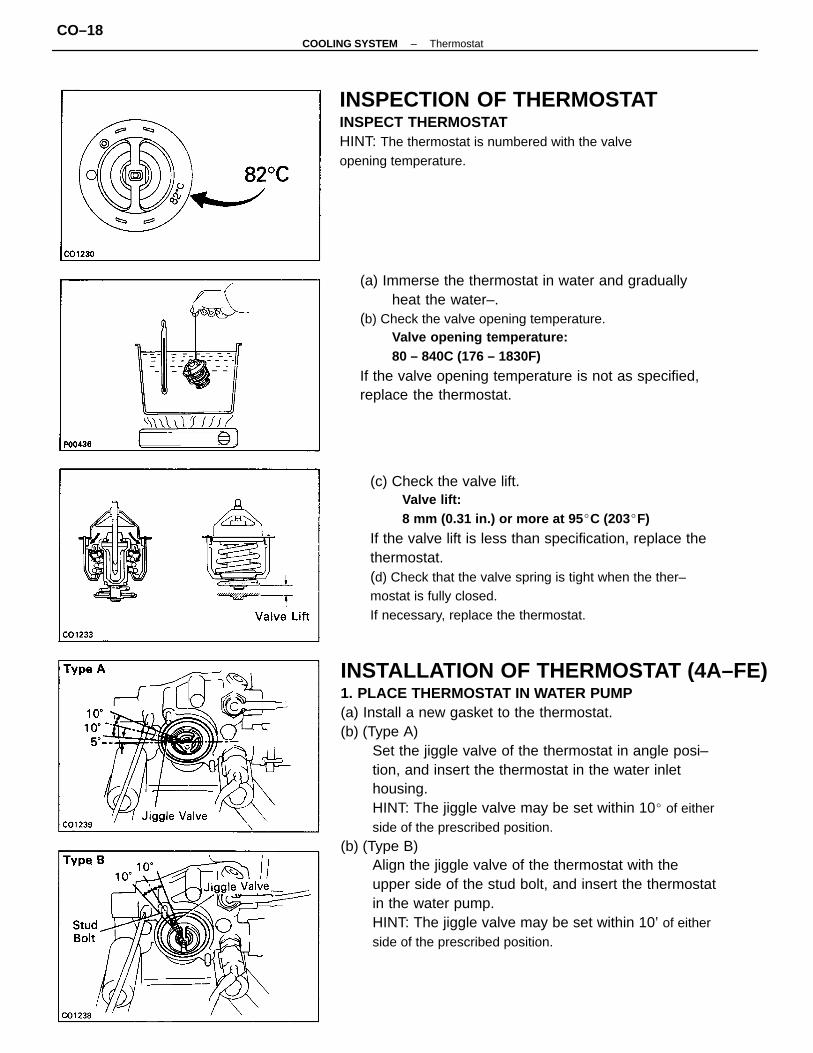
INSTALLATION OF THERMOSTAT (4A–FE)1. PLACE THERMOSTAT IN WATER PUMP(a) Install a new gasket to the thermostat.(b) (Type A)
Set the jiggle valve of the thermostat in angle posi–tion, and insert the thermostat in the water inlethousing.HINT: The jiggle valve may be set within 10 of eitherside of the prescribed position.
(b) (Type B)Align the jiggle valve of the thermostat with theupper side of the stud bolt, and insert the thermostatin the water pump.HINT: The jiggle valve may be set within 10’ of eitherside of the prescribed position.
(c) Check the valve lift.Valve lift:8 mm (0.31 in.) or more at 95 C (203F)
If the valve lift is less than specification, replace thethermostat.(d) Check that the valve spring is tight when the ther–mostat is fully closed.If necessary, replace the thermostat.
(a) Immerse the thermostat in water and graduallyheat the water–.
(b) Check the valve opening temperature.Valve opening temperature:80 – 840C (176 – 1830F)
If the valve opening temperature is not as specified,replace the thermostat.
INSPECTION OF THERMOSTATINSPECT THERMOSTATHINT: The thermostat is numbered with the valveopening temperature.
–COOLING SYSTEM ThermostatCO–18
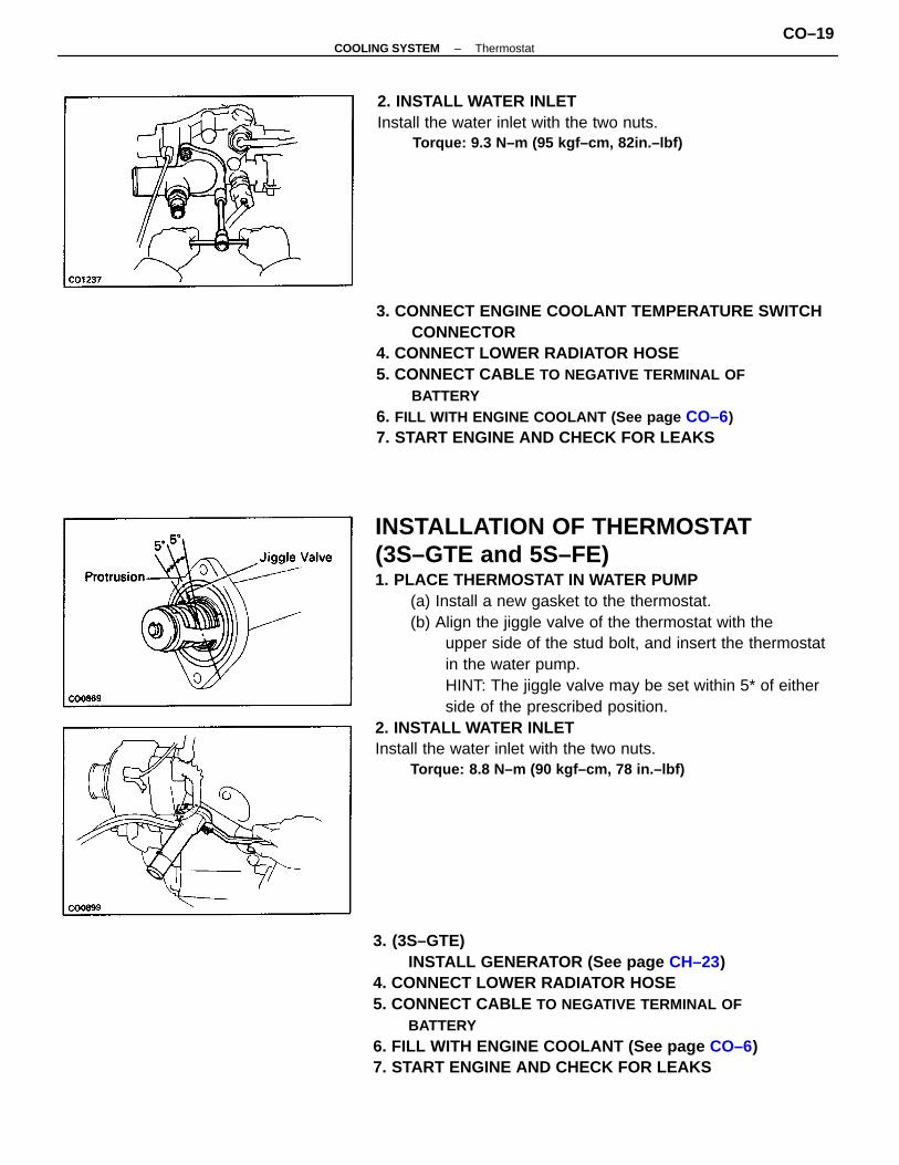
INSTALLATION OF THERMOSTAT(3S–GTE and 5S–FE)1. PLACE THERMOSTAT IN WATER PUMP
(a) Install a new gasket to the thermostat.(b) Align the jiggle valve of the thermostat with the
upper side of the stud bolt, and insert the thermostatin the water pump.HINT: The jiggle valve may be set within 5* of eitherside of the prescribed position.
2. INSTALL WATER INLETInstall the water inlet with the two nuts.
Torque: 8.8 N–m (90 kgf–cm, 78 in.–lbf)
3. CONNECT ENGINE COOLANT TEMPERATURE SWITCHCONNECTOR
4. CONNECT LOWER RADIATOR HOSE5. CONNECT CABLE TO NEGATIVE TERMINAL OF
BATTERY6. FILL WITH ENGINE COOLANT (See page CO–6)7. START ENGINE AND CHECK FOR LEAKS
3. (3S–GTE)INSTALL GENERATOR (See page CH–23)
4. CONNECT LOWER RADIATOR HOSE5. CONNECT CABLE TO NEGATIVE TERMINAL OF
BATTERY6. FILL WITH ENGINE COOLANT (See page CO–6)7. START ENGINE AND CHECK FOR LEAKS
2. INSTALL WATER INLETInstall the water inlet with the two nuts.
Torque: 9.3 N–m (95 kgf–cm, 82in.–lbf)
–COOLING SYSTEM ThermostatCO–19
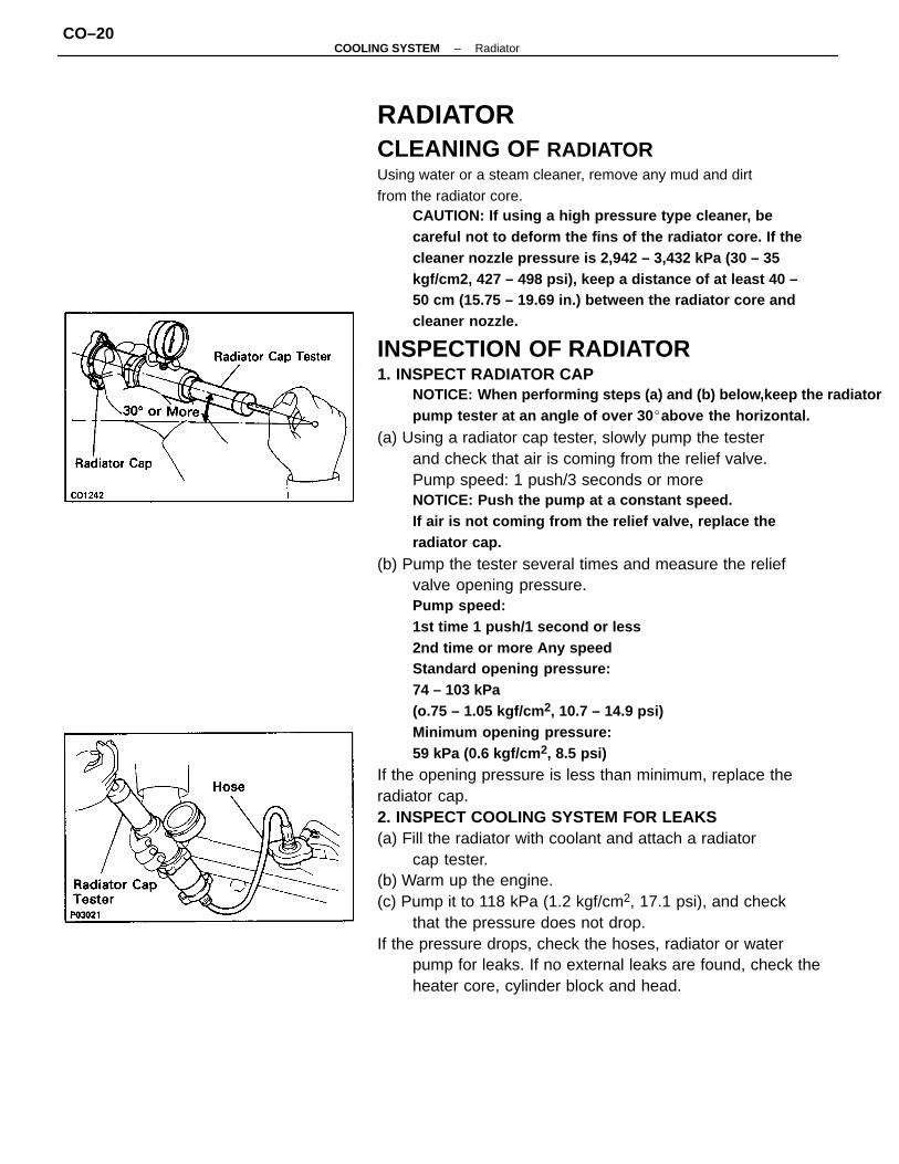
RADIATORCLEANING OF RADIATORUsing water or a steam cleaner, remove any mud and dirtfrom the radiator core.
CAUTION: If using a high pressure type cleaner, becareful not to deform the fins of the radiator core. If thecleaner nozzle pressure is 2,942 – 3,432 kPa (30 – 35kgf/cm2, 427 – 498 psi), keep a distance of at least 40 –50 cm (15.75 – 19.69 in.) between the radiator core andcleaner nozzle.
INSPECTION OF RADIATOR1. INSPECT RADIATOR CAP
NOTICE: When performing steps (a) and (b) below,keep the radiatorpump tester at an angle of over 30 above the horizontal.
(a) Using a radiator cap tester, slowly pump the testerand check that air is coming from the relief valve.Pump speed: 1 push/3 seconds or moreNOTICE: Push the pump at a constant speed.If air is not coming from the relief valve, replace theradiator cap.
(b) Pump the tester several times and measure the reliefvalve opening pressure.Pump speed:1st time 1 push/1 second or less2nd time or more Any speedStandard opening pressure:74 – 103 kPa(o.75 – 1.05 kgf/cm 2, 10.7 – 14.9 psi)Minimum opening pressure:59 kPa (0.6 kgf/cm 2, 8.5 psi)
If the opening pressure is less than minimum, replace theradiator cap.2. INSPECT COOLING SYSTEM FOR LEAKS(a) Fill the radiator with coolant and attach a radiator
cap tester.(b) Warm up the engine.(c) Pump it to 118 kPa (1.2 kgf/cm2, 17.1 psi), and check
that the pressure does not drop.If the pressure drops, check the hoses, radiator or water
pump for leaks. If no external leaks are found, check theheater core, cylinder block and head.
–COOLING SYSTEM RadiatorCO–20
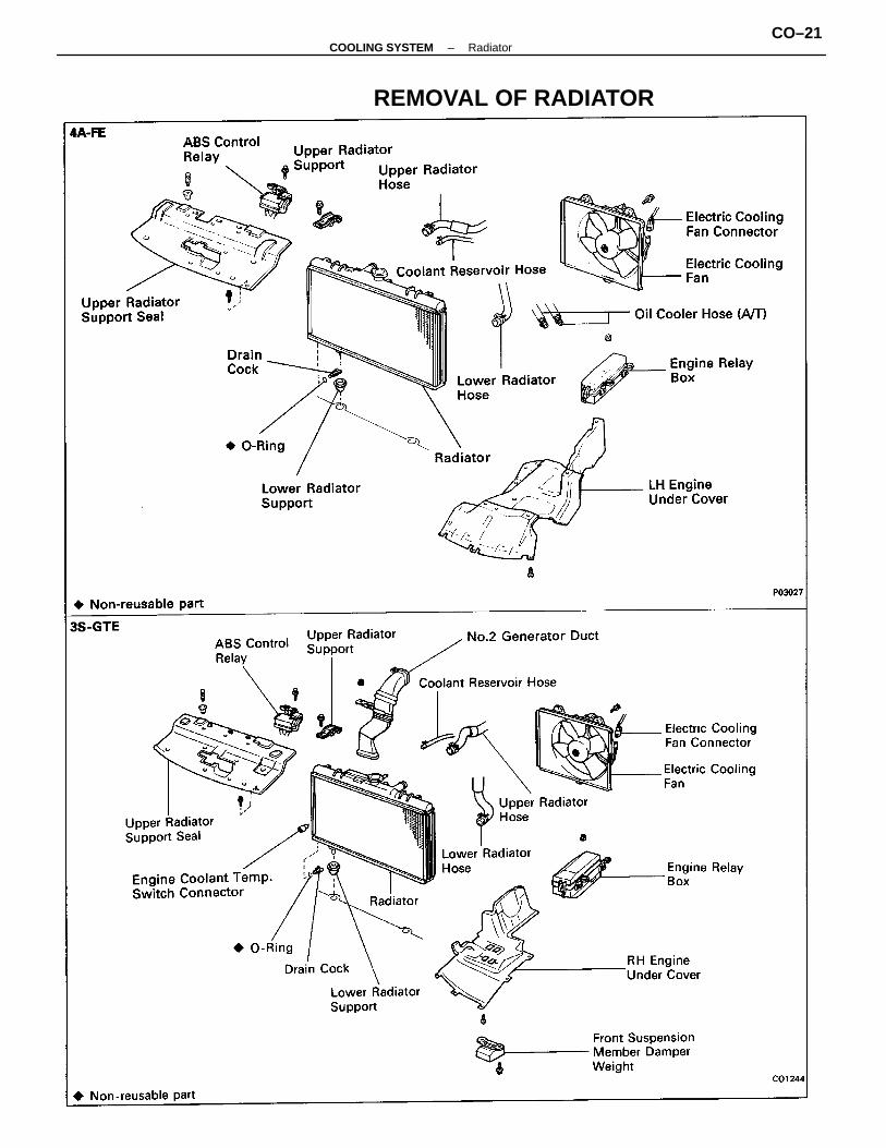
REMOVAL OF RADIATOR
–COOLING SYSTEM RadiatorCO–21
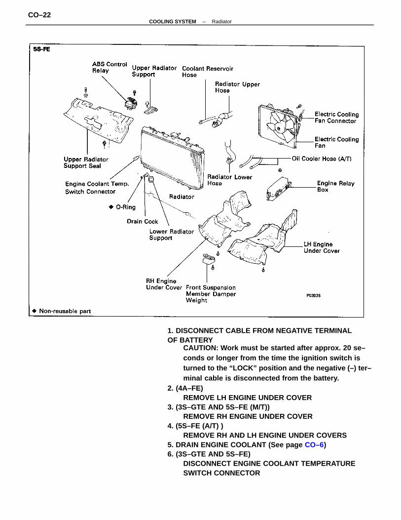
1. DISCONNECT CABLE FROM NEGATIVE TERMINALOF BATTERY
CAUTION: Work must be started after approx. 20 se–conds or longer from the time the ignition switch isturned to the “LOCK” position and the negative (–) ter–minal cable is disconnected from the battery.
2. (4A–FE)REMOVE LH ENGINE UNDER COVER
3. (3S–GTE AND 5S–FE (M/T))REMOVE RH ENGINE UNDER COVER
4. (5S–FE (A/T) )REMOVE RH AND LH ENGINE UNDER COVERS
5. DRAIN ENGINE COOLANT (See page CO–6)6. (3S–GTE AND 5S–FE)
DISCONNECT ENGINE COOLANT TEMPERATURESWITCH CONNECTOR
–COOLING SYSTEM RadiatorCO–22
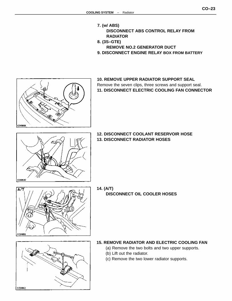
7. (w/ ABS)DISCONNECT ABS CONTROL RELAY FROMRADIATOR
8. (3S–GTE)REMOVE NO.2 GENERATOR DUCT
9. DISCONNECT ENGINE RELAY BOX FROM BATTERY
15. REMOVE RADIATOR AND ELECTRIC COOLING FAN(a) Remove the two bolts and two upper supports.(b) Lift out the radiator.(c) Remove the two lower radiator supports.
10. REMOVE UPPER RADIATOR SUPPORT SEALRemove the seven clips, three screws and support seal.11. DISCONNECT ELECTRIC COOLING FAN CONNECTOR
12. DISCONNECT COOLANT RESERVOIR HOSE13. DISCONNECT RADIATOR HOSES
14. (A/T)DISCONNECT OIL COOLER HOSES
–COOLING SYSTEM RadiatorCO–23
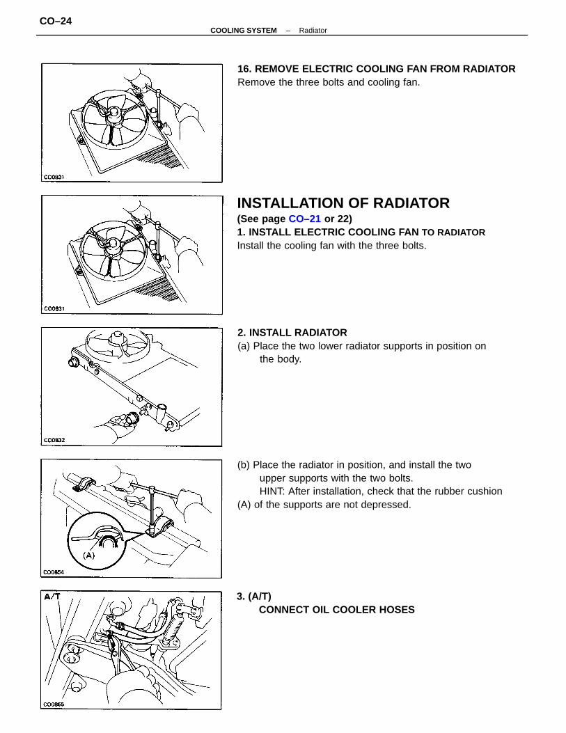
INSTALLATION OF RADIATOR(See page CO–21 or 22)1. INSTALL ELECTRIC COOLING FAN TO RADIATORInstall the cooling fan with the three bolts.
(b) Place the radiator in position, and install the twoupper supports with the two bolts.HINT: After installation, check that the rubber cushion
(A) of the supports are not depressed.
2. INSTALL RADIATOR(a) Place the two lower radiator supports in position on
the body.
16. REMOVE ELECTRIC COOLING FAN FROM RADIATORRemove the three bolts and cooling fan.
3. (A/T)CONNECT OIL COOLER HOSES
–COOLING SYSTEM RadiatorCO–24
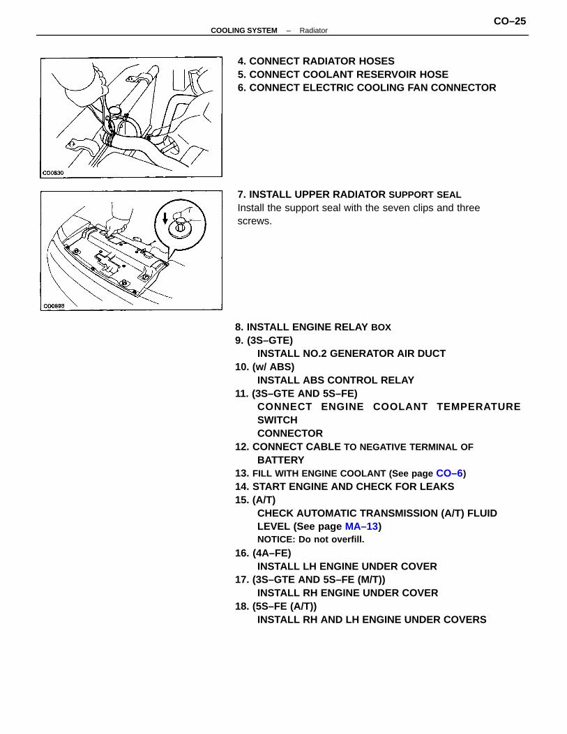
8. INSTALL ENGINE RELAY BOX9. (3S–GTE)
INSTALL NO.2 GENERATOR AIR DUCT10. (w/ ABS)
INSTALL ABS CONTROL RELAY11. (3S–GTE AND 5S–FE)
CONNECT ENGINE COOLANT TEMPERATURESWITCHCONNECTOR
12. CONNECT CABLE TO NEGATIVE TERMINAL OFBATTERY
13. FILL WITH ENGINE COOLANT (See page CO–6)14. START ENGINE AND CHECK FOR LEAKS15. (A/T)
CHECK AUTOMATIC TRANSMISSION (A/T) FLUIDLEVEL (See page MA–13)NOTICE: Do not overfill.
16. (4A–FE)INSTALL LH ENGINE UNDER COVER
17. (3S–GTE AND 5S–FE (M/T))INSTALL RH ENGINE UNDER COVER
18. (5S–FE (A/T))INSTALL RH AND LH ENGINE UNDER COVERS
4. CONNECT RADIATOR HOSES5. CONNECT COOLANT RESERVOIR HOSE6. CONNECT ELECTRIC COOLING FAN CONNECTOR
7. INSTALL UPPER RADIATOR SUPPORT SEALInstall the support seal with the seven clips and threescrews.
–COOLING SYSTEM RadiatorCO–25
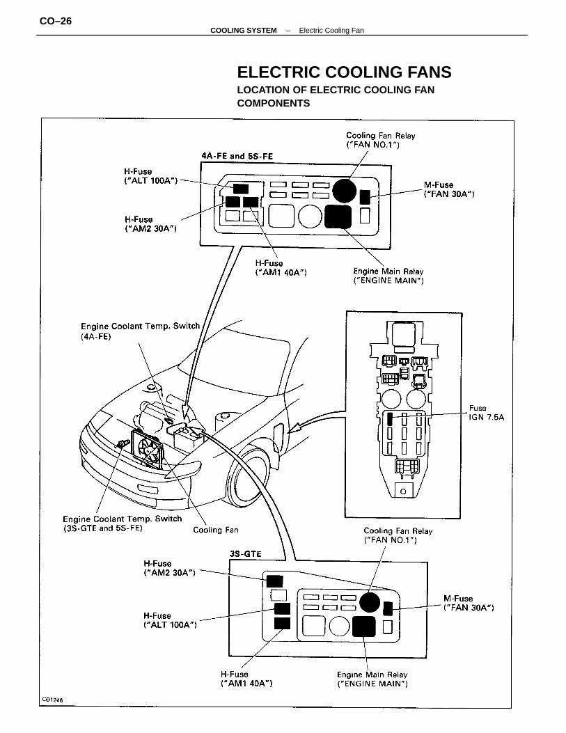
ELECTRIC COOLING FANSLOCATION OF ELECTRIC COOLING FANCOMPONENTS
–COOLING SYSTEM Electric Cooling FanCO–26
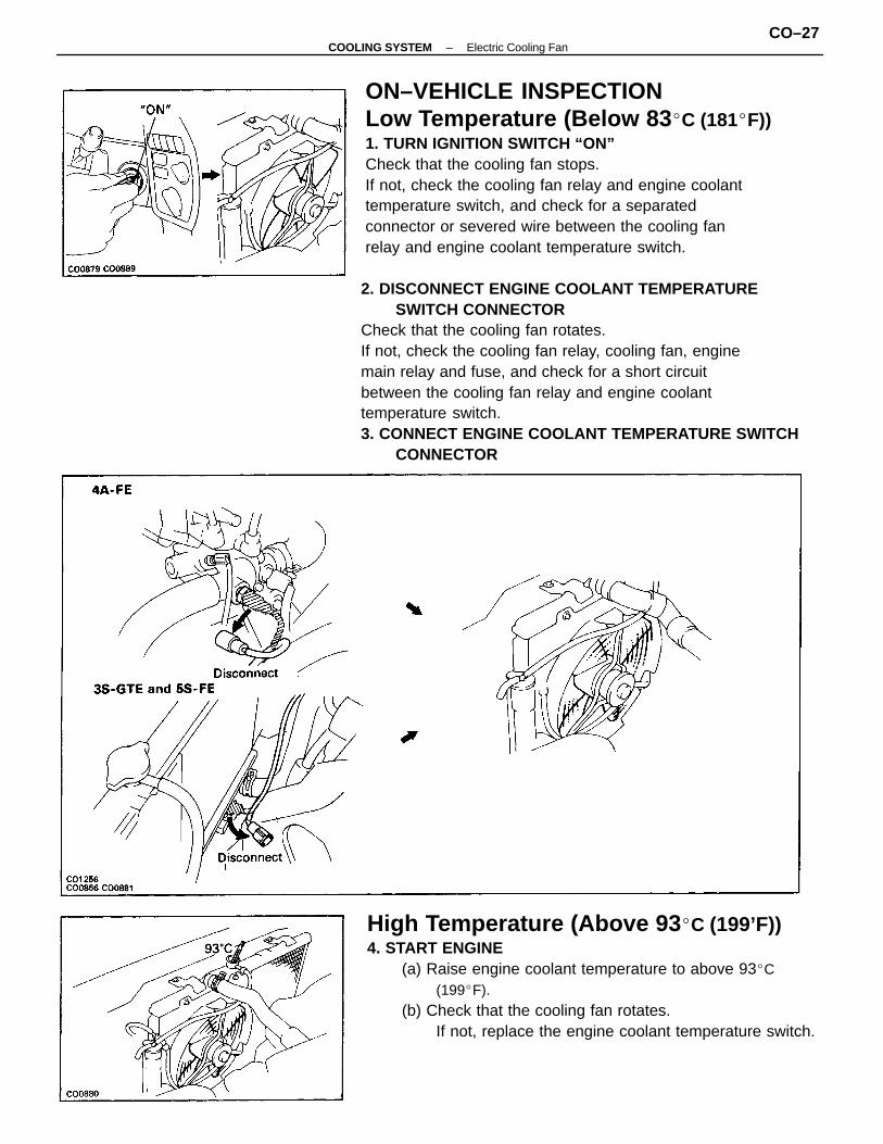
ON–VEHICLE INSPECTIONLow Temperature (Below 83 C (181F))1. TURN IGNITION SWITCH “ON”Check that the cooling fan stops.If not, check the cooling fan relay and engine coolanttemperature switch, and check for a separatedconnector or severed wire between the cooling fanrelay and engine coolant temperature switch.
2. DISCONNECT ENGINE COOLANT TEMPERATURESWITCH CONNECTOR
Check that the cooling fan rotates.If not, check the cooling fan relay, cooling fan, enginemain relay and fuse, and check for a short circuitbetween the cooling fan relay and engine coolanttemperature switch.3. CONNECT ENGINE COOLANT TEMPERATURE SWITCH
CONNECTOR
High Temperature (Above 93 C (199’F))4. START ENGINE
(a) Raise engine coolant temperature to above 93C(199F).
(b) Check that the cooling fan rotates.If not, replace the engine coolant temperature switch.
–COOLING SYSTEM Electric Cooling FanCO–27
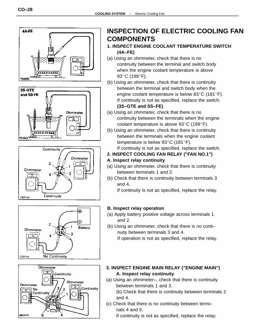
INSPECTION OF ELECTRIC COOLING FANCOMPONENTS1. INSPECT ENGINE COOLANT TEMPERATURE SWITCH
(4A–FE)(a) Using an ohmmeter, check that there is no
continuity between the terminal and switch bodywhen the engine coolant temperature is above93C (199F).
(b) Using an ohmmeter, check that there is continuitybetween the terminal and switch body when theengine coolant temperature is below 83C (181F).If continuity is not as specified, replace the switch.(3S–GTE and 5S–FE)
(a) Using an ohmmeter, check that there is nocontinuity between the terminals when the enginecoolant temperature is above 93C (199F).
(b) Using an ohmmeter, check that there is continuitybetween the terminals when the engine coolanttemperature is below 83C (181F).If continuity is not as specified, replace the switch.
2. INSPECT COOLING FAN RELAY (”FAN NO.1”)A. Inspect relay continuity(a) Using an ohmmeter, check that there is continuity
between terminals 1 and 2.(b) Check that there is continuity between terminals 3
and 4.If continuity is not as specified, replace the relay.
3. INSPECT ENGINE MAIN RELAY (”ENGINE MAIN”)A. Inspect relay continuity
(a) Using an ohmmeter–, check that there is continuitybetween terminals 1 and 3.(b) Check that there is continuity between terminals 2and 4.
(c) Check that there is no continuity between termi–nals 4 and 5.If continuity is not as specified, replace the relay.
B. Inspect relay operation(a) Apply battery positive voltage across terminals 1
and 2.(b) Using an ohmmeter, check that there is no conti–
nuity between terminals 3 and 4.If operation is not as specified, replace the relay.
–COOLING SYSTEM Electric Cooling FanCO–28
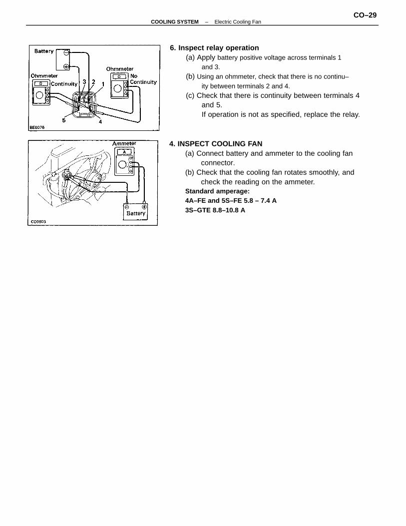
6. Inspect relay operation(a) Apply battery positive voltage across terminals 1
and 3.(b) Using an ohmmeter, check that there is no continu–
ity between terminals 2 and 4.(c) Check that there is continuity between terminals 4
and 5.If operation is not as specified, replace the relay.
4. INSPECT COOLING FAN(a) Connect battery and ammeter to the cooling fan
connector.(b) Check that the cooling fan rotates smoothly, and
check the reading on the ammeter.Standard amperage:4A–FE and 5S–FE 5.8 – 7.4 A3S–GTE 8.8–10.8 A
–COOLING SYSTEM Electric Cooling FanCO–29
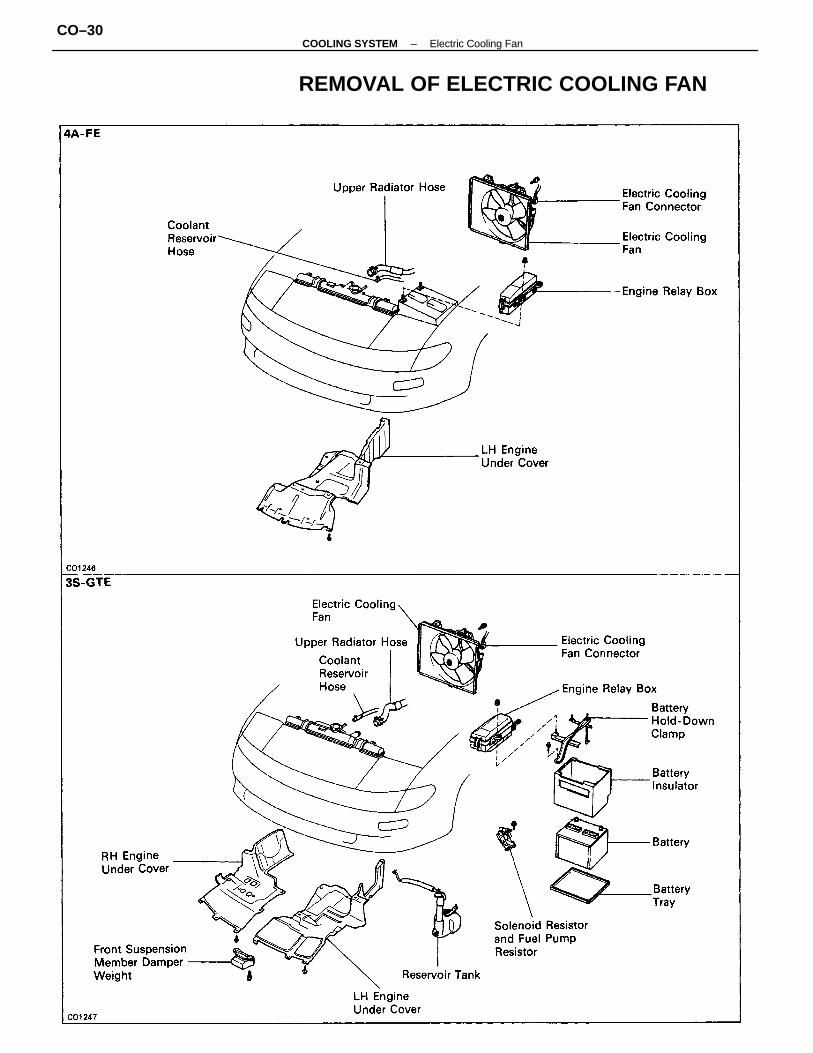
REMOVAL OF ELECTRIC COOLING FAN
–COOLING SYSTEM Electric Cooling FanCO–30
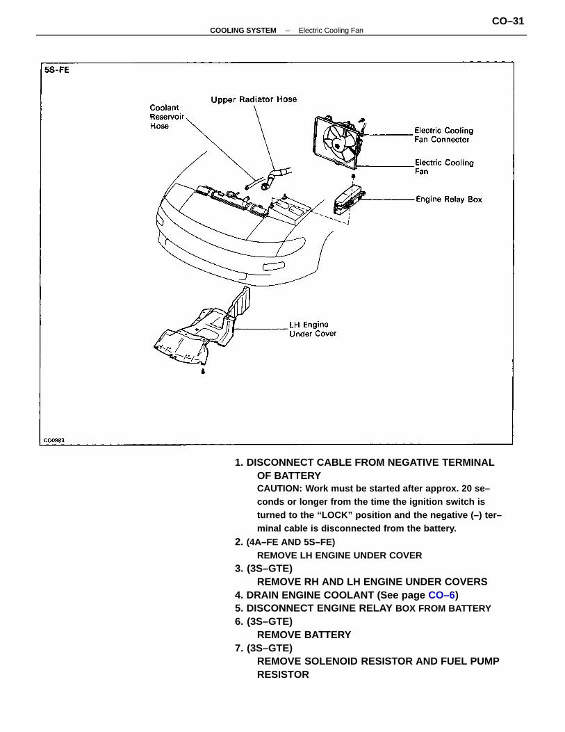
1. DISCONNECT CABLE FROM NEGATIVE TERMINALOF BATTERYCAUTION: Work must be started after approx. 20 se–conds or longer from the time the ignition switch isturned to the “LOCK” position and the negative (–) ter–minal cable is disconnected from the battery.
2. (4A–FE AND 5S–FE)REMOVE LH ENGINE UNDER COVER
3. (3S–GTE)REMOVE RH AND LH ENGINE UNDER COVERS
4. DRAIN ENGINE COOLANT (See page CO–6)5. DISCONNECT ENGINE RELAY BOX FROM BATTERY6. (3S–GTE)
REMOVE BATTERY7. (3S–GTE)
REMOVE SOLENOID RESISTOR AND FUEL PUMPRESISTOR
–COOLING SYSTEM Electric Cooling FanCO–31
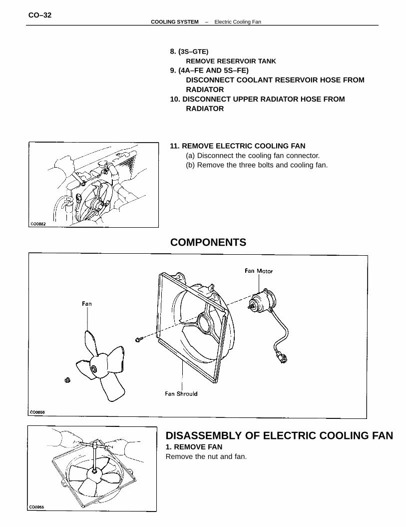
8. (3S–GTE)REMOVE RESERVOIR TANK
9. (4A–FE AND 5S–FE)DISCONNECT COOLANT RESERVOIR HOSE FROMRADIATOR
10. DISCONNECT UPPER RADIATOR HOSE FROMRADIATOR
DISASSEMBLY OF ELECTRIC COOLING FAN1. REMOVE FANRemove the nut and fan.
11. REMOVE ELECTRIC COOLING FAN(a) Disconnect the cooling fan connector.(b) Remove the three bolts and cooling fan.
COMPONENTS
–COOLING SYSTEM Electric Cooling FanCO–32
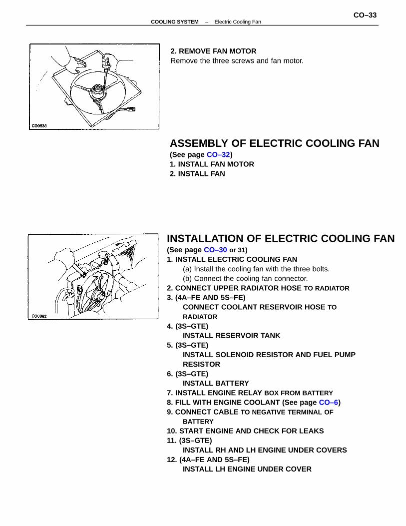
INSTALLATION OF ELECTRIC COOLING FAN(See page CO–30 or 31)1. INSTALL ELECTRIC COOLING FAN
(a) Install the cooling fan with the three bolts.(b) Connect the cooling fan connector.
2. CONNECT UPPER RADIATOR HOSE TO RADIATOR3. (4A–FE AND 5S–FE)
CONNECT COOLANT RESERVOIR HOSE TORADIATOR
4. (3S–GTE)INSTALL RESERVOIR TANK
5. (3S–GTE)INSTALL SOLENOID RESISTOR AND FUEL PUMPRESISTOR
6. (3S–GTE)INSTALL BATTERY
7. INSTALL ENGINE RELAY BOX FROM BATTERY8. FILL WITH ENGINE COOLANT (See page CO–6)9. CONNECT CABLE TO NEGATIVE TERMINAL OF
BATTERY10. START ENGINE AND CHECK FOR LEAKS11. (3S–GTE)
INSTALL RH AND LH ENGINE UNDER COVERS12. (4A–FE AND 5S–FE)
INSTALL LH ENGINE UNDER COVER
ASSEMBLY OF ELECTRIC COOLING FAN(See page CO–32)1. INSTALL FAN MOTOR2. INSTALL FAN
2. REMOVE FAN MOTORRemove the three screws and fan motor.
–COOLING SYSTEM Electric Cooling FanCO–33
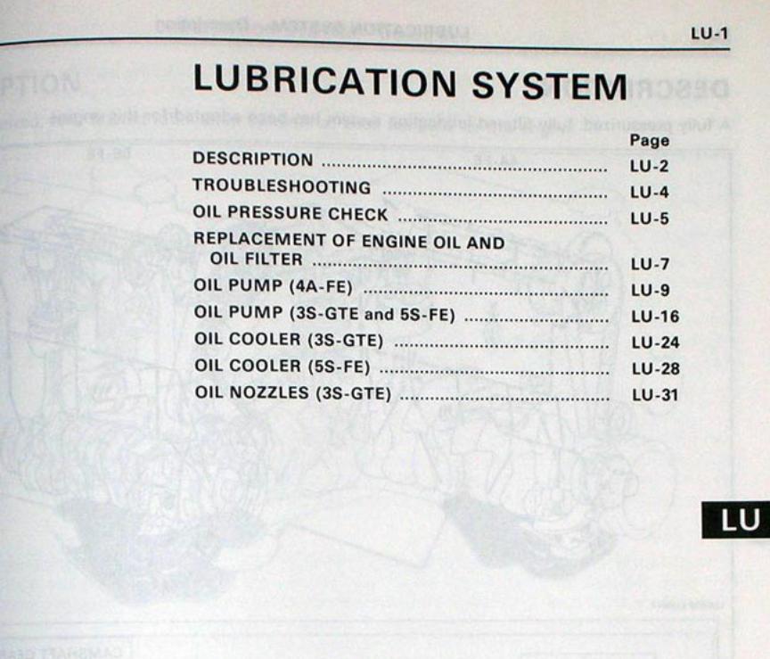
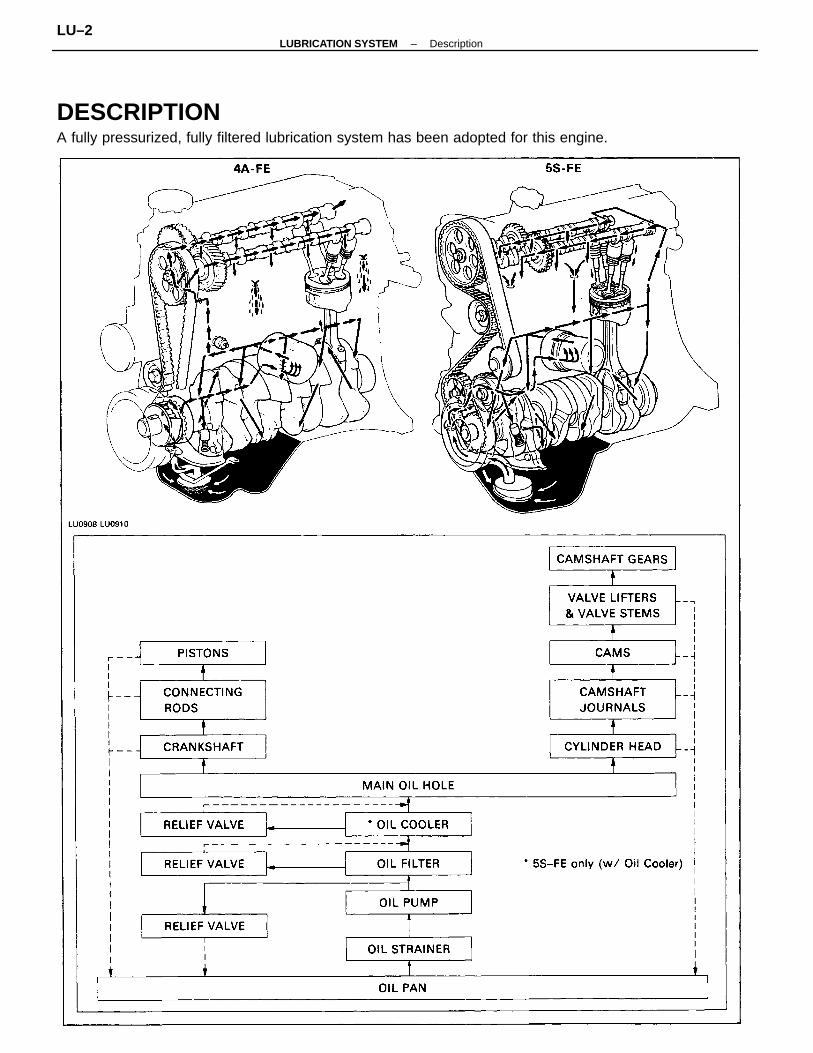
DESCRIPTIONA fully pressurized, fully filtered lubrication system has been adopted for this engine.
–LUBRICATION SYSTEM DescriptionLU–2
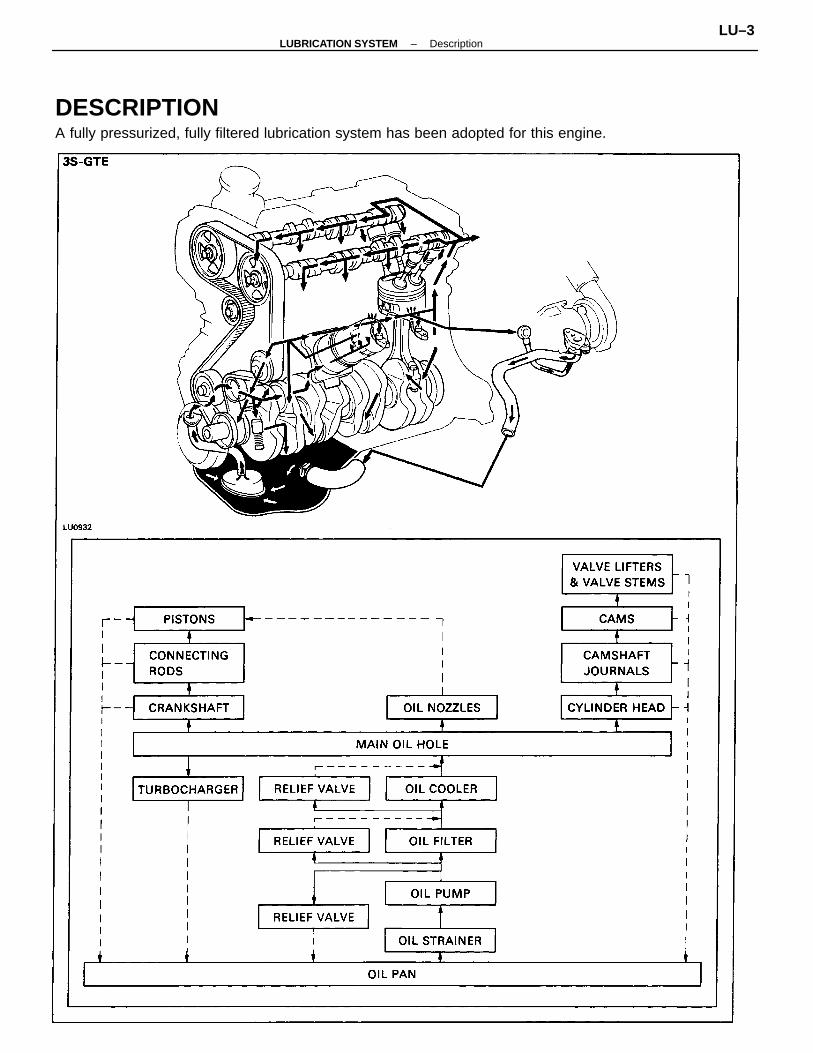
DESCRIPTIONA fully pressurized, fully filtered lubrication system has been adopted for this engine.
–LUBRICATION SYSTEM DescriptionLU–3
A pressure feeding lubrication system has been adopted to supply oil to the moving parts of this engine.The lubrication system consists of an oil pan, oil pump, oil filter and other external parts which supply oilto the moving parts in the engine block. The oil circuit is shown in the illustration at the top of the previouspage. Oil from the oil pan is pumped up by the oil pump. After it passes through the oil filter, it is fed throughthe various oil holes in the crankshaft and cylinder block. After passing through the cylinder block andperforming its lubricating function, the oil is returned by gravity to the oil pan. A dipstick on the center leftside of the cylinder block is provided to check the oil level.OIL PUMPThe oil pump pumps up oil from the oil pan and feeds it under pressure to the various parts of theengine. An oil strainer is mounted in front of the inlet to the oil pump to remove impurities. The oil pump itself isa trochoid type pump, inside of which is a drive rotor and a driven rotor.When the drive rotor rotates, the drivenrotor rotates in the same direction. and since the axis of the driven rotor shaft is different from the center of thedriver rotor, the space between the two rotor is changed as they rotate. Oil is drawn in when the space widensand is discharged when the space becomes narrow.OIL PRESSURE REGULATIONS (RELIEF VALVE)At high engine speed, the engine oil supplied by the pump exceeds the capacity of the engine to utilize it. Forthat reason, the oil pressure regulator works to prevent an oversupply of oil. During normal oil supply, a coilspring and valve keep the by–pass closed, but when too much oil is being fed, the pressure becomes extreme-ly high, overpowering the force of the spring and opening the valves. This allows the excess oil to flow throughthe valve and return to the oil pan.OIL FILTERThe oil filter is a full flow type filter with a relief valve built into the paper filter element. Particles of metalfrom wear, airborne dirt, carbon and other impurities can get into the oil during use and could causeaccelerated wear or seizing if allowed to circulate through the engine. The oil filter, integrated into the oilline, removes these impurities as the oil passes through it. The filter is mounted outside the engine tosimplify replacement of the filter element. A relief valve is also included ahead of the filter element to relievethe high oil pressure in case the filter element becomes clogged with impurities. The relief valve openswhen the oil pressure overpowers the force of the spring. Oil passing through the relief valve by–passesthe oil filter and flows directly into the main oil hole in the engine.
–LUBRICATION SYSTEM DescriptionLU–4
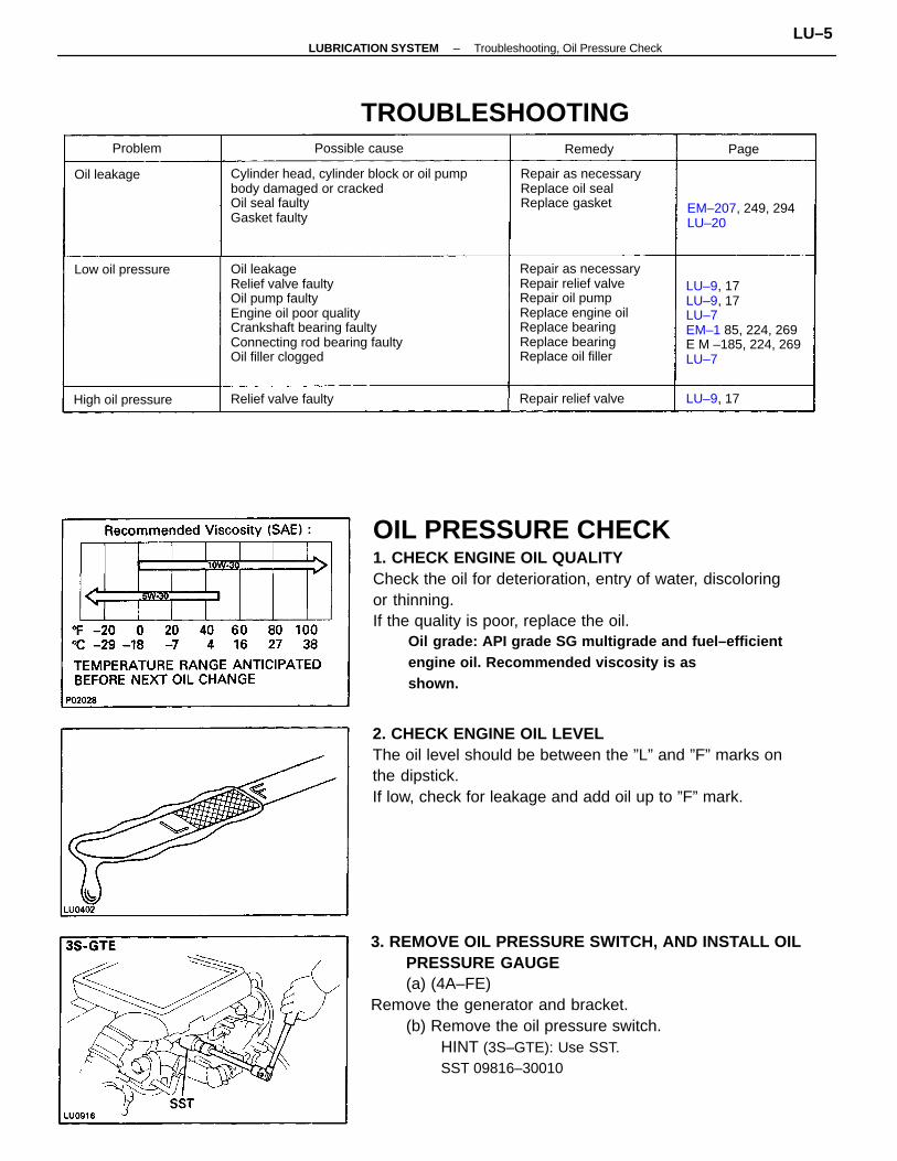
OIL PRESSURE CHECK1. CHECK ENGINE OIL QUALITYCheck the oil for deterioration, entry of water, discoloringor thinning.If the quality is poor, replace the oil.
Oil grade: API grade SG multigrade and fuel–efficientengine oil. Recommended viscosity is asshown.
3. REMOVE OIL PRESSURE SWITCH, AND INSTALL OILPRESSURE GAUGE(a) (4A–FE)
Remove the generator and bracket.(b) Remove the oil pressure switch.
HINT (3S–GTE): Use SST.SST 09816–30010
2. CHECK ENGINE OIL LEVELThe oil level should be between the ”L” and ”F” marks onthe dipstick.If low, check for leakage and add oil up to ”F” mark.
Cylinder head, cylinder block or oil pumpbody damaged or crackedOil seal faultyGasket faulty
Oil leakageRelief valve faultyOil pump faultyEngine oil poor qualityCrankshaft bearing faultyConnecting rod bearing faultyOil filler clogged
Repair as necessaryRepair relief valveRepair oil pumpReplace engine oilReplace bearingReplace bearingReplace oil filler
LU–9, 17LU–9, 17LU–7EM–1 85, 224, 269E M –185, 224, 269LU–7
Repair as necessaryReplace oil sealReplace gasket
TROUBLESHOOTING
EM–207, 249, 294LU–20
Repair relief valveRelief valve faultyHigh oil pressure
Low oil pressure
Possible cause
Oil leakage
LU–9, 17
Problem Remedy Page
–LUBRICATION SYSTEM Troubleshooting, Oil Pressure CheckLU–5
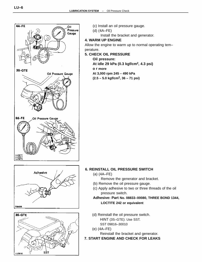
(c) Install an oil pressure gauge.(d) (4A–FE)
Install the bracket and generator.4. WARM UP ENGINEAllow the engine to warm up to normal operating tem–perature.5. CHECK OIL PRESSURE
Oil pressure:At idle 29 kPa (0.3 kgf/cm 2, 4.3 psi)o r moreAt 3,000 rpm 245 – 490 kPa(2.5 – 5.0 kgf/cm 2, 36 – 71 psi)
6. REINSTALL OIL PRESSURE SWITCH(a) (4A–FE)
Remove the generator and bracket.(b) Remove the oil pressure gauge.(c) Apply adhesive to two or three threads of the oil
pressure switch.Adhesive: Part No. 08833–00080, THREE BOND 1344,
LOCTITE 242 or equivalent
(d) Reinstall the oil pressure switch.HINT (3S–GTE): Use SST.SST 09816–30010
(e) (4A–FE)Reinstall the bracket and generator.
7. START ENGINE AND CHECK FOR LEAKS
–LUBRICATION SYSTEM Oil Pressure CheckLU–6
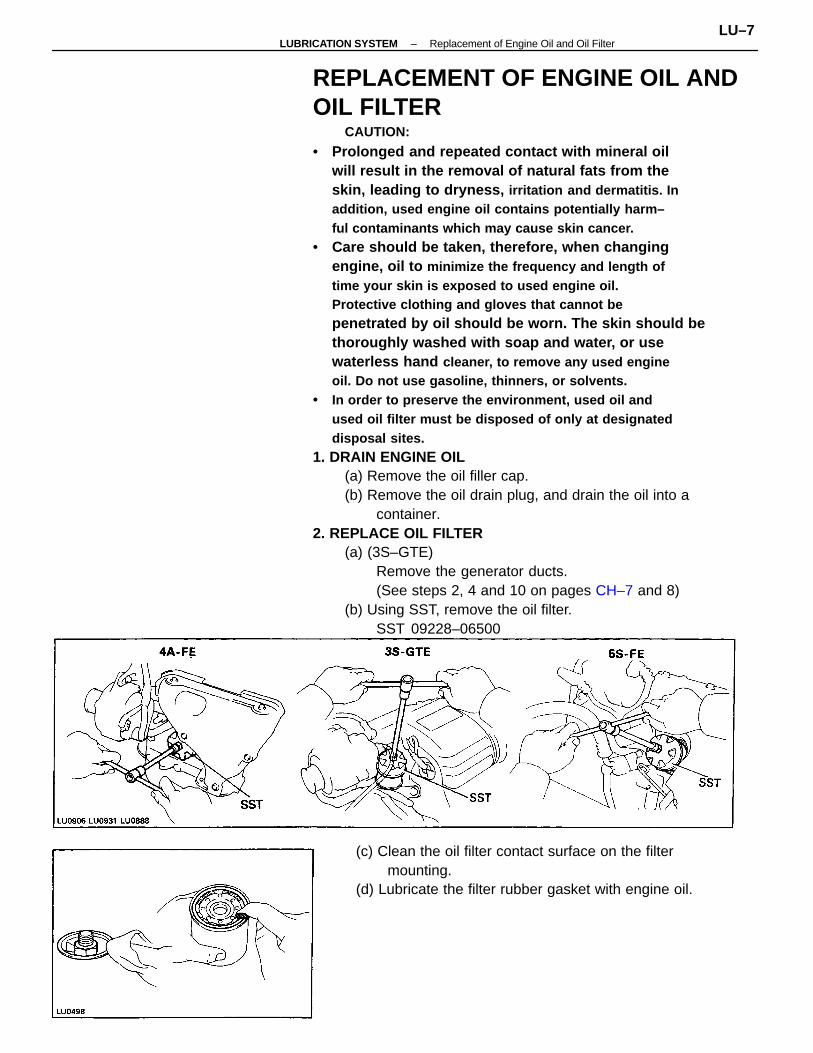
REPLACEMENT OF ENGINE OIL ANDOIL FILTER
CAUTION:
• Prolonged and repeated contact with mineral oilwill result in the removal of natural fats from theskin, leading to dryness, irritation and dermatitis. Inaddition, used engine oil contains potentially harm–ful contaminants which may cause skin cancer.
• Care should be taken, therefore, when changingengine, oil to minimize the frequency and length oftime your skin is exposed to used engine oil.Protective clothing and gloves that cannot bepenetrated by oil should be worn. The skin should bethoroughly washed with soap and water, or usewaterless hand cleaner, to remove any used engineoil. Do not use gasoline, thinners, or solvents.
• In order to preserve the environment, used oil andused oil filter must be disposed of only at designateddisposal sites.
1. DRAIN ENGINE OIL(a) Remove the oil filler cap.(b) Remove the oil drain plug, and drain the oil into a
container.2. REPLACE OIL FILTER
(a) (3S–GTE)Remove the generator ducts.(See steps 2, 4 and 10 on pages CH–7 and 8)
(b) Using SST, remove the oil filter.SST 09228–06500
(c) Clean the oil filter contact surface on the filtermounting.
(d) Lubricate the filter rubber gasket with engine oil.
–LUBRICATION SYSTEM Replacement of Engine Oil and Oil FilterLU–7
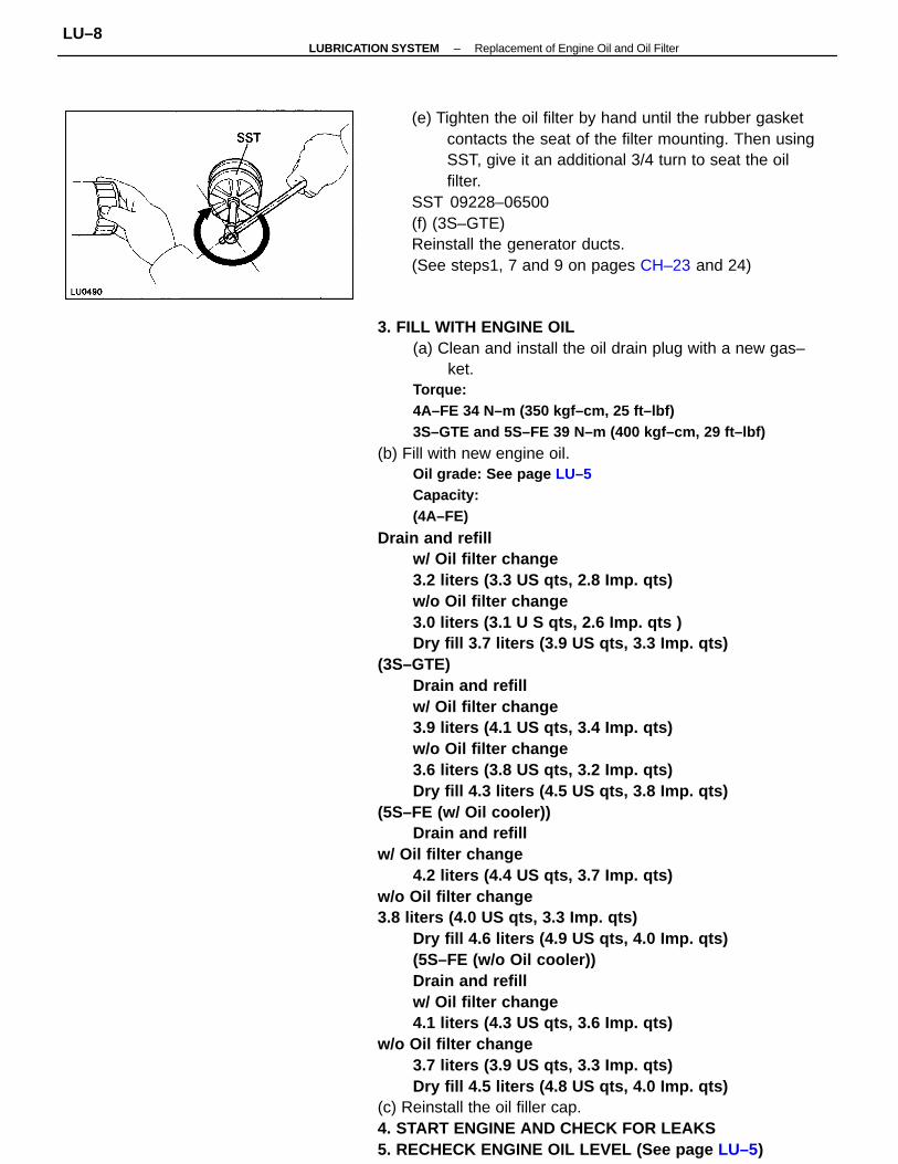
3. FILL WITH ENGINE OIL(a) Clean and install the oil drain plug with a new gas–
ket.Torque:4A–FE 34 N–m (350 kgf–cm, 25 ft–lbf)3S–GTE and 5S–FE 39 N–m (400 kgf–cm, 29 ft–lbf)
(b) Fill with new engine oil.Oil grade: See page LU–5Capacity:(4A–FE)
Drain and refillw/ Oil filter change3.2 liters (3.3 US qts, 2.8 Imp. qts)w/o Oil filter change3.0 liters (3.1 U S qts, 2.6 Imp. qts )Dry fill 3.7 liters (3.9 US qts, 3.3 Imp. qts)
(3S–GTE)Drain and refillw/ Oil filter change3.9 liters (4.1 US qts, 3.4 Imp. qts)w/o Oil filter change3.6 liters (3.8 US qts, 3.2 Imp. qts)Dry fill 4.3 liters (4.5 US qts, 3.8 Imp. qts)
(5S–FE (w/ Oil cooler))Drain and refill
w/ Oil filter change4.2 liters (4.4 US qts, 3.7 Imp. qts)
w/o Oil filter change3.8 liters (4.0 US qts, 3.3 Imp. qts)
Dry fill 4.6 liters (4.9 US qts, 4.0 Imp. qts)(5S–FE (w/o Oil cooler))Drain and refillw/ Oil filter change4.1 liters (4.3 US qts, 3.6 Imp. qts)
w/o Oil filter change3.7 liters (3.9 US qts, 3.3 Imp. qts)Dry fill 4.5 liters (4.8 US qts, 4.0 Imp. qts)
(c) Reinstall the oil filler cap.4. START ENGINE AND CHECK FOR LEAKS5. RECHECK ENGINE OIL LEVEL (See page LU–5)
(e) Tighten the oil filter by hand until the rubber gasketcontacts the seat of the filter mounting. Then usingSST, give it an additional 3/4 turn to seat the oilfilter.
SST 09228–06500(f) (3S–GTE)Reinstall the generator ducts.(See steps1, 7 and 9 on pages CH–23 and 24)
–LUBRICATION SYSTEM Replacement of Engine Oil and Oil FilterLU–8
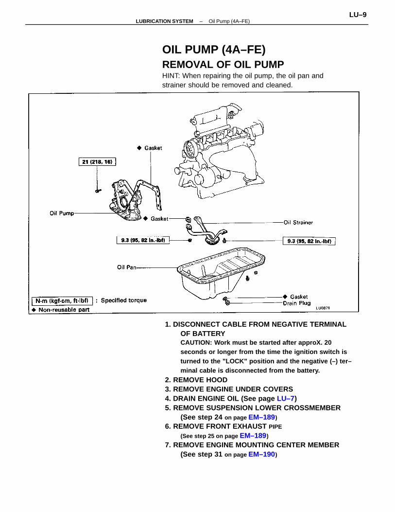
1. DISCONNECT CABLE FROM NEGATIVE TERMINALOF BATTERYCAUTION: Work must be started after approX. 20seconds or longer from the time the ignition switch isturned to the ”LOCK” position and the negative (–) ter–minal cable is disconnected from the battery.
2. REMOVE HOOD3. REMOVE ENGINE UNDER COVERS4. DRAIN ENGINE OIL (See page LU–7)5. REMOVE SUSPENSION LOWER CROSSMEMBER
(See step 24 on page EM–189)
6. REMOVE FRONT EXHAUST PIPE
(See step 25 on page EM–189)
7. REMOVE ENGINE MOUNTING CENTER MEMBER(See step 31 on page EM–190)
OIL PUMP (4A–FE)REMOVAL OF OIL PUMPHINT: When repairing the oil pump, the oil pan andstrainer should be removed and cleaned.
–LUBRICATION SYSTEM Oil Pump (4A–FE)LU–9
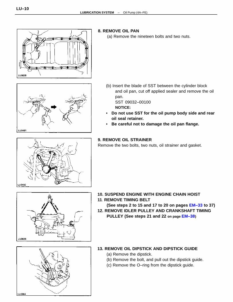
(b) Insert the blade of SST between the cylinder blockand oil pan, cut off applied sealer and remove the oilpan.SST 09032–00100NOTICE:
• Do not use SST for the oil pump body side and rearoil seal retainer.
• Be careful not to damage the oil pan flange.
10. SUSPEND ENGINE WITH ENGINE CHAIN HOIST11. REMOVE TIMING BELT
(See steps 2 to 15 and 17 to 20 on pages EM–33 to 37)12. REMOVE IDLER PULLEY AND CRANKSHAFT TIMING
PULLEY (See steps 21 and 22 on page EM–38)
13. REMOVE OIL DIPSTICK AND DIPSTICK GUIDE(a) Remove the dipstick.(b) Remove the bolt, and pull out the dipstick guide.(c) Remove the O–ring from the dipstick guide.
9. REMOVE OIL STRAINERRemove the two bolts, two nuts, oil strainer and gasket.
8. REMOVE OIL PAN(a) Remove the nineteen bolts and two nuts.
–LUBRICATION SYSTEM Oil Pump (4A–FE)LU–10
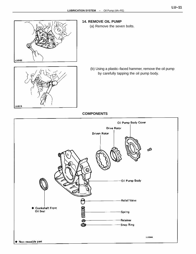
(b) Using a plastic–faced hammer, remove the oil pumpby carefully tapping the oil pump body.
14. REMOVE OIL PUMP(a) Remove the seven bolts.
COMPONENTS
–LUBRICATION SYSTEM Oil Pump (4A–FE)LU–11
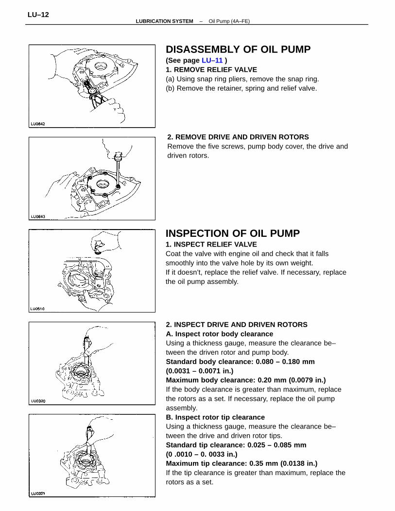
2. INSPECT DRIVE AND DRIVEN ROTORSA. Inspect rotor body clearanceUsing a thickness gauge, measure the clearance be–tween the driven rotor and pump body.Standard body clearance: 0.080 – 0.180 mm(0.0031 – 0.0071 in.)Maximum body clearance: 0.20 mm (0.0079 in.)If the body clearance is greater than maximum, replacethe rotors as a set. If necessary, replace the oil pumpassembly.B. Inspect rotor tip clearanceUsing a thickness gauge, measure the clearance be–tween the drive and driven rotor tips.Standard tip clearance: 0.025 – 0.085 mm(0 .0010 – 0. 0033 in.)Maximum tip clearance: 0.35 mm (0.0138 in.)If the tip clearance is greater than maximum, replace therotors as a set.
INSPECTION OF OIL PUMP1. INSPECT RELIEF VALVECoat the valve with engine oil and check that it fallssmoothly into the valve hole by its own weight.If it doesn’t, replace the relief valve. If necessary, replacethe oil pump assembly.
DISASSEMBLY OF OIL PUMP(See page LU–11 )1. REMOVE RELIEF VALVE(a) Using snap ring pliers, remove the snap ring.(b) Remove the retainer, spring and relief valve.
2. REMOVE DRIVE AND DRIVEN ROTORSRemove the five screws, pump body cover, the drive anddriven rotors.
–LUBRICATION SYSTEM Oil Pump (4A–FE)LU–12

C. Inspect rotor side clearanceUsing a thickness gauge and precision straight edge,measure the clearance between the rotors and precisionstraight edge.Standard side clearance: 0.025 – 0.085 mm(0.0010 – 0.0033 in.)Maximum side clearance: 0.10 mm (0.0039 in.)If the side clearance is greater than maximum, replace therotors as a set. If necessary, replace the oil pump assem–bly.
REPLACEMENT OF CRANKSHAFT FRONTOIL SEAL(See page EM–207)
ASSEMBLY OF OIL PUMP(See page LU–11)1. INSTALL DRIVE AND DRIVEN ROTORS(a) Place the drive and driven rotors into pump body
with the marks facing the pump body cover side.
2. INSTALL RELIEF VALVE(a) Insert the relief valve, spring and retainer into the
pump body hole.(b) Using snap ring pliers, install the snap ring.
(b) Install the pump body cover with the five screws.Torque: 10 N–m (105 kgf–cm, 8 ft–lbf)
–LUBRICATION SYSTEM Oil Pump (4A–FE)LU–13
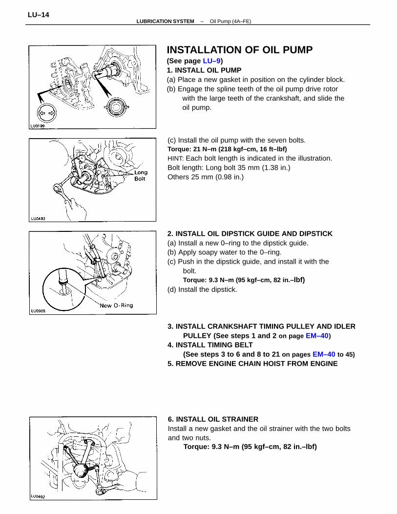
INSTALLATION OF OIL PUMP(See page LU–9)1. INSTALL OIL PUMP(a) Place a new gasket in position on the cylinder block.(b) Engage the spline teeth of the oil pump drive rotor
with the large teeth of the crankshaft, and slide theoil pump.
2. INSTALL OIL DIPSTICK GUIDE AND DIPSTICK(a) Install a new 0–ring to the dipstick guide.(b) Apply soapy water to the 0–ring.(c) Push in the dipstick guide, and install it with the
bolt.Torque: 9.3 N–m (95 kgf–cm, 82 in.– lbf)
(d) Install the dipstick.
3. INSTALL CRANKSHAFT TIMING PULLEY AND IDLERPULLEY (See steps 1 and 2 on page EM–40)
4. INSTALL TIMING BELT(See steps 3 to 6 and 8 to 21 on pages EM–40 to 45)
5. REMOVE ENGINE CHAIN HOIST FROM ENGINE
(c) Install the oil pump with the seven bolts.Torque: 21 N–m (218 kgf–cm, 16 ft–lbf)HINT: Each bolt length is indicated in the illustration.Bolt length: Long bolt 35 mm (1.38 in.)Others 25 mm (0.98 in.)
6. INSTALL OIL STRAINERInstall a new gasket and the oil strainer with the two boltsand two nuts.
Torque: 9.3 N–m (95 kgf–cm, 82 in.–lbf)
–LUBRICATION SYSTEM Oil Pump (4A–FE)LU–14
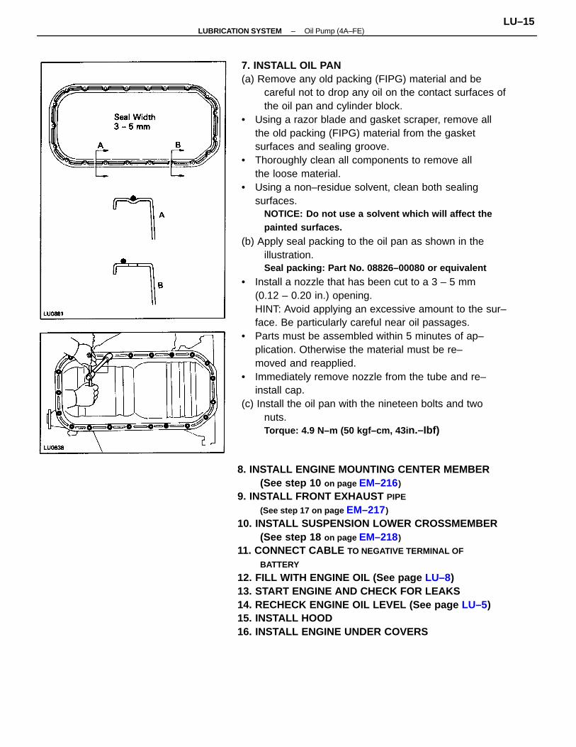
7. INSTALL OIL PAN(a) Remove any old packing (FIPG) material and be
careful not to drop any oil on the contact surfaces ofthe oil pan and cylinder block.
• Using a razor blade and gasket scraper, remove allthe old packing (FIPG) material from the gasketsurfaces and sealing groove.
• Thoroughly clean all components to remove allthe loose material.
• Using a non–residue solvent, clean both sealingsurfaces.
NOTICE: Do not use a solvent which will affect thepainted surfaces.
(b) Apply seal packing to the oil pan as shown in theillustration.Seal packing: Part No. 08826–00080 or equivalent
• Install a nozzle that has been cut to a 3 – 5 mm(0.12 – 0.20 in.) opening.HINT: Avoid applying an excessive amount to the sur–face. Be particularly careful near oil passages.
• Parts must be assembled within 5 minutes of ap–plication. Otherwise the material must be re–moved and reapplied.
• Immediately remove nozzle from the tube and re–install cap.
(c) Install the oil pan with the nineteen bolts and twonuts.Torque: 4.9 N–m (50 kgf–cm, 43i n.–Ibf)
8. INSTALL ENGINE MOUNTING CENTER MEMBER(See step 10 on page EM–216)
9. INSTALL FRONT EXHAUST PIPE
(See step 17 on page EM–217)
10. INSTALL SUSPENSION LOWER CROSSMEMBER(See step 18 on page EM–218)
11. CONNECT CABLE TO NEGATIVE TERMINAL OF
BATTERY
12. FILL WITH ENGINE OIL (See page LU–8)13. START ENGINE AND CHECK FOR LEAKS14. RECHECK ENGINE OIL LEVEL (See page LU–5)15. INSTALL HOOD16. INSTALL ENGINE UNDER COVERS
–LUBRICATION SYSTEM Oil Pump (4A–FE)LU–15
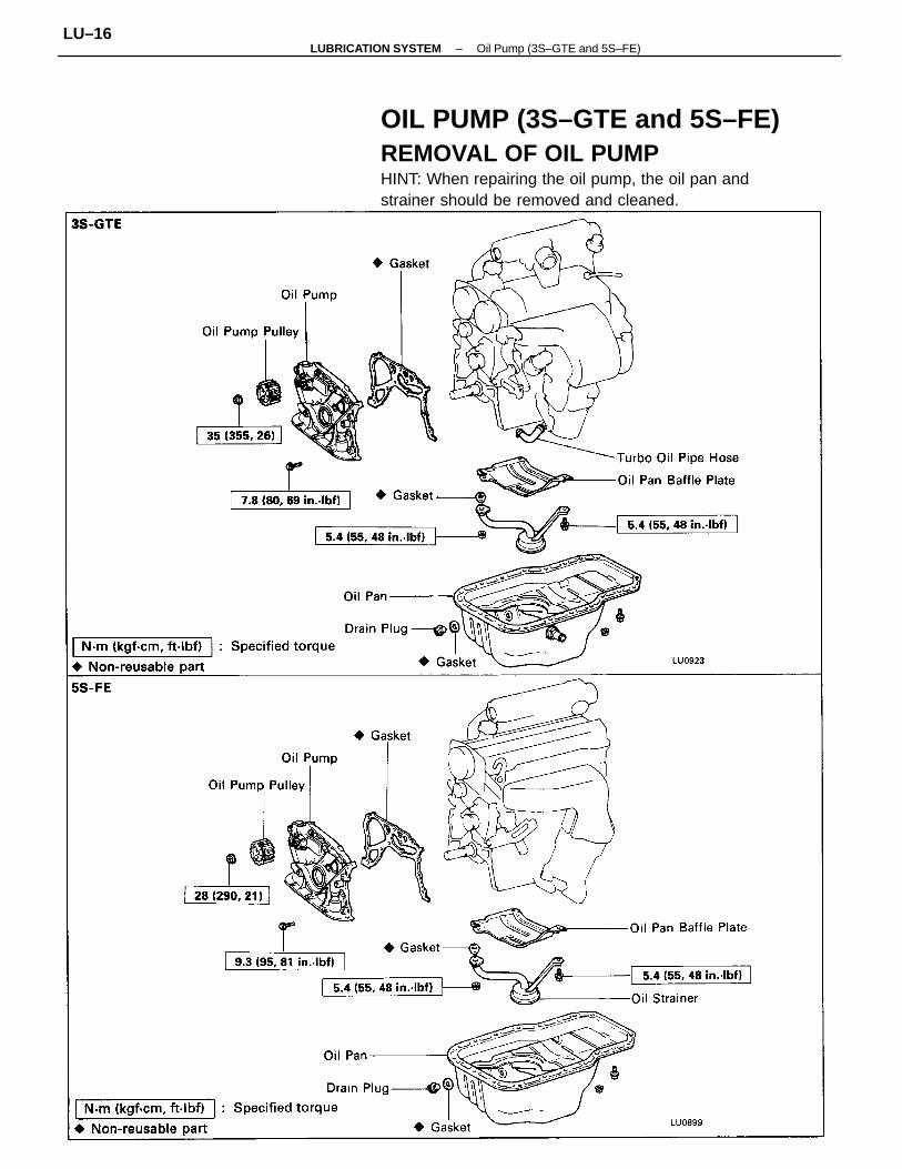
OIL PUMP (3S–GTE and 5S–FE)REMOVAL OF OIL PUMPHINT: When repairing the oil pump, the oil pan andstrainer should be removed and cleaned.
–LUBRICATION SYSTEM Oil Pump (3S–GTE and 5S–FE)LU–16
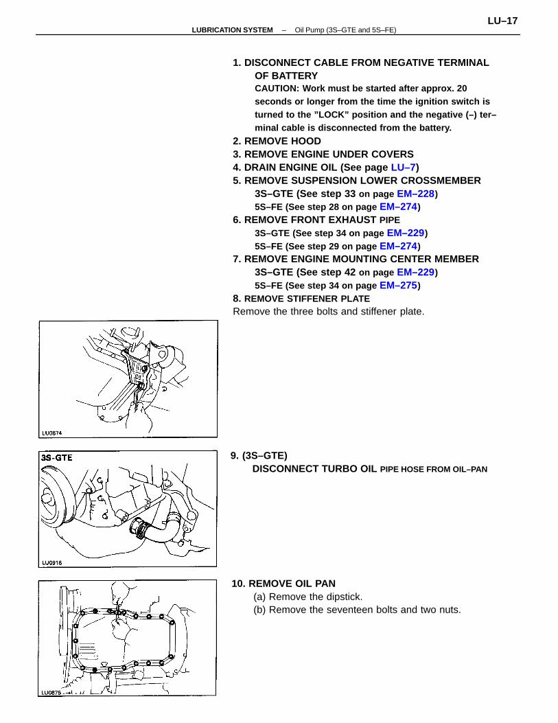
1. DISCONNECT CABLE FROM NEGATIVE TERMINALOF BATTERYCAUTION: Work must be started after approx. 20seconds or longer from the time the ignition switch isturned to the ”LOCK” position and the negative (–) ter–minal cable is disconnected from the battery.
2. REMOVE HOOD3. REMOVE ENGINE UNDER COVERS4. DRAIN ENGINE OIL (See page LU–7)5. REMOVE SUSPENSION LOWER CROSSMEMBER
3S–GTE (See step 33 on page EM–228)5S–FE (See step 28 on page EM–274)
6. REMOVE FRONT EXHAUST PIPE3S–GTE (See step 34 on page EM–229)5S–FE (See step 29 on page EM–274)
7. REMOVE ENGINE MOUNTING CENTER MEMBER3S–GTE (See step 42 on page EM–229)5S–FE (See step 34 on page EM–275)
8. REMOVE STIFFENER PLATERemove the three bolts and stiffener plate.
10. REMOVE OIL PAN(a) Remove the dipstick.(b) Remove the seventeen bolts and two nuts.
9. (3S–GTE)DISCONNECT TURBO OIL PIPE HOSE FROM OIL–PAN
–LUBRICATION SYSTEM Oil Pump (3S–GTE and 5S–FE)LU–17
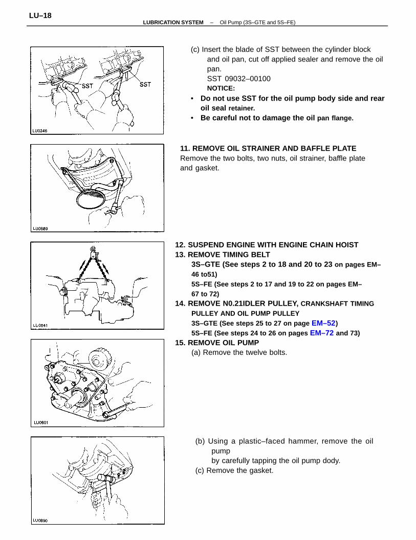
12. SUSPEND ENGINE WITH ENGINE CHAIN HOIST13. REMOVE TIMING BELT
3S–GTE (See steps 2 to 18 and 20 to 23 on pages EM–46 to51)5S–FE (See steps 2 to 17 and 19 to 22 on pages EM–67 to 72)
14. REMOVE N0.21IDLER PULLEY, CRANKSHAFT TIMINGPULLEY AND OIL PUMP PULLEY3S–GTE (See steps 25 to 27 on page EM–52)5S–FE (See steps 24 to 26 on pages EM–72 and 73)
15. REMOVE OIL PUMP(a) Remove the twelve bolts.
(c) Insert the blade of SST between the cylinder blockand oil pan, cut off applied sealer and remove the oilpan.SST 09032–00100NOTICE:
• Do not use SST for the oil pump body side and rearoil seal retainer.
• Be careful not to damage the oil pan flange.
11. REMOVE OIL STRAINER AND BAFFLE PLATERemove the two bolts, two nuts, oil strainer, baffle plateand gasket.
(b) Using a plastic–faced hammer, remove the oilpumpby carefully tapping the oil pump dody.
(c) Remove the gasket.
–LUBRICATION SYSTEM Oil Pump (3S–GTE and 5S–FE)LU–18
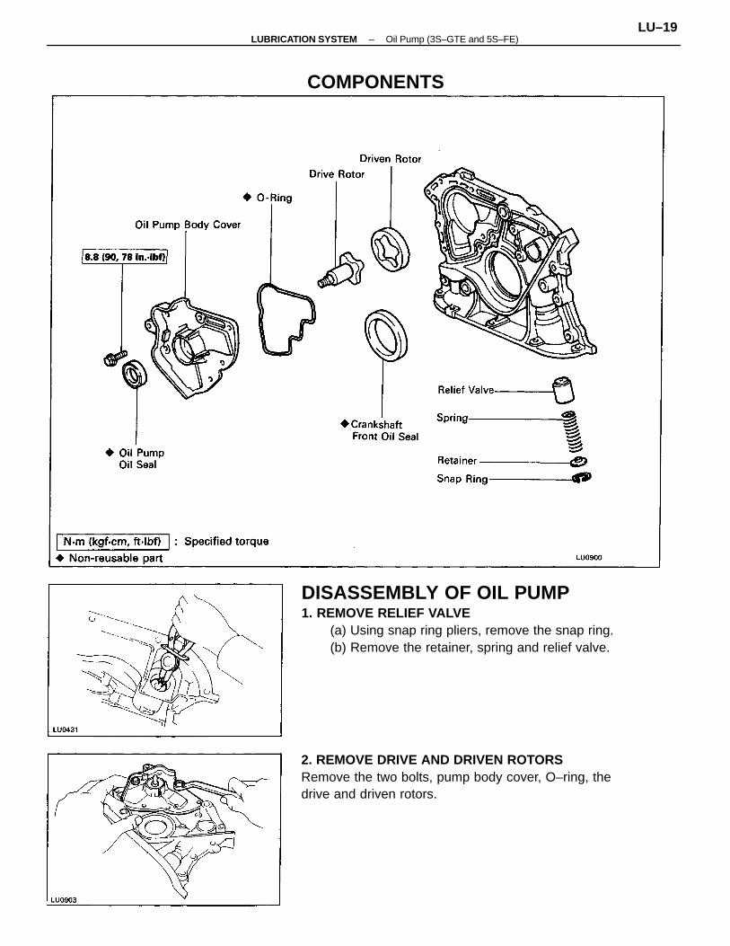
DISASSEMBLY OF OIL PUMP1. REMOVE RELIEF VALVE
(a) Using snap ring pliers, remove the snap ring.(b) Remove the retainer, spring and relief valve.
2. REMOVE DRIVE AND DRIVEN ROTORSRemove the two bolts, pump body cover, O–ring, thedrive and driven rotors.
COMPONENTS
–LUBRICATION SYSTEM Oil Pump (3S–GTE and 5S–FE)LU–19
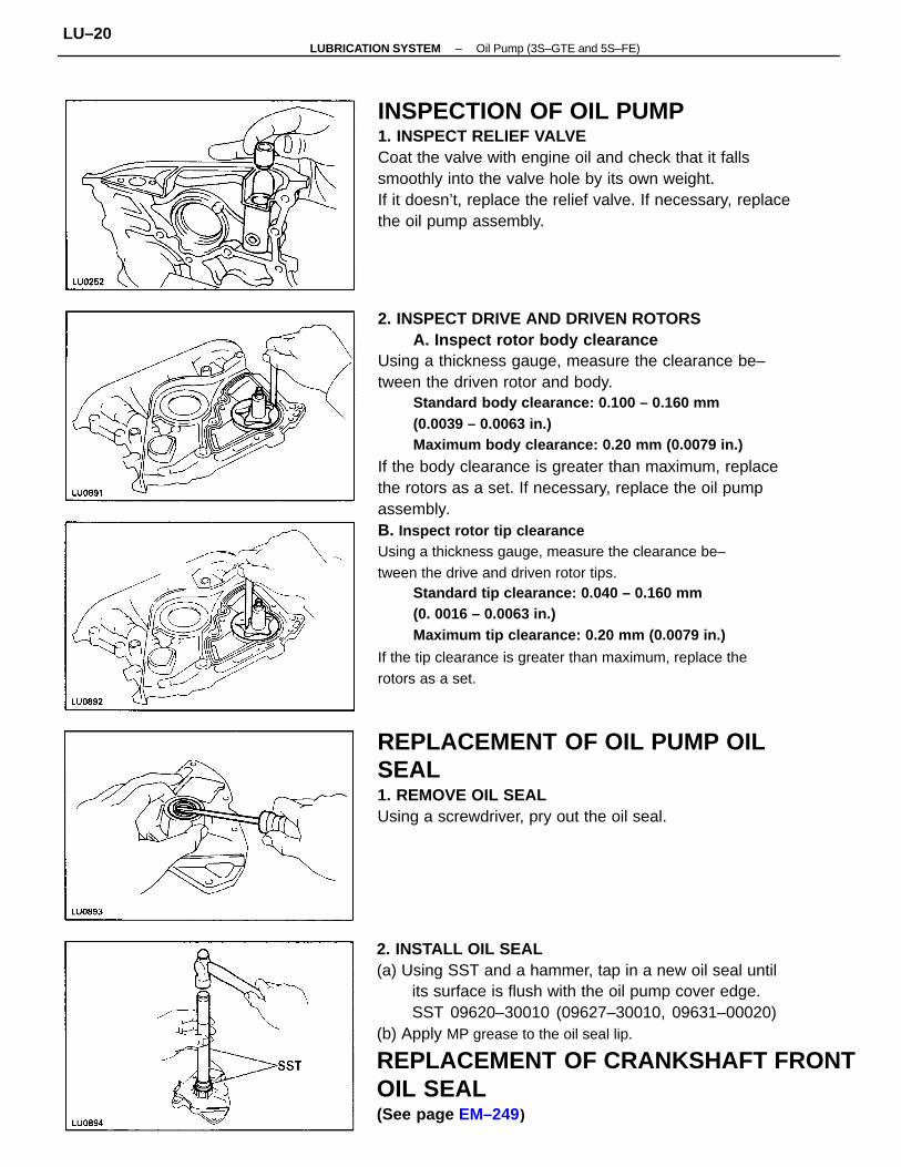
2. INSPECT DRIVE AND DRIVEN ROTORSA. Inspect rotor body clearance
Using a thickness gauge, measure the clearance be–tween the driven rotor and body.
Standard body clearance: 0.100 – 0.160 mm(0.0039 – 0.0063 in.)Maximum body clearance: 0.20 mm (0.0079 in.)
If the body clearance is greater than maximum, replacethe rotors as a set. If necessary, replace the oil pumpassembly.B. Inspect rotor tip clearanceUsing a thickness gauge, measure the clearance be–tween the drive and driven rotor tips.
Standard tip clearance: 0.040 – 0.160 mm(0. 0016 – 0.0063 in.)Maximum tip clearance: 0.20 mm (0.0079 in.)
If the tip clearance is greater than maximum, replace therotors as a set.
2. INSTALL OIL SEAL(a) Using SST and a hammer, tap in a new oil seal until
its surface is flush with the oil pump cover edge.SST 09620–30010 (09627–30010, 09631–00020)
(b) Apply MP grease to the oil seal lip.
REPLACEMENT OF CRANKSHAFT FRONTOIL SEAL(See page EM–249)
INSPECTION OF OIL PUMP1. INSPECT RELIEF VALVECoat the valve with engine oil and check that it fallssmoothly into the valve hole by its own weight.If it doesn’t, replace the relief valve. If necessary, replacethe oil pump assembly.
REPLACEMENT OF OIL PUMP OILSEAL1. REMOVE OIL SEALUsing a screwdriver, pry out the oil seal.
–LUBRICATION SYSTEM Oil Pump (3S–GTE and 5S–FE)LU–20
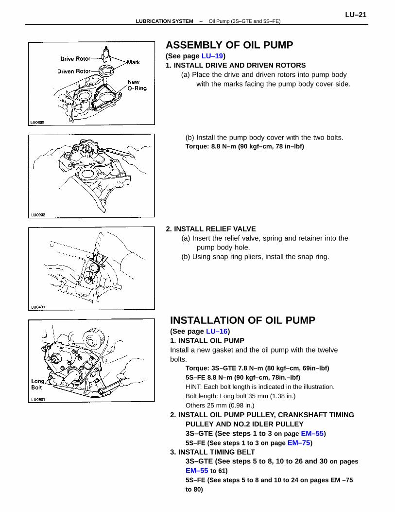
INSTALLATION OF OIL PUMP(See page LU–16)1. INSTALL OIL PUMPInstall a new gasket and the oil pump with the twelvebolts.
Torque: 3S–GTE 7.8 N–m (80 kgf–cm, 69in–lbf)5S–FE 8.8 N–m (90 kgf–cm, 78in.–Ibf)HINT: Each bolt length is indicated in the illustration.Bolt length: Long bolt 35 mm (1.38 in.)Others 25 mm (0.98 in.)
2. INSTALL OIL PUMP PULLEY, CRANKSHAFT TIMINGPULLEY AND NO.2 IDLER PULLEY3S–GTE (See steps 1 to 3 on page EM–55)5S–FE (See steps 1 to 3 on page EM–75)
3. INSTALL TIMING BELT3S–GTE (See steps 5 to 8, 10 to 26 and 30 on pagesEM–55 to 61)5S–FE (See steps 5 to 8 and 10 to 24 on pages EM –75to 80)
ASSEMBLY OF OIL PUMP(See page LU–19)1. INSTALL DRIVE AND DRIVEN ROTORS
(a) Place the drive and driven rotors into pump bodywith the marks facing the pump body cover side.
2. INSTALL RELIEF VALVE(a) Insert the relief valve, spring and retainer into the
pump body hole.(b) Using snap ring pliers, install the snap ring.
(b) Install the pump body cover with the two bolts.Torque: 8.8 N–m (90 kgf–cm, 78 in–lbf)
–LUBRICATION SYSTEM Oil Pump (3S–GTE and 5S–FE)LU–21
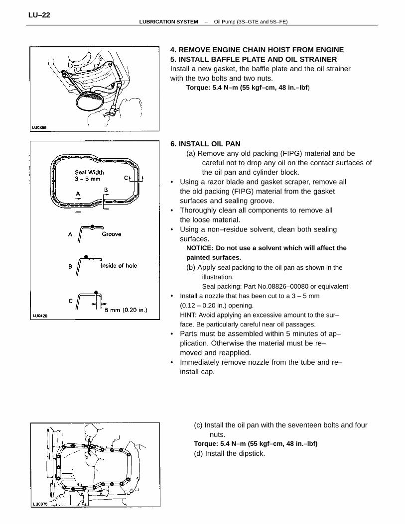
6. INSTALL OIL PAN(a) Remove any old packing (FIPG) material and be
careful not to drop any oil on the contact surfaces ofthe oil pan and cylinder block.
• Using a razor blade and gasket scraper, remove allthe old packing (FIPG) material from the gasketsurfaces and sealing groove.
• Thoroughly clean all components to remove allthe loose material.
• Using a non–residue solvent, clean both sealingsurfaces.
NOTICE: Do not use a solvent which will affect thepainted surfaces.
(b) Apply seal packing to the oil pan as shown in theillustration.Seal packing: Part No.08826–00080 or equivalent
• Install a nozzle that has been cut to a 3 – 5 mm(0.12 – 0.20 in.) opening.HINT: Avoid applying an excessive amount to the sur–face. Be particularly careful near oil passages.
• Parts must be assembled within 5 minutes of ap–plication. Otherwise the material must be re–moved and reapplied.
• Immediately remove nozzle from the tube and re–install cap.
4. REMOVE ENGINE CHAIN HOIST FROM ENGINE5. INSTALL BAFFLE PLATE AND OIL STRAINERInstall a new gasket, the baffle plate and the oil strainerwith the two bolts and two nuts.
Torque: 5.4 N–m (55 kgf–cm, 48 in.–Ibf )
(c) Install the oil pan with the seventeen bolts and fournuts.
Torque: 5.4 N–m (55 kgf–cm, 48 in.–lbf)
(d) Install the dipstick.
–LUBRICATION SYSTEM Oil Pump (3S–GTE and 5S–FE)LU–22
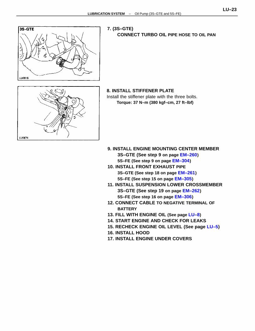
9. INSTALL ENGINE MOUNTING CENTER MEMBER3S–GTE (See step 9 on page EM–260)5S–FE (See step 9 on page EM–304)
10. INSTALL FRONT EXHAUST PIPE3S–GTE (See step 18 on page EM–261)5S–FE (See step 15 on page EM–305)
11. INSTALL SUSPENSION LOWER CROSSMEMBER3S–GTE (See step 19 on page EM–262)5S–FE (See step 16 on page EM–306)
12. CONNECT CABLE TO NEGATIVE TERMINAL OFBATTERY
13. FILL WITH ENGINE OIL (See page LU–8)14. START ENGINE AND CHECK FOR LEAKS15. RECHECK ENGINE OIL LEVEL (See page LU–5)16. INSTALL HOOD17. INSTALL ENGINE UNDER COVERS
8. INSTALL STIFFENER PLATEInstall the stiffener plate with the three bolts.
Torque: 37 N–m (380 kgf–cm, 27 ft–lbf)
7. (3S–GTE)CONNECT TURBO OIL PIPE HOSE TO OIL PAN
–LUBRICATION SYSTEM Oil Pump (3S–GTE and 5S–FE)LU–23
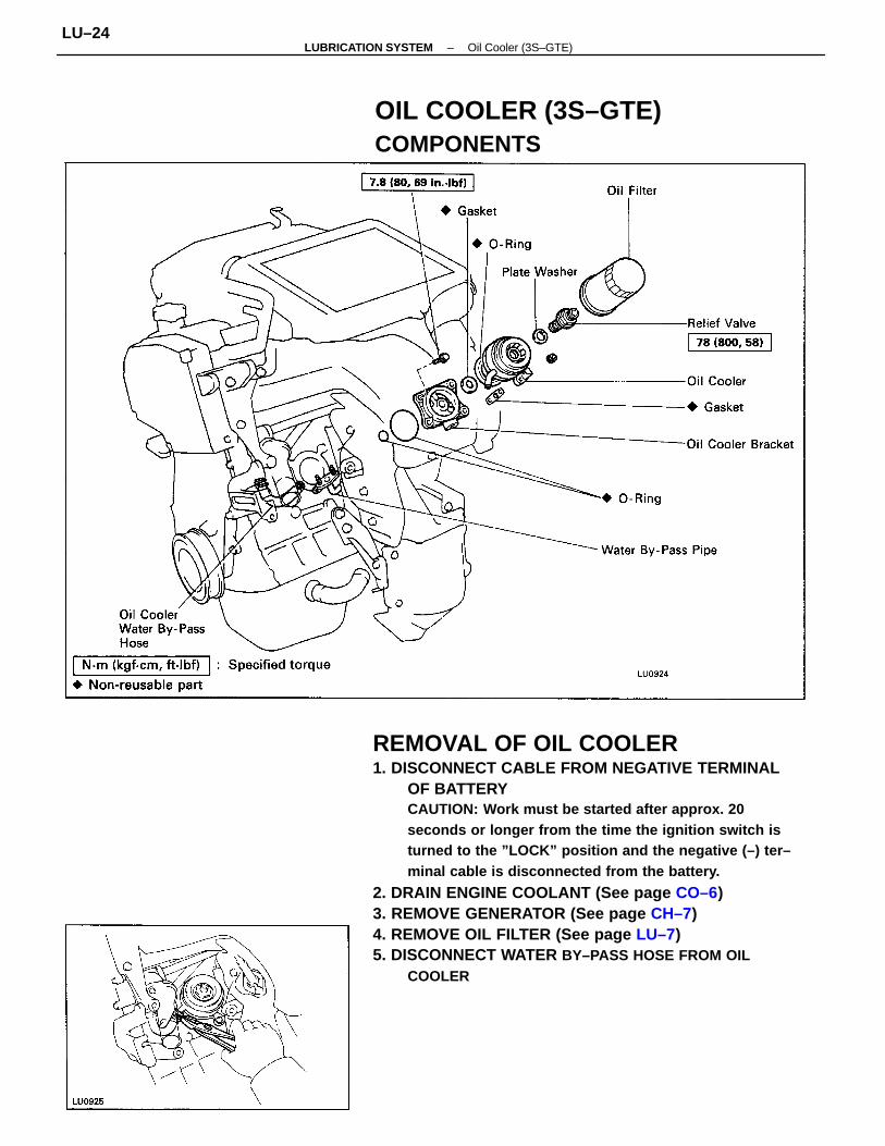
REMOVAL OF OIL COOLER1. DISCONNECT CABLE FROM NEGATIVE TERMINAL
OF BATTERYCAUTION: Work must be started after approx. 20seconds or longer from the time the ignition switch isturned to the ”LOCK” position and the negative (–) ter–minal cable is disconnected from the battery.
2. DRAIN ENGINE COOLANT (See page CO–6)3. REMOVE GENERATOR (See page CH–7)4. REMOVE OIL FILTER (See page LU–7)5. DISCONNECT WATER BY–PASS HOSE FROM OIL
COOLER
OIL COOLER (3S–GTE)COMPONENTS
–LUBRICATION SYSTEM Oil Cooler (3S–GTE)LU–24
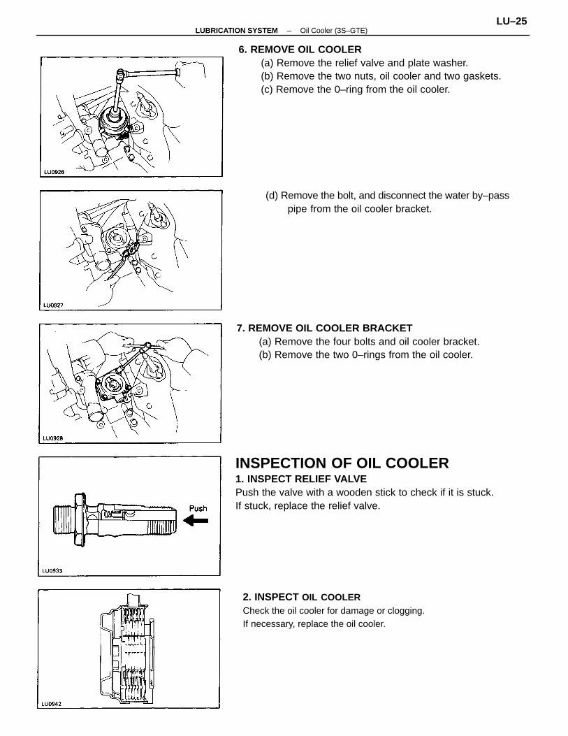
6. REMOVE OIL COOLER(a) Remove the relief valve and plate washer.(b) Remove the two nuts, oil cooler and two gaskets.(c) Remove the 0–ring from the oil cooler.
INSPECTION OF OIL COOLER1. INSPECT RELIEF VALVEPush the valve with a wooden stick to check if it is stuck.If stuck, replace the relief valve.
7. REMOVE OIL COOLER BRACKET(a) Remove the four bolts and oil cooler bracket.(b) Remove the two 0–rings from the oil cooler.
2. INSPECT OIL COOLERCheck the oil cooler for damage or clogging.If necessary, replace the oil cooler.
(d) Remove the bolt, and disconnect the water by–passpipe from the oil cooler bracket.
–LUBRICATION SYSTEM Oil Cooler (3S–GTE)LU–25
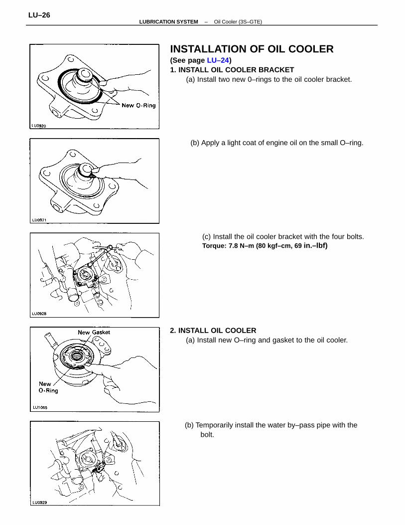
INSTALLATION OF OIL COOLER(See page LU–24)1. INSTALL OIL COOLER BRACKET
(a) Install two new 0–rings to the oil cooler bracket.
2. INSTALL OIL COOLER(a) Install new O–ring and gasket to the oil cooler.
(c) Install the oil cooler bracket with the four bolts.Torque: 7.8 N–m (80 kgf–cm, 69 in.–lbf)
(b) Temporarily install the water by–pass pipe with thebolt.
(b) Apply a light coat of engine oil on the small O–ring.
–LUBRICATION SYSTEM Oil Cooler (3S–GTE)LU–26
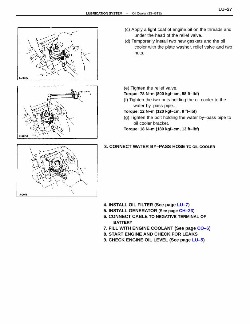
4. INSTALL OIL FILTER (See page LU–7)5. INSTALL GENERATOR (See page CH–23)6. CONNECT CABLE TO NEGATIVE TERMINAL OF
BATTERY7. FILL WITH ENGINE COOLANT (See page CO–6)8. START ENGINE AND CHECK FOR LEAKS9. CHECK ENGINE OIL LEVEL (See page LU–5)
(e) Tighten the relief valve.Torque: 78 N–m (800 kgf–cm, 58 ft–lbf)
(f) Tighten the two nuts holding the oil cooler to thewater by–pass pipe..
Torque: 12 N–m (120 kgf–cm, 9 ft–lbf)
(g) Tighten the bolt holding the water by–pass pipe tooil cooler bracket.
Torque: 18 N–m (180 kgf–cm, 13 ft–lbf)
(c) Apply a light coat of engine oil on the threads andunder the head of the relief valve.
(d) Temporarily install two new gaskets and the oilcooler with the plate washer, relief valve and twonuts.
3. CONNECT WATER BY–PASS HOSE TO OIL COOLER
–LUBRICATION SYSTEM Oil Cooler (3S–GTE)LU–27
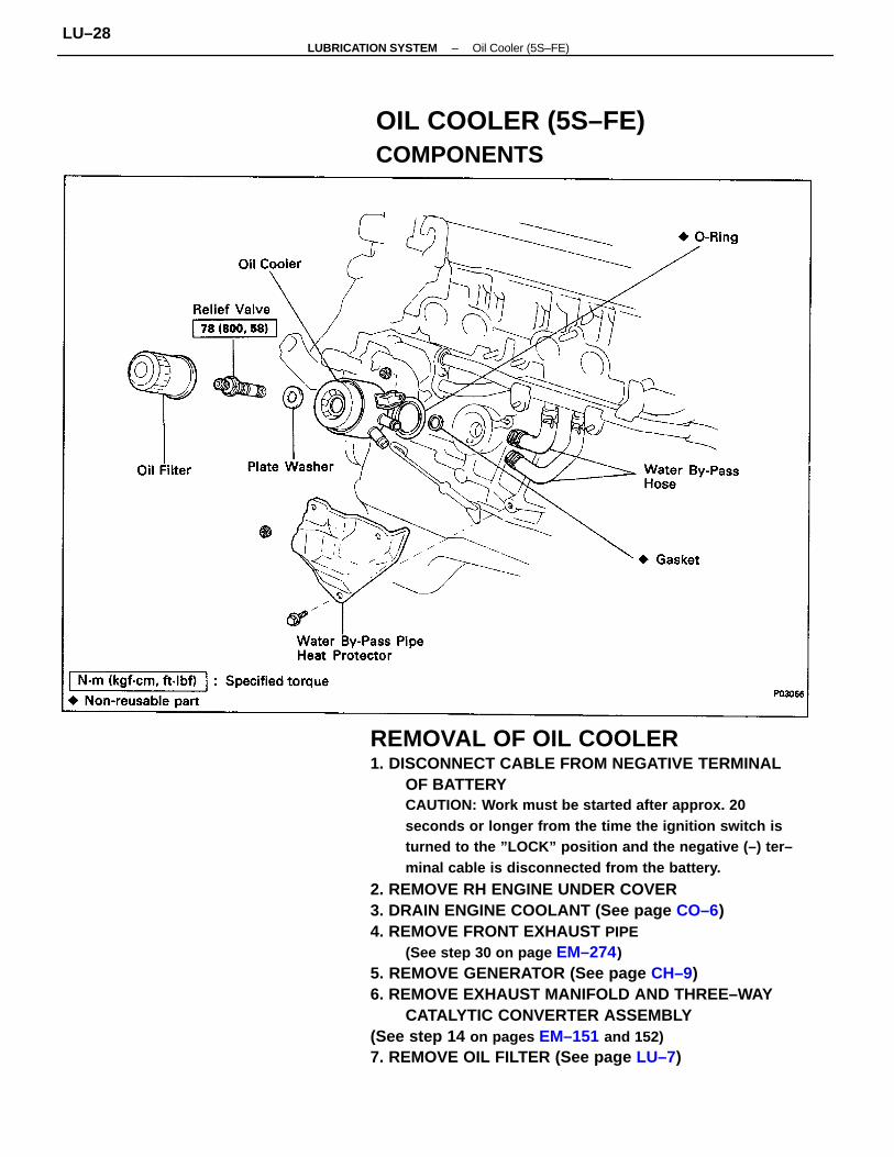
REMOVAL OF OIL COOLER1. DISCONNECT CABLE FROM NEGATIVE TERMINAL
OF BATTERYCAUTION: Work must be started after approx. 20seconds or longer from the time the ignition switch isturned to the ”LOCK” position and the negative (–) ter–minal cable is disconnected from the battery.
2. REMOVE RH ENGINE UNDER COVER3. DRAIN ENGINE COOLANT (See page CO–6)4. REMOVE FRONT EXHAUST PIPE
(See step 30 on page EM–274)5. REMOVE GENERATOR (See page CH–9)6. REMOVE EXHAUST MANIFOLD AND THREE–WAY
CATALYTIC CONVERTER ASSEMBLY(See step 14 on pages EM–151 and 152)7. REMOVE OIL FILTER (See page LU–7)
OIL COOLER (5S–FE)COMPONENTS
–LUBRICATION SYSTEM Oil Cooler (5S–FE)LU–28
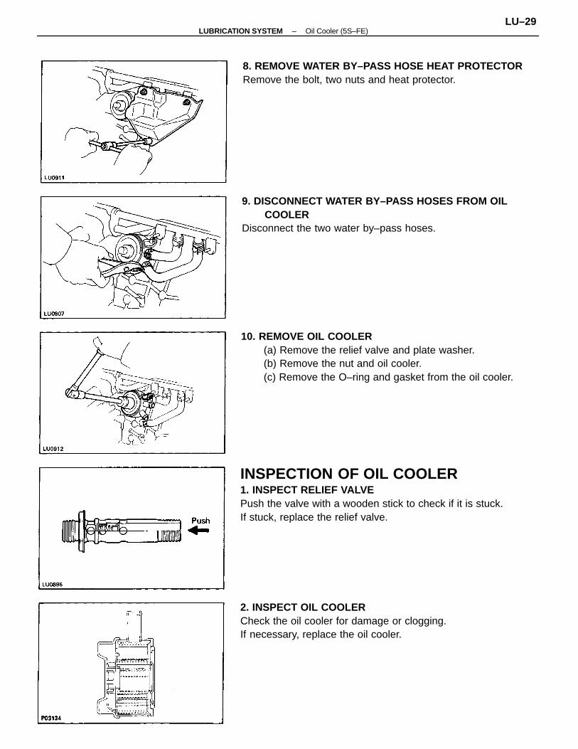
INSPECTION OF OIL COOLER1. INSPECT RELIEF VALVEPush the valve with a wooden stick to check if it is stuck.If stuck, replace the relief valve.
10. REMOVE OIL COOLER(a) Remove the relief valve and plate washer.(b) Remove the nut and oil cooler.(c) Remove the O–ring and gasket from the oil cooler.
9. DISCONNECT WATER BY–PASS HOSES FROM OILCOOLER
Disconnect the two water by–pass hoses.
2. INSPECT OIL COOLERCheck the oil cooler for damage or clogging.If necessary, replace the oil cooler.
8. REMOVE WATER BY–PASS HOSE HEAT PROTECTORRemove the bolt, two nuts and heat protector.
–LUBRICATION SYSTEM Oil Cooler (5S–FE)LU–29
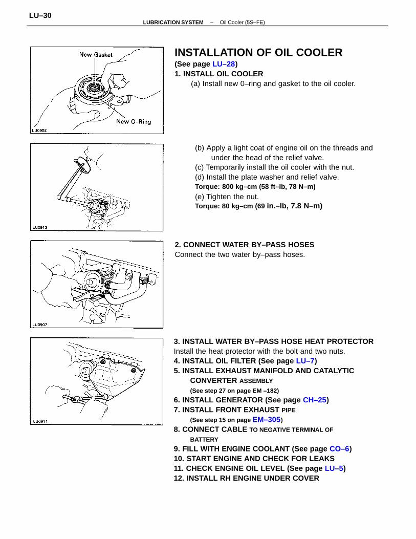
3. INSTALL WATER BY–PASS HOSE HEAT PROTECTORInstall the heat protector with the bolt and two nuts.4. INSTALL OIL FILTER (See page LU–7)5. INSTALL EXHAUST MANIFOLD AND CATALYTIC
CONVERTER ASSEMBLY
(See step 27 on page EM –182)
6. INSTALL GENERATOR (See page CH–25)7. INSTALL FRONT EXHAUST PIPE
(See step 15 on page EM–305)
8. CONNECT CABLE TO NEGATIVE TERMINAL OF
BATTERY
9. FILL WITH ENGINE COOLANT (See page CO–6)10. START ENGINE AND CHECK FOR LEAKS11. CHECK ENGINE OIL LEVEL (See page LU–5)12. INSTALL RH ENGINE UNDER COVER
(b) Apply a light coat of engine oil on the threads andunder the head of the relief valve.
(c) Temporarily install the oil cooler with the nut.(d) Install the plate washer and relief valve.Torque: 800 kg–cm (58 ft–Ib, 78 N–m)
(e) Tighten the nut.Torque: 80 kg–cm (69 in.–Ib, 7.8 N–m)
INSTALLATION OF OIL COOLER(See page LU–28)1. INSTALL OIL COOLER
(a) Install new 0–ring and gasket to the oil cooler.
2. CONNECT WATER BY–PASS HOSESConnect the two water by–pass hoses.
–LUBRICATION SYSTEM Oil Cooler (5S–FE)LU–30
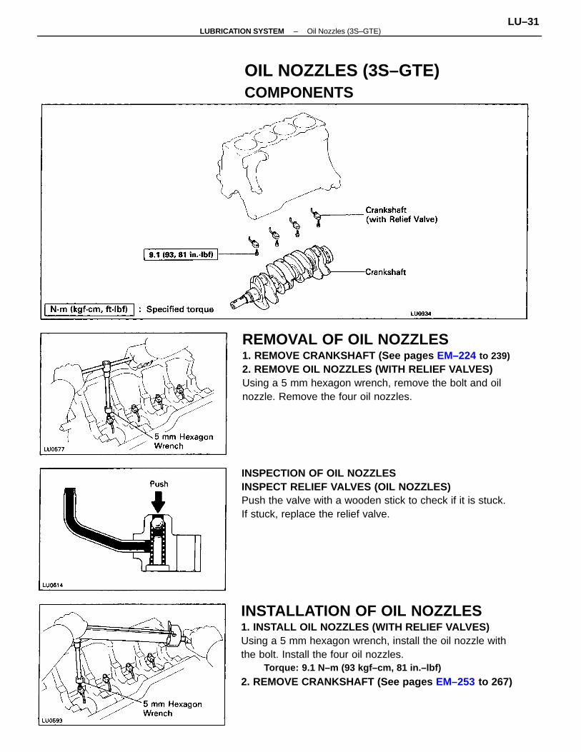
INSTALLATION OF OIL NOZZLES1. INSTALL OIL NOZZLES (WITH RELIEF VALVES)Using a 5 mm hexagon wrench, install the oil nozzle withthe bolt. Install the four oil nozzles.
Torque: 9.1 N–m (93 kgf–cm, 81 in.–lbf)
2. REMOVE CRANKSHAFT (See pages EM–253 to 267)
REMOVAL OF OIL NOZZLES1. REMOVE CRANKSHAFT (See pages EM–224 to 239)2. REMOVE OIL NOZZLES (WITH RELIEF VALVES)Using a 5 mm hexagon wrench, remove the bolt and oilnozzle. Remove the four oil nozzles.
INSPECTION OF OIL NOZZLESINSPECT RELIEF VALVES (OIL NOZZLES)Push the valve with a wooden stick to check if it is stuck.If stuck, replace the relief valve.
OIL NOZZLES (3S–GTE)COMPONENTS
–LUBRICATION SYSTEM Oil Nozzles (3S–GTE)LU–31
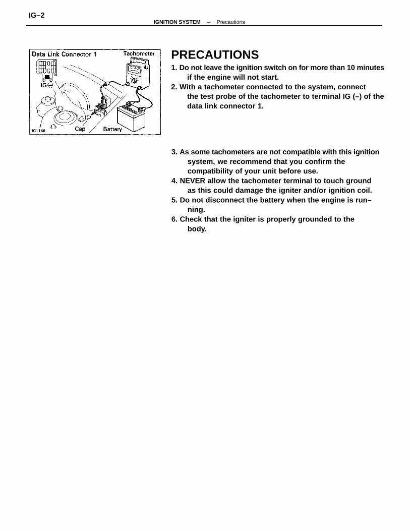
3. As some tachometers are not compatible with this ignitionsystem, we recommend that you confirm thecompatibility of your unit before use.
4. NEVER allow the tachometer terminal to touch groundas this could damage the igniter and/or ignition coil.
5. Do not disconnect the battery when the engine is run–ning.
6. Check that the igniter is properly grounded to thebody.
PRECAUTIONS1. Do not leave the ignition switch on for more than 10 minutes
if the engine will not start.2. With a tachometer connected to the system, connect
the test probe of the tachometer to terminal IG (–) of thedata link connector 1.
–IGNITION SYSTEM PrecautionsIG–2

Incorrect ignition timingIgnition problems• Ignition coil• Igniter• Distributor• High–tension cordsIgnition wiring disconnected or broken
Spark plug faultyIgnition wiring faultyIncorrect ignition timingIgnition problems• Ignition coil• Igniter• Distributor• High–tension cords
IG–25, 29, 37
IG–8,13,17IG–9, 14, 19IG–9, 13, 19IG–7, 11, 16
Spark plug faultyIgnition wiring faultyIncorrect ignition timing
Engine will not start/hard to start(cranks ok)
TROUBLESHOOTING
Engine dieseling(runs after ignitionswitch is turned off)
Spark plug faultyIncorrect ignition timing
Inspect plugsInspect wiringReset timing
Inspect plugsInspect wiringReset timing
Inspect coilInspect igniterInspect distributorInspect high–tension cords
IG–8,13,17IG–9, 14, 19IG–9, 13, 19IG–7, 11, 16
Muffler explosion(after fire) all the time
Engine hesitates/poor acceleration
Inspect plugsReset timing
IG–7,11,16IG–25, 29, 37
Incorrect ignition timing
Incorrect ignition timing
Incorrect ignition timing
Incorrect ignition timing
Poor gasoline mileage
Rough idle or stalls
Engine overheats
Engine backfires
Possible cause
IG–25, 29, 37
IG–25, 29, 37
IG–25, 29, 37
IG–25, 29, 37
IG–25, 29, 37
IG–25, 29, 37
Reset timing Inspect coil
Inspect igniterInspect distributorInspect high–tension cordsInspect wiring
Reset timing
Reset timing
Reset timing
Reset timing
IG–7, 11, 16
IG–7, 11, 16
Problem Remedy Page
–IGNITION SYSTEM TroubleshootingIG–3
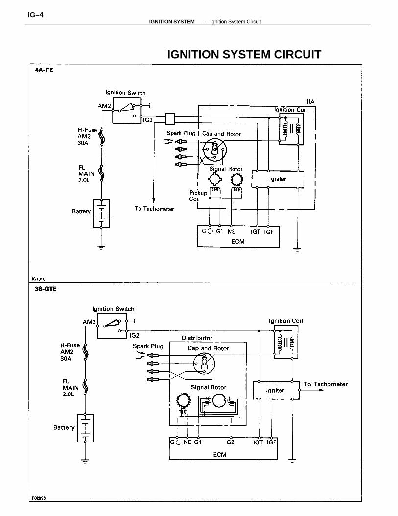
IGNITION SYSTEM CIRCUIT
–IGNITION SYSTEM Ignition System CircuitIG–4
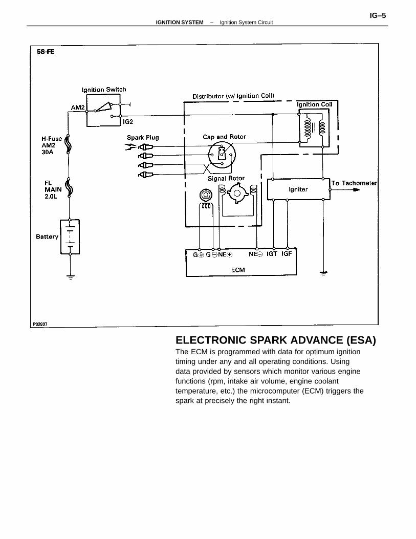
ELECTRONIC SPARK ADVANCE (ESA)The ECM is programmed with data for optimum ignitiontiming under any and all operating conditions. Usingdata provided by sensors which monitor various enginefunctions (rpm, intake air volume, engine coolanttemperature, etc.) the microcomputer (ECM) triggers thespark at precisely the right instant.
–IGNITION SYSTEM Ignition System CircuitIG–5
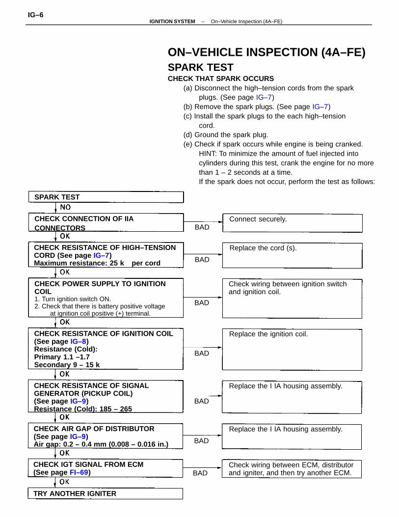
ON–VEHICLE INSPECTION (4A–FE)SPARK TESTCHECK THAT SPARK OCCURS
(a) Disconnect the high–tension cords from the sparkplugs. (See page IG–7)
(b) Remove the spark plugs. (See page IG–7)(c) Install the spark plugs to the each high–tension
cord.(d) Ground the spark plug.(e) Check if spark occurs while engine is being cranked.
HINT: To minimize the amount of fuel injected intocylinders during this test, crank the engine for no morethan 1 – 2 seconds at a time.If the spark does not occur, perform the test as follows:
CHECK RESISTANCE OF IGNITION COIL(See page IG–8)Resistance (Cold):Primary 1.1 –1.7
Secondary 9 – 15 k
CHECK POWER SUPPLY TO IGNITIONCOIL1. Turn ignition switch ON.2. Check that there is battery positive voltage
at ignition coil positive (+) terminal.
CHECK RESISTANCE OF SIGNALGENERATOR (PICKUP COIL)(See page IG–9)Resistance (Cold): 185 – 265
CHECK AIR GAP OF DISTRIBUTOR(See page IG–9)Air gap: 0.2 – 0.4 mm (0.008 – 0.016 in.)
CHECK RESISTANCE OF HIGH–TENSIONCORD (See page IG–7)Maximum resistance: 25 k per cord
Check wiring between ECM, distributorand igniter, and then try another ECM.
Check wiring between ignition switchand ignition coil.
CHECK IGT SIGNAL FROM ECM(See page FI–69)
CHECK CONNECTION OF IIACONNECTORS
Replace the I IA housing assembly.
Replace the I IA housing assembly.
Replace the ignition coil.
TRY ANOTHER IGNITER
Replace the cord (s).
Connect securely.
SPARK TEST
BAD
BAD
BAD
BAD
BAD
BAD
BAD
–IGNITION SYSTEM On–Vehicle Inspection (4A–FE)IG–6
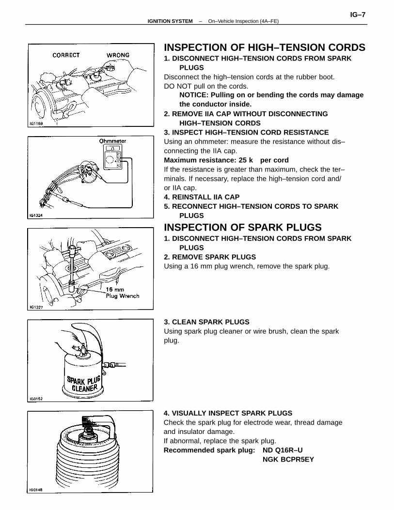
INSPECTION OF HIGH–TENSION CORDS1. DISCONNECT HIGH–TENSION CORDS FROM SPARK
PLUGSDisconnect the high–tension cords at the rubber boot.DO NOT pull on the cords.
NOTICE: Pulling on or bending the cords may damagethe conductor inside.
2. REMOVE IIA CAP WITHOUT DISCONNECTINGHIGH–TENSION CORDS
3. INSPECT HIGH–TENSION CORD RESISTANCEUsing an ohmmeter: measure the resistance without dis–connecting the IIA cap.Maximum resistance: 25 k per cordIf the resistance is greater than maximum, check the ter–minals. If necessary, replace the high–tension cord and/or IIA cap.4. REINSTALL IIA CAP5. RECONNECT HIGH–TENSION CORDS TO SPARK
PLUGS
INSPECTION OF SPARK PLUGS1. DISCONNECT HIGH–TENSION CORDS FROM SPARK
PLUGS2. REMOVE SPARK PLUGSUsing a 16 mm plug wrench, remove the spark plug.
4. VISUALLY INSPECT SPARK PLUGSCheck the spark plug for electrode wear, thread damageand insulator damage.If abnormal, replace the spark plug.Recommended spark plug: ND Q16R–U
NGK BCPR5EY
3. CLEAN SPARK PLUGSUsing spark plug cleaner or wire brush, clean the sparkplug.
–IGNITION SYSTEM On–Vehicle Inspection (4A–FE)IG–7
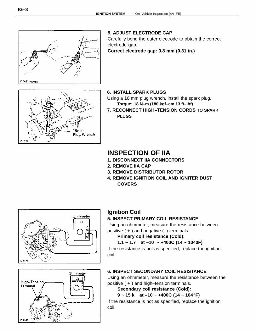
Ignition Coil5. INSPECT PRIMARY COIL RESISTANCEUsing an ohmmeter, measure the resistance betweenpositive ( + ) and negative (–) terminals.
Primary coil resistance (Cold):1.1 ~ 1.7 at –10 ~ +400C (14 ~ 1040F)
If the resistance is not as specified, replace the ignitioncoil.
6. INSPECT SECONDARY COIL RESISTANCEUsing an ohmmeter, measure the resistance between thepositive ( + ) and high–tension terminals.
Secondary coil resistance (Cold):9 ~ 15 k at –10 ~ +400C (14 ~ 104F)
If the resistance is not as specified, replace the ignitioncoil.
INSPECTION OF IIA1. DISCONNECT IIA CONNECTORS2. REMOVE IIA CAP3. REMOVE DISTRIBUTOR ROTOR4. REMOVE IGNITION COIL AND IGNITER DUST
COVERS
6. INSTALL SPARK PLUGSUsing a 16 mm plug wrench, install the spark plug.
Torque: 18 N–m (180 kgf–cm,13 ft–Ibf)
7. RECONNECT HIGH–TENSION CORDS TO SPARKPLUGS
5. ADJUST ELECTRODE CAPCarefully bend the outer electrode to obtain the correctelectrode gap.Correct electrode gap: 0.8 mm (0.31 in.)
–IGNITION SYSTEM On–Vehicle Inspection (4A–FE)IG–8
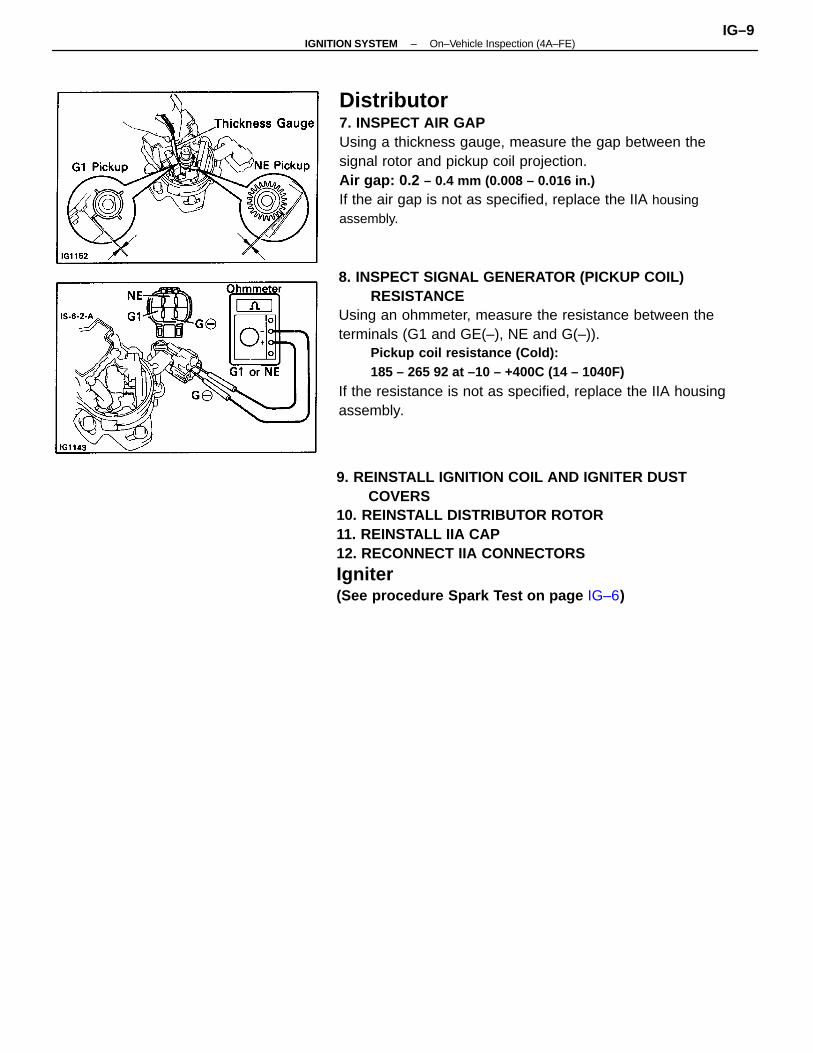
8. INSPECT SIGNAL GENERATOR (PICKUP COIL)RESISTANCE
Using an ohmmeter, measure the resistance between theterminals (G1 and GE(–), NE and G(–)).
Pickup coil resistance (Cold):185 – 265 92 at –10 – +400C (14 – 1040F)
If the resistance is not as specified, replace the IIA housingassembly.
9. REINSTALL IGNITION COIL AND IGNITER DUSTCOVERS
10. REINSTALL DISTRIBUTOR ROTOR11. REINSTALL IIA CAP12. RECONNECT IIA CONNECTORS
Igniter(See procedure Spark Test on page IG–6)
Distributor7. INSPECT AIR GAPUsing a thickness gauge, measure the gap between thesignal rotor and pickup coil projection.Air gap: 0.2 – 0.4 mm (0.008 – 0.016 in.)If the air gap is not as specified, replace the IIA housingassembly.
–IGNITION SYSTEM On–Vehicle Inspection (4A–FE)IG–9
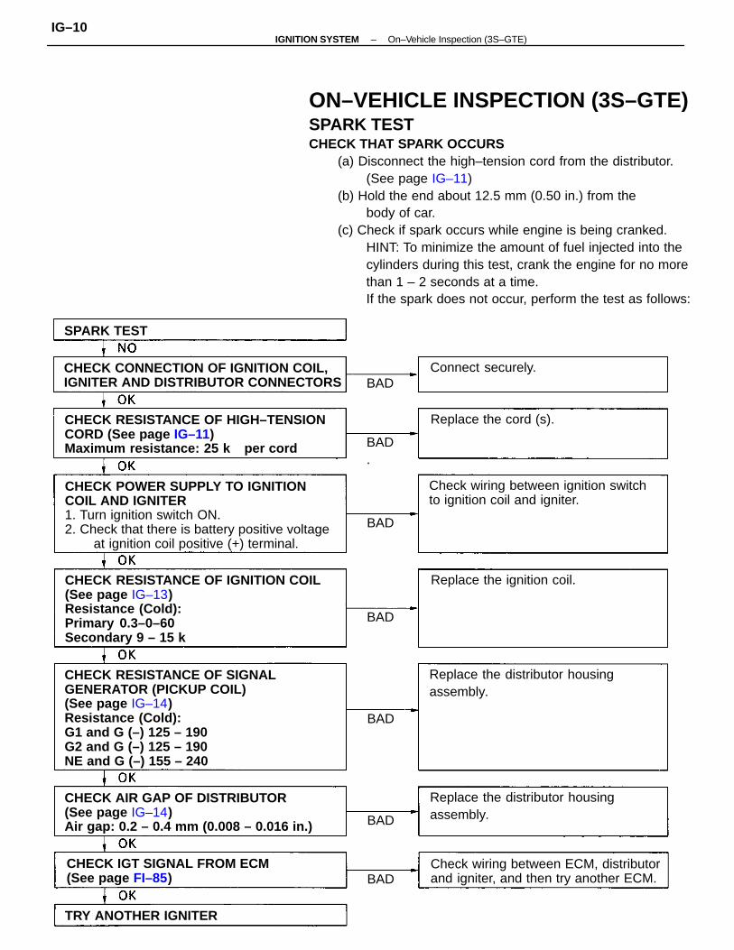
ON–VEHICLE INSPECTION (3S–GTE)SPARK TESTCHECK THAT SPARK OCCURS
(a) Disconnect the high–tension cord from the distributor. (See page IG–11)
(b) Hold the end about 12.5 mm (0.50 in.) from thebody of car.
(c) Check if spark occurs while engine is being cranked.HINT: To minimize the amount of fuel injected into thecylinders during this test, crank the engine for no morethan 1 – 2 seconds at a time.If the spark does not occur, perform the test as follows:
CHECK RESISTANCE OF SIGNALGENERATOR (PICKUP COIL)(See page IG–14)Resistance (Cold):G1 and G (–) 125 – 190G2 and G (–) 125 – 190NE and G (–) 155 – 240
CHECK RESISTANCE OF IGNITION COIL(See page IG–13)Resistance (Cold):Primary 0.3–0–60Secondary 9 – 15 k
CHECK POWER SUPPLY TO IGNITIONCOIL AND IGNITER1. Turn ignition switch ON.2. Check that there is battery positive voltage
at ignition coil positive (+) terminal.
CHECK RESISTANCE OF HIGH–TENSIONCORD (See page IG–11)Maximum resistance: 25 k per cord
CHECK AIR GAP OF DISTRIBUTOR(See page IG–14)Air gap: 0.2 – 0.4 mm (0.008 – 0.016 in.)
CHECK CONNECTION OF IGNITION COIL,IGNITER AND DISTRIBUTOR CONNECTORS
Check wiring between ECM, distributorand igniter, and then try another ECM.
Check wiring between ignition switchto ignition coil and igniter.
Replace the distributor housingassembly.
Replace the distributor housingassembly.
CHECK IGT SIGNAL FROM ECM(See page FI–85)
Replace the ignition coil.
TRY ANOTHER IGNITER
Replace the cord (s).
Connect securely.
SPARK TEST
BAD.
BAD
BAD
BAD
BAD
BAD
BAD
–IGNITION SYSTEM On–Vehicle Inspection (3S–GTE)IG–10
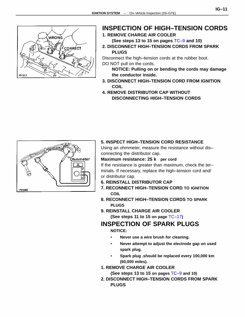
5. INSPECT HIGH–TENSION CORD RESISTANCEUsing an ohmmeter, measure the resistance without dis–connecting the distributor cap.Maximum resistance: 25 k per cordIf the resistance is greater than maximum, check the ter–minals. If necessary, replace the high–tension cord and/or distributor cap.6. REINSTALL DISTRIBUTOR CAP7. RECONNECT HIGH–TENSION CORD TO IGNITION
COIL8. RECONNECT HIGH–TENSION CORDS TO SPARK
PLUGS9. REINSTALL CHARGE AIR COOLER
(See steps 11 to 15 on page TC–17)
INSPECTION OF SPARK PLUGSNOTICE:
• Never use a wire brush for cleaning.
• Never attempt to adjust the electrode gap on usedspark plug.
• Spark plug .should be replaced every 100,000 km(60,000 miles).
1. REMOVE CHARGE AIR COOLER(See steps 13 to 15 on pages TC–9 and 10)
2. DISCONNECT HIGH–TENSION CORDS FROM SPARKPLUGS
INSPECTION OF HIGH–TENSION CORDS1. REMOVE CHARGE AIR COOLER
(See steps 13 to 15 on pages TC–9 and 10)2. DISCONNECT HIGH–TENSION CORDS FROM SPARK
PLUGSDisconnect the high–tension cords at the rubber boot.DO NOT pull on the cords.
NOTICE: Pulling on or bending the cords may damagethe conductor inside.
3. DISCONNECT HIGH–TENSION CORD FROM IGNITIONCOIL
4. REMOVE DISTRIBUTOR CAP WITHOUTDISCONNECTING HIGH–TENSION CORDS
–IGNITION SYSTEM On–Vehicle Inspection (3S–GTE)IG–11
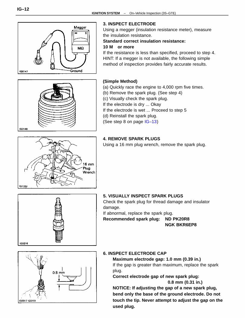
6. INSPECT ELECTRODE CAPMaximum electrode gap: 1.0 mm (0.39 in.)If the gap is greater than maximum, replace the sparkplug.Correct electrode gap of new spark plug:
0.8 mm (0.31 in.)NOTICE: If adjusting the gap of a new spark plug,bend only the base of the ground electrode. Do nottouch the tip. Never attempt to adjust the gap on theused plug.
3. INSPECT ELECTRODEUsing a megger (insulation resistance meter), measurethe insulation resistance.Standard correct insulation resistance:10 M or moreIf the resistance is less than specified, proceed to step 4.HINT: If a megger is not available, the following simplemethod of inspection provides fairly accurate results.
(Simple Method)(a) Quickly race the engine to 4,000 rpm five times.(b) Remove the spark plug. (See step 4)(c) Visually check the spark plug.If the electrode is dry ... OkayIf the electrode is wet ... Proceed to step 5(d) Reinstall the spark plug.(See step 8 on page IG–13)
5. VISUALLY INSPECT SPARK PLUGSCheck the spark plug for thread damage and insulatordamage.If abnormal, replace the spark plug.Recommended spark plug: ND PK20R8
NGK BKR6EP8
4. REMOVE SPARK PLUGSUsing a 16 mm plug wrench, remove the spark plug.
–IGNITION SYSTEM On–Vehicle Inspection (3S–GTE)IG–12
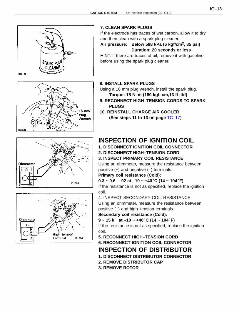
INSPECTION OF IGNITION COIL1. DISCONNECT IGNITION COIL CONNECTOR2. DISCONNECT HIGH–TENSION CORD3. INSPECT PRIMARY COIL RESISTANCEUsing an ohmmeter, measure the resistance betweenpositive (+) and negative (–) terminals.Primary coil resistance (Cold):0.3 ~ 0.6 92 at –10 ~ +40°C (14 ~ 104°F)If the resistance is not as specified, replace the ignitioncoil.4. INSPECT SECONDARY COIL RESISTANCEUsing an ohmmeter, measure the resistance betweenpositive (+) and high–tension terminals.Secondary coil resistance (Cold):9 ~ 15 k at –10 ~ +40°C (14 ~ 104°F)If the resistance is not as specified, replace the ignitioncoil.5. RECONNECT HIGH–TENSION CORD6. RECONNECT IGNITION COIL CONNECTOR
INSPECTION OF DISTRIBUTOR1. DISCONNECT DISTRIBUTOR CONNECTOR2. REMOVE DISTRIBUTOR CAP3. REMOVE ROTOR
8. INSTALL SPARK PLUGSUsing a 16 mm plug wrench, install the spark plug.
Torque: 18 N–m (180 kgf–cm,13 ft–Ibf)9. RECONNECT HIGH–TENSION CORDS TO SPARK
PLUGS10. REINSTALL CHARGE AIR COOLER
(See steps 11 to 13 on page TC–17)
7. CLEAN SPARK PLUGSIf the electrode has traces of wet carbon, allow it to dryand then clean with a spark plug cleaner.Air pressure: Below 588 kPa (6 kgf/cm 2, 85 psi)
Duration: 20 seconds or lessHINT: If there are traces of oil, remove it with gasolinebefore using the spark plug cleaner.
–IGNITION SYSTEM On–Vehicle Inspection (3S–GTE)IG–13
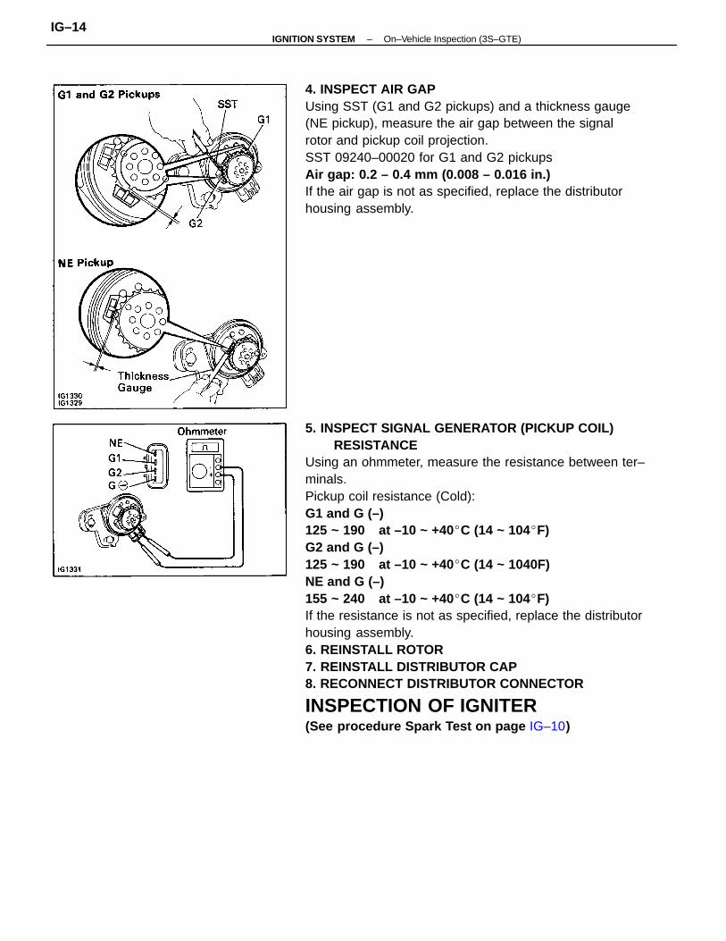
5. INSPECT SIGNAL GENERATOR (PICKUP COIL)RESISTANCE
Using an ohmmeter, measure the resistance between ter–minals.Pickup coil resistance (Cold):G1 and G (–)125 ~ 190 at –10 ~ +40C (14 ~ 104F)G2 and G (–)125 ~ 190 at –10 ~ +40C (14 ~ 1040F)NE and G (–)155 ~ 240 at –10 ~ +40C (14 ~ 104F)If the resistance is not as specified, replace the distributorhousing assembly.6. REINSTALL ROTOR7. REINSTALL DISTRIBUTOR CAP8. RECONNECT DISTRIBUTOR CONNECTOR
INSPECTION OF IGNITER(See procedure Spark Test on page IG–10)
4. INSPECT AIR GAPUsing SST (G1 and G2 pickups) and a thickness gauge(NE pickup), measure the air gap between the signalrotor and pickup coil projection.SST 09240–00020 for G1 and G2 pickupsAir gap: 0.2 – 0.4 mm (0.008 – 0.016 in.)If the air gap is not as specified, replace the distributorhousing assembly.
–IGNITION SYSTEM On–Vehicle Inspection (3S–GTE)IG–14
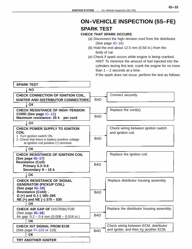
ON–VEHICLE INSPECTION (5S–FE)SPARK TESTCHECK THAT SPARK OCCURS
(a) Disconnect the high–tension cord from the distributor. (See page IG–16)
(b) Hold the end about 12.5 mm (0.50 in.) from thebody of car.
(e) Check if spark occurs while engine is being cranked.HINT: To minimize the amount of fuel injected into thecylinders during this test, crank the engine for no morethan 1 – 2 seconds at a time.If the spark does not occur, perform the test as follows:
CHECK RESISTANCE OF IGNITION COIL(See page IG–17)Resistance (Coil):
Primary 0.3–0.6 Secondary 9 – 15 k
CHECK RESISTANCE OF SIGNALGENERATOR (PICKUP COIL)(See page IG–19)Resistance (Cold): .G (+) and G (–) 185–265NE (+) and NE (–) 370 – 530
CHECK POWER SUPPLY TO IGNITIONCOIL1. Turn ignition switch ON.2. Check that there is battery positive voltage
at ignition coil positive (+) terminal.
CHECK RESISTANCE OF HIGH–TENSIONCORD (See page IG–16)Maximum resistance: 25 k per cord
CHECK AIR GAP OF DISTRIBUTOR(See page IG–18)Air gap: 0.2 – 0.4 mm (0.008 – 0.016 in.)
CHECK CONNECTION OF IGNITION COIL,IGNITER AND DISTRIBUTOR CONNECTORS
Check wiring between ECM, distributorand igniter, and then try another ECM.
Check wiring between ignition switchand ignition coil.
CHECK IGT SIGNAL FROM ECM(See page FI–103 or 119)
Replace the distributor housing assembly.
Replace distributor housing assembly.
Replace the ignition coil.
TRY ANOTHER IGNITER
Replace the cord(s).
Connect securely.
SPARK TEST
BAD
BAD
BAD
BAD
BAD
BAD
BAD
–IGNITION SYSTEM On–Vehicle Inspection (5S–FE)IG–15
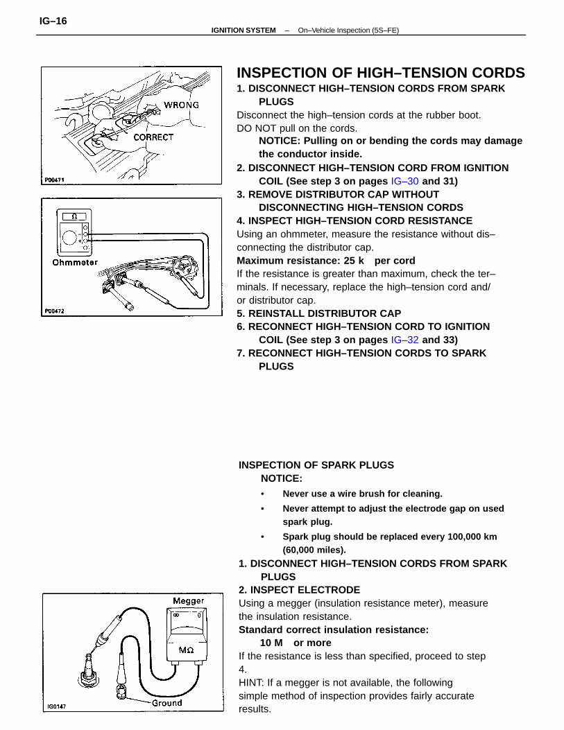
INSPECTION OF HIGH–TENSION CORDS1. DISCONNECT HIGH–TENSION CORDS FROM SPARK
PLUGSDisconnect the high–tension cords at the rubber boot.DO NOT pull on the cords.
NOTICE: Pulling on or bending the cords may damagethe conductor inside.
2. DISCONNECT HIGH–TENSION CORD FROM IGNITIONCOIL (See step 3 on pages IG–30 and 31)
3. REMOVE DISTRIBUTOR CAP WITHOUTDISCONNECTING HIGH–TENSION CORDS
4. INSPECT HIGH–TENSION CORD RESISTANCEUsing an ohmmeter, measure the resistance without dis–connecting the distributor cap.Maximum resistance: 25 k per cordIf the resistance is greater than maximum, check the ter–minals. If necessary, replace the high–tension cord and/or distributor cap.5. REINSTALL DISTRIBUTOR CAP6. RECONNECT HIGH–TENSION CORD TO IGNITION
COIL (See step 3 on pages IG–32 and 33)7. RECONNECT HIGH–TENSION CORDS TO SPARK
PLUGS
INSPECTION OF SPARK PLUGSNOTICE:• Never use a wire brush for cleaning.
• Never attempt to adjust the electrode gap on usedspark plug.
• Spark plug should be replaced every 100,000 km(60,000 miles).
1. DISCONNECT HIGH–TENSION CORDS FROM SPARKPLUGS
2. INSPECT ELECTRODEUsing a megger (insulation resistance meter), measurethe insulation resistance.Standard correct insulation resistance:
10 M or moreIf the resistance is less than specified, proceed to step4.HINT: If a megger is not available, the followingsimple method of inspection provides fairly accurateresults.
–IGNITION SYSTEM On–Vehicle Inspection (5S–FE)IG–16
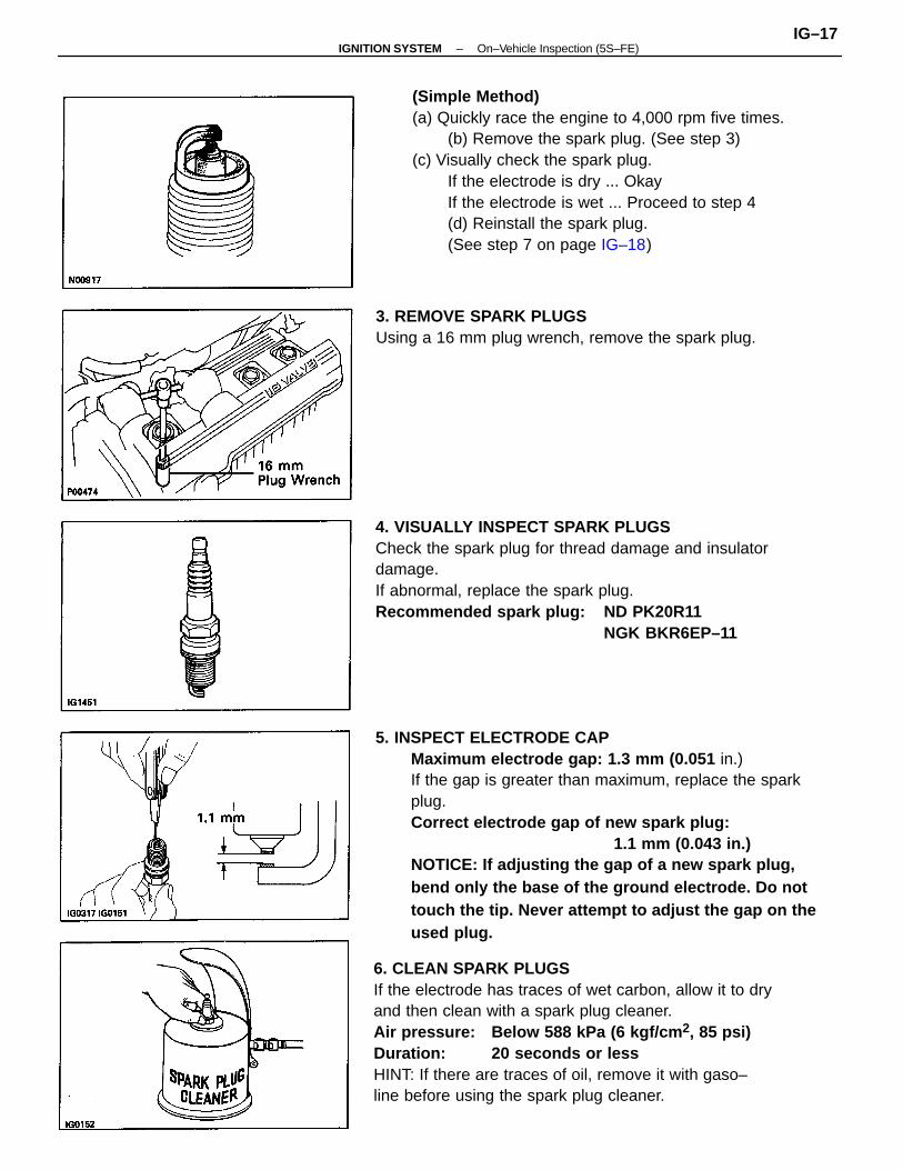
5. INSPECT ELECTRODE CAPMaximum electrode gap: 1.3 mm (0.051 in.)If the gap is greater than maximum, replace the sparkplug.Correct electrode gap of new spark plug:
1.1 mm (0.043 in.)NOTICE: If adjusting the gap of a new spark plug,bend only the base of the ground electrode. Do nottouch the tip. Never attempt to adjust the gap on theused plug.
6. CLEAN SPARK PLUGSIf the electrode has traces of wet carbon, allow it to dryand then clean with a spark plug cleaner.Air pressure: Below 588 kPa (6 kgf/cm 2, 85 psi)Duration: 20 seconds or lessHINT: If there are traces of oil, remove it with gaso–line before using the spark plug cleaner.
(Simple Method)(a) Quickly race the engine to 4,000 rpm five times.
(b) Remove the spark plug. (See step 3)(c) Visually check the spark plug.
If the electrode is dry ... OkayIf the electrode is wet ... Proceed to step 4(d) Reinstall the spark plug.(See step 7 on page IG–18)
4. VISUALLY INSPECT SPARK PLUGSCheck the spark plug for thread damage and insulatordamage.If abnormal, replace the spark plug.Recommended spark plug: ND PK20R11
NGK BKR6EP–11
3. REMOVE SPARK PLUGSUsing a 16 mm plug wrench, remove the spark plug.
–IGNITION SYSTEM On–Vehicle Inspection (5S–FE)IG–17
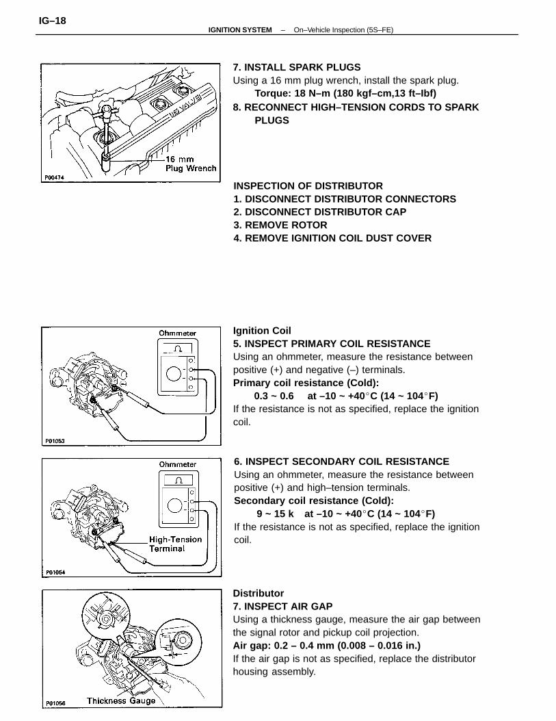
Ignition Coil5. INSPECT PRIMARY COIL RESISTANCEUsing an ohmmeter, measure the resistance betweenpositive (+) and negative (–) terminals.Primary coil resistance (Cold):
0.3 ~ 0.6 at –10 ~ +40C (14 ~ 104F)If the resistance is not as specified, replace the ignitioncoil.
Distributor7. INSPECT AIR GAPUsing a thickness gauge, measure the air gap betweenthe signal rotor and pickup coil projection.Air gap: 0.2 – 0.4 mm (0.008 – 0.016 in.)If the air gap is not as specified, replace the distributorhousing assembly.
6. INSPECT SECONDARY COIL RESISTANCEUsing an ohmmeter, measure the resistance betweenpositive (+) and high–tension terminals.Secondary coil resistance (Cold):
9 ~ 15 k at –10 ~ +40C (14 ~ 104F)If the resistance is not as specified, replace the ignitioncoil.
INSPECTION OF DISTRIBUTOR1. DISCONNECT DISTRIBUTOR CONNECTORS2. DISCONNECT DISTRIBUTOR CAP3. REMOVE ROTOR4. REMOVE IGNITION COIL DUST COVER
7. INSTALL SPARK PLUGSUsing a 16 mm plug wrench, install the spark plug.
Torque: 18 N–m (180 kgf–cm,13 ft–Ibf)8. RECONNECT HIGH–TENSION CORDS TO SPARK
PLUGS
–IGNITION SYSTEM On–Vehicle Inspection (5S–FE)IG–18
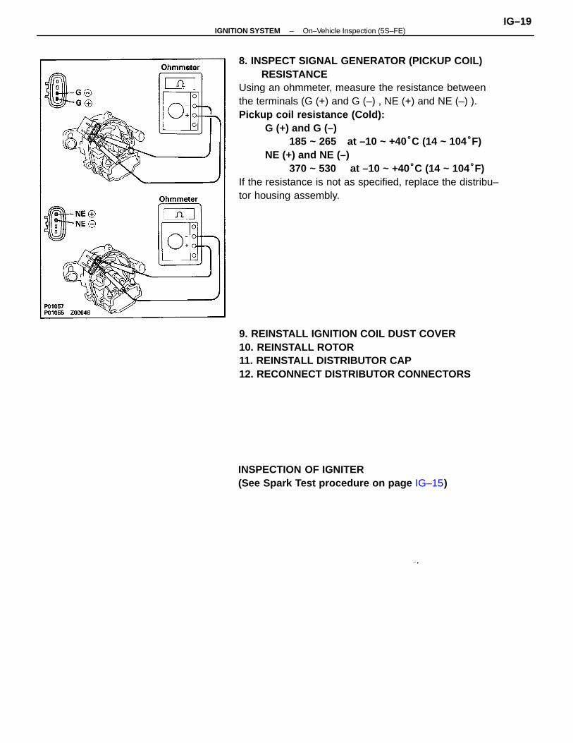
8. INSPECT SIGNAL GENERATOR (PICKUP COIL)RESISTANCE
Using an ohmmeter, measure the resistance betweenthe terminals (G (+) and G (–) , NE (+) and NE (–) ). Pickup coil resistance (Cold):
G (+) and G (–)185 ~ 265 at –10 ~ +40°C (14 ~ 104°F)
NE (+) and NE (–)370 ~ 530 at –10 ~ +40°C (14 ~ 104°F)
If the resistance is not as specified, replace the distribu–tor housing assembly.
9. REINSTALL IGNITION COIL DUST COVER10. REINSTALL ROTOR11. REINSTALL DISTRIBUTOR CAP12. RECONNECT DISTRIBUTOR CONNECTORS
INSPECTION OF IGNITER(See Spark Test procedure on page IG–15)
–IGNITION SYSTEM On–Vehicle Inspection (5S–FE)IG–19
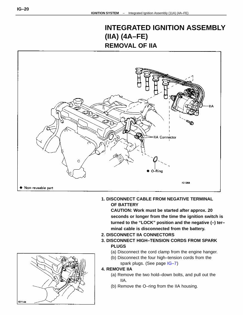
1. DISCONNECT CABLE FROM NEGATIVE TERMINALOF BATTERYCAUTION: Work must be started after approx. 20seconds or longer from the time the ignition switch isturned to the “LOCK” position and the negative (–) ter–minal cable is disconnected from the battery.
2. DISCONNECT IIA CONNECTORS3. DISCONNECT HIGH–TENSION CORDS FROM SPARK
PLUGS(a) Disconnect the cord clamp from the engine hanger.(b) Disconnect the four high–tension cords from the
spark plugs. (See page IG–7)4. REMOVE IIA
(a) Remove the two hold–down bolts, and pull out theIIA.
(b) Remove the O–ring from the IIA housing.
INTEGRATED IGNITION ASSEMBLY(IIA) (4A–FE)REMOVAL OF IIA
–IGNITION SYSTEM Integrated Ignition Assembly (11A) (4A–FE)IG–20
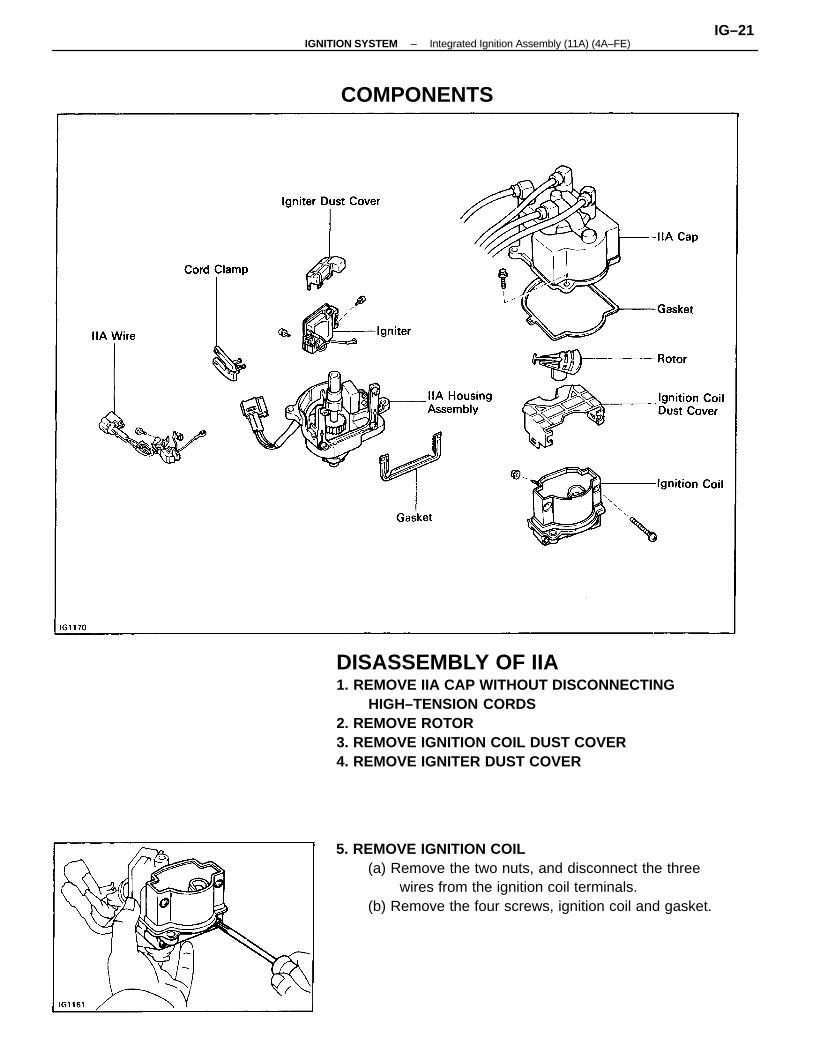
DISASSEMBLY OF IIA1. REMOVE IIA CAP WITHOUT DISCONNECTING
HIGH–TENSION CORDS2. REMOVE ROTOR3. REMOVE IGNITION COIL DUST COVER4. REMOVE IGNITER DUST COVER
5. REMOVE IGNITION COIL(a) Remove the two nuts, and disconnect the three
wires from the ignition coil terminals.(b) Remove the four screws, ignition coil and gasket.
COMPONENTS
–IGNITION SYSTEM Integrated Ignition Assembly (11A) (4A–FE)IG–21
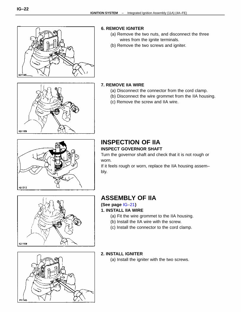
INSPECTION OF IIAINSPECT GOVERNOR SHAFTTurn the governor shaft and check that it is not rough orworn.If it feels rough or worn, replace the IIA housing assem–bly.
ASSEMBLY OF IIA(See page IG–21)1. INSTALL IIA WIRE
(a) Fit the wire grommet to the IIA housing.(b) Install the IIA wire with the screw.(c) Install the connector to the cord clamp.
7. REMOVE IIA WIRE(a) Disconnect the connector from the cord clamp.(b) Disconnect the wire grommet from the IIA housing.(c) Remove the screw and IIA wire.
6. REMOVE IGNITER(a) Remove the two nuts, and disconnect the three
wires from the ignite terminals.(b) Remove the two screws and igniter.
2. INSTALL IGNITER(a) Install the igniter with the two screws.
–IGNITION SYSTEM Integrated Ignition Assembly (11A) (4A–FE)IG–22
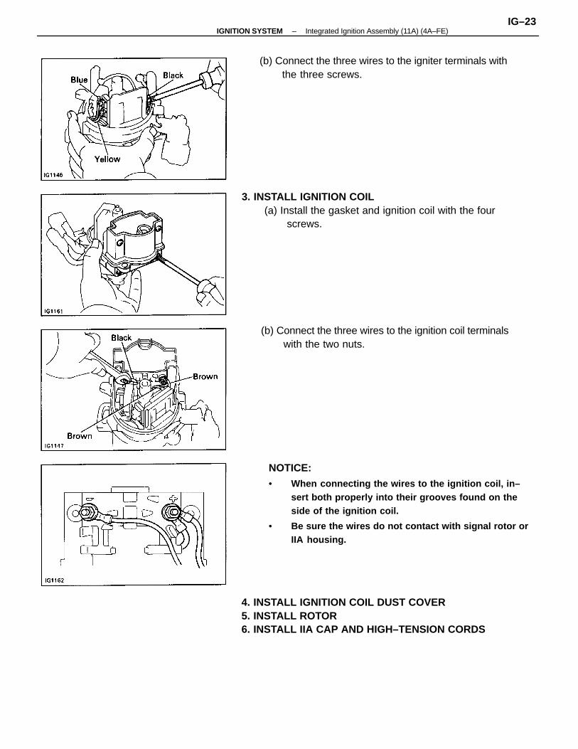
NOTICE:• When connecting the wires to the ignition coil, in–
sert both properly into their grooves found on theside of the ignition coil.
• Be sure the wires do not contact with signal rotor orIIA housing.
4. INSTALL IGNITION COIL DUST COVER5. INSTALL ROTOR6. INSTALL IIA CAP AND HIGH–TENSION CORDS
3. INSTALL IGNITION COIL(a) Install the gasket and ignition coil with the four
screws.
(b) Connect the three wires to the ignition coil terminalswith the two nuts.
(b) Connect the three wires to the igniter terminals withthe three screws.
–IGNITION SYSTEM Integrated Ignition Assembly (11A) (4A–FE)IG–23
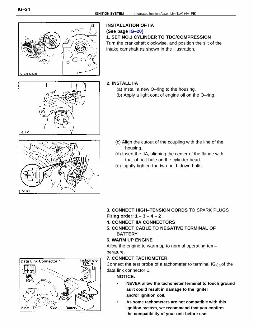
3. CONNECT HIGH–TENSION CORDS TO SPARK PLUGSFiring order: 1 – 3 – 4 – 24. CONNECT IIA CONNECTORS5. CONNECT CABLE TO NEGATIVE TERMINAL OF
BATTERY6. WARM UP ENGINEAllow the engine to warm up to normal operating tem–perature.7. CONNECT TACHOMETERConnect the test probe of a tachometer to terminal IG¿¿of thedata link connector 1.
NOTICE:• NEVER allow the tachometer terminal to touch ground
as it could result in damage to the igniterand/or ignition coil.
• As some tachometers are not compatible with thisignition system, we recommend that you confirmthe compatibility of your unit before use.
INSTALLATION OF IIA(See page IG–20)1. SET NO.1 CYLINDER TO TDC/COMPRESSIONTurn the crankshaft clockwise, and position the slit of theintake camshaft as shown in the illustration.
(c) Align the cutout of the coupling with the line of thehousing.
(d) Insert the IIA, aligning the center of the flange withthat of bolt hole on the cylinder head.
(e) Lightly tighten the two hold–down bolts.
2. INSTALL IIA(a) Install a new O–ring to the housing.(b) Apply a light coat of engine oil on the O–ring.
–IGNITION SYSTEM Integrated Ignition Assembly (11A) (4A–FE)IG–24
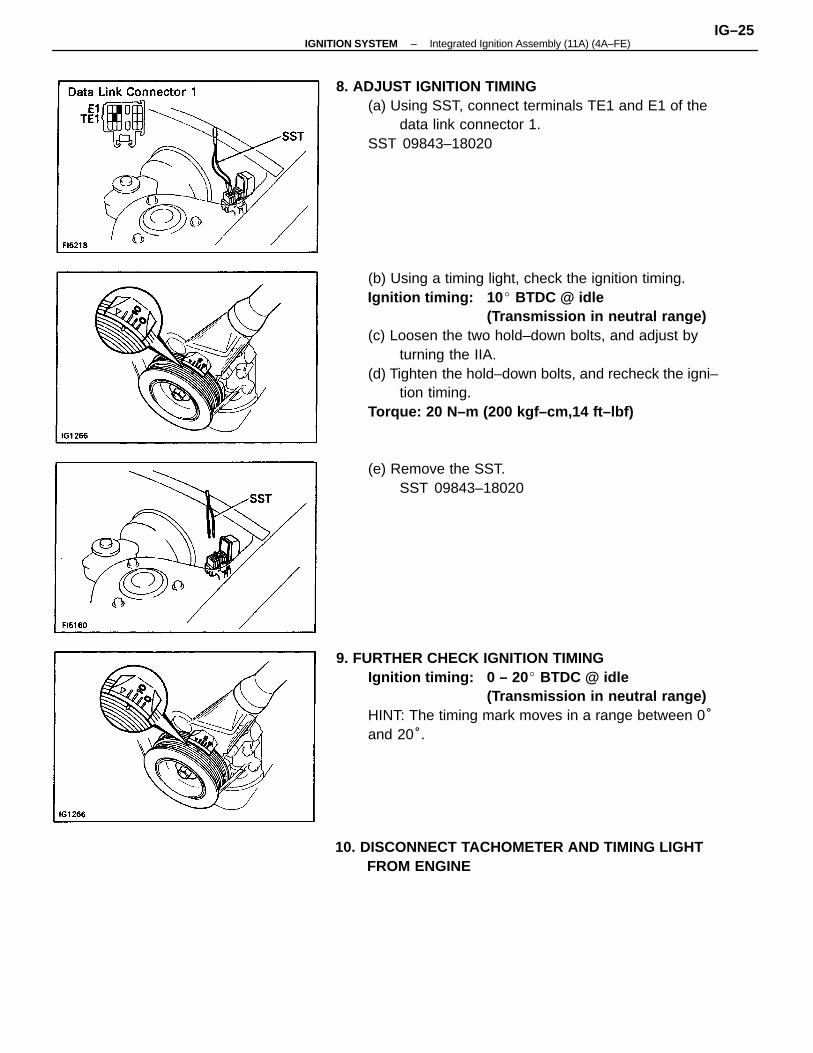
(b) Using a timing light, check the ignition timing.Ignition timing: 10 BTDC @ idle
(Transmission in neutral range)(c) Loosen the two hold–down bolts, and adjust by
turning the IIA.(d) Tighten the hold–down bolts, and recheck the igni–
tion timing.Torque: 20 N–m (200 kgf–cm,14 ft–lbf)
9. FURTHER CHECK IGNITION TIMINGIgnition timing: 0 – 20 BTDC @ idle
(Transmission in neutral range)HINT: The timing mark moves in a range between 0°and 20°.
8. ADJUST IGNITION TIMING(a) Using SST, connect terminals TE1 and E1 of the
data link connector 1.SST 09843–18020
10. DISCONNECT TACHOMETER AND TIMING LIGHTFROM ENGINE
(e) Remove the SST.SST 09843–18020
–IGNITION SYSTEM Integrated Ignition Assembly (11A) (4A–FE)IG–25
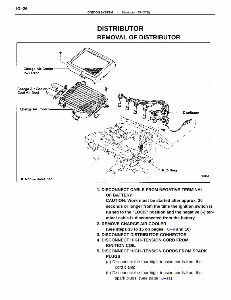
1. DISCONNECT CABLE FROM NEGATIVE TERMINALOF BATTERYCAUTION: Work must be started after approx. 20seconds or longer from the time the ignition switch isturned to the “LOCK” position and the negative (–) ter–minal cable is disconnected from the battery.
2. REMOVE CHARGE AIR COOLER(See steps 13 to 15 on pages TC–9 and 10)
3. DISCONNECT DISTRIBUTOR CONNECTOR4. DISCONNECT HIGH–TENSION CORD FROM
IGNITION COIL5. DISCONNECT HIGH–TENSION CORDS FROM SPARK
PLUGS(a) Disconnect the four high–tension cords from the
cord clamp.(b) Disconnect the four high–tension cords from the
spark plugs. (See page IG–11)
DISTRIBUTORREMOVAL OF DISTRIBUTOR
–IGNITION SYSTEM Distributor (3S–GTE)IG–26
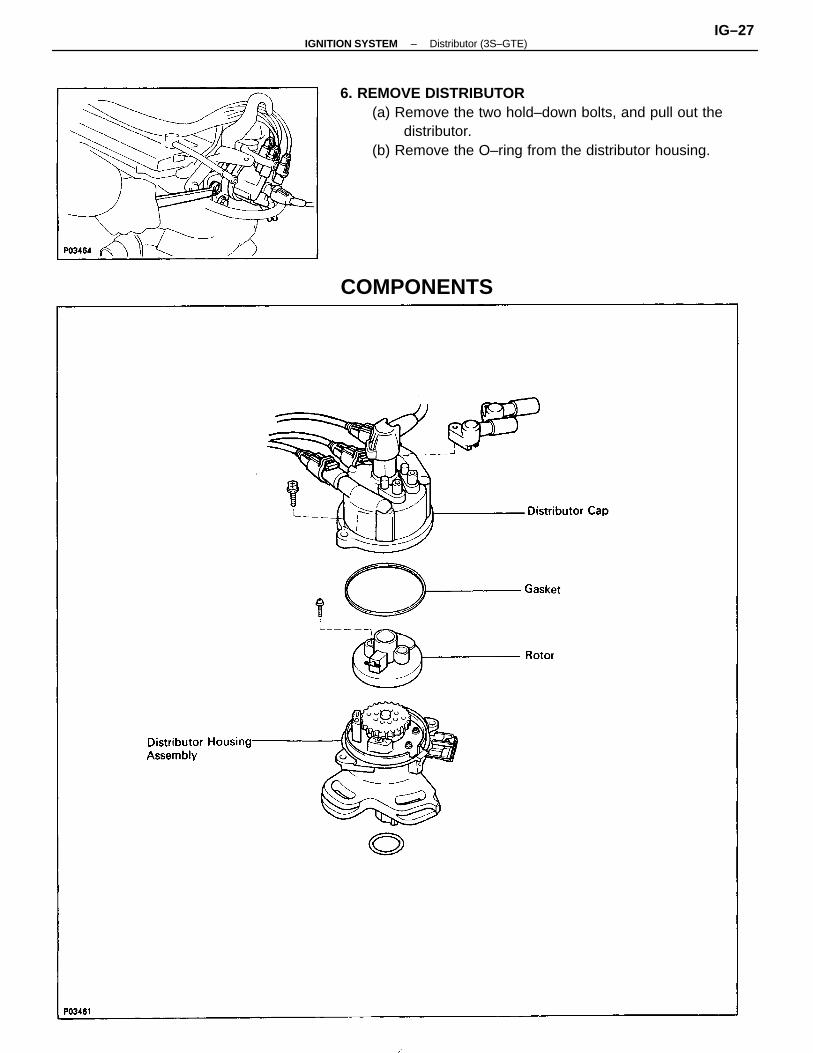
6. REMOVE DISTRIBUTOR(a) Remove the two hold–down bolts, and pull out the
distributor.(b) Remove the O–ring from the distributor housing.
COMPONENTS
–IGNITION SYSTEM Distributor (3S–GTE)IG–27
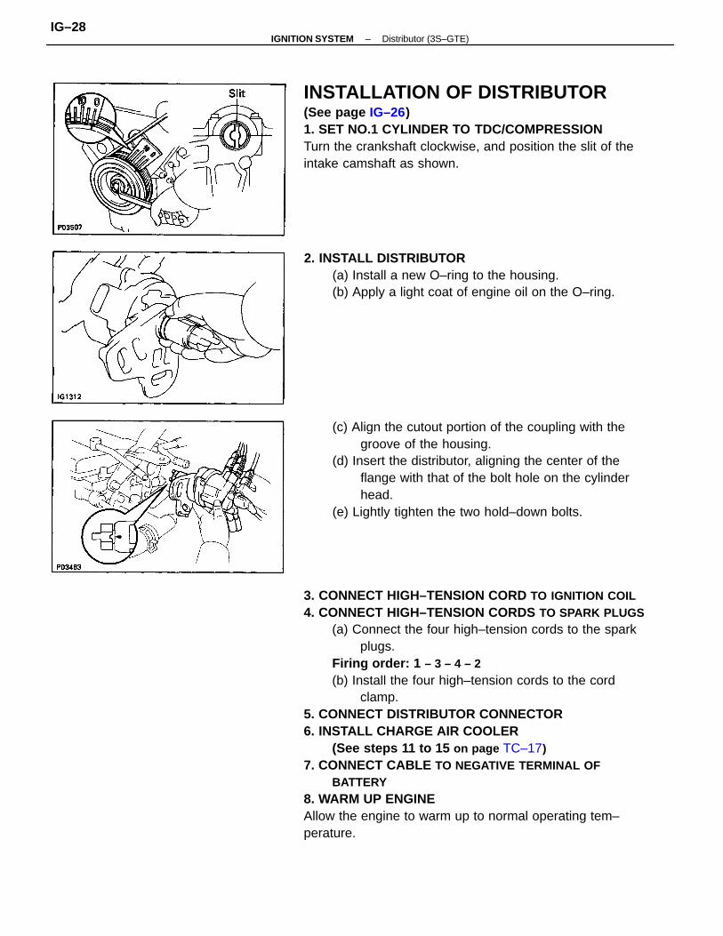
3. CONNECT HIGH–TENSION CORD TO IGNITION COIL4. CONNECT HIGH–TENSION CORDS TO SPARK PLUGS
(a) Connect the four high–tension cords to the sparkplugs.
Firing order: 1 – 3 – 4 – 2(b) Install the four high–tension cords to the cord
clamp.5. CONNECT DISTRIBUTOR CONNECTOR6. INSTALL CHARGE AIR COOLER
(See steps 11 to 15 on page TC–17)7. CONNECT CABLE TO NEGATIVE TERMINAL OF
BATTERY8. WARM UP ENGINEAllow the engine to warm up to normal operating tem–perature.
INSTALLATION OF DISTRIBUTOR(See page IG–26)1. SET NO.1 CYLINDER TO TDC/COMPRESSIONTurn the crankshaft clockwise, and position the slit of theintake camshaft as shown.
(c) Align the cutout portion of the coupling with thegroove of the housing.
(d) Insert the distributor, aligning the center of theflange with that of the bolt hole on the cylinderhead.
(e) Lightly tighten the two hold–down bolts.
2. INSTALL DISTRIBUTOR(a) Install a new O–ring to the housing.(b) Apply a light coat of engine oil on the O–ring.
–IGNITION SYSTEM Distributor (3S–GTE)IG–28
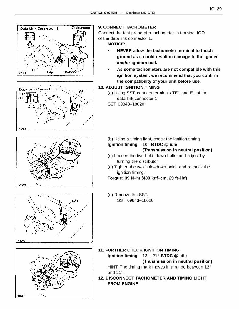
9. CONNECT TACHOMETERConnect the test probe of a tachometer to terminal IGOof the data link connector 1.
NOTICE:
• NEVER allow the tachometer terminal to touchground as it could result in damage to the igniterand/or ignition coil.
• As some tachometers are not compatible with thisignition system, we recommend that you confirmthe compatibility of your unit before use.
10. ADJUST IGNITION,TIMING(a) Using SST, connect terminals TE1 and E1 of the
data link connector 1.SST 09843–18020
(b) Using a timing light, check the ignition timing.Ignition timing: 10 BTDC @ idle
(Transmission in neutral position)(c) Loosen the two hold–down bolts, and adjust by
turning the distributor.(d) Tighten the two hold–down bolts, and recheck the
ignition timing.Torque: 39 N–m (400 kgf–cm, 29 ft–lbf)
11. FURTHER CHECK IGNITION TIMINGIgnition timing: 12 – 21 BTDC @ idle
(Transmission in neutral position)HINT: The timing mark moves in a range between 12and 21.
12. DISCONNECT TACHOMETER AND TIMING LIGHTFROM ENGINE
(e) Remove the SST.SST 09843–18020
–IGNITION SYSTEM Distributor (3S–GTE)IG–29
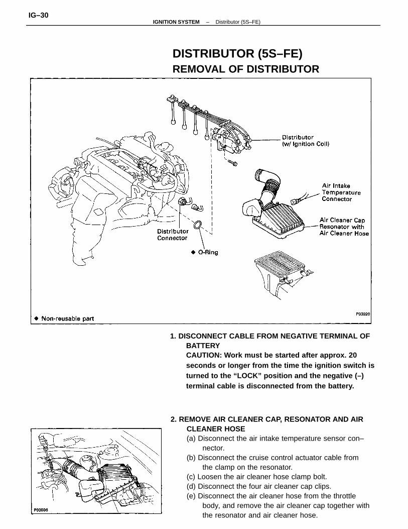
2. REMOVE AIR CLEANER CAP, RESONATOR AND AIRCLEANER HOSE(a) Disconnect the air intake temperature sensor con–
nector.(b) Disconnect the cruise control actuator cable from
the clamp on the resonator.(c) Loosen the air cleaner hose clamp bolt.(d) Disconnect the four air cleaner cap clips.(e) Disconnect the air cleaner hose from the throttle
body, and remove the air cleaner cap together withthe resonator and air cleaner hose.
1. DISCONNECT CABLE FROM NEGATIVE TERMINAL OFBATTERYCAUTION: Work must be started after approx. 20seconds or longer from the time the ignition switch isturned to the “LOCK” position and the negative (–)terminal cable is disconnected from the battery.
DISTRIBUTOR (5S–FE)REMOVAL OF DISTRIBUTOR
–IGNITION SYSTEM Distributor (5S–FE)IG–30
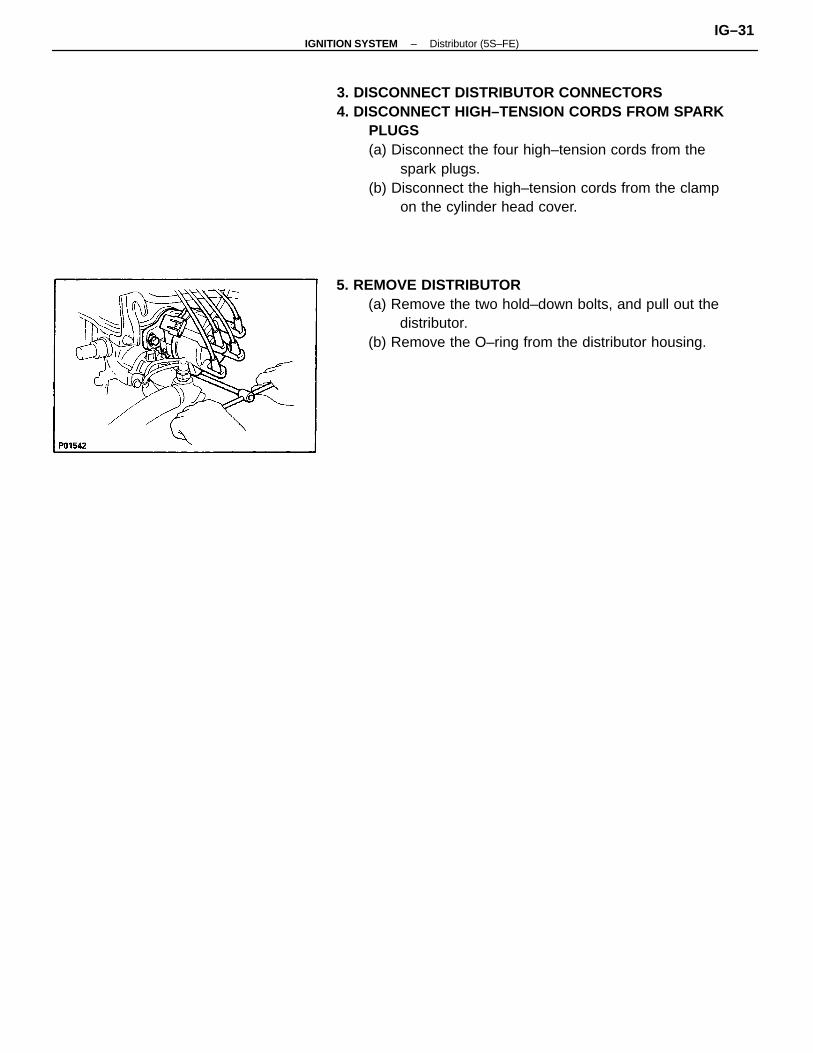
3. DISCONNECT DISTRIBUTOR CONNECTORS4. DISCONNECT HIGH–TENSION CORDS FROM SPARK
PLUGS(a) Disconnect the four high–tension cords from the
spark plugs.(b) Disconnect the high–tension cords from the clamp
on the cylinder head cover.
5. REMOVE DISTRIBUTOR(a) Remove the two hold–down bolts, and pull out the
distributor.(b) Remove the O–ring from the distributor housing.
–IGNITION SYSTEM Distributor (5S–FE)IG–31
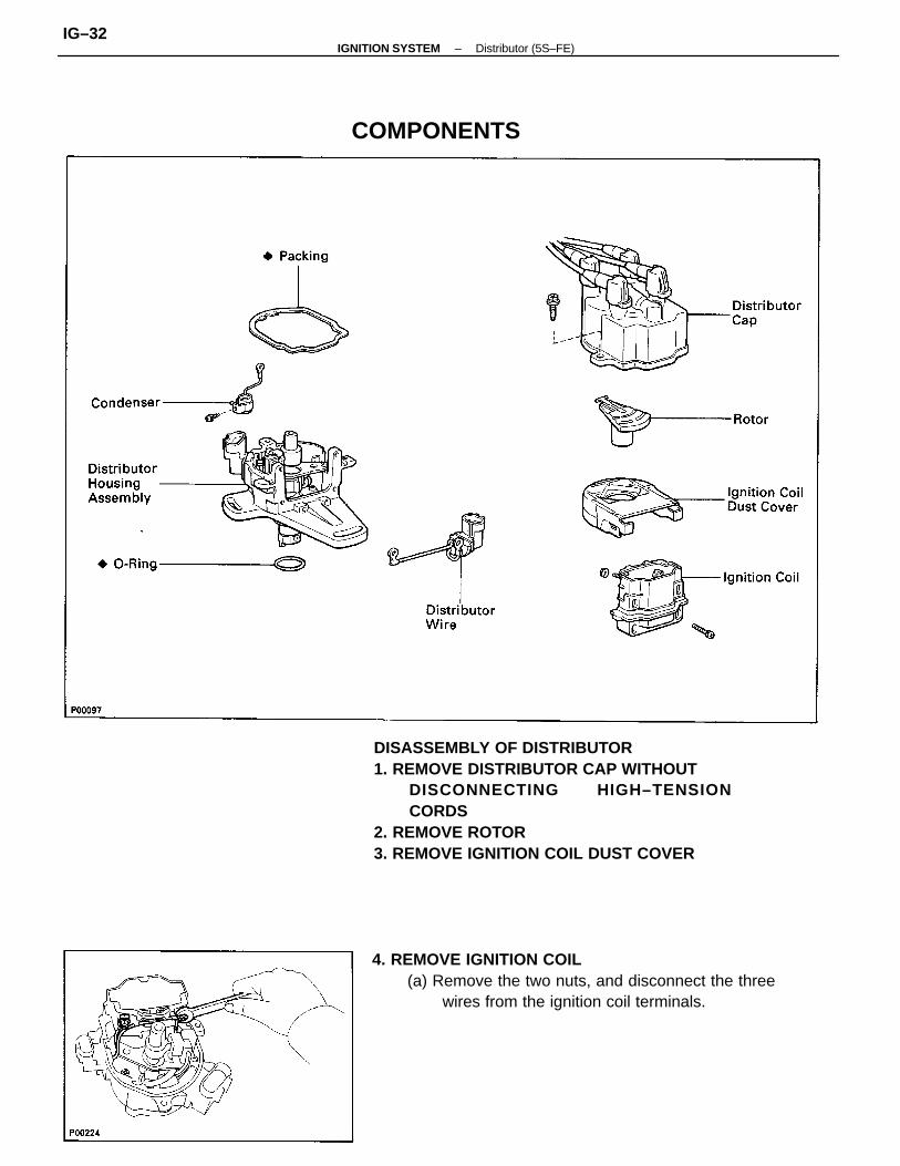
DISASSEMBLY OF DISTRIBUTOR1. REMOVE DISTRIBUTOR CAP WITHOUT
DISCONNECTING HIGH–TENSIONCORDS
2. REMOVE ROTOR3. REMOVE IGNITION COIL DUST COVER
4. REMOVE IGNITION COIL(a) Remove the two nuts, and disconnect the three
wires from the ignition coil terminals.
COMPONENTS
–IGNITION SYSTEM Distributor (5S–FE)IG–32
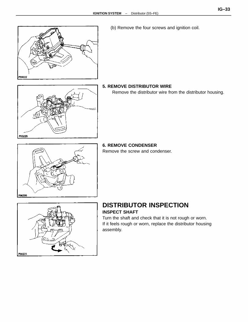
DISTRIBUTOR INSPECTIONINSPECT SHAFTTurn the shaft and check that it is not rough or worn.If it feels rough or worn, replace the distributor housingassembly.
5. REMOVE DISTRIBUTOR WIRERemove the distributor wire from the distributor housing.
6. REMOVE CONDENSERRemove the screw and condenser.
(b) Remove the four screws and ignition coil.
–IGNITION SYSTEM Distributor (5S–FE)IG–33
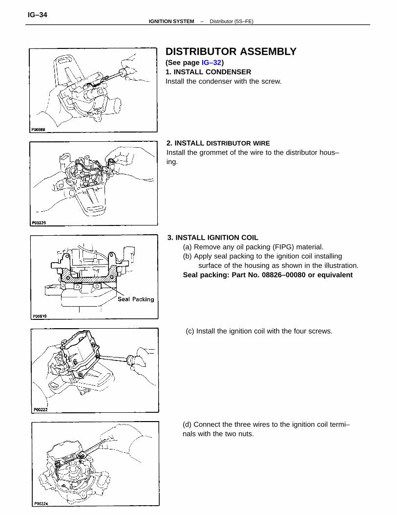
3. INSTALL IGNITION COIL(a) Remove any oil packing (FIPG) material.(b) Apply seal packing to the ignition coil installing
surface of the housing as shown in the illustration.Seal packing: Part No. 08826–00080 or equivalent
DISTRIBUTOR ASSEMBLY(See page IG–32)1. INSTALL CONDENSERInstall the condenser with the screw.
2. INSTALL DISTRIBUTOR WIREInstall the grommet of the wire to the distributor hous–ing.
(d) Connect the three wires to the ignition coil termi–nals with the two nuts.
(c) Install the ignition coil with the four screws.
–IGNITION SYSTEM Distributor (5S–FE)IG–34
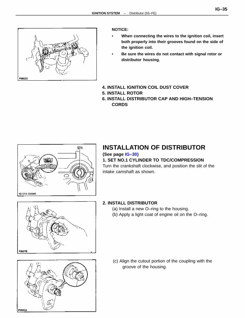
INSTALLATION OF DISTRIBUTOR(See page IG–30)1. SET NO.1 CYLINDER TO TDC/COMPRESSIONTurn the crankshaft clockwise, and position the slit of theintake camshaft as shown.
NOTICE:
• When connecting the wires to the ignition coil, insertboth properly into their grooves found on the side ofthe ignition coil.
• Be sure the wires do not contact with signal rotor ordistributor housing.
4. INSTALL IGNITION COIL DUST COVER5. INSTALL ROTOR6. INSTALL DISTRIBUTOR CAP AND HIGH–TENSION
CORDS
2. INSTALL DISTRIBUTOR(a) Install a new O–ring to the housing.(b) Apply a light coat of engine oil on the O–ring.
(c) Align the cutout portion of the coupling with thegroove of the housing.
–IGNITION SYSTEM Distributor (5S–FE)IG–35
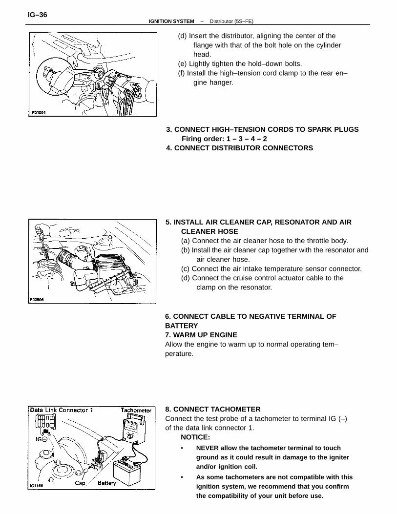
8. CONNECT TACHOMETERConnect the test probe of a tachometer to terminal IG (–)of the data link connector 1.
NOTICE:• NEVER allow the tachometer terminal to touch
ground as it could result in damage to the igniterand/or ignition coil.
• As some tachometers are not compatible with thisignition system, we recommend that you confirmthe compatibility of your unit before use.
5. INSTALL AIR CLEANER CAP, RESONATOR AND AIRCLEANER HOSE(a) Connect the air cleaner hose to the throttle body.(b) Install the air cleaner cap together with the resonator and
air cleaner hose.(c) Connect the air intake temperature sensor connector.(d) Connect the cruise control actuator cable to the
clamp on the resonator.
(d) Insert the distributor, aligning the center of theflange with that of the bolt hole on the cylinderhead.
(e) Lightly tighten the hold–down bolts.(f) Install the high–tension cord clamp to the rear en–
gine hanger.
6. CONNECT CABLE TO NEGATIVE TERMINAL OFBATTERY7. WARM UP ENGINEAllow the engine to warm up to normal operating tem–perature.
3. CONNECT HIGH–TENSION CORDS TO SPARK PLUGSFiring order: 1 – 3 – 4 – 2
4. CONNECT DISTRIBUTOR CONNECTORS
–IGNITION SYSTEM Distributor (5S–FE)IG–36
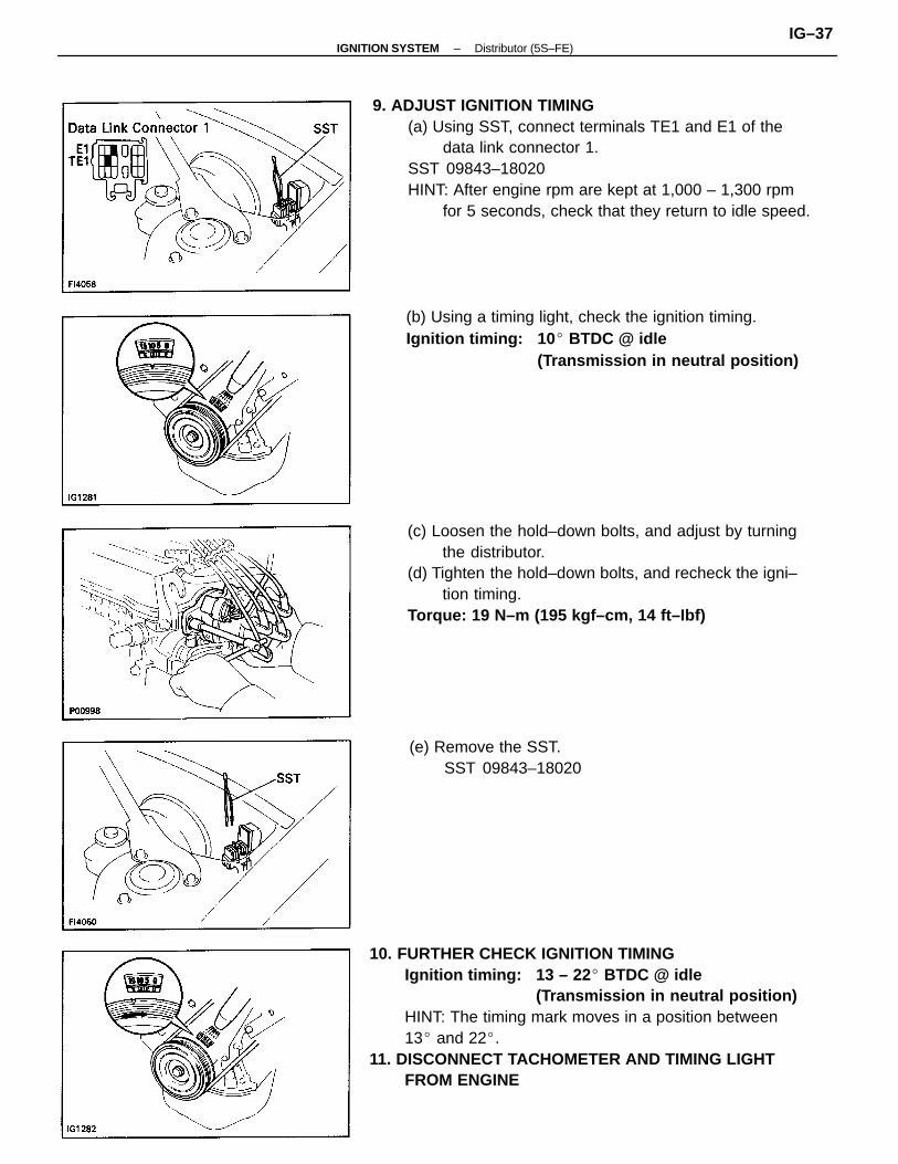
10. FURTHER CHECK IGNITION TIMINGIgnition timing: 13 – 22 BTDC @ idle
(Transmission in neutral position)HINT: The timing mark moves in a position between13 and 22.
11. DISCONNECT TACHOMETER AND TIMING LIGHTFROM ENGINE
9. ADJUST IGNITION TIMING(a) Using SST, connect terminals TE1 and E1 of the
data link connector 1.SST 09843–18020HINT: After engine rpm are kept at 1,000 – 1,300 rpm
for 5 seconds, check that they return to idle speed.
(c) Loosen the hold–down bolts, and adjust by turningthe distributor.
(d) Tighten the hold–down bolts, and recheck the igni–tion timing.
Torque: 19 N–m (195 kgf–cm, 14 ft–Ibf)
(b) Using a timing light, check the ignition timing.Ignition timing: 10 BTDC @ idle
(Transmission in neutral position)
(e) Remove the SST.SST 09843–18020
–IGNITION SYSTEM Distributor (5S–FE)IG–37
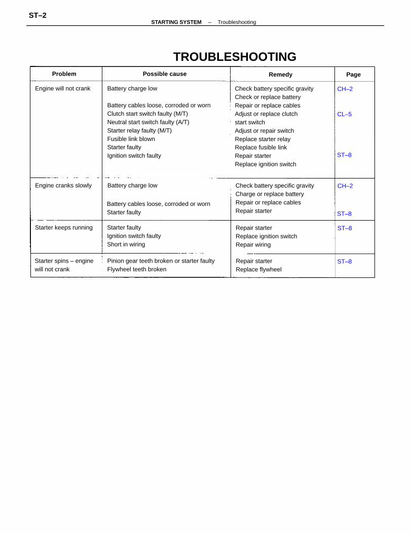
Check battery specific gravityCheck or replace batteryRepair or replace cablesAdjust or replace clutchstart switchAdjust or repair switchReplace starter relayReplace fusible linkRepair starterReplace ignition switch
Check battery specific gravityCharge or replace batteryRepair or replace cablesRepair starter
Pinion gear teeth broken or starter faultyFlywheel teeth broken
Battery cables loose, corroded or wornStarter faulty
Repair starterReplace ignition switchRepair wiring
Starter faultyIgnition switch faultyShort in wiring
TROUBLESHOOTING
Starter spins – enginewill not crank
Repair starterReplace flywheel
Starter keeps running
Engine will not crank
Engine cranks slowly
Battery charge low
Battery cables loose, corroded or wornClutch start switch faulty (M/T)Neutral start switch faulty (A/T)Starter relay faulty (M/T)Fusible link blownStarter faultyIgnition switch faulty
Battery charge low
Possible cause RemedyProblem Page
CH–2
CH–2
ST–8
ST–8
CL–5
ST–8
ST–8
–STARTING SYSTEM TroubleshootingST–2
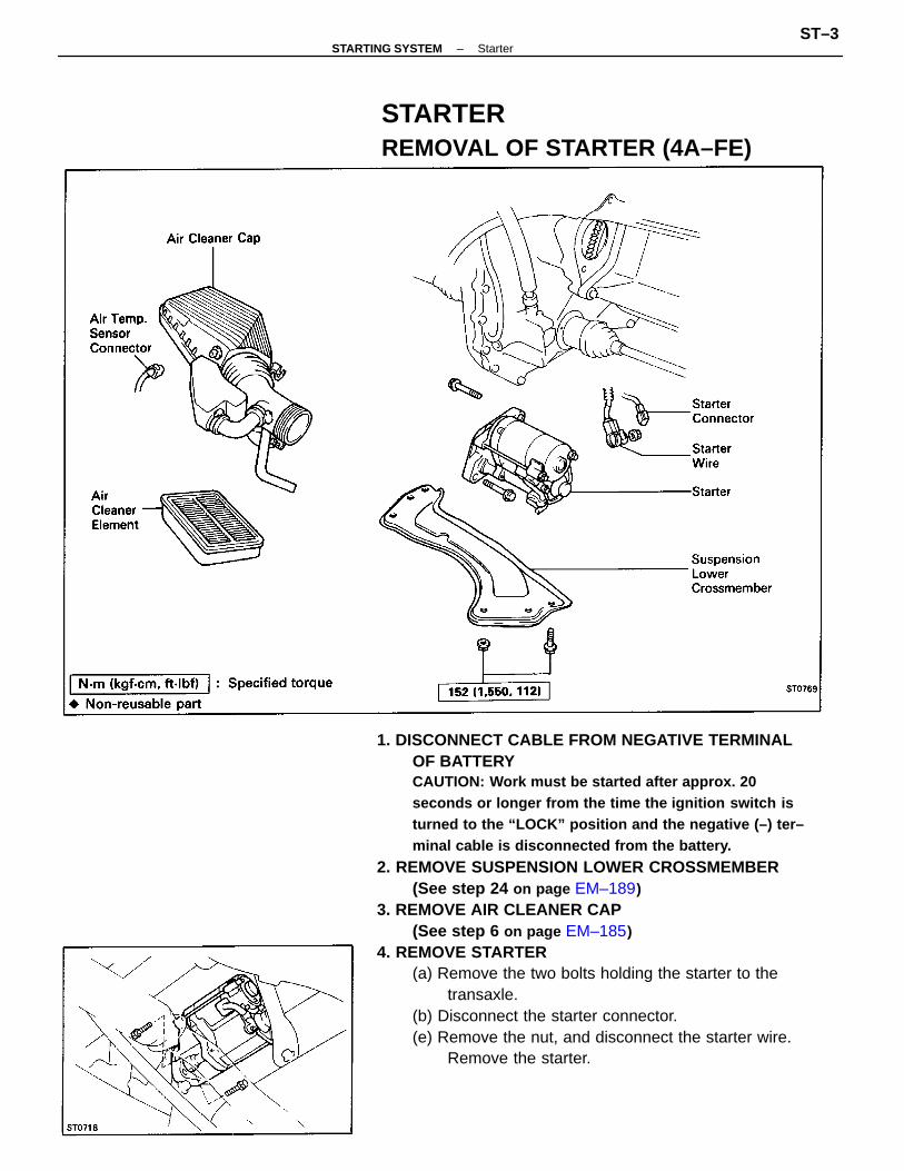
1. DISCONNECT CABLE FROM NEGATIVE TERMINALOF BATTERYCAUTION: Work must be started after approx. 20seconds or longer from the time the ignition switch isturned to the “LOCK” position and the negative (–) ter–minal cable is disconnected from the battery.
2. REMOVE SUSPENSION LOWER CROSSMEMBER(See step 24 on page EM–189)
3. REMOVE AIR CLEANER CAP(See step 6 on page EM–185)
4. REMOVE STARTER(a) Remove the two bolts holding the starter to the
transaxle.(b) Disconnect the starter connector.(e) Remove the nut, and disconnect the starter wire.
Remove the starter.
STARTERREMOVAL OF STARTER (4A–FE)
–STARTING SYSTEM StarterST–3
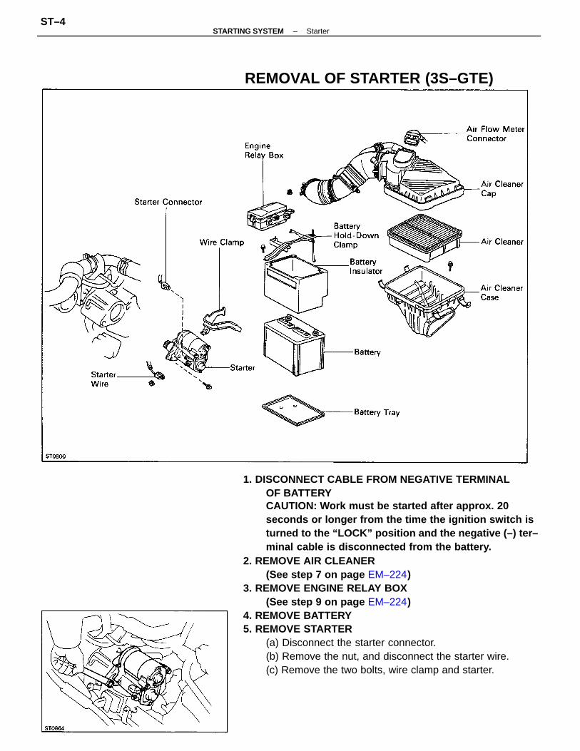
1. DISCONNECT CABLE FROM NEGATIVE TERMINALOF BATTERYCAUTION: Work must be started after approx. 20seconds or longer from the time the ignition switch isturned to the “LOCK” position and the negative (–) ter–minal cable is disconnected from the battery.
2. REMOVE AIR CLEANER(See step 7 on page EM–224)
3. REMOVE ENGINE RELAY BOX(See step 9 on page EM–224)
4. REMOVE BATTERY5. REMOVE STARTER
(a) Disconnect the starter connector.(b) Remove the nut, and disconnect the starter wire.(c) Remove the two bolts, wire clamp and starter.
REMOVAL OF STARTER (3S–GTE)
–STARTING SYSTEM StarterST–4
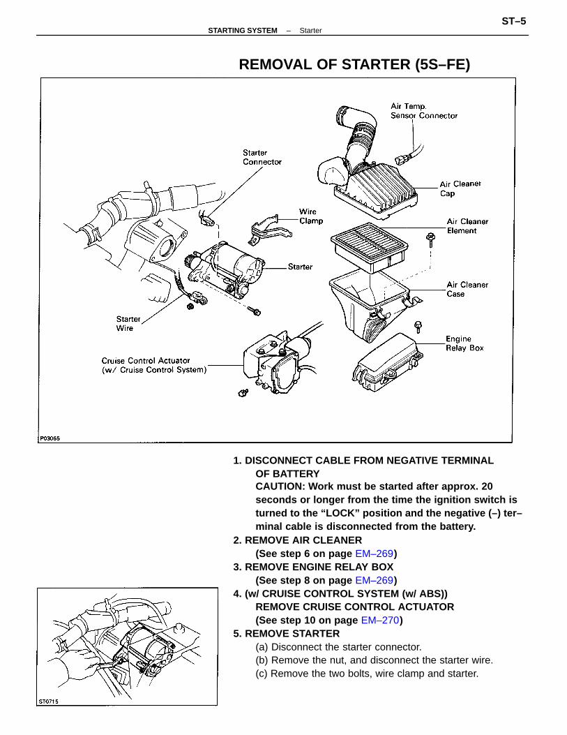
1. DISCONNECT CABLE FROM NEGATIVE TERMINALOF BATTERYCAUTION: Work must be started after approx. 20seconds or longer from the time the ignition switch isturned to the “LOCK” position and the negative (–) ter–minal cable is disconnected from the battery.
2. REMOVE AIR CLEANER(See step 6 on page EM–269)
3. REMOVE ENGINE RELAY BOX(See step 8 on page EM–269)
4. (w/ CRUISE CONTROL SYSTEM (w/ ABS))REMOVE CRUISE CONTROL ACTUATOR(See step 10 on page EM–270)
5. REMOVE STARTER(a) Disconnect the starter connector.(b) Remove the nut, and disconnect the starter wire.(c) Remove the two bolts, wire clamp and starter.
REMOVAL OF STARTER (5S–FE)
–STARTING SYSTEM StarterST–5
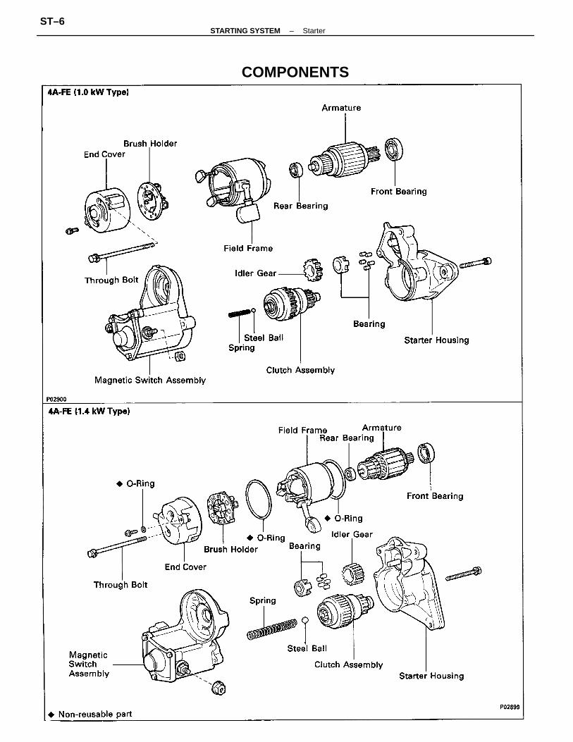
COMPONENTS
–STARTING SYSTEM StarterST–6
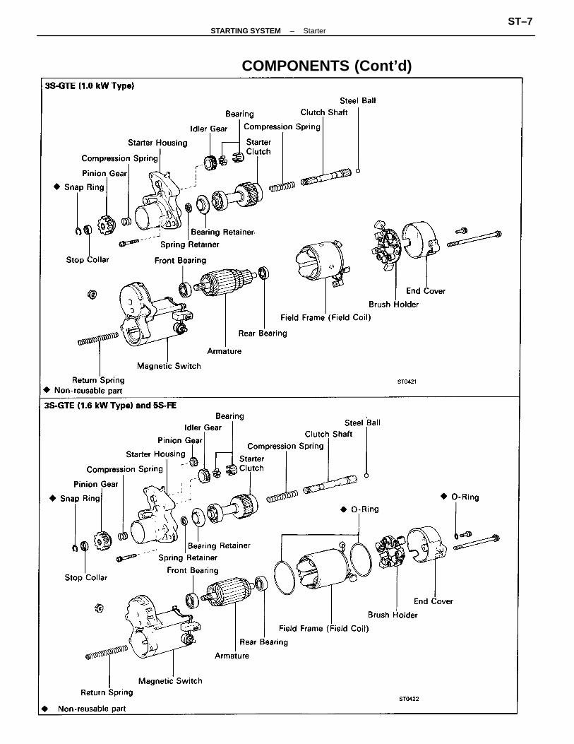
COMPONENTS (Cont’d)
–STARTING SYSTEM StarterST–7
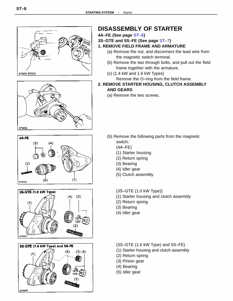
DISASSEMBLY OF STARTER4A–FE (See page ST–6)3S–GTE and 5S–FE (See page ST–7)1. REMOVE FIELD FRAME AND ARMATURE
(a) Remove the nut, and disconnect the lead wire fromthe magnetic switch terminal.
(b) Remove the two through bolts, and pull out the fieldframe together with the armature.
(c) (1.4 kW and 1.6 kW Types)Remove the O–ring from the field frame.
2. REMOVE STARTER HOUSING, CLUTCH ASSEMBLYAND GEARS(a) Remove the two screws.
(b) Remove the following parts from the magneticswitch:(4A–FE)(1) Starter housing(2) Return spring(3) Bearing(4) Idler gear(5) Clutch assembly
(3S–GTE (1.6 kW Type) and 5S–FE)(1) Starter housing and clutch assembly(2) Return spring(3) Pinion gear(4) Bearing(5) Idler gear
(3S–GTE (1.0 kW Type))(1) Starter housing and clutch assembly(2) Return spring(3) Bearing(4) Idler gear
–STARTING SYSTEM StarterST–8
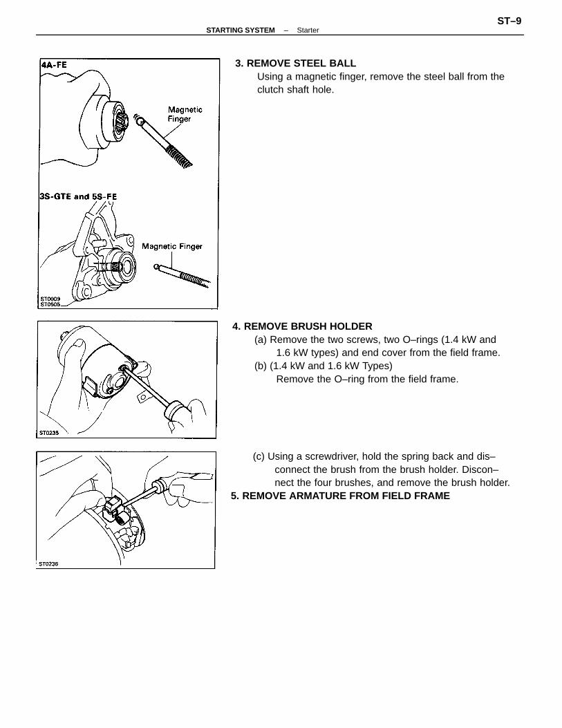
4. REMOVE BRUSH HOLDER(a) Remove the two screws, two O–rings (1.4 kW and
1.6 kW types) and end cover from the field frame.(b) (1.4 kW and 1.6 kW Types)
Remove the O–ring from the field frame.
(c) Using a screwdriver, hold the spring back and dis–connect the brush from the brush holder. Discon–nect the four brushes, and remove the brush holder.
5. REMOVE ARMATURE FROM FIELD FRAME
3. REMOVE STEEL BALLUsing a magnetic finger, remove the steel ball from theclutch shaft hole.
–STARTING SYSTEM StarterST–9
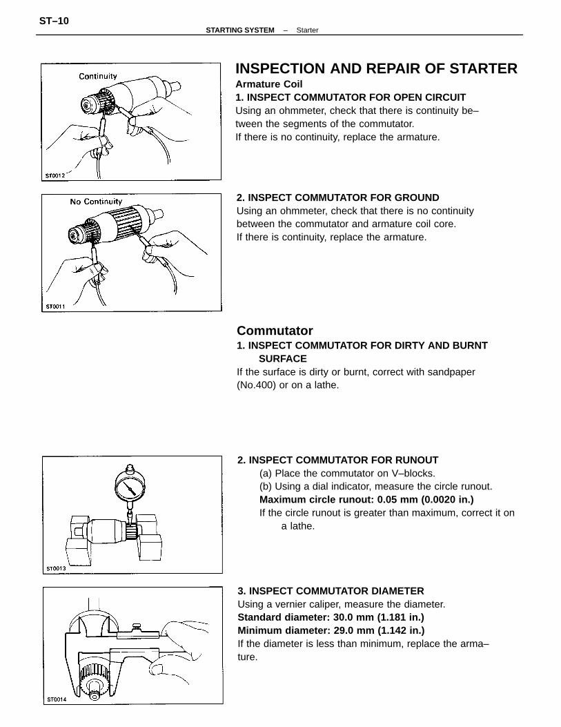
INSPECTION AND REPAIR OF STARTERArmature Coil1. INSPECT COMMUTATOR FOR OPEN CIRCUITUsing an ohmmeter, check that there is continuity be–tween the segments of the commutator.If there is no continuity, replace the armature.
3. INSPECT COMMUTATOR DIAMETERUsing a vernier caliper, measure the diameter.Standard diameter: 30.0 mm (1.181 in.)Minimum diameter: 29.0 mm (1.142 in.)If the diameter is less than minimum, replace the arma–ture.
2. INSPECT COMMUTATOR FOR RUNOUT(a) Place the commutator on V–blocks.(b) Using a dial indicator, measure the circle runout.Maximum circle runout: 0.05 mm (0.0020 in.)If the circle runout is greater than maximum, correct it on
a lathe.
Commutator1. INSPECT COMMUTATOR FOR DIRTY AND BURNT
SURFACEIf the surface is dirty or burnt, correct with sandpaper(No.400) or on a lathe.
2. INSPECT COMMUTATOR FOR GROUNDUsing an ohmmeter, check that there is no continuitybetween the commutator and armature coil core.If there is continuity, replace the armature.
–STARTING SYSTEM StarterST–10
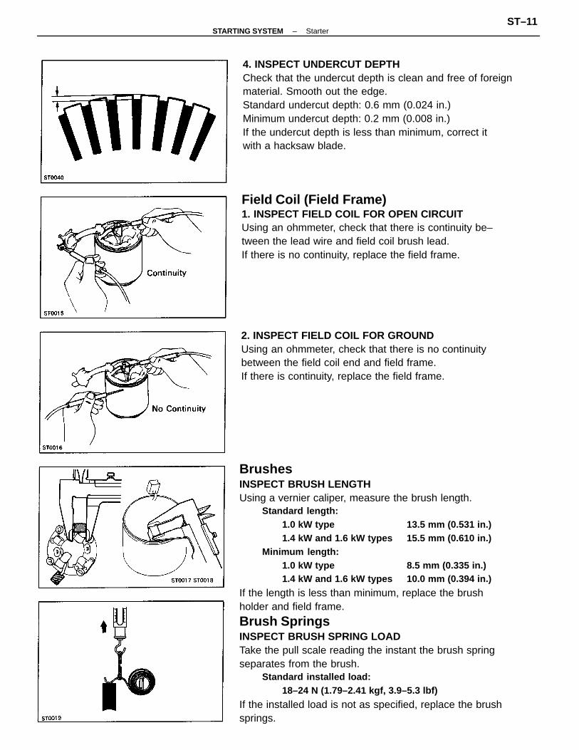
BrushesINSPECT BRUSH LENGTHUsing a vernier caliper, measure the brush length.
Standard length:1.0 kW type 13.5 mm (0.531 in.)1.4 kW and 1.6 kW types 15.5 mm (0.610 in.)
Minimum length:1.0 kW type 8.5 mm (0.335 in.)1.4 kW and 1.6 kW types 10.0 mm (0.394 in.)
If the length is less than minimum, replace the brushholder and field frame.
Brush SpringsINSPECT BRUSH SPRING LOADTake the pull scale reading the instant the brush springseparates from the brush.
Standard installed load:18–24 N (1.79–2.41 kgf, 3.9–5.3 lbf)
If the installed load is not as specified, replace the brushsprings.
4. INSPECT UNDERCUT DEPTHCheck that the undercut depth is clean and free of foreignmaterial. Smooth out the edge.Standard undercut depth: 0.6 mm (0.024 in.)Minimum undercut depth: 0.2 mm (0.008 in.)If the undercut depth is less than minimum, correct itwith a hacksaw blade.
Field Coil (Field Frame)1. INSPECT FIELD COIL FOR OPEN CIRCUITUsing an ohmmeter, check that there is continuity be–tween the lead wire and field coil brush lead.If there is no continuity, replace the field frame.
2. INSPECT FIELD COIL FOR GROUNDUsing an ohmmeter, check that there is no continuitybetween the field coil end and field frame.If there is continuity, replace the field frame.
–STARTING SYSTEM StarterST–11
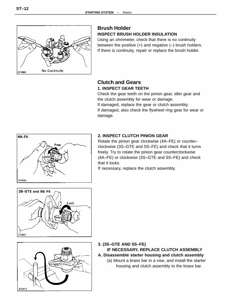
Clutch and Gears1. INSPECT GEAR TEETHCheck the gear teeth on the pinion gear, idler gear andthe clutch assembly for wear or damage.If damaged, replace the gear or clutch assembly.If damaged, also check the flywheel ring gear for wear ordamage.
2. INSPECT CLUTCH PINION GEARRotate the pinion gear clockwise (4A–FE) or counter–clockwise (3S–GTE and 5S–FE) and check that it turnsfreely. Try to rotate the pinion gear counterclockwise(4A–FE) or clockwise (3S–GTE and 5S–FE) and checkthat it locks.If necessary, replace the clutch assembly.
Brush HolderINSPECT BRUSH HOLDER INSULATIONUsing an ohmmeter, check that there is no continuitybetween the positive (+) and negative (–) brush holders.If there is continuity, repair or replace the brush holder.
3. (3S–GTE AND 5S–FE)IF NECESSARY, REPLACE CLUTCH ASSEMBLY
A. Disassemble starter housing and clutch assembly(a) Mount a brass bar in a vise, and install the starter
housing and clutch assembly to the brass bar.
–STARTING SYSTEM StarterST–12
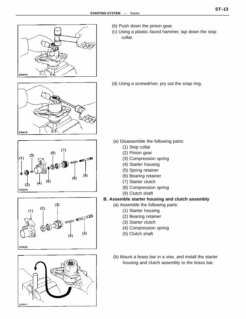
(e) Disassemble the following parts:(1) Stop collar(2) Pinion gear(3) Compression spring(4) Starter housing(5) Spring retainer(6) Bearing retainer(7) Starter clutch(8) Compression spring(9) Clutch shaft
B. Assemble starter housing and clutch assembly(a) Assemble the following parts:
(1) Starter housing(2) Bearing retainer(3) Starter clutch(4) Compression spring(5) Clutch shaft
(b) Mount a brass bar in a vise, and install the starterhousing and clutch assembly to the brass bar.
(b) Push down the pinion gear.(c) Using a plastic–faced hammer, tap down the stop
collar.
(d) Using a screwdriver, pry out the snap ring.
–STARTING SYSTEM StarterST–13
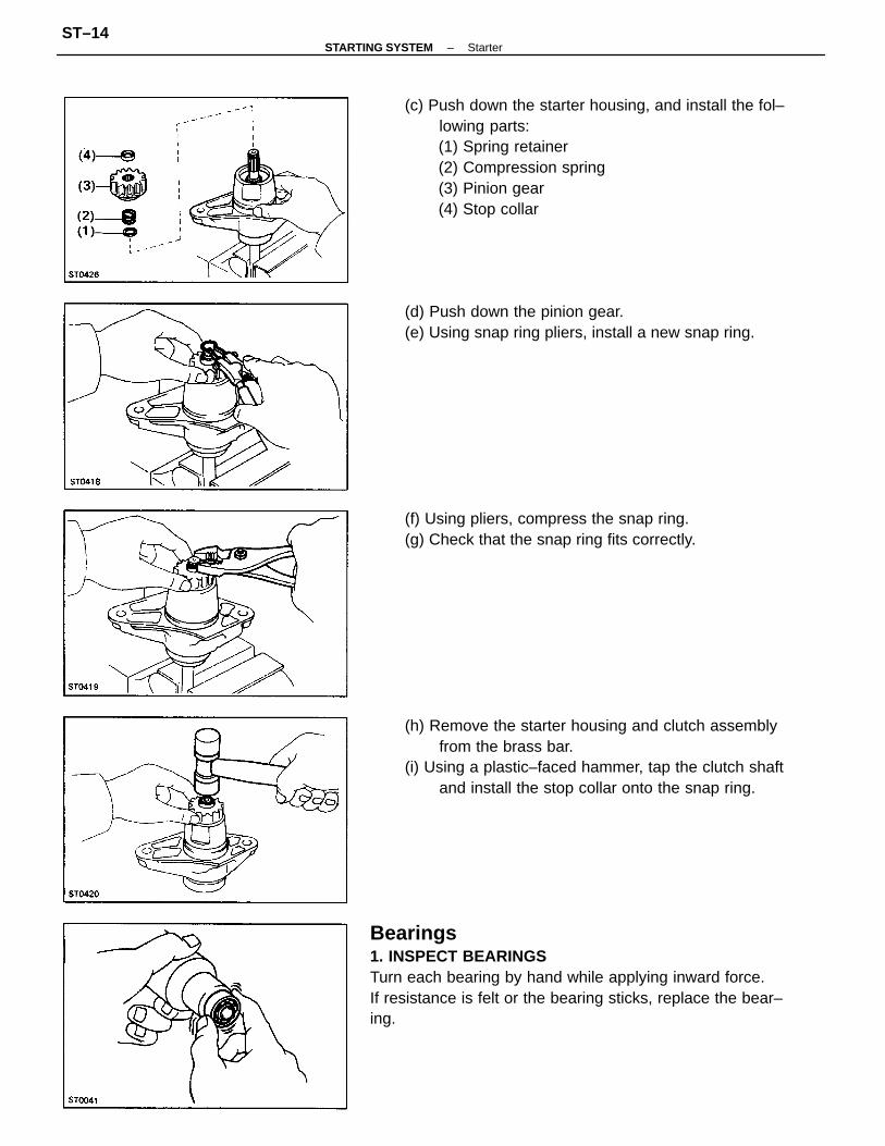
(c) Push down the starter housing, and install the fol–lowing parts:(1) Spring retainer(2) Compression spring(3) Pinion gear(4) Stop collar
Bearings1. INSPECT BEARINGSTurn each bearing by hand while applying inward force.If resistance is felt or the bearing sticks, replace the bear–ing.
(h) Remove the starter housing and clutch assemblyfrom the brass bar.
(i) Using a plastic–faced hammer, tap the clutch shaftand install the stop collar onto the snap ring.
(d) Push down the pinion gear.(e) Using snap ring pliers, install a new snap ring.
(f) Using pliers, compress the snap ring.(g) Check that the snap ring fits correctly.
–STARTING SYSTEM StarterST–14
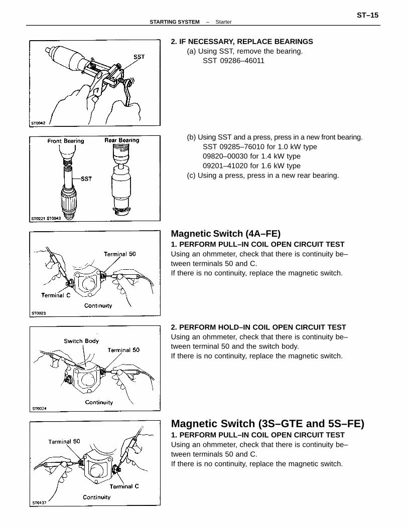
Magnetic Switch (4A–FE)1. PERFORM PULL–IN COIL OPEN CIRCUIT TESTUsing an ohmmeter, check that there is continuity be–tween terminals 50 and C.If there is no continuity, replace the magnetic switch.
Magnetic Switch (3S–GTE and 5S–FE)1. PERFORM PULL–IN COIL OPEN CIRCUIT TESTUsing an ohmmeter, check that there is continuity be–tween terminals 50 and C.If there is no continuity, replace the magnetic switch.
(b) Using SST and a press, press in a new front bearing.SST 09285–76010 for 1.0 kW type09820–00030 for 1.4 kW type09201–41020 for 1.6 kW type
(c) Using a press, press in a new rear bearing.
2. PERFORM HOLD–IN COIL OPEN CIRCUIT TESTUsing an ohmmeter, check that there is continuity be–tween terminal 50 and the switch body.If there is no continuity, replace the magnetic switch.
2. IF NECESSARY, REPLACE BEARINGS(a) Using SST, remove the bearing.
SST 09286–46011
–STARTING SYSTEM StarterST–15
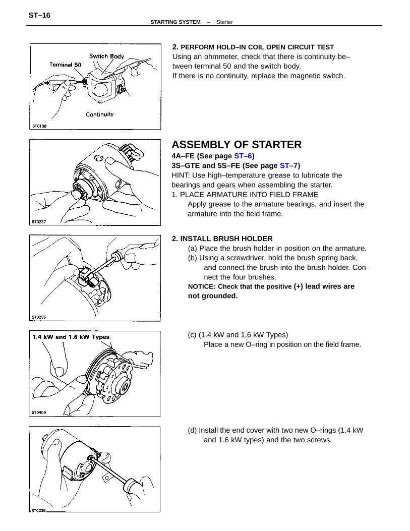
ASSEMBLY OF STARTER4A–FE (See page ST–6)3S–GTE and 5S–FE (See page ST–7)HINT: Use high–temperature grease to lubricate thebearings and gears when assembling the starter.1. PLACE ARMATURE INTO FIELD FRAME
Apply grease to the armature bearings, and insert thearmature into the field frame.
2. INSTALL BRUSH HOLDER(a) Place the brush holder in position on the armature.(b) Using a screwdriver, hold the brush spring back,
and connect the brush into the brush holder. Con–nect the four brushes.
NOTICE: Check that the positive (+) lead wires arenot grounded.
2. PERFORM HOLD–IN COIL OPEN CIRCUIT TESTUsing an ohmmeter, check that there is continuity be–tween terminal 50 and the switch body.If there is no continuity, replace the magnetic switch.
(d) Install the end cover with two new O–rings (1.4 kWand 1.6 kW types) and the two screws.
(c) (1.4 kW and 1.6 kW Types)Place a new O–ring in position on the field frame.
–STARTING SYSTEM StarterST–16
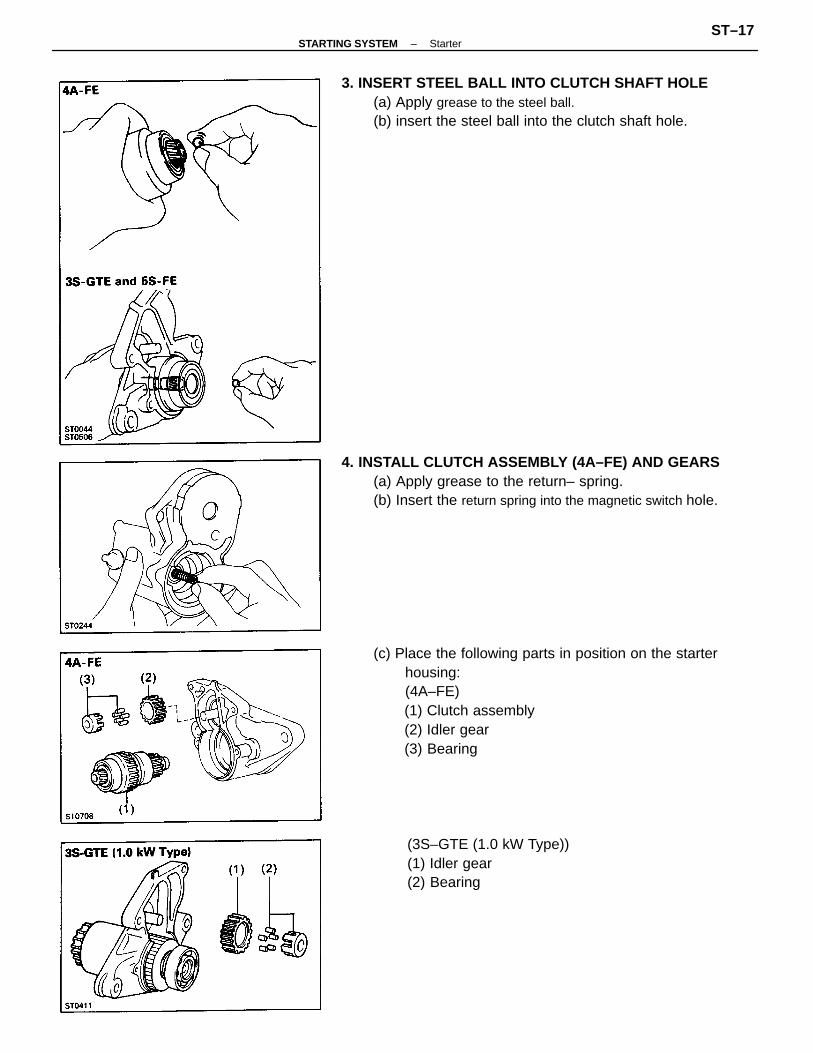
(c) Place the following parts in position on the starterhousing:(4A–FE)(1) Clutch assembly(2) Idler gear(3) Bearing
4. INSTALL CLUTCH ASSEMBLY (4A–FE) AND GEARS(a) Apply grease to the return– spring.(b) Insert the return spring into the magnetic switch hole.
3. INSERT STEEL BALL INTO CLUTCH SHAFT HOLE(a) Apply grease to the steel ball.(b) insert the steel ball into the clutch shaft hole.
(3S–GTE (1.0 kW Type))(1) Idler gear(2) Bearing
–STARTING SYSTEM StarterST–17
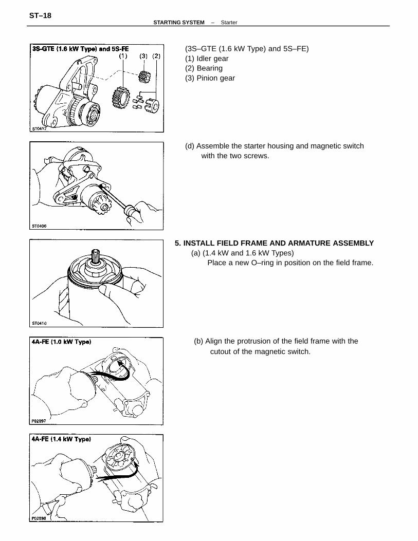
5. INSTALL FIELD FRAME AND ARMATURE ASSEMBLY(a) (1.4 kW and 1.6 kW Types)
Place a new O–ring in position on the field frame.
(3S–GTE (1.6 kW Type) and 5S–FE)(1) Idler gear(2) Bearing(3) Pinion gear
(b) Align the protrusion of the field frame with thecutout of the magnetic switch.
(d) Assemble the starter housing and magnetic switchwith the two screws.
–STARTING SYSTEM StarterST–18
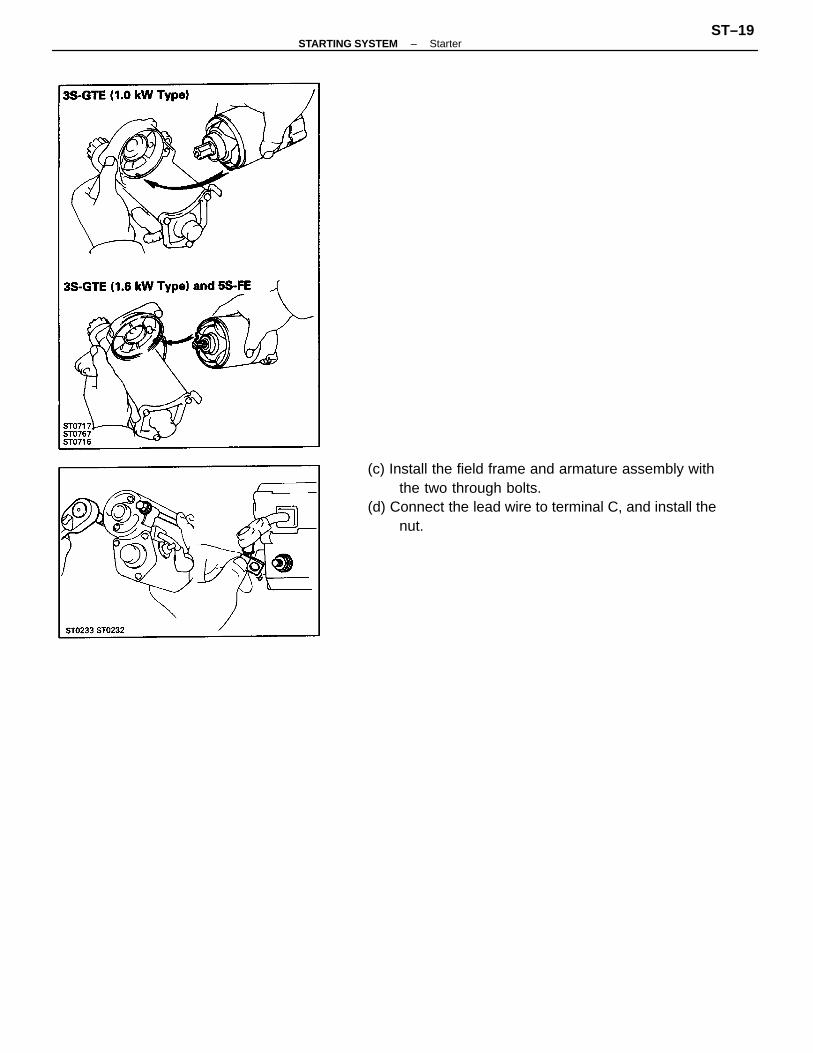
(c) Install the field frame and armature assembly withthe two through bolts.
(d) Connect the lead wire to terminal C, and install thenut.
–STARTING SYSTEM StarterST–19
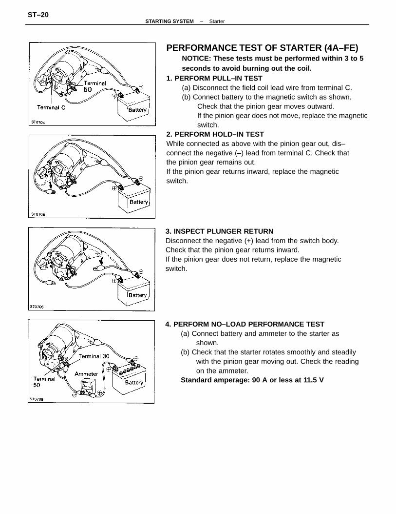
PERFORMANCE TEST OF STARTER (4A–FE)NOTICE: These tests must be performed within 3 to 5seconds to avoid burning out the coil.
1. PERFORM PULL–IN TEST(a) Disconnect the field coil lead wire from terminal C.(b) Connect battery to the magnetic switch as shown.
Check that the pinion gear moves outward.If the pinion gear does not move, replace the magneticswitch.
2. PERFORM HOLD–IN TESTWhile connected as above with the pinion gear out, dis–connect the negative (–) lead from terminal C. Check thatthe pinion gear remains out.If the pinion gear returns inward, replace the magneticswitch.
4. PERFORM NO–LOAD PERFORMANCE TEST(a) Connect battery and ammeter to the starter as
shown.(b) Check that the starter rotates smoothly and steadily
with the pinion gear moving out. Check the readingon the ammeter.
Standard amperage: 90 A or less at 11.5 V
3. INSPECT PLUNGER RETURNDisconnect the negative (+) lead from the switch body.Check that the pinion gear returns inward.If the pinion gear does not return, replace the magneticswitch.
–STARTING SYSTEM StarterST–20
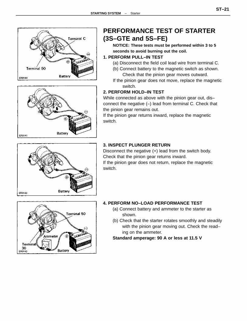
PERFORMANCE TEST OF STARTER(3S–GTE and 5S–FE)
NOTICE: These tests must be performed within 3 to 5seconds to avoid burning out the coil.
1. PERFORM PULL–IN TEST(a) Disconnect the field coil lead wire from terminal C.(b) Connect battery to the magnetic switch as shown.
Check that the pinion gear moves outward.If the pinion gear does not move, replace the magnetic
switch.2. PERFORM HOLD–IN TESTWhile connected as above with the pinion gear out, dis–connect the negative (–) lead from terminal C. Check thatthe pinion gear remains out.If the pinion gear returns inward, replace the magneticswitch.
4. PERFORM NO–LOAD PERFORMANCE TEST(a) Connect battery and ammeter to the starter as
shown.(b) Check that the starter rotates smoothly and steadily
with the pinion gear moving out. Check the read–ing on the ammeter.
Standard amperage: 90 A or less at 11.5 V
3. INSPECT PLUNGER RETURNDisconnect the negative (+) lead from the switch body.Check that the pinion gear returns inward.If the pinion gear does not return, replace the magneticswitch.
–STARTING SYSTEM StarterST–21
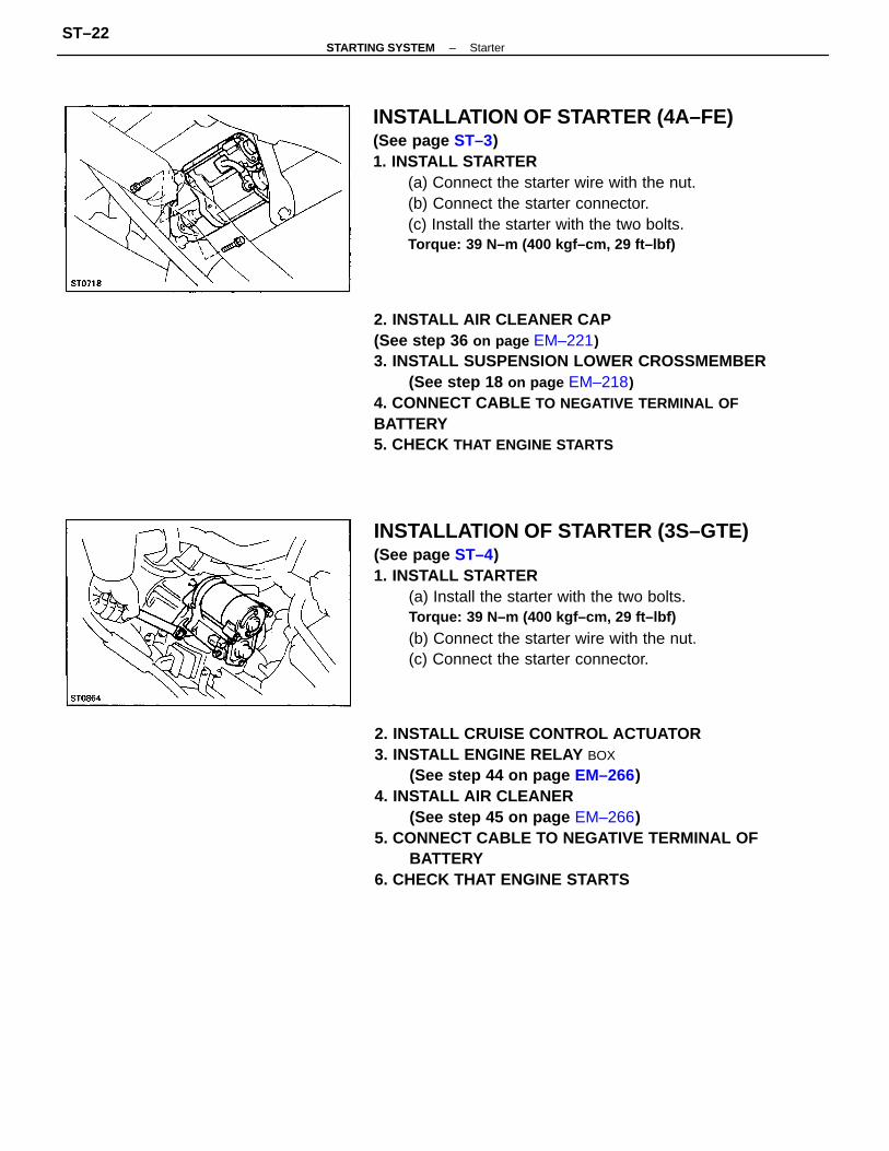
2. INSTALL CRUISE CONTROL ACTUATOR3. INSTALL ENGINE RELAY BOX
(See step 44 on page EM–266)4. INSTALL AIR CLEANER
(See step 45 on page EM–266)5. CONNECT CABLE TO NEGATIVE TERMINAL OF
BATTERY6. CHECK THAT ENGINE STARTS
2. INSTALL AIR CLEANER CAP(See step 36 on page EM–221)3. INSTALL SUSPENSION LOWER CROSSMEMBER
(See step 18 on page EM–218)4. CONNECT CABLE TO NEGATIVE TERMINAL OFBATTERY5. CHECK THAT ENGINE STARTS
INSTALLATION OF STARTER (3S–GTE)(See page ST–4)1. INSTALL STARTER
(a) Install the starter with the two bolts.Torque: 39 N–m (400 kgf–cm, 29 ft–lbf)
(b) Connect the starter wire with the nut.(c) Connect the starter connector.
INSTALLATION OF STARTER (4A–FE)(See page ST–3)1. INSTALL STARTER
(a) Connect the starter wire with the nut.(b) Connect the starter connector.(c) Install the starter with the two bolts.Torque: 39 N–m (400 kgf–cm, 29 ft–lbf)
–STARTING SYSTEM StarterST–22
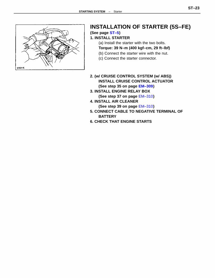
2. (w/ CRUISE CONTROL SYSTEM (w/ ABS))INSTALL CRUISE CONTROL ACTUATOR(See step 35 on page EM–309)
3. INSTALL ENGINE RELAY BOX(See step 37 on page EM–310)
4. INSTALL AIR CLEANER(See step 39 on page EM–310)
5. CONNECT CABLE TO NEGATIVE TERMINAL OFBATTERY
6. CHECK THAT ENGINE STARTS
INSTALLATION OF STARTER (5S–FE)(See page ST–5)1. INSTALL STARTER
(a) Install the starter with the two bolts.Torque: 39 N–m (400 kgf–cm, 29 ft–lbf)(b) Connect the starter wire with the nut.(c) Connect the starter connector.
–STARTING SYSTEM StarterST–23
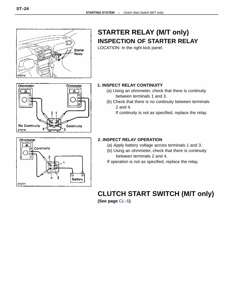
1. INSPECT RELAY CONTINUITY(a) Using an ohmmeter, check that there is continuity
between terminals 1 and 3.(b) Check that there is no continuity between terminals
2 and 4.If continuity is not as specified, replace the relay.
2. INSPECT RELAY OPERATION(a) Apply battery voltage across terminals 1 and 3.(b) Using an ohmmeter, check that there is continuity
between terminals 2 and 4.If operation is not as specified, replace the relay.
STARTER RELAY (M/T only)INSPECTION OF STARTER RELAYLOCATION: In the right kick panel.
CLUTCH START SWITCH (M/T only)(See page CL–5)
–STARTING SYSTEM Clutch Start Switch (M/T only)ST–24
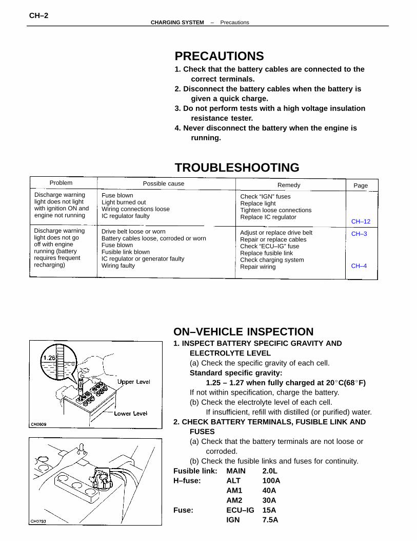
ON–VEHICLE INSPECTION1. INSPECT BATTERY SPECIFIC GRAVITY AND
ELECTROLYTE LEVEL(a) Check the specific gravity of each cell.Standard specific gravity:
1.25 – 1.27 when fully charged at 20 C(68F)If not within specification, charge the battery.(b) Check the electrolyte level of each cell.
If insufficient, refill with distilled (or purified) water.2. CHECK BATTERY TERMINALS, FUSIBLE LINK AND
FUSES(a) Check that the battery terminals are not loose or
corroded.(b) Check the fusible links and fuses for continuity.
Fusible link: MAIN 2.0LH–fuse: ALT 100A
AM1 40AAM2 30A
Fuse: ECU–IG 15AIGN 7.5A
PRECAUTIONS1. Check that the battery cables are connected to the
correct terminals.2. Disconnect the battery cables when the battery is
given a quick charge.3. Do not perform tests with a high voltage insulation
resistance tester.4. Never disconnect the battery when the engine is
running.
Drive belt loose or wornBattery cables loose, corroded or wornFuse blownFusible link blownIC regulator or generator faultyWiring faulty
Adjust or replace drive beltRepair or replace cablesCheck “ECU–IG” fuseReplace fusible linkCheck charging systemRepair wiring
Discharge warninglight does not gooff with enginerunning (batteryrequires frequentrecharging)
Check “IGN” fusesReplace lightTighten loose connectionsReplace IC regulator
Fuse blownLight burned outWiring connections looseIC regulator faulty
Discharge warninglight does not lightwith ignition ON andengine not running
TROUBLESHOOTINGPossible causeProblem Remedy
CH–12
Page
CH–4
CH–3
–CHARGING SYSTEM PrecautionsCH–2
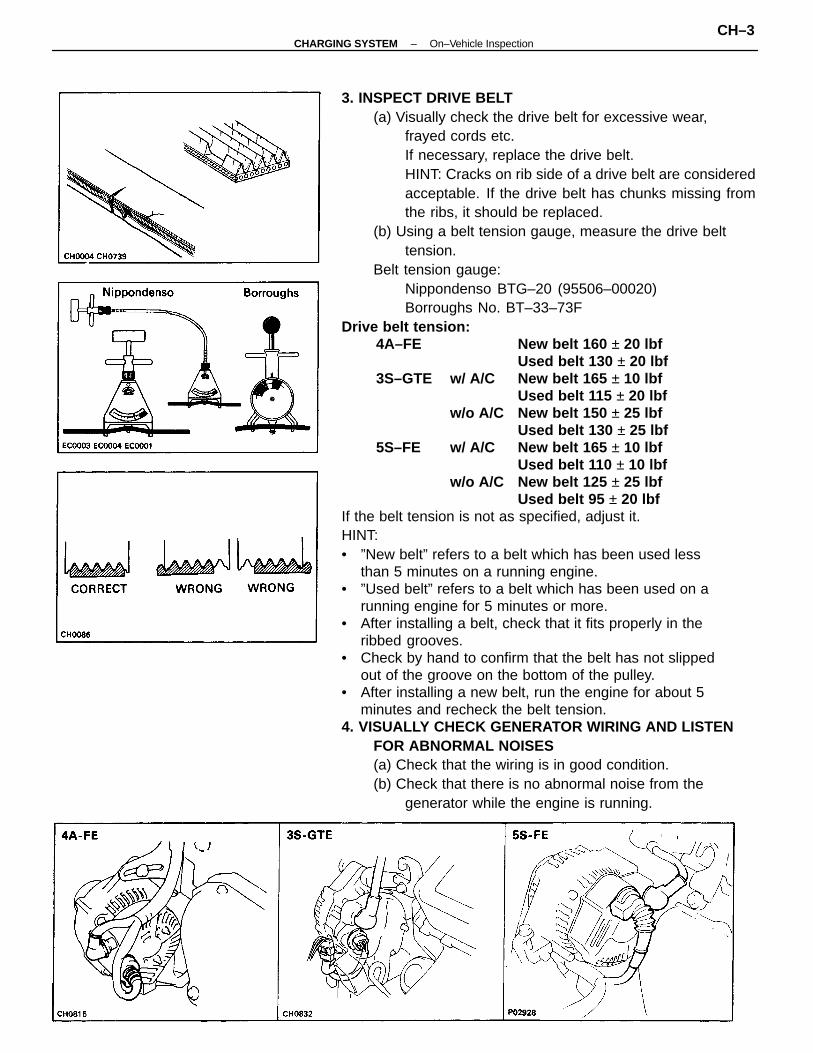
3. INSPECT DRIVE BELT(a) Visually check the drive belt for excessive wear,
frayed cords etc.If necessary, replace the drive belt.HINT: Cracks on rib side of a drive belt are consideredacceptable. If the drive belt has chunks missing fromthe ribs, it should be replaced.
(b) Using a belt tension gauge, measure the drive belttension.
Belt tension gauge:Nippondenso BTG–20 (95506–00020)Borroughs No. BT–33–73F
Drive belt tension:4A–FE New belt 160 ± 20 lbf
Used belt 130 ± 20 lbf3S–GTE w/ A/C New belt 165 ± 10 lbf
Used belt 115 ± 20 lbfw/o A/C New belt 150 ± 25 lbf
Used belt 130 ± 25 lbf5S–FE w/ A/C New belt 165 ± 10 lbf
Used belt 110 ± 10 lbfw/o A/C New belt 125 ± 25 lbf
Used belt 95 ± 20 lbfIf the belt tension is not as specified, adjust it.HINT:• ”New belt” refers to a belt which has been used less
than 5 minutes on a running engine.• ”Used belt” refers to a belt which has been used on a
running engine for 5 minutes or more.• After installing a belt, check that it fits properly in the
ribbed grooves.• Check by hand to confirm that the belt has not slipped
out of the groove on the bottom of the pulley.• After installing a new belt, run the engine for about 5
minutes and recheck the belt tension.4. VISUALLY CHECK GENERATOR WIRING AND LISTEN
FOR ABNORMAL NOISES(a) Check that the wiring is in good condition.(b) Check that there is no abnormal noise from the
generator while the engine is running.
–CHARGING SYSTEM On–Vehicle InspectionCH–3
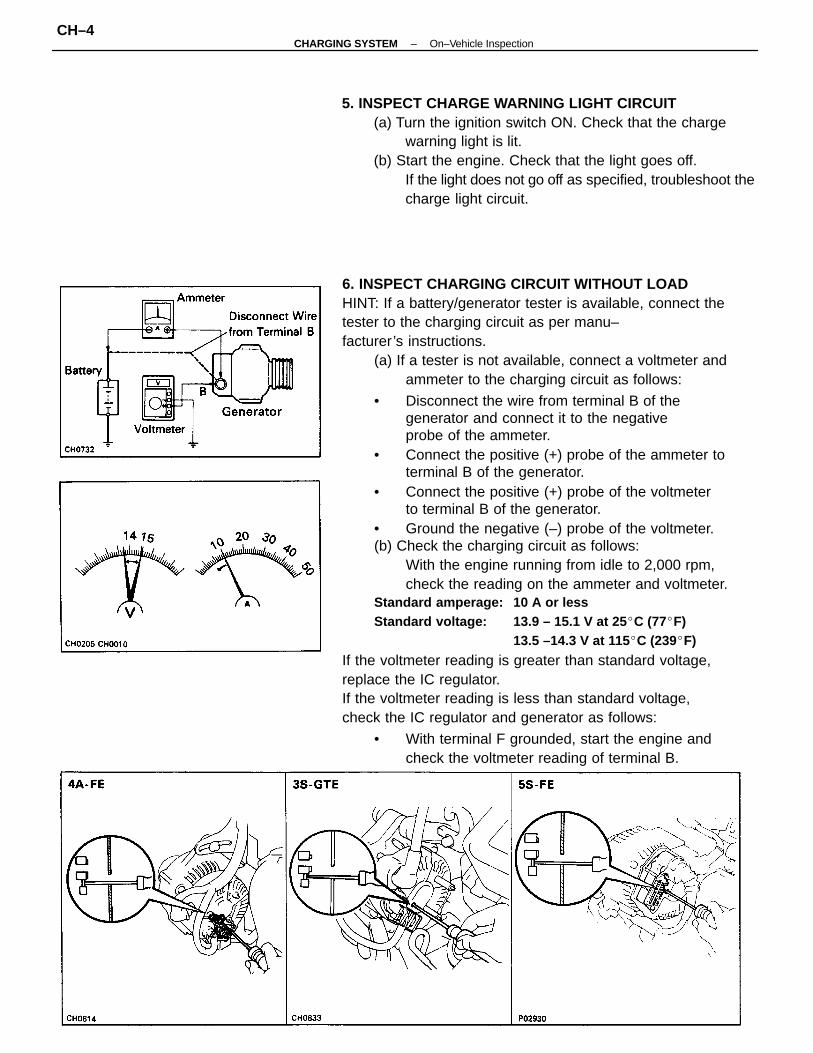
6. INSPECT CHARGING CIRCUIT WITHOUT LOADHINT: If a battery/generator tester is available, connect thetester to the charging circuit as per manu–facturer’s instructions.
(a) If a tester is not available, connect a voltmeter andammeter to the charging circuit as follows:
• Disconnect the wire from terminal B of thegenerator and connect it to the negativeprobe of the ammeter.
• Connect the positive (+) probe of the ammeter toterminal B of the generator.
• Connect the positive (+) probe of the voltmeterto terminal B of the generator.
• Ground the negative (–) probe of the voltmeter.(b) Check the charging circuit as follows:
With the engine running from idle to 2,000 rpm,check the reading on the ammeter and voltmeter.
Standard amperage: 10 A or lessStandard voltage: 13.9 – 15.1 V at 25 C (77F)
13.5 –14.3 V at 115C (239F)
If the voltmeter reading is greater than standard voltage,replace the IC regulator.If the voltmeter reading is less than standard voltage,check the IC regulator and generator as follows:
• With terminal F grounded, start the engine andcheck the voltmeter reading of terminal B.
5. INSPECT CHARGE WARNING LIGHT CIRCUIT(a) Turn the ignition switch ON. Check that the charge
warning light is lit.(b) Start the engine. Check that the light goes off.
If the light does not go off as specified, troubleshoot thecharge light circuit.
–CHARGING SYSTEM On–Vehicle InspectionCH–4
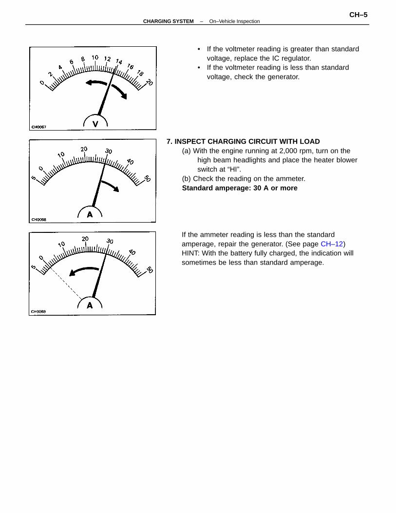
7. INSPECT CHARGING CIRCUIT WITH LOAD(a) With the engine running at 2,000 rpm, turn on the
high beam headlights and place the heater blowerswitch at “HI”.
(b) Check the reading on the ammeter.Standard amperage: 30 A or more
If the ammeter reading is less than the standardamperage, repair the generator. (See page CH–12)HINT: With the battery fully charged, the indication willsometimes be less than standard amperage.
• If the voltmeter reading is greater than standardvoltage, replace the IC regulator.
• If the voltmeter reading is less than standardvoltage, check the generator.
–CHARGING SYSTEM On–Vehicle InspectionCH–5
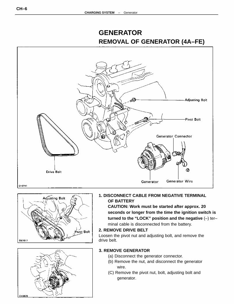
1. DISCONNECT CABLE FROM NEGATIVE TERMINALOF BATTERYCAUTION: Work must be started after approx. 20seconds or longer from the time the ignition switch isturned to the “LOCK” position and the negative (–) ter–minal cable is disconnected from the battery.
2. REMOVE DRIVE BELTLoosen the pivot nut and adjusting bolt, and remove thedrive belt.
3. REMOVE GENERATOR(a) Disconnect the generator connector.(b) Remove the nut, and disconnect the generator
wire.(C) Remove the pivot nut, bolt, adjusting bolt and
generator.
GENERATORREMOVAL OF GENERATOR (4A–FE)
–CHARGING SYSTEM GeneratorCH–6
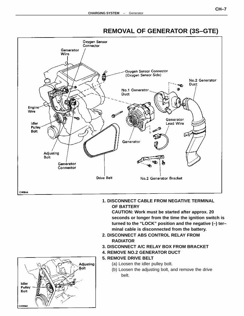
1. DISCONNECT CABLE FROM NEGATIVE TERMINALOF BATTERYCAUTION: Work must be started after approx. 20seconds or longer from the time the ignition switch isturned to the “LOCK” position and the negative (–) ter–minal cable is disconnected from the battery.
2. DISCONNECT ABS CONTROL RELAY FROMRADIATOR
3. DISCONNECT A/C RELAY BOX FROM BRACKET4. REMOVE NO.2 GENERATOR DUCT5. REMOVE DRIVE BELT
(a) Loosen the idler pulley bolt.(b) Loosen the adjusting bolt, and remove the drive
belt.
REMOVAL OF GENERATOR (3S–GTE)
–CHARGING SYSTEM GeneratorCH–7
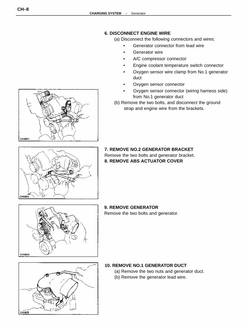
6. DISCONNECT ENGINE WIRE(a) Disconnect the following connectors and wires:
• Generator connector from lead wire
• Generator wire
• A/C compressor connector
• Engine coolant temperature switch connector
• Oxygen sensor wire clamp from No.1 generatorduct
• Oxygen sensor connector
• Oxygen sensor connector (wiring harness side)from No.1 generator duct
(b) Remove the two bolts, and disconnect the groundstrap and engine wire from the brackets.
7. REMOVE NO.2 GENERATOR BRACKETRemove the two bolts and generator bracket.8. REMOVE ABS ACTUATOR COVER
10. REMOVE NO.1 GENERATOR DUCT(a) Remove the two nuts and generator duct.(b) Remove the generator lead wire.
9. REMOVE GENERATORRemove the two bolts and generator.
–CHARGING SYSTEM GeneratorCH–8
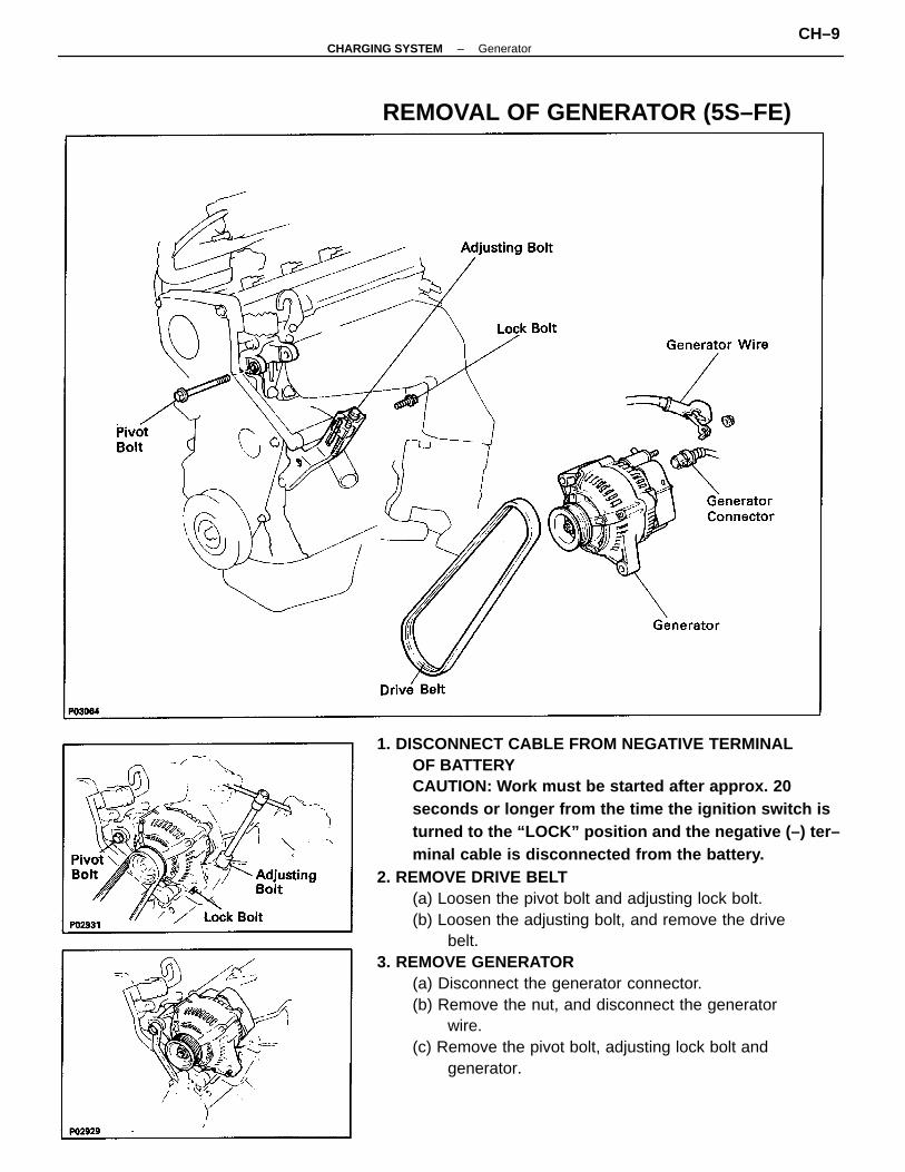
1. DISCONNECT CABLE FROM NEGATIVE TERMINALOF BATTERYCAUTION: Work must be started after approx. 20seconds or longer from the time the ignition switch isturned to the “LOCK” position and the negative (–) ter–minal cable is disconnected from the battery.
2. REMOVE DRIVE BELT(a) Loosen the pivot bolt and adjusting lock bolt.(b) Loosen the adjusting bolt, and remove the drive
belt.3. REMOVE GENERATOR
(a) Disconnect the generator connector.(b) Remove the nut, and disconnect the generator
wire.(c) Remove the pivot bolt, adjusting lock bolt and
generator.
REMOVAL OF GENERATOR (5S–FE)
–CHARGING SYSTEM GeneratorCH–9
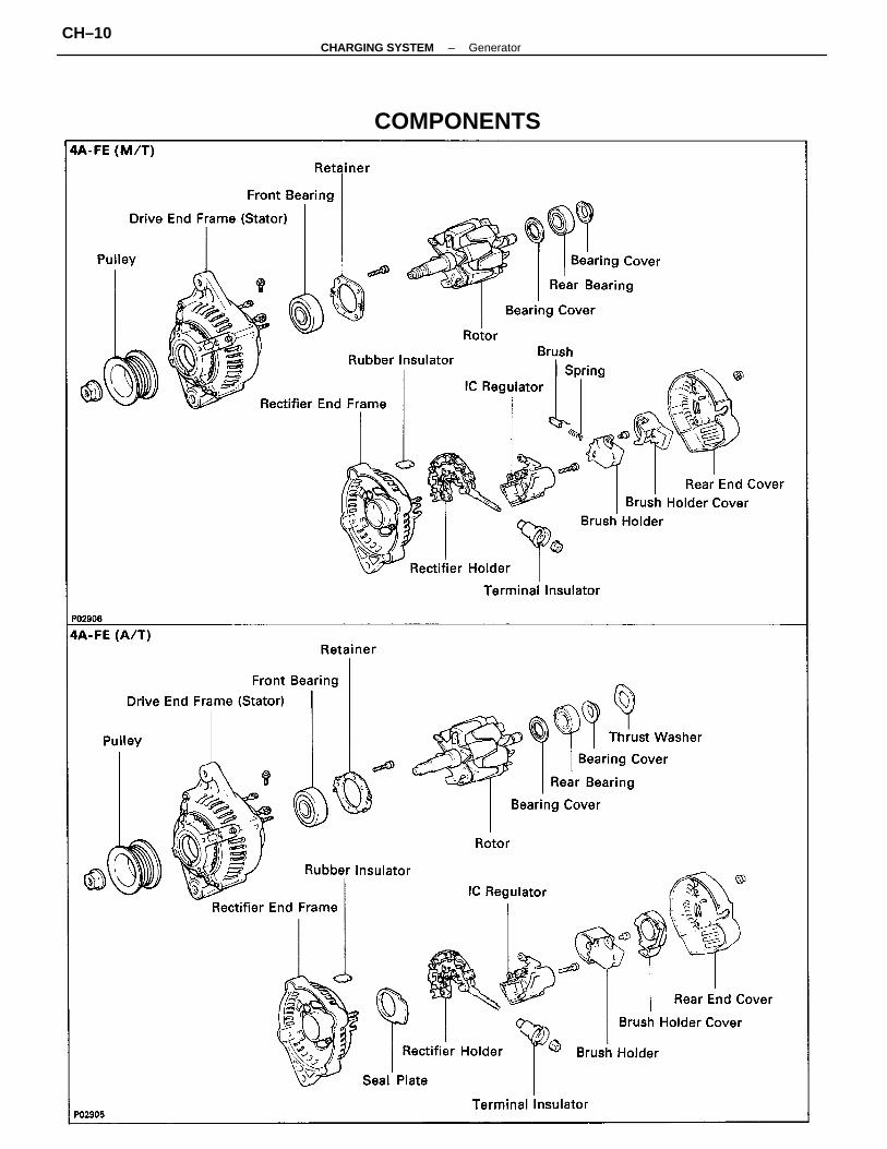
COMPONENTS
–CHARGING SYSTEM GeneratorCH–10
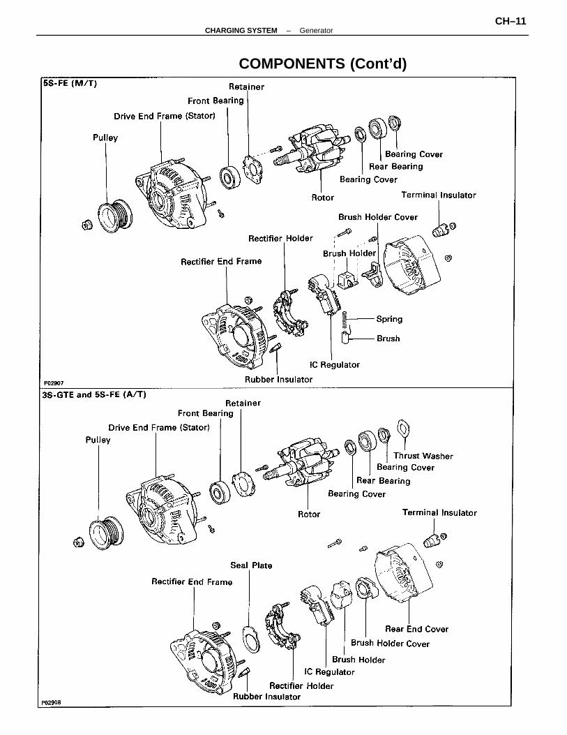
COMPONENTS (Cont’d)
–CHARGING SYSTEM GeneratorCH–11
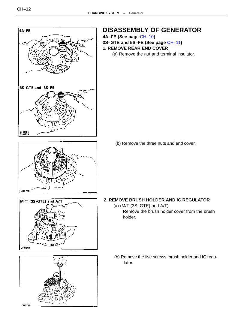
DISASSEMBLY OF GENERATOR4A–FE (See page CH–10)3S–GTE and 5S–FE (See page CH–11)1. REMOVE REAR END COVER
(a) Remove the nut and terminal insulator.
2. REMOVE BRUSH HOLDER AND IC REGULATOR(a) (M/T (3S–GTE) and A/T)
Remove the brush holder cover from the brushholder.
(b) Remove the five screws, brush holder and IC regu-lator.
(b) Remove the three nuts and end cover.
–CHARGING SYSTEM GeneratorCH–12
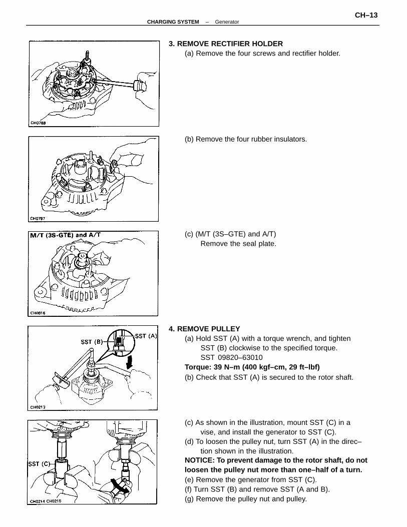
(c) As shown in the illustration, mount SST (C) in avise, and install the generator to SST (C).
(d) To loosen the pulley nut, turn SST (A) in the direc–tion shown in the illustration.
NOTICE: To prevent damage to the rotor shaft, do notloosen the pulley nut more than one–half of a turn.(e) Remove the generator from SST (C).(f) Turn SST (B) and remove SST (A and B).(g) Remove the pulley nut and pulley.
4. REMOVE PULLEY(a) Hold SST (A) with a torque wrench, and tighten
SST (B) clockwise to the specified torque.SST 09820–63010
Torque: 39 N–m (400 kgf–cm, 29 ft–lbf)(b) Check that SST (A) is secured to the rotor shaft.
3. REMOVE RECTIFIER HOLDER(a) Remove the four screws and rectifier holder.
(c) (M/T (3S–GTE) and A/T)Remove the seal plate.
(b) Remove the four rubber insulators.
–CHARGING SYSTEM GeneratorCH–13
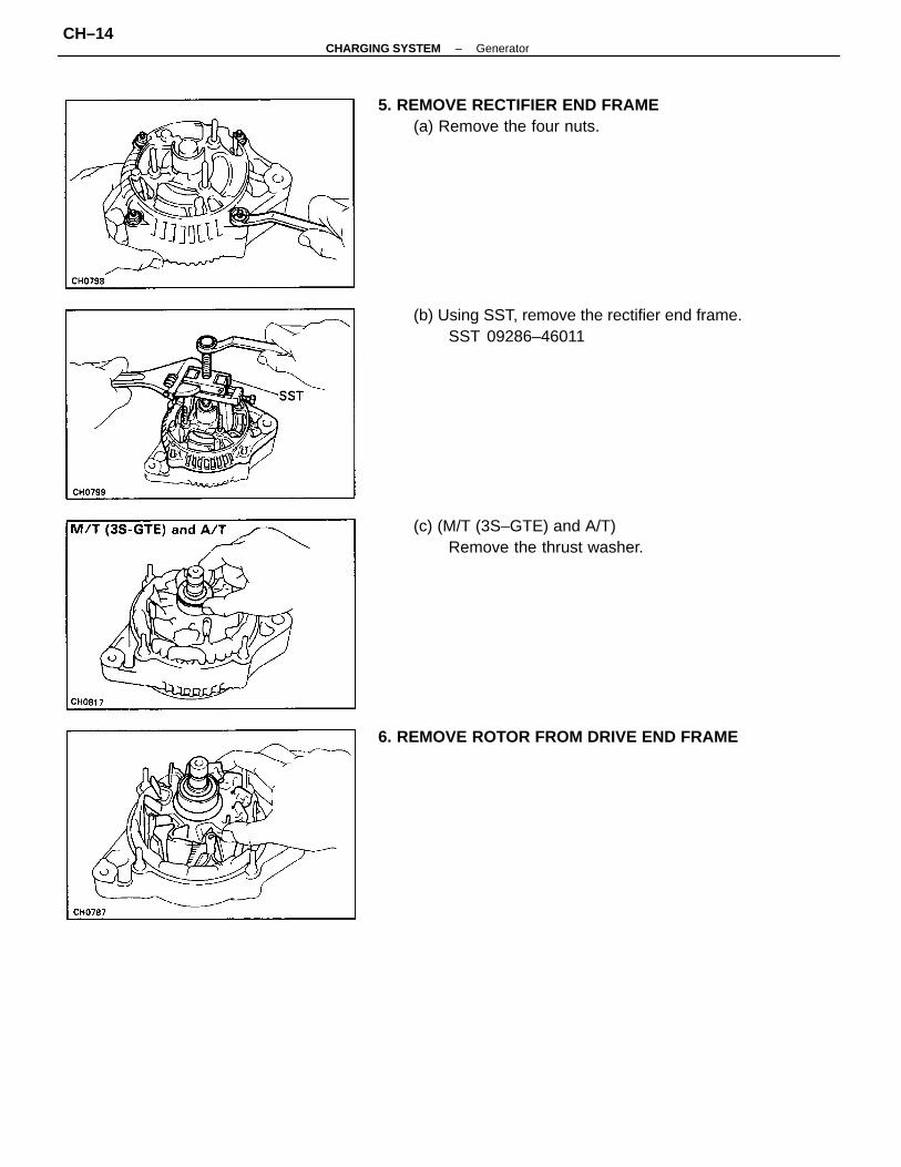
(b) Using SST, remove the rectifier end frame.SST 09286–46011
5. REMOVE RECTIFIER END FRAME(a) Remove the four nuts.
(c) (M/T (3S–GTE) and A/T)Remove the thrust washer.
6. REMOVE ROTOR FROM DRIVE END FRAME
–CHARGING SYSTEM GeneratorCH–14
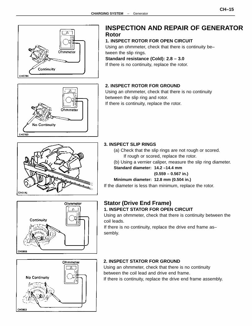
3. INSPECT SLIP RINGS(a) Check that the slip rings are not rough or scored.
If rough or scored, replace the rotor.(b) Using a vernier caliper, measure the slip ring diameter.Standard diameter: 14.2 –14.4 mm
(0.559 – 0.567 in.)Minimum diameter: 12.8 mm (0.504 in.)
If the diameter is less than minimum, replace the rotor.
Stator (Drive End Frame)1. INSPECT STATOR FOR OPEN CIRCUITUsing an ohmmeter, check that there is continuity between thecoil leads.If there is no continuity, replace the drive end frame as–sembly.
INSPECTION AND REPAIR OF GENERATORRotor1. INSPECT ROTOR FOR OPEN CIRCUITUsing an ohmmeter, check that there is continuity be–tween the slip rings.Standard resistance (Cold): 2.8 – 3.0
If there is no continuity, replace the rotor.
2. INSPECT STATOR FOR GROUNDUsing an ohmmeter, check that there is no continuitybetween the coil lead and drive end frame.If there is continuity, replace the drive end frame assembly.
2. INSPECT ROTOR FOR GROUNDUsing an ohmmeter, check that there is no continuitybetween the slip ring and rotor.If there is continuity, replace the rotor.
–CHARGING SYSTEM GeneratorCH–15
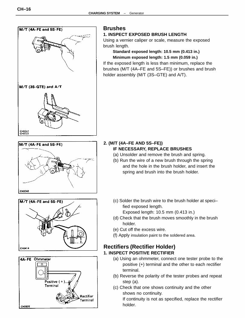
Rectifiers (Rectifier Holder)1. INSPECT POSITIVE RECTIFIER
(a) Using an ohmmeter, connect one tester probe to thepositive (+) terminal and the other to each rectifierterminal.
(b) Reverse the polarity of the tester probes and repeatstep (a).
(c) Check that one shows continuity and the othershows no continuity.If continuity is not as specified, replace the rectifierholder.
Brushes1. INSPECT EXPOSED BRUSH LENGTHUsing a vernier caliper or scale, measure the exposedbrush length.
Standard exposed length: 10.5 mm (0.413 in.)Minimum exposed length: 1.5 mm (0.059 in.)
If the exposed length is less than minimum, replace thebrushes (M/T (4A–FE and 5S–FE)) or brushes and brushholder assembly (M/T (3S–GTE) and A/T).
(c) Solder the brush wire to the brush holder at speci–fied exposed length.Exposed length: 10.5 mm (0.413 in.)
(d) Check that the brush moves smoothly in the brushholder.
(e) Cut off the excess wire.(f) Apply insulation paint to the soldered area.
2. (M/T (4A–FE AND 5S–FE))IF NECESSARY, REPLACE BRUSHES(a) Unsolder and remove the brush and spring.(b) Run the wire of a new brush through the spring
and the hole in the brush holder, and insert thespring and brush into the brush holder.
–CHARGING SYSTEM GeneratorCH–16
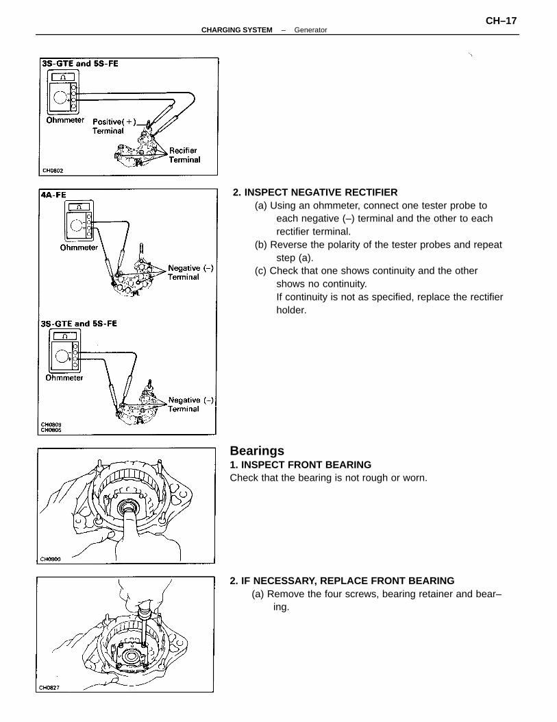
2. INSPECT NEGATIVE RECTIFIER(a) Using an ohmmeter, connect one tester probe to
each negative (–) terminal and the other to eachrectifier terminal.
(b) Reverse the polarity of the tester probes and repeatstep (a).
(c) Check that one shows continuity and the othershows no continuity.If continuity is not as specified, replace the rectifierholder.
Bearings1. INSPECT FRONT BEARINGCheck that the bearing is not rough or worn.
2. IF NECESSARY, REPLACE FRONT BEARING(a) Remove the four screws, bearing retainer and bear–
ing.
–CHARGING SYSTEM GeneratorCH–17
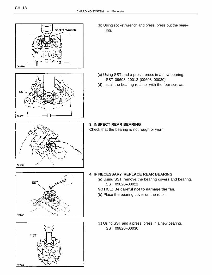
4. IF NECESSARY, REPLACE REAR BEARING(a) Using SST, remove the bearing covers and bearing.
SST 09820–00021NOTICE: Be careful not to damage the fan.(b) Place the bearing cover on the rotor.
(c) Using SST and a press, press in a new bearing.SST 09608–20012 (09608–00030)
(d) Install the bearing retainer with the four screws.
(c) Using SST and a press, press in a new bearing.SST 09820–00030
(b) Using socket wrench and press, press out the bear–ing.
3. INSPECT REAR BEARINGCheck that the bearing is not rough or worn.
–CHARGING SYSTEM GeneratorCH–18
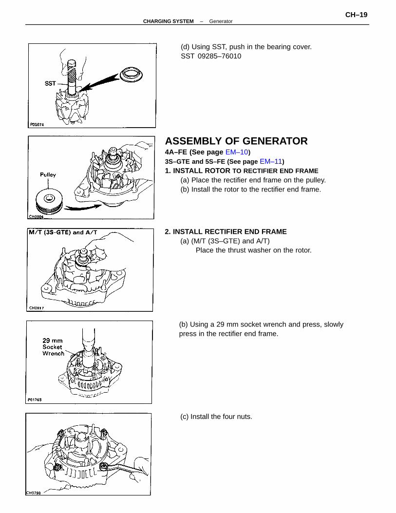
ASSEMBLY OF GENERATOR4A–FE (See page EM–10)3S–GTE and 5S–FE (See page EM–11)1. INSTALL ROTOR TO RECTIFIER END FRAME
(a) Place the rectifier end frame on the pulley.(b) Install the rotor to the rectifier end frame.
2. INSTALL RECTIFIER END FRAME(a) (M/T (3S–GTE) and A/T)
Place the thrust washer on the rotor.
(b) Using a 29 mm socket wrench and press, slowlypress in the rectifier end frame.
(d) Using SST, push in the bearing cover.SST 09285–76010
(c) Install the four nuts.
–CHARGING SYSTEM GeneratorCH–19
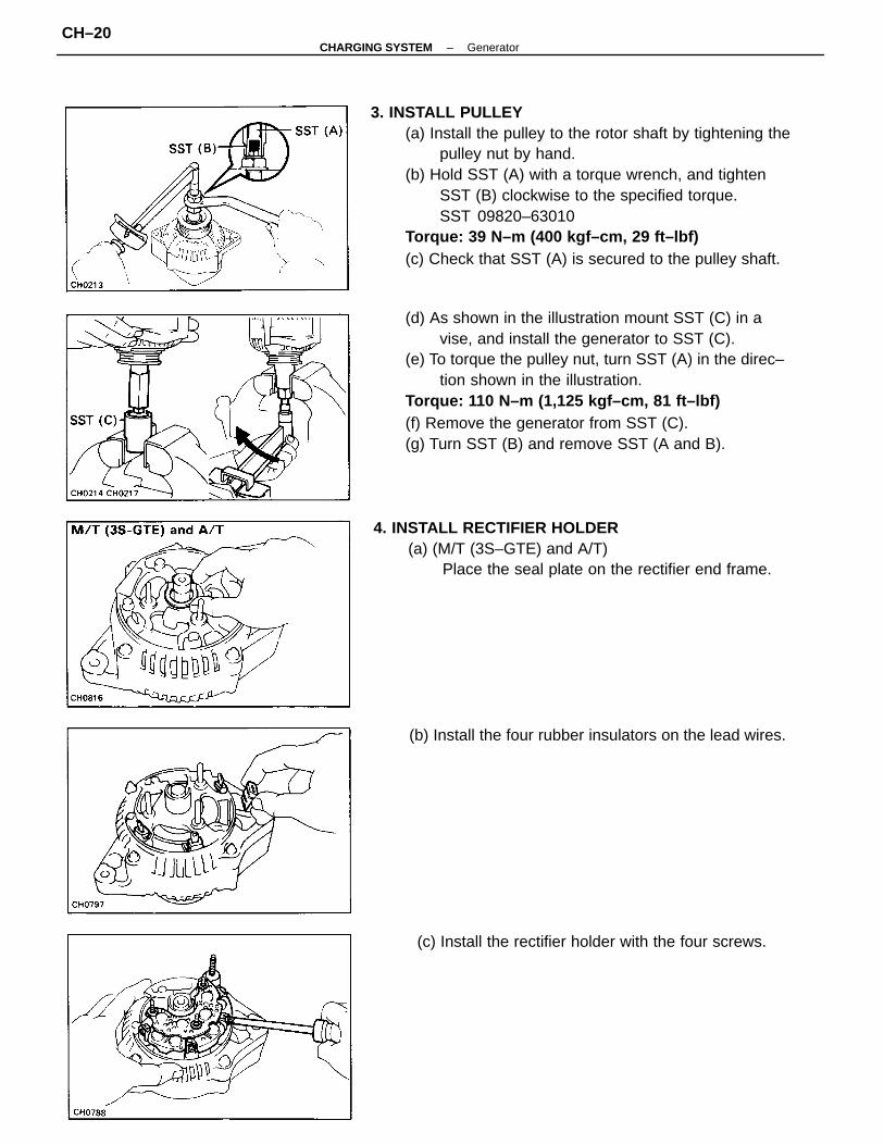
3. INSTALL PULLEY(a) Install the pulley to the rotor shaft by tightening the
pulley nut by hand.(b) Hold SST (A) with a torque wrench, and tighten
SST (B) clockwise to the specified torque.SST 09820–63010
Torque: 39 N–m (400 kgf–cm, 29 ft–lbf)(c) Check that SST (A) is secured to the pulley shaft.
(d) As shown in the illustration mount SST (C) in avise, and install the generator to SST (C).
(e) To torque the pulley nut, turn SST (A) in the direc–tion shown in the illustration.
Torque: 110 N–m (1,125 kgf–cm, 81 ft–lbf)(f) Remove the generator from SST (C).(g) Turn SST (B) and remove SST (A and B).
4. INSTALL RECTIFIER HOLDER(a) (M/T (3S–GTE) and A/T)
Place the seal plate on the rectifier end frame.
(b) Install the four rubber insulators on the lead wires.
(c) Install the rectifier holder with the four screws.
–CHARGING SYSTEM GeneratorCH–20
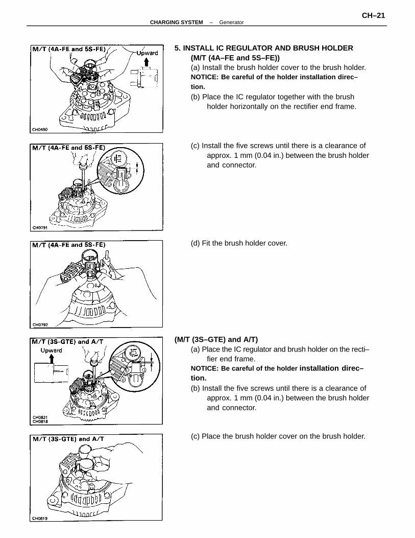
5. INSTALL IC REGULATOR AND BRUSH HOLDER(M/T (4A–FE and 5S–FE))(a) Install the brush holder cover to the brush holder.NOTICE: Be careful of the holder installation direc–tion.
(b) Place the IC regulator together with the brushholder horizontally on the rectifier end frame.
(M/T (3S–GTE) and A/T)(a) Place the IC regulator and brush holder on the recti–
fier end frame.NOTICE: Be careful of the holder installation direc–tion.(b) Install the five screws until there is a clearance of
approx. 1 mm (0.04 in.) between the brush holderand connector.
(c) Install the five screws until there is a clearance ofapprox. 1 mm (0.04 in.) between the brush holderand connector.
(c) Place the brush holder cover on the brush holder.
(d) Fit the brush holder cover.
–CHARGING SYSTEM GeneratorCH–21
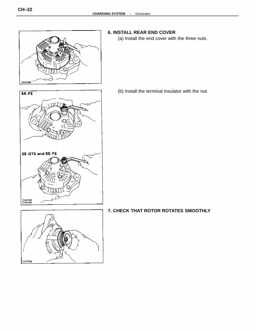
6. INSTALL REAR END COVER(a) Install the end cover with the three nuts.
(b) Install the terminal insulator with the nut.
7. CHECK THAT ROTOR ROTATES SMOOTHLY
–CHARGING SYSTEM GeneratorCH–22
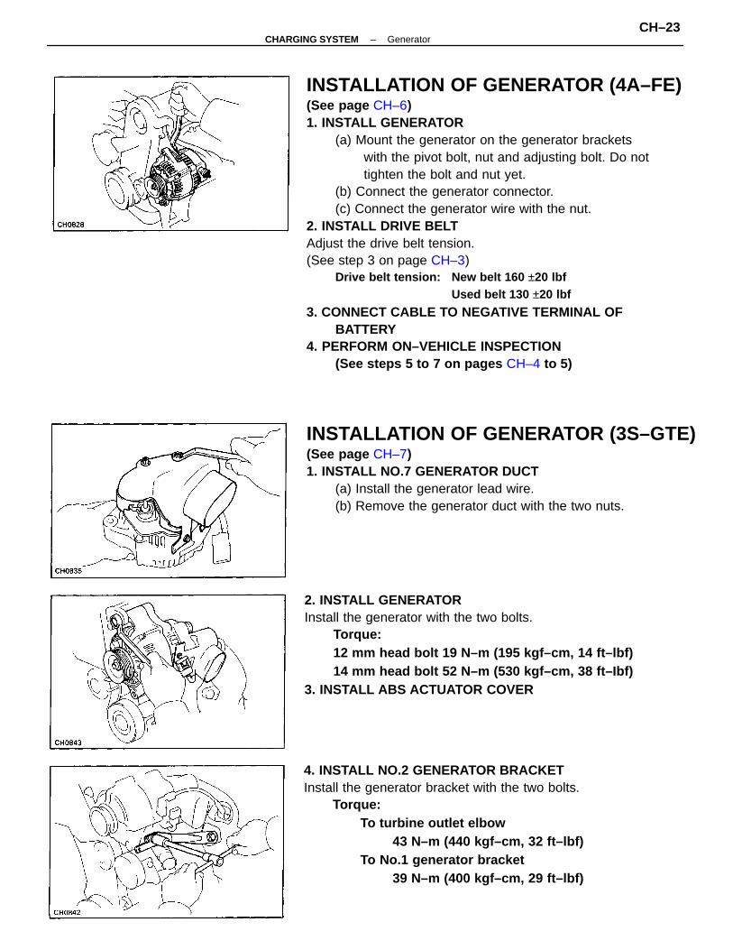
INSTALLATION OF GENERATOR (4A–FE)(See page CH–6)1. INSTALL GENERATOR
(a) Mount the generator on the generator bracketswith the pivot bolt, nut and adjusting bolt. Do nottighten the bolt and nut yet.
(b) Connect the generator connector.(c) Connect the generator wire with the nut.
2. INSTALL DRIVE BELTAdjust the drive belt tension.(See step 3 on page CH–3)
Drive belt tension: New belt 160 ±20 lbfUsed belt 130 ±20 lbf
3. CONNECT CABLE TO NEGATIVE TERMINAL OFBATTERY
4. PERFORM ON–VEHICLE INSPECTION(See steps 5 to 7 on pages CH–4 to 5)
2. INSTALL GENERATORInstall the generator with the two bolts.
Torque:12 mm head bolt 19 N–m (195 kgf–cm, 14 ft–lbf)14 mm head bolt 52 N–m (530 kgf–cm, 38 ft–Ibf)
3. INSTALL ABS ACTUATOR COVER
4. INSTALL NO.2 GENERATOR BRACKETInstall the generator bracket with the two bolts.
Torque:To turbine outlet elbow
43 N–m (440 kgf–cm, 32 ft–lbf)To No.1 generator bracket
39 N–m (400 kgf–cm, 29 ft–lbf)
INSTALLATION OF GENERATOR (3S–GTE)(See page CH–7)1. INSTALL NO.7 GENERATOR DUCT
(a) Install the generator lead wire.(b) Remove the generator duct with the two nuts.
–CHARGING SYSTEM GeneratorCH–23
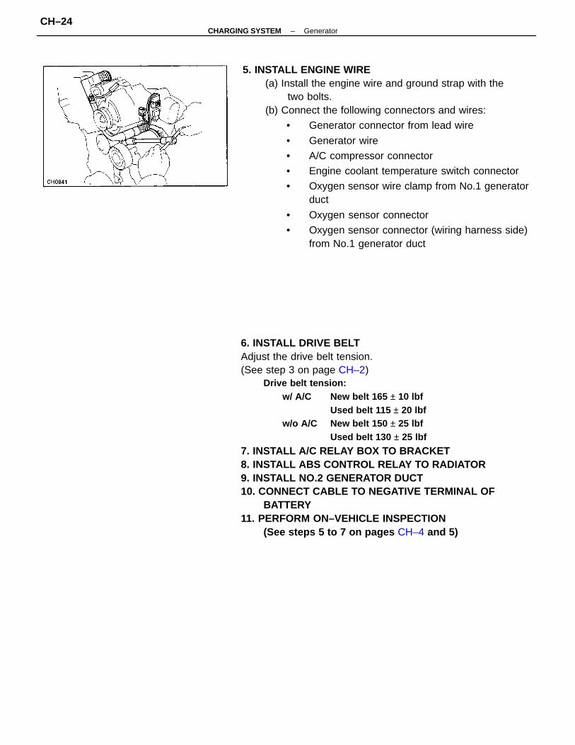
6. INSTALL DRIVE BELTAdjust the drive belt tension.(See step 3 on page CH–2)
Drive belt tension:w/ A/C New belt 165 ± 10 lbf
Used belt 115 ± 20 lbfw/o A/C New belt 150 ± 25 lbf
Used belt 130 ± 25 lbf
7. INSTALL A/C RELAY BOX TO BRACKET8. INSTALL ABS CONTROL RELAY TO RADIATOR9. INSTALL NO.2 GENERATOR DUCT10. CONNECT CABLE TO NEGATIVE TERMINAL OF
BATTERY11. PERFORM ON–VEHICLE INSPECTION
(See steps 5 to 7 on pages CH–4 and 5)
5. INSTALL ENGINE WIRE(a) Install the engine wire and ground strap with the
two bolts.(b) Connect the following connectors and wires:
• Generator connector from lead wire
• Generator wire
• A/C compressor connector
• Engine coolant temperature switch connector
• Oxygen sensor wire clamp from No.1 generatorduct
• Oxygen sensor connector
• Oxygen sensor connector (wiring harness side)from No.1 generator duct
–CHARGING SYSTEM GeneratorCH–24
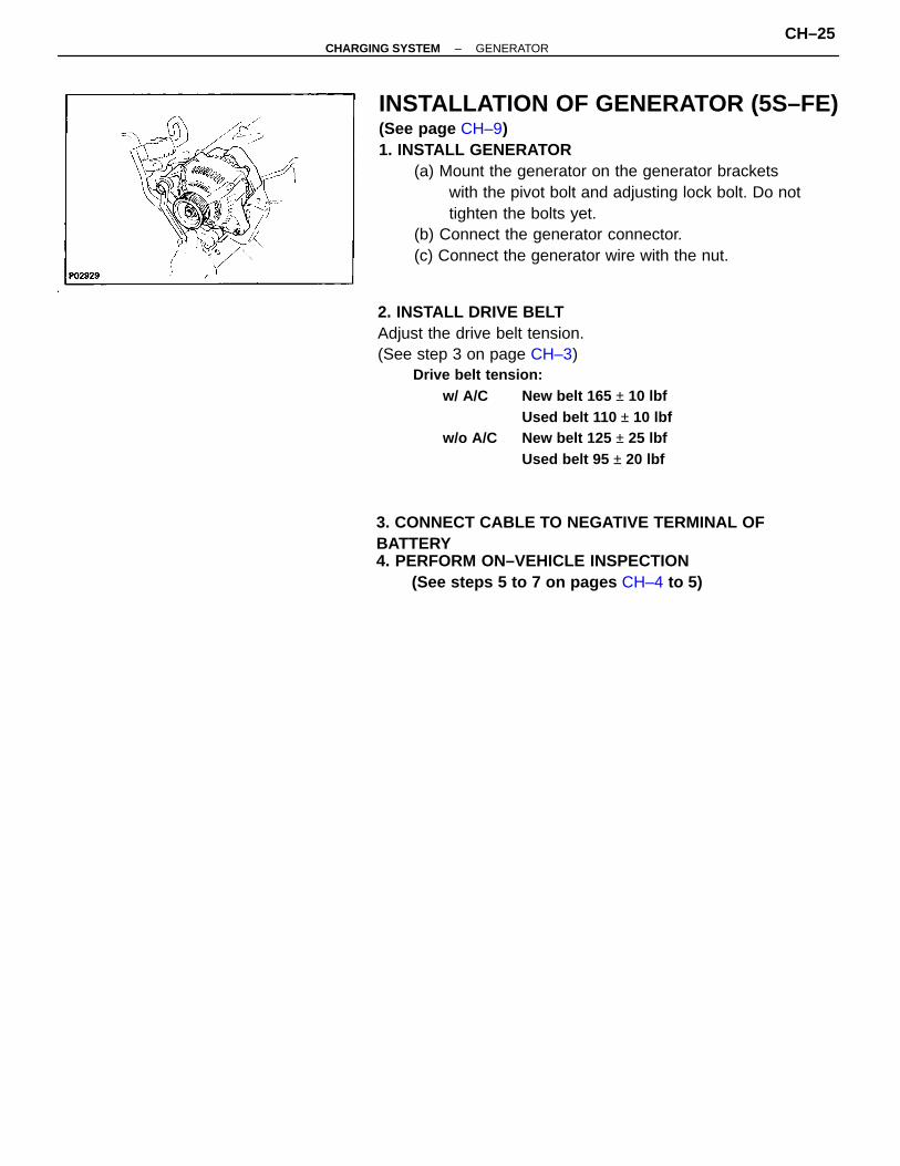
INSTALLATION OF GENERATOR (5S–FE)(See page CH–9)1. INSTALL GENERATOR
(a) Mount the generator on the generator bracketswith the pivot bolt and adjusting lock bolt. Do nottighten the bolts yet.
(b) Connect the generator connector.(c) Connect the generator wire with the nut.
2. INSTALL DRIVE BELTAdjust the drive belt tension.(See step 3 on page CH–3)
Drive belt tension:w/ A/C New belt 165 ± 10 lbf
Used belt 110 ± 10 lbfw/o A/C New belt 125 ± 25 lbf
Used belt 95 ± 20 lbf
3. CONNECT CABLE TO NEGATIVE TERMINAL OFBATTERY4. PERFORM ON–VEHICLE INSPECTION
(See steps 5 to 7 on pages CH–4 to 5)
–CHARGING SYSTEM GENERATORCH–25
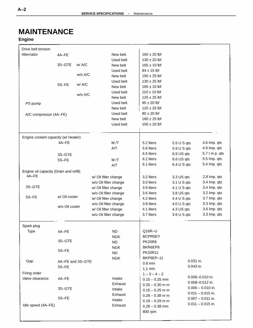
Q16R–UBCPR5EYPK20R8BKR6EP8PK20R11BKP6EP–110.8 mm1.1 mm1 – 3 – 4 – 20.15 – 0.25 mm0.20 – 0.30 m m0.15 – 0.25 m m0.28 – 0.38 m m0.19 – 0.29 m m0.28 – 0.38 mm800 rpm
160 ± 20 lbf130 ± 20 lbf165 ± 10 lbf84 ± 15 lbf150 ± 25 lbf130 ± 25 lbf165 ± 10 lbf110 ± 10 lbf125 ± 25 lbf95 ± 20 lbf125 ± 25 lbf80 ± 20 lbf160 ± 25 lbf100 ± 20 lbf
w/ Oil filter changew/o Oil filter changew/ Oil filter changew/o Oil filter changew/ Oil filter changew/o Oil filter changew/ Oil filter changew/o Oil filter change
New belt.Used beltNew beltUsed beltNew beltUsed beltNew beltUsed beltNew beltUsed beltNew beltUsed beltNew beltUsed belt
0.031 in.0.043 in.
0.006–0.010 in.0.008–0.012 in.0.006 – 0.010 in.0.011 – 0.015 in.0.007 – 0.011 in.0.011 – 0.015 in.
2.8 Imp. qts3.4 Imp. qts3.4 Imp. qts3.2 Imp. qts3.7 Imp. qts3.3 Imp. qts3.6 Imp. qts3.3 Imp. qts
3.3 US qts3.1 U S qts4.1 U S qts3.8 US qts4.4 U S qts4.0 U S qts4.3 US qts3.9 U S qts
3.2 liters3.0 liters3.9 liters3.6 Iiters4.2 liters3.8 liters4.1 liters3.7 liters
Engine coolant capacity (w/ Heater)
Engine oil capacity (Drain and refill)
MAINTENANCEEngine
4.6 Imp. qts4.9 Imp. qts5.7 I m p. qts5.5 Imp. qts5.4 Imp. qts
IntakeExhaustIntakeExhaustIntakeExhaust
5.5 U S qts5.9 U S qts6.9 US qts6.6 US qts6.4 U S qts
5.2 liters5.6 liters6.5 liters6.2 liters6.1 liters
4A–FE and 3S–GTE5S–FE
Drive belt tensionAlternator
NDNGKNDNGKNDNGK
Firing orderValve clearance
A/C compressor (4A–FE)
Spark plug Type
Idle speed (4A–FE)
3S–GTE w/ A/C
w/o Oil cooler
3S–GTE5S–FE
w/ Oil cooler
M /TA/T
M /TA/T
PS pump
w/o A/C
w/o A/C
w/ A/C
3S–GTE
3S–GTE
3S–GTE
4A–FE
4A–FE
5S–FE
5S–FE
5S–FE
4A–FE
5S–FE
Gap
4A–FE
4A–FE
–SERVICE SPECIFICATIONS MaintenanceA–2
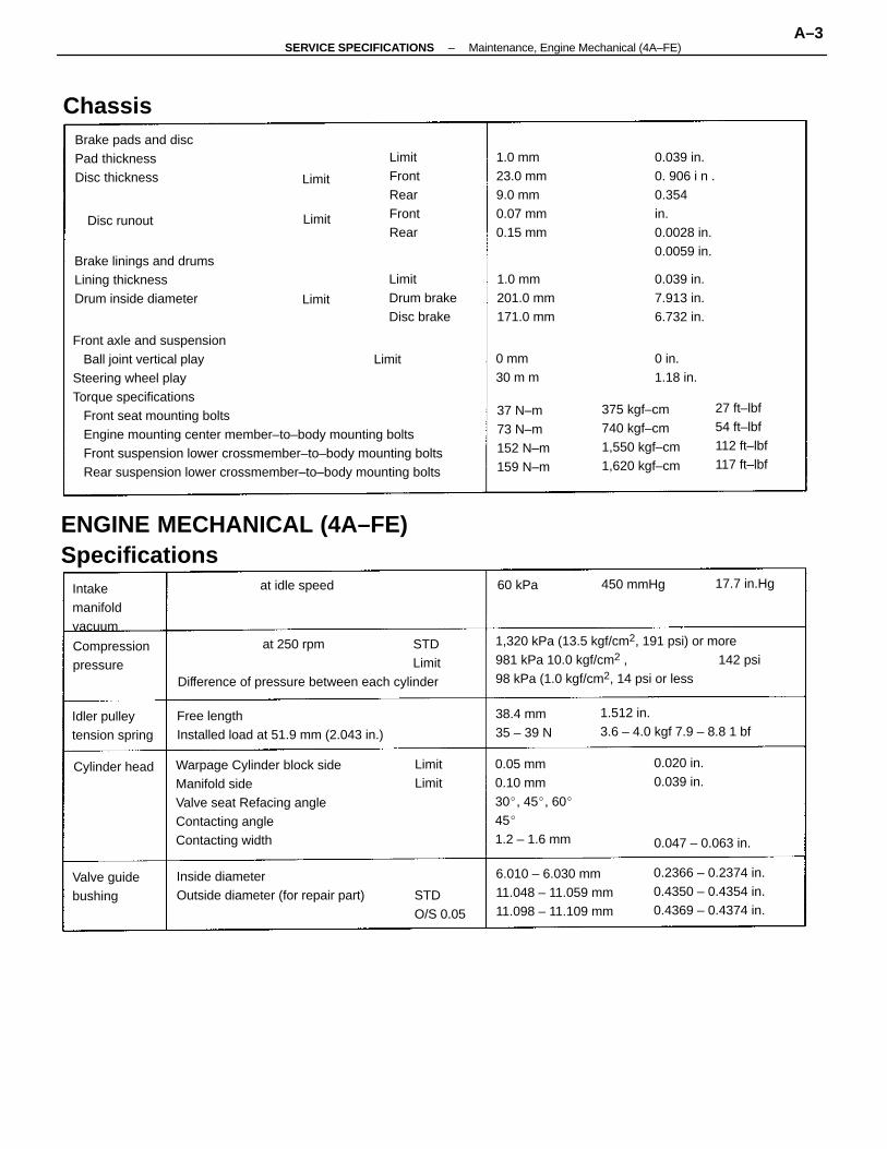
Front axle and suspension Ball joint vertical play LimitSteering wheel playTorque specifications Front seat mounting bolts Engine mounting center member–to–body mounting bolts Front suspension lower crossmember–to–body mounting bolts Rear suspension lower crossmember–to–body mounting bolts
Warpage Cylinder block sideManifold sideValve seat Refacing angleContacting angleContacting width
ENGINE MECHANICAL (4A–FE)Specifications
at 250 rpm STDLimit
Difference of pressure between each cylinder
1,320 kPa (13.5 kgf/cm2, 191 psi) or more981 kPa 10.0 kgf/cm2 , 142 psi98 kPa (1.0 kgf/cm2, 14 psi or less
Free lengthInstalled load at 51.9 mm (2.043 in.)
Brake linings and drumsLining thicknessDrum inside diameter
Inside diameterOutside diameter (for repair part)
0.05 mm0.10 mm30, 45, 60451.2 – 1.6 mm
1.512 in.3.6 – 4.0 kgf 7.9 – 8.8 1 bf
6.010 – 6.030 mm11.048 – 11.059 mm11.098 – 11.109 mm
Brake pads and discPad thicknessDisc thickness
0.2366 – 0.2374 in.0.4350 – 0.4354 in.0.4369 – 0.4374 in.
375 kgf–cm740 kgf–cm1,550 kgf–cm1,620 kgf–cm
0.039 in.0. 906 i n .0.354in.0.0028 in.0.0059 in.
1.0 mm23.0 mm9.0 mm0.07 mm0.15 mm
37 N–m73 N–m152 N–m159 N–m
LimitDrum brakeDisc brake
27 ft–lbf54 ft–lbf112 ft–lbf117 ft–lbf
LimitFrontRearFrontRear
1.0 mm201.0 mm171.0 mm
0.039 in.7.913 in.6.732 in.
Idler pulleytension spring
Compressionpressure
Intakemanifoldvacuum
Valve guidebushing
38.4 mm35 – 39 N
STDO/S 0.05
0.020 in.0.039 in.
0.047 – 0.063 in.
at idle speed
Cylinder head
0 mm30 m m
Chassis
450 mmHg
Disc runout
17.7 in.Hg
LimitLimit
60 kPa
Limit
Limit
Limit
0 in.1.18 in.
–SERVICE SPECIFICATIONS Maintenance, Engine Mechanical (4A–FE)A–3
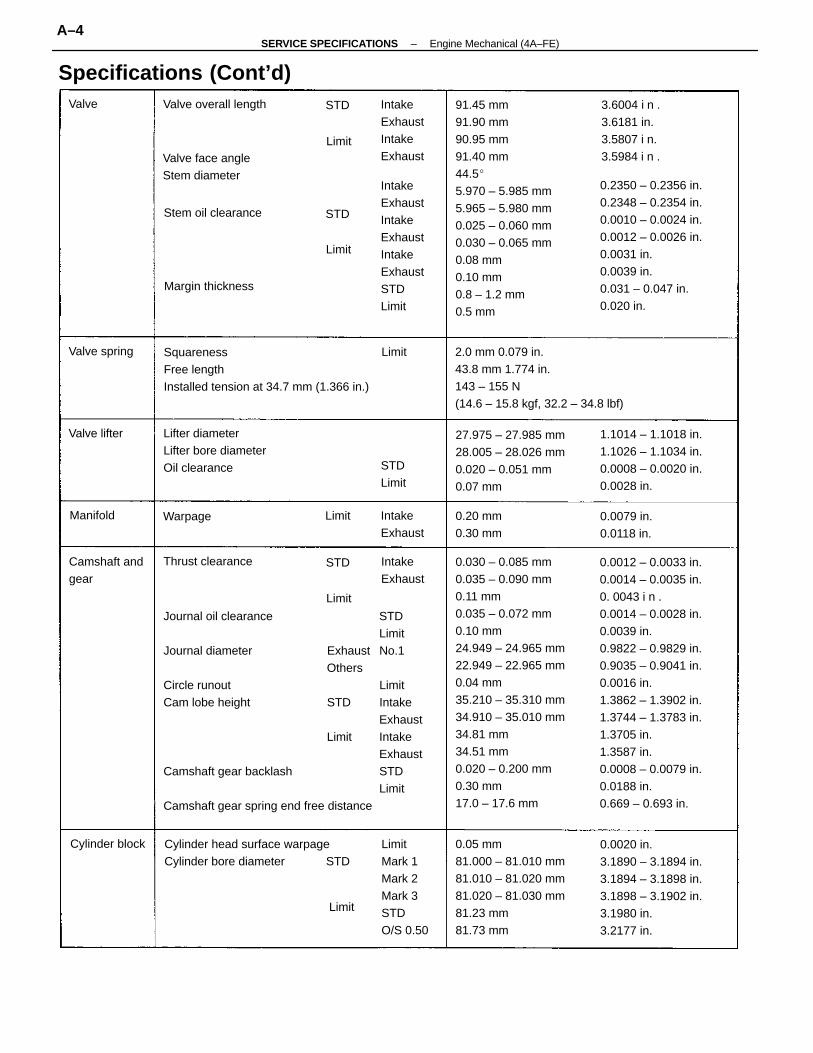
Journal oil clearance STD Limit
Journal diameter Exhaust No.1Others
Circle runout LimitCam lobe height STD Intake
ExhaustLimit Intake
ExhaustCamshaft gear backlash STD
LimitCamshaft gear spring end free distance
0.030 – 0.085 mm0.035 – 0.090 mm0.11 mm0.035 – 0.072 mm0.10 mm24.949 – 24.965 mm22.949 – 22.965 mm0.04 mm35.210 – 35.310 mm34.910 – 35.010 mm34.81 mm34.51 mm0.020 – 0.200 mm0.30 mm17.0 – 17.6 mm
0.0012 – 0.0033 in.0.0014 – 0.0035 in.0. 0043 i n .0.0014 – 0.0028 in.0.0039 in.0.9822 – 0.9829 in.0.9035 – 0.9041 in.0.0016 in.1.3862 – 1.3902 in.1.3744 – 1.3783 in.1.3705 in.1.3587 in.0.0008 – 0.0079 in.0.0188 in.0.669 – 0.693 in.
91.45 mm91.90 mm90.95 mm91.40 mm44.55.970 – 5.985 mm5.965 – 5.980 mm0.025 – 0.060 mm0.030 – 0.065 mm0.08 mm0.10 mm0.8 – 1.2 mm0.5 mm
0.2350 – 0.2356 in.0.2348 – 0.2354 in.0.0010 – 0.0024 in.0.0012 – 0.0026 in.0.0031 in.0.0039 in.0.031 – 0.047 in.0.020 in.
2.0 mm 0.079 in.43.8 mm 1.774 in.143 – 155 N(14.6 – 15.8 kgf, 32.2 – 34.8 lbf)
0.05 mm81.000 – 81.010 mm81.010 – 81.020 mm81.020 – 81.030 mm81.23 mm81.73 mm
SquarenessFree lengthInstalled tension at 34.7 mm (1.366 in.)
0.0020 in.3.1890 – 3.1894 in.3.1894 – 3.1898 in.3.1898 – 3.1902 in.3.1980 in.3.2177 in.
27.975 – 27.985 mm28.005 – 28.026 mm0.020 – 0.051 mm0.07 mm
1.1014 – 1.1018 in.1.1026 – 1.1034 in.0.0008 – 0.0020 in.0.0028 in.
Cylinder head surface warpageCylinder bore diameter STD
IntakeExhaustIntakeExhaustIntakeExhaustSTDLimit
LimitMark 1Mark 2Mark 3STDO/S 0.50
Lifter diameterLifter bore diameterOil clearance
Specifications (Cont’d)3.6004 i n .3.6181 in.3.5807 i n.3.5984 i n .
IntakeExhaustIntakeExhaustValve face angle
Stem diameter
Camshaft andgear
Valve overall length
0.0079 in.0.0118 in.
Margin thickness
Stem oil clearance
0.20 mm0.30 mm
Thrust clearance
IntakeExhaust
IntakeExhaust
Cylinder block
Valve spring
STDLimit
Valve lifter
WarpageManifold
Valve
Limit
Limit
Limit
Limit
Limit
Limit
STD
STD
STD
–SERVICE SPECIFICATIONS Engine Mechanical (4A–FE)A–4
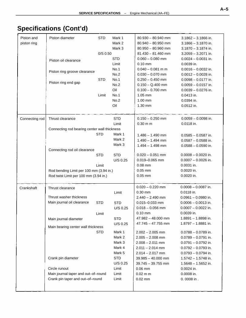
2.002 – 2.005 mm 0.0788 – 0.0789 in.2.005 – 2.008 mm 0.0789 – 0.0791 in.2.008 – 2.011 mm 0.0791 – 0.0792 in.2.011 – 2.014 mm 0.0792 – 0.0793 in.2.014 – 2.017 mm 0.0793 – 0.0794 in.39.985 – 40.000 mm 1.5742 – 1.5748 in.39.745 – 39.755 mm 1.5648 – 1.5652 in.0.06 mm 0.0024 in.0.02 m m 0.0008 in.0.02 mm 0. 0008 in .
80.930 – 80.940 mm80.940 – 80.950 mm80.950 – 80.960 mm81.430 – 81.460 mm0.060 – 0.080 mm0.10 mm0.040 – 0.081 m m0.030 – 0.070 mm0.250 – 0.450 mm0.150 – Q.400 mm0.100 – 0.700 mm1.05 mm1.00 mm1.30 mm
3.1862 – 3.1866 in.3.1866 – 3.1870 in.3.1870 – 3.1874 in.3.2059 – 3.2071 in.0.0024 – 0.0031 in.0.0039 in.0.0016 – 0.0032 in.0.0012 – 0.0028 in.0.0098 – 0.0177 in.0.0059 – 0.0157 in.0.0039 – 0.0276 in.0.0413 in.0.0394 in.0.0512 in.
Thrust clearance STDLimit
Connecting rod bearing center wall thicknessSTD Mark 1
Mark 2Mark 3
Connecting rod oil clearanceSTD STD
U/S 0.25Limit
Rod bending Limit per 100 mm (3.94 in.)Rod twist Limit per 100 mm (3.94 in.)
STD Mark 1Mark 2Mark 3
0/S 0.50 STDLimitNo.1No.2
STD No.1No.2Oil
Limit No.1No.2Oil
0.020 – 0.220 mm0.30 mm2.440 – 2.490 mm0.015–0.033 mm0.018 – 0.056 mm0.10 mm47.982 – 48.000 mm47.745 – 47.755 mm
0.0008 – 0.0087 in.0.0118 in.0.0961 – 0.0980 in.0.0006 – 0.0013 in.0.0007 – 0.0022 in.0.0039 in.1.8891 – 1.8898 in.1.8797 – 1.8881 in.
0.020 – 0.051 mm0.019–0.065 mm0.08 mm0.05 mm0.05 mm
0.0008 – 0.0020 in.0.0007 – 0.0026 in.0.0031 in.0.0020 in.0.0020 in.
Thrust washer thicknessMain journal oil clearance
Main bearing center wall thicknessSTD Mark 1
Mark 2Mark 3Mark 4Mark 5
Crank pin diameter STDU/S 0.25
Circle runout LimitMain journal taper and out–of–round LimitCrank pin taper and out–of–round Limit
0.0585 – 0.0587 in.0.0587 – 0.0588 in.0.0588 – 0.0590 in.
1.486 – 1.490 mm1.490 – 1.494 mm1.494 – 1.498 mm
Specifications (Cont’d)
0.0059 – 0.0098 in.0.0118 in.
0.150 – 0.250 mm0.30 m m
Piston ring groove clearance
Main journal diameter
Piston ring end gap
Piston oil clearance
Piston andpiston ring
STDU/S 0.25
STDU/S 0.25
Thrust clearance
Connecting rod
Piston diameter
CrankshaftLimit
Limit
STD
–SERVICE SPECIFICATIONS Engine Mechanical (4A–FE)A–5
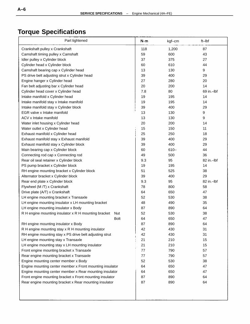
Crankshaft pulley x CrankshaftCamshaft timing pulley x CamshaftIdler pulley x Cylinder blockCylinder head x Cylinder blockCamshaft bearing cap x Cylinder headPS drive belt adjusting strut x Cylinder headEngine hanger x Cylinder headFan belt adjusting bar x Cylinder headCylinder head cover x Cylinder headIntake manifold x Cylinder headIntake manifold stay x Intake manifoldIntake manifold stay x Cylinder blockEGR valve x Intake manifoldACV x Intake manifoldWater inlet housing x Cylinder headWater outlet x Cylinder headExhaust manifold x Cylinder headExhaust manifold stay x Exhaust manifoldExhaust manifold stay x Cylinder blockMain bearing cap x Cylinder blockConnecting rod cap x Connecting rodRear oil seal retainer x Cylinder blockPS pump bracket x Cylinder blockRH engine mounting bracket x Cylinder blockAlternator bracket x Cylinder blockRear end plate x Cylinder blockFlywheel (M /T) x CrankshaftDrive plate (A/T) x CrankshaftLH engine mounting bracket x TransaxleLH engine mounting insulator x LH mounting bracketLH engine mounting insulator x BodyR H engine mounting insulator x R H mounting bracket Nut
BoltRH engine mounting insulator x BodyR H engine mounting stay x R H mounting insulatorRH engine mounting stay x PS drive belt adjusting strutLH engine mounting stay x TransaxleLH engine mounting stay x LH mounting insulatorFront engine mounting bracket x TransaxleRear engine mounting bracket x TransaxleEngine mounting center member x BodyEngine mounting center member x Front mounting insulatorEngine mounting center member x Rear mounting insulatorFront engine mounting bracket x Front mounting insulatorRear engine mounting bracket x Rear mounting insulator
87432744929201469 in.–lbf141429991411182929443682 in.–lbf14382982 in.–lbf58473835643847643131151557573847476464
1,20060037561013040028020080195195400130130200150250400400610–5009519552540095800650530490890530650890430430210210790790530650650890890
118593760133927207.81919391313201525393960499.31951399.378645248875264874242212177775264648787
Torque SpecificationsPart tightened kgf–cm ft–lbf
–SERVICE SPECIFICATIONS Engine Mechanical (4A–FE)A–6
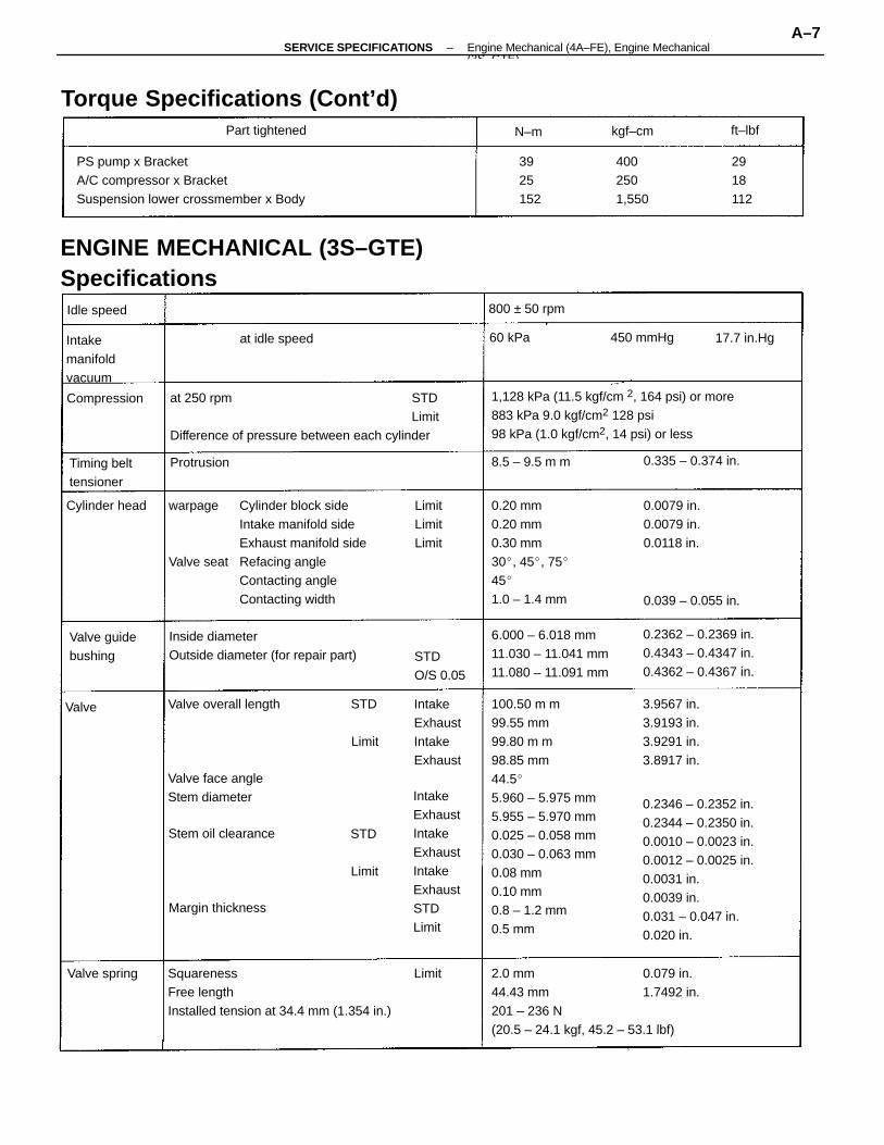
100.50 m m99.55 mm99.80 m m98.85 mm44.55.960 – 5.975 mm5.955 – 5.970 mm0.025 – 0.058 mm0.030 – 0.063 mm0.08 mm0.10 mm0.8 – 1.2 mm0.5 mm
warpage Cylinder block sideIntake manifold sideExhaust manifold side
Valve seat Refacing angleContacting angleContacting width
0.2346 – 0.2352 in.0.2344 – 0.2350 in.0.0010 – 0.0023 in.0.0012 – 0.0025 in.0.0031 in.0.0039 in.0.031 – 0.047 in.0.020 in.
2.0 mm 0.079 in.44.43 mm 1.7492 in.201 – 236 N(20.5 – 24.1 kgf, 45.2 – 53.1 lbf)
ENGINE MECHANICAL (3S–GTE)Specifications
at 250 rpm STDLimit
Difference of pressure between each cylinder
1,128 kPa (11.5 kgf/cm 2, 164 psi) or more883 kPa 9.0 kgf/cm2 128 psi98 kPa (1.0 kgf/cm2, 14 psi) or less
SquarenessFree lengthInstalled tension at 34.4 mm (1.354 in.)
PS pump x BracketA/C compressor x BracketSuspension lower crossmember x Body
0.20 mm0.20 mm0.30 mm30, 45, 75451.0 – 1.4 mm
Torque Specifications (Cont’d)
IntakeExhaustIntakeExhaustIntakeExhaustSTDLimit
Inside diameterOutside diameter (for repair part)
6.000 – 6.018 mm11.030 – 11.041 mm11.080 – 11.091 mm
0.2362 – 0.2369 in.0.4343 – 0.4347 in.0.4362 – 0.4367 in.
3.9567 in.3.9193 in.3.9291 in.3.8917 in.
Margin thickness
IntakeExhaustIntakeExhaust
Valve face angleStem diameter
0.0079 in.0.0079 in.0.0118 in.
Valve overall length
Intakemanifoldvacuum
Valve guidebushing
Timing belttensioner
4002501,550
Stem oil clearance
STDO/S 0.05
0.335 – 0.374 in.
0.039 – 0.055 in.
LimitLimitLimit
800 ± 50 rpm
Part tightened
at idle speed
Cylinder head
Compression
Valve spring
3925152
2918112
8.5 – 9.5 m m
450 mmHg 17.7 in.Hg
Idle speed
Protrusion
kgf–cm
60 kPa
Valve
ft–lbf
Limit
Limit
Limit
N–m
STD
STD
–SERVICE SPECIFICATIONS Engine Mechanical (4A–FE), Engine Mechanical(3S GTE)
A–7
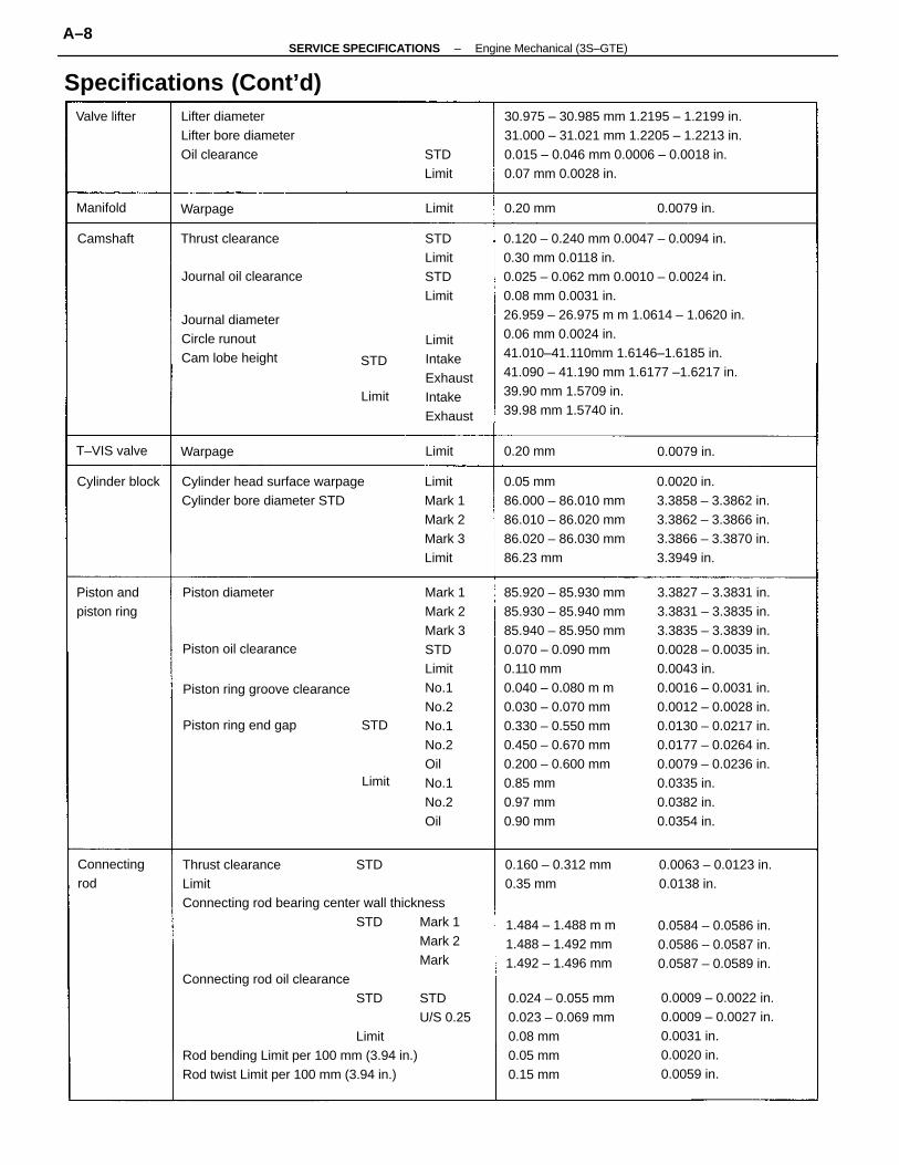
0.120 – 0.240 mm 0.0047 – 0.0094 in.0.30 mm 0.0118 in.0.025 – 0.062 mm 0.0010 – 0.0024 in.0.08 mm 0.0031 in.26.959 – 26.975 m m 1.0614 – 1.0620 in.0.06 mm 0.0024 in.41.010–41.110mm 1.6146–1.6185 in.41.090 – 41.190 mm 1.6177 –1.6217 in.39.90 mm 1.5709 in.39.98 mm 1.5740 in.
Thrust clearance STDLimitConnecting rod bearing center wall thickness
STD Mark 1Mark 2Mark
Connecting rod oil clearanceSTD STD
U/S 0.25Limit
Rod bending Limit per 100 mm (3.94 in.)Rod twist Limit per 100 mm (3.94 in.)
85.920 – 85.930 mm85.930 – 85.940 mm85.940 – 85.950 mm0.070 – 0.090 mm0.110 mm0.040 – 0.080 m m0.030 – 0.070 mm0.330 – 0.550 mm0.450 – 0.670 mm0.200 – 0.600 mm0.85 mm0.97 mm0.90 mm
3.3827 – 3.3831 in.3.3831 – 3.3835 in.3.3835 – 3.3839 in.0.0028 – 0.0035 in.0.0043 in.0.0016 – 0.0031 in.0.0012 – 0.0028 in.0.0130 – 0.0217 in.0.0177 – 0.0264 in.0.0079 – 0.0236 in.0.0335 in.0.0382 in.0.0354 in.
30.975 – 30.985 mm 1.2195 – 1.2199 in.31.000 – 31.021 mm 1.2205 – 1.2213 in.0.015 – 0.046 mm 0.0006 – 0.0018 in.0.07 mm 0.0028 in.
Mark 1Mark 2Mark 3STDLimitNo.1No.2No.1No.2OilNo.1No.2Oil
0.05 mm86.000 – 86.010 mm86.010 – 86.020 mm86.020 – 86.030 mm86.23 mm
0.0020 in.3.3858 – 3.3862 in.3.3862 – 3.3866 in.3.3866 – 3.3870 in.3.3949 in.
0.0009 – 0.0022 in.0.0009 – 0.0027 in.0.0031 in.0.0020 in.0.0059 in.
0.024 – 0.055 mm0.023 – 0.069 mm0.08 mm0.05 mm0.15 mm
Cylinder head surface warpageCylinder bore diameter STD
0.0584 – 0.0586 in.0.0586 – 0.0587 in.0.0587 – 0.0589 in.
Lifter diameterLifter bore diameterOil clearance
1.484 – 1.488 m m1.488 – 1.492 mm1.492 – 1.496 mm
Specifications (Cont’d)
Journal diameterCircle runoutCam lobe height
LimitIntakeExhaustIntakeExhaust
0.0063 – 0.0123 in.0.0138 in.
LimitMark 1Mark 2Mark 3Limit
0.160 – 0.312 mm0.35 mm
Piston ring groove clearance
STDLimitSTDLimit
Piston ring end gap
Journal oil clearance
Piston oil clearance
Connectingrod
Piston andpiston ring
Thrust clearance
Piston diameter
Cylinder block
T–VIS valve
STDLimit
Valve lifter
0.0079 in.
0.0079 in.Warpage
WarpageManifold 0.20 mm
0.20 mm
Camshaft
Limit
Limit
Limit
Limit
STD
STD
–SERVICE SPECIFICATIONS Engine Mechanical (3S–GTE)A–8
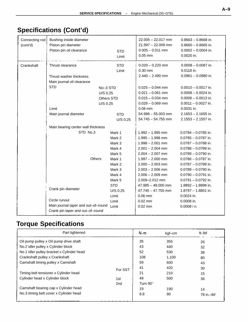
Oil pump pulley x Oil pump drive shaftNo.2 idler pulley x Cylinder blockNo.1 idler pulley bracket x Cylinder headCrankshaft pulley x CrankshaftCamshaft timing pulley x Camshaft
Timing belt tensioner x Cylinder headCylinder head x Cylinder block
1.992 – 1.995 mm1.995 – 1.998 mm1.998 – 2.001 mm2.001 – 2.004 mm2.004 – 2.007 mm1.997 – 2.000 mm2.000 – 2.003 mm2.003 – 2.006 mm2.006 – 2.009 mm2.009–2.012 mm47.985 – 48.000 mm47.745 – 47.755 mm0.06 mm0.02 mm0.02 mm
Mark 1Mark 2Mark 3Mark 4Mark 5Mark 1Mark 2Mark 3Mark 4Mark 5STDU/S 0.25LimitLimitLimit
0.0784 – 0.0785 in.0.0785 – 0.0787 in.0.0787 – 0.0788 in.0.0788 – 0.0789 in.0.0789 – 0.0790 in.0.0786 – 0.0787 in.0.0787 – 0.0789 in.0.0789 – 0.0790 in.0.0790 – 0.0791 in.0.0791 – 0.0792 in.1.8892 – 1.8898 in.1.8797 – 1.8801 in.0.0024 in.0.0008 in.0.0008 i n.
0.025 – 0.044 mm0.021 – 0.061 mm0.015 – 0.034 mm0.029 – 0.069 mm0.08 mm54.988 – 55.003 mm54.745 – 54.755 mm
0.0010 – 0.0017 in.0.0008 – 0.0024 in.0.0006 – 0.0013 in.0.0011 – 0.0027 in.0.0031 in.2.1653 – 2.1655 in.2.1553 – 2.1557 in.
35435210859412149Turn 90198.8
Circle runoutMain journal taper and out–of–roundCrank pin taper and out–of–round
22.005 – 22.017 mm21.997 – 22.009 mm0.005 – 0.011 mm0.05 mm
Camshaft bearing cap x Cylinder headNo.3 timing belt cover x Cylinder head
0.8663 – 0.8668 in.0.8660 – 0.8665 in.0.0002 – 0.0004 in.0.0020 in.
No–3 STDU/S 0.25Others STDU/S 0.25
Thrust washer thicknessMain journal oil clearanceSTD
Bushing inside diameterPiston pin diameterPiston pin oil clearance
Main bearing center wall thicknessSTD No.3
0.0008 – 0.0087 in.0.0118 in.0.0961 – 0.0980 in.
0.020 – 0.220 mm0.30 mm2.440 – 2.490 mm
3554405301,100600420210500
19090
Specifications (Cont’d)
LimitMain journal diameter
Torque Specifications
2632388043301536
1478 in.–lbf
Connecting rod(cont’d)
Crank pin diameter
STDU/S 0.25
Thrust clearance
Part tightened
STDLimit
STDLimit
Crankshaft
1st2nd
For SST
kgf–cm ft–lbf
Others
–SERVICE SPECIFICATIONS Engine Mechanical (3S–GTE)A–9
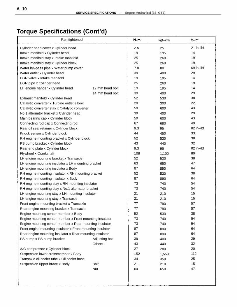
Cylinder head cover x Cylinder headIntake manifold x Cylinder headIntake manifold stay x Intake manifoldIntake manifold stay x Cylinder blockWater by–pass pipe x Water pump coverWater outlet x Cylinder headEGR valve x Intake manifoldEGR pipe x Cylinder headLH engine hanger x Cylinder head 12 mm head bolt
14 mm head boltExhaust manifold x Cylinder headCatalytic converter x Turbine outlet elbowCatalytic converter stay x Catalytic converterNo.1 alternator bracket x Cylinder headMain bearing cap x Cylinder blockConnecting rod cap x Connecting rodRear oil seal retainer x Cylinder blockKnock sensor x Cylinder blockRH engine mounting bracket x Cylinder blockPS pump bracket x Cylinder blockRear end plate x Cylinder blockFlywheel x CrankshaftLH engine mounting bracket x TransaxleLH engine mounting insulator x LH mounting bracketLH engine mounting insulator x BodyRH engine mounting insulator x RH mounting bracketRH engine mounting insulator x BodyRH engine mounting stay x RH mounting insulatorRH engine mounting stay x No.1 alternator bracketLH engine mounting stay x LH mounting insulatorLH engine mounting stay x TransaxleFront engine mounting bracket x TransaxleRear engine mounting bracket x TransaxleEngine mounting center member x BodyEngine mounting center member x Front mounting insulatorEngine mounting center member x Rear mounting insulatorFront engine mounting insulator x Front mounting insulatorRear engine mounting insulator x Rear mounting insulatorPS pump x PS pump bracket Adjusting bolt
OthersA/C compressor x Cylinder blockSuspension lower crossmember x BodyTransaxle oil cooler tube x Oil cooler hoseSuspension upper brace x Body Bolt
Nut
21 in–lbf14191969 in–lbf291419142938224329434982 in–lbf33383282 in–lbf8038476438645454151557573854546464293220112251547
251952602608040019526019540053030060040060068095450530440951,1005306508905308907407402102107907905307407408908904004402801,550350210650
2.51925257.839192519395229593959679.34452439.310852638752877373212177775273738787394327152342164
Torque Specifications (Cont’d)Part tightened kgf–cm ft–lbf
–SERVICE SPECIFICATIONS Engine Mechanical (3S–GTE)A–10
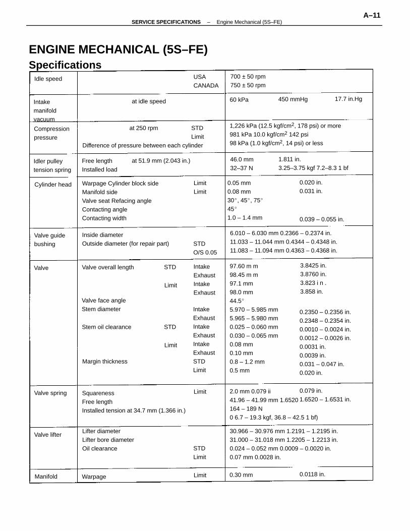
97.60 m m98.45 m m97.1 mm98.0 mm44.55.970 – 5.985 mm5.965 – 5.980 mm0.025 – 0.060 mm0.030 – 0.065 mm0.08 mm0.10 mm0.8 – 1.2 mm0.5 mm
30.966 – 30.976 mm 1.2191 – 1.2195 in.31.000 – 31.018 mm 1.2205 – 1.2213 in.0.024 – 0.052 mm 0.0009 – 0.0020 in.0.07 mm 0.0028 in.
Warpage Cylinder block sideManifold sideValve seat Refacing angleContacting angleContacting width
0.2350 – 0.2356 in.0.2348 – 0.2354 in.0.0010 – 0.0024 in.0.0012 – 0.0026 in.0.0031 in.0.0039 in.0.031 – 0.047 in.0.020 in.
1,226 kPa (12.5 kgf/cm2, 178 psi) or more981 kPa 10.0 kgf/cm2 142 psi98 kPa (1.0 kgf/cm2, 14 psi) or less
ENGINE MECHANICAL (5S–FE)Specifications
6.010 – 6.030 mm 0.2366 – 0.2374 in.11.033 – 11.044 mm 0.4344 – 0.4348 in.11.083 – 11.094 mm 0.4363 – 0.4368 in.
at 250 rpm STDLimit
Difference of pressure between each cylinder
2.0 mm 0.079 ii41.96 – 41.99 mm 1.6520164 – 189 N0 6.7 – 19.3 kgf, 36.8 – 42.5 1 bf)
SquarenessFree lengthInstalled tension at 34.7 mm (1.366 in.)
0.05 mm0.08 mm30, 45, 75451.0 – 1.4 mm
IntakeExhaustIntakeExhaustIntakeExhaustSTDLimit
Inside diameterOutside diameter (for repair part)
1.811 in.3.25–3.75 kgf 7.2–8.3 1 bf
Lifter diameterLifter bore diameterOil clearance
at 51.9 mm (2.043 in.)
3.8425 in.3.8760 in.3.823 i n .3.858 in.
0.079 in.1.6520 – 1.6531 in.
IntakeExhaustIntakeExhaust
Valve face angleStem diameter
700 ± 50 rpm750 ± 50 rpm
Free lengthInstalled load
Idler pulleytension spring
Compressionpressure
Intakemanifoldvacuum
Valve overall length
Valve guidebushing
USACANADA
Stem oil clearance
46.0 mm32–37 N
STDO/S 0.05
Margin thickness
0.020 in.0.031 in.
0.039 – 0.055 in.
Cylinder head
at idle speed
Valve spring
450 mmHg 17.7 in.Hg
Idle speed
STDLimit
LimitLimit
Valve lifter
0.0118 in.Warpage 0.30 mmManifold
60 kPa
Valve
Limit
Limit
Limit
Limit
STD
STD
–SERVICE SPECIFICATIONS Engine Mechanical (5S–FE)A–11
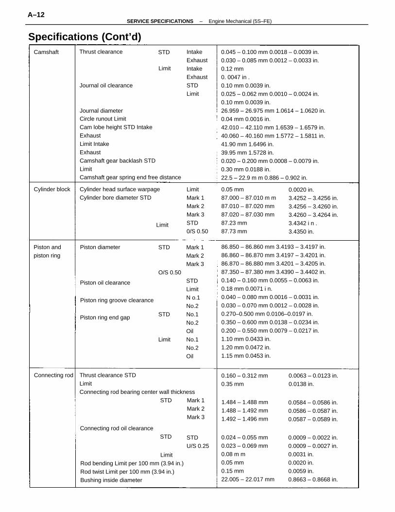
0.045 – 0.100 mm 0.0018 – 0.0039 in.0.030 – 0.085 mm 0.0012 – 0.0033 in.0.12 mm 0. 0047 in .0.10 mm 0.0039 in.0.025 – 0.062 mm 0.0010 – 0.0024 in.0.10 mm 0.0039 in.26.959 – 26.975 mm 1.0614 – 1.0620 in.0.04 mm 0.0016 in.42.010 – 42.110 mm 1.6539 – 1.6579 in.40.060 – 40.160 mm 1.5772 – 1.5811 in.41.90 mm 1.6496 in.39.95 mm 1.5728 in.0.020 – 0.200 mm 0.0008 – 0.0079 in.0.30 mm 0.0188 in.22.5 – 22.9 m m 0.886 – 0.902 in.
86.850 – 86.860 mm 3.4193 – 3.4197 in.86.860 – 86.870 mm 3.4197 – 3.4201 in.86.870 – 86.880 mm 3.4201 – 3.4205 in.87.350 – 87.380 mm 3.4390 – 3.4402 in.0.140 – 0.160 mm 0.0055 – 0.0063 in.0.18 mm 0.0071 i n.0.040 – 0.080 mm 0.0016 – 0.0031 in.0.030 – 0.070 mm 0.0012 – 0.0028 in.0.270–0.500 mm 0.0106–0.0197 in.0.350 – 0.600 mm 0.0138 – 0.0234 in.0.200 – 0.550 mm 0.0079 – 0.0217 in.1.10 mm 0.0433 in.1.20 mm 0.0472 in.1.15 mm 0.0453 in.
Journal diameterCircle runout LimitCam lobe height STD IntakeExhaustLimit IntakeExhaustCamshaft gear backlash STDLimitCamshaft gear spring end free distance
Thrust clearance STDLimitConnecting rod bearing center wall thickness
STD Mark 1Mark 2Mark 3
STD Mark 1Mark 2Mark 3
O/S 0.50STDLimitN o.1No.2
STD No.1No.2Oil
Limit No.1No.2Oil
LimitRod bending Limit per 100 mm (3.94 in.)Rod twist Limit per 100 mm (3.94 in.)Bushing inside diameter
0.05 mm87.000 – 87.010 m m87.010 – 87.020 mm87.020 – 87.030 mm87.23 mm87.73 mm
0.024 – 0.055 mm0.023 – 0.069 mm0.08 m m0.05 mm0.15 mm22.005 – 22.017 mm
0.0020 in.3.4252 – 3.4256 in.3.4256 – 3.4260 in.3.4260 – 3.4264 in.3.4342 i n .3.4350 in.
0.0009 – 0.0022 in.0.0009 – 0.0027 in.0.0031 in.0.0020 in.0.0059 in.0.8663 – 0.8668 in.
Cylinder head surface warpageCylinder bore diameter STD
Connecting rod oil clearance STD
LimitMark 1Mark 2Mark 3STD0/S 0.50
0.0584 – 0.0586 in.0.0586 – 0.0587 in.0.0587 – 0.0589 in.
1.484 – 1.488 mm1.488 – 1.492 mm1.492 – 1.496 mm
Specifications (Cont’d)IntakeExhaustIntakeExhaustSTDLimit
0.0063 – 0.0123 in.0.0138 in.
0.160 – 0.312 mm0.35 mm
Piston ring groove clearance
Piston ring end gap
Journal oil clearance
Piston oil clearance
Piston andpiston ring
STDU/S 0.25
Thrust clearance
Connecting rod
Piston diameter
Cylinder block
Limit
Camshaft
Limit
STD
–SERVICE SPECIFICATIONS Engine Mechanical (5S–FE)A–12
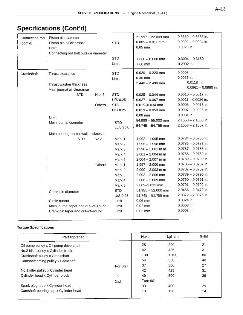
1.992 – 1.995 mm1.995 – 1.998 mm1.998 – 2.001 m m2.001 – 2.004 m m2.004 – 2.007 m m1.997 – 2.000 mm2.000 – 2.003 m m2.003 – 2.006 mm2.006 – 2.009 mm2.009–2.012 mm51.985 – 52.000 mm51.745 – 51.755 mm0.06 mm0.02 mm0.02 mm
Mark 1Mark 2Mark 3Mark 4Mark 5Mark 1Mark 2Mark 3Mark 4Mark 5STDU/S 0.25LimitLimitLimit
0.0784 – 0.0785 in.0.0785 – 0.0787 in.0.0787 – 0.0788 in.0.0788 – 0.0789 in.0.0789 – 0.0790 in.0.0786 – 0.0787 in.0.0787 – 0.0789 in.0.0789 – 0.0790 in.0.0790 – 0.0791 in.0.0791 – 0.0792 in.2.0466 – 2.0472 in.2.0372 – 2.0376 in.0.0024 in.0.0008 in.0.0008 in.
Oil pump pulley x Oil pump drive shaftNo.2 idler pulley x Cylinder blockCrankshaft pulley x CrankshaftCamshaft timing pulley x Camshaft
0.025 – 0.044 mm0.027 – 0.067 mm0.015–0.034 mm0.019 – 0.059 mm0.08 mm54.988 – 55.003 mm54.745 – 54.755 mm
0.0010 – 0.0017 in.0.0011 – 0.0026 in.0.0006 – 0.0013 in.0.0007 – 0.0023 in.0.0031 in.2.1653 – 2.1655 in.2.1553 – 2.1557 in.
284210854374249Turn 903919
Circle runoutMain journal taper and out–of–roundCrank pin taper and out–of–round
Spark plug tube x Cylinder headCamshaft bearing cap x Cylinder head
Thrust washer thicknessMain journal oil clearance
STD N o. 3 STDU/S 0.25
Others STDU/S 0.25
Main bearing center wall thicknessSTD No.3
No.1 idler pulley x Cylinder headCylinder head x Cylinder block
21.997 – 22.009 mm0.005 – 0.011 mm0.05 mm
0.8660 – 0.8665 in.0.0002 – 0.0004 in.0.0020 in.
0.0008 –0.0087 in.
0.0118 in.0.0961 – 0.0980 in.
Specifications (Cont’d)
0.020 – 0.220 mm0.30 mm2.440 – 2.490 mm
LimitMain journal diameter
Torque Specifications
Piston pin diameterPiston pin oil clearance STDLimitConnecting rod bolt outside diameter
STDLimit
2904251,100550380425500
400190
0.3094 – 0.3150 in.0.2992 in.
7.860 – 8.000 mm7.60 mm
21318040273136
2914
Connecting rod(cont’d)
Crank pin diameter
STDU/S 0.25
Thrust clearance
Part tightened
Crankshaft STDLimit
1st
2nd
For SST
kgf–cm ft–lbf
Others
–SERVICE SPECIFICATIONS Engine Mechanical (5S–FE)A–13
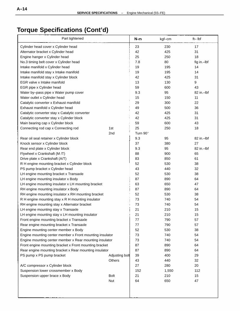
Cylinder head cover x Cylinder headAlternator bracket x Cylinder headEngine hanger x Cylinder headNo.3 timing belt cover x Cylinder headIntake manifold x Cylinder headIntake manifold stay x Intake manifoldIntake manifold stay x Cylinder blockEGR valve x Intake manifoldEGR pipe x Cylinder headWater by–pass pipe x Water pump coverWater outlet x Cylinder headCatalytic converter x Exhaust manifoldExhaust manifold x Cylinder headCatalytic converter stay x Catalytic converterCatalytic converter stay x Cylinder blockMain bearing cap x Cylinder blockConnecting rod cap x Connecting rod 1st
2ndRear oil seal retainer x Cylinder blockKnock sensor x Cylinder blockRear end plate x Cylinder blockFlywheel x Crankshaft (M /T)Drive plate x Crankshaft (A/T)R H engine mounting bracket x Cylinder blockPS pump bracket x Cylinder headLH engine mounting bracket x TransaxleLH engine mounting insulator x BodyLH engine mounting insulator x LH mounting bracketRH engine mounting insulator x BodyRH engine mounting insulator x RH mounting bracketR H engine mounting stay x R H mounting insulatorRH engine mounting stay x Alternator bracketLH engine mounting stay x TransaxleLH engine mounting stay x LH mounting insulatorFront engine mounting bracket x TransaxleRear engine mounting bracket x TransaxleEngine mounting center member x BodyEngine mounting center member x Front mounting insulatorEngine mounting center member x Rear mounting insulatorFront engine mounting bracket x Front mounting bracketRear engine mounting bracket x Rear mounting insulatorPS pump x PS pump bracket Adjusting bolt
OthersA/C compressor x Cylinder blockSuspension lower crossmember x BodySuspension upper brace x Body Bolt
Nut
2342257.819194213599.315294942425925Turn 909.3379.388835243528763875273732121777752737387873943271522164
173118fig in.–lbf14143194382 in.–lbf11223631314318
82 in.–lbf2782 in.–lbf65613832386447643854541515575738545464642932201121547
2304252508019519542513060095150300500425425600250
95380959008505304405308906508905307407402102107907905307407408908904004402801,550210650
Torque Specifications (Cont’d)Part tightened kgf–cm ft– lbf
–SERVICE SPECIFICATIONS Engine Mechanical (5S–FE)A–14
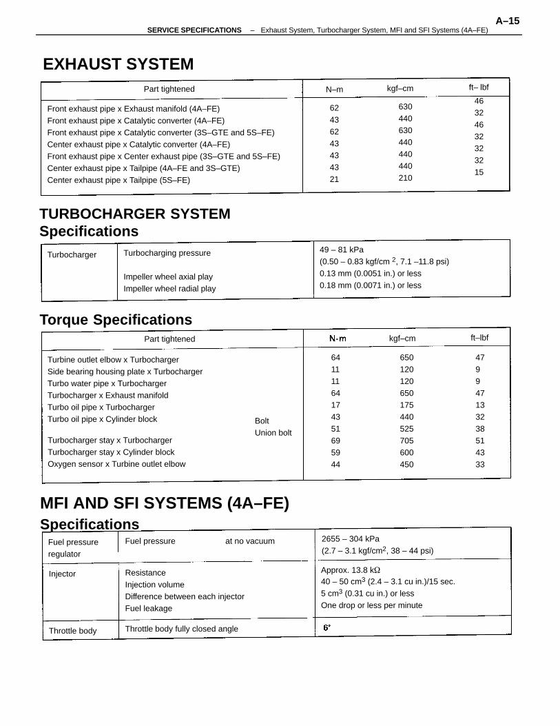
Front exhaust pipe x Exhaust manifold (4A–FE)Front exhaust pipe x Catalytic converter (4A–FE)Front exhaust pipe x Catalytic converter (3S–GTE and 5S–FE)Center exhaust pipe x Catalytic converter (4A–FE)Front exhaust pipe x Center exhaust pipe (3S–GTE and 5S–FE)Center exhaust pipe x Tailpipe (4A–FE and 3S–GTE)Center exhaust pipe x Tailpipe (5S–FE)
Turbine outlet elbow x TurbochargerSide bearing housing plate x TurbochargerTurbo water pipe x TurbochargerTurbocharger x Exhaust manifoldTurbo oil pipe x TurbochargerTurbo oil pipe x Cylinder block
49 – 81 kPa(0.50 – 0.83 kgf/cm 2, 7.1 –11.8 psi)0.13 mm (0.0051 in.) or less0.18 mm (0.0071 in.) or less
Approx. 13.8 k40 – 50 cm3 (2.4 – 3.1 cu in.)/15 sec.5 cm3 (0.31 cu in.) or lessOne drop or less per minute
ResistanceInjection volumeDifference between each injectorFuel leakage
TURBOCHARGER SYSTEMSpecifications
MFI AND SFI SYSTEMS (4A–FE)Specifications
Turbocharger stay x TurbochargerTurbocharger stay x Cylinder blockOxygen sensor x Turbine outlet elbow
Turbocharging pressure
Impeller wheel axial playImpeller wheel radial play
479947133238514333
2655 – 304 kPa(2.7 – 3.1 kgf/cm2, 38 – 44 psi)
46324632323215
650120120650175440525705600450
Torque Specifications
64111164174351695944
EXHAUST SYSTEM
Throttle body fully closed angle
630440630440440440210
62436243434321
Fuel pressureregulator
BoltUnion bolt
Part tightened
Part tightened
Fuel pressure
Throttle body
Turbocharger
at no vacuum
Injector
kgf–cm
kgf–cm
ft– lbf
ft–lbf
N–m
–SERVICE SPECIFICATIONS Exhaust System, Turbocharger System, MFI and SFI Systems (4A–FE)A–15
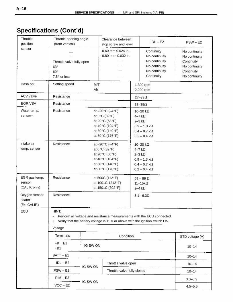
HINT:• Perform all voltage and resistance measurements with the ECU connected.• Verity that the battery voltage is 11 V or above with the ignition switch ON.
— —Throttle valve fully open63697.5 or less
0.60 mm 0.024 in.0.80 m m 0.032 in. — — — —
at –20C (–4F)at 0C (32F)at 20C (68F)at 40C (104F)at 60C (140F)at 80C (176F)
at –20C (–4F)at 0C (32F)at 20C (68F)at 40C (104F)at 60C (140F)at 80C (176F)
No continuityNo continuityContinuityNo continuityContinuityNo continuity
ContinuityNo continuityNo continuityNo continuityNo continuityContinuity
10–20 k4–7 k2–3 k0.9 – 1.3 k0.4 – 0.7 k0.2 – 0.4 k
10–20 k4–7 k2–3 k0.9 – 1.3 k0.4 – 0.7 k0.2 – 0.4 k
Specifications (Cont’d)
at 500C (112F)at 1001C 1212F)at 1501C (302F)
Throttle opening angle(from vertical)
Oxygen sensorheater(Ex. CALIF.)
EGR gas temp.sensor(CALIF. only)
Clearance betweenstop screw and lever
Throttle valve fully closed
69 – 89 11–15k2–4 k
Intake airtemp. sensor
Water temp.sensor–
Throttlepositionsensor
Throttle valve open
1,800 rpm2,200 rpm
+B _ E1+B1
STD voltage (V)
Setting speed
BATT – E1
Resistance
Resistance
Resistance
Resistance
Resistance
PSW – E2
Resistance
IG SW ON
ACV valve
5.1 –6.3
IG SW ON
Terminals
!G SW ON
VCC – E2
PIM – E2
IDL – E2
Condition
Dash pot
EGR VSV
PSW – E2
33–39
M/TAfr
Voltage
27–33
IDL – E2
3.3–3.9
4.5–5.5
10–14
10–14
10–14
10–14
ECU
–SERVICE SPECIFICATIONS MFI and SFI Systems (4A–FE)A–16
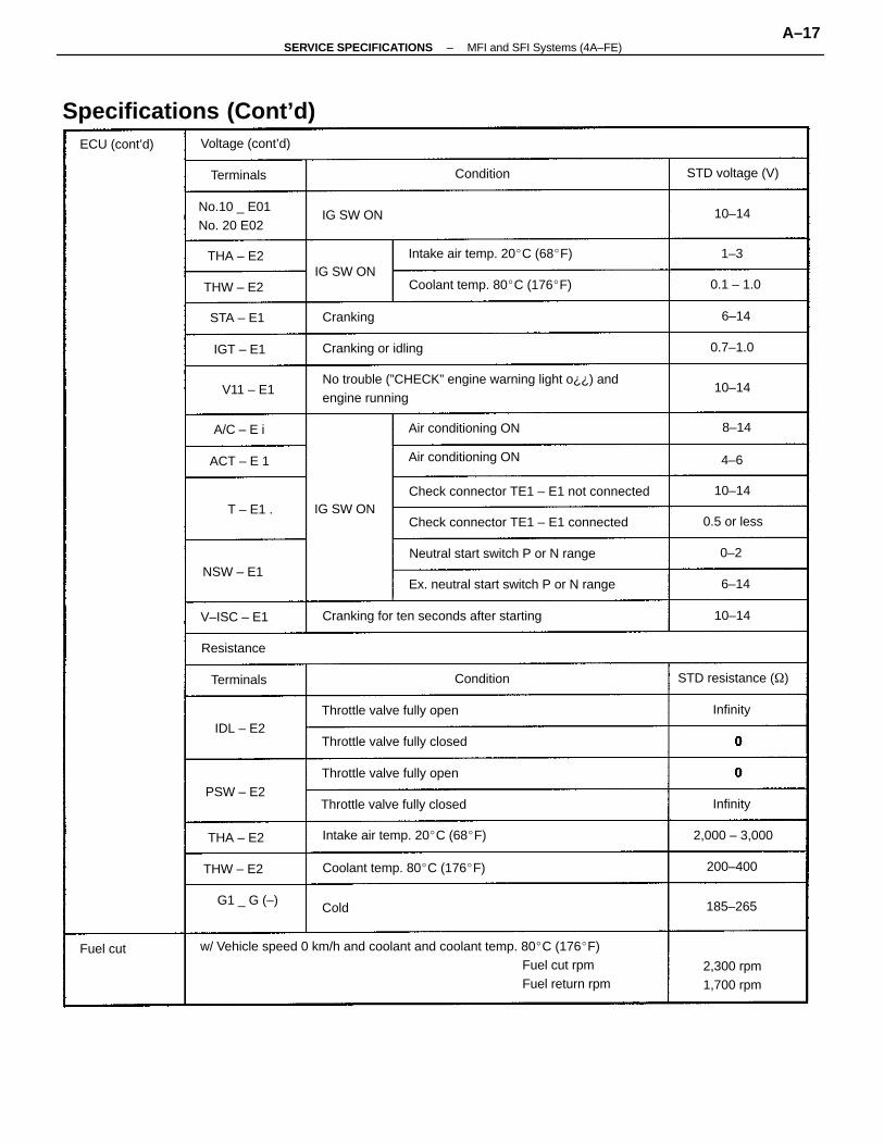
w/ Vehicle speed 0 km/h and coolant and coolant temp. 80C (176F)Fuel cut rpmFuel return rpm
No trouble (”CHECK” engine warning light o¿¿) andengine running
Specifications (Cont’d)
Cranking for ten seconds after starting
Check connector TE1 – E1 not connected
Ex. neutral start switch P or N range
Check connector TE1 – E1 connected
Neutral start switch P or N range
Intake air temp. 20C (68F)
Intake air temp. 20C (68F)
Coolant temp. 80C (176F)
Coolant temp. 80C (176F)
Throttle valve fully closed
Throttle valve fully closed
Throttle valve fully open
Throttle valve fully open
No.10 _ E01No. 20 E02
Air conditioning ON
Air conditioning ON
G1 _ G (–)
2,300 rpm1,700 rpm
STD resistance ()
Cranking or idling
Voltage (cont’d)
STD voltage (V)
2,000 – 3,000
Terminals
ECU (cont’d)
V–ISC – E1
NSW – E1
T – E1 .
Resistance
THW – E2
PSW – E2
THW – E2
STA – E1
0.5 or less
ACT – E 1
THA – E2
IG SW ON
Terminals
IG SW ON
THA – E2
IG SW ON
IGT – E1
A/C – E i
IDL – E2
Cranking
Condition
Condition
200–400
185–265
V11 – E1
0.7–1.0
0.1 – 1.0
Fuel cut
Infinity
Infinity
10–14
10–14
10–14
10–14
8–14
6–14
6–14
0–2
1–3
Cold
4–6
–SERVICE SPECIFICATIONS MFI and SFI Systems (4A–FE)A–17
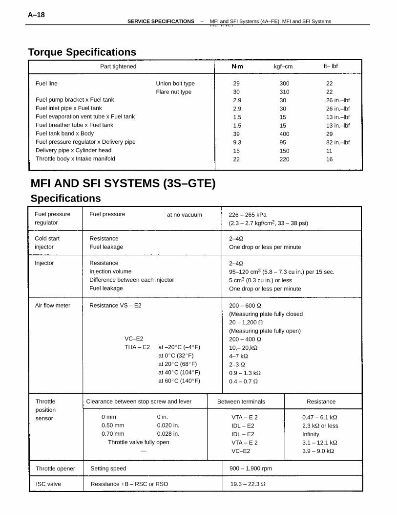
Fuel pump bracket x Fuel tankFuel inlet pipe x Fuel tankFuel evaporation vent tube x Fuel tankFuel breather tube x Fuel tankFuel tank band x BodyFuel pressure regulator x Delivery pipeDelivery pipe x Cylinder headThrottle body x Intake manifold
200 – 600 (Measuring plate fully closed20 – 1,200 (Measuring plate fully open)200 – 400 10,– 20,k4–7 k2–3 0.9 – 1.3 k0.4 – 0.7
VC–E2THA – E2 at –20C (–4F)
at 0C (32F)at 20C (68F)at 40C (104F)at 60C (140F)
2–495–120 cm3 (5.8 – 7.3 cu in.) per 15 sec.5 cm3 (0.3 cu in.) or lessOne drop or less per minute
0 mm 0 in.0.50 mm 0.020 in.0.70 mm 0.028 in. Throttle valve fully open —
ResistanceInjection volumeDifference between each injectorFuel leakage
MFI AND SFI SYSTEMS (3S–GTE)Specifications
222226 in.–lbf26 in.–lbf13 in.–lbf13 in.–lbf2982 in.–lbf1116
0.47 – 6.1 k2.3 k or lessInfinity3.1 – 12.1 k3.9 – 9.0 k
226 – 265 kPa(2.3 – 2.7 kgf/cm2, 33 – 38 psi)
2–4One drop or less per minute
29302.92.91.51.5399.31522
3003103030151540095150220
Clearance between stop screw and lever
VTA – E 2IDL – E2IDL – E2VTA – E 2VC–E2
Torque Specifications
Resistance +B – RSC or RSO
Union bolt typeFlare nut type
ResistanceFuel leakage
Fuel pressureregulator
Throttlepositionsensor
Resistance VS – E2
Between terminals
Cold startinjector
Throttle opener 900 – 1,900 rpm
Part tightened
Setting speed
Air flow meter
Fuel pressure at no vacuum
19.3 – 22.3
Resistance
ISC valve
Injector
Fuel line
kgf–cm ft– lbf
–SERVICE SPECIFICATIONS MFI and SFI Systems (4A–FE), MFI and SFI Systems(3S GTE)
A–18
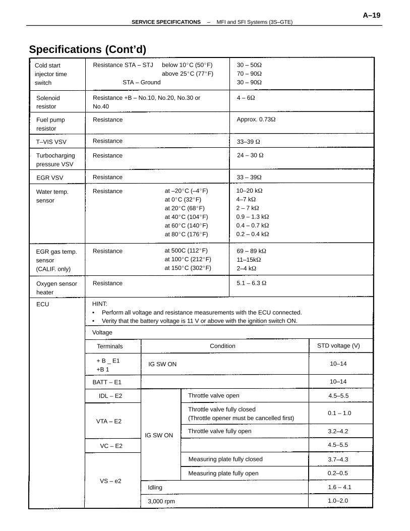
HINT:• Perform all voltage and resistance measurements with the ECU connected.• Verity that the battery voltage is 11 V or above with the ignition switch ON.
Resistance STA – STJ below 10C (50F)above 25C (77F)
STA – Ground
10–20 k4–7 k2 – 7 k0.9 – 1.3 k0.4 – 0.7 k0.2 – 0.4 k
at –20C (–4F)at 0C (32F)at 20C (68F)at 40C (104F)at 60C (140F)at 80C (176F)
Throttle valve fully closed(Throttle opener must be cancelled first)
Resistance +B – No.10, No.20, No.30 orNo.40
Specifications (Cont’d)
at 500C (112F)at 100C (212F)at 150C (302F)
Cold startinjector timeswitch
EGR gas temp.sensor(CALIF. only)
Measuring plate fully closed
Measuring plate fully open
69 – 89 k11–15k2–4 k
30 – 5070 – 9030 – 90
Turbochargingpressure VSV
Throttle valve fully open
Oxygen sensorheater
Water temp.sensor
Throttle valve open
Fuel pumpresistor
Resistance
+ B _ E1+B 1
STD voltage (V)
Solenoidresistor
Resistance
Approx. 0.73
BATT – E1
Resistance
Resistance
Resistance
3,000 rpm
Resistance
Resistance
T–VIS VSV
IG SW ON
Terminals
IG SW ON
5.1 – 6.3
VTA – E2
EGR VSV
IDL – E2
Condition
24 – 30
33–39
33 – 39
VC – E2
Voltage
VS – e2
0.1 – 1.0
1.0–2.0
0.2–0.5
4.5–5.5
3.7–4.3
1.6 – 4.1
3.2–4.2
4.5–5.5
10–14
10–14
4 – 6
Idling
ECU
–SERVICE SPECIFICATIONS MFI and SFI Systems (3S–GTE)A–19
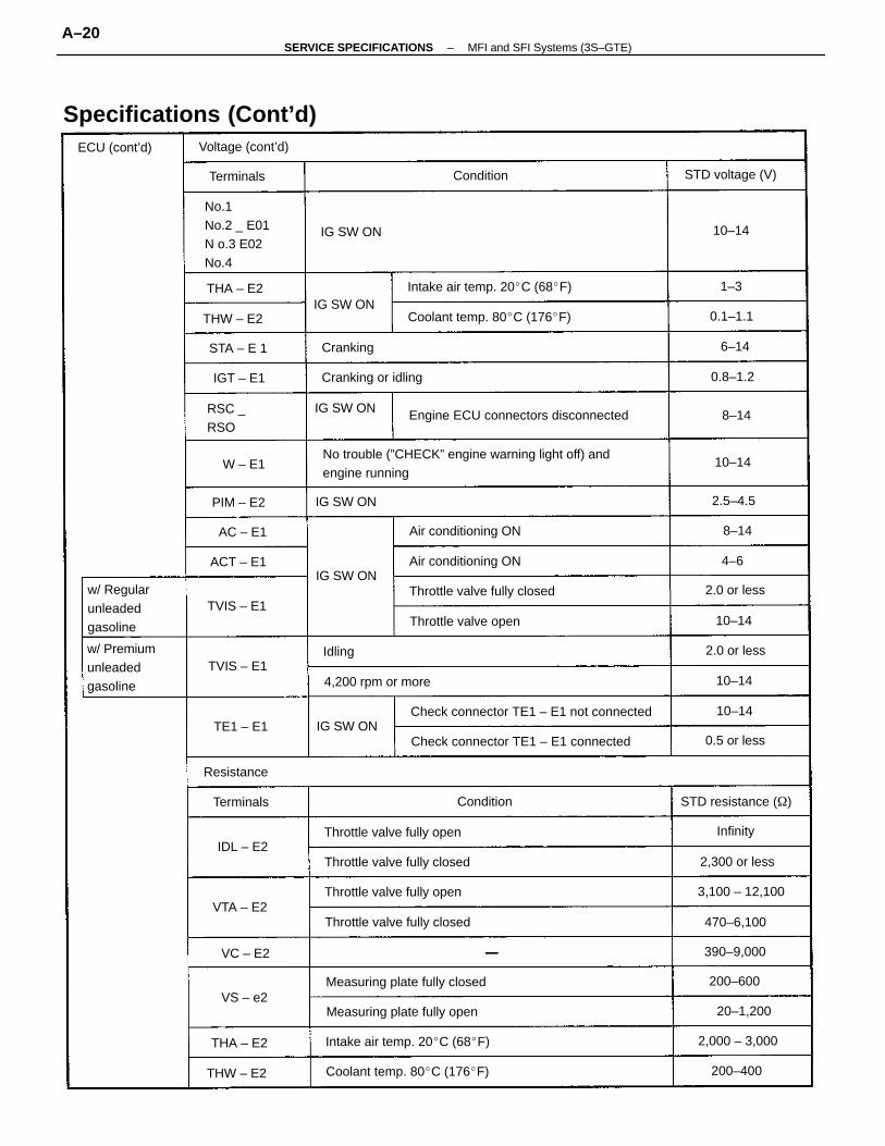
No trouble (”CHECK” engine warning light off) andengine running
Specifications (Cont’d)
No.1No.2 _ E01N o.3 E02No.4
Engine ECU connectors disconnected
Check connector TE1 – E1 not connected
Check connector TE1 – E1 connected
w/ Premiumunleadedgasoline
Measuring plate fully closed
Intake air temp. 20C (68F)
Intake air temp. 20C (68F)
w/ Regularunleadedgasoline
Coolant temp. 80C (176F)
Coolant temp. 80C (176F)
Measuring plate fully open
Throttle valve fully closed
Throttle valve fully closed
Throttle valve fully closed
Throttle valve fully open
Throttle valve fully open
Air conditioning ON
Air conditioning ON
Throttle valve open
4,200 rpm or more
STD resistance ()
Cranking or idling
RSC _RSO
Voltage (cont’d)
STD voltage (V)
3,100 – 12,100
2,000 – 3,000
IG SW ON
2,300 or less
ECU (cont’d)
390–9,000
470–6,100
TVIS – E1
TVIS – E1
Resistance
THW – E2
THW – E2
20–1,200
IG SW ON
ACT – E1
0.5 or less
2.0 or less
Terminals
2.0 or less
THA – E2
IG SW ON
THA – E2
IG SW ON
Terminals
IG SW ON
IG SW ON
PIM – E2
STA – E 1
TE1 – E1
VTA – E2
200–600
Condition
Condition
IGT – E1
Cranking
200–400
IDL – E2
AC – E1
VC – E2
VS – e2
W – E1
0.1–1.1
0.8–1.2
2.5–4.5
Infinity
10–14
10–14
10–14
10–14
10–14
Idling
6–14
8–14
8–14
4–6
1–3
–SERVICE SPECIFICATIONS MFI and SFI Systems (3S–GTE)A–20
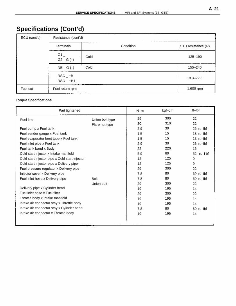
Fuel pump x Fuel tankFuel sender gauge x Fuel tankFuel evaporator bent tube x Fuel tankFuel inlet pipe x Fuel tankFuel tank band x BodyCold start injector x Intake manifoldCold start injector pipe x Cold start injectorCold start injector pipe x Delivery pipeFuel pressure regulator x Delivery pipeInjector cover x Delivery pipeFuel inlet hose x Delivery pipe
Delivery pipe x Cylinder headFuel inlet hose x Fuel filterThrottle body x Intake manifoldIntake air connector stay x Throttle bodyIntake air connector stay x Cylinder headIntake air connector x Throttle body
222226 in.–Ibf13 in.–Ibf13 in.–Ibf26 in.–Ibf1652 i n.–I bf992269 in.–Ibf69 in.–Ibf221422141469 in.–Ibf14
29302.91.51.52.9225.91212297.87.829192919197.819
3003103015153022060125125300808030019530019519580195
Specifications (Cont’d)
Torque Specifications
Union bolt typeFlare nut type
Resistance (cont’d)
BoltUnion bolt
STD resistance ()
G1 _G2 G (–)
Fuel return rpm
Part tightened
ECU (cont’d)
1,600 rpm
Terminals
19.3–22.3
Condition
155–240
125–190
Fuel line
Fuel cut
kgf–cm ft–lbf
Cold
Cold
N–m
NE – G (–)
RSC _ +BRSO +B1
–SERVICE SPECIFICATIONS MFI and SFI Systems (3S–GTE)A–21
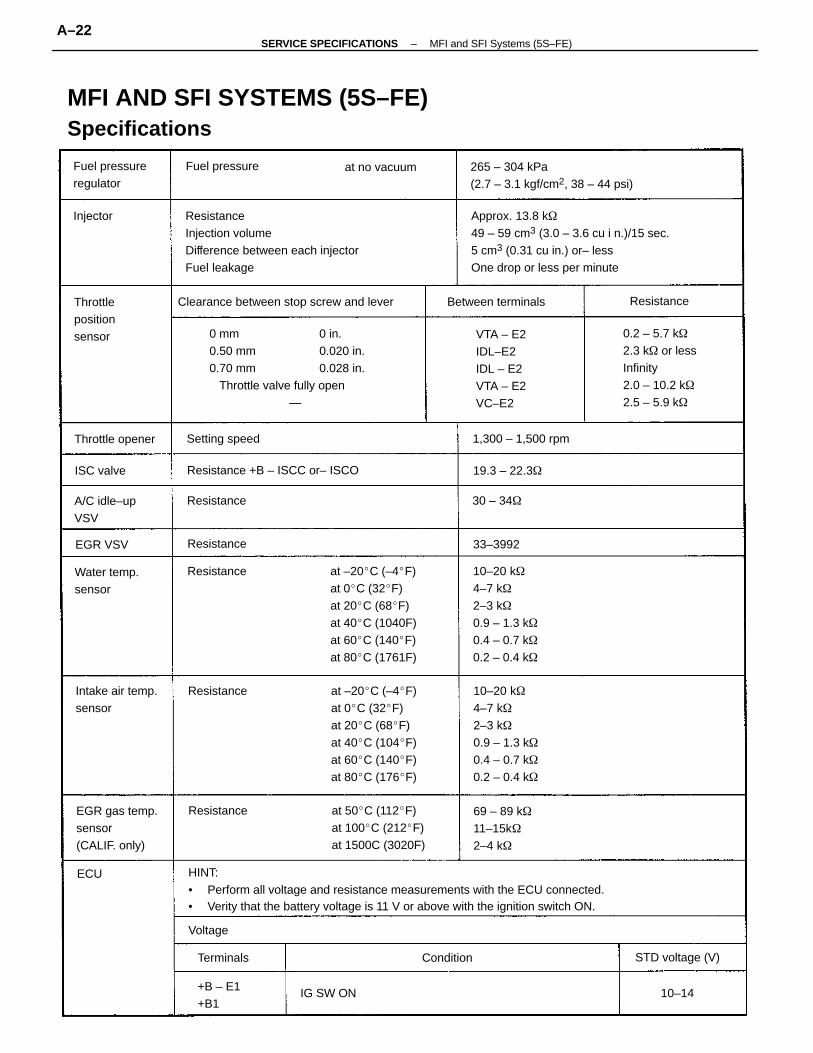
HINT:• Perform all voltage and resistance measurements with the ECU connected.• Verity that the battery voltage is 11 V or above with the ignition switch ON.
0 mm 0 in.0.50 mm 0.020 in.0.70 mm 0.028 in. Throttle valve fully open —
Approx. 13.8 k49 – 59 cm3 (3.0 – 3.6 cu i n.)/15 sec.5 cm3 (0.31 cu in.) or– lessOne drop or less per minute
ResistanceInjection volumeDifference between each injectorFuel leakage
MFI AND SFI SYSTEMS (5S–FE)Specifications
at –20C (–4F)at 0C (32F)at 20C (68F)at 40C (1040F)at 60C (140F)at 80C (1761F)
at –20C (–4F)at 0C (32F)at 20C (68F)at 40C (104F)at 60C (140F)at 80C (176F)
10–20 k4–7 k2–3 k0.9 – 1.3 k0.4 – 0.7 k0.2 – 0.4 k
10–20 k4–7 k2–3 k0.9 – 1.3 k0.4 – 0.7 k0.2 – 0.4 k
0.2 – 5.7 k2.3 k or lessInfinity2.0 – 10.2 k2.5 – 5.9 k
265 – 304 kPa(2.7 – 3.1 kgf/cm2, 38 – 44 psi)
at 50C (112F)at 100C (212F)at 1500C (3020F)
Clearance between stop screw and lever
VTA – E2IDL–E2IDL – E2VTA – E2VC–E2
EGR gas temp.sensor(CALIF. only)
Resistance +B – ISCC or– ISCO
69 – 89 k11–15k2–4 k
Intake air temp.sensor
Fuel pressureregulator
Water temp.sensor
Throttlepositionsensor
Between terminals
A/C idle–upVSV
1,300 – 1,500 rpm
+B – E1+B1
STD voltage (V)
Throttle opener Setting speed
Fuel pressure at no vacuum
19.3 – 22.3
Resistance
Resistance
Resistance
Resistance
Resistance
Resistance
Terminals
IG SW ON
Condition
30 – 34
ISC valve
EGR VSV
Injector
33–3992
Voltage
10–14
ECU
–SERVICE SPECIFICATIONS MFI and SFI Systems (5S–FE)A–22
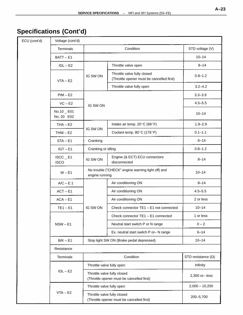
No trouble (”CHECK” engine warning light off) andengine running
Throttle valve fully closed(Throttle opener must be cancelled first)
Throttle valve fully closed(Throttle opener must be cancelled first)
Throttle valve fully closed(Throttle opener must be cancelled first)
Engine (& ECT) ECU connectorsdisconnected
Stop light SW ON (Brake pedal depressed)
Specifications (Cont’d)
Check connector TE1 – E1 not connected
Ex. neutral start switch P or– N range
Check connector TE1 – E1 connected
Neutral start switch P or N range
Intake air temp. 20C (68F)
Coolant temp. 80C (176F)
Throttle valve fully open
Throttle valve fully open
Throttle valve fully open
No.10 _ E01No. 20 E02
Air conditioning ON
Air conditioning ON
Air conditioning ON
Throttle valve open
ISCC _ E1ISCO
STD resistance ()
Cranking or idling
Voltage (cont’d)
STD voltage (V)
2,000 – 10,200
2,300 or– less
ECU (cont’d)
200–5,700
NSW – E1
BATT – E1
Resistance
THW – E2
ACA – E1
IG SW ON
STA – E1
Terminals
ACT – E1
B/K – E1
PIM – E2
IG SW ON
IG SW ON
Terminals
IG SW ON
IG SW ON
THA – E2
A/C – E 1
TE1 – E1
VTA – E2
VTA – E2
IDL – E2
IGT – E1
Condition
Condition
Cranking
IDL – E2
VC – E2
W – E1
2 or less
1 or less
0.8–1.2
0.1–1.1
0.8–1.2
1.9–2.9
4.5–5.5
3.2–4.2
3.3–3.9
4.5–5.5
Infinity
10–14
10–14
10–14
10–14
10–14
6–14
8–14
8–14
6–14
8–14
0 – 2
–SERVICE SPECIFICATIONS MFI and SFI Systems (5S–FE)A–23
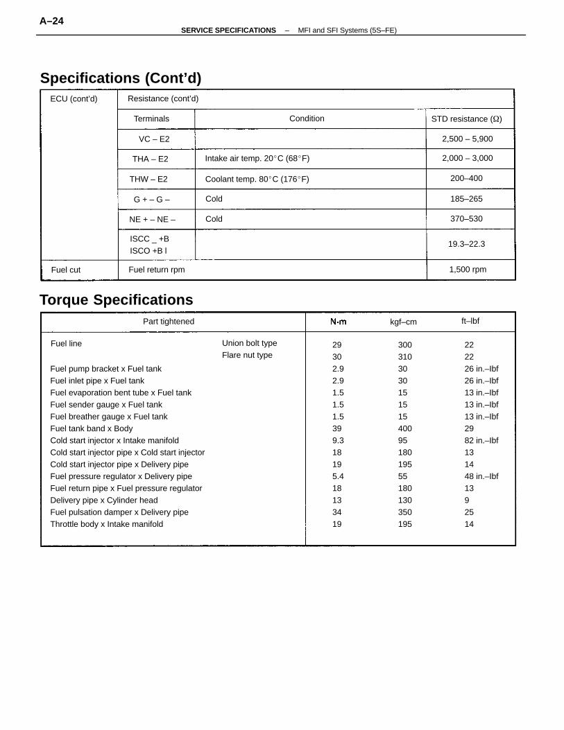
Fuel pump bracket x Fuel tankFuel inlet pipe x Fuel tankFuel evaporation bent tube x Fuel tankFuel sender gauge x Fuel tankFuel breather gauge x Fuel tankFuel tank band x BodyCold start injector x Intake manifoldCold start injector pipe x Cold start injectorCold start injector pipe x Delivery pipeFuel pressure regulator x Delivery pipeFuel return pipe x Fuel pressure regulatorDelivery pipe x Cylinder headFuel pulsation damper x Delivery pipeThrottle body x Intake manifold
222226 in.–Ibf26 in.–Ibf13 in.–Ibf13 in.–Ibf13 in.–Ibf2982 in.–Ibf131448 in.–Ibf1392514
29302.92.91.51.51.5399.318195.418133419
30031030301515154009518019555180130350195
Specifications (Cont’d)
Torque Specifications
Union bolt typeFlare nut type
Intake air temp. 20C (68F)
Coolant temp. 80C (176F)
ISCC _ +BISCO +B l
Resistance (cont’d)
STD resistance ()
Fuel return rpm
Part tightened
NE + – NE –
2,000 – 3,000
2,500 – 5,900
ECU (cont’d)
G + – G –
THW – E2
1,500 rpm
19.3–22.3
Terminals
THA – E2
200–400
370–530
Condition
185–265
VC – E2
Fuel line
Fuel cut
kgf–cm ft–lbf
Cold
Cold
–SERVICE SPECIFICATIONS MFI and SFI Systems (5S–FE)A–24
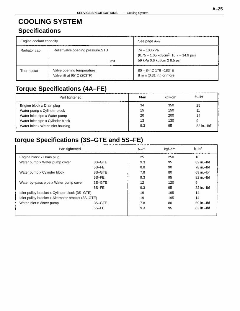
Engine block x Drain plugWater pump x Cylinder blockWater inlet pipe x Water pumpWater inlet pipe x Cylinder blockWater inlet x Water inlet housing
74 – 103 kPa(0.75 – 1.05 kgf/cm2, 10.7 – 14.9 psi)59 kPa 0.6 kgf/cm 2 8.5 psi
1882 in.–Ibf78 in.–Ibf69 in.–lbf82 in.–Ibf982 in.–Ibf141469 in.–Ibf82 in.–Ibf
torque Specifications (3S–GTE and 5S–FE)
COOLING SYSTEMSpecifications
Engine block x Drain plugWater pump x Water pump cover 3S–GTE
5S–FEWater pump x Cylinder block 3S–GTE
5S–FEWater by–pass pipe x Water pump cover 3S–GTE
5S–FEIdler pulley bracket x Cylinder block (3S–GTE)Idler pulley bracket x Alternator bracket (3S–GTE)Water inlet x Water pump 3S–GTE
5S–FE
80 – 84C 176 –183E8 mm (0.31 in.) or more
Torque Specifications (4A–FE)
Valve opening temperatureValve lift at 95C (203F)
251114982 in.–Ibf
Relief valve opening pressure STD
Engine coolant capacity
341520139.3
35015020013095
Part tightened
Part tightened
See page A–2
Radiator cap
Thermostat
kgf–cm
kgf–cm
Limit
ft– lbf
ft–lbfN–m
259.38.87.89.3129.319197.89.3
25095908095120951951958095
–SERVICE SPECIFICATIONS Cooling SystemA–25
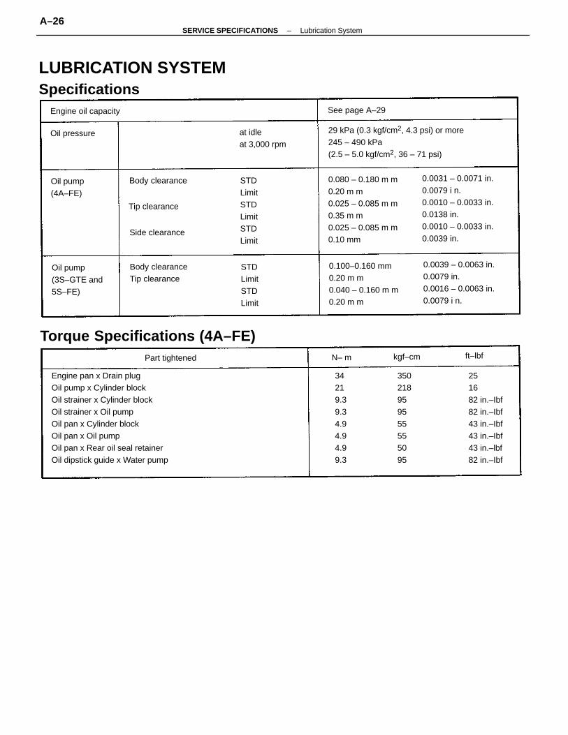
Engine pan x Drain plugOil pump x Cylinder blockOil strainer x Cylinder blockOil strainer x Oil pumpOil pan x Cylinder blockOil pan x Oil pumpOil pan x Rear oil seal retainerOil dipstick guide x Water pump
0.0031 – 0.0071 in.0.0079 i n.0.0010 – 0.0033 in.0.0138 in.0.0010 – 0.0033 in.0.0039 in.
29 kPa (0.3 kgf/cm2, 4.3 psi) or more245 – 490 kPa(2.5 – 5.0 kgf/cm2, 36 – 71 psi)
LUBRICATION SYSTEMSpecifications
0.080 – 0.180 m m0.20 m m0.025 – 0.085 m m0.35 m m0.025 – 0.085 m m0.10 mm
0.0039 – 0.0063 in.0.0079 in.0.0016 – 0.0063 in.0.0079 i n.
251682 in.–Ibf82 in.–Ibf43 in.–Ibf43 in.–Ibf43 in.–lbf82 in.–Ibf
0.100–0.160 mm0.20 m m0.040 – 0.160 m m0.20 m m
Torque Specifications (4A–FE)
Body clearanceTip clearance
34219.39.34.94.94.99.3
Oil pump(3S–GTE and5S–FE)
STDLimitSTDLimitSTDLimit
at idleat 3,000 rpm
STDLimitSTDLimit
Engine oil capacity
Oil pump(4A–FE)
Body clearance
Part tightened
See page A–29
Tip clearance
Side clearance
Oil pressure
kgf–cm ft–lbfN– m
350218959555555095
–SERVICE SPECIFICATIONS Lubrication SystemA–26
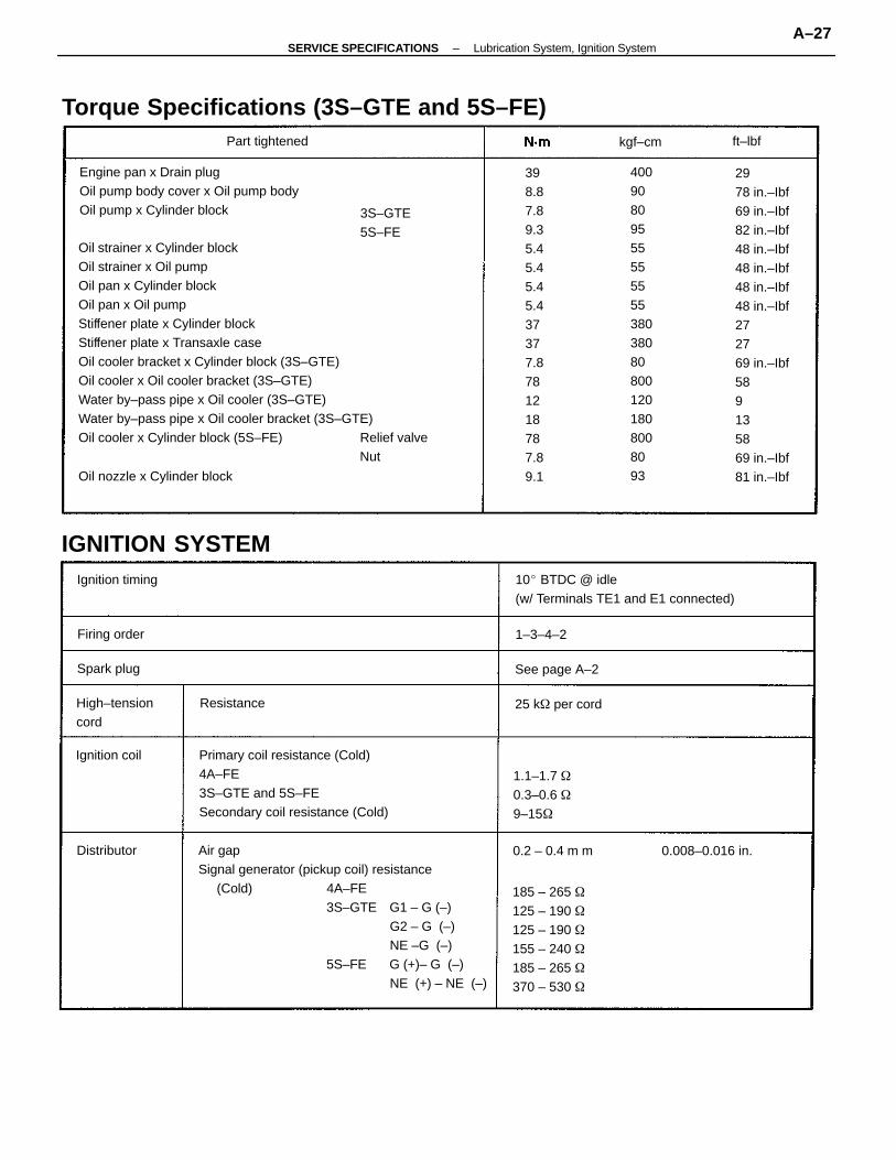
Oil strainer x Cylinder blockOil strainer x Oil pumpOil pan x Cylinder blockOil pan x Oil pumpStiffener plate x Cylinder blockStiffener plate x Transaxle caseOil cooler bracket x Cylinder block (3S–GTE)Oil cooler x Oil cooler bracket (3S–GTE)Water by–pass pipe x Oil cooler (3S–GTE)Water by–pass pipe x Oil cooler bracket (3S–GTE)Oil cooler x Cylinder block (5S–FE) Relief valve
Nut
Air gapSignal generator (pickup coil) resistance
(Cold) 4A–FE3S–GTE G1 – G (–)
G2 – G (–)NE –G (–)
5S–FE G (+)– G (–)NE (+) – NE (–)
2978 in.–Ibf69 in.–Ibf82 in.–Ibf48 in.–Ibf48 in.–Ibf48 in.–Ibf48 in.–Ibf272769 in.–Ibf589135869 in.–Ibf81 in.–Ibf
Primary coil resistance (Cold)4A–FE3S–GTE and 5S–FESecondary coil resistance (Cold)
Engine pan x Drain plugOil pump body cover x Oil pump bodyOil pump x Cylinder block
398.87.89.35.45.45.45.437377.8781218787.89.1
Torque Specifications (3S–GTE and 5S–FE)
40090809555555555380380808001201808008093
10 BTDC @ idle(w/ Terminals TE1 and E1 connected)
185 – 265 125 – 190 125 – 190 155 – 240 185 – 265 370 – 530
IGNITION SYSTEM
1.1–1.7 0.3–0.6 9–15
Oil nozzle x Cylinder block
High–tensioncord
0.008–0.016 in.
Ignition timing
Part tightened
25 k per cord
3S–GTE5S–FE
See page A–2
0.2 – 0.4 m m
Ignition coil
Firing order
Spark plug
Distributor
Resistance
1–3–4–2
kgf–cm ft–lbf
–SERVICE SPECIFICATIONS Lubrication System, Ignition SystemA–27
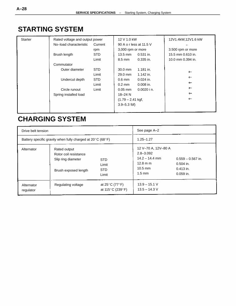
Rated voltage and output powerNo–load characteristic Current
rpmBrush length STD
LimitCommutator
Outer diameter STDLimit
Undercut depth STDLimit
Circle runout LimitSpring installed load
12 V–70 A, 12V–80 A2.8–3.09214.2 – 14.4 mm12.8 m m10.5 mm1.5 mm
12V1.4kW,12V1.6 kW ←3.500 rpm or more15.5 mm 0.610 in.10.0 mm 0.394 in.
12 V 1.0 kW90 A o r less at 11.5 V3,000 rpm or more13.5 mm 0.531 in.8.5 mm 0.335 in.
30.0 mm 1.181 in.29.0 mm 1.142 in.0.6 mm 0.024 in.0.2 mm 0.008 in.0.05 mm 0.0020 i n.18–24 N(1.79 – 2.41 kgf,3.9–5.3 !bf)
Battery specific gravity when fully charged at 20C (68F)
CHARGING SYSTEM
0.559 – 0.567 in.0.504 in.0.413 in.0.059 in.
Rated outputRotor coil resistanceSlip ring diameter
STARTING SYSTEM
at 25C (77F)at 115C (239F)
13.9 – 15.1 V13.5 – 14.3 V
Brush exposed length
STDLimitSTDLimit
Regulating voltageAlternatorregulator
Drive belt tension See page A–2
Alternator
1.25–1.27
Starter
–SERVICE SPECIFICATIONS Starting System, Charging SystemA–28
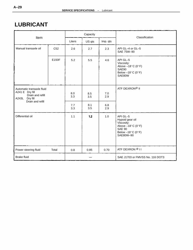
API GL–5Hypoid gear oilViscosity:Above –18C (0F)SAE 90Below –18C (0F)SAE80W–90
Automatic transaxle fluidA241 E Dry fill Drain and refillA243L Dry fill Drain and refill
API GL–5Viscosity:Above –18C (0F)SAE90Below –18C (0F)SAE80W
SAE J1703 or FMVSS No. 116 DOT3
API GL–4 or GL–5SAE 75W–90
Power steering fluid
Manual transaxle oil
LUBRICANT
ATF DEXRON @ I I
ATF DEXRON@ II
Differential oil
Classification
Brake fluid
Capacity
Imp. qts
8.03.3
7.02.9
8.53.5
8.13.5
6.82.9
US qts
7.73.3
E150F
Liters
Total
Item
0.700.85
C52
1.0
0.8
2.6
4.6
2.3
1.1
5.2 5.5
2.7
–SERVICE SPECIFICATIONS LubricantA–29
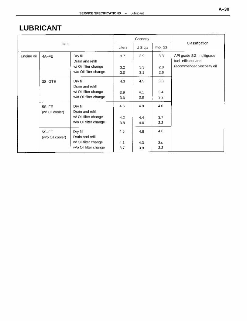
Dry fillDrain and refillw/ Oil filter changew/o Oil filter change
Dry fillDrain and refillw/ Oil filter changew/o Oil filter change
Dry fillDrain and refillw/ Oil filter changew/o Oil filter change
Dry fillDrain and refillw/ Oil filter changew/o Oil filter change
API grade SG, multigradefuel–efficient andrecommended viscosity oil
5S–FE(w/o Oil cooler)
5S–FE(w/ Oil cooler)
LUBRICANT
Classification
Engine oil
Capacity
Imp. qts
3.23.0
3.43.2
4.44.0
3S–GTE
4.13.8
U S qts
3.73.3
4.33.9
4.23.8
4.13.7
3.93.6
3.33.1
2.82.6
3.s3.3
4A–FE
LitersItem
4.0
4.04.5
4.94.6
4.8
3.8
3.3
4.3 4.5
3.93.7
–SERVICE SPECIFICATIONS LubricantA–30
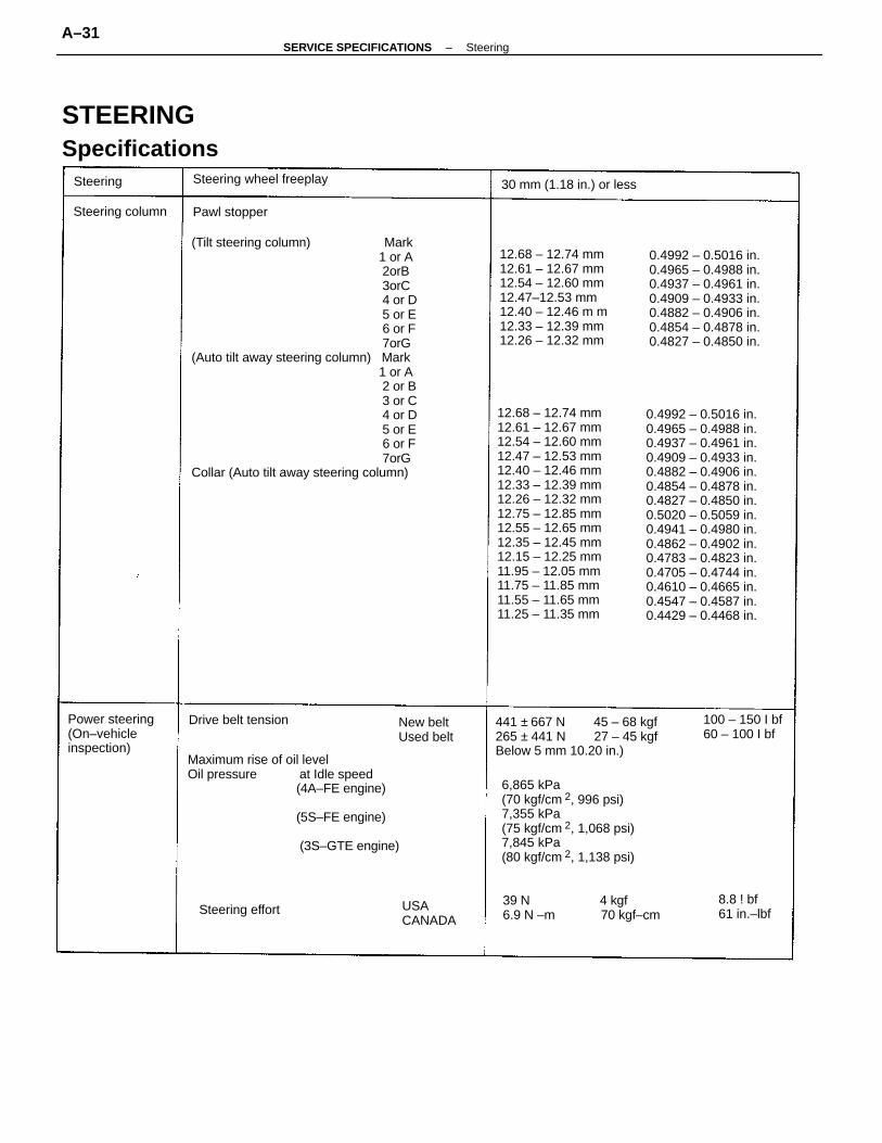
(Tilt steering column) Mark 1 or A 2orB 3orC 4 or D 5 or E 6 or F 7orG(Auto tilt away steering column) Mark 1 or A 2 or B 3 or C 4 or D 5 or E 6 or F 7orGCollar (Auto tilt away steering column)
0.4992 – 0.5016 in.0.4965 – 0.4988 in.0.4937 – 0.4961 in.0.4909 – 0.4933 in.0.4882 – 0.4906 in.0.4854 – 0.4878 in.0.4827 – 0.4850 in.0.5020 – 0.5059 in.0.4941 – 0.4980 in.0.4862 – 0.4902 in.0.4783 – 0.4823 in.0.4705 – 0.4744 in.0.4610 – 0.4665 in.0.4547 – 0.4587 in.0.4429 – 0.4468 in.
12.68 – 12.74 mm12.61 – 12.67 mm12.54 – 12.60 mm12.47 – 12.53 mm12.40 – 12.46 mm12.33 – 12.39 mm12.26 – 12.32 mm12.75 – 12.85 mm12.55 – 12.65 mm12.35 – 12.45 mm12.15 – 12.25 mm11.95 – 12.05 mm11.75 – 11.85 mm11.55 – 11.65 mm11.25 – 11.35 mm
Maximum rise of oil levelOil pressure at Idle speed (4A–FE engine)
(5S–FE engine)
(3S–GTE engine)
6,865 kPa(70 kgf/cm 2, 996 psi)7,355 kPa(75 kgf/cm 2, 1,068 psi)7,845 kPa(80 kgf/cm 2, 1,138 psi)
0.4992 – 0.5016 in.0.4965 – 0.4988 in.0.4937 – 0.4961 in.0.4909 – 0.4933 in.0.4882 – 0.4906 in.0.4854 – 0.4878 in.0.4827 – 0.4850 in.
12.68 – 12.74 mm12.61 – 12.67 mm12.54 – 12.60 mm12.47–12.53 mm12.40 – 12.46 m m12.33 – 12.39 mm12.26 – 12.32 mm
441 ± 667 N 45 – 68 kgf265 ± 441 N 27 – 45 kgfBelow 5 mm 10.20 in.)
STEERINGSpecifications
Pawl stopper
Power steering(On–vehicleinspection)
Steering wheel freeplay 30 mm (1.18 in.) or less
100 – 150 I bf60 – 100 I bf
New beltUsed belt
USACANADA
8.8 ! bf61 in.–lbf
Drive belt tension
Steering column
Steering effort
Steering
39 N 4 kgf6.9 N –m 70 kgf–cm
–SERVICE SPECIFICATIONS SteeringA–31

Rotor shaft bushing oil clearance STDMaximumVane plate to rotor groove clearanceVane plate Minimum heightMinimum thicknessMinimum lengthVane plate length Rotor and cam ring mark None 1 2 3 4Flow control valve spring length STD Minimum
14.996 – 14.998 mm 0.59039 – 0.59047 in.14.994 – 14.996 mm 0.59032 – 0.59039 in.14.992 – 14.994 mm 0.59024 – 0.59032 in.14.990 – 14.992 mm 0.59016 – 0.59024 in.14.988 – 14.990 mm 0.59008 – 0.59016 in.38 mm 1.49 in.36 mm 1.42 in.0.3 N–m (2.8 kgf–cm, 2.4 in.–lbf) or less
Main shaft x Steering wheelSteering wheel pad (w/ airbag)Column tube x BodyColumn tube attachment x Brake pedal bracketUniversal joint
Tilt memory boltTilt lever bracket installation boltTilt lever retainer set nut
No. 2 tilt memory plate set nut
Tilt lever assembly installation boltTilt pawl set nutTilt lever retainer set nutCompression spring bushing boltMain shaft x Intermediate shaft
0.3 mm 0.012 in.0.4 – 0.6 N–m (4.5 – 6.5 kgf–cm, 3.9 – 5.6 in.–lbf)0.9 – 1.2 N–m (9 – 12 kgf–cm, 7.8 – 10.4 in.–lbf)
0.0004 – 0.0012 in.0.0028 in.0.0012 in.0.315 in.0.0697 in.0.5894 in.
0.01 – 0.03 mm0.07 mm.0.03 mm8.0 mm1.77 mm14.97 mm
Steering rack runoutBearing preload (turning)Total preload (turning)
56 i n.–I bf26 in.–lbf1126 in.–lbf1152 in.–lbf69 in.–lbf26
6.42.9152.9155.97.835
2665 i n.–lbf19926
Specifications (Cont’d)
Steering column(Non–tiltsteering column)
Torque Specifications
26 in.–lbf52 in.–lbf1169 in.–lbf26
357.4251235
Main shaft x Intermediate shaft
(Tilt steeringcolumn)
(Auto tilt awaysteering column)
(Power steeringpump) .
14 mm8 mm14 mm10 mm
(Removal andinstallation)
2.95.9157.835
306015080360
36075260120360
Pump rotating torque
(Gear housing)
Part tightened
Maximum
kgf–cm ft–lbf
360
6530150306080360
Compression spring bushing boltMain shaft x Intermediate shaft
–SERVICE SPECIFICATIONS SteeringA–32
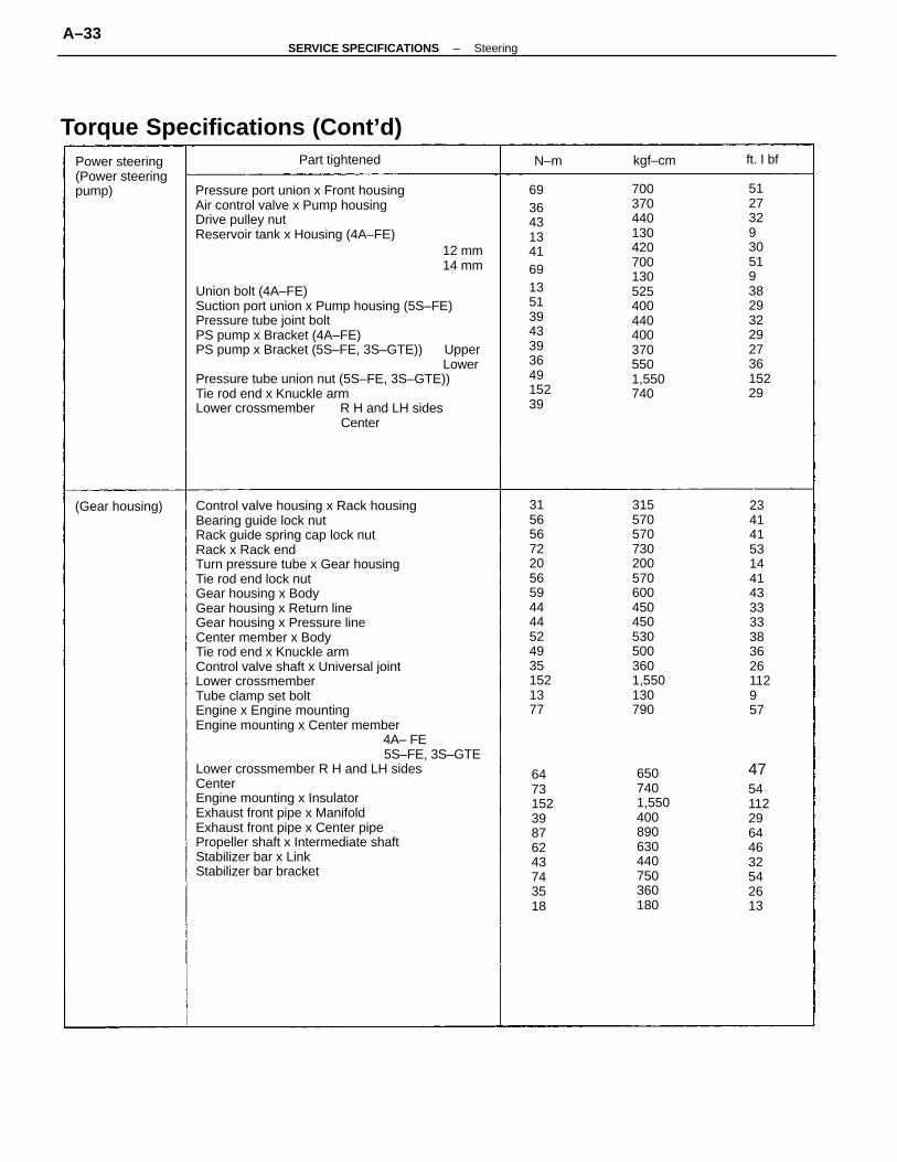
Control valve housing x Rack housingBearing guide lock nutRack guide spring cap lock nutRack x Rack endTurn pressure tube x Gear housingTie rod end lock nutGear housing x BodyGear housing x Return lineGear housing x Pressure lineCenter member x BodyTie rod end x Knuckle armControl valve shaft x Universal jointLower crossmemberTube clamp set boltEngine x Engine mountingEngine mounting x Center member 4A– FE 5S–FE, 3S–GTELower crossmember R H and LH sidesCenterEngine mounting x InsulatorExhaust front pipe x ManifoldExhaust front pipe x Center pipePropeller shaft x Intermediate shaftStabilizer bar x LinkStabilizer bar bracket
Union bolt (4A–FE)Suction port union x Pump housing (5S–FE)Pressure tube joint boltPS pump x Bracket (4A–FE)PS pump x Bracket (5S–FE, 3S–GTE)) Upper LowerPressure tube union nut (5S–FE, 3S–GTE))Tie rod end x Knuckle armLower crossmember R H and LH sides Center
Pressure port union x Front housingAir control valve x Pump housingDrive pulley nutReservoir tank x Housing (4A–FE)
3155705707302005706004504505305003601,550130790
7003704401304207001305254004404003705501,550740
3156567220565944445249351521377
234141531441433333383626112957
51273293051938293229273615229
6936431341691351394339364915239
Torque Specifications (Cont’d)
6507401,550400890630440750360180
647315239876243743518
475411229644632542613
Power steering(Power steeringpump)
(Gear housing)
Part tightened
12 mm14 mm
kgf–cm ft. I bfN–m
–SERVICE SPECIFICATIONS SteeringA–33