Embed Size (px)
Citation preview

OPERATING INSTRUCTIONS
TRACKED MINIDUMPER CARRY 110
serial numbers from nr.:
MD*00030
(Original instructions)
03/17 – R00Codice 2050307024
EN

CONTENTS
ROUTINE MAINTENANCE PREFACE SAFETY INFORMATION 1 SAFETY MEASURES ................................... .................................................................. 2
1.1 GENERAL ........................................... ........................................................................................................ 2
1.2 USE OF THE MACHINE ............................................................................................................................. 3
1.3 DRIVING SAFETY ...................................................................................................................................... 4
1.4 LOADING AND TRANSPORT .............................. ..................................................................................... 4
1.5 PARKING ........................................... ......................................................................................................... 5
1.6 SERVICE .................................................................................................................................................... 5
1.7 SAFETY LABELS AND SIGNS ............................... .................................................................................. 7
2 OPERATING INSTRUCTIONS ....................................................................................... 8
2.1 MACHINE CONTROLS ................................... ........................................................................................... 8 2.1.1 MOVING THE MACHINE (Levers A and B) ........................................................................................ 8 2.1.2 TRAVEL SPEED (Button C) ................................................................................................................ 9 2.1.3 THROTTLE LEVER (Lever D) .......................................................................................................... 10 2.1.4 IMPLEMENT LINKAGE LEVER (Lever E) ........................................................................................ 10 2.1.5 LOADER SHOVEL LEVER (Lever F) ............................................................................................... 10 2.1.6 USING THE AUXILIARY HYDRAULIC PTO (Lever G) ......................................................................... 10 2.1.7 AUXILIARY SWITCHING VALVE LEVER (Lever H) ............................................................................ 10
2.2 USING THE IC ENGINE ........................................................................................................................... 11 2.2.1 STARTING THE ENGINE ................................................................................................................. 11 2.2.2 SWITCHING OFF THE ENGINE ...................................................................................................... 11
2.3 PREHEATING THE MACHINE .............................. .................................................................................. 11
2.4 LIFTING THE MACHINE .................................. ........................................................................................ 12
2.5 LOADING AND UNLOADING THE MACHINE ................... ..................................................................... 12
2.6 EQUIPMENTS .......................................................................................................................................... 13
2.7 USE AND ACCESSORIES ............................... ........................................................................................ 14 2.7.1 SKIP .................................................................................................................................................. 14 2.7.2 SELF-LOADING SHOVEL ................................................................................................................ 14 2.7.3 TRILATERAL PLATFORM ................................................................................................................ 14 2.7.4 CEMENT MIXER KIT ........................................................................................................................ 15 2.7.5 FOOTPLATE ..................................................................................................................................... 15 2.7.6 USING THE AUXILIARY HYDRAULIC PTO AND SWITCHING VALVE (fluid flow rate 26 l/min.) .. 15 2.7.7 INSTALLING THE SELF-LOADING SHOVEL (OPTIONAL) ............................................................ 16 2.7.8 INSTALLING THE CEMENT MIXER KIT SELF-LOADING SHOVEL (OPTIONAL) ......................... 17
2.8 REPLACING THE ACCESSORY ............................. ................................................................................ 18 2.8.1 REMOVING THE ACCESSORY ....................................................................................................... 18 2.8.2 MOUNTING ACCESSORIES ............................................................................................................ 19
2.9 PRECAUTIONS WHEN USING RUBBER TRACKS ................ ............................................................... 20
2.10 PARKING THE MACHINE ............................... ........................................................................................ 20
3 MAINTENANCE ....................................... ..................................................................... 21
3.1 MAINTENANCE INTERVALS ................................ .................................................................................. 21
3.2 TABLE OF LUBRICANTS ................................... ..................................................................................... 21
3.3 REACTIVE CHECKS AND SERVICE JOBS ................... ........................................................................ 22 3.3.1 CHECKING THE TRACK TENSION ................................................................................................. 22 3.3.2 ADJUSTING THE TRACK TENSION ............................................................................................... 22 3.3.3 RUBBER TRACK MAINTENANCE ................................................................................................... 22 3.3.4 FUSES MAINTENANCE ................................................................................................................... 23 3.3.5 BATTERY MAINTENANCE .............................................................................................................. 24 3.3.6 GENERAL LUBRICATION ................................................................................................................ 24
3.4 DAILY CHECKS AND MAINTENANCE ........................ .......................................................................... 25 3.4.1 ENGINE OIL LEVEL AND CHANGE ................................................................................................ 25 3.4.2 HYDRAULIC FLUID TANK LEVEL ................................................................................................... 25 3.4.3 FILLING THE FUEL TANK ................................................................................................................ 25 3.4.4 INSPECTING THE MACHINE .......................................................................................................... 26 3.4.5 AIR CLEANER BLOCKAGE INDICATOR......................................................................................... 26
3.4.6 CLEANING THE FUEL SLUDGE SUMP .......................................................................................... 28 3.4.7 COOLANT LEVEL CHECK ............................................................................................................... 28 3.4.8 CLEANING THE ENGINE COOLING EQUIPMENT ......................................................................... 29 3.4.9 CHECKING AND REPLACING THE HYDRAULIC CIRCUITFILTERS ............................................ 29
3.5 250 HOURS MAINTENANCE AND CHECKS ................... ...................................................................... 30 3.5.1 ENGINE OIL CHANGE ..................................................................................................................... 30 3.5.2 REPLACING THE AIR FILTER ELEMENT ....................................................................................... 30 3.5.3 DRIVE MOTOR REDUCER GEAR OIL LEVEL CHECK .................................................................. 30
3.6 600 HOURS MAINTENANCE AND CHECKS (or 2 YEARS) ...... ............................................................ 31 3.6.1 HYDRAULIC FLUID CHANGE .......................................................................................................... 31 3.6.2 REPLACING THE DRIVE MOTOR OIL ............................................................................................ 32 3.6.3 REPLACING THE ENGINE COOLANT ............................................................................................ 32
3.7 SPECIAL OPERATING CONDITIONS ......................... ........................................................................... 33
3.8 LENGTHY STORAGE ..................................... ......................................................................................... 35
4 TROUBLESHOOTING ................................... ............................................................... 36
4.1 TROUBLESHOOTING TABLE ................................. ............................................................................... 36
4.2 SPARE PARTS ........................................ ................................................................................................ 36
5 HYDRAULIC SYSTEM .................................. ................................................................ 37
5.1 SPECIFICATIONS .................................................................................................................................... 37
5.2 HYDRAULIC SYSTEM DIAGRAM ............................ ............................................................................... 37
6 ELECRIC SYSTEM DIAGRAM ............................ ......................................................... 38
7 TECHNICAL SPECIFICATIONS .......................... ......................................................... 39
7.1 GENERAL SPECIFICATIONS ............................... .................................................................................. 39
7.2 DIMENSIONS ........................................................................................................................................... 39
7.3 CEMENT MIXER KIT SPECIFICATIONS ....................... ......................................................................... 39
7.4 DIMENSIONS OF MACHINE ................................................................................................................... 40
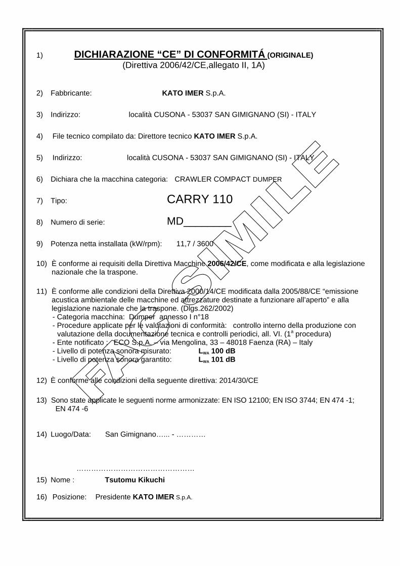
1) DICHIARAZIONE “CE” DI CONFORMITÁ (ORIGINALE) (Direttiva 2006/42/CE,allegato II, 1A) 2) Fabbricante: KATO IMER S.p.A.
3) Indirizzo: località CUSONA - 53037 SAN GIMIGNANO (SI) - ITALY
4) File tecnico compilato da: Direttore tecnico KATO IMER S.p.A.
5) Indirizzo: località CUSONA - 53037 SAN GIMIGNANO (SI) - ITALY
6) Dichiara che la macchina categoria: CRAWLER COMPACT DUMPER
7) Tipo: CARRY 110
8) Numero di serie: MD________
9) Potenza netta installata (kW/rpm): 11,7 / 3600
10) È conforme ai requisiti della Direttiva Macchine 2006/42/CE, come modificata e alla legislazione
nazionale che la traspone. 11) È conforme alle condizioni della Direttiva 2000/14/CE modificata dalla 2005/88/CE “emissione
acustica ambientale delle macchine ed attrezzature destinate a funzionare all’aperto” e alla legislazione nazionale che la traspone. (Dlgs.262/2002) - Categoria macchina: Dumper annesso I n°18 - Procedure applicate per le valutazioni di conformità: controllo interno della produzione con
valutazione della documentazione tecnica e controlli periodici, all. VI. (1a procedura) - Ente notificato : ECO S.p.A. – via Mengolina, 33 – 48018 Faenza (RA) – Italy - Livello di potenza sonora misurato: LWA 100 dB - Livello di potenza sonora garantito: LWA 101 dB
12) È conforme alle condizioni della seguente direttiva: 2014/30/CE
13) Sono state applicate le seguenti norme armonizzate: EN ISO 12100; EN ISO 3744; EN 474 -1;
EN 474 -6 14) Luogo/Data: San Gimignano…... - …………
…………………………………………
15) Nome : Tsutomu Kikuchi 16) Posizione: Presidente KATO IMER S.p.A.
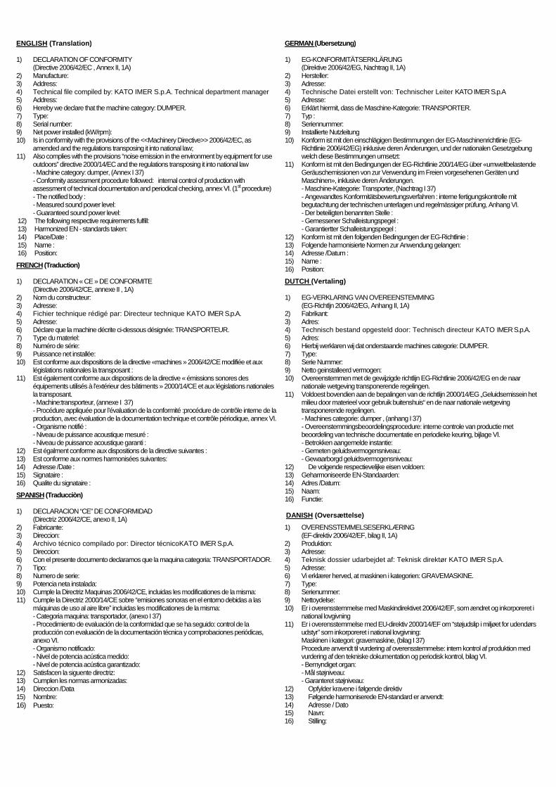
ENGLISH (Translation) 1) DECLARATION OF CONFORMITY (Directive 2006/42/EC , Annex II, 1A) 2) Manufacture: 3) Address: 4) Technical file compiled by: KATO IMER S.p.A. Technical department manager 5) Address: 6) Hereby we declare that the machine category: DUMPER. 7) Type: 8) Serial number: 9) Net power installed (kW/rpm): 10) Is in conformity with the provisions of the <<Machinery Directive>> 2006/42/EC, as
amended and the regulations transposing it into national law; 11) Also complies with the provisions “noise emission in the environment by equipment for use
outdoors” directive 2000/14/EC and the regulations transposing it into national law - Machine category: dumper, (Annex I 37) - Conformity assessment procedure followed: internal control of production with assessment of technical documentation and periodical checking, annex VI. (1st procedure)
- The notified body : - Measured sound power level: - Guaranteed sound power level: 12) The following respective requirements fulfill: 13) Harmonized EN - standards taken: 14) Place/Date : 15) Name : 16) Position: FRENCH (Traduction) 1) DECLARATION « CE » DE CONFORMITE (Directive 2006/42/CE, annexe II , 1A) 2) Nom du constructeur: 3) Adresse: 4) Fichier technique rédigé par: Directeur technique KATO IMER S.p.A. 5) Adresse: 6) Déclare que la machine décrite ci-dessous désignée: TRANSPORTEUR. 7) Type du materiel: 8) Numéro de série: 9) Puissance net installée: 10) Est conforme aux dispositions de la directive «machines » 2006/42/CE modifiée et aux
législations nationales la transposant : 11) Est également conforme aux dispositions de la directive « émissions sonores des
équipements utilisés à l’extérieur des bâtiments » 2000/14/CE et aux législations nationales la transposant. - Machine:transporteur, (annexe I 37) - Procédure appliquée pour l’évaluation de la conformité :procédure de contrôle interne de la production, avec évaluation de la documentation technique et contrôle périodique, annex VI.
- Organisme notifié : - Niveau de puissance acoustique mesuré : - Niveau de puissance acoustique garanti : 12) Est égalment conforme aux dispositions de la directive suivantes : 13) Est conforme aux normes harmonisées suivantes: 14) Adresse /Date : 15) Signataire : 16) Qualite du signataire : SPANISH (Traducciòn) 1) DECLARACION “CE” DE CONFORMIDAD (Directriz 2006/42/CE, anexo II, 1A) 2) Fabricante: 3) Direccion: 4) Archivo técnico compilado por: Director técnicoKATO IMER S.p.A. 5) Direccion: 6) Con el presente documento declaramos que la maquina categoria: TRANSPORTADOR. 7) Tipo: 8) Numero de serie: 9) Potencia neta instalada: 10) Cumple la Directriz Maquinas 2006/42/CE, incluidas les modificationes de la misma: 11) Cumple la Directriz 2000/14/CE sobre “emisiones sonoras en el entorno debidas a las
máquinas de uso al aire libre” incluidas les modificationes de la misma: - Categoria maquina: transportador, (anexo I 37) - Procedimiento de evaluación de la conformidad que se ha seguido: control de la producción con evaluación de la documentación técnica y comprobaciones periódicas, anexo VI.
- Organismo notificado: - Nivel de potencia acústica medido: - Nivel de potencia acústica garantizado: 12) Satisfacen la siguente directriz: 13) Cumplen les normas armonizadas: 14) Direccion /Data 15) Nombre: 16) Puesto:
GERMAN (Ubersetzung) 1) EG-KONFORMITÄTSERKLÄRUNG (Direktive 2006/42/EG, Nachtrag II, 1A) 2) Hersteller: 3) Adresse: 4) Technische Datei erstellt von: Technischer Leiter KATO IMER S.p.A 5) Adresse: 6) Erklärt hiermit, dass die Maschine-Kategorie: TRANSPORTER. 7) Typ : 8) Seriennummer: 9) Installierte Nutzleitung 10) Konform ist mit den einschlägigen Bestimmungen der EG-Maschinenrichtlinie (EG-
Richtlinie 2006/42/EG) inklusive deren Änderungen, und der nationalen Gesetzgebung welch diese Bestimmungen umsetzt:
11) Konform ist mit den Bedingungen der EG-Richtlinie 200/14/EG über «umweltbelastende Geräuschemissionen von zur Verwendung im Freien vorgesehenen Geräten und Maschinen», inklusive deren Änderungen. - Maschine-Kategorie: Transporter, (Nachtrag I 37) - Angewandtes Konformitätsbewertungsverfahren : interne fertigungskontrolle mit begutachtung der technischen unterlagen und regelmässiger prüfung, Anhang VI.
- Der beteiligten benannten Stelle : - Gemessener Schalleistungspegel : - Garantiertter Schalleistungspegel : 12) Konform ist mit den folgenden Bedingungen der EG-Richtlinie : 13) Folgende harmonisierte Normen zur Anwendung gelangen: 14) Adresse /Datum : 15) Name : 16) Position: DUTCH (Vertaling) 1) EG-VERKLARING VAN OVEREENSTEMMING (EG-Richtljn 2006/42/EG, Anhang II, 1A) 2) Fabrikant: 3) Adres: 4) Technisch bestand opgesteld door: Technisch directeur KATO IMER S.p.A. 5) Adres: 6) Hierbij werklaren wij dat onderstaande machines categorie: DUMPER. 7) Type: 8) Serie Nummer: 9) Netto geinstalleerd vermogen: 10) Overeenstemmen met de gewijzigde richtlijn EG-Richtlinie 2006/42/EG en de naar
nationale wetgeving transponerende regelingen. 11) Voldoest bovendien aan de bepalingen van de richtlijn 2000/14/EG „Geluidsemissein het
milieu door materieel voor gebruik buitenshuis“ en de naar nationale wetgeving transponerende regelingen. - Machines categorie: dumper , (anhang I 37) - Overeenstemmingsbeoordelingsprocedure: interne controle van productie met beoordeling van technische documentatie en periodieke keuring, bijlage VI.
- Betrokken aangemelde instantie: - Gemeten geluidsvermogensniveau: - Gewaarborgd geluidsvermogensniveau: 12) De volgende respectievelijke eisen voldoen: 13) Geharmoniseerde EN-Standaarden: 14) Adres /Datum: 15) Naam: 16) Functie: DANISH (Oversættelse) 1) OVERENSSTEMMELSESERKLÆRING (EF-direktiv 2006/42/EF, bilag II, 1A) 2) Produktion: 3) Adresse: 4) Teknisk dossier udarbejdet af: Teknisk direktør KATO IMER S.p.A. 5) Adresse: 6) Vi erklærer herved, at maskinen i kategorien: GRAVEMASKINE. 7) Type: 8) Serienummer: 9) Nettoydelse: 10) Er i overensstemmelse med Maskindirektivet 2006/42/EF, som ændret og inkorporeret i
national lovgivning 11) Er i overensstemmelse med EU-direktiv 2000/14/EF om “støjudslip i miljøet for udendørs
udstyr” som inkorporeret i national lovgivning: Maskinen i kategori: gravemaskine, (bilag I 37) Procedure anvendt til vurdering af overensstemmelse: intern kontrol af produktion med
vurdering af den tekniske dokumentation og periodisk kontrol, bilag VI. - Bemyndiget organ: - Mål støjniveau: - Garanteret støjniveau: 12) Opfylder kravene i følgende direktiv 13) Følgende harmoniserede EN-standard er anvendt: 14) Adresse / Dato 15) Navn: 16) Stilling:

SVENSKA (översättning) 1) EG-FÖRSÄKRAN OM ÖVERENSSTÄMMELSE (Direktiv 2006/42/EC , Annex II, 1A) 2) Tillverkare: 3) Adress: 4) Den tekniska filen har ifyllts av: den tekniska chefen vid KATO IMER S.p.A 5) Adress: 6) Det intygas att maskinen i kategorin: GRÄVSKOPA FÖR LASTNING 7) Typ: 8) Serienummer: 9) Installerad nettoeffekt (kW/rpm): 10) Överensstämmer med kraven i maskindirektivet 2006/42/EG, med ändringar, samt med den
italienska lagstiftningen som införlivar direktivet. 11) Uppfyller villkoren som omnämns i direktiv 2000/14/EG “buller från maskiner och utrustning
som är avsedda för utomhusanvändning”, samt med den lagstiftning som införlivar direktivet: Maskinkategori: grävskopa för lastning (bilaga I 37) Rutiner som har tillämpats för att bedöma överensstämmelsen: en intern kontroll av produktionen och en bedömning av den tekniska dokumentationen med periodiska kontroller, bilaga VI. - Anmält organ: - Uppmätt ljudeffektnivå: - Garanterad ljudeffektnivå::
12) Uppfyller villkoren som omnämns i följande direktiv: 13) Följande harmoniserade standarder har tillämpats: 14) Ort/Datum: 15) Namn: 16) Befattning: NORSK (oversettelse) 1) SAMSVARSERKLÆRING (ORIGINAL) (Direktiv 2006/42/EF, vedlegg II, 1A)) 2) Produsent: 3) Adresse: 4) Teknisk dokumentasjon utarbeidet av: Teknisk ansvarlig KATO IMER S.p.A. 5) Adresse: 6) Med dette erklærer vi at maskinkategorien: HJULLASTER 7) Type: 8) Serienummer: 9) Installert nettoeffekt (kW/rpm): 10) Er i samsvar med kravene i Maskindirektivet 2006/42/EF, med endringer og den nasjonale
lovgivningen som gjennomfører disse; 11) Den er også i samsvar med Direktiv 2000/14/EF "Støyemisjon fra maskiner og annet utstyr til
utendørs bruk” og nasjonal lovgivning som gjennomfører disse. Maskinkategori: hjullaster (vedlegg I 37) Prosedyrer brukt for samsvarsvurdering: intern kontroll av produksjonen med vurdering av teknisk dokumentasjon og periodisk kontroll, (vedlegg. VI). - Teknisk kontrollorgan: - Målt lydeffektnivå: - Garantert lydeffektnivå:: 12) Den er i samsvar med kravene i følgende direktiv: 13) Følgende harmoniserte normer brukes: 14) Sted/Dato: 15) Navn: 16) Stilling:

SCHEDULED MAINTENANCE Proper maintenance is essential to long service life and optimal operation. KATO IMER has scheduled a series of controls and work to be done at our authorised service centres. WARNING: Scheduled services are required by the Manufacturer. Failure to observe this requirement voids the warranty.
PROGRAMMED SERVICE TABLE
HOURS 20/50 200 400 600 800 1000 1200 1400 1600
OPERATION
Oil and engine filter change •••• •••• •••• •••• •••• •••• •••• •••• ••••
Check / replace engine air filter •••• •••• •••• •••• •••• •••• •••• •••• ••••
Check and adjust track tension •••• •••• •••• •••• •••• •••• •••• •••• ••••
Replace hydraulic circuit filter •••• •••• •••• •••• •••• •••• •••• ••••
Change hydraulic fluid •••• ••••
1
PREFACE This manual provides all the procedures and instructions required for operating, inspecting and servicing the minidumper. The procedures are designed to provide the best possible performance, productivity and safety. Please note the following rules: • The manual must be kept on board the machine in the provided compartment. • Before operating the machine, read this manual throughout. • Experience will augment the prescriptions of this manual, and will be gained in supervised operation of the
machine. Some of the illustrations given in the manual may not be identical with your machine due to intervening technological developments. If you have any questions about your machine or this manual, please contact your reseller for the most recent updates.
SAFETY INFORMATION This manual is a practical safe guide to the safe operation and control of the machine. Before operating the machine, read the manual in full. This is the best way to avoid accidents. Incorrect operation, control or servicing of the machine may cause injury or death.
Precautions are highlighted in the manual and on the machine itself with the symbol � and classified with the words DANGER - WARNING - CAUTION , depending on the degree of hazard. The classification is as follows: A dangerous situation which may cause injury or death. A potentially dangerous situation which may cause injury or death. A potentially dangerous situation which may cause light or moderate injury. May also be used to indicate the potential for damage to the machine or its parts. We have made every effort to reduce the risks associated with correct use of the machine and, nonetheless, we cannot be held responsible for predicting every kind of danger in all unintended operating conditions. We have taken every effort to prevent accidents during he machine’s operation, however we are not liable for all hazards in all working conditions. The owner or operator must ALWAYS take care during work and have read and understood this manual sufficiently to have the basic knowledge required to operate the machine correctly.
WARNING
CAUTION
• BEFORE OPERATING, INSPECTING OR SERVICING THE MACHINE, READ THIS MANUAL AND MAKE SURE YOU
HAVE UNDERSTOOD ITS CONTENTS. • INCORRECT OPERATION OR SERVICING MAY CAUSE ACCIDENTS , INJURY OR DEATH . • KEEP THIS MANUAL AT HAND FOR REFERENCE AT ALL TIMES . • IF LOST OR DAMAGED , ASK YOUR RESELLER FOR ANOTHER COPY . • CONSTRUCTION EQUIPMENT IS COVERED BY A VARIETY OF FE DERAL , NATIONAL AND LOCAL LEGISLATION .
SINCE THIS LEGISLATION IS CONTINUALLY CHANGING AND D IFFERS FROM COUNTRY TO COUNTRY, WE CANNOT INCLUDE IT IN THIS MANUAL . THE OWNER OR OPERATOR ARE RESPONSIBLE FOR INFORMING THEMSELVES IN THIS REGARD.
• THE MACHINE’S COMPONENTS AND SPECIFICATIONS ARE SUBJECT TO CHAN GE WITHOUT NOTICE. • MAKE SURE THAT THE SUPPLIED OPERATING MANUAL CORRESP ONDS TO THE FEATURES OF THE MACHINE , IN
CASE OF DOUBT CONTACT KATO IMER ASSISTANCE SERVICE . • KATO IMER RESERVES THE RIGHT TO CHANGE THE FEATURES OF THE MACHINE AND /OR THE CONTENTS OF
THIS MANUAL , WITHOUT BEING REQUIRED TO UPDATE THE PREVIOUS MACHINE AND /OR MANUALS .
WARNING
DANGER
1 SAFETY MINIDUMPER CARRY 110
2
1 SAFETY MEASURES 1.1 GENERAL
1. MAKE SURE YOU HAVE READ AND UNDERSTOOD THE INSTR UCTIONS AND
WARNINGS This manual, the nameplates and labels on the machine provide the information required for correct and safe operation of the machine. The user is responsible for reading and understanding the said information; failure to do so may lead to serious injury. Do not leave anything you have failed to understand to chance. Your reseller will provide any additional information you may require. If you lose or damage the manual, nameplates or labels, your reseller will replace them. 2. CHECK THE MINIDUMPER Before starting work, check the minidumper and make sure there are no persons or obstacles in your work area. Before starting, carefully check the machine for signs of wear and defects. 3. HEALTH Take special care of your mental and physical health and note that the operator of a complicated machine should be PHYSICALLY FIT. NEVER operate the machine under the influence of alcohol, medicines or drugs of any kind. 4. SNUG FITTING WORK CLOTHES Your work clothing must be snug, without lose sleeves, rings or other jewelry, as they may become trapped in moving parts. Always wear the necessary clothes and accessories, including: helmet, safety gloves, visible clothing, safety boots and ear defenders. 5. BEFORE STARTING THE MACHINE Since all equipment is hydraulically operated, it is EXTREMELY IMPORTANT that the hydraulic fluid be at temperature BEFORE you start working. while the fluid is heating up, the operator should check the machine’s operation and whether it needs servicing. Remember; the basic principle of hydraulics is flow of hydraulic fluid. If you hear a loud noise, this means that the pump is insufficiently lubricated due to cavitation, often caused by the use of too heavy or dense oil. NEVER OPERATE THE MACHINE in such conditions; it can seriously damage the pump. 6. MOVING PARTS DO NOT approach moving parts. Do not hold anything close to moving parts. This may cause serious accidents. 7. TAKE CARE IN THE VICINITY OF THE MACHINE’S HOT P ARTS Keep the engine away from buildings and other equipment during operation. Keep flammable materials away and not place anything on the engine while it is running. DO NOT touch the engine or exhaust when the machine is running or before it has had time to cool down. These parts are very hot and cause serious burns. 8. GETTING ON AND OFF THE MACHINE When getting on and off the machine, ALWAYS grip the handles. NEVER grip the control levers when getting on or off the machine. NEVER get on or off the machine while it is in motion. Never attempt to get onto the machine with your hands full.
BEFORE USING THE MACHINE MOVE AWAY EVERYONE NEARBY .
WARNING
1 SAFETY MINIDUMPER CARRY 110
3
9. MAINTAIN GOOD VENTILATION Do not use the machine for indoor works. Take all precautions to vent exhaust gas externally before starting the engine if working in a hole in the ground, tunnel or trench. In such a place, the air trends to stagnate. Breathing exhaust gas is very dangerous. Note that exhaust gases are fatally poisonous. 10. LIGHTING The machine is designed to work in building jobsites and it does not have own lighting. It must be used in enough illuminated places. 1.2 USE OF THE MACHINE
1. EXECUTE EACH MANOEUVRE, WITH RESPECT OF SAFETY Execute all manoeuvres carefully. Operating brusquely the machine this can cause damages and reduce consistently efficiency. Take care of regulations that warrant safety on job site. Leave after a sufficient safety distance between machine and obstacle. Leading the machine on foot raise the platform assuring the hook.
2. DO NOT OVERLOAD Never overload any cylinder enough to trigger the opening of the safety valve. This would cause an excessive rise in the oil temperature, lowering the useful life of the hydraulic components.
3. SECURE FOOTING FOR SAFE OPERATION Check that the machine footing is level and firm to avoid skidding or overturning if you need to use the machine on the shoulder of a road or a slope.
4. MACHINE OPERATING LIMITS The machine should be operated on a flat surface, but if you are moving material on sloping ground, be sure that the tracks are positioned in the direction of the slope and not crossways. If you need to work on soft, rough or unlevelled ground, take care to avoid overturning.
5. TIPPING Be careful, during the reversal of accessory the center of gravity of the machine can moves, so the operation must be done on a stable and not yielding surface.
1 SAFETY MINIDUMPER CARRY 110
4
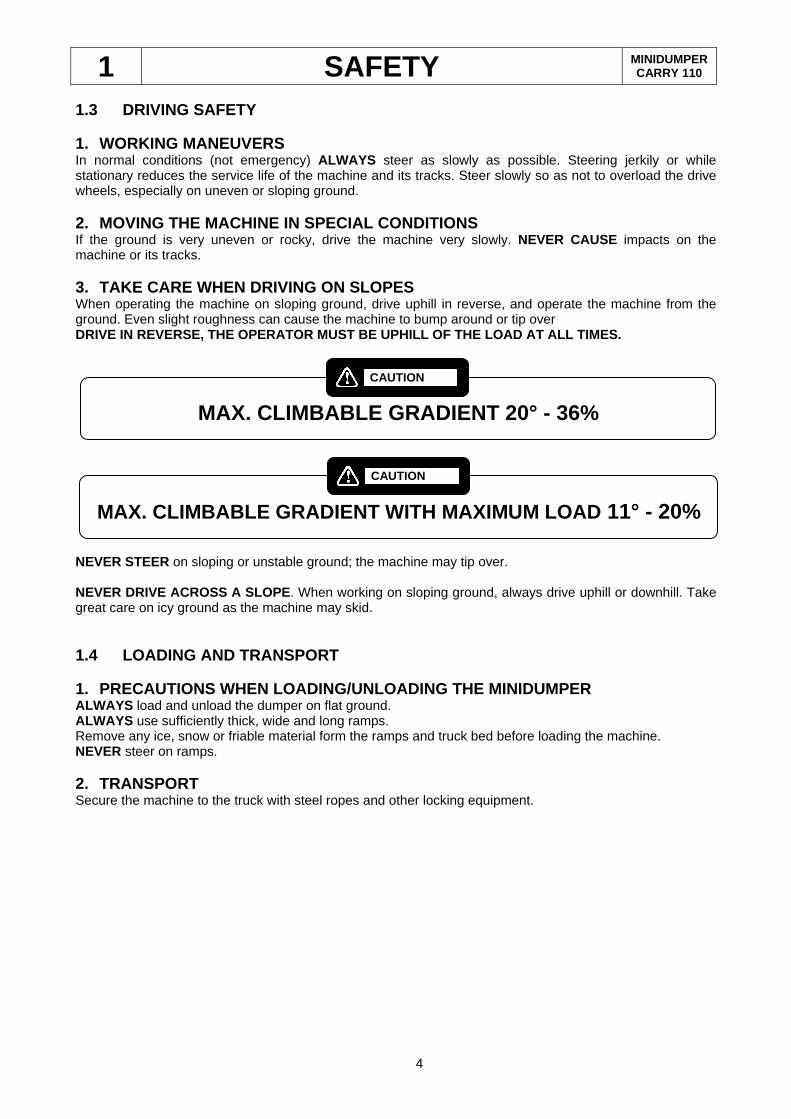
1.3 DRIVING SAFETY 1. WORKING MANEUVERS In normal conditions (not emergency) ALWAYS steer as slowly as possible. Steering jerkily or while stationary reduces the service life of the machine and its tracks. Steer slowly so as not to overload the drive wheels, especially on uneven or sloping ground. 2. MOVING THE MACHINE IN SPECIAL CONDITIONS If the ground is very uneven or rocky, drive the machine very slowly. NEVER CAUSE impacts on the machine or its tracks. 3. TAKE CARE WHEN DRIVING ON SLOPES When operating the machine on sloping ground, drive uphill in reverse, and operate the machine from the ground. Even slight roughness can cause the machine to bump around or tip over DRIVE IN REVERSE, THE OPERATOR MUST BE UPHILL OF THE LOAD AT ALL TIMES.
NEVER STEER on sloping or unstable ground; the machine may tip over. NEVER DRIVE ACROSS A SLOPE . When working on sloping ground, always drive uphill or downhill. Take great care on icy ground as the machine may skid. 1.4 LOADING AND TRANSPORT 1. PRECAUTIONS WHEN LOADING/UNLOADING THE MINIDUMPE R ALWAYS load and unload the dumper on flat ground. ALWAYS use sufficiently thick, wide and long ramps. Remove any ice, snow or friable material form the ramps and truck bed before loading the machine. NEVER steer on ramps. 2. TRANSPORT Secure the machine to the truck with steel ropes and other locking equipment.
MAX. CLIMBABLE GRADIENT WITH MAXIMUM LOAD 11° - 20%
CAUTION
MAX. CLIMBABLE GRADIENT 20° - 36%
CAUTION
1 SAFETY MINIDUMPER CARRY 110
5
1.5 PARKING
1. PARKING ON EMBANKMENTS AND SLOPES NEVER LEAVE THE MACHINE PARKED on or near to an embankment, or on the edge of a dig or quarry. They may collapse under its weight. Move the machine away form such danger areas if it is to remain inactive for any time. If possible, park it on flat ground. 2. PARKING ON THE ROAD If the machine must be parked on the road, warn other road users of its presence with barriers, flags, illuminated notices and signs. 3. LEAVING THE MACHINE UNSUPERVISED Before leaving the machine unsupervised, ALWAYS switch off the engine. Make sure its chocks are placed and the parking brake engaged.
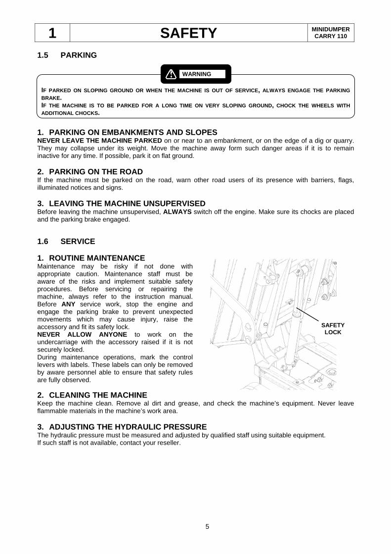
1.6 SERVICE 1. ROUTINE MAINTENANCE Maintenance may be risky if not done with appropriate caution. Maintenance staff must be aware of the risks and implement suitable safety procedures. Before servicing or repairing the machine, always refer to the instruction manual. Before ANY service work, stop the engine and engage the parking brake to prevent unexpected movements which may cause injury, raise the accessory and fit its safety lock. NEVER ALLOW ANYONE to work on the undercarriage with the accessory raised if it is not securely locked. During maintenance operations, mark the control levers with labels. These labels can only be removed by aware personnel able to ensure that safety rules are fully observed.
2. CLEANING THE MACHINE Keep the machine clean. Remove al dirt and grease, and check the machine’s equipment. Never leave flammable materials in the machine’s work area. 3. ADJUSTING THE HYDRAULIC PRESSURE The hydraulic pressure must be measured and adjusted by qualified staff using suitable equipment. If such staff is not available, contact your reseller.
IF PARKED ON SLOPING GROUND OR WHEN THE MACHINE IS O UT OF SERVICE, ALWAYS ENGAGE THE PARKING BRAKE . IF THE MACHINE IS TO BE PARKED FOR A LONG TIME ON VE RY SLOPING GROUND, CHOCK THE WHEELS WITH ADDITIONAL CHO CKS.
WARNING
SAFETY LOCK

1 SAFETY MINIDUMPER CARRY 110
6
FIRE AND EXPLOSION Always keep petrol, lubricants and coolants as far away as possible form sources of heat and ignition. Many liquids are extremely flammable. Dry immediately eventual overflows. NEVER FILL THE FUEL TANK or lubricate the machine with the engine running. NEVER SMOKE while filling the fuel tank or in the vicinity of flammable materials.
4. ELECTROLYTIC BATTERY MAINTENANCE Do not touch the internal battery elements. Battery acid burns the skin and can cause blindness if it is splashed into the eyes. In the event of contact with the acid, rinse the skin contacted with lots of water. Use bicarbonate of soda to neutralise the acid. If the acid gets in your eyes, rinse thoroughly and call for medical treatment immediately. During battery servicing, remember that charging or discharging generates a highly explosive mixture of hydrogen and oxygen. A flame or spark can ignite these gases. ALWAYS wear protective glasses and gloves when working with the battery. 5. HYDRAULIC SYSTEM MAINTENANCE Before disconnecting a hydraulic line on the machine, be sure that: - the shovel, if present, is on the ground - the tool holder is in the lowered position - the engine is off - the pressurised air has been relieved from the hydraulic tank - the control levers are moved repeatedly to lower the pressure in the pistons. Before switching on the engine, make sure that all the connections are firmly tightened and that all the pipes and fittings are in good conditions. If you are struck by escaping pressurised hydraulic fluid, serious reactions can occur if proper medical treatment is not administered immediately.
1 SAFETY MINIDUMPER CARRY 110
7
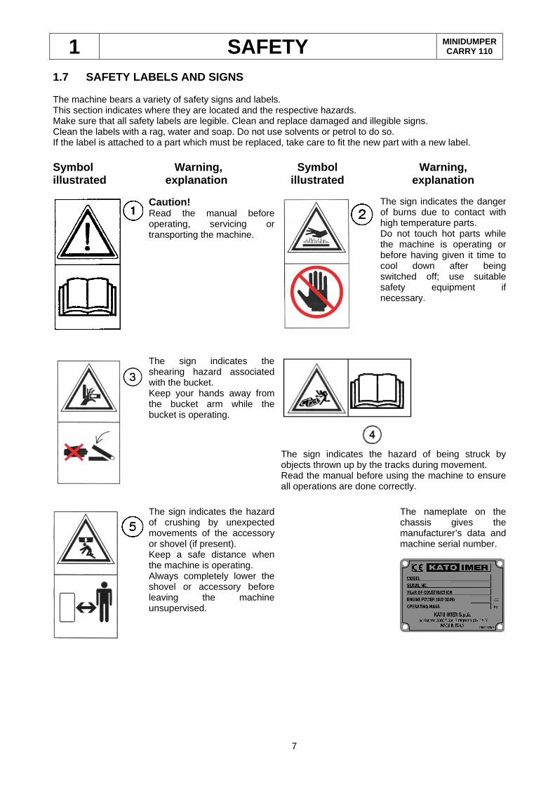
1.7 SAFETY LABELS AND SIGNS The machine bears a variety of safety signs and labels. This section indicates where they are located and the respective hazards. Make sure that all safety labels are legible. Clean and replace damaged and illegible signs. Clean the labels with a rag, water and soap. Do not use solvents or petrol to do so. If the label is attached to a part which must be replaced, take care to fit the new part with a new label. Symbol Warning, Symbol Warning, illustrated explanation illustrated explanation Caution!
Read the manual before operating, servicing or transporting the machine.
The sign indicates the danger of burns due to contact with high temperature parts. Do not touch hot parts while the machine is operating or before having given it time to cool down after being switched off; use suitable safety equipment if necessary.
The sign indicates the shearing hazard associated with the bucket. Keep your hands away from the bucket arm while the bucket is operating.
The sign indicates the hazard of being struck by objects thrown up by the tracks during movement. Read the manual before using the machine to ensure all operations are done correctly.
The sign indicates the hazard of crushing by unexpected movements of the accessory or shovel (if present). Keep a safe distance when the machine is operating. Always completely lower the shovel or accessory before leaving the machine unsupervised.
The nameplate on the chassis gives the manufacturer’s data and machine serial number.
2 OPERATING INSTRUCTIONS MINIDUMPER CARRY 110
8
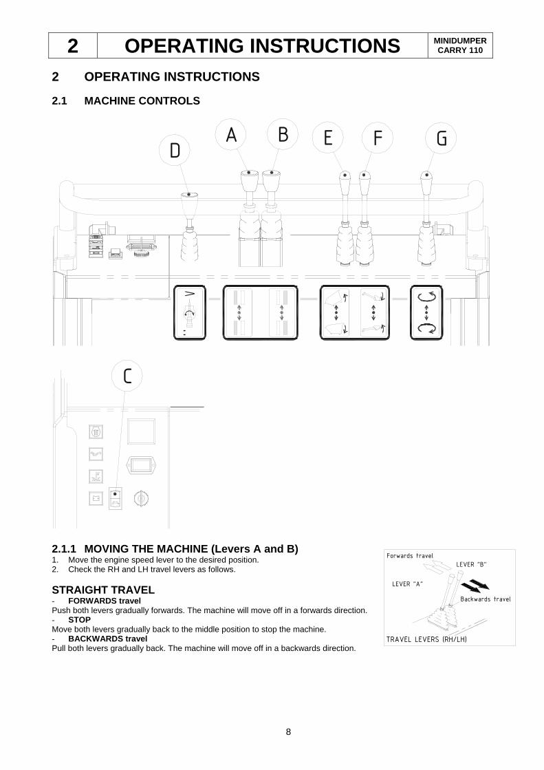
TRAVEL LEVERS (RH/LH)
LEVER "B"
LEVER "A"
Forwards travel
Backwards travel
2 OPERATING INSTRUCTIONS 2.1 MACHINE CONTROLS
:
>
GFBA ED
C
2.1.1 MOVING THE MACHINE (Levers A and B) 1. Move the engine speed lever to the desired position. 2. Check the RH and LH travel levers as follows.
STRAIGHT TRAVEL - FORWARDS travel Push both levers gradually forwards. The machine will move off in a forwards direction. - STOP Move both levers gradually back to the middle position to stop the machine. - BACKWARDS travel Pull both levers gradually back. The machine will move off in a backwards direction.
2 OPERATING INSTRUCTIONS MINIDUMPER CARRY 110
9
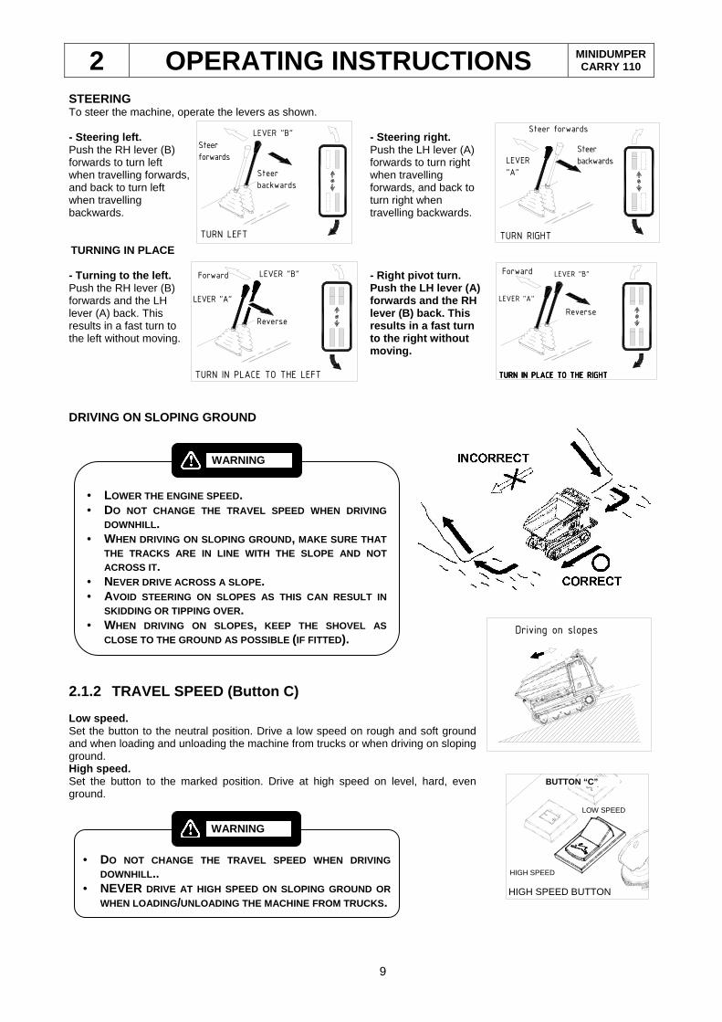
STEERING To steer the machine, operate the levers as shown. - Steering left. Push the RH lever (B) forwards to turn left when travelling forwards, and back to turn left when travelling backwards.
- Steering right. Push the LH lever (A) forwards to turn right when travelling forwards, and back to turn right when travelling backwards.
TURNING IN PLACE - Turning to the left. Push the RH lever (B) forwards and the LH lever (A) back. This results in a fast turn to the left without moving.
- Right pivot turn. Push the LH lever (A) forwards and the RH lever (B) back. This results in a fast turn to the right without moving.
DRIVING ON SLOPING GROUND
2.1.2 TRAVEL SPEED (Button C) Low speed. Set the button to the neutral position. Drive a low speed on rough and soft ground and when loading and unloading the machine from trucks or when driving on sloping ground. High speed. Set the button to the marked position. Drive at high speed on level, hard, even ground.
BUTTON “C”
HIGH SPEED
LOW SPEED
HIGH SPEED BUTTON
Driving on slopes
• LOWER THE ENGINE SPEED. • DO NOT CHANGE THE TRAVEL SPEED WHEN DRIVING
DOWNHILL . • WHEN DRIVING ON SLOPING GROUND, MAKE SURE THAT
THE TRACKS ARE IN LINE WITH THE SLOPE AND NOT ACROSS IT.
• NEVER DRIVE ACROSS A SLOPE . • AVOID STEERING ON SLOPES AS THIS CAN RESULT IN
SKIDDING OR TIPPING OVER. • WHEN DRIVING ON SLOPES, KEEP THE SHOVEL AS
CLOSE TO THE GROUND AS POSSIBLE (IF FITTED).
WARNING
TURN LEFT
LEVER "B"
Steer
forwards
Steer
backwards
TURN RIGHT
Steer forwards
Steer
backwards LEVER
"A"
TURN IN PLACE TO THE LEFT
Forward
Reverse
LEVER "B"
LEVER "A"
TURN IN PLACE TO TTURN IN PLACE TO TTURN IN PLACE TO TTURN IN PLACE TO THE RIGHTHE RIGHTHE RIGHTHE RIGHT
Forward
Reverse
LEVER "B"
LEVER "A"
• DO NOT CHANGE THE TRAVEL SPEED WHEN DRIVING
DOWNHILL .. • NEVER DRIVE AT HIGH SPEED ON SLOPING GROUND OR
WHEN LOADING /UNLOADING THE MACHINE FROM TRUCKS .
WARNING
2 OPERATING INSTRUCTIONS MINIDUMPER CARRY 110
10
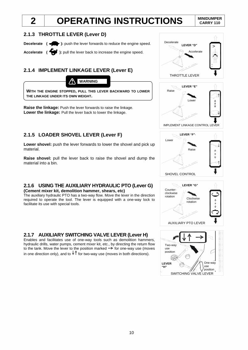
2.1.3 THROTTLE LEVER (Lever D) Decelerate ( ): push the lever forwards to reduce the engine speed. Accelerate ( ): pull the lever back to increase the engine speed.
2.1.4 IMPLEMENT LINKAGE LEVER (Lever E)
Raise the linkage: Push the lever forwards to raise the linkage. Lower the linkage: Pull the lever back to lower the linkage.
2.1.5 LOADER SHOVEL LEVER (Lever F) Lower shovel: push the lever forwards to lower the shovel and pick up material. Raise shovel: pull the lever back to raise the shovel and dump the material into a bin.
2.1.6 USING THE AUXILIARY HYDRAULIC PTO (Lever G) (Cement mixer kit, demolition hammer, shears, etc) The auxiliary hydraulic PTO has a two-way flow. Move the lever in the direction required to operate the tool. The lever is equipped with a one-way lock to facilitate its use with special tools.
2.1.7 AUXILIARY SWITCHING VALVE LEVER (Lever H) Enables and facilitates use of one-way tools such as demolition hammers, hydraulic drills, water pumps, cement mixer kit, etc., by directing the return flow to the tank. Move the lever to the position marked for one-way use (moves
in one direction only), and to for two-way use (moves in both directions).
WITH THE ENGINE STOPPED, PULL THIS LEVER BACKWARD TO LOWER THE LINKAGE UNDER ITS OWN WEIGHT .
WARNING
LEVA PRESA DI FORZA AUX.
Rotazionein sensoAntiorario
LEVA "C”
Rotazionein sensoOrario
Counter-clockwise rotation
AUXILIARY PTO LEVER
LEVER “G”
Clockwise rotation
One-way use position
SWITCHING VALVE LEVER
LEVER “H”
Two-way use position
LEVA ACCELERATORE
Accelera
LEVA "E"Decelera
:
>Decelerate
Accelerate
LEVER “D”
THROTTLE LEVER
LEVA MANOVRA PORTA-ATTREZZI
Alza
Abbassa
LEVA "D"
IMPLEMENT LINKAGE CONTROL LEVER
Raise LEVER “E”
Lower
LEVA MANOVRA PALA
Abbassa
LEVA "F"
Alza
SHOVEL CONTROL LEVER
Raise
LEVER “F”
Lower
2 OPERATING INSTRUCTIONS MINIDUMPER CARRY 110
11
2.2 USING THE IC ENGINE
CHECKS BEFORE STARTING THE ENGINE Check the hydraulic fluid, engine oil and fuel levels. For these checks, see the section “Daily checks” in this manual. This paragraph gives the basic instructions for starting the engine. However, you must supplement this information by referring to the engine manufacturer’s manual supplied with the machine and kept in the document compartment.
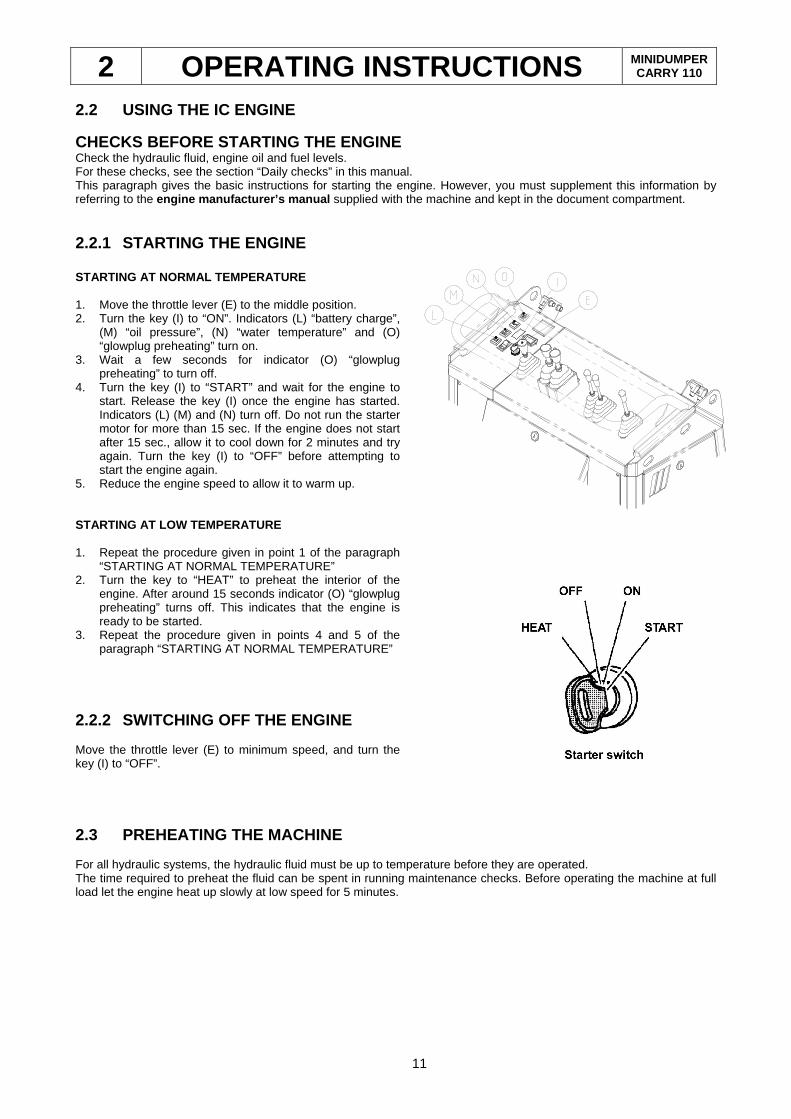
2.2.1 STARTING THE ENGINE STARTING AT NORMAL TEMPERATURE 1. Move the throttle lever (E) to the middle position. 2. Turn the key (I) to “ON”. Indicators (L) “battery charge”,
(M) “oil pressure”, (N) “water temperature” and (O) “glowplug preheating” turn on.
3. Wait a few seconds for indicator (O) “glowplug preheating” to turn off.
4. Turn the key (I) to “START” and wait for the engine to start. Release the key (I) once the engine has started. Indicators (L) (M) and (N) turn off. Do not run the starter motor for more than 15 sec. If the engine does not start after 15 sec., allow it to cool down for 2 minutes and try again. Turn the key (I) to “OFF” before attempting to start the engine again.
5. Reduce the engine speed to allow it to warm up. STARTING AT LOW TEMPERATURE
1. Repeat the procedure given in point 1 of the paragraph
“STARTING AT NORMAL TEMPERATURE” 2. Turn the key to “HEAT” to preheat the interior of the
engine. After around 15 seconds indicator (O) “glowplug preheating” turns off. This indicates that the engine is ready to be started.
3. Repeat the procedure given in points 4 and 5 of the paragraph “STARTING AT NORMAL TEMPERATURE”
2.2.2 SWITCHING OFF THE ENGINE Move the throttle lever (E) to minimum speed, and turn the key (I) to “OFF”.
2.3 PREHEATING THE MACHINE For all hydraulic systems, the hydraulic fluid must be up to temperature before they are operated. The time required to preheat the fluid can be spent in running maintenance checks. Before operating the machine at full load let the engine heat up slowly at low speed for 5 minutes.
2 OPERATING INSTRUCTIONS MINIDUMPER CARRY 110
12
2.4 LIFTING THE MACHINE
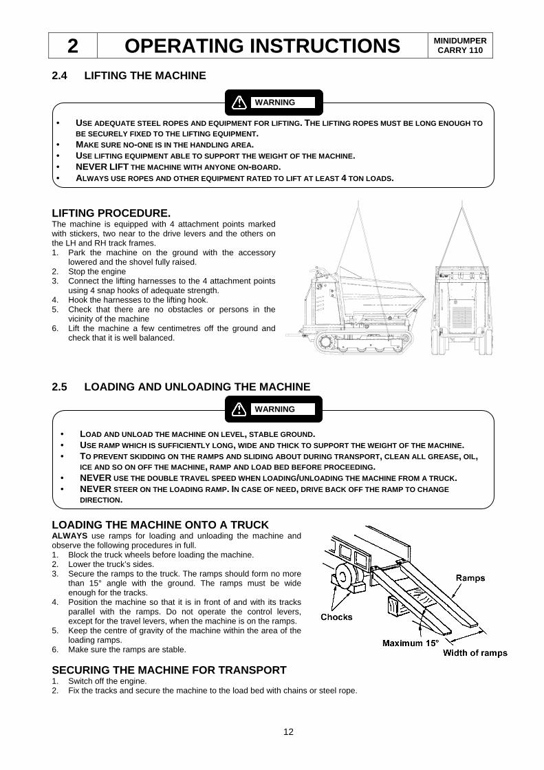
LIFTING PROCEDURE. The machine is equipped with 4 attachment points marked with stickers, two near to the drive levers and the others on the LH and RH track frames. 1. Park the machine on the ground with the accessory
lowered and the shovel fully raised. 2. Stop the engine 3. Connect the lifting harnesses to the 4 attachment points
using 4 snap hooks of adequate strength. 4. Hook the harnesses to the lifting hook. 5. Check that there are no obstacles or persons in the
vicinity of the machine 6. Lift the machine a few centimetres off the ground and
check that it is well balanced.
2.5 LOADING AND UNLOADING THE MACHINE
LOADING THE MACHINE ONTO A TRUCK ALWAYS use ramps for loading and unloading the machine and observe the following procedures in full. 1. Block the truck wheels before loading the machine. 2. Lower the truck’s sides. 3. Secure the ramps to the truck. The ramps should form no more
than 15° angle with the ground. The ramps must be wide enough for the tracks.
4. Position the machine so that it is in front of and with its tracks parallel with the ramps. Do not operate the control levers, except for the travel levers, when the machine is on the ramps.
5. Keep the centre of gravity of the machine within the area of the loading ramps.
6. Make sure the ramps are stable.
SECURING THE MACHINE FOR TRANSPORT 1. Switch off the engine. 2. Fix the tracks and secure the machine to the load bed with chains or steel rope.
• USE ADEQUATE STEEL ROPES AND EQUIPMENT FOR LIFTING . THE LIFTING ROPES MUST BE LONG ENOUGH TO
BE SECURELY FIXED TO THE LIFTING EQUIPMENT . • MAKE SURE NO-ONE IS IN THE HANDLING AREA . • USE LIFTING EQUIPMENT ABLE TO SUPPORT THE WEIGHT OF THE MACHINE. • NEVER LIFT THE MACHINE WITH ANYONE ON-BOARD . • ALWAYS USE ROPES AND OTHER EQUIPMENT RATED TO LIFT A T LEAST 4 TON LOADS .
WARNING
• LOAD AND UNLOAD THE MACHINE ON LEVEL , STABLE GROUND . • USE RAMP WHICH IS SUFFICIENTLY LONG , WIDE AND THICK TO SUPPORT THE WEIGHT OF THE MACHIN E. • TO PREVENT SKIDDING ON THE RAMPS AND SLIDING ABOUT D URING TRANSPORT, CLEAN ALL GREASE , OIL,
ICE AND SO ON OFF THE MACHINE , RAMP AND LOAD BED BEFORE PROCEEDING . • NEVER USE THE DOUBLE TRAVEL SPEED WHEN LOADING /UNLOADING THE MACHINE FROM A TRUCK . • NEVER STEER ON THE LOADING RAMP . IN CASE OF NEED, DRIVE BACK OFF THE RAMP TO CHANGE
DIRECTION.
WARNING
2 OPERATING INSTRUCTIONS MINIDUMPER CARRY 110
13
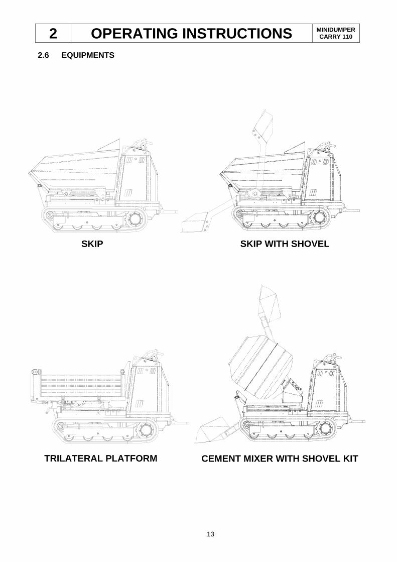
2.6 EQUIPMENTS
SKIP WITH SHOVEL SKIP
TRILATERAL PLATFORM
CEMENT MIXER WITH SHOVEL KIT
2 OPERATING INSTRUCTIONS MINIDUMPER CARRY 110
14
2.7 USE AND ACCESSORIES
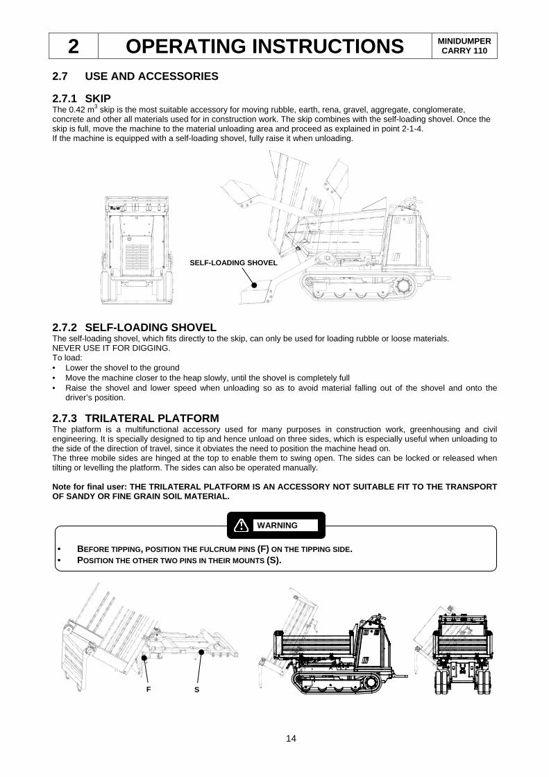
2.7.1 SKIP The 0.42 m3 skip is the most suitable accessory for moving rubble, earth, rena, gravel, aggregate, conglomerate, concrete and other all materials used for in construction work. The skip combines with the self-loading shovel. Once the skip is full, move the machine to the material unloading area and proceed as explained in point 2-1-4. If the machine is equipped with a self-loading shovel, fully raise it when unloading.
2.7.2 SELF-LOADING SHOVEL The self-loading shovel, which fits directly to the skip, can only be used for loading rubble or loose materials. NEVER USE IT FOR DIGGING. To load: • Lower the shovel to the ground • Move the machine closer to the heap slowly, until the shovel is completely full • Raise the shovel and lower speed when unloading so as to avoid material falling out of the shovel and onto the
driver’s position.
2.7.3 TRILATERAL PLATFORM The platform is a multifunctional accessory used for many purposes in construction work, greenhousing and civil engineering. It is specially designed to tip and hence unload on three sides, which is especially useful when unloading to the side of the direction of travel, since it obviates the need to position the machine head on. The three mobile sides are hinged at the top to enable them to swing open. The sides can be locked or released when tilting or levelling the platform. The sides can also be operated manually. Note for final user: THE TRILATERAL PLATFORM IS AN ACCESSORY NOT SUITABLE FIT TO THE TRANSPORT OF SANDY OR FINE GRAIN SOIL MATERIAL.
SELF-LOADING SHOVEL
• BEFORE TIPPING, POSITION THE FULCRUM PINS (F) ON THE TIPPING SIDE. • POSITION THE OTHER TWO PINS IN THEIR MOUNTS (S).
WARNING
F S
2 OPERATING INSTRUCTIONS MINIDUMPER CARRY 110
15
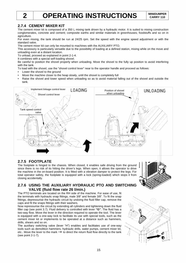
2.7.4 CEMENT MIXER KIT The cement mixer kit is composed of a 350 L mixing tank driven by a hydraulic motor. It is suited to mixing construction conglomerates, concrete and cement; composite earths and similar materials in greenhouses; foodstuffs and so on in agriculture. For even mixing, the tank should be run at 24/25 rpm. Set the speed with the engine speed adjustment or with the standard valve. The cement mixer kit can only be mounted to machines with the AUXILIARY PTO. This accessory is particularly versatile due to the possibility of loading at a defined station, mixing while on the move and unloading even at a distant location. To unload, proceed as explained in point 2-1-4. It combines with a special self-loading shovel. Be careful to position the shovel properly when unloading. Move the shovel to the fully up position to avoid interfering with the tank. To load with the shovel, use the “shovel control lever” near to the operator handle and proceed as follows: • Lower the shovel to the ground • Move the machine closer to the heap slowly, until the shovel is completely full • Raise the shovel and lower speed when unloading so as to avoid material falling out of the shovel and outside the
tank.
2.7.5 FOOTPLATE The footplate is hinged to the chassis. When closed, it enables safe driving from the ground since there is no risk of its hitting the driver’s legs. When open, it allows the operator to drive the machine in the on-board position. It is fitted with a vibration damper to protect the legs. For total operator safety, the footplate is equipped with a lock (spring-loaded) which stops it from closing accidentally.
2.7.6 USING THE AUXILIARY HYDRAULIC PTO AND SWITCHI NG VALVE (fluid flow rate 26 l/min.)
The PTO terminals are located on the RH side of the machine. For ease of use, fit the terminals with hydraulic snap fittings, male 3/8” and female 3/8”. To fit the snap fittings, depressurise the hydraulic circuit by undoing the fluid filler cap, remove the caps and fit the snaps fittings with their washers. Now repressurise the circuit by extending all cylinders and tightening down the fluid filler cap (see point 3.7). Fluid delivery is controlled with lever “G” . The fluid has a two-way flow. Move the lever in the direction required to operate the tool. The lever is equipped with a one-way lock to facilitate its use with special tools, such as the cement mixer kit or implements to be operated at a distance such as hammers, drills, shears and so on. The auxiliary switching valve (lever “H”) enables and facilitates use of one-way tools such as demolition hammers, hydraulic drills, water pumps, cement mixer kit, etc.. Move the lever to the mark to direct the return fluid flow directly to the tank (see point 2-1-7).
LOADING UNLOADING Implement linkage control lever
Shovel control lever
Tank speed control valve
Position of shovel when unloading
2 OPERATING INSTRUCTIONS MINIDUMPER CARRY 110
16
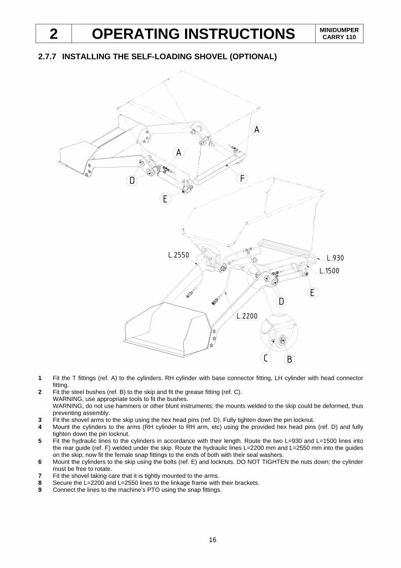
2.7.7 INSTALLING THE SELF-LOADING SHOVEL (OPTIONAL)
A
L.1500
E
L.930
F
L.2550
E
D
A
D
C B
L.2200
1 Fit the T fittings (ref. A) to the cylinders. RH cylinder with base connector fitting, LH cylinder with head connector
fitting. 2 Fit the steel bushes (ref. B) to the skip and fit the grease fitting (ref. C).
WARNING, use appropriate tools to fit the bushes. WARNING, do not use hammers or other blunt instruments; the mounts welded to the skip could be deformed, thus preventing assembly.
3 Fit the shovel arms to the skip using the hex head pins (ref. D). Fully tighten down the pin locknut. 4 Mount the cylinders to the arms (RH cylinder to RH arm, etc) using the provided hex head pins (ref. D) and fully
tighten down the pin locknut. 5 Fit the hydraulic lines to the cylinders in accordance with their length. Route the two L=930 and L=1500 lines into
the rear guide (ref. F) welded under the skip. Route the hydraulic lines L=2200 mm and L=2550 mm into the guides on the skip; now fit the female snap fittings to the ends of both with their seal washers.
6 Mount the cylinders to the skip using the bolts (ref. E) and locknuts. DO NOT TIGHTEN the nuts down; the cylinder must be free to rotate.
7 Fit the shovel taking care that it is tightly mounted to the arms. 8 Secure the L=2200 and L=2550 lines to the linkage frame with their brackets. 9 Connect the lines to the machine’s PTO using the snap fittings.
2 OPERATING INSTRUCTIONS MINIDUMPER CARRY 110
17
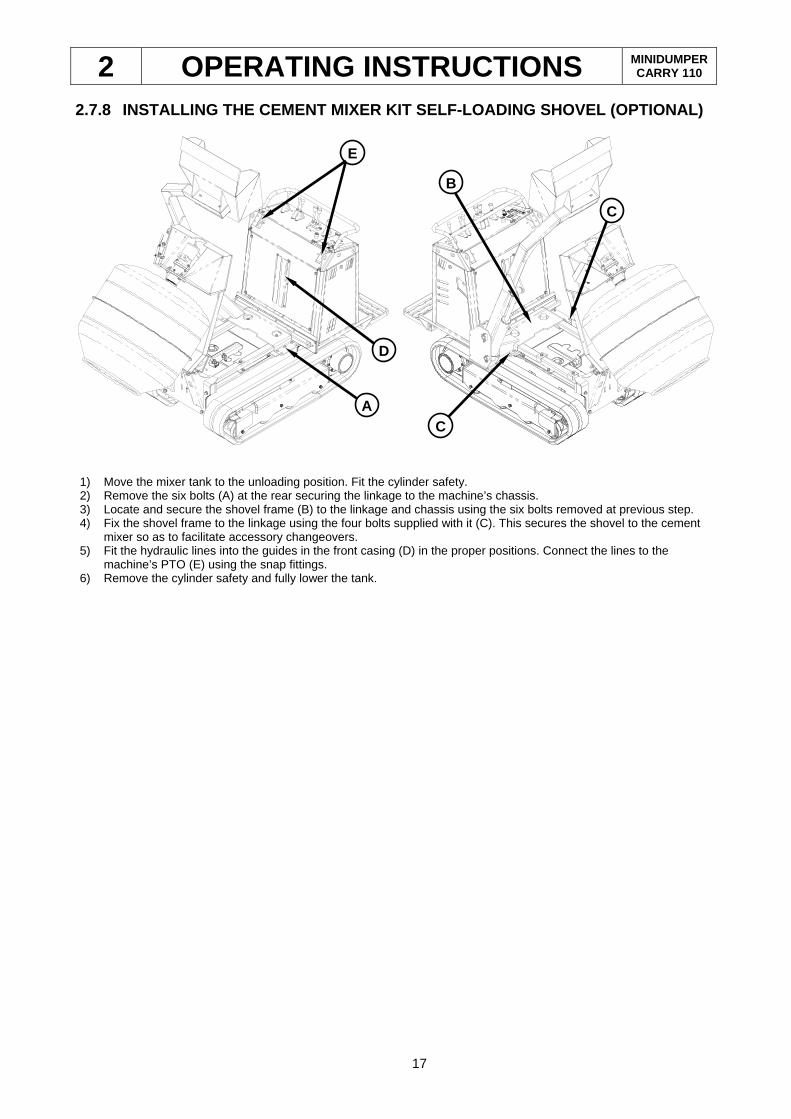
2.7.8 INSTALLING THE CEMENT MIXER KIT SELF-LOADING SHOVEL (OPTIONAL)
1) Move the mixer tank to the unloading position. Fit the cylinder safety. 2) Remove the six bolts (A) at the rear securing the linkage to the machine’s chassis. 3) Locate and secure the shovel frame (B) to the linkage and chassis using the six bolts removed at previous step. 4) Fix the shovel frame to the linkage using the four bolts supplied with it (C). This secures the shovel to the cement
mixer so as to facilitate accessory changeovers. 5) Fit the hydraulic lines into the guides in the front casing (D) in the proper positions. Connect the lines to the
machine’s PTO (E) using the snap fittings. 6) Remove the cylinder safety and fully lower the tank.
A C
D
B
C
E
2 OPERATING INSTRUCTIONS MINIDUMPER CARRY 110
18
2.8 REPLACING THE ACCESSORY
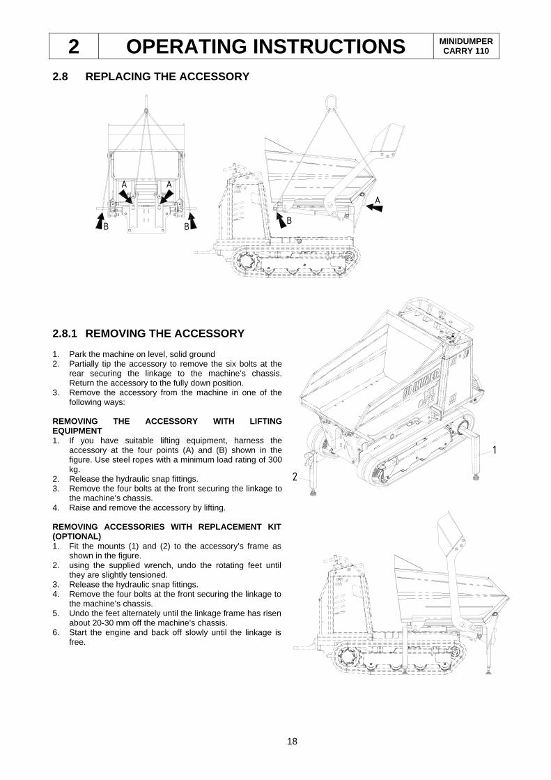
2.8.1 REMOVING THE ACCESSORY 1. Park the machine on level, solid ground 2. Partially tip the accessory to remove the six bolts at the
rear securing the linkage to the machine’s chassis. Return the accessory to the fully down position.
3. Remove the accessory from the machine in one of the following ways:
REMOVING THE ACCESSORY WITH LIFTING EQUIPMENT 1. If you have suitable lifting equipment, harness the
accessory at the four points (A) and (B) shown in the figure. Use steel ropes with a minimum load rating of 300 kg.
2. Release the hydraulic snap fittings. 3. Remove the four bolts at the front securing the linkage to
the machine’s chassis. 4. Raise and remove the accessory by lifting.
REMOVING ACCESSORIES WITH REPLACEMENT KIT (OPTIONAL) 1. Fit the mounts (1) and (2) to the accessory’s frame as
shown in the figure. 2. using the supplied wrench, undo the rotating feet until
they are slightly tensioned. 3. Release the hydraulic snap fittings. 4. Remove the four bolts at the front securing the linkage to
the machine’s chassis. 5. Undo the feet alternately until the linkage frame has risen
about 20-30 mm off the machine’s chassis. 6. Start the engine and back off slowly until the linkage is
free.
A
A
BB
A
B
2
1
2 OPERATING INSTRUCTIONS MINIDUMPER CARRY 110
19
2.8.2 MOUNTING ACCESSORIES 1. Park the machine on level, solid ground 2. Mount the accessory to the machine in one of the following ways:
MOUNTING THE ACCESSORY WITH LIFTING EQUIPMENT 1. If you have suitable lifting equipment, harness the accessory at the four points (A) and (B) shown in the figure. Use
steel ropes with a minimum load rating of 300 kg. 2. Raise the accessory and locate it on the machine’s chassis. 3. Locate and screw in the four front bolts. 4. Lock the hydraulic snap fittings. 5. Start the engine. 6. Partially tip the accessory to fit the six bolts at the rear securing the linkage to the machine’s chassis. Tighten down
all bolts. Fit the hydraulic lines into the guides in the front casing in the proper positions. Return the accessory to the fully down position.
7. Remove the lifting harness.
MOUNTING ACCESSORIES ONTO THE REPLACEMENT KIT (OPTI ONAL) 1. Start the engine and slowly approach the accessory making sure to keep the machine centred relative to the
mounts. Continue approaching until the two frames are fully coupled. 2. Stop the engine. With the provided wrench, screw the feet in alternately until the accessory frame is resting on the
machine’s chassis and the supports are free to be completely removed. 3. Locate and screw in the four front bolts. 4. Lock the hydraulic snap fittings according to their positions. 5. Start the engine. 6. Partially tip the accessory to fit the six bolts at the rear securing the linkage to the machine’s chassis. Tighten down
all bolts. Fit the hydraulic lines into the guides in the front casing. 7. Return the accessory to the fully down position.
• USE ADEQUATE STEEL ROPES AND EQUIPMENT FOR LIFTING . THE LIFTING ROPES MUST BE LONG ENOUGH TO
BE SECURELY FIXED TO THE LIFTING EQUIPMENT . • MAKE SURE NO-ONE IS IN THE HANDLING AREA . • USE LIFTING EQUIPMENT ABLE TO SUPPORT THE WEIGHT OF THE MACHINE. • NEVER LIFT THE MACHINE WITH ANYONE ON-BOARD . • ALWAYS USE ROPES AND OTHER EQUIPMENT RATED TO LIFT A T LEAST 4 TON LOADS .
WARNING
2 OPERATING INSTRUCTIONS MINIDUMPER CARRY 110
20
2.9 PRECAUTIONS WHEN USING RUBBER TRACKS
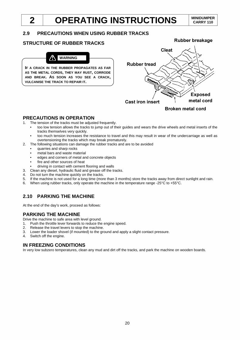
STRUCTURE OF RUBBER TRACKS
PRECAUTIONS IN OPERATION 1. The tension of the tracks must be adjusted frequently.
• too low tension allows the tracks to jump out of their guides and wears the drive wheels and metal inserts of the tracks themselves very quickly.
• too much tension increases the resistance to travel and this may result in wear of the undercarriage as well as overtensioning the tracks which may break prematurely.
2. The following situations can damage the rubber tracks and are to be avoided • quarries and sharp rocks • metal bars and waste material • edges and corners of metal and concrete objects • fire and other sources of heat • driving in contact with cement flooring and walls
3. Clean any diesel, hydraulic fluid and grease off the tracks. 4. Do not turn the machine quickly on the tracks. 5. If the machine is not used for a long time (more than 3 months) store the tracks away from direct sunlight and rain. 6. When using rubber tracks, only operate the machine in the temperature range -25°C to +55°C.
2.10 PARKING THE MACHINE At the end of the day’s work, proceed as follows:
PARKING THE MACHINE Drive the machine to safe area with level ground. 1. Push the throttle lever forwards to reduce the engine speed. 2. Release the travel levers to stop the machine. 3. Lower the loader shovel (if mounted) to the ground and apply a slight contact pressure. 4. Switch off the engine.
IN FREEZING CONDITIONS In very low subzero temperatures, clean any mud and dirt off the tracks, and park the machine on wooden boards.
IF A CRACK IN THE RUBBER PROPAGATES AS FAR AS THE METAL CORDS , THEY MAY RUST, CORRODE AND BREAK . AS SOON AS YOU SEE A CRACK , VULCANISE THE TRACK TO REPAIR IT .
WARNING
3 MAINTENANCE MINIDUMPER CARRY 110
21
3 MAINTENANCE
3.1 MAINTENANCE INTERVALS
Check Point Service
Whenever necessary
Tracks Check and adjust tension
Fuses Fuses maintenance
Battery Clean and check acid level
Parts with grease points Grease
Daily (every 8 hours of operation)
Diesel engine Check the oil level
Hydraulic Fluid Tank Check the hydraulic fluid level
Fuel tank Check the fuel level
Inspection Check the overall condition of the machine
Air cleaner Check visual blockage indicator
Engine Check fuel sludge filter water level
Hydraulic System Check filter
Radiator Check coolant level
Radiator Check cooling fins for blockage
Every 250 hours of operation (before the above serv ice jobs)
Engine Oil change
Air cleaner Replace filter element
Travel reducer gear Check oil level
Every 600 hours of operation (before the above serv ice jobs)
Hydraulic System Change fluid and clean filter element
Travel reducer gear Change reducer casing oil
Engine coolant Change coolant
The above intervals depend on the conditions in which the mac hine is working: very dusty conditions require more frequent air cleaner services.
3.2 TABLE OF LUBRICANTS
Position Quantity Features
YANMAR engine 3TNM68
1.2 litres 2.6 litres (WITH FILTER) SAE 20W40
HYDRAULIC FLUID Total quantity 25 litres Tank capacity 19 litres
LONG LIFE HYDRAULIC FLUID ISO N° 46
GENERAL LUBRICATION POINTS - EP-2 lithium grease
DRIVE MOTORS 0,30 litres each
REFER TO THE ENGINE MANUAL FOR SERVICE INSTRUCTIONS
WARNING
3 MAINTENANCE MINIDUMPER CARRY 110
22
3.3 REACTIVE CHECKS AND SERVICE JOBS
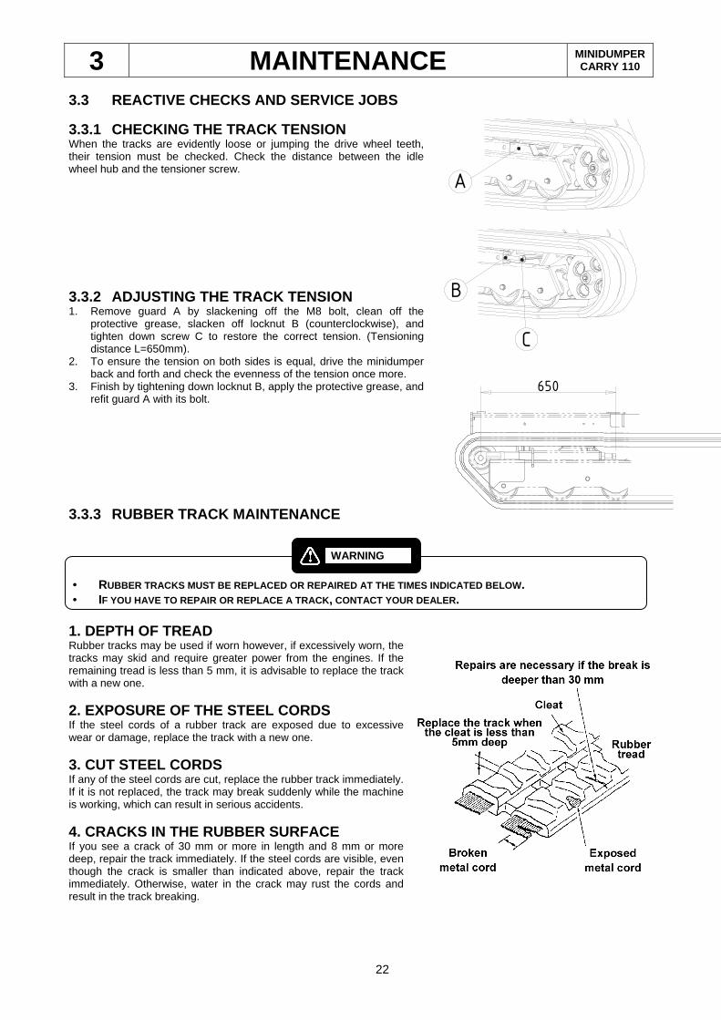
3.3.1 CHECKING THE TRACK TENSION When the tracks are evidently loose or jumping the drive wheel teeth, their tension must be checked. Check the distance between the idle wheel hub and the tensioner screw.
3.3.2 ADJUSTING THE TRACK TENSION 1. Remove guard A by slackening off the M8 bolt, clean off the
protective grease, slacken off locknut B (counterclockwise), and tighten down screw C to restore the correct tension. (Tensioning distance L=650mm).
2. To ensure the tension on both sides is equal, drive the minidumper back and forth and check the evenness of the tension once more.
3. Finish by tightening down locknut B, apply the protective grease, and refit guard A with its bolt.
3.3.3 RUBBER TRACK MAINTENANCE
1. DEPTH OF TREAD Rubber tracks may be used if worn however, if excessively worn, the tracks may skid and require greater power from the engines. If the remaining tread is less than 5 mm, it is advisable to replace the track with a new one.
2. EXPOSURE OF THE STEEL CORDS If the steel cords of a rubber track are exposed due to excessive wear or damage, replace the track with a new one.
3. CUT STEEL CORDS If any of the steel cords are cut, replace the rubber track immediately. If it is not replaced, the track may break suddenly while the machine is working, which can result in serious accidents.
4. CRACKS IN THE RUBBER SURFACE If you see a crack of 30 mm or more in length and 8 mm or more deep, repair the track immediately. If the steel cords are visible, even though the crack is smaller than indicated above, repair the track immediately. Otherwise, water in the crack may rust the cords and result in the track breaking.
• RUBBER TRACKS MUST BE REPLACED OR REPAIRED AT THE TI MES INDICATED BELOW . • IF YOU HAVE TO REPAIR OR REPLACE A TRACK , CONTACT YOUR DEALER .
WARNING
A
B
C
650
3 MAINTENANCE MINIDUMPER CARRY 110
23
3.3.4 FUSES MAINTENANCE
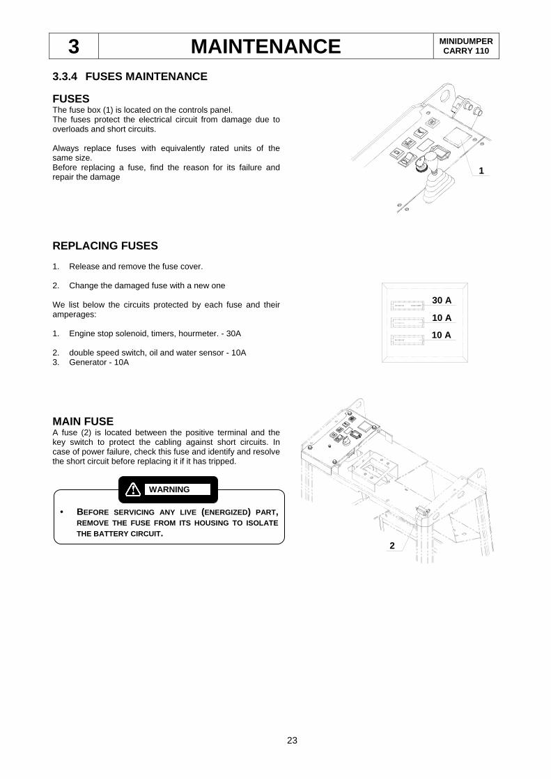
FUSES The fuse box (1) is located on the controls panel. The fuses protect the electrical circuit from damage due to overloads and short circuits. Always replace fuses with equivalently rated units of the same size. Before replacing a fuse, find the reason for its failure and repair the damage
REPLACING FUSES 1. Release and remove the fuse cover.
2. Change the damaged fuse with a new one We list below the circuits protected by each fuse and their amperages:
1. Engine stop solenoid, timers, hourmeter. - 30A
2. double speed switch, oil and water sensor - 10A 3. Generator - 10A
MAIN FUSE A fuse (2) is located between the positive terminal and the key switch to protect the cabling against short circuits. In case of power failure, check this fuse and identify and resolve the short circuit before replacing it if it has tripped.
2
1
30 A
10 A
10 A
• BEFORE SERVICING ANY LIVE (ENERGIZED) PART,
REMOVE THE FUSE FROM ITS HOUSING TO ISOLATE THE BATTERY CIRCUIT .
WARNING
3 MAINTENANCE MINIDUMPER CARRY 110
24
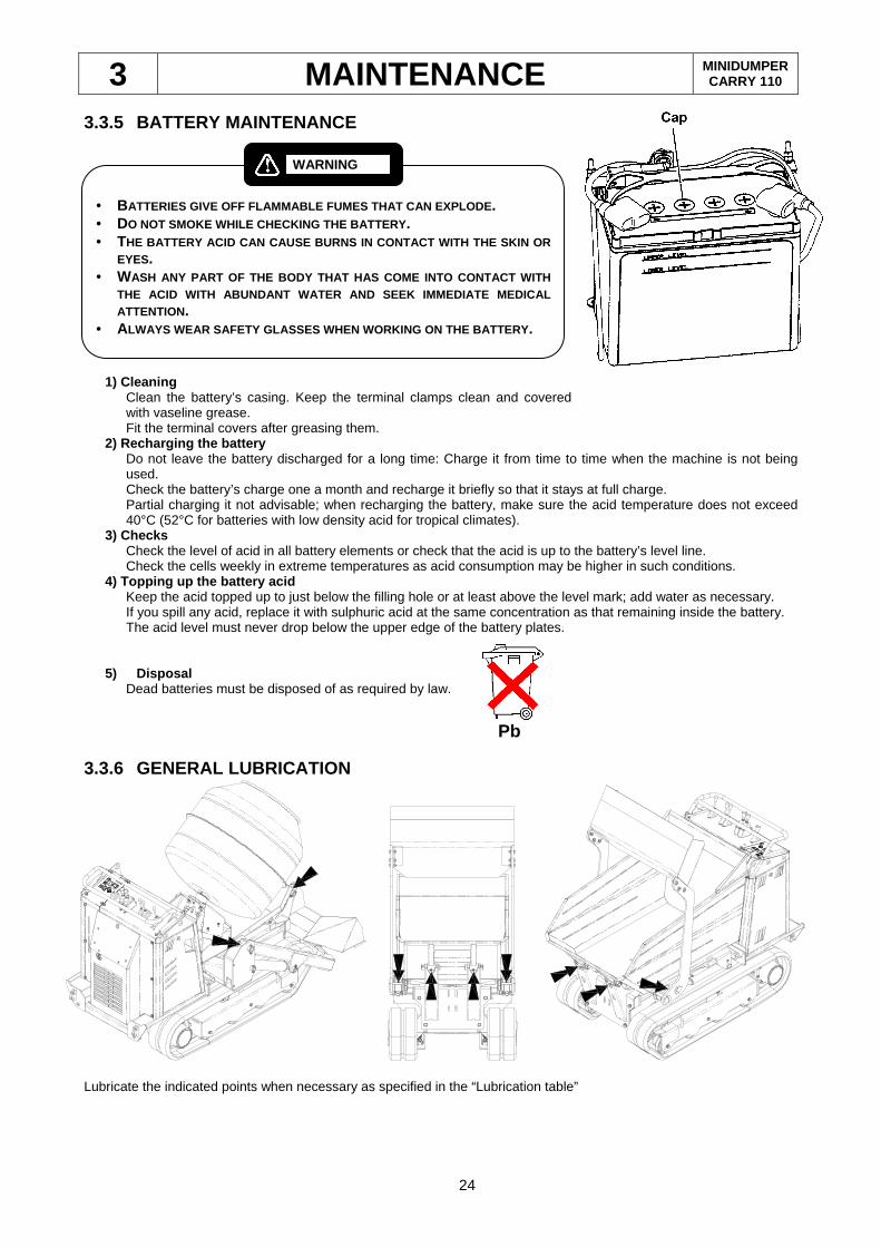
3.3.5 BATTERY MAINTENANCE
1) Cleaning
Clean the battery’s casing. Keep the terminal clamps clean and covered with vaseline grease. Fit the terminal covers after greasing them.
2) Recharging the battery Do not leave the battery discharged for a long time: Charge it from time to time when the machine is not being used. Check the battery’s charge one a month and recharge it briefly so that it stays at full charge. Partial charging it not advisable; when recharging the battery, make sure the acid temperature does not exceed 40°C (52°C for batteries with low density acid for tropical climates).
3) Checks Check the level of acid in all battery elements or check that the acid is up to the battery’s level line. Check the cells weekly in extreme temperatures as acid consumption may be higher in such conditions.
4) Topping up the battery acid Keep the acid topped up to just below the filling hole or at least above the level mark; add water as necessary. If you spill any acid, replace it with sulphuric acid at the same concentration as that remaining inside the battery. The acid level must never drop below the upper edge of the battery plates.
5) Disposal Dead batteries must be disposed of as required by law.
3.3.6 GENERAL LUBRICATION
Lubricate the indicated points when necessary as specified in the “Lubrication table”
• BATTERIES GIVE OFF FLAMMABLE FUMES THAT CAN EXPLODE . • DO NOT SMOKE WHILE CHECKING THE BATTERY . • THE BATTERY ACID CAN CAUSE BURNS IN CONTACT WITH THE SKIN OR
EYES. • WASH ANY PART OF THE BODY THAT HAS COME INTO CONTACT WITH
THE ACID WITH ABUNDANT WATER AND SEEK IMMEDIATE MED ICAL ATTENTION.
• ALWAYS WEAR SAFETY GLASSES WHEN WORKING ON THE BATTE RY.
WARNING
Pb
3 MAINTENANCE MINIDUMPER CARRY 110
25
3.4 DAILY CHECKS AND MAINTENANCE
3.4.1 ENGINE OIL LEVEL AND CHANGE
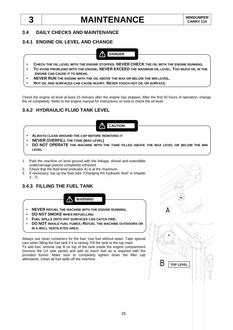
Check the engine oil level at least 15 minutes after the engine has stopped. After the first 50 hours of operation, change the oil completely. Refer to the engine manual for instructions on how to check the oil level.
3.4.2 HYDRAULIC FLUID TANK LEVEL
1. Park the machine on level ground with the linkage, shovel and extendible
undercarriage pistons completely retracted. 2. Check that the fluid level (indicator A) is at the maximum. 3. If necessary, top up the fluid (see “Changing the hydraulic fluid” in chapter
3 - 7).
3.4.3 FILLING THE FUEL TANK
Always use clean containers for the fuel. Use fuel without water. Take special care when filling the fuel tank if it is raining. Fill the tank to the top mark To add fuel, remove cap B on top of the tank inside the engine compartment (remove the LH side panel) and add as much fuel as is required with the provided funnel. Make sure to completely tighten down the filler cap afterwards. Clean all fuel spills off the machine.
• NEVER REFUEL THE MACHINE WITH THE ENGINE RUNNING . • DO NOT SMOKE WHEN REFUELLING . • FUEL SPILLS ONTO HOT SURFACES CAN CATCH FIRE . • DO NOT INHALE FUEL FUMES . REFUEL THE MACHINE OUTDOORS OR
IN A WELL VENTILATED AREA .
WARNING
• CHECK THE OIL LEVEL WITH THE ENGINE STOPPED . NEVER CHECK THE OIL WITH THE ENGINE RUNNING. • TO AVOID PROBLEMS WITH THE ENGINE , NEVER EXCEED THE MAXIMUM OIL LEVEL . TOO MUCH OIL IN THE
ENGINE CAN CAUSE IT TO BREAK . • NEVER RUN THE ENGINE WITH THE OIL ABOVE THE MAX OR BELOW THE MIN LEVEL. • HOT OIL AND SURFACES CAN CAUSE INJURY . NEVER TOUCH HOT OIL OR SURFACE .
DANGER
• ALWAYS CLEAN AROUND THE CAP BEFORE REMOVING IT • NEVER OVERFILL THE TANK (MAX LEVEL ) • DO NOT OPERATE THE MACHINE WITH THE TANK FILLED ABOVE THE MAX LEV EL OR BELOW THE MIN
LEVEL
CAUTION
A
B TOP LEVEL
3 MAINTENANCE MINIDUMPER CARRY 110
26
3.4.4 INSPECTING THE MACHINE 1. Check that the linkage bolts are fully tightened down. 2. Check that all bolts are fully tightened down. Fully tighten down all loose fasteners and replace any damaged ones. 3. Check for breakage at the cylinder mounts. Repair any damaged parts. 4. Check for breakage and wear of the cylinder and blade mounts. Repair/replace where necessary. 5. Check for leaks along the hydraulic circuit. Check the hydraulic fluid tank, cylinders, lines, caps, fittings and
accessories. Repair as necessary. 6. Check the seal of the drive engines. Check the engine oil for leaks. 7. Clean the engine compartment thoroughly. 8. After every use, at the end of the day, carefully clean all accessories (skip, platform, cement mixer, self-loading
shovel etc.)
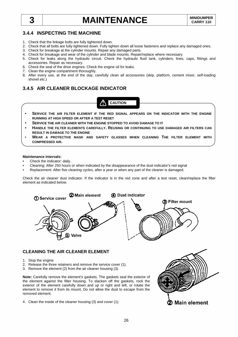
3.4.5 AIR CLEANER BLOCKAGE INDICATOR
Maintenance intervals: • Check the indicator: daily. • Cleaning: After 250 hours or when indicated by the disappearance of the dust indicator’s red signal • Replacement: After five cleaning cycles, after a year or when any part of the cleaner is damaged. Check the air cleaner dust indicator. If the indicator is in the red zone and after a test reset, clean/replace the filter element as indicated below.
CLEANING THE AIR CLEANER ELEMENT 1. Stop the engine 2. Release the three retainers and remove the service cover (1). 3. Remove the element (2) from the air cleaner housing (3). Note: Carefully remove the element’s gaskets. The gaskets seal the exterior of the element against the filter housing. To slacken off the gaskets, rock the exterior of the element carefully down and up or right and left, or rotate the element to remove it from its mount. Do not allow the dust to escape from the removed element. 4. Clean the inside of the cleaner housing (3) and cover (1).
• SERVICE THE AIR FILTER ELEMENT IF THE RED SIGNAL APP EARS ON THE INDICATOR WITH THE ENGINE
RUNNING AT HIGH SPEED OR AFTER A TEST RESET • SERVICE THE AIR CLEANER WITH THE ENGINE STOPPED TO A VOID DAMAGE TO IT • HANDLE THE FILTER ELEMENTS CAREFULLY . REUSING OR CONTINUING TO USE DAMAGED AIR FILTERS CAN
RESULT IN DAMAGE TO THE ENGINE • WEAR A PROTECTIVE MASK AND SAFETY GLASSES WHEN CLEAN ING THE FILTER ELEMENT WITH
COMPRESSED AIR.
CAUTION
3 MAINTENANCE MINIDUMPER CARRY 110
27
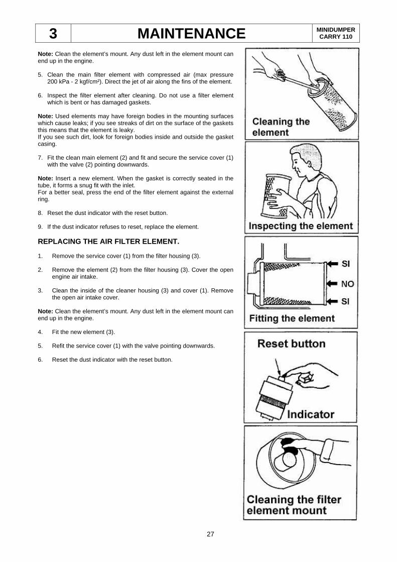
Note: Clean the element’s mount. Any dust left in the element mount can end up in the engine. 5. Clean the main filter element with compressed air (max pressure
200 kPa - 2 kgf/cm²). Direct the jet of air along the fins of the element. 6. Inspect the filter element after cleaning. Do not use a filter element
which is bent or has damaged gaskets. Note: Used elements may have foreign bodies in the mounting surfaces which cause leaks; if you see streaks of dirt on the surface of the gaskets this means that the element is leaky. If you see such dirt, look for foreign bodies inside and outside the gasket casing.
7. Fit the clean main element (2) and fit and secure the service cover (1)
with the valve (2) pointing downwards. Note: Insert a new element. When the gasket is correctly seated in the tube, it forms a snug fit with the inlet. For a better seal, press the end of the filter element against the external ring. 8. Reset the dust indicator with the reset button. 9. If the dust indicator refuses to reset, replace the element. REPLACING THE AIR FILTER ELEMENT. 1. Remove the service cover (1) from the filter housing (3). 2. Remove the element (2) from the filter housing (3). Cover the open
engine air intake. 3. Clean the inside of the cleaner housing (3) and cover (1). Remove
the open air intake cover. Note: Clean the element’s mount. Any dust left in the element mount can end up in the engine. 4. Fit the new element (3). 5. Refit the service cover (1) with the valve pointing downwards. 6. Reset the dust indicator with the reset button.
3 MAINTENANCE MINIDUMPER CARRY 110
28
3.4.6 CLEANING THE FUEL SLUDGE SUMP Maintenance intervals: • Check Level: daily. • Purge water and residue: when present in the sludge sump.
The sludge sump is inside the engine compartment directly under the fuel tank. To access it, remove the engine compartment LH side panel. Clean it as follows: 1. Switch off the engine. 2. Drain out the water and sludge into a container under the sump by opening the cock under the sump itself. Note: observe established waste liquid disposal regulations. 3. Once the water and sludge have been drained from the sump, close the cock again. Note: do not start the engine until the fuel system maintenance cycle is completed.
3.4.7 COOLANT LEVEL CHECK
Maintenance intervals: • Check Level: daily. • Add coolant to the maximum level mark. 1 Open the hatch on the engine compartment’s rear panel. 2 Slacken off the radiator cap slowly to depressurise it, then remove it. 3 Check the coolant level and condition. Top up to the maximum level mark if necessary.
Note: If the coolant is dirty or foamy, change it. See the coolant change instructions elsewhere in this manual.
4 Check the cap gasket and replace it if damaged. Refit the radiator cap and make sure to close it tightly.
FUEL SPILLS ONTO HOT SURFACES CAN CATCH FIRE
WARNING
• WHEN UP TO OPERATING TEMPERATURE , THE RADIATOR IS HOT AND UNDER INTERNAL PRESSURE . • STEAM CAUSES BURNS . • CHECK THE COOLANT ONLY WITH THE ENGINE STOPPED AND W HEN THE FILLER CAP HAS COOLED ENOUGH
TO BE REMOVED WITH BARE HANDS . • REMOVE THE FILLER CAP SLOWLY TO ALLOW THE RADIATOR T O DEPRESSURISE.
WARNING
3 MAINTENANCE MINIDUMPER CARRY 110
29
3.4.8 CLEANING THE ENGINE COOLING EQUIPMENT Maintenance intervals: • Check: daily. • Clean the dirt filter and radiator body: when dirt prevents free movement of the air. 1. Switch off the engine. 2. Remove the rear panel from the machine. 3. Remove the dirt filter mesh from the panel. 4. Clean the mesh thoroughly using compressed air, pressurised water cleaner, etc.. 5. Clean the radiator body in the same way, especially the radiator heat exchanger fins. 6. Refit the dirt filter mesh to the panel. 7. Refit the rear panel to the machine.
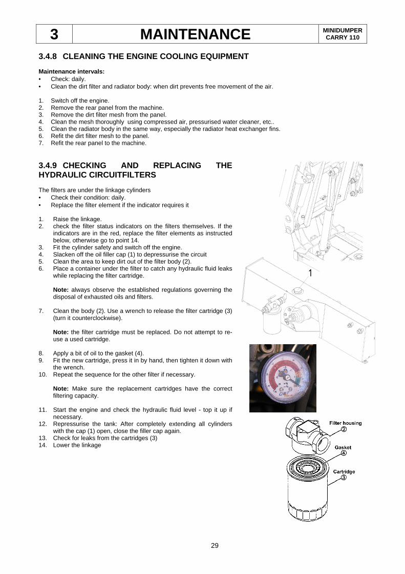
3.4.9 CHECKING AND REPLACING THE HYDRAULIC CIRCUITFILTERS The filters are under the linkage cylinders • Check their condition: daily. • Replace the filter element if the indicator requires it 1. Raise the linkage. 2. check the filter status indicators on the filters themselves. If the
indicators are in the red, replace the filter elements as instructed below, otherwise go to point 14.
3. Fit the cylinder safety and switch off the engine. 4. Slacken off the oil filler cap (1) to depressurise the circuit 5. Clean the area to keep dirt out of the filter body (2). 6. Place a container under the filter to catch any hydraulic fluid leaks
while replacing the filter cartridge.
Note: always observe the established regulations governing the disposal of exhausted oils and filters.
7. Clean the body (2). Use a wrench to release the filter cartridge (3) (turn it counterclockwise).
Note: the filter cartridge must be replaced. Do not attempt to re-use a used cartridge.
8. Apply a bit of oil to the gasket (4). 9. Fit the new cartridge, press it in by hand, then tighten it down with
the wrench. 10. Repeat the sequence for the other filter if necessary.
Note: Make sure the replacement cartridges have the correct filtering capacity.
11. Start the engine and check the hydraulic fluid level - top it up if necessary.
12. Repressurise the tank: After completely extending all cylinders with the cap (1) open, close the filler cap again.
13. Check for leaks from the cartridges (3) 14. Lower the linkage
1
3 MAINTENANCE MINIDUMPER CARRY 110
30
3.5 250 HOURS MAINTENANCE AND CHECKS
3.5.1 ENGINE OIL CHANGE • Check the condition: daily. • Change the oil after 250 hours of operation or if its condition makes an oil change imperative. Refer to paragraph 3.4.1 of this manual and the engine instruction manual for the oil change procedure. Note: always observe the established regulations governing the disposal of exhausted oils and filters.
3.5.2 REPLACING THE AIR FILTER ELEMENT • Check the condition: daily. • Replacement: After five cleaning cycles, after a year or when any part of the cleaner is damaged. Refer to point 3.4.5 of this manual for the replacement procedure Note: always observe the established regulations governing the disposal of exhausted filters.
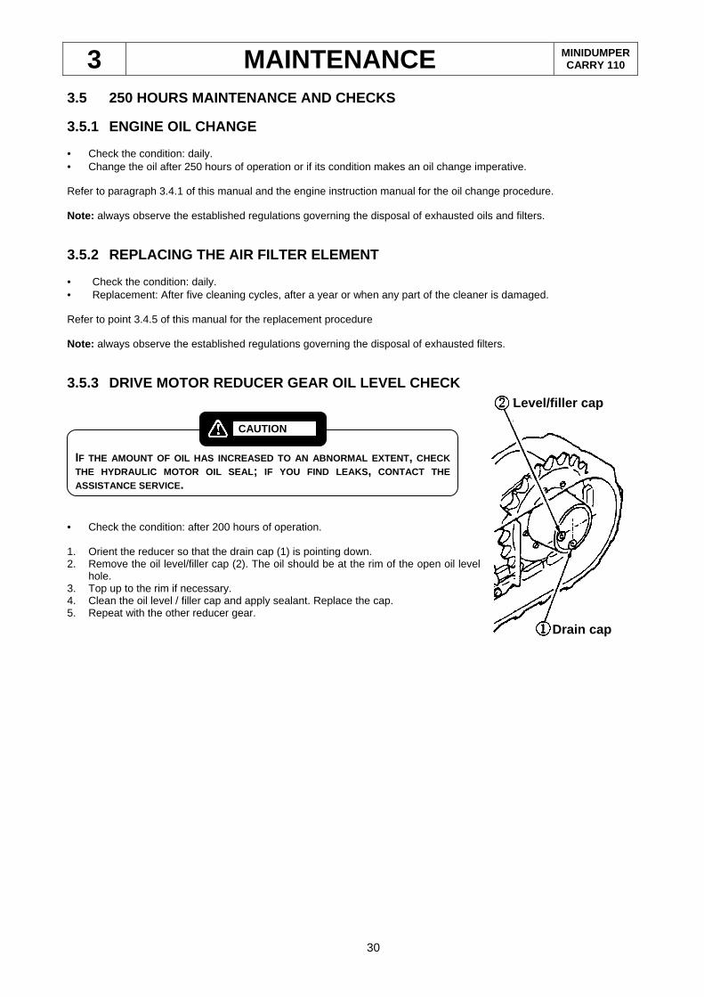
3.5.3 DRIVE MOTOR REDUCER GEAR OIL LEVEL CHECK
• Check the condition: after 200 hours of operation. 1. Orient the reducer so that the drain cap (1) is pointing down. 2. Remove the oil level/filler cap (2). The oil should be at the rim of the open oil level
hole. 3. Top up to the rim if necessary. 4. Clean the oil level / filler cap and apply sealant. Replace the cap. 5. Repeat with the other reducer gear.
Level/filler cap
Drain cap
IF THE AMOUNT OF OIL HAS INCREASED TO AN ABNORMAL EX TENT, CHECK THE HYDRAULIC MOTOR OIL SEAL ; IF YOU FIND LEAKS , CONTACT THE ASSISTANCE SERVICE .
CAUTION
3 MAINTENANCE MINIDUMPER CARRY 110
31
3.6 600 HOURS MAINTENANCE AND CHECKS (or 2 YEARS)
3.6.1 HYDRAULIC FLUID CHANGE
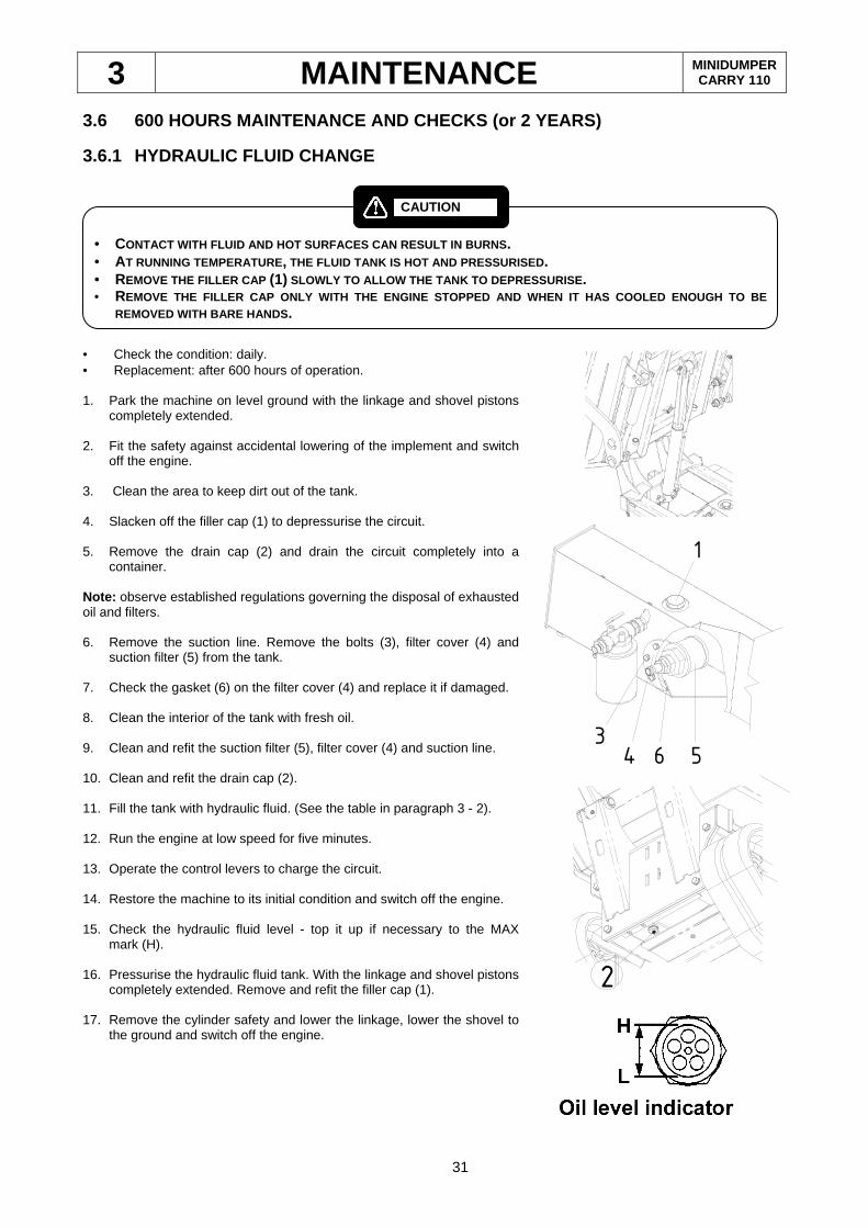
• Check the condition: daily. • Replacement: after 600 hours of operation. 1. Park the machine on level ground with the linkage and shovel pistons
completely extended. 2. Fit the safety against accidental lowering of the implement and switch
off the engine. 3. Clean the area to keep dirt out of the tank. 4. Slacken off the filler cap (1) to depressurise the circuit. 5. Remove the drain cap (2) and drain the circuit completely into a
container. Note: observe established regulations governing the disposal of exhausted oil and filters. 6. Remove the suction line. Remove the bolts (3), filter cover (4) and
suction filter (5) from the tank. 7. Check the gasket (6) on the filter cover (4) and replace it if damaged. 8. Clean the interior of the tank with fresh oil. 9. Clean and refit the suction filter (5), filter cover (4) and suction line. 10. Clean and refit the drain cap (2). 11. Fill the tank with hydraulic fluid. (See the table in paragraph 3 - 2). 12. Run the engine at low speed for five minutes. 13. Operate the control levers to charge the circuit. 14. Restore the machine to its initial condition and switch off the engine. 15. Check the hydraulic fluid level - top it up if necessary to the MAX
mark (H). 16. Pressurise the hydraulic fluid tank. With the linkage and shovel pistons
completely extended. Remove and refit the filler cap (1). 17. Remove the cylinder safety and lower the linkage, lower the shovel to
the ground and switch off the engine.
2
6 543
1
• CONTACT WITH FLUID AND HOT SURFACES CAN RESULT IN BU RNS. • AT RUNNING TEMPERATURE, THE FLUID TANK IS HOT AND PRESSURISED . • REMOVE THE FILLER CAP (1) SLOWLY TO ALLOW THE TANK TO DEPRESSURISE . • REMOVE THE FILLER CAP ONLY WITH THE ENGINE STOPPED A ND WHEN IT HAS COOLED ENOUGH TO BE
REMOVED WITH BARE HANDS .
CAUTION
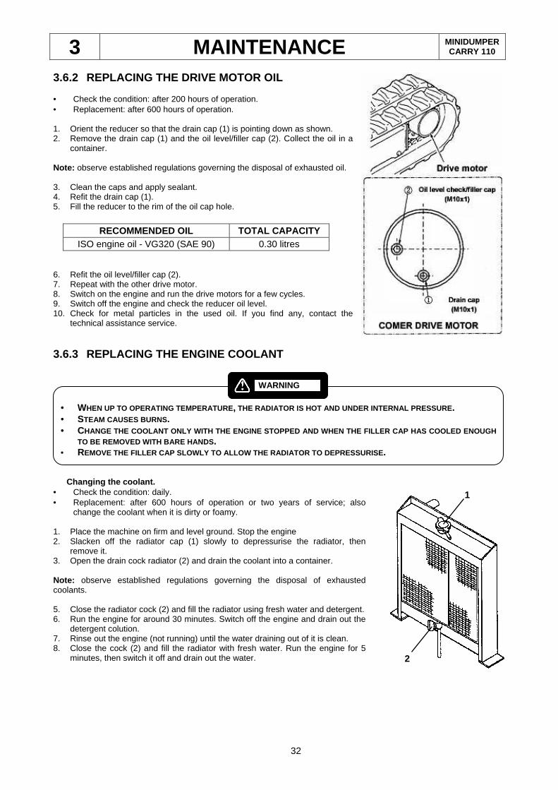
3 MAINTENANCE MINIDUMPER CARRY 110
32
RECOMMENDED OIL TOTAL CAPACITY ISO engine oil - VG320 (SAE 90) 0.30 litres
3.6.2 REPLACING THE DRIVE MOTOR OIL • Check the condition: after 200 hours of operation. • Replacement: after 600 hours of operation. 1. Orient the reducer so that the drain cap (1) is pointing down as shown. 2. Remove the drain cap (1) and the oil level/filler cap (2). Collect the oil in a
container. Note: observe established regulations governing the disposal of exhausted oil. 3. Clean the caps and apply sealant. 4. Refit the drain cap (1). 5. Fill the reducer to the rim of the oil cap hole.
6. Refit the oil level/filler cap (2). 7. Repeat with the other drive motor. 8. Switch on the engine and run the drive motors for a few cycles. 9. Switch off the engine and check the reducer oil level. 10. Check for metal particles in the used oil. If you find any, contact the
technical assistance service.
3.6.3 REPLACING THE ENGINE COOLANT
Changing the coolant. • Check the condition: daily. • Replacement: after 600 hours of operation or two years of service; also
change the coolant when it is dirty or foamy. 1. Place the machine on firm and level ground. Stop the engine 2. Slacken off the radiator cap (1) slowly to depressurise the radiator, then
remove it. 3. Open the drain cock radiator (2) and drain the coolant into a container. Note: observe established regulations governing the disposal of exhausted coolants. 5. Close the radiator cock (2) and fill the radiator using fresh water and detergent. 6. Run the engine for around 30 minutes. Switch off the engine and drain out the
detergent colution. 7. Rinse out the engine (not running) until the water draining out of it is clean. 8. Close the cock (2) and fill the radiator with fresh water. Run the engine for 5
minutes, then switch it off and drain out the water.
1
2
• WHEN UP TO OPERATING TEMPERATURE , THE RADIATOR IS HOT AND UNDER INTERNAL PRESSURE . • STEAM CAUSES BURNS . • CHANGE THE COOLANT ONLY WITH THE ENGINE STOPPED AND WHEN THE FILLER CAP HAS COOLED ENOUGH
TO BE REMOVED WITH BARE HANDS . • REMOVE THE FILLER CAP SLOWLY TO ALLOW THE RADIATOR T O DEPRESSURISE.
WARNING
3 MAINTENANCE MINIDUMPER CARRY 110
33
9. Repeat step 7 several times until the water drained out is clear. 10. Add coolant 11. Run the engine for 5 minutes with the radiator cap off (1). 12. Fill the radiator until the level reaches the neck of the filler. 13. Replace the cap if the gasket is damaged. Close the radiator cap (1).
Selecting the coolant the machine is delivered with long life coolant. This is a corrosion and deposit resistant antifreeze. The machine can then be used for two years without changing the coolant either in summer or winter. When it is time to change it, we recommend using a similar long life coolant. Mixture percentage for coolants The long life antifreeze/water ratio determines the freezing point of the solution. Select a dilution hat corresponds to a freezing point around 5°C below your lowest foreseeable temperature. The normal ratio is 30 % to 50 %. If less than 30 %, rust formation may be a problem, while more than 50 % can cause overheating. Always use fresh clean water for mixing the coolant.
3.7 SPECIAL OPERATING CONDITIONS Working in extreme atmospheric conditions (very high altitude, very high/low temperatures, salty water or very dusty/sandy worksites) can make special maintenance necessary. If the machine is to work in such conditions, certain precautions must be adopted o prevent damage and minimise wear and degradation of the components. EXTREMELY LOW TEMPERATURES. 1. Condensation may form in the fuel tank and freeze. The ice may block the flow of fuel in the ducts, thus stopping the
engine. This hazard can be reduced by keeping the fuel tank as fully topped up as possible during the cold season. If the water in the fuel should condense in the tank, drain the tank and fill it with fresh fuel.
2. Always use he recommended lubricants in relation to the ambient temperature - see the table in the manual’s Lubrication Chapter.
3. The battery is probably the component most vulnerable to low temperatures, and the electrolyte will freeze more
easily the lower the battery charge. On machines with batteries, keep the battery charged, especially if the machine is not used for a long time. The battery could also discharge if the terminals are covered with ice or snow and short circuit. Make sure to keep the terminals and clamps dry. Remove any signs of corrosion with water and sodium carbonate. In case of long periods of disuse at very low temperatures, remove the battery and keep it out of the cold.
Freezing point (°C) -15°C -25°C -35°C
Liquid/water ratio (%) 30% 40% 50%
IT MAY HAPPEN THAT THE DISTILLED WATER FREEZES BEFOR E IT CAN MIX WITH THE ACID . AT VERY LOW TEMPERATURES , ONLY ADD WATER TO THE BATTERY IMMEDIATELY BEFORE R UNNING THE ENGINE, OR EVEN WITH THE ENGINE ALREADY RUNNING . IF THE ENGINE CANNOT BE RUN FOR WHATEVER REASON , ADD WATER WITH EH BATTERY ’S TERMINALS CONNECTED TO THE EXTERNAL BATTERY CHARGE R.
WARNING
3 MAINTENANCE MINIDUMPER CARRY 110
34
4. Pay special attention to the hydraulic fluid.
5. At the end of periods of work or if the machine is not used for a long time, park the machine on a dry, solid surface to
prevent ice forming under it, such as: wood, cement, asphalt or similar. VERY HIGH TEMPERATURES Special precautions must also be taken in this case to protect the battery and lubrication system. 1. Use more viscous lubricants in very hot conditions, but not ones that degrade more quickly if subjected to heat. Refer
to the lubrication section of this manual for lubricants suited to high temperatures. Remember that the engine’s heat dissipation capacity also depends on the amount of oil in the engine casing; check the level frequently and top up as required.
2. When it is very hot, evaporation can cause a drop in the battery acid level; check it frequently and add distilled water
as necessary. 3. The air circulation around the machine must not be impeded, make sure the air intakes and exhausts are not blocked
by leaves, paper or similar materials. 4. Keep the engine clean of grease and other substances which prevent efficient heat dispersal. 5. Switch off the engine when not working. VERY SANDY/DUSTY CONDITIONS Particles in the air can accelerate the wear of the machine’s components; they exercise an abrasive action on moving parts. To prevent this, lubricate the machine more frequently and service the air intakes and filters more often. 1. Take care not to let sand or dust into the hydraulics; keep the tank well closed and keep an eye on the filter. 2. Do not let sand or dust enter the fuel tank. 3. The engine’s air intakes and the air cleaner must be checked more frequently. The engine oil and filter must be
replaced more frequently to ensure the oil is clean. 4. Before greasing parts with a manual gun, clean off all traces of residual grease. Then pump in a generous amount of
grease so as to clean the interior parts of residues. 5. When working on sandy ground, a support may be required for the tracks. 6. Do not allow them to dig themselves into the sand. To ensure a good support, it may be necessary to back off and fill
the loose area with more compact earth. 7. The increased frequency of maintenance operations depends on the effective conditions of use and will vary from
case to case, in relation to the results of the checks which will show accumulation of dust in the filters and the intakes.
BEFORE WORKING WITH THE MACHINE , HEAT UP THE HYDRAULIC FLUID AS INSTRUCTED IN PARAG RAPH 1.1
WARNING
3 MAINTENANCE MINIDUMPER CARRY 110
35
HIGH HUMIDITY AND SALINITY In some locations, for instance, coastal areas, the machine may be attacked by a combination of salinity and humidity. To protect exposed metal surfaces, electrical wiring and gaskets, take care to keep the machine dry and grease the metal surface abundantly. 1. Eliminate traces of rust as soon as they appear and paint over the affected area. 2. When painting is not an option - machined surfaces - apply grease or water-repellent lubricant. 3. Keep the bearings and their vicinity well lubricated to prevent water infiltration. 4. Never use saline water in the cooling system - this causes serious problems of corrosion and may require all affected
parts to be replaced. 5. Frequently wash the machine when working near to saline water, and clean all moving parts with an oily cloth. 6. If the machine is working wet, take good care not to allow the water to reach the top of the tracks. If this should occur,
you must remove, clean and lubricate the entire undercarriage. HIGH ALTITUDE Changes in altitude change the air/fuel mixture injected into the engine combustion chambers, so that the engine’s performance may be affcted; high altitudes have a lower atmospheric pressure and less oxygen in the air. Over 1500 metres above sea level you may have to adjust the fuel injection for the machine to run properly. Refer to the Technical Assistance Service for details. To reduce the problems attendant on the lower density of the air it is important to keep the air clean as clean as possible. Keep an eye on the engine temperature as it will tend to overheat.
3.8 LENGTHY STORAGE
Proceed as follows when storing the machine for a long time: • Clean the machine and store it under cover. If you have no choice but to store it outdoors, park it on level ground
and cover it with a tarp. • Grease all exposed parts of the cylinder pistons • Completely drain the fuel circuit. • Disconnect the battery’s negative terminal. Switch the machine on once a month during storage to maintain the lubricant film When taking the machine out of storage: • remove the grease from the cylinder pistons • make sure the fuel and lubricant tanks are topped up.
IMPLEMENT THE ENGINE STORAGE PROCEDURE GIVEN IN THE MANUALS . IF THE MACHINE IS INSIDE A WAREHOUSE , MAKE SURE THE AREA IS WELL VENTILATED TO PREVENT R USTING.
WARNING
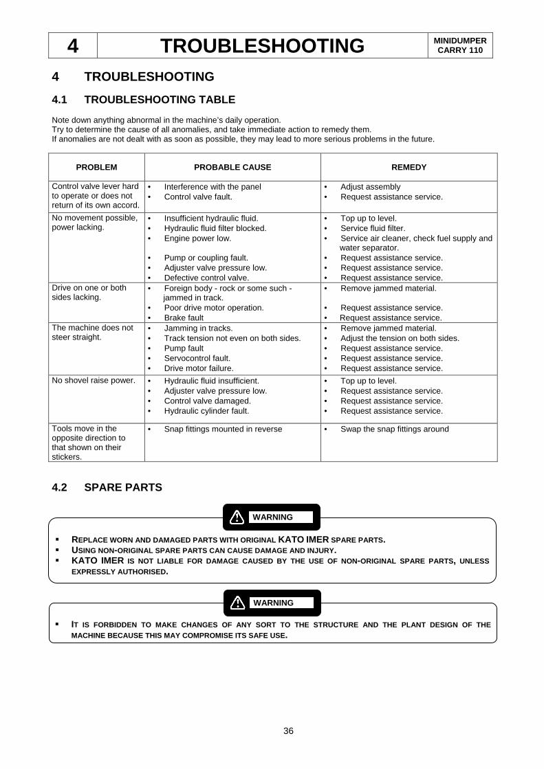
4 TROUBLESHOOTING MINIDUMPER CARRY 110
36
4 TROUBLESHOOTING
4.1 TROUBLESHOOTING TABLE Note down anything abnormal in the machine’s daily operation. Try to determine the cause of all anomalies, and take immediate action to remedy them. If anomalies are not dealt with as soon as possible, they may lead to more serious problems in the future.
PROBLEM PROBABLE CAUSE REMEDY
Control valve lever hard to operate or does not return of its own accord.
• Interference with the panel • Control valve fault.
• Adjust assembly • Request assistance service.
No movement possible, power lacking.
• Insufficient hydraulic fluid. • Hydraulic fluid filter blocked. • Engine power low. • Pump or coupling fault. • Adjuster valve pressure low. • Defective control valve.
• Top up to level. • Service fluid filter. • Service air cleaner, check fuel supply and
water separator. • Request assistance service. • Request assistance service. • Request assistance service.
Drive on one or both sides lacking.
• Foreign body - rock or some such - jammed in track.
• Poor drive motor operation. • Brake fault
• Remove jammed material. • Request assistance service. • Request assistance service.
The machine does not steer straight.
• Jamming in tracks. • Track tension not even on both sides. • Pump fault • Servocontrol fault. • Drive motor failure.
• Remove jammed material. • Adjust the tension on both sides. • Request assistance service. • Request assistance service. • Request assistance service.
No shovel raise power. • Hydraulic fluid insufficient. • Adjuster valve pressure low. • Control valve damaged. • Hydraulic cylinder fault.
• Top up to level. • Request assistance service. • Request assistance service. • Request assistance service.
Tools move in the opposite direction to that shown on their stickers.
• Snap fittings mounted in reverse • Swap the snap fittings around
4.2 SPARE PARTS � REPLACE WORN AND DAMAGED PARTS WITH ORIGINAL KATO IMER SPARE PARTS . � USING NON-ORIGINAL SPARE PARTS CAN CAUSE DAMAGE AND INJURY . � KATO IMER IS NOT LIABLE FOR DAMAGE CAUSED BY THE USE OF NON -ORIGINAL SPARE PARTS , UNLESS
EXPRESSLY AUTHORISED .
WARNING
� IT IS FORBIDDEN TO MAKE CHANGES OF ANY SORT TO THE S TRUCTURE AND THE PLANT DESIGN OF THE
MACHINE BECAUSE THIS MAY COMPROMISE ITS SAFE USE .
WARNING
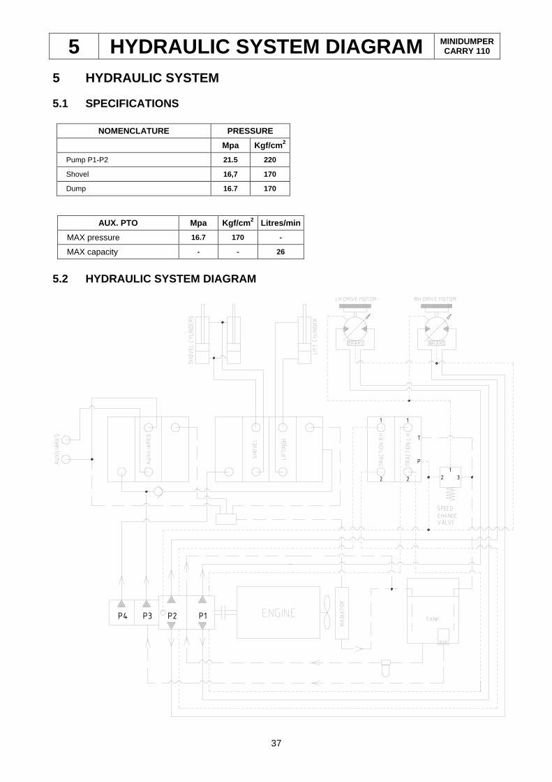
5 HYDRAULIC SYSTEM DIAGRAM MINIDUMPER CARRY 110
37
NOMENCLATURE PRESSURE Mpa Kgf/cm 2 Pump P1-P2 21.5 220
Shovel 16,7 170
Dump 16.7 170
AUX. PTO Mpa Kgf/cm 2 Litres/min MAX pressure 16.7 170 -
MAX capacity - - 26
5 HYDRAULIC SYSTEM 5.1 SPECIFICATIONS
5.2 HYDRAULIC SYSTEM DIAGRAM
P4 P3 P2 P1
1
2
T
2
P
32
1
1

6 ELECRIC SYSTEM DIAGRAM MINIDUMPER CARRY 110
38
6 ELECRIC SYSTEM DIAGRAM R
ed
1 m
m²
WIR
E C
ON
NEC
TIO
N O
N C
ON
NEC
TO
RS
SEEN
FR
OM
CA
BLES E
NG
AG
EM
EN
T S
IDE
Pin
k 0
.75 m
m²
Gre
y 0
.75 m
m²
HO
UR
METE
R R
ELA
Y (
11
92
47
-77
10
0)
BLU
E C
LAM
P 4
se
c.
TIM
ER
(1
29
155
-77
92
5)
BR
OW
N C
LAM
P 1
se
c.
TIM
ER
(1
29
211
-77
92
0)
LC
DI
NC
NC
2N
C1
F2
F3
F1
RCTE
2
TE1
RE
Re
d 2
.5 m
m²
Re
d 1
mm
²
B12
OIL
PR
ESSU
RE S
WIT
CH
DC
12
V 1
A-0
.5K
g/c
m2 O
FF
(11
42
50-3
94
50
)
WA
TER
TEM
PER
ATU
RE S
EN
SO
R
DC
12V
0.4
A-1
10
°C O
N
(121
25
0-4
49
01)
S
B
STA
RTE
R M
OTO
R
DC
12
V 1
.1K
w-(
519
12
5-7
70
10)
B14
FU
SE 6
0A
Red 6 mm² L=600 mm
Re
d 6
mm
²
Re
d 6
mm
² L=
550 m
m
B/M G
N
TIM
ER
4±
1 s
ec
.
B/R
G R N
B/M
G B/N N
R1
AC
C
B/R
R NG
R
RR
S
NG
TIM
ER
1±
0.5
se
c.
B/R
G R N
R GRRS
N
A B C D
AB
CD
DC
AB
RELA
Y D
C1
2V
40A
(1196
50-7
7910)
DIO
DE 6
00
V 1
A (
119
64
3-6
69
00)
A M A
N G R
A M A
N G/R R
CU
RR
EN
T LI
MIT
ER
DC
14
.5 +
- 0
.5V
(1
19
225
-77
72
0)
Bla
ck 4
mm
²
10A
30A
G/R A AMR N
Ye
llow
-Re
d 1
.5 m
m²
Pin
k 0
.75
mm
²
BR
N
RB
N
PU
LL
HO
LD
B R NB
5
EN
GIN
E S
TOP
SO
LEN
OID
DC
12
V-H
OLD
0.4
9A
-PU
LL 3
6.5
A
(11
96
53-7
79
50
)
DY
NA
MO
DC
12
V 2
0A
(11
96
26-7
72
00
)
2 3
2 3
SEC
ON
D S
PEED
SO
LEN
OID
Ora
ng
e 0
.75 m
m²
Black 0.75 mm²
Black 1.5 mm²SEC
ON
D S
PEED
SW
ITC
H1 2 Ora
ng
e 0
.75
mm
²
A1
7
A1
8
Re
d 0
.75 m
m²
BA
Gre
y 0
.75 m
m²
Pin
k 0
.75
mm
²
Re
d 2
.5 m
m²
L=270
mm
Wit
he
-Bro
wn
1 m
m²
Ye
llow
0.7
5 m
m²
Wit
he
-Bla
ck 0
.75 m
m²
Ora
ng
e 1
.5 m
m²
Ora
ng
e 1
.5 m
m²
Bro
wn
1 m
m²
Re
d 1
.5 m
m²
Bla
ck 1
.5 m
m²
GLO
W P
LUG
LED
OIL
LED
GEN
ER
ATO
R
LED
WA
TER
TEM
PER
ATU
RE
LED
B
C
R2
+
HO
UR
METE
R
KEY
SW
ITC
H
10A
A+
Black 35 mm² L=500 mm
BA
TTER
Y
2050309005 Red 35 mm² L=1050 mm
GLO
W P
LUG
Bla
ck 4
mm
²
A1
1
A1
3
A1
4
A1
5
A1
6
A1
2
A1
A5
A6
A19
A20
A2
3
A2
4
A2
5
A2
6
A2
8A
29
A30
A33
B2
B10
B9
B1
B8
2030809000
BR
A3
4
Pre
-ris
c.
Sta
rt
ON
OFFC
ON
NEC
TIO
N D
ETA
IL
R1
BA
cc
Br
R2
C
Bla
ck 0
.75
mm
²
Bla
ck 0
.75 m
m²
Bla
ck 0
.75
mm
²
Bla
ck 0
.75
mm
²
Ye
llow
0.7
5 m
m²
Bro
wn
1 m
m²
Pin
k 0
.75
mm
²
Re
d 2
.5 m
m²
Bla
ck 1
mm
²
Ora
ng
e 1
.5 m
m²
Ora
ng
e 1
.5 m
m²
Bla
ck 1
mm
²
Bla
ck 0
.75 m
m²
Bla
ck 0
.75 m
m²
Bla
ck 0
.75 m
m²
Re
d 2
.5 m
m²
Wit
he
2.5
mm
²
Bla
ck 2
.5 m
m²
Wit
he
2.5
mm
² L=
650 m
m
Bla
ck 1
.5 m
m²
Re
d 1
mm
²
Ye
llow
-Re
d 1
.5 m
m²
Re
d-B
row
n 1
.5 m
m²
Re
d 2
.5 m
m²
2 3
2 3
Ora
ng
e 1
.5 m
m²
Ora
ng
e 1
.5 m
m²
1 3 4
5 7 8
26
5 7 86
1 3 42O
ran
ge
0.7
5 m
m²
Pin
k 0
.75 m
m²
Bla
ck 1
.5 m
m²
1 2 4 35 6 7 8
1 2 34 5678
Bla
ck 1
.5 m
m²
Re
d 2
.5 m
m²
Wit
he
2.5
mm
²
Ora
ng
e 0
.75
mm
²
Pin
k 0
.75
mm
²
Bla
ck 1
.5 m
m²
Bla
ck 1
.5 m
m²
With
e-B
row
n 1
.5 m
m²
Re
d 2
.5 m
m²
Wit
he
2.5
mm
²W
ith
e-B
row
n 1
.5 m
m²
Wit
he
-Bro
wn
1.5
mm
²
Bla
ck 0
.75 m
m²
Bla
ck 0
.75
mm
²
B4
B11
B7
Lig
ht
blu
e 0
.75 m
m²
Lig
ht
blu
e 0
.75 m
m²
Lig
ht
blu
e 0.7
5 m
m²
N N
M V
M N VM
Bro
wn
1 m
m²
Bro
wn
1 m
m²
Bla
ck 0
.75 m
m²
Bla
ck 0
.75 m
m²
Gre
en
0.7
5 m
m²
C AE
D B
B E A C D
NC
CO
M
NO
B13
B6
Black 2.5 mm²
Black 1.5 mm²
A2
B/R
R NG
B/N
Ye
llow
-Re
d 1
.5 m
m²
Re
d-B
row
n 1
.5 m
m²
Re
d-B
row
n 1
.5 m
m²
Re
d-B
row
n 1
.5 m
m²
Re
d-B
row
n 1
.5 m
m²
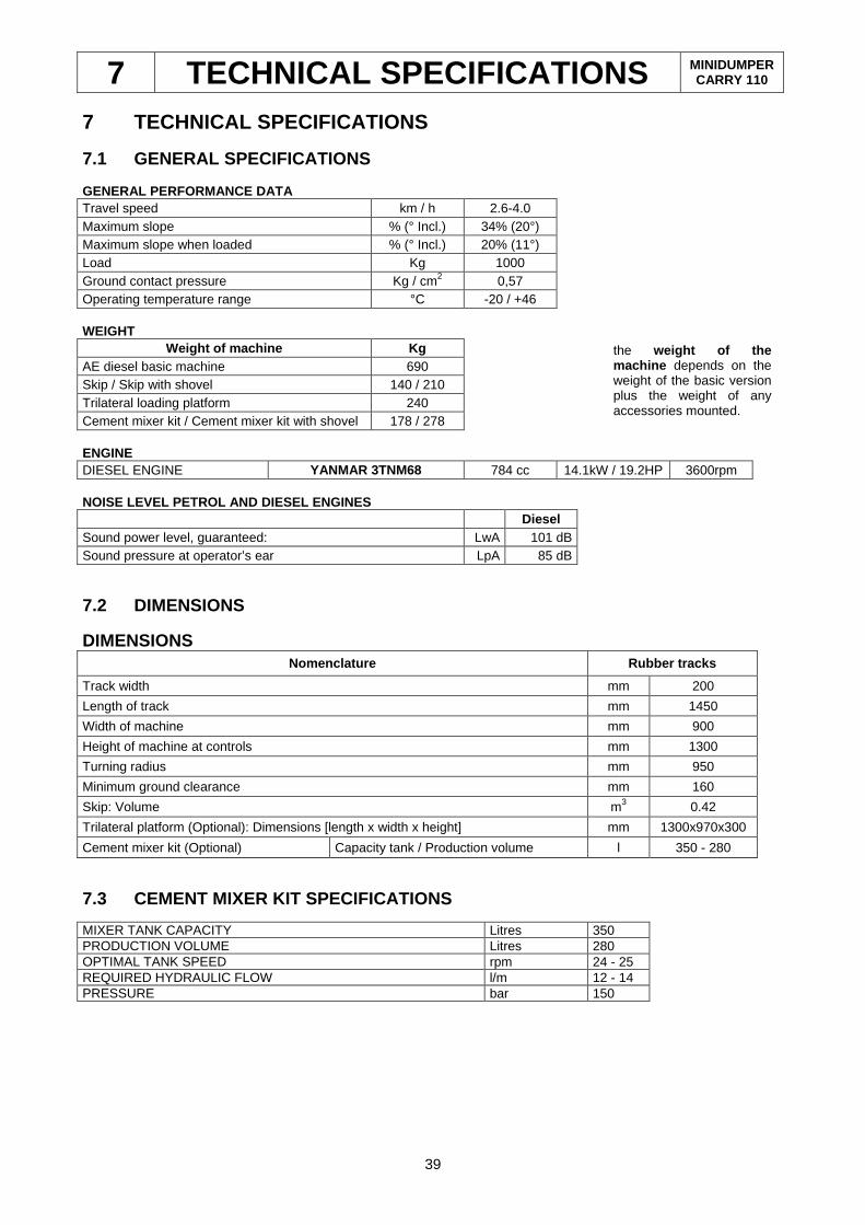
7 TECHNICAL SPECIFICATIONS MINIDUMPER CARRY 110
39
7 TECHNICAL SPECIFICATIONS
7.1 GENERAL SPECIFICATIONS GENERAL PERFORMANCE DATA Travel speed km / h 2.6-4.0 Maximum slope % (° Incl.) 34% (20°) Maximum slope when loaded % (° Incl.) 20% (11°) Load Kg 1000 Ground contact pressure Kg / cm2 0,57 Operating temperature range °C -20 / +46 WEIGHT
Weight of machine Kg AE diesel basic machine 690 Skip / Skip with shovel 140 / 210 Trilateral loading platform 240 Cement mixer kit / Cement mixer kit with shovel 178 / 278 ENGINE DIESEL ENGINE YANMAR 3TNM68 784 cc 14.1kW / 19.2HP 3600rpm NOISE LEVEL PETROL AND DIESEL ENGINES Diesel Sound power level, guaranteed: LwA 101 dB Sound pressure at operator’s ear LpA 85 dB
7.2 DIMENSIONS
DIMENSIONS Nomenclature Rubber tracks
Track width mm 200
Length of track mm 1450
Width of machine mm 900
Height of machine at controls mm 1300
Turning radius mm 950
Minimum ground clearance mm 160
Skip: Volume m3 0.42
Trilateral platform (Optional): Dimensions [length x width x height] mm 1300x970x300
Cement mixer kit (Optional) Capacity tank / Production volume l 350 - 280 7.3 CEMENT MIXER KIT SPECIFICATIONS MIXER TANK CAPACITY Litres 350 PRODUCTION VOLUME Litres 280 OPTIMAL TANK SPEED rpm 24 - 25 REQUIRED HYDRAULIC FLOW l/m 12 - 14 PRESSURE bar 150
the weight of the machine depends on the weight of the basic version plus the weight of any accessories mounted.
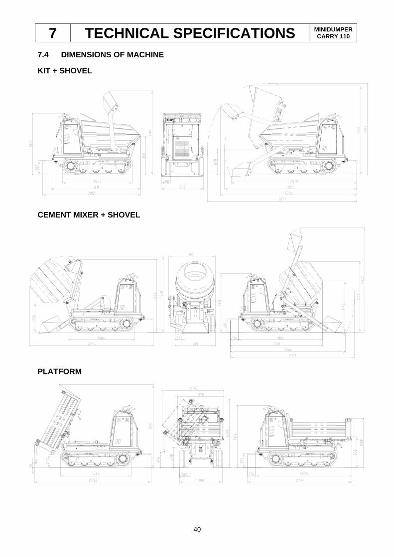
7 TECHNICAL SPECIFICATIONS MINIDUMPER CARRY 110
40
7.4 DIMENSIONS OF MACHINE
KIT + SHOVEL
CEMENT MIXER + SHOVEL
PLATFORM

TRACKED MINIDUMPER
CARRY 110
PUBLISHED: MARCH 2017
KATO IMER S.p.A.
ITALY