Embed Size (px)
Citation preview
i
TransCanada Keystone XL Pipeline ProjectPre-Construction Notification to the U.S. Army Corps of Engineers Omaha District – Montana
Prepared for:
TransCanada Keystone Pipeline, LP700 Louisiana StreetHouston, Texas 77002
Prepared by:
exp Energy Services Inc.1300 Metropolitan Blvd.Tallahassee, Florida 32308
Document NumberTAL-KXL-1100-04-02
Date SubmittedMay 25, 2017
TransCanada700 Louisiana Street Houston, Texas 77002Tel: (832) 320-5385
May 25, 2017
U.S. Army Corps of Engineers
490 North 31st Street, Suite 112
Billings, MT 59102
RE: Keystone XL Pipeline Project – Nationwide Permit 12 Pre-Construction Notification
(PCN)
Dear :
Please find attached the TransCanada Keystone Pipeline, LP (Keystone) Nationwide Permit
(NWP) 12 Pre-Construction Notification (PCN) package for the portion of the proposed Keystone
XL Pipeline Project (Project) located within the U.S. Army Corps of Engineers (USACE) Omaha
District in Montana.
The U.S. Department of State (DOS), as the lead federal action agency, issued the Final
Supplemental Environmental Impact Statement (FSEIS) in January 2014 and the Final
Environmental Impact Statement (FEIS) in August 2011. The FSEIS was prepared to address
Project changes since the August 2011 FEIS, most notably the route change implemented in
Nebraska and approved by the Governor in January 2013.
On January 24, 2017, President Trump issued a Presidential Memorandum Regarding
Construction of the Keystone XL Pipeline directing the USACE and other Federal permitting
agencies to process expeditiously Keystone’s permit applications for the Project. Keystone
submitted the application for a Presidential Permit on January 26, 2017, and it was subsequently
issued on March 23, 2017.
To assist with your review, the following documents are provided:
Standard Form 4345 (imbedded herein) - The standard Form 4345 and additionalinformation required for PCNs are included at the front of this package. The twowaterbody features requiring a PCN are addressed including information related to theapplicable PCN criteria, location, crossing length, anticipated construction method, andestimates of temporary and permanent impacts. Information relative to non-PCN featuresare also provided principally consisting of location and whether proposed impacts aretemporary or permanent. Keystone has adopted the USACE Regulatory Guidance Letter16-01, dated October 31, 2016, on jurisdiction of waters of the United States and is notrequesting jurisdictional concurrence due to the nature of the Project scope.
PCN Waterbody Mapbook (Attachment A) – Waterbody crossings requiring a PCN areillustrated on a U.S. Geological Survey (USGS) topographic base at a scale of 1:6,000, as

TransCanada700 Louisiana Street Houston, Texas 77002Tel: (832) 320-5385
well as on a digital ortho-rectified photographic base at the same scale. The pipeline
mileposts and anticipated construction work spaces are included. The aerial photographic
base is provided by the National Agricultural Imagery Program (NAIP) from aerial imagery
acquired during the 2015 agricultural growing season.
Wetland Assessment Methodology and Results, OMBIL Regulatory Module (ORM) Table(for PCN features), Non-PCN Datasheet Table (for non-PCN features), and Wetland andWaterbody Mapbook (Attachment B; bound separately).
Construction Mitigation and Reclamation Plan (CMRP; Attachment C). This documentprovides typical wetland and waterbody crossing procedures, as well as typical uplandconstruction methods.
Horizontal Directional Drill Frac-out Contingency Plan (Attachment D).
Horizontal Directional Drill Site-Specific Drawings (Attachment E).
2017 Nationwide Permits, Regional Conditions, Omaha District, State of Montana(Attachment F).
Montana Joint Application (Attachment G).
Upon completion of your review Keystone requests concurrence of NWP 12 applicability for the
Project. Should you require additional information or have questions with respect to this
submittal, please contact Michael Aubele at (713) 439-3606 or me at (832) 320-5385.
Sincerely,
Sandra Barnett
Environmental Specialist
Keystone Pipeline Projects
Cc:
Michael Aubele, exp Energy Services, Inc.
Jon Schmidt, exp Energy Services, Inc.
Meera Kohthari, Keystone
iv
Table of Contents
Pre-Construction Notification for NWP 12 ................................................................................................... 11
Blocks 5 through 10. Applicant’s Name and Address. ............................................................................... 11
Block 12. Project Name or Title. ................................................................................................................ 11
Block 13. Name of Waterbody. .................................................................................................................. 11
Block 14. Project Address. ......................................................................................................................... 11
Block 15. Location of Project. .................................................................................................................... 12
Block 16. Other Location Descriptions. ...................................................................................................... 12
Block 17. Directions to Site. ....................................................................................................................... 12
Block 18. Nature of Activity. ....................................................................................................................... 12
Block 19. Project Purpose. ......................................................................................................................... 20
Block 20. Reason for Discharge. ............................................................................................................... 20
Block 21. Types of Material Being Discharged. ......................................................................................... 20
Block 22. Surface Areas in Acres of Wetlands or Other Waters Filled. ..................................................... 20
Block 23. Description of Avoidance, Minimization, and Compensation. .................................................... 20
Block 24. Is Any Portion of the Work Already Complete? .......................................................................... 21
Block 25. Addresses of Adjoining Property Owners, Lessees, etc., Whose Property Adjoins theWaterbody. .................................................................................................................................................. 21
Block 26. List of Other Certifications or Approvals/Denials Received from other Federal, State, or LocalAgencies for Work Described in This Application. ...................................................................................... 21
List of Figures
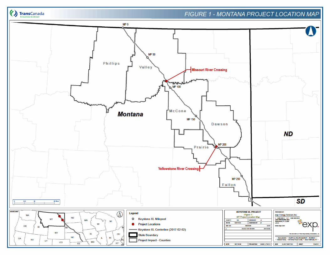
Figure 1 – Keystone XL Project – Project Location Map ............................................................................ 22
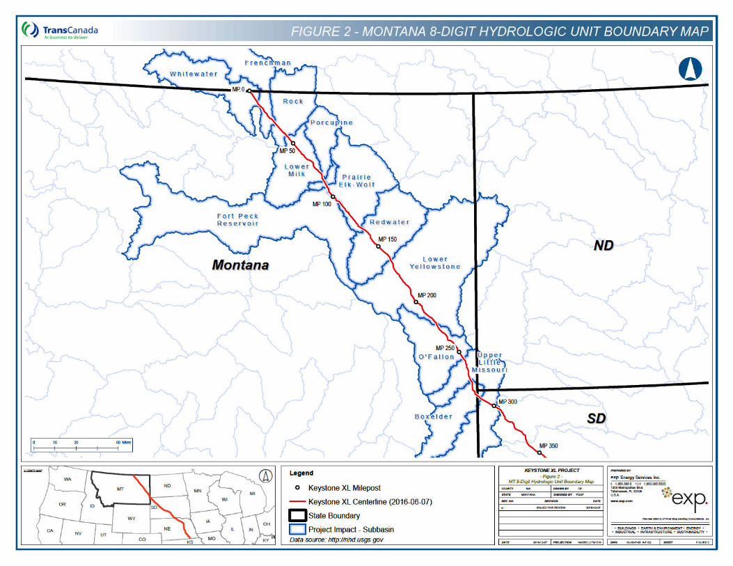
Figure 2 – Keystone XL Project – Hydrologic Unit Boundary Map ............................................................. 23
List of Tables Table 1 – Keystone XL Pipeline Project – Pre-Construction Notification Requirement Analysis USACE,
Omaha District, Montana .................................................................................................................... 24
Table 2 – Keystone XL Pipeline Project – Mainline Waterbody Crossings within the USACE OmahaDistrict Requiring Pre-Construction Notification – Montana ............................................................... 25
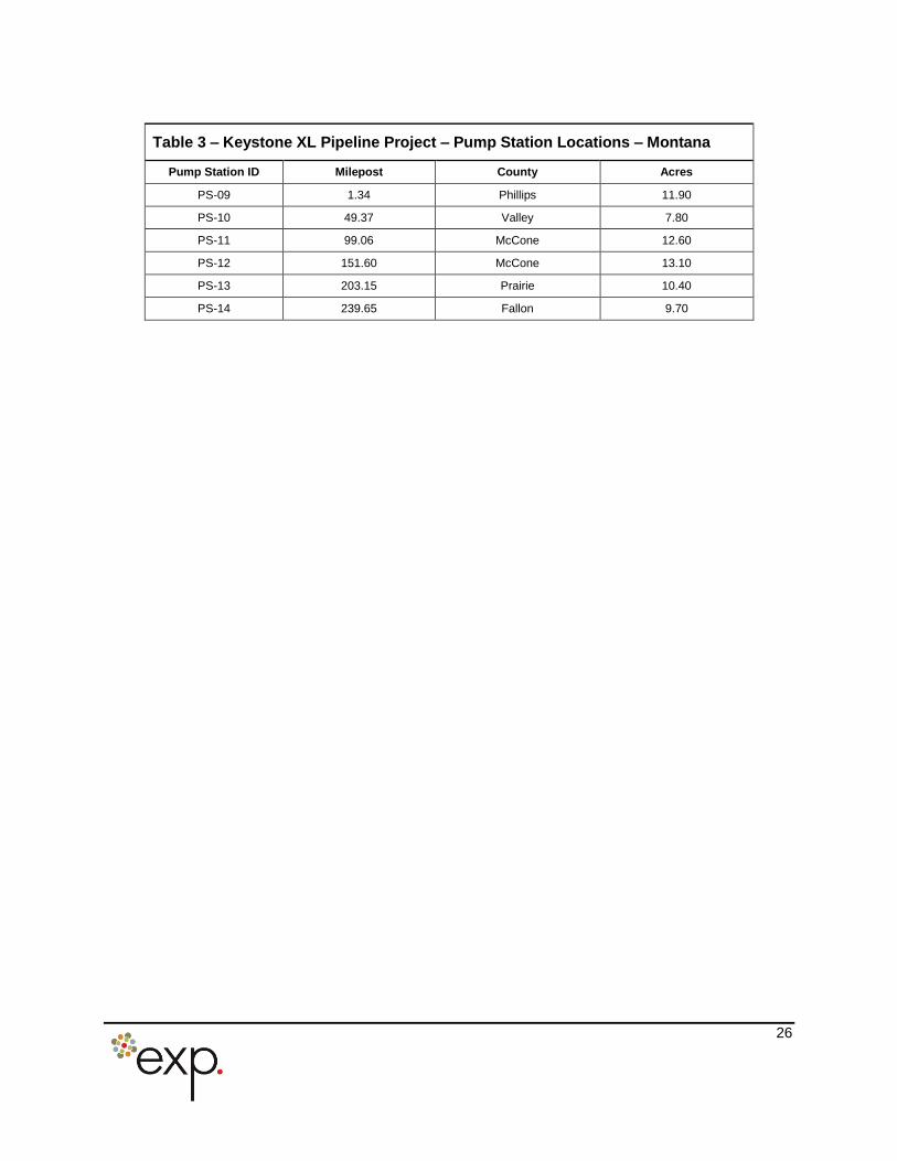
Table 3 – Keystone XL Pipeline Project – Pump Station Locations – Montana ......................................... 26
Table 4 – Keystone XL Pipeline Project – Permits, Licenses, Approvals, and Consultation Requirements........................................................................................................................................................................ 27
List of Attachments
Attachment A. Map Volume – PCN Waterbody Mapbook
v
Attachment B. Wetland Assessment Methodology and Results, OMBIL Regulatory Module (ORM) Table(for PCN features), Non-PCN Datasheet Table (for non-PCN features), and Wetland and WaterbodyMapbook (bound separately)
Attachment C. Construction Mitigation and Reclamation Plan
Attachment D. Horizontal Directional Drill Frac-out Contingency Plan
Attachment E. Horizontal Directional Drill Site-Specific Drawings
Attachment F. 2017 Nationwide Permits, Regional Conditions, Omaha District, State of Montana
Attachment G. Montana Joint Application
vi
Acronyms and AbbreviationsACHP Advisory Council on Historic PreservationAPE Area of Potential EffectATF Bureau of Alcohol, Tobacco, Firearms and ExplosivesARPA Archeological Resources Protection ActBA Biological AssessmentBiOp Biological OpinionBLM Bureau of Land ManagementBOR Bureau of ReclamationCFR Code of Federal RegulationsCMRP Construction Mitigation and Reclamation PlanCWA Clean Water ActDNRC Department of Natural Resources and ConservationDOS United States Department of StateEPA Environmental Protection AgencyERP Emergency Response PlanESA Endangered Species ActFEIS Final Environmental Impact StatementFHWA Federal Highway AdministrationFLPMA Federal Land Policy and Management ActFSA Farm Service AgencyFSEIS Final Supplemental Environmental Impact StatementHDD horizontal direction drillHUC hydrologic unit codeKeystone TransCanada Keystone Pipeline, LPMBTA Migratory Bird Treaty ActMCS Motor Carrier ServicesMDEQ Montana Department of Environmental QualityMFSA Major Facility Siting ActMGWPCS Montana Ground Water Pollution Control SystemMLA Mineral Leasing ActMP milepostMPDES Montana Pollutant Discharge Elimination SystemNAIP National Agriculture Imagery ProgramNEPA National Environmental Policy ActNHPA National Historic Preservation ActNPDES National Pollutant Discharge Elimination SystemNRCS National Resources Conservation ServiceNRHP National Register of Historic PlacesNWP Nationwide PermitOPS Office of Pipeline SafetyORM OMBIL Regulatory ModulePCN Pre-Construction NotificationPER Perennial
vii
PHMSA Pipeline and Hazardous Material Safety AdministrationPOD Plan of DevelopmentProject Keystone XL Pipeline ProjectPSRP Pipeline Spill Response PlanRHA Rivers and Harbors ActROW right-of-wayRUS Rural Utilities ServicesSEIS Supplemental Environmental Impact StatementSHPO State Historic Preservation OfficeU.S. United StatesUSACE U.S. Army Corps of EngineersUSDA U.S. Department of AgricultureUSFWS U.S. Fish and Wildlife ServiceUSGS U.S. Geological SurveyWCSB Western Canadian Sedimentary BasinWestern Western Area Power Administration
11
Pre-Construction Notification for NWP 12Department of the Army Permit Form 4345
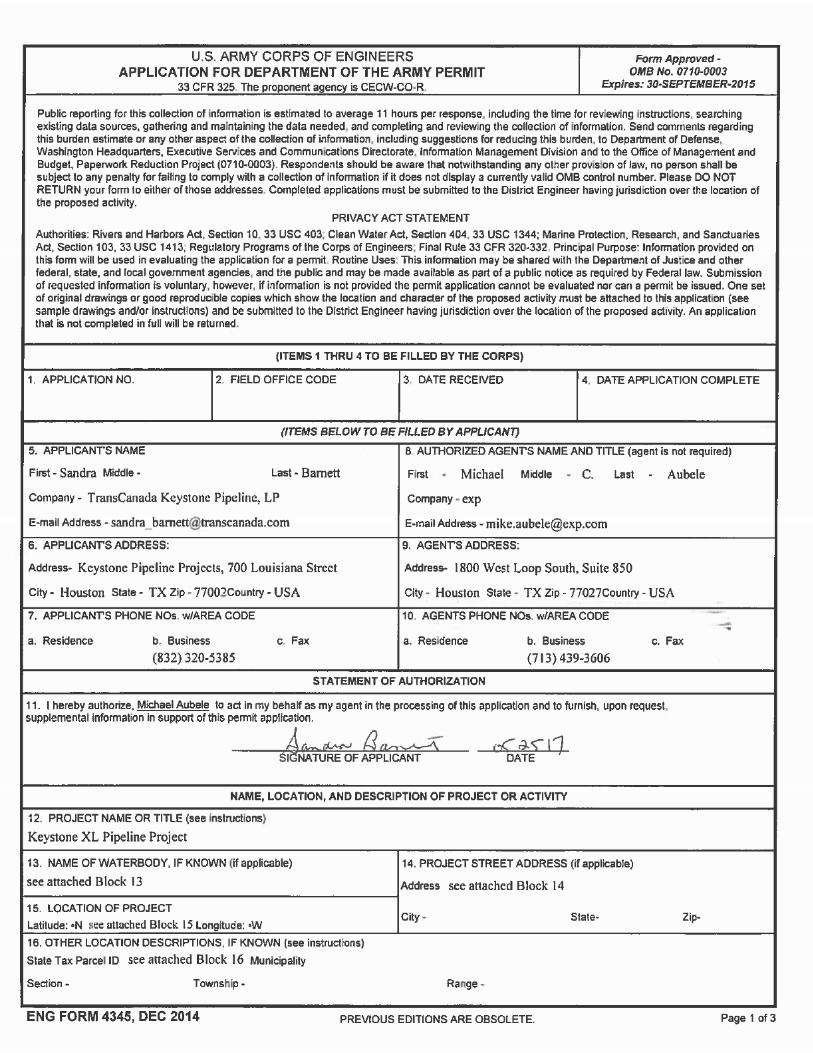
To supplement the attached U.S. Army Corps of Engineers (USACE) Application for Department of theArmy Permit, Form 4345, additional information necessary for the Pre-Construction Notification (PCN)requirements is included in the following sections. The Blocks in Form 4345 are referenced below andthe tables and figures are presented after the Block text.
Blocks 5 through 10. Applicant’s Name and Address.
Applicant
TransCanada Keystone Pipeline, LPSandra Barnett – Environmental SpecialistKeystone Pipeline Projects700 Louisiana Street, Suite 700Houston, Texas 77002-2700(832) 320-5385
Authorized Agent
Michael AubeleDirector, Environmental & Regulatory – United Statesexp Energy Services, Inc.1800 West Loop South, Suite 850Houston, Texas 77027(713) 439-3606
Block 12. Project Name or Title.
Keystone XL Pipeline Project (Project).
Block 13. Name of Waterbody.
The Project will cross two waterbodies (Missouri River and Yellowstone River) that are jurisdictionalwaterways under Section 10 of the Rivers and Harbors Act within the USACE Omaha District in Montanathat require the submittal of a PCN to the USACE based on NWP 12 Conditions, the NWP ProgramGeneral Conditions, and/or Regional Condition requirements. The PCN requirements evaluated for theProject in Montana are provided in Table 1. The locations, hydrologic unit code (HUC), and otherinformation related to these two waterbodies crossed by the Project and requiring PCN are provided inTable 2 below and the ORM Table in Attachment B. The individual PCN waterbody crossings areillustrated on the maps contained in the PCN Waterbody Mapbook (Attachment A) at a scale of 1: 6,000.The non-PCN wetlands and waterbodies located within the proposed Project construction footprint areincluded in the Non-PCN Datasheet Table and Wetland and Waterbody Mapbook provided inAttachment B.
Block 14. Project Address.
Not Applicable. The Project is a linear pipeline within the jurisdiction of the USACE Omaha District andacross the state of Montana.
12
Block 15. Location of Project.
Figure 1 provides a general overview of the overall Project within the State of Montana by County. Thelocations of the two PCN feature crossings (the Missouri River at the border of Valley and McConeCounties and Yellowstone River in Dawson County) are identified in the figure.
Block 16. Other Location Descriptions.
Table 2 and the ORM Table in Attachment B provides PCN waterbody crossing locations by pipelinemilepost (MP) and by latitude/longitude coordinates.
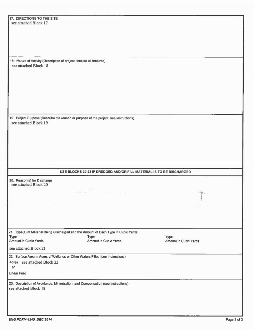
Block 17. Directions to Site.
The Missouri River crossing is located at
Please note that any access along the private road and land parcel to be used for the HDD entry point willrequire landowner notification (please refer to Attachment A).
The Yellowstone River crossing is located at
Please note that any access along the private road andland parcel to be used for the HDD entry point will require landowner notification (please refer toAttachment A).
Block 18. Nature of Activity.
The primary activities within the jurisdiction of the USACE Omaha District in Montana include: 1) theinstallation of a 36-inch steel pipeline within a standard 110-foot-wide construction right-of-way (ROW); 2)construction of six pump stations; and 3) installation of mainline isolation valves at intervals along thepipeline route in Montana.
The primary purpose of the proposed Project is to provide the infrastructure to transport WesternCanadian Sedimentary Basin (WCSB) crude oil from the border with Canada to existing pipeline facilitiesnear Steele City, Nebraska, for onward delivery to Cushing, Oklahoma, and the Texas Gulf Coast area.Most of the crude oil would be subsequently delivered to refineries in the Gulf Coast area. The proposedProject would also provide transport capacity for domestically produced crude oils, notably Bakken crudeoil that would be on-loaded in Montana, subject to commercial demand.
ENVIRONMENTAL IMPACTS AND MITIGATION
The Department of State (DOS) issued a Final Supplemental Environmental Impact Statement (FSEIS) inJanuary 2014, supplementing the Final Environmental Impact Statement (FEIS) issued for the Project inAugust 2011. The FSEIS addressed Project changes since the August 2011 FEIS, most notably theroute change in Nebraska. These documents included evaluations of impacts to wetlands, streams,rivers, and other waters of the United States (U.S.); historic properties; and biological resources. The
13
DOS concluded that the Project could be built with minimal environmental impact, utilizing the mitigationmeasures outlined in both the FEIS and FSEIS. Following issuance of the FSEIS, Keystone implementedminor modifications to further minimize environmental impacts, improve constructability, and addressagency and landowner requests. The modifications do not significantly change the conclusions of theFEIS or the FSEIS.
The DOS’s initial Biological Assessment (BA) was finalized on May 19, 2011, and the U.S. Fish andWildlife Service’s (USFWS’s) Biological Opinion (BiOp) was finalized on September 23, 2011. Toaccompany the development of the SEIS, the DOS updated the BA with the USFWS and issued therevised BA with the draft SEIS (March 2013). The final updated BiOp was issued by the USFWS on May15, 2013, and is still the Section 7 consultation record for the Project. The USFWS subsequentlycompleted a conference opinion for two species listed after the issuance of the BiOp (the northern long-eared bat and rufa red knot) and verified the standing of the BiOp on March 16, 2017.
The DOS, the Advisory Council on Historic Preservation, the State Historic Preservation Officers, andother parties developed a Programmatic Agreement for compliance with Section 106 of the NationalHistoric Preservation Act that was included in the FEIS. The DOS amended the prior existingProgrammatic Agreement in conjunction with the FSEIS. In addition, the DOS as the lead agency forSection 106 compliance conducted extensive government to government consultation with affectedNative American tribes as summarized in Section 3.11.4.3 of the FSEIS.
Keystone is committed to protecting waterbodies, wetlands, and their associated resources. The pipelineroute, construction procedures and a compliance program are designed to minimize environmentalimpacts during construction and restoration.
The pipeline route has been refined several times to reduce waterbody and wetland impacts through:
Avoiding waterbody and wetland crossings where feasible.
Minimizing the number of times that a single waterbody is crossed and impacts to wetlands.
Crossing waterbodies perpendicularly whenever possible.
Reducing the width of the ROW to 85 feet in saturated wetlands and across multiple waterbodiesas per the conditions of the Project’s Certificate of Compliance for the Major Facility Siting Act(MFSA).
During consultation activities with federal and state agencies and local stakeholders, additional rerouteswere incorporated to avoid or minimize impacts to significant resources or concerns identified. Inaddition, timing windows were established in the Project schedule to protect biological resources, such asspawning fish and threatened/endangered species. Additional mitigation measures are described in theProject’s Construction Mitigation and Reclamation Plan (CMRP) (Attachment C), and include:
Erosion and sediment controls implemented during and after construction.
Environmental training of all Project workers and supervisors.
Best management practices incorporated into the Project design and construction.
Wetland and waterbody construction procedures designed to minimize impacts duringconstruction and reclamation of the crossings.
Spill prevention and clean-up procedures.
14
Hazardous materials handling guidelines.
Clean-up, seeding, and reclamation details to ensure the effective stabilization of the ROW andProject disturbances.
Keystone’s CMRP provides typical procedures for wetland and waterbody crossings, as well as erosionand sediment control measures that will be installed during construction and stabilization/revegetation ofthe Project.
THREATENED AND ENDANGERED SPECIES
Within the jurisdiction of the USACE Omaha District in Montana, potential habitat exists for the followingfederally listed threatened or endangered species: the whooping crane (Grus americana), piping plover(Charadrius melodus), interior least tern (Sternula antillarum), pallid sturgeon (Scaphirhynchus albus),northern long-eared bat (Myotis septentrionalis), and rufa red knot (Calidris canutus rufa). PotentialProject impacts as presented in the final BA and 2013 BiOp and survey findings (where applicable) aredescribed below for these species: Two taxa that potentially occur within Montana, the northern long-eared bat (Myotis septentrionalis) and the rufa red knot (Calidris canutus rufa), have been listed since theBiOp was issued and are also described below. On March 16, 2017, the USFWS and DOS concluded aconference opinion that neither species would require formal consultation and Keystone had agreed tothe consultation measures recommended for the northern long-eared bat.
Whooping Crane
The Project in Montana is west of the primary migration pathway of the whooping crane. Individual birdscan be found outside the primary movement corridor and could possibly occur within the Project area inMontana during spring and fall migrations. Suitable whooping crane stopover habitat for roosting and/orforaging has specifically been identified within the Yellowstone River, and could potentially occur withinother major river systems, palustrine wetlands, and shallow areas of reservoirs, stockponds, and otherlacustrine wetlands within the Project area in Montana.
No direct impacts to the whooping crane are anticipated from the construction of the proposed Project.The Yellowstone River would be crossed by horizontal directional drilling (HDD), so potential habitat loss,alteration, or fragmentation would be negligible within the delineated boundary of the Yellowstone River.Minimal hand clearing of vegetation and limited equipment access would be required within the riparianareas of the river in order to use the HDD electronic guidance system that is associated with the drillingequipment, and in order to access the river to potentially withdraw water for the proposed Project’s HDDand hydrostatic tests. Any vegetation disturbance within the HDD would be allowed to completelyrevegetate following construction.
The primary construction-related impacts would be disturbance and potential exposure to small fuel spillsand leaks from construction machinery. The chance for construction-related spills within whooping craneroosting and foraging habitat is minimal. The CMRP (Attachment C) includes measures to minimize thelikelihood of a spill occurring and to promptly respond to and clean up spills that may occur.
If pipeline construction-related activities were to occur in close proximity to migrating whooping cranesduring spring and fall migration periods, environmental monitors would complete a brief survey of anywetland or riverine habitat areas potentially used by whooping cranes. The survey would be conducted inthe morning before starting equipment using the Whooping Crane Survey Protocol previously developedby the USFWS and Nebraska Games and Parks Commission as outlined in the 2012 TechnicalAssistance Letter for the TransCanada Keystone XL Pipeline issued by the USFWS Nebraska EcologicalServices Field Office. If whooping cranes are sighted during the morning surveys or any time during theday, Keystone would immediately contact the USFWS and Montana Fish, Wildlife, and Parks for furtherinstruction and require that all human activity and equipment start-up be delayed within a USFWS-determined distance of the cranes. Work would resume once the birds have left the area. The
15
environmental monitor would record the sighting, bird departure time, and work start time on the surveyform. Additionally, the USFWS would notify the compliance manager of whooping crane migrationlocations during the spring and fall migrations through information gathered from the whooping cranetracking program. If the migratory sighting locations are within a USFWS-approved distance fromconstruction activities, then environmental monitors would conduct protocol level surveys of theappropriate portions of the Project.
Downshielding of lights would be used if nighttime work is necessary for the HDD during the spring andfall whooping crane migrations in areas that provide suitable habitat.
Piping Plover
The Missouri River crossing in Valley and McCone counties was originally identified as having thepotential to support suitable breeding habitat (i.e., alkali lakes and wetlands) within the Project area inMontana. During field surveys conducted between May and November 2008 to 2011, no suitable alkaliwetlands for nesting piping plovers were identified along the entire route in Valley County and no pipingplovers were observed at the proposed crossing location. Additional consultation with the USFWS BillingEcological Services Field Office indicates that historic surveys have failed to identify nesting piping ploverwithin the Project area in Valley County.
Though the piping plover is not anticipated to occur within the Project area in Montana based on theresult of the field surveys and consultation with USFWS, the Project’s Certificate of Compliance under theMFSA issued by Montana Department of Environmental Quality (MDEQ) requires pre-constructionsurveys for the piping plover for the Yellowstone River and Missouri River crossings if constructionoverlaps with the breeding season.
If construction were to occur during the plover breeding season (April 15 through September 1), pre-construction surveys and daily surveys would occur in coordination with USFWS within 0.25-mile from theYellowstone River and Missouri River crossings to ensure that there are no nesting pairs within 0.25-mileof the construction area. If occupied piping plover nests are found, then construction within 0.25-mile ofthe nest would be suspended until the nest is no longer active.
Downshielding of lights would be used if nighttime work is necessary for the HDD crossings of theYellowstone and Missouri rivers, if the HDD site(s) lacks vegetative screening, and if an active pipingplover nest is located within 0.25-mile of the HDD site(s).
Interior Least Tern
The Yellowstone River crossing in Dawson County, Montana, has historically supported (and currentlysupports) breeding populations of interior least terns. During field surveys conducted in June and July of2011, no interior least terns were observed at the proposed crossing location at the Yellowstone River orat the proposed crossing of the Missouri River in Valley and McCone counties.
No direct impacts to least tern breeding habitat would be anticipated at these locations, because pipelineplacement across the rivers will be completed by HDD method. Minimal hand clearing of vegetation andlimited human access would be required within the riparian areas of these rivers in order to use the HDDelectronic guidance system that is associated with the drilling equipment and in order for equipment toaccess these rivers to potentially withdraw water for the Project’s HDD and hydrostatic tests.
The primary construction-related impacts would be disturbance and potential exposure to small fuel spillsand leaks from construction machinery. The chance of construction-related spills within least tern habitatis minimal because all hazardous materials such as fuels and oils would be stored at least 100 feet awayfrom surface waters and these types of spills or leaks generally are small in volume and are cleaned upquickly. Additionally, Keystone’s CMRP (Attachment C) provides the best management practices toreduce the potential for impacts due to construction-related spills as previously briefly described in theimpact evaluation for the whooping crane. Indirect impacts could result from increased noise and humanpresence at work site locations if breeding terns are located within 0.25-mile of the Project.
16
If construction occurs within 0.25-mile of the Yellowstone River crossing or the Missouri River crossingduring the breeding season (May 1 through September 1), then pre-construction surveys and dailysurveys would occur in coordination with USFWS within 0.25-mile from each of these crossings to ensurethat there are no nesting pairs within 0.25-mile of the construction area. If occupied interior least ternnests are found, then construction within 0.25-mile of the nest would be suspended until the nest is nolonger active.
Downshielding of lights would be used if nighttime work is necessary for the HDD crossings of theYellowstone and Missouri rivers, if the HDD site(s) lacks vegetative screening, and if an active tern nest islocated within 0.25-mile from the HDD site(s).
Pallid Sturgeon
The potential exists for the pallid sturgeon to occur within the Project area in Montana at the crossing ofthe Missouri River below Ft. Peck Dam and the crossing of the Yellowstone River downstream of Fallon,Montana. Both of these pipeline crossings are located in Recovery-Priority Management Areas for thepallid sturgeon. Because these river crossings would be constructed using the HDD method, directimpacts to pallid sturgeon are not anticipated as a result of Project construction. Water withdrawals tosupport the HDD and hydrostatic test operations would be appropriately screened and would bewithdrawn at an appropriate withdrawal rate to prevent entrainment or entrapment of pallid sturgeon to beaccordance with the conditions of the 2013 BiOp. The intake screens would be periodically checked forentrainment of fish or debris. In the unlikely event of a sturgeon becoming entrained, pumping operationswould immediately cease and the Compliance Manager would immediately consult with the USFWS.Hydrostatic testing water will require no additives and, after the completion of hydrostatic testing, waterwould be returned to an upland area adjacent to the source as per the Project’s CMRP and the Project’s Certificate of Compliance for the MFSA.
Northern Long-Eared Bat
The northern long-eared bat, previously a species proposed for Endangered Species Act (ESA) listing,was listed as a threatened species by the USFWS on April 2, 2015. With the exception of the change infederal listing for the northern long-eared bat, the habitat, range, migration patterns, and occurrences arethe same as discussed in Section 3.8.3.1 of the FSEIS.
At the time the species was listed, the USFWS determined that designation of critical habitat was prudent,but not determinable. On April 25, 2015, the USFWS issued its determination that the designation ofcritical habitat is not prudent for the northern long-eared bat and acknowledged that White-NoseSyndrome is the primary threat. According to the USFWS, information has become available thatdemonstrates that designating the wintering habitat as critical habitat for the northern long-eared batwould likely increase the risk of vandalism and disturbance and could potentially increase the spread ofWhite-Nose Syndrome. In addition, if the USFWS determines that disease, not loss of critical habitat, isthe primary threat to the species, it is unlikely that the northern long-eared bat would be affected by theProject. This is further supported by the minimal clearing of trees along streams and rivers, the use ofHDD, and the lack of trees along the route in Montana. Additionally, there are no known hibernacula forthis species found near the Project area. Consultation for the northern long-eared bat was concluded viathe letter from the USFWS to DOS dated March 16, 2017.
Rufa Red Knot
The rufa red knot (red knot) was proposed for threatened status under the ESA on September 27, 2013,and listed by the USFWS as threatened on January 12, 2015; therefore, it was not analyzed in the FSEIS.The red knot is considered threatened due to loss of both breeding and nonbreeding habitat, disruption tonatural predator cycles on the breeding grounds, reduced prey availability in the nonbreeding range, andasynchronies (mismatches) in the timing of migratory cycle relative to favorable food and weatherconditions.
17
The red knot exhibited a wide historical range, from Argentina, Aruba, and the Bahamas, north to morethan 40 U.S. states, and several provinces of Canada. The species typically overwinters along southerncoastal habitats. The red knot depends on seasonal migration stopovers between wintering and breedingareas. Of particular concern are habitat areas in the arctic tundra ecosystems, which are used asbreeding grounds, coastal habitats, and other food resource areas.
There is no breeding or wintering habitat for the red knot along any portion of the proposed Project. Mostred knots migrate along the eastern shoreline of the U.S., feeding on mollusks and softer invertebrateprey. The primary locations for these types of food sources are coastal marine and estuarine habitatswith exposed intertidal sediment, sand, gravel, or cobble beaches, tidal mudflats, salt marshes, shallowcoastal impoundments, and lagoons.
The lack of consistent records of red knot along the proposed Project is due to the paucity of suitablestop-over habitat (e.g., lack of beaches, mudflats, or shallow impoundments where mollusks may beconsistently available), and it is unlikely that inland stopover habitat is common along the Project. TheUSFWS and DOS concluded that the species would unlikely be impacted by the proposed Project (pleaserefer to the letter dated March 16, 2017).
CULTURAL RESOURCES
Within the jurisdiction of the USACE Omaha District in Montana, cultural resource surveys wereconducted between 2008 and 2014. In general, surveys were performed along approximately 285 milesof the proposed pipeline ROW, roughly 82 miles of proposed access roads, and about 1,742 acres ofproposed auxiliary facility sites (e.g., pump stations).
Regarding the areas of the two PCN waterbody features (Missouri and Yellowstone Rivers), a 150-footbuffer was created on either side of the centerline at these crossings creating a 300-foot-wide Area ofPotential Effect (APE). The APE was surveyed for cultural resources at both crossing locations.
Missouri River
Three cultural resources were identified within the APE of the Missouri River. Two resources(C720VA006 and C720VA007) are historic isolated finds. The third site is a historic canal (24VL2085).All sites are recommended not eligible for nomination to the National Register of Historic Places (NRHP).The Montana State Historic Preservation Office (SHPO) concurred with these findings for the two historicisolated finds (C720VA006 and C720VA007) via letter dated June 3, 2013. Concurrence regarding thehistoric canal is pending. As noted above, the Missouri River will be traversed via the HDD technique,therefore, the Project will have no effect on these resources.
Yellowstone River
Three resources were identified within the APE of the Yellowstone River consisting of two railroadsegments (24DW0419) and one canal segment (24DW0289). All three sites are considered eligibleresources. However, the two railroad segments are non-contributing to the site’s eligibility while the canalsegment is contributing but will not be impacted by the Project. As noted above, the Yellowstone Riverwill be traversed via the HDD technique and will have no adverse effect on these resources. The SHPOconcurred in a letter dated December 16, 2010.
PERMANENT FACILITIES
Pipeline Facilities
Construction of the pipeline facilities will require trees and vegetation to be cleared from the ROW.Grading of the work area will establish a stable and safer work surface for pipe installation. Once grading
18
is complete, a trench will be excavated to a depth sufficient to provide approximately 4 feet of soil coverover the buried pipeline in wetland and upland areas and a minimum of 5 feet of cover for waterbodycrossings. Where wetland conditions permit topsoil salvage during excavation, soil conservation will beconducted through stripping topsoil from the reduced 85-foot construction corridor and temporarily storingthe topsoil within the ROW limits. After the welded pipeline is installed in the trench, the subsoil will bebackfilled into the trench and the topsoil will be replaced on top of the subsoil. Standard industry boringtechniques will be employed to cross under significant highway and railroad crossings.
To install pipelines under watercourses, Keystone will adopt the standard open-cut crossing method forwet or dry crossings or the use of HDD crossing method. The crossing technique will be determinedbased on the presence of water at the time of construction. During open-cut crossing installations,material excavated from the trench line at waterbody crossings less than 30 feet wide will be stored onthe banks of the waterbodies. For waterbodies greater than 30 feet in width, excavated trench materialsmay be temporarily stored within the waterbody while the trench is being excavated and the pipelinecarried into place and installed in the trench. Immediately following installation of the pipeline at thewaterbody crossing, the trench will be backfilled, and original waterbody contours will be re-established tothe extent practicable.
The open cut, dry crossing methods involve two different approaches dependent upon waterbodyspecifications and volume of flow at the time of crossing. The dam and flume dry crossing methodinvolves diverting the flow of water across the trenching area through one or more flume pipes placed inthe waterbody. The dam and pump dry method is similar to the dam and flume dry method except thatpumps and hoses would be used instead of flume pipes to move water around the construction workarea. Once backfilling is completed, the waterbody banks are restored and stabilized according to theCMRP (Attachment C) and the dam materials as well as flume pipes or pump hoses are removed.
Keystone will use the HDD crossing method under select rivers, including the Missouri and Yellowstonerivers. Activity between the HDD entry and exit point would generally be limited to the temporarydeployment of the HDD electronic guidance system, placement of hoses for water withdrawal, and limitedequipment access to carry a pump to draw water from the waterbody for drilling mud makeup andhydrostatic testing of the HDD pipe section. Additional minor disturbance may be required for equipmentto carry and place water withdrawal pumps and dewatering lines to support the mainline hydrostatictesting operations. Within the permanent easement, a swath of up to 20 feet in width on each side of thewaterbody crossing will need to be maintained in an herbaceous state to accommodate aerialreconnaissance during Project operations. No discharge of dredged or fill material into waters of the U.S.is anticipated at HDD crossings. Within the Omaha District in Montana, HDD crossings are planned for:Frenchman Creek in Phillips County, the Milk River in Valley County, the Missouri River at the intersectionof Valley and McCone counties, and the Yellowstone River in Dawson County.
In addition, the Project route refinements have also added one additional HDD crossing for an unnamedtributary to West Fork Hungry Creek in McCone County. In the event that inadvertent releases of drillingmud occur at the surface of the ground, Keystone will implement the measures outlined in the attachedHDD Frac-Out Contingency Plan (Attachment D). HDD drawings for these crossings are provided inAttachment E.
Auxiliary Facilities
Pump Stations
Six pump stations will be constructed in Montana adjacent to the pipeline ROW on sites that will vary from7 to 14 acres in size. Pump station locations are provided in Table 3. There will be no permanent fill inwaters of the U.S. for the pump stations.
19
Pump stations will require electrical power that will be supplied by regional power utilities suppliers.Power lines will be constructed and operated by electrical power utilities and all relevant construction andoperational permits will be obtained by these utilities through their applicable approval processes.
Valves
Pipeline valves will be located within pump station facilities and at intervals along the pipeline ROW withinfenced enclosures. Keystone will not impact any waters of the U.S. with valve placement. Valvesgenerally will be located near existing roads to allow easy access. There will be no permanent fill inwaters of the U.S. for valves.
Access Roads
Permanent access roads will be required for pump stations and certain valve locations. As proposed, theconstruction of one permanent access road leading to a mainline valve will result in permanent impacts toone waterbody. The permanent disturbance at the waterbody crossing is less than 0.10-acre.Waterbodies impacted by access roads are listed in the Non-PCN Datasheet Table in Attachment B.
TEMPORARY FACILITIES
Construction of the Project will require the use several temporary facilities not adjacent to the pipelinemainline. These facilities include contractor yards, contractor camps, pipe storage yards, rail sidings, andaccess roads, discussed in more detail below. These areas will be restored during clean-up after pipelineconstruction is completed. As with the pipeline ROW, temporary fills of wetlands and waterbodies may berequired along access roads to provide stable access as well as temporary bridge crossings along theROW. As proposed, construction of the Project’s temporary facilities will avoid impacting the waterbodies and wetlands within the boundary of the temporary facilities. There will be no permanent filling of watersof the U.S. associated within the temporary facilities.
Contractor Yards
Each pipeline construction segment (spread) will have at least one contractor yard, generally 30 acres inarea. Contractor yards would be used as muster points, for equipment and personnel mobilization,equipment storage and maintenance, training, and other pipeline construction support activities.
Pipe Storage Yards
Pipe storage yards will be required to stage pipe along the proposed pipeline route to reduce haul timesand facilitate efficient transport to the ROW. Pipe storage yards will be approximately 30 acres in area.
Railroad Sidings
Several railroad sidings will be used to facilitate the unloading of pipe from railcars. The Project will haveup to three railroad sidings in Montana. Railroad sidings will generally be 20 acres in area.
Contractor Camps
Contractor Camps may be established to minimize the effects of the pipeline work force on communitieswith limited housing resources. Each spread will have approximately 1,000 members in the totalworkforce, including contractors, inspection staff, and construction management staff. The contractorcamps would be approximately 80 acres in area.
Access Roads
Temporary access roads will be necessary to provide ingress and egress for vehicles and equipment atregular intervals along the pipeline route.
20
Block 19. Project Purpose.
The primary purpose of the proposed Project is to provide the infrastructure to transport WCSB crude oilfrom the border with Canada to existing pipeline facilities near Steele City, Nebraska, for onward deliveryto Cushing, Oklahoma, and the Texas Gulf Coast area. Most of the crude oil would be subsequentlydelivered to refineries in the Gulf Coast area. The proposed Project would also provide transport capacityfor domestically produced crude oils, notably Bakken crude oil that would be on-loaded in Montana,subject to commercial demand.
Block 20. Reason for Discharge.
Excavation of the pipeline trench will require the temporary placement of fill (e.g., trench spoils, rock)within the ROW in wetlands and in some waterbodies. These trench materials will then be returned to thepipeline trench, and the original contours and elevations will be re-established to the extent practical. Inaddition, to provide a stable access and reduce rutting, compaction, erosion, and sedimentation,temporary access across wetlands and waterbodies may require the temporary placement of fill, asdescribed below and in the Project’s CMRP (Attachment C).
No discharges to the Missouri River or Yellowstone River are anticipated.
Block 21. Types of Material Being Discharged.
Spoil (e.g., soil, sand, rocks) will be excavated from the pipeline trench in wetlands and within waterbodychannels. Excavated materials will be returned to the trench in wetlands and waterbodies immediatelyafter the pipeline is installed in the trench. In addition, timber mats, timber rip-rap, or clean rock andflume pipes may be used to provide stable temporary access across wetlands and waterbodies.Materials utilized to provide access through wetlands and across waterbodies will likely remain in placefor longer than 90 days before being removed during final clean-up activities. These materials will beremoved from within wetlands and waterbodies at the completion of construction.
No material is anticipated to be discharged to the Missouri River or Yellowstone River.
Block 22. Surface Areas in Acres of Wetlands or Other Waters Filled.
The surface areas of wetlands and other waters crossed by the pipeline have been divided intowatersheds defined by U.S. Geologic Survey (USGS) HUCs (see Figure 2 for the watershed boundarieswithin Montana). The Project will impact two waterbodies (the Missouri River and Yellowstone River)within the USACE Omaha District in Montana that require the submittal of a PCN to the USACE. Thelocations, hydrologic unit code (HUC), and other information related to these two waterbodies crossed bythe Project and requiring PCN are provided in Table 2 below and the ORM Table in Attachment B. Thenon-PCN wetlands and waterbodies located within the proposed Project construction footprint areincluded in the Non-PCN Datasheet Table provided in Attachment B.
As proposed, permanent filling of waters of the U.S. includes one waterbody associated with a permanentaccess road in Montana. The Project does not impact any palustrine forested wetlands in Montana.
Temporary equipment access crossing materials (timber mats, timber rip-rap, and rock and flumecrossing materials) will be completely removed from wetlands and waterbodies at the completion ofconstruction. Disturbances associated with temporary equipment access methods will be restored andstabilized after the bridging equipment access materials are removed.
Block 23. Description of Avoidance, Minimization, and Compensation.
See Block 18 above.
21
Block 24. Is Any Portion of the Work Already Complete?
No.
Block 25. Addresses of Adjoining Property Owners, Lessees, etc., Whose Property Adjoins theWaterbody.
Not applicable.
Block 26. List of Other Certifications or Approvals/Denials Received from other Federal, State, orLocal Agencies for Work Described in This Application.
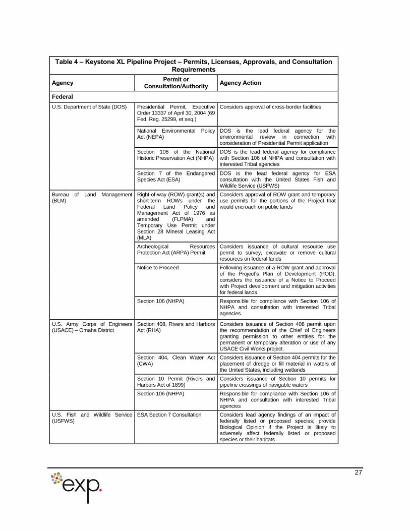
Table 4 provides a summary of other Project permits and approvals.
24
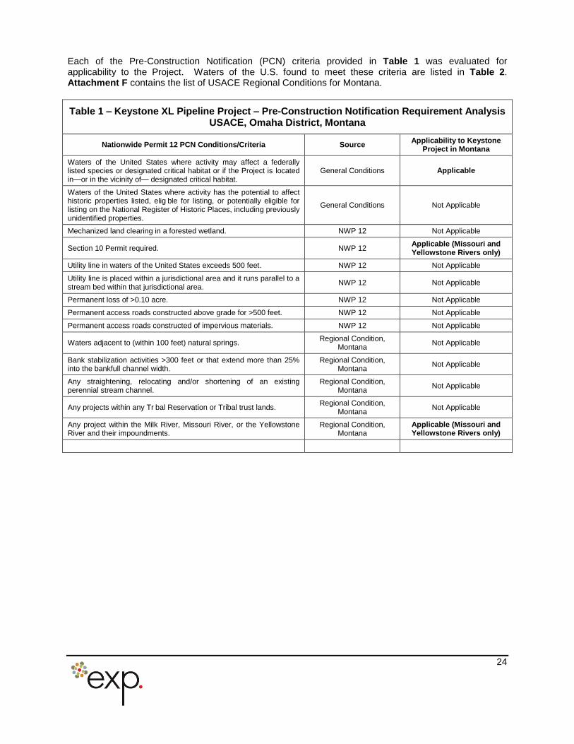
Each of the Pre-Construction Notification (PCN) criteria provided in Table 1 was evaluated forapplicability to the Project. Waters of the U.S. found to meet these criteria are listed in Table 2.Attachment F contains the list of USACE Regional Conditions for Montana.
Table 1 – Keystone XL Pipeline Project – Pre-Construction Notification Requirement AnalysisUSACE, Omaha District, Montana
Nationwide Permit 12 PCN Conditions/Criteria Source Applicability to KeystoneProject in Montana
Waters of the United States where activity may affect a federallylisted species or designated critical habitat or if the Project is locatedin—or in the vicinity of— designated critical habitat.
General Conditions Applicable
Waters of the United States where activity has the potential to affecthistoric properties listed, elig ble for listing, or potentially eligible forlisting on the National Register of Historic Places, including previouslyunidentified properties.
General Conditions Not Applicable
Mechanized land clearing in a forested wetland. NWP 12 Not Applicable
Section 10 Permit required. NWP 12 Applicable (Missouri andYellowstone Rivers only)
Utility line in waters of the United States exceeds 500 feet. NWP 12 Not Applicable
Utility line is placed within a jurisdictional area and it runs parallel to astream bed within that jurisdictional area. NWP 12 Not Applicable
Permanent loss of >0.10 acre. NWP 12 Not Applicable
Permanent access roads constructed above grade for >500 feet. NWP 12 Not Applicable
Permanent access roads constructed of impervious materials. NWP 12 Not Applicable
Waters adjacent to (within 100 feet) natural springs. Regional Condition,Montana Not Applicable
Bank stabilization activities >300 feet or that extend more than 25%into the bankfull channel width.
Regional Condition,Montana Not Applicable
Any straightening, relocating and/or shortening of an existingperennial stream channel.
Regional Condition,Montana Not Applicable
Any projects within any Tr bal Reservation or Tribal trust lands. Regional Condition,Montana Not Applicable
Any project within the Milk River, Missouri River, or the YellowstoneRiver and their impoundments.
Regional Condition,Montana
Applicable (Missouri andYellowstone Rivers only)
25
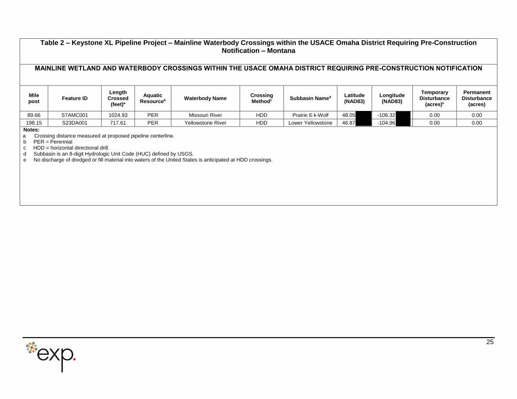
Table 2 – Keystone XL Pipeline Project – Mainline Waterbody Crossings within the USACE Omaha District Requiring Pre-ConstructionNotification – Montana
MAINLINE WETLAND AND WATERBODY CROSSINGS WITHIN THE USACE OMAHA DISTRICT REQUIRING PRE-CONSTRUCTION NOTIFICATION
Milepost Feature ID
LengthCrossed
(feet)a
AquaticResourceb Waterbody Name Crossing
Methodc Subbasin Named Latitude(NAD83)
Longitude(NAD83)
TemporaryDisturbance
(acres)e
PermanentDisturbance
(acres)
89.66 S7AMC001 1024.93 PER Missouri River HDD Prairie E k-Wolf 48.05 -106.32 0.00 0.00198.15 S23DA001 717.61 PER Yellowstone River HDD Lower Yellowstone 46.87 -104.96 0.00 0.00
Notes:a Crossing distance measured at proposed pipeline centerline.b PER = Perennialc HDD = horizontal directional drill.d Subbasin is an 8-digit Hydrologic Unit Code (HUC) defined by USGS.e No discharge of dredged or fill material into waters of the United States is anticipated at HDD crossings.
26
Table 3 – Keystone XL Pipeline Project – Pump Station Locations – Montana
Pump Station ID Milepost County Acres
PS-09 1.34 Phillips 11.90
PS-10 49.37 Valley 7.80
PS-11 99.06 McCone 12.60
PS-12 151.60 McCone 13.10
PS-13 203.15 Prairie 10.40
PS-14 239.65 Fallon 9.70
27
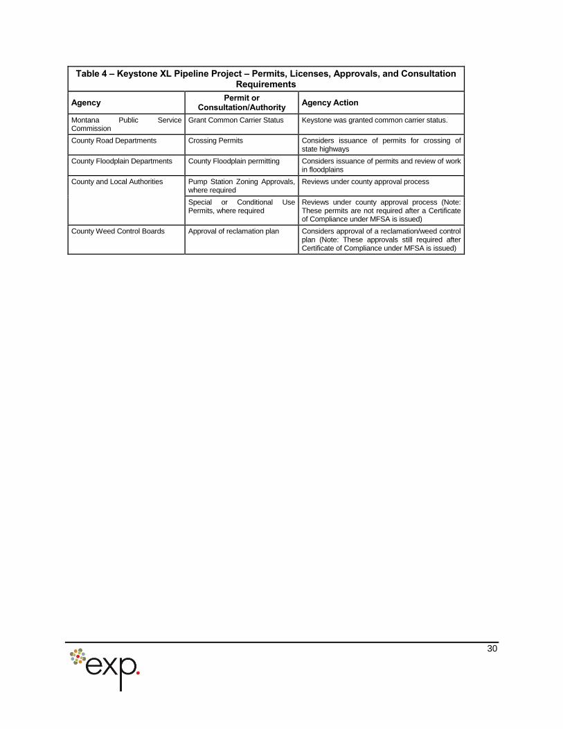
Table 4 – Keystone XL Pipeline Project – Permits, Licenses, Approvals, and Consultation Requirements
Agency Permit or
Consultation/Authority Agency Action
FederalU.S. Department of State (DOS) Presidential Permit, Executive
Order 13337 of April 30, 2004 (69Fed. Reg. 25299, et seq.)
Considers approval of cross-border facilities
National Environmental PolicyAct (NEPA)
DOS is the lead federal agency for theenvironmental review in connection withconsideration of Presidential Permit application
Section 106 of the NationalHistoric Preservation Act (NHPA)
DOS is the lead federal agency for compliancewith Section 106 of NHPA and consultation withinterested Tribal agencies
Section 7 of the EndangeredSpecies Act (ESA)
DOS is the lead federal agency for ESAconsultation with the United States Fish andWildlife Service (USFWS)
Bureau of Land Management(BLM)
Right-of-way (ROW) grant(s) andshort-term ROWs under theFederal Land Policy andManagement Act of 1976 asamended (FLPMA) andTemporary Use Permit underSection 28 Mineral Leasing Act(MLA)
Considers approval of ROW grant and temporaryuse permits for the portions of the Project thatwould encroach on public lands
Archeological ResourcesProtection Act (ARPA) Permit
Considers issuance of cultural resource use permit to survey, excavate or remove culturalresources on federal lands
Notice to Proceed Following issuance of a ROW grant and approvalof the Project’s Plan of Development (POD),considers the issuance of a Notice to Proceedwith Project development and mitigation activitiesfor federal lands
Section 106 (NHPA) Respons ble for compliance with Section 106 ofNHPA and consultation with interested Tribalagencies
U.S. Army Corps of Engineers(USACE) – Omaha District
Section 408, Rivers and HarborsAct (RHA)
Considers issuance of Section 408 permit uponthe recommendation of the Chief of Engineersgranting permission to other entities for thepermanent or temporary alteration or use of anyUSACE Civil Works project.
Section 404, Clean Water Act(CWA)
Considers issuance of Section 404 permits for the placement of dredge or fill material in waters ofthe United States, including wetlands
Section 10 Permit (Rivers andHarbors Act of 1899)
Considers issuance of Section 10 permits for pipeline crossings of navigable waters
Section 106 (NHPA) Respons ble for compliance with Section 106 ofNHPA and consultation with interested Tribalagencies
U.S. Fish and Wildlife Service (USFWS)
ESA Section 7 Consultation Considers lead agency findings of an impact offederally listed or proposed species; provideBiological Opinion if the Project is likely toadversely affect federally listed or proposedspecies or their habitats
28
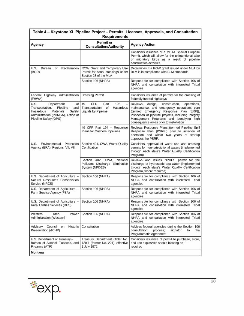
Table 4 – Keystone XL Pipeline Project – Permits, Licenses, Approvals, and Consultation Requirements
Agency Permit or
Consultation/Authority Agency Action
Considers issuance of a MBTA Special PurposePermit, which will allow for the unintentional takeof migratory birds as a result of pipelineconstruction activities.
U.S. Bureau of Reclamation (BOR)
ROW Grant and Temporary UsePermit for canal crossings underSection 28 of the MLA
Determines if a ROW grant issued under MLA byBLM is in compliance with BLM standards
Section 106 (NHPA) Respons ble for compliance with Section 106 ofNHPA and consultation with interested Tribalagencies
Federal Highway Administration (FHWA)
Crossing Permit Considers issuance of permits for the crossing offederally funded highways
U.S. Department of Transportation, Pipeline andHazardous Materials SafetyAdministration (PHMSA), Office ofPipeline Safety (OPS)
49 CFR Part 195 –Transportation of HazardousLiquids by Pipeline
Reviews design, construction, operations,maintenance, and emergency operations plan(termed Emergency Response Plan [ERP]),inspection of pipeline projects, including IntegrityManagement Programs and identifying highconsequence areas prior to installation
49 CFR Part 194 – ResponsePlans for Onshore Pipelines
Reviews Response Plans (termed Pipeline SpillResponse Plan [PSRP]) prior to initiation ofoperation and within two years of startupapproves the PSRP.
U.S. Environmental Protection Agency (EPA), Regions, VII, VIII
Section 401, CWA, Water QualityCertification
Considers approval of water use and crossing permits for non-jurisdictional waters (implementedthrough each state’s Water Quality Certification Program)
Section 402, CWA, NationalPollutant Discharge EliminationSystem (NPDES)
Reviews and issues NPDES permit for the discharge of hydrostatic test water (implementedthrough each state’s Water Quality Certification Program, where required)
U.S. Department of Agriculture – Natural Resources ConservationService (NRCS)
Section 106 (NHPA) Respons ble for compliance with Section 106 ofNHPA and consultation with interested Tribalagencies
U.S. Department of Agriculture – Farm Service Agency (FSA)
Section 106 (NHPA) Respons ble for compliance with Section 106 ofNHPA and consultation with interested Tribalagencies
U.S. Department of Agriculture – Rural Utilities Services (RUS)
Section 106 (NHPA) Respons ble for compliance with Section 106 ofNHPA and consultation with interested Tribalagencies
Western Area PowerAdministration (Western)
Section 106 (NHPA) Respons ble for compliance with Section 106 ofNHPA and consultation with interested Tribalagencies
Advisory Council on HistoricPreservation (ACHP)
Consultation Advises federal agencies during the Section 106 consultation process; signator to theProgrammatic Agreement
U.S. Department of Treasury –Bureau of Alcohol, Tobacco, andFirearms (ATF)
Treasury Department Order No.120-1 (former No. 221), effective1 July 1972
Considers issuance of permit to purchase, store,and use explosives should blasting berequired
Montana
29
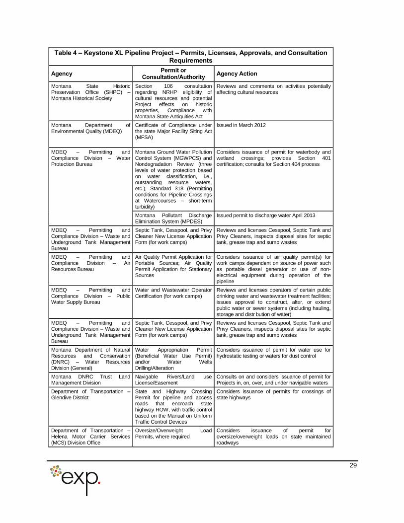
Table 4 – Keystone XL Pipeline Project – Permits, Licenses, Approvals, and Consultation Requirements
Agency Permit or
Consultation/Authority Agency Action
Montana State HistoricPreservation Office (SHPO) –Montana Historical Society
Section 106 consultationregarding NRHP eligibility ofcultural resources and potentialProject effects on historicproperties, Compliance withMontana State Antiquities Act
Reviews and comments on activities potentiallyaffecting cultural resources
Montana Department ofEnvironmental Quality (MDEQ)
Certificate of Compliance underthe state Major Facility Siting Act(MFSA)
Issued in March 2012
MDEQ – Permitting and Compliance Division – WaterProtection Bureau
Montana Ground Water PollutionControl System (MGWPCS) andNondegradation Review (threelevels of water protection basedon water classification, i.e.,outstanding resource waters,etc.), Standard 318 (Permittingconditions for Pipeline Crossingsat Watercourses – short-termturbidity)
Considers issuance of permit for waterbody andwetland crossings; provides Section 401certification; consults for Section 404 process
Montana Pollutant DischargeElimination System (MPDES)
Issued permit to discharge water April 2013
MDEQ – Permitting and Compliance Division – Waste andUnderground Tank ManagementBureau
Septic Tank, Cesspool, and PrivyCleaner New License ApplicationForm (for work camps)
Reviews and licenses Cesspool, Septic Tank andPrivy Cleaners, inspects disposal sites for septictank, grease trap and sump wastes
MDEQ – Permitting and Compliance Division – AirResources Bureau
Air Quality Permit Application forPortable Sources; Air QualityPermit Application for StationarySources
Considers issuance of air quality permit(s) forwork camps dependent on source of power suchas portable diesel generator or use of non-electrical equipment during operation of thepipeline
MDEQ – Permitting and Compliance Division – PublicWater Supply Bureau
Water and Wastewater OperatorCertification (for work camps)
Reviews and licenses operators of certain publicdrinking water and wastewater treatment facilities;issues approval to construct, alter, or extendpublic water or sewer systems (including hauling,storage and distr bution of water)
MDEQ – Permitting and Compliance Division – Waste andUnderground Tank ManagementBureau
Septic Tank, Cesspool, and PrivyCleaner New License ApplicationForm (for work camps)
Reviews and licenses Cesspool, Septic Tank andPrivy Cleaners, inspects disposal sites for septictank, grease trap and sump wastes
Montana Department of NaturalResources and Conservation(DNRC) – Water ResourcesDivision (General)
Water Appropriation Permit(Beneficial Water Use Permit)and/or Water WellsDrilling/Alteration
Considers issuance of permit for water use forhydrostatic testing or waters for dust control
Montana DNRC Trust LandManagement Division
Navigable Rivers/Land useLicense/Easement
Consults on and considers issuance of permit forProjects in, on, over, and under navigable waters
Department of Transportation –Glendive District
State and Highway CrossingPermit for pipeline and accessroads that encroach statehighway ROW, with traffic controlbased on the Manual on UniformTraffic Control Devices
Considers issuance of permits for crossings ofstate highways
Department of Transportation –Helena Motor Carrier Services(MCS) Division Office
Oversize/Overweight LoadPermits, where required
Considers issuance of permit for oversize/overweight loads on state maintainedroadways
30
Table 4 – Keystone XL Pipeline Project – Permits, Licenses, Approvals, and Consultation Requirements
Agency Permit or
Consultation/Authority Agency Action
Montana Public Service Commission
Grant Common Carrier Status Keystone was granted common carrier status.
County Road Departments Crossing Permits Considers issuance of permits for crossing ofstate highways
County Floodplain Departments County Floodplain permitting Considers issuance of permits and review of workin floodplains
County and Local Authorities Pump Station Zoning Approvals,where required
Reviews under county approval process
Special or Conditional UsePermits, where required
Reviews under county approval process (Note:These permits are not required after a Certificateof Compliance under MFSA is issued)
County Weed Control Boards Approval of reclamation plan Considers approval of a reclamation/weed controlplan (Note: These approvals still required afterCertificate of Compliance under MFSA is issued)
31
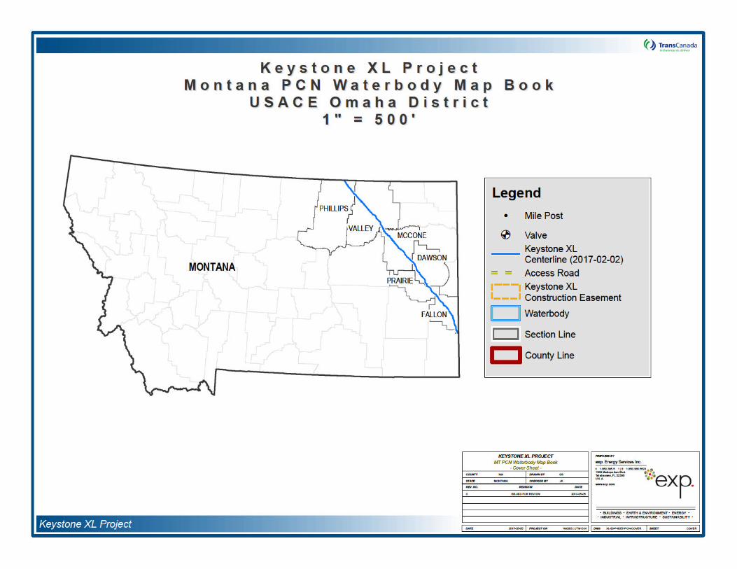
Discussion of Map Volume
(PCN Waterbody Mapbook – Attachment A)The U.S. Geological Survey (USGS) topographic maps were enlarged to depict the waterbodies crossedby the Project mainline and requiring Pre-Construction Notification to the USACE. A legend is providedon the first page, but generally the centerline is shown in blue with orange dashed lines depicting the limitof the proposed temporary construction footprint. A label on each waterbody provides the featureidentification number that corresponds to the table provided. Mileposts are also depicted along thecenterline and correspond to the features listed in Table 2 and the ORM Table in Attachment B.
The National Agricultural Imagery Program (NAIP) is administrated by the U.S. Department of Agriculture(USDA) Farm Service Agency (FSA) that acquires “leaf-on” digital ortho-rectified (geometrically corrected)imagery during the agriculture growing season. NAIP 2015 aerial photography-based sheets depict thesame information as shown on the USGS topographic maps and both versions are provided in color.

Attachment A:
Map Volume - PCN Waterbody Mapbook


Attachment B:
Wetland Assessment Methodology and Results
OMBIL Regulatory Module (ORM) Tables
Non-PCN Datasheet Tables
Wetland and Waterbody Map Book
Tra
WetlOm
Prepar
TransC700 LoHousto
Prepar
exp En1300 MTallaha DocumTAL-KX Date SMay
nsCana
and Asha Dist
ed for:
anada Keysuisiana Street n, Texas 770
ed by:
ergy Serviceetropolitan Blssee, Florida
ent Number L-1100-04-0
ubmitted
da Key
sessmenrict – Mo
one Pipeline
02
s Inc. vd. 32308
8
ystone X
nt Methoontana
e, LP
XL Pip
odolog
25,
eline Pr
and R
roject
esults
2017
Acro
CWA ESA FAC FACW FEMA GIS GPS KeystonNHD NRCS NWI OBL ORM PCN Project RHA RPW TNW U.S. USACE USDA USEPA USFWUSGS
nym Gl
CleaEnviFacuFacuFedGeoGlob
e TranNatioNatuNatioObligOMPre-KeyRiveRelaTradUniteUniteUniteUnite
UniteUnite
ssary
n Water Act ronmental Stuultative ultative-Wet eral Emergencgraphic Informal PositioningsCanada Key
onal Hydrograral Resources
onal Wetlandsgate BIL RegulatoryConstruction Nstone XL Pipers and Harbortively permanitional naviga
ed States ed States Armed States Deped States Enved States Fished States Geo
udy Area
cy Managememation Systemg System ystone Pipelinaphy Datasets Conservatios Inventory
y Module Notification line Project rs Act
nent waters ble waters
my Corps of Enpartment of Agvironmental Prh and Wildlife ological Surve
ent Agency m
e, LP
on Service
ngineers griculture rotection AgeService
ey
ncy
i
1.0 I
TransCawaterboMontanjurisdictiapproxifootprinthe OMfeaturesNotifica
1.1 The U.Clean W
The USinundatunder nconditiodefinitio
The Cle
a.
b.
c.
d.
e.
f.
g.
ntroduc
anada Keystdies from Jua. The wetlaonal waters
mate boundat (as part of tBIL Regulato) and on thtion (PCN).
RegulatioS. Army CorpWater Act (CW
ACE and the ed or saturatormal circumns. Wetlandn takes into c
an Water Act
All waters interstate or
All interstate
All other watsand flats, wdegradation waters:
1. Which ar
2. From wh
3. Which ar
All impound
Tributaries o
The territoria
Wetlands adj(a) through (
tion
one Pipeline, Lne 2008 thround and waterof the United ries of each fhe Environmery Module (ORe wetland an
ns and Defs of EngineerA) and Sectio
U.S. Environmed by surface stances do sus typically incluonsideration t
(CWA; 1977)
which are currforeign comm
waters includ
ters such as etlands, slougor destruction
re or could be
ich fish or she
re used or cou
ments of water
f waters identi
l seas;
acent to wateg).
LP (Keystoneugh May 201rbody assessmStates (U.S.)feature. All fntal Survey ARM) Table (fond waterbody
finitions rs (USACE) reon 10 of the R
mental Protecor groundwa
upport, a prevude swamps, three distinct e
) defines the te
rently used, oerce, includin
ing interstate
intrastate lakghs, prairie pon of which co
used by inter
ellfish are or c
uld be used fo
rs otherwise d
ified in paragr
ers (other than
e) conducted 7 for the pr
ment and deli exist within features that
Area [ESA]), or PCN featurey feature ma
egulates watRivers and Har
ction Agency ater at a freqvalence of ve
marshes, boenvironment
erm "waters
or were usedg all waters
wetlands;
kes, rivers, stotholes, wet mould affect in
rstate or forei
could be take
or industrial p
defined as wa
raphs (a) thro
n waters that
both desktooposed Keystineation werethe proposed were identifi
are summarizes) and Nonpping in Att
ers of the Unirbors Act (R
(USEPA) defiuency and dgetation typigs, and othel parameters:
of the United
d in the paswhich are sub
reams (inclumeadows, platerstate or fo
gn travelers f
n and sold in i
urpose by ind
ters of the Un
ugh (d) abov
are themselve
and field anaone XL Pipel
e conducted to Project areaed within the ed in this docPCN Datashe
achment B o
ted States unHA).
ne wetlands auration sufficiecally adapted r similar areas hydrology, so
States" as:
t, or may beject to the ebb
ding intermitteaya lakes, or nreign comme
or recreationa
nterstate or fo
ustries in inter
nited States un
e;
es wetlands) i
alyses of wetline Project (Po determine is and to deteproposed co
cument and liseet Table (forf the Pre-Co
nder Section 4
as “those areaent to supportfor life in satu
s” (USACE 19oil, and vege
e susceptible b and flow of t
ent streams), natural pondsrce including
al or other purp
oreign comme
rstate comme
nder the defin
identified in pa
2
tlands and Project) in if potential ermine the onstruction sted within r non-PCN onstruction
404 of the
as that are t, and that urated soil 987). This tation.
to use in the tide;
mudflats, s, the use,
any such
poses; or
erce; or
erce.
nition;
aragraphs
h.
1.2 In additiincludeboth the
1. Waste trequirem123.11(
Waters of tdeterminatiopurposes of
Technical on to applyi
d the guidan desktop and
Section II: S
A. RHA S
B. CWA S
1. W
a
Section III:
B. Charact
1. Ch
(i
2. Ch
(i
C. Significphysical
Section IV:
A. SuppoHydro(USD
reatment sysents of the CW
m), which also
he United Sn of an area'sthe CWA, the
Approach ng the definitice from the U
field analyses
ummary of Fi
ection 10; Nav
ection 404;
aters of the U.S
. Presence: T(RPWs); NoRPWs; DireIsolated wa
CWA Analysis
eristics of trib
aracteristics o
i) Physical Ch
(c) Flow reDiscontinuo
aracteristics o
) Physical Ch
(c) Wetland
ant Nexus Det relationship.
Data Sources
rting Data: USgraphy Datas) Natural Re
stems, includWA (other tha meet the crite
States do nos status as pfinal authority
on of waters USACE Appros. In particula
indings:
vigable waters
S.;
Traditional Naon-RPWs; Weect/indirect flowaters.
s:
utary and its a
of non-TNWs t
haracteristics
gime, Definedous ordinary h
of wetlands ad
haracteristics
d Adjacency D
termination:
s:
SACE navigaet (NHD); US
esource Cons
ding treatmean cooling poneria of this de
ot include pprior convertey regarding C
of the Uniteoved Jurisdic iar, Keystone
s;
avigable Wateetlands adjacw into TNWs,
adjacent wetla
that flow direc
;
d bed and bahigh water m
djacent to no
Determination
Carry capacit
able waters lSGS Topogrservation Se
nt ponds onds as define
efinition) are n
rior convertd cropland WA jurisdicti
d States to iional Determprincipally app
rs (TNWs); Rent to, directl, RPWs, Non
ands;
ctly or indirec
nk, Observablrk.
-TNW that fl
n with Non-TN
y; habitat/life
isting; U.S. aphic Mappirvice (NRCS
r lagoons dd in 40 Code ot waters of th
d cropland. y any other f
on remains wit
ts assessmenination Form plied:
Relatively Permy abutting TNWRPWs; Impou
tly into TNW;
le ordinary hig
ow directly or i
NW.
cycle; nutrient
Geological Sung; U.S. Dep) Soil Survey
esigned to of Federal Re
he United Sta
Notwithstanfederal agencth the USEPA
nt effort, Keys(Appendix B
manent WaterWs, RPWs, Nundments; an
gh water mark
indirectly into
t transfer; othe
urvey (USGSpartment of Ays; National
3
meet the egulations
ates.
nding the cy, for the A.
stone also ; 2007) in
rs Non-nd
k, and
TNW;
er
) National Agriculture
Wetlands
2.0
The follimplemincludinevaluat
2.1 Prior to constru
The objintersecof the U
The desources
2.1.1 AccessiproposeProject iof the pwidth alsurveye
Using cfield datimplemDelineatDelineatcorridor
InventMappi
Assess
owing sectiented by traig the pipelined to determi
Desktop conducting t
ction footprint
USGS NHD.
USGS 7.5-m
USDA NRC
U.S. Fish &
Aerial Photo
FEMA floodp
USGS Land
ectives of thited by the prSACE Omah
sktop analysinoted above
Field Survble areas seld pipeline alis collocated roposed centigned on the d in their enti
ommon wetlaa sheets, plaented the “thtion Manual tion Manual: and analyze
ory (NWI) Mng; Aerial Pho
ent Meth
ons describe ned biologistse, pump stat
ne the location
nalysis he environme(as part of the
inute Topogra
S Soil Surveys
Wildlife Servic
graphy (2008
lain/flood haz
Use and Land
s data reviewoposed Projeca District.
s was recentincluding Nat
ey ected for field gnment was with existing perline and 200centerline of
rety. Land pa
nd survey toont indicator lisree-paramete(USACE 198
Great Plains Rd vegetation, s
apping; Fedotography; an
hods
the backgros. The Projtions, and otn of wetlands
ental field sure ESA) using
aphic Quadran
s.
e (USFWS) N
through 2015
zard mapping.
d Cover Data.
w using the act areas. If n
ly reassessetional Agricultu
verification w300 feet in w
pipelines, the s0 feet on the each proposercels were on
ols such as sts, and visualr” approach s87) and the Region (2.0; Usoils, and hyd
eral Emerged previous d
ound informatect’s propos
ther auxiliary and waterbo
rvey activitiesthe following
ngle Maps.
NWI Maps.
5).
above-mentioecessary, furt
d in 2017 apure Imagery
ere surveyed width centeredsurvey width non-collocateed access ro
nly surveyed if
hovels and s observation
set forth in tRegional S
USACE 2010rology to det
ency Managetermination
tion that waed constructareas whet
dies and land
s, Keystone csources:
ned sourcesther delineati
pplying the mProgram aeri
by trained bid on the prowas adjusted ed side. Accad. Pump stf landowner p
oil augers, thfor plant iden
he 1987 U.S.upplement to ). Biologists
ermine uplan
ement Agenc.
s utilized anion footprint her permaneuse type.
completed a d
were to idenons will be co
ost current val photography
ologists. The posed pipelinto 100 feet o
ess roads wertations and teermission for
he Munsell Sotification, the Army Corps the Corps
collected datad/wetland bou
cy (FEMA) F
nd methods (as part of tnt or tempor
desktop analy
ntify waters ofonducted at th
versions of thy dated 2015.
ESA corridore. In areas wn the collocatre surveyed 1
emporary facilaccess was g
oil Color Charbiological sur
s of Engineersof Engineersa points withinndaries.
4
Floodplain
that were the ESA), rary, were
ysis of the
f the U.S. he request
e multiple .
r along the where the ted portion 100 feet in lities were granted.
rt, USACE rvey crews s Wetland s Wetland n the ESA
DominaWetlanvegetatifacultatirecordedrapid teand prorequire
Soils wcharactCorporapresent.
HydroloUSGS typically and secdrainag
Applicabank slconditio
2.1.2 As descmet the data poiwetland visited.
Trimbleused to
Identifielabeled
F = Fea
N = tea
CC = tw
000 = n
Alternati(e.g., “eaddition
F_UTM
nt vegetation ds: North Plaion, more thve-wet (FACd and an assst for hydropblematic hyd
ments that wo
ere examineeristics (hue, tion 1992). S
gical characttopographic associated
condary indice patterns).
ble data werope, stream ns, and distur
Documentcribed in the wetland critent within the delineation fi
® GPS Pathfrecord wetla
d features alin the followi
ture Type (str
m number
o-letter Coun
umber of feat
vely, some fxp“) and/or eto the nome
_000, where
was identifiedns Region 4
an 50 percenW), or facultaessment of thhytic vegetatirophytic vegetuld allow the a
d in the fieldvalue, and
Soils were the
eristics were maps, FEMA with wetlands aators of wetla
e gathered forflow direction bances. Wat
ation USACE Wetlaria were labelewetlands and eld data form
inder™ PRO-nd and waterb
ong the surveyng manner: F-
eam, wetland
ty abbreviatio
ure within eac
eatures were xtensions of pnclature descr
d and classifie(USFWS 198t of the dom
ative (FAC). he dominant son, the domitation were caarea to be cla
d by excavachroma) we
en evaluated
determined bFlood Hazarand wetland hand hydrolog
r each waterband type, wa
erbody Data S
and Delineatied as wetlandin immediatel
m. Photograph
-XRS and Tribody locations
y corridor werN-CC-000, wh
d habitat, etc.)
n
ch county, rep
labeled with previously-idenribed above, th
ed according 88). In order
minant speciesA list of sp
species madnance test, talculated an
assified as an
ating soil pitere recorded to determine
by field obsed Maps, andhabitats. Fiely were pres
body feature iater appearanSheets were
ion Manual (ds. Vegetatioly adjacent uphs were take
imble GeoXT with sub-me
re distinctly nahere:
presentative to
additional syntified featurhese features
to the Nationfor an area
s identified mecies identifie. Hydrophythe prevalenc assessed toarea domina
s ranging frusing Munswhether indi
vation as w NWI maps d observatio
ent (e.g. satu
ncluding: ordnce, stream completed fo
USACE 1987n, soil, and h
plands and wn showing a
T TM Global Pter accuracy.
amed to disti
o each team
mbols where s were deline
s were labeled
al List of Planto be considemust be consed within the ic vegetation e index, mor determine if ted by hydrop
om 12 to 2sell Soil Colocators of hydr
ell as examinto identify dis
ns were maderated soils, s
inary high wasubstrate, aqr each surveye
), areas wherydrology dataere then enterrepresentative
ositioning Sys
nguish each f
desktop delineated during sd using one of
nt Species thaered to supposidered obliga
survey area indicators incphological adthe vegetatio
phytic vegetati
inches deeor Charts (Kric (wetland) s
ing aerial phostinct features
e to determinestanding surfa
ater mark, bauatic habitatsed stream cro
re all three pa were collectered onto a stae view of eac
stem (GPS) u
feature. Feat
neation was csubsequent suf the following
5
at Occur in ort wetland ate (OBL),
was then cluding the daptations, on met the on.
p. Color Kollmorgen soils were
otographs, s that are
e if primary ace water,
nk height, s, channel ossing.
arameters ed at each andardized ch wetland
units were
tures were
conducted urveys. In g systems:
UTM =
or
F_TROW
TROW
or
exp_F_
exp = c
or
F0000,
0000 =
or
S0ADD
S0ADD
or
F_MDE
MDEQ
After cocreated surveyefield dat
3.0
The resuin the fo
3.1 WetlanDeepw
Universal Tra
W_000, wher
= company n
000, where
ompany nam
where
number of fe
00, where
= desktop str
Q_0000, whe
= streams shQuality.
llection, GPSusing ESRI
d features wia sheets, pho
Results
ults of the wellowing sectio
Wetlands ds were classater Habitats
nsverse Merc
e
ame
e
ature within co
eam feature
re
own on topog
/GeographicaArcMap™ 10
thin the propootographs, and
tland and watens.
ified accordinof the United
ator
ounty, represe
graphical map
al Information 0.3.1 softwarosed Project cd GPS survey
erbody deskto
ng to the CowStates (Cowa
entative to ea
ps as request
System (GIre. Maps wconstruction fy data were c
op assessme
wardin Systemardin 1979).
ch team
ed by the M
S) data were ere created iootprint (Attaompiled and m
nts and field
m, as describThis hierarch
ontana Depart
added to a Gn GIS to illuchment B of tmaintained by
surveys for the
ed in Classificical system a
tment of Envi
GIS databaseustrate the locthe PCN). Ad
y Keystone.
e Project are
cation of Wetids resource
6
ronmental
e that was cations of dditionally,
presented
tlands and managers
and otgeomor
Within twetland
3.2 WaterbfeaturesdetermiOpen wconsist perennicontain
Within tcrossin
hers by provphic, chemic
he proposed s were identif
25 indivi
2 individ
Waterbododies include (i.e., ponds, ned from reviaterbody featof intermittenal waterbodiea well-define
he proposed gs of waterbo
19 indivi
55 indivi
110 indi
10 indivi
iding uniformal, and biologic
Project consied and are ca
dual palustrine
ual palustrine
ies d linear water
lakes). Lineewing availabures were clat/ephemeral ss were identifd bed and ban
Project consdies were iden
dual crossings
dual crossings
vidual crossing
dual crossings
mity of concecal factors.
struction footpategorized as
e emergent w
scrub shrub w
features (i.e.,ear waterbodible data (e.g.assified as postreams/washefied as well. Tnk with channe
truction footpntified and are
s of perennial
s of intermitten
gs of epheme
s of seasonal
epts and ter
print in the US:
wetlands.
wetlands.
streams, rives were cla, maps) and nds or lakes. es with well These perennelized structu
print in the Ue categorized
waterbodies.
nt waterbodi
ral waterbodi
waterbodies.
ms used to
SACE Omah
ers, and man-sified by usinclude man The majorit
o poorly definial features re.
SACE Omahas:
s.
es.
define wetla
ha District in
made ditchese as observed-made ditchey of waterbodned bed and generally hold
a District in M
ands using h
Montana, 27
s) as well as od in the field es, streams, adies that werebank structurd water year-r
Montana 194
7
hydrologic,
individual
open water and/or as
and rivers. e identified res. Many round and
individual
4.0
Coward
G
Harring
P
HitchcoY
Knobel, E
KollmorE
Mitsch, Y
Niering,
Reed, a
United
S
United
CC
United
United G
United M
United N
United Su
Referenc
in, Lewis M. 1
overnment P
ton, H. D. 19
ress. Athen
ck, A. S. 197ork. 1051 pa
Edward. 19d. Dover Pu
gen Corporatidition.
William J. anork. 722 pag
William A. aildflowers.
P. B., Jr. 198nd Wildlife S
States Army etland Delin
tation, Vicksb
States Army etland Delin. V. Noble. ERenter.
States Army
States Departeographic (S
States Departap (STATSG
States DeparFSAM, Third
States Departrvey. http://w
es
979. Classifi
rinting Office,
77. How to I
s, Ohio. 142
1. Manual ofges.
80. Field Guiblications, Inc
on. 1990. M
d James G. Ges.
nd Nancy C. OAlfred A. Knop
8. National Liervice Biologic
Corps of Engineation Manualurg, MS.
Corps of Engieation ManuaRDC/EL TR-1
Corps of Engin
ment of AgricuSURGO) data
ment of AgricuO). 2006. For
tment of AgricEdition, 2nd A
ment of Agricuebsoilsurvey.n
ication of Wetl
Washington,
Identify Grass
pages.
f the Grasses
ide to the Grac. New York
Munsell Soil Co
Gosselink. 19
Olmstead. 19pf. New York.
ist of Plant Spcal Report 88
neers (USACE. Technical R
neers (USACl: Great Plain
10-1. Vicksbu
neers (USACE
ulture (USDA)abase. 2006-2
ulture (USDA)rt Worth Texas
culture (USDAAmendment,
ulture (USDA)nrcs.usda.gov/
tlands and D
D.C.
ses and Gra
s of the United
asses, Sedgek. 1051 pag
olor Charts.
993. Wetlan
992. The Au. 887 pages.
pecies that O(24). 244 pa
E), EnvironmReport Y-87-1
CE). 2010. Rns Region (Vrg, MS: U.S.
E). 2016. Re
), Natural Res2007. Fort W
), Natural Ress: USDA NRC
A). 1994. NDecember 2
). 1932. Natu/app/. Access
epwater Hab
slike Plants.
d States. 2n
s and Rusheses.
Munsell Color
s. 2nd Ed.
dubon Societ
Occur in Wetlges.
ental Laborat, US Army E
gional Supplersion 2.0), eArmy Engine
ulatory Guida
sources Conorth Texas: U
sources ConCS.
ational Food S0, 1996.
ral Resourcessed August 5
itats of the Un
Swallow Pre
d Ed. Dover P
s of the Unite
Division, Balt
Van Nostrand
y Field Guide
ands: Nationa
ory. 1987. Corngineer Water
ement to the d. J. S. Wakeeer Research
ance Letter No
ervation ServSDA NRCS.
ervation Serv
Security Act m
s Conservatio, 2008
nited States. U
ss, Ohio Univ
Publications,
d States. 2nd
timore, MD. R
d Reinhold. N
e to North Am
al Summary.
rps of Engineerways Experim
Corps of Engley, R. W. Licand Develop
o. 16-01.
vice. Soil Surv
vice. U.S. Ge
manual, 180-V
n Service We
8
U.S.
versity
Inc. New
d
Revised
New
merican
U.S. Fish
ers ment
gineers chvar, and ment
vey
neral Soil
V-
eb Soil
United
A
United 1h8.
United
States Fish aetlands and ildlife Servic
ssessment,
States Fish a988 National ttp://www.fws.pdf
States Geolog
nd Wildlife SerDeepwater Hae, WashingtonWashington, D
nd Wildlife SerSummary. Regov/pacific/ec
ical Survey (U
rvice (USFWSabitats of the Un, DC. FWS/O.C.
rvice (USFWSetrieved from coservices/ha
USGS) 7.5-Mi
S). 2006. NWUnited States
OBS-79/31., U
S).1988. Natio
bcon/pdf/Nati
inute Topogr
DBA.CONUs. U.S. Depart.S. Fish and W
onal List of Pl
ional%20List
aphic Quadra
S_wet_poly: Cment of the InWildlife Servic
ant Species th
%20of%20Pla
ngle Maps.
Classification onterior, Fish ace, Branch of
hat Occur In W
ant%20Specie
9
of nd Habitat
Wetlands:
es%20198

OMBIL Regulatory Module (ORM) Tables
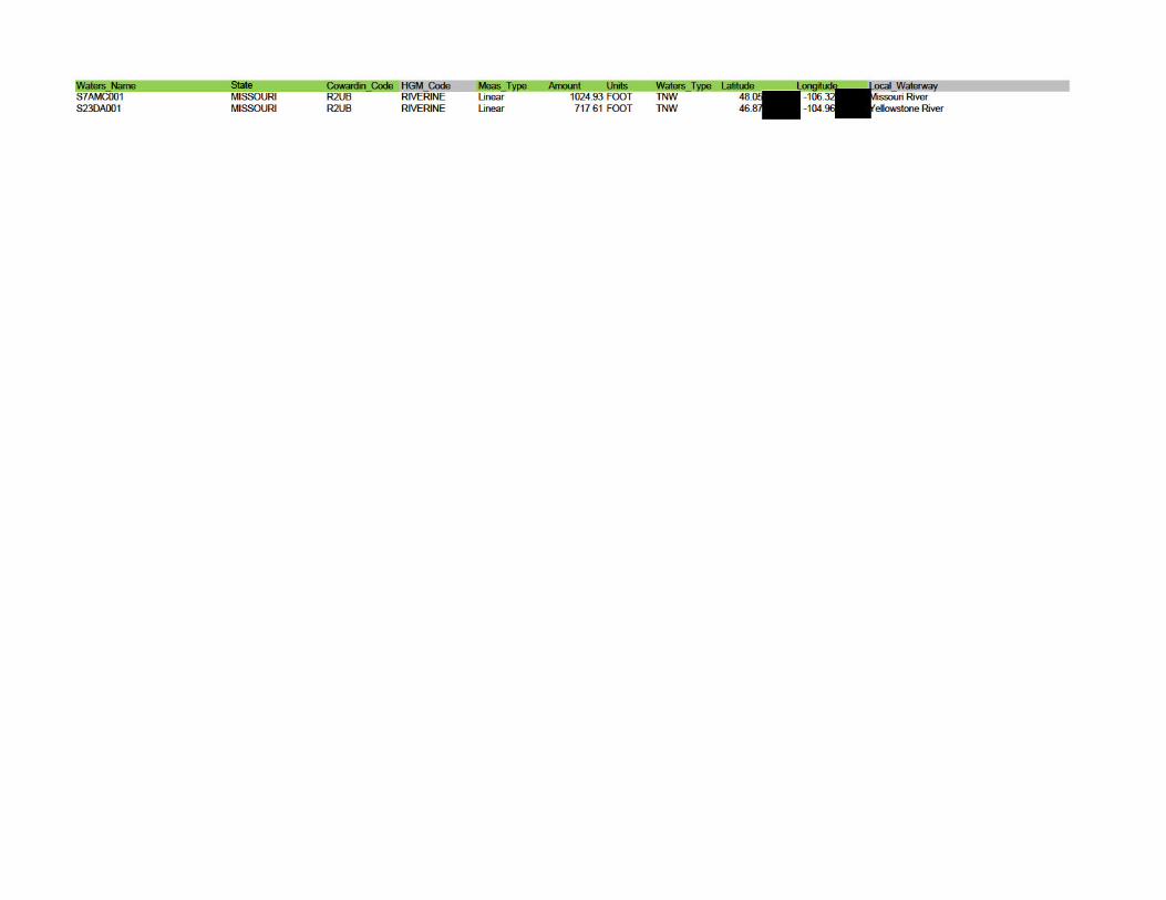
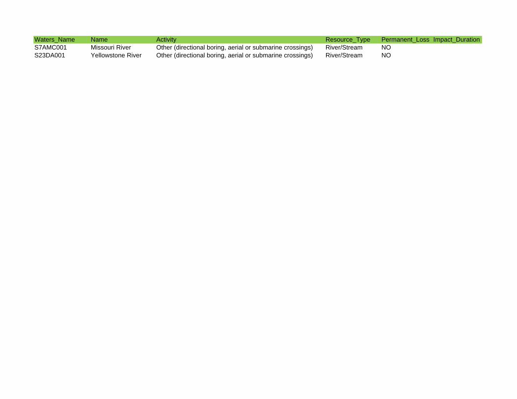
Waters_Name Name Activity Resource_Type Permanent_Loss Impact_DurationS7AMC001 Missouri River Other (directional boring, aerial or submarine crossings) River/Stream NOS23DA001 Yellowstone River Other (directional boring, aerial or submarine crossings) River/Stream NO
Non-PCN Datasheet Tables
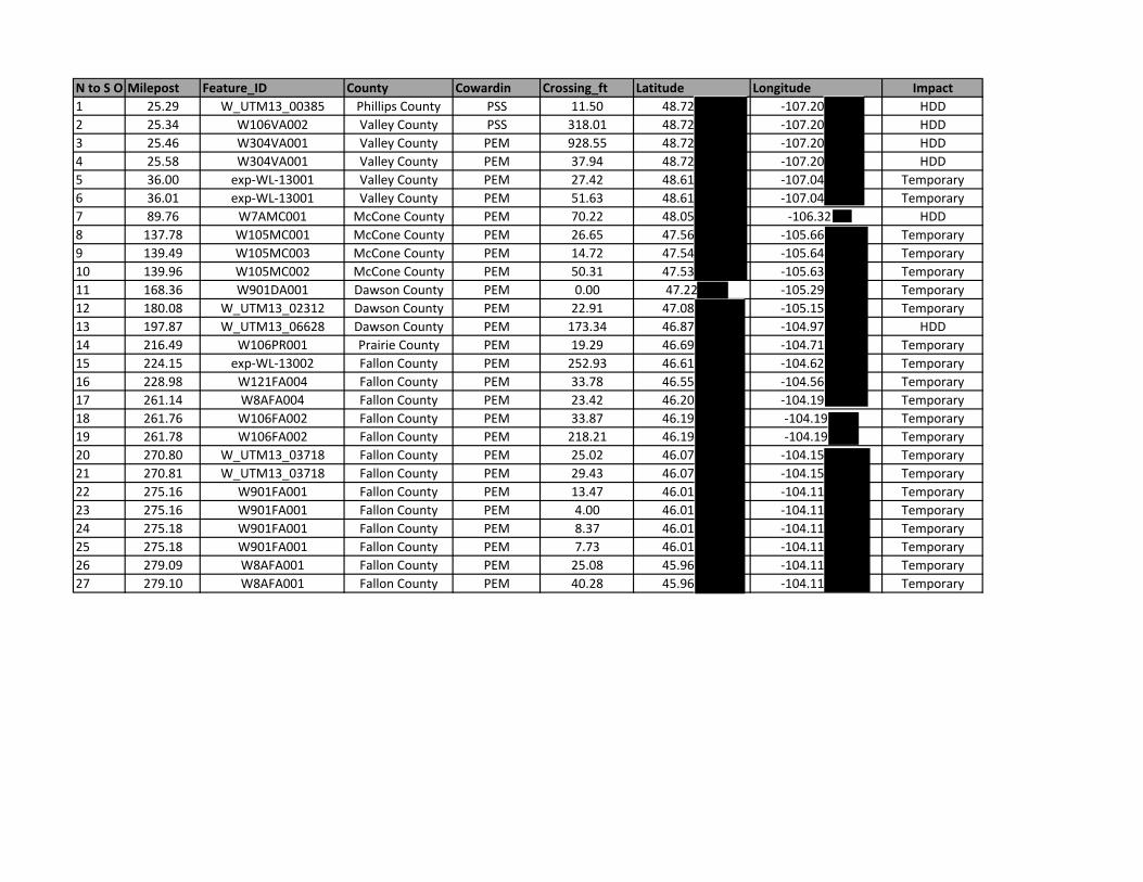
N to S O Milepost Feature_ID County Cowardin Crossing_ft Latitude Longitude Impact1 25.29 W_UTM13_00385 Phillips County PSS 11.50 48.72 ‐107.20 HDD2 25.34 W106VA002 Valley County PSS 318.01 48.72 ‐107.20 HDD3 25.46 W304VA001 Valley County PEM 928.55 48.72 ‐107.20 HDD4 25.58 W304VA001 Valley County PEM 37.94 48.72 ‐107.20 HDD5 36.00 exp‐WL‐13001 Valley County PEM 27.42 48.61 ‐107.04 Temporary6 36.01 exp‐WL‐13001 Valley County PEM 51.63 48.61 ‐107.04 Temporary7 89.76 W7AMC001 McCone County PEM 70.22 48.05 ‐106.32 HDD8 137.78 W105MC001 McCone County PEM 26.65 47.56 ‐105.66 Temporary9 139.49 W105MC003 McCone County PEM 14.72 47.54 ‐105.64 Temporary10 139.96 W105MC002 McCone County PEM 50.31 47.53 ‐105.63 Temporary11 168.36 W901DA001 Dawson County PEM 0.00 47.22 ‐105.29 Temporary12 180.08 W_UTM13_02312 Dawson County PEM 22.91 47.08 ‐105.15 Temporary13 197.87 W_UTM13_06628 Dawson County PEM 173.34 46.87 ‐104.97 HDD14 216.49 W106PR001 Prairie County PEM 19.29 46.69 ‐104.71 Temporary15 224.15 exp‐WL‐13002 Fallon County PEM 252.93 46.61 ‐104.62 Temporary16 228.98 W121FA004 Fallon County PEM 33.78 46.55 ‐104.56 Temporary17 261.14 W8AFA004 Fallon County PEM 23.42 46.20 ‐104.19 Temporary18 261.76 W106FA002 Fallon County PEM 33.87 46.19 ‐104.19 Temporary19 261.78 W106FA002 Fallon County PEM 218.21 46.19 ‐104.19 Temporary20 270.80 W_UTM13_03718 Fallon County PEM 25.02 46.07 ‐104.15 Temporary21 270.81 W_UTM13_03718 Fallon County PEM 29.43 46.07 ‐104.15 Temporary22 275.16 W901FA001 Fallon County PEM 13.47 46.01 ‐104.11 Temporary23 275.16 W901FA001 Fallon County PEM 4.00 46.01 ‐104.11 Temporary24 275.18 W901FA001 Fallon County PEM 8.37 46.01 ‐104.11 Temporary25 275.18 W901FA001 Fallon County PEM 7.73 46.01 ‐104.11 Temporary26 279.09 W8AFA001 Fallon County PEM 25.08 45.96 ‐104.11 Temporary27 279.10 W8AFA001 Fallon County PEM 40.28 45.96 ‐104.11 Temporary
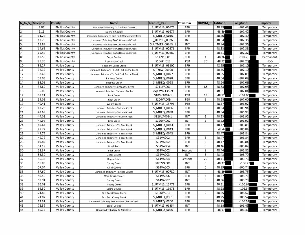
N_to_S_OMilepost County Name Feature_ID + Cowardin OHWM_ft Latitude Longitude Impacts1 9.06 Phillips County Unnamed Tributary To Dunham Coulee S_UTM13_06675 EPH 48.89 ‐107.42 Temporary2 9.13 Phillips County Dunham Coulee S_UTM13_06677 EPH 48.89 ‐107.42 Temporary3 11.27 Phillips County Unnamed Tributary To East Fork Whitewater River S_MDEQ_0016 EPH 48.86 ‐107.40 Temporary4 13.76 Phillips County Unnamed Tributary To Cottonwood Creek S_UTM13_00263 INT 48.84 ‐107.36 Temporary5 13.83 Phillips County Unnamed Tributary To Cottonwood Creek S_UTM13_00263_1 INT 48.84 ‐107.36 Temporary6 14.65 Phillips County Unnamed Tributary To Cottonwood Creek S_UTM13_00271 EPH 48.83 ‐107.35 Temporary7 16.44 Phillips County Unnamed Tributary To Cottonwood Creek S_UTM13_00280 EPH 48.81 ‐107.32 Temporary8 19.50 Phillips County Corral Coulee S112PH001 EPH 4 48.76 ‐107.28 Permanent9 25.30 Phillips County Frenchman Creek S106PH013 PER 30 48.72 ‐107.20 HDD10 32.27 Valley County East Fork Cache Creek S_UTM13_06100 EPH 48.65 ‐107.10 Temporary11 32.32 Valley County Unnamed Tributary To East Fork Cache Creek S_Trow_00900 EPH 48.65 ‐107.10 Temporary12 32.49 Valley County Unnamed Tributary To East Fork Cache Creek S_MDEQ_0027 EPH 48.65 ‐107.09 Temporary13 33.03 Valley County Papoose Creek S_MDEQ_0028 EPH 48.64 ‐107.09 Temporary14 33.09 Valley County Papoose Creek S_MDEQ_0028 EPH 48.64 ‐107.09 Temporary15 33.69 Valley County Unnamed Tributary To Papoose Creek S711VA001 EPH 1.5 48.63 ‐107.08 Temporary16 36.00 Valley County Unnamed Tributary To Jones Coulee exp‐WB‐13559 EPH 48.61 ‐107.04 Temporary17 38.21 Valley County Rock Creek S109VA002‐1 PER 15 48.57 ‐107.00 Temporary18 39.03 Valley County Rock Creek S106VA009 PER 8 48.58 ‐107.00 Temporary19 40.41 Valley County Willow Creek S_UTM13_13796 PER 48.57 ‐106.97 Temporary20 43.26 Valley County Unnamed Tributary To Lime Creek S_MDEQ_0036 EPH 48.54 ‐106.94 Temporary21 43.69 Valley County Unnamed Tributary To Lime Creek S_MDEQ_0038 EPH 48.54 ‐106.93 Temporary22 44.08 Valley County Unnamed Tributary To Lime Creek S126VA001‐1 INT 3 48.53 ‐106.92 Temporary23 44.96 Valley County Lime Creek S126VA002 INT 6 48.52 ‐106.91 Temporary24 49.64 Valley County Unnamed Tributary To Bear Creek S_MDEQ_0043 EPH 48.47 ‐106.85 Temporary25 49.72 Valley County Unnamed Tributary To Bear Creek S_MDEQ_0043 EPH 48.47 ‐106.84 Temporary26 49.76 Valley County Unnamed Tributary To Bear Creek S_MDEQ_0043 EPH 48.47 ‐106.84 Temporary27 49.79 Valley County Unnamed Tributary To Bear Creek S31VA002 EPH 6 48.47 ‐106.84 Temporary28 49.82 Valley County Unnamed Tributary To Bear Creek S31VA002 EPH 6 48.47 ‐106.84 Temporary29 51.19 Valley County Brush Fork S5AVA004 INT 3 48.46 ‐106.82 Temporary30 52.37 Valley County Bear Creek S14VA002 Seasonal 9 48.44 ‐106.81 Temporary31 53.39 Valley County Unger Coulee S14VA003 INT 8 48.43 ‐106.79 Temporary32 55.36 Valley County Buggy Creek S14VA004 Seasonal 20 48.41 ‐106.76 Temporary33 56.88 Valley County Spring Creek S802VA001 INT 5 48.37 ‐106.73 Temporary34 57.04 Valley County Alkali Coulee S14VA005 EPH 6 48.39 ‐106.74 Temporary35 57.60 Valley County Unnamed Tributary To Alkali Coulee S_UTM13_00780 INT 48.39 ‐106.73 Temporary36 59.40 Valley County Wire Grass Coulee S14VA006 EPH 4 48.37 ‐106.71 Temporary37 59.91 Valley County Spring Creek S14VA007 INT 9 48.36 ‐106.70 Temporary38 66.01 Valley County Cherry Creek S_UTM13_15972 EPH 48.31 ‐106.61 Temporary39 69.50 Valley County Spring Coulee S_UTM13_15973 EPH 48.28 ‐106.54 Temporary40 71.82 Valley County East Fork Cherry Creek S106VA011 EPH 2 48.25 ‐106.52 Temporary41 71.87 Valley County East Fork Cherry Creek S_MDEQ_0301 EPH 48.25 ‐106.52 Temporary42 72.31 Valley County Unnamed Tributary To East Fork Cherry Creek S_MDEQ_0300 EPH 48.25 ‐106.52 Temporary43 78.59 Valley County Espeil Coulee S_UTM13_06354 INT 48.18 ‐106.43 Temporary44 80.17 Valley County Unnamed Tributary To Milk River S_MDEQ_0056 EPH 48.17 ‐106.41 Temporary
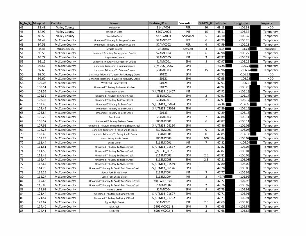
N_to_S_OMilepost County Name Feature_ID + Cowardin OHWM_ft Latitude Longitude Impacts45 83.43 Valley County Milk River S14VA008 PER 50 48.13 ‐106.38 HDD46 84.97 Valley County Irrigation Ditch S567VA005 INT 15 48.11 ‐106.37 Temporary47 85.50 Valley County Vandalia Canal S276VA001 Seasonal 5 48.10 ‐106.37 Temporary48 94.49 McCone County Unnamed Tributary To Struple Coulee S7AMC002 PER 6 47.99 ‐106.28 Temporary49 94.53 McCone County Unnamed Tributary To Struple Coulee S7AMC002 PER 6 47.99 ‐106.28 Temporary50 94.68 McCone County Struple Coulee S31MC002 Seasonal 3 47.99 ‐106.28 Temporary
51 95.55 McCone County Unnamed Tributary To Jorgensen Coulee S7AMC004 PER 6 47.98 ‐106.27 Temporary52 95.77 McCone County Jorgensen Coulee S7AMC005 INT 3 47.97 ‐106.27 Temporary53 96.12 McCone County Unnamed Tributary To Jorgensen Coulee S14MC001 EPH 8 47.97 ‐106.26 Temporary54 97.56 McCone County Unnamed Tributary To Colman Coulee S_MDEQ_0067 EPH 47.96 ‐106.24 Temporary55 97.60 McCone County Unnamed Tributary To Colman Coulee S31MC003 EPH 15 47.96 ‐106.24 Temporary56 99.55 McCone County Unnamed Tributary To West Fork Hungry Creek S0121 EPH 47.93 ‐106.22 HDD57 99.60 McCone County Unnamed Tributary To West Fork Hungry Creek S0121 EPH 47.93 ‐106.22 HDD58 100.06 McCone County West Fork Hungry Creek S0124 EPH 47.93 ‐106.21 Temporary59 100.51 McCone County Unnamed Tributary To Beaver Coulee S0125 EPH 47.92 ‐106.20 Temporary60 101.55 McCone County Scotsman Coulee S_UTM13_01407 INT 47.92 ‐106.18 Temporary61 102.32 McCone County Unnamed Tributary To Cheer Creek S31MC001 EPH 2 47.91 ‐106.17 Temporary62 102.36 McCone County Unnamed Tributary To Cheer Creek S31MC001 EPH 2 47.91 ‐106.17 Temporary63 103.40 McCone County Unnamed Tributary To Bear Creek S_UTM13_05094 EPH 47.89 ‐106.16 Temporary64 103.45 McCone County Unnamed Tributary To Bear Creek S_UTM13_05096 EPH 47.89 ‐106.16 Temporary65 103.84 McCone County Unnamed Tributary To Bear Creek S0133 EPH 47.89 ‐106.16 Temporary66 106.20 McCone County Bear Creek S14MC003 EPH 7 47.88 ‐106.11 Temporary67 106.57 McCone County Unnamed Tributary To Bear Creek S802MC001 EPH 6 47.87 ‐106.11 Temporary68 107.62 McCone County Unnamed Tributary To North Prong Shade Creek S_UTM13_06120 EPH 47.86 ‐106.09 Temporary69 108.26 McCone County Unnamed Tributary To Prong Shade Creek S304MC001 EPH 0 47.85 ‐106.08 Temporary70 108.48 McCone County Unnamed Tributary To Prong Shade Creek S304MC001 EPH 0 47.85 ‐106.08 Temporary71 109.25 McCone County North Prong Shade Creek S802MC003 EPH 100 47.84 ‐106.07 Temporary72 111.44 McCone County Shade Creek S113MC001 INT 7 47.82 ‐106.04 Temporary73 111.51 McCone County Unnamed Tributary To Shade Creek S_UTM13_01557 EPH 47.82 ‐106.04 Temporary74 111.55 McCone County Unnamed Tributary To Shade Creek S_MDEQ_0073 EPH 47.82 ‐106.04 Temporary75 112.43 McCone County Unnamed Tributary To Shade Creek S113MC002 EPH 2.5 47.81 ‐106.03 Temporary76 112.44 McCone County Unnamed Tributary To Shade Creek S113MC003 EPH 2.5 47.81 ‐106.03 Temporary77 112.64 McCone County Unnamed Tributary To Shade Creek S_UTM13_01569 EPH 47.80 ‐106.02 Temporary78 114.78 McCone County Unnamed Tributary To South Fork Shade Creek S_UTM13_06126 EPH 47.78 ‐106.00 Temporary79 115.25 McCone County South Fork Shade Creek S113MC004 INT 3 47.77 ‐105.99 Temporary80 115.27 McCone County South Fork Shade Creek S113MC004 INT 3 47.78 ‐105.99 Temporary81 115.68 McCone County Unnamed Tributary To South Fork Shade Creek exp‐WB‐13540 EPH 47.77 ‐105.98 Temporary82 116.85 McCone County Unnamed Tributary To South Fork Shade Creek S110MC002 EPH 2 47.76 ‐105.97 Temporary83 119.62 McCone County Flying V Creek S14MC004 EPH 9 47.73 ‐105.93 Temporary84 121.44 McCone County Unnamed Tributary To Flying V Creek S_UTM13_01697 EPH 47.71 ‐105.91 Temporary85 121.54 McCone County Unnamed Tributary To Flying V Creek S_UTM13_01702 EPH 47.71 ‐105.91 Temporary86 123.67 McCone County Figure Eight Creek S5AMC001 INT 2.5 47.69 ‐105.88 Temporary87 124.40 McCone County Elk Creek S901MC002_1 EPH 3 47.68 ‐105.87 Temporary88 124.41 McCone County Elk Creek S901MC002_1 EPH 3 47.68 ‐105.87 Temporary
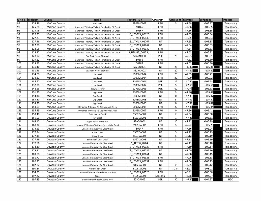
N_to_S_OMilepost County Name Feature_ID + Cowardin OHWM_ft Latitude Longitude Impacts89 124.46 McCone County Elk Creek S901MC002 EPH 3 47.68 ‐105.87 Temporary90 125.88 McCone County Unnamed Tributary To East Fork Prairie Elk Creek S0166 EPH 47.66 ‐105.85 Temporary91 125.98 McCone County Unnamed Tributary To East Fork Prairie Elk Creek S0167 EPH 47.66 ‐105.85 Temporary92 126.95 McCone County Unnamed Tributary To East Fork Prairie Elk Creek S_UTM13_06128 EPH 47.65 ‐105.84 Temporary93 127.23 McCone County Unnamed Tributary To East Fork Prairie Elk Creek S_UTM13_06130 EPH 47.65 ‐105.83 Temporary94 127.46 McCone County Unnamed Tributary To East Fork Prairie Elk Creek S_UTM13_01767 INT 47.65 ‐105.83 Temporary95 127.50 McCone County Unnamed Tributary To East Fork Prairie Elk Creek S_UTM13_01767 INT 47.64 ‐105.83 Temporary96 128.05 McCone County Unnamed Tributary To East Fork Prairie Elk Creek S_UTM13_06132 EPH 47.64 ‐105.83 Temporary97 128.42 McCone County Unnamed Tributary To East Fork Prairie Elk Creek S_UTM13_06135_1 EPH 47.63 ‐105.82 Temporary98 128.97 McCone County East Fork Prairie Elk Creek S7AMC008 PER 20 47.63 ‐105.81 Temporary99 129.62 McCone County Unnamed Tributary To East Fork Prairie Elk Creek S0186 EPH 47.62 ‐105.80 Temporary100 129.72 McCone County Unnamed Tributary To East Fork Prairie Elk Creek S0187 EPH 47.62 ‐105.80 Temporary101 131.40 McCone County Unnamed Tributary To East Fork Prairie Elk Creek S32MC001 INT 25 47.61 ‐105.81 Temporary102 131.43 McCone County East Fork Prairie Elk Creek S32MC002 INT 20 47.61 ‐105.80 Temporary103 134.09 McCone County Lost Creek S105MC004 EPH 20 47.59 ‐105.72 Temporary104 134.12 McCone County Lost Creek S105MC004 EPH 20 47.59 ‐105.72 Temporary105 136.62 McCone County Lost Creek S105MC001 PER 15 47.57 ‐105.68 Temporary106 137.78 McCone County Lost Creek S105MC002 PER 5 47.55 ‐105.66 Temporary107 148.55 McCone County Redwater River S276MC001 PER 60 47.44 ‐105.53 Temporary108 151.85 McCone County Gyp Creek S106MC003 EPH 3 47.40 ‐105.48 Temporary109 153.30 McCone County Gyp Creek S105MC006 INT 0 47.39 ‐105.47 Temporary110 153.30 McCone County Gyp Creek S105MC005 INT 5 47.39 ‐105.47 Temporary111 153.30 McCone County Gyp Creek S105MC006 INT 0 47.39 ‐105.47 Temporary112 154.69 McCone County Unnamed Tributary To Cottonwood Creek S802MC005 EPH 20 47.38 ‐105.44 Temporary113 156.49 McCone County Unnamed Tributary To Cottonwood Creek S105MC007 EPH 0 47.36 ‐105.41 Temporary114 158.40 Dawson County Cottonwood Creek S567DA001 INT 2 47.34 ‐105.38 Temporary115 165.03 Dawson County Hay Creek S121DA001 EPH 1 47.26 ‐105.31 Temporary116 168.15 Dawson County Upper Seven Mile Creek S8ADA001 INT 15 47.22 ‐105.29 Temporary117 168.34 Dawson County Unnamed Tributary To Upper Seven Mile Creek S901DA002 EPH 5 47.22 ‐105.29 Temporary118 173.13 Dawson County Unnamed Tributary To Clear Creek S0247 EPH 47.16 ‐105.24 Temporary119 177.24 Dawson County Clear Creek S567DA002 INT 5 47.12 ‐105.19 Temporary120 177.35 Dawson County Clear Creek S567DA002 INT 5 47.12 ‐105.19 Temporary121 177.49 Dawson County South Fork Clear Creek S567DA003 INT 3 47.11 ‐105.19 Temporary122 177.56 Dawson County Unnamed Tributary To Clear Creek S_TROW_0704 INT 47.11 ‐105.18 Temporary123 178.39 Dawson County Unnamed Tributary To Clear Creek S_UTM13_06137 EPH 47.10 ‐105.17 Temporary124 179.31 Dawson County Unnamed Tributary To Clear Creek S_UTM13_02285 INT 47.09 ‐105.16 Temporary125 180.08 Dawson County Unnamed Tributary To Clear Creek S_UTM13_07661 INT 47.08 ‐105.15 Temporary126 181.77 Dawson County Unnamed Tributary To Clear Creek S_UTM13_06328 EPH 47.06 ‐105.13 Temporary127 182.27 Dawson County Unnamed Tributary To Clear Creek S_UTM13_06331 EPH 47.06 ‐105.13 Temporary128 182.87 Dawson County Unnamed Tributary To Clear Creek S802DA001 INT 15 47.05 ‐105.12 Temporary129 190.24 Dawson County Cracker Box Creek S105DA002 INT 2.5 46.97 ‐105.02 Temporary130 194.85 Dawson County Unnamed Tributary To Yellowstone River S_UTM13_02520 EPH 46.91 ‐105.00 Temporary131 197.27 Dawson County Canal S105DA003 Seasonal 5 46.88 ‐104.97 Temporary132 197.85 Dawson County Side Channel Of Yellowstone River S23DA002 PER 30 46.87 ‐104.97 HDD
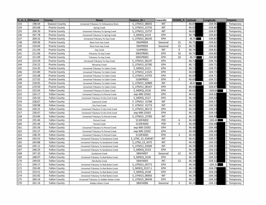
N_to_S_OMilepost County Name Feature_ID + Cowardin OHWM_ft Latitude Longitude Impacts133 198.44 Dawson County Unnamed Tributary To Yellowstone River S_UTM13_08692 INT 46.87 ‐104.96 Temporary134 203.68 Prairie County Spring Creek S_UTM13_15735 INT 46.82 ‐104.88 Temporary135 204.39 Prairie County Unnamed Tributary To Spring Creek S_UTM13_15737 INT 46.82 ‐104.87 Temporary136 207.78 Prairie County Unnamed Tributary To Spring Creek S_MDEQ_0119 EPH 46.78 ‐104.84 Temporary137 209.32 Prairie County Unnamed Tributary To Hay Creek S_UTM13_06145 EPH 46.76 ‐104.83 Temporary138 209.96 Prairie County West Fork Hay Creek S9APR004 Seasonal 15 46.75 ‐104.82 Temporary139 210.04 Prairie County West Fork Hay Creek S9APR004 Seasonal 15 46.75 ‐104.82 Temporary140 211.04 Prairie County Hay Creek S14PR001 INT 9 46.74 ‐104.81 Temporary141 211.06 Prairie County Tributary To Hay Creek S901PR001 EPH 10 46.74 ‐104.80 Temporary142 211.09 Prairie County Tributary To Hay Creek S901PR001 EPH 10 46.74 ‐104.80 Temporary143 213.59 Prairie County Unnamed Tributary To Hay Creek S_UTM13_06147 EPH 46.71 ‐104.76 Temporary144 214.22 Prairie County Mcnaney Creek S_UTM13_02780 EPH 46.71 ‐104.75 Temporary145 214.35 Prairie County Unnamed Tributary To Cabin Creek S_MDEQ_0121 EPH 46.71 ‐104.75 Temporary146 215.80 Prairie County Unnamed Tributary To Cabin Creek S_UTM13_11525 EPH 46.69 ‐104.73 Temporary147 216.48 Prairie County Unnamed Tributary To Cabin Creek S_UTM13_15755 EPH 46.69 ‐104.71 Temporary148 217.02 Prairie County Unnamed Tributary To Cabin Creek S106PR001 EPH 2 46.69 ‐104.71 Temporary149 218.95 Prairie County Unnamed Tributary To Cabin Creek S_UTM13_02889 INT 46.67 ‐104.68 Temporary150 219.50 Prairie County Unnamed Tributary To Cabin Creek S_UTM13_06167 EPH 46.66 ‐104.67 Temporary151 222.03 Fallon County Unnamed Tributary To Deer Creek S_MDEQ_0126 EPH 46.63 ‐104.64 Temporary152 224.17 Fallon County Unnamed Tributary To Pennel Creek exp‐WB‐13562 EPH 46.61 ‐104.62 Temporary153 226.50 Fallon County Unnamed Tributary To Dry Fork Creek S_MDEQ_0127 EPH 46.58 ‐104.60 Temporary154 228.67 Fallon County Lawrence Creek S UTM13 15768 INT 46.55 ‐104.57 Temporary155 228.98 Fallon County Dry Fork Creek S UTM13 15773 INT 46.55 ‐104.56 Temporary156 230.31 Fallon County Unnamed Tributary To Dry Fork Creek S_UTM13_06172 EPH 46.54 ‐104.54 Temporary157 230.67 Fallon County Unnamed Tributary To Dry Fork Creek exp‐WB‐13563 EPH 46.54 ‐104.54 Temporary158 233.84 Fallon County Unnamed Tributary To Pennel Creek S_UTM13_15783 INT 46.51 ‐104.49 Temporary159 235.46 Fallon County Pennel Creek S110FA002 PER 6 46.48 ‐104.48 Temporary160 235.46 Fallon County Pennel Creek S110FA002 PER 6 46.48 ‐104.48 Temporary161 235.56 Fallon County Unnamed Tributary To Pennel Creek exp‐WB‐13592 EPH 46.48 ‐104.48 Temporary162 235.57 Fallon County Unnamed Tributary To Pennel Creek exp‐WB‐13592 EPH 46.48 ‐104.48 Temporary163 238.70 Fallon County Unnamed Tributary To Pennel Creek S110FA001 EPH 3 46.46 ‐104.44 Temporary164 243.55 Fallon County Unnamed Tributary To Sandstone Creek S_UTM_13_034587 INT 46.41 ‐104.37 Temporary165 244.88 Fallon County Unnamed Tributary To Sandstone Creek S_UTM_13_4575 INT 46.40 ‐104.35 Temporary166 245.11 Fallon County Unnamed Tributary To Sandstone Creek S_UTM13_03284 INT 46.39 ‐104.35 Temporary167 246.33 Fallon County Unnamed Tributary To Sandstone Creek S_MDEQ_0133 EPH 46.38 ‐104.33 Temporary168 247.10 Fallon County Sandstone Creek S8AFA007 Seasonal 12 46.37 ‐104.33 Temporary169 248.97 Fallon County Unnamed Tributary To Red Butte Creek S_MDEQ_0136 EPH 46.34 ‐104.32 Temporary170 249.03 Fallon County Red Butte Creek S9AFA003 INT 12 46.34 ‐104.31 Temporary171 249.17 Fallon County Unnamed Tributary To Red Butte Creek S_UTM13_05771 EPH 46.34 ‐104.31 Temporary172 250.49 Fallon County Unnamed Tributary To Red Butte Creek S_MDEQ_0137‐1 EPH 46.33 ‐104.29 Temporary173 253.51 Fallon County Unnamed Tributary To Red Butte Creek S_MDEQ_0138 EPH 46.29 ‐104.26 Temporary174 253.92 Fallon County Unnamed Tributary To Red Butte Creek S_UTM13_06956 INT 46.29 ‐104.26 Temporary175 260.14 Fallon County Unnamed Tributary To Hidden Water Creek S_UTM13_06439 EPH 46.21 ‐104.20 Temporary176 261.14 Fallon County Hidden Water Creek S8AFA006 Seasonal 5 46.20 ‐104.19 Temporary
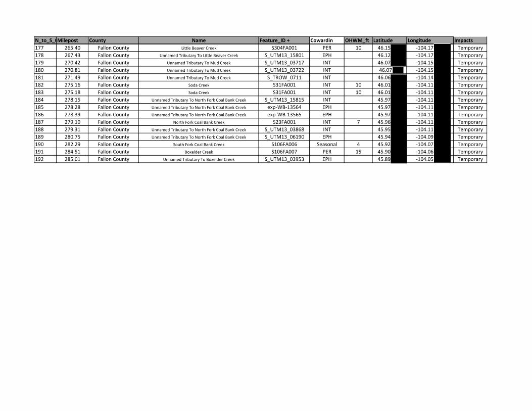
N_to_S_OMilepost County Name Feature_ID + Cowardin OHWM_ft Latitude Longitude Impacts177 265.40 Fallon County Little Beaver Creek S304FA001 PER 10 46.15 ‐104.17 Temporary178 267.43 Fallon County Unnamed Tributary To Little Beaver Creek S_UTM13_15801 EPH 46.12 ‐104.17 Temporary179 270.42 Fallon County Unnamed Tributary To Mud Creek S_UTM13_03717 INT 46.07 ‐104.15 Temporary180 270.81 Fallon County Unnamed Tributary To Mud Creek S_UTM13_03722 INT 46.07 ‐104.15 Temporary181 271.49 Fallon County Unnamed Tributary To Mud Creek S_TROW_0711 INT 46.06 ‐104.14 Temporary182 275.16 Fallon County Soda Creek S31FA001 INT 10 46.01 ‐104.11 Temporary183 275.18 Fallon County Soda Creek S31FA001 INT 10 46.01 ‐104.11 Temporary184 278.15 Fallon County Unnamed Tributary To North Fork Coal Bank Creek S_UTM13_15815 INT 45.97 ‐104.11 Temporary185 278.28 Fallon County Unnamed Tributary To North Fork Coal Bank Creek exp‐WB‐13564 EPH 45.97 ‐104.11 Temporary186 278.39 Fallon County Unnamed Tributary To North Fork Coal Bank Creek exp‐WB‐13565 EPH 45.97 ‐104.11 Temporary187 279.10 Fallon County North Fork Coal Bank Creek S23FA001 INT 7 45.96 ‐104.11 Temporary188 279.31 Fallon County Unnamed Tributary To North Fork Coal Bank Creek S_UTM13_03868 INT 45.95 ‐104.11 Temporary189 280.75 Fallon County Unnamed Tributary To North Fork Coal Bank Creek S_UTM13_06190 EPH 45.94 ‐104.09 Temporary190 282.29 Fallon County South Fork Coal Bank Creek S106FA006 Seasonal 4 45.92 ‐104.07 Temporary191 284.51 Fallon County Boxelder Creek S106FA007 PER 15 45.90 ‐104.06 Temporary192 285.01 Fallon County Unnamed Tributary To Boxelder Creek S_UTM13_03953 EPH 45.89 ‐104.05 Temporary
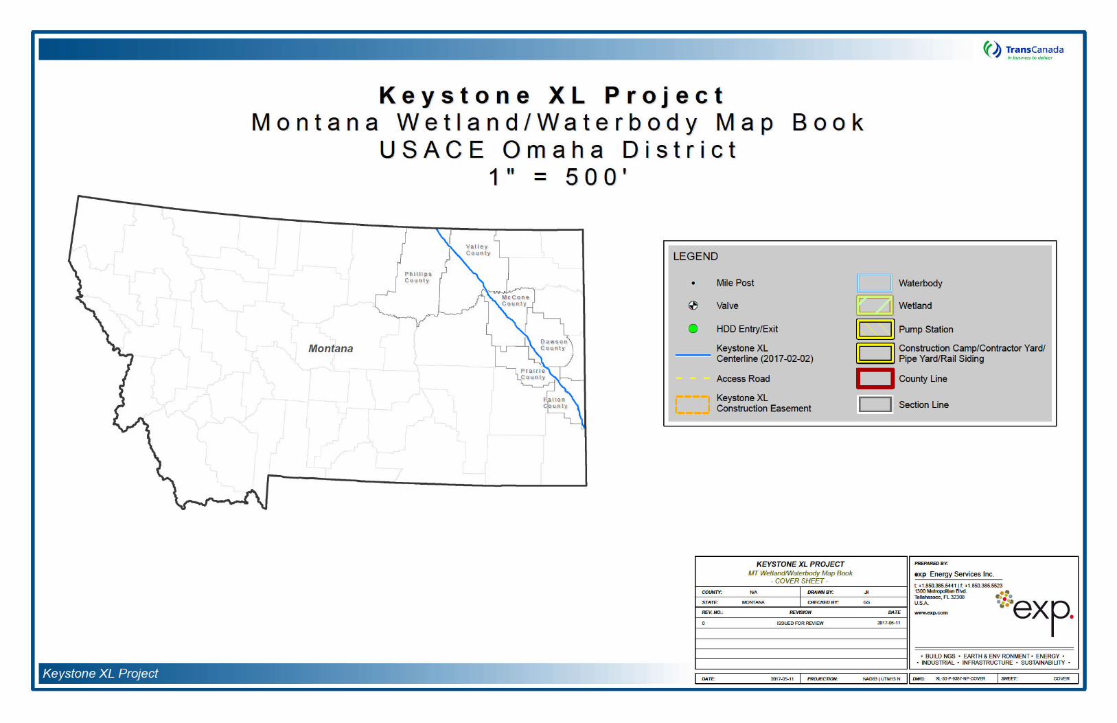


Attachment C:
Construction Mitigation and Reclamation Plan
KEYSTONE XL PROJECT
CONSTRUCTION, MITIGATION,
AND RECLAMATION PLAN
April 2012 Rev. 4

Keystone XL Project
-This page intentionally left blank-
March 2013
CONSTRUCTION MITIGATION AND RECLAMATION PLAN
1.0 INTRODUCTION
2.0 GENERAL CONDITIONS 2.1 Training 2.2 Environmental Inspection 2.3 Advance Notice of Access to Property Prior to Construction 2.4 Other Notifications 2.5 Damages to Private Property 2.6 Appearance of Worksite 2.7 Access 2.8 Aboveground Facilities 2.9 Minimum Depth of Cover 2.10 Non-Hazardous Waste Disposal 2.11 Hazardous Wastes 2.12 Noise Control 2.13 Weed Control 2.14 Dust Control 2.15 Off Road Vehicle Control 2.16 Fire Prevention and Control 2.17 Road and Railroad Crossings 2.18 Adverse Weather 2.19 Cultural Resources
3.0 SPILL PREVENTION AND CONTAINMENT 3.1 Spill Prevention
3.1.1 Staging Area 3.1.2 Construction Right of Way
3.2 Contingency Plans 3.3 Equipment 3.4 Emergency Notification 3.5 Spill Containment and Countermeasures
4.0 UPLANDS (AGRICULTURAL, FOREST, PASTURE, RANGE AND GRASS LANDS) 4.1 Interference with Irrigation Systems 4.2 Clearing 4.3 Topsoil Removal and Storage 4.4 Grading 4.5 Temporary Erosion and Sediment Control
4.5.1 General 4.5.2 Sediment Barriers 4.5.3 Trench Plugs 4.5.4 Temporary Slope Breakers (Water Bars) 4.5.5 Drainage Channels or Ditches 4.5.6 Temporary Mulching 4.5.7 Tackifier
4.6 Stringing
TRANSCANADA KEYSTONE PIPELINE, LP -i- April 2012
Rev. 4
CONSTRUCTION MITIGATION AND RECLAMATION PLAN
4.7 Trenching 4.7.1 Trench Dewater/Well Points
4.8 Welding, Field Joint Coating, and Lowering In 4.9 Padding and Backfilling 4.10 Clean Up 4.11 Reclamation and Revegetation
4.11.1 Relieving Compaction 4.11.2 Rock Removal 4.11.3 Soil Additives 4.11.4 Seeding 4.11.5 Permanent Erosion and Sediment Control 4.11.6 Fences 4.11.7 Farm Terraces 4.11.8 Right-of-Way and Pipeline Markers
4.12 Pasture and Range Lands 4.13 Forested Lands 4.14 Residential and Commercial/Industrial Areas
4.14.1 Residential and Commercial Areas 4.14.2 Site – Specific Plans 4.14.3 Landowner Complaint Resolution Procedure
4.15 Fragile Soil Clean Up and Reclamation/Revegetation 4.15.1 General 4.15.2 Right-of-Way Construction 4.15.3 Right-of-Way Reclamation 4.15.4 Post - Construction
4.16 Operations and Maintenance
5.0 DRAIN TILE SYSTEMS 5.1 General 5.2 Identification and Classification of Drain Tile Systems
5.2.1 Publicly Owned Drain Tiles 5.2.2 Privately Owned Drain Tiles
5.3 Mitigation of Damage to Drain Tile Systems 5.3.1 Non-interference with Drain Tile 5.3.2 Non-disturbance of Drain Tile Mains 5.3.3 Relocation or Replacement of Existing Drain Tiles Prior to Construction 5.3.4 Future Drain Tiles/Systems 5.3.5 Other Mitigation Measures
5.4 Responsibility for Repair of Drain Tile Systems 5.4.1 Local Drain Tile Contractor Repair 5.4.2 Pipeline Contractor Repair 5.4.3 Landowner/Tenant Repair
5.5 Drain Tile Repairs 5.5.1 Temporary Repairs During Construction 5.5.2 Permanent Repairs
5.6 Inspection/Acceptance of Drain Tile Repairs
TRANSCANADA KEYSTONE PIPELINE, LP -ii- April 2012
Rev. 4
CONSTRUCTION MITIGATION AND RECLAMATION PLAN
6.0 WETLAND CROSSINGS 6.1 General 6.2 Easement and Workspace 6.3 Vehicle Access and Equipment Crossing 6.4 Temporary Erosion and Sediment Control 6.5 Wetland Crossing Procedures
6.5.1 Dry Wetland Crossing Method 6.5.2 Standard Wetland Crossing Method 6.5.3 Flooded Push/Pull Wetland Crossing Method
6.6 Restoration and Reclamation
7.0 WATERBODIES AND RIPARIAN LANDS 7.1 General 7.2 Easement and Workspace 7.3 Vehicle Access and Equipment Crossings 7.4 Waterbody Crossing Methods
7.4.1 Non-flowing Open Cut Crossing Method 7.4.2 Flowing Open Cut Crossing Method of Minor, Intermediate, and Major
Waterbodies 7.4.3 Flowing Stream Crossing – Dry Flume Method 7.4.4 Flowing Stream Crossing – Dry Dam and Pump Method 7.4.5 Horizontal Directional Drill Crossings 7.4.6 Horizontal Bore Crossings
7.5 Clearing 7.6 Grading 7.7 Temporary Erosion and Sediment Control 7.8 Trenching 7.9 Pipe Installation 7.10 Backfilling 7.11 Stabilization and Restoration of Stream Banks and Slopes
8.0 HYDROSTATIC TESTING 8.1 Testing Equipment Location 8.2 Test Water Source and Discharge Locations 8.3 Filling the Pipeline 8.4 Dewatering the Pipeline
8.4.1 Splash Pup 8.4.2 Splash Plate 8.4.3 Plastic Liner 8.4.4 Straw Bale Dewatering Structure
TRANSCANADA KEYSTONE PIPELINE, LP -iii- April 2012
Rev. 4
CONSTRUCTION MITIGATION AND RECLAMATION PLAN
9.0 DRAWINGS AND FIGURES
Detail 1 Typical Silt Fence Barrier Detail 2 Typical Straw or Hay Bale Barrier Detail 3 Temporary/Permanent Slope Breaker Detail (Water Bars) Detail 4 Erosion Control Matting Installation Detail 5 Typical Dewatering Filter Bag Detail 6 Typical Straw Bale Dewatering Structure Detail 7 Typical Permanent Trench Breaker Detail 8 ”Dry” Wetland Crossing Method Detail 9 Standard Wetland Crossing Method Detail 10 Push/Pull Wetland Crossing Method Detail 11 Typical Open Cut Wet Crossing Method Non-Flowing Waterbody Detail 12 Typical Open Cut Wet Crossing Method Flowing Waterbody Detail 13 Typical Dry Flume Crossing Method Detail 13a Typical Dry Flume Crossing Method (Procedures) Detail 14 Typical Dam and Pump Crossing Detail 14a Typical Dam and Pump Crossing (Procedures) Detail 15 Typical Horizontal Drill (HDD) Site Plan & Profile Detail 16 Typical Temporary Bridge Crossing Detail 17 Typical Flume Bridge Crossing Detail 18 Typical Railcar Bridge Crossing Detail 19 Flexible Channel Liner Installation Detail 20 Typical Rock Rip-Rap Detail 21 Typical Uncased/Railroad Crossing Bore Detail Deail 22 (Omitted) Detail 23 Streambank Reclamation – Log Wall Detail 24 Streambank Reclamation – Vegetated Geotextile Installation Detail 25 Typical ROW Layout/Soil Handling 110’ Construction ROW 50’ Easement Drain Tile
Crossing Detail 26 Header/Main Crossovers of Pipeline Detail 27 Relocate/Replace Drainage Header/Main Detail 28 Drainage and Irrigation Temporary Drain Tile Repair Detail 29 Drainage and Irrigation Permanent Drain Tile Repair Detail 30 Equipment Cleaning Station Detail Detail 31 Equipment Wash Station Detail Detail 67/67A Topsoil Conservation—Triple Ditch
TRANSCANADA KEYSTONE PIPELINE, LP -iv- April 2012
Rev. 4
CONSTRUCTION MITIGATION AND RECLAMATION PLAN
1.0 INTRODUCTION
The construction, mitigation, and reclamation requirements described in this Plan apply to work on all of TransCanada Keystone Pipeline, L.P.’s (Keystone’s) Keystone XL Project (Project) lands, including the following;
uplands, including agricultural (cultivated or capable of being cultivated) lands, pasture lands; range lands; grass lands; forested lands; lands in residential, commercial, or industrial areas; lands in public rights of way; and lands in private rights-of-way;
wetlands; and
waterbodies and riparian areas.
Keystone, during the construction, operation, and maintenance of the Project, shall implement the construction, mitigation, and reclamation actions contained in this Plan to the extent that they do not conflict with the requirements of any applicable federal, state, or local rules and regulations, or other permits or approvals that are applicable to the Project. Additionally, Keystone may deviate from specific requirements of this Plan on specific private lands as agreed to by landowners or as required to suit actual site conditions as determined and directed by Keystone. All work must be in compliance with federal, state, and local permits.
The Project will be designed, constructed, operated and maintained in a manner that meets or exceeds applicable industry standards and regulatory requirements. Keystone’s Integrity Management Plan and Emergency Response Plan outlines the preventative maintenance, inspection, line patrol, leak detection systems, SCADA, and other pipeline integrity management procedures to be implemented during operation of the Project.
2.0 GENERAL CONDITIONS
2.1 Training
Experienced, well-trained personnel are essential for the successful implementation of this Plan. Keystone and its Contractors shall undergo prevention and response, as well as safety training. The program shall be designed to improve awareness of safety requirements, pollution control laws and procedures, and proper operation and maintenance of equipment.
The construction contractor (Contractor), and all of his subcontractors shall ensure that persons engaged in Project construction are informed of the construction issues and concerns and that they attend and receive training regarding these requirements as well as all laws, rules and regulations applicable to the work. Prior to construction, all Project personnel will be trained on environmental permit requirements and environmental specifications, including fuel handling and storage, cultural resource protection methods, stream and wetland crossing requirements, and sensitive species protection measures.
TRANSCANADA KEYSTONE PIPELINE, LP 1 April 2012
Rev. 4
CONSTRUCTION MITIGATION AND RECLAMATION PLAN
Different levels of training shall be required for different groups of Contractor personnel. Contractor supervisors, managers, field foremen, and other Contractor personnel designated by Keystone shall attend a comprehensive environmental training session. All other Contractor personnel shall attend a training session before the beginning of construction and during construction as environmental issues and incidents warrant. Additional training sessions shall be held for newly assigned personnel prior to commencing work on the Project.
All Contractor personnel shall attend the training session prior to entering the construction right-of-way. All Contractor personnel shall sign an acknowledgement of having attended the appropriate level of training and shall display a hard hat sticker that signifies attendance at environmental training. In order to ensure successful compliance, Contractor personnel shall attend repeat or supplemental training if compliance is not satisfactory or as new, significant new issues arise.
All visitors and any other personnel without specific work assignments shall be required to attend a safety and environmental awareness orientation.
2.2 Environmental Inspection
Keystone will use Environmental Inspectors on each construction spread. The Environmental Inspectors will review the Project activities daily for compliance with state, federal and local regulatory requirements. The Environmental Inspectors will have the authority to stop specific tasks as approved by the Chief Inspector. They can also order corrective action in the event that construction activities violate the provisions of this Plan, landowner requirements, or any applicable permit requirements.
2.3 Advance Notice of Access to Property Prior to Construction
Prior to initially accessing landowners’ property, Keystone shall provide the landowner or tenant with a minimum of 24 hours prior notice unless otherwise negotiated with the landowner and as described in the Project line list). Additionally, the landowner or tenant shall be provided with Keystone contact information. Landowners may utilize contact information to inform Keystone of any concerns related to construction.
Prior notice shall consist of a personal contact, a telephone contact, or delivery of written notice to the landowner to inform the landowner of whereby the landowner or tenant is informed of Keystone's intent to initially access the land. The landowner or tenant need not acknowledge receipt of written notice before Keystone can enter the landowner's property.
Keystone will coordinate with managers of public lands to reduce conflicts between construction activities and recreational uses. Keystone will consult with land managers on state and federal lands regarding any necessary construction and maintenance restrictions consistent with management and use of such lands. Damages from disruption of recreational uses of private lands will be the subject of compensation negotiations with individual landowners.
TRANSCANADA KEYSTONE PIPELINE, LP 2 April 2012
Rev. 4
CONSTRUCTION MITIGATION AND RECLAMATION PLAN
If pipeline activities occur during the winter season Keystone will consult with the appropriate regulatory agencies to establish the appropriate protective measures to avoid or mitigate wildlife seasonal, timing or migration concerns.
2.4 Other Notifications
The Contractor shall notify, in writing, both Keystone and the authority having jurisdiction over any road, railroad, canal, drainage ditch, river, foreign pipeline, or other utility to be crossed by the pipeline at least 48 hours (excluding Saturdays, Sundays, and statutory holidays), or as specified on the applicable permit(s), prior to commencement of pipeline construction, in order that the said authority may appoint an inspector to ensure that the crossing is constructed in a satisfactory manner.
The Contractor shall notify Keystone immediately of any spill of a potentially hazardous substance that creates a sheen on a wetland or waterbody, as well as any existing soil contamination discovered during construction.
The Contractor shall immediately notify Keystone of the discovery of previously unreported historic property, other significant cultural materials, or suspected human remains uncovered during pipeline construction.
The Contractor shall immediately notify Keystone of a Project-related injury to or mortality of a threatened or endangered animal.
2.5 Damages to Private Property
Pipeline construction activities shall be confined to the construction right-of-way, temporary work space, additional temporary work space, and approved access routes.
Keystone shall reasonably compensate landowners for any construction-related damages caused by Keystone which occur on or off of the established pipeline construction right-of-way.
Keystone shall reasonably compensate landowners for damages to private property caused by Keystone beyond the initial construction and reclamation of the pipeline, to include those damages caused by Keystone during future construction, operation, maintenance, and repairs relating to the pipeline.
2.6 Appearance of Worksite
The construction right-of-way shall be maintained in a clean, neat condition at all times. At no time shall litter be allowed to accumulate at any location on the construction right-of-way. The Contractor shall provide a daily garbage detail with each major construction crew to keep the construction right-of-way clear of trash, pipe banding and spacers, waste from coating products, welding rods, timber skids, defective materials and all construction and other debris immediately behind construction operations unless otherwise approved by Keystone. Paper from wrapping or coating products or lightweight items shall not be permitted to be scattered by the wind.
TRANSCANADA KEYSTONE PIPELINE, LP 3 April 2012
Rev. 4
CONSTRUCTION MITIGATION AND RECLAMATION PLAN
The traveled surfaces of roads, streets, highways, etc. (and railroads when applicable) shall be cleaned free of mud, dirt, or any debris deposited by equipment traversing these roads or exiting from the construction right-of-way.
2.7 Access
Prior to the pipeline's installation, Keystone and the landowner shall reach a mutually acceptable agreement on the route that shall be utilized by the Contractor for entering and exiting the pipeline construction right-of-way should access to the construction right-of-way not be practicable or feasible from adjacent segments of the pipeline construction right-of-way, public road, or railroad right-of-way.
All construction vehicles and equipment traffic shall be confined to the public roads, private roads acquired for use by Keystone, and the construction right-of-way. If temporary private access roads are constructed, they shall be designed to maintain proper drainage and shall be built to minimize soil erosion.
Sufficiently sized gaps shall be left in all spoil and topsoil wind rows and a hard or soft plug shall be left in the trench at all temporary private access roads and obvious livestock or wildlife trails unless the landowner agrees prior to construction that these access points can be blocked during construction.
All construction-related private roads and access points to the right-of-way shall be marked with signs. Any private roads not to be utilized during construction shall also be marked.
2.8 Aboveground Facilities
Locations for aboveground facilities shall be selected in a manner so as to be as unobtrusive as reasonably possible to ongoing agricultural or other landowner activities occurring on the lands adjacent to the facilities. If it is not feasible, to avoid interference, such activities shall be located so as to incur the least hindrance to the adjacent agricultural operations (i.e., located in field corners or areas where at least one side is not used for cropping purposes) provided the location is consistent with the design constraints of the pipeline. Aboveground facilities shall avoid floodplains and wetlands to the maximum extent possible. Additionally, they shall be located to avoid existing drain tile systems to the extent possible. To further reduce visual impacts from aboveground pipeline facilities and structures, Keystone will comply with standard industry painting practices with respect to aboveground facilities. Keystone will address any visual aesthetics issues with landowners in individual consultations.
2.9 Minimum Depth of Cover
The pipeline shall be installed so that the top of the pipe and coating is a minimum depth of 5 feet below the bottom of waterbodies including rivers, creeks, streams, ditches, and drains. This depth shall normally be maintained
TRANSCANADA KEYSTONE PIPELINE, LP 4 April 2012
Rev. 4
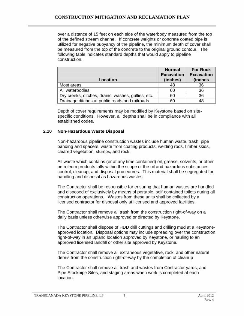
CONSTRUCTION MITIGATION AND RECLAMATION PLAN
over a distance of 15 feet on each side of the waterbody measured from the top of the defined stream channel. If concrete weights or concrete coated pipe is utilized for negative buoyancy of the pipeline, the minimum depth of cover shall be measured from the top of the concrete to the original ground contour. The following table indicates standard depths that would apply to pipeline construction.
Location
Normal Excavation
(inches)
For Rock Excavation
(inches
Most areas 48 36
All waterbodies 60 36
Dry creeks, ditches, drains, washes, gullies, etc. 60 36
Drainage ditches at public roads and railroads 60 48
Depth of cover requirements may be modified by Keystone based on site-specific conditions. However, all depths shall be in compliance with all established codes.
2.10 Non-Hazardous Waste Disposal
Non-hazardous pipeline construction wastes include human waste, trash, pipe banding and spacers, waste from coating products, welding rods, timber skids, cleared vegetation, stumps, and rock.
All waste which contains (or at any time contained) oil, grease, solvents, or other petroleum products falls within the scope of the oil and hazardous substances control, cleanup, and disposal procedures. This material shall be segregated for handling and disposal as hazardous wastes.
The Contractor shall be responsible for ensuring that human wastes are handled and disposed of exclusively by means of portable, self-contained toilets during all construction operations. Wastes from these units shall be collected by a licensed contractor for disposal only at licensed and approved facilities.
The Contractor shall remove all trash from the construction right-of-way on a daily basis unless otherwise approved or directed by Keystone.
The Contractor shall dispose of HDD drill cuttings and drilling mud at a Keystone-approved location. Disposal options may include spreading over the construction right-of-way in an upland location approved by Keystone, or hauling to an approved licensed landfill or other site approved by Keystone.
The Contractor shall remove all extraneous vegetative, rock, and other natural debris from the construction right-of-way by the completion of cleanup
The Contractor shall remove all trash and wastes from Contractor yards, and Pipe Stockpipe Sites, and staging areas when work is completed at each location.
TRANSCANADA KEYSTONE PIPELINE, LP 5 April 2012
Rev. 4
CONSTRUCTION MITIGATION AND RECLAMATION PLAN
The Contractor shall dispose of all waste materials at licensed waste disposal facilities. Wastes shall not be disposed of in any other fashion such as un-permitted burying or burning.
2.11 Hazardous Wastes
The Contractor shall ensure that all hazardous and potentially hazardous materials are transported, stored, and handled in accordance with all applicable legislation. Workers exposed to or required to handle dangerous materials shall be trained in accordance with the applicable regulator and the manufacturer's recommendations.
The Contractor shall dispose of all hazardous materials at licensed waste disposal facilities. Hazardous wastes shall not be disposed of in any other fashion such as un-permitted burying or burning.
All transporters of oil, hazardous substances, and hazardous wastes shall be licensed and certified according to the applicable state vehicle code. Incidents on public highways shall be reported to the appropriate agencies.
All hazardous wastes being transported off-site shall be manifested. The manifest shall conform to requirements of the appropriate state agency. The transporter shall be licensed and certified to handle hazardous wastes on the public highways. The vehicles as well as the drivers must conform to all applicable vehicle codes for transporting hazardous wastes. The manifest shall conform to 49 CFR Parts 172.101, 172.202, and 172.203.
If toxic or hazardous waste materials or containers are encountered during construction, the Contractor shall stop work immediately to prevent disturbing or further disturbing the waste material and shall immediately notify Keystone. The Contractor shall not restart work until clearance is granted by Keystone.
2.12 Noise Control
The Contractor shall minimize noise during non-daylight hours and within 1 mile of residences or other noise-sensitive areas such as hospitals, motels or campgrounds. Keystone shall abide by all applicable noise regulations regarding noise near residential and commercial/industrial areas. The Contractor shall provide notice to Keystone if noise levels are expected to exceed bylaws for a short duration. Keystone will give advanced notice to landowners within 500 feet of right-of-way prior to construction, limit the hours during which construction activities with high-decibel noise levels are conducted, coordinate work schedules, and ensure that construction proceeds quickly through such areas. The Contractor shall minimize noise in the immediate vicinity of herds of livestock or poultry operations, which are particularly sensitive to noise.
Keystone will set up a toll-free telephone line for landowners to report any construction noise-related issues.
TRANSCANADA KEYSTONE PIPELINE, LP 6 April 2012
Rev. 4
CONSTRUCTION MITIGATION AND RECLAMATION PLAN
2.13 Weed Control
Keystone will prepare a weed management plan for each state crossed by the project, as required. In general, these plans will consider the following measures listed below.
Prior to mobilization for the Project, the Contractor shall thoroughly clean all construction equipment, including timber mats, prior to moving the equipment to the job site to limit the potential for the spread of noxious weeds, insects and soil-borne pests. The Contractor shall clean the equipment with high-pressure washing equipment.
Prior to construction, Keystone will mark all areas of the right-of-way which contain infestations of noxious, invasive species or soil-borne pests. Such marking will clearly indicate the limits of the infestation along the right-of-way. During construction, the Contractor shall clean the tracks, tires, and blades of equipment by hand (track shovel) or compressed air to remove excess soil prior to movement of equipment out of weed or soil-borne pest infested areas, or utilize cleaning stations to remove vegetative materials using water under high pressure (see detail Drawings 30 and 31).
In areas of isolated weed populations, the Contractor shall strip topsoil from the full width of the construction right-of-way and store the topsoil separately from other topsoil and subsoil. The Environmental Inspectors will identify these locations in the field prior to grading activities.
The Contractor shall use mulch and straw or hay bales that are free of noxious weeds for temporary erosion and sediment control.
The Contractor shall implement pre-construction treatments such as mowing prior to seed development or herbicide application to areas of noxious weed infestation prior to other clearing, grading, trenching, or other soil disturbing work at locations identified in the construction drawings.
Keystone will implement Best Management Practices (BMPs) for conducting vegetation control where necessary before and after construction. Typical agricultural herbicides, developed in consultation with county or state regulatory agencies, will be used. Herbicide types will be determined based on the weed species requiring control. The Contractor shall apply herbicides, where required, within one week, or as deemed necessary for optimum mortality success, prior to disturbing the area by clearing, grading, trenching, or other soil disturbing work. Herbicides shall be applied by applicators appropriately licensed or certified by the state in which the work is conducted. All herbicides applied prior to construction shall be non-residual or shall have a significant residual effect no longer than 30 days. Herbicides applied during construction shall be non-residual. Keystone will implement BMPs in the use of pesticides and herbicides along the pipeline corridor to reduce potential impacts to avian and wildlife species.
The Contractor shall not use herbicides in or within 100 feet of a wetland or waterbody.
TRANSCANADA KEYSTONE PIPELINE, LP 7 April 2012
Rev. 4
CONSTRUCTION MITIGATION AND RECLAMATION PLAN
After pipeline construction, on any construction right-of-way over which Keystone will retain control over the surface use of the land after construction (i.e., valve sites, metering stations, pump stations, etc.), Keystone shall provide for weed control to limit the potential for the spread of weeds onto adjacent lands used for agricultural purposes. Any weed control spraying performed by Keystone shall be done by a state-licensed pesticide applicator.
Keystone shall be responsible for reimbursing all reasonable costs incurred by owners of land adjacent to aboveground facilities when the landowners must control weeds on their land which can be reasonably determined to have spread from land occupied by Keystone’s aboveground facilities.
2.14 Dust Control
The Contractor shall at all-time control airborne dust levels during construction activities to levels acceptable to Keystone. The Contractor shall employ water trucks, sprinklers or calcium chloride as necessary to reduce dust to acceptable levels. Utilization of calcium chloride is limited to roads.
Dust shall be strictly controlled where the work approaches dwellings, farm buildings, and other areas occupied by people and when the pipeline parallels an existing road or highway. This shall also apply to access roads where dust raised by construction vehicles may irritate or inconvenience local residents. The speed of all Contractor vehicles shall be controlled in these areas. Emissions from construction equipment combustion, open burning, and temporary fuel transfer systems and associated tanks will be controlled to the extent required by state and local agencies through the permit process.
The Contractor shall take appropriate precautions to prevent fugitive emissions caused by sand blasting from reaching any residence or public building. The Contractor shall place curtains of suitable material, as necessary, to prevent wind-blown particles from sand blasting operations from reaching any residence or public building.
Additional measures may be required by state regulations or local ordinances. The Contractor will comply with all applicable state regulations and local ordinances with respect to truck transportation and fugitive dust emissions.
2.15 Off Road Vehicle Control
Keystone shall offer to landowners or managers of forested lands to install and maintain measures to control unauthorized vehicle access to the construction right-of-way where appropriate. These measures may include the following unless otherwise approved or directed by Keystone based on site specific conditions or circumstances:
signs;
fences with locking gates;
slash and timber barriers, pipe barriers, or boulders lined across the
TRANSCANADA KEYSTONE PIPELINE, LP 8 April 2012
Rev. 4
CONSTRUCTION MITIGATION AND RECLAMATION PLAN
construction right-of-way; and
conifers or other appropriate trees or shrubs across the construction right-of-way.
2.16 Fire Prevention and Control
The Contractor shall comply with all federal, state, county and local fire regulations pertaining to burning permits and the prevention of uncontrolled fires. The following mitigative measures shall be implemented to prevent fire hazards and control of fires:
A list of relevant fire authorities and their designated representative to contact shall be maintained on site by construction personnel.
Adequate firefighting equipment shall be available on site in accordance with the applicable regulatory requirements shall be available on site.
The level of forest fire hazard shall be posted at the construction office (where visible for workers) and workers shall be made aware of the hazard level and related implications.
The Contractor shall provide equipment to handle any possible fire emergency. This shall include, although not be limited to, water trucks; portable water pumps; chemical fire extinguishers; hand tools such as shovels, axes, and chain saws; and heavy equipment adequate for the construction of fire breaks when needed.
Specifically, the Contractor shall supply and maintain in working order an adequate supply of fire extinguishers for each crew engaged in potentially combustible work such as welding, cutting, grinding, and burning of brush or vegetative debris.
In the event of a fire, the Contractor shall immediately use resources necessary to contain the fire. The Contractor shall then notify local emergency response personnel.
All tree clearing activities are to be carried out in accordance with local rules and regulations for the prevention of forest fires.
Burning shall be done in compliance with state, county, or local applicable regulations.
Any burning will be done within the right-of-way. Only small piles shall be burned to avoid overheating or damage to trees or other structures along the right-of-way.
Flammable wastes shall be removed from the construction site on a regular basis.
Flammable materials kept on the construction site must be stored in approved containers away from ignition sources.
Smoking shall be prohibited around flammable materials.
Smoking shall be prohibited on the entire construction site when the fire hazard is high.
TRANSCANADA KEYSTONE PIPELINE, LP 9 April 2012
Rev. 4
CONSTRUCTION MITIGATION AND RECLAMATION PLAN
2.17 Road and Railroad Crossings
Construction across paved roads, highways, and railroads will be in accordance with the requirements of the road and railroad crossing permits and approvals obtained by Keystone. In general, all major paved roads, all primary gravel roads, highways, and railroads will be crossed by boring beneath the road or railroad. Detail drawing 21 illustrates a typical bored road or railroad crossing. Boring requires the excavation of a pit on each side of the feature, the placement of boring equipment in the pit, and boring a hole under the road at least equal to the diameter of the pipe. For long crossings, sections can be welded onto the pipe string just before being pulled through the borehole. Boring will result in minimal or no disruption to traffic at road or railroad crossings. Each boring will be expected to take 1 to 2 days for most roads and railroads and up to 10 days for long crossings such as interstate or four-lane highways.
Most smaller, unpaved roads and driveways will be crossed using the open-cut method where permitted by local authorities or private owners. The open-cut method will require temporary closure of the road to traffic and establishment of detours. If no reasonable detour is feasible, at least one lane of traffic will be kept open, except during brief periods when it is essential to close the road to install the pipeline. Most open-cut road crossings can be finished and the road resurfaced in 1 or 2 days. Keystone will take measures, such as posting signs at open-cut road crossings, to ensure safety and minimize traffic disruptions.
2.18 Adverse Weather
The Contractor shall restrict certain construction activities and work in cultivated agricultural areas in excessively wet soil conditions to minimize rutting and soil compaction. In determining when or where construction activities should be restricted or suspended during wet conditions, the Contractor shall consider the following factors:
the extent that rutting may cause mixing of topsoil with subsoil layers or damage to tile drains;
excessive buildup of mud on tires and cleats;
excessive ponding of water at the soil surface; and
the potential for excessive soil compaction.
The Contractor shall implement mitigative measures as directed by Keystone in order to minimize rutting and soil compaction in excessively wet soil conditions which may include:
restricting work to areas on the spread where conditions allow;
using low ground weight, wide-track equipment, or other low impact construction techniques;
limiting work to areas that have adequately drained soils or have a cover of vegetation ,such as sod, crops or crop residues, sufficient to prevent mixing of topsoil with subsoil layers or damage to drain tiles; and
TRANSCANADA KEYSTONE PIPELINE, LP 10 April 2012
Rev. 4
CONSTRUCTION MITIGATION AND RECLAMATION PLAN
installing geotextile material or construction mats in problem areas.
“Stop work” authority will be designated to the chief inspector but will be implemented when recommended by the Environmental Inspector.
2.19 Cultural Resources
Keystone intends to avoid cultural resources to the extent practicable by rerouting the pipeline corridor and related appurtenances, avoiding construction activities on properties listed in or eligible for listing in the National Register of Historic Places (NRHP), as well as boring or using HDD through culturally sterile soils.
The Contractor shall implement the measures outlined in any unanticipated discovery plan or any Programmatic Agreement that is adopted to minimize disturbance to cultural sites and shall take immediate action as outlined in the Programmatic Agreement if any unanticipated cultural discovery is encountered during construction.
The preferred treatment of any historical property or culturally significant site is avoidance. Where required, Keystone will monitor the construction spread using a cultural resource monitor working under the direction of a professional who meets the standards of the Secretary of the Interior’s Historic Preservation Professional Qualification Standards (48 FR 44716, September 29, 1983).
Prior to commencing construction, Keystone also will provide an appropriate level of training to all construction personnel so that the requirements of any unanticipated discovery plan or Programmatic Agreement are understood and unanticipated discoveries quickly identified.
In the event an unanticipated cultural discovery is made, the Contractor will immediately halt all construction activities within a 100-foot radius, including traffic; notify the Keystone Environmental Inspector; and implement interim measures to protect the discovery from looting or vandalism. The appropriate federal, state, local, or tribal authorities will be notified of discovery within 48 hours of the initial find. Construction will not proceed within the 100-foot radius of discovery site until all mitigation measures defined in the Programmatic Agreement are concluded and Keystone receives approval from the appropriate agencies that construction may resume. No work or activity within the 100-foot buffer area may take place until approvals are communicated at the spread level by the lead Environmental Inspector.
3.0 SPILL PREVENTION AND CONTAINMENT
Spill prevention and containment applies to the use and management of hazardous materials on the construction right-of-way and all ancillary areas during construction. This includes the refueling or servicing of all equipment with diesel fuel, gasoline, lubricating oils, grease, and hydraulic and other fluids during normal upland applications and special applications within 100 feet of perennial streams or wetlands.
TRANSCANADA KEYSTONE PIPELINE, LP 11 April 2012
Rev. 4
CONSTRUCTION MITIGATION AND RECLAMATION PLAN
Keystone will prepare a project-specific Spill Prevention Containment and Countermeasure (SPCC) Plan. The Contractor shall provide additional information to complete the SPCC Plan for each construction spread, and shall provide site-specific data that meets the requirements of 40 CFR Part 112 for every location used for staging fuel or oil storage tanks and for every location used for bulk fuel or oil transfer. Each SPCC Plan will be prepared prior to introducing the subject fuel, oil, or hazardous material to the subject location.
3.1 Spill Prevention
3.1.1 Staging Areas
Staging areas (including Contractor yards and pipe stockpile sites) shall be set up for each construction spread. Bulk fuel and storage tanks will be placed only at Contractor yards. No bulk fuel and storage tanks will be placed in the construction ROW. Hazardous materials at staging areas shall be stored in compliance with federal and state laws. The following spill prevention measures shall be implemented by the Contractor:
Contractor fuel trucks shall be loaded at existing bulk fuel dealerships or from bulk tanks set up for that purpose at the staging area. In the former case, the bulk dealer is responsible for preventing and controlling spills.
The Environmental Inspector shall inspect the tank site for compliance with the 100-foot setback requirement and approve the tank site prior to installing bulk fuel or storage tanks on the construction yard.
Fuels and lubricants shall be stored only at designated staging areas. Storage of fuel and lubricants in the staging area shall be at least 100 feet away from the water's edge. Refueling and lubrication of equipment shall be restricted to upland areas at least 100 feet away from streams and wetlands.
Contractors shall be required to perform all routine equipment maintenance at the staging area and recover and dispose of wastes in an appropriate manner.
Fixed fuel dispensing locations will be provided with secondary containment to capture fuel from leaks, drips, and overfills.
Temporary liners, berms, or dikes (secondary containment) shall be constructed around the aboveground bulk tanks, providing 110 percent containment volume of the largest storage tank or trailer within the containment structure, so that potential spill materials shall be contained and collected in specified areas. Tanks shall not be placed in areas subject to periodic flooding or washout.
Drivers of tank trucks are responsible for safety and spill prevention during tank truck unloading. Procedures for loading and unloading tank trucks shall meet the minimum requirements established by the Department of Transportation.
TRANSCANADA KEYSTONE PIPELINE, LP 12 April 2012
Rev. 4
CONSTRUCTION MITIGATION AND RECLAMATION PLAN
Drivers of tank trucks are responsible for setting brakes and chocking wheels prior to off loading. Warning signs requiring drivers to set brakes and chock wheels shall be displayed at all tanks. Proper grounding of equipment shall be undertaken during fuel transfer operations. Drivers shall observe and control the fueling operations at all times to prevent overfilling the temporary tank.
Prior to departure of any tank truck, all vehicle outlets shall be examined closely by the driver for leakage, tightened, adjusted or replaced to prevent Ieakage while in transit.
A supply of sorbent and barrier materials sufficient to allow the rapid containment and recovery of spills shall be maintained at each construction staging area. Sorbent and barrier materials shall also be utilized to contain runoff from contaminated areas.
Shovels and drums shall be kept at each of the individual staging areas. In the event that small quantities of soil become contaminated, shovels shall be utilized to collect the soil and the material shall be stored in 55-gallon drums. Large quantities of contaminated soil may be bio-remediated on site or disposed in an approved landfill, subject to government approval, or collected utilizing heavy equipment, and stored in drums or other suitable containers prior to disposal. Should contamination occur adjacent to staging areas as a result of runoff, shovels or heavy equipment shall be utilized to collect the contaminated material. Contaminated soil shall be disposed of in accordance with state and federal regulations.
Temporary aboveground tanks shall be subject to visual inspection on a monthly basis and when the tank is refilled. Inspection records shall be maintained. Operators shall routinely keep tanks under close surveillance and potential leaks or spills shall be quickly detected.
Visible fuel leaks shall be reported to the Contractors' designated representative and corrected as soon as conditions warrant. Keystone's designated representative shall be informed.
Drain valves on temporary tanks shall be locked to prevent accidental or unauthorized discharges from the tank.
Oil and other hazardous materials stored in 350-gallon totes, 55-gallon drums, 5-gallon pails, smaller retail-size containers or other portable containers will be staged or stored in areas with a secondary temporary containment structure. Secondary containment structures may consist of temporary earthen berms with a chemical resistant liner, or a portable containment system constructed of steel, PVC, or other suitable material. The secondary containment structure will be capable of containing 110 percent of the volume of material stored in these areas.
Keystone may allow modification of the above specifications as necessary to accommodate specific situations or procedures. Any modifications must comply with all applicable regulations and permits.
TRANSCANADA KEYSTONE PIPELINE, LP 13 April 2012
Rev. 4
CONSTRUCTION MITIGATION AND RECLAMATION PLAN
3.1.2 Construction Right-of-Way
The Contractor will ensure that all equipment is free of leaks prior to use on the Project and prior to entering or working in or near waterbodies or wetlands. Throughout construction, the Contractor will conduct regular maintenance and inspections of the equipment to reduce the potential for spills or leaks.
Rubber-tired vehicles (pickup trucks, buses) normally shall refuel at the construction staging areas or commercial gas stations. Tracked machinery (backhoes, bulldozers) shall be refueled and lubricated on the construction right-of-way. Equipment maintenance shall be conducted in staging areas when practical. When impractical, repairs to equipment can be made on the construction right-of-way when approved by Keystone’s representative.
Each fuel truck that transports and dispenses fuel to construction equipment or Project vehicles along the construction ROW or within equipment staging and material areas shall carry an oil spill response kit and spill response equipment onboard at all times. In the event that response materials are depleted through use or their condition is deteriorated through age, the materials will be replenished prior to placing the fueling vehicle back into service.
The following preventive measures apply to refueling and lubricating activities on the construction right-of-way:
Construction activities shall be conducted to allow for prompt and effective cleanup of spills of fuel and other hazardous materials. Each construction crew, including cleanup crews shall have on hand sufficient tools and material to stop leaks and supplies of absorbent and barrier materials to allow rapid containment and recovery of spilled materials. Crew members must know and follow the procedure for reporting spills.
Refueling and lubricating of construction equipment shall be restricted to upland areas at least 100 feet away from streams and wetlands. Where this is not possible (e.g., trench dewatering pumps), the equipment shall be fueled by designated personnel with special training in refueling, spill containment, and cleanup. The Environmental Inspector shall ensure that signs are installed identifying restricted areas.
No fuel, oil or hazardous material storage, staging, or transfer other than refueling will occur within 100 feet of any storm drain, drop inlet, or high consequence area (HCA).
Spent oils, lubricants, filters, etc. shall be collected and disposed of at an approved location in accordance with state and federal regulations.
Equipment shall not be washed in streams.
Stationary equipment will be placed within a secondary containment if it will be operated or require refueling within 100 feet of a wetland or waterbody boundary.
TRANSCANADA KEYSTONE PIPELINE, LP 14 April 2012
Rev. 4
CONSTRUCTION MITIGATION AND RECLAMATION PLAN
Keystone may allow modification of the above specifications as necessary to accommodate specific situations or procedures. Any modifications must comply with all applicable regulations and permits.
3.2 Contingency Plans
The Contractor shall develop emergency response procedures for all incidents (e.g., spills, leaks, fires) involving hazardous materials which could pose a threat to human health or the environment. The procedures shall address activities in all work areas, as well as during transport to and from the construction right-of-way and to any disposal or recycling facility.
3.3 Equipment
The Contractor shall retain emergency response equipment in all areas where hazardous materials are handled or stored. This equipment shall be readily available to respond to a hazardous material emergency. Such equipment shall include, but not be limited to, the following:
first aid supplies;
phone or communications radio;
protective clothing (Tyvek suit, gloves, goggles, boots);
hand-held fire equipment;
absorbent material and storage containers;
non-sparking bung wrench and shovel; and
brooms and dust pan.
Hazardous material emergency equipment shall be carried in all mechanic and supervisor vehicles. This equipment shall include, at a minimum:
first aid supplies;
phone or communications radio;
2 sets of protective clothing (Tyvek suit, gloves, goggles, boots);
1 non-sparking shovel;
6 plastic garbage bags (20 gallon);
10 absorbent socks and spill pads;
Hand-held fire extinguisher;
barrier tape; and
2 orange reflector cones.
Fuel and service trucks shall carry a minimum of 20 pounds of suitable commercial sorbent material.
TRANSCANADA KEYSTONE PIPELINE, LP 15 April 2012
Rev. 4
CONSTRUCTION MITIGATION AND RECLAMATION PLAN
The Contractor shall inspect emergency equipment weekly, and service and maintain equipment regularly. Records shall be kept of all inspections and services.
3.4 Emergency Notification
Emergency notification procedures between the Contractor and Keystone shall be established in the planning stages of construction. A Keystone representative shall be identified to serve as contact in the event of a spill during construction activities. In the event of a spill meeting government reporting criteria, the Contractor immediately shall notify the Keystone representative who, in turn, shall notify the appropriate regulatory agencies.
Any material released into water that creates a sheen must be reported immediately to Keystone. The Contractor is required to notify Keystone immediately if there is any spill of oil, oil products, or hazardous materials that reaches a wetland or waterbody. Incidents on public highways shall be reported to Keystone and the appropriate agencies by Keystone.
If a spill occurs on navigable waters of the United States, Keystone shall notify the National Response Center (NRC) at 1-800-424-8802. For spills that occur on public lands, into surface waters, or into sensitive areas, the appropriate governmental agency’s district office also shall be notified.
3.5 Spill Containment and Countermeasures
In the event of a spill of hazardous material, Contractor personnel shall:
notify the appointed Keystone representative;
identify the product hazards related to the spilled material and implement appropriate safety procedures, based on the nature of the hazard;
control danger to the public and personnel at the site;
implement spill contingency plans and mobilize appropriate resources and manpower;
isolate or shutdown the source of the spill;
block manholes or culverts to limit spill travel;
initiate containment procedures to limit the spill to as small an area as possible to prevent damage to property or areas of environment concern (e.g., watercourses); and
commence recovery of the spill and cleanup operations.
When notified of a spill, the Keystone representative shall immediately ensure that:
Action is taken to control danger to the public and personnel at the site.
Spill contingency plans are implemented and necessary equipment and manpower are mobilized.
TRANSCANADA KEYSTONE PIPELINE, LP 16 April 2012
Rev. 4
CONSTRUCTION MITIGATION AND RECLAMATION PLAN
Measures are taken to isolate or shutdown the source of the spill.
All resources necessary to contain, recover and clean up the spill are available.
Any resources requested by the Contractor from Keystone are provided.
The appropriate agencies are notified. For spills which occur on public Iands, into surface waters or into sensitive areas, the appropriate federal or state managing office shall also be notified and involved in the incident.
For a land spill, berms shall be constructed with available equipment to physically contain the spill. Personnel entry and travel on contaminated soils shall be minimized. Sorbent materials shall be applied or, if necessary, heavily contaminated soils shall be removed to an approved facility. Contaminated sorbent materials and vegetation shall also be disposed of at an approved facility.
For a spill threatening a waterbody, berms or trenches shall be constructed to contain the spill prior to entry into the waterbody. Deployment of booms, skimmers, and sorbent materials shall be necessary if the spill reaches the water. The spilled product shall be recovered and the contaminated area shall be cleaned up in consultation with spill response specialists and appropriate government agencies.
4.0 UPLANDS (AGRICULTURAL, FOREST, PASTURE, RANGE AND GRASS LANDS)
4.1 Interference with Irrigation Systems
If existing irrigation systems (flood irrigation, ditch irrigation, pivot, wheel, or other type of spray irrigation systems), irrigation ditches, or sheet flow irrigation shall be impacted by the construction of the pipeline, the following mitigative measures shall be implemented unless otherwise approved or directed by Keystone:
If it is feasible and mutually acceptable to Keystone and the landowner or landowner's designate, temporary measures shall be implemented to allow an irrigation system to continue to operate across land on which the pipeline is being constructed.
If the pipeline or temporary work areas intersect an operational (or soon to be operational) pivot or other spray irrigation system, Keystone shall establish with the landowner or landowner's designate an acceptable amount of time the irrigation system may be out of service. If an irrigation system interruption results in crop damages, either on the pipeline construction right-of-way or off the construction right-of-way, the landowner shall be compensated reasonably for all such crop damages.
If the pipeline or temporary work areas intersect an operational sheet flow irrigation system, Keystone shall establish with the landowner or landowner's designate an acceptable amount of time the irrigation system may be out of service. If an irrigation system interruption results in crop
TRANSCANADA KEYSTONE PIPELINE, LP 17 April 2012
Rev. 4
CONSTRUCTION MITIGATION AND RECLAMATION PLAN
damages, either on the pipeline construction right-of-way or off the construction right-of-way, the landowner shall be compensated reasonably for all such crop damages.
Irrigation ditches that are active at the time of construction shall not be stopped or obstructed except for the length of time to install the pipeline beneath the ditch (typically, one day or less) unless otherwise approved or directed by Keystone.
4.2 Clearing
The objective of clearing is to provide a clear and unobstructed right-of-way for safe and efficient construction of the pipeline. The following mitigable measures shall be implemented:
Construction traffic shall be restricted to the construction right-of-way, existing public roads, and approved private roads.
Construction right-of-way boundaries including pre-approved temporary workspace shall be clearly staked to prevent disturbance to unauthorized areas.
If crops are present, they shall be mowed or disced to ground level unless an agreement is made for the landowner to remove.
Burning is prohibited on cultivated land.
Construction right-of-way at timber shelterbelts in agricultural areas shall be reduced to the minimum necessary to construct the pipeline.
4.3 Topsoil Removal and Storage
The objective of topsoil handling is to maintain topsoil capability by conserving topsoil for future replacement and reclamation and to minimize the degradation of topsoil from compaction, rutting, loss of organic matter, or soil mixing so that successful reclamation of the right-of-way can occur. The following mitigative measures shall be implemented during topsoil removal and storage unless otherwise approved or directed by Keystone based on site-specific conditions or circumstances. All work shall be conducted in accordance with applicable permits.
In areas designated for topsoil segregation, the actual depth of the topsoil, to a maximum depth of 12 inches, will be stripped from:
o The area excavated above the pipeline; or
o The area above the pipeline plus the spoil storage; or
o The area above the pipeline plus the working side; or
o Entire ROW
as required by applicable permit agreements with the landowner or as dictated by site-specific conditions.
TRANSCANADA KEYSTONE PIPELINE, LP 18 April 2012
Rev. 4
Stripped topsoil is to be stockpiled in a windrow along the edge of the right-of-way. The Contractor shall perform work in a manner to minimize the potential for subsoil and topsoil to be mixed.
Under no circumstances shall the Contractor use topsoil to fill a low area.
If required due to excessively windy conditions, topsoil piles shall be tackified using either water or a suitable tackifier (liquid mulch binder).
Gaps in the rows of topsoil will be left in order to allow drainage and prevent ponding of water adjacent to or on the right-of-way.
Topsoil shall not be utilized to construct ramps at road or waterbody crossings.
In areas with defined saline or sodic soil concerns, a triple-ditch method will be used to segregate problem soils as indicated in Detail 67 and 67A.
If frozen topsoil conditions are encountered during winter construction, specialized construction equipment (i.e. ripping, frozen topsoil cutter, road reclaimer, etc) may be required to adequately segregate and conserve topsoil resources.
4.4 Grading
The objective of grading is to develop a right-of-way that allows the safe passage of equipment and meets the bending limitations of the pipe. The following mitigative measures shall be implemented during grading unless otherwise approved or directed by Keystone based on site-specific conditions or circumstances. However, all work shall be conducted in accordance with applicable permits.
All grading shall be undertaken with the understanding that original contours and drainage patterns shall be re-established to the extent practicable..
Agricultural areas that have terraces shall be surveyed to establish pre-construction contours to be utilized for restoration of the terraces after construction.
On steep slopes, or wherever erosion potential is high, temporary erosion control measures shall be implemented.
Bar ditches adjacent to existing roadways to be crossed during construction shall be adequately ramped with grade or ditch spoil to prevent damage to the road shoulder and ditch.
Where the construction surface remains inadequate to support equipment travel, timber mats, timber riprap, or other method shall be used to stabilize surface conditions.
The Contractor shall limit the interruption of the surface drain network in the vicinity of the right-of-way using the appropriate methods:
providing gaps in the rows of subsoil and topsoil in order to prevent any accumulation of water on the land;
CONSTRUCTION MITIGATION AND RECLAMATION PLAN
TRANSCANADA KEYSTONE PIPELINE, LP 19 April 2012
Rev. 4
CONSTRUCTION MITIGATION AND RECLAMATION PLAN
preventing obstructions in furrows, furrow drains, and ditches;
installing flumes and ramps in furrows, furrow drains, and ditches to facilitate water flow across the construction right-of-way and allow for construction equipment traffic; and
installing flumes over the trench for any watercourse where flow is continuous during construction.
4.5 Temporary Erosion and Sediment Control
4.5.1 General
Temporary erosion and sediment control measures shall be installed immediately after initial disturbance of the soil, maintained throughout construction (on a daily basis), and reinstalled as necessary until replaced by permanent erosion control structures or restoration of the construction right-of-way is complete.
Specifications and configurations for erosion and sediment control measures may be modified by Keystone as necessary to suit actual site conditions. However, all work shall be conducted in accordance with applicable permits.
The Contractor shall inspect all temporary erosion control measures at least daily in areas of active construction or equipment operation, weekly in areas with no construction or equipment operation, and within 24 hours of each significant rainfall event of 0.5 inches or greater. The Contractor shall repair all ineffective temporary erosion control measures as expediently as practicable.
4.5.2 Sediment Barriers
Sediment barriers shall be constructed of silt fence, staked hay or straw bales, compacted earth (e.g., drivable berms across travel lanes), sand bags, or other appropriate materials.
The Contractor shall install sediment barriers in accordance with Details 1 and 2 or as otherwise approved or directed by Keystone. The Contractor is responsible for properly installing, maintaining, and replacing temporary and permanent erosion controls throughout construction and cleanup. In wetland or riparian zones, the Contractor will install sediment control structures along the construction right-of-way edges prior to vegetation removal where practicable. The aforementioned sediment barriers may be used interchangeably or together depending on site-specific conditions. In most cases, silt fence shall be utilized where longer sediment barriers are required.
Sediment barriers shall be installed below disturbed areas where there is hazard of offsite sedimentation. These areas include:
the base of slopes adjacent to road crossings;
TRANSCANADA KEYSTONE PIPELINE, LP 20 April 2012
Rev. 4
CONSTRUCTION MITIGATION AND RECLAMATION PLAN
the edge of the construction right-of-way adjacent to and upgradient of a roadway, flowing stream, spring, wetland, or impoundment;
trench or test water discharge locations where required;
where waterbodies or wetlands are adjacent to the construction right-of-way; (the Contractor shall install sediment barriers along the edge of the construction right-of-way as necessary to contain spoil and sediment within the construction right-of-way)
across the entire construction right-of-way at flowing waterbody crossings;
right-of-way immediately upslope of the wetland boundary at all standard (saturated or standing water) wetland crossings as necessary to prevent sediment flow into the wetland; (Sediment control barriers are not required at “dry” wetlands.)
along the edge of the construction right-of-way within standard (saturated or standing water) wetland boundaries as necessary to contain spoil and sediment within the construction right-of-way. Sediment control barriers are not required at “dry” wetlands (Detail 8).
Sediment barriers placed at the toe of a slope shall be set a sufficient distance from the toe of the slope, if possible, in order to increase ponding volume.
Sediment control barriers shall be placed so as not to hinder construction operations. If silt fence or straw bale sediment barriers (in lieu of drivable berms) are placed across the entire construction right-of-way at waterbodies, wetlands, or upslope of roads, a provision shall be made for temporary traffic flow through a gap for vehicles and equipment to pass within the structure. Immediately following each day’s shutdown of construction activities, a row of straw bales or a section of silt fence shall be placed across the up gradient side of the gap with sufficient overlap at each end of the barrier gap to eliminate sediment bypass flow, followed by bales tightly fitted to fill the gap. Following completion of the equipment crossing, the gap shall be closed using silt fence or straw bale sediment barrier.
The Contractor shall maintain straw bale and silt fence sediment barriers by removing collected sediment and replacing damaged bales. Sediment shall be removed and placed where it shall not reenter the barrier when sediment loading is greater than 40 percent or if directed by Keystone. If straw bale filters cannot be cleaned out due to access problems, the Contractor shall place a new row of sediment barriers upslope.
The Contractor shall use mulch and straw bales that are free of noxious weeds. Mulch or straw bales that contain evidence of noxious weeds or other undesirable species shall be rejected by the Contractor.
TRANSCANADA KEYSTONE PIPELINE, LP 21 April 2012
Rev. 4
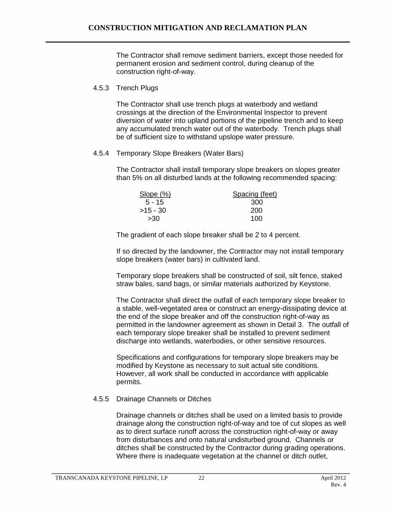
CONSTRUCTION MITIGATION AND RECLAMATION PLAN
The Contractor shall remove sediment barriers, except those needed for permanent erosion and sediment control, during cleanup of the construction right-of-way.
4.5.3 Trench Plugs
The Contractor shall use trench plugs at waterbody and wetland crossings at the direction of the Environmental Inspector to prevent diversion of water into upland portions of the pipeline trench and to keep any accumulated trench water out of the waterbody. Trench plugs shall be of sufficient size to withstand upslope water pressure.
4.5.4 Temporary Slope Breakers (Water Bars)
The Contractor shall install temporary slope breakers on slopes greater than 5% on all disturbed lands at the following recommended spacing:
Slope (%) Spacing (feet) 5 - 15 300
>15 - 30 200 >30 100
The gradient of each slope breaker shall be 2 to 4 percent.
If so directed by the landowner, the Contractor may not install temporary slope breakers (water bars) in cultivated land.
Temporary slope breakers shall be constructed of soil, silt fence, staked straw bales, sand bags, or similar materials authorized by Keystone.
The Contractor shall direct the outfall of each temporary slope breaker to a stable, well-vegetated area or construct an energy-dissipating device at the end of the slope breaker and off the construction right-of-way as permitted in the landowner agreement as shown in Detail 3. The outfall of each temporary slope breaker shall be installed to prevent sediment discharge into wetlands, waterbodies, or other sensitive resources.
Specifications and configurations for temporary slope breakers may be modified by Keystone as necessary to suit actual site conditions. However, all work shall be conducted in accordance with applicable permits.
4.5.5 Drainage Channels or Ditches
Drainage channels or ditches shall be used on a limited basis to provide drainage along the construction right-of-way and toe of cut slopes as well as to direct surface runoff across the construction right-of-way or away from disturbances and onto natural undisturbed ground. Channels or ditches shall be constructed by the Contractor during grading operations. Where there is inadequate vegetation at the channel or ditch outlet,
TRANSCANADA KEYSTONE PIPELINE, LP 22 April 2012
Rev. 4
CONSTRUCTION MITIGATION AND RECLAMATION PLAN
sediment barriers, check berms, or other appropriate measures shall be used to control erosion.
4.5.6 Temporary Mulching and Cover Crops
Unless otherwise directed by Keystone, the Contractor shall apply temporary seed and/or mulch on disturbed construction work areas that have been inactive for one month or are expected to be inactive for a month or more. The Contractor shall not apply temporary mulch in cultivated areas unless specifically requested by the landowner or in areas particularly prone to erosion. The Contractor shall not apply mulch within wetland boundaries.
Temporary mulch of straw or equivalent applied on slopes shall be spread uniformly to cover at least 75 percent of the ground surface at an approximate rate of 2 tons per acre of straw or its equivalent. Mulch application on slopes within 100 feet of waterbodies and wetlands shall be increased to an approximate rate of 3 tons per acre.
All seed that is used as a temporary cover crop will be approved and/or provided by Keystone.
4.5.7 Tackifier
When wetting topsoil piles with water does not prevent wind erosion, the Contractor shall temporarily suspend topsoil handling operations and apply a tackifier to topsoil stockpiles at the rate recommended by the manufacturer. The type of Tackifier will be approved by Keystone.
Should construction traffic, cattle grazing, heavy rains, or other related construction activity disturb the tackified topsoil piles and create a potential for wind erosion, additional tackifier shall be applied by the Contractor.
4.6 Stringing
The objective of stringing is to place the line pipe along the construction right-of-way for bending and welding in an expedient and efficient manner.
The Contractor shall utilize one or more of the following mitigative measures as applicable and when necessary to reduce compaction on the working side of the right-of-way or as directed by Keystone. However, all work shall be conducted in accordance with applicable permits.
prohibiting access by certain vehicles;
using only machinery possessing low ground pressure (tracks or extra-wide tires);
limiting access and thus minimizing the frequency of all vehicle traffic;
digging ditches to improve surface drainage;
TRANSCANADA KEYSTONE PIPELINE, LP 23 April 2012
Rev. 4
CONSTRUCTION MITIGATION AND RECLAMATION PLAN
using timber riprap, matting, or geotextile fabric overlain with soil; and
stopping construction for a period of time.
4.7 Trenching
The objective of trenching is to provide a ditch of sufficient depth and width with a bottom to continuously support the pipeline. During trenching operations, the following mitigative measures shall be implemented unless otherwise approved or directed by Keystone based on site-specific conditions or circumstances. All work shall be conducted in accordance with applicable permits.
Where required, subsoil shall be segregated from topsoil in separate, distinct rows with a separation that shall limit any admixing of topsoil and subsoil during handling.
Triple ditch soil handling will be completed at sites identified by Keystone according to Detail 67 and 67A to prevent soil degradation.
Gaps must be left in the spoil piles that coincide with breaks in the strung pipe to facilitate natural drainage patterns and to allow the passage of livestock or wildlife.
Trenching operations shall be followed as closely as practicable by lower in and backfill operations to minimize the length of time the ditch is open.
Construction debris (e.g., welding debris) and other garbage shall not be deposited in the ditch.
If trenching, pipe installation and backfill operations take place during frozen soil conditions, final clean-`up (including additional trench compaction, subsoil feathering, final contouring and topsoil replacement) will be delayed until the subsoil and topsoil thaw completely the following spring/summer. A pronounced subsoil berm will be left over the trench line until final clean-up takes place to account for settlement of thawing backfill. Gaps will be left in the berm to maintain cross-ROW drainage
The Contractor shall prepare a blasting plan that is applicable to any locations where blasting will be necessary adjacent to existing high pressure pipelines, overhead or underground utilities, farm operations, or public crossings. The Contractor and its blasting supervisor shall be thoroughly familiar with and comply with the rules and regulations of Occupational Safety and Health Administration (OSHA) and all federal, state, county and local regulations governing blasting operations. Keystone will file the blasting plan with applicable state or local jurisdictions, where required. Excavation and blasting along the ROW may uncover paleontological resources of scientific value. Keystone will consult with the appropriate regulatory agencies in each state on the applicability and requirements for Paleontological Resource Protection Plans. Keystone will prepare and file plans addressing vertebrate fossils with any respective states, as required.
Should blasting be necessary for removal of rock, the following mitigative measures may be implemented:
TRANSCANADA KEYSTONE PIPELINE, LP 24 April 2012
Rev. 4
CONSTRUCTION MITIGATION AND RECLAMATION PLAN
The Contractor shall use non-electric initiation systems for all blasting operations. If required by the blasting plan, blasting will be monitored for vibration levels and peak particle velocity. This work shall be performed by a third-party vibration monitoring consultant hired by and reporting to the Constructor Representative. The Contractor shall arrange for detonations to be carried out in cooperation with this consultant.
Prior to using explosives, the Contractor shall advise residents of the immediate area, in order to prevent any risk of accidents or undue disturbances.
No blasting shall be done without approval of the Constructor Representative. Prior to any detonation of explosives in the vicinity of a loaded line, dwelling, structure, overhead or underground utility, farm operation, or public crossings, a minimum of 48 hour’s notice shall be given to the Constructor Representative, in order that the appropriate people can be notified and the upstream and downstream mainline valves can be staffed.
The Contractor shall obtain all necessary permits and shall comply with all legal requirements in connection with the use, storage, and transportation of explosives.
Blasting mats or subsoil may be piled over the trench line to prevent rock from being blown outside the construction right-of-way.
Each blasting location shall be cleared and cleaned up before and after all blasting operations.
Blasting shall be carried out during regular, daylight working hours.
The Contractor shall at all times protect his workers and the public from any injury or harm that might arise from drilling dust and the use of explosives.
Only workers thoroughly experienced in handling explosives shall be permitted to supervise, handle, haul, load or shoot explosives. In those jurisdictions where the licensing of blasters is mandatory, the Contractor shall provide the Constructor Representative with proof of the required certification for every person so required.
The drilling pattern shall be set in a manner to achieve smaller rock fragmentation (maximum 1 foot in diameter) in order to use as much as possible of the blasted rock as backfill material after the pipe has been padded in accordance with the specifications.
Blasting testing of surface-water resources and water wells within 150 feet of the centerline will be performed in compliance with all applicable permits.
4.7.1 Trench Dewatering/Well Points
The Contractor shall make all reasonable efforts to discharge trench water in a manner that avoids damage to adjacent agricultural land, crops, and pasture. Damage includes, but is not limited to, the inundation of crops for more than 24 hours, deposition of sediment in ditches, and the deposition of gravel in fields or pastures.
TRANSCANADA KEYSTONE PIPELINE, LP 25 April 2012
Rev. 4
CONSTRUCTION MITIGATION AND RECLAMATION PLAN
If trench dewatering is necessary in an area where salt damage to adjacent crops is evident, the Environmental Inspector shall conduct a field conductivity test on the trench water before it is discharged. If the conductivity of the trench water is determined to potentially affect soil quality, it shall not be discharged to areas where salt damage to crops is evident, but shall be directed as feasible so that water flows over a well vegetated, non-cropland area or through an energy dissipater and sediment barrier.
When pumping water from the trench for any reason, the Contractor shall ensure that adequate pumping capacity and sufficient hose is available to permit dewatering as follows:
No heavily silt-laden trench water shall be allowed to enter a waterbody or wetland directly but shall instead be diverted through a well vegetated area, a geotextile filter bag, or a permeable berm (straw bale or Keystone approved equivalent).
Trench water shall not be disposed of in a manner which could damage crops or interfere with the functioning of underground drainage systems.
The Contractor shall screen the intake hose and keep the hose either one foot off the bottom of the trench or in a container to minimize entrainment of sediment.
4.8 Welding, Field Joint Coating, and Lowering In
The objectives of welding, field joint coating, and lowering in are to provide continuous segments of pipeline, to provide corrosion protection to the weld areas of the pipeline, and to place the pipeline in the center of the trench, without stress, at the required depth of cover. The following mitigative measures shall be followed during pipe welding, field joint coating, and lowering in, unless otherwise specified by Keystone in response to site-specific conditions or circumstances. All work shall be conducted in accordance with applicable permits.
Shavings produced during beveling of the line pipe are to be removed immediately following this operation to ensure that livestock and wildlife do not ingest this material. When welding operations create a continuous line of pipe that may be left in the right-of-way for an extended period of time due to construction or weather constraints, a gap in the welded pipe shall be provided to allow for access at farm road crossings and for passage of livestock and wildlife.
Prior to the application of epoxy powder, urethane epoxy, or other approved pipe coatings, a tarp shall be placed underneath the pipe in wetlands to collect any overspray of epoxy powder and liquid drippings. Excess powder, liquid, or other hazardous materials (e.g. brushes, rollers, gloves) shall be continuously collected and removed from the construction right-of-way and disposed of in a manner appropriate for these materials.
TRANSCANADA KEYSTONE PIPELINE, LP 26 April 2012
Rev. 4
CONSTRUCTION MITIGATION AND RECLAMATION PLAN
4.9 Padding and Backfilling
The objective of padding and backfilling is to cover the pipe with material that is not detrimental to the pipeline and pipeline coating. The following mitigative measures shall be utilized during backfilling, unless otherwise approved or directed by Keystone based on site-specific conditions or circumstances. All work shall be conducted in accordance with applicable permits.
Excessive water accumulated in the trench shall be eliminated prior to backfilling.
In the event it becomes necessary to pump water from open trenches, the Contractor shall pump the water and discharge it in accordance with the requirements of the Stormwater Pollution Prevention Plan (SWPPP) in order to avoid damaging adjacent areas. Detail 5 and Detail 6 provide typical examples of dewatering structures.
If it is impossible to avoid water-related damages (including inundation of crops for more than 24 hours, deposition of sediment in ditches and other water courses, and the deposition of gravel in fields, pastures, and any water courses), Keystone shall reasonably compensate the landowners for the damage and/or shall correct the damage so as to restore the land, crops, pasture, water courses, etc. to their pre-construction condition.
All pumping of water shall comply with existing drainage laws and local ordinances relating to such activities and provisions of the Clean Water Act.
Prior to backfilling, all drain tile shall be permanently repaired, inspected, and the repair documented as described in Section 5.5.
Prior to backfilling, trench breakers shall be installed on slopes where necessary to minimize the potential for water movement down the ditch and potential subsequent erosion.
During backfill, the stockpiled subsoil shall be placed back into the trench before replacing the topsoil.
Topsoil shall not be utilized for padding the pipe.
Backfill shall be compacted to a minimum of 90% of pre-existing conditions where the trench line crosses tracks of wheel irrigation systems (pivots).
To reduce the potential for ditch line subsidence, spoil shall be replaced and compacted by backhoe bucket or by the wheels or tracks of equipment traversing down the trench.
The lesser of 4 feet or the actual depth of topsoil cover, shall not be backfilled with soil containing rocks of any greater concentration or size than existed prior to pipeline construction in the pipeline trench, bore pits, or other excavations.
4.10 Cleanup
The objective of cleanup activities shall be to prepare the right-of-way and other disturbed areas to approximate pre-activity ground contours where appropriate and to replace spoil and stockpiled material in a manner which preserves soil
TRANSCANADA KEYSTONE PIPELINE, LP 27 April 2012
Rev. 4
CONSTRUCTION MITIGATION AND RECLAMATION PLAN
capability and quality to a degree reasonably equivalent to the original or that of representative undisturbed land. The following mitigative measures shall be utilized during cleanup, unless otherwise approved or directed by Keystone based on specific conditions or circumstances. All work shall be conducted in accordance with applicable permits.
Cleanup shall occur immediately following backfilling operations when weather or seasonal conditions allow.
All garbage and construction debris (e.g., lathing, ribbon, welding rods, pipe bevel shavings, pipe spacer ropes, end caps, pipe skids) shall be collected and disposed of at approved disposal sites.
The right-of-way shall be re-contoured with spoil material to approximate pre-construction contours and as necessary to limit erosion and subsidence. Loading of slopes with unconsolidated spoil material shall be avoided during slope re-contouring. Topsoil shall be replaced after re-contouring of the grade with subsoil. The topsoil shall be replaced on the subsoil storage area and over the trench so that after settling occurs, the topsoil's approximate original depth and contour (with an allowance for settling) shall be achieved.
Where topsoil has been segregated, subsoil shall not be permanently placed on top of topsoil.
Surface drainage shall be restored and re-contoured to conform to the adjacent land drainage system.
Erosion control structures such as permanent slope breakers and cross ditches shall be installed on steep slopes where necessary to control erosion by diverting surface run-off from the right-of-way to stable and vegetated off right-of-way areas.
During cleanup, temporary sediment barriers such as silt fence and hay bale diversions will be removed; accumulated sediment will re-contoured with the rest of the ROW; and permanent erosion controls will be installed as necessary.
After construction, all temporary access shall be returned to prior construction conditions unless specifically agreed with the landowner or otherwise specified by Keystone.
Warning signs, aerial markers, and cathodic protection test leads shall be installed in locations in compliance with U.S. Federal code and in locations that shall not impair farming operations where practicable.
All bridges, fences and culverts existing prior to construction shall be restored to meet or exceed approximate pre-construction conditions. Caution shall be utilized when re-establishing culverts to ensure that drainage is not improved to a point that would be detrimental to existing waterbodies and wetlands.
All temporary gates installed during construction shall be replaced with permanent fence unless otherwise requested by the landowner.
TRANSCANADA KEYSTONE PIPELINE, LP 28 April 2012
Rev. 4
CONSTRUCTION MITIGATION AND RECLAMATION PLAN
4.11 Reclamation and Revegetation
The objectives of reclamation and revegetation are to return the disturbed areas to approximately pre-construction use and capability. This involves the treatment of soil as necessary to preserve approximate pre-construction capability and the stabilization of the work surface in a manner consistent with the initial land use.
The following mitigative measures will be utilized unless otherwise approved or directed by Keystone based on site specific conditions or circumstances. However, all work shall be conducted in accordance with applicable permits.
4.11.1 Relieving Compaction
Compaction will typically be relieved in subsoils that have received substantial construction traffic, as determined by Keystone, prior to replacing and respreading topsoil. Compaction will typically not be relieved in topsoils that have been left in place and that have not been driven on. Any rock that is brought to the surface during decompaction activities will be removed until the quantity, size, and distribution of rock is equivalent to that found on adjacent land as determined by the Environmental Inspector. Compaction will typically be relieved as follows:
Compacted cropland compacted shall be ripped a minimum of 3 passes at least 18 inches deep and all pasture shall be ripped or chiseled a minimum of three passes at least 12 inches deep before replacing topsoil.
Areas of the construction right-of-way that were stripped for topsoil salvage shall be ripped a minimum of 3 passes (in cross patterns, as practical) prior to topsoil replacement. The approximate depth of ripping shall be 18 inches (or a lesser depth if damage may occur to existing drain tile systems). After ripping, the subsoil surface shall be graded smooth and any subsoil clumps broken up (disc and harrow) in an effort to avoid topsoil mixing.
The de-compacted construction right-of-way shall be tested by the Contractor at regular intervals for compaction in agricultural and residential areas. Tests shall be conducted on the same soil type under similar moisture conditions in undisturbed areas immediately adjacent to the right-of-way to approximate pre-construction conditions. Penetrometers or other appropriate devices shall be used to conduct tests
Topsoil shall be replaced to pre-existing depths once ripping and discing of subsoil is complete up to a maximum of 12 inches. Topsoil compaction on cultivated fields shall be alleviated with cultivation methods by the contractor.
If there is any dispute between the landowner and Keystone as to what areas need to be ripped or chiseled, the depth at which compacted areas should be ripped or chiseled, or the necessity or
TRANSCANADA KEYSTONE PIPELINE, LP 29 April 2012
Rev. 4
CONSTRUCTION MITIGATION AND RECLAMATION PLAN
rates of lime and fertilizer application, the appropriate NRCS shall be consulted by Keystone and the landowner.
Plowing under of organic matter including wood chips and manure, or planting of a green crop such as alfalfa to decrease soil bulk density and improve soil structure or any other measures in consultation with the Natural Resource Conservation Service (NCRS) shall be considered if mechanical relief of compaction is deemed not satisfactory.
In the first year after construction, Keystone will inspect the ROW to identify areas of erosion or settling. Subsequently, Keystone will monitor erosion and settling through aerial patrols, which are part of Keystone’s Integrity Management Plan, and through landowner reporting. Landowner reporting will be facilitated through use of Keystone’s toll-free telephone number, which will be made available to all landowners on the ROW. Landowner reporting also may be facilitated through contact with Keystone’s field offices.
Keystone plans to minimize impacts on soil productivity that may result from construction activities, but recognizes that some short- to long-term decreases in agricultural productivity are possible. Keystone recognizes its responsibility to restore agricultural productivity on the pipeline ROW and to compensate landowners for demonstrated decreases in productivity that may result from any degradation of agricultural soils along the ROW.
4.11.2 Rock Removal
Rocks that are exposed on the surface due to construction activity shall be removed from the right-of-way prior to and after topsoil replacement This effort will result in an equivalent quantity, size and distribution of rocks to that found on adjacent lands, as determined by the Environmental Inspectors.
Clearing of rocks may be carried out with a mechanical rock picker or by manual means, provided that preservation of topsoil is assured. Rock removed from the right-of-way shall be hauled off the landowner’s premises or disposed of on the landowner’s premises at a location that is mutually acceptable to the landowner and to Keystone.
4.11.3 Soil Additives
If site-specific conditions warrant and if agreed to by the landowner, the Contractor shall apply amendments (fertilizer and soil pH modifier materials and formulations) commonly used for agricultural soils in the area and in accordance with written recommendations from the local soil conservation authority, land management agencies, or landowner. Amendments shall be incorporated into the normal plow layer as soon as possible after application.
TRANSCANADA KEYSTONE PIPELINE, LP 30 April 2012
Rev. 4
CONSTRUCTION MITIGATION AND RECLAMATION PLAN
4.11.4 Seeding
The final seed mix shall be based on input from the local Natural Resource Conservation Service and the availability of seed at the time of reclamation. The landowner may request specific seeding requirements during easement negotiations.
Certificates of seed analysis are required for all seed mixes to limit the introduction of noxious weeds.
Seed not utilized within 12 months of seed testing shall be approved by Keystone prior to use. Seeding shall follow cleanup and topsoil replacement as closely as possible. Seed shall be applied to all disturbed surfaces (except cultivated fields unless requested by the landowner) as indicated on the construction drawings
If mulch was applied prior to seeding for temporary erosion control, the Contractor shall remove and dispose of the excess mulch prior to seedbed preparation to ensure that seedbed preparation equipment and seed drills do not become plugged with excess mulch; and to support an adequate seedbed; and to ensure that seed incorporation or soil packing equipment can operate without becoming plugged with mulch.
Identified seeding areas shall be seeded as specified by Keystone. Seeding rates shall be based on pure live seed.
Weather conditions, construction right-of-way constraints, site access, topography and soil type shall influence the seeding method to be used (i.e., drill seeding versus broadcast seeding).
The Contractor shall delay seeding as directed by Keystone until the soil is in the appropriate condition for seeding.
The Contractor shall use a Truax brand or Keystone approved equivalent-type drill seeder equipped with a cultipacker designed and equipped to apply grass and grass-legume seed mixtures with mechanisms such as seed box agitators to allow even distribution of all species in each seed mix, with an adjustable metering mechanism to accurately deliver the specified seeding rate and with a mechanism such as depth bands to accurately place the seed at the specified depth.
The Contractor shall operate drill seeders at an appropriate speed so the specified seeding rate and depth is maintained, as directed by Keystone.
The Contractor shall calibrate drill seeders so that the specified seeding rate is planted. The row spacing on drill seeders shall not exceed 8 inches.
The Contractor shall plant seed at depths consistent with the local or regional agricultural practices.
TRANSCANADA KEYSTONE PIPELINE, LP 31 April 2012
Rev. 4
CONSTRUCTION MITIGATION AND RECLAMATION PLAN
Broadcast or hydro seeding, used in lieu of drilling, shall utilize NRCS-recommended seeding rates. Where seed is broadcast, the Contractor shall use a harrow, cultipacker, or other equipment immediately following broadcasting to incorporate the seed to the specified depth and to firm the seedbed.
The Contractor shall delay broadcast seeding during high wind conditions if even distribution of seed is impeded.
The Contractor shall hand rake all areas that are too steep or otherwise cannot be safely harrowed or cultipacked in order to incorporate the broadcast seed to the specified depth.
Hydro seeding may be used, on a limited basis, where the slope is too steep or soil conditions do not warrant conventional seeding methods. Fertilizer, where specified, may be included in the seed, virgin wood fiber, tackifier, and water mixture. When hydro-seeding, virgin wood fiber shall be applied at the rate of approximately 3,000 pounds per acre on an air-dry weight basis as necessary to provide at least 75% ground cover. Tackifier shall consist of biodegradable, vegetable-based material and shall be applied at the rate recommended by the manufacturer. The seed, mulch, and tackifier slurry shall be applied so that it forms a uniform, mat-like covering of the ground.
Keystone shall work with landowners to discourage intense livestock grazing of the construction right-of-way during the first growing season by utilization of temporary fencing or deferred grazing, or increased grazing rotation frequency.
4.11.5 Permanent Erosion and Sediment Control
The Contractor shall restore all existing landowner soil conservation improvements and structures disturbed by pipeline construction to the approximate pre-construction line and grade. Soil conservation improvements and structures include, but are not limited to, grassed waterways, toe walls, drop inlets, grade control works, terraces, levees, and farm ponds.
4.11.5.1 Trench Breakers
The Contractor shall install trench breakers in steep terrain where necessary to limit the potential for trench line erosion and at the base of slopes adjacent to waterbodies and wetlands.
Trench breakers shall be constructed of materials such as sand bags, sand/cement bags, bentonite bags, or other suitable materials by the Contractor (Detail 7). The Contractor shall not use topsoil in trench breakers.
TRANSCANADA KEYSTONE PIPELINE, LP 32 April 2012
Rev. 4
CONSTRUCTION MITIGATION AND RECLAMATION PLAN
4.11.5.2 Permanent Slope Breakers (Water Bars)
Permanent slope breakers (water bars) shall be constructed of soil or, in some instances, sand bags.
The Contractor shall construct permanent slope breakers on the construction right-of-way where necessary to limit erosion, except in cultivated and residential areas. Slope breakers shall divert surface runoff to adjacent stable vegetated areas or to energy-dissipating devices as shown on Detail 3. In general, permanent slope breakers should be installed immediately downslope of all trench breakers. Permanent slope breakers shall be installed as specified on the construction drawings or generally with a minimum spacing as shown on the following table:
Slope (%) Spacing (feet) 5 - 15 300
>15 – 30 200 >30 100
The gradient (fall) for each slope breaker shall be two percent to four percent unless otherwise approved by Keystone based on site-specific conditions.
The Contractor shall construct slope breakers to divert surface flow to a stable, well-vegetated area. In the absence of a stable area, the Contractor shall construct appropriate energy-dissipating devices at the end of the slope breaker and beyond the area disturbed by construction.
4.11.5.3 Mulching
The Contractor shall apply mulch on all areas with high erosion potential and on slopes greater than 8 percent unless otherwise approved by Keystone based on site-specific conditions or circumstances. The Contractor shall spread mulch uniformly over the area to cover at least 75 percent of the ground surface at an approximate rate of 2 tons per acre of straw or its equivalent. The Environmental Inspector may reduce the application rate or forego mulching an area altogether if there is an adequate cover of rock or organic debris to protect the slope from erosion, or if annual companion crops have stabilized the soil.
Mulch application includes straw mulch, hydro mulch and tackifier or other materials as approved by Keystone.
The Contractor shall use mulch that is free of noxious weeds.
TRANSCANADA KEYSTONE PIPELINE, LP 33 April 2012
Rev. 4
CONSTRUCTION MITIGATION AND RECLAMATION PLAN
The Contractor shall apply mulch immediately following seeding. The Contractor shall not apply mulch in wetlands.
If a mulch blower is used, the majority of strands of the mulching material shall not be shredded to less than 8 inches in length to allow anchoring. The Contractor shall anchor mulch immediately after application to minimize loss by wind and water.
When anchoring (straw crimping) by mechanical means, the Contractor shall use a tool specifically designed for mulch anchoring with flat, notched disks to properly crimp the mulch to a depth of 2 to 3 inches. A regular farm disk shall not be used to crimp mulch. The crimping of mulch shall be performed across the slope of the ground, not parallel to it. In addition, in areas of steep terrain, tracked vehicles may be used as a means of crimping mulch (equipment running up and down the hill to leave crimps perpendicular to the slope), provided they leave adequate coverage of mulch.
In soils possessing high erosion potential, the Contractor may be required to make two passes with the mulch-crimping tool; passes must be as perpendicular to the others as possible.
When anchoring with liquid mulch binders (tackifiers), the Contractor shall use a biodegradable tackifier derived from a vegetable-based, organic source. The Contractor shall apply mulch binders at rates recommended by the manufacturer.
The Contractor shall limit the use of tackifiers for anchoring straw and the use of hydromulch and tackifier to areas that are too steep or rocky to safely or effectively operate mechanical mulch-anchoring tools. No asphalt-based tackifiers shall be used on the Project.
4.11.5.4 Erosion Control Matting
Erosion control matting shall be applied where shown on the construction drawings as shown on Detail 4. The Contractor shall anchor the erosion control matting with staples or other approved devices.
The Contractor shall use erosion control matting made of biodegradable, natural fiber such as straw or coir (coconut fiber).
The Contractor shall prepare the soil surface and install the erosion control matting to ensure it is stable and the matting makes uniform contact with the soil of the slope face or stream bank with no bridging of rills, gullies, or other low areas.
TRANSCANADA KEYSTONE PIPELINE, LP 34 April 2012
Rev. 4
CONSTRUCTION MITIGATION AND RECLAMATION PLAN
4.11.5.5 Riprap and Stream Bank Stabilization
Disturbed banks of streambeds and waterbodies shall be restored to their approximate original contours unless otherwise directed. Erosion protection shall be applied as specified in the construction drawings.
Most restored banks will be protected through the use of flexible channel liners installed as specified in Detail 19.
If the original stream bank is excessively steep and unstable and/or flow conditions are severe, a more stable final contour may be specified and alternate stabilization measures may be installed.
Alternate stabilization measures may consist of rock riprap, bio-stabilization, or engineered structures such as brush layering, logwalls, cribwalls, or vegetated geo-grids. See Details 20, 23, and 24.
Stream bank riprap structures shall consist of a layer of stone underlain with approved filter fabric or a gravel filter blanket. Riprap shall extend from the stabilized streambed to the top of the stream bank. Native rock shall be utilized wherever practicable.
4.11.6 Fences
Upon completion of all backfilling, cleanup, and restoration, including mulching and seeding of the construction right-of-way, permanent repairs shall be made to all fences by using either the original material or good quality new material similar to existing fences.
Historic fences shall be carefully reassembled by hand from the original material. Where the original material has deteriorated to a state that makes it unsalvageable, replacement material similar to the original shall be used if possible.
4.11.7 Farm Terraces
Keystone will work with landowners and farm service agencies to ensure restoration of farm terraces to their pre-construction function. Keystone may elect to negotiate a fair settlement with the landowner to employ a local land leveling contractor to restore the terrace.
Before any groundwork is performed in areas with farm terraces, Keystone will conduct a civil survey to document the location and contours of each terrace. Both the channel contour and the terrace berm will be surveyed within the construction right-of-way and up to 100 feet on either side of the ROW boundaries. The pre-construction survey will
TRANSCANADA KEYSTONE PIPELINE, LP 35 April 2012
Rev. 4
provide a baseline to ensure the proper restoration of the terrace following construction.
CONSTRUCTION MITIGATION AND RECLAMATION PLAN
The Contractor will maintain the pre-disturbance drainage of water along the terrace channel and will install temporary flume pipe for this purpose. As necessary, temporary erosion control measures such as water bars and sediment barriers will be installed and maintained throughout construction to reduce the potential for soil erosion along or off the construction ROW.
Following installation of the pipe, the trench will be backfilled, and the Contractor will restore the terrace contours as agreed to with the landowner.
Should the landowner agree to have a local contractor restore the terraces, the Contractor will backfill the trench and restore the terrace using typical compaction methods for pipeline construction with the understanding that the landowner’s contractor will re-excavate the location and re-install the terrace utilizing land levelling equipment and special compaction methods.
Should the landowner desire the Contractor to restore the terraces, the pipeline contractor will compact the trench before the terrace berm is replaced. Following restoration of the terraces, final contours and grades will be re-surveyed and documented with survey notes. Keystone will perform post-construction monitoring and inspection with the landowner’s concurrence. Should the terraces require further work, Keystone will either compensate the landowner to perform the work or arrange for a local contractor to perform the work.
4.11.8 Right-of-Way and Pipeline Markers
Upon completion of all backfilling, cleanup and restoration, including mulching and seeding of the construction right-of-way, and during the time when the Contractor is making permanent repairs to fences, the Contractor shall install pipeline markers on each side of all roads, railroads, fence lines, stream crossings, and other areas where the pipeline markers do not conflict with intended land use.
4.12 Pasture and Range Lands
The following mitigative measures shall be implemented in addition to the requirements previously stated in Sections 4.1 thru 4.11 unless otherwise approved by Keystone based on site-specific conditions or circumstances. All work shall be conducted in accordance with applicable permits.
Access across the right-of-way during construction shall be provided at locations requested by landowners, if practicable.
Shavings produced during pipe bevel operations are to be removed immediately to ensure that livestock and wildlife do not ingest this material.
TRANSCANADA KEYSTONE PIPELINE, LP 36 April 2012
Rev. 4
CONSTRUCTION MITIGATION AND RECLAMATION PLAN
Litter and garbage shall be collected and removed from the construction site at the end of the day’s activities.
Temporary gates shall be installed at fence lines for access to the construction right-of-way. These gates shall remain closed at all times. Upon completion of construction, the temporary gates shall be removed and the permanent fence replaced.
Feeding or harassment of livestock or wildlife is prohibited.
Construction personnel shall not be permitted to have firearms or pets on the construction right-of-way.
All food and wastes shall be stored and secured in vehicles or appropriate facilities.
Areas of disturbance in native range shall be seeded with a native seed mix after topsoil replacement.
Improved pasture shall be seeded with a seed mix approved by individual landowners.
4.13 Forested Lands
Mitigation measures are required to ensure that pipeline construction activities have a minimal impact on forested lands.
Clearing, grubbing, and grading of trees, brush, and stumps shall be performed in accordance with the following mitigative measures in addition to the requirements previously stated in Sections 4.1 thru 4.11 unless otherwise approved or directed by Keystone based on site-specific conditions or circumstances. Keystone will address mitigation, reclamation and remediation measures with individual landowners and comply with any applicable state requirements. These measures include non-vegetative remediation to reverse impacts on windbreaks, shelterbelts, and living snow fences. Where the pipeline follows an existing ROW in forested areas, Keystone attempted to route
the pipeline as close as practical to the existing ROW. All work shall be
conducted in accordance with applicable permits.
Prior to the start of clearing activity, right-of-way boundaries, including pre-approved temporary workspaces, shall be clearly staked to prevent disturbance of unauthorized areas.
If trees are to be removed from the construction right-of-way, Keystone shall consult with the landowner or landowner's designate to see if there are trees of commercial or other value to the landowner. Timber shall be salvaged as per landowner request.
If there are trees of commercial or other value to the landowner, Keystone shall allow the landowner the right to retain ownership of the trees with the disposition of the trees to be negotiated prior to the commencement of land clearing and included in the easement agreement.
If not performed by the landowner, the construction right-of-way Contractor may salvage all marketable timber from designated areas.
TRANSCANADA KEYSTONE PIPELINE, LP 37 April 2012
Rev. 4
CONSTRUCTION MITIGATION AND RECLAMATION PLAN
Tree stumps shall be grubbed to a maximum of 5 feet on either side of the trench line and where necessary for grading a level surface for pipeline construction equipment to operate safely.
Keystone shall follow the landowner's or landowner designee's desires as stated in the easement agreement regarding the disposal of trees, brush, and stumps of no value to the landowner by burning, burial, etc., or complete removal from any affected property.
Timber salvage operations shall use cut-off-type saw equipment. Felling shall be undertaken in a manner that minimizes butt shatter, breakage, and off ROW disturbance. Skidders or alternate equipment shall be used to transport salvaged logs to stacking sites.
Trees shall be felled to fall toward the center line of the right-of-way to avoid breaking trees and branches off ROW. Leaners (felled trees that inadvertently fall into adjacent undisturbed vegetation) shall be salvaged.
Trees and slash falling outside the right-of-way shall be recovered and disposed..
Salvaged logs shall be limbed and topped before removal from the construction right-of-way. Log decks (if required) shall be oriented to best facilitate loading by picker trucks and be located adjacent to the working side of the right-of-way, where possible.
The Contractor shall not be allowed to dispose of woody debris in wooded areas along the pipeline right-of-way.
Pruning of branches hanging over the right-of-way shall be done only when necessary for construction. Any branch that is broken or seriously damaged should be cut off near its fork and the collar of the branch preserved.
All tree wastes, stumps, tree crowns, brushes, branches, and other forest debris shall be either burned, chipped (using a mobile chipper), or removed from the right-of-way according to Keystone instructions contained in the specific mitigation measures. Burial of this waste material on the site by the Contractor shall require the landowner’s authorization. Chips must not be spread over cultivated land. However, they may be spread and incorporated with mineral soil over the forest floor at a density that shall not prevent revegetation of grass.
Stump removal and brush clearing shall be done with bulldozers equipped with brush rakes to preserve organic matter.
Decking sites shall be established: (1) approximately 2000 feet apart in timbered areas; (2) on sites located on approved temporary workspace in existing cleared areas; (3) in non-merchantable stands of timber; or (4) if no other options are available, in merchantable timber stands. Deck sites shall be appropriately sized to accommodate the loading equipment.
If the landowner does not want the timber, the Contractor shall remove decked timber from the construction right-of-way and transport it to a designated all-weather access point or mill
4.14 Residential and Commercial/Industrial Areas
4.14.1 Residential and Commercial Areas
TRANSCANADA KEYSTONE PIPELINE, LP 38 April 2012
Rev. 4
The principal measures that shall be used to mitigate impacts on existing residential and commercial areas include the following unless otherwise directed or approved by Keystone based on site-specific conditions or circumstances. All work shall be conducted in accordance with applicable permits.
notifying landowners prior to construction;
posting warning signs as appropriate;
reducing the width of construction right-of-way, if practicable, by eliminating the construction equipment passing lane, reducing the size of work crews, or utilizing the “stove pipe” or “drag section” construction techniques;
removing fences, sheds, and other improvements as necessary for protection from construction activities;
to the extent possible, preserving mature trees and landscaping while ensuring the safe operation of construction equipment;
fencing the edge of the construction work area that is within 25 feet to a residence for a distance of 100 feet on either side of the residence to ensure that construction equipment and materials, including the spoil pile, remain within the construction work area;
limiting the hours during which operations with high-decibel noise levels (i.e., drilling and boring) can be conducted;
limiting dust impact through prearranged work hours and by utilizing dust minimization techniques;
ensuring that construction proceeds quickly through such areas, thus minimizing exposure to nuisance effects such as noise and dust;
maintaining access and traffic flow during construction activities, particularly for emergency vehicles;
cleaning up construction trash and debris daily;
fencing or plating open ditches during non-construction activities;
if the pipeline centerline is within 25 feet of a residence, ensuring that the trench is not excavated until the pipe is ready for installation and that the trench shall be backfilled immediately after pipe installation; and
immediately after backfilling the trench, restoring all lawn areas, shrubs, specialized landscaping, fences, and other structures within the construction work area to its pre-construction appearance or the requirements of the landowner. Restoration work shall be done by personnel familiar with local horticultural and turf establishment practices.
to the extent possible, preserving mature trees and landscaping while ensuring the safe operation of construction equipment;
4.14.2 Site-Specific Plans
CONSTRUCTION MITIGATION AND RECLAMATION PLAN
TRANSCANADA KEYSTONE PIPELINE, LP 39 April 2012
Rev. 4
CONSTRUCTION MITIGATION AND RECLAMATION PLAN
For any residence or commercial/industrial building closer than 25 feet to the construction work area, Keystone shall prepare a site-specific construction plan. The plan shall include:
a description of construction techniques to be used;
a dimensioned site plan that shows, at a minimum:
a description of how Keystone would ensure that the trench is not excavated until the pipe is ready for installation and that the trench is backfilled immediately after pipe installation.
the location of the residence or commercial/industrial area in relation to the new pipeline;
the edge of the construction work area;
the edge of the new permanent construction right-of-way; and
other nearby topographical obstacles including landscaping, trees, structures, roads, parking areas, ditches, and streams; and
4.14.3 Landowner Complaint Resolution Procedure
Keystone shall implement a landowner complaint procedure as follows:
Landowners should first contact the construction spread office to express their concern over restoration or mitigation of environmental damages on their property. The Construction Manager or his designated representative shall respond to the landowner within 24 hours of receipt of the phone call.
If the landowner has not received a response or is not satisfied with the response, he can contact Keystone’s representative at 1-877-880-4881. The landowner should expect a response within 48 hours.
4.15 Fragile Soil Clean-up and Reclamation/Revegetation
4.15.1 General
Fragile soil types are a result of the high percentage of sand content that exists within the surficial soil. Theses soil types exist within regions found in southern South Dakota and central Nebraska and fragile due to their inherent high wind and water erosion potential, low water holding capacity and arid nature of the region, rolling to steep terrain and usually consists of predominantly native prairie landscapes and supports a variety of uses such as livestock grazing, wildlife habitat and recreational opportunities.
4.15.2 Right-of-way Construction
KXL will educate construction personnel regarding these areas and the necessity to strictly adhere to Project Best Management Practices (BMPs) designed to minimize impacts.
TRANSCANADA KEYSTONE PIPELINE, LP 40 April 2012
Rev. 4
CONSTRUCTION MITIGATION AND RECLAMATION PLAN
Minor route re-alignments will be incorporated through these areas to avoid particularly erosion-prone locations, such as ridge tops and existing blowouts as much as practicable.
KXL will avoid highly saturated areas, such as wetland, to the maximum extent possible.
Construction soil handling procedures will strive to reduce the width of disturbance to the native prairie landscape by adopting “Trench-line or Blade-width stripping procedures where practicable.
Topsoil conservation will be conducted on all areas where excavation occurs.
Topsoil piles will be protected from erosion through matting, mulching, watering or tackifying as deemed practicable.
Traffic management limitations will be employed on specific areas possessing high erosion potential or sensitive habitat.
4.15.3 Right-of-Way Reclamation
Native seed mixes will be developed with input from the local NRCS offices and through collaboration with regional experts. All seed will be certified noxious weed-free and will be calculated on a pure live seed (PLS) basis.
Straw or native prairie hay may be used as mulch, applied to the right-of-way and crimped into the soil to prevent wind erosion. All mulch will be documented as noxious weed-free.
Land imprinting may be employed to create impressions in the soil, thereby reducing erosion, improving moisture retention and creating micro-sites for seed germination.
Sediment logs or straw wattles will be used in place of slope breakers (short terraces) that are constructed of soil. Using sediment logs will result in less soil disturbance to the right-of-way.
Photodegradable matting will be applied on steep slopes or areas prone to extreme wind exposure such as north- or west-facing slopes and ridge tops. Biodegradable pins will be used in place of metal staples to hold the matting in place.
Keystone will work with landowners to evaluate fencing the right-of-way from livestock, or alternatively, provide compensation to rest a pasture until vegetation can become established. Management concerns such as livestock access to water or movement within a pasture would be incorporated as necessary.
4.15.4 Post-Construction
Keystone is committed to post-construction monitoring and repair and will monitor reclamation on the right-of-way for several years and repair
TRANSCANADA KEYSTONE PIPELINE, LP 41 April 2012
Rev. 4
CONSTRUCTION MITIGATION AND RECLAMATION PLAN
erosion and reseed poorly revegetated areas as necessary. During monitoring, landowners are informed of our efforts and intentions.
A noxious weed management plan will be established on these lands pending consultation with state and county experts
4.16 Operations and Maintenance
Operations and maintenance programs, such as vegetation management, pipeline maintenance, integrity surveys, and hydrostatic testing, may have an impact on the final reclamation of the right-of-way. To ensure the integrity of the facility and land surface reclamation of the right-of-way is maintained after completion of construction and that regulatory requirements are adhered to during operations, the following measures shall be implemented unless otherwise directed by Keystone in response to site-specific conditions or circumstances. All work shall be conducted in accordance with applicable permits.
Keystone shall monitor the pipeline right-of-way and all stream crossings for erosion or other potential problems that could affect the integrity of the pipeline. Any erosion identified shall be reclaimed as expediently as practicable by Keystone or by compensating to the landowner to reclaim the area.
Trench depressions on ditch line that may interfere with natural drainage, vegetation establishment, or land use shall be repaired as expediently as practicable by Keystone or by compensating the landowner to repair the area.
Post-construction monitoring inspections shall be conducted after the first growing season to determine the success of revegetation, unless otherwise required by permit. Areas which have not been successfully re-established shall be revegetated by Keystone or by compensation of the landowner to reseed the area. If, after the first growing season, revegetation is successful, no additional monitoring shall be conducted unless otherwise required by permit.
In non-agricultural areas, revegetation shall be considered successful if, upon visual survey, the density and cover of non-nuisance vegetation are similar in density and cover to adjacent undisturbed lands, unless otherwise required by permit.
In agricultural areas, revegetation shall be considered successful if crop yields are similar to adjacent undisturbed portions of the same field.
Restoration shall be considered successful if the surface condition is similar to adjacent undisturbed lands, construction debris is removed (unless requested otherwise by the landowner or land managing agency), revegetation is successful, and drainage has been restored.
Weed control measures shall be implemented as required by any applicable plan and in conjunction with the landowner.
Keystone shall be responsible for correcting tile line or irrigation system
TRANSCANADA KEYSTONE PIPELINE, LP 42 April 2012
Rev. 4
CONSTRUCTION MITIGATION AND RECLAMATION PLAN
repairs that fail, provided those repairs were made by Keystone. Keystone shall not be responsible for tile line or irrigation system repairs which Keystone compensated the landowner to perform.
When requested by owners in cultivated land, Keystone shall monitor the yield of land impacted by construction with the help of agricultural specialists. If yield deficiencies are indicated compared to yields on unaffected land, Keystone will compensate the landowner for reduced yields and shall implement procedures to return the land to equivalent capability.
In residential areas, landowners may use the right-of-way provided they do not interfere with the rights granted to Keystone. Trees, bushes, structures, including houses, tool sheds, garages, poles, guy wires, catch basins, swimming pools, trailers, leaching fields, septic tanks, and any other objects not easily removable, shall not be permitted on the permanent construction right-of-way without the written permission of Keystone, because they could impair access for maintenance of the pipeline.
Keystone shall maintain communication with the landowner and tenant throughout the operating life of the pipeline to allow expedient communication of issues and problems as they occur. Keystone shall provide the landowner with corporate contact information for these purposes. Keystone shall work with landowners to prevent excessive erosion on lands disturbed by construction. Reasonable methods shall be implemented to control erosion. These may not be implemented if the property across which the pipeline is constructed is bare cropland which the landowner intends to leave bare until the next crop is planted.
If the landowner and Keystone cannot agree upon a reasonable method to control erosion on the landowner's property, the recommendations of the appropriate NRCS office shall be considered by Keystone and the landowner.
5.0 DRAIN TILE SYSTEMS
5.1 General
If underground drainage tile is damaged by the pipeline installation, it shall be repaired in a manner that ensures the tile line's proper operating condition at the point of repair. Keystone may elect to negotiate a fair settlement with the affected county or landowner for repair of the damaged drain tile. In the event the landowner chooses to have the damaged tile repaired by Keystone, the Contractor shall follow these guidelines and procedures to identify the location of drain tiles, to mitigate damages to drain tiles prior to and during construction, to repair drain tiles damaged during installation of the pipeline, to inspect the proper repair of drain tiles, and to provide post-construction monitoring to determine any impacts caused by repair of drain tiles. Since all public and private drain tile systems are unique, i.e., varying age, depth of cover, type of material, geometry on the land, etc., it is not possible to develop a standard procedure for resolving each county’s or landowner’s drain tile issues. These guidelines provide a basis on which to develop site specific methodology to mitigate damage and to repair drain tiles affected by construction of the Project. A typical right-of-way layout and typical orientation for crossing drain tiles is provided in Detail 25. Typical header and main
TRANSCANADA KEYSTONE PIPELINE, LP 43 April 2012
Rev. 4
CONSTRUCTION MITIGATION AND RECLAMATION PLAN
crossovers are provided in Details 26 and 27. Actual measures will be developed based on site-specific information unique to specific installations. However, all work will be conducted in accordance with applicable permits.
5.2 Identification and Classification of Drain Tile Systems
Personnel shall attempt to identify and classify existing drain tile systems by meeting with local public officials and county engineers, and individual private landowners and tenants.
5.2.1 Publicly Owned Drain Tiles
Personnel shall identify and meet with the responsible county or local authority responsible for publicly owned drain tiles. Publicly owned drain tiles shall be identified and documented on the Project’s 1” = 2000’ USGS quad strip maps and additional data collected for input into an electronic spreadsheet by county, township, range, and section; responsible agency; and size, type, and depth of cover (if known). This data shall be cross-referenced to the centerline survey to be completed by Keystone. Additionally, any public records including maps or easement instruments on the drain tiles shall be acquired as well as any requirements of the local authority for installation of the pipeline.
5.2.2 Privately Owned Drain Tiles
Right-of-way agents shall meet with landowners and tenants of privately owned land along the route. As a minimum, the right-of-way agents shall ascertain the data concerning drain tiles outlined in a landowner questionnaire. The questionnaire requests data concerning: type of drain tile system; size, type of material, and depth of cover; preference for repair of drain tiles; and identification of local drain tile contractors. These data shall be collected into an electronic spreadsheet for utilization by right-of-way personnel in negotiating payments for easements and damages and by engineering or construction personnel for inclusion in specifications for the construction Contractor.
5.3 Mitigation of Damage to Drain Tile Systems
Keystone shall undertake mitigation measures to reduce damage to publicly and privately owned drain tile systems prior to and during installation of the pipeline.
5.3.1 Non-interference with Drain Tile
The Project shall be installed at a depth of cover and elevation so as not to interfere with the elevation and grade of existing drain tiles where practicable. Where not practicable, Keystone shall pursue alternative mitigation measures mutually acceptable to the landowner and jurisdictional agencies. Typically, the pipeline shall be installed below the elevation of drain tiles with a minimum clearance of 12 inches. Detail 25, Typical Right-of-Way Layout/Soil Handling, represents a typical drain tile crossing by the
TRANSCANADA KEYSTONE PIPELINE, LP 44 April 2012
Rev. 4
CONSTRUCTION MITIGATION AND RECLAMATION PLAN
pipeline with additional temporary work space to facilitate handling of topsoil and trench spoil created by the additional depth of cover for the pipeline.
5.3.2 Non-disturbance of Drain Tile Mains
Publicly owned and privately owned drain tile mains shall be identified through the processes identified in Section 5.2. Drain tile mains are essential to the overall drainage system of a land area and if disturbed, may require excessive pumping/dewatering of the pipe trench unless temporarily repaired and maintained until permanently repaired.
Keystone shall review drain tile mains and consider their size, flow rate, type of material, depth of cover, and geographic location. If determined to be practicable and reasonable for construction, the drain tile main shall not be cut and repaired during mainline installation (a pipe section shall be left out and installed by a tie-in crew without damaging the drain tile main).
5.3.3 Relocation or Replacement of Existing Drain Tiles Prior to Construction
In many instances, drain tile systems that have been installed after the installation of adjacent existing pipelines were installed with “headers” parallel to the existing pipeline with periodic jump overs as depicted on Detail 26, Header/Main Crossovers of Keystone XL Pipeline. The distance of these headers from the existing pipeline may vary.
Some of these drain tile headers may be most effectively relocated and/or replaced to the east of the Project. The existing header will be capped and made into a single drain tile as depicted on Detail 27, Relocate/Replace Drainage Header/Main. This could reduce the number of drain tile crossings on a particular landowner’s property by a significant quantity, thereby reducing the risk that repairs will fail.
5.3.4 Future Drain Tiles/Systems
Keystone shall attempt to determine where public agencies and private landowners or tenants are proposing to install drain tile systems in the future. These locations shall be input into an electronic spreadsheet by county, township, range, and section; landowner or responsible public agency; and proposed size and depth of cover. Keystone shall endeavor to construct the pipeline at a depth and elevation to accommodate the future installation of the proposed drain tile systems.
5.3.5 Other Mitigation Measures
Other mitigation measures that may be implemented during installation of the pipeline are as follows:
not removing topsoil from the working side of the construction right-of-way to prevent crushing of drain tile by heavy equipment;
spreading ditch and spoil side topsoil (not subsoil) over the working side to provide additional soil depth to protect existing drain tiles;
TRANSCANADA KEYSTONE PIPELINE, LP 45 April 2012
Rev. 4
CONSTRUCTION MITIGATION AND RECLAMATION PLAN
restricting the work of the pipe lower in crew if ground conditions are too wet to adequately support the heavy equipment;
limiting travel of heavy equipment the working lane of the construction right-of-way where possible;
limiting travel of heavy equipment to one pass over the drain tile per work crew where possible; and
removing and replacing topsoil during drain tile replacement should tile be crushed on the working side of the right-of-way.
5.4 Responsibility for Repair of Drain Tile Systems
Temporary and permanent drain tile repairs shall be the responsibility of the Contractor. The physical repairs shall be made by qualified and experienced drain tile repair personnel.
5.4.1 Local Drain Tile Contractor Repair
Keystone shall identify and qualify local drain tile contractors in the geographical area of the pipeline route from interviews with local public officials, landowners, tenants, and drain tile contractors. The preferred responsibility for permanent repair of drain tiles shall be for the pipeline Contractor to subcontract the supervision and repair to local reputable drain tile contractors acceptable to the landowners and tenants.
5.4.2 Pipeline Contractor Repair
In the event local drain tile contractors are not available to subcontract the supervision and repair, permanent repair shall be made with the Contractor’s supervision, equipment, and labor.
5.4.3 Landowner/Tenant Repair
The landowner or tenant may agree to take responsibility for the permanent repair of his drain tiles if not precluded by regulatory agency. The landowner or tenant shall be requested to ensure his ability to coordinate and complete the drain tile repair in a timely manner to allow the pipeline Contractor to completely backfill the damaged drain tile for repair by landowner/tenant in the immediate future. Keystone shall require that its representative be present to ensure the permanent drain tile repairs are made in accordance with the minimum requirements of this manual.
5.5 Drain Tile Repairs
The Contractor shall endeavour to locate all tile lines within the construction right-of-way prior to and during installation so repairs can be made if necessary.
5.5.1 Temporary Repairs During Construction
Drain tiles damaged or cut during the excavation of the trench shall be marked with a lath and ribbon in the spoil bank. Care shall be taken to
TRANSCANADA KEYSTONE PIPELINE, LP 46 April 2012
Rev. 4
locate markers where the chance of disturbance shall be minimized and a written record maintained of each drain tile crossing. A work crew following the pipeline trench crew shall complete a temporary repair to allow continuing flow. Detail 28, Temporary Drain Tile Repair, depicts the materials and installation procedure to complete the temporary repair. If a drain tile line shall not be temporarily repaired, the open ends of the drain tile shall be screened to prevent entry of foreign materials and small animals.
5.5.2 Permanent Repairs
Permanent repairs shall be made for all drain tiles damaged by installation of the pipeline.
5.5.2.1 Ditch Line Only Repairs
If water is flowing through a damaged tile line, the tile line shall be immediately and temporarily repaired until such time that permanent repairs can be made. If tile lines are dry and water is not flowing, temporary repairs are not required if the permanent repair is made within 7 days of the time damage
occurred. The temporary repair shall be removed just prior to lowering in the pipeline.
Drain tiles must be permanently repaired before the pipeline trench is backfilled and within 14 days of construction completion, weather and soil conditions permitting. All tile lines shall be repaired with materials of the same or better quality as that which was damaged. The drain tile marker shall not be removed until the tile repairs have been inspected, approved, and accepted by Keystone’s inspectors, the county inspectors, where applicable, and the landowner or tenant. Detail 29, Permanent Repair Method of Drain Tiles, depicts the minimum materials and installation procedure to complete a permanent repair.
5.5.2.2 Ditch Line and Temporary Work Space Repairs
Prior to making the permanent drain tile repair, the Contractor shall probe a segmented sewer rod with a plug that is not more than 15% smaller than the internal diameter of the drain tile to determine if additional damage has occurred to the drain tile. If the probe does not freely insert into the drain tile across the temporary workspace of pipeline construction, the Contractor shall excavate, expose, and repair the damaged drain tile to its original or better condition.
CONSTRUCTION MITIGATION AND RECLAMATION PLAN
TRANSCANADA KEYSTONE PIPELINE, LP 47 April 2012
Rev. 4
CONSTRUCTION MITIGATION AND RECLAMATION PLAN
5.6 Inspection/Acceptance of Drain Tile Repairs
Drain tile repairs shall be inspected by Keystone construction inspectors, county inspectors, as applicable, and the landowner or tenant or his representative.
Keystone shall designate inspector(s) for the sole purpose and responsibility for inspection of all repairs of drain tiles. These inspectors shall be, if possible, employed from local drain tile installation contractors, local farmers with extensive drain tile experience, or previously employed or retired employees of local jurisdictions familiar with drain tile installation and repair. In the event that a sufficient quantity of inspectors from these sources is not available, Keystone shall conduct in-the-field training seminars on drain tile repair for additional inspection personnel.
Inspection personnel shall observe the permanent repair of all drain tiles to ensure the replacement drain tile is: (1) the proper size and type; (2) installed at the proper grade; (3) properly supported and backfill beneath the drain tile is properly placed and compacted; and (4) properly tied into the existing drain tile. The inspection shall be documented on the Drain Tile Inspection Report Form.
A drain tile repair shall not be accepted until Keystone’s construction inspector and the landowner or tenant or designated representative approves the inspection form.
TRANSCANADA KEYSTONE PIPELINE, LP 48 April 2012
Rev. 4
CONSTRUCTION MITIGATION AND RECLAMATION PLAN
6.0 WETLAND CROSSINGS
6.1 General
Wetland boundaries shall be clearly marked in the field with signs and/or highly visible flagging during construction.
In the event a waterbody crossing is located within or adjacent to a wetland crossing, the measures of both Section 6 - Wetland Crossings and Section 7 -Waterbodies and Riparian Lands shall be implemented to the extent practicable.
A dry wetland is defined in Section 6.5.1. In these wetlands, equipment can traverse the wetland without the support of mats or timber riprap.
A standard wetland environment typically has soils that are saturated and non-cohesive. Difficult trenching conditions are likely resulting in excessively wide trenches. In these wetland environment types, supplemental support in the form of timber riprap or prefabricated equipment mats may be required for construction equipment to safely and efficiently operate.
A flooded wetland involves the presence of standing water over much of the wetland area. Equipment typically cannot traverse the wetland and must generally move around that portion of the area. Access is typically limited to marsh backhoes or equipment working from flexifloats or equivalents.
Keystone may allow modification of the following specifications as necessary to accommodate site-specific conditions or procedures. Any modifications must still comply with all applicable regulations and permits.
6.2 Easement and Workspace
The Contractor shall maintain wetland boundary markers during construction in all areas and until permanent seeding is complete in non-cultivated areas.
The width of the construction right-of-way shall be reduced to 85 feet or less in standard wetlands unless non-cohesive soil conditions require utilization of a greater width and unless the USACE or other regulatory authority authorizes a greater width.
The Contractor shall locate extra work areas (such as staging areas and additional spoil storage areas) shall be at least 10 feet away from wetland boundaries, where topographic conditions permit.
The Contractor shall limit clearing of vegetation between extra work areas and the edge of the wetland to the construction right-of-way and limit the size of extra work areas to the minimum needed to construct the wetland crossing.
TRANSCANADA KEYSTONE PIPELINE, LP 49 April 2012
Rev. 4
CONSTRUCTION MITIGATION AND RECLAMATION PLAN
6.3 Vehicle Access and Equipment Crossing
The only access roads, other than the construction right-of-way, that the Contractor shall use in wetlands are those existing public roads and private roads acquired by Keystone from the landowner shown on the construction drawings.
To the extent practicable, the Contractor’s construction equipment operating in saturated wetlands or wetlands with standing water shall be limited to that needed to clear the construction right-of-way, dig the trench, fabricate and install the pipeline, backfill the trench, and restore the construction right-of-way.
If equipment must operate within a wetland containing standing water or saturated soils, the Contractor shall use the following methods for equipment access unless otherwise approved by Keystone based on site-specific conditions:
wide-track or balloon-tire construction equipment; and
conventional equipment operated from timber and slash (riprap) cleared from the right-of-way, timber mats, or prefabricated equipment mats.
6.4 Temporary Erosion and Sediment Control
The Contractor shall install sediment barriers across the entire construction right-of-way immediately upslope of the wetland boundary at all standard wetland crossings, as necessary, to prevent sediment flow into the wetland. Sediment barriers must be properly maintained by the Contractor throughout construction and reinstalled as necessary. In the travel lane, these may incorporate removable sediment barriers or drivable berms. Removable sediment barriers can be removed during the construction day, but shall be re-installed after construction has stopped for the day or when heavy precipitation is imminent. The Contractor shall maintain sediment barriers until replaced by permanent erosion controls or restoration of adjacent upland areas is complete. The Contractor shall not install sediment barriers at wetlands designated as “dry” unless otherwise specified by Keystone.
Where standard wetlands are adjacent to the construction right-of-way, the Contractor shall install sediment barriers along the edge of the construction right-of-way as necessary to prevent a sediment flow into the wetland.
6.5 Wetland Crossing Procedures
The following general mitigative procedures shall be followed by the Contractor in all wetlands unless otherwise approved or directed by Keystone based on site-specific conditions. All work shall be conducted in accordance with applicable permits.
limit the duration of construction-related disturbance within wetlands to the extent practicable;
TRANSCANADA KEYSTONE PIPELINE, LP 50 April 2012
Rev. 4
CONSTRUCTION MITIGATION AND RECLAMATION PLAN
use no more than two layers of timber riprap to stabilize the construction right-of-way;
cut vegetation off at ground level leaving existing root systems in place and remove it from the wetland for disposal;
limit pulling of tree stumps and grading activities to directly over the trench line unless safety concerns require the removal of stumps from the working-side of the construction ROW;
segregate a maximum of 12 inches of topsoil from the area disturbed by trenching in dry wetlands, where practicable;
restore topsoil to its approximate original stratum, after backfilling is complete;
dewater the trench in a manner to prevent erosion and heavily silt-laden flowing directly into any wetland or waterbody;
remove all timber riprap and prefabricated equipment mats upon completion of construction;
locate hydrostatic test manifolds outside wetlands and riparian areas to the maximum extent practicable;
prohibit storing hazardous materials, chemicals, fuels, lubricating oils, or perform concrete coating activities in a wetland, or within 100 feet of any wetland boundary;
perform all equipment maintenance and repairs upland locations at least 100 feet from waterbodies and wetlands;
avoid parking equipment overnight within 100 feet of a watercourse or wetland;
prohibit washing equipment in streams or wetlands;
install trench breakers and/or seal the trench to maintain the original wetland hydrology, where the pipeline trench may drain a wetland;
attempt to refuel all construction equipment in an upland area at least 100 feet from a wetland boundary (otherwise follow the procedures outlined in Section 3); and
avoid sand blasting in wetlands to the extent practicable. If sandblasting is performed within a wetland, the Contractor shall place a tarp or suitable material in such a way as to collect as much waste shot as possible and dispose of the collected waste. The Contractor shall clean up all visible deposits of wastes and dispose of the waste at an approved disposal facility.
Specific procedures for each type of wetland crossing method are listed below and shall be designated on the construction drawings but may be modified depending on site conditions at the time of construction. All work shall be conducted in accordance with applicable permits.
6.5.1 Dry Wetland Crossing Method
TRANSCANADA KEYSTONE PIPELINE, LP 51 April 2012
Rev. 4
CONSTRUCTION MITIGATION AND RECLAMATION PLAN
Topsoil shall be segregated. Pipe stringing and fabrication may occur within the wetland adjacent to the trench line or adjacent to the wetland in a designated extra workspace.
The dry wetland crossing procedure depicted in Detail 8 shall be used where this type of wetland is identified on the construction drawings. The following are exceptions to standard wetland crossing methods:
The width of the construction right-of-way for upland construction is maintained through the wetland.
Where extra work areas (such as staging areas and additional spoil storage areas) are designated on the construction drawings, they may be placed no closer than 10 feet from the wetland's edge.
Seeding requirements for agricultural lands shall be applied to farmed wetlands.
6.5.2 Standard Wetland Crossing Method
Topsoil stripping is impracticable due to the saturated nature of the soil. Pipe stringing and fabrication may occur within the wetland adjacent to the trench line or adjacent to the wetland in a designated extra workspace. Based upon the length of a standard wetland crossing and presence of sufficient water to float the pipe, the Contractor may elect to install a standard wetland crossing utilizing the “push/pull” method.
The standard wetland crossing procedure depicted in Detail 9 shall be used where this type of wetland is identified on the construction drawings.
Procedures unique to standard wetlands include:
limiting construction right-of-way width to a maximum of 85 feet unless site conditions warrant a wider width;
utilizing low-ground-pressure construction equipment or support equipment on timber riprap or timber mats; and
installing sediment barriers across the entire right-of-way where the right-of-way enters and exits the wetland.
6.5.3 Flooded Push/Pull Wetland Crossing Method
Where standing surface water or high groundwater levels make trenching difficult, trench widths up to 35 feet are common. Topsoil stripping is impossible due to the flooded conditions. Pipe stringing and fabrication is required adjacent to the wetland in a designated extra workspace. Using floatation devices, the pipe string is pushed and pulled from the extra workspace to the trench.
The Push/Pull wetland crossing procedure as depicted in Detail 10 shall be used where water is sufficient to float the pipeline in the trench and other site conditions allow.
TRANSCANADA KEYSTONE PIPELINE, LP 52 April 2012
Rev. 4
CONSTRUCTION MITIGATION AND RECLAMATION PLAN
Clean metal barrels or Styrofoam floats may be used to assist in the flotation of the pipe. Metal banding shall be used to secure the barrels or floats to the pipe. All barrels, floats, and banding shall be recovered and removed upon completion of lower in. Backfill shall not be allowed before recovery of barrels, floats, and banding.
6.6 Restoration and Reclamation
All timber riprap, timber mats, and prefabricated equipment mats and other construction debris shall be removed upon completion of construction. As much as is feasible, the Contractor shall replace topsoil and restore original contours with no crown over the trench. Any excess spoil shall be removed from the wetland. The Contractor shall stabilize wetland edges and adjacent upland areas by establishing permanent erosion control measures and revegetation, as applicable, during final clean up.
For each standard wetland crossed, the Contractor shall install a permanent slope breaker and trench breaker at the base of slopes near the boundary between the wetland and adjacent upland areas. The Contractor shall locate the trench breaker immediately upslope of the slope breaker.
The Contractor shall not use fertilizer, lime, or mulch in wetlands unless required in writing by the appropriate land management agency.
All wetland areas within conservation lands or easements will be restored to a level consistent with any additional criteria established by the relevant managing agency.
TRANSCANADA KEYSTONE PIPELINE, LP 53 April 2012
Rev. 4
CONSTRUCTION MITIGATION AND RECLAMATION PLAN
7.0 WATERBODIES AND RIPARIAN AREAS
7.1 General
The Contractor shall comply with requirements of all permits issued for the waterbody crossings by federal, state or local agencies.
Waterbody includes any areas delineated as jurisdictional natural or artificial stream, river, or drainage, and other permanent waterbodies such as ponds and lakes:
Minor Waterbody includes all waterbodies less than or equal to 10 feet wide at the water's edge at the time of construction.
Intermediate Waterbody includes all waterbodies greater than 10 feet wide but less than or equal to 100 feet wide at the water's edge at the time of construction.
Major Waterbody includes all waterbodies greater than 100 feet wide at the water's edge at the time of construction.
In the event a waterbody crossing is located within or adjacent to a wetland crossing, the Contractor, to the extent practicable, shall implement the provisions of both Section 6 - Wetland Crossings and Section 7 - Waterbodies and Riparian Areas.
The Contractor shall supply and install advisory signs in a readily visible location along the construction right-of-way at a distance of approximately 100 feet on each side of the crossing and on all roads which provide direct construction access to waterbody crossing sites. Signs shall be supplied, installed, maintained, and then removed upon completion of the Project. Additionally, signs shall be supplied and installed by the Contractor on all intermediate and major waterbodies accessible to recreational boaters warning boaters of pipeline construction operations.
The Contractor shall not store hazardous materials, chemicals, fuels, lubricating oils, or perform concrete coating within 100 feet of any waterbody. The Contractor shall not refuel construction equipment within 100 feet of any waterbody. If the Contractor must refuel construction equipment within 100 feet of a waterbody, it must be done in accordance with the requirements outlined in Section 3. All equipment maintenance and repairs will be performed in upland locations at least 100 feet from waterbodies and wetlands. All equipment parked overnight shall be at least 100 feet from a watercourse or wetland, if possible. Equipment shall not be washed in streams or wetlands.
Throughout construction, the Contractor shall maintain adequate flow rates to protect aquatic life and to prevent the interruption of existing downstream uses.
Keystone may allow modification of the following specifications as necessary to accommodate specific situations or procedures. Any modifications must comply with all applicable regulations and permits. Keystone will complete site-specific
TRANSCANADA KEYSTONE PIPELINE, LP 54 April 2012
Rev. 4
CONSTRUCTION MITIGATION AND RECLAMATION PLAN
crossing plans for certain waterbody crossings if required by the applicable regulatory agencies during federal or state permitting processes.
7.2 Easement and Work Space
The permanent easement, temporary work space, additional temporary work space, and any special restrictions shall be depicted on the construction drawings. The work shall be contained within these areas and be limited in size to the minimum required to construct the waterbody crossing.
The Contractor shall locate all extra work areas (such as staging areas and additional spoil storage areas) at least 10 feet from the water's edge if practicable.
At all waterbody crossings, the Contractor shall install flagging across the construction right-of-way at least 10 feet from the water’s edge prior to clearing and ensure that riparian cover is maintained where practicable during construction.
7.3 Vehicle Access and Equipment Crossings
The Contractor shall inspect equipment for fluid leaks prior to entering or crossing over waterbodies.
Equipment bridges shall be installed at all flowing waterbodies and as directed by the Keystone EI. Equipment crossings shall be constructed as described in Details 16, 17 and/or 18.
Equipment crossings shall be perpendicular to drainage bottoms wherever possible.
Erosion and sediment control barriers will be installed and maintained around vehicle access points as necessary to prevent sediment from reaching the waterway.
The Contractor shall be responsible for the installation, maintenance, and removal of all temporary access crossings including portable bridges, bridges made from timber or mats, flumes, culverts, sand bags, subsoil, coarse granular material, and riprap.
The Contractor shall ensure that culverts and flumes are sized and installed of sufficient diameter to accommodate the existing flow of water and those that may potentially be created by sudden runoffs. Flumes shall be installed with the inlet and outlet at natural grade if possible.
Where bridges, culverts or flumes are installed across the work area, the Contractor shall be responsible for maintaining them (e.g. preventing collapse, clogging or tilting). All flumes and culverts shall be removed as soon as possible upon completion of construction.
TRANSCANADA KEYSTONE PIPELINE, LP 55 April 2012
Rev. 4
CONSTRUCTION MITIGATION AND RECLAMATION PLAN
The width of the temporary access road across culverts and flumes and the design of the approaches and ramps shall be adequate for the size of vehicle and equipment access required. The ramps shall be of sufficient depth and constructed to prevent collapse of the flumes, and the approaches on both sides of the flume shall be feathered.
Where culverts are installed for access, the culvert shall be of sufficient length to convey the stream flow through the construction zone.
The Contractor shall maintain equipment bridges to prevent soil from entering the waterbody.
7.4 Waterbody Crossing Methods
Construction methods pertinent to waterbody crossings are presented below. Selection of the most appropriate method at each crossing shall be depicted on the construction drawings but may be amended or changed based on site-specific conditions (i.e., environmental sensitivity of the waterbody, depth, and rate of flow, subsurface soil conditions, and the expected time and duration of construction) at the time of crossing. Construction will involve dry-ditch techniques at crossings where the timing of construction does not adequately protect environmentally sensitive waterbodies, as determined by the appropriate regulatory authority. Where required, horizontal directional drilling (HDD) will be used at designated major and sensitive waterbodies crossings. Each waterbody crossing shall be accomplished using one of the following construction methods:
Non-flowing Open Cut Crossing Method - (Detail 11)
Flowing Open Cut Crossing Method – Minor, Intermediate or Major Waterbody - (Detail 12)
Flowing Stream Crossing – Dry Flume Method - (Detail 13)
Flowing Stream Crossing – Dry Dam-and-Pump Method - (Detail 14)
Horizontal Directional Drill Crossing - (Detail 15)
Horizontal Bore Crossing - (Detail 21)
In conjunction with the appropriate jurisdictional agency, Keystone will develop specific crossing plans for major water bodies that contain recreationally or commercially important fisheries, or are classified as special use. Keystone will consult with state fisheries agencies with respect to applicable construction windows for each crossing and develop specific construction and crossing methods for open cuts in conjunction with USACE permitting and USFWS consultation.
7.4.1 Non-flowing Open Cut Crossing Method
The Contractor shall utilize the Non-flowing Open Cut Crossing Method (Detail 11) for all waterbody crossings (ditches, gullies, drains, swales, etc.) with no perceptible flow at the time of construction. Should site conditions change and the waterbody is flowing at the time of
TRANSCANADA KEYSTONE PIPELINE, LP 56 April 2012
Rev. 4
CONSTRUCTION MITIGATION AND RECLAMATION PLAN
construction, the Contractor shall install the crossing utilizing the Flowing Open Cut Crossing Method (Detail 12) unless otherwise approved by Keystone.
7.4.2 Flowing Open Cut Crossing Method of Minor, Intermediate, and Major Waterbodies
For minor waterbody crossings, except where the flume method is used, the Contractor shall complete construction in the waterbody (not including blasting, if required) as shown on Detail 12 within 24 hours if practicable.
For intermediate waterbodies, the Contractor shall attempt to complete trenching and backfill work within the waterbody (not including blasting if required) within 48 hours if practicable as shown on Detail 12.
The Contractor shall construct each major waterbody crossing in accordance with a site-specific plan as shown in the construction drawings. The Contractor shall complete in-stream construction activities as expediently as practicable.
7.4.3 Flowing Stream Crossing – Dry Flume Method
Where required, the Contractor shall utilize the Flowing Open Cut Crossing – Dry Flume Method as shown on Detail 13 with the following "dry ditch" techniques:
Flume pipe shall be installed after blasting (if necessary), but before any trenching.
Sand bag, sand bag and plastic sheeting diversion structure, or equivalent shall be used to develop an effective seal and to divert stream flow through the flume pipe (some modifications to the stream bottom may be required in order to achieve an effective seal).
Flume pipe(s) shall be aligned to prevent bank erosion and streambed scour.
Flume pipe shall not be removed during trenching, pipe laying, or backfilling activities, or initial streambed restoration efforts.
All flume pipes and dams that are not also part of the equipment bridge shall be removed as soon as final clean up of the stream bed and bank is complete.
7.4.4 Flowing Stream Crossing – Dry Dam-and-Pump Method
Where specified in the construction drawings, the Contractor shall utilize the Flowing Open Cut Crossing – Dry Dam-and-Pump Method as shown on Detail 14. The dam-and-pump crossing method shall meet the following performance criteria:
sufficient pumps to maintain 1.5 times the flow present in the stream at the time of construction;
TRANSCANADA KEYSTONE PIPELINE, LP 57 April 2012
Rev. 4
CONSTRUCTION MITIGATION AND RECLAMATION PLAN
at least one back up pump available on site;
dams constructed with materials that prevent sediment and other pollutants from entering the waterbody (e.g., sandbags or clean gravel with plastic liner);
screen pump intakes installed;
streambed scour prevented at pump discharge; and
dam and pumps shall be monitored to ensure proper operation throughout the waterbody crossing.
7.4.5 Horizontal Directional Drill Crossings
Where required, the horizontal directional drill method as shown on Detail 15 shall be utilized for designated major and sensitive waterbodies. The Contractor shall construct each directional drill waterbody crossing in accordance with a site specific plan as shown in the construction drawings.
Drilling fluids and additives utilized during implementation of a directional drill shall be non-toxic to the aquatic environment.
The Contractor shall develop a contingency plan to address a frac-out during a directional drill. The plan shall include instructions for monitoring during the directional drill and mitigation in the event that there is a release of drilling fluids. Additionally, the waterbody shall be monitored downstream by the Contractor for any signs of drilling fluid.
The Contractor shall dispose of all drill cuttings and drilling mud as permitted by the appropriate regulatory authority at a Keystone-approved location. Disposal options may include spreading over the construction right-of-way in an upland location approved by Keystone or hauling to an approved licensed landfill or other site approved by Keystone.
7.4.6 Horizontal Bore Crossings
Where required, the horizontal bore method as shown on Detail 21 shall be utilized for crossing waterbodies. The Contractor shall construct each horizontal bore waterbody crossing in accordance with a site specific plan as shown in the construction drawings.
7.5 Clearing
Except where rock is encountered and at non-flowing open cut crossings, all necessary equipment and materials for pipe installation must be on site and assembled prior to commencing trenching in a waterbody. All staging areas for materials and equipment shall be located at least 10 feet from the waterbody edge. The Contractor shall preserve as much vegetation as possible along the waterbody banks while allowing for safe equipment operation.
TRANSCANADA KEYSTONE PIPELINE, LP 58 April 2012
Rev. 4
CONSTRUCTION MITIGATION AND RECLAMATION PLAN
Clearing and grubbing for temporary vehicle access and equipment crossings shall be carefully controlled to minimize sediment entering the waterbody from the construction right-of-way.
Clearing and grading shall be performed on both sides of the waterbody prior to initiating any trenching work. All trees shall be felled away from watercourses.
Plant debris or soil inadvertently deposited within the high water mark of waterbodies shall be promptly removed in a manner that minimizes disturbance of the waterbody bed and bank. Excess floatable debris shall be removed above the high water mark from areas immediately above crossings.
Vegetation adjacent to waterbody crossings by horizontal directional drill or boring methods shall not be disturbed except by hand clearing as necessary for drilling operations.
7.6 Grading
The construction right-of-way adjacent to the waterbody shall be graded so that soil is pushed away from the waterbody rather than towards it whenever possible.
In order to minimize disturbance to woody riparian vegetation within extra workspaces adjacent to the construction right-of-way at waterbody crossings, the Contractor shall minimize grading and grubbing of waterbody banks. To the extent practicable, grubbing shall be limited to the ditch line plus an appropriate width to accommodate safe vehicle access and the crossing.
7.7 Temporary Erosion and Sediment Control
The Contractor shall install and maintain sediment barriers across the entire construction right-of-way at all flowing waterbody crossings.
The Contractor shall install sediment barriers immediately after initial disturbance of the waterbody or adjacent upland. Sediment barriers must be properly maintained throughout construction and reinstalled as necessary (such as after backfilling of the trench) until replaced by permanent erosion controls or restoration of adjacent upland areas is complete.
Where waterbodies are adjacent to the construction right-of-way, the Contractor shall install and maintain sediment barriers along the edge of the construction right-of-way as necessary to contain spoil and sediment within the construction right-of-way.
7.8 Trenching
The following requirements apply to all waterbody crossings except those being installed by the non-flowing open cut crossing method.
All equipment and materials shall be on site before trenching in the active channel of all minor waterbodies containing state-designated fisheries, and in
TRANSCANADA KEYSTONE PIPELINE, LP 59 April 2012
Rev. 4
CONSTRUCTION MITIGATION AND RECLAMATION PLAN
intermediate and major waterbodies. All activities shall proceed in an orderly manner without delays until the trench is backfilled and the stream banks stabilized. The Contractor shall not begin in-stream activity until the in-stream pipe section is complete and ready to be installed in the waterbody.
The Contractor shall use trench plugs at the end of the excavated trench to prevent the diversion of water into upland portions of the pipeline trench and to keep any accumulated upland trench water out of the waterbody. Trench plugs must be of sufficient size to withstand upslope water pressure.
The Contractor shall conduct as many in-stream activities as possible from the banks of the waterbodies. The Contractor shall limit the use of equipment operating in waterbodies to that needed to construct each crossing.
The Contractor shall place all spoil from minor and intermediate waterbody crossings and upland spoil from major waterbody crossings in the construction right-of-way at least 10 feet from the water's edge or in additional extra work areas. No trench spoil, including spoil from the portion of the trench across the stream channel, shall be stored within a waterbody unless the crossing cannot be reasonably completed without doing so.
The Contractor shall install and maintain sediment barriers around spoil piles to prevent the flow of spoil into the waterbody.
Spoil removed during ditching shall be used to backfill the trench usually with a backhoe, clamshell, or a dragline working from the waterbody bank. Sand, gravel, rockshield, or fill padding shall be placed around the pipe where rock is present in the channel bottom.
7.9 Pipe Installation
The following requirements apply to all waterbody crossings except those being installed by the non-flowing open cut crossing method.
A "free stress" pipe profile shall be used at all minor, intermediate, and major waterbodies with gradually sloping stream banks. The "box bend" pipe profile may be used for intermittent and major waterbodies with steep stream banks.
The trench shall be closely inspected to confirm that the specified cover and adequate bottom support can be achieved, and shall require Keystone approval prior to the pipe being installed. Such inspections shall be performed by visual inspection and/or measurement by a Keystone representative. In rock trench, the ditch shall be adequately padded with clean granular material to provide continuous support for the pipe.
The pipe shall be pulled into position or lowered into the trench and shall, where necessary, be held down by suitable negative buoyancy control, as-built recorded and backfilled immediately to prevent the pipe from floating.
The Contractor shall provide sufficient approved lifting equipment to perform the pipe installation in a safe and efficient manner. As the coated pipe is lowered in,
TRANSCANADA KEYSTONE PIPELINE, LP 60 April 2012
Rev. 4
it shall be prevented from swinging or rubbing against the sides of the trench. Only properly manufactured slings, belts, and cradles suitable for handling coated pipe shall be used. All pipes shall be inspected for coating flaws and/or damage as it is being lowered into the trench. Any damage to the pipe or coating shall be repaired.
7.10 Backfilling
The following requirements apply to all waterbody crossings except those being installed by the non-flowing open cut crossing method.
Trench spoil excavated from waterbodies shall be used to backfill the trench across waterbodies.
After lowering in is complete, but before backfilling, the line shall be re-inspected to ensure that no skids, brush, stumps, trees, boulders, or other debris is in the trench. If discovered, such materials or debris shall be removed from the trench prior to backfilling.
For each major waterbody crossed, the Contractor shall install a trench breaker at the base of slopes near the waterbody unless otherwise directed by Keystone based on site specific conditions. The base of slopes at intermittent waterbodies shall be assessed on site and trench breakers installed only where necessary.
Slurred muck or debris shall not be used for backfill. At locations where the excavated native material is not acceptable for backfill or must be supplemented, the Contractor shall provide granular material approved by Keystone.
If specified in the construction drawings, the top of the backfill in the stream shall be armored with rock riprap or bio-stabilization materials as appropriate.
7.11 Stabilization and Restoration of Stream Banks and Slopes
The Contractor will restore the contours of the bed and banks of all waterways immediately after pipe installation and backfill, except over the travel lane. Travel lanes and bridges may stay in place until hydrostatic testing and cleanup are complete. All materials used to support construction activities will be removed from waterbodies and wetlands, including, but not limited to, flumes, mats, plastic sheeting, and sandbags.
The stream bank contour shall be re-established. All debris shall be removed from the streambed and banks. Stream banks shall be stabilized and temporary sediment barriers shall be installed within 24 hours of completing the crossing if practicable.
Approach slopes shall be graded to an acceptable slope for the particular soil type and surface run off controlled by installation of permanent slope breakers. Where considered necessary, the integrity of the slope breakers shall be ensured by lining with erosion control blankets.
CONSTRUCTION MITIGATION AND RECLAMATION PLAN
TRANSCANADA KEYSTONE PIPELINE, LP 61 April 2012
Rev. 4
CONSTRUCTION MITIGATION AND RECLAMATION PLAN
Immediately following reconstruction of the stream banks, the Contractor shall install seed and flexible channel liners on waterbody banks as shown in Detail 19.
If the original stream bank is excessively steep and unstable or flow conditions are severe, or if specified on the construction drawings, the banks shall be stabilized with rock riprap, gabions, stabilizing cribs, or bio-stabilization measures to protect backfill prior to reestablishing vegetation.
Stream bank riprap structures shall consist of a layer of stone, underlain with approved filter fabric or a gravel filter blanket in accordance with Detail 20. Riprap shall extend from the stabilized streambed to the top of the stream bank. Where practicable, native rock shall be utilized.
Bio-stabilization techniques which may be considered for specific crossings are shown in Details 23 and 24.
The Contractor shall remove equipment bridges as soon as possible after final clean up.
8.0 HYDROSTATIC TESTING
8.1 Testing Equipment Location
The Contractor shall provide for the safety of all pipeline construction personnel and the general public during hydrostatic test operations by placing warning signs in populated areas.
The Contractor shall locate hydrostatic test manifolds 100 feet outside wetlands and riparian areas to the maximum extent practicable.
8.2 Test Water Source and Discharge Locations
Keystone is responsible for acquiring all permits required by federal, state and local agencies for procurement of water and for the discharge of water used in the hydrostatic testing operation. Keystone shall provide the Contractor with a copy of the appropriate withdrawal/discharge permits for hydrostatic test water. The Contractor shall keep water withdrawal/discharge permits on site at all times during testing operations.
Any water obtained or discharged shall be in compliance with permit notice requirements and with sufficient notice for Keystone's Testing Inspector to make water sample arrangements prior to obtaining or discharging water. Keystone will obtain water samples for analysis from each source before filling the pipeline. In addition, water samples will be taken prior to discharge of the water, as required by state and federal permits.
In some instances sufficient quantities of water may not be available from the permitted water sources at the time of testing. Withdrawal rates may be limited as stated by the permit. Under no circumstances shall an alternate water source be used without prior authorization from Keystone.
TRANSCANADA KEYSTONE PIPELINE, LP 62 April 2012
Rev. 4
CONSTRUCTION MITIGATION AND RECLAMATION PLAN
The Contractor shall be responsible for obtaining any required water analyses from each source to be used in sufficient time to have a lab analysis performed prior to any filling operations. The sample bottle shall be sterilized prior to filling with the water sample. The analysis shall determine the pH value and total suspended solids. Each bottle shall be marked with:
source of water with pipeline station number;
date taken;
laboratory order number; and
name of person taking sample.
Staging/work areas for filling the pipeline with water will be located a minimum of 100 feet from the waterbody or wetland boundary if topographic conditions permit. The Contractor will install temporary sediment filter devices adjacent to all streams to prevent sediments from leaving the construction site.
The Contractor shall screen the intake hose to prevent the entrainment of fish or debris. The hose shall be kept at least 1 foot off the bottom of the waterbody. Refueling of construction equipment shall be conducted a minimum distance of 100 feet from the stream or a wetland. Pumps used for hydrostatic testing within 100 feet of any waterbody or wetland shall be operated and refueled in accordance with Section 3.
During hydrostatic test water withdrawals, the Contractor will maintain adequate flow rates in the waterbody to protect aquatic life and provide for downstream uses, in compliance with regulatory and permit requirements.
The Contractor shall not use chemicals in the test water. The Contractor shall not discharge any water containing oil or other substances that are in sufficient amounts as to create a visible color film or sheen on the surface of the receiving water.
Selected road, railroad, and river crossing pipe sections may be specified to be pre-tested for a minimum of 4 hours. The water for pre-testing of any road and railroad crossings shall be hauled by a tanker truck from an approved water source. Water for pre-testing of a river crossing may be hauled or taken from the respective river if it is an approved water source. Since the volume of water utilized in these pre-tests shall be relatively small, the water shall be discharged overland along the construction right-of-way and allowed to soak into the ground utilizing erosion and sediment control mitigative measures.
Selection of final test water sources will be determined based on site conditions at the time of construction and applicable permits.
TRANSCANADA KEYSTONE PIPELINE, LP 63 April 2012
Rev. 4
CONSTRUCTION MITIGATION AND RECLAMATION PLAN
8.3 Filling the Pipeline
After final positioning of the pipe, the Contractor shall fill the pipe with water. Pipe ends shall not be restrained during the fill. The fill pump shall be set on a metal catch pan of sufficient dimensions to contain all leaking lubricants or fuel and prevent them from entering the water source. The suction inlet must be placed in a screened enclosure located at a depth that shall not allow air to be drawn in with the water. The screened enclosure shall be such that the fill water is free of organic or particulate matter.
The Contractor shall provide a filter of the back flushing or cartridge type with a means of cleaning without disconnecting the piping. The filter shall have the specifications of 100 mesh screen. If the cartridge type is used, a sufficient quantity of cartridges shall be on hand at the filter location. The Contractor shall install the filter between the fill pump and the test header. The Contractor shall be responsible for keeping the back flush valve on the filter closed during the filling operation. The Contractor shall be responsible for the proper disposal of materials back flushed from the filter or filter cartridges. The Contractor shall not be allowed to back flush the filter into the stream or other water source.
During water-filling of the pipeline, the Contractor shall employ fill pumps capable of injecting water into the pipeline at a maximum rate of approximately 0.7 to 1.0 mile per hour, except as limited by permits or the maintenance of adequate flow rates in the waterbody, as follows:
Nominal OD Max GPM
36” 3000
The Contractor shall maintain flow rates as necessary to protect aquatic life, provide for all waterbody uses, and provide for downstream withdrawals of water by existing users.
In areas where zebra mussels are known to occur, all equipment used during the hydrostatic test withdrawal and discharge will be thoroughly cleaned before being used at subsequent hydrostatic test locations to prevent the transfer of zebra mussels or their larvae (veligers) to new locations.
8.4 Dewatering the Pipeline
The Contractor shall comply with state-issued NPDES permits for discharging test water.
The Contractor shall not discharge any water containing oil or other substances that are in sufficient amounts as to create a visible color film on the surface of the receiving water.
The Contractor shall not discharge into state-designated exceptional value waters, waterbodies which provide habitat for federally listed threatened or endangered species, or waterbodies designated as public water supplies, unless appropriate federal, state, and local permitting agencies grant written permission.
TRANSCANADA KEYSTONE PIPELINE, LP 64 April 2012
Rev. 4
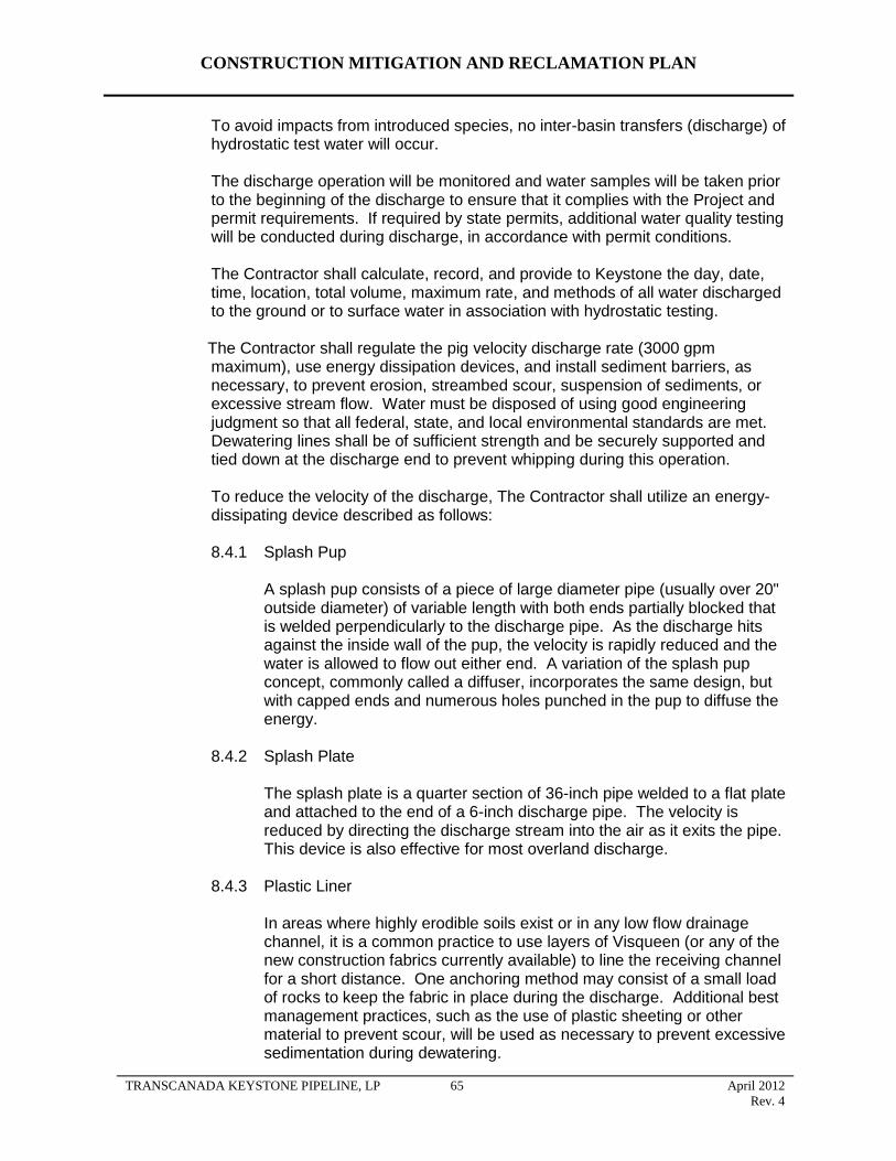
CONSTRUCTION MITIGATION AND RECLAMATION PLAN
To avoid impacts from introduced species, no inter-basin transfers (discharge) of hydrostatic test water will occur.
The discharge operation will be monitored and water samples will be taken prior to the beginning of the discharge to ensure that it complies with the Project and permit requirements. If required by state permits, additional water quality testing will be conducted during discharge, in accordance with permit conditions.
The Contractor shall calculate, record, and provide to Keystone the day, date, time, location, total volume, maximum rate, and methods of all water discharged to the ground or to surface water in association with hydrostatic testing.
The Contractor shall regulate the pig velocity discharge rate (3000 gpm maximum), use energy dissipation devices, and install sediment barriers, as necessary, to prevent erosion, streambed scour, suspension of sediments, or excessive stream flow. Water must be disposed of using good engineering judgment so that all federal, state, and local environmental standards are met. Dewatering lines shall be of sufficient strength and be securely supported and tied down at the discharge end to prevent whipping during this operation.
To reduce the velocity of the discharge, The Contractor shall utilize an energy-dissipating device described as follows:
8.4.1 Splash Pup
A splash pup consists of a piece of large diameter pipe (usually over 20" outside diameter) of variable length with both ends partially blocked that is welded perpendicularly to the discharge pipe. As the discharge hits against the inside wall of the pup, the velocity is rapidly reduced and the water is allowed to flow out either end. A variation of the splash pup concept, commonly called a diffuser, incorporates the same design, but with capped ends and numerous holes punched in the pup to diffuse the energy.
8.4.2 Splash Plate
The splash plate is a quarter section of 36-inch pipe welded to a flat plate and attached to the end of a 6-inch discharge pipe. The velocity is reduced by directing the discharge stream into the air as it exits the pipe. This device is also effective for most overland discharge.
8.4.3 Plastic Liner
In areas where highly erodible soils exist or in any low flow drainage channel, it is a common practice to use layers of Visqueen (or any of the new construction fabrics currently available) to line the receiving channel for a short distance. One anchoring method may consist of a small load of rocks to keep the fabric in place during the discharge. Additional best management practices, such as the use of plastic sheeting or other material to prevent scour, will be used as necessary to prevent excessive sedimentation during dewatering.
TRANSCANADA KEYSTONE PIPELINE, LP 65 April 2012
Rev. 4
CONSTRUCTION MITIGATION AND RECLAMATION PLAN
8.4.4 Straw Bale Dewatering Structure
Straw bale dewatering structures are designed to dissipate and remove sediment from the water being discharged. Straw bale structures are used for on land discharge of wash water and hydrostatic test water and in combination with other energy dissipating devices for high volume discharges. A straw bale dewatering structure is shown In Detail 6. A dewatering filter bags may be sued as an alternative to show bale dewatering structures. A dewatering filter bag is shown in Detail 5.
TRANSCANADA KEYSTONE PIPELINE, LP 66 April 2012
Rev. 4
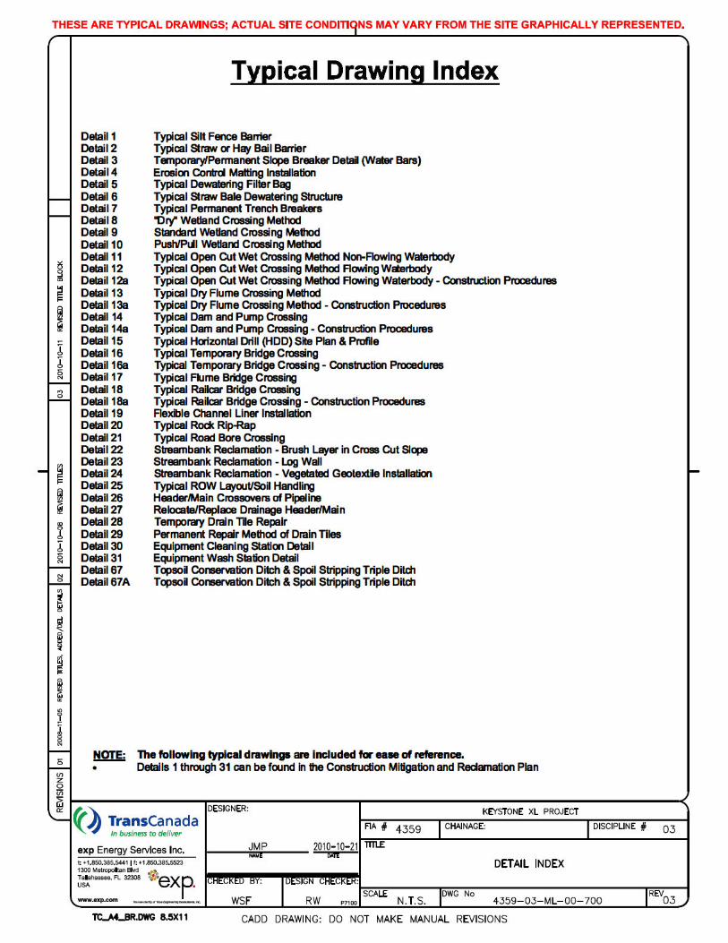
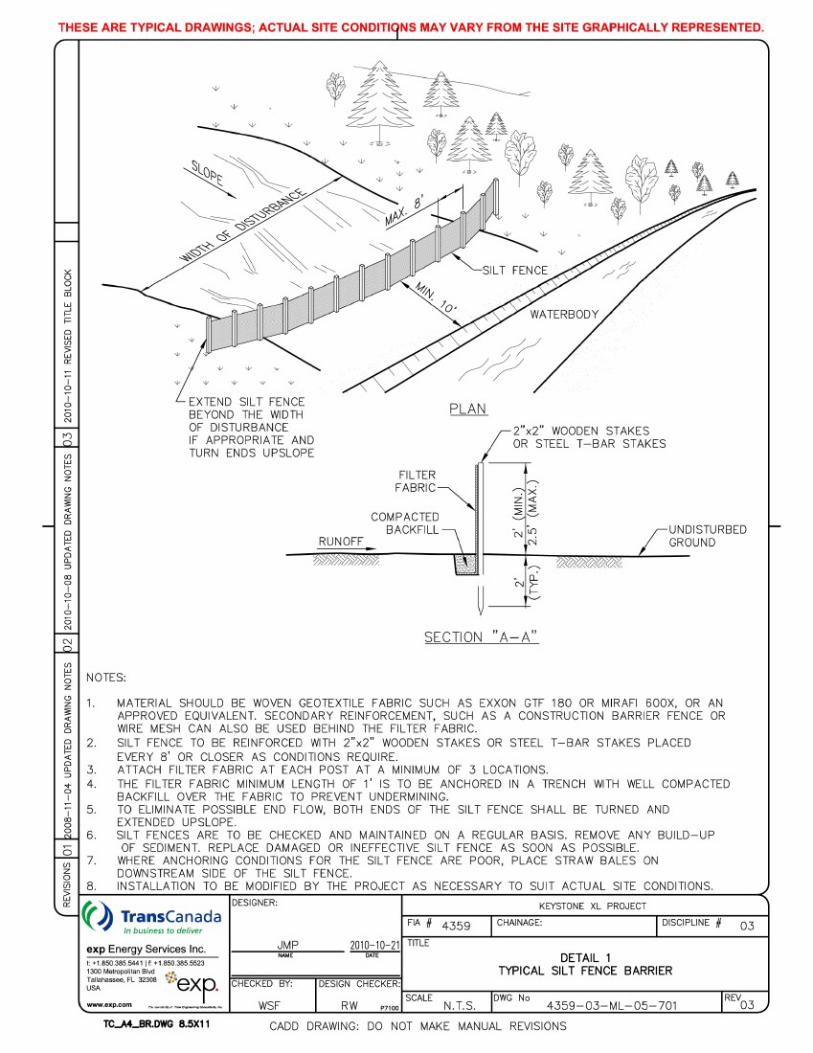
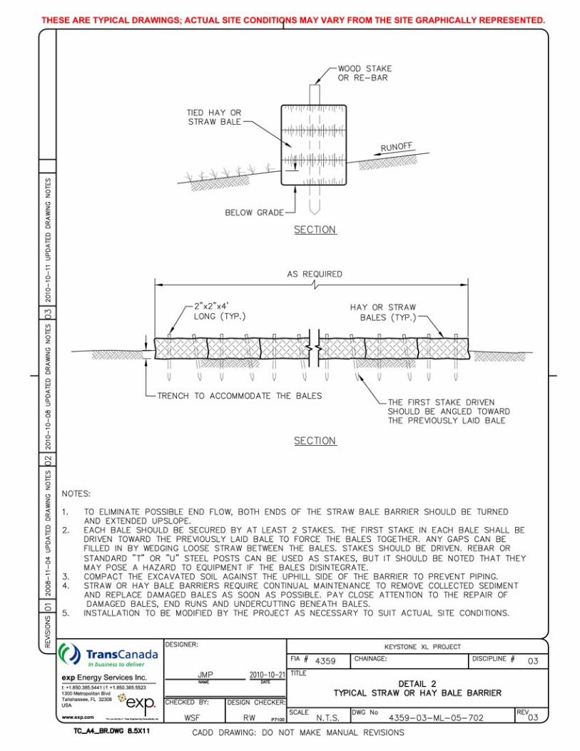
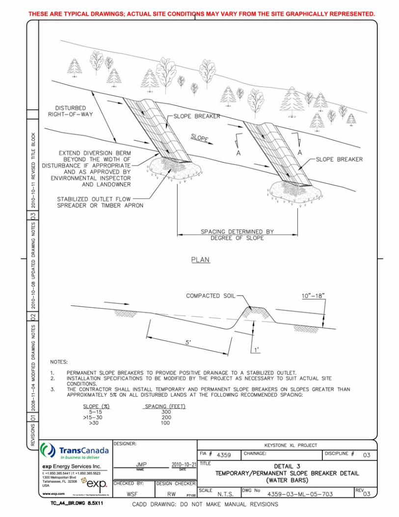
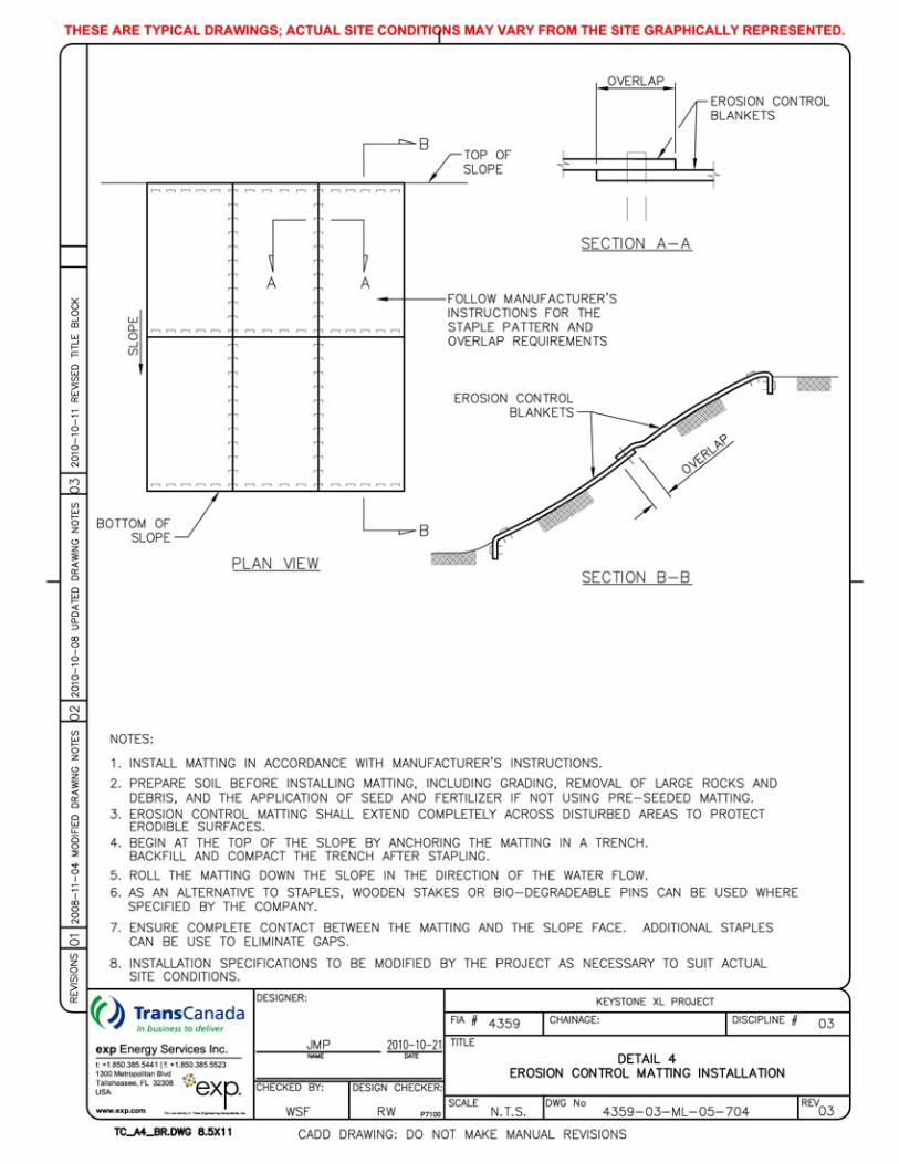
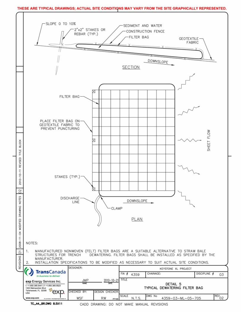
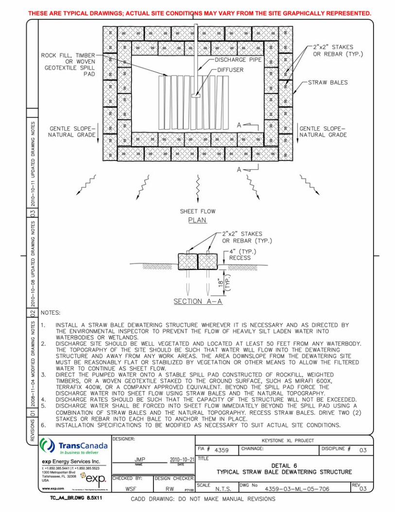
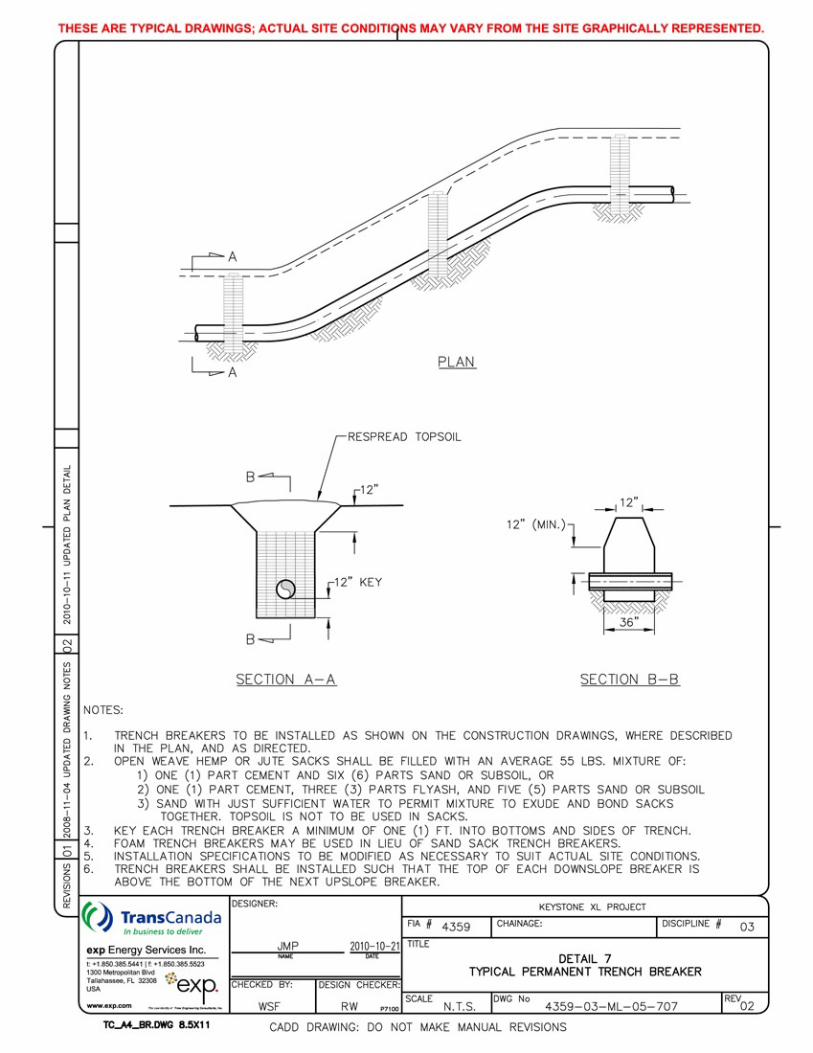
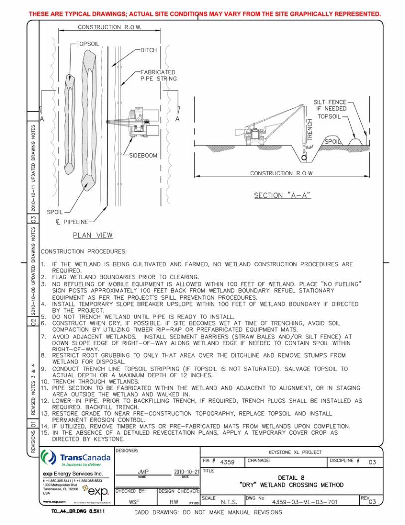
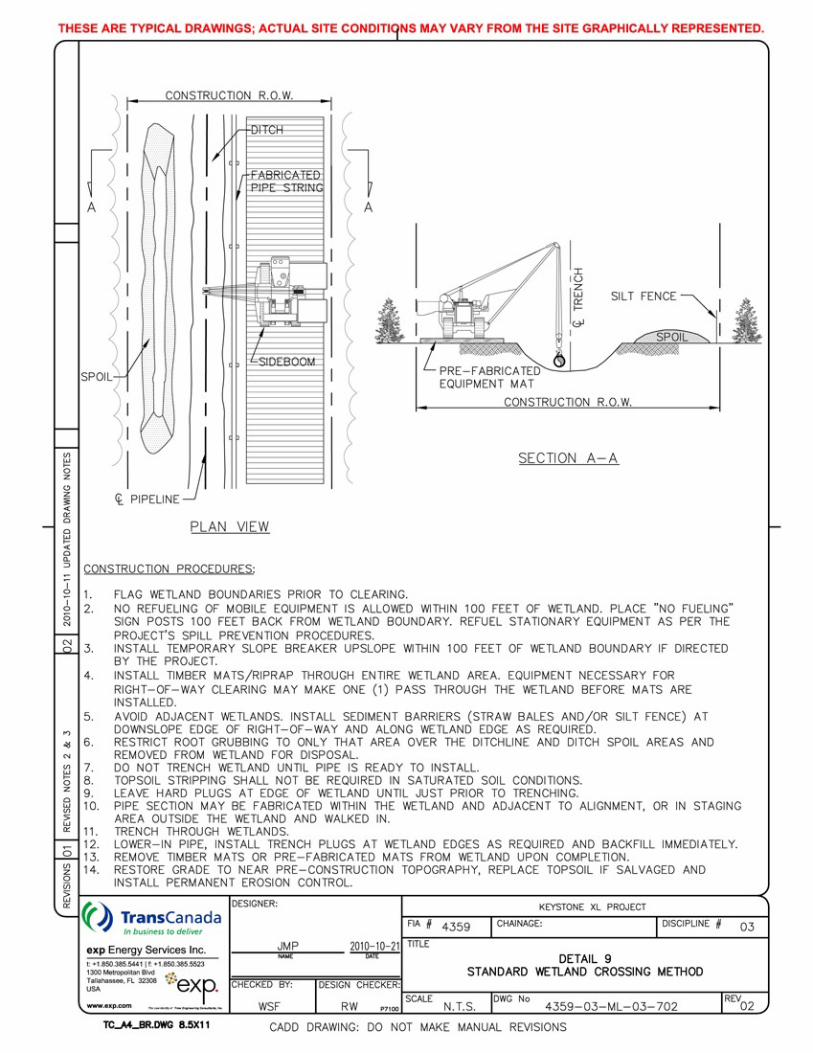
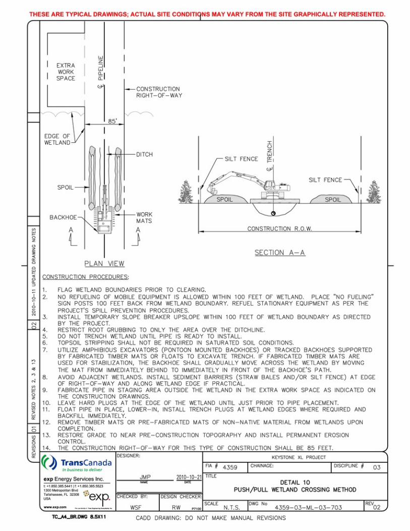
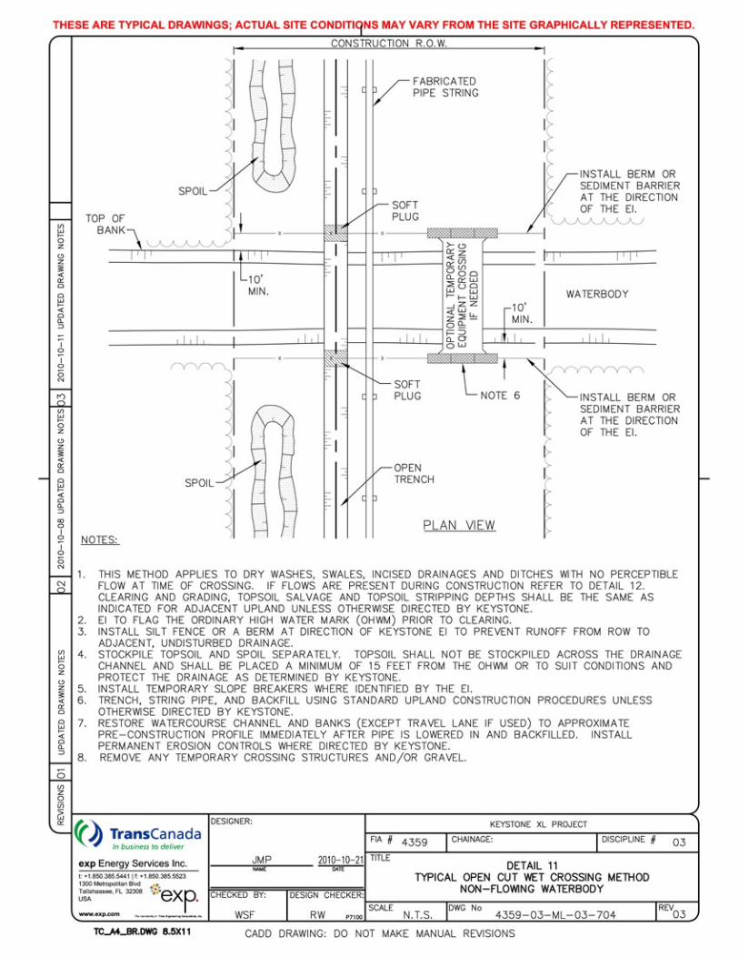
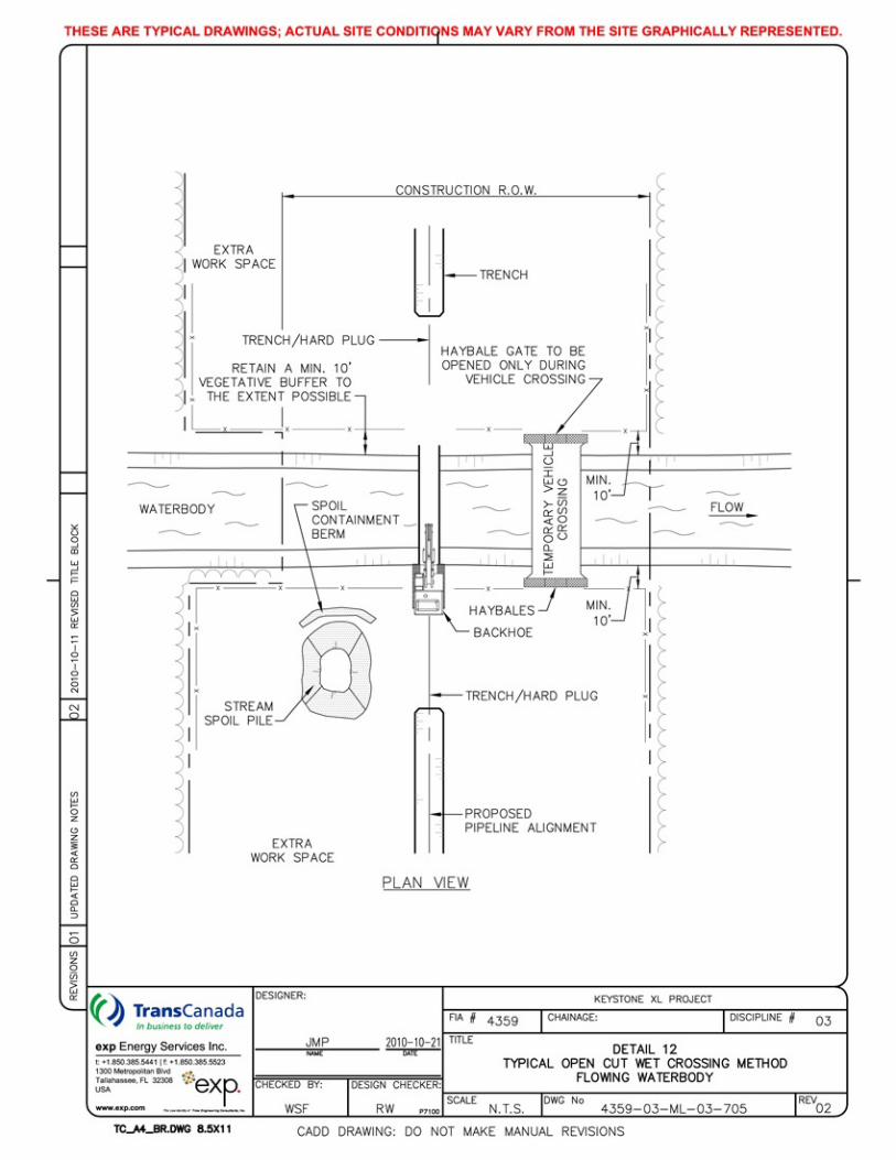
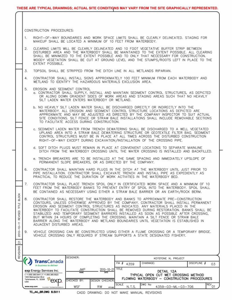
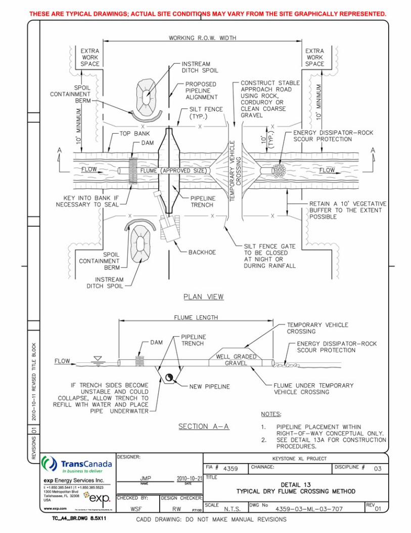
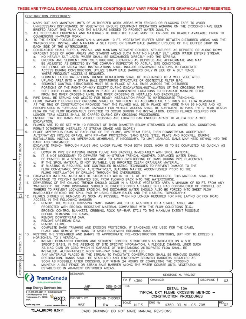
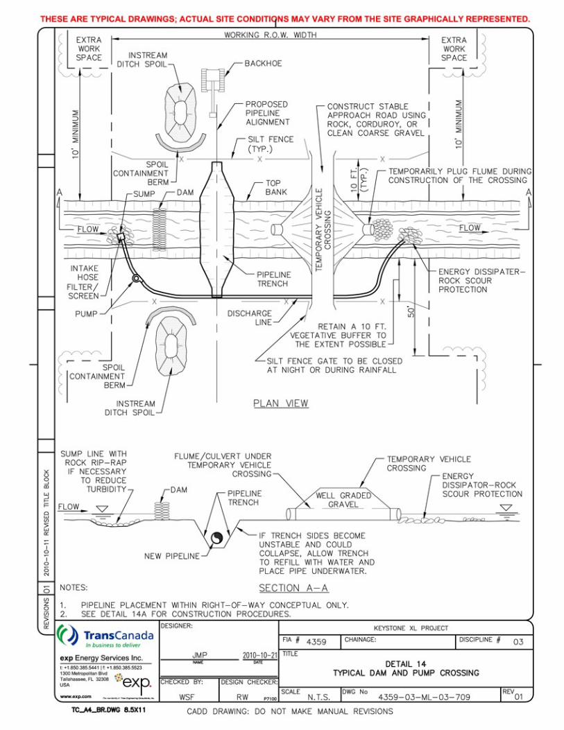
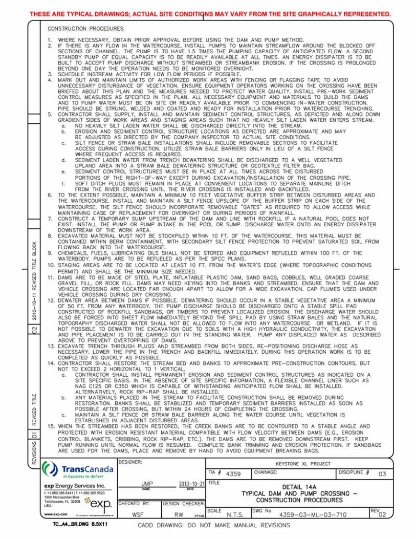
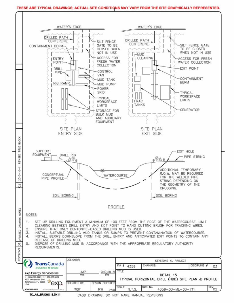
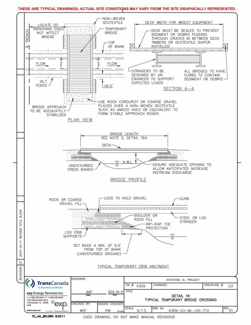
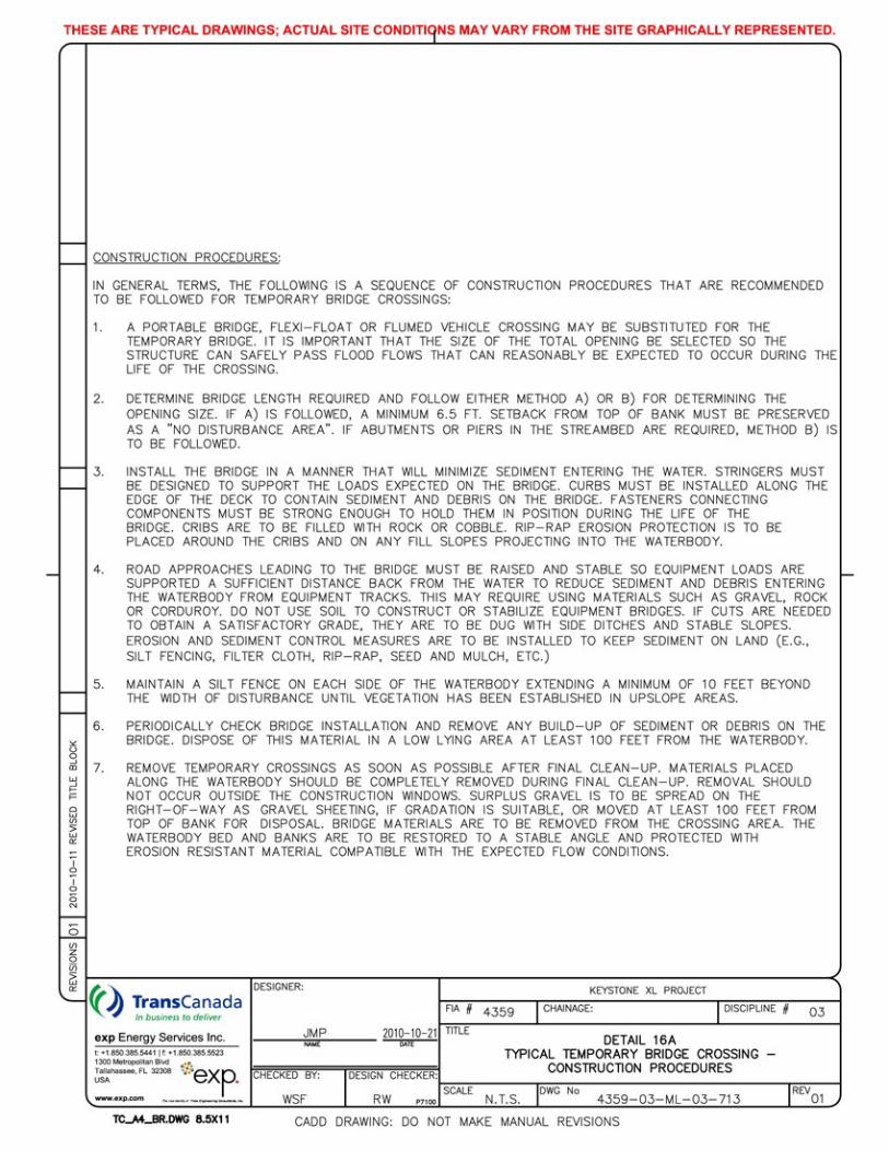
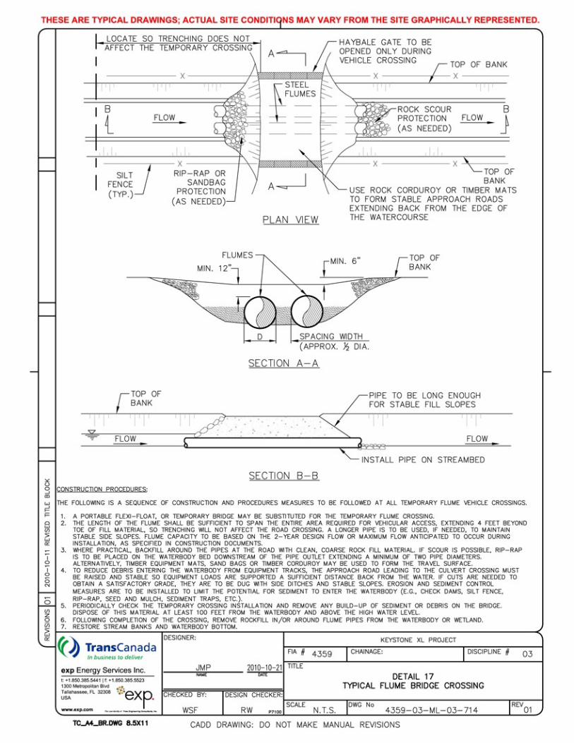
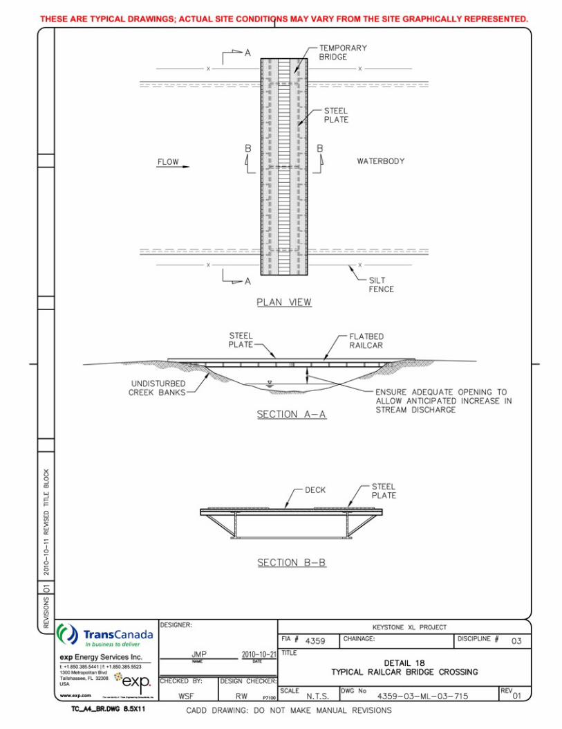
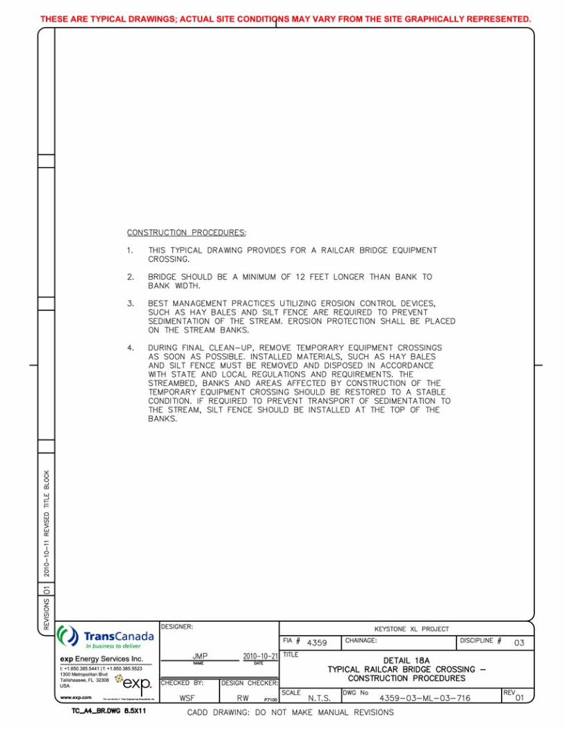
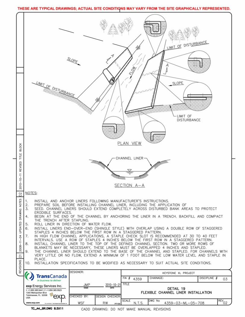
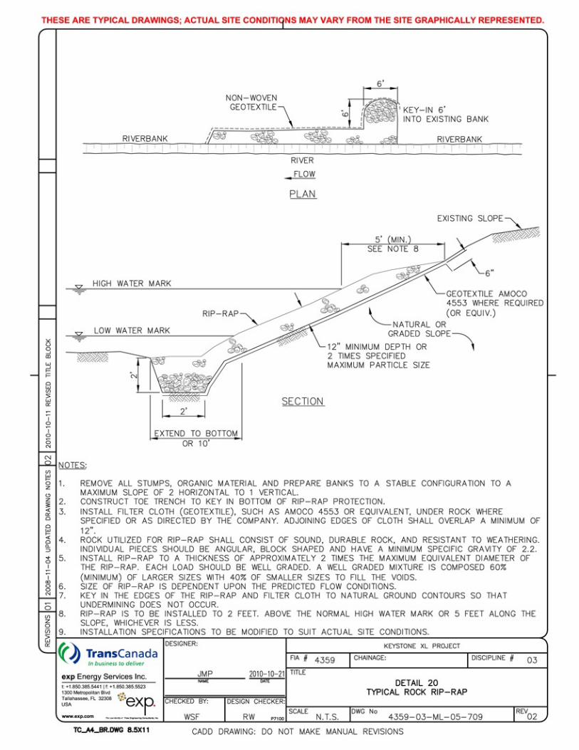
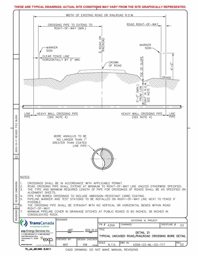
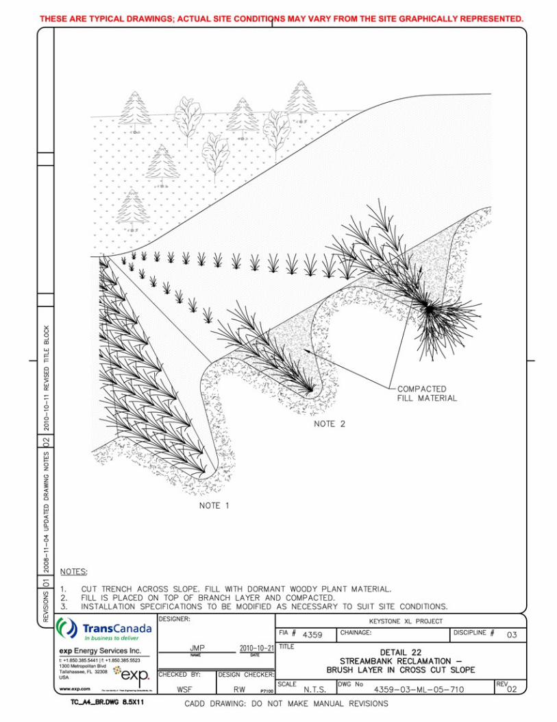
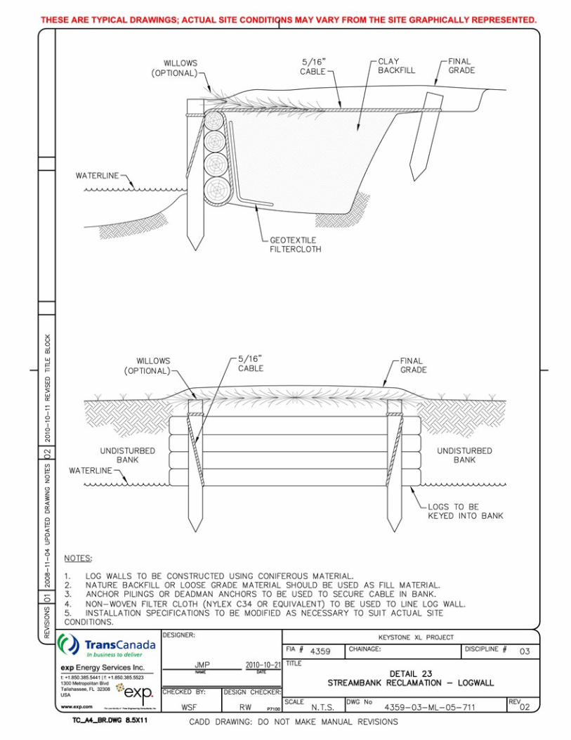
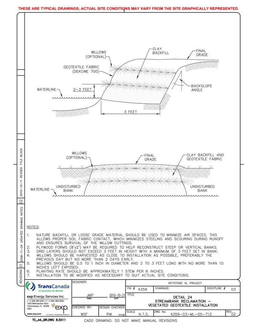
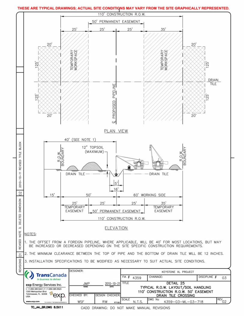
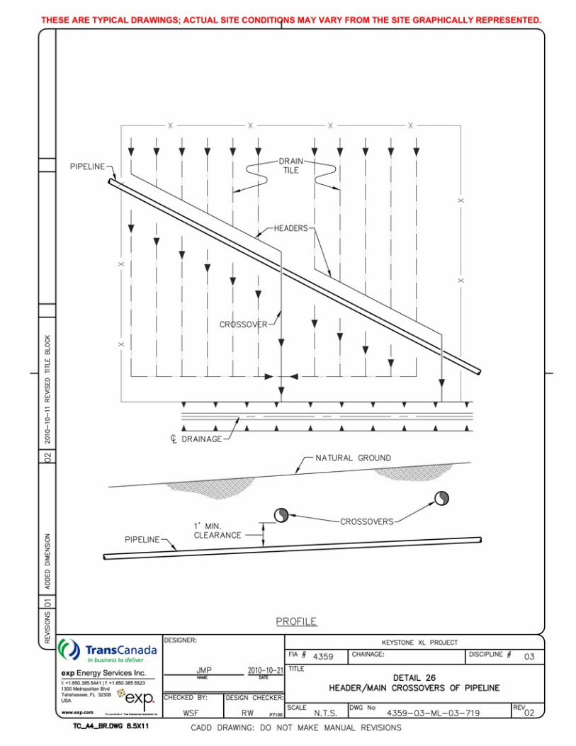
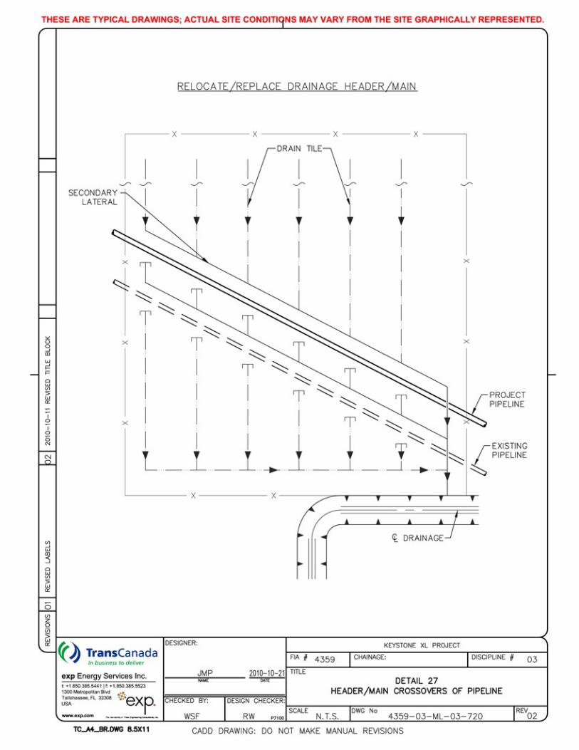
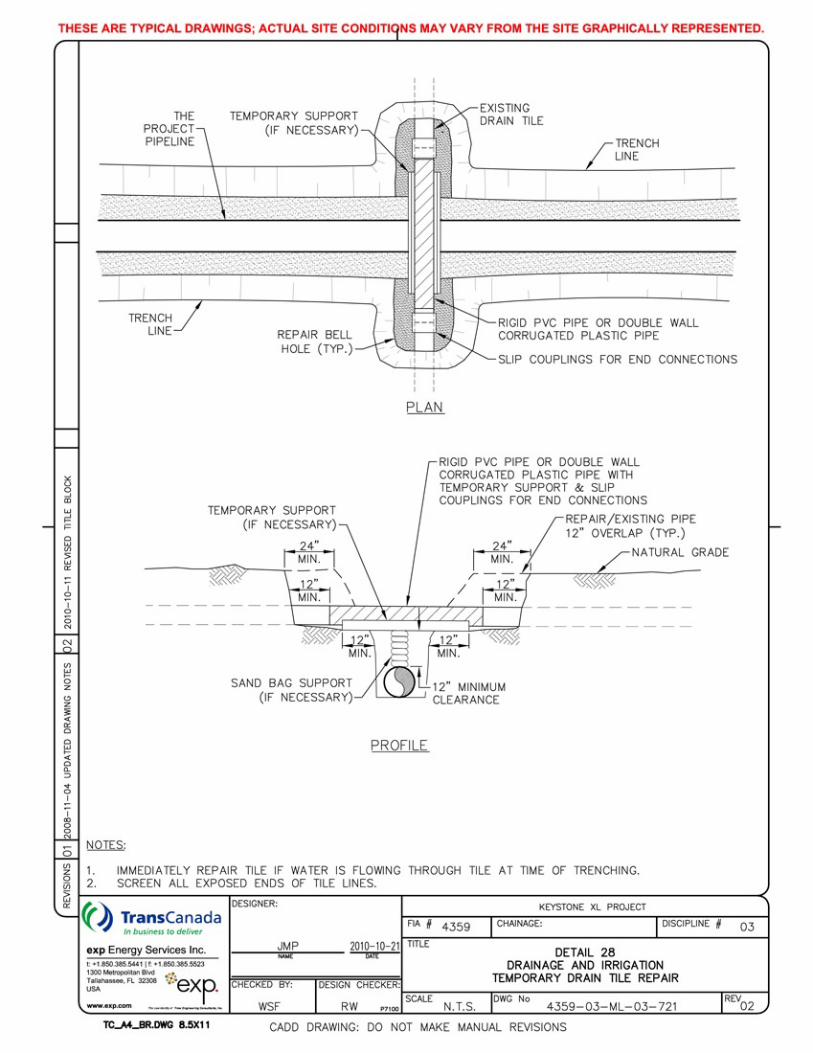
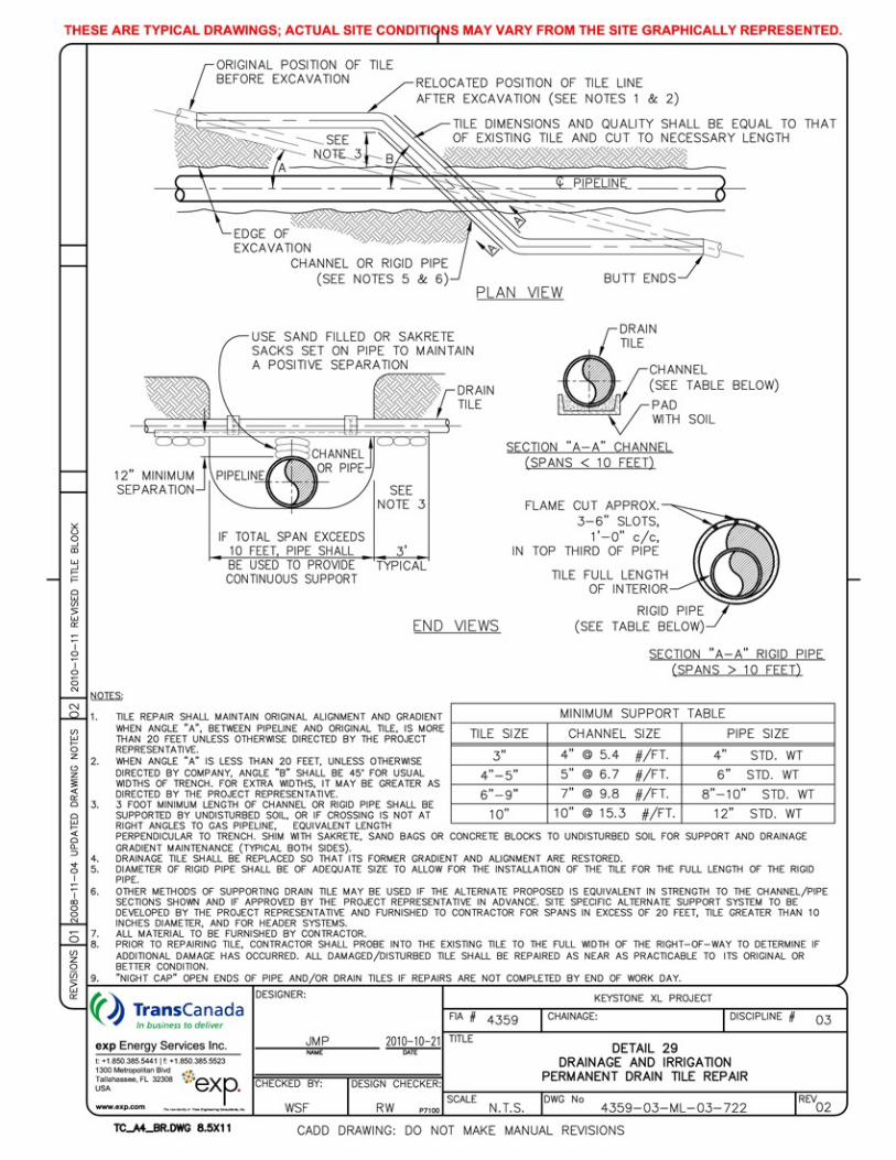
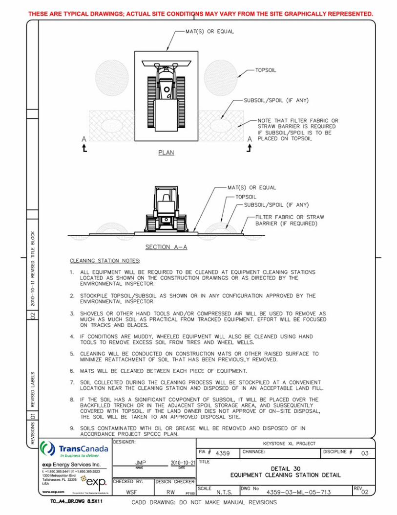
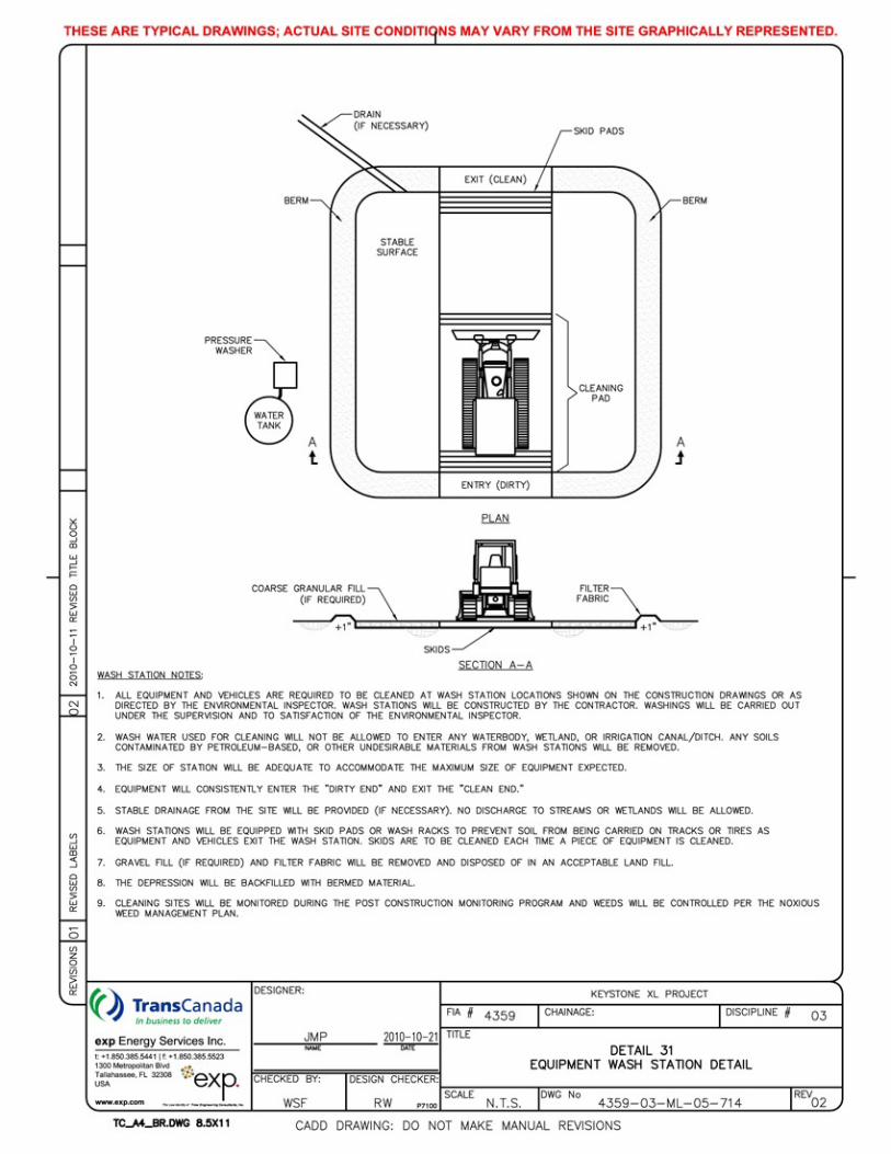
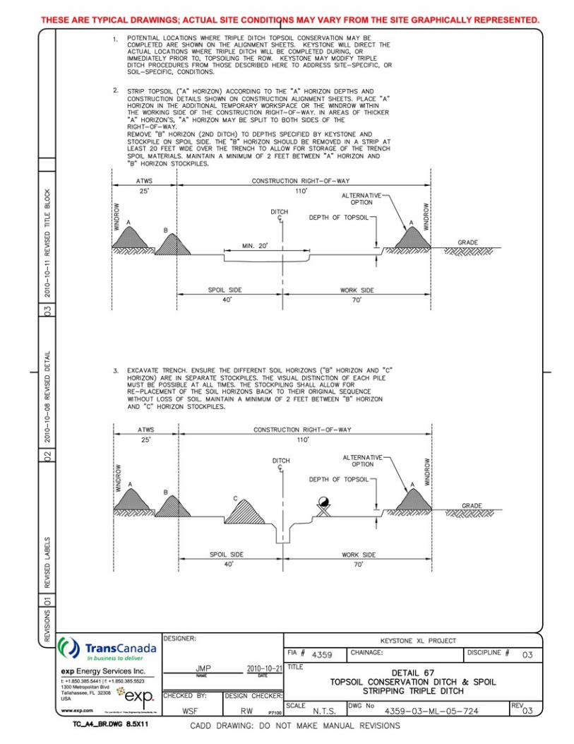
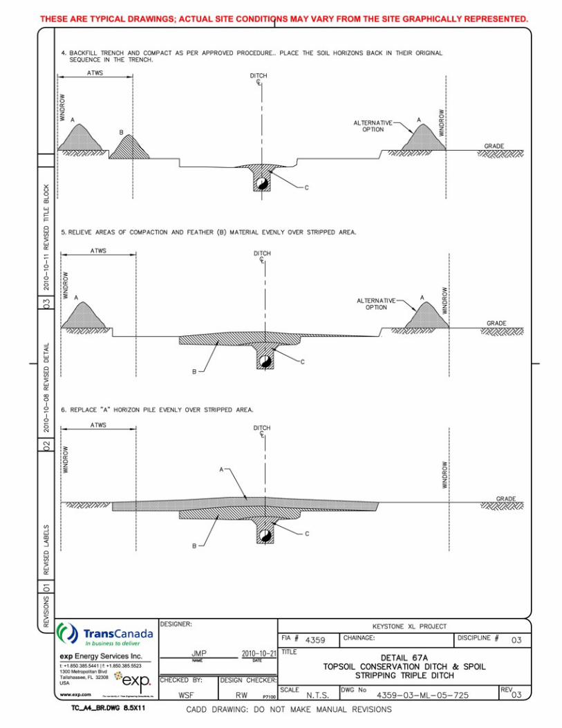

Keystone XL Project
-This page intentionally left blank-
March 2013
Attachment D:
Horizontal Directional Drill Frac-out Contingency Plan
Keystone XL Pipeline Project
HORIZIONTAL DIRECTIONAL DRILL FRAC-OUT CONTINGENCY PLAN
Prepared for:
TransCanada PipeLines Limited 450-1st Street, S.W.
Calgary, Alberta T2P 5H1
exp Energy Services, Inc.
1300 Metropolitan Boulevard, Suite 200 Project No: Tallahassee, Florida 32308 Telephone: (850) 385-5441 Revision No: Facsimile: (850) 385-5523 Issue Date: August 31, 2011
KEYSTONE XL FRAC-OUT CONTINGENCY PLAN
i
Table of Contents
1. Introduction ...................................................................................................... 1
2. Drilling Fluid and Drilling Fluid System ......................................................... 2
3. HDD Contractor Responsibilities and Requirements .................................. 3
4. Fluid Migration Detection ................................................................................ 4
5. Corrective Action for an Inadvertent Release ............................................... 5
6. Containment of Drilling Fluid Release ........................................................... 7
7. Clean-up of Releases ...................................................................................... 8
8. Agency Notification Procedures .................................................................... 9
KEYSTONE XL FRAC-OUT CONTINGENCY PLAN
1
1. Introduction
This horizontal directional drilling mud contingency plan provides specific procedures and steps to contain the inadvertent releases of drilling mud (frac-outs) during pipeline installations using horizontal direction drilling (HDD) techniques. Keystone will designate a representative that will coordinate the implementation of this plan and perform any environmental agency communications in the event of a frac-out during the project.
KEYSTONE XL FRAC-OUT CONTINGENCY PLAN
2
2. Drilling Fluid and Drilling Fluid System
The HDD process involves the use of a drilling fluid (also referred to as drilling mud) made up primarily of water. Bentonite clay is added to the water to enhance lubricating, spoil transport and caking properties of the drilling fluid. Bentonite is a naturally occurring, non-toxic, inert substance that meets NSF/ANSI 60 NSF Drinking Water Additives Standards and is frequently used for drilling potable water wells.
The primary purpose of drilling fluid is to power the downhole cutting tools, remove cuttings from the drill hole, stabilize the hole, and act as a coolant and lubricant during the drilling process.
The drilling fluid is prepared in a mixing tank containing both new and clean recycled drilling fluid. The fluid is pumped at rate of 100 to 1,000 gallons per minute (gpm) through the center of the drill pipe to the cutters. Return flow is through the annulus created between the wall of the boring and the drill pipe. The cuttings are then carried back to either the entry or the exit pit, depending on a combination of elevation difference and drilling/hole opening direction.
Once in the entry pit, the fluid moves to the pickup pit to be pumped to the fluid processing equipment. Typically, shaker screens, desanders and desilters remove increasingly finer cuttings from the drilling fluid. The cleaned and recycled fluid is returned to the mixing tank and pumps for reuse in the borehole. Following completion of the drill, cuttings and clay will be disposed of in accordance with all applicable federal, state and local environmental regulations. Accordingly, this material may be made available to landowners for use, mixed with native soil and buried on site with landowner permission, or disposed of in a landfill.
The HDD method has the potential for loss or seepage of drilling fluid into the native material through which the drill passes. In some cases, the drilling fluid may be forced to the surface resulting in what is commonly referred to as an inadvertent release or a frac-out. While one of the positive aspects of the HDD method is the avoidance surface disturbance, surface disturbances may occur when there is an inadvertent release of drilling fluid. Drilling fluid release is typically caused by pressurization of the drill hole beyond the containment capability of the overburden soil material or due to inherent weaknesses within the overlying soils such as a fissure or other pathway. In some cases, the pathway can be associated with boreholes advanced for geotechnical investigations or by bridge or building pilings.
The HDD operation is a closed system to minimize the discharge of drilling mud, fluids, and cuttings outside of the work area. To minimize the possibility of fluid escape, mud pits shall be used to contain the drilling fluids. The drilling fluids are cleaned and recycled to the extent possible. Tanks or dumpsters will be installed in lined pits. Care will be taken to prevent the fluids from getting into the soil and to prevent groundwater from entering the pits.
KEYSTONE XL FRAC-OUT CONTINGENCY PLAN
3
3. HDD Contractor Responsibilities andRequirements
The HDD contractor is responsible for execution of the HDD operation, including actions for detecting and controlling the inadvertent release of drilling fluid. Keystone will closely supervise the progress and actions of the HDD contractor through the use of onsite inspection teams.
The HDD contractor will be required to conduct the HDD operation in compliance with the project specific Spill Prevention Control and Countermeasure Plan (SPCC) which includes specifies the types and quantities of equipment to be provided, which would typically consist of a tracked hydraulic excavator, straw or hay bales, stakes to secure bails, silt fence, sand bags, shovels, pumps, and any other materials or equipment deemed necessary and adequate to contain and clean up inadvertent releases. The contractor will also provide for a vacuum truck and operator to be on call during drilling operations, such that the vacuum truck can respond and be on-site within three hours of notification.
The Contractor will provide a site-specific plan for each HDD crossing, identifying any site-specific requirements and provisions to be made to meet special site conditions.
Ancillary items must be readily available during drilling operations including a light tower in case cleanup operations are needed after dark, a boat with relevant safety equipment during the crossing of large water bodies, and leak free hose to allow pumping spilled drilling mud for mitigation where small creeks or drainages are involved.
KEYSTONE XL FRAC-OUT CONTINGENCY PLAN
4
4. Fluid Migration Detection
Drilling crews and the Keystone inspection personnel will be responsible for monitoring and detection of frac-outs. The most obvious signs of a frac-out are the visible pooling of drilling mud on the surface or a sudden decease in mud volume during drilling operations or loss in drilling mud pressure. The annular pressure will be specified in the HDD contract. Drilling and mud system personnel will observe alterations in drilling pressure or the volume of drilling fluid return and immediately report reductions or anomolies to the foreman and Keystone personnel. The contract will specify the use of an Electronic Data Recorder (EDR) to monitor volumes, pressures and other HDD operations.
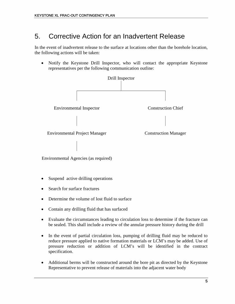
KEYSTONE XL FRAC-OUT CONTINGENCY PLAN
5
5. Corrective Action for an Inadvertent Release
In the event of inadvertent release to the surface at locations other than the borehole location, the following actions will be taken:
• Notify the Keystone Drill Inspector, who will contact the appropriate Keystone representatives per the following communication outline:
Drill Inspector
Environmental Inspector Construction Chief
Environmental Project Manager Construction Manager
Environmental Agencies (as required)
• Suspend active drilling operations
• Search for surface fractures
• Determine the volume of lost fluid to surface
• Contain any drilling fluid that has surfaced
• Evaluate the circumstances leading to circulation loss to determine if the fracture can be sealed. This shall include a review of the annular pressure history during the drill
• In the event of partial circulation loss, pumping of drilling fluid may be reduced to
reduce pressure applied to native formation materials or LCM’s may be added. Use of pressure reduction or addition of LCM’s will be identified in the contract specification.
• Additional berms will be constructed around the bore pit as directed by the Keystone
Representative to prevent release of materials into the adjacent water body
KEYSTONE XL FRAC-OUT CONTINGENCY PLAN
6
• The contractor will pump the spill in an attempt to recover all of the spilled fluid for
disposal
• Measures will be implemented (berm, silt fence, and/or hay bale installation) to prevent silt laden water from flowing into the water body.
• If hand tools cannot contain a small on-land release, small collection sumps may be
constructed to pump the released material into the mud processing system.
• Sump pumps or vacuum trucks will be used to remove and dispose of any drilling fluids.
KEYSTONE XL FRAC-OUT CONTINGENCY PLAN
7
6. Containment of Drilling Fluid Release
Immediately following the detection of the inadvertent drilling fluid release, containment and clean-up operations shall commence and Keystone will notify all appropriate authorities. For releases on land, Contractor shall use straw bales, silt fences, sand bags and earth berms to prevent fluid from migrating or flowing from the immediate area of the discharge. If the volume released is too small for containment measures or if the release occurs in an environmentally sensitive area where release of containments can cause additional damage, the receiving area will be allowed to dry naturally. If there is a threat to a sensitive resource or a threat to public safety, HDD activities will cease immediately.
In cases of inadvertent releases to open water or flooded wetlands, it may impractical or impossible to contain the release. For releases in shallow water, the HDD contractor shall install staked sediment barriers as described in the Keystone XL Construction Mitigation and Reclamation Plan (CMRP). Removal by vacuum truck may be attempted if deemed appropriate. The decision to proceed with the drilling operation will be at the sole discretion of the Keystone representative after all methods to seal off the location of the discharge identified in the SPCC Plan have been attempted. Underwater releases may be allowed to dissipate where cleanup would cause more damage than leaving the material in place. Where cleanup can be accomplished without causing additional damage, the cleanup of the spill will be conducted. The regulating agency with jurisdiction over the operation will be advised of planned actions in response to spills, when those actions do not include complete removal of the spilled material.
KEYSTONE XL FRAC-OUT CONTINGENCY PLAN
8
7. Clean-up of Releases
The clean-up shall commence after the release is contained. Clean-up shall include removal of all visible drilling fluid located in accessible areas. Removal methods will vary based on the volume of the release and the site specific conditions. Removal equipment may include vacuum trucks, loader and track hoe buckets, small pumps, shovels, buckets, brooms and squeegees. If the release occurs in a sensitive area, it may be necessary to pump the fluid into an upland area for additional containment and disposal. After removal of the released drilling fluid, the release area will be returned as close to the original condition as feasible. It may be necessary to store the drilling fluid residue on-site prior to disposal. On-site storage will include secondary containment with the capacity of 110 percent of the volume of drilling fluid residue to be stored.
Any water discharged from the HDD operation will be discharged through filter bags, or other approved dewatering structure, to contain suspended solids.
KEYSTONE XL FRAC-OUT CONTINGENCY PLAN
9
8. Agency Notification Procedures
If an inadvertent release is discovered, steps will be taken to contain the release as described in Section 4. It will be reported in accordance with the Keystone communication outline. The appropriate agency(s) will be consulted regarding the nature of the release the corrective actions to be applied and any additional measures necessary to minimize potentially adverse environmental impacts.
In the event an HDD crossing cannot be successfully completed, an alternative crossing plan will be developed and its implementation will be coordinated with the appropriate agencies.

Attachment E:
Horizontal Directional Drill Site-Specific Drawings


Attachment F:
2017 Nationwide Permits, Regional Conditions, Omaha District, State of Montana
2017 Nationwide Permits Regional Conditions
Omaha District State of Montana
1. PCN Requirement. For all NWPs, permittees must notify the Corps in accordance with GeneralCondition No. 32 (PCN) for regulated activities, located within or comprised of the following:
a. Wetlands Classified as Peatlands. Peatlands are seasonally waterlogged areas with a surfaceaccumulation of peat (organic matter) 30 centimeters (12 inches) or more thick. Any peat-covered areas, including fens, bogs, and muskegs, are all peatlands.
i. PCN required for NWP 3, 5, 6, 20, 27, 32, and 38.
ii. All NWPs not listed above are revoked for use in peatlands.
b. Waters Adjacent to Natural Springs. Any projects located within 100 feet of the water sourcein natural spring areas. A spring is defined as any location where there is groundwater flowemanating from a distinct point. Springs do not include seeps or other groundwater dischargeareas where there is no distinct point source.
c. Bank Stabilization Activities. Any project that involves bank stabilization greater than 300linear feet or includes features that extend out from the existing bank line greater than 25% ofthe bankfull channel width.
d. Channel Straightening and Relocation Activities. Any project that involves straightening,relocating and/or shortening an existing perennial stream channel.
e. Tribal Reservations and Tribal Trust Lands. Any projects within the boundaries of any TribalReservation or Tribal trust lands.
f. Specific Waterways Requiring PCN. Any projects within the following waterways and theirimpoundments:
-Bitterroot River -Flathead Lake -Clark Fork River (tributary to the -Milk River Columbia River) -Missouri River -Flathead River -Yellowstone River
2. Bank and Shoreline Stabilization Activities. The following additional requirements apply to allbank and shoreline stabilization: a. The revetment must conform to the existing bankline; must not extend above the top of the
bank (i.e. no new levees); and the slopes must be flatter than the angle of repose for the selected revetment material (i.e. rock riprap normally needs to be placed on a slope flatter than 1.5 Horizontal to 1 Vertical (1.5H:1V).
b. The revetment must not wholly or partially block flows from entering a side channel or anoverflow channel.
3. Counter-Sinking Riprap Associated with Culvert Installation. When riprap inlet and outletprotection is used below the OHWM (OHWM), it must be placed to match the adjacent culvertbottom elevations. Where culvert bottom elevations are lower than the stream bed elevation, theriprap must match the culvert elevation.
4. Placement and Removal of Temporary Fills. Temporary fills in wetlands must be placed on a
horizontal marker layer, such as fabric or certified weed-free straw, to delineate the pre-project ground elevation and facilitate complete fill removal and site restoration.
5. Erosion and Sediment Control Blanket. All erosion control blanket or fabric used in oradjacent to waters of the U.S. must be comprised of degradable material to ensure decomposition.Do not use material that includes stabilized netting or stabilized open mesh, as these products takea long time to degrade and they can trap small animals, birds, amphibians and fish. Thisprohibition also applies to mesh materials used for wattles, rolled materials, and bank wraps.Erosion control blanket or fabrics that break down within 24 months are acceptable. Non-degradable blankets or fabric may be allowed on a case-specific basis if it will be buried beneathriprap or structures and it is not likely to be exposed. Non-degradable blanket or fabric thatbecomes exposed within waters of the U.S. must be removed.
6. Suitable Material. NWP General Condition No. 6 prohibits the use of unsuitable material.Specific criteria can be found in the Omaha District’s “Generic Prohibitions Regarding the Use ofCertain Materials as Fill in Waters of the United States” and MT Department of EnvironmentalQuality’s (DEQ) “Specifications for use of Concrete Riprap for Streambank Stabilization,” whichapply to proposed work in jurisdictional waters.
REGIONAL CONDITIONS APPLICABLE TO SPECIFIC NATIONWIDE PERMITS
7. NWP-3 – Maintenance and NWP-45 – Repair of Uplands Damaged by Discrete Events. Thedefinition of “discrete event,” as used in these permits, includes, but is not limited to, unexpectednatural and human-caused events such as fires, storms, landslides, avalanches, earthquakes,accidents, debris or ice jams, and floods. For the purpose of the NWPs, discrete event floods arestream flow events that overflow the OHWM.
8. NWP-7 – Outfall Structures and Associated Intake Structures and NWP-12 – Utility LineActivities. Inlet screens for intakes in the Yellowstone River or the Missouri River in Blaine,Chouteau, Custer, Dawson, Fergus, Garfield, McCone, Petroleum, Phillips, Prairie, Richland,Roosevelt, Valley and Wibaux Counties must be installed on all pump intakes with a screen meshopening size no larger than 0.25 inch. Water intake velocities must not exceed 0.5 foot per secondthrough the mesh. Intakes must be located in the deepest water available and be elevated off thebottom of the river bed.
REGIONAL CONDITIONS APPLICABLE ONLY TO THE SPECIAL RIVER MANAGEMENT ZONE OF THE UPPER YELLOWSTONE RIVER
Special River Management Zone (SRMZ) of the Upper Yellowstone River is defined within the Special Area Management Plan (SAMP) as the 48-mile reach of the upper Yellowstone River (River Miles 531.8 to 483.6) from upstream of Emigrant River downstream to a few miles below the Shields River and Mission Creek confluences (0.7 miles downstream from the bridge at the community of Springdale). It includes secondary channels, side channels, and the main (primary) channels, and adjacent wetlands within the channel migration zone (CMZ) or, in absence of a CMZ, within areas flooded by the 100-year discharge. The SMRZ is located entirely within Park County.
In addition to Regional Conditions 1 through 8, the following Regional Conditions 9 through 24 apply within the SRMZ described above:
9. SRMZ – Notification – All NWPs. Permittees must notify the Corps in accordance with GeneralCondition No. 32 (PCN) for any regulated activity in waters of the U.S. within the SRMZ. This
includes all activities within the Yellowstone River, the portions of tributaries within the SRMZ, and wetlands within the SRMZ.
10. SRMZ – Emergency Work. Activities requiring a Department of the Army (DA) Permit that isnecessary to prevent imminent loss of life or property is allowed within the SRMZ. Contact theCorps as soon as reasonably possible by telephone at 406-441-1375 and/or by Fax at 406-441-1380. Contact may also be made in person or by sending an e-mail to:[email protected]. All such work will be fully reviewed under the SAMPprovisions.
11. SRMZ - NWPs Revoked for Use. The following NWPs have been revoked for all waters andactivities within the 48-mile SRMZ:NWP 17 - Hydropower ProjectsNWP 21 - Surface Coal Mining ActivitiesNWP 29 - Residential DevelopmentsNWP 39 - Commercial and Institutional DevelopmentsNWP 42 - Recreational FacilitiesNWP 43 - Stormwater Management FacilitiesNWP 44 - Mining ActivitiesNWP 45 - Repair of Uplands Damaged by Discrete EventsNWP 49 - Coal Remining ActivitiesNWP 50 - Underground Coal Mining Activities
12. SRMZ – Activities Requiring Individual Permit Review. The following project activities arenot authorized under a NWP in the SRMZ. These projects typically have more than minimaladverse impacts and must be reviewed under standard (individual) permit procedures.
a. New dams, new diversions, and/or new impoundments for any purpose;b. Construction of ponds and new artificial stream channels, unless they are necessary and
appropriate elements of a stream or wetland restoration project;c. Hydraulic dredging and mining and mechanical excavation to obtain aggregate, fill material,
or minerals, including gold. Processing of material for the purpose of obtaining selectminerals or a specific gradation of material, where only a portion of the sediment or alluviumis removed and the remainder returned to the SRMZ, is not allowed under a NWP in theSRMZ.
13. SRMZ - Bank Stabilization Activities - All NWPs. For bank stabilization activities associatedwith any NWP, including maintenance of bank stabilization, the following Regional Conditionsapply:
For bank revetments such as riprap, root wads, bioengineered revetments, or combination revetments, a. through e. apply:
a. Revetments must conform to the existing eroded or eroding bankline, unless such work isdetermined by the Corps to be biologically or geomorphically beneficial for the upperYellowstone River.
b. Revetment slopes must be flatter than the angle of repose for the selected revetment material.For example, rock riprap normally needs to be placed on a slope flatter than 1.5H:1V.
c. Revetments are only permittable under NWPs if they are parallel to and near the lateralboundaries of the SRMZ.
d. Revetments must not extend above the elevation of the adjacent natural bank height (i.e., no
new levees). e. Revetments must not wholly or partially block flows from entering a side channel, secondary
channel, or an overflow channel, unless such work is determined by the Corps to be necessary for maintaining or restoring the geomorphic integrity of the upper Yellowstone River.
For bank stabilization structures that project into the stream, such as weirs, barbs, vanes, or hard points, f. through k. apply:
f. Bank stabilization structures must not wholly or partially block flows from entering a sidechannel, secondary channel, or an overflow channel, unless such work is determined by theCorps to be necessary for maintaining or restoring the geomorphic integrity of the upperYellowstone River.
g. Bank stabilization structures are only permittable under NWPs if they result in an effectivebankline that is approximately parallel to and near the lateral boundaries of the CMZ.
h. Bank stabilization structures must be keyed into the bank far enough to prevent flanking.i. Bank stabilization structures cannot occupy more than 10% of the bankfull channel area.
Bankfull channel area pertains to the specific primary or secondary channel in question, andis not the aggregate channel area of all primary and secondary channels in multi-channelreaches.
j. Bank stabilization structures must not present hazardous obstructions to boating, floating, orother river uses.
k. Bank stabilization structures that are low in elevation, project only a short distance out fromthe bank, and angle upstream are more likely to qualify for NWPs because they typicallyresult in less adverse impact on aquatic resources than structures that are tall, long, and pointdownstream.
14. SRMZ – Temporary Bank Stabilization – All NWPs. Temporary bank stabilization isprohibited during seasonal high flows.
15. SRMZ – Sediment Management – All NWPs. Sediment removal is allowable only to maintainfunction of existing facilities and structures, or as necessary to maintain or restore the geomorphicintegrity of the upper Yellowstone River. Diversion or removal of sediment or alluvium from theriver channel and adjacent wetlands for other purposes is not allowed in the SRMZ under anyNWP.
16. SRMZ – Temporary Vegetation Impacts – All NWPs. Limit clearing of riparian or wetlandvegetation to the absolute minimum necessary. Where temporary riparian or wetland vegetationimpacts are unavoidable, mow or cut off the vegetation above the ground, leaving the topsoil androot mass intact. Restore temporarily disturbed areas to original contours and use seeding andplanting as necessary to re-establish desirable vegetative cover, utilizing native species in areaswhere native species were impacted.
17. SRMZ – NWP-11 – Temporary Recreational Structures. Temporary recreational structurescan be installed no earlier than seven (7) calendar days in advance of an event and must beremoved no later than seven (7) calendar days after the event concludes.
18. SRMZ – NWP-12 – Utility Line Activities. Trench excavation and backfill for utility lines isprohibited within the OHWM of main and secondary flow channels and in adjacent wetlands.
19. SRMZ – NWP-13 – Bank Stabilization. Construction of temporary or permanent levees isprohibited. Only bank stabilization that is parallel to and adjacent to the valley wall and/or SRMZ
boundary is allowed. All other bank stabilization must be reviewed under standard (individual) permit procedures. Bank stabilization along existing roads, ditches, fills, and structures already located along the valley wall is allowed under this Permit.
20. SRMZ – NWP-14 – Linear Transportation Projects. The construction of new transportationfacilities in waters of the U.S. is prohibited under this NWP and must be reviewed under standard(individual) permit procedures. The expansion, modification, improvement, replacement,reconstruction, and upgrading of existing transportation facilities are allowed under this NWPwithin the SRMZ.
21. SRMZ – NWP- 27 – Aquatic Habitat Restoration, Establishment, and EnhancementActivities. The construction of water control structures, dikes, berms, current deflectors, bankstabilization, and ponds is prohibited within the CMZ of the upper Yellowstone River unless it isdemonstrated the proposed features contribute to the restoration or rehabilitation of previouslylost or impaired functions of the upper Yellowstone River and adjacent aquatic areas.
22. SRMZ – NWP-30 – Moist Soil Management for Wildlife. Fire breaks within the CMZ of theupper Yellowstone River must be reclaimed and restored within six (6) months after the fire eventends.
23. SRMZ – NWP-33 – Temporary Construction, Access, and Dewatering. Construction oftemporary levees and other structures or fills in waters of the U.S. that prevent or reduceoverbank flow is prohibited.
24. SRMZ – NWP 40 – Agricultural Activities. Only those activities associated with the reductionof existing adverse impacts on the upper Yellowstone River may be authorized by this NWP.Examples of potentially allowable projects include work associated with livestock management;moving livestock watering areas off the river or out of the CMZ; removal of irrigation systemsfrom the CMZ; and the removal or conversion of irrigation systems from flood irrigation tosprinkler irrigation.

Attachment G:
Montana Joint Application
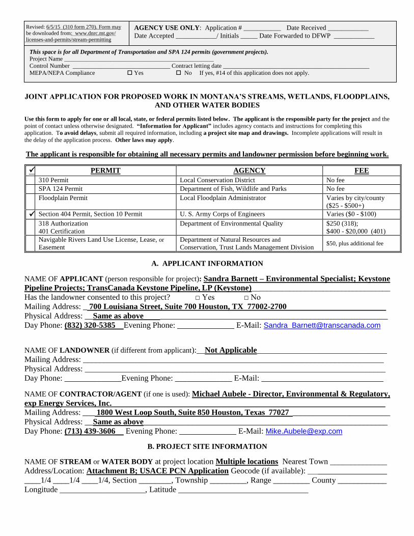
JOINT APPLICATION FOR PROPOSED WORK IN MONTANA’S STREAMS, WETLANDS, FLOODPLAINS,
AND OTHER WATER BODIES
Use this form to apply for one or all local, state, or federal permits listed below. The applicant is the responsible party for the project and the
point of contact unless otherwise designated. “Information for Applicant” includes agency contacts and instructions for completing this
application. To avoid delays, submit all required information, including a project site map and drawings. Incomplete applications will result in
the delay of the application process. Other laws may apply.
The applicant is responsible for obtaining all necessary permits and landowner permission before beginning work.
PERMIT AGENCY FEE
310 Permit Local Conservation District No fee
SPA 124 Permit Department of Fish, Wildlife and Parks No fee
Floodplain Permit Local Floodplain Administrator Varies by city/county
($25 - $500+)
Section 404 Permit, Section 10 Permit U. S. Army Corps of Engineers Varies ($0 - $100)
318 Authorization
401 Certification
Department of Environmental Quality $250 (318);
$400 - $20,000 (401)
Navigable Rivers Land Use License, Lease, or
Easement
Department of Natural Resources and
Conservation, Trust Lands Management Division $50, plus additional fee
A. APPLICANT INFORMATION
NAME OF APPLICANT (person responsible for project): Sandra Barnett – Environmental Specialist; Keystone
Pipeline Projects; TransCanada Keystone Pipeline, LP (Keystone)_____________________________________
Has the landowner consented to this project? □ Yes □ No
Mailing Address: _ 700 Louisiana Street, Suite 700 Houston, TX 77002-2700
Physical Address: __Same as above ________________________________________________________
Day Phone: (832) 320-5385 Evening Phone: ______________ E-Mail: Sandra [email protected]
NAME OF LANDOWNER (if different from applicant):__Not Applicable________________________________
Mailing Address: __________________________________________________________________________
Physical Address: __________________________________________________________________________
Day Phone: ______________Evening Phone: ______________ E-Mail: ______________________________
NAME OF CONTRACTOR/AGENT (if one is used): Michael Aubele - Director, Environmental & Regulatory,
exp Energy Services, Inc.
Mailing Address: ___ 1800 West Loop South, Suite 850 Houston, Texas 77027 ________________________
Physical Address: __Same as above____________________________________________________________
Day Phone: (713) 439-3606 Evening Phone: ______________ E-Mail: [email protected]
B. PROJECT SITE INFORMATION
NAME OF STREAM or WATER BODY at project location Multiple locations Nearest Town ______________
Address/Location: Attachment B; USACE PCN Application Geocode (if available): ____________________
____1/4 ____1/4 ____1/4, Section ________, Township _________, Range _________ County ____________
Longitude _____________________, Latitude ________________________________
AGENCY USE ONLY: Application # ___________ Date Received ____________
Date Accepted ____________/ Initials _____ Date Forwarded to DFWP ____________
Revised: 6/5/15 (310 form 270). Form may
be downloaded from: www.dnrc.mt.gov/
licenses-and-permits/stream-permitting
This space is for all Department of Transportation and SPA 124 permits (government projects). Project Name _________________________________________________
Control Number ________________________________ Contract letting date ________________________________________________
MEPA/NEPA Compliance Yes No If yes, #14 of this application does not apply.
ATTACH A PROJECT SITE MAP OR A SKETCH that includes: 1) the water body where the project will take
place, roads, tributaries, landmarks; 2) a circled “X” representing the exact project location. IF NOT CLEARLY
STATED ON THE MAP OR SKETCH, PROVIDE WRITTEN DIRECTIONS TO THE SITE. Att B; USACE PCN
C. PROJECT INFORMATION
1. TYPE OF PROJECT (check all that apply)
Bridge/Culvert/Ford Construction Fish Habitat Mining
Bridge/Culvert/Ford Removal Recreation (docks, marinas, etc.) Dredging
Road Construction/Maintenance New Residential Structure Core Drill
Bank Stabilization/Alteration Manufactured Home Placement of Fill
Flood Protection Improvement to Existing Structure Diversion Dam
Channel Alteration Commercial Structure X Utilities (Oil Pipeline) Irrigation Structure Wetland Alteration Pond
Water Well/Cistern Temporary Construction Access Debris Removal
Excavation/Pit Other _____________________________________________
2. PLAN OR DRAWING of the proposed project MUST be attached. This plan or drawing must include:
Attachment B; USACE PCN • a plan view (looking at the project from above) • a cross section or profile view
• dimensions of the project (height, width, depth in feet) • an elevation view
• location of storage or stockpile materials • dimensions and location of fill or excavation sites
• drainage facilities • location of existing or proposed structures, such as
• an arrow indicating north buildings, utilities, roads, or bridges
3. IS THIS APPLICATION FOR an annual maintenance permit? Yes X No
(If yes, an annual plan of operation must be attached to this application – see “Information for Applicant”)
4. PROPOSED CONSTRUCTION DATE. Include a project timeline. Start date TBD / /Finish date TBD_____/_____ Is any portion of the work already completed? Yes X No
(If yes, describe the completed work.)
5. WHAT IS THE PURPOSE of the proposed project?
The primary purpose of the proposed Project is to provide the infrastructure to transport Western
Canadian Sedimentary Basin crude oil from the border with Canada to existing pipeline facilities near
Steele City, Nebraska, for onward delivery to Cushing, Oklahoma, and the Texas Gulf Coast area. Most
of the crude oil would be subsequently delivered to refineries in the Gulf Coast area. The proposed Project
would also provide transport capacity for domestically produced crude oils, notably Bakken crude oil that
would be on-loaded in Montana, subject to commercial demand.
6. PROVIDE A BRIEF DESCRIPTION of the proposed project.
The primary activities of the proposed Project will be: 1) the installation of a 36-inch steel pipeline within
a standard 110-foot-wide construction right-of-way (ROW); 2) construction of six pump stations; and 3)
installation of mainline isolation valves at intervals along the pipeline route in Montana.
7. WHAT IS THE CURRENT CONDITION of the proposed project site? Describe the existing bank condition,
bank slope, height, nearby structures, and wetlands.
Keystone will evaluate the bank condition, slope, and height for waterbodies, and wetlands, crossed by the
Project and will apply the appropriate best management practices (BMPs) during construction and
restoration to minimize impacts resulting from construction activities. Prior to construction, Keystone will
The state owns the beds of certain state navigable waterways. Is this a state navigable waterway? Yes or No.
If yes, send copy of this application to appropriate DNRC land office – see Information for Applicant. EXEMPT
provide plan maps to the Montana Department of Environmental Quality (MDEQ), as required under the
Keystone Project’s Major Facility Siting Act (MFSA) Environmental Specifications. Site-specific drawings
have been created for the stream crossings noted in Appendix L of the MFSA Environmental Specifications.
8. PROJECT DIMENSIONS. How many linear feet of bank will be impacted? How far will the proposed
project encroach into and extend away from the water body?
There are 222 individual waterbody crossings associated with the proposed Project. Please refer to the
OMBIL Regulatory Module (ORM) Table in Attachment B of the USACE PCN application for
information pertaining to linear feet of each crossing, type of crossing, and temporary and permanent
impacts to each waterbody.
9. VEGETATION. Describe the vegetation present on site. How much vegetation will be disturbed or covered
with fill material during project installation? (Agencies require that only vegetation necessary to do the work be
removed.) Describe the revegetation plan for all disturbed areas of the project site in detail.
Vegetation types that will be affected by the Project consist primarily of native or non-native grasslands
and sagebrush. Cultivated land is also common along the Project in Montana. Forested areas are relatively
infrequent, as are riparian and other vegetation types.
Pipeline construction will require both the temporary and permanent alteration of vegetation. The
temporary construction right-of-way (ROW) will be cleared of vegetation during construction. Other
temporary work areas, such as pipe yards and contractor yards will also be cleared of vegetation, as
necessary. The permanent easement will be maintained in an herbaceous state (with few exceptions) once
the pipeline is in service, but the remainder of the temporary construction ROW will be allowed to return
to its pre-construction vegetative condition.
The objective of reclamation is to return the disturbed areas to approximately pre-construction use and
capability. Reclamation will be completed for disturbed areas within the construction ROW after Project
construction activities are completed. Revegetation specifications, special considerations, seeding method,
seed mix and rate, and National Resources Conservation Service (NRCS) recommended seeding dates are
outlined in the Keystone XL Pipeline Project Construction Mitigation and Reclamation Plan (CMRP;
Attachment C to the USACE PCN application).
10. MATERIALS. Describe the materials proposed to be used. Note: This may be modified during the permitting process. It is
recommended you do not purchase material until all permits are issued.
Cubic yards/Linear feet Size and Type Source
Spoil (soil, sand, rocks, etc.) will be excavated from the pipeline trench in wetlands and within stream
channels. Excavated materials will be returned to the trench in wetlands and waterbodies immediately
after the pipeline is installed in the trench. In addition, timber mats, timber rip-rap, or clean rock and
flumes may be used to provide stable temporary access across streams and wetlands. Materials utilized to
provide access through wetlands and across waterbodies will likely remain in place for longer than 90 days
before being removed during final clean-up activities. These materials will be removed from within
wetlands and waterbodies at the completion of construction.
11. EQUIPMENT. List all equipment that will be used for construction of the project. How will the equipment
be used on the bank and/or in the water? Note: Make sure equipment is clean and free of weeds, weed seeds, and excess
grease before using it in the water waterway. To prevent the spread of aquatic invasive species, to the extent practical, remove mud
and aquatic plants from heavy machinery and other equipment before moving between waters and work sites, especially in waters
known to be infested with aquatic invasive species. Drain water from machinery and let dry before moving to another location.
Multiple equipment types are to be used. Please refer to detailed drawings in Keystone’s CMRP
(Attachment C of the USACE PCN application).
12. DESCRIBE PLANNED EFFORTS TO MINIMIZE PROJECT IMPACTS. Consider the impacts of the
proposed project, even if temporary. What efforts will be taken to:
Minimize erosion, sedimentation, or turbidity?
Please refer to Keystone’s CMRP in Attachment C of the USACE PCN application.
Minimize stream channel alterations?
Please refer to Keystone’s CMRP in Attachment C of the USACE PCN application.
Minimize effects to stream flow or water quality caused by materials used or removal of ground cover?
Please refer to Keystone’s CMRP in Attachment C of the USACE PCN application.
Minimize effects on fish and aquatic habitat?
Please refer to Keystone’s CMRP in Attachment C of the USACE PCN application.
Minimize risks of flooding or erosion problems upstream and downstream?
Please refer to Keystone’s CMRP in Attachment C of the USACE PCN application.
Minimize vegetation disturbance, protect existing vegetation, and control weeds?
Please refer to Keystone’s CMRP in Attachment C of the USACE PCN application.
13. WHAT ARE THE NATURAL RESOURCE BENEFITS of the proposed project?
Detailed natural resource surveys (wildlife, wetlands, and waterbodies) along the pipeline ROW will
provide valuable data to federal, state and county agencies that will enhance management of these resources
in eastern Montana.
14. LIST ALTERNATIVES to the proposed project. Why was the proposed alternative selected?
During consultation activities with federal and state agencies and local stakeholders, additional reroutes
were incorporated to avoid or minimize impacts to significant resources or concerns identified. The
Project route is designed to minimize the miles of newly constructed pipe by taking advantage of
interconnection with existing pipe, as well as providing a shorter route and avoiding many of the
environmental and regulatory restraints associated with the 2011 Final Environmental Impact Statement
(FEIS) Alternatives A and A1A, which were analyzed in the MFSA application. The MFSA Certificate of
Compliance outlines and describes the processes incorporated into the final route selection in accordance
with MDEQ requirements.
D. ADDITIONAL INFORMATION FOR SECTION 404, SECTION 10, AND FLOODPLAIN PERMITS ONLY. If applying for a Section 404 or Section 10 permit, fill out questions 1-3. If applying for a floodplain permit, fill out
questions 3-6. (Additional information is required for floodplain permits – See “Information for Applicant.”)
1. Will the project involve placement of dredged (excavated) and/or fill material below the ordinary high water
mark, in a wetland, or other waters of the US? If yes, what is the surface area to be filled? How many cubic
yards of fill material will be used? Note: Wetland delineations are required if wetlands are affected.
There will be temporary placement of excavated material in waters of the United States. Please refer
to the ORM Table in Attachment B for the amount of temporary and permanent impacts.
2. Description of avoidance, mitigation, and compensation (see Information for Applicant). Attach additional
sheets if necessary.
As noted above, the proposed pipeline route was selected to avoid and/or minimize impacts to
resources. For construction mitigation techniques, please refer to the CMRP in attachment C of the
USACE PCN application.
3. List the names and address of landowners adjacent to the project site. This includes properties adjacent to
and across from the project site. (Some floodplain communities require certified adjoining landowner lists).
Not Applicable – there are multiple landowners associated with the proposed Project.
4. List all applicable local, state, and federal permits and indicate whether they were issued, waived, denied, or
pending. Note: All required local, state, and federal permits, or proof of waiver must be issued prior to the
issuance of a floodplain permit.
Not Applicable
5. Floodplain Map Number _____________________________ Not Applicable
6. Does this project comply with local planning or zoning regulations? Yes No
Not Applicable
E. SIGNATURES/AUTHORIZATIONS -- Each agency must have original signatures signed in blue ink.
After completing the form, make the required number of copies and then sign each copy. Send the copies
with original signatures and additional information required directly to each applicable agency.
The statements contained in this application are true and correct. The applicant possess’ the authority to undertake the
work described herein or is acting as the duly authorized agent of the landowner. The applicant understands that the
granting of a permit does not include landowner permission to access land or construct a project. Inspections of the
project site after notice by inspection authorities are hereby authorized.
APPLICANT (Person responsible for project): LANDOWNER:
Print Name: _Sandra Barnett_________________ Print Name: ___Not Applicable _____________________
______________________________________ ________________________________________________
Signature of Applicant Date Signature of Landowner Date
*CONTRACTOR/AGENT:
Print Name: _Michael Aubele________________
________________________________________
Signature of Contractor/Agent Date
*Contact agency to determine if contractor signature is required.


