Embed Size (px)
Citation preview

Transformation media producing quasi-perfect isotropic emission
Paul-Henri Tichit,1 Shah Nawaz Burokur,
2 and André de Lustrac
1,*
1IEF, Univ. Paris-Sud, CNRS, UMR 8622, 91405 Orsay Cedex, France 2LEME, EA 4416, Univ. Paris-Ouest, 92410 Ville d’Avray, France
Abstract: Using the idea of wave manipulation via transformation optics, we propose a way to create a quasi-perfect isotropic emission from a directional one. The manipulation is enabled by composite metamaterials that correspond to a space stretching around the source. It is shown that the directive radiation of a plane source larger than the operating wavelength can be transformed into an isotropic one by modifying the electromagnetic properties of the space around it. A set of parameters allowing practical realization of the proposed device is defined. Numerical simulations using Finite Element Method (FEM) are performed to illustrate the proposed coordinate transformation. This idea, which consists in strongly reducing the apparent size of a radiating source, can find various applications in novel antenna design techniques.
©2011 Optical Society of America
OCIS codes: (260.2065) Effective medium theory; (260.2110) Electromagnetic optics; (260.2710) Inhomogeneous optical media; (160.1190) Anisotropic optical materials; (160.3918) Metamaterials.
References and links
1. J. B. Pendry, D. Schurig, and D. R. Smith, “Controlling electromagnetic fields,” Science 312(5781), 1780–1782 (2006).
2. U. Leonhardt, “Optical conformal mapping,” Science 312(5781), 1777–1780 (2006). 3. D. Schurig, J. J. Mock, B. J. Justice, S. A. Cummer, J. B. Pendry, A. F. Starr, and D. R. Smith, “Metamaterial
electromagnetic cloak at microwave frequencies,” Science 314(5801), 977–980 (2006). 4. R. Liu, C. Ji, J. J. Mock, J. Y. Chin, T. J. Cui, and D. R. Smith, “Broadband ground-plane cloak,” Science
323(5912), 366–369 (2009). 5. B. Kanté, D. Germain, and A. de Lustrac, “Experimental demonstration of non-magnetic metamaterial cloak at
microwave frequencies,” Phys. Rev. B 80(20), 201104 (2009). 6. W. Cai, U. K. Chettiar, A. V. Kildishev, and V. M. Shalaev, “Optical cloaking with metamaterials,” Nat.
Photonics 1(4), 224–227 (2007). 7. J. Valentine, J. Li, T. Zentgraf, G. Bartal, and X. Zhang, “An optical cloak made of dielectrics,” Nat. Mater. 8(7),
568–571 (2009). 8. L. H. Gabrielli, J. Cardenas, C. B. Poitras, and M. Lipson, “Silicon nanostructure cloak operating at optical
frequencies,” Nat. Photonics 3(8), 461–463 (2009). 9. M. Rahm, D. Schurig, D. A. Roberts, S. A. Cummer, D. R. Smith, and J. B. Pendry, “Design of electromagnetic
cloaks and concentrators using form-invariant coordinate transformations of Maxwell’s equations,” Photonics Nanostruct. Fundam. Appl. 6(1), 87–95 (2008).
10. H. Chen, B. Hou, S. Chen, X. Ao, W. Wen, and C. T. Chan, “Design and experimental realization of a broadband transformation media field rotator at microwave frequencies,” Phys. Rev. Lett. 102(18), 183903 (2009).
11. A. Greenleaf, Y. Kurylev, M. Lassas, and G. Uhlmann, “Electromagnetic wormholes and virtual magnetic monopoles from metamaterials,” Phys. Rev. Lett. 99(18), 183901 (2007).
12. M. Rahm, D. A. Roberts, J. B. Pendry, and D. R. Smith, “Transformation-optical design of adaptive beam bends and beam expanders,” Opt. Express 16(15), 11555–11567 (2008).
13. M. Rahm, S. A. Cummer, D. Schurig, J. B. Pendry, and D. R. Smith, “Optical design of reflectionless complex media by finite embedded coordinate transformations,” Phys. Rev. Lett. 100(6), 063903 (2008).
14. L. Lin, W. Wang, J. Cui, C. Du, and X. Luo, “Design of electromagnetic refractor and phase transformer using coordinate transformation theory,” Opt. Express 16(10), 6815–6821 (2008).
15. J. Huangfu, S. Xi, F. Kong, J. Zhang, H. Chen, D. Wang, B.-I. Wu, L. Ran, and J. A. Kong, “Application of coordinate transformation in bent waveguide,” J. Appl. Phys. 104(1), 014502 (2008).
16. P.-H. Tichit, S. N. Burokur, and A. de Lustrac, “Waveguide taper engineering using coordinate transformation technology,” Opt. Express 18(2), 767–772 (2010).
#151938 - $15.00 USD Received 1 Aug 2011; revised 9 Sep 2011; accepted 9 Sep 2011; published 3 Oct 2011(C) 2011 OSA 10 October 2011 / Vol. 19, No. 21 / OPTICS EXPRESS 20551

17. W. X. Jiang, T. J. Cui, H. F. Ma, X. M. Yang, and Q. Cheng, “Layered high-gain lens antennas via discrete optical transformation,” Appl. Phys. Lett. 93(22), 221906 (2008).
18. Z. L. Mei, J. Bai, T. M. Niu, and T. J. Cui, “A planar focusing antenna design using quasi-conformal mapping,” PIER 13, 261–273 (2010).
19. Y. G. Ma, C. K. Ong, T. Tyc, and U. Leonhardt, “An omnidirectional retroreflector based on the transmutation of dielectric singularities,” Nat. Mater. 8(8), 639–642 (2009).
20. T. Tyc and U. Leonhardt, “Transmutation of singularities in optical instruments,” N. J. Phys. 10(11), 115038 (2008).
21. N. Kundtz and D. R. Smith, “Extreme-angle broadband metamaterial lens,” Nat. Mater. 9(2), 129–132 (2010). 22. H. F. Ma and T. J. Cui, “Three-dimensional broadband ground-plane cloak made of metamaterials,” Nat
Commun 1(3), 1–6 (2010). 23. Y. Luo, J. Zhang, L. Ran, H. Chen, and J. A. Kong, “Controlling the emission of electromagnetic source,” PIERS
4(7), 795–800 (2008). 24. J. Allen, N. Kundtz, D. A. Roberts, S. A. Cummer, and D. R. Smith, “Electromagnetic source transformations
using superellipse equations,” Appl. Phys. Lett. 94(19), 194101 (2009). 25. B. I. Popa, J. Allen, and S. A. Cummer, “Conformal array design with transformation electromagnetics,” Appl.
Phys. Lett. 94(24), 244102 (2009). 26. P.-H. Tichit, S. N. Burokur, and A. de Lustrac, “Ultradirective antenna via transformation optics,” J. Appl. Phys.
105(10), 104912 (2009). 27. P.-H. Tichit, S. N. Burokur, D. Germain, and A. de Lustrac, “Design and experimental demonstration of a high-
directive emission with transformation optics,” Phys. Rev. B 83(15), 155108 (2011). 28. P.-H. Tichit, S. N. Burokur, D. Germain, and A. de Lustrac, “Coordinate transformation based ultra-directive
emission,” Electron. Lett. 47(10), 580–582 (2011). 29. U. Leonhardt and T. G. Philbin, “Transformation optics and the geometry of light,” Prog. Opt. 53, 69–152
(2009). 30. Comsol MULTIPHYSICS Modeling, (http://www.comsol.com).
1. Introduction
Transformation optics is a mathematical tool that consists in generating a new transformed space from an initial one where solutions of Maxwell’s equations are known. As in general relativity, the first step is to imagine a virtual space with the desired topological properties, which will contain the underlying physics. This approach has been revived when J. B. Pendry et al. [1] have proposed an interpretation where permeability and permittivity tensors components can be viewed as a material in the original space. It is as if the new material mimicks the defined topological space. Since this pioneering work of J. B. Pendry and that of U. Leonhardt et al. [2], transformation optics is an emerging field where Maxwell’s equations are form invariant under a coordinate transformation. It offers an unconventional strategy to the design of novel class metamaterial devices. The most intriguing application conceived remains the invisibility cloak whose designs have been presented in microwave [3–5] and optical regimes [6–8]. Other interesting wave manipulation applications such as concentrators [9], rotators [10], wormholes [11], waveguide transitions and bends [12–16] have also been proposed. Concerning antenna applications, focusing lens antennas have been theoretically designed [17,18]. The performances of an omnidirectional retroreflector [19] based on the transmutation of singularities [20] and Luneberg lenses [21,22] have been experimentally demonstrated. Recently, techniques of source transformation [23–28] have offered new opportunities for the design of active devices with source distribution included in the transformed space. Using this last approach, we have designed an ultra-directive emission by stretching a source into an extended coherent radiator [26–28].
2. Transformation formulations
It is our aim in this present work to demonstrate a quasi-perfect isotropic emission from a plane source presenting a directive emission by manipulating the apparent size of the latter source. Such an antenna can be very important in communication systems since it allows designing a reference antenna for measurement setups. To do so, we define a transformation which stretches exponentially the area where the source is located. The wavelength will then be much larger in the vicinity of the source, which makes the latter appear much smaller from outside. To our knowledge, exponential transformation has not been developed in literature. The theoretical analysis devoted to this coordinate transformation is presented and numerical simulations are performed using finite element method to validate the proposed concept.
#151938 - $15.00 USD Received 1 Aug 2011; revised 9 Sep 2011; accepted 9 Sep 2011; published 3 Oct 2011(C) 2011 OSA 10 October 2011 / Vol. 19, No. 21 / OPTICS EXPRESS 20552

Fig. 1. Space stretching coordinate transformation: (a) the initial space (r, θ, z) is bounded by the blue circle; (b) the transformed space (r’, θ’, z’) is formed by an expansion of the central zone defined by the red circle and a compression of the annular region between the red and blue circles; (c) working principle of the transformation.
In this study, we will focus our attention on the transformation of radiating sources and our plan will be to show how coordinate transformation can be applied to transform directive emissions into isotropic ones. We will start from the basic transformation media approach. An intuitive schematic principle to illustrate the proposed method is presented in Fig. 1. Let us consider a source radiating in a circular space as shown in Fig. 1(a) and a circular region bounded by the blue circle around this source limits the radiation zone. The “space stretching” coordinate transformation consists in stretching exponentially the central zone of this delimited circular region represented by the red circle as illustrated in Fig. 1(b). The expansion procedure is further followed by a compression of the annular region formed between the red and blue circles so as to secure a good impedance matching with free space. Figure 1(c) summarizes the exponential form of our coordinate transformation. The diameter of the transformed, which will be the generated metamaterial circular medium is noted D. Mathematically this transformation is expressed as:
qD
2
' (1 )D 1
' with2
1 e'
qrr e
z z
(1)
where r’, θ’, and z’ are the coordinates in the transformed cylindrical space, and r, θ and z are those in the initial cylindrical space. In the initial space, we assume free space, with isotropic permittivity and permeability tensors ε0 and μ0. It can be noted that only parameter q appears
in Eq. (1). q (in m1
) must be negative in order to secure the impedance matching condition. This parameter is an expansion factor which can be physically viewed as to what extent space is expanded. A high (negative) value of q means a high expansion whereas a low (negative) value of q means a nearly zero expansion. The new material can then be described by permeability and permittivity tensors:
i' j' ij
i ji'j'
0 0
J J δε ψε and μ ψμ with ψ
det(J) (2)
where x
Jx
represents the Jacobian transformation matrix of Eq. (1) and ijδ is the
Kronecker symbol. Both electromagnetic parameters ε and μ have the same behavior, allowing an impedance matching with vacuum outside the transformed space. The inverse transformation is obtained from the initial transformation of Eq. (1) and derived by a substitution method, enabling the circular metamaterial design which leads to anisotropic
#151938 - $15.00 USD Received 1 Aug 2011; revised 9 Sep 2011; accepted 9 Sep 2011; published 3 Oct 2011(C) 2011 OSA 10 October 2011 / Vol. 19, No. 21 / OPTICS EXPRESS 20553

permittivity and permeability tensors. More details on similar calculations can be found in [29].
By substituting the new coordinate system in the tensor components, and after some simplifications, the material parameters are derived. Calculations lead to permeability and permittivity tensors given in the diagonal base by:
( ' )0 0
r''0 0 ln 1-'
0 0 0 0 with r( ' )
0 0
0 0' ( ' )
rr
zz
qr r
r
r
qr r q
r
r q r
(3)
The components in the Cartesian coordinate system are calculated and are as follows:
2 2
rr
rr
2 2
rr
cos ( )+ sin ( )
( - )sin ( )cos ( )
sin ( )+ cos ( )
xx
xy yx
yy
(4)
The ε and μ tensors components present the same behavior as given in Eq. (4).
Fig. 2. Variation in the permeability and permittivity tensor components of the transformed
space for D = 20 cm and q = 40 m1.
Figure 2 shows the variation of the permittivity and permeability tensor components in the new generated transformed space. The geometrical dimension D is chosen to be 20 cm and
parameter q is fixed to 40 m1
. It can be noted that components ψxx, ψyy and ψzz present variations and an extremum, that are simple to realize with commonly used metamaterials by reducing their inhomogeneous dependence [27]. At the center of the transformed space, ε and µ present very low values (<< 1). Consequently, light velocity and the corresponding wavelength are much higher than in vacuum. The width of the plane source then appears very small compared to wavelength and the source can then be regarded as a radiating wire, which is in fact an isotropic source. The merit of this transformation depends effectively on the expansion factor q value and more generally, it can be applied to a wide range of electromagnetic objects, where the effective size can be reduced compared to a given wavelength.
By fixing the electric field directed along the z-axis and by adjusting the dispersion equation without changing propagation in the structure, the following reduced parameters can be obtained [3]:
#151938 - $15.00 USD Received 1 Aug 2011; revised 9 Sep 2011; accepted 9 Sep 2011; published 3 Oct 2011(C) 2011 OSA 10 October 2011 / Vol. 19, No. 21 / OPTICS EXPRESS 20554
2
2
1
'
( ' )
'
rr
zz
r
qr r
r
r
(5)
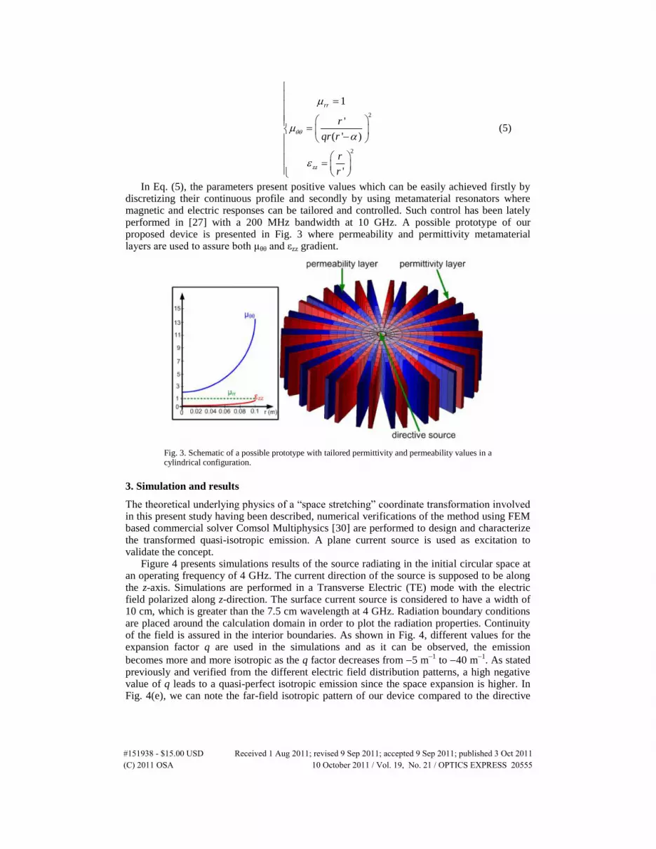
In Eq. (5), the parameters present positive values which can be easily achieved firstly by discretizing their continuous profile and secondly by using metamaterial resonators where magnetic and electric responses can be tailored and controlled. Such control has been lately performed in [27] with a 200 MHz bandwidth at 10 GHz. A possible prototype of our proposed device is presented in Fig. 3 where permeability and permittivity metamaterial layers are used to assure both μθθ and εzz gradient.
Fig. 3. Schematic of a possible prototype with tailored permittivity and permeability values in a cylindrical configuration.
3. Simulation and results
The theoretical underlying physics of a “space stretching” coordinate transformation involved in this present study having been described, numerical verifications of the method using FEM based commercial solver Comsol Multiphysics [30] are performed to design and characterize the transformed quasi-isotropic emission. A plane current source is used as excitation to validate the concept.
Figure 4 presents simulations results of the source radiating in the initial circular space at an operating frequency of 4 GHz. The current direction of the source is supposed to be along the z-axis. Simulations are performed in a Transverse Electric (TE) mode with the electric field polarized along z-direction. The surface current source is considered to have a width of 10 cm, which is greater than the 7.5 cm wavelength at 4 GHz. Radiation boundary conditions are placed around the calculation domain in order to plot the radiation properties. Continuity of the field is assured in the interior boundaries. As shown in Fig. 4, different values for the expansion factor q are used in the simulations and as it can be observed, the emission
becomes more and more isotropic as the q factor decreases from 5 m1
to 40 m1
. As stated previously and verified from the different electric field distribution patterns, a high negative value of q leads to a quasi-perfect isotropic emission since the space expansion is higher. In Fig. 4(e), we can note the far-field isotropic pattern of our device compared to the directive
#151938 - $15.00 USD Received 1 Aug 2011; revised 9 Sep 2011; accepted 9 Sep 2011; published 3 Oct 2011(C) 2011 OSA 10 October 2011 / Vol. 19, No. 21 / OPTICS EXPRESS 20555

source. Figure 4(f) gives an insight of the influence of the q parameter on the proposed coordinate transformation.
Fig. 4. Simulated electric field distribution for a TE wave polarization at 4 GHz: (a) current plane source used as excitation for the transformation. The current direction is perpendicular to the plane of the figure; [(b)-(d)] verification of the transformation for different values of
expansion factor q; (e) Far field radiation pattern of the emission with (q=40) and without transformation;(f) influence of the q parameter on the proposed coordinate transformation. The emitted radiation is more and more isotropic as q tends to high negative values.
4. Conclusion
In conclusion, using transformation optics, we have proposed a concept to manipulate electromagnetic waves and achieve a quasi-perfect isotropic emission from a directional source. The latter manipulation is enabled by using composite metamaterials corresponding to a space stretching around the source by coordinate transformation. Numerical verifications have been performed where the radiation of a plane source which is directive has been transformed into an isotropic emission by reducing the apparent size of this source. The proposed device can therefore be potentially useful in the reduction of an object’s Radar Cross Section (RCS).
#151938 - $15.00 USD Received 1 Aug 2011; revised 9 Sep 2011; accepted 9 Sep 2011; published 3 Oct 2011(C) 2011 OSA 10 October 2011 / Vol. 19, No. 21 / OPTICS EXPRESS 20556


