Embed Size (px)
Citation preview

Engineering
Technical Standard
TS 0371 - Arc Flash Hazard
Assessment and Design
Aspects
Version: 1.0
Date: 24 September 2020
Status: FINAL
Document ID: SAWS-ENG-0371
© 2020 SA Water Corporation. All rights reserved. This document may contain
confidential information of SA Water Corporation. Disclosure or dissemination to
unauthorised individuals is strictly prohibited. Uncontrolled when printed or
downloaded.

TS 0371 Arc Flash Hazard Assessment and Design Aspects SA Water - Technical Standard
Revision 1.0 - 24 September 2020 Document ID: SAWS-ENG-0371 Page 2 of 42
For Official Use Only Uncontrolled when printed or downloaded
Copyright
This Technical Standard remains intellectual property of the South Australian Water
Corporation. It is copyright and all rights are reserved by SA Water. No part may be
reproduced, copied or transmitted in any form or by any means without the express written
permission of SA Water.
The information contained in this Standard is strictly for the private use of the intended
recipient in relation to works or projects of SA Water.
This Standard has been prepared for SA Water’s own internal use and SA Water makes no
representation as to the quality, accuracy or suitability of the information for any other
purpose.
Application and Interpretation of this Document
It is the responsibility of the users of this Standard to ensure that the application of information
is appropriate and that any designs based on this Standard are fit for SA Water’s purposes
and comply with all relevant Australian Standards, Acts and Regulations.
Users of this Standard accept sole responsibility for interpretation and use of the information
contained in this Standard. Users should independently verify the accuracy, fitness for
purpose and application of information contained in this Standard.
Only the current revision of this Standard should be used which is available for download from
the SA Water website.
Significant/Major Changes Incorporated in This Edition
Nil.
This is the first issue of this Technical Standard.

TS 0371 Arc Flash Hazard Assessment and Design Aspects SA Water - Technical Standard
Revision 1.0 - 24 September 2020 Document ID: SAWS-ENG-0371 Page 3 of 42
For Official Use Only Uncontrolled when printed or downloaded
Document Controls
Revision History
Revision Date Author Comments
0.1 28/05/2019 J. Hamra DRAFT - New issue of Technical Standard
1.0 24/09/2020 J. Hamra First Issue
Template: Technical Standard Version 6.00, 10/05/2016
Approvers
Role Signature and Date
Principal Electrical Engineer
Justin Hamra
1 5 / 1 0 / 2 0 2 0
XS ig n e r 's N a m e
S ig n e d b y : H A 0 0 3 6 2 7
Manager Engineering Quality and Innovation
Matthew Davis
1 5 /1 0 /2 0 2 0
XS ig n e r ' s N a m e
S ig n e d b y : D A 0 0 3 6 8 1
Senior Manager Engineering
Richard Gray
1 6 /1 0 /2 0 2 0
X
S ig n e r 's N a m e
S ig n e d b y : G R 0 0 1 9 6 4
Reviewers
Role Name Revision Review Date
Senior Electrical Engineer Jonathan Nicholls 0.1 17/07/2020
Senior Electrical Engineer Stephen Dadswell 0.1 15/07/2020

TS 0371 Arc Flash Hazard Assessment and Design Aspects SA Water - Technical Standard
Revision 1.0 - 24 September 2020 Document ID: SAWS-ENG-0371 Page 4 of 42
For Official Use Only Uncontrolled when printed or downloaded
Contents
1 Introduction ........................................................................................................ 7
1.1 Purpose .......................................................................................................... 7
1.2 Acronyms, Abbreviations and Definitions ................................................... 7
1.3 References .................................................................................................... 8
1.3.1 Australian and International Standards .................................................. 8
1.3.2 SA Water and External Documents ........................................................ 9
2 Scope ............................................................................................................... 10
2.1 Approval to Deviate from This Standard ................................................... 10
3 Design Criteria ................................................................................................. 11
3.1 Arc Fault Verification Requirement ........................................................... 11
3.2 Design Expectations ................................................................................... 12
4 Methodology ................................................................................................... 13
4.1 General ........................................................................................................ 13
4.2 Calculation Method ................................................................................... 13
4.3 Collection of Power System Data .............................................................. 15
4.3.1 Generators .............................................................................................. 15
4.3.2 Transformers ............................................................................................ 15
4.3.3 Cables ..................................................................................................... 15
4.3.4 Protective Devices ................................................................................. 15
4.3.5 Switching Points ...................................................................................... 15
4.3.6 Loads ....................................................................................................... 16
4.4 Prepare Software Model of the Power System ......................................... 16
4.4.1 Determine the Power System Switching Scenarios .............................. 16
4.5 Calculate Maximum and Minimum Bolted Fault Currents ...................... 17
4.6 Calculate Arcing Current Using IEEE 1584 ................................................. 18
4.7 Determine the Arcing Duration ................................................................. 18
4.7.1 Forms of Segregation ............................................................................. 20
4.8 Calculate the Incident Energy and Arc Flash Boundary ......................... 22
4.9 Determine the Arc Flash Classification ...................................................... 23
4.9.1 Arc Classification Modifiers .................................................................... 23
5 Task-Specific PPE Selection ............................................................................ 25
5.1 Methodology .............................................................................................. 25
5.2 Activity Definitions and Explanations ........................................................ 26
5.2.1 Operating Controls Definition ................................................................ 26
5.2.2 Operating Controls Explanation............................................................ 27
5.2.3 Visual Inspection Definition .................................................................... 27
5.2.4 Visual Inspection Explanation ................................................................ 27
5.2.5 Electrical Work Definition ....................................................................... 28
5.2.6 Electrical Work Explanation ................................................................... 28
5.2.7 Switching Definition ................................................................................ 28

TS 0371 Arc Flash Hazard Assessment and Design Aspects SA Water - Technical Standard
Revision 1.0 - 24 September 2020 Document ID: SAWS-ENG-0371 Page 5 of 42
For Official Use Only Uncontrolled when printed or downloaded
5.2.8 Switching Explanation ............................................................................ 28
5.2.9 Racking Definition .................................................................................. 28
5.2.10 Racking Explanation .............................................................................. 28
6 Arc Flash Cautionary Labels ........................................................................... 30
7 Assessment Outcome and Control ................................................................ 34
8 Switchboard Design and Configuration Principles ....................................... 35
8.1 LV Power Reticulation Philosophy .............................................................. 35
8.2 General Design Requirements for Switchboards ..................................... 36
8.3 Main Switchboards ..................................................................................... 36
8.4 Distribution Switchboards ........................................................................... 37
8.5 Motor Control Centres ................................................................................ 37
8.6 Distribution Boards or Sections Rated ≤ 250A ........................................... 37
8.7 Arc Detection Systems................................................................................ 38
Appendix A – Excerpts from NFPA 70E .................................................................. 39
A1 Table 130.5 (C) ............................................................................................ 39
A2 Table 130.7 (C) ............................................................................................ 41
List of figures
Figure 4-1 - High-level flowchart for completing an Arc Flash Study .................... 14
Figure 4-2 - Typical LV Fuse Curve ........................................................................... 17
Figure 4-3 - Typical LV Circuit Breaker Curve .......................................................... 17
Figure 4-4 - Arc Fault Locations vs. Protection Device Selection .......................... 19
Figure 4-5 - Arc Fault Propagation for Form 1 Switchboards ................................. 20
Figure 4-6 - Arc Fault Propagation for Form 2a (left) and Form 2b (right) Switchboards
...................................................................................................................... 20
Figure 4-7 - Arc Fault Propagation for Form 3a (left) and Form 3b (right) Switchboards
...................................................................................................................... 21
Figure 4-8 - Arc fault propagation for Form 3a (left) and Form 3b (right) switchboards
...................................................................................................................... 21
Figure 4-9 - Arc Fault Propagation for Form 4a (left) and Form 4b (right) Switchboards
...................................................................................................................... 22
Figure 6-1 - Arc Flash ‘Warning’ Label Example ..................................................... 31
Figure 6-2 - Arc Flash ‘Danger’ Label Example ...................................................... 31
Figure 6-3 - General PPE Information Label Example ............................................ 32
Figure 6-4 - Example Label to be Used Where Space is Limited ........................... 33
Figure 8-1 - LV Power Reticulation Philosophy ........................................................ 35

TS 0371 Arc Flash Hazard Assessment and Design Aspects SA Water - Technical Standard
Revision 1.0 - 24 September 2020 Document ID: SAWS-ENG-0371 Page 6 of 42
For Official Use Only Uncontrolled when printed or downloaded
List of tables
Table 1-1 - Acronyms, Abbreviations and Definitions .............................................. 7
Table 1-2 - Australian and International Standards ................................................. 8
Table 1-3 - SA Water and External Documents ........................................................ 9
Table 4-1 - SA Water Arc Flash Classifications ........................................................ 23
Table 5-1 - NFPA 70(E) Table 130.5(C) summary .................................................... 25
Table 5-2 – Task-Specific Basis of PPE ...................................................................... 26
Table 5-3 – Task Specific PPE Category Groups ..................................................... 26
Table 6-1 - Arc Flash Cautionary Label Information............................................... 30
Table 8-1 - Switchboard Configuration Approach ................................................ 35
Table 8-2 - NFPA 70E Table 130.7 (C)....................................................................... 41

TS 0371 Arc Flash Hazard Assessment and Design Aspects SA Water - Technical Standard
Revision 1.0 - 24 September 2020 Document ID: SAWS-ENG-0371 Page 7 of 42
For Official Use Only Uncontrolled when printed or downloaded
1 Introduction Arc Flash is a destructive and potentially life-threatening type of electrical fault, caused by
unintended or accidental connection of energized conductors and /or earth. The result is an
explosive release of energy, which is sufficient to melt conductors and change the
surrounding air from gas to conductive plasma.
1.1 Purpose
The purpose of this Technical Standard is to:
• Detail a basic understanding of arc flash terminology;
• Provide an effective arc flash classification process;
• Recommend industrial practices to minimize the risk of arc flash hazards;
• Provide a guide for the appropriate selection of personal protective equipment against
the activity being undertaken;
• Outline arc flash cautionary label specifications and application;
• Provide principles on switchboard design and configuration; and
• Detail arc flash assessment study report requirements.
1.2 Acronyms, Abbreviations and Definitions
The following acronyms, abbreviations and definitions in Table 1-1 are used in this document:
Table 1-1 - Acronyms, Abbreviations and Definitions
Term Description
AC Alternating Current
Arc Flash Boundary
The arc flash boundary is the distance from live parts outside of which a person
without Arc Rated PPE cannot receive anything greater than a second-degree
burn. Outside of the boundary the assessed energy levels are below 1.2
cal/cm2. Within the boundary the energy levels are 1.2 cal/cm2 or above.
ATPV
Arc Thermal Performance Value is the maximum incident energy on a fabric or
material that will result in sufficient heat transfer through the fabric or material to
cause the onset of anything more than a second degree burn that occurs for
energy levels 1.2 cal/cm2 or above.
Arc Rated (AR) PPE
Clothing specified with an ATPV (Arc Thermal Performance Value) expressed in
calories per centimetre squared. AR PPE with an ATPV has been specifically
tested to provide protection against electrical arcing faults.
Arcing Fault Current A fault current flowing through an electrical arc plasma. Also referred to as arc
fault current or arc current.
Arc Flash Hazard A dangerous condition associated with the possible release of energy caused
by an electric arc.
AREP Auxiliary Winding Regulation Excitation Principle (Generator type)
Backup Protection
Should primary protection fail to operate, backup protection is the next
protection relay and circuit breaker combination to detect and clear an
electrical fault. For an arcing fault occurring on a switchboard’s main incomer,
this is typically the first upstream feeder protection.
Bolted Fault Current An expected fault current flowing where there is close to zero resistance or
impedance in the fault path.
Contributing Branch A connection to the switchboard through which a portion of the total arcing
fault current originates.

TS 0371 Arc Flash Hazard Assessment and Design Aspects SA Water - Technical Standard
Revision 1.0 - 24 September 2020 Document ID: SAWS-ENG-0371 Page 8 of 42
For Official Use Only Uncontrolled when printed or downloaded
Term Description
Electrical Shock Physical stimulation that occurs when electrical current passes through the
body.
Fault Current The theoretical amount of current delivered at a point on the system during a
short-circuit condition.
Flash-protection
Boundary
An approach limit at a distance from live parts that are uninsulated or exposed
outside of which a person cannot receive anything greater than a second
degree burn during an electrical arc event. Also referred to as ‘closest
approach distance’.
Hazard Risk Category
A rating category number used by NFPA 70E to classify the expected incident
energy that may exist within the specified working distance, due to an arcing
fault.
HV High Voltage
Incident Energy
The amount of energy impressed on a surface, a certain distance from the
source, during an electrical arc event. Incident energy is measured in either
calories per centimetre squared (cal/cm2) or joules per centimetre squared
(J/cm2).
Qualified Person
One who has demonstrated skills and knowledge related to the construction
and operation of electrical equipment and installations and has received safety
training to identify the hazards and reduce the associated risk.
PPE Personal protective equipment.
Primary Protection The fastest protection relay and/or circuit breaker combination to detect and
clear an electrical fault.
Working Distance The dimension between the potential arc point and the head and body of the
worker positioned to perform the assigned task. (455mm – 18 inches)
1.3 References
1.3.1 Australian and International Standards
Any Standard referred to in this Technical Standard shall be of the latest edition (including
amendments) of that Standard at the date of calling of tenders.
Table 1-2 identifies Australian and International standards and other similar documents
referenced in this document:
Table 1-2 - Australian and International Standards
Number Title
AS 2067:2016 Substations and high voltage installations exceeding 1kVac
AS/NZS 3000:2018 Wiring Rules
AS/NZS 3008.1.1 Electrical Installations – Selection of cables Part 1.1: Cables for alternating
voltages up to and including 0.6/1 kV – Typical Australian installation
conditions
AS/NZS 3439.1:2002 Low Voltage Switchgear and Control gear Assemblies – Part 1: Type- tested
and partially type-tested assemblies
AS/NZS 60076.5 Power Transformers Part5: Ability to withstand short circuit
AS/NZS 61439.1:2016 Low Voltage Switchgear and Controlgear Assemblies – General Rules
AS/NZS 61439.2:2016 Low Voltage Switchgear and Controlgear Assemblies – Power switchgear
and controlgear assemblies

TS 0371 Arc Flash Hazard Assessment and Design Aspects SA Water - Technical Standard
Revision 1.0 - 24 September 2020 Document ID: SAWS-ENG-0371 Page 9 of 42
For Official Use Only Uncontrolled when printed or downloaded
Number Title
AS 62271.200:2005
High Voltage Switchgear and Control gear – AC Metal-enclosed
Switchgear and Control gear for Rated Voltages Above 1kV and up to and
Including 52kV
IEC 60909-0:2016 Short-circuit currents in three-phase AC systems – Part 0: Calculation of
currents
IEC TR 61641:2014 Enclosed low-voltage switchgear and controlgear assemblies - Guide for
testing under conditions of arcing due to internal fault
IEEE 242:2001 Protection and Coordination of Industrial and Commercial Power systems
IEEE 551 – 2006 Recommended Practise for calculating AC Short circuit currents in Industrial
and Commercial Power Systems
IEEE 141:1993 IEEE Recommended Practice for Electric Power Distribution in Industrial
Plants
IEEE 1584 - 2013 Guide for Performing Arc-flash Hazard Calculations
1.3.2 SA Water and External Documents
Table 1-3 identifies the SA Water standards and other similar documents referenced in this
document:
Table 1-3 - SA Water and External Documents
Number Title
- Australian Electrical Arc Flash Hazard Management Guideline- March 2019
ENA NENS 09 – 2014 Energy Networks Australia – National Guideline for the Selection, Use and
Maintenance of Personal Protective Equipment for Electrical Arc Hazards
NFPA 70E – 2018 Standard for Electrical Safety in the Workplace

TS 0371 Arc Flash Hazard Assessment and Design Aspects SA Water - Technical Standard
Revision 1.0 - 24 September 2020 Document ID: SAWS-ENG-0371 Page 10 of 42
For Official Use Only Uncontrolled when printed or downloaded
2 Scope This Technical Standard covers aspects of the general requirements for the design, review
and maintenance of SA Water’s state-wide electrical power assets.
It defines the accepted SA Water practises to perform arc flash hazard calculations and
assessment for HV and LV switchgear assemblies in AC power systems with faults involving
three phases. This includes:
• HV and LV switchboards;
• Power equipment switchgear;
• Power factor correction equipment;
• Motor starters and variable speed drives;
• Harmonic filters; and
• Any other cubicle containing HV or LV power equipment.
The arc flash hazard assessment methodology detailed in this document shall be undertaken
during both the engineering design stage and for evaluation of existing equipment. This
Technical Standard applies to both new installations and for any changes to an installation
that affect the arc flash incident energy levels of existing switchboards or electrical power
equipment, or for the review of such equipment.
The main aim of this Technical Standard is to provide electrical systems that exhibit safe levels
of arc flash through reasonable application of these principles.
Control, instrumentation and SCADA cubicles do not require arc flash analysis or
categorisation.
This Technical Standard has been developed to assist in the design, maintenance, installation,
and management of this infrastructure. It should be read in conjunction with the associated
project specification, drawings and any documents annexed to the project specification. The
provisions of this Technical Standard shall apply unless they are specifically deleted or
amended in the project specification or drawings, which shall then take precedence.
The currency of this document should be checked prior to use.
2.1 Approval to Deviate from This Standard
Approval may ultimately be granted by the SA Water Principal Electrical Engineer, to deviate
from the requirements as stipulated in this Standard, if the functional requirements (e.g. asset
life, ease of use, maintainability, etc.) for the asset differs from those stated in the Standard,
but is assessed as still being acceptable. Any approval to deviate from the stated
requirements of this Standard shall not be seen as creating a precedent for future like
projects. Any request to deviate from this Standard must be carried out on a project by
project basis, where each alternative proposal will be individually assessed on its own merit.
No action should be taken until a written reply to such a request has been received.
SA Water encourages and welcomes suggestions as to the improvement of this standard for
future releases. These suggestions should be passed through to the SA Water Principal
Electrical Engineer.

TS 0371 Arc Flash Hazard Assessment and Design Aspects SA Water - Technical Standard
Revision 1.0 - 24 September 2020 Document ID: SAWS-ENG-0371 Page 11 of 42
For Official Use Only Uncontrolled when printed or downloaded
3 Design Criteria The design criteria must be ascertained and agreed with SA Water or its representative during
all stages of investigation, concept design and detailed design in order to achieve a value-
for-money installation that is fit for purpose and with minimum or negligible risks to SA Water.
The design criteria should consider the following aspects:
1. Safety Considerations
The installations are to be designed with the safety and welfare of construction, operation
and maintenance personnel and the general public in mind, complying with statutory
regulations. Wherever possible, electrical equipment and wiring should not be located in
areas classified as hazardous.
2. Life Cycle Costs
Designs should be innovative and incorporate the appropriate techniques and technology,
in conjunction with the selection of appropriate equipment, to minimise the life cycle costs,
while satisfying operational functionality and process risk management and maintenance
requirements. Energy consumption must be given particular attention in this respect.
3. Security of Operation
Designs should take into account the failure of a single item of equipment or a fault in a
particular area of an installation is confined to the associated part of the installation and
does not affect the continuous operation of the remaining parts of the installation, where
possible.
4. Reliability
The installations are to be designed to minimise the likelihood of a failure, taking into
consideration the electricity supply characteristics, ambient conditions, load characteristics
and operation and maintenance requirements.
5. Upgradability
The installations are to be designed to facilitate future upgrades, where applicable.
6. Interchangeability
The installations are to be designed to maximise the interchangeability of components and
assemblies as far as practical to improve flexibility and reduce the spare parts inventory.
7. Operation, Maintenance and Fault-Finding Facilities
The installations are to be provided with suitable and adequate facilities to allow ease of
operation, maintenance and fault finding.
8. Environmental Considerations
The installations are to be designed and suitable equipment selected to avoid or minimise
unacceptable impact on the environment, as far as possible.
3.1 Arc Fault Verification Requirement
All low voltage switchboards shall be designed to provide personal protection in the event of
an internal arcing fault.
The assembly shall limit the damage of the switchboard to the section affected by the fault,
thus allowing the unaffected part to be put back into service.
With regards to safety of personnel, assemblies rated above 250A per phase shall be verified
with respect to their ability to withstand internal arcing. The manufacturer shall confirm the
successful assessment in accordance with either Appendix ZD of AS 61439.1: 2016 or as per
the criteria specified in IEC TR 61641, Criteria 1 to 7. Test reports or certificates issued by
certified independent testing laboratories should be made available in the predesign stage.

TS 0371 Arc Flash Hazard Assessment and Design Aspects SA Water - Technical Standard
Revision 1.0 - 24 September 2020 Document ID: SAWS-ENG-0371 Page 12 of 42
For Official Use Only Uncontrolled when printed or downloaded
The prospective fault currents shall be used for designs and are to be based on the worst-
case operating scenarios, with a contribution that can be expected from any connected
load.
3.2 Design Expectations
As part of a detailed design, the Designer is expected to undertake the following design
activities as a minimum:
1. Site investigations to gather all required information and data to develop a site power
systems model in order to undertake arc flash assessment studies.
a. Where existing model data exists, it will be provided by SA Water, however, it is the
responsibility of the Designer to confirm the accuracy of the model prior to use.
b. Where model data does not exist, the Designer shall seek all data and develop a
new model.
2. Perform and submit an arc flash assessment report in accordance with this Technical
Standard, including calculations, arc flash category ratings, and any required
protection setting changes (i.e. upstream) to reduce the arc flash risk to as low as is
reasonably practicable.
3. Submit native data files of the power systems model developed and arc flash
calculations carried out for future use (e.g. SKM PowerTools, PowerCAD, etc.) to SA
Water as part of the project completion documentation. This may include data files in
Excel or CAD file format. Drawings of single line diagrams should include data such as
cable sizes and lengths, protection relay model numbers, circuit breaker
models/types/basic settings and basic transformer and generator parameters. Cable
schedules, protection relay settings and protection reports should be provided in an
easily editable format, such as Excel.
4. For brownfield sites, if it is found during the detailed design stage that the arc flash or
reticulation philosophy requirements cannot be achieved, the Designer shall engage
with the Superintendent’s Representative (SA Water’s Representative) to discuss the
options available and agree on an approach (i.e. to reduce the arc flash risk), within
the scope of the upgrade project.

TS 0371 Arc Flash Hazard Assessment and Design Aspects SA Water - Technical Standard
Revision 1.0 - 24 September 2020 Document ID: SAWS-ENG-0371 Page 13 of 42
For Official Use Only Uncontrolled when printed or downloaded
4 Methodology This section outlines the preferred methodology for the calculation of arc flash parameters for
SA Water existing and proposed assets.
4.1 General
Although consideration of arc faults is a requirement of AS/NZ 3000, there is currently no clear
regulatory framework for the calculation and assessment of arc fault hazards in Australia,
other than the recommended guidelines provided by Energy Networks Australia – NENS 09 -
2014 National Guideline for the Selection, Use and Maintenance of Personal Protective
Equipment for Electrical Arc Hazards.
Current accepted practice in Australia is to apply the internationally accepted calculation
methods provided in IEEE-1584 (Guide for Performing Arc Flash Hazard Calculations) to
determine arc flash incident energy levels.
Once the incident energy levels are established, equipment can be given an arc flash
hazard classification. Classifications have been derived from standards such as the American
National Fire Protection Association standard NFPA 70E – Standard for Electrical Safety in the
Workplace.
It is important to note that incident energy calculations and the resultant arc flash
classification represents the worst-case situation. It represents the hazard present with
equipment doors or panels open, and busbars or conductors exposed to personnel. It does
not consider the reduction of risk when panel doors/panels are securely closed, nor of arc-
rated switchgear or switchboards where the arc blast is either contained or safely re-
directed. The impact of these, and other arc mitigation measures, on equipment classification
should be carefully assessed on an individual basis.
Personal Protective Equipment (PPE) requirements in relation to arc flash have been
determined from both NFPA 70E and NENS 09 standards and have been considered as
industry norms in the development of this Technical Standard.
4.2 Calculation Method
Calculation of the arc flash incident energy at each location in an electrical network requires
detailed analysis and calculation of short-circuit fault levels throughout the network. Although
this may be determined by hand for simple systems, for more complex systems it is common
practice to calculate through electrical modelling software. For complex systems with
multiple operating scenarios, many electrical modelling software packages allow the IEEE-
1584 calculations to be performed in software. There are a number of modelling software
packages that are used to create power system models and perform arc flash hazard
assessments. (e.g. SKM Power Tools for Windows (PTW), Electrical Transient and Analysis
Program (ETAP), DIgSILENT, PowerCAD and EasyPower.)
A high-level flowchart outlining the steps to be completed when performing an arc flash
study is provided in Figure 4-1.

TS 0371 Arc Flash Hazard Assessment and Design Aspects SA Water - Technical Standard
Revision 1.0 - 24 September 2020 Document ID: SAWS-ENG-0371 Page 14 of 42
For Official Use Only Uncontrolled when printed or downloaded
Figure 4-1 - High-level flowchart for completing an Arc Flash Study
Collect Power System Data
Prepare a software model
of the power system
Determine the system
modes of operation
Calculate the maximum and
minimum bolted fault levels for
various network operating
scenarios using IEC-60909
Convert bolted fault current to the arcing fault current using
IEEE-1584
Study protective device
characteristics and
determine arc duration
Optimization of protection devices and
engineering controls
Calculate incident energy and arc flash boundary
distance
(Additional) Arc Flash
Mitigation Required?
Yes No Determine PPE
requirements and Arc
Flash cautionary labels

TS 0371 Arc Flash Hazard Assessment and Design Aspects SA Water - Technical Standard
Revision 1.0 - 24 September 2020 Document ID: SAWS-ENG-0371 Page 15 of 42
For Official Use Only Uncontrolled when printed or downloaded
4.3 Collection of Power System Data
The available fault currents at different locations in the electrical network are dependent on
the capability of the main power supply to provide and sustain a short circuit. The fault
current contribution should be confirmed with the power supply utility under the following
conditions:
1. Maximum three phase symmetrical fault level and corresponding X/R ratio; and
2. Minimum three phase symmetrical fault level and corresponding X/R ratio.
4.3.1 Generators
For power systems fed via local generation permanently installed at a site, the following data
should be collected:
1. Alternator kVA rating and power factor values from the nameplate;
2. Alternator impedance characteristics; and
3. Details of excitation system and field forcing; if applicable (e.g. AREP).
4.3.2 Transformers
The following information should be collected for transformers:
1. Primary and secondary voltage ratings;
2. Vector group;
3. kVA rating;
4. Tap position; and
5. Transformer impedance (%Z) and X/R ratio.
In the absence of impedance details, typical values per AS/NZS 60076.5 may be used.
4.3.3 Cables
In general, the data for the following cables should be collected:
1. Main cable from the utility connection up to site’s main switchboard;
2. Cables used to provide alternate supply sources; e.g. generator cables; and
3. Cables supplying sub-distribution boards feeding significant motor loads.
Once the data for the power cables has been collected, the relevant electrical parameters
(cable impedance) should be obtained from the cable manufacturer’s catalogue or
standard cable parameters listed under AS/NZS 3008.1.1.
4.3.4 Protective Devices
The time taken by the protective device to interrupt an arcing fault on the downstream
circuit is a critical factor in incident energy calculations. The protection settings and trip
characteristics of the primary, backup and largest outgoing feeder protection overcurrent
device should be obtained from design documents for new installations and for existing
installations, data from site and protection relay datasheets.
4.3.5 Switching Points
All switching points in the electrical system which could affect the fault current levels should
be identified by investigating the switchboard configuration and single line drawings. This
includes HV and LV switching points such as:

TS 0371 Arc Flash Hazard Assessment and Design Aspects SA Water - Technical Standard
Revision 1.0 - 24 September 2020 Document ID: SAWS-ENG-0371 Page 16 of 42
For Official Use Only Uncontrolled when printed or downloaded
1. Secondary selective changeover arrangements;
2. Ring main switches; and
3. Contingency and backup supply arrangements; etc.
4.3.6 Loads
Data related to all regenerative power system loads should be collected. This includes:
1. Large (>37kW rated) direct on-line and bypass soft-starter connected induction motors;
and
2. Large motors connected through four quadrant (regenerative type) variable speed
drives.
It is noted that although the sub-transient fault contribution from motors generally decays
quite rapidly (over a few electrical cycles), the resulting fault contribution may have a
significant impact on the available incident energy at the electrical switchboard.
The following information should be collected for the motors:
1. Motor kW rating;
2. Motor power factor; and
3. Starting (locked rotor) current.
4.4 Prepare Software Model of the Power System
The power system simulation model should be prepared using an industry-wide accepted
power system simulation software (such as ETAP, SKM PTW, DIgSILENT, EasyPower, PowerCAD,
etc). The electrical power system simulation software should be compliant with the latest
applicable standards for short circuit and incident energy calculations.
The model should include sufficient detail to allow for simulations under maximum and
minimum fault current scenarios.
As a minimum, the power system simulation model should include the components of the
electrical system from the utility point of supply to the busbars of the switchboards under
assessment. Any additional sources of fault current (large induction motors, supplementary /
backup generation) should also be included in the simulation model. Any assumptions for the
modelling data should be clearly documented and justified in the arc flash assessment
report.
4.4.1 Determine the Power System Switching Scenarios
The switching scenarios (operating modes) of the switchboard may significantly impact the
results of the arc flash calculations. For radial (single feed) switchboards only one switching
scenario needs to be considered, however, for complicated supply arrangements, several
operating modes may be possible; this includes:
1. Sites with more than one electrical utility supply;
2. Secondary selective switchboards (Main-tie-main arrangements);
3. Embedded generation that may be operated islanded from the electrical utility;
4. Switchboards with supplementary / emergency generation; etc.
The operating modes relevant to the power system or switchboard under assessment should
be mutually agreed between the asset owner and Power Systems Engineer at the outset of
the study.

TS 0371 Arc Flash Hazard Assessment and Design Aspects SA Water - Technical Standard
Revision 1.0 - 24 September 2020 Document ID: SAWS-ENG-0371 Page 17 of 42
For Official Use Only Uncontrolled when printed or downloaded
4.5 Calculate Maximum and Minimum Bolted Fault Currents
In order to identify the worst-case incident energy level at the electrical equipment,
calculations for fault currents under both maximum and minimum fault currents are
necessary, according to IEC 60909. This is because the overcurrent protection devices
employ inverse time protection characteristics, which can result in a disproportionate
increase in the fault clearing times (and hence the arcing duration) with a relatively small
decrease in the fault current.
Some situations where this can occur are shown in the figures below:
Figure 4-2 - Typical LV Fuse Curve
The fuse curve is so steep that an 800 A fault current takes ten times longer to clear, as
compared to a 1,600A fault current.
Figure 4-3 - Typical LV Circuit Breaker Curve
A small reduction in fault current causes fault to be cleared on LTPU in 5 s rather than STPU in
250ms.

TS 0371 Arc Flash Hazard Assessment and Design Aspects SA Water - Technical Standard
Revision 1.0 - 24 September 2020 Document ID: SAWS-ENG-0371 Page 18 of 42
For Official Use Only Uncontrolled when printed or downloaded
The fault current calculations should therefore consider:
1. All possible operating scenarios of the system;
2. Maximum and minimum pre-fault voltage factors (c-factors) as per IEC 60909; and
3. Fault current levels with and without motor contributions.
4.6 Calculate Arcing Current Using IEEE 1584
Currents associated with electrical arcing faults are always less than the prospective three
phase bolted fault current level of the system due to the arcing resistance.
For electrical installations between 0.208kV and 15kV, IEEE 1584 provides equations to
estimate the arcing current, depending upon several factors, including:
1. The prospective three phase bolted fault current.
2. The nominal voltage of the equipment.
3. The bus-gap (i.e. the gap between adjacent phases at a possible arcing point).
4. An adjustment factor “K”, which depends upon the location of arcing (enclosed vs.
unenclosed space).
For accurate arcing current calculations, the bus gap should be obtained from the
switchboard manufacturer, however, in the absence of manufacturer’s information, typical
bus gaps based on IEEE 1584 may be employed.
4.7 Determine the Arcing Duration
The duration of the arcing current used for incident energy calculations will depend on a
number of factors, including:
1. The tripping characteristics of the protective device that would interrupt the fault.
2. The location of the fault. In general, there are three possible locations on a switchboard
at which an arcing fault could occur, as shown in Figure 4-4 - Arc Fault Locations vs.
Protection Device Selection.

TS 0371 Arc Flash Hazard Assessment and Design Aspects SA Water - Technical Standard
Revision 1.0 - 24 September 2020 Document ID: SAWS-ENG-0371 Page 19 of 42
For Official Use Only Uncontrolled when printed or downloaded
Figure 4-4 - Arc Fault Locations vs. Protection Device Selection
It can be seen from the above figure that faults at the three locations will have different
arcing times associated with them. For faults at location C (downstream of a feeder circuit),
the associated trip device would be the outgoing feeder circuit breaker. Assuming that the
protection system is well-coordinated, it is expected that the protection settings of the
outgoing feeder circuit breaker will be set to more sensitive levels compared to the incoming
and upstream (remote) breaker settings. The incident energy associated with a fault at
location C would generally be less than locations B and A.
Similarly, the incident energy at location A is the most severe, as the expected tripping time
of the remote upstream protection is expected to be the highest. In most cases, the upstream
circuit breaker will be on the primary (HV) side of the distribution transformer feeding the
switchboard under assessment.

TS 0371 Arc Flash Hazard Assessment and Design Aspects SA Water - Technical Standard
Revision 1.0 - 24 September 2020 Document ID: SAWS-ENG-0371 Page 20 of 42
For Official Use Only Uncontrolled when printed or downloaded
4.7.1 Forms of Segregation
The form of segregation of the switchboard under assessment - AS/NZS 3439.1 and AS/NZS
61439.2 outline the forms of segregation for switchgear assemblies. Primarily, these forms
describe the varying configurations of physical barriers used in the separation of functional
units of switchgear from each other.
For existing switchgear assemblies, the identification of arc-fault clearing location is tied to
the issue of arc propagation. Although the physical barriers used for segregation in
switchgear assemblies are not guaranteed to impede arc propagation through the different
functional units (unless proven by verification tests), it is reasonable to assume that
segregation assemblies would have some impact on the selection of the protective device
for determining the arcing duration.
The figures given below illustrate the possible impact of the switchboard’s form of segregation
on the arc flash propagation through the functional units.
Figure 4-5 - Arc Fault Propagation for Form 1 Switchboards
Figure 4-6 - Arc Fault Propagation for Form 2a (left) and Form 2b (right) Switchboards

TS 0371 Arc Flash Hazard Assessment and Design Aspects SA Water - Technical Standard
Revision 1.0 - 24 September 2020 Document ID: SAWS-ENG-0371 Page 21 of 42
For Official Use Only Uncontrolled when printed or downloaded
Figure 4-7 - Arc Fault Propagation for Form 3a (left) and Form 3b (right) Switchboards
Figure 4-8 - Arc fault propagation for Form 3a (left) and Form 3b (right) switchboards

TS 0371 Arc Flash Hazard Assessment and Design Aspects SA Water - Technical Standard
Revision 1.0 - 24 September 2020 Document ID: SAWS-ENG-0371 Page 22 of 42
For Official Use Only Uncontrolled when printed or downloaded
Figure 4-9 - Arc Fault Propagation for Form 4a (left) and Form 4b (right) Switchboards
Based on the above basic principles, if the switchgear enclosure being assessed contains a
protective device with the line side terminals that are not fully segregated, then an arcing
fault can only be cleared by the next upstream device.
In general, SA Water utilizes low voltage switchboards of form 3b segregation; therefore, the
arcing times should be based on the protection characteristics of the device upstream of the
switchboard.
4.8 Calculate the Incident Energy and Arc Flash Boundary
The first step in the calculation of incident energy is the determination of working distance. As
defined by IEEE 1584, the working distance is the separation distance between the closest
possible arcing point and the body of the person conducting work. Generalized working
distances based on the voltage class of the equipment are provided in IEEE 1584 and should
be used for the assessment, where physical inspection is not possible.
Once the working distance associated with the switchboard under investigation has been
identified, empirical equations provided in IEEE 1584 should be used to estimate incident
energy levels. The basic inputs to the calculation are as follows:
1. The equipment operating voltage;
2. Working distance associated with the operating voltage;
3. Calculated arcing current (maximum and minimum); and
4. Arcing time (i.e. action time of the associated protective device).
IEEE 1584 also provides the empirical formulae to determine the distance from the
switchboard at which the incident energy is not considered as a major hazard to
unprotected personnel. This distance is termed the ‘Arc Flash Boundary’. Based on IEEE 1584,
the incident energy at the arc-flash boundary equals 1.2 Cal/cm2, which relates to the
threshold for a second-degree burn.

TS 0371 Arc Flash Hazard Assessment and Design Aspects SA Water - Technical Standard
Revision 1.0 - 24 September 2020 Document ID: SAWS-ENG-0371 Page 23 of 42
For Official Use Only Uncontrolled when printed or downloaded
4.9 Determine the Arc Flash Classification
When the worst-case arc flash incident energy has been determined, each piece of
equipment can be given the appropriate arc flash classification.
The arc flash classification adopted by SA Water closely relates to table 130.7(C) of NFPA 70E
(2018) reproduced in Appendix A.
Table 4-1 - SA Water Arc Flash Classifications
Category Incident Energy
CATEGORY 0 Incident Energy below 1.2 cal/cm2
CATEGORY 1 Incident Energy 1.2 to < 4 cal/cm2
CATEGORY 2 Incident Energy 4 to < 8 cal/cm2
CATEGORY 3 Incident Energy 8 to < 25 cal/cm2
CATEGORY 4 Incident Energy 25 to < 40 cal/cm2
UNACCEPTABLE DANGER Incident Energy above 40 cal/cm2
It is noted that the arc flash classification levels listed in Table 4-1, and the associated PPE
requirements, assume that the working personnel will be directly exposed to an arcing fault
i.e. switchboard panel doors open at the time of fault or incorrectly fastened or forced open
by the internal pressure developed by the arc.
4.9.1 Arc Classification Modifiers
Arc flash classification based on incident energy calculations does not consider the risk
reduction introduced through various mitigation measures.
4.9.1.1 Arc-rated switchgear
Modern HV and LV switchboards can be designed to withstand an internal arc fault blast. This
equipment is specially verified and certified so that any escaping arc fault energy is
contained or redirected, and injury to personnel is limited to less than second degree burns.
Switchboards intended to provide increased security against the occurrence or the effects of
internal arcing faults have been designed and tested according to the methods outlined in
AS/NZS 3439.1 Appendix ZC and ZD or AS/NZS 61439.1 Appendix ZC and ZD. This is an optional
switchboard specification, and AS/NZS 3439.1 or AS/NZS 61439.1 type-test certification does
not automatically infer that the equipment has been tested to contain and limit exposure to
an arc fault. It must be specifically requested from the switchboard manufacturer before
design and construction.
According to NFPA 70E guidelines, arc-rated and tested equipment is equivalent to “Below
Category 1” arc flash classification. Note that this applies only when all doors and panels are
closed. With doors/panels open, the classification reverts to the IEEE incident energy derived
classification.
4.9.1.2 Optimized protection settings
Arc fault incident energy can be greatly reduced by selecting appropriate protection
devices and protection settings. Setting optimization is achieved by reducing the protection
settings as much as possible, while maintaining time and current discrimination between
protective devices in the electrical system.

TS 0371 Arc Flash Hazard Assessment and Design Aspects SA Water - Technical Standard
Revision 1.0 - 24 September 2020 Document ID: SAWS-ENG-0371 Page 24 of 42
For Official Use Only Uncontrolled when printed or downloaded
4.9.1.3 Task specific classification
Further to the above, the arc fault exposure risk may vary depending on the particular task
performed. For example, circuit breaker switching is considered a lower risk task than racking
out a circuit breaker. NFPA 70E Table 130.7(C) (15) (A) (a) provides guidance with examples
of electrical operation and maintenance activities and the impact on PPE requirements.
4.9.1.4 Maintenance and condition
The risk of arc fault occurrence and effectiveness of any mitigation measures is highly
dependent on equipment maintenance and condition.
Existing equipment will require a physical inspection and assessment of condition when
considering its arc fault classification.
4.9.1.5 Arc flash detection
Optical arc fault detection devices help to detect and assist in the speed of operation of
protective devices under arc fault conditions. Optical arc fault detection devices can be
used to detect the flash of light emitted early in the arc flash event and trigger the operation
of circuit breakers well in advance of the normal trip caused by arc fault current.
The operating times of arc-detection devices can be used as part of the incident energy
calculation, or the presence of the device can be applied as a modifier to the arc flash
classification.
4.9.1.6 Arc quenching
Devices can be used in conjunction with an arc flash detection system to clear an arcing
fault within a few milliseconds. An arc flash quenching device extinguishes an arc much
faster than a circuit breaker by applying a rapid bolted short circuit between phases or
between phases and earth close to the arcing fault location. This causes a collapse in the arc
voltage, rapidly extinguishing the arc. The bolted short circuit current flows through the
quenching device until it is interrupted by the primary protection device.
4.9.1.7 Other mitigation measures
Various other technologies are available, such as zone selective interlocking and bus
differential protection schemes, which can be applied to reduce the incident energy levels.
Zone selective interlocking provides protection between backup, primary and outgoing
feeder protection that uses blocking signals between the devices, allowing protection to trip
more quickly without a protection grading trade-off. A bus differential protection scheme,
when implemented, provides a faster tripping time during a fault condition, within a given
zone of protection.
Where the mitigation methods described above do not reduce incident energy levels to
Category 1 or below, then remote switching of HV and LV circuit breakers and feeders shall
be implemented as an additional feature. This reduces exposure levels by allowing workers to
undertake switching operation (remote tripping, closing or spring charging) at a safe
distance from the switchboard. A label shall be installed adjacent to the device to indicate
remote switching is available.

TS 0371 Arc Flash Hazard Assessment and Design Aspects SA Water - Technical Standard
Revision 1.0 - 24 September 2020 Document ID: SAWS-ENG-0371 Page 25 of 42
For Official Use Only Uncontrolled when printed or downloaded
5 Task-Specific PPE Selection
5.1 Methodology
Given that most of the switchboards currently installed at SA Water facilities do not include
special means for detection and interruption of arcing faults, and that the switchboards are
not of form 4b construction, it is expected that the worst-case incident energy levels on the
switchboards will be high.
The equivalence of arc-rated equipment and ‘Below Category 1’ arc fault classification
should be negotiated with the Client and/or Operator, and an agreed operational
philosophy must be applied consistently.
For SA Water sites, a task- and condition-based PPE selection criteria has been selected that is
consistent with NFPA 70(E) Article 100 – Information Note 1, which states:
“The likelihood of occurrence of an arc flash increases when energized electrical conductors
or parts are exposed or when they are within equipment in a guarded or enclosed condition,
provided a person is interacting with the equipment in such a manner that could cause an
electric arc. An arc flash incident is not likely to occur under normal operating conditions
when enclosed energized equipment has been properly installed and maintained”.
The standard further refers to Table 130.5(C) for examples of tasks that increase the likelihood
of an arc flash incident occurring. Excerpts from NFPA 70(E) Table 130.5(C) are provided in
Appendix A of this document. A high-level summary of the task breakdowns and likelihood of
arc-flash occurrence as per NFPA 70(E) is provided in Table 5-1.
Table 5-1 - NFPA 70(E) Table 130.5(C) summary
High Level Task Description Equipment Condition Likelihood of Arc Flash
Visual inspections, reading of
panel meters, examination of
insulated cables without
manipulation
Any
No
Electrical (energized) work,
racking of circuit breakers,
examination and manipulation
of insulated cables, opening
compartments which include
bare live electrical circuits
Any
Yes
Normal operation of circuit
breakers (switching), opening of
hinged doors on panel boards to
access escutcheon mounted
devices on switchboards
Any
No
Based on the likelihood of arc flash occurrence as indicated in the above table and
Appendix A, lower PPE categories may be assigned for tasks requiring minimal interaction
with live electrical equipment. SA Water will follow a risk-based approach to determine the
PPE requirements for each activity separately.

TS 0371 Arc Flash Hazard Assessment and Design Aspects SA Water - Technical Standard
Revision 1.0 - 24 September 2020 Document ID: SAWS-ENG-0371 Page 26 of 42
For Official Use Only Uncontrolled when printed or downloaded
The following basis for PPE requirements shall be applied for SA Water assets:
Table 5-2 – Task-Specific Basis of PPE
Activity Descriptor
Switchboard is internally Arc Rated Switchboard is not internally Arc Rated
Doors Closed Doors Open Doors Closed Doors Open
Operating non-
switching Controls
Minimum PPE
for site
Based on Location
B or Location A
incident energy
Minimum PPE for
site
Based on Location
B or Location A
incident energy
Visual Inspection
Minimum PPE
for site
Based on
Location A and B
incident energy
Minimum PPE for
site
Based on
Location A and B
incident energy
Electrical Work
N/A
N/A
Switching
Minimum PPE
for site
Based on Location
B or Location A
incident energy
Based on
Location B or
Location A
incident energy
Based on Location
A incident
energy
Racking
Minimum PPE
for site
Based on Location
B or Location A
incident energy
Based on
Location B or
Location A
incident energy
Based on Location
A incident
energy
Note: Locations (A,B) relate to Figure 4-4 - Arc Fault Locations vs. Protection Device Selection
5.2 Activity Definitions and Explanations
The following sections define and explain the activities around and in switchboards that
relate to the category of PPE that shall be used for both Incomer and Non-Incomer circuits.
Table 5-3 – Task Specific PPE Category Groups
Task Specific PPE Category
ACTIVITY Doors Closed Doors Open
Incomer and Non-
Incomer circuits
Operating controls Cat x or blank Cat x or blank
Visual inspection Cat x or blank Cat x or blank
Electrical Work Cat x or blank
Switching Cat x or blank Cat x or blank
Racking Cat x or blank Cat x or blank
5.2.1 Operating Controls Definition
Operating Controls is the activity undertaken by trades and non-trades personnel during
routine operation of a switchboard’s control switch and pushbutton facilities. This activity
descriptor applies to:

TS 0371 Arc Flash Hazard Assessment and Design Aspects SA Water - Technical Standard
Revision 1.0 - 24 September 2020 Document ID: SAWS-ENG-0371 Page 27 of 42
For Official Use Only Uncontrolled when printed or downloaded
1. Personnel (Operators and Tradespeople) interacting with control or monitoring devices
mounted on the front panel or escutcheon of a switchboard or control panel.
2. Only locations on a switchboard or control panel that are designed to be accessed by
non-electrically qualified personnel.
3. Opening hinged doors to access escutcheon devices.
4. Does not apply to the operation of large load circuit breakers that may be in the
immediate vicinity.
The underlying assumption for applying a reduced PPE requirement for operating controls is
that since access to these controls is not compromising the arc flash category that deems it
safe to conduct this task, the likelihood of occurrence of an arc fault impacting on the
Operator is remote.
Where access to these controls does compromise the arc flash category, the higher arc flash
category must be adhered to and the appropriate PPE used or access should not be gained.
5.2.2 Operating Controls Explanation
The operation of controls on doors or escutcheons designed for this purpose is deemed a low
risk activity. However, depending upon the condition of the switchboard under assessment, a
higher category PPE may be applied. The switchboard must be inspected for the integrity of
fastening devices and covers and there should be no vents or louvres facing towards the
inspecting personnel. Consideration shall always be given to the impact of the operation,
which may result in the switching of heavy current devices in the vicinity of the Operator.
5.2.3 Visual Inspection Definition
Visual inspection is the activity undertaken during routine physical and visual examinations of
the switchboards. This activity descriptor also applies to:
1. Personnel reading panel meters (provided that all doors are closed).
2. Personnel present in the vicinity of, or passing near live switchboards, provided no work
(such as switching) is being carried out on the switchboard by others.
3. Opening hinged doors to access escutcheon devices.
The underlying assumption for applying a reduced PPE requirement for visual inspections is
that since the state of the electrical equipment is not being changed, the likelihood of
occurrence of an arc fault is remote.
5.2.4 Visual Inspection Explanation
1. Visual inspection with doors closed is always deemed a low risk activity. However,
depending upon the condition of the switchboard under assessment, a higher
category PPE may be applied. The switchboard must be inspected for the integrity of
fastening devices and covers and there should be no vents or louvres facing towards
the inspecting personnel.
2. Visual inspections with doors open pose a higher risk of arc flash. The following should
be considered for selecting the PPE for open door visual inspections:
a. If the line side busbars and terminals are fully insulated or phase barriered, select PPE
category based on Location B (busbar) incident energy assessment.
b. If the line side busbars and terminals are not fully insulated or phase barriered, select
PPE based on Location A (line side) incident energy assessment.

TS 0371 Arc Flash Hazard Assessment and Design Aspects SA Water - Technical Standard
Revision 1.0 - 24 September 2020 Document ID: SAWS-ENG-0371 Page 28 of 42
For Official Use Only Uncontrolled when printed or downloaded
5.2.5 Electrical Work Definition
Electrical work refers to:
1. Connecting / disconnecting electricity supply to electrical equipment or installation;
2. Installing, removing, adding, testing, replacing, altering electrical equipment or an
electrical installation, including testing for dead circuit; and/or
3. Cover removal or opening hinged doors on equipment that could contain exposed
energized equipment for the purpose of inspection or maintenance.
5.2.6 Electrical Work Explanation
Live electrical work on switchboards should generally be avoided unless the hazard
associated with powering off is deemed significant. If energised or ‘live’ electrical work is
unavoidable, a risk assessment must be undertaken before the work starts and it must be
carried out by competent persons. The PPE selection for live electrical work should be based
on the worst-case incident energy results (Location A).
5.2.7 Switching Definition
Switching refers to changing the state of a functional unit i.e.:
1. Test for dead circuit.
2. Lock/unlock cubicle using interlock key.
3. Operation of an isolator, fuse switch, contactor or circuit breaker.
4. Fuse removal / insertion.
5. Manual spring charging.
6. Operating earthing mechanisms.
7. Install/remove equipment service tags.
5.2.8 Switching Explanation
Although switching is considered as a low risk activity by NFPA 70(E), a conservative
approach to selection of the switching PPE is recommended.
1. For switchboards which have been verified for internal arc containment, switching
activities with the doors closed require minimum level “standard” PPE.
2. For non-internal arc rated boards, recognizing that there is little probability of an arc
flash occurrence on the line side terminals during switching, appropriate PPE should be
selected based on the following criteria:
a. If the line side busbars and terminals are fully insulated or phase barriered – select
PPE Category based on Location B (busbar) incident energy assessment.
b. If the line side busbars and terminals are not fully insulated or phase barriered - select
PPE category based on Location A (line side) incident energy assessment.
5.2.9 Racking Definition
Racking is the process of connecting or disconnecting the functional unit from a bus via an
integrated mechanism.
5.2.10 Racking Explanation
1. For switchboards which have been verified for internal arc containment, racking in/out
of the functional units do not require special PPE. The selection of PPE to be used during
racking with doors open should be based on the following criteria:

TS 0371 Arc Flash Hazard Assessment and Design Aspects SA Water - Technical Standard
Revision 1.0 - 24 September 2020 Document ID: SAWS-ENG-0371 Page 29 of 42
For Official Use Only Uncontrolled when printed or downloaded
a. If the line side busbars and terminals are fully insulated or phase barriered, and the
racking device is a moulded case circuit breaker, supported and guided by a frame
assembly – select PPE category based on Location B (busbar) incident energy
assessment.
b. If the line side busbars and terminals are not fully insulated or phase barriered, or the
racking device is not a moulded case circuit breaker supported and guided by a
frame assembly – select PPE category based on Location A (line side) incident
energy assessment.
c. If the line side busbars and terminals are fully insulated or phase barriered, and the
racking device is an air circuit breaker supported and guided by a rigid frame
assembly, fitted with fail safe mechanical trip interlocks (cannot be withdrawn or
inserted into the busbar when the circuit breaker is closed) and fitted with busbar
shutters – select PPE category based on Location B (busbar) incident energy
assessment.
2. For switchboards which have not been verified for internal arc containment, PPE
selection for racking with doors open is a high-risk activity and the PPE should be
selected based on the worst-case incident energy result (Location A).
If racking is being carried out with the doors closed, the following criteria are
recommended:
a. If the line side busbars and terminals are fully insulated or phase barriered, and the
racking device is a moulded case circuit breaker supported and guided by a frame
assembly – select PPE category based on Location B (busbar) incident energy
assessment.
b. If the line side busbars and terminals are not fully insulated or phase barriered, or the
racking device is not a moulded case circuit breaker supported and guided by a
frame assembly – select PPE category based on Location A (line side) incident
energy assessment.
c. If the line side busbars and terminals are fully insulated or phase barriered, and the
racking device is an air circuit breaker supported and guided by a rigid frame
assembly, fitted with fail safe mechanical trip interlocks (cannot be withdrawn or
inserted into the busbar when the circuit breaker is closed) and fitted with busbar
shutters – select PPE category based on Location B (busbar) incident energy
assessment.

TS 0371 Arc Flash Hazard Assessment and Design Aspects SA Water - Technical Standard
Revision 1.0 - 24 September 2020 Document ID: SAWS-ENG-0371 Page 30 of 42
For Official Use Only Uncontrolled when printed or downloaded
6 Arc Flash Cautionary Labels An adhesive arc flash cautionary label shall be produced for each switchboard or
equipment item requiring such labelling to inform personnel of potential arc flash
consequences and the required levels of arc rated PPE required for different activities. The
labels shall be logically located in relevant positions on the equipment so that they are easily
seen and read.
All the information required for the arc flash cautionary label shall be captured in tabular
format and shown on the Engineering Design Protection Grading drawings (Design Summary
or Primary Design).
The following information shall be included on the arc flash cautionary label:
Table 6-1 - Arc Flash Cautionary Label Information
Information Example
1 Site - main information Hallett Cove WWTP
2 Site - sub-information Pump Station No. 2
3 Equipment - main description PP-01 VSD Panel
4 Equipment - sub-description Incoming cables and busbar
5 Arc Fault Level 8.49 kA for 0.4 sec
6 Arc Fault Certification Status Certificate reference or “Unknown”
7 Date 12/08/2019
8 Company performing assessment Norfolk Engineering
9 Voltage (kV) 0.4
10 Incident Energy at Working Distance
(cal/cm2)
0.84
11 Arc Flash Boundary (closest approach
distance) (m)
0.36
12 Report details Arch flash performed by Norfolk
Engineering per document 13937-04
13 Validity Valid until 1/8/2024 (Validity will be void if
any changes are made to this electrical
installation.)
14 Notes Common label applies to each VSD on
this panel. If energy levels exceed 40
cal/cm2 - follow risk assessment
15 A table of minimum arc rated PPE
requirements against operational activities
with doors open and doors closed.
(Refer Figure 6-1and Figure 6-2 for
examples)

TS 0371 Arc Flash Hazard Assessment and Design Aspects SA Water - Technical Standard
Revision 1.0 - 24 September 2020 Document ID: SAWS-ENG-0371 Page 31 of 42
For Official Use Only Uncontrolled when printed or downloaded
It is important that the arc flash labels are posted in appropriate locations and be visible,
securely attached, and maintained in legible condition. The bottom of the label should be
placed 1.5m from ground level. A ‘warning’ label shall be applied for arc flash ratings that do
not exceed Category 1. A ‘danger’ label will apply for ratings Category 2 and above.
Typical arc flash cautionary labels are provided in Figure 6-1and Figure 6-2 for reference. Visio
copies of these examples are available on request from SA Water.
Arc Fault Level
WARNING
ARC FLASH AND SHOCK HAZARD
PPE REQUIREMENTS ARE MANDATORY
VOLTAGE (kV) ARC FLASH BOUNDARY (m)INCIDENT ENERGY AT WORKING
DISTANCE (Cal/cm )2
0.415 kV 2.99 Cal/cm2 0.80 m
TASK SPECIFIC PPE CATEGORIES FOR OUTGOING CIRCUITS
Arc flash assessment performed by ABC Engineering refer to document 102-REP-020_Rev A.
Valid until:12/03/2025 (Validity will be void if any changes are made to the electrical installation)
Notes:
1.Outgoing circuits that are within the arc flash boundary (0.130m) of the incomer circuit,
PPE category 2 is applicable.
2.Reduced arc hazard levels are applied based on NFPA70E, Table 130.5 (C).
Aldinga Waste Water
Treatment Plant
Position A02MCC10 bus and
outgoing circuits
Equipment A02MCC10
Location Aldinga Main MCC
7.62kA for 0.12s
Date 12/03/2020
CompanyABC Engineering
(for SA Water)
CATEGORY 0 (up to 1.2 Cal/cm2)CATEGORY 1 (1.2 to 4 Cal/cm2)CATEGORY 2 (4 to 8 Cal/cm2)CATEGORY 3 (8 to 25 Cal/cm2)CATEGORY 4 (25 to 40 Cal/cm2)DANGER (>40 Cal/cm2)
Arc Fault Certified Unknown
ACTIVITY DOORS CLOSED DOORS OPEN
RACKING Not Applicable Not Applicable
SWITCHING CATEGORY 1 (SEE NOTE 1) CATEGORY 1 (SEE NOTE 1)
ELECTRICAL WORK Not Applicable
VISUAL INSPECTION CATEGORY 0 (SEE NOTE 2)
OPERATING CONTROLS CATEGORY 0 (SEE NOTE 2) Not Applicable
CATEGORY 1 (SEE NOTE 1)
Figure 6-1 - Arc Flash ‘Warning’ Label Example
Arc Fault Level
DANGER
ARC FLASH AND SHOCK HAZARD
PPE REQUIREMENTS ARE MANDATORY
VOLTAGE (kV) ARC FLASH BOUNDARY (m)INCIDENT ENERGY AT WORKING
DISTANCE (Cal/cm )2
0.415 kV 5.95 Cal/cm2 1.21 m
TASK SPECIFIC PPE CATEGORIES FOR INCOMER AND OUTGOING CIRCUITS
Arc flash assessment performed by ABC Engineering refer to document 188-REP-022_Rev A.
Valid until: 12/03/2025 (Validity will be void if any changes are made to the electrical installation)
Note: Reduced hazard level is applied based on NFPA70E, Table 130.5(c)
Bolivar WWTP-
DAFF Plant
Position MCC01-Incomer and
Outgoing circuits
Equipment MCC01
Location DAFF MCC
15.27kA for 2s
Date 12/03/2020
CompanyABC Engineering
(for SA Water)
CATEGORY 0 (up to 1.2 Cal/cm2)CATEGORY 1 (1.2 to 4 Cal/cm2)CATEGORY 2 (4 to 8 Cal/cm2)CATEGORY 3 (8 to 25 Cal/cm2)CATEGORY 4 (25 to 40 Cal/cm2)DANGER (>40 Cal/cm2)
Arc Fault Certified Unknown
ACTIVITY DOORS CLOSED DOORS OPEN
RACKING Not Applicable Not Applicable
SWITCHING CATEGORY 2 CATEGORY 2
ELECTRICAL WORK Not Applicable
VISUAL INSPECTION CATEGORY 0 (SEE NOTE)
OPERATING CONTROLS CATEGORY 0 (SEE NOTE) Not Applicable
CATEGORY 2
Figure 6-2 - Arc Flash ‘Danger’ Label Example
In addition to the above warning/danger labels, a general PPE label similar to that of Figure
6-3, which contains protective clothing details that needs to be worn for the various incident

TS 0371 Arc Flash Hazard Assessment and Design Aspects SA Water - Technical Standard
Revision 1.0 - 24 September 2020 Document ID: SAWS-ENG-0371 Page 32 of 42
For Official Use Only Uncontrolled when printed or downloaded
energy levels, shall be posted at the entrances to areas and/or on the protective enclosures
on which the arc flash assessment has been undertaken. SA Water representatives may be
sought for guidance on suitable locations.
This general information is to be provided on a suitably formatted sign made using fit-for-
purpose material, separate to the Arc Flash rating signs, and located in a prominent and
relevant position.
ARC FLASH CATEGORIES - PPE REQUIREMENTS APPLY PPE CATEGORIES LISTED BELOW
AS SPECIFIED BY INDIVIDUAL EQUIPMENT SIGNS ON THIS SITE
Incident Energy below 1.2 cal/cm2
Incident Energy 1.2 to < 4 cal/cm2
Incident Energy 4 to < 8 cal/cm2
Incident Energy 8 to < 25 cal/cm2
Incident Energy 25 to < 40 cal/cm2
MINIMUM PPE FOR SITE
(Specified on a per-
site basis.)
This is a suggested minimum:
Arc-Rated Clothing - Minimum Arc Rating of 4 cal/cm2 (16.75
J/cm2 ): Arc-rated long-sleeve shirt and
pants or arc-rated coverall
Arc-Rated Clothing - Minimum Arc Rating
of 8 cal/cm2 (33.5 J/cm2 ):
Arc-rated long-sleeve shirt and
pants or arc-rated coverall
Arc-Rated Clothing - Minimum Arc Rating of 25 cal/cm2 (104.7
J/cm2 ): Appropriate clothing system to meet the minimum arc rating
Arc-Rated Clothing - Minimum Arc Rating of 40 cal/cm2 (167.5 J/cm2
): Appropriate clothing system to meet the minimum arc rating
Arc-rated face shield
Arc-rated arc flash suit hood or
arc-rated face shield and arc-rated
balaclava
Arc-rated arc flash suit hood
Arc-rated arc flash suit hood
Sturdy covered footware
Industrial work boots
Industrial work boots
Industrial work boots Industrial work boots
Long sleeve shirt and pants
Safety glasses or safety goggles
Safety glasses or safety goggles
Safety glasses or safety goggles
Safety glasses or safety goggles
Safety glasses or safety goggles – if
specified.
Hearing protection (ear plugs)
Hearing protection (ear plugs)
Hearing protection (ear plugs)
Hearing protection (ear plugs)
Heavy duty leather gloves
Heavy duty leather gloves
Arc Rated Gloves Arc Rated Gloves
Hard Hat Hard Hat Hard Hat Hard Hat
Figure 6-3 - General PPE Information Label Example

TS 0371 Arc Flash Hazard Assessment and Design Aspects SA Water - Technical Standard
Revision 1.0 - 24 September 2020 Document ID: SAWS-ENG-0371 Page 33 of 42
For Official Use Only Uncontrolled when printed or downloaded
Figure 6-4 - Example Label to be Used Where Space is Limited
All equipment rated Category 3 and above shall have the arc flash boundary suitably
identified on the ground.

TS 0371 Arc Flash Hazard Assessment and Design Aspects SA Water - Technical Standard
Revision 1.0 - 24 September 2020 Document ID: SAWS-ENG-0371 Page 34 of 42
For Official Use Only Uncontrolled when printed or downloaded
7 Assessment Outcome and Control The arc flash assessment study and calculation report shall be documented, covering the
following as a minimum:
1. Different operational scenarios considered in the study,
2. Worst-case scenario calculation results, including arc flash boundary, incident energy
category at the working distance, the arc flash safety in design approach and
outcomes,
3. A summary of arc flash PPE categories,
4. All applicable arc flash cautionary labels,
5. Arc flash mitigation measures and recommendations as applicable, and
6. Software model shall be included as a deliverable with any associated data and
reference files.
Changes to the electrical equipment, protection devices and settings (except for changes
recommended as part of the arc flash assessment study) will affect the arc flash incident
energy levels. If these changes occur after the final arc flash assessment study, the arc flash
energy levels shall be re-assessed in accordance with the requirements of this document.

TS 0371 Arc Flash Hazard Assessment and Design Aspects SA Water - Technical Standard
Revision 1.0 - 24 September 2020 Document ID: SAWS-ENG-0371 Page 35 of 42
For Official Use Only Uncontrolled when printed or downloaded
8 Switchboard Design and Configuration Principles The power reticulation strategy that SA Water intends to implement is based around the
following power reticulation configuration and switchboard design principles outlined in this
section.
8.1 LV Power Reticulation Philosophy
Figure 8-1 - LV Power Reticulation Philosophy
Table 8-1 - Switchboard Configuration Approach
Description
Arc Fault Containment
Required to AS61439
(Appendix ZD(1))
Maximum Permitted Arc
Flash Category Rating
(with Doors Open) –
refer to Note 2
Maximum Permitted Arc
Flash Category Rating
(with Doors Closed) –
refer to Note 2
Main Switchboard Yes 2(2b) 0
Distribution Switchboard Dependent on arc flash
assessment 1(2c) 0
Motor Control Centre Dependent on arc flash
assessment 1 0
General Light and Power
Distribution Board No 0 0
PLC/RTU/Comms
Cabinet No
N/A (Arc flash free
zones)
N/A (Arc flash free
zones)
DISTRIBUTION SWITCHBOARD
(Generally inside a building)
MAIN SWITCHBOARD
(Generally external to a building and contains metering equipment)
MOTOR CONTROL CENTRE
(Generally inside a building)
GENERAL LIGHT AND POWER
DISTRIBUTION BOARD
(Generally inside a building)
PLC/RTU/COMMS CABINET
(Generally inside a building)
SAPN LV
Supply/Supplies Generator Supply
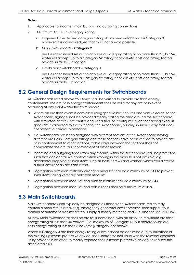
TS 0371 Arc Flash Hazard Assessment and Design Aspects SA Water - Technical Standard
Revision 1.0 - 24 September 2020 Document ID: SAWS-ENG-0371 Page 36 of 42
For Official Use Only Uncontrolled when printed or downloaded
Notes:
1. Applicable to incomer, main busbar and outgoing connections
2. Maximum Arc Flash Category Rating:
a. In general, the desired category rating of any new switchboard is Category 0,
however, it is acknowledged that this is not always possible.
b. Main Switchboard – Category 2
The Designer should set out to achieve a Category rating of no more than ‘2’, but SA
Water will accept up to a Category ‘4’ rating if complexity, cost and timing factors
provide suitable justification.
c. Distribution Switchboard – Category 1
The Designer should set out to achieve a Category rating of no more than ‘1’, but SA
Water will accept up to a Category ‘2’ rating if complexity, cost and timing factors
provide suitable justification.
8.2 General Design Requirements for Switchboards
All switchboards rated above 250 Amps shall be verified to provide arc flash energy
containment. The arc flash energy containment shall be valid for any arc flash event
occurring at any point within the switchboard.
a. Where an arc flash event is controlled using specific blast chutes and vents external to the
switchboard, signage shall be provided clearly stating the area around the switchboard
with restricted access. Arc chutes and vents shall be configured such that arcing exhaust
gases are evacuated to the exterior of the switchboard/building in such a way that does
not present a hazard to personnel.
b. If a switchboard has been designed with different sections of the switchboard having
different Arc Flash Category ratings and these sections have been verified to provide arc
flash containment to other sections, cable ways between the sections shall not
compromise the arc fault containment of either section.
c. Incoming and outgoing feeds from any module within the switchboard shall be protected
such that accidental live contact when working in the module is not possible, e.g.
accidental dropping of small items such as bolts, screws and washers which could create
a short circuit or an arc flash event.
d. Segregation between vertically arranged modules shall be a minimum of IP4X to prevent
small items falling vertically between modules.
e. Segregation between modules and busbar sections shall be a minimum of IP4X.
f. Segregation between modules and cable zones shall be a minimum of IP2X.
8.3 Main Switchboards
Main Switchboards shall typically be designed as standalone switchboards, which may
contain a main circuit breaker(s), emergency generator circuit breaker, solar supply input,
manual or automatic transfer switch, supply authority metering and CTs, and the site MEN link.
All new Main Switchboards shall be arc fault contained, with an absolute maximum arc flash
energy rating of less than 40 cal/cm2 (i.e. maximum of Category 4), but preferably an arc
flash energy rating of less than 8 cal/cm2 (Category 2 or below).
Where a Category 4 arc flash energy rating or less cannot be achieved due to limitations of
the existing upstream protective device, the Contractor shall liaise with the relevant electrical
utility provider in an effort to modify/replace the upstream protective device, to reduce the
associated risks.

TS 0371 Arc Flash Hazard Assessment and Design Aspects SA Water - Technical Standard
Revision 1.0 - 24 September 2020 Document ID: SAWS-ENG-0371 Page 37 of 42
For Official Use Only Uncontrolled when printed or downloaded
8.4 Distribution Switchboards
Distribution Switchboards shall typically be designed as standalone switchboards, containing
a main incoming circuit breaker, power metering and distribution circuit breakers to supply
power to various plant areas and equipment.
The need for arc fault containment of any new Distribution switchboard shall be determined
by the arc flash assessment conducted on each site, restricting arc flash energy to a rating of
< 4 cal/cm2 (Category 1).
A Distribution Switchboard will typically supply the following loads:
1. Other local power distribution switchboards
2. Local motor control centres
3. Local control panels
4. General light and small power distribution boards
5. Proprietary standalone process equipment packages
6. Power conditioning equipment
7. UPS systems, etc.
8.5 Motor Control Centres
Motor Control Centres shall typically be designed as standalone switchboards, containing a
main incoming circuit breaker, power metering, motor starting and control equipment (i.e.
circuit breakers, contactors, relays, overloads, soft starters, etc.) and suitable interfaces to the
wider control system i.e. segregated PLC/RTU section or facilities to interface to a separate
PLC/RTU panel.
The need for arc fault containment of any new Motor Control Centre shall be determined by
the arc flash assessment conducted on each site, restricting arc flash energy to a rating of < 4
cal/cm2 (Category 1).
Consideration should also be given to the location of any Variable Speed Drives. Where
space and installation environment/methodology allow, VSDs shall be IP54, mounted external
to the switchboard i.e. mounted on the switchroom building internal wall.
Multiple Motor Control Centres shall be considered for areas where:
1. Category 1 arc flash energy ratings cannot be achieved through the use of one
switchboard.
2. The required maximum demand is greater than 800 Amps.
3. The board length introduces supply, transportation, construction or installation issues.
4. There are benefits in providing electrical redundancy in the system.
5. There are benefits when carrying out future board replacement programs.
8.6 Distribution Boards or Sections Rated ≤ 250A
Low voltage distribution boards and control panels incorporating low voltage distribution
sections pose a potential risk to personnel, as typically these boards are not designed with
specific arc fault containment measures and are often accessed by non-electrically qualified
workers i.e. operations or maintenance personnel.
All low voltage distribution boards and control panels for this purpose shall have a maximum
current rating of ≤ 250A. Multiple distribution boards/control panels shall be installed if a
current rating above 250A is required.

TS 0371 Arc Flash Hazard Assessment and Design Aspects SA Water - Technical Standard
Revision 1.0 - 24 September 2020 Document ID: SAWS-ENG-0371 Page 38 of 42
For Official Use Only Uncontrolled when printed or downloaded
These boards typically contain a main incoming circuit breaker, power metering, distribution
circuit breakers, lighting and emergency control circuits, RCD testing facilities, surge
protection, etc.
These boards shall typically be designed as follows:
1. Maximum rating of 250 Amps and protected by a maximum 250 Amp adjustable circuit
breaker located within the upstream switchboard (i.e. within the Distribution
Switchboard or Motor Control Centre).
2. Arc flash energy rating of < 1.2 Cals/cm2 (i.e. Category 0). This will allow acceptable
safe access to Operators in appropriate standard PPE (i.e. clothing with typically > 80%
natural fibre and standard safety glasses).
3. Where attainment of Category 0 cannot be achieved, the capacity of the distribution
switchboard and associated protective devices shall be reduced to a level, lower than
250 Amps, which achieves a Category 0 rating. e.g. installation of multiple, lower-rated
distribution boards.
4. If it is not possible to demonstrate Category 0 attainment through calculation, providing
distribution boards with upstream protection limited to 63A or less, will be an
acceptable mitigation outcome.
5. For boards or sections which are accessible to personnel without an electrical license
(e.g. PLC cabinet, telemetry section, etc.), a minimum degree of protection of IPXXC
(i.e. 2.5mm diameter holes at least 100mm distant from live parts) shall be provided in
addition to ensuring that at the position of operation or inspection, arc flash energy
exposure is Category 0. Also, all cabling exposed to touch must be double insulated in
line with AS/NZS3000 requirements.
To minimise the size of these types of boards, all three-phase outlet circuit breakers shall be
supplied directly from the Distribution Switchboard or respective local Motor Control Centre.
Low Voltage Distribution Boards shall not be contained within other switchboards unless it can
be demonstrated that they are fully isolated (in an arc flash perspective) from the rest of the
switchboard, and achieve a Category 0 arc flash rating themselves.
8.7 Arc Detection Systems
Arc fault detection devices using optical technology, in combination with current
measurement sensors, or similar mitigation devices, are recommended for LV switchboards
rated 800A or more. The arc detection system can be used to trigger the operation of circuit
breakers well in advance of the normal trip caused by arc fault current alone.
Arc fault detectors shall be located in order to detect arc faults which occur:
• At the point of switchboard connection to the incoming supply;
• In the incoming circuit breaker compartment;
• Along the main busbar, (unless this is fully insulated);
• Along the distribution busbar, (unless this is fully insulated);
• In outgoing circuit breaker compartments; and
• In motor starter compartments, except where protected by HRC fuses which limits the
peak cut-off current to less than 17 kA, and the line side, of which is fully insulated.
The switchboard manufacturer shall perform tests to verify the performance and safety of arc
detection systems and provide certified test reports to SA Water. Where optical arc flash
detection protection is installed, warning labels are to be attached to the switchboard and in
a prominent position on each switchroom personnel access door. The mounting height of the
warning labels must be at least 1500mm from floor level.

TS 0371 Arc Flash Hazard Assessment and Design Aspects SA Water - Technical Standard
Revision 1.0 - 24 September 2020 Document ID: SAWS-ENG-0371 Page 39 of 42
For Official Use Only Uncontrolled when printed or downloaded
Appendix A – Excerpts from NFPA 70E
A1 Table 130.5 (C)

TS 0371 Arc Flash Hazard Assessment and Design Aspects SA Water - Technical Standard
Revision 1.0 - 24 September 2020 Document ID: SAWS-ENG-0371 Page 40 of 42
For Official Use Only Uncontrolled when printed or downloaded

TS 0371 Arc Flash Hazard Assessment and Design Aspects SA Water - Technical Standard
Revision 1.0 - 24 September 2020 Document ID: SAWS-ENG-0371 Page 41 of 42
For Official Use Only Uncontrolled when printed or downloaded
A2 Table 130.7 (C)
Table 8-2 - NFPA 70E Table 130.7 (C)
Arc-Flash PPE
Category
PPE
1 Arc-Rated Clothing, Minimum Arc Rating of 4 cal/cm2 (16.75 J/cm2)a Arc-rated
long-sleeve shirt and pants or arc-rated coverall Arc-rated face shieldb or arc
flash suit hood
Arc-rated jacket, parka, rainwear, or hard hat liner (AN)
Protective Equipment
Hard hat
Safety glasses or safety goggles (SR) Hearing protection (ear canal inserts)c
Heavy-duty leather glovesd Leather footwear (AN)
2 Arc-Rated Clothing, Minimum Arc Rating of 8 cal/cm2 (33.5 J/cm2)a Arc-rated
long-sleeve shirt and pants or arc-rated coverall
Arc-rated flash suit hood or arc-rated face shieldb and arc-rated balaclava Arc-
rated jacket, parka, rainwear, or hard hat liner (AN) Protective Equipment
Hard hat
Safety glasses or safety goggles (SR) Hearing protection (ear canal inserts)c
Heavy-duty leather glovesd Leather footwear
3 Arc-Rated Clothing Selected so that the System Arc Rating Meets the required
Minimum Arc Rating of 25 cal/cm2 (104.7 J/cm2)a
Arc-rated long-sleeve shirt (AR) Arc-rated pants (AR) Arc-rated coverall (AR)Arc-
rated arc flash suit jacket (AR) Arc-rated arc flash suit pants (AR) Arc-rated arc
flash suit hood
Arc-rated glovesd
Arc-rated jacket, parka, rainwear, or hard hat liner (AN)
Protective Equipment
Hard hat
Safety glasses or safety goggles (SR) Hearing protection (ear canal inserts)c
Leather footwear
4 Arc-Rated Clothing Selected so that the System Arc Rating meets the required
Minimum Arc Rating of 40 cal/cm2 (167.5 J/cm2)a
Arc-rated long-sleeve shirt (AR) Arc-rated pants (AR) Arc-rated coverall (AR)
Arc-rated arc flash suit jacket (AR) Arc-rated arc flash suit pants (AR) Arc-rated
arc flash suit hood
Arc-rated glovesc
Arc-rated jacket, parka, rainwear, or hard hat liner (AN)
Protective Equipment
Hard hat

TS 0371 Arc Flash Hazard Assessment and Design Aspects SA Water - Technical Standard
Revision 1.0 - 24 September 2020 Document ID: SAWS-ENG-0371 Page 42 of 42
For Official Use Only Uncontrolled when printed or downloaded
Arc-Flash PPE
Category
PPE
Safety glasses or safety goggles (SR) Hearing protection (ear canal inserts)c
Leather footwear
AN: As needed (optional). AR: As required. SR: Selection required.
a Arc rating is defined in Article 100.
b Face shields are to have wrap-around guarding to protect not only the face but also the
forehead, ears, and neck, or, alternatively, an arc-rated arc flash suit hood is required to be
worn.
c Other types of hearing protection are permitted to be used in lieu of or in addition to ear
canal inserts provided they are worn under an arc-rated arc flash suit hood.
d If rubber insulating gloves with leather protectors are used, additional leather or arc-rated
gloves are not required. The combination of rubber insulating gloves with leather protectors
satisfies the arc flash protection requirement.