Embed Size (px)
Citation preview
Draft Submittal (Pink Paper)
1. Operating Test Simulator Scenarios
TURKEY POINT EXAM 2002-301
50-250, 50-251/2002-301 OCTOBER 7 - 11 & 15, 2002
Scenarios Initial Submittal
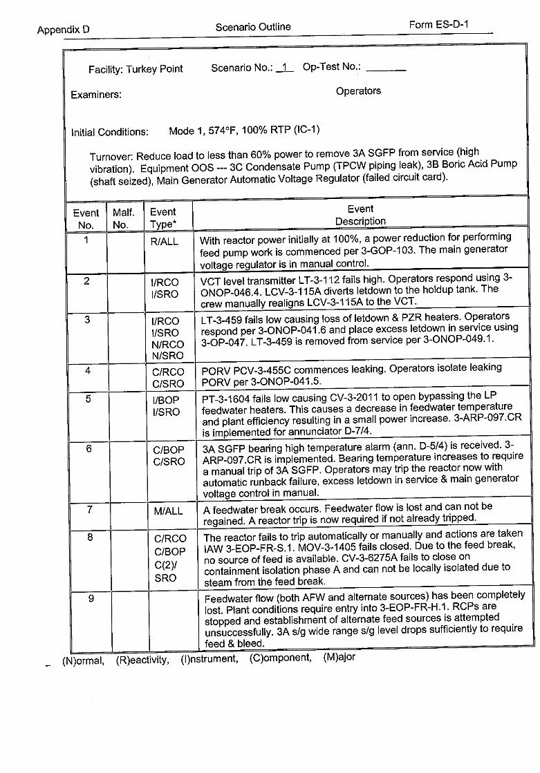
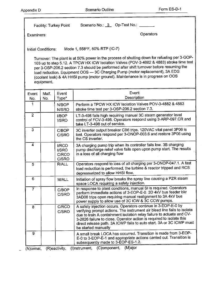
Appendix D Scenario Outline Form ES-D-1
Facility: Turkey Point Scenario No.: -A- Op-Test No.:
Examiners: Operators
Initial Conditions: Mode 1, 574°F, 100% RTP (IC-1)
Turnover: Reduce load to less than 60% power to remove 3A SGFP from service (high
vibration). Equipment OOS --- 3C Condensate Pump (TPCW piping leak), 3B Boric Acid Pump
(shaft seized), Main Generator Automatic Voltage Regulator (failed circuit card).
Event Malf. Event Event
No. No. Type* Description
1 R/ALL With reactor power initially at 100%, a power reduction for performing
feed pump work is commenced per 3-GOP-1 03. The main generator
voltage regulator is in manual control.
2 l/RCO VCT level transmitter LT-3-112 fails high. Operators respond using 3
I/SRO ONOP-046.4. LCV-3-115A diverts letdown to the holdup tank. The crew manually realigns LCV-3-115A to the VCT.
3 /RCO LT-3-459 fails low causing loss of letdown & PZR heaters. Operators
I/SRO respond per 3-ONOP-041.6 and place excess letdown in service using
N/RCO 3-OP-047. LT-3-459 is removed from service per 3-ONOP-049.i.
N/SRO
4 C/RCO PORV PCV-3-455C commences leaking. Operators isolate leaking
C/SRO PORV per 3-ONOP-041.5.
5 I/BOP PT-3-1 604 fails low causing CV-3-2011 to open bypassing the LP
I/SRO feedwater heaters. This causes a decrease in feedwater temperature and plant efficiency resulting in a small power increase. 3-ARP-097.CR is implemented for annunciator D-7/4.
6 C/BOP 3A SGFP bearing high temperature alarm (ann. D-5/4) is received. 3
C/SRO ARP-097.CR is implemented. Bearing temperature increases to require
a manual trip of 3A SGFP. Operators may trip the reactor now with
automatic runback failure, excess letdown in service & main generator
voltage control in manual.
7 M/ALL A feedwater break occurs. Feedwater flow is lost and can not be
regained. A reactor trip is now required if not already tripped.
8 C/RCO The reactor fails to trip automatically or manually and actions are taken
C/BOP lAW 3-EOP-FR-S.1. MOV-3-1405 fails closed. Due to the feed break,
C(2)/ no source of feed is available. CV-3-6275A fails to close on containment isolation phase A and can not be locally isolated due to
SRO steam from the feed break.
9 Feedwater flow (both AFW and alternate sources) has been completely
lost. Plant conditions require entry into 3-EOP-FR-H.I. RCPs are
stopped and establishment of alternate feed sources is attempted
unsuccessfully. 3A s/g wide range s/g level drops sufficiently to require feed & bleed.
- (N)ormal, (R)eactivity, (I)nstrument, (C)omponent, (M)ajor
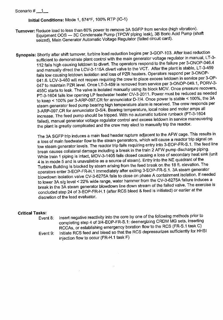
Scenario # 1
Initial Conditions: Mode 1, 574°F, 100% RTP (IC-1)
Turnover: Reduce load to less than 60% power to remove 3A SGFP from service (high vibration).
Equipment OOS --- 3C Condensate Pump (TPCW piping leak), 3B Boric Acid Pump (shaft
seized), Main Generator Automatic Voltage Regulator (failed circuit card).
Synopsis: Shortly after shift turnover, turbine load reduction begins per 3-GOP-103. After load reduction
sufficient to demonstrate plant control with the main generator voltage regulator in manual, LT-3
112 fails high causing letdown to divert. The operators respond to the failure per 3-ONOP-046.4
and manually direct the LCV-3-115A divert valve to the VCT. After the plant is stable, LT-3-459
fails low causing letdown isolation and loss of PZR heaters. Operators respond per 3-ONOP
041.6. LCV-3-460 will not reopen requiring the crew to place excess letdown in service per 3-OP
047 to maintain PZR level. Once LT-3-459 is removed from service per 3-ONOP-049.1, PORV-3
455C starts to leak. The valve is isolated manually using its block MOV. Once pressure recovers,
PT-3-1604 fails low opening LP feedwater heater CV-3-201 1. Power must be reduced as needed
to keep < 100% per 3-ARP-097.CR for annunciator D-7/4. Once power is stable < 100%, the 3A
steam generator feed pump bearing high temperature alarm is received. The crew responds per
3-ARP-097.CR for annunciator D-5/4. Bearing temperature, local noise and motor amps all
increase. The feed pump should be tripped. With no automatic turbine runback (PT-3-1604
failed), manual generator voltage regulator control and excess letdown in service maneuvering
the plant is greatly complicated and the crew may elect to manually trip the reactor.
The 3A SGFP trip induces a main feed header rupture adjacent to the AFW cage. This results in
a loss of main feedwater flow to the steam generators, which will cause a reactor trip signal on
low steam generator levels. The reactor trip fails requiring entry into 3-EOP-FR-S.1. The feed line
break causes collateral damage including a break in the train 2 AFW pump discharge piping.
While train 1 piping is intact, MOV-3-1405 fails closed causing a loss of secondary heat sink (unit
4 is in mode 5 and is unavailable as a source of steam). Entry into the NE quadrant of the
Turbine Building is blocked by steam arising from the feed break on the 18 ft. elevation. The
operators enter 3-EOP-FR-H.1 immediately after exiting 3-EOP-FR-S.1. 3A steam generator
blowdown isolation valve CV-3-6275A fails to close on phase A containment isolation. If needed
to lower 3A s/g level < 22% wide range, water hammer from the CV-3-6275A failure induces a
break in the 3A steam generator blowdown line down stream of the failed valve. The exercise is
concluded step 24 of 3-EOP-FR-H.1 (after RCS bleed & feed is initiated) or earlier at the
discretion of the lead evaluator.
Critical Tasks: Event 8: Insert negative reactivity into the core by one of the following methods prior to
completing step 4 of 3/4-EOP-FR-S.1: deenergizing CRDM MG sets, inserting
RCCAs, or establishing emergency boration flow to the RCS (FR-S.1 task C)
Event 9: Initiate RCS feed and bleed so that the RCS depressurizes sufficiently for HHSI
injection flow to occur (FR-H.1 task F)
Scenario XX NRC 1 Simulator Operating Instructions
Setup
IC-1 (100% MOL)
Load scenario 16.
Delete all conditional triggers and direct triggers as marked on the accompanying copy of the
scenario 16 computer printout.
Place simulator in run.
Main Generator Automatic Voltage Regulator in Manual: Touch SYS MAT -* GENERATOR & GRID --- GENERATOR EXCITER -- NO. 1 ISOL TRANSD -- LOSS OF OUTPUT SIGNAL -- set TFGFDIT1 = T. Acknowledge alarm, then select Voltage Regulator Control Switch --- OFF.
3C Condensate Pump OOS: Touch ELECTRICAL GENERATION --) 3C 4kV BUS --) bkr 12 BREAKER POSITION -- set TAF1 D6CP = 3
3B Boric Acid Pump OOS: Touch RCS PRESSURE --- CVCS LETDOWN -- BORON MKUP &
CHARGING --- EMER BORATE -* BORIC ACID PUMP B -- LOCAL CLOSE/TRIP (MECH) --> set TCB1 BMC = F
CV-3-6275A fails as is (open): Touch STEAM PRESSURE --> STEAM GEN -4 BLDN PROC . TO
BLDN -- CV6275A --> FAIL AS IS -- set TFSW75AA = T
ATWS/AMSAC failure: Touch SIM CTL --> SPECIAL CONTROLS --> ATWS - AMSAC FAILS TO ACTUATE
Acknowledge any alarms and place simulator in freeze.
Attach ECO information tags on control switches for 3C Condensate Pump, 3B Boric Acid Pump &
Main Generator Voltage Regulator.
Provide turnover package & copy of 3-GOP-1 03.
PELemutr~duction from 100% with manual main generator voltage control. Initiated by shift turnover (3-GOP-103). No sim IF actions.
Respond as System, NPS, NRC Resident Inspector, Shift Engineer & Chemistry regarding the
load reduction. Respond as SNPO. If asked, report idle charging pump ready for start. If directed to increase
NRHX CCW flow, after 2-4 min, touch SYS MAT -- COMMON SERVICES -> COMPONENT
COOLING -> 834 -4 VALVE PORT AREA --* set TAKA834 = as directed (0.6 = 780 gpm).
Event 2 - LT-3-112 fails high
When load reduced sufficient to demonstrate plant control, touch SYS MAT -* CHEMICAL
VOLUME CONTROL SYSTEM -4 CVCS VOLUME CONTROL TANK --- L-112 -4 TRANSMITTER
FAIL HIGH -> set TFB1LTHW = T to begin event. Crew responds per 3-ONOP-046.4.
Respond as SNPO if directed to locally check LT-3-112 inidication in the charging pump room.
Report back that the local indication reads 100%.
Respond as WCC/maintenance if called regarding LT-3-112 failure.
Event 3 - LT-3-459 fails low & excess letdown placed in service
Upon completion of 3-ONOP-046.4, touch PRESSURIZER LEVEL -> L-459 -- LT-459 -*
TRANSMITTER FAIL LOW -- set TFHITV59 = T -- RECALL --> CVCS LETDOWN . -> LCV-460
-- FAIL CLOSE --> set TFBVC01 = T. Crew should respond per 3-ONOP-041.6. When LCV-3-460
failure identified, crew should align excess letdown per 3-OP-047.
Respond as SNPO to verify excess letdown HX CCW flow (FI-3-624) < 238 gpm. Touch SYS MAT
--4 COMMON SERVICES --4 COMPONENT COOLING -4 CCW TO RCP & XS LTDWN HX'S,
NCC'S AND CRDM CLRS ---> report CCW flow as indicated next to XLHX.
Respond as WCC/I&C when notified. If operators trip bistables, 3-ONOP-049.1 Attachment 4 is used for L-3-459.
Event 4 - PORV PCV-3-455C leakage Once excess letdown placed in service, touch PRESSURIZER LEVEL -* PORV455C -> LEAK
BY --> set TVHV455C = 0.05 ( =20 gpm leak slowly reduces PZR pressure < 2200 psig). Operators
respond per 3-ONOP-041.5. Respond as NPO if directed to perform 3-ONOP-041.5 Attachment 1 (not necessary to provide
results).
Event 5 - PT-3-1604 fails low After 3-ONOP-041.5 response complete, touch STEAM PRESSURE -> MAIN STEAM PROC*
(right side) -- P-1604 -> PT-1604 -* TRANSMITTER FAIL LOW --> actuate parameter controller
direct trigger TFS1 ML3L. CV-3-2011 will automatically open and bypass all LP feedwater heaters,
reducing feedwater temperature & plant efficiency. That will cause a small reactor power increase.
Crew should respond per 3-ARP-097.CR for ann. D-7/4.
NOTE: CV-3-2011 switch must be held closed until valve fully closed or it will reopen.
Respond as NPO if asked to locally verify CV-3-1900 closed. Touch STEAM PRESSURE
FEEDWATER --> FW MAIN PROC . (far left side) -- HTR DRAINS PROCESS , -- report CV
1900 position (far right side).
Event 6 - 3A SGFP bearing failure After plant stabilization, actuate 3A SGFP high bearing temperature alarm (ann. D-5/4). Touch
STYL INST -- A304 -> Ann. panel D -- OVERRIDE -> SGFP A MOTOR BRG HI TEMP -* CRY
WOLF SGFP A MOTOR BEARING HI TEMP -> STATUS -- set V8:D32 = T. Operators should
consult 3-ARP-097.CR for ann. D-5/4. Respond as NPO if directed to check out 3A SGFP bearing temperatures. Tell crew outboard
motor bearing temperature is 205°F and slowly increasing.
Arm the feedwater break in event 7 by touching STEAM PRESSURE -* FEEDWATER -* LV20
-> VALVE PORT AREA -> ARM TVFAHDR2 = 1.0. Shortly thereafter, touch RECALL -4 FW MAIN
PROC (left side .) -> 3PIA -4 BEARING WEAR -> set TVFABP1A = 0.2/180. Report increasing
noise level from 3A SGFP outboard motor bearing with temperature of 215°F and slowly increasing.
The crew should trip 3A SGFP per 3-ARP-097.CR, but recognize that it will not cause a turbine
runback due to PT-3-1604 failure. The crew may attempt to trip the reactor here since excess
letdown is in service (limits RCS ability to respond to load change), the main generator voltage
regulator is in manual and the turbine must be manually run back.
Respond as system if notified of load reduction.
Event 7 - Feedwater break / Loss of feedwater If an attempt is made to trip the reactor or at lead evaluator direction during manual runback
after the 3A SGFP is tripped, press MAST FAIL and actuate parameter controller composite
"AFW LEAK". This creates a break just outside the AFW cage on the 18 ft. elevation of the Turbine
Bldg. Break location means SSGFP, condensate pump & SGFP are all unavailable as feed
sources. If the reactor hasn't already been tripped, the loss of feed flow will require a manual
reactor trip as steam generator levels rapidly drop.
Event 8 - ATWS with loss of AFW From event 7 the reactor does not trip either manually or automatically. The crew enters 3-EOP-E-0
step land transitions to 3-EOP-FR-S.1. No AFW is available since collateral damage from the feed
break includes a break in the AFW train 2 discharge pipe (see setup). MOV-3-1405 fails to open
taking train 1 AFW OOS. If directed as NPOINWE to locally open MOV-3-1405, report that the AFW MOV platform is
inaccessible due to steam. Unit 4 is in mode 5 and is therefore not available as a steam source for
train I AFW. Respond as NPO if directed to locally open rx trip breakers & MG set input/output breakers. Report
lots of steam coming from the unit 3 end of the Turbine Bldg. 18 ft. elevation, so may have trouble
getting to 3B MCC room. Once emergency boration is established, locally trip the reactor by opening the MG set input
breakers from the 480V LC room by touching ELECTRICAL GENERATION -> 3A(3D) 480V LC
bkr 30108(30401) -4 LOCAL CLOSE/NORM/TRIP (ELEC) -+ set TAE3108L(3401 L) = 2.
Event 9 - Loss of heat sink Upon completion of 3-EOP-FR-S.1, operators should transition to 3-EOP-FR-H.1.
If needed to get one steam generator level < 22% wide range after completion of 3-EOP-FR
S.1 to force initiation of feed & bleed, initiate 3A steam generator blowdown line leak as needed.
Touch STEAM PRESSURE -- STEAM GEN + (left side) -- BLDN PROC . TO BLDN -4 leak node
downstream of CV6275A -> VALVE PORT AREA -- set TVSDSD1 = as needed to get desired
level decrease. Operators should notice failure of CV-3-6275A to close. If directed as NPO to locally close it or locally close the associated manual isolation valve (SGB-3
007), report that the area is inaccessible due to steam. If directed as NPO to establish unit 2 feed flow, report that valve 3-20-510 is closed under
clearance (repairs to line from units 1 & 2). When directed as SNPO to align PAHMS for service, actuate parameter controller composite
"PAHM".
Appendix D Scenario Outline Form ES-D-1
Facility: Turkey Point Scenario No.: 2 Op-Test No.:
Examiners:
Initial Conditions: Mode 1, 5740F, 100% RTP (IC-1)
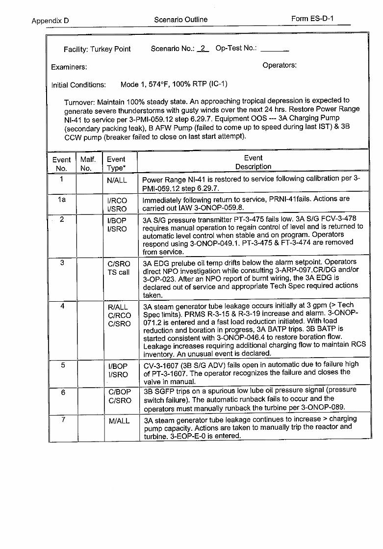
Turnover: Maintain 100% steady state. An approaching tropical depression is expected to generate severe thunderstorms with gusty winds over the next 24 hrs. Restore Power Range
NI-41 to service per 3-PMI-059.12 step 6.29.7. Equipment OOS --- 3A Charging Pump (secondary packing leak), B AFW Pump (failed to come up to speed during last IST) & 3B
CCW pump (breaker failed to close on last start attempt).
Event Malf. Event Event No. No. Type* Description
1 N/ALL Power Range NI-41 is restored to service following calibration per 3
PMI-059.12 step 6.29.7. la I/RCO Immediately following return to service, PRNI-41fails. Actions are
I/SRO carried out lAW 3-ONOP-059.8.
2 I/BOP 3A S/G pressure transmitter PT-3-475 fails low. 3A S/G FCV-3-478
I/SRO requires manual operation to regain control of level and is returned to automatic level control when stable and on program. Operators respond using 3-ONOP-049.1. PT-3-475 & FT-3-474 are removed from service.
3 C/SRO 3A EDG prelube oil temp drifts below the alarm setpoint. Operators TS call direct NPO investigation while consulting 3-ARP-097.CR/DG and/or
3-OP-023. After an NPO report of burnt wiring, the 3A EDG is declared out of service and appropriate Tech Spec required actions taken.
4 R/ALL 3A steam generator tube leakage occurs initially at 3 gpm (> Tech
C/RCO Spec limits). PRMS R-3-15 & R-3-19 increase and alarm. 3-ONOP
C/SRO 071.2 is entered and a fast load reduction initiated. With load reduction and boration in progress, 3A BATP trips. 3B BATP is started consistent with 3-ONOP-046.4 to restore boration flow. Leakage increases requiring additional charging flow to maintain RCS inventory. An unusual event is declared.
5 I/BOP CV-3-1607 (3B S/G ADV) fails open in automatic due to failure high
I/SRO of PT-3-1607. The operator recognizes the failure and closes the valve in manual.
6 C/BOP 3B SGFP trips on a spurious low lube oil pressure signal (pressure
C/SRO switch failure). The automatic runback fails to occur and the operators must manually runback the turbine per 3-ONOP-089.
7 M/ALL 3A steam generator tube leakage continues to increase > charging pump capacity. Actions are taken to manually trip the reactor and turbine. 3-EOP-E-0 is entered.
Operators:
Form ES-D-1Scenario OutlineAppendix D
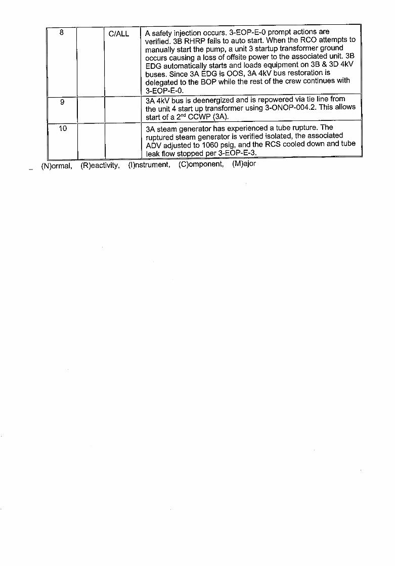
8 C/ALL A safety injection occurs. 3-EOP-E-0 prompt actions are verified. 3B RHRP fails to auto start. When the RCO attempts to manually start the pump, a unit 3 startup transformer ground occurs causing a loss of offsite power to the associated unit. 3B EDG automatically starts and loads equipment on 3B & 3D 4kV buses. Since 3A EDG is OOS, 3A 4kV bus restoration is delegated to the BOP while the rest of the crew continues with 3-EOP-E-0.
9 3A 4kV bus is deenergized and is repowered via tie line from the unit 4 start up transformer using 3-ONOP-004.2. This allows start of a 2 nd CCWP (3A).
10 3A steam generator has experienced a tube rupture. The ruptured steam generator is verified isolated, the associated ADV adjusted to 1060 psig, and the RCS cooled down and tube leak flow stopped per 3-EOP-E-3.
(N)ormal, (R)eactivity, (I)nstrument, (C)omponent, (M)ajor
Scenario # 2
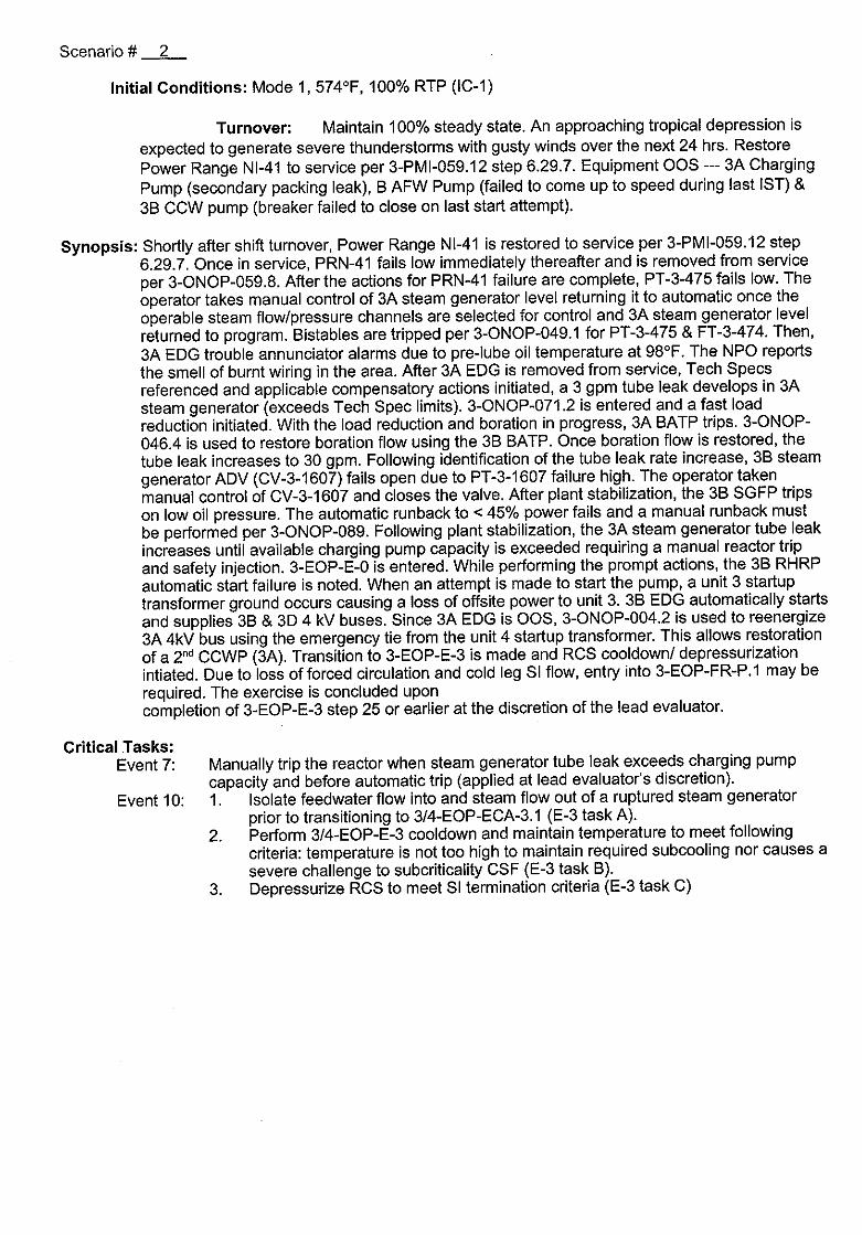
Initial Conditions: Mode 1, 574°F, 100% RTP (IC-1)
Turnover: Maintain 100% steady state. An approaching tropical depression is
expected to generate severe thunderstorms with gusty winds over the next 24 hrs. Restore Power Range NI-41 to service per 3-PMI-059.12 step 6.29.7. Equipment OOS --- 3A Charging Pump (secondary packing leak), B AFW Pump (failed to come up to speed during last IST) & 3B CCW pump (breaker failed to close on last start attempt).
Synopsis: Shortly after shift turnover, Power Range NI-41 is restored to service per 3-PMI-059.12 step 6.29.7. Once in service, PRN-41 fails low immediately thereafter and is removed from service per 3-ONOP-059.8. After the actions for PRN-41 failure are complete, PT-3-475 fails low. The operator takes manual control of 3A steam generator level returning it to automatic once the operable steam flow/pressure channels are selected for control and 3A steam generator level returned to program. Bistables are tripped per 3-ONOP-049.1 for PT-3-475 & FT-3-474. Then, 3A EDG trouble annunciator alarms due to pre-lube oil temperature at 98 0F. The NPO reports the smell of burnt wiring in the area. After 3A EDG is removed from service, Tech Specs referenced and applicable compensatory actions initiated, a 3 gpm tube leak develops in 3A steam generator (exceeds Tech Spec limits). 3-ONOP-071.2 is entered and a fast load reduction initiated. With the load reduction and boration in progress, 3A BATP trips. 3-ONOP046.4 is used to restore boration flow using the 3B BATP. Once boration flow is restored, the tube leak increases to 30 gpm. Following identification of the tube leak rate increase, 3B steam generator ADV (CV-3-1607) fails open due to PT-3-1607 failure high. The operator taken manual control of CV-3-1607 and closes the valve. After plant stabilization, the 3B SGFP trips on low oil pressure. The automatic runback to < 45% power fails and a manual runback must be performed per 3-ONOP-089. Following plant stabilization, the 3A steam generator tube leak increases until available charging pump capacity is exceeded requiring a manual reactor trip and safety injection. 3-EOP-E-0 is entered. While performing the prompt actions, the 3B RHRP automatic start failure is noted. When an attempt is made to start the pump, a unit 3 startup transformer ground occurs causing a loss of offsite power to unit 3. 3B EDG automatically starts and supplies 3B & 3D 4 kV buses. Since 3A EDG is OOS, 3-ONOP-004.2 is used to reenergize 3A 4kV bus using the emergency tie from the unit 4 startup transformer. This allows restoration of a 2 nd CCWP (3A). Transition to 3-EOP-E-3 is made and RCS cooldown/ depressurization intiated. Due to loss of forced circulation and cold leg SI flow, entry into 3-EOP-FR-P.1 may be required. The exercise is concluded upon completion of 3-EOP-E-3 step 25 or earlier at the discretion of the lead evaluator.
Critical Tasks: Event 7: Manually trip the reactor when steam generator tube leak exceeds charging pump
capacity and before automatic trip (applied at lead evaluator's discretion). Event 10: 1. Isolate feedwater flow into and steam flow out of a ruptured steam generator
prior to transitioning to 3/4-EOP-ECA-3.1 (E-3 task A). 2. Perform 3/4-EOP-E-3 cooldown and maintain temperature to meet following
criteria: temperature is not too high to maintain required subcooling nor causes a severe challenge to subcriticality CSF (E-3 task B).
3. Depressurize RCS to meet SI termination criteria (E-3 task C)
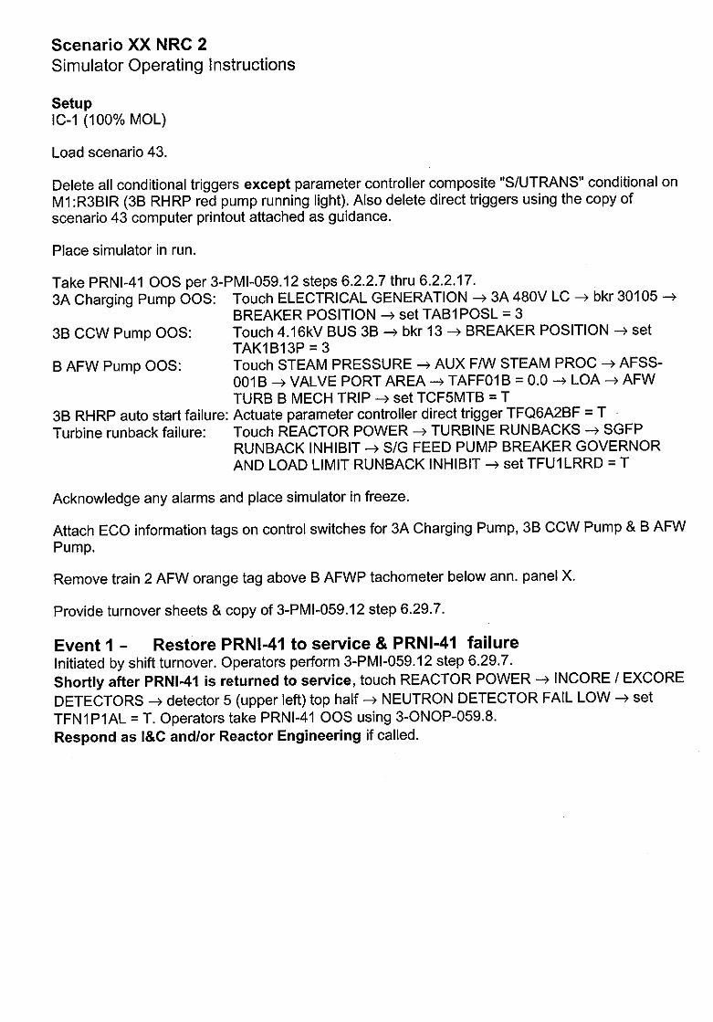
Scenario XX NRC 2 Simulator Operating Instructions
Setup
IC-1 (100% MOL)
Load scenario 43.
Delete all conditional triggers except parameter controller composite "S/UTRANS" conditional on M1 :R3BIR (3B RHRP red pump running light). Also delete direct triggers using the copy of scenario 43 computer printout attached as guidance.
Place simulator in run.
Take PRNI-41 OOS per 3-PMI-059.12 steps 6.2.2.7 thru 6.2.2.17.3A Charging Pump OOS:
3B CCW Pump OOS:
B AFW Pump OS:
3B RHRP auto start failure: Turbine runback failure:
Touch ELECTRICAL GENERATION --- 3A 480V LC -- bkr 30105 -
BREAKER POSITION -- set TAB1 POSL = 3 Touch 4.16kV BUS 3B -- bkr 13 -- BREAKER POSITION -4 set TAKIB13P = 3 Touch STEAM PRESSURE --> AUX F/W STEAM PROC -- AFSS001B -> VALVE PORT AREA -> TAFF01B = 0.0 --> LOA -* AFW TURB B MECH TRIP -> set TCF5MTB = T Actuate parameter controller direct trigger TFQ6A2BF = T Touch REACTOR POWER -- TURBINE RUNBACKS -- SGFP RUNBACK INHIBIT -- S/G FEED PUMP BREAKER GOVERNOR AND LOAD LIMIT RUNBACK INHIBIT --- set TFUILRRD = T
Acknowledge any alarms and place simulator in freeze.
Attach ECO information tags on control switches for 3A Charging Pump, 3B CCW Pump & B AFW Pump.
Remove train 2 AFW orange tag above B AFWP tachometer below ann. panel X.
Provide turnover sheets & copy of 3-PMI-059.12 step 6.29.7.
Event 1 - Restore PRNI-41 to service & PRNI-41 failure Initiated by shift turnover. Operators perform 3-PMI-059.12 step 6.29.7. Shortly after PRNI-41 is returned to service, touch REACTOR POWER -4 INCORE / EXCORE
DETECTORS -- detector 5 (upper left) top half -4 NEUTRON DETECTOR FAIL LOW -* set
TFN1PlAL = T. Operators take PRNI-41 OOS using 3-ONOP-059.8. Respond as I&C and/or Reactor Engineering if called.
Event 2 - PT-3-475 fails low When 3-ONOP-059.8 actions complete, touch STEAM PRESSURE -4 P-475 -> TRANSMITTER
PT-475 -- TRANSMITTER FAIL LOW -- set TFS1 MBWL = T.
If operators trip bistables, 3-ONOP-049.1 Attachment 4 is used for P-3-475 & F-3-474. Respond as
WCC if requested to prepare a PWO/Clearance and notify I&C.
Respond as I&C if called directly. Respond as NPO if requested to inspect the main steam platform area around PT-3-475 for trouble.
Report that you observe no apparent damage. Respond as NPO if directed to reset AMSAC (may be in due to 3A s/g level error before feed flow
returned to normal). Wait 1-3 min, then actuate parameter controller direct trigger TCL4RST = T.
Report when complete.
Event 3 - 3A EDG pre-lube oil temperature low Once event 2 response complete, actuate parameter controller direct trigger TVQ5GGAT =
80.0. Respond as NPO. After 1-3 min., report annunciators RA-1/7, NOT READY TO START and RA
2/2, LO OIL TEMP alarming and oil temp = 98 0F. If asked to perform 3-ARP-097.DG, report
immersion heater / soak back pump switch is ON but pump not running and a burnt wiring smell
exists at the DECP. Shortly thereafter, report 3A MCC breaker 30514 is tripped open. If directed
to take the 3A EDG MCSS -- OFF, wait 1-3 min. actuate parameter controller direct trigger
TAQ5LRSA = 0. Report when complete. Respond as WCC. If directed to rack out 3AA20 (3A EDG output bkr), wait 8-10 min, then
actuate parameter controller direct trigger TAQ5A20P = 3. Report when complete. If directed to
have Electrical investigate, after 10-15 min., report burned wiring inside 3A DECP.
Event 4 - 3A steam generator tube leak & BATP trip
After 3A EDG taken out of service (bistables thrown or earlier at lead evaluator direction),
initiate 3 gpm 3A steam generator tube leak by touching STEAM PRESSURE -- STEAM GEN.
(left side) -+ S/G A RCS HYD leak node -* S/G TUBE RUPTURE 3A -* set TVHHSGA = 0.003.
The crew will respond per 3-ONOP-071.2. Respond as Chemistry. Report back in 10-12 min. that counts appear highest on the 3A s/g
sample. Report DAM-1 reading background (normal). If called after R-3-19 alarm, wait 1-3 min,
then report no cold chem lab s/g sample flow.
Respond as HP. After 5-8 min, report 3A MSL radiation slightly > bkgd w/ SJAE dischg
contaminated. Posting turbine deck as a contamination area.
Respond as System. Respond as NPS. With load reduction & boration in progress, touch SYS MAT -> CHEMICAL VOLUME
CONTROL SYSTEM -- CVCS MAKEUP --> IDA -- THRML OVRLD RELAY FOR BA PUMP A -
set TFBIAOV = T.
Respond as WCC/I&C if called.
Respond as SNPO if directed to check out 3A BATP. After 2-4 min., report 3A BATP motor very
hot and bkr 30725 tripped open. Once boration flow restored and load reduction resumed, set TVHHSGA = 0.03 (increases
3A steam generator tube leak rate to 30 gpm).
Respond as SNPO. If asked, report idle charging pump ready for start. If directed to increase
NRHX CCW flow, after 2-4 min, touch SYS MAT -* COMMON SERVICES ---) COMPONENT
COOLING -- 834 ---) VALVE PORT AREA -* set TAKA834 = as directed (0.6 = 780 gpm).
Respond as NPO if directed to align aux stm from U4. Wait 1-3 min, then touch STEAM
PRESSURE -- AUX F/W STEAM PROC ---) 075 --* VALVE PORT AREA --> set TAFF075=0.0
SLWU-3-001 -- VALVE PORT AREA -- set TAFF02= 1.0 --> 007 -- VALVE PORT AREA -> set
TAFF007=0.0. Report when complete. Respond as NPO/NWE when directed to open bkr 4D01-28 for MOV-3-1403, after 1-3 min, touch
STEAM PRESSURE -> AUX F/W STEAM PROC -- MOV 1403 -- BREAKER LOA LOCAL
CLOSE / TRIP (MECH) --4 set TCF5MB28 = F -- MOV1403 -- VALVE FAIL CLOSE ---> set
TFFXCO3 = T. Report when breaker open.
Event 5 - PT-3-1607 fails high 1 3B steam generator ADV fails open
After > 10% load reduction when directed by lead evaluator, touch STEAM PRESSURE --> P
1607 -4 TRANSMITTER PT-1607 -- TRANSMITTER FAIL HIGH --> set TFS1MRDH = T.
Respond as NPO if called to check out CV-3-1607. After 1-3 min., report that valve is in indicated
(demanded) position. Respond as WCC/I&C if called regarding PT-3-1607 failure high. Inform crew that PWO will be
submitted and planner is working up package.
Event 6 - 3B SGFP spurious low lube oil pressure trip Once CV-3-1607 manually closed, touch STEAM PRESSURE -> FEEDWATER -* FW MAIN
PROC . (left side) -- T-MTP1 B -> SWITCH PS-2050 -- ALM #1 RLY FAIL ENERG -* set
TFF1X8F = T. Respond as System when called about sudden load change. Respond as Chemistry if called to do RCS sampling due to the > 15% power change. Respond as NPO if called to check out 3B SGFP locally, report that the oil sensing line to PS-3
2050 vibrated loose and that there is a small oil spill in the vicinity of the switch. Also report that
you have closed valve 3-40-096B which isolated the flow of oil out the sensing line. Respond as WCC if called to have Mechanical generate a work package to repair the PS-3-2050 sensing line.
Event 7 - 3A steam generator tube leak > charging pump capacity After plant stabilization and MOV-3-1403 deenergization I closure, set TVHHSGA 0.200/120 (increases leak to 200 gpm on 2 min ramp). Actions described in event 4 may be performed here before the reactor is tripped. Respond as System if called about impending reactor trip.
Event 8 - Safety injection / Loss of offsite power Immediately after the reactor trip, set TVHHSGA = 1.0. Starting 3B RHRP initiates parameter controller composite "S/U TRANS" causing loss of U3 startup transformer & 3B RHRP when red breaker closed light illuminates. Respond as NPOINWE if called to investigate U3 SUT. Report to crew that a high side bushing
apparently arced to ground and is destroyed. Respond as NPO if called to locally close MOV-3-1408 / 1409. 12-15 min. later, if 3A 4kV bus not
yet restored, actuate parameter controller direct triggers TFFVV08C = T & TFFW09C = T.
Respond as SNPO if called to locally close MOV-3-1426 / 1427.8-10 min. later, if 3A 4kV bus
not yet restored, actuate parameter controller direct triggers, TFSWVM6B = T & TFSWVM7B = T.
Respond as NPO if called to investigate 3B RHRP bkr 3AB1 5. After 1-3 min., report no apparent problem. Respond as SNPO if called to investigate 3B RHRP. After 1-3 min., report no apparent problem.
Respond as U4 RCO if asked about U4 status. Report U4 stable at 100% power. If asked to
realign U4 HHSIP suction to U3 RWST per 3-EOP-E-0 Att 1. After 5-7 min., actuate parameter controller composite "SIALIGN". Report completion. Respond as SNPO when directed to align PAHMS. After 10-15 min., actuate parameter controller
composite "PAHM". Report completion. NOTE: Early 3A MSIV closure may cause 3A s/g ADV lifting and associated release to
atmosphere. Respond as HP/Chemistry if directed to assess release from 3A ADV. Also report
HPs surveying turbine deck already started to rope off U3 mn stm platform & turb. deck downwind until extent of contamination determined.
Event 9 - 3A 4kV bus recovery
initiated based on loss of offsite power in event 8 and 3A EDG OOS from event 5. 3A 4kV bus
restoration will allow starting a 2 nd CCWP (3A). Respond as U4 RCO if asked about U4 SUT lockout that it is reset.
Respond as NPO/NWE if directed to rack in bkr 3AA22. After 4-6 min, actuate parameter
controller direct trigger TAE2D06P=T. Report completion. Respond as NPO/NWE if directed to locally check 3A 4kV bus for breaker targets. After 1-3 min,
report no breaker targets on 3A 4kV bus. If not yet done by end of event 9, report as SNPO that aux bldg PAHM alignment complete.
Event 10 - 3A steam generator tube rupture response Continuation of event 8 upon entry into 3-EOP-E-3. See events 4 & 8 for field response to this event.
Respond as SNPO if asked to check out charging pumps for start. After 1-3 min, report 3B/3C
charging pumps ready for start.
Appendix 0 Scenario Outline Form ES-0-1
Facility: Turkey Point Scenario No.: 3 Op-Test No.:
Examiners:
Initial Conditions: Mode 1, 5580F, 50% RTP (IC-7)
Turnover: The plant is at 50% power in the process of shutting down for refueling per 3-GOP103 up to step 5.12. A TPCW HX ICW Isolation Valves (POV-3-4882 & 4883) stroke time test per 3-OSP-206.2 section 7.3 should be performed after shift turnover before resuming the
load reduction. Equipment OOS --- 3C Charging Pump (motor replacement), 3A EDG (coolant leak) & 4A HHSI pump (motor ground). Maintenance is in progress on 0OS equipment.
Event Malf. Event Event No. No. Type* Description
1 N/BOP Perform a TPCW HX ICW Isolation Valves POV-3-4882 & 4883
N/SRO stroke time test per 3-OSP-206.2 section 7.3.
2 I/BOP LT-3-498 fails high requiring manual 3C steam generator level
I/SRO control of FCV-3-498. Operators respond using 3-ARP-097.CR and take LT-3-498 out of service.
3 C/BOP 3C inverter output breaker CB6 trips. 120VAC vital panel 3P06 is C/SRO lost. Operators respond per 3-ONOP-003.6 and restore 3P06 using
the CS inverter.
4 IIRCO 3A charging pump trip when its controller fails low. 3B charging I/SRO pump discharge relief valve fails open upon pump start. The results C/RCO in a loss of all charging flow C/SRO
5 R/ALL Operators respond to loss of all charging per 3-ONOP-047.1. A fast load reduction is performed, the turbine & reactor tripped and RCS depressurized to allow HHSI flow.
6 M/ALL Initiation of spray flow breaks the spray line causing a PZR steam space LOCA requiring a safety injection.
7 C/BOP In response to plant conditions, manual SI is required. Operators
C/SRO perform immediate actions of 3-EOP-E-0. 3D 4kV bus feeder bkr 3AD06 trips open requiring manual realignment to 3A 4kV bus power supply to allow use of 3C ICW & 3C CCW pumps.
8 C/RCO A safety injection occurs. Operators continue in 3-EOP-E-0 by
C/SRO verifying prompt actions. The instrument air bleed line fails to isolate due to train A containment isolation relay failure to actuate and CV3-2826 failure to close. Operator action is required to isolate this direct release path. 3A ICWP fails to auto start. 3A or 3C ICWP must be started manually
9 A small break LOCA has occurred. Transition is made from 3-EOPE-0 to 3-EOP-E-1 and appropriate actions carried out. Transition is
[T E _ subsequently made to 3-EOP-ES-1.2.
(R)eactivity, (I)nstrument, (C)omponent, (M)ajor
Operators
Form ES-D-1Scenario OutlineAppendix D
_(N)ormal,
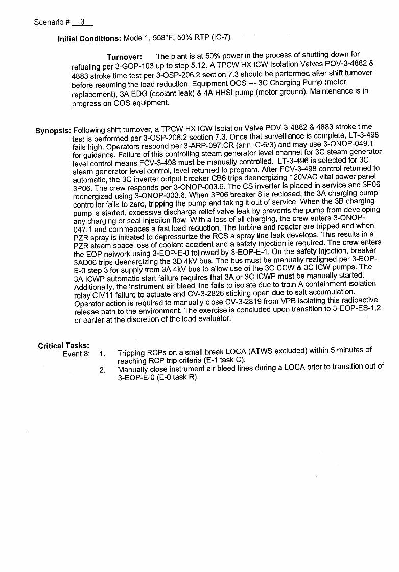
Scenario # 3
Initial Conditions: Mode 1, 5580F, 50% RTP (IC-7)
Turnover: The plant is at 50% power in the process of shutting down for
refueling per 3-GOP-103 up to step 5.12. A TPCW HX ICW Isolation Valves POV-3-4882 &
4883 stroke time test per 3-OSP-206.2 section 7.3 should be performed after shift turnover
before resuming the load reduction. Equipment OOS --- 3C Charging Pump (motor
replacement), 3A EDG (coolant leak) & 4A HHSI pump (motor ground). Maintenance is in
progress on OOS equipment.
Synopsis: Following shift turnover, a TPCW HX ICW Isolation Valve POV-3-4882 & 4883 stroke time
test is performed per 3-OSP-206.2 section 7.3. Once that surveillance is complete, LT-3-498
fails high. Operators respond per 3-ARP-097.CR (ann. C-6/3) and may use 3-ONOP-049.1
for guidance. Failure of this controlling steam generator level channel for 3C steam generator
level control means FCV-3-498 must be manually controlled. LT-3-496 is selected for 3C
steam generator level control, level returned to program. After FCV-3-498 control returned to
automatic, the 3C inverter output breaker CB6 trips deenergizing 120VAC vital power panel
3P06. The crew responds per 3-ONOP-003.6. The CS inverter is placed in service and 3P06
reenergized using 3-ONOP-003.6. When 3P06 breaker 8 is reclosed, the 3A charging pump
controller fails to zero, tripping the pump and taking it out of service. When the 3B charging
pump is started, excessive discharge relief valve leak by prevents the pump from developing
any charging or seal injection flow. With a loss of all charging, the crew enters 3-ONOP
047.1 and commences a fast load reduction. The turbine and reactor are tripped and when
PZR spray is initiated to depressurize the RCS a spray line leak develops. This results in a
PZR steam space loss of coolant accident and a safety injection is required. The crew enters
the EOP network using 3-EOP-E-0 followed by 3-EOP-E-1. On the safety injection, breaker
3AD06 trips deenergizing the 3D 4kV bus. The bus must be manually realigned per 3-EOP
E-0 step 3 for supply from 3A 4kV bus to allow use of the 3C CCW & 3C ICW pumps. The
3A ICWP automatic start failure requires that 3A or 3C ICWP must be manually started.
Additionally, the instrument air bleed line fails to isolate due to train A containment isolation
relay CIV11 failure to actuate and CV-3-2826 sticking open due to salt accumulation. Operator action is required to manually close CV-3-2819 from VPB isolating this radioactive
release path to the environment. The exercise is concluded upon transition to 3-EOP-ES-1.2 or earlier at the discretion of the lead evaluator.
Critical Tasks: Event 8: 1. Tripping RCPs on a small break LOCA (ATWS excluded) within 5 minutes of
reaching RCP trip criteria (E-1 task C). 2. Manually close instrument air bleed lines during a LOCA prior to transition out of
3-EOP-E-0 (E-0 task R).
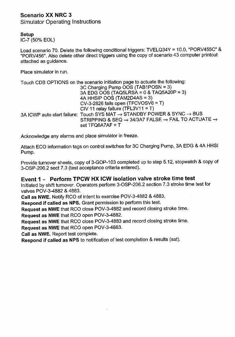
Scenario XX NRC 3 Simulator Operating Instructions
Setup IC-7 (50% EOL)
Load scenario 70. Delete the following conditional triggers: TVELQ34Y = 10.0, "PORV455C" & "PORV456". Also delete other direct triggers using the copy of scenario 43 computer printout attached as guidance.
Place simulator in run.
Touch CDB OPTIONS on the scenario initiation page to actuate the following: 3C Charging Pump OOS (TAB1POSN = 3) 3A EDG OOS (TAQ5LRSA = 0 & TAQ5A20P = 3) 4A HHSIP OOS (TAM2D4AS = 3) CV-3-2826 fails open (TFCVOSV6 = T) CIV 11 relay failure (TFL3V1 1 = T)
3A ICWP auto start failure: Touch SYS MAT -- STANDBY POWER & SYNC -* BUS STRIPPING & SEQ -* 34/3A7 FALSE -* FAIL TO ACTUATE -*
set TFQ6A7AF = T
Acknowledge any alarms and place simulator in freeze.
Attach ECO information tags on control switches for 3C Charging Pump, 3A EDG & 4A HHSI Pump.
Provide turnover sheets, copy of 3-GOP-1 03 completed up to step 5.12, stopwatch & copy of 3-OSP-206.2 sect 7.3 (test acceptance criteria entered).
Event 1 - Perform TPCW HX ICW isolation valve stroke time test Initiated by shift turnover. Operators perform 3-OSP-206.2 section 7.3 stroke time test for valves POV-3-4882 & 4883. Call as NWE. Notify RCO of intent to exercise POV-3-4882 & 4883. Respond if called as NPS. Grant permission to perform this test. Request as NWE that RCO close POV-3-4882 and record closing stroke time. Request as NWE that RCO open POV-3-4882. Request as NWE that RCO close POV-3-4883 and record closing stroke time. Request as NWE that RCO open POV-3-4883. Call as NWE. Report test complete. Respond if called as NPS to notification of test completion & results (sat).
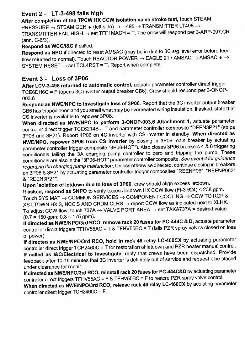
Event 2 - LT-3-498 fails high After completion of the TPCW HX CCW isolation valve stroke test, touch STEAM
PRESSURE --> STEAM GEN . (left side) -* L-495 -4 TRANSMITTER LT498 ->
TRANSMITTER FAIL HIGH -- set TFF1 MACH = T. The crew will respond per 3-ARP-097.CR
(ann. C-6/3). Respond as WCC/I&C if called. Respond as NPO if directed to reset AMSAC (may be in due to 3C s/g level error before feed
flow returned to normal). Touch REACTOR POWER -- EAGLE 21 / AMSAC -* AMSAC. -
SYSTEM RESET --> set TCL4RST = T. Report when complete.
Event 3 - Loss of 3P06 After LCV-3-498 returned to automatic control, actuate parameter controller direct trigger
TCE6DH6C = F (opens 3C inverter output breaker CB6). Crew should respond per 3-ONOP
003.6 Respond as NWE/NPO to investigate loss of 3P06. Report that the 3C inverter output breaker
CB6 has tripped open and you smell what may be overheated wiring insulation. If asked, state that
CS inverter is available to repower 3P06. When directed as NWE/NPO to perform 3-ONOP-003.6 Attachment 1, actuate parameter
controller direct trigger TCE6214S = T and parameter controller composite "DEEN3P21" (strips
3P06 and 3P21). Report 4P06 on 4C inverter with CS inverter in standby. When directed as
NWE/NPO, repower 3P06 from CS inverter by closing in 3P06 main breaker by actuating
parameter controller trigger composite "3P06-HOT"). Also closes 3P06 breakers 4 & 8 triggering
conditionals failing the 3A charging pump controller to zero and tripping the pump. These
conditionals are also in the "3P06-HOT" parameter controller composite. See event 4 for guidance
regarding the charging pump malfunction. Unless otherwise directed, continue closing in breakers
on 3P06 & 3P21 by actuating parameter controller trigger composites "REENP06", "REENP062"
& "REEN3P21". Upon isolation of letdown due to loss of 3P06, crew should align excess letdown.
If asked, respond as SNPO to verify excess letdown HX CCW flow (FI-3-624) < 238 gpm.
Touch SYS MAT --4 COMMON SERVICES -> COMPONENT COOLING -* CCW TO RCP &
XS LTDWN HX'S, NCC'S AND CRDM CLRS --> report CCW flow as indicated next to XLHX.
To adjust CCW flow, touch 737A -* VALVE PORT AREA --> set TAKA737A = desired value
(0.7 = 150 gpm; 0.8 = 175 gpm).
If directed as NWE/NPO/3rd RCO, remove rack 20 fuses for PC-444C & D, actuate parameter
controller direct triggers TFHV55AC = T & TFHV55BC = T (fails PZR spray valves closed on loss
of power). If directed as NWE/NPOI3rd RCO, hold in rack 46 relay LC-460CX by actuating parameter
controller direct trigger TCH2460C = T for restoration of letdown and PZR heater manual control.
If called as I&C/Electrical to investigate, reply that crews have been dispatched. Provide
feedback after 10-15 minutes that 3C inverter is definitely out of service and request it be placed
under clearance for repair. If directed as NWE/NPOI3rd RCO, reinstall rack 20 fuses for PC-444C&D by actuating parameter
controller direct triggers TFHV55AC = F & TFHV55BC = F to restore PZR spray valve control.
When directed as NWE/NPOI3rd RCO, release rack 46 relay LC-460CX by actuating parameter
controller direct trigger TCH2460C = F.
Event 4 - Loss of all charging When 3B charging pump is started following 3A charging pump trip in event 4, actuate
parameter controller direct trigger TVBVLK45 = 1.0 (fails 3B charging pump discharge relief
open, recirculating all discharge flow back to the pump suction). With 3C charging pump OOS,
a loss of all charging results. The crew responds per 3-ONOP-047.1.
When directed as SNPO to check out the 3B charging pump, reply back after approximately 2
minutes that you can hear flow through the associated discharge relief (RV-3-283B) line.
NOTE: 3P06 loss in event 3 closes MOV-3-626. With a loss of all charging, MOV-3-626 must be
reopened to prevent damage to RCP due to sustained loss of seal injection flow.
Event 5 - Fast load reduction Fast load reduction begins per 3-ONOP-047.1 in response to loss of all charging flow.
Respond as NPS to evaluate event per 0-EPIP-20101. Respond as WCC if called to have Mechanical check out RV-3-283B and/or I&C check out 3A
Charging Pump controller problems. Fix nothing before the end of the scenario.
Respond as System when called about sudden load change.
Respond as Chemistry if called to do RCS sampling due to the > 15% power change.
Event 6 - Pressurizer spray line failure When PZR spray valves are opened for RCS depressurization, actuate parameter controller
direct trigger TVHPSPBR = 0.30/30 (inserts PZR spray line break).
When manual SI is inititated, touch ELECTRICAL GENERATION -4 3D 4KV BUS --> bkr 06
--- FAIL OPEN --> set TFE2D22T = T (fails open breaker 3AD06 supply to 3D 4kV bus from 3B
4kV bus).
Event 7 - Reactor trip verification & loss of 3D 4kV bus The turbine & reactor were tripped earlier per 3-ONOP-047.1. Degrading containment
conditions require manual SI and entry into 3-EOP-E-0 (steps 1-4 in this event). The crew
should realign 3D 4kV bus to 3A 4kV bus supply. Respond as NPO/NWE if directed to check out breaker 3AD06. After 2-4 min., report breaker
tripped open, but no obvious cause. Request Electrical maint. support.
Event 8 - Safety injection with containment penetration isolation failure Continuation of 3-EOP-E-0 with safety injection (step 5 thru transition to 3-EOP-E-1)
When directed as SNPO to investigate why instrument air bleed isolation valve CV-3-2826 failed
to close, reply after 5-10 minutes that the valve stem appears to be covered with salt deposits and
corrosion. Request Mechanical maintenance assistance. Respond as Chemistry if directed to perform an offsite dose calculation in response to the release
path that existed through the instrument air bleed line to the plant vent stack. State that a Chemistry
tech has been dispatched to the TSC for this purpose.
Respond as I&C if called to check out relay CIV 11. After 10-15 minutes, report that the relay
shows signs of damage due to overheating and should be replaced.
Respond as NPO if called to check out 3A or 3C ICWP (3C tripped due to loss of 3D 4kV bus
& 3A ICWP did not auto start) or associated breakers. Report pump & breakers appear normal.
One pump will need to be restarted to get the two required by 3-EOP-E-0.
Respond as WCC/Electrical/l&C if asked to check out why 3A ICWP did not auto start. After
10-15 min, suggest a sequencer relay failure as the likely cause with additional troubleshooting
in progress. Respond as SNPO when directed to place PAHMS in service. Actuate parameter controller
composite "PAHM". After 10-15 minutes, report complete.
Event 9 - PZR steam space LOCA response Continuation of event 8 upon entry into 3-EOP-E-1. Respond as Chemistry/HP if queried about secondary radiation (take request & report that you will
call when ready for sample; call back in 10 minutes to request that secondary sample valves be
opened if not already; report any requested DAM-1 or SPING-4 readings). Respond as NPO if
directed to place EDGs in standby (10 minutes after EDG stops, notify crew that EDGs are in standby
per 3-OP-023). Respond as NPO/SNPO/NWE when directed to close breakers for cold leg recirculation per step 16
of 3-EOP-E-1, this may be done using the safety injection system mimic page and touching the
appropriate valves then mechanically closing the associated breaker. Since the scenario terminates
at step 19 (transition to 3-EOP-ES-1.2), closing these breakers may not be necessary prior to freezing
the simulator. Respond as SNPO if directed to close spray pump room & charging pump room shield doors. Report
complete 1-3 minutes later. Respond as HP when directed to survey unit 3 pipe & valve room & electrical penetration rooms.
Respond as Chemistry when directed to align PASS for RCS sampling.


