Embed Size (px)
Citation preview

ELECTRICAL ENGINEERING DEPARTMENT
Subject:- Advance Power Electronics (EEL803) Elective XI-2
1 In the ___________ type of chopper, two stage conversions take place. Marks
a AC-DC 1.5 b AC link
c DC link
d None of the mentioned
2 Choppers converter is Marks
a AC to DC 1.5 b DC to AC
c DC to DC
d AC to AC
3 A chopper may be thought as a Marks
a Inverter with DC input 1.5 b DC equivalent of an AC transformer
c Diode rectifier
d DC equivalent of an induction motor
4 Which device can be used in a chopper circuit? Marks
a BJT 1.5 b MOSFET
c GTO
d All of the mentioned
5 A chopper is a Marks
a Time ratio controller 1.5 b AC to DC converter
c DC transformer
d High speed semiconductor switch
6 What is the duty cycle of a chopper ? Marks
a Ton/Toff 1.5 b Ton/T
c T/Ton
d Toff x Ton
7 The load voltage of a chopper can be controlled by varying the Marks
a duty cycle 1.5 b firing angle

c reactor position
d extinction angle
8 The values of duty cycle (α) lies between Marks
a 0<α<1 1.5 b 0>α>-1
c 0<=α<=1
d 1<α<100
9 If T is the time period for a chopper circuit and α is its duty cycle, then the
chopping frequency is
Marks
a Ton/α 1.5 b Toff/α
c α/Toff
d α/Ton
10 Find the output voltage expression for a step down chopper with Vs as the
input voltage and α as the duty cycle.
Marks
a Vo = Vs/α 1.5 b Vo = Vs x α
c o = Vs2/α
d Vo = 2Vs/απ
11 The below given figure is that of a _________ (IGBT is used as a chopper
switch)
Marks
a step-up/step-down chopper 1.5 b step-down choppe
c step-up chopper
d none of the mentioned
12 In the below given circuit, when switch (SW) is on
Marks
a voltage is non-zero and current is rising 1.5 b voltage is non-zero and current is decaying

c voltage is zero and current is rising
d voltage is zero and current is decaying
13 In a step down chopper, if Vs = 100 V and the chopper is operated at a duty
cycle of 75 %. Find the output voltage.
Marks
a 100 V 1.5 b 75 V
c 25 V
d none of the mentioned
14 If Vo is the output voltage and Vs is the input DC voltage, then for the
below given circuit.
Marks
a Vo = Vs 1.5 b Vo <Vs
c Vo >Vs
d Insufficient information
15 In the below given circuit, when switch (SW) is on
Marks
a voltage is non-zero and current is rising 1.5 b voltage is zero and current is decaying
c voltage and current both are non-zero
d voltage and current both are zero
16 In the below given circuit, when switch (SW) is first switched closed and
then opened the
Marks
a voltage is non-zero and current is rising 1.5

b voltage is non-zero and current is rising
c voltage is non-zero and current is decaying
d voltage is zero and current is rising
17 What is the voltage across the load when the SW is first closed and then
opened?
Marks
a Vs 1.5 b duty cycle x Vs
c Vs + L (di/dt)
d zero
18 Find the expression for output voltage for a step-up chopper, assume linear
variation of load current and α as the duty cycle.
Marks
a Vs 1.5 b Vs/α
c Vs/(1-α)
d Vs/√2
19 Find the output voltage for a step-up chopper when it is operated at a duty
cycle of 50 % and Vs = 240 V
Marks
a 240 V 1.5 b 480 V
c 560 V
d 120 V
20 If a step up chopper’s switch is always kept off then (ideally) Marks
a Vo = 0 1.5 b Vo = ∞
c Vo = Vs
d Vo >Vs
21 If a step up chopper’s switch is always kept open then (ideally) Marks
a Vo = 0 1.5 b Vo = ∞
c Vo = Vs
d Vo >Vs

22 Find the average value of output voltage of a basic step-down chopper, with
duty cycle = α and load = R Ω.
Marks
a I = Vs x α 1.5 b I = (Vs x α)/R
c I = 0
d I = Vs/R
23 For the below given circuit, find the output current at the instant of
commutation.
Marks
a Vo/R 1.5 b Vs/R
c 0
d α/2
24 For a step-down chopper, find the rms value of output voltage. Let α be the
duty cycle and Vs be the input voltage.
Marks
a α x Vs 1.5 b Vs/α
c √α x Vs
d Vs/2
25 A step down chopper is operated at 240V at duty cycle of 75%. Find the
value of RMS switch (IGBT/MOSFET) current. Take R = 10 Ω.
Marks
a 2.07 A 1.5 b 200 mA
c 1.58 A
d 2.4 A
26 Find the expression for effective input resistance of a step down chopper.
With R load and duty cycle = α.
Marks
a R x α 1.5 b R/2
c 0

d R/α
27 For a step-up chopper, when the duty cycle is increased the average value of
the output voltage
Marks
a increases 1.5 b decreases
c remains the same
d none of the mentioned
28 For a step-down chopper, when the duty cycle is increased the average
value of the output voltage
Marks
a increases 1.5 b decreases
c remains the same
d none of the mentioned
29 The below given chopper circuit is that of a
Marks
a step-up chopper 1.5 b step-down chopper
c step-up/step-down chopper
d none of the mentioned
30 For a step-up/step-down chopper, if the duty cycle > 0.5 then Marks
a Vo = Vs 1.5 b Vo <Vs
c Vo >Vs
d None of the mentioned
31 For a step-up/step-down chopper, if α (duty cycle) = 0.5 then Marks
a Vo = Vs 1.5 b Vo <Vs
c Vo >Vs
d none of the mentioned
32 For a step-up/step-down chopper, if α (duty cycle) < 0.5 then Marks
a Vo = Vs 1.5 b Vo <Vs
c Vo >Vs
d none of the mentioned

33 For a step-up/step-down chopper, if current increases from I1 to I2 linearly
during Ton, then find the energy stored in the inductor during Ton
Marks
a zero 1.5 b Vs x (I1 + I2)
c Vs x [ (I1 + I2)/2 ] x Ton
d Vs x [ (I1 + I2)/2 ] x T
34 A step-down chopper is also called as a Marks
a first-quadrant chopper 1.5 b second-quadrant chopper
c third-quadrant chopper
d fourth-quadrant chopper
MCQ The type-C chopper or two quadrant type-A chopper has Marks
a type-A and type-B choppers in series 1.5 b type-A and type-B choppers in parallel
c two type-A choppers in series
d two type-A choppers in parallel
35 In case of TRC (Time Ratio Control), _________ is varied Marks
a duty cycle 1.5 b firing angle
c supply frequency
d supply voltage magnitude
36 In constant frequency TRC or pulse width modulation scheme, ________ is
varied.
Marks
a Vs 1.5 b Ton
c T
d f
37 In case of variable frequency system __________ is varied Marks
a T 1.5 b Ton
c Toff
d supply frequency
38 In pulse width modulation scheme, _________ is kept constant. Marks
a Vs 1.5 b Ton
c T
d Toff
39 In case of frequency modulation system, ________ is kept constant. Marks
a T 1.5 b Ton
c Toff
d Either Ton or Toff
40 The control strategy in which on and off time is guided by the pervious set
of values of a certain parameter is called as
Marks
a time ratio control 1.5 b pulse width modulation
c current limit control
d constant frequency scheme
41 In the current limit control method, the chopper is switched off when Marks
a load current reaches the lower limit 1.5 b load current reaches the upper limit
c load current falls to zero
d none of the mentioned
42 Which of the following mentioned control strategy/strategies would require
a feedback loop?
Marks
a pwm 1.5 b constant frequency system
c current limit control
d none of the mentioned
43 In the current limit control method, when the load current reaches a
predefined lower value, then
Marks
a the chopper is switched off 1.5 b the chopper is switched on
c the source voltage is removed
d load voltage goes to zero
44 Which type of chopper is used in the regenerative braking of DC motors? Marks
a type A 1.5 b type B
c type C
d type D

46 Type C chopper consists of Marks
a two diodes and two switches 1.5 b one diode and one switch
c one diode and three switches
d three diodes and two switches
47 In a type C chopper, if only one switch is operated Marks
a only one quadrant operation will be obtained 1.5 b two quadrant operation can be obtained
c the chopper won’t work
d none of the mentioned
48 A type D chopper is a Marks
a two quadrant type-B chopper 1.5 b two quadrant type-A chopper
c two quadrant type-C chopper
d none of the mentioned
49 In a type-D chopper Marks
a current can flow in both the directions of the load 1.5 b current cannot flow in both the directions of the load
c voltage can only be positive
d voltage can only be negative
UNIT-2
50 A cycloconverter is a _________ Marks
a one stage power converter 1.5 b one stage voltage converter
c one stage frequency converter
d none of the mentioned
51 Applications of cycloconverters include Marks
a speed control of ac drives 1.5 b induction heating
c static VAr compensation
d all of the mentioned
52 The single phase mid-point type cycloconverter uses __________ number
of SCRs.
Marks
a 4 1.5 b 8
c 6

d none of the mentioned
53 The single phase bridge type cycloconverter uses __________ number of
SCRs.
Marks
a 4 1.5 b 8
c 6
d none of the mentioned
54 In the below given cycloconverter circuit, _________ and _________
conduct in one cycle together.
Marks
a P1, P2 and N1, N2 1.5 b P1, N2 and N1, P2
c N1, P1 and N1, P2
d None of the mentioned
55 In the positive half cycle, _________ SCRs are forward biased.
Marks
a P1, P2, N1, N2 1.5 b P1, P2, P3, P4
c N1, N2, N3, N4
d P3, P4, N1, N2
56 The principle of three phase cycloconverter is to Marks
a add and remove number of SCRs 1.5 b vary progressively the firing angle of the devices
c keep the firing angle as 0° for all the devices
d none of the mentioned
57 In three phase cycloconverters, the reduction factor is given by Marks
a input frequency/output frequency 1.5 b (input frequency/output frequency) -1

c (input frequency/output frequency) -1/2
d (input frequency/output frequency) 1/2
58 In a three phase half-wave cycloconverter ___________ Marks
a both inverting and converting action takes place 1.5 b only inversion action takes place
c only converting action takes place
d none of the mentioned
59 Dual converters provide Marks
a two quadrant operation 1.5 b three quadrant operation
c four quadrant operation
d none of the mentioned
60 A dual converters has Marks
a two full converters in series 1.5 b two half converters in series
c two full converters in anti-parallel
d two half converters in anti-parallel
61 The major advantage of using dual converters is that Marks
a it is cheaply available 1.5 b it has better pf
c no mechanical switch is required to change the mode of operation
d its operating frequency is very high
62 The four quadrant operation of dual converters can be obtained by Marks
a moving the mechanical lever 1.5 b adding inductance to the circuit
c changing the firing angle value
d none of the mentioned
63 The output frequency of a cycloconverter is less than the input frequency
because
Marks
a there is no intermediate dc link 1.5 b the number of switching devices is large compared to that in a cascaded
converter pair
c the cycloconverter is normally used for high voltage and high current
applications
d the cycloconverter employs natural commutation of SCRs and more number
of supply cycles are needed to form one cycle of the output voltage

64 The output frequency of a cycloconverter is generally limited to Marks
a four times the supply frequency 1.5 b twice that of line frequency
c 33% to 50% line frequency
d less than 10% of line frequency
65 For low-speed high-power reversible operation, the most suitable drives are Marks
a VSI fed ac drives 1.5 b CSI fed ac drives
c dual converter fed dc drives
d cycloconverter fed ac drives
66 An advantage of a cycloconverter is Marks
a very good power factor 1.5 b requires few number of thyristors
c commutation failure does not short circuit the source
d load commutation is possible
67 The quality of output ac voltage of a cycloconverter is improved with Marks
a increase in output voltage at reduced frequency 1.5 b increase in output voltage at increased frequency
c decrease in output voltage at reduced frequency
d decrease in output voltage at increased frequency
68 An intergroup reactor is used in a 1-phase cycloconverter circuit to Marks
a reduce current ripples 1.5 b reduce voltage ripples
c limit circulating current
d limit di/dt in the semiconductor switch
69 A cycloconverter is operating on a 50 Hz supply. The range of output
frequency that can be obtained with acceptable quality, is
Marks
a 0 - 16 Hz 1.5 b 0 - 32 Hz
c 0 - 64 Hz
d 0 - 128 Hz
70 How many switches are used to construct a 3-phase to 3-phase
cycloconverter?
Marks
a 3 1.5 b 6
c 12
d 18

71 A 3-phase to 3-phase cycloconverter requires Marks
a 18 SCRs for 6-pulse device 1.5 b 36 SCRs for 3-pulse device
c 36 SCRs for 6-pulse device
d none of the above
72 The ratio of power handled by 18 SCRs to 36 SCRs 3-phase to 3-phase
cycloconverter for the same voltage and current rating of SCRs is
Marks
a 1 1.5 b ½
c ¼
d 1/8
73 In the positive half cycle from ωt = 0 to π
Marks
a P1 and N2 are forward biased 1.5 b P1 and P2 are forward biased
c P1 and P2 are forward biased
d N1 and P2 are forward biased
74 A chopper operating at a fixed frequency is feeding an RL load. As the duty
ratio of the chopper is increased from 25% to 75%, the ripple in the load
current is
Marks
a Remains constant 1.5 b Decreases, reaches a minimum at 50% duty ratio and then increases
c Increases, reaches a maximum at 50% duty ratio and then decreases
d Keeps on increasing as the duty ratio is increased
75 The cycloconverter require natural or forced commutation as under Marks
a Natural commutationinbothstep-up and step down cycloconverter 1.5 b Forced commutation in both step-up and step-down cycloconverter
c Forced commutation in step-up cycloconverter
d Forced commutation in step-down cycloconverter
76 A cycloconverter is a Marks
a Frequency changer from higher to lower frequency with one-state 1.5

conversion
b Frequency changer from higher to lower frequency with two-stage
conversion
c Frequency changer from lower to higher frequency with one-stage
conversion
d Either a or c
77 The cycloconverter require natural or forced commutation as under Marks
a Natural commutationinbothstep-up and step down cycloconverter 1.5 b Forced commutation in both step-up and step-down cycloconverter
c Forced commutation in step-up cycloconverter
d Forced commutation in step-down cycloconverter
78 In synchronized UJT triggering of an SCR, voltage VC across capacitor
reaches UJT threshold thrice in each half cycle so that there are three firing
pulses during each half cycle. The firing angle of the SCR can be controlled
Marks
a Once in each half cycle 1.5 b Thrice in each half cycle
c Twice in each half cycle
d Four times in each half cycle
79 The SCR can be turned on by
(a) Applying anode voltage at a sufficiently fast rate
(b) Applying sufficiently large anode voltage
(c) Increasing the temperature of SCR to a sufficiently large value
(d) Applying sufficiently large gate current
Marks
a (a),(b) 1.5 b (c),(d)
c (b),(c)
d (a),(b), (c),(d)
80 Inverters converts Marks
a dc power to dc power 1.5 b dc power to ac power
c ac power to ac power
d ac power to dc power
81 Line-commutated inverters have Marks
a AC on the supply side and DC on the load side 1.5 b AC on both supply and load side
c DC on both supply and load side
d DC on the supply side and AC on the load side

82 In a VSI (Voltage source inverter) Marks
a the internal impedance of the DC source is negligible 1.5 b the internal impedance of the DC source is very very high
c the internal impedance of the AC source is negligible
d the IGBTs are fired at 0 degrees.
83 VSIs using GTOs are turned off by Marks
a load commutation 1.5 b line commutation
c applying a negative gate pulse
d removing the base signal
84 VSIs using IGBTs are turned off by Marks
a load commutation 1.5 b line commutation
c applying a negative gate pulse
d removing the base signal
85 __________ based inverters do not require self-commutation. Marks
a IGBT 1.5 b GTO
c PMOSFET
d SCR
86 Identify the circuit given below.
Marks
a Half wave series inverter 1.5 b Full wave series inverter
c Half wave bridge inverter
d Half wave parallel inverter
87 Single phase half bridge inverters requires Marks
a two wire ac supply 1.5 b two wire dc supply
c three wire ac supply
d three wire dc supply
88 What is the voltage across the R load when only T1 is conducting? Marks

a Vs
1.5 b Vs/2
c 2Vs
d zero
89 In a single-phase half wave inverter ________ SCR(s) are/is gated at a
time.
Marks
a one 1.5 b two
c three
d none of the mentioned
90 What is the voltage across the R load when only T2 is conducting?
Marks
a Vs 1.5 b Vs/2
c 2Vs
d Zero
91 The voltage in a single phase half wave inverter varies between Marks
a Vs and 0 1.5 b Vs/2 and 0
c Vs/2 and –Vs/2
d Vs and –Vs
92 Below given is a Marks

a SCR based inverter
1.5 b MOSFET based inverter
c IGBT based inverter
d None of the mentioned
93 The output of a single-phase half bridge inverter on R load is ideally Marks
a a sine wave 1.5 b a square wave
c a triangular wave
d constant dc
94 In the below given circuit, T1 is fired at 0,T and so on and T2 at T/2, 3T/2
etc. What is the frequency of the alternating voltage obtained?
Marks
a 50 Hz 1.5 b T Hz
c 1/T Hz
d T/2 Hz
95 In the below circuit, if Vs/2 = 50 V. Find, the rms AC voltage that would be
ideally obtained.
Marks
a 50 V 1.5 b 100 V

c 0.707 x 50 V
d 0.707 x 100 V
96 Find the conduction time of the diodes if the SCRs are fired at 0 and T/2
respectively in a single phase half wave inverter with R load.
Marks
a 0 1.5 b T/2
c 2/T
d insufficient data
97 The output current wave of a single-phase full bridge inverter on RL load is Marks
a a sine wave 1.5 b a square wave
c a triangular wave
d constant dc
98 Single-phase full bridge inverters requires Marks
a 4 SCRs and 2 diodes 1.5. b 4 SCRs and 4 diodes
c 2 SCRs and 4 diodes
d 2 SCRs and 2 diodes
99 Identify the circuit given below.
Marks
a Full wave series inverter 1.5 b Half wave series inverter
c Full wave bridge inverter
d Full wave parallel inverter
100 The output voltage from a single phase full wave bridge inverter varies from Marks
a Vs to –Vs 1.5 b Vs to zero
c Vs/2 to zero
d –Vs/2 to Vs/2

101 In a single phase full wave bridge inverter, when the output is Vs or –Vs Marks
a one SCR and one diode are conducting 1.5 b four SCRs are conducting
c two SCRs are conducting
d two diodes are conducting
102 In the following circuit, the diodes D1 to D4 are used to
Marks
a reduce the switching losses 1.5 b send current back to the dc source when SCRs are off
c send current back to the load when SCRs are off
d send current back to the dc source when SCRs are conducting
103 For a full wave bridge inverter, the output voltage (Vo) Marks
a Vo = Vs/2 for 0 < t < T/2 1.5 b Vo = Vs for 0 < t <T/2
c Vo = Vs for T/2< t < T
d Vo = -Vs for T/2< t < 3T/2
104 For a half wave bridge inverter, the output voltage Marks
a Vo = – Vs/2 for 0 < t < T/2 1.5 b Vo = – Vs/2 for T/2< t<T
c Vo = – Vs for 0 < t < T/2
d Vo = Vs/2 for T/2< t < T
105 The fundamental component of output voltage for a half wave bridge inverter
is given by
Marks
a (4Vs/π) sinωt 1.5 b (2Vs/π) sinωt
c (Vs/2π) sinωt
d (Vs)
Ans b

106 The fundamental component of output voltage for a full wave bridge
inverter is given by
Marks
a (2Vs/π) sinωt 1.5 b (4Vs/π) sinωt
c (Vs/2π) sinωt
d (Vs)
107 A single phase half bridge inverter has load R = 2 Ω and a dc voltage source
Vs/2 = 115 V. Find the power delivered to the load due to the fundamental
component
Marks
a 536 kW 1.5 b 53.61 kW
c 5.361 kW
d 536 W
108 A single phase full bridge inverter has a dc voltage source Vs = 230 V. Find
the rms value of the fundamental component of output voltage
Marks
a 90 V 1.5 b 207 V
c 350 V
d 196 V
109 A single phase full bridge inverter has load R = 2 Ω, and dc voltage source
Vs = 230 V. Find the rms value of the fundamental load current.
Marks
a 96 A 1.5 b 0 A
c 103 A
d none of the mentioned
110 A certain full bridge type inverter circuit has its rms value of fundamental
load current component given by W. The fundamental frequency component
of the load current would be given by
Marks
a W sin ωt 1.5 b (W/√2) sin ωt
c √2 W sin ωt
d sin ωt
111 In a half wave bridge inverter circuit, the power delivered to the load by
each source is given by
Marks
a Vs x Is 1.5 b (Vs x Is)/2
c 2(Vs x Is)
d None of the mentioned

112 In a half wave circuit, forced commutation is essential when the Marks
a load is inductive 1.5 b load is resistive
c source voltage is below 150 V
d none of the mentioned
113 In VSI (voltage source inverters) Marks
a both voltage and current depend on the load impedance 1.5 b only voltage depends on the load impedance
c only current depends on the load impedance
d none of the mentioned
114 ____________ is the measure of the contribution of any individual
harmonic to the inverter output voltage
Marks
a THD 1.5 b Distortion Factor
c Harmonic Factor
d TUF
115 in voltage fed thyristor inverters __________ commutation is required. Marks
a load 1.5 b forced
c self
d any commutation technique can be used
Ans b
116 The McMurray circuit is a Marks
a commutation circuit 1.5 b force commutated VSI
c self commutated VSI
d none of the mentioned
117 Forced commutation requires Marks
a a precharged inductor 1.5 b a precharged capacitor
c an overdamped RLC load
d a very high frequency ac source
118 Identify the below given circuit. Marks

a Three-phase bridge regulator
1.5 b Three-phase bridge type semi-converter circuit
c Three-phase bridge thyristor inverter
d Three-phase bridge IGBT inverter
119 A three-phase bridge inverter requires minimum of _____________
switching devices.
Marks
a 3 1.5 b 4
c 6
d 8
120 The below given inverter circuit is a __ step inverter.
Marks
6 a 3 1.5 b 2
c 6
d 8
121 In the three-phase bridge inverter, each step consists of Marks
a 30° 1.5 b 60°
c 90°
d will depend on the value of the firing angle
122 In inverters, to make the supply voltage constant Marks
a an inductor is placed in series with the load 1.5 b capacitor is connected in parallel to the load side
c capacitor is connected in parallel to the supply side
d none of the mentioned
123 In the 180° mode VSI, ___________ devices conduct at a time. Marks
a 5 1.5 b 2
c 3
d 4
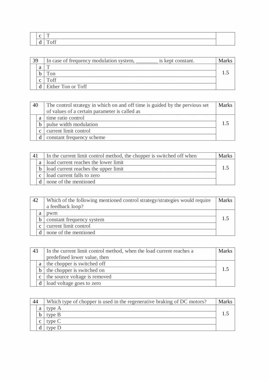
124 In the figure given below, for 180° mode of operation if T1 is fired at 0°.
Then SCRs T3 and T5 should be fired at _________ and _________
respectively.
Marks
a 180°, 360° 1.5 b 90°, 180°
c 120°, 240°
d none of the mentioned
125 For a three phase bridge inverter in the 180° mode, ___________ devices
are conducting from 120° to 180°.
Marks

a T1, T6, T5
1.5 b T2, T6, T5
c T1, T6, T5
d T1, T2, T3
126 What is the peak value of phase voltage in case of 3-phase VSI with 180°
mode. The supply side consists of a constant dc voltage source of Vs.
Marks
a Vs 1.5 b 3Vs/2
c 2Vs/3
d 3Vs
127 What is the R phase voltage when T1, T6 and T5 are conducting? Consider
a star connected R load.
Marks
a Vs 1.5 b 2Vs/3
c Vs/3

d –Vs/3
128 What are the phase voltages when T6, T1 and T2 are conducting? Consider
a star connected R load.
Marks
a VYN = VBN = Vs/3, VRN = 0 1.5 b VYN = VRN = – Vs/3, VBN = 2Vs/3
c VRN = VBN = – Vs/3, VYN = 2Vs/3
d VYN = VBN = – Vs/3, VRN = 2Vs/3
129 What are the phase voltages when T1, T2 and T3 are conducting? Consider
a star connected R load.
Marks
a VYN = VBN = VRN = 0 1.5 b VYN = VRN = Vs/3, VBN = – 2Vs/3
c VRN = VBN = – Vs/3, VYN = 2Vs/3
d VYN = VBN = Vs/3, VRN = – 2Vs/3
130 What is the maximum line voltage value in case of a three-phase VSI in
180° mode?
Marks
a 2Vs 1.5 b Vs

c 3Vs
d 2Vs/3
131 Find VRY, when T6, T1 and T2 are conducting. Consider a star connected
R load.
Marks
a Vs 1.5 b Vs/3
c 0
d 2Vs/3
132 What is the Y phase voltage, when T2, T3 and T4 are conducting?
Marks
a 0 1.5 b Vs/3
c 2Vs/3
d -Vs/3
133 What is the voltage between the B phase and the neutral, when T2, T3 and
T4 are conducting?
Marks

a -2Vs/3
1.5 b Vs/3
c 2Vs/3
d -Vs/3
134 The 120° mode of operation of a three phase bridge inverter requires
___________ number of steps.
Marks
a 2 1.5 b 4
c 6
d 8
135 In case of the 120° mode of operation, __________ devices conduct at a
time.
Marks
a 2 1.5 b 3
c 4
d 8
136 Safe commutation can be achieved in case of the ____________ operating
mode.
Marks
a 180° 1.5 b 120°
c 360°
d none of the mentioned
137 What is the R phase voltage when only T1 and T2 are conducting from 60°
to 120°. Consider star connected R load.
Marks

a Vs
1.5 b Vs/2
c –Vs/2
d 0
138 If T1 is gated at 0 °, T3 and T5 will start conducting at _______ and
_________ respectively.
Marks
a 180°, 270° 1.5 b 120°, 240°
c 180°, 300°
d 240°, 360°
139 What is the B phase voltage when only T1 and T2 are conducting from 60°
to 120°. Consider star connected R load.
Marks
a Vs 1.5 b Vs/2
c –Vs/2
d 0
140 What is the R phase voltage and Y phase voltage when only T3 and T4 are Marks

conducting? Consider a star connected balanced R load.
a Vs, -Vs
1.5 b Vs/2, -Vs/2
c –Vs/2, Vs/2
d –Vs, Vs
141 Find the line voltage VYR when only T3 and T4 are conducting? Consider a
star connected balanced R load.
Marks
a 2Vs/3 1.5 b Vs/2
c Vs
d –Vs
142 The peak value of the line voltage in case of 120° mode of operation of a
three-phase bridge inverter is
Marks
a Vs/2 1.5 b 3Vs/2
c Vs/√2
d Vs
143 The external control of ac output voltage can be achieved in an inverter by Marks
a connecting a cyclo-converter 1.5 b connecting an ac voltage controller between the output of the inverter and
the load
c connecting an ac voltage controller between the dc source and inverter
d connecting an ac voltage controller between the load and the dc source

144 The series-inverter control method is a/an Marks
a internal voltage control method 1.5 b external frequency control method
c external voltage control method
d none of the mentioned
145 In the series-inverter control method Marks
a two inverters are connected back-to-back 1.5 b the output from the inverter is taken serially
c output voltages of two inverters are summed up with the help of a
transformer
d output voltages of two inverters are summed up with the help of a third
inverter
146 External control of dc input voltage can be obtained by the use of a Marks
a transformer 1.5 b chopper
c inverter
d Converter
147 In the external control of dc input voltage Marks
a a chopper is placed just after the inverter block 1.5 b a chopper is placed just after the filter block
c a chopper is placed before the filter and the inverter block
d none of the mentioned
148 _________ method is an internal method for controlling the inverter output
voltage.
Marks
a series connection of inverters 1.5 b chopper method
c commutating capacitor
d pulse width modulation
149 In the PWM method Marks
a external commutating capacitors are required 1.5 b more average output voltage can be obtained
c lower order harmonics are minimized
d higher order harmonics are minimized
150 Which of the following is not a PWM technique? Marks
a Single-pulse width modulation 1.5 b Multiple-pulse width modulation
c Triangular-pulse width modulation

d Sinusoidal-pulse width modulation
151 In pulse width modulation Marks
a the output voltage is modulated 1.5 b the input voltage is modulated
c the gating pulses are modulated
d none of the mentioned
152 In the single-pulse width modulation method, the output voltage waveform
is symmetrical about __________
Marks
a π 1.5 b 2π
c π/2
d π/4
153 In the single-pulse width modulation method, the output voltage waveform
is symmetrical about ____________ in the negative half cycle.
Marks
a 2π 1.5 b 3π/2
c π/2
d 3π/4
154 The shape of the output voltage waveform in a single PWM is Marks
a square wave 1.5 b triangular wave
c quasi-square wave
d sine wave
155 In the below shown semi-converter circuit, T1 and T2 are fired at an angle
α, then from ωt = α to π
Marks
a T1 and T2 conduct 1.5 b T1 and D1 conduct
c D1 and D2 conduct
d FD conducts

156 A type D chopper is a Marks
a two quadrant type-B chopper 1.5 b two quadrant type-A chopper
c two quadrant type-C chopper
d none of the mentioned
157 In a type-D chopper Marks
a current can flow in both the directions of the load 1.5 b current cannot flow in both the directions of the load
c voltage can only be positive
d voltage can only be negative
158 What is the load voltage value when both the chopper switches are on?
Marks
a 0 1.5 b Vs
c 2Vs
d Vs/2
159 For a type D chopper, the average value of output voltage will be positive
when
Marks
a Ton = Toff 1.5 b Ton < Toff
c Toff = 0
d Ton > Toff
160 For a type D chopper, if duty cycle = 0.5 then the Marks
a average voltage is positive 1.5 b average voltage is negative
c average voltage is zero
d chopper cannot be operated with duty cycle = 0.5
161 In the below given circuit, if only SW1 is operated then Marks

a the power flows from load to source
1.5 b the power flows from source to load
c the average voltage is positive
d none of the mentioned
162 Find the expression for average output voltage in a type D chopper on RL
load.
Marks
a Vs x Duty cycle (α) 1.5 b Vs x (T-T)/T
c Vs x T
d Vs2/2
163 A type C chopper consists of __________ diodes and _________ switches
in anti-parallel.
Marks
a 2, 2 1.5 b 3, 3
c 4, 4
d 3, 4
164 A type C chopper can operate in Marks
a Ist and IInd quadrants 1.5 b IInd and IIIrd quadrants
c Ist, IInd and IIIrd quadrants
d all the four quadrants
165 What is the expression for load voltage when the chopper is operated in the
second quadrant?
Marks
a Vs 1.5 b E
c 0
d E + Ldi/dt
166 For a type E chopper operating in the first quadrant, find the expression for
average output voltage.
Marks
a Vs 1.5

b E – Ldi/dt
c 0
d E + Ldi/dt
167 The load emf E must be reversed for Marks
a first and second quadrant operation 1.5 b third quadrant operation
c fourth quadrant operation
d both third and fourth quadrant operation
168 The below given circuit can
Marks
a operate in all the four quadrants 1.5 b operate in only the first and second quadrant
c operate in only the fourth and third quadrant
d operate in only the first and fourth quadrant
169 In the below shown chopper circuit, when CH3 is on
Marks
a both load voltage and current are zero 1.5 b both load voltage and current are positive
c both load voltage and current are negative
d none of the mentioned
170 For the type E chopper to be operated in the fourth quadrant Marks
a only one switch is operated 1.5 b two switches are operated
c three switches are operated

d all the switches are operated
171 The AC ripple voltage is given by Marks
a Vrms/Vo 1.5 b Vrms2/π
c √(Vrms2 – Vo2)
d √(Vrms + Vo)
172 In a type E chopper, if all the four chopper switches are closed
simultaneously thenv
Marks
a load is short circuited 1.5 b supply is short circuited
c both load and supply are shorted
d none of the mentioned.
173 The process of commutating a SCR by applying a reverse voltage to an SCR
through a previously charged capacitor is called as
Marks
a capacitor commutation 1.5 b forced commutation
c voltage commutation
d current commutation
174 In case of current commutation of SCR Marks
a a diode is connected in series with the main SCR 1.5 b a diode is connected in parallel with the main SCR
c a diode is connected in anti-parallel with the main SCR
d none of the mentioned
175 Below given circuit is a
Marks
a current commutated chopper 1.5 b voltage commutated chopper
c load commutated chopper
d none of the mentioned
176 In a voltage commutated SCR, the main SCR is commutated by Marks

a triggering the auxiliary SCR 1.5 b sending a negative pulse to the main SCR
c removing the supply Vs
d none of the mentioned
177 Which type of commutation circuit does not work on no load? Marks
a Voltage commutation 1.5 b Current commutation
c Both voltage and current commutation
d None of the mentioned
178 What is the expression for the value of the capacitor in the voltage
commutation circuit? Let tc be the circuit turn off time and Io be the
constant load current.
Marks
a Io x (dv/dt) 1.5 b Vs/Io
c (tc x Io)/Vs
d none of the mentioned
179 Identify the below given circuit.
Marks
a current commutated chopper 1.5 b voltage commutated chopper
c load commutated chopper
d load commutated inverter
180 In current commutated copper circuit Marks
a the capacitor cannot charge on no load 1.5
b the auxiliary thyristor is turned on automatically
c the auxiliary thyristor is naturally commutated
d the commutation is not reliable
181 The load commutated chopper circuit consists of Marks
a two thyristors and one commutating capacitor 1.5 b four thyristors and one commutating capacitor
c two thyristors and two commutating capacitors
d four thyristors and two commutating capacitors
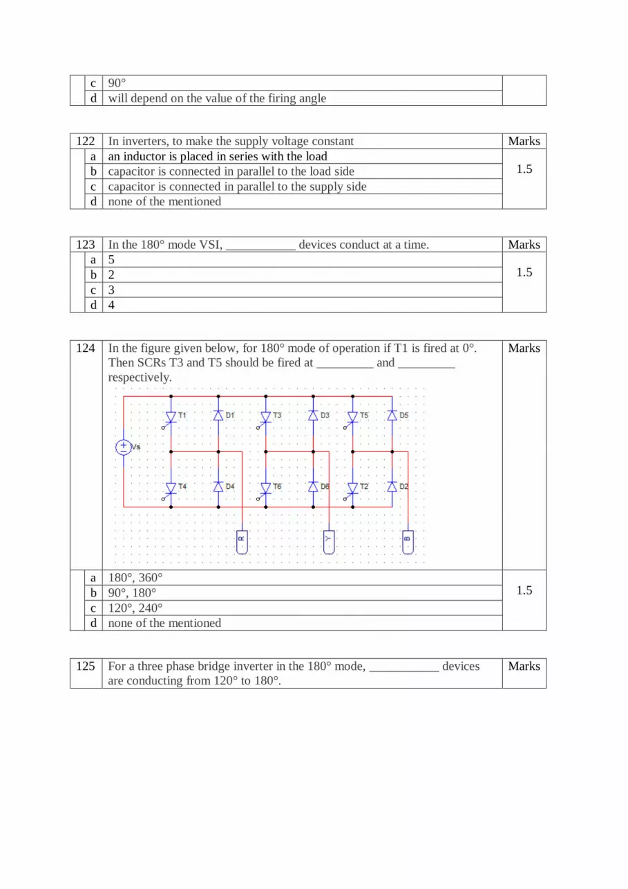
182 Identify the below given chopper circuit.
Marks
a Type D chopper 1.5 b Type C chopper with commutating capacitor
c Load commutated step-down chopper
d Voltage commutated step-up chopper
183 Which type of commutating circuit will have highest switching losses for
same rating of all the components?
Marks
a current commutated chopper 1.5 b voltage commutated chopper
c load commutated chopper
d forced commutated chopper
184 Dual converters provide Marks
a two quadrant operation 1.5 b three quadrant operation
c four quadrant operation
d none of the mentioned
185 A dual converters has Marks
a two full converters in series 1.5 b two half converters in series
c two full converters in anti-parallel
d two half converters in anti-parallel

186 The major advantage of using dual converters is that Marks
a t is cheaply available 1.5 b it has better pf
c no mechanical switch is required to change the mode of operation
d its operating frequency is very high
187 The four quadrant operation of dual converters can be obtained by Marks
a moving the mechanical lever 1.5 b adding inductance to the circuit
c changing the firing angle value
d none of the mentioned
188 A single full converter alone can given a Marks
a four quadrant operation 1.5 b three quadrant operation
c two quadrant operation
d none of the mentioned
189 Choose the correct statement Marks
a Circulating current exists only in circulating current mode 1.5 b Circulating current exists only in non-circulating current mode
c Circulating current exists in both the circulating and non-circulating current
mode
d none of the mentioned
190 What causes circulating current in dual converters? Marks
a Temperature issues 1.5 b Inductance in load circuit
c Out of phase voltages from both the converters
d none of the mentioned
191 In case of circulating current type dual converters, the reactor is inserted
between
Marks
a supply and converter 1.5 b across the load
c between the converters
d no reactor is used in case of circulating type dual converter
192 Circulating current flows Marks
a from load to converters 1.5 b from one converter to another converter
c in the whole circuit
d none of the mentioned

193 The reactor in circulating current type dual converters Marks
a increases losses 1.5 b reduces power factor
c increase the weight of the circuit
d all of the above
194 Dual converters handle ________ during no load. Marks
a very high temperature 1.5 b no current
c only circulating current
d load current
195 In circulating current type of dual converters, the nature of voltage across
the reactor is
Marks
a triangular 1.5 b pulsating
c constant
d alternating
196 In the process of diode based rectification, the alternating input voltage is
converted into
Marks
a an uncontrolled alternating output voltage 1.5 b an uncontrolled direct output voltage
c a controlled alternating output voltage
d a controlled direct output voltage
197 In a half-wave rectifier, the Marks
a current & voltage both are bi-directional 1.5 b current & voltage both are uni-directional
c current is always uni-directional but the voltage can be bi-directional or uni-
directional
d current can be bi-directional or uni-directional but the voltage is always uni-
directional
198 A single-phase full wave rectifier is a Marks
a single pulse rectifier 1.5 b multiple pulse rectifier
c two pulse rectifier
d three pulse rectifier
199 In a three-phase half wave rectifier usually, the primary side of the
transformer is delta connected because
Marks

a it has no neutral connection 1.5 b we can get greater output voltage
c it provides a path for the triplen harmonics
d it provides better temperature stability
200 In a three-phase half wave diode rectifier using 3 diodes, each diode
conducts for
Marks
a 90 degrees 1.5 b 120 degrees
c 180 degrees
d 360 degrees