Embed Size (px)
Citation preview
u~ii ILE LUtO~
ESL-TR-87-45
0)
TECHNOLOGY ASSESSMENT OFo SELECTED HAZARDOUS WASTE
MINIMIZATION PROCESS CHANGES
,p C.J. CARPENTER
HO AIR FORCE ENGINEERING AND SERVICE CENTERAIR FORCE ENGINEERING AND SERVICESLABORATORYTYNDALL AFB FL 32403
MARCH 1988 f ELEOTE-CT
FINAL REPORT JUL 19 98O
SEPTEMBER 1986-APRIL 1987 %
APPROVED FOR PUBLIC RELEASE: DISTRIBUTION UNLIMITED
- _ _
ENGINEERING & SERVICES LABORATORYAIR FORCE ENGINEERING & SERVICES CENTERTYNDALL AIR FORCE BASE. FLORIDA 32403
i4

UNCLASSIFIEDSECUTY CLASSIFICATION OF THIS PAGE
REPORT DOCUMENTATION PAGE I OS No.O070O18
la. REPORT SECURITY CLASSIFICATION lb. RESTRICTIVE MARKINGSUNCLASSI1E
Za. SECURIY CLASSIFICATION AUTHORITY 3. DISTRIBUTION /AVAILABIUITY OF REPORT2b. DECLASSICATION I DOWNGRADING SCH4EDULE Approved for public release.
Distribution unlimited.
4. PERFORMING ORGANIZATION REPORT NUMBER(S) S. MONITOR'.G ORGANIZATION REPORT NUMBER(S)
ESL-TR-87-45
GI. NAME OF PERFORMING ORGANIZATION 6b. OFFICE SYMBOL 7a. NAME OF MONITORING ORGANIZATION
(ifC appkab)HQ AFESC _ VS
6C. ADDRESS (City. StM, NW a ZCodJ 7b. ADDRESS (Ci,. State. and ZIP Code)
Tyndall AFB FL 32403-6001
Sa. NAME OF FUNDINGISPONSORING 8b. OFFICE SYM9OL 9- PROCUREMENT INSTRUMENT IDENTIFICATION NUMBERORGANIZATION (if 4AUkOe)
[( ADDRESS (City, Sem, and ZIPCode) 10. SOURCE OF FUNDING NUMBERSPROGRAM PROJECT TASK WOR UNITELEMENT NO. I NO 1 • CCSSION NO
Technology Assessaent of Selected Hazardous Waste Minimization Process Changes
12. PERSONAL AUTHORS)Charles J. Carpenter
13a1 TYPE OF REPORT 13b. TIME COVERED 114. DATE OF REPORT (Year, Month Day) 115. PAGE COUVlTFinal 1 FROm6109/30 TO87/0 3' March 1988I 69
16. SUPPEMENTARY NOTATION
Availability of this report is specified on reverse of front cover.
17. COSATI CODES 18. SUBJECT TERMS (Convkwu on renm if necesmy and identify by biock number)FIELD GROUP SUB-GROUP Technology Assessment, Industrial Processes, Vapor Deposi-11 03 .tion, Aluminum, Strippers, Noncyanide, Plasma Spray,
Chromium, Nickel Boron, Hazardous Waste Minimization (-" .-19. ABSTRACT (Continue on ree% if necesuy ,&W identify by block nhmmber)
"e objective of this study was to technically evaluate selected industrial processchanges for applications to Air Logistics Centers for hazardous waste minimization. Thoseprocesses evaluated were as follows: (a) Ion vapor deposition of aluminum as a replacementfor cadmium electroplating, (b) Noncyanide strippers to replace cyanide strippers,(c) Plasma spray of chromium to replace chromium electroplating, and (d) Nickel boron as areplacement for chromium electroplating. The study resulted in the recommendation todevelop databases, test plans, pilot studies, and demonstrations of the effectiveness ofprocesses a and b, above, in minimizing hazardous waste generatica. Processes c and dshowed minimum potential for hazardous waste minimization, and were not recommended forfurther study. - ./ ' a . -_ ' - " . -- : --
20. DS•RBUTIONiAVAILAUTY OF ABSTRACT 21 ABSTRACT SECtU-ITY CLASSIFICATIONGUNCLASSIFIEDIUNUMITED 0 SAME AS =PT - DTIC USERS UNCLASSrFIED
22a NAME OF RESPONSBLE INDmIDUAL 22b. TELEPHONE (kxkje Area Code) 22c OF;IC- SYMVBOLCharles J. Carpenter 904 283-2942 77 RDV,
DDO Form 1473. JUN 26 Prevows ed'omn are obsolete. SECURITY CLASSIFICATMON OF TfiS PAGEi UNCLASSIFIED(The reverse of this page is blank. )
PREFACE
This report was prepared by the Air Force Engineering and ServicesCenter, (AFESC) Air Force Engineering and Services Laboratory, (ESL),Tyndall Air Force Base, Florida 32403-6001. Mr. Charles J. Carpenterwas the Government technical program manager. This report summarizeswork accomplished between 30 September 1986 and 30 April 1987.
This report has been reviewed by the Public Affairs Office and isreleasable to the National Technical Information Service (NTIS). A NTISit will be available to the general public, including foreign nations.
This technical report has been reviewed and is approved :or publication.
CHARLES J.i Z ; THOMAS J. WALKER, Lt Col, USAF, BSCPrjc Officer Chief, Environics Division
SEE T. D YIE MNaj, USAF C Colonel, USAFChief, Environmental Sciences Branch Director, Engineering and Services
Laboratory
fLC DT10
A --
(The ~ ~ __ revers oftioaeI ln.
! i?y
I' - *-- _- -_,_--
A. .'".'-, . •
- !
ii
(The reverse of this page is blank. )
TABLE OF CONTENTS
Section Title Page
INTRODUCTION ................................................ 1
A. OBJECTIVE ............................................... IB. BACKGROUND .............................................. 1C. APPROACH ................................................ 2
II DEFINITION OF PROBLEM ........................................ 3L
A. POLLUTION CONTROL REGULATIONS FOR ELECTROPLATING ........ 3B. WASTE REDUCTION AND NATIONAL POLICY ..................... 7C. ELECTROPLATING PROCESSES ................................ 8
1. General ............................................. 82. Cadmium and Cadmium Electroplating .................. 83. Cyanide ............................................ 124. Chromium and Chromium Electroplating ................ 165. Stripping Processes and Strippers ................... 19
III ASSESSMENT OF THE TECHNOLOGICAL STATE OF ION VAPOR-DEPOSITEDALUMINUM FOR ELIMINATION OF CADMIUM ELECTROPLATING .......... 20
A. INTRODUCTION TO ION VAPOR DEPOSITION .................... 20B. DESCRIPTION OF EQUIPMENT AND PROCESS .................... 21C. COATING PERFORM1ANCE ..................................... 23D. PRODUCTION APPLICATIONS ................................. 25E. PROMISING APPLICATIONS .................................. 26F. ECONOMICS ............................................... 27G. ENVIRONMENTAL CONSIDERATIONS ............................ 28H. RECOMMENDED RESEARCH PROGRAM ............................ 29I. COST ESTIMATE ........................................... 30J. SUMMARY ................................................. 30
IV TECHNICAL ASSESSMENT OF NONCYANIDE REPLACEMENTS FOR CYANIDESTRIPPING BATHS ............................................. 32
A. INTRODUCTION TO.STRIPPING PROCESSES ..................... 32B. STATUS OF ALCs STRIPPING PROCESSES ...................... 32C. NONCYANIDE ALfERNATIVES ................................. 35D. RECOMMENDED RESEARCH PROGRAM ............................ 38E. COST ESTIMATE ........................................... 38F. SUMMARY ................................................. 59
V PLASMA SPRAY OF CHROMIUM AS A REPLACEMENT FOR CHROMIUMELECTROPLATING .............................................. 40
A. INTRODUCTION TO PLASMA SPRAY ............................ 40B. DESCRIPTION OF EQUIPMENT ................................ 40C. STATE OF THE ART ........................................ 41D. HEALTH AND SAFETY .... ................................ 43E. ENVIRONMENTAL CONSIDERATIONS ............................ 44
v
TABLE OF CONTENTS(Continued)
Section Title Page
F. RECOMMENDED RESEARCH PROGRAM ............................ 46G. COST ESTIMATE ............................................ 47H. SUMMARY ................................................. 47
VI NICKEL BORON AS A REPLACEMENT FOR CHROMIUM ELECTROPLATING... 48
A. INTRODUCTION TO NICKEL BORON ............................ .. 48B. PROCESS DESCRIPTION ..................................... 48C. PRODUCT APPLICATIONS .................................... 50D. RESEARCH REQUIREMENTS ................................... 51E. COST ESTIMATE ........................................... 51F. SUMMARY ................................................. 51
VII CONCLUSIONS AND RECOMMENDATIONS
A. CONCLUSIONS ............................................. 52B. RECOMMENDATIONS ......................................... 54C. ESTIMATED COSTS ......................................... 55
REFERENCES .................................................. 56
vi
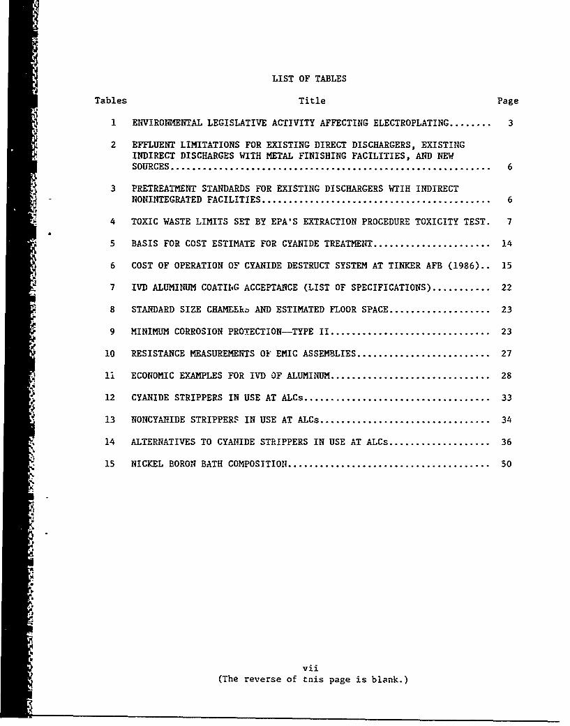
LIST OF TABLES
Tables Title Page
1 ENVIRONMENTAL LEGISLATIVE ACTIVITY AFFECTING ELECTROPLATING ........ 3
2 EFFLUENT LIMITATIONS FOR EXISTING DIRECT DISCHARGERS, EXISTINGINDIRECT DISCHARGES WITH METAL FINISHING FACILITIES, AND NEWSOURCES ............................................................ 6
3 PRETREATMENT STANDARDS FOR EXISTING DISCHARGERS WTIH INDIRECTNONINTEGRATED FACILITIES ........................................... 6
4 TOXIC WASTE LIMITS SET BY EPA'S EXTRACTION PROCEDURE TOXICITY TEST. 7
5 BASIS FOR COST ESTIMATE FOR CYANIDE TREATMENT ...................... 14
6 COST OF OPERATION OF CYANIDE DESTRUCT SYSTEM AT TINKER AFB (1986).. 15
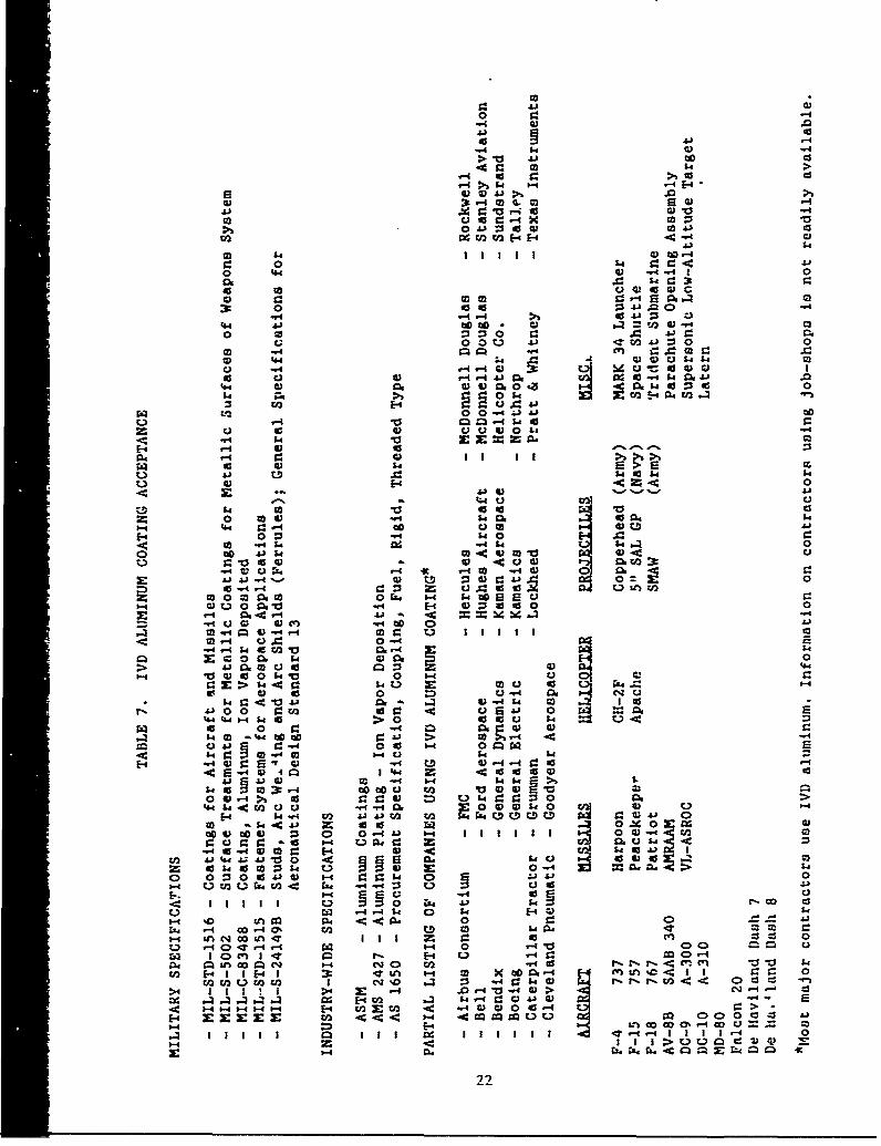
7 IVD; ALUMINUM COATING ACCEPTANCE (LIST OF SPECIFICATIONS) ........... 22
8 STANDARD SIZE CHAMEEka AND ESTIMATED FLOOR SPACE ................... 23
9 MINIMUM CORROSION PROTECTION--TYPE II .............................. 23
10 RESISTANCE MEASUREMENTS OF EMIC ASSEMBLIES ......................... 27
1i ECONOMIC EXAMPLES FOR IV) OF ALUMINUM .............................. 28
12 CYANIDE STRIPPERS IN USE AT ALCs ................................... 33
13 NONCYANIDE STRIPPERS IN USE AT ALCs ................................ 34
14 ALTERNATIVES TO CYANIDE STRIPPERS IN USE AT ALCs ................... 36
15 NICKEL BORON BATH COMPOSITION ...................................... 50
'a
b
vii(The reverse of tnis page is blank.)
SECTION I
INTRODUCTION
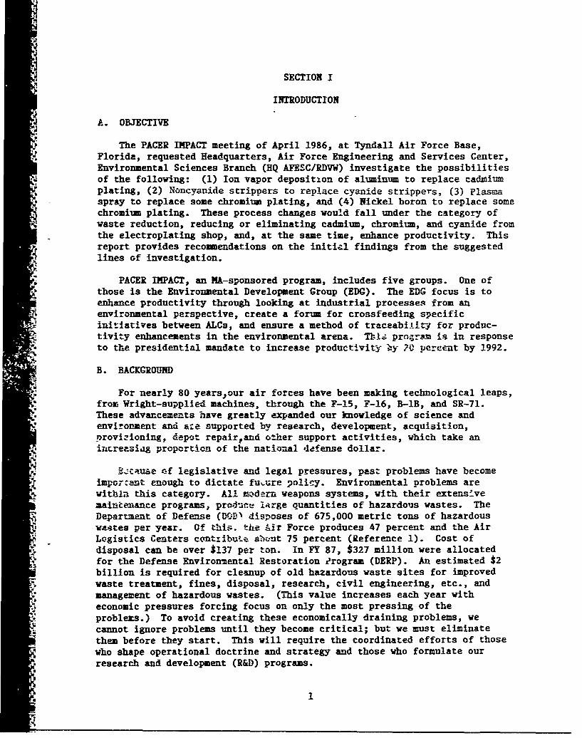
A. OBJECTIVE
"The PACER IMPACT meeting of April 1986, at Tyndall Air Force Base,Florida, requested Headquarters, Air Force Engineering and Services Center,Environmental Sciences Branch (HQ AFESC/RDVW) investigate the possibilities
4' of the following: (1) Ion vapor deposition of aluminum to replace cadmiumplating, (2) Noncyanide strippers to replace cyanide strippers, (3) Plasma
*: spray to replace some chromium plating, and (4) Nickel boron to replace somechromium plating. These process changes would fall under the category ofwaste reduction, reducing or eliminating cadmium, chromium, and cyanide fromthe electroplating shop, and, at the same time, enhance productivity. Thisreport provides recommendations on the initial findings from the suggestedlines of investigation.
* PACER IMPACT, an MA-sponsored program, includes five groups. One ofthose is the Environmental Development Group (EDG). The EDG focus is toenhance productivity through looking at industrial processes from anenvironmental perspective, create a forum for crossfeeding specificinitiatives between ALCs, and ensure a method of traceabiAltyj for produc-tivity enhancements in the environmental arena. TL,; pro;-ram is in response
; to the presidential mandate to increase productivity by ?7 percetnt by 1992.
B. BACKGROUND
p •For nearly 80 yearsour air forces have been making technological leaps,from Wright-supplied machines, through the F-15, F-16, B-lB, and SR-71.
- These advancements have greatly expanded our knowledge of science andenvironment and aze supported by research, development, acquisition,provizioning. depeit repair~and other support activities, which take aniincreasiag proportion of the national defense dollar.
S-tctuae *f legislative and legal pressures, past problems have become
important enough to dictate fuuure policy. Environmental problems arewithil this category. All m.tdern weapons systems, with their extensivemai•ienance programs, prod-uc lirge quantities of hazardous wastes. TheDepartment of Defense (Df.;V disposes of 675,000 metric tons of hazardouswastes per year. Of this. the Air Force produces 47 percent and the AirLogistics Centers contribute alu•ut 75 percent (Reference 1). Cost ofdisposal can be over $137 per ton. In FY 87, $327 million were allocatedfor the Defense Environmental Restoration ?rogram (DERP). An estimated $2billion is required for cleanup of old hazardous waste sites for improvedwaste treatment, fines, disposal, research, civil engineering, etc., andmanagement of hazardous wastes. (This value increases each year witheconomic pressures forcing focus on only the most pressing of theproblems.) To avoid creating these economically draining problems, wecannot ignore problems until they become critical; but we must eliminatethem before they start. This will require the coordinated efforts of thosewho shape operational doctrine and strategy and those who formulate ourresearch and development (R&D) programs.
I
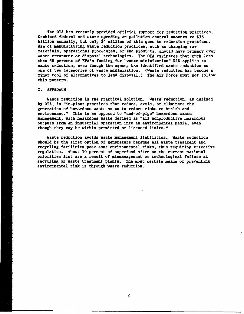
The OTA has recently provided official support for reduction practices.Combined federal and state spending on pollution control amounts to $16billion annually, but only $4 million of this goes to reduction practices.Use of manufacturing waste reduction practices, such as changing rawmaterials, operational procedures, or end produ.ts, should have primacy overwaste treatment or disposal technologies. The OTA estimates that much lessthan 50 percent of EPA's funding for "waste minimization" R&D applies towaste reduction, even though the agency has identified waste reduction asone of two categories of waste minimization. (Waste reduction has become aminor tool of alternatives to land disposal.) The Air Force must not followthis pattern.
Z. APPROACH
Waste reduction is the practical solution. Waste reduction, as definedby 0TA, is "in-plant practices that reduce, avoid, or eliminate thegeneration of hazardous waste so as to reduce risks to health andenvironment." This is as opposed to "end-of-pipe" hazardous wastemanagement, with hazardous waste defined as "all nonproductive hazardousoutputs from an industrial operation into an environmental media, eventhough they may be within permitted or licensed limits."
Waste reduction avoids waste management liabilities. Waste reductionshould be the first option of generators because all waste treatment andrecycling facilities pose some environmental risks, thus requiring effectiveregulation. About 10 percent of superfund sitep on the current nationalpriorities list are a result of mismanagement or technological failure atrecycling or waste treatment plants. The most certain means of preventingenvironmental risk is through waste reduction.
2
SECTION II
DEFINITION OF PROBLEM
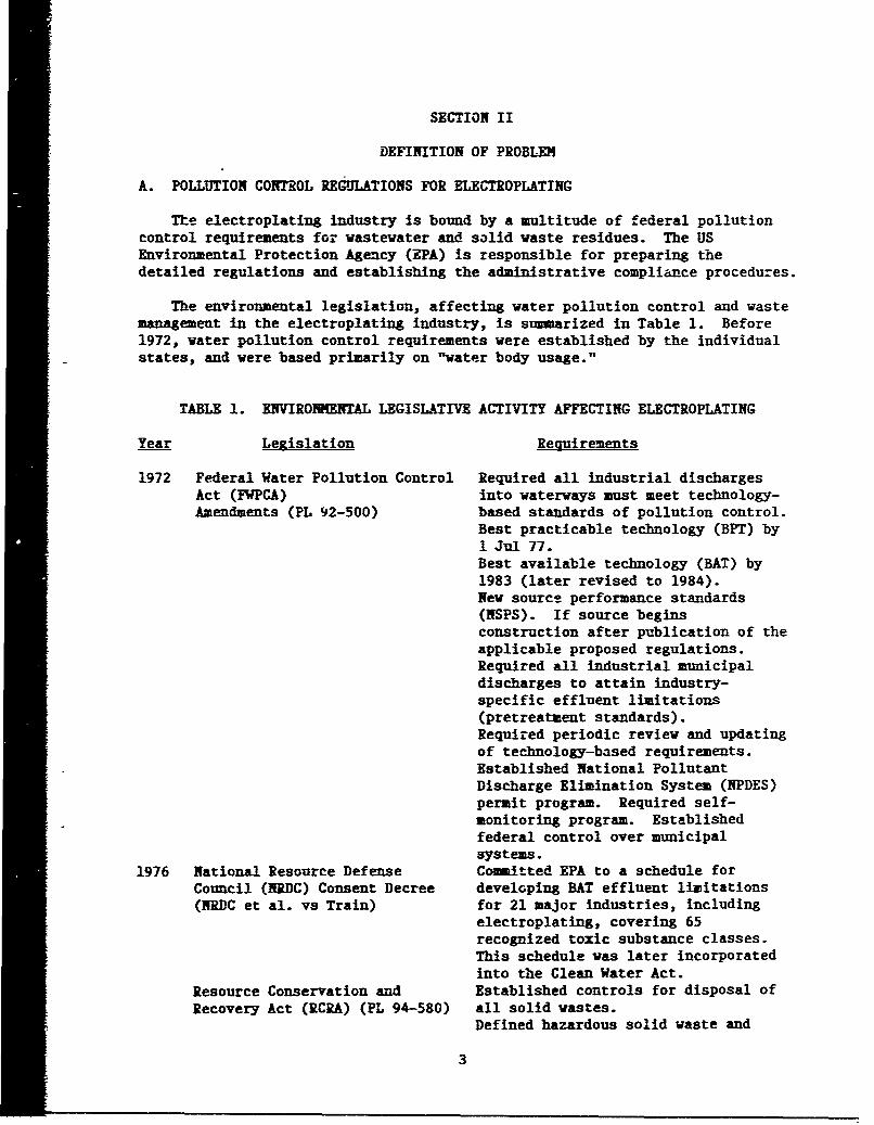
A. POLLUTION CONTROL REGULATIONS FOR ELECTROPLATING
Te electroplating industry is bound by a multitude of federal pollutioncontrol requirements for wastewater and solid waste residues. The USEnvironmental Protection Agency (EPA) is responsible for preparing thedetailed regulations and establishing the administrative compliance procedures.
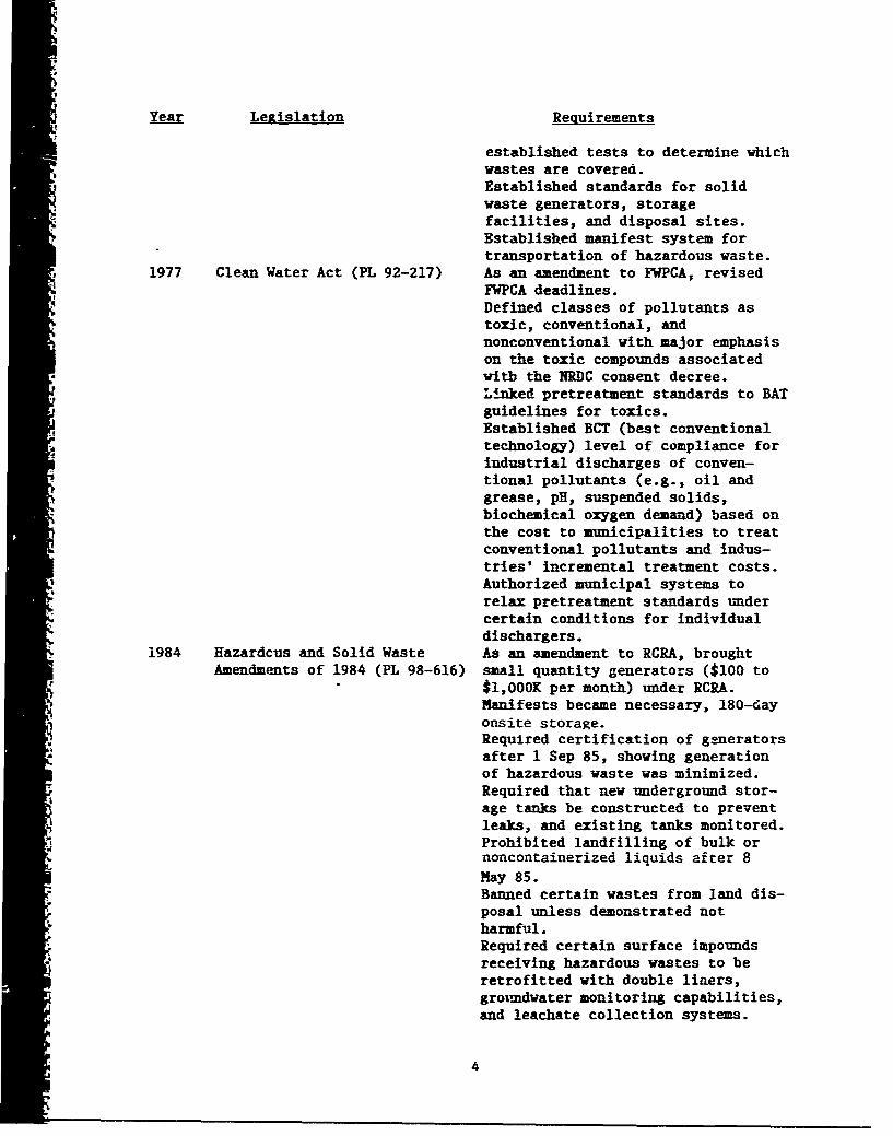
The environmental legislation, affecting water pollution control and wastemanagement in the electroplating industry, is s-marized in Table 1. Before1972, water pollution control requirements were established by the individualstates, and were based primarily on "water body usage."
TABLE 1. ENVIRO0ENTAL LEGISLATIVE ACTIVITY AFFECTING ELECTROPLATING
Year Legislation Requirements
1972 Federal Water Pollution Control Required all industrial dischargesAct (FWPCA) into waterways must meet technology-Amendments (PL 92-500) based standards of pollution control.
Best practicable technology (BPT) by1 Jul 77.Best available technology (BAT) by1983 (later revised to 1984).New source performance standards(NSPS). If source beginsconstruction after publication of theapplicable proposed regulations.Required all industrial municipaldischarges to attain industry-specific effluent limitations(pretreatment standards).Required periodic review and updatingof technology-based requirements.Established National PollutantDischarge Elimination System (NPDES)permit program. Required self-monitoring program. Establishedfederal control over municipalsystems.
1976 National Resource Defense Committed EPA to a schedule forCouncil (NRDC) Consent Decree developing BAT effluent limitations(NRDC et al. vs Train) for 21 major industries, including
electroplating, covering 65recognized toxic substance classes.This schedule was later incorporatedinto the Clean Water Act.
Resource Conservation and Established controls for disposal ofRecovery Act (RCRA) (PL 94-580) all solid wastes.
Defined hazardous solid waste and
3
Year Legislation Requirements
established tests to determine whichwastes are covered.
Established standards for solidwaste generators, storagefacilities, and disposal sites.Establisbhed manifest system fortransportation of hazardous waste.
1977 Clean Water Act (PL 92-217) As an amendment to FWPCA, revisedFWPCA deadlines.Defined classes of pollutants astoxic, conventional, andnonconventional with major emphasison the toxic compounds associatedwitb the NIRDC consent decree.Linked pretreatment standards to BATguidelines for toxics.Established BCT (best conventionaltechnology) level of compliance forindustrial discharges of conven-tional pollutants (e.g., oil andgrease, pH, suspended solids,biochemical oxygen demand) based onthe cost to municipalities to treatconventional pollutants and indus-tries' incremental treatment costs.Authorized municipal systems torelax pretreatment standards undercertain conditions for individualdischargers.
1984 Hazardcus and Solid Waste As an amendment to RCRA, broughtAmendments of 1984 (PL 98-616) small quantity generators ($100 to
$1,000K per month) under RCRA.Manifests became necessary, 180-dayonsite storage.Required certification of generatorsafter 1 Sep 85, showing generation
of hazardous waste was minimized.Required that new underground stor-age tanks be constructed to preventleaks, and existing tanks monitored.
o1 Prohibited landfilling of bulk ornoncontainerized liquids after 8MNay 85.Banned certain wastes from land dis-posal unless demonstrated notharmful.Required certain surface impoundsreceiving hazardous wastes to beretrofitted with double liners,grotmdwater monitoring capabilities,and leachate collection systems.
4
Year Legislation Requirements
Required EPA to report to Congresson hazardous wastes not addressed byRCRA because they are sent throughmumicipal severs.
EPA has prepared a number of regulations to provide specific guidancefor carrying out the requirements of the legislation. These regulationscontain achievable specific performance standards for processes arcontaminants.
Wastewater regulations, including enforcement mechanisms, have beendivided into several layers of categories: those for existing sources andnew sources; and those for direct and indirect dischargers. Directdischargers are regulated by NPDES, under which EPA or its state equivalentissues a separate permit to each discharger. This permii contains specificdischarge limitations, reporting requirements, and compliance schedules.Indirect dischargers must conform to national pretreatment standazds, whichare enforced by the local governcent under EPA.
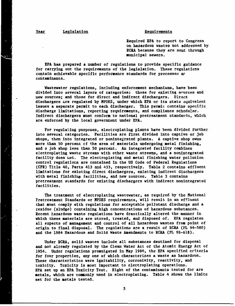
For regulating purposes, electroplating plants have been divided furtherinto several categories. Facilities are first divided into captive or jobshops, then into integrated or nonintegrated plants. A captive shop ownsmore than 50 percent cf the area of materials undergoing metal finishing,and a Job shop less than 50 percent. An integrated facility combinese'ectroplating waste streams with other waste streams, and a nonintegratedfacility does hot. The electroplating and metal finishing water pollutioncontrol regulations are contained in the US Code of Federal Regulations(CFR) Title 40, Parts 413 and 433, respectively. Table 2 contains effluentlimitations for existing direct dischargers, existing indirect dischargerswith metal finishing facilities, and new sources. Table 3 containspretreatment standards for existing dischargers with indirect nonintegratedfacilities.
The treatment of electroplating wastewater, as required by the NationalPretreatment Standards or NPDES requirements, will result in an effluentthat must comply with regulations for acceptable pollutant discharge and aresidue (sludge) containing high concentrations of hazardous substances.Recent Lazardous waste regulations have drastically altered the manner inwhich these materials are stored, treated, and disposed of. EPA regulatesall espects of management and control of all hazardous wastes from point oforigin to final disposal. The regulations are a res.alt of RCRA (PL 94-580)and the 1984 Hazardous and Solid Waste Amendments to RCRA (pL 98-618).
Under RiRA, solid wastes include all substances destined for disposaland not already regulated by the Clean Water Act or the Atomic Energy Act of1954. Under regulations promulgated in Nay 1980, the EPA specified criteriafor four properties, any one of which characterizes a waste as hazardous.These characteristics were ignitability, corrosivity, reactivity, andtoxicity. Toxicity is most important to electroplating operations.EPA set up an EPA Toxicity Test. Eight of the contaminants tested for aremetals, which are commonly used in electroplating. Table 4 shows the limitsset for the metals tested.
5
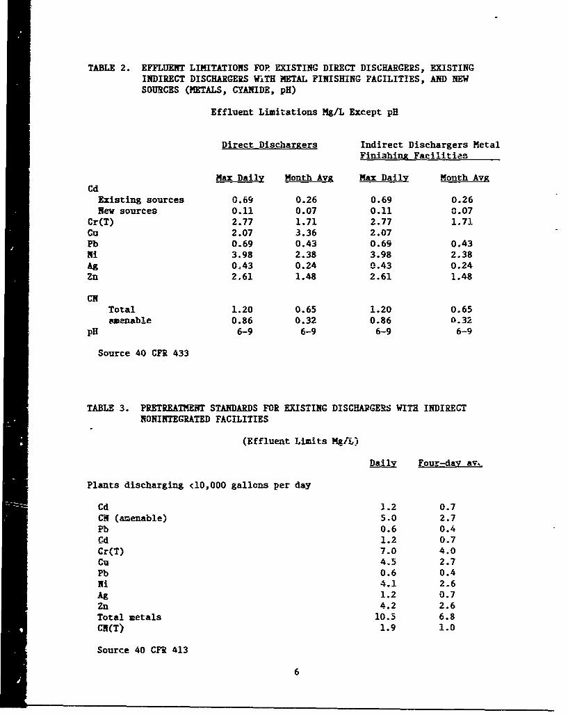
TABLE 2. EFFLUENT LIMITATIONS FOP EXISTING DIRECT DISCHARGERS, EXISTINGINDIRECT DISCHARGERS WITH METAL FINISHING FACILITIES, AND NEWSOURCES (METALS, CYANIDE, pH)
Effluent Limitations Mg/L Except pH
Direct Dischargers Indirect Dischargers MetalFinishing Facilities
Max Daily Month Avg Max Daily Month AvgCd
Existing sources 0.69 0.26 0.69 0.26New sources 0.11 0.07 0.11 (i0.07
Cr(T) 2.77 1.71 2.77 1.71Cu 2.07 3.36 2.07Pb 0.69 0.43 0.69 0.43Ni 3.98 2.38 3.98 2.38Ag 0-43 0.24 0.43 0.24Zn 2.61 1.48 2.61 1.48
CITotal 1.20 0.65 1.20 0.65amenable 0.86 0.32 0.86 0.32
pH 6-9 6-9 6-9 6-9
Source 40 CFR 433
TABLE 3. PRETREATMENT STANDARDS FOR EXISTING DISCHARGERS WITH INDIRECT
NONINTEGRATED FACILITIES
(Effluent Limits Mg/L)
Dail Four-day av.,
Plants discharging <10,000 gallons per day
Cd 3.2 0.7CH (amenable) 5.0 2.7Pb 0.6 0.4Gd 1.2 0.7Cr(T) 7.0 4.0Cu 4.5 2.7Pb 0.6 0.4Ni 4.1 2.6Ag 1.2 0.7Zn 4.2 2.6Total metals 10.5 6.8CN(T) 1.9 1.0
Source 40 CFR 413
6
TLBLE 4. TOXIC WASTE LIITS SET BY EPA'S EXTRACTION PROCEDURE TOXICITY TEST
Contaminant Ez-at Level
Arsenic 5.0Barim 100.0Cadmium 1.0Chromium 5.0L ead 5.0Mercury 0.2S elinium 1 . 0
Silver 5.0
If these limits are exceeded, or if the sludge is in any of the followingcategories, it is considered hazardous waste:
- Wastewater treatment sludge
- Spent plating bath solutions
- Sludge from bottom of plating baths
- Spent stripping and cleaning bath solutions
Producers of hazardous waste (generators) are ultimately responsible forproper identification, storage, transportation, and disposal of the waste.Generators are responsible for notifying EPA and maintaining records of theiractivities, using appropriate containers and labeling, and ensuring properdisposal. Most generators must use a manifest system which tracks the wastethroughout. New require=nts are constantly affecting disposal. Forinstance, the landfilliny; of bulk or noncontainerized liquids is nowprohibited and land disposal may be prohibited in the future.
B. WASTE REDUCTION AND NATIONAL POLICY
Waste reduction is no lor.er the prerogative, but is now the responsi-bility of industry. The Resource Conservation and Recovery Act, as amended bythe US Congress in November 1984 and supported by waste minimization"provisions, states, "The Congress hereby declares it to be the national policyof the United States that, whenever feasible, the generation of hazardouswaste is to be reduced or eliminated as expeditlo-!sly as possible. Waste
Z-. nevertheless generated should be treated and disposed of so as to minimize thepresent and future threat to human health aaid the environn.-- ."
This statute and related regulations have lead DOD to set nonbindingreduction goals which will become more stringent. To be met by 1992, suchgoals have already been established within some military departments. Theseare sumarized as follows:
1. Office of the Secretary:
Defense Environmental Leadership Prolect (DELP)-Seeks innovativesolutions to long-term environmental problems with cost and policy implications
Si. 7
and tries to improve DOD's national leadership position in environmentalprotection.
Defense Logistics Agency (DLA)-Provides material support(procurement, quality control, storage, distribution, maintenance). Hasinstituted some informal changes in material ordering to reduce wastes createdby shelf-life regulations.
2. Air Force
Office of Secretary of Air Force-Studies on decision-making andcosting practices that affect waste generation.
Air Force Systems Comand (AFSC)-Requested $13 million from DefenseEnvironmental Restoration Account for waste minimization in 1986. Hascompleted assessment of waste minimization opportunities in eight majorfacilities. (US Air Force, Aeronautical Systems Division, Waste Minimizationat Air Force Plants, by the Earth Technology Corporation, 1986.)
Air Force Logistics Command (AFLC)-"PACER REDUCE" waste minimizationplan in place since end of 1985. Overall goal of over 50 percent reduction by1992. Has done complete waste stream inventory by process. Studyingtechnologies in private sector for transfer to AF operations. Some R&Dconducted at Tyndall AFB by AFESC.
3. Navy:
All commaudf-Were required to report by April 1986 on wasteminimization measures taken. The objective was to raise awareness of issuesand accumulate information for transfer across commands.
Na'al Civil Engineering Laboratory-Is investigating private industryinitiati7es for transferability and Navy operations.
4. Army:
Army Materiel Coiand (AYMC)-Has developed a hazardous wasteminimization (HAZMIN) plan. All ANC installations rmust implement a wide rangeof activities including reduction goals (15-60 percent by 1992), for majorwaste streams (metal working, electroplating, paimf ing, electricalmaintenance, and waste treatment sludges). Also disposal of untreated wastesin landfills to be eliminated by 1992.
C. ELECTROPLATING PROCESSES
i. General
Electroplating is the electrodepositton of an adherent metalliccoating upon an electrode for the purpose of securing a surface withproperties or dimensions different from those of the basis metal. Generally,the electroplating process consists of four parts: (1) the exter .--I circuitconsisting of a source of direct curzent (dc), a means of carrying thiscurrent to the plating tank, associatea "1struments such as aueters, volt-meters, and means of regulating the voltage ind current at their xppropriate
8
values; (2) the negative electrodes or cathodes, which are the material to beplate1, along with mezs of positioning the material in the plating solutionso that contact is made with the current source; (3) the plating solutionitself. called the "bath"; and (4) the gositive electrodes (anodes) usually ofthe metal being plated, or an inert material, used to complete the circuit.The solution is contained in a tank with a liner appropriate to the solution.A detailed description of electroplating will not be given here. References 2and 3 can be used for this information.
Electrodeposited coatings are usually applied for the followingspecial properties: (1) appearance, (2) protection, (3) special surfaceproperties or (4) engineering or mechanical properties. A decorative coatingmay be applied for appearance "eye appeal." Inexpensive zinc die castings orordinary steels may have a thin layer of chromium applied to enhance theirappearance. A corrosion resistant coating of cadmium may be applied toequipment used in a corrosive salt spray. The cadmium will act sacrificiallyto protect the steel electrochemically. Special surface characteristics suchas improved solderability or conductivity of electrical current may beobtained by electrodeposition of copper. Rebuilding a part to dimension byelectroplating with hard nickel is one of many engineering or mechanicalproperties possible from electroplating of metals.
2. Cadmium and Cadmium Electroplating
Cadmium is a corrosion-resistant, soft, white metal with bluishtinges, possessing considerable ductility The corrosion-resistant propertiesare of interest for cadmium electroplating.
Most cadmium plating is carried out in alkaline cyanide baths preparedby dissolving cadmium oxide (CdO) in a sodium cyanide (NaCN) solution. Sodiumhydroxide (NaOH) and sodium carbonate (Na 2 C02 ) are formed by functionswithin and are part of this bath. Cadmium balls suspended in steel wire cagesserve as the plating anodes. Bath compositions and plating methods vary anddepend on the purpose and the material to be plated. Other considerationsir:.Lude plating efficiency, plating speed, deposition uniformity, and hydrogenevolutions.
Hydrogen evolution is a major concern in the aerospace industrybecause of hydrogen eabrittlement of high-strength steels and alloys. Everyprecaution is necessary to eliminate hydrogen contact with the work pieces.After plating, baking is a required to drive off hydrogen. Over 90 percent ofthe tensile strength of a material can be lost from hydrogen embrittlement.Because cadmium plating cannot be accomplished without production of hydrogen,the process shculd be optimized for minimal hydrogen production.
The vapor pressure of cadmium is 1.4 m at 400 °C. Hightemperature-incineration and industrial processes lead to vaporization ofcadmium into the atmosphere, where it oxidizes quickly to produce cadmiumoxide. Atmospheric emissions are estimated at 16 percent of total emissionsfor the US on approximately 1800 metric tons per year. An estimated 70 metrictons are contributed by the electroplating process. Atmospheric concentra-tions in the US are usually on the order of a few hundredths or thousandths ofmicrograms per cubic meter of 4ir.
9
The solubility of cadmium in water is low, and pH-dependent. Cadmiumconcentrations in surface waters are, therefore, usually lower than 1 milligramper liter. Elevated levels occur as a result of industrial and municipaldischarges, but these levels disaipate rapidly due to adsorption to suspendedparticles on bottom sediment. Yost (1979), Reference 4, estimated that theelectroplating industry accounts for 70 percent of the cadmium discharged tosewer collection 3ystems. Over the years, these sediments are washed to theoceans where bioaccumulation occurs in plants, shellfish, mussels, etc.
According to the EPA, land-disposed cadmium wastes represent more than80 percent of estimated total environmental releases. This. cadmium is aresult of hazardous sludge disposal, and about 47 percent of this is a resultof electroplating. DOD disposes of an estimated 675,000 metric tons ofhazardous waste per year, of which 41 percent is accredited to the Air Force.Host of this waste contains cadmium.
A recent report by the Office of Technology Assessment stated that"ultimately, because an element cannot be destroyed, all cadmium minedeventually becomes waste: during mining and extraction, during manufacturingand industrial use, or after the disposal of cadmium containing products."This is true whether emissions are to the air, waters, or the land. Manyareas, usually around industrial complexes, have reported rising concentra-tions, causing concern throughout the country.
Because cadmium does not occur in the pure state, it is produced as aby product of zinc, copper, and lead production. This results in an inelasticmarket, completely dependent on demand. Zinc production is a slow-growingindustry, and cannot provide for increases in cadmium production. As aresult, import of cadmium has increased over the years, until approximately 67percent is now imported. Small fluctuations in either demand or supply couldcause large price increases. The United States is the largest consumer in theworld, using approximately one-fourth of the total world refined production.
The National Institute for Occupational Safety and Health (NIOSH)states that sources of potential worker exposure to cadmium include"ore-smelting operations, mist from cadmium-containing electroplating baths,calcination (drying) of cadmium pigments, and handling of powdered oxide inproduction of cadmium soaps used to stabilize plastics. Cadmium is notessential for the health of mammals. It steadily accumulates in body tissues,especially the liver and kidneys. In hmmums, chronic low-level cadmiumingestion in nonoccupational settings can result in adverse health effectssuch as Itai-Itai disease in Japan. Recent epidemiological studies providepersuasive evidence for the carcinogenicity of cadmium oxide. The possibilityof chromosomal aberrations exists. In humans, acute cadmium intoxicationsymptoms are severe nausea, vomiting, diarrhea, muscular cramps, salivation,sensory disturbances, liver injury, and convulsions. In fatal intoxications,these symptoms are followed by shock caused by dehydration and death within 24hours, or by acute renal failure, cardiopulmonary depression and death within7 to 14 days. The health effects of cadmium have brought about significantregulation. Some major legislation and regulations (Source: Office ofTechnology Assessment, 1986), pertaining to cadmium are cited as follows:
10
a. Clean Water Act
This was intended to list cadmium as a hazardous air pollutant(published 16 November 1985), based in part on EPA's conclusion that Cd is aprobable human carcinogen. Decision to list will rely on pollution controltechniques for cadmium and further public health risk analysis.
b. Safe Drinking Water Act
National interim primary drinking water standards (NIPDWS) of .01milligrams per liter were set December 1975 and intended to include a fourfoldsafety factor to reduce earliest manifestation of chronic cadmium poisoning.
c. Clean Water Act
The water quality criterion for cadmium to protect human health isidentical to NIPDWS, O.Olmg/Il; set 15 March 1979. Ocean dumping was bannedfor all but trace amounts of cadmium (proposed 11 January 1977, finalized 6January 1978). "Reportable quantities" on cadmium acetate, cadmium bromide,cadmium chloride were set at 100 pounds in 1979. Discharge of more than thereportable quantity into navigable waters within a 24-hour period must bereported to a national response center. Cadmium and cadmium compounds werespecifically designated in a list of 65 priority toxic pollutants or pollutantcategories. Cadufum and cadmium compounds are regulated for specificindustrial point sources.
Applicants for NPDES permits in certain primary industrialcategories with processes which discharge Cd or Cd compounds must reportquantitative data on Cd discharge at each outfall.
d. Resource Conservation and Recovery Act (RCRA)
Solid waste is classified as toxic hazardous waste if it passesthe toxicity test. Wastewater treatment sludges from electroplatingoperations are designated as hazardous, in part, because of their cadmiumcontent. Dusts/sludges from the primary production of steel in electricfurnaces and secondary lead smelting are regulated as hazardous, partiallybecause of their cadmium content. All of these designated hazardous wastesare subject to the "cradle-to-grave" manifest system that covers generators,transportation, storage, and disposal of such wastes. Groundwater cannot becontaminated beyond the facility boundary at cadmium levels in excess of 0.01mg/L. Oil containing more than 2 ppm cadmium is restricted for burning.
e. Comprehensive Environmental Response, Compensation, and LiabilityAct (CERCLA)
This places a tax of $4.45 per ton on zunufi.cturers, producers,and importers of cadmium. The act taxed receipt of waste containing cadmiumat $2.13 per dry weight ton. Reportable quantities are 1 pound for cadmiumand 100 pounds for cadmium acetate, cadmium bromide, and cadmium chloridereleased into the environment. Cadmium particles need not be reported iflarger than 100 micrometers.
11

f. Occupational Safety and Health Act
Average exposure limit of 0.1mg/m3 of cadmium fumes and0.2mg/m3 of cadmium dust; maximum exposure-0.3mg/m3 and 0.6mg/m 3 ,respcctively.
g. Mine Safety and Health Act
Maximum air concentrations of cadmium established for differenttypes of mining operation.
h. Federal Food, Drug, and Cosmetic Act
Same standards as NIPDWS-0.O0mg/l.
i. Hazardous Materials Transportation Act
Has established rules governing transport of cadmium acetate,cadm•um bromide, and cadmitm chloride.
3. Cyanide
Cadmium electroplating is especially dangerous because most cadmiumelectroplating baths are made up of cadmium oxide (CdO) in a sodium cyanide(RaCN) solution. Sodium hydroxide (NaOH) and sodium carbonate (Na 2 CO2 )are formed by internal reactions and produce an alkaline cyanide bath. Spentplating solutions, and rinsewaters containing cyanide must be treated.
A separate treatment system is necessary to treat cyanide beforemetals removal. Virtually all treatment of dilute cyanide waste streams isdone by alkaline chlorination. The process has been in commercial use forover 25 years, and, if properly designed and maintained, will oxidizecyanides, Al•c! are amenab s le tl - - to less than 1 ppm.
Destruction ef the cyanide by chlorination can be accomplished bydirect addition of sodium hypochlorine (NaCCl) or by addition of chlorine gasplus sodium hydroxide (NaOH) to the waste. Sodium hydroxide reacts with thechlorine to form sodium hypochlorite. Selection between the two methods isbased on economics and safety. The chemical costs for chlorine gas treatmentare about half those of direct hypochlor•te additions, but handling is moredangerous and equipment costs are higher.
The hypochlorite oxidizes cyanide to cyanate. This reaction isaccomplished most completely and rapidly under alkaline conditions at pH 10 orhigher. An oxidation period of 30-60 minutes to 1 hour is usually allowed.The wastewater should be continuously mixed during treatment to avoidproducing solid cyanide precipitates, which may resist chlorlnation.
The resulting cyanste is much less toxic than cyanide, but regulationsrequire that it be further oxidized to carbon dioxide and nitrogen. This canbe accomplished by additional chlorination. The pH must be kept at 8.5 sothat the overall reaction rate is increased, otherwise oxidation will occurslowly over several hours. Usually, excess chlorine is used to speedbreakdown.
12
When sodiua hypochlorite is used, the r-action in the first stage is:
NaCN + NaOC1 NaCNO + NaCi
and in the second stage:
2NaCNO + 3NaOC1 + H2 0 3MaCl + N2 + 2NaHC03
Sodimi hypochlorite consumption is usually 25 to 100 peraent greaterthan stoichiometric requirements. The excess is consumed by oxidation oforganics and raising of the valence of metals in the wastewater.
The major costs of an alkaline chlorine cyanide treatment system areequipment installation, segregation of waste, maintenance, chemical usage, andsludge disposal. Elimination of cyanide would eliminate these costs and thesavings could be used for other military O&N projects.
Table 5 sumarizes the basis for costs presented in Table 6. Thesevalues are for Tinker AFB and were a result of 1986 data presented at the 1987Airline Plating and Finishing Forum by a representative of Tinker AFB. Theinformation is based on an 80 gpm flow rate, achieved with the practice ofwater conservation methods.
The bottom line is that $169,600 per year can be saved at Tinker AFBby elimination of cyenides from the plating shop. If the five ALCs havesimilar savings, the total yearly savings will be approximately $848,000.This is a significant savings.
13
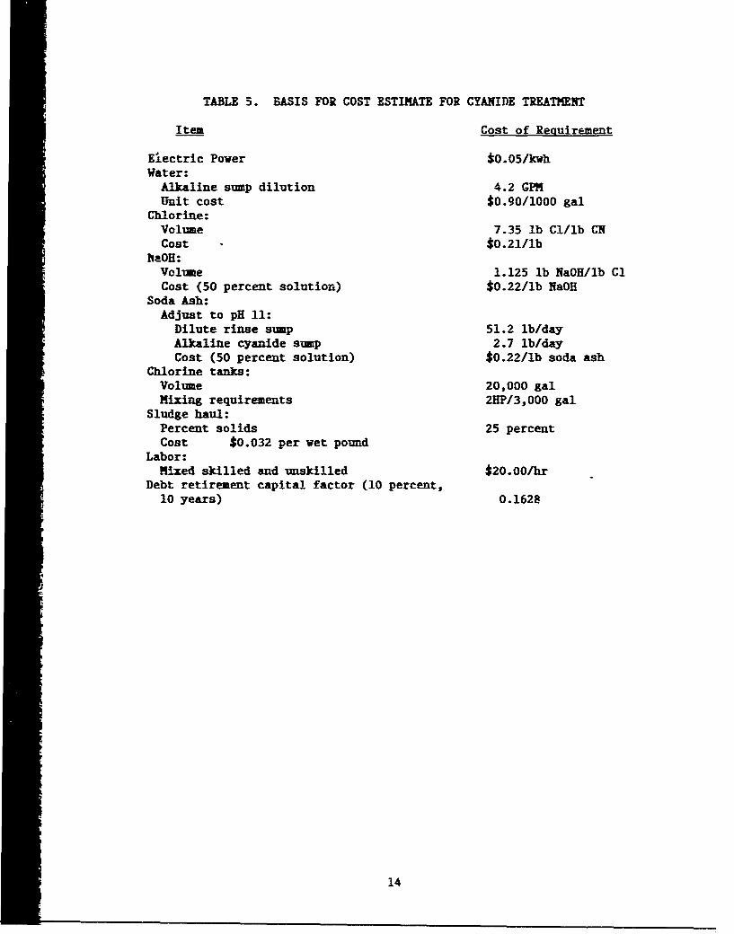
TABLE 5. BASIS FOR COST ESTIMATE FOR CYANIDE TREATMENT
Item Cost of Requirement
Electric Power $0.05/kwhWater:
Alkaline sump dilution 4.2 GPMUnit cost $0.90/1000 gal
Chlorine:Volume 7.35 lb Cl/lb CNCost - *0.21/lb
lhaOH:Volume 1.125 lb NaOH/ilb ClCost (50 percent solution) *0.22/lb NaOH
Soda Ash:Adjust to pH 11:
Dilute rinse sump 51.2 lb/dayAlkaline cyanide sump 2.7 lb/dayCost (50 percent solution) *0.22/lb soda ash
Chlorine tanks:Volume 20,000 galMixing requirements 2HP/3,000 gal
Sludge haul:Percent solids 25 percentCost $0.032 per vet pound
Labor:Mixed skilled and unskilled $20.00/hr
Debt retirement capital factor (10 percent,10 years) 0.1628
14
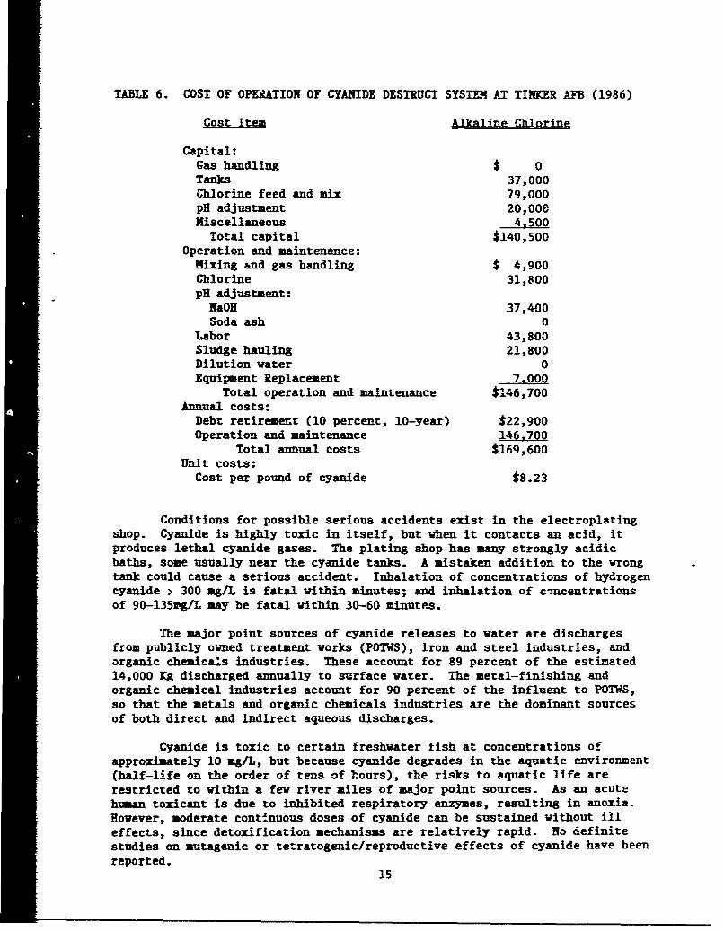
TABLE 6. COST OF OPERATION OF CYANIDE DESTRUCT SYSTEM AT TINKER AFB (1986)
Cost Item Alkaline Chlorine
Capital:Gas handling $ 0Tanks 37,000Chlorine feed and mix 79,000pH adjustment 20,000Miscellaneous 4,500
Total capital $140,500Operation and maintenance:
Mixing and gas handling $ 4,900Chlorine 31,800pH adjustment:
NaOH 37,400Soda ash 0
Labor 43,800Sludge hauling 21,800Dilution water 0Equipment Replacement 7,000
Total operation and maintenance $146,700Annual costs:
Debt retirement (10 percent, 10-year) $22,900Operation and maintenance 146,700
Total annual costs $169,600Unit costs:
Cost per pound of cyanide $8.23
Conditions for possible serious accidents exist in the electroplatingshop. Cyanide is highly toxic in itself, but when it contacts an acid, itproduces lethal cyanide gases. The plating shop has many strongly acidicbaths, some usually near the cyanide tanks. A mistaken addition to the wrongtank could cause a serious accident. Inhalation of concentrations of hydrogencyanide > 300 agL is fatal within minutes; and inhalation of c-ncentrationsof 90-135wg/L may be fatal within 30-60 minutes.
The major point sources of cyanide releases to water are dischargesfrom publicly owned treatment works (POTWS), iron and steel industries, andorganic chemicals industries. These account for 89 percent of the estimated14,000 Kg discharged annually to surface water. The metal-finishing andorganic chemical industries account for 90 percent of the influent to POTWS,so that the metals and organic chemicals industries are the dominant sourcesof both direct and indirect aqueous discharges.
Cyanide is toxic to certain freshwater fish at concentrations ofapproximately 10 mg/L, but because cyanide degrades in the aquatic environment(half-life on the order of tens of hours), the risks to aquatic life arerestricted to within a few river miles of major point sources. As an acutehuman toxicant is due to inhibited respiratory enzymes, resulting in anoxia.However, moderate continuous doses of cyanide can be sustained without Illeffects, since detoxification mechanisms are relatively rapid. No definitestudies on mutagenic or tetratogenic/reproductive effects of cyanide have beenreported.
15
In ssmary, the chemicals involved in cadmium plating are extremelyhazardous to humans and their environment. The plating process can causeserious problems with hydrogen embrittlement, which can result in expensivefailures with loss of aircraft and lives. Expensive treatment equipment isrequired both for eliminating the cyanide, and then removal of the metal. Thecost of cadmium is not stable and depends on demand. Environmentalregulations are becoming more stringent, and could result in an eventual banon cadmium in the US.
4. Chromium and Chromium electroplating
Elemental chromium is a blue-white, refractory metal that exists in theearth's crust in relative abundance. The production of chrcmim on acommercial basis started in 1616 and has continued without interruption.Chroml= compcunds are now valuable in many industrial areas. Various formsof chromium are used extensively in the paint and dye industries, platingindustry, steel industry for stainless steel and other alloys, chrome tanningin the leather goods industries, and in production of high-melting refractorymaterials. In mozt compounds, cadmium is found in the more stable trivalentand hexavalent states.
Chromium in an electrodeposited coating has many desirable ergineeringproperties, some of which are: pleasing blue-vhite color, high reflectivity,excellent tarnish resistance, good corrosion-resistance, good wear-resistance,and good scratch-resistance. Chromium is usually divided into two categories,decorative chromium plate and engineering (hard) chromium plate. The AirForce is usually interested in engineering (hard) chromium plating.
In hard chrome plating, a chromium electrodeposit is applied inthicknesses of .002 to .05 inches (usually not more than .010) to parts suchas shafts, cylinders, gears, struts, sleeves, and armat zes. The deposit isused for rebuilding worn surfaces and/or to obtain one or more of thefollowing properties: hardness, low coefficient or friction, corrosionresistance, nongalling, and nunwetting.
The chromic acid solution for decorative and engineering chromium maybe the same for both, and excellent results may be obtained. If, however,best coverage and nickel activation for decorative and best plating speed forengineering use are desired, different baths and operating conditions arenecessay7.
The conventional solution for electrodepositing chromium has twoconstituents: chromic trioxide flakes (Cr0 2 ), which combine with water toform chromic acid (H2 CrO4 ); and the sulfate ion ($04) introduced assulfuric acid or sulfate salt. Chromic acid flakes are added inconcentrations of 20 to 60 oz/gal. The critical point is that theCr03 /S0 4 ratio be about 100/L, although ratios between 80 to 1 and 130 to1 are used for specific engineering requirements. There are other mixedcatalyst baths, but this report does not present these baths in detail.
Chromiua plating differs from most other plating operations in that aninsoluble anode is used, and chromium is replenished by the addition ofchronic a'.id. Iron anodes have been used, but are not generally suitablebecause they add iron to the bath and allow buildup of trivalent chromium in
16
solution. Platinum has had limited success, but it allows buildup oftrivalent -hromium. The universally used material is lead or lead alloy,especially 7 percent tin, which oxidizes the trivalent back to hexavalentchromitm during electrolysis.
Because hydrogen evolution is excessive, it is a major concern in theaerospace industry. As with cadmium, critical parts must be baked to preventhydrogen embrittlement.
Harmful effects to man or animals seldom result from chromium inambient air or public drinking water. Reported chromium toxicity occursmainly from occupational exposure. Trivalent compounds are not highly toxic,but excessive exposure to dust or mists of hexavalent chromium compoundsproduces dermatitic skin lesions, and ulceration and perforation of the nasalseptum, as well as liver and kidney damage. Incidence of lung cancerincreases with long-term exposure to hexavalent chromium compounds. None ofthe reports suggest these compounds are mutagenic or tetratogenic risks.
Trace levels of chromium are essential to mammalian life. Irreversiblemetabolic damage is possible from long-term chromium deficiencies. Americansusually have less chromium in their diets than do people of most othercountries and, in fact, may have marginal intake of biologically activechromium.
Sources of atmospheric chromium include emissions from coal-fired powerplants, iron and steel industries, municipal incinerators, and coolingtowers. Yearly averages range from below detection limits in nonurban areasto .1 mg/m 2 in urban areas. Most of the chromium in the atmosphere isparticulate and most likely in the trivalent state.
Chromium concentration in soils can range from 5 to 200 ppm. The clayfraction of soils typically has a higher proportion of chromium. Chromiumconcentration does not change significantly with depth. Chromium in soils ismainly insoluble in adsorbed, mineral, or precipitated form. Water-extractable chromium in soils is usually less than .01 ppm. Evidence ofsampling done near cooling towers sugge--ts that hexavalent chromium is reducednaturally to the trivalent state and is readily adsorbed or precipitated.
Some chromium can be found in both surface waters and groundwaters.Freshwater concentrations are reported to range between 0-112 ppb with anaverage of 9.7 ppb. Concentrations in sea water ranged from 0-.5 ppb,considerably less than in freshwater. Most city drinking waters have lessthan 50 ppb chromium content.
For all intents and purposes, chromium in soil is imobile and mainlytrivalent, having been reduced by organic matter. Flowing water transportsvast amounts of chromium to estuaries to be deposited in the sediment. (Forexample, 790 metric tons/yr by the Susquehanna River.) The chromium remainstied up and is not raised back to hexava]ent state.
Electroplating and metal finishing account for the major releases ofchromium to wastewater. The sources from electroplating are fron tankoverflows, rinsevater, wash-down from cleaning procedures, scrubber water,etc. All of these waters must be treated before discharge. Chromium requires
17
an additional step to the normal metal precipitation process. Chromium (+6)must be reduced tc chromium (+3) state, then precipitated. This requireslowering the pH to 3.0-3.5 and bubbling sulfur dioxide or adding sodiummetabisulfate to the wastewater. This process is expensive beca-ase ofchemical usage and equipment requirements.
After reduction, the pH of the wastewater must be raised to 7-10 toprecipitate the metals. This can be done with hydrated lime or otherchemicals such as caustic soda, sodium bicarbonate, etc. Excessive amounts ofchemicals are necessitated by lowering and raising the pH; excessive amountsof chemicals are necesEary. A polymer is usually used to help settling. Theentire process is costly, as chemicals for metal treatment at Tinker AFB costapproximately $775/day, including polymer usage.
Sludge produced by the precipitation process must be disposed of as ahazardous waste. Tinker AFB pays $137/ton to dispose of hazardous waste.Tinker IWTP produces 4 to 5 tons per day of hazardous waste. Costs ofdisposal increase steadily, while disposal sites available decrease yearly.Future land disposal may be banned altogether.
Chromium is a strategic metal. The US has no reserves: over 95percent of the chromium reserves in the world are in *"'rouble spots" (73.9percent, Republic of South Africa; 19.7 percent, Zimbabwe; and 2.9 percent,USSR). A recent congressional research report concluded: "The US isstrategically more vulnerable to a long-term chromium embargo than to anembargo of any other natural resource, including petroleum." The vulner-ability of chromium and robalt supplies represents a potential threat to theF-100 engine in the F-15 and F-16 weapons systems.
Future access to chromium is not guaranteed. Without chromium, itwould be impossible to manufacture stainless steel, yet the US imports closeto 90 percent of its chromium. Reference 30 estimates that a 15-26 percentreduction in imports due to a disruption in supply for 10 years would resultin an economic loss of 4.2 billion dollars. The chance of such an eventoccurring before the year 2000 is greater than 50 percent.
New metal coating systems such as ion vapor deposition, plasma spray,substitute materials (nickel boron), etc-,could easily reduce chromium usage.Processes such as IVD do not generate waste products as chrome plating does.Economic incentives will be required to produce change. Environmentalcontinue to provide such incentives. These techniques could be rapidly increasedir the event cf severe chromium shortage.
Techniques are available to nearly elimin..te chromium discharge fromthe electroplating shop. Dead rinses can be used to collect chromium-containing rinsewaters and return them to the plating tank as makeup water.Scrubber waters can be reduced and routed to the plating tanks. Automatedspray syster.s can reduce water usage and automatically return chromium platingrinses to baths. Bath purifiers are available to clean the baths and elimi-nate disposal of used baths. The Navy has developed a system for this purpose.
In si•mary, chromium is generally dangerous to health only for occupa-tional areas where inhalation of vapors, mists, or dusts is a real possibility.Chromium plating can cause hydrogen embrittlement of high-strength steels and
18
alloys, leading to expensive failures of weapons systems. Special treatmentwith added steps and expense is required for treatment of wastewater
containing chromium, and tiix disposal of the hazardous sludges. Nearly allchromium used in the US is imported from areas of unstable political climate.Disruption of these imports has significant probability of occurrence over thenext 13 years, especially since the USSR is still pursuing "Stalin's goal ofdepriving the West of mineral resources of the planet." Replacing chromiumplating with other techniques will require economic incentives.
5. Stripping Processes and Strippers
As electroplating has evolved, so have the processes that support theart. Stripping, rinsing, media blasting, and others are necessary to theelectroplating process. Most of these processes contribute to the amounts ofhazardous wastes leaving the electroplating shop and eventually to thosehauled to disposal sites.
The stripping process is a major contribution of hazardous wastes froman electroplating shop. The process involves removing a thin skin of onemetal from the basis metal. Many of these solutions are also used to clean oractivate a surface. Examples are forms of NaCN baths which strip nickel orsilver from steel, or which are used as alkaline cleaners or activators priorto silver-rhodium plating.
Salvage of plated articles is one of the major reasons for strippingand depends on removal of all or part of the metallic coating beforereprocessing. The stripping process depends on the difference in chemicalactivity of the metallic coating and the basis metal. For successfulstripping, the coating must be active and the basis metal relatively inert. Asolution can always be found that will attack the coating, but only a fewsolutions will attack the coating without affecting the underlying metal.
Developing a stripping solution is more art than science. The basismetal may be unaffected under one set of-conditions or one instance, but pitunder slightly different conditions. This is particularly true when alloycomposition may change from time to time. A high-carbon or an alloy steel maybe pitted by a solution that will not attack a plain low-carbon steel. Bychanging the condition of the electrolyte or the voltage, this pitting may beminimized or avoided.
Stripping solutions vary in life and in stripping rate. Some cyanidebaths may be used indefinitely since the metals will be deposited on the anodeas fast as it is stripped. On the other hand, some baths will have very shortlives before impurity buildup requires regeneration or disposal. As life ofthe bath ends, the solution must be either disposed of as a hazardous waste ortreated. If the solution is treated, the cyanide must first be destroyed andthen the metals precipitated. This requires two treatment processes and theequipment iDecessary for both. The combined cost of equipment, chemicals, andman-hours can be significant.
19
SECTION III
ASSESSMENT OF THE TECHNOLOGICAL STATE OF ION VAPOR DEPOSITION OFALUMINUM FOR ELIMINATION OF CADMIUM ELECTROPLATING
A. INTRODUCTION TO ION VAPOR DEPOSITION OF ALUMINUM
The Air Force, as with its civilian counterpant, must protect productsfrom corrosion. The stringent demands of new technologies associated withmodern aircraft and support equipment for improved product life and perfor-mance have resulted in continuous investigation of new corrosion coatrolsystems. With cadmium in disfavor, and with the strong possibility of itsbeing benned throughout the country, other corrosion prevention systems arenecessary.
Ion vapor deposition is one of several similar vacuum-metallizingprocesses. These processes are usually performed in an airtight chamber. Thechamber is evacuated to high vacuum pressures, less than 1-millionth of anatmospheric pressure, by a series of mechanical or diffusion-type pumps.While the vacuum is held, the metal is evaporated, usually by a high 7oltagesource. Enough heat is added to produce a vapor pressure in the boiling metalconsiderably higher than the total pressure in the chamber. Metals leave theheated source and, in conventional systems, travel towards the outer walls ofthe vacuum chamber. The molecules will travel in a straight path because ofthe low density of air within the chamber. These systems plate line-of-sightsurfaces, which means that only those surfaces that come within line-of-sight"of the source during the evaporation can become coated.
The ion vapor deposition is similar in that the material is evaporatedwithin the vacuum chamber rad allowed to condense on the parts being coated.However, other features set it apart. Glow discharge cleaning and plating onall sides (now line-of-sight) are just some of the characteristics discussedlater.
In the late 1960s, the search for improved corrosion protection led togovernment-sponsored, in-service testing of different coatings on operationalmilitary aircraft (Reference 2). These tests showed that only aluminumcoating provided superior corrosion protection. Being the least dissimilar toaluminum alloy structure, it is ideally compatible. Furthermore, aluminum isanodic to steel and provides galvanic protection, as does cadmium.
Because ion vapor deposition offered particularly good potential forlarge-scale production applications of aluminum, it was selected for furtherdevelopment and evaluation. Other available processes for applying aluminumcoatings such as metal spraying, electroplating, cladding, hot dipping, etc.,have severe limitations. These include thickness control, adhesion, size, andshape of product that could be coated, and effective.,ess on substrataproperties.
The performance advantages of ion vapor-deposited alaminum were confirmedover the next several years, and the ultimate value of this process foraircraft applications was demonstrated when a full-scale production coatingsystem was fabricated and delivered to the US Navy in 1974. Since that time,
20
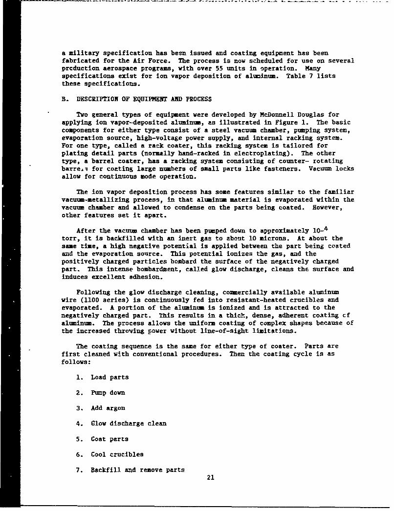
a military specification has been issued and coating equipment has beenfabricated for the Air Force. The process is now scheduled for use on severalprcduction aerospace programs, with over 55 units in operation. Manyspecifications exist for ion vapor deposition of aluminum. Table 7 liststhese specifications.
B. DESCRIPTION OF EQUIPMENT AND PROCESS
Two general types of equipment were developed by McDonnell Douglas forapplying ion vapor-deposited aluminum, as illustrated in Figure 1. The basiccomponents for either type consist of a steel vacuum chamber, pumping system,evaporation source, high-voltage power supply, and internal racking system.For one type, called a rack coater, this racking system is tailored forplating detail parts (normally hand-racked in electroplating). The othertype, a barrel coater, has a racking system consisting of counter- rotatingbarre4 for coating large numbers of small parts like fasteners. Vacuum locksallow for continuous mode operation.
The ion vapor deposition process has some features similar to the familiarvacuum-metallizing process, in that aluminum material is evaporated within thevacuum chamber and allowed to condense on the parts being coated. However,other features set it apart.
After the vacuum chamber has been pumped down to approximately 10-4torr, it is backfilled with an inert gas to about 10 microns. At about thesame time, a high negative potential is applied between the part being coatedand the evaporation source. This potential ionizes the gas, and thepositively charged particles bombard the surface of the negatively chargedpart. This intense bombardment, called glow discharge, cleans the surface andinduces excellent adhesion.
Following the glow discharge cleaning, commercially available aluminumwire (1100 series) is continuously fed into resistant-heated crucibles andevaporated. A portion of the aluminum is ionized and is attracted to thenegatively charged part. This results in a thich., dense, adherent coating cfaluminum. The process allows the uniform coating of complex shapes because ofthe increased throting power without line-of-sight limitations.
The coating sequence is the same for either type of coater. Parts arefirst cleaned with conventional procedures. Then the coating cycle is asfollows:
1. Load parts
2. Pump down
3. Add argon
4. Glow discharge clean
5. Coat parts
6. Cool crucibles
7. Backfill and remove parts21
0
>11 coo e -- E4
10 1" 16
E-- E-4 @3 .
0t 1." 00 0 w4
-40 is as43 0 0
@3 30@ 0 S -4 114.3 to to = to V
C; 0 J0 Q 4 O4 04 0
0m 54 =ii Q @34-0 544 4
go -4 -4.41 0os 4$ 640. 0 " 40 0et -- = 0
0 00 -4 J4Jt.4- -4 $J la
go 0 lAUz0
0E- 040 .
g 2 -4-4mO 00. 0
v .4c UC3@to54-4 5o V EEZ0 v1-' 4j-4 =3 W0 J
0. 03 II oII.t aEra)u0 *a 54 E- = 00
-4UG 4) n 54o5 54
U- =3 1-4 04r
to54 a V 00 r-.V'-4- $
44 4-I to V- 3. .
1-'0 0. .4 04 -
w 15 0J5 &.d0 *a 0 UL>0 $4 54 r.5 &4.. u0
c43UX 04 -4W 0 % u.
410 U3 do- 9: C. ) rt3~J 4 0E0.4 &d" 4 la >A .0 agoc & cJ
la 0-4 0.0. .4 1-i cp00w 4 0 .-%4 ton 1 a .4 1.uW s 3C 04 0 a
W.4@3 40- -4 U 11 1
0 v-4 46 0. r-v : C.4.4 &4 4Oco -- 0. 0wv
1-4 V@ 0 4V 0 -4 ca 4 Vc o a Dm - W 4~ V4 0Uaso r 0 .5c 0-cc @3 ti 0) 0 0.4 41 0- 12) -
Q4 ~ j r. 0- @345 is C.1 10wc&4.44-4 4) M0 r00 E54 $4 a
V2 414 ;40 0 -C 04 0.i@ 41 0G540 w 4~ 0A 0 =>- w - .0 0 J~. 0= 0- o0r V2 .a
u to uU4 0 l-4 54 54UId4
.4 . W4 1~ 1 1 11 uI @3 0u ra 10.4 14 0 L-44 i$
r 4X0 .- Go -4tom05.-I>, 00 C) 5~~ 0
44540 C 0 C440 1 W 54 O1 V U
Q -54co Z 040 C- 0.c @U3W@ E -~ -4 111 1 [email protected] cc6cnLnL 0
EO ca Le4 r. W C) C3 4=
.40.cc0 1-4 -4 - E4j
0E~04 @ -4 E oC 0 to >J 0E-4 EC U~O E3 E44 E to14 4 9 o U UcOýC 0C * 4
E-. 1-4 (Y. -4 w ~ ut
U~~~~ 1 1-~5 00414'-4u T'3 0.a~ -4 -4O% CO W 540 0gm
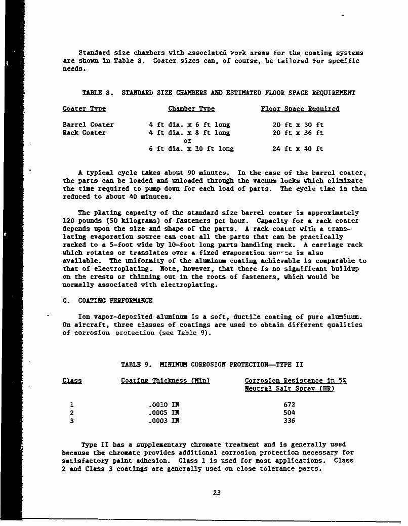
Standard size chambers with associated vori areas for the coating systemsare shown in Table 8. Coater sizes can, of course, be tailored for specificneeds.
TABLE 8. STANDARD SIZE CHAMBERS AND ESTIMATED FLOOR SPACE REQUIREMENT
Coater TVye Chamber Type Floor Space Required
Barrel Coater 4 ft dia. x 6 ft long 20 ft x 30 ftRack Coater 4 ft dia. x 8 ft long 20 ft x 36 ft
or6 ft dia. x 10 ft long 24 ft x 40 ft
A typical cycle takes about 90 minutes. In the case of the barrel coater,the parts can be loaded and unloaded through the vacuum locks which eliminatethe time required to pump down for each load of parts. The cycle time is thenreduced to about 40 minutes.
The plating capacity of the standard size barrel coater is approximately120 pounds (50 kilograms) of fasteners per hour. Capacity for a rack coaterdepends upon the size and shape of the parts. A rack coater with a trans-lating evaporation source can coat all the parts that can be practicallyracked to a 5-foot wide by 10-foot long parts handling rack. A carriage rackwhich rotates or translates over a fixed evaporation sov-:-e is alsoavailable. The uniformity of the aluminum coating achievable is comparable tothat of electroplating. Note, however, that there is no significant buildupon the crests or thinning out in the roots of fasteners, which would benormally associated with electroplating.
C. COATING PERFORMANCE
Ion vapor-deposited aluminum is a soft, ductile coating of pure aluminum.On aircraft, three classes of coatings are used to obtain different qualitiesof corrosion protection (see Table 9).
TABLE 9. MINIMUM CORROSION PROTECTION-TYPE II
Class Coatinz Thickness (Min) Corrosion Resistance in 5.Neutral Salt Spray (HR)
1 .0010 IN 6722 .0005 IN 5043 .0003 IN 336
Type II has a supplementary chromate treatment and is generally usedbecause the chromate provides additional corrosion protection necessary forsatisfactory paint adhesion. Class 1 is used for most applications. Class2 and Class 3 coatings are generally used on close tolerance parts.
23
Numerous corrosion tests have been performed on ion vapor-depositedaluminum coatings at McDonnell Douglas, as well at ..ther companies. The AirForce and Navy have both evaluated aluminum-coated fasteners in laboratorytests and on aircraft in service. As is normal with corrosion testing,tests are on aircraft in service, and results vary. The performancead7antages, however, are clearly indicated.
In, service tests on fasteners, aluminum coatings outperformed cadmium(Reference 6). Similar results were obtained in laboratory tests whenfasteners were exposed to SO2 salt spray for 168 hours. Although all thefastener heads were corroded, corrosion was more severe in thecadmiui-plat.d fasteners. More important, however, was the condition of thecountersinks in the 7075 aluminum panels. The ion vapor-depcsited aluminumcoating provided far more protection to the countersinks.
Corrosion testing of steel panels in 5 percent neutral salt spray, perASTH B-117, will generally show that the same thickness of bright electro-
plated cadmium coating performs better than aluminum. However, the samethickness of aluminum will perform better in acidic S02 salt spray and inmost outdoor exposure tests. Additionally, IVD aluminum can be appliedsubstantially thicker than electroplated cadmium for applications wheretolerances allow.
In aluminum panels, aluminum-coated fasteners will proiide superiozprotection to the countersinks. In a test on 7075-T6 al" inum panels, after2500 hours of exposure, the aluminum panel showed much more severe corrosionin the countersinks where cadmium-coated fasteners were installed.
There are also advantages for ion vapor-deposited aluminum coatings ontitanium fasteners installed in aluminum structures. A comparison was madebetween aluminum-coated titanium fasteners installed dry and bare titaniumfasteners installed with wet epoxy primer (a standard procedure onaircraft). The fasteners were installed in 7075-T6 aluminum alloy that hadbeen treated with NIL-C-5541. The panel was sprayed with one coat ofMIL-C-2377 primer and exposed to S02 salt spray for 28 days. Visualexamination showed that the blistering of primer around the peripheries ofthe bare fasteners was more severe than around the aluminum-coated
. fasteners. The countersinks also showed less corrosion where thealuminum-coated fasteners were installed.
Studies at McDonnell have also shown a cost advantage of using ionvapor-deposited aluminum-coated fasteners in lieu of wet installation.
A large amount of fastener qualification data has been generated on theuse of ion vapor-deposited aluminum. A small portion of the data is
*• presented here. Two conclusions are: (a) ion vapor deposition of aluminumis not detrimental to the substrate mechanical properties, and (b) thecoefficient of friction of aluminum is higher than cadimium, thereforehigherinstallation forces are required. However, in most cases these highervalues are within the working ranges presently used for cadmium. (The useof interference fit fasteners may require closer attention to lubricants.)
Although the ion vapor deposition process would not be expected to causehydrogen embrittlement, stress durability tests were performed in accordance
24¾
with NIL-STD-1312, Test 5. Aluminum coated H-lI alloy steel bolts werestressed to 90 percent of the minim-m ultimate strength. The tests werediscontinued after 11 days without failure (Reference 3).
Higher usable temperature of 9250F to cadmium's 450OF allows stressrupture tests at 800°F to be performed on H-I1 steel alumintm-coatedbolts. A load equivalent to 75 percent of the bolt ultimate tensilestrength wa• applied for 200 hours. No failures occurred (Reference 7).
Tension fatigue tests were also made on fasteners, following theprocedures specified in Test 11, NIL-ST-O-1312. The tests were conductedwith R = +0.1. The data showed ion vapor-deposited aluminum to be slightlybetter than cadmium.
As stated, the coefficient of friction for the ion vepor-depositedaluminum is slightly higher than for electroplated cadmium. The difference,hovever, is generally not significant enough to require a change ininstallation procedures.
I, torque-tension relationships, even without dedicated development workto optimize nut materials, lubricants, and crimps for ion vapor-depositedaluminu*-coated bolts, galling and seizing are either insignificant ormanageable. This was also confirmed in reusability tests.
D. PRODUCTION APPLICATIONS
Both rack-and-barrel type coaters have been produced and are operatingin production environments. Primary applications of ion vapor-depositedaluminum in aircraft include the replacement of electroplated cadmium,diffused-nickel cadmium, vacuum-deposited cadmium, sacrificial paint-typecoatings, and anodized coatings. In addition, aluminum can be applied coparts previously left unplated because of inadequacies in the otheravailable coatings.
A large rack coater 7 feet (2 meters) in diameter by 12 feet (3.7meters) long, was put into operation at McDonnell Aircraft Company, StLouis, in 1976. Steel parts for the F-4 Phantom and F-15 Eagle aircraft,plus some engine components, were coated in that equipment. As a result ofthe new process, some stainless steel parts have been changed toaluzminum-plated alloy steel at a cost savings. This is possible by takingadvantage of the aluminum coating's compatibility with fuel and titanium andits higher temperature capability.
The aluminum wing skins, placed in the chamber together, have the largestplan area coated to date. Sulfuric acid anodizer was formerly used on thesefatigue-critical parts. While the brittle anodic film reduced fatiguestrength, the aluminum coating resulted in no fatigue strength reduction.No design change was necessary. The substitution also eliminated a shot-peening operation, resulting in cost savings.
ion vapor-deposited aluminum is also used on the Harrier aircraft, andis the primary corrosion-protective plating on the F-18 Hornet. On theHornet, it is used on all fatigue-critical aluminum structures, on alloysteel structure of all strength levels, on titanium and steel fasteners, andfor electrical bonding and ENIC applications.
25
Two slightly smaller (standard size) rack-type coaters are available.The coatrer delivered to the Navy in 1974 is 4 feet" (1.2 meters) by 8 feet(2.4 meters), and the Air Force coater is 6 feet (1.8 meters) by 10 feet (3meters). A typical application for these coaters might be the replacementof cadmium on aircraft landing gears or jet engine components. In addition,the rack-coater, with tailored internal racking systems, is being procuredby comercial companies with their own plating facilities and by job shopplaters.
In addition to the use of ion vapor-deposited aluminum on aircraft andengine hardw:4re limited to 9250 F, there is a growing interest in potentialapplication in the high-temperature turbine section of jet engines. Afterdeposition in the standard way, the aluminum coating is diffused into thebase metal to produce the constituents cf a good, high-temperature turbineblade coating. Compared to pack cementation, preliminary tests of thediffused aluminum coating have been very encouraging.
The IVD aluminum coating has been used recently as a substitute foranodizing on fittings requiring electrical continuity. For aluminum alloyfuel and pneumatic line fittings, IVD aluminum provides an electrical bondacross the fitting which dissipates static electrical charges generated byfuel or airflow. At the same time, it protects the fitting againstcorrosion. With anodizing, a bonding jumper or other technique is needed toestablish the required conductive path. Substantial cost savings arerealized by eliminating the bonding-jumper installation step. IVD canreplace anodize, aloeline, and most other conversion coatings on aluminumalloys.
IVD aluminum is also being used in place of electroplated tin forelectrical bonding and electromagnetic interference compatibility (ENIC).The IVD coating offers protection superior to electroplated tin againstcorrosion of aluminum alloys. The aluminum coating is sacrificial to thesubstrate, whereas tin is not. As a result, the IVD aluminum has replacedthe commonly used electroplated tin for many aircraft applications wherealuminum structure-to-structure interfaces must meet EMIC requirements.When treated with a chromatic conversion coating per NIL-C-5541, and whennormal joint clamp-up forces are used, the IVD aluminum will provide lowerjoint resistance after exposure to corrosive environments than will the tinelectroplate (Table 10).
The use of IVD aluminum, instead of the tin, is cost-effective not onlybecause of higher performance and less maintenance, but also becauseprocessing steps such as masking, and processing problems such as pooradhesion of the electroplated tin, are eliminated.
26
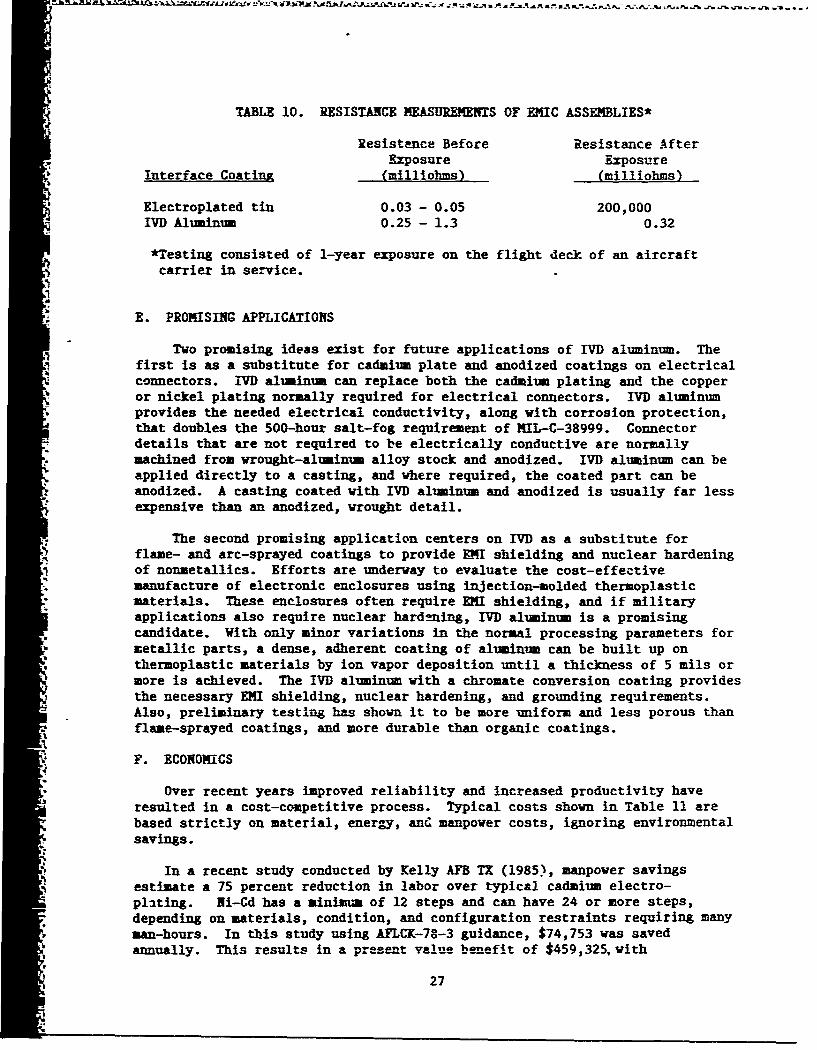
TABLE 10. RESISTANCE MEASIUREMETS OF EMIC ASSEMBLIES*
Resistance Before Resistance After* Exposure Exposure
Interface Coating (milliohms) (milliohms)
Electroplated tin 0.03 - 0.05 200,000IVD Aluminum 0.25 - 1.3 0.32
*Testing consisted of 1-year exposure on the flight deck of an aircraftcarrier in service.
E. PROMISING APPLICATIONS
Two promising ideas exist for future applications of IVD aluminum. Thefirst is as a substitute for cadmium plate and anodized coatings on electricalconnectors. IVM aluminum can replace both the cadmium plating and the copperor nickel plating normally required for electrical connectors. IVD aluminumprovides the needed electrical conductivity, along with corrosion protection,that doubles the 500-hour salt-fog requirement of MIL-C-38999. Connectordetails that are not required to be electrically conductive are normallymachined from wrought-aluminum alloy stock and anodized. IVD aluminum can beapplied directly to a casting, and where required, the coated part can beanodized. A casting coated with IVD aluminum and anodized is usually far lessexpensive than an anodized, wrought detail.
The second promising application centers on IV]) as a substitute forflame- and arc-sprayed coatings to provide XI shielding and nuclear hardeningof nonmetallics. Efforts are underway to evaluate the cost-effectivemanufacture of electronic enclosures using injection-molded thermoplasticmaterials. These enclosures often require EMI shielding, and if militaryapplications also require nuclear hard-ning, IVD) aluminum is a promisingcandidate. With only minor variations in the normal processing parameters formetallic parts, a dense, adherent coating of aluminum can be built up onthermoplastic materials by ion vapor deposition until a thickness of 5 mils ormore is achieved. The IVD aluminum with a chromate conversion coating providesthe necessary ENI shielding, nuclear hardening, and grounding requirements.Also, preliminary testing has shown it to be more uniform and less porous thanflame-sprayed coatings, and more durable than organic coatings.
F. ECONOMICS
'* Over recent years improved reliability and increased productivity haveresulted in a cost-competitive process. Typical costs shown in Table 11 arebased strictly on material, energy, and manpower costs, ignoring environmentalsavings.
In a recent study conducted by Kelly AFB TX (1985), manpower savingsestimate a 75 percent reduction in labor over typical cadmium electro-plating. Ni-Cd has a minimum of 12 steps and can have 24 or more steps,depending on materials, condition, and configuration restraints requiring manyman-hours. In this study using AFLCK-78-3 guidance, $74,753 was savedannually. This results in a present value benefit of $459,325. with
27
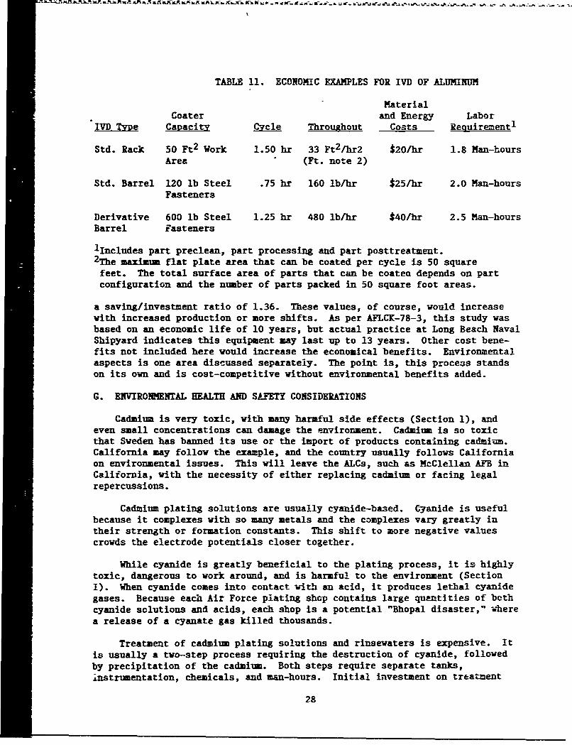
TABLE 11. ECONOMIC EXAMPLES FOR IVD OF ALUMINUM
MaterialCoater and Energy Labor
IVD TyDe Capacity Cycle Throughout Costs Requirement 1
Std. Rack 50 Ft 2 Work 1.50 hr 33 Ft 2/hr2 $20/hr 1.8 Nan-hoursArea (Ft. note 2)
Std. Barrel 120 lb Steel .75 hr 160 lb/hr $25/hr 2.0 Man-hoursFasteners
Derivative 600 lb Steel 1.25 hr 480 lb/hr $40/hr 2.5 Man-hoursBarrel Fasteners
lIncludes part preclean, part processing and part posttreatment.2 The maximum flat plate area that can be coated per cycle is 50 squarefeet. The total surface area of parts that can be coatea depends on partconfiguration and the number of parts packed in 50 square foot areas.
a saving/investment ratio of 1.36. These values, of course, would increasewith increased production or more shifts. As per AFLCK-78-3, this study wasbased on an economic life of 10 years, but actual practice at Long Beach NavalShipyard indicates this equipment may last up to 13 years. Other cost bene-fits not included here would increase the economical benefits. Environmentalaspects is one area discussed separately. The point is, this process standson its own and is cost-competitive without environmental benefits added.
C. ENVIROMENTAL HEALTH AND SAFETY CONSIDERATIONS
Cadmium is very toxic, with many harmful side effects (Section 1), andeven small concentrations can damage the environment. Cadmium is so toxicthat Sweden has banned its use or the import of products containing cadmium.California may follow the example, and the country usually follows Californiaon environmental issues. This will leave the ALCs, such as McClellan AFB inCalifornia, with the necessity of either replacing cadmium or facing legalrepercussions.
Cadmium plating solutions are usually cyanide-based. Cyanide is usefulbecause it complexes with so many metals and the complexes vary greatly intheir strength or formation constants. This shift to more negative valuescrowds the electrode potentials closer together.
While cyanide is greatly beneficial to the plating process, it is highlytoxic, dangerous to work around, and is harmful to the environment (SectionI). When cyanide comes into contact with an acid, it produces lethal cyanidegases. Because each Air Force plating shop contains large quantities of bethcyanide solutions and acids, each shop is a potential "Bhopal disaster," wherea release of a cyanate gas killed thousands.
Treatment of cadmium plating solutions and rinsewaters is expensive. Itis usually a two-step process requiring the destruction of cyanide, followedby precipitation of the cadmium. Both steps require separate tanks,instrumentation, chemicals, and man-hours. Initial investment on treatment
28
systems can run into several hundred thousand dollars with no payback,except to remain in compliance with regulations. These overhead costs runup the cost of production for each item plated.
After precipitation of the cadmium, the hazardous sludges formed mustbe disposed of in a hazardous waste disposal site. This costs each ALC1 adreds of thousands of dollars each year, with costs constantly rising.Even if EPA bans land disposal of hazardous wastes, "Cradle to Grave"legislation says the Air Force is still responsible for that material.Another defense environmental restoration program may, with billions ofdollars, clean up the cadmium wastes disposed of this year.
Cadmium plating usually requires lined, stainless-steel tanks, orequivalent, which can hold 1500 gallons or more. Each tank is filled with asolution which must be maintained by a chemist, and disposed of whencontaminated. Estimates run as high as $12,000 per tank, per year toservice them. Ventilation must be installed around each tank which,connects to a scrubber system. Each scrubber system runs hundre'.s ofthousands of dollars to purchase and maintain.
Cadmium is a soft metal and, as such, easily contaminates strippingsolutions removing paint from an aircraft, or blast media stripping paintfrom an aircraft. Over 1500 pounds of blast media is disposed of from astripping operation and is considered hazardous waste. Over 200 aircraftstripped by plastic beads at Hill each year generate 300,000 pounda of beadsto be disposed of as hazardous waste. At a $.20-per-pound disposal fee,this results in $60,000 each year for this one item. The two things thatmake the beaes hazardous materials are chromium from the paint and cadmiumfrom the cadmium-plated rivets. Nonchromium primers and paints are beingdeveloped now and will be used in the future. El :mination of cadmium (whichcan be done) would result in nonhazardous blasting that could be disposed offor only several dollars a ton.
Cadmium is a byproduct of zinc production, which -is slowly growing;therefore, the supply of cadmium is not very elastic. Roughly 50 percent oftotal consumption is for electroplating. A new use of cadmium (accountingfor 20 percent) is as a stabilizer for polyvinyl chloride. Pigments accountfor another 20 percent, and 10 percent is attributed to miscellaneous use.
The use of IVD of aluminum to replace cadmium electroplating wouldeliminate all environmental problems associated with the process withoutintroducing new ones. Health and safety problems would be eliminatedtecause aluminum is not a hazardous material and the process does notrequire cyanide bases, tanks, special ventilation, or rinsewater. Itproduces no hazardous sludges and requires no waste treatment facilities.All unused aluminum is recoverable, and a superior product is produced.
H. RECO!9EEDED RESEARCH PROGRAM
Since its conception in the 1960s, IVD has become a viable, competingproduction process. Based on the lists of Cadmium and Ni-Cd plated partssupplied by the ALCs, and previous studies completed on components over thelast decade, approximately 85 percent of components now plated with cadmiumcan immediately be changed to IYD of aluminum. The other percentage is
29
composed of inside diameters, and erosion control surfaces. Testing andpossible new surface coatings may be necessary to eliminate that 15 percent.
The recommended research program would be in two phases. Phase I wouldbe a paper study with the following objectives: (1) Compile a "complete"list of all cadmium-plated parts at the ALCs, collect all data on previoustesting of IVD, contact aircraft and engine manufactures and appropriate ALCpersonnel fo determine testing required to technically justify technicalorder change, and try to develop ii generic testing program. (2) Providetechnical justifications for all parts similar to those already tested. (3)Provide cost justifications which include processing and environmental,health, safety, and life-cycle costs. (4) Update military specifications toprovide for IVD of aluminum on parts which have been technically justified.
Phase II would be to provide a demonstration site for elimination ofcadmium. Phase II would have the following objectives: (1) Test thoseparts which cannot be technically justified on experience. (2) Developmethods or coatings to eliminate cadmium on those parts necessary. (3)Modify military specifications to eliminate cadmium plating of these parts.(4) Provide necessary equipment and expertise for a demonstration toeliminate cadmium plating at an ALC. Phase II would be to follow the sameprocedures outlined in Phaae I, Task 2, for all ALCs.
I. COST ESTINATE
Year I Data collection, testing development, technical evaluation ofcadmium-plated parts for immediate conversion to IVD of aluminum,process specification alternatives development, some testing ofparts (Air Force-wide). This would cost an estimated $400,000.
Year 2 Selection of demonstration site for complete conversion to IVDof aluminum, continued testing, initiation of demonstrationsite, at an estimated cost of $850,000.
Year 3 Testing of remaining parts throughout the ALCs andmodification of process specifications, provide operations andmaintenance manuals, and health and safety requirements.
Cost estimate would be $500,000.
J. SUMMARY
Even small amounts of cadmium can be harmful to both health andenvironmez.t. Cadmium plating solutions are usually cyanide-based. Cyanideis also hazardous and, when mixed with acid, releases gases similar to thecyanate gas that killed thousands in the Bhopal disaster.
IVD of aluminum can feasibly eliminate cadmium plating. This wouldeliminate disposal problems and associated costs, help prevent future"'superfunds" sites, eliminate health and environmental dangers, and avoidwaste management liabilities.
30
IVD of aluminum provides a proven, superior coating for prevention ofcorrosion. Numerous studies, a military standard, and a military specifica-tion recommend the process, which is both nontoxic and cost-competitive.Over 85 percent of cadmium plating can be eliminated initially, and theremaining 15 percent can be eliminated through testing and processmodification.
1Waste management, as defined by the Office of Technology Assessment, is"All nonproductive hazardous outputs from industrial operations into theenvironmental media, even though they may be within permitted or licensedlimits."
31
- ~ ~ ~ ~ ~ ~ --- -- - -- --
SECTION IV
TECHNICAL ASSESSM•NT OF NONCYANIDE REPLACEMENTSFOR CYANIDE STRIPPING BATHS
A. INTRODUCTION TO THE STRIPPING PROCESS
Development of a stripping solution is as much an art as a science. Thesame principles apply to noncyanide stripping solutions. Most noncyanidestrippers on the market are proprietary. Those that are not proprietary aresimple, widely used chemical combinations that have been used for decades.
Cyanides are dangerous to health and environment (Section I). Cyanidestrippers contribute to the cyanide vastp, which reach the IWTP by way ofwastewater. They must be treated, usually by alkaline chlorination. Thesestrippers have been used to remove various plated metals from substratemetals, and are usually contaminated with these metals. These solutions andthe wastewater resulting from them, are difficult to treat because of thepresence of stable ferrocyanides, and other cyanide complexes not amenableto chlorination. Since many discharge lirits are based on total cyanides,some facilities having cyanide strippers may find it difficult to avoidpermit violations.
Regulatory and economic pressures resulting from environmentalconsiderations have resulted in development of many noncyanide strippingbaths. Choice baths are usually left to individual cozmands. This hasresulted in DOD electroplatiug shops with a variety of stripping processeswhich have been tested and found satisfactory, but which are not necessarilyused DOD-wide. Better counication between DOD components could eliminatemost cyanide stripping baths. Enhanced communication with the privatesector would also result in other proven processes to transfer.
B. STATUS OF ITM ALCs STRIPPING PROCESSES
Recently, information was requested about the cyanide and noncyanidestrippers at each of the ALCs. Environmental and Industrial Management(MAQCD) at McClellan AFB was the lead center for gathering the information.Table 12 lists cyanide strippers in use, while Table 13 lists noncyanidestrippers in use today as reported by MAQCD.
32
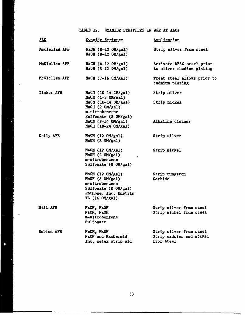
TABLE 12. CYANIDE STRIPPERS IN USE AT ALCs
ALC Cyanide Stripper Avplication
McClellan AFB NaCN (8-12 OM/gal) Strip silver from steelNaOH (8-12 OM/gal)
McClellan AFB NaCN (8-12 ON/gal) Activate DEAC steel priorNaOH (8-12 ON/gal) to silver-rhodium plating
McClellan AFB NaCN (7-16 OM/gal) Treat steel alloys prior tocadmium plating
Tinker AFB NaCH (10-14 ON/gal) Strip silverN&OH (1-3 ON/gal)NaCN (10-14 ON/gal) Strip nickelNaOH (2 ON/gal)a-nitrobenzeneSulfonate (8 OM/gal)NaCN (8-14 ON/gal) Alkaline cleanerNaOH (18-24 ON/gal)
Kelly AFB Na'1 (12 ON/gal) Strip silverNaOH (2 ON/gal)
NaCN (12 ON/gal) Strip nickelNaOH (2 OM/gal)m-nitrobenzeneSulfonate (8 ON/gal)
NaCN (12 ON/gal) Strip tungstenNaOH (8 OM/gal) Carbidea-nitrobenzeneSulfonate (8 ON/gal)Enthone, Inc, EnstripTL (16 OM/gal)
Hill AFB NaCN, NaOH Strip silver from steelNaCN, NaOH Strip nickel from steelm-nitrobenzeneSulfonate
Robins AFB NaCN, NaOH Strip silver from steelNaCN and MacDermid Strip cadmium and nickelInc, metex strip aid from steel
33

TABLE 13. NONCYANIDE STRIPPERS IN USE AT ALCSs
ALC Noneyanide Strippers Application
McClellan AFB Shipley Company, inc, Strip electrolesselectroless nickel strip- nickel from steelper 424D and 424L
Ammonium nitrate Strip cadmium from steel
Chromic acid Strip chrome from aluminum
Sodium hydroxide Str'p chrome from steel
Hot sulfuric nitric acid Strip precious metals from
copper-based alloys
"Nitric acid Strip nickel from aluminum
Tinker AFB None
Kelly AFB Enthone Enstrip GT 317 Strip tungsten carbide
Hill AFB 10 percent sulfuric acid Strip nickel from aluminum
Sodium hydroxide Strip chrome from steel
Ammonium nitrate Strip cadmium from steelChromic and phosphoric Strip anodizeacid
Robins AFB Tetra potassium Strip chrome from steelPyrophosphate
Potassium hydroxide andproprietary compounds.(M&T Chemical, Inc,Unichrome 80)
* Proprietary acidified Strip tin-leadperoxide solution (Chem- solder from printedlink Division [T-Strip] circuit boardsand Surface Chem Corp(Lead-Off])
-34
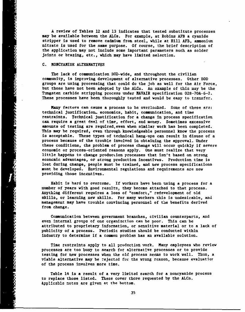
A review of Tables 12 and 13 indicates that tested substitute processesmay be available between the ALCs. For example, at Robins AFB a cyanidestripper is used to remove cadmium from steel, while at Hill AFB, ammoniumnitrate is used for the same purpose. Of course, the brief description ofthe application may not include some important parameters such as solderjoints or brazing, etc., which may have limited selection.
C. NONCYANIDE ALTERNATIVES
The lack of communication DOD-wide, and throughout the civiliancommunity, is improving development of alternative processes. Other DODgroups are using processing that could do the job as well for the Air Force,but those have not been adopted by the ALCs. An example of this may be theTungsten carbide stripping process under NAVAIR specification 028-70A-6-2.These processes have been thoroughly tested and would be easy to tramsfer.
Many factors can cause a process to be overlooked. Some of these are:technical justification- economics, habit, communication, and timerestraints. Technical justification for a change in process specificationcan require a greet deal of time, effort, and noney. Sometimes excessiveamounts of testing are required,even when similar work has been completed.
* This may be required, even through knowledgeable personnel know the processis acceptable. These types of technical hang-ups can result in disuse of aprocess because of the trouble involved in obtaining the approval. Under
* these conditions, the problem of process change will occur quickly if severeeconomic or process-oriented reasons apply. One must realize that verylittle happens to change production processes that isn't based on strongeconomic advantages, or strong production incentives. Production time islost during change, people must be trained, and new process specificationsmust be developed. Environmental regulations and requirements are nowproviding those incentives.
Habit is bard to overcome. If workers have been using a process for anumber of years with good results; they become attached to that process.Anything different requires a loss of "comfort," redevelopment of oldskills, or learning new skills. For many workers this is undesirable, andmanagement may have trouble convincing personnel of tie benefits derivedfrom change.
Coiaunication between government branches, civilian counterparts, andeven internal groups of one organizttion can be poor. This can beattributed to proprietary information, or sensitive material or to a lack ofpublicity of a process. Periodic studies should be conducted withinindustry to determine if a common problem has an available solution.
Time restraints apply to all production work. Many employees who reviewprocesses are too busy to search for alternative processes or to providetesting for new processes when the old process seems to work well. Thus, aviable alternative may be rejected for the wrong reason, because evaluatloTof the process involves more time.
Table 14 is a result of a very limited search for a noncyanide processto replace those listed. These cover those requested by the ALCs.&ppllcable notes are giyen at the bottom.
35
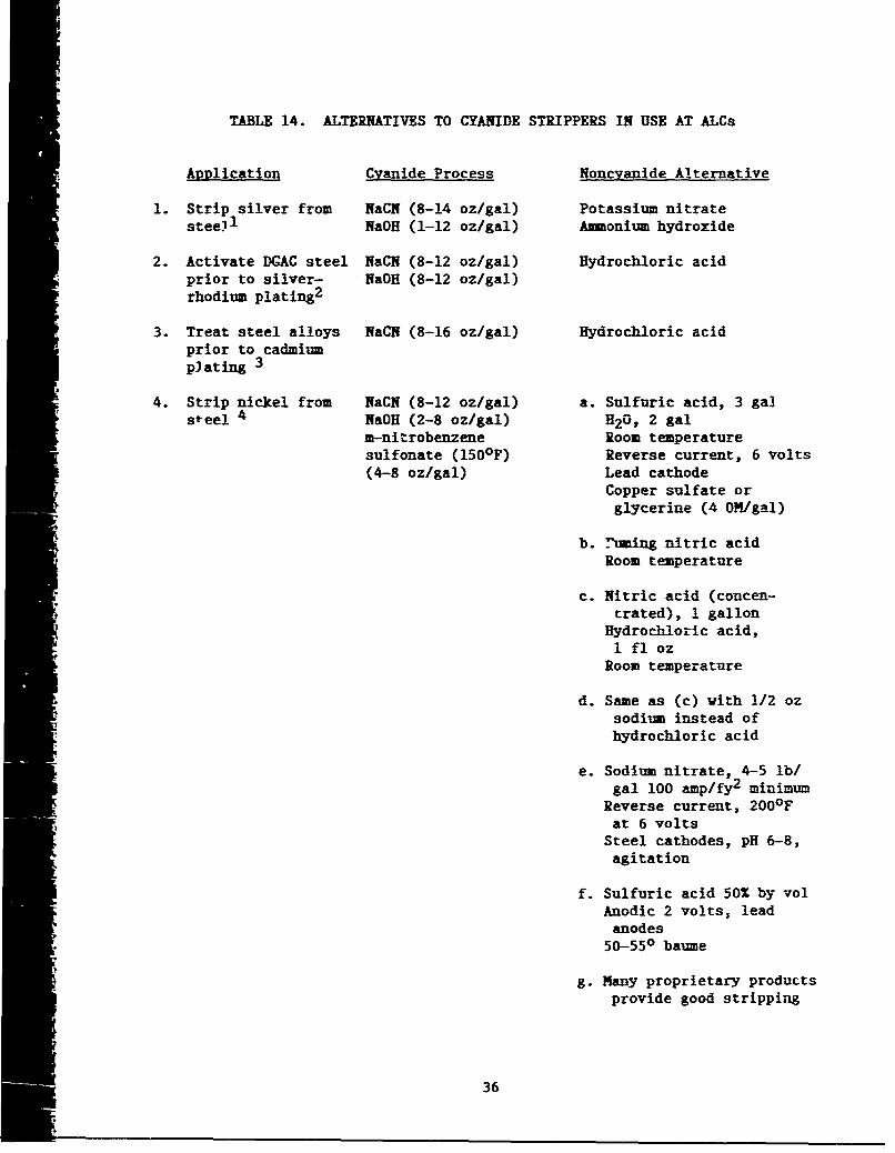
TABLE 14. ALTERNATIVES TO CYANIDE STRIPPERS IN USE AT ALCs
Application Cyanide Process Noncyanide Alternative
1. Strip silver from NaCN (8-14 oz/gal) Potassium nitrate"steell NaOH (1-12 oz/gal) Ammonium hydroxide
2. Activate DGAC steel NaCN (8-12 oz/gal) Hydrochloric acidprior to silver- NaQH (8-12 oz/gal)rhodium plating2
3. Treat steel alloys NaCN (8-16 oz/gal) Hydrochloric acidprior to cadmiumplating 3
4. Strip nickel from NaCN (8-12 oz/gal) a. Sulfuric acid, 3 galsteel 4 NaOH (2-8 oz/gal) H20, 2 gal
m-nitrobenzene Room temperaturesulfonate (150 0 F) Reverse current, 6 volts(4-8 oz/gal) Lead cathode
Copper sulfate orglycerine (4 OM/gal)
b. .-uming nitric acidRoom temperature
c. Nitric acid (concen-trated), 1 gallon
Hydrochloric acid,1 fl oz
Room temperature
d. Same as (c) with 1/2 ozsodium instead ofhydrochloric acid
e. Sodium nitrate, 4-5 lb/gal 100 amp/fy 2 minimum
Reverse current, 200OFat 6 volts
Steel cathodes, pH 6-8,agitation
f. Sulfuric acid 50% by volAnodic 2 volts, lead
anodes50-550 baume
g. Many proprietary productsprovide good stripping
36
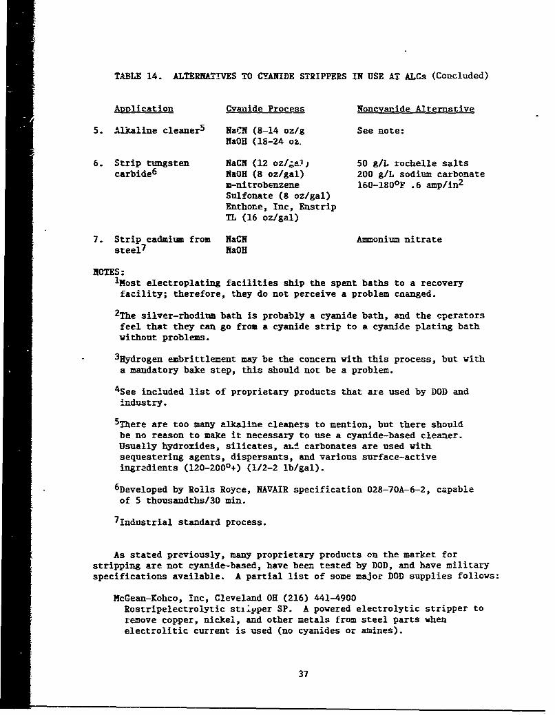
TABLE 14. ALTERNATIVES TO CYANIDE STRIPPERS IN USE AT ALCs (Concluded)
Application Cyanide Process Noncyanide Alternative
5. Alkaline cleaner 5 NaCN (8-14 oz/g See note:NaOH (18-24 oz.
6. Strip tungsten NaCN (12 oz/W-0) 50 g/L rochelle saltscarbide6 NaOH (8 oz/gal) 200 g/L sodium carbonate
m-nitrobenzene 160-180OF .6 amp/in 2
Sulfonate (8 oz/gal)Enthone, Inc, EnstripTL (16 oz/gal)
7. Strip cadmium from NaCN Ammonium nitratesteel 7 NaOH
NOTES:iNost electroplating facilities ship the spent baths to a recoveryfacility; therefore, they do not perceive a problem cnanged.
2 The silver-rhodium bath is probably a cyanide bath, and the cperatorsfeel that they can go from a cyanide strip to a cyanide plating bathwithout problems.
3Hydrogen embrittlement may be the concern with this process, but witha mandatory bake step, this should not be a problem.
4See included list of proprietary products that are used by DOD andindustry.
5There are too many alkaline cleaners to mention, but there shouldbe no reason to make it necessary to use a cyanide-based cleaner.Usually hydroxides, silicates, au:! carbonates are used withsequestering agents, dispersants, and various surface-activeingredients (120-2000+) (1/2-2 lb/gal).
6 Developed by Rolls Royce, NAVAIR specification 028-70A-6-2, capableof 5 thousandths/30 min.
7 1ndustrial standard process.
As stated previously, many proprietary products on the market forstripping are not cyanide-based, have been tested by DOD, and have militaryspecifications available. A partial list of some major DOD supplies follows:
McGean-Kohco, Inc, Cleveland OH (216) 441-4900Rostripelectrolytic stixper SP. A powered electrolytic stripper toremove copper, nickel, and other metals from steel parts whenelectrolitic current is used (no cyanides or amines).
37
Witco Corp (Allied Kelire) Des Plaines IL 1-800-323-9784 (Mark FarverProduct(s))
ARP 66. A high-speed, cyanide-free immersion stripper for electrolessnickel deposits-strips all types electroless nickel withoutattacking substrate.
ARP 4. Liqul'" chelating agent.ARP 60 Application 2. Strip from brass.ISOPREP 177. Powdered alkaline descaleProcess 235L. Liquid alkaline descale.Process 235 CXCF. Alkaline descale additive.
Enthone Inc, New Haven CO (203) 934-8611 (Frank Brindisi Products)ENSTRIP NP (alkaline). Strips watts-type and sulfamate nickel from
steel with copper alloy and silver brazed details.ENSTRIP N-190. Strips nickel from steel and copper without ammonia on
cyanide.ENSTRIP S-180. Stripper for nickel, nickel sulfamate, nickel iron,
and copper from steel.ENSTRIP CT-317 Strips tungsten carbideENSTRIP EN 79. Stripper for electroless nickel from steel and copper
alloys.ENSTRIP EN 86. Stripper for electroless nickel from steel and copper
alloys.ENSTRIP L-90. Immersion stripper for nickel, copper, anL other metals
from aluminum and stainless steel.ENSTRIP GT-317. Stripper for tungsten and carbide from titanium,steel, and stainless steel.
Other companies were either not contacted or did not respond within the
required time limits.
D. RECOMMENDED RESEARCH PROGRAM
Because of the abundance of commercial interest and the number of bathsavailable, it appears unnecessary for HQ AFESC to devote research time todevelop "new" stripping processes. Instead, available noncyanide processesused both by DOD and commercial facilities should be investigated andresults should be provided as a data bank for use by plating facilities.Available military standards, military specifications, and useridentification should be included. The noncyanide strippers noted in thisreport should be investigated, along with others that show promise forincorporation into ALC plating facilities.
E. COST ESTIMATE
Year 1: Develop database and change processes where $300Ktechnically justifiable.
Year 2: Test processes where necessary. $500K
Year 3: Develop noncyanide strippers if needed. $200K
38
F. SUMMARY
Development of stripping solutions is advanced and many proprietary andnonproprietary noncyanide stripping solutions are available to industry.Noncyanide strippers will help eliminate cyanides from the plating shop.This will reduce treatment costs, and provide a safer industrialenvironment. Regulatory approaches encourage use of noncyanide strippers.
Proven tested alternatives are available to replace the cyanidestrippers reported by the ALCs. Most of them have DOD specifications orstandards that apply. A survey should be conducted throughout DOD and theindustry to provide a database of processes and parts already tested. Thedatabase should include existing standards, specifications, etc. Wherevernecessary, a generic testing program should be conducted for technicaljustification. Qualified Products Lists or performance-relatedspecifications should be developed wherever applicable.
39
"m&P.LCs( Ira .~ 9 910". P-! APf .- N
SECTION V
PLASMA SPRAY AS A REPLACEMENT FOR CHROMIUM ELECTROPLATING
A. INTRODUCTION TO PLASMA SPRAY
Thermal spraying is a method of melting and transporting materials athigh velocities to coat other surfaces. Techniques vary from oxyacetylenetorches to plasma generators, some of which *ay be operated in a vacuum.Coatings available are dense, adherent, and temperature-resistant, with highintegrity. As a gas, plasma has enough energy content to ionize asignificant portion and will then conduct electricity. Plasmas aresustained by continued passage of electrical cutrrent through the gas. Forthe high-temperature plasmas, local thermodynamic equilibrium is obtainedwith electrons and ions at the same energy level.
Typical plasma spray techniques pass a suitable gas through a high-current arc, creating the plasma. Thermal balance is charged by constrict-ing the arc, which can raise the temperature to as high as 40,O000C. Thetypical system has the plasma arc spray gun, a power feed, a plasma arccontrol unit, a gas control unit, power, water, and gas supplies.
B. DESCRIPTION OF EQUIPMENT
The most important piece of equipment is the plasma torch, a highlyengineered piece of equipment. In the torch, a gas, normally argon ornitrogen, flows around a tungsten cathode and between it and a copperanode. With the gas flowing, a high-frequency electrical discharge is usedto initiate a direct current arc between electrodes, carried by the ionizedgas plasma. A region of extremely high temperature is produced, into whichpowdered materials are injected and propelled towards a target. Powerconsumption is usually 5-80 kilowatt with temperatures ranging from10,000°C-40,000°C. Cooling water is used to control temperatures whereneeded to preserve equipment.
Plasma temperatures and gas velocities are governed by electrodegeometry, gas density, current-volta&,e conditions, and mass flow rate. Arccore temperature depends on the extent to which the arc is restricted insidethe torch. This restriction is achieved by reducing the anode bore diameterand by utilizing thermal and magneto hydrodynamic pinch.
High temperatures cause gas expansion, which provides encrgy forspraying. Velocities controlled by geometry can achieve supersonic flowrates. Powder velocity depends on mass flow rate and distance of travel.Velocity ranges are reported between 120-550 meters second.
Powder injection should be uniform and introduced in such a way as toallow long resident times. Problems have been reported with powder adhesiveadhering to the throat of anodes and resulting in blockage and overheating.Consequently, most manufacturers inject powder either where the nozzlediverges or just beyond the exit. Ideally, the powder should be injectedupstream of the anode for a more complete melt. Research is continuing withpowder injection systems. Other components such as gas, water, andelectrical power equipment are typical to other industrial processes.
40
C. STATE OF THE ART
Plasma spray techniques are used to apply a multitude of materials,including the following:
* Metals
Metal Alloys
• Ceramics
Cermets
* -Plastics
* Composites
- Refractories
- •ixtures of all the above
The list of materials being applied is almost infinite and constantlygrowing. Uses include application of bonding materials, abrasives, abradableclearance control coatings, salvage or repair materials, wear protectionmaterials, instrumentation base materials, corrosion protection materials,heat-resistant materials, and many special-purpose deposits. Some specificmaterials include nickel aluminum, molybdenum, silicon aluminum, cermet,aluminum titania, nickel chromium, and other nickel chromium alloys, carbonand stainless steels, carbides, and many more. Thicknesses range from lessthan 0.001 inches to 0.1 inch, or greater; usually, 0.003 inches to 0.015inches. Coatings can be dense, adherent with possible porosities of lessthan 1 percent with conventional equipment.
Some problems reported with plasma spray techniques are high-oxidedeposits, por- adhesion, low densities, and high residual stresses, all ofwhich result in negative mechanical reliability of the coating and reductionof oxidation/corrosion protection properties. Some available techniques canol-Inste these problems.
New plasma spray guns allow operation at up to 80 kilowatts of powerwith a single gas, argon. The new technology incorporates arc stabiliza-tion, coupled with closed-loop voltage control, resulting in the ability totailor the plasma plume through control of plasma gas flow, arc voltage, andarc current. The guns are built to use only argon, which reduces thepossibility of eabrittlement caused by hydrogen or nitrogen. Arcstabilization produces a fuller plasma plume, improving the temperatureprofile at the nozzle which results in improved melt characteristics andthus, improved adhesion. Research and development in this area iscontinuous in the civilian sector.
Extensive work is going on in developing new powders for plasma spraytechniques. The powders must be chemically pure and homogeneous, withuniform size and low-gas content. Many new materials are available to usefor just about any purpose. These materials are constantly being evaluated
41
for performance characteristics useful to the aerospace industries. Many ofthe coatings developed for a specialized function can often provide morereliable mechanical functioning.
A process that has opened up many ways of improving deposit characteris-tics is vacuua plasma deposition (VPD). Completely controlling the sprayenvironment in a vacuum of less than 100 torr, it permits higher gun andsubstrate temperatures, eliminates substrate oxidation, and leads toimproved deposit efficiencies. Substrates can be preheated to 760-10380 C,greatly enhancing adhesion. Pre.'iminary roughing can be eliminated with theplasma gun used to sputter clean and slightly erode the part. Sincedeposition is accomplished at high temperature, the particles areimmediately recrystallized after solidification, eliminating residualstresses which allow thicker coatings. Deposits are recrystallized andannealed in situ, resulting in stress relief. Effluent velocities are muchhigher in a vacuum, resulting in a greater density coating.
* Laser processing is a new developing process used in conjunction withplasma spray techniques. This technique modifies an applied coating byremelting the applied coating and a minor portion of substrate surface byscanning the coating relative to the focused laser beam to produce melting.Resolidification results in reduction or elimination of structuralinhomogeneities. Coating adhesion and general mechanical properties aresignificantly improved by alloying with the substrates and development of ametallurgical bond. The process greatly reduces porosity and subsequentlyreduces potential.
Automated systems for plasma spray techniques are being developed. Acomputer-controlled industrial robot can provide consistency and flexibil-ity, resulting in high quality, reproducible coatings for complicated"parts. Robotic manipulation can do repetitive, relatively dangerous workwith no adverse effects. Rigid control of parameters and environmentresults in superior coatings. Robotic configurations would allow many parts"to be completed before breaking vacuum of a vacuum plasma system.
The technical advantages and disadvantages of the two forefront plasmaspray processes are summarized below:
1. Argon-Shrouded Torch
a. Benefits:
(1) It is simple to operate, with relatively low initial cost.
(2) All operation is carried out in normal, clean workshop.
(3) Components can be processed in large nubers.
(4) Torch can give consistent, accurate, and uniform deposits.
(5) Spraying is in invert atmosphere to give clean, densecoatings.
(6) Over 95 percent product yield is possible, routinely.
42
b. Limitations:
(1) Relatively short standoff distance requires programnmedtorch movement to coat complex parts.
(2) Deposition onto substratcs at high temperatures cannot.rmally be carried out, because of atmospheric conditions.
2. Low-Pressure or Vacuum Torch
a. Benefits:
(1) Components can be preheated without oxidation to minimizeinternal stress effects and allow low-stress, thick,high-de,.sity deposits.
(2) The plasma jet becomes elongated, allowing larger standoffdistances to be used, minimizing the effects of componentand torch geometry, and allowing a more complete melt, anddenser, more uniform coatings.
(3) Environmental health and safety problems are eliminated.
b. Limitations:
(1) Capital outlay is extremely high.
(2) Vacuum limits number of parts processed, unless roboticequipment is used.
(3) High maintenance is caused by powder particles enteringpumping system.
(4) Extra cleanliness is required.
D. HEALTH AND SAFETY
Plasma spray, like numerous other industrial processes being used today,has its hazards, which can be eliminated or minimized with proper awarenessand precautions. Potential hazards to workers are dust and fumes, gases,noise, arc radiation, and electrical shock. Dust and fumes produced duringplasma arc spraying originate primarily with the material being sprayed.The magnitude of the hazard depends on the material being sprayed and theconcentration. A vacuum plasma spiay system with robotic control wouldeliminate these hazards. Other conventional methods are available forworker protection. Most of the materials "oversprayed" are recoverable,leading to no environmental pollution.
The plasma spray process results in the presence of various gases. Inaddition to the gas being used to form the plasma (argon, helium, nitrogen,hydrogen, etc.), nitrogen oxides of various sorts are produced, as well asozone from the reaction of atmospheric oxygen and ultraviolet radiation fromthe plasma arc. Other gases may be present under certain circumstances.For instance, phosgene and Cichloroacetyl chloride can be produced by
43
reactions in the presence of ultraviolet radiation of the chlorinated hydro-carbons (e.g., trichloroetbylene) used for degreasing metal surfaces. Suchreactions may occur if spraying is done near degreasing equipment.Precautions shou'd be taken to avoid health problems. Although not toxic,even the inert gases used in the process can cause oxygen deDletion in thegeneral area, resulting in a worker becoming unconscious- Few problems willresult if proper ventilation is supplied.
Arc radiation has ultraviolet components which can produce temporary orpermanent eye damage. The most common eye problem associated with plasmaarcs is conjunctivitis, or "arc flash." This is temporary unless reexposureoccurs and can be prevented with the use of proper eye protection (Shade 12or higher). Ultraviolet radiation can also produce skin burns similar to
= ,sunburn and just as painful. Heavy work clothing is advisable for mildexposures, and a protective suit is recommended for heavy exposure.Infrared radiation comprises most of the radiation from the plasma arc."Excessive exposure can produce retina burns and cataracts. The precautionslisted above can prevent this problem. A plasma arc operated in a vacuumcould totally eliminate these hazards.
The noise associated with plasma arc operations may present a hazardbecause of its intensity or frequency. Noise levels in excess of 90decibels have been measured near plasma arcs. Also, the noise produced bysuch arcs is distributed over a wide frequency range, including those towhich the ear is sensitive. The effect of noise is a function of the soundintensity, pitch or frequency, and duration. Precautions should be taken toavoid exposure. Noise-attenuation equipment is available for the machines,as well as personal protective equipment for the workers.
Electrical shock hazards from plasma-arc spraying equipment are similarto those presented by other types of electrical equipment. Onlywell-designed and well-built equipment should be used, and it should bewell-maintained. The open-circuit, operating, and supply circuit voltagesand amperages are all high enough to present a serious hazard. Propergrounding, insulation, and guarding will minimize electrical shock hazards.
E. ENVIRONMENTAL CONSIDERATIONS
In comparison to chromium electroplating, plasma spray techniques canreduce environmental hazards. Elimination of chromium electroplating"removes the requirement for plating tanks, rinse systems, bath maintenance,chromic acid fume removal, or disposal or treatment of hazardous waste.Wastewater is reduced to the IWTP.
Plasma spray of chromium or other materials can reduce the amount ofchromium electroplating at a facility. Reductions range from 10 to 80percent. Each usage would have to be judged on its own merit, based onengineering requirements. Unlike cadmium, chromium is used for variedindustrial processes. Materials personnel at each facility would berequired to provide technical justifications for each engineeringapplication.
Elimination of plating tanks may be possible if enough chromiumelectroplating is eliminated. Most facilities already have chrome plating
44
tanks; therefore, initial investment would only apply to new facilities, butcan be extremely costly. 'Elimination of the tank will remove ventilation,space, and maintenance requirements for that tank.
Ventalation requirements for a plasma spray system can be much lesscostly and more efficient in removing chromium. The chief difference isthat plating results in chromic acid fumes above the tank that must beremoved, while plasma spray ginerates chromium dust. Chromic acid fumes arecorrosive, hazardous to health and safety, and require extensive removalcapability. It has been stated that "more chromium goes up the ventilationsystem than is plated." In some cases, this is true; a great deal ofchromium is lost when a recovery system is not used. Plasma spray, on the
_ other hand, has a chromium dust to collect. This dust is much lesshazardous, lower in volume, and recoverable. One benefit of removal of achromic acid tank is that ventilation capability for that system can beapplied elsewhere.
Chromium plating is normally accomplished at 130 0 -140 0 F. Thesetemperatures require heating apparatus to maintain tank temperature.Soretimes when a tank is being heavily used, a cooling system is required.Maintaining tank temperature is expensive and energy-intensive. No similarrequirement exists for plasma spray.
Chromic acid is highly corrosive. Tanks and equipment need constantmaintenance under hazardous conditions. Tanks must be drained, cleaned, andmaintained in optimum plating condition. The electrical system supplyingthe tanks must be maintained in these conditions. Maintenance is verycostly depending on the age, material, and man-hour costs of a facility.Under most conditions, plasma will cost less to maintain (excluding vacuumsystem).
Chromium plating baths use evert anodes (Section I). This results inadding additional chromium to the plating bath to make up for losses throughplating, rinsing, and ventilation. Daily monitoring of the plating tank isrequired and additions are made to maintain chemical balances. This requirestrained experienced personnel. Plasma spray will eliminate this need.
If enough plating baths are eliminated, rinse tanks may be eliminated.Many of these tanks run at up to 15 gallons/minute. Elimination of thesetanks eliminates the need for treatment of approximately 7-8 million gallonsof wastewater/year and can save several hundred thousand dollars intreatment and disposal costs, as well as elimination of future liabilities.Treatment facilities can also be designed for lower flow rates.
Although savings may be significant, the initial cost of changingchromium electroplating for plasma spray is important. Extensive testing ofparts would be required, initial costs for advanced equipment could be high,and training personnel would require funds. These costs might be justifiedif all chromium treatment could be eliminated, or if a facility was havingdifficulty in meeting discharge limits. In most cases, however, chromiumcannot be entirely eliminated from the discharge to sewer, and chromiumplating cannot be eliminated. This means treatment for chromium would stillbe a requirement.
45
Chromic acid is used for stripping, conversion coatings, chromate-phosphate treatments, anodizing, plating, etc. Chromium is found inpaint-stripping wastes, machine shop wastewater, engine cleaning wastewater,etc. Elimination of chromium plating would not eliminate requirements forchromium treatment. Similar chemical usage would result since the pH forthe entire waste stream would still require adjustment. S02 or otherreducing chemical cost changes would be minimal. The major savings wouldresult from elimination of batch treatments of concentrated chromiumsolutions and reduction of wastewater volumes.
Wastewater volumes can be eliminated without elimination of chromiumelectroplating. With controlled rinsing, water usage can be made to matchevaporation rates out of the plating tanks. This allows all rinsewater tobe returned to the plating tank, eliminating treatment requirements.Similarly, condensed chromic acid from ventilation can be returned to theplating tank. Extensive work has been completed by the Navy under the titleof "Innovative Hard Chrome Electroplating," which eliminates discharge ofchromium from chromium electroplating operations to industrial wastewatertreatment operations.
F. RECOMMENDED RESEARCH PROGRAM
The probability of complete elimination of chromium electroplating byplasma spray techniques at the present time is minimal. Elimination of themost chro±aium electroplating would probably require state-of-the-art auto-mated vacuum plasma spray equipment with laser remelt. This equipment wouldrequire high initial costs with high maintenance. Evaluations would requirelarge .Lounts of parts testing and materials evaluation at high costs.
Much plasma spray research is being done by the civilian community.Much of the advanced work, which has the greatest probability of eliminatingchromium electroplating, is still in preliminary stages. Development is pro-ceeding rapidly, with a great deal of knowledge becoming available each year.
The elimination of chromium electroplating will not eliminate chromiumdis:harges from the electroplating shop, nor from other shops. Treatmentand disposal of chromium wastes will still be required. Much of the cost ofthis treatment is based on volume of water, not chromium content.
Some methods are available for minimizing and eliminating rinsewater andchromium discharges from chromium electroplating operations. The Navy hasdeveloped and implemented O-discharge systems. These methods should beapplicable to Air Force facilities.
Minimal research is recommended for replacement of chromium electro-plating by plasma spray. Economic benefits, based solely on environmentalconsiderations, do not appear substantial enough to warrant large governmentresearch efforts. The following is recommended.
1. Evaluate the extent of liabilities from chromium wastes at eachfacility. Does the facility have a problem? If so, what is the extent ofthe problem and what are the economics involved?
46

2. Upon determination of a problem of significant economic stature,evaluate the impact of elimination of chromium discharges from the chromiumelectroplating processes. Compare the technical and economic advantages ofeach system, and choose the appropriate technology.
3. Concurrent technical evaluation of parts that can be immediatelychanged to a plasma spray process to replace chromium electroplating shouldbe condicted. This study should be based on past justifications of similarparts. The impact of replacing the process on those parts should bedetermined in relation to possible reduction in the number of chromiumelectroplating tanks.
G. COST ESTIMATE
Based on anticipated minimal impact of elimination of chromiumelectroplating on environmental problems, no funding is recommended forresearch at HQ AFESC.
H. SUMMARY
Plasma spray has developed into a viable multipurpose industrial processsince its conception in the 1920s. A high-temperature (up to 40,0000 C)plasma gas melts and transports materials at high velocities to impact onthe surface to be coated. New techniques such as automated vacuum plasmaspraying, inverted gas shielding, and laser remelting make it possible tominimize or eliminate some of the major problems associated with plasmaspray, including high-oxide deposits, poor adhesion, low densities, and highresidual stresses.
Some benefits of plasma spray are reduced health and safety problems,elimination of hazardous waste production, and reduction of ventilationrequirements. There is no discharge to sewers of chromium-contaminatedwastewaters. Powdered chromium is removed from the air by a filter systemless demanding than those necessary for chromium electroplating. There areno hazardous acids or chemicals to work with reducing health and safetyproblems. Replacement of chromium electroplating by plasma spray would bebeneficial for environmental health and safety reasons.
Chromium is found in many processes throughout the iLCs. Chromium t-paint stripping, machining, and plating processes finds its way to theindustrial waste plant or to barrels of concentrated hazardous waste. ±nesewastes need to be treated or disposed of. Chromium treatment cannot beeliminated just by elimination or reduction of chromium electroplating.0-discharge system may be able to eliminate most chromium from chromiumelectroplating from reachinE the sewers.
Plasma spray techniques are estimated to be able to replace 10-80 percentof chromium electroplating. Indications are that, on the average. a minimalamount of chromium electroplating can be replaced. It is recommended thatminimal research effort be applied to modification of plasma spray, unlessenvironmental considerationa at a particular installation requireelimination of chromium electroplating. The effort should be limited totechnical Justification of process change due to past records for partspreviously plasma-sprayed. If enough parts can be plasma sprayed: then the
47
number of plating tanks should be reduced or eliminated. The remainingtanks should be converted to a closed-loop system, eliminating rinsewaterand scrubber discharges. The closed-loop systems are not the subject ofthis report, but they are easily modified for each facility.
48
SECTION VI
NICKEL BORON AS A REPLACEMENT FOR CHROMIUM? ELECIROPLATING
A. INTRODUCTION TO NICKEL BORON
Nickel boron is a electroless nickel process using boron containingreducing agents, especially the borohydrides and amine boranes. Depositsare characterized by unifoim deposition, relative hardness, solderability,and electrical conductivity. These characteristics make nickel boronidea -y suited for applications in the electronics industry.
Components of the electrolese bath include an aqueous solution of metalions, catalyst, reducing agent, complexing agents, and bath stabilizersoperating in a specific metal ion concentration, temperature, and pH range.Unlike conventional electroplating, no electrical current is required fordeposition. The base subztrate must be catalytic in nature.
The electroless bath pr....de deposit which follows all contours ofthe substrate exactly, without buildup of corners or edges. A sharp edgereceives the same thickness as a "blind hole." If air or evolved gases aretrapped in a blind hole or on a downward-facing cavity, however, this willprevent deposit i: these areas.
When a proper catalytic sarface is introduced into the electrolessnickel bath, a uniform deposition begins. Minute amounts of the electroless
metal itself can catalyze the reaction, so the deposition is autocatalyticafter the original surfaces are coated. Electroless deposition continues,providing that the metal ion and reducing agent are replenished. Metal ionsare reduced to metal by the action of chemical reducing agents, which donateelectrons. The metal ions accept the electrons and react with the electronclosers. The catalyst accelerates the reaction, allowing oxidation of thereducing agent.
The plating bath must be monitored and controlled closely to maintainproper ratios and chemical balance. The deposition rate depends on controlof temperature, pH, and metal ion/reducer csLz-itration. CompleXing agentsact as buffers to help control pH and "free" metEl salt ions. Thestabilizers act as catalytic inhibitors, recarding potential spontaneousdecomposition of the bath. impurities, inorganic ions, and organiccontamiuation in the bath will affect deposition properties and appearance,
L@ ±.. .......... .... ..~S , *....- - - -. .. - ...- .. -. s
B. PROCESS DESCRIPTION
Research to develop alternative reducing agents leads to investigationof boron containing redvcing agents; In F.-rticular, the borohydrides and*amine boranes. The borohydride reducing agent may consist of any water-soluble borohydride. Sodium or potassium borohydride is generallypreferred. The pH of the solution must bc between 12.0-14.0 to suppressformation of nickel boride and allow formation of elemental nickel. Toprevent precipitation of nickel hydroxide, ligands are used. Strongcomplexing agents are used and cause decreased rate of deposition. Constantadditions of aimonia hydroxide are required, since the pH decrease is due to
49
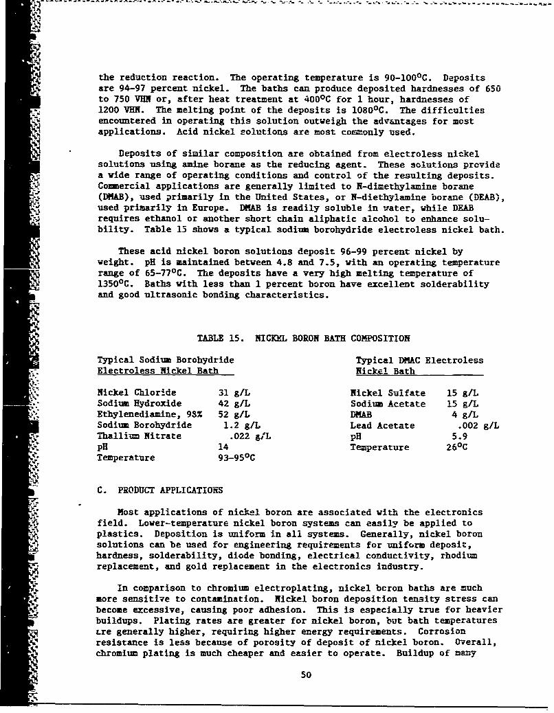
the reduction reaction. The operating temperature is 90-1000 C. Depositsare 94-97 percent nickel. The baths can produce deposited hardnesses of 650to 750 VHN or, after heat treatment at 4000 C for 1 hour, hardnesses of1200 VHN. The melting point of the deposits is 1080 0 C. The difficultiesencountered in operating this solution outweigh the advantages for mostapplications. Acid nickel solutions are most coi.-only used.
Deposits of similar composition are obtained from electroless nickelsolutions using amine borane as the reducing agent. These solutions providea wide range of operating conditions and control of the resulting deposits.Commercial applications are generally limited to N-dimethylamine borane(DMAB), used primarily in the United States, or N-diethylamine borane (DEAB),used primarily in Europe. DMAB is readily soluble in water, while DEABrequires ethanol or another short chain aliphatic alcohol to enhance solu-bility. Table 15 shows a typical sodium borohydride electroless nickel bath.
These acid nickel boron solutions deposit 96-99 percent nickel byweight. pH is maintained between 4.8 and 7.5, with an operating temperaturerange of 65-770 C. The deposits have a very high melting temperature of13500 C. Baths with less than I percent boron have excellent solderabilityand good ultrasonic bonding characteristics.
TABLE 15. NICKEL BORON BATH COMPOSITION
Typical Sodium Borohydride Typical DIAC ElectrolessElectroless Nickel Bath Nickel Bath
Nickel Chloride 31 g/L Nickel Sulfate 15 gILSodium Hydroxide 42 g/L Sodium Acetate 15 g/LEthylenediamine, 93% 52 g/L DMAB 4 g/LSodium Borohydride 1.2 g/L Lead Acetate .002 g/LThallium Nitrate .022 g&L DH 5.9pH 14 Temperature 260 CTemperature 93-950 C
C. PRODUCT APPLICATIONS
Most applications of nickel boron are associated with the electronicsfield. Lover-temperature nickel boron systems can easily be applied toplastics. Deposition is uniform in all systems. Generally, nickel boronsolutions can be used for engineering requirements for uniform deposit,hardness, solderability, diode bonding, electrical conductivity, rhodiumreplacement, and gold replacement in the electronics industry.
In comparison to chromium electroplating, nickel bcron baths are muchmore sensitive to contamination. Nickel boron deposition tensity stress canbecome excessive, causing poor adhesion. This is especially true for heavierbuildups. Plating rates are greater for nickel boron, but bath temperaturestre generally higher, requiring higher energy requirements. Corrosionresistance is less because of porosity of deposit of nickel boron. Overall,chromium plating is much cheaper and easier to operate. Buildup of many
50
parts would be impossible due to increased porosity with greaterthicknesses, adherence, and stress problems.
Nickel boron can replace some applications of hard chrome plating, butusually not enough to make a significant difference in chromium plating tankrequirements, or in chromium content of ITWP influent. Since nickel boronbaths are much more sensitive to contamination, return of rinsewater to theplating bath would not be practical with chromium. Overall, the potentialfor nickel boron as a replacement for hard chromium is extremely low.
D. .- ARCH REQUIREMIENTS
As the potential for nickel boron plating as a replacement for hardchrome plating is low, replacement would be a negligible contribution toenvironmental improvements (with possibility of det.'mental effects);further research is not recommended. The materials engineer of eachfacility should determine if nickel boron offers any significant engineeringadvantage over a chromium coating. If so, this engineer must determine ifthere are enough applications to justify changing a plating tank fromchromium to nickel boron.
E. COST ESTIMATE
Year 1 Year 2 Year 3
F. SU•w-t.'Y
Several characteristics make nickel boron an unlikely candidate for mostchromium eleczroplatlng applications. Chemical costs and extensive bathmaintenance programs (caused by sensitivity of baths to contaminants) makenickel boron baths expensive. When heavy buildup is required, excessivetensile stress can develop, causing poor adhesion. Corrosion resistance isusually less than for chromium because of porosity. Energy requirements aremuch greater because of higher bath temperatures 90-1000 C.
Nickel boron can replace some applications of hard chromium electroplat-ing, but in most cases, not enough to significantly affect tank requirementsor environmental problems associated with chromium electroplating. Withbaths much mere sensitive to contamination, return of rinsewater to theplating bath would not be practical, as with chromium electroplating.Overall, tJ~e potential of nickel boron as a replacement for hard chromiumelectroplating is extremely low. No significant research is recommended.
51
SECTION VII
CONCLUSIONS AND RECOMMENDATIONS
A. CONCULSIONS
1. Ion Vapor Deposition (IVD) Of Aluminum To Replace CadmiumElectroplating
IVD is a technique wherein the material to be used as a coating isevaporated within a vaculm chamber, then condensed on the part being coated.The process is distinguished from other vacuum deposition techniques by aglow-discharge cleaning process, and by plating on all sides, applyingcurrent to make the "part" cathodic.
IVD aluminum is a soft ductile coating of pure aluminum.Performance advantages of IVD or aluminum over cadmium electroplating havebee- confirmed over the past decade. Hrmerous tests have been conducted byMcDonnell Douglas, the Navy, and the Air Force. Tests have been conductedon fasteners, steel panels, engine parts, etc., and all have shown superiorcorrosion resistance. Specific attributes of IVD aluminum include:
a. It outperforms cadmium and other coatings in actual service
tests.
b. It has a useful temperature to 925 0 F (496 0 C).
c. It can protect steels of all strength levels because there is no
hydrogen embrittlement.
d. It does not cause solid metal embrittlement of Titanium.
e. It can be used in contact with fuel.
f. It provides galvanic protection to aluminum alloys and does notcause fatigue reduction.
g. It can be applied thinner than alclad on aluminum alloys. This
results in weight savings. It is not limited to rolled forms.
h. It provides man-hours on EMI shielding, when used, instead ofelectrical connectors.
i. Neither the process nor the coating involve toxic materials.
iVD aluminum is equal or superior to cadmium electroplating for allengineering applications in use by the aerospace industry. Productionequipment is available.
2. Noncyanide Strippers As A Substitute For Cyanide Strippers
Cyanides are dangerous to health and environment. Cyanide stripperscontribute to the cyanide wastes which reach the IWTP by way of wastewater.
These must be treated, usually by alkaline chlorination. These strippers
52
have been used to remove various plated metals from substrate metals. Thesesolutions and the wastewater resulting from them are difficult to treatbecause stable ferrocyanides and other cyanide complexes are not amenable tochlorination. Since facilities usually have a total cyanide limit, they mayhave trouble avoiding outages.
Over the years, regulatory pressures have resulted in development ofmany noncyanide stripping baths. Most of the work is being completed andmarketed by the private sector to DOD. Use of the baths throughout DOD isusually the prerogative of the individual commands. Each electroplatingshop has its own st-ipping processes. Noncyanide baths have been testedthroughout DOD and could be used to replace all cyanide strippers in use bythe ALCs.
With the elimination of cadmium electroplating and cyanidestrippers, most of the cyanide would be eliminated from the plating shop.The small contributions by usage areas such as silver plating, or copperplating, can then be eliminated by process changes readily available today.The total elimination of cadmium and cyanide is therefore feasible withpresent technology.
3. Plasma Spray Of Chromium As A Substitute For Chromium Electroplating
Plasma spray is one of the many thermal spray processes. Since itsintroduction in the 1950s, it has developed into a viable engineeringprocess. The list of materials being applied is constantly growing, as isthe number of applications. Fatremely high temperatures in a plasma gunallow any material to be sprayed, provided: (1) it melts withoutsignificant disassociation, and (2) that a practical temperature intervalexists between melting and boiling points.
Fast problems have been related to burning of substrate, pooradhesion, and porosity. Methods are available which will reduce oreliminate most of these problems. New methods, such as laser processing andvacuum plasma spray techniques, are reliable in eliminatin. adhesion andporosity problems. Vacuum plasma spray can also reduce the oxidedeposited. Proper parameter control can eliminate most other problems.
Plasma spray of chromium is a viable engineering alternative to manychromium-plated parts. The specific engineering properties desired for eachpart would determine if plasma spray could be used. Many proprietarymaterials and equipment are on the market, with constant competitiveresearch occurring in the private sector. This research makes it unlikelythat the Air Force needs to contribute to development.
In evaluating the potential for replacing chromium electroplating ateach facility with plasma spray, the facility needs to determine if enoughchromium plating can be eliminated to remove a plating tank(s). If so, itmay be worthwhile to implement the plasma spray. During evaluatior, onemust remember that other major sources of chromium (paint strippingprocesses, chromating, etc.) will prevent elimination of chromium metaltreatment of wastewater. Chemical savings can be achieved, but thewastewater must be raised and lowered in pH, regardless of chromium content.
53
4. Nickel Boron Plating As An Alternative to Chromium Plating
Nickel boron is an electroless nickel process where boron is co-deposi:ed
with the nickel, rather than the usual phosphorous. The amount of boronvaries with application. The characteristics associated with nickel boronare its resistance to high temperatures (1300-14000 melting point cpurity of deposit (to 99.99 percent), hardness and wear resistance (Ro'--iolC69-70), and solderability (solders with mild flux, ifionths after plating).Because of these characteristics, nickel boron has its major application inthe electronics industry. Excellent solderability and electrical conductionmake nickel boron a viable gold replacement.
Several disadvantages of the system relative to chromiumelectroplating are porosity, expense, low corrosion resistance, and a bathcontamination. This high porosity gives less corrosion protection than thestandard electroless nickel baths, or chromium plating. With bathcontamination, deposition tensile stress can become excessive, causing pooradhesion. The bath plates at one-third to one-half the rate of aphosphorous electroless nickel bath. The cost is 10-15 times that of astandard nickel phosphorous bath. Also, to obtain high hardnesscharacteristics, an added heat-treat step is necessary.
Replacement of chromium in certain specific applications may bepractical, but cverall replacement is not feasible. An added plating tankwith limited use and added cost would result. It is not recommended forextensive research. Each ALC materials laboratory should determine if thereis an application.
NOTE: Techniques are available to eliminate chromium dischargefrom chromium electroplating, without eliminating the process. The Navy hasdeveloped "Innovative Hard Chromium Electroplating" that can eliminatechromium wastes.
E. RECOImENDATIONS
Upon evaluation of the specified processes, the following recommenda-tions are made by HQ AFESC/RDVS:
1. ion Vapor Deposition of Aluminum as a Replacement of Chromium.Recommend this process be substituted for cadmium electroplating. Suggestfunding of project to (a) develop a database to provide technical justifi-cation for process and technical order changes, (b) develop a test plan toprovide testing and evaluation of parts not immediately justifiable, (c)provide demonstration site for complete elimination of cadmium, and (d)eliminate cadmium plating from all ALCs.
2. Replacement of Cyanide Strippers with Noncyanide Strippers.Recommend funding a study of noncyanide stripping processes and applicationsused throughout DOD and industry. Recommend changes to proven noncyanidestripping baths as the study provides technical juptification.
3. Plasma Spray of Chromium as a Replacement for Chromium Plating.
Recommend each ALC consult with materials personnel to determine each
54
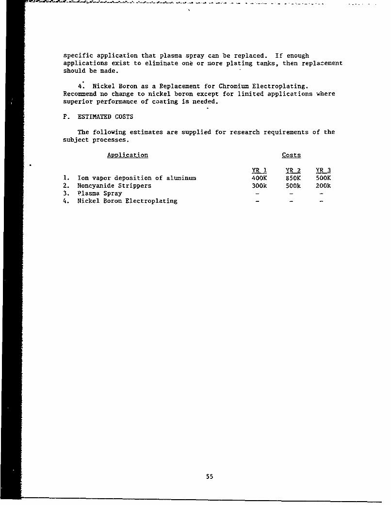
specific application that plasma spray can be replaced. If enoughapplications exist to eliminate one or more plating tanks, then replacementshould be made.
4. Nickel Boron as a Replacement for Chromium Electroplating.Recommend no change to nickel boron except for limited applications wheresuperior performance of coating is needed.
F. ESTIMATED COSTS
The following estimates are supplied for research requirements of thesubject processes.
Application Costs
YR 1 YR 2 YR 31. Ion vapor deposition of aluminum 400K 850K 500K2. Noncyanide Strippers 300k 500k 200k3. Plasma Spray4. Nickel Boron Electroplating - - -
55
- - - -
REFERENCES
1. Defense Environmental Status Report, Defense Environmental Leadership
Program, Washington D.C., 1984.
2. Metal Finishing Guidebook and Director '86, "Vol 84, No. 1A," Metals andPlastics Publications, Inc., Hackensack, Nei Jersey, January 1986.
3. Durney, Lawrence J., Electroplating Handbook, Fourth Edition, VanNostrand Reinhold Company, Inc., New York, New York, 1985.
4. Cadmium Contamination of the Environment: An Assessment of NationwideRisks, PB85-221679, U.S. Environmental Protection Agency, Washington
D.C., February 1935.a
5. Serious Reduction of Hazardous Waste, Congress of the United States,Office of Technology Assessment, Washington D.C., September 1986.
6. Fannin, E.R., "Aluminum Coated Fasteners by Ion Vapor Deposition,"Finishing '77 Conference (SME), October 1977.
7. "Mechanical Property Tests of Aluminum Coated H-11 Steel Fasteners,"McAir TM No. 256.4464, 29 April 1977.
S8. Military Engineer, Vol. 76, Number 496, October 1984.
9. The Electroplating Andsatti-., EPAIV62510.-RS0I1- September 1985, Revised.
10. Environmental Reporter, "Electroplating Section 413.14 (a)," The Bureauof National Affairs, Inc., Washington D.C.
11. U.S. Congress of Technology Assessment, Serious Reduction of HazardousWaste: For Pollution Prevention and Industrial Efficiency, OTA-ITE-317(Washington D.C.: U.S. Governme-it Printing Office, September 1986).
12. "The Resource Conservation and Recovery Act", Public Law 94-580, 1976.
13. U.S. Code of Federal Regulations (CFR) Title 40, "Part 413 and 433,"July 1987.
14. Military Specification, MIL-C 83488B, "Coating, Aluminum, Ion VaporDeposited," December 1998.
15. Dept. of the Army, U.S. Army Armament R&D Command, Ion Vapor DepositionProcessing of Arm.ment Parts, Gov. Accession Number ADA 119 810, 1982.
3 16. Meyer, F.H. Jr. and Jankowski, Edward, "Corrosion Performance of NewFastener Coatings on Operational Military Aircraft," InternationalCorrosion Forum, NACE, March 1973.
" 17. Fannin, E.R., "Ion Vapor Deposited Aluminum Coatings," Government-
Industry Workshop on Alternatives for Cadmium Electroplating in MetalFinishing, National Bureau of Standards, October 1977.
5 56
18. McAir M&PD R&D Report No. 118, 6 February 1975.
19. Fannin, E.R., and Muehlberger, D.E., "IVADIZER Applied Aluminum CoatingImproves Corrosion Protection of Aircraft," American Airlines -American Electroplateis' Society 14th Airlines Plating Forum, Tulsa,Oklahoma, April 1978.
20. Jankowski, E.J., Shipboard Exposure Testing-USS American, Naval AirDevelopment Center, Department of the Navy, Washington D.C., August1982.
21. Muehlberger, D.E., "Ion Vapor Deposition of Aluminum: More Than Just aCadmium Substitute," Platixig and Surface Finishing Ilagazine, November1983.
22. Spiers, K. and Blaise, J., "Chromalloy IVD on Disks and Spacers,"Chrc-mallou Compressor Technical Report, Chromalloy CompressorTechnologies, April 1982.
23. Ortolano, Ralph J., "Improving Steam Turbines by Using Abrasion-Resistant and Corrosion-Resistant Surface Protection Systems," SouthernCalifornia Edison Company, Presented to The American Power Conference,April 1986.
24. McDaniel, P.L. and Cellish, W.A., Materials Development LaboratoryWork, "Request and Report on Evaluation of Properties of Co-.-erciallyAvailable Coating Suitable for Use on 410 Steel (AMS 5504) CompressorComponents," November 1982.
25. "Shipboard Exposure Testing of F/A-18 Aircraft Finish Systems," NavalAir Development Center, December 1982.
26. Air Force Memorandum 237-588, 20 Sept 1974, "IVD Plating Fatigue Tests."
27. Stirling, P., "Beat Corrosion Without Cadmium," Engineering Materialsand Design, October 1982.
28. Health Effects A-,sessment for Trivalent Chromium, EPA/540/l-86/033,U.S. Environmental Protection Agency, September 1984.
29. "Health Effects Assessment for Hexavalent Chromium, EPAI/540/!-86/019,U.S. Environiental Protection Agency, September 1984.
30. Long, P., and McClam, J., "Strategic Materialz: A Crisis Waiting toHappen," A_.T/GL:M/LSM/245-40, Department of the Air Force, November1984.
31. "Materials Substitution and Recycling," Proceedings of the Meetina ofthe Structures and Materials Panel (57th) Held at Vimairo, Portugal,October 1983, AD-A148 598, October 1983.
32. Health Hazard Evaluation Report No. HETA-81-085-889, Valley ChfomePlaters, Bay City, Michigan, U.S. National Inst. for OccupationalSafety and Health, Cincinnati, Ohio, June 1981.
57
50. Boron, J. Carr, J., Fix, G., and Judge, J., Nickel Boron Coatings, AirForce Materials Laboratory, Wright-Patterson AFB, Ohio, August 1977.
51. A Plasma Spray Handbook, Report No. MT-043, Naval Ordnance Station,Louisville, Kentucky, March 1977.
52. Gill, B.J. and Tucker, R.C. Jr., Plasma Spray Coating Processes, UnionCarbide Corporation; Indianapolis, Indiana, 1986.
53. Hermanek, F.J., "Automation of the Thermal Spray Process," Alloy Metals,Inc., Troy, Michigan, Presented at the 18th Annual Airline Plating andMetal Finishing Forum, February 1987.
54. Szekeiy, J., and Apelian, D., "Plasma Processing and Synthesis ofMaterials," Materials Research Society Symposia Proceedings, Vol. 30,November 1983.
55. Rigsbee, J.M., "Surface Engineering by Laser and Physical VaporDeposition Techniques," Journal of Metals, August 1984.
56. Hermanek, F.J., "Thermal Spray Coatings, The Process and Its Evolution,"SAlloy Metals Inc., Troy, Michigan, 1987.
57. Hermanek, F.J., "Coatings Produced Under Protective Cover Vacuim PlasmaDeposition," The International Journal of Powder Metallurgy and PowerTechnology, Vol. 18, No. 1, 1982.
58. Bernecki, T., New Plasma Gun Technology, Society of AutomotiveEngineers, Inc., 1987.
59. Nicl1 A.R., Gruner, H.. West, G., and Keller, S., "FutureDevelopments in Plasma Spray Coating," Materials Science andTechnology. Vol. 2, March 1986.
60. George, L.C., and Irons, G., "A Flexible Remanufacturing System-GritBlasting and Plasma Spraying Aircraft Engine Parts," 21st AnnualAirline Plating and Metal Finishing Forum, Atlanta, Georgia, SAETechnical Paper Series 850715, February 1985.
59(The reverse of this page is blank.)