Embed Size (px)
Citation preview
1
SCHOOL OF BIO AND CHEMICAL ENGINEERING
DEPARTMENT OF CHEMICAL ENGINEERING
UNIT – 1- CLASSIFICATION OF CRUDE AND REFINING
2
UNIT I INTRODUCTION
Petroleum, along with oil and coal, is classified as a fossil fuel. Fossil fuels are formed when
sea plants and animals die, and the remains become buried under several thousand feet of silt,
sand or mud. Fossil fuels take millions of years to form and therefore petroleum is also
considered to be a non-renewable energy source.
Petroleum is formed by hydrocarbons (a hydrocarbon is a compound made up of carbon and
hydrogen) with the addition of certain other substances, primarily sulphur. Petroleum in its
natural form when first collected is usually named crude oil, and can be clear, green or black
and may be either thin like gasoline or thick like tar.
In 1859 Edwin Drake sank the first known oil well, this was in Pennsylvania. Since this time
oil and petroleum production figure grew exponentially.
Originally the primary use of petroleum was as a lighting fuel, once it had been distilled and
turned into kerosene. When Edison opened the world's first electricity generating plant in
1882 the demand for kerosene began to drop. However, by this time Henry Ford had shown
the world that the automobile would be the best form of transport for decades to come, and
gasoline began to be a product in high demand. World War I was the real catalyst for
petroleum production, with more petroleum being produced throughout the war than had ever
been produced previously. In modern times petroleum is viewed as a valuable commodity,
traded around the world in the same way as gold and diamonds.
USES OF PETROLEUM OTHER THAN FUEL PURPOSE
Most people tend to believe that petroleum is mostly used to power internal combustion
engines in the form of gasoline or petrol. They may even conjure up images of jet fuel, but
most will rarely consider the other unexpected places that petroleum by-products show up in
modern life. Because crude oil contains a vast number of different hydrocarbons, various
refined products have found their way into everything from plastics to pharmaceuticals.
The industry that uses petroleum to produce other chemicals is referred to as the
petrochemical industry. It is estimated that a citizen in an industrialized nation currently
consumes petrochemical products at a rate of three and a half gallons of oil per day. That
means that, excluding fuel oil, modern life results in each citizen of an industrial nation using
over 1,200 gallons of oil per year.
Agriculture
3
One of the most important uses of petroleum is in the production of ammonia to be used as
the nitrogen source in agricultural fertilizers. Agriculture also depends on the use of
pesticides to ensure consistent, healthy crop yields. Pesticides are almost all produced from
oil. In essence, from running farm machinery to fertilizing plants, agriculture is one of the
largest users of petroleum based products.
Plastics
Plastic is a staple of modern life. From computer monitors to nylon to Styrofoam, plastics are
integral aspects of many manufactured products. Polystyrene, from which Styrofoam is made,
and polyvinyl chloride (PVC) were both products of post-World War II industrialization.
Nylon, which is in everything from dresses to mechanical gears and even in car engines, is
the most successful petroleum-based plastic to date. Most plastics come from olefins, which
include ethylene and propylene.
Pharmaceuticals
Mineral oil and petrolatum are petroleum by-products used in many creams and topical
pharmaceuticals. Tar, for psoriasis and dandruff, is also produced from petroleum. Most
pharmaceuticals are complex organic molecules, which have their basis in smaller, simpler
organic molecules. Most of these precursors are petroleum by-products.
Dyes, Detergents, and Other
Petroleum distillates such as benzene, toluene, xylene, and others provide the raw material
for products that include dyes, synthetic detergents, and fabrics. Benzene and toluene are the
starting materials used to make polyurethanes, which are used in surfactants, oils, and even to
varnish wood. Even sulphuric acid has its origins in the sulphur that is removed from
petroleum.
PETROLEUM CHEMISTRY
Petroleum Chemistry is made of a mixture of different hydrocarbons. A hydrocarbon is an
organic compound composed of two elements, hydrogen and carbon. A large part of the
composition of petroleum is made up of hydrocarbons of varying lengths. The smallest
hydrocarbon, methane, is composed of a single carbon atom and four hydrogen atoms.
However, hydrocarbons can literally consist of hundreds or thousands of individual atoms
that are linked together in any number of ways, including chains, circles, and other complex
shapes.
4
The most prolific hydrocarbons found in the chemistry of petroleum are alkanes, these are
also sometimes knows as branched or linear hydrocarbons. A significant percentage of the
remaining chemical compound is the made up of aromatic hydrocarbons and cycloalkanes.
Additionally petroleum chemistry contains several more complex hydrocarbons such as
asphaltenes.
Alkanes
The primary forms of hydrocarbons in the chemistry of petroleum are the alkanes, which are
also often named paraffins. These saturated, branched or straight run hydrocarbons can make
up 15 to 60% of crude. They have the general formula CnH2n+2. The paraffins are very pure
hydrocarbons and contain only hydrogen and carbon; it is the alkanes which give petroleum
chemistry its combustible nature.
Depending upon the type of alkanes present in the raw petroleum chemistry it will be suitable
for different applications.
For fuel purposes only the alkanes from the following groups will be used: Pentane and
Octane will be refined into gasoline, hexadecane and nonane will be refined into kerosene or
diesel or used as a component in the production of jet fuel, hexadecane will be refined into
fuel oil or heating oil. The exception to this are the petroleum molecules which have less than
five carbon atoms, these are a form of natural petroleum gas and will either be burned away
or harvested and sold under pressure as LPG (Liquid Petroleum Gas).
Alkene
Alkenes are not saturated, which means they contain at least one carbon-to-carbon double
bound. They are also called olefins. Like alkanes, this can be confusing because there is also
an olefin material. As in the case of paraffin wax and alkanes, olefin is just a type of fiber that
is made from alkenes. Olefin is often made from polypropylene or polyethylene and is used
in everything from rope to car interiors. It is useful because it is strong without being heavy,
resistant to sunlight, and relatively easy to produce.
The double bound structure of alkenes changes their chemistry in comparison to alkanes.
First, alkenes are more acidic than alkanes. They are also more reactive than alkanes and
easily undergo polymerization reactions, which makes them highly valuable in industrial
applications. General chemical formula cycloalkanes would be CnH2n.
Alkynes
5
In order to be considered an alkyne (also called acetylenes), a hydrocarbon must possess at
least one triple bond between two carbons. A single triple bond results in a hydrocarbon
molecule with the general formula of CnH2n-2. In following the general trend where alkenes
were more reactive than alkanes, alkynes are more reactive than alkenes, making them the
most reactive of the three basic hydrocarbon classes.
Cycloalkanes
The cycloalkanes, which are also often referred to as the napthenes are classed as a saturated
form of hydrocarbon. These can make up 30 to 60% of crude. By saturated we mean the
molecule contains either one or several carbon rings with atoms of hydrogen attached to
them. Cycloalkanes are similar to alkanes in their general physical properties, but they have
higher boiling points, melting points, and densities than alkanes. This is due to stronger
London forces because the ring shape allows for a larger area of contact. General chemical
formula cycloalkanes would be CnH2n.
Aromatics
Aromatic hydrocarbons, also called arenes, are a unique class of carbon molecules in which
carbon atoms are connected by alternating double and single bonds. These can constitute
anywhere from 3 to 30% of crude. The aromatic hydrocarbons are another form of
unsaturated hydrocarbon and having the general formula as CnH2n-6 . The specific
difference between the other hydrocarbons in the petroleum molecule is that the aromatic
hydrocarbons will contain benzene rings, with atoms of hydrogen attached to them. Aromatic
hydrocarbons tend to produce far more emissions when combusted, many will have a sweet,
sickly smell to them, hence the name aromatic hydrocarbons.
The quantity and percentages of the specific types of hydrocarbons in raw petroleum
chemistry can be determined by testing in a laboratory. The process involves extracting the,
molecules using some form of solvent and then separating them using a gas chromatograph.
Finally an instrument such as a mass spectrometer will be used to examine the separate
molecules in the chemical compound of the sample.
PETROLEUM COMPOSITION
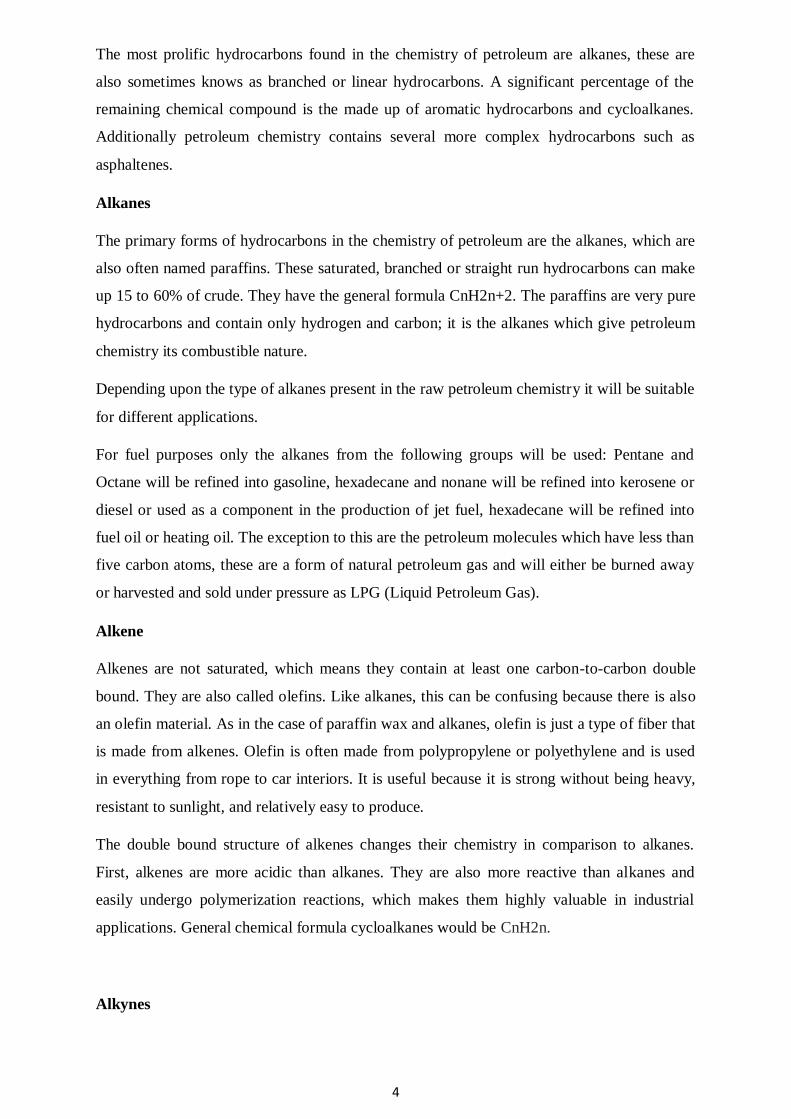
The exact molecular composition varies widely from formation to formation but the
proportion of chemical elements vary over fairly narrow limits as follows
Element Composition (Weight%)
6
Carbon 83 to 85%
Hydrogen 10 to 14%
Nitrogen 0.1 to 2%
Oxygen 0.05 to 1.5%
Sulfur 0.05 to 6.0%
Metals < 0.1%
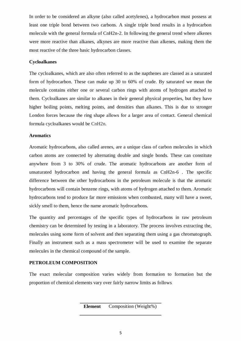
The actual overall properties of each different petroleum source are defined by the percentage
of the four main hydrocarbons found within petroleum as part of the petroleum composition.
The percentages for these hydrocarbons can vary greatly, giving the crude oil a quite distinct
compound personality depending upon geographic region. These hydrocarbons are typically
present in petroleum at the following percentages:
Composition (Weight%)
Hydrocarbon Average Range
Alkanes (paraffins) 30% 15 to 60%
Naphthenes 49% 30 to 60%
Aromatics 15% 3 to 30%
Asphaltic 6% remainder
CLASSIFICATION OF PETROLEUM
For several decades now the crude oil or petroleum industry has classified the raw crude
geographic region. Further classification of petroleum, derived from the density of the raw
petroleum (API gravity) and its various non-hydrocarbon components (especially sulphur), is
then added to the geographic designation.
In general, if the crude oil contains high levels of sulphur the petroleum classification is
termed „sour, if it has relatively low levels of sulphur the petroleum classification is termed
„sweet'. If the raw petroleum is of a high density then the petroleum classification is termed
„heavy' and if it is of a low density the petroleum classification is termed 'light'. Density of
7
oil is determined by the length of the hydrocarbons it contains. If it contains a great deal of
long-chain hydrocarbons, the petroleum will be denser. If it contains a greater proportion of
short-chain hydrocarbons it will be less dense.
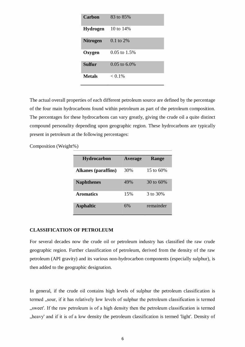
The API gravity is used to classify oils as light, medium, heavy, or extra heavy. As the
“weight” of oil is the largest determinant of its market value, API gravity is exceptionally
important. The API values for each “weight” are as follows:
Classification API Value
Light API > 31.1
Medium 22.3<API < 31.1
Heavy API < 22.3
Extra Heavy API < 10.0
PRODUCTS OF PETROLEUM
Liquefied Petroleum Gas
Liquefied Petroleum Gas or LPG is a flammable liquid that is a combination of various
hydrocarbons. It is used in heating appliances, in vehicles, as a refrigerant, for cooking
purposes etc. The most common forms of LPG are propane and butane. It is also produced by
refining crude oil. Its boiling range is less than 25 ⁰C.
Petrochemicals
Petrochemicals as the name suggests are chemical products obtained from petroleum.
Petrochemicals are classified as olefins and aromatics. These sub classes are obtained by the
catalytic cracking of petroleum fractions. Its boiling range is between 30 ⁰C to 200 ⁰C.
Petrochemicals are produced by the fractional distillation of crude oil and natural gas.
Petrochemicals are used in fertilizers, wax, polish, detergents, food additives, synthetic shoes,
dyes, plastic bottles and so on.
Gasoline
Gasoline is also referred to as Petrol and is a transparent liquid obtained from the fractional
distillation of crude oil. It consists of organic compounds and is mainly used in internal
combustion engines. It is widely used across the globe and its consumption is so high that its
prices have also soared and are continuously
8
changing as per increase in demand. Gasoline is obtained by the fractional distillation of
crude oil between 40 ⁰C (104 ⁰F) and 205 ⁰C (401 ⁰F), which is its boiling range. Gasoline is
used in vehicles, electrical generators, compressors etc.
Jet fuel
Jet fuel is sometimes called Aviation Turbine Fuel (ATF) and is primarily used for aircraft.
This fuel is a combination of various hydrocarbons. The most common types of Jet fuel are
Jet A and Jet A-1. The boiling range for Jet fuel (similar to Kerosene) is between 150 ⁰C to
275 ⁰C.
Kerosene
Kerosene, also called paraffin, is a combustible liquid containing hydrocarbons. Kerosene is
used to power jet engines, for cooking, heating, lighting fuels and toys. Kerosene lamps are
extremely popular. The boiling range for Kerosene is between 150 ⁰C to 275 ⁰C. Other
applications of Kerosene are as a pesticide, as a solvent, lubricant, x-ray crystallography and
so on.
Diesel
Diesel fuel or petro-diesel is a derivative of petroleum. Diesel fuel most commonly used
today is the Ultra-Low Sulphur Diesel as it contains reduced amounts of sulphur in it
comparatively. Diesel is obtained by fractional distillation of crude oil with a boiling range of
250 ⁰C (392 ⁰F) and 350 ⁰C (662 ⁰F) at atmospheric pressure. The quality of diesel fuel is
measured in terms of Cetane numbers. Diesel is comparatively easier to refine from
petroleum than gasoline. Diesel is mainly used as a vehicle fuel and engines using diesel are
considered to be more energy efficient and have better fuel economy than for example,
gasoline. Diesel is also used in gas turbines and external combustion engines.
Lubricating oils
Lubricants are mainly used to reduce friction between surfaces. A good lubricant has a high
boiling point and viscosity. It is found to have thermal and hydraulic stability as well as a low
freezing point. Lubricants contain 90 percent base oil and less than 10 percent additives. The
boiling range for lubricants is between 300 ⁰C (572 ⁰F) to 370 ⁰C (700 ⁰F). Lubricants are
also used as motor oils, transmit power, transfer heat, prevent corrosion and rusting etc.
Paraffin wax
Paraffin is a waxy solid that is used as a lubricant. It is typically a solid at room temperature.
Its boiling point is greater than 370 ⁰C. Paraffin wax is mostly used in candle making,
9
waxing materials such as paper or cloth, sealant, crayons, propellant for rocket motors,
waxing surfboards, floors, cosmetics such as Vaseline and so on.
Fuel oils
Fuel oils are obtained from distillation of petroleum. Fuel oil is the heaviest fuel that can be
obtained from refining crude oil. It is produced by the fractional distillation of crude oil
between 370 ⁰C (700 ⁰F) and 600 ⁰C (1112 ⁰F) boiling range. Fuel oils have many
applications such as heating homes, offices and for the usage of trucks, ships and
automobiles. It is also used as a back up in power plants and electrical generators etc.
Asphalt
Asphalt is commonly called Bitumen. Asphalt is a black and thicker version of petroleum
that is obtained both naturally and as a refined product. It is also classified as pitch. Its
viscosity is the same as cold molasses. Asphalt is obtained by fractional distillation of crude
oil at 525 ⁰C (977 ⁰F). Asphalt is primarily used to lay roads. Other uses are for
waterproofing products meant to seal roofs etc.
Tar
Tar is obtained by the process called destruction distillation using several organic
compounds. It can be manufactured from coal, petroleum, wood or peat. The end product is a
combination of various hydrocarbons and free carbon. The boiling point for tar is greater than
600 ⁰C. Tar has several uses such as a disinfectant, to seal roofs, hulls of ships etc. Wood tar
is used as a flavor, spice, scent for spas, cosmetics, anti-dandruff shampoos and so on.
CHARACTERIZATION OF CRUDE
Crude of petroleum is very complex except for the low-boiling components, no attempt is
made by the refiner to analyze for the pure components that contained in the crude oil.
Relatively simple analytical tests are run on the crude and the results of these are used with
empirical correlations to evaluate the crude oils as feedstocks for the particular refinery. Each
crude is compared with the other feedstocks available and, based upon the operating cost and
product realization, is assigned a value. The useful properties are discussed.
API Gravity
API stands for the American Petroleum Institute, which is the major United States trade
association for the oil and natural gas industry. One of the most important standards that the
API has set is the method used for measuring the density of petroleum. This standard is
called the API graity.
10
Specific gravity is a ratio of the density of one substance to the density of a reference
substance, usually water. The API gravity is nothing more than the standard specific gravity
used by the oil industry, which compares the density of oil to that of water through a
calculation designed to ensure consistency inmeasurement. Less dense oil or “light oil” is
preferable to more dense oil as it contains greater quantities of hydrocarbons that can be
converted to gasoline.
API gravity is calculated using the specific gravity of an oil, which is nothing more than the
ratio of its density to that of water (density of the oil/density of water). Specific gravity for
API calculations is always determined at 60 degrees Fahrenheit.
Though API values do not have units, they are often referred to as degrees. Specific gravity
of Crude oil may vary from less than 10oAPI to over 50oAPI but most crudes fall in the 20 to
45oAPI range. API gravity always refers to the liquid sample at 60oF (15.6oC).
Sulphur Content, wt%
Sulphur content and API gravity are two properties which have the greatest influence on the
value of crude oil, although nitrogen and metals contents are increasing in importance. The
sulphur content is expressed as per cent of sulphur by weight and varies from less than 0.1%
to greater than 5%. Crudes with greater than 0.5% sulphur generally require more extensive
processing than those with lower sulphur content.
Pour Point
The pour point of the crude oil, in oF or oC, is a rough indicator of the relative paraffinicity
and aromaticity of the crude. The lower the pour point, the lower the paraffin content and the
greater the content of aromatics.
Carbon Residue
Carbon residue is determined by distillation to a coke residue in the absence of air. The
carbon residue is roughly related to the asphalt content of the crude and to the quantity of the
lubricating oil fraction that can be recovered. In most cases the lower the carbon residue, the
more valuable the crude. This is expressed in terms of the weight percent carbon residue by
either the Ramsbottom (RCR) or Conradson (CCR) .
Salt Content
11
If the salt content of the crude, when expressed as NaCl, is greater than 10 lb/ 1000 bbl, it is
generally necessary to desalt the crude before processing. If the salt is not removed, severe
corrosion problems may be encountered. If residua are processed catalytically, desalting is
desirable at even lower salt contents of the crude. Although it is not possible to have an
accurate conversion unit between lb/1000 bbl and ppm by weight because of the different
densities of crude oils, 1 lb/1000 bbl is approximately 3 ppm.
Characterization Factors
There are several correlations between yield and the aromaticity and paraffinicity of crude
oils, but the two most widely used are the UOP or Watson „„characterization factor‟‟ (KW)
and the U.S. Bureau of Mines „„correlation index‟‟ (CI).
Nitrogen Content, wt%
High nitrogen content is undesirable in crude oils because organic nitrogen compounds cause
severe poisoning of catalysts used in processing and cause corrosion problems. Crudes
containing nitrogen more than 0.25% by weight require special processing to remove the
nitrogen.
Distillation Range
The boiling range of the crude gives an indication of the quantities of the various products
present. The most useful type of distillation is known as a true boiling point (TBP) distillation
and generally refers to a distillation performed in equipment that accomplishes a reasonable
degree of fractionation. There is no specific test procedure called a TBP distillation, but the
U.S. Bureau of Mines Hempel and ASTM D-285 distillations are the tests most commonly
used. Neither of these specify either the number of theoretical plates or the reflux ratio used
and, as a result, there is a trend toward using the results of a 15:5 distillation (D- 2892) rather
than the TBP. The 15:5 distillation is carried out using 15 theoretical plates at a reflux ratio of
5: 1. The crude distillation range has to be correlated with ASTM distillations because
product specifications are generally based on the simple ASTM distillation tests like D-86
and D-1160 etc.
Metals Content, ppm
The metals content metals (nickel, vanadium, and copper) of crude oils vary from a few
parts per million to more than 1000 ppm. Minute quantities of some of these metals can
severely affect the activities of catalysts and result in a lower value product distribution.
Vanadium concentrations above 2 ppm in fuel oils can lead to severe corrosion to turbine
blades and deterioration of refractory furnace linings and stacks. Distillation concentrates the
12
metallic constituents of crude in the residues, but some of the organometallic compounds are
actually volatilized at refinery distillation temperatures and appear in the higher-boiling
distillates. The metallic content may be reduced by solvent extraction with propane or similar
solvents as the organometallic compounds are precipitated with the asphaltenes and resins.
DESALTING PROCESS
Crude oil often contains water, inorganic salts, suspended solids, and water-soluble trace
metals. As a first step in the refining process, to reduce corrosion, plugging, and fouling of
equipment and to prevent poisoning the catalysts in processing units, these contaminants
must be removed by desalting (dehydration).
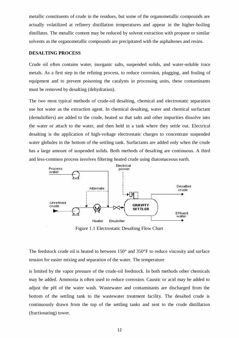
The two most typical methods of crude-oil desalting, chemical and electrostatic separation
use hot water as the extraction agent. In chemical desalting, water and chemical surfactant
(demulsifiers) are added to the crude, heated so that salts and other impurities dissolve into
the water or attach to the water, and then held in a tank where they settle out. Electrical
desalting is the application of high-voltage electrostatic charges to concentrate suspended
water globules in the bottom of the settling tank. Surfactants are added only when the crude
has a large amount of suspended solids. Both methods of desalting are continuous. A third
and less-common process involves filtering heated crude using diatomaceous earth.
Figure 1.1 Electrostatic Desalting Flow Chart
The feedstock crude oil is heated to between 150° and 350°F to reduce viscosity and surface
tension for easier mixing and separation of the water. The temperature
is limited by the vapor pressure of the crude-oil feedstock. In both methods other chemicals
may be added. Ammonia is often used to reduce corrosion. Caustic or acid may be added to
adjust the pH of the water wash. Wastewater and contaminants are discharged from the
bottom of the settling tank to the wastewater treatment facility. The desalted crude is
continuously drawn from the top of the settling tanks and sent to the crude distillation
(fractionating) tower.
13
Safety Considerations
The potential exists for a fire due to a leak or release of crude from heaters in the crude-
desalting unit. Low boiling point components of crude may also be released if a leak occurs.
Because this is a closed process, there is little potential for exposure to crude oil unless a leak
or release occurs. Where elevated operating temperatures are used when desalting sour
crudes, hydrogen sulfide will be present. There is the possibility of exposure to ammonia, dry
chemical demulsifiers, caustics, and/or acids during this operation.
Depending on the crude feedstock and the treatment chemicals used, the wastewater will
contain varying amounts of chlorides, sulfides, bicarbonates, ammonia, hydrocarbons,
phenol, and suspended solids. If diatomaceous earth is used in filtration, exposures should be
minimized or controlled. Diatomaceous earth can contain silica in very fine particle size,
making this a potential respiratory hazard.
Corrosion Considerations
Inadequate desalting can cause fouling of heater tubes and heat exchangers throughout the
refinery. Fouling restricts product flow and heat transfer and leads to failures due to increased
pressures and temperatures. Corrosion, which occurs due to the presence of hydrogen sulfide,
hydrogen chloride, naphthenic (organic) acids, and other contaminants in the crude oil, also
causes equipment failure. Neutralized salts (ammonium chlorides and sulfides), when
moistened by condensed water, can cause corrosion. Over-pressuring the unit is another
potential hazard that causes failures.
ATMOSPHERIC DISTILLATION PROCESS
Desalting is the first separation process that takes place at the front end of a petroleum
refinery. Its primary objective is to prevent corrosion and fouling of downstream lines and
equipment by reducing the oil‟s salt content significantly. The main separation step in any
crude oil refinery is atmospheric or primary distillation. Atmospheric distillation fractionates
the crude oil into various distillates, fractions, or cuts of hydrocarbon compounds based on
molecular size and boiling)point range [e.g., light ends, propane, butanes, straight) run
naphthas (light and heavy), kerosene, straight-run gas oils (light and heavy), and atmospheric
residue] (Figure 1.2).
14
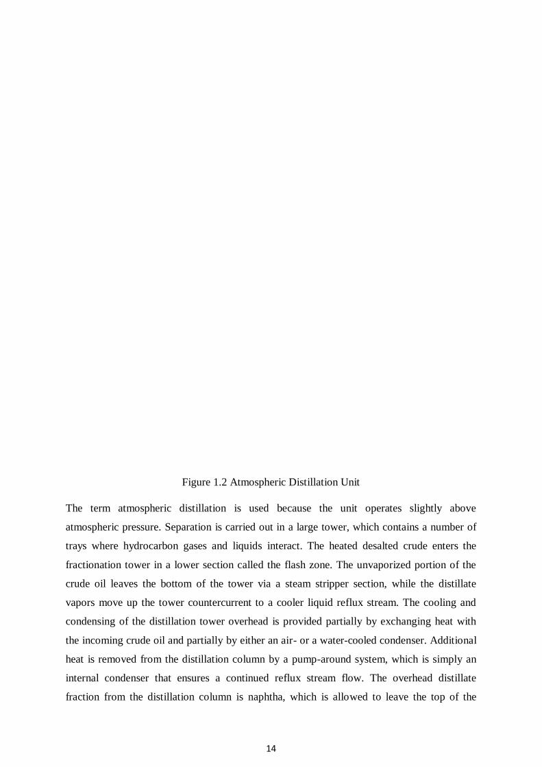
Figure 1.2 Atmospheric Distillation Unit
The term atmospheric distillation is used because the unit operates slightly above
atmospheric pressure. Separation is carried out in a large tower, which contains a number of
trays where hydrocarbon gases and liquids interact. The heated desalted crude enters the
fractionation tower in a lower section called the flash zone. The unvaporized portion of the
crude oil leaves the bottom of the tower via a steam stripper section, while the distillate
vapors move up the tower countercurrent to a cooler liquid reflux stream. The cooling and
condensing of the distillation tower overhead is provided partially by exchanging heat with
the incoming crude oil and partially by either an air- or a water-cooled condenser. Additional
heat is removed from the distillation column by a pump-around system, which is simply an
internal condenser that ensures a continued reflux stream flow. The overhead distillate
fraction from the distillation column is naphtha, which is allowed to leave the top of the
15
tower to be condensed and collected in the overhead drum. A portion of this stream is
returned as reflux, while the rest is delivered to the lightend processes for stabilizing and
further distillation. The other fractions removed from the side of the distillation column [i.e.,
from selected trays (draw-off trays)] at various points between the column top and bottom are
jet fuel, kerosene, light gas oil, and heavy gas oil, which are steam stripped, cooled by
exchanging heat with the incoming crude oil, and sent to other treatment areas and/or to
storage. The heavier material (i.e., atmospheric residue oil) is withdrawn from the bottom of
the tower.
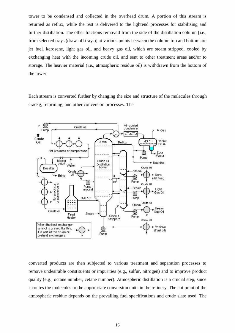
Each stream is converted further by changing the size and structure of the molecules through
crackg, reforming, and other conversion processes. The
converted products are then subjected to various treatment and separation processes to
remove undesirable constituents or impurities (e.g., sulfur, nitrogen) and to improve product
quality (e.g., octane number, cetane number). Atmospheric distillation is a crucial step, since
it routes the molecules to the appropriate conversion units in the refinery. The cut point of the
atmospheric residue depends on the prevailing fuel specifications and crude slate used. The
16
atmospheric residue leaves the bottom of the unit and is processed further in the vacuum
distillation unit.
It is important not to subject crude oil to temperatures above 370 to 380°C because the high-
molecular-weight components will undergo thermal cracking and form coke. The coke, by
operating the distillation units at a high temperature, would result in plugging the tubes in the
furnace that heats the crude oil fed to the distillation column. Plugging would also occur in
the piping from the furnace to the distillation column as well as in the column itself.
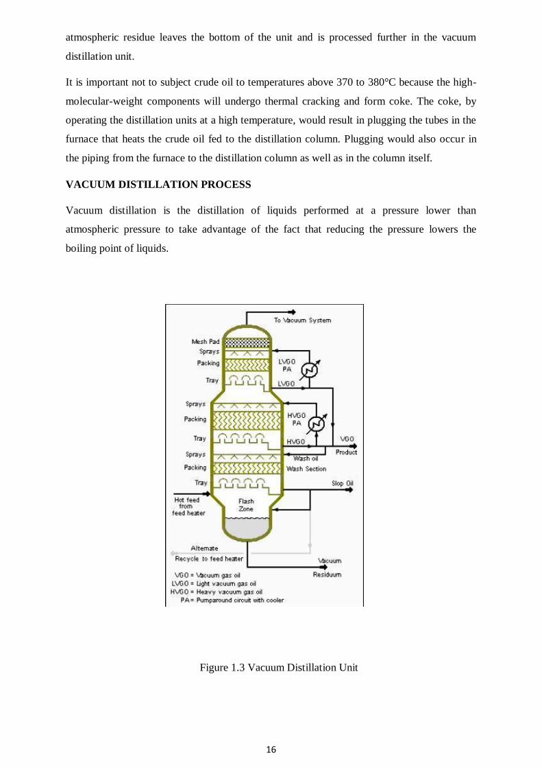
VACUUM DISTILLATION PROCESS
Vacuum distillation is the distillation of liquids performed at a pressure lower than
atmospheric pressure to take advantage of the fact that reducing the pressure lowers the
boiling point of liquids.
Figure 1.3 Vacuum Distillation Unit
17
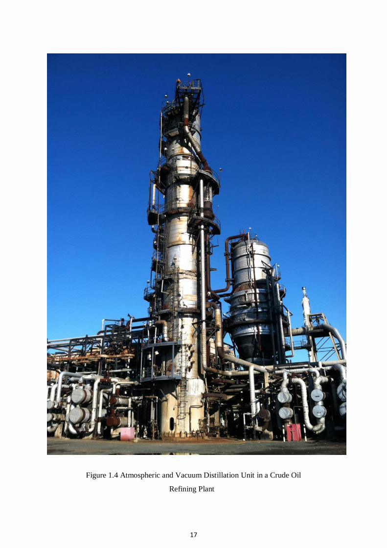
Figure 1.4 Atmospheric and Vacuum Distillation Unit in a Crude Oil
Refining Plant
18
The residual oil from the atmospheric distillation unit, is distilled at absolute pressures as low as
10 to 40 mmHg (also referred to as torr) so as to limit the operating temperature to less than 370
to 380 °C.
The 10 to 40 mmHg absolute pressure in a vacuum distillation column increases the volume of
vapor formed per volume of liquid distilled. The result is that such columns have very large
diameters.[5] Vacuum distillation columns, such those in Images 1 and 2, may have diameters of
15 meters or more, heights ranging up to about 50 meters, and feed rates ranging up to about
25,400 cubic meters per day (160,000 barrels per day).
The vacuum distillation column internals must provide good vapor-liquid contacting while, at the
same time, maintaining a very low pressure increase from the column top to the column bottom.
Therefore, refinery vacuum columns often use distillation trays only where withdrawing products
from the side of the column (referred to as side draws). The remainder of the column uses
packing material for the vapor-liquid contacting because such packing has a lower pressure drop
than distillation trays. This packing material can be either structured sheet metal or randomly
dumped packing such as Raschig rings.
The absolute pressure of 10 to 40 mmHg in a refinery vacuum distillation column is most often
achieved by a vacuum system using multiple stages of steam jet ejectors.
Many industries, other than the petroleum refining industry, use vacuum distillation on a much
smaller scale.
REFERENCE BOOKS:
1. Nelson, W.L., Petroleum Refinery Engineering, 4th Edition., McGraw Hill, New York,1985
2. Bhaskara Rao B. K., Modern Petroleum Refining Processes, 2nd Edition., Oxford and IBH
Publishing Company, New Delhi,1989.
3. Hobson G. D and Pohl. W., Modern Petroleum Technology, 2nd Edition, Gulf Publishers,1986.
1
SCHOOL OF BIO AND CHEMICAL ENGINEERING
DEPARTMENT OF CHEMICAL ENGINEERING
UNIT – 2- CRACKING AND REFORMING
2
UNIT II CRACKING AND REFORMING CRACKING The ‘‘bottom of the barrel’’ has become more of a problem for refiners because heavier crudes
are being processed and the market for heavy residual fuel oils has been decreasing. Historically,
the heavy residual fuel oils have been burned to produce electric power and to supply the energy
needs of heavy industry, but more severe environmental restrictions have caused many of these
users to switch to natural gas. Cracking units convert large hydrocarbon molecules into smaller
and more useful bits. Cracking is the process whereby complex long chain hydrocarbons are broken down into simpler
molecules such as light hydrocarbons, by the breaking of carbon-carbon bonds in the precursors
his is achieved by using high pressures and temperatures without a catalyst, or lower
temperatures and pressures in the presence of a catalyst. The source of the large hydrocarbon
molecules is often the naphtha fraction or the gas oil fraction from the fractional distillation of
crude oil (petroleum). These fractions are obtained from the distillation process as liquids, but
are re-vaporised before cracking. There isn't any single unique reaction happening in the cracker.
The hydrocarbon molecules are broken up in a fairly random way to produce mixtures of smaller
hydrocarbons, some of which have carbon-carbon double bonds.
Reactions A large number of chemical reactions take place during the cracking process, most of them based
on free radicals. The main reactions that take place include Initiation In these reactions a single molecule breaks apart into two free radicals. Only a small fraction of
the feed molecules actually undergo initiation, but these reactions are necessary to produce the
free radicals that drive the rest of the reactions. In steam cracking, initiation usually involves
breaking a chemical bond between two carbon atoms, rather than the bond between a carbon and
a hydrogen atom. CH3CH3 → 2 CH3•
Hydrogen abstraction In these reactions a free radical removes a hydrogen atom from another molecule, turning the
second molecule into a free radical. CH3• + CH3CH3 → CH4 + CH3CH2•
Radical decomposition
In these reactions a free radical breaks apart into two molecules, one an alkene, the other a free
radical. This is the process that results in alkene products. CH3CH2• → CH2=CH2 + H•
Radical addition In these reactions, the reverse of radical decomposition reactions, a radical reacts with an alkene
to form a single, larger free radical. These processes are involved in forming the aromatic
products that result when heavier feedstocks are used. CH3CH2• + CH2=CH2 → CH3CH2CH2CH2•

3
1
4
Termination
In these reactions two free radicals react with each other to produce products that are not free
radicals. Two common forms of termination are recombination, where the two radicals combine
to form one larger molecule, and disproportionation, where one radical transfers a hydrogen
atom to the other, giving an alkene and an alkane. CH3• + CH3CH2• → CH3CH2CH3 CH3CH2• + CH3CH2• → CH2=CH2 + CH3CH3
Cracking Methodologies
1. Thermal methods a. Thermal cracking b. Steam cracking
2. Catalytic methods a. Fluid Catalytic cracking b. Hydrocracking
THERMAL CRACKING Breaking down large molecules by heating at high temperature and pressure is termed as thermal
cracking. Thermal cracking process for upgradation of heavy residue has been used since long
and still it is playing an important role in the modern refinery through upgradation of heavy
residue and improving the economics of the refinery through the production of lighter distillate
and other valuable product like low value fuel gas and petroleum coke.
VISBREAKING Visbreaking is essentially a mild thermal cracking operation at mild conditions where in long
chain molecules in heavy feed stocks are broken into short molecules thereby leading to a
viscosity reduction of feedstock. Now all the new visbreaker units are of the soaker type. Soaker
drum utilizes a soaker drum in conjunction with a fired heater to achieve conversion.
Visbreaking is a non-catalytic thermal process. It reduces the viscosity and pour point of heavy
petroleum fractions so that product can be sold as fuel oil. It gives 80 - 85% yield of fuel oil and
balance recovered as light and middle distillates. The unit produces gas, naphtha, heavy naphtha,
visbreaker gas oil, visbreaker fuel oil (a mixture of visbreaker gas oil and vsibreaker tar). A given conversion in visbreaker can be achieved by two ways:
1. High temp., low residence time cracking: Coil Visbreaking.
2. Low temp., high residence time cracking: Soaker visbreaking. Coil cracking uses higher furnace outlet temperatures [885–930°F(473–500°C)] and reaction
times from one to three minutes, while soaker cracking uses lower furnace outlet temperatures
[800–830°F (427–443°C)] and longer reaction times. The product yields and properties are
similar, but the soaker operation with its lower furnace outlet temperatures has the advantages of
lower energy consumption and longer run times
2
5
before having to shut down to remove coke from the furnace tubes. Run times of 3–6 months are
common for furnace visbreakers and 6–18 months for soaker visbreakers. This apparent
advantage for soaker visbreakers is at least partially balanced by the greater difficulty in cleaning
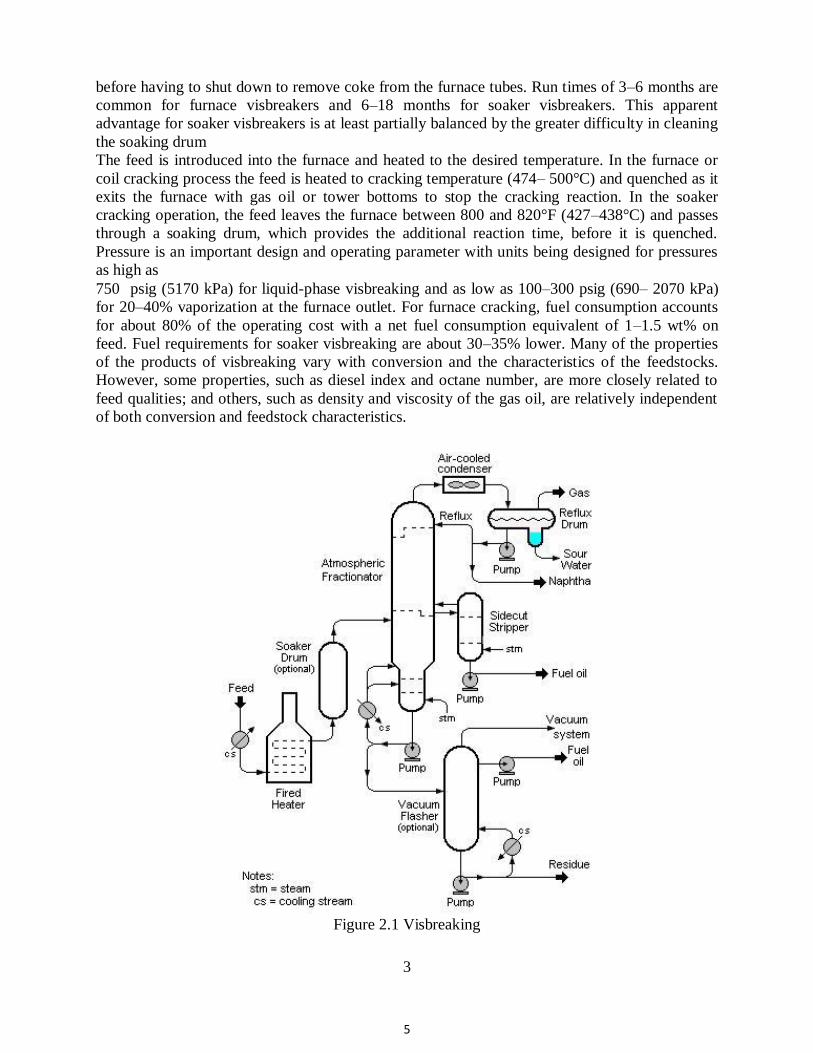
the soaking drum The feed is introduced into the furnace and heated to the desired temperature. In the furnace or
coil cracking process the feed is heated to cracking temperature (474– 500°C) and quenched as it
exits the furnace with gas oil or tower bottoms to stop the cracking reaction. In the soaker
cracking operation, the feed leaves the furnace between 800 and 820°F (427–438°C) and passes
through a soaking drum, which provides the additional reaction time, before it is quenched.
Pressure is an important design and operating parameter with units being designed for pressures
as high as 750 psig (5170 kPa) for liquid-phase visbreaking and as low as 100–300 psig (690– 2070 kPa)
for 20–40% vaporization at the furnace outlet. For furnace cracking, fuel consumption accounts
for about 80% of the operating cost with a net fuel consumption equivalent of 1–1.5 wt% on
feed. Fuel requirements for soaker visbreaking are about 30–35% lower. Many of the properties
of the products of visbreaking vary with conversion and the characteristics of the feedstocks.
However, some properties, such as diesel index and octane number, are more closely related to
feed qualities; and others, such as density and viscosity of the gas oil, are relatively independent
of both conversion and feedstock characteristics.
Figure 2.1 Visbreaking
3
6
CATALYTIC CRACKING Catalytic cracking is the most important and widely used refinery process for converting heavy
oils into more valuable gasoline and lighter products. Originally cracking was accomplished
thermally but the catalytic process has almost completely replaced thermal cracking because
more gasoline having a higher octane and less heavy fuel oils and light gases are produced. The
light gases produced by catalytic cracking contain more olefins than those produced by thermal
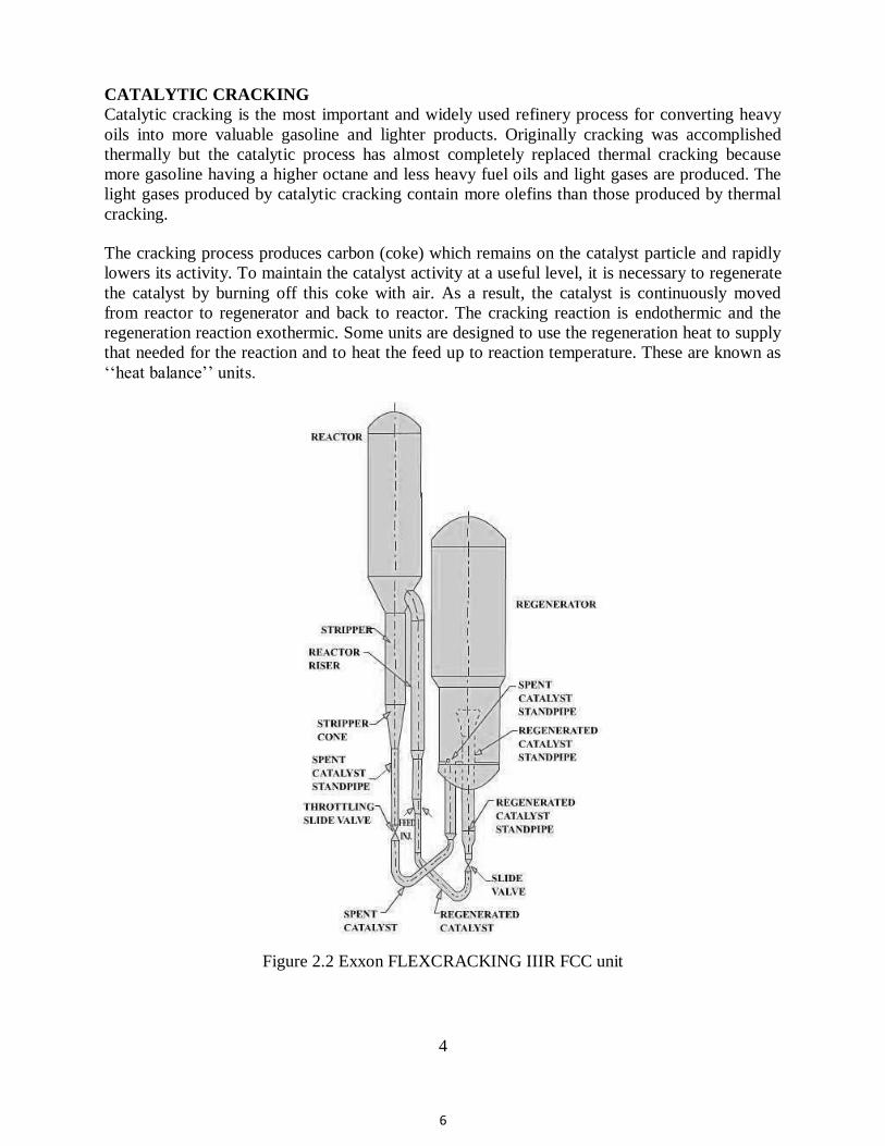
cracking. The cracking process produces carbon (coke) which remains on the catalyst particle and rapidly
lowers its activity. To maintain the catalyst activity at a useful level, it is necessary to regenerate
the catalyst by burning off this coke with air. As a result, the catalyst is continuously moved
from reactor to regenerator and back to reactor. The cracking reaction is endothermic and the
regeneration reaction exothermic. Some units are designed to use the regeneration heat to supply
that needed for the reaction and to heat the feed up to reaction temperature. These are known as
‘‘heat balance’’ units.
Figure 2.2 Exxon FLEXCRACKING IIIR FCC unit
4
7
Average riser reactor temperatures are in the range 900 to 1000°F (480–540°C), with oil feed
temperatures from 500 to 800°F (260–425°C) and regenerator exit temperatures for catalyst from
1200 to 1500°F (650–815°C). The catalytic-cracking processes in use today can all be classified as
Moving-bed units
Fluidized-bed units. There are several modifications under each of the classes depending upon the designer or
builder, but within a class the basic operation is very similar. The Thermafor catalytic cracking
process (TCC) is representative of the moving-bed units and the fluid catalytic cracker (FCC) of
the fluidized-bed units. There are very few TCC units in operation today and the FCC unit has
taken over the field. The FCC units can be classified as either bed or riser (transfer line) cracking
units depending upon where the major fraction of the cracking reaction occurs.
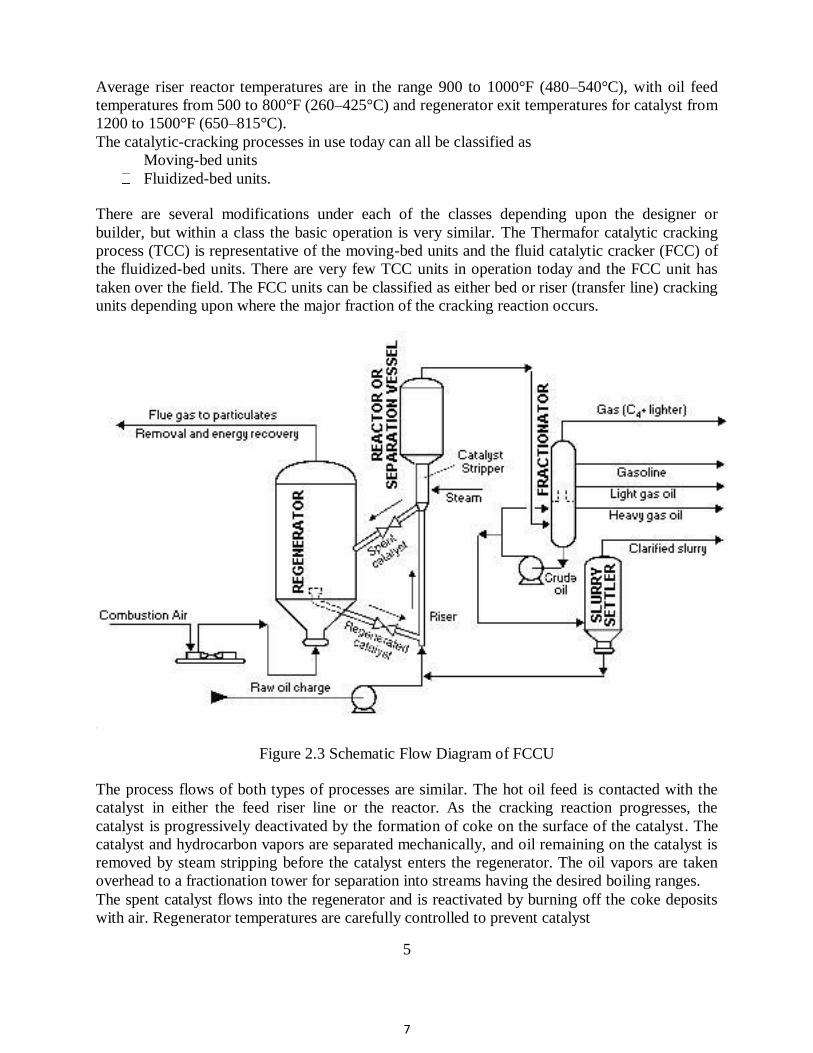
Figure 2.3 Schematic Flow Diagram of FCCU
The process flows of both types of processes are similar. The hot oil feed is contacted with the
catalyst in either the feed riser line or the reactor. As the cracking reaction progresses, the
catalyst is progressively deactivated by the formation of coke on the surface of the catalyst. The
catalyst and hydrocarbon vapors are separated mechanically, and oil remaining on the catalyst is
removed by steam stripping before the catalyst enters the regenerator. The oil vapors are taken
overhead to a fractionation tower for separation into streams having the desired boiling ranges. The spent catalyst flows into the regenerator and is reactivated by burning off the coke deposits
with air. Regenerator temperatures are carefully controlled to prevent catalyst
5
8
deactivation by overheating and to provide the desired amount of carbon burn-off. This is done
by controlling the air flow to give a desired CO2/CO ratio in the exit flue gases or the desired
temperature in the regenerator. The flue gas and catalyst are separated by cyclone separators and
electrostatic precipitators. The catalyst in some units is steam-stripped as it leaves the regenerator
to remove adsorbed oxygen before the catalyst is contacted with the oil feed. The moving-bed catalytic cracking process is similar to the FCC process. The catalyst is in the
form of pellets that are moved continuously to the top of the unit by conveyor or pneumatic lift
tubes to a storage hopper, then flow downward by gravity through the reactor, and finally to a
regenerator. The regenerator and hopper are isolated from the reactor by steam seals. The
cracked product is separated into recycle gas, oil, clarified oil, distillate, naphtha, and wet gas.
Cracking Catalysts Commercial cracking catalysts can be divided into three classes:
(1) acid-treated natural aluminosilicates,
(2) amorphous synthetic silica-alumina combinations, and (3) crystalline synthetic silica-alumina catalysts called zeolites or molecular sieves.
The advantages of the zeolite catalysts over the natural and synthetic amorphous catalysts are:
1. Higher activity 2. Higher gasoline yields at a given conversion 3. Production of gasolines containing a larger percentage of paraffinic and aromatic
hydrocarbons 4. Lower coke yield (and therefore usually a larger throughput at a given conversion level) 5. Increased isobutane production
6. Ability to go to higher conversions per pass without overcracking
Process Variables
Within the limits of normal operations, increasing 1. Reaction temperature
2. Catalyst/oil ratio 3. Catalyst activity 4. Contact time
results in an increase in conversion, while a decrease in space velocity increases conversion. It
should be noted that an increase in conversion does not necessarily mean an increase in gasoline
yield, as an increase in temperature above a certain level can increase conversion, coke and gas
yields, and octane number of the gasoline but decrease gasoline yield. HYDROCRACKING Although hydrogenation is one of the oldest catalytic processes used in refining petroleum, only
in recent years has catalytic hydrocracking developed to any great extent in this country. This
interest in the use of hydrocracking has been caused by several factors, including (1) the demand for petroleum products has shifted to high ratios of gasoline and jet fuel
compared with the usages of diesel fuel and home heating oils,
6
9
(2) by-product hydrogen at low cost and in large amounts has become available from
catalytic reforming operations, and (3) Environmental concerns limiting sulfur and aromatic compound concentrations in motor
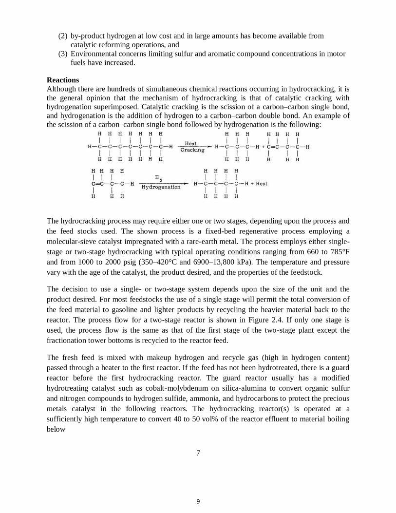
fuels have increased. Reactions Although there are hundreds of simultaneous chemical reactions occurring in hydrocracking, it is
the general opinion that the mechanism of hydrocracking is that of catalytic cracking with
hydrogenation superimposed. Catalytic cracking is the scission of a carbon–carbon single bond,
and hydrogenation is the addition of hydrogen to a carbon–carbon double bond. An example of
the scission of a carbon–carbon single bond followed by hydrogenation is the following:
The hydrocracking process may require either one or two stages, depending upon the process and
the feed stocks used. The shown process is a fixed-bed regenerative process employing a
molecular-sieve catalyst impregnated with a rare-earth metal. The process employs either single-
stage or two-stage hydrocracking with typical operating conditions ranging from 660 to 785°F
and from 1000 to 2000 psig (350–420°C and 6900–13,800 kPa). The temperature and pressure
vary with the age of the catalyst, the product desired, and the properties of the feedstock. The decision to use a single- or two-stage system depends upon the size of the unit and the
product desired. For most feedstocks the use of a single stage will permit the total conversion of
the feed material to gasoline and lighter products by recycling the heavier material back to the
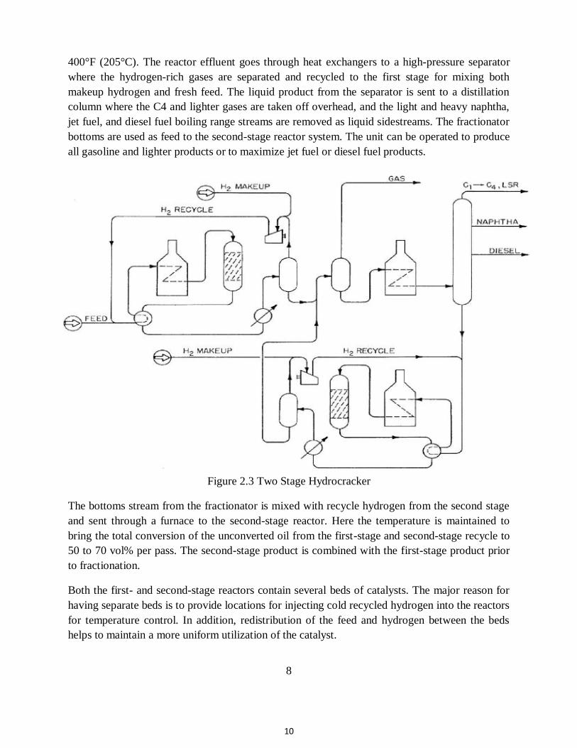
reactor. The process flow for a two-stage reactor is shown in Figure 2.4. If only one stage is
used, the process flow is the same as that of the first stage of the two-stage plant except the
fractionation tower bottoms is recycled to the reactor feed. The fresh feed is mixed with makeup hydrogen and recycle gas (high in hydrogen content)
passed through a heater to the first reactor. If the feed has not been hydrotreated, there is a guard
reactor before the first hydrocracking reactor. The guard reactor usually has a modified
hydrotreating catalyst such as cobalt-molybdenum on silica-alumina to convert organic sulfur
and nitrogen compounds to hydrogen sulfide, ammonia, and hydrocarbons to protect the precious
metals catalyst in the following reactors. The hydrocracking reactor(s) is operated at a
sufficiently high temperature to convert 40 to 50 vol% of the reactor effluent to material boiling
below
7
10
400°F (205°C). The reactor effluent goes through heat exchangers to a high-pressure separator
where the hydrogen-rich gases are separated and recycled to the first stage for mixing both
makeup hydrogen and fresh feed. The liquid product from the separator is sent to a distillation
column where the C4 and lighter gases are taken off overhead, and the light and heavy naphtha,
jet fuel, and diesel fuel boiling range streams are removed as liquid sidestreams. The fractionator
bottoms are used as feed to the second-stage reactor system. The unit can be operated to produce
all gasoline and lighter products or to maximize jet fuel or diesel fuel products.
Figure 2.3 Two Stage Hydrocracker The bottoms stream from the fractionator is mixed with recycle hydrogen from the second stage
and sent through a furnace to the second-stage reactor. Here the temperature is maintained to
bring the total conversion of the unconverted oil from the first-stage and second-stage recycle to
50 to 70 vol% per pass. The second-stage product is combined with the first-stage product prior
to fractionation. Both the first- and second-stage reactors contain several beds of catalysts. The major reason for
having separate beds is to provide locations for injecting cold recycled hydrogen into the reactors
for temperature control. In addition, redistribution of the feed and hydrogen between the beds
helps to maintain a more uniform utilization of the catalyst.
8
11
When operating hydrocrackers for total conversion of distillate feeds to gasoline, the butane-and-
heavier liquid yields are generally from 120 to 125 vol% of fresh feed. Hydrocracking Catalyst There are a number of hydrocracking catalysts available and the actual composition is tailored to
the process, feed material, and the products desired. Most of the hydrocracking catalysts consist
of a crystalline mixture of silica-alumina with a small uniformly distributed amount of rare earths
contained within the crystalline lattice. The silica-alumina portion of the catalyst provides
cracking activity while the rare-earth metals promote hydrogenation. Catalyst activity decreases
with use, and reactor temperatures are raised during a run to increase reaction rate and maintain
conversion. Process Variables The primary reaction variables are reactor temperature and pressure, space velocity, hydrogen
consumption, nitrogen content of feed, and hydrogen sulphide content of the gases. CATALYTIC REFORMING The demand of today’s automobiles for high-octane gasolines has stimulated the use of catalytic
reforming. In catalytic reforming, the change in the boiling point of the stock passed through the
unit is relatively small as the hydrocarbon molecular structures are rearranged to form higher-
octane aromatics with only a minor amount of cracking. Thus catalytic reforming primarily
increases the octane of motor gasoline rather than increasing its yield; in fact, there is a decrease
in yield because of hydrocracking reactions which take place in the reforming operation. The typical feedstocks to catalytic reformers are heavy straight-run (HSR) gasolines and
naphthas [180–375°F (82–190°C)] and heavy hydrocracker naphthas. These are composed of the
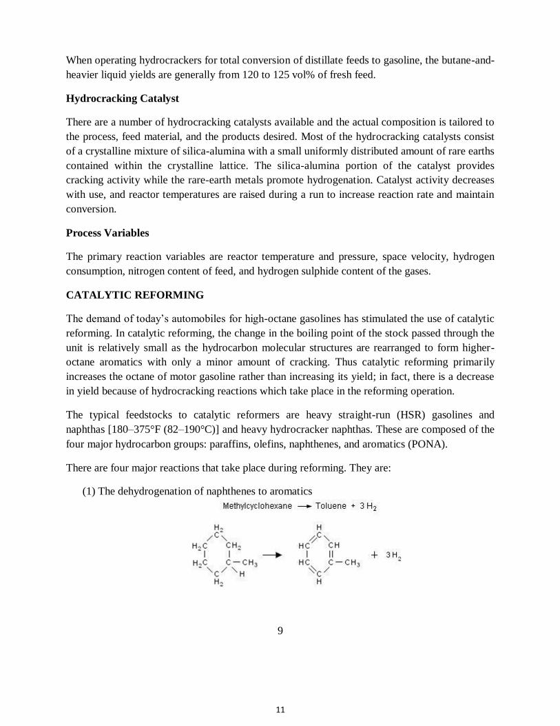
four major hydrocarbon groups: paraffins, olefins, naphthenes, and aromatics (PONA). There are four major reactions that take place during reforming. They are:
(1) The dehydrogenation of naphthenes to aromatics
9
12
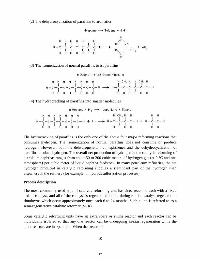
(2) The dehydrocyclization of paraffins to aromatics
(3) The isomerization of normal paraffins to isoparaffins
(4) The hydrocracking of paraffins into smaller molecules
The hydrocracking of paraffins is the only one of the above four major reforming reactions that
consumes hydrogen. The isomerization of normal paraffins does not consume or produce
hydrogen. However, both the dehydrogenation of naphthenes and the dehydrocyclization of
paraffins produce hydrogen. The overall net production of hydrogen in the catalytic reforming of
petroleum naphthas ranges from about 50 to 200 cubic meters of hydrogen gas (at 0 °C and one
atmosphere) per cubic meter of liquid naphtha feedstock. In many petroleum refineries, the net
hydrogen produced in catalytic reforming supplies a significant part of the hydrogen used
elsewhere in the refinery (for example, in hydrodesulfurization processes). Process description The most commonly used type of catalytic reforming unit has three reactors, each with a fixed
bed of catalyst, and all of the catalyst is regenerated in situ during routine catalyst regeneration
shutdowns which occur approximately once each 6 to 24 months. Such a unit is referred to as a
semi-regenerative catalytic reformer (SRR).
Some catalytic reforming units have an extra spare or swing reactor and each reactor can be
individually isolated so that any one reactor can be undergoing in-situ regeneration while the
other reactors are in operation. When that reactor is
10
13
regenerated, it replaces another reactor which, in turn, is isolated so that it can then be
regenerated. Such units, referred to as cyclic catalytic reformers, are not very common. Cyclic
catalytic reformers serve to extend the period between required shutdowns.
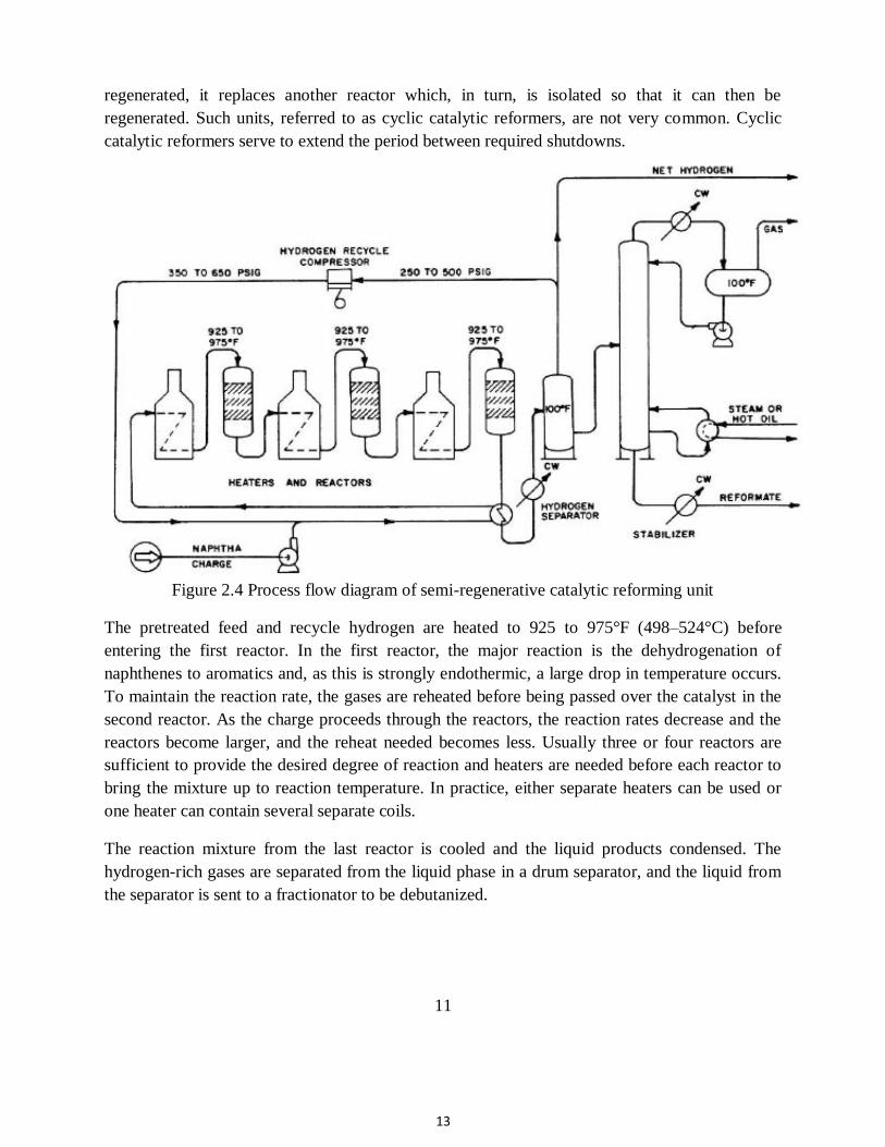
Figure 2.4 Process flow diagram of semi-regenerative catalytic reforming unit The pretreated feed and recycle hydrogen are heated to 925 to 975°F (498–524°C) before
entering the first reactor. In the first reactor, the major reaction is the dehydrogenation of
naphthenes to aromatics and, as this is strongly endothermic, a large drop in temperature occurs.
To maintain the reaction rate, the gases are reheated before being passed over the catalyst in the
second reactor. As the charge proceeds through the reactors, the reaction rates decrease and the
reactors become larger, and the reheat needed becomes less. Usually three or four reactors are
sufficient to provide the desired degree of reaction and heaters are needed before each reactor to
bring the mixture up to reaction temperature. In practice, either separate heaters can be used or
one heater can contain several separate coils. The reaction mixture from the last reactor is cooled and the liquid products condensed. The
hydrogen-rich gases are separated from the liquid phase in a drum separator, and the liquid from
the separator is sent to a fractionator to be debutanized.
11
14
The hydrogen-rich gas stream is split into a hydrogen recycle stream and a net hydrogen by-
product which is used in hydrotreating or hydrocracking operations or as fuel. The reformer operating pressure and the hydrogen/feed ratio are compromises among obtaining
maximum yields, long operating times between regeneration, and stable operation. It is usually
necessary to operate at pressures from 50 to 350 psig (345– 2415 kPa) and at hydrogen charge
ratios of 3–8 mol H2/mol feed (2800–7600 scp/bbl). Liquid hourly space velocities in the area of
1 to 3 are in general use. The original reforming process is classified as a semiregenerative type because catalyst
regeneration is infrequent and runs of 6 to 24 months between regeneration are common. In the
cyclic processes, regeneration is typically performed on a 24- or 48-hour cycle, and a spare
reactor is provided so that regeneration can be accomplished while the unit is still on-stream.
Because of these extra facilities, the cyclic processes are more expensive but offer the
advantages of low pressure operation and higher yields of reformate at the same severity. Reforming Catalyst All of the reforming catalyst in general use today contains platinum supported on an alumina
base. In most cases rhenium is combined with platinum to form a more stable catalyst which
permits operation at lower pressures. Process Variables The yield of aromatics is increased by:
(1) High temperature (increases reaction rate but adversely affects chemical equilibrium) (2) Low pressure (shifts chemical equilibrium ‘‘to the right’’) (3) Low space velocity (promotes approach to equilibrium) (4) Low hydrogen-to-hydrocarbon mole ratios (shifts chemical equilibrium ‘‘to the right,’’
however, a sufficient hydrogen partial pressure must be maintained to avoid excessive
coke formation).
12
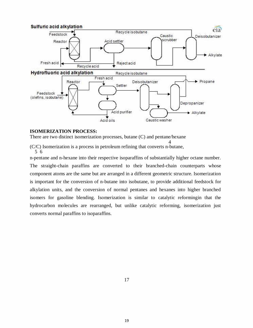
ALKYLATION: (SULPHURIC ACID AND HYDROFLUORIC ACID PROCESS)
15
Alkylation unit, is one of the conversion processes used in the petroleum refineries.It is used to
convert isobutane and low-molecular-weight alkenes (primarily a mixture of propene and
butene)into analkylate,a high octane gasoline component. The process occurs in presence of a
strong acting acid as catalyst.The acid can be either sulfuric acid or hydrofluoric acid (HF).
Depending on the acid used as catalyst the unit takes the name of SAAU (Sulphuric Acid
Alkylation Unit) or HFAU (Hydrofluoric Acid Alkylation Unit). Since crude oil generally
contains only 10 to 40 percent of hydrocarbon constituents in the gasoline range, refineries use a
fluid catalytic cracking unit (FCCU) process to convert high molecular weight hydrocarbons
into smaller and more volatile compounds, which are then converted into liquid gasoline-size
hydrocarbons. Alkylation processes transform low molecular-weight alkenes and iso-paraffin
molecules into larger iso-paraffins with a high octane number.The product of the unit, the
alkylate, is composed of a mixture of high-octane, branched-chain paraffinic
hydrocarbons(mostly isoheptane and isooctane). Alkylate is a premium gasoline blending stock
because it has exceptional antiknock properties and is clean burning. The octane number of the
alkylate depends mainly upon the kind of alkenes used and upon operating conditions. For
example, isooctane results from combining butylene with isobutane and has an octane rating of
100 by definition. There are other products in the alkylate effluent, so the octane rating will vary
accordingly.
Catalyst requirement to build an alkylation unit: The availability of a suitable catalyst is also an important factor in deciding whether to build an alkylation plant. If sulfuric acid (HSO) is used, significant volumes are
2 4 needed. Access to a suitable plant is required for the supply of fresh acid and the disposition of
spent acid. If a sulfuric acid plant must be constructed specifically to support an alkylation unit,
such construction will have a significant impact on both the initial requirements for capital and
ongoing costs of operation. Alternatively it is possible to install a WSA Process unit to
regenerate the spent acid. No drying of the gas takes place. This means that there will be no
loss of acid, no acidic waste material
13
16
and no heat is lost in process gas reheating. The selective condensation in the WSA condenser
ensures that the regenerated fresh acid will be 98% weight, even with the humid process gas. It
is possible to combine spent acid regeneration with disposal of hydrogen sulfideby using the
hydrogen sulfide as a fuel. The second main option is to use hydrofluoric acid (HF) as catalyst. In typical alkylation plants,
rates of consumption for acid are much lower than for sulfuric acid. The small amount of
organofluorine side products are continuously removed from the reactor and the consumed HF
is replenished. HF acid plants can process a wider range of feedstocks with propylenes and
butylenes. These plants also produce alkylate with better octane rating than do sulfuric plants.
However, due to its hazardous nature, HF acid is produced at very few locations and
transportation must be managed rigorously.
Feed to the alkylation unit: The olefin feed to an alkylation unit generally originates from a FCCU and contains butene,
isobutene, and possibly propene and/or amylenes. The olefin feed is also likely to contain
diluents (such as propane, n-butane, and n-pentane), noncondensables (such as ethane and
hydrogen) and contaminants. Diluants in principle have no effect on the reaction of alkylation
but occupy a portion of the reactor and can influence the yield of secondary reactions of
polymerisation and of undesired organofluorine side products. Incondensable are from a
chemical perspective similar to diluents but they do not condense at the pressure and
temperature of the process, and therefore they concentrate to a point that must be vented.
Contaminants are compounds that react with and/or dilute the sulfuric acid catalyst. They
increase acid consumption and contribute to produce undesirable reaction products and increase
polymer formation. Common contaminants are water,methanol and ethanol.
The isobutane feed to an alkylation unit can be either low or high purity. Low purity makeup
isobutane feedstock (typically < 70% volisobutane) usually originates from the refinery (mainly
from the reformer) and need to be processed in the deisobutanizer (DIB). High purity feedstock
(> 95% volisobutane) normally originates from an external
14
17
DIB and is fed directly to the alkylation unit reaction zone. The isobutane feed does not
normally contain any significant level of contaminants.
Operating variables: Many variables impact the product quality and operating costs of an alkylation unit. Isobutane Concentration: In order to promote the desired alkylation reactions, which are those involving isobutane and
olefins, it is necessary to maintain a high concentration of isobutane in the reaction zone. Low
isobutane-olefin ratios increase the likelihood of olefin-olefi polymerization that will result in
lower octane. Polymerization reactions also have a higher rate of production of acid soluble
oils, resulting in higher acid consumption.
Temperature: Typically, alkylation is carried out in the neighborhood of 20 °C. Higher reaction temperatures
dramatically favor polymerization reactions that will dilute the acid. Equipment corrosion will
also increase with higher reaction temperatures. Low reaction temperatures slow the settling
rate of the acid from the alkylate. Lower temperature than ambient cannot be achieved as the
coldest possible temperature is that of the cooling fluids (air and water). Seasonal factors
influence the production of polymerization reactions, therefore in summer the consumption of
acid is higher, especially in HFAU.
Acid strength: As the concentration of the acid catalyst is reduced, the rate of production of acid soluble
polymers increases. Feeds that contain high amounts of propylene have a much higher rate of
increase in acid consumption over the normal spending range. High acid concentration must be
maintained in order to minimize polymerization and red oil production. When concentrations
are too low catalyst activity is substantially decreased and polymerization enhanced to the point
that it is difficult to maintain acid strength. This condition is known as acid runaway.In HSAU
recent studies have found that both butylenes and amylenes can be spent to a lower acid
concentration
15
18
without entering into a runaway condition. While the economics of alkylating both butylenes
and amylenes will benefit from lowering the acid spending strength, the acid consumption of
amylenes has a greater response than that of butylenes. Also the expected decrease in octane of
alkylates produced at lower acid concentrations is less for amylenes than butylenes.
Olefin space velocity: Olefin space velocity is defined as the volume of olefin charged per hour divided by the average
volume of sulfuric acid in the contactor reactor. In general, higher olefin space velocities tend
to increase sulfuric acid consumption rates and decrease alkylate octane.
Mixing: Mixing is an important parameter, especially in HSAU because the alkylation reaction depends
on the emulsion of the hydrocarbon into the sulfuric acid. This is an acid continuous emulsion
and it is presumed that the reaction occurs at the interface of acid and hydrocarbon. The better
the emulsion, the finer the droplets and the better the reaction.
16
19
ISOMERIZATION PROCESS: There are two distinct isomerization processes, butane (C) and pentane/hexane
4 (C/C) Isomerization is a process in petroleum refining that converts n-butane,
5 6 n-pentane and n-hexane into their respective isoparaffins of substantially higher octane number.
The straight-chain paraffins are converted to their branched-chain counterparts whose
component atoms are the same but are arranged in a different geometric structure. Isomerization
is important for the conversion of n-butane into isobutane, to provide additional feedstock for
alkylation units, and the conversion of normal pentanes and hexanes into higher branched
isomers for gasoline blending. Isomerization is similar to catalytic reformingin that the
hydrocarbon molecules are rearranged, but unlike catalytic reforming, isomerization just
converts normal paraffins to isoparaffins.
17
20
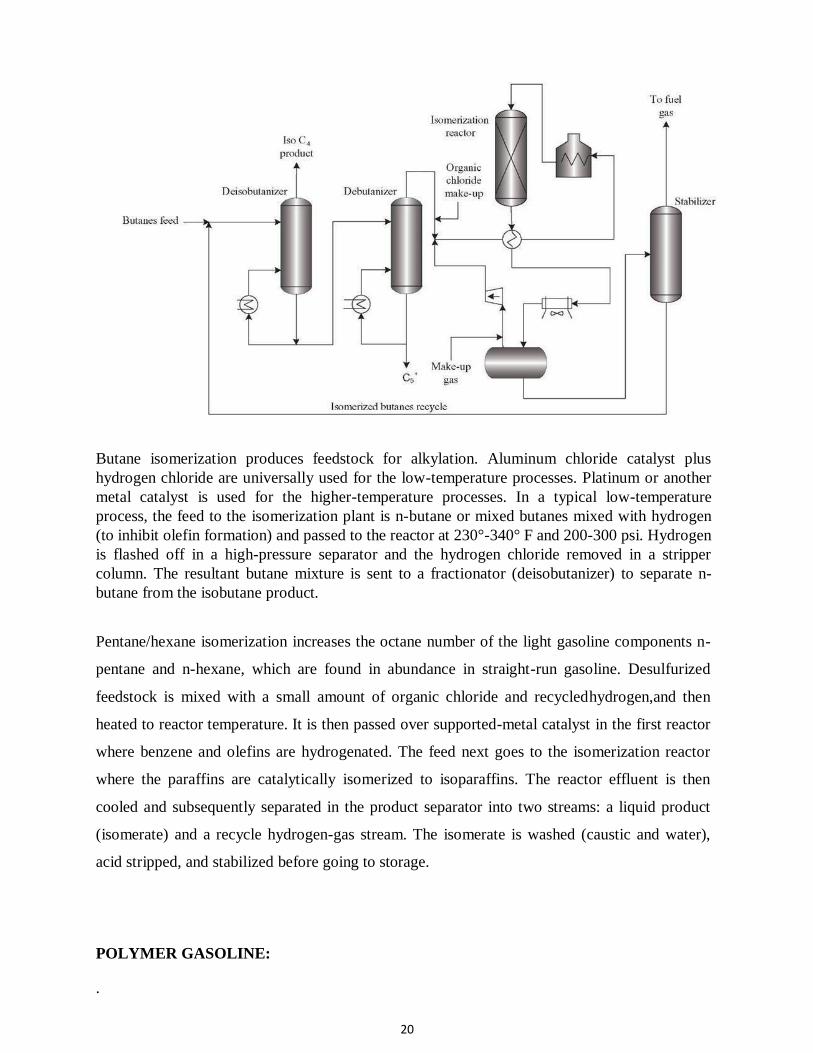
Butane isomerization produces feedstock for alkylation. Aluminum chloride catalyst plus
hydrogen chloride are universally used for the low-temperature processes. Platinum or another
metal catalyst is used for the higher-temperature processes. In a typical low-temperature
process, the feed to the isomerization plant is n-butane or mixed butanes mixed with hydrogen
(to inhibit olefin formation) and passed to the reactor at 230°-340° F and 200-300 psi. Hydrogen
is flashed off in a high-pressure separator and the hydrogen chloride removed in a stripper
column. The resultant butane mixture is sent to a fractionator (deisobutanizer) to separate n-
butane from the isobutane product. Pentane/hexane isomerization increases the octane number of the light gasoline components n-
pentane and n-hexane, which are found in abundance in straight-run gasoline. Desulfurized
feedstock is mixed with a small amount of organic chloride and recycledhydrogen,and then
heated to reactor temperature. It is then passed over supported-metal catalyst in the first reactor
where benzene and olefins are hydrogenated. The feed next goes to the isomerization reactor
where the paraffins are catalytically isomerized to isoparaffins. The reactor effluent is then
cooled and subsequently separated in the product separator into two streams: a liquid product
(isomerate) and a recycle hydrogen-gas stream. The isomerate is washed (caustic and water),
acid stripped, and stabilized before going to storage.
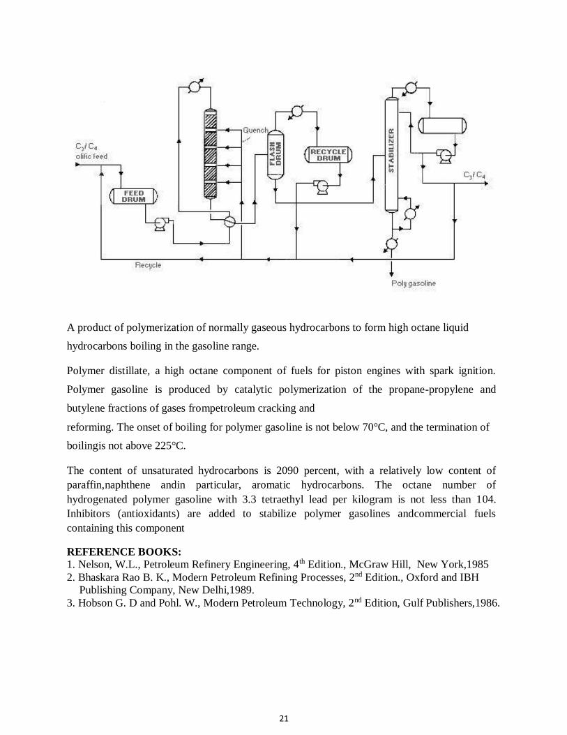
POLYMER GASOLINE: .
21
A product of polymerization of normally gaseous hydrocarbons to form high octane liquid
hydrocarbons boiling in the gasoline range.
Polymer distillate, a high octane component of fuels for piston engines with spark ignition.
Polymer gasoline is produced by catalytic polymerization of the propane-propylene and
butylene fractions of gases frompetroleum cracking and reforming. The onset of boiling for polymer gasoline is not below 70°C, and the termination of
boilingis not above 225°C.
The content of unsaturated hydrocarbons is 2090 percent, with a relatively low content of
paraffin,naphthene andin particular, aromatic hydrocarbons. The octane number of
hydrogenated polymer gasoline with 3.3 tetraethyl lead per kilogram is not less than 104.
Inhibitors (antioxidants) are added to stabilize polymer gasolines andcommercial fuels
containing this component REFERENCE BOOKS:
1. Nelson, W.L., Petroleum Refinery Engineering, 4th Edition., McGraw Hill, New York,1985
2. Bhaskara Rao B. K., Modern Petroleum Refining Processes, 2nd Edition., Oxford and IBH
Publishing Company, New Delhi,1989.
3. Hobson G. D and Pohl. W., Modern Petroleum Technology, 2nd Edition, Gulf Publishers,1986.

22
8
1
SCHOOL OF BIO AND CHEMICAL ENGINEERING
DEPARTMENT OF CHEMICAL ENGINEERING
UNIT – 3 TREATMENT TECHNIQUES
2
UNIT-3 TREATMENT TECHNIQUES
3.1 Treatment techniques for removal of objectionable gases and to improve
performance
3.2 Treatment of gasoline,
3.3 Treatment of kerosene,
3.4 Treatment of lubes.
3.5 Extraction of aromatics and olefins
3.1 Treatment techniques for removal of objectionable gases and to improve
performance
The essential purpose of the primary processes is to produce the required amounts of the various
products from the available crude. The products obtained are, as a general rule, unsuitable as
such for immediate use, for the following reasons :
1) Inadequate performance, 2) Instability in storage, and 3) Objectionable odor and
appearance and contamination with water or particulate matter. Secondary refining
processes (finishing or treating processes), are required to give the products acceptable
with respect to the above criteria.
Main Finishing Processes
a) The removal of the objectionable gases (Acid gas removal).
b) The removal of the objectionable odors.
c) The improvement in storage stability.
d) The improvement in performance characteristics.
e) The removal of water and particulate matter.
a)The removal of the objectionable gases
3
Hydrogen sulphide : Has to be removed from products because :
a) toxic, b) foul smelling, c) corrosive, d) traces of it may seriously contaminate regenerative
treating solvents such as a solutizer used for final sweetening of the products.
A) Scrubbing with caustic soda : It is still the most widely used process for the removal of H2S ,
mainly because it simultaneously removes other constituents such as CO2 , carbonyl sulphide,
lower aliphatic mercaptans, phenols fatty acids and naphthenic acids.
The disadvantage of this processes is that there is no known cheap method ofregenerating the
spent soda, and if H2S is present in gross amounts, as is frequently in crude gases, especially the
C2 -C3 fractions , a regenerative method of extraction such as the girbotol method is more
generally used. This method is more economical than caustic washing but caustic washing may
still be required as a final cleaning-up operation for the removal of the last traces of H2S. The
combination of the two processes not only provides a very low H2S content economically but
also safe guards against high sulfur contents in the treated products should there be a temporary
failure of the regenerative treating plant.
In the caustic washing of gases rather weak solutions of 2-10%wt NaOH have to be used to
prevent the deposition of sodium sulphide crystals. The reaction proceeds almost to the
completeconversion of NaOH to NaHS. Traces of H2S often appear in fractions much heavier
than C2 -C3 fraction because of a slight breakdown of sulfur compounds owing to pyrolysis
during re-distillation or a similar operation. Caustic soda may be employed for its removal.
4
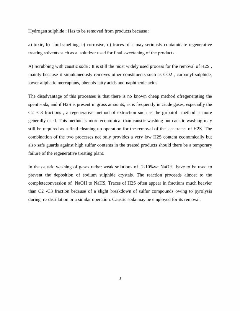
FIGURE.H2S removal from gases by caustic washing
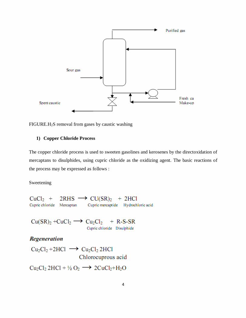
1) Copper Chloride Process
The copper chloride process is used to sweeten gasolines and kerosenes by the directoxidation of
mercaptans to disulphides, using cupric chloride as the oxidizing agent. The basic reactions of
the process may be expressed as follows :
Sweetening
5
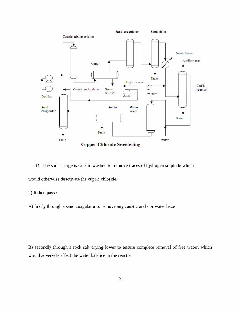
1) The sour charge is caustic washed to remove traces of hydrogen sulphide which
would otherwise deactivate the cupric chloride.
2) It then pass :
A) firstly through a sand coagulator to remove any caustic and / or water haze
B) secondly through a rock salt drying lower to ensure complete removal of free water, which
would adversely affect the water balance in the reactor.
6
3) After passing through a pre-heater to raise the temperature sufficiently to dissolve the water
formed during the process, air or oxygen is injected into the line, and the dried and oxygenated
feed flows upwards through the reactor which contains a bed of fullers earth impregnated with
cupric chloride.
4) The sweetened product is water washed to remove traces of acidity, clarified from water haze
in an up-flow sand coagulator and passed to storage.
2) Merox Process :
The Merox process, Developed by UOP (Universal Oil Products), is combination of mercaptan
extraction and sweetening. The combined process is applicable to all gasoline and lighter boiling
range fractions; the sweetening process is applicable to many jet fuel and kerosenes.
A) Merox Extraction:
1- The mercaptans are extracted by an aqueous solution of caustic soda according to
the reaction :
Since the reaction is reversible it is impossible to get complete removal of mercaptans by
extraction without the use of an excessive amount of caustic soda solution. The forward reaction
is favored by low temperature, low molecular weight of mercaptan and high caustic oncentration.
It is also promoted by the use of compounds that increase the solubility of the mercaptan in the
aqueous phase, of these methanol, isobutyric acid and cresols.
2- The caustic is generated ,after separation from hydrocarbons by blowing with air in the
presence of a catalyst at ambient temperature the reaction proceeding according to the reaction :
7
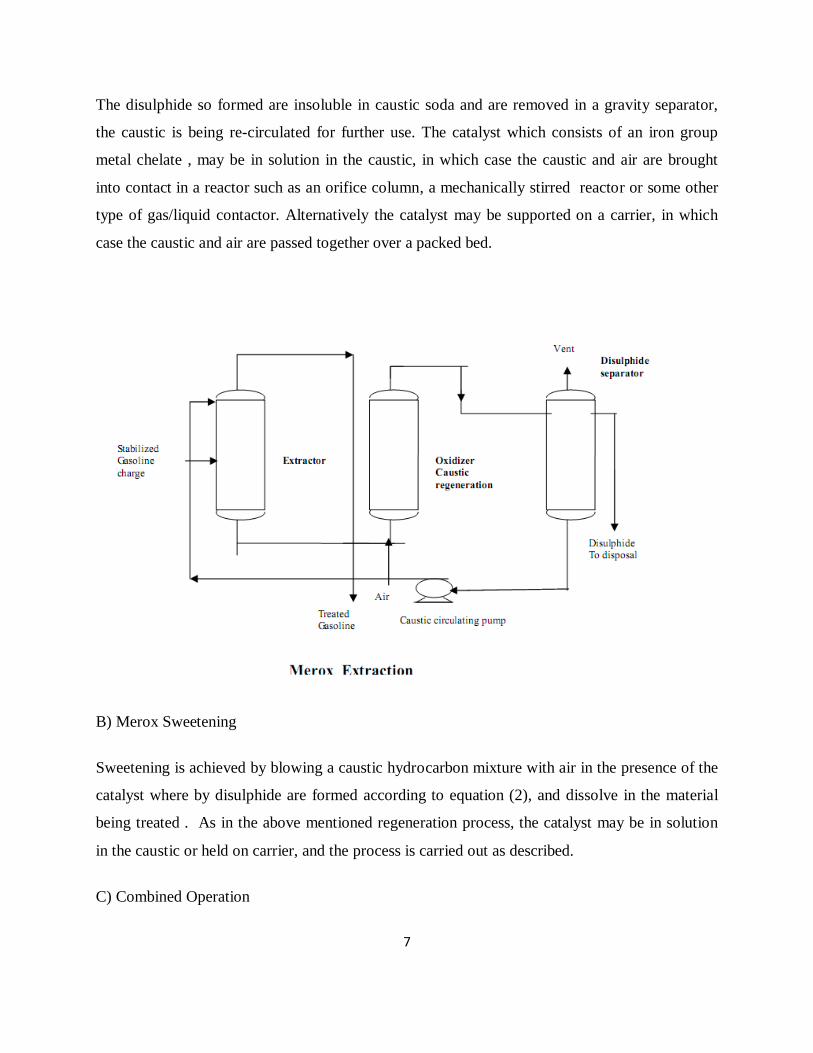
The disulphide so formed are insoluble in caustic soda and are removed in a gravity separator,
the caustic is being re-circulated for further use. The catalyst which consists of an iron group
metal chelate , may be in solution in the caustic, in which case the caustic and air are brought
into contact in a reactor such as an orifice column, a mechanically stirred reactor or some other
type of gas/liquid contactor. Alternatively the catalyst may be supported on a carrier, in which
case the caustic and air are passed together over a packed bed.
B) Merox Sweetening
Sweetening is achieved by blowing a caustic hydrocarbon mixture with air in the presence of the
catalyst where by disulphide are formed according to equation (2), and dissolve in the material
being treated . As in the above mentioned regeneration process, the catalyst may be in solution
in the caustic or held on carrier, and the process is carried out as described.
C) Combined Operation
8
The combined extraction/ Sweetening operation is carried out by a combination of the extraction
and sweetening processes.
c) Removal of Water and Particulate Matter In the Refinery
1) Water and particulate matter in the fuel can have disastrous effects on gas turbine blades.
2) Free water may cause corrosion through out a fuel distribution system.
3) Particulate matter may block filters or the fine orifices of fuel injection and burner.
Water may be removed by :
1) Physically 2) Chemically 3) Electro- statically
Particulate matter may be removed by:
1) Water washing 2) Filtration
Processes:
1) Salt Dryers: Used to remove water from water primary distillation products and to control
the water content both before and after secondary processing. The product is passed through a
vertical drum filled with suitably graded rock salt. Rock salts are not powerful desiccants; it will
remove the free water but not dissolved water. If more dissolved water has to be removed it is
usual to use calcium chloride in the dryer.
2) Electrostatic Coalescers : Uses electrical coalescing for the removal of free water and sodium
chloride or calcium chloride for the removal of any residual traces of water. The process is used
9
for the dehydration of heating oil, kerosene, jet fuel, diesel fuel and solvents. The dehydration
product contains no free water but may contain some dissolved water.
3) Sand Coagulators and Filters : Vertical drums filled with fine sand are used for removal of
particulate matter and water, this process have the advantage over salt dryers is not involving the
use of chemicals. Down flow through the bed and up flow through a water separator will remove
gross water but not haze. For this purpose the oil must pass upward through the bed with a
bottom water drain so that it can emerge clear , and bright from the top of the drum, 5 micron
peculator filter may be needed for turbo jet fuel.
4) Vacuum Flashing : Where difficulties might be met in the removal of water from high-boiling
or viscous products by the previous methods, water may be removed by passing the product
through a vessel at a sufficiently reduced pressure to cause the water to evaporates , it is used
sometimes for the clarification of lubrication oil.
Improvement in Storage Stability
Owing to their complex composition and the presence of small amounts of N2, S, organic acids,
and oxygen, most petroleum products are subjected to deterioration in storage. This storage
instability may be noticed by a darkening in color, the formation of gums, and in some cases a
significant deterioration in those characteristics that control the performance of the products.
Instability may be accompanied by a marked degree of corrosiveness due to the presence of
organic and/ or inorganic acids.
Caustic Extraction
In addition to the use of caustic soda for the removal of acidic gases and malodorous compounds
as described earlier , it is widely used for the removal of substances which cause instability
and corrosion.
e) Improvement in Performance
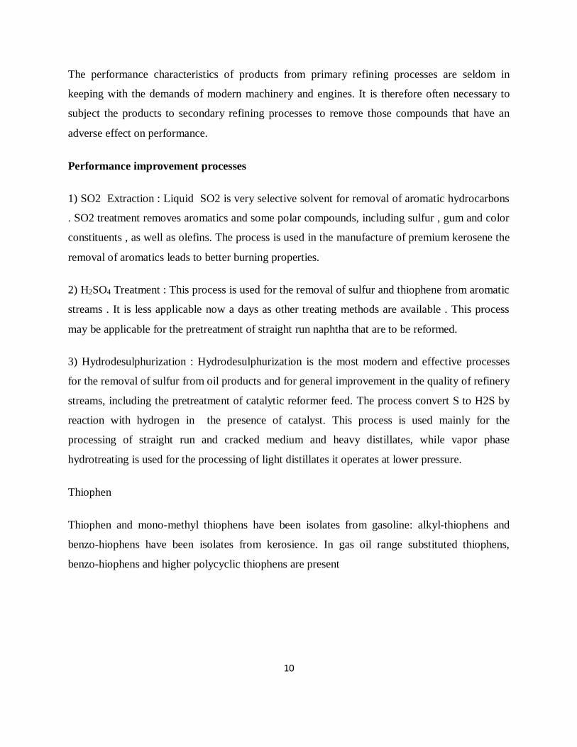
10
The performance characteristics of products from primary refining processes are seldom in
keeping with the demands of modern machinery and engines. It is therefore often necessary to
subject the products to secondary refining processes to remove those compounds that have an
adverse effect on performance.
Performance improvement processes
1) SO2 Extraction : Liquid SO2 is very selective solvent for removal of aromatic hydrocarbons
. SO2 treatment removes aromatics and some polar compounds, including sulfur , gum and color
constituents , as well as olefins. The process is used in the manufacture of premium kerosene the
removal of aromatics leads to better burning properties.
2) H2SO4 Treatment : This process is used for the removal of sulfur and thiophene from aromatic
streams . It is less applicable now a days as other treating methods are available . This process
may be applicable for the pretreatment of straight run naphtha that are to be reformed.
3) Hydrodesulphurization : Hydrodesulphurization is the most modern and effective processes
for the removal of sulfur from oil products and for general improvement in the quality of refinery
streams, including the pretreatment of catalytic reformer feed. The process convert S to H2S by
reaction with hydrogen in the presence of catalyst. This process is used mainly for the
processing of straight run and cracked medium and heavy distillates, while vapor phase
hydrotreating is used for the processing of light distillates it operates at lower pressure.
Thiophen
Thiophen and mono-methyl thiophens have been isolates from gasoline: alkyl-thiophens and
benzo-hiophens have been isolates from kerosience. In gas oil range substituted thiophens,
benzo-hiophens and higher polycyclic thiophens are present
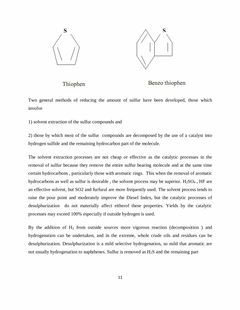
11
Two general methods of reducing the amount of sulfur have been developed, those which
involve
1) solvent extraction of the sulfur compounds and
2) those by which most of the sulfur compounds are decomposed by the use of a catalyst into
hydrogen sulfide and the remaining hydrocarbon part of the molecule.
The solvent extraction processes are not cheap or effective as the catalytic processes in the
removal of sulfur because they remove the entire sulfur bearing molecule and at the same time
certain hydrocarbons , particularly those with aromatic rings. This when the removal of aromatic
hydrocarbons as well as sulfur is desirable , the solvent process may be superior. H2SO4 , HF are
an effective solvent, but SO2 and furfural are more frequently used. The solvent process tends to
raise the pour point and moderately improve the Diesel Index, but the catalytic processes of
desulphurization do not materially affect eitherof these properties. Yields by the catalytic
processes may exceed 100% especially if outside hydrogen is used.
By the addition of H2 from outside sources more vigorous reaction (decomposition ) and
hydrogenation can be undertaken, and in the extreme, whole crude oils and residues can be
desulphurization. Desulphurization is a mild selective hydrogenation, so mild that aromatic are
not usually hydrogenation to naphthenes. Sulfur is removed as H2S and the remaining part
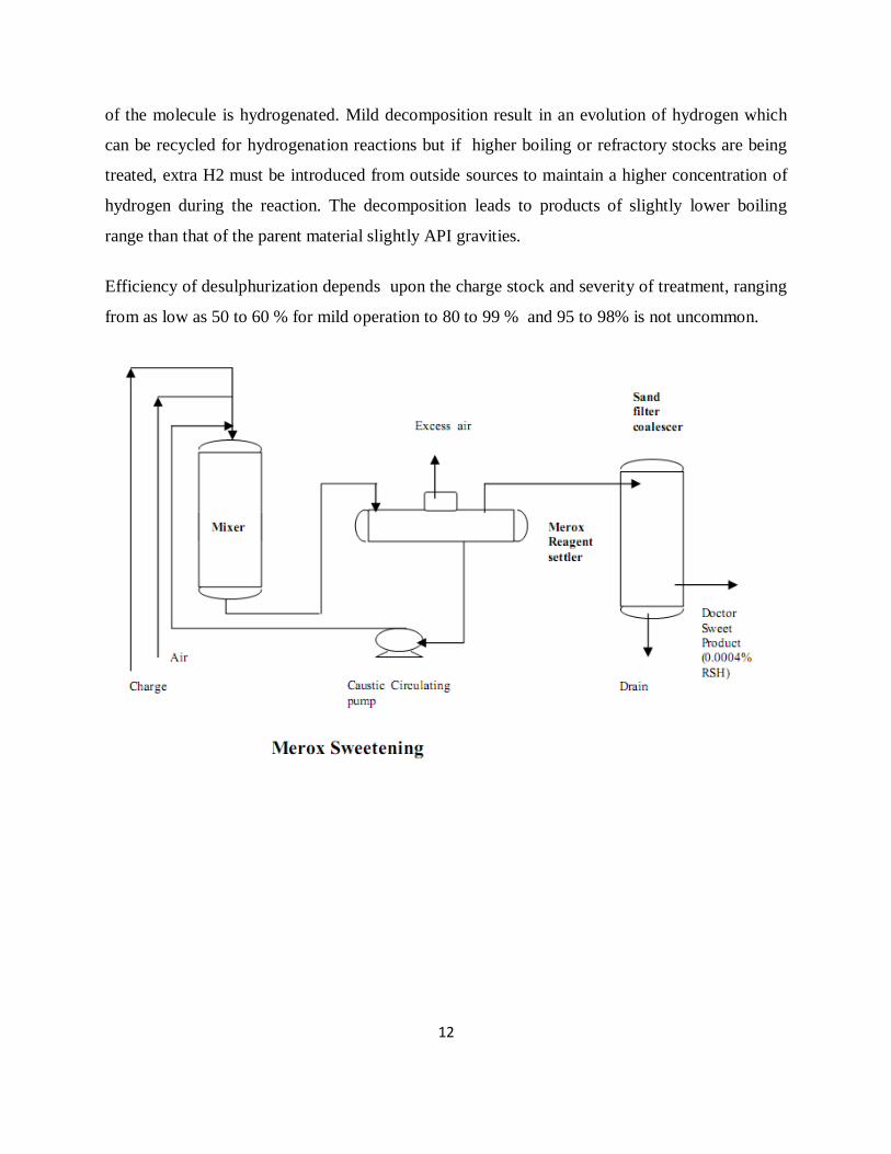
12
of the molecule is hydrogenated. Mild decomposition result in an evolution of hydrogen which
can be recycled for hydrogenation reactions but if higher boiling or refractory stocks are being
treated, extra H2 must be introduced from outside sources to maintain a higher concentration of
hydrogen during the reaction. The decomposition leads to products of slightly lower boiling
range than that of the parent material slightly API gravities.
Efficiency of desulphurization depends upon the charge stock and severity of treatment, ranging
from as low as 50 to 60 % for mild operation to 80 to 99 % and 95 to 98% is not uncommon.
13
3.2 Treatment of gasoline,
3.2 Treatment of Gasoline
.
Please refer the above pages
3.3 Treatment of Kerosene
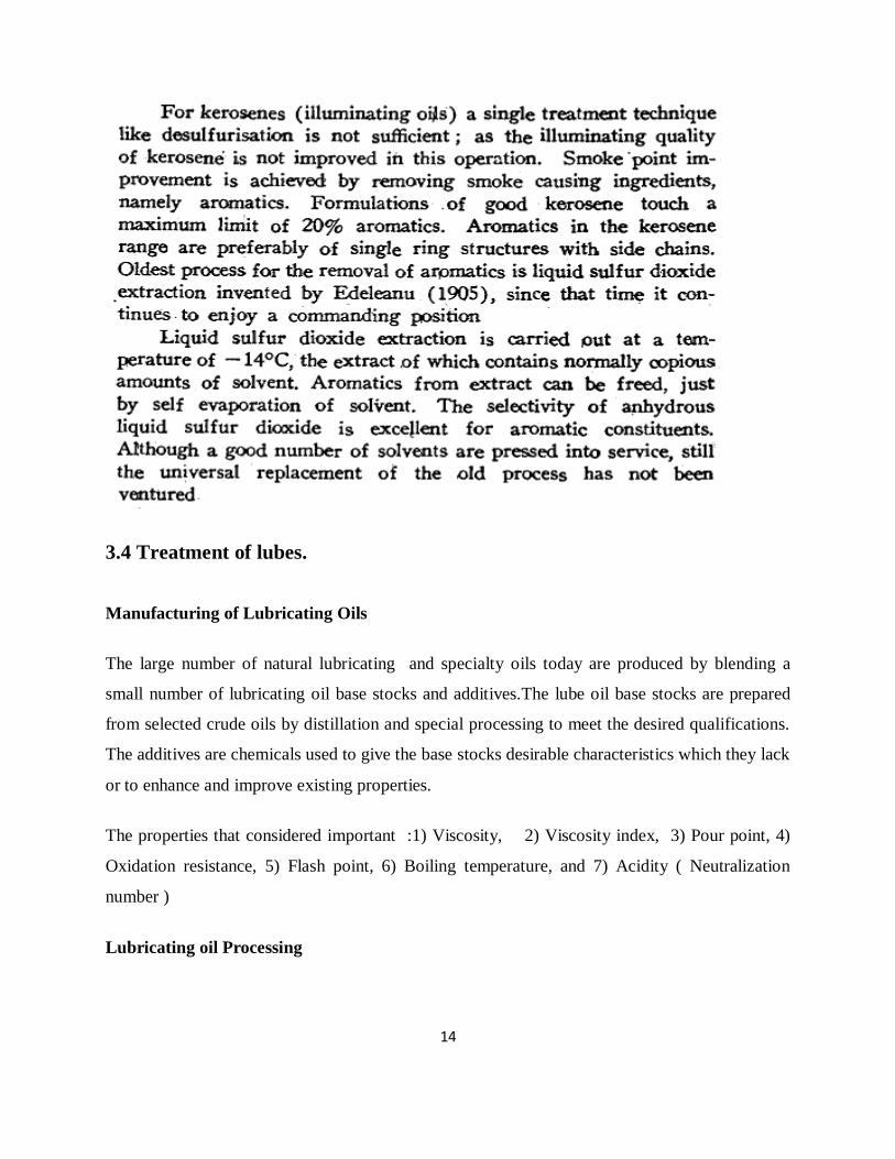
14
3.4 Treatment of lubes.
Manufacturing of Lubricating Oils
The large number of natural lubricating and specialty oils today are produced by blending a
small number of lubricating oil base stocks and additives.The lube oil base stocks are prepared
from selected crude oils by distillation and special processing to meet the desired qualifications.
The additives are chemicals used to give the base stocks desirable characteristics which they lack
or to enhance and improve existing properties.
The properties that considered important :1) Viscosity, 2) Viscosity index, 3) Pour point, 4)
Oxidation resistance, 5) Flash point, 6) Boiling temperature, and 7) Acidity ( Neutralization
number )
Lubricating oil Processing
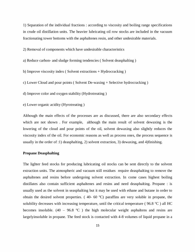
15
1) Separation of the individual fractions : according to viscosity and boiling range specifications
in crude oil distillation units. The heavier lubricating oil row stocks are included in the vacuum
fractionating tower bottoms with the asphaltenes resin, and other undesirable materials.
2) Removal of components which have undesirable characteristics
a) Reduce carbon- and sludge forming tendencies ( Solvent deasphalting )
b) Improve viscosity index ( Solvent extractions + Hydrocracking )
c) Lower Cloud and pour points ( Solvent De-waxing + Selective hydrocracking )
d) Improve color and oxygen stability (Hydrotreating )
e) Lower organic acidity (Hyrotreating )
Although the main effects of the processes are as discussed, there are also secondary effects
which are not shown . For example, although the main result of solvent dewaxing is the
lowering of the cloud and pour points of the oil, solvent dewaxing also slightly reduces the
viscosity index of the oil. For economic reasons as well as process ones, the process sequence is
usually in the order of :1) deasphalting, 2) solvent extraction, 3) dewaxing, and 4)finishing.
Propane Deasphalting
The lighter feed stocks for producing lubricating oil stocks can be sent directly to the solvent
extraction units. The atmospheric and vacuum still residues require deasphalting to remove the
asphaltenes and resins before undergoing solvent extraction. In come cases highest boiling
distillates also contain sufficient asphaltenes and resins and need deasphalting. Propane : is
usually used as the solvent in seasphalting but it may be used with ethane and butane in order to
obtain the desired solvent properties. ( 40- 60 oC) paraffins are very soluble in propane, the
solubility decreases with increasing temperature, until the critical temperature ( 96.8 oC ) all HC
becomes insoluble. (40 – 96.8 oC ) the high molecular weight asphaltens and resins are
largelyinsoluble in propane. The feed stock is contacted with 4-8 volumes of liquid propane in a
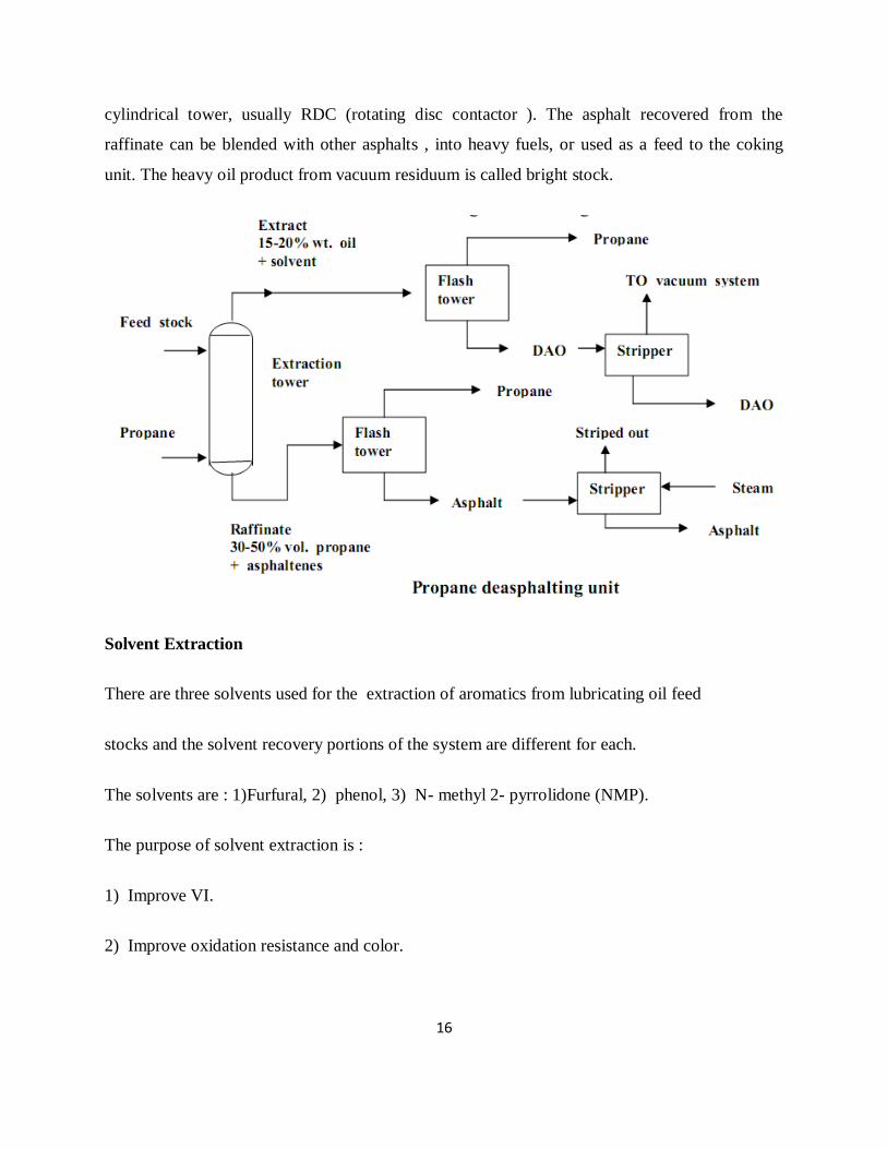
16
cylindrical tower, usually RDC (rotating disc contactor ). The asphalt recovered from the
raffinate can be blended with other asphalts , into heavy fuels, or used as a feed to the coking
unit. The heavy oil product from vacuum residuum is called bright stock.
Solvent Extraction
There are three solvents used for the extraction of aromatics from lubricating oil feed
stocks and the solvent recovery portions of the system are different for each.
The solvents are : 1)Furfural, 2) phenol, 3) N- methyl 2- pyrrolidone (NMP).
The purpose of solvent extraction is :
1) Improve VI.
2) Improve oxidation resistance and color.
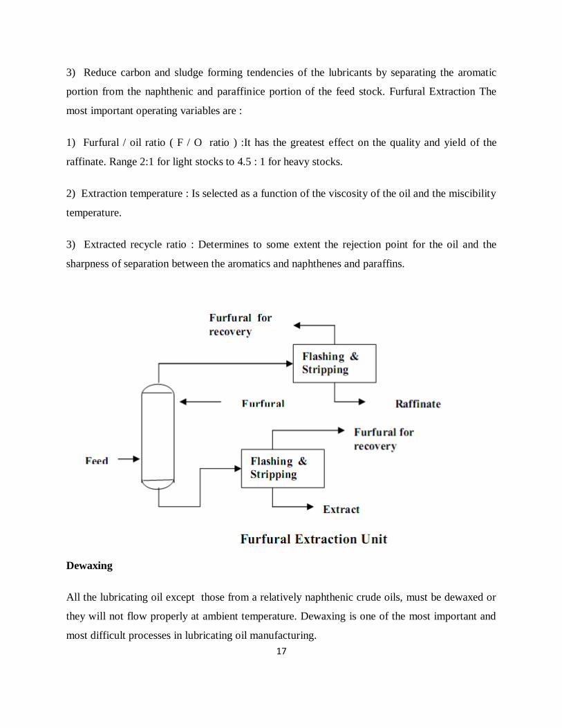
17
3) Reduce carbon and sludge forming tendencies of the lubricants by separating the aromatic
portion from the naphthenic and paraffinice portion of the feed stock. Furfural Extraction The
most important operating variables are :
1) Furfural / oil ratio ( F / O ratio ) :It has the greatest effect on the quality and yield of the
raffinate. Range 2:1 for light stocks to 4.5 : 1 for heavy stocks.
2) Extraction temperature : Is selected as a function of the viscosity of the oil and the miscibility
temperature.
3) Extracted recycle ratio : Determines to some extent the rejection point for the oil and the
sharpness of separation between the aromatics and naphthenes and paraffins.
Dewaxing
All the lubricating oil except those from a relatively naphthenic crude oils, must be dewaxed or
they will not flow properly at ambient temperature. Dewaxing is one of the most important and
most difficult processes in lubricating oil manufacturing.
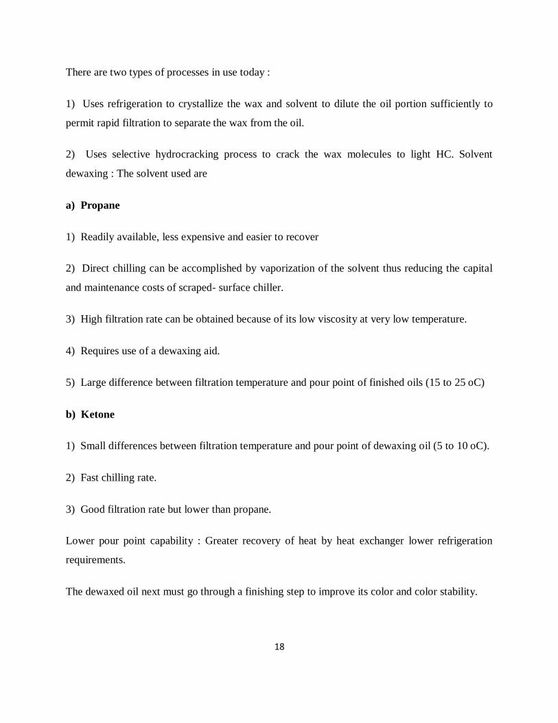
18
There are two types of processes in use today :
1) Uses refrigeration to crystallize the wax and solvent to dilute the oil portion sufficiently to
permit rapid filtration to separate the wax from the oil.
2) Uses selective hydrocracking process to crack the wax molecules to light HC. Solvent
dewaxing : The solvent used are
a) Propane
1) Readily available, less expensive and easier to recover
2) Direct chilling can be accomplished by vaporization of the solvent thus reducing the capital
and maintenance costs of scraped- surface chiller.
3) High filtration rate can be obtained because of its low viscosity at very low temperature.
4) Requires use of a dewaxing aid.
5) Large difference between filtration temperature and pour point of finished oils (15 to 25 oC)
b) Ketone
1) Small differences between filtration temperature and pour point of dewaxing oil (5 to 10 oC).
2) Fast chilling rate.
3) Good filtration rate but lower than propane.
Lower pour point capability : Greater recovery of heat by heat exchanger lower refrigeration
requirements.
The dewaxed oil next must go through a finishing step to improve its color and color stability.
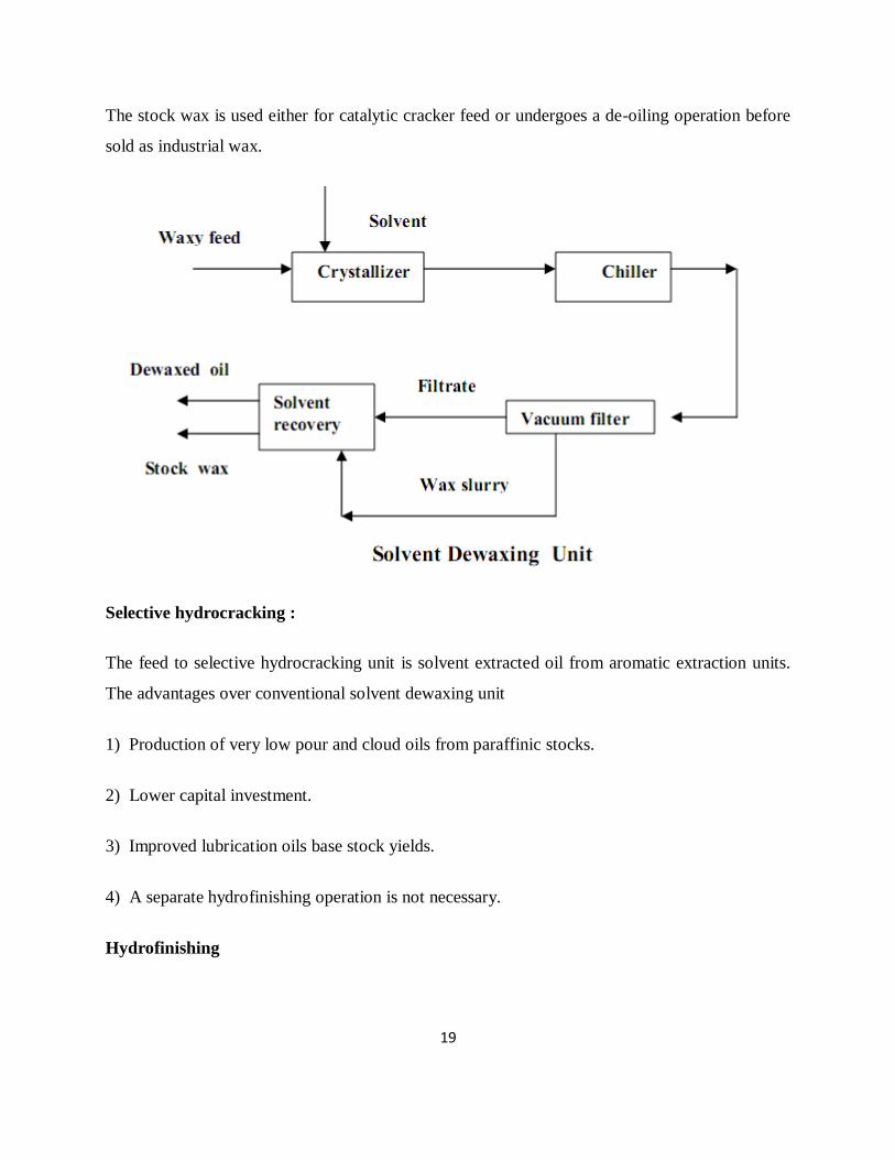
19
The stock wax is used either for catalytic cracker feed or undergoes a de-oiling operation before
sold as industrial wax.
Selective hydrocracking :
The feed to selective hydrocracking unit is solvent extracted oil from aromatic extraction units.
The advantages over conventional solvent dewaxing unit
1) Production of very low pour and cloud oils from paraffinic stocks.
2) Lower capital investment.
3) Improved lubrication oils base stock yields.
4) A separate hydrofinishing operation is not necessary.
Hydrofinishing
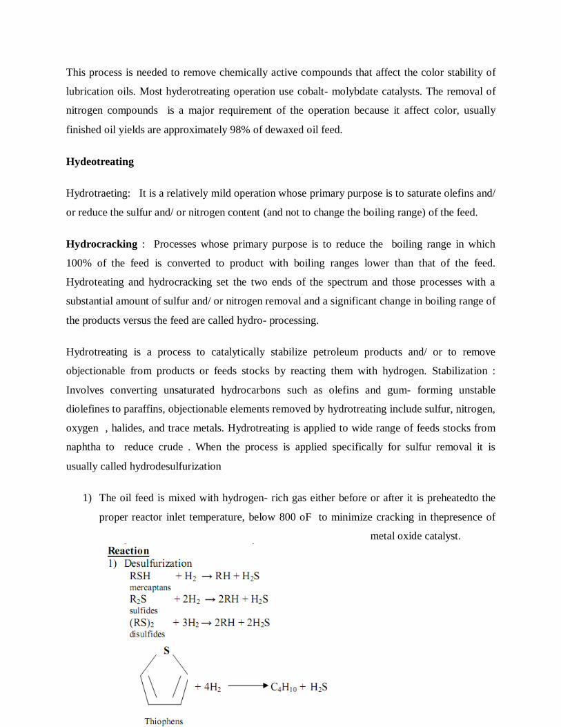
20
This process is needed to remove chemically active compounds that affect the color stability of
lubrication oils. Most hyderotreating operation use cobalt- molybdate catalysts. The removal of
nitrogen compounds is a major requirement of the operation because it affect color, usually
finished oil yields are approximately 98% of dewaxed oil feed.
Hydeotreating
Hydrotraeting: It is a relatively mild operation whose primary purpose is to saturate olefins and/
or reduce the sulfur and/ or nitrogen content (and not to change the boiling range) of the feed.
Hydrocracking : Processes whose primary purpose is to reduce the boiling range in which
100% of the feed is converted to product with boiling ranges lower than that of the feed.
Hydroteating and hydrocracking set the two ends of the spectrum and those processes with a
substantial amount of sulfur and/ or nitrogen removal and a significant change in boiling range of
the products versus the feed are called hydro- processing.
Hydrotreating is a process to catalytically stabilize petroleum products and/ or to remove
objectionable from products or feeds stocks by reacting them with hydrogen. Stabilization :
Involves converting unsaturated hydrocarbons such as olefins and gum- forming unstable
diolefines to paraffins, objectionable elements removed by hydrotreating include sulfur, nitrogen,
oxygen , halides, and trace metals. Hydrotreating is applied to wide range of feeds stocks from
naphtha to reduce crude . When the process is applied specifically for sulfur removal it is
usually called hydrodesulfurization
1) The oil feed is mixed with hydrogen- rich gas either before or after it is preheatedto the
proper reactor inlet temperature, below 800 oF to minimize cracking in thepresence of
metal oxide catalyst.
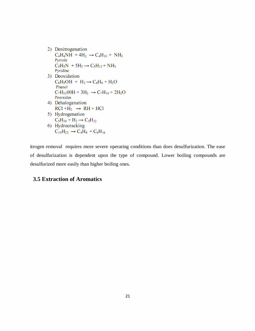
21
itrogen removal requires more severe operating conditions than does desulfurization. The ease
of desulfurization is dependent upon the type of compound. Lower boiling compounds are
desulfurized more easily than higher boiling ones.
3.5 Extraction of Aromatics
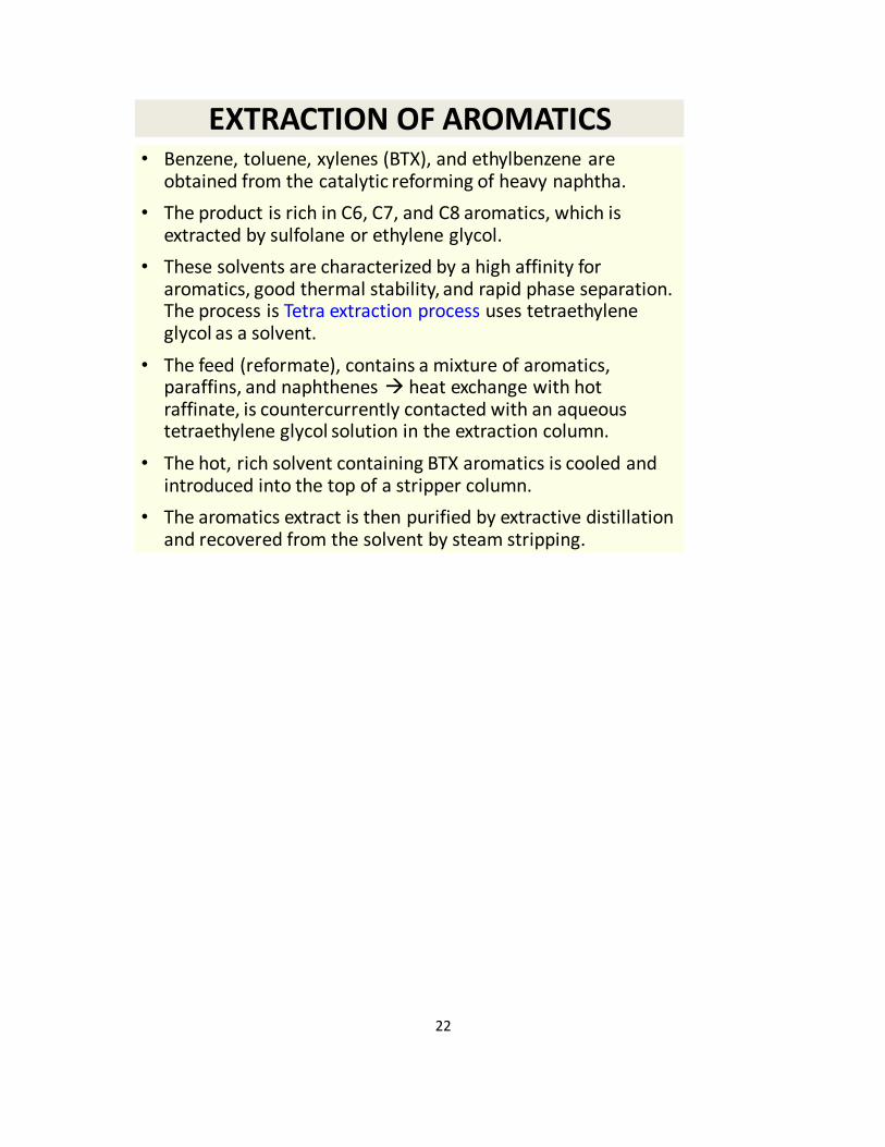
22
EXTRACTION OF AROMATICS• Benzene, toluene, xylenes (BTX), and ethylbenzene are
obtained from the catalytic reforming of heavy naphtha.
• The product is rich in C6, C7, and C8 aromatics, which is extracted by sulfolane or ethylene glycol.
• These solvents are characterized by a high affinity for aromatics, good thermal stability, and rapid phase separation. The process is Tetra extraction process uses tetraethylene glycol as a solvent.
• The feed (reformate), contains a mixture of aromatics, paraffins, and naphthenes heat exchange with hot raffinate, is countercurrentIy contacted with an aqueous tetraethylene glycol solution in the extraction column.
• The hot, rich solvent containing BTX aromatics is cooled and introduced into the top of a stripper column.
• The aromatics extract is then purified by extractive distillation and recovered from the solvent by steam stripping.
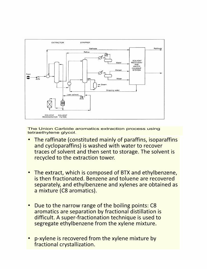
23
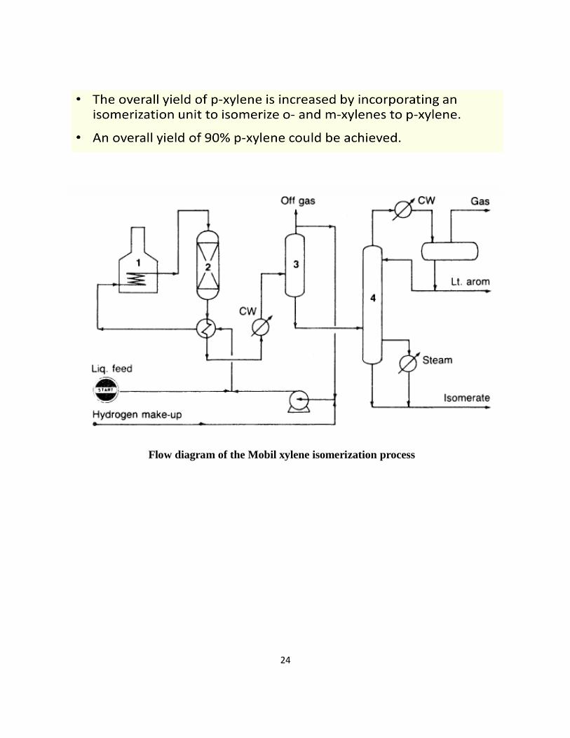
24
Flow diagram of the Mobil xylene isomerization process
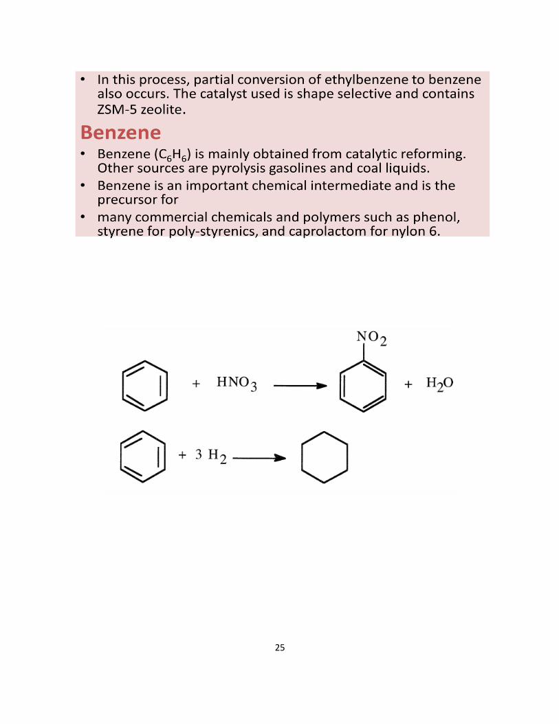
25
26
REFERENCE BOOKS:
1. Nelson, W.L., Petroleum Refinery Engineering, 4th Edition., McGraw Hill, New York,1985
2. Bhaskara Rao B. K., Modern Petroleum Refining Processes, 2nd Edition., Oxford and IBH
Publishing Company, New Delhi,1989.
3. Hobson G. D and Pohl. W., Modern Petroleum Technology, 2nd Edition, Gulf Publishers,1986.
27
1
SCHOOL OF BIO AND CHEMICAL ENGINEERING
DEPARTMENT OF CHEMICAL ENGINEERING
UNIT – 4- CHEMICALS FROM METHANE AND ETHANE
2
UNIT IV CHEMICALS FROM METHANE AND ETHANE
1.0 Petrochemicals: Overview 1.1Introduction In this lecture, we present a brief overview of petrochemical technologies and discuss upon
the general topology of the petrochemical process technologies. Petrochemicals refers to all those compounds that can be derived from the petroleum
refinery products Typical feedstocks to petrochemical processes include C1 Compounds: Methane & Synthesis gas
C2 Compounds: Ethylene and Acetylene
C3 Compounds: Propylene C4 Compounds: Butanes and Butenes Aromatic Compounds: Benzene It can be seen that petrochemicals are produced from simple compounds such as methane,
ethylene and acetylene but not multicomponent products such as naphtha, gas oil etc. Definition : These are the chemicals that are made from petroleum and natural gas. Petroleum and natural gas are made up of hydrocarbon molecules, which comprises of one or more carbon atoms, to which hydrogen atoms are attached. About 5 % of the oil and gas consumed each year is needed to make all the petrochemical products. Petrochemicals play an important role on our food, clothing, shelter and leisure. Because of low cost and easy availability, oil and natural gas are considered to be the main sources of raw materials for most petrochemicals. Classification: Petrochemicals can be broadly classified into three categories-
a. Light Petrochemicals: These are mainly used as bottled fuel and raw materials for other
organic chemicals. The lightest of these -- methane, ethane and ethylene -- are gaseous at room temperature.The next lightest fractions comprise petroleum ether and light naphtha
with boiling points between 80 and 190 degrees Fahrenheit.
b. Medium Petrochemicals: Hydrocarbons with 6 – 12 carbon atoms are called "gasoline", which are mainly used as automobile fuels. Octane, with eight carbons,
is a particularly good automobile fuel, and is considered to be of high quality.
Kerosene contains 12 to 15 carbons and is used in aviation fuels, and also as
solvents for heating and lighting.
c. Heavy Petrochemicals: These can be generally categorized as diesel oil,
heating oil and lubricating oil for engines and machinery. They contain around 15
and 18 carbon atoms with boiling points between 570 and 750 degrees Fahrenheit.
The heaviest fractions of all are called "bitumens" and are used to surface roads or
for waterproofing. Bitumens can also be broken down into lighter hydrocarbons using a process
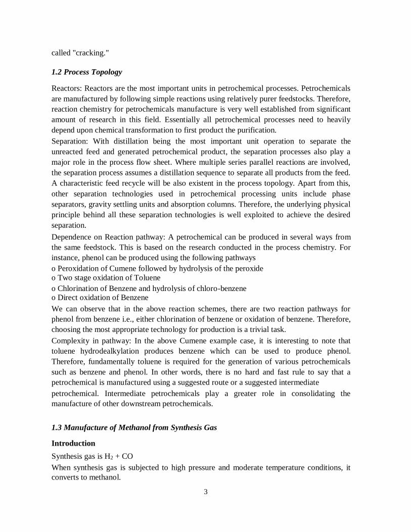
3
called "cracking."
1.2 Process Topology Reactors: Reactors are the most important units in petrochemical processes. Petrochemicals
are manufactured by following simple reactions using relatively purer feedstocks. Therefore,
reaction chemistry for petrochemicals manufacture is very well established from significant
amount of research in this field. Essentially all petrochemical processes need to heavily
depend upon chemical transformation to first product the purification. Separation: With distillation being the most important unit operation to separate the
unreacted feed and generated petrochemical product, the separation processes also play a
major role in the process flow sheet. Where multiple series parallel reactions are involved,
the separation process assumes a distillation sequence to separate all products from the feed.
A characteristic feed recycle will be also existent in the process topology. Apart from this,
other separation technologies used in petrochemical processing units include phase
separators, gravity settling units and absorption columns. Therefore, the underlying physical
principle behind all these separation technologies is well exploited to achieve the desired
separation. Dependence on Reaction pathway: A petrochemical can be produced in several ways from
the same feedstock. This is based on the research conducted in the process chemistry. For
instance, phenol can be produced using the following pathways o Peroxidation of Cumene followed by hydrolysis of the peroxide
o Two stage oxidation of Toluene o Chlorination of Benzene and hydrolysis of chloro-benzene o Direct oxidation of Benzene We can observe that in the above reaction schemes, there are two reaction pathways for
phenol from benzene i.e., either chlorination of benzene or oxidation of benzene. Therefore,
choosing the most appropriate technology for production is a trivial task. Complexity in pathway: In the above Cumene example case, it is interesting to note that
toluene hydrodealkylation produces benzene which can be used to produce phenol.
Therefore, fundamentally toluene is required for the generation of various petrochemicals
such as benzene and phenol. In other words, there is no hard and fast rule to say that a
petrochemical is manufactured using a suggested route or a suggested intermediate petrochemical. Intermediate petrochemicals play a greater role in consolidating the
manufacture of other downstream petrochemicals. 1.3 Manufacture of Methanol from Synthesis Gas Introduction Synthesis gas is H2 + CO When synthesis gas is subjected to high pressure and moderate temperature conditions, it
converts to methanol.
4
Followed by this, the methanol is separated using a series of phase separators and
distillation columns. The process technology is relatively simple Reactions
Desired: CO + 2H2 CH3OH Side reactions: CO + 3H2 CH4 + H2O
2CO + 2H2 CH4 + CO2 All above reactions are exothermic Undesired reaction: zCO + aH2 alchohols + hydrocarbons Catalyst: Mixed catalyst made of oxides of Zn, Cr, Mn, Al. Process Technology Figure: Flow sheet of manufacture of Methanol from Synthesis Gas H2 and CO adjusted to molar ratio of 2.25 The mixture is compressed to 200 – 350 atms Recycle gas (Unreacted feed) is also mixed and sent to the compressor Then eventually the mixture is fed to a reactor. Steam is circulated in the heating tubes to
maintain a temperature of 300 – 375 oC After reaction, the exit gases are cooled After cooling, phase separation is allowed. In this phase separation operation methanol and
other high molecular weight compounds enter the liquid phase and unreacted feed is
produced as the gas phase. The gas phase stream is purged to remove inert components and most of the gas stream is
sent as a recycle to the reactor. The liquid stream is further depressurized to about 14 atms to enter a second phase separator
that produces fuel gas as the gaseous product and the liquid stream bereft of the fuel gas
components is rich of the methanol component. The liquid stream then enters a mixer fed with KMNO4 so as to remove traces of impurities
such as ketones, aldehydes etc.
5
Eventually, the liquid stream enters a distillation column that separates dimethyl ether as a
top product. The bottom product from the first distillation column enters a fractionator that produces
methanol, other high molecular weight alcohols and water as three different products.
Methane and synthesis gas are important petrochemical feedstock for manufacture of
a large number of chemicals, which are used directly or as intermediates, many of these
products are number of which are finding use in plastic, synthetic fiber, rubber,
pharmaceutical and other industries. ‘Synthesis gas’ is commonly used to describe two basic
gas mixtures - synthesis gas containing CO, hydrogen and synthesis gas containing
hydrogen and nitrogen for the production of ammonia. Major requirements of synthesis gas
in world scale petrochemical are given.
Some of the emerging technologies in utilization of synthesis gas and methane for the
production of petrochemicals, are Fischer-Tropsch synthesis, oxidative coupling of methane
with chlorine to yield ethane and ethylene, methanol to olefin technology (MTO). Fischer-
Tropsch synthesis is being studied in great detail world over and it is promising to be a
future technology for manufacture of olefins from synthesis gas. CO that can be separated
from synthesis gas either by cryogenic or by pressure swing adsorption is a promising
feedstock for production of a variety of products. Product profile of methane, synthesis gas
and CO based building blocks are given in Figure BELOW
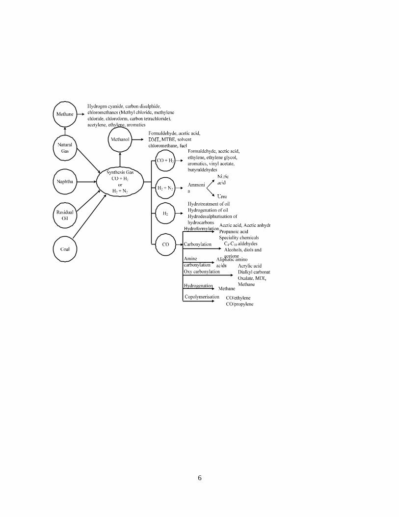
6
Figure: Methane, Synthesis Gas and CO
Building Blocks
Source: Mall, 2007
7
1.4 SYNTHESIS GAS
Methane and synthesis gas are important petrochemical feedstock for the manufacture of a large
number of chemicals, which are used directly or as intermediates, a number of which are finding
use in plastic, synthetic fiber, rubber, pharmaceutical and other industries. ‘Synthesis gas’ is
commonly used to describe two basic gas mixtures - synthesis gas containing CO, hydrogen and
synthesis gas containing hydrogen and nitrogen for the production of ammonia.
Petrochemical derivatives based on synthesis gas and carbon monoxide have experienced steady
growth due to large scale utilization of methanol and development of a carbonylation process for
acetic acid and Oxo synthesis process for detergents, plasticizers, and alcohols. Recent market
studies show that there will be a dramatic increase in demand of CO and syngas derivatives .
Methanol is the largest consumer of synthesis gas. The reformed gas is to meet certain
requirements with regard to its composition. It is characterized by the stoichiometric conversion
factor, which differs from case to case
1.5 RAW MATERIALS FOR SYNTHESIS GAS
Various raw materials for synthesis gas production are natural gas, refinery gases, naphtha, fuel
oil/residual heavy hydrocarbons and coal. Although coal was earlier used for production of
synthesis gas, it has now been replaced by petroleum fractions and natural gas. Petrocoke is the
emerging source for Synthesis gas. Coal is again getting importance alone are with combination of
petroleum coke. Various Routes for Synthesis gas and Ammonia and Methanol manufacture is
shown in Figure. Reactions in the manufacture of synthesis gas by Steam reforming and Partial
oxidation in Table
Process Technology
Various synthesis gas production technologies are steam methane reforming, naphtha reforming,
auto-thermal reforming, oxygen secondary reforming, and partial oxidation of heavy
hydrocarbons, petroleum coke and coal.
Various steps involved in synthesis gas production through steam reforming are:
Desulphurization of gas
Steam reforming and compression
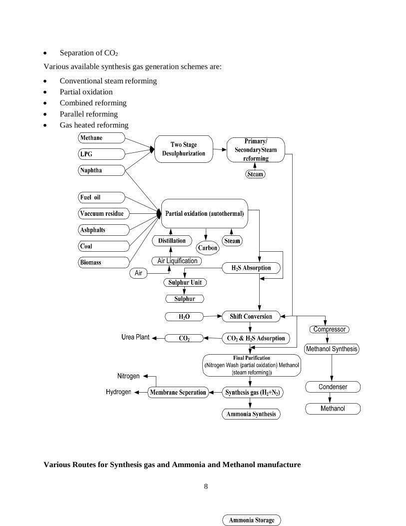
8
Separation of CO2
Various available synthesis gas generation schemes are:
Conventional steam reforming
Partial oxidation
Combined reforming
Parallel reforming
Gas heated reforming
Various Routes for Synthesis gas and Ammonia and Methanol manufacture
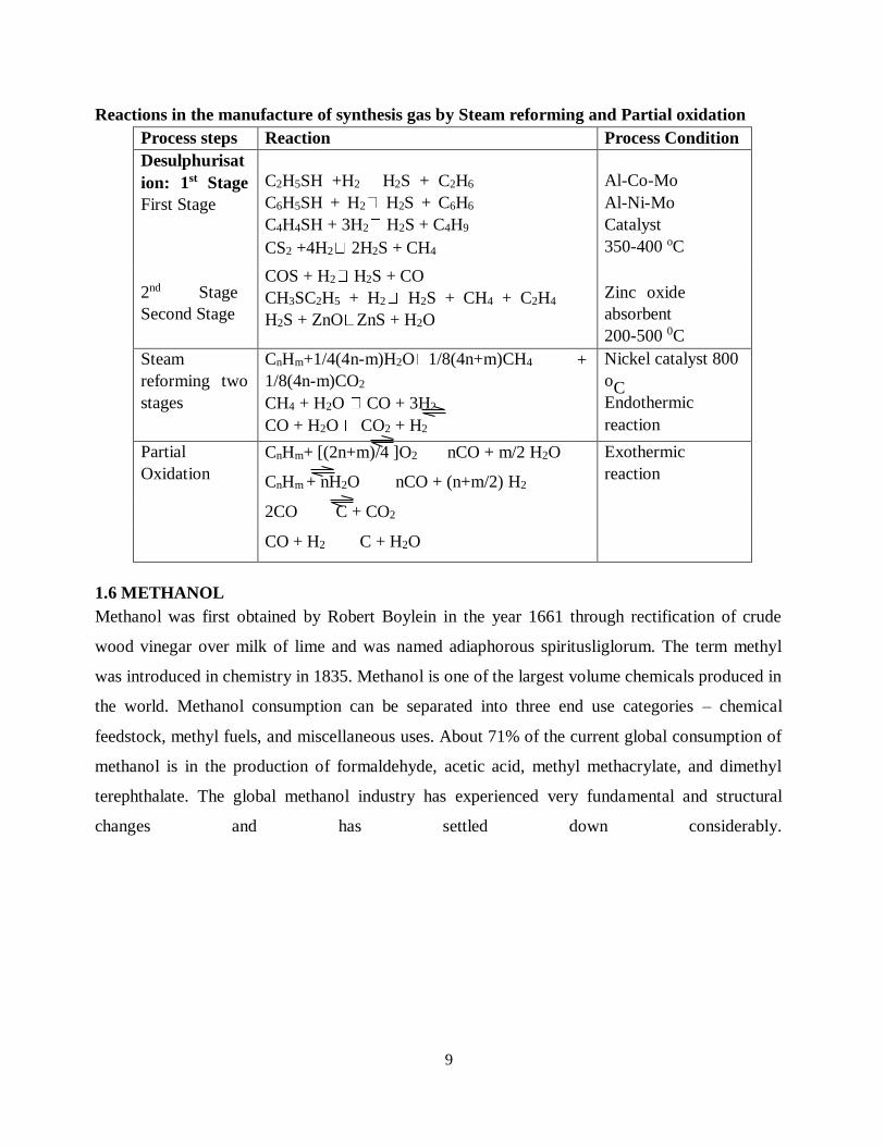
9
Reactions in the manufacture of synthesis gas by Steam reforming and Partial oxidation
Process steps Reaction Process Condition
Desulphurisat
ion: 1st Stage
First Stage
C2H5SH +H2 H2S + C2H6
C6H5SH + H2 H2S + C6H6
C4H4SH + 3H2 H2S + C4H9
CS2 +4H2 2H2S + CH4
Al-Co-Mo
Al-Ni-Mo
Catalyst
350-400 oC
2nd Stage
Second Stage
COS + H2 H2S + CO
CH3SC2H5 + H2 H2S + CH4 + C2H4
H2S + ZnO ZnS + H2O
Zinc oxide
absorbent
200-500 0C
Steam
reforming two
stages
CnHm+1/4(4n-m)H2O 1/8(4n+m)CH4
1/8(4n-m)CO2
CH4 + H2O CO + 3H2
CO + H2O CO2 + H2
+ Nickel catalyst 800
oC
Endothermic
reaction
Partial
Oxidation
CnHm+ [(2n+m)/4 ]O2 nCO + m/2 H2O
CnHm + nH2O nCO + (n+m/2) H2
Exothermic
reaction
2CO C + CO2
CO + H2 C + H2O
1.6 METHANOL
Methanol was first obtained by Robert Boylein in the year 1661 through rectification of crude
wood vinegar over milk of lime and was named adiaphorous spiritusliglorum. The term methyl
was introduced in chemistry in 1835. Methanol is one of the largest volume chemicals produced in
the world. Methanol consumption can be separated into three end use categories – chemical
feedstock, methyl fuels, and miscellaneous uses. About 71% of the current global consumption of
methanol is in the production of formaldehyde, acetic acid, methyl methacrylate, and dimethyl
terephthalate. The global methanol industry has experienced very fundamental and structural
changes and has settled down considerably.
10
1.7 METHANOL PROCESS TECHNOLOGY
From the early 1800s until 1920s, the distillation of wood to make wood alcohol was the source of
Methanol. The most common industrially favored method for the production of methanol was first
developed by BASF in 1923 in Germany from synthesis gas utilising high pressure process using
zinc-chromic oxide catalyst. However, due to high capital and compression energy costs
compounded by poor catalyst activity, high-pressure process was rendered obsolete when ICI in
the year 1966 introduced a low-pressure version of the process at 5-10 MPa and 210-270 oC, with
a new copper-zinc oxide based catalyst of high selectivity and stability.
Process steps involved in the production of methanol are:
Production of synthesis gas using steam reforming or partial oxidation
Synthesis of methanol
High-pressure process (25 – 30 MPa)
Medium pressure (10-25 MPa) process
Low-pressure process (5-10 MPa)
Figure BELOW illustrate the production of methanol from steam reforming of natural gas and
naphtha.
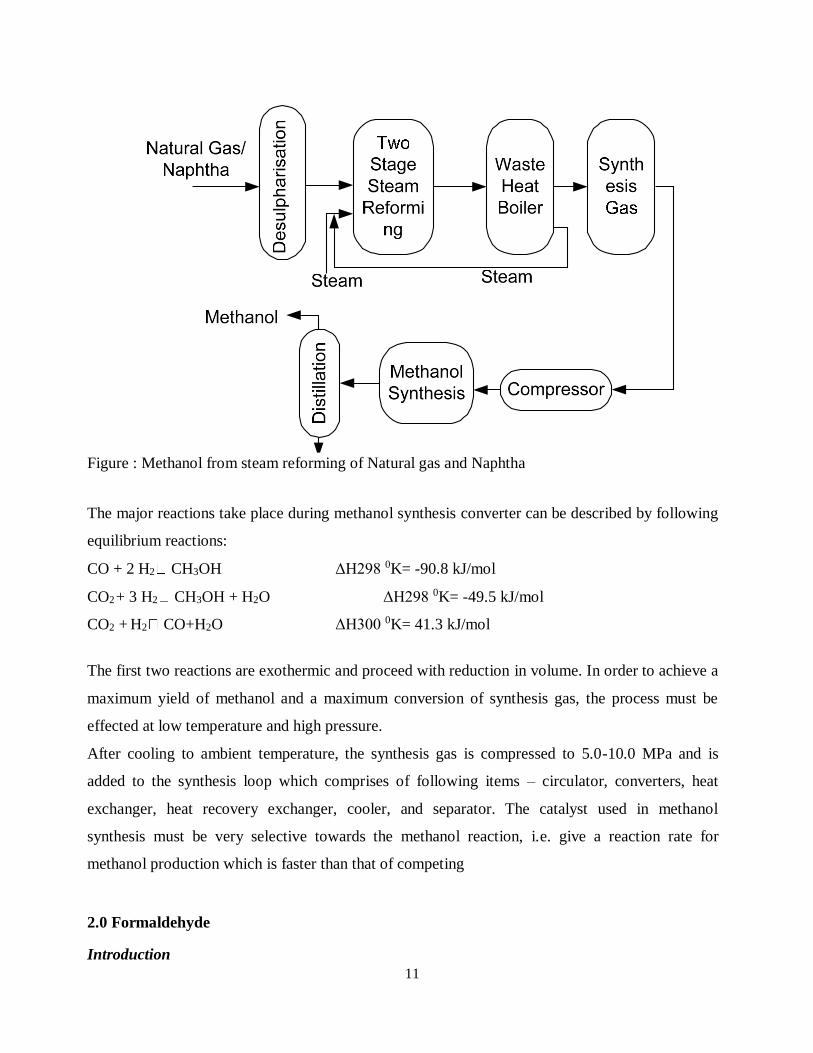
11
Figure : Methanol from steam reforming of Natural gas and Naphtha
The major reactions take place during methanol synthesis converter can be described by following
equilibrium reactions:
CO + 2 H2 CH3OH ΔH298 0K= -90.8 kJ/mol
CO2 + 3 H2 CH3OH + H2O ΔH298 0K= -49.5 kJ/mol
CO2 + H2 CO+H2O ΔH300 0K= 41.3 kJ/mol
The first two reactions are exothermic and proceed with reduction in volume. In order to achieve a
maximum yield of methanol and a maximum conversion of synthesis gas, the process must be
effected at low temperature and high pressure.
After cooling to ambient temperature, the synthesis gas is compressed to 5.0-10.0 MPa and is
added to the synthesis loop which comprises of following items – circulator, converters, heat
exchanger, heat recovery exchanger, cooler, and separator. The catalyst used in methanol
synthesis must be very selective towards the methanol reaction, i.e. give a reaction rate for
methanol production which is faster than that of competing
2.0 Formaldehyde Introduction
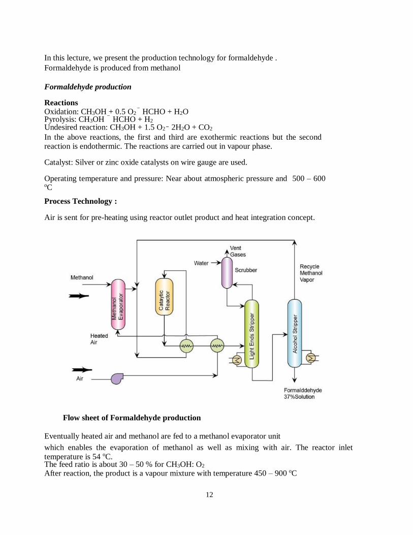
12
In this lecture, we present the production technology for formaldehyde . Formaldehyde is produced from methanol
Formaldehyde production Reactions Oxidation: CH3OH + 0.5 O2 HCHO + H2O Pyrolysis: CH3OH HCHO + H2 Undesired reaction: CH3OH + 1.5 O2 2H2O + CO2 In the above reactions, the first and third are exothermic reactions but the second reaction is endothermic. The reactions are carried out in vapour phase. Catalyst: Silver or zinc oxide catalysts on wire gauge are used. Operating temperature and pressure: Near about atmospheric pressure and 500 – 600 oC Process Technology : Air is sent for pre-heating using reactor outlet product and heat integration concept.
Flow sheet of Formaldehyde production
Eventually heated air and methanol are fed to a methanol evaporator unit which enables the evaporation of methanol as well as mixing with air. The reactor inlet
temperature is 54 oC. The feed ratio is about 30 – 50 % for CH3OH: O2 After reaction, the product is a vapour mixture with temperature 450 – 900 oC
13
After reaction, the product gas is cooled with the heat integration concept and then eventually fed
to the absorption tower. The absorbent in the absorption tower is water as well as formaldehyde rich water. Since formaldehyde rich water is produced in the absorption, a portion of the rich water absorbent
solution from the absorber is partially recycled at a specific section of the absorber. From the absorber, HCHO + methanol rich water stream is obtained as the bottom product. The stream is sent to a light end stripper eventually to remove any light end compounds that got
absorbed in the stream. The vapors from the light end unit consisting of light end compounds can
be fed at the absorption unit at specific location that matches with the composition of the vapors in
the absorption column. Eventually, the light end stripper bottom product is fed to a distillation tower that produces
methanol vapour as the top product and the bottom formaldehyde + water product (37 %
formaldehyde concentration). 3.0 Hydrocarbon Steam Cracking for Petrochemicals Introduction In industrial processes, hydrocarbons are contacted with H2O, depending upon the
desired effect. When hydrocarbon vapors at very high pressures are contacted with
water, water which has a very high latent heat of vaporization quenches the hydrocarbon
vapors and transforms into steam. In such an operation, chemical transformations would
not be dominant and energy lost from the hydrocarbons would be gained by water to
generate steam. The quenching process refers to direct contact heat transfer operations
and therefore has maximum energy transfer effeiciency. This is due to the fact that no
heat transfer medium is used that would accompany heat losses. The steam cracking of
hydrocarbons is an anti-quenching operation, and will involve the participation of water
molecule in reactions in addition to teh cracking of the bnydriocarbond on their own.
Since steam and the hydrocarbons react in the vapour phase the reaction products can be
formed very fast. Therefore cracking of the hydrocarbons on their own as well as by
steam in principle is very effective. When steam cracking is carried out, in addition to the energy supplied by the direct contact of steam with the hydrocarbons, steam also takes part in the reaction to produce wider choices of hydrocarbon distribution along with the generation of H2 and CO. Hydrocarbons such as Naphtha and LPG have lighter compounds. When they are subjected to steam pyrolysis, then good number of petrochemicals can be produced. These include primarily ethyelene and acetylene along with other compounds such as propylene,
butadiene, aromatics (benzene, toluene and xylene) and heavy oil residues. The reaction is of paramount importance to India as India petrochemical market is dominated by
this single process. Reaction CxHy + H2O + O2 C2H4 + C2H6 + C2H2 + H2 + CO + CO2 + CH4 + C3H6 + C3H8 +
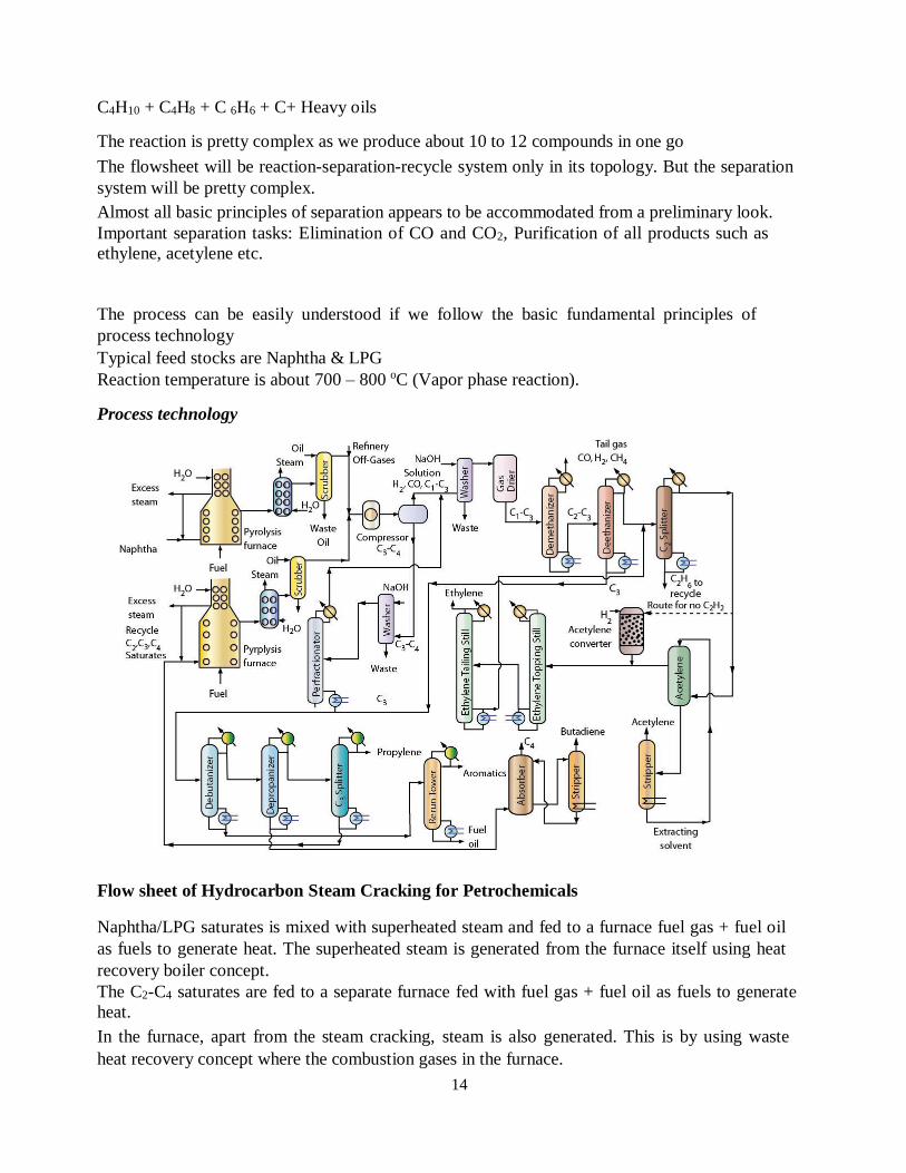
14
C4H10 + C4H8 + C 6H6 + C+ Heavy oils The reaction is pretty complex as we produce about 10 to 12 compounds in one go The flowsheet will be reaction-separation-recycle system only in its topology. But the separation
system will be pretty complex. Almost all basic principles of separation appears to be accommodated from a preliminary look. Important separation tasks: Elimination of CO and CO2, Purification of all products such as
ethylene, acetylene etc.
The process can be easily understood if we follow the basic fundamental principles of
process technology Typical feed stocks are Naphtha & LPG Reaction temperature is about 700 – 800 oC (Vapor phase reaction). Process technology
Flow sheet of Hydrocarbon Steam Cracking for Petrochemicals Naphtha/LPG saturates is mixed with superheated steam and fed to a furnace fuel gas + fuel oil
as fuels to generate heat. The superheated steam is generated from the furnace itself using heat
recovery boiler concept. The C2-C4 saturates are fed to a separate furnace fed with fuel gas + fuel oil as fuels to generate
heat. In the furnace, apart from the steam cracking, steam is also generated. This is by using waste
heat recovery concept where the combustion gases in the furnace.
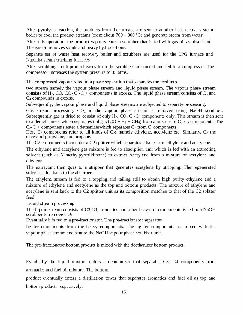
15
After pyrolysis reaction, the products from the furnace are sent to another heat recovery steam boiler to cool the product streams (from about 700 – 800 oC) and generate steam from water. After this operation, the product vapours enter a scrubber that is fed with gas oil as absorbent.
The gas oil removes solids and heavy hydrocarbons. Separate set of waste heat recovery boiler and scrubbers are used for the LPG furnace and
Naphtha steam cracking furnaces After scrubbing, both product gases from the scrubbers are mixed and fed to a compressor. The
compressor increases the system pressure to 35 atms. The compressed vapour is fed to a phase separation that separates the feed into two stream namely the vapour phase stream and liquid phase stream. The vapour phase stream consists of H2, CO, CO2 C1-C3+ components in excess. The liquid phase stream consists of C3 and C4 compounds in excess. Subsequently, the vapour phase and liquid phase streams are subjected to separate processing. Gas stream processing: CO2 in the vapour phase stream is removed using NaOH scrubber.
Subsequently gas is dried to consist of only H2, CO, C1-C3 components only. This stream is then sent
to a demethanizer which separates tail gas (CO + H2 + CH4) from a mixture of C1-C3 components. The
C2-C3+ components enter a dethanizerwhich separates C2 from C3 components. Here C2 components refer to all kinds of C2s namely ethylene, acetylene etc. Similarly, C3 the excess of propylene, and propane. The C2 components then enter a C2 splitter which separates ethane from ethylene and acetylene. The ethylene and acetylene gas mixture is fed to absorption unit which is fed with an extracting
solvent (such as N-methylpyrrolidinone) to extract Acetylene from a mixture of acetylene and
ethylene. The extractant then goes to a stripper that generates acetylene by stripping. The regenerated solvent is fed back to the absorber. The ethylene stream is fed to a topping and tailing still to obtain high purity ethylene and a
mixture of ethylene and acetylene as the top and bottom products. The mixture of ethylene and
acetylene is sent back to the C2 splitter unit as its composition matches to that of the C2 splitter
feed. Liquid stream processing The liqiuid stream consists of C3,C4, aromatics and other heavy oil components is fed to a NaOH scrubber to remove CO2. Eventually it is fed to a pre-fractionator. The pre-fractionator separates lighter components from the heavy components. The lighter components are mixed with the
vapour phase stream and sent to the NaOH vapour phase scrubber unit.
The pre-fractionator bottom product is mixed with the deethanizer bottom product.
Eventually the liquid mixture enters a debutanizer that separates C3, C4 components from
aromatics and fuel oil mixture. The bottom
product eventually enters a distillation tower that separates aromatics and fuel oil as top and
bottom products respectively.
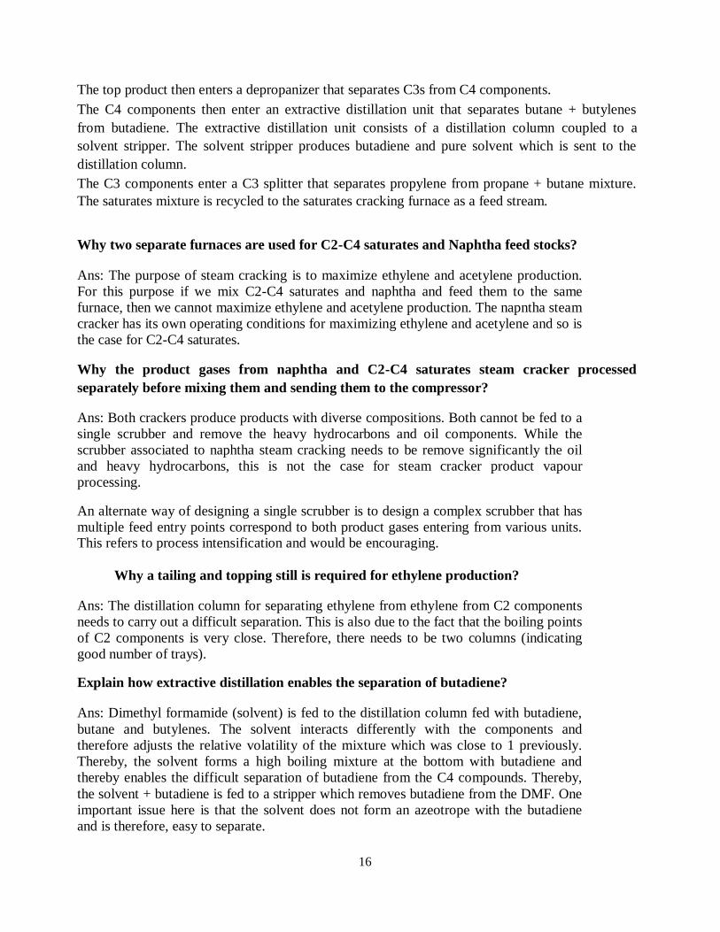
16
The top product then enters a depropanizer that separates C3s from C4 components. The C4 components then enter an extractive distillation unit that separates butane + butylenes
from butadiene. The extractive distillation unit consists of a distillation column coupled to a
solvent stripper. The solvent stripper produces butadiene and pure solvent which is sent to the
distillation column. The C3 components enter a C3 splitter that separates propylene from propane + butane mixture.
The saturates mixture is recycled to the saturates cracking furnace as a feed stream. Why two separate furnaces are used for C2-C4 saturates and Naphtha feed stocks? Ans: The purpose of steam cracking is to maximize ethylene and acetylene production.
For this purpose if we mix C2-C4 saturates and naphtha and feed them to the same
furnace, then we cannot maximize ethylene and acetylene production. The napntha steam
cracker has its own operating conditions for maximizing ethylene and acetylene and so is
the case for C2-C4 saturates. Why the product gases from naphtha and C2-C4 saturates steam cracker processed
separately before mixing them and sending them to the compressor? Ans: Both crackers produce products with diverse compositions. Both cannot be fed to a
single scrubber and remove the heavy hydrocarbons and oil components. While the
scrubber associated to naphtha steam cracking needs to be remove significantly the oil
and heavy hydrocarbons, this is not the case for steam cracker product vapour
processing. An alternate way of designing a single scrubber is to design a complex scrubber that has
multiple feed entry points correspond to both product gases entering from various units. This refers to process intensification and would be encouraging.
Why a tailing and topping still is required for ethylene production? Ans: The distillation column for separating ethylene from ethylene from C2 components
needs to carry out a difficult separation. This is also due to the fact that the boiling points
of C2 components is very close. Therefore, there needs to be two columns (indicating
good number of trays). Explain how extractive distillation enables the separation of butadiene? Ans: Dimethyl formamide (solvent) is fed to the distillation column fed with butadiene,
butane and butylenes. The solvent interacts differently with the components and
therefore adjusts the relative volatility of the mixture which was close to 1 previously.
Thereby, the solvent forms a high boiling mixture at the bottom with butadiene and
thereby enables the difficult separation of butadiene from the C4 compounds. Thereby,
the solvent + butadiene is fed to a stripper which removes butadiene from the DMF. One
important issue here is that the solvent does not form an azeotrope with the butadiene
and is therefore, easy to separate.
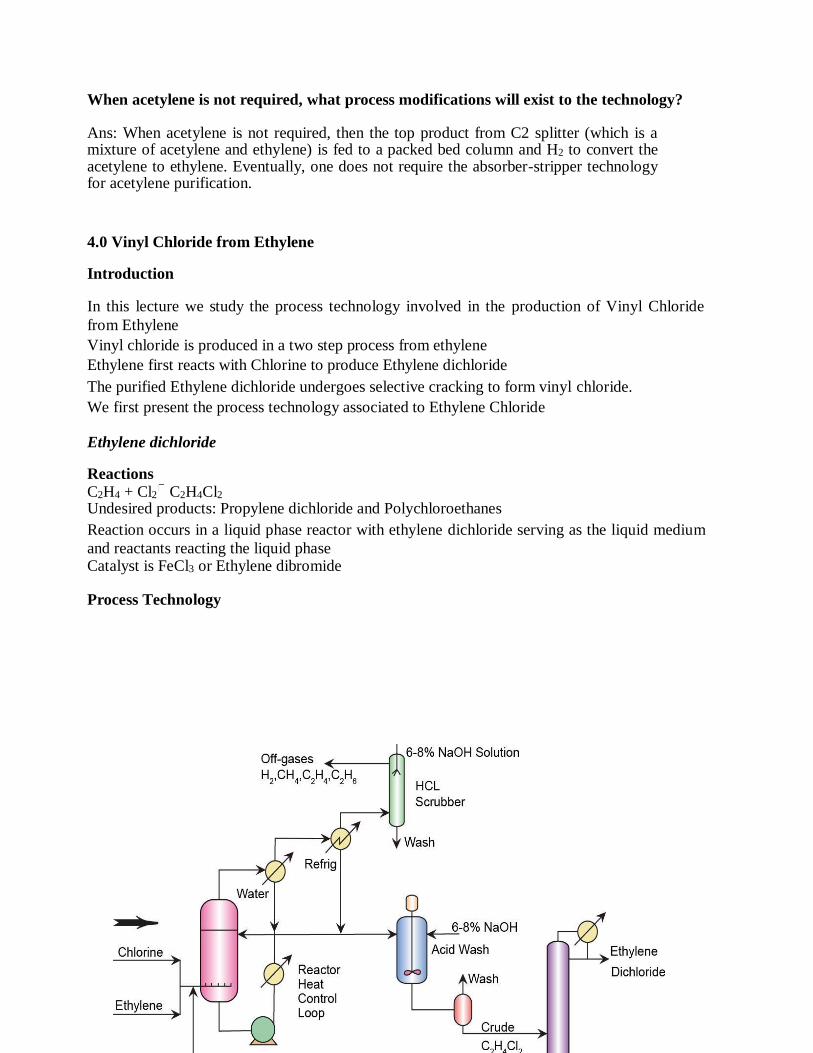
17
When acetylene is not required, what process modifications will exist to the technology? Ans: When acetylene is not required, then the top product from C2 splitter (which is a mixture of acetylene and ethylene) is fed to a packed bed column and H2 to convert the acetylene to ethylene. Eventually, one does not require the absorber-stripper technology for acetylene purification. 4.0 Vinyl Chloride from Ethylene Introduction In this lecture we study the process technology involved in the production of Vinyl Chloride
from Ethylene Vinyl chloride is produced in a two step process from ethylene Ethylene first reacts with Chlorine to produce Ethylene dichloride The purified Ethylene dichloride undergoes selective cracking to form vinyl chloride. We first present the process technology associated to Ethylene Chloride Ethylene dichloride Reactions
C2H4 + Cl2 C2H4Cl2 Undesired products: Propylene dichloride and Polychloroethanes Reaction occurs in a liquid phase reactor with ethylene dichloride serving as the liquid medium
and reactants reacting the liquid phase Catalyst is FeCl3 or Ethylene dibromide Process Technology
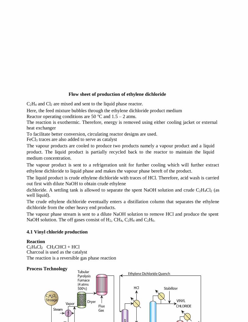
18
Flow sheet of production of ethylene dichloride C2H4 and Cl2 are mixed and sent to the liquid phase reactor. Here, the feed mixture bubbles through the ethylene dichloride product medium Reactor operating conditions are 50 oC and 1.5 – 2 atms. The reaction is exothermic. Therefore, energy is removed using either cooling jacket or external
heat exchanger To facilitate better conversion, circulating reactor designs are used. FeCl3 traces are also added to serve as catalyst The vapour products are cooled to produce two products namely a vapour product and a liquid
product. The liquid product is partially recycled back to the reactor to maintain the liquid
medium concentration. The vapour product is sent to a refrigeration unit for further cooling which will further extract
ethylene dichloride to liquid phase and makes the vapour phase bereft of the product. The liquid product is crude ethylene dichloride with traces of HCl. Therefore, acid wash is carried
out first with dilute NaOH to obtain crude ethylene dichloride. A settling tank is allowed to separate the spent NaOH solution and crude C2H4Cl2 (as well liquid). The crude ethylene dichloride eventually enters a distillation column that separates the ethylene
dichloride from the other heavy end products. The vapour phase stream is sent to a dilute NaOH solution to remove HCl and produce the spent
NaOH solution. The off gases consist of H2, CH4, C2H4 and C2H6.
4.1 Vinyl chloride production Reaction C2H4Cl2 CH2CHCl + HCl Charcoal is used as the catalyst The reaction is a reversible gas phase reaction Process Technology
19
Flow sheet of production of vinyl chloride Ethylene dichloride is initially vaporized using a heat exchanger fed with process steam Ethylene vapors then enter a dryer that removes traces of water molecules After drying, the vapors enter a pyrolysis furnace operated at 4 atm and 500 oC. The furnace is similar to a shell and tube arrangement with the gases entering the tube side and hot flue gas goes past the tubes in the shell side. The product vapors eventually enter a quenching tower in which cold ethylene dichloride is used
to quench the product gases and cool them.
The gases from the quench tower then enter a partial condenser which produces HCl as a gas and
the liquid stream consisting of vinyl chloride, unreacted ethylene dichloride and polychlorides. The liquid stream from the quench tower as well as the condenser is fed to the vinyl still which
produces the vinyl chloride product. The product is stabilized using a stabilizer as vinyl chloride is
highly reactive without stabilizer. The bottom product from the vinyl still is fed to a distillation column which separates the ethylene
dichloride from the polychlorides. The ethylene dichloride vapors are recycled back to the
cracking furnace and the ethylene dichloride liquid is sent to the quenching tower to serve as the
quenching liquid. 5.0 FORMALDEHYDE Some major intermediates derived from formaldehyde are chelating agents, acetal resins, 1,4-
butanediol, polyols, methylene diisocynate. It is also used for the manufacture of wide variety of
chemicals, including sealant, herbicides, fertilisers, coating, and pharmaceutical.
Formaldehyde is commercially available as aqueous solution with concentration ranging from 30-
56 wt.% HCHO. It is also sold in solid form as paraformaldehyde or trioxane. The production of
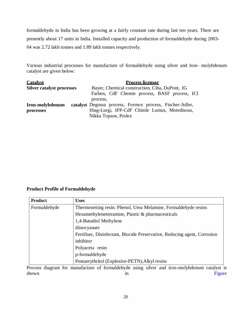
20
formaldehyde in India has been growing at a fairly constant rate during last ten years. There are
presently about 17 units in India. Installed capacity and production of formaldehyde during 2003-
04 was 2.72 lakh tonnes and 1.89 lakh tonnes respectively.
Various industrial processes for manufacture of formaldehyde using silver and iron- molybdenum
catalyst are given below:
Catalyst Process licensor
Silver catalyst processes Bayer, Chemical construction, Ciba, DuPont, IG
Farben, CdF Chemie process, BASF process, ICI
process,
Iron-molybdenum catalyst
processes
Degussa process, Formox process, Fischer-Adler,
Hiag-Lurgi, IFP-CdF Chimle Lumus, Motedisous,
Nikka Topsoe, Prolex
Product Profile of Formaldehyde
Product Uses
Formaldehyde Thermosetting resin: Phenol, Urea Melamine, Formaldehyde resins
Hexamethylenetetramine, Plastic & pharmaceuticals
1,4-Butadiol Methylene
diisocyanate
Fertiliser, Disinfectant, Biocide Preservative, Reducing agent, Corrosion
inhibitor
Polyaceta resin
p-formaldehyde
Pentaerythritol (Explosive-PETN),Alkyl resins
Process diagram for manufacture of formaldehyde using silver and iron-molybdenum catalyst is
shown in Figure
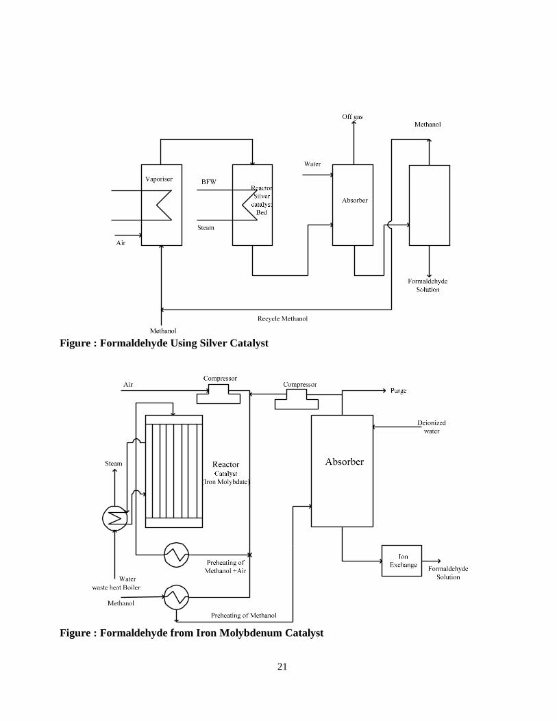
21
Figure : Formaldehyde Using Silver Catalyst
Figure : Formaldehyde from Iron Molybdenum Catalyst
22
6.0 ACETYLENE
Various Routes for Acetylene:
Calcium Carbide Route: This is the oldest method for production of acetylene and still acetylene
is produced by this process in small scale as well large scale. Calcium carbide is produced by
reacting lime with coke at temperature 2,000-2,100 oCin an electric furnace. Two processes
produce acetylene from calcium carbide process: Wet process and Dry process. Dry process is
preferred as in case of calcium hydroxide, which is produced during the process (is produced in
the form of dry calcium hydrate).
CaC2 +2 H2O C2H2 + Ca(OH) 2
Acetylene from Cracking of Hydrocarbons: Cracking of hydrocarbons such as methane, ethane,
propane, butane, ethylene, and natural gas can make acetylene.
2 CH4 C2H2 +3 H2
C2H4 C2H2+H2
C4H10 C2H2+C2H4+2 H2
Product Derived from Acetylene: Acetylene is extremely reactive hydrocarbon and was initially
was used for the manufacture of large number of chemicals which are now being derived from
acetylene route.
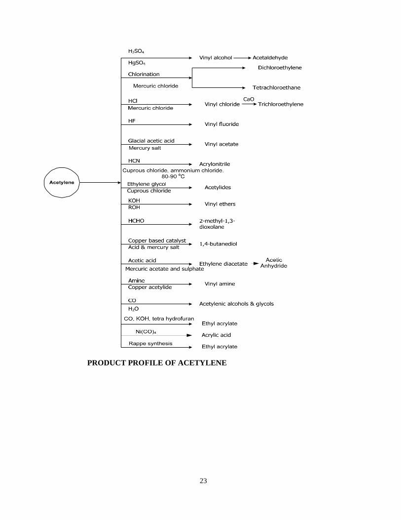
23
PRODUCT PROFILE OF ACETYLENE
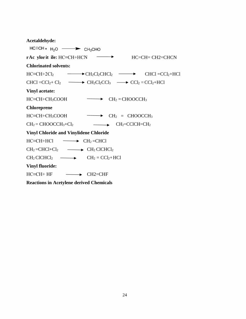
24
A c yl o it il e : N
Acetaldehyde:
r r HC≡CH+HC HC=CH= CH2=CHCN
Chlorinated solvents:
HC≡CH+2Cl2 CH2Cl2CHCl2 CHCl =CCl2+HCl
CHCl =CCl2+ Cl2 CH2Cl2CCl3 CCl2 = CCl2+HCl
Vinyl acetate:
HC≡CH+CH3COOH CH2 = CHOOCCH3
Chloreprene
HC≡CH+CH3COOH CH2 = CHOOCCH3
CH2 = CHOOCCH3+Cl2 CH2=CClCH=CH2
Vinyl Chloride and Vinylidene Chloride
HC≡CH+HCl CH2 =CHCl
CH2 =CHCl+Cl2 CH2 ClCHCl2
CH2 ClCHCl2 CH2 = CCl2+ HCl
Vinyl fluoride:
HC≡CH+ HF CH2=CHF
Reactions in Acetylene derived Chemicals
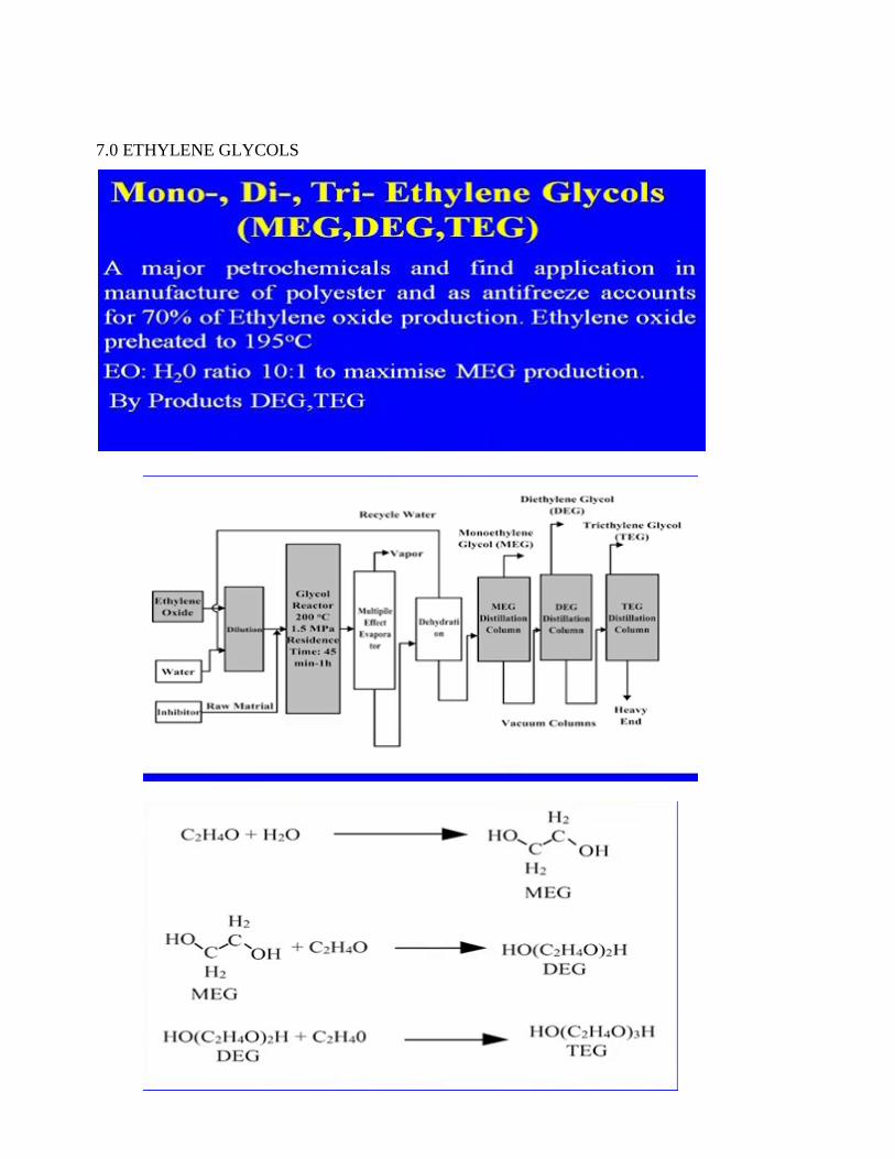
25
7.0 ETHYLENE GLYCOLS
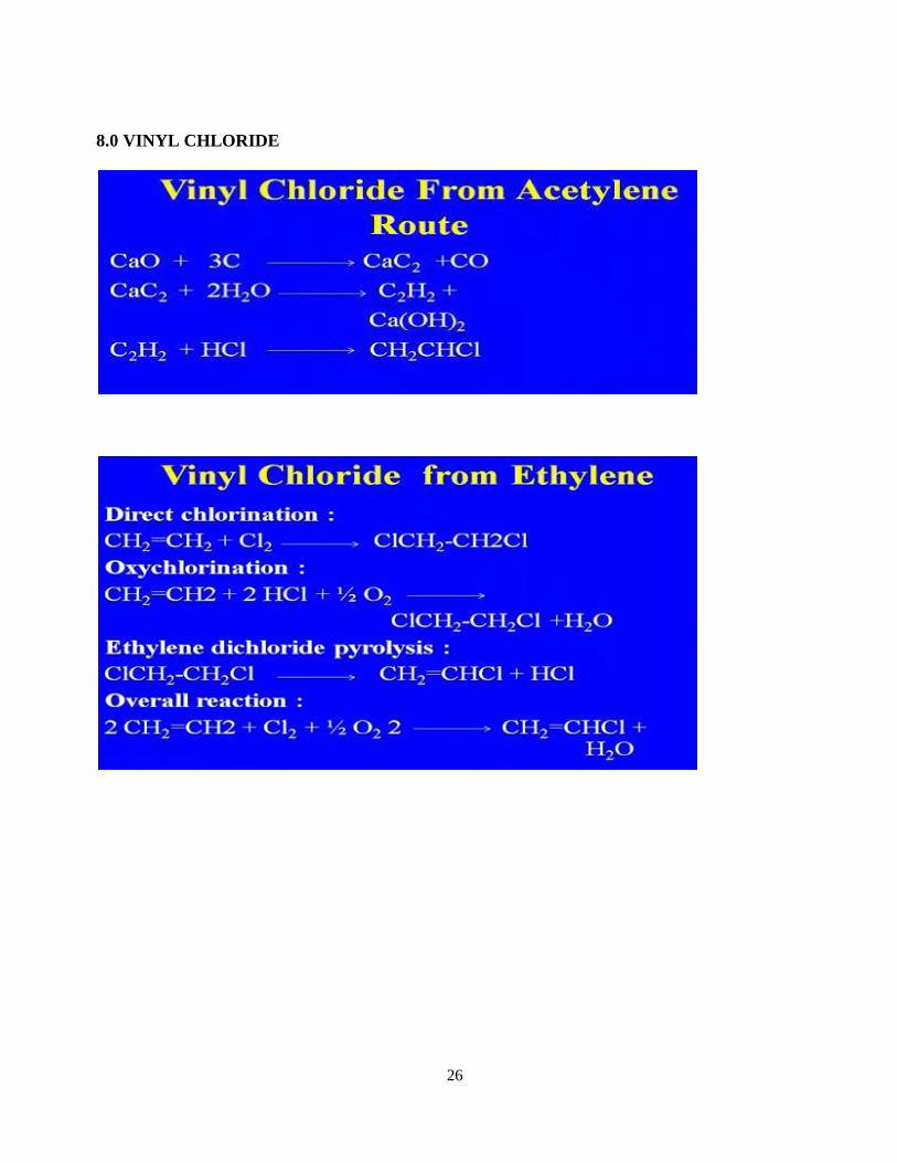
26
8.0 VINYL CHLORIDE
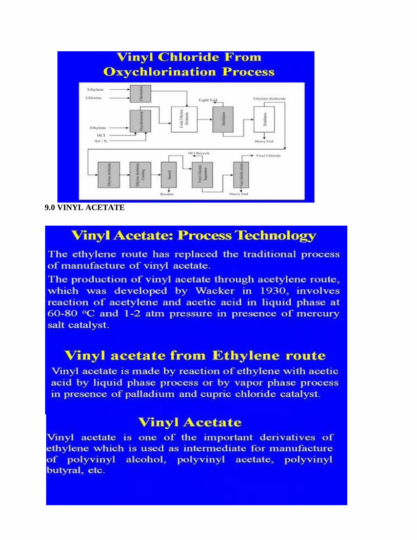
27
9.0 VINYL ACETATE
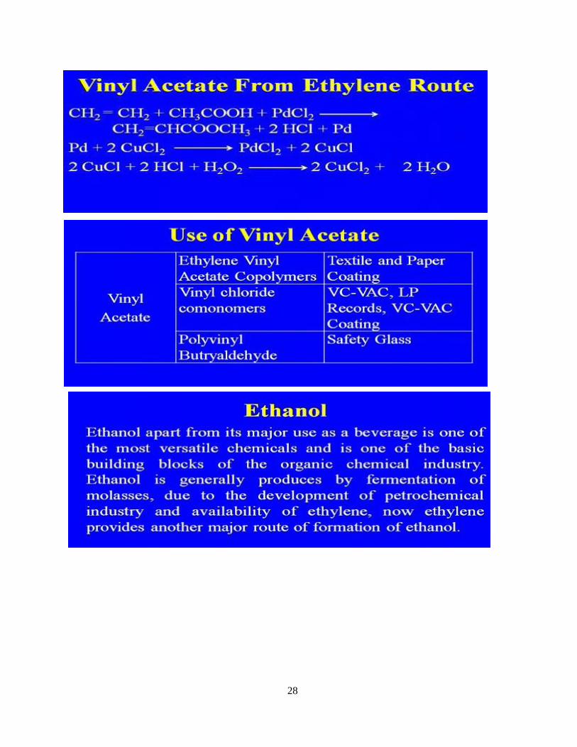
28
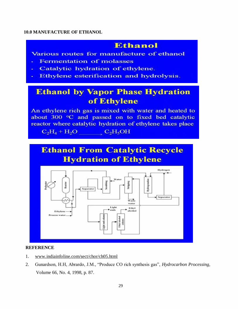
29
10.0 MANUFACTURE OF ETHANOL
REFERENCE
1. www.indiainfoline.com/sect/chor/ch05.html
2. Gunardson, H.H, Abrardo, J.M., “Produce CO rich synthesis gas”, Hydrocarbon Processing,
Volume 66, No. 4, 1998, p. 87.
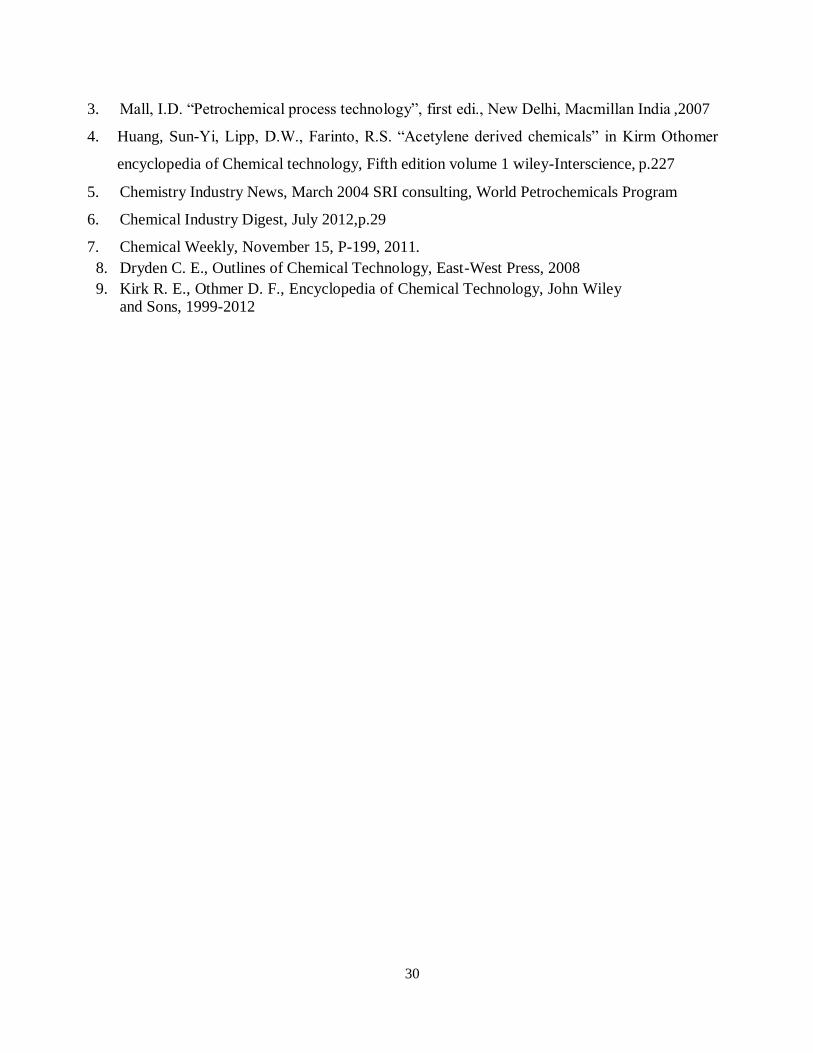
30
3. Mall, I.D. “Petrochemical process technology”, first edi., New Delhi, Macmillan India ,2007
4. Huang, Sun-Yi, Lipp, D.W., Farinto, R.S. “Acetylene derived chemicals” in Kirm Othomer
encyclopedia of Chemical technology, Fifth edition volume 1 wiley-Interscience, p.227
5. Chemistry Industry News, March 2004 SRI consulting, World Petrochemicals Program
6. Chemical Industry Digest, July 2012,p.29
7. Chemical Weekly, November 15, P-199, 2011.
8. Dryden C. E., Outlines of Chemical Technology, East-West Press, 2008
9. Kirk R. E., Othmer D. F., Encyclopedia of Chemical Technology, John Wiley and Sons, 1999-2012
1
SCHOOL OF BIO AND CHEMICAL ENGINEERING
DEPARTMENT OF CHEMICAL ENGINEERING
UNIT – 5- CHEMICALS FROM HIGHER ALKANES
2
UNIT V CHEMICALS FROM HIGHER ALKANES
Cracking of naphtha and gas for the production of ethylene, propylene
Isobutylene
Butadiene
Synthetic fibers.
1.0 Cracking of naphtha and gas for the production of ethylene, propylene
Olefins are major building blocks for petrochemicals. Because of their reactivity and
versatility,olefins especially the light olefins like ethylene, propylene, butenes, butadiene, etc.,
there has been tremendous growth in the demand of the olefins. Olefins are finding wide
application in the manufacture of polymers, chemical intermediates, and synthetic rubber.
Ethylene itself is basic building block for large number of petrochemicals and is quoted as king
of chemicals.
The steam cracker remains the fundamental unit and is the heart of any petrochemical complex
and mother plant and produces large number of products and byproducts such as olefins -
ethylene, propylene, butadiene, butane and butenes, isoprene, etc., and pyrolysis gasoline. The
choice of the feedstock for olefin production depends on the availability of raw materials and the
range of downstream products. Naphtha has made up about 50-55percent of ethylene feedstock
sources since 1992.
Modern ethylene plants incorporate following major process steps : cracking compression and
separation of the cracked gas by low temperature fractionation. The nature of the feed stock and
the level of pyrolysis severity largely determine the operating conditions in the cracking and
quenching section. Various steps involved in the pyrolysis of naphtha and separation of the
products are discussed below. In case of gas cracking separation of ethane and propane from
natural gas is involved. Flow diagram for pyrolysis of napththa is given in
FIGURE BEOW
Hot Section It consists of convection zone and radiant zone. In the convection zone, hydrocarbon feed stock
is preheated and mixed with steam and heated to high temperature. In the convection zone the
rapid rise in temperature takes place and pyrolysis reaction takes place. The addition of dilution
steam enhances ethylene yield and reduces the coking tendency in the furnace coils. The
production of the pyrolysis reaction consists of a wide range of saturated and unsaturated
hydrocarbons.
Quench Section To avoid subsequent reaction the effluent are fixed in their kinetic development by sudden
quench first by indirect quench by water to 400 – 450 oC in transfer line exchanger or quench
boiler. This is a large heat exchanger that is a bundle of metal tubes through which the gases pass
and around which is circulated water under pressure. The hot water produced is used to generate
steam for use in the plant. In the next step the quench is done by heavy product of pyrolysis.
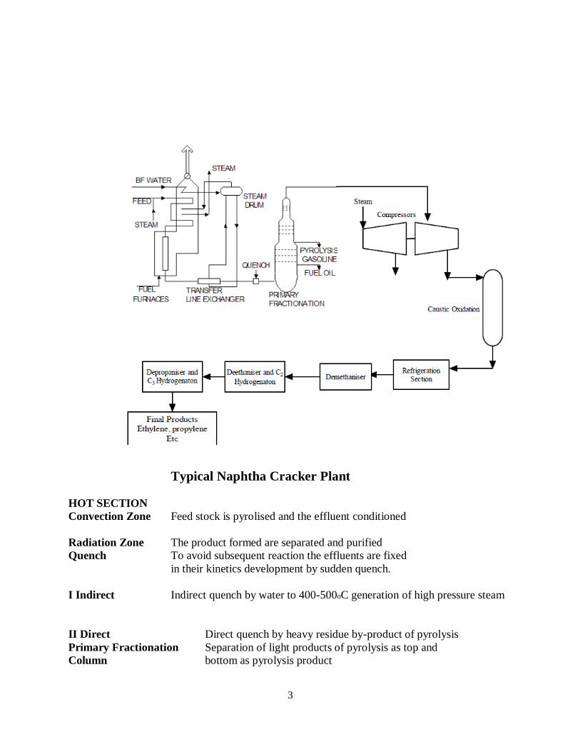
3
Typical Naphtha Cracker Plant
HOT SECTION
Convection Zone Feed stock is pyrolised and the effluent conditioned
Radiation Zone The product formed are separated and purified
Quench To avoid subsequent reaction the effluents are fixed
in their kinetics development by sudden quench.
I Indirect Indirect quench by water to 400-500oC generation of high pressure steam
II Direct Direct quench by heavy residue by-product of pyrolysis
Primary Fractionation Separation of light products of pyrolysis as top and
Column bottom as pyrolysis product
4
Compression Compression of light products
Caustic Scrubbing and Scrubbing with caustic followed by molecular sieve
Drying adsorption to remove sulphur compounds ,mercaptan, etc.
Cold Section After compression, caustic scrubbing and drying the light effluents enter the cold section of the
unit which performs the separation of (I) hydrogen to various concentration (ii) ethyllhene
containing 99.4percent (iii) 95percent propylene (iv) A C4 cut containing 25-50percent butadiene
(v) pyrolysis gasoline which is rich in aromatic hydrocarbons.
The complexity of the separation section of a cracker increases markedly as the feed changes
from ethane.
COLD SECTION Hydrogen separation
Ethylene separation 99.9percent
Propylene separation
A C4 cut containing 25-50percent butadiene
Complementary fraction of pyrolysis gasoline rich in aromatic hydrocarbons
Demethaniser Methane condensed at top around – 1000C pressure 32 Pa
Deethaniser Separation of C2 cut;(Ethane and ethylene)
Acetylene eliminated by selective hydrog-nation Catalyst : Palladium or
Nickel 40-80oC, 3 kPa
Separation of Ethylene is fractionated and unreacted ethane recycled
Ethylene
Depropaniser C3+ cut from bottom of deethaniser is fractionated.
C3 cut from top of depropaniser is selectively hydrogenated to remove
methyl acetylene and propadience.
Propylene content 95percent.
Separation in supplementary column for more pure propylene.
Removal of propane Separation in supplementary column for more pure
from propylene propylene
Debutaniser Separation of C4 stream from C5+ stream
REACTIONS IN STEAM CRACKING The reactions involved in thermal cracking of hydrocarbons are quite complex and involve many
radical steps. The thermal cracking reaction proceeds via a free radical mechanism. Two types of
reactions are involved in the thermal cracking (i) primary cracking where the initial formation of
paraffin and olefin takes place (ii) secondary cracking reaction where light products rich in
olefins are formed. The total cracking reactions can be grouped as follows:
Initiation reaction.
Propagation reaction.
5
Addition reaction.
Isomerization reaction.
Termination reaction.
Molecular cyclization reaction
OPERATING VARIABLES OF STEAM CRACKING The main operating variables in the pyrolysis of hydrocarbon are composition of feed stock, reaction
temperature, residence time, hydrocarbon partial pressure and severity.
Composition of Feed Stock Naphtha are mixture of alkane, cycloalkanes, and aromatic hydrocarbons depending on the type
of oil from which the naphtha was derived. The group properties of these components greatly
influence the yield pattern of the pyrolysis products. A full range naphtha boiling range
approximately 20 to 200oC would contain compound, with from 4-12 carbon atms. Short naphtha
boiling point range from 100-140oC and long chain naphtha boiling point lies around 200-220oC.
The steam cracking of the naphtha yields wide variety of products, ranging from hydrogen to
highly aromatic heavy liquid fractions. The thermal stability of hydrocarbons increases in the
following order: parafins, naphthenes, aromatics. Yield of ethylene as well as that of propylene is
higher if the naphtha feed stock is rich in paraffins. It may be seen that relative production of
ethylene decreases as the feed stock becomes heavier. The percentage of pyrolysis gasoline C5-
200oC cut increases. Simultaneously butadiene yield varies slight with feed stock in the treatment
of liquid petroleum fractions.
With the rising demand of ethylene and propylene, there has been a tremendous growth in the
steam cracking of hydrocarbons during the last four decades. Similarly, FCC (Fluid Catalytic
Cracking) has developed into a major upgrading process in the petroleum refinery industry for
the conversion of heavy fuel oil into more valuable products ranging from light olefins to
naphtha and middle distillate. Large amounts of C4 and C5 compounds are produced along with
the production of ethylene in steam cracking and gasoline in FCC. C4 & C5 streams are an
important source of feedstock for synthetic rubber and many chemicals.
With increasing demand of C5 hydrocarbons and oxygenates, upgrading of C4 and C5 streams
from steam crackers and catalytic cracker is important to the economic performance of the above
processes. It also provides a rich resource of reactive molecules, which forms the backbone of
the synthetic rubber industry. The quantity and composition of the C4 and C5 stream depends on
6
the severity of the steam cracker operation and feedstock processed.
FLUID CATALYTIC CRACKING Fluid catalytic cracking (FCC) converts low value crude oil into a variety of higher value
products which include gasoline, diesel, heating oil and valuable gases containing LPG,
propylene and C4 and C5 gases. Various products from fluid catalytic cracking and their uses
are given in Table FCC units are versatile and can be operated in three main modes which are
aimed at maximizing middle distillate, gasoline, or olefins respectively by means of the
adequate combination of various parameters such as catalyst type, catalyst to oil ratio, rise of
outlet temperature and recycle of fractionators bottom. FCC is the second largest source of
propylene supplied for petrochemical application.
Conventional FCC 4-7% propylene and 1-2 % Ethylene
High Severity FCC:10% propylene
Petro FCCTM
(UOP): Ethylene 6%, Propylene 20-22%, Higher aromatics (18%) in
Naphtha
Higher C4-8 olefins yield which can be cracked to yield lower olefins by Total
Petrochemicals ATOFINA/UOP Olefin cracking Process
Although FCC is an important petroleum refining process, however, FCC gases have now
become important petrochemical feedstock for production of LPG that can be converted
to aromatics and C3, C4, & C5 hydrocarbons, i.e. propylene, butene, isobutene, pentene,
etc.
Product distribution from FCC depends
Reactor temp
Feed preheat temperature
Catalyst activity
Catalyst circulation rate
Catalyst activity
Recycle rate
Various Petroleum Products from FCC and their uses
Product Composition and Uses
Light gases Primarily H2, C1 and C2s, ethylene can be recovered
LPG C3s and C4s containing light olefins suitable for
alkylations
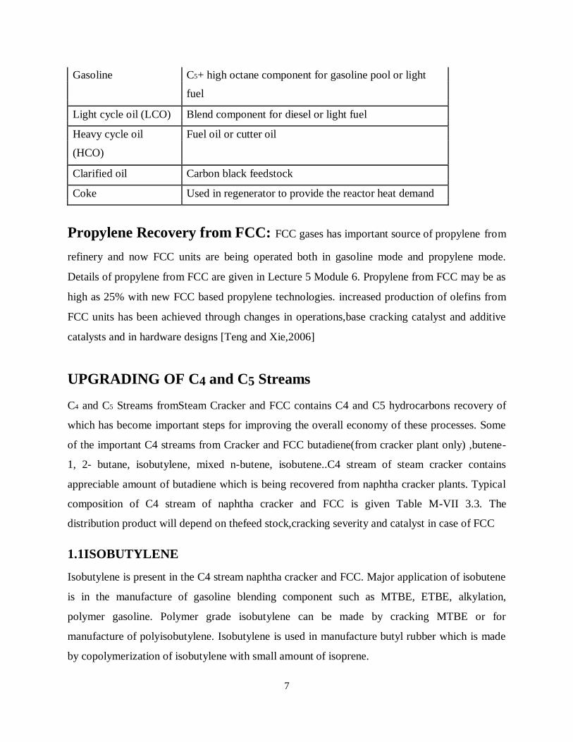
7
Gasoline C5+ high octane component for gasoline pool or light
fuel
Light cycle oil (LCO) Blend component for diesel or light fuel
Heavy cycle oil Fuel oil or cutter oil
(HCO)
Clarified oil Carbon black feedstock
Coke Used in regenerator to provide the reactor heat demand
Propylene Recovery from FCC: FCC gases has important source of propylene from
refinery and now FCC units are being operated both in gasoline mode and propylene mode.
Details of propylene from FCC are given in Lecture 5 Module 6. Propylene from FCC may be as
high as 25% with new FCC based propylene technologies. increased production of olefins from
FCC units has been achieved through changes in operations,base cracking catalyst and additive
catalysts and in hardware designs [Teng and Xie,2006]
UPGRADING OF C4 and C5 Streams
C4 and C5 Streams fromSteam Cracker and FCC contains C4 and C5 hydrocarbons recovery of
which has become important steps for improving the overall economy of these processes. Some
of the important C4 streams from Cracker and FCC butadiene(from cracker plant only) ,butene-
1, 2- butane, isobutylene, mixed n-butene, isobutene..C4 stream of steam cracker contains
appreciable amount of butadiene which is being recovered from naphtha cracker plants. Typical
composition of C4 stream of naphtha cracker and FCC is given Table M-VII 3.3. The
distribution product will depend on thefeed stock,cracking severity and catalyst in case of FCC
1.1ISOBUTYLENE
Isobutylene is present in the C4 stream naphtha cracker and FCC. Major application of isobutene
is in the manufacture of gasoline blending component such as MTBE, ETBE, alkylation,
polymer gasoline. Polymer grade isobutylene can be made by cracking MTBE or for
manufacture of polyisobutylene. Isobutylene is used in manufacture butyl rubber which is made
by copolymerization of isobutylene with small amount of isoprene.
8
Various Routes for Isobutylene Extraction of C4 cuts from steam cracking / FCC: Isobutylene is separated from C4 cuts from
naphtha cracker after extraction of butadiene and from FCC gases after propylene recovery. First
isobutylenes is converted to MTBE by etherification and the recovered by cracking of MTBE to
get polymer grade isobutylene it is also obtained by hydration of isobutylene containing stream
and then cracking.
Isomerisation of Butene: isobutylene can be also produced from butane by isomerisation using
zeolite ferrierite (zeolite of medium pore size) [Maulijanet al.2001] Dehydrogenation of Isobutene:
BUTENE -1 Butene-1 is co-monomer in the production of low density polyethylene and high density
polyethylene. Butene-1 can be separated from C4 stream of cracker after extraction of butadiene
SHB-CB process: This process selectively hydrogenate the butadiene in the C4 cut by converting
it to butane-1 and butane-2. Acetylenes and dienes are likewise hydrogenated. If the process is
optimized to produce butane-1, about 60% of butadiene is converted to butane-1. The process is
operated in the liquid phase mild temperatures and moderate pressures.
UPGRADING OF C5 CUTS The steam cracker C5 stream is a rich resource of olefins and diolefins which can be upgraded to
produce elastomers, resins and fine chemical intermediates. In steam crackers during cracking
process along with ethylene, propylene, C4 stream, aromatics and pyrolysis gasoline bare also
formed. Apart from aromatics, Pyrolysis gasoline stream also contains C5 stream
[Morgan,1996]. The quantity and composition of the stream depend on the nature of the cracked
product and severity of cracker operation C5 stream.
1.2 Butadiene and Benzene Manufacture
Introduction
In this lecture, we present the process technologies associated to Butadiene
and Toluene. Butadiene manufacture is considered using n-Butane as the feed stock.
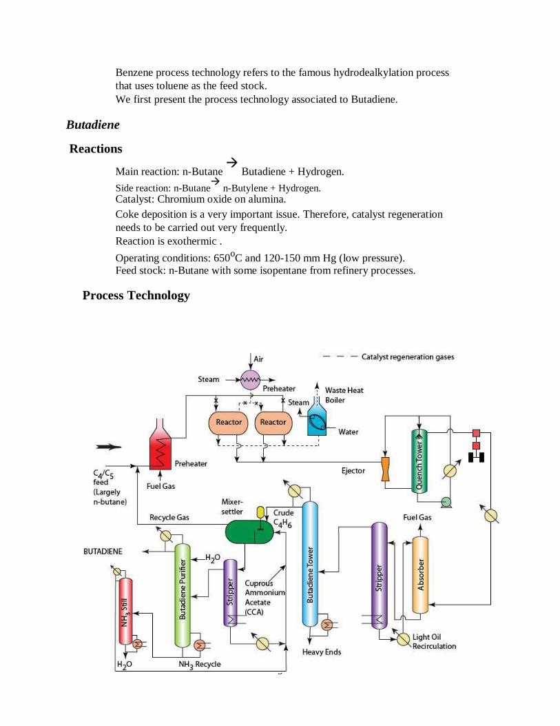
9
Benzene process technology refers to the famous hydrodealkylation process
that uses toluene as the feed stock. We first present the process technology associated to Butadiene.
Butadiene
Reactions
Main reaction: n-Butane
Butadiene + Hydrogen. Side reaction: n-Butane
n-Butylene + Hydrogen.
Catalyst: Chromium oxide on alumina. Coke deposition is a very important issue. Therefore, catalyst regeneration
needs to be carried out very frequently. Reaction is exothermic .
Operating conditions: 650oC and 120-150 mm Hg (low pressure).
Feed stock: n-Butane with some isopentane from refinery processes.
Process Technology
10
Flow sheet of Butadiene manufacture
- The process technology for Butadiene manufacture consists of a reactor-
separator-recycle system.
The separation network is extremely complex and involves quenching,
absorption, distillation and extractive distillation process. First, the feed stock is pre-heated in a furnace along with unreacted gases that
have been recovered in the process using the separator network. After pre-heating in a furnace to desired temperature, the gases enter the
catalytic packed bed reactors loaded with the catalyst. After the specified residence time, the product is withdrawn and the feed to the
unit is stopped. The product withdraw and stoppage of the feed flow to the reactor
unit is carried out using valves.
The coked catalyst is subjected to combustion using pre-heated air. Air pre-
heating is done using steam in an extended area heat exchanger equipment.
Therefore during regeneration, another set of valves operate to allow the pre-
heated air in and enable the product withdrawal after the combustion.
The pre-heated air not only removes the coke as CO2 but increases the reactor
temperature to 650 oC.
The flue gases are sent to a waste heat recovery boiler so as to generate steam
from water. The entire operation of a feed entry, product withdrawal, pre-heated air entry
and combustion gases withdrawal from the packed bed reactor corresponds to
one single cycle.
Since the above operation is a batch operation, to make the operation continuous
in accordance to the separation network, two reactors are used and these reactors
are operated in cyclic fashion i.e., when the first reactor is subjected to reaction,
the second reactor is subjected to catalyst regeneration and vice-versa.
The hot reactor outlet gases are sent to a quenching operation where light gas oil
is used to quench the gases using a recirculating quenching tower. After product gases from the quenching tower are compressed and cooled to enter
an absorber In this absorber, naphtha is used as an absorbent to absorb all hydrocarbons
except fuel gas. The absorbent + hydrocarbons enter a stripper that produces fresh naphtha and
hydrocarbon mixture. The hydrocarbon mixture consists of unreacted feed stock
and butadiene and some heavy ends.
11
This mixture now enters a fractionator to separate the crude butadiene and
heavy ends. The crude butadiene consists of butadiene and unreacted feed stock i.e., n-butane
and isopentane. The separation of n-butane, other hydrocarbons with butadiene is
one of the difficult separations and they cannot be separated using ordinary
distillation. Therefore, a complicated route of separation is followed next that
involves azeotropic distillation using ammonia.
The crude butadiene is mixed with ammoniated cuprous ammonium acetate
solution in a mixer settler. This solution is generated by absorbing ammonia into
fresh cuprous ammonium acetate solution. The ammoniated cuprous ammonium acetate is sent to a mixer settler unit where
the butadiene dissolves in the ammoniated solution. The gas from the mixer
settler unit is recycled to mix with the feed stock and enter the pre-heater.
The ammoniated cuprous ammonium acetate solution is thereby stripped to separate butadiene + ammonia from the ammonium acetate solution. The
regenerated fresh solvent is allowed to absorb NH3 and thereby enter the mixer-
settler unit.
The ammonia + butadiene mixture enters a fractionator fed with water. Here,
water interacts with ammonia and generates the ammonium hydroxide product as
the bottom product and butadiene is obtained as the top product.
The ammonia solution is subjected to stripping to separate water and ammonia.
The water is recycled back to the butadiene purifier and ammonia is allowed to
get absorbed into the fresh cuprous ammonium acetate solution. This process is not followed in India . In India, it is manufactured from ethanol by
catalytic cracking at 400-450 oC over metal oxide catalyst.
1.3 Synthetic fibers
Synthetic fibers and synthetic fabrics consist of bulk fibers, yarns, woven cloth or other textile
products manufactured from polymer-based materials such as polyamide (nylon), polyester,
aramid, or other spun thermoplastics. The end-product is the form of the fiber/fabric when
manufacturing is complete.
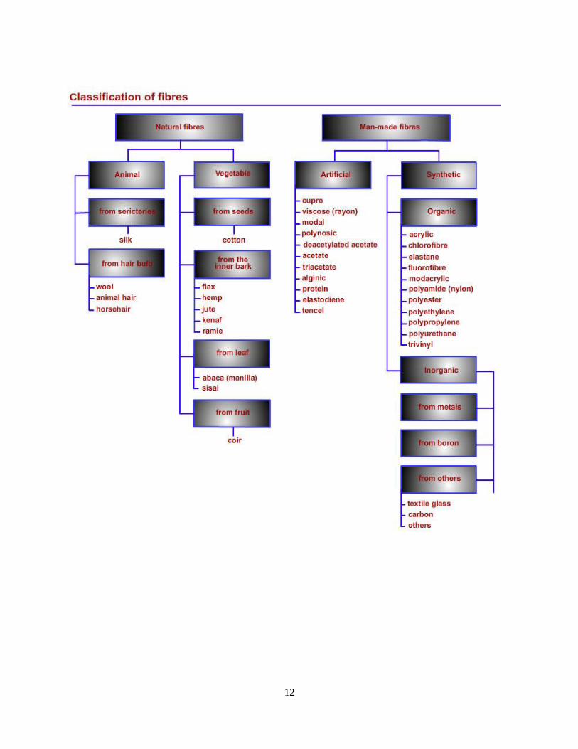
12
13
REFERENCES 1. Briggs, B.A., Simpson S.O., Lemerk C.A., Ward D.J., “Fluid catalytic cracker as a source
of petrochemical olefins”, Chemical Age of India, Volume 38, No. 1, 1987, p. 21.
2. Chauvel, A., Lefebvre G., “Treatment of olefinic C4 and C5 cuts”, in Petrochemical
Processes, Synthesis-Gas derivatives and major hydrocarbons, Editions Technip Paris
1985, p. 195.
3. Chemical Weekly, December, 27, P-198, 2011. 4. Convers, A., “Make chemicals from C4olefinic fractions”, Chemical Age of India, 5. Morgan, M., “C5 hydrocarbons and derivatives new opportunity”, Chemistry and industry
2 September, 1996, p.646.
6. Moulijan, J.A., Makkee, M., Diepen, A.V., “Chemica Process technology”, John Wiley &
Sons, 2001
7. Teng, J., Xie, Z., “OCC process for propylene production”, Hydrocarbon Asia May/June
2006,p.26
8. Vermilion, W.L., Niclaes H.J., “Petrochemicals from the FCC unit”, Hydrocarbon
Processing, September 1977, p. 193.

14