Embed Size (px)
Citation preview

NARIN INSTRUMENT CO., LTD Operation Manual
Page 1 20/12/2010
Universal Testing Machine
Model NRI-TS500-50
Please read this Operation Manual carefully before use.
Keep it in the reference manual

NARIN INSTRUMENT CO., LTD Operation Manual
Page 2 20/12/2010
Table Contents
Matter. Page Use of Operation Manual 3 To SUPERVISOR in charge of this equipment 4 Safety Precautions 5
1. Intended use of the product 8 2. Feature of product 8 3. Appearance 10 4. Installation 12 5. Name & functions 14 6. Maintenance and service 24 7. Trouble shooting 25 8. After-sales service 27 9. Specification 28 10 . Certification
10.1 ISO9001 certificate 30 10.2 Product warranty certificate 31
11 Inspection data 11.1 Inspection report 32 11.2 Calibration certificate 36 11.3 Appendix A 37

NARIN INSTRUMENT CO., LTD Operation Manual
Page 3 20/12/2010
Use of Operation Manual
Please read through and understand this Operation Manual before operating the product. After reading, always keep the manual nearby so that you may refer to it as needed. When moving the product to another location, be sure to bring the manual as well.
If you find any incorrectly arranged or missing pages in this manual, they will be replaced. If the manual it gets lost or soiled, a new Operation Manual can be purchased. In either case, please contact Narin Instrument Co.,Ltd or your NRI agent or and provide the "Model No." given on cover.
This manual has been prepared with the utmost care; however, if you have any questions, or note any errors or omissions, please contact Narin Instrument Co.,Ltd or your NRI distributor or agent.
This manual is proprietary Narin Instrument Co.,Ltd. of all forbidden. and / or part of the new publisher. or create new without our permission. The company reserves the right to modify both unit specifications and manual contents without notice
Copyright © 2010 Narin Instrument Co.,Ltd Printed in Thailand

NARIN INSTRUMENT CO., LTD Operation Manual
Page 4 20/12/2010
To SUPERVISOR in charge of this equipment.
If the operator does not read the language used in this manual translate the manual into appropriate language.
Help the operator in understanding this manual before use in operation
Keep this manual near the tester for easy access by the operator

NARIN INSTRUMENT CO., LTD Operation Manual
Page 5 20/12/2010
Safety Precautions The following safety precautions must be observed and followed to avoid fire hazard, electrical shock, accidents, and other failures. Keep them in mind and make sure that all the precautions are observed and followed properly. Narin Instrument Co., Ltd. assumes no liability nor any responsibility against any damages, accidents, or problems resulting from negligence of the precautions.
Users
This product must be used only by qualified personnel who understand the contents of this operation manual.
If it is handled by disqualified personnel, personal injury may result. Be sure to handle it under supervision of qualified personnel.
Purpose of use
If the product is to be used for purposes not described in this manual, contact NRI agent/distributor in advance.
Input Power
Use the product with the specified input power voltage.
For applying power, use the AC power cable provided. The shape of the plug differs according to the power voltage and areas. Use the cable which is suitable for the line voltage used.
Fuse
With products with a fuse holder on the exterior surface, the fuse can be replaced with a new one.
When replacing a fuse, use the one which has appropriate shape, ratings and specifications.
Cover
There are parts inside the product which may cause physical hazards. Do not remove the external cover. If the cover must be removed, contact your NRI agent/distributor in advance
NARIN INSTRUMENT CO., LTD Operation Manual
Page 6 20/12/2010
Installation
When installing products be sure to observe Installation Precaution described in this manual.
To avoid electrical shock, connect the protective ground terminal to electrical ground (safety ground).
When applying power to the products from a switchboard, be sure work is performed by a qualified and licensed electrician or is conducted under the direction of such a person.
Be sure to use the AC power cable provided.
Relocation
Turn off the power switch and then disconnect all cables when relocating the product.
Use two or more persons when relocating the product which weights more than 20 kg. The weight of the products can be found on the rear panel of the product and/or in this operation manual.
Use extra precautions such as using more people when relocating into or out of present locations including inclines or steps. Also handle carefully when relocating tall products as they can fall over easily.
Be sure the operation manual be included when the product is relocate
Maintenance
To avoid electrical shock, be absolutely sure to unplug the AC power cable or stop applying power before performing maintenance or checking.
Do not remove the cover when performing maintenance or checking. If the cover must be removed, contact your NRI agent/distributor in advance.
To maintain performance and safe operation of the product, it is recommended that periodic maintenance, checking, cleaning, and calibration be performed.
SERVICE
Internal service is to be done by NRI service engineers
If the product must be adjusted or repaired, contact your NRI
agent/distributor.

NARIN INSTRUMENT CO., LTD Operation Manual
Page 7 20/12/2010
Operation Caution 1. Load cell is equipped with high precision using the following precautions.
Tension /Compression action will not exceed 100% of the maximum capability of load cell
Must not press / pull directly to the load cell and / or act in a sudden manner
Should be used in an environment that does not change or alter the temperature is not much about ± 2 degrees celsius
Load cell criticism should be set to enter nut every position and tightened all the time.
Remove the Universal Joint Grip every time the experiment was completed
Load cell assembly with crosshead before powering or excite load cell.
Before the test. check the operation of the upper limit switch and lower limit.
The installation of the testing machine must be grounded (Earth).
Upon completion of the test. “Click Stop” or be stopped due to wait 10-20 seconds for processing
Do not add to the command of non-washout period processing. Testing program may have to balk
2 The condition of the test
Test speed up to 1000 mm / min.
The machine should be started prior to the test of not less than 15 minutes and should monitor the actions of the primary. Machine before proceeding.
3 The security of machine
The limit switch. adjust in a safe operating distance.
Adjust force and stroke limit to prevent over load.
Force limit should be set to 80% of the capacity of load cell.
Stroke limit adjust the stage safe enough to use.
Press emergency to cancel or cut power systems.
A power overload protection
NARIN INSTRUMENT CO., LTD Operation Manual
Page 8 20/12/2010
1. Intended use of the equipment. The Universal testing Machine is a electromechanical machine used for precision measurement of mechanical properties for metal rod, concrete, fabric, plastic, rubber, paper, wood etc. Can offer a more economic solution for test; satisfy the test need for finished, semi-finished and material product It is floor type UTM easy to operate, small volume, high rigidity. User can sole operate this by computer controller serial is simplest type, controller and machine movement operate independently, provided with output signal of stop machine, collocate with different type flexible. Provided with data output function, can connect to computer and do analyses, statistics, save data with NRI software. Also can install other accessories like sensor, extensometer, grips and software depending on the various different specimens. 2. Feature of product.
Tensile testing machine is a dual column floor type testing machine applied by new design and producing skill to have strong structure, saving transmission power and electric current
Driver This machine is power by Servo motor & gear - Servo motor 1.5 kW/3000 rpm - Ball Screw : 32 x 10 mm. - Reducing gear 1: 30 - Torque limiters and safety couplings without any risk
Load frame Is the rigid frame consisting of two strong ball screw and strong desktop A movable cross head (crosshead) is controlled to move up or down. This is at a constant speed and can program the crosshead speed or conduct cyclical testing, testing at constant force, testing at constant deformation, etc - Fame capacity 50 kN
- Frame stiffness ~2,000 N/μm
Force measurement system - Measuring the load by precision load cell (low profile tension and compression) 3 mV/V - Overload capability : 120% of load cells without damage - Data acquisition rate 400 Hz

NARIN INSTRUMENT CO., LTD Operation Manual
Page 9 20/12/2010
Measuring extension Stroke readings, as well as minimum test speed of 0.005 mm/min, for the high performance and most accurate results - Position detection : Rotary encoder 1000 plus
- Encoder Amplifier and counter card : 24 bit
- Data sampling rate : 400 Hz - Position resolution : 0.001 mm
NARIN INSTRUMENT CO., LTD Operation Manual
Page 10 20/12/2010
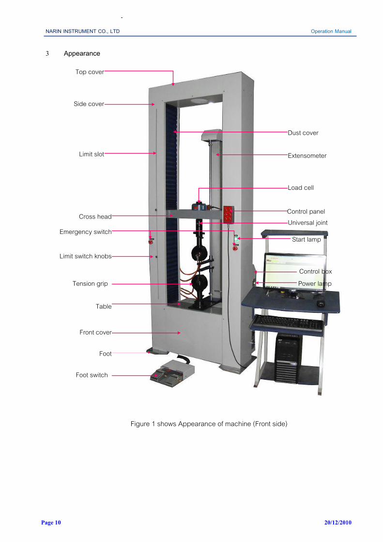
3 Appearance
Top cover
Side cover
Limit slot
Dust cover
Extensometer
Load cell
Control panelCross head
Emergency switch
Limit switch knobs
Tension grip
Table
Front cover
Foot
Foot switch
Start lamp
Control boxPower lamp
Universal joint
Figure 1 shows Appearance of machine (Front side)
NARIN INSTRUMENT CO., LTD Operation Manual
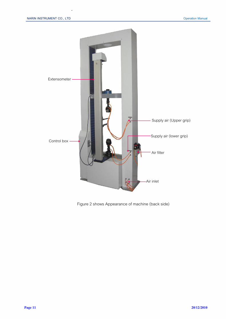
Page 11 20/12/2010
Extensometer
Control box
Air filter
Supply air (Upper grip)
Supply air (lower grip)
Air inlet
Figure 2 shows Appearance of machine (back side)

NARIN INSTRUMENT CO., LTD Operation Manual
Page 12 20/12/2010
4 Installation 4.1 Precautions for Installation
This equipment is designed and manufactured to operate properly only in use of rated voltage.Refer to specification section of this manual for rated voltage before installation
Use AC power cable that comes with (or installed to) the product.
Do not touch the Power Cord wet handed.
Avoid locations where the equipment is exposed to direct sunshine.
Do not place the equipment in a corrosive atmosphere.
Do not use the equipment in a flammable atmosphere.
Do not use the equipment where ventilation is poor.
Do not locate the equipment in a dusty location.
Do not use in an unstable place that are subject to vibrations.
Avoid locations of high humidity.
Avoid locations where the equipment is exposed to high temperature.
Recommended temperature range : 20°C to 30°C
Operation temperature range : 10°C to 40 °C
Relative humidity ranged 20 to 80%
Avoid locations of altitude higher than 2,000m.
Use the equipment indoors only.
Secure adequate space around the power plug.
Vibration frequency is less than 10 Hz and vibration less than 0.005 mm.
Must be in areas where no electromagnetic interference. 4.2 How to install
Use with a minimum distance all around of 30 cm from walls of other items.
Machines must be placed on a flat surface that is strong enough. And adjust the machine to the vertical
Connect the power cord to an outlet with earthling point.
In case of connecting to an outlet without earthling point, connect lead wire to the earth after connecting grounding adapter.

NARIN INSTRUMENT CO., LTD Operation Manual
Page 13 20/12/2010
4.3 How to ground Earth wire WARNING Earth wire must be grounded to prevent any electrical accidents.
Improper or no grounding may cause electrical shock.
Grounding terminal is included in the power plug.
Therefore, there is no need to earth if plug in connected to a consent with grounding terminal.
If grounding terminal with consent is not available, install adapter to plug to ground earth wire from green terminal or install earth wire to the grounding terminal of the equipment.
NARIN INSTRUMENT CO., LTD Operation Manual
Page 14 20/12/2010
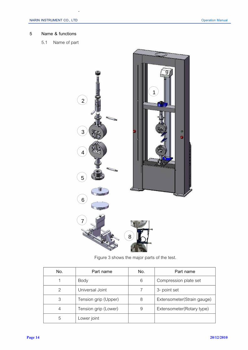
5 Name & functions 5.1 Name of part
2
3
4
5
6
7
1
8
9
Figure 3 shows the major parts of the test.
No. Part name No. Part name 1 Body 6 Compression plate set 2 Universal Joint 7 3- point set 3 Tension grip (Upper) 8 Extensometer(Strain gauge) 4 Tension grip (Lower) 9 Extensometer(Rotary type) 5 Lower joint

NARIN INSTRUMENT CO., LTD Operation Manual
Page 15 20/12/2010
11
10
12
14
13
15
Figure 4 shows the image on the back-machine.
16
17
18
19
20
21
22
23
No. Part name 10 Upper limit switch knobs 11 Emergency switch(R) 12 Lower limit switch knobs 13 Control panel 14 Start lamp 15 Emergency switch(L) 16 Power lamp 17 Control panel connector 18 Com. Port 232(load cell) 19 Com. Port 232(encoder) 20 Com. Port 232
(strain gauge extensometer) 21 Com. Port 232
(long range extensometer) 22 Breaker 23 Power connector
Figure 5 show the signal connector

NARIN INSTRUMENT CO., LTD Operation Manual
Page 16 20/12/2010
30
31
32
33
34
35
24
25
26
27
28
29
No. Part name No. Part name 24 Load cell
connector 30 Analog signal±0-10
VDC 25 Control panel
connector 31 Data acquisition
(Load cell) 26 Signal monitor 32 Data acquisition
(Extensometer) 27 Extensometer
signal input 33 Extensometer port
28 Load signal port 34 Control Panel Card 29 Encoder signal
port 35 Data acquisition
(Encoder)
Figure 6. show the device connected signal

NARIN INSTRUMENT CO., LTD Operation Manual
Page 17 20/12/2010
36
37
38
39
40
41
42
Figure 7 show the moving system
43
44
45
46
47
48
50
52
49
51
Figure 8 shows images of machine components. No. Part name No. Part name 36 Servo Motor 45 Universal joint nut 37 Timing belt 46 Universal joint 38 Disc Couplings 47 Joint nut 39 Low voltage supply 48 Grip body 40 Worm Gear 49 Teeth fixing plate 41 Rotary Shaft 50 Grip teeth 42 Servo driver 51 Lower joint 43 Load cell fixing nut 52 Pin 44 Tension joint

NARIN INSTRUMENT CO., LTD Operation Manual
Page 18 20/12/2010
43
53
54
5855
59
60
56
57
58
59
Figure 9 shows the bending test equipment.
No. Part name 53 Compression joint 54 Screw 55 Bending Roller 56 Lock nut 57 Bending span adjust 58 Bending jig 59 Stud 60 Bending support

NARIN INSTRUMENT CO., LTD Operation Manual
Page 19 20/12/2010
1
2
3
4
6
5
7
Figure 10 shows the assembly.(Tension test )
The assembly for tensile testing. 1 Load cell installation, and then compete with Crosshead nut
is tightened all the positions (*). 2 Assembly tension joint (2), Load cell with inserted through
the crosshead and competition nut (1)is tightened . 3 Retaining Upper joint fixing nut (3) to the tension joint (2). 4 Insert the Universal joint (4) with tension joint (2). 5 Insert pin(7) 6 Insert the tension grip(5) with universal joint (4). 7 Insert pin(5) 8 Adjust fixing nut to grips with the universal joint tightly. 9 Holding the lower grips to perform in the same way. Note (*). 1 for clamping Load Cell. shall not be paid while the electricity or machine is in a state breaker off only
1
2
3
4
5
Figure 11 shows the bending test assembly
The assembly for bending test. 1 Load cell installation, and then compete with Crosshead nut
is tightened all the positions (*) 2 Assembly compression joint (2)l with inserted through the
Crosshead and competition nut (1)is tightened 3 Insert bending (4) to Universal joint (2). 4 Retaining screw (3) to the compression joint (2) 5 Installed 3-point bending device on the table 6 Adjust the cradle, Bending span desired size or the
standard 7 Retaining nut bending span adjust. tighten.

NARIN INSTRUMENT CO., LTD Operation Manual
Page 20 20/12/2010
1
2
3
4
5
Figure 12 shows the compression test assembly.
The assembly for the compression test. 1 Load cell installation, and then compete with crosshead nut
is tightened all the positions (*) 2 Assembly compression joint (2)to Load cell with inserted
through the crosshead and competition nut (1)is tightened 3 Insert compression plate (4) to Universal joint (2). 4 Retaining screw (3) to the compression joint (2) 5 Install pads on the table of the machine.

NARIN INSTRUMENT CO., LTD Operation Manual
Page 21 20/12/2010
5.2 How to operate
Check rated voltage of the equipment as well as check the specification. (AC220V, 50Hz) - In case of using 110V, use a boosting transformer with enough capacity. - Be sure to use AVR (Automatic Voltage Regulator) in the place with unstable voltage.
Connect the power plug to the power outlet. Use POWER CORD with enough capacity.
Check if E.L.B. (Electric Leakage Breaker) is working properly.. Turn on the E.L.B, press red button on the E.L.B., then it should be turned OFF. If E.L.B is switched off by pressing green button, then it is working properly.
5.2.1 How to use control panel
Connection to the computer system
Connection between the computer and testing machine can connect with USB or RS 232.
Turn ON the E.L.B. (Electric Leakage Breaker). and observe the power lamp in green
Press Start to (Switch on) test available for work (Refer to Figure 9)
Limit switches must be adjusted to a level appropriate to both the top and bottom for easy-to-use test. And to secure the highest level Worm Up for testing machine before use.
Computer power On
Press “Start” (Control Panel) and observed that the indicator lamp is green
Press the UP-Down (Control Panel) to find the test stroke as need
Figure 13 shows Control Panel.
Control Panel Start Press Start to (Switch on) test available for work.
Stop Press Stop button to stop the test (Switch off)
Speed 1 Up Press Speed 1 Up Crosshead keys for moving up slowly.
Speed 2 UP Press Speed 2 UP Crosshead keypad to move up quickly.
Speed 1 Down Press Speed 1 Down Crosshead keypad to move down slowly.
Speed 2 Down Speed 2 Down Crosshead keypad to move down quickly.
Note (*) can control the movement of Crosshead through programs at the screen. Computer after pressing Start

NARIN INSTRUMENT CO., LTD Operation Manual
Page 22 20/12/2010
5.3 Test procedures. 1 Load cell installation by tightening all the screws. 2 Press Start at the Control panel. 3 Press Speed Up or Speed Down the aforesaid crosshead adjusted for equipment installation 4 Preparation of test piece clamping kit Universal joint, Grip or Compression plate as illustrated
in Figure 11-13. 5 Turn on the computer. 6 Into the test program. And set the parameters for the test. 7 Clamping specimen. 8 Press Speed Up or Speed Down the aforesaid Crosshead move into position to start the test. 9 Click Chart and Click Adjust Zero.
10 Click: Start to start the test. 11 Click: Stop if you want to stop the experiment. Before the fracture.or to the value specified in
the test program.
Note.
1 Upon completion of the testing program, or stop by Click Stop should wait 10-20 seconds for processing.
2 Do not add to the command of non-interval processing. May cause the program to stop.

NARIN INSTRUMENT CO., LTD Operation Manual
Page 23 20/12/2010
5.4 Practice after use. 1 When to stop testing or tests are done under the conditions set machine will stop working or
go back to that position has been set (Return Position). 2. Press the switch to Speed Up or Speed Down crosshead set in the right position. 3 Press the Stop the Control panel. 4 Disconnect all devices (Universal joint, Compression joint or Grip) from the load cell on work
completed. 5. Power Off 6 Check and clean equipment after use. 7 Cover test. With a cloth or rubber sheet to prevent dust and extend the life of the machine-
testing Note: Users should be trained sufficiently.

NARIN INSTRUMENT CO., LTD Operation Manual
Page 24 20/12/2010
6 Maintenance and service. 6.1 In case of cleaning body of the equipment.
- Disconnect the power plug from power outlet. - Clean the outside part of the machine with sponge or soft clothes getting wet by neutral cleaner. - Clean the accessories of the machine with sponge or soft clothes getting wet by water. - Clean with dry clothes. - Do not use organic solvent. - Do not use flammable or volatile chemicals such as benzene alcohol to clean.
6.2 Lubricant - Disconnect the power plug from power outlet. - Clean the ball screw of the equipment with sponge or soft clothes getting wet by neutral
cleaner - Check and clean. Wipe with oil to prevent rust. - Do not use flammable or volatile chemicals such as benzene. alcohol to clean. - Add oil (grease) at Ball Screw moderation and a reasonable time period - Check disorders that may occur, such as heat, vibration noise before and after use.
6.3 Cleaning electric parts. - Clean with dry clothes.
6.4 When the equipment is not used for long time. - Remove power plug from power outlet. - Clean with soft clothes. - Pack the equipment in a appropriate way and store in a safe place for storage.

NARIN INSTRUMENT CO., LTD Operation Manual
Page 25 20/12/2010
7 Trouble shooting A In case machine fails to work at all :-
Control unit switched off :- => Ensure unit is on.
Power supply shortage :- => Refer to specification and check whether sufficient power is being supplied. => Is the breaker on the side of outer part open?
Check if lamp is turned down. => Check unit in a power outlet that is known to work.
If still does not work, contact your NRI agent/distributor & have it repaired. B Is the equipment inclined?
install the equipment vertically all the time. C Load or stroke swing occurs during operation or motion is not uniform :-
=> Check whether high frequency welding machine, high frequency sewing machine or large capacity SCR controller generating strong high frequency noise is located near the equipment. If so, move the equipment to another location => Perform resetting or calibration process
D When load is not rise (or down) as accordingly :- => Check load cell Load Cell connector (In &Out) condition for possible physical damage => Check load cell condition for possible physical damage.
E Can not press start at the control panel =>Make sure the machine is turned on. =>Check the connecting cable. =>Check the position of emergency switch. =>Check position of the limit Switch. =>Press stop and start again
F Noise and vibration disorders =>Check the level of the ground paste machine. =>Align the machine on flat ground does not shake. =>Contact your NRI agent/distributor

NARIN INSTRUMENT CO., LTD Operation Manual
Page 26 20/12/2010
G graph is not smooth or suspend =>Check the USB connection to computer =>Check the connection cable (Load Cell Cable and Encode Cable). =>Contact your NRI agent/distributor
H Machine stopped during the experiment =>Check the connecting cable. =>Check setting Parameter (Load limit, Stroke limit). =>Check position of the Limit Switch. =>Press Stop and Start Again
I In case general failure :- => Check unit in a power outlet that is known to work. If still does not work, contact your local NRI agent/distributor & have it repaired.

NARIN INSTRUMENT CO., LTD Operation Manual
Page 27 20/12/2010
8. After-sales service. 8.1 Free repair
Faults which is responsible for manufacture in normal condition can be repaired with free for 1 (one) year from purchase date (only, load cell is zero year), and it is desirous to check following items when requesting or plan - Part and condition generated fault
(It is necessary to explain in detail within limit of possibility) - Model name - Serial Number - Purchase date (year, month, date)
8.2 Onerous repair In following case, it is required to repair with compensation in spite of guarantee period. - Fault by user mistake, unsuitable repair or modification - Fault by negligence for carrying and handling during use - Fault due to natural disasters such as fire, flood disaster, political protest or employees and
abnormal voltage - Fault by using people who do not receive training from NRI distributor or agent - Fault by using against direction for use. - There is no scientific proof.

NARIN INSTRUMENT CO., LTD Operation Manual
Page 28 20/12/2010
9. Specification. 9.1 Technical Specification
Universal Testing Machine : NRI-TS500 - 50
Machine Features
System
: Computer control & Operating with the program by USB
Type
: Ball Screw type& located on the ground
Capacity : 5,000 kgf (50 kN ) (Tension-Compression)
Applications : Metallic materials, Plastics, Textile, Fabric, Composite materials
Driver
: Screw type (Servo motor& Gear )
Servo motor : 1,5kW / 3000 rpm
Ball Screw : 32 x 10 mm.: Double Column
Rigid frame : Frame stiffness ~1000 N / μm.
Frame maximum load capacity 18,000 kgf (180kN)
Safety
: Limit switch for over stroke limit (upper & lower)
Emergency stop switch
Power supply : 220V/AC
Force measurement system
Precision Load cell
: 2mV/V or 3mV/V
Load Amplifier and reader card
: 24 bit
Load range
: 4 range or 4 load cells (as required)
Position detection
: Rotary encoder 1000 Plus
Encoder Amplifier and counter card : 24 bit
Data sampling rate
: 400 Hz
Measurement range
: 0.01kN-50kN
Measurement Unit
: SI , Metric , English
Force units
: kN, N, cN, kgf, gf, lbf. (Selectable )
Accuracy
: Conforms to JIS B7721, ISO 7500-1, BS1610
DIN51221 Class 1, and ASTM E4 , EN 10002 Grade 1.0
Test speed
: < 0.5~1000 mm/min
Return position speed (max.)
: 1000 mm/min
Tension-Compression range
: 1445 mm.
Space between column
: 500 mm.
Position resolution
: 0.001 mm.
Test force measurement
: 1/500000 of load cell rate capacity
Software : NRI-Testing Machine V-3.9 Graph • Tension test (Single/Cycle)
: Stress – Strain
Test mode constant load control/Load set point
: Load – Stoke
Load set point (as required)
: Stress – Time
Test mode constant speed/stroke control
: Stroke - Time
Stroke set point (as required)
: Load - Time
Test mode constant stress rate control
: Load- Elongation / Auto range etc.
Test mode constant strain rate control Data Processing
Test mode step control cycle
: Statistic, analytical data
step load control or stroke (as required)
: Data marking line
• Peeling test (Fix / Sliding)
: Monitoring display • Compression / Bending
: Movement monitor
• Plunger Test
: Test force monitor • Flexural Bending Test
: Select sample type and dimension setting
• Shear test
: Data recalculation • Coefficient of Friction Tester (COF)/Bonding Test
: Report design (Select Data)
• Spring Test
: Test parameter setting • Test mathod setting program no limit
: Test data export
JIS k 6301,JIS Z 2241 ,TIS 683 ,etc.(As required)
- word - Excel - Text file,-PDF
• Report design Control panel , Start Up
• Start Down Environmental
Others
• Positional jog Down Operate temperature 0-40° C
: Calibration Certificate • Positional jog up Relative Humidity 20 ~ 80 %
: Operation Manual Operating training & user guide

NARIN INSTRUMENT CO., LTD Operation Manual
Page 29 20/12/2010
9.2 Component list Name of part Specification Model No Maker
Load cell 50 kN:3mV/V
tension/compression DSCK-5T BONGSHIN
Servo motor 1.5 kW TSB13152C TECO Servo drive 170-230VAC TSTA-50D TECO Ball screw 32 x 10 SCR 03210 ABBA
Gear I 1:30 NMRV 050 SUNTECH Rotary encoder 1000 plus I58-H-1000 ZU46RL2 LIKA
Breaker 240V 10A BS 1110YT Panasonic
Magnetic switch 220-240V 50Hz 20A S-N11 MITUBISHI Emergency stop switch 240V 10A T2BKR-P TEND Encoder Amplifier and
counter card 24 bit DAQ-E24 NRI
Load Amplifier reader card 24 bit DAQ-L24 NRI Extensometer card 24 bit U6 LAB JACK
Power lamp 220 V, 20mA 5D22-R2DH-G SALSER
Ball bearing - 16005 SKF Tapered roller bearing - 33205Q SKF
Torque limit - CPDT50-20-20 MISIMI Timing belt - HTBN520-S5M MISUMI
NARIN INSTRUMENT CO., LTD Operation Manual
Page 30 20/12/2010
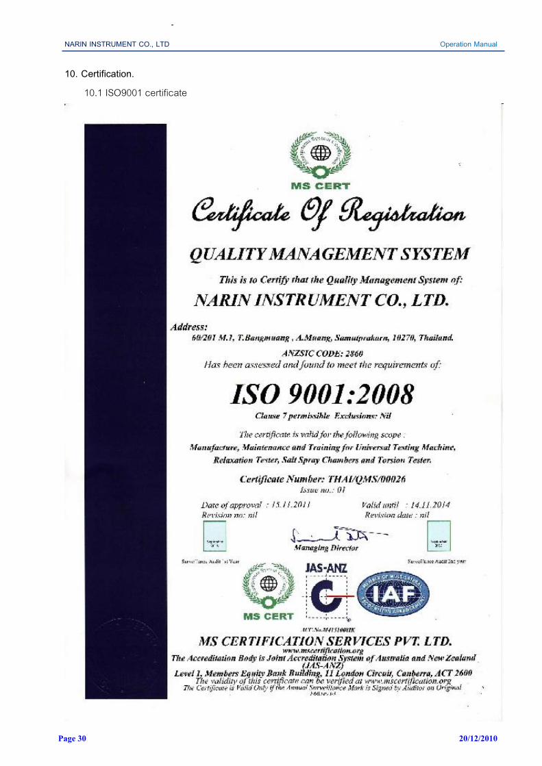
10. Certification. 10.1 ISO9001 certificate
NARIN INSTRUMENT CO., LTD Operation Manual
Page 31 20/12/2010
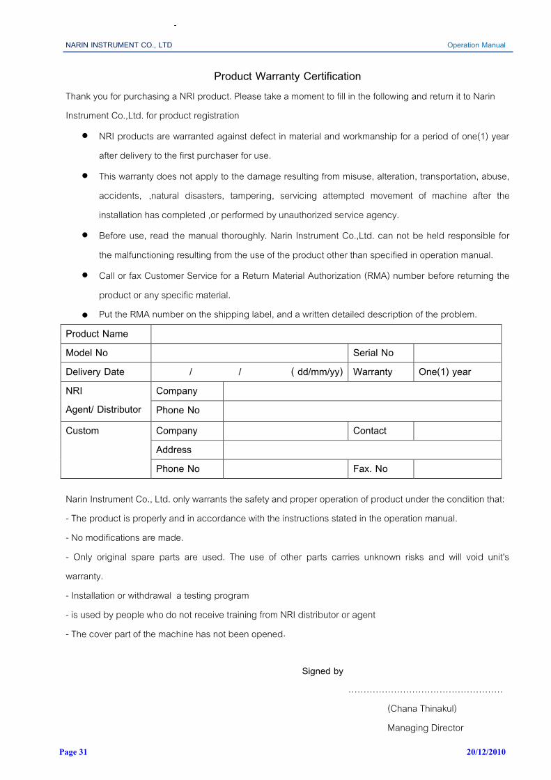
Product Warranty Certification Thank you for purchasing a NRI product. Please take a moment to fill in the following and return it to Narin Instrument Co.,Ltd. for product registration
NRI products are warranted against defect in material and workmanship for a period of one(1) year after delivery to the first purchaser for use.
This warranty does not apply to the damage resulting from misuse, alteration, transportation, abuse, accidents, ,natural disasters, tampering, servicing attempted movement of machine after the installation has completed ,or performed by unauthorized service agency.
Before use, read the manual thoroughly. Narin Instrument Co.,Ltd. can not be held responsible for the malfunctioning resulting from the use of the product other than specified in operation manual.
Call or fax Customer Service for a Return Material Authorization (RMA) number before returning the product or any specific material.
Put the RMA number on the shipping label, and a written detailed description of the problem. Product Name Model No Serial No Delivery Date / / ( dd/mm/yy) Warranty One(1) year NRI Agent/ Distributor
Company Phone No
Custom Company Contact Address Phone No Fax. No
Narin Instrument Co., Ltd. only warrants the safety and proper operation of product under the condition that: - The product is properly and in accordance with the instructions stated in the operation manual. - No modifications are made. - Only original spare parts are used. The use of other parts carries unknown risks and will void unit's warranty. - Installation or withdrawal a testing program - is used by people who do not receive training from NRI distributor or agent - The cover part of the machine has not been opened.
Signed by
…………………………………………… (Chana Thinakul) Managing Director

NARIN INSTRUMENT CO., LTD Operation Manual
Page 32 20/12/2010

NARIN INSTRUMENT CO., LTD Operation Manual
Page 33 20/12/2010

NARIN INSTRUMENT CO., LTD Operation Manual
Page 34 20/12/2010

NARIN INSTRUMENT CO., LTD Operation Manual
Page 35 20/12/2010

NARIN INSTRUMENT CO., LTD Operation Manual
Page 36 20/12/2010

NARIN INSTRUMENT CO., LTD Operation Manual
Page 37 20/12/2010
Appendix A


