Embed Size (px)
Citation preview

November 2017
Duck Island WWTF Improvements City of Lowell, MA
Hazen TOC-1
TABLE OF CONTENTS
DIVISION 00 00 00 – PROCUREMENT AND CONTRACTING REQUIREMENTS
Please refer Volume 3 submitted by Woodard & Curran for Division 00 00 00 Procurement and
Contracting Requirements
DIVISION 01 00 00 – GENERAL REQUIREMENTS
Section Title
01 35 43.13 Environmental Procedures for Hazardous Materials
Please refer to Volume 3 submitted by Woodard & Curran for a continuation of Division 01 00 00
General Requirements
DIVISION 02 00 00 – EXISTING CONDITIONS
Section Title
02 41 13 Selective Site Demolition
DIVISION 03 00 00 – CONCRETE
Section Title
03 15 00 Concrete Accessories
03 15 16 Concrete Construction Joints
03 60 00 Grouting
DIVISION 04 00 00 – MASONRY
Section Title
04 05 16 Mortar and Masonry Grout
04 05 23 Masonry Accessories
04 22 00 Concrete Unit Masonry
04 99 20 Masonry Restoration and Cleaning
DIVISION 05 00 00 – METALS
Section Title
05 05 35 Galvanizing
05 12 00 Structural Steel Framing
05 21 00 Steel Joist Framing
05 31 00 Steel Decking
05 51 33 Metal Ladders
05 55 00 Stair Treads and Nosings
05 56 00 Metal Castings
DIVISION 06 00 00 – WOOD, PLASTICS, AND COMPOSITES
Section Title
06 10 53 Miscellaneous Carpentry
06 60 00 Plastic Fabrications
November 2017
Duck Island WWTF Improvements City of Lowell, MA
Hazen TOC-2
DIVISION 07 00 00 – THERMAL AND MOISTURE PROTECTION
Section Title
07 11 00 Dampproofing
07 21 00 Thermal Insulation
07 26 00 Vapor Barrier
07 54 00 Thermoplastic Membrane Roofing (PVC or KEE)
07 60 00 Flashing and Sheet Metal
07 70 00 Roof Specialties and Accessories
07 84 00 Firestopping
DIVISION 08 00 00 – OPENINGS
Section Title
08 11 16 Aluminum Metal Doors
08 13 13 Hollow Metal Doors and Frames
08 70 00 Hardware
08 81 00 Glazing
08 91 00 Louvers and Dampers
DIVISION 09 00 00 – FINISHES
Section Title
09 30 13 Ceramic Tiling
09 51 23 Acoustical Tile Ceiling
09 90 00 Painting and Coating
09 97 10 Liquid Applied Water Repellents
DIVISION 10 00 00 – SPECIALTIES
Section Title
10 14 00 Signage
10 21 13 Toilet Compartments
10 43 16 First Aid Cabinet
10 44 16 Fire Extinguishers
10 50 00 Lockers
10 80 00 Toilet and Bath Accessories
DIVISION 22 00 00 – PLUMBING
Section Title
22 05 00 Overall Plumbing
November 2017
Duck Island WWTF Improvements City of Lowell, MA
Hazen TOC-3
DIVISION 23 00 00 – HEATING, VENTILATING AND AIR CONDITIONING (HVAC)
Section Title
23 05 93 HVAC Testing, Adjusting, and Balancing
23 09 00 Building Management System and Controls
23 09 93 Sequence of Operations
23 23 00 HVAC Copper and Brass Piping
23 31 13 Metallic Ductwork and Duct Accessories
23 31 16 FRP Ductwork and Duct Accessories
23 34 00 Fans
23 40 13 Positive Pressurization Units
23 73 13 Central Station Air Handler
23 75 00 Custom Heating and Ventilating Units
DIVISION 26 00 00 – ELECTRICAL
Section Title
26 05 04 Electrical Testing
26 05 53 Identification for Electrical System
26 24 16.12 Panelboards
26 50 00 Lighting System
DIVISION 31 00 00 – EARTHWORK
Section Title
31 05 16 Aggregates for Earthwork
31 05 19.13 Geotextiles for Earthwork
31 10 00 Site Clearing
31 23 16 Earthwork
31 25 00 Erosion and Sedimentation Controls
DIVISION 32 00 00 – EXTERIOR IMPROVEMENTS
Section Title
32 12 16 Asphalt Paving
32 91 19.13 Topsoil Placement and Grading
32 92 19 Seeding
DIVISION 40 00 00 – PROCESS INTERCONNECTIONS
Section Title
40 05 13.01 Basic Mechanical Requirements
40 05 13.02 Hangers and Supports for Process Piping
40 05 13.03 Piping and Equipment Identification Systems
40 05 13.73 PVC Pipe, Fittings and Valves
40 05 59.23 Stainless Steel Slide Gates
40 06 20 Piping and Tubing Schedules
40 91 23.36 Level Process Measurement Devices
DIVISION 41 00 00 – MATERIALS PROCESSING AND HANDLING EQUIPMENT
Section Title
41 12 13.36 Screw Bulk Material Conveyors
November 2017
Duck Island WWTF Improvements City of Lowell, MA
Hazen TOC-4
DIVISION 43 00 00 – PROCESS GAS AND LIQUID HANDLING, PURIFICATION AND
STORAGE EQUIPMENT
Section Title
43 41 43 High Density Polyethylene Storage Tanks
DIVISION 46 00 00 – WATER AND WASTEWATER EQUIPMENT
Section Title
46 00 00 Equipment General Provisions
46 33 44 Peristaltic (Tube) Pumps
November 2017
Duck Island WWTF Improvements City of Lowell, MA
Hazen Environmental Procedures for Hazardous Materials
01 35 43.13-1
SECTION 01 35 43.13
ENVIRONMENTAL PROCEDURES FOR
HAZARDOUS MATERIALS
PART 1 GENERAL
1.01 SECTION INCLUDES
A. Hazardous Waste Contingency Plan and Hazardous Waste Minimization Plan
B. Known Hazardous Materials
C. Unforeseen Hazardous Materials
D. Remediation Plan
E. Waste Management Records
F. Submittals
G. Payment
H. Hazardous Waste Tax
1.02 RELATED DOCUMENTS
A. Section 01 00 00 – General Requirements
1.03 DEFINITIONS
A. A competent person is one who is capable of identifying existing and predictable
hazards in the work area or unsanitary, hazardous, or dangerous working conditions,
and who has authority to take prompt corrective measures (29 CFR 1926.32(f)).
B. Large Quantity Generator - A facility that generates (in a calendar month) ≥1,000 kg
of total hazardous waste or >1 kg of acute hazardous waste or >100 kg of acute
hazardous waste spill residue or soil, or stores hazardous and acute hazardous wastes
in greater quantities (at any time) than ≤6,000 kg of hazardous waste, ≤1 kg acute
hazardous waste and ≤100 kg of acute hazardous waste spill residue or soil specified
for an SQG.
1.04 HAZARDOUS WASTE CONTINGENCY PLAN AND HAZARDOUS WASTE
MINIMIZATION PLAN
A. If the total hazardous waste generation of all Contracts under this project or all
projects on this site changes the site generator status to a Large Quantity Generator,
as determined by MassDEP, the Engineer will direct the Contractor to prepare a
Hazardous Waste Contingency Plan and a Hazardous Waste Minimization Plan.
1.05 KNOWN HAZARDOUS MATERIALS
A. With the exception of hazardous materials already stored and in operational use,
there are no other known hazardous materials present within the designated work
areas.
B. Prior to removing the Underground Diesel Storage Tank, the Contractor shall furnish
a qualified independent testing service approved by the Engineer to perform
November 2017
Duck Island WWTF Improvements City of Lowell, MA
Hazen Environmental Procedures for Hazardous Materials
01 35 43.13-2
assessments in accordance with 310 CMR 80.43(4). The inspection shall occur
within 24 hours after the existing Underground Storage Tank is removed, but prior
to backfill of the excavation area, to measure for the presence of a release of diesel
oil in the subsurface. The independent testing service shall provide test results
directly to the Owner and Engineer.
C. The contractor shall, in accordance with 310 CMR 80.43(3), remove the existing
Underground Storage Tank System including, without limitation, underground pipes
connected thereto that contain regulated substances. The Underground Storage Tank
System shall be evacuated of regulated substances prior to removal. Sections of
underground pipe that run underneath existing permanent structures do not require
removal and shall be permanently closed-in-place by filling the pipe with approved
inert material and capping both ends.
D. The Contractor shall furnish a registered professional civil or structural engineer to
prepare in accordance with 310 CMR 80.43(3) a determination of why sections of
the UST system underground pipe that run underneath existing permanent structures
should be closed-in-place instead of removed. The registered professional civil or
structural engineer shall submit the determination to the owner at least forty days
prior to removal of the Underground Storage Tank System.
1.06 UNFORESEEN HAZARDOUS MATERIAL
A. The possibility also exists of encountering unforeseen hazardous materials at
locations where their presence could not be ascertained prior to the performance of
the work. When this potential has been identified or an upgrade in health and safety
protocol is necessary for unforeseen hazardous materials, the Engineer will direct
the Contractor to engage the services of a Hazardous Materials Specialist to perform
the necessary investigation, develop the Remediation Plan, and perform the
remediation work. Additionally, the Engineer will direct the Contractor to update
its Environmental Health and Safety Plan as necessary.
B. The Contractor shall be responsible for identifying previously unknown and suspect
hazardous materials as they are encountered. Indication of the presence of hazardous
materials, such as odorous or stained soils, sediment or liquids, and asbestos
containing materials must be immediately reported to the Engineer. All work in the
area shall stop until otherwise directed by the Engineer.
C. The Engineer shall direct the Contractor to obtain cost proposals for the work, from
up to three separate MassDEP approved certified Hazardous Material Specialists,
and submit them in writing to the Engineer within ten (10) business days of receiving
the scope of work. The Engineer may select one proposal and direct the Contractor
to engage the selected remediation Hazardous Material Specialist as a subcontractor.
Remediation work shall not commence until the Contractor receives written notice
from the Engineer to proceed with the work.
D. No Contractor shall initiate or proceed with any work in areas associated with the
contaminated, potentially hazardous, or hazardous materials until these materials
have been removed from these areas or managed in accordance with applicable
guidelines.
November 2017
Duck Island WWTF Improvements City of Lowell, MA
Hazen Environmental Procedures for Hazardous Materials
01 35 43.13-3
E. Some of the remediation work may be critical to maintaining construction schedules.
When this occurs, the Engineer will establish a time of completion.
1.07 REMEDIATION PLAN
A. Remediation Plans for unforeseen hazardous materials shall comply with all
applicable requirements of federal, state, and local hazardous waste regulations and
shall include, but not be limited to:
1. Identification of hazardous and regulated/non-hazardous wastes associated
with the Work.
2. Estimated quantities of wastes to be generated and disposed of.
3. Names and qualifications of each sub-contractor that will be testing,
transporting, storing, and disposing of wastes. Include the facility location and
a 24-hr phone contact number and applicable transporter and TSDF permits,
EPA Identification Numbers, and insurance certificates.
4. Names and qualifications (experience and training) of personnel who will be
responsible for on site management of hazardous wastes.
5. Detailed description of the containment and removal procedures.
6. List of waste handling equipment to be used in performing the Work, to include
cleaning, volume reduction, and transport equipment.
7. Spill prevention and cleanup contingency measures to be implemented.
8. Work plan for waste management, on-site storage, removal and disposal.
9. Detailed schedule indicating the beginning and completion dates for each
activity and each work area, including time for clean-up, inspection, and
monitoring activities.
1.08 WASTE MANAGEMENT RECORDS
A. Disposal of wastes generated by either demolition, removal or remediation work will
be based on the results of testing and shall be at a site permitted to accept such waste
by the Environmental Protection Agency (EPA) or an authorized state or local
government agency. The Contractor shall provide waste profiles for DEP signature
as generator, permit documentation required for the selected Transportation, Storage
and Disposal Facility (TSDF) to receive these wastes, and the transporter’s Part 364
Waste Transporter Permit(s) required to transport wastes to the TSDF. The
Contractor shall also provide advance copies of the waste manifest(s) for the
Engineer’s review and approval.
B. The Contractor shall submit written evidence that selected TSDF’s will accept or
have accepted the wastes generated during demolition, removal and remediation.
The Contractor shall also submit copies of the completed manifest, signed and dated
by the initial transporter, in accordance with Federal and State requirements and with
associated documentation (e.g., Waste Profile and Hazardous Waste Land Disposal
Restrictions (LDR) Notification and Certification Form). Copies of completed and
signed waste manifests from TSDF’s shall be provided to the Engineer within seven
(7) days of waste shipment offsite.
November 2017
Duck Island WWTF Improvements City of Lowell, MA
Hazen Environmental Procedures for Hazardous Materials
01 35 43.13-4
1.09 SUBMITTALS
A. Six (6) copies of the following items shall be submitted to the Engineer:
1. Remediation Plan for Unforeseen Hazardous Materials
2. Proposals for remedial action work and evidence of disposal of hazardous and
non-hazardous waste at an approved facility in accordance with the
requirements of this section.
B. The Contractor, when requested by the Engineer, shall provide additional copies of
all reports and related materials as may be needed for conferences with the
-END OF SECTION-
November 2017
Duck Island WWTF Improvements City of Lowell, MA
Hazen Selective Site Demolition
02 41 13-1
SECTION 02 41 13
SELECTIVE SITE DEMOLITION
PART 1 -- GENERAL
1.01 THE REQUIREMENT
A. The Contractor shall demolish and remove all concrete, asphaltic, and gravel paving, curbs,
sidewalk, and miscellaneous yard structures as required and shown on the Contract
Drawings during the construction work.
1.02 RELATED WORK SPECIFIED ELSEWHERE
A. Section 01 42 19 - Reference Standards
B. Section 01 11 05 – Overall General Requirements
C. Section 31 05 16 – Aggregates for Earthwork
1.03 REFERENCE SPECIFICATIONS, CODES, AND STANDARDS
A. References shall be in accordance with reference standards, codes, and specifications as
set forth herein and in Section 31 10 00 – Site Clearing.
PART 2 -- EXECUTION
2.01 DEMOLITION
A. Existing concrete and asphaltic paving, curbs, sidewalk and miscellaneous yard structures
within the areas designated for new construction work shall be completely demolished and
all debris removed from the site.
B. Excavation caused by demolition shall be backfilled with select fill free from rubbish and
debris, as per specification 31 23 16.
C. Work shall be performed in such manner as not to endanger the safety of the workmen or
the public or cause damage to nearby structures.
D. Provide all barriers and precautionary measures in accordance with Owner's requirements
and other authorities having jurisdiction.
November 2017
Duck Island WWTF Improvements City of Lowell, MA
Hazen Selective Site Demolition
02 41 13-2
E. Where parts of existing structures or pavements are to remain in service, demolish the
portions to be removed, repair damage, and leave the structure or pavement in proper
condition for the intended use. Remove asphalt, concrete, and masonry to the lines
designated by drilling, chipping, or other suitable methods. Leave the resulting surfaces
reasonably true and even, with sharp straight corners that will result in neat joints with new
construction and be satisfactory for the purpose intended. Where existing reinforcing rods
are to extend into new construction, remove the concrete so that the reinforcing is clean
and undamaged. Cut off other reinforcing 1/2-inch below the surface and fill with epoxy
resin binder flush with the surface.
F. Prior to the execution of the work, the Contractor, Owner and Engineer shall jointly survey
the condition of the adjoining and/or nearby structures and pavements. Photographs and
records shall be made of any prior settlement or cracking of structures, pavements, and the
like, that may become the subject of possible damage claims.
2.02 DISPOSAL OF MATERIAL
A. All debris resulting from the demolition and removal work shall be disposed of by the
Contractor as part of the work of this Contract. Material designated by the Engineer to be
salvaged shall be stored on the construction site as directed. All other material shall be
disposed of off site at a properly permitted facility by the Contractor at his expense.
B. Burning of any debris resulting from the demolition will not be permitted at the site.
- END OF SECTION -
November 2017
Duck Island WWTF Improvements City of Lowell, MA
Hazen Concrete Accessories
03 15 00-1
SECTION 03 15 00
CONCRETE ACCESSORIES
PART 1 -- GENERAL
1.01 THE REQUIREMENT
A. Furnish all materials, labor and equipment required to provide all concrete accessories
including waterstops, expansion joint material, joint sealants, expansion joint seals,
contraction joint inserts, and epoxy bonding agent.
1.02 RELATED WORK SPECIFIED ELSEWHERE
A. Section 03 11 00 – Concrete Forming
B. Section 03 15 16 – Concrete Construction Joints
C. Section 03 30 00 – Cast-in-Place Concrete
D. Section 07 92 00 – Joint Sealants
1.03 REFERENCE SPECIFICATIONS, CODES AND STANDARDS
A. Without limiting the generality of the other requirements of the specifications, all work
herein shall conform to the applicable requirements of the following documents. All
referenced specifications, codes, and standards refer to the most current issue available at the
time of Bid.
1. ASTM C881 Standard Specification for Epoxy-Resin-Base Bonding Systems
for Concrete
2. ASTM D412 Standard Tests for Rubber Properties in Tension
3. ASTM D 624 Standard Test method for Rubber Property - Tear Resistance
4. ASTM D 638 Standard Test Method for Tensile Properties of Plastics
November 2017
Duck Island WWTF Improvements City of Lowell, MA
Hazen Concrete Accessories
03 15 00-2
5. ASTM D1751 Standard Specifications for Preformed Expansion Joint fillers for
Concrete Paving and Structural Construction (nonextruding and
resilient bituminous types)
6. ASTM D 1752 Standard Specification for Preformed Sponge Rubber and Cork
Expansion Joint Fillers for Concrete Paving and Structural
Construction
7. ASTM D 1171 Standard Test Method for Ozone Resistance at 500 pphm
8. ASTM D 471 Standard Test Method for Rubber Properties
1.04 SUBMITTALS
A. Submit the following in accordance with Division 01 00 00, General Requirements.
1. Manufacturer's literature on all products specified herein including material
certifications.
2. Proposed system for supporting PVC waterstops in position during concrete
placement
3. Samples of products if requested by the Engineer.
PART 2 -- PRODUCTS
2.01 POLYVINYL CHLORIDE (PVC) WATERSTOPS
A. PVC waterstops for construction joints shall be flat ribbed type, 6 inches wide with a
minimum thickness at any point of 3/8 inches.
B. Waterstops for expansion joints shall be ribbed with a center bulb. They shall be 9 inches
wide with a minimum thickness at any point of 3/8 inch unless shown or specified otherwise.
The center bulb shall have a minimum outside diameter of 1 inch and a minimum inside
diameter of 1/2 inch.
C. The waterstops shall be manufactured from virgin polyvinyl chloride plastic compound and
shall not contain any scrap or reclaimed material or pigment whatsoever. The properties of
the polyvinyl chloride compound used, as well as the physical properties of the waterstops,
shall exceed the requirements of the U.S. Army Corps. of Engineers' Specification
CRD-C572. The waterstop material shall have an off-white, milky color.
03
04
15
BR
November 2017
Duck Island WWTF Improvements City of Lowell, MA
Hazen Concrete Accessories
03 15 00-3
D. The required minimum physical characteristics for this material are:
1. Tensile strength - 1,750 psi (ASTM D-638).
2. Ultimate elongation - not less than 280% (ASTM D-638).
E. No reclaimed PVC shall be used for the manufacturing of the waterstops. The Contractor
shall furnish certification that the proposed waterstops meet the above requirements.
F. PVC waterstops shall be as manufactured by BoMetals, Inc., DuraJoint Concrete
Accessories, or Sika Greenstreak.
G. All waterstop intersections, both vertical and horizontal, shall be made from factory
fabricated corners and transitions. Only straight butt joint splices shall be made in field.
2.02 RETROFIT WATERSTOPS
A. Retrofit waterstops shall be used where specifically shown on Drawings for sealing joints
between existing concrete construction and new construction.
B. Retrofit waterstops shall be PVC waterstops fabricated from material as described in Section
2.01 of this Specification.
C. Retrofit waterstop shall be attached to existing concrete surface as shown on Drawings.
D. Use of split waterstop in lieu of specially fabricated retrofit waterstop will not be acceptable.
E. Retrofit Waterstop manufacturer must provide a complete system including all Waterstop,
stainless steel anchoring hardware, and epoxy for installation.
F. For construction joints, retrofit waterstop shall be style number 609 by Sika Greenstreak, RF-
638 by BoMetals, Inc., Type 18 kit by DuraJoint Concrete Accessories, or approved equal.
For expansion joints, retrofit waterstop shall be style number 667 by Sika Greenstreak, Type
18-9 kit by DuraJoint Concrete Accessories, or approved equal.
2.03 CHEMICAL RESISTANT WATERSTOPS
A. Where specifically noted on Contract Drawings, chemical resistant waterstops shall be used
instead of PVC waterstops.
B. Chemical resistant waterstops for construction joints shall be ribbed with a center bulb. They
shall be 6 inches wide with a minimum thickness at any point of 3/16 inches.
November 2017
Duck Island WWTF Improvements City of Lowell, MA
Hazen Concrete Accessories
03 15 00-4
C. Chemical resistant waterstops for expansion joints shall be ribbed tear web. They shall be 9
inches wide with a tear web designed to accommodate 1 inch of free movement minimum.
D. Chemical resistant retrofit waterstop shall be a minimum of 2½” wide along the ribbed side
and a minimum 5” wide along the side attached to the existing concrete surface. Retrofit
waterstop shall include a centerbulb and shall have a minimum thickness of 3/16”. Retrofit
waterstop manufacturer shall provide a complete system including waterstop, stainless steel
anchoring hardware and epoxy for installation.
E. Chemical resistant waterstops shall be manufactured from a fully crosslinked thermoplastic
vulcanizate rubber.
F. Waterstops shall be TPE-R by BoMetals, Inc., Earth Shield TPV/TPE-R by JP Specialties,
Inc., Westec TPE-R by Westec Barrier Technologies, or TPE-R by DuraJoint Concrete
Accessories.
2.04 HYPALON RUBBER WATERSTOPS
A. Hypalon rubber waterstops shall be Sikadur Combiflex by Sika Corporation or approved
equal. Minimum width of waterstop material shall be twelve (12) inches unless shown
otherwise on Contract Drawings.
2.05 EXPANDING RUBBER WATERSTOP
A. Expanding rubber shall be designed to expand under hydrostatic conditions. Waterstops
shall be Adeka Ultra Seal MC-2010M by Adeka Ultra Seal/OCM, Inc., or Hydrotite CJ-
1020-2K by Sika Greenstreak, for concrete thickness greater than nine inches. For
thicknesses less than nine inches, Adeka Ultra Seal KBA-1510FF or Hydrotite CJ-1020-2K
shall be used.
B. Waterstop shall be a chemically modified natural rubber product with a hydrophilic agent.
C. Waterstop has a stainless steel mesh or coextrusion of non-hydrophilic rubber to direct
expansion in the thickness direction and restrict the expansion in the longitudinal direction.
November 2017
Duck Island WWTF Improvements City of Lowell, MA
Hazen Concrete Accessories
03 15 00-5
2.06 WATERSTOP ADHESIVE
A. Adhesive between waterstops and existing concrete shall be 20+F Contact Cement by
Miracle Adhesives Corporation, Neoprene Adhesive 77-198 by JGF Adhesives, Sikadur 31
Hi-Mod Gel by Sika Corporation, DP-605 NS Urethane Adhesive by 3M Adhesive Systems.
B. Hydrophilic, non-bentonite water swelling elastic sealant shall be used to bond expanding
rubber waterstops to rough surfaces. Hydrophilic elastic sealant shall be P-201 by Adeka
Ultra Seal/OCM, Inc., Leakmaster LV-1 by Sika Greenstreak, or approved equal.
2.07 JOINT SEALANTS
A. Joint sealants shall comply with Section 07 92 00, Joint Sealants.
2.08 EXPANSION JOINT MATERIAL
A. Preformed expansion joint material shall be non-extruding, and shall be of the following
types:
1. Type I - Sponge rubber, conforming to ASTM D1752, Type I.
2. Type II - Cork, conforming to ASTM D1752, Type II.
3. Type III - Self-expanding cork, conforming to ASTM D1752, Type III.
4. Type IV - Bituminous fiber, conforming to ASTM Designation D1751.
2.09 EXPANSION JOINT SEAL
A. Expansion Joint Seal System shall consist of a preformed neoprene profile, installed using
the same dimensions as the joint gap, bonded with a two-component epoxy adhesive and
pressurized during the adhesive cure time.
B. The expansion joint system shall be Hydrozo/Jeene Structural Sealing joint system by
Hydrozo/Jeene, Inc.
2.10 CONTRACTION JOINT INSERTS
A. Contraction joint inserts shall be ZipCap Control Joint former by Greenstreak Plastic
Products.
November 2017
Duck Island WWTF Improvements City of Lowell, MA
Hazen Concrete Accessories
03 15 00-6
2.11 EPOXY BONDING AGENT
A. Epoxy bonding agent shall conform to ASTM C881 and shall be Sikadur 32 Hi-Mod, Sika
Corporation, Lyndhurst, N.J.; Euco #452 Epoxy System, Euclid Chemical Company,
Cleveland, OH, MasterInject 1500 by BASF Master Builder Solutions (BASF).
2.12 EPOXY RESIN BINDER
A. Epoxy resin binder shall conform to the requirements of ASTM C-881, Type III, Grade 3,
Class B and C for epoxy resin binder and shall be Sikadur 23, Low-Mod-Gel, manufactured
by the Sika Corporation, Lyndhurst, N.J., Flexocrete Gel manufactured by DuraJoint
Concrete Accessories or Euco #352 Gel, Euclid Chemical Company, MasterEmaco ADH
327 or 327 RS by BASF Master Builder Solutions.
PART 3 -- EXECUTION
3.01 PVC AND CHEMICAL RESISTANT WATERSTOPS
A. PVC and chemical resistant waterstops shall be provided in all construction and expansion
joints in water bearing structures and at other such locations as required by the Drawings.
B. Waterstops shall be carefully positioned so that they are embedded to an equal depth in
concrete on both sides of the joint. They shall be kept free from oil, grease, mortar or other
foreign matter. To ensure proper placement, all waterstops shall be secured in correct
position at 12" on center along the length of the waterstop on each side, prior to placing
concrete. Such method of support shall be submitted to the Engineer for review and
approval. Grommets or small pre-punched holes as close to the edges as possible will be
acceptable for securing waterstops.
C. Splices in PVC waterstops and chemical resistant waterstops shall be made with a
thermostatically controlled heating element. Only straight butt joint splices will be allowed in
the field. Factory fabricated corners and transitions shall be used at all intersections. Splices
shall be made in strict accordance with the manufacturer's recommended instructions and
procedures. At least three satisfactory sample splices shall be made on the site. The
Engineer may require tests on these splices by an approved laboratory. The splices shall
exhibit not less than 80 percent of the strength of the unspliced material.
D. All splices in waterstops will be subject to rigid review for misalignment, bubbles,
inadequate bond, porosity, cracks, offsets, discoloration, charring, and other defects which
would reduce the potential resistance of the material to water pressure at any point. All
defective joints shall be replaced with material which will pass said review and all faulty
material shall be removed from the site and disposed of by the Contractor at no additional
cost to the Owner.
November 2017
Duck Island WWTF Improvements City of Lowell, MA
Hazen Concrete Accessories
03 15 00-7
E. Retrofit waterstops shall be installed as shown on Contract Drawings using approved
waterstop adhesive and Type 316 stainless steel batten bars and expansion anchors.
F. Waterstop installation and splicing defects which are unacceptable include, but are not
limited to the following:
1. Tensile strength not less than 80 percent of parent material.
2. Overlapped (not spliced) Waterstop.
3. Misalignment of Waterstop geometry at any point greater than 1/16 inch.
4. Visible porosity or charred or burnt material in weld area.
5. Visible signs of splice separation when splice (24 hours or greater) is bent by hand at
sharp angle.
3.02 HYPALON RUBBER AND EXPANDING RUBBER WATERSTOPS
A. Waterstops shall be installed only where shown on the Drawings.
B. Waterstops shall be installed in strict accordance with manufacturer's recommendations.
3.03 WATERSTOP ADHESIVE
A. Adhesive shall be applied to both contact surfaces in strict accordance with manufacturer's
recommendations.
B. Adhesive shall be used where waterstops are attached to existing concrete surfaces.
3.04 INSTALLATION OF EXPANSION JOINT MATERIAL AND SEALANTS
A. Type I, II, or III shall be used in all expansion joints in structures and concrete pavements
unless specifically shown otherwise on the Drawings. Type IV shall be used in sidewalk and
curbing and other locations specifically shown on the Drawings.
B. All expansion joints exposed in the finish work, exterior and interior, shall be sealed with the
specified joint sealant. Expansion joint material and sealants shall be installed in accordance
with manufacturer's recommended procedures and as shown on the Drawings.
November 2017
Duck Island WWTF Improvements City of Lowell, MA
Hazen Concrete Accessories
03 15 00-8
C. Expansion joint material that will be exposed after removal of forms shall be cut and
trimmed to ensure a neat appearance and shall completely fill the joint except for the space
required for the sealant. The material shall be held securely in place and no concrete shall be
allowed to enter the joint or the space for the sealant and destroy the proper functions of the
joint.
D. A bond breaker shall be used between expansion joint material and sealant. The joint shall
be thoroughly clean and free from dirt and debris before the primer and the sealant are
applied. Where the finished joint will be visible, masking of the adjoining surfaces shall be
carried out to avoid their discoloration. The sealant shall be neatly tooled into place and its
finished surfaces shall present a clean and even appearance.
E. Type 1 joint sealant shall be used in all expansion and contraction joints in concrete, except
where Type 7 or Type 8 is required as stated below, and wherever else specified or shown on
the Drawings. It shall be furnished in pour grade or gun grade depending on installation
requirements. Primers shall be used as required by the manufacturer. The sealant shall be
furnished in colors as directed by the Engineer.
F. Type 8 joint sealant shall be used in all concrete pavements and floors subject to heavy traffic
and wherever else specified or shown on the Drawings.
G. Type 7 joint sealant shall be used for all joints in chlorine contact tanks and wherever
specified or shown on the Drawings.
3.05 EXPANSION JOINT SEAL
A. The expansion joint seal system shall be installed as shown on the Drawings in strict
accordance with the manufacturer's recommendations.
3.06 CONTRACTION JOINT INSERTS
A. For contraction joints in slabs, inserts shall be floated in fresh concrete during finishing.
B. For contraction joints in walls, inserts shall be secured in place prior to casting wall.
C. Inserts shall be installed true to line at the locations of all contraction joints as shown on the
Drawings.
D. Inserts shall extend into concrete sufficient depth as indicated on the Drawings or specified
in Section 03 15 16, Concrete Construction Joints.
November 2017
Duck Island WWTF Improvements City of Lowell, MA
Hazen Concrete Accessories
03 15 00-9
E. Inserts shall not be removed from concrete until concrete has cured sufficiently to prevent
chipping or spalling of joint edges due to inadequate concrete strength.
3.07 EPOXY BONDING AGENT
A. The Contractor shall use an epoxy bonding agent for bonding fresh concrete to existing
concrete as shown on the Drawings.
B. Bonding surface shall be clean, sound and free of all dust, laitance, grease, form release
agents, curing compounds, and any other foreign particles.
C. Application of bonding agent shall be in strict accordance with manufacturer's
recommendations.
D. Fresh concrete shall not be placed against existing concrete if epoxy bonding agent has lost
its tackiness.
3.08 EPOXY RESIN BINDER
A. Epoxy resin binder shall be used to seal all existing rebar cut and burned off during
demolition operations. Exposed rebar shall be burned back 1/2-inch minimum into existing
concrete and the resulting void filled with epoxy resin binder.
- END OF SECTION –

November 2017
Duck Island WWTF Improvements City of Lowell, MA
Hazen Concrete Accessories
03 15 00-10
- THIS PAGE INTENTIONALLY LEFT BLANK -
November 2017
Duck Island WWTF Improvements City of Lowell, MA
Hazen Concrete Construction Joints
03 15 16-1
SECTION 03 15 16
CONCRETE CONSTRUCTION JOINTS
PART 1 -- GENERAL
1.01 THE REQUIREMENTS
A. Provide all materials, labor and equipment required for the construction of all joints in
concrete specified herein and shown on the Drawings.
B. Types of joints in concrete shall be as follows:
1. Construction Joints - Joints between adjacent concrete placements continuously
connected with reinforcement.
2. Expansion Joints - Joints in concrete which allow thermal expansion and contraction
of concrete. Reinforcement terminates within concrete on each side of joint.
3. Contraction Joints - Joints formed in concrete to provide a weakened plane in
concrete section to control formation of shrinkage cracks.
1.02 RELATED WORK SPECIFIED ELSEWHERE
A. Section 03 11 00 - Concrete Forming
B. Section 03 15 00 - Concrete Accessories
C. Section 03 30 00 - Cast-in-Place Concrete
D. Section 07 92 00 - Joint Sealants
1.03 REFERENCE SPECIFICATIONS, CODES AND STANDARDS
A. Without limiting the generality of the other requirements of the specifications, all work
herein shall conform to the applicable requirements of the following documents. All
referenced specifications, codes, and standards refer to the most current issue available at the
time of Bid.
1. ACI 301 - Specifications for Structural Concrete for Buildings
03
07
17
BR
November 2017
Duck Island WWTF Improvements City of Lowell, MA
Hazen Concrete Construction Joints
03 15 16-2
2. ACI 318 - Building Code Requirements for Structural Concrete
3. ACI 350 – Code Requirements for Environmental Engineering Concrete Structures
4. ACI 224.3 – Joints in Concrete Construction
1.04 SUBMITTALS
A. Submit the following in accordance with Division 01 00 00, General Requirements.
1. Layout drawings showing location and type of all joints to be placed in each
structure.
2. Details of proposed joints in each structure.
3. For sawcut contraction joints submit documentation indicating the following:
a. Proposed method of sawcutting indicating early entry or conventional sawing.
b. Description of how work is to be performed including equipment to be
utilized, size of crew performing the work and curing methods.
c. Description of alternate method in case of time constraint issues or failure of
equipment.
PART 2 -- MATERIALS
2.01 MATERIALS
A. All materials required for joint construction shall comply with Section 03 15 00 - Concrete
Accessories, and Section 07 92 00 - Joint Sealants.
PART 3 -- EXECUTION
3.01 CONSTRUCTION JOINTS
A. Construction joints shall be as shown on the Drawings. Otherwise, Contractor shall submit
description of the joint and its location to Engineer for approval.
November 2017
Duck Island WWTF Improvements City of Lowell, MA
Hazen Concrete Construction Joints
03 15 16-3
B. Unless noted otherwise on the Drawings, construction joints shall be located near the middle
of the spans of slabs, beams, and girders unless a beam intersects a girder at this point. In
this case, the joints in the girders shall be offset a distance equal to twice the width of the
beam. Joints in walls and columns shall be at the underside of floors, slabs, beams, or
girders and the top of footings or floor slabs unless noted otherwise on Drawings. Beams,
girders, brackets, column capitals, haunches, and drop panels shall be placed at the same time
as slabs. Joints shall be perpendicular to the main reinforcement.
C. Maximum distance between horizontal joints in slabs and vertical joints in walls shall be
45'-0". For exposed walls with fluid or earth on the opposite side, the spacing between
vertical and horizontal joints shall be a maximum of 25’-0”.
D. All corners shall be part of a continuous placement, and should a construction joint be
required, the joint shall not be located closer than five feet from a corner.
E. All reinforcing steel and welded wire fabric shall be continued across construction joints.
Keys and inclined dowels shall be provided as shown on the Drawings or as directed by the
Engineer. Longitudinal keys shall be provided in all joints in walls and between walls and
slabs or footings, except as specifically noted otherwise on the Drawings. Size of keys shall
be as shown on the Drawings.
F. All joints in water bearing structures shall have a waterstop. All joints below grade in walls
or slabs which enclose an accessible area shall have a waterstop.
3.02 EXPANSION JOINTS
A. Size and location of expansion joints shall be as shown on the Drawings.
B. All expansion joints in water-bearing structures shall have a center-bulb type waterstop. All
expansion joints below grade in walls or slabs which enclose an accessible area shall have a
center-bulb type waterstop. Waterstop shall be as shown on Drawings and specified in
Section 03 15 00, Concrete Accessories.
3.03 CONTRACTION JOINTS
A. Location of contraction joints shall be as shown on the Drawings.
B. Contraction joints shall be formed either by sawcutting or with contraction joint inserts as
specified in Section 03 15 00, Concrete Accessories. Sawcutting of joints will not be
permitted unless specifically approved by the Engineer.
November 2017
Duck Island WWTF Improvements City of Lowell, MA
Hazen Concrete Construction Joints
03 15 16-4
C. If approved by the Engineer, sawcutting of contraction joints in lieu of forming shall conform
to the following requirements:
1. Joints shall be sawed as soon as the concrete can support foot traffic without leaving
any impression, normally the same day as concrete is placed and in no case longer
than 24 hours after concrete is placed.
2. Curing shall be performed using wet curing methods as indicated in Section 03 30 20
– Concrete Placing, Curing, and Finishing. Curing mats, fabrics or sheeting materials
shall remain in place to the extent possible while cutting of joint is being performed.
Curing materials shall only be removed as required and shall be immediately
reinstalled once cutting of the joint has been completed.
3. Depth of joint shall be as shown on the drawings or noted in these specifications. At
locations where the joint cannot be installed to full depth due to curbs or other
stopping points hand tools shall be used to complete joints.
4. Saw cut joints shall meet the requirements of ACI 224.3, Section 2.8, Jointing
Practice.
D. Unless noted otherwise on Drawings, depth of contraction joints shall be 1-1/2 inches in
reinforced concrete and 1/3 of concrete thickness in unreinforced concrete.
3.04 JOINT PREPARATION
A. No concrete shall be allowed to enter the joint or the space for the sealant and destroy the
proper functions of the joint.
B. The surface of the concrete at all joints shall be thoroughly cleaned and all laitance removed
by wire brushing, air or light sand blasting.
C. The joint shall be thoroughly clean and free from dirt and debris before the primer and the
sealant are applied. Where the finished joint will be visible, masking of the adjoining
surfaces shall be carried out to avoid their discoloration. The sealant shall be neatly tooled
into place and its finished surface shall present a clean and even appearance.
D. All joints shall be sealed as shown on the Drawings and specified in Section 03 15 00,
Concrete Accessories.
- END OF SECTION -
November 2017
Duck Island WWTF Improvements City of Lowell, MA
Hazen Grouting
03 60 00-1
SECTION 03 60 00
GROUTING
PART 1 -- GENERAL
1.01 THE REQUIREMENT
A. Furnish all materials, labor, and equipment required to provide all grout used in concrete
work and as bearing surfaces for base plates, in accordance with the Contract Documents.
1.02 RELATED WORK SPECIFIED ELSEWHERE
A. Requirements of related work are included in Division 01 00 00 and Division 02 00 00 of
these Specifications.
1.03 REFERENCE SPECIFICATIONS, CODES AND STANDARDS
A. Without limiting the generality of the other requirements of the specifications, all work
herein shall conform to the applicable requirements of the following documents. All
referenced specifications, codes, and standards refer to the most current issue available at the
time of Bid.
1. CRD-C 621 Corps of Engineers Specification for Non-shrink Grout
2. ASTM C 109 Standard Test Method for Compressive Strength of Hydraulic
Cement Mortars (Using 2 inch or 50 mm cube Specimens)
3. ASTM C 531 Standard Test Method for Linear Shrinkage and Coefficient of
Thermal Expansion of Chemical-Resistant Mortars, Grouts
and Monolithic Surfacings
4. ASTM C 579 Test Method for Compressive Strength of Chemical-Resistant
Mortars and Monolithic Surfacings
5. ASTM C 827 Standard Test Method for Early Volume Change of
Cementitious Mixtures
6. ASTM C 144 Standard Specification for Aggregate for Masonry Mortar
04
04
16
BR
November 2017
Duck Island WWTF Improvements City of Lowell, MA
Hazen Grouting
03 60 00-2
7. ASTM C 1107 Standard Specification for Packaged Dry, Hydraulic Cement
Grout (Nonshrink)
1.04 SUBMITTALS
A. Submit the following in accordance with Division 01 00 00, General Requirements.
1. Certified test results verifying the compressive strength and shrinkage and expansion
requirements specified herein.
2. Manufacturer's literature containing instructions and recommendations on the
mixing, handling, placement and appropriate uses for each type of grout used in the
work.
1.05 QUALITY ASSURANCE
A. Field Tests
1. Compression test specimens will be taken during construction from the first
placement of each type of grout and at intervals thereafter as selected by the Engineer
to insure continued compliance with these Specifications. The specimens will be
made by the Engineer or its representative.
a. Compression tests and fabrication of specimens for cement grout and non-
shrink grout will be performed as specified in ASTM C 109 at intervals
during construction as selected by the Engineer. A set of three specimens
will be made for testing at seven days, 28 days and any additional time period
as appropriate.
b. Compression tests and fabrication of specimens for epoxy grout will be
performed as specified in ASTM C 579, Method B, at intervals during
construction as selected by the Engineer. A set of three specimens will be
made for testing at seven days and any other time period as appropriate.
2. The cost of all laboratory tests on grout will be borne by the Contractor. The
Contractor shall assist the Engineer in obtaining specimens for testing. The
Contractor shall be charged for the cost of any additional tests and investigation on
work performed which does not meet the specifications. The Contractor shall supply
all materials necessary for fabricating the test specimens, at no additional cost to the
Owner.
November 2017
Duck Island WWTF Improvements City of Lowell, MA
Hazen Grouting
03 60 00-3
3. All grout, already placed, which fails to meet the requirements of these
Specifications, is subject to removal and replacement at no additional cost to the
Owner.
PART 2 -- PRODUCTS
2.01 MATERIALS
A. Cement Grout
1. Cement grout shall be composed of Portland Cement and sand in the proportion
specified in the Contract Documents and the minimum amount of water necessary to
obtain the desired consistency. If no proportion is indicated, cement grout shall
consist of one part Portland Cement to three parts sand. Water amount shall be as
required to achieve desired consistency without compromising strength requirements.
White Portland Cement shall be mixed with the Portland Cement as required to
match color of adjacent concrete.
2. The minimum compressive strength at 28 days shall be 4000 psi.
3. For beds thicker than 1-1/2 inch and/or where free passage of grout will not
be obstructed by coarse aggregate, 1-1/2 parts of coarse aggregate having a top size of
3/8 inch should be added. This stipulation does not apply for grout being swept in by
a mechanism. These applications shall use a plain cement grout without coarse
aggregate regardless of bed thickness.
4. Sand shall conform to the requirements of ASTM C33.
B. Non-Shrink Grout
1. Non-shrink grout shall conform to CRD-C 621 and ASTM C 1107, Grade B or C
when tested at a max. fluid consistency of 30 seconds per CDC 611/ASTM C939 at
temperature extremes of 45°F and 90°F and an extended working time of 15 minutes.
Grout shall have a min. 28-day strength of 7,000 psi. Non-shrink grout shall be,
"Euco N-S" by the Euclid Chemical Company, "Sikagrout 212" by Sika Corporation,
“Conspec 100 Non-Shrink Non-Metallic Grout” by Conspec, “Masterflow 555
Grout” by BASF Master Builder Solutions.
November 2017
Duck Island WWTF Improvements City of Lowell, MA
Hazen Grouting
03 60 00-4
C. Epoxy Grout
1. Epoxy grout shall be "Sikadur 32 Hi-Mod" by Sika Corporation, "Duralcrete LV" by
Tamms Industries, or "Euco #452 Series" by Euclid Chemical, “MasterEmaco ADH
1090 RS” by BASF Master Builder Solutions.
2. Epoxy grout shall be modified as required for each particular application with
aggregate per manufacturer's instructions.
D. Epoxy Base Plate Grout
1. Epoxy base plate grout shall be “Sikadur 42, Grout-Pak” by Sika Corporation, or
“Masterflow 648” by BASF Master Builder Solutions.
2.02 CURING MATERIALS
A. Curing materials shall be as specified in Section 03 30 20, Concrete Placing, Curing, and
Finishing for cement grout and as recommended by the manufacturer for prepackaged grouts.
PART 3 -- EXECUTION
3.01 GENERAL
A. The different types of grout shall be used for the applications stated below unless noted
otherwise in the Contract Documents. Where grout is called for in the Contract Documents
which does not fall under any of the applications stated below, non-shrink grout shall be used
unless another type is specifically referenced.
1. Cement grout shall be used for grout toppings and for patching of fresh concrete.
2. Non-shrink grout shall be used for grouting beneath base plates of structural metal
framing.
3. Epoxy grout shall be used for bonding new concrete to hardened concrete.
4. Epoxy base plate grout shall be used for precision seating of base plates including
base plates for all equipment such as engines, mixers, pumps, vibratory and heavy
impact machinery, etc.
November 2017
Duck Island WWTF Improvements City of Lowell, MA
Hazen Grouting
03 60 00-5
B. New concrete surfaces to receive cement grout shall be as specified in Section 03 30 20,
Concrete Placing, Curing, and Finishing, and shall be cleaned of all dirt, grease and oil-like
films. Existing concrete surfaces shall likewise be cleaned of all similar contamination and
debris, including chipping or roughening the surface if a laitance or poor concrete is evident.
The finish of the grout surface shall match that of the adjacent concrete. Curing and
protection of cement grout shall be as specified in Section 03 30 20, Concrete Placing,
Curing, and Finishing.
C. All mixing, surface preparation, handling, placing, consolidation, and other means of
execution for prepackaged grouts shall be done according to the instructions and
recommendations of the manufacturer.
D. The Contractor, through the manufacturer of a non-shrink grout and epoxy grout, shall
provide on-site technical assistance upon request, at no additional cost to the Owner.
3.02 CONSISTENCY
A. The consistency of grouts shall be that necessary to completely fill the space to be grouted for
the particular application. Dry pack consistency is such that the grout is plastic and moldable
but will not flow.
3.03 MEASUREMENT OF INGREDIENTS
A. Measurements for cement grout shall be made accurately by volume using containers.
Shovel measurement shall not be allowed.
B. Prepackaged grouts shall have ingredients measured by means recommended by the
manufacturer.
3.04 GROUT INSTALLATION
A. Grout shall be placed quickly and continuously, shall completely fill the space to be grouted
and be thoroughly compacted and free of air pockets. The grout may be poured in place,
pressure grouted by gravity, or pumped. The use of pneumatic pressure or dry-packed
grouting requires approval of the Engineer. For grouting beneath base plates, grout shall be
poured from one side only and thence flow across to the open side to avoid air-entrapment.
- END OF SECTION -

November 2017
Duck Island WWTF Improvements City of Lowell, MA
Hazen Grouting
03 60 00-6
- THIS PAGE INTENTIONALLY LEFT BLANK -
November 2017
Duck Island WWTF Improvements City of Lowell, MA
Hazen Mortar and Masonry Grout
04 05 16-1
SECTION 04 05 16
MORTAR AND MASONRY GROUT
PART 1 -- GENERAL
1.01 REQUIREMENTS
A. Furnish labor, materials, equipment and appliances required for complete execution of Work
shown on Drawings and specified herein.
B. Principal items of work include:
1. Mortar for unit masonry work.
2. Grout for grouting masonry.
3. Mortar for pointing and touchup.
1.02 RELATED WORK SPECIFIED ELSEWHERE
A. Section 04 05 23 – Masonry Accessories.
B. Section 04 22 00 – Concrete Unit Masonry.
1.03 REFERENCE SPECIFICATIONS, CODES, AND STANDARDS
A. Without limiting the generality of the Specifications, the Work shall conform to the
applicable requirements of the following documents:
1. ASTM C91 Standard Specification for Masonry Cement.
2. ASTM C144 Standard Specification for Aggregate for Masonry Mortar.
3. ASTM C150 Standard Specification for Portland Cement.
4. ASTM C207 Standard Specification for Hydrated Lime for Masonry
Purposes.
5. ASTM C270 Standard Specification for Mortar for Unit Masonry.
November 2017
Duck Island WWTF Improvements City of Lowell, MA
Hazen Mortar and Masonry Grout
04 05 16-2
6. ASTM C476 Standard Specification for Grout for Masonry.
7. ASTM C979 Pigments for Integrally Colored Concrete.
8. ASTM C1019 Standard Methods of Sampling and Testing Grout.
9. ACI 530.1/ASCE 6 Specification for Masonry Structures.
1.04 SUBMITTALS
A. In accordance with the procedures and requirements set forth in Division 01 00 00, General
Requirements, submit the following:
1. Manufacturer's data and mixing instructions for each product.
2. Certificate of compliance with these specifications for each material specified below.
3. Test reports.
4. Samples of colored masonry mortar.
1.05 DELIVERY AND STORAGE
A. Deliver materials in manufacturer's original containers, bearing labels indicating product and
manufacturer's name.
B. Store cementitious materials in waterproof locations to prevent damage by elements. Reject
containers showing evidence of damage.
C. Store aggregates in separate bins to prevent intrusion of foreign particles. Do not use bottom
6 inches of sand or other aggregate stored in contact with the ground.
PART 2 -- PRODUCTS
2.01 ACCEPTABLE MANUFACTURERS
A. Subject to compliance with the Specifications provide products manufactured by one of the
following:
1. LaFarge, Reston, VA.
November 2017
Duck Island WWTF Improvements City of Lowell, MA
Hazen Mortar and Masonry Grout
04 05 16-3
2. Lehigh Cement Company, Allentown, PA.
3. Holcim, Inc., Dundee, MI.
2.02 MATERIALS
A. Mortar and Grout Materials:
1. Portland Cement: ASTM C-150, Type I above grade and Type II below grade.
2. Hydrated lime: ASTM C-207, Type "S".
3. Sand: Clean, coarse, free of loam, salt, organic and foreign matter and conforming to
ASTM C-144.
4. Coarse and fine aggregates for grout: ASTM C-404.
5. Masonry Cement: ASTM C 91, Type S and meet the following criteria:
a. Prepackaged masonry cement shall contain Portland Cement, hydrated lime
and plasticizing admixtures or hydraulic hydrated lime. Masonry cements
which contain other materials, including ground limestone, ground slag, or
other cementitious and non-cementitious materials, are not acceptable.
6. Water: clean, fresh, potable and free from injurious amounts of oil, acids, alkalies,
salts, organic matter or other deleterious substances.
B. Admixtures:
1. Do not use calcium chloride.
2. Provide water repellant admixture in mortar used for architectural concrete masonry
units. Admixture shall be compatible with ACMU water repellant admixture.
3. Do not use admixtures, without written approval of Engineer.
C. Mortar Pigment:
1. Natural or synthetic iron oxide and chromium oxides meeting the requirements of
ASTM C979.
November 2017
Duck Island WWTF Improvements City of Lowell, MA
Hazen Mortar and Masonry Grout
04 05 16-4
2. Pigment shall not exceed 10% of the weight of Portland cement. Carbon black shall
not exceed 2% of Portland cement.
3. Color shall match existing mortar at split-face CMU on site and be approved by
Owner from the manufacturer’s full range of color samples.
2.03 GROUT AND MORTAR MIXES
A. Masonry mortar shall be Type "S" according to ASTM C-270. Proportions for masonry
mortar shall be one of the following:
1. Proportions by volume: 1 part Portland cement to 1/4 - 1/2 parts hydrated lime, and
aggregate volume of not less than 2-1/4 or more than 3 times the sum of the volumes
of cement and lime.
2. Proportions by volume: 1/2 part Portland cement to 1 part masonry cement, and
aggregate volume of not less than 1-1/4 or more than 3 times the sum of the volumes
of cement and lime.
B. Proportions for pointing mortar:
1. Proportions by volume: 1 part Portland cement to 1/4 part hydrated lime and 2 parts
extra fine sand.
C. Masonry grout shall conform to the requirements of ASTM C 476 and ACI 530.1/ASCE 6,
strength of grout, tested in accordance with ASTM C 1019 shall be equal to f'm as specified
in Section 04 22 00 – Concrete Unit Masonry, but not less than 2,000 psi:
1. Test grout for every 500 square feet of masonry, with a minimum of one test per
structure.
2. Masonry grout compression tests shall be performed in accordance with ASTM C
1019. A set of three specimens will be made for testing at seven days, 28 days and
any additional time period as appropriate (total of nine specimens per each test).
3. The cost of all laboratory tests on masonry grout will be borne by the Contractor.
The Contractor is also responsible for the cost of any additional tests and
investigation on work performed which does not meet the specifications. The
Contractor shall supply all materials necessary for fabricating the test specimens, at
no additional cost to the Owner.
November 2017
Duck Island WWTF Improvements City of Lowell, MA
Hazen Mortar and Masonry Grout
04 05 16-5
4. All masonry grout, already placed, which fails to meet the requirements of these
Specifications, is subject to removal and replacement at no additional cost to the
Owner.
PART 3 -- EXECUTION
3.01 FIELD MORTAR MIXING
A. Mixing shall be by mechanically operated batch mixer. Entirely discharge before recharging.
Mix sand, lime, cement and admixtures dry for two (2) minutes minimum, add water and
mix for three (3) minutes minimum. Control batching procedures by measuring materials by
volume. Measurement by shovel count shall not be permitted. Mix mortar with less water
than the maximum amount, consistent with workability, to provide near maximum tensile
bond strength. Mix only quantity that can be used before initial set, or within the first one-
half hour.
B. Mixers, wheel barrows, mortar boards, etc., shall be kept clean.
C. Retempering of mortar will not be permitted and mortar allowed to stand more than one (1)
hour shall not be used.
3.02 INSTALLATION
A. Install mortar and grout in accordance with ACI 530.1/ASCE 6.
3.03 REPOINTING MORTAR
A. Prehydrate the mortar by mixing ingredients together dry, and then add only enough water to
make a damp, stiff mix that will retain its form when pressed into a ball. After one to two
hours, add water to bring it to the proper consistency.
- END OF SECTION -

November 2017
Duck Island WWTF Improvements City of Lowell, MA
Hazen Mortar and Masonry Grout
04 05 16-6
- THIS PAGE INTENTIONALLY LEFT BLANK -
November 2017
Duck Island WWTF Improvements City of Lowell, MA
Hazen Masonry Accessories
40 05 23-1
SECTION 04 05 23
MASONRY ACCESSORIES
PART 1 – GENERAL
1.01 REQUIREMENTS
A. Furnish labor, materials, equipment and appliances required for complete execution of Work
shown on Drawings and specified herein.
B. Principal items of work include:
1. Metal joint reinforcement for masonry.
2. Accessories for masonry construction.
1.02 RELATED WORK SPECIFIED ELSEWHERE
A. Section 04 05 16 – Mortar and Masonry Grout.
B. Section 04 22 00 – Concrete Unit Masonry.
1.03 REFERENCE SPECIFICATIONS, CODES AND STANDARDS
A. Without limiting the generality of these specifications, Work shall conform to the applicable
requirements of the following documents:
1. ASTM A1064/1064M Standard Specification for Carbon Steel Wire, Plain and
Welded Wire Reinforcement, Plain and Deformed, for
Concrete.
2. ASTM A153 Standard Specification for Zinc Coating (Hot Dip) on Iron
and Steel Hardware.
3. ASTM A 951 Standard Specification for Steel Wire Masonry Joint
Reinforcement
4. ASTM D1056 Standard Specification for Flexible Cellular Materials -
Sponge or Extruded Rubber.
November 2017
Duck Island WWTF Improvements City of Lowell, MA
Hazen Masonry Accessories
40 05 23-2
5. ACI 530.1/ASCE 6 Specifications for Masonry Structures.
1.04 SUBMITTALS
A. In accordance with the procedures and requirements set forth in Division 01 00 00, General
Requirements, submit the following:
1. Provide manufacturer's complete product data.
2. Provide manufacturer's certification attesting compliance of material and source of
each material specified below.
PART 2 -- PRODUCTS
2.01 ACCEPTABLE MANUFACTURERS FOR MASONRY REINFORCEMENT
A. Subject to compliance with the Specifications, provide products manufactured by the
following:
1. AA Wire Products, Company, Chicago, IL.
2. Dur-O-Wal, Inc., Arlington Heights, IL.
3. Heckmann Building Products, Inc., Chicago, IL.
4. Holman and Barnard, Inc., Hauppauge, NY.
2.02 MATERIALS
A. Multi Wythe Joint Reinforcement:
Steel ladder type reinforcement with adjustable pintel and eye assembly; 3/16 inch side rods
and 9 gauge continuous cross rods; manufactured with wire conforming to ASTM A 82, with
widths 2-inches less than nominal wall thickness. Provide seismic clip with 9 gauge
continuous wire.
B. Single Wythe Joint Reinforcement:
Steel ladder type reinforcement with 3/16 inch side rods and 9 gauge continuous cross rods;
manufactured with wire conforming to ASTM A 82, with widths 2-inches less than nominal
wall thickness.
November 2017
Duck Island WWTF Improvements City of Lowell, MA
Hazen Masonry Accessories
40 05 23-3
C. Anchors: Cast into concrete or weld to steel.
1. Dovetail Slot shall be 1 inch back by 1 inch deep by 5/8 inch throat, 22 gauge, foam
filled.
2. Dovetail Anchor - accessory for anchoring triangular flexible tie to dovetail slot, shall
be 12 gage by 1 inch wide 1/2 inch long dovetail section.
3. Wire/Strap Anchor - 1/4 inch wire or 12 gauge x 3/4 inch x length required, welded
or mechanically attached to back up structure.
4. Partition Top Anchor – 3/8” diameter rod welded to 3/16” anchor plate, hot dipped
galvanized, provide clear plastic tube with compressible polyethylene filler to isolate
rod from masonry. Partition Top Anchor DA411 by Dur-O-Wall, PTA-420 by
Holman and Barnard, Inc, or equal.
D. Ties:
1. Triangular Flexible Tie: 3/16 inch wire, sized to suit application.
2. Adjustable Tie: Pintel and eye full tie; properly sized for application, 3/16 inch cold
drawn steel.
E. Seismic Clip and Continuous Wire:
1. Seismic clip shall be impact resistant PVC with retaining ridges to accept continuous
wire.
2. Continuous wire shall be 9 gauge galvanized steel.
F. Top of Wall Anchor
1. Top of wall anchor shall be a 3/8” diameter rod welded to a 3/16” plate with two
anchor holes. Provide a plastic tube to allow vertical deflection.
G. Finish:
November 2017
Duck Island WWTF Improvements City of Lowell, MA
Hazen Masonry Accessories
40 05 23-4
1. Reinforcements, anchorages and ties shall be hot dipped galvanized, Class B-2, after
fabrication in accordance with ASTM A153.
2.03 ACCESSORIES
A. Expansion and Joint Filler Material:
1. Closed cell neoprene material conforming to ASTM D1056, with a minimum
compressibility of 50 percent. Horizontal joint filler shall be 1/4 inch thick.
Expansion joints shall be a minimum 3/8 inch thick.
B. Weep and Vent Holes:
1. Open head joints for brick and half-head joints for concrete masonry veneer.
C. Control Joint:
1. Wide flange rapid preformed neoprene or PVC gasket.
D. Hardware Cloth:
1. Waterproof paper backed with 1/2 inch hardware cloth.
E. Through Wall Flashing:
1. Self-sealing, fully adhering composite flashing consisting of 32 mil rubberized
asphalt bonded to a 8 mil cross laminated polyethylene film to produce an overall
40 mil thickness.
2. Provide Perm-A-Barrier Wall Flashing by W.R. Grace, Flash-Bond by Wire-Bond or
Poly-Barrier Wall Flashing by Polytite Manufacturing Corporation.
F. Cavity Drainage Mat at Masonry Construction: CavClear Masonry Mat as manufactured by
Archovations, Inc. or approved equal.
1. Full-height Airspace Maintenance and Cavity Drainage Mat: Description: Fluid
conducting, non-absorbent, mold and mildew resistant polymer mesh consisting of
100 percent recycled plastic with binder. Masonry mat shall be non-woven textile
product in random pattern and have voids no greater than 1/4 inch in diameter.
Suitable for substantially continuous installation behind the full-height of masonry.
2. Size: 16 inches by 8 feet.
November 2017
Duck Island WWTF Improvements City of Lowell, MA
Hazen Masonry Accessories
40 05 23-5
3. Thickness: Masonry mat thickness shall allow no more than 3/8 inch tolerance
between the masonry mat and masonry wythe.
4. Drainage Mat Thickness: 3/4 inch (19 mm).
G Cavity Wall Weep Vents: CavClear Weep Vents as manufactured by Archovations, Inc. or
approved equal.
1. Type: Non-woven mesh with M-notched bottom, made from 100 percent post-
consumer recycled plastic.
2. Color: Shall be selected by Owner from full range of standard colors.
3. Size: 3/8 inch by 2-1/2 inches high by 3-1/2 inches wide with M-shaped notch.
PART 3 -- EXECUTION
3.01 REINFORCEMENT AND ANCHORAGE
A. In masonry wall panels, place horizontal joint reinforcement at a vertical spacing of 16 inches
on center, unless otherwise noted.
B. Lap side rods at each end joint a minimum of 6 inches.
C. Install prefabricated corner and tee assemblies at each wall corner and intersection.
D. Mitre and butt end joints are prohibited.
E. Place horizontal joint reinforcement in approximate center of out-to-out wall assembly and
assuring a 5/8 inch, minimum, mortar coverage on exterior face and 1/2 inch on interior face.
F. Adjustable anchor assemblies may be offset no more than that which is stated in
manufacturer's published instructions. Pintles may be installed either up or down.
G. Install horizontal joint reinforcement continuous, terminating only at vertical control joints.
H. Place masonry joint reinforcement in first and second horizontal joints above and below
openings. Extend 24 inches minimum each side of opening.
I. Place joint reinforcement continuous and at 8 inches on center vertically above roof.
November 2017
Duck Island WWTF Improvements City of Lowell, MA
Hazen Masonry Accessories
40 05 23-6
J. Place reinforcing bars supported and secured against displacement. Maintain position with
½ inch to true dimension.
K. Coordinate and verify that dowels and anchorages embedded in concrete and attached to
structural steel members are properly placed.
L. Provide wall ties for masonry veneer at maximum 16 inches on center vertically and 16
inches on center horizontally. Place at maximum 8 inches on center each way around
perimeter of openings, within 12 inches of openings.
M. Masonry adjacent to steel and concrete columns to be attached to the column with masonry
anchors at 16 inches on center. Anchors to be attached to each face of the column which is
adjacent to a masonry wall, unless otherwise noted.
3.02 DOVETAIL SLOTS AND ANCHORS
A. Provide dovetail slots to concrete contractor for placement into the concrete construction.
Dovetail slots shall be placed vertically and spaced 16 inches on center horizontally.
B. Remove slot filler after forms are removed.
C. Hook dovetail anchor into slots and set in masonry joints at 16 inches on center.
3.03 BENDING, CUTTING AND SPLICING REINFORCEMENT
A. Make bends and splices in reinforcement only where indicated, or prior-approval by
Engineer. Bend reinforcement only when cold, and prior to any placement in construction,
forming around a steel pin of diameter at least 6 times the reinforcement size. Cut bars only
by approved sawing, shearing or welding methods. Make ends of reinforcement straight,
square, clean and free of defects before splicing. Do not heat or weld bends and splices at
points of maximum stress. Clip and bend any tie wires as required to direct the ends away
from external surfaces of masonry walls.
B. Where welding is necessary, provide materials and perform welding in accordance with
AWS requirements.
C. All lap splices to be 48 bar diameters, unless otherwise noted.
3.04 THROUGH WALL FLASHING
A. Clean areas to receive flashing. Surface shall be free of voids, spalled areas, or sharp
protrusions. Concrete surfaces shall be cured a minimum of 7 days.
November 2017
Duck Island WWTF Improvements City of Lowell, MA
Hazen Masonry Accessories
40 05 23-7
B. Apply primer as recommended by manufacturer.
C. Apply flashing in strict accordance with manufacturer's instructions and recommendations.
Sidelaps shall be a minimum of 2-1/2 inches. End laps shall have a 6-inch minimum lap.
Provide end dams at ends of lintels and other interruptions.
D. Seal flashing where vertical reinforcing penetrates flashing with a mastic approved for use by
manufacturer.
3.05 CAVITY DRAINAGE MAT
A. Cavity Drainage Mat at Masonry Construction: Install masonry mat continuously throughout
full-height of all exterior masonry cavities during construction of exterior wythe in
accordance with manufacturer's installation instructions. Verify that airspace width is no
more than 3/8 inch (10 mm) greater than masonry mat thickness. Install horizontally
between joint reinforcement. Stagger end joints in adjacent rows. Butt adjacent pieces to
moderate contact. Fit to perimeter construction and penetrations without voids. Do not
install more cavity drainage mat than can be covered by masonry veneer in the same day.
B. Cavity Wall Weep Vents: Place weep vents in vertical head joints at exterior wythe of cavity
wall located immediately above ledges and flashing and at top of cavity wall where indicated,
spaced 24 inches (610 mm) on center, unless otherwise shown. Leave the side of the
masonry units forming the vent space unbuttered and clear of mortar. Install with notched
side down in accordance with manufacturer’s installation instructions. Slide vent material
into joint once the two masonry units forming the weep vent are in place.
- END OF SECTION -

November 2017
Duck Island WWTF Improvements City of Lowell, MA
Hazen Masonry Accessories
40 05 23-8
- THIS PAGE INTENTIONALLY LEFT BLANK -
November 2017
Duck Island WWTF Improvements City of Lowell, MA
Hazen Concrete Unit Masonry
04 22 00-1
SECTION 04 22 00
CONCRETE UNIT MASONRY
PART 1 – GENERAL
1.01 REQUIREMENTS
A. Furnish labor, materials, equipment and appliances required for complete execution of
Work shown on Drawings and specified work.
1. Principal items of work include:
a. Exterior masonry wall construction.
b. Interior masonry wall construction.
c. Installation of masonry reinforcement and accessories.
d. Masonry unit lintels.
e. Installing dampproofing, insulation, flashing and work required to be built
into masonry work.
f. Building into masonry work all anchors, inserts, hangers and the like
provided under other Sections.
g. Pointing and cleaning of exposed masonry surfaces.
1.02 RELATED WORK SPECIFIED ELSEWHERE
A. Section 04 05 16 – Mortar and Masonry Grout.
B. Section 04 05 23 – Masonry Accessories.
C. Section 07 11 00 – Dampproofing.
D. Section 07 21 00 – Thermal Insulation.
E. Section 07 60 00 – Flashing and Sheet Metal.
November 2017
Duck Island WWTF Improvements City of Lowell, MA
Hazen Concrete Unit Masonry
04 22 00-2
1.03 REFERENCE SPECIFICATIONS, CODES AND STANDARDS
A. Without limiting the generality of the Specifications the Work shall conform to the
applicable requirements of the following documents:
1. TMS 402/ACI 530/ASCE 5 Building Code Requirements for Masonry
Structures
2. ACI 530.1/ASCE 6 Specifications for Masonry Structures.
a) ACI 530.1/ASCE 6, jointly published by the American Concrete Institute
and the American Society of Civil Engineers, hereafter referred to as ACI
530.1 shall be considered minimum specifications for all materials,
workmanship, methods and techniques for all masonry work.
b) Obtain a copy of the above Specifications prior to beginning any work in
this Section.
3. ASTM C62 Standard Specification for Building Brick.
4. ASTM C90 Standard Specification for Load-Bearing Concrete Masonry
Units.
5. ASTM C140 Standard Methods for Sampling and Testing Concrete
Masonry Units.
6. ASTM C216 Standard Specification for Facing Brick.
7. ASTM C744 Standard Specification for Prefaced Concrete and Calcium
Silicate Masonry Units.
8. ANSI A41.1 R70 Code Requirements for Masonry.
1.04 TESTING
A. Tests:
The Owner reserves the right to test materials for compliance with these specifications.
Sampling and testing will be done in accordance with the ASTM standard, by an
independent testing agency employed by the Owner. Materials that fail to meet
requirements are considered defective. Subsequent tests to establish compliance (of the
same or new materials) shall be paid for by the Contractor.
November 2017
Duck Island WWTF Improvements City of Lowell, MA
Hazen Concrete Unit Masonry
04 22 00-3
1.05 SUBMITTALS
A. In accordance with the procedures and requirements set forth in Division 01 00 00,
General Requirements, submit the following:
1. Samples of each material to be used showing full range of colors.
2. Manufacturer's specifications and certifications of compliance to the
Specifications, including results of tests on masonry units showing such
compliance, for each type of masonry. Provide handling, storage, and installation
instructions along with protection instructions. Indicate by transmittal that
installer has received copies of each instruction.
3. Cold and/or hot weather construction procedures in accordance with
ACI 530.1/ASCE 6 sections 2.3.2.2. and 2.3.2.3.
4. Cleaning procedures and cleaner for each masonry type.
1.06 MOCK-UPS
A. Build mock-ups at the site, where directed, full thickness and approximately 4 feet x 4
feet, indicating the proposed color range, texture and workmanship for each type of
masonry. Obtain Engineer's acceptance of visual qualities of the mock-up before start of
masonry work. Do not alter, move or destroy mock-ups until Work is completed and
removal is directed by the Engineer.
1.07 DELIVERY, STORAGE AND HANDLING
A. Deliver materials in the manufacturer's original unbroken, undamaged and unopened
packaging with labels bearing the name of the manufacturer and the product. Masonry
units and brick shall be factory packaged and strapped, delivered to the site and stored on
skids.
B. Store and handle materials to prevent inclusion of water or foreign matter and to prevent
damage of any nature.
C. Distribute materials on floor slabs to prevent overloading. Designated live loads shown
for floor shall not be exceeded.
November 2017
Duck Island WWTF Improvements City of Lowell, MA
Hazen Concrete Unit Masonry
04 22 00-4
PART 2 -- PRODUCTS
2.01 GENERAL
A. Provide special shape, type or size indicated or for application requiring a form, size or
finish which cannot be produced from standard masonry units by sawing. Provide solid
units where masonry unit is exposed.
B. Masonry units for fire-rated walls shall comply with Underwriter's Laboratory
requirements for fire rating shown on the Drawings.
2.02 MATERIALS
A. Mortar
1. In accordance with Section 04 05 16 - Mortar and Masonry Grout
B. Concrete Masonry Units:
1. Provide units conforming to ACI 530.1 unless otherwise specified.
2. Provide light weight units meeting the requirements of ASTM C90, Type II, for
hollow and solid load bearing CMU.
3. Manufacture units of Portland Cement, conforming to ASTM C-150 and light
weight aggregate conforming to ASTM C331 and ASTM C33. Weight of unit
shall not exceed 105 pounds per cubic foot. when measured in accordance with
provisions of ASTM C140. Units shall be nominally 8 inches x 16 inches x
thicknesses shown or as required. Masonry units shall be manufactured not less
than 30 days prior to being used and stored under cover until shipment. All units
shall have true, sharp edges and corners, free from cracks or other defects.
Provide half special sizes and shapes as required by the Drawings or to meet job
conditions.
4. Net area compressive strength of concrete masonry units shall be a minimum of
2,000 psi when tested in accordance with ASTM C140. Compressive strength of
masonry (f'm) shall be a minimum of 2,000 psi in accordance with ACI 530.1
when these units are used with the mortar specified in Section 04 05 16.
C. Concrete Masonry Lintels:
Specially formed units with reinforcing bars and mortar fill provided where shown and
wherever openings in masonry are indicated without structural steel or other supporting
lintels.
November 2017
Duck Island WWTF Improvements City of Lowell, MA
Hazen Concrete Unit Masonry
04 22 00-5
D. Architectural Concrete Masonry Units:
1. Smooth and scored split-face (four scores per block, match existing CMU on site),
CMU shall be manufactured by firm producing architectural concrete masonry
units for a minimum of five years.
2. Units shall conform to ASTM C-90, Type I, normal weight.
3. Provide units with integral water repellant admixture. Absorption shall not
exceed 10 pounds per cubic foot.
4. Minimum compressive strength shall be 2,700 psi on wet area of a single unit.
5. Colors shall match existing smooth and scored split-face CMU on site and be
approved by Owner from samples submitted. Up to two colors will be selected.
PART 3 -- EXECUTION
3.01 GENERAL
A. Examine areas and conditions under which masonry is to be installed and notify the
Engineer in writing of conditions detrimental to the proper and timely completion of the
work. Do not proceed until unsatisfactory conditions have been corrected.
B. Do not wet concrete masonry units.
C. Clean reinforcing, removing loose rust, ice or other coatings from bars, before placement.
D. Thickness of cavity and composite walls, and other masonry construction shall be the full
thickness shown. Build single wythe walls to the actual size of masonry units.
E. Build chases and recesses as shown and as required for the work of other trades.
F. Build other work into masonry work as shown, fitting masonry units around other work
and grouting to assure anchorage.
G. Cut masonry units with motor driven saw designed to cut masonry with clean, sharp,
unchipped edges. Cut units as required to provide pattern shown or specified, and to fit
adjoining work neatly.
H. Cold and hot weather construction.
November 2017
Duck Island WWTF Improvements City of Lowell, MA
Hazen Concrete Unit Masonry
04 22 00-6
1. No masonry shall be erected when ambient temperature has dropped below 45
degrees F unless it is rising and at no time when it has dropped below 40°F.
Provisions shall be made for heating and drying of materials, and the complete
work shall be protected in accordance with the ACI 530.1/ASCE 6 Section
2.3.2.2. Masonry shall not be laid with ice or frost on its surfaces, and no masonry
shall be laid on frozen work. Any work which freezes before the mortar has set
shall be removed and replaced at the Contractor's own expense. Do not use any
admixtures or antifreeze in the mortar.
2. When the temperature is above 100 degrees F or 90 degrees F with a wind
velocity greater than 8 mph, mortar beds shall be spread no more than 4 feet
ahead of masonry and masonry units shall be set within one minute of spreading
mortar.
3.02 CONSTRUCTION TOLERANCES
A. Variation from plumb: For vertical lines and surfaces of columns, walls and arises do not
exceed ¼ inch in 10 feet, or 3/8 inch in a story height not to exceed 20 feet, nor 1/2 inch
in 40 feet or more. For external corners, expansion joints, control joints and other
conspicuous lines, do not exceed 1/4 inch in any story or 20 feet maximum, nor 1/2 inch
in 40 feet or more. For vertical alignment of head joints do not exceed plus or minus 1/4
inch in 10 feet, 1/2 inch maximum.
B. Variation from level: For bed joints and lines of exposed lintels, sills, parapets,
horizontal grooves and other conspicuous lines do not exceed 1/4 inch in any bay or 20
feet maximum, nor 1/2 inch in 40 feet or more. For top surface of bearing walls do not
exceed 1/8 inch between adjacent floor elements in 10 feet or 1/16 inch within width of a
single unit.
C. Variation of Linear Building Line: For position shown on plan and related portion of
columns, walls, and partitions, do not exceed 1/2 inch in any bay or 20 feet maximum,
nor 3/4 inch in 40 feet or more.
D. Variation in Cross Sectional Dimensions: For columns and thickness of walls, from
dimensions shown, do not exceed minus 1/4 inch nor plus 1/2 inch.
E. Variation in Mortar Joint Thickness: Do not exceed bed joint thickness indicated by
more than plus or minus 1/8 inch, with a maximum thickness limited to 1/2 inch. Do not
exceed head joint thickness indicated by more than plus or minus 1/8 inch.
November 2017
Duck Island WWTF Improvements City of Lowell, MA
Hazen Concrete Unit Masonry
04 22 00-7
3.03 LAYING MASONRY WALLS
A. Layout walls in advance for accurate spacing of surface bond patterns, with uniform joint
widths and to properly locate openings, movement-type joints, returns and offsets. Avoid
the use of less-than-half size units at corners, jambs, and wherever possible at other
locations.
B. Lay-up walls to comply with specified construction tolerances, with courses accurately
spaced and coordinated with other work.
C. Pattern Bond: Lay exposed masonry in the bond pattern shown or, if not shown, lay in
running bond with vertical joint in each course centered on units in courses above and
below.
D. Stopping and Resuming Work: Rack back 1/2 unit length in each course; do not tooth.
Clean exposed surfaces of set masonry, wet units lightly, and remove loose masonry units
and mortar prior to laying fresh mortar.
E. Cover top of walls at the end of each day. Protect wall from water infiltration from the
top until wall is capped.
F. Built-In Work: As work progresses, build-in items specified under this and other sections
of these Specifications. Fill in solidly with masonry around built-in items.
1. Fill space between hollow metal frames and masonry solidly with mortar, unless
otherwise indicated.
2. Where built-in items are to be embedded in cores of hollow masonry units, place
a layer of hardware cloth in the joint below and rod grout into core.
3. Fill cores in hollow masonry units with grout 3 courses (24 inches) under bearing
plates, beams, lintels, posts and similar items, unless otherwise noted.
4. Seal masonry tight around wall penetrations such as beams, joists, pipes, ducts,
and conduit by cutting masonry units to fit as tightly as possible, then closing
final gap all around with mortar, or joint filler and caulking as necessary.
3.04 MORTAR BEDDING AND JOINTING
A. Lay solid masonry units with completely filled bed and head joints; butter ends with
sufficient mortar to fill head joints and shove into place. Do not slush head joints.
November 2017
Duck Island WWTF Improvements City of Lowell, MA
Hazen Concrete Unit Masonry
04 22 00-8
B. Lay hollow concrete masonry units with full mortar coverage on horizontal and vertical
face shells; also bed webs with mortar in starting courses on footing or floors, and where
adjacent cells are to be reinforced or filled with grout. For starting courses where cells
are not grouted, spread full mortar bed including areas under cells.
C. Maintain joint widths of 3/8 inch, except for minor variations required to maintain bond
alignment.
D. Tooling: Joints shall be tooled to a uniform concave joint. Head joints first and then the
bed joints.
E. Remove masonry units disturbed after laying; clean and reset in fresh mortar. Do not
pound corners and jambs to shift adjacent stretcher units which have been set in position.
If adjustments are required, remove units, clean and reset in fresh mortar.
3.05 JOINT REINFORCING
A. Use continuous horizontal joint reinforcement installed in horizontal mortar joints not
more than 16 inches o.c. vertically.
B. Parapets: Use continuous horizontal joint reinforcement installed in horizontal joints at
8" o.c. vertically.
C. Reinforced masonry openings greater than 12 inches wide, with horizontal joint
reinforcing placed in 2 horizontal joints immediately above the lintel and immediately
below the sill. Extend reinforcements 2 feet - 0 inches beyond jambs of the opening
except at control joints.
D. Cut or interrupt joint reinforcement at control and expansion joints, unless otherwise
indicated.
E. Provide continuity at corners and wall intersections by use of prefabricated "L" and "T"
sections. Cut and bend reinforcement units as directed by manufacturer for continuity at
returns, offsets, pipe enclosures and other special conditions.
F. Intersecting Load-bearing Walls: Provide rigid steel anchors at not more than 2 feet - 0
inches o.c vertically. Embed ends in mortar-filled cores.
G. Non-loadbearing Interior Partitions: Build full height of story to underside of solid floor
or structure above, unless shown otherwise. Fill joint with mortar after dead load
deflection of structure above approaches final position.
November 2017
Duck Island WWTF Improvements City of Lowell, MA
Hazen Concrete Unit Masonry
04 22 00-9
3.06 CAVITY WALLS
A. Keep cavity clean of mortar droppings and other materials during construction. Strike
joints facing cavity, flush.
B. Tie exterior wythe to back-up wythe of masonry with horizontal joint reinforcement at 16
inches o.c. vertically.
C. Coordinate placement of dampproofing and insulation board with work to ensure there
are no gaps or air spaces between pieces of insulation board.
D. Weep joints shall be placed in exterior wythe of cavity wall, spaced a maximum of 32
inches o.c. horizontally, immediately above ledges, at lintels over openings, and as
shown.
3.07 CAVITY WALL INSULATION
A. Provide and install insulation as shown and as specified in Section 07 21 00, Thermal
Insulation.
3.08 CONTROL AND EXPANSION JOINTS
A. General: Provide vertical and horizontal expansion, control and isolation joints in
masonry where shown. Where not shown provide vertical control joints in concrete
masonry units at 40 feet on center maximum or as recommended by the masonry unit
manufacturer. Build-in related items as the masonry work progresses.
3.09 LINTELS
A. Install galvanized steel lintels where indicated.
B. Provide masonry lintels where shown and wherever openings of more than 8 inches for
brick size units and 1 foot - 4 inches for block size units are shown without structural
steel or other supporting lintels. Provide precast or poured-in-place masonry lintels.
Cure precast lintels before handling and installation. Temporarily support formed-in-
place lintels.
C. For hollow concrete masonry unit walls, use specially formed "U"-shaped lintel units
with reinforcement bars placed as shown and filled with grout.
D. Provide minimum bearing of 8 inches at each jamb.
November 2017
Duck Island WWTF Improvements City of Lowell, MA
Hazen Concrete Unit Masonry
04 22 00-10
3.10 FLASHING
A. Provide flashing as shown and as specified in Section 07 60 00, Flashing and Sheet
Metal.
3.11 REINFORCED UNIT MASONRY
A. Vertical reinforcement shall be held in place by means of frames or other suitable means.
Place horizontal joint reinforcement as masonry work progresses. Provide minimum
clear distance between longitudinal bars equal to nominal diameter of bar. Minimum
thickness of mortar or grout between masonry and reinforcement shall be 1/4 inch, except
6 gage or smaller wires may be laid in 3/8 inch mortar joints. Collar joints which contain
both horizontal and vertical reinforcement shall have a minimum width of 1/2 inch larger
than the diameter of the horizontal and vertical reinforcement.
B. Bar splices shall be contact lap splices. Length of splice shall be a minimum of 36 inches
for #4 bars and 45 inches for #5 and #6 bars.
C. Low lift grouting shall be used when grout space is less than 2 inches in width. Place
grout at maximum intervals of 24 inches in lifts of 6 to 8 inches as the work progresses.
Cores to be grouted shall be clean of mortar, mortar dropping and debris. Agitate grout
to assure complete filling and coverage of reinforcement. Hold grout 1-1/2 inches below
to top of masonry if work is discontinued for more than an hour.
D. High lift grouting may be used when the grout space is greater than 2 inches. Grout shall
not be placed in lifts greater than 4 feet. Grout core shall be kept clean of mortar, mortar
dripping and debris. Provide cleanout holes as required for inspection and cleaning.
Replace cleanout plugs after inspection and acceptance. Do not place grout until entire
wall has been in place a minimum of three (3) days. Hold grout 1-1/2 inches below top
of masonry if work is discontinued for more than one (1) hour.
E. Forms and shoring shall be substantial and tight to prevent leakage of mortar or grout.
Brace and shore forms to maintain position and shape. Do not remove forms or shoring
until masonry gains enough strength to sufficiently carry its own weight and any other
loads, temporary or permanent, placed on it during construction.
3.12 PROTECTION OF WORK
A. Exposed masonry surfaces shall be protected from staining. Tops of wall shall be
covered with nonstaining waterproof coverings when work is not in progress. Installed
material shall be secure in high winds.
November 2017
Duck Island WWTF Improvements City of Lowell, MA
Hazen Concrete Unit Masonry
04 22 00-11
B. Protection shall be provided for all openings in the walls to prevent damage to sills,
jambs, etc., from all causes. Aluminum or steel frames and other finish materials shall be
protected from damage during masonry work.
3.13 REPAIR, POINTING AND CLEANING
A. Remove and replace masonry units which are loose, chipped, broken, stained or
otherwise damaged, or if units do not match adjoining units as intended. Provide new
units to match adjoining units and install fresh mortar or grout, pointed to eliminate
evidence of replacement.
B. Pointing of Masonry: At the completion of the masonry work, all holes in exposed
masonry shall be pointed. Defective joints shall be cut out and tuckpointed solidly with
mortar. Pointing and tuckpointing shall be done with a pre-hydrated mortar. The mortar
cement shall be controlled so that, after curing of the mortar, no difference in texture or
color exists with that of adjacent masonry.
C. Masonry Cleaning: While laying masonry units, good workmanship and job
housekeeping practices shall be used so as to minimize the need for cleaning the masonry
work. Protect the base of the wall from mud splashes and mortar droppings. The
technique for laying masonry shall be such that mortar does not run down the face of the
wall or smear onto the face.
1. After the joints are tooled, cut off mortar failings with the trowel and brush excess
mortar burrs and dust from the face of the masonry, use a bricklayer's brush made
with medium soft hair.
2. Remove all large mortar particles with a hardwood scraper.
3. If, after using the above outlined techniques, additional cleaning of the walls is
found necessary, allow the walls to cure one month prior to initiating further
cleaning processes.
D. Clean masonry to comply with the masonry manufacturer's directions and applicable
NCMA "Tek" bulletins or BIA technical notes and the following requirements.
1. Saturate the wall with clean water. The wall shall be thoroughly saturated prior to
and at the time the cleaning solution is applied.
November 2017
Duck Island WWTF Improvements City of Lowell, MA
Hazen Concrete Unit Masonry
04 22 00-12
2. Clean masonry with an approved cleaning solution for each type of masonry
applied with a brush, starting at the top of the wall. Approved cleaners shall be
composed primarily of detergents, wetting agents, buffering agents, and a
maximum of 10 percent muriatic acid. Do not use acids on masonry surfaces that
will be damaged by use of an acid cleaner. The use of any of the above cleaning
agents shall first be approved in writing by the manufacturer of the masonry being
cleaned and the Engineer. The concentration, method of application of the
cleaning solution, and method of scraping shall be as outlined on the container by
the manufacturer.
3. High pressure water and sandblasting shall not be used for cleaning except with
the recommendation of the masonry manufacturer and the written approval of the
Engineer.
4. Immediately after cleaning a small area, the wall shall be rinsed thoroughly with
quantities of water.
5. Protect adjacent surfaces and materials during masonry cleaning operations.
6. After the walls are cleaned, take the necessary precautions to ensure that other
contractors and subcontractors do not damage or soil the walls. Mud protection
around the base of walls shall be left in place until the grading work is done.
- END OF SECTION -
November 2017
Duck Island WWTF Improvements City of Lowell, MA
Hazen Masonry Restoration and Cleaning
04 99 20-1
SECTION 04 99 20
MASONRY RESTORATION AND CLEANING
PART 1 – GENERAL
1.01 REQUIREMENTS
A. Furnish all labor, materials, equipment and appliances required for the complete execution of
Work as shown on the Drawings and specified herein.
B. Section includes the following:
1. Cleaning exposed masonry and concrete surfaces shown on the Drawings.
2. Repairing damaged masonry, stone, and concrete as shown on the Drawings.
3. Repointing mortar joints.
4. Resealing control and expansion joints.
1.02 RELATED WORK SPECIFIED ELSEWHERE
A. Section 04 05 16 - Mortar and Masonry Grout.
B. Section 04 05 23 - Masonry Accessories.
C. Section 04 22 00 - Concrete Unit Masonry.
D. Section 07 60 00 - Flashing and Sheet Metal.
E. Section 07 92 00 - Joint Sealants.
1.03 REFERENCE SPECIFICATIONS, CODES AND STANDARDS
A. Without limiting the generality of these specifications the Work shall conform to the
applicable requirements of the following documents:
1. Brick Institute of America, "Technical Notes on Brick Construction."
1.04 SUBMITTALS
November 2017
Duck Island WWTF Improvements City of Lowell, MA
Hazen Masonry Restoration and Cleaning
04 99 20-2
A. In accordance with the procedures and requirements set forth in Division 01 00 00, General
Requirements, submit the following:
1. Manufacturer's data on each product to be used.
2. Manufacturer's recommendations and instructions.
3. Qualification data demonstrating conformance with requirements of Quality
Assurance paragraph.
4. Restoration and cleaning program outlining proposed process, including protection of
adjacent vegetation, water, structures, and other items not intended to be affected by
this work.
1.05 QUALITY ASSURANCE
A. Use only masonry restoration and cleaning firm to perform work. Firm shall have a
minimum of five years of experience in masonry restoration and cleaning.
B. Prior to staring restoration and cleaning work, demonstrate the materials and methods to be
used on nine square feet of each masonry, or concrete surface and in an inconspicuous area.
After sample has been cleaned or restored wait seven days after completion, and reevaluate to
determine any negative reactions prior to cleaning the remaining areas.
1.06 DELIVERY, STORAGE AND HANDLING
A. Delivery materials to job site in original unopened packages, with manufacturer's label
indicating name, and description of contents.
B. Store materials off the ground in a clean, dry, well ventilated space and in accordance with
manufacturer's recommendations.
PART 2 -- PRODUCTS
2.01 MORTAR MATERIALS
A. Portland Cement: ASTM C150, Type 1.
B. Hydrated Lime: ASTM C207, Type S.
November 2017
Duck Island WWTF Improvements City of Lowell, MA
Hazen Masonry Restoration and Cleaning
04 99 20-3
C. Aggregate for Mortar: ASTM C144. Aggregate size and texture shall closely match
existing.
D. Water: Clean, fresh, potable and free from injurious amounts of oil, acids, alkalies, salts,
organic matter or other deleterious substances.
2.02 CLEANING MATERIALS AND EQUIPMENT
A. Water: Clean, fresh, potable and free from injurious amounts of oil, acids, alkalies, salts,
organic matter or other deleterious substances.
B. Brushes: Fiber bristle.
C. Cleaners: Provide cleaners and detergents recommended by manufacturer for cleaning brick,
stone, and concrete. Provide products manufactured by ProSoCo, Inc., Diedrich
Technologies, Inc., or Watson Bowman Acme, Inc.
D. Provide equipment recommended for use by cleaning and restoration agent manufacturer.
Apply water and cleaners at recommended rates and as required, to ensure that damage to
masonry does not occur.
2.03 ACCESSORIES
A. Provide masking products, plastic sheeting, canvas tarp, or other protective covers and mask
required to protect adjacent surfaces, vehicles, and other objects not intended to be cleaned.
PART 3 -- EXECUTION
3.01 GENERAL
A. Protect persons, vehicles, vegetation, and surrounding structures and surfaces from injury
resulting from cleaning and restoration.
B. Do not perform work during windy conditions which may spread cleaning and restoration
products onto unprotected surfaces.
C. Build temporary protection covers at points of entrance and exit which must remain in
operation during the course of restoration and cleaning.
3.02 CLEANING AND RESTORATION WORK
November 2017
Duck Island WWTF Improvements City of Lowell, MA
Hazen Masonry Restoration and Cleaning
04 99 20-4
A. Perform work in a manner consistent with the manufacturer's recommendations and
instruction and produces an even finish without streaking or damage.
B. Rinse off chemical residue.
C. Dispose of waste.
3.03 REPOINTING MASONRY
A. Rake out mortar to a depth equal to 2½ times their widths but no less than 1/2 inch, and not
until sound, unweathered mortar is exposed. Back of joint shall be square. Do not spall
edges of masonry.
B. Remove loose mortar and debris from joint by brushing or vacuuming.
C. Rinse joint to ensure dust and loose mortar have been removed. Do not begin pointing until
joint has sufficiently dried.
D. Apply mortar in layers not to exceed 3/8 inch until uniform depth is achieved with adjacent
mortar joints. Compact each layer and allow to become thumbprint hard, before applying
next layer. Don not spread mortar over edges of brick.
E. After last layer has been applied and is thumbprint hard, tool joint to match adjacent mortar
joints.
F. Cure mortar by keeping damp for not less than seventy-two (72) hours.
G. Where repointing of masonry is accomplished prior to cleaning, do not clean for thirty (30)
days after repointing mortar has been placed before cleaning.
H. After mortar has hardened clean brick and remove mortar splatter.
- END OF SECTION -
November 2017
Duck Island WWTF Improvements City of Lowell, MA
Hazen Galvanizing
05 05 35-1
SECTION 05 05 35
GALVANIZING
PART 1 – GENERAL
1.01 THE REQUIREMENT
A. Where galvanizing is called for in the Contract Documents, the galvanizing shall be performed in
accordance with the provisions of this Section unless otherwise noted.
1.02 RELATED WORK SPECIFIED ELSEWHERE
A. Further requirements for galvanizing specific items may be included in other Sections of the
Specifications. See section for the specific item in question.
1.03 REFERENCE SPECIFICATIONS, CODES, AND STANDARDS
A. Without limiting the generality of the other requirements of the specifications, all work herein shall
conform to the applicable requirements of the following documents. All referenced specifications,
codes, and standards refer to the most current issue available at the time of Bid.
1. Massachusetts State Building Code
2. ASTM A123 - Standard Specification for Zinc (Hot-Galvanized) Coatings on
Products Fabricated from Rolled, Pressed, and Forged Steel Shapes,
Plates, Bars, and Strip
3. ASTM A153 - Standard Specification for Zinc Coating (Hot-Dip) on Iron and Steel
Hardware
4. ASTM A653 - Standard Specification for Steel Sheet, Zinc Coated (Galvanized), or
Zinc-Iron Alloy-Coated (Galvannealed) by the Hot-Dip Process
4. ASTM A924 - Standard Specification for General Requirements for Steel Sheet,
Metallic-Coated by the Hot-Dip Process
5. ASTM A780 - Standard Practice of Repair of Damaged Hot-Dip Galvanized
Coatings
6. ASTM F2329 - Standard Specification for Zinc Coating, Hot-Dip, Requirements for
Application to Carbon and Alloy Steel Bolts, Screws, Washers,
Nuts, and Special Threaded Fasteners
1.04 SUBMITTALS
A. Submit the following in accordance with Division 01 00 00, General Requirements.
November 2017
Duck Island WWTF Improvements City of Lowell, MA
Hazen Galvanizing
05 05 35-2
1. Certification that the item(s) are galvanized in accordance with the applicable ASTM
standards specified herein. This certification may be included as part of any material
certification that may be required by other Sections of the Specifications.
PART 2 -- PRODUCTS
2.01 GALVANIC COATING
A. Material composition of the galvanic coating shall be in accordance with the applicable ASTM
standards specified herein.
PART 3 -- EXECUTION
3.01 FABRICATED PRODUCTS
A. Products fabricated from rolled, pressed, and forged steel shapes, plates, bars, and strips, 1/8 inch
thick and heavier which are to be galvanized shall be galvanized in accordance with ASTM A123.
Products shall be fabricated into the largest unit which is practicable to galvanize before the
galvanizing is done. Fabrication shall include all operations necessary to complete the unit such as
shearing, cutting, punching, forming, drilling, milling, bending, and welding. Components of bolted
or riveted assemblies shall be galvanized separately before assembly. When it is necessary to
straighten any sections after galvanizing, such work shall be performed without damage to the zinc
coating. The galvanizer shall be a member of American Galvanizers Association.
B. Components with partial surface finishes shall be commercial blast cleaned prior to pickling.
C. Sampling and testing of each lot shall be performed prior to shipment from the galvanizer’s facility per
ASTM A123.
3.02 HARDWARE
A. Iron and steel hardware which is to be galvanized shall be galvanized in accordance with ASTM A153
and ASTM F2329.
3.03 ASSEMBLED PRODUCTS
A. Assembled steel products which are to be galvanized shall be galvanized in accordance with ASTM
A123. All edges of tightly contacting surfaces shall be completely sealed by welding before
galvanizing.
Assemblies shall be provided with vent and drain holes as required by the fabricator. Vent and drain
hole sizes and locations shall be included in the structural steel shop drawings required in
Specification 05 12 00 Structural Steel Framing for approval. All vent and drain holes shall be
plugged and finished to be flush with and blend in with the surrounding surface. Where water
November 2017
Duck Island WWTF Improvements City of Lowell, MA
Hazen Galvanizing
05 05 35-3
intrusion can occur, the plug shall be carefully melted into the surrounding zinc coating using an
appropriate fluxing agent.
3.04 METAL DECK
A. Unless noted otherwise, metal deck shall be galvanized in accordance with ASTM A653 G60
minimum. In moist environments or as indicated on the Contract Drawings, galvanizing shall meet the
requirements of ASTM A653 G90.
B. Galvanized metal deck shall meet the requirements of ASTM A924.
3.05 REPAIR OF GALVANIZING
A. Galvanized surfaces that are abraded or damaged at any time after the application of zinc coating shall
be repaired by thoroughly wire brushing the damaged areas and removing all loose and cracked
coating, after which the cleaned areas shall be painted with 2 coats of zinc rich paint meeting the
requirements of Federal Specification DOD-P-21035A and shall be thoroughly mixed prior to
application. Zinc rich paint shall not be tinted. The total thickness of the 2 coats shall not be less than
6 mils. In lieu of repairing by painting with zinc rich paint, other methods of repairing galvanized
surfaces in accordance with ASTM A780 may be used provided the proposed method is acceptable to
the Engineer.
- END OF SECTION –

November 2017
Duck Island WWTF Improvements City of Lowell, MA
Hazen Galvanizing
05 05 35-4
- THIS PAGE INTENTIONALLY LEFT BLANK -
November 2017
Duck Island WWTF Improvements City of Lowell, MA
Hazen Structural Steel Framing
05 12 00-1
SECTION 05 12 00
STRUCTURAL STEEL FRAMING
PART 1 -- GENERAL
1.01 THE REQUIREMENT
A. Furnish all equipment, labor, materials, and services required to provide all structural steel
work in accordance with the Contract Documents. The term "structural steel" shall include
items as defined in the AISC "Code of Standard Practice".
1.02 RELATED WORK SPECIFIED ELSEWHERE
A. Section 05 50 00 – Metal Fabrications
1.03 REFERENCE SPECIFICATIONS, CODES, AND STANDARDS
A. Without limiting the generality of the Specifications, all work specified herein shall conform
to the applicable requirements of the following documents.
1. Massachusetts State Building Code
2. AISC - "Code of Standard Practice."
3. AISC - "Specification for Structural Steel Buildings".
4. AISC 348 - "The 2009 RCSC Specification for Structural Joints”.
5. AWS - "Structural Welding Code".
1.04 SUBMITTALS
A. Submit the following in accordance with Division 01 00 00, General Requirements.
1. Certified Mill Test Reports
2. Affidavit of Compliance with grade specified
3. Shop Drawings which include the following:
04
24
15
BR
November 2017
Duck Island WWTF Improvements City of Lowell, MA
Hazen Structural Steel Framing
05 12 00-2
a. Layout drawings indicating all structural shapes, sizes, and dimensions.
b. Beam and column schedules.
c. Detailed drawings indicating jointing, anchoring and connection details.
1.05 QUALITY ASSURANCE
A. Shop inspection may be required by the Owner at his own expense. The Contractor shall
give ample notice to the Engineer prior to the beginning of any fabrication work so that
inspection may be provided. The Contractor shall furnish all facilities for the inspection of
materials and workmanship in the shop, and the inspectors shall be allowed free access to the
necessary parts of the work. Inspectors shall have the authority to reject any materials or
work which do not meet the requirements of these Specifications. Inspection at the shop is
intended as a means of facilitating the work and avoiding errors, but is expressly understood
that it will in no way relieve the Contractor from his responsibility for furnishing proper
materials or workmanship under this Specification.
B. The erector shall be a qualified installer who participates in the AISC Certification program
and is designated an AISC Certified Erector, Category ACSE.
C. The fabricator shall be a qualified fabricator who participates in the AISC Certification
program and is designated an AISC Certified Plant, Category STD.
PART 2 -- PRODUCTS
2.01 MATERIALS
A. Structural Steel
1. Structural steel for W shapes shall conform to ASTM A992 unless otherwise
indicated.
2. Structural steel for HP shapes shall conform to ASTM A572 Grade 50 unless
otherwise indicated.
3. Structural steel for S, M, C, and MC shapes and angles and plates shall conform to
ASTM A36 unless otherwise indicated.
4. Steel pipe shall be ASTM A53, Grade B.
November 2017
Duck Island WWTF Improvements City of Lowell, MA
Hazen Structural Steel Framing
05 12 00-3
5. HSS shall be ASTM A500, Grade C or ASTM A1085. All members shall be
furnished full length without splices unless otherwise noted or accepted by the
Engineer.
6. All unidentified steel will be rejected and shall be removed from the site and replaced
by the Contractor, all at the expense of the Contractor.
7. Fasteners for structural steel shall be in accordance with Section 05 50 00, Metal
Fabrications.
B. Welds
1. Electrodes for welding shall be in accordance with Section 05 50 00, Metal
Fabrications.
PART 3 -- EXECUTION
3.01 MEASUREMENT
A. The Contractor shall verify all dimensions and shall make any field measurements necessary
and shall be fully responsible for accuracy and layout of work. The Contractor shall review
the Drawings and any discrepancies shall be reported to the Engineer for clarification prior to
starting fabrication.
3.02 FABRICATION
A. Fabrication shall be in accordance with the AISC "Specification for Structural Steel
Buildings and AISC "Code of Standard Practice". Fabrication shall begin only after Shop
Drawing approval.
B. Except where otherwise noted on the Drawings or in this Specification, all shop connections
shall be welded.
C. All holes in structural steel members required for anchors, anchor rods, bolts, sag rods or
other members or for attachment of other work shall be provided by the fabricator and
detailed on the Shop Drawings.
D. All materials shall be properly worked and match-marked for field assembly.
E. Where galvanizing of structural steel is required, it shall be done in accordance with ASTM
A123.
November 2017
Duck Island WWTF Improvements City of Lowell, MA
Hazen Structural Steel Framing
05 12 00-4
3.03 DELIVERY, STORAGE AND HANDLING
A. Structural members shall be loaded in such a manner that they may be transported and
unloaded without being over-stressed, deformed or otherwise damaged.
B. Structural steel members and packaged materials shall be protected from corrosion and
deterioration. Material shall be stored in a dry area and shall not be placed in direct contact
with the ground. Materials shall not be placed on the structure in a manner that might cause
distortion or damage to the members or the supporting structures. The Contractor shall repair
or replace damaged materials or structures as directed.
3.04 ERECTION
A. The erection of all structural steel shall conform to the applicable requirements of the AISC
"Specification for Structural Steel Buildings" and AISC "Code of Standard Practice". All
temporary bracing, guys and bolts as may be necessary to ensure the safety of the structure
until the permanent connections have been made shall be provided by the Contractor.
B. Structural members shall be set accurately to the lines and elevations indicated. The various
members shall be aligned and adjusted to form a part of a complete frame or structure before
permanently fastened.
C. No cutting of structural steel members in the field will be allowed except by the written
approval of the Engineer.
D. Bearing surfaces and other surfaces which will be in permanent contact shall be cleaned
before assembly.
E. Field welding shall not be permitted unless specifically indicated in the Drawings or
approved in writing by the Engineer. All field welding shall comply with Section 05 50 00,
Metal Fabrications.
F. All bolted connections shall use high strength bolts in accordance with Section 05 50 00,
Metal Fabrications. High strength bolts shall be installed in accordance with AISC 348 “The
2009 RCSC Specification for Structural Joints”. Bolts specified or noted on the Drawings to
be a tension or slip critical “SC” type connection shall be fully pretensioned with proper
preparation of the faying surfaces. All other bolts shall be snug tightened unless otherwise
noted on the Drawings.
G. All field connections shall be accurately fitted up before being bolted. Drifting shall be only
such as will bring the parts into position and shall not be sufficient to enlarge the holes or to
distort the metal. All unfair holes shall be drilled or reamed.
November 2017
Duck Island WWTF Improvements City of Lowell, MA
Hazen Structural Steel Framing
05 12 00-5
H. Misfits at Bolted Connections
1. Where misfits in erection bolting are encountered, the Engineer shall be immediately
notified. The Contractor shall submit a method to remedy the misfit for review by
the Engineer. The Engineer will determine whether the remedy is acceptable or if the
member must be refabricated.
2. Incorrectly sized or misaligned holes in members shall not be enlarged by burning or
by the use of drift pins. The Contractor shall notify the Engineer immediately and
shall submit a proposed method of remedy for review by the Engineer.
3. Where misalignment between anchor rods and rod holes in steel members are
encountered, the Engineer shall be immediately notified. The Contractor shall submit
a method to remedy the misalignment for review by the Engineer.
I. Grouting of Base Plates and Bearing Plates
1. The bottom surface of the plates shall be cleaned of all foreign materials, and
concrete or masonry bearing surface shall be cleaned of all foreign materials and
roughened to improve bonding.
2. Accurately set all base and bearing plates to designated levels with steel wedges or
leveling plates.
3. Baseplates shall be grouted with non-shrink grout to assure full uniform bearing.
Grouting shall be done prior to placing loads on the structure. Non-shrink grout shall
conform to Section 03 60 00, Grouting.
4. Anchor rods shall be tightened after the supported members have been positioned and
plumbed and the non-shrink grout has attained its specified strength.
J. Where finishing is required, assembly shall be completed including bolting and welding of
units before start of finishing operations.
November 2017
Duck Island WWTF Improvements City of Lowell, MA
Hazen Structural Steel Framing
05 12 00-6
3.05 PAINTING
A. Painting shall be performed according to Section 09 90 00, Painting and Coating, and the
following additional requirements.
1. Concrete Encased Steel: Steel members which will be encased in concrete shall be
cleaned but not painted prior to encasement.
2. Contact Surfaces: Contact surfaces such as at field connections, shall be cleaned and
primed but not painted.
3. Finished Surfaces: Machine finished surfaces shall be protected against corrosion by
a rust-inhibiting coating which is easily removed prior to erection or which has
characteristics that make removal unnecessary prior to erection.
4. Surfaces Adjacent to Field Welds: Surfaces within 2 inches of any field weld
location shall be free of materials that would prevent proper welding or produce
objectionable fumes while welding is being done.
- END OF SECTION -
November 2017
Duck Island WWTF Improvements City of Lowell, MA
Hazen Steel Joist Framing
05 21 00-1
SECTION 05 21 00
STEEL JOIST FRAMING
PART 1 -- GENERAL
1.01 THE REQUIREMENT
A. Furnish all materials, labor and services for the delivery, handling, storing and erecting of
steel joists in accordance with the Contract Documents.
1.02 RELATED WORK SPECIFIED ELSEWHERE
A. Section 05 12 00 - Structural Steel Framing
B. Section 05 31 0 - Steel Decking
C. Section 05 50 00 - Metal Fabrications
D. Section 09 90 00 – Painting and Coating
1.03 REFERENCE STANDARDS
A. AISC - Specifications for Open Web Steel Joist
B. AWS - Structural Welding Code
C. Standard Specification, Load Tables and Weight Tables for Steel Joist and Joist Girders,
published by Steel Joist Institute (SJI)
D. ASTM - Standard Specifications for Materials
E. AISI - Specifications for the Design of Cold-Formed Steel Structural Members.
1.04 SUBMITTALS
A. In accordance with the procedures and requirements set forth in Division 01 00 00, General
Requirements the Contractor shall submit the following:
1. Certified mill test reports.
2. Affidavit of compliance with type of grade specified.
06
05
14
BR
November 2017
Duck Island WWTF Improvements City of Lowell, MA
Hazen Steel Joist Framing
05 21 00-2
3. Joist placement plans showing detailed layouts, design details, connection details,
fabrication details, bridging (size, location and connections), deflection criteria and
load data.
4. Signed and sealed calculations from the joist manufacturer’s registered professional
engineer. Manufacturer’s professional engineer shall be registered in the
Commonwealth of Massachusetts.
5. Certified weld inspection reports.
6. Joist manufacturer, at the completion of manufacture, shall provide a certificate of
compliance stating that the supplied joists and associated work have been provided in
accordance with the approved Contract Documents and with SJI standard
specifications.
1.05 QUALITY ASSURANCE
A. All materials, workmanship and production methods shall be in accordance with standards in
the industry.
B. Joist manufacturers shall submit a certificate of compliance stating that plant and production
methods have met the requirements of all joist specifications, codes and standards.
1.06 QUALIFICATIONS
A. Steel joist manufacturer must be a member of SJI and conform to SJI standards.
B. Manufacturer must specialize in steel joist design and fabrication for a minimum of five (5)
years documented experience.
PART 2 -- PRODUCTS
2.01 MATERIALS
A. Joists and joist girders shall conform to SJI Standard Specifications.
B. Joist location, spacing and loading shall be as shown on the Contract Documents.
C. Joist sizes shown on the Contract Documents must be evaluated by the manufacturer.
November 2017
Duck Island WWTF Improvements City of Lowell, MA
Hazen Steel Joist Framing
05 21 00-3
PART 3 -- EXECUTION
3.01 FABRICATION AND DESIGN
A. Joists shall be designed in accordance with SJI standard specifications as simply supported
trusses, unless indicated otherwise on the Drawings.
B. All welding shall conform to AWS Standards. No fusion welding is permitted for steel
joists.
C. The number of rows of bridging and type of bridging shall be established by the
manufacturer for loads shown on the Drawings.
D. Each joist shall be marked and labeled for identification. All joists shall have one coat of
primer shop paint.
3.02 DELIVERY AND STORAGE
A. Handle, transport and store joists in a manner to prevent damage affecting their structural
integrity. Store all items off the ground in a well drained location protected from the weather
and easily accessible for inspection and handling.
B. Any damaged joists shall not be accepted.
3.03 INSTALLATION
A. All bridging and bridging anchors shall be completely installed before roof or floor
construction loads are placed on the joists. The ends of all bridging shall be anchored.
B. End anchorage of steel joists shall have a steel bearing plate resting on masonry or concrete,
as shown on the Drawings. End anchorage of steel joist resting on steel supports shall be
attached with a minimum of two 1/8-inch fillet welds, one inch long, or with 1/2 inch bolts,
unless indicated otherwise on the Drawings.
C. The deflection of steel joists due to live load shall not exceed L/360 of span for floors and
L/240 of span for roof.

November 2017
Duck Island WWTF Improvements City of Lowell, MA
Hazen Steel Joist Framing
05 21 00-4
3.04 PAINTING
A. Painting shall conform to Section 09 90 00, Painting and Coating.
- END OF SECTION -
November 2017
Duck Island WWTF Improvements City of Lowell, MA
Hazen Steel Decking
05 31 00-1
SECTION 05 31 00
STEEL DECKING
PART 1 -- GENERAL
1.01 THE REQUIREMENT
A. Furnish all labor, equipment, materials and services to install all metal deck complete with all
accessories for a complete installation in accordance with the Drawings and as specified
herein.
1.02 RELATED WORK SPECIFIED ELSEWHERE
A. Section 05 12 00 - Structural Steel Framing
B. Section 05 21 00 - Steel Joist Framing
C. Section 05 50 00, Metal Fabrications
1.03 REFERENCE SPECIFICATIONS, CODES, AND STANDARDS
A. AISI - Specification for the Design of Cold-Formed Steel Structural Members
B. SDI - Design Manual for Floor Decks and Roof Decks and Manual of Construction with
Steel Deck.
C. ASTM Standards for Test Methods.
D. AWS D1.3 – Structural Welding Code – Sheet Steel
E. ANSI/SDI RD-2010 – Standard for Steel Roof Deck
F. ANSI/SDI NC1.0-2006 – Standard for Non-Composite Steel Floor Deck
1.04 SUBMITTALS
A. Submit the following in accordance with Division 01 00 00, General Requirements.
1. Complete layout and installation drawings and schedules with clearly marked
dimensions.
12
15
16
5B
R
November 2017
Duck Island WWTF Improvements City of Lowell, MA
Hazen Steel Decking
05 31 00-2
2. Detail and location drawings for all framing, supports, type and location of all welds
and fasteners.
3. Details of all accessories showing welding washers, studs and reinforcing strips.
4. Manufacturer's design calculations or published literature for the structural properties
of the metal decking.
5. Qualifications of welders.
1.05 QUALITY ASSURANCE
A. All materials, workmanship and production methods shall be in accordance with ANSI/SDI
RD-2010 for Roof Deck and ANSI/SDI NC1.0-2006 for Non-Composite Floor Deck.
B. Manufacturer shall be regularly engaged in the manufacture of metal decking.
PART 2 -- PRODUCTS
2.01 MATERIALS
A. Steel sheet shall be flat rolled carbon steel sheets meeting the requirements of ASTM A653
Grade 80 for galvanized metal deck or ASTM A1008 Grades 80 for bare metal deck.
B. Minimum yield strength shall be 33 ksi.
C. Unless noted otherwise, metal deck shall be galvanized in accordance with ASTM A653 G60
minimum. In moist environments or as indicated on the Contract Drawings, galvanizing
shall meet the requirements of ASTM A653 G90.
D. Galvanized metal deck shall meet the requirements of ASTM A924.
E. Mechanical fasteners used for sidelap connections shall be SDI standard.
PART 3 -- EXECUTION
3.01 FABRICATION AND DESIGN
A. Design, fabrication and erection of decking shall comply with references listed in Section
1.03 and manufacturer's recommendations.
November 2017
Duck Island WWTF Improvements City of Lowell, MA
Hazen Steel Decking
05 31 00-3
B. Deck units shall conform to the SDI standard type and gage shown on the Drawings.
3.02 DELIVERY, STORAGE, AND HANDLING
A. Materials shall be delivered in unbroken, undamaged, original packages bearing
manufacturer's labels.
B. Metal decking shall be stored off the ground with one end elevated for drainage and covered
with vented water-proof material in accordance with decking manufacturer's
recommendations.
C. Decking shall be handled so as to preclude damage from any source.
D. Metal decking units may not be used for any purpose (such as scaffold decking) prior to
incorporation in the work. Any units which have been so used will be rejected.
3.03 INSPECTION
A. Verify correct layout and alignment of supporting members and clean all support surfaces of
debris. All defects shall be corrected prior to installation of metal decking.
3.04 INSTALLATION
A. Install deck units and accessories in accordance with shop drawings and manufacturer's
recommendations. Deck units shall be installed where called for on the Drawings.
B. Position deck units on supporting steel framework and adjust to final position with ends
bearing on supporting members and accurately aligned end to end before being permanently
fastened. Extend deck units over three or more supports unless shown otherwise on the
Drawings. Lap ends not less than 2 inches. Place deck units flat and square, secured to
adjacent framing without warp or deflection.
C. Secure deck units to supporting members as shown on the Drawings. Weld pattern shall be
as indicated on the Drawings in accordance with SDI and AWS D1.3. The Contractor may
use an equivalent pattern of mechanical fasteners in lieu of welded fastening.
D. Attach deck at sidelaps with screws as indicated on the Drawings or as recommended by the
manufacturer.
E. Cut and fit deck units around openings. Deck manufacturer shall approve openings larger
than 6" diameter prior to cutting.
3.05 REPAIR OF GALVANIZING
November 2017
Duck Island WWTF Improvements City of Lowell, MA
Hazen Steel Decking
05 31 00-4
A. Galvanizing shall be repaired at all welds, scarred areas, and rust spots.
B. Galvanized surfaces that are abraded or damaged at any time after the application of zinc
coating shall be repaired by thoroughly wire brushing the damaged areas and removing all
loose and cracked coating, after which the cleaned areas shall be painted with 2 coats of zinc
rich paint meeting the requirements of Federal Specification DOD-P-21035A and shall be
thoroughly mixed prior to application. Zinc rich paint shall not be tinted. The total thickness
of the 2 coats shall not be less than 6 mils. In lieu of repairing by painting with zinc rich
paint, other methods of repairing galvanized surfaces in accordance with ASTM A780 may
be used provided the proposed method is acceptable to the Engineer.
3.06 CONSTRUCTION GUIDELINES
A. Do not use deck units as a working platform or storage area until units are permanently
attached in position.
B. Construction loads shall not exceed the load carrying capacity of the deck.
C. All units damaged during construction shall be repaired or replaced by the Contractor.
- END OF SECTION -
November 2017
Duck Island WWTF Improvements City of Lowell, MA
Hazen Metal Ladders
05 51 33-1
SECTION 05 51 33
METAL LADDERS
PART 1 – GENERAL
1.01 REQUIREMENT
A. Furnish all materials, labor, and equipment required to provide all ladders in accordance with
the requirements of the Contract Documents.
1.02 RELATED WORK SPECIFIED ELSEWHERE
A. Section 05 50 00 - Metal Fabrications
1.03 REFERENCE SPECIFICATIONS, CODES AND STANDARDS
A. Without limiting the generality of the Specifications, all work specified herein shall conform
to the applicable requirements of the following documents.
1. Massachusetts State Building Code
2. Aluminum Association Specifications for Aluminum Structures
3. Occupational Safety and Health Administration (OSHA) Regulations
1.04 SUBMITTALS
A. Submit the following in accordance with Division 01 00 00, General Requirements.
1. Complete fabrication and erection drawings of all metalwork specified herein.
2. Other submittals as required in accordance with Section 05 50 00, Metal Fabrications.
PART 2 -- PRODUCTS
2.01 METAL MATERIALS
A. Metal materials used for ladders shall conform to Section 05 50 00, Metal Fabrications,
unless noted otherwise.
01
22
14
BR
November 2017
Duck Island WWTF Improvements City of Lowell, MA
Hazen Metal Ladders
05 51 33-2
2.02 METAL FASTENING
A. All welds and fasteners used for ladders shall conform to Section 05 50 00, Metal
Fabrications, unless noted otherwise.
2.03 LADDERS
A. Ladders shall be furnished with all mounting brackets, baseplates, fasteners, and necessary
appurtenances for a complete and rigid installation.
B. All ladders shall be aluminum alloy 6061-T6 or 6063-T5, with a clear, anodized finish,
Aluminum Association M12C22A41.
C. All ladders shall conform to dimensions indicated on the Drawings and shall comply with
OSHA requirements.
D. Side rails shall be 1-1/2 inch diameter Schedule 80 pipe, minimum.
E. Rungs shall be serrated 3/4 inch diameter, minimum.
F. All exposed connections shall be welded and ground smooth.
G. Ladders shall be as manufactured by Thompson Fabricating Company, or equal.
PART 3 -- EXECUTION
3.01 FABRICATION
A. All measurements and dimensions shall be based on field conditions and shall be verified by
the Contractor prior to fabrication. Such verification shall include coordination with
adjoining work.
B. All fabricated work shall be shop fitted together as much as practicable, and delivered to the
field, complete and ready for erection.
C. All work shall be fabricated and installed in a manner that will provide for expansion and
contraction, prevent shearing of bolts, screws, and other fastenings, ensure rigidity, and
provide a close fit of sections.
D. Finished members shall conform to the lines, angles, and curves shown on the Drawings and
shall be free from distortions of any kind.
November 2017
Duck Island WWTF Improvements City of Lowell, MA
Hazen Metal Ladders
05 51 33-3
E. All shearings shall be neat and accurate, with parts exposed to view neatly finished. Flame
cutting is allowed only when performed utilizing a machine.
F. All shop connections shall be welded unless otherwise indicated on the Drawings or
specified herein. Bolts and welds shall conform to Section 05 50 00, Metal Fabrications. All
fastenings shall be concealed where practicable.
G. Fabricated items shall be shop painted when specified in accordance with Section 09 90 00,
Painting and Coating.
3.02 INSTALLATION
A. Assembly and installation of fabricated system components shall be performed in strict
accordance with manufacturer's recommendations.
B. All miscellaneous metalwork shall be erected square, plumb and true, accurately fitted,
adequately anchored in place, and set at proper elevations and positions.
C. Metalwork shall be field painted when specified in accordance with Section 09 90 00,
Painting and Coating.
- END OF SECTION –

November 2017
Duck Island WWTF Improvements City of Lowell, MA
Hazen Metal Ladders
05 51 33-4
- THIS PAGE INTENTIONALLY LEFT BLANK -
November 2017
Duck Island WWTF Improvements City of Lowell, MA
Hazen Stair Treads and Nosings
05 55 00-1
SECTION 05 55 00
STAIR TREADS AND NOSINGS
PART 1 -- GENERAL
1.01 REQUIREMENT
A. Furnish all materials, labor, and equipment required to provide all stair treads and nosings in
accordance with the requirements of the Contract Documents.
1.02 RELATED WORK SPECIFIED ELSEWHERE
A. Section 05 50 00 - Metal Fabrications
B. Section 06 60 00 - Plastic Fabrications
1.03 REFERENCE SPECIFICATIONS, CODES AND STANDARDS
A. Without limiting the generality of the other requirements of the specifications, all work
herein shall conform to the applicable requirements of the following documents. All
referenced specifications, codes, and standards refer to the most current issue available at the
time of Bid.
1. Massachusetts State Building Code
1.04 SUBMITTALS
A. Submit the following in accordance with Division 01 00 00, General Requirements.
1. Complete fabrication and erection drawings of all work specified herein.
2. Other submittals as required in accordance with Section 05 50 00, Metal
Fabrications.
PART 2 -- PRODUCTS
2.01 METAL MATERIALS
01
20
10
BR
November 2017
Duck Island WWTF Improvements City of Lowell, MA
Hazen Stair Treads and Nosings
05 55 00-2
A. Metal materials used for stair treads and nosings shall conform to Section 05 50 00, Metal
Fabrications, unless noted otherwise.
2.02 METAL FASTENING
A. All welds and fasteners used for stair treads and nosings shall conform to Section 05 50 00,
Metal Fabrications, unless noted otherwise.
2.03 FRP STAIR TREADS
A. FRP stair treads shall be provided for FRP stairs in sodium hypochlorite areas and as
indicated on the Drawings.
B. FRP stair treads shall conform to Section 06 60 00, Plastic Fabrications.
PART 3 -- EXECUTION
3.01 FABRICATION
A. All measurements and dimensions shall be based on field conditions and shall be verified by
the Contractor prior to fabrication. Such verification shall include coordination with
adjoining work.
B. All fabricated work shall be shop fitted together as much as practicable, and delivered to the
field, complete and ready for erection. All miscellaneous items such as stiffeners,
connections, brackets, and other details necessary for a complete installation shall be
provided.
C. All work shall be fabricated and installed in a manner that will provide for expansion and
contraction, prevent shearing of bolts, screws, and other fastenings, ensure rigidity, and
provide a close fit of sections.
D. All shearings shall be neat and accurate, with parts exposed to view neatly finished. Flame
cutting is allowed only when performed utilizing a machine.
E. All shop connections shall be welded unless otherwise indicated on the Drawings or
specified herein. Bolts and welds shall conform to Section 05 50 00, Metal Fabrications. All
fastenings shall be concealed where practicable.
3.02 INSTALLATION
November 2017
Duck Island WWTF Improvements City of Lowell, MA
Hazen Stair Treads and Nosings
05 55 00-3
A. Assembly and installation of stair treads and nosings shall be performed in strict accordance
with manufacturer's recommendations.
B. All stair treads and nosings shall be erected square, plumb and true, accurately fitted,
adequately anchored in place, and set at proper elevations and positions.
- END OF SECTION -

November 2017
Duck Island WWTF Improvements City of Lowell, MA
Hazen Stair Treads and Nosings
05 55 00-4
- THIS PAGE INTENTIONALLY LEFT BLANK -
November 2017
Duck Island WWTF Improvements City of Lowell, MA
Hazen Metal Castings
05 56 00-1
SECTION 05 56 00
METAL CASTINGS
PART 1 -- GENERAL
1.01 REQUIREMENT
A. Furnish all materials, labor, and equipment required to provide all metal castings in
accordance with the requirements of the Contract Documents.
1.02 RELATED WORK SPECIFIED ELSEWHERE
A. Section 05 50 00 - Metal Fabrications
1.03 REFERENCE SPECIFICATIONS, CODES AND STANDARDS
A. Without limiting the generality of the other requirements of the specifications, all work
herein shall conform to the applicable requirements of the following documents. All
referenced specifications, codes, and standards refer to the most current issue available at
the time of Bid.
1. Massachusetts State Building Code
1.04 SHOP DRAWINGS, PRODUCT DATA, AND SAMPLES
A. Submit the following in accordance with Division 01 00 00, General Requirements.
2. Complete fabrication and erection drawings of all castings specified herein.
3. Other submittals as required in accordance with Division 5 specifications.
PART 2 -- PRODUCTS
2.01 METAL MATERIALS
A. Metal materials used for castings shall conform to Division 5 specifications.
2.02 METAL FASTENINGS
A. All welds and fasteners used for castings shall conform to Section 05 50 00, Metal
Fabrications, unless noted otherwise.
November 2017
Duck Island WWTF Improvements City of Lowell, MA
Hazen Metal Castings
05 56 00-2
2.03 IRON CASTINGS
A. General - Iron Castings shall include, but not be limited to frames, covers, and grates for
trench drains, catch basins, and inlets.
1. Castings shall be of gray iron of uniform quality, free from defects, smooth and
well cleaned by shotblasting.
2. All covers shall be cast with raised letters as designated on the Drawings.
3. Iron castings shall conform to the requirements of AASHTO-M105, Class No. 30
unless otherwise specified.
4. Test bars required shall be Test Bar B, 1.20 inches in diameter.
B. Covers and Grates
1. Covers and grates shall be provided with matching frames. Cover shall fit flush
with the surrounding finished surface. The cover shall not rock or rattle when
loading is applied.
2. Round covers and frames shall have machined bearing surfaces.
3. Design loadings:
a. Where located within a structure, a minimum design loading of 300 psf shall
be used, unless noted otherwise.
b. At all locations not within a structure, the design loading shall be a standard
AASHTO H-20 truck loading, unless otherwise noted.
C. Watertight gasketing, bolting, locking devices, patterns, lettering, pickholes, vents, or self-
sealing features shall be as detailed on the Drawings.
November 2017
Duck Island WWTF Improvements City of Lowell, MA
Hazen Metal Castings
05 56 00-3
PART 3 -- EXECUTION
3.01 FABRICATION
A. All measurements and dimensions shall be based on field conditions and shall be verified
by the Contractor prior to fabrication. Such verification shall include coordination with
adjoining work.
B. All fabricated work shall be shop fitted together as much as practicable, and delivered to
the field, complete and ready for erection. All miscellaneous items such as stiffeners,
fillets, connections, brackets, and other details necessary for a complete installation shall
be provided.
C. Finished members shall conform to the lines, angles, and curves shown on the Drawings
and shall be free from distortions of any kind.
3.02 INSTALLATION
A. Assembly and installation of fabricated system components shall be performed in strict
accordance with manufacturer's recommendations.
B. All castings shall be erected square, plumb and true, accurately fitted, adequately anchored
in place, and set at proper elevations and positions.
- END OF SECTION -
November 2017
Duck Island WWTF Improvements City of Lowell, MA
Hazen Metal Castings
05 56 00-4
- THIS PAGE INTENTIONALLY LEFT BLANK -
November 2017
Duck Island WWTF Improvements City of Lowell, MA
Hazen Miscellaneous Carpentry
06 10 53-1
SECTION 06 10 53
MISCELLANEOUS CARPENTRY
PART 1 -- GENERAL
1.01 REQUIREMENTS
A. Furnish labor, materials, equipment and appliances required for complete execution of Work
shown on the Drawings and specified herein.
B. Principal items of work include:
1. Wood blocking, nailers, grounds, furring, ties, centering, etc., necessary or required
for attachment or support of work under this Section, and other Sections.
2. Fasteners, including nails, screws, bolts, anchors and other fastenings, required to
secure work under this Section.
3. Temporary enclosures and protective boarding.
4. Wood preservative treatment for all wood members in contact with roofing, masonry,
concrete, and exposed to the elements.
1.02 REFERENCE SPECIFICATIONS, CODES AND STANDARDS
A. Without limiting the generality of these specifications Work shall conform to the applicable
requirements of the following documents:
1. AWPA-CA - Preservative Standards, Lumber and Plywood.
2. AWPA-C20 - Structural Lumber Fire-Retardant Treatment by Pressure Process.
3. AWPC-C27 - Plywood Fire-Retardant Treatment by Pressure Process.
4. AWPA-M4 - Standards for Care of Preservative Treated Wood Products.
5. APA - Guide to Plywood Grades.
6. FM 1-49 - Perimeter Flashing
November 2017
Duck Island WWTF Improvements City of Lowell, MA
Hazen Miscellaneous Carpentry
06 10 53-2
1.03 SUBMITTALS
A. In accordance with the procedures and requirements set forth in Division 01 00 00, General
Requirements, submit the following:
1. Certifications of Preservative and Fire Retardant Treatment.
2. Warranty of treatment manufacturer.
3. Certification of type and grade of lumber to be used.
4. Certification of type, rating and conformance to APA Standards.
1.04 DELIVERY AND STORAGE
A. Take all measures necessary to protect products against damage during delivery and storage.
B. Store lumber in enclosed places in such a manner to provide ventilation and protection from
the weather.
PART 2 -- PRODUCTS
2.01 MATERIALS
A. Blocking, nailers, grounds and the like: Eastern Spruce or Douglas Fir - No. 3 Dimension
Lumber or Construction Grade, with a moisture content not to exceed 19 percent.
B. Plates, blocking, and nailers in contact with masonry: Pressure treated southern yellow pine.
C. Plywood: Identified with APA Grade trademarks of the American Plywood Association, in
thickness as shown on the Drawings.
1. Exterior: AC-EXT-APA where exposed to view or a finish is required, CD-EXT-
APA where concealed.
2. Interior: AC-INT-APA where exposed to view or a finish is required, CD-INT-APA
where concealed.
D. Structural Framing Lumber: Douglas Fir No.1 grade with fb = 1,500 pounds per square inch
and E = 1,700,000 pounds per square inch, 19 percent moisture content.
November 2017
Duck Island WWTF Improvements City of Lowell, MA
Hazen Miscellaneous Carpentry
06 10 53-3
E. Fasteners: Provide clamps, connectors, straps, nails, bolts, screws, anchors, ties and other
accessories and fasteners shown or required to properly secure all rough carpentry. Fasteners
and accessories shall be stainless steel, galvanized, or other noncorrosive metal
recommended for use.
F. Wood Preservative Treatment: Disodium octoborate tetra hydrate pressure treatment in
conformance with the American Wood Preservers' Association standard P5. Retention shall
be in accordance with AWPA Standards and be a minimum of 0.40 pounds per cubic foot.
Stamp each piece of treated wood with a trademark identifying the classification of the
treatment or a certificate from the processor for each shipment.
G. Fire Retardant Treatment: Fire-retardant lumber and plywood must have an Underwriters
Laboratories stamp signifying a FR-S rating and certifying a 25 or less flame spread and
smoke developed value, when tested in accordance to UL 723, ASTM E 84, and NFPA 255
"Tunnel Test", and when the test is extended for 20 additional minutes. Treatment
formulation shall contain no halogens, sulfates, chlorides or ammonium phosphate. Smoke
toxicity shall be no more than that of untreated wood.
PART 3 -- EXECUTION
3.01 COORDINATION
A. Coordinate with all trades as to nailers, blocking, grounds and the like required for the
attachment of their work and other items requiring same. Carry out all work as required to
cooperate work of other trades.
3.02 INSTALLATION
A. Perform work in conformance manufacturer's recommendations and specifications, industry,
national and local standards and codes.
B. Layout, cut, fit and erect rough blocking, nailers, furring and other rough carpentry. Do
cutting work in connection with carpentry and finish for other trades. Brace plumb and level
all members in true alignment and rigidly secure in place with sufficient nails, spikes, screws
and bolts. Defects which render any piece or part unable to serve its intended purpose shall
be discarded or, cut out and replaced.
C. Provide all bracing, supports and shoring required to support construction.
November 2017
Duck Island WWTF Improvements City of Lowell, MA
Hazen Miscellaneous Carpentry
06 10 53-4
D. Protect all masonry including edges of concrete platforms and similar items. Remove
protective covering when directed. Take special precautions at masonry openings and
corners of the building.
E. Set all rough hardware, such as plates, spikes, bolts, nails, lag screws, lagging bolts, anchors,
etc., as required to hold woodwork together or to anchor or secure it to other materials and
construction.
F. Provide wood grounds, nailing strips and similar items wherever necessary or required
throughout the project for the support, proper erection or installation of the work and support
of mirrors, cabinets, shelf cleats, base and similar items. Thoroughly secure in place by
approved means.
G. Secure wood grounds, nailing strips and similar items to metal plugs set in masonry, toggle
or expansion bolts. Give the mason all necessary information to enable him to lay out
correctly the location for metal wall plugs. Wood plugs will not be accepted.
H. Construct joints to support dead loads, live loads, snow loads, wind loads, or combinations in
conformance with "National Design Specifications for Stress Grade Lumber and its
Fastenings", recommended by National Forest Products Association.
I. Nailers and Blocking: Provide and secure wood nailers, blocking, for the reception of roof
curbs, roofing, etc. in accordance with FM I-49, or as required by the Building Code,
whichever is most stringent. Coordinate attachment with roofing system, where roofing
system design includes design of nailers provide attachment in accordance with engineered
roofing design.
1. Provide nailers of sizes, shapes and profiles indicated on the Drawings. Nailers shall
not be less than 2 x6. Build up nailers as required to achieve thickness of insulation
or as required to provide proper attachment of roofing and curbs. Provide anchors as
required for secure attachment of roofing systems, copings, gravel stops or other edge
terminations.
3.03 TEMPORARY PROTECTION:
A. Provide and install all temporary protection in accordance with applicable provisions of the
Contract Documents, OSHA regulations, and as follows:
1. Temporary protection shall include wood doors, railings, protection of floor or roof
openings, temporary partitions, and the like; adequately maintained in good repair
during the life of the Contract.
November 2017
Duck Island WWTF Improvements City of Lowell, MA
Hazen Miscellaneous Carpentry
06 10 53-5
2. Furnish and set temporary partitions with wood doors at all exterior doorways,
exterior openings or in locations exposed to weather. Substantially build and hang,
with proper hinges, locks and other necessary hardware, and remove and reset
whenever required to accommodate the Work and keep in good repair.
3. Provide substantial temporary wood covering or guards for openings left in floor or
roof slabs for ducts, shafts, etc., using rough planking at least 2 inch thick, cleated
together and otherwise made sufficiently strong and put in place wherever required
immediately after the forms have been removed.
3.04 JOB CONDITIONS
A. If the installation of metal frames and glass does not promptly follow the completion of the
exterior enclosures, and if the absence of enclosures would cause damage, close in all such
openings temporarily by the use of heavy polyethylene plastic sheeting, or canvas stretched
over and nailed to frames of 1 inch x 2 inch or heavier strips.
3.05 REMOVAL OF TEMPORARY WORK:
A. Remove all temporary protection when so directed, or prior to acceptance of this project.
- END OF SECTION -

November 2017
Duck Island WWTF Improvements City of Lowell, MA
Hazen Miscellaneous Carpentry
06 10 53-6
- THIS PAGE INTENTIONALLY LEFT BLANK -
November 2017
Duck Island WWTF Improvements City of Lowell, MA
Hazen Plastic Fabrications
06 60 00-1
SECTION 06 60 00
PLASTIC FABRICATIONS
PART 1 -- GENERAL
1.01 THE REQUIREMENT
A. The Contractor shall furnish and install all fiberglass items as specified herein and as shown on the
Drawings. The Contractor shall be responsible for the coordination with related work specified
elsewhere and to provide all hardware, accessories and appurtenances required for a complete
installation, including all fabrication and mounting hardware.
1.02 RELATED WORK SPECIFIED ELSEWHERE
A. Section 07 92 00, Joint Sealants
B. Section 09 90 00, Painting and Coating
1.03 REFERENCE SPECIFICATIONS, CODES, AND STANDARDS
A. Without limiting the generality of the other requirements of the specifications, all work herein shall
conform to the applicable requirements of the following documents. All referenced specifications,
codes, and standards refer to the most current issue available at the time of Bid.
1. ASTM D2996 – Specification for Filament Sound Reinforced Thermosetting Resin Pipe
2. ASTM D3647 - Standard Practice for Classifying Reinforced Plastic Pultruded Shapes
According to Composition
3. ASTM D3917 - Standard Specification for Dimensional Tolerances of Thermosetting Glass -
Reinforced Plastic Pultruded Shapes
4. ASTM D4385 - Standard Practice for Classifying Visual Defects in Thermosetting
Reinforced Plastic Pultruded Products
1.04 SUBMITTALS
A. The Contractor shall submit shop drawings showing fabrication details and a Performance Affidavit
for all items specified herein in accordance with Division 01 00 00, General Requirements.
B. Certification of compliance with ASTM Standards.
C. Where specifically requested, design calculations sealed by a currently Registered Professional
Engineer in the Commonwealth of Massachusetts.
1.05 QUALITY ASSURANCE
November 2017
Duck Island WWTF Improvements City of Lowell, MA
Hazen Plastic Fabrications
06 60 00-2
A. All fiberglass items of the same type provided shall be the products of a single manufacturer for
compatibility.
B. It shall be the Contractor's responsibility to ensure that the fiberglass items and appurtenances
furnished shall be compatible and have the necessary operating clearances with the structural elements
and equipment shown on the Drawings.
C. Manufacturer shall provide a 3 year warranty on all FRP products against defect in material and
workmanship.
PART 2 -- MATERIALS
2.01 GENERAL
A. The manufacturer shall maintain a continuous quality control program and shall, upon request, furnish
the Engineer with certified test reports consisting of physical tests of samples.
B. Ultraviolet light resistive resins shall be used for all exterior locations and where specified.
C. All FRP resins shall be flame resistant and shall meet the requirements of ASTM D 635 and ASTM E
84, Class 1 with a maximum flame spread rating of 25.
D. All edges shall be sealed in the mold where possible. Machined or cut edges shall be sealed with a
compatible resin system.
2.02 GRATING AND TREADS
A. Fiberglass grating and treads shall be furnished and installed in areas shown on the Drawings
including all FRP angle supports, fasteners and accessories. Gratings and treads shall consist of
extruded bearing bars positioned and locked by crossbars. Grating and treads shall be installed in
accordance with the manufacturer's recommendations.
B. Grating shall be fabricated into easily removable sections as large as possible up to 150 lbs. per
section.
C. Fasteners shall not project above the walking surface.
D. Fiberglass grating and treads shall be manufactured of polyester resin except for sodium hypochlorite
applications where vinyl ester resin shall be used. Grating and treads shall be produced by IKG
Industries, Fibergrate, Inc., IMCO Reinforced Plastics, Inc., or equal.
E. Grating shall be designed for a uniform loading of 100 PSF over the gross projected area with
deflection limited to 0.375” or grating span/240 whichever is less. Fiberglass or PVC support beams
shall be provided as required to meet deflection criteria.
November 2017
Duck Island WWTF Improvements City of Lowell, MA
Hazen Plastic Fabrications
06 60 00-3
F. The grating and tread supplier shall supply all shelf support angles, embedded angles with anchors,
concrete anchors and necessary 316 stainless steel grating clips coated with epoxy paint per Section 09
90 00, Painting and Coating, for a complete system.
G. Treads shall be designed for a 300 lb. concentrated load at midspan. Treads shall be furnished with
integral nosing.
2.03 CONNECTIONS
A. All connections shall be non-corrosive, non-staining, and concealed where practicable, as detailed on
the Drawings or specified herein.
B. Fiberglass fasteners shall be "Fibrebolt", as manufactured by Strongwell, Inc., or equal.
C. All metal fasteners shall be Type 316 stainless steel, except for sodium hypochlorite applications,
Hastelloy C-276 or fiberglass fasteners where manufacturer recommends shall be used unless noted
otherwise.
D. Holes for bolts and screws shall be drilled.
E. Joints exposed to weather shall be formed to exclude water.
F. Design and installation of fiberglass items shall provide for expansion and contraction, prevent
shearing of bolts, screws and other fastenings, and provide close fitting of sections.
2.04 STRUCTURAL SHAPES AND FLAT SHEETS
A. Shapes shall conform to sizes indicated on Drawings and shall be ISOFR except for sodium
hypochlorite applications where VEFR shall be used. Shapes shall be manufactured by Strongwell,
Inc., or equal.
B. Metal bolted connections shall be made with stainless steel bolts except for sodium hypochlorite
applications where Hastelloy C bolts or fiberglass fasteners where manufacturer recommends shall be
used. Bolts shall conform to Section 05 05 23, Metal Fastenings.
C. Adhesive bonded connections shall be made with a compatible epoxy adhesive following
manufacturer's instructions. Adhesive bonded connections shall only be used where bolted connection
are not feasible.
2.13 FRP HANDRAIL
A. Fiberglass reinforced plastic (FRP) handrail system shall be designed by the Contractor to meet or
exceed OSHA requirements with a minimum safety factor equal to 2, and shall be furnished and
installed as shown on the Contract Drawings. All rails, posts, kick plates, base plates, fasteners, and
necessary appurtenances for a complete and rigid installation shall be provided and installed per
manufacturer's recommendations. Handrail systems shall be manufactured by Strongwell, Inc.,
Bristol, VA, R.W. Fowler Company, Atlantic Beach, FL, IMCO Reinforced Plastics, Inc.,
Moorestown, NJ, or equal.
November 2017
Duck Island WWTF Improvements City of Lowell, MA
Hazen Plastic Fabrications
06 60 00-4
B. The handrail system shall consist of pultruded fiberglass shapes manufactured with the following
minimum properties:
Properties Test Method Value
Tensile Stress ASTM D638 30,000 psi
Tensile Modulus ASTM D638 2.5 x 10⁶ psi
Compressive Strength ASTM D695 30,000 psi
Compressive Modulus ASTM D695 2.5 x 10⁶ psi
Flexural Stress ASTM D790 30,000 psi
Flexural Modulus ASTM D790 2.0 x 10⁶ psi
Shear Stress ASTM D2344 4,500 psi
Density ASTM D792 .070 lbs/in3
24 hr. Water Absorption ASTM D570 0.6% max
Coeff. of Thermal Expansion ASTM D696 6 x 10⁶ in/in/EF
Barcol Hardness 50
C. The handrail system shall have two (2) rails, unless otherwise noted on the Contract Drawings, with
the top rail located 42 inches above the walking surface. Rails shall be 1-3/4” minimum square tubing
and posts shall be 2" minimum square tubing with internal fittings for all connections. Kick plates
shall be provided where required by OSHA. All rail and kick plate corner joints shall be mitered at a
45° angle and securely fastened to posts. Maximum horizontal spacing between posts shall be 4 feet.
For stair rail, the top rail shall be not less than 34 inches nor more than 38 inches above the leading
edge of the stair tread.
D. Handrails shall be erected with true horizontal and vertical alignment and shall be smooth and free of
surface defects. All cut edges and holes shall be sealed with a compatible resin system.
PART 3 -- EXECUTION
3.01 FABRICATION
A. All cut edges and holes shall be sealed with a compatible resin.
B. All FRP items shall conform to the dimensions indicated on the Drawings.
C. All fiberglass items described in this Section shall be supplied by a manufacturer that normally
fabricates such items so that appearance and quality control are first class.
3.02 HANDLING, TRANSPORTING, AND STORING
November 2017
Duck Island WWTF Improvements City of Lowell, MA
Hazen Plastic Fabrications
06 60 00-5
A. All FRP items shall be properly packed, labeled and stored in accordance with Divisions 1 and 46, and
where directed by the Engineer.
3.03 INSTALLATION
A. Installation of all items shall be according to manufacturer's instructions, unless otherwise noted.
B. Exposed threads of FRP bolts shall be sealed with a compatible resin after installation of the bolts.
Where bolts are attaching removable items, the exposed threads shall be sealed with a light coat of
polyurethane sprayed onto the threads.
- END OF SECTION –
November 2017
Duck Island WWTF Improvements City of Lowell, MA
Hazen Plastic Fabrications
06 60 00-6
- THIS PAGE INTENTIONALLY LEFT BLANK -
November 2017
Duck Island WWTF Improvements City of Lowell, MA
Hazen Dampproofing
07 11 00-1
SECTION 07 11 00
DAMPPROOFING
PART 1 -- GENERAL
1.01 REQUIREMENTS
A. Furnish labor, materials, equipment and appliances required for complete execution of work
as shown on Drawings and specified herein.
B. Principal items of work include:
1. Dampproofing on exterior side of interior wythe of masonry cavity walls above
grade.
1.02 RELATED WORK SPECIFIED ELSEWHERE
A. Section 04 22 00 - Concrete Unit Masonry.
1.03 REFERENCE SPECIFICATIONS CODES AND STANDARDS:
A. Without limiting the generality of these specifications Work shall conform to the applicable
requirements of the following documents:
1. ASTM D 449 - Standard Specification for Asphalt Used in Dampproofing and
Waterproofing.
1.04 SUBMITTALS
A. In accordance with the procedures and requirements set forth in the Division 01 00 00,
General Requirements, submit the following:
1. Manufacturers product literature, specification data sheets and installation
instructions.
1.05 DELIVERY, STORAGE AND HANDLING
A. Deliver materials in manufacturer's unopened containers identified with name, brand, type,
grade, class and all other qualifying information.
November 2017
Duck Island WWTF Improvements City of Lowell, MA
Hazen Dampproofing
07 11 00-2
B. Store materials in dry location to prevent damage or intrusion of foreign matter. Remove
damaged materials from the job site. PART 2 -- PRODUCTS 2.01 ACCEPTABLE MANUFACTURERS
A. Subject with compliance with the Specifications provide products from one of the following:
1. Karnak Corp.
2. W.R. Meadows.
3. Koch Materials Co. 2.02 MATERIALS
A. Asphalt Primer: Type recommended by manufacturer.
B. Dampproofing: Non-asbestos, fibrated mastic conforming to ASTM D-1227, Type II, Class 1, compatible with cavity wall insulation.
PART 3 -- EXECUTION 3.01 EXAMINATION OF SURFACES
A. Examine all surfaces and installation of work done by other trades. 3.02 APPLICATION:
A. Prime surfaces with manufacturers recommended primer. Apply dampproofing at the rate of 6 gallons per 100 square feet.
B. Apply dampproofing to substrates to provide a complete moisture resistant coating.
3.03 PROTECTION
A. Protect building from damage resulting from spillage, dripping and dropping of materials. Repair work damaged during dampproofing operations.
B. Take precautions against fire and other hazards during delivery, storage and installation of
flammable materials. Comply with local ordinances and fire regulations in the installation of hazardous materials.
November 2017
Duck Island WWTF Improvements City of Lowell, MA
Hazen Dampproofing
07 11 00-3
3.04 CLEANING:
A. Clean adjacent materials and finishes which have been soiled.
- END OF SECTION -

November 2017
Duck Island WWTF Improvements City of Lowell, MA
Hazen Dampproofing
07 11 00-4
- THIS PAGE INTENTIONALLY LEFT BLANK -
November 2017
Duck Island WWTF Improvements City of Lowell, MA
Hazen Thermal Insulation
07 21 00-1
SECTION 07 21 00
THERMAL INSULATION
PART 1 -- GENERAL
1.01 REQUIREMENTS
A. Furnish labor, materials, equipment and appliances required for complete execution of Work
as shown on Drawings and specified herein.
1.02 RELATED WORK SPECIFIED ELSEWHERE
A. Section 03 30 00 – Cast-in-Place Concrete.
B. Section 04 22 00 – Concrete Unit Masonry.
1.03 REFERENCE SPECIFICATIONS, CODES AND STANDARDS
A. Without limiting the generality of these specifications Work shall conform to applicable
requirements of the following documents:
1. HH-I-526C - Insulation Board, Thermal (Mineral Fiber).
2. HH-I-1972/1 - Insulation Board, Thermal, Polyurethane or Polyisocyanurate,
Faced with Aluminum Foil On one side.
3. TT-S-001657 - Sealing Compound Single Component, Butyl Rubber Based,
Solvent Release Type (For Buildings and other Types of
Construction).
4. ASTM C 578 - Specification for Preformed, Block Type Cellular Polystyrene
Thermal Insulation
5. ASTM C 665 - Specification for Mineral Fiber Blanket Thermal Insulation for
Light Frame Construction and Manufactured Housing.
November 2017
Duck Island WWTF Improvements City of Lowell, MA
Hazen Thermal Insulation
07 21 00-2
1.04 SUBMITTALS
A. In accordance with the procedures and requirements set forth in Division 01 00 00, General
Requirements, submit the following:
1. Manufacturer's literature, specifications, installation instructions, technical data, and
general recommendations.
2. Samples of each type of insulation specified.
1.05 DELIVERY, STORAGE AND HANDLING
A. Deliver materials in unopened, undamaged original packaging with bearing the
manufacturer's name.
B. Store materials in clean, dry, protected areas. Do not leave materials exposed to the weather
or sunlight, except to the extent necessary to perform the work.
C. Protect against ignition.
PART 2 -- PRODUCTS
2.01 ACCEPTABLE MANUFACTURERS
A. Subject to compliance with the requirements, provide products as manufactured by the
following:
1. Manufacturers of Extruded Polystyrene Board Insulation:
a. Amoco Foam Products Company.
b. Dow Chemical U.S.A.
c. UC Industries.
2. Manufacturers of Polyisocyanurate Foam Insulation:
a. Apache Products Company.
b. Atlas Energy Products.
November 2017
Duck Island WWTF Improvements City of Lowell, MA
Hazen Thermal Insulation
07 21 00-3
c. The Celotex Corporation.
3. Manufacturers of Sprayed Polyurethane Foam:
a. Demilec LLC.
b. BASF.
c. NCFI Polyurethanes.
d. Icynene.
4. Manufacturers of Sprayed Polyurethane Foam (Gap Sealant):
a. The Dow Chemical Company.
b. Or approved equal.
2.02 MATERIALS
A. Under Slab and Foundation Wall Insulation: Expanded polystyrene extruded into 2 inch
thick boards for under slabs and over foundation waterproofing, or as indicated on Drawings.
Provide insulation conforming to the requirements of ASTM C 578, Type IV; with a 5 year
aged R-value of 5.
B. Unit Masonry Insulation: Fill ungrouted cells of masonry with foamed in place two
component thermal insulation. Insulation shall be a Class A material with an R value of 4.9
per inch. Provide CORE-FILL 500 masonry insulation as manufactured by Tailored
Chemical Products, Hickory, NC, or acceptable equal.
C. Cavity Wall Insulation: Extruded polystyrene insulation boards meeting or exceeding the
requirements of ASTM C578, Type IV, and with a "K" factor of 0.20 or less when tested in
accordance with ASTM C 518. Provide insulation 1-1/2 inches thick unless otherwise
shown.
D. Roof Insulation: Provide a minimum of 2 inch extruded polystyrene insulation. Provide a
minimum of two staggered layers, unless otherwise indicated. Provide tapered insulation
where roof structure does not slope. Roof insulation shall be approved by roofing
manufacturer in accordance with the requirements of the roofing warranty. Roof insulation
shall meet the requirements of a UL Class A and FM Class 1 roof. Insulation shall have an
aged R-value of 5 per inch. Secure insulation as required by the roofing manufacturer to
November 2017
Duck Island WWTF Improvements City of Lowell, MA
Hazen Thermal Insulation
07 21 00-4
achieve an FM 90 installation. Install 1/2 inch glass faced gypsum board where insulation is
installed over metal deck.
E. Sprayed Polyurethane Foam: Apply by factory trained or certified installers. Foam blowing
agent shall have zero ozone depleting potential, no VOC’s and be formaldehyde free. Foam
shall be a closed cell with a 2 pound density and provide a minimum R value of 5 per inch.
Foam shall be Class I product in accordance with ASTM E84. Exposed surfaces shall be
sprayed with an approved 15 minute intumescent barrier or approved thermal barrier.
F. Spray-Applied Slag/Rock-Wool-Fiber insulation: Self-Supported, Spray-Applied Slag/Rock-
Wool-Fiber Insulation: ASTM C 764, Type I (materials applied with liquid adhesive; suitable
for either exposed or enclosed applications), and Type II (materials containing a dry adhesive
activated by water during installation; intended only for enclosed or covered applications).
Insulation shall have postconsumer recycled content plus one-half of preconsumer recycled
content not less than 60 percent. Insulation shall have maximum flame-spread and smoke-
developed indexes of 5 and 0, respectively, per ASTM E 84 and rated as non-combustible as
defined by NFPA 220 when tested in accordance with ASTM E 136. Provide K-13 cellulose
spray-applied insulation manufactured by International Cellulose Corporation, Houston, TX,
or acceptable equal.
G. Gap Sealant – General Purpose Type: single-component polyurethane sealant. Gun-applied
and Straw-applied products, Thermal Value R3.5 per inch. Provide GREATSTUFF PRO™
Gaps & Cracks Insulating Foam Sealant as manufactured by The Dow Chemical Company or
approved equal. Provide Substrate Cleaner as recommended by foam sealer manufacturer.
H. Safing Insulation: Semi-rigid boards for use as fire stop. Materials shall conform to
requirements of UL penetration systems. Safing material shall meet the requirements of
ASTM E-136.
I. Adhesive and Fasteners: Type compatible with insulation, masonry, concrete, or other
substrate and as recommended or produced by the insulation manufacturer.
J. Sealer and Tape: Type recommended by insulation manufacturer and having perm rating and
fire resistance characteristics similar to that of the insulation.
PART 3 -- EXECUTION
3.01 GENERAL
A. Insulation shall be provided in walls, slabs and ceilings and where shown on Drawings.
November 2017
Duck Island WWTF Improvements City of Lowell, MA
Hazen Thermal Insulation
07 21 00-5
3.02 INSTALLATION OF INSULATION
A. Install in accordance with the manufacturer's printed installation instructions to provide
maximum sound and thermal benefits for material specified. Install to fill or cover voids.
Cut neatly to snugly fit angles, corners and irregular areas and carefully wrapped around
pipes, conduits, outlets, switches, beams, etc., to maintain continuity of insulation. Avoid
gaps or bridges.
B. Foundation and Under-Slab Insulation:
1. On vertical surfaces, set units in adhesive applied in accordance with manufacturer's
instructions. Stagger vertical joints, except ends over line of expansion joints.
2. On horizontal surfaces, set units level, unless otherwise noted.
C. Cavity Wall Insulation:
1. On vertical surfaces of masonry adhere to inner wythe of block.
2. Joints between insulation board units shall coincide with masonry joint reinforcing.
D. Block Insulation: Install foamed in place two component thermal insulation in all ungrouted
cells of masonry in exterior walls.
E. Roofing Insulation: Install roofing insulation in accordance with insulation and roofing
manufacturer printed instructions and recommendations.
F. Sprayed Polyurethane Foam: Install in strict accordance with manufacturer’s
recommendations. Separate final installation with code approved thermal barrier.
G. Sprayed-Applied Slag/ Rock-Wool-Fiber Insulation: Install in strict accordance with
manufacturer’s recommendations.
H. Gap Sealant: Seal all gaps at perimeter of walls and penetrations and openings. Install in
strict accordance with manufacturer’s recommendations. Remove excess gap sealant to finish
flush with the adjacent materials where visible or required to allow installation of finish
materials.
I. Safing Insulation: Install safing insulation in accordance with UL design requirements and in
accordance with manufacturer's recommendations.
November 2017
Duck Island WWTF Improvements City of Lowell, MA
Hazen Thermal Insulation
07 21 00-6
3.03 ADJUSTMENT AND CLEANING
A. Adequately protect Work from damage resulting from subsequent construction operations.
Replace damaged or soiled Work.
- END OF SECTION -
November 2017
Duck Island WWTF Improvements City of Lowell, MA
Hazen Vapor Barrier
07 26 00-1
SECTION 07 26 00
VAPOR BARRIER
PART 1 -- GENERAL
1.01 REQUIREMENTS
A. Furnish labor, material, equipment and appliances required for complete execution of Work
shown on Drawings and specified herein.
B. Principal items of work include:
1. Vapor barrier below structural slabs on grade.
1.02 RELATED WORK SPECIFIED ELSEWHERE
A. Section 03 30 00 - Cast-in-Place Concrete.
1.03 SUBMITTALS
A. In accordance with the procedures and requirements set forth in Division 01 00 00, General
Requirements, submit the following:
1. Manufacturer's data and installation instructions.
PART 2 -- PRODUCTS
2.01 VAPOR BARRIER
A. Vapor Barrier: A reinforced laminate membrane with a minimum tensile strength of
75 lbs/inch in accordance with ASTM D-882, vapor transmission rating of 0.02 perms in
accordance with E-96, and a puncture resistance of 25 pounds in accordance with ASTM
D-4833.
B. Adhesive/Tape: Type approved by the Manufacturer of the vapor material.
C. Penetration sealing: Provide manufacturer’s recommended penetration seals at all pipe,
conduit, and similar penetrations.
November 2017
Duck Island WWTF Improvements City of Lowell, MA
Hazen Vapor Barrier
07 26 00-2
2.02 ACCEPTABLE MANUFACTURERS
A. Subject to compliance with the Specifications, provide products from one of the following
manufacturers:
1. Viper Vapercheck 10 by Insulation Solutions, Inc.
2. Griffolyn Type-85, by Reef Industries, Inc.
3. Or Equal.
PART 3 -- EXECUTION
3.01 VAPOR BARRIER
A. Vapor barrier shall be placed on top of 4 inches minimum of compacted structural fill stone,
free of debris and protrusions, as shown on the Drawings for structural slabs.
B. Lap edges 12 inches and seal with adhesive tape. Lay with seams perpendicular to and
lapped in the direction of placement. Do not penetrate vapor barrier.
C. Protect from damage until concrete is placed. Punctures and tears in vapor barrier shall be
repaired using patches of the material which overlaps puncture or tear a minimum of 12
inches; seal with tape or adhesive.
D. Penetrations through vapor barrier, such as pipe, drains, conduits and similar penetrations,
shall be sealed in strict accordance with manufacturer’s recommended instructions.
- END OF SECTION -
November 2017
Duck Island WWTF Improvements City of Lowell, MA
Hazen Thermoplastic Membrane Roofing (PVC or KEE)
07 54 00-1
SECTION 07 54 00
THERMOPLASTIC MEMBRANE ROOFING (PVC OR KEE)
PART 1 -- GENERAL
1.01 THE REQUIREMENT
A. Furnish labor, materials, equipment and appliances required for complete execution of Work
shown on Drawings and specified herein.
B. Principal items of work include:
1. Preparation of roof deck to receive new roofing materials.
2. Application of insulation, and accessories.
3. Fully adhered roofing system with applied battens.
4. Twenty year "Total Roofing System Warranty".
5. Removal and cleanup of excess materials and debris.
1.02 REFERENCE SPECIFICATIONS, CODES AND STANDARDS
A. ASTM Designations; Stipulated under PART 2 - PRODUCTS.
1.03 SUBMITTALS
A. In accordance with the procedures and requirements set forth in Division 01 00 00, General
Requirements, submit the following:
1. Manufacturer's Data.
2. Manufacturer's Installation Instructions.
3. Total System Warranty.
01
14
15
BR
November 2017
Duck Island WWTF Improvements City of Lowell, MA
Hazen Thermoplastic Membrane Roofing (PVC or KEE)
07 54 00-2
4. Dimensioned shop drawings which shall include:
a. Outline of roof with roof size and elevations shown.
b. Profile details of flashing methods for penetrations.
c. Technical acceptance from manufacturer.
5. Certification that all materials submitted are acceptable for warranty coverage
indicated.
1.04 QUALITY ASSURANCE
A. The installer must be skilled and experienced and approved by roofing membrane
manufacturer for type of roofing and associated work required, and equipped to perform
workmanship in accordance with recognized standards.
B. Provide periodic inspections by an official manufacturer's technical representative on all
roofing and flashing. Inspections to be made at the beginning of the job and a minimum of
one more while the roofing and/or flashing work is in progress to insure workmanship is in
accordance with the manufacturer's specifications.
1.05 CODE REQUIREMENTS
A. Installed system shall meet all State and local codes, approved and listed to meet the
following: UL class A and FM 1-90.
B. Inform all personnel working on roof of fall protection requirements. Provide all necessary
equipment and training for proper use to comply.
1.06 GUARANTEE
1. Furnish to the Owner a twenty (20) year written Manufacturer's Warranty covering
materials and workmanship for the entire "Roofing System", including repair and
replacement of roofing components which are deemed faulty or in disrepair during
the guarantee period. Such items in disrepair shall be repaired at no cost to the
Owner. Cover both labor and materials necessary to effect watertightness, including
that required to repair roof leaks caused by standing water, defective material or
workmanship, without limit as to amount required to effect watertightness.
November 2017
Duck Island WWTF Improvements City of Lowell, MA
Hazen Thermoplastic Membrane Roofing (PVC or KEE)
07 54 00-3
1.07 JOB CONDITIONS
A. Roofing products shall be installed in accordance with manufacturer’s recommended job
conditions including environmental and physical.
1.08 DELIVERY, STORAGE AND HANDLING
A. Deliver materials in manufacturer's unopened containers identified with name, type, grade,
class and all other qualifying information, including UL and other specified insurance
agency's labels.
B. Store materials in a dry location, in such manner as to prevent damage or intrusion of foreign
matter. Conspicuously mark "Rejected" on materials which have once been wet or damaged
and remove from the job site.
PART 2 -- PRODUCTS
2.01 MEMBRANE
A. Membrane shall conform to ASTM D4434-96 (or latest revision), "Standard for Polyvinyl
Chloride Sheet Roofing". Classification: Type II, Grade I.
1. Sarnafil 6G410-15 feltback, 59 mil (1.5 mm), thermoplastic membrane with
fiberglass reinforcement and a factory applied 9 oz geotextile felt backing.
2. Sure-Flex FRS PVC Fleece BACK Membrane as manufactured by Carlisle SynTec:
115 membrane incorporating 60 mil thick fiberglass reinforced PVC membrane
laminated to 55 mil non-woven fleece backing for a total thickness of 115 mils.
3. Or approved equal.
B. Color of Membrane
1. White with a Solar Reflectance Index of 78 or greater.
2.02 FLASHING MATERIALS
A. Provide flashing approved for use with manufacturer’s system warranty and in accordance
with manufacturer’s details.
November 2017
Duck Island WWTF Improvements City of Lowell, MA
Hazen Thermoplastic Membrane Roofing (PVC or KEE)
07 54 00-4
2.03 INSULATION/OVERLAYMENT/RECOVER BOARD
A. Polyisocyanurate Insulation
A rigid isocyanurate foam insulation with black mat facers.
2.04 UNDERLAYMENTS
A. Provide Dens-Deck, a siliconized gypsum, fire-tested hard board with glass mat facers or
equal.
2.05 VAPOR BARRIER
A. Two layers of bituminous vapor retarder as recommended by manufacturer.
2.06 ATTACHMENT COMPONENTS
A. Membrane and Underlayment Adhesive
1. Use manufacturer’s recommended adhesives for materials and substrates to be
fastened.
B. Insulation Board Adhesive
1. Type III hot asphalt or other adhesive recommended by manufacturer.
C. Fasteners
1. Use manufacturer’s recommended fasteners for materials and substrates to be
fastened.
2.07 MISCELLANEOUS ACCESSORIES
A. Provide all accessories recommended by the manufacturer to provide a watertight system.
November 2017
Duck Island WWTF Improvements City of Lowell, MA
Hazen Thermoplastic Membrane Roofing (PVC or KEE)
07 54 00-5
2.08 RELATED MATERIALS
A. Wood Nailer
Treated wood nailers shall be installed at the perimeter of the entire roof and around such
other roof projections and penetrations as specified on Project Drawings. Thickness of
nailers must match the insulation thickness to achieve a smooth transition. Wood nailers
shall be treated and be #2 quality or better lumber. Creosote, CCA, or asphalt-treated wood
is not acceptable. Wood nailers shall conform to Factory Mutual Loss Prevention Data Sheet
1-49. All wood shall have a maximum moisture content of 19% by weight on a dry-weight
basis.
PART 3 -- EXECUTION
3.01 SURFACE PREPARATION
A. Installer shall notify Design/Builder, in writing, of defects in the substrate, and work shall not
proceed until defects have been corrected. The starting of work implies the acceptance of
such surfaces.
B. Construction work on the roof shall be complete before the roofing operations commence.
The roof surfaces shall be clean, smooth, dry, and free from loose and foreign materials, dirt,
oil, grease, and holes.
C. Surface joints (including walls and substrate) shall be 1/4-inch or less in width. Repair all
joints wider than 1/4-inch with approved joint filler before proceeding with installation.
D. Vents and all other projections through the roof shall be secured in position before roofing is
commenced.
3.02 INSTALLATION
A. Roofing shall be furnished and installed in compliance with U.L. Class "A" requirements.
Manufacturer's instructions for the installation of such roofing system shall be strictly
adhered to. All accessories necessary to complete the installation shall be provided.
B. The roofing shall be applied and finished in one area in a continuous operation. Care shall be
taken to insure that water does not flow beneath any completed sections of roof. Loose edges
of membrane shall be temporarily sealed with an approved night seal when the weather is
threatening. When work is resumed, the sheet shall be pulled free before continuing
installation.
November 2017
Duck Island WWTF Improvements City of Lowell, MA
Hazen Thermoplastic Membrane Roofing (PVC or KEE)
07 54 00-6
C. Roofing and flashing installation at the junction of all parapet walls, curbs, and other roof
openings shall be in accordance with the roof membrane manufacturer's standard details
unless shown otherwise on the Drawings. Typical details of all actual roof conditions shall
be submitted for approval prior to membrane installation.
3.03 WOOD NAILER INSTALLATION
A. Install continuous wood nailers at the perimeter of the entire roof and around roof projections
and penetrations as shown on the Detail Drawings.
B. Nailers shall be anchored to resist a minimum force of 300 pounds per lineal foot in any
direction. Individual nailer lengths shall not be less than 3 feet long. Nailer fastener spacing
shall be at 12 inches on center. Fasteners shall be staggered 1/3 the nailer width and installed
within 6 inches of each end. Two fasteners shall be installed at ends of nailer lengths. Nailer
attachment shall meet this requirement and that of the current Factory Mutual Loss
Prevention Data Sheet 1-49.
C. Thickness shall be as required to match substrate or insulation height to allow a smooth
transition.
3.04 VAPOR BARRIER INSTALLATION
A. Conduct moisture and adhesion tests in accordance with industry guidelines. If test
requirements are met, prime the deck with asphalt primer, let dry and then adhere a base
sheet with full mopping of Type III hot asphalt at a minimum rate of 25 lbs. per 100 square
feet (1.2 kg/m²). Install a second ply in the same manner and then seal with an asphalt glaze
coat. The base sheet and asphalt shall be installed in accordance with the manufacturer's
instructions. The new insulation board shall be attached with additional Type III hot asphalt
or by mechanical fasteners to the roof deck.
3.05 INSULATION INSTALLATION
A. Insulation shall be installed according to insulation manufacturer's instructions.
B. Insulation shall be neatly cut to fit around penetrations and projections.
C. Install tapered insulation in accordance with insulation manufacturer's shop drawings.
D. Do not install more insulation board than can be covered by the roofing membrane by the end
of the day or the onset of inclement weather.
November 2017
Duck Island WWTF Improvements City of Lowell, MA
Hazen Thermoplastic Membrane Roofing (PVC or KEE)
07 54 00-7
3.06 INSTALLATION MEMBRANE
A. Inspect the surface of insulation prior to install of the roof membrane. The substrate shall be
clean, dry, free from debris and smooth with no surface roughness or contamination. Broken,
delaminated, wet or damaged insulation boards shall be removed and replaced.
B. Apply adhesive and membrane in strict accordance to roofing manufacturer’s instructions
and recommendations. Membrane shall be applied with no air pockets or wrinkles.
C. Mechanically fasten roof system 4’-0” from all roof edges along the entire perimeter
using manufacturer termination bar fastened 12” o.c. and with a welded cover strip.
3.07 HOT-AIR WELDING OF SEAM OVERLAPS
A. Welding: All seams shall be hot-air welded. Seam overlaps should be 3 inches (75 mm)
wide when automatic machine-welding and 4 inches (100 mm) wide when hand-welding,
except for certain details. All membrane to be welded shall be clean and dry. Welding shall
be accomplished in strict accordance with manufacturer’s recommendations.
B. Quality Control of Welded Seams: Applicator shall check all welded seams for continuity
using a rounded screwdriver. Visible evidence that welding is proceeding correctly is smoke
during the welding operation, shiny membrane surfaces, and an uninterrupted flow of dark
grey material from the underside of the top membrane. On-site evaluation of welded seams
shall be made daily by the applicator including taking one inch (25 mm) wide cross-section
samples of welded seams. Correct welds display failure from shearing of the membrane
prior to separation of the weld. Each test cut shall be patched by the Applicator at no extra
cost to the Owner.
3.08 MEMBRANE FLASHINGS
A. All flashings shall be installed concurrently with the roof membrane as the job progresses.
No temporary flashings shall be allowed without the prior written approval of the Owner's
Representative and manufacturer’s representative. Approval shall only be for specific
locations on specific dates. If any water is allowed to enter under the newly completed
roofing, the affected area shall be removed and replaced at no expense to the Owner.
Flashing shall be adhered to compatible, dry, smooth, and solvent-resistant surfaces. Use
caution to ensure adhesive fumes are not drawn into the building. Apply flashing in strict
accordance with manufacturer’s instructions.
B. All flashings shall extend a minimum of 8 inches (0.2 m) above roofing level.
November 2017
Duck Island WWTF Improvements City of Lowell, MA
Hazen Thermoplastic Membrane Roofing (PVC or KEE)
07 54 00-8
C. All flashing membranes shall be consistently adhered to substrates. All interior and exterior
corners and miters shall be cut and hot-air welded into place. No bitumen shall be in contact
with the Sarnafil membrane.
3.09 METAL FLASHINGS
A. Metal details, fabrication practices and installation methods shall conform to the applicable
requirements of the following:
1. Factory Mutual Loss Prevention Data Sheet 1-49 (latest issue).
2. Sheet Metal and Air Conditioning Contractors National Association, Inc.
(SMACNA) - latest issue.
B. Complete all metal work in conjunction with roofing and flashings so that a watertight
condition exists daily.
C. Metal shall be installed to provide adequate resistance to bending to allow for normal thermal
expansion and contraction.
D. Metal joints shall be watertight.
E. Metal flashings shall be securely fastened into solid wood blocking. Fasteners shall penetrate
the wood nailer a minimum of 1 inch (25 mm).
F. Hook strips shall extend past wood nailers over wall surfaces by 1½ inch (38 mm) minimum
and shall be securely sealed from air entry.
3.10 COMPLETION
A. The Owner and manufacturer’s representative shall review the work at completion. All
defects noted and non-compliances with the Specifications or the recommendations of
manufacturer shall be itemized in a punch list. These items must be corrected immediately
by the Installer to the satisfaction of the Owner and manufacturer. All work shall comply
with warranty including necessary reviews prior to installation.
- END OF SECTION -
November 2017
Duck Island WWTF Improvements City of Lowell, MA
Hazen Flashing and Sheet Metal
07 60 00-1
SECTION 07 60 00
FLASHING AND SHEET METAL
PART 1 -- GENERAL
1.01 REQUIREMENTS
A. Furnish labor, materials, equipment and appliances required for complete execution of
Work shown on Drawings and specified herein.
1.02 RELATED WORK SPECIFIED ELSEWHERE
A. Section 04 22 00 - Concrete Unit Masonry.
B. Section 07 54 00 – Thermoplastic Membrane Roofing (PVC or KEE).
C. Section 07 70 00 - Roof Specialties and Accessories.
D. Section 07 92 00 - Joint Sealants.
1.03 REFERENCES SPECIFICATIONS, CODES AND STANDARDS
A. Without limiting the generality of these specifications Work shall conform to the
applicable requirements of the following documents:
1. OF-506C - Flux, Soldering, Paste, and Liquid.
2. ASTM A176 - Stainless and Heat-Resisting Chromium Steel Plate, Sheet
and Strip.
3. ASTM B32 - Specifications for Solder Metal.
4. ASTM D1187 - Test Method for Asphalt-Base Emulsions for use as
Protective Coatings for Metal.
5. "Architectural Sheet Metal Manual" by Sheet Metal and Air Conditioning
Contractors National Association.
November 2017
Duck Island WWTF Improvements City of Lowell, MA
Hazen Flashing and Sheet Metal
07 60 00-2
1.04 SUBMITTALS
A. In accordance with the procedures and requirements set forth in Division 01 00 00,
General Requirements, submit the following:
1. Manufacturer's literature and installation instructions.
2. Complete layout and installation Drawings and schedules with clearly indicated
dimensions.
3. Color samples.
1.05 DELIVERY, STORAGE, AND HANDLING
A. Store materials in a clean dry protected area in such manner to preclude damage by
denting, warping, or other distortion.
PART 2 -- MATERIALS
2.01 MATERIALS
A. Metal Flashing
1. Exposed to View: Provide prefinished 0.050 inches aluminum. Finish shall be
dark bronze anodized in accordance with AA-C22A44, Class 1. Provide a full-
strength Kynar 500 baked-on paint finish with a 20-year warranty where
additional color selections are required.
2. Concealed from View: Provide a minimum of 22 gage galvanized steel sheet,
stainless steel sheet, or mill-finished aluminum sheet.
B. Nails, screws, rivets, bolts and other fasteners: same material as sheet metal being
attached. Nails shall be 18 gage diameter shank, 1/4 inch diameter flat head, annular-
thread, diamond point, long enough to penetrate backing by at least 1 inch. Nails shall be
spaced 3 inches on center unless other spacing is indicated. Exposed fasteners shall
match finish of metal being fastened.
C. Reglets shall be formed of 300 series stainless steel, minimum of 0.020 inch. Reglets
shall be Model CO for insertion in concrete, MA-4 for insertion in masonry as
manufactured by FRY Reglet Corporation. Corners shall be factory made, mitered and
sealed. Furnish reglets to proper trade in sufficient time to be incorporated into the
masonry or concrete work.
November 2017
Duck Island WWTF Improvements City of Lowell, MA
Hazen Flashing and Sheet Metal
07 60 00-3
D. Plastic cement shall conform to ASTM D4586.
E. Sealants shall be silicone type.
F. Sealer tape shall be polyisobutylene tape specifically manufactured for setting flanges on
bituminous roofing such as Morrison and Company CL-50.
PART 3 -- EXECUTION
3.01 FABRICATION
A. Shop fabricate Work to greatest extent possible. Comply with details shown and
applicable requirements of SMACNA "Architectural Sheet Metal Manual" and other
recognized industry standards. Fabricate for waterproof and weather resistant
performance; with expansion provisions for running work, sufficient to permanently
prevent leakage, and damage or deterioration of the work. Comply with material
manufacturer's instructions and recommendations for forming material. Form exposed
work without excessive oil-canning, buckling and tool marks, true to line and levels as
indicated, with exposed edges folded back to form hems.
B. Roof penetration sheet metal work shall be provided and coordinated with the roofing
system. The design and details shall conform to SMACNA "Architectural Sheet Metal
Manual". Sheet metal items shall be built into roofing in strict accordance with the
instructions of the roofing manufacturer.
- END OF SECTION -

November 2017
Duck Island WWTF Improvements City of Lowell, MA
Hazen Flashing and Sheet Metal
07 60 00-4
- THIS PAGE INTENTIONALLY LEFT BLANK -
November 2017
Duck Island WWTF Improvements City of Lowell, MA
Hazen Roof Specialties and Accessories
07 70 00-1
SECTION 07 70 00
ROOF SPEIALTIES AND ACCESSORIES
PART 1 -- GENERAL
1.01 THE REQUIREMENT
A. Furnish all labor, materials, equipment and appliances required for the complete execution of
Work shown on Drawings and specified herein.
1.02 RELATED WORK SPECIFIED ELSEWHERE
A. Section 06 10 53 – Miscellaneous Carpentry
B. Section 07 54 00 –Thermoplastic Membrane Roofing (PVC or KEE)
C. Section 07 60 00 - Flashing and Sheet Metal
D. Section 07 92 00 - Joint Sealants.
1.03 REFERENCE SPECIFICATIONS, CODES, AND STANDARDS
A. Without limiting the generality of these specifications Work shall conform to the applicable
requirements of the following documents:
1. TT-P-641 (1) Primer Coating, Zinc Dust - Zinc Oxide (for galvanized surfaces
2. ASTM A 525 Specification for General Requirements for Steel Sheet, Zinc
Coated (Galvanized) by the Hot-Dip Process.
3. ASTM A 526 Specification for Steel Sheet, Zinc Coated (Galvanized) by the
Hot-Dip Process, Commercial Quality.
4. ASTM B 209 Specification for Aluminum and Aluminum-Alloy Sheet and
Plate.
5. Sheet Metal and Air Conditioning Contractors National Association "Architectural
Sheet Metal Manual" (ASMM).
November 2017
Duck Island WWTF Improvements City of Lowell, MA
Hazen Roof Specialties and Accessories
07 70 00-2
6. The Aluminum Association "Specification for Aluminum Sheet Metal Work in
Building Construction."
7. American Welding Society (AWS).
1.04 SUBMITTALS
A. In accordance with the procedures and requirements set forth in Division 01 00 00, General
Requirements, submit the following:
1. Manufacturers literature and installation instructions.
2. Samples, of each material listed.
1.05 DELIVERY, STORAGE AND HANDLING
A. Deliver all materials in factory packed unopened cartons and crating bearing the
manufacturer's labels.
B. Store materials in clean, dry protected area in such manner to preclude damage of any nature.
C. Handle all materials with proper care to avoid denting, marring, warping or other distortions
during delivery, storage and handling.
PART 2 -- PRODUCTS
2.01 MATERIALS
A. General: Provide roof specialties and accessories of design and construction compatible and
approved for use with roofing manufacturer.
B. Fasteners: Provide all fasteners and attachments required to secure item to substrate and
support loads required by applicable Building Code. Use only non-corrosive fasteners which
are compatible with materials being joined.
C. Colors: Colors shall be selected by Owner.
November 2017
Duck Island WWTF Improvements City of Lowell, MA
Hazen Roof Specialties and Accessories
07 70 00-3
2.02 CONDUCTOR HEADS AND DOWNSPOUTS
A. Material: 0.040 inch aluminum.
B. Design: Manufacture gutters tapered and notched to provide telescoping joint. Design
gutters and downspouts to accommodate expected thermal movement.
C. Supports and Fasteners: Provide manufacturers' standard straps, brackets and fasteners.
Place supports and fasteners at 36 inches on center or as recommended by the manufacturer.
Finish of supports, brackets and fasteners shall match conductor head and downspout.
D. Accessories: Provide end caps, flashing, trim, and other items required for a complete
installation.
E. Finish: Baked on Kynar, with 20 year warranty.
2.03 ROOF CURBS
A. Material: 18 gauge, G-90 galvanized steel, 12 inches high with mitered and continuous
welded corners and seams, factory installed pressure treated wood nailers, and rigid
fiberglass insulation.
B. Design: Provide roof curb units manufactured to fit manufactured roof panels. Provide
integral water diverter. Design roof curb to support weight of equipment. Coordinate roof
curb unit with roof panel manufacturer to ensure proper fit. Roof curb shall be approved for
use by manufacturer.
C. Accessories: Provide interior liner, flashing, trim and other items required for a complete
installation.
2.04 COPINGS
A. Material: 0.050 inches aluminum with smooth surfaces.
B. Splice Plate: Aluminum and finished to match coping. Provide six inch wide units at twelve foot
centers with extruded butyl seal strips.
C. Anchor Plate: Galvanized steel. Anchor to substrate with anchors as recommended by manufacturer.
D. Finish: Color Anodized in accordance with AA-C22A44, Class 1. *** or Clear Anodized in
accordance with AA-C22A41 or “Baked" on Kynar, with 20 year warranty.
E. Guarantees: Twenty year performance guarantees relative to blow-off, leaktightness and finish.
November 2017
Duck Island WWTF Improvements City of Lowell, MA
Hazen Roof Specialties and Accessories
07 70 00-4
PART 3 -- EXECUTION
3.01 INSTALLATION - GENERAL
A. Install roof accessories and specialties in accordance with the manufacturer's instructions.
Provide a complete watertight and weatherproof installation. Install with provision for
expansion and contraction.
3.02 DAMAGED MATERIAL
A. Repair or replace materials damaged during installation.
3.03 ADJUSTING AND CLEANING
A. Check levels and adjust as necessary after roofing and flashing is complete.
B. Protect materials from damage by other trades. Remove protective coatings at completion of
project.
- END OF SECTION -
November 2017
Duck Island WWTF Improvements City of Lowell, MA
Hazen Firestopping
07 84 00-1
SECTION 07 84 00
FIRESTOPPING
PART 1 -- GENERAL
1.01 REQUIREMENTS
A. Furnish labor, materials and equipment required to complete the installation of troweled or
gun applied firestopping as indicated on the Drawings and specified herein.
1.02 RELATED WORK SPECIFIED ELSEWHERE
A. Division 23 00 00 – Heating, Ventilating, and Air Conditioning.
B. Division 26 00 00 – Electrical.
C. Division 40 00 00 – Process Integration.
1.03 REFERENCE SPECIFICATIONS, CODES AND STANDARDS
A. Without limiting the generality of these specifications Work shall conform to the applicable
requirements of the following documents:
1. ASTM E84 - Test Method for Surface Burning Characteristics of Building
Materials.
2. ASTM E119 - Method for Fire Tests of Building Construction and Materials.
3. ASTM E814 - Test Method of Fire Tests of Through- Penetration Firestops.
4. ASTM E 1966 - Standard Test Method for Five Resistive Joint Systems.
5. UL-01 - Building Materials Directory.
6. Ul-1479 - Fire Test of Through-Penetration Firestops.
7. UL-2079 - Tests for Fire Resistance of Building Joint Systems.
November 2017
Duck Island WWTF Improvements City of Lowell, MA
Hazen Firestopping
07 84 00-2
1.04 SUBMITTALS
A. In accordance with the procedures and requirements set forth in Division 01 00 00, General
Requirements, submit the following:
1. Product data on characteristics, performance, and limitation criteria.
2. Manufacturer's installation instructions.
3. Certification that products meet or exceed requirements.
4. Detail Drawings.
1.05 QUALITY ASSURANCE
A. A manufacturer’s direct representative (not distributor or agent) to be on-site during initial
installation of firestop systems to train appropriate contractor personnel in proper selection
and installation procedures. This will be done per manufacturer’s written recommendations
published in their literature and drawing details.
B. Firestop System installation must meet requirements of ASTM E-814, UL 1479 or UL 2079
tested assemblies that provide a fire rating equal to that of construction being penetrated.
C. Proposed firestop materials and methods shall conform to applicable governing codes having
local jurisdiction.
D. Firestop Systems do not reestablish the structural integrity of load bearing
partitions/assemblies, or support live loads and traffic. Installer shall consult the structural
engineer prior to penetrating any load bearing assembly.
E. Engage an installer with a minimum of 5 years experience and who is certified, licensed, or
otherwise qualified by firestopping manufacturer as having been provided the necessary
training to install manufacturer’s products per specified requirements.
1.06 DELIVERY, STORAGE, AND HANDLING
A. Deliver materials undamaged in manufacturer’s clearly labeled, unopened containers,
identified with brand, type, and UL label where applicable.
B. Coordinate delivery of materials with scheduled installation date to allow minimum storage
time at job-site.
November 2017
Duck Island WWTF Improvements City of Lowell, MA
Hazen Firestopping
07 84 00-3
C. Store materials under cover and protect from weather and damage in compliance with
manufacturer’s requirements, including temperature restrictions.
D. Comply with recommended procedures, precautions or remedies described in material safety
data sheets as applicable.
E. Do not use damaged or expired materials.
1.07 PROJECT CONDITIONS
A. Do not use materials that contain flammable solvents.
B. Schedule installation of firestopping after completion of penetrating item installation but
prior to covering or concealing of openings.
C. Verify existing conditions and substrates before starting work. Correct unsatisfactory
conditions before proceeding.
D. Weather conditions: Do not proceed with installation of firestop materials when
temperatures exceed the manufacturer’s recommended limitations for installation printed on
product label and product data sheet.
E. During installation, provide masking and drop cloths to prevent firestopping materials from
contaminating any adjacent surfaces.
PART 2 -- PRODUCTS
2.01 ACCEPTABLE MANUFACTURERS
A. Subject to compliance with the Specifications provide products manufactured by one of the
following:
1. Hilti, Inc.
2. 3M Corp.
3. Specified Technologies, Inc.
November 2017
Duck Island WWTF Improvements City of Lowell, MA
Hazen Firestopping
07 84 00-4
2.02 MATERIALS
A. Provide firestopping materials of commercially manufactured products complying with the
following minimum requirements and as listed in Underwriters Laboratories, Inc. -Building
Materials Directory.
1. ASTM E84 or UL 723 with a flame spread of 25 or less; smoke development rating
of 50 or less; fuel contribution of 50 or less.
2. Non-toxic and non-corrosive during each stage of application and during fire
conditions.
3. Penetrations: ASTM E814 or UL 1479 with 2 hour ratings or as shown on Drawings.
4. Joints: UL 2079 2 hour rating or as shown on Drawings.
5. Non-combustible when tested in accordance with ASTM E136.
6. Materials shall impede the passage of smoke and gases.
B. Backing Material: Unfaced non-combustible mineral wool, or manufacturer pre-fabricated
backer rod, as per Underwriters Laboratories, Inc. Building Materials Data.
C. Accessories: Collars, fasteners, straps, and other accessories shall be manufacturer's standard
products approved for UL through penetrations.
PART 3 -- EXECUTION
3.01 SURFACE PREPARATION
A. Perform preparation and cleaning procedures in compliance with manufacturer's instructions.
3.02 INSTALLATION
A. Install firestopping as shown on the Drawings, as specified, and as required by UL-system.
Firestop the following:
1. Duct, conduit, and pipe penetrations through below-grade floors and time-rated
partitions.
2. Penetrations of vertical shafts.
November 2017
Duck Island WWTF Improvements City of Lowell, MA
Hazen Firestopping
07 84 00-5
3. Gaps between fire rated partitions and structure above, or exterior walls.
B. Install firestopping in strict accordance with UL through-penetrations systems requirements.
C. Cure finished work as recommended by the manufacturer to avoid shrinkage cracks.
3.03 MIXING
A. Mix and prepare materials in compliance with the manufacturer's directions.
B. Store materials in tightly covered containers. Maintain containers used in storage, mixing,
and application of firestopping in a clean condition, free of foreign materials and residue.
C. Mix materials to produce a uniform density and as required for application of the materials.
3.04 INSPECTION:
A. Examine the substrates to receive firestopping and the conditions under which the work is to
be performed and notify the Engineer in writing of any conditions detrimental to the proper
and timely completion of the work and performance of the firestopping. Do not proceed with
the work until unsatisfactory conditions have been corrected in a manner acceptable to the
material manufacturer and Engineer.
B. Commencement of firestopping work shall be interpreted as proof of acceptability of the
substrates, by the applicator and the applicator's acceptance of responsibility for any failure
of bond between installation of firestopping and substrate in any particular area.
C. Do not apply materials over incompatible steel primers, dirt, rust, grease, moisture or other
conditions unacceptable according to the manufacturer's instructions.
3.05 FIELD QUALITY CONTROL
A. Examine sealed penetration areas to ensure proper installation before concealing or enclosing
areas.
B. Keep areas of work accessible until inspection by applicable code authorities.
C. Inspection of through-penetration firestopping shall be performed in accordance with ASTM
E 2174, “Standard Practice for On-Site Inspection of Installed Fire Stops” or other
recognized standard.
November 2017
Duck Island WWTF Improvements City of Lowell, MA
Hazen Firestopping
07 84 00-6
D. Perform under this section patching and repairing of firestopping caused by cutting or
penetrating of existing firestop systems already installed by other trades.
3.06 ADJUSTMENT AND CLEANING
A. Upon completion of work, clean spattered surfaces. Remove spattered materials by methods
of washing and scraping, using care not to scratch or otherwise damage finish surfaces.
Clean with manufactures recommended solution.
B. Protect work of other trades, whether to be coated or not, against damage by the work.
Correct damage by cleaning, repairing or replacing and recoating. Leave all work in
undamaged condition.
C. Take precautions to ensure that workmen and work areas are adequately protected from fire
hazards and health hazards resulting from handling, mixing and application of firestopping.
- END OF SECTION -
November 2017
Duck Island WWTF Improvements City of Lowell, MA
Hazen Aluminum Metal Doors
08 11 16-1
SECTION 08 11 16
ALUMINUM METAL DOORS
PART 1 -- GENERAL
1.01 THE REQUIREMENT
A. Furnish and install all flush aluminum doors, frames, and related items, complete and
operable, including all finish hardware and appurtenant work, all in accordance with the
requirements of the Contract Documents.
1.02 REFERENCE SPECIFICATIONS, CODES AND STANDARDS
A. Without limiting the generality of other requirements of the specifications, all work specified
herein shall conform to or exceed the requirements and applicable requirements of the
following documents to the extent that the provisions of such documents are not in conflict
with the requirements of this Section
1. Architectural Aluminum Manufacturers Association (AAMA) Specifications
2GD-A2HP.
2. National Association of Architectural Metal Manufacturers (NAAMM).
3. Windload test in accordance with ASTM E 330.
1.03 SUBMITTALS
A. In accordance with the procedures and requirements set forth in Division 01 00 00, General
Requirements, submit the following:
1. Shop drawings indicating details of construction, and connections.
2. Schedules showing sizes, types, finishes, locations, assembly methods, hardware and
building location.
3. Manufacturer's specifications and installation instructions.
4. Certification that doors meet wind design criteria.
12
10
13
BR
November 2017
Duck Island WWTF Improvements City of Lowell, MA
Hazen Aluminum Metal Doors
08 11 16-2
1.04 DELIVERY, STORAGE AND HANDLING
A. Materials shall be boxed or crated and protected prior to shipment from the factory.
Protection shall be arranged to protect all hardware which may be attached.
PART 2 -- PRODUCTS
2.01 ALUMINUM DOORS
A. Provide doors designed and manufactured by Cline or Special Lite, or approved equal.
B. Design doors to resist 20 psf wind load.
C. Materials of construction:
1. Standard Face Skins: Smooth, aluminum sheets of 5005-H14 alloy.
2. Skin: Minimum 0.024 inch thick, with a minimum tensile strength off 22,000 psi.
3. Core: phenolic-resin impregnated 99# kraft honeycomb.
4. Internal Reinforcing Members: Extruded aluminum alloy 6063-T5, minimum wall
thickness 0.125 inch.
5. Edge Reinforcing Members: Extruded aluminum alloy 6063-T5, minimum wall
thickness 0.250 inch.
6. Shock Plate: 1/8 inch oil-tempered hardboard.
7. Fasteners: Non-corrosive and as recommended by manufacturer.
8. Sealants: Non-staining and as recommended by manufacturer.
D. Hardware shall be of type recommended and designed for use with door and meet the
following requirements:
1. Doors shall be swinging type, with mortise hardware. Cylinder shall be coordinated
with Section 08710 - Finish Hardware. Provide weatherstripping at head, jamb and
sill.
November 2017
Duck Island WWTF Improvements City of Lowell, MA
Hazen Aluminum Metal Doors
08 11 16-3
2.02 ALUMINUM FRAMES
A. Aluminum frames shall be extruded from 6063-T5 aluminum alloy, with a minimum wall
thickness of .125 inches. Frames shall be designed by the manufacturer to accommodate
door and to meet wind load requirements.
B. Adequately reinforce frame to receive hardware. Reinforcements shall be 6061-T6
aluminum and not less than 1/4 inch thick.
2.03 ANCHORS
A. Jamb anchors in unit shall be as recommended by manufacturer. Space anchors maximum of
24 inches on center.
2.04 FINISH
A. Doors and Frames: High performance organic coating Kynar/Polyvinylidene Fluoride
(PVDF); AAMA 605.2.
B. Color: To be selected by from Manufacturer’s full range of colors.
PART 3 -- EXECUTION
3.01 GENERAL
A. Workmanship and installation shall be in accordance with referenced standards. Field
dimensions, conditions, and coordination with adjoining work shall be verified prior to
fabrication.
3.02 INSTALLATION
A. General: The doors shall be securely anchored in a straight, plumb, and level condition
without distortion of frame or panel components and in strict accordance with the
manufacturer's published installation details and instructions.
B. Door Operation: Door shall operate freely, smoothly and quietly. Doors shall have a 3/32
inch head and jamb clearances with 1/32 inch tolerance.
- END OF SECTION –

November 2017
Duck Island WWTF Improvements City of Lowell, MA
Hazen Aluminum Metal Doors
08 11 16-4
- THIS PAGE INTENTIONALLY LEFT BLANK -
November 2017
Duck Island WWTF Improvements City of Lowell, MA
Hazen Hollow Metal Doors
08 13 13-1
SECTION 08 13 13
HOLLOW METAL DOORS
PART 1 -- GENERAL
1.01 REQUIREMENTS
A. Furnish labor, material, equipment and appliances required for complete execution of Work
shown on Drawings and specified herein.
1.02 RELATED WORK SPECIFIED ELSEWHERE
A. Section 04 22 00 – Concrete Unit Masonry.
B. Section 08 70 00 – Hardware.
C. Section 08 80 00 – Glazing.
D. Section 09 90 00 – Painting and Coating.
1.03 REFERENCE SPECIFICATIONS, CODES AND STANDARDS
A. Without limiting the generality of these specifications, the work shall conform to the
applicable requirements of the following documents:
1. ANSI/DHI A115 - Series Specifications for Steel Door and Frame
Preparation for Hardware
2. ANSI/SDI 100 - Recommended Specifications: Standard Steel Doors
and Frames
3. ASTM A153 - Standard Specification for Zinc Coating (Hot-Dip) on
Iron and Steel Hardware
4. ASTM A366/A 366M - Standard Specification for Steel, Sheet, Carbon, Cold-
Rolled Commercial Quality
November 2017
Duck Island WWTF Improvements City of Lowell, MA
Hazen Hollow Metal Doors
08 13 13-2
5. ASTM A525 - Standard Specification for General Requirements for
Steel Sheet, Zinc-Coated (Galvanized) by the Hot-Dip
Process.
6. ASTM E152 - Standard Methods of Fire Tests of Door Assemblies
7. NFPA 80 - Standard for Fire Doors and Windows
1.04 SUBMITTALS
A. In accordance with the procedures and requirements set forth in Division 01 00 00, General
Requirements, submit the following:
1. Manufacturer's product data.
2. Complete layout and installation drawings and schedules with clearly marked
dimensions. Indicate details of construction, profiles, gauges, reinforcing and
location of doors and frames.
3. Certify that shop applied primer is compatible with finish coats specified in
Section 09 90 00, Painting and Coating.
1.05 QUALITY ASSURANCE
A. Comply with ANSI/SDI 100.
B. Locations where fire-rated door and frame assemblies are required, provide assemblies which
comply with NFPA 80 and have been tested and labeled in accordance with ASTM E152 by
agency acceptable to governing authorities.
C. Provide certificate or label for fire-rated doors which exceed sizes tested from an
independent testing and inspection agency. Certificate or label shall indicate that door and
frame assembly conforms to the requirements of the design.
D. Provide stairwell doors which have temperature rise rating of 450 degrees F maximum in
30 minutes of fire exposure.
1.06 DELIVERY, STORAGE AND HANDLING
A. Deliver products boxed or crated suitable for storage.
November 2017
Duck Island WWTF Improvements City of Lowell, MA
Hazen Hollow Metal Doors
08 13 13-3
B. Store products under cover, raised above ground level, and stacked to prevent warping and
damage.
C. Replace items damaged during delivery, storage, or handling.
PART 2 -- PRODUCTS
2.01 ACCEPTABLE MANUFACTURERS
A. Subject to compliance with the Specifications, provide products from one of the following
manufacturers:
1. Curries Company, Mason City, Iowa.
2. Amweld Building Products, Inc.
3. Steelcraft, Cincinnati, Ohio.
2.02 MATERIALS
A. Steel Sheets: Commercial quality hot or cold rolled. Galvanize sheet steel in accordance
with ASTM A525, commercial quality, A60 zinc coating, mill phosphatized.
B. Anchorages: Galvanized steel, minimum 18 gage.
C. Fasteners and Inserts: Galvanized units standard with manufacturer.
D. Primer: Rust-inhibitive coating, suitable to receive finish coatings specified in Section 09 90
00, Painting and Coating.
2.03 FABRICATION, GENERAL
A. Shop-fabricate assemblies to greatest extent possible.
B. Fabricate exterior and interior doors, frames and louvers from hot-dip galvanized steel.
C. Where exposed screws and fasteners are used, provide countersunk, flat Phillips-head
fasteners.
November 2017
Duck Island WWTF Improvements City of Lowell, MA
Hazen Hollow Metal Doors
08 13 13-4
D. Fabricate exterior, vestibule and other doors indicated to be insulated in the schedule with
foam in place insulation. Door and frame assembly shall have a maximum U-value of
0.10 BTU per hour per square foot per degree F in accordance with ASTM C1363.
E. Comply with ANSI/DHI A115 series specifications for door and frame hardware preparation.
Prepare door and frame using final hardware schedule and templates from hardware supplier.
F. Shop Painting:
1. Clean surfaces thoroughly before beginning painting operations, removing rust, scale,
oil, grease and other contaminants.
2. Apply primer evenly to provide full protection of all exposed surfaces.
2.04 STEEL (HOLLOW METAL) DOORS
A. Provide doors of size and style indicated.
1. Exterior Doors: SDI-100, Grade III, extra heavy-duty, Model 4, seamless, 16 gauge
for doors less than four feet wide and 14 gauge for doors greater than four feet wide.
2. Interior Doors: SDI 100, Grade II, heavy-duty, Model 3, seamless, 18 gauge for
doors less than four feet wide and 16 gauge for doors greater than four feet wide.
B. Provide top and bottom closures on all doors, weather tight cap on all exterior doors.
C. Where indicated, provide doors with sightproof and weatherproof louvers formed of 24
gauge galvanized steel.
D. Glass lite kits shall be provided to accommodate glass shown or specified. Fame material
shall be 20 gauge (minimum) cold rolled steel with mitered corners.
2.05 STEEL (HOLLOW METAL) DOOR FRAMES
A. Fabricate door frames with mitered and welded corners.
B. Provide concealed fastenings, unless otherwise indicated.
C. Provide galvanized plaster guards or mortar boxes at back of finish hardware cutouts.
D. Drill frames to receive three silencers on strike jamb of side swinging doors, and two
silencers on heads of double doors, unless doors are to receive weatherstripping.
November 2017
Duck Island WWTF Improvements City of Lowell, MA
Hazen Hollow Metal Doors
08 13 13-5
E. Provide a minimum of three jamb anchors per jamb for doors 96 inches or less in height and
one additional anchor for each additional 24 inches of height.
PART 3 -- EXECUTION
3.01 INSTALLATION
A. All doors and frames specified herein shall be neatly installed in designated locations
indicated on Drawings.
B. Install frames in accordance with SDI-105 and as herein specified.
C. Install doors in accordance with SDI-100 and as herein specified.
D. Install fire-rated doors and frames in accordance with NFPA 80.
3.02 PROTECTION AND CLEANING
A. Provide protection against stains, dirt or damage to the finished installation. Adjust doors for
proper operation.
B. Immediately after erection and prior to finish painting, remove rusted or damaged prime coat
and apply touch-up primer compatible with original primer and final coats.
- END OF SECTION -

November 2017
Duck Island WWTF Improvements City of Lowell, MA
Hazen Hollow Metal Doors
08 13 13-6
- THIS PAGE INTENTIONALLY LEFT BLANK -
November 2017
Duck Island WWTF Improvements City of Lowell, MA
Hazen Hardware
08 70 00-1
SECTION 08 70 00
HARDWARE
PART 1 -- GENERAL
1.01 REQUIREMENTS
A. Furnish all labor, materials, equipment and appliances required for the complete execution of
Work as shown on Drawings and specified herein.
1.02 RELATED WORK SPECIFIED ELSEWHERE
A. Section 08 13 13 – Hollow Metal Doors.
B. Section 08 11 16 – Aluminum Metal Doors.
1.03 REFERENCE SPECIFICATIONS, CODES, AND STANDARDS
A. Without limiting the generality of these specifications, the Work shall conform to the
applicable requirements of the following documents:
1. ANSI/BHMA 156
1.04 SUBMITTALS
A. In accordance with the procedures and requirements set forth Division 01 00 00, General
Requirements, submit the following:
1. Manufacturers data for each item of hardware. Include installation and maintenance
instructions.
2. Furnish templates to fabricators of other work which is to receive hardware.
3. Hardware schedule organized into "hardware sets," indicating complete designation
of every item required for each door or opening. Furnish initial draft of schedule at
the earliest possible date, in order to facilitate the fabrication of other work (such as
hollow metal frames) which may be critical in the project construction schedule.
Furnish final draft of schedule after samples, manufacturer's data sheets, and
November 2017
Duck Island WWTF Improvements City of Lowell, MA
Hazen Hardware
08 70 00-2
coordination with shop drawings for other work, delivery schedules and similar
information has been completed and accepted.
4. Prepare a keying schedule in consultation with the Owner.
1.05 QUALITY ASSURANCE
A. Provide materials, assemblies, equipment and services from a single source for each category
except that locksets, latchsets and cylinders must originate from the same manufacturer.
B. Replace any item of finish hardware which cannot be installed or will not function properly.
C. Provide hardware complying with NFPA 80 and UL labeled for fire rated openings.
D. Furnish templates or information to door and frame manufacturer. Coordinate between the
manufacturers where two or more articles of hardware are to be mounted on the same door.
Verify all dimensions, new and existing.
E. Coordinate hardware with other work. Furnish hardware items of proper design for use on
doors and frames of the thicknesses, profile, swing, security and similar requirements
indicated, as necessary for proper installation and function.
1.06 DELIVERY, STORAGE AND HANDLING
A. Handle, store, distribute, protect and install hardware in accordance with manufacturer's
instructions or recommendations. Deliver packaged materials in original containers with
seals unbroken and labels intact.
B. Properly mark or label, so each piece of hardware is readily identifiable with the approved
hardware schedule. Tag each change key or otherwise identifying the door of which its
cylinder is intended. Where double cylinder functions are used or where it is not obvious
which is the key side of a door, appropriate instructions shall be included with the lock and
hardware schedule.
C. Provide secure storage area for hardware.
PART 2 -- PRODUCTS
2.01 MATERIALS AND FABRICATION
A. Hand of Door:
November 2017
Duck Island WWTF Improvements City of Lowell, MA
Hazen Hardware
08 70 00-3
1. Drawings show swing or hand of each door leaf (left, right, reverse bevel, etc.).
Furnish hardware for proper installation and operation of door.
B. Manufacturer's Name Plate:
1. Do not use manufacturer's products which have name or trade name displayed in a
visible location (omit removable nameplates), except in conjunction with required
UL labels.
C. Base Metals:
1. Produce hardware units of the basic metal and forming method indicated, using
manufacturer's non-corrosive metal alloy, composition, temper and hardness but in
no case of lesser quality material than specified.
D. Fasteners:
1. Manufacture hardware to conform to published templates, generally prepared for
machine screw installation. Do not provide hardware which has been prepared for
self tapping sheet metal screws, except as specifically indicated.
2. Furnish stainless steel fasteners for installation with each hardware item. Exposed
finish (under any condition) to match hardware finish or surfaces of adjacent work.
Match the finish of adjacent work as closely as possible, including surfaces to receive
painted finish.
3. Provide fasteners which are compatible with unit fastened and the substrate, and
which will not cause corrosion of deterioration of finish hardware, base material or
fastener.
E. Tools for Maintenance:
1. Furnish a complete set of specialized tools as needed for Owner's continued
adjustment, maintenance, removal and replacement of builder’s hardware.
F. Hardware Finishes:
1. Stainless steel, US32D unless otherwise noted.
2. Closers shall have a USP finish unless otherwise noted.
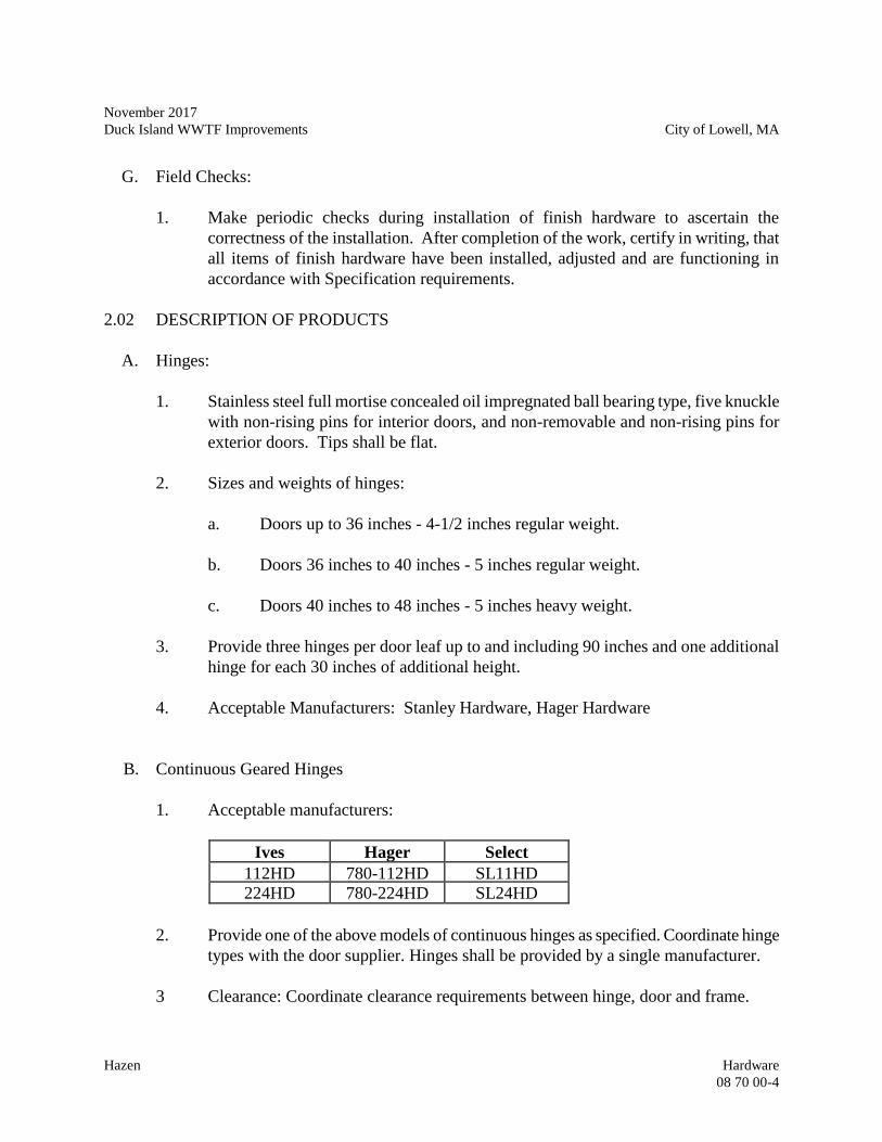
November 2017
Duck Island WWTF Improvements City of Lowell, MA
Hazen Hardware
08 70 00-4
G. Field Checks:
1. Make periodic checks during installation of finish hardware to ascertain the
correctness of the installation. After completion of the work, certify in writing, that
all items of finish hardware have been installed, adjusted and are functioning in
accordance with Specification requirements.
2.02 DESCRIPTION OF PRODUCTS
A. Hinges:
1. Stainless steel full mortise concealed oil impregnated ball bearing type, five knuckle
with non-rising pins for interior doors, and non-removable and non-rising pins for
exterior doors. Tips shall be flat.
2. Sizes and weights of hinges:
a. Doors up to 36 inches - 4-1/2 inches regular weight.
b. Doors 36 inches to 40 inches - 5 inches regular weight.
c. Doors 40 inches to 48 inches - 5 inches heavy weight.
3. Provide three hinges per door leaf up to and including 90 inches and one additional
hinge for each 30 inches of additional height.
4. Acceptable Manufacturers: Stanley Hardware, Hager Hardware
B. Continuous Geared Hinges
1. Acceptable manufacturers:
Ives Hager Select
112HD 780-112HD SL11HD
224HD 780-224HD SL24HD
2. Provide one of the above models of continuous hinges as specified. Coordinate hinge
types with the door supplier. Hinges shall be provided by a single manufacturer.
3 Clearance: Coordinate clearance requirements between hinge, door and frame.
November 2017
Duck Island WWTF Improvements City of Lowell, MA
Hazen Hardware
08 70 00-5
4. Fasteners: Per manufacturer's recommendations.
5. Material: Aluminum 6063-T6
6. Length: Hinge length shall be full height of door minus manufacturer requirements
(1" max).
7. Door Reinforcement: Minimum 16 gauge channel.
8. Frame Reinforcement: Minimum 16 gauge channel.
9 Provide electric power transfer (EPT) cutouts, or electric through-wire options as
specified in hardware groups.
C. Locksets and Latchsets:
1. Stainless steel, heavy-duty mortise type conforming to ANSI A156.13 Series 1000,
Grade 1.
2. Wrought steel box strikes.
3. Stainless steel deadbolt with 1" throw approval.
4. 2 3/4 inch back set, 3/4 inch throw, two-piece anti-friction latchbolt.
5. Non-ferrous critical internal parts.
6. Cylinders shall be manufactured to conform to grand master key program.
7. Trim Design: LWM with wrought escutcheon by Corbin\Russwin or equal lever with
return. Provide knurling on all levers leading into hazardous rooms and electrical
rooms.
8. Acceptable Manufacturers: Yale, Corbin\Russwin, Schlage
D. Keys and Keying:
1. Provide construction keyed, removable core master key system as directed by the
Owner.
November 2017
Duck Island WWTF Improvements City of Lowell, MA
Hazen Hardware
08 70 00-6
2. Furnish ten core removal keys and a quantity of master keys as directed by the
Owner, not to exceed ten each per group. Furnish a minimum of 5 change keys per
cylinder.
3. Furnish cylinders with six pin cores.
4. Provide a key schedule showing all key numbers and spaces to which each permits
entry. The schedule and key cabinet, along with key gathering envelopes containing
keys for each lock endorsed with lock number and space designation, shall be turned
over to the Owner. Install keys with proper tags in the key cabinet. Establish a
construction master key, and apply to locks and cylinders, except for closets, within
major spaces. Locks for closets shall be shipped unlocked and the keys delivered to
the Owner with the balance of the keys.
5. Acceptable Manufacturers: Yale, Corbin\Russwin, Schlage
E. Closers:
1. Cast iron case with seamless one-piece forged steel spring tub.
2. Heavy duty forged steel arm.
3. Non-sized fully adjustable from size 1-6.
4. Backcheck intensity and location valves.
5. Delayed action closing.
6. Full metal cover.
7. Mechanical hold open device, except at fire rated doors.
8. ANSI 156.4, Grade 1.
9. Conforms to ADA 5 lbf. maximum door opening force requirement for non-fire rated
interior doors.
10. Provide mounting brackets, and fasteners required for proper attachment.
11. Provide closers at fire rated doors.
12. Acceptable manufacturers: Corbin/Russwin, LCN, Norton
November 2017
Duck Island WWTF Improvements City of Lowell, MA
Hazen Hardware
08 70 00-7
F. Overhead Door Holder:
1. Heavy duty bronze, surface mounted with positive grip holder.
2. Track: extruded bronze.
3. Degree of opening: 85 - 110.
4. Finish: Satin Chrome Plated.
5. Acceptable manufacturers: Corbin/Russwin, Glynn-Johnson, Norton.
I. Door Stops and Bumpers:
1. Finish: Satin chrome plated.
2. Floor mounted door stops:
a. Acceptable manufacturers and products: H.B. Ives 444, Hager Hardware
Model 267F, and Glynn-Johnson Model FB36.
3. Wall bumpers:
a. Acceptable manufacturers and products: H.B. Ives Model 407, Hagar
Hardware Model 234W, and Glynn-Johnson Model 60C.
G. Flush Bolts:
1. U.L. listed.
2. Forged brass construction, 1/2" diameter flattened bolt tip, 12" long rod.
3. Fit standard ANSI door preparation.
4. Acceptable manufacturers: Glynn-Johnson, Hager Hardware, and H.B. Ives.
H. Push Plates and Pulls
1. Push and pull plates: 4"x16"x0.050" stainless steel.
2. Pulls: through bolted, 1" diameter, 2 1/2" projection, 12" centers, stainless steel.
November 2017
Duck Island WWTF Improvements City of Lowell, MA
Hazen Hardware
08 70 00-8
3. Acceptable manufacturers: H.B. Ives, Hager Hardware, and Builders Brass Works.
I. Coordinator:
1. U.L. labeled and tested for 100,000 cycles.
2. Stop mounted, provide filler strips to fully cover stop.
3. Adjustable holding power and override feature.
4. Acceptable manufacturers: Gylnn-Johnson, Hager Hardware, and H.B. Ives.
J. Kickplates:
1. Stainless steel, 0.050" thick, beveled 3 sides, 8" high, and width 2 inches less than
door width.
2. Acceptable manufacturers: H.B. Ives, Hagar Hardware, and Builders Brass Works.
K. Silencers:
1. Rubber silencers: 3 for each single door and 2 for each double doors.
2. Rubber Silencers at fiberglass door locations shall be self-adhesive type.
3. Acceptable manufacturers and products: (Hollow metal doors and frames): Glynn-
Johnson Models 64 or 65, Hager Hardware Models 308D or 307D, H.B. Ives Models
20 or 21.
4. Acceptable manufacturers and products: (Fiberglass doors and frames): H. B. Ives
Model SR66 or equal.
PART 3 -- EXECUTION
3.01 GENERAL
A. Templates:
1. After the hardware schedule is approved furnish to the various manufacturers,
required blueprint templates for fabrication purposes. Templates shall be made
available not more than ten (10) days after receipt of the approved hardware
schedule.
November 2017
Duck Island WWTF Improvements City of Lowell, MA
Hazen Hardware
08 70 00-9
B. Packaging and Marking:
1. Ship hardware with proper non-corrosive fastenings for secure application. Each
package of hardware shall be legibly marked indicating the part of the work for
which it is intended. Markings shall correspond with the item numbers shown on the
approved hardware schedule. Keys shall be tagged within each package set and
plainly marked on the face of the envelope with the key control number, door
designation and all identification as necessary.
3.02 INSTALLATION
A. Install hardware in a manner which will eliminate cracks on surfaces.
B. Mount hardware units at heights recommended in "Recommended Locations for Builders
Hardware" by BHMA, except as otherwise indicated or required to comply with governing
regulations.
C. Install each hardware item in compliance with the manufacturer's instructions and
recommendations. Do not install surface-mounted items until finishes have been completed
on the substrate.
D. Set units level, plumb and true to line and location. Adjust and reinforce the attachment
substrate as is necessary for proper installation and operation.
E. Drill and countersink units which are not factory-prepared for anchorage fasteners. Space
fasteners and anchors in accordance with factory standards.
F. Cut and fit thresholds and floor covers to profile of door frames, with mitered corners and
hair-line joints. Join units with concealed welds or concealed mechanical joints. Cut smooth
openings for spindles, bolts and similar items, if any.
G. Screw thresholds to substrate with No. 10 or larger screws, of the proper type for permanent
anchorage and of bronze or stainless steel which will not corrode in contact with the
threshold metal.
H. Set thresholds in a bed of either butyl rubber sealant or polyisobutylene mastic sealant to
completely fill concealed voids and exclude moisture. Do not plug drainage holes or block
weeps. Remove excess sealant.
3.03 ADJUST AND CLEAN
November 2017
Duck Island WWTF Improvements City of Lowell, MA
Hazen Hardware
08 70 00-10
A. Adjust and check each operating item of hardware and each door to ensure proper operation
or function. Lubricate moving parts as recommended by manufacturer. Replace units which
cannot be adjusted to operate freely and smoothly as intended for the application.
B. Final Adjustment:
1. One week prior to acceptance or occupancy make a final check and adjustment of all
hardware items. Clean and relubricate operating items as necessary to restore proper
function and finish of hardware and doors. Adjust door control devices and
compensate for final operation of heating and ventilating equipment.
C. Instruct Owner personnel in proper adjustment and maintenance of hardware and hardware
finishes, during the final adjustment of hardware.
3.04 HARDWARE SETS
A. The door hardware sets on the Drawings indicates functional and general requirements.
Items shall be quality and finish as specified. Hardware set identification refers to set
numbers indicated on the Drawings. Provide hardware required to meet Code requirements.
Consult Drawings for set number required.
B. Hardware shall be as follows:
Hardware Sets
1. Hinges
Entrance Lock Set
Door Closer
Kickplate
Threshold
Door Bottom Seal
Weatherstripping
2. Continuous Geared Hinges
Passage Latchset
Floor Mounted Door Stop
Kickplate
Silencers
Door Bumpers
November 2017
Duck Island WWTF Improvements City of Lowell, MA
Hazen Hardware
08 70 00-11
3. Hinges
Passage Latchset
Door Closer (each leaf)
Flush Bolts
Coordinator
Overhead Door Stop
Kickplate
Wallbumper
Silencers
4. Hinges
Push/Pull
Door Closer/Holder
Kickplates
Silencers
- END OF SECTION –
November 2017
Duck Island WWTF Improvements City of Lowell, MA
Hazen Hardware
08 70 00-12
- THIS PAGE INTENTIONALLY LEFT BLANK -
November 2017
Duck Island WWTF Improvements City of Lowell, MA
Hazen Glazing
08 80 00-1
SECTION 08 80 00
GLAZING
PART 1 -- GENERAL
1.01 REQUIREMENTS
A. Furnish all labor, materials, equipment and appliances required for the complete execution of
Work as shown on Drawings and specified herein.
1.02 RELATED WORK SPECIFIED ELSEWHERE
A. Section 08 13 13 – Hollow Metal Doors.
1.03 REFERENCE SPECIFICATIONS, CODES AND STANDARDS:
A. Without limiting the requirements of these specifications the Work shall conform to the
applicable requirements of the following documents:
1. CPSC 16 CFR1201 "Safety Standard for Architectural Glazing Materials."
2. ANSI Z97.1 "Performance Specifications and Methods of Test for Safety Glazing
Material Used in Buildings."
3. North American Glazing Association "Glazing Manual."
4. Underwriters' Laboratories "Building Materials Directory."
1.04 SUBMITTALS
A. In accordance with the procedures and requirements set forth in Division 01 00 00, General
Requirements, submit the following:
1. Sample of each type of glass and color chart.
2. Complete layout and installation drawings and schedules with clearly marked
dimensions.
3. Manufacturer's technical descriptions and reports for glass and glazing.
November 2017
Duck Island WWTF Improvements City of Lowell, MA
Hazen Glazing
08 80 00-2
1.05 JOB CONDITIONS
A. Check openings to verify that frames are plumb and true, square and secure.
B. Take field dimensions for cutting glass and fabricating units.
C. Do not install glazing when ambient temperature is less than 50 degrees F.
1.06 DELIVERY, STORAGE AND HANDLING
A. Deliver materials in the manufacturer's original unopened labeled containers, clearly marked
with their name and brand. Transport large panes of glass in vertical position with spacers to
prevent contact between panes and edges.
B. Store glass in a dry, well ventilated location at a constant temperature, maintained above dew
point. Handling shall be kept to a minimum. Protect glass from soiling, condensation or
moisture of any kind.
PART 2 -- PRODUCTS
2.01 ACCEPTABLE MANUFACTURERS
A. Subject to compliance with the Specifications provide products manufactured by one of the
following:
1. PPG Industries
2. Libby - Owens - Ford
3. Cardinal IG
2.02 MATERIALS
A. Primary glass shall meet the requirements of ASTM C1036-90. Heat treated glass shall meet
the requirements of ASTM C1048-90.
B. Tempered glass shall be plate or float glass tempered by a special heat process and 1/4-inch
thick or as noted on Drawings. Tempered glass shall meet the requirements of ANSI Z97.1
and Consumer Product Safety Commission 16 CFR 1201. Tempered glass shall be used for
all applications, unless otherwise noted.
November 2017
Duck Island WWTF Improvements City of Lowell, MA
Hazen Glazing
08 80 00-3
C. Glazing materials shall be a resilient, non-hardening glazing compound of either a
polysulfide or a silicone type. Materials shall not contain any solvents and shall be 100%
solids. Oil base putty shall not be used. Glazing compounds shall not be thinned with
chlorinated solvents or benzene related compounds. Glazing tape may be used where, and
as, recommended by the manufacturer. The color of all exposed glazing materials shall
harmonize with the window units.
D. Setting blocks and spacer shims shall be a non-staining material as recommended by the
glass manufacturer.
PART 3 -- EXECUTION
3.01 GENERAL
A. Determine glass sizes by measuring the frames to receive the glass at the site. Comply with
the manufacturer's specified tolerances for each type of glass including cutting tolerance,
minimum edge clearance, minimum face clearance, and cover on glass.
B. The edges of all tempered and insulating glass shall be protected from damage and edges
shall not be modified in any way after the glass leaves the factory. Nipping of any glass to
reduce size shall not be permitted.
C. Deliver glass with manufacturer's labels showing type, thickness and quality of material (and
U.L. label as required). These labels shall not be removed until the glass is set and final
approval has been secured.
3.02 INSTALLATION
A. Sheet glass shall be cut and set with waves running horizontally.
B. All glass shall be set in such manner as to avoid possibility of breakage.
C. Rabbets shall be thoroughly cleaned and shall have been prime coated before glass is set.
D. Glass shall be well bedded and back glazed and all surplus compound and markings shall be
carefully removed from doors, sash and adjoining work, while still fresh. Compound shall be
finished in true, even lines, neatly and smooth faced. Set glass in strict accordance with the
manufacturer's printed directions.
E. All glass when set and glazed shall be free from rattle and be watertight.
November 2017
Duck Island WWTF Improvements City of Lowell, MA
Hazen Glazing
08 80 00-4
F. Glazing molds shall be removed and replaced in their correct locations in such a manner as
not to mar molding or the screws securing same.
3.03 PROTECTION AND CLEANING
A. Before and after installation, all work shall be properly protected against damage.
B. On completion and prior to turning the project over to the Owner, all metal work and glass
shall be cleaned and left in perfect condition. Glass shall be washed outside and inside.
- END OF SECTION -
November 2017
Duck Island WWTF Improvements City of Lowell, MA
Hazen Louvers and Dampers
08 91 00-1
SECTION 08 91 00
LOUVERS AND DAMPERS
PART 1 -- GENERAL
1.01 REQUIREMENTS
A. Furnish all labor, materials, equipment, and appliances required for the complete execution
of additions, modifications, alterations, to existing buildings and new construction work as
shown on the Drawings and specified under the several sections of the Specifications.
B. Principal items of work include:
1. Fixed type, stormproof louvers and frames.
2. Combination louver damper.
3. Manual, gravity or electrically operated dampers and frames.
1.02 RELATED WORK SPECIFIED ELSEWHERE
A. Division 01 00 00 – General Requirements
1.03 REFERENCE CODES, SPECIFICATIONS, AND STANDARDS
A. Without limiting the generality of these Specifications, work shall conform to the applicable
requirements of the following documents. All referenced Specifications, codes, and
standards refer to the most current issue available at the time of the Bid.
1. All work shall comply with the Massachusetts State Building Code (780 CMR) and
the requirements of all other authorities having jurisdiction.
2. All units shall conform to AA-Aluminum Standards and Data, latest edition.
3. Louvers shall bear the AMCA Seal with ratings in accordance with AMCA Standard
500 which applies to air performance ratings and water penetration ratings.
November 2017
Duck Island WWTF Improvements City of Lowell, MA
Hazen Louvers and Dampers
08 91 00-2
4. All louvers, fasteners and supports shall be designed to meet a wind loading in
accordance with the local building codes, but shall not be less than 25 pounds per
square foot.
1.04 SUBMITTALS
A. In accordance with the procedures and requirements set forth in Division 01 00 00, General
Requirements, the Contractor shall submit the following:
1. Samples.
2. Shop Drawings.
B. Each submittal shall be identified by the Specification Section Number.
C. Each submittal shall be complete in all respects, incorporating all information and data listed
herein and all additional information required for evaluation of the proposed materials
compliance with the Contract Documents.
D. Partial, incomplete or illegible submissions will be returned to the Contractor without review
for resubmission.
E. Samples shall include:
1. Color and finish samples for each finish type required.
F. Shop Drawings shall include but not be limited to:
1. Complete detail drawings showing materials, methods of fabrication and clearly
indicating all dimensions.
2. Detailed installation drawings showing all methods of attachment.
1.05 DELIVERY, STORAGE AND HANDLING
A. Brace and support units to prevent deformation during delivery.
B. Factory wrap units with approved materials to protect finish during delivery and storage.
C. Handle units with care to prevent bending or scratching.
November 2017
Duck Island WWTF Improvements City of Lowell, MA
Hazen Louvers and Dampers
08 91 00-3
PART 2 -- PRODUCTS
2.01 ACCEPTABLE MANUFACTURERS
A. Subject to compliance with the Specifications, provide products manufactured by the
following:
1. Construction Specialties, Inc.
2. Penn, Inc.
3. Airolite Company, Marietta, Ohio.
4. Ruskin, Philips Industries, Inc.
2.02 FABRICATION
A. Extruded aluminum 6063-T52 alloy, extruded within commercial tolerances and free of
defects, minimum 0.081 inches thick with reinforcing bosses. All corners of frames shall be
reinforced and welded.
B. Hardware and fasteners shall be of Type 316 stainless steel placed through nylon bushings.
C. The louver installation shall consist of a fixed exterior louver with frame depth of 6-inches
and an interior gravity adjustable damper section with a frame depth of 4-inches.
D. The gravity adjustable damper shall consist of adjustable blades with vinyl gaskets extending
the full width of the adjustable blade. Adjustable blades shall pivot in direction of airflow to
minimize static pressure losses. Minimum free area shall be 40 percent.
E. The fixed louvers shall be spaced on 4½-inches on center and a section thickness of
0.125-inches (frames and blades). The gravity adjustable damper blades shall be spaced
6-inches on center and a section thickness of 0.081-inches (frames and blades).
F. Louver and damper assemblies which are to be placed in openings exceeding 5 feet in width
shall have slidable interlocked heavy gauge extruded aluminum mullions at mid span of
integral tongue and groove construction.
G. Manual, gravity and electrically operated damper shall be standard with the approved
manufacturer. Electrical characteristics to be coordinated with the Electrical Sections of
Division 26 and the Engineer. Hand crank actuators shall be provided for adjustable interior
dampers as required by the Drawings. Gravity dampers shall be free moving with air flow.
November 2017
Duck Island WWTF Improvements City of Lowell, MA
Hazen Louvers and Dampers
08 91 00-4
H. Coordinate louver sizes and free area requirements with the HVAC work.
I. Provide blanked off sections as required.
J. Bird screens shall be 1/2-inch square FRP or aluminum mesh P.V.C. coated, placed in
removable 0.081-inch thick folded aluminum frames standard with the manufacturer.
2.03 FINISH
A. Extruded aluminum louvers and damper frames and blades to receive finish in accordance
with the Aluminum Designation AA-M12-C22-A44, anodic coating Architectural Class I.
B. Interior louvers to receive alumilite finish 204-R1 as produced by the Aluminum Company
of America, or equal.
PART 3 -- EXECUTION
3.01 INSTALLATION
A. Anchor louver frames using stainless steel bolts into holes drilled and tapped in channel or
angle subframes and suspended lintels, or with strap anchors to masonry in accordance with
the manufacturer's approved directions.
B. Isolate aluminum from contact with masonry or dissimilar metals with heavy coat of
bituminous paint or neoprene gaskets.
C. Mount bird screens on inside face with clips, machine screwed into frames.
D. All frames shall be installed with aluminum (or compatible) screws, bolts, anchors, etc., in
such a manner that the frames are removable.
3.02 CUTTING AND FITTING
A. Do all cutting and fitting required for the installation in a neat manner.
3.03 CLEANING:
A. Upon completion remove any and all protective coatings, clean off all parts of the work and
leave entire installation in orderly condition.
- END OF SECTION -
November 2017
Duck Island WWTF Improvements City of Lowell, MA
Hazen Ceramic Tiling
09 30 13-1
SECTION 09 30 13
CERAMIC TILING
PART 1 -- GENERAL
1.01 THE REQUIREMENT
A. Furnish all labor, tools, equipment, materials and supplies required for complete execution of
Work shown on Drawings and specified herein.
1.02 RELATED WORK SPECIFIED ELSEWHERE
A. Section 03 30 00 - Cast-In-Place Concrete
B. Section 04 22 00 – Concrete Unit Masonry
C. Division 22 05 00 – Overall Plumbing
1.03 REFERENCE SPECIFICATIONS, CODES AND STANDARDS
A. TCNA Handbook Handbook for Ceramic, Glass and Stone Tile Installation.
B. ANSI A137.1 Specification for Ceramic Tile
1.04 QUALITY ASSURANCE
A. Conform to American National Standard Specifications for the Installation of Ceramic Tile.
1.05 SUBMITTALS
A. In accordance with the procedures and requirements set forth in Division 01 00 00, General
Requirements, submit the following:
1. Samples of each color and type of tile specified.
2. Product data specifications and instructions for using adhesives and grouts.
3. Manufacturer's certification that tile conforms to ANSI A137.1.
05
24
16
BR
November 2017
Duck Island WWTF Improvements City of Lowell, MA
Hazen Ceramic Tiling
09 30 13-2
4. Cleaning methods, cleaning solutions, stain removal methods, and polishes and
waxes recommended.
1.06 DELIVERY, STORAGE, AND HANDLING
A. Deliver tile in unopened grade sealed containers.
B. Maintain tile in protective packaging whenever possible.
C. Protect adhesive from freezing or overheating in accordance with manufacturer's instructions.
1.07 EXTRA STOCK
A. Deliver to the Owner a minimum of one unopened box of tile of each size and color provided
on project for extra stock.
PART 2 -- PRODUCTS
2.01 ACCEPTABLE TILE MANUFACTURERS
A. The following manufacturers are approved for use:
1. Florida Tile Industries, Inc.
2. American Olean Company.
3. Dal Tile Company.
2.02 MATERIALS
A. Provide tile from a domestic manufacture, standard grade, complying with ANSI 137.1.
Colors shall be selected by the Owner from manufacturer's full range of colors. Obtain
material required for any one type and color of tile from a single source and lot.
B. Ceramic wall tile shall be nonvitreous body, matte glazed, cushion-edged, 6 inches square,
unless otherwise shown; with self-spacing lugs on all four edges, including all required trim
and cove type base. Provide bull-nosed external corners and square internal corners.
C. Mosaic floor tile shall be impervious porcelain body, unglazed, non-slip, 2 inches square
unless otherwise shown. Floor tiles shall have a minimum wet dynamic coefficient of
friction of 0.42 when tested in accordance with ANSI A137.1. Provide tile with an abrasion
November 2017
Duck Island WWTF Improvements City of Lowell, MA
Hazen Ceramic Tiling
09 30 13-3
classification of Class III or IV when tested in accordance with ASTM C1027. Floor tile shall
ah 0.50 percent maximum water absorption in accordance with ASTM C373.
D. Marble Saddles: Double bevel, 4 inches in width and 1/2 inch deep, length, as shown on
Drawings. Cope to door frame.
E. Provide trim shapes for typical conditions and as required to make a complete installation at
all conditions. Trim shapes shall conform to the following:
1. Base - Cove required.
2. In-Corners - Square.
3. Jambs - Bullnose where tilework projects form jamb.
F. Sealer for substrate as recommended by manufacturer of setting material.
2.03 SETTING MATERIALS
A. Mortar materials shall conform with ANSI A118.4 Latex Modified Portland Cement with the
following properties:
1. Hydrated Lime - ASTM C207 Type S
2. Sand - ASTM C144
3. Water - Potable
4. Portland Cement ASTM C150 Type 1
5. Latex as recommended by manufacturer
B. Provide Portland cement mortar bed were recesses are provided in structural floor to provide
proper slope to drain. Install in accordance with ANSI A108.1.
2.04 GROUT TYPE
A. Cementitious type, resistant to shrinking, and manufactured by Jamo, Southern Grouts and
Mortars, Inc., American Olean. Grout shall meet the requirements of ANSI A118.7.
2.05 ACCESSORIES
November 2017
Duck Island WWTF Improvements City of Lowell, MA
Hazen Ceramic Tiling
09 30 13-4
A. Metal edge strips shall be zinc alloy or stainless steel, 1/8 inch x 1-1/4 inch x length required.
B. Manufacturer's standard anti-fracture membrane.
PART 3 -- EXECUTION
3.01 CERAMIC TILE INSTALLATION
A. Maximum variations in wall surface shall be 1/8 inch in 8 feet and 1/8 inch in 10 feet for
floor surfaces. Report all unacceptable surfaces to Engineer and do not tile such surfaces
until acceptable.
B. Before tiling, be sure surfaces to be tiled are free from coatings, oil, grease, wax and dust.
C. Align all wall and floor joints to achieve straight uniform grout lines plumb and level (at
walls) and parallel with walls (at floors).
D. Use products in strict accordance with recommendations and directions of manufacturers,
ANSI and TCA.
E. All wall surfaces to receive tile shall be primed when recommended by the adhesive
manufacturer.
F. Determine locations of all movement joints before starting tile work.
G. Do not set tile on surfaces where other work is specified or detailed to be embedded in or
behind the tile work, until such work has been installed and approved.
H. Provide expansion joints or control joints over all structural slab joints as per T.C.A. and
manufacturer's recommendations and instructions, and where shown on Drawings. Joints
shall be of constant width, neatly done and sealed with specified sealant. Sealant shall match
grout color of the tile field in which it is used.
I. Where slab is cracked and minimal movement is anticipated provide anti-fracture membrane
over crack.
J. Lay out tile to avoid using less than half a tile. Locate tile cuts in both walls and floors to be
least conspicuous. Smooth and clean all exposed tile edges prior to installation.
K. Form angles with proper integral round-in and round-out tile, with stop tile and proper
trimmers installed where required.
November 2017
Duck Island WWTF Improvements City of Lowell, MA
Hazen Ceramic Tiling
09 30 13-5
L. Cut and drill tile neatly and accurately, so intersections and returns are perfectly formed. Cut
edges of tile shall be carefully ground and fitted. Fit tile closely around electrical and other
outlets, piping, fixtures and fittings, so plates, collars and escutcheons, overlap the tile.
M. Do drilling, cutting and fitting where required for the installation of accessories and Work of
other trades, and upon completion, do all patching neatly and carefully. Build in all
accessories and similar items furnished by others.
N. Furnish and install metal edge strips where tile floor abuts another material. Locate strip
below the center line of doors at doorways.
O. Leave 1/8 inch wide and 1/4 inch deep open joint at inside corners and at door frames, caulk
to match grout only after installation is set and grout cured.
P. Joints shall be of constant width, neatly done and sealed with specified sealant.
3.03 STORAGE AND PROTECTION
A. Apply to all clean, completed tile work a protective coat of neutral cleaner solution, one part
cleaner to one part water.
B. Cover all tile floors with heavy duty non-staining construction paper masked in place.
C. Prohibit all foot and wheel traffic from using newly tiled floors for at least 3 days, preferably
7 days after completion of installation.
D. Place large flat boards in walkways and wheelways for 7 days where use of new tiled floors
is unavoidable.
3.04 CLEANING
A. Upon completion of grouting, clean all tile surfaces as thoroughly as possible, observing tile
manufacturer's recommendations as to the use of acid and chemical cleaners.
B. Just before final acceptance of tile work, remove paper and rinse protective coat for neutral
cleaner from all tile surfaces.
- END OF SECTION -

November 2017
Duck Island WWTF Improvements City of Lowell, MA
Hazen Ceramic Tiling
09 30 13-6
- THIS PAGE INTENTIONALLY LEFT BLANK -
November 2017
Duck Island WWTF Improvements City of Lowell, MA
Hazen Acoustical Tile Ceiling
09 51 23-1
SECTION 09 51 23
ACOUSTICAL TILE CEILING
PART 1 -- GENERAL
1.01 REQUIREMENTS
A. Furnish labor, materials equipment, and appliances required for complete execution of
Work shown on Drawings and Specified herein.
1.02 REFERENCE SPECIFICATIONS, CODES, AND STANDARDS
A. ASTM C635 - Metal Suspension Systems for Acoustical Tile and Lay-in Panel Ceilings.
B. ASTM C636 - Installation of Metal Ceiling Suspension Systems for Acoustical Tile and
Lay-in Panels.
C. ASTM E580 - Practice for Application of Ceiling Suspension Systems for Acoustical Tile
and Lay-in Panels in Areas Requiring Seismic Restraint.
D. ASTM E1264 - Classification of Acoustical Ceiling Products.
E. CISCA 0-2 (Ceilings and Interior Systems Contractors Association) for Seismic Design
Category C structures.
F. ASCE/SEI 7-05- Section13.5.6.2.1 for Seismic Design Category C structures.
1.03 SUBMITTALS
A. In accordance with the procedures and requirements set forth in Division 01 00 00,
General Requirements, submit the following:
1. Manufacturer's literature, and installation instructions.
2. Sample tiles showing color and texture.
November 2017
Duck Island WWTF Improvements City of Lowell, MA
Hazen Acoustical Tile Ceiling
09 51 23-2
1.04 PRODUCT DELIVERY, STORAGE, AND HANDLING
A. Deliver in original, unbroken, packages, container, or bundles bearing the manufacturer's
label.
B. Carefully store in an area that is protected from the elements in a manner recommended
by the product manufacturer. Store in a manner that will prevent damage to the material
or marring of its finish.
1.05 EXTRA MATERIAL
A. Provide 50 square feet of extra material to Owner.
PART 2 -- PRODUCTS
2.01 ACCEPTABLE MANUFACTURERS
A. Acoustical Panels:
1. The following manufacturers are approved for use:
a. U.S. Gypsum.
b. Armstrong World Inc.
c. Celotex.
B. Grid Systems:
1. The following manufacturers are approved for use:
a. Donn Products, Inc.
b. National Rolling Mills, Inc.
c. Chicago Metallic Co.
2.02 GRID SYSTEM MATERIALS
A. Main tees shall be heavy duty, cold-rolled 15/16 inch exposed 'T', electro-galvanized steel,
with corrosion-resistant aluminum cap on exposed surfaces.
B. Cross tees shall be properly sized, 15/16 exposed 'T' cold-rolled, electro-galvanized steel,
with corrosion-resistant aluminum cap on exposed surfaces.
November 2017
Duck Island WWTF Improvements City of Lowell, MA
Hazen Acoustical Tile Ceiling
09 51 23-3
C. Wall molding shall be 1-inch x 3/4-inch matching tees in material and finish.
D. Hanger and diagonal bracing wires shall be not lighter than 12-gauge, pre-straightened,
galvanized, annealed steel wire.
E. Spacers shall be tempered spring steel and shall be fitted into wall molding to provide
tension on the ceiling system.
2.03 ACOUSTICAL PANEL AND TILE MATERIALS
A. ACT: 100 percent ceramic-bonded mineral fiber, 5/8 inch thick, square edge tile or panel
with sizes, as specified or shown, Class A, ASTM E 1264 and a flame spread rating of under
25 per Federal Specifications SS-S 118B. Panels shall have non-directional fissured design.
Design for use in high humidity areas.
PART 3 -- EXECUTION
3.01 GENERAL:
A. The acoustical ceiling system shall consist basically of continuous main tees and intersecting
cross tees, joined together to form the patterns specified or shown herein, and acoustical
ceiling panels and tiles layed in. The system shall be complete with all necessary
components, anchors, and supports.
B. The system shall be designed so that the ceiling panels may be removed and replaced without
damage, and so that main tees and cross tees can be removed or replaced without deforming
the members or disturbing the balance of the grid system.
C. Suspension systems and tile work shall be coordinated with lighting fixtures, air diffusers,
and other features so that all installations work together without interference.
3.02 INSTALLATION
A. Install in strict accordance with the manufacturer's published directions, instructions, and
specifications.
3.03 PROBLEM AREAS
A. Manufacturer's published recommendations and specifications shall be followed for
installation, materials, and treatment of problem areas; provided, that the manufacturer's
published recommendations and specifications are not less than those required by
"Specification for Acoustical Tile and Lay-In Panel Ceiling Suspension Systems" of the
Acoustical Materials Association, and the Building Code.
November 2017
Duck Island WWTF Improvements City of Lowell, MA
Hazen Acoustical Tile Ceiling
09 51 23-4
3.04 DEFLECTIONS
A. The ceiling system shall be engineered to carry the applied dead and live loads with a
deflection of less than 1/360 of the span and shall be level to within 1/8-inch in 12 feet. The
ceiling system shall conform to ASTM C 635 (Heavy Duty classification) with a minimum
load carrying capacity of the main runner of 16 pounds per linear foot of span of 4-feet 0-
inches.
3.05 PREPARATION
A. Inspect areas receiving acoustical treatment ensure a proper installation. Do not proceed with
work before all conditions are ready to receive the acoustical panel work.
3.06 PATTERN AND SYMMETRY
A. Layout ceiling panels symmetrical about the center of the rooms to provide the least number
of cut panels. The panels shall be laid in a pattern with all edges in alignment and with all
faces in a plane. There shall be no noticeable variations in the finish ceiling plane. Items
located within the ceiling plane such as, but not limited to, the following: light fixtures, air
diffusers, speakers smoke detectors, and fire sprinklers shall be coordinated with other trades
and shall be installed at the locations shown.
B. Nondirectional tile shall be laid so no fissure pattern direction is established.
C. Tiles shall be held down by use of hold down clips, in exterior and vestibule areas.
3.07 BEAM SPLICES AND TEE INTERSECTIONS
A. Main tees shall be joined together by a splice clip which draws the members tightly together
with bottom flanges flush. Cross tee intersections shall be joined together by interlock
methods, by positioning the ends of the cross tees snugly against the main tee and in holding
the cross tees in vertical alignment with bottom flanges flush. Main tee splices and cross tee
intersections shall be capable of withstanding at least 100 pounds tension or compression.
B. The main tees and cross tees which terminate at the walls shall be attached to a perimeter
wall molding, which shall be continuous along at least 2 intersecting walls, with spring steel
stops. Wall molding shall be securely attached to the walls at approximately 16-inch
intervals in an acceptable manner.
November 2017
Duck Island WWTF Improvements City of Lowell, MA
Hazen Acoustical Tile Ceiling
09 51 23-5
3.08 HANGER WIRES
A. Hanger wires shall be spaced at maximum 48-inch on center along the main beams and at the
corners of lay-in-fixtures and elsewhere as required for a fire-rate system.
B. Secure to the supporting structure with acceptable fastenings. Hangers and fastenings shall
be capable of carrying at least 4 times the design load but not less than 100 pounds.
3.09 HORIZONTAL RESTRAINT
A. Ceiling systems shall be provided with diagonal bracing wires. Horizontal restraints shall be
effected by 4 No. 12-gage wires secured to the main tees within 2 inches of the cross tee
intersection and splayed 90 degrees from each other at an angle not exceeding 45 degrees
from the plane of the ceiling. The horizontal restraint points shall be placed 12 feet on center
in both directions with the first point within 4 feet from each wall. The restraint wire
attachment to the supporting structure shall be adequate for the loads imposed.
3.10 FINISHED CONDITION
A. Acoustical ceiling system shall be free from any discoloration, dire, smidges, scratches, chips
blemishes, and/or any misalignment. All damaged materials shall be replaced so that a new
uniform acoustical ceiling system is provided.
- END OF SECTION -

November 2017
Duck Island WWTF Improvements City of Lowell, MA
Hazen Acoustical Tile Ceiling
09 51 23-6
- THIS PAGE INTENTIONALLY LEFT BLANK -
November 2017
Duck Island WWTF Improvements City of Lowell, MA
Hazen Painting and Coating
09 90 00-1
SECTION 09 90 00
PAINTING AND COATING
PART 1 -- GENERAL
1.01 REQUIREMENTS
A. Furnish labor, materials, equipment and appliances required for complete execution of Work
shown on Drawings and Specified herein.
B. Section Includes:
1. Paint Materials
2. Shop Painting
3. Field Painting
a. Surface Preparation.
b. Piping and Equipment Identification.
c. Schedule of Colors.
d. Work in Confined Spaces.
e. OSHA Safety Colors.
1.02 RELATED SECTIONS
A. Section 40 05 13.03 - Piping and Equipment Identification Systems
1.03 REFERENCE SPECIFICATIONS, CODES AND STANDARDS
A. Without limiting the generality of these specifications the Work shall conform to the
applicable requirements of the following documents:
1. SSPC – The Society for Protective Coatings Standards:
a. SSPC-Vis 1 - Pictorial Surface Preparation Standards for Painting
Steel Structures.
November 2017
Duck Island WWTF Improvements City of Lowell, MA
Hazen Painting and Coating
09 90 00-2
b. SSPC-SP2 - Hand Tool Cleaning.
c. SSPC-SP3 - Power Tool Cleaning.
d. SSPC-SP5 - White Metal Blast Cleaning.
e. SSPC-SP6 - Commercial Blast Cleaning.
f. SSPC-SP10 - Near-White Metal Blast.
g. SSPC-SP13/NACE6 - Surface Preparation of Concrete.
2. NACE - National Association of Corrosion Engineers.
3. ASTM D1737 - Test Method for Elongation of Attached Organic Coatings
with Cylindrical Mandrel Apparatus.
4. ASTM B117 - Method of Salt Spray (Fog) Testing.
5. ASTM D4060 - Test Method for Abrasion Resistance of Organic Coating by
the Taber Abraser.
6. ASTM D3359 - Method for Measuring Adhesion by Tape Test.
1.04 SUBMITTALS
A. In accordance with the procedures and requirements set forth in Division 01 00 00, General
Requirements, submit the following:
1. Manufacturer's literature and Material Safety Data Sheets for each product.
2. Painting schedule identifying surface preparation and paint systems proposed.
Cross-reference with Tables 9-1 and 9-2. Provide the name of the paint
manufacturer, and name, address, and telephone number of manufacturer's
representative who will inspect the work. Submit schedule for approval as soon as
possible following the Award of Contract, so approved schedule may be used to
identify colors and specify shop paint systems for fabricated items.
1.05 SYSTEM DESCRIPTION
November 2017
Duck Island WWTF Improvements City of Lowell, MA
Hazen Painting and Coating
09 90 00-3
A. Work shall include surface preparation, paint application, inspection of painted surfaces and
corrective action required, protection of adjacent surfaces, cleanup and appurtenant work
required for the proper painting of all surfaces to be painted. Surfaces to be painted are
designated within the Painting Schedule and may include new and existing piping,
miscellaneous metals, equipment, buildings, exterior fiberglass, exposed electrical conduit
and appurtenance.
B. Perform Work in strict accordance with manufacturer's published recommendations and
instructions, unless the Engineer stipulates that deviations will be for the benefit of the
project.
C. Paint surfaces which are customarily painted, whether indicated to be painted or not, with
painting system applied to similar surfaces, areas and environments, and as approved by
Engineer.
D. Piping and equipment shall receive color coding and identification. Equipment shall be the
same color as the piping system.
E. Galvanized metal shall not be painted unless noted otherwise.
1.06 QUALITY ASSURANCE
A. Painting operations shall be accomplished by skilled craftsman and licensed by the state to
perform painting work.
B. Provide a letter indicating that the painting applicator has five (5) years of experience, and
five (5) references which show previously successful application of the specified or
comparable painting systems. Include the name, address, and the telephone number for the
Owner of each installation for which the painting applicator provided services.
1.07 STORAGE AND DELIVERY
A. Bring materials to the job site in the original sealed and labeled containers.
B. Container label to include manufacturer's name, type of paint, brand name, lot number, brand
code, coverage, surface preparation, drying time, cleanup requirements, color designation,
and instructions for mixing and reducing.
C. Store paint materials at minimum ambient temperature of 45 degrees F (7 degrees C) and a
maximum of 90 degrees F (32 degrees C), in ventilated area, and as required by
manufacturer's instructions.
November 2017
Duck Island WWTF Improvements City of Lowell, MA
Hazen Painting and Coating
09 90 00-4
PART 2 -- MATERIALS
2.01 GENERAL INFORMATION
A. The term "paint" is defined as both paints and coatings including emulsions, enamels, stains,
varnishes, sealers, and other coatings whether organic or inorganic and whether used as
prime, intermediate, or finish coats.
B. Purchase paint from an approved manufacturer. Manufacturer shall assign a representative to
inspect application of their product both in the shop and field. The manufacturer's
representative shall submit a report to the Engineer at the completion the Work identifying
products used and verifying that surfaces were properly prepared, products were properly
applied, and the paint systems were proper for the exposure and service.
C. Provide primers and intermediate coats produced by same manufacturer as finish coat. Use
only thinners approved by paint manufacturer, and only within manufacturer's recommended
limits.
D. Ensure compatibility of total paint system for each substrate. Test shop primed equipment
delivered to the site for compatibility with final paint system. Provide an acceptable barrier
coat or totally remove shop applied paint system when incompatible with system specified,
and repaint with specified paint system.
E. Use painting materials suitable for the intended use and recommended by paint manufacturer
for the intended use.
F. Require that personnel perform work in strict accordance with the latest requirements of
OSHA Safety and Health Standards for construction. Meet or exceed requirements of
regulatory agencies having jurisdiction and the manufacturer's published instructions and
recommendations. Maintain a copy of all Material Safety Data Sheets at the job site of each
product being used prior to commencement of work. Provide and require that personnel use
protective and safety equipment in or about the project site. Provide respiratory devices, eye
and face protection, ventilation, ear protection, illumination and other safety devices required
to provide a safe work environment.
November 2017
Duck Island WWTF Improvements City of Lowell, MA
Hazen Painting and Coating
09 90 00-5
2.02 ACCEPTABLE MANUFACTURERS
A. Subject to compliance with the Specifications, provide products from one of the following
manufacturers:
1. Tnemec Company Inc.
2. Ameron.
3. CARBOLINE.
4. Sherwin-Williams.
PART 3 -- EXECUTION
3.01 SHOP PAINTING
A. Shop prime fabricated steel and equipment with at least one shop coat of prime paint
compatible with finish paint system specified. Prepare surface to be shop painted in strict
accordance with paint manufacturer's recommendations and as specified. Finish coats may
be shop applied, if approved by the Engineer. Package, store and protect shop painted items
until they are incorporated into Work. Repair painted surfaces damaged during handling,
transporting, storage, or installation to provide a painting system equal to the original
painting received at the shop.
B. Identify surface preparation and shop paints on Shop Drawings. Verify compatibility with
field applied paints.
3.02 SURFACE PREPARATION
A. General:
1. Surfaces to be painted shall be clean and dry, and free of dust, rust, scale, and foreign
matter. No solvent cleaning, power or hand tool cleaning shall be permitted unless
approved by the Engineer.
2. Protect or remove, during painting operations, hardware, accessories, machined
surfaces, nameplates, lighting fixtures, and similar items not intended to be painted
prior to cleaning and painting. Reposition items removed upon completion of
painting operations.
November 2017
Duck Island WWTF Improvements City of Lowell, MA
Hazen Painting and Coating
09 90 00-6
3. Examine surfaces to be coated to determine that surfaces are suitable for specified
surface preparation and painting. Report to Engineer surfaces found to be unsuitable
in writing. Do not start surface preparation until unsuitable surfaces have been
corrected. Starting surface preparation precludes subsequent claim that such surfaces
were unsuitable for the specified surface preparation or painting.
4. Surface preparation shall be in accordance with specifications and manufacturer's
recommendations. Provide additional surface preparation, and fill coats where
manufacturer recommends additional surface preparation, in addition to requirements
of specification.
5. Touch-up shop or field applied coatings damaged by surface preparation or any other
activity, with the same shop or field applied coating; even to the extent of applying an
entire coat when required to correct damage prior to application of the next coating.
Touch-up coats are in addition to the specified applied systems, and not considered a
field coat.
6. Protect motors and other equipment during blasting operation to ensure blasting
material is not blown into motors or other equipment. Inspect motors and other
equipment after blasting operations and certify that no damage occurred, or where
damage occurred, the proper remedial action was taken.
7. Field paint shop painted equipment in compliance with Color Coding and as
approved by Engineer.
B. Metal Surface Preparation:
1. Conform to current The Society for Protective Coatings Standards (SSPC)
Specifications for metal surface preparation. Use SSPC-Vis-1 pictorial standards or
NACE visual standards TM-01-70 or TM-01-75 to determine cleanliness of abrasive
blast cleaned steel.
2. Perform blast cleaning operations for metal when following conditions exist:
a. Moisture is not present on the surface.
b. Relative humidity is below 80 percent.
c. Ambient and surface temperatures are 5 degrees F or greater than the dew
point temperature.
d. Painting or drying of paint is not being performed in the area.
November 2017
Duck Island WWTF Improvements City of Lowell, MA
Hazen Painting and Coating
09 90 00-7
e. Equipment is in good operating condition.
f. Proper ventilation, illumination, and other safety procedures and equipment
are being provided and followed.
3. Sandblast ferrous metals to be shop primed, or component mechanical equipment in
accordance with SSPC-SP5, White Metal Blast.
4. Sandblast field prepared ferrous metals in accordance with SSPC-SP10, Near White
Metal Blast, where metal is to be submerged, in a corrosive environment, or in severe
service.
5. Sandblast field prepared ferrous metals in accordance with SSPC-SP6 Commercial
Blast, where metal is to be used in mild or moderate service, or non-corrosive environment.
6. Clean nonferrous metals, copper, or galvanized metal surfaces in accordance to
SSPC-SP1, Solvent Cleaning, or give one coat of metal passivator or metal
conditioner compatible with the complete paint system.
7. Prime cleaned metals immediately after cleaning to prevent rusting.
8. Clean rusted metals down to bright metal by sandblasting and immediately field
primed.
C. Concrete Surface Preparation:
1. Cure concrete a minimum of 30 days before surface preparation, and painting begins.
2. Test concrete for moisture content, pH and salts using test method recommended by
the paint manufacturer. Do not begin surface preparation, or painting until moisture
content is acceptable to manufacturer.
3. Prepare concrete surfaces to receive coatings in accordance with SSPC-13 – Concrete
Surface Preparation. Remove contaminants, open bugholes, surface voids, air
pockets, and other subsurface irregularities using blasting or grinding. Do not expose
underlying aggregate. Use dry, oil-free air for blasting operations. Surface texture
after blasting shall achive profile as required by manufacturer or where not defined
by manufacturer similar to that of medium grit sandpaper. Remove residual
abrasives, dust, and loose particles by vacuuming or other approved method.
November 2017
Duck Island WWTF Improvements City of Lowell, MA
Hazen Painting and Coating
09 90 00-8
4. Acid etch (Reference ASTM D 260) concrete floors to receive paint. Following
method is a minimum requirement. Remove residual dust and dirt. Wet surface of
concrete until surface is damp. Etch surface with 15-20 percent muriatic acid
solution to produce a "medium sandpaper" texture. Do not allow acid solution to dry
on concrete. Rinse concrete when bubbling action of the acid begins to subside.
Continue rinsing process until pH is 7.0 or higher. Remove excess water and allow
concrete to thoroughly dry before coating. Other methods may be used, if approved
by Engineer.
5. Surface defects, such as hollow areas, bugholes, honeycombs, and voids shall be
filled with polymeric filler compatible with painting system. Complete fill coats may
be used in addition to specified painting system and as approved by the Engineer.
Fins, form marks, and all protrusions or rough edges shall be removed.
6. Repair existing concrete surfaces which are deteriorated to the point that surface
preparation exposes aggregate with fill coats or patching mortar as recommended by
paint manufacturer and as directed by the Engineer.
7. Clean concrete of all dust, form oils, curing compounds, oil, tar, laitance,
efflorescence, loose mortar, and other foreign materials before paints are applied.
D. Wood
1. Clean wood surfaces free of all foreign matter, with cracks and nail holes and other
defects properly filled and smoothed. Remove sap and resin by scraping and wipe
clean with rags dampened with mineral spirits.
2. Saturate end grain, cut wood, knots, and pitch pockets with an appropriate sealer
before priming.
3. Prime and backprime wood trim before setting in place.
4. After prime coat has dried, fill nailholes, cracks, open joints, and other small holes
with approved spackling putty. Lightly sand wood trim prior to applying second coat
of paint.
E. Castings:
1. Prepare castings for painting by applying a brush or a knife-applied filler. Fillers are
not to be used to conceal cracks, gasholes, or excessive porosity.
November 2017
Duck Island WWTF Improvements City of Lowell, MA
Hazen Painting and Coating
09 90 00-9
2. Apply one coat of primer with a minimum thickness of 1.2 mils in addition to coats
specified. Allow sufficient drying time before further handling.
F. Masonry:
1. Cure for a minimum of 30 days prior to paint application.
2. Clean masonry surfaces free from all dust, dirt, oil, grease, loose mortar, chalky
deposits, efflorescence, and other foreign materials.
3. Test masonry for moisture content. Use test method recommended by paint
manufacturer. Do not begin painting until moisture content is acceptable to
manufacturer.
G. Previously-Painted Surfaces:
1. Totally remove existing paint when: surface is to be submerged in a severe
environment, paint is less than 75 percent intact, brittle, eroded or has underfilm
rusting.
2. Surfaces which are greater than 75 percent intact require removal of failed paints and
then spot primed. Spot priming is in addition to coats specified.
3. Remove surface contamination such as oil, grease, loose paint, mill scale, dirt,
foreign matter, rust, mold, mildew, mortar, efflorescence, and sealers.
4. Clean and dull glossy surfaces prior to painting in accordance with the manufacturer's
recommendations.
5. Check existing paints for compatibility with new paint system. If incompatible,
totally remove existing paint system or apply a barrier coat recommended by the
paint manufacturer. Remove existing paints of undetermined origin. Prepare a test
patch of approximately 3 square feet over existing paint. Allow test patch to dry
thoroughly and test for adhesion. If proper adhesion is not achieved remove existing
paint and repaint.
3.03 APPLICATION OF PAINT
A. Apply paint by experienced painters with brushes or other applicators approved by the
Engineer, and paint manufacturer.
B. Apply paint without runs, sags, thin spots, or unacceptable marks.
November 2017
Duck Island WWTF Improvements City of Lowell, MA
Hazen Painting and Coating
09 90 00-10
C. Apply at rate specified by the manufacturer to achieve at least the minimum dry mil thickness
specified. Apply additional coats, if necessary, to obtain thickness.
D. Special attention shall be given to nuts, bolts, edges, angles, flanges, etc., where insufficient
film thicknesses are likely. Stripe paint prior to applying prime coat. Stripe painting shall be
in addition to coats specified.
E. Perform thinning in strict accordance with the manufacturer's instructions, and with the full
knowledge and approval of the Engineer and paint manufacturer.
F. Allow paint to dry a minimum of twenty-four hours between application of any two coats of
paint on a particular surface, unless shorter time periods are a requirement by the
manufacturer. Longer drying times may be required for abnormal conditions as defined by
the Engineer and paint manufacturer. Do not exceed manufacturer's recommended drying
time between coats.
G. Suspend painting when any of the following conditions exist:
1. Rainy or excessively damp weather.
2. Relative humidity exceeds 85 percent.
3. General air temperature cannot be maintained at 50 degrees F or above through the
drying period, except on approval by the Engineer and paint manufacturer.
4. Relative humidity will exceed 85 percent or air temperature will drop below 40
degrees F within 18 hours after application of paint.
5. Surface temperature of item is within 5 degrees of dewpoint.
6. Dew or moisture condensation are anticipated.
7. Surface temperature exceeds the manufacturer's recommendations.
3.04 INSPECTION
A. Each field coat of paint will be inspected and approved by the Engineer or his authorized
representative before succeeding coat is applied. Tint successive coats so that no two coats
for a given surface are exactly the same color. Tick-mark surfaces to receive black paint in
white between coats.
November 2017
Duck Island WWTF Improvements City of Lowell, MA
Hazen Painting and Coating
09 90 00-11
B. Use magnetic dry film thickness gauges and wet fiber thickness gauges for quality control.
Furnish magnetic dry film thickness gauge for use by the Engineer.
C. Coatings shall pass a holiday detector test.
D. Determination of Film Thickness: Randomly selected areas, each of at least 107.5
contiguous square feet, totaling at least 5 percent of the entire control area shall be tested.
Within this area, at least 5 squares, each of 7.75 square inches, shall be randomly selected.
Three readings shall be taken in each square, from which the mean film thickness shall be
calculated. No more than 20 percent of the mean film thickness measurements shall be
below the specified thickness. No single measurement shall be below 80 percent of the
specified film thickness. Total dry film thickness greater than twice the specified film
thickness shall not be acceptable. Areas where the measured dry film thickness exceeds
twice that specified shall be completely redone unless otherwise approved by the Engineer.
When measured dry film thickness is less than that specified additional coats shall be applied
as required.
E. Holiday Testing: Holiday test painted ferrous metal surfaces which will be submerged in
water or other liquids, or surfaces which are enclosed in a vapor space in such structures.
Mark areas which contain holidays. Repair or repaint in accordance with paint
manufacturer's printed instructions and retest.
1. Dry Film Thickness Exceeding 20 Mils: For surfaces having a total dry film
thickness exceeding 20 mils: Pulse-type holiday detector such as Tinker & Rasor
Model AP-W, D.E. Stearns Co. Model 14/20, shall be used. The unit shall be
adjusted to operate at the voltage required to cause a spark jump across an air gap
equal to twice the specified coating thickness.
2. Dry Film Thickness of 20 Mils or Less: For surfaces having a total dry film
thickness of 20 mils or less: Tinker & Rasor Model M1 non-destructive type holiday
detector, K-D Bird Dog, shall be used. The unit shall operate at less than 75-volts.
For thicknesses between 10 and 20 mils, a non-sudsing type wetting agent, such as
Kodak Photo-Flow, shall be added to the water prior to wetting the detector sponge.
F. Paint manufacturer or his representative shall provide their services as required by the
Engineer. Services shall include, but not be limited to, inspecting existing paint,
determination of best means of surface preparation, inspection of completed work, and final
inspection of painted work 11 months after the job is completed.
3.05 PROTECTION OF ADJACENT PAINT AND FINISHED SURFACES
November 2017
Duck Island WWTF Improvements City of Lowell, MA
Hazen Painting and Coating
09 90 00-12
A. Use covers, masking tape, other method when protection is necessary, or requested by Owner
or Engineer. Remove unwanted paint carefully without damage to finished paint or surface.
If damage does occur, repair the entire surface adjacent to and including the damaged area
without visible lapmarks and without additional cost to the Owner.
B. Take all necessary precautions to contain dispersion of sandblasting debris and paint to the
limits of the work. Take into account the effect of wind and other factors which may cause
dispersion of the sandblasting debris and paint. Suspend painting operations when sanding
debris or paint cannot be properly confined. Assume all responsibilities and cost associated
with damage to adjacent structures, vehicles, or surfaces caused by the surface preparation
and painting operations.
3.06 PIPING AND EQUIPMENT IDENTIFICATION
A. Piping and equipment identification shall be in accordance with Section 40 05 13.03, Piping
and Equipment Identification Systems.
3.07 SCHEDULE OF COLORS
A. Match colors indicated. Piping and equipment colors are indicated in Section 40 05 13.03.
Colors which are not indicated shall be selected from the manufacturer's full range of colors
by the Engineer. No variation shall be made in colors without the Engineer's approval.
Color names and numbers shall be identified according to the appropriate color chart issued
by the manufacturer of the particular product in question.
3.08 WORK IN CONFINED SPACES
A. Provide and maintain safe working conditions for all employees. Supply fresh air
continuously to confined spaces through the combined use of existing openings, forced-draft
fans and temporary ducts to the outside, or direct air supply to individual workers. Exhaust
paint fumes to the outside from the lowest level in the contained space. Provide
explosion-proof electrical fans, if in contact with fumes. No smoking or open fires will be
permitted in, or near, confined spaces where painting is being done. Follow OSHA, state and
local regulations at all times.
3.09 OSHA SAFETY COLORS
A. Paint wall around wall-mounted breathing or fire apparatus with the appropriate safety red
color; area not exceed 2-feet wide by 3-feet high, unless apparatus covers the area. Fire
apparatus include fire hoses, extinguisher, and hydrants.
B. Paint hazardous areas and objects in accordance with OSHA regulations.
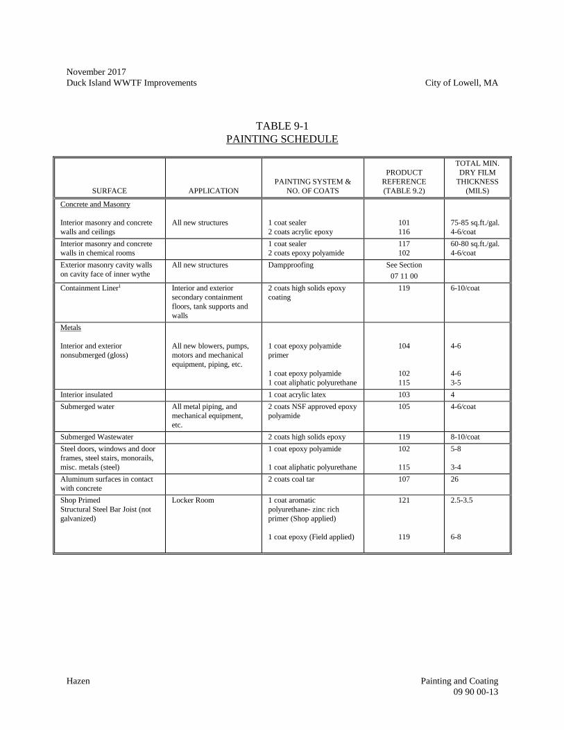
November 2017
Duck Island WWTF Improvements City of Lowell, MA
Hazen Painting and Coating
09 90 00-13
TABLE 9-1
PAINTING SCHEDULE
SURFACE APPLICATION
PAINTING SYSTEM &
NO. OF COATS
PRODUCT
REFERENCE
(TABLE 9.2)
TOTAL MIN.
DRY FILM
THICKNESS
(MILS)
Concrete and Masonry
Interior masonry and concrete
walls and ceilings
All new structures
1 coat sealer
2 coats acrylic epoxy
101
116
75-85 sq.ft./gal.
4-6/coat
Interior masonry and concrete
walls in chemical rooms
1 coat sealer
2 coats epoxy polyamide
117
102
60-80 sq.ft./gal.
4-6/coat
Exterior masonry cavity walls
on cavity face of inner wythe
All new structures Dampproofing See Section
07 11 00
Containment Liner1 Interior and exterior
secondary containment
floors, tank supports and
walls
2 coats high solids epoxy
coating
119 6-10/coat
Metals
Interior and exterior
nonsubmerged (gloss)
All new blowers, pumps,
motors and mechanical
equipment, piping, etc.
1 coat epoxy polyamide
primer
1 coat epoxy polyamide
1 coat aliphatic polyurethane
104
102
115
4-6
4-6
3-5
Interior insulated 1 coat acrylic latex 103 4
Submerged water All metal piping, and
mechanical equipment,
etc.
2 coats NSF approved epoxy
polyamide
105 4-6/coat
Submerged Wastewater 2 coats high solids epoxy 119 8-10/coat
Steel doors, windows and door
frames, steel stairs, monorails,
misc. metals (steel)
1 coat epoxy polyamide
1 coat aliphatic polyurethane
102
115
5-8
3-4
Aluminum surfaces in contact
with concrete
2 coats coal tar 107 26
Shop Primed
Structural Steel Bar Joist (not
galvanized)
Locker Room 1 coat aromatic
polyurethane- zinc rich
primer (Shop applied)
1 coat epoxy (Field applied)
121
119
2.5-3.5
6-8
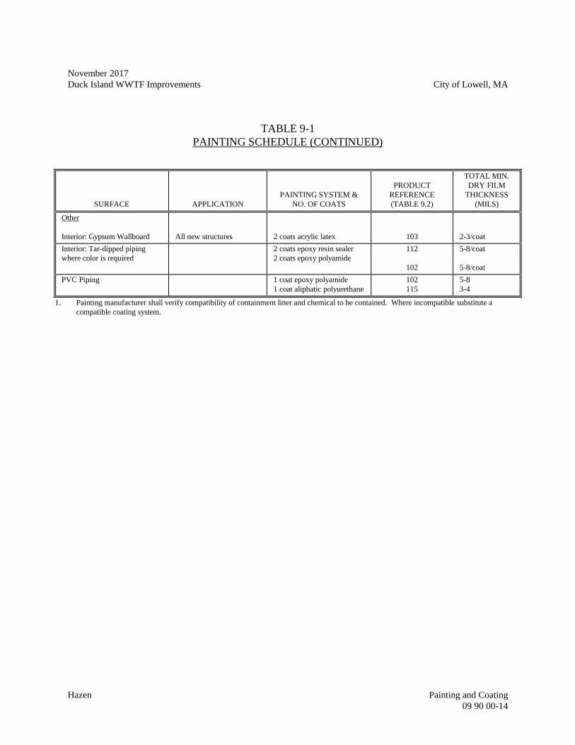
November 2017
Duck Island WWTF Improvements City of Lowell, MA
Hazen Painting and Coating
09 90 00-14
TABLE 9-1
PAINTING SCHEDULE (CONTINUED)
SURFACE APPLICATION
PAINTING SYSTEM &
NO. OF COATS
PRODUCT
REFERENCE
(TABLE 9.2)
TOTAL MIN.
DRY FILM
THICKNESS
(MILS)
Other
Interior: Gypsum Wallboard
All new structures
2 coats acrylic latex
103
2-3/coat
Interior: Tar-dipped piping
where color is required
2 coats epoxy resin sealer
2 coats epoxy polyamide
112
102
5-8/coat
5-8/coat
PVC Piping 1 coat epoxy polyamide
1 coat aliphatic polyurethane
102
115
5-8
3-4
1. Painting manufacturer shall verify compatibility of containment liner and chemical to be contained. Where incompatible substitute a
compatible coating system.
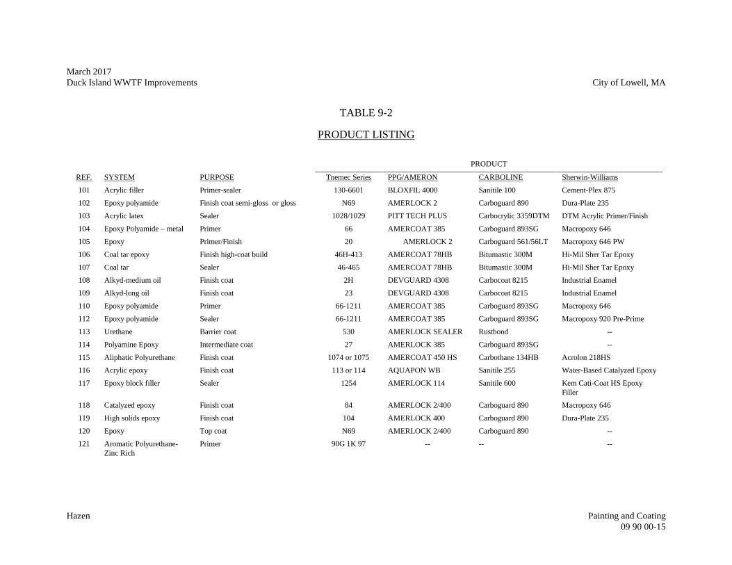
March 2017
Duck Island WWTF Improvements City of Lowell, MA
Hazen Painting and Coating
09 90 00-15
TABLE 9-2
PRODUCT LISTING
PRODUCT
REF. SYSTEM PURPOSE Tnemec Series PPG/AMERON CARBOLINE Sherwin-Williams
101 Acrylic filler Primer-sealer 130-6601 BLOXFIL 4000 Sanitile 100 Cement-Plex 875
102 Epoxy polyamide Finish coat semi-gloss or gloss N69 AMERLOCK 2 Carboguard 890 Dura-Plate 235
103 Acrylic latex Sealer 1028/1029 PITT TECH PLUS Carbocrylic 3359DTM DTM Acrylic Primer/Finish
104 Epoxy Polyamide – metal Primer 66 AMERCOAT 385 Carboguard 893SG Macropoxy 646
105 Epoxy Primer/Finish 20 AMERLOCK 2 Carboguard 561/56LT Macropoxy 646 PW
106 Coal tar epoxy Finish high-coat build 46H-413 AMERCOAT 78HB Bitumastic 300M Hi-Mil Sher Tar Epoxy
107 Coal tar Sealer 46-465 AMERCOAT 78HB Bitumastic 300M Hi-Mil Sher Tar Epoxy
108 Alkyd-medium oil Finish coat 2H DEVGUARD 4308 Carbocoat 8215 Industrial Enamel
109 Alkyd-long oil Finish coat 23 DEVGUARD 4308 Carbocoat 8215 Industrial Enamel
110 Epoxy polyamide Primer 66-1211 AMERCOAT 385 Carboguard 893SG Macropoxy 646
112 Epoxy polyamide Sealer 66-1211 AMERCOAT 385 Carboguard 893SG Macropoxy 920 Pre-Prime
113 Urethane Barrier coat 530 AMERLOCK SEALER Rustbond --
114 Polyamine Epoxy Intermediate coat 27 AMERLOCK 385 Carboguard 893SG --
115 Aliphatic Polyurethane Finish coat 1074 or 1075 AMERCOAT 450 HS Carbothane 134HB Acrolon 218HS
116 Acrylic epoxy Finish coat 113 or 114 AQUAPON WB Sanitile 255 Water-Based Catalyzed Epoxy
117 Epoxy block filler Sealer 1254 AMERLOCK 114 Sanitile 600 Kem Cati-Coat HS Epoxy
Filler
118 Catalyzed epoxy Finish coat 84 AMERLOCK 2/400 Carboguard 890 Macropoxy 646
119 High solids epoxy Finish coat 104 AMERLOCK 400 Carboguard 890 Dura-Plate 235
120 Epoxy Top coat N69 AMERLOCK 2/400 Carboguard 890 --
121 Aromatic Polyurethane-
Zinc Rich
Primer 90G 1K 97 -- -- --

March 2017
Duck Island WWTF Improvements City of Lowell, MA
Hazen Painting and Coating
09 90 00-16
- END OF SECTION -
November 2017
Duck Island WWTF Improvements City of Lowell, MA
Hazen Liquid Applied Water Repellents
09 97 10-1
SECTION 09 97 10
LIQUID APPLIED WATER REPELLENTS
PART 1 -- GENERAL
1.01 REQUIREMENTS
A. Furnish all labor, materials, equipment and appliances required for the complete execution of
Work as shown on the Drawings and specified herein.
B. Principal items of work:
1. Seal all masonry exposed to exterior weather conditions.
1.02 SUBMITTALS
A. In accordance with the procedures and requirements set forth in Division 01 00 00, General
Requirements, submit the following:
1. Manufacturer's product data.
2. Test reports confirming compliance with specifications.
1.03 SHIPPING, HANDLING AND STORAGE
A. Deliver material in manufacturer's original sealed containers.
B. Store materials in such a way as to prevent any damage to container or product and protect
from freezing temperatures.
PART 2 -- PRODUCTS
2.01 ACCEPTABLE MANUFACTURERS
A. L&M Construction Chemicals
B. BASF Master Builder Solutions
November 2017
Duck Island WWTF Improvements City of Lowell, MA
Hazen Liquid Applied Water Repellents
09 97 10-2
C. Tex-Cote
D. Tnemec
E. Prosoco
2.02 ACCEPTABLE MATERIALS
A. Liquid applied water repellant shall be a clear penetrating, water based silane product.
2.03 PERFORMANCE CRITERIA
A. Water Permeance ASTM E514 99% Improvement
B. Moisture Vapor
Transmission Rate ASTM D1653 24.4 gm/sq ft/24 hrs
C. Freeze Thaw Resistance ASTM C672 No Scaling
D. Resistance to chloride Excellent
PART 3 -- EXECUTION
3.01 INSPECTION
A. Verify that masonry surfaces are ready to receive water repellant. Report any unacceptable
conditions to the Engineer and do not begin application until unacceptable conditions have
been corrected.
3.02 SURFACE PREPARATION
A. Alkali or efflorescence shall be removed or neutralized prior to application. Neutralizing
shall be in accordance with manufacturer's recommendations.
B. Caulking, glazing, painting and other materials shall be protected from damage prior to
application.
3.03 APPLICATION
November 2017
Duck Island WWTF Improvements City of Lowell, MA
Hazen Liquid Applied Water Repellents
09 97 10-3
A. Flood surface with water repellant as recommended by manufacturer. Apply material to
assure that water repellant has soaked into surface and penetrated, hairline cracks and similar
opening. Apply product at a minimum rate of 100 square feet per gallon.
3.04 CLEANING
A. Clean windows, metals, caulking, and other materials not required to coated, which get
coated, immediately in manner approved by manufacturer of item coated.
- END OF SECTION -
November 2017
Duck Island WWTF Improvements City of Lowell, MA
Hazen Liquid Applied Water Repellents
09 97 10-4
- THIS PAGE INTENTIONALLY LEFT BLANK -
November 2017
Duck Island WWTF Improvements City of Lowell, MA
Hazen Signage
10 14 00-1
SECTION 10 14 00
SIGNAGE
PART 1 -- GENERAL
1.01 REQUIREMENTS
A. Furnish all labor, materials, equipment and appliances required for the complete execution
of the Work as shown on the Drawings and specified herein.
B. Principal items of work include:
1. Informational signs as indicated on the Drawings or Specifications.
2. Safety signs as indicated on the Drawings or Specifications.
3. Nameplates/Stenciling as indicated on the Drawings or Specifications.
1.02 SUBMITTALS
A. In accordance with the procedures and requirements set forth in Division 01 00 00, General
Requirements, submit the following:
1. Color and finish samples for all nameplates/stenciling, signs and building name
letters.
2. Shop Drawings shall include, but not be limited to:
a. Complete details for all signs and building name letters giving sizes and
styles of lettering and colors.
b. Complete schedules for all nameplates, signs, and building name letters
giving location, message, letter, size, color, and method of attachment.
c. Details of fabrication and attachment of all items.
d. Recommended procedures for cleaning, preparation and application of the
stenciling.
e. Recommended paint for stenciling.
November 2017
Duck Island WWTF Improvements City of Lowell, MA
Hazen Signage
10 14 00-2
f. Pictures of stenciling samples applied to similar materials.
1.03 DELIVERY, STORAGE AND HANDLING
A. Deliver all materials in unopened, unbroken and undamaged original packaging bearing
the manufacturer's label and identification for installation.
B. Handle all materials with care to prevent defacement of any nature.
PART 2 -- PRODUCTS
2.01 ACCEPTABLE MANUFACTURERS
A. Subject to compliance with the Specifications, provide products from one of the following
manufacturers:
1. Andco Industries Corporation.
2. Innerface Architectural Signage Incorporated.
3. Environmental Sign Systems.
4. Engineer approved equal.
2.02 MATERIALS
A. Signs:
1. Interior signs shall be self-extinguishing plastic with raised letters meeting the
requirements of the American with Disabilities Act of 1990; total thickness
minimum of 0.125 inch; rounded corners.
2. Exterior signs shall be aluminum with vinyl lettering and numbering.
B. Character size and style shall be 3/4 inch high minimum upper case Helvetica. Spacing
and proportions of letters shall be in strict accordance with the Americans with Disabilities
Act of 1990.
C. Colors shall be as selected by the Owner from the manufacturer standard colors.
D. Materials shall be suitable for exterior or interior exposure as applicable.
November 2017
Duck Island WWTF Improvements City of Lowell, MA
Hazen Signage
10 14 00-3
E. Stenciling paint shall be suitable for exterior or interior exposure (wet well conditions) as
applicable.
F. Stenciling paint shall be suitable to adhere to hatches.
2.03 ACCESSORIES
A. Mounting Hardware: Stainless steel screws.
B. Tape Adhesive: Double sided tape, permanent adhesive.
C. Stencil: Hard plastic (two (2) – one (1) unused, both to be provided to Owner at end of
project)
2.04 FABRICATION
A. All items specified herein to be factory fabricated to the extent practicable.
B. Provide all attachments and anchors necessary for concealed installments for door
numbers, room name plates, and bulletin boards.
PART 3 -- EXECUTION
3.01 INSTALLATION
A. All materials specified herein shall be installed in compliance with the approved
manufacturer's printed specifications. Mounting devices, bolts, screws, nuts and the like
shall be of high strength aluminum or stainless steel. The final location of each sign shall
be as determined by the Engineer.
B. Plastic door numbers and room name plates shall be attached stainless steel oval Phillips
head screw at each corner.
1. Submit a schedule of door numbers and name plates to the Engineer for approval.
2. Install door and name plates after final field finish has been applied and thoroughly
dried.
C. Stenciling per paint manufacturers recommendation
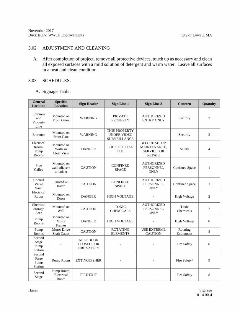
November 2017
Duck Island WWTF Improvements City of Lowell, MA
Hazen Signage
10 14 00-4
3.02 ADJUSTMENT AND CLEANING
A. After completion of project, remove all protective devices, touch up as necessary and clean
all exposed surfaces with a mild solution of detergent and warm water. Leave all surfaces
in a neat and clean condition.
3.03 SCHEDULES:
A. Signage Table:
General
Location
Specific
Location Sign Header Sign Line 1 Sign Line 2 Concern Quantity
Entrance
and
Property
Line
Mounted on
Front Gates WARNING
PRIVATE
PROPERTY
AUTHORIZED
ENTRY ONLY Security 2
Entrance Mounted on
Front Gate WARNING
THIS PROPERTY
UNDER VIDEO
SURVEILLANCE
- Security 2
Electrical
Room,
Pump
Rooms
Mounted on
Walls in
Clear View
DANGER LOCK OUT/TAG
OUT
BEFORE SETUP,
MAINTENANCE,
SERVICE, OR
REPAIR
Safety 4
Pipe
Galley
Mounted on
wall adjacent
to ladder
CAUTION CONFINED
SPACE
AUTHORIZED
PERSONNEL
ONLY
Confined Space
1
Control
Valve
Vault
Painted on
Hatch CAUTION
CONFINED
SPACE
AUTHORIZED
PERSONNEL
ONLY
Confined Space 1
Electrical
Room
Mounted on
Doors DANGER HIGH VOLTAGE - High Voltage 2
Chemical
Storage
Area
Mounted on
Wall CAUTION
TOXIC
CHEMICALS
AUTHORIZED
PERSONNEL
ONLY
Toxic
Chemicals 2
Pump
Rooms
Mounted on
Motor
Frames
DANGER HIGH VOLTAGE - High Voltage 8
Pump
Rooms
Motor Drive
Shaft Cages CAUTION
ROTATING
ELEMENTS
USE EXTREME
CAUTION
Rotating
Equipment 8
Second
Stage
Pump
Station
-
KEEP DOOR
CLOSED FOR
FIRE SAFETY
- - Fire Safety 8
Second
Stage
Pump
Station
Pump Room EXTINGUISHER - - Fire Safety2 9
Second
Stage
Pump Room,
Electrical
Room
FIRE EXIT - - Fire Safety 8
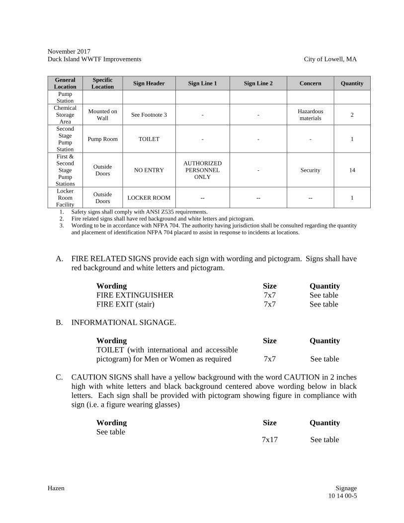
November 2017
Duck Island WWTF Improvements City of Lowell, MA
Hazen Signage
10 14 00-5
General
Location
Specific
Location Sign Header Sign Line 1 Sign Line 2 Concern Quantity
Pump
Station
Chemical
Storage
Area
Mounted on
Wall See Footnote 3 - -
Hazardous
materials 2
Second
Stage
Pump
Station
Pump Room TOILET - - - 1
First &
Second
Stage
Pump
Stations
Outside
Doors NO ENTRY
AUTHORIZED
PERSONNEL
ONLY
- Security 14
Locker
Room
Facility
Outside
Doors LOCKER ROOM -- -- -- 1
1. Safety signs shall comply with ANSI Z535 requirements.
2. Fire related signs shall have red background and white letters and pictogram.
3. Wording to be in accordance with NFPA 704. The authority having jurisdiction shall be consulted regarding the quantity
and placement of identification NFPA 704 placard to assist in response to incidents at locations.
A. FIRE RELATED SIGNS provide each sign with wording and pictogram. Signs shall have
red background and white letters and pictogram.
Wording Size Quantity
FIRE EXTINGUISHER 7x7 See table
FIRE EXIT (stair) 7x7 See table
B. INFORMATIONAL SIGNAGE.
Wording Size Quantity
TOILET (with international and accessible
pictogram) for Men or Women as required 7x7 See table
C. CAUTION SIGNS shall have a yellow background with the word CAUTION in 2 inches
high with white letters and black background centered above wording below in black
letters. Each sign shall be provided with pictogram showing figure in compliance with
sign (i.e. a figure wearing glasses)
Wording Size Quantity
See table 7x17 See table
November 2017
Duck Island WWTF Improvements City of Lowell, MA
Hazen Signage
10 14 00-6
D. SAFETY SIGNS shall have a white background with the word DANGER in 2 inches high
with white letters and red background centered above wording below in black letters. Each
sign shall be provided with pictogram.
Wording Size Quantity
KEEP DOOR CLOSED FOR FIRE
SAFETY
Note 1 See table
Note 1: Sign shall be 2½ inches high x length required. Sign shall be centered.
E. EXTERIOR HAZARDOUS MATERIAL BUILDING SIGNAGE
1. The authority having jurisdiction shall be consulted regarding the quantity and
placement of identification NFPA 704 placard to assist in response to incidents at
locations.
Wording Size Quantity
In accordance with NFPA 704 10X10 See table
- END OF SECTION -
November 2017
Duck Island WWTF Improvements City of Lowell, MA
Hazen Toilet Compartments
10 21 13-1
SECTION 10 21 13
TOILET COMPARTMENTS
PART 1 -- GENERAL
1.01 REQUIREMENTS
A. Furnish all labor, materials, equipment and appliances required for the complete execution of
the work as shown on the Drawings and specified herein.
1.02 RELATED WORK SPECIFIED ELSEWHERE
A. Section 06 10 53 - Miscellaneous Carpentry
B. Section 10 80 00 - Toilet and Bath Accessories
1.03 QUALITY ASSURANCE
A. Field measurements shall be made prior to preparation of shop drawings and fabrication
where possible, to ensure proper fitting of work. Allow for adjustments within specified
tolerances wherever taking of field measurements before fabrication might delay work.
B. Inserts and anchorages which must be built into other work for installation of toilet partitions
and related work shall be furnished to other trades. Delivery shall be coordinated to avoid
delay.
1.04 SUBMITTALS
A. In accordance with the procedures and requirements set forth in Division 01 00 00, General
Requirements, submit the following:
1. Shop Drawings indicating partition plan, elevation views, dimensions, supports and
door swings.
2. Manufacturer's detailed technical data fabrication and installation requirements
including catalog cuts of anchors, hardware, fastening and accessories.
3. Color charts
1.05 DELIVERY, STORAGE AND HANDLING
012612B
R
November 2017
Duck Island WWTF Improvements City of Lowell, MA
Hazen Toilet Compartments
10 21 13-2
A. Deliver all materials in unopened, undamaged original protective cartons and crating, bearing
the name of the manufacturer and identification for installation.
B. Store materials in a dry, clean area above the floor in such a manner to prevent damage from
any source.
C. Handle all materials with care to prevent bending, scratching and other defacements.
PART 2 -- PRODUCTS
2.01 ACCEPTABLE MANUFACTURERS
A. The following manufacturers are approved for use.
1. Bradley Corporation
2. General Partitions Mfg. Corp
3. Ampco Products, Inc.
2.02 MATERIALS
A. Provide overhead braced stainless steel doors, panels and screens. Stainless steel shall be 20
gage with an oval crown edge strip mitered, welded and finished at the corners. Stainless
steel shall be type 304 with #4 finish.
B. Brackets, wall supports and shoes shall be s 1/2 inch stainless steel plate welded construction
with upper and lower plate welded to a common 1/2 inch stainless steel plate, fastened to a
supporting steel chair carriage behind each panel and bearing on the rough floor slab.
C. Headrails shall be 1-7/8-inch x 1-5/32 inch x 1/16 inch with integral Anti-Grip Crown loafer
rail, extruded aluminum, heat - treated and anodized with manufacturer's fittings.
D. Urinal screens shall be 24 inches wide x 42 inches high and mounted 18 inches above the
finished floor.
E. Hardware
1. Doors shall be equipped with concealed latch with emergency access, stop and
keeper, hinges, and a combination coat and hat hook with rubber tip bumper.
Provide adjustable gravity hinges of case hardened steel arranged to hold door open
November 2017
Duck Island WWTF Improvements City of Lowell, MA
Hazen Toilet Compartments
10 21 13-3
when compartment is not in use and substantially made to pivot. Latch shall be
operated with ADA compliant device.
2. Hardware shall be plain pattern chromium plated over nickel plated forged brass.
Keeper and latch shall be No. 302 stainless steel.
2.03 CONSTRUCTION
A. Doors and panels shall be 1 inch thick Pilasters shall be 1¼ inch thick.
B. Panels, pilasters, and doors shall be sealed at edges with a surrounding oval-crown locking
strip, mitered, welded and finished at corners.
C. Partition panels, pilaster stiles and doors shall have honeycomb cores cemented to both inner
metal surfaces under pressure. Dividing partitions shall be anchored to pilaster stiles, which
shall be adequately reinforced to receive dividing partition panels and hardware.
PART 3 -- EXECUTION
3.01 INSPECTION
A. Examine the areas and conditions under which toilet partitions and related items are to be
installed. Work shall not proceed until unsatisfactory conditions have been corrected in a
manner acceptable to the installer.
3.02 INSTALLATION
A. Partitions shall be installed rigid, straight, plumb and level with the panels laid out as shown.
Clearances shall be provided of not more than 1/2 inch between pilasters and panels and not
more than one inch between panels and walls. Panels shall be secured to walls with not less
than two stirrup brackets, attached near top and bottom of the panel. Wall brackets shall be
located so that holes for wall anchorages occur in masonry or tile joints. Panels shall be
secured in supporting devices as indicated on final shop drawings or in manufacturer's
instructions.
November 2017
Duck Island WWTF Improvements City of Lowell, MA
Hazen Toilet Compartments
10 21 13-4
B. Pilasters shall be secured to the headrails with the specified anchorage device. The
installation shall be level, plumb and tightened with the leveling device. Tops of doors shall
be adjusted parallel with the ceiling when doors are in the closed position.
C. Hardware shall be adjusted and lubricated for proper operations after installation.
D. Hinges shall be set on in-swing door to hold door open approximately 30 degrees form the
closed position.
E. Units shall be protected so that there will be no indication of use or damage at the time of
acceptance.
F. Urinal screens shall be wall hung type attached to wall with three diecast chrome plated wall
brackets.
G. Final adjustment to pilaster leveling devices, door hardware and other operating parts of the
partition assembly shall be performed just prior to final inspection. Exposed surfaces of
partitions, hardware, fittings and accessories shall be cleaned using materials and methods
recommended by the partition manufacturer.
H. Damaged units which cannot be satisfactorily repaired as acceptable to the Engineer shall be
replaced.
- END OF SECTION -
November 2017
Duck Island WWTF Improvements City of Lowell, MA
Hazen First Aid Cabinets
10 43 16-1
SECTION 10 43 16
FIRST AID CABINETS
PART 1 -- GENERAL
1.01 REQUIREMENTS
A. Furnish and install first aid cabinets as shown on the Drawings and as specified herein.
Coordinate work in this Section with painting and marking as specified in Section 09 90 00,
Painting and Coating. Certain equipment items will be field located by Owner, if not
otherwise shown on the Drawings.
1.02 SUBMITTALS
A. Submit Shop Drawings, Performance Affidavit, Operation and Maintenance Instructions and
other information as specified for all items of equipment in this Section in accordance with
Section 46 00 00, Equipment General Provisions and Division 01 00 00, General
Requirements. Shop Drawings shall also include complete erection, installation, and
adjustment instructions and recommendations.
1.03 MANUFACTURERS
A. The materials covered by these Specifications are intended to be standard equipment of
proven reliability and as manufactured by reputable manufacturers having experience in the
production of such equipment. The equipment furnished shall be designed, constructed, and
installed in accordance with the best practices and methods and shall operate satisfactorily
when installed as shown on the Drawings and operated per manufacturers' recommendations.
PART 2 -- PRODUCTS
2.01 FIRST AID CABINET
A. The first aid cabinets shall be a Fisher Scientific Co. Catalog #19-035-116, or equal. First
aid cabinets shall be provided as shown on the Drawings. Mounting brackets for masonry
mounting shall be provided. Cabinets shall be field located as directed by the Engineer.
November 2017
Duck Island WWTF Improvements City of Lowell, MA
Hazen First Aid Cabinets
10 43 16-2
PART 3 -- EXECUTION
3.01 INSTALLATION
A. First aid cabinets shall be installed where shown on the Drawings or as directed by the
Engineer. Where required by OSHA regulations, the background of the mounting location
shall be painted the appropriate color.
- END OF SECTION –
November 2017
Duck Island WWTF Improvements City of Lowell, MA
Hazen Fire Extinguishers
10 44 16-1
SECTION 10 44 16
FIRE EXTINGUISHERS
PART 1 -- GENERAL
1.01 REQUIREMENTS
A. Furnish and install fire extinguishers as shown on the Drawings and specified herein.
1.02 REFERENCE SPECIFICATIONS, CODES, AND STANDARDS
A. Without limiting the generality of these Specifications the Work shall conform to the
applicable requirements of the following documents:
1. NFPA 10 - Portable Fire Extinguishers
1.03 SUBMITTALS
A. In accordance with the procedures and requirements set forth in Division 01 00 00, General
Requirements, submit the following:
1. Manufacturer's data sheets and verification of U.L. ratings.
PART 2 -- PRODUCTS
2.01 ACCEPTABLE MANUFACTURERS
A. Subject to compliance with the Specifications provide products from one of the following
manufacturers:
1. Kidde Fire Extinguisher Company
2. Ansul Fire Protection
3. Potter - Roemer
4. J. L. Industries
November 2017
Duck Island WWTF Improvements City of Lowell, MA
Hazen Fire Extinguishers
10 44 16-2
2.02 MATERIALS
A. Dry Chemical (DC) Fire Extinguishers
1. Provide, where indicated on drawings, 10 lb. capacity, hand portable, with wall
mount, tri-class dry chemical type, with Underwriters' Laboratories rating of 4-A: 60
BC.
B. Carbon Dioxide (CO2) Fire Extinguishers
1. Provide, where indicated on drawings capacity, portable carbon dioxide type with
wall mounts, having Underwriters' Laboratories rating of 10-BC.
PART 3 -- EXECUTION
3.01 INSTALLATION
A. Fire extinguishers shall be installed where directed by the Engineer.
B. Wall mounts for extinguishers shall be securely mounted to masonry with lag bolts and
shields.
C. Fire extinguishers shall be installed so that the top of the fire extinguisher is not more than 5
feet above the floor.
- END OF SECTION -
November 2017
Duck Island WWTF Improvements City of Lowell, MA
Hazen Lockers
10 50 00-1
SECTION 10 50 00
LOCKERS
PART 1 -- GENERAL
1.01 THE REQUIREMENTS
A. Furnish all labor, materials, equipment and appliances required for the complete execution of
the Work as shown on the Drawings and specified herein.
1.02 REFERENCES
A. ANSI/ASTM A446 - Steel Sheet, Zinc-Coated (Galvanized) by the Hot-Dip Process,
Structural (Physical) Quality.
B. ANSI/ASTM A526 - Steel Sheet, Zinc-Coated (Galvanized) by the Hot-Dip Process,
Commercial Quality.
1.03 SUBMITTALS
A. In accordance with the procedures and requirements set forth in Division 01 00 00, General
Requirements, submit the following:
1. Shop Drawings showing arrangement, dimensions, accessories and installation
details.
2. Manufacturer's data and installation instructions.
3. Color chart.
1.04 DELIVERY, STORAGE AND HANDLING
A. Store lockers in upright position, in dry ventilated area. Protect units from dents and
scratches during handling.
092311B
R
November 2017
Duck Island WWTF Improvements City of Lowell, MA
Hazen Lockers
10 50 00-2
PART 2 -- PRODUCTS
2.01 ACCEPTABLE MANUFACTURERS
A. The following manufacturers are approved for use.
1. The Interior Steel Equipment Company
2. Republic Storage Systems Company, Incorporated
3. Lyon Metal Products, Incorporated
2.02 SYSTEM DESCRIPTION
A. Locker Units:
Width: 24 inches
Depth: 18 inches
Height: 72 inches
Configuration: Single tier or double tier as indicated on Drawings
Mounting: Free standing
Base: As indicated on Drawings
Top: Continuous sloped metal with closures.
Locking Ventilation: Equipped for padlock hasps.
Method: Louvered top and bottom of door.
2.03 MATERIALS
A. Sheet Steel: ANSI/ASTM A446 Grade B, ANSI/ASTM A526 galvanized to G90 coating,
stretcher leveled; to the following minimum thicknesses:
1. Body and Shelf: 16 gauge
2. Door Face: 14 gauge
3. Door Frame: 16 gauge
4. Hinges: 14 gauge
5. Sloping Top and Trim: 20 gauge
November 2017
Duck Island WWTF Improvements City of Lowell, MA
Hazen Lockers
10 50 00-3
2.04 ACCESSORIES
A. Each Locker: one double prong wall hook, coat hanger bar with hook at ends, hat shelf, and
metal plate number.
B. Locker Benches: Bench top of maple species wood, stained, sealed and varnished, with
heavy duty painted steel tube pedestal with top and bottom flanges painted to match lockers
anchored to the floor.
2.05 FABRICATION
A. Locker Body: Formed and flanged; with steel stiffener ribs; electric spot welded.
B. Frames: Formed channel shape, welded and ground flush, welded to body, resilient gaskets
and latching for quiet operation.
C. Doors: Hollow channel construction; welded construction, channel reinforced top and
bottom with intermediate stiffener ribs, grind and finish edges smooth.
D. Hinges: Three for doors over 42 inches high; or continuous weld securely to locker body and
door.
E. Number Plates: Provide rectangular shaped aluminum plates. Form numbers of block font
style, in contrasting color. Numbers to be designated by the Owner.
F. Provide ventilation openings at top and bottom of each locker door.
G. Finish edges smooth without burrs.
H. Fabricate sloped metal tops, ends, filler and closure pieces of same gauge and finish of
lockers. Fabricate to fill all voids for a continuous finish appearance.
2.06 FINISHES
A. Clean, degrease, and neutralize metal; prime and finish with two coats of baked enamel.
B. Color: Color as selected from manufacturer's standard range.
November 2017
Duck Island WWTF Improvements City of Lowell, MA
Hazen Lockers
10 50 00-4
PART 3 -- EXECUTION
3.01 EXAMINATION
A. Verify that prepared bases are in correct position and configuration.
B. Verify bases and embedded anchors are properly sized.
3.02 INSTALLATION
A. Install in accordance with manufacturer's instructions.
B. Install lockers plumb and square.
C. Secure lockers with anchor devices to suit substrate materials. Minimum Pullout Force:
100 lbs.
D. Bolt adjoining locker units together to provide rigid installation.
E. Install end panels, filler panels, closers, and sloped tops to provide a continuous finish
appearance.
F. Install accessories.
- END OF SECTION -
November 2017
Duck Island WWTF Improvements City of Lowell, MA
Hazen Toilet and Bath Accessories
10 80 00-1
SECTION 10 80 00
TOILET AND BATH ACCESSORIES
PART 1 -- GENERAL
1.01 REQUIREMENTS
A. Furnish and install toilet and bath accessories as shown on the Drawings and specified
herein.
1.02 RELATED WORK SPECIFIED ELSEWHERE
A. Section 04 22 00 – Concrete Unit Masonry
B. Section 10 21 13 – Toilet Compartments
1.03 SUBMITTALS:
A. In accordance with the procedures and requirements set forth in Division 01 00 00, General
Requirements, submit the following:
1. Manufacturer's data.
1.04 QUALITY ASSURANCE
A. Coordinate with other work to avoid interference and to assure proper operation and
servicing of accessory units.
PART 2 -- PRODUCTS
2.01 ACCEPTABLE MANUFACTURERS
A. The following manufacturers are approved for use.
1. American Specialties Inc.
2. Bobrick Washroom Equipment, Inc.
3. Bradley Corp.
November 2017
Duck Island WWTF Improvements City of Lowell, MA
Hazen Toilet and Bath Accessories
10 80 00-2
4. McKinney Parker
2.02 MATERIALS
A. Provide the following (Model numbers are Bobrick Washroom Equipment, Inc. numbers and
are used for convenience only).
1. Surface Mounted Toilet Tissue Dispenser for Two Rolls At each water closet -
Model B-686, Type 304 -stainless, polished finish, concealed stainless steel wall
plate.
2. Surface Mounted Paper Towel Dispenser and Disposal: Satin finish stainless steel,
12 gallon removable receptacle. Dispenses 600 C-fold, 800 multifold, or 1100 single
fold towels. Model B-3949 with skirt.
3. Wall Mirrors: One (1) at each lavatory - stainless steel angle frame mirror, Model B-
290. Corners shall heliarc welded, ground and polished smooth. No. 1 quality, ¼”
(6mm) select float glass mirror electrolytically copper-plated; guaranteed against
silver spoilage for 15 years. Provide 1/8 inch (3mm) thick, water-resistant, shock-
absorbing padding and 20 gauge galvanized steel back. Concealed mounting. Size
as shown on Drawings.
4. Mop Holder: 18 gauge, 304 stainless steel shelf, hooks and anti-slip mop holders
with spring loaded rubber cam., 34 inch, Model B-239 x 34.
5. Grab Bars: 1-1/2 inch diameter, 18 gauge, stain finish, Type 304 stainless steel,
concealed mounting with set screws. Joints and supports shall be contour cut and
heliarc welded. Length shall be as indicated on the Drawings, and shall comply with
the requirements of the Americans with Disabilities Act.
6. Robe Hooks: Three stainless steel hooks and flanges, bright polished finish mounted
to a four inch high, 1/2 inch thick solid laminated plastic mounting strip with wood
grain finish. Model B-232.
7. Surface Mounted Soap Dispenser: 304 stainless steel back and body with satin finish.
Capacity of 40 fluid ounces. Corrosion-resistant valve and dispenser. Unbreakable
refill window. Vandal resistant. Large, locked, hinged, stainless steel filler top.
Model B-2112.
8. Shower Curtain and Rod: Provide one inch diameter stainless steel shower curtain
rod with concealed fasteners Model B-207. Provide opaque, matte white vinyl 0.008
inch (2mm) thick shower curtain with nickel-plated brass grommets at 6" centers.
November 2017
Duck Island WWTF Improvements City of Lowell, MA
Hazen Toilet and Bath Accessories
10 80 00-3
Hem edges. Size to fit opening of shower stalls. Provide stainless steel shower
curtain hooks.
PART 3 -- EXECUTION
3.01 INSPECTION
A. Examine substrates, previously installed inserts and anchorages necessary for mounting of
toilet accessories and other conditions under which installation is to occur, and notify the
Contractor of conditions detrimental to proper completion of work. Do not proceed until
unsatisfactory conditions have been corrected in a manner acceptable.
3.02 INSTALLATION
A. Install in accordance with manufacturer's instructions, using fasteners which are appropriate
to substrate and recommended by the manufacturer of the unit. Install plumb and level,
firmly anchored in locations indicated.
B. Install mirrors with back frame concealed fasteners.
C. Mounting heights shall comply with the American with Disabilities Act.
3.03 ADJUST AND CLEAN
A. Adjust for proper operation of that mechanisms function smoothly.
B. Clean and polish exposed surfaces after removing protective coating.
- END OF SECTION -

November 2017
Duck Island WWTF Improvements City of Lowell, MA
Hazen Toilet and Bath Accessories
10 80 00-4
- THIS PAGE INTENTIONALLY LEFT BLANK -
November 2017 Duck Island WWTF Improvements City of Lowell, MA
Hazen Plumbing 22 05 00-1
SECTION 22 05 00
PLUMBING
PART 1 - GENERAL
1.01 RELATED DOCUMENTS
A. Drawings and general provisions of the Contract, including General and Supplementary Conditions and Division 1 Specification Sections, apply to this Section.
B. Specifications throughout all Divisions of the Project Manual are directly applicable to this Section, and this Section is directly applicable to them.
1.02 SUMMARY
A. The Contractor shall furnish all labor, equipment and material for the complete installation of the plumbing system as indicated on the Drawings and specified herein.
B. Plumbing systems shall be furnished and installed to operate as a system. The Contractor shall coordinate all requirements between manufacturers to insure unit responsibility and compatibility of the systems.
C. Provide the following Plumbing Equipment.
1. Potable water piping systems.
2. Water Hammer Arresters.
3. Thermometers.
4. Pressure Gauges.
5. Pipe supports, hangers, escutcheon plates, and sleeves.
6. Plumbing pipe insulation.
7. Pipe ID markers and equipment identification tags.
8. Plumbing Fixtures
9. Emergency Shower and Eye/Face Wash Combination.
10. Flow Alarm Switches.
11. Tempered Water Systems.
12. Reduced Pressure Zone Backflow Preventer (RPZ).
13. Wall Hydrants (Non-Freeze).
06
17
13
BR
November 2017 Duck Island WWTF Improvements City of Lowell, MA
Hazen Plumbing 22 05 00-2
14. Shut-off valves
15. Sanitary sewer (DWV) piping systems, floor drains and cleanouts.
16. Natural gas piping systems.
1.03 SUBMITTALS
A. The Contractor shall submit shop drawings on all equipment, accessories and appurtenances and all fabrication work or other mechanical and air conditioning work required, all in accordance with the requirements of Division 1, Submittals.
B. Data to be submitted shall include but not be limited to:
1. Catalog data consisting of specifications, illustrations and a parts schedule that identifies the materials to be used for the various parts and accessories. The illustrations shall be in sufficient detail to serve as a guide for assembly and disassembly.
2. Complete assembly and installation drawings with clearly marked dimensions. This information shall be in sufficient detail to serve as a guide for assembly and disassembly and for ordering parts.
3. Weight of all component parts and assembled weight.
4. Electrical characteristics, wiring, diagrams, etc.
5. Sample data sheet of equipment nameplate(s) including information contained thereon.
6. Insulation materials, coating, jackets, detail density, thermal conductivity and thickness of all insulation materials to be furnished.
7. Details of special fasteners and accessories.
8. Type of adhesives, binders, joint cement, mastics.
9. Proposed insulation procedures and installation methods.
10. Spreadsheet or chart identifying piping systems type and pipe size, model numbers of hangers to be used, special coatings for pipe supports etc.
11. Sample data sheet of piping and valves including information contained thereon.
12. Spare parts list
13. Special tools list
C. The Contractor shall obtain from the manufacturer and submit to the Engineer copies of
November 2017 Duck Island WWTF Improvements City of Lowell, MA
Hazen Plumbing 22 05 00-3
the results of all certified shop tests.
D. The Contractor shall obtain from the manufacturer and submit to the Engineer copies of certified letters of compliance in accordance with the Specifications.
E. The Contractor shall submit operation and maintenance manual in accordance with the procedures and requirements set forth in the General Conditions and Division 1. Operation and Maintenance Manuals shall be submitted for all equipment.
1.04 DELIVERY, STORAGE AND HANDLING
A. Deliver, store, protect and handle products to the Project Site under provisions of Division 1.
B. Accept products on site in factory-fabricated protective containers, with factory-installed shipping skids and lifting lugs. Inspect for damage.
C. Store in clean dry place and protect from weather and construction traffic. Handle carefully to avoid damage to components, enclosures and finish.
D. Protect openings in casing and seal them with plastic wrap to keep dirt and debris. Protect coils from entry of dirt and debris with pipe caps or plugs.
1.05 SCHEDULES ON DRAWINGS
A. In general, all capacities of equipment and fixtures characteristics are shown in schedules on the Drawings. Reference shall be made to the schedules for such information. Variations of the scheduled equipment supplied under this Contract will be permitted only with the written direction of the Engineer.
1.06 MANUFACTURER'S INSTRUCTIONS
A. Installation of all equipment shall be in accordance with manufacturer's data.
B. All changes from the installation procedures in manufacturers' data shall be submitted for approval in accordance with the requirements for shop drawings.
C. Keep all manufacturers' data provided in a secure manner at the job site at all times. Catalog and index this data for convenient reference.
D. Manufacturers' data shall be available for the information of the Owner, Engineer, and the use of other trades.
E. Turn over all data to the Owner through the Owner's representative at completion of the Work and final testing.
F. Submit all instruction books and manuals in accordance with Division 1.
1.07 CODES, PERMITS AND STANDARDS
November 2017 Duck Island WWTF Improvements City of Lowell, MA
Hazen Plumbing 22 05 00-4
A. The Contractor shall obtain and pay for all permits and shall comply with all laws and codes that apply to the Work.
B. The Contractor shall be responsible for all added expense due to his choice of equipment, materials or construction methods.
C. All work and materials shall be in full accordance with the latest State rules and regulations or publications including those of the State Fire Marshall, the Massachusetts Plumbing and Energy Codes, and all local codes. Nothing in the Plans and/or Specifications shall be construed to permit work not conforming to the above codes, rules and regulations.
D. All equipment, materials and installations shall conform to the requirements of the most recent edition with latest revisions, supplements and amendments of the following, as applicable:
1. American National Standards Institute (ANSI).
2. American Society for Testing and Materials (ASTM).
3. American Society of Mechanical Engineers (ASME).
4. Factory Mutual (FM).
5. National Electric Code (NEC).
6. Occupational Safety and Health Standards (OSHA).
7. State and local codes, ordinances and statutes.
8. Underwriters Laboratories (UL).
9. Others as designated in the specifications.
1.08 QUALITY ASSURANCE
A. Manufacturer Qualifications: Company specializing in manufacturing the products specified in this Section with minimum three (3) years documented experience, who issues complete catalog data on total product.
B. All material and equipment shall be the latest design, new, not deteriorated, and the first quality standard product of manufacturers regularly engaged in the production of such material and equipment.
C. When two or more units of the same class of material or equipment are required, they shall be products of a single manufacturer.
D. All work shall be performed in a neat and workmanlike manner by workers skilled in their respective trades, and all materials and equipment shall be installed as
November 2017 Duck Island WWTF Improvements City of Lowell, MA
Hazen Plumbing 22 05 00-5
recommended by the manufacturers and in accordance with specified codes and standards.
E. Touch up and/or repaint to match original finishes all factory finished or painted equipment and materials which are scratched or marred during shipment or installation.
F. Plumbing fixtures shall be set and connected to soil, waste, and vent and cold and hot water supplies in a neat, finished and uniform manner. Fixtures of each class and the connection to same shall be of equal height, level and at right angles to the wall unless otherwise directed by the Architect/Engineer.
G. Each plumbing fixture shall be provided with an approved P-trap, which shall be set as close to the outlet as practicable, all water supply connections shall be provided with loose key stops.
H. Vitreous china fixtures shall be carefully selected, free from spots, grazing or chips.
I. Fixture trim, traps, faucets, escutcheons, and waste pipes that are exposed to view shall be brass with polished chromium plating over nickel finish. Exposed supplies shall be brass pipe plated in the same manner.
J. All fixtures designated for use by the disabled shall fully conform and shall be installed per the requirements of the American Disabilities Act.
K. All iron and steel piping, and pipe fittings shall be manufactured domestically within the United States of America.
L. Regulatory Requirements: Comply with requirements in Public Law 102-486, "Energy Policy Act," about water flow and consumption rates for plumbing fixtures.
M. NSF Standard: Comply with NSF 61, "Drinking Water System Components--Health Effects," for fixture materials that will be in contact with potable water.
PART 2 - PRODUCTS
2.01 GENERAL
A. Each item of equipment shall be furnished and installed complete with all supports, mounting frames, piping, electrical work, insulation and appurtenances ready for operation.
B. All equipment and appurtenances shall be anchored or connected to supporting members as specified or as indicated on the Plans.
C. The Plans shall be taken as diagrammatic. The Contractor shall check the Structural Plans and sections for detail dimensions and clearances. Sizes of ducts and their locations are indicated, but not every offset, fitting, or structural obstruction is shown.
November 2017 Duck Island WWTF Improvements City of Lowell, MA
Hazen Plumbing 22 05 00-6
D. All supports required for the proper installation of the equipment, but not forming an integral part of the building structure, shall be provided, unless specifically noted otherwise. Equipment shall be supported on spring type vibration isolators.
2.02 MATERIALS
A. Underground cold water piping shall be copper tubing, Type “K”, 2-1/2-inch and smaller with wrought copper solder joint fittings; 3-inch and larger shall be ductile iron pipe, bell and spigot, Class 52. Fittings shall be bell and spigot, Class 250.
B. Aboveground tempered, hot and cold water piping in Classified areas shall be cross linked polyethylene tubing, Type “a” (PEX-a) fabricated with the Engel method, 3-inch and smaller with engineered polymer cold expansion joint fittings.
C. Aboveground tempered, hot and cold water piping in Unclassified areas shall be copper tubing, Type “L”, 3-1/2-inch and smaller with wrought copper solder joint fittings; 4-inch and larger shall be ductile iron pipe, AWWA C151, grooved or flanged ends or cross linked polyethylene tubing, Type “a” (PEX-a) fabricated with the Engel method, 3-inch and smaller with engineered polymer cold expansion joint fittings.
D. Underground soil, waste, and drainage pipe inside building and to a point 5’-0” (five feet) outside the building shall be standard weight cast iron soil pipe and fittings conforming to ASTM A74. Joints shall be hub and spigot, caulk joint, or installed with compression gaskets conforming to ASTM C-564. No-hub is not permitted underground.
E. Aboveground soil, waste, and vent piping shall be Schedule 40 PVC pipe with PVC Socket Fittings: ASTM D 2665, socket type, made to ASTM D 3311, drain, waste, and vent patterns fittings and solvent-cemented joints.
2.03 PIPING
A. Contractor shall form all holes; furnish and install all concrete inserts, flashings and sleeves in existing floors, walls, equipment foundations, ceilings, and roofs as required for the erection, installation, and support of all pipe and tubing.
1. Provide sleeves and flashings for all pipes and tubing, etc., furnished which passes through existing walls, intermediate floors, partition walls and roofs. Caulk wall opening with fire retardant sealant.
2. Provide fire stopping materials which consist of commercially manufactured products capable of passing ASTM E-814 (UL 1479) Standard Method of Fire Test for Through Penetration Fire Stops wherever piping penetrates a fire rated roof, wall or floor assembly.
3. Install concrete inserts, sleeves and flashings required, as indicated, or in a manner acceptable to the Engineer.
November 2017 Duck Island WWTF Improvements City of Lowell, MA
Hazen Plumbing 22 05 00-7
4. All holes missed by the Contractor, but required for the installation of the piping systems, shall be made in the walls, floors, roof and by the Contractor at no additional expense to the Owner by core drilling or saw cutting methods only.
5. Provide escutcheons around pipes in all areas. Use chromium plated escutcheons on pipe penetrations exposed in finished rooms or areas. Use stainless steel escutcheons in all process areas.
6. Install water hammer arrestors on all hot and cold water branch lines to fixtures and equipment.
B. Copper Water Tube:
1. Tube:
a. Reference: ASTM B88.
b. Type: K or L.
c. Temper: Hard drawn or soft annealed.
2. Joints:
a. General: Connect pipe with solder joints except where threaded or flanged fittings are required at valves, equipment connections or otherwise shown or directed.
b. Solder Joints: ASTM B32, Sb5 (95 5 tin antimony).
c. Threaded Joints:
1) Taper Pipe Threads: ANSI B2.1.
2) Joint Preparation: Teflon Tape.
d. Flanged Joints:
e. Flanges: ANSI B16.24, 150 lb. class.
1) Gaskets: Red rubber, ASTM D1330, Grade 1, 1/8 inch thick.
f. Bolts and Nuts:
1) Standard: ANSI B18.21 and ANSI B18.2.2, respectively.
2) Material: ASTM A307, Grade B.
3. Fittings:
a. Type: Wrought Copper.
November 2017 Duck Island WWTF Improvements City of Lowell, MA
Hazen Plumbing 22 05 00-8
b. Reference: ANSI B16.22.
4. Unions:
a. Reference: FS WW U 516.
b. Material: Bronze.
c. Rating: 250 pound W.O.G.
5. All copper piping 2 1/2 inches and smaller, run within the interior of a building, shall be hard drawn copper Type "L".
6. All buried copper piping 2 1/2 inches and smaller shall be soft temper copper Type "K".
C. Cross Linked Polyethylene Piping (PEX)
1. Tube:
a. Reference: ASTM F876, ASTM F877
2. Type:
a. Material: Cross Linked Polyethylene Engel or peroxide method
b. Rating: 220° F at 80 PSI
3. Joints:
a. General: Connect pipe with cold joints except where threaded or flanged fittings are required at valves, equipment connections or otherwise shown or directed.
b. Reference: ASTM F1960
4. Fittings:
a. Type: Engineered Polymer
b. Reference: ASTM F1960
c. Backing Ring: Crosslinked Polyethylene (PEX-a)
d. Connection Method: Cold expansion. Crimped connections are not acceptable.
D. Ductile Iron Pipe:
1. Pipe:
November 2017 Duck Island WWTF Improvements City of Lowell, MA
Hazen Plumbing 22 05 00-9
a. Reference: AWWA C151.
2. Joints:
a. Ductile-Iron Piping, Grooved-End Fittings: ASTM A 47 (ASTM A 47M), malleable-iron castings or ASTM A 536 ductile-iron castings with dimensions matching pipe.
1) Ductile-Iron-Piping, Keyed Couplings: AWWA C606 for ductile-iron-pipe dimensions. Include ferrous housing sections, gasket suitable for water, and bolts and nuts.
b. Mechanical-Joint, Ductile-Iron Fittings: AWWA C110, ductile- or gray-iron, standard pattern; or AWWA C153, ductile-iron, compact pattern.
1) Glands, Gaskets, and Bolts: AWWA C111, ductile- or gray-iron glands, rubber gaskets, and steel bolts.
E. Drain, waste and vent piping and fittings shall be manufactured by Tyler Pipe, Charlotte Pipe and Foundry, A.B. and I. Foundry, or equal.
1. The piping shall be installed complete, of the size and arrangement shown on the drawings. All piping shall be installed to allow for expansion, and parallel or perpendicular to the building construction. When pipe is installed underground, the ground shall be excavated to a minimum depth to accomplish the grade shown or required by code. The pipe shall have bearing along its entire length and if installed on fill, shall be supported by concrete cradles to firm earth.
2. All pipe shall be supported from the building structure in a neat manner, in compliance with current trade practices and wherever possible, parallel runs of horizontal piping shall be grouped together on trapeze hangers. Single runs of horizontal piping shall be supported with clevis type hangers. Vertical risers shall be supported at each floor line with steel pipe clamps. The use of wire or perforated metal to support pipe will not be permitted. In concrete construction, approved inserts will be carefully set to support the piping. Soil and waste pipe shall be supported at intervals of not more than five feet on horizontal runs and at the base of every stack.
3. Sealing Coupling Sleeve for No-hub joints: The coupling shall be made of stainless steel, ASTM C 1277 assembly of metal housing, corrosion-resistant fasteners, and ASTM C 564 EPDM rubber sleeve with integral, center pipe stop. All surfaces of the sleeve shall be smooth except for the specified marking. The sleeves shall be free from dirt and foreign materials.
4. All pipes extending through the roof shall be a minimum of 3-inch diameter and shall be flashed with black EPDM rubber flashing boots. Vents shall extend 12- inches above finished roof and in conformity with NRCA details.
November 2017 Duck Island WWTF Improvements City of Lowell, MA
Hazen Plumbing 22 05 00-10
F. Natural Gas Piping System
1. Piping 1½ inches and smaller shall be seamless Schedule 40 black steel, ASTM A53 Type "S", Grade A or B, with Class 150 black malleable iron threaded fittings conforming to ASME B16.3.
2. Piping 2 inches and larger shall be Type "S" seamless or Type "E" electric resistance welded Schedule 40 black steel, ASTM A53, Grade A or B, with Schedule 40 wrought carbon steel fittings, ASTM A 234 and butt weld joints.
3. Provide factory-applied, three-layer coating of epoxy, adhesive, and PE or field applied primer and epoxy paint coating on all pipe and fittings. Field applied coating is restricted to fittings and short sections of pipe necessarily stripped for threading or welding. Field coating shall be manufactured by Amercoat Type 240 or approved equal and applied in accordance with manufacturer's recommendations.
4. All valves shall be designed, manufactured and approved for natural gas service.
a. Line Shut-off Valves sizes 2 inches and smaller shall be iron body lubricated plug valve conforming to ASTM-A-126, U.L. Listed and A.G.A. Approved for natural gas service with threaded ends, wrench operation, rated for 200 WOG service pressure and –20 to 200 degrees F., manufactured by Resun Model R-1430 or Nordstrom Model 142.
b. Appliance/Equipment Shut-off Valves at local connections sizes 2 inches and smaller shall be bronze body, full port ball or butterfly type, U.L. Listed and A.G.A. Approved for natural gas service with threaded ends, quarter turn lever handle operation, rated for 175 W.O.G. service pressure and 30 to 275 degrees F., manufactured by Nibco Model T585-70-UL, Model T580-70-UL or Milwaukee Model BB2-100.
c. Manual Emergency Shut-off Valves sizes 2 inches and smaller shall be bronze body, full port ball or butterfly type, U.L. Listed and A.G.A. Approved for natural gas service with threaded ends, quarter turn lever handle operation, rated for 175 W.O.G. service pressure and 30 to 275 degrees F., manufactured by Nibco Model T585-70-UL, Model T580-70-UL or Milwaukee Model BB2-100.
5. All pressure regulators shall be designed, manufactured and approved for natural gas service.
a. Pressure regulators for individual service lines shall be capable of reducing distribution line pressure to pressures required for users. Pressure relief shall be set at a lower pressure than would cause unsafe operation of any connected user. Regulator shall have a single port with orifice
November 2017 Duck Island WWTF Improvements City of Lowell, MA
Hazen Plumbing 22 05 00-11
diameter no greater than that recommended by manufacturer for the maximum gas pressure at the regulator inlet. Regulator vent valve shall be of resilient materials designed to withstand flow conditions when pressed against valve port. Regulator shall be capable of limiting build-up of pressure under no-flow conditions to 50 percent or less of the discharge pressure maintained under flow conditions.
b. Commercial grade diaphragm type with internal relief valve, vent valve, cast iron body, Buna-N diaphragm. Manufactured by Rockwell, or Fisher.
c. Install pressure gauge adjacent to and downstream of each line pressure regulator.
6. Unions in 2 inches and smaller in ferrous lines shall be Class 300 AAR malleable iron unions with iron to brass seats, 2-1/2 inches and larger shall be ground flange unions. Companion flanges on lines at various items of equipment, machines and pieces of apparatus may serve as unions to permit disconnection of piping.
7. Unions connecting ferrous pipe to copper or brass pipe shall be Epco dielectric type.
8. Service line riser steel-to-polyethylene transition fittings shall provide pull-out strength greater than PE tubing to which they are connected. Anodeless service line riser shall meet or exceed the requirements of ASTM D 2513 Category I, ASTM F 1973, ANSI B1.20, ANSI B31.8, US DOT Part 192, NFPA 58 and CSA B137.4. Service line riser shall be by Elster Perfection, or Approved Equal.
G. Pipe sleeves and escutcheons:
1. Sleeves shall be provided for all piping passing through masonry or concrete walls and floors. Sleeves for walls and floors shall be indicated, made watertight and extend above floor lines. Sleeves shall conform to the requirements of Division 15.
2. Escutcheon plates shall be polished chrome. Provide for all wall penetrations in finished areas.
H. Hangers and Supports shall be as specified in Section 40 05 13.02.
2.04 THERMOMETERS
A. Thermometers shall be all 300 Series stainless steel welded construction, 5” anti-parallax dial with bold black on non-reflective satin or white background, hermetically sealed and weatherproof, vibration dampened bimetallic actuation, over range protection of 50 percent full scale up to 500 F and 10 percent above 500 F, external recalibrator, 1 percent full scale accuracy. Thermometers shall be of the variangle stem configuration to maintain perpendicular orientation of the dial face to the User’s vision. Temperature
November 2017 Duck Island WWTF Improvements City of Lowell, MA
Hazen Plumbing 22 05 00-12
ranges shall be: 0/20-140 F.
B. Acceptable products: Tel-Tru Manufacturing #AA575R, Marshall Town Figure 254, or A. A. Weiss & Sons #5VBM.
2.05 PRESSURE GAGES
A. Pressure gages shall be selected so that normal operating pressures fall at approximately midscale and so that continuous operation does not exceed 75 percent of full scale.
B. Pressure gages shall be 4-1/2” dial type with bold black markings on white background, aluminum or steel pressure relieving case, phosphor bronze brazed Bourdon tube, bronze and stainless steel movement, provision for zero shift calibration without removing or bending the pointer. Accuracy shall be ANSI Grade A per ANSI B40.1 1980. Acceptable products: AMETEK/U. S. Gage 5000 Series, Marshall Town Figures 42 and 224, or A. A. Weiss & Sons #PG-1 Series.
2.06 GAGE COCKS
A. Gage cocks shall be brass with 1/4 inch NPT female threads and lever or tee handles. They shall be rated for service at 600 pounds WOG and 150 pounds saturated steam pressure. All gage cocks shall be the same.
B. Acceptable products: AMETEK/U. S. Gage Figure 520, Dresser Industries Figure 1095, or Parker Hannifin #V500P-4.
2.07 BACKFLOW PREVENTERS
A. Reduced Pressure Backflow Preventers (3/4 to 2-inch):
1. Provide reduced pressure zone backflow preventers in the size shown on the Drawings. Backflow preventers shall be rated for 175 psig and temperatures up to 140 degrees F. Backflow preventers shall be tested and certified in accordance with ASSE 1013 and AWWA C506.
2. Provide with bronze body construction, FDA epoxy coated bronze body check valve and relief valve assemblies, and bronze seats, stainless steel trim.
3. Provide isolation valves on the inlet and outlet of each backflow preventer. Valves shall be quarter-turn, full port, resilient seated, bronze ball valves.
4. Provide bronze body valve test cocks.
5. Backflow preventers shall be Watts Series 909, Wilkins, or approved equal.
2.08 WATER SERVICE BALL VALVES
A. Products and Manufacturers: Provide ball valves as made by one of the following:
November 2017 Duck Island WWTF Improvements City of Lowell, MA
Hazen Plumbing 22 05 00-13
1. Watts, Series FBV-3C or FBVS-3C.
2. Nibco.
3. Or Approved Equal.
B. 2-piece full port brass ball valve.
C. NSF/ANSI Standard 61, for potable water use.
D. Sizes: 1/4” – 3”.
2.09 FIXTURE WATER STOPS
A. Products and Manufacturers: Provide stops as made by one of the following:
1. Zurn, Model Z8800 to Z8845.
2. Watts.
3. Or Approved Equal.
B. Chrome plated, solid brass with round wheelhandle.
2.10 PIPE INSULATION
A. Products and Manufacturers: Provide insulation as made by one of the following:
1. Armstrong: AP Armaflex
2. Schuller: Aerotube II
3. Rubatex Corp.: R-180-FS
4. IMCOA: Imcolock
B. Pipe Insulation:
1. Type: Elastomeric Closed Cell.
2. FM Approved.
3. Unit slit tubing and miter cut fittings.
4. Thickness and Application: 1/2” to 1-1/4” pipe – 3/4 inch insulation and 1-1/2” to 4” pipe – 1-inch of insulation on all water piping above slab/grade.
November 2017 Duck Island WWTF Improvements City of Lowell, MA
Hazen Plumbing 22 05 00-14
5. Average thermal conductivity not to exceed 0.27 (Btu-in)/(hr-FT2-°F) at mean temperature of 75° F, temperature range -40° to 220° F; permeability not to exceed 0.20 by ASTM E96; water absorption 3 percent by ASTM D1056 and ozone resistant.
2.11 PIPE IDENTIFICATION
A. Piping shall be identified by means of card mounted, self-bonding pipe markers. Markers shall be made of nonporous, color fast, nonabsorbent vinyl plastic. Letters shall be black or white for easy readability.
B. Markers for pipe having an outside diameter of 3-inches or more (including insulation) shall have 2-inch high letters. Markers for pipe having an outside diameter of less than 3-inches (including insulation) shall have 1-inch high letters.
C. Provide matching 3/4-inch wide banding tape.
D. Acceptable Manufacturers: Seton Name Plate Corporation, W. H. Brady Company, or Westline Products Company.
2.12 VALVE TAGS AND NUMBERING
A. All valves shall be tagged with 1-1/4-inch diameter, 0.040-inch thick brass or laminated plastic tags with numbers and letters. A complete directory of valves, pump motors, controls, devices, and other equipment, giving use, location, size, and manufacturer’s number of each shall be prepared with permanent ink, framed under glass, and hung in the mechanical equipment room where directed by Using Agency/Owner.
B. All valves above ceilings or access panels shall be identified by color-coded, self-adhesive “dots” affixed to the ceiling grid or the access panel frame. Dots shall be visible from a standing position on the floor immediately below the marker.
2.13 PLUMBING FIXTURES
A. Provide and install plumbing fixtures and equipment specified and scheduled on Drawings. Fixtures shall bear the manufacturer's name and trademark and quality or class of fixture. All exposed piping, etc., shall be chromium plated brass. The Contractor shall check the Architectural and Plumbing Drawings for details and dimensions prior to roughing in for fixtures.
B. WC: Water Closet: Vitreous china, wall mounted, automatic sensor flush, HET (high efficiency toilet), elongated, flushometer type, siphon jet action, 1.28 gallon per flush. Seat shall be antimicrobial, white, open front, solid plastic with check hinge. Refer to fixture schedule for basis of design model numbers. Flush valve shall be lever action manual handle, chrome plated; Sloan-Royal 8111-1.28 or approved equal.
1. Acceptable Products:
November 2017 Duck Island WWTF Improvements City of Lowell, MA
Hazen Plumbing 22 05 00-15
a. American Standard
b. Kohler
c. Toto
2. Acceptable seats:
a. Church
b. Olsonite
c. Beneke
C. UR Urinal: Vitreous china, wall mounted, HET (high efficiency urinal), open trap way with integral trap, siphon jet action, ultra low flow volume 0.125-gallon flush. Provide and install 3/4-inch top spud, low consumption flush valve with manual piston-type flush valve with non-hold open handle, made of durable chrome plated cast brass construction as scheduled. Include Type II urinal carrier with hanger and bearing plates and steel uprights with feet. Refer to fixture schedule for basis of design model numbers.
1. Acceptable products:
a. American Standard
b. Kohler
c. Toto
D. LAV3: Wall Hung, Lavatory: Wall hung, stainless steel, with wall hangers and punched for single hole center set faucets. Provide open grid strainer with tailpiece, 17 gauge chrome plated brass offset trap assembly (ADA compliant), p-trap and supplies with loose key stops. Provide wall mounted concealed arm carrier. Anchor carrier securely to wall. Provide closed cell insulation, or Truebro Lavguard with vinyl cover on waste, stop valves and supply piping. Cover shall be antimicrobial. Refer to fixture schedule for basis of design model numbers
1. Acceptable products:
a. American Standard
b. Just
c. Elkay
2. Acceptable trim:
a. American Standard
November 2017 Duck Island WWTF Improvements City of Lowell, MA
Hazen Plumbing 22 05 00-16
b. Eljer
c. Kohler
d. Chicago Faucets.
3. Acceptable P-Traps:
a. American Standard #4401.014
b. Eljer #804-1180
c. Kohler #K-9000
4. Acceptable carriers:
a. Zurn
b. Wade
c. Josam
5. Acceptable faucet:
a. American Standard
b. Kohler
c. Moen Commercial Line
E. SB: Mop Service Basin: Floor type 24x24 neo-corner sinks of acid resistant high impact structural fiberglass and strainer. Fitting to have elevated vacuum breaker and rigid spout with brace and pail hook. Provide mop and hose rack. Provide hose. Refer to fixture schedule for basis of design model numbers.
1. Acceptable manufacturers:
a. Mustee
b. Swanstone
c. Crane/Fiat
F. SH: Provide at each shower a pressure balancing mixing valve with single blade lever handle and adjustable stop screw to limit handle turn, diverter with integral 2.5 gpm volume control, shower head with arm and flange; Symmons Industries, Temptrol Model 96-500-B30-L-V with 1.5 gpm flow restrictor, or approved equal. Provide Symmons Model 4-295 institutional shower head in lieu of standard head. Height of controls above floor shall be coordinated with the required height provided under
November 2017 Duck Island WWTF Improvements City of Lowell, MA
Hazen Plumbing 22 05 00-17
another related Division.
1. Refer to Architectural Drawings for additional information.
2. Acceptable products:
a. Symmons
b. Leonard
c. Lawler
G. ESE-1: Emergency Shower and Eye Wash Station. Shower to have self-closing valve operated by pull chain or rod. Shower head is deluge type, corrosion resistant plastic, steady flow (unit shall be complete with automatic flow control devices as required to limit emergency shower flow to 20 gpm and eye wash flow to 3 gpm) under operating pressures between 30-90 psig, assured by integral flow control in spray head assembly. Eye wash station to have corrosion resistant plastic bowl and push lever independent to shower. Supply and waste to be 1-1/4” I.P.S. with floor flange and interconnecting piping. Piping is galvanized steel protected by safety yellow corrosion resistant coating. Provide 120 VAC flow switch.
1. Acceptable products:
a. Bradley
b. Haws
c. Speakman
H. Flow Alarm Switches for Emergency Shower and Eye Wash Stations.
I. Provide flow alarm switches in conjunction with emergency showers, eye-wash units and face/body sprays where shown on the Drawings. Switches shall be selected according to the flow rate of the specific unit specified. Switches shall be provided by the manufacturer of the emergency flushing equipment or shall be accompanied by a statement of the equipment flow to ensure that proper selection is made. A typical combination eyewash/shower requires a modified flow switch capable of actuation at 2.5 gpm. Each switch shall include a single pole double throw snap action switch rated for 5 Amps, 125/250 VAC. Unless otherwise specified, the local alarm units shall be furnished and installed under Division 16.
1. Acceptable products:
a. Bradley
b. Haws Model 9001
November 2017 Duck Island WWTF Improvements City of Lowell, MA
Hazen Plumbing 22 05 00-18
c. Speakman
d. W.E. Anderson, Model V-6
J. Water Hammer Arrestor
Shock control device shall be tested and certified in accordance with Plumbing and Drainage Institute Standard PDI-WH201. Device shall be of all stainless steel construction with nitrogen gas cushion with welded nested bellows.
1. Acceptable Products:
a. Wade #W-5
b. J.R. Smith 5000 series
c. Zurn #Z-1700-100
2.14 WALL HYDRANTS
A. Exposed "anti-siphon" automatic draining wall hydrant. Complete with integral backflow preventer, copper casing, all bronze interior parts with 1/2 turn ceramic disk cartridge and combination ¾ female solder and ¾ male pipe thread inlet. Stainless steel face with operating key lock. All solder connections are lead free.
2.15 FLOOR DRAINS
A. Floor drains shall be located as shown on the drawings. They shall have seepage flanges and nickel brass tops.
B. Refer to plumbing fixture schedule for floor drain variations, basis of design manufacturer and type.
C. Verify floor finish and type of proper top configuration.
D. Acceptable manufacturers: Zurn, Wade, or J.R. Smith.
2.16 TRAP PRIMERS
A. Trap primers shall be located as shown on the Drawings. Thay shall be piston type constructed of brass.
B. Acceptable manufacturers: Precision Plumbing Products, J. R. Smith or Zurn.
2.17 CLEANOUTS
A. Cleanouts shall be flush with floor with adjustable round or square nickel brass top, and shall be the same size as the pipe except that cleanout plugs larger than 4 inches will not be required.
November 2017 Duck Island WWTF Improvements City of Lowell, MA
Hazen Plumbing 22 05 00-19
B. Adjustable Top Assemblies: Top assemblies shall vary with the floor finish where it is applied. Verify floor finishes for proper top configuration with General Contractor.
C. Yard cleanouts shall be flush with grade with poured concrete anchoring/encasement, troweled smooth all around
D. Acceptable products:
1. Floor cleanout: Zurn #ZN-1400-K-BP, J.R. Smith 4020, or Wade.
2. Wall Cleanout: Zurn #Z-1446, J.R. Smith 4530, or Wade.
3. Yard cleanout: Zurn #Z-1449, J.R. Smith 4280, or Wade.
2.18 ACCESS COVERS (FINISHED AREAS)
A. Cleanouts in or behind walls shall have an access cover and frame embedded flush with the finished wall. The cover shall be polished brass or nickel brass of ample size to provide a clear access to the cleanout.
2.19 GASKETS AND CONNECTORS
A. Provide new gaskets wherever gasketed mating equipment items or pipe connections have been dismantled. Gaskets shall be in accordance with manufacturer's recommendations.
B. Replace all assembly bolts, studs, nuts and fasteners of any kind which are bent, flattened, corroded or have their threads, heads or slots damaged.
C. Furnish all bolts, studs, nuts and fasteners for make up of all connections to equipment and replace any of these items damaged in storage, shipment or moving.
PART 3 - EXECUTION
3.01 POTABLE WATER SYSTEMS
A. Provide cold and hot water supply systems in the buildings as indicated, making connections to all fixtures and equipment requiring hot and/or cold water.
B. The Contractor shall provide swing or swivel joints on connections from mains to risers and from risers to branches. Installation shall meet or exceed all applicable federal, state and local requirements, referenced standards and conform to codes and ordinances of authorities having jurisdiction.
C. Install gages and thermometers in straight runs of piping so they may be read from the floor or operating platform. Install all gages with gage cocks.
D. Underground Pipe
November 2017 Duck Island WWTF Improvements City of Lowell, MA
Hazen Plumbing 22 05 00-20
1. The piping shown on the drawings shall be installed complete and shall be of the size shown. All pipe shall be installed in such a manner that it does not bear directly on rocks or debris in ground. Where pipe passes close to or through walls or footings, it shall be protected from contact with concrete or cinder block. All pipe passing through building walls shall be protected by a cast iron sleeve large enough to permit free movement of pipe. All turns shall be made with a gradual curve so there is no chance of kinking or collapsing the pipe. Where pipe passes through a building wall from underground to inside building, the sleeve shall be packed with oakum and made watertight.
2. Pipe Joints
a. Solder Joints for copper pipe: All pipe shall be reamed to full diameter before joining. Ends of pipe and inside of fittings shall be cleaned and flux applied to entire area of pipe end to be soldered. On pipe 1-1/2-inch and larger, flux shall be applied to pipe and fittings. Joints shall be made with silver solder and a torch using a mixture of oxygen and acetylene.
b. Install underground ductile-iron piping according to AWWA C600, and AWWA M41. Install buried piping inside building between wall and floor penetrations and connection to water service piping outside building with restrained joints. Anchor pipe to wall or floor. Install thrust-block supports at vertical and horizontal offsets
3. Pipe Supports: Earth shall be excavated to a minimum depth with an even surface to insure solid bearing of pipe for its entire length. Where water lines cross deeper excavations, these shall be filled and tamped to the proper level before copper pipe is installed.
4. Pipe Depth
a. Interior: Water pipe shall NOT be permitted inside concrete slabs.
b. Exterior: the water pipe shall have a minimum of 4 feet of cover and shall comply with state and local codes.
5. Under floor water piping shall be insulated with closed cell elastomeric foam insulation (reference Section 15260).
F. Aboveground Pipe:
1. The piping shown on the drawings shall be installed complete and shall be of the size shown. All piping shall be installed to allow for expansion, either parallel or perpendicular to the building construction. On individual fixtures, water hammer arrestors shall be installed at each fixture sized per PDI recommended sizes. On groups of fixtures, one water hammer arrestor (shock absorber) shall be installed for each group.
November 2017 Duck Island WWTF Improvements City of Lowell, MA
Hazen Plumbing 22 05 00-21
2. Pipe Joints: All pipe shall be reamed to full diameter before joining. Ends of pipe and inside of fittings shall be cleaned and flux applied to entire area of pipe end to be soldered. On pipe 1-1/2-inch and larger, flux shall be applied to pipe and fittings.
3. Solder Joints: Make up joints with 95% tin and 5% antimony (95-5) solder conforming to ASTM B32 “Solder Metal” Grade 95TA. Solder and flux used for piping material providing water for human consumption shall be lead free. Flux shall be non-acid, non-lead type. Remove composition discs from solder end valves during soldering. Wipe excess solder, leaving a uniform fillet around cup of fitting.
4. Copper pipe shall be supported not to exceed 8 feet on center. Plastic pipe shall be supported in accordance with manufacturer’s instructions, but in no case shall exceed 3 feet on center.
5. Use bracket type hanger fastened to walls to support piping running adjacent to walls and not supported from ceilings. Valves 3 inches and over in horizontal lines shall be supported independent of the pipelines.
6. Perforated strap iron hangers or wire are prohibited.
7. Pipe hangers shall be cleaned and painted with rust resistant paint before installation.
8. Hanger supports shall be securely fastened to structural members by beam clamps and clips, concrete inserts, or anchors.
9. Where pipes pass through walls and suspended ceilings, provide pipe sleeves of No. 20 gage galvanized iron, 1/2 inch larger than insulated pipe or bare pipe outside diameter.
10. Pipe passing through floors and foundation shall be provided with sleeves of standard weight galvanized steel pipe. Sleeves shall be at least 1 inch larger than bare pipe and 1/2 inch larger than insulated pipe outside diameter. Ends shall be cut square and smooth and finish flush with surface of building construction. Where specifically noted, ends shall extend 1 inch above floor and edges chamfered.
11. Pipe sleeves shall be securely bedded in the building construction. Sleeves shall finish flush with finished wall and ceiling lines. Note that where covering is provided, it shall extend continuously through sleeves.
12. Sleeves installed in vertical positions shall be perfectly plumb and sleeves in horizontal positions shall be level. They shall be located, set, and maintained in position while surrounding construction work is being installed so that the center of each pipe shall be accurately installed in the center of the sleeve. The space
November 2017 Duck Island WWTF Improvements City of Lowell, MA
Hazen Plumbing 22 05 00-22
between the pipe or the insulation and the sleeve shall be caulked to prevent light or air transfer. Where vertical sleeves occur, such as in floors or ceilings, special collars secured to the pipes or to the ceiling construction shall be provided to prevent the packing from falling out. The standard floor and ceiling plates herein specified for finished areas may be used for this purpose provided they are firmly secured to the pipes.
13. Pipe Insulation: Continuous through inside walls and at all hangers; pack insulation around pipes with fireproof self-supporting mineral wool insulation material, fully sealed.
14. Insulation for cold piping: Insulate all fittings, including flanges, all valve bodies and devices associated with cold surfaces. Maintain vapor barrier integrity.
15. Insulation for hot and tempered water piping: Insulate all fittings. Do not insulate unions, flanges, strainers, valves, flexible connections, or expansion joints.
16. Finish insulation neatly at hangers, supports and other protrusions or interruptions.
17. Ensure hangers and cradles are properly installed to avoid crushing insulation.
18. Install protective metal saddles and insulated inserts to prevent insulation compression.
19. Insulate all exposed piping below fixtures scheduled for use by the disabled in accordance with ADA with pre-formed insulation kits.
a. Truebro Lavguard 2E-Z, or equal.
3.02 ROOF VENTS
A. Roof stack terminals shall be flashed using 16 ounce sheet copper.
3.03 WASTE SYSTEMS
A. Horizontal piping shall be installed as high as possible without sags. Install 3 inches and larger horizontal drain and waste piping to 1/8 inch per foot slope. Piping 2-1/2 inches and smaller shall be installed at a slope of 1/4 inch per foot.
B. Concealed piping shall be installed in time so as not to delay work of other trades and to allow ample time for tests and inspection.
C. Before beginning installation work, check plumbing Drawings with architectural, structural, mechanical, civil, air conditioning and electrical Drawings and make accurate layouts of plumbing piping. Coordinate with other trades and report all interferences, discrepancies, or proposed changes to the Engineer for approval prior to beginning
November 2017 Duck Island WWTF Improvements City of Lowell, MA
Hazen Plumbing 22 05 00-23
installation work.
D. Underground piping shall be firmly bedded on solid ground as specified in Division 2. Soil and vent stacks shall be supported at the base by means of piers or hangers close to the bottom of the riser and at the floor by means of riser clamps.
1. Each horizontal length of cast or ductile iron pipe and PVC DWV pipe shall be firmly fastened to wall, or otherwise suitably supported.
2. All water risers shall be properly anchored with allowance made for expansion.
3. Hangers, support and anchors shall be installed as required to adequately support the lines without interfering with their inherent flexibility. Pipes, pipe installation, hangers, supports, and anchors shall conform to the requirements of Section 15020.
E. Should the Contractor fail to accurately locate and lay out all necessary openings in new construction in sufficient time to incorporate same in the structure, then the Contractor shall, at no extra cost to the Owner, cut such holes as may be required and replace at his own expense all completed work which may have been damaged or destroyed by the cutting of the holes. All such cutting shall be done under the direction and with the permission of the Engineer.
F. Provide sleeves as described under potable water systems of this specification section.
3.04 FLOOR DRAIN AND CLEANOUT INSTALLATION
A. Floor drains shall be installed perfectly plumb and level with elevation to provide for proper floor pitch.
B. Verify that the floor drains are not disturbed during floor or concrete installation.
C. Cleanouts installed in connection with cast iron soil pipe shall consist of a long sweep 1/4 bend or one or two 1/8 bends extended to place of access or as shown on the drawings. An extra heavy cast brass ferrule with countersunk head screw plug shall be caulked into the hub of the fitting and shall be flush with the floor. Cleanouts in connection with other pipe shall be tee pattern, 90-degree branch drainage fittings with screw cast brass plugs of the same size as the pipe up to and including 4-inches.
D. Cleanout tee branches with screw plug shall be installed at the foot of soil and waste stacks and on each building drain outside the building. Cleanouts on pipe concealed in partitions and walls shall be provided with chromium plated cast brass covers secured to plugs.
E. The access covers shall be installed to provide easy and complete access to the cleanout plug. Due consideration of wall construction must be given to allow for proper installation of frame and the installation shall be coordinated with the GC.
November 2017 Duck Island WWTF Improvements City of Lowell, MA
Hazen Plumbing 22 05 00-24
F. Each cleanout, unless installed under an approved cover plate, shall be above grade, readily accessible, and so located as to serve the purpose for which it is intended. Cleanouts located under cover plates shall be so installed as to provide the clearances and accessibility required by the local plumbing code.
G. Each cleanout in piping 2- inches or less in size shall be so installed that there is a clearance of not less than 12-inches in front of the cleanout. Cleanouts in piping larger than 2-inches shall have a clearance of not less than 18-inches in front of the cleanout.
3.05 PLUMBING FIXTURES
A. After plumbing fixtures have been installed, fixtures and trim shall be thoroughly cleaned of all grease, oil, dirt, labels, stickers, and other foreign matter, and all packing materials shall be promptly removed from the premises. All valves and faucets shall be adjusted to suit the operating water pressure and all work maintained in clean and proper operating condition until accepted by the Engineer.
B. Connect water supplies from water distribution piping to fixtures.
C. Connect drain piping from fixtures to drainage piping.
D. Supply and Waste Connections to Plumbing Fixtures: Connect fixtures with water supplies, stops, risers, traps, and waste piping. Use size fittings required to match fixtures. Connect to plumbing piping.
E. Install fixtures level and plumb according to manufacturers' written instructions and roughing-in drawings.
F. The Contractor shall not install any equipment or materials until the Owner and Engineer have approved all submittals.
G. Install water-supply piping with stop on each supply to each fixture to be connected to water distribution piping. Attach supplies to supports or substrate within pipe spaces behind fixtures. Install stops in locations where they can be easily reached for operation.
H. Installation of the plumbing fixtures and accessories shall meet the applicable requirements of the Accommodations for the Physically Handicapped Federal Regulation (36 CFR 910.34) and shall be located as shown on the Architectural Drawings.
I. Install flushometer valves for accessible water closets and urinals with handle mounted on wide side of compartment. Install other actuators in locations that are easy for people with disabilities to reach.
J. Install toilet seats on water closets.
K. Install faucet, flow-control fittings with specified flow rates and patterns.
L. Install traps on fixture outlets.
November 2017 Duck Island WWTF Improvements City of Lowell, MA
Hazen Plumbing 22 05 00-25
M. Seal joints between fixtures and walls, floors, and counters using sanitary-type, one-part, mildew-resistant, silicone sealant. Match sealant color to fixture color. Refer to Division 7 for sealant and installation requirements.
3.06 TESTING
A. Notify Owner and Engineer one week in advance that the items are ready for testing.
1. Perform testing before work is concealed with construction or insulation, or before backfilling if piping is to be buried.
a. Concealed piping shall be installed in time so as not to delay work of other trades and to allow ample time for tests and inspection.
B. Test pressures shall be in accordance with ANSI B31.1 Code for Pressure Piping, Paragraphs 121(a), (b), and (c).
1. Test pressures shall be as follows:
a. Cold Water System - 100 psig hydrostatic.
b. Drainage, Waste, and Vent - 15 feet hydrostatic.
c. Natural Gas:
1) Systems on which the normal operating pressure is less than 0.5 pounds per square inch gauge (psig), the test pressure shall be 5.0 psig and the time interval shall be 30 minutes.
2) Systems on which the normal operating pressure is between 0.5 psig and 5.0 psig, the test pressure shall be 1.5 times the normal operating pressure or 5.0 psig, whichever is greater, and the time interval shall be 30 minutes.
3) Systems on which the normal operating pressure is 5.0 psig or greater, the test pressure shall be 1.5 times the normal operating pressure, and the time interval shall be one (1) hour.
2. All tests other than natural gas shall be held for at least 4 hours and until each joint has been inspected.
3. At conclusion of testing remove special test fittings, caps, blanking plates, etc. and replace damaged gaskets and place systems in operation.
C. If inspection or tests show defects or failure, such defective work, materials or failure shall be replaced without delay and inspection and tests repeated. Repairs to piping and equipment shall be repaired or replaced with new material or equipment. Caulking of screw joints or plugging leaks shall not be permitted.
November 2017 Duck Island WWTF Improvements City of Lowell, MA
Hazen Plumbing 22 05 00-26
D. All water piping shall be hydraulically tested at 100 psig and proven tight for a period of not less than 4 hours with no loss of pressure. Tests for each section shall be repeated at no additional cost to the Owner until the piping is proven tight at the specified test pressure. Upon completion of work, inspection shall be made by the Engineer. All corrections, changes or removal of defective work shall be made by the Contractor at no cost to the Owner prior to approval of installation.
E. Water and DWV Pipe Testing: Shall be hydrostatic tested as follows, except where more stringent tests are required by the codes.
1. Slowly fill with water each valved section in pipe, and apply the specified test pressure by means of a portable positive displacement pump connected to the piping in an acceptable manner.
2. Make taps if necessary, at points of highest elevation, and plug tightly afterwards.
3. Carefully examine all exposed pipe, fittings, valves and joints during the tests.
4. Where joints show seepage or slight leaks repair as requested.
5. Remove and replace any cracked or damaged pipe, fittings, valves, or other defective materials discovered during the test.
6. After replacements and repairs have been made, repeat tests until work is satisfactory and approved.
F. All drainage and vent piping shall be tested before fixtures are installed, by capping or plugging the openings and filling the entire system with water and allowing it to stand thus filled for three hours.
G. All natural gas systems shall be inspected, tested, purged and placed into operation in accordance with NFPA 54 and as required herein.
H. All water supply piping shall be tested before fixtures or faucets are connected.
I. Each fixture shall be tested for soundness, stability of support and satisfactory operation of all its parts.
J. Disinfection of potable water systems shall be performed in accordance with the procedures described in AWWA C651 or AWWA C652.
3.07 PIPE IDENTIFICATION
A. Pipe markers shall be located as follows:
1. On straight runs of pipe at intervals not exceeding 100 feet.
2. At every sectionalizing or main shut off valve.
November 2017 Duck Island WWTF Improvements City of Lowell, MA
Hazen Plumbing 22 05 00-27
3. On each riser at a point 5 feet above floor or platform.
4. On both sides of a wall or partition through which pipe passes.
B. Markers shall be applied so they can be read from the floor.
C. Markers shall be applied only after all insulating and painting has been completed.
D. Surfaces shall be clean and free of dust, oil, or loose paint before applying markers.
E. Before applying markers on insulated surfaces, smooth the surface with sandpaper. Clean surface of all dust after sanding.
F. After applying each marker, wrap one turn of pipe banding tape completely around the circumference of the pipe at each end of the marker. Overlap ends of marker with the tape and overlap the tape upon itself a minimum of 1-inch. The pipe banding tape shall match the background color of the marker.
G. Where a service is indicated on the drawings as a circulating system, the pipe marker legend for the particular service shall be followed by either the word “supply” or “return” to clarify the line function. An arrow designating direction of flow shall follow the legend on each marker.
3.08 CLEANING
A. Clean dirt and marks and other debris from exterior of equipment weekly.
B. Remove debris and waste material resulting from installation weekly.
C. Properly protect all plumbing fixtures and trim at all times and temporarily close all openings to prevent obstruction and damage.
D. Maintain protective covers on all units until final clean-up time and, at that time, remove covers, clean and polish all fixture and trim surfaces.
END OF SECTION

November 2017 Duck Island WWTF Improvements City of Lowell, MA
Hazen HVAC Testing Adjustment and Balancing
23 05 93-1
SECTION 23 05 93
HVAC TESTING, ADJUSTING, AND BALANCING PART 1 - GENERAL 1.01 THE REQUIREMENT
A. This Section specifies the requirements and procedures for testing, adjusting, and balancing the HVAC systems. Requirements include measurement and establishment of the fluid quantities of the HVAC systems as required to meet design specifications, and recording and reporting the results.
B. The following HVAC systems shall be tested, adjusted and balanced:
1. Supply air systems, all pressure ranges, including new and existing systems 2. Exhaust air systems 3. Outside air systems, including new and existing systems 4. Air Heating systems 5. Hot Water systems 6. Air Cooling systems 7. Cooling Water systems 8. Verify HVAC Master Control Station (HMCS) operation
C. This Section does not include specifications for materials for patching HVAC systems, or
specifications for materials and installation of adjusting and balancing devices. If devices must be added to achieve proper adjusting and balancing, refer to the respective system sections for materials and installation requirements.
1.02 DEFINITIONS
A. Systems testing, adjusting, and balancing is the process of checking and adjusting all the building environmental systems to produce the design objectives. It includes the balance of air distribution, water distribution, the adjustment of total system to provide design
November 2017 Duck Island WWTF Improvements City of Lowell, MA
Hazen HVAC Testing Adjustment and Balancing
23 05 93-2
quantities, the electrical measurement, and the verification of performance of all equipment and automatic controls.
1. Test: To determine quantitative performance of equipment. 2. Adjust: To regulate the specified fluid flow rate and air patterns at the terminal
equipment (e.g., reduce fan speed, throttling). 3. Balance: To proportion flows within the distribution system (submains, branches,
and terminals) according to specified design quantities. 4. Procedure: Standardized approach and execution of sequence of work operations
to yield reproducible results. 5. Report Forms: Test data sheets arranged for collecting test data in logical order for
submission and review. These data should also form the permanent record to be used as the basis for required future testing, adjusting, and balancing.
6. Terminal: The point where the controlled fluid enters or leaves the distribution
system. These are supply inlets or supply outlets on air terminals and exhaust or return inlets on air terminals such as registers, grilles, diffusers, louvers, and hoods.
7. Main: Duct containing the system's major or entire fluid flow. 8. Submain: Duct containing part of the systems' capacity and serving two or more
branch mains. 9. Branch Main: Duct serving two or more terminals. 10. Branch: Duct serving a single terminal.
1.03 SUBMITTALS
A. Prior to balancing, the Contractor shall perform Equipment Testing as indicated in section 3.1. Prior to performing System Testing, the Contractor shall have the system balanced as indicated in section 3.1.
B. Submit proof that the Test and Balance Engineer assigned to supervise the procedures, and
the technicians proposed to perform the procedures meet the qualifications specified below.
C. The Contractor shall submit a detailed testing procedure which shall include:
1. Step by step instructions as to how the tests will be performed including but not
November 2017 Duck Island WWTF Improvements City of Lowell, MA
Hazen HVAC Testing Adjustment and Balancing
23 05 93-3
limited to temporary layout modifications, procedures for testing instrument functionality, steps required to prove that the Control Strategy has been properly implemented, and steps required to compensate for ambient air temperature versus normal operating temperature such as thermostat setpoint adjustment. The steps shall indicate all actions to be taken, the expected result of the actions, and what the expected result verifies in regards to proving that the unit operates as designed.
2. A list of any additional or temporary equipment necessary to perform the tests. 3. Provide a checklist of items that will checked during the test as listed in Section
3.1. Each item shall be initialed by the Contractor’s Testing and Balancing Technician conducting the test. The Contractor’s Testing and Balancing Engineer shall sign and date the bottom of the test sheet verifying all results.
D. The Contractor shall submit the signed results of the equipment testing to the Engineer for
approval. The equipment manufacturer’s representative shall be present for all testing. The results shall include a letter from the manufacturer’s representative stating that the equipment has been installed per the manufacturer’s installation requirements and is in satisfactory working order.
E. The Contractor shall submit an adjusting and balancing procedure which shall include:
1. Standard procedure the Contractor will use for balancing the systems. 2. Tables specific to the equipment for this project for recording the required
information from Part 3 – Execution. 3. Flow diagrams specific to the systems present on this project. The flow diagrams
shall contain at a minimum: a. A diagrammatic representation of the system
b. All duct or pipe sizes
c. All inline equipment such as fans, pumps, duct heaters, filters, and strainers
d. All air inlet and outlet grilles and registers
e. All dampers, valves, or flow control equipment
4. A list of the equipment the balancing technician will use to balance the system
F. Submit completed adjusting and balancing reports bearing the seal and signature of the
November 2017 Duck Island WWTF Improvements City of Lowell, MA
Hazen HVAC Testing Adjustment and Balancing
23 05 93-4
Test and Balance Engineer. The reports shall be certified proof that the systems have been adjusted and balanced in accordance with the referenced standards; are an accurate representation of how the systems have been installed; are a true representation of how the systems are operating at the completion of the testing, adjusting, and balancing procedures; and are an accurate record of all final quantities measured, to establish normal operating values of the systems. The adjusting and balancing reports shall contain at a minimum
1. Report Format: Report forms shall be those standard forms prepared by the
referenced standard for each respective item and system to be tested, adjusted, and balanced. Bind report forms complete with schematic systems diagrams and other data in reinforced, vinyl, three-ring binders. Provide binding edge labels with the project identification and a title descriptive of the contents. Divide the contents of the binder into the below listed divisions, separated by divider tabs: a. General Information and Summary
b. Technician Qualifications and Certificates
c. Completed Adjusting and Balancing Report including procedure
d. Temperature Control System Settings
e. Calibration Certificates of all Instruments Used
2. Report Contents: Provide the following minimum information, forms and data:
a. General Information and Summary: Inside cover sheet to identify testing,
adjusting, and balancing agency, Contractor, Owner, Architect, Engineer, and Project. Include addresses, and contact names and telephone numbers. Also include a certification sheet containing the seal and name, address, telephone number, and signature of the Certified Test and Balance Engineer.
b. Calibration Certificates: Submit proof that all required instrumentation has been calibrated to tolerances specified in the referenced standards, within a period of six months prior to the date of the start of balancing.
c. Flow Diagrams
d. Balancing Datasheets
e. Balancer Comments: The Balancer shall provide comments, suggestions,
and corrective actions to any issues that occur during balancing including
November 2017 Duck Island WWTF Improvements City of Lowell, MA
Hazen HVAC Testing Adjustment and Balancing
23 05 93-5
excessive noise, excessive vibration, or an inability to meet design conditions.
1.04 QUALITY ASSURANCE
A. Test and Balance Personnel Qualifications: The personnel responsible for testing, adjusting, and balancing the specified systems shall have at least three years’ experience in testing and balancing systems similar to this project and shall be an employee of the installer or an independent testing and balancing agency.
B. Codes and Standards:
1. NEBB, "Procedural Standards for Testing, Adjusting, and Balancing of
Environmental Systems." 2. ASHRAE Handbook, 1984 Systems Volume, Chapter 37, Testing, Adjusting, and
Balancing.
C. Contractor shall provide all necessary instrumentation, tools, ladders, and labor etc. to complete all air balancing, tests and adjustments.
D. Instrumentation shall be in accordance with NEBB, AABC, or SMACNA requirements
and shall be calibrated to the accuracy standards demanded by these organizations.
E. All testing, adjusting, and balancing of air systems shall be performed in compliance with the standard procedure manual published by the testing, adjusting, and balancing organization affiliated with NEBB, AABC, or SMACNA Organization. Testing, adjusting, and balancing technician shall hold current certification by one of these organizations. Submit certification to Engineer for approval.
F. Contractor shall be solely responsible for the protection and safeguarding of his work and
shall provide every protection against accidents, injury, and damage to persons and property.
G. Contractor shall keep dust, dirt, and debris to an absolute minimum and reinstall all
removed ceiling components to their original positions at the end of each day.
H. Contractor shall be fully responsible for removal and reinstallation of ceiling system and replacement of any component damaged.
1.05 SEQUENCING AND SCHEDULING
A. Systems shall be fully operational prior to beginning procedures.
November 2017 Duck Island WWTF Improvements City of Lowell, MA
Hazen HVAC Testing Adjustment and Balancing
23 05 93-6
1.06 RELATED SECTIONS
A. Section 23 23 00 – HVAC Copper Piping
B. Section 23 34 00 – Fans
C. Section 23 31 13 – Metallic Ductwork and Duct Accessories
D. Section 23 09 00 – Building Management System and Controls
E. Section 23 09 93 – Sequence of Operations
F. Section 23 73 13 – Central Station Air
G. Section 23 75 00 – Custom Heating and Ventilating Units
PART 2 - MATERIALS (NOT USED) PART 3 - EXECUTION 3.01 HVAC TESTING
A. Equipment to be tested shall include at a minimum all fans, duct heaters, unit heaters, CRAC units, H&V units, dehumidifiers, and electric control systems. The specific requirements for equipment indicated below shall be performed in addition to any requirements of the Manufacturer for startup and initial operation.
B. The equipment manufacturer’s representative shall be present for all testing.
C. Fans:
1. Pre Startup Inspection:
a. Verify proper equipment mounting and setting
b. Verify that control, interlock and power wiring is complete
November 2017 Duck Island WWTF Improvements City of Lowell, MA
Hazen HVAC Testing Adjustment and Balancing
23 05 93-7
c. Verify alignment of motors and drives
d. Verify proper belt tension
e. Verify proper duct connections and accessories
f. Verify that lubrication is completed
g. Verify that equipment is in good condition and free from damage
h. Verify that all packing materials, temporary stops, and temporary supports
used during shipping have been removed
i. Verify that equipment and associated ducts are free from debris
j. Verify that equipment is installed per the Manufacturer’s requirements
2. Equipment Test: a. Prior to energizing motor, verify and record voltage of power supply
b. Bump motor to verify direction of rotation
c. Run the fan for 1 hour of continuous trouble free operation. Any issues or
stops required for tuning or repairs shall cause the test to be restarted from the beginning of this procedure.
d. Monitor heat build-up in bearings
e. Monitor for any abnormal noises or vibration
f. Check motor loads against nameplate data
g. Record fan sound levels ten (10) feet from the surface of the fan in five (5) minute intervals during 1 hour run period. The sound levels shall not be used for any sound rating verification. The sound levels shall be used for information by the owner to identify areas that will require hearing protection.
3. System Test:
a. Verify the system operates per the respective equipment specification 23 34
November 2017 Duck Island WWTF Improvements City of Lowell, MA
Hazen HVAC Testing Adjustment and Balancing
23 05 93-8
00 - Fans and Section 23 09 93 – Sequence of Operation including all modes of operation, interlocks, alarms, and safeties.
D. Pumps:
1. Pre Startup Inspection:
a. Verify proper equipment mounting and setting
b. Verify that control, interlock and power wiring is complete
c. Verify alignment of motors and drives
d. Verify proper pipe connections and accessories
e. Verify that lubrication is completed
f. Verify that equipment is in good condition and free from damage
g. Verify that all packing materials, temporary stops, and temporary supports
used during shipping have been removed
h. Verify that strainers are clean and screens are in place
i. Verify that equipment is installed per the Manufacturer’s requirements
2. Equipment Test: a. Prior to energizing motor, verify and record voltage of power supply
b. Bump motor to verify direction of rotation
c. Run the pump for 1 hour of continuous trouble free operation. Any issues
or stops required for tuning or repairs shall cause the test to be restarted from the beginning of this procedure.
d. Monitor heat build-up in bearings
e. Monitor for any abnormal noises or vibration
f. Check motor loads against nameplate data
g. Record pump sound levels ten (10) feet from the surface of the pump in five
November 2017 Duck Island WWTF Improvements City of Lowell, MA
Hazen HVAC Testing Adjustment and Balancing
23 05 93-9
(5) minute intervals during 1 hour run period. The sound levels shall not be used for any sound rating verification. The sound levels shall be used for information by the owner to identify areas that will require hearing protection.
3. System Test:
a. Verify the system operates per the respective equipment specification and
Section 23 09 93 – Sequence of Operation including all modes of operation, interlocks, alarms, and safeties.
E. Electric Duct Heaters
1. Pre Startup Inspection:
a. Verify proper equipment mounting and setting
b. Verify that control, interlock and power wiring is complete
c. Verify proper duct connections and accessories
d. Verify that equipment is in good condition and free from damage
e. Verify that all packing materials, temporary stops, and temporary supports
used during shipping have been removed
f. Verify that equipment and associated ducts are free from debris
g. Verify that equipment is installed per the Manufacturer’s requirements
2. Equipment Test: a. Prior to energizing, verify and record voltage of power supply
b. Run the duct heater for 1 hour of continuous trouble free operation. Any
issues or stops required for tuning or repairs shall cause the test to be restarted from the beginning of this procedure. Any safety trips will cause this testing to be restarted from the beginning of this procedure. If the ambient air temperature is too high to have the coils energized constantly for 1 hour, the Contractor shall adjust the setpoint temperature of the duct heater. The Contractor shall coordinate this testing with all other trades. The Contractor is responsible for scheduling this testing and shall take into account any additional measures required to accomplish the testing based
November 2017 Duck Island WWTF Improvements City of Lowell, MA
Hazen HVAC Testing Adjustment and Balancing
23 05 93-10
on the ambient air temperature. The Contractor shall not raise the temperature in the space to a point where it will cause damage to any equipment in the space or create unsafe or uncomfortable working conditions for the workers as determined by the Resident Engineer. If the Resident Engineer determines that the ambient conditions will not allow the testing of this equipment because the Contractor has scheduled the testing for a point in the season known to be warm, the Contractor shall provide any temporary cooling required to run this test including but not limited to temporary fans, ductwork, chillers, generators, cooling towers, make-up water supplies, heat exchangers, or air conditioners at no additional cost to the project.
c. Monitor and record the inlet and outlet air temperatures
d. Monitor for any abnormal noises or temperature fluctuation
e. Check heater electrical loads against nameplate data
3. System Test: a. Verify the system operates per Section 15604-Electric Resistance Heaters
and 23 09 93 – Sequence of Operation including all modes of operation, interlocks, alarms, and safeties.
F. CRAC Units, Air Handling Units, Packaged DX Units, Split Systems, and Fan Coil Units
1. Pre Startup Inspection: a. Verify proper equipment mounting and setting
b. Verify that control, interlock and power wiring is complete
c. Verify proper duct connections and accessories
d. Verify that lubrication is completed
e. Verify that equipment is in good condition and free from damage
f. Verify that all packing materials, temporary stops, and temporary supports
used during shipping have been removed
g. Verify that equipment and associated ducts are free from debris
November 2017 Duck Island WWTF Improvements City of Lowell, MA
Hazen HVAC Testing Adjustment and Balancing
23 05 93-11
h. Verify that the refrigeration system has been evacuated and charged per the
Manufacturer’s requirements
i. Verify that equipment is installed per the Manufacturer’s requirements 2. Equipment Test:
a. Prior to energizing unit, verify and record voltage of power supply
b. Run the unit for 1 hour of continuous trouble free operation. Any issues or
stops required for tuning or repairs shall cause the test to be restarted from the beginning of this procedure. If the ambient air temperature is too low to have the refrigeration system running constantly for 1 hour, the Contractor shall take into account any additional measures required to accomplish the testing based on the ambient air temperature. The Contractor shall provide any temporary heating equipment required to run this test including but not limited to temporary fans, ductwork, heaters, generators, heat exchangers, combustion equipment, and fuel storage and pumping at no cost to the project. Use of any heating equipment that was installed as part of this work shall not be permitted to be used as a heat source.
c. Monitor discharge and return air temperatures
d. Monitor for any abnormal noises or vibration
e. Record fan sound levels ten (10) feet from the surface of the equipment in five (5) minute intervals during 1 hour run period. The sound levels shall not be used for any sound rating verification. The sound levels shall be used for information by the owner to identify areas that will require hearing protection.
3. System Test:
a. Verify the system operates per Section 23 73 13 – Central Station Air
Handlers and 23 09 93 – Sequence of Operation including all modes of operation, interlocks, alarms, and safeties.
G. H&V Units
1. Pre Startup Inspection:
November 2017 Duck Island WWTF Improvements City of Lowell, MA
Hazen HVAC Testing Adjustment and Balancing
23 05 93-12
a. Verify proper equipment mounting and setting
b. Verify that control, interlock and power wiring is complete
c. Verify alignment of motors and drives
d. Verify proper belt tension
e. Verify proper duct connections and accessories
f. Verify that lubrication is completed
g. Verify that equipment is in good condition and free from damage
h. Verify that all packing materials, temporary stops, and temporary supports used during shipping have been removed
i. Verify that equipment and associated ducts are free from debris
j. Verify that equipment is installed per the Manufacturer’s requirements
2. Equipment Test: a. Prior to energizing unit, verify and record voltage of power supply
b. Run the unit for 1 hour of continuous trouble free operation in heating mode
and for 1 hour of continuous trouble free operation in ventilating mode. Any issues or stops required for tuning or repairs shall cause the test to be restarted from the beginning of the respective 1 hour test. Any safety trips will cause this testing to be restarted from the beginning of this procedure. If the ambient air temperature is too high to have the unit heating constantly for 1 hour, the Contractor shall adjust the setpoint temperature of the unit. The Contractor shall coordinate this testing with all other trades. The Contractor is responsible for scheduling this testing and shall take into account any additional measures required to accomplish the testing based on the ambient air temperature. The Contractor shall not raise the temperature in the space to a point where it will cause damage to any equipment in the space or create unsafe or uncomfortable working conditions for the workers as determined by the Resident Engineer. If the Resident Engineer determines that the ambient conditions will not allow the testing of this equipment because the Contractor has scheduled the testing for a point in the season known to be warm, the Contractor shall provide any temporary cooling required to run this test including but not limited to
November 2017 Duck Island WWTF Improvements City of Lowell, MA
Hazen HVAC Testing Adjustment and Balancing
23 05 93-13
temporary fans, ductwork, chillers, generators, cooling towers, make-up water supplies, heat exchangers, or air conditioners at no additional cost to the project.
c. Monitor heat build-up in bearings
d. Monitor for any abnormal noises or vibration
e. Check unit loads against nameplate data
f. Record fan sound levels ten (10) feet from the surface of the fan in five (5) minute intervals during both 1 hour continuous operating periods.
3. System Test:
a. Verify the system operates per Section 23 75 00 – Custom Heating and
Ventilating Units and 23 09 93 – Sequence of Operation including all modes of operation, interlocks, alarms, and safeties.
H. Dehumidification Units
1. Pre Startup Inspection:
a. Verify proper equipment mounting and setting
b. Verify that control, interlock and power wiring is complete
c. Verify alignment of motors and drives
d. Verify proper belt tension
e. Verify proper duct connections and accessories
f. Verify that lubrication is completed
g. Verify that equipment is in good condition and free from damage
h. Verify that all packing materials, temporary stops, and temporary supports
used during shipping have been removed
i. Verify that equipment and associated ducts are free from debris
j. Verify that refrigeration system has been properly evacuated and charged
November 2017 Duck Island WWTF Improvements City of Lowell, MA
Hazen HVAC Testing Adjustment and Balancing
23 05 93-14
per the Manufacturer’s requirements (applicable to DX type dehumidifiers only)
k. Verify that equipment is installed per the Manufacturer’s requirements
2. Equipment Test: a. Prior to energizing unit, verify and record voltage of power supply
b. Run the unit for 1 hour of continuous trouble free operation in
dehumidifying mode and for 1 hour of continuous trouble free operation in heating mode. Any issues or stops required for tuning or repairs shall cause the test to be restarted from the beginning of the respective 1 hour test. Any safety trips will cause this testing to be restarted from the beginning of this procedure. If the ambient air temperature is too high to have the unit heating constantly for 1 hour, the Contractor shall adjust the setpoint temperature of the unit. The Contractor shall coordinate this testing with all other trades. The Contractor is responsible for scheduling this testing and shall take into account any additional measures required to accomplish the testing based on the ambient air temperature. The Contractor shall not raise the temperature in the space to a point where it will cause damage to any equipment in the space or create unsafe or uncomfortable working conditions for the workers as determined by the Resident Engineer. If the Resident Engineer determines that the ambient conditions will not allow the testing of this equipment because the Contractor has scheduled the testing for a point in the season known to be warm, the Contractor shall provide any temporary cooling required to run this test including but not limited to temporary fans, ductwork, chillers, generators, cooling towers, make-up water supplies, heat exchangers, or air conditioners at no additional cost to the project. The Contractor shall run the dehumidification test when the outdoor dewpoint is above 55oF.
c. Monitor heat build-up in bearings
d. Monitor for any abnormal noises or vibration
e. Check unit loads against nameplate data
f. Record fan sound levels ten (10) feet from the surface of the fan in five (5) minute intervals during both 1 hour continuous operating periods.
3. System Test:
November 2017 Duck Island WWTF Improvements City of Lowell, MA
Hazen HVAC Testing Adjustment and Balancing
23 05 93-15
a. Verify the system operates per Section 23 09 93 – Sequence of Operation including all modes of operation, interlocks, alarms, and safeties.
I. Drip Pans
1. Drip pans and drains shall be hydrostatically tested under gravity of a filled drip
pan and drain line for a minimum of 30 minutes. Any leaks shall be corrected and the drip pan/drains retested until a watertight drip pan drainage system is confirmed.
J. Ductwork
1. All openings in the ductwork shall be temporarily sealed and the ductwork shall be
pressurized and leak tested to demonstrate that the installation meets the specified SMACNA leakage class requirements. The Contractor shall follow SMACNA procedures for testing as outlined in SMACNA’s HVAC Air Duct Leakage Test Manual.
K. Piping
1. Piping shall be tested as indicated in specification 23 23 00 – HVAC Copper Piping.
L. At the completion of all of the individual equipment testing, the Contractor perform a HVAC System Run Test. The Run Test shall consist of operating the entire HVAC system as a whole using automatic controls for a period of not less than 15 consecutive days with no significant disruptions, repairs, reprogramming, or outages. Any issues during this period shall reset the testing period until it passes.
3.02 ADJUSTMENT AND BALANCING REQUIREMENTS
A. Identify and list size, type, and manufacturer of all equipment to be balanced, including air terminals and all end user equipment.
B. Test and record motor voltages, running amperes, shaft rpm and power factor including
motor nameplate data, and starter heater ratings for each unit listed above.
C. Air Equipment Balancing 1. The Contractor shall start the fan and verify that the fan amperage and speed are within
the design requirements. The Contractor shall then proportionally balance the air distribution system using the dampers at the air terminals. When the system is proportionally balanced, the Contractor shall adjust the fan speed to achieve the total design flowrate of the system. Fan speed adjustment shall be accomplished by adjusting variable pitch drives or by replacing the fan sheaves. The Contractor shall
November 2017 Duck Island WWTF Improvements City of Lowell, MA
Hazen HVAC Testing Adjustment and Balancing
23 05 93-16
then take final readings for the total system flow as well as readings for each air terminal.
2. For all ducted air systems, the Contractor shall measure the flow rate in cfm at each air
inlet, at the fan, and at each outlet for each system. The Contractor shall provide this information in the report to demonstrate that the system as installed meets the seal class rating as indicated in section 23 31 13 - Metallic Ductwork and Duct Accessories and section 23 31 16 – HVAC Fiberglass Ductwork and Duct Accessories.
3. Test and record the following:
a. Fan system static pressure.
b. All fan speeds.
c. Air quantity delivered by each grille and register.
d. Pressure drop across each piece of inline equipment such as a duct heater or filter bank. Filters shall be new and clean at time of testing and balancing.
e. Final damper and air extractor positions for all dampers and extractors
4. Distribution:
a. Adjust volume dampers, control dampers, etc., to provide the proper design CFM
in ducts.
5. Air Terminals:
a. Identify each air terminal as to location and determine required flow reading.
b. Test and adjust each air terminal to within flow rate tolerance of design requirements as listed below. Under no circumstances shall the balancing impact the pressurization of spaces that are required to have a specific pressurization: i. Diffusers and Supply Registers: 0% to +10%
ii. Return Registers: 0% to -10%
iii. Exhaust Registers: 0% to -10%
6. Verification:
November 2017 Duck Island WWTF Improvements City of Lowell, MA
Hazen HVAC Testing Adjustment and Balancing
23 05 93-17
a. At the completion of the balancing work, the Contractor shall check and record the flow rate and static pressure at all supply, return, and exhaust air points to show final balanced conditions. The Contractor shall provide in the report a table with a summation of readings comparing the required cfm, final cfm, and final static pressure for each supply, return, and exhaust terminal and all final damper positions.
b. Verify design cfm at fans as described above.
c. If the air systems are not properly balanced, the Contractor shall re-balance and
recheck all data.
D. Hydronic Equipment Balancing 1. For hydronic systems that operate on a constant pressure differential, the balancer shall
determine the minimum pressure differential that will allow the system to balance at maximum system flow. The balancing valve for the equipment that is deemed to have the highest system resistance shall not be more than 10% closed. The balancer shall set this loop differential pressure value in the system controls.
2. For all hydronic systems, the Contractor shall measure the flow rate in gpm at each piece of equipment or bypass station for each system. The Balancer shall set all pieces of equipment to simultaneously operate at maximum design flow. The Contractor shall provide all information in the report.
3. Test and record the following:
a. Pump suction and discharge pressures, pipe sizes, and gauge height
b. All pump speeds
c. Flowrate delivered to all equipment
d. Final balancing valve position 4. Distribution:
a. Adjust balancing valves, control valves, etc to provide the proper design gpm to
equipment.
5. Hydronic Equipment:
November 2017 Duck Island WWTF Improvements City of Lowell, MA
Hazen HVAC Testing Adjustment and Balancing
23 05 93-18
a. Identify each end user of the hydronic system including location and required flow reading.
b. Test and adjust each end user to within +/- 5% of the design flow.
6. Verification: a. At the completion of the balancing work, the Contractor shall check and record the
flow rate and pressure at all hydronic equipment to show final balanced conditions. The Contractor shall provide in the report a table with a summation of readings comparing the required gpm, final gpm, and all final balancing valve positions.
b. Verify design flow at pumps as described above.
c. If the hydronic systems are not properly balanced, the Contractor shall re-balance
and recheck all data.
E. The testing and balancing activities described in this Section shall culminate in a report to be provided in quadruplicate (4), individually bound and also provided electronically to the Engineer for approval. Neatly type and arrange data. Include with the data, the dates tested, personnel present, weather conditions, nameplate record of test instrument and list all measurements taken after all corrections are made to the system. Record all failures and corrective action taken to remedy incorrect situation. The intent of the report is to provide a reference of actual operating conditions for the Owner's operations personnel.
F. All measurements and recorded readings (of air, water, electricity, etc.) that appear in the
report must have been made at the Project Site by the permanently employed technicians or engineers of the TAB Firm.
3.03 PERFORMING TESTING, ADJUSTING, AND BALANCING
A. Perform testing and balancing procedures on each system identified in accordance with the detailed procedures outlined in the referenced standards.
B. Cut insulation and ductwork for installation of test probes to the minimum extent necessary
to allow adequate performance of procedures.
C. Patch insulation, ductwork, and housings using materials identical to those removed.
D. Seal ducts, test, and repair leaks created during the testing and balancing procedures on the hydronic and air systems.
E. Seal insulation to re-establish integrity of the vapor barrier at all locations where the vapor
November 2017 Duck Island WWTF Improvements City of Lowell, MA
Hazen HVAC Testing Adjustment and Balancing
23 05 93-19
barrier was disturbed during the testing and balancing procedures.
F. Mark equipment settings, including damper control positions, valve indicators, fan speed control levers, and similar controls and devices, to show final settings. Mark with paint or other suitable, permanent identification materials.
G. Retest, adjust, and balance systems subsequent to significant system modifications, and
resubmit test results. 3.04 RECORD AND REPORT DATA
A. Record all data obtained during testing, adjusting, and balancing in accordance with standard practices and the specific requirements identified in this section.
B. Prepare report of recommendations for correcting unsatisfactory mechanical performances
when system cannot be successfully balanced.
- END OF SECTION -

November 2017 Duck Island WWTF Improvements City of Lowell, MA
Hazen Building Management System and Controls 23 09 00- 1
SECTION 23 09 00
BUILDING MANAGEMENT SYSTEM AND CONTROLS
PART 1 - GENERAL
1.01 RELATED DOCUMENTS
A. Drawings and general provisions of the Contract, including General and Supplementary Conditions and Division 01 00 00 Specification Sections, apply to this Section.
1.02 RELATED SECTIONS
A. This Section includes the Building Management System (BMS) control equipment for HVAC systems and components, including open protocol control components for terminal heating and cooling units.
B. Additional related sections and sub-sections that may apply.
1. 23 09 93 Sequences of Operation
1.03 STANDARD TERMS
A. STANDARD
1. ASHRAE: American Society Heating, Refrigeration, Air Conditioning Engineers
2. AHU: Air Handling Unit
3. BACnet: Building Automation Controls Network
4. BMS: Building Management System
5. DDC: Direct Digital Control
6. EIA: Electronic Industries Alliance
7. GUI: Graphical User Interface
8. HVAC: Heating, Ventilation, and Air Conditioning
9. IEEE: Institute Electrical Electronic Engineers
10. MER: Mechanical Equipment Room
11. PID: Proportional, Integral, Derivative
12. VAV: Variable Air Volume Box
November 2017 Duck Island WWTF Improvements City of Lowell, MA
Hazen Building Management System and Controls 23 09 00- 2
B. Communications and protocols
1. ARP: Address Resolution Protocol
2. CORBA: Common Object Request Broker Architecture
3. CSMA/CD: Carrier Sense Multiple Access/Collision Detect
4. DDE: Dynamic Data Exchange
5. FTT: Free Topology Transceivers
6. HTTP: Hyper Text Transfer Protocol
7. IIOP: Internet Inter-ORB Protocol
8. LAN: Local Area Network
9. LON: Echelon Communication – Local Operating Network
10. MS/TP: Master Slave Token Passing
11. ODBC: Open DataBase Connectivity
12. ORB: Object Request Broker
13. SNVT: Standard Network Variables Types
14. SQL: Structured Query Language
15. UDP: User Datagram Protocol
16. XML: eXtensible Markup Language
C. Controllers
1. ASD: Application Specific Device
2. AAC: Advanced Application Controller
3. ASC: Application Specific Controller.
4. CAC: Custom Application Controller.
5. NSC: Network Server Controller
6. PPC: Programmable Process Controller
7. SDCU: Standalone Digital Control Units
8. SLC: Supervisory Logic Controller
November 2017 Duck Island WWTF Improvements City of Lowell, MA
Hazen Building Management System and Controls 23 09 00- 3
9. UEC: Unitary Equipment Controller
10. VAVDDC: Variable Air Volume Direct Digital Controller
11. FIP: Field Interface Panel
D. Tools and Software
1. CCDT: Configuration, Commissioning and Diagnostic Tool
2. BPES: BACnet Portable Engineering Station
3. LPES: LON Portable Engineering Station
4. POT: Portable Operator’s Terminal
1.04 QUALIFICATIONS OF BIDDER AND PRE-BID SUBMITTAL
A. The Building Management System contractor shall have a full service facility within 100 miles of the project that is staffed with engineers trained and certified by the manufacturer in the configuration, programming and service of the automation system. The contractor’s technicians shall be fully capable of providing instructions and routine emergency maintenance service on all system components.
B. All bidders must be a factory branch office or an authorized installing distributors for 10 years.
C. The bidder must be an independent BMS contractor, not affiliated with a mechanical contractor.
D. The Only Approved/ Acceptable Bidders are as follows:
1. Delta by Albireo Energy- Contact Jerome Kapferer (978-417-2038) (Basis of Design)
2. Honeywell
3. Siemens
1.05 TECHNICAL PROPOSAL
A. The technical proposal shall contain the following information as a minimum:
1. A profile of the manufacturer and the local installation and service/organization.
2. Description of how the system meets and achieves all the specified criteria in terms of configuration, operation, and control.
3. System Architecture with single line riser diagram showing all major components (digital controllers, routers, hubs, etc.) that will be required for this project.
November 2017 Duck Island WWTF Improvements City of Lowell, MA
Hazen Building Management System and Controls 23 09 00- 4
4. Contractors approach for the project planning and management.
5. Product Data Sheets for all components, DDC panels, and all accessories listed per the appropriate specification sections herein.
6. Examples of actual graphic screens for other similar projects.
7. Number and types of DDC panels required for this installation.
8. List of 5 similar systems in size, point capacity, total installed value, installed and commissioned by the local office with a list of the installers/manufacturers design team members for each project and the owners contact information.
9. Samples of service offerings and a list of current similar service contracts with contact information.
10. Resumes for the management team and all employees who will be involved with the project design, commissioning, project management, and after installation service. Resumes should include copies of manufacturer's certifications for the proposed product line.
1.06 SCOPE OF WORK
A. The Contractor shall furnish and install a DDC control system including all necessary hardware and all operating and applications software necessary to perform the control sequences of operation as called for in this specification. All components of the system – network control panels, touch screen panels, application controllers, unitary controllers, etc. shall communicate using the BACnet protocol, as defined by ASHRAE Standard 135-2007 or Modbus protocol. No gateways shall be used for communication to controllers furnished under this section. Reference the sequences of operation for equipment to be controlled/monitored.
B. All equipment/systems controlled and monitored by the DDC control system shall connect to the respective building’s touch screen network control panel. The network controller within the panel shall be an IP level controller and shall be capable of connecting to a site wide Building Management System. The touch screen network control panel shall be utilized to access color graphics, alarms, setpoints, commands, etc for all equipment/controllers connected to the associated network controller. The BMS contractor shall provide a separate touch screen network control panel for each of the following locations:
1. Administration Area
2. Sludge Handling Area
3. Emergency Generator Building
4. Influent Building
November 2017 Duck Island WWTF Improvements City of Lowell, MA
Hazen Building Management System and Controls 23 09 00- 5
C. Except as otherwise noted, the control system shall consist of all necessary Ethernet Network Controllers, Stand-alone Digital Control Units, workstations, software, sensors, transducers, relays, valves, dampers, damper operators, control panels, and other accessory equipment, along with a complete system of electrical interlocking wiring to fill the intent of the specification and provide for a complete and operable system. Except as otherwise specified, provide operators for equipment such as dampers if the equipment manufacturer does not provide these. Coordinate requirements with the various Contractors.
D. The BAS contractor shall review and study all HVAC drawings and the entire specification to familiarize themselves with the equipment and system operation and to verify the quantities and types of dampers, operators, alarms, etc. to be provided.
E. All interlocking wiring, wiring and installation of control devices associated with the equipment listed below shall be provided under this Contract. When the BAS system is fully installed and operational, the BAS Contractor and representatives of the Owner will review and check out the system – see System Acceptance and Testing section of this document. At that time, the BAS contractor shall demonstrate the operation of the system and prove that it complies with the intent of the drawings and specifications.
F. Provide services and manpower necessary for commissioning of the system in coordination with the HVAC Contractor, Balancing Contractor and Owner’s representative.
G. All work performed under this section of the specifications shall comply with all governing codes, laws and governing bodies. If the drawings and/or specifications are in conflict with governing codes, the Contractor, with guidance from the engineer, shall submit a proposal with appropriate modifications to the project to meet code restrictions. If this specification and associated drawings exceed governing code requirements, the specification shall govern. The Contractor shall obtain and pay for all necessary construction permits and licenses.
1.07 SYSTEM DESCRIPTION
A. In accordance to the scope of work, the BMS contractor shall provide a touch screen network control panel in each respective building that allows for instant access to any system through a graphical user interface. The contractor must provide microcomputer controllers of modular design providing distributed processing capability, and allowing future expansion of both input/output points and processing/control functions.
B. For this project, the system shall consist of the following components:
1. Touch screen network control panels: Users shall have access to all system points and graphics, shall be able to receive and acknowledge alarms, and shall be able to control set points and other parameters.
2. Ethernet-based Network Router and/or Network Server Controller(s): The BAS Contractor shall furnish as many Ethernet-based Network Server
November 2017 Duck Island WWTF Improvements City of Lowell, MA
Hazen Building Management System and Controls 23 09 00- 6
Controllers as necessary to meet optimal system functionality. These controllers shall provide communication to the Standalone Digital Control Units and/or other Input/Output Modules. Network Server Controllers shall conform to BACnet device profile B-BC. Network controllers that utilize RS232 serial communications or ARCNET to communicate with the workstations are not acceptable. Network Controllers shall be tested and certified by the BACnet Testing Laboratory (BTL) as Network Server Controllers (B-BC).
3. Standalone Digital Control Units (SDCUs): Provide the necessary quantity and types of SDCUs to meet the requirements of the project for mechanical equipment control including air handlers, central plant control, and terminal unit control. Each SDCU shall operate completely standalone, containing all of the I/O and programs to control its associated equipment. Each BACnet protocol SDCU shall conform to the BACnet device profile B-AAC.BACnet SDCUs shall be tested and certified by the BACnet Testing Laboratory (BTL) as Advanced Application Controllers (B-AAC).
C. The Local Area Network (LAN) shall be either a 10 or 100 Mpbs Ethernet network supporting BACnet, Modbus, Java, XML, HTTP, and CORBA IIOP for maximum flexibility for integration of building data with enterprise information systems and providing support for multiple Network Server Controllers (NSCs), user workstations and a local host computer system.
D. The system shall enable an open architecture that utilizes ANSI / ASHRAE™ Standard 135-2007, BACnet functionality to assure interoperability between all system components. Native support for the ANSI / ASHRAE™ Standard 135-2007, BACnet protocol are required to assure that the project is fully supported by the HVAC open protocols to reduce future building maintenance, upgrade, and expansion costs.
E. The system shall enable an architecture that utilizes a MS/TP selectable 9.6-76.8 KBaud protocol, as the common communication protocol between all controllers and integral ANSI / ASHRAE™ Standard 135-2008, BACnet functionality to assure interoperability between all system components. The AAC shall be capable of communicating as a MS/TP device or as a BACnet IP device communicating at 10/100 Mbps on a TCP/IP trunk. The AAC shall have a MS/TP bus that is capable of supporting up to 127 UEC's or VAVDDC's without the addition of repeaters. The ANSI / ASHRAE™ Standard 135-2008, BACnet protocol is required to assure that the project is fully supported by the leading HVAC open protocol to reduce future building maintenance, upgrade, and expansion costs.
F. The software tools required for network management of the ANSI / ASHRAE™ Standard 135-2008, BACnet protocol must be provided with the system. Drawings are diagrammatic only. Equipment and labor not specifically referred to herein or on the plans and are required to meet the functional intent, shall be provided without additional cost to the Owner. Minimum BACnet compliance is Level 4; with the ability to support data read and write functionality. Physical connection of BACnet devices shall be via Ethernet IP or MS/TP.
November 2017 Duck Island WWTF Improvements City of Lowell, MA
Hazen Building Management System and Controls 23 09 00- 7
G. The system shall support Modbus TCP and RTU protocols natively, and not require the use of gateways.
H. Complete temperature control system to be DDC with electronic sensors and electronic/electric actuation of Mechanical Equipment Room (MER) valves and dampers and electronic actuation of terminal equipment valves and actuators as specified herein. The BMS is intended to seamlessly connect devices throughout the building regardless of subsystem type, i.e. variable frequency drives, low voltage lighting systems, electrical circuit breakers, power metering and card access should easily coexist on the same network channel.
I. All work described in this section shall be installed, wired, circuit tested and calibrated by factory certified technicians qualified for this work and in the regular employment of the approved manufacturer's local field office. The approved manufacturer's local field office shall have a minimum of 10 years of installation experience with the manufacturer and shall provide documentation in the bid and submittal package verifying longevity of the installing company's relationship with the manufacturer when requested. Supervision, hardware and software engineering, calibration and checkout of the system shall be by the employees of the approved manufacturer's local field office and shall not be subcontracted. The control contractor shall have an in place support facility within 100 miles of the site with factory certified technicians and engineers, spare parts inventory and all necessary test and diagnostic equipment for the installed system, and the control contractor shall have 24 hours/day, 7 days/week emergency service available.
1.08 WORK BY OTHERS
A. The BAS Contractor shall cooperate with other contractors performing work on this project necessary to achieve a complete and neat installation. To that end, each contractor shall consult the drawings and specifications for all trades to determine the nature and extent of others’ work.
B. The BAS Contractor shall furnish all control valves, sensor wells, flow meters and other similar equipment for installation by the Mechanical Contractor.
C. Electrical Work:
1. The Electrical Contractor shall provide:
a. All power wiring to motors, heat trace, junction boxes for power to BAS panels.
b. Furnish smoke detectors and wire to the building fire alarm system. HVAC Contractor to mount devices.
1.09 CODE COMPLIANCE
A. Provide BAS components and ancillary equipment, which are UL-916 listed and labeled.
B. All equipment or piping used in conditioned air streams, spaces or return air
November 2017 Duck Island WWTF Improvements City of Lowell, MA
Hazen Building Management System and Controls 23 09 00- 8
plenums shall comply with NFPA 90A Flame/Smoke/Fuel contribution rating of 25/50/0 and all applicable building codes or requirements.
C. All wiring shall conform to the National Electrical Code.
D. All smoke dampers shall be rated in accordance with UL 555S.
E. Comply with FCC rules, Part 15 regarding Class A radiation for computing devices and low power communication equipment operating in commercial environments.
F. Comply with FCC, Part 68 rules for telephone modems and data sets.
1.10 SUBMITTALS
A. All shop drawings shall be prepared in Visio Professional or AutoCAD software. In addition to the drawings, the Contractor shall furnish a CD containing the identical information. Drawings shall be B size or larger.
B. Shop drawings shall include a riser diagram depicting locations of all controllers and workstations, with associated network wiring. Also included shall be individual schematics of each mechanical system showing all connected points with reference to their associated controller. Typicals will be allowed where appropriate.
C. Submittal data shall contain manufacturer's data on all hardware and software products required by the specification. Valve, damper and air flow station schedules shall indicate size, configuration, capacity and location of all equipment.
D. Software submittals shall contain narrative descriptions of sequences of operation, program listings, point lists, and a complete description of the graphics, reports, alarms and configuration to be furnished with the workstation software. Information shall be bound or in a three ring binder with an index and tabs. Diagrams shall be on 11” by 17” foldouts. If color has been used to differentiate information, the printed copies shall be in color.
E. Submit two (2) copies of submittal data and shop drawings to the Engineer for review prior to ordering or fabrication of the equipment. The Contractor, prior to submitting, shall check all documents for accuracy.
F. The Engineer will make corrections, if required, and return to the Contractor. The Contractor will then resubmit with the corrected or additional data. This procedure shall be repeated until all corrections are made to the satisfaction of the Engineer and the submittals are fully approved.
G. The following is a list of post construction submittals that shall be updated to reflect any changes during construction and re-submitted as “As-Built”.
1. System architecture drawing.
2. Layout drawing for each control panel
November 2017 Duck Island WWTF Improvements City of Lowell, MA
Hazen Building Management System and Controls 23 09 00- 9
3. Wiring diagram for individual components
4. System flow diagram for each controlled system
5. Instrumentation list for each controlled system
6. Sequence of control
7. Binding map
8. Operation and Maintenance Manuals
H. Information common to the entire system shall be provided. This shall include but not be limited to the following.
1. Product manuals for the key software tasks.
2. Operating the system.
3. Administrating the system.
4. Engineering the operator workstation.
5. Application programming.
6. Engineering the network.
7. Setting up the web server.
8. Report creation.
9. Graphics creation.
10. All other engineering tasks.
11. System Architecture Diagram.
12. List of recommended maintenance tasks associated with the system servers, operator workstations, data servers, web servers and web clients.
13. Define the task.
14. Recommend a frequency for the task.
15. Reference the product manual that includes instructions on executing the task.
16. Names, addresses, and telephone numbers of installing contractors and service representatives for equipment and control systems.
17. Licenses, guarantees, and warranty documents for equipment and systems.
November 2017 Duck Island WWTF Improvements City of Lowell, MA
Hazen Building Management System and Controls 23 09 00- 10
18. Submit one copy for each building, plus two extra copies.
I. Information common to the systems in a single building shall be provided.
1. System architecture diagram for components within the building annotated with specific location information.
2. As-built drawing for each control panel.
3. As-built wiring design diagram for all components.
4. Installation design details for each I/O device.
5. As-built system flow diagram for each system.
6. Sequence of control for each system.
7. Binding map for the building.
8. Product data sheet for each component.
9. Installation data sheet for each component.
10. Submit two copies for each building and two extra copies.
J. Software shall be provided:
1. Submit a copy of all software installed on the servers and workstations.
2. Submit all licensing information for all software installed on the servers and workstations.
3. Submit a copy of all software used to execute the project even if the software was not installed on the servers and workstations.
4. Submit all licensing information for all of the software used to execute the project.
5. All software revisions shall be as installed at the time of the system acceptance.
6. Firmware Files
7. Submit a copy of all firmware files that were downloaded to or pre-installed on any devices installed as part of this project.
8. This does not apply to firmware that is permanently burned on a chip at the factory and can only be replaced by replacing the chip.
9. Submit a copy of all application files that were created during the execution of the project.
November 2017 Duck Island WWTF Improvements City of Lowell, MA
Hazen Building Management System and Controls 23 09 00- 11
10. Submit a copy of all graphic page files created during the execution of the project.
1.11 COORDINATION
A. Coordinate location of thermostats, humidistats, and other exposed control sensors with plans and room details before installation.
B. Coordinate equipment from other divisions including "Intrusion Detection," "Lighting Controls,” "Motor Control Centers," "Panel boards," “SCADA”, and "Fire Alarm" to achieve compatibility with equipment that interfaces with those systems.
C. Coordinate supply of conditioned electrical circuits for control units and operator workstation.
D. Coordinate location of concrete bases. Cast anchor-bolt inserts into bases. Concrete, reinforcement, and formwork requirements are specified in Division 3 Section "Cast-in-Place Concrete".
E. Coordinate with the Owner's IT department on locations for UNC's, Ethernet communication cabling and TCP/IP addresses.
1.12 OWNERSHIP
A. The Owner shall retain licenses to software for this project.
B. The Owner shall sign a copy of the manufacturer’s standard software and firmware licensing agreement as a condition off this contractor. Such license shall grant use of all programs and application software to the Owner as defined by the manufacturer’s license agreement, but shall protect the manufacturer’s rights to disclosure of Trade Secrets contained within such software.
C. The licensing agreement shall not preclude the use of the software by individuals under contract to the owner for commissioning, servicing or altering the system in the future. Use of the software by individuals under contract to the owner shall be restricted to use on the owner’s computers and only for the purpose of commissioning, servicing, or altering the installed system.
D. All project developed software, files and documentation shall become the property of the Owner.
1.13 QUALITY ASSURANCE - SYSTEM STARTUP AND COMMISSIONING
A. Each point in the system shall be tested for both hardware and software functionality. In addition, each mechanical and electrical system under control of the BAS will be tested against the appropriate sequence of operation specified herein. Successful completion of the system test shall constitute the beginning of the warranty period. A written report will be submitted to the owner indicating that the installed system functions in accordance with the plans and specifications.
November 2017 Duck Island WWTF Improvements City of Lowell, MA
Hazen Building Management System and Controls 23 09 00- 12
B. The BAS contractor shall commission and set in operating condition all major equipment and systems, such as the chilled water, hot water and all air handling systems, in the presence of the equipment manufacturer’s representatives, as applicable, and the Owner and Architect’s representatives.
C. The BAS Contractor shall provide support to assist the HVAC Contractor and Balancing Contractor in testing, adjusting, and balancing all systems in the building.
D. Startup Testing shall be performed for each task on the startup test checklist, which shall be initialed by the technician and dated upon test was completion along with any recorded data such as voltages, offsets or tuning parameters. Any deviations from the submitted installation plan shall also be recorded.
E. Required elements of the startup testing include:
1. Measurement of voltage sources, primary and secondary
2. Verification of proper controller power wiring.
3. Verification of component inventory when compared to the submittals.
4. Verification of labeling on components and wiring.
5. Verification of connection integrity and quality (loose strands and tight connections).
6. Verification of bus topology, grounding of shields and installation of termination devices.
7. Verification of point checkout.
8. Each I/O device is landed per the submittals and functions per the sequence of control.
9. Analog sensors are properly scaled and a value is reported
10. Binary sensors have the correct normal position and the state is correctly reported.
11. Analog outputs have the correct normal position and move full stroke when so commanded.
12. Binary outputs have the correct normal state and respond appropriately to energize/de-energize commands.
13. Documentation of analog sensor calibration (measured value, reported value and calculated offset).
14. Documentation of Loop tuning (sample rate, gain and integral time constant).
November 2017 Duck Island WWTF Improvements City of Lowell, MA
Hazen Building Management System and Controls 23 09 00- 13
F. A performance verification test shall also be completed for the operator interaction with the system. Test elements shall be written to require the verification of all operator interaction tasks including, but not limited to the following.
1. Graphics navigation.
2. Trend data collection and presentation.
3. Alarm handling, acknowledgement and routing.
4. Time schedule editing.
5. Application parameter adjustment.
6. Manual control.
7. Report execution.
8. Automatic backups.
9. Web Client access.
G. A Startup Testing Report and a Performance Verification Testing Report shall be provided upon test completion.
1.14 WARRANTY AND MAINTENANCE
A. All components, system software, and parts furnished and installed by the BMS contractor shall be guaranteed against defects in materials and workmanship for 1 year of substantial completion. Labor to repair, reprogram, or replace these components shall be furnished by the BMS contractor at no charge during normal working hours during the warranty period. Materials furnished but not installed by the BMS contractor shall be covered to the extent of the product only. Installation labor shall be the responsibility of the trade contractor performing the installation. All corrective software modifications made during warranty periods shall be updated on all user documentation and on user and manufacturer archived software disks. The Contractor shall respond to the owner's request for warranty service within 24 standard working hours.
1.15 TRAINING
A. The BAS Contractor shall provide both on-site training to the Owner’s representative and maintenance personnel per the following description:
B. On-site training shall consist of a minimum of (16) hours of hands-on instruction geared at the operation and maintenance of the systems. The curriculum shall include
1. System Overview
2. System Software and Operation
November 2017 Duck Island WWTF Improvements City of Lowell, MA
Hazen Building Management System and Controls 23 09 00- 14
3. System access
4. Software features overview
5. Changing setpoints and other attributes
6. Scheduling
7. Editing programmed variables
8. Displaying color graphics
9. Running reports
10. Viewing application programming
11. Operational sequences including start-up, shutdown, adjusting and balancing.
12. Equipment maintenance.
PART 2 - PRODUCTS
2.01 SYSTEM ARCHITECTURE
A. GENERAL
1. The Building Automation System (BAS) shall consist of Network Server/Controllers (NSCs), a family of Standalone Digital Control Units (SDCUs), Administration and Programming Workstations (APWs), and Web-based Operator Workstations (WOWs). The BAS shall provide control, alarm detection, scheduling, reporting and information management for the entire facility, and Wide Area Network (WAN) if applicable.
2. The system shall be designed with a top-level 10/100bT Ethernet network, using the BACnet/IP, and/or Modbus TCP protocol. A sub-network of SDCUs using the BACnet MS/TP, and/or Modbus RTU protocol shall connect the local, stand-alone controllers with Ethernet-level Network Server Controllers/IP Routers.
B. TCP/IP Level
1. The TCP/IP layer connects all of the buildings on a single Wide Area Network (WAN) isolated behind the campus firewall. Fixed IP addresses for connections to the campus WAN shall be used for each device that connects to the WAN.
C. Fieldbus Level with Standalone Digital Control Units (SDCUs)
1. The fieldbus layer shall be support all of the following types of SDCUs:
November 2017 Duck Island WWTF Improvements City of Lowell, MA
Hazen Building Management System and Controls 23 09 00- 15
a. BACnet SDCU requirements: The system shall consist of one or more BACnet MS/TP field buses managed by the Network Server Controller. Minimum speed shall be 76.8kbps. The field bus layer consists of an RS485, token passing bus that supports up to 50 Standalone Digital Control Units (SDCUs) for operation of HVAC and lighting equipment. These devices shall conform to BACnet standard 135-2007
b. Modbus SDCU requirements: The system shall consist of one or more Modbus RTU (RS-485 or RS-232) field buses managed by the Network Server Controller. The field bus layer shall consist of up to 240 SDCUs for operation of HVAC, power metering, and lighting equipment.
D. Standard Network Support
1. All NSCs, shall be capable of residing directly on the owner’s Ethernet TCP/IP LAN/WAN with no required gateways. Furthermore, the NSC’s, With this design the owner may utilize the investment of an existing or new enterprise network or structured cabling system. This also allows the option of the maintenance of the LAN/WAN to be performed by the owner’s Information Systems Department as all devices utilize standard TCP/IP components.
E. System Expansion
1. The BAS system shall be scalable and expandable at all levels of the system using the same software interface, and the same TCP/IP level and fieldbus level controllers. Systems that require replacement of either the workstation software or field controllers in order to expand the system shall not be acceptable.
2. The system shall be capable of using graphical and/or line application programming language for the Network Server Controllers.
F. Support For Open Systems Protocols
1. All Network Server Controllers must natively support the BACnet IP, BACnet MS/TP, Modbus TCP, Modbus RTU (RS-485 and RS-232), and Modbus ASCII protocols.
2.02 GRAPHICAL USER INTERFACE
G. Color Graphic Displays
1. The system shall allow for the creation of user defined, color graphic displays for the viewing of mechanical and electrical systems, or building schematics. These graphics shall contain point information from the database including any attributes associated with the point (engineering units, etc.). Requirements of the color graphic subsystem include:
a. It shall be possible for the user to use JavaScript to customize the behavior of each graphic.
November 2017 Duck Island WWTF Improvements City of Lowell, MA
Hazen Building Management System and Controls 23 09 00- 16
b. The editor shall use Scalable Vector Graphics (SVG) technology.
c. Using the mouse, operators shall be able to adjust setpoints, start or stop equipment, modify PID loop parameters, or change schedules.
d. Status changes or alarm conditions must be able to be highlighted by objects changing screen location, size, color, text, blinking or changing from one display to another.
e. Ability to link graphic displays through user defined objects, alarm testing, or the result of a mathematical expression. Operators must be able to change from one graphic to another by selecting an object with a mouse - no menus will be required.
f. It shall be possible to create and save graphical components and JavaScript code in reusable and transferrable, customized libraries.
H. Alarm Management
1. The NSCs or controllers, shall be capable of generating alarms based on evaluation of data in controllers and comparing to limits or conditional equations configured through the software. Any alarm (regardless of its origination) will be integrated into the overall alarm management system and will appear in all standard alarms.
I. Scheduling
1. From the touch screen panel it shall be possible to configure and download schedules for any of the controllers on the network.
2. Time of day schedules shall be in a calendar style and viewable in both a graphical and tabular view.
3. Schedules shall be programmable for a minimum of one year in advance.
4. To change the schedule for a particular day, a user shall simply select the day and make the desired modifications.
5. Schedules will be assigned to specific controllers and stored in their local RAM memory. Any changes made at the workstation will be automatically updated to the corresponding schedule in the controller.
6. It shall be possible to assign a lead schedule such that shadow/local schedules are updated based upon changes in the Lead.
7. It shall be possible to assign a list(s) of exception event days, dates, date ranges to a schedule.
J. Programmer's Environment
1. Programming in the NSC shall be either in graphical block format or line-programming format or both.
November 2017 Duck Island WWTF Improvements City of Lowell, MA
Hazen Building Management System and Controls 23 09 00- 17
2. The programmer's environment will include access to a superset of the same programming language supported in the SDCUs.
3. NSC devices will support both script programming language as well as the graphical function block programming language. For both languages, the programmer will be able to configure application software off-line (if desired) for custom program development, and write global control programs.
4. It shall be possible to save custom programs as libraries for reuse throughout the system. A wizard tool shall be available for loading programs from a library file in the program editor.
5. It shall be possible to view graphical programming live and real-time from the Workstation.
2.03 NETWORK SERVER CONTROLLERS (NSCS)
A. Network Router Controllers shall combine both network routing functions, control functions, and server functions into a single unit.
B. The BACnet NSC shall be classified as a “native” BACnet device, supporting the BACnet Network Server Controller (B-BC) profile. Controllers that support a lesser profile such as B-SA are not acceptable. NSCs shall be tested and certified by the BACnet Testing Laboratory (BTL) as BACnet Network Server Controllers (B-BC).
C. The Network Server Controller shall provide the interface between the LAN or WAN and the field control devices, and provide global supervisory control functions over the control devices connected to the NRS.
D. They shall also be responsible for monitoring and controlling their own HVAC equipment such as an AHU or boiler.
E. They shall also contain graphics, trends, trend charts, alarm views, and other similar presentation objects that can be served to workstations or web-based interfaces. A sufficient number of NSCs shall be supplied to fully meet the requirements of this specification and the attached point list.
F. It shall be capable of executing application control programs to provide:
1. Calendar functions
2. Scheduling
3. Trending
4. Alarm monitoring and routing
5. Native integration of LonWorks controller data and Modbus controller data or BACnet controller data and Modbus controller data
November 2017 Duck Island WWTF Improvements City of Lowell, MA
Hazen Building Management System and Controls 23 09 00- 18
6. Network Management functions for all LonWorks based devices
G. Hardware Specifications
1. Memory:
a. The operating system of the controller, application programs, and all other portions of the configuration database, shall be stored in non-volatile, FLASH memory. Servers/Controllers shall contain enough memory for the current application, plus required history logging, plus a minimum of 20% additional free memory.
2. Each NRC shall provide the following on-board hardware for communication:
a. One 10/100bT Ethernet for communication to Workstations, other NRCs and onto the Internet
b. Two RS-485 ports for communication to BACnet MSTP bus or serial Modbus (software configurable)
c. One TP/FT port for communication to LonWorks devices.
d. One Device USB port
e. Two host USB Ports
H. Modular Expandability:
1. The system shall employ a modular I/O design to allow expansion. Input and output capacity is to be provided through plug-in modules of various types. It shall be possible to combine I/O modules as desired to meet the I/O requirements for individual control applications.
I. Hardware Override Switches:
1. All digital outputs shall, optionally, include three position manual override switches to allow selection of the ON, OFF, or AUTO output state. These switches shall be built into the unit and shall provide feedback to the controller so that the position of the override switch can be obtained through software. In addition each analog output shall be equipped with an override potentiometer to allow manual adjustment of the analog output signal over its full range, when the 3 position manual override switch is placed in the ON position.
J. Local Status Indicator Lamps:
1. The NSC shall provide as a minimum LED indication of CPU status, Ethernet LAN status, and field bus status. For each input or output, provide LED indication of the value of the point (On/Off). The LED indication shall support software configuration to set whether the
November 2017 Duck Island WWTF Improvements City of Lowell, MA
Hazen Building Management System and Controls 23 09 00- 19
illumination of the LED corresponds to On or Off or whether the color when illuminated is Red or Green.
K. Real Time Clock (RTC):
1. Each NSC shall include a battery-backed, real time clock, accurate to 10 seconds per day. The RTC shall provide the following: time of day, day, month, year, and day of week. Each NSC will allow for its own UTC offset, depending upon the time zone. When the time zone is set, the NSC will also store the appropriate times for daylight savings time.
L. Power Supply:
1. The 24 VDC power supply for the NSCs shall provide 30 watts of available power for the NSC and associated IO modules. The system shall support the use of more than one power supply if heavily power consuming modules are required.
M. Automatic Restart After Power Failure:
1. Upon restoration of power after an outage, the NSC shall automatically and without human intervention update all monitored functions, resume operation based on current, synchronize time and status, and implement special start-up strategies as required.
N. Battery backup:
1. The NSC shall include an on-board battery to back up the controller’s RAM memory. The battery shall provide accumulated backup of all RAM and clock functions for at least 30 days. In the case of a power failure, the NSC shall first try to restart from the RAM memory. If that memory is corrupted or unusable, then the NSC shall restart itself from its application program stored in its FLASH memory.
O. Software Specifications
1. The operating system of the controller, application programs, and all other portions of the configuration database such as graphics, trends, alarms, views, etc., shall be stored in non-volatile, FLASH memory. There will be no restrictions placed on the type of application programs in the system. Each NSC shall be capable of parallel processing, executing all control programs simultaneously. Any program may affect the operation of any other program. Each program shall have the full access of all I/O facilities of the processor. This execution of control function shall not be interrupted due to normal user communications including interrogation, program entry, printout of the program for storage, etc.
2. Each NSC shall have an available capacity of 4 GB of memory. This shall represent 2 GB for application and historical data and 2 GB dedicated for backup storage.
November 2017 Duck Island WWTF Improvements City of Lowell, MA
Hazen Building Management System and Controls 23 09 00- 20
P. User Programming Language:
1. The application software shall be user programmable. This includes all strategies, sequences of operation, control algorithms, parameters, and setpoints. The source program shall be either a script-based structured text or graphical function block based and fully programmable by the user. The language shall be structured to allow for the configuration of control programs, schedules, alarms, reports, telecommunications, local displays, mathematical calculations, and histories. Users shall be able to place comments anywhere in the body of either script or function block programs.
2. Network Server Controllers that use a “canned” program method will not be accepted.
Q. Control Software:
1. The NSC shall have the ability to perform the following pre-tested control algorithms:
a. Proportional, Integral plus Derivative Control (PID)
b. Two Position Control
c. Digital Filter
d. Ratio Calculator
e. Equipment Cycling Protection
R. Mathematical Functions:
1. Each controller shall be capable of performing basic mathematical functions (+, -, *, /), squares, square roots, exponential, logarithms, Boolean logic statements, or combinations of both. The controllers shall be capable of performing complex logical statements including operators such as >, <, =, and, or, exclusive or, etc. These must be able to be used in the same equations with the mathematical operators and nested up to five parentheses deep.
S. NSCs shall have the ability to perform any or all of the following energy management routines:
1. Time of Day Scheduling
2. Calendar Based Scheduling
3. Holiday Scheduling
4. Temporary Schedule Overrides
5. Optimal Start
November 2017 Duck Island WWTF Improvements City of Lowell, MA
Hazen Building Management System and Controls 23 09 00- 21
6. Optimal Stop
7. Night Setback Control
8. Dry Bulb Switchover (Economizer)
9. Peak Demand Limiting
10. Temperature Compensated Duty Cycling
11. CFM Tracking
12. Heating/Cooling Interlock
13. Hot Water Reset
14. Condenser Water Reset
T. History Logging:
1. Each NSC controller shall be capable of LOCALLY logging any input, output, calculated value or other system variable either over user defined time intervals ranging from 1 second to 1440 minutes or based upon a user configurable change of value. A minimum of 1000 values shall be stored in each of these types of logs. Each log can record either the instantaneous, average, minimum or maximum value of the point. Logged data shall be downloadable to a higher level NSC long term archiving based upon user-defined time intervals, or manual command.
2. Management of a power meter replacement to ensure meter log data is accurate shall be possible in the NSC.
3. Every hardware input and output point shall be trended automatically without the requirement for manual creation, and each of these logs shall log values based upon a change of value and store at least 500 trend samples before replacing the oldest sample with new data.
4. The presentation of logged data shall be built into the server capabilities of the NSC Presentation can be in time stamped list formats or in a chart format with fully configurable pen colors, weights, scales and time spans.
U. Alarm Management:
1. For each system point, alarms can be created based on high/low limits or in comparison to other point values. All alarms will be tested each scan of the NSC and can result in the display of one or more alarm messages or reports.
2. There is no limit to the number of alarms that can be created for any point/
3. Alarms can be configured to be generated based upon a single system condition or multiple system conditions.
November 2017 Duck Island WWTF Improvements City of Lowell, MA
Hazen Building Management System and Controls 23 09 00- 22
4. Alarms will be generated based on an evaluation of the alarm conditions and can be presented to the user in a fully configurable order, by priority, by time, by category, etc. These configurable alarm views will be presented to a user upon logging into the system regardless of whether the log in takes place at a WorkStation or a Webstation.
5. The alarm management system shall support the ability to create and select cause and action notes to be selected and associated with an alarm event. Checklists shall also be possible in order to present to an operator a suggested mode of troubleshooting. When acknowledging an alarm, it shall be possible to assign it to a user of the system such that the user is notified of the assignment and is made responsible for the alarm resolution.
6. Alarms must be capable of being routed to any BACnet workstation that conforms to the B-OWS device profile and uses the BACnet/IP protocol.
V. Embedded Web Server
1. Each NSC must have the ability to serve out web pages containing the same information that is available from the WorkStation. The development of the screens to accomplish shall not require any additional engineering labor over that required to show them at the WorkStation itself.
2.04 BACNET FIELDBUS AND BACNET SDCUS
A. Networking
1. IP Network: All devices that connect to the WAN shall be capable of operating at 10 megabits per second or 100 megabits per second.
2. IP To Field Bus Routing Devices
a. A Network Server Controller shall be used to provide this functionality.
b. These devices shall be configurable locally with IP crossover cable and configurable via the IP network.
c. The routing configuration shall be such that only data packets from the field bus devices that need to travel over the IP level of the architecture are forwarded.
B. Field Bus Wiring and Termination
1. The wiring of components shall use a bus or daisy chain concept with no tees, stubs, or free topology.
2. Each field bus shall have a termination resistor at both ends of each segment.
3. The field bus shall support the use of wireless communications.
November 2017 Duck Island WWTF Improvements City of Lowell, MA
Hazen Building Management System and Controls 23 09 00- 23
C. Repeaters
1. Repeaters are required to connect two segments.
2. Repeaters shall be installed in an enclosure. The enclosure may be in an interstitial space.
D. Field Bus Devices
1. General Requirements
a. Devices shall have a light indicating that they are powered.
b. Devices shall be locally powered. Link powered devices (power is furnished from a central source over the field bus cable) are not acceptable.
c. Application programs shall be stored in a manner such that a loss of power does not result in a loss of the application program or configuration parameter settings. (Battery backup, flash memory, etc.)
E. Network Server Controllers (NSCs)
1. If NSCs have embedded I/O, all of the requirements for I/O that are described under Advance Application Controllers shall apply.
2. Shall support the export of data to NSCs from other vendors that support the data sharing, read property service.
3. Shall support the export of data using Change of Value (COV) initiation to NSCs from other vendors that support the subscription to data using the COV concept.
4. Shall support the export of data to any BACnet OWS that supports the data sharing, read property service.
5. Shall support the export of data using Change of Value (COV) initiation to any BACnet OWS that supports the subscription to data using the COV concept.
6. Shall provide trend log support for all of the devices on the field bus. They shall provide sufficient memory to store up to 300 samples for each variable required to be trended by the sequence of control.
7. Shall support the exporting of trend log data to any BACnet OWS that supports the read range BACnet service for trending.
8. Shall provide time schedule support for all of the devices on the field bus.
9. Shall support the editing of time schedule entries from any BACnet OWS that supports the BACnet service for writing of time schedule parameters.
November 2017 Duck Island WWTF Improvements City of Lowell, MA
Hazen Building Management System and Controls 23 09 00- 24
10. Shall provide alarm message initiation for all alarms conditions from any of the field bus devices.
11. Shall deliver alarm messages to any BACnet OWS that supports the BACnet service for receiving alarm messages and is configured to be a recipient of the notification.
12. Shall support alarm acknowledgement from any BACnet OWS that supports the BACnet service for executing alarm/event acknowledgement.
13. Shall support the control of the out of service property and assignment of value or state to analog and binary objects from any BACnet OWS that supports writing to the out of service property and the value property of analog and binary objects.
14. Shall support the “Who is?” and “I am.” BACnet service.
15. Shall support the “”Who has?” and “I have.” BACnet service.
16. Shall support Backup and Restore commands from any BACnet OWS that supports the initiation of Backup and Restore commands.
17. Shall be BTL certified.
F. Advance Application Controllers (B-AAC)
1. The key characteristics of a B-AAC are:
a. They have physical input and output circuits for the connection of analog input devices, binary input devices, pulse input devices, analog output devices, and binary output devices. The number and type of input and output devices supported will vary by model.
b. They may or may not provide support for additional input and output devices beyond the number of circuits that are provided on the basic circuit board. Support for additional I/O shall be provided by additional circuit boards that physically connect to the basic controller.
c. The application to be executed by a B-AAC is created by an application engineer using the vendor’s application programming tool.
d. If local time schedules are embedded, the B-AAC shall support the editing of time schedule entries from any BACnet OWS that supports the BACnet service for writing of time schedule parameters.
e. If local trend logging is embedded, the B-AAC shall support the exporting of trend log data to any BACnet OWS that supports the read range BACnet service for trending.
f. If local alarm message initiation is embedded, the B-AAC shall:
1) Deliver alarm messages to any BACnet OWS that supports the
November 2017 Duck Island WWTF Improvements City of Lowell, MA
Hazen Building Management System and Controls 23 09 00- 25
BACnet service for receiving alarm messages and is configured to be a recipient off the alarm message.
2) Support alarm acknowledgement from any BACnet OWS that supports the BACnet service for executing alarm/event acknowledgement,
g. Shall support the reading of analog and binary data from any BACnet OWS or Building Controller that supports the BACnet service for the reading of data.
h. Shall support the control of the out of service property and assignment of value or state to analog and binary objects from any BACnet OWS that supports writing to the out of service property and the value property of analog and binary objects.
i. Shall support the “Who is” and “I am.” BACnet services.
j. Shall support the “Who has” and “I have.” BACnet services.
2. Analog Input Circuits
a. The resolution of the A/D chip shall not be greater than 0.01 Volts per increment. For an A/D converter that has a measurement range of 0 to 10 VDC and is 10 bit, the resolution is 10/1024 or 0.00976 Volts per increment.
b. For non-flow sensors, the control logic shall provide support for the use of a calibration offset such that the raw measured value is added to the (+/-) offset to create a calibration value to be used by the control logic and reported to the Operator Workstation (OWS).
c. For flow sensors, the control logic shall provide support for the use of an adjustable gain and an adjustable offset such that a two point calibration concept can be executed (both a low range value and a high range value are adjusted to match values determined by a calibration instrument).
d. For non-linear sensors such as thermistors and flow sensors the B-AAC shall provide software support for the linearization of the input signal.
3. Binary Input Circuits
a. Dry contact sensors shall wire to the controller with two wires.
b. An external power supply in the sensor circuit shall not be required.
4. Pulse Input Circuits
a. Pulse input sensors shall wire to the controller with two wires.
b. An external power supply in the sensor circuit shall not be required.
c. The pulse input circuit shall be able to process up to 20 pulses per
November 2017 Duck Island WWTF Improvements City of Lowell, MA
Hazen Building Management System and Controls 23 09 00- 26
second.
5. True Analog Output Circuits
a. The logical commands shall be processed by a digital to analog (D/A) converter chip. The 0% to 100% control signal shall be scalable to the full output range which shall be either 0 to 10 VDC, 4 to 20 milliamps or 0 to 20 milliamps or to ranges within the full output range (Example: 0 to 100% creates 3 to 6 VDC where the full output range is 0 to 10 VDC).
b. The resolution of the D/A chip shall not be greater than 0.04 Volts per increment or 0.08 milliamps per increment.
6. Binary Output Circuits
a. Single pole, single throw or single pole, double throw relays with support for up to 230 VAC and a maximum current of 2 amps.
b. Voltage sourcing or externally powered triacs with support for up to 30 VAC and 0.5 amps at 24 VAC.
7. Program Execution
a. Process control loops shall operate in parallel and not in sequence unless specifically required to operate in sequence by the sequence of control.
b. The sample rate for a process control loop shall be adjustable and shall support a minimum sample rate of 1 second.
c. The sample rate for process variables shall be adjustable and shall support a minimum sample rate of 1 second.
d. The sample rate for algorithm updates shall be adjustable and shall support a minimum sample rate of 1 second.
e. The application shall have the ability to determine if a power cycle to the controller has occurred and the application programmer shall be able to use the indication of a power cycle to modify the sequence of controller immediately following a power cycle.
8. Local Interface
a. The controller shall support the connection of a portable interface device such as a laptop computer or vendor unique hand-held device. The ability to execute any tasks other than viewing data shall be password protected. Via this local interface, an operator shall be able to:
1) Adjust application parameters. 2) Execute manual control of input and output points. 3) View dynamic data.
G. Application Specific Devices
November 2017 Duck Island WWTF Improvements City of Lowell, MA
Hazen Building Management System and Controls 23 09 00- 27
1. Application specific devices shall have fixed function configurable applications.
2. If the application can be altered by the vendor’s application programmable tool, the device is an advanced application controller and not an application specific device.
3. Application specific devices shall be BTL certified.
2.05 DDC SENSORS AND POINT HARDWARE
A. Temperature Sensors
1. All temperature devices shall use precision thermistors accurate to +/- 1 degree F over a range of –30 to 230 degrees F or RTDs. Space temperature sensors shall be accurate to +/-1 degrees F over a range of 40 to 100 degrees F.
2. Transmitter shall have an enclosure with a NEMA rating of 4X
3. Where manual overrides are required, the sensor housing shall feature both an optional sliding mechanism for adjusting the space temperature setpoint, as well as a push button for selecting after hours operation.
4. LCD Displays shall be provided for temperature sensors.
5. Duct temperature sensors shall incorporate a thermistor bead embedded at the tip of a stainless steel tube. Probe style duct sensors are useable in air handling applications where the coil or duct area is less than 14 square feet.
6. Averaging sensors shall be employed in ducts which are larger than 14 square feet. The averaging sensor tube must contain at least one thermistor for every 3 feet, with a minimum tube length of 12 feet.
7. Immersion sensors shall be employed for measurement of temperature in all chilled and hot water applications as well as refrigerant applications. Thermal wells shall be brass or stainless steel for non-corrosive fluids below 250 degrees F and 300 series stainless steel for all other applications.
8. A pneumatic signal shall not be allowed for sensing temperature.
B. Flow Sensors (Air Flow measuring Stations)
1. Provide flow sensors of the thermal dispersion type.
2. The sensor enclosure shall be constructed of 316 stainless steel and rated NEMA 4X, rated for Hazardous locations. All parts exposed to the air stream shall be 316 stainless steel.
3. Probe length shall be coordinated with location. The Contractor shall
November 2017 Duck Island WWTF Improvements City of Lowell, MA
Hazen Building Management System and Controls 23 09 00- 28
locate the sensor as follows unless specifically prohibited by the sensor manufacturer’s installation instructions:
a. The sensor shall be located away from the edges of the duct as close to the middle as is practical while still maintaining access. The sensor shall extend between 1/3 and ½ of the way into the duct.
4. Where the Contract Drawings indicate that an Analog Output be generated by the device, the flow sensor shall be capable of generating a 4-20mA signal that indicates the current flow rate. Where the Contract Drawings indicate that a discrete output be generated by the device, contacts of sufficient quantity and rating shall be provided on the device and the device shall be programmed to alarm at the desired set point.
5. The instrument power shall be separate from all signal wires and shall be powered by the respective HVAC control panel that the sensor serves. The Contractor shall coordinate the sensor voltage with the panel fabricator.
6. Flow sensors for unclassified spaces shall be Fluid Components International model ST50 or approved equal.
7. Flow sensors for classified spaces shall be rated for Class I Div I rates locations. Flow sensors shall be Fluid Components International model ST51 or approved equal.
C. Pressure Sensors
1. Air pressure measurements in the range of 0 to 10” water column will be accurate to +/- 1% using a solid-state sensing element. Acceptable manufacturers include Modus Instruments and Mamac.
2. Differential pressure measurements of liquids or gases shall be accurate to =/- 0.5% of range. The housing shall be Nema 4X rated.
D. Alarm Strobe and Siren
1. Unclassified Spaces
a. Strobe shall be a red Federal Signal Corporation Model 225XL Electraray Hazardous Series or approved equal located as shown in the Contract Drawings.
b. Siren shall be a Federal Signal Corporation Model 300GCX SelecTone Hazardous Series or approved equal located as shown in the Contract Drawings.
c. All devices shall be UL listed, NEMA 4X rated, and designed for hazardous indoor and outdoor locations where corrosive vapors are present.
November 2017 Duck Island WWTF Improvements City of Lowell, MA
Hazen Building Management System and Controls 23 09 00- 29
d. Strobe shall have a flashing LED array. The strobe shall generate 60 flashes per minute. The Strobe shall have a minimum candela of 1000 with a lamp life of 60,000 hours.
e. The siren shall have built in gain control and be capable of generating an alarm tone within an adjustable range of 0dBA to 110dBA at a distance of 10 feet. Any controllers or modules required to generate the alarm tone shall be provided by the same manufacturer as the siren. The Contractor shall coordinate with the Owner and the Engineer for the specific tone to be used.
2. Classified Spaces
a. Strobe shall be a red Federal Signal Corporation model 27XL Explosion Proof Series or approved equal located as shown in the Contract Drawings.
b. Siren shall be a Federal Signal Corporation Model 300X SelecTone Explosion Proof Series or approved equal located as shown in the Contract Drawings.
c. All devices shall be UL listed for Class I, Division I service, NEMA 4X rated, and designed for hazardous indoor and outdoor locations where explosive and corrosive vapors are present.
d. The Strobe shall have a flashing LED array. The strobe shall generate 60 flashes per minute. The Strobe shall have a minimum candela of 1000 with a lamp life of 60,000 hours.
e. The siren shall have built in gain control and be capable of generating an alarm tone within an adjustable range of 0dBA to 110dBA at a distance of 10 feet. Any controllers or modules required to generate the alarm tone shall be provided by the same manufacturer as the siren. The Contractor shall coordinate with the Owner and the Engineer for the specific tone to be used.
E. Touch Screen Displays
1. Touch screen displays shall be color graphical displays.
2. Acceptable Mfr: eTouch by Delta or approved equal
F. Current and KW Sensors
1. Current status switches shall be used to monitor fans, pumps, motors and electrical loads. Current switches shall be available in solid and split core models, and offer either a digital or an analog signal to the automation system. Acceptable manufacturer is Veris or approved equal.
2. Measurement of three phase power shall be accomplished with a kW/kWH transducer. This device shall utilize direct current transformer inputs to
November 2017 Duck Island WWTF Improvements City of Lowell, MA
Hazen Building Management System and Controls 23 09 00- 30
calculate the instantaneous value (kW) and a pulsed output proportional to the energy usage (kWH). Provide Veris Model 6000 Power Transducer or approved equal.
G. Control Valves
1. Provide automatic control valves suitable for the specified controlled media. Provide valves which mate and match the material of the connected piping. Equip control valves with the actuators of required input power type and control signal type to accurately position the flow control element and provide sufficient force to achieve required leakage specification.
2. Control valves shall meet the heating and cooling loads specified, and close off against the differential pressure conditions within the application. Valves should be sized to operate accurately and with stability from 10 to 100% of the maximum design flow.
3. Trim material shall be stainless steel for steam and high differential pressure applications.
4. Electric actuation should be provided on all terminal unit reheat applications.
H. Dampers
1. Metallic Dampers shall be furnished per requirements in specification 233113 – Metallic Ductwork and Duct Accessories
2. FRP Dampers shall be furnished per requirements in specification 233116 – FRP Ductwork and Duct Accessories
I. Damper Motorized Actuators
1. Operating Temperature range shall be from -20 to 200oF (-29 to 90oC).
2. The actuator shall be provided with open and close limit switches. The open limit switch shall be adjustable.
3. Damper actuators shall be rated NEMA 2 for unclassified administrative areas, NEMA 4X for unclassified non-administrative areas, and NEMA 7 for classified areas. When external enclosures are provided to meet the space NEMA requirement, the actuator shall be NEMA 2 or better.
4. Provide damper position indicator. The indicator is not required to be visible on the exterior of NEMA 4X and NEMA 7 actuator external enclosures.
5. Size each actuator to operate dampers with sufficient reserve power to provide smooth modulating action or 2-position action as specified.
November 2017 Duck Island WWTF Improvements City of Lowell, MA
Hazen Building Management System and Controls 23 09 00- 31
6. Actuators shall be direct coupled type.
7. All actuators shall fail closed by an integrated spring return system unless specifically indicated otherwise by the Contract Drawings. The actuator shall be capable of providing clockwise or counterclockwise fail safe operation based on the required mounting.
8. Actuators shall be protected from overload at all angles of rotation.
9. Actuators shall be UL approved.
10. The actuators shall be constructed to meet the requirements for double insulation so an electrical ground is not required to meet agency listings.
11. All dampers shall receive power from the respective HVAC ventilation control panel that they serve.
PART 3 - EXECUTION
3.01 CONTRACTOR RESPONSIBILITIES
A. General
1. Installation of the building automation system shall be performed by the Contractor or a subcontractor. However, all installation shall be under the personal supervision of the Contractor. The Contractor shall certify all work as proper and complete. Under no circumstances shall the design, scheduling, coordination, programming, training, and warranty requirements for the project be delegated to a subcontractor.
B. Access to Site
1. Unless notified otherwise, entrance to building is restricted. No one will be permitted to enter the building unless their names have been cleared with the Owner or the Owner’s Representative.
C. Code Compliance
1. All wiring shall be installed in accordance with all applicable electrical codes and will comply with equipment manufacturer's recommendations. Should any discrepancy be found between wiring specifications in Division 17 and Division 16, wiring requirements of Division 17 will prevail for work specified in Division 17.
D. Cleanup
1. At the completion of the work, all equipment pertinent to this contract shall be checked and thoroughly cleaned, and all other areas shall be cleaned around equipment provided under this contract.
2. All panel interiors shall be free from discarded cables, cable insulation, crimp connectors, and other electrical related debris. Pages and manuals
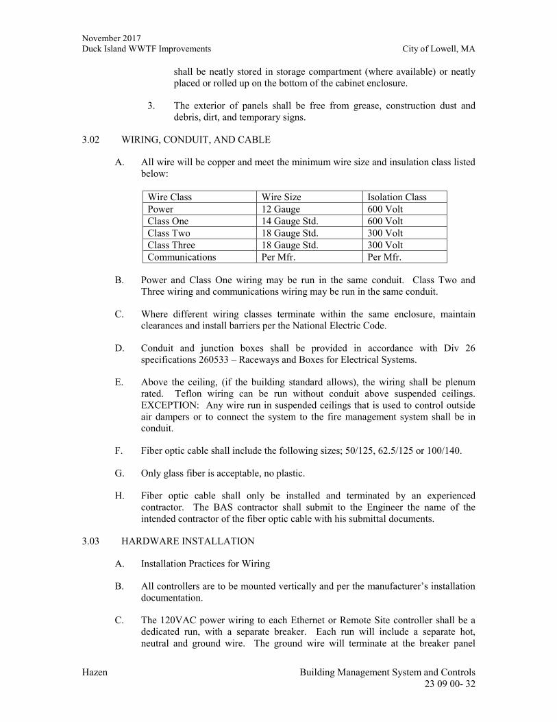
November 2017 Duck Island WWTF Improvements City of Lowell, MA
Hazen Building Management System and Controls 23 09 00- 32
shall be neatly stored in storage compartment (where available) or neatly placed or rolled up on the bottom of the cabinet enclosure.
3. The exterior of panels shall be free from grease, construction dust and debris, dirt, and temporary signs.
3.02 WIRING, CONDUIT, AND CABLE
A. All wire will be copper and meet the minimum wire size and insulation class listed below:
Wire Class Wire Size Isolation Class Power 12 Gauge 600 Volt Class One 14 Gauge Std. 600 Volt Class Two 18 Gauge Std. 300 Volt Class Three 18 Gauge Std. 300 Volt Communications Per Mfr. Per Mfr.
B. Power and Class One wiring may be run in the same conduit. Class Two and Three wiring and communications wiring may be run in the same conduit.
C. Where different wiring classes terminate within the same enclosure, maintain clearances and install barriers per the National Electric Code.
D. Conduit and junction boxes shall be provided in accordance with Div 26 specifications 260533 – Raceways and Boxes for Electrical Systems.
E. Above the ceiling, (if the building standard allows), the wiring shall be plenum rated. Teflon wiring can be run without conduit above suspended ceilings. EXCEPTION: Any wire run in suspended ceilings that is used to control outside air dampers or to connect the system to the fire management system shall be in conduit.
F. Fiber optic cable shall include the following sizes; 50/125, 62.5/125 or 100/140.
G. Only glass fiber is acceptable, no plastic.
H. Fiber optic cable shall only be installed and terminated by an experienced contractor. The BAS contractor shall submit to the Engineer the name of the intended contractor of the fiber optic cable with his submittal documents.
3.03 HARDWARE INSTALLATION
A. Installation Practices for Wiring
B. All controllers are to be mounted vertically and per the manufacturer’s installation documentation.
C. The 120VAC power wiring to each Ethernet or Remote Site controller shall be a dedicated run, with a separate breaker. Each run will include a separate hot, neutral and ground wire. The ground wire will terminate at the breaker panel
November 2017 Duck Island WWTF Improvements City of Lowell, MA
Hazen Building Management System and Controls 23 09 00- 33
ground. This circuit will not feed any other circuit or device.
D. A true earth ground must be available in the building. Do not use a corroded or galvanized pipe, or structural steel.
E. Wires are to be attached to the building proper at regular intervals such that wiring does not droop. Wires are not to be affixed to or supported by pipes, conduit, etc.
F. Conduit in finished areas will be concealed in ceiling cavity spaces, plenums, furred spaces and wall construction. Exception; metallic surface raceway may be used in finished areas on masonry walls. All surface raceway in finished areas must be color matched to the existing finish within the limitations of standard manufactured colors.
G. Conduit, in non-finished areas where possible, will be concealed in ceiling cavity spaces, plenums, furred spaces, and wall construction. Exposed conduit will run parallel to or at right angles to the building structure.
H. Wires are to be kept a minimum of three (3) inches from hot water, steam, or condensate piping.
I. Where sensor wires leave the conduit system, they are to be protected by a plastic insert.
J. Wire will not be allowed to run across telephone equipment areas.
3.04 INSTALLATION PRACTICES FOR FIELD DEVICES
A. Well-mounted sensors will include thermal conducting compound within the well to insure good heat transfer to the sensor.
B. Actuators will be firmly mounted to give positive movement and linkage will be adjusted to give smooth continuous movement throughout 100 percent of the stroke.
C. Relay outputs will include transient suppression across all coils. Suppression devices shall limit transients to 150% of the rated coil voltage.
D. Water line mounted sensors shall be removable without shutting down the system in which they are installed.
E. For duct static pressure sensors, the high pressure port shall be connected to a metal static pressure probe inserted into the duct pointing upstream. The low pressure port shall be left open to the plenum area at the point that the high pressure port is tapped into the ductwork.
F. For building static pressure sensors, the high pressure port shall be inserted into the space via a metal tube. Pipe the low pressure port to the outside of the building.
3.05 CONTROL PANELS
A. Enclosures
November 2017 Duck Island WWTF Improvements City of Lowell, MA
Hazen Building Management System and Controls 23 09 00- 34
1. Enclosures located in electrical rooms and administrative areas shall be NEMA 12 painted steel enclosures. Enclosures in unclassified process areas shall be NEMA 4X Type 316L stainless steel construction. Enclosures in classified areas shall be NEMA 7. NEMA 12 and NEMA 4X enclosures shall have a minimum thickness of 12 gauge for all surfaces (except those areas requiring reinforcement).
2. Wall mounted panels shall be furnished with quick-release clamp assemblies on three sides of each door matching the panel material. Floor mounted panels shall be furnished with, 3-point, lockable door latch with stainless steel handles.
3. A lockable hasp shall be provided for all panels that have quick-release clamps assemblies.
4. Panels shall be furnished with rolled lip around three sides of the door and along top of enclosure opening.
5. NEMA 4X panels shall be provided with clear plastic, gasketed lockable hinged door to encompass all non-NEMA 4X front panel devices.
B. Power Conditioner
1. All PLC, PC, or DDC equipped panels shall be furnished with a power conditioner unless powered by a UPS. Surge protection shall be provided to protect the electronic instrumentation system from surges propagation along the signal and power supply lines.
2. Line Regulation: shall provide regulated voltage output of +/- 3% when input varies +10% to -20% of nominal input rating.
3. Output Harmonic Distortion: Max 3% total RMS content at full load
4. Unit shall tolerate a temporary voltage surge or sag of +20% to -35% of input voltage.
5. Noise Attenuation: 120dB common mode; 60 dB transverse mode
6. Surge Suppression: shall be tested in compliance with ASNI/IEEE C63.41 Class A & B waveform with a let through of less than 0.2%
7. UL listed
8. MTBF: 25 years
9. Efficiency: 90% at full load
10. Operating temperature: -20 to 50 Deg C
11. Wiring Type: Hardwired
12. Overload Protection: 1.65 rated current at nominal input voltage
November 2017 Duck Island WWTF Improvements City of Lowell, MA
Hazen Building Management System and Controls 23 09 00- 35
13. Audible Noise: 65dB max
14. Manufactured by Sola model Hevi-Duty MCR or approved equal
C. Enclosure Lighting and Convenience Receptacle
1. All panels shall be furnished with one (1) 120VAC, 15A duplex, grounding type convenience power receptacle and 120 VAC fluorescent light fixture with 470 lumen lamp and plastic protective shield. A minimum of one (1) lamp shall be provided for every four (4) square feet of panel face area.
2. The power receptacle and fluorescent light shall have a dedicated circuit breaker and power feed.
3. All lights shall be controlled by a single a snap switch which will turn all the lights on and off. The switch shall be installed in an outlet box with cover and located to be easily accessible. The switch shall be labeled as the “Control Panel Interior Light Switch”.
4. Light shall be Allen Bradley series 855L-NX or approved equal.
D. Relays
1. The Contractor shall provide mechanically held, socket type, oil tight, heavy-duty type contractors (relays) for DIN rail mounting. Miniature relays are not acceptable. Relays shall be rated as required by the design with a minimum contact rating of 10A. The relay shall be provided with the number of poles required by the design and one spare Type C dry contact.
2. Timing relays and relays shall be Allen Bradley, Series 700 or approved equal.
E. Indicating Lights
1. All indicating lights shall be transformer type with replaceable high intensity LED type lamp. All indicating lights shall be rated NEMA 4X. All indicating lights used on the project shall be from one manufacturer and shall be of the same line.
2. Devices shall be of the 30.5 mm type rated for extra heavy duty service.
3. Indicating light shall have a push to test function. The push to test feature shall not interact with any other circuitry and shall not rely on PLC or DDC operation to function.
4. Lens color shall be as indicated on the Contract Drawings.
5. Indicating lights shall be Allen Bradley, Series 800H or approved equal
F. Switches and Buttons
November 2017 Duck Island WWTF Improvements City of Lowell, MA
Hazen Building Management System and Controls 23 09 00- 36
1. Switches and push-button type operators shall be rated NEMA 4X. All operators used on the project shall be from one manufacturer and shall be the same line.
2. Devices shall be of the 30.5 mm type rated for extra heavy duty service.
3. Selector switches shall have gloved hand operating handles.
4. Pushbuttons shall be of the guarded type except those being used for emergency stop control.
5. Emergency stop pushbuttons shall be Push-Pull mushroom-type with maintained contacts.
G. The control panel shall contain power supplies for sensors, interface relays and contactors, and safety circuits.
H. All wiring to and from the FIP will be to screw type terminals. Analog or communications wiring may use the FIP as a raceway without terminating. The use of wire nuts within the FIP is prohibited.
I. The wiring within all enclosures shall be run in plastic track. Wiring within controllers shall be wrapped and secured.
3.06 IDENTIFICATION
A. Identify all control wires with labeling tape or sleeves using words, letters, or numbers that can be exactly cross-referenced with as-built drawings.
B. All field enclosures, other than controllers, shall be identified with a Bakelite nameplate. The lettering shall be in white against a black or blue background.
C. Junction box covers will be marked to indicate that they are a part of the BAS system.
D. All I/O field devices (except space sensors) that are not mounted within FIP's shall be identified with name plates.
E. All I/O field devices inside FIP's shall be labeled.
3.07 EXISTING CONTROLS
A. Existing controls which are to be reused must each be tested and calibrated for proper operation. Existing controls which are to be reused and are found to be defective requiring replacement, will be noted to the Owner. The Owner will be responsible for all material and labor costs associated with their repair.
3.08 LOCATION
A. The location of sensors shall be per HVAC drawings.
B. Space humidity or temperature sensors shall be mounted away from machinery
November 2017 Duck Island WWTF Improvements City of Lowell, MA
Hazen Building Management System and Controls 23 09 00- 37
generating heat, direct light and diffuser air streams.
C. Outdoor air sensors shall be mounted on the north building face directly in the outside air. Install these sensors such that the effects of heat radiated from the building or sunlight is minimized.
D. Field enclosures shall be located immediately adjacent to the controller panel(s) to which it is being interfaced.
3.09 COLOR GRAPHIC DISPLAYS
A. Unless otherwise directed by the owner, the Contractor shall provide color graphic displays as depicted in the mechanical drawings for each system and floor plan. For each system or floor plan, the display shall contain the associated points identified in the point list and allow for setpoint changes as required by the owner.
3.10 DOCUMENTATION
A. As built software documentation will include the following:
1. Descriptive point lists
2. Application program listing
3. Application programs with comments.
4. Printouts of all reports.
5. Alarm list.
6. Printouts of all graphics
7. Commissioning and System Startup
3.11 POINT TO POINT CHECKOUT
A. Each I/O device (both field mounted as well as those located in FIPs) shall be inspected and verified for proper installation and functionality. A checkout sheet itemizing each device shall be filled out, dated and approved by the Project Manager for submission to the owner or owner’s representative.
3.12 CONTROLLER CHECKOUT
A. A field checkout of all controllers and network control panels shall be conducted to verify proper operation of both hardware and software. A checkout sheet itemizing each device and a description of the associated tests shall be prepared and submitted to the owner or owner’s representative by the completion of the project.
3.13 SYSTEM ACCEPTANCE TESTING
A. All application software will be verified and compared against the sequences of
November 2017 Duck Island WWTF Improvements City of Lowell, MA
Hazen Building Management System and Controls 23 09 00- 38
operation.
B. Control loops will be exercised by inducing a setpoint shift of at least 10% and observing whether the system successfully returns the process variable to setpoint. Record all test results and attach to the Test Results Sheet.
C. Test each alarm in the system and validate that the system generates the appropriate alarm message, that the message appears at all prescribed destinations (workstations or printers), and that any other related actions occur as defined (i.e. graphic panels are invoked, reports are generated, etc.). Submit a Test Results Sheet to the owner.
D. Perform an operational test of each unique graphic display and report to verify that the item exists, that the appearance and content are correct, and that any special features work as intended. Submit a Test Results Sheet to the owner.
E. Perform an operational test of each third party interface that has been included as part of the automation system. Verify that all points are properly polled, that alarms have been configured, and that any associated graphics and reports have been completed. If the interface involves a file transfer over Ethernet, test any logic that controls the transmission of the file, and verify the content of the specified information.
F. BMS Contractor shall include technician labor to provide onsite support and assistance to the owner’s third party commissioning agent (if applicable) during commissioning.
- END OF SECTION -
November 2017 Duck Island WWTF Improvements City of Lowell, MA
Hazen Building Management System and Controls 23 09 00- 39
- THIS PAGE INTENTIONALLY LEFT BLANK -

November 2017 Duck Island WWTF Improvements City of Lowell, MA
Hazen Sequence of Operations 23 09 93- 1
SECTION 23 09 93
SEQUENCE OF OPERATIONS
PART 1 - GENERAL
1.01 SEQUENCE OF OPERATIONS
A. General
1. This contractor shall coordinate with the contract drawings. All necessary points shall be added so as to conform to the intent of sequence of operation described below.
2. Optimal Start - The BMS contractor shall provide the programming necessary to optimally start the equipment connected to the respective building’s touch screen network control panel. The units shall start prior to the scheduled occupancy based on the time necessary for the associated zones to reach their occupied setpoint at the scheduled occupancy.
3. Discharge Temperature Setpoint Reset - The BMS contractor shall provide the programming necessary for discharge temperature setpoint reset (adj) for the equipment connected to the respective building’s touch screen network control panel. The discharge temperature setpoint shall be reset incrementally up/down if 95% (adj) of the associated zones are calling for heating/cooling.
4. Discharge Static Pressure Setpoint Reset - The BMS contractor shall provide the programming necessary for discharge static pressure setpoint reset (adj) for the equipment connected to the respective building’s touch screen network control panel. The discharge static pressure setpoint shall be reset incrementally up/down if 95% (adj) of the associated zones are fully open/closed.
B. Existing RTU-4,5,6 (existing RTUs located on the Administration building roof)
1. Each RTU’s existing factory controls, control end devices, and wiring shall remain and be reused.
2. The existing RTU shall have a BACnet network interface card installed and tested for each unit by the owner.
3. The BMS contractor shall bring BACnet communication from the RTU to the respective building’s touch screen network control panel to control and monitor all points available via BACnet protocol.
4. The RTU shall be enabled to operate by the respective building’s touch screen network control panel based on a time clock schedule. Once enabled, the RTU unit shall start and operate to maintain temperature setpoint through its own internal control system.
November 2017 Duck Island WWTF Improvements City of Lowell, MA
Hazen Sequence of Operations 23 09 93- 2
5. The following shall be displayed and alarmed as necessary at the respective building’s touch screen network control panel:
a. All available control, monitoring, and alarm points through the BACnet interface
C. Existing Split AC unit (existing Trane Split AC unit located in the Generator Electrical Building)
1. The split AC unit’s existing factory controls, control end devices, and wiring shall remain and be reused.
2. The BMS contractor shall provide a DDC controller to monitor the AC unit fan status and common alarm.
a. The BMS contractor shall provide relays and current switches as needed to monitor the above.
3. The following shall be displayed and alarmed as necessary at the respective building’s touch screen network control panel:
a. AC unit fan status
b. AC unit common alarm
c. Dirty Filter
D. Existing Split AC unit (existing Trane Split AC unit located in the Influent Building Electrical Room)
1. The split AC unit’s existing factory controls, control end devices, and wiring shall remain and be reused.
2. The BMS contractor shall provide a DDC controller to monitor the AC unit fan status and common alarm.
a. The BMS contractor shall provide relays and current switches as needed to monitor the above.
3. The following shall be displayed and alarmed as necessary at the respective building’s touch screen network control panel:
a. AC unit fan status
b. AC unit common alarm
c. Dirty Filter
E. Existing AHU-2 (existing AHU-2 located in the Influent building)
November 2017 Duck Island WWTF Improvements City of Lowell, MA
Hazen Sequence of Operations 23 09 93- 3
1. The AHU’s existing factory controls, control end devices, and wiring shall remain and be reused.
2. The existing AHU shall have a BACnet network interface card installed and tested for each unit by the owner.
3. The BMS contractor shall bring BACnet communication from the AHU to the respective building’s touch screen network control panel to control and monitor all points available via BACnet protocol.
4. The AHU shall be enabled to operate by the respective building’s touch screen network control panel based on a time clock schedule. Once enabled, the AHU unit shall start and operate to maintain temperature setpoint through its own internal control system.
5. The following shall be displayed and alarmed as necessary at the respective building’s touch screen network control panel:
a. All available control, monitoring, and alarm points through the BACnet interface
F. Existing Boiler System (existing Boiler system located in the Influent building)
1. The Boiler system existing controls, control end devices, and wiring shall remain and be reused.
2. The BMS contractor shall provide a new DDC controller for monitoring of the Boiler system existing points. The following points shall be hard-wired monitored (integration is not available) from the existing Boiler system:
a. UH Building pump status
b. Boiler 1 pump status
c. HW system lockout status
d. HW system alarm status
e. Expansion tank pressure switch alarm status
f. Bldg HW call status
g. Screen pump status
h. AHU-2 bldg pump status
i. Combustion air damper status
November 2017 Duck Island WWTF Improvements City of Lowell, MA
Hazen Sequence of Operations 23 09 93- 4
3. The BMS contractor shall bring BACnet communication from the DDC controller to the respective building’s touch screen network control panel to monitor all points available via BACnet protocol.
4. The BMS contractor shall also provide and monitor a new Boiler room temperature sensor at the DDC controller.
5. The following shall be displayed and alarmed as necessary at the respective building’s touch screen network control panel:
a. UH Building pump status
b. Boiler 1 pump status
c. HW system lockout status
d. HW system alarm status
e. Expansion tank pressure switch alarm status
f. Bldg HW call status
g. Screen pump status
h. AHU-2 bldg pump status
i. Combustion air damper status
j. Boiler room temperature
G. AHU-A-01
1. The AHU shall be furnished with factory DDC controls for complete stand-alone operation and shall tie into the respective building’s touch screen network control panel via the factory provided BACnet interface.
2. The BMS contractor shall provide all required field wiring of controls that cannot be factory installed for proper AHU unit operation, including, but not limited to, wiring the Mfr discharge temperature and discharge static pressure sensor.
3. The BMS contractor shall also furnish the 3-way hot water control valve and wire it back to the unit mfr factory controller.
4. The AHU shall be enabled to operate by the respective building’s touch screen network control panel based on a time clock schedule or a call for cooling or heating. Once enabled, the AHU shall start and operate to maintain discharge temperature and discharge static pressure through its own internal control system
November 2017 Duck Island WWTF Improvements City of Lowell, MA
Hazen Sequence of Operations 23 09 93- 5
5. The BMS contractor shall bring BACnet communication from the AHU to the respective building’s touch screen network control panel to control and monitor all points available via BACnet protocol.
6. The following shall be displayed and alarmed as necessary at the respective building’s touch screen network control panel:
a. All available control, monitoring, and alarm points through the BACnet interface
H. SB-MAU-01
1. The MAU unit shall be furnished with factory DDC controls for complete stand-alone operation and shall tie into the respective building’s touch screen network control panel via the factory provided BACnet interface.
a. The MAU unit shall also be provided with a factory mounted and wired supply air flow measuring station by the MAU unit mfr
2. The BMS contractor shall provide all required field wiring of controls that cannot be factory installed for proper MAU unit operation, including, but not limited to, wiring the Mfr discharge temperature and discharge static pressure sensor.
3. The BMS contractor shall furnish and wire (2) duct mounted airflow measuring stations back to a BMS provided DDC controller. The DDC controller will measure the air flow in both locations (as shown on the mechanical dwgs) and utilize the measured airflows to calculate the Dewatering/sludge room airflow.
a. If any of the airflows associated with the Sludge Garage or Dewatering Room supply or exhaust fall below 80% of the design flow (adj), the Sludge Garage building’s touch screen network control panel shall generate an alarm and turn on the room’s horn and strobe station.
1) The BMS contractor shall furnish (1) new horn and strobe station in the sludge garage and (1) new horn and strobe station in the dewatering room.
a) In the event of an alarm condition, the horn can be manually silenced, but the strobe will continue to flash until the airflow is within 20% (adj) of the design flow.
4. The MAU shall be enabled to operate 24x7 (adj) by the respective building’s touch screen network control panel based on a time clock schedule. Once enabled, the MAU shall start and operate to maintain discharge temperature through its own internal control system.
November 2017 Duck Island WWTF Improvements City of Lowell, MA
Hazen Sequence of Operations 23 09 93- 6
5. The BMS contractor shall bring BACnet communication from the MAU to the respective building’s touch screen network control panel to control and monitor all points available via BACnet protocol.
6. The network control panel shall be capable of sending the MAU DDC signals to change the supply air temperature setpoint and fan speed. The signals shall be transmitted via the BACnet communication.
7. The following shall be displayed and alarmed as necessary at the respective building’s touch screen network control panel:
a. All available control, monitoring, and alarm points through the BACnet interface
b. Airflow measuring station #1 airflow
c. Airflow measuring station #2 airflow
d. Calculated Dewatering/sludge exhaust airflow
e. Horn/Strobe Station (Sludge garage) command: On/off
f. Horn/Strobe Station (Dewatering Room) command: On/off
I. SB-MAU-02
1. The MAU unit shall be furnished with factory DDC controls for complete stand-alone operation and shall tie into the respective building’s touch screen network control panel via the factory provided BACnet interface.
a. The MAU unit shall also be provided with a factory mounted and wired supply air flow measuring station and exhaust air flow measuring station by the MAU unit mfr
2. The BMS contractor shall furnish and wire back to the MAU controller, infrared occupancy sensors. The sensor quantity shall be as needed to detect occupancy in all areas of the Odor Control Room. The sensors shall be used by the MAU controller to determine if the unit can enter recirculation mode.
3. The BMS contractor shall provide all required field wiring of controls that cannot be factory installed for proper MAU unit operation, including, but not limited to, wiring the Mfr discharge temperature and discharge static pressure sensor.
4. If any of the airflows fall below 80% of the design flow (adj), the respective building’s touch screen network control panel shall generate an alarm and turn on the respective room’s horn and strobe station.
1) The BMS contractor shall provide a DDC controller to control the existing horn and strobe station in area served by MAU-2.
November 2017 Duck Island WWTF Improvements City of Lowell, MA
Hazen Sequence of Operations 23 09 93- 7
a) In the event of an alarm condition, the horn can be manually silenced, but the strobe will continue to flash until the airflow is within 20% (adj) of the design flow.
5. The MAU shall be enabled to operate 24x7 (adj) by the respective building’s touch screen network control panel based on a time clock schedule. Once enabled, the MAU shall start and operate to maintain discharge temperature and discharge static pressure through its own internal control system
6. The BMS contractor shall bring BACnet communication from the MAU to the respective building’s touch screen network control panel to control and monitor all points available via BACnet protocol.
7. The network control panel shall be capable of sending the MAU DDC signals to force the unit to operate in 100% outside air mode and prevent recirculation. The signal shall be transmitted via the BACnet communication.
8. The following shall be displayed and alarmed as necessary at the respective building’s touch screen network control panel:
a. All available control, monitoring, and alarm points through the BACnet interface
b. Existing Horn/Strobe Station command: On/off
J. Zone Dampers
1. The BMS contractor shall provide DDC controllers, zone damper actuators and space temperature sensors for each zone.
2. During occupied mode (when the associated RTU is on):
a. If the space temperature rises above setpoint (adj), the DDC controller shall modulate open the associated zone damper actuator to maintain space temperature setpoint (adj).
b. If the space temperature falls below setpoint (adj), the DDC controller shall modulate close the associated zone damper actuator to maintain space temperature setpoint (adj).
3. During unoccupied mode (when the associated RTU is off):
a. The zone damper actuator shall close.
4. The BMS contractor shall bring BACnet communication from the DDC controllers to the respective building’s touch screen network control panel to control and monitor all points available via BACnet protocol.
5. The following shall be displayed and alarmed as necessary at the respective building’s touch screen network control panel:
November 2017 Duck Island WWTF Improvements City of Lowell, MA
Hazen Sequence of Operations 23 09 93- 8
a. Zone Damper command: 0-100%
b. Space temperature and setpoint
K. Bypass Dampers
1. The BMS contractor shall provide DDC controllers, bypass damper actuators and discharge air static pressure sensors for each bypass system.
2. During occupied mode (when the associated RTU is on):
a. If the discharge air static pressure rises above setpoint (adj), the DDC controller shall modulate open the associated bypass damper actuator to maintain static pressure setpoint (adj).
b. If the discharge air static pressure falls below setpoint (adj), the DDC controller shall modulate close the associated bypass damper actuator to maintain static pressure setpoint (adj).
3. During unoccupied mode (when the associated RTU is off):
a. The bypass damper actuator shall close.
4. The BMS contractor shall bring BACnet communication from the DDC controllers to the respective building’s touch screen network control panel to control and monitor all points available via BACnet protocol.
5. The following shall be displayed and alarmed as necessary at the respective building’s touch screen network control panel:
a. Bypass Damper command: 0-100%
b. Discharge air static pressure and setpoint
L. Room Pressure Controls
1. The BMS contractor shall provide DDC controllers, room damper actuators and room differential pressure sensors for each room pressure control system.
a. Reference mechanical dwgs for quantities and locations
2. During occupied mode:
a. If the room differential pressure drops below setpoint (adj), the DDC controller shall modulate open the associated room damper actuator to maintain differential pressure setpoint (adj).
b. If the room differential pressure rises above setpoint (adj), the DDC controller shall modulate close the associated room damper actuator to maintain differential pressure setpoint (adj).
November 2017 Duck Island WWTF Improvements City of Lowell, MA
Hazen Sequence of Operations 23 09 93- 9
3. During unoccupied mode:
a. The room damper actuator shall close.
4. The BMS contractor shall bring BACnet communication from the DDC controllers to the respective building’s touch screen network control panel to control and monitor all points available via BACnet protocol.
5. The following shall be displayed and alarmed as necessary at the respective building’s touch screen network control panel:
a. Room Damper command: 0-100%
b. Room differential pressure and setpoint
M. RTU-M-01
1. The RTU shall be furnished with factory mounted and wired standalone controls by the unit manufacturer.
2. The BMS contractor shall provide all required field wiring of controls that cannot be factory installed for proper RTU operation, including, but not limited to, wiring the space temperature sensor.
3. The building’s touch screen network control panel shall not control or monitor the dehumidification unit.
N. EDH-A-01
1. The EDH shall be furnished with factory mounted and wired standalone controls by the unit manufacturer.
2. The BMS contractor shall provide all required field wiring of controls that cannot be factory installed for proper EDH operation, including, but not limited to, wiring the discharge air temperature sensor and space thermostat.
3. The EDH shall only operate after airflow is proven.
4. The building’s touch screen network control panel shall not control or monitor the dehumidification unit.
O. Dehumidifier (HD-M-01)
1. The Dehumidifier shall be furnished with factory mounted and wired standalone controls by the unit manufacturer.
2. The BMS contractor shall provide all required field wiring of controls that cannot be factory installed for proper Dehumidifier operation, including, but not limited to, wiring the space humidistat and interlocking the respective condensing unit.
November 2017 Duck Island WWTF Improvements City of Lowell, MA
Hazen Sequence of Operations 23 09 93- 10
3. The building’s touch screen network control panel shall not control or monitor the dehumidification unit.
P. Miscellaneous Fans (BS-EF-01 & TN-xx-xx)
1. BS-EF-01 and all TN Fans (TN-xx-xx) shall have local standalone controls furnished and wired by the base electrician.
2. The building’s touch screen network control panel shall not control or monitor any of these fans.
- END OF SECTION -
November 2017 Duck Island WWTF Improvements City of Lowell, MA
Hazen HVAC Copper and Brass Pipe
23 23 00-1
SECTION 23 23 00
HVAC COPPER AND BRASS PIPE
PART 1 – GENERAL
1.01 SECTION INCLUDES
A. The Contractor shall provide copper and brass pipe and fittings as indicated. This section includes all copper and brass pipe and fittings, including all insulation, painting and related work as shown on the Contract Drawings, specified in the Specifications or required for a complete installation.
1.02 PAYMENT
A. Payment will be made as provided for in the Specifications.
B. No direct payment will be made for painting, insulation and testing pipelines or for gaskets, bolts, nuts and other appurtenances and material required to erect the lines; the costs thereof shall be included in the prices bid for the pipe.
1.03 REFERENCES
A. ASTM B16 – Free-Cutting Brass Rod, Bar and Shapes for Use in Screw Machines.
B. ASTM B32 – Solder Metal.
C. ASTM B42 – Seamless Copper Pipe, Standard Sizes.
D. ASTM B43 – Seamless Red Brass Pipe, Standard Sizes.
E. ASTM B61 – Steam or Valve Bronze Castings.
F. ASTM B62 – Composition Bronze or Ounce Metal Castings.
G. ASTM B88 – Seamless Copper Water Tube.
H. ASTM B124 – Copper and Copper Alloy Forging Rod, Bar and Shapes.
I. ASTM B251 – Wrought Seamless Copper and Copper-Alloy Tube.
J. ASTM B280 – Seamless Copper Tube for Air Conditioning and Refrigeration Field Service.
K. ASTM B302 – Threadless Copper Pipe.
November 2017 Duck Island WWTF Improvements City of Lowell, MA
Hazen HVAC Copper and Brass Pipe
23 23 00-2
L. ASME B1.20.1 – Screw Threads – Pipe Threads, General Purpose (Inch).
M. ASME B16.15 – Cast Bronze Threaded Fittings, Classes 125 and 250 (Includes Revisions Service).
N. ASME B16.18 – Cast Copper Alloy Solder Joint Pressure Fittings (Includes Revision Service).
O. ASME B16.22 – Wrought Copper and Copper Alloy Solder-Joint Pressure Fitting (Includes Revision Service).
P. ASME B16.24 – Cast Copper Alloy Pipe Flanges and Flanged Fittings Class 150, 300, 400, 600, 900, 1500 and 2500.
Q. MSS SP-58 – Pipe Hangers and Supports – Materials, Design, and Manufacture.
R. MSS SP-69 – Pipe Hangers and Supports – Selection and Application.
S. MSS SP-89 – Pipe Hangers and Supports – Fabrication and Installation Practices.
T. ASME Code, Section VIII, Appendix bb.
1.04 DESIGN REQUIREMENTS
A. Copper and brass pipe and fittings shall conform to the latest Building Code of the State of Connecticut in respect to plumbing and other applications covered by these laws.
B. Copper and brass pipe shall conform to the latest standards of the American Society for Testing and Materials (ASTM), the American National Standards Institute (ANSI), the American Society of Mechanical Engineers (ASME), the Copper and Brass Research Association (CABRA), the Society of Automotive Engineers (SAE), the Manufacturer's Standardization Society (MSS), the American Welding Society (AWS), and National Pipe Thread (NPT).
1.05 DELIVERY, STORAGE AND HANDLING
A. Deliver, store and handle all products and materials as specified in Division 01 00 00 of the Specifications.
PART 2 - PRODUCTS
2.01 MANUFACTURERS
A. The following manufacturers are acceptable. Equivalent products from other manufacturers may be submitted for approval.
November 2017 Duck Island WWTF Improvements City of Lowell, MA
Hazen HVAC Copper and Brass Pipe
23 23 00-3
B. Copper Pipe and Fittings:
1. Pipe and Fittings:
a. Mueller Industries, Inc., Wichita, KS. b. IBCO, Elkhart, IN. c. Or equal.
2. Flared Tube Fittings:
a. Parker Hannifin Corp., Triple-Lok Fittings. b. NIBCO, Elkhart, IN. c. Or equal.
C. Brass Pipe and Fittings:
1. Metalloy Industries, Inc., Alachua, FL.
2. NIBCO, Elkhart, IN.
3. Or equal.
D. Wall Sleeve Annular Seals:
1. Thunderline Corp. (Link-Seal), Belleville, MI.
2. The Metraflex Corporation, Metraseal, Chicago, IL.
3. Flexicraft Industries (The Pipe Seal), Chicago, IL.
4. Or equal.
E. Insulation:
1. Armstrong World Industries, Inc.
2. Rubatex Corp.
3. Or equal.
November 2017 Duck Island WWTF Improvements City of Lowell, MA
Hazen HVAC Copper and Brass Pipe
23 23 00-4
2.02 PIPE MATERIALS
A. Copper Pipe and Fittings
1. Refrigeration Piping: For refrigeration copper pipe, provide type ACR seamless, round, hard drawn copper tubing that meets ASTM B280 requirements. The pipe shall be delivered to the site clean, charged with nitrogen, and sealed. Provide tube sizes, dimensions and wall thickness conforming to ASTM B280 for Type ACR tubing, unless otherwise specified. Provide nominal lengths of hard copper tubing in straight lengths of approximately 20 feet, unless otherwise specified.
a. Fittings: For copper tubing, use brazed joint socket type fittings, as specified. No bending of hard copper tubing will be permitted, unless otherwise specified; make all bends and connections with suitable fittings.
i. Braze Joint Fittings: Provide ASME B16.18, cast copper alloy or ASME B16.22 wrought copper and copper alloy fittings. Braze joint fittings and tubing in conformity with the specifications of Section 3 of the CABRA Copper Tube Handbook. Brazing alloy shall be copper-phosphorus alloy, Class BCuP-5, as specified by American Welding Society Spec. AWS A5.8.
2. Drain Copper Piping: For drain copper pipe, provide type L seamless, round, hard drawn copper tubing that meets ASTM B88 requirements. Provide tube sizes, dimensions and wall thickness conforming to ASTM B88 for Type L tubing, unless otherwise specified. Provide nominal lengths of hard copper tubing in straight lengths of approximately 20 feet, unless otherwise specified.
a. Fittings: Provide solder type fittings of the same material as the pipe. b. Joints: Use ASTM B32 alloy Grade 95TA (95 percent tin and 5 percent
antimony) solder for piping.
3. Potable Water Piping: Use ASTM B32 alloy Grade 95TA (95 percent tin and 5 percent antimony) solder for piping carrying potable water.
4. Unacceptable Uses: Do not use copper pipe with soldered joints for transporting fuel oil or other flammable or toxic liquids inside buildings.
B. Wall Sleeves
1. Unless otherwise shown or specified, furnish and install suitable pipe sleeves at all points where pipes pass through walls or floors of structures. Sleeve material shall be steel unless indicated otherwise on the Contract Drawings or specified in the Specifications.
November 2017 Duck Island WWTF Improvements City of Lowell, MA
Hazen HVAC Copper and Brass Pipe
23 23 00-5
C. Wall Sleeve Annular Seals
1. Where pipes pass through walls, partitions or floors where fire-rated construction is not required, provide modular mechanical type seals consisting of interlocking synthetic rubber links shaped to continuously fill the annular space between the pipe and the wall sleeve. Provide an elastomeric element that is of the size, quantity, type and material that the manufacturer recommends for the intended service and that will provide an effective hydrostatic seal. Bolts and nuts shall be stainless steel. Wall sleeve annular seals shall be approved equal to those manufactured by the companies listed in Paragraph 2.01.D.
2. For all penetrations through fire-rated walls, partitions and floors, provide a permanent fire stop system. The fire stop system shall maintain the integrity of the wall or floor system for the rated time period and shall allow normal pipe movement without being displaced. The fire stop system shall be intumescent when exposed to flame or heat. Asbestos shall not be used as fire stop material.
D. Corrosion Resistant Coating
1. All copper pipe shall receive a corrosion resistant coating. For piping that receives insulation, the coating shall be applied and allowed to cure per the manufacturer’s instructions prior to insulating.
2. Coating shall be a field applied Bronz-Glow’s SPC-Clear coating, Incralac or approved equal. The coating shall be specifically listed for use on copper pipe for the protection from corrosion due to hydrogen sulfide and shall be UV resistant.
2.03 INSULATION MATERIALS
A. Insulation shall be flexible elastomeric type, closed cell, cylindrical or sheet type as required by the application. Flexible elastomeric insulation shall have a thermal conductivity not exceeding 0.27 BTU per hour per square foot per degree F per inch thickness at 75 degrees F mean temperature. Water absorption shall be less than 5% (ASTM D 1056). Water vapor permeability shall not exceed 0.10 perms per inch in accordance with ASTM E 96 Procedure A. The insulation shall meet the requirements of ASTM C534 and ASTM D 1056. The insulation shall have a flame spread rating of less than 25 and a smoke development of less than 50 per ASTM-E84.
B. Joints and Seams: All joints shall be cut straight and butted with no gaps. Seal all joints with the manufacturer’s recommended adhesive.
C. Fittings, flanges and valves:
November 2017 Duck Island WWTF Improvements City of Lowell, MA
Hazen HVAC Copper and Brass Pipe
23 23 00-6
1. Seams and mitered joints shall be adhered using the manufacturer’s recommended adhesive. Screwed fittings shall be sleeved and adhered with a minimum one-inch overlap onto the adjacent insulation.
2. Flanges, strainers, couplings, and valves shall be insulated using donuts, then covered with sheet or oversize tubular insulation.
D. Jacket:
1. All insulated copper pipe, fittings, and appurtenances shall receive an anodized aluminum jacket.
2. The jacket shall be a minimum of 0.016” thick.
3. The jacket shall be secured using latching metal straps.
PART 3 EXECUTION
3.01 INSTALLATION
A. General: Install all pipe and fittings in accordance with this Specification and as shown on the Contract Drawings, and in accordance with the manufacturer's recommendations and approved shop drawings.
B. Connections Between Dissimilar Metals in Pipes: Where connections are to be made between pipelines or equipment of dissimilar metals, make the connections using dielectric insulating couplings, unions or other approved dielectric insulating devices.
C. Connections Between Dissimilar Metals in Supports: Where contact between dissimilar metals between pipes and supports, or supports and the structure occur, the site of the contact shall be suitable protected using a dielectric media to prevent the contact between the surfaces such as a neoprene pad.
D. Pipe Lengths: Full standard lengths of pipe shall be used in each pipe run in so far as possible. Shorter lengths than standard shall be used only to complete a straight run of pipe, to connect to established locations of valves, equipment, bends, and the like. Random lengths of pipe or cuttings from standard lengths shall not be coupled together when a full standard pipe length will fit in the pipe run.
E. Piping for refrigeration shall remain charged with nitrogen and sealed until it is installed. The Contractor shall take precautions to ensure that the pipe is clean and free from debris.
F. The Contractor shall provide a flow of nitrogen through the piping and fittings during brazing to prevent the formation of scale.
November 2017 Duck Island WWTF Improvements City of Lowell, MA
Hazen HVAC Copper and Brass Pipe
23 23 00-7
G. Reducing Fittings: Use reducing fittings for all changes in pipe size. Do not use bushings.
H. All copper piping shall receive a corrosion resistant coating. The coating shall be applied within 24 hours of the pipe passing the leak test. The copper pipe shall be thoroughly cleaned prior to application of the coating. At a minimum, the pipe shall be free of all signs of corrosion, oils, flux, and other substances that will hinder proper application of the coating. The Contractor shall follow all cleaning and pipe preparations required by the coating Manufacturer.
I. All refrigeration piping and all interior condensate piping shall be insulated with 1.5” of elastomeric insulation and provided with an aluminum jacket. The insulation shall be applied after the corrosion coating has fully cured as indicated by the coating manufacturer.
J. Pipe Flexibility
1. Make ample provisions for flexibility in all pipelines.
2. Install branch tees on risers in locations that will allow the branch lines, when expanded by heat, to drain properly.
3. Unless other forms of expansion compensation are specified, such as expansion joints, fabricate all runs of pipe subject to change in length shorter than their theoretical length to the extent of one half of the expansion and erect them such that they may be free to expand without increasing the stresses imposed when cold.
4. When the foregoing method of compensation for expansion is not adequate, furnish and install in the pipelines expansion devices adequate to allow the lines to expand and contract freely without injury to any part of the piping system. The devices may be in the form of expansion joints, swivel joints, swing joints, pipe bends or flexible couplings, and shall include such anchors as may be shown or required to make the devices effective. A sufficient number of fittings and pipe lengths shall be used in connection with swing joints to assure the absence of distortion of either the pipelines or branches. Application guide and anchor requirements for expansion joints shall be in accordance with the recommendations of the manufacturer or the Standards of the EJMA.
K. Venting
1. Each high point in liquid lines shall be provided with a vent consisting of an automatic air release/vacuum relief valve and an outlet vent line. The automatic valve and vent line for pipelines up to and including 1-inch size shall be the same size as the carrier pipe. In larger carrier pipes, the valve and vent line shall be of
November 2017 Duck Island WWTF Improvements City of Lowell, MA
Hazen HVAC Copper and Brass Pipe
23 23 00-8
the size given in the Specifications, but not smaller than 1 inch. The automatic valve shall have a cast or ductile iron body and cover, stainless steel internals, and Viton or Buna N seal, unless otherwise specified. The outlet vent line from the valve shall be Schedule 80 CPVC, and shall terminate at a point approximately 3 feet above the floor. A bronze ball valve shall be provided between the carrier pipe and the automatic valve to allow removal of the automatic valve for repair or replacement.
2. Where vent valves are so located that liquids discharged therefrom would cause damage to structure or equipment, the vent shall be piped to the nearest gutter or drain in an approved manner.
L. Drainage
1. Each low point in liquid lines shall be provided with not less than a 1-inch drain line. A bronze ball valve shall be provided at the connection to the carrier pipe and at the terminus approximately 3 feet above the floor. A quick connect coupling shall be provided at the end of the drain line for attachment of a hose. The drain line shall be Schedule 80 CPVC.
M. Hangers and Supports: Furnish and install all supporting devices. The hangers and supports shall conform to the requirements of MSS SP-58, 69, and 89.
N. Drip Pans: Provide drip pans under all metallic pipelines installed over electrical equipment and motors to conduct drainage to the nearest floor drain, gutter or other drainage system with 3/4-inch red brass pipe. Make the connection between the drip pan and the brass drain pipe leaktight, and pitch the drip pan uniformly toward the drain pipe at a slope not less than 1/8-inch per lineal foot.
O. Pipe identification signs and valve identification numbers shall be furnished and installed in conformity with Section 15030 – Piping and Equipment Identification Systems.
3.02 CLEANING AND TESTING
A. Cleaning: During construction, clean all piping before placement and keep the lines free from every kind of foreign matter. All pipelines shall be left thoroughly clean to the satisfaction of the Engineer. Flush all process and potable water pipelines with clean water.
B. Refrigerant piping must be tested before any piping is insulated, coated, or concealed. The entire refrigerant circuit must be thoroughly tested to be sure that it is absolutely tight. The system shall be tested with oil pumped dry nitrogen. The low side of a 410a system shall be tested at 375 psig and the high side at 420 psig. Other refrigerant test pressures shall match the respective test pressures used by the manufacturer of the evaporator and condenser coils. All pipe joints shall be tapped sharply with a rubber
November 2017 Duck Island WWTF Improvements City of Lowell, MA
Hazen HVAC Copper and Brass Pipe
23 23 00-9
mallet and tested for leaks with a soap solution. After all leaks have been repaired, the system shall be charged with a small quantity of refrigerant and the entire system shall be checked with a detector suitable for the type of refrigerant. Once the system is found tight, it shall be allowed to stand for 6 hours with the pressure on. If any pressure drop occurs, except those due to changes in ambient temperature, the entire system shall be retested. The system shall be evacuated with a vacuum pump to a minimum vacuum of 1 mm Hg absolute is achieved or as prescribed by the equipment manufacturer, whichever is more stringent. Under no circumstances shall the compressor be used to evacuate the system. After evacuation, the system shall be allowed to stand for 12 hours. If no noticeable rise in pressure occurs, the system shall be charged.
C. Condensate piping shall be tested under pressure of a filled line. The discharge shall be temporarily plugged and the line filled with clean water. All joints shall be visually inspected. Any leaks shall be corrected and the line retested. Condensate piping located outside shall not be tested when the temperature is below freezing.
- END OF SECTION -
November 2017 Duck Island WWTF Improvements City of Lowell, MA
Hazen HVAC Copper and Brass Pipe
23 23 00-10
- THIS PAGE INTENTIONALLY LEFT BLANK -
November 2017 Duck Island WWTF Improvements City of Lowell, MA
Hazen Metallic Ductwork and Duct Accessories
23 31 13-1
SECTION 23 31 13
METALLIC DUCTWORK AND DUCT ACCESSORIES PART 1 -- GENERAL 1.01 THE REQUIREMENT
A. The Contractor shall furnish and install all ductwork, fittings, and accessories as shown on the Drawings and in accordance with the Specifications.
B. The equipment shall be furnished complete with all accessories, special tools, base
attachments, mountings, anchor bolts and other appurtenances as specified or as may be required for a complete installation.
1.02 RELATED WORK SPECIFIED ELSEWHERE
A. Section 23 05 93 – HVAC Testing, Adjustment, and Balancing
1.03 SUBMITTALS
A. The Contractor shall submit shop drawings on all new and modified ductwork, accessories and appurtenances and all fabrication work required for all equipment specified in this section in accordance with Division 01 00 00 General Requirements.
B. The Contractor shall submit shop drawings for supports for new and modified ductwork. The shop drawings shall locate and identify each support, brace, hanger, guide, component and anchor. Ductwork support systems shall be designed and Shop Drawings prepared and seal by a Registered Professional Engineer of The Commonwealth of Massachusetts and shall comply with ASCE 7
C. The Contractor shall submit shop drawings for support of multi-section dampers and louvers. The shop drawings shall identify all supports and reinforcement required to allow the multi-section dampers and louvers to be rated for the maximum pressure of the individual damper and louver sections. The support system shall be designed and calculations prepared and sealed by a Registered Professional Engineer of The Commonwealth of Massachusetts.
1.04 WARRANTY AND GUARANTEE
A. The Contractor shall warranty that the ductwork is free from defects and damage due to workmanship for period of for two (2) years.
November 2017 Duck Island WWTF Improvements City of Lowell, MA
Hazen Metallic Ductwork and Duct Accessories
23 31 13-2
PART 2 -- PRODUCT 2.01 GENERAL REQUIREMENTS
A. All work shall be constructed and installed in a first class workmanlike manner in accordance with the recommendations given in the latest edition of the Sheet Metal & Air Conditioning Contractors National Association (SMACNA) HVAC Duct Construction Standards and Round Industrial Duct Construction Standards, unless otherwise specified.
B. All ductwork shall be constructed in accordance with the Schedule of Duct Construction
Standards listed on the last page of this section. Transverse duct connections shall be bolted, gasketed connections.
C. All ducts shall conform accurately to the dimensions indicated on the Drawings, shall be
straight and smooth on the inside with neatly finished joints, and shall not be decreased at any point to avoid obstructions. No piping, conduit or structural work shall be installed in or through any ductwork. All ductwork shall be run as close as possible to structural members, walls and ceilings. Duct work shall be as shown on the drawings, subject to such modifications as may be necessary to suit field conditions.
D. Where existing walls, floors or roofs must be penetrated, the Contractor shall neatly cut the
required openings and patch the existing work to provide a neat and finished appearance.
E. All ducts shall be made reasonably tight throughout and shall have no openings other than those required for the proper operation and maintenance of the systems.
F. Minimum thickness for metal ducts shall be per SMACNA guidelines, but in no instance
shall be less than 20 gauge for steel ducts and 14 gauge for aluminum ducts.
G. Supports for ducts shall be provided and securely fastened in place at every change in direction and as required to prevent deflection.
H. Changes in size of ducts shall be by means of a taper transformation piece, the included
angle of the taper being not more than 20 degrees.
I. All duct work joints shall be sealed to achieve a SMACNA Seal Classification Rating as indicated in the ductwork schedule of this specification.
J. The weight of material used for ducts and stiffeners, the fabrication methods, cross
breaking of flat duct surfaces, and assembling of the ductwork shall conform to the Duct Manual and Sheet Metal Construction for Ventilating and Air Conditioning Systems published by the Sheet Metal and Air Conditioning Contractors National Association, Inc. Beaded duct construction shall not be used.
November 2017 Duck Island WWTF Improvements City of Lowell, MA
Hazen Metallic Ductwork and Duct Accessories
23 31 13-3
K. All duct panels shall be braced or reinforced as necessary, in addition to the minimum
requirements in the ASHRAE Guide, to eliminate vibration and noise and to prevent deflection from the indicted shapes and dimensions.
2.02 STAINLESS STEEL AND ALUMINUM DUCT
A. Ductwork material shall be as indicated in the duct schedule in Part 3 of this specification.
B. Stainless Steel: ASTM A480/A480M, Type 316 having a number 2D finish for all applicable ducts and of adequate strength and rigidity to meet the conditions of the service and installation requirements, and shall be properly protected where subject to mechanical injury.
C. Aluminum: ASTM B209, alloy 1100, 3003, or 5052 for all applicable ducts and of
adequate strength and rigidity to meet the conditions of the service and installation requirements, and shall be properly protected where subject to mechanical injury.
D. Transverse duct connections for rectangular ducts shall be bolted, gasketed connections made with standard Ductmate 35 System as manufactured by Duct Mate Industries, W.D.C.I. or approved equal. All longitudinal seems shall be Pittsburg Z, or better. Duct flange system material shall match the duct material. Gaskets shall be suitable for exposure to hydrogen sulfide 2ppm.
E. Transverse duct connections for round ducts shall be bolted, gasketed connections in
accordance with chapter 12 of SMACNA Round Industrial Duct Construction Standards. Duct connections shall be the same material as the duct. Utilize longitudinal seam ductwork. Gaskets shall be suitable for exposure to hydrogen sulfide 2 ppm and outdoor use.
F. All ductwork shall be shop fabricated in sections with flanged ends. The Ductmate 35
flange system shall be factory spot welded to the ductwork. No field welding of ductwork shall be permitted. Welding equipment and electrodes shall be of a type specifically suited for welding light gauge 316 stainless steel or aluminum, as applicable, to provide consistently good quality welds.
G. All duct sections shall be constructed and installed without forming dips and traps.
H. All ducts shall have a minimum clearance of three (3) inches from all combustible material.
2.03 HANGERS AND SUPPORTS
November 2017 Duck Island WWTF Improvements City of Lowell, MA
Hazen Metallic Ductwork and Duct Accessories
23 31 13-4
A. All ductwork shall be securely hung and anchored to the building structure. Unless otherwise shown or specified, hangers and stiffeners for ducts shall conform with the recommendations given in the SMACNA HVAC Duct Construction standards and SMACNA seismic restraint manual. Ducts shall be supported on trapeze hangers consisting of angles and rods. Use of strap hangers and straps is prohibited.
B. All hangers, rods, supports, bolts, nuts, washers, inserts, and appurtenances shall be
constructed of the same material as the ductwork that it supports.
C. All ductwork shall be supported from trapeze type hangers. Stainless steel hanger rods shall be minimum 3/8 inch for all ducts with half perimeter up to 72 inches, and ½ inch diameter for all ducts with half perimeter larger than 72 inches. Aluminum hanger rods shall be of sufficient diameter to achieve the equivalent strength of the stainless steel hanger rods for the sizes indicated. A pair of rods shall be provided at each duct support point. Maximum hanger spacing shall be 8 feet for ducts with half perimeter up to 72 inches and 6 feet for ducts with half perimeter larger than 72 inches.
D. Hanger Construction and installation shall conform to SMACNA Standards, except as
specified. No sheet metal duct hangers or straps will be allowed.
E. Support shall be furnished at each fitting. Material of supports shall match duct material.
F. Seismic & Wind Requirements: All ductwork shall be provided with seismic and wind restraints in accordance with the Seismic Restraint Manual, Guidelines for Mechanical Systems, as published by SMACNA, in accordance with the Virginia Building Code, the indicated design wind speed, and ASCE-7 to the extent that the most stringent provisions are utilized. Material of seismic and wind restraints shall be as specified herein. A calculation signed and sealed by a Professional Engineer of the Commonwealth of Virginia shall be provided verifying that the installed supports meet the seismic and wind requirements. See section 01350, Seismic Anchorage and Bracing and the Structural Design Drawings for additional details and requirements.
2.04 ACCESSORIES
A. Manual Volume & Backdraft Dampers in Rectangular Stainless Steel or Aluminum Duct:
1. Manufacturer: Provide products of one of the following: a. Greenheck
b. Ruskin
c. Nailor
November 2017 Duck Island WWTF Improvements City of Lowell, MA
Hazen Metallic Ductwork and Duct Accessories
23 31 13-5
d. or equal
2. Frame, blade, axle, bearings, jamb seal, and linkage materials: Match ductwork.
3. Blades: a. Opposed blades for volume dampers and parallel blades for backdraft
dampers;
b. Vinyl edge seals, thermoplastic elastomer seals for corrosive/chemical services.
4. Damper shafts shall be solid hexagonal or square shape.
5. Linkage shall be concealed in damper frame.
6. Provide outside handle, quadrant and approved position indicator and locking
device on volume dampers.
7. Reference: SMACNA Standards.
B. Backdraft Dampers in Round Stainless Steel or Aluminum Duct:
1. Manufacturer: Provide products of one of the following:
a. Ruskin
b. Greenheck
c. Nailor
d. Or equal
2. Frame, blade, axle, bearings: Match ductwork
3. Damper shall be of the two blade design mounted on separate axles and shall be suitable for horizontal or vertical installations
4. Blades shall be retained in the closed position by a tensioned spring. The spring
shall be field adjustable 5. Seal shall be a vinyl foam
November 2017 Duck Island WWTF Improvements City of Lowell, MA
Hazen Metallic Ductwork and Duct Accessories
23 31 13-6
C. Stainless Steel Motorized Dampers:
1. Manufacturer: Provide products of one of the following: a. Ruskin
b. Greenheck
c. or equal
2. Frame, blade, axle, bearings, jamb seal, and linkage materials: 316 Stainless Steel.
3. Blades: a. Opposed blades (control) and Parallel blades (shut-off)
b. Vinyl edge seals, thermoplastic elastomer seals for corrosive/chemical services.
4. Damper shafts shall be solid hexagonal or square shape.
5. Actuators shall be externally mounted to the damper and shall be a minimum of NEMA 2. All actuators shall be enclosed in a NEMA 4X case unless otherwise specified. Actuators located in classified spaces shall be enclosed in a NEMA 7 case unless otherwise specified. See Section 23 09 93 - HVAC Electric Control Systems for actuator requirements.
6. Damper leakage rate shall not exceed 3 cfm/sq. ft. at 1” w.g.
7. Reference: SMACNA Standards.
D. Aluminum Motorized Dampers:
1. Manufacturer: Provide products of one of the following: a. Ruskin
b. Greenheck
c. Or equal
2. Frame, blade, axle, bearings, jamb seal, and linkage materials: 6063T5 Aluminum
3. Blades:
November 2017 Duck Island WWTF Improvements City of Lowell, MA
Hazen Metallic Ductwork and Duct Accessories
23 31 13-7
a. Opposed blades (modulating control) and Parallel blades (2 position shut-
off)
b. Neoprene blade edge seals and flexible metal compressible jamb seals.
4. Damper shafts shall be solid hexagonal or square shape.
5. Actuators shall be externally mounted to the damper and shall be a minimum of NEMA 2. All actuators shall be enclosed in a NEMA 4X case unless otherwise specified. Actuators located in classified spaces shall be enclosed in a NEMA 7 case unless otherwise specified.
6. Reference: SMACNA Standards.
E. Duct Mounted Fire Dampers in Fire Walls with Rating of 2 Hours or Less:
1. NFPA 90A rated for 1-1/2-hour service.
2. Blades, frame, and mounting angles same material as ductwork.
3. Accordion style folded blades.
4. 165 degrees F fusible link.
5. Approved for installation with 2-hour fire rating.
6. Rated, manufactured, tested, and approved in accordance with UL 555.
7. Blades out of airstream when open (Style B).
8. Furnish with sleeved frame for duct connections.
9. Labeled for use in static mode.
10. Furnish dynamic and horizontal mounted dampers with springs for proper closure.
11. Corrosive Service Dampers: Type 316 stainless steel.
12. Manufacturers and Products: a. Nailor Industries; Model 0130, Type B.
b. Ruskin; (D)IBD20, Type B.
November 2017 Duck Island WWTF Improvements City of Lowell, MA
Hazen Metallic Ductwork and Duct Accessories
23 31 13-8
F. Duct Mounted Fire Dampers in Walls with 3-Hour or Greater Fire Rating:
1. NFPA 90A rated for 3-hour service.
2. Blades, frame, and mounting angles.
3. Accordion style folding blades.
4. 165 degrees F fusible link.
5. Approved for installation in 4-hour wall.
6. Rated, manufactured, tested, and approved in accordance with UL 555.
7. Blades out of airstream when open (Type B).
8. Furnish with sleeved frame for duct connection.
9. Labeled for use in static mode.
10. Furnish dynamic and horizontal mounted dampers with springs for proper closure.
11. Corrosive Service Dampers: Type 316 stainless steel.
12. Manufacturers and Products: a. Nailor Industries; Model 0530, Type B.
b. Ruskin; IBD23, Type B.
G. Combination Louver/Dampers:
1. Manufacturer: Provide products of one of the following: a. Ruskin
b. Greenheck
c. Approved Equal
November 2017 Duck Island WWTF Improvements City of Lowell, MA
Hazen Metallic Ductwork and Duct Accessories
23 31 13-9
2. Frame, blade, axle, bearings, jamb seal, and linkage materials: 6063T5 Aluminum
3. Inside and outside of all parts shall be coated with a corrosion resistant coating. The coating shall be Kynar 500 or approved equal. Final color selection shall be provided by the Owner. The Contractor shall submit a full color chart for selection and approval.
4. Frame shall be 0.125 inches thick
5. Front Blades:
a. Drainable with minimum wall thickness of 0.081 inch
b. Blades shall be angled at 37 degrees
6. Rear Blades:
a. Double wall airfoil shape with minimum wall thickness of 0.14 inch
b. Linkage shall be concealed in the frame
c. Bearings shall be stainless steel
d. Axles shall be stainless steel
7. Damper shafts shall be solid hexagonal or square shape.
8. Seals: a. Blade edge seals shall be extruded vinyl
b. Jamb seals shall be compressible type of aluminum construction
9. Drain gutters shall be in head frame and each blade
10. Downspouts in jambs shall drain water from louver
11. Provide aluminum bird screens. Screens shall be expanded and flattened type.
H. Stationary Louvers:
1. Manufacturer: Provide products of one of the following:
a. Ruskin
November 2017 Duck Island WWTF Improvements City of Lowell, MA
Hazen Metallic Ductwork and Duct Accessories
23 31 13-10
b. Greenheck
c. Or equal
2. Frame, blade, and jamb seal materials: 6063T5 Aluminum or 316 Stainless Steel
3. Inside and outside of all aluminum parts shall be coated with a corrosion resistant coating. The coating shall be Kynar 500 or approved equal. Final color selection shall be provided by the Owner. The Contractor shall submit a full color chart for selection and approval.
4. Frame shall be a minimum 0.125 inches thick for aluminum and 18 gauge for
stainless steel
5. Blades: a. Drainable with minimum wall thickness of 0.081 inch for aluminum and 18
gauge for stainless steel
b. Blades shall be angled at 37 degrees
6. Drain gutters shall be in head frame and each blade
7. Downspouts in jambs shall drain water from louver
8. Provide bird screens in identical material to match louver. Screens shall be expanded and flattened type.
I. Tiered Penthouse:
1. Manufacturer: Provide products of one of the following:
a. Ruskin
b. Greenheck
c. Or equal
2. Frame, structural supports, sill flashing, blade, axle, bearings, jamb seal, and linkage materials: 6063T5 Aluminum
November 2017 Duck Island WWTF Improvements City of Lowell, MA
Hazen Metallic Ductwork and Duct Accessories
23 31 13-11
3. Inside and outside of all parts shall be coated with a corrosion resistant coating. The coating shall be Kynar 500 or approved equal. Final color selection shall be provided by the Owner. The Contractor shall submit a full color chart for selection and approval.
4. Louver section shall be Ruskin ELF81 profile or approved equal
5. Louver blades and penthouse covering shall be minimum of .081 inches thick
6. Sill flashing shall be 0.125” thick
7. Penthouse shall contain 1” of fiberglass roof insulation
8. Provide aluminum bird screens. Screens shall be expanded and flattened type.
J. Filter Bank:
1. Manufacturer: Provide products of one of the following:
a. Flanders
b. or equal
2. Housing and internal rack materials shall match the associated ductwork material.
3. Filter box shall have flanged duct connections.
4. Filters bank shall be V-type arrangement with a minimum of two (2) 2” MERV 8
pleated filters. 5. Filter bank shall have a differential pressure switch set to indicate when the filters
are dirty. The contacts shall be located in a NEMA 12 rated enclosure in spaces that have unclassified area classifications. In areas that have area classifications, the contacts shall be in a NEMA 7 rated enclosure or the device shall be rated for installation in spaces that are classified as Class I, Div I or Div II.
K. Sheet Metal Safing: Provide sheet metal safing of the same material as the duct, to close
off and seal airtight all unused areas behind louvers.
L. Screens: ½-inch (13 mm) mesh, with screen material matched duct material, framed with bolt holes unless indicated otherwise.
November 2017 Duck Island WWTF Improvements City of Lowell, MA
Hazen Metallic Ductwork and Duct Accessories
23 31 13-12
M. Registers and Grilles:
1. Manufacturer: Provide product(s) of one of the following: a. Titus (Basis of Design, model numbers scheduled on drawings)
b. Anemostat
c. Price Industries
d. Nailer Industries, Inc.
e. Hart and Cooley.
2. Units shall be factory-fabricated of Type 316 stainless steel construction for stainless steel and FRP ductwork and aluminum for aluminum ductwork. They shall distribute the specified air volume (cubic feet per minute).
3. Outlets for diffusion, spread, throw, and noise level shall be as required for
specified performance.
4. Diffusers and registers shall be provided with volume damper with accessible operator, unless otherwise indicated; or if standard with the manufacturer, an automatically controlled device will be acceptable. Volume dampers shall be opposed blade type for all diffusers and registers.
5. Registers shall be provided with sponge-rubber gasket between flanges and wall or
ceiling.
6. An additional volume damper shall be installed in duct stub to each air outlet for balancing of air volume.
7. Supply Registers:
a. Supply registers shall be double deflection type, complete with adjustable
vertical face bars and a key operated opposed blade damper.
8. Air extracting devices shall be installed at all collar take-offs to supply registers. The air extracting devices shall have two sets of individually adjustable blades to equalize flow and control volume at collar takeoffs and shall be gasketed around the perimeter.
November 2017 Duck Island WWTF Improvements City of Lowell, MA
Hazen Metallic Ductwork and Duct Accessories
23 31 13-13
9. Exhaust and Return Registers and Grilles: a. Exhaust and return registers shall be furnished with fixed vertical face bars,
set straight, and a key operated opposed blade damper.
N. Duct-Mounted Access Doors and Panels:
1. Provide access doors at all duct connections dampers for access and maintenance of damper motor actuators and linkages.
2. Fabricate doors and panels airtight and suitable for duct pressure class.
3. Seal around frame attachment to duct and door to frame with neoprene.
4. Door and frame to be of same material as duct.
O. Flexible Connectors unless indicated otherwise shall meet the following requirements:
1. Self-extinguishing material shall meet NFPA 90A, NFPA 701 and UL-214
Standards.
2. Material: a. Commercial grade neoprene coated woven fiberglass, Proflex by
DUCTMATE, or approved equal.
b. Corrosion/chemical resistant applications shall be of Teflon coated woven fiberglass fabric. Minimum density 18 oz./sq. yd. and rated to 500 F.
3. Extra wide edge connectors factory fabricated with a strip of fabric. Material of
connectors shall match duct material.
P. Instrument Test Holes: Material to suit duct material, including screw. Size holes to allow insertion of pitot and other testing instruments, and length to suit duct insulation thickness.
Q. Turning Vanes:
1. Turning vanes shall be double wall turning vanes fabricated from the same material
as the duct. Mounting rails shall have friction insert tabs that align the vanes automatically.
November 2017 Duck Island WWTF Improvements City of Lowell, MA
Hazen Metallic Ductwork and Duct Accessories
23 31 13-14
2. Tab spacing shall be as specified in SMACNA Manual, “HVAC Duct Construction Standards, Metal & Flexible” Second Edition standard. Rail systems with non-standard tab spacing shall not be accepted.
3. Due to tensile loading, vanes shall be capable of supporting 250 pounds when
secured according to the manufacturer’s instructions.
R. Drip Pans
1. Drip pans shall be welded 16 gauge, type 316 Stainless Steel.
2. Drip pans shall extend 2” beyond the dimensions of the equipment of ductwork above on all sides.
3. Drip pan shall have a minimum 1” lip.
4. Drip pan shall be sloped to a ¾” copper type L drain line such that pooling or
standing water is prevented. The drain shall be continuously sloped a minimum of 1/8” per foot. The drain shall terminate 6” above the sink or nearest floor drain.
5. Provide a dielectric coupling between the stainless steel drip pan and copper drain
line to prevent contact between dissimilar metals.
6. Contractor shall coordinate drip pan supports with the existing structural construction above. The Contractor shall provide all supplemental beams and channels needed. The support system shall be capable of supporting the weight of a full drip pan plus an additional 300 lb. load.
7. See Section 23 05 93 - HVAC Testing, Adjusting, and Balancing for drip pan
testing procedures.
S. Hot Water Duct Heater
1. Duct heater shall consist of a cabinet, heating coil, and headers.
2. Duct heater cabinet materials shall match duct material. Cabinet shall have flanged connections for mating with adjacent ductwork. The cabinet shall be reinforced to limit deflection to ½” and prevent casing pulsing and vibration. The cabinet shall be equipped with a 1” threaded and capped drain connection to allow the cabinet to be drained should the coil become damaged.
3. Heating coil shall consist of ½” copper tubes expanded into corrugated aluminum fins. Fin spacing shall not exceed 12 fins/inch. Coil headers shall be copper.
November 2017 Duck Island WWTF Improvements City of Lowell, MA
Hazen Metallic Ductwork and Duct Accessories
23 31 13-15
4. The heating coil and all copper piping shall be coated with a corrosion resistant
coating. The coating shall be suitable for use for air typically found at a Wastewater Treatment facility which shall include warm moist air containing 5 ppm hydrogen sulfide.
5. 2-Way or 3-Way Modulating Valve
a. The Contractor shall furnish a 2-way modulating valve or 3-way converging modulating valve as indicated in the schedule
b. The valve shall have a brass body with stainless steel trim. Seats shall be PTFE
c. Valve shall be suitable for use with 60% propylene glycol solution
d. Actuator shall be proportional type with spring return, position feedback,
and open and close end switches.
e. Actuator shall be NEMA 2 with a NEMA 4X external enclosure
f. 3-way converging valves shall be Belimo B3 series or approved equal. 2-way modulating valves shall be Belimo B2 series or approved equal. Actuator shall be Belimo AFRB series or approved equal.
6. Circuit Setter
a. The Contractor shall furnish a circuit setter valve as indicated in applicable
equipment piping details
b. Valve shall be bronze body with brass ball construction.
c. Valve shall provide calibrated accurate flow control and measurement.
d. Valve shall be suitable for use with 60% propylene glycol solution at 250oF and a pressure of 200 psig.
e. Valve shall have a memory stop indicator, integrated EPT insert and check
valve on differential pressure readout ports across valve seat, and calibrated nameplate.
November 2017 Duck Island WWTF Improvements City of Lowell, MA
Hazen Metallic Ductwork and Duct Accessories
23 31 13-16
2.05 DUCT INSULATION
A. Products and Manufacturers:
1. Provide insulation as made by one of the following: a. Armacell – AP/Armaflex FS
b. Aeroflex – Aerocel
c. or equal
B. Insulation
1. Type: Elastomeric Closed Cell Foam
2. FM Approved
3. Application
a. 1.5-inch thick where insulation is required. See Part 3 for required
insulation installation locations.
4. Average thermal conductivity not to exceed 0.28 (Btu-in)/(hr-FT2-°F) at mean temperature of 75° F, temperature range -40° to 220° F; permeability not to exceed 0.20 by ASTM E96; water absorption 3 percent by ASTM D1056 and ozone resistant. The insulation shall have a flame spread rating of less than 25 and a smoke development of less than 50 per ASTM-E84.
5. Insulation shall be sealed vapor tight using an adhesive at all joints. The adhesive
shall have a flame spread of less than 25 and a smoke development of less than 50 when tested per ASTM-E84.
C. Jacket
1. All insulation shall receive a 316 stainless steel jacket for stainless steel ductwork
and aluminum for all other duct materials. The jacket shall be a minimum of 0.016 nominal thickness. Exposed insulation ends such as duct discharge points or overlapping insulation shall receive caps made of the same material as the jacketing.
2. Jacketing shall be secured with straps of the same material as the jacketing.
November 2017 Duck Island WWTF Improvements City of Lowell, MA
Hazen Metallic Ductwork and Duct Accessories
23 31 13-17
PART 3 -- EXECUTION 3.01 DELIVERY, STORAGE, AND HANDLING
A. Protect shop-fabricated and factory-fabricated ductwork, accessories and purchased products from damage during shipping, storage and handling.
B. Prevent end damage and prevent dirt and moisture from entering ducts and fittings. Where
possible, store ductwork inside and protect from weather. If necessary to store outside, store above grade and enclose with waterproof wrapping.
3.02 INSTALLATION OF DUCTWORK
A. Examine areas and conditions under which ductwork is to be installed. Do not proceed with work until unsatisfactory conditions have been corrected in a manner acceptable to Installer.
B. Assemble and install ductwork in accordance with recognized industry practices,
Manufacturer’s installation instructions, and SMACNA standards to achieve the seal and leakage classes indicated in the Duct Construction Table at the end of this specification.
C. Install each run with minimum number of joints. Align ductwork accurately at connections,
within 1/8" misalignment tolerance and with internal surfaces smooth.
D. Support ducts rigidly with suitable ties, braces, hangers and anchors of type which will hold ducts true-to-shape and to prevent buckling. Support vertical ducts at every floor.
E. Field Fabrication: Complete fabrication of work at project as necessary to match shop-
fabricated work and accommodate installation requirements.
F. Locate ductwork runs, except as otherwise indicated, vertically and horizontally and avoid diagonal runs wherever possible. Locate runs as indicated by diagrams, details and notations or, if not otherwise indicated, run ductwork in shortest route which does not obstruct useable space or block access for servicing building and its equipment.
G. Hold ducts close to walls, overhead construction, columns, and other structural and
permanent enclosure elements of building. Limit clearance to 3" where furring is shown for enclosure or concealment of ducts, but allow for insulation thickness, if any. Where possible, locate insulated ductwork for 1" clearance outside of insulation. Wherever possible in finished and occupied spaces, conceal ductwork from view, by locating in mechanical shafts, hollow wall construction or above suspended ceilings.
November 2017 Duck Island WWTF Improvements City of Lowell, MA
Hazen Metallic Ductwork and Duct Accessories
23 31 13-18
H. Do not encase horizontal runs in solid partitions, except as specifically shown. Coordinate layout with suspended ceiling and lighting layouts and similar finished work.
I. Turning vanes shall be installed in all miter elbows to permit air to make the abrupt turns
with a minimum of turbulence. The turning vanes shall be quiet and free from vibration when the system is in operation. Vanes shall be installed in all short radius elbows in accordance with SMACNA Duct Construction standards.
J. The dial regulators for manual volume dampers shall be marked so that the "open" and
"shut" positions are clearly identified. The dial regulators on insulated ductwork shall be mounted on an elevated platform which will finish flush with the surface of the insulation. Manual volume dampers shall be located at accessible points and wherever possible some distance from a duct transition or fitting. Care shall be taken during installation to make certain that sheet metal fasteners do not protrude into the duct and interfere with damper operation. Volume dampers shall be provided in each branch duct take off and in both ducts downstream of each trunk duct split.
K. Duct access doors shall be provided before and after duct mounted coils, within working
distance of, and on the fusible link side of all fire dampers, adjacent to volume dampers, on the linkage side of automatic dampers, duct mounted sensors, and at all other apparatus requiring service or inspection in the duct system. Access doors shall be a minimum of 15 x 18 inches; where the size of the duct will not accommodate this size the doors shall be made as large as practical. The doors shall be rigid and airtight, and provided with neoprene gaskets, hinges and sash locks. Whenever space requirements are such that a hinged access door is impractical, a screw fastened lift-out door shall be provided instead.
L. Test openings shall be installed in the ductwork at the points listed below. The openings
shall be sealed by a screw cap and gasket, and shall be installed so that the insulation is not disturbed when the cap is removed. The test openings shall be located as follows in all heating, ventilating, air conditioning, and dehumidification systems:
1. Upstream and downstream of each coil
2. In the outside air duct adjacent to the unit
3. In the return air duct adjacent to the unit
4. In the main supply duct on single zone units and in each zone supply duct on
multizone units
5. Upstream and downstream of each filter bank 6. As indicated on the Contract Drawings
November 2017 Duck Island WWTF Improvements City of Lowell, MA
Hazen Metallic Ductwork and Duct Accessories
23 31 13-19
M. Air filter gauges for measuring the differential pressure through all filter banks shall be
supplied and installed; one gauge shall be installed for each bank. The gauge shall be of the inclined tube differential type complete with 1" thick acrylic plastic body, mirror-polished scale, built-in level vial, over pressure safety traps, signal flags, 2 vent valves for zeroing gauge, 2 static pressure tips, two 5-foot lengths of 1/4" stainless steel tubing, 2 compression fittings, mounting hardware, a bottle of red gauge oil and instructions. The gauges shall have a range of 0-1.0 inch water column with minor divisions of .02 inch water column.
N. The Contractor shall install prefabricated roof curbs before the installation of roofing.
O. All air outlets shall be with rigid connection to the ductwork.
P. After the installation is completed, the Contractor shall seal all joints air tight. Sealants
and tape shall have a flame spread not greater than 25 and a smoke developed rating of not over 50 per ASTM E-84.
3.03 INSULATION INSTALLATION
A. Insulation shall be installed on all outdoor ductwork carrying conditioned air, all ductwork
carrying conditioned air through unconditioned spaces, and all ductwork carrying unconditioned air through conditioned spaces. Conditioned air is any air that has received any heating, cooling, or dehumidification from HVAC equipment. Conditioned spaces are any spaces that receive conditioned air. Return and exhaust ductwork serving a conditioned space is considered conditioned air.
B. Ductwork carrying cooled conditioned air passing through spaces that only receive heated conditioned air shall be insulated. Ductwork carrying cooled air for spaces that require year round cooling such as electrical rooms, shall be insulated when passing through spaces that are provided heated conditioned air during the heating season.
C. Follow manufacturer’s installation instructions and recommended adhesives. The installation method shall provide a continuous vapor barrier.
D. The insulation vapor barrier shall be maintained through all supports, flanges, reinforcement, and penetrations. Where the duct weight would deform the insulation material at supports, the Contractor shall use fiberglass insulation blocks. The blocks shall be the same thickness as the insulation. The vapor barrier shall be maintained using a system approved by the insulation manufacturer for spanning the insulation block.
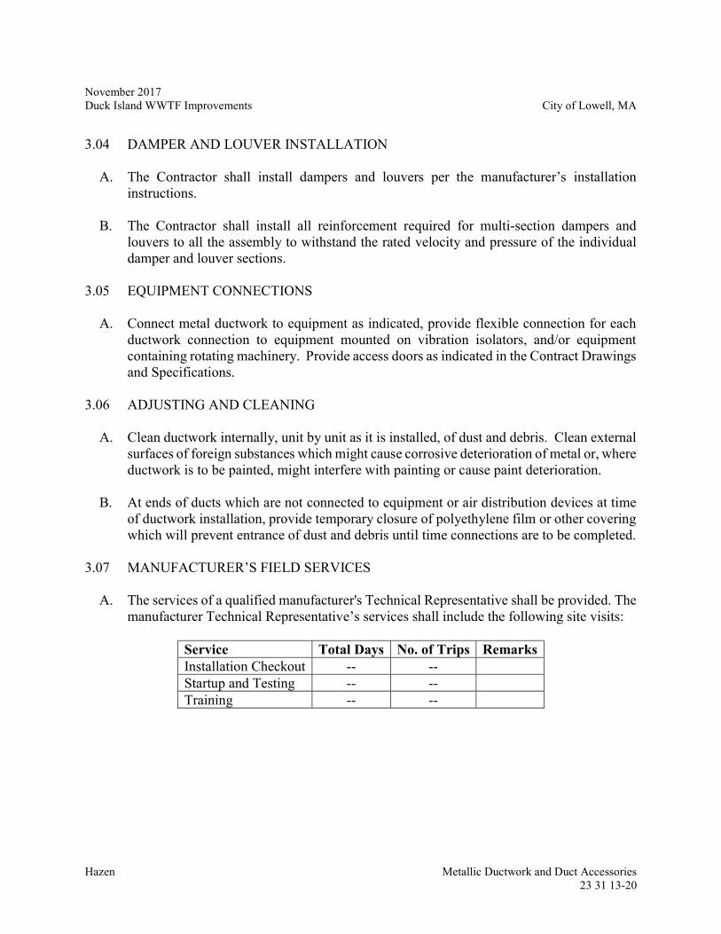
November 2017 Duck Island WWTF Improvements City of Lowell, MA
Hazen Metallic Ductwork and Duct Accessories
23 31 13-20
3.04 DAMPER AND LOUVER INSTALLATION
A. The Contractor shall install dampers and louvers per the manufacturer’s installation instructions.
B. The Contractor shall install all reinforcement required for multi-section dampers and louvers to all the assembly to withstand the rated velocity and pressure of the individual damper and louver sections.
3.05 EQUIPMENT CONNECTIONS
A. Connect metal ductwork to equipment as indicated, provide flexible connection for each ductwork connection to equipment mounted on vibration isolators, and/or equipment containing rotating machinery. Provide access doors as indicated in the Contract Drawings and Specifications.
3.06 ADJUSTING AND CLEANING
A. Clean ductwork internally, unit by unit as it is installed, of dust and debris. Clean external surfaces of foreign substances which might cause corrosive deterioration of metal or, where ductwork is to be painted, might interfere with painting or cause paint deterioration.
B. At ends of ducts which are not connected to equipment or air distribution devices at time
of ductwork installation, provide temporary closure of polyethylene film or other covering which will prevent entrance of dust and debris until time connections are to be completed.
3.07 MANUFACTURER’S FIELD SERVICES
A. The services of a qualified manufacturer's Technical Representative shall be provided. The manufacturer Technical Representative’s services shall include the following site visits:
Service Total Days No. of Trips Remarks Installation Checkout -- -- Startup and Testing -- -- Training -- --
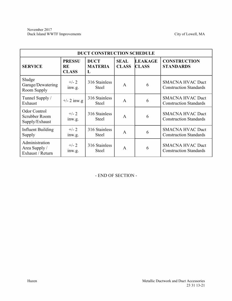
November 2017 Duck Island WWTF Improvements City of Lowell, MA
Hazen Metallic Ductwork and Duct Accessories
23 31 13-21
DUCT CONSTRUCTION SCHEDULE
SERVICE PRESSURE CLASS
DUCT MATERIAL
SEAL CLASS
LEAKAGE CLASS
CONSTRUCTION STANDARDS
Sludge Garage/Dewatering Room Supply
+/- 2 inw.g.
316 Stainless Steel
A 6 SMACNA HVAC Duct Construction Standards
Tunnel Supply / Exhaust
+/- 2 inw.g 316 Stainless
Steel A 6
SMACNA HVAC Duct Construction Standards
Odor Control Scrubber Room Supply/Exhaust
+/- 2 inw.g.
316 Stainless Steel
A 6 SMACNA HVAC Duct Construction Standards
Influent Building Supply
+/- 2 inw.g.
316 Stainless Steel
A 6 SMACNA HVAC Duct Construction Standards
Administration Area Supply / Exhaust / Return
+/- 2 inw.g.
316 Stainless Steel
A 6 SMACNA HVAC Duct Construction Standards
- END OF SECTION -
November 2017 Duck Island WWTF Improvements City of Lowell, MA
Hazen Metallic Ductwork and Duct Accessories
23 31 13-22
- THIS PAGE INTENTIONALLY LEFT BLANK -
November 2017 Duck Island WWTF Improvements City of Lowell, MA
Hazen HVAC FRP Ductwork and Duct Accessories
23 31 16-1
SECTION 23 31 16
HVAC FIBERGLASS REINFORCED PLASTIC (FRP) DUCTWORK AND DUCT ACCESSORIES
PART 1 -- GENERAL
1.01 SUMMARY
A. This section shall govern the materials, fabrication, and installation of FRP ductwork that is used for the purposes of conveying air associated with heating, ventilation, and air conditioning systems shown on the HVAC Design Drawings. This section shall not govern FRP ductwork associated with any odor control duct or ductwork shown on the Mechanical Design Drawings.
B. Contractor shall furnish any and all labor, materials, equipment, services and incidentals required to field measure, install, field test, complete and place in satisfactory operation all Fiberglass Reinforced Plastic (FRP) ductwork contained in this Section as shown on contract drawings and as specified herein.
C. Contractor shall be system supplier, where ductwork Manufacturer’s professional engineer shall provide Contractor with complete materials and mechanical engineering necessary to satisfy all ductwork design requirements of this Section.
1.02 RELATED WORK
A. Section 23 31 13 – Metallic Ductwork and Duct Accessories
B. Section 23 05 93 – HVAC Testing, Adjustment, and Balancing
1.03 REFERENCES
A. The most recently published standards at time contract to manufacture fiberglass ductwork are entered into shall govern requirements imposed on the Manufacturer.
B. In the event of conflict, inconsistency or ambiguity between these references and the specific project requirements, the following order of precedence shall govern where laminate quality, dimensional accuracy and conformance to this specification are brought into question:
1. This ductwork specification Section.
2. Contract drawings.
3. FRPI practices, specifications and bulletins.
November 2017 Duck Island WWTF Improvements City of Lowell, MA
Hazen HVAC FRP Ductwork and Duct Accessories
23 31 16-2
4. References within this paragraph 1.3, where ASTM D2563 definitions shall take precedence over ASTM C582 for types and quantity limitations.
C. Building Codes:
1. Maine Uniform Building and Energy Code
D. Air Movement and Control Association (“AMCA”):
1. AMCA 500-D - Laboratory Methods of Testing Dampers for Rating.
2. AMCA 511 - Certified Ratings Program for Air Control Devices.
E. American Society of Mechanical Engineers (“ASME”):
1. ASME RTP-1 - Reinforced Thermoset Plastic Corrosion Resistant Equipment
F. American Society for Testing and Materials (“ASTM”):
1. ASTM C582 - Standard Specification for Contact-Molded Reinforced Thermosetting Plastic (RTP) Laminates for Corrosion Resistant Equipment.
2. ASTM D695 – Standard Test Method for Compressive Properties of Rigid Plastics.
3. ASTM D696 - Standard Test Method for Coefficient of Linear Thermal Expansion of Plastics.
4. ASTM D883 - Standard Definition of Terms Relating to Plastics.
5. ASTM D2471 - Standard Test Method for Gel Time and Peak Exothermic Temperature of Reacting Thermosetting Resins.
6. ASTM D2563 - Standard Practice for Classifying Visual Defects in Glass-Reinforced Plastic Laminate Parts.
7. ASTM D2583 - Standard Test Method for Indentation Hardness of Rigid Plastics By Means of a Barcol Impressor.
8. ASTM D2584 - Standard Test Method for Ignition Loss of Cured Reinforced Resins.
9. ASTM D3299 - Standard Specification for Filament-Wound Glass-Fiber-Reinforced Thermoset Resin Corrosion-Resistant Tanks.
10. ASTM D3982 - Standard Specification for Contact Molded “Fiberglass” (Glass Fiber Reinforced Thermoset Resin) Ducts.
November 2017 Duck Island WWTF Improvements City of Lowell, MA
Hazen HVAC FRP Ductwork and Duct Accessories
23 31 16-3
11. ASTM D5421 - Standard Specification for Contact Molded “Fiberglass” (Glass-Fiber-Reinforced Thermosetting Resin) Flanges.
12. ASTM E84 - Standard Test Method for Surface Burning Characteristics of Building Materials.
G. Fiberglass Reinforced Plastics Institute (“FRPI”):
1. FRPI SP9000 - Laminating Process Certification.
2. FRPI SP9100 - Laminate Certification.
3. FRPI LS600 - Brominated Bis-A Epoxy Vinyl Ester Laminates with One (1) C-Glass Veil and MEKP/CoNap Cure System.
1.04 DEFINITIONS
A. General:
1. The term “Manufacturer” where used in this Section, refers to the entity which designs, engineers, fabricates and provides quality control and field inspection services for ductwork provided under this Section.
2. The term “Resin Supplier” where used in this Section, refers to the entity which produces resin for distribution.
3. Acronyms:
a. “Bis-A” is “Bisphenol-A”
b. “CA” is “Corrosion Allowance”
c. “CB” is Corrosion Barrier
d. “CoNap” is “Cobalt Napthinate”
e. “EVER” is “Epoxy Vinyl Ester Resin”
f. “FR” is Fire Retardant
g. “MEKP” is “Methyl Ethyl Keytone Peroxide”
h. “OS” is Outer Surface
i. “PE” is “Polyester”
November 2017 Duck Island WWTF Improvements City of Lowell, MA
Hazen HVAC FRP Ductwork and Duct Accessories
23 31 16-4
j. “SL” is Structural Layer
k. “SS” is “Stainless Steel”
l. Standard definitions of terms relating to FRP as described in ASTM D883.
B. Design:
1. FRPI SP9100 definitions for laminate lay-up composition.
2. ASTM D2563 definitions for types and quantity limitations of visual defects.
3. Minimum dimensions: Where minimum dimensions are specified in reference standards and this Section, the dimensions specified shall include any tolerances allowed by industry standards and shall be interpreted as absolute minimums for purposes of determining compliance with this Section. Such minimum dimensions shall not be construed to be in lieu of engineering calculations or demonstration of design as required of Manufacturer per this Section.
4. Corrosion allowance: Where a corrosion allowance is specified in this Section it shall be interpreted to require that thickness of inner corrosion barrier specified shall be added to minimum structural thicknesses shown within industry standard tables or determined through use of industry standard rules, other design equations, stress analysis and lamination analysis. The thickness and physical properties associated with an inner corrosion barrier that is specified as a corrosion allowance shall not contribute to strength of material and be regarded as sacrificial layers. This additional thickness shall apply to all components possessing an inner corrosion barrier and outer corrosion barrier where such outer barrier is regarded as a wetted or process side surface. Thickness shown within industry standards shall be interpreted to mean structural layer thicknesses.
1.05 SUBMITTALS
A. Detailed Manufacturer shop drawings, including:
1. Ductwork dimensions for each major component and assembly, with all nozzles, joints and accessories located and dimensioned.
2. Ductwork data table indicating sizes, thickness and weight, piece numbers, diameter, pressure rating, chemical service temperature limit and maximum allowable spans.
3. Construction details such as reinforcing ribs, transitions, reducers, elbows, access points, turning vanes, louvers, dampers plus FRP buildups, shear collars, flanges, lugs and pedestals used at support locations.
November 2017 Duck Island WWTF Improvements City of Lowell, MA
Hazen HVAC FRP Ductwork and Duct Accessories
23 31 16-5
4. Nozzle schedule with construction details demonstrating conformance to this specification. Schedule shall include nozzle mark number, flange inside and outside diameter, flange and neck thicknesses, attachment overlays, bolt circle diameter, number and diameter of bolt holes and recommended torque limits.
5. Outside and inside overlay joint details such as width, thickness, taper and material composition plus field trim allowance at field joint locations. Identify shop and field joint locations.
6. Identification of materials of construction for all components.
7. Support arrangement, with recommended anchoring and restraint methods.
8. Location of permanent and temporary labeling as required by this Section.
B. Detailed Contractor supplied drawings, including:
1. Support, anchor, guide and restraint FRP dimensions for coordination with Manufacturer’s related engineering and shop drawings plus installation by Contractor as required per this Section.
C. Data requirements, including:
1. Design calculations substantiating support, anchor, guide and restraint FRP shapes required for the ductwork support system.
2. Manufacturer’s ductwork catalogs, descriptive literature and specifications.
3. Manufacturer’s design calculations and stress analysis substantiating materials shown on Manufacturer’s drawings, including:
a. Ductwork wall thickness.
b. Reinforcing ribs and locations.
c. Flanges over 36-in diameter or 120-in perimeter in the case of rectangular flanges.
d. Support spans plus guide, anchor and restraint locations.
e. FRP shear collars for vertical support and/or anchor interface.
f. Expansion and contraction, with loads at flexible connectors identified.
g. Color stress plots supporting pipe stress analysis where performed.
November 2017 Duck Island WWTF Improvements City of Lowell, MA
Hazen HVAC FRP Ductwork and Duct Accessories
23 31 16-6
h. Any and all other such ductwork design calculations required to fulfill the requirements of this Section.
4. ASTM test records demonstrating proof of physical properties used in design calculations.
5. List showing size and quantity of FRP shop and field joints required for installation.
6. Specifications and details for:
a. Gaskets and fasteners
b. Expansion joints and flexible connectors
c. Volume and shutoff dampers and louvers
d. Corrosion coating for non FRP components
e. Other accessories
7. Letter from Resin Supplier confirming laminate design specified within this Section and detailed on drawings is suitable for intended service.
8. Permanent and temporary ductwork labels.
9. Copy of Manufacturer’s AMCA certification, which demonstrate dampers and louvers are certified according to 500-D and 511 standards.
10. Manufacturer’s Certificate of Proper Installation.
D. Provide all submittals as also required and published in FRPI Standard Practice SP9100 Laminate Certification, including quality control documents such as:
1. In process and final inspection reports, including demonstration of material, dimensional and visual quality conformance to this specification. Reports shall include non-conformity and corrective action for any deviations found.
2. Factory inspection and testing report:
a. Resin gel time testing per ASTM D2471
b. Visual inspection per ASTM D2563
c. Barcol hardness per ASTM D2583.
d. Acetone sensitivity.
November 2017 Duck Island WWTF Improvements City of Lowell, MA
Hazen HVAC FRP Ductwork and Duct Accessories
23 31 16-7
E. Installation, Operation and Maintenance Manual shall include:
1. Instructions for shipping, receiving, handling, storage, installation, FRP field butt wrap joints and flange connections.
2. Material Safety Data Sheets for all materials included in FRP field butt wrap joint kits.
3. Copy of Manufacturer’s warranty statement for ductwork as required by this Section.
4. Manufacture’s recommend initial ductwork inspection interval.
F. Contractor’s procedures for:
1. Chemical segregation, spill containment and placarding for hazardous material storage and use areas.
2. Managing fiberglass dust and styrene emissions propagated through cutting, grinding and laminating operations conducted during installation.
G. Contractor’s field FRP work inspection and testing report:
1. Alignment, pitch and fit up tolerances.
2. Out of round or square tolerances.
3. Resin gel time testing per ASTM D2471.
4. Butt wrap joint tracking checklist, including surface preparation and material utilization.
5. Visual inspection per ASTM D2563.
6. Barcol hardness per ASTM D2583.
7. Acetone sensitivity.
November 2017 Duck Island WWTF Improvements City of Lowell, MA
Hazen HVAC FRP Ductwork and Duct Accessories
23 31 16-8
1.06 QUALITY ASSURANCE
A. All design calculations, drawings and other engineering related submittals provided by Contractor and Manufacturer are to be stamped by a licensed Professional Engineer employed full time or contracted by the Contractor or Manufacturer.
B. Reference to names of Manufacturers within this specification is for the sole purpose of setting a quality standard desired.
C. To ensure standardization of appearance, Manufacturer’s services, operations, maintenance, and all ductwork and fittings must be completely fabricated by a single Manufacturer. Outsourcing FRP ductwork components and contracting manufacturing labor is not permitted, with the exception of stub flanges incorporated into nozzle fabrications as specified herein.
D. Contractor shall provide systems complete and ready for use, do work in accordance with all federal, state and local codes and ordinances and arrange for all permits, inspections, tests and registrations necessary for satisfying safety, environmental and other requirements.
E. This specification Section and related contract drawings provide a general description for ductwork, but do not include sufficient detail for design, fabrication, installation and startup. Contractor shall provide such equipment and services so that systems are complete and ready for operation.
1.07 DELIVERY, STORAGE AND HANDLING
A. Manufacturer shall properly prepare and protect ductwork from damage under normal circumstances.
B. Ductwork shall be shipped complete, with no fiberglass related laminating work, assembly or fabrication permitted outside of Manufacturer’s facility other than field joints shown on drawings.
C. Ductwork shipped horizontally shall be mounted on padded cradles of sufficient size to prevent damage and adequately support the ductwork circumference. Suitable skid or dunnage shall be provided for ductwork shipped in other orientations. Cradles, skids and dunnage shall stay with ductwork for protection prior to installation.
D. Sufficiently cross brace openings to maintain roundness or squareness within standard tolerances. Plug or cover all openings to prevent entrance of undesirables such as dirt, water or debris.
November 2017 Duck Island WWTF Improvements City of Lowell, MA
Hazen HVAC FRP Ductwork and Duct Accessories
23 31 16-9
E. Protect all flange faces with securely fastened durable flat blinds, ensuring that blind covering material extends to or beyond flange edges. Blind material and attachment method shall not cause abrasion or delamination to any flange surfaces or bolt holes during shipping, storage or installation.
F. Accessories not reliably attached to ductwork for transportation purposes and cradled or skidded shall be properly packaged and shipped to prevent damage. No nesting of smaller ductwork inside larger is permitted. No components or accessories are allowed to be shipped inside ductwork.
G. Load ductwork on truck with sufficient clearances all around to eliminate potential adjacent interferences. Firmly secure and protect all freight to prevent shifting or other movement during transportation. Nozzles, lugs, brackets or other projections shall not be used for securing, lifting or rotating ductwork.
H. Manufacturer shall properly package butt wrap field joint materials and supplies:
1. Each fiberglass butt and wrap field joint shall be individually packaged in a water proof container and labeled, with all reinforcement precut by the Manufacturer and properly sequenced in the package.
2. Labeling shall designate size, location keyed to drawings and laminate sequence.
3. One (1) extra kit per joint type and size shall be provided.
4. Resin and Catalyst (hardener) shall be packaged and properly labeled in Department of Transportation (DOT) approved five (5) gallon or smaller pails. Separate pails must be provided for Inner Corrosion Barrier, Structural Layer and Outer Surface resin, Finish Coat resin and Paste used to fill allowable gaps at fit up of joints.
5. An extra 35% more resin shall be supplied than theoretically required given butt and wrap kit resin to glass ratios.
6. Resin shipped for field work shall have a minimum three (3) month shelf life, with non-consumed resin removed from the jobsite upon completion of the installation.
7. A sufficient quantity of cups, brushes, stir sticks and rollers required shall be supplied by Manufacturer and bulk packaged. Cups and brushes shall be solvent resistant, whereas all materials shall be suitably sized for work to be performed.
I. Skids and cradles shall be configured and oriented during transport for ease of offloading and handling at site with crane or lift truck.
November 2017 Duck Island WWTF Improvements City of Lowell, MA
Hazen HVAC FRP Ductwork and Duct Accessories
23 31 16-10
J. Store all field butt wrap joint materials and related supplies furnished by Manufacturer in an area that is dry, between 35 and 75°F for maximum shelf life, properly protected from humidity and away from any direct sunlight and potential source of ignition or fire.
1.08 SEQUENCING AND SCHEDULING
A. Contractor shall make and submit to Manufacturer any and all field measurements confirming ductwork requirements plus support, anchor, guide and restraint details prior to Manufacturer’s development of design, engineering calculations and drawings as required under Part 1.05 Submittals. Such information furnished by Contractor shall include identification of ductwork piece numbers, field joints and trim locations.
B. Where Contractor directly procures and supplies material interconnected with ductwork, Contractor shall coordinate:
1. As built outside diameter of ductwork FRP buildups with Contractor supplied support, anchor, guide and restraint steel products such that padded steel is fabricated to provide full contact with ductwork buildups as shown on Manufacturer’s drawings.
2. Results of Manufacturer thermal expansion and contraction plus seismic calculations with Contractor supplied steel products plus expansion joint and flexible connector manufacturers to assure ductwork system design compatibility such that loads are properly restrained and/or absorbed.
3. Fit-up of Contractor supplied dampers and louvers, gaskets, fasteners and other such materials.
C. Ductwork and related materials shall not be fabricated by Manufacturer until Engineer confirms receipt and acceptance of design calculations.
D. Delivery of ductwork shall be planned such that existing or new openings shall be utilized for installation. Ductwork shall not be cut or otherwise modified to facilitate installation or accommodate obstructions.
1.09 WARRANTY
A. Manufacturer’s standard warranty shall warrant in writing that their products are free from defects in design, material and workmanship under normal use and service for a period of two (2) years commencing from date work under paragraphs 3.02 below is complete.
November 2017 Duck Island WWTF Improvements City of Lowell, MA
Hazen HVAC FRP Ductwork and Duct Accessories
23 31 16-11
1.10 TOLERANCES
A. All tolerances pertaining to measurements such as laminate thickness, glass content, Barcol hardness, flange face flatness and perpendicularity, ductwork roundness or squareness, location of fittings and accessories and overall dimensions shall meet the more stringent requirements of referenced industry standards or as referenced within this Section.
1.11 MANUFACTURER’S REPRESENTATIVE
A. The Manufacturer shall provide services of their shop inspector for field inspection of ductwork supplied. This inspection must be performed after equipment installation and cleaning required by this Section. Independent sales representatives shall not be considered as substitutes for shop inspectors unless they meet the requirements for third party inspectors, as published in FRPI SP9100. The shop or third party inspector’s work will be considered complete once requirements of Section 3.02 are completed.
PART 2 -- PRODUCTS
2.01 GENERAL
A. Contractor shall be responsible for determining and communicating to Manufacturer restrictions that may prevent proper installation of ductwork, including clearances required during handling, setting, anchoring, accessories installation and piping.
2.02 FIBERGLASS DUCTWORK
A. Provide all ductwork in accordance with this Section as shown on contract drawings and specified herein.
B. FRP ductwork shall be designed and fabricated in accordance with ASTM D3982 and other references within this Section, unless otherwise permitted or required by this Section.
C. FRP ductwork shall be fabricated by one of the following manufacturers:
1. An-Cor Industrial Plastics of North Tonawanda, NY USA
2. Troy Manufacturing of Brockville, ON CANADA
3. Approved Equal
November 2017 Duck Island WWTF Improvements City of Lowell, MA
Hazen HVAC FRP Ductwork and Duct Accessories
23 31 16-12
D. Manufacturer’s ductwork system design shall include the following requirements:
1. Design calculations supporting ductwork component thicknesses, including all steel, expansion joint and flexible connector interface considerations provided by Contractor, applicable loads individually or in combination per requirements of this Section, federal, state and local building codes and best engineering practices.
2. Physical properties used in all design calculations shall be developed and demonstrated following industry standard protocol.
3. Ductwork wall thicknesses shall be suitably designed for all loads and spans with or without reinforcing ribs.
4. All ductwork shall be designed and fabricated to span support spacing as required. Buckling between supports shall be taken into consideration through stress analysis.
5. Ductwork wall thickness shall be suitably designed with reinforcing ribs incorporated where necessary to achieve span within acceptable deflection limits.
6. Maximum allowable deflection for any size ductwork or span shall be limited to the lesser of 1/2-in or 1/2-percent of span under worse case operating and weather conditions.
7. Thermal expansion and contraction calculations shall be made, with results used to adequately design ductwork to absorb related loads or communicate with expansion joint manufacturers for proper joint design. Material properties used in calculations shall be derived in accordance with ASTM D695 and D696.
8. Ductwork systems equal to or large than 48-in diameter for round and 168-in perimeter for rectangular shall be analyzed using formal Pipe Stress Analysis (PSA), such as Caesar II, ALGOR PipePak or equal. Stress shall be fully evaluated at all critical locations, including flanges, elbows, tees, wyes, hangers, supports, anchors and restraints.
9. Flanges over 36-in diameter and 120-in perimeter in the case of rectangular flanges shall be designed per ASME RTP-1 NM-2 Design of Integral Body Flanges and NM-12 FRP Flange Design as is applicable. As a minimum, rectangular ductwork flange dimensions shall correspond to those of round ductwork having the same diameter as the longest side of the rectangular ductwork and rounded up if not equal.
E. Manufacturer’s design calculations supporting ductwork component thicknesses must include all applicable loads individually or in combination, where required by Part 1.3 References, design criteria listed below and best engineering practices:
November 2017 Duck Island WWTF Improvements City of Lowell, MA
Hazen HVAC FRP Ductwork and Duct Accessories
23 31 16-13
1. Design pressure: As indicated in ductwork schedule in Part 3 of this submittal
2. Wind: 100mph (for outdoor ductwork only)
3. Expansion and contraction associated with temperature differential:
a. 0oF to 100oF
4. Accumulation of snow, ice and/or water on ductwork: 30 lbs./sq.ft
5. Seismic: The Contractor shall follow the requirements of ASCE 7 for locations requiring seismic bracing and support.
6. Mechanical link seal force
F. Ductwork construction shall be as follows:
1. Shop manufactured and assembled to fullest extent without need for permitted transportation thereby minimizing field assembly and field FRP butt wrap joints. A list showing size and quantity of FRP shop and field joints required for installation shall be submitted for approval.
2. Reinforcing ribs:
a. Ribs must be installed at point of ductwork manufacture and located so as not to interfere with supports, hangers, anchors, restraints and other such interconnected or adjacent equipment, accessories, materials and building structures.
b. No pultruded, extruded, formed, milled or welded plastic, metallic or wood structural shapes or mechanical fasteners are allowed.
c. Rib construction shall be detailed on shop drawings.
3. Flange connections:
a. All connections to expansion joints, flexible connectors, fans, dampers, louvers, registers, grillwork, hatches, covers, tank vents, scrubber inlets, condensate drain piping, instrumentation or other equipment shall be flanged with 6-in projection where flange is not on a straight run of ductwork. Auxiliary equipment directly screwed into fiberglass ductwork is not allowed. Such flanged connections shall be full faced for proper seating with ductwork flanges.
November 2017 Duck Island WWTF Improvements City of Lowell, MA
Hazen HVAC FRP Ductwork and Duct Accessories
23 31 16-14
b. Custom filler pieces or spacer rings will not be allowed between mating flanges.
c. Flanges shall be hand lay-up construction using Type I or II laminate composition per ASTM C582, with flat full face flange on straight Section or integrally molded construction. No filament winding, rotational molding, resin transfer, vacuum infusion, compression molding or casting of flanges is permitted. Flange face shall be textured by lightly hand sanding with block sander to remove surface gloss imparted by mold surface.
d. Flanges on straight run sections shall have no voids or filler material where pipe joins flange lay-up.
e. Nozzles incorporating ASTM D5421 flange requirements shall be integrally molded per ASTM D5421 Figure 1 Type A and flush type per ASTM D3299 Figure 7, where installation shall follow ASTM D3299 Figure 6 and 7 with structural overlay placed as All Exterior material.
f. Cutout reinforcement shall be provided per ASTM D3299 Article 7.3.2.2 and good engineering practices for all nozzle and branch connections.
g. All bolt holes shall be shop drilled by Manufacturer using calibrated template and back spot faced or otherwise formed for flat and parallel seating of SAE or ASME B18.22.1 Type A Narrow washer seat, with all flange exterior and machined surfaces resin finish coated. All sharp edges, corners and projections shall be removed. Randomly match drilling flanges in Manufacturer’s shop or field drilling of any kind is not allowed.
h. Gussets shall be provided for nozzles 4-in and smaller and be Plate-Type or Conical-Type per ASTM D3299 Figures 4 or 5.
i. Flange flatness, warpage, perpendicularity and cant tolerances specified within this Section shall be strictly adhered to. Flange faces refaced or machined to meet tolerances shall have the Corrosion Barrier fully included.
j. All flange bolts shall be torqued to values as recommended by Manufacturer.
4. Round ductwork:
a. Reinforcing ribs:
i. Ribs shall be laminated and formed to a suitable shape over core material. Rib core material shall impart a laminate shape suitable
November 2017 Duck Island WWTF Improvements City of Lowell, MA
Hazen HVAC FRP Ductwork and Duct Accessories
23 31 16-15
for stiffening ductwork consistent with design calculations submitted and not contribute to strength of material in calculations.
ii. Rib core materials shall be closed cell foam half round or trapezoidal shape with laminate overlay to meet design submitted.
b. Fittings:
i. All fittings such as elbows, laterals, tees and reducers shall have the same internal dimensions as the adjacent ductwork.
ii. Fitting thickness and laminate composition shall be equal to design of ductwork cylindrical sections composed of Type I or II laminates per ASTM C582 that meet design basis of this Section. Minimum thickness for reducer and transition fittings shall be the same as the wall thickness of the ductwork adjoined to the larger fitting opening.
iii. Standard Round Elbows up to 48-inch diameter shall have smooth radius with a centerline radius equal to 1-1/2 times the ductwork diameter. Short radius round elbows, where the centerline radius is less than 1-1/2 times the ductwork diameter, are not permitted.
iv. Mitered Elbows are permitted for ductwork 54-inch diameter and greater. Standard dimensions shall be as shown in ASTM D3982 Figure 4.
v. The length of concentric and eccentric reducers shall be five (5) times the difference in diameter and not as shown in ASTM D3982 Figure 4.
vi. Branch connections shall be perpendicular or 45 degrees per ASTM D3982 Figure 4.
c. Flange connections:
i. Flange construction and dimensions shall meet ASTM D5421 for tank vent, condensate drain piping and instrumentation connections and D3982 for all other connections.
ii. Flanges on smaller end of reducers and transitions shall have a minimum of 6-in straight section to accommodate bolting, as shown for reducers in ASTM D3982 Figure 4 Standard Duct Dimensions.
iii. Minimum flange thicknesses shall be 5/8-in for less than or equal to 8-in diameter and 3/4-in for 10-in to 36-in diameter. Thicknesses
November 2017 Duck Island WWTF Improvements City of Lowell, MA
Hazen HVAC FRP Ductwork and Duct Accessories
23 31 16-16
for flanges greater than 36-in diameter shall not less than ¾-in thick. Minimum flange thickness shall be measured at bolt hole in washer seating area.
5. Rectangular ductwork and transitions:
a. All rectangular ductwork, fittings, transitions and other such structures shall have integrally molded corners with radiuses. Corner radii for adjoining walls of less than or equal to 24-inch shall be 1/2-inch, 1-inch for adjoining walls between 24-inch and 48-inch and 1 1/2-inch for greater than 48-inch adjoining wall lengths. In no case shall rectangular or rectangular to round components or systems be fabricated from flat panels, with or without quartered pipe sections in corners, and joined by butt wrap joints. Care shall be exercised to assure corner radii thicknesses are maintained as a minimum, with additional plies added if required.
b. Reinforcing ribs:
i. Ribs shall be laminated structural shapes such as angle, channel, tees or tube material and laminated to ductwork. Complete rib structural shape laminate and attachment method utilized shall contribute to strength of material in calculations. Adhesives may be used in place of laminating structural shapes to ductwork where Manufacturer in-house test data, design calculations and drawing details are submitted demonstrating reliability.
ii. As an alternate to laminated structural shapes, ribs may be laminated and formed to a suitable shape over core material. Rib core material shall impart a laminate shape suitable for stiffening ductwork and not contribute to strength of material in calculations. Rib core materials shall be closed cell foam half round or trapezoidal shape with laminate overlay to meet design submitted.
iii. Rib shape shall be suitable for stiffening ductwork consistent with design calculations submitted.
c. Flange Connections:
i. Flanges on smaller end of reducers and transitions shall have a minimum of 6-in straight section to accommodate bolting, as shown for reducers in ASTM D3982 Figure 4 Standard Duct Dimensions.
ii. Minimum flange thicknesses shall be 5/8-in for less than or equal to 28-in perimeter and 3/4-in for 36-in to 120-in in perimeter. Thicknesses for flanges greater than 120-in in perimeter shall not
November 2017 Duck Island WWTF Improvements City of Lowell, MA
Hazen HVAC FRP Ductwork and Duct Accessories
23 31 16-17
less than ¾-in thick. Minimum flange thickness shall be measured at bolt hole in washer seating area.
iii. Bolt hole location and size shall be designed by the Manufacturer, shall straddle major centerlines and not exceed 4 1/2-in space between hole centerlines.
d. Turning vanes:
i. Mitered elbows shall have Hand Lay-up quarter round shaped turning vanes with 3:1 tapered leading edges, with a radius equal to that of the centerline radius of the elbow.
ii. Each turning vane shall be composed of an all random strand mat construction, with a C-Glass Veil on both sides of the curved vane. A sufficient number of turning vanes shall be provided such that they are spaced no greater than 6-in apart. Each turning vane shall protrude through the fitting wall on both sides a minimum of 1.5-in, with a fiberglass overlay equal in thickness to the fitting wall laid up onto the entire projecting portion of the vane and the adjoining fitting wall a minimum of 1.5-in forming a seal and reliable attachment.
iii. Turning vane thicknesses shall be determined by design calculations given all design criteria and deflection limits defined above. Minimum vane thickness shall be 3/8-in.
e. Tops of all outdoor exposed rectangular ductwork, fittings, transitions and other structures shall be sloped ¼-in per foot to shed water. Slope shall be shown on shop drawing submittal.
6. Access hatches shall be 12-in and 24-in diameter, where the larger size that can be accommodated on the ductwork shall be provided. One (1) hatch shall be located on the upstream side of each bank of turning vanes, damper, louver and fan. Hatches shall be flanged as specified within this Section and provided with flat or domed cover.
7. FRP Threaded couplings and nipples:
a. Shall be installed following the same requirements as specified within this Section for nozzles of the same size or as indicated in the Design Drawings.
b. Outside surface of fittings that receive secondary attachment overlay shall be ground smooth with a contour providing mechanical lock and primed with Atprime 2 secondary bonding agent prior to fitting installation.
November 2017 Duck Island WWTF Improvements City of Lowell, MA
Hazen HVAC FRP Ductwork and Duct Accessories
23 31 16-18
c. Thermoplastic and metallic couplings and nipples are not allowed.
8. FRP shop and field butt wrap joints.
a. All ductwork joints shall be butt wrap per ASTM D3982 Article 9.2 Joints. All outer surfaces of joint overlays are to be coated with resin finish coat containing paraffin wax.
b. All gaps between mating edges of ductwork and fittings must be limited to the thickness of the adjoining material, not to exceed 3/8-inch, and maximum offset of lesser of 1/4-inch or two (2) times edge thickness divided by three (3) prior to application of paste and butt wrap joint material. Paste used to fill gaps shall not protrude more than 1/8-inch past inner surface of ductwork, fitting or transition wall.
c. For round ductwork, joint minimum thickness and laminate composition shall be equal to design of ductwork cylindrical sections composed of Type I or II laminates per ASTM C582 that meet design basis of this Section. For rectangular ductwork, joint minimum thickness and laminate composition shall be equal to the thicker component being adjoined. Joint minimum thickness and laminate composition for reducer and transition connections shall equal the ductwork adjoined to the larger fitting opening.
d. At least one (1) field butt wrap joint shall be provided for each change in direction and elevation, with a minimum of 6-in field trim included and shown on drawings by Manufacturer at each field joint location. Field joints shall also be located at dimension “H” from duct flange faces per ASTM D3982 Figure 4 Standard Duct Dimensions. Duct flanges mating with dampers, fans, flex connectors and other related equipment shall be properly aligned and reliably bolted together with no undue stresses prior to applying butt wrap joint material.
e. Adhesive joints are not permitted.
f. An inside overlay shall be provided for all accessible shop and field joints for ductwork greater than or equal to 20-in diameter for round or 72-in perimeter for rectangular ductwork. All accessible nozzle and branch connections shall be inside overlaid. Inside overlay composition and thickness shall be equal to Inner Corrosion Barrier specified.
9. No joints in axial direction of ductwork straight run sections are permitted.
10. Ductwork support:
November 2017 Duck Island WWTF Improvements City of Lowell, MA
Hazen HVAC FRP Ductwork and Duct Accessories
23 31 16-19
a. All ductwork supports, anchors, guides and restraints shall be engineered and supplied by the FRP Manufacturer and coordinated with the Contractor. Contractor shall work with the Manufacturer to determine number, location and configuration of such supplied materials, so that proper support, restraint, fit-up and thermal expansion and contraction is accounted for in FRP ductwork system design provided by Manufacturer.
b. All support materials shall match the construction of the ductwork. Materials thicknesses shall be calculated by the FRP Manufacturer and submitted with the stress analysis. FRP support materials shall include but not be limited to threaded rods, nuts, channels, angles, and plates. Support components that cannot be fabricated from FRP such as beam clamps, concrete anchors that extend beyond the concrete surface such as studs, or other components exposed to the atmosphere in the space shall be 316 stainless steel and field coated with a corrosion resistant coating suitable for exposure to the chemicals and concentrations listed in section 2.3.B of this specification.
c. Maximum support spacing shall be equal to or less than limits set forth in ASTM D3982 Table 1 Typical Spacing, unless otherwise engineered by Manufacturer given design loads and support spans specified herein, on contract drawings or Contractor field dimensions.
d. Vertical riser sections of ductwork shall be supported by FRP pedestals laminated to backside of elbow sections or FRP shear collars or lugs designed to abut braced steel support rings where required. Riser clamps shall not be used to support FRP ductwork.
e. Ductwork shall be reinforced at each support, hanger, anchor and restraint with a minimum 1/4-in FRP buildup. This reinforcement shall cover and extend 3-in beyond the support bearing surface. Buildups shall be flat, smooth and fully in contact with the support. A ¼-in neoprene pad shall be placed between FRP and support and adhered to support. Contractor shall provide supports with sufficient dimensions to accommodate FRP collar and neoprene pad given ductwork tolerances specified in this Section.
f. Supports shall provide a minimum of 180 degrees of uniform complete contact with round ductwork and full contact with bottom and top of rectangular ductwork. Minimum support widths for round ductwork shall be 2-in wide for duct less than or equal to 10-in, 3-in wide for duct 12-in to 20-in, 4-in wide for duct 22-in to 36-in, 8-in wide for duct 38-in to 48-in and 12-in wide for duct 50-in to 60-in diameter. Minimum support widths for rectangular ductwork shall correspond to those of round ductwork
November 2017 Duck Island WWTF Improvements City of Lowell, MA
Hazen HVAC FRP Ductwork and Duct Accessories
23 31 16-20
having the same diameter as the longest side of the rectangular duct when rounded up if not equal.
g. Ductwork shall be supported to allow removal of inline devices without adding temporary support, where such devices may include dampers, louvers, expansion joints, flexible connectors and fans.
h. Ductwork shall be supported within 12-in of duct free end where connected to flexible connections, expansion joints or equipment.
G. Ductwork Signage:
1. Each fabricated duct Section shall be temporarily labeled with a piece number corresponding to drawings for installation coordination. Labels shall be able to withstand weather and durable enough to stay affixed to the duct until such time installation is complete and they can be removed.
2. Manufacturer to furnish the following data on a water proof permanent label laminated directly on the side of ductwork near access hatches or other a prominent locations:
a. Manufacturer’s name.
b. Date of manufacture.
c. Pressure and temperature rating.
d. Corrosion Barrier resin, cure system and surface veil type.
H. FRP workmanship:
1. No layout markings, scratches, dings, sharp resin cured glass fiber projections, sharp edges or corners, major color variation or significant resin finish coat inconsistencies will be permitted.
2. All cut or machined edges and exterior surfaces shall be de-burred, chamfered, smooth and resin finish coated.
3. Resin finish coat work shall be free of defects such as but not limited to pinholes, excessive or inadequate film build, dry spots, drips, runs, sagging, and foreign inclusions. Any such defects shall be removed from the coat and the coat reapplied. The finish coat must appear uniform.
November 2017 Duck Island WWTF Improvements City of Lowell, MA
Hazen HVAC FRP Ductwork and Duct Accessories
23 31 16-21
I. Manufacturer shall clean ductwork inside and out prior to packaging for shipment, removing any and all mold release materials, temporary fabrication layout lines, dirt, dust, debris and other such undesirables.
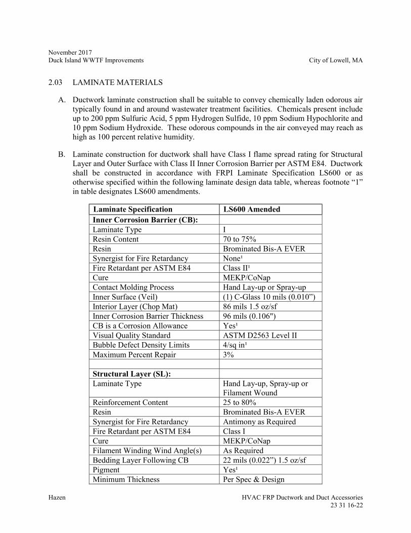
November 2017 Duck Island WWTF Improvements City of Lowell, MA
Hazen HVAC FRP Ductwork and Duct Accessories
23 31 16-22
2.03 LAMINATE MATERIALS
A. Ductwork laminate construction shall be suitable to convey chemically laden odorous air typically found in and around wastewater treatment facilities. Chemicals present include up to 200 ppm Sulfuric Acid, 5 ppm Hydrogen Sulfide, 10 ppm Sodium Hypochlorite and 10 ppm Sodium Hydroxide. These odorous compounds in the air conveyed may reach as high as 100 percent relative humidity.
B. Laminate construction for ductwork shall have Class I flame spread rating for Structural Layer and Outer Surface with Class II Inner Corrosion Barrier per ASTM E84. Ductwork shall be constructed in accordance with FRPI Laminate Specification LS600 or as otherwise specified within the following laminate design data table, whereas footnote “1” in table designates LS600 amendments.
Laminate Specification LS600 Amended Inner Corrosion Barrier (CB): Laminate Type I Resin Content 70 to 75% Resin Brominated Bis-A EVER Synergist for Fire Retardancy None¹ Fire Retardant per ASTM E84 Class II¹ Cure MEKP/CoNap Contact Molding Process Hand Lay-up or Spray-up Inner Surface (Veil) (1) C-Glass 10 mils (0.010”) Interior Layer (Chop Mat) 86 mils 1.5 oz/sf Inner Corrosion Barrier Thickness 96 mils (0.106") CB is a Corrosion Allowance Yes¹ Visual Quality Standard ASTM D2563 Level II Bubble Defect Density Limits 4/sq in¹ Maximum Percent Repair 3% Structural Layer (SL): Laminate Type Hand Lay-up, Spray-up or
Filament Wound Reinforcement Content 25 to 80% Resin Brominated Bis-A EVER Synergist for Fire Retardancy Antimony as Required Fire Retardant per ASTM E84 Class I Cure MEKP/CoNap Filament Winding Wind Angle(s) As Required Bedding Layer Following CB 22 mils (0.022”) 1.5 oz/sf Pigment Yes¹ Minimum Thickness Per Spec & Design
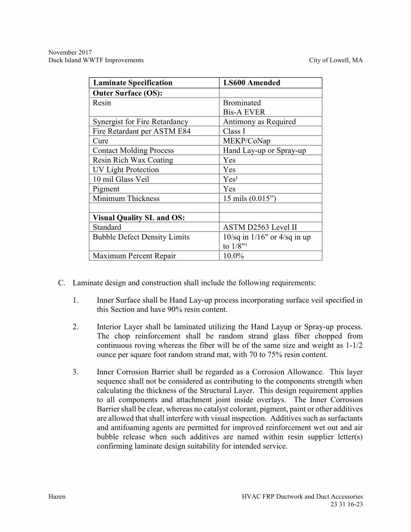
November 2017 Duck Island WWTF Improvements City of Lowell, MA
Hazen HVAC FRP Ductwork and Duct Accessories
23 31 16-23
Laminate Specification LS600 Amended Outer Surface (OS): Resin Brominated
Bis-A EVER Synergist for Fire Retardancy Antimony as Required Fire Retardant per ASTM E84 Class I Cure MEKP/CoNap Contact Molding Process Hand Lay-up or Spray-up Resin Rich Wax Coating Yes UV Light Protection Yes 10 mil Glass Veil Yes¹ Pigment Yes Minimum Thickness 15 mils (0.015”) Visual Quality SL and OS: Standard ASTM D2563 Level II Bubble Defect Density Limits 10/sq in 1/16" or 4/sq in up
to 1/8"¹ Maximum Percent Repair 10.0%
C. Laminate design and construction shall include the following requirements:
1. Inner Surface shall be Hand Lay-up process incorporating surface veil specified in this Section and have 90% resin content.
2. Interior Layer shall be laminated utilizing the Hand Layup or Spray-up process. The chop reinforcement shall be random strand glass fiber chopped from continuous roving whereas the fiber will be of the same size and weight as 1-1/2 ounce per square foot random strand mat, with 70 to 75% resin content.
3. Inner Corrosion Barrier shall be regarded as a Corrosion Allowance. This layer sequence shall not be considered as contributing to the components strength when calculating the thickness of the Structural Layer. This design requirement applies to all components and attachment joint inside overlays. The Inner Corrosion Barrier shall be clear, whereas no catalyst colorant, pigment, paint or other additives are allowed that shall interfere with visual inspection. Additives such as surfactants and antifoaming agents are permitted for improved reinforcement wet out and air bubble release when such additives are named within resin supplier letter(s) confirming laminate design suitability for intended service.
November 2017 Duck Island WWTF Improvements City of Lowell, MA
Hazen HVAC FRP Ductwork and Duct Accessories
23 31 16-24
4. Structural Layer shall be Hand Layup and/or Spray-up for all components, whereas Filament Winding may be utilized only for round ductwork with such wind angle determined by Manufacturer. Where Filament Winding is utilized, a nominal 22 mil layer of 1-1/2 ounce per square foot chopped strand glass or equivalent thickness of chop shall be applied as a bedding layer for first pass filament winding glass strands between the cured Inner Corrosion Barrier and Structural Layer.
5. Structural Layer shall have a minimum thickness as calculated by Manufacturer given application and 28 to no more than 80% reinforcement content, with structural thickness no less than minimums specified within ASTM D3982 Table 1 for Hand Lay-up and Spray-up or 0.20-in for round Filament Wound ductwork.
6. All laminate thicknesses for ductwork shall be calculated such that 10:1 factor of safety for internal and 5:1 for external pressure has been provided, with strain limited to 0.001 for Hand Lay-up laminates. Strain for Filament Wound laminates shall be limited to 1/10 of strain at failure, where strain at failure must be proven by Manufacturer per ASTM D638 tensile and ASTM D2584 glass content testing methods. Laminate designs used for proof of allowable strain used in calculations submitted shall be representative of same laminate sequence and resin to glass ratio as used for ductwork shown on drawings submitted.
7. Safety factors for combined loads shall be 10:1 for sustained loads and 5:1 for intermittent loads, where intermittent are combined individual loads or individual combined with sustained loads. As a minimum, loadings to be considered are defined in paragraph 2.02 E above. The greater laminate thicknesses as determined by paragraph 2.3 D.6 and D.7 herein shall be used.
8. The minimum longitudinal tensile strength shall be 9,000 psi for all Structural Layer laminate construction.
9. The outer most sub-layer of the Structural Layer and Outer Surface shall be pigmented and include ultra violet light inhibitor plus a 10 mil A-Glass veil containing 90 percent resin by weight.
10. The Outer Surface shall be coated with a 5 mil unreinforced resin rich layer containing paraffin wax and include pigment plus ultra violet light inhibitor.
11. Pigment color shall be submitted for approval.
12. Painting is not allowed for any FRP surface.
13. The resins specified within the laminate specifications shall be as supplied by AOC, Ashland, Interplastic or Reichhold. Only one (1) resin supplier’s products are allowed for all ductwork.
November 2017 Duck Island WWTF Improvements City of Lowell, MA
Hazen HVAC FRP Ductwork and Duct Accessories
23 31 16-25
14. Only Uni-axial stitched glass reinforcements are allowed where required with Filament Winding in order to meet the requirements of this Section. Reinforcing such as random strand mat stitched to woven roving shall not be permitted.
15. Vacuum infusion and other such closed or contained laminating process shall not be permitted.
2.04 PRE-INSULATED DOUBLE WALLED DUCT
A. Where indicated in the Contract Drawings, the FRP Duct Manufacturer shall provide pre-insulated double walled duct where spray insulation is injected between two concentric FRP ducts.
B. The inner wall and outer walls of the duct shall be constructed to the requirements of Sections 2.02 and 2.03 above. The design requirements of the inner and outer walls shall be the same including, internal duct pressure, wind, seismic, and other miscellaneous loads.
C. The insulation shall be spray injected and shall be a minimum of 1” thick. The insulation shall have a minimum R value of 7. The insulation shall have a flame spread of less than 25 and a smoke development of less than 50 as tested by ASTM E84.
D. Ducts required to have flanges shall have flanges sized for the inner duct. The outer wall shall taper and joint to the inner wall at the duct ends.
2.05 MANUFACTURER INSPECTION AND QUALITY CONTROL
A. Quality control shall include a process and a final inspection by Manufacturer per requirements of FRPI SP9000 and SP9100. Final inspection prior to shipment shall include checks for laminate visual quality, resin cure, dimensional verification, review of certified test results for tests such as Barcol hardness, cutouts review and corrective action taken for any non-conformity reports generated.
B. Manufacturer tolerances:
1. ASTM D3982 Section 8, identified within this Paragraph for convenience:
a. Overall lengths are limited to plus or minus 1/4-in.
b. Cut ends of round ductwork shall be square within plus or minus 1/8-in for less than 24-in diameter, 3/16-in for between 24-in and 48-in and 1/4-in for greater than 48-in diameter.
November 2017 Duck Island WWTF Improvements City of Lowell, MA
Hazen HVAC FRP Ductwork and Duct Accessories
23 31 16-26
c. Flanges:
i. Face flatness plus or minus 1/32-in for less than or equal to 18-in diameter and plus or minus 1/16-in for greater than 18-in diameter.
ii. Warpage shall be plus or minus 3 degrees.
iii. Face perpendicularity to axis of duct shall be plus or minus 1/2 degree.
iv. Flange angularity plus or minus 1 degree for less than or equal to 24-in diameter, 3/4 degree for greater than 24-in to less than or equal to 48-in and 1/2 degree for greater than 48-in diameter.
v. Offset shall be plus or minus 1/8-in.
vi. Cant shall be plus or minus 1/2 degree.
2. Other tolerance requirements:
a. Minimum thicknesses shall be minus 0.00-in plus 20% of thicknesses specified or otherwise designed per requirements of this Section.
b. Out of flatness is limited to the lesser of plus or minus 1/2-in or 1/2% of span.
c. Out of roundness is limit to the greater of plus or minus 1/8-in or 1% of ductwork inside diameter, not to exceed 3/4-in.
d. Angles of all fittings shall be plus or minus 1 degree, up to and including 24-inch diameter, plus or minus 3/4 degree for greater than 24-inch to less than or equal to 48-inch and plus or minus 1/2 degree for greater than 48-inch diameter.
e. Gap for fit-up at shop and field joint is limited to the thickness of the adjoining material, not to exceed 3/8-in, and maximum offset of lesser of 1/4-in or two (2) times edge thickness divided by three (3) prior to application of paste and butt wrap joint material.
C. The Manufacturer shall provide adequate lead time to the Contractor, who will in turn notify the Owner, Owner’s Engineer and Owner’s or Engineer’s designated agent at the Engineer’s direction, for coordination of optional participation in major component inspection prior to assembly, test witnessing and Manufacturer’s final inspection.
November 2017 Duck Island WWTF Improvements City of Lowell, MA
Hazen HVAC FRP Ductwork and Duct Accessories
23 31 16-27
D. The Engineer reserves the right to inspect and reject any and all equipment being manufactured that does not fully and completely meet the requirements of this Section. Fabrication and inspection records shall be made available upon request. The Owner, Owner’s Engineer and Owner’s or Engineer’s designated agent will have adequate, open and safe access to the Manufacturer’s facility at all times during regular business hours for purpose of inspecting equipment being manufactured for them.
E. The Manufacturer shall make any and all inspection tools readily available to parties that may participate in inspection. Such tools shall be in a good state of repair and properly calibrated for accurate measurement. Ductwork shall be oriented for safe entry.
F. Final acceptance by Engineer or Contractor is not in lieu of nor is it intended to compromise Manufacturer’s warranty in any way as required by this Section.
2.06 EXTERIOR INSULATION
A. Insulation for FRP duct shall follow the same requirements as metallic duct. See Specification 23 31 13 – Metallic Ductwork and Duct Accessories section Duct Insulation for insulation requirements.
2.07 ACCESSORIES
A. All gaskets and fasteners required for flanges, nozzles and access points with mating parts supplied by Manufacturer shall be furnished by Manufacturer, where:
1. Gasket material shall be EPDM with a shore A hardness of 60 to 70. Gaskets shall be full face, predrilled to match flange bolt pattern plus single piece construction up to 36-in diameter and dovetail vulcanized construction for sizes greater than 36-in diameter. Minimum gasket thickness shall be 1/8-in for flanges less than or equal to 6-in, 3/16-in for flanges greater than 6-in and up to 18-in and 1/4-in for flanges equal to or greater than 20-in diameter. As a minimum, rectangular ductwork gasket material specifications shall correspond to those of round ductwork having the same diameter as the longest side of the rectangular ductwork and rounded up if not equal.
2. Fastener material shall be 316 stainless steel and be field coated with a corrosion resistant coating as required in the supports section of this specification. The fasteners shall be properly sized to fit gasketed or non-gasketed connections. Washers shall meet SAE or ASME B18.22.1 Type A Narrow washer seat requirements. Lock washes are not permitted.
November 2017 Duck Island WWTF Improvements City of Lowell, MA
Hazen HVAC FRP Ductwork and Duct Accessories
23 31 16-28
B. Expansion joints and flexible connectors.
1. Manufacturer: Provide products of one of the following:
a. Holz Rubber Company Inc.
b. Approved Equal
2. Joints shall consist of an elastomeric reinforced flexible material with integral molded flanges. The molded flanges shall be secured to the duct or fan connections using a 3/8” metal backing plate. The backing plate and fasteners shall be field coated with a corrosion resistant coating.
3. The joint flexible material shall be Neoprene and suitable for exposure to air containing chemicals as indicated in section 2.03(B) of this specification. Alternate materials as recommended by the manufacturer shall require Engineer approval.
4. The joint body style shall be suitable for constant vacuum service.
5. The joint body thickness shall be suitable for the pressure class of the applicable ductwork. The pressure class shall be indicated in the Duct Construction Schedule at the end of this specification. The nominal body thickness shall not be less than 1/8”.
6. The face to face length of the joint shall be determined by the stress and support analysis. The joint shall be able to handle the axial and lateral movements indicated in the calculations.
7. All fasteners shall be type 316 stainless steel including nuts, bolts, and washers. Lock washers shall not be used. All hardware shall be field coated with a corrosion resistant coating.
C. Manual Volume and Manual Isolation Dampers
1. Manufacturer: Provide products of one of the following:
a. Swartwout, Division of Phillips Industries
b. Belco Manufacturing
c. Ershigs
d. Approved Equal
November 2017 Duck Island WWTF Improvements City of Lowell, MA
Hazen HVAC FRP Ductwork and Duct Accessories
23 31 16-29
2. All round FRP dampers shall be the butterfly type and all rectangular FRP dampers shall be of the opposed blade type. FRP fabrication shall meet the corrosion requirements specified in this section 2.3(B) of this specification
3. Fabrication:
a. Frame and blade: premium vinyl ester. Blade shall fully encapsulate shaft. Blades that bolt to a single side of the shaft will not be accepted.
b. Shaft: premium vinyl ester for all manually actuated dampers below 30 inches in diameter. The shaft shall be glassed into the damper blade with center significantly thicker than center perimeter with an even taper from center to perimeter. For all dampers 30 inches in diameter and larger, the shaft shall be type 316 stainless steel encased in FRP material. Rectangular damper shafts shall correspond to those of round ductwork having the same diameter as the side of the rectangular parallel with the blades.
c. Bearings and bushings: Teflon
d. Pins and all hardware: Type 316 stainless steel (Contractor shall field coat with corrosion resistant coating)
e. Shaft seals: EPDM
f. Provide all round dampers with a blade stop consisting of FRP angles with full circumference EPDM seals.
g. All dampers shall have flanged ends. Provide type 316 stainless steel bolts, nuts, and washers. (Contractor shall field coat with corrosion resistant coating)
h. All dampers >24” diameter shall be provided with gear operators with an epoxy coating. The coating shall be suitable for exposure to air as described in section 2.3.B of this specification. Dampers 24” and smaller shall be supplied with hand quadrants actuators fabricated of type 316 stainless steel with a 5-stage locking quadrant indicator. All volume dampers shall have a fully adjustable slot with an extra hole drilled in the handle for the Contractor to “drill and pin-in place” once the system is balanced so the handle cannot vibrate loose. Rectangular damper shafts shall correspond to those of round ductwork having the same diameter as the side of the rectangular parallel with the blades.
i. All isolation dampers provided shall bear the AMCA seal. Dampers must have been tested in an AMCA lab for performance (pressure drop) and leakage. Test results shall be submitted and confirmed by the Engineer.
November 2017 Duck Island WWTF Improvements City of Lowell, MA
Hazen HVAC FRP Ductwork and Duct Accessories
23 31 16-30
j. Assembly shall be rated for flame spread less than 25 and a smoke development of less than 50 per ASTM E-84
D. Motorized Dampers:
1. Manufacturer: Provide products of one of the following:
a. MK Plastics Corporation
b. Swartwout Corporation
c. Polymil Products, Inc.
d. Approved Equal
2. Dampers shall be fiberglass with air foil blades. Damper shall be of pultruded construction and comply with ASTM-D4385-84A, ASTM E-84, and ASME/ANSI RTP1-1989. Damper blades shall be minimum of ¼ inch thick of a hollow airfoil shape and contain a slot for insertion of blade seal. Blade seal shall be silicon rubber extruded to provide a double seal. Adhesive seals are not acceptable. Bearings shall be Teflon based material.
3. Damper shall be low leakage class based on AMCA 500/511 (3 cfm/sq.ft maximum leakage rate at 1 inch w.c.)
4. Dampers shall bear the AMCA seal.
5. Material used in construction shall be a flame retardant vinyl ester based resin.
6. All materials used shall be corrosion resistant and appropriate for exposure to air containing chemicals as indicated in section 2.3.B of this specification. All hardware and misc parts that are not FRP shall be type 316 stainless steel. Any non-fiberglass fasteners located in the air stream shall be fully encapsulated in the FRP material. The Contractor shall field coat all non-encapsulated metallic components with a corrosion resistant coating.
7. Actuators shall be externally mounted to the damper and shall be a minimum of NEMA 2. All actuators shall be enclosed in a NEMA 4X enclosure unless otherwise specified. Actuators located in classified spaces shall be enclosed in a NEMA 7 case unless otherwise specified. See Section 23 31 13 and 23 09 00 for additional actuator requirements.
November 2017 Duck Island WWTF Improvements City of Lowell, MA
Hazen HVAC FRP Ductwork and Duct Accessories
23 31 16-31
PART 3 -- EXECUTION
3.01 INSTALLATION
A. Caution should be exercised when placing ductwork, with special attention paid to nozzles and other such projections that interface with adjacent area or could get entangled and damaged during handling.
B. All FRP butt wrap work must be done at temperatures between 60 and 90 degrees Fahrenheit and humidity less than 80%, without exposure to wind, rain, snow, direct sunlight and any other wet and extreme temperature conditions beyond these ranges permitted. Temporary weather tight temperature and humidity controlled shelters shall be provided by Contractor where needed during field butt wrap joining procedures.
C. Ductwork shall be stabilized and isolated from any and all movement during FRP butt and wrap field joint work.
D. Hazardous materials, fiberglass dust, and styrene emissions propagated through cutting, grinding and laminating operations shall be managed per procedures provided.
E. Turning Vanes shall be installed in all miter elbows to permit air to make the abrupt turns with a minimum amount of turbulence. The turning vanes shall be quiet and free from vibration when the system is in operation.
F. The dial regulators for manual dampers shall be marked so that the “open” and “shut” positions are clearly identified. The dial regulators on insulated ductwork shall be mounted on an elevated platform which will finish flush with the surface of the insulation. Manual volume dampers shall be located at accessible points and wherever possible some distance from a duct transition or fitting. Care shall be taken during installation to make certain that fasteners do not protrude into the duct and interfere with damper operation.
G. Access doors shall be provided at all apparatus requiring service or inspection in the duct system.
H. Test openings shall be installed in the ductwork at the points listed below. The openings shall be sealed by a screw cap and gasket, and shall be installed so that the insulation is not disturbed when the cap is removed. The test openings shall be located as follows in all heating, ventilating, air conditioning, and dehumidification systems:
1. Upstream and downstream of each coil
2. In the outside air duct adjacent to HVAC equipment
3. In the return air duct adjacent to HVAC equipment
November 2017 Duck Island WWTF Improvements City of Lowell, MA
Hazen HVAC FRP Ductwork and Duct Accessories
23 31 16-32
4. In the main supply duct on single zone units and in each zone supply duct on multizone units
5. Upstream and downstream of each filter bank
6. Where indicated on Design Drawings
I. See Section 23 31 13 – Metallic Ductwork and Duct Accessories in Section 3.03 -Insulation Installation for insulation installation location requirements.
3.02 FIELD INSPECTION AND PERFORMANCE TESTING
A. Contractor shall inspect ductwork for conformance to laminate quality, thicknesses, major dimensions and tolerances per this Section upon receipt and notify Engineer in writing of nonconformities that will inhibit timely completion of installation. Unless otherwise acknowledged by Engineer in writing, Contractor shall not proceed until nonconformities are corrected by Manufacturer.
B. Contractor shall perform a process installation inspection, with required reporting per paragraph 1.05 G.
C. Manufacturer’s Field Services:
1. Provide qualified Manufacturer’s Technical Representative to perform FRP butt wrap training for Contractor ductwork installers. Manufacturer’s Technical Representative shall provide a minimum of one (1) day training or one (1) day per ten (10) field FRP butt wrap joints, whichever is more, but not to exceed five (5) days of training. Training shall be consecutive days.
2. Provide inspection in accordance with FRPI SP9100, as referenced in paragraph 1.11 above.
3. The manufacturer Technical Representative’s field services shall include the following site visits for installation:
Service Total Days
No. of Trips Remarks
Installation Checkout 1 1
4. Manufacturer’s obligation under substantial completion is satisfied with Manufacturer’s field application of FRPI Certified labels, Manufacturer’s submittal of Certificate of Proper Installation per paragraph 1.5.
November 2017 Duck Island WWTF Improvements City of Lowell, MA
Hazen HVAC FRP Ductwork and Duct Accessories
23 31 16-33
D. Ductwork system shall be free from deflection, pulsation, vibration, chatter, leakage or any other such condition when system is in or out of service.
E. See Section 23 05 93 – HVAC Testing, Adjustment, and Balancing for additional testing and balancing requirements.
3.03 CLEANING
A. Ductwork shall be thoroughly cleaned inside and out by Contractor prior to being put into service.
B. All temporary labeling used to identify piece numbers for installation shall be removed where not a part of permanent labeling.
C. Ductwork cleaning process shall use materials that will not harm ductwork, be performed after ductwork installation and before Manufacturer’s field inspection services required per this Section.
DUCT CONSTRUCTION SCHEDULE
SERVICE PRESSURE
CLASS LEAKAGE
CLASS DUCT
MATERIAL Influent Building - Screening Room Exhaust
+/- 4 inw.g. 3 FRP
Sludge Garage Exhaust Duct +/- 2 inw.g. 3 FRP
- END OF SECTION -

November 2017 Duck Island WWTF Improvements City of Lowell, MA
Hazen Fans
23 34 00-1
SECTION 23 34 00
FANS PART 1 --– GENERAL 1.01 GENERAL REQUIREMENTS
A. All parts of the equipment furnished shall be amply designed and constructed for the maximum stresses occurring during fabrication, erection and continuous operation. All materials shall be new and both workmanship and materials shall be of the very best quality, entirely suitable for the service to which the unit is to be subjected and shall conform to all applicable sections of these specifications. All parts of duplicate equipment shall be interchangeable without modification. Manufacturer's design shall accommodate all the requirements of these specifications.
B. All anchor bolts, washers, clips, clamps and fasteners of any type shall be constructed of
316 stainless steel.
C. All fan motors shall be provided with high premium energy efficient totally enclosed fan cooled type, unless otherwise noted.
D. Provide exhaust fans which have been tested and rated in accordance with AMCA
standard, and bear AMCA Certified Ratings Seal.
E. Provide motors and electrical accessories complying with NEMA standards.
F. Fans shall be standard prefabricated units of the type, size and arrangement indicated on the Drawings. All fans shall be rated and constructed in accordance with the Air Moving and Conditioning Association. Special construction materials, coatings and multi-speed fan motors shall be provided as indicated on the Drawings.
G. Impellers shall be rigidly constructed, accurately balanced dynamically and statically at
the speed at which it is scheduled to operate and free from objectionable vibration or noise. Fans with corrosion resistant coatings shall be balanced after being coated.
H. Fans shall have no overloading characteristics for the horsepower indicated. All points
on the fan brake horsepower curve shall not exceed the motor horsepower rating.
I. V-belt drives shall be rated at least 50 percent greater than the rated motor horsepower, and shall have sheaves which can vary the fan speed by 10 percent above or below the rating point. The fan motor shall be mounted on an adjustable heavy mounting plate.
November 2017 Duck Island WWTF Improvements City of Lowell, MA
Hazen Fans
23 34 00-2
J. The operating fan speed shall be no greater than 85% of the maximum allowable fan speed for the selected model.
1.02 RELATED WORK SPECIFIED ELSEWHERE
A. Section 23 31 13 – Metallic Ductwork and Duct Accessories
B. Section 23 31 16 – HVAC Fiberglass Reinforced Plastic Ductwork and Duct Accessories
C. Section 23 05 93 – HVAC Testing, Adjustment, and Balancing 1.03 SUBMITTALS
A. The Contractor shall submit shop drawings on all equipment, accessories and appurtenances and all fabrication work required for all equipment specified in this section in accordance with Division 01 00 00 General Requirements.
B. The Contractor shall submit shop drawings for fan supports, locating and identifying each
support, brace, hanger, guide, component and anchor. Fan support systems shall be designed and Shop Drawings prepared and sealed by a Registered Professional Engineer of state of Massachusetts and shall comply with ASCE 7.
C. Required information shall include:
1. Horsepower, voltage, and rotating speed of motors. 2. Total weight of the equipment plus the approximate weight of the shipped
materials. 3. Complete erection, installation, and adjustment instructions and
recommendations. 4. Fan performance curve at the operating speed, minimum, and maximum speeds.
Provide brake horsepower curve for the operating speed. 5. Details of corrosion resistance coating. 6. Detailed construction information and data sheets for all accessories such as roof
curbs, dampers, damper operators disconnect switches, vibration isolators etc. 7. Example equipment nameplate data sheet. 8. Interconnecting wiring diagrams.
November 2017 Duck Island WWTF Improvements City of Lowell, MA
Hazen Fans
23 34 00-3
9. List of recommended lubricants. 10. Special Tools List 11. Reports of Certified Shop Tests 12. AMCA Approval for Fan Ratings 13. Sound data 14. Manufacturer’s Installation Certification 15. Manufacturer’s Field Test Results Certification
D. The Contractor shall submit to the Owner a color chart of available colors for the corrosion coating to be applied to fans as indicated in the Contract Documents. The Owner shall select the final color choice.
1.04 OPERATION AND MAINTENANCE MANUALS
A. The Contractor shall submit complete operation and maintenance manuals in accordance with the procedures and requirements set forth in Section 01300, Submittals.
1.05 MANUFACTURERS
A. The materials covered by these specifications are intended to be equipment of proven reliability and as manufactured by reputable manufacturers having experience in the production of such equipment. The equipment furnished shall be designed, constructed, and installed in accordance with the best practices and methods and shall operate satisfactorily when installed as shown on the Contract Drawings and operated per manufacturer's recommendations.
November 2017 Duck Island WWTF Improvements City of Lowell, MA
Hazen Fans
23 34 00-4
1.06 CONTRACTOR'S RESPONSIBILITY AND MANUFACTURER’S FIELD SERVICES
A. The services of a qualified manufacturer's Technical Representative shall be provided. The manufacturer Technical Representative’s services shall include the following site visits:
Service Total Days No. of Trips Remarks
Installation Checkout 1 1 In accordance with Section 23 34 00 Startup and Testing 3 3 In accordance with Section 23 05 93 Training 1 1
B. A written report covering the representative's findings and installation approval shall be
mailed directly to the Engineer covering all inspection and outlining in detail any deficiencies noted.
C. The times specified are exclusive of travel time to and from the facility and shall not be
construed as to relieve the manufacturer of any additional visits to provide sufficient service to place the equipment in satisfactory operation.
1.07 SPECIAL TOOLS
A. Furnish all special tools necessary to disassemble, service, repair and adjust the equipment.
PART 2 -- PRODUCT 2.01 CENTRIFUGAL FLOOR MOUNTED FANS
A. Centrifugal fans shall be backwardly inclined, non-overloading blades of aluminum construction. Wheel inlets shall overlap an aerodynamic aluminum inlet cone.
B. Wheel shall be balanced in accordance with AMCA Standard 204-05.
C. Provide exhaust fans which are listed by UL and have UL label affixed, and which are
designed, manufactured, and tested in accordance with UL 705 "Power Ventilators".
D. Fans shall be V-belt or direct driven as indicated on the drawings or as contained herein.
E. Motors on V-belt units shall be supported on the exterior of the fan casing with bearings encased within the fan tube. All models shall incorporate a 100 percent gasketed panel to permit access to interior direct drive motor. Motors shall be protected and cooled from outside the unit by forced ventilation.
November 2017 Duck Island WWTF Improvements City of Lowell, MA
Hazen Fans
23 34 00-5
F. V-belt fans shall be supported by channel supports or brackets for ceiling suspension or
wall mounting and provided with extended lubrication fittings and suitable vibration isolation provisions.
G. Fans shall have internal terminal box mounted on the exterior for ready wiring.
H. The motor shall be separated from the air stream.
I. Adjustable motor plates shall utilize threaded rods to provide positive belt tensioning.
J. Extended lube lines shall be furnished for lubrication of the fan bearings.
K. Bearings shall be heavy duty regreasable ball type in a cast iron pillow block housing
selected for a minimum L10 life in excess of 80,000 hours at maximum catalogued operating speed.
L. Belts shall be oil and heat resistant, static conducting.
M. Drives shall be keyed and securely attached to the wheel and motor shafts.
N. All drives shall be variable pitched type and shall be sized for 150 percent of the installed
motor horsepower.
O. Centrifugal fans shall be as manufactured by Greenheck Fan Corp., Loren Cook Co., Hartzell, or approved equal.
P. See section 2.10 of this specification for additional requirements. 2.02 MIXED FLOW INLINE FANS
A. Mixed flow fans shall be non-overloading single thickness blades of aluminum
construction. The blades shall be continuously welded to the backplate. Wheel inlets shall overlap an aerodynamic aluminum inlet cone.
B. Wheel shall be balanced in accordance with AMCA Standard 204-05.
C. Provide exhaust fans which are listed by UL and have UL label affixed, and which are
designed, manufactured, and tested in accordance with UL 705 "Power Ventilators".
D. Fans shall be V-belt or direct driven as indicated on the drawings or as contained herein.
November 2017 Duck Island WWTF Improvements City of Lowell, MA
Hazen Fans
23 34 00-6
E. Motors on V-belt units shall be supported on the exterior of the fan casing with bearings encased within the fan tube. Motors shall be protected and cooled from outside the unit by forced ventilation.
F. Fan shall be supported from a structural base with integral vibration isolation provisions.
G. Fans shall have internal terminal box mounted on the exterior for ready wiring.
H. The motor shall be separated from the air stream.
I. Adjustable motor plates shall utilize threaded rods to provide positive belt tensioning.
J. Extended lube lines shall be furnished for lubrication of the fan bearings.
K. Bearings shall be heavy duty regreasable ball type in a pillow block housing selected for
a minimum L50 life in excess of 200,000 hours at maximum catalogued operating speed.
L. Belts shall be oil and heat resistant, static conducting.
M. Drives shall be keyed and securely attached to the wheel and motor shafts.
N. All drives shall be variable pitched type and shall be sized for 150 percent of the installed motor horsepower.
O. Mixed flow fans shall be as manufactured by Loren Cook Co., Greenheck Fan Corp.,
Hartzell, or approved equal.
P. See Section 2.10 of this specification for additional requirements.
2.03 INLINE CENTRIFUGAL FANS
A. Centrifugal fans shall be backwardly inclined, non-overloading. Wheel inlets shall overlap an aerodynamic inlet cone.
B. The fan shall be of 316 stainless steel construction unless otherwise noted.
C. The fan shall be rated AMCA Type A or B spark resistant construction where required by
the Contract Drawings.
D. Wheel shall be balanced in accordance with AMCA Standard 204-05.
E. Provide exhaust fans which are listed by UL and have UL label affixed, and which are designed, manufactured, and tested in accordance with UL 705 "Power Ventilators".
November 2017 Duck Island WWTF Improvements City of Lowell, MA
Hazen Fans
23 34 00-7
F. Fans shall be V-belt or direct driven as indicated on the drawings or as contained herein.
G. Motors on V-belt units shall be supported on the exterior of the fan casing with bearings
encased within the fan tube. Motors shall be protected and cooled from outside the unit by forced ventilation.
H. Fan shall be supported from a structural base with integral spring vibration isolators.
I. Fans shall have internal terminal box mounted on the exterior for ready wiring.
J. Housing shall be supplied with a bolted and gasketed access door.
K. The motor shall be separated from the air stream.
L. Adjustable motor plates shall utilize threaded rods to provide positive belt tensioning.
M. Extended lube lines shall be furnished for lubrication of the fan bearings.
N. Bearings shall be heavy duty regreasable ball type in a cast iron pillow block housing
selected for a minimum L10 life of 50,000 hours at maximum catalogued operating speed.
O. Belts shall be oil and heat resistant, static conducting.
P. Drives shall be keyed and securely attached to the wheel and motor shafts.
Q. All drives shall be variable pitched type and shall be sized for 150 percent of the installed
motor horsepower.
R. Mixed flow fans shall be as manufactured by Hartzell, Loren Cook Co., Greenheck Fan Corp., Hartzell, or approved equal.
S. See Section 2.10 of this specification for additional requirements.
2.04 ROOF MOUNTED UPBLAST CENTRIFUGAL EXHAUST FANS
A. Centrifugal fans shall be backwardly inclined, non-overloading blades of aluminum construction. Wheel inlets shall overlap an aerodynamic aluminum inlet cone.
B. Wheel shall be balanced in accordance with AMCA Standard 204-05.
November 2017 Duck Island WWTF Improvements City of Lowell, MA
Hazen Fans
23 34 00-8
C. Provide exhaust fans which are listed by UL and have UL label affixed, and which are designed, manufactured, and tested in accordance with UL 705 "Power Ventilators".
D. Fans shall be V-belt or direct driven as indicated on the drawings or as contained herein.
E. The aluminum base shall have a one piece inlet spinning and continuously welded curb
cap corners.
F. The two piece top cap shall have stainless steel quick release latches to provide access to the motor compartment without the use of tools.
G. Fans shall have internal terminal box mounted on the exterior for ready wiring.
H. The motor shall be separated from the exhaust air stream.
I. Bearings shall be heavy duty regreasable ball type in a cast iron pillow block housing
selected for a minimum L50 life in excess of 200,000 hours at maximum catalogued operating speed.
J. Belts shall be oil and heat resistant, static conducting.
K. Drives shall be keyed and securely attached to the wheel and motor shafts.
L. All drives shall be variable pitched type and shall be sized for 150 percent of the installed
motor horsepower.
M. Centrifugal fans shall be as manufactured by Loren Cook Co., Greenheck Fan Corp, or approved equal.
N. See Section 2.10 of this specification for additional requirements. 2.05 ROOF MOUNTED CENTRIFUGAL FANS
A. Centrifugal fans shall be airfoil, non-overloading blades of aluminum construction
continuously welded. Wheel inlets shall overlap an aerodynamic aluminum inlet cone.
B. Wheel shall be balanced in accordance with AMCA Standard 204-05.
C. Provide supply fans which are listed by UL and have UL label affixed, and which are designed, manufactured, and tested in accordance with UL 705 "Power Ventilators".
D. Fans shall be V-belt or direct driven as indicated on the Contract Drawings or as
contained herein.
November 2017 Duck Island WWTF Improvements City of Lowell, MA
Hazen Fans
23 34 00-9
E. The fan shall utilize all aluminum construction.
F. The aluminum base shall have continuously welded curb cap corners.
G. Fans shall have adjustable motor mounting plate with threaded studs for positive belt
tensioning.
H. Fans shall have internal terminal box mounted on the exterior for ready wiring.
I. The motor shall be separated from the exhaust air stream.
J. Bearings shall be heavy duty regreasable ball type in a cast iron pillow block housing selected for a minimum L50 life in excess of 200,000 hours at maximum catalogued operating speed.
K. Belts shall be oil and heat resistant, static conducting.
L. Drives shall be keyed and securely attached to the wheel and motor shafts.
M. All drives shall be variable pitched type and shall be sized for 150 percent of the installed
motor horsepower.
N. Centrifugal fans shall be as manufactured by Loren Cook Co., Greenheck Fan Corp, PennBarry, Hartzell, or approved equal.
O. See Section 2.10 of this specification for additional requirements.
2.06 WALL MOUNTED PROPELLER FANS
A. Fans shall be an airfoil propeller fan with integral wall panel. The power assembly shall be bolted to a heavy duty wall panel with continuously welded corners and an integral venturi. The fan and wall panel shall be all aluminum construction.
B. The propeller shall be extruded aluminum air foil design with cast aluminum hub. The
hub shall be keyed and locked to the shaft utilizing two set screws or a taper lock bushing.
C. Propeller shall be balanced in accordance with AMCA Standard 204-05.
D. Provide fans which are listed by UL and have a UL label affixed, and which are designed,
manufactured, and tested in accordance with UL 705 "Power Ventilators".
November 2017 Duck Island WWTF Improvements City of Lowell, MA
Hazen Fans
23 34 00-10
E. Fans shall be V-belt or direct driven as indicated on the drawings or as contained herein.
F. The motor, bearings, and drives shall be mounted on a heavy duty aluminum power assembly.
G. Fans shall have internal terminal box mounted on the exterior for ready wiring.
H. Adjustable motor plates shall utilize threaded rods to provide positive belt tensioning.
I. Bearings shall be heavy duty regreasable ball type in a cast iron pillow block housing
selected for a minimum L10 life in excess of 50,000 hours at maximum catalogued operating speed.
J. Belts shall be oil and heat resistant, static conducting.
K. Drives shall be keyed and securely attached to the wheel and motor shafts.
L. All drives shall be variable pitched type and shall be sized for 150 percent of the installed
motor horsepower.
M. Provide OSHA motor guard to prevent accidental contact with motor or fan blades. The guard shall be of aluminum construction.
N. Provide aluminum wall sleave.
O. Centrifugal fans shall be as manufactured by Hartzell, Greenheck Fan Corp., Loren Cook Co, or Approved Equal.
P. See Section 2.10 of this specification for additional requirements.
2.07 FIBERGLASS REINFORCED PLASTIC (FRP) CENTRIFUGAL FANS
A. Product and Manufacturer: Provide product(s) of one of the following:
1. MK Plastics Model BHK 2. New York Blower Model FE 3. Hartzell 4. Approved Equal
November 2017 Duck Island WWTF Improvements City of Lowell, MA
Hazen Fans
23 34 00-11
B. General:
1. Provide fans that are factory-fabricated and assembled, factory-tested, and factory-finished, with indicated capacities and characteristics. All air side materials shall be suitable to convey chemically laden odorous air typically found in and around wastewater treatment facilities. Chemicals present include up to 200 ppm Sulfuric Acid, 5 ppm Hydrogen Sulfide, 10 ppm Sodium Hypochlorite, and 10 ppm Sodium Hydroxide. These odorous compounds in the air conveyed may reach as high as 100 percent relative humidity.
2. Base fan performance at standard conditions (density 0.075 lb/ft3). 3. Selected fans are to be capable of accommodating static pressure and flow
variations of +/-15% of scheduled values. 4. Fans are to be belt driven unless indicated otherwise on the equipment schedule. 5. Fans are to be equipped with lifting lugs. 6. Nameplate: Each fan to be furnished with a permanently affixed SS nameplate
with manufacturer’s name, model number, serial number and electrical data. 7. Mounting: The entire fan and motor assembly is to be mounted on rubber-in-
shear vibration isolators to reduce noise transmission. 8. Rotating Assembly: Statically and dynamically balanced to balance grade G6.3
per ANSI S2.19 and designed for continuous operation at the maximum rated fan speed and motor horsepower.
C. Provide fiberglass reinforced plastic (FRP) fire retardant fans with an epoxy or UV
resistant gel coating to protect against ultraviolet degradation. Fans shall be installed complete with motors, drives, guards, and coatings of sufficient capacity for the duty required.
D. Fan shall be constructed such that all surfaces in contact with the corrosive gas stream are
made of solid, corrosion resistant FRP. All nuts, bolts and fasteners in contact with the gas stream shall be type 316 SST and encapsulated in FRP.
E. Performance: Fan ratings shall be based on tests made in accordance with AMCA
Standard 210. Fans shall be licensed to bear the AMCA Certified Ratings Seal for Air Performance. Fans not licensed to bear the AMCA Seal for performance shall be tested, at supplier's expense, in an AMCA Registered Laboratory. Fans shall have a sharply rising pressure characteristic extending throughout the operating range to assure quiet and
November 2017 Duck Island WWTF Improvements City of Lowell, MA
Hazen Fans
23 34 00-12
stable operation. Fan speed and motor size shall be selected by the manufacturer to meet the required conditions of air flowrate and pressure drop specified above. Fan speed shall not exceed 85% of the maximum allowable driven speed of the fan.
F. Sound: Fan manufacturers shall provide sound power level ratings for fans tested and
rated in accordance with AMCA Standards 300 and 301. Sound power ratings shall be in decibels (reference lOE-12 watts) in eight octave bands.
G. Construction: Fan shall be constructed in accordance with the ASTM D-4167 standard specification for fiber-reinforced plastic fans and blowers to ensure structural integrity. All surfaces exposed to the atmosphere shall be resin rich of a paraffinated resin stabilized against ultraviolet degradation and include a reinforcement not to exceed 20% “C” grade fiberglass. All parts exposed to the gas stream shall be constructed of, or encapsulated in, an FRP laminate capable of resisting continuous airstream temperatures of 250 degrees Fahrenheit. Use of pigments, gel coats, inhibitors and additives which may disguise flaws in the laminate is prohibited. Other minimum construction requirements shall consist of the following:
1. Housing - Fan housing shall be constructed of a fire retardant polyester resin with an ASTM E84 Class I rating. Housing laminate construction shall conform to ASTM Standard C-582. Airstream surfaces shall be smooth to minimize resistance and prevent buildup of airborne contaminants. Shaft hole openings shall be fitted with a Teflon closure having a maximum clearance of 1/32" to minimize leakage. Fan shall be furnished with a lubricatable, double-lip Teflon shaft seal. A flanged inlet and flanged outlet shall be furnished on the fan and shall be of FRP construction. Inlet assembly shall be bolted to permit wheel removal. Fan shall be furnished with an access door, positioned to avoid collection of condensation, and a 1-inch minimum flanged type drain connection, positioned at the lowest portion of the fan scroll. The housing shall be impregnated with graphite to allow grounding of the housing to dissipate static electricity.
2. Wheel - Wheel shall be fabricated of a fire-retardant vinyl ester resin with an ASTM E84 Class II rating no greater than 30. Wheel hub shall be permanently bonded to the shaft and completely encapsulated in FRP to insure corrosion resistant integrity. Due to high moisture content of the air, the wheel shall receive a ceramic coating for impact resistance to water droplets. Steel wheels coated with FRP or wheels with taper-lock hubs are not acceptable.
3. Shaft - Shaft shall be 316 stainless steel with a Hastelloy C-276 sleeve. The shaft sleeve is to be securely fixed and bonded to the wheel backplate and extend out of the housing through a shaft seal. The sleeve shall extend out through the housing shaft hole for corrosion protection. The shaft first critical speed shall be at least 125 percent of the fan's maximum operating speed. Shaft shall be counter-sunk for tachometer readings.
November 2017 Duck Island WWTF Improvements City of Lowell, MA
Hazen Fans
23 34 00-13
H. Fan wheel shall have single thickness air foil type blades or backwardly inclined blades
and shall not exceed the brake horsepower shown on the schedule.
I. Wheel and surrounding housing shall be non-sparking.
J. Balance and Run Test: The wheel and shaft shall be dynamically balanced as an assembly to a balance quality grade of G6.3 at the factory. The test procedure shall be sent to the engineer for approval and the final results shall be sent for record. Prior to shipment, completed fans shall receive a final test balance at the specified operating speed.
K. Final Inspection: All fans shall receive a final inspection by a qualified inspector prior to
shipment. Inspection shall include: fan description and accessories, balance, welding, dimension, bearings, duct and base connection points, paint finish and overall workmanship.
L. Expansion joints shall be provided suitable for the service (hydrogen sulfide 2 ppm) with
multiple layers of nylon fabric impregnated with synthetic compounds and laminated into a strong body by vulcanizing. Stainless steel reinforcing rings or split rings shall be provided for bolting to equipment flanges. Connectors shall be designed to withstand at least twice the operating pressure.
M. The Contractor shall properly ground the fan case to dissipate static electricity.
N. Fan Motors and Drive:
1. Shafts: Precision turned, ground and polished 316 stainless steel sized so that the
first critical speed is at least 25 percent over the maximum operating speed. 2. Bearings:
a. Type: Air Handling Quality, heavy-duty grease lubricated, self-aligning
ball or roller pillow block type. Air Handling Quality bearings to be designed with low swivel torque to allow the outer race of the bearing to pivot or swivel within the cast pillow block.
b. Fixed to the fan shaft using concentric mounting locking collars. Bearings that use set screws are not acceptable.
c. Minimum (L10) life in excess of 80,000 hours at maximum cataloged operating speeds. Life as specified in accordance with ABMA Standard 9 for ball bearings and ABMA Standard 11 for roller bearings. Bearing life is not to be reduced below specified level if fan mounting or motor orientation is changed.
November 2017 Duck Island WWTF Improvements City of Lowell, MA
Hazen Fans
23 34 00-14
d. Provide extended lube lines with Zerk fittings. e. Bearings enclosed within the fan housing where they can be exposed to
the corrosive gas stream are not acceptable.
3. Belt or Direct Drives: a. Drive components to be sized based on a service factor of 1.4. b. Pulleys for belt drives shall be of the fully machined stainless steel type,
keyed and securely attached to the wheel and motor shafts. Motor pulleys to be adjustable for final balancing.
c. Belts: Oil-resistant, non-sparking, and non-static. d. Belt drives are to be factory-mounted, with final alignment and belt
adjustment made after installation. e. Guards: Provide FRP, corrosion resistant, OSHA compliant belt guards
and motor guards. The Guards shall completely cover any exposed moving or rotating parts.
4. Motors:
a. Motor construction shall be explosion proof and meet requirements of
applicable motor sections in Division 16. b. Motor Sizes: Minimum sizes and electrical characteristics as indicated.
Motor to be large enough so that the driven load will not require the motor to operate in the service factor range.
c. Torque Characteristics: Sufficient to accelerate the driven loads satisfactorily.
d. Provide motor with an adjustable base for varying belt tension and belt alignment for belt driven fans.
e. Where fans are indicated to require VFDs, the motors shall be rated for operation with a VFD.
O. Sound Enclosure: Required if fan without sound mediation exceeds 85 dBA measured at
a distance of three (3) feet from any part of the exhaust fan. Provide an acoustical enclosure for fan motor unit suitable for a corrosive environment. The enclosure shall be of a sandwich type construction consisting of 1” thick structural honeycomb core laminated on both sides with fiberglass. The enclosure shall be complete with FRP housing, gaskets, fasteners, flashing or any additional components required for installation. The sound enclosure shall reduce fan noise to a maximum of 85 dBA as measured per statement above.
P. See Section 2.10 of this specification for additional requirements.
November 2017 Duck Island WWTF Improvements City of Lowell, MA
Hazen Fans
23 34 00-15
2.08 FIBERGLASS REINFORCED PLASTIC (FRP) AXI-JET FANS
A. Product and Manufacturer: Provide product(s) of one of the following:
1. MK Plastics Model Axijet-F 2. Approved Equal
B. General:
1. Provide fans that are factory-fabricated and assembled, factory-tested, and
factory-finished, with indicated capacities and characteristics. All air side materials shall be suitable to convey chemically laden odorous air typically found in and around wastewater treatment facilities. Chemicals present include up to 200 ppm Sulfuric Acid, 5 ppm Hydrogen Sulfide, 10 ppm Sodium Hypochlorite, and 10 ppm Sodium Hydroxide. These odorous compounds in the air conveyed may reach as high as 100 percent relative humidity.
2. Base fan performance at standard conditions (density 0.075 lb/ft3). 3. Selected fans are to be capable of accommodating static pressure and flow
variations of +/-15% of scheduled values. 4. Fans are to be belt driven unless indicated otherwise on the equipment schedule. 5. Fans are to be equipped with lifting lugs. 6. Nameplate: Each fan to be furnished with a permanently affixed SS nameplate
with manufacturer’s name, model number, serial number and electrical data. 7. Mounting: The entire fan and motor assembly is to be mounted on rubber-in-
shear vibration isolators to reduce noise transmission. 8. Rotating Assembly: Statically and dynamically balanced to balance grade G6.3
per ANSI S2.19 and designed for continuous operation at the maximum rated fan speed and motor horsepower.
C. Provide fiberglass reinforced plastic (FRP) fire retardant fans with an epoxy or UV
resistant gel coating to protect against ultraviolet degradation. Fans shall be installed complete with motors, drives, guards, and coatings of sufficient capacity for the duty required.
November 2017 Duck Island WWTF Improvements City of Lowell, MA
Hazen Fans
23 34 00-16
D. Fan shall be constructed such that all surfaces in contact with the corrosive gas stream are made of solid, corrosion resistant FRP. All nuts, bolts and fasteners in contact with the gas stream shall be type 316 SST and encapsulated in FRP.
E. Performance: Fan ratings shall be based on tests made in accordance with AMCA
Standard 210. Fans shall be licensed to bear the AMCA Certified Ratings Seal for Air Performance. Fans not licensed to bear the AMCA Seal for performance shall be tested, at supplier's expense, in an AMCA Registered Laboratory. Fans shall have a sharply rising pressure characteristic extending throughout the operating range to assure quiet and stable operation. Fan speed and motor size shall be selected by the manufacturer to meet the required conditions of air flowrate and pressure drop specified above. Fan speed shall not exceed 85% of the maximum allowable driven speed of the fan.
F. Sound: Fan manufacturers shall provide sound power level ratings for fans tested and
rated in accordance with AMCA Standards 300 and 301. Sound power ratings shall be in decibels (reference lOE-12 watts) in eight octave bands.
G. Construction: Fan shall be constructed in accordance with the ASTM D-4167 standard
specification for fiber-reinforced plastic fans and blowers to ensure structural integrity. All surfaces exposed to the atmosphere shall be resin rich of a paraffinated resin stabilized against ultraviolet degradation and include a reinforcement not to exceed 20% “C” grade fiberglass. All parts exposed to the gas stream shall be constructed of, or encapsulated in, an FRP laminate capable of resisting continuous airstream temperatures of 250 degrees Fahrenheit. Use of pigments, gel coats, inhibitors and additives which may disguise flaws in the laminate is prohibited. Other minimum construction requirements shall consist of the following:
1. Housing - Fan housing shall be constructed of a fire retardant polyester resin with
an ASTM E84 Class I rating. Housing laminate construction shall conform to ASTM Standard C-582. Airstream surfaces shall be smooth to minimize resistance and prevent buildup of airborne contaminants. Shaft hole openings shall be fitted with a Teflon closure having a maximum clearance of 1/32" to minimize leakage. Fan shall be furnished with a lubricatable, double-lip Teflon shaft seal. A flanged inlet and flanged outlet shall be furnished on the fan and shall be of FRP construction. Inlet assembly shall be bolted to permit wheel removal. Fan shall be furnished with an access door, positioned to avoid collection of condensation, and a 1-inch minimum flanged type drain connection, positioned at the lowest portion of the fan scroll. The housing shall be impregnated with graphite to allow grounding of the housing to dissipate static electricity.
November 2017 Duck Island WWTF Improvements City of Lowell, MA
Hazen Fans
23 34 00-17
2. Discharge Nozzle – A bifurcated FRP discharge nozzle shall be supplied by the fan manufacturer and be designed to efficiently handle an outlet velocity of up to 7,000 FPM. The discharge shall include a venturi and fiberglass wind band to induce ambient air.
3. Wheel - Wheel shall be fabricated of a fire-retardant vinyl ester resin with an
ASTM E84 Class II rating no greater than 30. Wheel hub shall be permanently bonded to the shaft and completely encapsulated in FRP to insure corrosion resistant integrity. Due to high moisture content of the air, the wheel shall receive a ceramic coating for impact resistance to water droplets. Steel wheels coated with FRP or wheels with taper-lock hubs are not acceptable.
4. Shaft - Shaft shall be 316 stainless steel with a Hastelloy C-276 sleeve. The shaft
sleeve is to be securely fixed and bonded to the wheel backplate and extend out of the housing through a shaft seal. The sleeve shall extend out through the housing shaft hole for corrosion protection. The shaft first critical speed shall be at least 125 percent of the fan's maximum operating speed. Shaft shall be counter-sunk for tachometer readings.
5. Fan Inlet Plenum – A fan inlet plenum shall be provided by the fan manufacturer
when required. The plenum shall be constructed of FRP and designed to handle the static pressure indicated in Specification 15599 for the indicated service. a. The plenum shall be supplied with a weather cowl and bypass air damper
to allow additional ambient air to be mixed prior to the fan inlet. The weather cowl shall have a fiberglass inlet bird screen.
b. The bypass air damper shall be constructed per the requirements of fiberglass motorized dampers in Section 15599. Control of the damper shall be as indicated in Section 15608 and the Contract Drawings.
c. Where a plenum is required, it shall be installed on a combination integral fan platform such that both fan and plenum are on one skid.
d. A flexible connection shall be installed by the fan manufacturer between the inlet to the fan and the plenum. The flexible connection shall be constructed of FPVC.
H. Fan wheel shall have single thickness air foil type blades or backwardly inclined blades
and shall not exceed the brake horsepower shown on the schedule.
I. Wheel and surrounding housing shall be non-sparking.
November 2017 Duck Island WWTF Improvements City of Lowell, MA
Hazen Fans
23 34 00-18
J. Balance and Run Test: The wheel and shaft shall be dynamically balanced as an assembly to a balance quality grade of G6.3 at the factory. The test procedure shall be sent to the engineer for approval and the final results shall be sent for record. Prior to shipment, completed fans shall receive a final test balance at the specified operating speed.
K. Final Inspection: All fans shall receive a final inspection by a qualified inspector prior to shipment. Inspection shall include: fan description and accessories, balance, welding, dimension, bearings, duct and base connection points, paint finish and overall workmanship.
L. Expansion joints shall be provided suitable for the service (hydrogen sulfide 2 ppm) with
multiple layers of nylon fabric impregnated with synthetic compounds and laminated into a strong body by vulcanizing. Stainless steel reinforcing rings or split rings shall be provided for bolting to equipment flanges. Connectors shall be designed to withstand at least twice the operating pressure.
M. The Contractor shall properly ground the fan case to dissipate static electricity.
N. Fan Motors and Drive:
1. Shafts: Precision turned, ground and polished 316 stainless steel sized so that the
first critical speed is at least 25 percent over the maximum operating speed. 2. Bearings:
a. Type: Air Handling Quality, heavy-duty grease lubricated, self-aligning
ball or roller pillow block type. Air Handling Quality bearings to be designed with low swivel torque to allow the outer race of the bearing to pivot or swivel within the cast pillow block.
b. Fixed to the fan shaft using concentric mounting locking collars. Bearings that use set screws are not acceptable.
c. Minimum (L10) life in excess of 80,000 hours at maximum cataloged operating speeds. Life as specified in accordance with ABMA Standard 9 for ball bearings and ABMA Standard 11 for roller bearings. Bearing life is not to be reduced below specified level if fan mounting or motor orientation is changed.
d. Provide extended lube lines with Zerk fittings. e. Bearings enclosed within the fan housing where they can be exposed to
the corrosive gas stream are not acceptable.
November 2017 Duck Island WWTF Improvements City of Lowell, MA
Hazen Fans
23 34 00-19
3. Belt or Direct Drives: a. Drive components to be sized based on a service factor of 1.4. b. Pulleys for belt drives shall be of the fully machined stainless steel type,
keyed and securely attached to the wheel and motor shafts. Motor pulleys to be adjustable for final balancing.
c. Belts: Oil-resistant, non-sparking, and non-static. d. Belt drives are to be factory-mounted, with final alignment and belt
adjustment made after installation. e. Guards: Provide FRP, corrosion resistant, OSHA compliant belt guards
and motor guards. The Guards shall completely cover any exposed moving or rotating parts.
4. Motors:
a. Motor construction shall be explosion proof and meet requirements of
applicable motor sections in Division 16. b. Motor Sizes: Minimum sizes and electrical characteristics as indicated.
Motor to be large enough so that the driven load will not require the motor to operate in the service factor range.
c. Torque Characteristics: Sufficient to accelerate the driven loads satisfactorily.
d. Provide motor with an adjustable base for varying belt tension and belt alignment for belt driven fans.
e. Where fans are indicated to require VFDs, the motors shall be rated for operation with a VFD.
O. Sound Enclosure: Required if fan without sound mediation exceeds 85 dBA measured at
a distance of three (3) feet from any part of the exhaust fan. Provide an acoustical enclosure for fan motor unit suitable for a corrosive environment. The enclosure shall be of a sandwich type construction consisting of 1” thick structural honeycomb core laminated on both sides with fiberglass. The enclosure shall be complete with FRP housing, gaskets, fasteners, flashing or any additional components required for installation. The sound enclosure shall reduce fan noise to a maximum of 85 dBA as measured per statement above.
P. See section 2.10 of this specification for additional requirements. 2.09 FIBERGLASS REINFORCED PLASTIC (FRP) CENTRIFUGAL UPBLAST FANS
A. Product and Manufacturer: Provide product(s) of one of the following:
1. MK Plastics Model RBK
November 2017 Duck Island WWTF Improvements City of Lowell, MA
Hazen Fans
23 34 00-20
2. Approved Equal
B. General:
1. Provide fans that are factory-fabricated and assembled, factory-tested, and factory-finished, with indicated capacities and characteristics. All air side materials shall be suitable to convey chemically laden odorous air typically found in and around wastewater treatment facilities. Chemicals present include up to 200 ppm Sulfuric Acid, 5 ppm Hydrogen Sulfide, 10 ppm Sodium Hypochlorite, and 10 ppm Sodium Hydroxide. These odorous compounds in the air conveyed may reach as high as 100 percent relative humidity.
2. Base fan performance at standard conditions (density 0.075 lb/ft3). 3. Selected fans are to be capable of accommodating static pressure and flow
variations of +/-15% of scheduled values. 4. Fans are to be belt driven unless indicated otherwise on the equipment schedule. 5. Fans are to be equipped with lifting lugs. 6. Nameplate: Each fan to be furnished with a permanently affixed SS nameplate
with manufacturer’s name, model number, serial number and electrical data. 7. Rotating Assembly: Statically and dynamically balanced to balance grade G6.3
per ANSI/AMCA 204-96 and designed for continuous operation at the maximum rated fan speed and motor horsepower.
C. Provide fiberglass reinforced plastic (FRP) fire retardant fans with a flame spread rating
of 25 or less when tested per ASTM-E84. Fans shall be installed complete with motors, drives, guards, and coatings of sufficient capacity for the duty required.
D. Fan shall be constructed such that all surfaces in contact with the corrosive gas stream are
made of solid, corrosion resistant FRP. No metal parts shall be in contact with the air stream.
E. Performance: Fan ratings shall be based on tests made in accordance with AMCA
Standard 210. Fans shall be licensed to bear the AMCA Certified Ratings Seal for Air Performance. Fans not licensed to bear the AMCA Seal for performance shall be tested, at supplier's expense, in an AMCA Registered Laboratory. Fans shall have a sharply rising pressure characteristic extending throughout the operating range to assure quiet and stable operation. Fan speed and motor size shall be selected by the manufacturer to meet
November 2017 Duck Island WWTF Improvements City of Lowell, MA
Hazen Fans
23 34 00-21
the required conditions of air flowrate and pressure drop specified above. Fan speed shall not exceed 85% of the maximum allowable driven speed of the fan.
F. Sound: Fan manufacturers shall provide sound power level ratings for fans tested and
rated in accordance with AMCA Standards 300 and 301. Sound power ratings shall be in decibels (reference lOE-12 watts) in eight octave bands.
G. Construction: Fan shall be constructed in accordance with the ASTM D-4167 standard
specification for fiber-reinforced plastic fans and blowers to ensure structural integrity. All surfaces exposed to the atmosphere shall be resin rich of a paraffinated resin stabilized against ultraviolet degradation and include a reinforcement not to exceed 20% “C” grade fiberglass. All parts exposed to the gas stream shall be constructed of, or encapsulated in, an FRP laminate capable of resisting continuous airstream temperatures of 210 degrees Fahrenheit. Use of pigments, gel coats, inhibitors and additives which may disguise flaws in the laminate is prohibited. Other minimum construction requirements shall consist of the following:
1. Housing - Fan housing shall be constructed of a fire retardant polyester resin with
an ASTM E84 Class I rating. Housing laminate construction shall conform to ASTM Standard C-582. Airstream surfaces shall be smooth to minimize resistance and prevent buildup of airborne contaminants. Fan shall be furnished with a lubricatable, double-lip Teflon shaft seal. The housing shall be impregnated with graphite to allow grounding of the housing to dissipate static electricity and shall have a grounding connection on the outside of the fan. The housing shall contain a drain to permit the drainage of rainwater.
2. Wheel - Wheel shall be fabricated of a fire-retardant vinyl ester resin with an
ASTM E84 Class II rating no greater than 30. Wheel hub shall keyed to the shaft. Steel wheels coated with FRP are not acceptable.
3. Shaft - Shaft shall be 316 stainless steel and shall not be exposed to the air stream.
The shaft first critical speed shall be at least 125 percent of the fan's maximum operating speed.
H. Fan wheel shall have single thickness air foil type blades or backwardly inclined blades
and shall not exceed the brake horsepower shown on the schedule.
I. Balance and Run Test: The wheel and shaft shall be dynamically balanced as an assembly to a balance quality grade of G6.3 at the factory. The test procedure shall be sent to the engineer for approval and the final results shall be sent for record. Prior to shipment, completed fans shall receive a final test balance at the specified operating speed.
November 2017 Duck Island WWTF Improvements City of Lowell, MA
Hazen Fans
23 34 00-22
J. Final Inspection: All fans shall receive a final inspection by a qualified inspector prior to shipment. Inspection shall include: fan description and accessories, balance, welding, dimension, bearings, duct and base connection points, paint finish and overall workmanship.
K. The Contractor shall properly ground the fan case to dissipate static electricity.
L. Fan Motors and Drive:
1. Shafts: Precision turned, ground and polished 316 stainless steel sized so that the
first critical speed is at least 25 percent over the maximum operating speed. 2. Bearings:
a. Type: Air Handling Quality, heavy-duty, grease lubricated, self-aligning
ball or roller pillow block type. Air Handling Quality bearings to be designed with low swivel torque to allow the outer race of the bearing to pivot or swivel within the cast pillow block.
b. Fixed to the fan shaft using concentric mounting locking collars. Bearings that use set screws are not acceptable.
c. Minimum (L10) life in excess of 80,000 hours at maximum cataloged operating speeds. Life as specified in accordance with ABMA Standard 9 for ball bearings and ABMA Standard 11 for roller bearings. Bearing life is not to be reduced below specified level if fan mounting or motor orientation is changed.
d. Provide extended lube lines with Zerk fittings. e. Bearings enclosed within the fan housing where they can be exposed to
the corrosive gas stream are not acceptable. 3. Belt or Direct Drives:
a. Drive components to be sized based on a service factor of 1.4. b. Pulleys for belt drives shall be of the fully machined stainless steel type,
keyed and securely attached to the wheel and motor shafts. Motor pulleys to be adjustable for final balancing.
c. Belts: Oil-resistant, non-sparking, and non-static. d. Belt drives are to be factory-mounted, with final alignment and belt
adjustment made after installation. e. Guards: Provide FRP, corrosion resistant, OSHA compliant belt guards
and motor guards. The Guards shall completely cover any exposed moving or rotating parts.
November 2017 Duck Island WWTF Improvements City of Lowell, MA
Hazen Fans
23 34 00-23
4. Motors: a. Motor construction shall be as indicated on the Design Drawings and meet
requirements of applicable motor sections in Division 16. b. Motor Sizes: Minimum sizes and electrical characteristics as indicated on
the Design Drawings. The motor shall be large enough so that the driven load will not require the motor to operate in the service factor range at any point along the fan curve at the design speed.
c. Torque Characteristics: Sufficient to accelerate the driven loads satisfactorily.
d. Provide motor with an adjustable base for varying belt tension and belt alignment for belt driven fans.
e. Where fans are indicated to require VFDs, the motors shall be rated for operation with a VFD.
M. See Section 2.10 of this specification for additional requirements.
2.10 ADDITIONAL REQUIREMENTS FOR ALL FANS
A. The following additional requirements shall apply to all fans.
1. Backdraft or motor-operated dampers shall be provided and installed in the openings as indicated on the Contract Drawings.
2. All fans shall be provided with either integral or supplementary spring vibration
or sound-absorbing mountings. 3. Where indicated, roof mounted exhaust fans shall be mounted on a prefabricated
roof curb. 4. All motors unless indicated otherwise in this Specification or the Contract
Drawings shall be TEFC. The break horsepower at any point on the fan curve for the design speed shall not exceed the motor nameplate horsepower. The break horse power shall include all applicable belt drive losses. Using the motor service factor shall be prohibited.
5. All equipment shall be seismically secured and restrained in accordance with the
Seismic Restraint Manual, Guidelines for Mechanical Systems, latest edition, as published by the Sheet Metal and Air Conditioning Contractors National Association, Inc. (SMACNA) and designed in accordance with the seismic provisions of ASCE-7 and the current Massachusetts Building Code to the extent that the most stringent provisions are utilized in developing the design seismic forces.
November 2017 Duck Island WWTF Improvements City of Lowell, MA
Hazen Fans
23 34 00-24
6. All non-fiberglass fans shall receive a corrosion resistant coating. The coating
shall be an epoxy coating suitable for protecting the equipment from continuous exposure to air containing hydrogen sulfide 3ppm. The fans in the Supplemental Carbon Facility shall be suitable for exposure to methanol in addition to hydrogen sulfide. The coating shall be applied to all surfaces of the fans including but not limited to fan wheels, propellers, hubs, structural components, housings (interior and exterior), inlet boxes, dampers, screens, lube lines, curb boxes, and curb box adapters. A UV resistant top coat shall be applied to all coating systems that are not rated for UV exposure. The Contractor shall submit and coordinate the available color choices to the Owner for final color selection.
2.11 DAMPERS
A. See the respective sections in Sections 23 31 13 and 23 31 16 for construction requirements.
B. Dampers shall be coordinated to operate and interface with the fan being furnished.
C. Dampers shall be sized to fit the specified openings.
2.12 PREFABRICATED ROOF AND WALL CURBS
A. Prefabricated roof and wall curbs shall be installed where indicated on the Drawings or as specified herein. The curbs shall be fabricated of .064 inch sheet aluminum with all joints heliarc welded. Cants and roof flanges shall be an integral part of the curb. The inside of the curb shall be insulated with rigid glass-fiber thermal and acoustical liner of approximately 3-lb. density and 1-1/2 inch minimum thickness with a neoprene or equal coating for protection from erosion. The lining shall conform to NFPA 90A Standards with a flame spread and fuel contributed rating not exceeding 50. Pressure-treated wood nailers shall be provided at the tops of the curbs. The curbs shall be sized to suit equipment. Roof curbs shall be a nominal of 12-inches above the height of the roof unless indicated otherwise on the Contract Drawings. The roof curbs shall receive an epoxy corrosion resistant coating on the interior and exterior surfaces that is suitable for the conditions indicated in the Additional Requirements for All Fans section above.
PART 3 -- EXECUTION 3.01 INSTALLATION
A. Contractor shall install fans in accordance with manufacturer's installation instructions and recognized industry practices to insure that ventilators serve their intended function.
November 2017 Duck Island WWTF Improvements City of Lowell, MA
Hazen Fans
23 34 00-25
B. Contractor shall coordinate fan work with work of walls, and ceilings, as necessary for
proper interfacing.
C. Connect ducts to fans in accordance with manufacturer's installation instructions.
D. The Contractor shall have the Manufacturer’s Technical Representative provide in writing that the equipment is installed per the manufacturer’s requirements and operates as required by the Contract. The Contractor shall submit the written confirmation to the Engineer for information only.
3.02 FIELD QUALITY CONTROL
A. Testing: After installation of fans has been completed, test each fan to demonstrate proper operation of units at performance requirements as specified. When possible, field correct malfunctioning units, then retest to demonstrate compliance. Replace units which cannot be satisfactorily corrected. See Section 23 05 93, HVAC Testing, Adjusting and Balancing for testing requirements.
B. Cleaning: Clean factory-finished surfaces. Repair any marred or scratched coatings with
a coating specified by the equipment manufacturer for repairs.
- END OF SECTION -

November 2017 Duck Island WWTF Improvements City of Lowell, MA
Hazen Fans
23 34 00-26
- THIS PAGE INTENTIONALLY LEFT BLANK -
November 2017 Duck Island WWTF Improvements City of Lowell, MA
Hazen Positive Pressurization Units 23 40 13-1
SECTION 23 40 13
POSITIVE PRESSURIZATION UNITS
PART 1 - GENERAL
1.01 RELATED DOCUMENTS
A. Drawings and general provisions of the Contract, including General and Supplementary Conditions and Division 01 00 00 Specification Sections, apply to this Section.
1.02 SUMMARY
A. The Contractor shall furnish all labor, equipment and material for the complete installation of the positive pressurization air scrubbing units as indicated on the Drawings and specified herein.
B. Work Included Under Other Sections:
1. 480V, 3-phase power wiring and conduit under Division 26 00 00, Electrical.
1.03 SUBMITTALS
A. The Contractor shall submit shop drawings on all equipment, accessories and appurtenances and all fabrication work or other mechanical and air conditioning work required, all in accordance with the requirements of Division 01 00 00 General Requirements.
B. Data to be submitted shall include but not be limited to:
1. Catalog data consisting of specifications, illustrations and a parts schedule that identifies the materials to be used for the various parts and accessories. The illustrations shall be in sufficient detail to serve as a guide for assembly and disassembly.
2. Complete assembly and installation drawings with clearly marked dimensions. This information shall be in sufficient detail to serve as a guide for assembly and disassembly and for ordering parts.
3. Weight of scrubbing media and unit assembled weight.
4. Electrical characteristics, wiring, diagrams, etc.
5. Sample data sheet of equipment nameplate(s) including information contained thereon.
1.04 DELIVERY, STORAGE AND HANDLING
A. Deliver, store, protect and handle products to the Project Site under the provisions of Division 1.
1.05 EXTRA MATERIALS
A. Provide a minimum of one (1) spare set of filters for each unit provided.
1.06 MANUFACTURER'S INSTRUCTIONS
A. Installation of all equipment shall be in accordance with manufacturer's data.
November 2017 Duck Island WWTF Improvements City of Lowell, MA
Hazen Positive Pressurization Units 23 40 13-2
B. All changes from the installation procedures in manufacturers' data shall be submitted for approval in accordance with the requirements for shop drawings.
C. Keep all manufacturers' data provided in a secure manner at the job site at all times. Catalog and index this data for convenient reference.
D. Manufacturers' data shall be available for the information of the Owner, Engineer, and the use of other trades.
E. Turn over all data to the Owner through the Owner's representative at completion of the Work and final testing.
F. Submit all instruction books and manuals in accordance with Division 1.
1.07 QUALITY ASSURANCE
A. Manufacturer Qualifications: Company specializing in manufacturing the products specified in this Section with minimum five (5) years documented experience, who issues complete catalog data on total product.
B. When two or more units of the same class of material or equipment are required, they shall be products of a single manufacturer.
C. All work shall be performed in a neat and workmanlike manner by workers skilled in their respective trades, and all materials and equipment shall be installed as recommended by the manufacturers and in accordance with specified codes and standards.
D. Touch up and/or repaint to match original factory finishes for all finished or painted equipment and materials which are scratched or marred during shipment or installation.
PART 2 - PRODUCTS
2.01 POSITIVE PRESSURIZATION CARBON FILTERING UNIT (PPU)
A. Subject to compliance with requirements, provide positive pressure air chemical scrubber unit(s) manufactured by one of the following:
1. Purafil.
2. American Air Filter.
3. Or approved equal
B. The modular chemical scrubber shall be a complete package, designed for the removal of both organic and inorganic contaminants from the re-circulated air in gas or vapor atmospheres. Controls shall be factory mounted and wired. The manufacturer shall be a single source provider of equipment, media and testing services, and be certified to ISO-9001 standards or adhere to quality standards equal to ISO-9001:2000 with an in-house laboratory.
C. Scrubber Housing Construction:
1. The scrubber housing shall be constructed of 14 gauge cold rolled steel, seam welded. The unit shall be provided with gasketed front access door(s) for servicing all
November 2017 Duck Island WWTF Improvements City of Lowell, MA
Hazen Positive Pressurization Units 23 40 13-3
components. Latches shall have a positive locking action. All hinges and draw latches shall be constructed of stainless steel. The scrubber shall be designed for indoor installation.
2. Welding procedure qualifications and welder performance qualifications shall conform to the requirements of Section IX of the ASME Code, latest edition. Welder’s performance qualification records shall be made available to Engineer upon request.
3. Housing shall be painted inside and out (before assembly) using the following three-step procedure: 1) Steam/pressure wash with a paint prep (Oakit 187SC, or approved equal); 2) Epoxy prime (CheckRust Insl-Tile Activated Epoxy Coating, EP-5000 Series, or approved equal) 3) Polyurethane final coat of no less than 1.5 mils (CheckRust Insl-Thane Heavy Duty Polyurethane Enamel, GU-2500 Series or approved equal). Color shall be gray.
4. Scrubber housing shall be provided with a base support.
5. The scrubber housing shall be designed to facilitate standard fan and motor for maintenance.
6. Door seals shall be attached by mechanical means and designed for replacement. Seals shall be glued in conjunction with mechanical attachment.
7. The scrubber shall be arranged for horizontal or vertical airflow and shall deliver the designated combined airflow (pressurization plus recirculation). There shall be a manually controlled damper located at the intake for optimization of pressurization air.
8. Aluminum nameplate shall be provided, permanently attached to the unit. Nameplate shall be engraved with the scrubber type, order number and serial number.
9. Inlet pressurization air shall be ducted by the contractor into the duct opening at top of unit. The re-circulation air shall enter in from an air intake located above the pre-filter. The non-ducted return and discharge openings shall include grilles with four-way deflection louvers.
10. The Purafil PPU-500V shall contain four sections of scrubbing. The first stage shall contain one (1) particulate pre-filters model Purafil TP-25 and sized 24” x 24” x 1”. The second stage shall contain three (3) PuraGrid Filters with Puracarb that measures 24” x 24” x 4”. The 3rd stage shall contain modules consisting of two (2) 24” x 12” x 12” PK-12 polystyrene containers filled with Purafil SP Blend. The 4th stage shall contain one (1) particulate final filter model Purafil JFL-90 and sized 24” x 24” x 5”.
11. The Purafil PPU-1000V shall contain four sections of scrubbing. The first stage shall contain two (2) particulate pre-filters model Purafil TP-25 and sized 24” x 24” x 1”. The second stage shall contain six (6) PuraGrid Filters with Puracarb that measures 24” x 24” x 4”. The 3rd stage shall contain modules consisting of four (4) 24” x 12” x 12” PK-12 polystyrene containers filled with Purafil SP Blend. The 4th stage shall contain two (2) particulate final filter model Purafil JFL-90 and sized 24” x 24” x 5”.
D. Blower shall be located in the housing between the second and third stages of air cleaning. It shall have a backward curved, centrifugal, glass reinforced polyamine wheel and direct variable
November 2017 Duck Island WWTF Improvements City of Lowell, MA
Hazen Positive Pressurization Units 23 40 13-4
frequency drive. The blower system rating shall be as specified on Drawings. Sound insulation shall be provided on the blower section for decibel reduction.
E. Motors shall be TEFC premium efficiency, inverter grade, 460 Volt, 3-phase, 60 Hz. and have a 1.15 service factor.
F. Scrubber Chemical Media Sections:
1. The housing shall contain two chemical media sections, designed to accommodate 12.0” modular media containment devices, utilizing filter rack tracks.
2. Modular media containment device (module) shall have a nominal size of 24.0” wide x 12.0” deep in direction of airflow with a medium bed depth of 3.0”. Device shall be completely recyclable and/or disposable. Device shall be constructed of 0.125” thick, black, high impact polystyrene.
3. Module shall be factory-filled with selected chemical media.
4. Pressure drop through each chemical media section shall not exceed 1.30 inches of water gage. Maximum airflow velocity through the chemical section shall be 250 feet per minute.
5. The residence time through the chemical media section shall not be less than 0.24 seconds total of 0.12 seconds per media bed in direction of airflow. Residence time calculations shall only include media in direct path of air.
6. Module shall be UL Class II. Manufacturer shall provide documentation.
7. Media shall be specifically for corrosive environments and consist of spherical, porous pellets composed of carbon, alumina and other binders impregnated for reaction for removal of hydrogen sulfide, sulfur dioxide and volatile organic compounds.
November 2017 Duck Island WWTF Improvements City of Lowell, MA
Hazen Positive Pressurization Units 23 40 13-5
8. The Purafil SP Blend Media shall consist of an equal mix (by volume) of Purafil SP Media and Purakol media. Purafil SP Media shall be manufactured of generally spherical, porous pellets formed from a combination of powdered activated alumina and other binders, suitably impregnated with sodium permanganate to provide optimum adsorption, absorption, and oxidation of a wide variety of gaseous contaminants. The sodium permanganate shall be applied during pellet formation, such as the impregnate is uniformly distributed throughout the pellet volume and is totally available for reaction. Purakol Media shall be a premium grade, activated carbon with a high surface area available for adsorption.
9. Media Removal Capacity: Hydrogen Sulfide 20% minimum by weight; Sulfur Dioxide 5% minimum by weight; Chlorine 8% minimum by weight.
10. Media Application Criteria: Temperature -4° F to 125° F; Humidity 10 to 95% RH.
G. Particulate Filters:
1. Pre-filters shall be 20%-25% efficient, disposable filters. Efficiency shall be rated and tested to ASHRAE Standard 52.1-92, Dust Spot Efficiency. The clean filter resistance shall not exceed 0.20 inches of water gage based on a face velocity of 100 feet per minute. Filters shall be 1” deep.
2. Final filters shall be 85% - 90% efficient pleated disposable filters. Efficiency shall be rated and tested to ASHRAE Standard 52.1-92, Dust Spot Efficiency. The clean filter resistance shall not exceed 0.30 inches of water gage based on a face velocity of 100 feet per minute.
H. Remote and unit factory mounted control panels (refer to drawings for mounting type):
1. NEMA 4X, 316 stainless steel enclosure, shipped loose for wall mounting in the field or factory mounted on side of unit as indicated on drawings.
2. Motor VFD: Sized accurately for motor sizes as indicated or scheduled on drawings.
3. Control power transformer, 460/120 VAC, with fused primary and secondary.
4. Main circuit breakers, magnetic, with front-panel operating handle disconnect.
5. “Hand-Off-Auto” selector switch.
6. Indicating lamps (all lamps are push-to-test style): FAN OFF and FAN RUNNING.
7. Complete air measuring station and room pressurization gage.
I. Required Factory Options:
1. Room pressurization and airflow gage (mounted on control panel face as described above).
2. Static pressure differential gages pre-filter and final filter.
November 2017 Duck Island WWTF Improvements City of Lowell, MA
Hazen Positive Pressurization Units 23 40 13-6
3. Variable frequency drive with keypad on door.
PART 3 - EXECUTION
3.01 INSTALLATION
A. Installation shall meet or exceed all applicable federal, state and local requirements, referenced standards and conform to codes and ordinances of authorities having jurisdiction.
B. All installation shall be in accordance with manufacturer’s published recommendations.
C. Install units on vibration isolators, where fans are not internally isolated.
D. Do not operate units for any purpose, temporary or permanent, until ductwork is clean, filters are in place, bearings have been lubricated, and fan has been test run under observation of the Owner's representative(s).
E. Provide the minimum access space for maintenance of individual components such as fans, filters, coils, humidifiers, etc., as scheduled or shown on the Drawings. Arrange these components in a manner that allows for ease of replacement.
F. Arrange fans and surrounding components in such a way that poor fan performance does not result.
G. Remote wall mounted control panels shall be installed per NEC clearance requirements.
3.02 GUARANTEE
A. All components, parts, and assemblies shall be guaranteed against defects in materials and workmanship for a period of one (1) year. The period of such warranties shall start on the date the particular equipment is placed in use by the Owner with corresponding start-up certification provided by the manufacturer’s technical representative as specified herein, provided that the equipment demonstrates satisfactory performance during the thirty day operational period after the equipment startup. If the equipment does not perform satisfactorily during the thirty day operational period, the start of the warranty period will be delayed until the equipment demonstrates proper operation. The Equipment Supplier shall repair or replace without charge to the Owner any part of equipment which is defective or showing undue wear within the guarantee period, or replace the equipment with new equipment if the mechanical performance is unsatisfactory; furnishing all parts, materials, labor, etc., necessary to return the equipment to its specified performance level.
3.03 START UP SERVICES AND MEDIA TESTING:
A. Manufacturer or manufacturer’s representative shall provide a minimum of one (1) eight hour day for startup and training on all units.
B. The manufacturer shall be able to provide in-house lab analysis of the equipment media predicting the remaining life cycle of the media. Such service shall be provided at the manufacturer’s expense. Such service shall be provided at the manufacturer's expense for a period of at least ten years.
-END OF SECTION-
November 2017 Duck Island WWTF Improvements City of Lowell, MA
Hazen Central Air Station Air Handler 23 73 13-1
SECTION 23 73 13
CENTRAL STATION AIR HANDLER
PART 1 GENERAL
1.01 WORK INCLUDED
A. Applied Air Handling Units.
1.02 RELATED SECTIONS
A. Division 01 00 00 – General Requirements
B. Section 23 23 00 – HVAC Copper and Brass Pipe
1.03 REFERENCES
A. AMCA Publication 99 – Standards Handbook.
B. AMCA Publication 611 – Certified Ratings Program – Airflow Measurement Performance
C. AMCA Standard 500-D – Laboratory Methods of Testing Dampers for Rating.
D. ANSI/ABMA Standard 9 - Load Ratings and Fatigue Life for Ball Bearings.
E. ANSI/AMCA Standard 204 – Balance Quality and Vibration Levels for Fans.
F. ANSI/AMCA Standard 610 – Laboratory Methods of Testing Airflow Measuring Stations for Rating.
G. ANSI/AHRI Standard 410 - Forced Circulation Air-Cooling and Air-Heating Coils.
H. ANSI/AHRI Standard 430 - Central Station Air Handling Units.
I. ANSI/AHRI Standard 1060 – Rating Air-To-Air Energy Recovery Ventilation Equipment
J. ANSI/ASHRAE Standard 52.2 – Method of Testing General Ventilation Air-Cleaning Devices for Removal Efficiency by Particle Size.
K. ANSI/ASHARE Standard 62.1 – Ventilation for Acceptable Indoor Air Quality.
L. ANSI/ASHARE Standard 90.1 – Energy Standard for Buildings Except Low-Rise Residential Buildings.
November 2017 Duck Island WWTF Improvements City of Lowell, MA
Hazen Central Air Station Air Handler 23 73 13-2
M. ANSI/NEMA MG 1 – Motors and Generators.
N. ANSI/UL 900 – Standard for Safety Air Filter Units.
O. AHRI Standard 260 – Sound rating of Ducted Air Moving and Conditioning Equipment.
P. ASHRAE Standard 84 - Method of Testing Air-to-Air Heat Exchangers.
Q. ASHRAE Standard 111 – Measurement, Testing, Adjusting, and Balancing of Building HVAC Systems.
R. ASTM B117 - Standard Practice for Operation Salt Spray Apparatus.
S. ASTM C1071 – Thermal and Acoustic Insulation (Mineral Fiber, Duct Lining Material).
T. ASTM C1338 – Standard Test Method for Determining Fungi Resistance of Insulation Material and Facings.
U. ASTM E477 – Standard Test Method for Measure Acoustical and Airflow Performance of Duct Liner Materials and Prefabricated Silencers.
V. NFPA 70 – National Electrical Code®.
W. NFPA 90A – Standard for the Installation of Air Conditioning and Ventilation Systems.
X. UL 1995 – Standard for Safety Heating and Cooling Equipment
1.04 QUALITY ASSURANCE
A. Air Coils: Certify capacities, pressure drops and selection procedures in accordance with current AHRI Standard 410.
B. Air handling units with fan sections utilizing single fans shall be rated and certified in accordance with AHRI Standard 430.
C. Air handling units with fan sections utilizing multiple fans shall be rated in accordance with AHRI Standard 430 for airflow, static pressure, and fan speed performance.
D. Airflow monitoring station: Certify airflow measurement station performance in accordance with AMCA 611.
E. ISO 9001 Certification.
November 2017 Duck Island WWTF Improvements City of Lowell, MA
Hazen Central Air Station Air Handler 23 73 13-3
1.05 SUBMITTALS
A. No equipment shall be fabricated or delivered until the receipt of approved shop drawings from the Owner or Owner’s approved representative.
B. AHU manufacturer shall provide the following information with each shop drawing/product data submission:
1. Dimensioned arrangement drawings for each AHU including a plan and elevation view of the assembled unit with overall dimensions, lift points, unit shipping split locations and dimensions, installation and operating weights, and installation, operation and service clearances.
2. All electrical, piping, and ductwork requirements, including sizes, connection locations, and connection method recommendations.
3. Each component of the unit shall be identified and mechanical specifications shall be provided for unit and accessories describing construction, components, and options.
4. All performance data, including capacities and airside and waterside pressure drops, for components.
5. Fan curves shall be provided for fans with the design operating points indicated. Data shall be corrected to actual operating conditions, temperatures, and altitudes.
6. For units with multiple fans, a fan curve shall be provided showing the performance of the entire bank of fans at design conditions. In addition, a fan curve shall be provided showing the performance of each individual fan in the bank of fans at design conditions. Finally, a fan curve shall be provide showing the performance of the bank of fans when one fan is down. The percent redundancy of the bank of fans with one fan down shall be noted on the fan curve or in the tabulated fan data.
7. A filter schedule must be provided for each air handling unit supplied by the air handling unit manufacturer. Schedule shall detail unit tag, unit size, corresponding filter section location within the AHU, filter arrangement (e.g. angled/flat), filter depth, filter type (e.g. pleated media), MERV rating, and filter quantity and size.
8. A schedule detailing necessary trap height shall be provided for each air handling unit. Schedule shall detail unit tag, unit size, appropriate trap schematic with recommended trap dimensions, and unit supplied base rail height. Contractor shall be responsible for additional trap height required for trapping and insulation beyond the unit supplied base rail height by adequate
November 2017 Duck Island WWTF Improvements City of Lowell, MA
Hazen Central Air Station Air Handler 23 73 13-4
housekeeping pad.
9. A coil valve coordination schedule shall be provided for each air handling unit supplied by the air handling unit manufacturer. Schedule shall detail unit tag, coil type and corresponding section location within the AHU, valve style (e.g. global, ball), valve type (e.g. electronic 2-way/3-way), valve position (e.g. normally open/closed), size, flow coefficient (CV), and close-off pressure.
10. An electrical MCA – MOP schedule shall be provided for each electrical circuit to which field-power must be supplied. Schedule to detail unit tag, circuit description, voltage/phase/hertz, Minimum Circuit Ampacity (MCA), and calculated Maximum Overcurrent Protection (MOP).
11. Sound data shall be provided using AHRI 260 test methods. Unit discharge, inlet, and radiated sound power levels in dB shall be provided for 63, 125, 250, 500, 1000, 2000, 4000, and 8000 Hz.
C. The AHU manufacturer shall provide appropriate sets of submittals as referenced in the General Conditions and shall submit to the Owner electronic copies of the IOM.
D. The AHU manufacturer shall list any exceptions to the specification.
1.06 REGULATORY REQUIREMENTS
A. Agency Listings/Certifications
1. Unit shall be manufactured to conform to UL 1995 and shall be listed by either UL/CUL or ETL. Units shall be provided with listing agency label affixed to the unit. In the event the unit is not UL/CUL or ETL approved, the contractor shall, at his/her expense, provide for a field inspection by a UL/CUL or ETL representative to verify conformance. If necessary, contractor shall perform modifications to the unit to comply with UL/CUL or ETL as directed by the representative, at no additional expense to the owner.
2. Certify air handling units in accordance with AHRI Standard 430. Units shall be provided with certification label affixed to the unit. If air handling units are not certified in accordance with AHRI Standard 430, contractor shall be responsible for expenses associated with testing of units after installation to verify performance of fan(s). Any costs incurred to adjust fans to meet scheduled capacities shall be the sole responsibility of the contractor.
3. Certify air handling coils in accordance with AHRI Standard 410. Units shall be provided with certification label affixed to the unit. If air handling coils are not certified in accordance with AHRI Standard 410, contractor shall be responsible for expenses associated with testing of coils after installation to verify performance of coil(s). Any costs incurred to adjust coils to meet scheduled
November 2017 Duck Island WWTF Improvements City of Lowell, MA
Hazen Central Air Station Air Handler 23 73 13-5
capacities shall be the sole responsibility of the contractor.
4. Certify airflow monitoring stations are tested for differential pressure in accordance with AMCA 611 in an AMCA registered laboratory and comply with the requirements of the AMCA Certified Ratings Program. Airflow monitoring station shall be licensed to bear the AMCA Seal.
1.07 DELIVERY, STORAGE, AND HANDLING
A. Comply with manufacturer's installation instructions for rigging, unloading, and transporting units.
B. Units shall ship fully assembled up to practical shipping and rigging limitations. Units not shipped fully assembled shall have tags and airflow arrows on each section to indicate location and orientation in direction of airflow. Shipping splits shall be clearly defined on submittal drawings. Cost associated with non-conformance to shop drawings shall be the responsibility of the manufacturer. Each section shall have lifting lugs for field rigging and final placement of AHU sections. Indoor AHUs less than 100 inches wide shall allow for forklift transport for maneuverability on jobsite.
C. Deliver units to jobsite with fan motor(s), sheave(s), and belt(s) completely assembled and mounted in units.
D. Indoor air handling units shall be shipped in a clear shrink-wrap or stretch-wrap to protect unit from in-transit rain and debris per ASHRAE 62.1 recommendations. See Section 2.26 for outdoor air handling unit requirements.
E. Installing contractor shall be responsible for storing AHU in a clean, dry place and protect from weather and construction traffic. Handle carefully to avoid damage to components, enclosures, and finish.
1.08 START-UP AND OPERATING REQUIREMENTS
A. Do not operate units for any purpose, temporary or permanent, until ductwork is clean, filters in place, bearings lubricated (if applicable), condensate properly trapped, piping connections verified and leak-tested, belts aligned and tensioned, all shipping braces removed, bearing set screws torqued, and fan has been test run under observation.
1.09 WARRANTY
A. AHU manufacturer shall provide, at no additional cost, a standard parts warranty that covers a period of one year from Substantial Completion. This warrants that all products are free from defects in material and workmanship and shall meet the capacities and ratings set forth in the equipment manufacturer's catalog and bulletins.
PART 2 PRODUCTS
November 2017 Duck Island WWTF Improvements City of Lowell, MA
Hazen Central Air Station Air Handler 23 73 13-6
2.01 ACCEPTABLE MANUFACTURERS
A. Basis of Design manufacturer shall be Trane, with pre-approved alternates considered. Manufacturers not pre-approved, must obtain pre-approval in writing from consulting engineer prior to bid day. Alternates must comply with all performance and features as called for in this specification. Job awarded on basis of specified equipment. Alternate will be evaluated and considered after job is awarded.
B. Manufacturer must clearly define any exceptions made to Plans and Specifications. Any deviations in layout or arrangement shall be submitted to consulting engineer prior to bid date. Acceptance of deviation(s) from specifications shall be in the form of written approval from the consulting engineer. Mechanical Contractor is responsible for expenses that occur due to exceptions made.
C. Approved Manufacturers:
1. Trane: Performance Climate Changer
2. York: Solution XTI / Solution XTO
3. McQuay: Vision / Skyline
2.02 GENERAL
A. Unit layout and configuration shall be as defined in project plans and schedule.
B. Unit manufacturer to provide an integral base frame to support all sections of unit and raise unit for proper trapping. Contractor will be responsible for providing a housekeeping pad when indoor air handling unit base frame is not of sufficient height to properly trap unit. Unit base frames not constructed of galvanized steel shall be chemically cleaned and coated with both a rust-inhibiting primer and finished coat of rust-inhibiting enamel.
C. See Section 2.26 for outdoor air handling unit requirements.
2.02 UNIT CASING
A. Unit manufacturer shall ship separate segments so unit can be broken down for ease of installation in tight spaces. The entire air handler shall be constructed of galvanized steel. Indoor air handling unit casing finish to meet ASTM B117 250-hour salt-spray test. See Section 2.26 for outdoor air handling unit requirements. The removal of access panels or access doors shall not affect the structural integrity of the unit. All removable panels shall be gasketed. All doors shall have gasketing around full perimeter to prevent air leakage. Contractor shall be responsible to provide connection flanges and all other framework that is needed to properly support the unit.
November 2017 Duck Island WWTF Improvements City of Lowell, MA
Hazen Central Air Station Air Handler 23 73 13-7
B. Casing performance – Casing air leakage shall not exceed leak class 6 (CL = 6) per ASHRAE 111 at specified casing pressure, where maximum casing leakage (cfm/100 ft2 of casing surface area) = CL X P0.65.
B. Air leakage shall be determined at 1.00 times maximum casing static pressure up to 8 inches w.g. Specified air leakage shall be accomplished without the use of caulk. Total estimated air leakage shall be reported for each unit in CFM, as a percentage of supply air, and as an ASHRAE 111 Leakage Class.
C. Air leakage shall be determined at a casing static pressure of 8 inches w.g. Specified air leakage shall be accomplished without the use of caulk. Total estimated air leakage shall be reported for each unit in CFM, as a percentage of supply air, and as an ASHRAE 111 Leakage Class.
D. Under 55°F supply air temperature and design conditions on the exterior of the unit of 81°F dry bulb and 73°F wet bulb, condensation shall not form on the casing exterior. The AHU manufacturer shall provide tested casing thermal performance for the scheduled supply air temperature plotted on a psychrometric chart. The design condition on the exterior of the unit shall also be plotted on the chart. If tested casing thermal data is not available, AHU manufacturer shall provide, in writing to the Engineer and Owner, a guarantee against condensation forming on the unit exterior at the stated design conditions above. The guarantee shall note that the AHU manufacturer will cover all expenses associated with modifying units in the field should external condensate form on them. In lieu of AHU manufacturer providing a written guarantee, the installing contractor must provide additional external insulation on AHU to prevent condensation.
E. Unit casing (wall/floor/pressure bulkhead roof panels and doors) shall be able to withstand up to 1.5 times design static pressure up to +8” w.g. in all positive pressure sections and -8” w.g. in all negative pressure sections, whichever is less, and shall not exceed 0.0042” per inch of panel span (L/240).
F. Floor panels shall be double-wall construction and designed to support a 300-lb load during maintenance activities and shall deflect no more than 0.0042” per inch of panel span.
G. Unit casing panels shall be 2” double-wall construction, with solid galvanized exterior and solid stainless steel interior, to facilitate cleaning of unit interior.
H. Unit casing panels (pressure bulkhead roof panels, walls, floor) and doors shall be provided with a minimum thermal resistance (R-value) of 13 Hr*Ft2*°F/BTU.
I. Unit casing panels (pressure bulkhead roof panels, walls, floor) and external structural frame members shall be completely insulated filling the entire panel cavity in all directions so that no voids exist. Panel insulation shall comply with NFPA 90A.
November 2017 Duck Island WWTF Improvements City of Lowell, MA
Hazen Central Air Station Air Handler 23 73 13-8
J. Structural frame must not extend from air-handling unit interior to exterior. All component and panel support structure must be internal to AHU. Casing panel inner liners must not extend to the exterior of the unit or contact the exterior frame. A mid-span, no-through-metal, internal thermal break shall be provided for all unit casing panels.
K. Access panels and/or access doors shall be provided in all sections to allow easy access to drain pan, coil(s), motor, drive components and bearings for cleaning, inspection, and maintenance.
L. Access panels and doors shall be fully removable without the use of specialized tools to allow complete access of interior surfaces.
M. Treadplate shall be applied to the unit floor to improve the walking surface in those unit sections where the floor is fully accessible, and not impeded by internal structural or functional features.
2.04 Access Doors
A. Access doors shall be 2” double-wall construction. Interior and exterior shall be of the same construction as the interior and exterior wall panels.
B. All doors downstream of cooling coils shall be provided with a thermal break construction of door panel and door frame.
C. Gasketing shall be provided around the full perimeter of the doors to prevent air leakage.
D. Door hardware shall be surface-mounted to prevent through-cabinet penetrations that could likely weaken the casing leakage and thermal performance.
E. Handle hardware shall be designed to prevent unintended closure.
F. Access doors shall be hinged and removable without the use of specialized tools to allow.
G. Hinges shall be interchangeable with the door handle hardware to allow for alternating door swing in the field to minimize access interference due to unforeseen job site obstructions.
H. Door handle hardware shall be adjustable and visually indicate locking position of door latch external to the section.
I. All doors shall be a minimum 60” high when sufficient height is available, or the maximum height allowed by the unit height.
November 2017 Duck Island WWTF Improvements City of Lowell, MA
Hazen Central Air Station Air Handler 23 73 13-9
J. A single door handle shall be provided for each door linking multiple latching points necessary to maintain the specified air leakage integrity of the unit.
K. A shatterproof window shall be provided in access doors where indicated on the plans.
2.05 PRIMARY DRAIN PANS
A. All cooling coil sections shall be provided with an insulated, double-wall, stainless steel drain pan.
B. The drain pan shall be designed in accordance with ASHRAE 62.1 being of sufficient size to collect all condensation produced from the coil and sloped in two planes, pitched toward drain connections, promoting positive drainage to eliminate stagnant water conditions when unit is installed level and trapped per manufacturer's requirements. See section 2.07, paragraph F through H for specifications on intermediate drain pans between cooling coils.
C. The outlet shall be located at the lowest point of the pan and shall be sufficient diameter to preclude drain pan overflow under any normally expected operating condition.
D. All drain pan threaded connections shall be visible external to the unit. Threaded connections under the unit floor shall not be accepted.
E. Drain connections shall be of the same material as the primary drain pan and shall extend a minimum 2-1/2” beyond the base to ensure adequate room for field piping of condensate traps.
F. The installing contractor is responsible to ensure the unit is installed level, trapped in accordance with the manufacturer's requirements, and visually inspected to ensure proper drainage of condensate.
G. Coil support members inside the drain pan shall be of the same material as the drain pan and coil casing.
H. Drain pans shall be provided for heating coils, access sections, and mixing sections as indicated in the plans.
2.06 FANS
A. Fan sections shall have a minimum of one access door located on the drive side of the unit to allow inspection and maintenance of the fan, motor, and drive components. Construct door(s) per Section 2.04.
B. Provide fans of type and class as specified on the schedule. Fan shafts shall be solid steel, coated with a rust-inhibiting coating, and properly designed so that fan shaft
November 2017 Duck Island WWTF Improvements City of Lowell, MA
Hazen Central Air Station Air Handler 23 73 13-10
does not pass through first critical speed as unit comes up to rated RPM. All fans shall be statically and dynamically tested by the manufacturer for vibration and alignment as an assembly at the operating RPM to meet design specifications. Fans controlled by variable frequency drives shall be statically and dynamically tested for vibration and alignment at speeds between 25% and 100% of design RPM. If fans are not factory-tested for vibration and alignment, the contractor shall be responsible for cost and labor associated with field balancing and certified vibration performance. Fan wheels shall be keyed to fan shafts to prevent slipping.
C. Belt-driven fans shall be provided with grease lubricated, self-aligning, anti-friction bearings selected for L-50 200,000-hour average life per ANSI/AFBMA Standard 9. Lubrication lines for both bearings shall be extended to the drive side of the AHU and rigidly attached to support bracket with zerk fittings. Lubrication lines shall be a clear, high-pressure, polymer to aid in visual inspection. If extended lubrication lines are not provided, manufacturer shall provide permanently lubricated bearing with engineering calculations for proof of bearing life.
D. All fans, including direct-drive plenum fans, shall be mounted on spring isolation bases. Internally-mounted motor shall be on the same isolation base. Fan and motor shall be internally isolated with spring isolators. Unit sizes up to nominal 4,000 cfm shall have 1-inch springs. Unit sizes larger than nominal 4,000 cfm shall have 2-inch spring isolators. A flexible connection (e.g. canvas duct) shall be installed between fan and unit casing to ensure complete isolation. Flexible connection shall comply with NFPA 90A and UL 181 requirements. If fans and motors are not internally isolated, then the entire unit shall be externally isolated from the building, including supply and return duct work, piping, and electrical connections. External isolation shall be furnished by the installing contractor in order to avoid transmission of noise and vibration through the ductwork and building structure.
E. Fan sections containing multiple fans shall be provided as indicated on the schedule and drawings. Each fan shall operate in parallel to each other fan in the array. The fans shall be SWSI plenum type with high efficient AF blades. Fans shall be direct-driven. Fan wheels shall be aluminum. The Hp characteristic of the fans shall be non-overloading.
F. Fan sections containing multiple fans shall be controlled using a common control signal, such as the duct static control signal, to modulate the fan speed.
G. Fan airflow measurement systems shall be provided as indicated on the schedule and drawings to measure fan airflow directly or to measure differential pressure that can be used to calculate airflow. The accuracy of the devices shall be no worse than +/- 5 percent when operating within stable fan operating conditions. Devices shall not affect the submitted fan performance and acoustical levels. Devices that obstruct the fan inlet or outlet shall not be acceptable. Devices shall be connected to transducers with a 2-10 VDC output. Signal shall be proportional to air velocity.
November 2017 Duck Island WWTF Improvements City of Lowell, MA
Hazen Central Air Station Air Handler 23 73 13-11
H. Belts shall be enclosed as required by OSHA standard 29 CFR 1910 to protect worker from accidental contact with the belts and sheaves.
I. MOTORS AND DRIVES
1. All motors and drives shall be factory-installed and run tested. All motors shall be installed on a slide base to permit adjustment of belt tension. Slide base shall be designed to accept all motor sizes offered by the air-handler manufacturer for that fan size to allow a motor change in the future, should airflow requirements change. Fan sections without factory-installed motors shall have motors field installed by the contractor. The contractor shall be responsible for all costs associated with installation of motor and drive, alignment of sheaves and belts, run testing of the motor, and balancing of the assembly.
2. Motors shall meet or exceed all NEMA Standards Publication MG 1 – 2006 requirements and comply with NEMA Premium efficiency levels when applicable. Motors shall comply with applicable requirements of NEC and shall be UL Listed.
3. Fan Motors shall be heavy duty, NEMA Premium efficient] [NEMA Energy efficient TEFC, operable at 460/3, exceeding the EPAct efficiency requirements.
4. Belt-driven fan sections with single fans shall use 4-pole (1800 rpm) motors, NEMA Design B, with Class B insulation to operate continuously at 104°F (40°C) ambient without tripping of overloads.
5. Direct-driven fan sections shall use 2-pole (3600 rpm), 4-pole (1800 rpm), or 6-pole (1200 rpm) motors, NEMA Design B, with Class B insulation to operate continuously at 104°F (40°C) ambient without tripping of overloads. Multiple fan selections utilizing 8-pole (900 rpm) motors are unacceptable due to motor inefficiency, cost, and replacement lead times.
6. Motors shall have a +/- 10 percent voltage utilization range to protect against voltage variation.
7. V-Belt Drive shall be variable pitch rated at 1.5 times the motor nameplate. Drives 20 hp and larger or any drives on units equipped with VFDs shall be fixed pitch.
8. All fans with fixed-pitch drives and motors 15 hp and larger shall be equipped with multiple belt drives.
9. Manufacturer shall provide for each fan a nameplate with the following information to assist air balance contractor in start up and service personnel in maintenance:
November 2017 Duck Island WWTF Improvements City of Lowell, MA
Hazen Central Air Station Air Handler 23 73 13-12
a. Fan and motor sheave part number b. Fan and motor bushing part number c. Number of belts and belt part numbers d. Fan design RPM and motor HP e. Belt tension and deflection f. Center distance between shafts
2.07 COILS
A. Coils section side panel shall be removable to allow for removal and replacement of coils without impacting the structural integrity of the unit.
B. Install coils such that headers and return bends are enclosed by unit casing to ensure that if condensate forms on the header or return bends, it is captured by the drain pan under the coil.
C. Coils shall be manufactured with plate fins to minimize water carryover and maximize airside thermal efficiency. Fin tube holes shall have drawn and belled collars to maintain consistent fin spacing to ensure performance and air pressure drop across the coil as scheduled. Tubes shall be mechanically expanded and bonded to fin collars for maximum thermal conductivity. Use of soldering or tinning during the fin-to-tube bonding process is not acceptable due to the inherent thermal stress and possible loss of bonding at that joint.
D. Construct coil casings of stainless steel. End supports and tube sheets shall have belled tube holes to minimize wear of the tube wall during thermal expansion and contraction of the tube.
E. All coils shall be completely cleaned prior to installation into the air handling unit. Complete fin bundle shall be degreased and cleaned to remove any lubricants used in the manufacturing of the fins, or dirt that may have accumulated, in order to minimize the chance for water carryover.
F. When two or more cooling coils are stacked in the unit, an intermediate drain pan shall be installed between each coil. The intermediate drain pan shall be designed being of sufficient size to collect all condensation produced from the coil and sloped to promote positive drainage to eliminate stagnant water conditions. The intermediate drain pan shall be constructed of the same material as the primary drain pan.
G. The intermediate drain pan shall begin at the leading face of the water-producing device and be of sufficient length extending downstream to prevent condensate from passing through the air stream of the lower coil.
H. Intermediate drain pan shall include downspouts to direct condensate to the primary drain pan. The intermediate drain pan outlet shall be located at the lowest point of the pan and shall be sufficient diameter to preclude drain pan overflow under any
November 2017 Duck Island WWTF Improvements City of Lowell, MA
Hazen Central Air Station Air Handler 23 73 13-13
normally expected operating condition.
I. Coil shall have a flexible epoxy polymer e-coat uniformly applied to all coil surface areas without material bridging between fins. Coating process shall ensure complete coil encapsulation and a uniform dry film thickness from 0.8 – 1.2 mil on all surface areas including fin edges. Corrosion durability shall be confirmed through testing to no less than 5,000 hours salt spray per ASTM B117.
J. Hydronic Coils
1. Supply and return header connections shall be clearly labeled on unit exterior such that direction of coil water-flow is counter to direction of unit air-flow.
2. Coils shall be proof-tested to 300 psig and leak-tested to 200 psig air pressure under water.
3. Headers shall be constructed of round copper pipe or cast iron.
4. Tubes shall be 1/2 inch O.D., minimum 0.025 inch thick copper or 5/8 inch O.D., minimum 0.035 inch thick copper. Fins shall be aluminum Fins shall be aluminum.
5. Hydronic coils shall be supplied with factory installed drain and vent piping to the unit exterior.
K. Refrigerant Cooling Coils
1. Refrigerant suction and liquid connections shall be clearly labeled on unit exterior.
2. Coils shall be proof-tested to 600 psig and leak-tested to 400 psig air pressure under water. After testing, insides of tubes shall be air dried, charged with dry nitrogen or dry air (-20 deg F dew point), and sealed to prevent contamination.
3. Refrigerant suction and liquid headers shall be constructed of copper tubing. Suction and liquid connections shall penetrate unit casings to allow for sweat connections to refrigerant lines.
4. Tubes shall be 1/2 inch O.D., minimum 0.025 inch thick copper. Fins shall be aluminum.
5. Coils shall have equalizing type vertical distributors sized in conjunction with capacities of coils.
2.08 FILTERS
November 2017 Duck Island WWTF Improvements City of Lowell, MA
Hazen Central Air Station Air Handler 23 73 13-14
A. Provide factory-fabricated filter section of the same construction and finish as unit casings. Filter section shall be provided with side or front-loading filter frames. Filter holding frames shall be continuously welded for heavy-duty construction, long-term reliability, minimal maintenance, and minimal air bypass such that filtration efficiency is that of the scheduled filters. Frames shall be equipped with filter fasteners of the same material as the filter frame. Filter holding frames shall be of the universal type to accommodate standard filters as well as appropriate fasteners. Access door(s) shall be provided to facilitate filter removal. Construct doors in accordance with Section 2.04.
B. Filter type, MERV rating, and arrangement shall be provided as defined in project plans and schedule.
C. Manufacturer shall provide one set of startup filters.
D. Each filter section shall be provided with a factory-installed, flush-mounted Dwyer dial-type differential pressure gauge piped to both sides of the filter to indicate status. Gauge shall maintain a +/- 5 percent accuracy within operating temperature limits of -20°F to 120°F. Filter sections consisting of pre- and post-filters shall have a gauge for each.
2.09 DAMPERS
A. All dampers, with the exception of external bypass, shall be internally mounted. Dampers shall be premium ultra low leak and located as indicated on the schedule and plans. Blade arrangement (parallel or opposed) shall be provided as indicated on the schedule and drawings. Dampers shall be Ruskin CD60 double-skin airfoil design or equivalent for minimal air leakage and pressure drop. Leakage rate shall not exceed 3 CFM/square foot at one inch water gauge complying with ASHRAE 90.1 maximum damper leakage and shall be AMCA licensed for Class 1A. All leakage testing and pressure ratings shall be based on AMCA Standard 500-D. Manufacturer shall submit brand and model of damper(s) being furnished, if not Ruskin CD60.
B. Airflow measuring stations shall be provided and located in the outside and/or return air paths as indicated on the schedule and plans to measure airflow. Airflow measuring stations shall be tested per AMCA Standard 611 and licensed to bear the AMCA Ratings Seal for airflow measurement performance. Integral control damper blades shall be provided as galvanized steel and housed in a galvanized steel frame. Leakage rate shall not exceed 4 CFM/square foot at one inch water gauge complying with ASHRAE 90.1 maximum damper leakage.
1. The airflow measurement station shall measure up to 100 percent of the total outside air and/or return air. The airflow measurement station shall be capable of measuring down to 300 fpm. The airflow measuring device shall adjust for temperature variations. Output shall be provided from the station as a 2-10 VDC signal. Signal shall be proportional to air velocity. The accuracy of the measuring station shall be no greater than +/- 5 percent. Airflow measuring
November 2017 Duck Island WWTF Improvements City of Lowell, MA
Hazen Central Air Station Air Handler 23 73 13-15
stations shall be mounted on the AHU interior.
2. The installing contractor shall provide duct-mounted pleated media MERV 8 filtration upstream of airflow monitoring stations requiring air straightening vanes to prevent blockage of vanes. A filter access door shall be provided for filter replacement that does not degrade the specified duct leakage class. Duct-mounted filtration section with access door for filter removal shall be tested for compliance to specified duct leakage class on the schedule and plans.
2.10 ACCESS SECTIONS
A. Access sections shall be provided where indicated in the schedule and plans to allow additional access for inspection, cleaning, and maintenance of unit components. The unit shall be installed for proper access. Procedure for proper access, inspection and cleaning of the unit shall be provided in the AHU manufacturer’s maintenance manual. Access section doors shall be constructed per Section 2.04.
2.11 DISCHARGE PLENUM SECTIONS
A. Plenums shall be provided as indicated in the schedule and plans to efficiently turn air and provide acoustical attenuation. Discharge plenum opening types and sizes shall be scaled to meet pressure drop requirements scheduled and align with duct takeoffs.
B. Discharge plenum panels shall include an acoustical liner where indicated in the schedule and plans to meet acoustical requirements. The liner shall be fabricated from stainless steel perforated material to prevent corrosion and designed to completely encapsulate fiberglass insulation. The perforation spacing and hole size shall be such as to prevent insulation breakaway, flake off, or delamination when tested at 9000 fpm, in accordance with UL 181 or ASTM C1071. Insulation material must be resistant to fungi in accordance with ASTM C1338.
2.12 OUTDOOR AIR HANDLING UNITS
A. In addition to all other details specified within for air handling units, units that are installed outdoors shall also comply with the following sections. Outdoor air handling units shall have only single door handles for each door linking multiple latching points necessary to maintain the specified air leakage integrity of the unit and ease of maintenance. Outdoor AHUs shall be shipped with all openings covered to protect unit interior from in-transit debris.
B. Unit Paint
1. External surfaces of all outdoor unit casings shall be prepared and painted with a minimum 1.5 mil thick enamel finish or equal. Paint shall be able to withstand a salt spray test in accordance with ASTM B117 for a minimum of 500 consecutive hours. Paint shall be AHU Manufacturer’s standard color, unless
November 2017 Duck Island WWTF Improvements City of Lowell, MA
Hazen Central Air Station Air Handler 23 73 13-16
otherwise indicated in the schedule and drawings.
C. Unit Base
1. Outdoor units shall have a 6-inch welded base and steel cross members for structural rigidity and supports the full perimeter of the air handling unit. AHU panels must overhang the primary unit base such that no ledge exists for water to pool. The entire AHU perimeter shall be sealed for additional water management protection. A drain pan under the entire unit or sections shall not be an acceptable alternative to prevent water from entering the building space.
2. Unit base shall be designed to allow the unit to be either pier-mounted or rest on a roof curb when field-installed as indicated on the schedule and drawings.
D. Unit Roof
1. Outdoor unit roofs shall incorporate a standing seam on the exterior to ensure a rigid roof construction and prevent water infiltration. Roof assembly shall overhang all walls by 1.5-inch minimum to prevent sheeting from roof to side panels. Rain gutters shall also be provided over all doors to direct rain away from the door assembly.
2. Outdoor roofs shall be sloped, not less than 0.125 inches per foot, for water drainage. Where outdoor units are shipped in multiple sections, provide standing-seam joiners at each split with adhesive, hardware, and cover strips for field joining by the installing contactor.
E. External Pipe Cabinets
1. The AHU manufacturer shall provide external pipe cabinet assemblies as indicated on the schedule and drawings. External pipe cabinets shall be factory assembled and shipped with the units for field mounting. Pipe cabinets shall have a minimum internal depth of 24 inches. Cabinet walls and doors shall be the same double-wall construction and exterior color/finish as the unit wall panels. Cabinet roofs shall be sloped away from the unit for water drainage.
F. Weather Hoods
1. Outside and exhaust air weather hoods shall be fabricated from the same material as the unit exterior. Hoods shall extend past the perimeter of the unit casing opening to ensure the hood does not obstruct the airflow path. Hoods shall be painted with the same paint requirements identified for the external casing herein.
2. Inlet hoods for each outside damper shall be provided with a high performance sine-wave moisture eliminator to prevent entrainment of water into the unit from
November 2017 Duck Island WWTF Improvements City of Lowell, MA
Hazen Central Air Station Air Handler 23 73 13-17
outside air. Wire mesh screens shall not be acceptable as a moisture eliminator. Exhaust hoods shall be provided on exhaust air openings.
3. All hoods shall be sized for 100 percent of nominal damper capacities and furnished with bird screens or similar protection to prevent nesting and entry into AHU inlet or exhaust paths.
G. Roof Curbs
1. Roof curbs shall be provided where indicated on the plans and shall be galvanized steel. Roof curb shall support the full perimeter of the air handling unit, including pipe chases.
2. A 2”x4” nominal wood nailing strip shall be supplied attached to the roof curb. Wood nailing strip shall be of #4 Spruce or #4 Yellow Pine.
3. Roof curb shall include frame work necessary to support supply and return duct installation prior to unit placement.
4. Roof curb shall be shipped loose for field installation prior to unit placement.
2.13 MARINE LIGHTS
A. Marine lights shall be provided throughout AHUs as indicated on the schedule and plans. Lights shall be instant-on, light-emitting diode (LED) type to minimize amperage draw and shall produce lumens equivalent to a minimum 75W incandescent bulb (1200 lumens). LED lighting shall provide instant-on, white light and have a minimum 50,000 hr life.
B. Light fixture shall be weather-resistant, enclosed and gasketed to prevent water and dust intrusion.
C. Fixtures shall be designed for flexible positioning during maintenance and service activities for best possible location providing full light on work surface of interest and not being blocked by technician.
D. All lights on a unit shall be wired in the factory to a single on-off switch.
E. Installing contractor shall be responsible for providing 115V supply to the factory-mounted marine light circuit.
2.14 CONVENIENCE OUTLETS
A. A 15-amp, 115V GFCI convenience outlet shall be provided by the AHU manufacturer. The outlet shall be separate from the load side of the equipment per NEC requirements. Installing contractor shall be responsible for providing 115V
November 2017 Duck Island WWTF Improvements City of Lowell, MA
Hazen Central Air Station Air Handler 23 73 13-18
supply to the factory-mounted GFCI outlet circuit per NEC (even when single-point power is specified to be provided by AHU manufacturer).
2.15 Variable Frequency Drives (VFDs)
A. Variable frequency drives shall be provided, mounted and wired by the AHU manufacturer as indicated on the schedule and drawings. All standard and optional features shall be included within the VFD enclosure, unless otherwise specified. The VFDs shall be UL listed. The listing shall allow mounting in plenum or other air handling compartments.
B. The VFD shall convert incoming fixed frequency three-phase AC power into a variable frequency and voltage for controlling the speed of three-phase AC motors. The motor current shall closely approximate a sine wave. Motor voltage shall be varied with frequency to maintain desired motor magnetization current suitable for centrifugal pump and fan control and to eliminate the need for motor derating.
C. With the motor’s rated voltage applied to the VFD input, the VFD shall allow the motor to produce full rated power at rated amps, RMS fundamental volts, and speed without using the motor's service factor. VFDs utilizing sine weighted/coded modulation (with or without 3rd harmonic injection) must provide data verifying that the motors will not draw more than full load current during full load and full speed operation.
D. The VFD shall include an input full-wave bridge rectifier and maintain a fundamental power factor near unity regardless of speed or load.
E. The VFD and options shall be tested to ANSI/UL Standard 508. The complete VFD, including all specified options, shall be assembled by the manufacturer, which shall be UL 508 certified for the building and assembly of option panels. Assembly of separate panels with options by a third-party is not acceptable. The appropriate UL stickers shall be applied to both the VFD and option panel, in the case where these are not contained in one panel.
F. The VFD shall have DC link reactors on both the positive and negative rails of the DC bus to minimize power line harmonics. VFDs without DC link reactors shall provide a minimum 3% impedance line reactor.
G. The VFDs full load amp rating shall meet or exceed NEC Table 430-150. The VFD shall be able to provide full rated output current continuously, 110% of rated current for 60 seconds and 160% of rated current for up to 0.5 second while starting.
H. The VFD shall be able to provide full torque at any selected frequency from 28 Hz to base speed to allow driving direct drive fans without derating.
I. An automatic energy optimization selection feature shall be provided standard in the
November 2017 Duck Island WWTF Improvements City of Lowell, MA
Hazen Central Air Station Air Handler 23 73 13-19
VFD. This feature shall automatically and continually monitor the motor’s speed and load and adjust the applied voltage to maximize energy savings and provide up to an additional 3% to 10% energy savings.
J. Input and output power circuit switching shall be able to be accomplished without interlocks or damage to the VFD. Switching rate may be up to 1 time per minute on the input and unlimited on the output.
K. An automatic motor adaptation test algorithm shall measure motor stator resistance and reactance to optimize performance and efficiency. It shall not be necessary to run the motor or de-couple the motor from the load to run the test.
L. Galvanic and/or optical isolation shall be provided between the VFDs power circuitry and control circuitry to ensure operator safety and to protect connected electronic control equipment from damage caused by voltage spikes, current surges, and ground loop currents. VFDs not including either galvanic or optical isolation on both analog I/O and discrete I/O shall include additional isolation modules.
M. The VFD shall minimize the audible motor noise through the use of an adjustable carrier frequency. The carrier frequency shall be automatically adjusted to optimize motor and VFD efficiencies while reducing motor noise.
N. Protective Features
1. Protection shall be provided against input transients, loss of AC line phase, output short circuit, output ground fault, overvoltage, undervoltage, VFD overtemperature and motor overtemperature. The VFD shall display all faults as words. Codes are not acceptable.
2. The VFD shall be protected from sustained power or phase loss. The VFD shall provide full rated output with an input voltage as low as 90% of the nominal. The VFD shall continue to operate with reduced output with an input voltage as low as 164 V AC for 208/230 volt units, 313 V AC for 460 volt units, and 394 volts for 600 volts units.
3. The VFD shall incorporate a motor preheat circuit to keep the motor warm and prevent condensation build up in the stator.
4. The VFD package shall include semi-conductor rated input fuses to protect power components.
5. To prevent breakdown of the motor winding insulation, the VFD shall be designed to comply with IEC Part 34-17. Otherwise the AHU manufacturer shall ensure that inverter rated motors are supplied.
6. The VFD shall include a “signal loss detection” circuit to sense the loss of an
November 2017 Duck Island WWTF Improvements City of Lowell, MA
Hazen Central Air Station Air Handler 23 73 13-20
analog input signal such as 4 to 20 mA or 2 to 10 V DC, and shall be programmable to react as desired in such an instance.
7. The VFD shall function normally when the keypad is removed while the VFD is running and continue to follow remote commands. No warnings or alarms shall be issued as a result of removing the keypad.
8. The VFD shall catch a rotating motor operating forward or reverse up to full speed.
9. The VFD shall be rated for 100,000 amp interrupting capacity (AIC).
10. The VFD shall include current sensors on all three output phases to detect and report phase loss to the motor. The VFD shall identify which of the output phases is low or lost.
11. The VFD shall continue to operate without faulting until input voltage reaches 300 V AC on 208/230 volt units, 539 V AC on 460 volt units, and 690 volts on 600 volt units.
O. Interface Features
1. Hand/Start, Off/Stop and Auto/Start selector switches shall be provided to start and stop the VFD and determine the speed reference. On units with bypass, a VFD/Off/Bypass selector switch shall be provided.
2. The VFD shall be able to be programmed to provide a 24 V DC output signal to indicate that the VFD is in Auto/Remote mode.
3. The VFD shall provide digital manual speed control. Potentiometers are not acceptable.
4. A lockable, alphanumeric backlit display keypad shall be provided. The keypad shall be remotely mountable up to 10 feet away using standard 9-pin cable.
5. The keypads for all sizes of VFDs shall be identical and interchangeable.
6. To set up multiple VFDs, it shall be possible to upload all setup parameters to the VFDs keypad, place that keypad on all other VFDs in turn and download the setup parameters to each VFD. To facilitate setting up VFDs of various sizes, it shall be possible to download from the keypad only size independent parameters.
7. The display shall be programmable to display in English, Spanish and French at a minimum.
November 2017 Duck Island WWTF Improvements City of Lowell, MA
Hazen Central Air Station Air Handler 23 73 13-21
8. A red FAULT light, a yellow WARNING light and a green POWER-ON light shall be provided. These indications shall be visible both on the keypad and on the VFD when the keypad is removed.
9. A quick setup menu with factory preset typical HVAC parameters shall be provided on the VFD eliminating the need for macros.
10. The VFD shall include a standard EIA-485 communications port and capabilities to be connected at a future date to a Johnson Controls N2 Metasys or Siemens FLN system at no additional cost to the owner. The connection shall be software selectable by the user.
11. At a minimum, the following points shall be controlled and/or accessible:
a. VFD Start/Stop
b. Speed reference
c. Fault diagnostics
d. Meter points
(i) Motor power in HP
(ii) Motor power in kW
(iii) Motor kW-hr
(iv) Motor current
(v) Motor voltage
(vi) Hours run
(vii) 2 Feedback signals
(viii) DC link voltage
(ix) Thermal load on motor
(x) Thermal load on VFD
(xi) Heatsink temperature
12. Four additional Form C 230 volt programmable relays shall be available for field installation within the VFD
November 2017 Duck Island WWTF Improvements City of Lowell, MA
Hazen Central Air Station Air Handler 23 73 13-22
13. LonWorks® communication shall be available for factory or field installation within the VFD.
14. Two set-point control interfaces (PID control) shall be standard in the unit. The VFD shall be able to look at two feedback signals, compare with two set-points and make various process control decisions.
15. Floating point control interface shall be provided to increase/decrease speed in response to contact closures.
16. Four simultaneous displays shall be available. They shall include frequency or speed, run time, output amps and output power. VFDs unable to show these four displays simultaneously shall provide panel meters.
17. Sleep mode shall be provided to automatically stop the VFD when its speed drops below set “sleep” level for a specified time. The VFD shall automatically restart when the speed command exceeds the set “wake” level.
18. The sleep mode shall be functional in both follower mode and PID mode.
19. A run permissive circuit shall be provided to accept a “system ready” signal to ensure that the VFD does not start until dampers or other auxiliary equipment are in the proper state for VFD operation. The run permissive circuit shall also be capable of sending an output signal as a start command to actuate external equipment before allowing the VFD to start.
20. The following displays shall be accessible from the control panel in actual units: Reference Signal Value, Output Frequency in Hz or percent, Output Amps, Motor HP, Motor kW, kWhr, Output Voltage, DC Bus Voltage, VFD Temperature in degrees, and unit CFM.
21. The display shall be programmed to read in inches of water column (in-wg).
22. The VFD shall be able to be programmed to sense the loss of load and signal a no load/broken belt warning or fault.
23. If the temperature of the VFDs heat sink rises to 80°C, the VFD shall automatically reduce its carrier frequency to reduce the heat sink temperature. If the temperature of the heat sink continues to rise the VFD shall automatically reduce its output frequency to the motor. As the VFDs heat sink temperature returns to normal, the VFD shall automatically increase the output frequency to the motor and return the carrier frequency to its normal switching speed.
24. The VFD shall have temperature controlled cooling fans for quiet operation and minimized losses.
November 2017 Duck Island WWTF Improvements City of Lowell, MA
Hazen Central Air Station Air Handler 23 73 13-23
25. The VFD shall store in memory the last 10 faults and related operational data.
26. Eight programmable digital inputs shall be provided for interfacing with the systems control and safety interlock circuitry.
27. Two programmable relay outputs, one Form C 240 V AC, one Form A 30 V AC, shall be provided for remote indication of VFD status.
28. Three programmable analog inputs shall be provided and shall accept a direct-or-reverse acting signal. Analog reference inputs accepted shall include two voltage (0 to 10 V DC, 2 to 10 V DC) and one current (0 to 20 mA, 4 to 20 mA) input.
29. Two programmable 0 to 20 mA analog outputs shall be provided for indication of VFD status. These outputs shall be programmable for output speed, frequency, current and power. They shall also be programmable to provide a selected 24V DC status indication.
30. Under fire mode conditions, the VFD shall be able to be programmed to automatically default to a preset speed.
P. Adjustments
1. The VFD shall have an adjustable carrier frequency in steps of not less than 0.1 kHz to allow tuning the VFD to the motor.
2. A minimum of sixteen preset speeds shall be provided.
3. Four acceleration and four deceleration ramps shall be provided. Accel and decel time shall be adjustable over the range from 0 to 3,600 seconds to base speed. The shape of these curves shall be automatically contoured to ensure no-trip acceleration and deceleration.
4. Four current limit settings shall be provided.
5. If the VFD trips on one of the following conditions, the VFD shall be programmable for automatic or manual reset: undervoltage, overvoltage, current limit and inverter overload.
6. The number of restart attempts shall be selectable from 0 through 20 or infinitely and the time between attempts shall be adjustable from 0 through 600 seconds.
7. An automatic “on delay” shall be selectable from 0 to 120 seconds.
Q. Service Conditions
November 2017 Duck Island WWTF Improvements City of Lowell, MA
Hazen Central Air Station Air Handler 23 73 13-24
1. VFDs shall provide full output in an ambient temperature from -10 to 50°C (14 to 104°F).
2. VFDs shall provide full output in a relative humidity from 0 to 95%, non-condensing.
3. VFDs shall provide full output up to 3,300 feet elevation without derating.
4. VFDs shall provide full output with an AC line voltage variation from -10 to +10% of nominal voltage.
5. No side clearance shall be required for cooling of any units. All power and control wiring shall be done from the bottom.
R. Warranty
1. The VFD shall be warranted by the manufacturer for a period of 42 months from date of shipment, or 36 months from start-up, which ever occurs first. The warranty shall include parts, labor, travel costs and living expenses incurred by the manufacturer to provide factory-authorized on-site service.
2.16 Factory-Installed Motor Wire Termination, VFD, and Combination Starter/Disconnect Enclosures
A. VFDs shall be factory mounted on the drive side of the fan section. VFD may be mounted on the interior of the unit, accessible from the unit exterior through an access door, or on the casing exterior in a NEMA Type 1 enclosure for indoor units. If not mounted on the fan section due to NEC disconnect height limitations or serviceability constraints in the mechanical equipment room, VFD may be mounted in another location other than the fan.
B. Any welds shall be properly finished with no rough edges. Enclosures shall house circuit breaker disconnects, bypass circuitry, Drive-OFF-Bypass switches, manual speed controls, and control transformers. VFDs and starter/disconnects shall have an external disconnect located on the outside of the access door.
2.17 Factory Wiring of Lights, VFDs, and Combination Starters/Disconnects
A. VFDs shall be wired per NEC, UL, and NFPA 90A requirements. Units with factory-mounted controls shall also include power wiring from the VFD or starter/disconnect control transformer to the control system transformers. Units with VFDs and factory-mounted controls shall have a binary start-stop signal and an analog speed signal wired from the direct digital controller to the VFD.
B. All power wiring for voltages greater than 24V and traveling through multiple unit sections shall be contained in an enclosed, metal, power-wiring raceway or EMT.
November 2017 Duck Island WWTF Improvements City of Lowell, MA
Hazen Central Air Station Air Handler 23 73 13-25
Sections less than 6’ in length may be contained in FMC.
2.18 Factory Commissioning of VFDs and Combination Starter/Disconnects
A. After mounting and wiring of VFDs, on the AHUs, trained factory personnel shall ensure proper operation of each VFD, through a thorough factory test. Testing shall include a Hypot test of unit wiring to ensure that no weaknesses exist in wiring or motor. Each VFD shall be energized and the fan run to ensure the VFD will operate throughout the usable range of the drive and that the fan rotation is correct. Each VFD with bypass shall also be tested in the bypass position to ensure the bypass is operational.
2.19 FACTORY-ENGINEERED AUTOMATIC TEMPERATURE CONTROLS
A. Damper actuators shall be selected, provided, and mounted by the AHU manufacturer on each damper. Actuators shall be of sufficient size and quantity to ensure complete damper operation. Actuators shall be direct coupled to minimize linkage.
B. Differential pressure switches shall be provided by the AHU manufacturer. Pressure switches shall be factory installed across each filter bank for individual filters to monitor clean/dirty filter status.
C. Differential pressure gauges shall be provided by the AHU manufacturer. Pressure gauges shall be factory installed across each filter bank for individual filters. The gauge shall be diaphragm-actuated dial type.
D. A momentary push-button reset circuit using a double-pole low limit switch shall be provided by the AHU manufacturer. Low limits shall be factory engineered to maximize coil coverage. Capillary radius clips shall be used at low limit bends to ensure no crimping or wear of low limits. Low limits shall be wired to shut down the fan to protect the unit.
E. Fan status switches shall be provided and mounted by the AHU manufacturer.
F. Discharge temperature sensors shall be provided and mounted on the fans by the AHU manufacturer. Temperature sensors mounted within the AHU shall have sensor material selected to integrate with the BAS controller. Sensors shall not be proprietary and shall be readily available for long-term replacement. Sensors not acceptable for AHU installation are 1.8k ohm thermistor, 2.252k ohm thermistor, and 3k ohm thermistor.
G. Outside air temperature sensors shall be provided by the AHU manufacturer.
H. Averaging temperature sensors shall be provided by the AHU manufacturer. Sensors shall be factory engineered to accurately measure mixed air temperatures. Capillary radius clips shall be used at capillary bends to ensure no crimping or wear of the tube.
November 2017 Duck Island WWTF Improvements City of Lowell, MA
Hazen Central Air Station Air Handler 23 73 13-26
Temperature sensors mounted within the AHU shall have sensor material selected to integrate with the BAS controller. Sensors shall not be proprietary and shall be readily available for long-term replacement. Sensors not acceptable for AHU installation are 1.8k ohm thermistor, 2.252k ohm thermistor, and 3k ohm thermistor.
I. For variable-air-volume units, duct static pressure switches shall be provided by the AHU manufacturer in the unit. Switches shall be piped in the field.
J. Valves shall be provided by the AHU manufacturer. Valves shall be shipped from the valve manufacturer directly to the job site or Mechanical Contractor for installation. Electrical connections shall be provided on the valves and at the AHU coil section for field connection.
K. See section 2.09, paragraph B for specifications on “Outside and Return Airflow Measuring Stations”.
L. See section 2.06, paragraph G for specifications on “Fan Airflow Measurement Systems”.
2.20 Unit DDC Controller
A. One programmable DDC controller shall be provided by the AHU manufacturer for each AHU as indicated on the schedule and drawings. Control of multiple units from a single controller is not acceptable. Each programmable DDC controller shall use the LonTalk protocol and shall be LonMark certified to ensure open communication with other open BASs. Complete communications and diagnostics including all AI, BI, AO, BO, set points and alarms shall only require a twisted pair of wires between the unit controller and the BAS. Each unit controller shall be factory wired to the unit end devices. For indoor units, each controller shall have a user display touch screen for user interface. The display on indoor units shall be unit mounted in the factory. For outdoor units, one portable user display touch screen for user interface shall be provided for all controllers. Displays shall give user access to AHU status, set points and alarms.
B. The programmable DDC controller and the control components shall be selected, mounted, wired and tested by the AHU manufacturer to ensure delivery of specified performance and to minimize jobsite startup time. Testing shall be performed to ensure wiring continuity between the controller and all devices, and to ensure proper operation of the end devices. DDC controllers shall be located on unit as indicated on the drawings.
PART 3 EXECUTION
3.01 SHIPPING
A. Paper copies of the IOM shall also be shipped with each AHU.
November 2017 Duck Island WWTF Improvements City of Lowell, MA
Hazen Central Air Station Air Handler 23 73 13-27
B. The AHU manufacturer shall identify all shipments with the order number. Enough information shall be provided with each shipment to enable the Mechanical Contractor to confirm the receipt of units when they are received. For parts too small to mark individually, the AHU manufacturer shall place them in containers.
C. To protect equipment during shipment and delivery, all indoor units shall be completely stretch or shrink wrapped. Wrap shall be a minimum of 7 mil plastic. Pipe ends and pipe connection holes in the casing shall be capped or plugged prior to shipment.
D. After loading the equipment for shipment, the AHU manufacturer shall contact the shipping contact on the order and provide the name of the carrier, description of equipment, order number, shipping point, and date of shipment.
3.02 ON-SITE STORAGE
A. If equipment is to be stored for a period of time prior to installation, the Mechanical Contractor shall remove all stretch or shrink wrap from units upon receipt to prevent unit corrosion and shall either place the units in a controlled indoor environment or shall cover the units with canvas tarps and place them in a well-drained area. Covering units with plastic tarps shall not be acceptable.
3.03 FIELD EXAMINATION
A. The Mechanical Contractor shall verify that the mechanical room and/or roof are ready to receive work and the opening dimensions are as indicated on the shop drawings and contract documents.
B. The Mechanical Contractor shall verify that the proper power supply is available prior to starting of the fans.
3.04 INSTALLATION
A. The Mechanical Contractor shall be responsible to coordinate ALL installation requirements with the Owner and the Owner’s selected Mechanical Contractor to ensure that a complete installation for each unit is being provided. Coordination efforts shall include such items as unloading and hoisting requirements, field wiring requirements, field piping requirements, field ductwork requirements, requirements for assembly of field-bolted or -welded joints, and all other installation and assembly requirements.
B. The AHU manufacturer shall provide all screws and gaskets for joining of sections in the field.
C. The Mechanical Contractor shall verify that the following items have been completed prior to scheduling the AHU manufacturer's final inspection and start up:
November 2017 Duck Island WWTF Improvements City of Lowell, MA
Hazen Central Air Station Air Handler 23 73 13-28
1. All spring-isolated components have had their shipping restraints removed and the components have been leveled.
2. On all field-joined units, that all interconnections have been completed, i.e., electrical and control wiring, piping, casing joints, bolting, welding, etc.
3. All water and steam piping connections have been completed and hydrostatically tested and all water flow rates have been set in accordance with the capacities scheduled on the Drawings.
4. All ductwork connections have been completed and all ductwork has been pressure tested for its intended service.
5. All power wiring, including motor starters and disconnects, serving the unit has been completed.
6. All automatic temperature and safety controls have been completed.
7. All dampers are fully operational.
8. All shipping materials have been removed.
9. All (clean) filter media has been installed in the units.
3.05 LEVELING
A. The Mechanical Contractor shall level all unit sections in accordance with the unit manufacturer’s instructions. The Mechanical Contractor shall provide and install all necessary permanent shim material to ensure individual sections and entire assembled units are level.
3.06 FINAL INSPECTION AND START UP SERVICE
A. After the Mechanical Contractor has provided all water and steam piping connections, ductwork connections, and field control wiring, and Electrical Contractor has provided all the field power wiring, the Mechanical Contractor shall inspect the installation. The Mechanical Contractor shall then perform startup of the equipment.
B. The Automatic Temperature Control (Building Direct Digital Control) Contractor shall be scheduled to be at the job site at the time of the equipment start up.
C. The Mechanical Contractor, shall perform the following tests and services and submit a report outlining the results:
1. Record date, time, and person(s) performing service.
November 2017 Duck Island WWTF Improvements City of Lowell, MA
Hazen Central Air Station Air Handler 23 73 13-29
2. Lubricate all moving parts.
3. Check all motor and starter power lugs and tighten as required.
4. Verify all electrical power connections.
5. Conduct a start up inspection per the AHU manufacturer's recommendations.
6. Record fan motor voltage and amperage readings.
7. Check fan rotation and spin wheel to verify that rotation is free and does not rub or bind.
8. Check fan for excessive vibration.
9. Check V belt drive or coupling for proper alignment.
10. Check V belt drive for proper tension. Tighten the belts in accordance with the AHU manufacturer's directions. Check belt tension during the second and seventh day's operation and re-adjust belts, as may be required, to maintain proper tension as directed by the AHU manufacturer.
11. Remove all foreign loose material in ductwork leading to and from the fan and in the fan itself.
12. Disengage all shipping fasteners on vibration isolation equipment.
13. Check safety guards to insure they are properly secured.
14. Secure all access doors to the fan, the unit and the ductwork.
15. Switch electrical supply "on" and allow fan to reach full speed.
16. Physically check each fan at start up and shut down to insure no abnormal or problem conditions exist.
17. Check entering and leaving air temperatures (dry bulb and wet bulb) and simultaneously record entering and leaving chilled water temperatures and flow, steam pressures and flow, and outside air temperature.
18. Check all control sequences.
END OF SECTION

November 2017 Duck Island WWTF Improvements City of Lowell, MA
Hazen Central Air Station Air Handler 23 73 13-30
- THIS PAGE INTENTIONALLY LEFT BLANK -
November 2017 Duck Island WWTF Improvements City of Lowell, MA
Hazen Custom Heating and Ventilating Units
23 75 00-1
SECTION 23 75 00
CUSTOM HEATING AND VENTILATING UNITS
PART 1 --GENERAL 1.01 SECTION INCLUDES
A. The Contractor shall provide all labor, materials, equipment and incidentals to furnish
and install all heating and ventilating units with the requirements specified herein and as shown on the Contract Drawings or specified in the Specifications.
B. The equipment shall be furnished complete with all accessories, special tools, spare parts,
base attachments, mountings, anchor bolts and other appurtenances as specified or as may be required for a satisfactory installation.
C. All heating and ventilating units shall be furnished in accordance with the schedule shown on the Contract Drawings.
1.02 SUBMITTALS
A. The Contractor shall submit shop drawings on all equipment, accessories and appurtenances and all fabrication work or other mechanical and air conditioning work required, all in accordance with the requirements of Division 01 00 00 specifications.
B. Data to be submitted shall include but not be limited to:
1. Catalog data consisting of specifications, illustrations and a parts schedule that identifies the materials to be used for the various parts and accessories. The illustrations shall be in sufficient detail to serve as a guide for assembly and disassembly.
2. Complete assembly and installation drawings with clearly marked dimensions.
This information shall be in sufficient detail to serve as a guide for assembly and disassembly and for ordering parts.
3. Weight of all component parts and assembled weight. 4. Electrical characteristics, wiring, diagrams, etc. 5. Sample data sheet of equipment nameplate(s) including information contained
thereon.
November 2017 Duck Island WWTF Improvements City of Lowell, MA
Hazen Custom Heating and Ventilating Units
23 75 00-2
6. Insulation materials, coating, jackets, detail density, thermal conductivity and thickness of all insulation materials to be furnished.
7. Details of special fasteners and accessories. 8. Type of adhesives, binders, joint cement, mastics.
9. Proposed insulation procedures and installation methods. 10. Spare parts list. 11. Special tools list. 12. Control Panels:
a. Panel layout drawings indicating dimensions and device layout for panel mounted devices, sub-panel mounted devices and internal components.
b. Wiring schematics indicating factory installed wiring as well as field
installed interconnection wiring between control panels, and remote mounted equipment.
c. Catalog data for all control panel components including but not limited to
enclosures, controllers, starters, pilot lights, selector switches, pushbuttons, etc.
C. The Contractor shall submit a detailed factory test procedure to the Engineer for approval
prior to unit fabrication.
D. The Contractor shall submit the results of the factory test to the Engineer for approval prior to shipping of the unit.
E. The Contractor shall submit the affidavit from the Manufacturer’s representative that the unit is installed in accordance with the Manufacturer’s installation instructions.
F. The Contractor shall obtain from the manufacturer and submit to the Engineer copies of certified letters of compliance in accordance with the Specifications.
G. The Contractor shall submit operation and maintenance manual in accordance with the procedures and requirements set forth in the General Conditions and Division 1. Operation and Maintenance Manuals shall be submitted for all equipment.
November 2017 Duck Island WWTF Improvements City of Lowell, MA
Hazen Custom Heating and Ventilating Units
23 75 00-3
1. Include instructions for lubrication, filter replacement, motor and drive replacement, spare parts lists and wiring diagrams.
2. In addition to a full set of manuals with closeout documentation, each unit shall
ship with its own manual in a watertight enclosure. 1.03 DELIVERY, STORAGE, AND HANDLING
A. Deliver, store, protect and handle products to the Project Site under the provisions of
Division 1.
B. Accept products on site in factory-fabricated protective containers, with factory-installed shipping skids and lifting lugs. Inspect for damage.
C. Store in clean dry place and protect from weather and construction traffic. Handle carefully to avoid damage to components, enclosures and finish.
D. Protect openings in casing and seal them with plastic wrap to keep dirt and debris. Protect coils from entry of dirt and debris with pipe caps or plugs.
1.04 SPARE PARTS AND SUPPLIES
A. Furnish all special tools necessary to dissemble, service, repair and adjust the equipment.
B. The following spare parts shall be furnished with each unit:
1. One (1) set of fan belts 2. One (1) set of sheaves 3. One (1) set of bearings 4. One (1) set of filters
C. Furnish all additional spare parts as recommended by the equipment manufacturer for
normal maintenance of equipment.
D. Spare parts lists, included with the shop drawing submittal shall indicate specific sizes, quantities, and part numbers of items to be furnished. Terms such as “1 lot of packing material” are not acceptable.
November 2017 Duck Island WWTF Improvements City of Lowell, MA
Hazen Custom Heating and Ventilating Units
23 75 00-4
E. Parts shall be completely identified with a numerical system to facilitate parts inventory control and stocking. Each part shall be property identified by a separate number. Those parts which are identical for more than one size, shall have the same parts number.
1.05 SCHEDULES ON DRAWINGS
A. In general, all capacities of equipment characteristics are shown in schedules on the
Drawings. Reference shall be made to the schedules for such information. The capacities shown are minimum capacities. Variations in capacities of the scheduled equipment supplied under this Contract will be permitted only with the written direction of the Engineer.
B. Motors and wheel diameters shown on the schedules are the minimum. If a larger wheel diameter or horsepower is required, it shall be so quoted and noted.
1.06 MANUFACTURER'S INSTRUCTIONS
A. Installation of all equipment shall be in accordance with manufacturer's data.
B. All changes from the installation procedures in manufacturers' data shall be submitted for
approval in accordance with the requirements for shop drawings.
C. Keep all manufacturers' data provided in a secure manner at the job site at all times. Catalog and index this data for convenient reference.
D. Manufacturers' data shall be available for the information of the Owner, Engineer, and the use of other trades.
E. Turn over all data to the Owner through the Owner's representative at completion of the Work and final testing.
F. Submit all instruction books and manuals in accordance with Division 1. 1.07 CODES, PERMITS AND STANDARDS
A. The Contractor shall obtain and pay for all permits (unless specifically excluded under
Division 1 requirements) and shall comply with all laws and codes that apply to the Work.
B. The Contractor shall be responsible for all added expense due to his choice of equipment, materials or construction methods.
November 2017 Duck Island WWTF Improvements City of Lowell, MA
Hazen Custom Heating and Ventilating Units
23 75 00-5
C. All work and materials shall be in full accordance with the latest State rules and regulations or publications including those of the Fire Marshall, the International Mechanical and Energy Codes, and all local codes. Nothing in the Plans and/or Specifications shall be construed to permit work not conforming to the above codes, rules and regulations.
D. All equipment, materials and installations shall conform to the requirements of the most recent edition with latest revisions, supplements and amendments of the following, as applicable: 1. Air Diffusion Council (ADC) 2. Air Moving and Conditioning Association (AMCA) 3. American Society of Heating, Refrigerating and Air Conditioning Engineers, Inc.
(ASHRAE) 4. American National Standards Institute (ANSI)
5. American Society for Testing and Materials (ASTM) 6. American Society of Mechanical Engineers (ASME) 7. National Electric Code (NEC) 8. NFPA 90A Air Conditioning and Ventilation Systems 2009 edition 9. NFPA 820 Standard for Fire Protection in Wastewater Treatment and Collection
Facilities 2012 edition 10. Occupational Safety and Health Standards (OSHA) 11. Sheet Metal & Air Conditioning Contractors National Association (SMACNA) 12. State and local codes, ordinances and statutes 13. Underwriters Laboratories (UL) 14. Others as designated elsewhere in the specifications.
November 2017 Duck Island WWTF Improvements City of Lowell, MA
Hazen Custom Heating and Ventilating Units
23 75 00-6
1.08 QUALITY ASSURANCE
A. Manufacturer Qualifications: Company specializing in manufacturing the products specified in this Section with minimum five (5) years documented experience, who issues complete catalog data on total product.
B. All material and equipment shall be the latest design, new, not deteriorated, and the first
quality standard product of manufacturers regularly engaged in the production of such material and equipment.
C. When two or more units of the same class of material or equipment are required, they
shall be products of a single manufacturer.
D. All work shall be performed in a neat and workmanlike manner by workers skilled in their respective trades, and all materials and equipment shall be installed as recommended by the manufacturers and in accordance with specified codes and standards.
E. The Contractor is responsible to furnish and touch up and/or repaint to match original
factory finishes for all finished or painted equipment and materials which are scratched or marred during shipment or installation.
PART 2 -- PRODUCTS 2.01 GENERAL
A. Each item of equipment shall be furnished and installed complete with all supports,
mounting frames, roof curbs (when applicable) duct work, piping, louvers, panels, grilles, electric drive units and controls, mechanical equipment, electrical work, insulation and appurtenances ready for operation.
B. Each unit shall be completely factory assembled and shipped in one piece.
C. All units shall have decals and tags to indicate caution areas and to aid in unit service. A unit nameplate shall be fixed to a permanent panel next to the main control panel access. Electrical wiring diagrams shall be supplied with each unit. Installation, operating and maintenance bulletins and start-up forms shall be supplied with each unit.
D. All equipment and appurtenances shall be anchored or connected to supporting members as specified or as indicated on the Plans.
November 2017 Duck Island WWTF Improvements City of Lowell, MA
Hazen Custom Heating and Ventilating Units
23 75 00-7
E. All mechanisms or parts shall be amply proportioned for the stresses which may occur during operation or for any other stresses which may occur during fabrication and erection. Individual parts furnished which are alike in all units shall be alike in workmanship, design, and materials and shall be interchangeable. All equipment shall be of the manufacturer's top line, industrial commercial grade.
F. The Contractor shall ascertain that all chassis, shafts, and openings are correctly located otherwise he shall cut all new openings required at his own expense. Cutting of new openings shall be coordinated with other trades. Proposed new cutting shall be submitted to the Engineer for review and acceptance prior to cutting.
G. The Plans shall be taken as diagrammatic. The Contractor shall check the Structural drawing information for detail dimensions and clearances. Sizes of ducts and their locations are indicated, but not every offset, fitting, or structural obstruction is shown. The Contractor is responsible for all coordination of openings, curbs, and supports with all other trades.
H. Alignment of ducts may be varied where necessary to account for slight architectural changes or to avoid conflict with the Work of other trades without additional expense to the Owner.
I. All supports required for the proper installation of the equipment, but not forming an integral part of the building structure, shall be provided, unless specifically noted otherwise.
2.02 MANUFACTURERS
A. Provide custom heating and ventilating unit(s) manufactured by one of the following:
1. Haakon Industries (Basis of Design) 2. Engineered Air 3. MAFNA Air Technologies 4. Or Approved Equal accepted by the engineer in writing ten (10) days prior to bid
opening.
B. Custom heating and ventilating units shall conform to the specifications of this Section, shall have the performance as listed in the Drawing Schedule, the component order and dimensions as indicated on the Drawings.
C. The units shall be factory assembled on an integral base frame, wired and tested for all operating functions before shipping.
November 2017 Duck Island WWTF Improvements City of Lowell, MA
Hazen Custom Heating and Ventilating Units
23 75 00-8
D. The unit shall bear certification label from ETL or UL and shall certify entire unit assembly as a system.
2.03 UNIT CONSTRUCTION
A. The casing shall be able to withstand up to 1.5 times the design total pressure at the fan
zero air flow with no more than 0.005 inch deflection per inch of panel span. The casing shall be reinforced with stiffeners to prevent casing pulsation.
B. Unit base shall be fabricated from steel C-channel with all joints fully welded. Base shall be steel. All parts shall be coated with a corrosion resistant coating. All fasteners and hardware shall be stainless steel.
C. Exterior walls, roof, down turn plenum and floor shall be 316 stainless steel panels.
D. Double wall construction insulation and interior metal liner: Casing walls, roof, down turn plenum and floor shall be insulated with 2-inch thick, expanding polyurethane spray foam (R 12) insulation with vapor barrier. Insulation shall be provided with 0.63-inch thick stainless steel inner liner.
E. Floor wearing surface shall have a 2-inch turned up lip around the entire perimeter. All seams in the floor wearing surface shall be continuously welded. All openings in the floor shall be framed by a collar which extends 2-inches above the wearing surface. Floor sheets shall be welded to all perimeter and intermediate base frame members. Unit shall be designed for 4 or 6 point lift. Floor wearing surface shall be heavy gage 0.083” stainless steel. The floor shall be sloped to drains to permit washdown of the inside of the unit. The drains shall be trapped. The drain traps shall be sized based on the unit operating pressure.
F. Provide access doors as required for access to all internal components and controls requiring maintenance or service. Access doors shall be insulated. Doors shall be double pan construction with fully-welded corners and all pan joints continuously sealed with a butyl rubber sealant. Door frame shall be fabricated from brake-formed angles of same material required for unit wall casing construction. Frame shall be fitted with a continuous neoprene bulb gasket. Door thickness shall be 2-inches. Each door shall have full length 316 stainless steel piano hinges. Hinges shall be welded or bolted to the door frame and the door pan. Each door shall have a minimum two corrosion resistant stainless steel handles equal to Ventlock 260 or Approved Equal. Handles shall be operable from either side of the door. Doors exposed to weather shall be fitted with tiebacks and drip guards above the top of the door and on the bottom of the door for in-swinging doors. All doors shall be sized to allow removal of the largest component inside of the respective section or to allow worker entrance, whichever is larger.
November 2017 Duck Island WWTF Improvements City of Lowell, MA
Hazen Custom Heating and Ventilating Units
23 75 00-9
G. The cabinet shall be provided with maintenance lights. The lights shall be wired to a switch located in the unit local control panel. The lights shall be powered by the unit local control panel.
H. All electrical devices located in the unit cabinet shall be rated for washdown including but not limited to heating coils, lights, actuators, motors, conduits, sensors, switches, and misc electrical devices.
I. All grease fittings shall be extended to be within 6” of an access door. 2.04 FAN ASSEMBLY
A. Original source for fans shall be the manufacturing facilities of one of the following
available manufacturers: 1. Twin City Fan 2. New York Blower 3. Greenheck 4. Aerovent 5. Approved equal.
B. Fans shall be arranged for even air distribution over the heating coils.
C. Fans shall be 316 stainless steel construction.
D. Bearings shall be the grease lubricated pillow block type supported on a rigid structural epoxy coated steel frame. Fan bearings shall be rated for 60,000 hours AFBMA L-10 life at maximum fan RPM operating conditions.
E. Motors shall be mounted on an adjustable base. Motors 10 HP and smaller shall be equipped with a variable pitch V belt drive.
F. Fan motor assembly shall be provided with internal spring vibration isolation and a neoprene coated flexible connector between the fan outlet and fan section wall. Vibration isolators shall be coated with epoxy coating system specified below. Spring vibration isolators shall be capable of adjustment for fan leveling purposes.
G. Motors shall be TEFC, 460 Volt, 3-phase, 60 Hz. and have a 1.15 service factor.
November 2017 Duck Island WWTF Improvements City of Lowell, MA
Hazen Custom Heating and Ventilating Units
23 75 00-10
H. Motor shaft, cooling fan, and cooling fan guard shall be stainless steel
I. Motor and fan shall be protected from corrosion by corrosion inhibiting coating.
J. All fan motor assemblies 10 HP and larger shall be mounted on a trolley system. The trolley system shall allow the easy removal of the fan assembly from the cabinet. When fully extended, the motor shall fully extend beyond the cabinet. The trolley system shall be designed for less than L/400 deflection when fully extended. The trolley system shall be capable of free movement with full motor and fan weight.
2.05 FILTER SECTION
A. Filter sections shall have filter racks and block-offs fabricated from Stainless Steel as required to prevent air bypass around filters. The filter bank shall hold the filters in place using mechanical means. The filter bank shall be equipped with reinforcing for the filter bank rack that shall not allow filters to bow and become dislodged from the filter rack. The reinforcing shall be spring fasteners that span the top and bottom rails for each row of filters.
B. Filters shall be arranged in a flat or “V” configuration and shall have a maximum 350 FPM velocity. Filters shall be deep pleated 2" filters with a MERV 8 rating (30-35% ASHRAE 52.1).
C. Provide photohelic pressure gauge/switch 0-2” WC, Dwyer Series A3000. The gauge shall measure the differential pressure across the filter bank. The switches shall be set up to alarm as indicated below in the Controls section.
2.06 INDIRECT FIRED NATURAL GAS HEAT SECTION
A. Heating units shall be indirect natural gas fired approved for both sea level and high altitude. The entire package, including damper controls, fan controls, and all other miscellaneous controls and accessories shall be approved by an independent testing authority and carry the approval label of the authority as a complete operating package.
B. All units must exceed the ASHRAE 90.1 requirement of steady state efficiency as low fire.
C. Operating natural gas pressure at unit(s) manifold shall be 14-inches water column. Gas fired units shall be approved for operation down to (minus) -40º F. Contractor shall provide a regulator (as specified under section 15500) and shut-off for each unit to regulate the upstream natural gas from medium pressure to 14-inches water column low pressure. [Confirm natural gas pressure available on site]
D. Burner Assembly: The burner shall be blow through positive pressure type with a combustion air damper that is adjustable to provide optimum air/fuel ratios at all inputs
November 2017 Duck Island WWTF Improvements City of Lowell, MA
Hazen Custom Heating and Ventilating Units
23 75 00-11
and 80% or higher efficiency throughout its operating range (refer to equipment schedules for units requiring higher efficiencies).
E. Flame surveillance shall be with a solid state programmable relay utilizing a flame rod for natural gas operation.
F. Burner system shall comply with FM requirements. Burner piping and controls shall be protected by a weatherproof Type 304 stainless steel enclosure with access door.
G. Burner shall be capable of modulating turndown ratio of 15 to 1.
H. Heat exchanger shall be a primary drum and multi-tube secondary assembly constructed of titanium stainless steel with multi-plane metal turbulators and shall be of a floating stress relieved design. Heat exchanger shall be provided with condensate drain connection. The heat exchanger casing shall have 1-inch of insulation between the outer cabinet and inner heat reflective galvanized steel liner. Blower location shall be engineered to improve the required air flow patter around the heat exchanger. Using duct type furnaces and closed coupled blowers are not acceptable.
I. Primary heat exchanger shall be two pass single shell construction, of welded 400 series stainless steel.
J. Secondary heat exchanger shall be multi-tubed single pass type with tubes of 400 series stainless steel, and complete with multi-plane 400 series stainless steel turbulators.
K. Units shall include high efficiency heat exchangers tested and certified to ANS/CSA standards to provide a minimum of 90% efficiency throughout the entire operating range as required by ASHRAE 90.1. The manufacturer shall be routinely engaged in the manufacture of this type of high efficiency equipment.
L. The heat exchanger/burner assembly shall be a blow through positive pressure type.
M. Flame surveillance shall be from the main flame after ignition not the pilot flame. The burner and gas train shall be in a cabinet enclosure. Atmospheric burners or burners requiring power assisted venting are not acceptable.
N. The heat exchanger/ burner assembly shall include 15:1 turndown for all input ranges from 100MBH to 1400MBH. The high turn down heat exchanger / burner assembly minimum input shall be capable of controlling 6.7% of its rated input, excluding the pilot assembly, without on/off cycling and include built in electronic linearization of fuel and combustion air. Efficiency shall increase from high to low fire.
O. Factory testing of indirect fired gas heating section.
P. Tests shall be performed after complete final unit assembly, just prior to shipping to job site. The tests shall be performed in accordance with the equipment standard that the gas heating section is certified.
November 2017 Duck Island WWTF Improvements City of Lowell, MA
Hazen Custom Heating and Ventilating Units
23 75 00-12
Q. Heat exchanger shall be clocked with a dedicated calibrated gas meter to insure proper set up of the gas manifold.
R. High and Low input flue gas combustion analysis using a calibrated combustion analyzer including O2 and CO to provide proper air fuel ratio throughout the entire operating range.
S. Any single component or size or type or orientation change requires these tests. The tests shall be performed with standard factory temperature air, not design temperature air, through the unit as an additional heat exchanger safety factor.
T. Heat Exchanger airflow pattern shall be tested to ensure uniform airflow across all parts of the heat exchanger. Once the equilibrium operating temperatures have been reached, the heat exchanger temperatures shall be checked to insure that all surfaces are below 1075º F. Temperatures above this can lead to premature heat exchanger failure.
U. Flue gas temperature and combustion analysis shall be performed. The heat exchanger efficiency shall be analyzed and must meet current requirements.
V. High limit operational check shall be performed to ensure proper function at all normal airflows including loaded filters.
W. If the unit is capable of or intended to operate at varying air flows, all of the above tests must be performed at high flow and low flow.
2.07 DAMPERS
A. Ruskin Model CD50 or approved equal for outside air intake damper – Heavy Duty stainless steel damper with air foil blades and EPDM blade seals and electric actuator. Leakage shall not exceed 3.0 CFM per square foot at 1” static pressure and is an AMCA licensed as a Class 1A damper.
B. Ruskin Model PSD or approved equal for supply air damper – Bubble tight isolation damper with dished blade and ¼” thick neoprene seal and axle shaft seal. Shall be able to seal against 10” w.g. static pressure and 2000 fpm velocity while in conformance to AMCA Standard 500-D-98. Damper shall be 304 stainless steel construction.
C. All damper actuators shall be rated NEMA 12 and shall be provided with a NEMA 4X enclosure. Actuators shall be sized to provide twice the torque required by the damper manufacturer to allow for smooth operation.
D. Damper actuators shall have open and close limit switches.
2.08 CORROSION COATING SYSTEM

November 2017 Duck Island WWTF Improvements City of Lowell, MA
Hazen Custom Heating and Ventilating Units
23 75 00-13
A. All air stream components and surfaces that are not 316 stainless steel shall be coated
with a corrosion resistant coating. The coating shall be suitable for continuous exposure to air at wastewater treatment facilities. Typical constituents include but are not limited to the following; 100% relative humidity air, 200 ppm Sulfuric Acid, 5 ppm Hydrogen Sulfide, 10 ppm Sodium Hypochlorite, 10 ppm Sodium Hydroxide, and methanol vapors. The coating shall be a Heresite VR-500 series, Blygold, or approved equal.
November 2017 Duck Island WWTF Improvements City of Lowell, MA
Hazen Custom Heating and Ventilating Units
23 75 00-14
2.09 FACTROY SUPPLIED CONTROLS/WIRING
A. Heating and ventilating units shall be factory wired and tested, and shall be certified by Electrical Testing Labs (ETL) or Underwriters Laboratory (UL). All electrical circuits shall undergo a dielectric strength test, and shall be factory tested and checked as to proper function. Pre-wired make-up air units shall bear an ETL or UL label with all the necessary identification marks, electrical data, and any necessary cautions as required by the National Electrical Code. Units to have single point power connection. All wires shall be run in rigid metal conduits. Flexible conduits are acceptable at connections to equipment including fans, actuators, and sensors.
B. Control panels shall be NEMA-4X enclosure.
C. Provide a system of motor control, including all necessary terminal blocks, motor contactors, motor overload protection, grounding lugs, control transformers, auxiliary contactors and terminals for the connection of external control devices or relays. Automatic controls shall be housed in a control panel mounted in or on the unit, which will met the standard of the specific installation.
D. The unit shall utilize a PLC electronic controller with the capability of modulating the heating to meet the set point. When heating, the controller shall provide a signal to the heating controller modules.
E. Provide factory mounted modulating, normally closed electric damper operators for outside air. These damper operators shall be interlocked so that when the unit is shutdown or on a power failure, the damper shall return to the closed position.
F. Provide air temperature sensors as shown in the Control Diagrams of the Contract Drawings or required to execute the required controls. Any sensors used for low temperature shutdown shall be provided with an automatic bypass time delay to allow for cold weather start-up. This device shall require manual resetting before the unit is allowed to restart.
G. Fire alarm circuits (where required) shall be powered from a relay in the unit circuitry.
H. Flow sensors shall be provided to measure the supply and exhaust air flowrates. The sensors shall be integral to the unit construction. These signals shall be available for transmission via BACNet communication to the operator interface panels provided by the BMS Contractor.
I. SB-MAU-02 shall be supplied with a methane gas detector in the return air section of the unit.
2.10 CONTROLS
November 2017 Duck Island WWTF Improvements City of Lowell, MA
Hazen Custom Heating and Ventilating Units
23 75 00-15
A. Unit wiring shall comply with NEC requirements and with all applicable UL standards. All electrical components shall be UL recognized, where applicable. To provide for easy identification, all wiring and electrical components shall be numbered, color-coded and labeled according to the electrical diagrams provided with each unit. The main unit control panel shall be completely factory wired and contained in an accessible enclosure. The main control panel shall be provided with dead front covers over all line voltage components. A terminal board shall be provided for low voltage control wiring. Branch circuit fusing, 115V control circuit transformer with fuse, system switches and high temperature sensor shall also be provided.
B. Pilot knockouts shall be provided at the main control panel for field wiring entrance. The unit shall have disconnects and starters.
C. Each fan motor circuit shall include a dedicated contactor, external line break overload protection and dedicated fuse protection. Group fusing of components in lieu of individual fuse protection for each component is not acceptable.
D. Phase Failure/Under Voltage Protection – A phase failure/under voltage protection device shall be provided to protect three-phase motors from damage due to single phasing, phase reversal and low voltage conditions.
E. Unit Controller:
1. Each unit shall be equipped with a complete microprocessor based control system.
The unit control system shall include all required temperature and pressure sensors, main microprocessor control board and operator interface. The unit control system shall perform all unit control functions including scheduling, with cooling/modulating heating discharge temperature control (DAC), unit diagnostics and safeties. All boards shall be individually replaceable for ease of service. All microprocessors, boards, and sensors shall be factory mounted, wired and tested.
2. The microprocessor shall be a stand-alone PLC controller not dependent on
communications with any on-site or remote PC or master control panel. The microprocessor shall maintain existing set points and operate stand-alone if the unit loses either direct connect or network communications. The microprocessor memory shall be protected from voltage fluctuations as well as any extended power failures. All factory and user set schedules and control points shall be maintained in nonvolatile memory. No settings shall be lost, even during extended power shutdowns.
3. All digital inputs and outputs shall be protected against damage from transients or
wrong voltages. Each digital input and digital output on the main microprocessor
November 2017 Duck Island WWTF Improvements City of Lowell, MA
Hazen Custom Heating and Ventilating Units
23 75 00-16
shall be equipped with an LED for ease of service. An alarm LED on the user interface shall provide quick visual identification that an alarm condition exists. All field wiring shall be terminated at a separate, clearly marked terminal strip.
4. The unit keypad/display character format shall be 20 characters x 4 lines. The
character font shall be 5 x 8 dot matrix. The display shall be a supertwist nematic (STN) LCD display with black characters on yellow background for high visibility. For ease of service, the display format shall be English language readout. Coded formats with look-up tables shall not be acceptable.
5. The unit controller shall be capable of communicating via BACNet protocols with
the Operator Interface Panels provided by the BMS Contractor. All sensor readings, alarms, and alerts generated by the AHU controller shall be available over the BACNet connection.
6. The keypad interface shall be equipped with eight individual touch-sensitive
membrane key switches that allow convenient navigation and access to all control functions. All control settings shall be password protected against unauthorized changes.
7. The user interaction with the display shall provide the following information:
a. Supply air temperature
b. Outdoor air temperature
c. Airflow verification
d. Heating status
e. Supply fan operation status
f. Unit status
g. Up to 4 active alarms with time and date
h. Previous 8 alarms with time and date
i. Changing Set points
j. System operating hours
i. Supply Fan
ii. Exhaust Fan
November 2017 Duck Island WWTF Improvements City of Lowell, MA
Hazen Custom Heating and Ventilating Units
23 75 00-17
iii. Heating
8. The unit mounted control panel shall include the following: a. Fan Motor VFD(SB-MAU-1) / Motor Starter(SB-MAU-2)
b. Local/Remote switch
c. On/Off pushbuttons for each fan which will only operate unit when in Local Mode. In Remote Mode, the buttons shall do nothing.
d. High Flow, Low Flow, and Fan Speed Control pushbuttons (SB-MAU-1)
e. Occupied & Unoccupied indicating lights (SB-MAU-2)
f. A means to adjust the set point for the supply air temperature and fan speed (where applicable) using a dial with digital readout, LCD display, or other visual means
g. Supply and Exhaust Flowrate readout
h. A means to view alarms for the unit such as dirty filter, motor starter thermal cutout, etc using lights, and LCD display, or other means
F. Sequence of Operation – SB-MAU-1
1. When in Remote Mode, as initiated by the Local/Remote switch on the unit control panel, the AHU controller shall start and stop the unit based on a run signal from the Operator Interface Panel provided by the BMS Contractor. The unit shall also receive fan speed commands from the Operator Interface Panel. These signals will be transmitted via BACNet protocols.
2. When in Local Mode, as initiated by the Local/Remote switch on the unit control panel, the AHU controller shall start and stop the unit based on the start and stop pushbuttons located on the AHU control panel and shall respond to fan speed commands from pushbuttons located on the AHU control panel. Start and stop commands and speed control commands received over the BACNet connection shall be ignored.
3. When the unit is commanded to run, the AHU controller shall open all unit mounted dampers. When the dampers are confirmed open, the unit shall start the supply fan. The supply fan shall start at the normal design flowrate of 6 ACH.
4. The unit shall maintain constant supply air temperature. When the supply air temperature drops below 50oF (adjustable), the unit shall start the heater and
November 2017 Duck Island WWTF Improvements City of Lowell, MA
Hazen Custom Heating and Ventilating Units
23 75 00-18
modulate heating to maintain the supply air temperature setpoint (initial setting 60oF, adjustable)
5. If the supply air temperature drops below 40oF, the unit shall alarm and shut down.
G. Sequence of Operation – SB-MAU-2
1. When in Remote Mode, as initiated by the Local/Remote switch on the unit control panel, the AHU controller shall start and stop the unit based on a run signal from the Operator Interface Panel provided by the BMS Contractor. This signal will be transmitted via BACNet protocols. If the AHU controller receives a BACNet signal from the Operator Interface Panel to enter Occupied Mode, the AHU controller shall leave Recirculation Mode and supply the space with 100% outside air and exhaust all return air. The unit shall operate in this mode until the AHU Controller receives a signal to resume normal operation.
2. When in Local Mode, as initiated by the Local/Remote switch on the unit control panel, the AHU controller shall start and stop the unit based on the start and stop pushbuttons located on the AHU control panel. Start and stop commands and speed control commands received over the BACNet connection shall be ignored.
3. When the unit is commanded to run, the AHU controller shall open all unit mounted dampers. When the dampers are confirmed open, the unit shall start the unit in 100% outside air mode.
4. When the outside air temperature is less than 50oF, the return gas detector indicates LEL is <10%, and the space is unoccupied as proven by the space occupancy sensors, the unit shall enter Recirculation Mode. When in Recirculation Mode, the AHU controller shall recirculate 75% of the return air to the unit. The remaining air shall be exhausted. When the unit leaves Recirculation Mode, it shall resume supplying 100% outside air and exhausting all return air. The unit shall not enter Recirculation Mode again until a fixed time has passed (30 minutes, adjustable).
5. The unit shall maintain constant supply air temperature. When the supply air temperature drops below 50oF (adjustable), the unit shall start the heater and modulate heating to maintain the supply air temperature setpoint (initial setting 60oF, adjustable)
6. If the supply air temperature drops below 40oF, the unit shall alarm and shut down.
November 2017 Duck Island WWTF Improvements City of Lowell, MA
Hazen Custom Heating and Ventilating Units
23 75 00-19
PART 3 --EXECUTION 3.01 INSTALLATION
A. Install unit level and plumb.
B. Heating and ventilating units shall be installed, connected and placed in satisfactory working order in accordance with the manufacturer's instructions and details, approved shop drawings, the Contract Drawings, and the Contract Specifications. A manufacturer authorized representative shall inspect the unit installation and shall provide written approval that unit installation meets all manufacturer requirements. The Contractor shall be responsible to correct all deficient items at no cost to the Owner.
C. Install equipment so that sufficient access and working space is provided for ready and safe operation and maintenance.
3.02 IDENTIFICATION
A. Each unit of equipment shall be identified with the equipment item numbers given on the Contract Drawings and in Division 1 of the Detailed Specifications. A corrosion resistant tag or nameplate, securely affixed in a conspicuous place on each unit shall give the equipment item number, manufacturer's name or trademark and such other information as the manufacturer may consider necessary, or as specified, to complete identification.
3.03 CONNECTIONS
A. Ground equipment.
1. Tighten electrical connectors and terminals according to manufacturer's published
torque-tightening values. If manufacturer's torque values are not indicated, use those specified in UL 486A and UL 486B.
November 2017 Duck Island WWTF Improvements City of Lowell, MA
Hazen Custom Heating and Ventilating Units
23 75 00-20
3.04 FIELD QUALITY CONTROL
A. Installation Inspection: Engage a factory-authorized service representative to inspect field-assembled components and equipment installation, including piping and electrical connections, and to prepare a written report of inspection.
B. Operational Test: After electrical circuitry has been energized, start units to confirm proper motor rotation and unit operation. Remove malfunctioning units, replace with new components, and retest.
C. Test and adjust controls and safeties. Replace damaged and malfunctioning controls and equipment.
3.05 MANUFACTURER’S REPRESENTATIVE
A. The Contractor shall provide the services of a qualified manufacturer's technical representative who shall adequately supervise the installation and testing of all equipment furnished under this Contract.
B. The services of the manufacturer's representative shall be provided for a period of not less than 3 days as follows: 1. At least 2 trips of up to 1 day after installation of the equipment. 2. At least 1 trip of up to 1 day for training.
C. Any additional time required to achieve successful installation and operation shall be at the expense of the Contractor. The manufacturer's representative shall sign in and out the office of the Resident representative on each day he is at the project.
D. The Manufacturer’s Representative shall inspect the unit after installation is complete and submit to the Engineer for approval that the unit is installed in accordance with the manufacturer’s installation requirements.
E. Training
1. The Contractor shall provide training for Owner’s maintenance personnel in
accordance with detailed specification - equipment start-up services and training, Division 1 - General Requirements.
November 2017 Duck Island WWTF Improvements City of Lowell, MA
Hazen Custom Heating and Ventilating Units
23 75 00-21
2. The Contractor shall include in his request for manufacturer approval a certification that the manufacturer has been advised of the stringent requirements for training, and that the costs associated with said training submittals and training have been included in the manufacturer’s pricing.
- END OF SECTION –
November 2017 Duck Island WWTF Improvements City of Lowell, MA
Hazen Custom Heating and Ventilating Units
23 75 00-22
- THIS PAGE INTENTIONALLY LEFT BLANK -
November 2017 Duck Island WWTF Improvements City of Lowell, MA
Electrical Testing Hazen 26 05 04-1
SECTION 26 05 04
ELECTRICAL TESTING
GENERAL
DESCRIPTION OF WORK
A. Acceptance tests shall be performed for all electrical equipment furnished under this Contract.
The test requirements for equipment shall be as required by applicable standards and manufacturer's recommendations, and in accordance with this specification. In no case will the absence of test requirements herein be construed as alleviation of acceptance testing.
The purpose of electrical field acceptance tests is to ensure that all electrical equipment is operational and within industry and manufacturer's tolerances and is installed in accordance with the Contract Documents and approved Shop and Working Drawings.
Tests are in addition to factory tests at the Manufacturer's facility, and may not substitute for same.
Tests are in addition to all other tests specified under other Specification Sections and shall be coordinated by the Contractor.
Tests in general shall be conducted after the equipment installation is complete. Tests shall be complete and in order given herein and/or in Specification Section for the particular equipment unless otherwise approved by the Engineer.
Tests are also intended to provide, ensure, or determine the following:
a. Provide initial acceptance tests and recorded data that can be used as a bench mark for future routine maintenance and troubleshooting by plant personnel.
b. Ensure a successful start-up with a minimum of last minute interruptions and problems.
c. Determine the suitability of the equipment and systems for energization and placing into operation.
November 2017 Duck Island WWTF Improvements City of Lowell, MA
Electrical Testing Hazen 26 05 04-2
d. Provide assurance that each system component is not only installed satisfactorily but performs, and will continue to perform its function in the system with reasonable reliability throughout the life of the equipment.
B. Related work specified elsewhere may include but is not limited to:
1. Special Provisions and General Requirements
2. Division 01: General
3. Division 26: Electrical
QUALITY ASSURANCE
A. Codes and Standards
1. All inspections and tests shall be in accordance with the latest edition of the following codes, standards, and specifications except as provided otherwise herein:
a. American National Standards Institute (ANSI)
b. American Society for Testing and Materials (ASTM)
c. Association of Edison Illuminating Companies (AEIC)
d. Canadian Standards Association (CSA)
e. Institute of Electrical and Electronic Engineers (IEEE)
f. Insulated Cable Engineers Association (ICEA)
g. International Electrical Testing Association (NETA)
h. National Electrical Manufacturer's Association (NEMA)
i. National Fire Protection Association (NFPA)
j. Occupational Safety and Health Administration (OSHA)
k. Underwriters Laboratory (UL)
l. State and local codes and ordinance
m. All Standard, Special and Supplemental Conditions of this Contract
November 2017 Duck Island WWTF Improvements City of Lowell, MA
Electrical Testing Hazen 26 05 04-3
2. All inspections and tests shall utilize the following references:
a. Contract Documents
b. Manufacturer's instruction manuals applicable to each particular apparatus
B. Test coordination and responsibilities:
1. The Contractor shall engage the services of a recognized independent testing agency approved by the Engineer to perform acceptance tests as specified herein.
a. The testing firm shall submit proof of the certification by NETS or NICET, and proof of the qualifications for the lead, on-site technical person when requested.
2. The testing firm shall provide all material, equipment, labor, and technical supervision to perform such tests and inspections.
3. All cost associated with the testing shall be the responsibility of the Contractor, including the expenses of retest because of defects and failure of equipment to meet Specifications.
4. Wiring and equipment which is defective, or which fails to meet Specifications, shall be replaced by the Contractor, unless specific approval for repair is given by the Engineer. The Contractor shall bear the costs for either action.
5. Contractor shall open circuits, place and connect all instruments and equipment needed for the tests, remove same and restore circuits when tests are complete.
6. Coordinate activities, and cooperate with others on project, to ensure that systems are energized when required, loads applied, and requirements of other Specification Sections are carried out on timely, coordinated basis.
7. Other Specification Sections may require services of one or more manufacturer's representatives, to ensure that equipment supplied has been installed properly and adjusted to proper working order. Advise representative of all applicable tests in this Section, so that work will be coordinated, and tests combined where feasible.
8. Contractor shall notify the Engineer, in writing; at least fourteen (14) calendar days before the test are to take place. The tests shall be conducted in the presence of the Engineer or his representative and shall not be started without his permission.
9. Perform all tests as closely as possible to conditions of actual use.
November 2017 Duck Island WWTF Improvements City of Lowell, MA
Electrical Testing Hazen 26 05 04-4
10. All testing and checkout work shall be performed with fully qualified personnel skilled in the particular tests being conducted. This is essential for obtaining and properly evaluating data while the tests are in progress and for insuring that important facts and questionable data are reported.
11. It is important that equipment warranties or guarantees not be voided by the Contractor's testing and checkout work. The tests will normally be supplemental to and compatible with the manufacturer's installation instructions and recommendations. Where deviations are apparent, the manufacturer's review and approval shall be obtained prior to testing. Reasonable cooperation is to be extended to permit witnessing by the manufacturer's representative if so requested. Where any questionable repairs, modifications, significant adjustments, tests or checks are to be made, the Contractor shall contact the Owner’s Representative to determine if the work should be performed by or with the manufacturer's representative.
12. The Contractor shall ensure that all testing and checkout work is conducted in a safe manner. Special safety pre-cautions such as the following to be utilized where appropriate:
a. Occupational Safety and Health Act (OSHA)
b. Accident Prevention Manual for Industrial Operations, National Safety Council
c. Applicable state and local safety operating procedures
d. Owner safety procedures
e. National Fire Protection Association (NFPA 70E)
f. American National Standards for Personnel Protection
g. Locking procedures
h. Barricades
i. Maintenance of voice communications
j. Erection of warning signs
k. Stationing of guards and watchmen
November 2017 Duck Island WWTF Improvements City of Lowell, MA
Electrical Testing Hazen 26 05 04-5
l. De-energize and/or isolate equipment prior to testing. Exceptions must be thoroughly reviewed to identify safety hazards and devise adequate safeguards.
The sequence of all tests and checks shall be such that the equipment can be energized immediately after the completion of the applicable tests.
C. Field Testing: Power cables Control Cables, Instrumentation cables, Panelboards and Motor Control Centers shall be field tested by this Contractor as detailed in the individual General and Detailed equipment specifications.
SUBMITTALS
A. General
1. Contractor shall submit detailed test procedure including test equipment for all field acceptance testing prior to testing.
2. Contractor shall submit to the Engineer six copies of all test reports. Format and types of reports, data sheets, forms, etc. shall be submitted for approval.
3. Each test report shall include as minimum the following:
a. Listing of equipment tested including the list of test equipment used and the test equipment’s associated calibration dates
b. Test method and standards governing the test
c. Test results
d. Recommendations
4. Test results shall incorporate inspection reports, instrument calibration curves, plotted test results, and all measurements and data.
5. All inspections, tests, and calibrations are to be reported in writing. The recorded data form shall have the signatures of the persons conducting the tests and authorized witnesses. The forms shall be designed to serve as the test and inspection checklist for inspection requirements. The test and checkout data shall also include any data taken prior to the adjustments, repairs, drying out, or similar work prior to final testing and acceptance. "As-found" and "as-left" test data shall be recorded and reported in writing.
November 2017 Duck Island WWTF Improvements City of Lowell, MA
Electrical Testing Hazen 26 05 04-6
6. Copies of Test Data Reports shall be incorporated in each of the related Operations and Maintenance Manuals. The Data Reports shall include those items of equipment contained in the Service Manual. Reports shall be separated by a divider labeled "Electrical Field Acceptance Tests". Reports shall contain data for all power conductors and controls including instrumentation conductors and devices for static and dynamic equipment in the Operations and Maintenance Manual. In addition, Operating Tests of the equipment shall be included in this section of the Operations and Maintenance Manual.
PRODUCTS
2.01 MATERIALS
A. Test Equipment
1. Provide all necessary test equipment and tools as specified herein and as recommended by the tested equipment manufacturer.
2. All test equipment shall be in good mechanical and electrical conditions, and shall be calibrated per NETA-ATS schedule requirements. Records, which show date and results of instrument calibration or testing, must be kept up-to-date and provided with the test report upon request.
3. The accuracy shall be directly traceable to the National Institute of Standards and Technology.
4. Calibrating standard shall be of higher accuracy than that of the instrument tested.
5. Test equipment shall include but not limited to and shall have operating accuracy equal to, or better than listed.
a. Portable multimeters shall be true RMS measuring
b. Multimeters shall have the following accuracy limits, or better (for 60Hz where applicable):
AC voltage ranges: 0.75%±3 last single digits
AC current ranges: 0.90% ± 3 last single digits, including adapters, transducers
DC voltage ranges: 0.25% ± 1 last single digit
Resistance ranges: 0.50% ± 1 last single digit
November 2017 Duck Island WWTF Improvements City of Lowell, MA
Electrical Testing Hazen 26 05 04-7
Frequency range: 0.10% ± 1 last single digit
November 2017 Duck Island WWTF Improvements City of Lowell, MA
Electrical Testing Hazen 26 05 04-8
c. Low-range DC resistance equipment: 1.0% of reading, ± 2 last single digits
d. Insulation (Megger) test sets: 0 - 1000 V DC ± 20% of reading at mid-scale for equipment 600 volts and less and 0 - 2500 volts DC ± 20% of reading at mid-scale for equipment over 600 volt
EXECUTION
3.01 CONSTRUCTION REQUIREMENTS
A. All tests shall be performed with regard to protecting solid state devices and electronic components from potential damage. Where applicable, disconnect solid state devices and electronic components prior to applying testing voltage.
B. Wire and cable insulation resistance tests
1. Low voltage, 600V maximum
a. Inspect wire and cables for physical damage and proper connection in accordance with approved shop and working drawings.
b. Check color-coding with Specifications and NEC standards.
c. Perform continuity test to insure proper connection.
d. Perform insulation-resistance test on each conductor with respect to ground and adjacent conductors. Applied potential shall be 1000 volts DC for 1 minute.
e. Evaluate test results by comparison with wires and cables of the same length and type. Investigate any values less than 50 Megaohms.
November 2017 Duck Island WWTF Improvements City of Lowell, MA
Electrical Testing Hazen 26 05 04-9
C. Grounding Systems
1. Verify that grounding system is in accordance with Contract Documentation and applicable codes.
2. The grounding system shall be tested for continuity of connection and for resistance to flow of current through ground connections.
a. The ground resistance of conduits, equipment cases, and supporting frames shall be only fractionally higher than system ground.
b. Method of measurement of ground resistance shall be as specified by NETA-ATS and be approved by the Engineer before the start of tests.
3. Ground/resistance maximum values shall be as follows:
a. Equipment rated 500 KVA and less: 10 ohms.
3.02 MEASURE AND PAYMENT
A. The Field Acceptance Tests will not be measured separately for payment and will be included as part of the lump sum price of the project.
- END OF SECTION

November 2017 Duck Island WWTF Improvements City of Lowell, MA
Identification For Electrical System Hazen 26 05 53-1
SECTION 260553
IDENTIFICATION FOR ELECTRICAL SYSTEM
PART 1 -- GENERAL
1.01 THE REQUIREMENT
The Contractor shall provide labeling and identification in accordance with the requirements specified under this section.
A. The labeling and identification shall be provided for the identification of equipment. The work shall include providing all equipment nameplates, markers and tags for all equipment furnished under this Contract.
1.02 REFERENCE SPECIFICATIONS, CODES AND STANDARDS
A. Labeling and identification shall comply with the latest applicable provisions and recommendations of the following:
1. NFPA 70, National Electrical Code.
2. OSHA, Occupational Safety and Health Act.
1.03 SUBMITTALS
A. The Contractor shall submit working drawings, shop drawings and material specifications for the approval of the Engineer.
B. Working Drawings:
1. Prior to equipment submission, submit a list of proposed manufacturers with the products they produce proposed for the contract.
2. Submit signs, nameplates and other labeling and identification devices proposed for use with specifications and other data required to demonstrate compliance with the specified requirements.
1.04 QUALITY ASSURANCE
A. All labeling and identification signs and nameplates shall be provided in accordance with the NFPA 70 and OSHA.
PART 2 -- PRODUCTS
2.01 EQUIPMENT NAMEPLATES
A. Equipment nameplates shall be provided in addition to the manufacturer's nameplate, to identify the equipment number and the item's function and the equipment to which it serves.
November 2017 Duck Island WWTF Improvements City of Lowell, MA
Identification For Electrical System Hazen 26 05 53-2
B. Equipment nameplates shall be laminated plastic with black letters on a white background. Nameplates for equipment identification shall have 1/2-inch high letter engravings. Nameplates for pilot device identification shall have 1/4-inch high letter engravings.
C. Nameplates for distribution equipment shall have the following information:
1. Equipment name and number.
2. Voltage.
3. Phases and number of wires.
D. Pullboxes, junction boxes, control stations, disconnect switches and combined motor starters shall have a nameplate identifying the equipment name and number.
E. All control and indicating devices shall have individual nameplates identifying device function.
F. Nameplate mounting screws shall be 3/16 inch diameter, round-head, stainless steel self-tapping type. Adhesives shall not be used.
2.02 CONDUIT MARKERS AND TAGS
A. Conduit markers and tags shall be provided for the identification of the electric conduit system.
2.03 CABLE AND WIRE MARKERS
A. Cable and wire markers shall be provided for the identification of the electric wire and cable.
PART 3 -- EXECUTION
3.01 INSTALLATION
A. All signs, nameplates and tags shall be installed neatly, properly and as recommended by the manufacturers.
B. Signs and nameplates shall be mounted with screws. Where mounting of signs or nameplates with screws is impractical, the Contractor shall alert the Engineer.
C. Control, signal and status wire and cable shall be identified by a unique number. The numbering system shall reflect the actual identification used in the work and shall be documented on the point-to-point wiring diagrams.
- END OF SECTION -
November 2017 Duck Island WWTF Improvements City of Lowell, MA
Panelboards Hazen 26 24 16.12-1
SECTION 26 24 16.12
PANELBOARDS
PART 1 - GENERAL
DESCRIPTION OF WORK
A. The Contractor shall provide the labor, tools, equipment, and materials necessary to install panelboards in accordance with the plans and as specified herein.
B. This section includes power distribution panelboards, and lighting and power panelboards rated 600 volts or less.
RELATED DOCUMENTS
A. Division 26: Section 26 05 00 Common Work Results For Electrical
QUALITY ASSURANCE
A. Reference Standards: The panelboard(s) and circuit breaker(s) referenced herein are designed and manufactured according to the latest revision of the following specifications.
1. NEMA PB 1 – Panelboards
2. NEMA PB 1.1 – Instructions for Safe Installation, Operation, and Maintenance of Panelboards Rated 600 Volts or Less
3. NEMA AB 1- Molded Case Circuit Breakers
4. UL 50 – Enclosures for Electrical Equipment
5. UL 67 – Panelboards
6. UL 489 – Molded – Case Circuit Breakers and Circuit Breaker Enclosures
7. CSA Standard C22.2 No. 29-M1989 – Panelboards and Enclosed Panelboards
8. CSA Standard C22.2 No. 5-M91 – Molded Case Circuit Breakers
9. Federal Specification W-P-115C – Type I Class I
November 2017 Duck Island WWTF Improvements City of Lowell, MA
Panelboards Hazen 26 24 16.12-2
10. Federal Specification W-C-375B/Gen – Circuit Breakers, Molded Case, Branch
Circuit and Service
11. Federal Specification W-C-865C – Fusible Switches
12. NFPA 70 – National Electrical Code (NEC)
13. ASTM – American Society of Testing Materials
SUBMITTALS
A. Furnish manufacturer's product data, test reports, and materials certifications as required.
B. Submit the following in accordance with Conditions of Contract and Division 01 specification sections:
1. Product data for each type panelboard specified.
2. Approval documents shall include drawings. Drawings shall contain overall panelboard dimensions, interior mounting dimensions, and wiring gutter dimensions. The location of the main, branches, and solid neutral shall be clearly shown. In addition, the drawing shall illustrate one line diagrams with applicable voltage systems.
3. Panel schedules for installation in panelboards. Submit final versions after load balancing.
PART 2 - PRODUCTS
2.01 MANUFACTURER
A. Acceptable panelboard manufacturers shall be:
1. Square D Company
2. General Electric Co.
3. Eaton/Cutler Hammer
B. Substitutions must be submitted in writing three weeks prior to original bid date with supporting documentation demonstrating that the alternate manufacturer meets all aspects of the specification herein.
November 2017 Duck Island WWTF Improvements City of Lowell, MA
Panelboards Hazen 26 24 16.12-3
2.02 LIGHTING AND APPLIANCE PANELBOARDS
A. Lighting and Appliance Panelboards shall be designed for three phase, four wire, solid neutral, 60-hertz service rated for 480/277 volt or 120/208V service as indicated. Where main circuit breakers are indicated on the Drawings, provide main circuit breaker type interiors. Back-fed branch circuit breakers shall not be utilized for main circuit breakers.
B. Panelboards shall be flush or surface mounted, etc., as indicated by panel schedule; code gauge galvanized steel boxes and enameled steel fronts sized for minimum 6" minimum side, top and bottom gutters, or greater as required by NEC.
C. Each panel shall have door in door trim with full length piano hinge to allow for access to wireways.
D. Each panel shall have door provided with cylinder lock and latch allowing for common key access to each panel. Each panel shall have fully typed out directory indicating outlets, fixtures, devices and locations served by the intended circuit. Panelboards for use as service disconnecting means shall additionally conform to UL 869.
E. Mechanical lugs furnished with panelboards shall be cast copper or copper alloys of sizes suitable for the conductors indicated to be connected thereto. Panelboards shall have fully capacity neutral bus, ground bus and bolt-on circuit breakers.
F. Circuit breakers shall be molded-case, thermal-magnetic, quick-make, quick-break, bolt-in type. Interrupting rating of circuit breakers shall be as indicated. Provide with suitable handle locks where indicated. Where interrupting rating is not indicated, panels for 120/208 volts service shall have breakers with 10,000 ampere RMS minimum interrupting rating.
2.03 SPD DEVICES
A. IEEE C62.41, integrally mounted, plug-in style, solid-state, parallel-connected, sine-wave tracking suppression and filtering modules.
B. Minimum single-impulse current rating shall be as follows:
1. Line to Neutral: 100,000A
2. Line to Ground: 100,000A
3. Neutral to Ground: 50,000A
C. Protection modes shall be as follows:
1. Line to neutral
November 2017 Duck Island WWTF Improvements City of Lowell, MA
Panelboards Hazen 26 24 16.12-4
2. Line to ground
3. Neutral to ground
D. EMI/RFI Noise Attenuation Using 50-ohm Insertion Loss Test: 55dB at 100kHz.
E. Accessories shall include the following:
1. Form-C contacts, one normally open and one normally closed, for remote monitoring of system operation. Contacts to reverse position on failure of any surge diversion module.
2. Audible alarm activated on failure of any surge diversion module.
2.04 ENCLOSURES
A. Reference Specification 26 05 34 Raceways, Boxes, & Supporting Devices for approved NEMA ratings and enclosure types.
PART 3 - EXECUTION
3.01 PANELBOARDS
A. Install panelboards and accessory items in accordance with NEMA PB 1.1,"General Instructions for Proper Installation, Operation, and Maintenance of Panelboards Rated 600 Volts or Less" and manufacturers' written installation instructions.
B. Mounting Heights: Top of trim shall be 6'-2" above finished floor, except as indicated.
C. Circuit Directory: Typed and reflective of final circuit changes required to balance panel loads. Obtain approval before installing. Number branch circuit devices accordingly to correspond to circuit directory.
D. After substantial completion, conduct load balancing measurements and circuit changes. Should the difference at any panelboard between phases exceed 20 percent, rearrange circuits in the panelboard to balance the phase loads within 20 percent. Take care to maintain proper phasing for multi-wire branch circuits.
E. Make equipment grounding connections for panelboards as indicated.
F. Provide ground continuity to main electrical ground bus indicated.
G. Electrical Tests: Include the following items performed in accordance with manufacturer's instructions:
November 2017 Duck Island WWTF Improvements City of Lowell, MA
Panelboards Hazen 26 24 16.12-5
1. Ground resistance test on system and equipment ground connections.
2. Test main and sub-feed overcurrent protective devices.
3.02 CLEANING
A. Upon completion of installation, inspect all panelboards and transformers. Remove paint splatters and other spots, dirt, and debris. Touch up scratches and marks of finish to match original finish.
- END OF SECTION -

November 2017 Duck Island WWTF Improvements City of Lowell, MA
Lighting System Hazen 26 50 00-1
Section 26 50 00 Lighting System
PART 1 - GENERAL
DESCRIPTION OF WORK
The Contractor shall provide the labor, tools, equipment, and materials necessary to furnish and install lighting fixtures in accordance with the plans and schedules as specified herein.
Provide a complete lighting system as indicated. Lighting control equipment shall include, if indicated: light fixtures, control modules, power packs, dimming ballasts, occupancy sensors, and light level sensors.
Section includes the following:
1. Light Emitting Diode (LED)
2. Luminaires and lamp holders
3. Exit signs
4. Emergency lighting units
5. Lamps
6. Ballasts
7. Dimming systems
RELATED DOCUMENTS
General: Drawings and general provisions of Contract, including General and Supplementary Conditions and Division 01 specification sections, apply to work of this section.
QUALITY ASSURANCE
Reference Standards.
National Electrical Code (NEC)
National Electrical Manufacturers Association (NEMA) Compliance
NEMA Standard LE 1 and LE 2
Underwriters' Laboratories, Inc. (UL) Compliance
UL 486A and B, standards
National Fire Protection Association (NFPA) Compliance
NFPA 78, NFPA 101
November 2017 Duck Island WWTF Improvements City of Lowell, MA
Lighting System Hazen 26 50 00-2
Warrant all lighting and components for one year after acceptance of the work and at no additional cost to the Owner, promptly provide and install replacements for luminaires or components which are defective in materials or workmanship; or repair installed equipment at the job site as necessary to restore first class operating condition. For any time during the warranty period that luminaires are not fully functional due to defects in materials or workmanship, provide, install, and remove suitable temporary lighting. Warrant replacement luminaires in a similar manner for a period of one year following replacement including replacement of defective replacements.
Warrant ballasts, batteries, and occupancy sensors as further specified herein.
Provide products of firms regularly engaged in the manufacture of interior luminaires or components of similar types and ratings to those required. Such products shall have been in satisfactory use in similar applications for not less than two years.
SUBMITTALS
Submit shop drawings, product data, test data, warranties, and other information as appropriate for the following:
1. Light Emitting Diode (LED)
2. Luminaires and lamp holders
3. Exit signs
4. Emergency lighting units
5. Lamps
6. Ballasts
7. Dimmers
8. Dimming systems
9. Occupancy sensors
10. Photocell controls
11. Time switch
12. Central Lighting Inverter
Shop Drawings: Indicate construction details for products which are not manufacturer's standard, when product data does not adequately describe fixture physical characteristics, or upon request by Engineer.
Product Data: Provide product data for each luminaire and lighting unit.
Submit written warranty for extended warranty items such as batteries and ballasts.
November 2017 Duck Island WWTF Improvements City of Lowell, MA
Lighting System Hazen 26 50 00-3
Submit luminaire shop drawings in booklet form with a separate sheet for each luminaire type. Indicate clearly on each sheet the proposed luminaire "type" designation, manufacturer, luminaire, lamp, and ballast designation.
Submittals shall indicate materials, finishes, metal gauges, overall and detail dimensions, sizes of electrical and mechanical connections, fasteners, welds, joints, end conditions, provisions for the work of others and similar information.
A photometric test report showing photometric candlepower distribution, brightness, coefficients of utilization, and paint reflectance shall be included for LED fixtures. Photometric reports shall be prepared for actual fixture, lamp, lens, and ballast combination. Certify data as that taken under National Bureau of Standards calibrated test conditions according to standards of the Illuminating Engineering Society; upon request, submit photometric test of proposed fixture prepared by an independent testing laboratory such as ETL.
The submittals shall state whether or not the fixture, as an assembly, has been UL tested and approved.
Upon request, submit sample products for inspection. Provide luminaires identical with approved samples; retain approved samples at site for comparison until after all other luminaires have been shipped to site and installed. Transportation charges for samples shall be paid by Contractor. Unapproved samples will be returned at Contractor's expense. Upon notification of disapproval, immediately submit new samples that meet contract requirements.
Upon request by Engineer, provide computerized illumination calculation data for specified interior or exterior areas in digital or iso-foot-candle format and in such detail as requested.
Operating and Maintenance Instructions: Provide maintenance and operating instructions for battery powered lighting units. Include technical data sheets and parts ordering information for components used in all luminaires.
DELIVERY, STORAGE AND HANDLING
Deliver luminaires and their components to job site, factory assembled and wired to the greatest extent practical, in strict accordance with approved shop drawings, samples, certificates and catalog cuts.
Protect exposed finishes during manufacture, transport, storage and handling; replace damaged materials.
Luminaires shall be stored under cover, above the ground, in clean, dry areas, and be tagged and/or marked as to type and site destination.
PART 2 - PRODUCTS
2.01 GENERAL
November 2017 Duck Island WWTF Improvements City of Lowell, MA
Lighting System Hazen 26 50 00-4
Provide lighting fixtures as listed on the Lighting, Lamping, and Fixture Schedule on the drawings and as specified herein that meet the physical, performance and quality standard exhibited by that fixture. Substitutes shall be equal in all respects including mechanical, electrical, physical, performance, photometric, and quality characteristics except minor variances in construction details which do not affect overall quality or performance are permitted.
Accessories: Provide required accessories for mounting and operation of each luminaire as indicated.
1. Recessed Luminaires: Provide trim type suitable for ceiling system in which luminaire is installed; design fixtures to operate in a 140 F environment.
2. Thermal Protection: Provide thermal protection devices to meet NFPA 70 requirements.
3. Disconnecting Means: Provide disconnecting means in fluorescent luminaires that utilize double-ended lamps and contain ballast(s) that can be serviced in place.
4. Surface Luminaires: Provide spacers and brackets required for mounting; design for a minimum ambient temperature of 92°F.
5. Pendant Luminaires: Provide swivel hangers, pendant rods, tubes, chains, and other hardware as required and/or indicated to install luminaire at appropriate height.
2.02 LED LENSED STRIP FIXTURE
Construction: Housing and wireway are formed from code-gauge steel. Housing components act as heat sink for LED heat dissipation. Knockouts are provided for electrical access and mounting.
Shielding: 100% clear prismatic acrylic.
Finish: All parts pre-painted with high gloss baked white enamel, minimum reflectance 86%, applied over iron phosphate pre-treatment for maximum adhesion and rust resistance.
Electrical: Long-life LEDs are rated for 50,000 hours at L80 lumen maintenance. Driver options include fixed output for on/off function, step dimming (high/low/ off) or continuous 0-10V dimming.
Emergency: Fixture shall be provided with emergency battery backup internal to fixture as indicated on contract drawings.
Certification: All luminaires are built to UL 1598 and 2108 standards, and bear appropriate CSA labels. Damp location labeling is standard. Emergency equipped fixtures built to UL924. Adheres to LM79, LM80 and TM21 industry standards.
Warranty: Fixture shall be provided with manufacturer 5 year warranty.
2.03 LED ENCLOSED AND GASKETED FIXTURE
Construction: Housing is formed from UL 5VA fiberglass. F1 weather-ability rating, suitable for indoor or outdoor use with respect to exposure to UV light. Pour-in-place non-porous gasketing assures seal. LED affixed to removable heat sinked gear tray. 14 Latches per 8', 8 per 4', 6 per 2'.
November 2017 Duck Island WWTF Improvements City of Lowell, MA
Lighting System Hazen 26 50 00-5
Latches are provided tamper resistance ready, tamper resistant screws by others. Latches are standard polyacetal (POM), optional in stainless steel. Access openings are provided for electrical connection.
Shielding: Lineal ribbed frosted acrylic lens impact modified equivalent to 100% DR; modification adds flexibility to reduce impact breakage compared to standard acrylic formulations. Optional ribbed polycarbonate lens or deep acrylic.
Finish: White painted parts are treated with a five-stage phosphate bonding process and finished with high reflectance baked enamel.
Electrical: Long-life LEDs are rated for 60,000 hours at L80 lumen maintenance. Extra High Lumen packages (XL) rated L70 at 60,000 hours. Driver options include fixed output for on/off function, step dimming4 (high/low/off) or continuous 0-10V dimming. QR code label affixed to housing for easy traceability.
Emergency: Fixture shall be provided with emergency battery backup internal to fixture as indicated on contract drawings.
Certification: All luminaires are built to UL 1598 and 2108 standards, and bear appropriate CSA labels. Ingress protection IP65 and IP67 standard. UL Sanitation certified. Wet location labeling is standard. Emergency-equipped fixtures built to UL 924. DesignLights Consortium® (DLC) qualified.
Warranty: Fixture shall be provided with manufacturer 5 year warranty.
2.04 EXIT SIGNS
LED Exit Sign Fixture with Battery Backup
1. Lamps: Manufacturer's standard, light emitting diode (LED) type designed to NFPA 101 and 70 marking of egress requirements. Warrant lamps for 5 years full replacement.
2. Input Voltage: 120 volts for normal power. Provide self-contained battery, solid state charger with brown out protection, and test switch in locations indicated on the Contract Drawings.
3. Battery: Sealed nickel cadmium, warrant for five years full replacement, plus additional 7 years prorata.
Construction
1. Housing: High strength cast aluminum, equip with low profile canopy mount.
2. Housing and Lens in High Abuse Areas: Injection molded polycarbonate.
3. Face: Aluminum or white painted steel stencil face with red letters, 6" high x 3/4" stroke.
4. Directional Arrows: Universal type for field adjustment.
5. Mounting: Universal, for field selection.
6. Mounting in High Abuse Areas: Ceiling or wall as indicated.
November 2017 Duck Island WWTF Improvements City of Lowell, MA
Lighting System Hazen 26 50 00-6
2.05 EMERGENCY LIGHTING UNITS
LED fixtures shall be provided with internal battery backup for emergency lighting. Refer to section 2.02 and 2.03.
Self-contained emergency lighting unit.
1. Input Voltage: 120 volts
2. Battery: Lead calcium maintenance free type, 3 year full, plus 7 year prorated (total 10 year) warranty. Gelled electrolyte batteries are not permitted.
3. Battery Charger: Dual rate type, solid state, with low voltage and brown out protection.
4. Lamps and Lamp holder: LH3-12V halogen, 12 watt, or as specified on the Contract Drawings.
5. Housing: Steel with manufacturer's standard finish.
Indicators and Controls: AC ON, RECHARGING; TEST switch, battery charge voltmeter.
Electrical Connection: Hardwired
2.06 LAMPS
Manufacturers
1. General Electric
2. Osram/Sylvania
3. Venture
4. Phillips
5. Or Equal
Provide type and color indicated on the Lighting, Lamping, and Fixture Schedule.
All fluorescent lamps shall be specifically approved by the Efficiency Maine Program for incentive qualification.
T8 Lamps
1. Initial lumen rating: 3150, mean lumen rating 2992.
2. Rated lamp life shall be 35,000 hours when operating on Osram Quicktronic Prostart ballast in rapid start mode.
3. Color temperature shall be 4,100oK and color rendering index 85 or better.
Rapid start medium bipin T-12 U-bent or 2G11 base single-ended twin tube lamps:
November 2017 Duck Island WWTF Improvements City of Lowell, MA
Lighting System Hazen 26 50 00-7
1. Lamp shall be rated at nominal 40 watts, bent in a "U" shape with nominal 6" spacing between legs, minimum initial rated lumen output 3,050 lumens, and minimum rated lamp life 12,000 hours, based on three-hour starts and tested in accordance with IES LM 40-87.
2. LLD shall be a minimum mean lumen value of 87% of the initial lamp lumens at 40% of rated life, and 81% at 70% of rated life.
3. Lamp life, color temperature, and color rendering index shall be as specified above for 32 watt lamp.
T-8 U-Tube, 1" diameter, 31 watt, 6" leg spacing Lamps
1. Lamps shall only be operated on ballasts designed for T-8 lamps.
2. Rated lamp life shall be at least 15,000 hours or 20,000 hours, per IES LM 40-87, operating in an instant start or rapid start mode, respectively.
3. LLD shall be a minimum mean lumen value of at least 90% of the initial lamp lumens at 40% of rated life and 84% at 70% of rated life.
4. Lamp life, color temperature, and color rendering index shall be as specified above for 32 watt lamp.
5. Lamp shall only be operated on ballasts designed for this type lamp.
6. Initial rated lumen output shall be at least 41,000 lumens.
7. Average rated lamp life shall be at least 20,000 hours when operated at ten (10) hours per start.
8. Mean lumens at 40% of rated life shall be at least 28,000 lumens.
2.07 FLUORESCENT BALLASTS
Acceptable Manufacturers: Osram/Sylvania, or approved equal, select for lamp and switching configuration indicated on the drawings.
All fluorescent ballasts shall be specifically approved by the Efficiency Maine Program for incentive qualification.
Where relevant, ballasts shall conform to UL 935, "Fluorescent Lamp Ballasts"; ANSI C82.1, "Ballasts for Fluorescent Lamps - Specification"; ANSI C82.2, "Methods of Measurement of Fluorescent Lamp Ballasts"; ANSI NFPA/70; and Public Law 100-357 National Appliance Energy Conservation Amendment of 1988, as applicable.
Ballasts shall not exhibit excessive noise during start-up or steady state operation. Any ballast or group of ballasts in a space which contribute more than 1 db to the background room noise level when measured with a sound meter calibrated to the "A" scale will be considered defective.
Ballasts shall:
1. Withstand line transients as defined in ANSI/C62.41.
November 2017 Duck Island WWTF Improvements City of Lowell, MA
Lighting System Hazen 26 50 00-8
2. Contain no polychlorinated biphenyls (PCBs) and shall be labeled "NO PCBs."
3. Safely and reliably operate in a room ambient temperature from 50°F to 105F for an input voltage of plus or minus 10 percent about the center design voltage. Provide low temperature fluorescent ballasts having a minimum starting temperature of -20°F in luminaires located where the ambient temperature may fall below 32°F.
4. Operate the lamps at a frequency between 20 and 40 KHz from an input frequency of 60 Hz.
Mark the ballast to indicate the required supply voltage, frequency, RMS current, current surge during starting, input watts, power factor at the design center voltage, open circuit voltage, crest factor and efficacy.
Performance
1. Voltage: As scheduled.
2. Power factor corrected to at least 95% lagging, maximum Total Line Current Harmonic Distortion 10%.
3. Tests shall be made in fixtures designed only for the number of lamps being tested.
4. For other applications (higher ambients, etc.) the tests should be operated with equivalent lamp wall temperatures plus or minus 4°C.
5. The light output shall not vary by more than plus or minus 15 percent for a plus or minus 10 percent variation of the input voltage about the center design voltage.
6. The ballast shall operate the lamps in a manner that will not adversely curtail the normal life of the lamp.
7. The ballast shall be able to withstand a single input surge of 6,000 volts from a 50 ohm 50 KHz damped sinewave source.
8. Flicker shall be less than 5 percent.
9. Audible noise levels shall be equivalent to the Class A rating of CBM certified ballasts.
10. Ballasts shall meet the requirements of the Federal Communications Commission Rules and Regulations, Chapter 18, Part C (RF Lighting Devices), regarding radio frequency interference (RFI) and electromagnetic interference (EMI).
11. Ballasts shall safely operate the specified lamps for two, three, or four lamp combinations in accordance with its rating. Failed lamps shall not affect ballast life.
12. Power factor shall be not less than 90 percent, crest factor not more than 1.6, and total harmonic content not more than 10 percent of input current.
Certifications: Ballasts shall be certified, labeled or listed by UL, CBM or ETL. Upon request, submit a test report from an independent testing laboratory certified by a qualified registered professional engineer upon request showing that the electronic ballasts meet or exceed all the performance requirements in this specification.
November 2017 Duck Island WWTF Improvements City of Lowell, MA
Lighting System Hazen 26 50 00-9
Warrant ballast and lamp system in accordance with Osram/Sylvania “Quick 60 Limited Warranty with ballast warranted for 60 months and lamp for 36 months.
2.08 OCCUPANCY SENSOR SYSTEMS
Acceptable Manufacturers
1. Watt Stopper
2. Unenco
3. Approved Equal
General
1. All sensors, control units, transformers, power packs, switchpacks, and relays of the systems shall be UL listed under Section 508 Industrial Control Equipment and conform to applicable portions of the National Electrical Code to provide automatic operation of lights in response to space occupancy, like devices produced by Watt-Stopper or approved equal.
2. Provide sensors that will be able to detect typical motion (eg. walking in corridors, writing and computer use in offices) throughout the accessible portions of spaces lighted by controlled luminaires. Provide additional sensors at no extra cost as needed to provide the required coverage.
3. Rate system for operation in ambient temperatures up to 115°F.
4. Time delay, (after occupants are no longer present before lights are automatically switched off), shall be a linear adjustment with a range including at least 30 seconds to 15 minutes. Sensitivity to motion shall be a linear adjustment.
5. Calibration, time, or sensitivity adjustments shall be accomplished using common hand tools and not require the use of separate keys or pins.
6. Units that allow light to be forced on during periods of no occupancy shall do so by means of a covered, concealed switch within the unit to prevent access by unauthorized personnel.
7. All occupancy sensors shall include an LED, clearly visible throughout sensor coverage range, which flashes each time the unit senses motion.
8. Units shall be capable of operating the fluorescent ballasts in the luminaires being controlled and shall switch all fluorescent and compact fluorescent lamp types without noticeable delay.
9. Occupancy sensors and system components shall have a minimum 3-year warranty.
10. The switching capacity of occupancy sensing units or systems shall exceed the ballast input wattage of the lighting system to be switched.
11. Select components and locate so as to avoid false triggering by heating or cooling systems, computers and VDTs, adjacent spaces and windows.
November 2017 Duck Island WWTF Improvements City of Lowell, MA
Lighting System Hazen 26 50 00-10
12. Units shall be equipped to allow adjustment of field of view, as required to prevent false triggering due to adjacent spaces, corridors, etc.
13. For large areas requiring multiple sensing units and/or the use of switching relays or power packs shall use 10 to 24 volt DC class 2 wiring between sensing and controlling units.
14. Design wall mounted sensing units to fit in single or two gang switch boxes at a height of 3 to 5 feet.
15. Design ceiling mounted sensing units to be mounted at a height of 8 feet or more.
16. Design sensors to permit running low voltage sensor wires (use 600 volt rating) in same conduit as 120 volt supply and load wires, or provide separate conduit run for control wires.
Corridor/Stairwell Applications
1. All units shall be the fail-safe type so that in the event of an occupancy sensor unit or system failure lights will turn on or remain on.
2. Corridor applications shall use units designed and manufactured specifically for linear coverage (not area) in one, two, or three directions, as appropriate.
3. Sensing units shall be placed so that motion is detected at all points in the corridor or stairwell.
4. Sensor control shall exclude designated, constant-burn sources so that minimal illumination required by applicable codes is provided after occupancy sensors have switched off primary lighting.
Infrared Occupancy Sensors
1. Install so that all points where occupants might be stationary in the space are in the direct field of view of the sensor.
Automatic Occupancy Sensors
1. Occupancy sensors and systems shall switch lights on and off automatically depending on the state of the local manual switches. Turning off manual switches will turn off lights. If manual switches are left on, the occupancy sensor will turn off the lights when no occupancy is sensed. If the manual switches are off, they must be turned on when entering an area. If the manual switches are left on, the occupancy sensor will switch on the lights when entering an area.
Calibration and Troubleshooting
1. Occupant sensor calibration shall be performed by the Contractor prior to system turnover and rechecked and recalibrated three months later (or as recommended by sensor manufacturer). Contractor shall first arrange for and receive on-site training by a representative of the system manufacturer in a number of spaces representing the range of applications (wall mounted, ceiling mounted, open office, small office, rest room, ambient sensing, etc.) on the project. Training shall include appropriate maintenance personnel from the building operations staff.
November 2017 Duck Island WWTF Improvements City of Lowell, MA
Lighting System Hazen 26 50 00-11
2. Specific instructions for calibration and troubleshooting shall be provided as part of the O&M manual which represents the range of applications (wall mounted, ceiling mounted, open office, small office, rest room, photocell sensing, etc.) on the project.
PART 3 - EXECUTION
3.01 INSTALLATION
Examine adjacent surfaces to determine that surfaces are ready to receive work.
Install luminaires and accessories in accordance with manufacturer's instructions, as indicated, with equipment, materials, parts, attachments, devices, hardware, hangers, cables, supports, channels, frames and brackets necessary to make a safe, complete, and fully operative installation.
Install luminaires plumb, square, and level with ceiling and walls, in alignment with adjacent luminaires, and secure in accordance with manufacturers' directions and approved shop drawings. Conform to the requirements of National Electrical Code ANSI/NFPA 70.
1. Specified or indicated mounting heights are to be to the bottom of each luminaire for suspended and ceiling mounted luminaires, and to the center of each luminaire for wall mounted luminaires. Obtain approval of exact mounting for luminaires on the job before installation is commenced and, where applicable, after coordinating with type, style, and pattern of ceiling being installed.
2. Provide pendant accessory to mount suspended luminaires and exit signs at height indicated. Use swivel hanger on sloped ceilings.
3. Support surface mounted luminaires from ceiling grid tee structure; provide auxiliary support laid across top of ceiling tees and fasten to prohibit movement.
4. Install recessed luminaires to permit removal from below and install earthquake clips.
5. For lighting fixtures mounted in or on suspended ceilings, provide two support hangers per fixture so that each is independently supported from the building structure.
6. Provide two support hangers for the minimum security fixtures so that each is independently supported from the building structure.
7. Install lamps in luminaires and lamp holders.
8. Ground non-current carrying parts of electrical equipment in accordance with UL and NEC provisions.
Install lighting fixtures where indicated on the plans; plans may be scaled for approximate locations; minor adjustments are permitted to avoid conflicts. Fixture placement that does not conform to the layout indicated shall be corrected; if in doubt about correct placement consult Engineer prior to roughing in. Install all lighting so that it is securely fastened, rows are uniformly spaced and in alignment, and fixture rests flat on mounting surface.
Install ballasts and fixtures to avoid amplifying hum. Any ballast or fixture which develops an excessive hum within one year shall be replaced.
November 2017 Duck Island WWTF Improvements City of Lowell, MA
Lighting System Hazen 26 50 00-12
Where multilevel switching is indicated, all outer lamps shall be switched together and all inner lamps together.
Install 2 x 2 fixtures for consistent lamp orientation within each room.
Perform insulation resistance and ground continuity test.
3.02 ADJUSTING AND CLEANING
Align luminaires and clean lenses and diffusers at completion of work.
Aim adjustable luminaires and lamp holders as indicated or as directed.
Adjust directional arrows on exit signs to meet approval of authority having jurisdiction.
Clean paint splatters, dirt, and debris from installed luminaires.
Touch up luminaire and pole finish at completion of work.
Relamp luminaires which have failed lamps at completion of work.
3.03 EMERGENCY LIGHTING UNITS
Wire self-contained emergency lighting units ahead of the switch to the normal lighting circuit located in the same room or area.
3.04 EXIT SIGNS
Wire self-contained exit signs on separate circuits from a dedicated circuit breaker within local lighting panelboard. Signs shall have only one disconnecting means, which shall be the dedicated circuit breaker. Paint control device red and provide lockout.
3.05 FIELD QUALITY CONTROL
At Date of Substantial Completion, clean luminaires and replace lamps in lighting fixtures that are observed to be noticeably dimmed after Contractor's use and testing, as judged by the Engineer.
3.06 OWNER INSTRUCTION
Provide on-site training of Owner’s personnel in operation of controls systems by a factory trained manufacturer’s representative. Include instruction in programming time controls to obtain required control functions. Provide one follow-up visit if necessary.
END OF SECTION
November 2017
Duck Island WWTF Improvements City of Lowell, MA
Hazen Aggregates for Earthwork
31 05 16-1
SECTION 31 05 16
AGGREGATES FOR EARTHWORK
PART 1 -- GENERAL
1.01 THE REQUIREMENT
A. The Contractor shall furnish all labor, equipment and materials required to complete all
work associated with the installation of aggregate material beneath foundations, as backfill
and as roadway subgrades and other related and incidental work as required to complete
the work shown on the Drawings and specified herein.
1.02 RELATED WORK SPECIFIED ELSEWHERE
A. Section 01 42 19 - Reference Standards
B. Section 31 23 16 – Excavation
C. Section 31 25 00 - Erosion and Sedimentation Controls
D. Section 32 12 16 – Asphalt Paving
E. Section 32 91 19.13 - Topsoil Placement and Grading
1.03 REFERENCE SPECIFICATIONS, CODES AND STANDARDS
A. Without limiting the generality of the other requirements of the Specifications, all work
herein shall conform to the applicable requirements of the following documents. All
referenced specifications, codes, and standards refer to the most current issue available at
the time of Bid.
1. Massachusetts Department of Transportation (MassDOT) Standard Specifications for
Highways and Bridges and the Supplemental Specifications to the Standard
Specifications for Highways and Bridges
2. MassDOT Supplemental Specifications to the Standard Specifications for Highways
and Bridges
3. AASHTO M 43 Standard Specification for Sizes of Aggregate for Road and Bridge
Construction
4. ASTM C 127 Test for Specific Gravity and Absorption of Coarse Aggregate
November 2017
Duck Island WWTF Improvements City of Lowell, MA
Hazen Aggregates for Earthwork
31 05 16-2
5. ASTM C 136 Test for Sieve Analysis of Fine and Coarse Aggregates
6. ASTM C 535 Test for Resistance to Degradation of Large Size Coarse Aggregate by
Abrasion and Impact in the Los Angeles Machine.
7. AASHTO T 96 Test for Resistance to Degradation of Small Size Coarse Aggregate
by Abrasion and Impact in the Los Angeles Machine.
1.04 SHOP DRAWINGS, PRODUCT DATA AND SAMPLES
A. Submit the following in accordance with Division 01 00 00, General Requirements.
1. Materials constituents, gradation, source and certification
2. ASTM C127, ASTM C136, and ASTM C535 test results
3. Samples: submit in air-tight containers, one 10-pound sample of each type of
aggregate to testing laboratory
1.05 DEFINITIONS
A. Unsuitable material: vegetation, muck, coal, sludge, refuse, construction debris, plastic,
concrete, bricks, rubble, hazardous waste as defined by 40 CFR 261.3, soft unstable
materials, mud, frozen material, organic material including peat, ash, and topsoil, and other
deleterious matter designated by the Engineer. Contaminated materials may be considered
unsuitable at the discretion of the Engineer.
PART 2 -- PRODUCTS
2.01 CRUSHED STONE
A. Crushed stone shall meet the requirements of Section M2.01.0 of the MassDOT Standard
Specifications for Highways and Bridges. Crushed stone shall consist of durable crushed
rock or durable crushed gravel stone, free from ice and snow, sand, clay, loam, or other
deleterious or organic material. The crushed stone shall be uniformly blended and shall
conform to the following requirements.
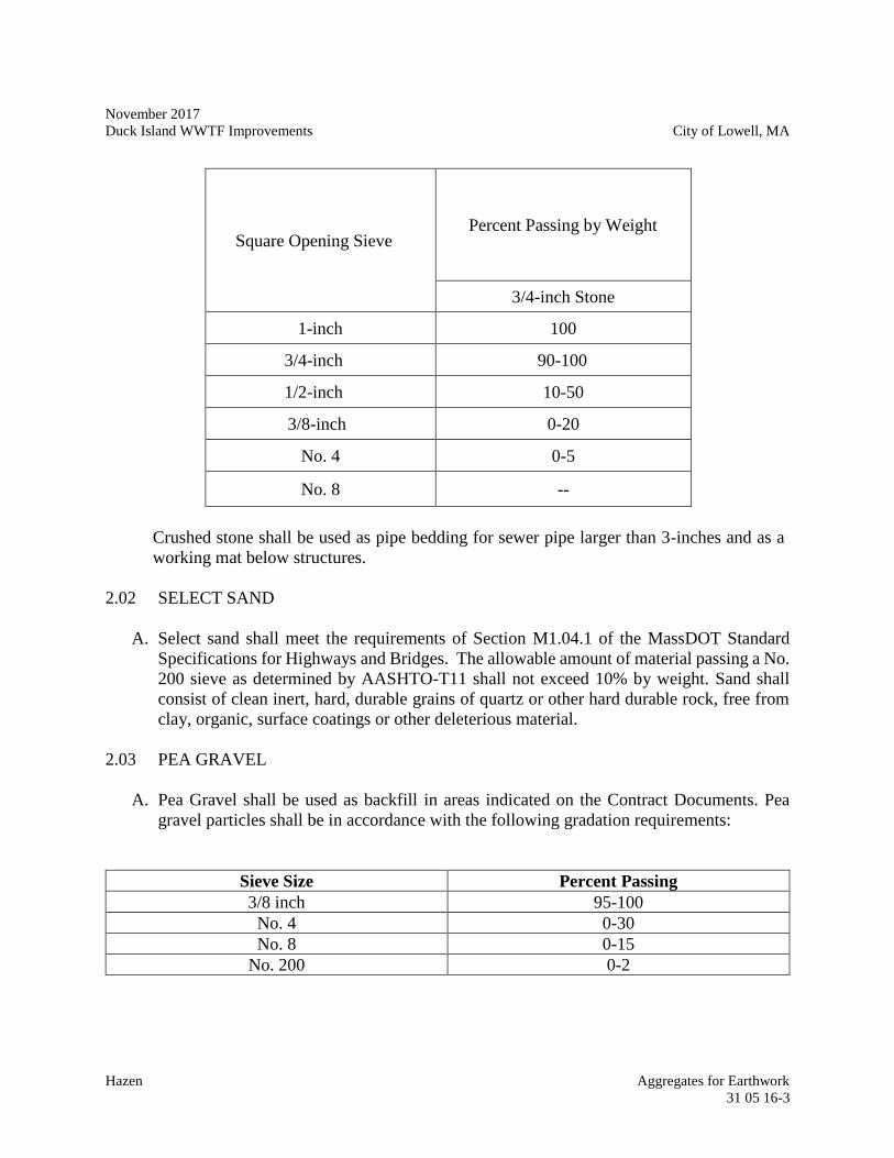
November 2017
Duck Island WWTF Improvements City of Lowell, MA
Hazen Aggregates for Earthwork
31 05 16-3
Square Opening Sieve Percent Passing by Weight
3/4-inch Stone
1-inch 100
3/4-inch 90-100
1/2-inch 10-50
3/8-inch 0-20
No. 4 0-5
No. 8 --
Crushed stone shall be used as pipe bedding for sewer pipe larger than 3-inches and as a
working mat below structures.
2.02 SELECT SAND
A. Select sand shall meet the requirements of Section M1.04.1 of the MassDOT Standard
Specifications for Highways and Bridges. The allowable amount of material passing a No.
200 sieve as determined by AASHTO-T11 shall not exceed 10% by weight. Sand shall
consist of clean inert, hard, durable grains of quartz or other hard durable rock, free from
clay, organic, surface coatings or other deleterious material.
2.03 PEA GRAVEL
A. Pea Gravel shall be used as backfill in areas indicated on the Contract Documents. Pea
gravel particles shall be in accordance with the following gradation requirements:
Sieve Size Percent Passing
3/8 inch 95-100
No. 4 0-30
No. 8 0-15
No. 200 0-2
November 2017
Duck Island WWTF Improvements City of Lowell, MA
Hazen Aggregates for Earthwork
31 05 16-4
PART 3 -- EXECUTION
3.01 CRUSHED STONE, SELECT SAND, & PEA GRAVEL
A. Contractor shall install crushed stone, select sand, and pea gravel in accordance with the
MassDOT Standard Specifications and as indicated in the Contract Documents.
B. Select sand shall be used as backfill in trench excavation to a minimum of 10” above
installed pipe.
3.02 STOCKPILING
A. Stockpile differing materials separately to prevent mixing.
B. Direct surface water away from stockpile site so as to prevent erosion or deterioration of
materials.
C. Soil stockpiles shall be protected with perimeter erosion control and temporary or
permanent stabilization measures, as appropriate, at all times during construction activities.
Stockpile slopes shall be 3H:1V at maximum and top of stockpile shall have a minimum
5% grade to provide positive drainage.
D. Stockpile Cleanup: Remove stockpile, leave area in a clean and neat condition. Grade site
surface to prevent free standing surface water.
- END OF SECTION -
November 2017
Duck Island WWTF Improvements City of Lowell, MA
Hazen Geotextiles for Earthwork
31 05 19.13-1
SECTION 31 05 19.13
GEOTEXTILES FOR EARTHWORK
PART 1 -- GENERAL
1.01 THE REQUIREMENT
A. The Contractor shall furnish and install all Geotextiles, including all necessary and
incidental items, as detailed or required for the Contractor to complete the installation in
accordance with the Drawings and these Specifications.
B. For the location of each type of Geotextile see the Drawings.
1.02 SUBMITTALS
A. Prior to shipping to the site, the Contractor shall submit to the Engineer two copies of a
mill certificate or affidavit signed by a legally authorized official of the Manufacturer for
each type of Geotextile. The Supplier shall also submit three Geotextile samples of each
product, Samples shall be at least one (1) foot wide and four (4) feet long taken across the
roll with the warp direction appropriately marked, seamed and un-seamed as appropriate,
with the mill certificate for each Geotextile type supplied. The mill certificate or affidavit
shall list the Geotextile chemical, mechanical, it, physical and manufacturing properties
and attest that it meets the requirements stated in the specifications. The samples shall be
labeled with the manufacturer's lot number, machine direction, date of sampling, project
number, specifications, manufacturer and product name.
B. The Engineer shall be furnished copies of the delivery tickets or other acceptable receipts
as evidence for materials received that will be incorporated into construction.
1.03 REFERENCES
A. Massachusetts Department of Transportation Standard Specifications for Highways and
Bridges, Section M9.50.0
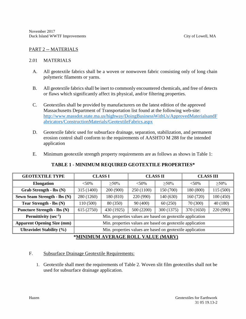
November 2017
Duck Island WWTF Improvements City of Lowell, MA
Hazen Geotextiles for Earthwork
31 05 19.13-2
PART 2 -- MATERIALS
2.01 MATERIALS
A. All geotextile fabrics shall be a woven or nonwoven fabric consisting only of long chain
polymeric filaments or yarns.
B. All geotextile fabrics shall be inert to commonly encountered chemicals, and free of detects
or flaws which significantly affect its physical, and/or filtering properties.
C. Geotextiles shall be provided by manufacturers on the latest edition of the approved
Massachusetts Department of Transportation list found at the following web-site:
http://www.massdot.state.ma.us/highway/DoingBusinessWithUs/ApprovedMaterialsandF
abricators/ConstructionMaterials/GeotextileFabrics.aspx
D. Geotextile fabric used for subsurface drainage, separation, stabilization, and permanent
erosion control shall conform to the requirements of AASHTO M 288 for the intended
application
E. Minimum geotextile strength property requirements are as follows as shows in Table 1:
TABLE 1 - MINIMUM REQUIRED GEOTEXTILE PROPERTIES*
GEOTEXTILE TYPE CLASS I CLASS II CLASS III
Elongation <50% ≥50% <50% ≥50% <50% ≥50%
Grab Strength - lbs (N) 315 (1400) 200 (900) 250 (1100) 150 (700) 180 (800) 115 (500)
Sewn Seam Strength - lbs (N) 280 (1260) 180 (810) 220 (990) 140 (630) 160 (720) 100 (450)
Tear Strength - lbs (N) 110 (500) 80 (350) 90 (400) 60 (250) 70 (300) 40 (180)
Puncture Strength - lbs (N) 615 (2750) 430 (1925) 500 (2200) 300 (1375) 370 (1650) 220 (990)
Permittivity (sec-1) Min. properties values are based on geotextile application
Apparent Opening Size (mm) Min. properties values are based on geotextile application
Ultraviolet Stability (%) Min. properties values are based on geotextile application
*MINIMUM AVERAGE ROLL VALUE (MARV)
F. Subsurface Drainage Geotextile Requirements:
1. Geotextile shall meet the requirements of Table 2. Woven slit film geotextiles shall not be
used for subsurface drainage application.
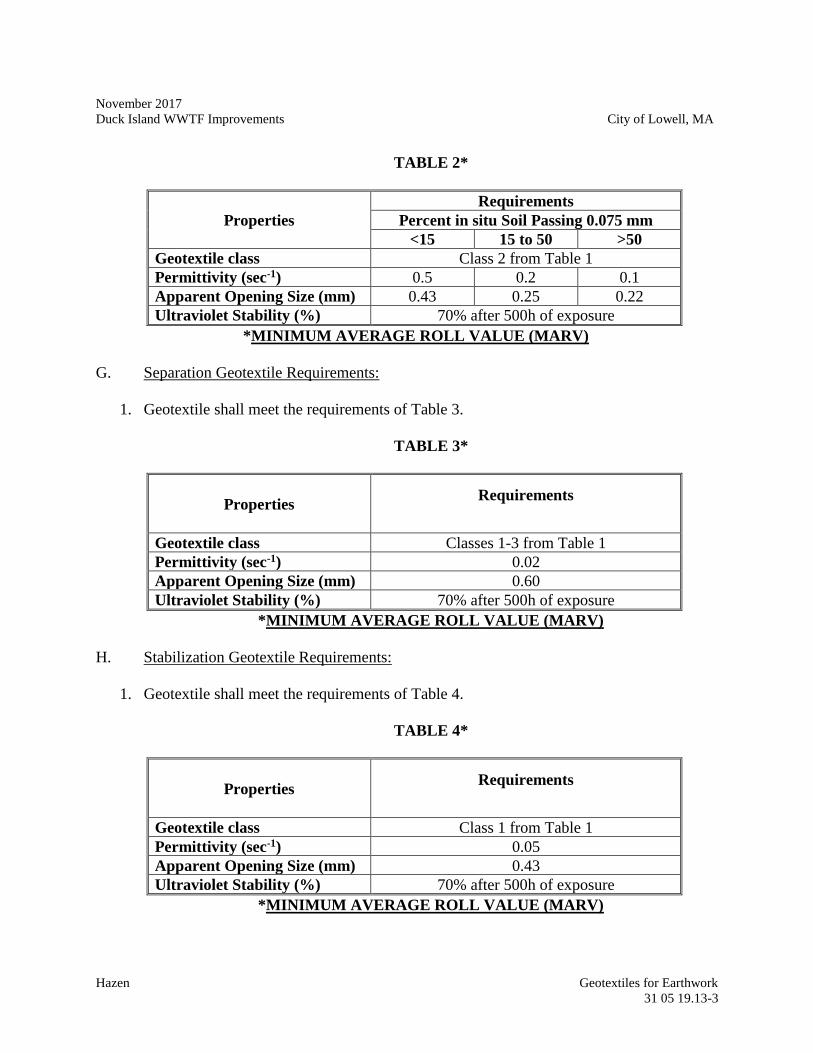
November 2017
Duck Island WWTF Improvements City of Lowell, MA
Hazen Geotextiles for Earthwork
31 05 19.13-3
TABLE 2*
Properties
Requirements
Percent in situ Soil Passing 0.075 mm
<15 15 to 50 >50
Geotextile class Class 2 from Table 1
Permittivity (sec-1) 0.5 0.2 0.1
Apparent Opening Size (mm) 0.43 0.25 0.22
Ultraviolet Stability (%) 70% after 500h of exposure
*MINIMUM AVERAGE ROLL VALUE (MARV)
G. Separation Geotextile Requirements:
1. Geotextile shall meet the requirements of Table 3.
TABLE 3*
Properties Requirements
Geotextile class Classes 1-3 from Table 1
Permittivity (sec-1) 0.02
Apparent Opening Size (mm) 0.60
Ultraviolet Stability (%) 70% after 500h of exposure
*MINIMUM AVERAGE ROLL VALUE (MARV)
H. Stabilization Geotextile Requirements:
1. Geotextile shall meet the requirements of Table 4.
TABLE 4*
Properties Requirements
Geotextile class Class 1 from Table 1
Permittivity (sec-1) 0.05
Apparent Opening Size (mm) 0.43
Ultraviolet Stability (%) 70% after 500h of exposure
*MINIMUM AVERAGE ROLL VALUE (MARV)
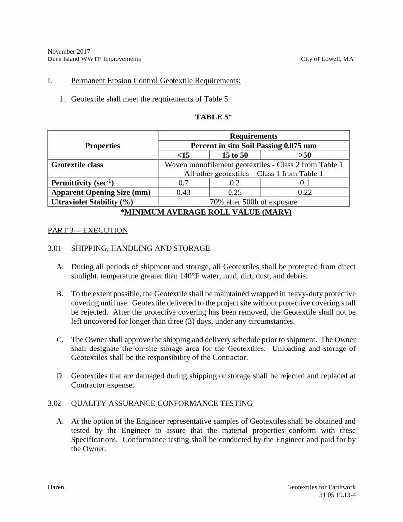
November 2017
Duck Island WWTF Improvements City of Lowell, MA
Hazen Geotextiles for Earthwork
31 05 19.13-4
I. Permanent Erosion Control Geotextile Requirements:
1. Geotextile shall meet the requirements of Table 5.
TABLE 5*
Properties
Requirements
Percent in situ Soil Passing 0.075 mm
<15 15 to 50 >50
Geotextile class Woven monofilament geotextiles - Class 2 from Table 1
All other geotextiles – Class 1 from Table 1
Permittivity (sec-1) 0.7 0.2 0.1
Apparent Opening Size (mm) 0.43 0.25 0.22
Ultraviolet Stability (%) 70% after 500h of exposure
*MINIMUM AVERAGE ROLL VALUE (MARV)
PART 3 -- EXECUTION
3.01 SHIPPING, HANDLING AND STORAGE
A. During all periods of shipment and storage, all Geotextiles shall be protected from direct
sunlight, temperature greater than 140°F water, mud, dirt, dust, and debris.
B. To the extent possible, the Geotextile shall be maintained wrapped in heavy-duty protective
covering until use. Geotextile delivered to the project site without protective covering shall
be rejected. After the protective covering has been removed, the Geotextile shall not be
left uncovered for longer than three (3) days, under any circumstances.
C. The Owner shall approve the shipping and delivery schedule prior to shipment. The Owner
shall designate the on-site storage area for the Geotextiles. Unloading and storage of
Geotextiles shall be the responsibility of the Contractor.
D. Geotextiles that are damaged during shipping or storage shall be rejected and replaced at
Contractor expense.
3.02 QUALITY ASSURANCE CONFORMANCE TESTING
A. At the option of the Engineer representative samples of Geotextiles shall be obtained and
tested by the Engineer to assure that the material properties conform with these
Specifications. Conformance testing shall be conducted by the Engineer and paid for by
the Owner.
November 2017
Duck Island WWTF Improvements City of Lowell, MA
Hazen Geotextiles for Earthwork
31 05 19.13-5
B. Conformance testing shall be completed at a minimum frequency of one sample per
100,000 square feet of Geotextile delivered to the project site. Sampling and testing shall
be as directed by the Engineer.
C. Conformance testing of the Geotextiles shall include but not be limited to the following
properties:
1. Elongation (ASTM D-4632/ASTM D-4632M-15a)
2. Grab Strength (ASTM D-4632/ASTM D-4632M-15a)
3. Sewn Seam Strength (ASTM D-4632/ASTM D-4632M-15a)
4. Tear Strength (ASTM D-4533/ASTM D-4533-15)
5. Puncture Strength (ASTM D-3787-16)
6. Permittivity (ASTM D-4491)
7. Apparent Opening Size (ASTM D-4751)
8. Ultraviolet Stability (ASTM D-4355)
D. The Engineer may add to, remove or revise the test methods used for determination of
conformance properties to allow for use of improved methods.
E. All Geotextile conformance test data shall meet or exceed requirements outlined in Table
1 of these Specifications for the particular category of Geotextile prior to installation. Any
materials that do not conform to these requirements shall be retested or rejected at the
direction of the Engineer.
F. Each roll of Geotextile will be visually inspected by the Engineer or his representative.
The Engineer reserves the right to sample and test at any time and reject, if necessary, any
material based on visual inspection or verification tests.
G. A Geotextile that is rejected shall be removed from the project site and replaced at the
Contractor's expense. Sampling and conformance testing of the Geotextile supplied as
replacement for rejected material shall be performed by the Engineer at Contractor's
expense.
3.03 INSTALLATION
A. Geotextiles shall be placed to the lines and grades shown on the Drawings. At the time of
installation, the Geotextile shall be rejected by the Engineer if it has defects, rips, holes,
flaws, evidence of deterioration, or other damage.
B. The Geotextiles shall be placed smooth and free of excessive wrinkles.
C. When the Geotextiles are placed on slopes, the upslope fabric portion shall be lapped such
that it is the upper or exposed Geotextile.
November 2017
Duck Island WWTF Improvements City of Lowell, MA
Hazen Geotextiles for Earthwork
31 05 19.13-6
D. Geotextiles shall be temporarily secured in a manner accepted by the Engineer prior to
placement of overlying materials.
E. Any Geotextile that is torn or punctured shall be repaired or replaced as directed by the
Engineer by the Contractor at no additional cost to the Owner. The repair shall consist of
a patch of the same type of Geotextile placed over the failed areas and shall overlap the
existing Geotextile a minimum of 12-inches from any point of the rupture.
F. Any Geotextile that is subjected to excessive sediment buildup on its surface during
construction shall be replaced by the Contractor prior to placement of overlying material.
– END OF SECTION –
November 2017
Duck Island WWTF Improvements City of Lowell, MA
Hazen Site Clearing
31 10 00-1
SECTION 31 10 00
SITE CLEARING
PART 1 -- GENERAL
1.01 THE REQUIREMENT
A. Includes all labor, material, equipment and appliances required for the complete execution
of any additions, modifications, or alterations to existing building(s) and new construction
work as shown on the Drawings and specified herein.
B. Principal items of work include:
1. Notifying all authorities owning utility lines running to or on the property.
Protecting and maintaining all utility lines to remain and capping those that are not
required in accordance with instructions of the Utility Companies, and all other
authorities having jurisdiction.
2. Clearing the site within the Limit of Work including removal of grass, brush,
shrubs, trees, loose debris and other encumbrances except for trees marked to
remain.
3. Boxing and protecting all trees, shrubs, lawns and the like within areas to be
preserved. Relocating trees and shrubs, so indicated on the Drawings, to designated
areas.
4. Repairing all injury to trees, shrubs, and other plants caused by site preparation
operations shall be repaired immediately. Work shall be done by qualified
personnel in accordance with standard horticultural practice and as approved by the
Engineer.
5. Removing topsoil to its full depth from designated areas and stockpiling on site
where directed by the Engineer for future use.
6. Disposing from the site all debris resulting from work under this Section.
November 2017
Duck Island WWTF Improvements City of Lowell, MA
Hazen Site Clearing
31 10 00-2
1.02 RELATED WORK SPECIFIED ELSEWHERE
A. Section 02 41 13 – Selective Site Demolition
B. Section 31 23 16 – Excavation
1.03 REFERENCE SPECIFICATIONS, CODES, AND STANDARDS
A. Massachusetts Department of Transportation (MassDOT) Standard Specifications for
Highways and Bridges
B. MassDOT Supplemental Specifications to the Standard Specifications for Highways and
Bridges
C. Massachusetts Erosion and Sediment Control Guidelines for Urban and Suburban Areas
1.04 STREET AND ROAD BLOCKAGE
A. Closing of streets and roads during progress of the work shall be in compliance with the
requirements of the Owner and other authorities having jurisdiction. Access shall be
provided to all facilities remaining in operation.
1.05 PROTECTION OF PERSONS AND PROPERTY
A. All work shall be performed in such a manner to protect all personnel, workmen,
pedestrians and adjacent property and structures from possible injury and damage.
B. All conduits, wires, cables and appurtenances above or below ground shall be protected
from damage.
C. Contractor shall immediately notify the appropriate utility of any damage to conduits,
wires, cables and appurtenances above or below ground caused by site preparation
operations. Repairs shall be completed immediately at no expense to the Owner. Repairs
shall be performed by qualified personnel in accordance with standard practices as
approved by the Engineer or by Utility owner as appropriate.
D. Provide warning and barrier fence where shown on the Drawings and as specified herein.
PART 2 -- EXECUTION
2.01 CLEARING OF SITE
November 2017
Duck Island WWTF Improvements City of Lowell, MA
Hazen Site Clearing
31 10 00-3
A. Before removal of topsoil, and start of excavation and grading operations, the areas within
the clearing limits shall be cleared and grubbed.
B. Clearing shall consist of cutting, removal, and satisfactory disposal of all trees, fallen
timber, brush, bushes, rubbish, sanitary landfill material, fencing, and other perishable and
objectionable material within the areas to be excavated or other designated areas Prior to
the start of construction, the Contractor shall survey the entire Contract site and shall
prepare a plan which defines the areas to be cleared and grubbed, trees to be pruned, extent
of tree pruning, and/or areas which are to be cleared but not grubbed. This plan shall be
submitted to the Engineer for approval. Should it become necessary to remove a tree, bush,
brush or other plants adjacent to the area to be excavated, the Contractor shall do so only
after permission has been granted by the Engineer.
C. Excavation resulting from the removal of trees, roots and the like shall be filled with
suitable material, as approved by the Engineer, and thoroughly compacted per the
requirements contained in Section 31 23 16, Excavation.
D. Unless otherwise shown or specified, the Contractor shall clear and grub a strip at least
15 ft. wide along all permanent fence lines installed under this Contract.
E. In temporary construction easement locations, only those trees and shrubs shall be removed
which are in actual interference with excavation or grading work under this Contract, and
removal shall be subject to approval by the Engineer. However, the Engineer reserves the
right to order additional trees and shrubs removed at no additional cost to the Owner, if
such, in his opinion, are too close to the work to be maintained or have become damaged
due to the Contractor's operations.
2.02 STRIPPING AND STOCKPILING EXISTING TOPSOIL
A. Existing topsoil and sod on the site within areas designated on the Drawings shall be
stripped to whatever depth it may occur, and stored in locations directed by the Engineer.
B. The topsoil shall be free of stones, roots, brush, rubbish, or other unsuitable materials
before stockpiling the topsoil.
C. Care shall be taken not to contaminate the stockpiled topsoil with any unsuitable materials.
2.03 GRUBBING
A. Grubbing shall consist of the removal and disposal of all stumps, roots, logs, sticks and
other perishable materials to a depth of at least 6-inches below ground surfaces.
November 2017
Duck Island WWTF Improvements City of Lowell, MA
Hazen Site Clearing
31 10 00-4
B. Large stumps located in areas to be excavated may be removed during grading operations,
subject to the approval of the Engineer.
2.04 DISPOSAL OF MATERIAL
A. All debris resulting from the clearing and grubbing work shall be disposed of by the
Contractor at a properly permitted facility as part of the work of this Contract. Material
designated by the Engineer to be salvaged shall be stored on the construction site as
directed by the Engineer for reuse in this Project or removal by others.
D. Burning of any debris resulting from the clearing and grubbing work will not be permitted
at the site.
2.05 WARNING AND BARRIER FENCE
A. The fence shall be made of a visible, lightweight, flexible, high strength polyethylene
material and placed at perimeter of limit of work excluding only areas that may obstruct
site access as approved by the engineer.
B. Physical Properties
Fence:
Color: International Orange
Roll Size: 4' x 100'
Roll weight: 8.25 lbs.
Mesh opening: 1-3/4" x 3"
Posts:
ASTM Designation: ASTM 702
Length: 5 feet long (T-Type)
Weight: 1.25 #/Foot (min)
Area of Anchor Plate: 14 Sq. In.
C. Drive posts 12 to 18 inches into ground every 10' to 12'. Wrap fence material around first
terminal post allowing overlap of one material opening. Use metal tie wire or plastic tie
wrap to fasten material to itself at top, middle and bottom. At final post, cut with utility
knife or scissors at a point halfway across an opening. Wrap around and tie at final post in
the same way as the first post.
D. Use tie wire or tie wrap at intermediate posts and splices as well. Thread ties around a
vertical member of the fence material and the post, and bind tightly against the post. For
November 2017
Duck Island WWTF Improvements City of Lowell, MA
Hazen Site Clearing
31 10 00-5
the most secure fastening, tie at top, middle and bottom. Overlap splices a minimum of
four fence openings, tie as above, fastening both edges of the fence material splice overlap.
- END OF SECTION –
November 2017
Duck Island WWTF Improvements City of Lowell, MA
Hazen Site Clearing
31 10 00-6
--THIS PAGE INTENTIONALLY LEFT BLANK--
November 2017
Duck Island WWTF Improvements City of Lowell, MA
Hazen Earthwork and Excavation
31 23 16-1
SECTION 31 23 16
EARTHWORK
PART 1 -- GENERAL
1.01 THE REQUIREMENT
A. Furnish all labor, equipment and materials required to complete all work associated with
excavation, including off-site borrow excavation, dewatering, backfill, drainage layers
beneath and around structures, foundation and backfill stone, filter fabric, embankments,
stockpiling topsoil and any excess suitable material in designated areas, in place
compaction of embankments, backfill and subgrades beneath foundations and roadways,
excavation support, disposing from the site all unsuitable materials, providing erosion and
sedimentation control grading, site grading and preparation of pavement and structure
subgrade, and other related and incidental work as required to complete the work shown
on the Drawings and specified herein. The General Contractor shall be responsible for all
excavation, including backfilling and conduit encasement. With respect to conduit
encasement, care shall be taken to avoid conduit floatation.
B. All excavations shall be in conformity with the lines, grades, and cross sections shown on
the Drawings or established by the Engineer.
C. It is the intent of this Specification that the Contractor conduct the construction activities
in such a manner that erosion of disturbed areas and off-site sedimentation be absolutely
minimized.
D. All work under this Contract shall be done in conformance with and subject to the
limitations of the latest editions of the Massachusetts Department of Transportation
(MassDOT) Standard Specifications for Highways and Bridges, the MassDOT
Supplemental Specifications to the Standard Specifications for Highways and Bridges, and
the Massachusetts Erosion and Sediment Control Guidelines for Urban and Suburban
Areas.
E. All fill material, processed stone, topsoil, etc. imported to the site and onsite material
requested to be used shall be subjected to the testing requirements contained in Part 3 of
this section. An independent testing laboratory retained by the Contractor shall perform all
testing. Certified test results will determine if a material meets the Sections. The Contractor
shall furnish all necessary samples for laboratory test and shall provide assistance and
cooperation during field tests. The Contractor shall plan his operations to allow adequate
time for laboratory tests and to permit taking of field density tests during compaction. Any
November 2017
Duck Island WWTF Improvements City of Lowell, MA
Hazen Earthwork and Excavation
31 23 16-2
costs of retesting required as a result of failure to meet compaction requirements shall be
borne by the Contractor.
1.02 RELATED WORK SPECIFIED ELSEWHERE
A. Requirements of related work are included in Divisions 01 00 00 and 31 00 00 of these
Specifications.
1.03 REFERENCE SPECIFICATIONS, CODES, AND STANDARDS
A. Without limiting the generality of the other requirements of the Specifications, all work
herein shall conform to the applicable requirements of the following documents. All
referenced Specifications, codes, and standards refer to the most current issue available at
the time of Bid.
1. MassDOT Standard Specifications for Highways and Bridges
2. MassDOT Supplemental Specifications to the Standard Specifications for
Highways and Bridges
3. Massachusetts Wetlands Protection Act, Chapter 131, Section 40
4. Code of Massachusetts Regulation 520, Part 14, “Excavation and Trench Safety.”
5. Massachusetts Erosion and Sediment Control Guidelines for Urban and Suburban
Areas.
B. American Society for Testing and Materials (ASTM):
ASTM C127-15 Test for Specific Gravity and Absorption of Coarse Aggregate.
ASTM C136-14 Test for Sieve Analysis of Fine and Coarse Aggregates.
ASTM D4318 Standard Test Methods for Liquid Limit, Plastic Limit, and Plasticity
Index of Soils.
ASTM C535-16 Test for Resistance to Degradation of Large Size Coarse Aggregate by
Abrasion and Impact in the Los Angeles Machine.
ASTM D698-12 Standard Test Methods for Laboratory Compaction Characteristics of
Soil Using Standard Effort
ASTM D1556-15 Test for Density of Soil in Place by the Sand-Cone Method.
November 2017
Duck Island WWTF Improvements City of Lowell, MA
Hazen Earthwork and Excavation
31 23 16-3
ASTM D1557-12 Standard Test Methods for Laboratory Compaction Characteristics of
Soil Using Modified Effort
ASTM D4253-16 Standard Test Methods for Maximum Index Density and Unit Weight
of Soils Using a Vibratory Table
ASTM D2167-15 Standard Test Method for Density and Unit Weight of Soil in Place by
the Rubber Balloon Method
ASTM D2216-10 Test for Laboratory Determination of Water (Moisture) Content of Soil,
Rock, and Soil Aggregate Mixtures.
ASTM D2487-11 Test for Classification of Soils for Engineering Purposes.
ASTM D6938-15 Standard Test Method for In-Place Density and Water Content of Soil
and Soil-Aggregate by Nuclear Methods (Shallow Depth)
1.04 SUBSURFACE CONDITIONS
A. Information on subsurface conditions is referenced under Division 01 00 00, General
Requirements.
B. Attention is directed to the fact that there may be water pipes, storm drains and other
utilities located in the area of proposed excavation. Perform all repairs to same in the event
that excavation activities disrupt service. The Contractor shall contact DigSafe 811 at
phone number 811 or 1 888 344 7233 to request an underground utility location mark out
at least three (3) business days, not including the day the request is called in, prior to the
beginning of excavation. The Contractor shall also contact and request utility location
mark-out from buried utility owners with utilities on the project site that are not participants
of DigSafe.
1.05 SHOP DRAWINGS, PRODUCT DATA, AND SAMPLES
A. In accordance with the procedures and requirements set forth in Division 01 00 00 General
Requirements, the Contractor shall submit the following:
1. Name and location of all material suppliers.
2. Certificate of compliance with the standards specified above for each source of each
material.
3. List of disposal sites for waste and unsuitable materials and all required permits for
use of those sites.
November 2017
Duck Island WWTF Improvements City of Lowell, MA
Hazen Earthwork and Excavation
31 23 16-4
4. Plans and cross sections of open cut excavations showing side slopes and limits of
the excavation at grade.
5. Construction drawings and structural calculations for any types of excavation
support required. Drawings and calculations shall be sealed by a currently
registered Professional Engineer in the State of Massachusetts
6. Monitoring plan and pre-construction condition inspection and documentation of
all adjacent structures, utilities, and roadways near proposed installation of
excavation support systems.
7. Dewatering procedures shall be in accordance with the guidelines shown in Section
31 23 19 - Dewatering.
B. Backfill Materials: Submit a grain size analysis and curve performed in accordance with
ASTM D422 for each proposed source of backfill for review by the Engineer. The grain
size analysis shall indicate the backfill material conforms to the gradation requirements
specified. Submit a moisture-density curve indicating the maximum dry density and
optimum moisture content as determined by ASTM D1557 for each proposed source of
backfill for review of the Engineer.
C. Controlled Density Fill (CDF) Mix Design or Concrete Flowable Fill
1. Prior to beginning the work the Contractor shall submit for review, flowable fill
mix designs which shall show the proportions and gradations of all materials for
each class and type of flowable fill specified herein.
D. Submit the qualifications of the independent geotechnical testing laboratory performing
soil testing and inspection services during earthwork operations. The geotechnical testing
laboratory shall demonstrate to the Engineer's satisfaction, based on evaluation of
laboratory submitted criteria conforming to ASTM D3740, that it has the experience and
capability to conduct required field and laboratory geotechnical testing. In addition, the
laboratory shall be supervised by a Registered Professional Engineer in the Commonwealth
of Massachusetts.
E. The Contractor shall notify the Engineer of the off-site or on-site sources of structural fill
and submit to the Engineer a representative sample weighing approximately 50 lbs. The
sample shall be delivered to a designated location designated by the Engineer on site.
1.06 PRODUCT HANDLING
A. Soil and rock material shall be excavated, transported, placed, and stored in a manner so as
to prevent contamination, segregation and excessive wetting. Materials which have
November 2017
Duck Island WWTF Improvements City of Lowell, MA
Hazen Earthwork and Excavation
31 23 16-5
become contaminated or segregated will not be permitted in the performance of the work
and shall be removed from the site.
1.07 USE OF EXPLOSIVES
A. The use of explosives for excavation work is strictly prohibited on this project.
1.08 EXCAVATION CLASSIFICATIONS
A. Earth Excavation or "Excavation" consists of removal of materials encountered to the
subgrade elevations indicated and subsequent reuse or disposal of the materials removed.
All excavation is classified as earth excavation unless it otherwise meets the classifications
provided below for unauthorized excavation, additional excavation, or rock excavation.
B. Unauthorized Excavation consists of removal of materials beyond indicated subgrade
elevations or dimensions without specific direction of the Engineer. Unauthorized
excavation, as well as remedial work directed by the Engineer, shall be at Contractor's
expense.
1. Under footings, foundations bases, concrete slabs, retaining walls or other
structures, fill unauthorized excavations to the proper elevations with lean concrete.
Elsewhere, backfill and compact unauthorized excavations as specified for
excavations of the same class, unless otherwise directed by the Engineer.
C. Removal of unsuitable material and its replacement as directed will be paid on the basis of
contract conditions relative to changes in work or as provided for under the unit rates for
this classification.
1.09 EXCAVATION
A. The Contractor shall perform all excavations of every description and of whatever
substances encountered, in a manner as required to allow for placing of temporary earth
support, forms, installation of pipe and other work, and to permit access to the Engineer
for the purpose of observing the work. Excavations shall be to such widths as will give
suitable space for the work. Bottoms of trenches and excavations shall be protected from
frost and shall be firm, dry and in an acceptable condition to receive the work; work shall
not be placed on frozen surfaces nor shall work be placed on wet or unstable surfaces.
B. All excavations made in open cut shall be controlled by the conditions existing at the
various locations and shall always be confined to the limits as designated by the Engineer.
In no case shall earth be excavated or disturbed by machinery so near to the finished
subgrade for structures and pipelines as to result in the disturbance of the earth below the
subgrade. The final excavation to subgrade should be accomplished with a smooth faced
bucket or by hand if directed by the Engineer.
November 2017
Duck Island WWTF Improvements City of Lowell, MA
Hazen Earthwork and Excavation
31 23 16-6
C. If soil sampling shows contamination, the contractor shall dispose of all contaminated
material at an appropriate offsite disposal site, as approved by the Engineer.
1.10 SEPARATION OF EXCAVATED MATERIALS FOR REUSE
A. Remove only existing pavement that is necessary for prosecution of work.
B. Carefully remove loam and topsoil from excavated areas. Store separately for further use
or furnish equivalent loam and topsoil as directed.
C. Carefully remove acceptable material from excavated areas and store separately for further
use as backfill material.
PART 2 -- PRODUCTS
2.01 BACKFILL MATERIALS
A. Crushed stone shall be in accordance with subsection 2.01 of Section 31 05 16 – Aggregates
for Earthwork
B. Sand shall be in accordance with subsection 2.02 of Section 31 05 16 – Aggregates for
Earthwork
C. Filter Fabric shall be in accordance with requirements of Section 31 05 19.13 –
Geotextiles for Earthwork and as called out on the Contract Drawings
D. Control Density Fill (CDF; also referred to as concrete flowable fill): Controlled density
fill material is a flowable, self consolidating, rigid setting, low density material that can
substitute for compacted gravel in backfills, fills and structural fills. There are two main
categories of CDFs, excavatable and non-excavatable with a sub category of flowable and
very flowable. It shall be a mixture of portland cement, fly ash (if very flowable), sand,
and water designed to provide strengths within the range specified.
1. The categories of CDF’s are Type 1 (Very Flowable & Non Excavatable), Type 1E (Very
Flowable & Excavatable), Type 2 (Flowable & Non Excavatable) and Type 2E (Flowable
& Excavatable)
2. The following Type 1 and Type 1E mix designs are for information only, the actual mix
designs submitted by the ready mix operator, in accordance with standard Department
practice, must be confirmed by trial batches.
November 2017
Duck Island WWTF Improvements City of Lowell, MA
Hazen Earthwork and Excavation
31 23 16-7
MATERIAL TYPE 1 MIX DESIGN TYPE 1E MIX DESIGN
Cement 100 pounds 50 pounds
Fly Ash 250 pounds 250 pounds
Sand 2,650 pounds 2,700 pounds
Water 60 gallons 60 gallons
3. Various types of controlled density fill must meet the requirements set forth in the table
below:
CONTROLLED DENSITY FILL TYPE 1 & 2 TYPE 1E & 2E
Compressive Strength @ 28 days 30-150 psi 30-80 psi*
Compressive Strength @ 90 days 200 psi maximum 100 psi maximum*
Slump 10-12 inches 10-12 inches
*May be changed by Design Engineer to fit particular job requirements.
E. Select fill shall be in accordance with the following requirements:
1. Select fill shall be soil containing no stone greater than 6 inches. The materials shall be
free of trash, ice, snow, tree stumps, roots and other organic and deleterious materials.
Select fill shall generally be excavated material from the project. Select fill shall not
contain more than 25 percent by weight of silt and clay. It shall be of such a nature and
character that it can be compacted to the specified densities in a reasonable length of
time. Topsoil and subsoil shall not be considered select fill. Select fill shall be used as
trench backfill and as backfill outside limits of structures and pavement structures.
2. Regardless of material used as Select fill, materials shall be compacted at a moisture
content satisfactory to the Engineer, which shall be approximately that required to produce
the maximum density except that the moisture content shall not be more than 1% below
nor more than 4% above the optimum moisture content for the particular material tested in
accordance with the ASTM D698.
3. Select fill used as subgrade support shall be a coarse aggregate material meeting the
gradation requirements of #57 or #78 aggregates in accordance with ASTM C-33.
4. Select fill used under structures (structural fill) shall be furnished from off-site or on-site
sources as required. Structural fill material shall be crushed stone in accordance with
subsection 2.01 of Section 31 05 16 – Aggregates for Earthwork ,
5. Where excavated material does not meet requirements for select fill, Contractor shall
furnish off-site borrow material meeting the specified requirements herein.
6. When the excavated material from required excavations is suitable for use as backfill,
bedding, or embankments, but is replaced with off-site borrow material for the Contractor’s
November 2017
Duck Island WWTF Improvements City of Lowell, MA
Hazen Earthwork and Excavation
31 23 16-8
convenience, the costs associated with such work and material shall be borne by the
Contractor.
2.02 TOPSOIL
A. Topsoil for placement for final grading and landscaping shall be in accordance with the
guidelines shown in Section 32 91 19.13 – Topsoil Placement and Grading.
2.03 GEOTEXTILES
A. Geotextiles used shall be in accordance with the guidelines shown in Section 31 05 19.13
– Geotextiles for Earthwork and as called out on the Contract Drawings.
PART 3 -- EXECUTION
3.01 STRIPPING OF TOPSOIL
A. In all areas to be excavated, filled, paved, or graveled the topsoil shall be stripped to its full
depth and shall be deposited in storage piles on the site, at locations designated by the
Engineer, for subsequent reuse. Topsoil shall be kept separated from other excavated
materials and shall be piled free of roots and other undesirable materials.
3.02 EXCAVATION
A. All material excavated, regardless of its nature or composition, shall be classified as
UNCLASSIFIED EXCAVATION. Excavation shall include the removal of all soil, rock,
weathered rock, rocks of all types, boulders, conduits, pipe, buried concrete, brick, and all
other obstacles encountered and shown to be removed within the limits of excavation
shown on the Drawings or specified herein. No additional payment will be made for the
removal of obstacles encountered within the excavation limits shown on the Drawings and
specified herein.
B. All suitable material removed in the excavation shall be used as far as practicable in the
formation of embankments, subgrades, and shoulders, and at such other places as may be
indicated on the Drawings or indicated by the Engineer. No excavation shall be wasted
except as may be permitted by the Engineer. Refer to the drawings for specific location
and placement of suitable excavated materials in the formation of embankments, backfill,
and structural and roadway foundations. THE Engineer WILL DESIGNATE
MATERIALS THAT ARE UNSUITABLE. The Contractor shall furnish off-site disposal
areas for the unsuitable material. Where suitable materials containing excessive moisture
are encountered above grade in cuts, the Contractor shall construct above grade ditch drains
prior to the excavation of the cut material when in the opinion of the Engineer such
measures are necessary to provide proper construction.
November 2017
Duck Island WWTF Improvements City of Lowell, MA
Hazen Earthwork and Excavation
31 23 16-9
C. All excavations shall be made in the dry and in such a manner and to such widths as will
give ample room for properly constructing and inspecting the structures and/or piping they
are to contain and for such excavation support, pumping and drainage as may be required.
Excavation shall be made in accordance with the grades and details shown on the Drawings
and as specified herein.
D. Excavation slopes shall be flat enough to avoid slides that will cause disturbance of the
subgrade or damage of adjacent areas. Excavation requirements and slopes shall be as
indicated in the Drawings. The Contractor shall intercept and collect surface runoff both at
the top and bottom of cut slopes. The intersection of slopes with natural ground surfaces,
including the beginning and ending of cut slopes, shall be uniformly rounded as shown on
the Drawings or as may be indicated by the Engineer. Concurrent with the excavation of
cuts, the Contractor shall construct intercepting berm ditches or earth berms along and on
top of the cut slopes at locations shown on the Drawings or designated by the Engineer.
All slopes shall be finished to reasonably uniform surfaces acceptable for seeding and
mulching operations. No rock or boulders shall be left in place which protrude more than
1 foot within the typical section cut slope lines, and all rock cuts shall be cleaned of loose
and overhanging material. All protruding roots and other objectionable vegetation shall be
removed from slopes. The Contractor shall be required to submit plans of open-cut
excavation for review by the Engineer before approval is given to proceed.
E. The bottom of all excavations for structures and pipes shall be examined by the Engineer
for bearing value and the presence of unsuitable material. If, in the opinion of the Engineer,
additional excavation is required due to the low bearing value of the subgrade material, or
if the in-place soils are soft, yielding, pumping and wet, the Contractor shall remove such
material to the required width and depth and replace it with thoroughly compacted select
fill, and/or crushed stone or screened gravel as indicated by the Engineer. Payment for
such additional work ordered by the Engineer shall be made as an extra by a Change Order
in accordance with the General Conditions and Division 1. No payment will be made for
subgrade disturbance caused by inadequate dewatering or improper construction methods.
F. All cuts shall be brought to the grade and cross section shown on the Drawings, or
established by the Engineer, prior to final inspection and acceptance by the Engineer.
G. Slides and overbreaks which occur due to negligence, carelessness or improper
construction techniques on the part of the Contractor shall be removed and disposed of by
the Contractor as indicated by the Engineer at no additional cost to the Owner. If grading
operations are suspended for any reason whatsoever, partially completed cut and fill slopes
shall be brought to the required slope and the work of seeding and mulching or other
required erosion and sedimentation control operations shall be performed.
H. Where the excavation exposes sludge, sludge contaminated soil or other odorous materials,
the Contractor shall cover such material at the end of each workday with a minimum of
November 2017
Duck Island WWTF Improvements City of Lowell, MA
Hazen Earthwork and Excavation
31 23 16-10
6-inches and a maximum of 24-inches of clean fill. The work shall be an odor abatement
measure and the material shall be placed to the depth deemed satisfactory by the Engineer
for this purpose.
3.03 UNAUTHORIZED EXCAVATION
A. Excavation carried outside of the work limits required by the Contract Documents shall be
at the Contractor's expense, and shall be backfilled by the Contractor at its own expense
with suitable material, as directed by the Engineer. Where, in the judgment of the Engineer,
such over-excavation requires use of lean concrete or crushed stone, the Contractor, at its
expense shall furnish and place such materials.
3.04 HAND REMOVAL
A. Where hazardous conditions exist, or clearances with existing piping or structures are very
small, or strong possibility of damage to persons or property exists Contractor shall remove
earth or rock in these areas by hand methods.
B.
3.05 STORAGE AND DISPOSAL
A. Excavated material suitable and approved for filling and backfilling shall be places in
stockpiles until it can be placed in the work. All excavated material shall be kept at least 2
feet from the edge of the open excavation in accordance with 29 CFR 1926.651 (j) (2).
Excavated material shall be places in a manner that will not obstruct the work nor endanger
the workers or the public. No material shall be stored within street right-of-ways, or,
obstruct sidewalks, driveways, roadways, or other structures, or within 50 feet of water
bodies, streams, or wetlands as possible. Placement of excavated shall be done in
compliance with Federal, State, and Local Regulations.
B. If the areas on the site prove to be insufficient to store all the excavated material required
for backfilling, the Contractor shall obtain areas off the property, at his own expense, for
the storage of such material. All costs of moving such material to the storage piles, and
removing it and placing it in the work shall be expense of the Contractor.
3.06 EXCAVATION SUPPORT
A. The Contractor shall furnish, place, and maintain such excavation support which may be
required to support sides of excavation or to protect pipes and structures from possible
damage and to provide safe working conditions. Excavation support such as sheeting,
shoring and bracing, shall be maintained regardless of the period of time excavations will
be open. If the Engineer is of the opinion that at any point sufficient or proper supports
have not been provided, he may order additional supports put in at the expense of the
Contractor. The Contractor shall be responsible for the adequacy of all supports used and
November 2017
Duck Island WWTF Improvements City of Lowell, MA
Hazen Earthwork and Excavation
31 23 16-11
for all damage resulting from failure of support system or from placing, maintaining and
removing it.
B. Selection of and design of any proposed excavation support systems is exclusively the
responsibility of the Contractor. Contractor shall submit drawings and calculations on
proposed systems sealed by a Professional Engineer currently registered in the State of
Massachusetts.
C. The Contractor shall exercise caution in the installation and removal of supports to insure
that excessive or unusual loadings are not transmitted to any new or existing structure, to
prevent damage to adjacent structures from slippage, shifting or settling beyond the
excavation lines, to maintain stability of soil beyond excavation lines, and to prevent
undermining of pavement. The Contractor shall promptly repair at his expense any and all
damage that can be reasonably attributed to installation or removal of excavation support
system. Contractor shall monitor movement in the excavation support systems as well as
movement at adjacent structures, utilities and roadways near excavation supports.
Contractor shall submit a monitoring plan developed by the excavation support design
engineer. All pre-construction condition assessment and documentation of adjacent
structures on-site and off-site shall be performed by the Contractor. If any sign of distress
such as cracking or movement occurs in any adjacent structure, utility or roadway during
installation of supports, subsequent excavation, service period of supports, subsequent
backfill and construction, or removal of supports, Engineer shall be notified immediately.
Contractor shall be exclusively responsible for any damage to any roadway, structure,
utility, pipes, etc. both on-site and off-site, as a result of his operations.
D. Sheeting, shoring, and bracing shall be of sufficient dimensions and strengths necessary to
attain proper restraint and temporary stability as the work progresses.
E. All work shall be done in accordance with OSHA, The 29 Code of Federal Regulations,
Part 1926, Subpart P and other relevant regulations.
F. Where necessary, the Contractor, without separate compensation, shall provide and
maintain safety guard railings around excavations and crossover walkways or bridges
with standard guardrails.
G. All excavation supports shall be removed upon completion of the work except as indicated
herein. The Engineer may permit supports to be left in place at the request and expense of
the Contractor. The Engineer may order certain supports left permanently in place in
addition to that required by the Contract. The cost of the materials so ordered left in place,
less a reasonable amount for the eliminated expense of the removal work omitted, will be
paid as an extra by a Change Order in accordance with the General Conditions and Division
1. Any excavation supports left in place shall be cut off at least two (2) feet below the
finished ground surface or as directed by the Engineer.
November 2017
Duck Island WWTF Improvements City of Lowell, MA
Hazen Earthwork and Excavation
31 23 16-12
3.07 PROTECTION OF SUBGRADE
A. To minimize the disturbance of bearing materials and provide a firm foundation, the
Contractor shall comply with the following requirements:
1. Use of heavy rubber-tired construction equipment shall not be permitted on the final
subgrade unless it can be demonstrated that drawdown of groundwater throughout
the entire area of the structure is at least 3 feet below the bottom of the excavation
(subgrade). Even then, the use of such equipment shall be prohibited should
subgrade disturbance result from concentrated wheel loads.
2. Subgrade soils disturbed through the operations of the Contractor shall be
excavated and replaced with compacted select fill or crushed stone at the
Contractor's expense as directed by the Engineer.
3. The Contractor shall provide positive protection against penetration of frost into
materials below the bearing level during work in winter months. This protection
can consist of a temporary blanket of straw or hay covered with a plastic membrane
or other acceptable means.
3.08 PROOFROLLING
A. The subgrade of all structures and all areas that will support pavements or select fill shall
be proof-rolled. After stripping of topsoil, excavation to subgrade and prior to placement
of fills, the exposed subgrade shall be carefully inspected by probing and testing as needed.
Any topsoil or other organic material still in place, frozen, wet, soft, or loose soil, and other
undesirable materials shall be removed. The exposed subgrade shall be proof-rolled with
a heavily loaded tandem-wheeled dump truck to check for pockets of soft material hidden
beneath a thin crust of better soil. Any unsuitable materials thus exposed shall be removed
and replaced with an approved compacted material.
3.09 DEWATERING
A. The Contractor shall do all dewatering as required for the completion of the work.
Procedures for dewatering proposed by the Contractor shall be submitted to the Engineer
for review prior to any earthwork operations. All water removed by dewatering operations
shall be disposed of in accordance with the Massachusetts Dewatering General Permit
(DGP).
B. The dewatering system shall be of sufficient size and capacity as required to control
groundwater or seepage to permit proper excavation operations, embankment construction
and reconstruction, subgrade preparation, and to allow concrete to be placed in a dry
condition. The system shall include a sump system or other equipment, appurtenances and
November 2017
Duck Island WWTF Improvements City of Lowell, MA
Hazen Earthwork and Excavation
31 23 16-13
other related earthwork necessary for the required control of water. The Contractor shall
drawdown groundwater to at least 3 feet below the bottom of excavations (subgrade) at all
times in order to maintain a dry and undisturbed condition.
C. The Contractor shall control, by acceptable means, all water regardless of source. Water
shall be controlled and its disposal provided for at each berm, structure, etc. The entire
periphery of the excavation areas shall be ditched and diked to prevent water from entering
the excavation. The Contractor shall be fully responsible for disposal of the water and shall
provide all necessary means at no additional expense to the Owner. The Contractor shall
be solely responsible for proper design, installation, proper operation, maintenance, and
any failure of any component of the system.
D. The Contractor shall be responsible for and shall repair without cost to the Owner, any
damage to work in place and the excavation, including damage to the bottom due to heave
and including removal of material and pumping out of the excavated area. The Contractor
shall be responsible for damages to any other area or structure caused by his failure to
maintain and operate the dewatering system proposed and installed by the Contractor.
E. The Contractor shall take all the steps that he considers necessary to familiarize himself
with the surface and subsurface site conditions, and shall obtain the data that is required to
analyze the water and soil environment at the site and to assure that the materials used for
the dewatering systems will not erode, deteriorate, or clog to the extent that the dewatering
systems will not perform properly during the period of dewatering. Copies of logs of
borings and laboratory test results are available to the Contractor. This data is furnished
for information only, and it is expressly understood that the Owner and Engineer will not
be held responsible for any interpretations or conclusions drawn therefrom by the
Contractor.
F. Prior to the execution of the work, the Contractor, Owner and Engineer shall jointly survey
the condition of adjoining structures. Photographs and records shall be made of any prior
settlement or cracking of structures, pavements, and the like, that may become the subject
of possible damage claims.
3.10 EMBANKMENTS
A. The Contractor shall perform the construction of embankments in such a manner that cut
and fill slopes will be completed to final slopes and grade in a continuous operation. The
operation of removing excavation material from any cut and the placement of embankment
in any fill shall be a continuous operation to completion unless otherwise permitted by the
Engineer.
B. Surfaces upon which embankments are to be constructed shall be stripped of topsoil,
organic material, rubbish and other extraneous materials. After stripping and prior to
November 2017
Duck Island WWTF Improvements City of Lowell, MA
Hazen Earthwork and Excavation
31 23 16-14
placing embankment material, the Contractor shall compact the top 12-inches of in place
soil as specified under Paragraph 3.19, COMPACTION.
C. Any soft or unsuitable materials revealed before or during the in place compaction shall be
removed as indicated by the Engineer and replaced with select fill.
D. Ground surfaces on which embankment is to be placed, shall be scarified or stepped in a
manner which will permit bonding of the embankment with the existing surface. The
embankment soils shall be as specified under Part 2 - Products, and shall be deposited and
spread in successive, uniform, approximately horizontal layers not exceeding 8-inches in
compacted depth for the full width of the cross section, and shall be kept approximately
level by the use of effective spreading equipment. Hauling shall be distributed over the
full width of the embankment, and in no case will deep ruts be allowed to form during the
construction of the embankment. The embankment shall be properly drained at all times.
Each layer of the embankment shall be thoroughly compacted to the density specified under
Paragraph 3.19, COMPACTION.
E. The embankment or fill material in the layers shall be of the proper moisture content before
rolling to obtain the prescribed compaction. Wetting or drying of the material and
manipulation when necessary to secure a uniform moisture content throughout the layer
shall be required. Should the material be too wet to permit proper compaction or rolling,
all work on all portions of the embankment thus affected shall be delayed until the material
has dried to the required moisture content. Samples of all embankment materials for
testing, both before and after placement and compaction, will be taken at frequent intervals.
From these tests, corrections, adjustments, and modifications of methods, materials, and
moisture content will be made to construct the embankment.
F. Where embankments are to be placed and compacted on hillsides, or when new
embankment is to be compacted against embankments, or when embankment is built in
part widths, the slopes that are steeper than 4:1 shall be loosened or plowed to a minimum
depth of 6 inches or, if in the opinion of the Engineer, the nature of the ground is such that
greater precautions should be taken to bind the fill to the original ground then benches shall
be cut in the existing ground as indicated by Engineer.
G. When rock and other embankment material are excavated at approximately the same time,
the rock shall be incorporated into the outer portions of the embankments and the other
material which meets the requirements for select fill shall be incorporated into the formation
of the embankments. Stones or fragmentary rock larger than 4-inches in their greatest
dimension will not be allowed within the top 6-inches of the final grade. Stones,
fragmentary rock, or boulders larger than 12-inches in their greatest dimension will not be
allowed in any portions of embankments and shall be disposed of by the Contractor as
indicated by the Engineer. When rock fragments or stone are used in embankments, the
material shall be brought up in layers as specified or directed and every effort shall be
November 2017
Duck Island WWTF Improvements City of Lowell, MA
Hazen Earthwork and Excavation
31 23 16-15
exerted to fill the voids with finer material to form a dense, compact mass which meets the
densities specified for embankment compaction.
3.11 TRENCH EXCAVATION
A. When pipe is to be laid in bedding material, excavate trench by machinery to, or just below
designated subgrade. If material remaining at bottom of trench is disturbed, re-compaction
shall be required.
3.12 DEPTH OF TRENCH
A. Sewer, water, or stormwater pipe trenches shall be excavated to depths required to install
pipe as shown on the drawings.
B. In areas where insufficient trench depth exists, Contractor shall be responsible for
additional excavation of materials including rock or ledge required to maintain the depth
of cover specified above.
3.13 WIDTH OF TRENCH
A. Make pipe trenches as narrow as practicable and do not widen by scraping or loosening
materials from the sides. Make every effort to maintain sides of trenches firm and
undisturbed until backfilling has been placed and compacted.
B. Excavate trenches with approximately vertical sides between spring-line of pipe and
elevation 1 ft. [30 cm] above top of pipe.
C. Trench width shall be as shown on the drawings.
3.14 TRENCH EXCAVATION IN FILL
A. Place and compact material to top of fill or to a minimum height of 1 ft. above top of pipe,
whichever is less, when pipe is to be laid in embankment or other recently filled material.
Take particular care to ensure maximum consolidation of material under pipe location.
Excavate pipe trench as though in undisturbed material.
3.15 EXCAVATION NEAR EXISTING STRUCTURES
A. Discontinue digging by machinery when excavation approaches pipes, conduits, or other
underground structures. Continue excavation by use of hand tools. Include such manual
excavation in work to be done when incidental to normal excavation and under items
involving normal excavation.
B. Excavate test pits when determination of exact location of pipe or other underground
structure is necessary for doing work properly.
November 2017
Duck Island WWTF Improvements City of Lowell, MA
Hazen Earthwork and Excavation
31 23 16-16
3.16 REMOVAL OF SUBSURFACE OBSTRUCTIONS
A. Remove indicated subsurface structures and related obstructions to complete
the work.
B. Promptly notify the Engineer when any unexpected subsurface facilities are
encountered during excavation such as utility lines and appurtenances, walls and
foundations.
3.17 REUSE AND DISPOSAL OF SURPLUS EXCAVATED MATERIALS
A. Reuse surplus acceptable excavated materials for backfill; deposit neatly and grade so as
to make or widen fills, flatten side slopes, or fill depressions; or legally dispose off-site; all
as directed or permitted and without additional compensation.
B. Payment which is ground and stockpiled may be used as gravel sub-base material. Payment
will be made at the unit price bid.
3.18 FILLING AND BACKFILLING
A. After the subgrade has been shaped to line, grade, and cross-section, it shall be thoroughly
compacted. This operation shall include any required reshaping and wetting to obtain
proper compaction. All soft or otherwise unsuitable material shall be removed and replaced
with suitable material from excavation or borrow. The resulting area, and all other low
sections, holes, or depressions shall be brought to the required grade with accepted material
and the entire subgrade shaped to line, grade and cross-section and thoroughly compacted.
B. Unless otherwise specified or directed, material used for filling and backfilling shall meet
the requirements specified under Materials (Part 2.01). In general, the material used for
backfilling utility trench excavations shall be material removed from the excavations
provided that the reuse of these materials results in the required trench compaction and
meets the requirements specified for common fill. All backfill placed within the structure
limits shall be structural fill unless otherwise specified. In areas where the bottom of the
excavation is in fine sand and silt, and is below the groundwater table, the first lift of
backfill shall be 12-inches of compacted crushed stone to provide a working mat and
drainage layer. Maintain backfill material with a uniform moisture content, with no visible
wet or dry streaking, between plus 2 percent and minus 3 percent of optimum moisture
content. The final filled soil mass shall be as uniform as possible in lift thickness, moisture
content, and effort required to compact soil mass. Backfill which is too wet for use shall
be stockpiled, allowed to dry sufficiently, and reused by the Contractor at no additional
cost to the Owner.
C. Trench Backfill
1. Backfill material shall meet the requirements specified under Materials (Part 2.01),
November 2017
Duck Island WWTF Improvements City of Lowell, MA
Hazen Earthwork and Excavation
31 23 16-17
and as shown on the plans, or otherwise specified or directed.
2. All backfill material shall be compacted at near optimum moisture content, in
layers not exceeding 6 inches compacted thickness by pneumatic tampers,
vibratory compactors, or other approved means. All backfill material shall be
compacted to not less than 95% of maximum dry density as determined by
AASHTO T99 (Standard Proctor Test). Water shall be uniformly applied during
compaction in the amount necessary for proper compaction.
3. The trenches shall be backfilled as soon as practicable.
4. All trench backfilling shall be done with special care and must be carefully placed
so as not to disturb the work at any time; if necessary, a timber grillage or other
suitable method shall be used to break the fall of material. The moisture content of
the backfill material shall be such that proper compaction will be obtained.
Puddling of backfill with water will not be permitted. Backfill within areas to
receive topsoil or pavement construction shall be made to grades required to
establish the proper subgrade for the placement of topsoil or pavement base
courses.
5. Any trenches or excavations improperly backfilled or where settlement occurs
shall be reopened, to the depth required for proper compaction, then refilled and
compacted with the surface restored to the required grade and condition, at no
additional expense to the Owner.
6. During filling and backfilling operations, pipelines will be checked by the
Engineer to determine whether any displacement of the pipe has occurred. If the
observation of the pipelines shows poor alignment, displaced pipe or any other
defects they shall be remedied in a manner satisfactory to the Engineer at no
additional cost to the Owner.
D. Backfilling against Structures
1. Backfilling against masonry or concrete shall not be done until permitted by the
Engineer. The Contractor shall not place backfill against or on structures until they
have attained sufficient strength to support the loads (including construction loads)
to which they will be subjected, without distortion, cracking or other damage. As
soon as practicable after the structures are structurally adequate and other necessary
work has been satisfactorily completed, special leakage tests of the structures shall
be made by the Contractor, as required by the Engineer. After the satisfactory
completion of leakage tests and the satisfactory completion of any other required
work in connection with the structures, the backfilling around the structures shall
proceed using suitable and approved excavation material. The best of the backfill
material shall be used for backfilling within 2 feet of the structure. Just prior to
placing backfill, the areas shall be cleaned of all excess construction material and
November 2017
Duck Island WWTF Improvements City of Lowell, MA
Hazen Earthwork and Excavation
31 23 16-18
debris and the bottom of excavations shall be in a thoroughly compacted condition.
2. Symmetrical backfill loading shall be maintained. Special care shall be taken to
prevent any wedging action or eccentric loading upon or against the structures.
During backfilling operations, care shall be exercised that the equipment used will
not overload the structures in passing over and compacting these fills. Except as
otherwise specified or directed, backfill shall be placed in layers not more than 12-
inches in loose depth and each layer of backfill shall be compacted thoroughly and
evenly using approved types of mechanical equipment. Each pass of the equipment
shall cover the entire area of each layer of backfill.
3. In compacting and other operations, the Contractor shall conduct his operations in
a manner to prevent damage to structures due to passage of heavy equipment over,
or adjacent to, structures, and any damage thereto shall be made good by the
Contractor at no additional expense to the Owner.
E. After backfilling trenches and excavations, the Contractor shall maintain the surfaces of
backfill areas in good condition so as to present a smooth surface at all times level with
adjacent surfaces. Any subsequent settling over backfilled areas shall be repaired by the
Contractor immediately, in a manner satisfactory to the Engineer, and such maintenance
shall be provided by the Contractor for the life of this Contract, at no additional expense to
the Owner.
F. The finished subgrade of the fills and filled excavations upon which topsoil is to be placed,
or pavements are to be constructed, shall not be disturbed by traffic of other operations and
shall be maintained in a satisfactory condition until the finished courses are placed. The
storage or stockpiling of materials on finished subgrade will not be permitted.
G. Uniformly smooth grading of all areas to be graded, as indicated and as directed, including
excavated and filled sections, embankments and adjacent transition areas, and all areas
disturbed as a result of the Contractor's operations, shall be accomplished. The finished
surfaces shall be reasonably smooth, compacted and free from surface irregularities.
3.19 COMPACTION
A. The degree of compaction is expressed as a percentage of the maximum dry density at
optimum moisture content as determined by ASTM Test D1557, Method C. The
compaction requirements are as follows:
November 2017
Duck Island WWTF Improvements City of Lowell, MA
Hazen Earthwork and Excavation
31 23 16-19
Density %
Std. Proctor
(D698)
Density %
Mod. Proctor
(D1557)
Max. Lift
Thickness as
Compacted Inches
Embankments Beneath Structures* 98 95 8
Other Embankments 95 92 8
Backfill Around Structures 95 92 8
Backfill in Pipe Trenches 95 92 8
Crushed Stone Beneath Structures ** ** 12
Select Sand -- 98 8
Dense Graded Crushed
StoneBeneath Pavements and
Structures
-- 95 8
Crushed Stone Backfill ** ** 12
Crushed Stone Pipe Bedding ** ** 12
In place Subgrade Beneath
Structures
98 95 Top 12-inches
* Embankments beneath structures shall be considered to include a zone 10 feet out
from the foundation of the structure extending down to the natural ground on a 45
degree slope.
** The aggregate shall be compacted to a degree acceptable to the Engineer by use of
a vibratory compactor and/or crawler tractor.
B. Moisture Control
1. Fill that is too wet for proper compaction shall be harrowed, or otherwise dried to
a proper moisture content to allow compaction to the required density. If fill cannot
be dried within 24 hours of placement, it shall be removed and replaced with drier
fill.
2. Fill that is too dry for proper compaction shall receive water uniformly applied
over the surface of the loose layer. Sufficient water shall be added to allow
compaction to the required density.
C. Unfavorable Conditions
1. In no case shall fill be placed over material that is frozen. No fill material shall be
placed, spread or rolled during unfavorable weather conditions. When work is
interrupted by heavy rains, fill operations shall not be resumed until the moisture
November 2017
Duck Island WWTF Improvements City of Lowell, MA
Hazen Earthwork and Excavation
31 23 16-20
content and the density of the previously placed fill are as specified.
2. In freezing weather, a layer of fill shall not be left in an uncompacted state at the
close of the day's operations. Prior to terminating work for the day, the final layer
of compacted fill shall be rolled with a smooth wheeled roller to eliminate ridges
of soil left by compaction equipment.
D. Compaction Control
1. In-place density tests
a. For work on City owned right-of-way and easements, in place density tests
shall be made in accordance with ASTM D1556, D2922 or D2167 as the
work progresses, to determine the degree of compaction being attained by
the Contractor. Any corrective work required as a result of such tests, such
as additional compaction, or a decrease in the thickness of layers, shall be
performed by the Contractor at no additional expense to the Owner. In-
place density tests shall be scheduled and made at the Engineer’s expense
by a testing laboratory experienced and certified to complete the testing
required.
2. The Engineer's duties do not include supervision or direction of the actual work by
the Contractor, his employees or agents. Neither the presence of the Engineer nor
any observation and testing performed by him shall excuse the Contractor from
defects discovered in his work at that time or subsequent to the testing.
3. In-place density tests shall be performed as directed by the Engineer.
3.20 REMOVAL OF EXCESS AND UNSUITABLE MATERIALS
A. The Contractor shall remove and dispose of off-site all unsuitable materials. Within thirty
(30) consecutive days after Notice to Proceed, the Contractor shall submit to the Engineer
for review all required permits and a list of disposal sites for the unsuitable materials. If
the disposal site is located on private property, the submittal shall also include written
permission from the owner of record.
B. All unsuitable materials shall be disposed of in locations and under conditions that comply
with federal, state and local laws and regulations.
C. The Contractor shall obtain an off-site disposal area prior to beginning demolition or
excavation operations.
D. All excess and unsuitable materials shall be hauled in trucks of sufficient capacity and tight
construction to prevent spillage. Trucks shall be covered to prevent the propagation of
dust.
November 2017
Duck Island WWTF Improvements City of Lowell, MA
Hazen Earthwork and Excavation
31 23 16-21
D. When all excess and unsuitable material disposal operations are completed, the Contractor
shall leave the disposal sites in a condition acceptable to the Owner and Owner(s) of the
disposal site(s).
3.21 BORROW EXCAVATION
A. Description
1. The work covered by this section consists of the excavation of approved material
from borrow sources and the hauling and utilization of such material as required on
the Drawings or directed by the Engineer. It shall also include the removing,
stockpiling, and replacement of topsoil on the borrow source; the satisfactory
disposition of material from the borrow source which is not suitable for use; and
the satisfactory restoration of the borrow source and haul roads to an acceptable
condition upon completion of the work.
Borrow excavation shall not be used before all available suitable unclassified
excavation has been used for backfill and incorporated into the embankments.
B. Coordination with Seeding Operations
1. The Contractor shall coordinate the work covered by this section with the
construction of embankments so that the requirements of Section 31 05 16 are met.
C. Materials
All material shall meet the requirements of Section 31 05 16.
D. Construction Methods
1. General
a. The surface of the borrow area shall be thoroughly cleared and grubbed and
cleaned of all unsuitable material including all organics, topsoil, etc., before
beginning the excavation. Disposal of material resulting from clearing and
grubbing shall be in accordance with Section 31 10 00.
b. Each borrow operation shall not be allowed to accumulate exposed,
erodible slope area in excess of 1 acre at any one given time without the
Contractor's beginning permanent seeding and mulching of the borrow
source or other erosion control measures as may be approved by the
Engineer.
c. The topsoil shall be removed and stockpiled at locations that will not
November 2017
Duck Island WWTF Improvements City of Lowell, MA
Hazen Earthwork and Excavation
31 23 16-22
interfere with the borrow operations and that meet the approval of the
Engineer. Temporary erosion control measures shall be installed as may be
necessary to prevent the erosion of the stockpile material. Once all borrow
has been removed from the source or portion thereof, the stockpiled topsoil
shall be spread uniformly over the source.
d. Where it is necessary to haul borrow material over existing roads, the
Contractor shall use all necessary precautions to prevent damage to the
existing roads. The Contractor shall also conduct his hauling operations in
such a manner as to not interfere with the normal flow of traffic and shall
keep the traffic lanes free from spillage at all times.
2. Owner Furnished Sources
a. Where borrow sources are furnished by the Owner the location of such
sources will be as designated on the Drawings or as directed by the
Engineer.
b. The Owner will furnish the necessary haul road right-of-way at locations
designated by the Engineer. All haul roads required shall be built,
maintained, and when directed by the Engineer, obliterated, at no cost to
the Owner. Where the haul road is to be reclaimed for cultivation the
Contractor shall plow or scarify the area to a minimum depth of 8 inches.
c. The borrow sources shall be left in a neat and presentable condition after
use. All slopes shall be smoothed, rounded, and constructed not steeper
than 3:1. Where the source is to be reclaimed for cultivation the source
shall be plowed or scarified to a minimum depth of 8 inches, disc harrowed,
and terraces constructed. The source shall be graded to drain such that no
water will collect or stand and a functioning drainage system shall be
provided.
d. All sources shall be seeded and mulched in accordance with Section 32 92
19.
3. Contractor Furnished Sources
a. Prior to the approval of any off-site borrow source(s) developed for use on
this project, the Contractor shall obtain certification from the State Historic
Preservation Officer of the State Department of Cultural Resources
certifying that the removal of the borrow material from the borrow source(s)
will have no effect on any known district, site building, structure, or object
that is included or eligible for inclusion in the National Register of Historic
Places. A copy of this certification shall be furnished to the Engineer prior
November 2017
Duck Island WWTF Improvements City of Lowell, MA
Hazen Earthwork and Excavation
31 23 16-23
to performing any work on the proposed borrow source.
b. The approval of borrow sources furnished by the Contractor shall be subject
to the following conditions:
(1) The Contractor shall be responsible for acquiring the right to take
the material and any rights of access that may be necessary; for
locating and developing the source; and any clearing and grubbing
and drainage ditches necessary.
(2) Such right shall be in writing and shall include an agreement with
the Owner that the borrow source may be dressed, shaped, seeded,
mulched, and drained as required by these Specifications after all
borrow has been removed.
(3) Except where borrow is to be obtained from a commercial source,
the Contractor and the property owner shall jointly submit a borrow
source development, use, and reclamation plan to the Engineer for
his approval prior to engaging in any land disturbing activity on the
proposed source other than material sampling that may be
necessary. The Contractor's plan shall address the following:
i. Drainage
The source shall be graded to drain such that no water will
collect or stand and a functioning drainage system shall be
provided. If drainage is not practical, and the source is to
serve as a pond, the minimum average depth below the water
table shall be 4 feet or the source graded so as to create
wetlands as appropriate.
ii. Slopes
The source shall be dressed and shaped in a continuous
manner to contours which are comparable to and blend in
with the adjacent topography, but in no case will slopes
steeper than 3:1 be permitted.
iii. Erosion Control
The plan shall address the temporary and permanent
measures that the Contractor intends to employ during use
of the source and as a part of the reclamation. The
Contractor's plan shall provide for the use of staged
November 2017
Duck Island WWTF Improvements City of Lowell, MA
Hazen Earthwork and Excavation
31 23 16-24
permanent seeding and mulching on a continual basis while
the source is in use and the immediate total reclamation of
the source when no longer needed.
4. Maintenance
During construction and until final acceptance the Contractor shall use any
methods approved by the Engineer which are necessary to maintain the
work covered by this section so that the work will not contribute to
excessive soil erosion.
- END OF SECTION –
November 2017
Duck Island WWTF Improvements City of Lowell, MA
Hazen Erosion and Sediment Controls
31 25 00-1
SECTION 31 25 00
EROSION AND SEDIMENTATION CONTROLS
PART 1 -- GENERAL
1.01 THE REQUIREMENTS
A. The Contractor is responsible for implementing Best Management Practices (BMPs) to
prevent and minimize erosion and resultant sedimentation in all cleared and grubbed areas
during and after construction. This item covers the work necessary for the installation of
structures and measures for the prevention of soil erosion and control of sedimentation.
The Contractor shall furnish all material, labor and equipment necessary for the proper
installation, maintenance, inspection, monitoring, reporting, and removal (where
applicable) of erosion prevention and sediment control measures and, if applicable, to
cause compliance with all local permits under this Section 31 25 00.
B. Any land disturbance as the result of modifications to a site’s drainage features or
topography requires protection from erosion and sedimentation.
C. All excavations shall be in conformity with the lines, grades, and cross sections shown on
the Contract Drawings or established by the Engineer.
D. It is the intent of this Specification that the Contractor conducts the construction activities
in such a manner that erosion of disturbed areas and off site sedimentation be absolutely
minimized.
E. Due to the nature of the work required by this Contract, it is anticipated that the location
and nature of the erosion and sediment control devices will be adjusted on several
occasions to reflect the current phase of construction. The construction schedule adopted
by the Contractor will impact the placement and need for specific devices required for the
control of erosion. The Contractor shall develop and implement such additional techniques
as may be required to minimize erosion and off-site sedimentation. The location and extent
of erosion and sedimentation control devices shall be revised at each phase of construction
that results in a change in either the quantity or direction of surface runoff from constructed
areas. All deviations from the erosion and sedimentation control provisions shown on the
Contract Drawings shall have the prior acceptance of the Engineer and shall be completed
at no additional cost to the Owner.
F. Erosion and sedimentation controls applicable to this project shall be as shown on the
Contract Drawings, as specified herein, as indicated by the Engineer and as detailed in the
November 2017
Duck Island WWTF Improvements City of Lowell, MA
Hazen Erosion and Sediment Controls
31 25 00-2
Massachusetts Erosion and Sediment Control Guidelines for Urban and Suburban Areas
Manual.
1.02 RELATED WORK SPECIFIED ELSEWHERE
A. Section 02 41 13 – Selective Site Demolition
B. Section 31 10 00 – Site Clearing
C. Section 31 23 19 – Dewatering
D. Section 31 23 16 – Excavation
E. Section 31 05 19.13 – Geotextiles for Earthwork
F. Section 32 91 19.13 – Topsoil Placement and Grading
1.03 REFERENCE SPECIFICATIONS, CODES AND STANDARDS
A. Without limiting the generality of other requirements of these specifications, all work
hereunder shall conform to the applicable requirements of the referenced portions of the
following documents, to the extent that the requirements therein are not in conflict with the
provisions of this Section.
1. Massachusetts Erosion and Sediment Control Guidelines for Urban and Suburban
Areas Manual, latest edition.
2. United States Environmental Protection Agency Multi-Sector General Permit for
Stormwater Discharges Associated with Industrial Activity to discharge stormwater
under the National Pollution Discharge Elimination System for Construction
Activities, for any land disturbance or construction activity of one (1) acre or more
3. Massachusetts Department of Transportation (MassDOT) Standard Specifications
for Highways and Bridges
B. See Specification Section 01 42 19 - Reference Standards.
November 2017
Duck Island WWTF Improvements City of Lowell, MA
Hazen Erosion and Sediment Controls
31 25 00-3
1.04 REGULATORY COMPLIANCE
A. Land disturbance activities are not authorized to begin until after all required erosion and
sediment control permits are obtained from the United States, the State of Massachusetts
and local authorities, as necessary. Contractor is the Co-Primary Permittee and Operator
under the provisions of the MassDEP NPDES 2017 Construction General Permit (CGP).
As such, the Contractor will be required to sign certain certifications as described in the
CGP. Contractor shall comply with requirements specified in the Contract Documents, on
the approved Erosion Control Plan, and by the Engineer. Contractor shall also comply with
all other laws, rules, regulations, ordinances and requirements concerning soil erosion and
sediment control established in the United States, the State of Massachusetts and local
authorities as applicable. The following documents and the documents referenced therein
define the regulatory requirements for this Section 31 25 00.
1. NPDES PERMIT: United States Environmental Protection Agency Multi-Sector
General Permit for Stormwater Discharges Associated with Industrial Activity to
discharge stormwater under the MassDEP National Pollution Discharge
Elimination System Construction General Permit, for any land disturbance or
construction activity of one (1) acre or more. On applicable sites, Contractor is
responsible for complying with terms and conditions of this permit.
2. Manual for Erosion and Sediment Control: Contractor shall follow Practices and
Standards of the Massachusetts Erosion and Sediment Control Guidelines for
Urban and Suburban Areas, latest edition.
B. Storm Water Pollution Prevention Plans (SWPPPs)
1. The Contractor shall abide by the site specific Stormwater Pollution Prevention Plan.
C. During the period beginning on the effective date of the permit and lasting until expiration,
the Permittee is authorized to discharge stormwater associated with construction activity
including clearing, grading and excavation activities resulting in the disturbance of land
and related support activities. Such discharges shall be controlled, limited and monitored
as specified below.
1. The Contractor, as Co-Primary Permittee and Operator under the provisions of the
CGP, shall submit a plan for compliance with the Owner-provided approved
erosion and sedimentation control plan to the Engineer for approval. Plans must
include designation of where 7 and 14-day ground stabilization requirements and
where basins which comply with surface-withdrawal requirements of the CGP, if
applicable, are located. Land disturbing activity shall not commence until the plan
is approved by the Engineer. Maintain an up-to-date copy of the approved plan on
the site.
November 2017
Duck Island WWTF Improvements City of Lowell, MA
Hazen Erosion and Sediment Controls
31 25 00-4
2. Implement the approved plan. Deviation from the plan is allowed only to correct
emergency situations of sediment discharge offsite or when minor modifications
are made to improve performance of the measures and the approval authority has
been notified. Note allowed deviations on the plan maintained on the site.
3. Manage onsite activities such that no adverse impacts to water quality occur from
site activities or allowed discharges. The following activities, and others on a site-
specific basis, require oversight throughout the construction and development
process to assure that all water quality standards are protected.
a. Equipment Operation and Maintenance: Equipment utilized during the
construction activity on a site must be operated and maintained in such a
manner as to prevent the potential or actual pollution of the surface or
ground waters of the State. Fuels, lubricants, coolants, and hydraulic fluids,
or any other petroleum products, shall not be discharged onto the ground or
into surface waters. Spent fluids shall be disposed of in a manner so as not
to enter the waters, surface or ground, of the State and in accordance with
applicable state and federal disposal regulations. Any spilled fluids shall be
cleaned up to the extent practicable and disposed of in a manner so as not
to allow their entry into the waters, surface or ground, of the State.
b. Material Handling: Herbicide, pesticide, and fertilizer usage during the
construction activity shall be consistent with the Federal Insecticide,
Fungicide, and Rodenticide Act and shall be in accordance with label
restrictions.
c. Building Material Waste Handling: All wastes composed of building
materials shall be disposed of in accordance with Massachusetts General
Laws, Chapter 111, Section 150A.
d. Litter and Sanitary Waste: The Permittee shall control the management and
disposal of litter and sanitary waste from the site.
D. Violations and Fines
1. Contractor shall be responsible for reimbursing the Owner for any fines incurred as
a result of violations to the Massachusetts Clean Waters Act, the MassDEP CGP,
and any applicable delegated local program’s sediment control regulations until
construction activities are complete and the project is accepted by the Owner.
November 2017
Duck Island WWTF Improvements City of Lowell, MA
Hazen Erosion and Sediment Controls
31 25 00-5
2. If violations result in the issuance of a Notice of Violation, the Contractor shall
comply with the requirements of the Notice within the specified time period for
compliance. Failure to comply could result in the assessment of a penalty for each
day of the continuing violation, beginning with the date of the violation.
3. Violations may result in civil and/or criminal penalties which include fines and
imprisonment.
1.05 SUBMITTALS
A. Prior to the start of the work, the Contractor shall prepare and submit a plan to the Lowell
Regional Wastewater Utility and the Engineer for implementing the temporary and
permanent erosion and sedimentation control measures as shown on the Erosion and
Sediment Control Plan approved by the appropriate regulatory authority. Construction
work shall not commence until the schedule of work and the methods of operations have
been reviewed and approved.
B. The Contractor shall perform inspections of erosion and sedimentation control measures
and stormwater discharge outfalls and prepare inspection reports as described in Part 3 of
this Section. Copies of the inspection reports shall be submitted to the Engineer on a
monthly basis.
C. In accordance with the procedures and requirements set forth in Division 01 00 00 General
Requirements, the Contractor shall submit the following:
1. Name and location of all material suppliers.
2. Certificate of compliance with the standards specified above for each source of each
material.
3. List of disposal sites for waste and unsuitable materials and evidence of all required
permits for use of those sites.
1.06 GUARANTEE
A. All restoration and re-vegetation work shall be subject to the one-year guarantee period of
the Contract as specified in the General Conditions.
November 2017
Duck Island WWTF Improvements City of Lowell, MA
Hazen Erosion and Sediment Controls
31 25 00-6
PART 2 -- MATERIALS
2.01 MATERIALS
A. Materials for use in erosion and sedimentation control devices shall be in accordance with
the Massachusetts Erosion and Sediment Control Guidelines for Urban and Suburban
Areas, latest edition.
B. All erosion and sediment control bid prices shall include all excavation, grading,
maintenance, legal sediment disposal, permits and all other work and appurtenances
necessary to design, install and maintain the sediment and erosion control measures as
detailed herein and in accordance with the Massachusetts Erosion and Sediment Control
Guidelines for Urban and Suburban Areas, latest edition
2.02 SEDIMENT FENCE
A. Sediment (or silt) fence shall be constructed as shown on the Contract Drawings, at other
locations indicated by the Engineer, as specified herein, and as detailed in Part III (pgs.
146-152) of the Massachusetts Erosion and Sediment Control Guidelines for Urban and
Suburban Areas. Sediment fences shall be installed below small disturbed areas that are
less than ¼ acre disturbed per 100-feet of fence where runoff may occur in the form of
sheet and rill erosion. Sediment fence shall not be installed across streams, ditches, or
waterways or other areas of concentrated flows.
B. Sediment fence shall be designed, installed and maintained in accordance with Part 3 of
this Section and Part III (pgs. 146-152) of the Massachusetts Erosion and Sediment Control
Guidelines for Urban and Suburban Areas. Sediment fence shall be a woven geotextile
filter fabric made specifically for sediment control. Filter fabric shall not rot when buried
and shall resist attack from soil chemicals, alkalines and acids in the pH range from 2 to
13, and shall resist damage due to prolonged ultraviolet exposure. The cost of sediment
fence shall include the materials, excavation, backfill, aggregate, etc. and all maintenance
and restoration activities required.
C. Sediment fence shall be stable for the 10-year peak storm runoff. Fabric shall meet the
following specifications:
November 2017
Duck Island WWTF Improvements City of Lowell, MA
Hazen Erosion and Sediment Controls
31 25 00-7
Temporary Sediment fence Material Property Requirements
Test
Material Units
Supported1
Sediment
fence
Un-Supported1
Sediment fence
Type of
Value
Grab Strength ASTM
D 4632
N (lbs)
Machine Direction 400 550 MARV
(90) (90)
x-Machine
Direction
400 450 MARV
(90) (90)
Permittivity2 ASTM
D 4491
sec-1 0.05 0.05 MARV
Apparent Opening
Size2
ASTM
D 4751
mm 0.60 0.60 Max.
ARV3
(US Sieve #) (30) (30)
Ultraviolet Stability ASTM
D 4355
% Retained
Strength
70% after
500 hours
exposure
70% after 500
hours exposure
Typical
1 Sediment fence support shall consist of 14 gage steel wire with a mesh spacing of 150 mm
(6 inches), or prefabricated polymer mesh of equivalent strength. 2 These default values are based on empirical evidence with a variety of sediment. For
environmentally sensitive areas, a review of previous experience and/or site or regionally
specific geotextile tests in accordance with Test Method D 5141 should be performed by the
agency to confirm suitability of these requirements. 3 As measured in accordance with Test Method D 4632.
D. The synthetic filter fabric shall consist of at least 95% by weight of polyolefins or polyester,
certified by the manufacturer, and as specified by Part III (pgs. 146-152) of the
Massachusetts Erosion and Sediment Control Guidelines for Urban and Suburban Areas.
E. The posts for sediment fences shall be 1.33 lb/linear feet steel with a minimum cross
sectional area of 3 square inches; posts shall have projections to facilitate fastening of the
fabric.
F. For reinforcement of standard strength filter fabric use wire fence with a minimum 14
gauge and a maximum mesh spacing of 6 inches.
2.03 INLET PROTECTION
A. Inlet Protection Measures shall be constructed at the locations shown on the Contract
Drawings, at other locations indicated by the Engineer, as specified herein, and as detailed
in Part III (pgs. 93-102) of the Massachusetts Erosion and Sediment Control Guidelines for
Urban and Suburban Areas. Inlet erosion control measures shall be used to prevent or limit
the introduction of sediment to storm drain systems and allow early use of the of the storm
November 2017
Duck Island WWTF Improvements City of Lowell, MA
Hazen Erosion and Sediment Controls
31 25 00-8
drainage system. Maximum drainage areas for inlet erosion control measures vary from
less than 1 acre for excavated drop inlet protection, hardware & cloth gravel inlet
protection, and block and gravel inlet protection to 2 acres for sod drop inlet protection. In
addition to the inlet protection measures described in the Massachusetts Erosion and
Sediment Control Guidelines for Urban and Suburban Areas, other measures may be
specified by the Engineer. For measures not detailed in the Massachusetts Erosion and
Sediment Control Guidelines for Urban and Suburban Areas, the materials will be as
specified by the Engineer’s and Manufacturer’s instructions, with more stringent
specifications superseding.
B. Materials for Inlet Erosion Control Measures consist of silt fence, stone (gravel), sod,
concrete blocks, filter fabric, and sediment logs.
C. Inlet Erosion Control Measures shall be designed, installed and maintained in accordance
with Part III of the Massachusetts Erosion and Sediment Control Guidelines for Urban and
Suburban Areas. Measures not described in the Massachusetts Erosion and Sediment
Control Guidelines for Urban and Suburban Areas shall be designed, installed, and
maintained in accordance with the Engineer’s and Manufacturer’s instructions, with more
stringent instructions superseding. The cost of inlet erosion control measures shall include
all excavation, grading and materials as well as all maintenance activities required.
D. Catch Basin Inserts:
1. Catch Basin inserts shall only be utilized in areas where the use of the storm drain inlet
protection can create adverse or hazardous driving conditions to the work site or
roadways as determined and approved by the Engineer.
2. Catch Basin Inserts are a woven polypropylene bag that is inserted into a catch basin
or drop inlet to capture sediment. Sediment control devices are equipped with lifting
loops or lugs to allow the devices to be removed, cleaned and reinserted back into catch
basin or drop inlet.
3. The sediment control device shall be manufactured from woven polypropylene and
sewn using high strength nylon thread.
4. The sediment control device should be sized to fit a standard catch basin or drop inlet.
5. The sediment control device should include dumping straps and a visual means to
indicate when the device needs to be emptied.
6. The sediment control device should be manufactured by ACF Environmental Inc.,
ADS, TenCate Geosynthetics Americas, or approved equal.
November 2017
Duck Island WWTF Improvements City of Lowell, MA
Hazen Erosion and Sediment Controls
31 25 00-9
7. The fabric shall be woven polypropylene fabric with the following properties:
Property Test Method Test Result
Grab Tensile ASTM D-4632 265 lb to 300 lbs.
Grab Elongation ASTM D-4632 20%
Puncture ASTM D-4833 120 lbs.
Min. Mullen Burst ASTM D-3786 420 lbs
Min. Trapezoid Tear ASTM D-4533 120 lbs.
Min. UV Resistance ASTM D-4355 80%
Apparent Opening ASTM D-4751 20 to 40 US Sieve
Min. Flow Rate ASTM D-4491 40 Gal/Min/Ft2
Permittivity ASTM D-4491 0.55 sec.-1
2.04 PORTABLE SEDIMENT TANKS
A. Portable Sediment Tanks shall be manufactured and installed as shown on the Drawings and
as specified herein. They shall be constructed of steel with interior baffles and sized
sufficiently for inflow and outflow requirements. Portable sediment tanks shall be cleaned
out and maintained in accordance with Part III of the Massachusetts Erosion and Sediment
Control Guidelines for Urban and Suburban Areas to the satisfaction of the Engineer until
the site has been stabilized.
PART 3 -- EXECUTION
3.01 INSTALLATION AND MAINTENANCE
A. All installation and maintenance shall be conducted in accordance with this specification
and the Massachusetts Erosion and Sediment Control Guidelines for Urban and Suburban
Areas. In the event of a discrepancy between this specification, Manufacturer’s
recommendations and the Massachusetts Erosion and Sediment Control Guidelines for
Urban and Suburban Areas, the more stringent requirements shall take precedence.
B. If applicable, all requirements of the MassDEP CGP shall be followed. In the event of a
discrepancy between this specification and the MassDEP CGPrequirements, the more
stringent requirements shall take precedence.
C. If possible, erosion and sedimentation control devices shall be established prior to clearing
operations in a given area. Where such practice is not feasible, the erosion and
sedimentation control device(s) shall be established concurrent with the clearing operations
or immediately following completion of the clearing operations.
November 2017
Duck Island WWTF Improvements City of Lowell, MA
Hazen Erosion and Sediment Controls
31 25 00-10
D. The Contractor shall furnish the labor, materials and equipment required for routine
maintenance of all erosion and sedimentation control devices. At a minimum, maintenance
shall be scheduled as required for a particular device to maintain the removal efficiency
and intent of the device. Note that specific maintenance intervals for various measures and
practices are specified within the Massachusetts Erosion and Sediment Control Guidelines
for Urban and Suburban Areas. Of the maintenance requirements specified herein and in
the Massachusetts Erosion and Sediment Control Guidelines for Urban and Suburban
Areas, the more stringent shall take precedence for each and every sediment and erosion
control measure utilized on the site. Maintenance shall include but not be limited to 1) the
removal and satisfactory, legal disposal of accumulated sediment from traps or silt barriers
and 2) replacement of filter fabrics used for sediment fences and stone impaired by
sediment in stone filters, gravel construction entrances, etc. Maintenance as noted in items
1) and 2) above shall be performed as required, and at least once every 3 months for the
duration of construction activities. Sediment removed from erosion and sedimentation
control devices shall be disposed of in locations that will not result in off-site sedimentation
as acceptable to the Engineer, at no additional cost to the Owner. If no suitable on site
locations are available, all such sediment will be legally disposed of off site, at no
additional cost to the Owner.
3.02 SEDIMENT FENCE
A. Sediment Fence shall be designed, installed and maintained in accordance with the
requirements of Part III (pgs. 146-152) of the Massachusetts Erosion and Sediment Control
Guidelines for Urban and Suburban Areas. Sediment fence shall be erected at the locations
shown on the Contract Drawings and at all other locations as may be directed by the
Engineer. Sediment fence shall be erected and maintained to the satisfaction of the
Engineer until a vegetative ground cover has been established. Replacement of the filter
fabric and its associated appurtenances, if required by the Engineer, will be at the
Contractor's expense.
B. Sediment fence shall not be installed across streams, ditches, waterways or other areas of
concentrated flow.
C. Dig a trench approximately 8 inches deep and 4 inches wide and place the fabric in the
bottom of the excavated ditch or use the slicing method to insert the fabric into a cut sliced
in the ground with a disc. Ensure that the height of the sediment fence does not exceed 24
inches above the ground surface.
D. Install posts 4 feet apart in critical areas and 6 feet apart on standard applications when
extra strength filter fabric is used. When wire mesh support is used, posts shall be installed
a maximum of 8 feet apart. Install posts 2 feet deep on the downstream side of the sediment
fence, as close as possible to the fabric.
November 2017
Duck Island WWTF Improvements City of Lowell, MA
Hazen Erosion and Sediment Controls
31 25 00-11
E. Joints should be avoided along the fencing. When joints are necessary, securely fasten the
filter cloth only at a support post with 4 feet minimum overlap to the next post.
F. Compaction is vitally important for effective results. Compact the soil immediately next
to the sediment fence fabric with the front wheel of the tractor, skid steer or roller exerting
at least 60 pounds per square inch. Compact the upstream side first and then each side
twice for a total of 4 trips.
G. Stabilized outlets for sediment fence shall be provided at locations shown on the Contract
Drawings. The outlet section shall have a maximum width of 4 feet. The height of
sediment fence at the outlet shall be a maximum of 1 foot. A 5 foot x 5 foot (minimum)
apron of #57 washed stone shall be provided on the downstream side of the sediment fence
outlet.
H. Sediment fence shall be erected around all catch basins which are located downstream from
any construction work unless other inlet protection is specified. Should any catch basins
be indicated to be relocated or modified, sediment fence shall be utilized until work is
completed on the catch basins. Upon completion of the modification, the area shall be
rough graded, as shown on the Contract Drawings, until the end of the project, at which
time final grading shall occur.
I. Inspect sediment fence at least once a week and after each rainfall event. Make any
required repairs immediately.
J. Should the fabric of any sediment fence collapse, tear, decompose or become ineffective,
replace it promptly. All fabric shall be replaced after the first 3 months of construction
activity and every 3 months thereafter until construction activities are complete.
K. Remove sediment deposits as necessary to provide adequate storage volume for the next
rain and to reduce pressure on the fence. Take care to avoid undermining the fence during
cleanout.
L. Remove all fencing materials and unstable sediment deposits and bring the area to grade
and stabilize it after the contributing drainage area has been properly stabilized. Removal
of any sediment fence shall be permitted only with the prior approval of the Engineer or
the local governing agency.
3.03 INLET PROTECTION
A. Inlet erosion control measures shall be designed, installed and maintained in accordance
with the applicable requirements of Part III (pgs. 93-102) of the Massachusetts Erosion and
Sediment Control Guidelines for Urban and Suburban Areas. If inlet erosion control
measures shown on the Contract Drawings are not included in the Massachusetts Erosion
November 2017
Duck Island WWTF Improvements City of Lowell, MA
Hazen Erosion and Sediment Controls
31 25 00-12
and Sediment Control Guidelines for Urban and Suburban Areas., Engineer’s and
Manufacturer’s instructions for design, installation, and maintenance shall be followed,
with more stringent instructions superseding. The Contractor shall provide inlet erosion
control measures at all locations noted on the Contract Drawings, and at all other locations
as may be directed by the Engineer.
3.04 ADDITIONAL REQUIREMENTS
A. All storm sewer piping shall be blocked at the end of every working day until the inlet is
constructed above grade.
B. All streets around the construction area shall be scraped as necessary to prevent
accumulation of dirt and debris.
C. The Contractor shall provide adequate means to prevent any sediment from entering any
storm drains, curb inlets (curb inlet filter box), ditches, streams, or bodies of water
downstream of any area disturbed by construction. Excavation materials shall be placed
upstream of any trench or other excavation to prevent sedimentation of offsite areas.
Sediment fence will be provided, at no additional cost to the Owner, around excavation
materials if deemed necessary by the Engineer. In areas where a natural buffer area exists
between the work area and the closest stream or water course, this area shall not be
disturbed. In the city of Lowell, a buffer of 100 feet is required between material stockpiles
and waterways. The Lowell Conservation Commission administers the State Wetlands Act,
which in general requires review of projects within 100 feet of a river, stream, lake, pond
or wetlands.
D. The Engineer may direct the Contractor to place any additional sediment and erosion control
devices at other locations not shown on the Drawings.
3.05 INSPECTIONS AND MAINTENANCE
A. The Contractor shall designate an Authorized Representative to perform inspections and
maintenance as described herein. Contractor shall perform regular inspections and
maintain records as follows:
1. Inspections shall be performed, at a minimum, once every seven calendar days and
within 24 hours after any storm event of greater than ½ inch of rain per 24 hour
period.
2. A rain gauge shall be maintained in good working order on the site and all rainfall
amounts recorded throughout the duration of construction activities.
November 2017
Duck Island WWTF Improvements City of Lowell, MA
Hazen Erosion and Sediment Controls
31 25 00-13
3. Inspection reports must be available on-site during business hours unless a site-
specific exemption is approved.
4. Inspection records must be kept for 3 years following completion of construction
and be available upon request.
5. Electronically-available records may be substituted under certain conditions
B. During inspections the following will be observed and appropriate maintenance activities
shall be performed:
1. The conformance to specifications and current condition of all erosion and sediment
control structures.
2. The effectiveness and operational success of all erosion and sediment control
measures.
3. The presence of sediments or other pollutants in storm water runoff at all runoff
discharge points.
4. The presence of sediments or other pollutants in receiving waters.
5. Evidence of off-site tracking at all locations where vehicles enter or exit the site.
6. Evidence of impacts to water quality due to site activities pertaining to equipment
operation and maintenance, material handling, and material storage and
construction laydown areas exposed to precipitation.
C. Immediate action shall be taken to repair/maintain erosion and sediment control measures
that are not performing as designed. The State reserves the right to stop all construction
activities not related to these measures until such deficiencies are repaired.
D. In areas that have undergone final stabilization, inspections and, if necessary, maintenance
by Contractor will occur at least once per month for the duration of the contract or project,
whichever is longer.
3.06 MONITORING AND REPORTING
A. Monitoring: The Contractor shall be responsible for the implementation of the Inspections
and Maintenance Procedures as included in the approved erosion and sediment control
plan. The implementation must comply with guidelines as set forth in the MassDEP CGP,
as well as those of any local regulatory authorities. Minimum monitoring requirements are
as follows:
November 2017
Duck Island WWTF Improvements City of Lowell, MA
Hazen Erosion and Sediment Controls
31 25 00-14
1. A rain gauge shall be maintained in good working order on the site.
2. A written record of the daily rainfall amounts shall be retained. (Note: if no rainfall
occurred the Contractor must record “zero”).
3. The control measures shall be inspected to ensure that they are operating correctly.
Inspection records must be maintained for each inspection event and for each
measure. All erosion and sedimentation control measures must be inspected by the
Contractor at least once every seven calendar days and within 24 hours after any
storm event of greater than ½ inch of rain per 24 hour period unless otherwise noted
herein. Some measures require inspection following each rainfall event.
4. Once land disturbance has begun on the site, stormwater runoff discharge outfalls
shall be inspected by observation for erosion, sedimentation and other stormwater
discharge characteristics such as clarity, floating solids, and oil sheens. Inspections
of the outfalls shall be made at least once every seven calendar days and within 24
hours after any storm event of greater than ½ inch of rain per 24 hour period.
Inspection records must be maintained for each inspection event and for each
discharge location.
5. If any visible sedimentation is leaving the site or entering waters of the State,
corrective action shall be taken immediately to control the discharge of sediments.
B. Reporting: The Contractor must keep a record of inspections onsite with a copy of the
approved erosion and sediment control plan. Inspection records shall be made available to
authorized agent upon request. Copies of inspection records shall be sent to the Engineer
on a monthly basis. The records must provide the details of each inspection including
observations and corrective actions taken as described below.
1. Control Measure Inspections: Inspection records must include at a minimum: 1)
identification of the measures inspected, 2) date and time of the inspection, 3) name
of the person performing the inspection, 4) indication of whether the measures were
operating properly, 5) description of maintenance needs for the measure, 6)
corrective actions taken and 7) date of actions taken.
2. Stormwater Discharge Inspections: Inspection records must include at a minimum:
1) identification of the discharge outfall inspected, 2) date and time of the
inspection, 3) name of the person performing the inspection, 4) evidence of
indicators of stormwater pollution such as oil sheen, floating or suspended solids
or discoloration, 5) indication of visible sediment leaving the site, 6) actions taken
to correct/prevent sedimentation and 7) date of actions taken.
November 2017
Duck Island WWTF Improvements City of Lowell, MA
Hazen Erosion and Sediment Controls
31 25 00-15
3. Visible Sedimentation Found Outside the Site Limits: Inspection records must
include 1) an explanation as to the actions taken to control future releases, 2) actions
taken to clean up or stabilize the sediment that has left the site limits and 3) the date
of actions taken.
4. Visible Sedimentation Found in Streams or Wetlands: All inspections should
include evaluation of streams or wetlands onsite or offsite (where accessible) to
determine if visible sedimentation has occurred.
5. Visible Stream Turbidity – If the discharge from a site results in visible stream
turbidity, inspection records must record that evidence and actions taken to reduce
sediment contributions.
3.07 REMOVAL OF TEMPORARY SEDIMENT CONTROL STRUCTURES
A. At such time that temporary erosion and sediment control structures are no longer required
under this item, the Contractor shall notify the Engineer of its intent and schedule for the
removal of the temporary structures. The Contractor shall obtain the Engineer’s approval
in writing prior to removal. Once the Contractor has received such written approval from
the Engineer, the Contractor shall remove, as approved, the temporary structures and all
sediments accumulated at the removed structure shall be returned upgrade and stabilized
so they do not re-erode. In areas where temporary control structures are removed, the site
shall be left in a condition that will restore original drainage. Such areas shall be evenly
graded and seeded as specified in Section 32 91 19.13 – Topsoil Placement and Grading.
- END OF SECTION –
November 2017
Duck Island WWTF Improvements City of Lowell, MA
Hazen Erosion and Sediment Controls
31 25 00-16
--THIS PAGE INTENTIONALLY LEFT BLANK--
November 2017
Duck Island WWTF Improvements City of Lowell, MA
Hazen Asphalt Paving
32 12 16-1
SECTION 32 12 16
ASPHALT PAVING
PART 1 -- GENERAL
1.01 THE REQUIREMENT
A. The Contractor shall furnish all labor, equipment and materials and perform all operations
in connection with the furnishing and installing pavement and aggregate base course
complete as specified herein and as detailed on the Drawings.
B. All new roads including the replacement of portions of the existing roads shall be to the
limits, grades, thicknesses and types as shown on the Drawings. Patches for pipe crossings
and areas damaged during the construction work shall be asphalt and/or gravel, depending
upon the material encountered, unless otherwise indicated.
C. Keep pavement removal to a minimum width suitable for the required construction.
D. Removal and replacement of pavement due to damage by the operation of the Contractor,
but not required as part of the project, is at the Contractor’s expense.
1.02 RELATED WORK SPECIFIED ELSEWHERE
A. Requirements of related work are included in Division 01 00 00, Division 03 00 00 and
Division 31 00 00 of these Specifications.
1.03 RELATED SECTIONS
A. Section 31 23 16 – Excavation
B. Section 32 13 13 – Concrete Paving
C. Section 03 30 00 - Cast-In-Place Concrete
1.04 STANDARD SPECIFICATIONS
A. Except as otherwise provided in the Specifications or on the plans, all work shall be in
accordance with the Massachusetts Department of Transportation Standard Specifications
for Highways and Bridges except that any reference to “MassDOT,” "Department" or
"Unit" shall mean the "Owner". When reference to these Specifications is intended, the
description will be MassDOT Section _____ or MassDOT Specifications.
November 2017
Duck Island WWTF Improvements City of Lowell, MA
Hazen Asphalt Paving
32 12 16-2
B. Except with the approval of the Engineer, the placing of concrete or asphalt concrete
surface paving shall be subject to the Seasonal and Weather Restrictions set forth in
MassDOT Specifications.
1.05 SHOP DRAWINGS, PRODUCT DATA AND SAMPLES
A. Submit the following in accordance with Division 01 00 00 General Requirements.
1. Materials constituents, gradation, source and certification
PART 2 -- PRODUCTS
2.01 TACK COAT
A. A tack coat of asphalt emulsion, grade RS-1 shall be uniformly applied to new pavement
surfaces prior to placing pavement courses.
B. Tack coat shall be applied at a rate of 1/20 gal/s.y. immediately prior to laying bottom
course of the new pavement.
2.02 SELECT FILL
A. The Contractor shall place select fill as necessary to complete the embankments, shoulders,
subgrade foundation and replacement for removed unsuitable material in accordance with
Section 31 23 16 Earthwork.
2.03 PAVEMENT
A. Asphalt shall be provided by MassDOT approved producer. See following web-link:
http://www.massdot.state.ma.us/highway/DoingBusinessWithUs/ApprovedMaterialsand
Fabricators/ConstructionMaterials/HotMixAsphaltProducers.aspx
B. Pavement for this project shall meet the requirements of the MassDOT Standard
Specifications and as specified herein.
1. Permanent asphalt pavement restoration should be as follows:
a. BASE: The base shall be a minimum thickness of 12”. Material shall be
dense graded crushed stone meeting the requirements of MassDOT
Section M2.01.07. Dense graded crushed stone shall be free from loam
and clay. Gradation of material shall meet the requirements as follows:
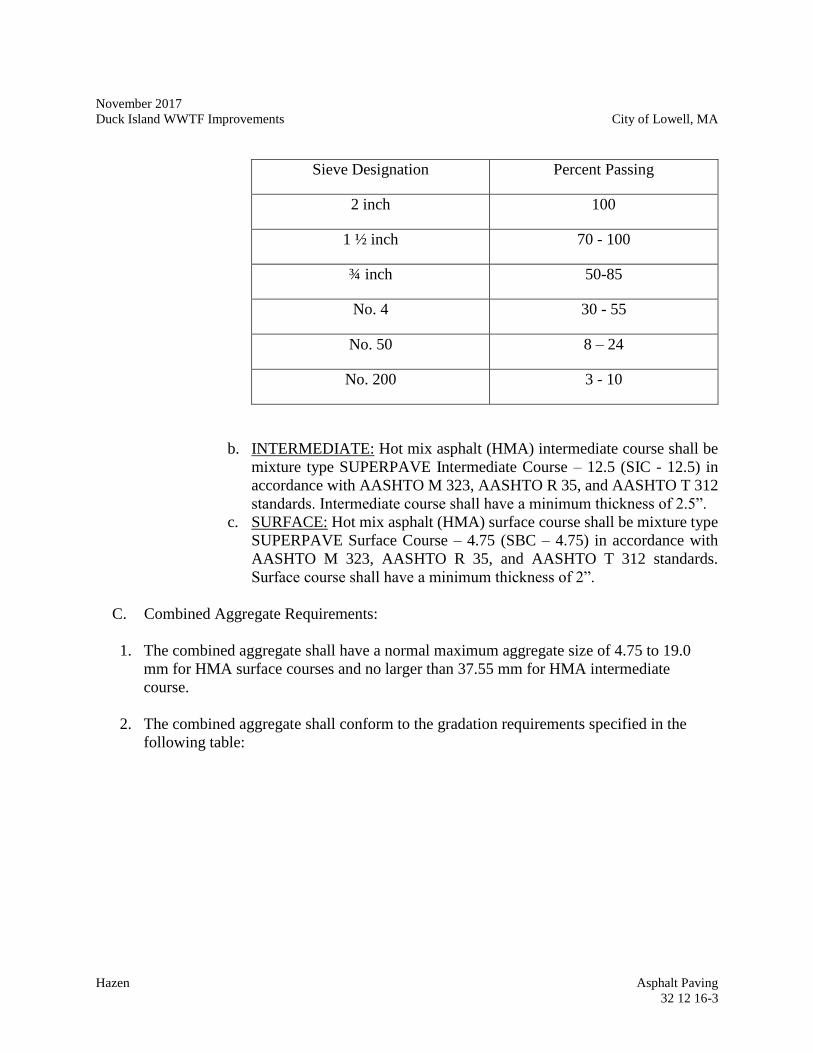
November 2017
Duck Island WWTF Improvements City of Lowell, MA
Hazen Asphalt Paving
32 12 16-3
Sieve Designation Percent Passing
2 inch 100
1 ½ inch 70 - 100
¾ inch 50-85
No. 4 30 - 55
No. 50 8 – 24
No. 200 3 - 10
b. INTERMEDIATE: Hot mix asphalt (HMA) intermediate course shall be
mixture type SUPERPAVE Intermediate Course – 12.5 (SIC - 12.5) in
accordance with AASHTO M 323, AASHTO R 35, and AASHTO T 312
standards. Intermediate course shall have a minimum thickness of 2.5”.
c. SURFACE: Hot mix asphalt (HMA) surface course shall be mixture type
SUPERPAVE Surface Course – 4.75 (SBC – 4.75) in accordance with
AASHTO M 323, AASHTO R 35, and AASHTO T 312 standards.
Surface course shall have a minimum thickness of 2”.
C. Combined Aggregate Requirements:
1. The combined aggregate shall have a normal maximum aggregate size of 4.75 to 19.0
mm for HMA surface courses and no larger than 37.55 mm for HMA intermediate
course.
2. The combined aggregate shall conform to the gradation requirements specified in the
following table:
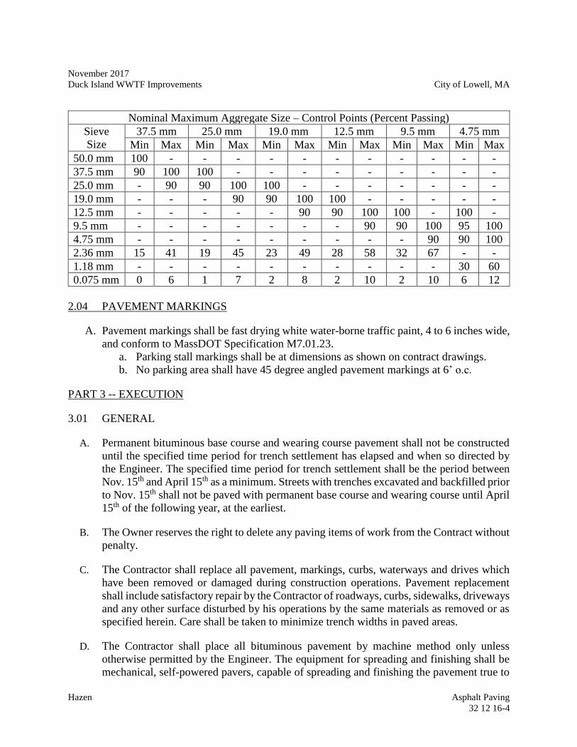
November 2017
Duck Island WWTF Improvements City of Lowell, MA
Hazen Asphalt Paving
32 12 16-4
Nominal Maximum Aggregate Size – Control Points (Percent Passing)
Sieve
Size
37.5 mm 25.0 mm 19.0 mm 12.5 mm 9.5 mm 4.75 mm
Min Max Min Max Min Max Min Max Min Max Min Max
50.0 mm 100 - - - - - - - - - - -
37.5 mm 90 100 100 - - - - - - - - -
25.0 mm - 90 90 100 100 - - - - - - -
19.0 mm - - - 90 90 100 100 - - - - -
12.5 mm - - - - - 90 90 100 100 - 100 -
9.5 mm - - - - - - - 90 90 100 95 100
4.75 mm - - - - - - - - - 90 90 100
2.36 mm 15 41 19 45 23 49 28 58 32 67 - -
1.18 mm - - - - - - - - - - 30 60
0.075 mm 0 6 1 7 2 8 2 10 2 10 6 12
2.04 PAVEMENT MARKINGS
A. Pavement markings shall be fast drying white water-borne traffic paint, 4 to 6 inches wide,
and conform to MassDOT Specification M7.01.23.
a. Parking stall markings shall be at dimensions as shown on contract drawings.
b. No parking area shall have 45 degree angled pavement markings at 6’ o.c.
PART 3 -- EXECUTION
3.01 GENERAL
A. Permanent bituminous base course and wearing course pavement shall not be constructed
until the specified time period for trench settlement has elapsed and when so directed by
the Engineer. The specified time period for trench settlement shall be the period between
Nov. 15th and April 15th as a minimum. Streets with trenches excavated and backfilled prior
to Nov. 15th shall not be paved with permanent base course and wearing course until April
15th of the following year, at the earliest.
B. The Owner reserves the right to delete any paving items of work from the Contract without
penalty.
C. The Contractor shall replace all pavement, markings, curbs, waterways and drives which
have been removed or damaged during construction operations. Pavement replacement
shall include satisfactory repair by the Contractor of roadways, curbs, sidewalks, driveways
and any other surface disturbed by his operations by the same materials as removed or as
specified herein. Care shall be taken to minimize trench widths in paved areas.
D. The Contractor shall place all bituminous pavement by machine method only unless
otherwise permitted by the Engineer. The equipment for spreading and finishing shall be
mechanical, self-powered pavers, capable of spreading and finishing the pavement true to
November 2017
Duck Island WWTF Improvements City of Lowell, MA
Hazen Asphalt Paving
32 12 16-5
the established line, grade, width and crown. The pavement shall be placed and compacted
only at such times as to permit the proper checking by the Engineer. Paving boxes shall be
of proper size to allow paving the excavated trenches.
E. Hand methods of placing bituminous pavement will be permitted only for particular
locations in the work where because of irregularity, inaccessibility or other unavoidable
obstacles mechanical spreading and finishing cannot be performed.
F. Exercise extreme care in the removal of pavement so that pavement will not be
unnecessarily disturbed or destroyed. Mechanically cut pavement to be cut to a straight
line, unless otherwise directed by the Engineer.
3.02 BASE COURSES AND SUBGRADE
A. After the subgrade has been shaped to line, grade, and cross section, it shall be thoroughly
compacted. This operation shall include any required reshaping and wetting to obtain
proper compaction. All soft or otherwise unsuitable material shall be removed and
replaced with suitable material from excavation or borrow. The resulting area, and all low
sections, holes, or depressions shall be brought to the required grade with approved
material and thoroughly compacted. Refer to Section 31 23 16 for compaction
requirements.
B. After compaction is complete for the subgrade, install a filter fabric in accordance with
Section 31 05 19.13 Geotextiles for Earthwork and the Contract Drawings.
C. Base courses shall be constructed to the depths and areas shown on the Drawings.
D. Aggregate base courses shall be constructed in accordance with MassDOT Standard
Specifications, Division III – Materials. Construction Requirements except as herein
modified:
1. The density of dense graded crushed stone courses shall be determined by
AASHTO T 191 (Sand-Cone Method) or AASHTO T 238 (Nuclear Methods). The
density of crushed stone base courses shall be determined by AASHTO T 238
(Nuclear Methods). The density shall not be less than 95 percent of the maximum
density as determined by AASHTO T 99 (Standard Proctor Test). The contractor
shall be required to do all testing and submit results to the engineer. Refer to
Section 31 23 16 – Earthwork and Excavation for additional compaction
requirements.
2. No pavement shall be placed until fine grading has been checked by the Engineer.
E. The Contractor shall regrade and recompact the base course for installation of permanent
base and wearing course pavement in areas which are disturbed during construction, and
in areas as directed by the Engineer.
November 2017
Duck Island WWTF Improvements City of Lowell, MA
Hazen Asphalt Paving
32 12 16-6
E.. After the base course has been rolled to the required grade, any broken or irregular edges
of the existing pavement shall be saw cut in straight lines leaving a sound vertical face 12-
inches back from the edge of the trench or other excavations to accept placement of a 12-
inch minimum overlap of bituminous base course pavement on undisturbed material.
F. The edges of the existing pavement shall receive an application of a cut-back asphalt so
that the new pavement material may be properly bonded to the existing.
3.03 BITUMINOUS PAVEMENT
A. Bituminous base course and wearing course pavement for all roads, driveways and parking
areas shall be constructed in accordance with the MassDOT Standard Specifications,
Division II – Construction Details.
B. Temporary Pavement
1. Temporary pavement shall be placed in areas where test pits or exploratory
excavations occur in paved areas, where shown on the Drawings, and as directed
by the Engineer.
2. The Contractor shall place temporary pavement the full width of the excavation
within the same week of the trench being backfilled unless otherwise directed by
the Engineer.
3. Temporary pavement shall be repaired as necessary to maintain the surface of the
pavement until replaced by the permanent pavement. If points of settlement or
holes appear in the temporary pavement, the Contractor shall repair the same
within 24 hours of notification by the Engineer.
4. After the specified time period for trench settlement has elapsed and when so
directed by the Engineer, the Contractor shall remove and dispose of the temporary
pavement, cut the trench edges and regrade the base course for installation of the
permanent pavement.
C. Full Width Permanent Pavement Overlay
1. When ordered by the Engineer, the Contractor shall furnish a full width overlay
from curb to curb or edge of traveled way to edge of traveled way as shown on the
Drawings. The overlay shall be completed after the roadway has been in place for
one freeze/thaw cycle, unless otherwise ordered by the Owner.
2. Work shall include:
a. At the overlay limits, mechanically grind (cold-plane) a joint in the existing
pavement to provide overlap of base course on undisturbed material as
November 2017
Duck Island WWTF Improvements City of Lowell, MA
Hazen Asphalt Paving
32 12 16-7
shown on the Drawings. Place a 6” wide strip of emulsified asphalt at all
joints.
b. Remove all temporary paving and existing paving within the cut limits of
the trench repair area.
c. All driveways shall be mechanically ground (cold planed) or saw cut prior
to installation of pavement overlays. Feathering will not be acceptable.
Place a 6” wide strip of emulsified asphalt at all joints.
d. The trench shall be shimmed as required to remove all settlement.
Shimming shall be considered subsidiary to the overlay item unless
otherwise noted.
e. The Contractor shall mechanically sweep the entire roadway prior to
placement of the overlay.
f. Contractor shall be responsible for raising all utility covers and boxes prior
to placement of the overlay. The final elevation of the fixtures shall be ¼”
below the final pavement elevation.
g. The full width permanent pavement overlay shall consist of hot bituminous
concrete wearing course over the existing pavement and trench repair base
course. A tack coat shall be applied to the existing pavement surface
immediately before placing permanent pavement overlay.
h. After placement of the overlay, the Contractor shall pour a bead of
emulsified asphalt in all tie-in joints and cover with a layer of sand.
3.05 FIELD QUALITY CONTROL
A. Thickness and Surface Tolerances:
1. Bituminous pavement courses shall be tested in-place for compliance with
compacted thickness and surface tolerance requirements.
2. Contractor shall repair or remove and replace unacceptable pavement and retest as
directed by the Engineer, all at no additional cost to the Owner.
3. Testing, tolerances and replacement shall be as specified in MassDOT Standard
Specifications.
4. In-place testing shall be scheduled and made at the Engineer’s expense by a testing
laboratory experienced and certified to complete the testing required.
November 2017
Duck Island WWTF Improvements City of Lowell, MA
Hazen Asphalt Paving
32 12 16-8
B. Compaction: Refer to Section 31 23 16.
C. Protection: Protect completed work with barricades or other devices as approved by
Engineer so that no damage occurs as a result of subsequent construction operations. Repair
damages or other irregularities to satisfaction of Engineer, at no additional cost to the
Owner, before final acceptance by the Engineer.
D. Guarantee: During the one year correction period, the Contractor shall maintain the
surfacing and shall promptly fill any depressions and holes that may occur so as to keep
compliance with these Specifications.
-END OF SECTION-
November 2017
Duck Island WWTF Improvements City of Lowell, MA
Hazen Topsoil Placement and Grading
32 91 19.13-1
SECTION 32 91 19.13
TOPSOIL PLACEMENT AND GRADING
PART 1 -- GENERAL
1.01 THE REQUIREMENT
A. Provide all labor, equipment, and materials necessary for final grading, topsoil placement,
and miscellaneous site work not included under other Sections but required to complete
the work as shown on the Drawings and specified herein.
1.02 RELATED WORK SPECIFIED ELSEWHERE
A. Section 31 23 16 - Excavation
B. Section 31 25 00 - Erosion and Sedimentation Controls
1.03 STANDARD SPECIFICATIONS
A. Except as otherwise provided in the Specifications or on the plans, all work shall be in
accordance with the Massachusetts Department of Transportation Standard Specifications
for Highways and Bridges except that any reference to “MassDOT,” "Department" or
"Unit" shall mean the "Owner". When reference to these Specifications is intended, the
description will be MassDOT Section _____ or MassDOT Specifications.
B. Except with the approval of the Engineer, the placing of concrete or asphalt concrete
surface paving shall be subject to the Seasonal and Weather Restrictions set forth in
MassDOT Specifications.
1.04 REFERENCES
A. Massachusetts Department of Transportation Standard Specifications for Highways and
Bridges, Sections 170, 751 and M1.07.0
PART 2 -- MATERIALS
2.01 TOPSOIL
A. Topsoil shall consist of fertile, friable, loamy (loam, sandy loam, silt loam, sandy clay
loam, clay loam) natural topsoil, reasonably free of stumps, roots, stiff clay, stones larger
November 2017
Duck Island WWTF Improvements City of Lowell, MA
Hazen Topsoil Placement and Grading
32 91 19.13-2
than 1 inch diameter, and other litter. Areas of natural ground water recharge should be
avoided.
PART 3 -- EXECUTION
3.01 FINAL GRADING
A. Following approval of rough grading the subgrade shall be prepared as follows:
1. For bare soil 24 inches below finish grade or as directed by Engineer.
2. For topsoil, scarify 2-inches deep at 4 inches below finish grade.
B. For final surface grading, topsoiled, landscape graveled, and riprapped areas shall be
mechanically raked or hand raked to an even finished surface.
3.02 TOPSOIL PLACEMENT
A. Topsoil shall be placed over all areas disturbed during construction under any contract
except those areas which will be paved, graveled or rip rapped.
B. Topsoil shall be spread in place for lawn and road shoulder seed areas at a 4-inch
consolidated depth and at a sufficient quantity for plant beds and backfill for shrubs and
trees.
C. Topsoil shall not be placed in a frozen or muddy condition.
D. Final surface shall be hand or mechanically raked to an even finished surface to finish grade
as shown on Drawings.
E. All stones and roots over 2-inches and rubbish and other deleterious materials shall be
removed and disposed of.
- END OF SECTION –
November 2017
Duck Island WWTF Improvements City of Lowell, MA
Hazen Seeding
32 92 19-1
SECTION 32 92 19
SEEDING
PART 1 -- GENERAL
1.01 THE REQUIREMENT
A. Provide all labor, equipment, and materials necessary for seeding not included under other
Sections but required to complete the work as shown on the Drawings and specified herein.
Under this Section, all areas of the project site disturbed by excavation, materials storage,
temporary roads, etc., shall be reseeded as specified herein.
1.02 RELATED WORK SPECIFIED ELSEWHERE
A. Section 31 23 16 – Earthwork and Excavation
B. Section 31 25 00 - Erosion and Sedimentation Controls
C. Section 32 91 19.13 – Topsoil Placement and Grading
1.03 STANDARD SPECIFICATIONS
A. Except as otherwise provided in the Specifications or on the plans, all work shall be in
accordance with the Massachusetts Department of Transportation Standard Specifications
for Highways and Bridges except that any reference to “MassDOT,” "Department" or
"Unit" shall mean the "Owner". When reference to these Specifications is intended, the
description will be MassDOT Section _____ or MassDOT Specifications.
B. Except with the approval of the Engineer, the placing of concrete or asphalt concrete
surface paving shall be subject to the Seasonal and Weather Restrictions set forth in
MassDOT Specifications.
1.04 REFERENCES
A. Massachusetts Department of Transportation Standard Specifications for Highways and
Bridges, Sections 765, M6.01.0, M6.02.0, M6.03.0
PART 2 -- MATERIALS
2.01 LIMESTONE
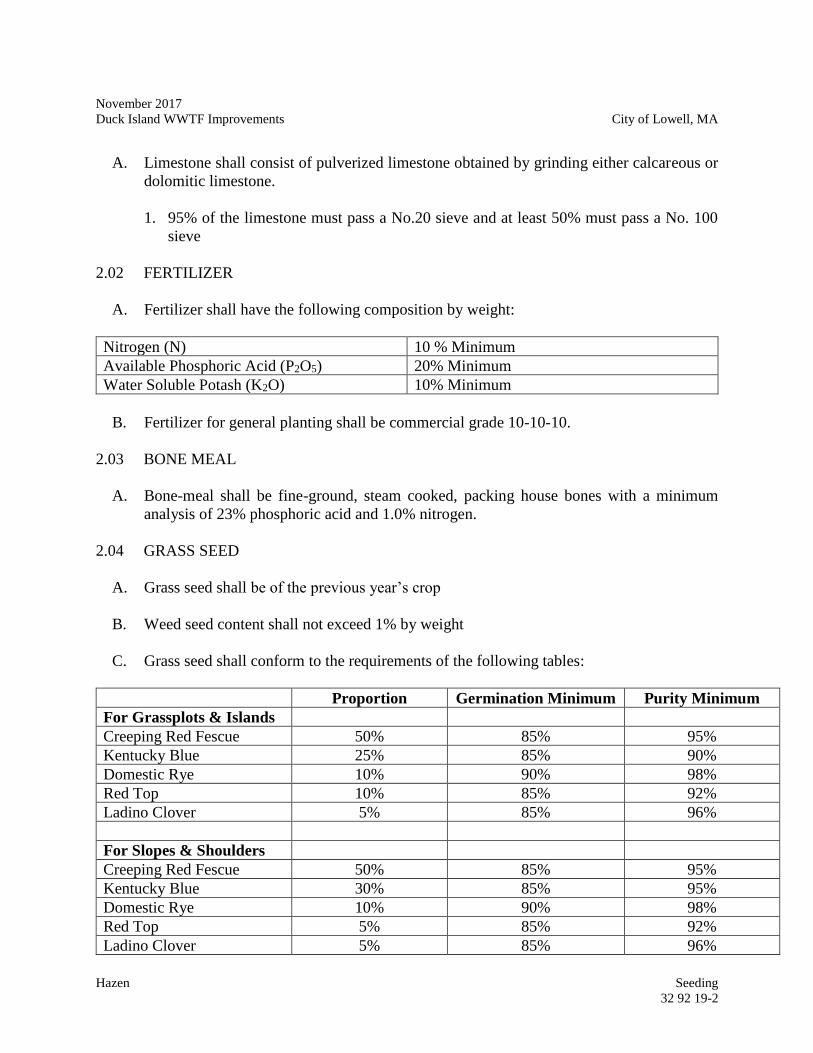
November 2017
Duck Island WWTF Improvements City of Lowell, MA
Hazen Seeding
32 92 19-2
A. Limestone shall consist of pulverized limestone obtained by grinding either calcareous or
dolomitic limestone.
1. 95% of the limestone must pass a No.20 sieve and at least 50% must pass a No. 100
sieve
2.02 FERTILIZER
A. Fertilizer shall have the following composition by weight:
Nitrogen (N) 10 % Minimum
Available Phosphoric Acid (P2O5) 20% Minimum
Water Soluble Potash (K2O) 10% Minimum
B. Fertilizer for general planting shall be commercial grade 10-10-10.
2.03 BONE MEAL
A. Bone-meal shall be fine-ground, steam cooked, packing house bones with a minimum
analysis of 23% phosphoric acid and 1.0% nitrogen.
2.04 GRASS SEED
A. Grass seed shall be of the previous year’s crop
B. Weed seed content shall not exceed 1% by weight
C. Grass seed shall conform to the requirements of the following tables:
Proportion Germination Minimum Purity Minimum
For Grassplots & Islands
Creeping Red Fescue 50% 85% 95%
Kentucky Blue 25% 85% 90%
Domestic Rye 10% 90% 98%
Red Top 10% 85% 92%
Ladino Clover 5% 85% 96%
For Slopes & Shoulders
Creeping Red Fescue 50% 85% 95%
Kentucky Blue 30% 85% 95%
Domestic Rye 10% 90% 98%
Red Top 5% 85% 92%
Ladino Clover 5% 85% 96%
November 2017
Duck Island WWTF Improvements City of Lowell, MA
Hazen Seeding
32 92 19-3
PART 3 -- EXECUTION
3.01 GENERAL
A. The Contractor shall remove all debris and stones greater than 2 inches diameter before the
application of limestone, fertilizer, and seed.
3.02 APPLICATION OF LIMESTONE
A. Limestone shall be applied in dry form or hydraulically as described in MassDOT Section
765.65
B. Rate of application of limestone will vary up to a maximum of 1 pound per square yard
depending on laboratory test results.
C. Limestone shall be incorporated into the layer of topsoil and the upper 1 inch of the
underlying subsoil
3.03 APPLICATION OF FERTILIZER
A. Fertilizer shall be applied in dry form or hydraulically as described in MassDOT Section
765.65
B. Fertilizer shall be spread on the top layer of topsoil at the rate of 800 pounds per acre and
worked into the seed bed.
3.04 GRASS SEEDING
A. Grass seed shall be sown at a rate of 50 pounds per acre after the application of limestone
and fertilizer.
B. Seeding shall be done in two directions perpendicular to each other.
- END OF SECTION -
July 2017
Duck Island WWTF Improvements City of Lowell, MA
Hazen Seeding
32 92 19-4
--THIS PAGE INTENTIONALLY LEFT BLANK--
November 2017
Duck Island WWTF Improvements City of Lowell, MA
Hazen Basic Mechanical Requirements
40 05 13.01-1
SECTION 40 05 13.01
BASIC MECHANICAL REQUIREMENTS
PART 1 -- GENERAL
1.01 THE REQUIREMENT
A. The Contractor shall furnish and install to the required line and grade, all piping and
products specified herein, including wall sleeves, tapping sleeves, flanged adapters, unions,
and cam-lock fittings; together with all fittings and appurtenances, required for a complete
installation. All piping located outside the face of structures or building foundations and
all piping embedded in concrete within a structure or foundation shall be considered
exterior piping.
B. The Contractor shall furnish and install fittings, couplings, connections, sleeves, adapters,
harness rods and closure pieces as required to connect pipelines of dissimilar materials
and/or sizes herein included under this Section and other concurrent Contracts for a
complete installation.
C. The Contractor shall furnish all labor, materials, equipment, tools, and services required
for the furnishing, installation and testing of all piping as shown on the Drawings, specified
in this Section and required for the Work. Piping shall be furnished and installed of the
material, sizes, classes, and at the locations shown on the Drawings and/or designated in
this Section. Piping shall include all fittings, adapter pieces, couplings, closure pieces,
harnessing rods, hardware, bolts, gaskets, wall sleeves, wall pipes, hangers, supports, and
other associated appurtenances for required connections to equipment, valves, or structures
for a complete installation.
D. Piping assemblies under 4-inch size shall be generally supported on walls and ceilings,
unless otherwise shown on the Drawings or ordered by the Engineer, being kept clear of
openings and positioned above "headroom" space. Where practical, such piping shall be
run in neat clusters, plumb and level along walls, and parallel to overhead beams.
E. The Contractor shall provide taps on piping where required or shown on the Drawings.
Where pipe or fitting wall thicknesses are insufficient to provide the required number of
threads, a boss or pipe saddle shall be installed.
F. The work shall include, but not be limited to, the following:
1. Connections to existing pipelines.
2. Test excavations necessary to locate or verify existing pipe and appurtenances.
November 2017
Duck Island WWTF Improvements City of Lowell, MA
Hazen Basic Mechanical Requirements
40 05 13.01-2
3. Installation of all new pipe and materials required for a complete installation.
4. Cleaning, testing and disinfecting as required.
1.02 MATERIAL CERTIFICATION AND SHOP DRAWINGS
A. The Contractor shall furnish to the Owner (through the Engineer) a Material Certification
stating that the pipe materials and specials furnished under this Section conform to all
applicable provisions of the corresponding Specifications. Specifically, the Certification
shall state compliance with the applicable standards (ASTM, AWWA, etc.) for fabrication
and testing. The requirements for Certifications shall be as specified in Division 01 00 00,
General Requirements.
B. Shop Drawings for major piping (2-inches in diameter and greater) shall be prepared and
submitted in accordance with Section Division 01 00 00, General Requirements. In
addition to the requirements of Division 01 00 00, General Requirements, the Contractor
shall submit laying schedules and detailed Drawings in plan and profile for all piping as
specified and shown on the Drawings.
C. Shop Drawings shall include, but not be limited to, complete piping layout, pipe material,
sizes, class, locations, necessary dimensions, elevations, supports, hanger details, pipe
joints, and the details of fittings including methods of joint restraint. No fabrication or
installation shall begin until Shop Drawings are approved by the Engineer.
PART 2 -- PRODUCTS
2.01 GENERAL
A. All specials and every length of pipe shall be marked with the manufacturer's name or
trademark, size, class, and the date of manufacture. Special care in handling shall be
exercised during delivery, distribution, and storage of pipe to avoid damage and
unnecessary stresses. Damaged pipe will be rejected and shall be replaced at the
Contractor's expense. Pipe and specials stored prior to use shall be stored in such a manner
as to keep the interior free from dirt and foreign matter.
B. Testing of pipe before installation shall be as described in the corresponding ASTM or
AWWA Specifications and in the applicable standard specifications listed in the following
sections. Testing after the pipe is installed shall be as specified in Section 3.10.
C. The Drawings indicate work affecting existing piping and appurtenances. The Contractor
shall investigate all connections and crossings which may affect the Contractor's work prior
to ordering pipe and fittings to determine sufficient information for ordering materials. The
Contractor shall take whatever measurements that are required to complete the work as
shown or specified.
November 2017
Duck Island WWTF Improvements City of Lowell, MA
Hazen Basic Mechanical Requirements
40 05 13.01-3
D. All mechanical components and systems shall be designed to resist operational forces as
well as lateral sway and axial motion from seismic and thermal forces.
E. The contractor shall match the material and grade of existing pipe when pipe repair work
requires sections of the existing pipe to be removed and replaced. If not shown on the
Drawings, the Contractor shall submit to the Engineer the details of the replacement pipe
he proposes to install; and no fabrication or installation thereof shall take place until the
Engineer's approval is obtained.
2.03 WALL SLEEVES
A. Unless shown otherwise, all piping passing through walls and floors shall be installed in
sleeves or wall castings accurately located before concrete is poured, or placed in position
during construction of masonry walls. Sleeves passing through floors shall extend from
the bottom of the floor to a point 3 inches above the finished floor, unless shown otherwise.
Water stop flanges are required on all sleeves located in floors or walls which are
continually wet or under hydrostatic pressure on one or both sides of the floor or wall.
B. Sleeves shall be cast iron, black steel pipe, or fabricated steel in accordance with details
shown on the Drawings. If not shown on the Drawings, the Contractor shall submit to the
Engineer the details of sleeves he proposes to install; and no fabrication or installation
thereof shall take place until the Engineer's approval is obtained. Steel sleeves shall be
fabricated of structural steel plate in accordance with the standards and procedures of AISC
and AWS. Steel sleeve surfaces shall receive a commercial sandblast cleaning and then be
shop painted in accordance with Section 09 90 00, Painting and Coating.
2.07 FLANGED ADAPTERS
A. Flanged adapters shall be furnished as required and as shown on the Drawings.
B. All flanged adapters, 12 inches in diameter and smaller, except as shown on the Drawings
or directed by the Engineer, shall be locking type flanged adapters.
C. Pressure and service shall be the same as connected piping.
D. Materials shall be cast iron for pipes up to 12 inch diameter and high strength steel for
pipes larger than 12 inch diameter.
E. Flanged adapters shall be shop primed with a premium quality primer compatible with the
paint system specified in Section 09 90 00, Painting and Coating. Field painting of wetted
area shall be done prior to installation.
F. Flanged coupling adapters larger than 12 inches in diameter shall be harnessed by tying the
adapter to the nearest pipe joint flange using threaded rods and rod tabs. The threaded rods
and rod tabs shall be as shown on the Drawings.
November 2017
Duck Island WWTF Improvements City of Lowell, MA
Hazen Basic Mechanical Requirements
40 05 13.01-4
H. Flanged adapters shall be as manufactured by Dresser Industries, Style 127 or 128, Smith
Blair Corporation, or equal.
2.09 UNIONS
A. For PVC piping unions shall be socket weld type with Viton O-ring.
2.10 CAMLOCK FITTINGS/QUICK DISCONNECT COUPLINGS
A. Camlock fittings and quick disconnect type couplings shall be provided where indicated
on the Drawings. Couplings shall be constructed of 316 stainless steel with a BUNA-N
O-ring and integral safety lock. Couplings shall be as manufacture by Dixon Valve or
equal.
2.11 TAPPING SLEEVE FOR FRP DRAIN PIPE
A. Tapping sleeves shall be of cast iron, designed to withstand a working pressure of at least
150 psig. Tapping sleeves shall have an epoxy finish conforming to AWWA C213.
Tapping sleeves shall fit the existing lines as shown on the Drawings. The
CONTRACTOR shall field verify the material and diameter of the existing lines to be
tapped prior to ordering the sleeve. The tapping sleeve shall provide 360° of pipe support,
reinforcement and sealing pressure without the need for shims or pads. Tapping sleeves
shall have mechanical joint ends and shall be provided complete with all necessary split-
end gaskets, longitudinal gaskets and two-piece (split) glands. Gaskets shall be shipped to
the job site separately in suitable protective container. Materials for split-end gaskets
shall conform to ANSI A21.11. Material for longitudinal gaskets shall be neoprene
conforming to ANSI A21.11. Double sets of gaskets shall be provided to fit existing pipe.
B. Tapping sleeves shall be provided complete with all necessary bolts and nuts to join or
connect the two halves of the sleeve together. Bolts and nuts shall be standard steel
square of hex head bolts and nuts which have been hot dip galvanized or the same as for
the tapping valve as specified hereinabove. The contractor shall coordinate with the
manufacturer regarding the maximum and minimum bolt torque required for FRP pipe
applications.
C. Tapping saddles may be used on mains sixteen (16) inches and larger where the required
tap size does not exceed one-half the size of the main (i.e. 8-inch tapping saddle for use
on a 16-inch main). Tapping saddles shall be manufactured of ductile iron providing a
factor of safety of at least 2.5 at a working pressure of 250 psi. Saddles shall be equipped
with a standard AWWA C-110-77 flange connection on the branch. Sealing gaskets shall
be "O" ring type, high quality molded rubber having an approximate seventy durometer
hardness, placed into a groove on the curved surface of the tapping saddles. Straps shall
be of alloy steel. The tapping saddle shall be the American tapping saddle, U.S. Pipe
tapping saddle, or equal. All taps shall be machine cut, no burned taps will be allowed.
November 2017
Duck Island WWTF Improvements City of Lowell, MA
Hazen Basic Mechanical Requirements
40 05 13.01-5
D. The tapping sleeve shall be as manufactured by Smith-Blair, Romac Industries, Mueller
Co., American, or equal.
E. Cutting tools and methods suitable for cutting of GRP pipe shall be used for cutting the
tapping holes. Tapping services shall be provided by the following service providers, or
equal: 1. Rangeline (http://www.rangeline.com) 2. International Flow Technologies
(http://www.hottap.com/index.html) 3. T.D. Williamson, Inc.
(http://www.tdwilliamson.com/).
PART 3 -- EXECUTION
3.01 INSTALLATION
A. All piping shall be installed by skilled workmen and in accordance with the best standard
practice for piping installation as shown on the Drawings, specified or recommended by
the pipe manufacturer. Proper tools and appliances for the safe and convenient handling
and installing of the pipe and fittings shall be used. Great care shall be taken to prevent
any pipe coating from being damaged on the inside or outside of the pipe and fittings. All
pieces shall be carefully examined for defects, and no piece shall be installed which is
known to be cracked, damaged, or otherwise defective. If any defective pieces should be
discovered after having been installed, it shall be removed and replaced with a sound one
in a satisfactory manner by the Contractor and at his own expense. Pipe and fittings shall
be thoroughly cleaned before they are installed and shall be kept clean until they are
accepted in the complete work. All piping connections to equipment shall be provided
with unions or coupling flanges located so that piping may be readily dismantled from the
equipment. At certain applications, Dresser, Victaulic, or equal, couplings may also be
used. All piping shall be installed in such a manner that it will be free to expand and
contract without injury to itself or to structures and equipment to which it is connected. All
piping shall be erected to accurate lines and grades with no abrupt changes in line or grade
and shall be supported and braced against movement, temporary, or permanent. All
exposed piping shall be installed with vertical and horizontal angles properly related to
adjoining surfaces or pipes to give the appearance of good workmanship. Unless otherwise
shown or approved, provide a minimum headroom clearance under all piping of 7 feet 6
inches.
B. Unless otherwise shown or specified, all waste and vent piping shall pitch uniformly at a
1/4-inch per foot grade and accessible cleanouts shall be furnished and installed as shown
and as required by local building codes. Installed length of waste and vent piping shall be
determined from field measurements in lieu of the Drawings.
C. JOINT DEFLECTION SHALL NOT EXCEED 75 PERCENT OF THE
MANUFACTURERS RECOMMENDED DEFLECTION. All exposed piping shall be
adequately supported and braced by means of hangers, concrete piers, pipe supports, or
otherwise as may be required by the location.
November 2017
Duck Island WWTF Improvements City of Lowell, MA
Hazen Basic Mechanical Requirements
40 05 13.01-6
D. All piping shall be installed in such a manner that it will be free to expand and/or contract
without injury to itself or to structures and equipment to which it is connected. All piping
shall be erected to accurate lines and grades with no abrupt changes in line or grade and
shall be supported and braced against movement, temporary, or permanent. All exposed
piping shall be installed with vertical and horizontal angles properly related to adjoining
surfaces or pipes to give the appearance of good workmanship. Pipes crossing within a
vertical distance of less than or equal to one (1) foot shall be encased and supported with
concrete at the point of crossing to prevent damage to the adjacent pipes as shown on the
Drawings.
E. Proper and suitable tools and appliances for the safe convenient handling and laying of
pipe shall be used and shall in general agree with manufacturer's recommendations.
3.02 PVC/ PIPE
A. Polyvinyl chloride (PVC) pipe shall be laid and joints assembled according to the
respective manufacturer's recommendation. PVC pipe installation shall comply with
applicable sections of the Uni-Bell PVC Pipe Association Recommended Standard
Specifications.
B. Plastic piping shall not be installed when the temperature is less then 60°F except as
otherwise recommended by the manufacturer and approved by the Engineer.
3.04 JOINTS IN PIPING
A. Flanged joints shall be brought to exact alignment and all gaskets and bolts or studs inserted
in their proper places. Bolts or studs shall be uniformly tightened around the joints. Where
stud bolts are used, the bolts shall be uniformly centered in the connections and equal
pressure applied to each nut on the stud. Pipes in all lines subject to temperature changes
shall be cut short and cold sprung into place to compensate for expansion when hot.
B. Mechanical joints shall be made up with gaskets, glands and bolts. When a joint is to be
made up, the bell or socket and plain end shall be cleaned and washed with a solution or
mild soap in water; the gland and gasket shall be slid onto the plain end and the end then
entered into the socket until it is fully "home" on the centering ring. The gasket shall then
be painted with soapy water and slid into position, followed by the gland. All bolts shall
be inserted and made up hand tight and then tightened alternately to bring the gland into
position evenly. Excessive tightening of the bolts shall be avoided. All nuts shall be pulled
up using a torque wrench which will not permit unequal stresses in the bolts. Torque shall
not exceed the recommendations of the manufacturer of the pipe and bolts for the various
sizes. Care shall be taken to assure that the pipe remains fully "home" while the joint is
being made. Joints shall conform to the applicable AWWA Specifications.
November 2017
Duck Island WWTF Improvements City of Lowell, MA
Hazen Basic Mechanical Requirements
40 05 13.01-7
C. Threaded and/or screwed joints shall have long tapered full depth threads to be made with
the appropriate paste or jointing compound, depending on the type of fluid to be processed
through the pipe. All pipe up to, and including 1-1/2-inches, shall be reamed to remove
burr and stood on end and well pounded to remove scale and dirt. Wrenches on valves and
fittings shall be applied directly over the joint being tightened. Not more than three pipe
threads shall be exposed at each connection. Pipe, in all lines subject to temperature
changes shall be cut short and cold sprung into place to compensate for expansion when
hot. Joints in plastic piping (PVC/CPVC) shall be laid and joints made with compounds
recommended by the manufacturer. Installation shall conform to the requirements of
ASTM D2774 and ASTM D2855. Unions are required adjacent to valves and equipment.
D. Solvent or adhesive welded joints in plastic piping shall be accomplished in strict
accordance with the pipe manufacturer's recommendations, including necessary field
cuttings, sanding of pipe ends, joint support during setting period, etc. Care shall be taken
that no droppings or deposits of adhesive or material remain inside the assembled piping.
Solvent or adhesive material shall be compatible with the pipe itself, being a product
approved by the pipe manufacturer. Unions are required adjacent to valves and equipment.
Sleeve-type expansion joints shall be supplied in exposed piping to permit 1-inch minimum
of expansion per 100 feet of pipe length.
E. Eccentric reducers shall be installed where air or water pockets would otherwise occur in
mains because of a reduction in pipe size.
3.10 FLUSHING AND TESTING
A. All piping shall be properly flushed and tested unless specifically exempted elsewhere in
the Specifications or otherwise approved by the Engineer. Air and gas pipelines shall be
flushed and tested with compressed air. All other liquid conveying pipelines shall be
flushed and tested with water. The Contractor shall furnish and install all means and
apparatus necessary for getting the air or water into the pipeline for flushing and testing
including pumps, compressors, gauges, and meters, any necessary plugs and caps, and any
required blow-off piping and fittings, etc., complete with any necessary reaction blocking
to prevent pipe movement during the flushing and testing. All pipelines shall be flushed
and tested in such lengths or sections as agreed upon among the Owner, Engineer, and
Contractor. Test pressures shall be as specified in Section 40 06 20, Schedules, and shall
be measured at the lowest point of the pipe segment being tested. The Contractor shall
give the Owner and Engineer reasonable notice of the time when he intends to test portions
of the pipelines. The Engineer reserves the right, within reason, to request flushing and
testing of any section or portion of a pipeline.
B. Raw water or non-potable water may be used for flushing and testing liquid pipelines not
connected to the potable water system. Only potable water shall be used for flushing and
testing the potable water system.
November 2017
Duck Island WWTF Improvements City of Lowell, MA
Hazen Basic Mechanical Requirements
40 05 13.01-8
C. At the conclusion of the installation work, the Contractor shall thoroughly clean all new
liquid conveying pipe by flushing with water or other means to remove all dirt, stones,
pieces of wood, etc., which may have entered the pipe during the construction period. If
after this cleaning any obstructions remain, they shall be corrected by the Contractor, at his
own expense, to the satisfaction of the Engineer. Liquid conveying pipelines shall be
flushed at the rate of at least 2.5 feet per second for a duration suitable to the Engineer or
shall be flushed by other methods approved by the Engineer.
D. During testing the piping shall show no leakage. Any leaks or defective piping disclosed
by the leakage test shall be repaired or replaced by the Contractor, at his own expense, and
the test repeated until all such piping shows tight.
E. After flushing, all liquid conveying pipelines shall be hydrostatically tested at the test
pressure specified in the appropriate Piping System Schedule in Section 40 06 20,
Schedules. The procedure used for the hydrostatic test shall be in accordance with the
requirements of AWWA C600. Each pipeline shall be filled with water for a period of no
less than 24 hours and then subjected to the specified test pressure for 2 hours. During this
test, exposed piping shall show no leakage. Allowable leakage in buried piping shall be in
accordance with AWWA C600.
F. Any leaks or defective pipe disclosed by the hydrostatic test shall be repaired or replaced
by the Contractor, at his own expense, and the test repeated until all such piping shows
tight.
G. All gravity sewer/storm drain lines shall be leak tested as directed by the Engineer.
H. After flushing, all gas piping shall be leak tested in accordance with all local codes and
regulations and in conformance with the recommendations or requirements of any National
Institute or Association for the specific service application.
I. The contractor shall clear blocked pipes as directed by the Engineer. Video inspection shall
be performed on the pipes as required to identify the location of blockages. Blockages shall
be cleared using high-pressure water or by installing a tapping sleeve at the blockage, that
allows access to the debris. Debris shall be disposed of according to Section 01 35 43.13
Environmental Procedures for Hazardous Materials. The section of the pipes that cannot
be cleaned shall be shall be replaced as directed by the engineer.
3.12 PAINTING AND COLOR CODING SYSTEM
A. All piping specified shall be color coded in accordance with the Owner's standard color
designation system for pipe recognition and in accordance with Section 40 05 13.03,
Piping and Equipment Identification Systems. In the absence of a standard color
designation system, the Engineer will establish a standard color designation for each piping
November 2017
Duck Island WWTF Improvements City of Lowell, MA
Hazen Basic Mechanical Requirements
40 05 13.01-9
service category from color charts submitted by the Contractor in compliance with
Section 09 90 00, Painting and Coating.
- END OF SECTION -
November 2017
Duck Island WWTF Improvements City of Lowell, MA
Hazen Basic Mechanical Requirements
40 05 13.01-10
--THIS PAGE INTENTIONALLY LEFT BLANK--
November 2017
Duck Island WWTF Improvements City of Lowell, MA
Hazen Pipe Supports
40 05 13.02-1
SECTION 40 05 13.02
PIPE SUPPORTS
PART 1 -- GENERAL
1.01 THE REQUIREMENT
A. Furnish all equipment, labor, materials, and design calculations required to provide pipe
supports in accordance with the Contract Documents.
B. Reference Section 40 05 13.01, Basic Mechanical Requirements.
1.02 SUBMITTALS
A. Applicable and associated cut sheets and drawings for materials and support components
shall be submitted with the Shop Drawings in accordance with or in addition to the submittal
requirements specified in Division 01 00 00 General Requirements, Section 40 05 13.01 -
Basic Mechanical Requirements and other referenced Sections above.
1. Catalog cut information on all system components such as pipe supports, hangers,
guides, anchors, and channel-type supports.
2. Drawings of the piping support systems, locating each support, brace, hanger, guide,
component and anchor. Identify support, hanger, guide and anchor type by catalog
number and Shop Drawing detail number.
3. With each piping support system Shop Drawing, the Contractor shall attach calculations
prepared and sealed by a Professional Engineer licensed in the Commonwealth of
Massachusetts showing that the piping support system complies with the specified
requirements, including all building code and seismic code requirements pertaining to
support of piping and other non-structural components.
4. Table showing the manufacturer’s recommended hanger support spacing for PVC,
CPVC and FRP pipe for the services listed in Section 40 06 20 Piping and Tubing
Schedules.
1.03 QUALITY ASSURANCE
A. Piping support systems shall be designed and Shop Drawings prepared and sealed by a
Professional Engineer licensed in Commonwealth of Massachusetts.
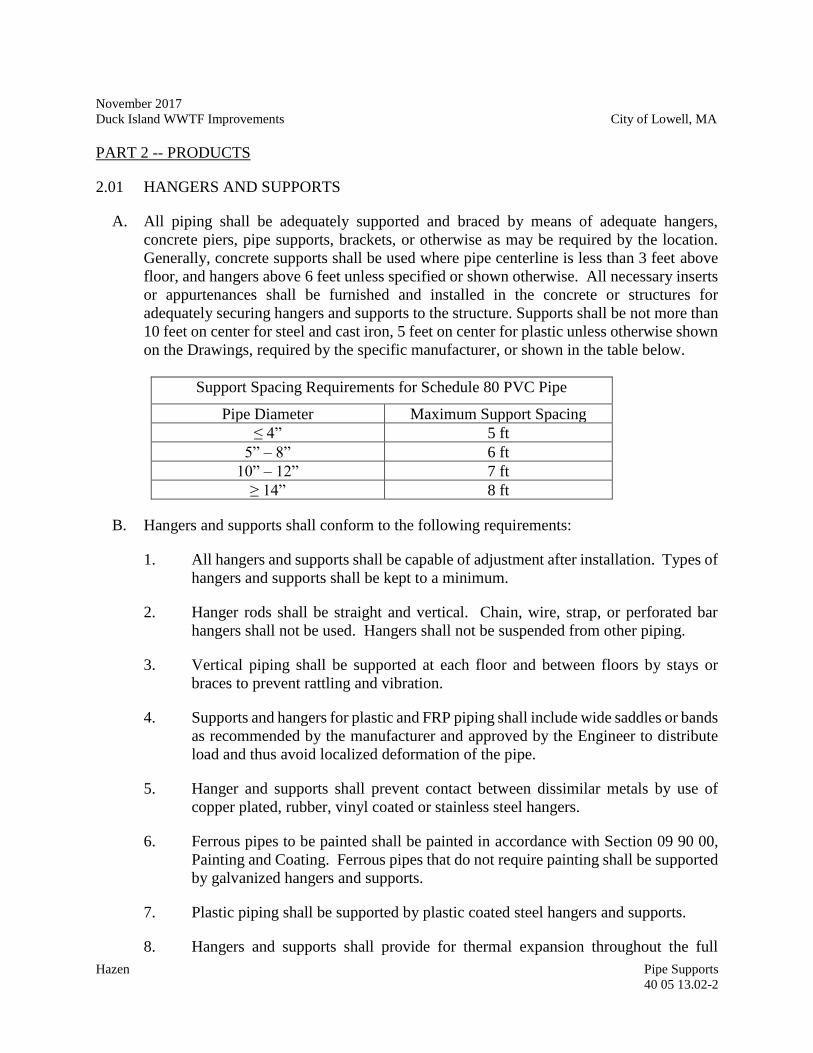
November 2017
Duck Island WWTF Improvements City of Lowell, MA
Hazen Pipe Supports
40 05 13.02-2
PART 2 -- PRODUCTS
2.01 HANGERS AND SUPPORTS
A. All piping shall be adequately supported and braced by means of adequate hangers,
concrete piers, pipe supports, brackets, or otherwise as may be required by the location.
Generally, concrete supports shall be used where pipe centerline is less than 3 feet above
floor, and hangers above 6 feet unless specified or shown otherwise. All necessary inserts
or appurtenances shall be furnished and installed in the concrete or structures for
adequately securing hangers and supports to the structure. Supports shall be not more than
10 feet on center for steel and cast iron, 5 feet on center for plastic unless otherwise shown
on the Drawings, required by the specific manufacturer, or shown in the table below.
Support Spacing Requirements for Schedule 80 PVC Pipe
Pipe Diameter Maximum Support Spacing
≤ 4” 5 ft
5” – 8” 6 ft
10” – 12” 7 ft
≥ 14” 8 ft
B. Hangers and supports shall conform to the following requirements:
1. All hangers and supports shall be capable of adjustment after installation. Types of
hangers and supports shall be kept to a minimum.
2. Hanger rods shall be straight and vertical. Chain, wire, strap, or perforated bar
hangers shall not be used. Hangers shall not be suspended from other piping.
3. Vertical piping shall be supported at each floor and between floors by stays or
braces to prevent rattling and vibration.
4. Supports and hangers for plastic and FRP piping shall include wide saddles or bands
as recommended by the manufacturer and approved by the Engineer to distribute
load and thus avoid localized deformation of the pipe.
5. Hanger and supports shall prevent contact between dissimilar metals by use of
copper plated, rubber, vinyl coated or stainless steel hangers.
6. Ferrous pipes to be painted shall be painted in accordance with Section 09 90 00,
Painting and Coating. Ferrous pipes that do not require painting shall be supported
by galvanized hangers and supports.
7. Plastic piping shall be supported by plastic coated steel hangers and supports.
8. Hangers and supports shall provide for thermal expansion throughout the full
November 2017
Duck Island WWTF Improvements City of Lowell, MA
Hazen Pipe Supports
40 05 13.02-3
operating temperature range.
9. Expansion type anchors used for pipe hangers and supports shall be Type 304
stainless steel.
10. All supports shall be braced laterally and longitudinally for seismic area. Reference
SMACNA “Seismic Restraint Manual” ANSI/SMACNA 001-2000 and ASCE 7-
05.
11. All metallic valves installed in plastic piping systems shall be supported
independently of the piping.
C. All metallic hangers and supports shall be standard make by Anvil International, Inc.,
"Witch" by Carpenter & Paterson, Ltd., B-Line Systems, Inc., or equal; and data on the
types and sizes to be used shall be furnished to the Engineer for approval. Metallic support
system brackets, rods, support clips, clevis hangers, hardware, etc. shall be cast iron or
welded steel construction.
D. Non-metallic support system shall be a heavy-duty channel framing system. Channel
frames shall be manufactured by the pultrusion process using corrosion grade polyester or
vinylester resins. All fiberglass construction shall include suitable ultraviolet inhibitors for
UV exposure and shall have a flame spread rating of 25 or less per ASTM E84. Piping
accessories, pipe clamps, clevis hangers, support posts, support racks, fasteners, etc., shall
be constructed of vinylester or polyurethane resin. Non-metallic support systems shall be
standard make Aickinstrut by Aickinstrut, Inc., Unistrut Fiberglass by Unistrut, Inc.,
Enduro Fiberglass Systems, or equal. The Contractor shall submit data on the types and
sizes for approval. Unless otherwise shown or specified the Contractor shall provide
support spacings in the conformance with the pipe and support system manufacturer's
requirements.
- END OF SECTION –
November 2017
Duck Island WWTF Improvements City of Lowell, MA
Hazen Pipe Supports
40 05 13.02-4
--THIS PAGE INTENTIONALLY LEFT BLANK--
November 2017
Duck Island WWTF Improvements City of Lowell, MA
Hazen Piping and Equipment Identification Systems
40 05 13.03-1
SECTION 40 05 13.03
PIPING AND EQUIPMENT IDENTIFICATION SYSTEMS
PART 1 -- GENERAL
1.01 THE REQUIREMENT
A. The Contractor shall furnish and install all components of the system for identification of
piping and equipment as specified hereinafter. The system shall include the application of
color coding to all new and altered plant piping. The Contractor shall paint the equipment
and piping of all Contracts in the colors herein specified, and in accordance with the
requirements of Section 09 90 00, Painting and Coating.
B. In addition to the legends specified herein the Engineer may order the Contractor to furnish
and install additional identification legends and arrows at no additional cost to the Owner.
Such additional signs may be requested near completion of the work and shall be limited
to no more than five (5) signs for each type specified herein. The legends and color
combinations for additional signs shall conform to the requirements specified herein.
C. The Contractor shall submit a schedule of the colors and designations proposed in
accordance with Division 01 00 00 General Requirements, and this Section. A minimum
of four (4) color charts with cross-references to the colors listed herein shall be included
with the Submittal.
D. Reference Section 40 05 13.01, Basic Mechanical Requirements.
PART 2 -- PRODUCTS
2.01 PIPING BAND
A. All new and altered piping shall receive identification bands. Such bands shall be 6-inches
wide, neatly made by masking, and spaced at intervals of 30-inches on centers regardless
of the diameter of the pipe being painted. The Contractor may use approved precut and
prefinished metal bands on piping, in lieu of the masked and painted bands, where
approved by the Engineer.
2.02 PIPING IDENTIFICATION LEGEND
A. The Contractor shall apply identification legends to all types and sections of piping as
shown on the Drawings or as designated by the Engineer. Such legends shall be in the
form of plain block lettering giving the name of the pipe content in full or abbreviated form,
and showing the direction of flow by arrows. All lettering and arrows shall be of the plastic
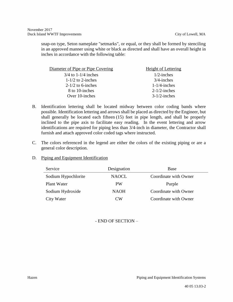
November 2017
Duck Island WWTF Improvements City of Lowell, MA
Hazen Piping and Equipment Identification Systems
40 05 13.03-2
snap-on type, Seton nameplate "setmarks", or equal, or they shall be formed by stenciling
in an approved manner using white or black as directed and shall have an overall height in
inches in accordance with the following table:
Diameter of Pipe or Pipe Covering Height of Lettering
3/4 to 1-1/4 inches
1-1/2 to 2-inches
2-1/2 to 6-inches
8 to 10-inches
Over 10-inches
1/2-inches
3/4-inches
1-1/4-inches
2-1/2-inches
3-1/2-inches
B. Identification lettering shall be located midway between color coding bands where
possible. Identification lettering and arrows shall be placed as directed by the Engineer, but
shall generally be located each fifteen (15) feet in pipe length, and shall be properly
inclined to the pipe axis to facilitate easy reading. In the event lettering and arrow
identifications are required for piping less than 3/4-inch in diameter, the Contractor shall
furnish and attach approved color coded tags where instructed.
C. The colors referenced in the legend are either the colors of the existing piping or are a
general color description.
D. Piping and Equipment Identification
Service Designation Base
Sodium Hypochlorite NAOCL Coordinate with Owner
Plant Water PW Purple
Sodium Hydroxide NAOH Coordinate with Owner
City Water CW Coordinate with Owner
- END OF SECTION –
November 2017
Duck Island WWTF Improvements City of Lowell, MA
Hazen PVC Pipe, Fittings and Valves
40 05 13.73-1
SECTION 40 05 13.73
PVC PIPE, FITTINGS AND VALVES
PART 1 -- GENERAL
1.01 THE REQUIREMENT
A. Reference Section 40 05 13.01, Basic Mechanical Requirements.
PART 2 -- PRODUCTS
2.01 POLYVINYL CHLORIDE (PVC) PIPE AND FITTINGS FOR CHEMICAL SERVICE
A. PVC pipe and fittings shall be manufactured in accordance with ASTM D 1785, D 1784
and F 441, "normal impact" pipe, Schedule 80 as specified.
B. Fittings used with this pipe shall be socket type or flanged type as specified herein, in
Section 40 06 20, Schedules, or indicated on the Drawings. Plastic piping shall be installed
in full accordance with the manufacturer's recommendations for the specific installation.
No field bending or distortion of the pipe will be permitted.
C. PVC pipe shall be Type 1 Grade 1 conforming to ASTM D 1784 and D 1785. Fittings
shall conform to the following standard specifications:
Socket Type (Schedule 40); ASTM D 2466
Socket Type (Schedule 80); ASTM D 2467
D. Provide flanged fittings of the same material as the specified pipe and material conforming
to ANSI B16.5 at all valves and equipment with Teflon filled or natural rubber gaskets.
Bolts shall be type 316 stainless steel for flanged joints unless otherwise specified. Flanges
are not required at true (double) union valves.
E. Solvent cement for socket type joints shall conform to ASTM D 2564 for PVC pipe and
fittings. Solvent cement for sodium hypochlorite service shall be Weld-On 724 as
manufactured by IPS Corporation or equal.
H. PVC pressure rated pipe (PR 160) shall be in sizes between 1/2 inch and 12 inches and
shall conform to all the requirements of ASTM D1784 and ASTM D2241 and shall be a
minimum of SDR 26 and shall be capable of withstanding the overburden pressures
determined by the depth of burial in the field.
1. Pipe material shall be made from clean, virgin, NSF approved Class 12454-A PVC
compound conforming to resin specification ASTM D1784. Standard laying
lengths shall be 20-feet ( 1 inch). Random lengths of not more than 15% of the
November 2017
Duck Island WWTF Improvements City of Lowell, MA
Hazen PVC Pipe, Fittings and Valves
40 05 13.73-2
total footage of each size may be shipped in lieu of the standard lengths. Reruns of
reclaimed materials shall not be accepted.
2. The pipe shall have bell and spigot ends with push-on, O-ring rubber gasket,
compression type joints conforming to the requirements of ASTM 2672.
Elastomeric gaskets shall conform to the requirements of ASTM D1869 and ASTM
F477.
3. Minimum pipe stiffness (F/dY) at 5% deflection shall be 135 psi for all sizes when
tested in accordance with ASTM D2241.
4. The pipe shall be designed to pass a quick burst test pressure of 500 psi applied in
60 to 70 seconds when tested in accordance with ASTM D1599, as referenced in
ASTM D2241.
5. The pipe shall be designed to pass for 1000 hours a sustained test pressure of 340
psi when tested in accordance with ASTM D1598, as referenced in ASTM D2241.
I. Fittings for PR 160, SDR 26 shall be PVC and designed for the pipe being supplied.
J. Type PSM polyvinyl chloride (PVC) pipe and fittings shall conform to the requirements of
ASTM D 3034 with a maximum SDR of 35. Pipe and fittings shall have bell and spigot
ends with O-ring rubber gasketed, compression type joints. Joints shall conform to the
requirements of ASTM Specification D 3212. Reruns of reclaimed materials shall not be
accepted. Unless indicated otherwise, PVC wall pipes shall be provided for all piping
passing through exterior walls. Wall pipes shall have a water stop solvent-welded to the
pipe. Each wall pipe shall be of the same class and type as the piping to which it is joined.
2.02 SECONDARY CONTAINMENT PIPING FOR CHEMICAL SERVICE
A. When called for on the Drawings or listed in the schedules, provide secondary containment
piping meeting the following requirements:
1. Secondary containment piping for chemical service piping shall be a prefabricated
system. The system shall consist of a primary piping system within a secondary
containment housing. Fittings are to be modified from injection molded and/or
seamless fittings. All secondary containment fittings shall be prefabricated to house
the corresponding primary (carrier) fittings as a subassembly and be fully anchored
to the corresponding primary fittings. Pipe supports shall be designed and
fabricated by the manufacturer so that pipe is supported and locked inside the
containment pipe. Secondary containment piping shall be equipped with
centralizing spiders to hold the carrier pipe securely inside the secondary
containment pipe. The secondary containment piping system shall be Manufactured
by Flo Safe, IPEX Guardian, or equal, and shall have a minimum of five (5) years’
November 2017
Duck Island WWTF Improvements City of Lowell, MA
Hazen PVC Pipe, Fittings and Valves
40 05 13.73-3
experience. The system shall be fabricated, installed and tested in accordance with
manufacturer’s recommendations and as specified herein. Contractor shall not
design and/or fabricate the piping system.
2. Gland seals and anchors shall be designed and factory-prefabricated to prevent the
ingress of moisture into the system. Anchors shall be of sufficient thickness to
withstand the maximum possible end loads that can be generated by the carrier pipe
during the life of the system. Bends must be anchored at both ends. Tees and laterals
must be anchored on both the run and branch connections. All subassemblies shall
be designed to allow for complete draining and drying of the secondary
containment piping.
2.03 BALL VALVES (PVC/CPVC)
A. Ball valves (PVC/CPVC) shall be used on PVC/CPVC piping systems and shall be of
self-lubricating normal impact Class 12454-B PVC or Class 23447-B CPVC construction
with renewable Teflon seat, EPDM "O" rings and removable handle. Valves intended for
chemical service shall be constructed of materials suitable for the intended service. Valves
shall be manufactured by Chemtrol Products Division of NIBCO, Inc., or equal, and shall
have 250 psi minimum non-stock cold water pressure rating and integral unions with
screwed ends or flanged ends as required.
B. Ball valves for sodium hypochlorite service shall be single-seal type valves. The ball shall
be drilled by the valve manufacturer at the factory and installed with vent hole facing
upstream. The pressure rating shall be a minimum of 125 psi at 70º F.
2.04 SWING CHECK VALVES (PVC/CPVC)
A. Swing check valves (PVC/CPVC) shall be constructed of solid Class 12454-B PVC or
Class 23447-B CPVC (to match piping) with EPDM, Viton or Teflon seats and seals (as
required for chemical compatibility). Valves shall have an external lever and weight. Check
valves shall have flanged ends. Valves shall be capable of top entry to facilitate cleaning
and repair without removal from the line. Valve shall incorporate a single disc design.
Check valves shall be as manufactured by ASAHI/AMERICA, or equal.
PART 3 -- EXECUTION
3.01 GENERAL
A. PVC secondary containment piping systems for chemical service piping shall be installed
according to the manufacturer’s printed instructions and recommendations.
November 2017
Duck Island WWTF Improvements City of Lowell, MA
Hazen PVC Pipe, Fittings and Valves
40 05 13.73-4
3.02 TESTING
A. The testing schedule shall be submitted in writing for approval a minimum of 48 hours
before testing is to start.
B. All test equipment, temporary valves, bulkheads, or other materials shall be determined
and furnished by the Contractor subject to the Engineer’s review. No materials shall be
used which would be injurious to the pipe or its future function.
C. Prior to pressure testing, piping shall be flushed or blown out as appropriate. The
Contractor shall test the piping system either in sections or as a unit. The test shall be made
closing valves when available, or by placing temporary bulkheads in the pipe and filling
the line. The Contractor shall be responsible for ascertaining that all test bulkheads are
suitably restrained to resist the thrust of the test procedure without damage to, or movement
of, the adjacent pipe.
D. The containment system shall be filled at a rate which will not cause any damage to the
line or adjacent structures.
E. The secondary containment piping shall be tested at 5 psi. The containment system shall
not show a loss of pressure of more than 5 percent. In case the containment system fails to
pass the described leakage test, the Contractor shall determine the cause of the leakage,
shall take corrective measures necessary to repair the leaks and shall again test the
containment system. Secondary containment pipe joints completed at the factory shall be
tested and shall have no leakage. The test pressure shall be held for not less than 4 hours.
F. PVC Carrier piping shall be hydrostatically tested to the pressures noted in the pipe
schedule and measured at the lowest point of the section being tested. The test pressure
shall be held for not less than 4 hours.
- END OF SECTION –
November 2017
Duck Island WWTF Improvements City of Lowell, MA
Hazen Stainless Steel Slide Gates
40 05 59.23-1
SECTION 40 05 59.23
STAINLESS STEEL SLIDE GATES
PART 1 -- GENERAL
1.01 THE REQUIREMENT
A. The Contractor shall furnish and install all slide gates complete with all accessories, special
tools, spare parts, mountings, anchor bolts and other appurtenances as specified herein, as
shown on the Contract Drawings, and as required for a complete and operating installation.
B. Equipment shall be provided in accordance with the requirements of Section 40 05 13.01
– Basic Mechanical Requirements.
C. Locations, dimensions, design criteria, number required, etc. for slide gates are indicated
in the appropriate Schedule in Section 40 59 69.23A – Slide Gate Schedule.
D. Gate operators shall be designed to unseat, open or close, and seat the gate under the most
adverse operating condition to which the gates will be subjected.
E. Operator mounting arrangements shall be as indicated on the Drawings or as directed by
the manufacturer and/or Engineer.
F. The anchor bolts, gate operators and other appurtenances shall be the full and undivided
responsibility of the gate manufacturer to ensure complete coordination of the components
and to provide unit responsibility.
G. The Contractor shall coordinate all details, locations, clearances, and other conditions with
the various equipment suppliers, so that the slide gates function as part of a complete
system.
H. The Contractor shall verify all dimensions and site conditions prior to slide gate
procurement and installation and notify the Engineer of any discrepancy.
I. The slide gates shall meet or exceed the latest edition of AWWA C-561.
1.02 SUBMITTALS
A. Shop Drawings shall be submitted in accordance with requirements specified in Division
01 00 00 General Requirements, Section 40 05 13.01 – Basic Mechanical Requirements.
Working drawings shall include arrangement and erection drawings of the gates, operators
and any control equipment if applicable.
October 2017
Duck Island WWTF Improvements City of Lowell, MA
Hazen
Stainless Steel Slide Gates
40 05 59.23-2
B. Submit the manufacturer’s structural computations for approval, showing that stresses and
deflection are within specified limits. Submit calculations of anchor bolts, including
concrete penetration. Indicate all forces on structures resulting from gate operation. Submit
computations for sizing of the operator and stem. Calculations shall be prepared, signed
and sealed by a Professional Engineer currently registered in the Commonwealth of
Massachusetts.
C. Submit material test reports representing all major components of slide gates, and
operators. All such components shall be traceable to the original heat and/or lot numbers
unless otherwise approved.
1.03 WARRANTY AND GUARANTEE
A. Warranty and Guarantee shall be as specified in Section 46 00 00 – Equipment General
Provisions with the exception that the warranty period shall be for two (2) years from the
date that the equipment is operating successfully after start-up.
PART 2 -- PRODUCTS
2.01 GENERAL
A. Subject to compliance with the Specifications provide products manufactured by Whipps,
Hydrogate, Fontaine-Aquinox, or approved equal.
B. Liberal safety factors shall be used in the design of all of the equipment. Working stresses
shall not exceed the lower value of: One-third of the yield strength, or one-fifth of the
ultimate strength of the material. The gates and appurtenances shall be designed for
installation in the structures as shown on the Contract Drawings.
C. Stainless steel nameplates shall be permanently attached to each of the self-contained
frames indicating the invert elevation of the gate, the equipment tag number, manufacturer
name, the manufacture date and the manufacturer serial number.
D. Manual operators shall be provided on all gates.
E. Manual operators shall be mounted on the self-contained yoke
F. All manual actuators shall be provided with a clear, butyrate plastic for rising stem cover
which shall not discolor or become opaque for a minimum of five (5) years after
installation.
1. "Fully Open" and Fully Closed" positions shall be marked on each cover with mylar
labels for rising stem gates.
October 2017
Duck Island WWTF Improvements City of Lowell, MA
Hazen
Stainless Steel Slide Gates
40 05 59.23-3
2. Covers shall be graduated in one (1) inch increments.
3. The top of the stem cover shall be closed and the bottom shall be mounted in an
adapter plate or housing for easy field mounting to the gear housing.
2.02 SLIDE GATES
A. Slide gates shall be 316 SS fabricated, self-contained, rising stem, designed to mount on
the face of the concrete, or flush within the channel as detailed on the Contract Drawings
and described in Section 40 59 69.23A – Slide Gate Schedule.
B. The guides shall be of 316 stainless steel construction and incorporate the following:
1. The guides shall be designed for maximum rigidity, shall have a weight of not less
than nine pounds per foot, and shall be provided with holes for anchor bolts every
18-inches.
2. Guides shall be provided with ultrahigh molecular weight polyethylene (UHMW)
bearing strips, minimum 3/8-inch thick, with an intrinsic viscosity of 14 or more by
test, which shall reduce friction between the sliding disc and the frame and prevent
any metal to metal contact.
3. The invert of the frame shall be an angle welded to the lower ends of the guides to
form a seating surface for the resilient seal mounted to the invert frame. Where the
guides extend above the operating floor, they shall be sufficiently strong so that no
further reinforcing is required.
C. The yoke to support the handwheel, handcrank or 2” square nut operator shall be formed
by two (2) angles welded at the top of the guides to provide a one (1) piece rigid frame.
The arrangement of the yoke shall be such that the disc and stem can be removed without
disconnecting the yoke.
D. The disc or sliding member shall be of 316 stainless steel construction.
1. The disc shall not deflect more than 1/360 of the span of the gate under the design
head.
2. Reinforcing ribs shall extend into the guides so that they overlap the seating surface
of the guide.
E. All parts of the gate shall have a minimum thickness of 1/4-inch per AWWA C-561-12.
F. Operating stems shall be of Type 316 stainless steel, of a size to safely withstand, without
buckling or permanent distortion, the stresses induced by normal operating forces. The
stems shall be designed to transmit in compression at least 2-1/2 times the rated output of
October 2017
Duck Island WWTF Improvements City of Lowell, MA
Hazen
Stainless Steel Slide Gates
40 05 59.23-4
the operating mechanism with a 40-pound effort on the hand-crank, handwheel or
T-Wrench.
1. Slenderness ratio (L/r) shall be less than 200.
2. The threaded portion of the stem shall have machined cut or rolled threads of the
Acme type.
3. Stems of more than one section shall be joined by 316 stainless steel couplings
threaded and keyed or bored and pinned, to the stems.
4. Keys or pins shall be corrosion resistant materials. All threaded and keyed
couplings of the same size shall be interchangeable.
G. All slide gates shall be provided with an adjustable 316 stainless steel stop collar on the
stem above the lift nut.
H. Stem guides shall be stainless steel, UHMW bushed with stainless steel brackets. Guides
shall be adjustable in two directions and shall be spaced in accordance with manufacturer's
recommendations. Anchor bolts for stem guides shall be Type 316 stainless steel.
Necessary number of anchor bolts, arrangement and embedment depth shall be the
responsibility of the slide gate manufacturer.
I. The frame shall be made of 316 stainless steel plate, formed and cold worked to a shape to
accept the specially molded seat/seal and stiffened to withstand unseating heads.
J. All gates shall be provided with a self-adjusting seal.
K. All gates shall be equipped with UHMW polyethylene seat/seals to reduce leakage and to
prevent metal to metal contact between the frame and slide.
L. The seat/seals shall extend to accommodate the 1-½ times the height of the slide when the
slide is in the fully closed or fully opened position. All upward opening gates shall be
provided with a resilient seal to seal the bottom portion of the gate.
M. The seal shall be attached to the invert member or the bottom of the slide and it shall be
held in place with stainless steel attachment hardware. All seal system shall be durable and
shall be designed to accommodate high velocities and frequent cycling without loosening
or suffering damage.
N. All seals must be bolted or otherwise mechanically fastened to the frame or slide.
Arrangement with seals that are force fit or held in place with adhesives are unacceptable.
O. The seals shall be mounted so as not to obstruct the water way opening. Gates that utilize
rubber “J” seals or “P” seals are not acceptable.
October 2017
Duck Island WWTF Improvements City of Lowell, MA
Hazen
Stainless Steel Slide Gates
40 05 59.23-5
P. The gates shall be designed to accommodate portable operators in the future without any
necessary field modifications to the gate frame, yoke or stem.
2.03 MANUAL OPERATORS
A. Manual operators shall be provided by the gate manufacturer. Manual operators shall be
handcrank, handwheel or T-Wrench operated as indicated on the Drawings and specified
in the Gate Schedule.
1. Manual operation shall require no greater than a 40 pound pull on the crank with
the specified operating head on the gate.
2. Manual operators shall be provided with a threaded cast bronze lift nut to engage
the operating stem. Tapered anti-friction roller or ball thrust bearings shall be
provided above and below a flange on the operating nut to support both opening
and closing thrusts.
3. Lubricating fittings and extensions shall be provided for the lubrication of all gears
and bearings.
4. An arrow with the word "open" shall be permanently attached or cast on the
floor-stand or bench-stand indicating the direction of rotation to open the gate.
Unless otherwise noted, all operators shall turn counter-clockwise to open.
5. All slide gates 3 ft. wide and larger shall be crank-operated, unless otherwise
indicated herein as shown on the Drawings.
B. Crank-operated type manual operators shall have either single or double gear reduction
depending upon the lifting capacity required.
1. Crank operators shall be suitable for operation by a portable gate operator.
2. Gearing shall be steel or cast iron with machine cut teeth designed for smooth
operation.
3. The pinion shafts on crank-operated floor-stands, either single or double, shall be
stainless steel, and supported on tapered roller bearings.
4. All components shall be totally enclosed in a cast iron weather-proof housing with
cover.
October 2017
Duck Island WWTF Improvements City of Lowell, MA
Hazen
Stainless Steel Slide Gates
40 05 59.23-6
5. Positive mechanical seals shall be provided on the operating nut and the pinion
shafts where they extend from the cast iron case or gear box to retain lubricant and
to exclude moisture and dirt.
6. The removable crank shall be cast iron with a revolving brass grip.
PART 3 -- EXECUTION
3.01 MANUFACTURER’S FIELD SERVICES
A. The services of a qualified manufacturer's technical representative shall be provided in
accordance with Section 40 05 13.01 – Basic Mechanical Requirements and shall include
the following site visits:
Service Number of Trips Number of Days/Trip
Installation and Testing 1 1
Startup and Training 1 1
Services after Startup 1 1
3.02 INSTALLATION
A. The slide gates shall be set carefully in the locations shown on the Drawings in accordance
with the installation manual furnished by the gate manufacturer.
1. The stems shall be provided with wall-mounted guides where required.
2. Floorstands and Wall brackets shall be secured in place with adequately sized
anchor bolts.
3. All gates shall be operated and tested to assure proper installation.
4. All gate actuators shall be installed in accordance with the manufacturer's published
recommendations.
3.03 PAINTING
A. All ferrous parts, except stainless steel, of the slide gates shall be painted with a prime coat
and one shop coat of asphalt varnish suitable for wastewater, in accordance with
Section 09 90 00 - Painting and Coating.
B. Surfaces shall be blast-cleaned in accordance with the Steel Structure Painting Council
Specification SP #10 before painting.
October 2017
Duck Island WWTF Improvements City of Lowell, MA
Hazen
Stainless Steel Slide Gates
40 05 59.23-7
C. A prime coat shall be applied to the castings after cleaning and prior to machining. The
shop coat shall be applied after assembly.
D. All machined iron surfaces, including drilled and tapped holes, shall be coated with a
protective grease.
E. Gate actuators shall be factory coated in accordance with the manufacturer’s standard
paint system.
3.04 TESTING
A. Shop Testing - The completely assembled slide gates, in vertical position, shall be
inspected for proper seating.
1. Seat facings shall be machined and wedges adjusted to exclude a 0.004-inch
thickness gauge between the frame and disc seating surfaces.
2. The gate disc shall be fully opened and closed in its guide system to insure that it
operates freely.
3. Floorstands shall be shop-operated to ensure proper assembly and operation.
4. Gate actuators shall be tested together with the associated gates.
5. All slide gates shall be certified that at the operating head conditions indicated on
the Gate Schedule, leakage shall not exceed 0.1 gallon per minute per foot of
seating perimeter or for the seating head conditions and 0.2 gallons per minute for
unseating conditions up to a maximum of 20 feet; or that specified in the latest
version of AWWA C561
B. Field Testing - Perform field tests to check and adjust system components, and to test and
adjust operation of the overall system, in accordance with Section 40 05 13.01 – Basic
Mechanical Requirements.
1. Preliminary and final field tests shall be conducted at a time approved by the
Engineer.
2. Test all gates at the operating pressures at which each unit will be used.
3. Preliminary Field Tests.
a. Preliminary field tests shall be conducted prior to start up and shall include
a functional check of the entire gate operator system and all system
components.
October 2017
Duck Island WWTF Improvements City of Lowell, MA
Hazen
Stainless Steel Slide Gates
40 05 59.23-8
b. Preliminary field tests shall demonstrate that the gate operator system
performs according to specifications and that all equipment, gates, controls,
alarms, interlocks, etc., function properly.
c. Based on results of preliminary field tests, the Contractor shall make any
adjustments required to settings, etc., to achieve the required gate closing
time and operation, as specified or otherwise directed.
4. Final Field Tests
a. Final field tests shall be conducted during start-up and in accordance with
the latest revision of AWWA C500.
b. Final field tests shall be conducted for the full range of operating modes and
conditions specified and as directed by the Engineer. Each of the gates shall
be tested at minimum, maximum, and normal head/flow conditions, and
under all specified conditions of opening and closing.
C. Certification of Equipment Compliance: After the final field tests are completed and
passed, submit affidavit according to 46 00 00 – Equipment General Provisions.
-END OF SECTION-
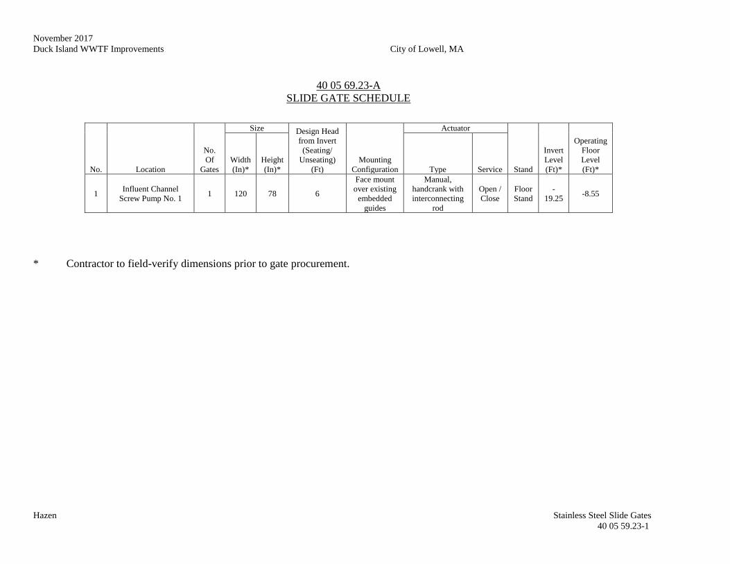
November 2017
Duck Island WWTF Improvements City of Lowell, MA
Hazen Stainless Steel Slide Gates
40 05 59.23-1
40 05 69.23-A
SLIDE GATE SCHEDULE
* Contractor to field-verify dimensions prior to gate procurement.
No. Location
No.
Of
Gates
Size Design Head
from Invert
(Seating/
Unseating)
(Ft)
Mounting
Configuration
Actuator
Stand
Invert
Level
(Ft)*
Operating
Floor
Level
(Ft)*
Width
(In)*
Height
(In)* Type Service
1 Influent Channel
Screw Pump No. 1 1 120 78 6
Face mount
over existing
embedded
guides
Manual,
handcrank with
interconnecting
rod
Open /
Close
Floor
Stand
-
19.25 -8.55

October 2017
Duck Island WWTF Improvements City of Lowell, MA
Hazen Stainless Steel Slide Gates
40 05 59.23-2
--THIS PAGE INTENTIONALLY LEFT BLANK--
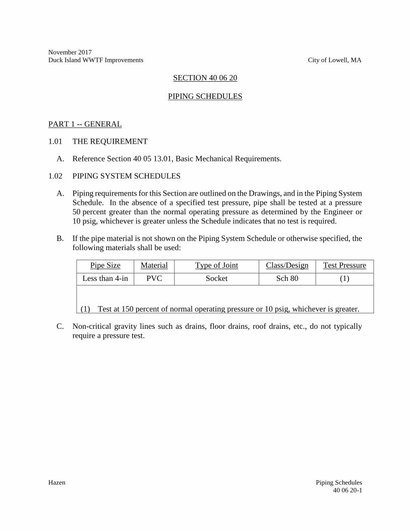
November 2017
Duck Island WWTF Improvements City of Lowell, MA
Hazen Piping Schedules
40 06 20-1
SECTION 40 06 20
PIPING SCHEDULES
PART 1 -- GENERAL
1.01 THE REQUIREMENT
A. Reference Section 40 05 13.01, Basic Mechanical Requirements.
1.02 PIPING SYSTEM SCHEDULES
A. Piping requirements for this Section are outlined on the Drawings, and in the Piping System
Schedule. In the absence of a specified test pressure, pipe shall be tested at a pressure
50 percent greater than the normal operating pressure as determined by the Engineer or
10 psig, whichever is greater unless the Schedule indicates that no test is required.
B. If the pipe material is not shown on the Piping System Schedule or otherwise specified, the
following materials shall be used:
Pipe Size Material Type of Joint Class/Design Test Pressure
Less than 4-in PVC Socket Sch 80 (1)
(1) Test at 150 percent of normal operating pressure or 10 psig, whichever is greater.
C. Non-critical gravity lines such as drains, floor drains, roof drains, etc., do not typically
require a pressure test.
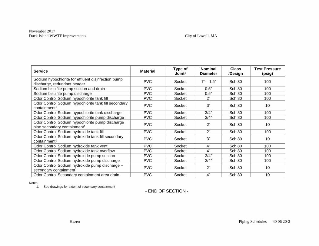
November 2017
Duck Island WWTF Improvements City of Lowell, MA
Hazen Piping Schedules 40 06 20-2
Service Material Type of Joint1
Nominal Diameter
Class /Design
Test Pressure (psig)
Sodium hypochlorite for effluent disinfection pump discharge, redundant header
PVC Socket 1” – 1.5” Sch 80 100
Sodium bisulfite pump suction and drain PVC Socket 0.5” Sch 80 100
Sodium bisulfite pump discharge PVC Socket 0.5” Sch 80 100
Odor Control Sodium hypochlorite tank fill PVC Socket 2" Sch 80 100
Odor Control Sodium hypochlorite tank fill secondary containment1 PVC Socket 3” Sch 80 10
Odor Control Sodium hypochlorite tank discharge PVC Socket 3/4" Sch 80 100
Odor Control Sodium hypochlorite pump discharge PVC Socket 3/4" Sch 80 100
Odor Control Sodium hypochlorite pump discharge pipe secondary containment1 PVC Socket 2” Sch 80 10
Odor Control Sodium hydroxide tank fill PVC Socket 2" Sch 80 100
Odor Control Sodium hydroxide tank fill secondary containment1
PVC Socket 3” Sch 80 10
Odor Control Sodium hydroxide tank vent PVC Socket 4" Sch 80 100
Odor Control Sodium hydroxide tank overflow PVC Socket 4" Sch 80 100
Odor Control Sodium hydroxide pump suction PVC Socket 3/4" Sch 80 100
Odor Control Sodium hydroxide pump discharge PVC Socket 3/4" Sch 80 100
Odor Control Sodium hydroxide pump discharge – secondary containment1
PVC Socket 2" Sch 80 10
Odor Control Secondary containment area drain PVC Socket 4” Sch 80 10 Notes
1. See drawings for extent of secondary containment - END OF SECTION -
November 2017
Duck Island WWTF Improvements City of Lowell, MA
Hazen Level Process Measurement Devices
40 91 23.36-1
SECTION 40 91 23.36
LEVEL PROCESS MEASUREMENT DEVICES
PART 1 -- GENERAL
1.01 THE REQUIREMENT
A. The Contractor shall furnish, test, install and place in satisfactory operation the radar liquid
level measurement systems, with all spare parts, accessories, and appurtenances as herein
specified and as shown on the Drawings; including, one sensor and one transmitter for level
measurement of sodium hydroxide for odor control; and (Bid Alternate #1:, two sensors
and one transmitter for level measurement of sodium bisulfite for effluent dichlorination).
1.02RELATED WORK SPECIFIED ELSEWHERE
A. Section 40 70 00 Instrumentation for Process Systems
B. Section 40 09 00 Instrumentation & Control for Process Systems
PART 2 -- PRODUCTS
2.01 ULTRASONIC LEVEL CONTROLLERS
A. Each ultrasonic level monitoring system shall include one ultrasonic level sensor and an
"intelligent" transmitter (controller). The ultrasonic level monitoring system shall be
required to monitor the level of liquids as shown on the Drawings and/or as specified
herein. Location of the sensor and transmitters shall be as shown on the Drawings and/or
as specified.
B. For outdoor installation, the use of approved watertight conduit hub/glands shall be
required. Tank mounting applications shall include mounting flange adapter supplied by
the manufacturer, which is compatible with the process liquid and the tank flange
connection. Sensor mounting thread shall be 1" NPT.
C. The level sensor shall be unaffected by moisture droplets on the transducer face and operate
on the ultrasonic echo ranging principle. Sensor accuracy shall be a minimum of 0.25
percent of level measurement range, and include integral temperature compensation with
an accuracy of 0.01% per C. Resolution shall be at least 0.1 percent of full range or 0.08
inches, whichever is greater.

November 2017
Duck Island WWTF Improvements City of Lowell, MA
Hazen Level Process Measurement Devices
40 91 23.36-2
D. The transmitter shall be programmable with a LCD display, which shall have the capability
to display a minimum of 4 characters at one time, and shall be shielded from direct sunlight.
The transmitter shall compensate for temperature and air density. The controller shall be
capable of performing the following functions: level monitor, both linear and nonlinear
level to flow relationships, volumetric, level signals, control of up to 5 pumps, alarms,
monitor pump runtime and pump sequencing. Output level signal shall be linear, isolated
4-20 mA DC. Power requirement for the transmitter shall be 120 VAC, 60 Hz. The units
shall have a stainless steel or nonmetallic NEMA 4X enclosure. The units shall have as a
minimum, the required number of programmable set points to perform the functions
specified. Each set point shall operate a set of contacts rated at 10 amps, 120 VAC.
E. Ultrasonic level measurement system shall be by Siemens/Milltronics (HydroRanger 200,
MultiRanger 200), Pulsar (Ultra series), Endress + Hauser, or equal.
PART 3 -- EXECUTION
3.01 REQUIREMENTS
A. Refer to Section 40 70 00 Instrumentation for Process Systems and Section 40 09 00
Instrumentation & Control for Process Systems.
- END OF SECTION -
November 2017
Duck Island WWTF Improvements City of Lowell, MA
Hazen Screw Bulk Material Conveyors
41 12 13.36-1
SECTION 41 12 13.36
SCREW BULK MATERIAL CONVEYORS
The equipment and systems in this section shall be furnished by the Contractor by and through
the Vendor, with whom the Owner has pre-selected equipment. The Contractor shall purchase
said equipment and systems from the Vendor, and shall include the cost of such equipment and
systems in its Form for General Bid. The equipment that has been selected by the Owner is
provided in Volume 3, Appendix D and contains the cost of the equipment and systems to be
purchased by the Contractor. The Contractor shall be responsible for the purchase, installation,
startup, testing and functioning of such equipment and systems to the same extent that Contractor
is responsible for all other supplies and work required by, shown in and inferable from the
Contract Documents, and shall be responsible for the Vendor to the same extent that is
responsible for all of its other subcontractors and suppliers for the project.
PART 1 -- GENERAL
1.01 REQUIREMENTS
A. The conveyor equipment has been pre-selected by the Owner as part of a separate pre-
selection process for SCREW BULK MATERIAL CONVEYORS. Atara Equipment
Ltd. of Laval, QC has been selected to furnish the conveyor equipment.
B. The conveyor equipment manufacturer will furnish the conveyor materials, equipment,
and accessories, including all necessary components, drives, motors, instrumentation,
controls, ancillary items and supports.
C. The manufacturer shall provide manufacturer’s services to inspect, test and certify the
completed system.
D. Additional components are necessary to provide a complete system as specified herein, in
other Technically Specifications and shown on the Drawings.
E. This specification section applies to the receipt, storage, installation, and other General
Contractor services for the conveyor equipment. The Contractor shall install, test and
place in satisfactory operation a screw conveyor system, including conveyors, slide gates,
interconnecting chutes, supports, and other ancillary equipment required for a fully
functional system. The screw conveyor system shall transport mechanically dewatered
wastewater treatment plant sludge from the centrifuge to the final discharge point located
in the truck loading area as shown on the Drawings.
F. The design of the sludge conveyor system shall be based upon the Contract Drawings,
these Specifications and the conveyor manufacturer submittal included as an attachment
November 2017
Duck Island WWTF Improvements City of Lowell, MA
Hazen Screw Bulk Material Conveyors
41 12 13.36-2
to these Specifications regarding the design of the conveyor system. The Contractor shall
install the conveyor system according to manufacturer requirements.
G. The Contract Drawings, and this Section, provide equipment descriptions, minimum
requirements and mandatory features of the equipment to be furnished. It is the
Contractor’s responsibility to provide a fully functioning system, complete in all details,
performance, and reliability meeting the requirements and intent of the Contract
Drawings and these Specifications.
H. The equipment shall be furnished complete with all accessories, special tools, spare parts,
base attachments, mounting anchor bolts, and other appurtenances as specified herein or
as may be required for a satisfactory installation.
1.02 QUALITY ASSURANCE
A. All supports for conveyors shall be provided for the conveyor support framing. The
Contractor shall be responsible for coordinating the placement of all supports necessary
to tie the equipment together and shall have the undivided responsibility for the system's
structural integrity.
B. The materials and equipment covered in this specification are intended to be standard
materials and equipment of proven ability as manufactured by reputable concerns.
Equipment shall be designed and constructed in accordance with the best practice of the
industry. The materials and equipment shall be installed by the Contractor in accordance
with the Manufacturer’s recommendations and these Specifications. The Specifications
call attention to certain features but do not purport to cover all details entering into the
construction of the equipment. Contractor shall refer to the Manufacturer’s materials and
equipment submittal.
C. The Contractor shall assure that all field dimensions are taken accurately and
communicated property to the Manufacturer.
D. No substitution of materials will be accepted unless they are submitted for review and the
Engineer approves their use.
1.03 DELIVERY, STORAGE, AND HANDLING
A. All packing slips and shipments shall be inspected by the Contractor and Engineer upon
delivery for completeness and damage during transportation. The freight company and
manufacturer shall be notified immediately of any damage or quantity shortages. All
missing items shall be furnished, and all damaged materials shall be replaced by the
Manufacturer at no additional cost or operating inconvenience to the Owner.
November 2017
Duck Island WWTF Improvements City of Lowell, MA
Hazen Screw Bulk Material Conveyors
41 12 13.36-3
B. The Manufacturer shall provide shipment (F.O.B.) to the site, 451 First Street Boulevard,
Lowell, MA. Offloading and storage shall be the responsibility of the Contractor.
1.04 WARRANTY
A. Conveyor equipment shall be warranted by the Manufacturer in accordance with Volume
3, Appendix D.
B. All other mechanical components shall be warranted free of manufacturing defects for a
period of 12 months from substantial completion.
C. The Contractor is responsible for the cost of replacing or rebuilding defective Work re-
gardless of whether the Owner has benefited from use of the Work through a portion of
its anticipated useful service life.
D. This warranty shall not deprive the Owner of the other rights the Owner may have under
other provisions of the Contract Documents and is in addition to and runs con-current
with other warranties made under the requirements of the Contract Doc-uments.
1.03 ADMINISTRATIVE REQUIREMENTS
A. Coordinate testing at least 2 weeks in advance with Engineer and Owner.
1.04 SUBMITTALS
A. Conveyor equipment submittal requirements are provided in Volume 3, Appendix D.
PART 2 – PRODUCTS
2.01 EQUIPMENT
A. Refer to Volume 3, Appendix D for Manufacturer’s Design Requirements.
B. Contractor shall field-verify all dimensions, bolt patterns, and piping connections prior to
start of fabrication.
PART 3 -- EXECUTION
3.01 MANUFACTURER’S FIELD SERVICES
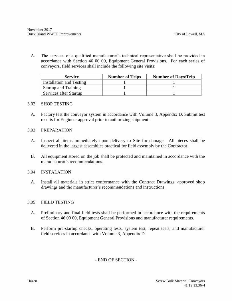
November 2017
Duck Island WWTF Improvements City of Lowell, MA
Hazen Screw Bulk Material Conveyors
41 12 13.36-4
A. The services of a qualified manufacturer’s technical representative shall be provided in
accordance with Section 46 00 00, Equipment General Provisions. For each series of
conveyors, field services shall include the following site visits:
Service Number of Trips Number of Days/Trip
Installation and Testing 1 1
Startup and Training 1 1
Services after Startup 1 1
3.02 SHOP TESTING
A. Factory test the conveyor system in accordance with Volume 3, Appendix D. Submit test
results for Engineer approval prior to authorizing shipment.
3.03 PREPARATION
A. Inspect all items immediately upon delivery to Site for damage. All pieces shall be
delivered in the largest assemblies practical for field assembly by the Contractor.
B. All equipment stored on the job shall be protected and maintained in accordance with the
manufacturer’s recommendations.
3.04 INSTALATION
A. Install all materials in strict conformance with the Contract Drawings, approved shop
drawings and the manufacturer’s recommendations and instructions.
3.05 FIELD TESTING
A. Preliminary and final field tests shall be performed in accordance with the requirements
of Section 46 00 00, Equipment General Provisions and manufacturer requirements.
B. Perform pre-startup checks, operating tests, system test, repeat tests, and manufacturer
field services in accordance with Volume 3, Appendix D.
- END OF SECTION -
November 2017
Duck Island WWTF Improvements City of Lowell, MA
Hazen High Density Polyethylene Storage Tanks
43 41 43-1
SECTION 43 41 43
HIGH DENSITY POLYETHYLENE STORAGE TANKS
PART 1 - GENERAL
1.01 Work Included
A. The Contractor shall furnish, install, adjust, test and place in satisfactory operation of
chemical storage tanks and all accessories as shown on the Contract Drawings and
specified herein.
B. The tanks shall be suitable for storage of sodium hydroxide.
1.02 Related Work
A. 40 05 13.01 Basic Mechanical Requirements
1.03 Submittals
A. In accordance with the procedures and requirements set forth in the General
Conditions and in applicable provisions of Division 01 00 00, the Contractor shall
obtain from the equipment manufacturer and shall submit the following:
1. Working Drawings.
B. Working drawings shall include, but not be limited to, the following:
1. Submit shop drawings of all layouts in plan and section including dimensions,
weights, construction details, size, type, and orientation of fittings,
installation/handling guidelines and information on type of and manufacturer of
resin used. Manufacturer and Contractor shall submit design calculations
(including hold down lug and anchor bolt reactions) and details for anchorage,
lateral restraint details and foundation requirements. Copies of seismic, buoyancy,
etc. computations, adequately detailed, shall be submitted to the Engineer for
review and approval. The computations shall be submitted in the form of a report.
All design calculations shall be signed and sealed by a professional engineer
licensed in the Commonwealth of Massachusetts.
2. Equipment specifications and data sheets, with identification of all materials
used and methods of fabrication and anchor bolt locations.
November 2017
Duck Island WWTF Improvements City of Lowell, MA
Hazen High Density Polyethylene Storage Tanks
43 41 43-2
3. Complete assembly, layout, installation and shop drawings, with clearly marked
dimensions.
4. Equipment cross-section drawings.
5. Anchor bolt sizes, depth of embedment, shear, and pullout strength.
6. Manufacturer’s delivery, storage, and handling requirements.
7. Manufacturer’s installation instructions and recommendations.
8. Weights of equipment component parts, assembled weight of equipment, and
total shipping weight.
9. Comprehensive schematic diagrams showing the wiring for each electrical or
electro-mechanical equipment item, as well as interconnecting and point-to-
point field wiring diagrams.
10. Equipment nameplate data.
11. Evidence of manufacturer experience and of the successful operation in other
facilities of equipment similar to that proposed for this project, as specified
herein and in the General Conditions.
C. Prior notification of shop tests shall be submitted for all equipment, shall be as
specified in the General Conditions, and shall include, but not be limited to, a
description of the proposed testing facilities and procedures.
1. Reports of certified shop tests shall be submitted as specified herein and in the
General Conditions. Reports shall include, at a minimum, hydrotest, impact test,
degree of crosslink test, and wall thickness readings taken at every 90 degrees at
each one foot elevation up to three feet. No equipment shall be shipped from its
place of manufacture before the certified shop test reports have been approved
by the Engineer.
D. Other applicable submittals, as required elsewhere in the Contract Documents
G. Any required additions, modifications and/or deletions to the tank foundation as well as
modification of the fitting locations as shown on the Contract Drawings shall be
submitted to the Engineer for approval. Any additional costs for those changes shall be
borne by the Contractor; the Contractor shall include any such costs in his bid price.
H. The design shall conform to the current requirements promulgated under the Federal
Occupational Safety and Health Act (OSHA).
1.04 Quality Assurance
The equipment covered by these specifications is intended to be standard equipment of proven
November 2017
Duck Island WWTF Improvements City of Lowell, MA
Hazen High Density Polyethylene Storage Tanks
43 41 43-3
performance as manufactured by reputable concerns. Process and quality control shall be
constantly monitored and manufacturer must maintain manufacturing and quality control
records for each tank.
A. Materials
The tank manufacturer shall verify receipt of a supplier certification that each lot of
resin conforms to supplier's specifications. The manufacturer shall verify that each
lot of resin complies with its purchase order. The manufacturer shall visually examine
each lot of resin for contamination, color, texture, etc. A sieve analysis shall be
performed on each lot of resin for particle size distribution, per ASTM D 1921. The
contractor shall provide certifications for both of the above requirements. The
completed tanks and fittings, fasteners and gaskets shall be NSF 61 certified for use
with the specified chemicals.
1.05 Storage and Protection
All equipment under this Section shall be stored and protected in accordance with the
manufacturer's recommendations and the requirements of Division 1.
The Contractor shall follow recommendations as shown in the manufacturer's
installation/handling guidelines. The Contractor is responsible to insure that all products
shipped shall be stored, handled, and installed in such a manner as not to degrade quality,
serviceability or appearance.
1.06 Marking
All packing, packaging and marking provisions of ASTM D3892 shall apply to this
specification. All tanks shall be marked to identify the manufacturer, the date of manufacturer
and the serial number. Product identification label, "Damage in Transit" inspection form,
installation/handling guidelines and "How to Use" label shall be applied to each tank.
1.07 Shipping
The manufacturer's shipping instructions shall be followed. When the tank has arrived at the
destination, the Contractor shall be responsible for inspecting the tank according to the
inspection guidelines supplied for damage in transit. If damages have occurred, the
Contractor shall sign "damaged" on the bill of lading and file a claim with the carrier while
notifying the manufacturer. Damaged tanks will not be acceptable.
1.08 Workmanship
The furnished tank wall shall be free of visual defects such as foreign inclusions, air bubbles
and pin holes that may impair the serviceability of the vessel. The inner surface shall be
November 2017
Duck Island WWTF Improvements City of Lowell, MA
Hazen High Density Polyethylene Storage Tanks
43 41 43-4
smooth and free of cracks, crazing or pits.
1.09 Warranty
The tank shall be warranted for five (5) years for 100% replacement against defects in
materials, workmanship and chemical attack from start of use or seven (7) years warranty
from date of delivery. Copy of warranty must be present on tank or on invoice with
instruction sheets accompanying fittings.
PART 2 - PRODUCTS
2.01 General
All parts of the storage tanks furnished shall be amply designed and constructed for the
maximum stresses occurring during fabrication, transport, erection and continuous use at
maximum capacity and severest conditions as indicated in Appendix A at the end of this
Section. Materials and resins used in the fabrication of the tanks shall be compatible with the
chemical service of each tank as indicated in Appendix A.
2.02 Manufacturer
The storage tanks, ladders, and all accessories shall be manufactured by Poly Processing,
Snyder Industries, Inc., or equal.
The manufacturer shall be ISO approved.
2.03 Materials
A. Tanks shall comply with the most current version of ASTM D-1998 Polyethylene
Upright Storage Tanks, except where modified in this specification. Resin used in
the tank manufacture shall be high-density cross-linked linear polyethylene
(HDXLPE) such as PAXON 7004 as manufactured by Exxon-Mobil; or PolyCL as
manufactured by PolyProcessing Company LLC; or approved equal.
B. For sodium hydroxide storage, tanks shall be designed to withstand use with 50 %
sodium hydroxide solution with specific gravity of 1.9.
C. The tank material shall be rotationally molded and meet or exceed the following
properties:
November 2017
Duck Island WWTF Improvements City of Lowell, MA
Hazen High Density Polyethylene Storage Tanks
43 41 43-5
Property
High Density
Cross-linked
Polyethylene
Value
Medium Density
Linear
Polyethylene
Value
ASTM Test
Density, gm/cc 0.938-0.944 0.938 D1505, D762
Environmental Stress
Cracking Resistance,
F50, hours
>1,000 >1,000 D1693
Tensile Strength,
Ultimate psi,
2-inch/minimum
2,600 2,900 D638
Type IV
Specimen
Elongation at Break, %
2-inch minimum
400
D638
Type IV
Specimen
Vicat Softening Point ~248°F D1525
Impact Brittleness
temperature
<-180°F D746
Flexural Modulus, psi 100,000 122,000 D790
2.04 Dimensions and Tolerances
The top head shall be integrally molded (one piece) with the cylinder shell. The minimum
thickness of the top head shall be 3/16 inch.
The tanks shall have flat mounting surfaces for fittings.
All dimensions shall be taken with the tank empty and in the vertical position. Tank
dimensions shall represent exterior measurements.
Outside diameter - Tolerances, including out-of-roundness, shall be +/- 3%.
Thickness - The tolerance for thickness specified shall be +/- 20%
Placement of fittings - The tolerances for fitting placement shall be +/- 0.5 inches in elevation.
The invert of the discharge shall be placed three inches from the bottom of the tank. The
invert of the overflow shall be located six inches above the usable design volume on the
straight side of the tank.
2.05 Fittings
A. Tank fittings shall be provided as indicated in Appendix A. Locations of fittings shall
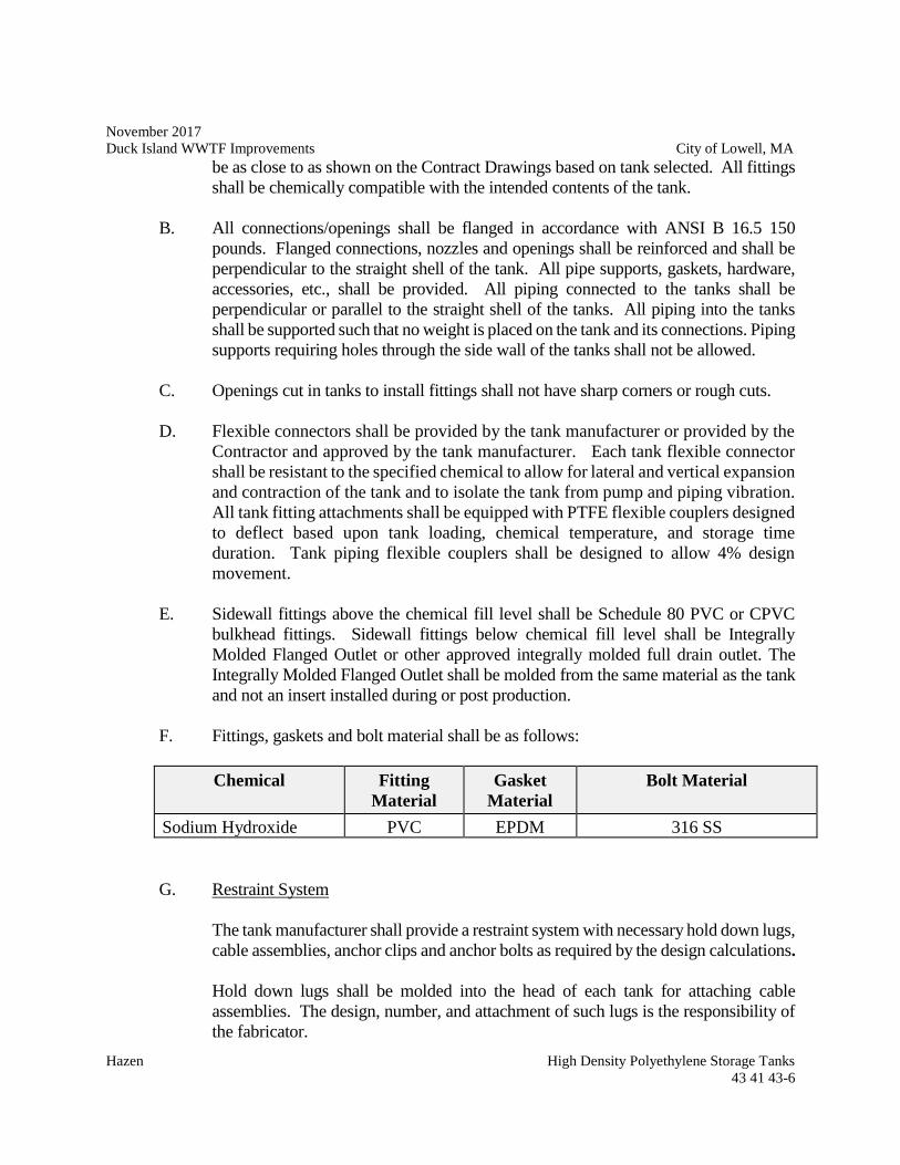
November 2017
Duck Island WWTF Improvements City of Lowell, MA
Hazen High Density Polyethylene Storage Tanks
43 41 43-6
be as close to as shown on the Contract Drawings based on tank selected. All fittings
shall be chemically compatible with the intended contents of the tank.
B. All connections/openings shall be flanged in accordance with ANSI B 16.5 150
pounds. Flanged connections, nozzles and openings shall be reinforced and shall be
perpendicular to the straight shell of the tank. All pipe supports, gaskets, hardware,
accessories, etc., shall be provided. All piping connected to the tanks shall be
perpendicular or parallel to the straight shell of the tanks. All piping into the tanks
shall be supported such that no weight is placed on the tank and its connections. Piping
supports requiring holes through the side wall of the tanks shall not be allowed.
C. Openings cut in tanks to install fittings shall not have sharp corners or rough cuts.
D. Flexible connectors shall be provided by the tank manufacturer or provided by the
Contractor and approved by the tank manufacturer. Each tank flexible connector
shall be resistant to the specified chemical to allow for lateral and vertical expansion
and contraction of the tank and to isolate the tank from pump and piping vibration.
All tank fitting attachments shall be equipped with PTFE flexible couplers designed
to deflect based upon tank loading, chemical temperature, and storage time
duration. Tank piping flexible couplers shall be designed to allow 4% design
movement.
E. Sidewall fittings above the chemical fill level shall be Schedule 80 PVC or CPVC
bulkhead fittings. Sidewall fittings below chemical fill level shall be Integrally
Molded Flanged Outlet or other approved integrally molded full drain outlet. The
Integrally Molded Flanged Outlet shall be molded from the same material as the tank
and not an insert installed during or post production.
F. Fittings, gaskets and bolt material shall be as follows:
Chemical Fitting
Material
Gasket
Material
Bolt Material
Sodium Hydroxide PVC EPDM 316 SS
G. Restraint System
The tank manufacturer shall provide a restraint system with necessary hold down lugs,
cable assemblies, anchor clips and anchor bolts as required by the design calculations.
Hold down lugs shall be molded into the head of each tank for attaching cable
assemblies. The design, number, and attachment of such lugs is the responsibility of
the fabricator.
November 2017
Duck Island WWTF Improvements City of Lowell, MA
Hazen High Density Polyethylene Storage Tanks
43 41 43-7
Each storage tank shall be provided with a minimum of four hold down lugs and all
necessary anchor bolts. Tank manufacturer shall be responsible for complete hold
down lug design and layout required per each tank. The manufacturer shall provide
anchor bolts as required by the engineer seal design calculations. Hold down lugs and
anchor bolts shall be designed for all applicable loading (seismic, buoyancy, etc) in
accordance with the Massachusetts State Building Code and ASCE 7. See Drawing
S-001 for site specific seismic design parameter including Seismic Design Category,
short period design spectral response (SDS), long period design spectral response
(SD1). In addition, hold down lugs and anchor bolts shall be capable of withstanding
buoyancy of an empty tank in a flooded containment area. Refer to Drawings for
containment wall/curb height. Drawings and calculations (including hold down lug
and anchor bolt reactions) sealed and signed by a Professional Engineer registered in
the Commonwealth of Massachusetts shall be submitted to Engineer for approval and
verification that foundations are capable of resisting loads. Anchor clips requiring
holes through the side wall of the tanks shall not be allowed.
H. Identification Label
An identification label shall be provided on each tank stating the tank resin, specific
gravity and maximum temperature, tank capacity, fabricator's name and address, date
of manufacture.
I. Connections
Connections for vent, fill, discharge, overflow(s), level indicator, manway cover and
pressure relief, shall be as specified in Appendix A. All connections shall be bulkhead
fittings unless otherwise specified. Vent material shall be suitable for the chemical
service. Vent insect screens shall be FRP.
2.06 Tools, Supplies, and Spare Parts
Furnish all special tools necessary to install, disassemble, service, and repair the equipment.
Spare parts lists, included with the shop drawing submittal shall indicate specific sizes,
quantities, and part numbers of the items to be furnished. Terms such as "1 lot of packing
material" are not acceptable.
Parts shall be completely identified with a numerical system to facilitate parts inventory
control and stroking. Each part shall be properly identified by a separate number. Those parts
which are identical for more than one size, shall have the same parts number. Spare parts
shall be packed in individual, suitable containers clearly labeled with the part number; name,
quantity, and the equipment for which they are intended.
November 2017
Duck Island WWTF Improvements City of Lowell, MA
Hazen High Density Polyethylene Storage Tanks
43 41 43-8
Spare parts shall be delivered at the same time as the equipment to which they pertain. The
Contractor shall properly store and safeguard such spare parts until completion of the work,
at which time they shall be delivered to the Owner.
PART 3 - EXECUTION
3.01 Handling and Installation
Tanks shall be handled and installed in accordance with the manufacturer's recommendations
as shown in the installation/ handling guidelines. The Contractor shall support all pipes
leading to and from the tank. Contractor shall ensure that construction work is sequenced to
allow installation of the tanks. Tanks shall not be used as temporary supports.
3.02 Cleaning
After satisfactory completion of field testing, drain the testing water. Rinse the inside of the
tanks with clean, potable water. Hand wipe and dry as required to leave the tank interior
clean, dry, and ready for storage of the chemical.
3.03 Inspection and Testing
A. Shop Tests
Test specimens shall be taken from the cover cut-out area and where fittings are
installed. Impact resistance shall be tested according to ARM procedure. Ductile
failures indicate proper cure, while cracking or shattering indicate a possibility of
insufficient cure.
The percent gel for XLPE tanks shall be tested according to ASTM D2765, Method
B on a 1/8- in. sample taken from the inside wall. This sample must be taken at the
fitting area. The gel test is a quantitative measure for degree of cure for cross-linked
polyethylene. Minimum acceptable gel is 60 percent.
Inspection lights shall be used to check for any air bubbles, pin holes or foreign
particles which would cause the tank to be rejected. Special attention shall be given
to any parting line seams.
A wall thickness audit shall be performed using an ultrasonic thickness gauge.
A four-hour hydrostatic test in which the tank is completely filled with water shall be
performed by the manufacturer.
Certified test reports of all tests and inspections shall be furnished to the Engineer.
November 2017
Duck Island WWTF Improvements City of Lowell, MA
Hazen High Density Polyethylene Storage Tanks
43 41 43-9
Reports shall be submitted prior to shipment. No equipment shall be shipped to the
site until the Engineer approves, in writing, that the reports are acceptable.
B. Field Tests
After the tanks have been installed, they shall be filled with water up to the overflow
and the hold down lugs tightened. The hold down lugs shall not be tightened before
the tanks are filled. At this time tanks shall be hydrostatically tested for
watertightness. Any tank which shows any leakage during the tests shall be
satisfactorily repaired or replaced, and then retested. No tank will be accepted unless
it is completely watertight.
C. Services of Manufacturers Representative
Furnish the services of a factory representative for two (2) days during the installation
phase of the tanks. The factory representative shall have full knowledge and
experience in the installation of the tanks.
END OF SECTION
November 2017
Duck Island WWTF Improvements City of Lowell, MA
Hazen High Density Polyethylene Storage Tanks
43 41 43-10
--THIS PAGE INTENTIONALLY LEFT BLANK--
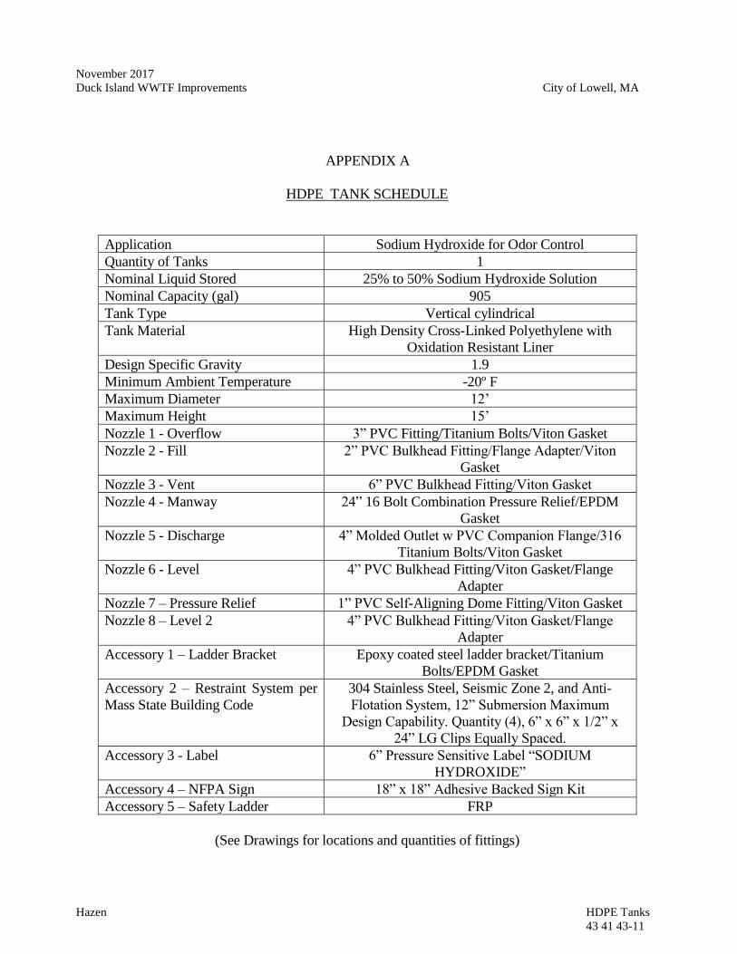
November 2017
Duck Island WWTF Improvements City of Lowell, MA
Hazen HDPE Tanks
43 41 43-11
APPENDIX A
HDPE TANK SCHEDULE
Application Sodium Hydroxide for Odor Control
Quantity of Tanks 1
Nominal Liquid Stored 25% to 50% Sodium Hydroxide Solution
Nominal Capacity (gal) 905
Tank Type Vertical cylindrical
Tank Material High Density Cross-Linked Polyethylene with
Oxidation Resistant Liner
Design Specific Gravity 1.9
Minimum Ambient Temperature -20º F
Maximum Diameter 12’
Maximum Height 15’
Nozzle 1 - Overflow 3” PVC Fitting/Titanium Bolts/Viton Gasket
Nozzle 2 - Fill 2” PVC Bulkhead Fitting/Flange Adapter/Viton
Gasket
Nozzle 3 - Vent 6” PVC Bulkhead Fitting/Viton Gasket
Nozzle 4 - Manway 24” 16 Bolt Combination Pressure Relief/EPDM
Gasket
Nozzle 5 - Discharge 4” Molded Outlet w PVC Companion Flange/316
Titanium Bolts/Viton Gasket
Nozzle 6 - Level 4” PVC Bulkhead Fitting/Viton Gasket/Flange
Adapter
Nozzle 7 – Pressure Relief 1” PVC Self-Aligning Dome Fitting/Viton Gasket
Nozzle 8 – Level 2 4” PVC Bulkhead Fitting/Viton Gasket/Flange
Adapter
Accessory 1 – Ladder Bracket Epoxy coated steel ladder bracket/Titanium
Bolts/EPDM Gasket
Accessory 2 – Restraint System per
Mass State Building Code
304 Stainless Steel, Seismic Zone 2, and Anti-
Flotation System, 12” Submersion Maximum
Design Capability. Quantity (4), 6” x 6” x 1/2” x
24” LG Clips Equally Spaced.
Accessory 3 - Label 6” Pressure Sensitive Label “SODIUM
HYDROXIDE”
Accessory 4 – NFPA Sign 18” x 18” Adhesive Backed Sign Kit
Accessory 5 – Safety Ladder FRP
(See Drawings for locations and quantities of fittings)

November 2017
Duck Island WWTF Improvements City of Lowell, MA
Hazen High Density Polyethylene Storage Tanks 43 41 43-12
--THIS PAGE INTENTIONALLY LEFT BLANK--
November 2017
Duck Island WWTF Improvements City of Lowell, MA
Hazen Equipment General Provisions
46 00 00-1
SECTION 46 00 00
EQUIPMENT GENERAL PROVISIONS
PART 1 -- GENERAL
1.01 THE REQUIREMENT
A. The Contractor shall furnish, install, test, and place in acceptable operation all mechanical
equipment and all necessary accessories as specified herein, as shown on the Drawings,
and as required for a complete and operable system.
B. The mechanical equipment shall be provided complete with all accessories, special tools,
spare parts, mountings, and other appurtenances as specified, and as may be required for a
complete and operating installation.
C. It is the intent of these Specifications that the Contractor shall provide the Owner complete
and operational equipment/systems. To this end, it is the responsibility of the Contractor
to coordinate all interfaces with related mechanical, structural, electrical, instrumentation
and control work and to provide necessary ancillary items such as controls, wiring, etc., to
make each piece of equipment operational as intended by the Specifications.
D. The complete installation shall be free from excessive vibration, cavitation, noise, and oil
or water leaks.
E. The requirements of this section shall apply to equipment furnished under Divisions 40 and
46.
1.02 REFERENCE SPECIFICATIONS, CODES, AND STANDARDS
A. All equipment, materials, and installations shall conform to the requirements of the most
recent editions with latest revisions, supplements, and amendments of the specifications,
codes, and standards listed in Section 01 42 19, Codes and Standards.
1.03 MANUFACTURERS CERTIFICATE OF COMPLIANCE
A. When required in the individual equipment Specifications, the Contractor shall submit
manufacturer's certificate of compliance for equipment to be furnished as described in
Section 01 60 00 – Product Requirements.
1.04 SHOP DRAWINGS
A. Shop Drawings shall be submitted to the Engineer for all equipment in accordance with
Division 01 00 00 General Requirements, and shall include the following information in
addition to the requirements of Division 01 00 00 General Requirements:
November 2017
Duck Island WWTF Improvements City of Lowell, MA
Hazen Equipment General Provisions
46 00 00-2
1. Performance characteristics and descriptive data.
2. Detailed equipment dimensional drawings (both plan and section views) and setting
plans.
3. General lifting, erection, installation, and adjustment instructions and
recommendations.
4. Complete information regarding location, type, size, and length of all field welds
in accordance with "Standard Welding Symbols" AWS A2.0 of the American
Welding Society. Special conditions shall be fully explained by notes and details.
5. The total uncrated weight of the equipment plus the approximate weight of shipped
materials. Support locations and loads that will be transmitted to bases and
foundations. Exact size, placement, and embedment requirements of all anchor
bolts.
6. Details on materials of construction of all components including applicable ASTM
designations.
7. Information on bearing types and bearing life.
8. Gear box design and performance criteria and AGMA service factor.
9. Piping schematics
10. Motor data sheet indicating motor horsepower; enclosure type; voltage; insulation
class; temperature rise and results of dielectric tests; service-rating; rotative speed;
motor speed-torque relationship; efficiency and power factor at ½, ¾, and full load;
slip at full load; running, full load, and locked rotor current values; and safe running
time-current curves.
11. Equipment and motor protective device details. Connection diagrams for motor
and all protective devices.
12. Equipment shop coating systems, interior and exterior.
13. Panel layout drawings, schematic wiring diagrams, and component product data
sheets for control panels.
14. A list of spare parts and special tools to be provided.
15. Any additional information required to show conformance with the equipment
specifications.
16. Warranty documentation including statement of duration of warranty period and
contact phone numbers and addresses for warranty issues.
November 2017
Duck Island WWTF Improvements City of Lowell, MA
Hazen Equipment General Provisions
46 00 00-3
1.05 OPERATION AND MAINTENANCE INSTRUCTION/MANUALS
A. Operation and Maintenance (O&M) manuals shall be submitted in accordance with
Division 01 00 00 General Requirements.
1.06 GENERAL INFORMATION AND DESCRIPTION
A. All parts of the equipment furnished shall, be designed and constructed for the maximum
stresses occurring during fabrication, transportation, installation, testing, and all conditions
of operation. All materials shall be new, and both workmanship and materials shall be
entirely suitable for the service to which the units are to be subjected and shall conform to
all applicable sections of these Specifications.
B. All parts of duplicate equipment shall be interchangeable without modification.
Manufacturer's design shall accommodate all the requirements of these Specifications.
C. Equipment and appurtenances shall be designed in conformity with ASTM, ASME, AIEE,
NEMA, and other generally accepted applicable standards.
D. All bearings and moving parts shall be adequately protected by bushings or other approved
means against wear, and provision shall be made for accessible lubrication by extending
lubrication lines and fittings to approximately 30 inches above finished floor elevation.
E. Details shall be designed for appearance as well as utility. Protruding members, joints,
corners, gear covers, etc., shall be finished in appearance. All exposed welds on machinery
shall be ground smooth and the corners of structural shapes shall be rounded or chamfered.
F. Machinery parts shall conform within allowable tolerances to the dimensions shown on the
working drawings.
G. All machinery and equipment shall be safeguarded in accordance with the safety codes of
the USA and the State in which the project is located.
H. All rotating shafts, couplings, or other moving pieces of equipment shall be provided with
suitable protective guards of sheet metal or wire mesh, neatly and rigidly supported.
Guards shall be removable as required to provide access for repairs.
I. All equipment greater than 100 pounds shall have lifting lugs, eyebolts, etc., for ease of
lifting, without damage or undue stress exerted on its components.
J. All manufactured items provided under this Section shall be new, of current manufacture,
and shall be the products of reputable manufacturers specializing in the manufacture of
such products.
1.07 WARRANTY AND GUARANTEE
November 2017
Duck Island WWTF Improvements City of Lowell, MA
Hazen Equipment General Provisions
46 00 00-4
A. All equipment shall be guaranteed in accordance with the General Conditions as modified
by the Supplementary Conditions.
B. Guarantee requirements may be added to or modified in the individual equipment
specifications.
PART 2 -- PRODUCTS
2.01 ACCEPTABLE MANUFACTURERS
A. The materials covered by these Specifications are intended to be equipment of proven
reliability, and as manufactured by reputable manufacturers having experience in the
production of such equipment. The Contractor shall, upon request of the Engineer, furnish
the names of not less than 5 successful installations of the manufacturer's equipment of the
same size and model of that offered under this contract. The equipment furnished shall be
designed, constructed, and installed in accordance with the industry accepted practices and
shall operate satisfactorily when installed as shown on the Drawings and operated per
manufacturer's recommendations.
2.02 ANCHORS AND SUPPORTS
A. The Contractor shall furnish, install, and protect all necessary guides, bearing plates,
anchor and attachment bolts, and all other appurtenances required for the installation of the
devices included in the equipment specified. Working Drawings for installation shall be
furnished by the equipment manufacturer, and suitable templates shall be used by the
Contractor when required in the detailed equipment Specifications.
B. Anchor bolts and fasteners shall be furnished in accordance with Section 05 50 00, Metal
Fabrications, and with the individual equipment Specifications. All anchor bolts shall be
a minimum of 1/2-inch diameter. All anchor bolts, handrail bolts, washers, clips, clamps,
and fasteners of any type shall be constructed of 316 stainless steel, unless otherwise
specified the individual equipment Specifications.
C. The Contractor shall provide all concrete pads or pedestals required for equipment
furnished. All concrete equipment pads shall be a minimum of 6” high, unless otherwise
shown on the Drawings and shall be doweled.
D. Pipe sleeves or other means of adjusting anchor bolts shall be provided where indicated or
required. Equipment shall be leveled by first using sitting nuts on the anchor bolts, and
then filling the space between the equipment base and concrete pedestal with non-shrink
grout, unless alternate methods are recommended by the manufacturer and are acceptable
to the Engineer (such as shim leveling pumps, or chemical grout). Non-shrink grout shall
be as specified in Section 03 60 00, Grouting.
2.03 STRUCTURAL STEEL
November 2017
Duck Island WWTF Improvements City of Lowell, MA
Hazen Equipment General Provisions
46 00 00-5
A. All materials shall conform to applicable provisions of the AISC Specifications for the
design and fabrication of structural steel, and to pertinent ASTM Standard Specifications.
2.04 DISSIMILAR METALS
A. All dissimilar metals shall be properly isolated to the satisfaction of the Engineer.
2.06 STANDARDIZATION OF GREASE FITTINGS
A. The grease fittings on all mechanical equipment shall be such that they can be serviced
with a single type of grease gun. Fittings shall be “Zerk” type.
2.07 ELECTRICAL REQUIREMENTS
A. All electrical equipment and appurtenances, including but not limited to motors, panels,
conduit and wiring, etc., specified in the equipment specifications shall comply with the
applicable requirements of the Division 26 specifications and the latest National Electric
Code.
B. In the individual equipment specifications, specified motor horsepower is intended to be
the minimum size motor to be provided. If a larger motor is required to meet the specified
operating conditions and performance requirements, the Contractor shall furnish the larger
sized motor and shall upgrade the electrical service (conduit, wires, starters, etc.) at no
additional cost to the Owner.
D. Motor starters and controls shall be furnished and installed under Division 26 and Division
40 unless otherwise specified in the individual pump specifications.
2.08 ACCESSORIES, SPARE PARTS, AND SPECIAL TOOLS
A. Spare parts for equipment shall be furnished where indicated in the equipment
Specifications or where recommended by the equipment manufacturer.
B. Spare parts shall be identical and interchangeable with original parts.
C. The spare parts shall be packed in containers suitable for long term storage, bearing labels
clearly designating the contents and the pieces of equipment for which they are intended.
D. Painting requirements for spare parts shall be identical to those for original, installed parts.
Where no painting or protective coating is specified, suitable provisions shall be made to
protect against corrosion.
E. Spare parts shall be delivered at the same time as the equipment to which they pertain.
Spare parts shall be stored separately in a locked area, maintained by the Contractor, and
shall be turned over to the Owner in a group prior to substantial completion. All of these
materials shall be properly packed, labeled, and stored where directed by the Owner and
Engineer.
November 2017
Duck Island WWTF Improvements City of Lowell, MA
Hazen Equipment General Provisions
46 00 00-6
F. The Contractor shall furnish all special tools necessary to operate, disassemble, service,
repair, and adjust the equipment in accordance with the manufacturers operation and
maintenance manual.
G. The Contractor shall furnish a one year supply of all recommended lubricating oils and
greases. The manufacturer shall submit a list of at least four manufacturer's standard
lubricants which may be used interchangeably for each type of lubricant required. All of
these materials shall be properly packed, labeled and stored where directed by the Engineer.
2.09 EQUIPMENT IDENTIFICATION
A. All mechanical equipment shall be provided with a substantial stainless steel nameplate,
mechanically fastened with stainless steel hardware in a conspicuous place, and clearly
inscribed with the manufacturer's name, year of manufacture, serial number, and principal
rating data.
B. Each pump and other piece of mechanical equipment shall also be identified as to name
and number by a suitable laminated plastic or stainless steel nameplate mechanically
fastened with stainless steel hardware; for example, "Raw Water Pump #1". Coordinate
name and number with same on remotely located controls, control panel, and other related
equipment.
C. Nameplates shall not be painted over.
PART 3 -- EXECUTION
3.01 SHOP TESTING
A. All equipment shall be tested in the shop of the manufacturer in a manner which shall
conclusively prove that its characteristics comply fully with the requirements of the
Contract Documents and that it will operate in the manner specified or implied.
B. No equipment shall be shipped to the project until the Engineer has been furnished a
certified copy of test results and has notified the Contractor, in writing, that the results of
such tests are acceptable.
C. Seven (7) certified copies of the manufacturer's actual test data and interpreted results
thereof shall be forwarded to the Engineer for review.
D. If required by the individual equipment Specifications, arrangements shall be made for the
Owner/Engineer to witness performance tests in the manufacturer's shop. The Engineer
shall be notified ten (10) working days before shop testing commences. Expenses are to
be paid by Owner.
November 2017
Duck Island WWTF Improvements City of Lowell, MA
Hazen Equipment General Provisions
46 00 00-7
E. Shop testing of electric motors shall be in accordance with applicable requirements of
Section 26 05 00, Common Work Results for Electrical.
3.02 STORAGE OF EQUIPMENT AND MATERIALS
A. Contractor shall store his equipment and materials at the job site in strict accordance with
the manufacturer's recommendations and as directed by the Owner or Engineer, and in
conformity to applicable statutes, ordinances, regulations, and rulings of the public
authority having jurisdiction. Equipment and materials shall not be delivered to the site
prior to 90 days in advance of the scheduled installation. Partial payment requests will not
be processed for materials delivered prior to 90 days before installation or for materials
that are not properly stored.
B. Material or equipment stored on the job site is stored at the Contractor's risk. Any damage
sustained of whatever nature shall be repaired to the Engineer's satisfaction at no expense
to the Owner. Stored electrical equipment is to be protected from the elements and shall
have space heaters energized.
C. Contractor shall not store unnecessary materials or equipment on the job site and shall take
care to prevent any structure from being loaded with a weight which will endanger its
security or the safety of persons.
D. Contractor shall observe all regulatory signs for loadings on structures, fire safety, and
smoking areas.
E. Contractor shall not store materials or encroach upon private property without the written
consent of the owners of such private property.
3.03 MANUFACTURER’S FIELD SERVICES
A. The Contractor shall arrange for a qualified Technical Representative from each
manufacturer or supplier of equipment who is regularly involved in the inspection,
installation, start-up, troubleshooting, testing, maintenance, and operation of the specified
equipment. Qualification of the Technical Representative shall be appropriate to the type
of equipment furnished and subject to the approval of the Engineer and the Owner. Where
equipment furnished has significant process complexity, furnish the services of
engineering personnel knowledgeable in the process involved and the function of the
equipment. When necessary, the Contractor shall schedule multiple Technical
Representatives to be present at the same time for the purpose of coordinating the operation
of multiple pieces of related equipment.
B. For each site visit, the Technical Representative shall submit jointly to the Owner, the
Engineer, and the Contractor a complete signed report of the results of his inspection,
operation, adjustments, and testing. The report shall include detailed descriptions of the
points inspected, tests and adjustments made, quantitative results obtained if such are
specified.
November 2017
Duck Island WWTF Improvements City of Lowell, MA
Hazen Equipment General Provisions
46 00 00-8
C. The manufacturer's Technical Representative shall provide the following services.
1. Installation: The Technical Representative shall inspect the installed equipment to
verify that installation is in accordance with the manufacturer’s requirements.
Where required by individual equipment specifications, the Technical
Representative shall also supervise the installation of the equipment.
2. Testing: After installation of the equipment has been completed and the equipment
is presumably ready for operation, but before it is operated by others, the Technical
Representative shall inspect, operate, test, and adjust the equipment as required to
prove that the equipment is in proper condition for satisfactory operation under the
conditions specified. Unless otherwise noted in the signed site visit report, the
report shall constitute a certification that the equipment conforms to the
requirements of the Contract and is ready for startup and that nothing in the
installation will render the manufacturer's warranty null and void. The report shall
include date of final acceptance field test, as well as a listing of all persons present
during tests.
3. Startup: The Technical Representative shall start up the equipment for actual
service with the help of the Contractor. In the event that equipment or installation
problems are experienced, the Contractor and the representative shall provide the
necessary services until the equipment is operating satisfactorily and performing
according to the specifications at no additional cost to the Owner. Unless otherwise
noted in the signed site visit report, the report shall constitute a certification that the
equipment conforms to the requirements of the Contract and is ready for permanent
operation and that nothing in the installation will render the manufacturer's
warranty null and void.
4. Training: The Technical Representative shall instruct the Owner's operating
personnel in correct operation and maintenance procedures. The instruction shall
demonstrate start-up, operation, control, adjustment, trouble-shooting, servicing,
maintenance, and shutdown of each item of equipment. Such instruction shall be
scheduled at a time arranged with the Owner at least 2 weeks in advance of the
training and shall be provided while the respective Technical Representative's
equipment is fully operational. The Contractor shall have submitted, and the
Engineer shall have accepted, the O&M Manuals prior to commencement of
training.
5. Services after Startup: Where required by the individual equipment specifications,
the Technical Representative shall return to the project site thirty (30) days after the
start up date to review the equipment performance, correct any equipment
problems, and conduct operation and maintenance classes as required by the
Owner. This follow-up trip is required in addition to the specified services of
Technical Representative prior to and during equipment startup. At this time, if
there are no equipment problems, each manufacturer shall certify to the Owner in
November 2017
Duck Island WWTF Improvements City of Lowell, MA
Hazen Equipment General Provisions
46 00 00-9
writing that his equipment is fully operational and capable of meeting operating
requirements. If the equipment is operating incorrectly, the Technical
Representative will make no certification to the Owner until the problems are
corrected and the equipment demonstrates a successful thirty (30) days operating
period.
D. Services of the Technical Representative will require a minimum of three (3) site visits,
one for installation and testing, one for startup, and one for training, and will be for the
minimum number of days recommended by the manufacturer and approved by the
Engineer but will not be less than the number of days specified in individual equipment
sections.
E. The Contract amount shall include the cost of furnishing the Technical Representative for
the minimum number of days specified, and any additional time required to achieve
successful installation and operation. The times specified for services by the Technical
Representative in the equipment Specifications are exclusive of travel time to and from the
facility and shall not be construed as to relieve the manufacturer of any additional visits to
provide sufficient service to place the equipment in satisfactory operation.
F. The Contractor shall notify the Engineer at least 14 days in advance of each equipment test
or Owner training session.
G. The Technical Representative shall sign in and out at the office of the Engineer's Resident
Project Representative on each day he is at the project.
3.04 INSTALLATION
A. The Contractor shall obtain written installation manuals from the equipment manufacturer
prior to installation. Equipment shall be installed strictly in accordance with
recommendations of the manufacturer. A copy of all installation instructions shall be
furnished the Engineer's field representative one week prior to installation.
B. The Contractor shall have on hand sufficient personnel, proper construction equipment,
and machinery of ample capacity to facilitate the work and to handle all emergencies
normally encountered in work of this character. To minimize field erection problems,
mechanical units shall be factory-assembled insofar as practical.
C. Equipment shall be erected in a neat and workmanlike manner on the foundations at the
locations and elevations shown on the Drawings.
D. All equipment sections and loose items shall be match-marked prior to shipping.
E. For equipment such as pumping units, which require field alignment and connections, the
Contractor shall provide the services of the manufacturer's qualified mechanic, millwright,
or machinist, to align the pump and motor prior to making piping connections or anchoring
the pump base. Alignment shall be as specified herein.
November 2017
Duck Island WWTF Improvements City of Lowell, MA
Hazen Equipment General Provisions
46 00 00-10
F. The Contractor shall furnish oil and grease for initial operation and testing. The
manufacturer and grades of oil and grease shall be in accordance with the recommendations
of the equipment manufacturer.
3.05 ALIGNMENT
A. Set equipment to dimensions shown on drawings. Dimensions shall be accurate to +/- 1/16
inch unless otherwise noted on the drawings. Wedges shall not be used for leveling,
aligning, or supporting equipment.
B. General Equipment Leveling: Non-rotating equipment shall be set level to +/- 1/16 inch
per 10 foot length (.005 inch per foot) unless otherwise noted on the drawings. Shims shall
be used unless equipment is furnished with leveling feet. Set shims flush with equipment
baseplate edges. When grouting is required, equipment shall be shimmed to allow a
minimum of one inch grout thickness. Grout shall cover shims at least 3 inches. Final
level check shall be held for inspection and approval by Engineer before proceeding.
C. Grouting
1. Fill anchor bolt holes or sleeves with grout, after bolt alignment is proven, and prior
to placing grout under equipment bases.
2. Surface Preparation. Roughen surface by chipping, removing laitance, and
unsound concrete. Clean area of all foreign material such as oil, grease, and scale.
Saturate area with water at least 4 hours prior to grouting, removing excess water
ponds.
3. Application. Place grout after the equipment base has been set and its alignment
and level have been approved. Form around the base, mix grout, and place in
accordance with the grout manufacturers published instructions. Eliminate all air
or water pockets beneath the base using a drag chain or rope.
4. Finishing. Point the edges of the grout to form a smooth 45 degree slope.
5. After grout has cured (not before 3 days after placement) paint exposed surfaces of
grout with shellac.
6. Level Verification. After grout has cured, and immediately prior to drive
alignment, recheck equipment for level and plumb. Re-level and square as
necessary. Hold final checks for inspection and approval by Engineer.
D. Inspect for and remove all machining burrs or thread pulls in female holes on mating
surfaces of mounting frame and machine feet.
E. Inspect and clean equipment mounting base pads, feet, and frames to remove all grease,
rust, paint and dirt.
November 2017
Duck Island WWTF Improvements City of Lowell, MA
Hazen Equipment General Provisions
46 00 00-11
F. Assembled equipment shafts shall be set level to .0015 inches per foot of shaft length (+/-
.0005 inches) up to a maximum of 0.015 inches for any length shaft unless the
manufacturer’s requirements are more stringent or unless otherwise noted in the equipment
specifications. Use the machined surfaces on which the equipment sets for the
base/mounting frame leveling plane. Use the machined shaft surface for equipment
leveling plane.
G. Sprocket and Sheave Alignment. Check shaft mounted components for face runout and
eccentricity (outside diameter) runout by magnetically mounting a dial indicator on a
stationary base and indicating over 360 degrees on a continuous machined surface at the
outside diameter of the component. Maximum allowable total indicated face runout and
eccentricity for sprockets and sheaves will be per ANSI Standard B29.1-1975.
H. Belt tensioning. Set drive belt tension to manufacturer's specification for the belt type.
Recheck alignment after drive tensioning.
I. Thermal/Mechanical Growth. Thermal/mechanical growth corrections for driver and
driven machines will be used in vertical and horizontal alignment where applicable. The
equipment manufacturer will determine thermal/mechanical growth applicability for any
machine and provide the correction offsets to be used.
3.06 FIELD TESTING
A. All equipment shall be set, aligned and assembled in conformance with the manufacturer's
drawings and instructions. Provide all necessary calibrated instruments to execute
performance tests. Submit report certified by the pump manufacturer’s representative.
B. Preliminary Field Tests, Yellow Tag
1. As soon as conditions permit, after the equipment has been secured in its permanent
position, the Contractor shall:
a. Verify that the equipment is free from defects.
b. Check for alignment as specified herein.
c. Check for direction of rotation.
d. Check motor for no load current draw.
2. Contractor shall flush all bearings, gear housings, etc., in accordance with the
manufacturer's recommendations, to remove any foreign matter accumulated
during shipment, storage or erection. Lubricants shall be added as required by the
manufacturer's instructions.
3. When the Contractor has demonstrated to the Engineer that the equipment is ready
for operation, a yellow tag will be issued. The tag will be signed by the Engineer,
November 2017
Duck Island WWTF Improvements City of Lowell, MA
Hazen Equipment General Provisions
46 00 00-12
or his assigned representative and attached to the equipment. The tag shall not be
removed.
4. Preliminary field tests, yellow tag, must be completed before equipment is
subjected to final field tests, blue tag.
C. Final Field Tests, Blue Tag
1. Upon completion of the above, and at a time approved by the Engineer, the
equipment will be tested by operating it as a unit with all related piping, ducting,
electrical and controls, and other ancillary facilities.
2. The equipment will be placed in continuous operation as prescribed or required and
witnessed by the Engineer or his assigned representative and the Owner or his
assigned representative.
3. The tests shall prove that the equipment and appurtenances are properly installed,
meet their operating cycles and are free from defects such as overheating,
overloading, and undue vibration and noise. Operating field tests shall consist of
the following:
a. Check equipment for excessive vibration and noise as specified herein.
b. Check motor current draw under load conditions. The rated motor
nameplate current shall not be exceeded.
c. Recheck alignment with dial indicators where applicable, after unit has run
under load for a minimum of 24 hours.
D. In addition to the above described field tests, any other tests specifically required by the
individual equipment Specifications, or by the manufacturer shall be performed.
E. Until final field tests are acceptable to the Engineer, the Contractor shall make all necessary
changes, readjustments and replacements at no additional cost to the Owner.
F. Upon acceptance of the field tests, a blue tag will be issued. The tag will be signed by the
Engineer and attached to the unit. The tag shall not be removed and no further construction
work will be performed on the unit, except as required during start-up operations and
directed by the Engineer.
G. Defects which cannot be corrected by installation adjustments will be sufficient grounds
for rejection of any equipment.
H. All costs in connection with field testing of equipment such as lubricants, temporary
instruments, labor, equipment, etc., shall be borne by the Contractor. Power, fuel,
chemicals, water, etc. normally consumed by specific equipment shall be supplied by the
Owner unless otherwise specified in the individual equipment specifications.
November 2017
Duck Island WWTF Improvements City of Lowell, MA
Hazen Equipment General Provisions
46 00 00-13
I. The Contractor shall be fully responsible for the proper operation of equipment during tests
and instruction periods and shall neither have nor make any claim for damage which may
occur to equipment prior to the time when the Owner formally takes over the operation
thereof.
J. Field testing of electric motors shall be in accordance with Section 26 05 00, Common
Work Results for Electrical.
3.07 VIBRATION TESTING
A. Unless specified otherwise in the detailed equipment specifications, each pump, blower,
compressor, motor or similar item of stationary rotating equipment having a rated power
in excess of 40 HP shall be tested after installation for acceptable vibration levels.
B. Vibration testing shall be performed by an experienced factory-trained and authorized
third-party analysis expert (not a sales representative) retained by the Contractor and
approved by the Engineer. Each unit or pump system shall be tested separately without
duplicate equipment running. All field testing shall be done in the presence of the
Engineer. The Engineer shall be furnished with four (4) certified copies of vibration test
data for each test performed.
C. For systems with variable speed drives, tests shall be conducted at various speeds between
maximum and minimum. For systems with two-speed drives, tests shall be conducted at
both speeds. For systems with constant-speed drive, tests shall be conducted under various
loading conditions as determined by the Engineer.
D. All field vibration tests shall be performed with the equipment operating on the product for
which it is intended, or a substitute acceptable to the Engineer.
E. The term displacement, as used herein, shall mean total peak-to-peak movement of
vibrating equipment, in mils; velocity or speed of the vibration cycle, measured in G's.
Displacement and velocity shall be measured by suitable equipment equal to IRD
Mechanalysis, Bentley, Nevada.
E. Frequency of vibration, in cycles per minute (cpm), shall be determined when vibration
exceeds specified levels or as otherwise necessary. Vibration shall be measured on the
bearing housing, unless other locations are deemed necessary by the vibration analysis
expert and Engineer.
F. For all equipment tested, vibration shall be checked in the radial and axial directions.
Unless otherwise specified elsewhere, axial vibration shall not exceed 0.1 in/sec; and radial
vibration shall not exceed 0.2 in/sec. For pumps radial vibration shall not exceed that
permitted by the Hydraulic Institute Standards except that, at vibration frequencies in
excess of 8,000 cpm, the velocity shall not exceed 0.2 in/sec.
November 2017
Duck Island WWTF Improvements City of Lowell, MA
Hazen Equipment General Provisions
46 00 00-14
G. Copies of test results shall be submitted to the Engineer for review. Should the vibration
field test results exceed shop test results, the manufacturer’s recommendations, or the limits
specified herein, the Contractor shall correct the deficiencies within thirty (30) days. After
corrections have been completed, the vibration testing shall be re-run and the results re-
submitted to the Engineer for review.
H. Noise or vibration in any rotating equipment which the Engineer judges to be excessive or
damaging shall be cause for rejection.
3.08 FAILURE OF EQUIPMENT TO PERFORM
A. Any defects in the equipment or failure to meet the guarantees or performance requirements
of the Specifications shall be promptly corrected by the Contractor by replacements or
otherwise.
B. If the Contractor fails to make these corrections, or if the improved equipment shall fail
again to meet the guarantees or specified requirements, the Owner, notwithstanding his
having made partial payment for work and materials which have entered into the
manufacture of said equipment, may reject said equipment and order the Contractor to
remove it from the premises at the Contractor's expense.
C. Upon receipt of said sums of money, the Owner will execute and deliver to the Contractor
a bill of sale of all his rights, title, and interest in and to said rejected equipment; provided,
however, that said equipment shall not be removed from the premises until the Owner
obtains from other sources other equipment to take the place of that rejected.
D. Said bill of sale shall not abrogate Owner's right to recover damages for delays, losses, or
other conditions arising out of the basic contract.
3.09 PAINTING
A. All surface preparation, shop painting, field repairs, finish painting, and other pertinent
detailed painting specifications shall conform to applicable sections of Section 09 90 00,
Painting and Coating.
B. All shop coatings shall be compatible with proposed field coatings.
C. All inaccessible surfaces of the equipment, which normally require painting, shall be
finished painted by the manufacturer. The equipment and motor shall be painted with a
high quality epoxy polyamide semi-gloss coating specifically resistant to chemical,
solvent, moisture, and acid environmental conditions, unless otherwise specified.
D. Gears, bearing surfaces, and other unpainted surfaces shall be protected prior to shipment
by a heavy covering of rust-preventive compound sprayed or hand applied which shall be
maintained until the equipment is placed in operation. This coating shall be easily
removable by a solvent.
November 2017
Duck Island WWTF Improvements City of Lowell, MA
Hazen Equipment General Provisions
46 00 00-15
3.10 WELDING
A. The Equipment Manufacturer's shop welding procedures, welders, and welding operators
shall be qualified and certified in accordance with the requirement of AWS D1.1
"Structural Welding Code - Steel" or AWS D1.2 "Structural Welding Code - Aluminum"
of the American Welding Society, as applicable.
B. The Contractor's welding procedures, welders, and welding operators shall be qualified and
certified in accordance with the requirements of AWS D1.1 "Structural Welding Code -
Steel" or AWS D1.2 "Structural Welding Code - Aluminum" of the American Welding
Society, as applicable.
C. The Contractor shall perform all field welding in conformance with the information shown
on the Equipment Manufacturer's drawings regarding location, type, size, and length of all
welds in accordance with "Standard Welding Symbols" AWS A2.0 of the American
Welding Society, and special conditions, as shown by notes and details.
- END OF SECTION –
November 2017
Duck Island WWTF Improvements City of Lowell, MA
Hazen Equipment General Provisions
46 00 00-16
--THIS PAGE INTENTIONALLY LEFT BLANK--
November 2017
Duck Island WWTF Improvements City of Lowell, MA
Hazen Peristaltic (Tube) Pumps
46 33 44-1
SECTION 46 33 44
PERISTALTIC (TUBE) PUMPS
PART 1 - GENERAL
1.01. WORK INCLUDED
A) The Contractor shall furnish, shop test, install, adjust, field test, and place into satisfactory
operation eight (8) positive displacement variable speed peristaltic (tube) pumps for
metering of sodium hydroxide for odor control (2 pumps), sodium hypochlorite for odor
control (1 pumps), sodium hypochlorite for effluent disinfection (3 pumps), (and Bid
Alternate #1:, sodium bisulfite for effluent dichlorination (2 pumps)) as shown on the
Contract Drawings and specified herein. Pumps shall be provided as simple and duplex
pump skids, furnished by a single manufacturer, as indicated in Appendix A, Peristaltic
Tube Pump Schedule.
B) The equipment shall be furnished complete with all accessories, special tools, spare parts,
support frames, skid mountings, anchor bolts and other appurtenances as specified or as
may be required for a complete installation. The pump manufacturer shall provide pumps,
motors, drives, pulsation accumulators, dampeners, calibration column, pressure reducing
valves, piping, fittings (if required), leak detection systems and pressure gauges/switches
and other accessories as specified herein or shown on the drawings, regardless of
manufacturer, as a complete integrated package to insure proper coordination and
compatibility.
C) All pumping equipment shall be provided in accordance with the requirements of Section
46 00 00, Equipment General Provisions.
1.02. RELATED WORK
A) Division 01 - General Requirements
B) Division 26 - Electrical
C) Division 40 - Process Interconnections
1.03. REFERENCE SPECIFICATIONS
A) Comply with applicable provisions and recommendations of the following, except as
otherwise shown or specified.
1) Standards of the Hydraulic Institute.
2) ASTM, American Society for Testing and Materials
November 2017
Duck Island WWTF Improvements City of Lowell, MA
Hazen Peristaltic (Tube) Pumps
46 33 44-2
3) NEC, National Electric Code.
4) NEMA, Standards of National Electrical Manufacturers Association.
5) IEEE, Institute of Electrical and Electronic Engineers.
6) ANSI, American National Standard Institute.
1.04. SUBMITTALS
A) In accordance with the procedures and requirements set forth in the General Conditions and
in applicable provisions of Division 01 00 00, the Contractor shall obtain from the
equipment manufacturer and shall submit the following:
1) Working Drawings.
2) Design calculations, including hydraulic calculations and component sizing.
3) Operation and Maintenance Manuals.
4) Spare Parts and Special Tools Lists.
5) Reports of Certified Shop Tests.
6) Reports of Field Tests.
B) The working drawings shall include but not be limited to the following:
1) Equipment specifications and data sheets identifying all materials used and methods of
fabrication.
2) Certification by manufacturer that materials used are compatible for intended chemical
service as specified herein.
3) Complete assembly, layout, installation and foundation drawings with clearly marked
dimensions, anchor bolts and grouting requirements.
4) Certification by manufacturer that suction and discharge pipe diameters and
configurations are compatible with pumps submitted. Provide piping schematics,
detailed piping layouts and support details. Show location of all electrical panels and
conduits in relation to pumps and piping.
5) Certified data on the characteristics and performance of the peristaltic (tube) pumps.
Data shall include guaranteed performance curves, based on actual shop tests of
similar units, which show that they meet the specified requirements. Curves for
chemical feed pumps shall be submitted on 8½-inch by 11-inch sheets, at as large a
November 2017
Duck Island WWTF Improvements City of Lowell, MA
Hazen Peristaltic (Tube) Pumps
46 33 44-3
scale as is practical. Catalog sheets showing a family of curves will not be acceptable
6) Motor nameplate data as specified in Section 33 05 93 - Electric Motors.
7) Example equipment nameplate data sheet.
8) Comprehensive schematic diagrams showing the wiring for each electrical or electro-
mechanical equipment item, as well as interconnecting and point-to-point field wiring
diagrams.
9) Documentation for instrumentation and control equipment provided under this
Specification, said documentation to conform to the requirements specified under
Division 25 – Integrated Automation.
10) Weight of all component parts, assembled weight of units and approximate total
shipping weight. As applicable, include dynamic loads and weight when full.
11) Manufacturer’s delivery, storage, and handling requirements.
12) Manufacturer’s installation instructions and recommendations
13) Painting details.
14) List of recommended lubricants.
15) Evidence of manufacturer experience and of the successful operation in other facilities
of equipment similar to that proposed for this project, as specified herein and in the
General Conditions.
C) Operation and maintenance manuals shall conform to the requirements set forth in the
General Conditions and Division 1. An electronic version of the O&M manual shall be
provided.
D) Spare parts lists shall indicate sizes, quantities, and part numbers of the items to be
furnished. Terms such as “one lot of packing material” shall not be acceptable.
E) Reports of certified shop tests shall be submitted as specified herein and in the General
Conditions. No equipment shall be shipped from its place of manufacture before the
certified shop test reports have been approved by the Engineer.
1) Prior notification of shop tests shall be submitted for all equipment, shall be as
specified in the General Conditions, and shall include, but not limited to, a description
of the proposed testing facilities and procedures.
November 2017
Duck Island WWTF Improvements City of Lowell, MA
Hazen Peristaltic (Tube) Pumps
46 33 44-4
2) Pumps to be rated for specified capacity or higher.
F) Reports of field tests shall be submitted as specified herein, in the General Conditions,
and in Division 01.
1) Prior notification of field tests shall be submitted for all equipment as specified in
Division 01.
G) Other applicable submittals, as required elsewhere in the Contract Documents.
1.05. QUALITY ASSURANCE
A) In addition to the requirements for approvals specified in the General Conditions, the
following provisions shall pertain to the work under this Specification:
1) All peristaltic (tube) pumping systems provided under this Specification shall be
furnished by a single peristaltic (tube) pump manufacturer.
2) The manufacturer shall be responsible for the complete integration and compatibility
of the peristaltic (tube) pumping systems, including but not limited to, pump skids and
support frames, component sizing, piping, materials selection, coordination of set and
relief pressures at specified flow rates, and coordination among system components.
3) The manufacturer of the pumps shall furnish the pump motors and be responsible for
their integration and compatibility. Pumps and motors shall be assembled and fitted
together on the manufacturer’s premises, not at the site.
4) The Contractor shall secure the pump manufacturer’s certification in writing that any
equipment required under this Specification that is not manufactured directly by the
pump manufacturer is suitable for use with the pumps provided and for the conditions
of service specified.
5) The manufacturer shall provide a minimum five (5) year warranty on the peristaltic
metering pumps.
1.06. EQUIPMENT IDENTIFICATION
A) The Contractor shall provide corrosion-resistant nameplates, securely affixed in a
conspicuous place, on each item of equipment. Nameplates shall bear the manufacturer’s
name or trademark and such other information as is specified or deemed necessary by
the manufacturer to complete the identification. Nameplate numbering shall be as
specified or shown on the Contract Drawings; the Engineer may change or supplement
such numbering at the time of or at any time before the approval of working drawings.
November 2017
Duck Island WWTF Improvements City of Lowell, MA
Hazen Peristaltic (Tube) Pumps
46 33 44-5
1.07. MANUFACTURER’S REPRESENTATIVE
A) The Contractor shall provide the services of a qualified manufacturer’s representative to:
assist in the installation of the equipment; check the installation before the equipment is
placed into operation; assist in the performance of field tests; assist in the start-up of the
equipment; and train the plant operations and maintenance staff in the care, operation, and
maintenance of the equipment. The services provided shall be in accordance with the
requirements of the General Conditions and Division 01.
B) The Contractor shall provide the services of the manufacturer’s representative at such
times and for such durations of time as are needed to perform the tasks required of the
representative, as listed in Article 1.07.A above. At a minimum, the services of the
manufacturer’s representative shall be provided as indicated herein below. The number of
visits indicated below shall be understood as referring to the total required services for the
lot of equipment provided under this Specification.
1) Installation: 2 visit of up to 8 hours each.
2) Field Testing: 2 visits of up to 8 hours each
3) Start-up: 2 visits of up to 8 hours each.
4) Training: 1 visit (for both morning and evening shifts).
1.08.DELIVERY, STORAGE, AND HANDLING
A) The Contractor shall deliver, store, and handle the equipment and materials provided under
this Specification as specified in Section 01600 – Materials and Equipment.
B) Additional requirements for delivery, storage, and handling of equipment and materials
provided under this Specification are as follows:
1) Pumps shall be completely flushed, drained, and dried prior to shipment. Suction and
discharge ports shall be sealed appropriately.
2) Each pumping system shall be delivered, stored, and handled in complete accordance
with manufacturer’s recommendations.
3) Contractor shall be responsible for corrosion prevention while equipment is stored
onsite, prior to complete working installation.
1.09. LUBRICANTS
A) The manufacturer shall submit a list with a minimum of four manufacturers’ standard
November 2017
Duck Island WWTF Improvements City of Lowell, MA
Hazen Peristaltic (Tube) Pumps
46 33 44-6
lubricants, which may be used interchangeably for each type of lubricant required. If the
manufacturer has a preferred lubricant for each type required, this shall be indicated.
PART 2 -PRODUCTS
2.01. MANUFACTURERS
A) Equipment provided under this Specification shall be furnished by Watson-Marlow, Blue
White or approved equal. The Contractor shall provide evidence to the Engineer that
equipment which was designed and manufactured by the manufacturer, and which is similar
to the equipment required under this Specification, has been in continuous and successful
operation in at least five (5) separate facilities for the past five (5) years.
B) To ensure that all the equipment is properly coordinated and shall function in accordance
with the intent of these specifications, the Contractor shall obtain all the equipment specified
herein from the pump manufacturer in whom shall be vested unit responsibility for the
proper functioning of the pumps and motors as shown and specified. However, the
Contractor shall retain ultimate responsibility under this contract for equipment
coordination, installation, operation, and guarantee.
2.02. DESIGN CRITERIA
A) Each peristaltic (tube) pump shall conform to the requirements specified in Appendix A,
Peristaltic Tube Pump Schedule.
2.03. PERISTALTIC PUMPS
A) Pumps shall be a positive displacement peristaltic type complete with pumphead, self-
contained variable speed drive, flexible extruded tube, and roller assembly.
B) Each pump shall be capable of meeting the capacity ranges listed in the table provide at the
end of this section and be suitable for the chemical service specified herein.
C) Each pump shall incorporate an integral brushless DC motor, SCR drive and operator’s
interface, all items shall be enclosed in a common NEMA 4X enclosure.
D) Each pump shall be field-mounted complete with base plate, supports and anchor bolts.
E) Each pump shall be capable of running continuously and maintaining identical flow rate and
pressure when run in either clockwise or counter-clockwise direction. Flow through the tube
shall be in the direction of the rotor rotation, which shall be reversible.
F) Each pump shall be dry self-priming, capable of being run dry without damaging effects to
pump or tube, and shall have a maximum suction lift capability of up to 30’ vertical water
November 2017
Duck Island WWTF Improvements City of Lowell, MA
Hazen Peristaltic (Tube) Pumps
46 33 44-7
column.
G) Each pump shall not require the use of check valves or diaphragms and shall not require
dynamic seals in contact with the pumped fluid. Process fluid shall be contained within
pump tubing and shall not directly contact any rotary or metallic components.
H) Each pump shall be supplied with tubing element with molded fittings, which shall be self-
locating when fitted into the pumphead. Tube element shall be in contact with the inside
diameter of the track (housing) through an angle of 180º and be held in place on the suction
and discharge by the element fittings. The tubing shall be replaceable with no disassembly
of the pumphead and without the use of tools.
I) Tubing element shall be constructed of a material compatible with the application and sized
for the required output. Tubing element shall be provided with PVDF quick release
connectors or half-union connections.
J) Reinforced transparent PVC flexible hose shall be provided for connection of pump to
suction and discharge process lines. Flexible hose shall have a PVDF female quick release
fitting for connection to the tubing element and male quick release fitting for connection to
barbed adaptor with build in shut off valve, or half-unions with ball valve shut-off for ease
of maintenance and connection to process lines.
K) The rotor assembly shall incorporate at least two (2) rollers for compression of the tubing.
At least one roller shall at all times be fully engaged with the tubing providing complete
compression to prevent back flow or siphoning. The pumping action is created by the
occlusion (compression) of the pump tube and its subsequent restitution (return to original
shape) causing a vacuum effect to draw the fluid into the suction side of the tube.
L) The material of construction on all pump and pipe supports shall be corrosion resistant for
the chemical of service specified herein.
M) Provide a leak sensor mounted in the pump head for leak detection and pump shut down in
the event of a tubing failure.
N) No special tools shall be required for regular maintenance.
2.04. PUMP DRIVES AND CONTROLS
A) Each pump shall incorporate an integral brushless DC motor, SCR drive and operators
keypad, all items shall be enclosed in a common NEMA 4X enclosure
B) Motors shall be designed and manufactured in accordance with the standards of NEMA and
in conformance with Section 33 05 93 - Electric Motors.
November 2017
Duck Island WWTF Improvements City of Lowell, MA
Hazen Peristaltic (Tube) Pumps
46 33 44-8
C) Each pump shall have the following characteristics:
1) Power: 120 volt, single phase, 60 Hz
2) Max. Horsepower: 1/3 HP
3) Max. Speed: 265 rpm
D) Drive shall be rated for continuous 24-hour operation at ambient temperature to 40ºC.
E) Pump drive shall be close coupled and self-aligning, requiring no flexible couplings.
F) Drive circuitry shall be microprocessor controlled PWM type with temperature and load
compensation and protection.
G) Each pump shall be provided with an integral control panel. External control panels shall
not be accepted.
H) The peristaltic pump shall be provided with a local and an external speed control capabilities.
I) The SCADA system interface shall provide:
1) Remote Control Inputs (from SCADA system):
a) Speed Control
b) Start/Stop Control
c) Auto/Manual Mode Control
d) Leak Detector Run/Stop Control
2) Status Outputs (from pump):
a) Speed Output
b) Running/Stopped Status
c) Auto/Manual Status
d) General Alarm Status
e) Leak Detected Status
J) 4-20 mA analog signal from the plant PLC shall be wired to the pump integral control panel
for remote speed control.
K) Dry contacts (N.O. and N.C.) shall be provided in the pump integral control panel for remote
indication of pump run status and pump failure conditions.
2.05. ACCESSORIES
November 2017
Duck Island WWTF Improvements City of Lowell, MA
Hazen Peristaltic (Tube) Pumps
46 33 44-9
A) As indicated by Appendix A, Peristaltic Tube Pump Schedule, the manufacturer shall
provide the pump with the following components to provide a complete and functional pump
skid assembly:
1) Provide a polypropylene pump skid to accommodate the pump and all other components
listed in this subsection. The pump skid shall provide access for normal operation and
maintenance of pump controls, valves and gauges.
2) Provide a type 316 stainless-steel support frame to support the pump skid the necessary
elevation above the containment area floor as shown on the Contract drawings. The
manufacturer shall coordinate with the contractor regarding the necessary height of the
support frame. The support frame shall be anchored to the containment area floor.
Necessary anchor bolt diameter, embedment depth and pattern is the responsibility of the
manufacturer. The pump skid and support frame shall be provided with necessary type
316 stainless-steel fastenings and anchor bolts to allow assembly in the field and to
provide a complete and stable pump skid assembly.
3) Provide pipe connections between the pump and all other components listed in this
subsection. Pipe material shall be as specified in Section 40 05 13.73 with materials of
construction which are resistant to corrosion by the chemicals referred to in this
specification.
4) Provide true union ball valves to isolate the suction and discharge connections between
the skid piping and the pump. Provide a true union ball valve to isolate the suction and
discharge connections between the skid piping and the plant piping. Ball valves shall be
as specified in Section 40 05 13.73 with materials of construction which are resistant to
corrosion by the chemicals referred to in this specification.
5) Provide calibration chambers constructed of transparent PVC and furnished with
isolation valve. Calibration chambers shall provide a minimum capacity of 500 mL and
have a calibrated scale with major graduations with numbers each 25 mL and minor
graduations each 5 mL. The calibration column shall include an automatic air vent and
true union ball valves on the upper and lower pipe connections. All materials of
construction shall be resistant to corrosion by the chemicals referred to in this
specification.
6) Provide pressure gauges on discharge of peristaltic pumps. Each gauge shall have a range
of zero to 60 psig as indicated by the maximum discharge pressure in Appendix A. Each
gauge shall be provided with a diaphragm seal and isolation ball valve as specified in
Section 40 05 13.73 constructed of materials which are resistant to corrosion by the
chemicals referred to in this specification.
7) The peristaltic pump supplier shall furnish pressure relief valves for the peristaltic
November 2017
Duck Island WWTF Improvements City of Lowell, MA
Hazen Peristaltic (Tube) Pumps
46 33 44-10
pump installations. Pressure relief valves shall be resistant to the chemicals for which
they are provided. Pressure relief valves shall be diaphragm activated, single seat, pilot
operated and shall maintain a constant upstream pressure by relieving excess pressure.
The valve shall be normally closed and shall open to maintain the required back
pressure when the valve inlet pressure reaches the pilot control set point. The valve
shall be a Thermoplastic Grade 1 Type 1 PVC pressure relief valve, with 0.5" NPT
threads, and is to be 90° angle pattern featuring PTFE/EPDM diaphragm. The valve is
to have a solid, machined and polished PVC shaft. Manufacturer shall factory set the
pressure relief valve at 65 psig. All valves shall be tested at the factory. The valve shall
be model G-Series as manufactured by Griffco Valve, Inc; or approved equal.
2.06. TOOLS, SUPPLIES AND SPARE PARTS
A) Furnish all special tools necessary to disassemble, service, repair, and adjust the
equipment.
B) The following spare parts shall be furnished for each pair of pumps provided:
1) Four (4) spare tube elements.
2) One (1) spare pump head assembly and rotor.
3) Others as recommended by equipment manufacturer.
C) Spare parts listed, included with the shop drawing submittal shall indicate specific sizes,
quantities, and part numbers of the items to be furnished. Terms such as "1 lot of packing
material" are not acceptable.
D) Parts shall be completely identified with a numerical system to facilitate parts inventory
control and stocking. Each part shall be properly identified by a separate number. Those
parts, which are identical for more than one size, shall have the same parts number. Spare
parts shall be packed in individual, suitable containers clearly labeled with the part
number, name, quantity, and the pump for which they are intended.
E) Spare parts shall be delivered at the same time as the equipment to which they pertain.
The Contractor shall properly store and safeguard such spare parts until completion of
the work, at which time they shall be delivered to the Owner.
PART 3 - EXECUTION
3.01. INSTALLATION
A) Installation shall be in strict accordance with the Division 1 and the respective
manufacturer's instructions and recommendations. Installation shall include furnishing
any required oil and grease in accordance with the manufacturer's recommendations.
Anchor bolts shall be Type 316 stainless steel and shall be set by the Contractor in
November 2017
Duck Island WWTF Improvements City of Lowell, MA
Hazen Peristaltic (Tube) Pumps
46 33 44-11
accordance with the manufacturer's recommendations and approved shop drawings.
B) Contractor shall be responsible for coordination, sizing, and installation/mounting of the
pump foundation, based on manufacturer’s recommendation and subject to Engineer’s
approval.
C) After installation of piping and accessories but before connection of piping to storage
tanks and pumps Contractor shall flush the system with potable water to clean and remove
all foreign matter.
D) Prior to placing required chemicals in any tank, pipeline, or piece of equipment, the same
shall be blow dried to remove all moisture and any other materials that could contaminate
the chemicals to be used.
3.02. CLEANING
A) Prior to acceptance of the work of this section, thoroughly clean all installed materials,
equipment and related areas in accordance with Section 01 77 00 – Closeout Procedures.
3.03. INSPECTION AND TESTING
A) General
1) Before the pumping equipment is shipped, shop running and acceptance tests shall be
made by the manufacturer and certified curves shall be submitted as specified in the
General Conditions and Division 01.
2) Reports of shop tests shall be submitted prior to shipment. The running tests shall
consist of operation of pumps and motors for proper balance of equipment, and all
other requirements as specified under this section. The Contractor shall submit
information which fully describes the manufacturer's testing facilities. In case of
failure of any unit to meet the test requirements, the manufacturer shall make such
alterations as are necessary, and the tests shall be repeated without additional costs to
the Owner until the equipment is satisfactory.
3) No equipment shall be shipped to the site until the Engineer approves, in writing,
that the shop test reports are acceptable.
B) Shop Pump Tests
1) Each pump shall be tested as follows:
a) Pump hydrostatic and production test shall conform to the standards of the
Hydraulic Institute for rotary (peristaltic) pumps. Production test shall be Level
III and shall be at least 30 minutes duration.
November 2017
Duck Island WWTF Improvements City of Lowell, MA
Hazen Peristaltic (Tube) Pumps
46 33 44-12
b) Test information shall include the capacities, heads, speeds, liquid horsepower,
electric horsepower inputs, input break horsepower and pump efficiencies.
c) Inlet Vacuum Test.
C) Electric Motor Tests
1) Each electric motor shall be tested as specified in Section 33 05 93 - Electric Motors.
D) Report of Tests
1) Eight (8) certified copies of the test reports shall be furnished to the Engineer. These
reports shall include a pump and motor speed torque curve from 0 to 100% full load
speed.
E) Field Pump Tests
1) Field tests shall conform to Sections of 01 43 00 and as specified herein.
2) Each pump shall be tested with water at maximum rated speed for at least four (4)
points on the pump curve for capacity, head and electric power input. The rated motor
nameplate current and power shall not be exceeded at any point within the specified
range.
3) Equipment shall be in complete working order at the time of above tests.
4) Promptly correct or replace all defective equipment revealed by or noted during tests
at no additional cost to the Owner and repeat tests until specified results acceptable to
Engineer are obtained.
5) Perform hydrostatic tests of complete system (with potable water). Repair or replace
all malfunctioning or unsatisfactory components, or leaking joints.
6) Each pumping system shall be tested with its specified service chemical under full
capacity conditions after the chemicals are delivered to the site.
7) The installed systems shall be demonstrated to meet the functional requirements
intended and that all components of the system are properly calibrated.
8) Eight (8) copies of the test reports shall be furnished to the Engineer. These reports
shall include a pump speed and output curve from 0 to 100% full load speed at given
pressure.
END OF SECTION
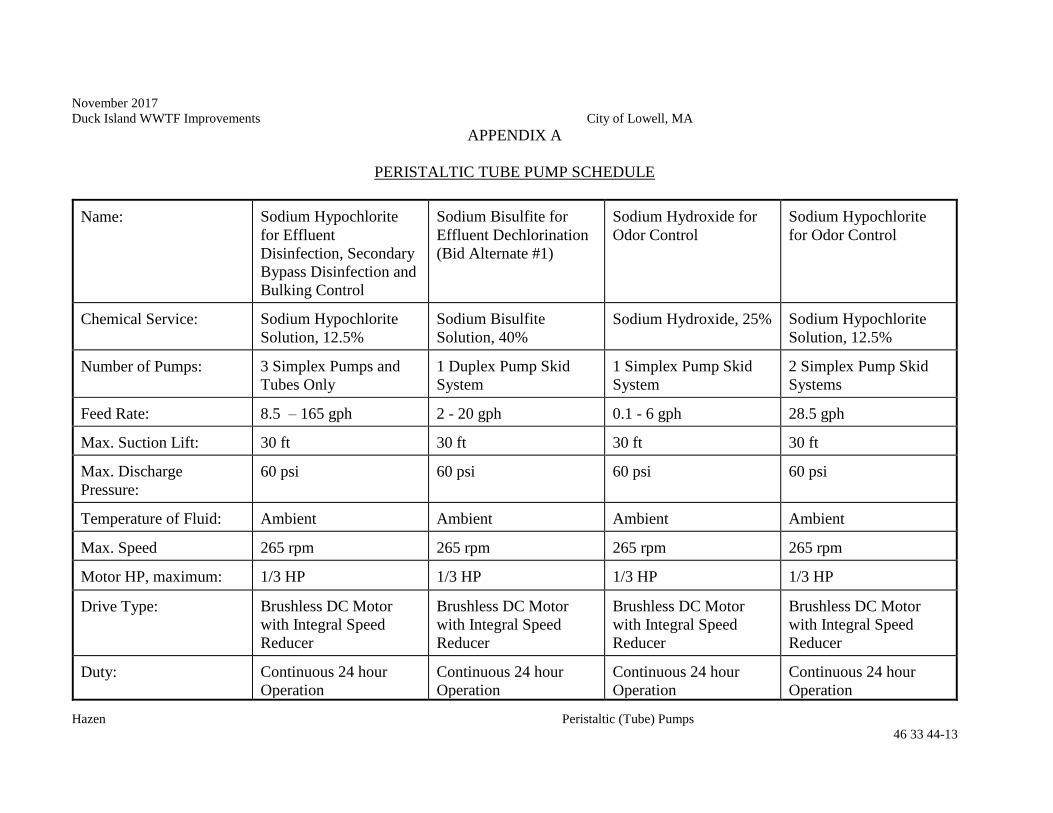
November 2017
Duck Island WWTF Improvements City of Lowell, MA
Hazen Peristaltic (Tube) Pumps
46 33 44-13
APPENDIX A
PERISTALTIC TUBE PUMP SCHEDULE
Name: Sodium Hypochlorite
for Effluent
Disinfection, Secondary
Bypass Disinfection and
Bulking Control
Sodium Bisulfite for
Effluent Dechlorination
(Bid Alternate #1)
Sodium Hydroxide for
Odor Control
Sodium Hypochlorite
for Odor Control
Chemical Service: Sodium Hypochlorite
Solution, 12.5%
Sodium Bisulfite
Solution, 40%
Sodium Hydroxide, 25% Sodium Hypochlorite
Solution, 12.5%
Number of Pumps: 3 Simplex Pumps and
Tubes Only
1 Duplex Pump Skid
System
1 Simplex Pump Skid
System
2 Simplex Pump Skid
Systems
Feed Rate: 8.5 – 165 gph 2 - 20 gph 0.1 - 6 gph 28.5 gph
Max. Suction Lift: 30 ft 30 ft 30 ft 30 ft
Max. Discharge
Pressure:
60 psi 60 psi 60 psi 60 psi
Temperature of Fluid: Ambient Ambient Ambient Ambient
Max. Speed 265 rpm 265 rpm 265 rpm 265 rpm
Motor HP, maximum: 1/3 HP
1/3 HP
1/3 HP
1/3 HP
Drive Type: Brushless DC Motor
with Integral Speed
Reducer
Brushless DC Motor
with Integral Speed
Reducer
Brushless DC Motor
with Integral Speed
Reducer
Brushless DC Motor
with Integral Speed
Reducer
Duty: Continuous 24 hour
Operation
Continuous 24 hour
Operation
Continuous 24 hour
Operation
Continuous 24 hour
Operation

November 2017
Duck Island WWTF Improvements City of Lowell, MA
Hazen Peristaltic (Tube) Pumps
46 33 44-14
--THIS PAGE INTENTIONALLY LEFT BLANK--


