Embed Size (px)
Citation preview
CH
UP
ENAB(A Joint
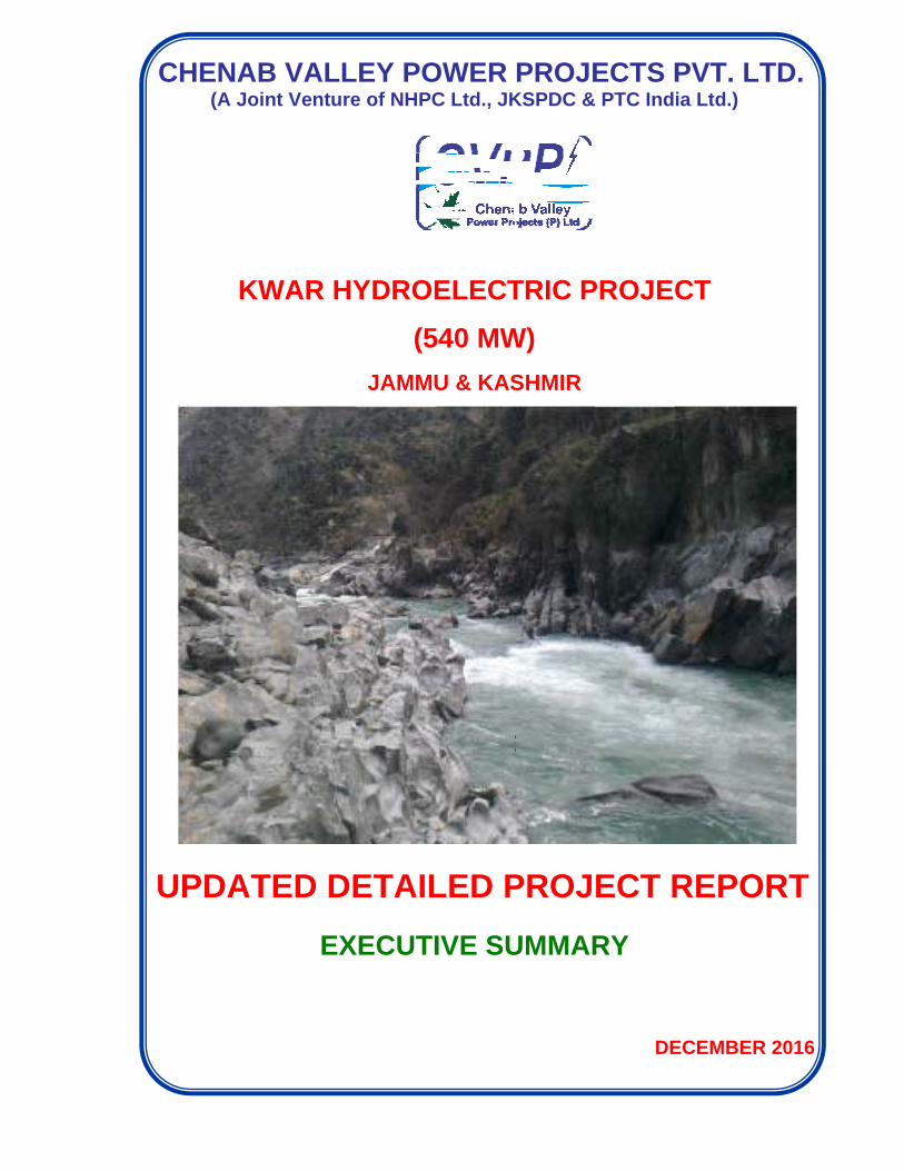
KW
PDATE
VALLt Venture
WAR HY
DETA
ED DE
EX
EY POe of NHPC
YDROE
(5
JAMMU
AILED P
ETAIL
XECUTI
OWER C Ltd., JK
ELECT
540 MW
U & KAS
PROJEC
LED P
IVE SU
PROJEKSPDC &
TRIC P
W)
SHMIR
CT REP
PROJ
UMMAR
ECTS & PTC Ind
PROJE
ORT
ECT R
RY
DE
PVT. Lia Ltd.)
CT
REPO
ECEMBER
LTD.
ORT
R 2016
Kwar Hydroelectric Project (540 MW) Detailed Project Report
Copyright © 2015 CVPP
“ALL RIGHTS RESERVED. The contents of this Detailed
Project Report are exclusive property of CVPP being
protected under Copyright Laws. Any unauthorized reprint or
use of this material is prohibited. None of the contents in full
or part can be reproduced, transmitted, translated, adapted in
any form or by any means including photocopying, recording
or by any information storage or retrieval system without prior
written permission of Competent Authority of CVPP.”
The
five
V
V
V
V
V
Volu
summ
stud
mech
envir
Volu
mate
facil
Volu
Volu
Volu
In ad
Field
Deta
Cent
neces
for t
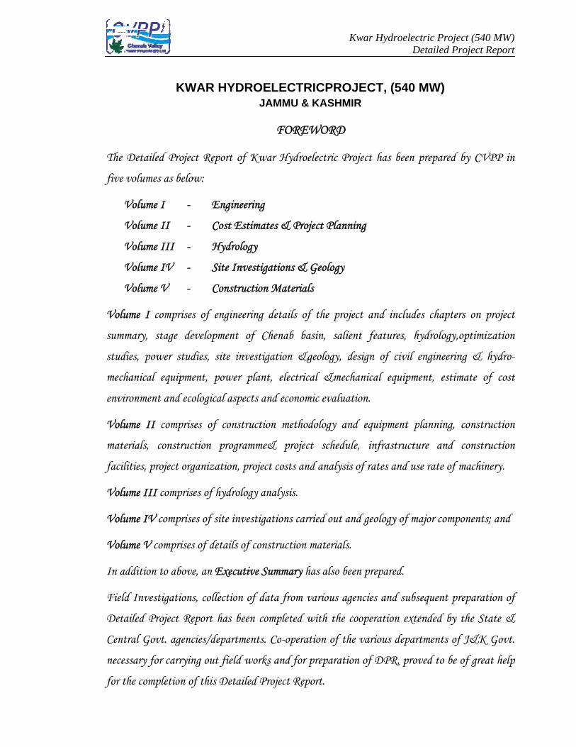
Detailed Pr
volumes as
Volume I
Volume II
Volume III
Volume IV
Volume V
ume I comp
mary, stage
dies, power
hanical equi
ronment and
ume II com
erials, cons
lities, project
ume III comp
ume IV comp
ume V compr
ddition to a
ld Investigat
ailed Project
tral Govt. ag
ssary for car
the completio
KWAR HY
roject Repor
below:
- Eng
- Cos
- Hyd
- Site
- Con
prises of eng
e developme
studies, site
ipment, pow
d ecological
mprises of co
truction pr
t organizatio
mprises of hyd
prises of site
rises of deta
bove, an Ex
tions, collect
t Report ha
gencies/depa
rrying out fi
on of this D
YDROELJAM
F
rt of Kwar
gineering
st Estimates
drology
e Investigati
nstruction M
gineering de
ent of Che
e investigat
wer plant,
aspects and
onstruction
rogramme&
on, project c
drology anal
e investigati
ails of constr
xecutive Sum
tion of data
as been comp
artments. Co
field works a
Detailed Proj
LECTRICPMMU & KAS
FOREWO
Hydroelectr
s & Project P
ions & Geol
Materials
etails of the
nab basin,
tion &geolo
electrical &
d economic ev
methodolog
project sc
costs and an
lysis.
ions carried o
ruction mate
mmary has al
a from vario
pleted with
o-operation
and for prepa
ject Report.
Kwar H
PROJECTSHMIR
RD
ric Project h
Planning
logy
e project an
salient fea
ogy, design
&mechanical
valuation.
gy and equi
chedule, inf
nalysis of rat
out and geol
erials.
lso been prep
ous agencies
the coopera
of the vario
aration of D
HydroelectriDeta
T, (540 MW
has been pre
d includes c
atures, hydr
of civil eng
l equipment
ipment plan
frastructure
tes and use r
logy of majo
pared.
and subsequ
ation extend
ous departm
DPR, proved
c Project (54ailed Project
W)
epared by C
chapters on
drology,optim
gineering &
t, estimate
nning, const
and cons
rate of mach
or componen
uent prepara
ded by the S
ments of J&K
d to be of gr
40 MW) t Report
CVPP in
n project
mization
& hydro-
of cost
truction
truction
hinery.
nts; and
ration of
State &
K Govt.
reat help
Kwar Hydroelectric Project (540 MW) Detailed Project Report
Executive Summary
i
EXECUTIVE SUMMARY
TABLE OF CONTENTS
CHAPTER - 1 PROJECT SUMMARY
1.0 Introduction
1.1 Power Position – Present and Future
1.2 The Need
1.3 Chenab Basin
1.3.1 Hydroelectric Potential of Chenab Basin
1.4 The Project
1.4.1 Background
1.4.2 Topography & Physiography
1.4.3 Drainage
1.4.4 Hydrology
1.4.5 Geology & Seismicity
1.4.6 Dam and Reservoir
1.4.7 River Diversion Arrangement
1.4.8 Water Conductor System
1.4.9 Power House Complex
1.5 Power Generation
1.6 Cost Estimate & Financial Forecast
1.7 Time Schedule
CHAPTER - 2 SALIENT FEATURES
CHAPTER - 3 ESTIMATE OF COST
3.0 Introduction
3.1 Basis for Estimate
3.2 Cash Flow Statement
3.3 Abstract of Cost
Kwar Hydroelectric Project (540 MW) Detailed Project Report
Executive Summary
ii
CHAPTER - 4 HYDROLOGY
4.1 General
4.2 River System and Basin Characteristics
4.3 Water Availability Study
4.4 Reservoir Elevation Area Capacity curve
4.5 Rating Curve
4.6 Design Flood
4.7 Glacial Lake Outburst Flood
4.8 Diversion Flood
4.9 Reservoir Sedimentation
4.10 Analysis of Transient Condition of Upstream & Downstream
Waterway
CHAPTER-5 GEOLOGY
5.0 Introduction
5.1 Field Investigation
5.2 Regional Geology
5.3 Geological & Geotechnical Appraisal of Project Components
5.3.1 Dam
5.3.2 Plunge Pool Area
5.3.3 Diversion Tunnel
5.3.4 Water Conducting System
5.3.5 Power House Complex
5.3.6 Tail Race Tunnel
5.4 Reservoir
5.5 Seismicity
5.6 Construction Material
CHAPTER- 6 POWER STUDIES
6.1
6.1.1
Power Supply Demand
On All India Basis
Kwar Hydroelectric Project (540 MW) Detailed Project Report
Executive Summary
iii
6.1.2
6.1.3
On Regional Basis
Justification for the Project
6.2
6.3
6.4
6.5
Scheme for Wheeling Evacuating Power
Available Generating Capacity in Region
Future Energy Requirement in Region
Power Supply Position With & Without Project
CHAPTER- 7 OPTIMISATION STUDIES
7.0 Introduction
7.1 Available Inflow
7.2 90% Dependable Year and Net Head
7.3 Installed Capacity
7.4 Annual Energy Generation in 90% Dependable Year
CHAPTER– 8
DESIGN OF CIVIL ENGINEERING STRUCTURES AND
HYDROMECHANICAL EQUIPMENTS
8.1 Introduction
8.2
8.2.1
8.2.2
8.2.3
8.3
8.3.1
8.3.2
8.3.3
8.3.4
8.3.5
Layout Optimization
Introduction
Review of the Project
Conclusion
Indus Water Treaty
Pondage
Minimum Drawdown Level
Power Intake Level
Spillway Crest Level
Free Board
8.4 River Diversion Works
8.4.1 Diversion Tunnel
8.4.2 Coffer Dams
8.5 The Dam
Kwar Hydroelectric Project (540 MW) Detailed Project Report
Executive Summary
iv
8.5.1 General
8.5.2 Dam Height
8.5.3 Type of Dam
8.5.4 Dam Arrangement
8.5.5 Reservoir
8.5.6 Spillway
8.5.7 Outlet for Environmental Releases
8.5.8 Construction Sluices
8.5.9 Non Overflow Section
8.5.10 Stability Analysis
8.5.11 Energy Dissipation Arrangement
8.5.12 Dam Instrumentation
8.6 Power Dam and Intake
8.7 Pressure Shafts and Penstocks
8.8 Power House
8.8.1 General
8.8.2 Layout of Power House Complex
8.8.3 Power House Cavern
8.8.4 Control Room Cavern
8.8.5 Transformer cum Draft Tube Gate Cavern
8.8.6 GIS Cavern
8.8.7 Access Tunnel to Power House and Transformer Cavern
8.8.8 Adit cum Cable Tunnel
8.8.9 Down Stream Surge Arrangement
8.8.10 Outdoor Pothead Yard
8.9 Tail Race Tunnel
8.10 Tailrace Outlet Works
8.11 Hydro – Mechanical Equipment
8.11.1 General
8.11.2 Diversion Tunnel Gates and Hoists
8.11.3 Construction Sluice Gates and Hydraulic Hoists
Kwar Hydroelectric Project (540 MW) Detailed Project Report
Executive Summary
v
8.11.4 Orifice type Spillway Radial Gates, Hydraulic Hoists
8.11.5 Crest type Spillway, Radial Gates & Hydraulic Hoists
8.11.6 Spillway Stoplogs & Gantry Crane
8.11.7 Environment Release Gate and Hoist
8.11.8 Power Intake Gates, Hoists, Intake Bulkhead gate and Gantry crane, Trash Rack & Trash Rack Cleaning Machine
8.11.9 Penstock Steel Liner
8.11.10 Draft Tube Gates and Hoists
8.11.11 TRT Outlet Gates and Rope Drum Hoists.
8.11.12 Instrumentation and Automatic Reservoir Monitoring and Control System
8.11.13 Diesel Generator Set
PLATES PROJECT DRAWINGS
CHAPTER– 9 POWER PLANT, ELECTRICAL & MECHANICAL EQUIPMENT
9.0 Introduction
9.1 Mechanical Equipments
9.1.1 Turbines
9.1.2 Main Inlet Valve
9.1.3 Governor
9.1.4 Power House EOT Cranes
9.1.5 GIS Crane
9.1.6 Transformer Uploading Crane
9.1.7 Auxiliary Systems of The Power Station
9.1.7.a Cooling Water System
9.1.7.b Fire Protection System
9.1.7.c Drainage and Dewatering System
9.1.7.d Heating, Ventilating and Air Conditioning System
9.1.7.e Oil Handling System
9.1.7.f Station Compressed Air System
9.1.7.g Potable Water and Sanitary Services
Kwar Hydroelectric Project (540 MW) Detailed Project Report
Executive Summary
vi
9.1.7.h Public Address and Surveillance System
9.1.7.i Elevator
9.1.7.j Workshop
9.1.7.k Testing Equipment
9.2 Electrical Equipments
9.2.1 Generators
9.2.2 Static Excitation System
9.2.3 Bus Duct
9.2.4 Generator Step UP Transformers
9.2.5 Control, Monitoring and Protection System
9.2.6 Auxiliary Power Requirements
9.2.7 11 KV Switchgear
9.2.8 D.C. Supply System
9.2.9 Illumination System
9.2.10 Equipment Grounding
9.2.11 Gas Insulated Switchgear (GIS)
9.2.12
9.2.13
Bus Reactor
400 KV XLPE Cable
9.2.14 400 KV Outdoor Pothead Yard
9.2.15 Power Line Carrier Communication Equipment (PLCC)
9.2.16 Power Evacuation System
CHAPTER-10 ECONOMIC EVALUATION
10.0 General
10.1 Energy Contribution From The Project
10.2 Project Cost
10.3 Fixed And Running Charges
10.3.1 Interest Rate
10.3.2 Return On Equity
10.3.3 Depreciation
10.3.4 Operation And Maintenance Charges
Kwar Hydroelectric Project (540 MW) Detailed Project Report
Executive Summary
vii
10.4 Unit Cost Of Energy
CHAPTER-11 CONSTRUCTION METHODOLOGY & EQUIPMENT PLANNING
11.0 General
11.1 Diversion Tunnel
11.2 Coffer Dam
11.3 Concrete Gravity Dam
11.4 Intake Structures
11.5 Pressure Shaft
11.6 Power House
11.7 Transformer Cavern, GIS Cavern & DT Gate Hall
11.8 Tail Race Tunnel
11.9 GIS & Pot Head Yard
Annexure – I List of Equipment for Infrastructural Development
Annexure – II Equipment List for Construction Stage
Annexure – III Construction Programme and Project Schedule
CHAPTER-12 ENVIRONMENT AND ECOLOGICAL ASPECTS
APPENDIX – A Letters of clearances of DPR aspects by various
Divisions / Directorates of CEA/CWC, GSI, etc.
Kwar Hydroelectric Project (540 MW) Detailed Project Report
Executive Summary
viii
APPENDIX – A – INDEX
Sr. No.
Aspect Directorate/ Division/ Dept.
Date of Clearance
1 Inter State Aspects PA(N), CWC 31.10.2012 2 Hydrology - Water Series Hydrology(N), CWC 27.06.2013 3 Instrumentation Aspects Instrumentation
Dte., CWC 24.10.2013
4 Hydrology - Design Flood & Diversion Flood Hydrology(N), CWC 01.11.2013 5 Glacial Lake Outburst Flood FE&SA, CWC 06.02.2014 6 Power Potential Studies HPA, CEA 16.12.2014 7 Power Evacuation Aspects SP&PA, CEA 05.01.2015
16.03.2015 8 Geological Aspects GSI 15.06.2015
17.10.2016 9 Annual Energy Generation HPA, CEA 22.01.2016
10 E&M – Design Aspects & BOQ HE&TD, CEA 29.01.2016 25.05.2016
11 Construction Power Aspects HPA, CEA 09.02.2016 12 Pondage Aspects (IWT Angle) HPP&I, CEA 10.02.2016 13 Foundation Engineering & Seismic Aspects FE&SA, CWC 30.03.2016 14 Site Specific Design Earthquake Parameters NCSDP / FE&SA,
CWC 07.10.2016
15 Legal Aspects
Legal Div, CEA 10.10.2016
16 Construction Material & Geotechnical Aspects CSMRS, MoWR 19.10.2016 17 Hydel Civil Design Aspects HCD, CWC 19.10.2016 18 Dam Design Aspects CMDD, CWC 20.10.2016 19 Gates Design Aspects /HM Gates & Design
(N&W) CWC 24.10.2016
20 Plant Planning/ Construction Machinery Aspects CMC, CWC 27.10.2016 21 Cost Estimate of E&M Works HPA-I, CEA 27.10.2016 22 Cost Estimate of Civil & HM Works CA(HWF), CWC 31.10.2016 23 Quantities of Civil & HM Works TCD, CEA 31.10.2016 24 Construction Schedule and Phasing of Civil & HM
Cost TCD, CEA 10.11.2016
11.11.2016 25 Phasing of Total Hard Cost HPA-I, CEA 11.11.2016 26 Financial & Commercial Aspects F&CA, CEA 15.11.2016
Kwar Hydroelectric Project (540 MW) Detailed Project Report
Executive Summary
CHAPTER –1
PROJECT SUMMARY
Kwar Hydroelectric Project (540 MW) Detailed Project Report Executive Summary
1 -1
CHAPTER – 1
PROJECT SUMMARY
1.0 INTRODUCTION
Kwar H.E. Project is one of the four projects on river Chenab in Distt. Kishtwar,
J&K entrusted to NHPC for detailed investigation and preparation of DPRs by
Central Electricity Authority (CEA) in August, 2004. These projects have been
included in the ranking studies done by CEA and pre-feasibility reports (PFR)
have been prepared by WAPCOS under 50,000 MW hydro initiative by the
Hon’ble Prime Minister.
After detailed discussion during various meetings under CEA and Ministry of
Power (MOP), Govt. of India it was decided that low tariff hydroelectric schemes
should be taken up for detailed investigation and preparation of DPRs. CEA had
classified the schemes into A-1, A-2 and A-3 categories. The classification of
schemes are based on decision taken during the meeting held by Secretary
(Power) on 23.03.2004 as under.
Scheme to be directly taken up for implementation in central sector-“A-1”
Category.
Schemes for which PFR have been prepared by those agencies which are
also involved in execution of the projects (e.g. NHPC, NEEPCO etc.). Such
agencies could be offered projects for making DPRs- “A-2” Category.
The projects for which PFRs have been prepared by those consultants who
are not involved in implementation of the projects (e.g. WAPCOS). The
preparation of DPRs of such projects can be offered to other agencies –“A-3”
Categories.
Kwar H. E. Project has been given to NHPC under “A-2” category.
As per pre-feasibility report prepared by WAPCOS , Kwar H.E. Project, a run-of-
river scheme located in Tehsil Kishtwar, Distt. Kishtwar (erstwhile Doda district)
Kwar Hydroelectric Project (540 MW) Detailed Project Report Executive Summary
1 -2
of J&K envisages construction of a concrete gravity dam 68 m high across river
Chenab at village Kandni, a 4.3 Km long HRT of 12.0 m dia., one no surge shaft
of 25 m dia, four no. pressure shafts 90 m long & 5.4 m dia, a surface
powerhouse at right bank of river Chenab near village Kwar to accommodate 4
units of 80.00MW each and a tail race channel of 75 m length of size 12.0m for
discharging the water back into the river course.
The stage-I clearance of the project was obtained from Ministry of Environment
& Forest (MOEF), Govt. of India by NHPC in the month of March, 2005 as per
layout decided by WAPCOS. However when detailed survey and investigation
works were taken up by NHPC, it was found that layout of the project needed
some modifications based on ground survey as well as feasibility of the project.
Subsequently request has been made by NHPC during December, 2005 for
stage-II clearance from MOEF.
Features of the project have been slightly modified vis-a-vis proposal of
WAPCOS. Dam location has been shifted downstream, power house was also
brought adjacent to dam site and dam height (from deepest foundation) has
been increased from 68m to 109m, surface powerhouse has been changed to
underground powerhouse.
1.1 POWER POSITION – PRESENT AND FUTURE
Power is a critical infrastructure for economic development and improving quality
of life. Since independence power generation has taken great strides and
increased almost 200 times from a mere 1362 MW in 1947 to 2,78,733MW as on
Sep’2015. The demand for power has primarily been fuelled by the fast track
industrialization and growing commercial use of energy. But despite outstanding
achievements in terms of capacity addition, the supply has not been able to keep
pace with the demand. The major concern for Indian economy is to cope up with
the increasing power demand vis-à-vis supply. Apart from this (energy & peak
shortage), issues like adverse hydro: thermal mix, grid instability, frequency
fluctuation etc. are other major concerns affecting the power sector of the
country.
Kwar Hydroelectric Project (540 MW) Detailed Project Report Executive Summary
1 -3
Hydro share percentage in the total installed capacity which peaked to 50.62%
during 1963 stands only at about 15.2% presently. Considering the fact that
hydro-power is renewable, pollution free, environment friendly, has decreasing
trend in tariff and inherits several technical advantages, it becomes the most
sought after alternative form of power and energy security for the future.
As per the estimate by CEA, hydro-power-potential has been assessed during
the period 1978-87 as 84044 MW at 60% load factor corresponding to about
1,50,000 MW of installed capacity. Against this, only 41,997 MW of hydro
potential has been developed till Aug’2015. Out of the total assessed hydro-
power potential, Chenab basin contributes 5932 MW at 60% load factor.
Recognizing the importance of hydro-power, Govt. of India has taken several
initiatives over last decade or so for accelerated development of hydro-power.
These include Hydro Policy of 1998, Ranking Studies by CEA, three stage
clearances for hydro projects, 50000 MW hydro initiative, preparation of DPRs of
low tariff hydro power stations etc.
1.2 THE NEED
Over the years demand for power has outpaced its supply which has become a
major concern for the Indian economy. Energy and peak demand shortages in
the country during 2014-15 (Sep’ 2015) stand at 3.2% and 3.2% respectively.
Another important concern is the excessive dependence on conventional
resources for power generation. Out of total installed capacity of 278733 MW,
194199 MW (70%) is being contributed from thermal sources, 42283MW
(15.2%) from hydro- power, 5780MW (2.1%) from nuclear sources and 36470
MW (13%) from renewable sources. Thus there is less percentage of hydro-
power in the system than the optimal level (40%).
In view of inadequate power supply position, other technical constraints arising
out of excessive dependence on thermal power and multiple techno-economical-
Kwar Hydroelectric Project (540 MW) Detailed Project Report Executive Summary
1 -4
environmental superiority offered by hydro-power, it makes perfect case for
capacity addition of hydro-power through its accelerated development.
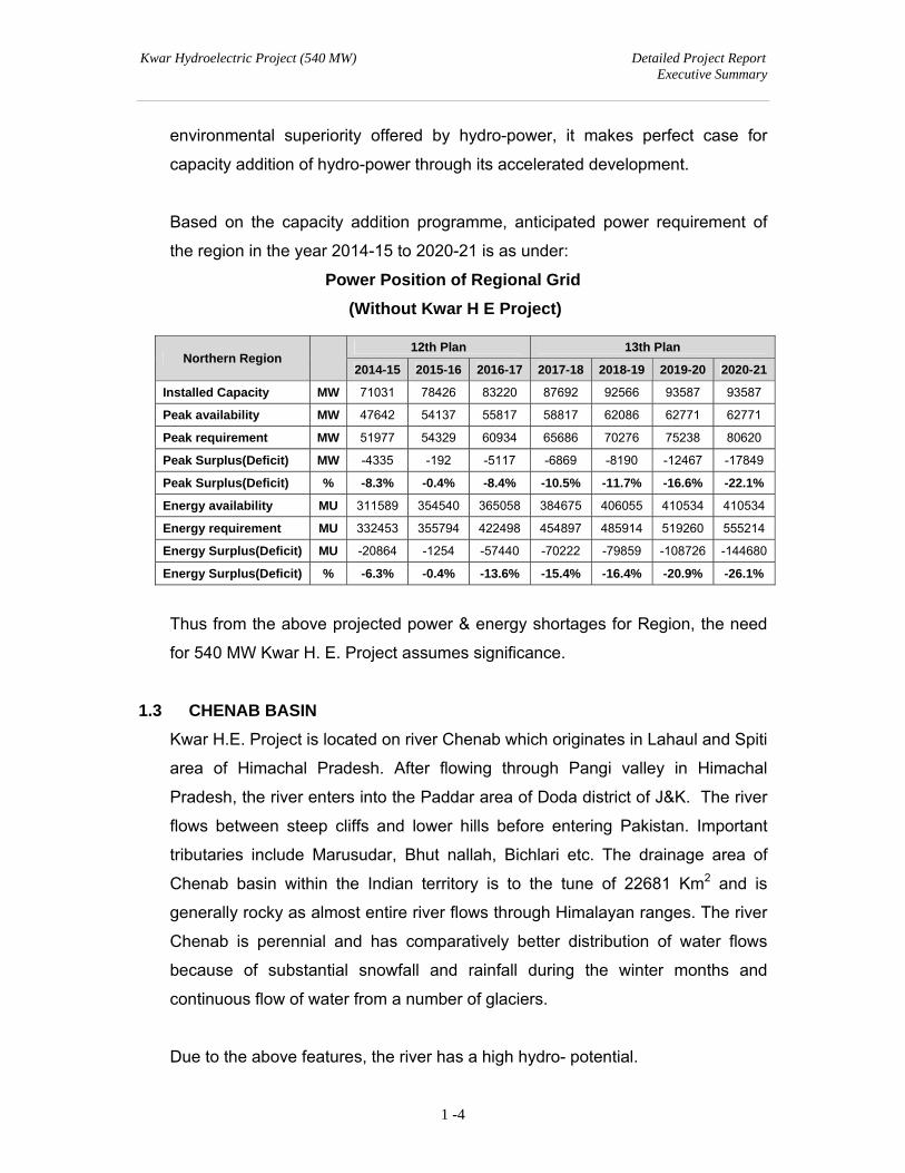
Based on the capacity addition programme, anticipated power requirement of
the region in the year 2014-15 to 2020-21 is as under:
Power Position of Regional Grid
(Without Kwar H E Project)
Thus from the above projected power & energy shortages for Region, the need
for 540 MW Kwar H. E. Project assumes significance.
1.3 CHENAB BASIN
Kwar H.E. Project is located on river Chenab which originates in Lahaul and Spiti
area of Himachal Pradesh. After flowing through Pangi valley in Himachal
Pradesh, the river enters into the Paddar area of Doda district of J&K. The river
flows between steep cliffs and lower hills before entering Pakistan. Important
tributaries include Marusudar, Bhut nallah, Bichlari etc. The drainage area of
Chenab basin within the Indian territory is to the tune of 22681 Km2 and is
generally rocky as almost entire river flows through Himalayan ranges. The river
Chenab is perennial and has comparatively better distribution of water flows
because of substantial snowfall and rainfall during the winter months and
continuous flow of water from a number of glaciers.
Due to the above features, the river has a high hydro- potential.
Northern Region 12th Plan 13th Plan
2014-15 2015-16 2016-17 2017-18 2018-19 2019-20 2020-21
Installed Capacity MW 71031 78426 83220 87692 92566 93587 93587
Peak availability MW 47642 54137 55817 58817 62086 62771 62771
Peak requirement MW 51977 54329 60934 65686 70276 75238 80620
Peak Surplus(Deficit) MW -4335 -192 -5117 -6869 -8190 -12467 -17849
Peak Surplus(Deficit) % -8.3% -0.4% -8.4% -10.5% -11.7% -16.6% -22.1%
Energy availability MU 311589 354540 365058 384675 406055 410534 410534
Energy requirement MU 332453 355794 422498 454897 485914 519260 555214
Energy Surplus(Deficit) MU -20864 -1254 -57440 -70222 -79859 -108726 -144680
Energy Surplus(Deficit) % -6.3% -0.4% -13.6% -15.4% -16.4% -20.9% -26.1%
Kwar Hydroelectric Project (540 MW) Detailed Project Report Executive Summary
1 -5
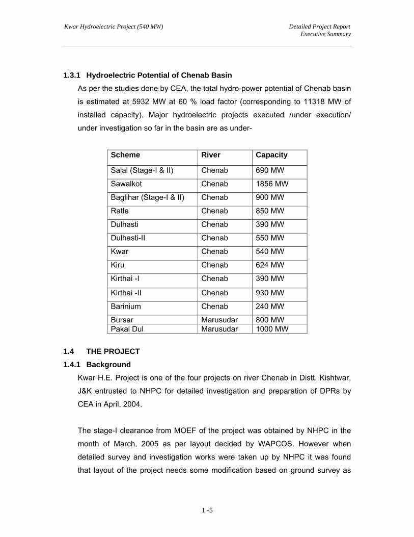
1.3.1 Hydroelectric Potential of Chenab Basin
As per the studies done by CEA, the total hydro-power potential of Chenab basin
is estimated at 5932 MW at 60 % load factor (corresponding to 11318 MW of
installed capacity). Major hydroelectric projects executed /under execution/
under investigation so far in the basin are as under-
Scheme River Capacity
Salal (Stage-I & II) Chenab 690 MW
Sawalkot Chenab 1856 MW
Baglihar (Stage-I & II) Chenab 900 MW
Ratle Chenab 850 MW
Dulhasti Chenab 390 MW
Dulhasti-II Chenab 550 MW
Kwar Chenab 540 MW
Kiru Chenab 624 MW
Kirthai -I Chenab 390 MW
Kirthai -II Chenab 930 MW
Barinium Chenab 240 MW
Bursar Marusudar 800 MW Pakal Dul Marusudar 1000 MW
1.4 THE PROJECT
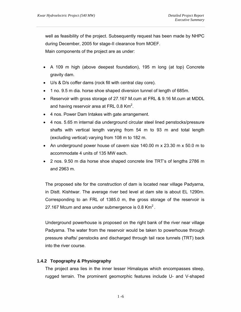
1.4.1 Background
Kwar H.E. Project is one of the four projects on river Chenab in Distt. Kishtwar,
J&K entrusted to NHPC for detailed investigation and preparation of DPRs by
CEA in April, 2004.
The stage-I clearance from MOEF of the project was obtained by NHPC in the
month of March, 2005 as per layout decided by WAPCOS. However when
detailed survey and investigation works were taken up by NHPC it was found
that layout of the project needs some modification based on ground survey as
Kwar Hydroelectric Project (540 MW) Detailed Project Report Executive Summary
1 -6
well as feasibility of the project. Subsequently request has been made by NHPC
during December, 2005 for stage-II clearance from MOEF.
Main components of the project are as under:
A 109 m high (above deepest foundation), 195 m long (at top) Concrete
gravity dam.
U/s & D/s coffer dams (rock fill with central clay core).
1 no. 9.5 m dia. horse shoe shaped diversion tunnel of length of 685m.
Reservoir with gross storage of 27.167 M.cum at FRL & 9.16 M.cum at MDDL
and having reservoir area at FRL 0.8 Km2.
4 nos. Power Dam Intakes with gate arrangement.
4 nos. 5.65 m internal dia underground circular steel lined penstocks/pressure
shafts with vertical length varying from 54 m to 93 m and total length
(excluding vertical) varying from 108 m to 182 m.
An underground power house of cavern size 140.00 m x 23.30 m x 50.0 m to
accommodate 4 units of 135 MW each.
2 nos. 9.50 m dia horse shoe shaped concrete line TRT’s of lengths 2786 m
and 2963 m.
The proposed site for the construction of dam is located near village Padyarna,
in Distt. Kishtwar. The average river bed level at dam site is about EL 1290m.
Corresponding to an FRL of 1385.0 m, the gross storage of the reservoir is
27.167 Mcum and area under submergence is 0.8 Km2 .
Underground powerhouse is proposed on the right bank of the river near village
Padyarna. The water from the reservoir would be taken to powerhouse through
pressure shafts/ penstocks and discharged through tail race tunnels (TRT) back
into the river course.
1.4.2 Topography & Physiography
The project area lies in the inner lesser Himalayas which encompasses steep,
rugged terrain. The prominent geomorphic features include U- and V-shaped
Kwar Hydroelectric Project (540 MW) Detailed Project Report Executive Summary
1 -7
valleys, interlocking spurs, ridges, saddles and river terraces. The narrow
valleys bounded by high ridges open out in their upper glacial parts. Slopes are
very steep due to which the rockfall occurs at certain points often under the
effect of gravity. The altitude of the area varies from about 1250m to very high
mountains. There are plentiful of grazing lands on the upper reaches of high
mountains. A number of meadows and pastures on the uplands are well known.
The vegetation is dominated with conifers. The local/ Gujjar population have
extended their settlements in forests at high reaches.
Rocks are strongly folded at certain places and are mainly composed of granite,
gneiss, schist, quartzite and phyllite. Some hot springs along river course have
been observed in the area from where the water is emerging from the earth in its
natural form.
1.4.3 Drainage
The river Chenab enters Kishtwar at Sansari in Paddar area of J&K from
Himachal Pradesh. It is joined by major tributary Bhut nallah at Arthal (EL 1785
m). Subsequently it is joined by the largest tributary Marusudar river at
Bhandarkot (EL 1100 m). Further down the river is joined by its tributaries
Bichlari and Ans river on its right. From its origin in Baralacha pass in Lahul Spiti
(Himachal Pradesh) to Akhnoor (Jammu), the river traverses about 585 Kms and
drops by 5340 m. The local area drained by the river up to international border
with Pakistan is 22681km2 out of which 4662 Sqm are under glaciers.
1.4.4 Hydrology
The catchment area of river Chenab up to dam site of the project is estimated as
10325 km2. It lies between Latitude 320 06'N to 330 39’ N and Longitude 750 55'
E to 770 48' E. Average annual rain fall is 838 mm at Benzwar/1000 mm for the
entire basin.
1.4.5 Geology and Seismicity
Geologically the project area lies within inner lesser Himalayan belt under
Kishtwar group of rocks. All the project components viz. dam & powerhouse are
Kwar Hydroelectric Project (540 MW) Detailed Project Report Executive Summary
1 -8
housed in competent gneissose granite except tail race tunnel and part of
diversion tunnel, which lies in incompetent phyllite rocks.
The proposed concrete gravity dam (109 m above deepest foundation level) is
placed in the ‘U’ shaped valley where the dam foundation and abutments shall
be on strong granites. Interestingly, the bedrock is exposed along the river
channel at dam site at many places which indicate very shallow overburden
depth in the active river channel section.
Some open valley dipping joints are observed on the right bank at upper level
drifts. Based on the drift logs stripping limit varying from 3.51m to 13.25m is
proposed for right abutment to abut the dam with sound & fresh rock. Apart from
this adequate grouting shall also be required considering shearing and
fracturization of rockmass as observed in the drifts. However, shear
seams/zones would be suitably treated with dental excavation/treatment and
duly backfilled with richer grade of concrete during actual excavation of dam
foundation and abutment.
Based on the drift logs and some engineering considerations, the stripping limit
varying from 2.30m to 25.96m is proposed for left abutment to abut the dam with
sound & fresh rock. The permeability values in the bedrock vary from 4 to 26
Lugeon. This necessitates provision of adequate grouting to minimize seepage
path below dam foundation.
The water conductor system comprises 4 nos. pressure shafts/penstocks to feed
powerhouse. All the structure viz. Intake, Pressure shaft etc, shall be housed in
competent granites. However, in case of intake structure some stripping due to
open joints may be required to abut the structure in sound rock.
Considering all geotechnical characteristics of rock mass, the pressure shaft is
anticipated to negotiate through Class-I 10%, Class-II 50%, Class-III 30%, &
Class-IV 10% as per RMR classification.
Kwar Hydroelectric Project (540 MW) Detailed Project Report Executive Summary
1 -9
The underground powerhouse complex having installed capacity of 540MW
consist 140m x 23.3m x 50m machine hall and 116m x 17m x 16m transformer
hall caverns, connecting through bus bar gallery etc. An underground power
house is proposed on right bank in a sub vertical rocky cliff.
Though, dry to moist conditions are observed in exploratory drifts on right bank,
but deeper inside possibility of seepage in powerhouse is anticipated due to well
jointed nature of rock and surface charging from nearby nalas through open
joints. Thus, provision of suitable mitigation measures are foreseen to control
seepage into the machine hall.
The powerhouse cavern, in general, shall be in good to fair class of rock with
random pockets of poor rock.
The twin tunnels are anticipated to be mainly in phyllitic rocks (around 90%)
however quartzitic bands within phyllite-quartzite sequence and intrusive granitic
rocks may appear in the initial part from PH side. An old slide scar has been
observed on right bank near the TRT outlet and slide material is lying at the river
bed following the rock profile. As such broad estimation regarding the tunneling
media has been made and the same has been classified as 50% in class III –
Fair rock, 30% class IV – Poor rock and 20% class V – Very poor rock.
Considering the difficulties during excavation at various structures, adequate
provisions of rock supports has been kept in the cost estimate.
This dam shall create a 6.7 km long reservoir up to outlet of TRT of Kiru Project.
The full reservoir level (FRL) has been proposed at EL 1385M having 0.8 sq km
area. Right bank of the river is almost rocky (80% touching rock) whereas left
bank shall be touching partly overburden (50%) and partly rock outcrops (50%).
Major part of the reservoir rim shall be in contact with bedrock comprising of
gneissose granite and phyllite-quartzite sequence. The topography & river
course is generally found structurally controlled. Overall, the reservoir rim
appears to be safe from geo-environmental consideration (except some part of
Kwar Hydroelectric Project (540 MW) Detailed Project Report Executive Summary
1 -10
rim on left bank near village Galhar) with no possibility of reservoir leakage. No
economic mineral within reservoir periphery has been reported till date.
The project area falls in Zone-IV of Seismic Zoning map of India which
corresponds to high seismically active area. Site Specific Design Earthquake
Parameters study has been carried out by DEQ, IIT Roorkee, 2007. The PGA
value recommended for MCE & DBE was 0.31g and 0.16g respectively based
on above study. Further, Department has also suggested αh=0.17 and αv=0.11.
However, updated and modified report on Site Specific Design Earthquake
Parameters study has been carried out by DEQ, IIT Roorkee, 2016 and the
recommended PGA values for the MCE and DBE conditions are estimated as
0.50g and 0.28g for horizontal component and 0.33g & 0.19g for vertical
component. The recommended values for αh=0.16 and αv=0.11.
Dam height being 109m i.e. greater than 100m, MEQ studies were undertaken
within a radius of 50km of the dam site by Wadia Institute of Himalayan Geology
(WIHG) as per NCSDP guidelines.
Accordingly, Six (6) Broad band seismographs were installed for continuous
recording of six months from June 2015-Dec. 2015.
The site specific seismic design parameter study report along with the MEQ
study report was submitted to NCSDP. NCSDP in its 31st meeting held on 23rd
June 2016 approved the response spectra and seismic design parameters of the
project.
1.4.6 Dam and Reservoir
Reservoir will be formed by construction of a 109 m high (from deepest
foundation level) concrete gravity dam. Broad feature of the reservoir shall be as
under-
Dam top EL 1387 M
Full reservoir level EL 1385 M
Kwar Hydroelectric Project (540 MW) Detailed Project Report Executive Summary
1 -11
Gross storage up to FRL 27.167 M cum.
Gross storage at MDDL 9.16 M cum.
Type of Dam Concrete gravity dam.
Deepest Foundation Level El 1278 M
Height of Dam 109 M from deepest foundation level
Length of Dam at top 195 M
1.4.7 River Diversion Arrangement
River diversion arrangement comprises of one number diversion tunnel horse-
shoe shaped of dia 9.5m and length 685m; and the upstream and downstream
coffer dams. The proposed diversion arrangement is designed for a flood
discharge of 1041cumec (return period of 1 in 25 years non-monsoon).
1.4.8 Water Conductor System
4 no. power dam blocks with one intake each have been provided to lead the
water through 4 no, 5.65 m dia underground circular steel lined penstocks to the
Power house and the water shall be discharged back to the river through 2 no
9.5 m dia horse shoe shaped TRTs of lengths 2786 m and 2963 m.
1.4.9 Power House Complex
The underground powerhouse is located on right bank of river Chenab near
village Padyarna. It will have an installed capacity of 540 MW (4 generating units
of 135 MW each). Power House cavern is 140 m x 23.30 m x 50 m and
transformer cavern is 116 m x 17 m x 16 m.
1.5 POWER GENERATION
The power generation and the optimization of Kwar H.E. Project has been made
based on long series of available hydrological data with the objective of
maximum utilization of the available inflow within economical limits. The
observed discharge data for the 90% dependable year have been used as the
Kwar Hydroelectric Project (540 MW) Detailed Project Report Executive Summary
1 -12
basis for carrying out the optimization studies. The project shall generate
1975.54 MU power in 90% dependable year with 95% machine availability.
1.6 COST ESTIMATE AND FINANCIAL FORECAST
The project has been estimated to cost Rs. 4949.24 crores including IDC of
Rs.532.21 crores at April 2016 price level. The unit cost of energy at Bus Bar (Ist
Year), considering return on equity of 16.5% based on generation in 90%
dependable year works out to Rs. 6.21 per unit at April 2016 price level.
The levelised tariff at Present Day Cost at April 2016 price level works out to be
Rs.5.77 per unit considering 12% free power to home state & 1% free power
towards Local Area Development Fund.
1.7 TIME SCHEDULE
The project is proposed to be completed in a period of 54 months after accord of
Government sanction. Infrastructural facilities shall be developed concurrently
with the process of obtaining various govt. clearances.

Kwar Hydroelectric Project (540 MW) Detailed Project Report
Executive Summary
CHAPTER –2
SALIENT FEATURES
Kwar Hydroelectric Project (540 MW) Detailed Project Report Executive Summary
2-1
CHAPTER-2
SALIENT FEATURES
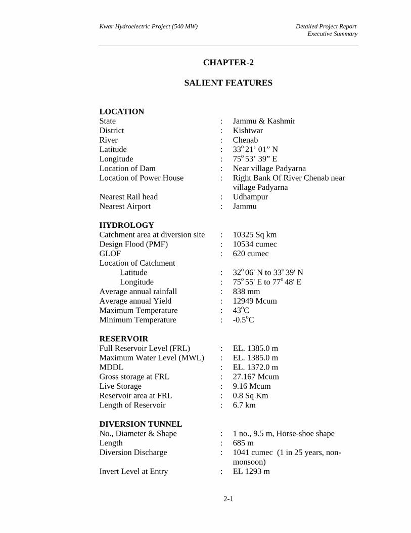
LOCATION State : Jammu & Kashmir District : KishtwarRiver : ChenabLatitude : 33o 21’ 01” N Longitude : 75o 53’ 39” ELocation of Dam : Near village Padyarna Location of Power House : Right Bank Of River Chenab near
village PadyarnaNearest Rail head : Udhampur Nearest Airport : Jammu HYDROLOGY Catchment area at diversion site : 10325 Sq km Design Flood (PMF) : 10534 cumecGLOF : 620 cumecLocation of Catchment Latitude : 32o 06' N to 33o 39' N Longitude : 75o 55' E to 77o 48' E Average annual rainfall : 838 mm Average annual Yield : 12949 McumMaximum Temperature : 43oC Minimum Temperature : -0.5oC RESERVOIR Full Reservoir Level (FRL) : EL. 1385.0 mMaximum Water Level (MWL) : EL. 1385.0 mMDDL : EL. 1372.0 mGross storage at FRL : 27.167 McumLive Storage : 9.16 McumReservoir area at FRL : 0.8 Sq KmLength of Reservoir : 6.7 km DIVERSION TUNNEL No., Diameter & Shape : 1 no., 9.5 m, Horse-shoe shapeLength : 685 mDiversion Discharge : 1041 cumec (1 in 25 years, non-
monsoon)Invert Level at Entry : EL 1293 m

Kwar Hydroelectric Project (540 MW) Detailed Project Report Executive Summary
2-2
Invert Level at Exit : EL 1285 mDiversion Tunnel Gate : 2 Nos. Vertical Lift gate Size of Opening : 2 Nos. 3.94 m x 9.5 m Gate Operating Platform Level : EL. 1336 m COFFER DAMS Type : Rock fill with central clay coreTop of upstream coffer dam : EL 1315.00 mTop of downstream coffer dam : EL 1292.00 m DAM Type : Concrete gravity Dam Dam Top : EL 1387 m FRL : EL 1385 mDam height (above river bed level / deepest foundation level)
: 101 m / 109 m
Length of dam at top : 195 m
SPILLWAY Type : Orifice & Crest type Design Discharge : 10534 cumec
No of bays(Orifice type) No of bays(Crest type)
: : :
4 Nos. of Orifice Spillway of 9.5m x 13.8m at EL. 1330.0m 1 No. of Crest Spillway of 9.5m x 17.0m at EL. 1368.0m.
Width of Orifice spillway block : 64.0 m Width of Crest spillway block : 16.0 m
ENERGY DISSIPATION ARRANGEMENTType : Ski-jump bucket with preformed
plunge pool
OUTLET FOR ENVIRONMENTAL RELEASE Design Discharge i) For lean period (Dec– mar.) ii) For Peak flow period(Jun-Sep) iii) Remaining four months
: : :
16.49 cumec 74.09 cumec 16.79 cumec
Size of Gate : 2.6 m (W) x 2.0 m (H) Crest Level : 1369.90 m
Kwar Hydroelectric Project (540 MW) Detailed Project Report Executive Summary
2-3
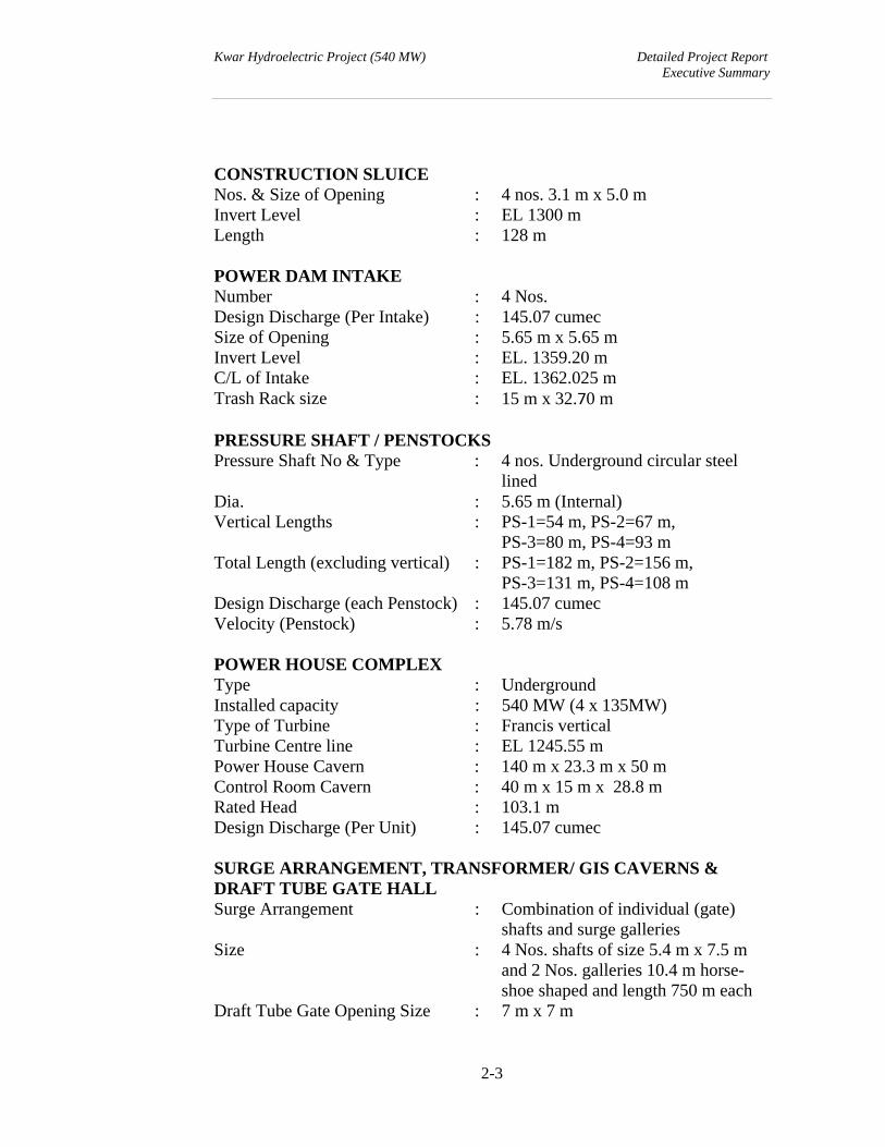
CONSTRUCTION SLUICE Nos. & Size of Opening : 4 nos. 3.1 m x 5.0 m Invert Level : EL 1300 mLength : 128 m POWER DAM INTAKE Number : 4 Nos.Design Discharge (Per Intake) : 145.07 cumec Size of Opening : 5.65 m x 5.65 m Invert Level : EL. 1359.20 mC/L of Intake : EL. 1362.025 m Trash Rack size : 15 m x 32.70 m PRESSURE SHAFT / PENSTOCKSPressure Shaft No & Type : 4 nos. Underground circular steel
lined Dia. : 5.65 m (Internal) Vertical Lengths : PS-1=54 m, PS-2=67 m,
PS-3=80 m, PS-4=93 m Total Length (excluding vertical) : PS-1=182 m, PS-2=156 m,
PS-3=131 m, PS-4=108 m Design Discharge (each Penstock) : 145.07 cumec Velocity (Penstock) : 5.78 m/s POWER HOUSE COMPLEX Type : UndergroundInstalled capacity : 540 MW (4 x 135MW) Type of Turbine : Francis verticalTurbine Centre line : EL 1245.55 m Power House Cavern : 140 m x 23.3 m x 50 m Control Room Cavern : 40 m x 15 m x 28.8 m Rated Head : 103.1 mDesign Discharge (Per Unit) : 145.07 cumec SURGE ARRANGEMENT, TRANSFORMER/ GIS CAVERNS & DRAFT TUBE GATE HALLSurge Arrangement : Combination of individual (gate)
shafts and surge galleries Size : 4 Nos. shafts of size 5.4 m x 7.5 m
and 2 Nos. galleries 10.4 m horse-shoe shaped and length 750 m each
Draft Tube Gate Opening Size : 7 m x 7 m
Kwar Hydroelectric Project (540 MW) Detailed Project Report Executive Summary
2-4
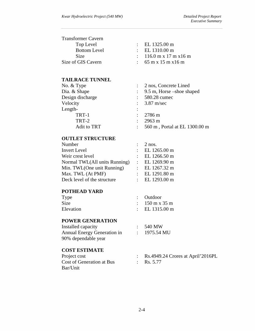
Transformer Cavern Top Level : EL 1325.00 m Bottom Level : EL 1310.00 m Size : 116.0 m x 17 m x16 m Size of GIS Cavern : 65 m x 15 m x16 m
TAILRACE TUNNEL No. & Type : 2 nos, Concrete Lined Dia. & Shape : 9.5 m, Horse –shoe shaped Design discharge : 580.28 cumecVelocity : 3.87 m/secLength- : TRT-1 : 2786 m TRT-2 : 2963 m Adit to TRT : 560 m , Portal at EL 1300.00 m OUTLET STRUCTURE Number : 2 nos. Invert Level : EL 1265.00 m Weir crest level : EL 1266.50 mNormal TWL(All units Running) : EL 1269.90 mMin. TWL(One unit Running) : EL 1267.32 mMax. TWL (At PMF) : EL 1291.80 mDeck level of the structure : EL 1293.00 m POTHEAD YARD Type : OutdoorSize : 150 m x 35 m Elevation : EL 1315.00 m POWER GENERATIONInstalled capacity : 540 MW Annual Energy Generation in 90% dependable year
: 1975.54 MU
COST ESTIMATE Project cost : Rs.4949.24 Crores at April’2016PLCost of Generation at Bus Bar/Unit
: Rs. 5.77

Kwar Hydroelectric Project (540 MW) Detailed Project Report
Executive Summary
CHAPTER –3
ESTIMATE OF COST
Kwar Hydroelectric Project (540 MW) Detailed Project Report Executive Summary
3-1
CHAPTER - 3
ESTIMATE OF COST
(Equity upfront)
3.1 INTRODUCTION
A summary of the Cost Estimate, including direct and indirect charges for
the Civil and Generation work is provided on page 5-6 under heading
‘Abstract of Cost’. The proposed cash flow for the Project is provided in this
Chapter.
3.2 BASIS FOR ESTIMATE
GENERAL
The Cost Estimate of Kwar H.E Project has been prepared broadly on the
basis of “Guidelines for Formulation of Detailed Project Reports for Hydro
Electric Schemes, their Acceptance and Examination for Concurrence”, New
Delhi, April 2012 (Revision 3.0) and “Guidelines for preparation of Project
Estimate for River Valley Projects” (Second Edition, March 1997, CWC)
Published by CWC, New Delhi. The experience gained during preparation of
Cost Estimates of other projects has also been utilized to arrive at the
realistic cost of the project.
I- WORKS
Under this heading, provision has been made for various components of the
Project as detailed hereunder.
A- PRELIMINARY
Under this heading, provision has been made for surveys and investigations
to be conducted to arrive at the optimum of the project components.
Kwar Hydroelectric Project (540 MW) Detailed Project Report Executive Summary
3-2
B- LAND
This covers the provision for acquisition of land and compensation for
houses and other properties etc including expenditure incurred for the same
till date.
C- WORKS
This covers the cost of Diversion Tunnel, Coffer and Concrete Dam, Plunge
Pool for Kwar H.E. Project along with associated Hydro-mechanical Works.
J- POWER PLANT CIVIL WORKS
This covers the cost of project components viz Intake Structure, Pressure
Shaft Penstock & PS Adit, Underground Power House, Tail Race Tunnel,
Tail Race Tunnel Outlet, Pot Head Yard and other appurtenant works.
The quantities indicated in the estimates for C - Works & J-Power Plant Civil
Works are calculated from the preliminary engineering drawings and as per
experience of other on-going or commissioned projects. A provision of 5%
has been made for contingencies and the work charged establishment.
The unit rates for various items are based on Central water Commission
norms and worked out at current market rates. The details of items and the
supporting analysis are given in Chapter-6 of Volume-II of DPR.
K- BUILDINGS
Buildings, both residential and non-residential have been provided under this
head. Included under the permanent category are all those structures which
will be subsequently utilized during the operation and maintenance of the
project utilities. The costs are worked out on plinth area basis prevalent in
the area for the type of construction involved.
O- MISCELLANEOUS
Under this head, provision has been made to cover the cost of the following
miscellaneous works.
Kwar Hydroelectric Project (540 MW) Detailed Project Report Executive Summary
3-3
a) Capital cost of electrification, water supply, sewage disposal, fire fighting
equipments etc.
b) Repair and maintenance of electrification, water supply, sewage
disposal, medical assistance, recreation, post office, telephone and
telegraph office, security arrangements, fire fighting, inspection vehicles,
schools, transport of labour etc.
c) Other services such as laboratory testing, R&M of guest house and
transit camps, community center, retrenchment compensation,
photographic instruments as well as R&M charges etc.
P- MAINTENANCE DURING CONSTRUCTION AND Y-LOSSES ON
STOCK
A provision of 1% and 0.25% of C-Civil works, J-Power Plants, K-Buildings &
R-Communications has been made for maintenance of works during
construction period and losses on stock respectively.
Q-SPECIAL TOOLS AND PLANT
This provision under this head has been made to cover the residual value of
the equipment to be used for infrastructure works only i.e. capital cost of the
equipment less the credit due to resale or transfer of equipment and life of
machinery used in works. For this purpose, the provision for the machinery
likely to be used in infrastructure works (like buildings, roads etc.) excluding
inspection vehicles has been taken as 25% of their value and for inspection
vehicles, 100% of the cost has been booked under this head
R-COMMUNICATION
Provision under this head covers the cost of construction/improvement of
roads and strengthening of bridges. The road widths have been planned to
cater to the anticipated traffic including movement of heavy trailers. The
costs of roads and bridges are based on the present rate structure for the
type of construction involved.
Kwar Hydroelectric Project (540 MW) Detailed Project Report Executive Summary
3-4
X-ENVIRONMENT AND ECOLOGY
Provision towards Bio-diversity Conservation, Creation of Green belt,
Restoration of Construction Area, Catchment Area Treatment,
Compensatory Afforestation etc. and Disaster Management Plan have been
made under this head as per EIA & EMP report.
ELECTRICAL WORKS AND GENERATING PLANT
The cost of generating plant and equipment is based on average of awarded
cost of last three NHPC’s Projects awarded having similar rating and
escalating the same at DPR price level. The prices of auxiliary equipment
and services are based on prevailing market prices/costs incurred at other
ongoing or commissioned projects. The switchyard equipments are based
on prevailing market costs. Taxes, duties and transport to site are based on
prevailing prices. Erection and commissioning charges have been estimated
as experienced on similar installations in the country.
A provision of 1% contingencies covering variations in the quantity of
equipment and services has also been made.
II-ESTABLISHMENT
Provision for establishment has been made as per “Guidelines for
Formulation of Detailed Project Reports for Hydro Electric Schemes, their
Acceptance and Examination for Concurrence”, New Delhi, April 2014
(Revision 3.0) for Civil works and Generation works respectively.
III-TOOLS AND PLANTS
This provision is distinct from that under Q-Special T&P and is meant to
cover cost of survey instruments, camp equipment and other small tools and
plants. A provision of Rs. 2 crores has been provided as per new guideline.
Kwar Hydroelectric Project (540 MW) Detailed Project Report Executive Summary
3-5
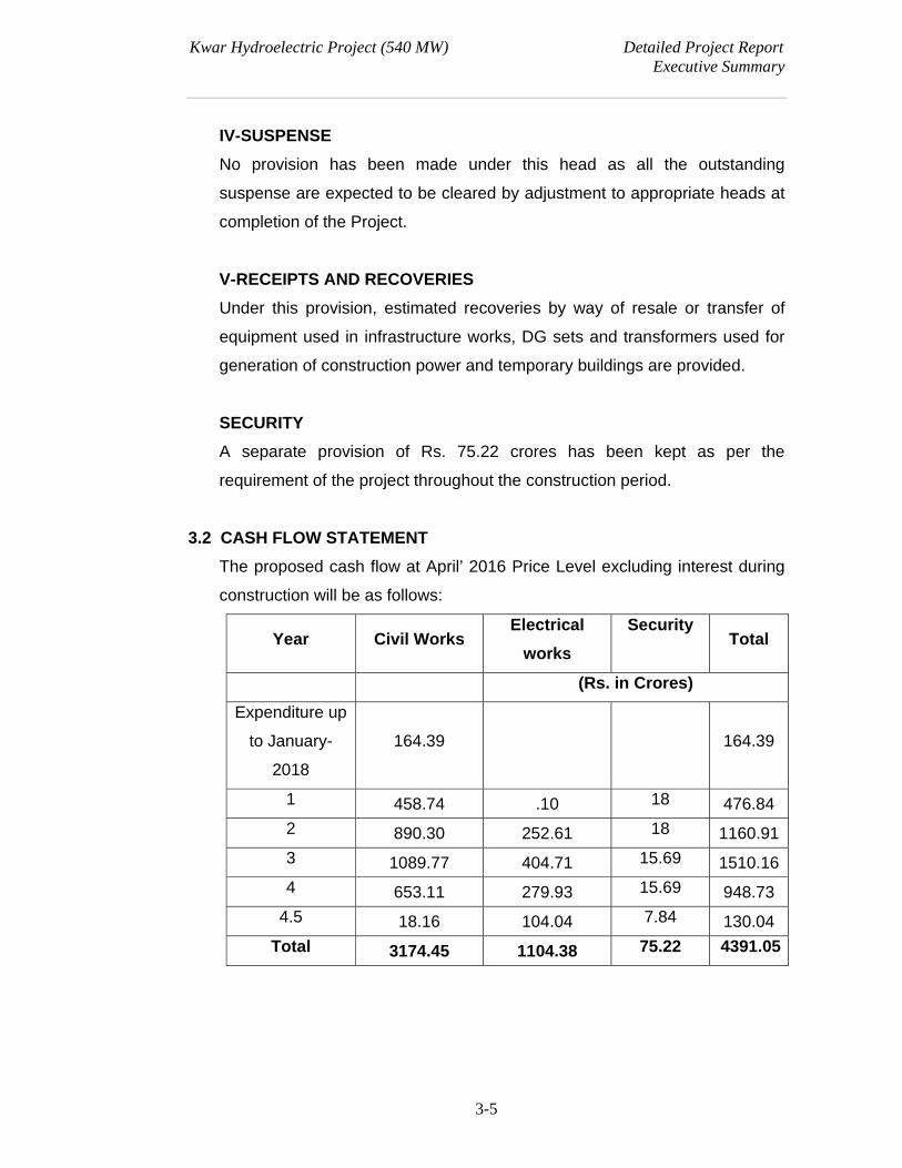
IV-SUSPENSE
No provision has been made under this head as all the outstanding
suspense are expected to be cleared by adjustment to appropriate heads at
completion of the Project.
V-RECEIPTS AND RECOVERIES
Under this provision, estimated recoveries by way of resale or transfer of
equipment used in infrastructure works, DG sets and transformers used for
generation of construction power and temporary buildings are provided.
SECURITY
A separate provision of Rs. 75.22 crores has been kept as per the
requirement of the project throughout the construction period.
3.2 CASH FLOW STATEMENT
The proposed cash flow at April’ 2016 Price Level excluding interest during
construction will be as follows:
Year Civil Works Electrical
works
Security Total
(Rs. in Crores)
Expenditure up
to January-
2018
164.39
164.39
1 458.74 .10 18 476.84
2 890.30 252.61 18 1160.91
3 1089.77 404.71 15.69 1510.16
4 653.11 279.93 15.69 948.73
4.5 18.16 104.04 7.84 130.04
Total 3174.45 1104.38 75.22 4391.05
Kwar Hydroelectric Project (540 MW) Detailed Project Report Executive Summary
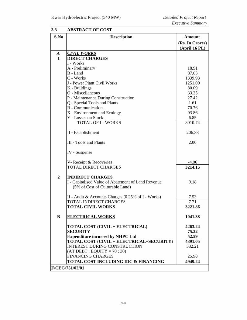
3.3 ABSTRACT OF COST
S.No Description Amount (Rs. In Crores)(April'16 PL)
A CIVIL WORKS1 DIRECT CHARGES
I - WorksA - Preliminary 18.91B - Land 87.05C - Works 1339.93J - Power Plant Civil Works 1251.00K - Buildings 80.09O - Miscellaneous 33.25P - Maintenance During Construction 27.42Q - Special Tools and Plants 1.61R - Communication 70.76X - Environment and Ecology 93.86Y - Losses on Stock 6.85 TOTAL OF I - WORKS 3010.74 II - Establishment 206.38
III - Tools and Plants 2.00
IV - Suspense
V- Receipt & Recoveries -4.96TOTAL DIRECT CHARGES 3214.15
2 INDIRECT CHARGESI - Capitalised Value of Abatement of Land Revenue 0.18 (5% of Cost of Culturable Land)
II - Audit & Accounts Charges (0.25% of I - Works) 7.53TOTAL INDIRECT CHARGES 7.71TOTAL CIVIL WORKS 3221.86
B ELECTRICAL WORKS 1041.38
TOTAL COST (CIVIL + ELECTRICAL) 4263.24SECURITY 75.22Expenditure incurred by NHPC Ltd 52.59TOTAL COST (CIVIL + ELECTRICAL+SECURITY) 4391.05INTEREST DURING CONSTRUCTION 532.21(AT DEBT : EQUITY = 70 : 30)FINANCING CHARGES 25.98TOTAL COST INCLUDING IDC & FINANCING 4949.24
F/CEG/751/02/01
3 -6

Kwar Hydroelectric Project (540 MW) Detailed Project Report
Executive Summary
CHAPTER –4
HYDROLOGY
Kwar Hydroelectric Project (540 MW) Detailed Project Report Executive Summary
4-1
CHAPTER 4
HYDROLOGY
4.1 GENERAL
Kwar Hydroelectric Project is a run-of-river type development scheme, planned
across Chenab river, near Padyarna village in Kishtwar district of Jammu region.
The entire project area is located in a highly mountainous and difficult terrain of
Kishtwar Tehsil. The project envisages construction of 109 m high concrete
gravity dam across Chenab River. At Full Reservoir Level (EL 1385 m) the
reservoir storage is 27.17 Mcum and reservoir surface area is 0.8 Sq.km. Length
of the reservoir at FRL is around 6.0 km. Gross storage capacity at MDDL (i.e EL
1372 m) is 18 Mcum and live storage capacity is 9.16 Mcum.
4.2 RIVER SYSTEM AND BASIN CHARACTERSTICS
The Kwar Hydro Electric Project is proposed on the river Chenab. Chenab river is
one of the three main rivers viz. the Indus, the Jhelum and the Chenab which
drains the state of Jammu and Kashmir. It is formed of two streams (namely, the
Chandra and the Bhaga) joining each other at Tandi (EL 2820 m) south of
Keylong, the district head quarter of Lahaul and Spiti in the Himachal Pradesh
State. The streams of Chandra and Bhaga originate respectively from the north
and south faces of Baralacha pass at elevation 4891 m situated in the great
Himalayas of Lahaul region of Himachal Pradesh.
The river flows in a general north-west direction before it is joined by the biggest
of all tributaries, namely the Marau or the Marusudar River at Bhandalkot. The
Marau or the Marusudar river, in turn is formed by the confluence of two major
streams namely the Warwan and the Rin-Nai, rising in the glaciers on the slopes
of Nunkun Peak of the Great Himalayas, and joins at Yurdu. The Chenab takes a
great bend at Bhandalkot changing its north westerly course to a southerly course.
Downstream of this Bhandalkot point, the river is generally known as Chenab, and
Kwar Hydroelectric Project (540 MW) Detailed Project Report Executive Summary
4-2
flows almost due south upto Thatri, where it is joined by Kal Nai on the left. The
river then takes a great bend at Thatri changing its course from nearly southerly
direction to almost westerly direction. The Niru Nakla joins the Chenab from the
left bank at Doda. The Chenab continues to flow in a westerly direction till it is
joined by its tributary Bichlari river on its right at Ramban. The famous Banihal
Pass in the Pir Panjal range is located in the watershed line of this tributary. The
river then runs in a south westerly course. Before it turns south below the famous
Salal loop, the Ans River joins the Chenab river on its right below Kanthan village.
The Chenab river basin is a part of Western Himalayas. At its upper part the basin
is narrow and elongated while it broadens down along the lower part. The upper
portion of the basin is characterised by rugged mountainous topography, whereas
lower basin consists of low hills and aggradational plain. More than 10,000 sq.km.
of the total catchment of Chenab in India remains permanently above snowline.
As about one third of catchment area of Chenab remains perpetually covered by
snow and glaciers, the comparatively high flows between March to June are largely
contributed by snow melting. High discharge in the river between July to
September is further compounded due to monsoon precipitation. The minimum
flow occurs during December, January and February.
The upper catchment is covered with glaciers. The snow line is considered at EL
4500 m. The catchment area of Chenab at Kwar is 10325 sq.km. The rainfed
catchment area is 4692 sq.km whereas snowfed catchment area is 5633 sq.km.
The catchment area of Chenab at Kwar lies between Longitude 75o55’ E to 77o48’
E and Latitude 32o06’ N to 33o39’ N. The proposed dam site lies at Longitude
75o53’39” E and Latitude 33o21’01” N.
4.3 WATER AVAILABILITY STUDY
Kwar H.E. Project is proposed at around 10 km u/s of Dul dam site of Dulhasti
Power Station. Long term average 10-daily series has been developed at Dul dam
Kwar Hydroelectric Project (540 MW) Detailed Project Report Executive Summary
4-3
site for the period 1975-2012, which is based on daily discharge data at Benzwar
from 1975-2003 and daily discharge data at Dul dam from 2004-2012. Considering
uniform rainfall pattern, 10 daily average flow series has been estimated at
proposed dam site by transposing the data of Benzwar and Dul dam site in
catchment area proportion. The water availability study was submitted to CWC and
has been duly approved by them. Average annual yield of CWC approved series
(1975-2012) at Kwar dam site is 12949 Mcum.
4.4 RESERVOIR ELEVATION AREA CAPACITY CURVE
Reservoir elevation area capacity curve has been obtained on the basis of
1:10000 scale contour maps @ 10 m interval. The gross capacity of reservoir at
proposed FRL (EL 1385 m) is computed as 27.167 Mcum. The reservoir will
extend up to a distance of around 6 km upstream of the dam site and will have a
surface area of 80 Ha at FRL EL 1385 m. Gross storage capacity at MDDL (EL
1372 m) is 18 Mcum and live storage capacity is 9.16 Mcum.
4.5 RATING CURVE
On the basis of observed G&D data sites and available cross sections, rating
curves have been prepared at different locations.
4.6 DESIGN FLOOD
As suggested by CWC, the flood between Kirthai-1 and Kwar H.E.Project has been
estimated using Flood Estimation report of CWC (Subzone-7) and routed flood of
Kirthai-1 HEP has been added to this flood to estimate design flood at Kwar
H.E.Project. PMF of 10534 cumec has been recommended for design and
planning purposes by CWC.
4.7 GLACIAL LAKE OUTBURST FLOOD
It was suggested by CWC that as around 76 % area is under permanent snow,
GLOF studies may also be carried out. Accordingly a GLOF study was carried out

Kwar Hydroelectric Project (540 MW) Detailed Project Report Executive Summary
4-4
and submitted to CWC in Nov 2013. In CWC clearance letter received vide
6/11/2009/FE & SA/94 dated 06.02.2014, it is stated that peak discharge of 620
cumec estimated at dam site, due to GLOF event, is in order.
4.8 DIVERSION FLOOD
The flood frequency analysis has been carried out for non-monsoon flood peaks
(data base 1975-2012) for different working season by Log Pearson type-III
distribution based on modified discharge data after discussions with IWC. The 7.5
months working period (i.e. 1st Oct to 15th May) has been decided for construction.
1 in 25 year non-monsoon flood at mean line is 1021 cumec for this period
whereas maximum observed flood is 1041 cumec for this period. Maximum
observed flood of 1041 cumec is recommended as Diversion flood by CWC.
4.9 RESERVOIR SEDIMENTATION
At Dulhasti Power Station, a sediment rate of 0.224 ham/sq.km/year has been
adopted based on data observed at Benzwar site. The sediment data observed at
Dul dam in later years shows comparatively lower sediment rate (0.151
ham/sq.km/year).
4.10 ANALYSIS OF TRANSIENT CONDITION FOR UPSTREAM & DOWNSTREAM
WATERWAY
The hydraulic transient study for Kwar hydroelectric project has been carried out
to ascertain the transient conditions in upstream waterway and downstream
waterway occurring during operation of the power plant and especially to satisfy
those stipulated in Indian Standards for total closing and/or opening of the turbine.
The detailed hydrological studies and hydraulic transient studies along with
annexures and figures are compiled in Hydrology volume, Volume-III of DPR.

Kwar Hydroelectric Project (540 MW) Detailed Project Report
Executive Summary
CHAPTER –5
GEOLOGY
Kwar H.E. Project (540MW) Detailed Project Report Executive Summary
5-1
CHAPTER – 5
GEOLOGY
5.0 INTRODUCTION
The 540MW Kwar HE Project is located on river Chenab near village
Padyarna. The project is 10 km upstream of Dulhasti Power Station (Under
operation by NHPC) in Kishtwar District of J&K on Kishtwar-Paddar Road.
Modifications in the layout were made by NHPC wherein dam site was shifted
from Galhar to Padyarna & powerhouse was also brought contiguous to dam
body to make the scheme more compact & viable. However, the TRT is
extended upto tail of Dulhasti reservoir to harness complete head between
Kwar and Dulhasti Projects.
Geologically the project area lies within inner lesser Himalayan belt under
Kishtwar group of rocks. All the project components viz. dam & powerhouse
are housed in competent gneissose granite except tail race tunnel and part of
diversion tunnel, which lies in incompetent phyllite rocks.
5.1 FIELD INVESTIGATION
After taking over the project for DPR preparation, detailed investigation works
have been carried out. The investigations include topographical survey,
geological mapping, exploratory drilling (21 nos. of holes cum depth
1453.72m), and exploratory drifting in dam (7nos.,cum length 417.50m) and in
Power house area (cum length 293.3m(old drift)+150.7m(new drift),
geophysical explorations, laboratory and in-situ rock mechanic tests &
construction material survey etc.
5.2 REGIONAL GEOLOGY
In the project area quartzite-phyllite sequence of Dul and Lopara Formation
and Pias Granite as an intrusive body are exposed. The granite is intruded in
the host rock of quartzite-phyllite sequence. In general, the foliation trends
Kwar H.E. Project (540MW) Detailed Project Report Executive Summary
5-2
NW-SE with moderate to steep dips in NE direction with folding attitude at the
proposed dam site.
5.3 GEOLOGICAL EVALUATION OF MAIN CIVIL STRUCTURES
5.3.1 Dam
The proposed concrete gravity dam (101m above river bed level) is placed in
the narrow ‘U’ shaped valley where the dam foundation and abutments shall
be on strong granite. However, the phyllite-quartzite-phyllite sequence of
rocks, which are exposed in the area lie above the dam top. The bedrock is
exposed along the river channel at dam site at many places which indicate
shallow overburden depth (5m to 7m) in the active river channel section. The
bedrock profile has been considered at EL 1291m & 1280m at dam axis
towards right & left side respectively from centre of river, based on present
investigations. Overall the rock mass is dissected by 4 sets of joints along with
random joint. Foliation is faintly developed in this rock and wherever it is
observed, it shows downstream dips. Steep dips have been noticed near the
river bank which might have been developed due to folding nature of strata.
Right Abutment
Right abutment is explored by drifts at three levels. All the drifts are driven
through granite/ gneissose granite with intermittent shear seams/zones.
Shearing/ shattering generally follow S-2 & S-3 joint sets. Random thick
quartz bands are also noticed mainly in the lower drift. Irregular bands of
phyllite appeared at the upper level drift, while amphibolite at the end of u/s
cross cut of lower level drift. The rock is generally fresh, strong with
moderately to widely jointed nature.
Right abutment may require large stripping at selective locations due to open
clay filled joints to abut the dam with sound rock. Further, it may also require
adequate grouting considering shearing and fracturization of rock mass as
observed in the drifts.
Kwar H.E. Project (540MW) Detailed Project Report Executive Summary
5-3
Left Abutment
Left abutment is explored by drifts at three levels. As per drift data rock mass
condition is relatively better than right bank. Normal stripping is proposed to
abut the dam with sound rock however; it may require selective large
stripping. Apart from this, adequate grouting may also be required considering
shearing and fracturization of rock mass as observed in the drifts. The left
bank slope in the downstream of dam site is of concern where a large slide
scar cum subsidence zone is observed between elevations 1450 & 1370m.
This feature has developed in scree and sheared material and have tendency
of subsidence on charging of the ground. This may affect the dam toe
location. As such, it is mandatory to provide proper protection works to
safeguard the toe of the dam. Provision for slope treatment has been kept
accordingly.
The foundation and the abutments of dam shall be placed exclusively in
granite, but it shall require selective stripping for founding the dam in fresh
and good rocks. Though the bed rock of granite is strong and competent but it
may also require curtain grouting to minimize seepage path below dam
foundation.
5.3.2 Plunge Pool Area
The plunge pool area encompasses bedrock of gneissose granite and phyllite.
Plunge pool area is explored by a drill hole towards left bank (i.e. KDH-4) out
of proposed two drill holes. The drill hole has gone entirely in
granite/gneissose granite. Gneissose granite is competent, strong and widely
jointed whereas phyllite is incompetent and thinly foliated in nature. Riverbed
is occupied by riverine material (10m to 12m) as such; excavation of riverbed
material and bedrock is required to attain the required level for plunge pool.
5.3.3 Diversion Tunnel
A 685m long 10m dia horse shoe shaped diversion tunnel has been
envisaged on the left bank to divert the river water to facilitate construction of
dam and its appurtenant structures. Diversion Tunnel will be housed partly in
granite (from u/s side) and partly in Phyllite-quartzite sequence. Gneissose
Kwar H.E. Project (540MW) Detailed Project Report Executive Summary
5-4
granite rock is well exposed at inlet location however at outlet location phyllite-
quartzite sequence is exposed at river level but overlooking slope is under
overburden cover. Due to thick overburden in the outlet area a drill hole (KDH-
5) is made to estimate thickness of overburden. The bedrock is encountered
at 16.6m depth (El. 1312.14M). The overburden is constituted of slope wash
material of phyllites and silty soil. The bed rock is light grey coloured, weak to
medium strong phyllite/quartzitic phyllite. Part of tunnel is likely to be within
granite/gneissose granite upto Ch. 270m (±) from inlet side and rest in phyllitic
rocks. Foliation is feeble in granite but developed at places and have
moderate to steep dips. Consequently, the phyllite-quartzite rocks, which are
expected in a length of approx. 415m are relatively well foliated and weak in
nature.
Apart from this, a shear zone has also been inferred within quartzite-phyllite
sequence. A drill hole was made on DT alignment (KDH-6) to confirm the
existence of shear zone. The hole was drilled on hill slope and the shear zone
is encountered between 29m to 35m depth which confirms the apprehension.
This shear zone is likely to encounter between Ch. 550m (±) to Ch. 570m (±)
from inlet side. In view of weak nature of strata, it may pose difficult tunneling
condition if the medium is charged. As such, such poor zones will require
advance probing and concurrent rock support measures during excavation.
The diversion tunnel is anticipated to negotiate about 20% class II, 30% class
III, 25% class IV and 25% class V rocks based on RMR classification.
5.3.4 Water Conductor System
The water conductor system comprises intake structure, 4 nos. pressure
shafts, directly from intake to join the Power House.
All the structure viz Intake, Pressure shaft etc, shall be housed in competent
granites. The intake structure is located on right bank very close to dam body.
The area around proposed structure exhibits outcrops of granite however,
some scanty talus material (slope wash) is also observed on the slope below
El. 1350M (±). The overburden is insignificant however need to be removed to
Kwar H.E. Project (540MW) Detailed Project Report Executive Summary
5-5
expose the rock. Granite is hard, moderately jointed, slightly weathered with
some open joints (filled with soil/clay) in the area.
To explore the subsurface geological conditions a drift with cumulative length
of 50m (including X-cuts) is made in the proposed intake area. The drift has
driven through granite/gneissose granite, which is strong & moderately to
widely joint in nature. Shear seams/zones (few cms. to <50cm) are observed
at places. Open joints with soil filling are also observed in the initial reach i.e.,
from portal to Ch. 4m in the main drift. The pressure shafts are expected to be
in competent granitic rocks but wedge failures aided by sheared joints is
foreseen due to shattered nature of rock and open joints filled with clay at the
surface. Considering all geotechnical characteristics of rock mass, the
pressure shaft is anticipated to negotiate through fair to good rock condition
except random stretch of poor rock condition.
5.3.5 Power House Complex
The powerhouse complex is adjoining to dam body on right bank and shall be
located under a cover of around 200m mainly in granites. Irregular bands of
phyllite are seen in P/H drift & drill hole KDH-12, while amphibolite is seen
within granite in the old and new power house drift as well as in drill hole
KDH-15 &17, which indicates that these two units have intertounging
relationship with granite and may occur randomly within granite. A new drift
of 150.7m length has been made from ± RD 50m of old P/H drift to explore
the subsurface geological conditions around new alignment of P/H cavern.
The rock mass (granite) encountered in the drift are hard and competent to
accommodate the large caverns. In all 4 sets of joints dissect the rock mass.
Out of these, foliation (S-1), across foliation (S-2) & valley dipping (S-3) joints
are more prominent. Foliation joint cut obliquely to the longer axis of the
cavern. In order to minimize the adverse effect of orientation of joints, the
longer axis of the cavern is realigned in N 090o. Nevertheless intersection of
some of the joint sets can lead to wedge formation and few of them may result
in gravity fall or sliding failures from crown and side walls which need to be
taken care. Suitable provisions have been kept accordingly.
Kwar H.E. Project (540MW) Detailed Project Report Executive Summary
5-6
Though, dry conditions are observed in new exploratory drift, but deeper
inside possibility of seepage cannot be ruled out due to well jointed nature of
rock and surface charging from nearby nallas through open joints. Further, the
powerhouse cavern is placed adjoining to dam body, seepage from reservoir
through well jointed granite rock is also apprehended. Thus, provisions of
suitable mitigative measures are foreseen to control seepage into the
machine hall. The powerhouse cavern, in general, shall be in good to fair
class of rock with random pockets of poor rock.
5.3.6 Tail Race Tunnel
The water from the power house shall be discharged back into the river
through 2 nos. horse shoe tunnels on right bank of 2.786 & 2.963km long,
having 9.5m dia at normal TWL 1270M to harness the maximum head. Both
the tunnels are 78m apart from centre to centre and aligned almost
subparallel to river course with a kink near Phullar nalla.
Both the tunnels are anticipated to be mainly in phyllitic rocks (around 90%)
however quartzitic bands within phyllite-quartzite sequence and intrusive
granitic rocks may appear in the initial part from PH side (around 10%). To
know the rock cover and subsurface geological conditions two drill holes i.e.
KDH-11 & KDH-14 were drilled in Phullar nala and on TRT-2 alignment
respectively. A thick shear/fracture zone (>20m) was encountered in drill hole
KDH-11 beyond 41.35m depth (El. 1383.6M) and continued down to the end
of the hole , while in drill hole KDH-14 also ,a shear/fracture zone of nearly
21m thickness was encountered between 52.5 (EL. 1301.3M) and 73.5m
depth (EL.1280.3M). The shear zone intercepted in this drill hole may
encounter in TRT nearly at Ch. 1.2km (approximate 30m zone) from upstream
side if shear zone follows the bedding attitude. An old slide scar has been
observed on R/B near the TRT outlet and the slide material is lying at the river
bed following the rock profile. As the valley slide TRT is under the slide
material, a drill hole was proposed to assess the rock cover above the
alignment. The drill hole (KDH-16) drilled in slide debris on TRT-1 alignment
has intercepted the bedrock at 42m depth (El. 1342.96M). The bedrock is light
green to grey colored and weak phyllite. A thick sheared/crushed zone is
Kwar H.E. Project (540MW) Detailed Project Report Executive Summary
5-7
encountered between 51 and 55.5m depth. The cover over the tunnel varies
from 72m to 398m over TRT-1 and 92m to 468m over TRT-2 respectively.
The minimum cover of 72m (TRT-1) comes below Phullar nalla.
Owing to weak and laminated nature of rock (phyllite) and at places tunnel
having aligned sub-parallel to the strike of rock formation coupled with
superincumbent cover, the tunnel may experience squeezing condition at
places. There are number of surface manifestations of shear zones,
lineaments & master joints etc. within phyllite which can be considered as
zone of weaknesses for tunneling. Further, there are apprehensions of
encountering number of weak zones (around 40% of total tunnel length)
intermittently along the tunnel route. As such, 50% tunneling may be
considered in class-III (fair rock) and 30% in class IV & 20% in class V rocks
5.4 RESERVOIR
This dam shall create a 6.7km long reservoir upto outlet of TRT of Kiru
Project. The full reservoir level (FRL) has been proposed at EL 1385M having
0.8sq km area. Right bank of the river is almost rocky (80 % touching rock)
whereas left bank shall be touching partly overburden (50%) and partly rock
outcrops (50%). Major part of the reservoir rim shall be in contact with
bedrock comprising of gneissose granite and phyllite-quartzite sequence. A
thermal spring has been observed within reservoir which indicates presence
of some structural control along the river course. A landslide is observed on
R/B near tail of reservoir. However, some stretches under slope wash material
near Galhar village may result in sloughing after filling up of the reservoir.
These issues will be addressed during EMP studies. Overall, the reservoir rim
appears to be safe from geo-environmental consideration (except some part
of rim on left bank near village Galhar) with no possibility of reservoir leakage.
No economic mineral within reservoir periphery has been reported.
Kwar H.E. Project (540MW) Detailed Project Report Executive Summary
5-8
5.5 SEISMICITY
The project area falls in Zone-IV of Seismic Zoning map of India which
corresponds to high seismically active area. Site Specific Design Earthquake
Parameters study has been carried out by DEQ, IIT Roorkee.
As per updated report, the PGA value recommended for MCE & DBE
conditions are 0.50g and 0.28g for horizontal and 0.33g MCE and 0.19g DBE
for the vertical ground motion respectively. Further, Department has also
suggested the design seismic coefficient for preliminary design of Dam as
αh=0.17 and αv=0.12, which was approved by NCSDP in its 31st meeting
held on 23rd June 2016. (Letter dated 07.10.2016 is appended as Annexure-
XII).
Further, as suggested by GSI during the evaluation of DPR, MEQ studies by
Wadia Institute of Himalayan Geology, Dehradun have been carried out to
know the local seismicity of the area as well as to establish the presence of
neo-tectonic activity. The study is now completed and the report was
discussed with NCSDP. Further, NCSDP has suggested some modifications
in the MEQ report, however, these suggestions will not have any impact on
the approved seismic design parameters. The final updated report shall be
submitted after getting approved by NCSDP.
5.6 CONSTRUCTION MATERIAL
For the construction of concrete dam, coffer dams, diversion tunnel,
powerhouse and other allied civil structures of the project, 4 rock quarries and
one impervious soil deposit have been selected for meeting the requirements.
The requirement of coarse and fine aggregate has been estimated to be 21.9
lac.cum, whereas 0.69 lac.cum. of impervious soil, 3.0 lac.cum. of rockfill
material, 0.13 lac.cum. of filter material and 0.19 lac.cum. of Riprap material
shall be required for construction of coffer dams.
Based on the test results and keeping in view the available quantity, it is
concluded that sufficient suitable construction material is available to meet the
requirement of the project.

Kwar Hydroelectric Project (540 MW) Detailed Project Report
Executive Summary
CHAPTER –6
POWER STUDIES
Kwar Hydroelectric Project (540 MW) Detailed Project Report Executive Summary
6-1
CHAPTER – 6 POWER STUDIES
6.1 POWER SUPPLY-DEMAND
6.1.1 ON ALL INDIA BASIS
The Power System in India has grown from small, isolated stations, serving
limited consumers in and around large cities, into large regional Power
Grids. The generating capacity installed in the country has already grown
to 306358.25 MW by September 2016.
For the purpose of system planning and operation the country has been
divided into the following five geopolitical regions: Northern, Western,
Southern, Eastern and North-Eastern regional power grids and the
transmission system are being progressively inter-connected for efficient
operation of these five regional grids.
The objective of the system development is to evolve self-sufficient regional
grid catering to the individual regional power demands. It is also aimed at
achieving the maximum benefits from integrated operation, through a
proper mix of thermal and hydro generation. The present power position in
the five regional Grids as per “'Load Generation Balance Report (LGBR)
2016-17” published by CEA is shown in Table 6.1a and 6.1b.
6.1.2 ON REGIONAL BASIS
The Northern Region comprises the states of Punjab, Haryana, Himachal
Pradesh, Delhi, UP, Uttarakhand, Rajasthan, Chandigarh and J&K. The
Northern grid comprises the power system controlled by Electricity Boards/
Corporations of the above states.
The Northern Region has been experiencing acute power shortage during
the last decade due to rapid industrialization, developing irrigation network
& urbanization. It is obviously not possible to meet rapidly growing power
demands of industry and agriculture from the existing power stations.
Electrical energy being the basic ingredient for economic upliftment through
industrial and agricultural development, power shortage has slowed down
the wheels of progress and put a curb on all development activities in the
region. Thermal and nuclear generation of power is not the right solution for
meeting peaking power deficit in this region because of limitations imposed
Kwar Hydroelectric Project (540 MW) Detailed Project Report Executive Summary
6-2
by inadequate availability of coal and nuclear fuel, long distances over
which fuel has to be transported through an overloaded railway system and
higher cost of power generation from thermal and nuclear power plants.
Even considering the coordinated operation of existing hydro, nuclear and
thermal stations, as well as benefits from on-going projects and also from
the schemes cleared by CEA, the Northern region shall face power deficits
by the end of 12th five Year Plan and is also expected to face further
power deficits in the upcoming years.
The Power position in Northern region for 12th ,13th and 14th five Year
Plans has been summarized in Table 6.2. In the table, the peaking and
energy capabilities are taken for optimum condition. The benefits from all
schemes that have been cleared by CEA have been included.
6.1.3 JUSTIFICATION FOR THE PROJECT
From the Table 6.1a for the year 2015-16, it is observed that the North
Region had deficit in capacity of (-)7.1 % and energy peak deficit of (-)
4.8%.
Northern region has Hydro thermal mix ratio of 23:64 at present in
comparison to overall scenario in the country vis-à-vis Hydro Thermal ratio
stands at 14:70. The proposed Kwar Project would form an integral part of
the Northern Grid to contribute in projected energy requirement. Besides, it
will also provide peak capacity to the grid and helps in optimizing the
generation from thermal stations which are forced to operate at poor load
factor in absence of matching hydropower contribution.
6.2 SCHEME FOR WHEELING EVACUATING POWER
The responsibility of power evacuation system from Kwar Power Project as
per present scenario remains with PGCIL to be connected to grid at 400 kV
level.
6.3 AVAILABLE GENERATING CAPACITY IN REGION
The Total Installed Capacity in Northern Region as on Sep 2016 is
80862.58 MW. Out of this, 18376.78 MW is Hydel and the rest are thermal
and nuclear and thus the Hydro Thermal mix is 23:64 which is better than
the national average of 14:70.
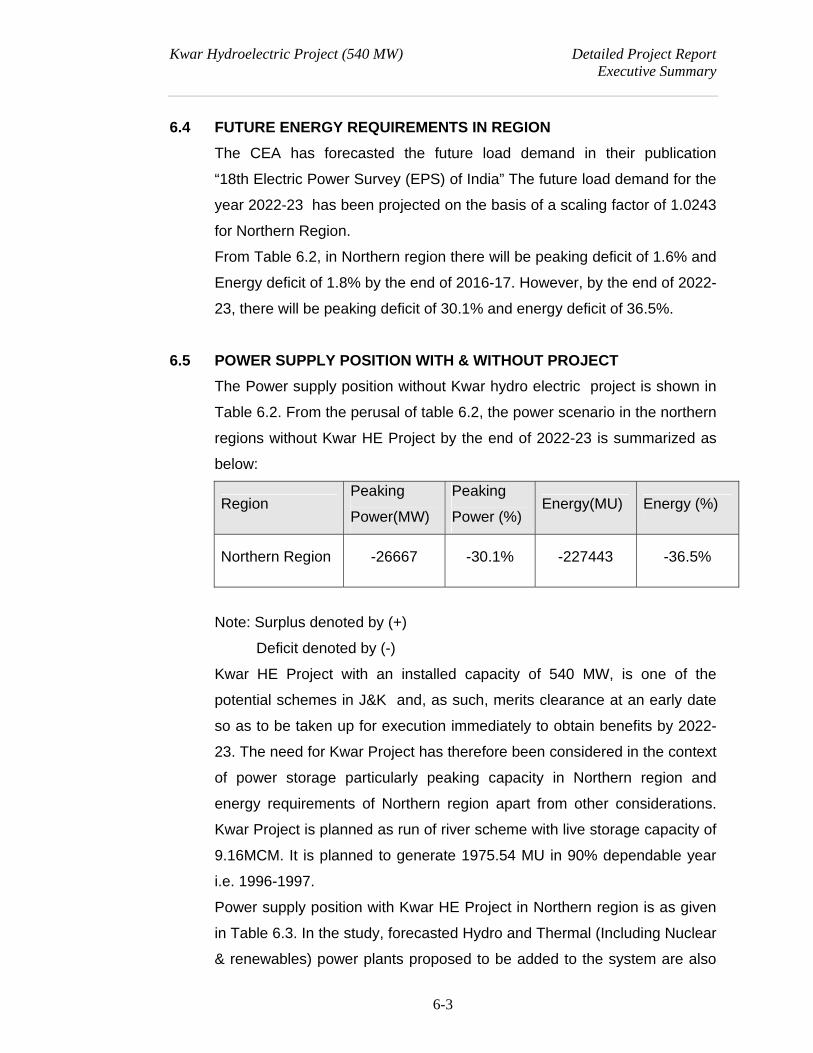
Kwar Hydroelectric Project (540 MW) Detailed Project Report Executive Summary
6-3
6.4 FUTURE ENERGY REQUIREMENTS IN REGION
The CEA has forecasted the future load demand in their publication
“18th Electric Power Survey (EPS) of India” The future load demand for the
year 2022-23 has been projected on the basis of a scaling factor of 1.0243
for Northern Region.
From Table 6.2, in Northern region there will be peaking deficit of 1.6% and
Energy deficit of 1.8% by the end of 2016-17. However, by the end of 2022-
23, there will be peaking deficit of 30.1% and energy deficit of 36.5%.
6.5 POWER SUPPLY POSITION WITH & WITHOUT PROJECT
The Power supply position without Kwar hydro electric project is shown in
Table 6.2. From the perusal of table 6.2, the power scenario in the northern
regions without Kwar HE Project by the end of 2022-23 is summarized as
below:
Region Peaking
Power(MW)
Peaking
Power (%) Energy(MU) Energy (%)
Northern Region -26667 -30.1% -227443 -36.5%
Note: Surplus denoted by (+)
Deficit denoted by (-)
Kwar HE Project with an installed capacity of 540 MW, is one of the
potential schemes in J&K and, as such, merits clearance at an early date
so as to be taken up for execution immediately to obtain benefits by 2022-
23. The need for Kwar Project has therefore been considered in the context
of power storage particularly peaking capacity in Northern region and
energy requirements of Northern region apart from other considerations.
Kwar Project is planned as run of river scheme with live storage capacity of
9.16MCM. It is planned to generate 1975.54 MU in 90% dependable year
i.e. 1996-1997.
Power supply position with Kwar HE Project in Northern region is as given
in Table 6.3. In the study, forecasted Hydro and Thermal (Including Nuclear
& renewables) power plants proposed to be added to the system are also
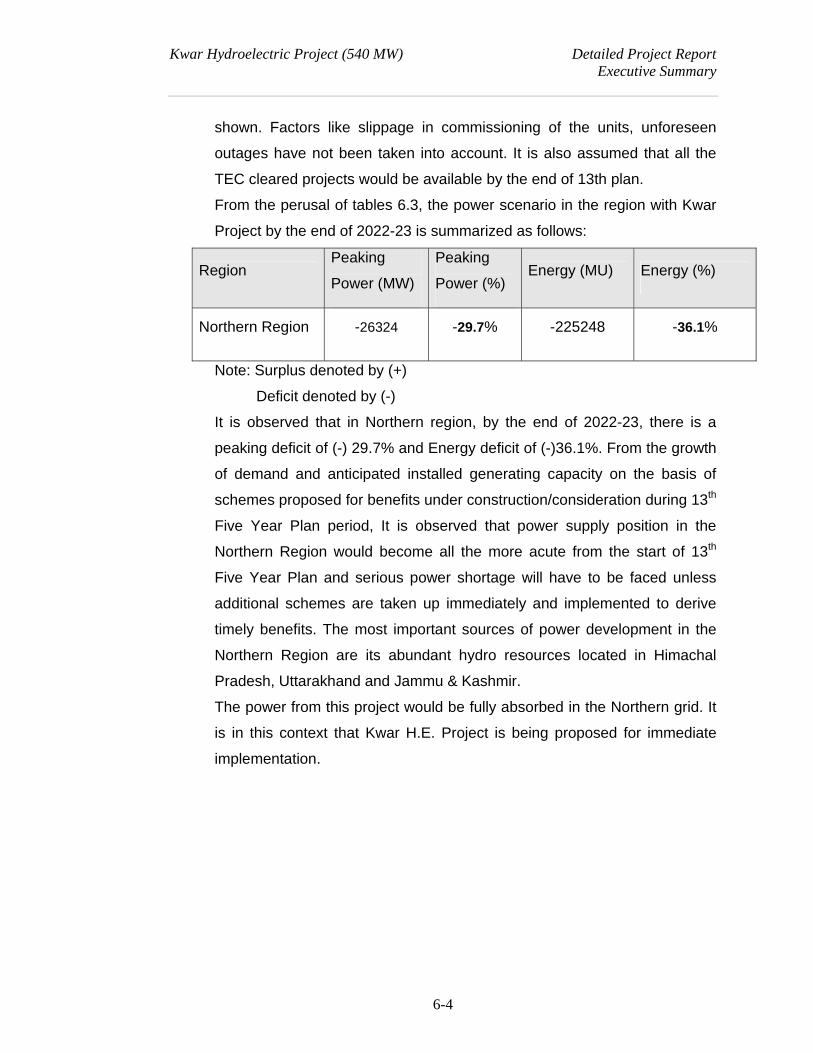
Kwar Hydroelectric Project (540 MW) Detailed Project Report Executive Summary
6-4
shown. Factors like slippage in commissioning of the units, unforeseen
outages have not been taken into account. It is also assumed that all the
TEC cleared projects would be available by the end of 13th plan.
From the perusal of tables 6.3, the power scenario in the region with Kwar
Project by the end of 2022-23 is summarized as follows:
Region Peaking
Power (MW)
Peaking
Power (%) Energy (MU) Energy (%)
Northern Region -26324 -29.7% -225248 -36.1%
Note: Surplus denoted by (+)
Deficit denoted by (-)
It is observed that in Northern region, by the end of 2022-23, there is a
peaking deficit of (-) 29.7% and Energy deficit of (-)36.1%. From the growth
of demand and anticipated installed generating capacity on the basis of
schemes proposed for benefits under construction/consideration during 13th
Five Year Plan period, It is observed that power supply position in the
Northern Region would become all the more acute from the start of 13th
Five Year Plan and serious power shortage will have to be faced unless
additional schemes are taken up immediately and implemented to derive
timely benefits. The most important sources of power development in the
Northern Region are its abundant hydro resources located in Himachal
Pradesh, Uttarakhand and Jammu & Kashmir.
The power from this project would be fully absorbed in the Northern grid. It
is in this context that Kwar H.E. Project is being proposed for immediate
implementation.
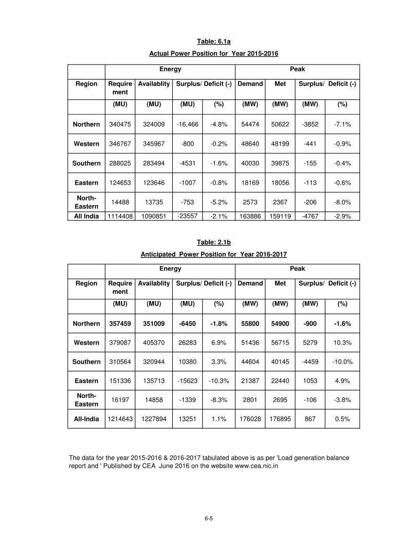
Region Require
ment
Availablity Demand Met
(MU) (MU) (MU) (%) (MW) (MW) (MW) (%)
Northern 340475 324009 -16,466 -4.8% 54474 50622 -3852 -7.1%
Western 346767 345967 -800 -0.2% 48640 48199 -441 -0.9%
Southern 288025 283494 -4531 -1.6% 40030 39875 -155 -0.4%
Eastern 124653 123646 -1007 -0.8% 18169 18056 -113 -0.6%
North-
Eastern14488 13735 -753 -5.2% 2573 2367 -206 -8.0%
All India 1114408 1090851 -23557 -2.1% 163886 159119 -4767 -2.9%
Region Require
ment
Availablity Demand Met
(MU) (MU) (MU) (%) (MW) (MW) (MW) (%)
Northern 357459 351009 -6450 -1.8% 55800 54900 -900 -1.6%
Western 379087 405370 26283 6.9% 51436 56715 5279 10.3%
Southern 310564 320944 10380 3.3% 44604 40145 -4459 -10.0%
Eastern 151336 135713 -15623 -10.3% 21387 22440 1053 4.9%
North-
Eastern16197 14858 -1339 -8.3% 2801 2695 -106 -3.8%
All-India 1214643 1227894 13251 1.1% 176028 176895 867 0.5%
Table: 6.1a
Actual Power Position for Year 2015-2016
Peak
Surplus/ Deficit (-) Surplus/ Deficit (-)
Energy
The data for the year 2015-2016 & 2016-2017 tabulated above is as per 'Load generation balance
report and ' Published by CEA June 2016 on the website www.cea.nic.in
Surplus/ Deficit (-) Surplus/ Deficit (-)
Table: 2.1b
Anticipated Power Position for Year 2016-2017
Energy Peak
6-5
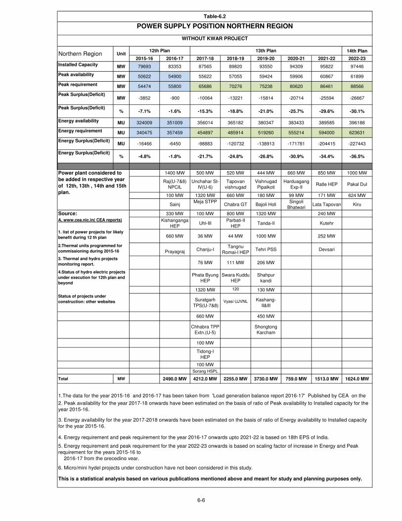
14th Plan
2015-16 2016-17 2017-18 2018-19 2019-20 2020-21 2021-22 2022-23
Installed Capacity MW 79693 83353 87565 89820 93550 94309 95822 97446
Peak availability MW 50622 54900 55622 57055 59424 59906 60867 61899
Peak requirement MW 54474 55800 65686 70276 75238 80620 86461 88566
Peak Surplus(Deficit)MW -3852 -900 -10064 -13221 -15814 -20714 -25594 -26667
Peak Surplus(Deficit)% -7.1% -1.6% -15.3% -18.8% -21.0% -25.7% -29.6% -30.1%
Energy availability MU 324009 351009 356014 365182 380347 383433 389585 396188
Energy requirement MU 340475 357459 454897 485914 519260 555214 594000 623631
Energy Surplus(Deficit)MU -16466 -6450 -98883 -120732 -138913 -171781 -204415 -227443
Energy Surplus(Deficit)% -4.8% -1.8% -21.7% -24.8% -26.8% -30.9% -34.4% -36.5%
1400 MW 500 MW 520 MW 444 MW 660 MW 850 MW 1000 MW
Raj(U-7&8)
NPCIL
Unchahar St-
IV(U-6)
Tapovan
vishnugad
Vishnugad
Pipalkoti
Harduagang
Exp-IIRatle HEP Pakal Dul
100 MW 1320 MW 660 MW 180 MW 99 MW 171 MW 624 MW
SainjMeja STPP
Chabra GT Bajoli HoliSingoli
BhatwariLata Tapovan Kiru
330 MW 100 MW 800 MW 1320 MW 240 MW
Kishanganga
HEPUhl-III
Parbati-II
HEPTanda-II Kutehr
660 MW 36 MW 44 MW 1000 MW 252 MW
Prayagraj
TPP
Chanju-ITangnu
Romai-I HEPTehri PSS Devsari
76 MW 111 MW 206 MW
Phata Byung
HEP
Swara Kuddu
HEP
Shahpur
kandi
1320 MW 120 130 MW
Suratgarh
TPS(U-7&8)
Vyasi UJVNL Kashang-
II&III
660 MW 450 MW
Chhabra TPP
Extn.(U-5)
Shongtong
Karcham
100 MW
Tidong-I
HEP
100 MW
Sorang HSPL
Total MW 0.0 MW 2490.0 MW 4212.0 MW 2255.0 MW 3730.0 MW 759.0 MW 1513.0 MW 1624.0 MW
6. Micro/mini hydel projects under construction have not been considered in this study.
Source:
1.The data for the year 2015-16 and 2016-17 has been taken from 'Load generation balance report 2016-17' Published by CEA on the
2. Peak availability for the year 2017-18 onwards have been estimated on the basis of ratio of Peak availability to Installed capacity for the
year 2015-16.
This is a statistical analysis based on various publications mentioned above and meant for study and planning purposes only.
4.Status of hydro electric projects
under execution for 12th plan and
beyond
12th Plan 13th Plan
Power plant considered to
be added in respective year
of 12th, 13th , 14th and 15th
plan.
A. www.cea.nic.in( CEA reports)
1. list of power projects for likely
benefit during 12 th plan
2.Thermal units programmed for
commissioning during 2015-16
3. Thermal and hydro projects
monitoring report.
Northern Region Unit
3. Energy availability for the year 2017-2018 onwards have been estimated on the basis of ratio of Energy availability to Installed capacity
for the year 2015-16.
4. Energy requirement and peak requirement for the year 2016-17 onwards upto 2021-22 is based on 18th EPS of India.
5. Energy requirement and peak requirement for the year 2022-23 onwards is based on scaling factor of increase in Energy and Peak
requirement for the years 2015-16 to
2016-17 from the preceding year.
Table-6.2
POWER SUPPLY POSITION NORTHERN REGION
WITHOUT KWAR PROJECT
Status of projects under
construction: other websites
6-6
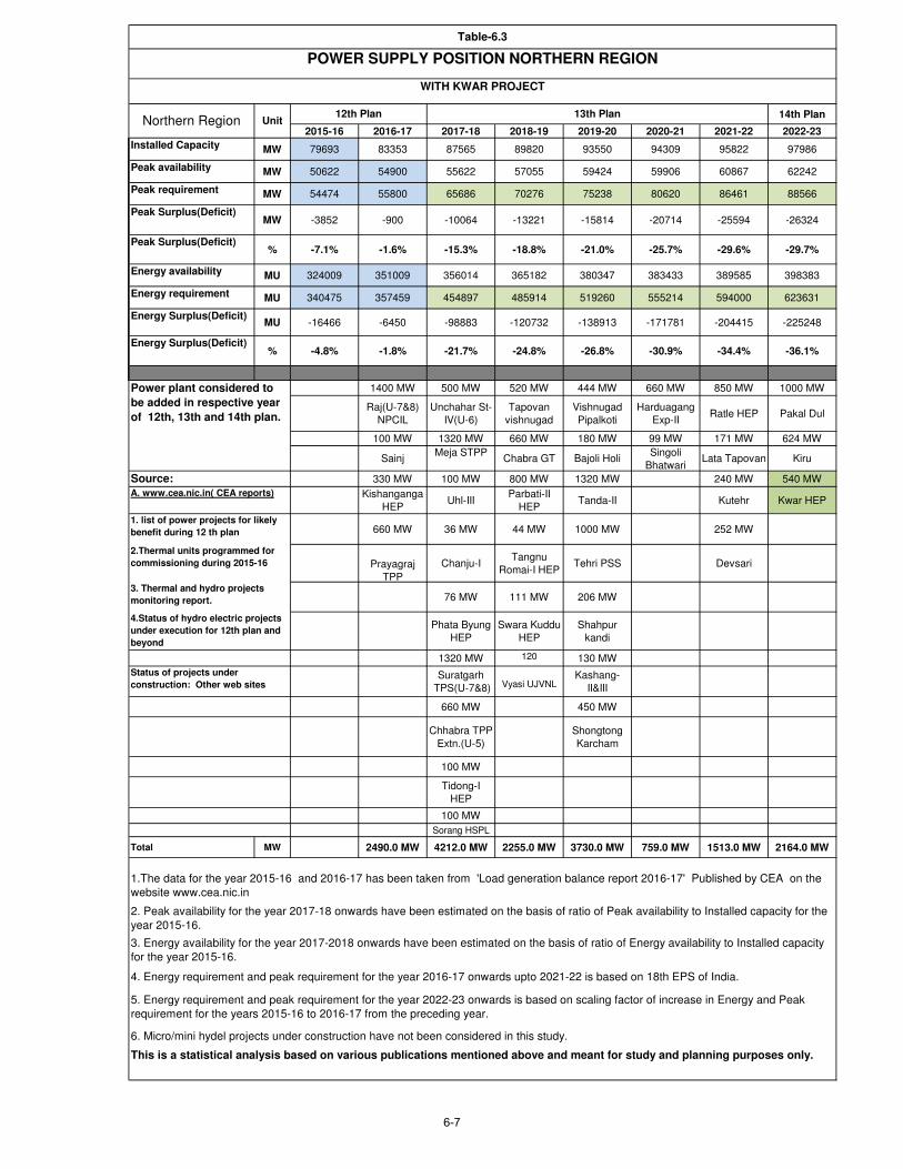
14th Plan
2015-16 2016-17 2017-18 2018-19 2019-20 2020-21 2021-22 2022-23
Installed Capacity MW 79693 83353 87565 89820 93550 94309 95822 97986
Peak availability MW 50622 54900 55622 57055 59424 59906 60867 62242
Peak requirement MW 54474 55800 65686 70276 75238 80620 86461 88566
Peak Surplus(Deficit)MW -3852 -900 -10064 -13221 -15814 -20714 -25594 -26324
Peak Surplus(Deficit)% -7.1% -1.6% -15.3% -18.8% -21.0% -25.7% -29.6% -29.7%
Energy availability MU 324009 351009 356014 365182 380347 383433 389585 398383
Energy requirement MU 340475 357459 454897 485914 519260 555214 594000 623631
Energy Surplus(Deficit)MU -16466 -6450 -98883 -120732 -138913 -171781 -204415 -225248
Energy Surplus(Deficit)% -4.8% -1.8% -21.7% -24.8% -26.8% -30.9% -34.4% -36.1%
1400 MW 500 MW 520 MW 444 MW 660 MW 850 MW 1000 MW
Raj(U-7&8)
NPCIL
Unchahar St-
IV(U-6)
Tapovan
vishnugad
Vishnugad
Pipalkoti
Harduagang
Exp-IIRatle HEP Pakal Dul
100 MW 1320 MW 660 MW 180 MW 99 MW 171 MW 624 MW
SainjMeja STPP
Chabra GT Bajoli HoliSingoli
BhatwariLata Tapovan Kiru
Source: 330 MW 100 MW 800 MW 1320 MW 240 MW 540 MW
Kishanganga
HEPUhl-III
Parbati-II
HEPTanda-II Kutehr Kwar HEP
660 MW 36 MW 44 MW 1000 MW 252 MW
Prayagraj
TPP
Chanju-ITangnu
Romai-I HEPTehri PSS Devsari
76 MW 111 MW 206 MW
Phata Byung
HEP
Swara Kuddu
HEP
Shahpur
kandi
1320 MW 120 130 MW
Suratgarh
TPS(U-7&8)
Vyasi UJVNLKashang-
II&III
660 MW 450 MW
Chhabra TPP
Extn.(U-5)
Shongtong
Karcham
100 MW
Tidong-I
HEP
100 MW
Sorang HSPL
Total MW 2490.0 MW 4212.0 MW 2255.0 MW 3730.0 MW 759.0 MW 1513.0 MW 2164.0 MW
Table-6.3
POWER SUPPLY POSITION NORTHERN REGION
WITH KWAR PROJECT
Northern Region Unit12th Plan 13th Plan
Power plant considered to
be added in respective year
of 12th, 13th and 14th plan.
A. www.cea.nic.in( CEA reports)
1. list of power projects for likely
benefit during 12 th plan
2.Thermal units programmed for
commissioning during 2015-16
3. Thermal and hydro projects
monitoring report.
4.Status of hydro electric projects
under execution for 12th plan and
beyond
Status of projects under
construction: Other web sites
5. Energy requirement and peak requirement for the year 2022-23 onwards is based on scaling factor of increase in Energy and Peak
requirement for the years 2015-16 to 2016-17 from the preceding year.
6. Micro/mini hydel projects under construction have not been considered in this study.
This is a statistical analysis based on various publications mentioned above and meant for study and planning purposes only.
1.The data for the year 2015-16 and 2016-17 has been taken from 'Load generation balance report 2016-17' Published by CEA on the
website www.cea.nic.in
2. Peak availability for the year 2017-18 onwards have been estimated on the basis of ratio of Peak availability to Installed capacity for the
year 2015-16.
3. Energy availability for the year 2017-2018 onwards have been estimated on the basis of ratio of Energy availability to Installed capacity
for the year 2015-16.
4. Energy requirement and peak requirement for the year 2016-17 onwards upto 2021-22 is based on 18th EPS of India.
6-7

Kwar Hydroelectric Project (540 MW) Detailed Project Report
Executive Summary
CHAPTER –7
OPTIMISATION STUDIES
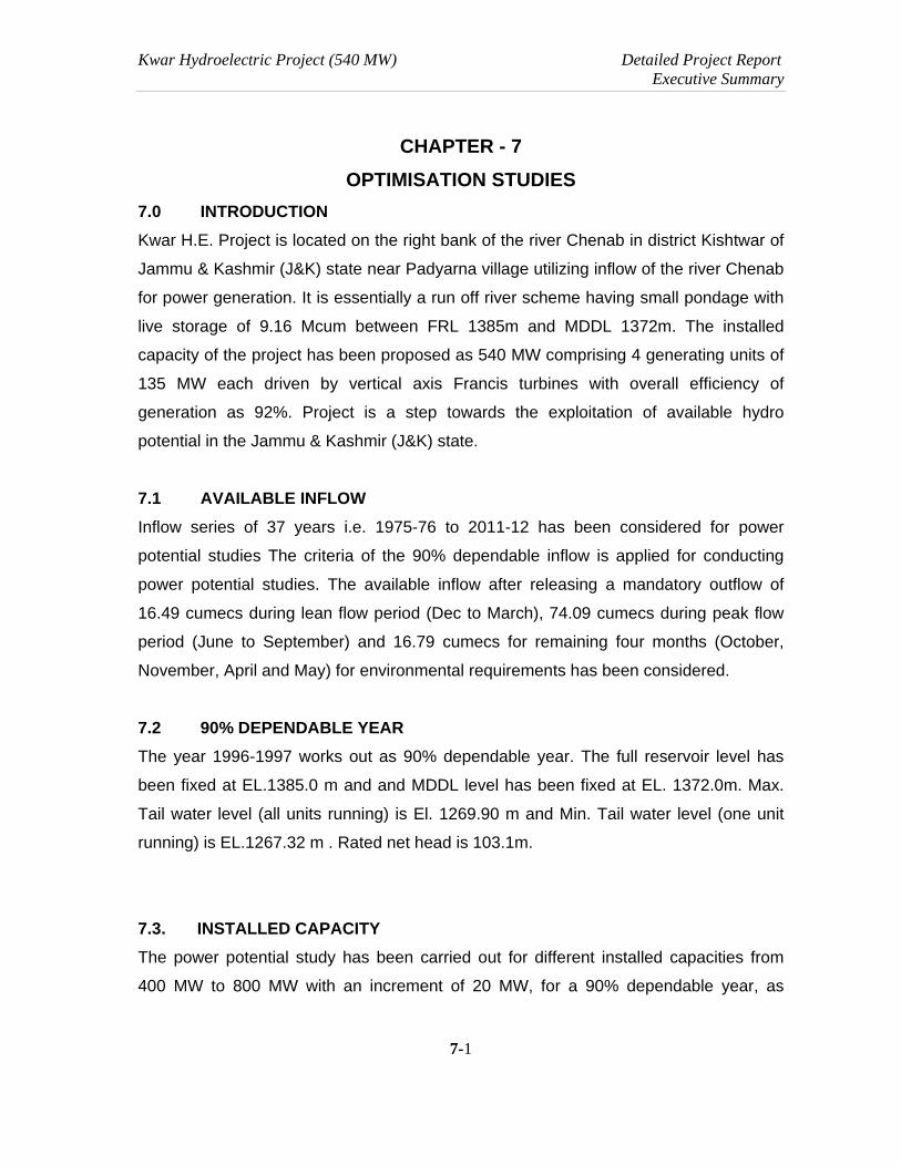
Kwar Hydroelectric Project (540 MW) Detailed Project Report Executive Summary
7-1
CHAPTER - 7
OPTIMISATION STUDIES
7.0 INTRODUCTION
Kwar H.E. Project is located on the right bank of the river Chenab in district Kishtwar of
Jammu & Kashmir (J&K) state near Padyarna village utilizing inflow of the river Chenab
for power generation. It is essentially a run off river scheme having small pondage with
live storage of 9.16 Mcum between FRL 1385m and MDDL 1372m. The installed
capacity of the project has been proposed as 540 MW comprising 4 generating units of
135 MW each driven by vertical axis Francis turbines with overall efficiency of
generation as 92%. Project is a step towards the exploitation of available hydro
potential in the Jammu & Kashmir (J&K) state.
7.1 AVAILABLE INFLOW
Inflow series of 37 years i.e. 1975-76 to 2011-12 has been considered for power
potential studies The criteria of the 90% dependable inflow is applied for conducting
power potential studies. The available inflow after releasing a mandatory outflow of
16.49 cumecs during lean flow period (Dec to March), 74.09 cumecs during peak flow
period (June to September) and 16.79 cumecs for remaining four months (October,
November, April and May) for environmental requirements has been considered.
7.2 90% DEPENDABLE YEAR
The year 1996-1997 works out as 90% dependable year. The full reservoir level has
been fixed at EL.1385.0 m and and MDDL level has been fixed at EL. 1372.0m. Max.
Tail water level (all units running) is El. 1269.90 m and Min. Tail water level (one unit
running) is EL.1267.32 m . Rated net head is 103.1m.
7.3. INSTALLED CAPACITY
The power potential study has been carried out for different installed capacities from
400 MW to 800 MW with an increment of 20 MW, for a 90% dependable year, as
Kwar Hydroelectric Project (540 MW) Detailed Project Report Executive Summary
7-2
shown in Table 7.1. The studies indicate selection of 540MW as optimum installed
capacity at a load factor of 43.02% and incremental load factor of 25.21%. Four no.
generating units, each of 135MW has been proposed for the power house of this
project.
7.4. ANNUAL ENERGY GENERATION IN 90% DEPENDABLE YEAR
The annual energy generation with 95% machine availability after considering the
environmental releases of 16.49 cumecs during lean flow period (Dec to March), 74.09
cumecs during peak flow period (June to September) and 16.79 cumecs for remaining
four months (October, November, April and May) in 90% dependable year 1996-1997
works out to be 1975.54 MU with an annual load factor of 41.76%. Power potential
study in 90% dependable year with 95% machine availability is Table 7.2.
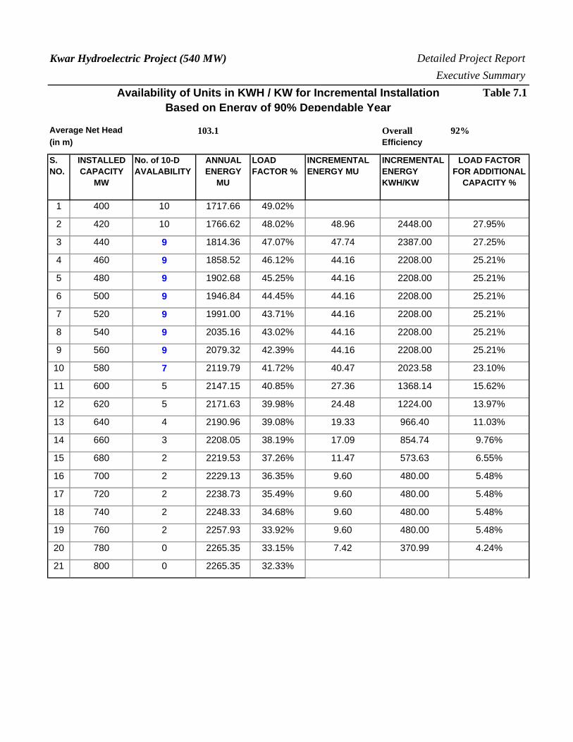
Kwar Hydroelectric Project (540 MW) Detailed Project Report
Executive Summary
Availability of Units in KWH / KW for Incremental Installation Table 7.1Based on Energy of 90% Dependable Year
Average Net Head 103.1 Overall 92%(in m) Efficiency
S. NO.
INSTALLED CAPACITY
MW
No. of 10-D AVALABILITY
ANNUAL ENERGY
MU
LOAD FACTOR %
INCREMENTAL ENERGY MU
INCREMENTAL ENERGY KWH/KW
LOAD FACTOR FOR ADDITIONAL
CAPACITY %
1 400 10 1717.66 49.02%
2 420 10 1766.62 48.02% 48.96 2448.00 27.95%
3 440 9 1814.36 47.07% 47.74 2387.00 27.25%
4 460 9 1858.52 46.12% 44.16 2208.00 25.21%
5 480 9 1902.68 45.25% 44.16 2208.00 25.21%
6 500 9 1946.84 44.45% 44.16 2208.00 25.21%
7 520 9 1991.00 43.71% 44.16 2208.00 25.21%
8 540 9 2035.16 43.02% 44.16 2208.00 25.21%
9 560 9 2079.32 42.39% 44.16 2208.00 25.21%
10 580 7 2119.79 41.72% 40.47 2023.58 23.10%
11 600 5 2147.15 40.85% 27.36 1368.14 15.62%
12 620 5 2171.63 39.98% 24.48 1224.00 13.97%
13 640 4 2190.96 39.08% 19.33 966.40 11.03%
14 660 3 2208.05 38.19% 17.09 854.74 9.76%
15 680 2 2219.53 37.26% 11.47 573.63 6.55%
16 700 2 2229.13 36.35% 9.60 480.00 5.48%
17 720 2 2238.73 35.49% 9.60 480.00 5.48%
18 740 2 2248.33 34.68% 9.60 480.00 5.48%
19 760 2 2257.93 33.92% 9.60 480.00 5.48%
20 780 0 2265.35 33.15% 7.42 370.99 4.24%
21 800 0 2265.35 32.33%
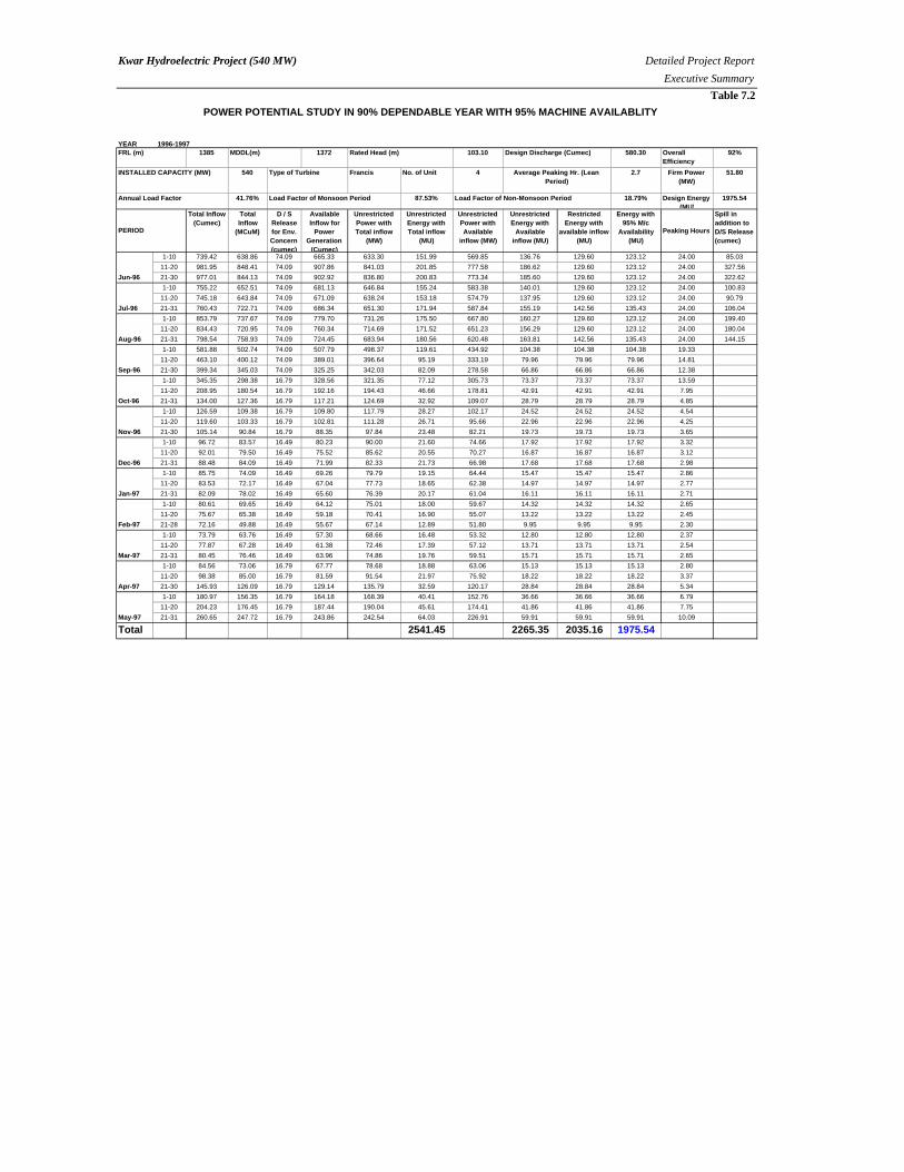
Kwar Hydroelectric Project (540 MW) Detailed Project Report
Executive Summary
Table 7.2
POWER POTENTIAL STUDY IN 90% DEPENDABLE YEAR WITH 95% MACHINE AVAILABLITY
YEAR 1996-19971385 1372 103.10 580.30 Overall
Efficiency92%
540 Francis No. of Unit 4 2.7 Firm Power(MW)
51.80
41.76% 87.53% 18.79% Design Energy(MU)
1975.54
Total Inflow (Cumec)
Total Inflow
(MCuM)
D / S Release for Env. Concern (cumec)
Available Inflow for
Power Generation
(Cumec)
Unrestricted Power with Total inflow
(MW)
Unrestricted Energy with Total inflow
(MU)
Unrestricted Power with Available
inflow (MW)
Unrestricted Energy with
Available inflow (MU)
Restricted Energy with
available inflow (MU)
Energy with95% M/c
Availability (MU)
Peaking Hours
Spill in addition to D/S Release (cumec)
1-10 739.42 638.86 74.09 665.33 633.30 151.99 569.85 136.76 129.60 123.12 24.00 85.03
11-20 981.95 848.41 74.09 907.86 841.03 201.85 777.58 186.62 129.60 123.12 24.00 327.56
21-30 977.01 844.13 74.09 902.92 836.80 200.83 773.34 185.60 129.60 123.12 24.00 322.62
1-10 755.22 652.51 74.09 681.13 646.84 155.24 583.38 140.01 129.60 123.12 24.00 100.83
11-20 745.18 643.84 74.09 671.09 638.24 153.18 574.79 137.95 129.60 123.12 24.00 90.79
21-31 760.43 722.71 74.09 686.34 651.30 171.94 587.84 155.19 142.56 135.43 24.00 106.04
1-10 853.79 737.67 74.09 779.70 731.26 175.50 667.80 160.27 129.60 123.12 24.00 199.40
11-20 834.43 720.95 74.09 760.34 714.69 171.52 651.23 156.29 129.60 123.12 24.00 180.04
21-31 798.54 758.93 74.09 724.45 683.94 180.56 620.48 163.81 142.56 135.43 24.00 144.15
1-10 581.88 502.74 74.09 507.79 498.37 119.61 434.92 104.38 104.38 104.38 19.33
11-20 463.10 400.12 74.09 389.01 396.64 95.19 333.19 79.96 79.96 79.96 14.81
21-30 399.34 345.03 74.09 325.25 342.03 82.09 278.58 66.86 66.86 66.86 12.38
1-10 345.35 298.38 16.79 328.56 321.35 77.12 305.73 73.37 73.37 73.37 13.59
11-20 208.95 180.54 16.79 192.16 194.43 46.66 178.81 42.91 42.91 42.91 7.95
21-31 134.00 127.36 16.79 117.21 124.69 32.92 109.07 28.79 28.79 28.79 4.85
1-10 126.59 109.38 16.79 109.80 117.79 28.27 102.17 24.52 24.52 24.52 4.54
11-20 119.60 103.33 16.79 102.81 111.28 26.71 95.66 22.96 22.96 22.96 4.25
21-30 105.14 90.84 16.79 88.35 97.84 23.48 82.21 19.73 19.73 19.73 3.65
1-10 96.72 83.57 16.49 80.23 90.00 21.60 74.66 17.92 17.92 17.92 3.32
11-20 92.01 79.50 16.49 75.52 85.62 20.55 70.27 16.87 16.87 16.87 3.12
21-31 88.48 84.09 16.49 71.99 82.33 21.73 66.98 17.68 17.68 17.68 2.98
1-10 85.75 74.09 16.49 69.26 79.79 19.15 64.44 15.47 15.47 15.47 2.86
11-20 83.53 72.17 16.49 67.04 77.73 18.65 62.38 14.97 14.97 14.97 2.77
21-31 82.09 78.02 16.49 65.60 76.39 20.17 61.04 16.11 16.11 16.11 2.71
1-10 80.61 69.65 16.49 64.12 75.01 18.00 59.67 14.32 14.32 14.32 2.65
11-20 75.67 65.38 16.49 59.18 70.41 16.90 55.07 13.22 13.22 13.22 2.45
21-28 72.16 49.88 16.49 55.67 67.14 12.89 51.80 9.95 9.95 9.95 2.30
1-10 73.79 63.76 16.49 57.30 68.66 16.48 53.32 12.80 12.80 12.80 2.37
11-20 77.87 67.28 16.49 61.38 72.46 17.39 57.12 13.71 13.71 13.71 2.54
21-31 80.45 76.46 16.49 63.96 74.86 19.76 59.51 15.71 15.71 15.71 2.65
1-10 84.56 73.06 16.79 67.77 78.68 18.88 63.06 15.13 15.13 15.13 2.80
11-20 98.38 85.00 16.79 81.59 91.54 21.97 75.92 18.22 18.22 18.22 3.37
21-30 145.93 126.09 16.79 129.14 135.79 32.59 120.17 28.84 28.84 28.84 5.34
1-10 180.97 156.35 16.79 164.18 168.39 40.41 152.76 36.66 36.66 36.66 6.79
11-20 204.23 176.45 16.79 187.44 190.04 45.61 174.41 41.86 41.86 41.86 7.75
21-31 260.65 247.72 16.79 243.86 242.54 64.03 226.91 59.91 59.91 59.91 10.09
Total 2541.45 2265.35 2035.16 1975.54
FRL (m) MDDL(m) Rated Head (m) Design Discharge (Cumec)
INSTALLED CAPACITY (MW) Type of Turbine Average Peaking Hr. (LeanPeriod)
Annual Load Factor Load Factor of Monsoon Period Load Factor of Non-Monsoon Period
PERIOD
Jun-96
Jul-96
Aug-96
Sep-96
Oct-96
Nov-96
May-97
Dec-96
Jan-97
Feb-97
Mar-97
Apr-97
Kwar Hydroelectric Project (540 MW) Detailed Project Report
Executive Summary
CHAPTER –8
DESIGN OF CIVIL ENGINEERING
STRUCTURES AND HYDROMECHANICAL EQUIPMENTS
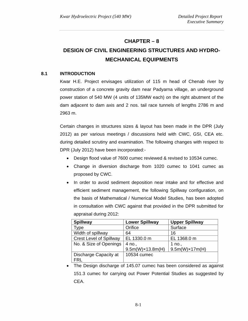
Kwar Hydroelectric Project (540 MW) Detailed Project Report Executive Summary
8-1
CHAPTER – 8
DESIGN OF CIVIL ENGINEERING STRUCTURES AND HYDRO-
MECHANICAL EQUIPMENTS
8.1 INTRODUCTION
Kwar H.E. Project envisages utilization of 115 m head of Chenab river by
construction of a concrete gravity dam near Padyarna village, an underground
power station of 540 MW (4 units of 135MW each) on the right abutment of the
dam adjacent to dam axis and 2 nos. tail race tunnels of lengths 2786 m and
2963 m.
Certain changes in structures sizes & layout has been made in the DPR (July
2012) as per various meetings / discussions held with CWC, GSI, CEA etc.
during detailed scrutiny and examination. The following changes with respect to
DPR (July 2012) have been incorporated:-
Design flood value of 7600 cumec reviewed & revised to 10534 cumec.
Change in diversion discharge from 1020 cumec to 1041 cumec as
proposed by CWC.
In order to avoid sediment deposition near intake and for effective and
efficient sediment management, the following Spillway configuration, on
the basis of Mathematical / Numerical Model Studies, has been adopted
in consultation with CWC against that provided in the DPR submitted for
appraisal during 2012:
Spillway Lower Spillway Upper SpillwayType Orifice Surface Width of spillway 64 16 Crest Level of Spillway EL 1330.0 m EL 1368.0 m No. & Size of Openings 4 no.,
9.5m(W)×13.8m(H) 1 no., 9.5m(W)×17m(H)
Discharge Capacity at FRL
10534 cumec
The Design discharge of 145.07 cumec has been considered as against
151.3 cumec for carrying out Power Potential Studies as suggested by
CEA.
Kwar Hydroelectric Project (540 MW) Detailed Project Report Executive Summary
8-2
Silt excluder arrangement below intake has been deleted as per
discussion with CWC, considering the low level spillway.
As per Technical clearance received from CWC, the principal components of the
project are:
A. A concrete gravity dam 101 m high above river bed level.
B. River diversion works comprising of 1 no, 9.5 m diameter horseshoe
shape diversion tunnel with upstream and downstream cofferdams.
C. 4 nos. orifice type spillways with discharging capacity of 3221 cumec
each and 1 no. crest spillway with discharging capacity of 884 cumec and
corresponding gate control structures to serve for flood release.
D. One outlet for environmental releases, having discharging capacity of
16.49 cumec to 74.09 cumec and gate opening size of 2.6m(W) x
2.0m(H)..
E. 4 nos. Construction sluices, each 3.1 m wide and 5.0 m high with crest at
EL.1300.0 m to serve for diversion flood during construction stage.
F. Water conductor system consisting of:
i. 4 nos. Power Dam Intakes with gate arrangement.
ii. 4 nos. 5.65 m dia. circular penstocks / pressure shafts, with vertical
lengths varying from 54.0 m to 93.0 m, and total lengths (excluding
vertical) varying from 108.0 m to 182.0 m.
iii. 2 nos. 9.5 m dia. horseshoe shaped tailrace tunnels of lengths
2786 m and 2963 m, respectively.
iv. 2 nos. downstream surge galleries of dia. 10.4 m and length 750
m.
G. An underground power house complex consisting of:
i. A machine hall cavern with MIV of size 140 m x 23.3 m x 50 m.
ii. A control room cavern of size 40 m x 15 m x 28.8 m.
iii. A transformer cavern of size 116.0 m x 17 m x 16 m.
iv. A GIS cavern of size 65 m x 15 m x 16 m.
H. An outdoor Pothead Yard of size 150 m x 35 m at EL.1315.0 m.
Kwar Hydroelectric Project (540 MW) Detailed Project Report Executive Summary
8-3
All these components are marked on the project layout plan (drawing no. NHKR-
D-41-GA-002).
These are based on the data available from various field investigations carried
out as detailed in Volume-IV.
8.2 LAYOUT OPTIMIZATION
8.2.1 Introduction
The pre-feasibility report of Kwar H.E. Project was prepared by WAPCOS as a
part of 50,000 MW hydro initiatives by Hon’ble PM. The project is located
upstream of Dulhasti project. The proposed FRL and Tail Water level of the
project as conceived in PFR were EL 1362.0 m and EL 1275.0m respectively. In
the PFR, the project was envisaged with a rated head of 74.0m and an installed
capacity of 320 MW with annual energy generation of 1426.56 MU in a 90%
dependable year.
8.2.2 Review of the Project
Kwar project is one of the four projects handed over by CEA to NHPC for
detailed investigation and preparation of Detailed Project Report in August 2004.
The Kwar Project as planned in the PFR envisaged construction of 68 m high
concrete Dam above deepest foundation level across the river Chenab and the
4.3 Km long head race tunnel of 12.0m dia with surface power house on the
right bank of Chenab river near Kwar village.
After handing over of the project to NHPC for preparation of DPR, the study of
PFR revealed that many components such as desilting basin are missing and
diameter of surge shaft provided was on lower side. Preliminary calculations
indicated that project would require large size desilting basins and very large
diameter surge shafts in geologically unstable terrain. Considering above, it was
felt necessary to workout alternative layout to optimize and simplify the project
components especially with respect to spillway, desilting requirement, surge
shaft and head race tunnel.
Kwar Hydroelectric Project (540 MW) Detailed Project Report Executive Summary
8-4
The topography of the area was further studied to locate alternative dam site.
After collecting preliminary site data and reconnaissance survey of the site, an
alternative-II were studied.
Alternative I – As proposed in PFR; Alternative-II - Dam at Padyarna village and
Power House on the right bank near Dam and TRT out fall near Kwar village as
proposed in the PFR.
Desk studies of all the alternative proposal were carried out and comparison
made in respect of installed capacity and merit of the various alternative vis a vis
utilization of available head and it revealed that the layout envisaged in
Alternative II seems attractive with respect to layout optimization, sizes of the
project components and overall benefit. Thus, the layout as above i.e.
Alternative II was been taken up for detailed investigation.
The results of further geological investigations carried out has revealed
availability of limited zone of competent rock mass for housing underground
power house and associated structures. This constraint necessitated some
changes in the initial layout of the project, notable among them being
replacement of power intakes with power dam blocks, layout and sizes of
caverns of power house complex, and optimization in size and alignment of
water conductor system and installed capacity. It is this revised layout that is
presented in this report.
8.2.3 Conclusion
Desk studies of all the alternative proposals were carried out and comparison
made in respect of installed capacity and merit of the various alternative vis-a-vis
utilization of available head and it revealed that the modified layout envisaged in
alternative II seems attractive with respect to geological setup, layout
optimization, sizes of the project components and overall benefit.
The layout as above i.e. Alternative II, was taken up for detailed investigation in
2007. Since then, results of additional investigations have necessitated further
Kwar Hydroelectric Project (540 MW) Detailed Project Report Executive Summary
8-5
optimization of layout and sizing of the project components, which are presented
and discussed in this DPR.
8.3 INDUS WATER TREATY ASPECT
The Kwar project is proposed on the Chenab river which is one of the western
rivers covered in the Indus Water Treaty, 1960. The parameters of the project
have been planned in accordance with the provision of the treaty. Following
aspects of the treaty has been considered while fixing the project parameters.
8.3.1 Pondage
The Kwar project is situated downstream of the Naunut (Latitude 33º21’01” North
and Longitude 75º53’39” East) and as such no storage could be provided as per
the treaty. However, the pondage as mentioned in the run of the river plant in
para 8 of Annexure D of the treaty has been proposed considering the following
operation of the plant:
a) The volume of water received in the river upstream of the plant, during
any period of seven consecutive days shall be delivered into the river
below the plant during the same seven day period. and
b) Volume of the water delivered in the river below the plant in any one
period of 24 hrs shall not be less than 50% and not more than 130% of
the volume received above the plant during the same 24 hrs period.
8.3.2 Minimum Drawdown Level
The FRL of the project has been decided on the basis of tailrace level of
upstream project (i.e Kiru Project). The MDDL has been fixed at EL 1372.0 m
on the basis of reservoir area capacity curve thus providing pondage of 9.16
Mcum between FRL and MDDL.
8.3.3 Power Intake Level
The power plant is proposed to operate between head water level of EL
1385.0m and EL 1372.0 m. In order to keep the flow condition in the intake
smooth and to avoid the vortex formation, water seal above the intake centerline
has been provided as per IS guidelines. On the basis of this the centre-line level
Kwar Hydroelectric Project (540 MW) Detailed Project Report Executive Summary
8-6
of intake has been fixed at EL 1362.025 m, the size of opening being 5.65 m x
5.65 m.
8.3.4 Spillway Crest Level
In order to ensure passage of design flood discharge of 10534 cumec, the crest
level of four nos. of orifice spillways have been kept at EL. 1330.0 m. In
combination with 1 no. crest spillway with crest level at 1368.0m, the level of
spillway crest would facilitate entry of silt-free water inside the water conductor
system. The above parameters shall be optimized on the basis of model study.
The proposed orifice spillway shall be used for dual purpose of sediment
management and passing of design flood.
8.3.5 Free Board
The free board for the concrete gravity dam has been calculated as per the
guidelines of IS 6512 and IS 10084. A free board of 2.0 m has been provided
which is reasonable considering the height of the dam, reservoir length, wind
velocity etc.
8.4 RIVER DIVERSION WORKS
8.4.1 Diversion Tunnel
For the construction of concrete gravity dam and appurtenant works, the river
diversion is proposed to be carried out through 1 no.9.5 m diameter concrete
lined, horse shoe shaped diversion tunnel located on the left bank of the river.
The diversion tunnel has been designed for passing 1 in 25 years non-monsoon
(1st October to 15th May) flood of 1041 cumec.
8.4.2 Coffer Dams
Rock-fill cofferdams with a central impervious core shall be provided. Axes of
these coffer dams shall be located about 115.0 m upstream and 350.0 m
downstream of the proposed dam axis. The top level of 23m high upstream and
14m high downstream cofferdams has been provided at EL 1315.0 m and EL
1292.0 m respectively.
Kwar Hydroelectric Project (540 MW) Detailed Project Report Executive Summary
8-7
8.5 THE DAM
8.5.1 General
The proposed concrete gravity dam with its top at EL 1387.0 m has a length of
195 m. The top width of the dam varies from 12.5 m to 14.6 m.
8.5.2 Dam Height
The full reservoir level of the project has been finalized based upon the tail water
level of upstream project (i.e. Kiru Project). The dam site, at Padyarna village
has exposed rock on both the abutments and the valley is relatively narrow.
Considering the above, dam location has been kept at this site. Dam height of
101 m high above river bed level has been proposed. The height of dam above
deepest foundation level is expected to be of the order of 109 m.
8.5.3 Type of Dam
Considering the shape of the valley, rock exposure on the abutments and
relatively low depth of overburden in the river (7 to 10m), a conventional
concrete gravity dam has been proposed. The spillway has been
accommodated in the central portion of the concrete dam. The power intakes
have been provided in separate power dam blocks in the right portion of the
concrete dam.
8.5.4 Dam Arrangement
The proposed dam is concrete gravity dam across the river with dam top at EL
1387.0m. The bedrock level at dam axis is at EL 1283.0m. Initial 4-5m depth
of rock is expected to be weathered and as such after accounting for removal of
this portion of rock, the deepest foundation level has been proposed as EL.
1278.0 m. Thus the height of dam above deepest foundation level is expected
to be of the order of 109 m. Min. top width of dam is proposed to be kept as
12.5 m, which shall provide for carriageway of the road.
8.5.5 Reservoir
The full reservoir level has been kept as EL 1385.0 m. This level has been fixed
keeping in view the TWL at the outlet of Kiru Project. The project is run of the
Kwar Hydroelectric Project (540 MW) Detailed Project Report Executive Summary
8-8
river scheme with pondage as per provision of Indus Water Treaty 1960. The
gross storage capacity of the reservoir shall be 27.167 Mcum and the live
storage at pre-sedimentation stage is 9.16 Mcum respectively.
8.5.6 Spillway
To pass the excess water from dam, spillway section has been provided. The
overflow section of 64 m width comprises of four low level spillway blocks, with
crest level at EL 1330.0 m, each of 16.0m width with 9.5 m clear waterway and
discharging capacity of 3221 cumec each. The thickness of the piers shall be
designed by FEM analysis & may be increased during detailed design stage.
One no. crest spillway with crest level of 1368.0m is also proposed with opening
size of 9.5m x 17m and discharging capacity of 884 cumec. With one gate
inoperative, the remaining three bays with one no. crest spillway are capable of
discharging the design flood of 10534 cumec. The height of each orifice spillway
opening has been kept as 13.8 m. Each spillway has been provided with a
hydraulically operated radial gate. Upstream of radial gate, stop-log gate has
also been proposed in order to facilitate maintenance of radial gates.
8.5.7 Outlet for Environmental Releases
In addition to the spillways, an outlet for (mandatory) environmental releases has
also been provided, with a discharging capacity of 16.49 to 74.09 cumec and
size of gate opening as 2.6 m x 2.0 m.
8.5.8 Construction sluices
To facilitate construction of dam, 4 numbers construction sluices have been
proposed with crest at EL. 1300.0 m. The size of each construction sluice is 3.1
m x 5.0 m. These construction sluices will cater for passing monsoon flood
during construction. Each construction sluice has discharge capacity of 289
cumec at EL 1336.60 m.
8.5.9 Non Overflow Section
Out of total dam length of 195 m, five bays of spillway shall cover 80 m length.
Remaining length of dam has been provided as non-overflow sections. On the
left bank two number non-overflow blocks of 16.0 m width and 16.725 m width
Kwar Hydroelectric Project (540 MW) Detailed Project Report Executive Summary
8-9
have been provided. On the right bank, four power dam blocks of 15.0 m width
each and one non-overflow block of 22.08 m width have been provided.
8.5.10 Stability Analysis
The preliminary stability analysis for over flow and non-overflow sections has
been carried out in accordance with IS: 6512 for various load combinations and
found within the permissible limits as per code. In-situ rock mechanics tests
have also been conducted in the dam drifts for confirmation of parameters, and
have been adopted in the design. Study for site specific Earthquake parameters
has been completed by Department of Earthquake Engineering, IIT Roorkee
which has been subsequently approved by National Committee on Seismic
Design Parameters (NCSDP).
8.5.11 Energy Dissipation Arrangement
A ski jump type energy dissipation arrangement has been provided at
downstream of spillway. Flip bucket of radius 44.0 m with invert level at EL.
1311.478 m and lip angle of 34 has been adopted. The lip has been provided
at EL 1319 m. A preformed plunge pool with lowest bed level at EL. ±1262.0 m
and of size 60.0 m x 60.0 m has been proposed. The energy dissipation
arrangement will, however be optimized on the basis of hydraulic model studies
before finalization of engineering designs.
8.5.12 Dam Instrumentation
As the project envisages a high concrete gravity dam, instrumentation shall be
provided to monitor behavior of the dam during construction as well as operation
stage. At this stage percentage provision has been made in the cost estimate for
instrumentation. 7 numbers of drawings for instrumentation have been prepared
and submitted with this updated DPR. Further detailing shall be carried out
during detailed design.
8.6 POWER DAM AND INTAKE
4 nos. power dam blocks with one intake each have been provided to lead the
water to the powerhouse. The invert of intake structure has been kept at EL.
Kwar Hydroelectric Project (540 MW) Detailed Project Report Executive Summary
8-10
1359.20 m, to keep the intake relatively silt free. Each intake structure has been
provided with trash rack structure at its entry. The maximum permissible velocity
through trash rack has been kept as 1.5 m/s. The top of power dam is at EL
1387.0 m.
8.7 PRESSURE SHAFTS AND PENSTOCKS
The water from each intake is carried by 5.65 m finished diameter penstocks
and pressure shafts. Full length of penstocks / pressure shafts is proposed to
be steel lined to take care of pressure rise in case of load rejection. After the
lower vertical bend at bottom, each penstock / pressure shaft leads to a unit of
135 MW each. The space around steel liner shall be back-filled with concrete.
To facilitate excavation and erection of steel liner, independent erection
platforms have been proposed at the top of each pressure shaft, in addition to
an adit and erection gallery at the bottom of the shafts.
8.8 POWER HOUSE
8.8.1 General
The underground powerhouse is located on the right bank of River Chenab near
dam axis. The powerhouse complex comprises the following main feature:
Power house cavern with four generating units & MIV.
Control Room Cavern.
Transformer cavern.
GIS Cavern.
Access Tunnel to PH and TC.
Adit cum Cable Tunnel.
Downstream surge arrangement.
Outdoor Pothead yard.
The proposed powerhouse will have an installed capacity of 540 MW (4
generating units of 135 MW each). The units are spaced at a distance of 27.0 m
centers. The turbine centerline is placed at EL 1245.55 m. The excavation level
of the draft tube pit is at EL 1230.75 m. TRT outlet is proposed at EL 1266.50 m.
Kwar Hydroelectric Project (540 MW) Detailed Project Report Executive Summary
8-11
8.8.2 Layout of Power House Complex
Powerhouse cavern and other associated caverns/galleries have been provided
inside the ridge at the right bank of Chenab River. The layout of the
powerhouse complex is shown in Drawing No. NHKR-D-41-GA-005. The layout
of individual caverns / galléries is discussed below:
8.8.3 Power House Cavern
Powerhouse cavern having width of 23.30 m consists of 112 m long machine
hall housing 4 units placed at 27 m c/c. Service bay of length 28 m has been
located at EL. 1258.65 m at one end of cavern, and an equipment gallery of
length 30 m and size 10 m D-shaped has been provided at the other end (Unit-
4), also at EL. 1258.65 m. The overall size of power house cavern is 140 m x
23.3 m x 50 m.
8.8.4 Control Room Cavern
Due to geological and topographical constraints, the Control Room has been
located in a separate cavern aligned perpendicular to the main power house
cavity. The size of cavern is 40 m x 15 m x 28.8 m, and the building itself has 5
levels (excluding roof). It is connected to the service bay of power house by
means of an adit cum cable gallery of size 30 m x 6 m x 15.3 m.
8.8.5 Transformer cum Draft Tube Gate Cavern
Transformer cavern of size 116 m x 17 m x 16 m, has been proposed 54.45 m
downstream of powerhouse cavern at EL. 1310.0 m. It is aligned parallel to the
main power house cavern and is connected to it by means of an inclined cable
cum escape gallery and 4 nos. inclined bus ducts. The draft tube gates shall be
operated from the transformer cavern and hence, independent gate hoists are
located towards the downstream wall of the cavern. An unloading bay has been
provided at one end of the cavern and therefore, in this portion, the height of the
cavern is raised accordingly. At the other end of the cavern, a gallery of size 26
m x 11.5 m x 10 m has been provided for housing equipment and providing
connectivity to power house through escape cum cable gallery.
Kwar Hydroelectric Project (540 MW) Detailed Project Report Executive Summary
8-12
8.8.6 GIS Cavern
As in the case of control room cavern, the GIS cavern has been located
separate from the transformer cavern, due to geological and topographical
constraints. Aligned parallel to the transformer cavern, it is offset from it by 15 m.
The overall size of GIS cavern is 65 m x 15 m x 16 m. At one end of the GIS
cavern, the access to transformer cavern passes through it. At the other end, an
adit cum cable tunnel provides connectivity to the pothead yard.
8.8.7 Access Tunnel to Power House and Transformer Cavern
A main access tunnel (MAT) of length ±610 m and size 8.0 m D-shaped with
portal invert at EL 1310.0 m has been provided for permanent access to power
house and control room caverns. Access to transformer cavern is by means of a
branch tunnel of length ±310 m, which is connected to MAT at EL. 1292.726 m.
The downstream surge gallery for TRT-2 is connected to access tunnel to TC at
EL. 1310.0 m. Access to lower erection gallery for pressure shafts is provided
through a tunnel of size 8.0 m, D-shaped, which branches out from surge gallery
for TRT-2. Length of this tunnel is ±305 m. For excavating crown portion of
power house, a construction adit of size 6.0 m x 6.5 m has been provided
between the control room cavern and service bay end of power house cavern.
For excavating crown portion of GIS and transformer caverns, an adit cum cable
tunnel has been provided, as discussed below in 8.7.8.
8.8.8 Adit cum Cable Tunnel
An adit cum cable tunnel of size 6.0 m x 6.5 m and length ±275 m has been
provided with portal invert at EL. 1305.0 m, near pothead yard. This tunnel
meets the GIS cavern at EL. 1318.5 m, for facilitating excavation of crown
portions of GIS and transformer caverns. After excavation, the same adit will
serve as cable tunnel between GIS and pothead yard.
8.8.9 Downstream Surge Arrangement
Considering the length of the downstream waterway, provision of surge
arrangement is required as per transient study. Tail race system comprises of 4
nos. draft tubes merging into 2 nos. tail race tunnels. The surge arrangement
Kwar Hydroelectric Project (540 MW) Detailed Project Report Executive Summary
8-13
consists of a combination of individual draft tube gate shafts, draft tubes and
manifold and surge galleries, one for each TRT. The gate shafts are of size 5.4
m x 7.5 m, with bottom at EL. 1235.65 m and top at EL. 1310.0 m, opening into
transformer cavern. The size of draft tube gate opening is 7.0 m x7.0 m. The
surge galleries of length 750 m each are 10.4 m in diameter and Horse Shoe-
shaped. Invert levels of the surge galleries are EL. ±1234.5 m at the bottom and
EL. 1310.0 m at the top. The downstream surge gallery for TRT-2 is connected
to access tunnel to TC and downstream surge gallery for TRT-1 open out with a
separate portal at EL. 1310.0m. The maximum up-surge and minimum down-
surge levels are EL. 1303.0 m and EL. 1246.40 m, respectively.
8.8.10 Outdoor Pothead Yard
An outdoor Pothead Yard is proposed to be accommodated on the right bank, in
a bench of size 150 m x 35 m, at EL. 1315.0 m. An adit cum cable tunnel of size
6.0 m x 6.5 m and length ±275 m is proposed to connect the GIS cavern to
pothead yard, with invert level at portal being EL. 1305.0 m. From the portal to
pothead yard, a cable trench is proposed to be provided for a length of ±90 m.
8.9 TAIL RACE TUNNEL SYSTEM
The Tail Race system comprises of 4 nos. draft tubes merging into 2 nos. tail
race tunnels. Shortly downstream of the merging points, the downstream surge
galleries branch out from each TRT, as discussed above. The diameter of
tailrace tunnel has been proposed as 9.5 m, to optimize tunnel hydraulics
including downstream surge arrangement, and also to ensure stability of
excavation of TRT. The lengths of the tunnels are 2786 m and 2963 m. To
facilitate the construction of TRT, an intermediate construction adit of size 6.0 m
x 6.5 m and length 560 m has been provided with portal invert at EL. 1300.0 m.
The adit is proposed to be concrete lined in invert and shall be plugged later
after completion of the project work.
8.10 TAILRACE OUTLET WORKS
Each tailrace tunnel opens into a tailrace outlet structure, with a common tail
pool of varying length and an outlet weir. The outlet structure has been provided
Kwar Hydroelectric Project (540 MW) Detailed Project Report Executive Summary
8-14
with gate arrangement to isolate the unit from downstream side. The maximum
tail water level is calculated to be 1291.8 m corresponding to PMF. The gate
operation platform is proposed at EL. 1293.0m. The crest level of gate is at EL
1265.0 m and crest level of outlet weir is at EL. 1266.50 m.
8.11 HYDRO-MECHANICAL EQUIPMENTS
8.11.1 GENERAL
As per planning & layout of civil structures, following hydro-mechanical
equipments are proposed for Kwar Hydroelectric Project: -
8.11.2 DIVERSION TUNNEL GATES AND HOISTS
For the purpose of closing diversion tunnels, two numbers fixed wheel type
gates for opening size of 3.94 m wide x 9.50 m height have been envisaged at
the inlet of tunnel. The gates shall have an upstream skin plate & upstream
sealing. The sill of gate is located at EL 1293.00M. The gates are to be designed
for water head corresponding to water level EL 1336.70M which is
corresponding to mean annual flood. The deck level of the diversion tunnels has
been fixed at EL 1338.00M.
The gates shall be operated by means of dedicated electrically operated rope
drum hoists of capacity not less than 120T located on the hoist platform installed
over trestles above the deck level. These gates are not envisaged to be kept in
partial open condition and are meant for one time closure during lean season.
During closure of DT gates water shall be passed through construction sluices
and spillways. The diversion tunnel shall be plugged before the start of reservoir
filling.
8.11.3 CONSTRUCTION SLUICE GATES AND HYDRAULIC HOISTS
In addition to the Diversion Tunnel, four numbers construction sluices are
provided in the body of Dam. One number fixed wheel type gate for opening size
of 3.1m x 5.0m has been provided in each sluice. The gates shall have an
upstream skin plate & upstream sealing. The sill of the gate is located at EL
1300.00M. Sluice gates are capable of sustaining water loads up to FRL i.e.
1385.00M and designed to be lowered under unbalanced water head up to
Kwar Hydroelectric Project (540 MW) Detailed Project Report Executive Summary
8-15
1336.70M which is corresponding to mean annual flood. Each gate shall be
operated by means of an independent double acting hydraulic cylinder of
capacity not less than 125T Pull and 70T Push & a power pack located in the
operation gallery. A watertight bonnet and bonnet cover is also provided at the
top of groove in the gate operation chamber to avoid any ingress of water into
the gallery.
Construction sluice shall be closed by lowering the gates in each groove for
construction of concrete plug. Suitable sized air vent pipe shall be embedded in
the downstream of gate of all four construction sluices for aeration purpose and
to reduce hydrodynamic forces on the gate during operation. A monorail hoist of
capacity not less than 15T shall be provided to facilitate erection of gates and
hydraulic hoist system.
8.11.4 ORIFICE TYPE SPILLWAY RADIAL GATES & HYDRAULIC HOISTS
Spillways consist of four nos. orifice type bays of opening size 9.50 m x 13.80 m
with crest at EL 1330.00M. Four submerged type radial gates for opening size of
9.50 m x 13.80 m shall be provided to control the discharge through the
spillways. The radial gates shall be designed to sustain and operate against a
head corresponding to FRL i.e. EL 1385.00M. Each gate shall be operated by
means of two hydraulic cylinders, each of capacity not less than 330T, and a
power pack. The gate operation shall be done from individual local control
panels as well as from remote control system located at the dam control room
(DCR), with provision of gate position indication in powerhouse control room.
Steel liner has been proposed to be provided underside of breast wall, in the
piers and spillway glacis along the flow path from upstream of Stoplog to
downstream of spillway radial gates to prevent erosion of piers and spillway
glacis concrete resulting in damage of sill beams of spillway Stoplog and radial
gates.
Two numbers trolley mounted mobile gasoline engine operated power pack
capable of operating one gate at 1/4th of the normal rated speed is also
envisaged.
Kwar Hydroelectric Project (540 MW) Detailed Project Report Executive Summary
8-16
One no. oil filter unit to purify the hydraulic oil, one unit contamination checking
kit for checking of contamination level of the hydraulic oil & one no. low vacuum
dehydration and degasification unit to remove water and gases from the
hydraulic oil shall be provided to cater for hydraulic hoists envisaged in the HM
equipment.
8.11.5 CREST TYPE SPILLWAY RADIAL GATES & HYDRAULIC HOISTS
Spillways consist of one number crest type bay of opening size 9.50 m x 17.00
m with crest at EL 1368.00M. One number crest type radial gate for opening size
of 9.50m x 17.00m shall be provided to control the discharge through the
spillway. The radial gates shall be designed to sustain and operate against a
head corresponding to FRL i.e. EL 1385.00M. Each gate shall be operated by
means of two hydraulic cylinders of 150T capacities each, and a power pack.
The gate operation shall be done from individual local control panels as well as
from remote control system located at the dam control room (DCR), with
provision of gate position indication in powerhouse control room.
8.11.6 SPILLWAY STOPLOG & GANTRY CRANE
The inspection and maintenance of the Spillway Radial Gates (Orifice type as
well as Crest type) shall be carried out by using one set of wheel type stoplog on
the upstream side of these gates. The stoplog shall be fabricated in four units for
opening size 9.50 m wide x 17.00 m high for Crest type Spillway Radial Gate.
Except top unit, all three units shall be interchangeable. The same stoplog shall
be used for inspection and maintenance of Orifice type Spillway Radial Gates
also.
The stoplog shall have upstream skin plate and downstream sealing. The
stoplog shall be designed for a head corresponding to FRL i.e. EL 1385.00M
and shall be operated under balanced head condition. The top unit shall be
provided with a filling–in-valve to create balance head condition. The stoplog
units shall be kept over latches in the stoplog grooves. The stoplog units shall be
operated by means of a gantry crane of 130T capacity and a lifting beam. Gantry
rails (upstream rails on concrete girder and downstream rails on breast wall)
Kwar Hydroelectric Project (540 MW) Detailed Project Report Executive Summary
8-17
shall be provided at the deck level for movement of the gantry crane across
spillway bays. Suitable cross travel shall also be provided in gantry crane to
handle Stoplog units in bays/storage groove.
8.11.7 ENVIRONMENT RELEASE GATE AND HOIST
For environmental release of water, one number slide type regulating gate and
one number slide type emergency gate for opening size of 2.60 m wide x 2.00 m
height have been envisaged at the inlet. The gates shall have an upstream skin
plate & upstream sealing. The sill of the gates is located at EL 1369.90M. The
gates are to be designed for water head corresponding to water level EL
1385.00M. The deck level of the gate has been fixed at EL 1387.00M. A
watertight bonnet cover is provided at the top of groove to avoid any ingress of
water into the gate operation niche/chamber.
The gate shall be operational under any water head between elevations EL
1369.90M to EL 1385.00M. The gates shall be operated by means of double
acting hydraulic hoists of 90T capacity and a common power pack located on
the deck level. Suitable steel cover shall be provided at Deck Level EL
1387.00M to cover the gate operation niche/chamber
8.11.8 POWER INTAKE GATES, HOISTS, INTAKE BULKHEAD AND GANTRY
CRANE, TRASH RACK & TRASH RACK CLEANING MACHINE
Four nos. power tunnel intakes are located on right bank to feed water to
Pressure shaft/turbine units. Dedicated fixed wheel type gate for opening size
5.65 m wide x 5.65 m height shall be provided for each intake. The sill of the
gates is located at EL 1359.20M. The gates are to be designed for a head
corresponding to FRL i.e. EL 1385.00M. The gates shall have an upstream skin
plate & upstream sealing. The gates shall be capable of lowering against
unbalanced head corresponding to FRL i.e. EL 1385.00M. The gate shall be
lifted under balanced head conditions created by crack opening of gate against
U/S water level up to FRL i.e. EL 1385.00M. The gates shall be operated by
means of dedicated rope drum hoists with lifting capacity not less than 90T
installed on hoist supporting structure at Intake deck level at EL 1387.0 m.
Kwar Hydroelectric Project (540 MW) Detailed Project Report Executive Summary
8-18
For maintenance and inspection of intake gate, one set of slide type bulkhead
made of 3 units for opening size 8.5m wide X 8.9m height has been proposed on
the upstream side. The sill of the bulkhead is located at EL 1357.59 m and
bulkhead shall be designed for corresponding to FRL i.e. EL 1385.0 m. The gate
shall have upstream skin plate & downstream sealing. The top unit of stoplog
shall be provided with filling in valve to create balanced head condition before
lifting of the units.
The bulkhead shall be operated under balanced head condition by means of a
gantry crane of 130 T capacity located on the intake deck and shall be lowered
only for inspection and maintenance of the Intake gate embedded parts. The
balance head shall be achieved by using filling-in-valve provided in the
bulkhead.
It is proposed to provide steel liners in the lower bell mouth area of intake along
the flow path from downstream of Intake bulkhead up to transition of pressure
shaft to prevent erosion of concrete resulting in dislodging of sill beams.
On upstream face of the intakes, trash rack Inclined at 10 degree with vertical
shall be provided. Each of four trash rack shall be for opening of size
approximately 15.0m wide x 32.20 m vertical height and shall be fabricated in
panels of suitable sizes. A total of four such screens are provided in the intake
structure for complete covering of intakes.
The cleaning of the trash rack shall be done by means of trash rack-cleaning
machine installed on the intake deck. The machine will be mounted on rail tracks
running across the intakes. Suitable grapple arrangement shall also be provided
with TRCM. Provision shall be made for suitable capacity trash removal
trolley/vehicle.
8.11.9 PENSTOCK STEEL LINER
Four number pressure shaft of size 5.65 m fully steel lined take off from the d/s
of Dam intake gate. Steel liner of diameter 5.65 m consist of transition, straight,
Kwar Hydroelectric Project (540 MW) Detailed Project Report Executive Summary
8-19
vertical and inclined ferrules, three inclined bends, one compound bends, thrust
collar etc. for each lane, to feed four nos. turbines placed in the power house.
Steel liner shall be designed for internal pressure equal to static head plus the
induced water hammer due to normal Wicket gate operation as well as for the
external pressure as per IS: 11639 (Part 2). Accordingly the thickness of liner
shall be adopted and provision of stiffeners shall be made.
8.11.10 DRAFT TUBE GATES AND HOISTS
To isolate turbines from the tailrace tunnels to cater to the inspection /
maintenance requirements of turbines, one number fixed wheel type gate having
skin plate on tail race side & sealing on turbine side has been provided in each
of the four draft tubes. The clear opening of the gate is 7.0 m wide 7.0 m
height. The sill of the gate shall be located at EL 1235.65M. The gate shall be
designed for water levels corresponding to TWL EL 1270.00M corresponding to
all four units are running, and checked for TWL EL 1291.80M corresponds to
PMF. The gates shall be capable to be lowered under unbalanced condition.
The raising of gates shall be under balanced head created by operation of filling
in valves provided in the gates.
Each gate shall be operated by means of dedicated rope drum hoists with lifting
capacity not less than 125T installed on hoist supporting structure at deck level
1310.00M.
8.11.11 TRT OUTLET GATES AND ROPE DRUM HOISTS.
Each tailrace tunnel is provided with a gate of opening size 9.5 m wide x 9.5 m
height at the outlet. Wheel type gate suitable for the above opening is provided
to isolate the tunnel/generating unit from tail water. The sill of the gate is located
at EL. 1265.00M. The gate shall have skin plate and sealing on the riverside.
The TRT gates shall be capable of lowering against unbalanced head
corresponding to EL 1291.80M which is corresponding to PMF with turbine units
closed. The opening of the gates shall be under balanced head creating by
crack opening of the gate. These gates shall be suitably designed to sustain a
water head in the river at EL 1291.80M.
Kwar Hydroelectric Project (540 MW) Detailed Project Report Executive Summary
8-20
Each gate shall be operated by means of a dedicated rope drum hoist with lifting
capacity not less than 125T installed on hoist supporting structure at Deck EL
1293.00M.
8.11.12 INSTRUMENTATION AND AUTOMATIC RESERVOIR MONITORING AND
CONTROL SYSTEM
One complete set of microprocessor based remote control system shall be
provided in dam control room for the operation of spillway radial gates and
Environmental release gates. The programmable reservoir monitoring and
control system shall include all necessary instrumentation like water level
measuring instruments, gate position indicators, transducers, terminals,
contacts, cabling etc. The status indications shall also be made available in the
powerhouse control room. The communication system shall be bridged through
fiber optic cable.
One uninterruptible power supply to provide back up (minimum 30 minutes) to
the system in case of failure of main power supply to equipments shall also be
provided.
8.11.13 DIESEL GENERATOR SET
One number 500 KVA, three phase synchronous type 415 volts, 50 Hz diesel
generator sets with acoustic enclosures has been envisaged for the emergency
operations of the HM equipments at the dam site. The diesel generating sets
shall be suitably located to provide back-up supply to gate operating equipments
and to computerized control system in case of power failure.
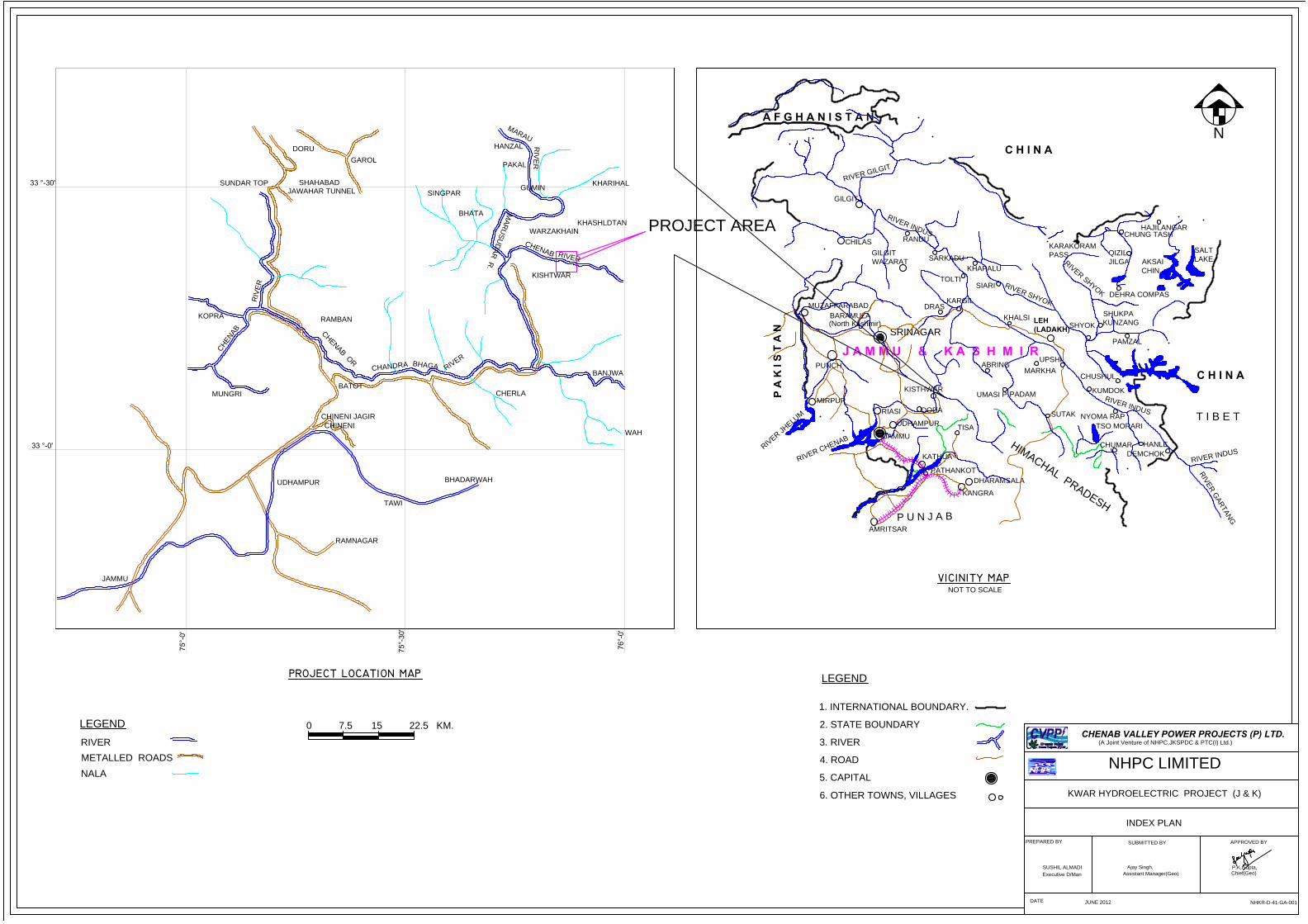
0 7.5 15 22.5 KM.
METALLED ROADS
LEGEND
NALA
RIVER
R
IV
E
R
IN
D
U
S
C H I N A
T I B E T
DHARAMSALA
NOT TO SCALE
KANGRA
J A M M U & K A S H M I R
UMASI P.
SIARI
KHAPALU
TOLTI
MUZAFFARABAD
(North Kashmir)
BARAMULA
R
I
V
E
R
C
H
E
N
A
B
R
I
V
E
R
J
H
E
L
U
M
P A
K
I S
T
A
N
PUNCH
MIRPUR
JAMMU
P U N J A B
AMRITSAR
PATHANKOT
KATHUA
KISTHWAR
UDHAMPUR
SRINAGAR
RIASI
DODA
TISA
KARGIL
DRAS
A F G H A N I S T A N
CHILAS
R
IV
E
R
G
IL
G
IT
GILGIT
RANDU
R
I
V
E
R
I
N
D
U
S
GILGIT
WAZARAT
SARKADU
R
I
V
E
R
S
H
Y
O
K
TSO MORARI
H
I
M
A
C
H
A
L
P
R
A
D
E
S
H
CHUMAR
R
IV
E
R
IN
D
U
S
NYOMA RAP
KUMDOK
SHUKPA
KUNZANG
CHUSHUL
R
I
V
E
R
S
H
Y
O
K
LEH
(LADAKH)
UPSHI
MARKHA
PADAM
ABRING
KHALSI
SUTAK
SHYOK
DEMCHOK
HANLE
R
I
V
E
R
G
A
R
T
A
N
G
PAMZAL
DEHRA COMPAS
C H I N A
KARAKORAM
PASS
HAJILANGAR
CHUNG TASH
QIZIL
JILGA AKSAI
CHIN
SALT
LAKE
JAMMU
RAMNAGAR
RAMBAN
KOPRA
CHINENI JAGIR
UDHAMPUR
TAWI
CHINENI
MUNGRI
C
H
E
N
A
B
CH
AN
DR
A
C
H
E
N
A
B
O
R
BATOT
R
IV
E
R
DORU
JAWAHAR TUNNEL
SHAHABADSUNDAR TOP
GAROL
BHADARWAH
WAH
CHERLA
R
I
V
E
R
BH
AG
A
BANJWA
PROJECT AREA
KHASHLDTAN
KHARIHAL
M
A
R
U
S
U
D
A
R
R
.
KISHTWAR
WARZAKHAIN
R
IV
E
R
C
H
E
N
A
B
RIV
ER
M
A
R
A
U
BHATA
SINGPAR
PAKAL
HANZAL
GUMIN
1. INTERNATIONAL BOUNDARY.
2. STATE BOUNDARY
3. RIVER
4. ROAD
5. CAPITAL
6. OTHER TOWNS, VILLAGES
LEGEND
KWAR HYDROELECTRIC PROJECT (J & K)
N
P.K.Gupta,
Chief(Geo)
INDEX PLAN
PREPARED BY
SUBMITTED BY
APPROVED BY
SUSHIL ALMADI
Executive D/Man
Ajay Singh,
Assistant Manager(Geo)
DATE
JUNE 2012
NHPC LIMITED
CHENAB VALLEY POWER PROJECTS (P) LTD.
(A Joint Venture of NHPC,JKSPDC & PTC(I) Ltd.)
NHKR-D-41-GA-001
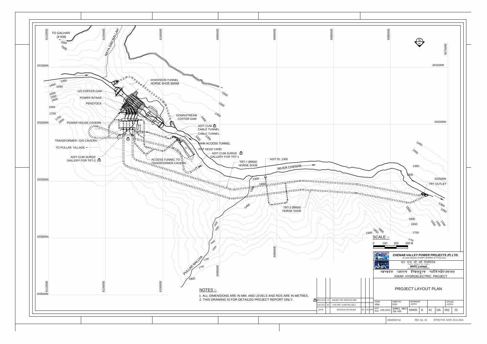
201500N
202000N
202500N
608000E
608500E
609000E
609500E
610000E
610500E
611000E
202000N
202500N
203000N
203500N
609000E
609500E
610000E
610500E
611000E
607500E
1
4
5
0
1
4
0
0
1350
1300
1600
1650
1700
1
7
5
0
1700
1650
1
6
0
0
1
7
5
0
1
8
0
0
1
5
5
0
1
5
0
0
1
5
0
0
1
4
5
0
1
4
0
0
1900
1
3
5
0
TO GALHAR
(4 KM)
1
3
0
0
1
4
0
0
1
5
0
0
1. ALL DIMENSIONS ARE IN MM. AND LEVELS AND RDS ARE IN METRES.
2. THIS DRAWING IS FOR DETAILED PROJECT REPORT ONLY.
NOTES :-
DIVERSION TUNNEL
DOWNSTREAM
COFFER DAM
PENSTOCK
ADIT EL.1300
1
4
5
0
1
5
5
0
1
8
5
0
N
TO PULLAR VILLAGE
HORSE SHOE
NHKR D 41 GA 002 01
POWER INTAKE
POWER HOUSE CAVERN
TRANSFORMER / GIS CAVERN
KWAR HYDROELECTRIC PROJECT
EFFECTIVE DATE- 29.11.2010
CH.
REV. No. 02IMS/DED/F-02
00
DATE REVISION OR ISSUES
FOR DPR PURPOSE ONLY
BY. APP.
NHPC Limited
CHENAB VALLEY POWER PROJECTS (P) LTD.(A Joint Venture of NHPC,JKSPDC & PTC(I) Ltd.)
JUN.2012
1000 200 300 M
SCALE :-
PROJECT LAYOUT PLAN
201500N
ACCESS TUNNEL TO
TRANSFORMER CAVERN
1
5
5
0
1
3
0
0
1
3
5
0
1
6
0
0
1
5
0
0
1
6
5
0
1
4
5
0
1400
1300
1450
1
4
0
0
1
3
5
0
TRT OUTLET
ADIT-CUM-SURGE
GALLERY FOR TRT-1
1800
1
7
0
0
1
7
5
0
JUN.2012
CABLE TUNNEL
ADIT-CUM-SURGE
GALLERY FOR TRT-2
U/S COFFER DAM
HORSE SHOE
ADIT CUM
CABLE TUNNEL
POT HEAD YARD
01
01
01
01
01
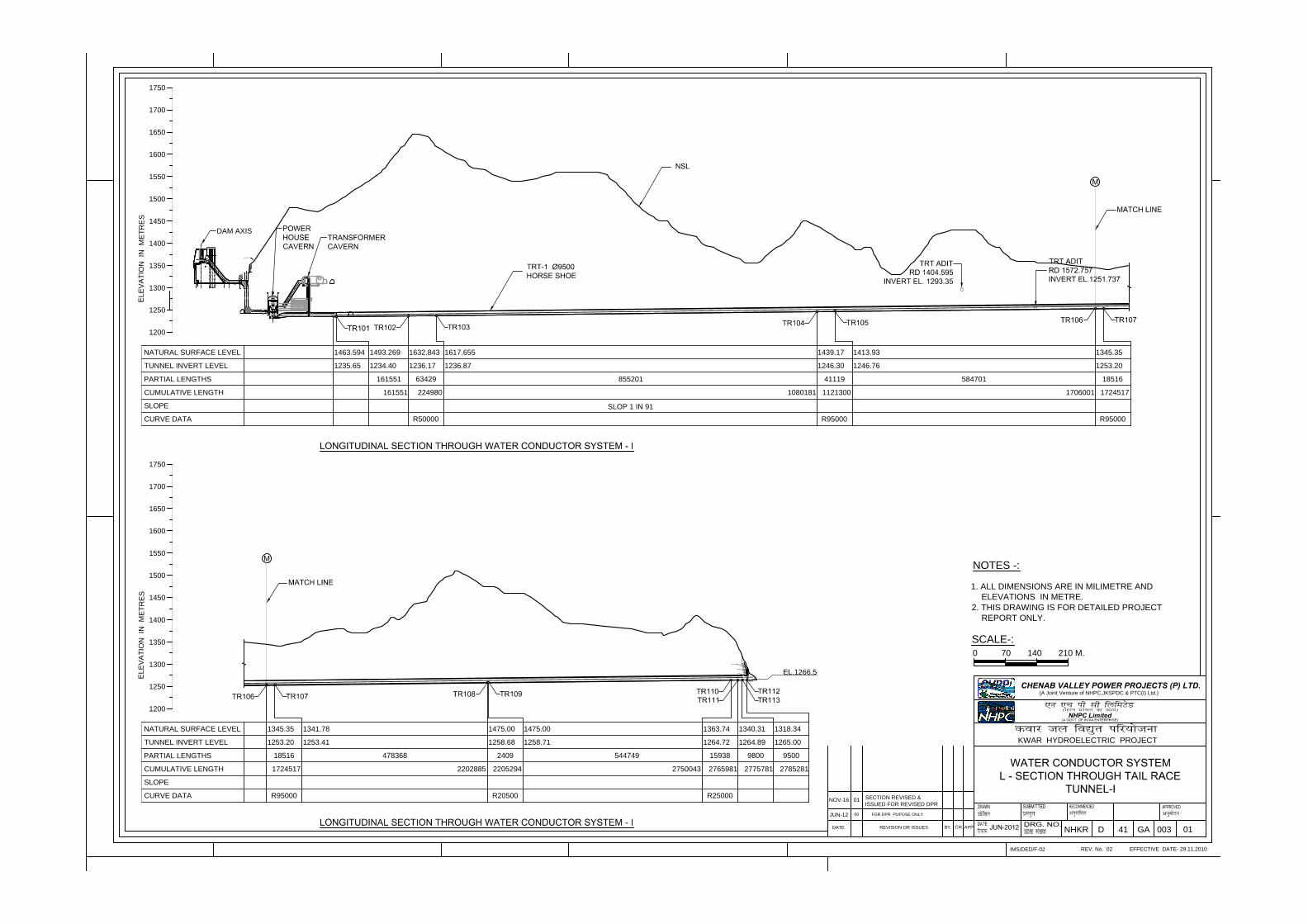
EFFECTIVE DATE- 29.11.2010
CH.
REV. No. 02IMS/DED/F-02
DATE REVISION OR ISSUES BY. APP.
NHPC Limited
KWAR HYDROELECTRIC PROJECT
FOR DPR PUPOSE ONLY
CHENAB VALLEY POWER PROJECTS (P) LTD.(A Joint Venture of NHPC,JKSPDC & PTC(I) Ltd.)
00
SCALE-:
0 70 140 210 M.
1. ALL DIMENSIONS ARE IN MILIMETRE AND
ELEVATIONS IN METRE.
2. THIS DRAWING IS FOR DETAILED PROJECT
REPORT ONLY.
NOTES -:
NHKR D 41 GA 003 01
1500
1450
1400
1350
1300
1250
1550
1600
1650
1463.594
1235.65 1234.40
1493.269 1632.843
1236.17
161551
NATURAL SURFACE LEVEL
TUNNEL INVERT LEVEL
PARTIAL LENGTHS
CUMULATIVE LENGTH
SLOPE
CURVE DATA R50000
1617.655
1236.87
63429 855201
1439.17
1246.30
41119
R95000
1413.93
1246.76
584701
1345.35
1253.20
18516
R95000
224980161551 1080181 1121300 1706001 1724517
EL
EV
AT
IO
N IN
M
ET
RE
S
1700
1750
1200
1500
1450
1400
1350
1300
1250
1550
1600
1650
NATURAL SURFACE LEVEL
TUNNEL INVERT LEVEL
PARTIAL LENGTHS
CUMULATIVE LENGTH
SLOPE
CURVE DATA
1345.35
1253.20
18516
R95000
1341.78
1253.41
478368
1475.00
1258.68
2409
R20500
1475.00
1258.71
544749
1363.74
1264.72
15938
R25000
1340.31
1264.89
9800
1318.34
1265.00
9500
1724517 2202885 2205294 2750043 2765981 2775781 2785281
EL
EV
AT
IO
N IN
M
ET
RE
S
1700
1750
1200
DAM AXIS
JUN-12
SLOP 1 IN 91
NOV-16 01
SECTION REVISED &
ISSUED FOR REVISED DPR
EL.1266.5
NSL UNIT-2
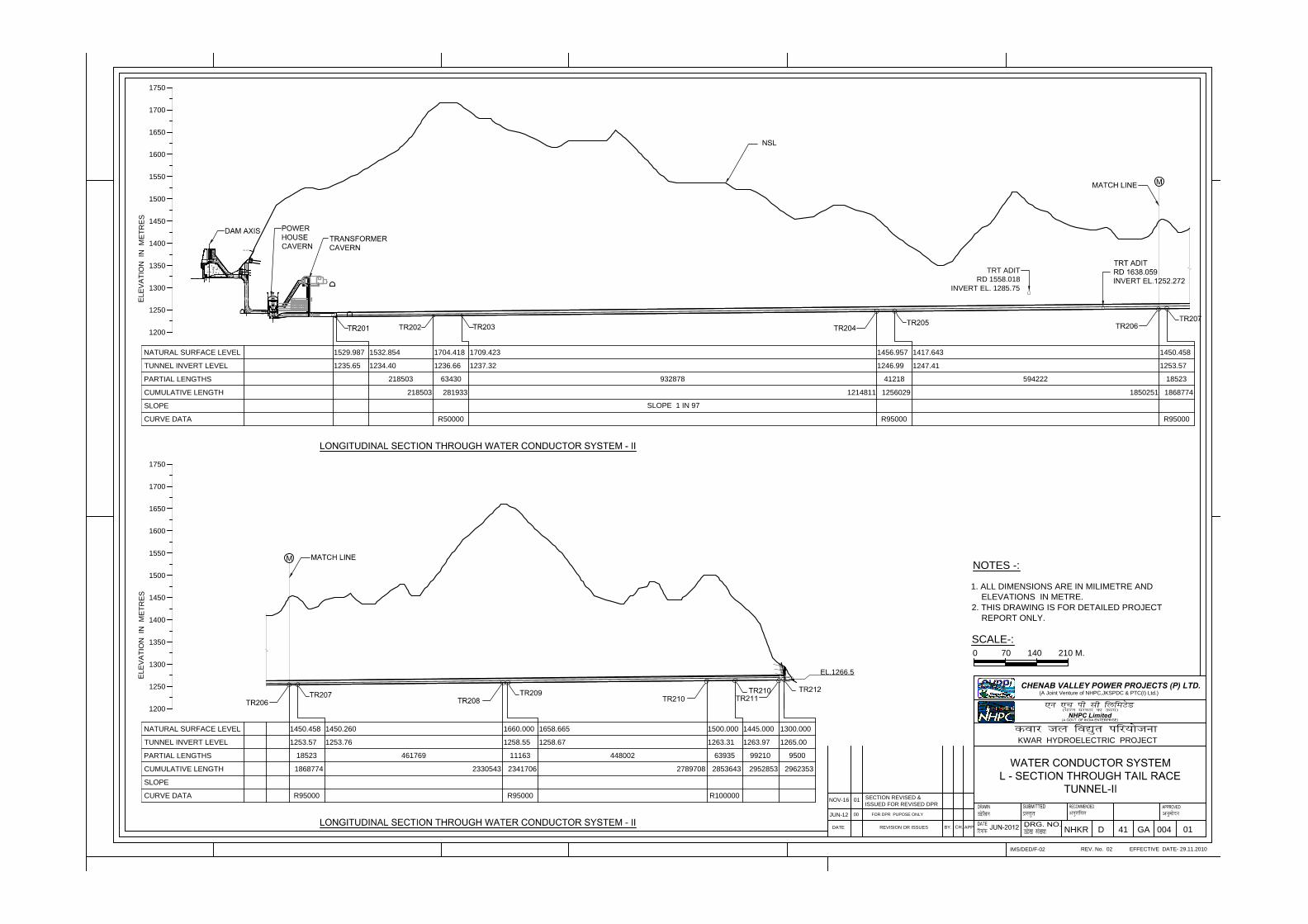
1529.987
1235.65 1234.40
1532.854
218503
218503
1236.66
1704.418
63430
1237.32
1709.423
932878
1246.99
1456.957
41218
1247.41
1417.643
594222
1253.57
1450.458
18523
281933 1214811 1256029 1850251 1868774
R50000 R95000 R95000
1500
1450
1400
1350
1300
1250
1550
1600
1650
NATURAL SURFACE LEVEL
TUNNEL INVERT LEVEL
PARTIAL LENGTHS
CUMULATIVE LENGTH
SLOPE
CURVE DATA
EL
EV
AT
IO
N IN
M
ET
RE
S
1700
1750
1200
EFFECTIVE DATE- 29.11.2010
CH.
REV. No. 02IMS/DED/F-02
DATE REVISION OR ISSUES BY. APP.
NHPC Limited
KWAR HYDROELECTRIC PROJECT
FOR DPR PUPOSE ONLY
CHENAB VALLEY POWER PROJECTS (P) LTD.(A Joint Venture of NHPC,JKSPDC & PTC(I) Ltd.)
00
SCALE-:
0 70 140 210 M.
1. ALL DIMENSIONS ARE IN MILIMETRE AND
ELEVATIONS IN METRE.
2. THIS DRAWING IS FOR DETAILED PROJECT
REPORT ONLY.
NOTES -:
NHKR D 41 GA 004 01
1500
1450
1400
1350
1300
1250
1550
1600
1650
NATURAL SURFACE LEVEL
TUNNEL INVERT LEVEL
PARTIAL LENGTHS
CUMULATIVE LENGTH
SLOPE
CURVE DATA
EL
EV
AT
IO
N IN
M
ET
RE
S
1700
1750
1200
1253.57
1450.458
18523
1253.76
1450.260
461769
1258.55
1660.000
11163
1258.67
1658.665
448002
1263.31
1500.000
63935
1263.97
1445.000
99210
1265.00
1300.000
9500
1868774 2330543 2341706 2789708 2853643 2952853 2962353
R95000 R95000 R100000
TRT ADIT
RD 1558.018
INVERT EL. 1285.75
SLOPE 1 IN 97
JUN-12
NOV-16 01
SECTION REVISED &
ISSUED FOR REVISED DPR
EL.1266.5
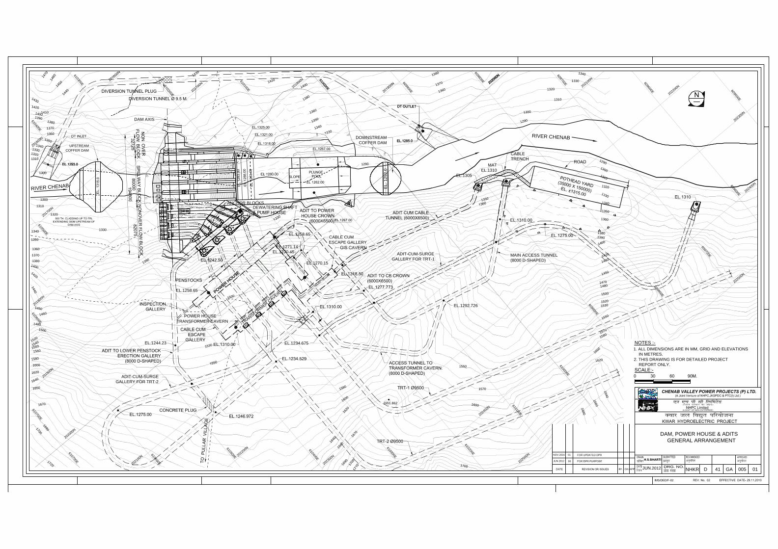
EL.1305
T
R
A
N
S
F
O
R
M
E
R
C
A
V
E
R
N
MAIN ACCESS TUNNEL
(8000 D-SHAPED)
EL.1258.65
P
O
W
E
R
H
O
U
S
E
MAT
EL.1310
ADIT-CUM-SURGE
GALLERY FOR TRT-1
EL.1270.15
C
O
N
T
R
O
L
B
L
O
C
K
G
I
S
R
O
O
M
EL.1270.45
EL.1271.14
CABLE CUM
ESCAPE GALLERY
EL.1292.726
ANCHOR BLOCKS
ADIT-CUM-SURGE
GALLERY FOR TRT-2
EL.1258.65
TRANSFORMER CAVERN
POWER HOUSE
EL.1244.23EL.1234.675
2
0
2
0
0
0
N
2
0
2
1
0
0
N
2
0
2
2
0
0
N
2
0
2
3
0
0
N
6
0
9
9
0
0
E
6
1
0
1
0
0
E
6
1
0
2
0
0
E
6
1
0
3
0
0
E
6
1
0
4
0
0
E
6
1
0
6
0
0
E
6
1
0
7
0
0
E
6
1
0
5
0
0
E
2
0
1
9
0
0
N
2
0
1
8
0
0
N
2
0
1
7
0
0
N
2
0
1
6
0
0
N
2
0
2
0
0
0
N
2
0
1
8
0
0
N
2
0
1
7
0
0
N
2
0
2
1
0
0
N
2
0
2
3
0
0
N
2
0
2
4
0
0
N
6
0
9
9
0
0
E
6
1
0
5
0
0
E
6
1
0
6
0
0
E
6
1
0
7
0
0
E
6
1
0
4
0
0
E
6
1
0
3
0
0
E
6
1
0
1
0
0
E
6
1
0
0
0
0
E
6
0
9
8
0
0
E
6
0
9
7
0
0
E
2
0
2
4
0
0
N
RIV
ER
CH
EN
AB
1290
A
1
4
2
0
1
4
0
0
1
3
8
0
1
3
6
0
1
3
4
0
1310
1651.862
1
5
7
0
1330
1310
1
3
0
0
1350
1
4
5
0
1
5
5
0
1
3
9
0
1
4
5
0
1
4
6
0
1
4
7
0
1
4
3
0
1
4
2
0
1410
1
4
0
0
1
3
9
0
1
3
8
0
1370
1360
1
3
5
0
1
3
4
0
1
3
3
0
1
3
2
0
1310
1300
1
4
3
0
1300
1
2
9
0
1320
1
3
4
0
1
3
6
0
1
3
7
0
1
3
8
0
1
2
9
0
1
3
1
0
1
3
2
0
1
3
3
0
1340
1
4
3
0
1
4
2
0
1390
1360
1380
1
4
0
0
1470
1480
1500
1520
1530
1
6
7
0
1
6
9
0
1
7
0
0
1
6
6
0
1
6
4
0
1
6
2
0
1
6
0
0
1
5
8
0
1310
1
5
3
0
1
5
0
0
1
5
4
0
1560
1580
1600
1620
1
6
4
0
1650
1670
1300
1320
1330
1340
1350
1360
1370
1380
1
4
0
0
1
4
2
0
1
4
4
0
1
4
6
0
1480
1
5
0
0
1
5
2
0
1
6
9
0
1
7
0
0
1
7
2
0
RIV
ER
CH
EN
AB
1570
1
6
0
0
1550
1300
DAM, POWER HOUSE & ADITS
GENERAL ARRANGEMENT
D 41 GA 005 01
JUN.2012
NHKR
1
3
5
0
DAM AXIS
UPSTREAM
COFFER DAM
DOWNSTREAM
COFFER DAM
EL. 1292.0
JUN.2012
NOTES :-
1. ALL DIMENSIONS ARE IN MM, GRID AND ELEVATIONS
IN METRES.
2. THIS DRAWING IS FOR DETAILED PROJECT
REPORT ONLY.6
1
0
0
0
0
E
1
4
4
0
1
5
8
0
1
6
0
0
1620
1
6
4
0
1
6
6
0
1
6
8
0
1
7
0
0
2
0
2
5
0
0
N
2
0
2
2
0
0
N
6
0
9
6
0
0
E
6
0
9
5
0
0
E
6
0
9
8
0
0
E
6
0
9
7
0
0
E
6
0
9
6
0
0
E
2
0
2
5
0
0
N
2
0
2
0
0
0
N
6
1
0
0
0
0
E
2
0
2
0
0
0
N
NOV.2016 01
P
O
W
E
R
H
O
U
S
E
1
4
5
0
1
5
5
0
1
3
5
0
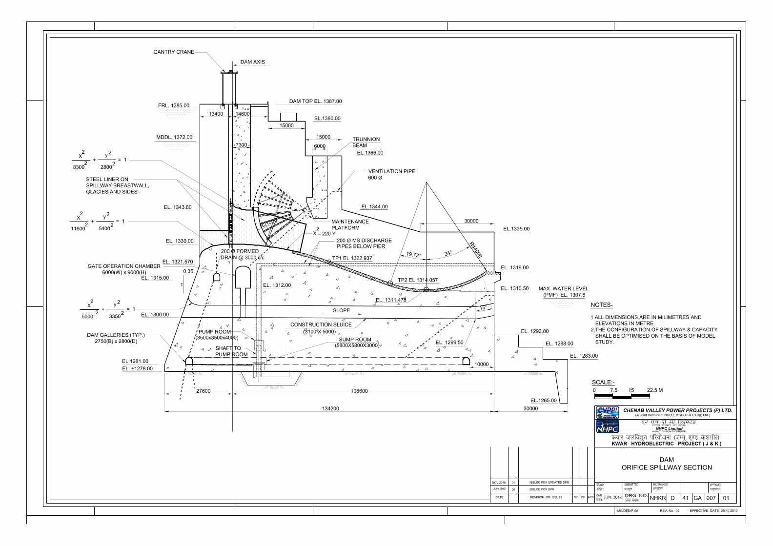
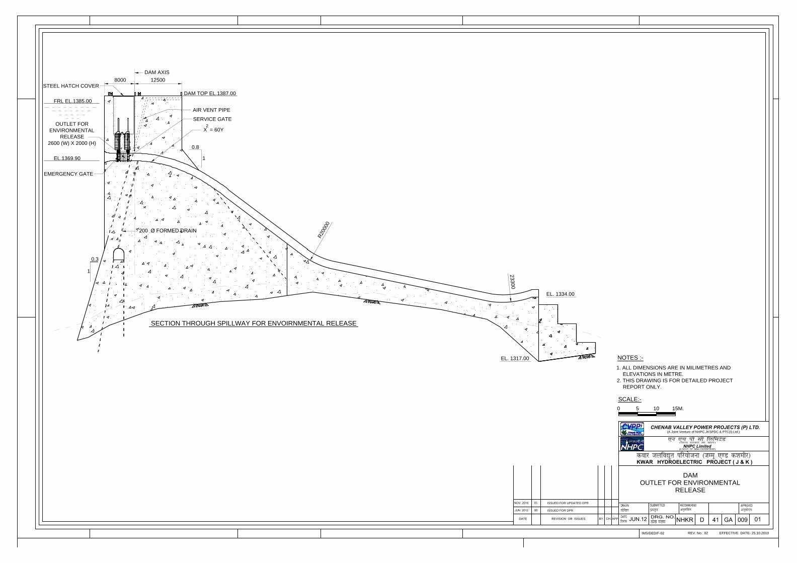
NOTES :-
1. ALL DIMENSIONS ARE IN MILIMETRES AND
ELEVATIONS IN METRE.
2. THIS DRAWING IS FOR DETAILED PROJECT
REPORT ONLY.
DAM
OUTLET FOR ENVIRONMENTAL
RELEASE
0 5 10 15M.
SCALE:-
EFFECTIVE DATE- 25.10.2010
CH.
REV. No. 02IMS/DED/F-02
00
DATE REVISION OR ISSUES
ISSUED FOR DPR
BY. APP.
NHPC Limited
KWAR HYDROELECTRIC PROJECT ( J & K )
CHENAB VALLEY POWER PROJECTS (P) LTD.(A Joint Venture of NHPC,JKSPDC & PTC(I) Ltd.)
01ISSUED FOR UPDATED DPR
DAM AXIS
12500
DAM TOP EL.1387.00
FRL EL.1385.00
0.8
1
0.3
1
AIR VENT PIPE
SECTION THROUGH SPILLWAY FOR ENVOIRNMENTAL RELEASE
OUTLET FOR
ENVIRONMENTAL
RELEASE
2600 (W) X 2000 (H)
X = 60Y
2
EL. 1317.00
R
2
0
0
0
0
EL. 1334.00
23300
8000
EL.1369.90
EMERGENCY GATE
SERVICE GATE
STEEL HATCH COVER
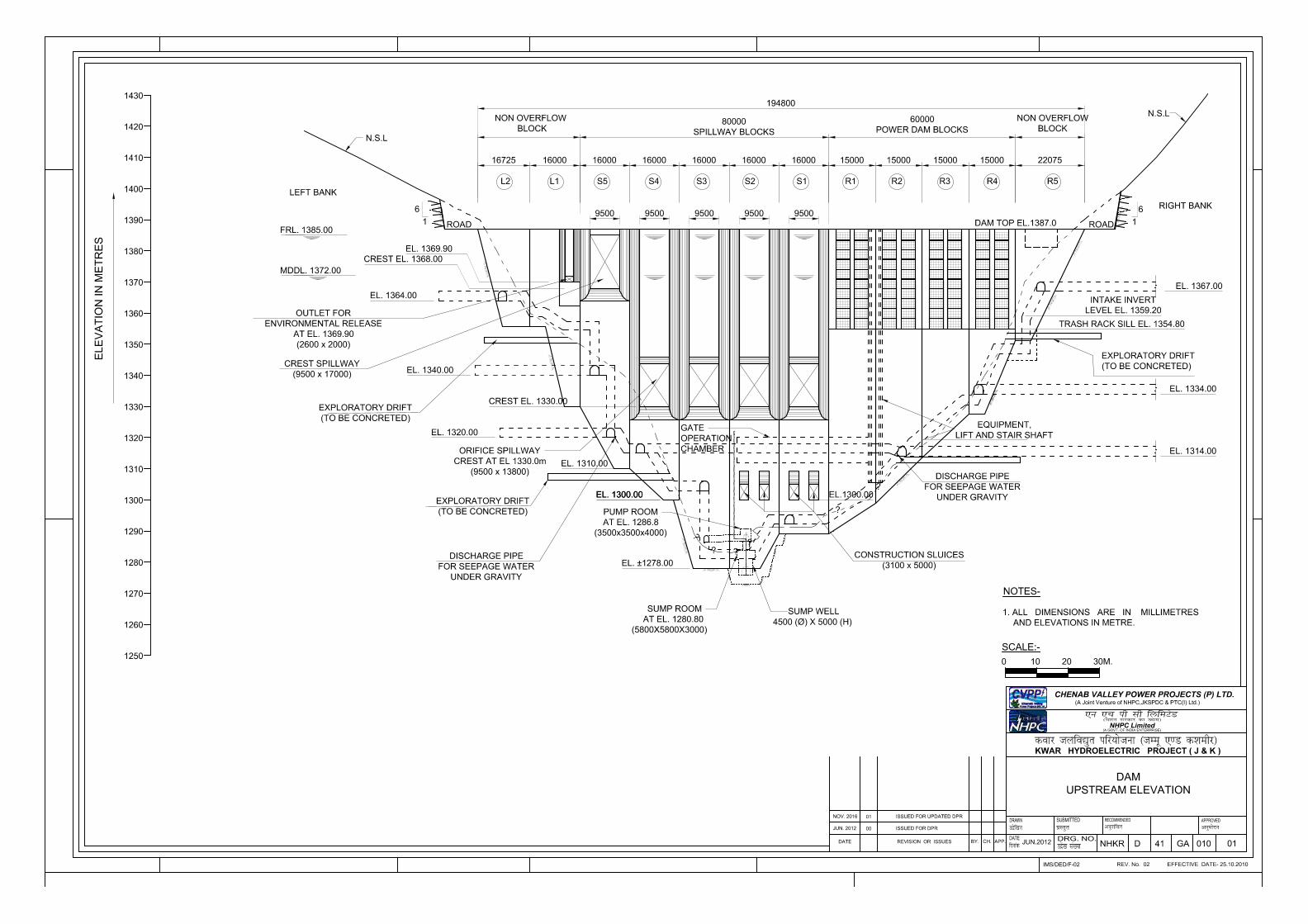
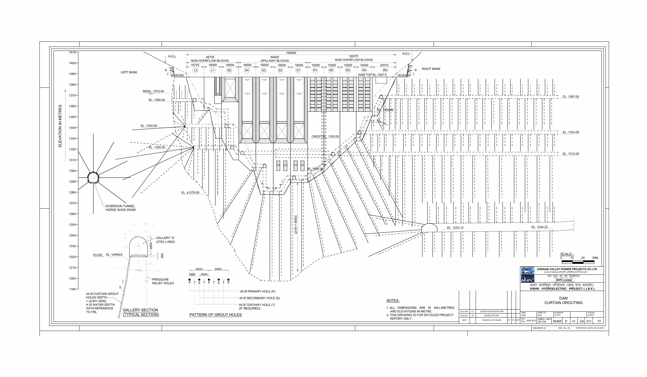
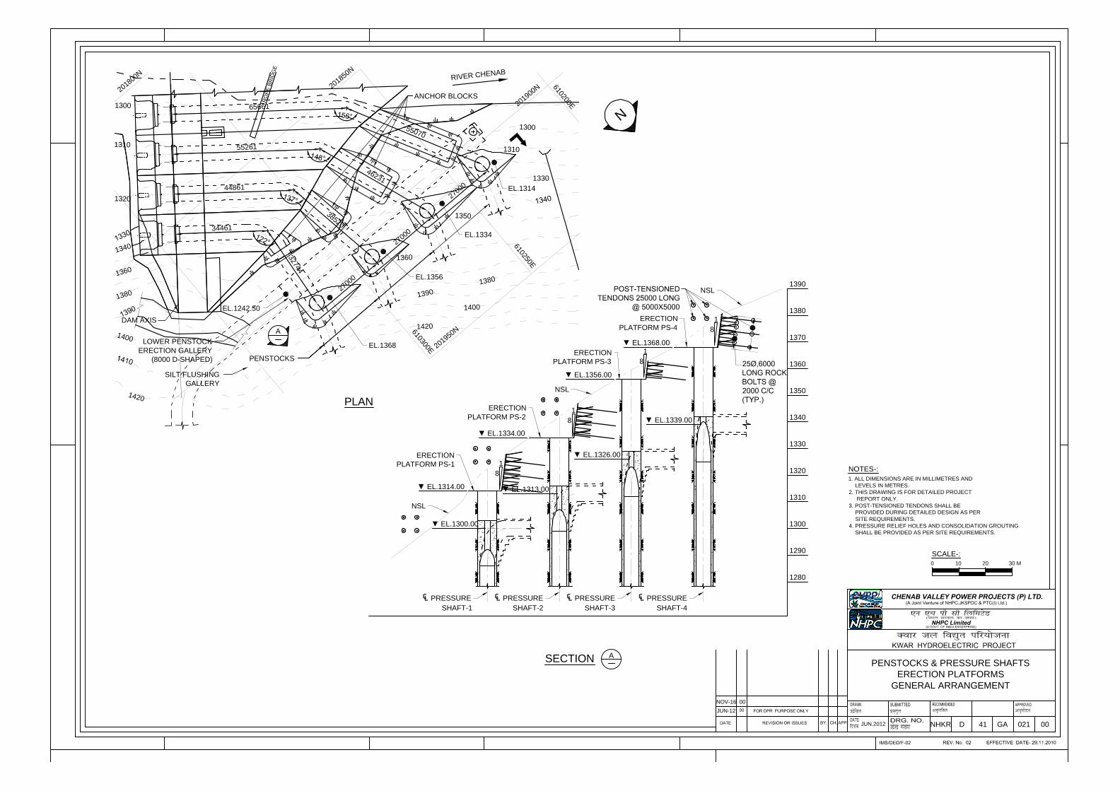
1310
R
O
P
E
B
R
ID
G
E
1
3
9
0
1310
1330
1350
1360
1
3
8
0
1400
1420
1300
1320
1
3
4
0
1300
N
EL.1242.50
2
7
0
0
0
2
7
0
0
0
2
7
0
0
0
5
5
0
7
0
4
6
2
3
1
3
8
5
2
0
3
2
7
4
4
PENSTOCKS
34461
44861
55261
65661
1
3
6
0
1
3
8
0
1
4
0
0
1
4
2
0
2
0
1
9
0
0
N
6
1
0
2
0
0
E
6
1
0
3
0
0
E
PENSTOCKS & PRESSURE SHAFTS
ERECTION PLATFORMS
GENERAL ARRANGEMENT
A
DAM AXIS
PLAN
SECTION
LOWER PENSTOCK
ERECTION GALLERY
(8000 D-SHAPED)
SILT FLUSHING
GALLERY
JUN.2012
NHKR D 41 GA 021 00
SCALE-:
30 M20100
6
1
0
2
5
0
E
2
0
1
9
5
0
N
2
0
1
8
5
0
N
2
0
1
8
0
0
N
1290
1300
1310
1320
1330
1340
1350
1360
1370
1380
1390
RIV
ER
CH
EN
AB
EL.1368
EL.1356
EL.1334
EL.1314
A
PRESSURE
SHAFT-1
NSL
NSL
EL.1339.00
EL.1326.00
EL.1313.00
EL.1300.00
PRESSURE
SHAFT-2
PRESSURE
SHAFT-3
PRESSURE
SHAFT-4
1
8
1
8
1
8
1
8
1280
EL.1314.00
EL.1334.00
EL.1356.00
EL.1368.00
NSL
ERECTION
PLATFORM PS-1
ERECTION
PLATFORM PS-2
ERECTION
PLATFORM PS-3
ERECTION
PLATFORM PS-4
ANCHOR BLOCKS
NOTES-:
1. ALL DIMENSIONS ARE IN MILLIMETRES AND
LEVELS IN METRES.
2. THIS DRAWING IS FOR DETAILED PROJECT
REPORT ONLY.
3. POST-TENSIONED TENDONS SHALL BE
PROVIDED DURING DETAILED DESIGN AS PER
SITE REQUIREMENTS.
4. PRESSURE RELIEF HOLES AND CONSOLIDATION GROUTING
SHALL BE PROVIDED AS PER SITE REQUIREMENTS.
JUN-12
NOV-16 00
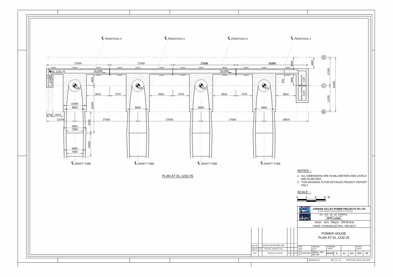
NHKR D 41 GA 026
PLAN AT EL.1232.25
POWER HOUSE
APP.REVISION OR ISSUES
FOR DPR PURPOSE ONLY
00
DATE CH.BY.
KWAR HYDROELECTRIC PROJECT
EFFECTIVE DATE- 29.11.2010REV. No. 02IMS/DED/F-02
NHPC Limited
CHENAB VALLEY POWER PROJECTS (P) LTD.(A Joint Venture of NHPC,JKSPDC & PTC(I) Ltd.)
1. ALL DIMENSIONS ARE IN MILLIMETERS AND LEVELS
ARE IN METERS.
2. THIS DRAWING IS FOR DETAILED PROJECT REPORT
ONLY.
0 4 8 12 M
SCALE :-
NOTES :-
00
27000
2762
8600
U4
DRAFT TUBE
ST
AIR
S
27000
8600
DRAFT TUBE
27000
8600
DRAFT TUBE
18924
8600
DRAFT TUBE
B
D
C
12100
11200
23300
PLAN AT EL.1232.25
U3 U2 U1
PENSTOCK-4 PENSTOCK-3 PENSTOCK-2 PENSTOCK-1
4800
10000
4314
9924 7076 9924 7076 9924 7076 8662
27000 27000 31000
12076
4800
5300
4800
SLOPE SLOPE
EL.1231.75
7500
7000
27000
9000
20300
DE
WA
TE
RIN
G
SU
MP
DR
AIN
AG
E
SU
MP
9500
500
9100
10000
27000 31000
JUN-2012
JUN-12
NOV-16
ISSUED FOR REVISED DPR
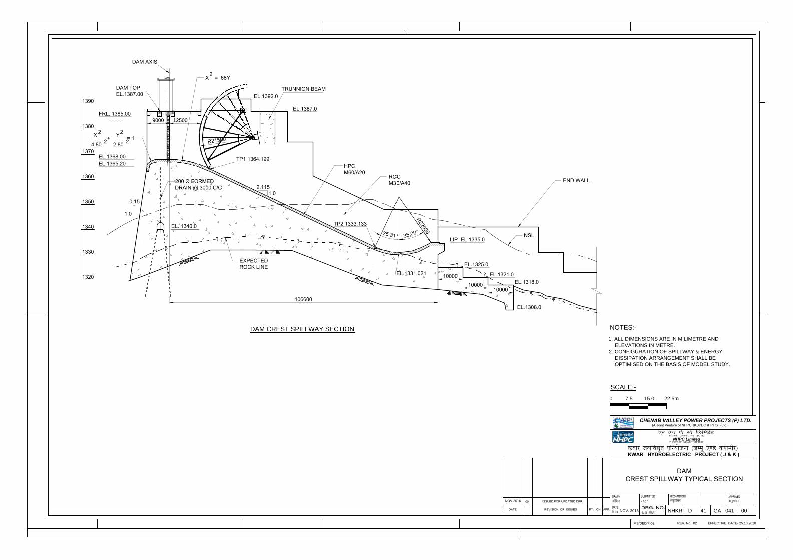
NOTES:-
1. ALL DIMENSIONS ARE IN MILIMETRE AND
ELEVATIONS IN METRE.
2. CONFIGURATION OF SPILLWAY & ENERGY
DISSIPATION ARRANGEMENT SHALL BE
OPTIMISED ON THE BASIS OF MODEL STUDY.
KWAR HYDROELECTRIC PROJECT ( J & K )
NHPC Limited
APP.BY.
ISSUED FOR UPDATED DPR
REVISION OR ISSUESDATE
00
IMS/DED/F-02REV. No. 02
CH.
EFFECTIVE DATE- 25.10.2010
NOV. 2016
NOV.2016
NHKR D 41 GA 041 00
SCALE:-
0 7.5 15.0 22.5m
9000 12500
DAM CREST SPILLWAY SECTION
Kwar Hydroelectric Project (540 MW) Detailed Project Report
Executive Summary
CHAPTER –9
POWER PLANT, ELECTRICAL &
MECHANICAL EQUIPMENT
Kwar Hydroelectric Project (540 MW) Detailed Project Report Executive Summary
9-1
CHAPTER – 9
POWER PLANT, ELECTRICAL AND MECHANICAL EQUIPMENT
9.0 INTRODUCTION
Kwar H.E. Project envisages installation of four generating units of 135 MW
each, operating under a rated design head of 103.1m placed in an underground
power house located on river Chenab in Kishtwar district of Jammu & Kashmir
state. The generation voltage is proposed to be 13.8 KV. This voltage will be
stepped up to 400 KV voltage level by single-phase step up transformers.
The generator transformers are placed in a separate cavern downstream of
power house cavern which shall be connected to its respective generators by
isolated phase bus ducts. The transformers & bus reactors will be further
connected to the Gas Insulated Switchgear placed in another separate
underground cavern through 400 KV XLPE cables. Provision of 2 No. 400 KV
outgoing line bays have been kept for evacuation of power from this project
along with the provision of 3 No. single phase 41.67 MVAR, 400 KV bus
reactors. 2 No. Outgoing 400 KV feeders from GIS shall be connected to
pothead yard, located outside the power house through 400 KV XLPE cables.
The 540 MW Power from Kwar H.E. Project would be fed to the Northern grid.
The Salient features of the Project are mentioned as per below:
Installed capacity 540 MW
No. & size of units 4 units of 135 MW
Type of Power house Underground
Rated Design head 103.1 m
Maximum net head 110.0 m
Minimum net head 94.4 m
Type of Switchgear 400 KV Gas Insulated Switchgear
Kwar Hydroelectric Project (540 MW) Detailed Project Report Executive Summary
9-2
Turbine type Francis
Speed of turbine 166.67 RPM
Generation voltage 13.8 KV
Transmission voltage 400 KV
GSU Transformer 55 MVA, 1 phase, 13.8/400/3 KV
Overall efficiency of Unit 92%
9.1 MECHANICAL EQUIPMENTS
9.1.1 Turbines
The turbine would be of vertical shaft, Francis type, directly coupled to the
generator. Each turbine would be designed for its rated output of 137.76 MW at
rated net head of 103.1m in order to deliver rated generator output of 135 MW.
The provision would also be made for 10% continuous overloading. The rated
speed of turbine would be 166.67 rpm & the efficiency of turbine has been taken
as 94.0%. The turbine characteristics would be selected such that the optimum
efficiency falls close to the rated output of the unit.
The spiral casing would be of suitable cross-section fabricated from carbon steel
plates. The stay rings would be of cast steel/fabricated welded to the spiral
casing and would guide the water to the runner. The draft tube would be of
fabricated structural steel, with adequate stiffening ribs. The runner would be
integrally casted, made of stainless steel G-X5 Cr-Ni 13-4 material. The main
turbine parts in the path of water i.e. the runner, top cover liners, bottom ring
liners and wicket gates would be of stainless steel for improved resistance to
wear. To counter the silt erosion effect, these items would have HVOF coating
and in addition, provision of one set of spare runner, guide vanes, check plates
and labyrinth would also be made. Bottom runner removal arrangement would
be provided for repair and easy maintenance of runner.
Kwar Hydroelectric Project (540 MW) Detailed Project Report Executive Summary
9-3
9.1.2 Main Inlet Valves
Main inlet valve of butterfly type with a diameter of 4.6 m would be provided at
the inlet of spiral casing of each turbine & connected to penstock on upstream
side through matching piece for maintenance of turbines and for emergency
isolation of the turbine in the event of governor failure. MIV would be housed in
the Power house cavern with a 20 degree entry of penstock in Power house
cavern.
9.1.3 Governor
The governor of each unit would be of the digital-hydraulic type with electronic
speed sensing, electronic hydraulic transducer, oil-pressure actuator and an air-
oil pressure (OPU) system. Speed, gate opening, gate limiter positioning etc will
be indicated both on the governor cubicle and on the unit control board, to
facilitate supervision of operation of the unit. The controls would include
provision for emergency shutdown of unit in case of:
- Loss of pressure in the oil pressure vessel of the governor oil system.
- Excessive temperature rise in bearings.
- Excessive speed rise in the unit.
- Emergency closing of the MIV in case of excessive speed rise.
- Electrical faults.
9.1.4 Power House EOT Cranes
It is proposed to install two numbers EOT cranes with 220 ton main hook
capacity each, auxiliary hooks of 45 ton & monorail of 10 ton capacity designed
to travel the full length of the power house. Both the EOT cranes shall be used in
tandem to handle the rotor. The capacity of EOT crane has been selected on the
basis of preliminary assessment of rotor weight including weight of lifting
arrangement & design margin. For handling the rotor, both of the powerhouse
Kwar Hydroelectric Project (540 MW) Detailed Project Report Executive Summary
9-4
EOT cranes would operate in tandem & shall be controlled by one cabin. Two
monorail cranes shall be installed, one on each of the EOT cranes.
9.1.5 GIS Crane
One No. Electric overhead traveling crane of 10 Ton capacity would be installed
in the GIS cavern for the erection & maintenance purposes.
9.1.6 Transformer unloading crane
Since the Transformer cavern is at higher elevation than Power house service
bay level, one no. Electric overhead crane of 90/30T capacity would be installed
in the draft tube gate cum transformer cavern. The crane would be used for
loading, unloading & movement of transformers within the underground
transformer cavern.
9.1.7 Auxiliary Systems of the Power Station
(a) Cooling Water System
Water for the closed loop cooling water system will be taken from the draft tube.
This system would provide for the cooling of turbine and generator bearings,
turbine shaft seal, generator transformer and other selected services. Necessary
equipment/system will be included to provide silt free water for cooling
requirements to minimize the damages due to silt.
(b) Fire Protection system
A complete fire protection system shall be provided for the powerhouse,
Transformer cavern, GIS cavern, Pothead yard, Control block and other areas.
Water for the fire protection system would be drawn from the tail race and stored
in an elevated tank through pumps.
High velocity type mulsifier fire protection system along with nitrogen fire
injection system shall be provided for GSU Transformers. MVWS spray shall be
provided for cable galleries/tunnels and control room. Portable fire extinguishers
Kwar Hydroelectric Project (540 MW) Detailed Project Report Executive Summary
9-5
of different types shall also be provided at strategic points at all the floors of
powerhouse, transformer cavern, GIS cavern and Pothead yard area for the
protection in case of fire emergencies. Fire hydrants shall also be located at
strategic points in Power House as well as other areas.
(c) Drainage and Dewatering System
A dewatering system would be provided in Power house with suitable number of
pump motor sets arranged to dewater passages of the turbine and draft tube for
each unit. A separate station drainage system, with suitable number of pump
sets, would also be provided to drain and pump off miscellaneous inflows, and
ground water seepage in the power house. Starting and stopping of the pumps
would be automatic, controlled by level switches in the dewatering/drainage
sumps.
Drainage system shall also be provided in pressure shaft bottom Adit, Main
access tunnel, Transformer & GIS caverns. Provision of pumps for emergency
drainage shall also be kept.
(d) Heating, Ventilating and Air conditioning System
Each powerhouse shall be provided with adequate ventilating and air
conditioning system as required to maintain the control room, work areas, Power
house cavern, Transformer cavern & GIS cavern at the selected temperature &
humidity levels. The temperature and humidity levels would be selected to suit
the requirement of equipment and plant staff.
(e) Oil Handling System
Oil handling system for transformer oil and lubricating oil will be provided with
suitable piping, valves, tanks, purifiers etc. In addition, portable type oil purifiers
will also be provided.
(f) Station Compressed Air System
Two Sets of high pressure (HP) compressed air system with operating pressure
of 60 bars would be installed to meet the requirements of the governor oil system
& operation of Main Inlet Valve (MIV).
Kwar Hydroelectric Project (540 MW) Detailed Project Report Executive Summary
9-6
Four sets of compressed air system with an operating pressure of 15 bars would
also be installed for compressed air requirements for synchronous condenser
operation mode of generating units.
Two Sets of low pressure (LP) compressed air system with operating pressure of
7 bars would be installed to meet the requirements of generator brakes, fire
fighting system and station service air.
(g) Portable Water & Sanitary Service
Water from the cooling water system would be used to supply the plant’s
portable and sanitary water needs. The potable water would be filtered and
chemically treated as required.
(h) Public Address and Surveillance System
A suitable public address and surveillance system like CCTV camera, personal
identification system etc. will be installed in the Power house complex area to
facilitate the communication and desired security in the power house area.
(i) Elevator
One no. Electric elevator will be provided in the Control block cavern. It will be
designed for 16 persons and approximately load of 2000 Kg and have landings
at all floors of the Control block cavern. One additional inclined type industrial
escalator would also be provided between the passage/escape gallery from
transformer cavern to the PH building and would be designed for 16 persons and
approximately load of 2000 Kg.
(j) Workshop
A Mechanical workshop with machine tools as i.e. lathe, drills, grinder, welding
machine, milling machine and general tools and work benches, etc. would be
provided to carry out normal repairs of the equipment in each powerhouse.
(k) Testing Equipment
A test laboratory will be provided to carry out normal testing of the power house
equipment. The laboratory will be equipped with custom made CTs, KW meters,
HV test set, Oil testing set, Meggars, Relay testing set, rectiformers etc.
Kwar Hydroelectric Project (540 MW) Detailed Project Report Executive Summary
9-7
9.2 ELECTRICAL EQUIPMENTS
9.2.1 Generators
Each synchronous generator would be of direct driven, vertical shaft, salient pole
type complete with air cooled stator, rotor, shaft, thrust and guide bearings,
upper bracket, lower bracket and other components
directly coupled to the turbine. It would be rated for a continuous output of 165
MVA (includes 10% continuous overloading), 50Hz at a power factor of 0.9 and
rated voltage of 13.8 KV capacity. The provision of synchronous condenser
mode of operation of generator would also be made along with the necessary
associated equipments. The efficiency of the generator has been taken as
98.0%.
The stator and rotor would be transported in sections, so that the weight and size
of the heaviest package is kept within transport limitations.
The generator would be semi-umbrella type in construction with thrust bearing
cum lower guide bearing at the bottom & upper guide bearing at the top portion.
Generator bearing arrangements would include an automatic high-pressure oil
injection system, which would provide an oil film at the thrust bearings surface, to
prevent damage during starting and stopping of the unit. A high-pressure oil
system would also be provided for jacking up the generator rotor for
maintenance purposes.
The windings of stator/rotor would be provided with class ‘F’ type insulation. The
line terminals of the generator would be suitable for connection to the isolated
phase bus conductors. The neutral side of the generator would be grounded
through a resistor loaded distribution transformer in order to ground the star
point.
The generators would be air cooled in a closed system designed to meet class
‘B’ insulation temperature limits with air-water heat exchangers mounted on the
stator frame. Water based fire protection system shall be provided. Generator
Kwar Hydroelectric Project (540 MW) Detailed Project Report Executive Summary
9-8
protection shall be provided through latest technology numerical relays having
necessary protections.
9.2.1 Static Excitation System
The Excitation system of the generator would be of the static type and shall
include digital type voltage regulator, field suppression equipment and the
associated accessories. The voltage regulation system would continuously and
instantly respond to correct any change in the generator voltage and maintain it
within its prescribed limits over the entire operating range of the generator. The
excitation system shall be equipped with all type of limiters & protection system.
The power for the excitation system would be obtained from a dry type excitation
transformer, through tapoff bus duct connected directly to the generator voltage
bus.
9.2.3 Bus Duct
Each generator would be connected to its step-up transformer by means of air
insulated isolated phase bus ducts. The tentative current rating of the Bus duct is
chosen in accordance with IS/International standards as 8000A . The isolated
phase bus duct system would incorporate the required number of current and
voltage transformers for protection and metering on line and neutral side of the
generator. The bus would be provided with suitable lightening arrestors and
surge protections. Required number of tap off duct shall be provided from 13.8
KV main isolated bus duct for connection to UATs, Excitation transformer’s and
LAVT/SAVT cubicles placed in the horizontal portion of the respective bus duct
gallery.
9.2.4 Generator Step–Up Transformers
The step up transformers proposed would be single–phase units necessary to
meet the transportation limitations to the project site. The transformers would be
rated, 13.8/400/3 KV, 55 MVA, 1, 50 Hz. The transformers shall be oil-
Kwar Hydroelectric Project (540 MW) Detailed Project Report Executive Summary
9-9
immersed with OFWF cooling & would be placed in separate transformer cavern.
In order to meet contingencies due to failure of any of the transformers, one no.
spare transformer would be provided. The transformers shall also be equipped
with necessary protection equipment & relays.
9.2.5 Control, Monitoring and Protection System
Control, Monitoring and Protection system will be of fully automated type. It will
be of the latest state of art available in the world market at the time of
procurement. The power generating station would be centrally controlled from
the central Control room/station which will be PC based computerized work
stations.
Metering will include measurement of all standard quantities and recorders for
constant monitoring of power generated and transmitted. Control would include
all the necessary devices and schemes required to efficiently control the various
systems of the plant, monitor the systems, their operation and identify points of
trouble. The automatic control would include unit start/stop, synchronizing,
emergency shut down etc. and joint control of the units. All protection, metering,
control and plant supervisory systems will be seamlessly integrated.
Additionally, Unit controllers will be provided locally near each unit with provision
for human machine interface, for the local control of units and its associated
auxiliaries. On-line monitoring, plant supervisory and data acquisition system will
be provided for monitoring and diagnostics need of plant for optimum and
smooth operation.
9.2.6 Auxiliary Power Requirements
Power requirements of the Unit & Station auxiliaries would be provided through 2
No. 11 KV Switchgear boards, one placed inside power house cavern & other in
the pothead yard. These 11 KV switchgears would be fed through 4 No. Station
Kwar Hydroelectric Project (540 MW) Detailed Project Report Executive Summary
9-10
auxiliary transformers, 2 Nos. 11 KV regional supply feeders & 2 Nos. Diesel
generating Sets of 1000 KVA, 11KV rating.
The respective Station auxiliary transformers (SAT), each of 4000 KVA, 13.8/11
KV rating would be fed directly through tap-off bus duct connected to its
respective 13.8 KV generator voltage bus.
Power requirements of the Station auxiliaries would be provided through Two (2)
no. Station service boards (SSB’s) which would be fed from 2 No. Station
Service Transformer (SST) of rating 2500KVA, 11/0.415 KV. These SST’s would
be provided power from 11KV Switchgear placed inside power house cavern.
Power requirements of the Unit auxiliaries would be provided through their Unit
Auxiliary boards (UAB) which would be fed from their respective dry type unit
auxiliary transformer (UAT) rated 800 KVA, 11/0.415 KV. These UAT’s would be
provided power from the 11KV Switchgear placed inside power house cavern.
Two nos. Diesel generating Sets of rating 1000 KVA, 11KV to meet the start up
power, emergency station supply and contingencies are proposed & would be
connected directly to 11 KV Switchgear placed in the outdoor pothead yard area.
Similarly, 2 nos. 500 KVA, 11 KV/415 V transformers for Dam area, 1 no. 400
KVA, 11 KV/415 V transformer for the pothead yard area & 1 no. 250 KVA, 11
KV/415 V transformer for TRT area shall also be provided. All these transformers
would be fed from the 11 KV Switchgear placed in outdoor pothead yard area.
9.2.7 11 KV Switchgear
The 11 KV Switchgear system would comprise of two 11 KV switchgear boards,
one placed inside the power house cavern & other in the outdoor pothead yard.
These two boards would be inter-connected through 2 No. 11 KV XLPE cables.
The 11 KV Switchgears would include all necessary protection equipment and
relays.
11 KV Switchgear at power house would comprise of total 13 bays including 4
incoming feeders from SATs, 6 No. outgoing feeders for UATs & SSTs, one bus
Kwar Hydroelectric Project (540 MW) Detailed Project Report Executive Summary
9-11
coupler bay & 2 No. interconnection bays for its connection to 11 KV switchgear
of pothead yard.
11 KV Switchgear at pothead yard would comprise of total 12 bays including two
no. 11 KV regional supplies incoming feeders, two no. D.G. set supply incoming
feeders. The 4 No. outgoing feeders would include 2 No. feeders for Dam area,
1 No. feeder for TRT area & 1 No. feeder for Pothead yard area. 1 No. bus
coupler bay, 2 No. interconnection bays for its connection to the 11 KV
switchgear of power house with 1 No. outgoing spare feeder would also be
provided.
9.2.8 D.C. Supply System
A 220 volt DC System with two sets of 2000AH capacity battery bank would
provide power for the control of switchgear, for the protection and control
equipment, and for emergency lighting of the power house. The batteries would
be provided with two battery chargers, each equipped with float and boost
charging facility with all protective devices necessary to protect the system from
damage. 220 V DC Distribution boards would be provided for feeding various
types of 220 V DC loads.
A 48 V DC system with two sets of battery chargers & two sets of 500 AH
capacity battery bank will be installed for the station communication and the
PLCC system. 48V DC Distribution boards would be provided for feeding various
48V DC loads.
9.2.9 Illumination System
The Power plant lightning would comprise interior and exterior lights as
appropriate for the entire power house area, transformer cavern & GIS building
and pothead yard area. A separate emergency lightning system fed from the 220
V DC station battery system would be provided for essential locations e.g.
control room, machine hall, GIS cavern, exits etc.
Kwar Hydroelectric Project (540 MW) Detailed Project Report Executive Summary
9-12
9.2.10 Equipment Grounding
The Power house, Transformer & GIS cavern and Pothead yard area would be
provided with separate main grounding grids and the two grids will be
interconnected. All non-current carrying equipment in the power house,
transformer & GIS cavern and pothead yard would be grounded separately and
connected to the main grounding grid. The grounding system would be designed
to minimize the touch & step potential within acceptable safe limits.
9.2.11 Gas Insulated Switchgear (GIS)
In view of shortage of space at the power house site, it is proposed to install 400
KV Gas Insulated Switchgear (GIS). The 400 KV GIS shall be placed in an
underground GIS cavern. The switching scheme proposed would incorporate
400 KV double bus arrangements to ensure reliability and flexibility in switching
without interruption. The 400 KV GIS would be connected to the generator step
up transformers through 400 KV XLPE cables. There would be total 8 nos. of
GIS bays with four bays for generator transformers, one bay for bus coupler,
provision of two bays for outgoing feeders & one bay for bus reactor. The GIS
bays would have circuit breakers, isolators, C.T, P.T, Earthing switches, surge
arrestors etc. The detailed characteristics and rating of the equipment would be
established during the detailed design stage.
9.2.12 Bus Reactors
Provision of 3 No. single phase bus reactors, each of rating 41.67 MVAR, 400
KV, 50Hz has been kept & being placed in the underground transformer cavern.
The reactors shall also be equipped with necessary protection equipment &
relays.
Kwar Hydroelectric Project (540 MW) Detailed Project Report Executive Summary
9-13
9.2.13 400 KV XLPE Cable
400 KV GIS would be connected to single phase generator step up transformers
placed in underground transformer cavern single-phase 400 KV XLPE cables.
One No. spare cable for the above would also be provided. One No. reactor bay
of 400 KV GIS would be connected to the single phase bus reactors placed in
underground transformer cavern by single-phase 400 KV XLPE cables. Also
feeder bays of 400 KV GIS would also be connected to the outdoor pothead yard
through single-phase 400 KV XLPE cables. The spare cables would be provided,
with sufficient slack at both ends for connection to any of the unit bays in GIS to
any of the unit step up transformers/bus reactors & pothead yard feeder bay
respectively. Therefore, total 23 No. single phase 400 KV XLPE cables
(including two spare cables) with terminal kits would be provided.
9.2.14 400 KV Outdoor Pothead Yard
Two No. outgoing feeders would be provided in the outdoor potyard area. The
outgoing feeders in pothead yard would have CVT, lightning arrestors, wave
trap, gantry structures etc.
9.2.15 Power Line Carrier Communication Equipment (PLCC)
For purposes of transmission line protection, remote control, data and voice
communication, transmission systems would have provision for installation of
PLCC equipments. The PLCC equipment (panels) would be provided for each
line for both sending & receiving ends by transmission line utility (i.e. PGCIL).
9.2.16 Power Evacuation System
The provision of total 2 nos. of 400 KV feeder bays have been kept. Space
provision for one no. additional bay in Potyhead yard area and GIS cavern has
also been kept.
Kwar Hydroelectric Project (540 MW) Detailed Project Report
Executive Summary
CHAPTER –10
ECONOMIC EVALUATION
Kwar Hydroelectric Project (540 MW) Detailed Project Report Executive Summary
10 - 1
CHAPTER -10
ECONOMIC EVALUATION
(Equity upfront)
10.0 GENERAL
Kwar Hydro-Electric Project (540 MW) has been contemplated as a run off the
river Scheme on the river Chenab in Distt. Kishtwar ,J&K, This project, has
been estimated to cost Rs. 4949.24 Crores at April 2016 Price Level including
Rs. 3221.86 Crores on Civil Works, Rs. 1041.38 Crores on Electrical Works,
Rs. 75.22 Crores on Security and Rs. 532.21 Crores on IDC & Rs. 25.98
Crores on Financing Charges. Sale Rate of Energy generated at Powerhouse
Bus Bars has been worked out as Rs. 6.21 / unit in 90% dependable year at
April 2016 P.L.
10.1 ENERGY CONTRIBUTION FROM THE PROJECT
The energy generation of the project with an installed capacity of (4 X 135 MW)
has been estimated at 1975.54 MU in a 90% dependable year.
10.2 PROJECT COST
The project has been estimated to cost Rs. 4949.24 Crores including IDC of
Rs. 532.21 Crores and Financing Charges of Rs. 25.98 Crores at April 2016
Price Level.
10.3 FIXED AND RUNNING CHARGES
i) Interest rate
The interest rate of 10.55% has been considered for working out the financial
return. The interest during construction has also been capitalized as 70% loan
and 30% equity.
Kwar Hydroelectric Project (540 MW) Detailed Project Report Executive Summary
10 - 2
ii) Return on Equity
For working out the unit cost of energy, the return on equity has been taken at
16.50% as per CERC guidelines.
iii) Depreciation
In accordance with the current practice Depreciation has been charged as
4.90% of total cost excluding cost of land for initial 12 years and then the rest of
the amount (90% of Total cost excluding cost of land – that booked during initial
12 years) has been booked uniformly for the balance life of the Project.
iv) Operation and Maintenance charges
According to CERC Guidelines, 2.0% of capital cost excluding cost of R & R has
been considered for operation and maintenance charges during generation period.
10.4 UNIT COST OF ENERGY
The unit cost of energy generated at bus bar, considering 16.5% return on
equity based on generation in 90% dependable year has been worked out as
Rs. 6.21 per unit at April 2016 P.L.
The Levellised Tariff at Present Day Cost at April 2016 price level works out to
Rs 5.77 per unit considering 12% free power to home state.
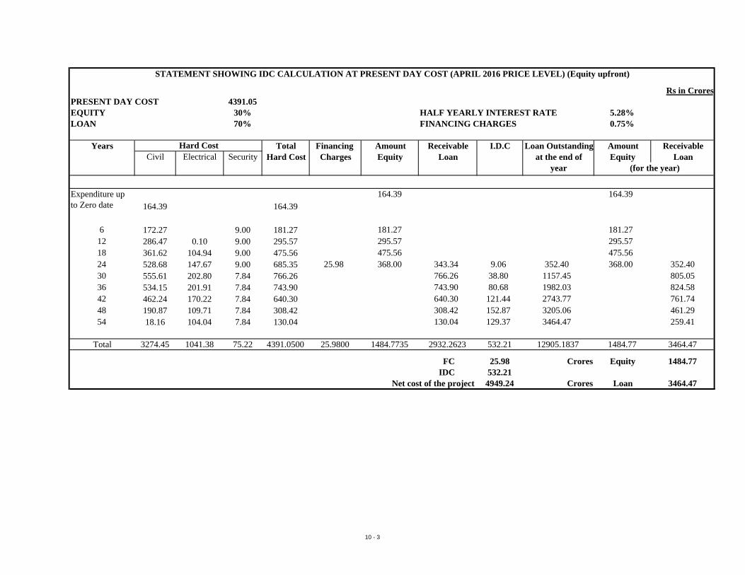
Rs in CroresPRESENT DAY COST 4391.05EQUITY 30% HALF YEARLY INTEREST RATE 5.28%LOAN 70% FINANCING CHARGES 0.75%
Years Total Financing Amount Receivable I.D.C Loan Outstanding Amount ReceivableCivil Electrical Security Hard Cost Charges Equity Loan at the end of Equity Loan
year
Expenditure up to Zero date 164.39 164.39
164.39 164.39
6 172.27 9.00 181.27 181.27 181.2712 286.47 0.10 9.00 295.57 295.57 295.5718 361.62 104.94 9.00 475.56 475.56 475.5624 528.68 147.67 9.00 685.35 25.98 368.00 343.34 9.06 352.40 368.00 352.4030 555.61 202.80 7.84 766.26 766.26 38.80 1157.45 805.0536 534.15 201.91 7.84 743.90 743.90 80.68 1982.03 824.5842 462.24 170.22 7.84 640.30 640.30 121.44 2743.77 761.7448 190.87 109.71 7.84 308.42 308.42 152.87 3205.06 461.2954 18.16 104.04 7.84 130.04 130.04 129.37 3464.47 259.41
Total 3274.45 1041.38 75.22 4391.0500 25.9800 1484.7735 2932.2623 532.21 12905.1837 1484.77 3464.47
FC 25.98 Crores Equity 1484.77IDC 532.21
Net cost of the project 4949.24 Crores Loan 3464.47
STATEMENT SHOWING IDC CALCULATION AT PRESENT DAY COST (APRIL 2016 PRICE LEVEL) (Equity upfront)
Hard Cost
(for the year)
10 - 3
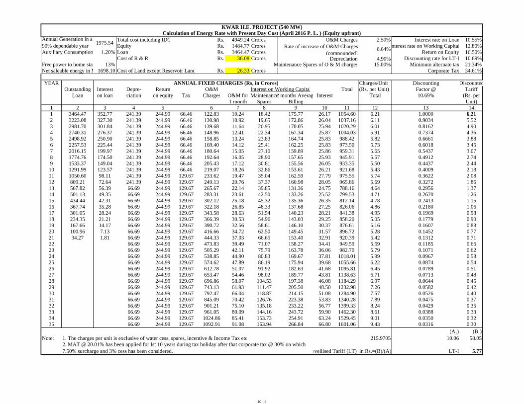
Total cost including IDC Rs. 4949.24 Crores O&M Charges 2.50% Interest rate on Loan 10.55%Equity Rs. 1484.77 Crores nterest rate on Working Capital 12.80%
Auxiliary Consumption 1.20% Loan Rs. 3464.47 Crores Return on Equity 16.50%Cost of R & R Rs. 36.08 Crores 4.90% Discounting rate for LT-I 10.69%
Free power to home stat 13% Maintenance Spares of O & M charges 15.00% Minimum alternate tax 21.34%Net saleable energy in M 1698.10 Cost of Land except Reservoir Land Rs. 26.33 Crores Corporate Tax 34.61%
YEAR Charges/Unit Discounting DiscountedOutstanding Interest Depre- Return O&M Total (Rs. per Unit) Factor @ Tariff
Loan on loan ciation on equity Tax Charges O&M for Maintenance2 months Averag Interest Total 10.69% (Rs. per1 month Spares Billing Unit)
1 2 3 4 5 6 7 8 9 10 11 12 13 141 3464.47 352.77 241.39 244.99 66.46 122.83 10.24 18.42 175.77 26.17 1054.60 6.21 1.0000 6.212 3223.08 327.30 241.39 244.99 66.46 130.98 10.92 19.65 172.86 26.04 1037.16 6.11 0.9034 5.523 2981.70 301.84 241.39 244.99 66.46 139.68 11.64 20.95 170.05 25.94 1020.29 6.01 0.8162 4.904 2740.31 276.37 241.39 244.99 66.46 148.96 12.41 22.34 167.34 25.87 1004.03 5.91 0.7374 4.365 2498.92 250.90 241.39 244.99 66.46 158.85 13.24 23.83 164.74 25.83 988.42 5.82 0.6661 3.886 2257.53 225.44 241.39 244.99 66.46 169.40 14.12 25.41 162.25 25.83 973.50 5.73 0.6018 3.457 2016.15 199.97 241.39 244.99 66.46 180.64 15.05 27.10 159.89 25.86 959.31 5.65 0.5437 3.078 1774.76 174.50 241.39 244.99 66.46 192.64 16.05 28.90 157.65 25.93 945.91 5.57 0.4912 2.749 1533.37 149.04 241.39 244.99 66.46 205.43 17.12 30.81 155.56 26.05 933.35 5.50 0.4437 2.44
10 1291.99 123.57 241.39 244.99 66.46 219.07 18.26 32.86 153.61 26.21 921.68 5.43 0.4009 2.1811 1050.60 98.11 241.39 244.99 129.67 233.62 19.47 35.04 162.59 27.79 975.55 5.74 0.3622 2.0812 809.21 72.64 241.39 244.99 129.67 249.13 20.76 37.37 160.98 28.05 965.86 5.69 0.3272 1.8613 567.82 56.39 66.69 244.99 129.67 265.67 22.14 39.85 131.36 24.75 788.16 4.64 0.2956 1.3714 501.13 49.35 66.69 244.99 129.67 283.31 23.61 42.50 133.26 25.52 799.53 4.71 0.2670 1.2615 434.44 42.31 66.69 244.99 129.67 302.12 25.18 45.32 135.36 26.35 812.14 4.78 0.2413 1.1516 367.74 35.28 66.69 244.99 129.67 322.18 26.85 48.33 137.68 27.25 826.06 4.86 0.2180 1.0617 301.05 28.24 66.69 244.99 129.67 343.58 28.63 51.54 140.23 28.21 841.38 4.95 0.1969 0.9818 234.35 21.21 66.69 244.99 129.67 366.39 30.53 54.96 143.03 29.25 858.20 5.05 0.1779 0.9019 167.66 14.17 66.69 244.99 129.67 390.72 32.56 58.61 146.10 30.37 876.61 5.16 0.1607 0.8320 100.96 7.13 66.69 244.99 129.67 416.66 34.72 62.50 149.45 31.57 896.72 5.28 0.1452 0.7721 34.27 1.81 66.69 244.99 129.67 444.33 37.03 66.65 153.40 32.91 920.39 5.42 0.1312 0.7122 66.69 244.99 129.67 473.83 39.49 71.07 158.27 34.41 949.59 5.59 0.1185 0.6623 66.69 244.99 129.67 505.29 42.11 75.79 163.78 36.06 982.70 5.79 0.1071 0.6224 66.69 244.99 129.67 538.85 44.90 80.83 169.67 37.81 1018.01 5.99 0.0967 0.5825 66.69 244.99 129.67 574.62 47.89 86.19 175.94 39.68 1055.66 6.22 0.0874 0.5426 66.69 244.99 129.67 612.78 51.07 91.92 182.63 41.68 1095.81 6.45 0.0789 0.5127 66.69 244.99 129.67 653.47 54.46 98.02 189.77 43.81 1138.63 6.71 0.0713 0.4828 66.69 244.99 129.67 696.86 58.07 104.53 197.38 46.08 1184.29 6.97 0.0644 0.4529 66.69 244.99 129.67 743.13 61.93 111.47 205.50 48.50 1232.98 7.26 0.0582 0.4230 66.69 244.99 129.67 792.47 66.04 118.87 214.15 51.08 1284.90 7.57 0.0526 0.4031 66.69 244.99 129.67 845.09 70.42 126.76 223.38 53.83 1340.28 7.89 0.0475 0.3732 66.69 244.99 129.67 901.21 75.10 135.18 233.22 56.77 1399.33 8.24 0.0429 0.3533 66.69 244.99 129.67 961.05 80.09 144.16 243.72 59.90 1462.30 8.61 0.0388 0.3334 66.69 244.99 129.67 1024.86 85.41 153.73 254.91 63.24 1529.45 9.01 0.0350 0.3235 66.69 244.99 129.67 1092.91 91.08 163.94 266.84 66.80 1601.06 9.43 0.0316 0.30
(A1) (B1)Note: 1. The charges per unit is exclusive of water cess, spares, incentive & Income Tax etc 215.9705 10.06 58.05
evellised Tariff (LT) in Rs.=(B)/(A) LT-I 5.77
Interest on Working CapitalANNUAL FIXED CHARGES (Rs, in Crores)
KWAR H.E. PROJECT (540 MW)Calculation of Energy Rate with Present Day Cost (April 2016 P. L. ) (Equity upfront)
Annual Generation in a 90% dependable year
1975.54Rate of increase of O&M Charges
(compounded)6.64%
Depreciation
2. MAT @ 20.01% has been applied for Ist 10 years during tax holiday after that corporate tax @ 30% on which 7.50% surcharge and 3% cess has been considered.
10 - 4
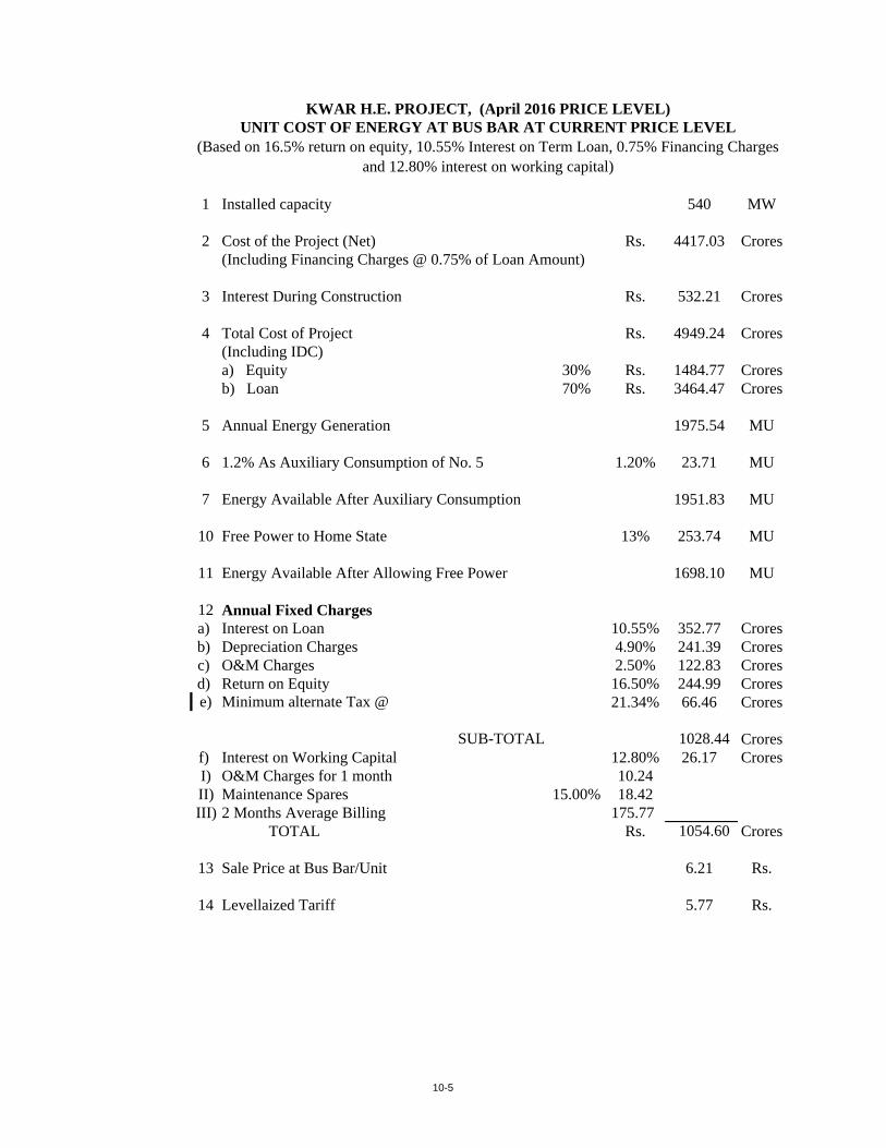
1 Installed capacity 540 MW
2 Cost of the Project (Net) Rs. 4417.03 Crores(Including Financing Charges @ 0.75% of Loan Amount)
3 Interest During Construction Rs. 532.21 Crores
4 Total Cost of Project Rs. 4949.24 Crores(Including IDC)a) Equity 30% Rs. 1484.77 Croresb) Loan 70% Rs. 3464.47 Crores
5 Annual Energy Generation 1975.54 MU
6 1.2% As Auxiliary Consumption of No. 5 1.20% 23.71 MU
7 Energy Available After Auxiliary Consumption 1951.83 MU
10 Free Power to Home State 13% 253.74 MU
11 Energy Available After Allowing Free Power 1698.10 MU
12 Annual Fixed Chargesa) Interest on Loan 10.55% 352.77 Croresb) Depreciation Charges 4.90% 241.39 Croresc) O&M Charges 2.50% 122.83 Croresd) Return on Equity 16.50% 244.99 Crorese) Minimum alternate Tax @ 21.34% 66.46 Crores
SUB-TOTAL 1028.44 Croresf) Interest on Working Capital 12.80% 26.17 CroresI) O&M Charges for 1 month 10.24II) Maintenance Spares 15.00% 18.42III) 2 Months Average Billing 175.77
TOTAL Rs. 1054.60 Crores
13 Sale Price at Bus Bar/Unit 6.21 Rs.
14 Levellaized Tariff 5.77 Rs.
KWAR H.E. PROJECT, (April 2016 PRICE LEVEL)UNIT COST OF ENERGY AT BUS BAR AT CURRENT PRICE LEVEL
(Based on 16.5% return on equity, 10.55% Interest on Term Loan, 0.75% Financing Charges and 12.80% interest on working capital)
10-5
Kwar Hydroelectric Project (540 MW) Detailed Project Report
Executive Summary
CHAPTER –11
CONSTRUCTION METHODOLOGY & EQUIPMENT PLANNING
Kwar Hydroelectric Project (540 MW) Detailed Project Report Executive Summary
11 -1
CHAPTER - 11
CONSTRUCTION METHODOLOGY & EQUIPMENT PLANNING
11.0 GENERAL:
Kwar Hydroelectric Project is a run of the river scheme proposed to harness
the hydel potential of Chenab River. The project is located in Kishtwar
district of Jammu & Kashmir, envisaging utilisation of 102.5 m of rated head
available between proposed Concrete Gravity Dam and the Powerhouse.
Construction methodology and selection of equipment has been planned
with the aim to commission the project in a total period of four and half years
(excluding infrastructural works). Major construction works shall start from
2nd month after necessary initial mobilization and the project shall be
commissioned in 54th month. Available working season in a year in the
project area shall be 12 months for all underground works and 9 months for
surface works.
The project headquarter is located at Kishtwar which is about 240 kms from
Jammu, the winter capital town of J&K. The dam site is about 40 kms from
Kishtwar. The nearest rail head is Udhampur. The nearest domestic airport
is at Jammu and the international airport is at New Delhi.
Since major works of the project are proposed to be executed through
contract, some provisions of machinery like material trucks, tippers, trailers,
motor grader, dozers, road rollers and other Q special T&P required for
carrying out the infrastructural works have been made in the project
estimate. Provisions for inspection vehicles, personnel carriers, ambulances
and field workshop equipment have also been made in the estimate for
infrastructural facilities.
Equipment planning for all the project components has been carried out in
the upcoming pages and optimization studies have been conducted as if the
works are to be executed under single package of Contract.
Kwar Hydroelectric Project (540 MW) Detailed Project Report Executive Summary
11 -2
The construction methodologies for different components of the project are
as under:
11.1 DIVERSION TUNNEL:
1 No., 685 m long, 9.5 m finished diameter, Horse-shoe shaped diversion
tunnel on the left bank of river Chenab shall be excavated through drilling &
blasting by heading & benching method. Excavated diameter of diversion
tunnel shall be 10.3 m. The total time for excavation and concreting of
Diversion tunnel shall be 13 months commencing from 2nd month including
excavation and establishment of portals. Heading and Benching of D/T will
be done from both the faces of the tunnel simultaneously. For the excavation
of Diversion tunnel, equipment like 2-boom drill jumbo, 2.5 cum side dump
loader & 20/25 t Multi-axle Rear dumpers have been proposed for
deployment. Concreting shall be taken up in two parts i.e. Overt and Invert.
The concreting and grouting shall be completed in 5.5 months. 2 nos. of
10m tunnel gantry have been proposed for concreting so that concrete in
one gantry can be poured everyday in tunnel. 6 cum transit mixers and 60
cum/hr concrete pumps etc. have also been proposed to facilitate the
concreting. As such total diversion tunnel would be completed in 13 months
time.
11.2 COFFER DAM:
It has been envisaged that the coffer dams shall be constructed / repaired
three times during entire construction period of the project. Construction of
coffer dam with the placement quantity of rock fill materials shall be carried
out in a period of 3.5 months including excavation & grouting etc. It is
proposed to use the useful excavated muck from the Diversion Tunnel as
well as abutment excavation in the construction of coffer dams. The
equipment required for the construction of the Coffer Dams would be 20/25t
rear dumpers, 2 cum Hyd. excavators, Dozers, Vibratory compactors etc.
11.3 CONCRETE GRAVITY DAM:
Abutment stripping of 101 m high & 195 m long dam will commence from 4th
month and will be completed in 16th month. River bed excavation will be
Kwar Hydroelectric Project (540 MW) Detailed Project Report Executive Summary
11 -3
completed in 2 months i.e. from 16th month to 17th month. 1.0/2.0 cum
Hydraulic Excavator, 20/25t Rear Dumper, Air Tracks, Diamond Core Drills,
Rock Breaker etc. will be used for dam excavation.
The concreting of 101 m high & 195 m long Concrete Dam will be started
from 18th month. The concreting quantity below RBL shall be placed in 3
months commencing from 18th months with the help of tower crane of the
capacity 10T@30 m radius. The remaining concreting quantity shall be
placed in 25 months commencing from 20th month with the help of same
tower crane used for concreting below RBL. One no. 38 cum/hr concrete
pump shall also be deployed to supplement the concreting requirement.
Batching & Mixing plants, Aggregate Processing Plants, Chilling plant, Ice
plant etc (of suitable capacities) shall be used for production of aggregates
and concrete placement. The U/s & D/s coffer dams will be constructed in
the successive seasons till dam level reaches up to EL 1370m.
11.4 INTAKE STRUCTURE:
Four numbers of intakes have been proposed to convey the water from dam
to powerhouse through 4 nos. pressure shafts/penstocks. Excavation of
intake structures would be carried out in 2 months commencing from 6th
month and completing in the 7th month. Excavation of intake portal would be
carried out with 1.0 cum hydraulic excavators, 20/25t multi axle rear
dumpers, wagon drills/crawler rigs etc.
Concreting of intake structure would be taken up from 43rd month and would
be completed in 6 months (effective) by 49th month. Other equipment
required for concreting purpose would be concrete pump, vibrators, 6 cum
transit mixers etc.
11.5 PRESSURE SHAFT:
4 nos. steel lined pressure shafts, 5.65 m circular finished diameter, having
max vertical length of 93 m max. And max. Total length (excluding vertical)
182.0m have been proposed for the four units to be installed at powerhouse.
Since adits at bottom of the pressure shafts have been provided, the
excavation of the vertical pressure shafts shall not depend on the
Kwar Hydroelectric Project (540 MW) Detailed Project Report Executive Summary
11 -4
excavation/ concreting of intake structure and therefore it will be an
independent activity. The excavation of vertical pressure shafts would be
carried out manually through full sinking method taking both shafts at a time.
The excavation of lower horizontal pressure shafts would be carried out from
intake side by normal drilling and blasting method taking two shafts at a time
with one set of equipment. The total period for excavation of pressure shafts
(vertical & bottom) would be 8 months starting from 31st month, 9 months
starting from 30th month, 11 months starting from 18th month & 13 months
starting from 16th month for PS 1, PS-2, PS-3 & PS4 respectively. Steel
liner erection and concrete back filling shall start from 30th month and end in
47th month in a period of 13 months.
11.6 POWER HOUSE:
4 X 135 MW (540 MW) underground power house located on the right bank
of the river Chenab shall be fed by four penstocks.
The excavation of Powerhouse (140m X 23.3m X 50m) would be taken up
after the excavation of construction adit to the powerhouse crown. This adit
would further be extended throughout the length of the powerhouse. This
excavation would take around 2 months. Further, this pilot tunnel would be
widened upto 25.62 m width in two stages in 4 months.
Power house excavation would be carried out initially by benching of 3 meter
from EL 1276 to EL 1273 in one month. Mucking would be carried out
through adits to crown of power house.
Power house excavation would be subsequently carried out by constructing
suitable ramps for benching down. Movement of equipment would be carried
out through ramps. For excavation from El 1273 to El 1258.65, mucking
would be carried out through adits to crown of power house in 6 months
including removal of the ramps.
Suitable ramps would be prepared to come down below El 1246 and
benching of the power house upto El 1237.3 would be carried out in 2
months. Mucking would be carried out through MAT.
Kwar Hydroelectric Project (540 MW) Detailed Project Report Executive Summary
11 -5
After reaching the EL 1237.3, pit excavation would be carried out in 2
months. After the excavation of draft tube pit, MAT ramp would be removed
in 1 month.
The excavation of power house cavern would require 13 months
commencing from 12th month and completing in 24th month.
The equipment required for this purpose are 2 boom drill jumbo, 1.0/2.0 cum
hydraulic excavator, 2.5 cum side dump loader, 20/25t multi axle rear
dumpers, wagon drills/ crawler rigs, jack hammers, shotcrete machine, grout
pump, concrete pump (38/60 cum/hr), vibrator, transit mixers etc. Batching &
mixing plant, aggregate processing plant would meet the concreting
requirement of power house.
11.7 TRANSFORMER CAVERN, GIS CAVERN & DT GATE HALL
The excavation of Transformer Cavern (116m X 17m X 16m) would be taken
up after the excavation of construction adit to the Transformer Cavern
crown. Construction adit to Transformer Cavern crown would be further
extended to full length of the Transformer Cavern. Thereafter, it would be
enlarged sideways to the full width of the Transformer Cavern.
The excavation of GIS cavern & DT gate hall (65m X 17m X 16m) would be
taken up after the excavation of Transformer Cavern. Through this cavern
pilot shafts of 3.0 m diameter would be excavated manually upto bottom.
The pilot shafts would be excavated with Jack hammers & EOT/Gantry
crane installed at the top of GIS cavern & DT gate cavern. The excavation of
these four shafts would be taken up simultaneously. Time required for the
excavation of Pilot shafts upto EL1242.30 would be around 3.0 months.
GIS & DT gate cavern would be benched down through these pilot shafts.
Muck would be dozed through these pilot shafts & would be hauled through
the TRT. The equipment required for this purpose are 2 boom drill jumbo,
1.0/2.0 cum hydraulic excavator, 2.5 cum side dump loader, 20/25t multi
axle rear dumpers, tippers, wagon drills/ crawler rigs, jack hammers,
Kwar Hydroelectric Project (540 MW) Detailed Project Report Executive Summary
11 -6
shotcrete machine, grout pump, concrete pump (38 cum/hr), vibrator, transit
mixers etc.
The total time required for the excavation of Transformer cavern, GIS & DT
gate cavern would be around 9 months.
11.8 TAIL RACE TUNNEL
2 nos. Horse shoe shaped 9.5 m finished diameter Tail Race Tunnels having
maximum length of 2883 m shall convey 302.6 cumecs of design discharge.
Excavation of the TRT would be carried out by heading & benching method.
Excavated diameter of Tail race tunnel shall be 9.8 m. The total time for
excavation of 732m for U/s of Tail Race tunnel - 1 shall be 12.5 months
commencing from 14th month and 1212 m for D/s of Tail Race tunnel - 1
shall be 20 months commencing from 14th month. Similarly total time for
excavation of 823m for U/s of Tail Race tunnel - 2 shall be 13.5 months and
1237 m for D/s of Tail Race tunnel - 2 shall be 20 months commencing from
13th month. Heading and Benching of Tail Race Tunnel will be done from
three faces in both the tunnels. For the excavation of Tail Race tunnel,
equipment like 2-boom drill jumbo, 2.5 cum side dump loader & 20/25 t
Multi-axle Rear dumpers have been proposed for deployment. Concreting
shall be taken up in two parts i.e. Overt and Invert. Concreting of TRT outlet
portal. 2 nos. of 10m tunnel gantry in each TRT have been proposed for
concreting so that concrete in one gantry can be poured everyday in each
tunnel. 6 cum transit mixers and 60 cum/hr concrete pumps etc. have also
been proposed to facilitate the concreting.
11.9 GIS & POT HEAD YARD
Excavation of GIS & Pot Head Yard would be carried out in a period of 6
months commencing from 27th month and completing in 32nd month.
Concreting of the GIS & Pot Head Yard would be carried out in 10 months
starting from 33rd month. The excavation & concreting of GIS & Pot Head
Yard would be carried out with the help of 2 cum. hyd. excavator, wagon
drills/ crawler rigs, 20/25 T multi-axle rear dumpers, 6 cum transit mixers, 38
cum concrete pump & B&M plant, aggregate processing plant etc.
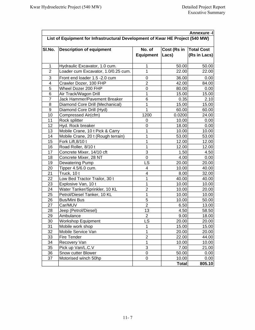
Sl.No. Description of equipment No. of Equipment
Cost (Rs in Lacs)
Total Cost (Rs in Lacs)
1 Hydraulic Excavator, 1.0 cum. 1 50.00 50.002 Loader cum Excavator, 1.0/0.25 cum. 1 22.00 22.00
3 Front end loader 1.5 -2.0 cum 0 36.00 0.004 Crawler Dozer, 100 FHP 2 42.00 84.005 Wheel Dozer 200 FHP 0 80.00 0.006 Air Track/Wagon Drill 1 15.00 15.007 Jack Hammer/Pavement Breaker 6 0.35 2.108 Diamond Core Drill (Mechanical) 1 15.00 15.009 Diamond Core Drill (Hyd) 1 60.00 60.00
10 Compressed Air(cfm) 1200 0.0200 24.0011 Rock splitter 0 10.00 0.0012 Hyd. Rock breaker 0 18.00 0.0013 Mobile Crane, 10 t Pick & Carry 1 10.00 10.0014 Mobile Crane, 20 t (Rough terrain) 1 53.00 53.0015 Fork Lift,8/10 t 1 12.00 12.0016 Road Roller, 8/10 t 1 12.00 12.0017 Concrete Mixer, 14/10 cft 3 1.50 4.5018 Concrete Mixer, 28 NT 0 4.00 0.0019 Dewatering Pump LS 20.00 20.0020 Tipper 4.5/6.0 cum. 4 10.00 40.0021 Truck, 10 t 4 8.00 32.0022 Low Bed Tractor Trailor, 30 t 1 40.00 40.0023 Explosive Van, 10 t 1 10.00 10.0024 Water Tanker/Sprinkler, 10 KL 2 10.00 20.0025 Petrol/Diesel Tanker, 10 KL 1 10.00 10.0026 Bus/Mini Bus 5 10.00 50.0027 Car/MUV 2 6.50 13.0028 Jeep (Petrol/Diesel) 13 4.50 58.5029 Ambulance 2 9.00 18.0030 Workshop Equipment LS 20.00 20.0031 Mobile work shop 1 15.00 15.0032 Mobile Service Van 1 20.00 20.0033 Fire Tender 2 22.00 44.0034 Recovery Van 1 10.00 10.0035 Pick up Van/L.C.V 3 7.00 21.0036 Snow cutter Blower 0 50.00 0.0037 Motorised winch 50hp 0 10.00 0.00
Total 805.10
Annexure -IList of Equipment for Infrastructural Development of Kwar HE Project (540 MW)
Kwar Hydroelectric Project (540 MW) Detailed Project Report Executive Summary
11- 7
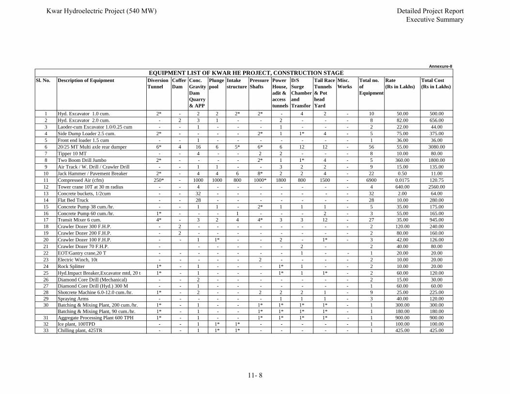
Sl. No. Description of Equipment Diversion Tunnel
Coffer Dam
Conc. Gravity Dam Quarry& APP
Plunge pool
Intake structure
Pressure Shafts
Power House, adit & access tunnels
D/S Surge Chamber and Transfor
Tail Race Tunnels & Pot head Yard
Misc. Works
Total no. of Equipment
Rate (Rs in Lakhs)
Total Cost (Rs in Lakhs)
1 Hyd. Excavator 1.0 cum. 2* - 2 2 2* 2* - 4 2 - 10 50.00 500.002 Hyd. Excavator 2.0 cum. - 2 3 1 - - 2 - - - 8 82.00 656.003 Laoder-cum Excavator 1.0/0.25 cum - - 1 - - - 1 - - - 2 22.00 44.004 Side Dump Loader 2.5 cum. 2* - - - - 2* 1 1* 4 - 5 75.00 375.005 Front end loader 1.5 cum - - 1 - - - - - - - 1 36.00 36.006 20/25 MT Multi axle rear dumper 6* 4 16 6 5* 6* 6 12 12 - 56 55.00 3080.007 Tipper 10 MT - - 4 - - 2 2 - - - 8 10.00 80.008 Two Boom Drill Jumbo 2* - - - - 2* 1 1* 4 - 5 360.00 1800.009 Air Track / W. Drill / Crawler Drill - - 1 1 - - 3 2 2 - 9 15.00 135.00
10 Jack Hammer / Pavement Breaker 2* - 4 4 6 8* 2 2 4 - 22 0.50 11.0011 Compressed Air (cfm) 250* - 1000 1000 800 1000* 1800 800 1500 - 6900 0.0175 120.75
EQUIPMENT LIST OF KWAR HE PROJECT, CONSTRUCTION STAGEAnnexure-II
12 Tower crane 10T at 30 m radius - - 4 - - - - - - - 4 640.00 2560.0013 Concrete buckets, 1/2cum - - 32 - - - - - - - 32 2.00 64.0014 Flat Bed Truck - - 28 - - - - - - - 28 10.00 280.0015 Concrete Pump 38 cum./hr. - - 1 1 - 2* 1 1 1 - 5 35.00 175.0016 Concrete Pump 60 cum./hr. 1* - - - 1 - - - 2 - 3 55.00 165.0017 Transit Mixer 6 cum. 4* - 3 2 4 4* 3 3 12 - 27 35.00 945.0018 Crawler Dozer 300 F.H.P. - 2 - - - - - - - - 2 120.00 240.0019 Crawler Dozer 200 F.H.P. - 2 - - - - - - - - 2 80.00 160.0020 Crawler Dozer 100 F.H.P. - - 1 1* - - 2 - 1* - 3 42.00 126.0021 Crawler Dozer 70 F.H.P. - - - - - - 2 - 2 40.00 80.0022 EOT/Gantry crane,20 T - - - - - - - 1 - - 1 20.00 20.0023 Electric Winch, 10t - - - - - 2 - - - - 2 10.00 20.0024 Rock Splitter 1* - 1 - - - 1* 1 - - 2 10.00 20.0025 Hyd.Impact Breaker,Excavator mtd, 20 t 1* - 1 - - - 1* 1 1* - 2 60.00 120.0026 Diamond Core Drill (Mechanical) - - 2 - - - - - - - 2 15.00 30.0027 Diamond Core Drill (Hyd.) 300 M - - 1 - - - - - - - 1 60.00 60.0028 Shotcrete Machine 6.0-12.0 cum./hr. 1* - 2 - - 2 2 2 1 - 9 25.00 225.0029 Spraying Arms - - - - - - 1 1 1 - 3 40.00 120.0030 Batching & Mixing Plant, 200 cum./hr. 1* - 1 - - 1* 1* 1* 1* - 1 300.00 300.00
Batching & Mixing Plant, 90 cum./hr. 1* - 1 - - 1* 1* 1* 1* - 1 180.00 180.0031 Aggregate Processing Plant 600 TPH 1* - 1 - - 1* 1* 1* 1* - 1 900.00 900.0032 Ice plant, 100TPD - - 1 1* 1* - - - - - 1 100.00 100.0033 Chilling plant, 425TR - - 1 1* 1* - - - - - 1 425.00 425.00
Kwar Hydroelectric Project (540 MW) Detailed Project Report Executive Summary
11- 8
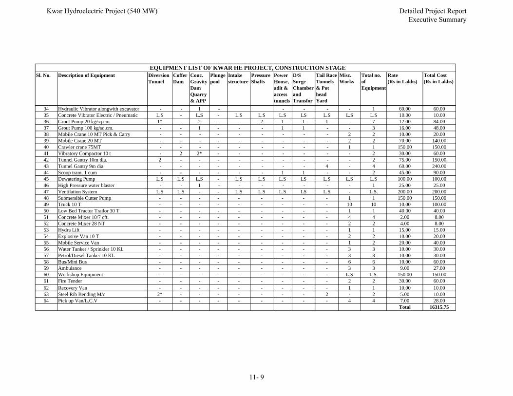
Sl. No. Description of Equipment Diversion Tunnel
Coffer Dam
Conc. Gravity Dam Quarry& APP
Plunge pool
Intake structure
Pressure Shafts
Power House, adit & access tunnels
D/S Surge Chamber and Transfor
Tail Race Tunnels & Pot head Yard
Misc. Works
Total no. of Equipment
Rate (Rs in Lakhs)
Total Cost (Rs in Lakhs)
EQUIPMENT LIST OF KWAR HE PROJECT, CONSTRUCTION STAGE
34 Hydraulic Vibrator alongwith excavator - - 1 - - - - - 1 60.00 60.0035 Concrete Vibrator Electric / Pneumatic L.S - L.S - L.S L.S L.S LS L.S L.S L.S 10.00 10.0036 Grout Pump 20 kg/sq.cm 1* - 2 - - 2 1 1 1 - 7 12.00 84.0037 Grout Pump 100 kg/sq.cm. - - 1 - - - 1 1 - - 3 16.00 48.0038 Mobile Crane 10 MT Pick & Carry - - - - - - - - - 2 2 10.00 20.0039 Mobile Crane 20 MT - - - - - - - - - 2 2 70.00 140.0040 Crawler crane 75MT - - - - - - - - - 1 1 150.00 150.0041 Vibratory Compactor 10 t - 2 2* - - - - - - - 2 30.00 60.0042 Tunnel Gantry 10m dia. 2 - - - - - - - - - 2 75.00 150.0043 Tunnel Gantry 9m dia. - - - - - - - - 4 - 4 60.00 240.0044 Scoop tram, 1 cum - - - - - - 1 1 - - 2 45.00 90.0045 Dewatering Pump L.S L.S L.S - L.S L.S L.S LS L.S L.S L.S 100.00 100.0046 High Pressure water blaster 1 1 25 00 25 0046 High Pressure water blaster - - 1 - - - - - - - 1 25.00 25.0047 Ventilation System L.S L.S - - L.S L.S L.S LS L.S - L.S. 200.00 200.0048 Submersible Cutter Pump - - - - - - - - - 1 1 150.00 150.0049 Truck 10 T - - - - - - - - - 10 10 10.00 100.0050 Low Bed Tractor Trailor 30 T - - - - - - - - - 1 1 40.00 40.0051 Concrete Mixer 10/7 cft. - - - - - - - - - 4 4 2.00 8.0052 Concrete Mixer 28 NT - - - - - - - - - 2 2 4.00 8.0053 Hydra Lift - - - - - - - - - 1 1 15.00 15.0054 Explosive Van 10 T - - - - - - - - - 2 2 10.00 20.0055 Mobile Service Van - - - - - - - - - 1 2 20.00 40.0056 Water Tanker / Sprinkler 10 KL - - - - - - - - - 3 3 10.00 30.0057 Petrol/Diesel Tanker 10 KL - - - - - - - - - 3 3 10.00 30.0058 Bus/Mini Bus - - - - - - - - - 6 6 10.00 60.0059 Ambulance - - - - - - - - - 3 3 9.00 27.0060 Workshop Equipment - - - - - - - - - L.S L.S. 150.00 150.0061 Fire Tender - - - - - - - - - 2 2 30.00 60.0062 Recovery Van - - - - - - - - - 1 1 10.00 10.0063 Steel Rib Bending M/c 2* - - - - - - - 2 - 2 5.00 10.0064 Pick up Van/L.C.V - - - - - - - - - 4 4 7.00 28.00
Total 16315.75
Kwar Hydroelectric Project (540 MW) Detailed Project Report Executive Summary
11- 9
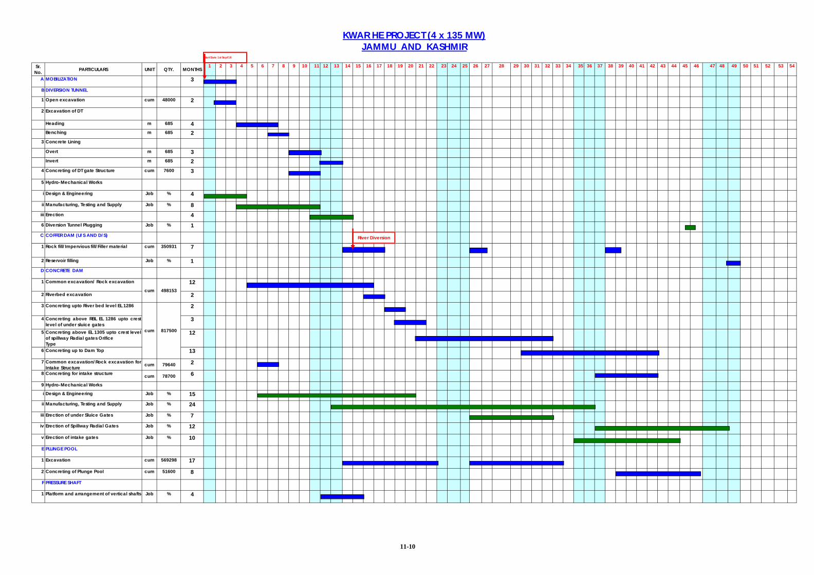
Sr. No. PARTICULARS UNIT QTY. MONTHS
1 2 3 4 5 6 7 8 9 10 11 12 13 14 15 16 17 18 19 20 21 22 23 24 25 26 27 28 29 30 31 32 33 34 35 36 37 38 39 40 41 42 43 44 45 46 47 48 49 50 51 52 53 54
A MOBILIZATION 3
B DIVERSION TUNNEL
1 Open excavation cum 48000 2
2 Excavation of DT
Heading m 685 4Benching m 685 2
3 Concrete Lining
Overt m 685 3Invert m 685 2
4 Concreting of DT gate Structure cum 7600 3
5 Hydro-Mechanical Works
i Design & Engineering Job % 4
ii Manufacturing, Testing and Supply Job % 8iii Erection 46 Diversion Tunnel Plugging Job % 1C COFFER DAM (U/S AND D/S)
1 Rock fill/Impervious fill/Filler material cum 350931 7
2 Reservoir filling Job % 1D CONCRETE DAM
1 Common excavation/ Rock excavation 12
2 Riverbed excavation 2
3 Concreting upto River bed level EL 1286 2
4 Concreting above RBL EL 1286 upto crestlevel of under sluice gates
3
5 Concreting above EL 1305 upto crest levelof spillway Radial gates OrificeType
12
6 Concreting up to Dam Top 13
7 Common excavation/Rock excavation forIntake Structure cum 79640 2
8 Concreting for intake structure cum 78700 6
9 Hydro-Mechanical Works
i Design & Engineering Job % 15ii Manufacturing, Testing and Supply Job % 24
iii Erection of under Sluice Gates Job % 7
iv Erection of Spillway Radial Gates Job % 12
v Erection of intake gates Job % 10
E PLUNGE POOL
1 Excavation cum 569298 17
2 Concreting of Plunge Pool cum 51600 8
F PRESSURE SHAFT
1 Platform and arrangement of vertical shafts Job % 4
River Diversion
KWAR HE PROJECT (4 x 135 MW)JAMMU AND KASHMIR
817500cum
498153cum
Start Date 1st Sept'18
11-10
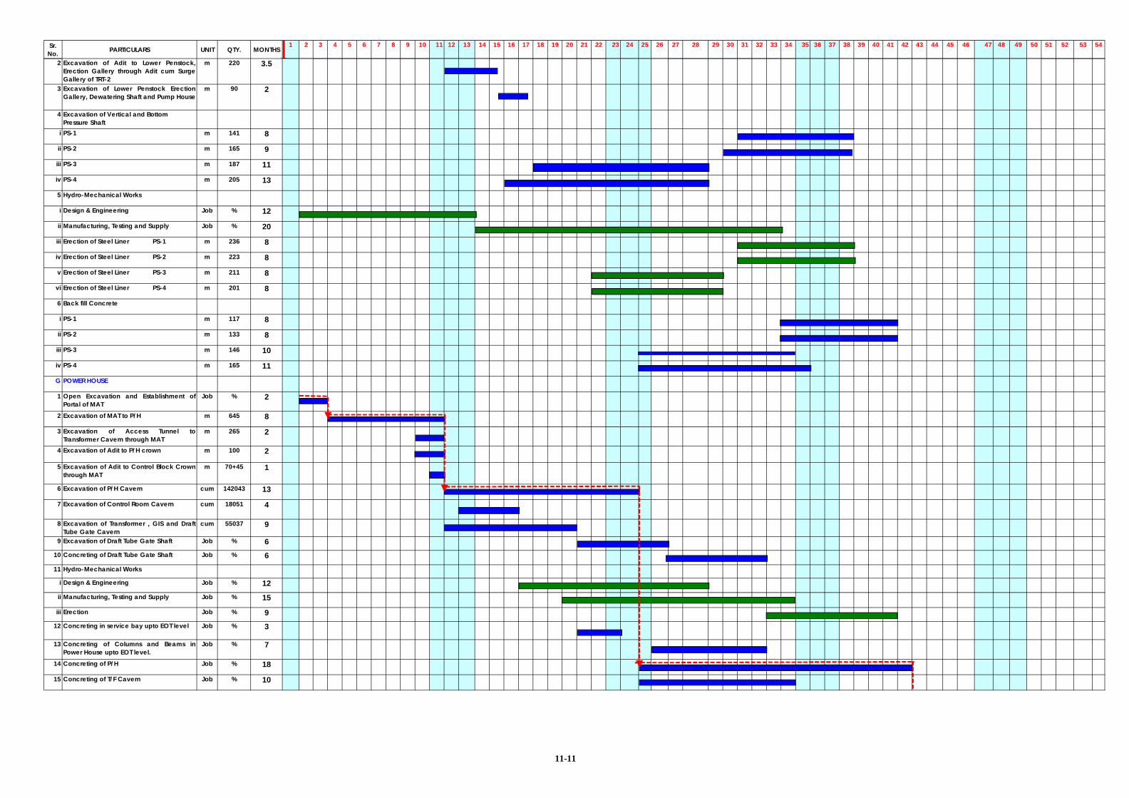
Sr. No. PARTICULARS UNIT QTY. MONTHS
1 2 3 4 5 6 7 8 9 10 11 12 13 14 15 16 17 18 19 20 21 22 23 24 25 26 27 28 29 30 31 32 33 34 35 36 37 38 39 40 41 42 43 44 45 46 47 48 49 50 51 52 53 54
2 Excavation of Adit to Lower Penstock,Erection Gallery through Adit cum SurgeGallery of TRT-2
m 220 3.5
3 Excavation of Lower Penstock ErectionGallery, Dewatering Shaft and Pump House
m 90 2
4 Excavation of Vertical and BottomPressure Shaft
i PS-1 m 141 8
ii PS-2 m 165 9
iii PS-3 m 187 11
iv PS-4 m 205 13
5 Hydro-Mechanical Works
i Design & Engineering Job % 12
ii Manufacturing, Testing and Supply Job % 20
iii Erection of Steel Liner PS-1 m 236 8
iv Erection of Steel Liner PS-2 m 223 8
v Erection of Steel Liner PS-3 m 211 8
vi Erection of Steel Liner PS-4 m 201 8
6 Back fill Concrete
i PS-1 m 117 8
ii PS-2 m 133 8
iii PS-3 m 146 10
iv PS-4 m 165 11
G POWER HOUSE
1 Open Excavation and Establishment ofPortal of MAT
Job % 2
2 Excavation of MAT to P/H m 645 8
3 Excavation of Access Tunnel toTransformer Cavern through MAT
m 265 2
4 Excavation of Adit to P/H crown m 100 2
5 Excavation of Adit to Control Block Crownthrough MAT
m 70+45 1
6 Excavation of P/H Cavern cum 142043 13
7 Excavation of Control Room Cavern cum 18051 4
8 Excavation of Transformer , GIS and DraftTube Gate Cavern
cum 55037 9
9 Excavation of Draft Tube Gate Shaft Job % 610 Concreting of Draft Tube Gate Shaft Job % 611 Hydro-Mechanical Works
i Design & Engineering Job % 12ii Manufacturing, Testing and Supply Job % 15
iii Erection Job % 912 Concreting in service bay upto EOT level Job % 3
13 Concreting of Columns and Beams inPower House upto EOT level.
Job % 7
14 Concreting of P/H Job % 18
15 Concreting of T/F Cavern Job % 10
11-11
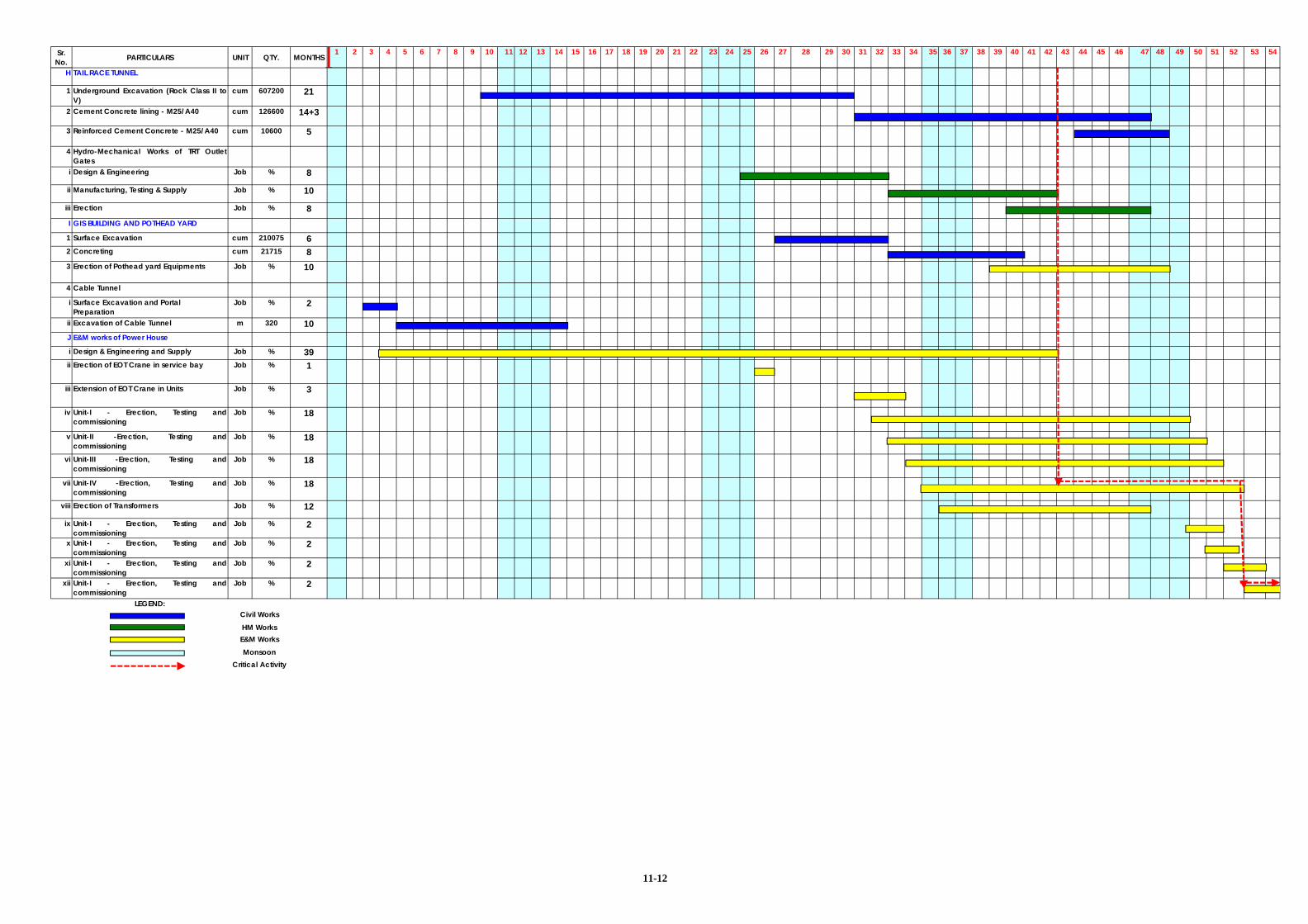
Sr. No. PARTICULARS UNIT QTY. MONTHS
1 2 3 4 5 6 7 8 9 10 11 12 13 14 15 16 17 18 19 20 21 22 23 24 25 26 27 28 29 30 31 32 33 34 35 36 37 38 39 40 41 42 43 44 45 46 47 48 49 50 51 52 53 54
H TAIL RACE TUNNEL
1 Underground Excavation (Rock Class II toV)
cum 607200 21
2 Cement Concrete lining - M25/A40 cum 126600 14+3
3 Reinforced Cement Concrete - M25/A40 cum 10600 5
4 Hydro-Mechanical Works of TRT OutletGates
i Design & Engineering Job % 8
ii Manufacturing, Testing & Supply Job % 10
iii Erection Job % 8I GIS BUILDING AND POTHEAD YARD
1 Surface Excavation cum 210075 62 Concreting cum 21715 83 Erection of Pothead yard Equipments Job % 10
4 Cable Tunnel
i Surface Excavation and PortalPreparation
Job % 2
ii Excavation of Cable Tunnel m 320 10J E&M works of Power House
i Design & Engineering and Supply Job % 39ii Erection of EOT Crane in service bay Job % 1
iii Extension of EOT Crane in Units Job % 3
iv Unit-I - Erection, Testing andcommissioning
Job % 18
v Unit-II -Erection, Testing andcommissioning
Job % 18
vi Unit-III -Erection, Testing andcommissioning
Job % 18
vii Unit-IV -Erection, Testing andcommissioning
Job % 18
viii Erection of Transformers Job % 12
ix Unit-I - Erection, Testing andcommissioning
Job % 2
x Unit-I - Erection, Testing andcommissioning
Job % 2
xi Unit-I - Erection, Testing andcommissioning
Job % 2
xii Unit-I - Erection, Testing andcommissioning
Job % 2
LEGEND:
Critical Activity
HM WorksE&M WorksMonsoon
Civil Works
11-12

Kwar Hydroelectric Project (540 MW) Detailed Project Report
Executive Summary
CHAPTER –12
ENVIRONMENT AND ECOLOGICAL ASPECTS
Kwar Hydroelectric Project (540 MW) Detailed Project Report Executive Summary
12-1
CHAPTER - 12 ENVIRONMENT AND ECOLOGICAL ASPECTS
Kwar (540MW) H.E. Project, a run-of-river scheme is located on river Chenab
in district Kishtwar of Jammu and Kashmir State. Kishtwar is the major
township situated near the project site on a central plateau which is linked with
other parts of the state by NH1B. The catchment area of the proposed project
at the dam site is 10325 sq km. The terrain of the catchment is generally
rugged and steep, with narrow valleys bounded by high ridges opening out in
their upper glacial parts. The area observes sub-temperate climate. The
influence of the monsoon is weak in the region. The basin receives
precipitation round the year. Cold season precipitation from December to
March occurs due to western disturbances leading to heavy snowfall during
the winter season in the upstream portions. The catchment area is by and
large snow bound for about two months during winter. For the remaining
months, the lower reaches of the drainage area are free from the snow cover.
The maximum and minimum temperature observed at Dul dam site is 430C
and -10C, respectively.
The soils of Kishtwar region have been classified as Sandy skeletal, Loamy
skeletal, Fine loamy, Course loamy and Loamy. Soil depth in general is
moderately deep to deep varying up to 30 cm depth. However, at some places
particularly in agricultural fields the depth is more. By and large, soils are
immature containing large proportion of un-decomposed organic materials.
Physico-chemical analysis of the soils reveals that the soils of the Chenab
catchment at this particular area are not very fertile because it is deficient in
most of the essential elements though the moisture and water contents are
available in appreciable quantity. Generally, soils of this area are alkaline in
nature. The microelements like zinc, iron, copper and manganese are also
present in a quantity that can be considered as moderately sufficient in a
mountainous soil. Overall the soils in the area are deficient in fertility level and
categorize under medium range of fertility.
Kwar Hydroelectric Project (540 MW) Detailed Project Report Executive Summary
12-2
The various land use / land cover categories of the project area comprise of
agriculture, forest, water bodies and other government land. Overall land
requirement of the project is 136.35 ha for different components of project. Out
of this 29.75 ha is forest land, 89.57 ha revenue (Govt.) land and 17.03 ha
private land. Submergence at FRL (EL 1385m) is 55.25 ha, comprising of
state land (river bed land). Execution of Kwar HE Project is likely to affect 5
villages viz. Bhagna, Semna Bhata, Ajna, Dichla and Galhar Bhata. Out of
these, Galhar Bhata village shall be losing only the river bed land and any
private land or property from this village shall not be affected. Therefore, it is
not considered in the main affected villages. As per Census 2011, the total
population in the four main project affected villages is 5705 spread over 1013
households with average household size of 5.6 and average sex ratio of 944.
During surveys, 63 PAFs with a total population of 350 from these 4 villages
have been identified as affected families. Out of 63 PAFs, 19 belong to ST
category and 44 belong to General category. The project affected population
would be properly rehabilitated as per the R&R plan.
The major forest types and subtypes in the area, based on Champion and
Seth (1968) classification, include Himalayan Moist Temperate forest (with two
subtypes viz. Ban Oak forest and Moist Temperate Deodar forest), Western
Himalayan Upper Oak-Fir forest, Western Himalayan Subalpine Fir forest and
Dwarf Rhododendron scrub. The vegetation in these forest types is
represented by species like Quercus baloot, Quercus semecarpifolia, Salix
alba and Aesculus indica in Ban-Oak forests; Cedrus deodara, Pinus
wallichiana, Quercus semecarpifolia and Pinus gerardiana in Moist Temperate
Deodar forests; Quercus floribunda, Quercus semecarpifolia, Abies pindrow
and Picea smithiana in Western Himalayan Upper Oak-Fir forests; Abies
pindrow, Picea smithiana and Pinus gerardiana in Western Himalayan
Subalpine Fir forest and Rhododendron arboreum and Betula utilis in Dwarf
Rhododendron Scrub.
The floristic composition of the Kwar catchment/study area as per the EIA
study comprises of 382 species distributed over 89 families with predominance
Kwar Hydroelectric Project (540 MW) Detailed Project Report Executive Summary
12-3
of Asteraceae followed by Lamiaceae and Fabaceae. During floral
investigations, the presence of few rare, endangered and threatened species
was also confirmed and presented in the EIA report. Most of these species
were observed to inhabit higher altitudinal belts in the catchment area of the
project. The RET species reported from the area include Juglans regia, Ulmus
wallichiana, Sassurea costus, Gentiana kurroo, Pinus gerardiana and Texus
baccatta.
Survey in the study area was undertaken to look for distribution pattern of
wildlife. Some of the faunal species reported in area are yellow throated
marten, rhesus macaque, jackal, porcupine, wild boar, fox, jungle cat, leopard,
black bear, grass snake, garden lizard, house gecko, jungle crow, common
myna, blue rock pigeon, red jungle fowl, black drongo, dove, bulbul, etc.
Project as well as study area does not fall within any National Park, Sanctuary,
or Biosphere Reserve. The nearest protected area from the project is Kishtwar
High Altitude National Park (KHANP). The southern boundary of KHANP is
located at an aerial distance of about 10.50 km from project components and
shall not be affected by project execution.
Based on the findings of Environmental Impact Assessment study, various
Environment Management Plans have been prepared to mitigate the adverse
impacts and to maximize the positive impact of the project construction on the
environment. These management plans include: Biodiversity Conservation
and Management Plan, Catchment Area Treatment Plan, Fisheries
Management Plan, Solid Waste Management Plan, Public Health Delivery
System, Energy Conservation Measures, Muck Disposal Plan, Landscaping
and Restoration Plan, Air and Water Management Plan, Reservoir Rim
Treatment Plan, Compensatory Afforestation Plan, Rehabilitation and
Resettlement Plan, Environmental Monitoring Plan and Disaster Management
Plan.

Kwar Hydroelectric Project (540 MW) Detailed Project Report
Executive Summary
APPENDIX – A
Letters of clearances of DPR aspects by various Divisions / Directorates of
CEA/CWC, GSI, etc.
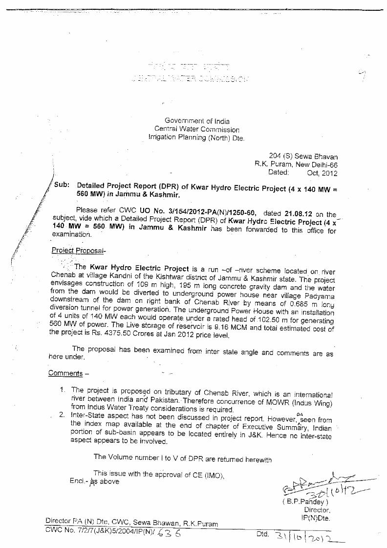
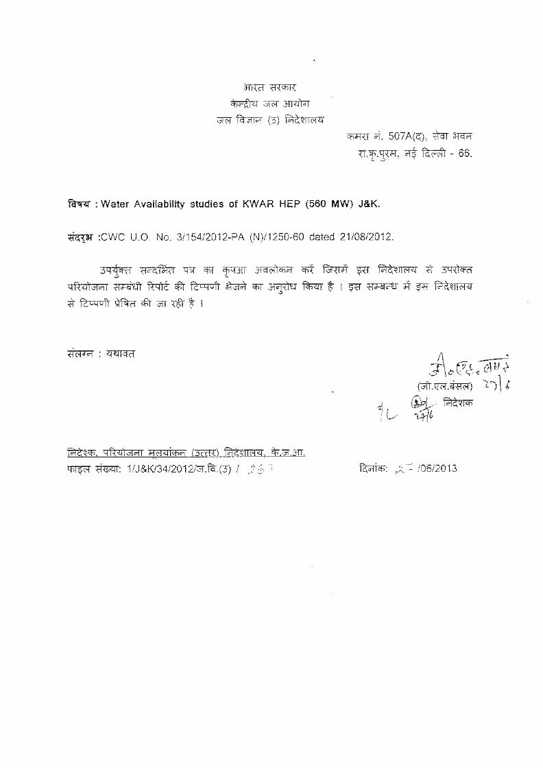
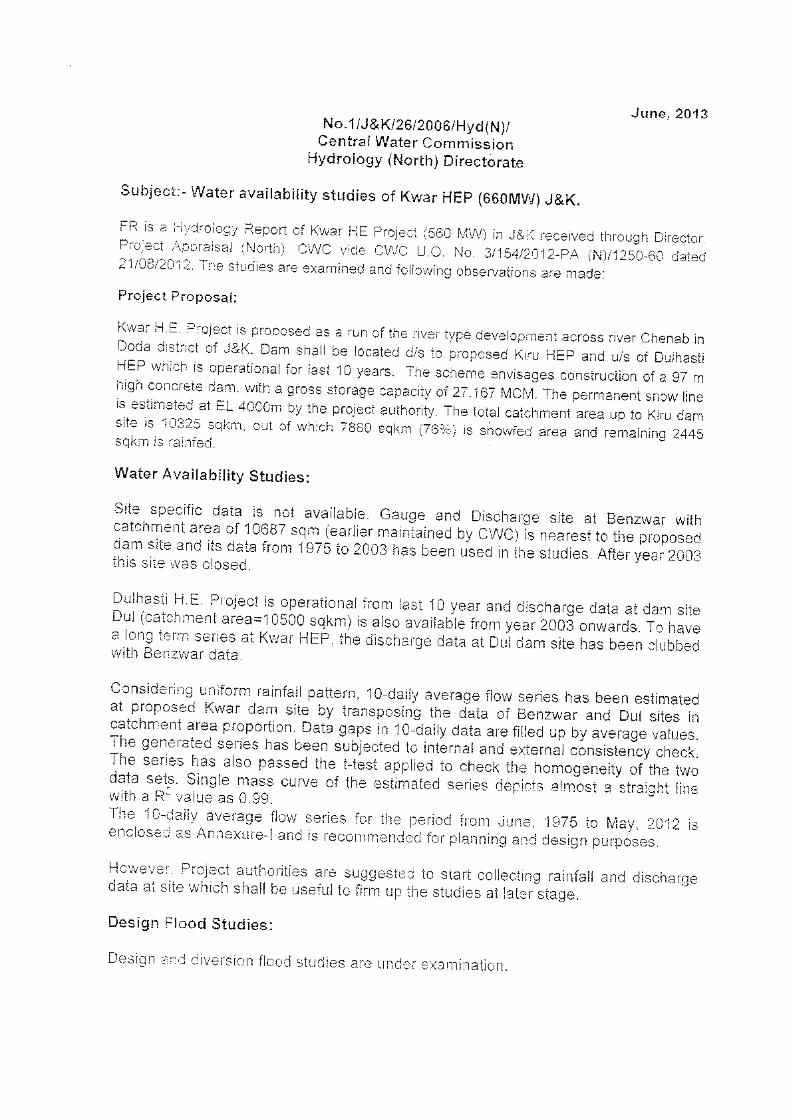
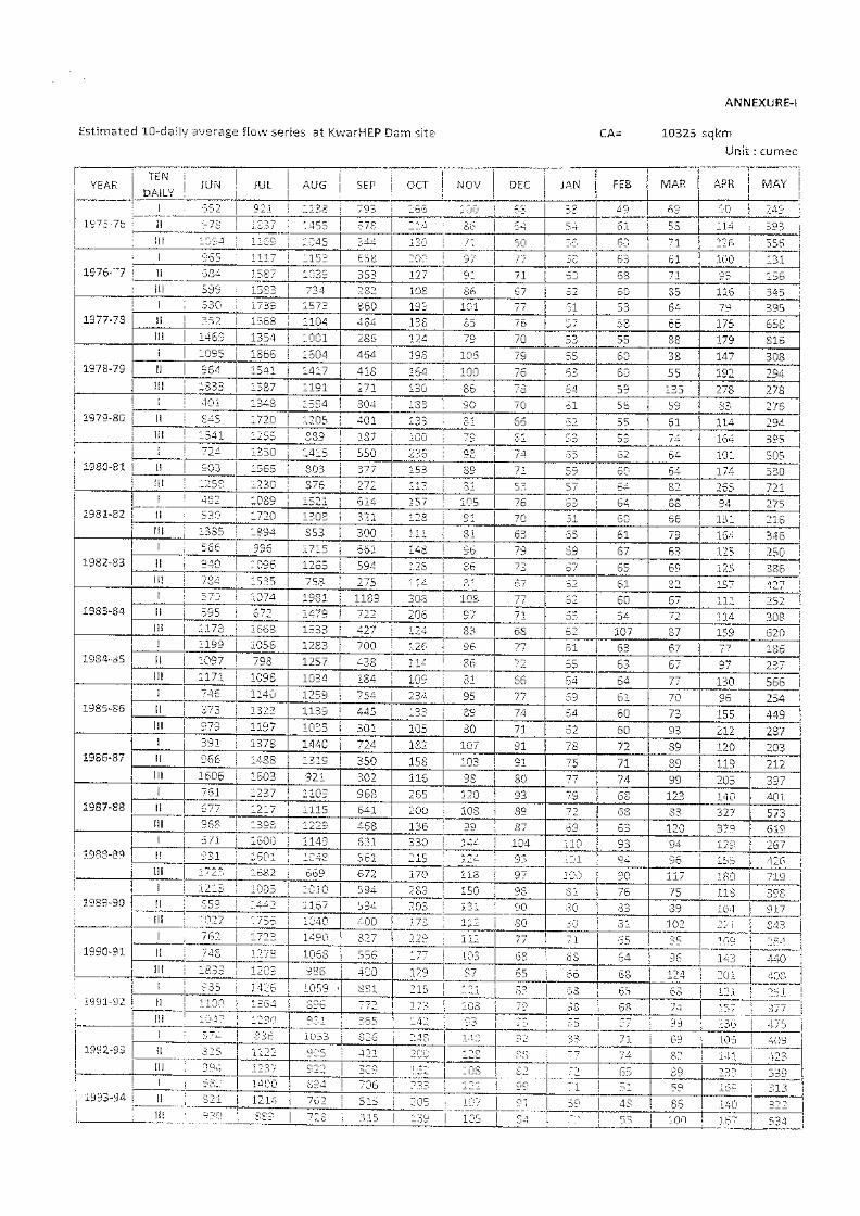
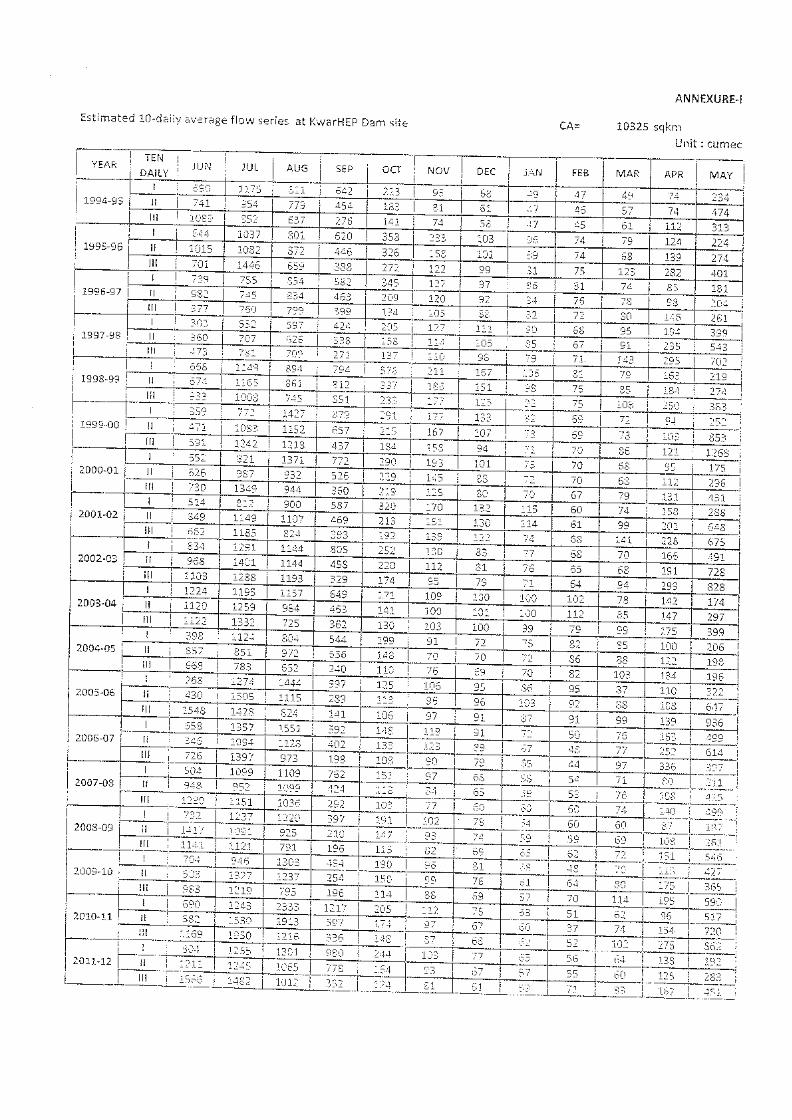
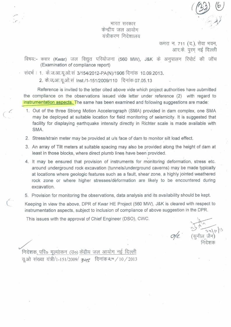
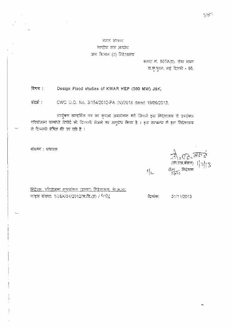
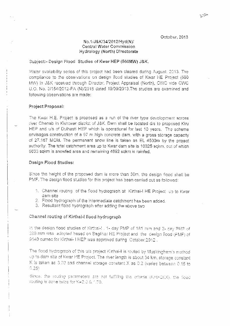
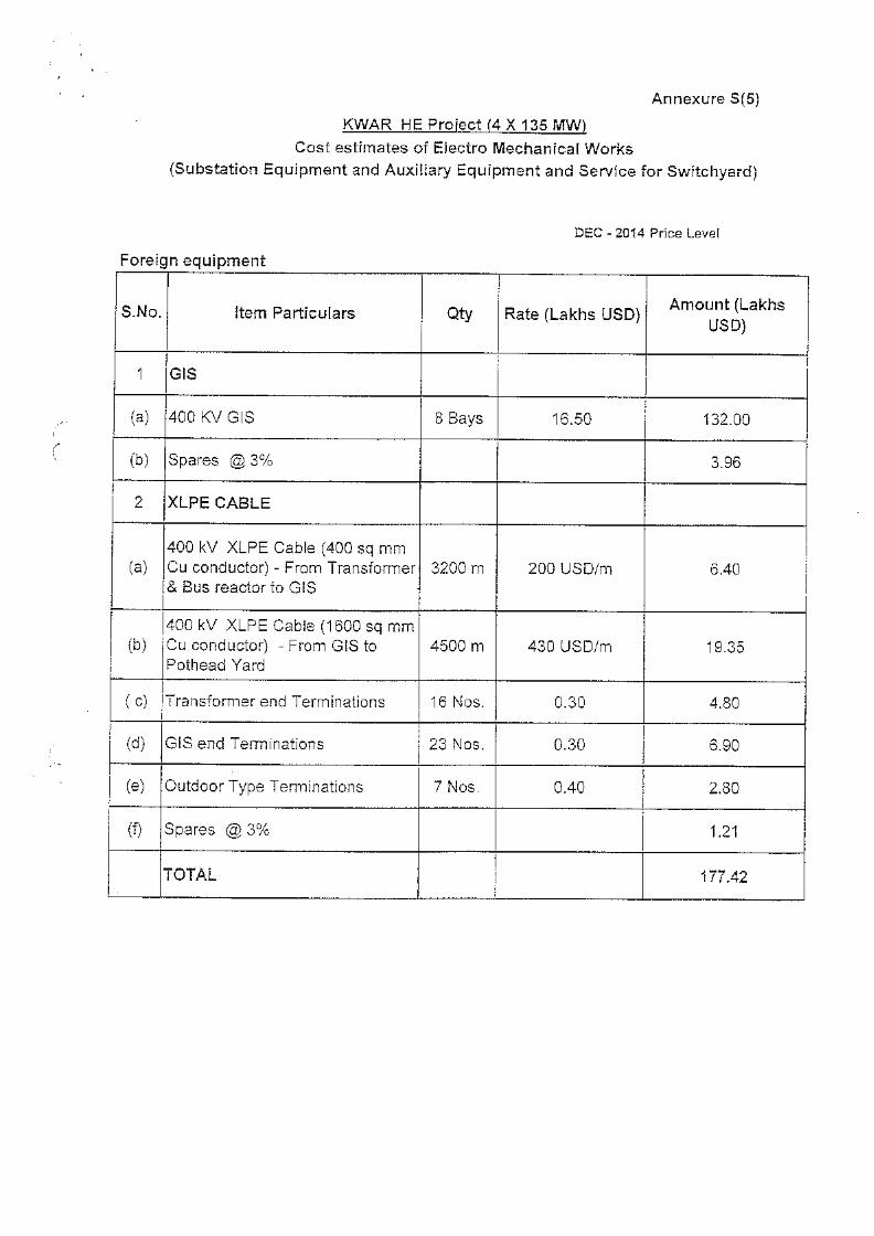
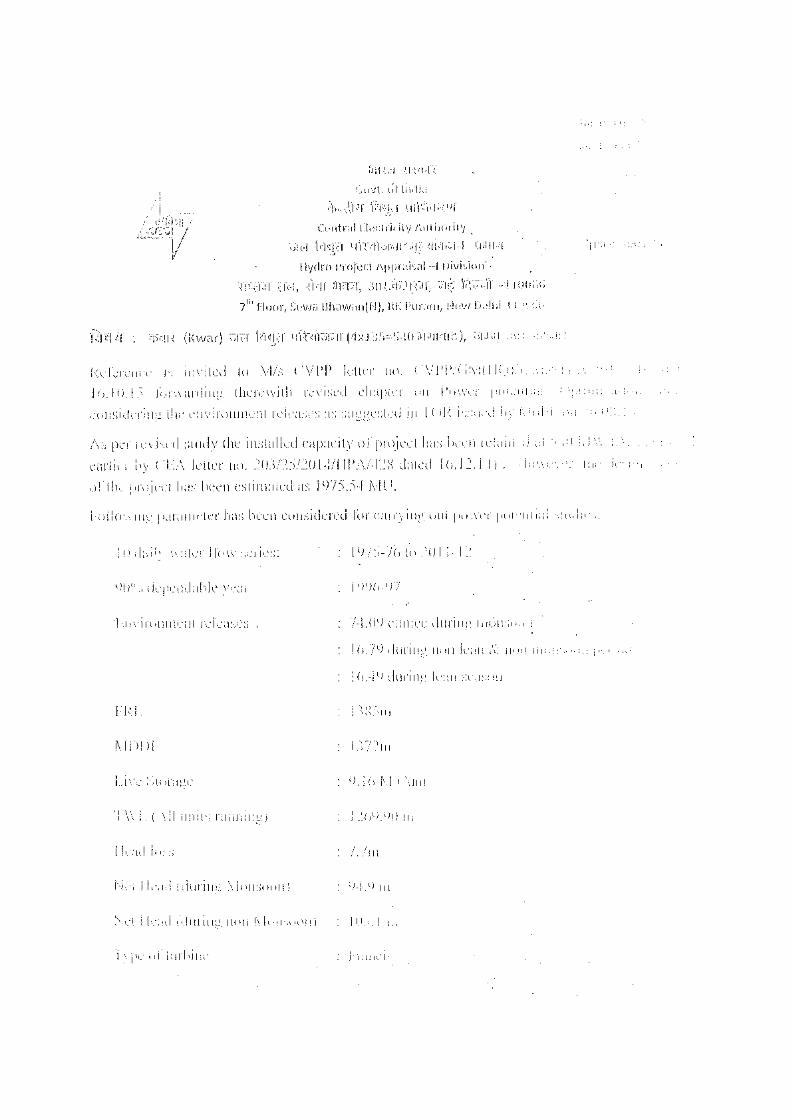
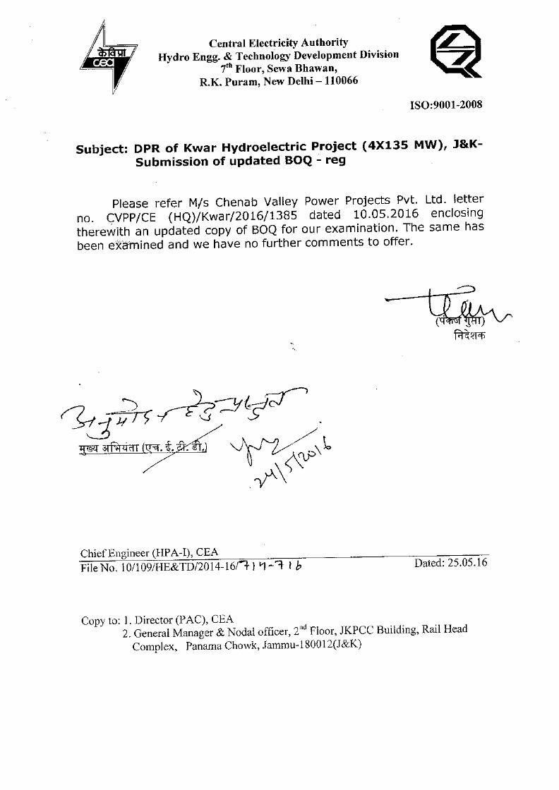
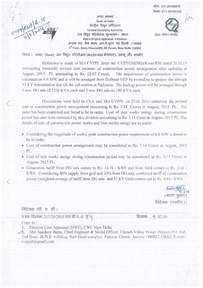
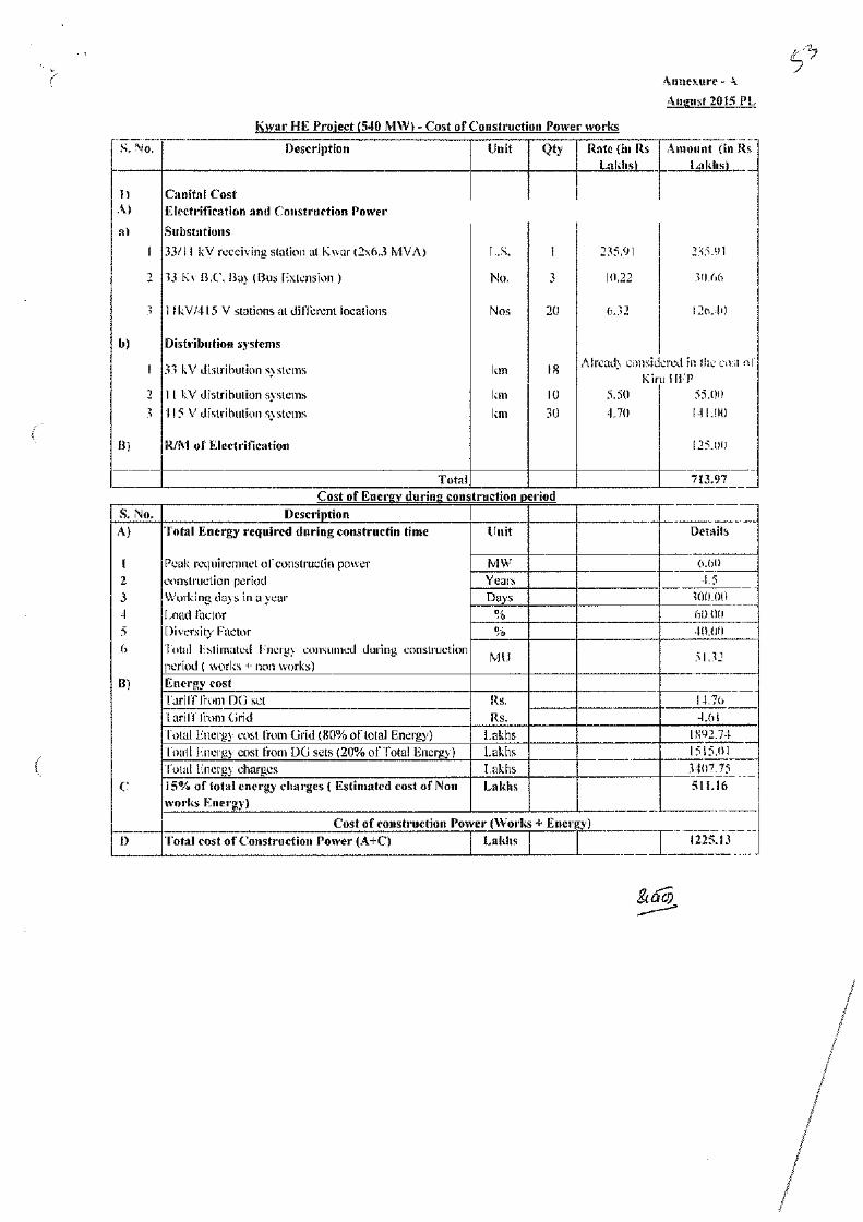
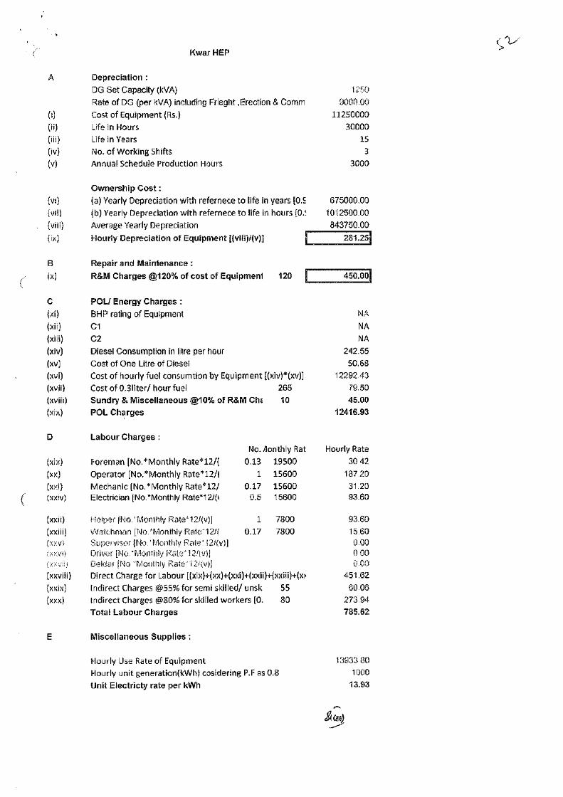
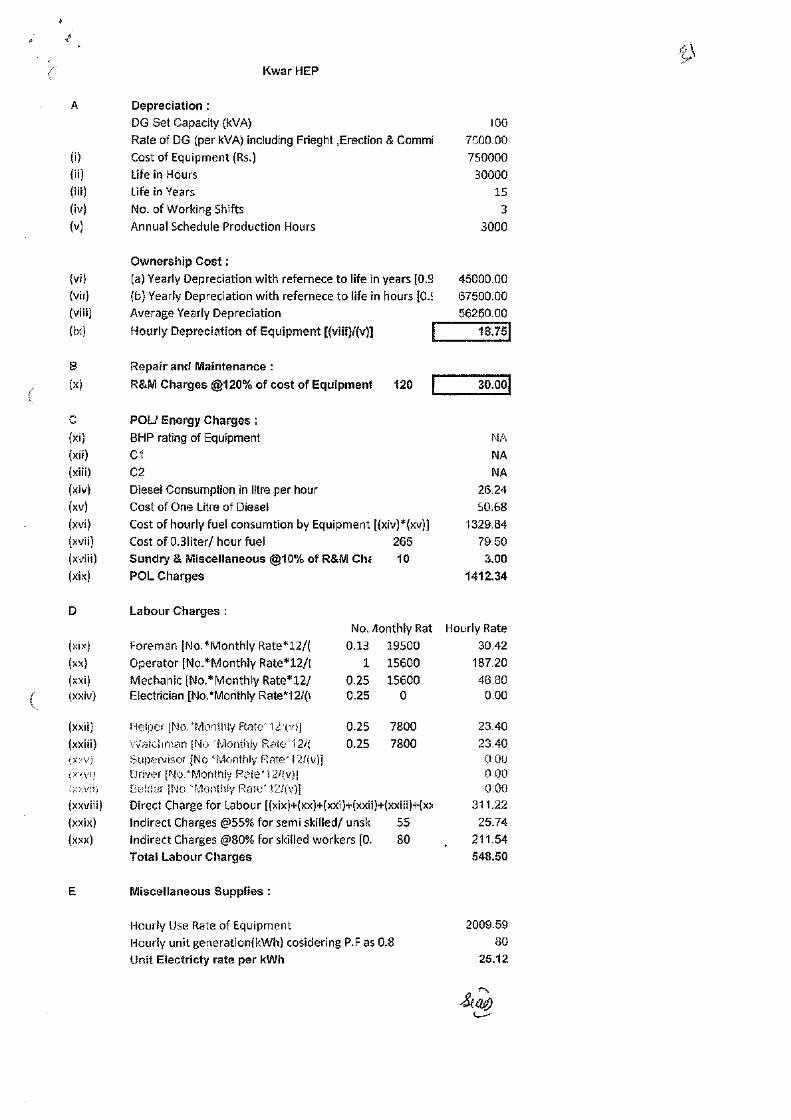
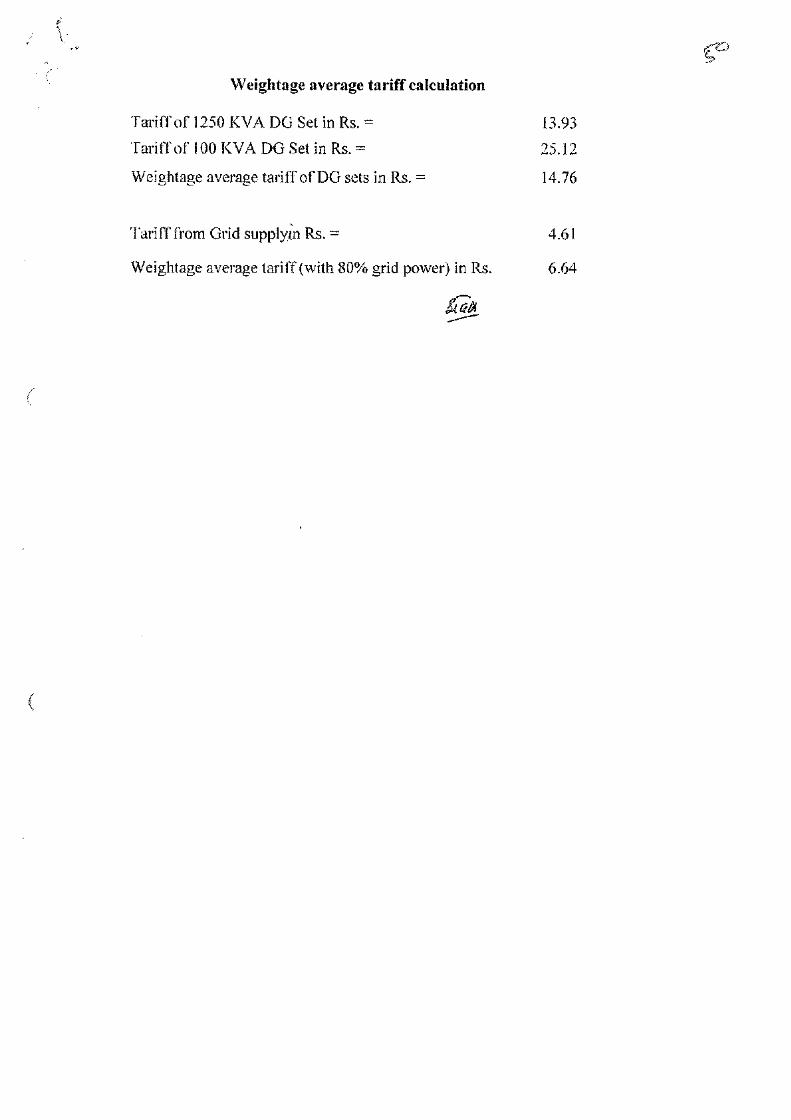
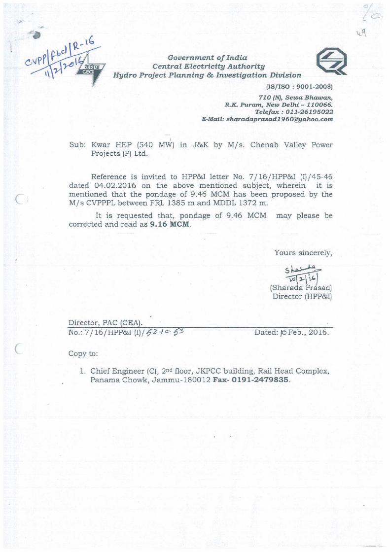
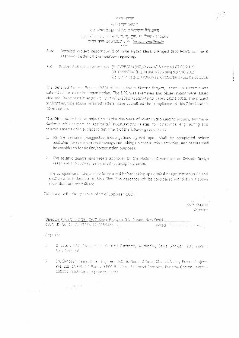
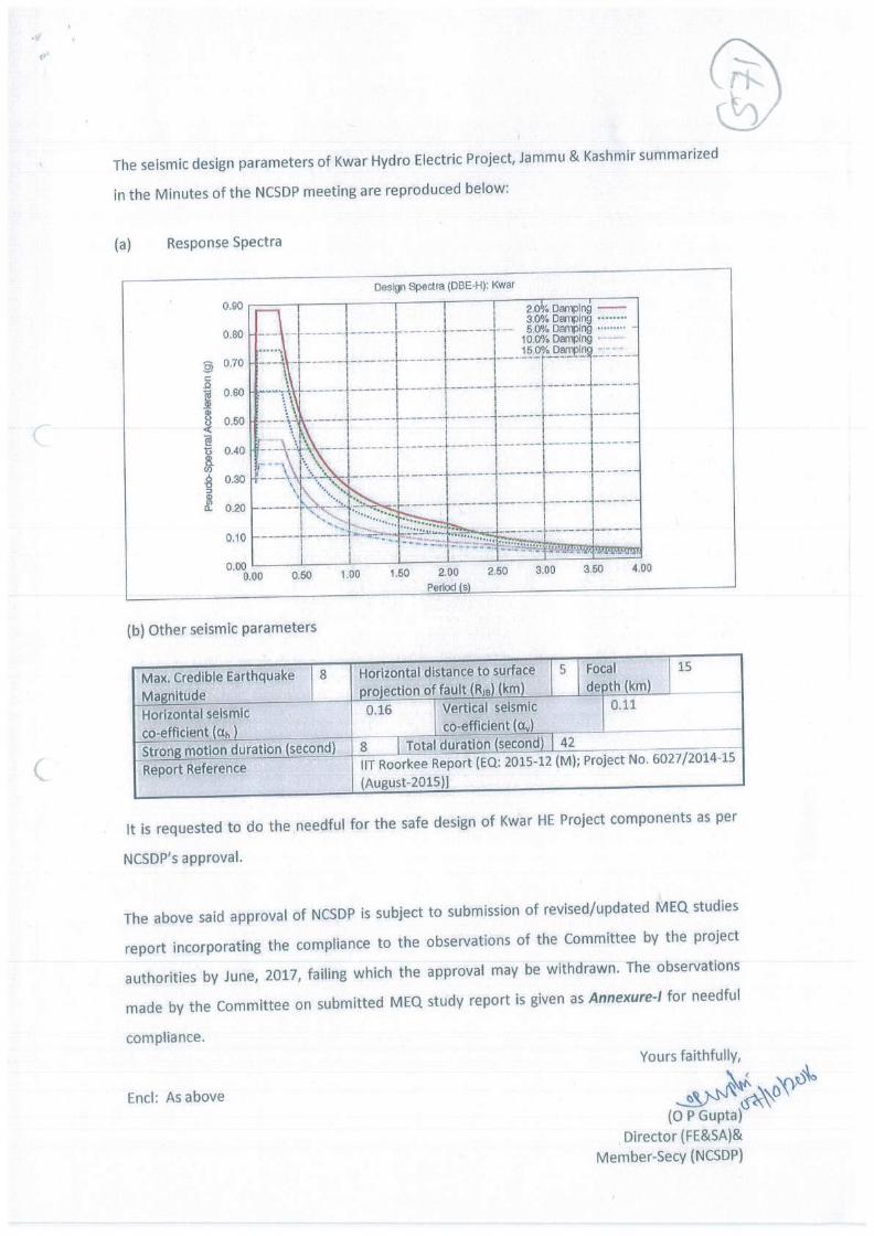
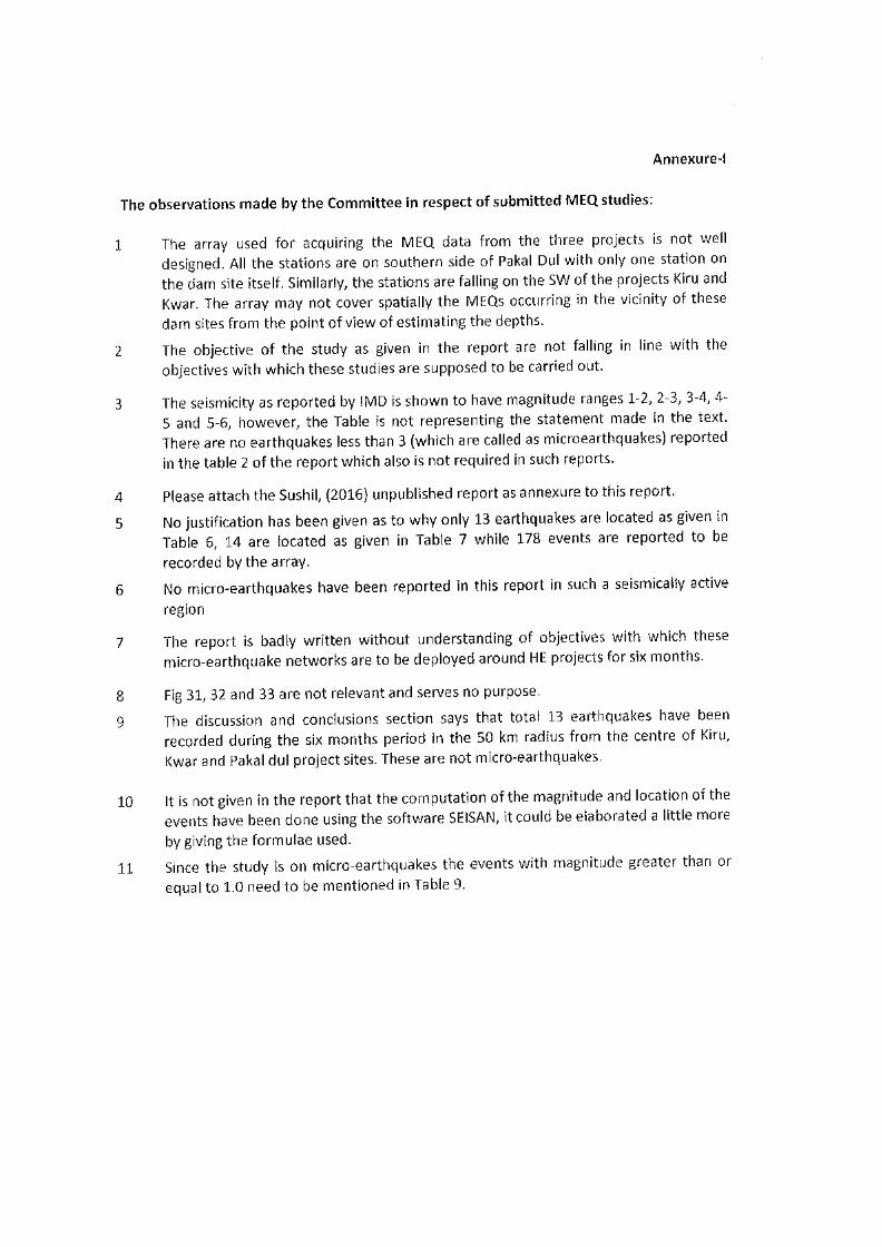
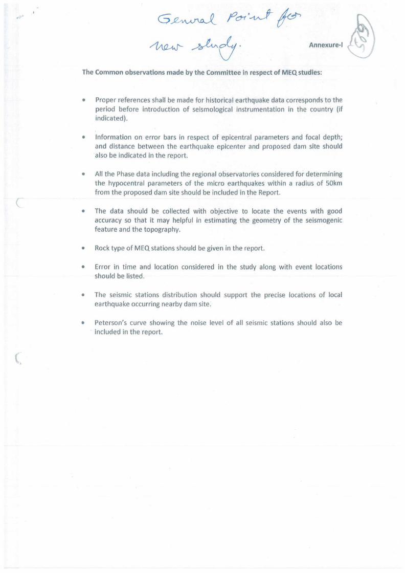
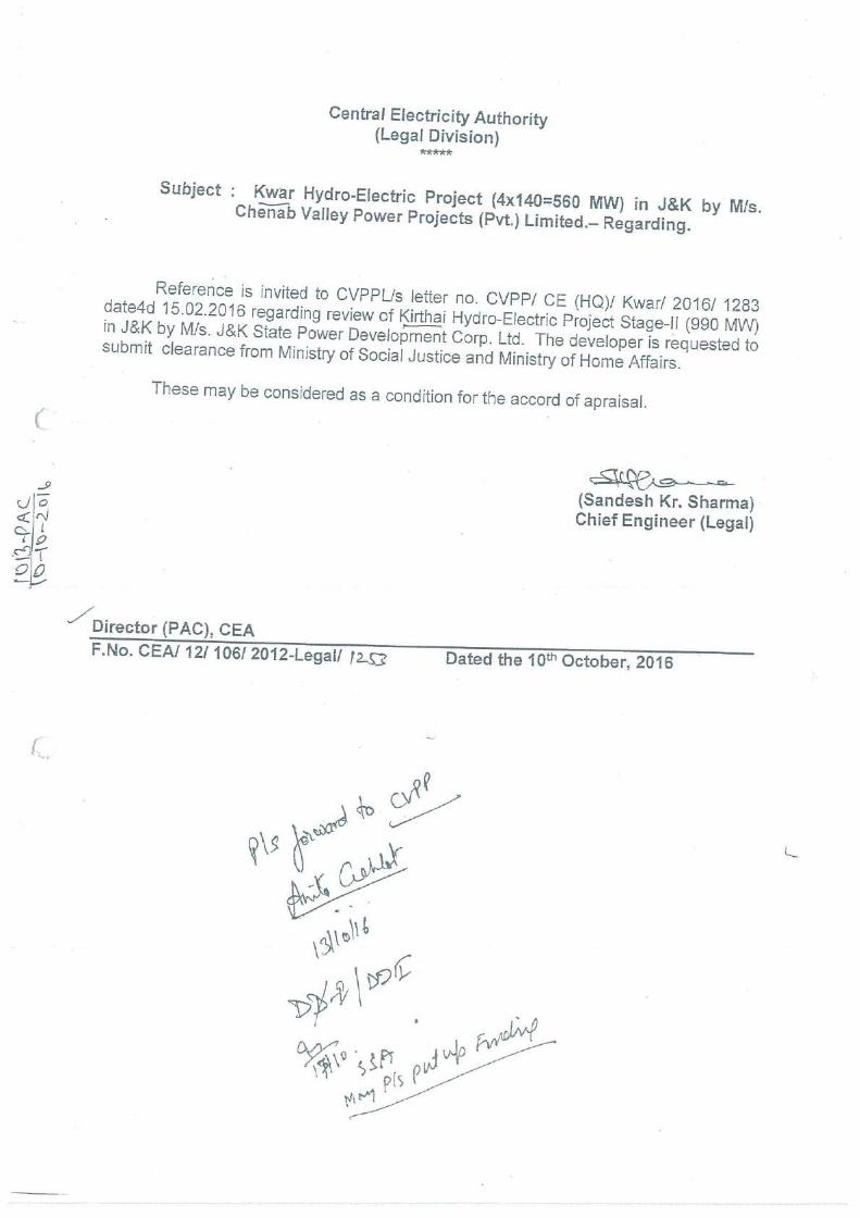
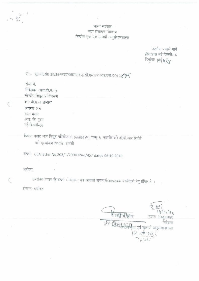
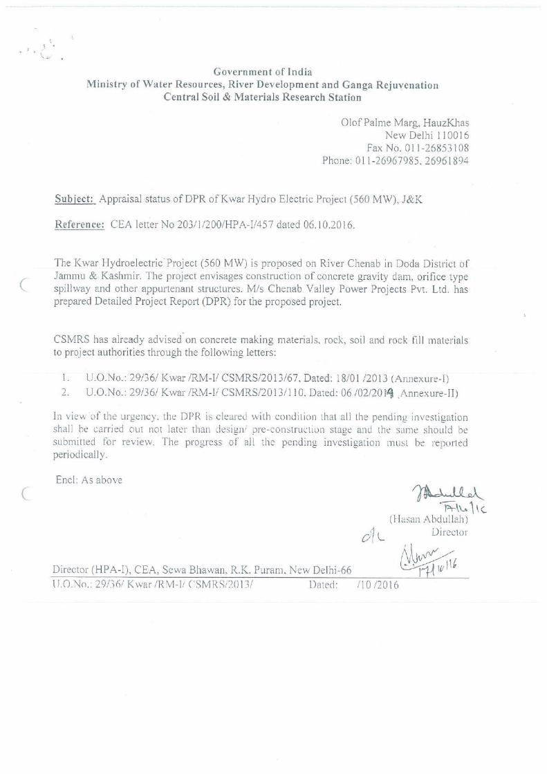
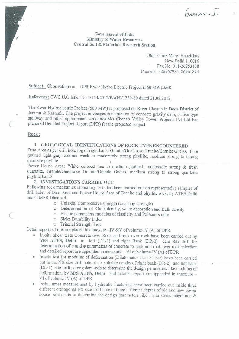
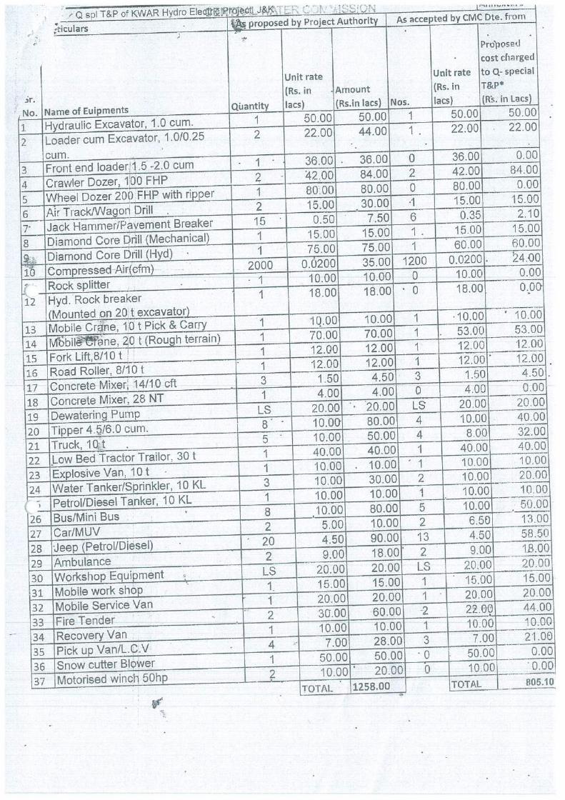

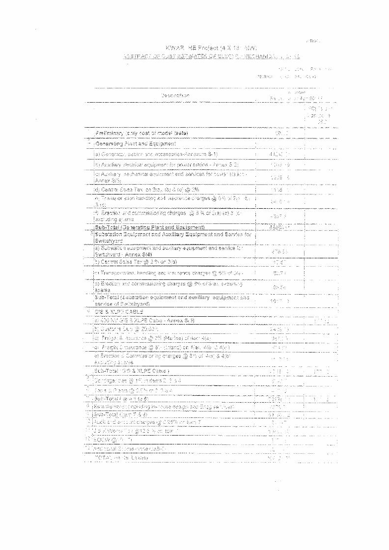
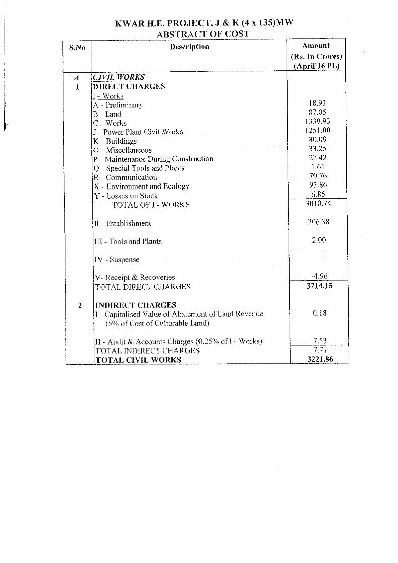
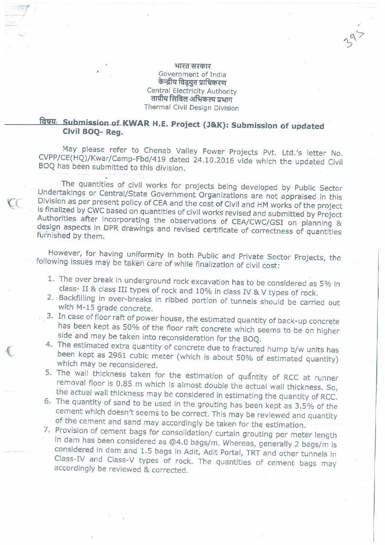
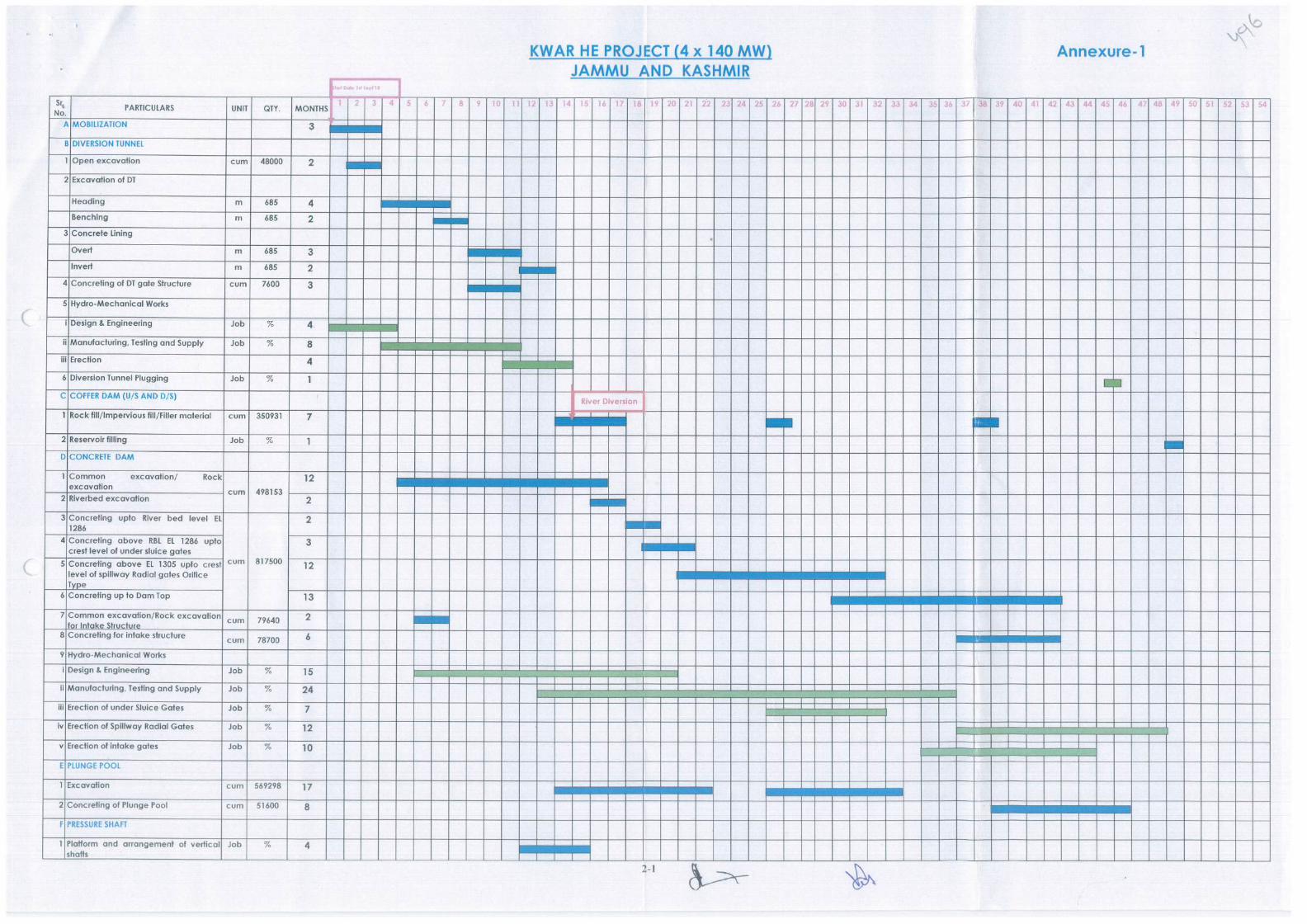
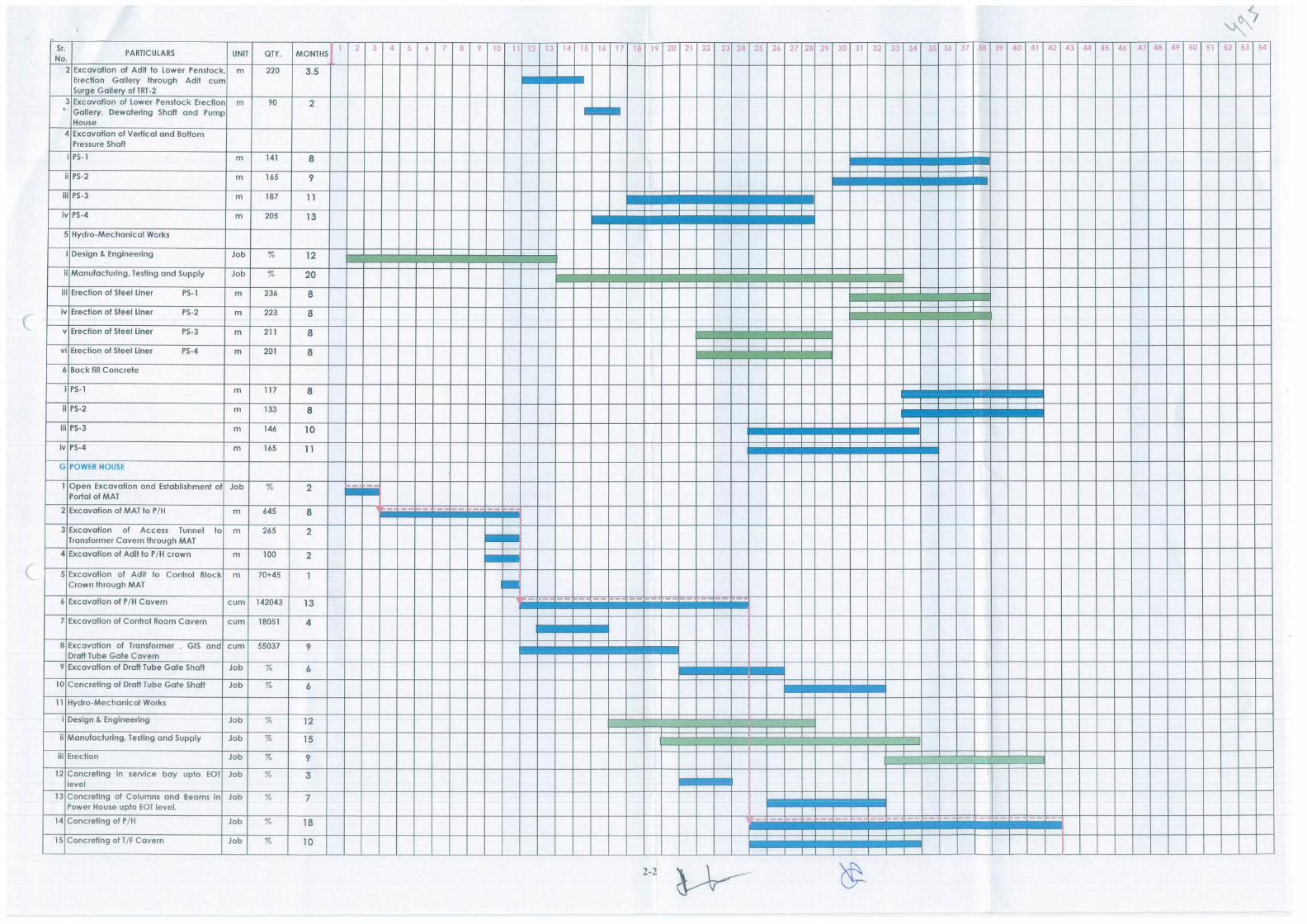
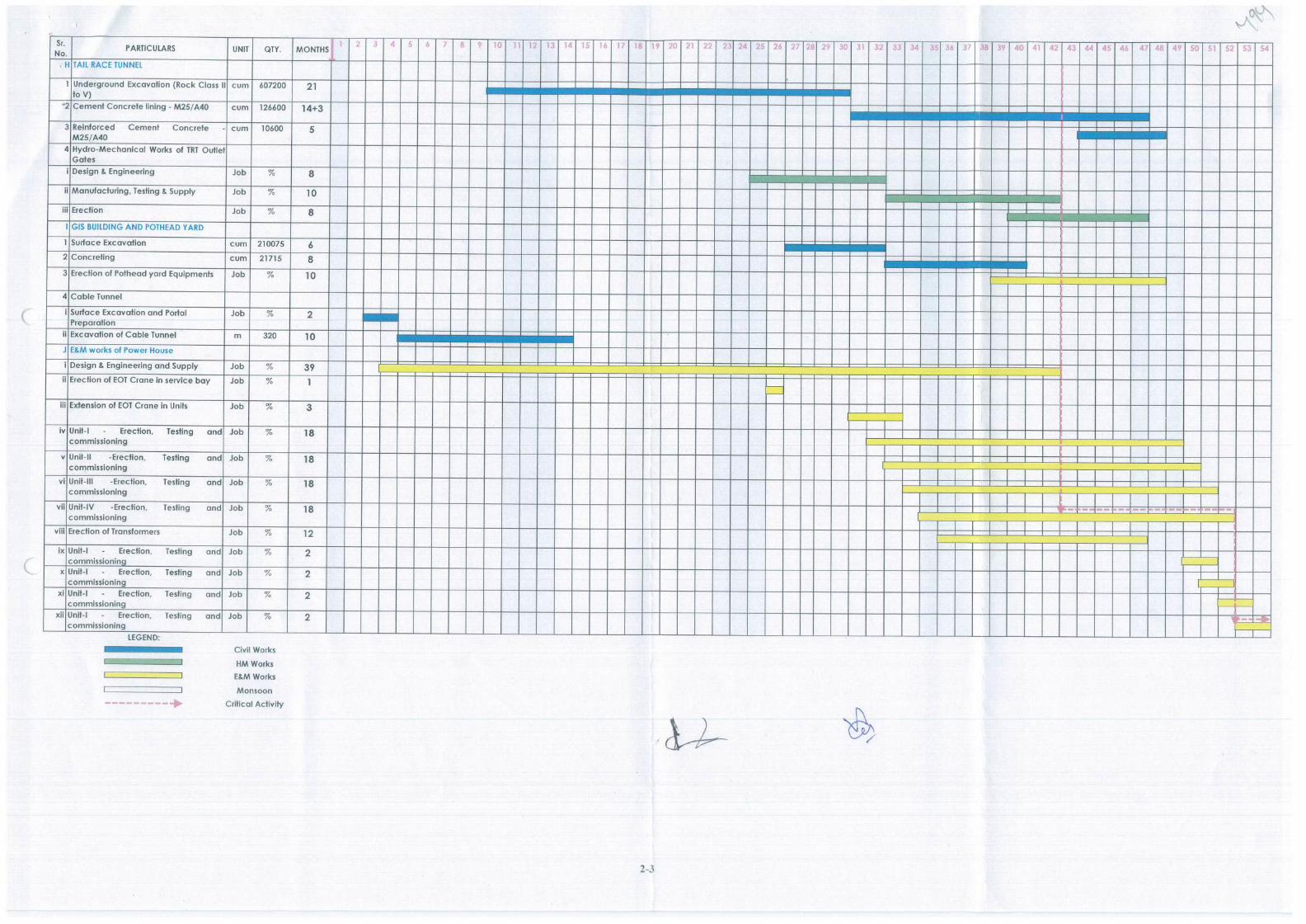
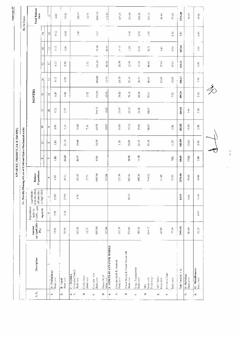
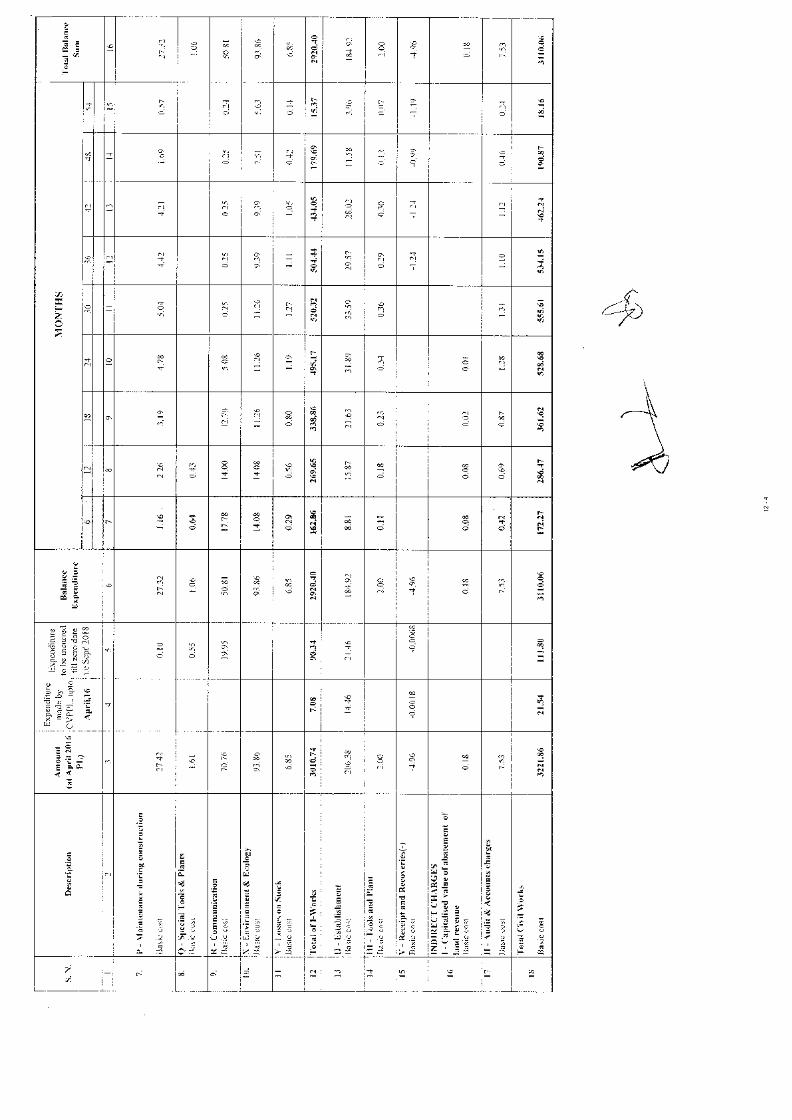
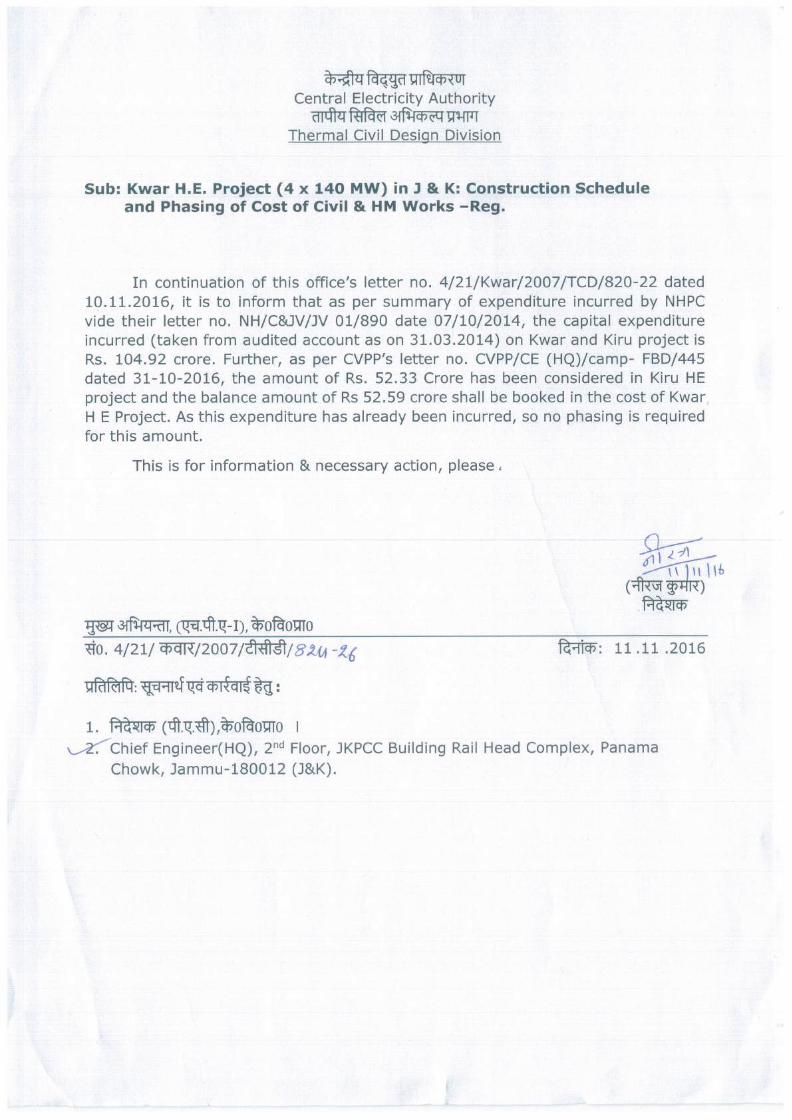
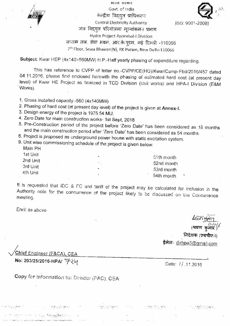
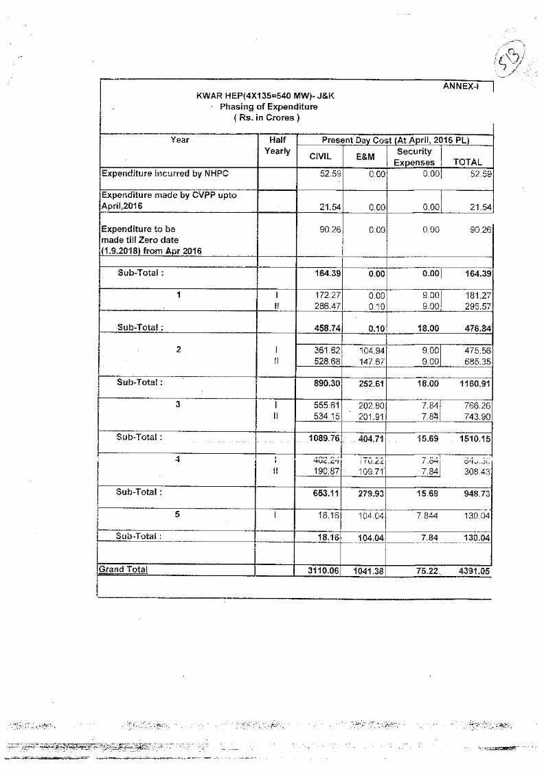
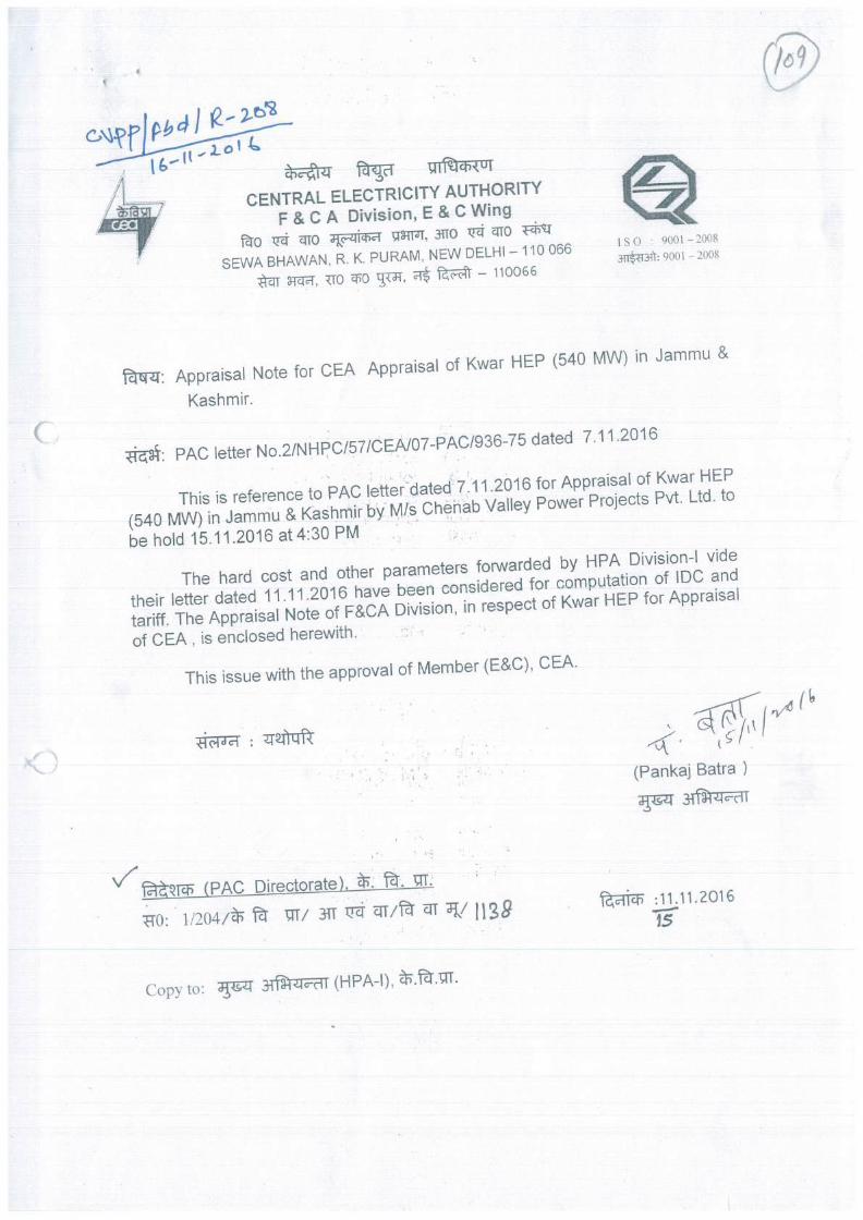
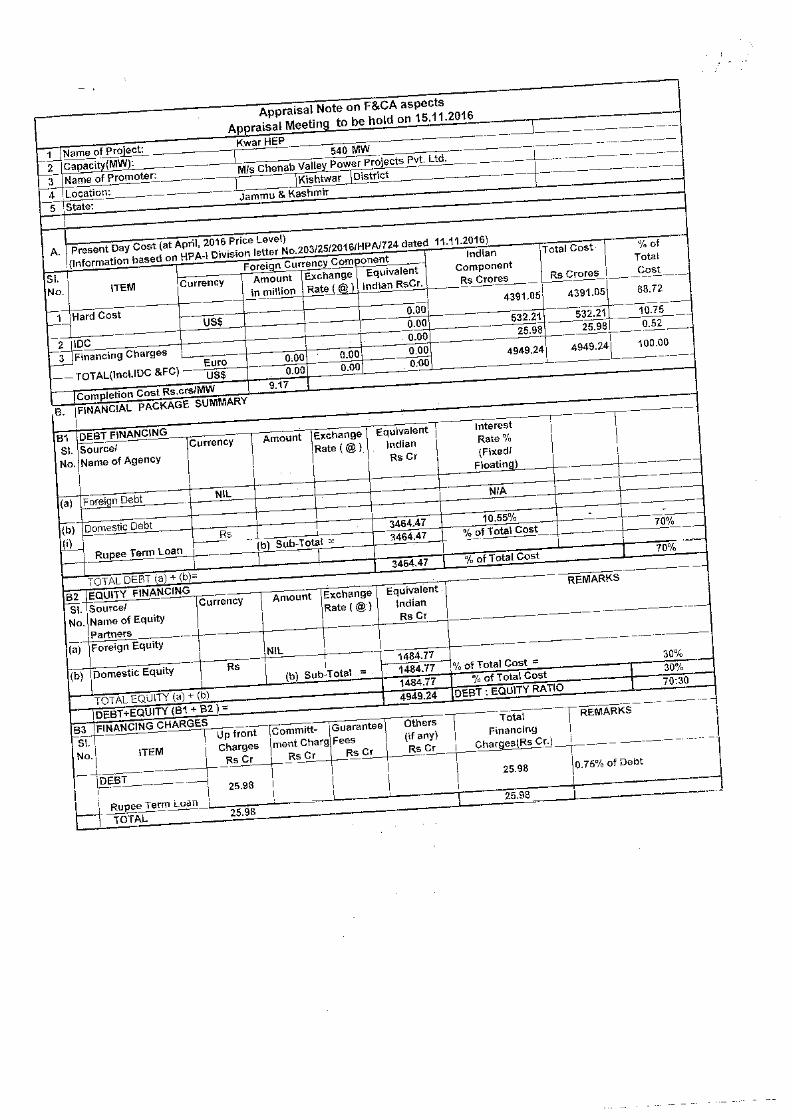
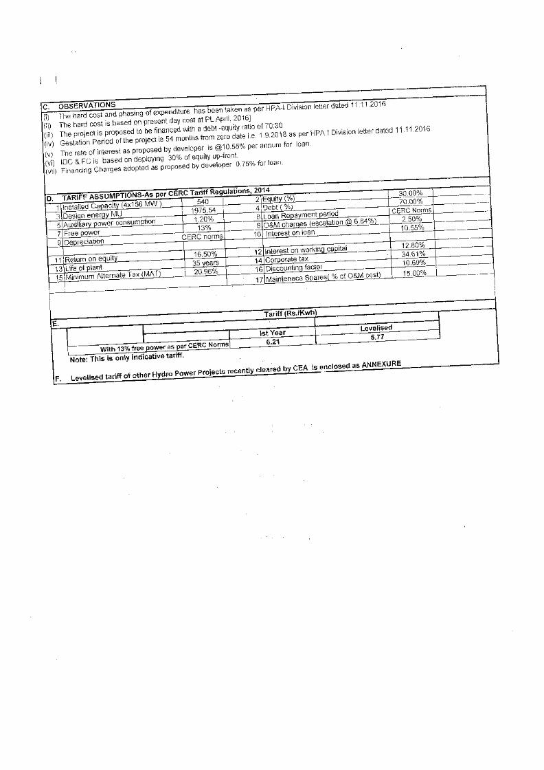
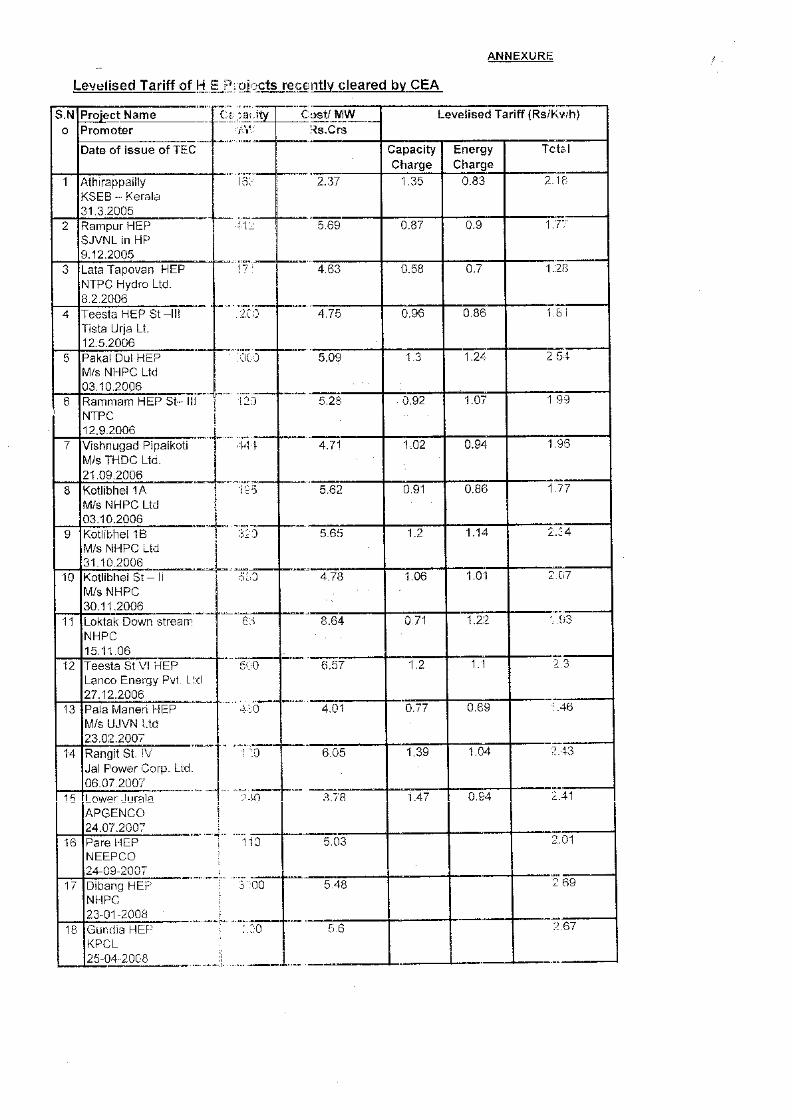
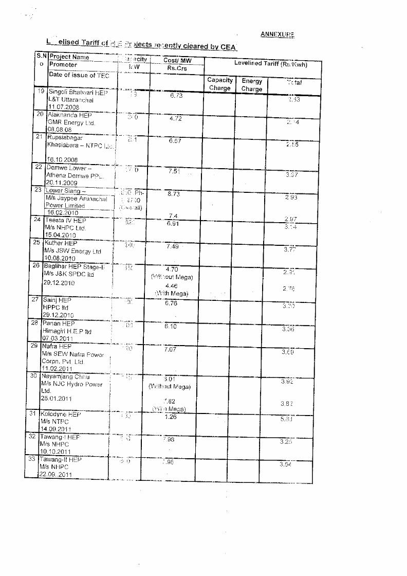
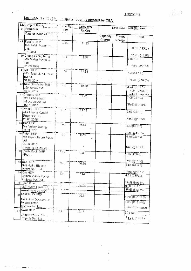
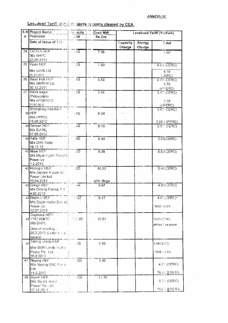
Save Energy for Benefit of Self and Nation


![[Project Management Institute] A Guide to the Proj(Book Za org)](https://img.pdfslide.net/doc/110x75/6314ad875cba183dbf07ac7c/project-management-institute-a-guide-to-the-projbook-za-org.jpg)