Embed Size (px)
Citation preview
1
USBird4.1.1
RAVEN / RAVEN-16 / SD-RAVEN / MICRO-RAVEN / RAVEN-EYE / RAVEN-RX / RAVEN-
MONITOR / RAVEN-REPEATER
AUDIO / VIDEO RECORDERS
USERS MANUAL
WINDOWS VERSION
RELEASE 2.0
10/15/2010
2
TABLE OF CONTENTS SECTION PAGE
1 INTRODUCTION ……………………………………………….. 4
1.1 RAVEN 1.2 RAVEN16 1.3 MICRO-RAVEN
1.4 SD-RAVEN 1.5 RAVEN-EYE 1.6 RAVEN-RX 1.7 RAVEN-MON
1.8 RAVEN-REPEATER 1.9 RAVEN-RX SYSTEM
2 USBIRD4 SOFTWARE…………………………….………… 34 2.1 System Requirements
2.2 Installation 2.3 Run Program 2.4 Red LED 2.5 Powered USB Hub
3 CONTROLS….…………………………………………………… 37 3.1 Recorder Setup 3.2 Set Recorder clock / PC Date & Time
3.3 Timer Setup 3.4 Erase Recorder 3.5 Update Recorder Software
3.6 Start Memory Diagnostic
4 USBIRD INTERFACE ……………………………….…….…..….. 44
4.1 MONITOR 4.2 Camera Adapter
4.3 Storage Devices 4.4 View Recorder Revision Data 4.5 Clock Battery Expiration Date 5 TRANSFER ………………………………………………...……... 48 5.1 Definitions of Status Abbreviations
3
5.2 Format CD/DVD 5.3 Eject CD/DVD 5.4 Copy Recording from Hard Drive to CD/DVD 6 PLAYBACK ………………………………………………….….. 55 6.1 Definitions of PLAYBACK controls
7 PLAYER ……………………………………….…….…………..…. 60
7.1 PLAYER MAIN MENU BUTTONS
7.2 AVI
APPENDIX - A USBird4 SOFTWARE INSTALLATION APPENDIX - B UPDATE BINARY CODE APPENDIX - C ADS SOFTWARE CONFIGURATIONS
4
SECTION - 1
INTRODUCTION
The manual describes the Recorders in the RAVEN family. The term
"RECORDER" will be used when referring to the RAVEN; RAVEN-16; SD-RAVEN; MICRO-RAVEN; RAVEN-RX; and RAVEN-EYE. The RAVEN; SD-RAVEN; MICRO-RAVEN; RAVEN-EYE; and RAVEN-RX have similar attributes and controls. The manual describes the operation of the RAVEN and the USBIRD4.0 Software.
Important!
The RAVEN needs up to 5 seconds to completely turn off all circuitries. The LED
will flash during this shutdown period. If the RAVEN is disconnected from the USB or is turned off, always wait 5 seconds before turning on the recorder again. 1.1 RAVEN
The RAVEN is the new generation audio / video recording device. The RAVEN
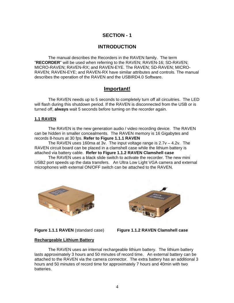
can be hidden in smaller concealments. The RAVEN memory is 16 Gigabytes and records 8-hours at 30 fps. Refer to Figure 1.1.1 RAVEN
The RAVEN uses 160ma at 3v. The input voltage range is 2.7v – 4.2v. The RAVEN circuit board can be placed in a clamshell case while the lithium battery is attached via battery cable. Refer to Figure 1.1.2 RAVEN Clamshell case
The RAVEN uses a black slide switch to activate the recorder. The new mini USB2 port speeds up the data transfers. An Ultra Low Light VGA camera and external microphones with external ON/OFF switch can be attached to the RAVEN. Figure 1.1.1 RAVEN (standard case) Figure 1.1.2 RAVEN Clamshell case Rechargeable Lithium Battery
The RAVEN uses an internal rechargeable lithium battery. The lithium battery lasts approximately 3 hours and 50 minutes of record time. An external battery can be attached to the RAVEN via the camera connector. The extra battery has an additional 3 hours and 50 minutes of record time for approximately 7 hours and 40min with two batteries.
5
External power can be attached to the recorder if the internal battery life is short for the application. Longer record times are possible by an external power supply.
The battery charges while the RAVEN is attached to a USB port or USB charger. The USB charger does not speed the recharge of the lithium battery. A lithium battery is good up to 500 charges; always check the battery before you deploy the recorder and always make sure the battery is fully charged.
A flashing red LED indicates the charging of the internal while a green LED indicates a full charge. If the battery is dead it will take 2 1/2 hours to fully charge the lithium battery. LED
The RAVEN has dual LEDs that turn red and green. The LED indicates an operation. The operations include record and recharging. The LED also describes error codes.
The "LED" is located in the front, near the ON switch. When the unit is turned "ON" the RECORD LED will turn flash “red” indicating that it recognized the switch. When the camera is connected, in 2 seconds the green LED appears solid “green” indicating the camera is ready and the record process has started.
Note!!
If the GREEN and RED LEDs do not show proper operation turn the RAVEN “OFF” for 5 seconds then slide switch to “ON.” A green LED appears on a Video recorder when any camera is attached. If the camera malfunctions the green light will not appear, replace the camera.
During an audio and video recording the red LED will follow and trace the loudest audio from the left microphone.
The red LED will flash repeatedly 3 times when the recorder memory is full. If the battery is low then the LED will flash slowly. LED Codes
The red LEDs will flash 3 times repeatedly when the recorder’s memory is full. Another reason for the red blinking LEDs is the data has been transferred and the recorder memory needs to be erased.
The Recorder has been turned on and a red LED appears and disappears, go to a computer and erase the data. After the data transfers always erase the recorder or the recorder will not record. Go to the nearest computer and erase the data. If the battery is low then the LED will flash ON and OFF slowly. No red or green LED is present; the RAVEN is not recording. Check batteries and memory has been erased.
6
NOTE! If the low battery indicator is flashing, turn the unit “OFF” place the RAVEN on a charger or USB port or add an additional battery via camera connector. Turn the unit “ON” once the battery is fully charged or an additional battery is attached.
The computer displays the “last recording” was stopped short because of a low
battery condition.
While the RAVEN, SD-RAVEN, MICRO-RAVEN, RAVEN-RX, RAVEN-MONITOR and FINCH, are attached the red LED will flash indicating the internal battery is charging. Once a green flashing LED is displayed the internal battery has been fully charged. CAMERA
The RAVEN uses an Ultra Lowlight VGA camera that operates at (640 X 480) resolution. The NANOCAM, and VERSACAM are color only cameras. The Ultra-Lowlight Black and White camera is used for lowest light.
Once the camera is connected and the unit is turned ON, the RAVEN will automatically detect the camera and adjusts the parameters accordingly. An external battery can be attached next to the camera connector. Refer to Figure 1.1.3 Connectors, Transmitter, and External Battery
NOTE!
If no camera is found the LED will not turn “GREEN”, hence you should turn the unit “off” wait 5 seconds and try again. A problem with the camera may occur, switch out the camera. The RAVEN will record “audio” if the camera does not operate. MICROPHONE
The RAVEN can use its stereo internal or external microphones. If the external microphone is plugged in it is automatically selected for use. The internal microphone is factory set for 6 dB more sensitivity, over the external microphone. USB2 PORT The RAVEN USB2 port uses a special USB cable that connects the RAVEN to the computer’s USB port. The USB2 port aids in faster data transfer. The RAVEN, SD-RAVEN, RAVEN-RX and FINCH uses the same new USB download cable.
7
RAVEN CONTROL SWITCHES RECORDING
The RAVEN, SD-RAVEN, MICRO-RAVEN, RAVEN-EYE, and RAVEN-RX use a black switch that slides into designated modes "ON" and "OFF.” External Microphone and Record Switch If the external record switch is attached to the RAVEN, the external switch must be used for ON/OFF control. When the red slide switch is slid to the “ON” a black dot appears; the RAVEN begins recording.
An RF switch and IR Motion Detector are other options to activate the RAVEN. ON
The “ON black slide switch " activates the RAVEN. The LED turns red; a green LED appears within 2 seconds a green LED appears indicating the camera is attached. The LED will modulate “red” following incoming audio while the unit is recording.
NOTE!
The user should make a short “preamble” recording to check if the cameras and external or internal microphones are working properly. Make sure the red and green LEDS are present, if they are not, go to the nearest computer and make sure the memory has been erased and the batteries are fully charged. OFF
“The OFF black switch” halts recording, and puts the unit in a low power state. The RAVEN logs the states of “ON / OFF” and the date/time as “Session” information. RECORDING LENGTH
A forced ending is created when the maximum session size is reached. The maximum size of a session is 512 megabytes. A new session will begin. A RAVEN that records for long periods of time without shutting off will have forced endings; data can safely fit on CD and DVD media. TRANSMITTERS A RAVEN-TX has a built-in officer safety transmitter. To begin transmitting, “XMT” should be already switched “ON” and the RAVEN is switched to “ON”. The white plastic antenna should never be wrapped around the recorder. The plastic antenna should lie flat in a north or south direction. Refer to Figure 1.1.3 Connectors, Transmitter, and External Battery
8
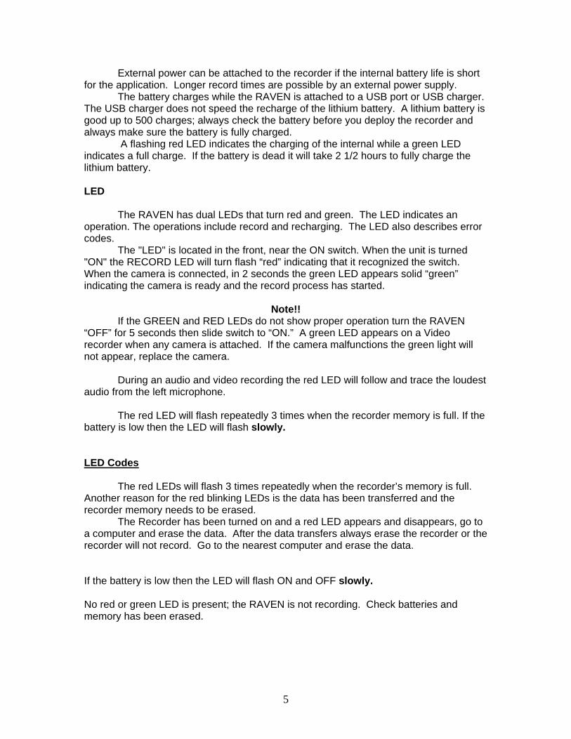
To remove antenna, XMT switch should be in the off position first and turn the RAVEN “OFF.” The XMT switch should be in the off position, if you do not want audio to be transmitted. The transmitter in use while recording diminishes the record time because battery life is shortened.
Figure 1.1.3 Connectors, Transmitter, and External Battery
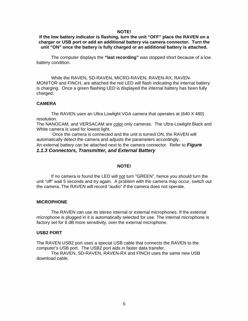
1.2 RAVEN-16 The RAVEN-16 records 16 hours of audio and video at 30 frames per second. The recorder has dual camera capability and uses 3 disposable AAA batteries. The main recorder compartment separates from the battery compartment.
1.2 RAVEN-16
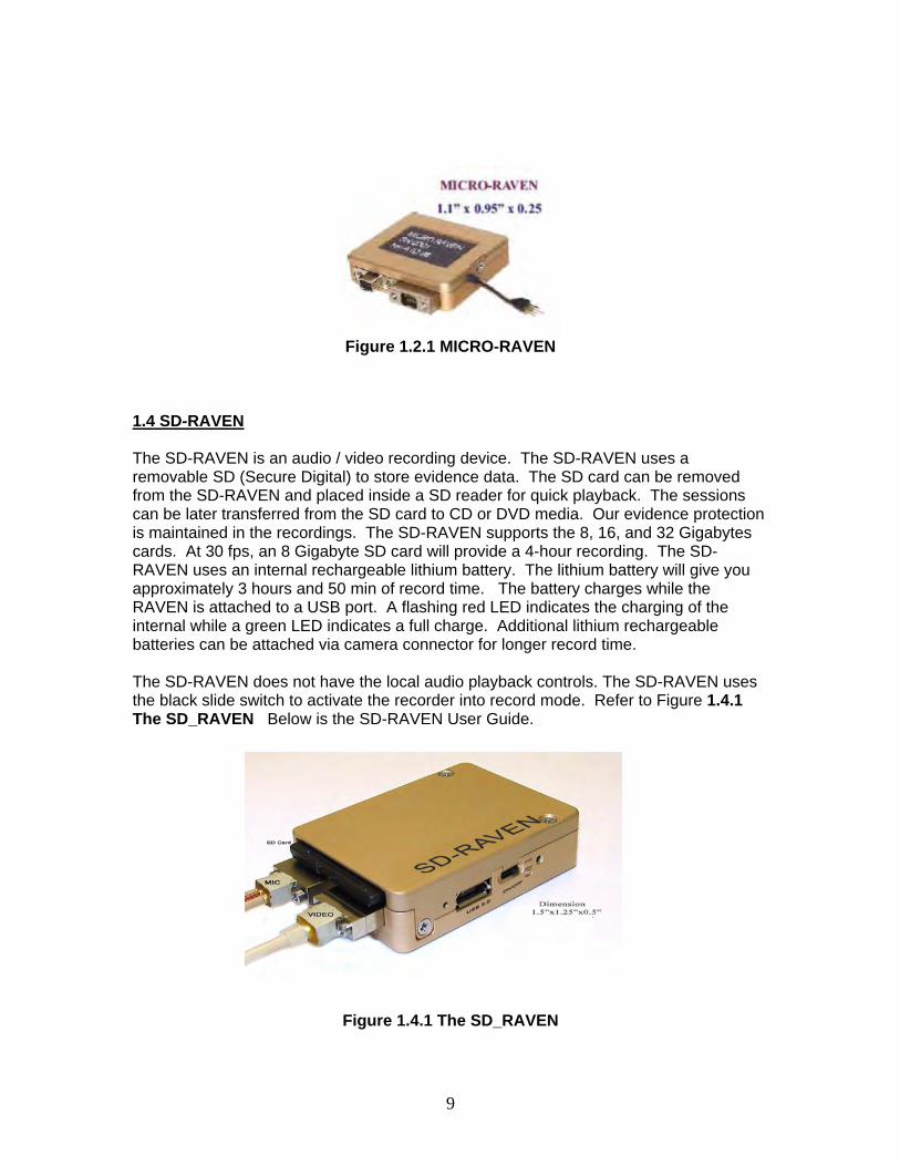
1.3 MICRO-RAVEN The MICRO-RAVEN is a scaled down version of the RAVEN. The same cameras and external microphones can be used with the MICRO-RAVEN. The MICRO-RAVEN records for 4 hours at 30fps and the internal lithium battery last about 2.5 hours. Refer to Figure 1.2.1 MICRO- RAVEN
9
Figure 1.2.1 MICRO-RAVEN
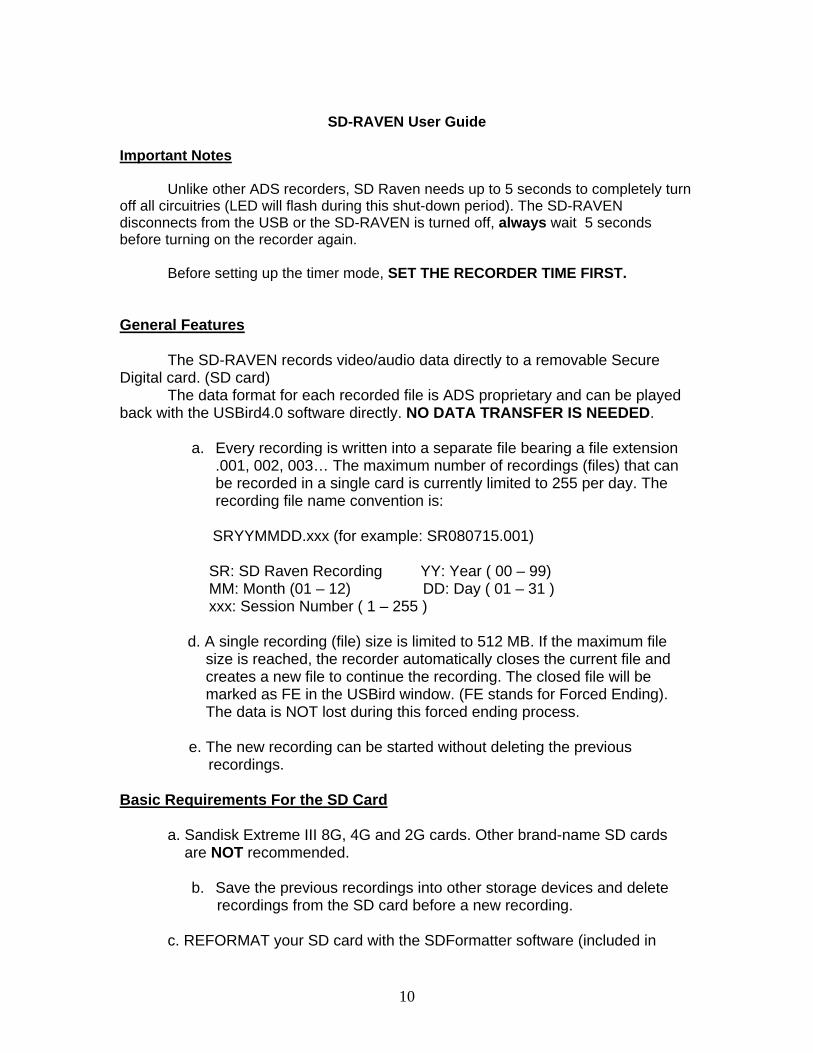
1.4 SD-RAVEN The SD-RAVEN is an audio / video recording device. The SD-RAVEN uses a removable SD (Secure Digital) to store evidence data. The SD card can be removed from the SD-RAVEN and placed inside a SD reader for quick playback. The sessions can be later transferred from the SD card to CD or DVD media. Our evidence protection is maintained in the recordings. The SD-RAVEN supports the 8, 16, and 32 Gigabytes cards. At 30 fps, an 8 Gigabyte SD card will provide a 4-hour recording. The SD- RAVEN uses an internal rechargeable lithium battery. The lithium battery will give you approximately 3 hours and 50 min of record time. The battery charges while the RAVEN is attached to a USB port. A flashing red LED indicates the charging of the internal while a green LED indicates a full charge. Additional lithium rechargeable batteries can be attached via camera connector for longer record time. The SD-RAVEN does not have the local audio playback controls. The SD-RAVEN uses the black slide switch to activate the recorder into record mode. Refer to Figure 1.4.1 The SD_RAVEN Below is the SD-RAVEN User Guide.
SD-RAVEN Recorder User Guide
Figure 1.4.1 The SD_RAVEN
10
SD-RAVEN User Guide
Important Notes
Unlike other ADS recorders, SD Raven needs up to 5 seconds to completely turn
off all circuitries (LED will flash during this shut-down period). The SD-RAVEN disconnects from the USB or the SD-RAVEN is turned off, always wait 5 seconds before turning on the recorder again.
Before setting up the timer mode, SET THE RECORDER TIME FIRST.
General Features The SD-RAVEN records video/audio data directly to a removable Secure
Digital card. (SD card) The data format for each recorded file is ADS proprietary and can be played
back with the USBird4.0 software directly. NO DATA TRANSFER IS NEEDED. a. Every recording is written into a separate file bearing a file extension
.001, 002, 003… The maximum number of recordings (files) that can be recorded in a single card is currently limited to 255 per day. The recording file name convention is:
SRYYMMDD.xxx (for example: SR080715.001)
SR: SD Raven Recording YY: Year ( 00 – 99) MM: Month (01 – 12) DD: Day ( 01 – 31 ) xxx: Session Number ( 1 – 255 ) d. A single recording (file) size is limited to 512 MB. If the maximum file
size is reached, the recorder automatically closes the current file and creates a new file to continue the recording. The closed file will be marked as FE in the USBird window. (FE stands for Forced Ending). The data is NOT lost during this forced ending process. e. The new recording can be started without deleting the previous
recordings.
Basic Requirements For the SD Card
a. Sandisk Extreme III 8G, 4G and 2G cards. Other brand-name SD cards are NOT recommended.
b. Save the previous recordings into other storage devices and delete recordings from the SD card before a new recording.
c. REFORMAT your SD card with the SDFormatter software (included in
11
the package) to format the SD card before each use.
USBird and RavenUtility Software Installation a. USBird Software Installation
Please refer to the USBird Manual on the USBird CD.
b. RavenUtility Software Installation RavenUtility CD contains two programs:
i. SDFormatter for formatting the SD card. ii. RavenUtility for renaming the recording file iii.
To install the software, just place the CD in the CD drive, double click on the CD drive under My Computer window. And then follow the on-screen instruction to complete the installation. To use these two programs, please go to “Start->All Programs->ADS”. There is a readme file for each program. There is also a shortcut on the desktop for each program.
Charging the Battery Internal Charger: Two hours are needed to charge a single lithium battery. Before using the SD-RAVEN, make sure to charge the battery first. To charge the internal battery, connect the USB cable to any computer’s USB port or use the USBTO-WALL converter. The RED flashing LED on the SD-RAVEN indicates the battery is being charged. The GREEN LED starts to flash when the battery is fully charged. You can charge both the external and internal battery at the same time by connecting the external battery to the connector on the camera cable. The charging time for both batteries will increase proportionally. If you are unsure the battery has been charged, reconnect the USB to the recorder for at least 1 minute. If the RED LED flashes, the battery is not fully charged. If the GREEN LED flashes, the battery is already charged. External Charger: Using the external charger to charge the external battery, just have the battery connected to it for 2 hours. Solid Red LED indicates the battery is being charged and solid theGreen LED indicates the battery is fully charged.
Camera View
USBird 4.0x users:
1. Connect the recorder to the USB port and start the USBIRD software from Start Menu->Program Files->ADS->USBird4->Usbird.
2. Once the SD-RAVEN and serial number is displayed, click on Monitor tab at the bottom of the window
12
3. Select Camera 1. 4. If this is the first time to use Camera View, Windows may ask for a new 5. USB(camera) device driver installation. Just follow the wizard to complete the installation. . The camera driver is located at c:\program
files\ads\usbird4\driver folder.
SD-RAVEN Setup
Follow the procedures below to change the SD-RAVEN settings: a. Connect the SD-RAVEN to the USB port. The first time USB port is used
by the SD-RAVEN, Windowsmay pop-up a message for the driver installation. Just follow the Installation Wizard to complete the driver installation.
b. Start the USBird from Start Menu->Program Files->Ads->Usbird4->Usbird c. The software will automatically show the current recorder settings on the
top of USBird window. d. Click on Controls tab at the bottom of the window and select Recorder
Setup to set the recorder in Audio+Video, Video Only, and Audio Only mode. In the video mode, you can also select the frame rate desired from the drop-down menu.
e. Click on Controls tab at the bottom of the window and select Timer setup to set the timer mode.
VERY IMPORTANT: set your SD-RAVEN time FIRST.
In addition, the SD-RAVEN time can be synced to the current time of your computer by selecting “Set recorder clock”.
NOTES:
1. If the USBird4.0 shows “DATA NOT TRANSFERRED”, current settings cannot be changed until you transfer all the
sessions and erase the recorder memory 2. If the USBird window shows “MEMORY NOT ERASED”, The SD-RAVEN cannot record until the recorder memory has been erased.
3. Currently audio setting cannot be changed. It is fixed to a sampling rate of 11.025 KHz (equivalent to a bandwidth of 5 KHz) with no compression (1:1 compression).
Recording and Playback
If the remote microphone cable is NOT connected, just insert the SD card and turn on the recording switch to start the recording. If the remote microphone cable is connected, please keep the recorder switch in OFF position. Use the switch on the remote microphone ONLY to control the recorder on/off.
13
The internal battery will last for about 100 minutes. The external battery can be connected to the connector on the camera cable to double the recording time up to 200 minutes. Video + Audio Recording If the recorder is setup for audio+video, both video and audio will be recorded into the SD card. Audio Only Recording Set the recorder to Audio Only (NO VDIEO) or just disconnect the camera from the recorder; the recorder automatically goes into the audio-only recording mode. Video Only Recording Set the recorder to Video Only (NO AUDIO) mode and connect the camera, the recorder will record the video only. Playback After recording, remove the SD card and insert it into the SD reader. This card will show up as a removable driver in the PC (for example: removable disk (G:) ). Add this drive to the USBird software: USBird->Utility->Setup Driver->Add Drive and your recorded files will show up in the USBird playback window. You can playback, perform the avi/wav conversion, or make another CD copy. Please refer to the USBird User Guide for more details.
Troubleshooting
1. Turn on the switch to start recording; the red LED flashes for 3 seconds and then off
Possible reasons: 1.SD card is not present.
2. SD card is not recognized. 3. SD card has no room for new recordings.
4. Battery voltage is too low. Solutions:
1. Use the recommended SD card and use the SD-READER to determine if the computer can recognize the SD card.
2. Delete all other files from the SD card to free some space for new recordings. The card has to have at least 16 MB or more space before any new recording can be recorded.
3.Reformat the SD card with SDFormatter software 4.Charge the battery before any new recording.
2. Connecting the recorder to the USB, the LED stay solid (either RED or
GREEN) Possible Reasons: the recorder charger fails to turn on Solutions: disconnect the recorder for 10s and connect back to the USB again.
14
3. Fail to delete the files from the SD card Possible Reasons: the files may be corrupted Solutions: reformat the SD card using SDFormatter software. DO NOT use the window default format function since it may affect the SD performance.
4. Update Recorder Software Fails Possible Reasons: the USB communication error Solutions: DO NOT disconnect the recorder from USB. Click on Connect Recorder and go to Utility->UPDATE RECORDER SOFTWARE one more time.
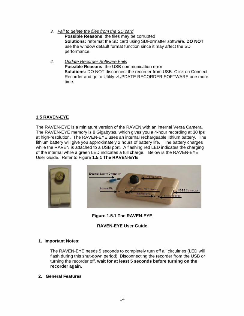
1.5 RAVEN-EYE The RAVEN-EYE is a miniature version of the RAVEN with an internal Versa Camera. The RAVEN-EYE memory is 8 Gigabytes, which gives you a 4-hour recording at 30 fps at high-resolution. The RAVEN-EYE uses an internal rechargeable lithium battery. The lithium battery will give you approximately 2 hours of battery life. The battery charges while the RAVEN is attached to a USB port. A flashing red LED indicates the charging of the internal while a green LED indicates a full charge. Below is the RAVEN-EYE User Guide. Refer to Figure 1.5.1 The RAVEN-EYE
Figure 1.5.1 The RAVEN-EYE
RAVEN-EYE User Guide
1. Important Notes:
The RAVEN-EYE needs 5 seconds to completely turn off all circuitries (LED will flash during this shut-down period). Disconnecting the recorder from the USB or turning the recorder off, wait for at least 5 seconds before turning on the recorder again.
2. General Features
15
a. The Raven-EYE records video/audio data directly to a non-removable memory in the recorder.
b. The data format for each recorded file is ADS
proprietary and needs ADS USBird software to transfer and playback.
c. A standard lithium battery provides a 2+ hours of video
and audio recording, and a high capacity lithium ion battery provides a 3.5+ hours of video and audio recording when fully charged.
d. A high-speed charger is built into the recorder and the
battery can be charged with any USB port or from a wall outlet through the USB-TO-WALL converter.
e. A sophisticated NAND FLASH bad block identification
algorithm was built into the recorder so that the memory diagnostics is no longer necessary.
2- USBird Software Installation a. USBird Software Installation Please refer to the USBird Manual on the USBird CD.
3- Charging the Battery Internal Charger: It takes about 2 hours to charge a single battery. Before using the unit, make sure to charge the battery first. To charge the battery, connect the battery to the recorder battery connector, and connect the USB cable to any computer or use the USB-TO-WALL converter to plug into any power outlet. The RED flashing LED on the RAVEN-EYE indicates the battery is being charged. The GREEN LED starts to flash when the battery is fully charged. If you are unsure if the battery has been charged, reconnect the USB to the recorder for at least 1 minute. If the RED LED flashes, the battery is not fully charged. If GREEN LED flashes, the battery is already charged. External Charger: Using the external charger to charge the battery, just have the battery connected to it for 2 hours. Solid Red LED indicates the battery is being charged and solid Green LED indicates the battery is fully charged.
4- Recorder Setup USBird 4.0x users, follow the procedures below to change the recorder
settings: a. Connect the recorder to the USB port. If it is your first
time to plug-in the recorder into the USB port, Window may pop-up a message for the driver installation. Just
16
follow the window installation wizard to complete the installation.
b. Start the USBird and USBird will automatically shows the current recorder settings on the top of USBird window.
c. Click on Controls tab at the bottom of the window and select Recorder Setup to set the recorder in Audio+Video, Video Only, and Audio Only mode. In the video mode, you can also select the frame rate desired from the drop-down menu.
d. Click on Controls tab at the bottom of the window and select Timer setup to set the timer mode.
VERY IMPORTANT: set your recorder time FIRST.
In addition, you can set your recorder time to be the current time of your computer by pressing RECORDER button inside the SET CLOCK group box. It is the BEST PRACTICE to set the recorder time every time before deploying the device.
NOTES:
a. VERY IMPORTANT: You need to press the button “Apply” before any recorder setting changes can take effect.
b. If the USBird window shows “DATA NOT TRANSFERRED”, you CANNOT change the current setting until you transfer all the sessions and erase the recorder memory
c. If the USBird window shows “MEMORY NOT ERASED”, you CANNOT put the recorder in the recording mode until you erase the recorder memory.
d. Currently audio setting cannot be changed. It is fixed to a sampling rate of 11.025 KHz (equivalent to a bandwidth of 5 KHz) with no compression (1:1 compression).
6. CameraView Function
USBird 4.0x users,
a. Connect the recorder to the USB and start the USBIRD software b. After the software recognizes the recorder, click on Monitor tab at the
bottom of the window c. And then select Camera 1. d. If this is the first time to use this feature, Window may ask for a new USB
(camera) device driver installation. Just follow the wizard to complete the installation. . The camera driver is located at c:\program files\ads\usbird4\driver folder.
17
Please note, once the cameraView function starts, the RAVEN-EYE will no longer respond to any request from the USBird software. You need to disconnect/reconnect the recorder for performing the regular USBird functions.
7. Recording and playback Just connect the battery and turn on the recording switch to start the recording. a. Video + Audio Recording If the recorder is setup for audio+video, both video and audio will be recorded. b. Audio Only Recording Set the recorder to Audio Only (NO VDIEO), the recorder automatically goes into the audio-only recording mode. c. Video Only Recording Set the recorder to Video Only (NO AUDIO) mode, the recorder will record the video only. d. Transfer and Playback After recording, connect the recorder to the USB and use USBird software to transfer the sessions and playback. Please refer to the USBird User Guide for more details.
Note: In order to keep the internal recorder clock running, you must
connect the battery first before disconnecting the recorder from the PC USB.
If you disconnect the battery from the recorder, you have up to 2 minutes to connect a new battery to the recorder before the internal clock loses its power.
8.Troubleshooting
a. Disconnect the recorder from the USB and turn on the recorder switch, the recorder failed to turn on and nothing was recorded
Possible reasons: You may not wait long enough ( 5 seconds minimum ) before turning on the recorder switch. Every time, the RAVEN-EYE recorder is disconnected from USB, the LED will flash very fast for up to 5 seconds. During this period, the recorder will not detect the recorder switch status. Therefore, if you turn on the recorder switch within this interval, the recorder will not go into the recording mode.
Solutions: You need to wait until the LED is fully turned off or just wait for at least 5 seconds after disconnecting the recorder from the USB. This applies to the consecutive recordings. If you just complete the first recording by turning off the recorder switch, you will notice that the LED flashes fast for a few seconds before it completely shuts off. You should
18
not turn on the recorder switch during this LED flushing period. Instead, just wait for 5 seconds before turning on the switch for the second time.
b. Turn on the switch to start recording; the red LED flashes for 3 seconds
and then off Possible reasons:
i. Memory not erased. ii. Battery voltage is too low.
Solutions: i. Connect the recorder to the USB and use USBird to erase the
recorder memory. ii. Fully charge the battery before any new recording.
c. Update Recorder Software Fails
Possible Reasons: the USB communication error Solutions: DO NOT disconnect the recorder from USB. Click on Connect Recorder and go to Utility->UPDATE RECORDER SOFTWARE one more time.
d. After connecting the recorder, the last session status shows “PF”
Possible Reasons: During the recording, the recorder lost the power. Solutions: Due to the power loss, the recorder time is automatically set to the last session ending time. You must transfer the last session, which is guaranteed to be a valid session, and erase the recorder in order to reset the time.
e. Setup the timer mode and recorder did not turn on as expected Possible Reasons: Recorder time may not be aligned to the PC time Solutions: To correctly set up the timer mode, make sure to set the recorder time first before setting up the timer mode. In addition, the recorder on/off switch should be in OFF position in order for the timer mode to work. If you leave the recorder switch in ON position, the recorder will wake up and record until the battery low or memory full.
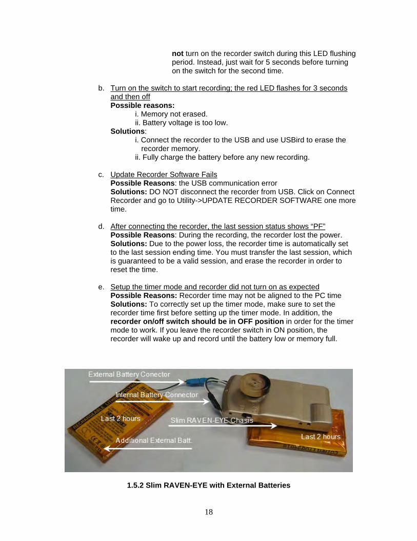
1.5.2 Slim RAVEN-EYE with External Batteries
19
1.6 RAVEN-RX
The RAVEN-RX uses an internal Wi-Fi radio with a range of 2500 feet line of sight. The RAVEN-RX can communicate with a RAVEN-MONITOR or RAVEN-Repeater to send video and audio. Refer to Figure 1.7.2 RAVEN-RX and RAVEN-MON
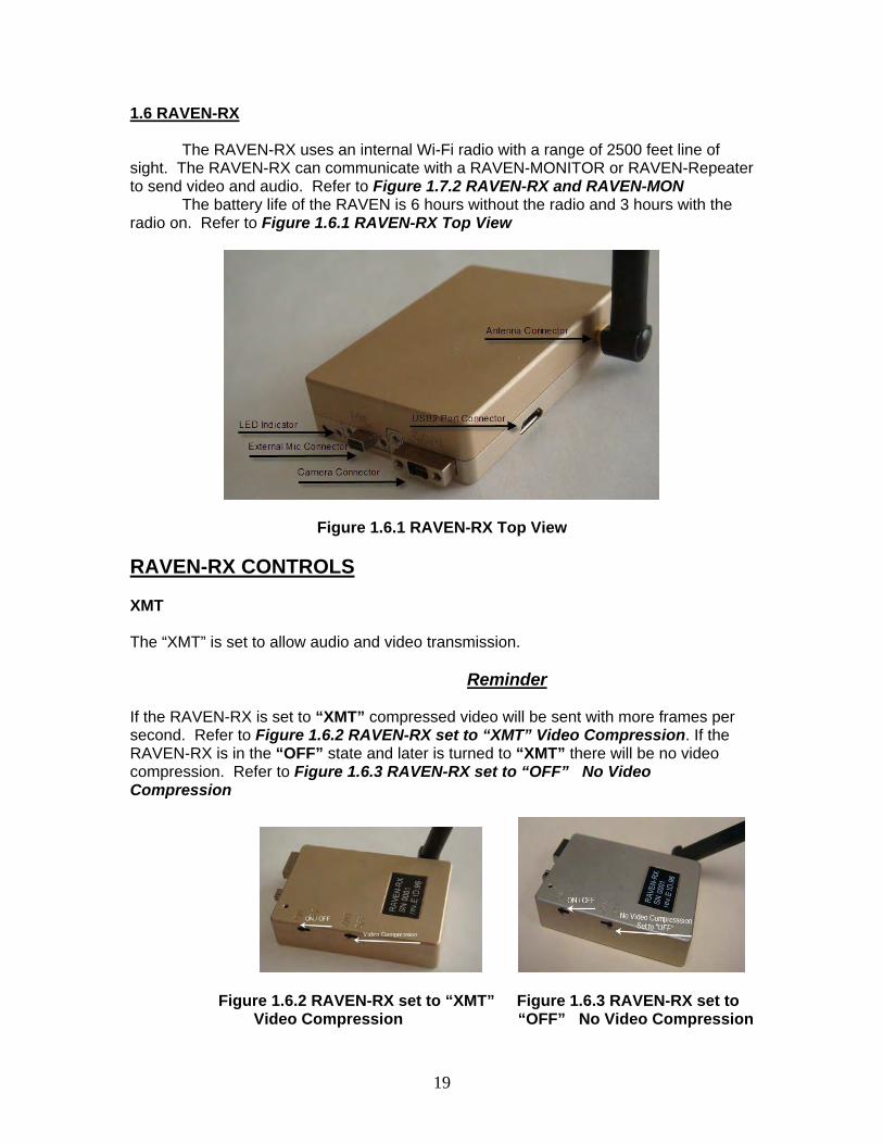
The battery life of the RAVEN is 6 hours without the radio and 3 hours with the radio on. Refer to Figure 1.6.1 RAVEN-RX Top View
Figure 1.6.1 RAVEN-RX Top View
RAVEN-RX CONTROLS XMT The “XMT” is set to allow audio and video transmission.
Reminder
If the RAVEN-RX is set to “XMT” compressed video will be sent with more frames per second. Refer to Figure 1.6.2 RAVEN-RX set to “XMT” Video Compression. If the RAVEN-RX is in the “OFF” state and later is turned to “XMT” there will be no video compression. Refer to Figure 1.6.3 RAVEN-RX set to “OFF” No Video Compression
Figure 1.6.2 RAVEN-RX set to “XMT” Figure 1.6.3 RAVEN-RX set to Video Compression “OFF” No Video Compression
20
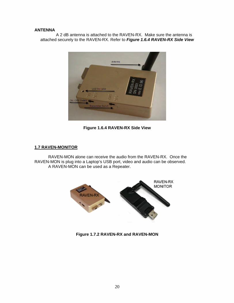
ANTENNA A 2 dB antenna is attached to the RAVEN-RX. Make sure the antenna is
attached securely to the RAVEN-RX. Refer to Figure 1.6.4 RAVEN-RX Side View
Figure 1.6.4 RAVEN-RX Side View
1.7 RAVEN-MONITOR
RAVEN-MON alone can receive the audio from the RAVEN-RX. Once the RAVEN-MON is plug into a Laptop’s USB port, video and audio can be observed.
A RAVEN-MON can be used as a Repeater.
Figure 1.7.2 RAVEN-RX and RAVEN-MON
21
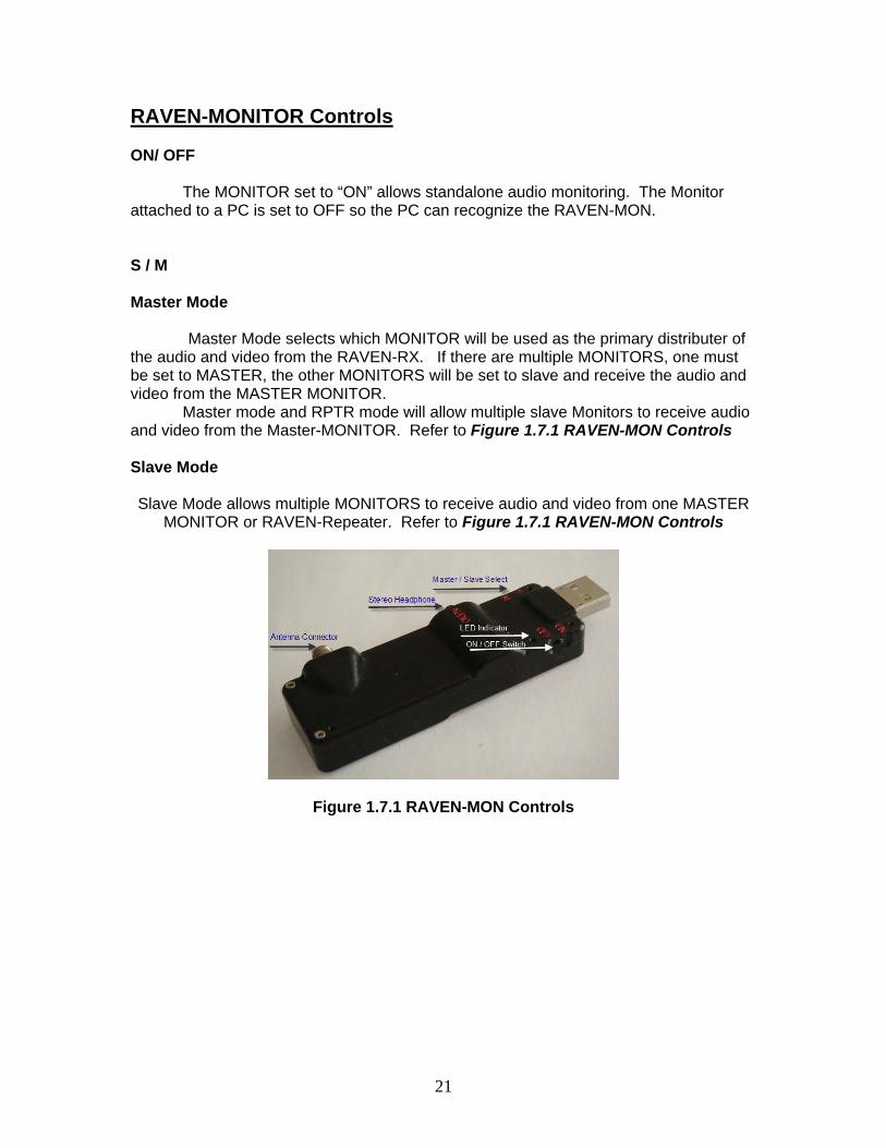
RAVEN-MONITOR Controls ON/ OFF
The MONITOR set to “ON” allows standalone audio monitoring. The Monitor
attached to a PC is set to OFF so the PC can recognize the RAVEN-MON. S / M Master Mode Master Mode selects which MONITOR will be used as the primary distributer of the audio and video from the RAVEN-RX. If there are multiple MONITORS, one must be set to MASTER, the other MONITORS will be set to slave and receive the audio and video from the MASTER MONITOR.
Master mode and RPTR mode will allow multiple slave Monitors to receive audio and video from the Master-MONITOR. Refer to Figure 1.7.1 RAVEN-MON Controls Slave Mode Slave Mode allows multiple MONITORS to receive audio and video from one MASTER
MONITOR or RAVEN-Repeater. Refer to Figure 1.7.1 RAVEN-MON Controls
Figure 1.7.1 RAVEN-MON Controls
22
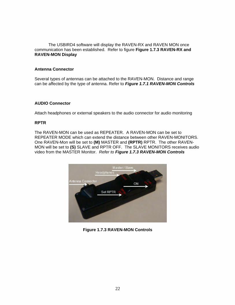
The USBIRD4 software will display the RAVEN-RX and RAVEN MON once communication has been established. Refer to figure Figure 1.7.3 RAVEN-RX and RAVEN-MON Display
Antenna Connector Several types of antennas can be attached to the RAVEN-MON. Distance and range can be affected by the type of antenna. Refer to Figure 1.7.1 RAVEN-MON Controls AUDIO Connector Attach headphones or external speakers to the audio connector for audio monitoring RPTR The RAVEN-MON can be used as REPEATER. A RAVEN-MON can be set to REPEATER MODE which can extend the distance between other RAVEN-MONITORS. One RAVEN-Mon will be set to (M) MASTER and (RPTR) RPTR. The other RAVEN-MON will be set to (S) SLAVE and RPTR OFF. The SLAVE MONITORS receives audio video from the MASTER Monitor. Refer to Figure 1.7.3 RAVEN-MON Controls
Figure 1.7.3 RAVEN-MON Controls
23
1.8 RAVEN-REPEATER
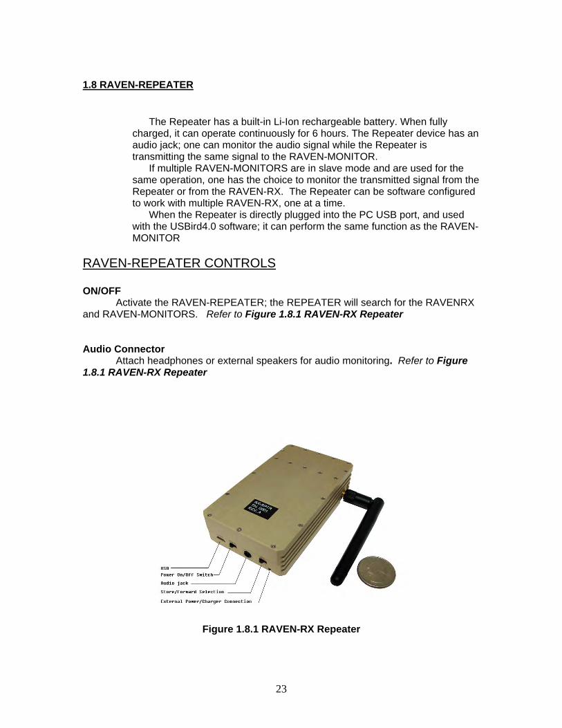
The Repeater has a built-in Li-Ion rechargeable battery. When fully charged, it can operate continuously for 6 hours. The Repeater device has an audio jack; one can monitor the audio signal while the Repeater is transmitting the same signal to the RAVEN-MONITOR.
If multiple RAVEN-MONITORS are in slave mode and are used for the same operation, one has the choice to monitor the transmitted signal from the Repeater or from the RAVEN-RX. The Repeater can be software configured to work with multiple RAVEN-RX, one at a time.
When the Repeater is directly plugged into the PC USB port, and used with the USBird4.0 software; it can perform the same function as the RAVEN-MONITOR
RAVEN-REPEATER CONTROLS ON/OFF
Activate the RAVEN-REPEATER; the REPEATER will search for the RAVENRX and RAVEN-MONITORS. Refer to Figure 1.8.1 RAVEN-RX Repeater Audio Connector Attach headphones or external speakers for audio monitoring. Refer to Figure 1.8.1 RAVEN-RX Repeater
Figure 1.8.1 RAVEN-RX Repeater
24
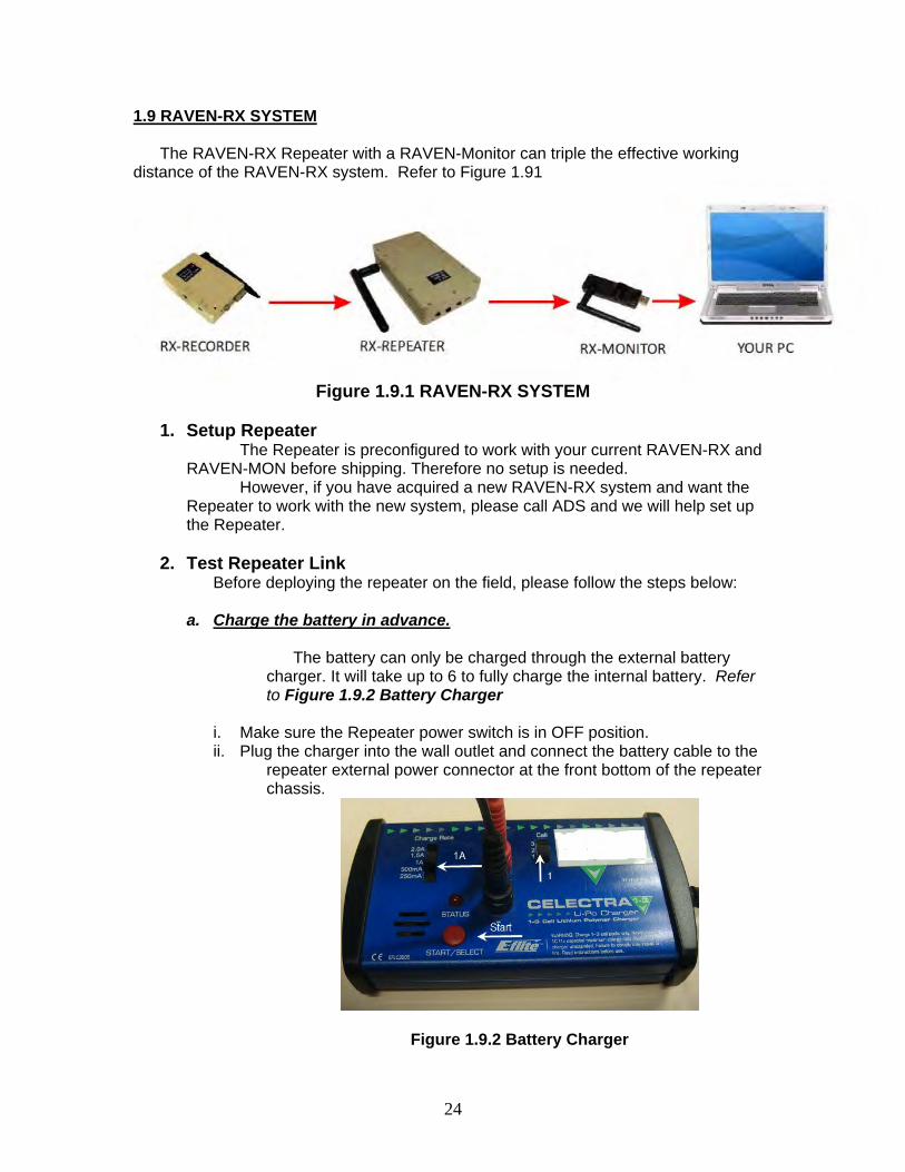
1.9 RAVEN-RX SYSTEM
The RAVEN-RX Repeater with a RAVEN-Monitor can triple the effective working distance of the RAVEN-RX system. Refer to Figure 1.91
Figure 1.9.1 RAVEN-RX SYSTEM 1. Setup Repeater
The Repeater is preconfigured to work with your current RAVEN-RX and RAVEN-MON before shipping. Therefore no setup is needed.
However, if you have acquired a new RAVEN-RX system and want the Repeater to work with the new system, please call ADS and we will help set up the Repeater.
2. Test Repeater Link
Before deploying the repeater on the field, please follow the steps below: a. Charge the battery in advance.
The battery can only be charged through the external battery charger. It will take up to 6 to fully charge the internal battery. Refer to Figure 1.9.2 Battery Charger
i. Make sure the Repeater power switch is in OFF position. ii. Plug the charger into the wall outlet and connect the battery cable to the
repeater external power connector at the front bottom of the repeater chassis.
Figure 1.9.2 Battery Charger
25
iii. Set the Charge Rate to 1A and Cell to 1 iv. Press Start/Select button to start the charging process v. When the battery is fully charged, the RED LED will start flashing.
b. Test the link between the Repeater and the RAVEN-RX
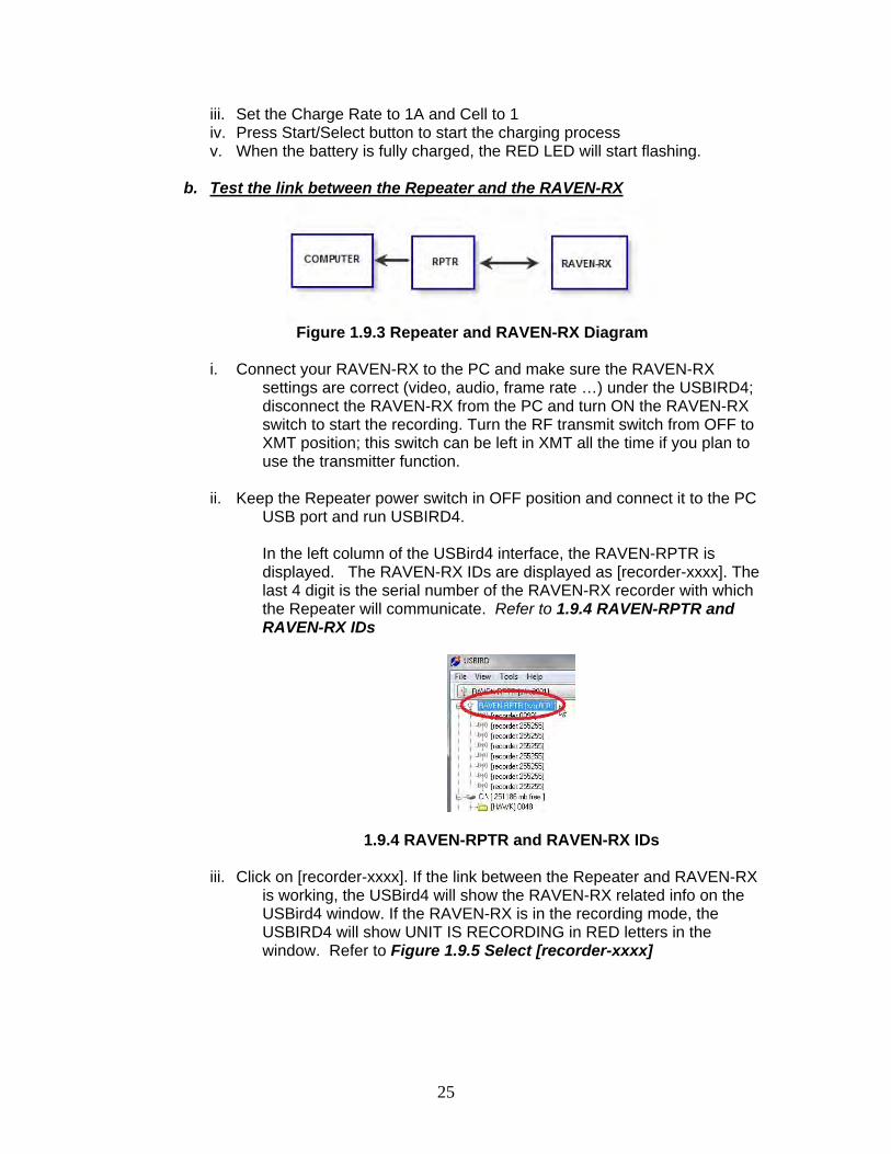
Figure 1.9.3 Repeater and RAVEN-RX Diagram
i. Connect your RAVEN-RX to the PC and make sure the RAVEN-RX
settings are correct (video, audio, frame rate …) under the USBIRD4; disconnect the RAVEN-RX from the PC and turn ON the RAVEN-RX switch to start the recording. Turn the RF transmit switch from OFF to XMT position; this switch can be left in XMT all the time if you plan to use the transmitter function.
ii. Keep the Repeater power switch in OFF position and connect it to the PC USB port and run USBIRD4.
In the left column of the USBird4 interface, the RAVEN-RPTR is displayed. The RAVEN-RX IDs are displayed as [recorder-xxxx]. The last 4 digit is the serial number of the RAVEN-RX recorder with which the Repeater will communicate. Refer to 1.9.4 RAVEN-RPTR and RAVEN-RX IDs
1.9.4 RAVEN-RPTR and RAVEN-RX IDs
iii. Click on [recorder-xxxx]. If the link between the Repeater and RAVEN-RX is working, the USBird4 will show the RAVEN-RX related info on the USBird4 window. If the RAVEN-RX is in the recording mode, the USBIRD4 will show UNIT IS RECORDING in RED letters in the window. Refer to Figure 1.9.5 Select [recorder-xxxx]
26
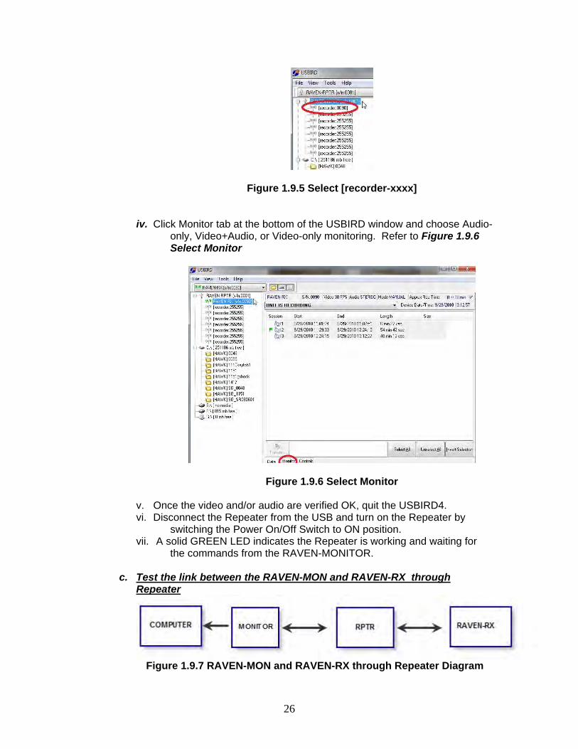
Figure 1.9.5 Select [recorder-xxxx]
iv. Click Monitor tab at the bottom of the USBIRD window and choose Audio-only, Video+Audio, or Video-only monitoring. Refer to Figure 1.9.6 Select Monitor
Figure 1.9.6 Select Monitor
v. Once the video and/or audio are verified OK, quit the USBIRD4. vi. Disconnect the Repeater from the USB and turn on the Repeater by
switching the Power On/Off Switch to ON position. vii. A solid GREEN LED indicates the Repeater is working and waiting for
the commands from the RAVEN-MONITOR. c. Test the link between the RAVEN-MON and RAVEN-RX through
Repeater
Figure 1.9.7 RAVEN-MON and RAVEN-RX through Repeater Diagram
27
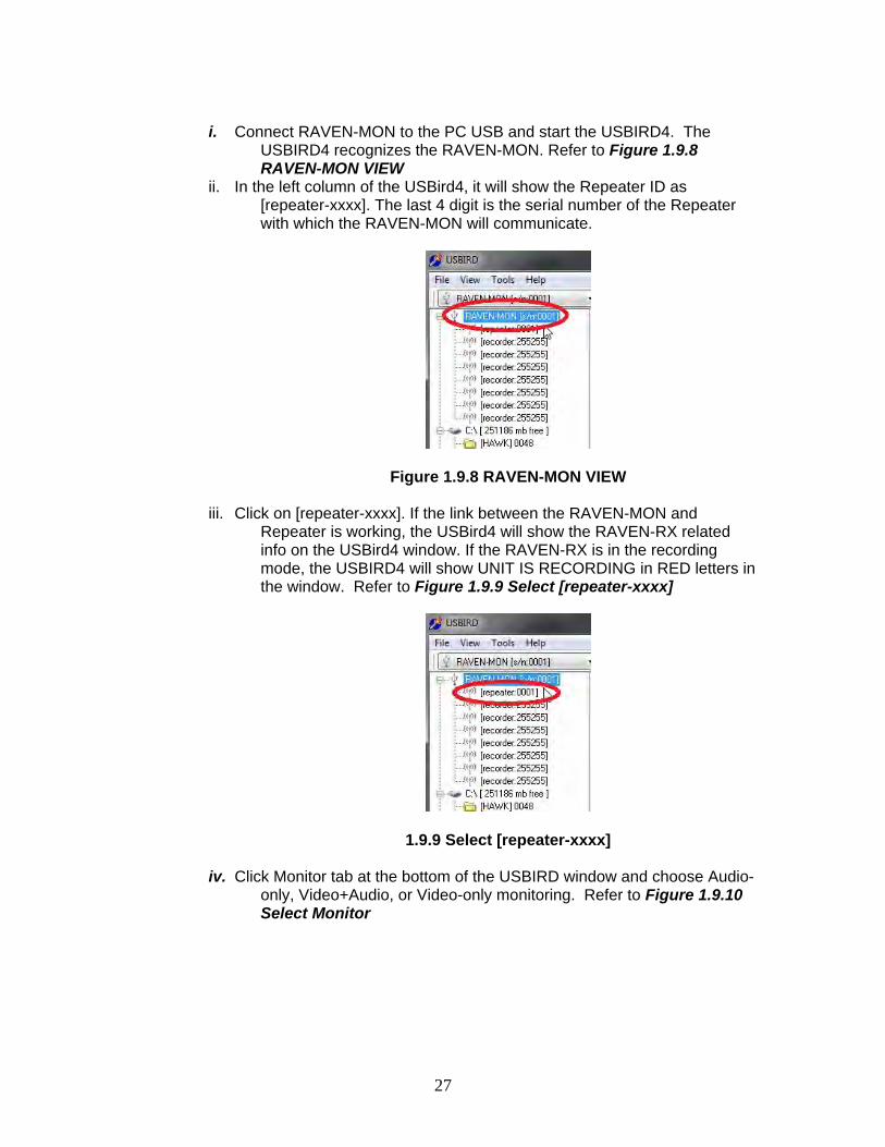
i. Connect RAVEN-MON to the PC USB and start the USBIRD4. The
USBIRD4 recognizes the RAVEN-MON. Refer to Figure 1.9.8 RAVEN-MON VIEW
ii. In the left column of the USBird4, it will show the Repeater ID as [repeater-xxxx]. The last 4 digit is the serial number of the Repeater with which the RAVEN-MON will communicate.
Figure 1.9.8 RAVEN-MON VIEW
iii. Click on [repeater-xxxx]. If the link between the RAVEN-MON and Repeater is working, the USBird4 will show the RAVEN-RX related info on the USBird4 window. If the RAVEN-RX is in the recording mode, the USBIRD4 will show UNIT IS RECORDING in RED letters in the window. Refer to Figure 1.9.9 Select [repeater-xxxx]
1.9.9 Select [repeater-xxxx]
iv. Click Monitor tab at the bottom of the USBIRD window and choose Audio-only, Video+Audio, or Video-only monitoring. Refer to Figure 1.9.10 Select Monitor
28
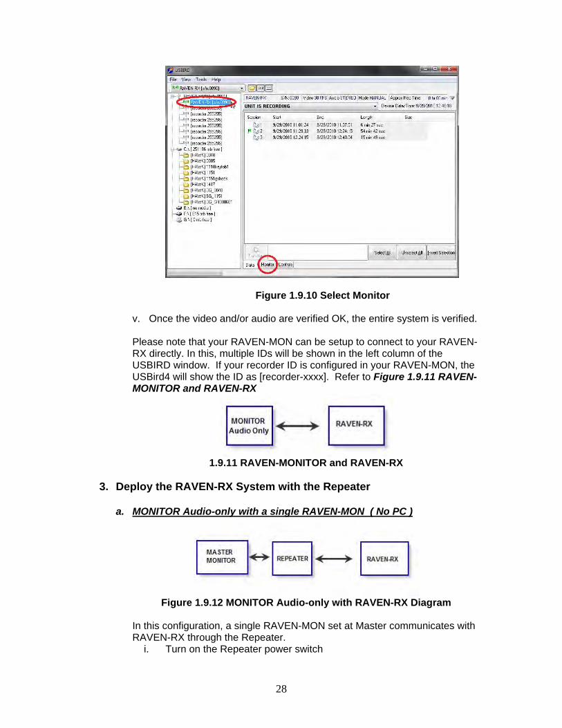
Figure 1.9.10 Select Monitor
v. Once the video and/or audio are verified OK, the entire system is verified. Please note that your RAVEN-MON can be setup to connect to your RAVEN-RX directly. In this, multiple IDs will be shown in the left column of the USBIRD window. If your recorder ID is configured in your RAVEN-MON, the USBird4 will show the ID as [recorder-xxxx]. Refer to Figure 1.9.11 RAVEN-MONITOR and RAVEN-RX
1.9.11 RAVEN-MONITOR and RAVEN-RX
3. Deploy the RAVEN-RX System with the Repeater
a. MONITOR Audio-only with a single RAVEN-MON ( No PC )
Figure 1.9.12 MONITOR Audio-only with RAVEN-RX Diagram
In this configuration, a single RAVEN-MON set at Master communicates with RAVEN-RX through the Repeater.
i. Turn on the Repeater power switch
29
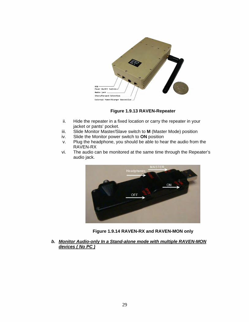
Figure 1.9.13 RAVEN-Repeater
ii. Hide the repeater in a fixed location or carry the repeater in your
jacket or pants’ pocket. iii. Slide Monitor Master/Slave switch to M (Master Mode) position iv. Slide the Monitor power switch to ON position v. Plug the headphone, you should be able to hear the audio from the
RAVEN-RX vi. The audio can be monitored at the same time through the Repeater’s
audio jack.
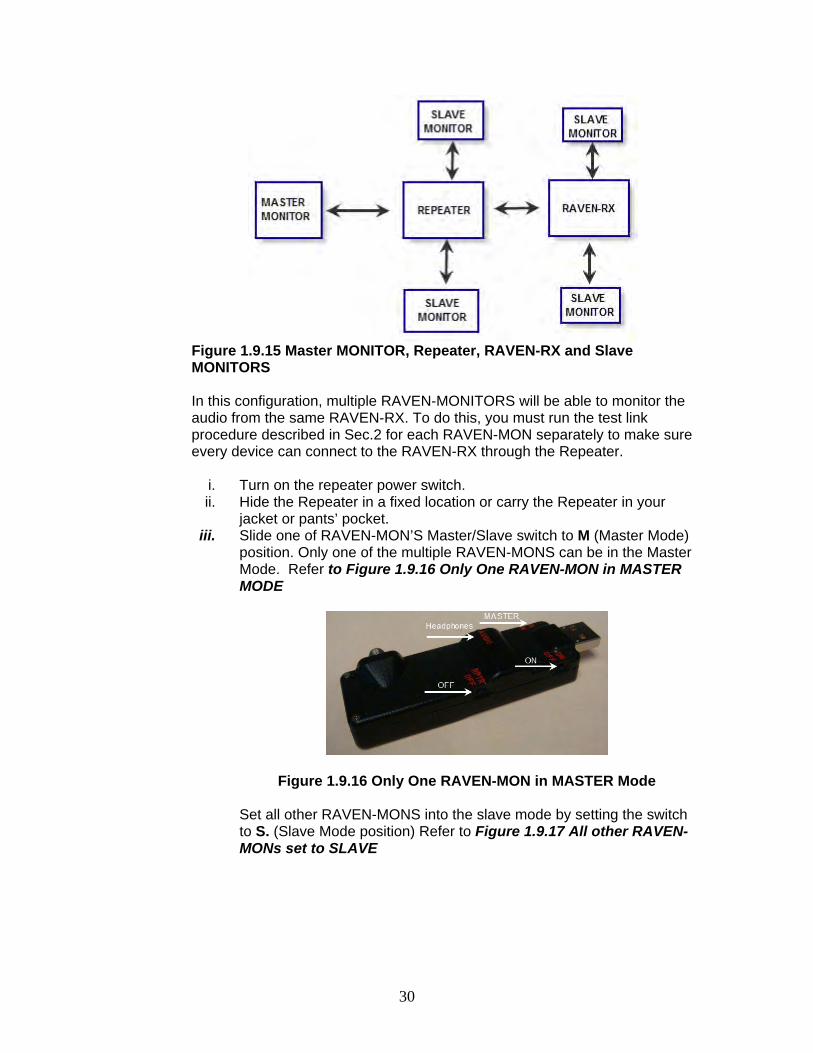
Figure 1.9.14 RAVEN-RX and RAVEN-MON only
b. Monitor Audio-only In a Stand-alone mode with multiple RAVEN-MON devices ( No PC )
30
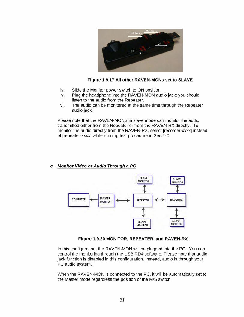
Figure 1.9.15 Master MONITOR, Repeater, RAVEN-RX and Slave MONITORS
In this configuration, multiple RAVEN-MONITORS will be able to monitor the audio from the same RAVEN-RX. To do this, you must run the test link procedure described in Sec.2 for each RAVEN-MON separately to make sure every device can connect to the RAVEN-RX through the Repeater.
i. Turn on the repeater power switch. ii. Hide the Repeater in a fixed location or carry the Repeater in your
jacket or pants’ pocket. iii. Slide one of RAVEN-MON’S Master/Slave switch to M (Master Mode)
position. Only one of the multiple RAVEN-MONS can be in the Master Mode. Refer to Figure 1.9.16 Only One RAVEN-MON in MASTER MODE
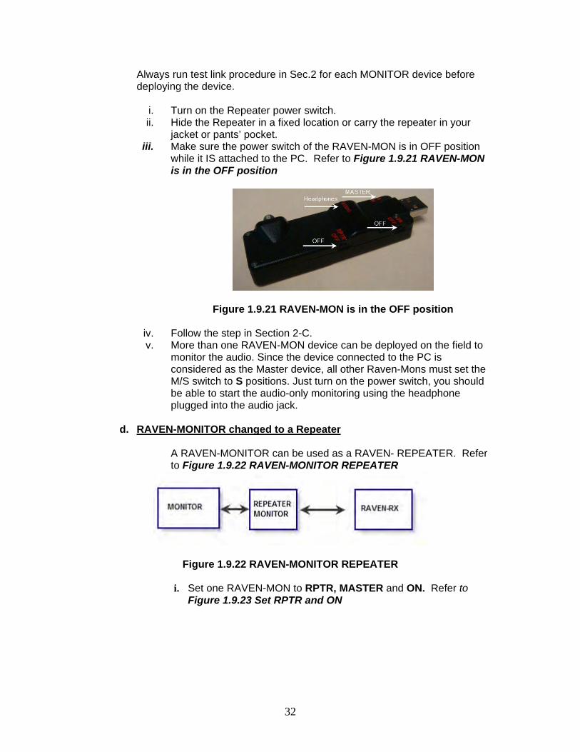
Figure 1.9.16 Only One RAVEN-MON in MASTER Mode
Set all other RAVEN-MONS into the slave mode by setting the switch to S. (Slave Mode position) Refer to Figure 1.9.17 All other RAVEN-MONs set to SLAVE
31
Figure 1.9.17 All other RAVEN-MONs set to SLAVE
iv. Slide the Monitor power switch to ON position v. Plug the headphone into the RAVEN-MON audio jack; you should
listen to the audio from the Repeater. vi. The audio can be monitored at the same time through the Repeater
audio jack. Please note that the RAVEN-MONS in slave mode can monitor the audio transmitted either from the Repeater or from the RAVEN-RX directly. To monitor the audio directly from the RAVEN-RX, select [recorder-xxxx] instead of [repeater-xxxx] while running test procedure in Sec.2-C.
c. Monitor Video or Audio Through a PC
Figure 1.9.20 MONITOR, REPEATER, and RAVEN-RX In this configuration, the RAVEN-MON will be plugged into the PC. You can control the monitoring through the USBIRD4 software. Please note that audio jack function is disabled in this configuration. Instead, audio is through your PC audio system. When the RAVEN-MON is connected to the PC, it will be automatically set to the Master mode regardless the position of the M/S switch.
32
Always run test link procedure in Sec.2 for each MONITOR device before deploying the device.
i. Turn on the Repeater power switch. ii. Hide the Repeater in a fixed location or carry the repeater in your
jacket or pants’ pocket. iii. Make sure the power switch of the RAVEN-MON is in OFF position
while it IS attached to the PC. Refer to Figure 1.9.21 RAVEN-MON is in the OFF position
Figure 1.9.21 RAVEN-MON is in the OFF position
iv. Follow the step in Section 2-C. v. More than one RAVEN-MON device can be deployed on the field to
monitor the audio. Since the device connected to the PC is considered as the Master device, all other Raven-Mons must set the M/S switch to S positions. Just turn on the power switch, you should be able to start the audio-only monitoring using the headphone plugged into the audio jack.
d. RAVEN-MONITOR changed to a Repeater
A RAVEN-MONITOR can be used as a RAVEN- REPEATER. Refer to Figure 1.9.22 RAVEN-MONITOR REPEATER
Figure 1.9.22 RAVEN-MONITOR REPEATER
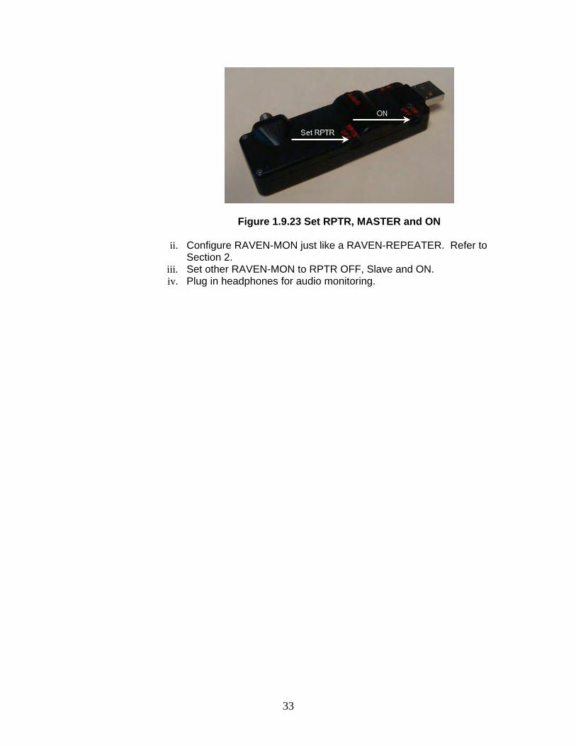
i. Set one RAVEN-MON to RPTR, MASTER and ON. Refer to Figure 1.9.23 Set RPTR and ON
33
Figure 1.9.23 Set RPTR, MASTER and ON
ii. Configure RAVEN-MON just like a RAVEN-REPEATER. Refer to Section 2.
iii. Set other RAVEN-MON to RPTR OFF, Slave and ON. iv. Plug in headphones for audio monitoring.
34
SECTION - 2
USBIRD4.0
The USBird4.x series support unit code was designed to be simple to use. It features all Windows controls. The manual describes the features of the USBIRD4.0. Section- 7 describes the PLAYER program; the software plays the “audio” and “video” data from the CD or DVD. The PLAYER program is automatically written to the “CD” or “DVD” and installs on any computer that contains a CD/DVD-ROM and a sound card. The installation steps are the same as given below. For help, call ADS at 949 955-3103. 2.1 SYSTEM REQUIREMENTS The CPU should be at least Pentium III or higher with 600 MHz processing speed, 512 Megabyte RAM, and at least 20 Gigabytes of hard drive space. The supported operating systems are Windows 2000; XP; 7; VISTA; (32 and 64) and ME. 2.2 INSTALLATION The software is supplied on one CD. It can also be retrieved from our Web Site at (www.adaptivedigitalsystems.com) under Download. The “USER” and “PASSWORD” are both “kondor” all small case. Instructions are shipped with every update and are also on the website. A copy is included below. The CD contains the following folders:
1- USBird4.0 – software installs in DRSU (desktop, laptop) and PDR2 2- PLAYER – used to playback audio/video recordings 3- Windows Media Player- used to playback .AVI and .WAV files 4- USBird4.0_Manual - a PDF copy of this manual 5- USBird4.0_Install - a PDF instruction guide to load software.
For new software installation follow this order: Before you install the USBIRD4 make sure you are the Administrator. When a computer is logged on a network it may have security features that block the full installation of new software.
1. Install USBird4.0 software. Refer to Appendix A. 2. Optional - Windows Media Player. If your computer does not correctly display
AVI files, install new Windows Media Player. Refer to Appendix C. After the installation, the shortcut icon for the USBird4.x will appear on the DESKSTOP.
35
2.3 RUN PROGRAM To run the USBird4.x program, click on the shortcut “USBird4” found on the deskstop. From the Windows operating system access the USBird program select, Start->All Programs->ADS-> USBIRD4->USBIRD.
NOTE!!!
Conflicts between Recorders and other devices such as USB printers, scanners may occur. It is recommended that you use a powered, USB2.0 hub if you are using multiple USB devices on your PC. The USB drivers must be installed. USBird4 loads the USB driver automatically 2.4 RED LED
The RAVEN, SD-RAVEN, MICRO-RAVEN, RAVEN-EYE, RAVEN-RX have an internal Lithium battery that charges from the USB port. The LED’s flash “RED” when first plugged into the PC. After the battery is charged the LED flashes “GREEN” If the power from the USB port is marginal an external power supply such as USB2.0 Hub should be used.
BATTERY power vs. EXTERNAL power
Always use fresh batteries and charge the rechargeable battery before you deploy the Recorder. Once battery power winds down, the Recorder automatically shuts off without losing data.
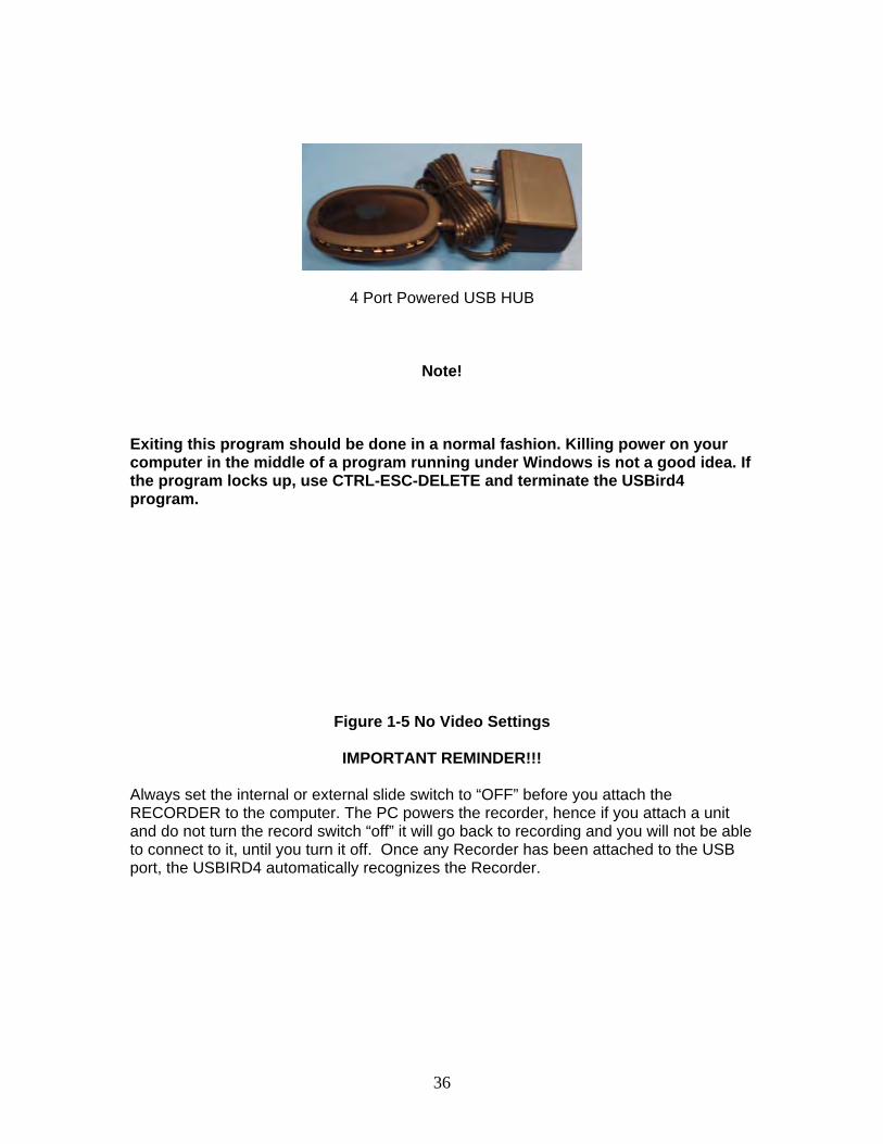
All Recorders can have external power if the rechargeable batteries do not supply sufficient record times. External power will give you longer record times; call ADS for details. Car kits and converters are available. 2.5 POWERED USB HUB Some laptops and some desktops need the aid of an external power supply (USB Hub) in order for the RAVEN to function properly. If the power is marginal the RECORDER will not connect or communicate with the computer. The USB Hub provided by ADS can be used to power the RECORDER. The USB Hub will be needed if the Red LED does not appear from the recorder. All other USB devices such as PDAs, scanners, printers, mouse, keyboard, etc, should be connected through the USB hub to reduce device conflicts and power issues.
36
4 Port Powered USB HUB
Note!
Exiting this program should be done in a normal fashion. Killing power on your computer in the middle of a program running under Windows is not a good idea. If the program locks up, use CTRL-ESC-DELETE and terminate the USBird4 program.
Figure 1-5 No Video Settings
IMPORTANT REMINDER!!!
Always set the internal or external slide switch to “OFF” before you attach the RECORDER to the computer. The PC powers the recorder, hence if you attach a unit and do not turn the record switch “off” it will go back to recording and you will not be able to connect to it, until you turn it off. Once any Recorder has been attached to the USB port, the USBIRD4 automatically recognizes the Recorder.
37
SECTION - 3
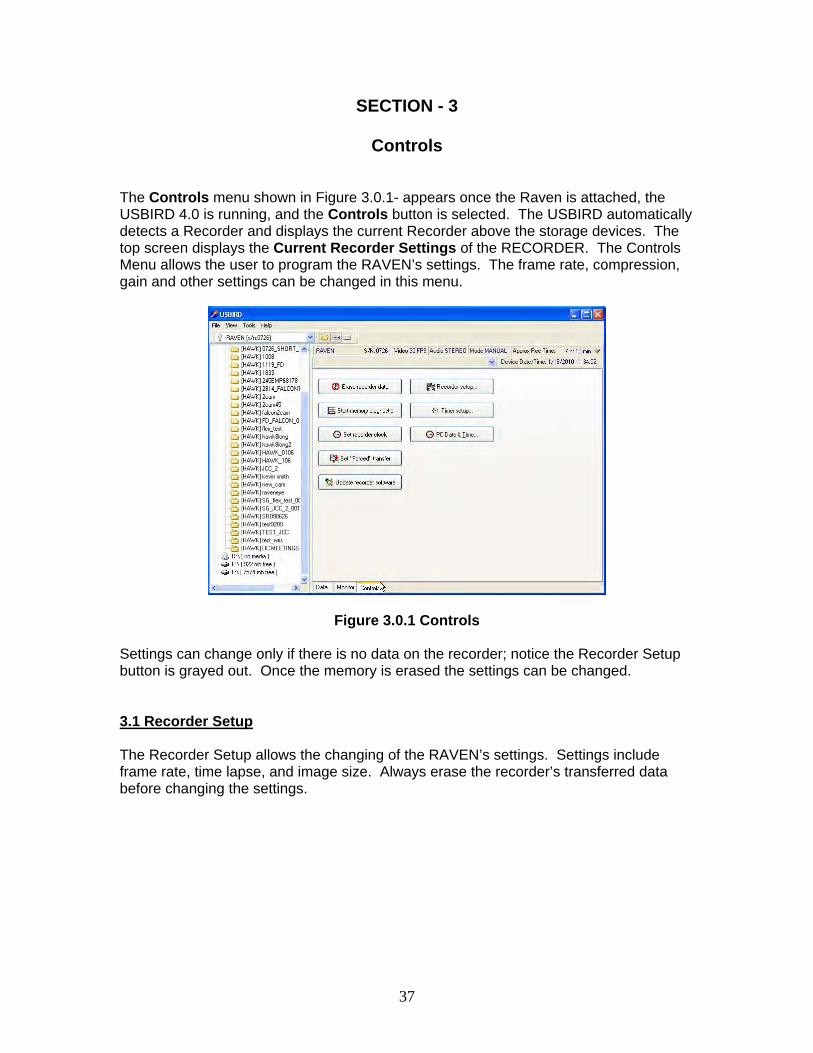
Controls The Controls menu shown in Figure 3.0.1- appears once the Raven is attached, the USBIRD 4.0 is running, and the Controls button is selected. The USBIRD automatically detects a Recorder and displays the current Recorder above the storage devices. The top screen displays the Current Recorder Settings of the RECORDER. The Controls Menu allows the user to program the RAVEN’s settings. The frame rate, compression, gain and other settings can be changed in this menu.
Figure 3.0.1 Controls Settings can change only if there is no data on the recorder; notice the Recorder Setup button is grayed out. Once the memory is erased the settings can be changed.
3.1 Recorder Setup The Recorder Setup allows the changing of the RAVEN’s settings. Settings include frame rate, time lapse, and image size. Always erase the recorder’s transferred data before changing the settings.
38
Figure 3.1.2 SETUP Menu
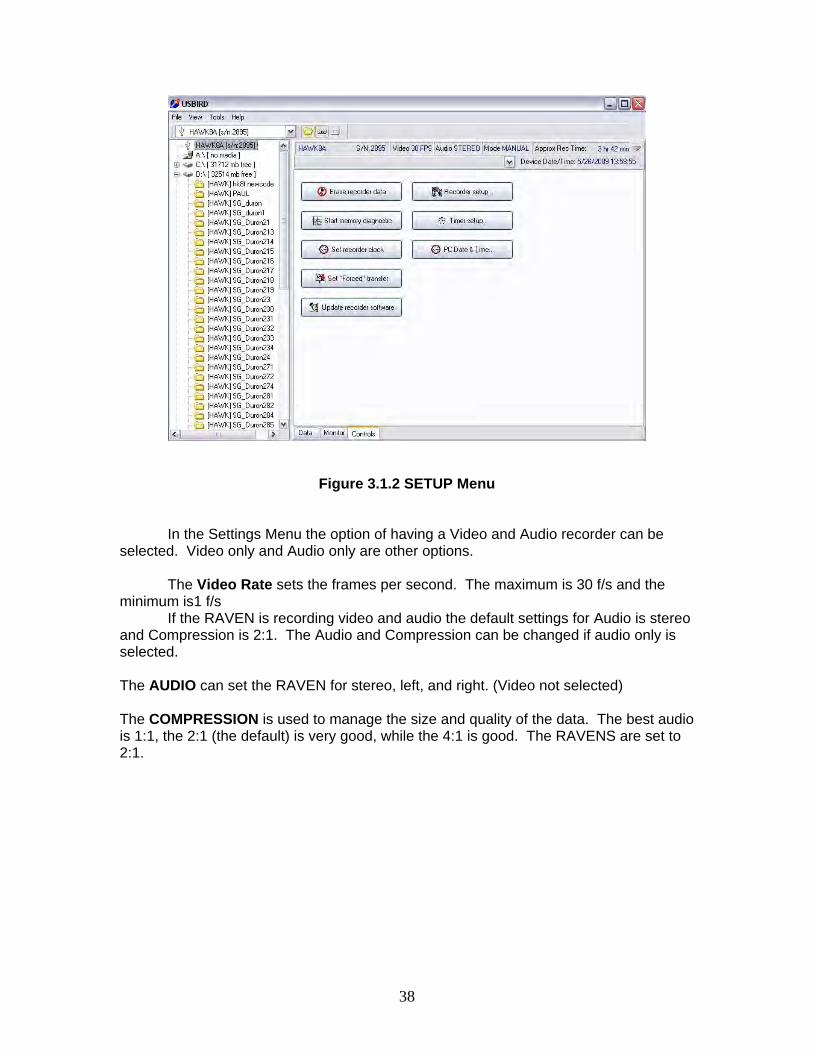
In the Settings Menu the option of having a Video and Audio recorder can be selected. Video only and Audio only are other options.
The Video Rate sets the frames per second. The maximum is 30 f/s and the minimum is1 f/s
If the RAVEN is recording video and audio the default settings for Audio is stereo and Compression is 2:1. The Audio and Compression can be changed if audio only is selected.
The AUDIO can set the RAVEN for stereo, left, and right. (Video not selected) The COMPRESSION is used to manage the size and quality of the data. The best audio is 1:1, the 2:1 (the default) is very good, while the 4:1 is good. The RAVENS are set to 2:1.
39
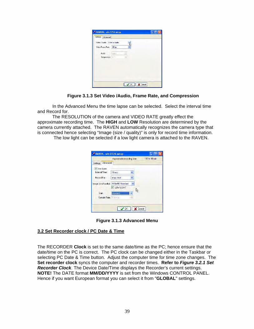
Figure 3.1.3 Set Video /Audio, Frame Rate, and Compression In the Advanced Menu the time lapse can be selected. Select the interval time
and Record for. The RESOLUTION of the camera and VIDEO RATE greatly effect the
approximate recording time. The HIGH and LOW Resolution are determined by the camera currently attached. The RAVEN automatically recognizes the camera type that is connected hence selecting “Image (size / quality)” is only for record time information.
The low light can be selected if a low light camera is attached to the RAVEN.
Figure 3.1.3 Advanced Menu 3.2 Set Recorder clock / PC Date & Time The RECORDER Clock is set to the same date/time as the PC; hence ensure that the date/time on the PC is correct. The PC clock can be changed either in the Taskbar or selecting PC Date & Time button. Adjust the computer time for time zone changes. The Set recorder clock syncs the computer and recorder times. Refer to Figure 3.2.1 Set Recorder Clock. The Device Date/Time displays the Recorder’s current settings. NOTE! The DATE format MM/DD/YYYY is set from the Windows CONTROL PANEL. Hence if you want European format you can select it from "GLOBAL" settings.
40
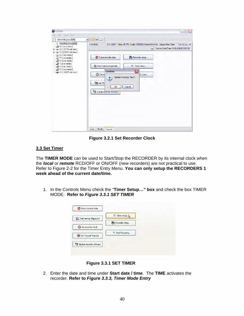
Figure 3.2.1 Set Recorder Clock
3.3 Set Timer The TIMER MODE can be used to Start/Stop the RECORDER by its internal clock when the local or remote RCD/OFF or ON/OFF (new recorders) are not practical to use. Refer to Figure 2-2 for the Timer Entry Menu. You can only setup the RECORDERS 1 week ahead of the current date/time.
1. In the Controls Menu check the “Timer Setup…” box and check the box TIMER MODE. Refer to Figure 3.3.1 SET TIMER
Figure 3.3.1 SET TIMER
2. Enter the date and time under Start date / time. The TIME activates the recorder. Refer to Figure 3.3.3, Timer Mode Entry
41
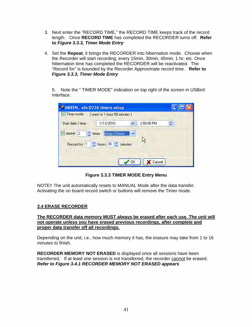
3. Next enter the ”RECORD TIME,” the RECORD TIME keeps track of the record length. Once RECORD TIME has completed the RECORDER turns off. Refer to Figure 3.3.3, Timer Mode Entry
4. Set the Repeat, it brings the RECORDER into hibernation mode. Choose when the Recorder will start recording, every 15min, 30min, 45min, 1 hr; etc. Once hibernation time has completed the RECORDER will be reactivated. The “Record for” is bounded by the Recorder Approximate record time. Refer to Figure 3.3.3, Timer Mode Entry
5. Note the “ TIMER MODE” indication on top right of the screen in USBird Interface.
Figure 3.3.3 TIMER MODE Entry Menu
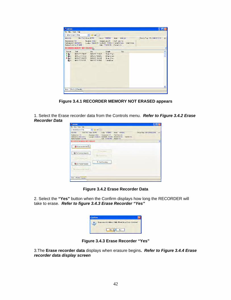
NOTE!! The unit automatically resets to MANUAL Mode after the data transfer. Activating the on board record switch or buttons will remove the Timer mode. 3.4 ERASE RECORDER The RECORDER data memory MUST always be erased after each use. The unit will not operate unless you have erased previous recordings, after complete and proper data transfer off all recordings. Depending on the unit, i.e., how much memory it has, the erasure may take from 1 to 16 minutes to finish. RECORDER MEMORY NOT ERASED is displayed once all sessions have been transferred. If at least one session is not transferred, the recorder cannot be erased. Refer to Figure 3.4.1 RECORDER MEMORY NOT ERASED appears
42
Figure 3.4.1 RECORDER MEMORY NOT ERASED appears 1. Select the Erase recorder data from the Controls menu. Refer to Figure 3.4.2 Erase Recorder Data
Figure 3.4.2 Erase Recorder Data 2. Select the “Yes” button when the Confirm displays how long the RECORDER will take to erase. Refer to figure 3.4.3 Erase Recorder “Yes”
Figure 3.4.3 Erase Recorder “Yes”
3.The Erase recorder data displays when erasure begins. Refer to Figure 3.4.4 Erase recorder data display screen
43
Figure 3.4.4 Erase recorder data display screen
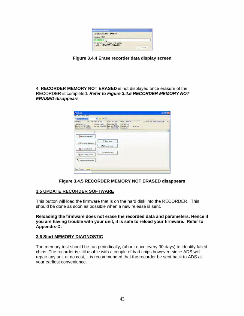
4. RECORDER MEMORY NOT ERASED is not displayed once erasure of the RECORDER is completed. Refer to Figure 3.4.5 RECORDER MEMORY NOT ERASED disappears
Figure 3.4.5 RECORDER MEMORY NOT ERASED disappears 3.5 UPDATE RECORDER SOFTWARE This button will load the firmware that is on the hard disk into the RECORDER. This should be done as soon as possible when a new release is sent. Reloading the firmware does not erase the recorded data and parameters. Hence if you are having trouble with your unit, it is safe to reload your firmware. Refer to Appendix-D. 3.6 Start MEMORY DIAGNOSTIC The memory test should be run periodically, (about once every 90 days) to identify failed chips. The recorder is still usable with a couple of bad chips however, since ADS will repair any unit at no cost, it is recommended that the recorder be sent back to ADS at your earliest convenience.
44
Section – 4
USBIRD Interface
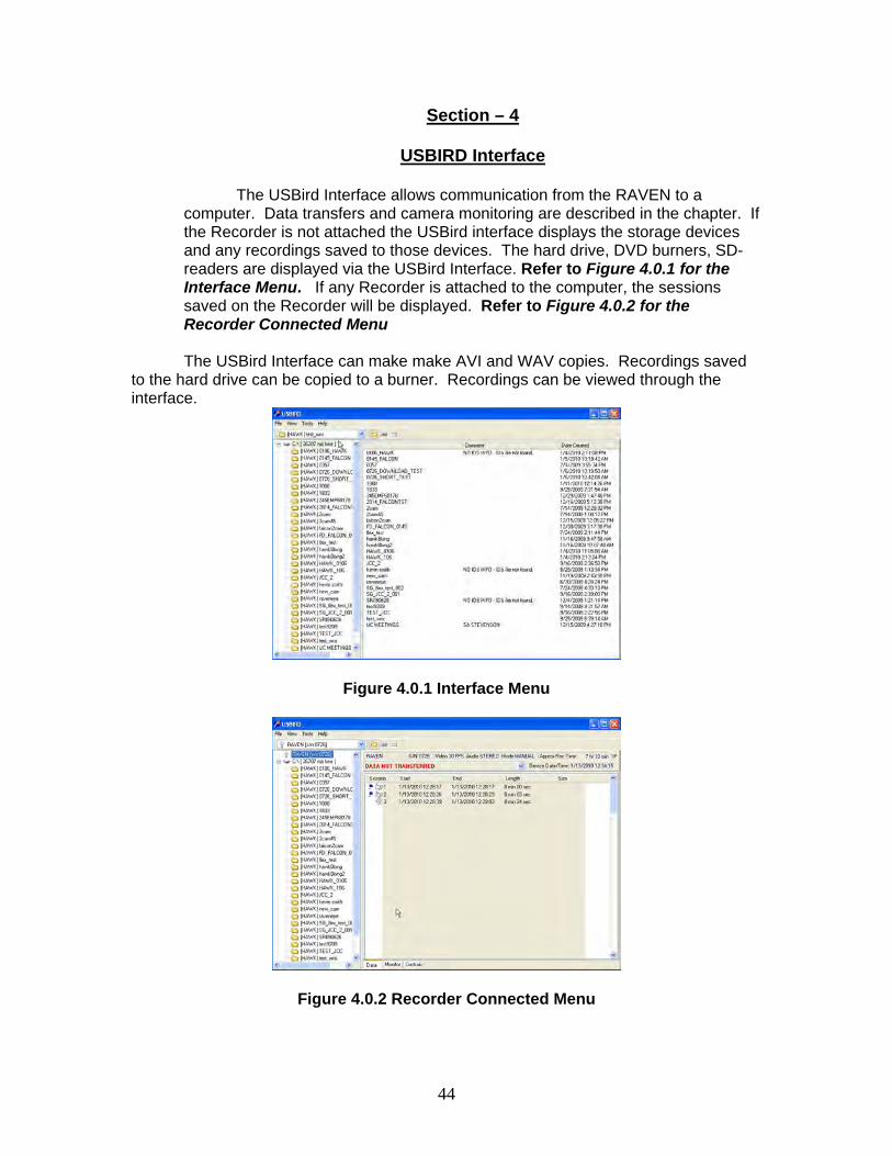
The USBird Interface allows communication from the RAVEN to a computer. Data transfers and camera monitoring are described in the chapter. If the Recorder is not attached the USBird interface displays the storage devices and any recordings saved to those devices. The hard drive, DVD burners, SD-readers are displayed via the USBird Interface. Refer to Figure 4.0.1 for the Interface Menu. If any Recorder is attached to the computer, the sessions saved on the Recorder will be displayed. Refer to Figure 4.0.2 for the Recorder Connected Menu
The USBird Interface can make make AVI and WAV copies. Recordings saved to the hard drive can be copied to a burner. Recordings can be viewed through the interface.
Figure 4.0.1 Interface Menu
Figure 4.0.2 Recorder Connected Menu
45
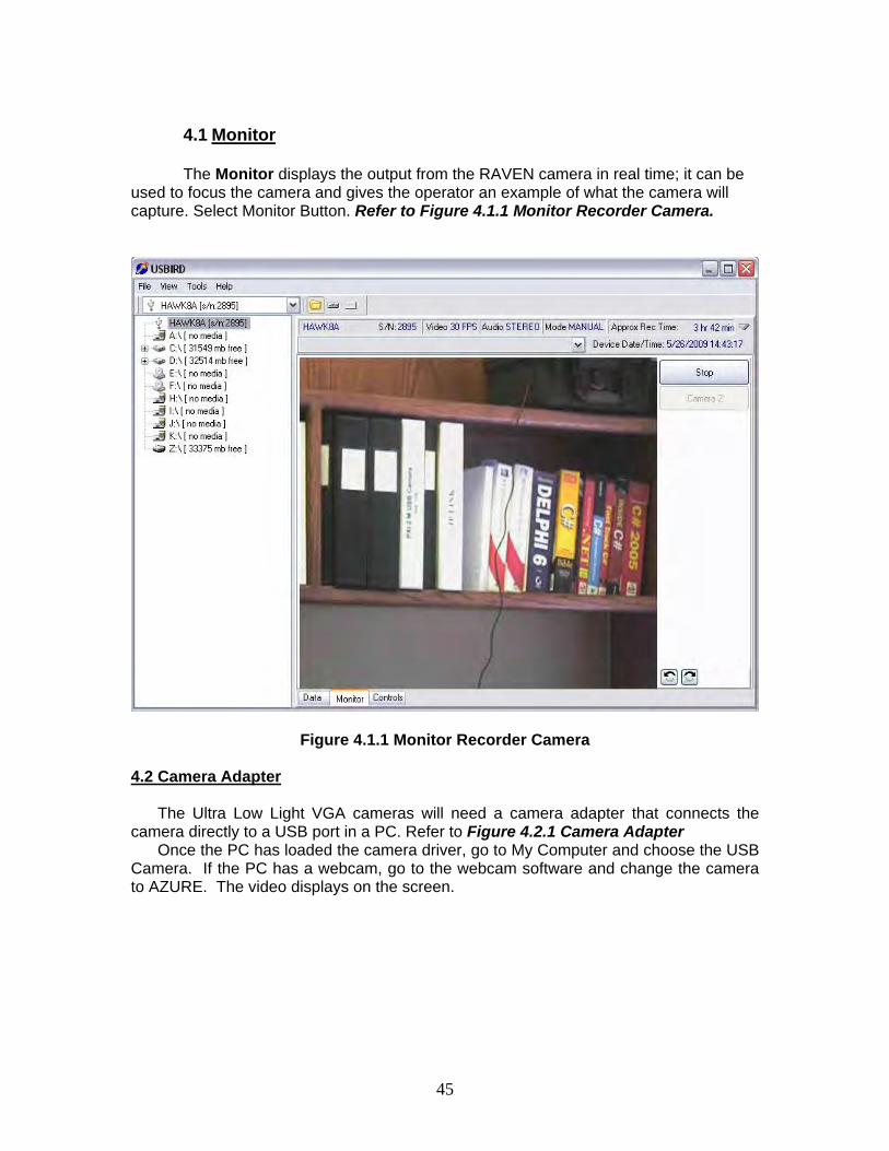
4.1 Monitor
The Monitor displays the output from the RAVEN camera in real time; it can be
used to focus the camera and gives the operator an example of what the camera will capture. Select Monitor Button. Refer to Figure 4.1.1 Monitor Recorder Camera.
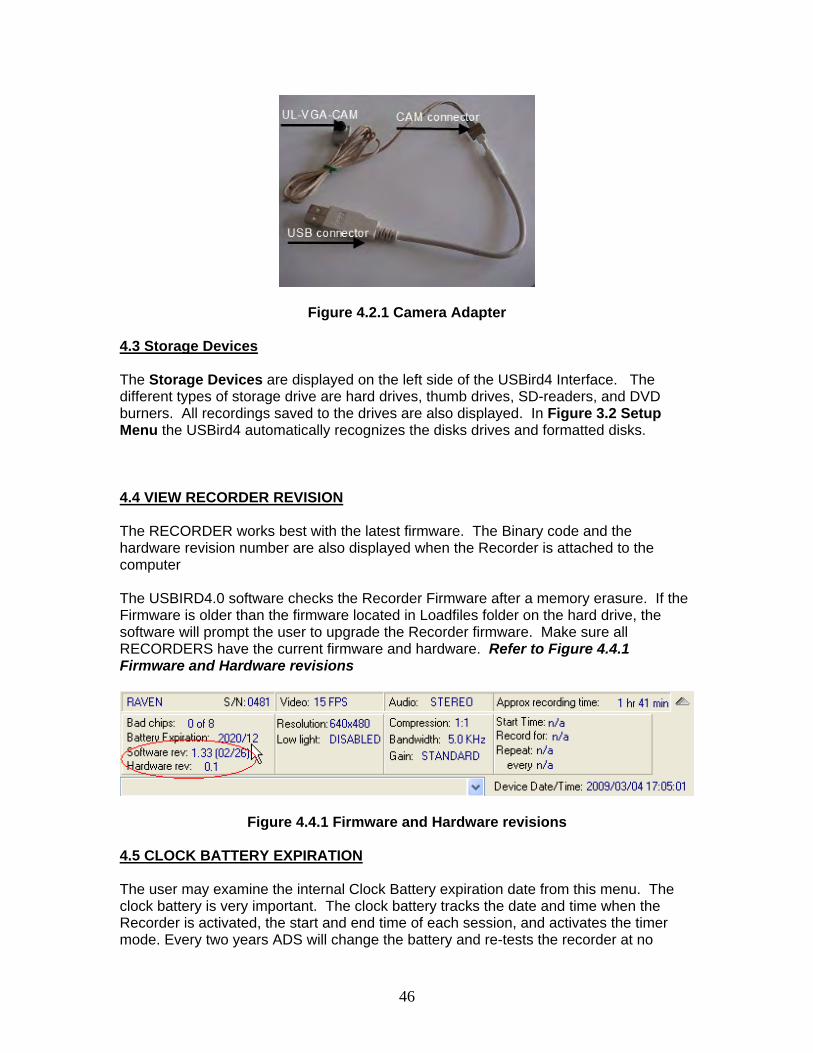
Figure 4.1.1 Monitor Recorder Camera 4.2 Camera Adapter
The Ultra Low Light VGA cameras will need a camera adapter that connects the camera directly to a USB port in a PC. Refer to Figure 4.2.1 Camera Adapter Once the PC has loaded the camera driver, go to My Computer and choose the USB Camera. If the PC has a webcam, go to the webcam software and change the camera to AZURE. The video displays on the screen.
46
Figure 4.2.1 Camera Adapter 4.3 Storage Devices The Storage Devices are displayed on the left side of the USBird4 Interface. The different types of storage drive are hard drives, thumb drives, SD-readers, and DVD burners. All recordings saved to the drives are also displayed. In Figure 3.2 Setup Menu the USBird4 automatically recognizes the disks drives and formatted disks.
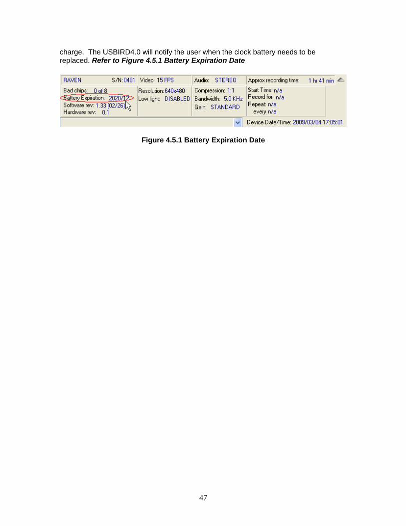
4.4 VIEW RECORDER REVISION The RECORDER works best with the latest firmware. The Binary code and the hardware revision number are also displayed when the Recorder is attached to the computer The USBIRD4.0 software checks the Recorder Firmware after a memory erasure. If the Firmware is older than the firmware located in Loadfiles folder on the hard drive, the software will prompt the user to upgrade the Recorder firmware. Make sure all RECORDERS have the current firmware and hardware. Refer to Figure 4.4.1 Firmware and Hardware revisions
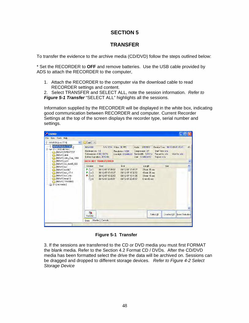
Figure 4.4.1 Firmware and Hardware revisions 4.5 CLOCK BATTERY EXPIRATION The user may examine the internal Clock Battery expiration date from this menu. The clock battery is very important. The clock battery tracks the date and time when the Recorder is activated, the start and end time of each session, and activates the timer mode. Every two years ADS will change the battery and re-tests the recorder at no
47
charge. The USBIRD4.0 will notify the user when the clock battery needs to be replaced. Refer to Figure 4.5.1 Battery Expiration Date
Figure 4.5.1 Battery Expiration Date
48
SECTION 5
TRANSFER
To transfer the evidence to the archive media (CD/DVD) follow the steps outlined below: * Set the RECORDER to OFF and remove batteries. Use the USB cable provided by ADS to attach the RECORDER to the computer,
1. Attach the RECORDER to the computer via the download cable to read RECORDER settings and content.
2. Select TRANSFER and SELECT ALL, note the session information. Refer to Figure 5-1 Transfer “SELECT ALL” highlights all the sessions. Information supplied by the RECORDER will be displayed in the white box, indicating good communication between RECORDER and computer. Current Recorder Settings at the top of the screen displays the recorder type, serial number and settings.
Figure 5-1 Transfer
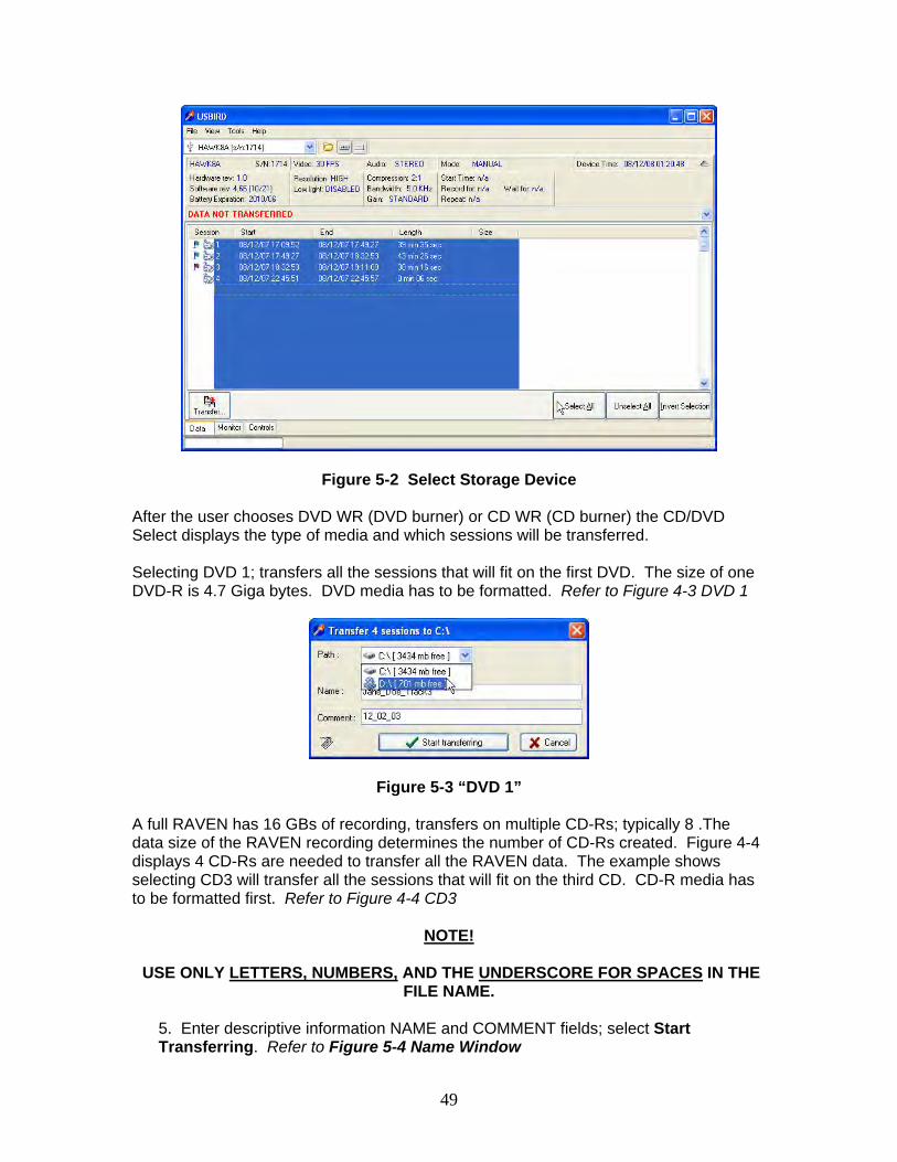
3. If the sessions are transferred to the CD or DVD media you must first FORMAT the blank media. Refer to the Section 4.2 Format CD / DVDs. After the CD/DVD media has been formatted select the drive the data will be archived on. Sessions can be dragged and dropped to different storage devices. Refer to Figure 4-2 Select Storage Device
49
Figure 5-2 Select Storage Device
After the user chooses DVD WR (DVD burner) or CD WR (CD burner) the CD/DVD Select displays the type of media and which sessions will be transferred. Selecting DVD 1; transfers all the sessions that will fit on the first DVD. The size of one DVD-R is 4.7 Giga bytes. DVD media has to be formatted. Refer to Figure 4-3 DVD 1
Figure 5-3 “DVD 1”
A full RAVEN has 16 GBs of recording, transfers on multiple CD-Rs; typically 8 .The data size of the RAVEN recording determines the number of CD-Rs created. Figure 4-4 displays 4 CD-Rs are needed to transfer all the RAVEN data. The example shows selecting CD3 will transfer all the sessions that will fit on the third CD. CD-R media has to be formatted first. Refer to Figure 4-4 CD3
NOTE!
USE ONLY LETTERS, NUMBERS, AND THE UNDERSCORE FOR SPACES IN THE FILE NAME.
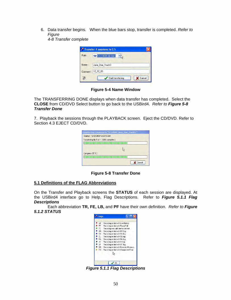
5. Enter descriptive information NAME and COMMENT fields; select Start Transferring. Refer to Figure 5-4 Name Window
50
6. Data transfer begins. When the blue bars stop, transfer is completed. Refer to Figure
4-8 Transfer complete
Figure 5-4 Name Window
The TRANSFERRING DONE displays when data transfer has completed. Select the CLOSE from CD/DVD Select button to go back to the USBird4. Refer to Figure 5-8 Transfer Done 7. Playback the sessions through the PLAYBACK screen. Eject the CD/DVD. Refer to Section 4.3 EJECT CD/DVD.
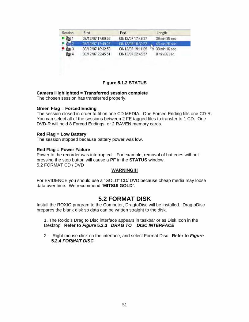
Figure 5-8 Transfer Done 5.1 Definitions of the FLAG Abbreviations On the Transfer and Playback screens the STATUS of each session are displayed. At the USBird4 interface go to Help, Flag Descriptions. Refer to Figure 5.1.1 Flag Descriptions
Each abbreviation TR, FE, LB, and PF have their own definition. Refer to Figure 5.1.2 STATUS
Figure 5.1.1 Flag Descriptions
51
Figure 5.1.2 STATUS Camera Highlighted = Transferred session complete The chosen session has transferred properly. Green Flag = Forced Ending The session closed in order to fit on one CD MEDIA. One Forced Ending fills one CD-R. You can select all of the sessions between 2 FE tagged files to transfer to 1 CD. One DVD-R will hold 8 Forced Endings, or 2 RAVEN memory cards. Red Flag = Low Battery The session stopped because battery power was low. Red Flag = Power Failure Power to the recorder was interrupted. For example, removal of batteries without pressing the stop button will cause a PF in the STATUS window. 5.2 FORMAT CD / DVD
WARNING!!! For EVIDENCE you should use a “GOLD” CD/ DVD because cheap media may loose data over time. We recommend “MITSUI GOLD”.
5.2 FORMAT DISK
Install the ROXIO program to the Computer, DragtoDisc will be installed. DragtoDisc prepares the blank disk so data can be written straight to the disk.
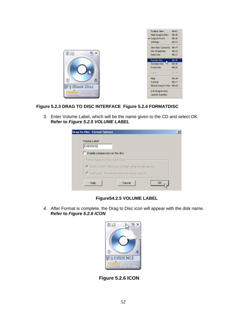
1. The Roxio’s Drag to Disc interface appears in taskbar or as Disk Icon in the Desktop. Refer to Figure 5.2.3 DRAG TO DISC INTERFACE 2. Right mouse click on the interface, and select Format Disc. Refer to Figure
5.2.4 FORMAT DISC
52
Figure 5.2.3 DRAG TO DISC INTERFACE Figure 5.2.4 FORMATDISC
3. Enter Volume Label, which will be the name given to the CD and select OK. Refer to Figure 5.2.5 VOLUME LABEL
Figure54.2.5 VOLUME LABEL 4. After Format is complete, the Drag to Disc icon will appear with the disk name.
Refer to Figure 5.2.6 ICON
Figure 5.2.6 ICON
53
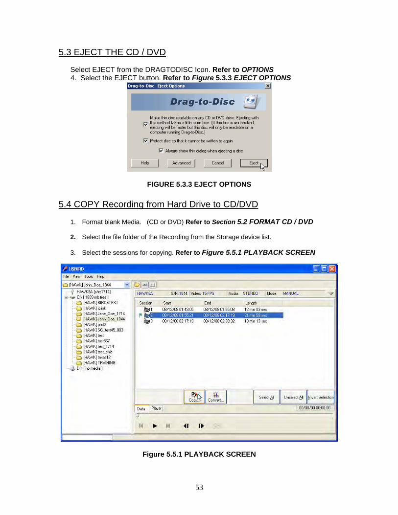
5.3 EJECT THE CD / DVD
Select EJECT from the DRAGTODISC Icon. Refer to OPTIONS 4. Select the EJECT button. Refer to Figure 5.3.3 EJECT OPTIONS
FIGURE 5.3.3 EJECT OPTIONS
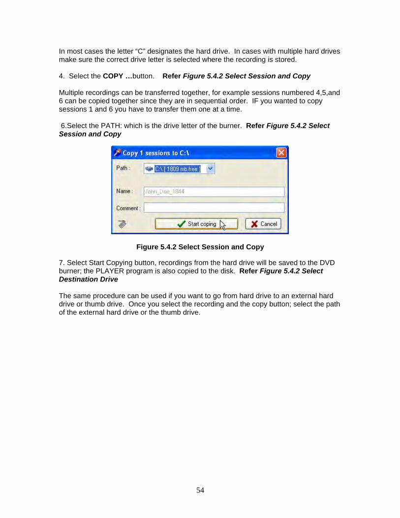
5.4 COPY Recording from Hard Drive to CD/DVD
1. Format blank Media. (CD or DVD) Refer to Section 5.2 FORMAT CD / DVD 2. Select the file folder of the Recording from the Storage device list.
3. Select the sessions for copying. Refer to Figure 5.5.1 PLAYBACK SCREEN
Figure 5.5.1 PLAYBACK SCREEN
54
In most cases the letter “C” designates the hard drive. In cases with multiple hard drives make sure the correct drive letter is selected where the recording is stored. 4. Select the COPY …button. Refer Figure 5.4.2 Select Session and Copy Multiple recordings can be transferred together, for example sessions numbered 4,5,and 6 can be copied together since they are in sequential order. IF you wanted to copy sessions 1 and 6 you have to transfer them one at a time. 6.Select the PATH: which is the drive letter of the burner. Refer Figure 5.4.2 Select Session and Copy
Figure 5.4.2 Select Session and Copy
7. Select Start Copying button, recordings from the hard drive will be saved to the DVD burner; the PLAYER program is also copied to the disk. Refer Figure 5.4.2 Select Destination Drive The same procedure can be used if you want to go from hard drive to an external hard drive or thumb drive. Once you select the recording and the copy button; select the path of the external hard drive or the thumb drive.
55
SECTION 6
PLAYBACK
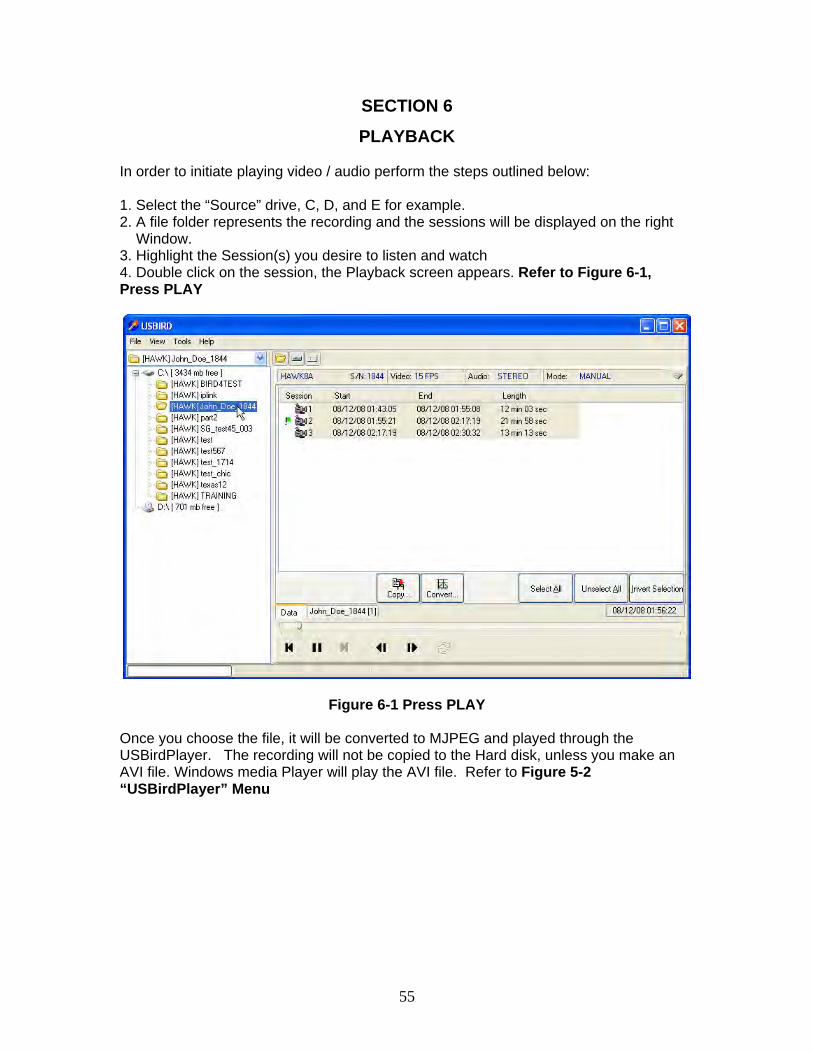
In order to initiate playing video / audio perform the steps outlined below: 1. Select the “Source” drive, C, D, and E for example. 2. A file folder represents the recording and the sessions will be displayed on the right Window. 3. Highlight the Session(s) you desire to listen and watch 4. Double click on the session, the Playback screen appears. Refer to Figure 6-1, Press PLAY
Figure 6-1 Press PLAY
Once you choose the file, it will be converted to MJPEG and played through the USBirdPlayer. The recording will not be copied to the Hard disk, unless you make an AVI file. Windows media Player will play the AVI file. Refer to Figure 5-2 “USBirdPlayer” Menu
56
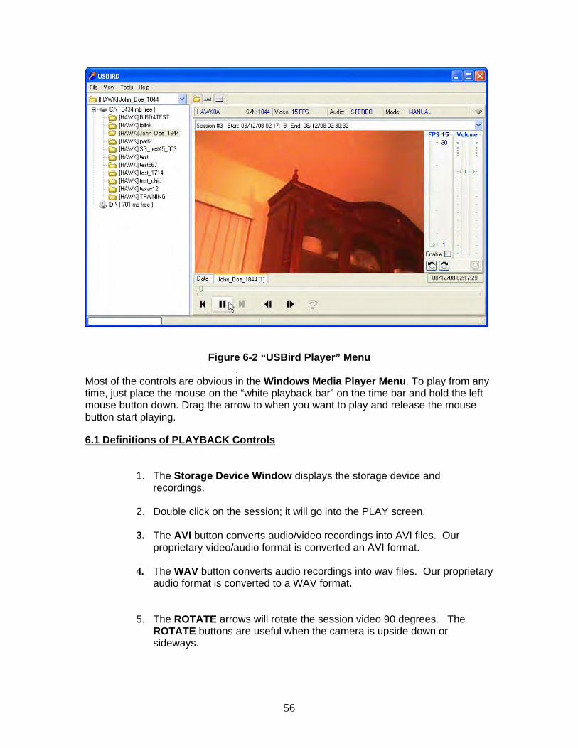
Figure 6-2 “USBird Player” Menu
. Most of the controls are obvious in the Windows Media Player Menu. To play from any time, just place the mouse on the “white playback bar” on the time bar and hold the left mouse button down. Drag the arrow to when you want to play and release the mouse button start playing. 6.1 Definitions of PLAYBACK Controls
1. The Storage Device Window displays the storage device and
recordings. 2. Double click on the session; it will go into the PLAY screen.
3. The AVI button converts audio/video recordings into AVI files. Our
proprietary video/audio format is converted an AVI format.
4. The WAV button converts audio recordings into wav files. Our proprietary audio format is converted to a WAV format.
5. The ROTATE arrows will rotate the session video 90 degrees. The ROTATE buttons are useful when the camera is upside down or sideways.
57
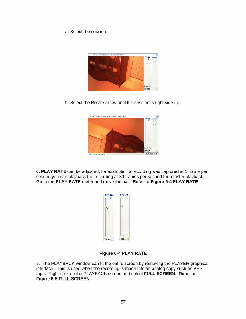
a. Select the session.
b. Select the Rotate arrow until the session is right side up.
6. PLAY RATE can be adjusted, for example if a recording was captured at 1 frame per second you can playback the recording at 30 frames per second for a faster playback. Go to the PLAY RATE meter and move the bar. Refer to Figure 6-4 PLAY RATE
Figure 6-4 PLAY RATE
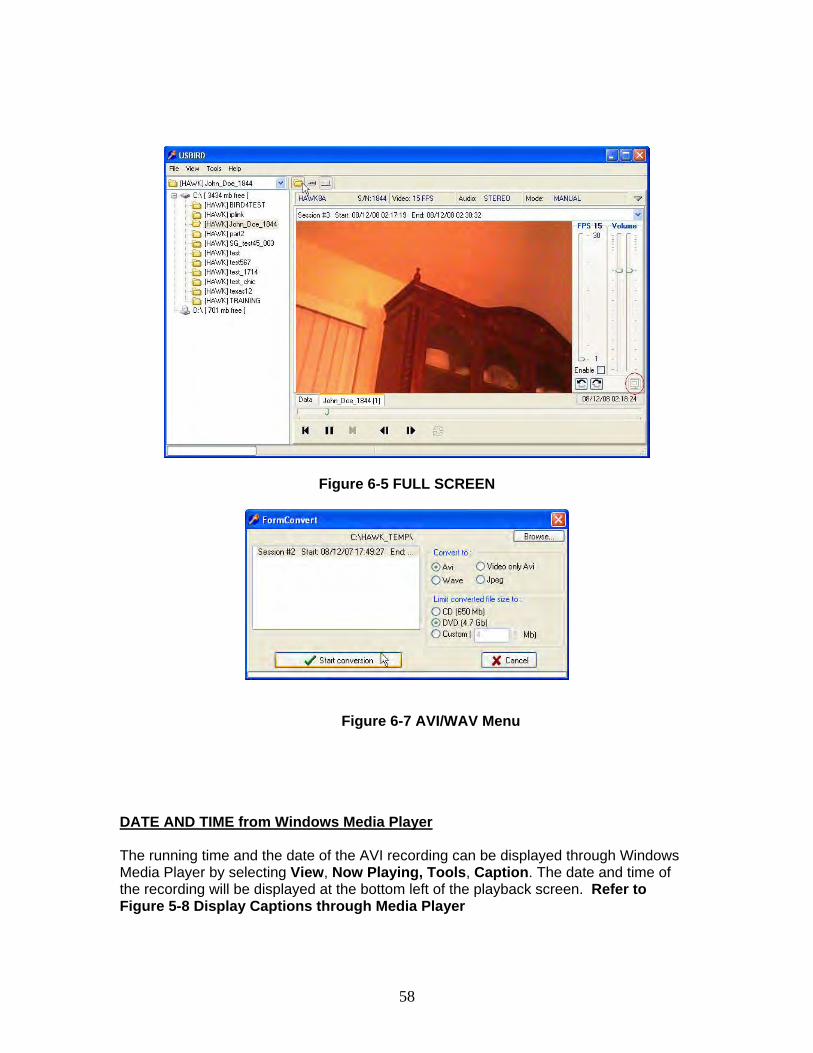
7. The PLAYBACK window can fit the entire screen by removing the PLAYER graphical interface. This is used when the recording is made into an analog copy such as VHS tape. Right click on the PLAYBACK screen and select FULL SCREEN. Refer to Figure 6-5 FULL SCREEN
58
Figure 6-5 FULL SCREEN
Figure 6-7 AVI/WAV Menu
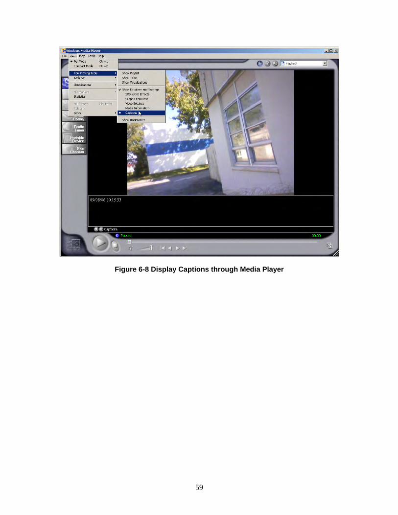
DATE AND TIME from Windows Media Player The running time and the date of the AVI recording can be displayed through Windows Media Player by selecting View, Now Playing, Tools, Caption. The date and time of the recording will be displayed at the bottom left of the playback screen. Refer to Figure 5-8 Display Captions through Media Player
59
Figure 6-8 Display Captions through Media Player
60
SECTION 7
PLAYER Program
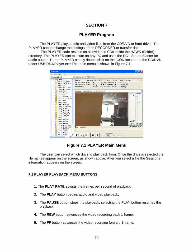
The PLAYER plays audio and video files from the CD/DVD or hard drive. The PLAYER cannot change the settings of the RECORDER or transfer data.
The PLAYER code resides on all evidence CDs inside the HAWK (Folder) directory. The PLAYER can execute on any PC and uses the PC’s Sound Blaster for audio output. To run PLAYER simply double click on the ICON located on the CD/DVD under USBIRD4/Player.exe The main menu is shown in Figure 7.1.
Figure 7.1 PLAYER Main Menu
The user can select which drive to play back from. Once the drive is selected the file names appear on the screen, as shown above. After you select a file the Sessions information appears on the screen. 7.1 PLAYER PLAYBACK MENU BUTTONS
1. The PLAY RATE adjusts the frames per second of playback.
2. The PLAY button begins audio and video playback.
3. The PAUSE button stops the playback, selecting the PLAY button resumes the
playback.
4. The REW button advances the video recording back 1 frame.
5. The FF button advances the video recording forward 1 frame.
61
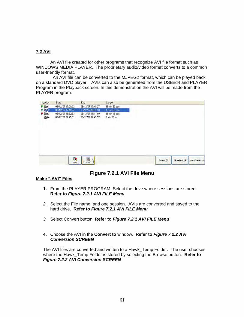
7.2 AVI
An AVI file created for other programs that recognize AVI file format such as WINDOWS MEDIA PLAYER. The proprietary audio/video format converts to a common user-friendly format.
An AVI file can be converted to the MJPEG2 format, which can be played back on a standard DVD player. AVIs can also be generated from the USBird4 and PLAYER Program in the Playback screen. In this demonstration the AVI will be made from the PLAYER program.
Figure 7.2.1 AVI File Menu Make “.AVI” Files
1. From the PLAYER PROGRAM, Select the drive where sessions are stored. Refer to Figure 7.2.1 AVI FILE Menu
2. Select the File name, and one session. AVIs are converted and saved to the
hard drive. Refer to Figure 7.2.1 AVI FILE Menu
3. Select Convert button. Refer to Figure 7.2.1 AVI FILE Menu
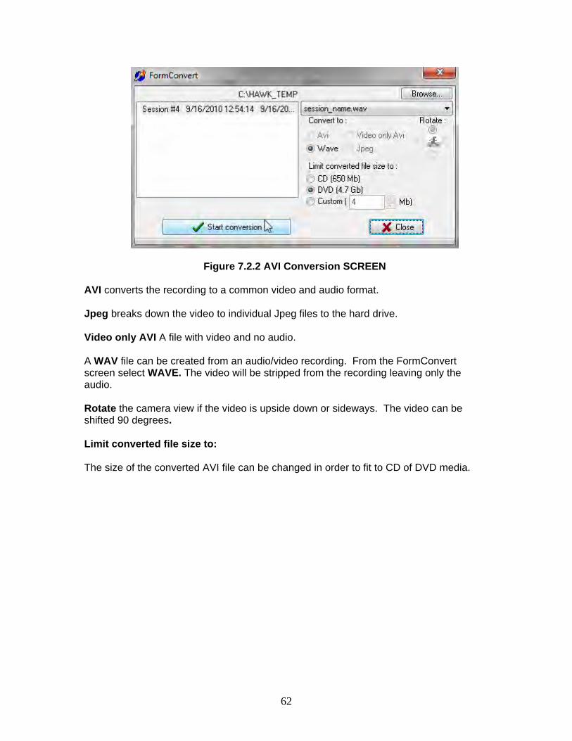
4. Choose the AVI in the Convert to window. Refer to Figure 7.2.2 AVI
Conversion SCREEN
The AVI files are converted and written to a Hawk_Temp Folder. The user chooses where the Hawk_Temp Folder is stored by selecting the Browse button. Refer to Figure 7.2.2 AVI Conversion SCREEN
62
Figure 7.2.2 AVI Conversion SCREEN
AVI converts the recording to a common video and audio format. Jpeg breaks down the video to individual Jpeg files to the hard drive.
Video only AVI A file with video and no audio.
A WAV file can be created from an audio/video recording. From the FormConvert screen select WAVE. The video will be stripped from the recording leaving only the audio. Rotate the camera view if the video is upside down or sideways. The video can be shifted 90 degrees. Limit converted file size to: The size of the converted AVI file can be changed in order to fit to CD of DVD media.
63
APPENDIX - A
USBird SOFTWARE INSTALLATION
To install/update the resident code from CD:
1. Remove existing software from the CONTROL PANEL/ ADD REMOVE PROGRAMS
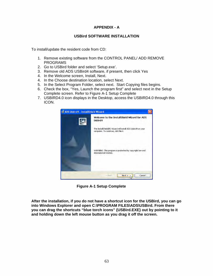
2. Go to USBird folder and select ‘Setup.exe’. 3. Remove old ADS USBird4 software, if present, then click Yes 4. In the Welcome screen, Install, Next. 4. In the Choose destination location, select Next. 5. In the Select Program Folder, select next. Start Copying files begins. 6. Check the box, “Yes, Launch the program first” and select next in the Setup
Complete screen. Refer to Figure A-1 Setup Complete 7. USBIRD4.0 icon displays in the Desktop, access the USBIRD4.0 through this
ICON.
Figure A-1 Setup Complete
After the installation, if you do not have a shortcut icon for the USBird, you can go into Windows Explorer and open C:\PROGRAM FILES\ADS\USBird. From there you can drag the shortcuts “blue torch icons” {USBird.EXE} out by pointing to it and holding down the left mouse button as you drag it off the screen.
64
APPENDIX - B
UPDATE BINARY CODE
How to update Recorder Binary Code
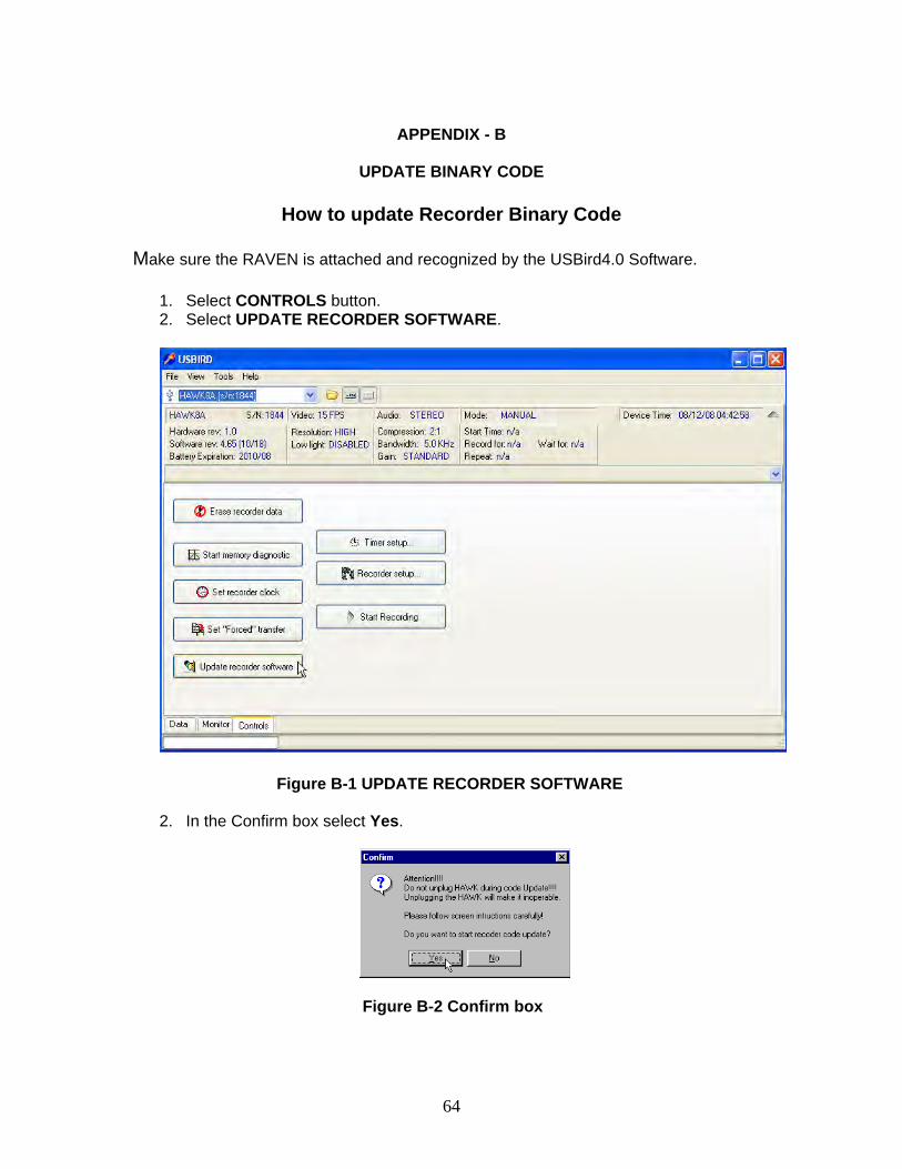
Make sure the RAVEN is attached and recognized by the USBird4.0 Software.
1. Select CONTROLS button. 2. Select UPDATE RECORDER SOFTWARE.
Figure B-1 UPDATE RECORDER SOFTWARE 2. In the Confirm box select Yes.
Figure B-2 Confirm box
65
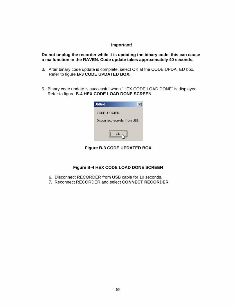
Important!
Do not unplug the recorder while it is updating the binary code, this can cause a malfunction in the RAVEN. Code update takes approximately 40 seconds. 3. After binary code update is complete, select OK at the CODE UPDATED box. Refer to figure B-3 CODE UPDATED BOX.
5. Binary code update is successful when “HEX CODE LOAD DONE” is displayed. Refer to figure B-4 HEX CODE LOAD DONE SCREEN
Figure B-3 CODE UPDATED BOX
Figure B-4 HEX CODE LOAD DONE SCREEN
6. Disconnect RECORDER from USB cable for 10 seconds.
7. Reconnect RECORDER and select CONNECT RECORDER
66
APPENDIX - C
ADS SOFTWARE CONFIGURATIONS
This message was written to clear up some confusion that may exists on the various software and hardware releases that are out in the field.
“USBird4.X” (4.X) is used on all new recorders that have a built in USB port and attached WRIS transceiver. In fact, everything to be released from now on will use this software. The recorders already using the USBird4.0 software are: HAWK/4 /8 /8A /A2 /A4 FALCON/2/4 RAVEN SD-RAVEN MICRO-RAVEN RAVEN-EYE RAVEN-16 RAVEN-64 RAVEN-RX RAVEN-MONITOR RAVEN-RX-REPEATER FINCH EAGLE8/A /A2 /A3 / B / B2 /C /C1 /D /E MICRO-EAGLE MICRO-FINCH MONO8/ A MICROFLEX FLEX8C /C2 /D /E /F WRIS DCMS


