Embed Size (px)
Citation preview

1
Version 3.0
2
Table of contents
1. Safety instructions ......................................................................................................... 32. Operating determination ................................................................................................ 43. Fixture exterior view ...................................................................................................... 64. Installation....................................................................................................................... 7
4.1 Connection to the mains ............................................................................................ 74.2 Eggcrate installation ................................................................................................... 74.3 Diffuser installation ..................................................................................................... 84.4 Rigging the fixture ...................................................................................................... 94.5 DMX-512 connection ................................................................................................ 114.6 Ethernet connection ................................................................................................. 124.7 Wireless DMX operation .......................................................................................... 14
5. Remotely controllable functions ................................................................................. 156. Control menu map ........................................................................................................ 177. Control menu ............................................................................................................... 20
7.1 Tab " Address" .......................................................................................................... 217.2 Tab "Information" ...................................................................................................... 227.3 Tab "Personality" ...................................................................................................... 237.4 Tab "Manual Control" ................................................................................................ 257.5 Tab "Stand-alone" .................................................................................................... 257.6 Tab "Service" ............................................................................................................ 26
8. RDM ............................................................................................................................... 299. Error and information messages ................................................................................ 3110. Technical Specifications ............................................................................................ 3211. Maintenance and cleaning ......................................................................................... 33
11.1 Removing the optical module ................................................................................. 3511.2 Disposing of the product ......................................................................................... 37
12. ChangeLog ................................................................................................................. 3713. Photometric diagrams................................................................................................ 3814. Appendix - DMX modes overview ............................................................................. 40
Robin Spiider
3
CAUTION!Keep this device away from rain and moisture!Unplug mains lead before opening the housing!
FOR YOUR OWN SAFETY, PLEASE READ THIS USER MANUAL CAREFULLY BEFORE YOU INITIAL START - UP!
1. Safety instructionsEvery person involved with installation and maintenance of this device have to:- be qualified- follow the instructions of this manual
CAUTION! Be careful with your operations.
With a high voltage you can suffera dangerous electric shock when touching the wires!
This device has left our premises in absolutely perfect condition. In order to maintain this condition and to en-sure a safe operation, it is absolutely necessary for the user to follow the safety instructions and warning notes written in this manual.
ImportantThe manufacturer will not accept liability for any resulting damages caused by the non-observance of this manual or any unauthorized modification to the device.
Please consider that damages caused by manual modifications to the device are not subject to warranty.
Handle the power cord and all connections with the mains with particular caution!
Make sure that the available voltage is not higher than stated on the rear panel.
WARNING! This unit does not contain an ON/OFF switch. Always disconnect power input cable to completely remove power from unit when not in use or before cleaning or servicing the unit.
Make sure that the power-cord is never crimped or damaged by sharp edges. Check the device and the pow-er-cord from time to time.
Always disconnect from the mains, when the device is not in use or before cleaning it. Only handle the pow-er-cord by the plug. Never pull out the plug by tugging the power cord.
This device falls under protection class I. Therefore it is essential to connect the yellow/green conductor to earth.
The electric connection, repairs and servicing must be carried out by a qualified employee.
Do not connect this device to a dimmer pack.
During the initial start-up some smoke or smell may arise. This is a normal process and does not necessarily mean that the device is defective.
Do not touch the device’s housing bare hands during its operation (housing becomes hot)!For replacement use fuses of same type and rating only.
LED light emission. Risk of eye injury. Do not look into the beam at short distance of the of the product. Do not view the light output with optical instruments or any device
that may conncentrate the beam. The light source contains blue LEDs.
4
2. Operating determination
This device is a moving head for creating decorative effects and was designed for indoor use only.
This device is for professional use only. It is not for household use.
If the device has been exposed to drastic temperature fluctuation (e.g. after transportation), do not switch it on immediately. The arising condensation water might damage your device. Leave the device switched off until it has reached room temperature.
Do not shake the device. Avoid brute force when installing or operating the device.
Never lift the fixture by holding it at the projector head, as the mechanics may be damaged. Always hold the fixture at the transport handles.
When choosing the installation spot, please make sure that the device is not exposed to extreme heat, moisture or dust. There should not be any cables lying around. You endanger your own and the safety of others!
Make sure that the area below the installation place is blocked when rigging, derigging or servicing the fixture.
Always secure the fixture with an appropriate safety wire.
Only operate the fixture after having checked that the housing is firmly closed and all screws are tightly fastened.
The maximum ambient temperature 45°C must never be exceeded.
To avoid damage of an internal optical system of the fixture, never let the sunlight (or other light source) lights directly to the lens array, even when the fixture is not working
Operate the device only after having familiarized with its functions. Do not permit operation by persons not qualified for operating the device. Most damages are the result of unprofessional operation!
Please use the original packaging if the device is to be transported.
Please consider that unauthorized modifications on the device are forbidden due to safety reasons!
If this device will be operated in any way different to the one described in this manual, the product may suffer damages and the guarantee becomes void. Furthermore, any other operation may lead to dangers like short-cir-cuit, burns, electric shock, burns etc.
Potential foggy front lens array does not influence function of the fixture and does not subject to complaint.
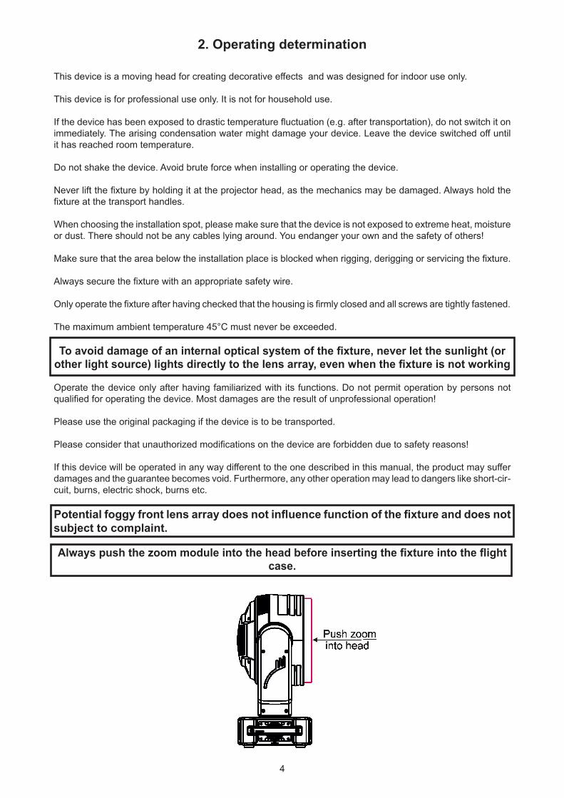
Always push the zoom module into the head before inserting the fixture into the flight case.

5
Immunity of the equipment is designed for electromagnetic environments E1, E2, E3 according to the stand-ard EN55103-2 ed.2 Electromagnetic compatibility. Product family standard for audio, video, audiovisual and entertainment lighting control apparatus for professional use. Part 2: Immunity.
The installation company should check levels of possible interferences above the tested levels E1,E2,E3 given by this standard (e.g. transmitters in surrounding area) before installing the equipment. Emission of the equipment complies with the standard EN55032 Electromagnetic compatibility of multimedia equipment – Emission Requirements according to class B.
6
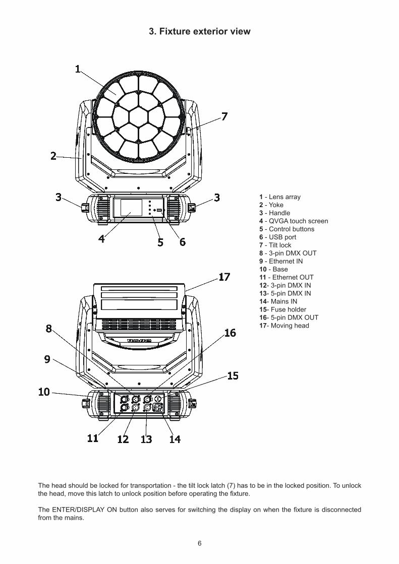
3. Fixture exterior view
The head should be locked for transportation - the tilt lock latch (7) has to be in the locked position. To unlock the head, move this latch to unlock position before operating the fixture.
The ENTER/DISPLAY ON button also serves for switching the display on when the fixture is disconnected from the mains.
1 - Lens array2 - Yoke 3 - Handle4 - QVGA touch screen5 - Control buttons 6 - USB port7 - Tilt lock8 - 3-pin DMX OUT9 - Ethernet IN10 - Base11 - Ethernet OUT12- 3-pin DMX IN13- 5-pin DMX IN 14- Mains IN15- Fuse holder16- 5-pin DMX OUT17- Moving head
7
4. Installation
Fixtures must be installed by a qualified electrician in accordance with all national and local electrical and construction codes and regulations.
4.1 Connection to the mainsFor protection from electric shock, the fixture must be earthed!
The Robin Spiider is equipped with auto-switching power supply that automatically adjusts to any 50-60Hz AC power source from 100-240 Volts.
If you install a cord cap on the power cable to allow connection to power outlets, install a grounding-type (earthed) plug, following the plug manufacturer’s instructions.The cores in the power cable are coloured according to the following table.
Core (EU) Core (US) Connection Plug Terminal Marking
Brown Black Live L
Light blue White Neutral N
Yellow/Green Green Earth
This device falls under class one and must be earthed (grounded)!To apply power, first check that the head pan and tilt locks are released.Wiring and connection work must be carried out by qualified staff!
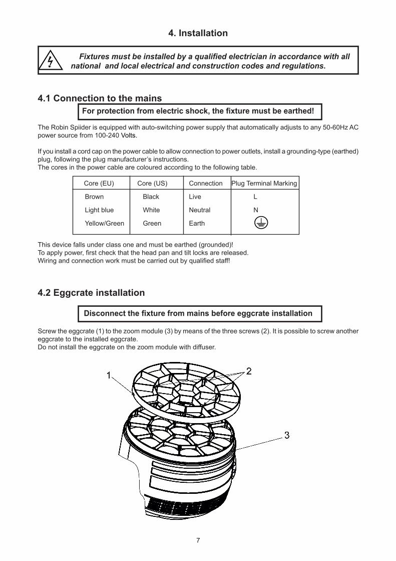
4.2 Eggcrate installation
Disconnect the fixture from mains before eggcrate installation
Screw the eggcrate (1) to the zoom module (3) by means of the three screws (2). It is possible to screw another eggcrate to the installed eggcrate.Do not install the eggcrate on the zoom module with diffuser.
8
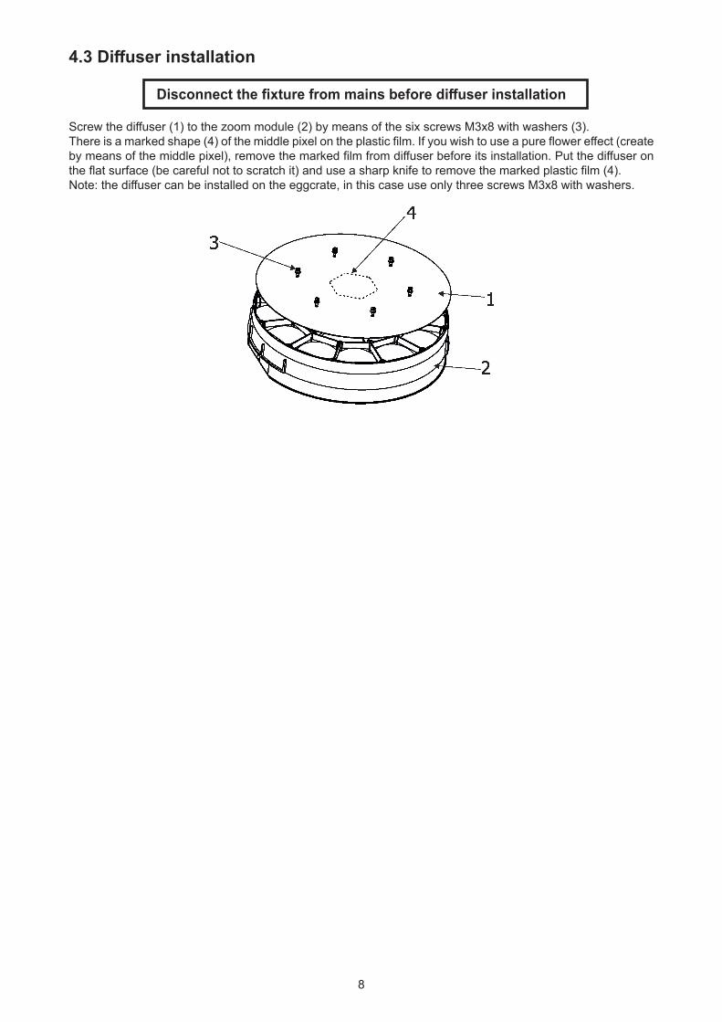
4.3 Diffuser installation
Disconnect the fixture from mains before diffuser installation
Screw the diffuser (1) to the zoom module (2) by means of the six screws M3x8 with washers (3).There is a marked shape (4) of the middle pixel on the plastic film. If you wish to use a pure flower effect (create by means of the middle pixel), remove the marked film from diffuser before its installation. Put the diffuser on the flat surface (be careful not to scratch it) and use a sharp knife to remove the marked plastic film (4). Note: the diffuser can be installed on the eggcrate, in this case use only three screws M3x8 with washers.
9
4.4 Rigging the fixture
A structure intended for installation of the fixture (s) must safely hold weight of the fixture(s) placed on it. The structure has to be certificated to the purpose.
The fixture (fixtures) must be installed in accordance with national and local electrical and construction codes and regulations.
For overhead installation, the fixture must be always secured with a safety wire that can bear at least 10 times the weight of the fixture.
When rigging, derigging or servicing the fixture staying in the area below the installation place, on bridges, under high working places and other endangered areas is forbidden.
The operator has to make sure that safety-relating and machine-technical installations are approved by an expert before taking into operation for the first time and after changes before taking into operation another time.
The operator has to make sure that safety-relating and machine-technical installations are approved by a skilled person once a year.
Allow the fixture to cool for ten minutes before handling.
The fixture should be installed outside areas where persons may walk by or be seated.
IMPORTANT! OVERHEAD RIGGING REQUIRES EXTENSIVE EXPERIENCE, including calculating working load limits, installation material being used, and periodic safety inspection of all installation material and the projector. If you lack these qualifications, do not attempt the installation yourself, but use a help of professional companies.
CAUTION: Fixtures may cause severe injuries when crashing down! If you have doubts concerning the safety of a possible installation, do not install the fixture!
The fixture has to be installed out of the reach of public.
The fixture must never be fixed swinging freely in the room.
Danger of fire ! When installing the device, make sure there is no highly inflammable material (decoration articles, etc.) in a distance of min. 0.5 m.
CAUTION! Use 2 appropriate clamps to rig the fixture on the truss. Follow the instructions mentioned at the bottom of the base.
Make sure that the device is fixed properly! Ensure that the structure (truss) to which you are attaching the fixtures is secure.
The fixture can be placed directly on the stage floor or rigged in any orientation on a truss without altering its operation characte ristics .For securing the fixture to the truss, install a safety wire which can hold at least 10 times the weight of the fixture. Use only the safety wire with a snap hook with screw lock gate.
.
.
10
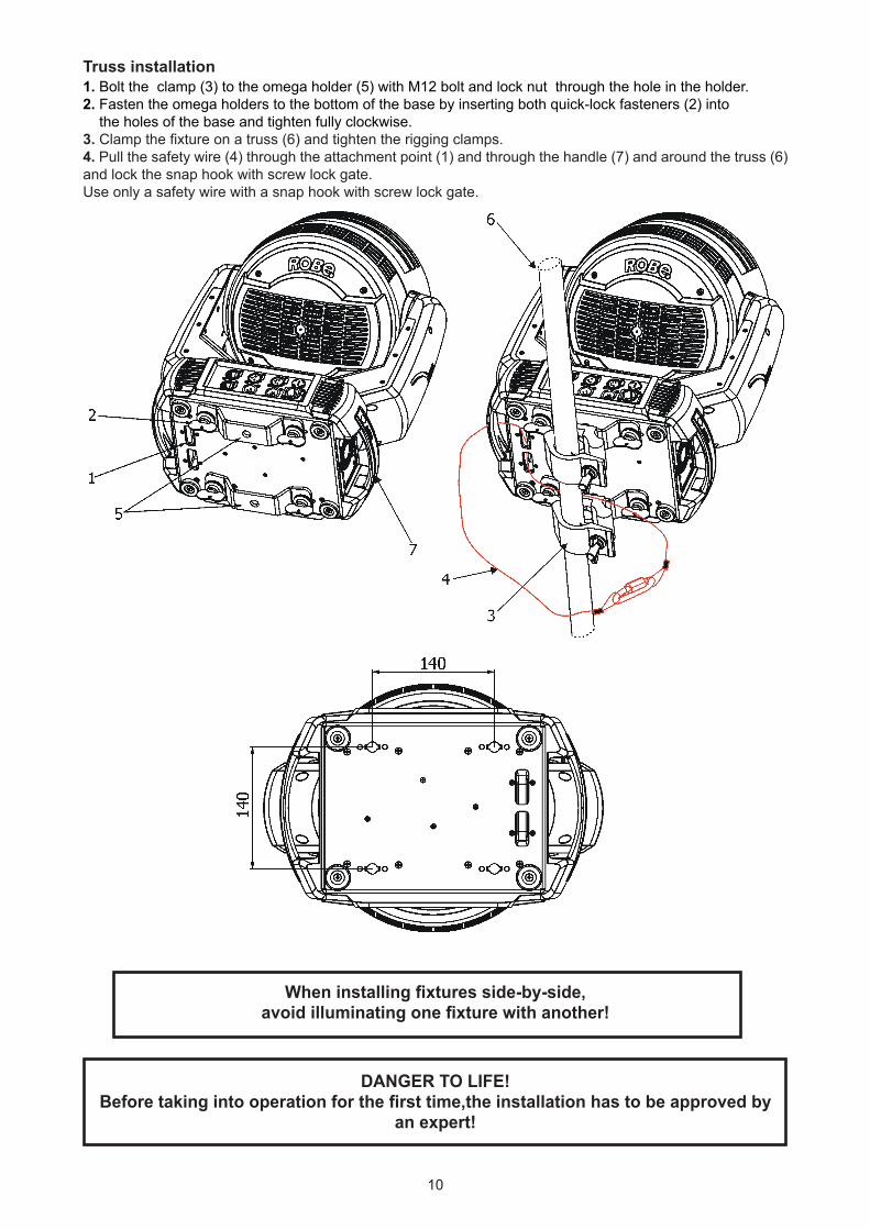
Truss installation1. Bolt the clamp (3) to the omega holder (5) with M12 bolt and lock nut through the hole in the holder.2. Fasten the omega holders to the bottom of the base by inserting both quick-lock fasteners (2) into the holes of the base and tighten fully clockwise.3. Clamp the fixture on a truss (6) and tighten the rigging clamps.4. Pull the safety wire (4) through the attachment point (1) and through the handle (7) and around the truss (6) and lock the snap hook with screw lock gate. Use only a safety wire with a snap hook with screw lock gate.
When installing fixtures side-by-side,avoid illuminating one fixture with another!
DANGER TO LIFE!Before taking into operation for the first time,the installation has to be approved by
an expert!
11
In order to protect the internal parts of the head from the sun, the function PARKING POSITION must be switched ON before switching the fixture off.
The PARKING POSITION function is located on the Power/Special functions channel (120-129 DMX). If the function is on, the fixture will automatically detect via G-sensor whether the fixture is on the floor or hangs on the truss or is mounted sideways on the truss and moves the pan and tilt to the position (including movement of zoom to the front part of the head) in which the head will always face down. Owing this position of the fixture head, there is not chance to burn internal parts of the head by the sun light.
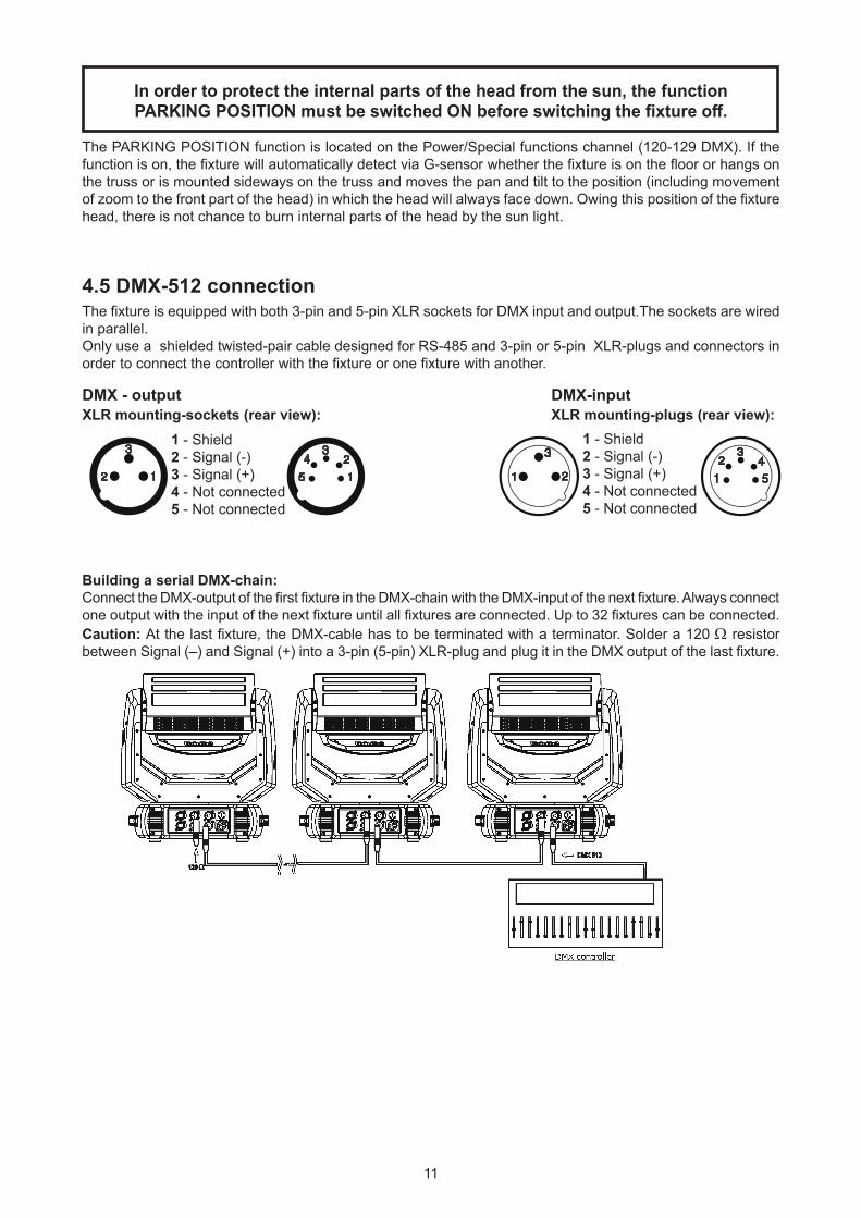
4.5 DMX-512 connectionThe fixture is equipped with both 3-pin and 5-pin XLR sockets for DMX input and output.The sockets are wired in parallel.Only use a shielded twisted-pair cable designed for RS-485 and 3-pin or 5-pin XLR-plugs and connectors in order to connect the controller with the fixture or one fixture with another.
DMX - output DMX-inputXLR mounting-sockets (rear view): XLR mounting-plugs (rear view):
Building a serial DMX-chain:Connect the DMX-output of the first fixture in the DMX-chain with the DMX-input of the next fixture. Always connect one output with the input of the next fixture until all fixtures are connected. Up to 32 fixtures can be connected.Caution: At the last fixture, the DMX-cable has to be terminated with a terminator. Solder a 120 Ω resistor between Signal (–) and Signal (+) into a 3-pin (5-pin) XLR-plug and plug it in the DMX output of the last fixture.
1 - Shield2 - Signal (-)3 - Signal (+)4 - Not connected5 - Not connected
1 - Shield2 - Signal (-)3 - Signal (+)4 - Not connected5 - Not connected
12
4.6 Ethernet connectionThe fixtures on a data link are connected to the Ethernet with ArtNet communication protocol.The control soft-ware running on your PC (or light console) has to support Art-Net protocol.Art-Net communication protocol is a 10 Base T Ethernet protocol based on the TCP/IP.Its purpose is to allow transfer of large amounts of DMX 512 data over a wide area using standard network technology.
IP address is the Internet protocol address.The IP uniquely identifies any node (fixture) on a network.The Universe is a single DMX 512 frame of 512 channels.
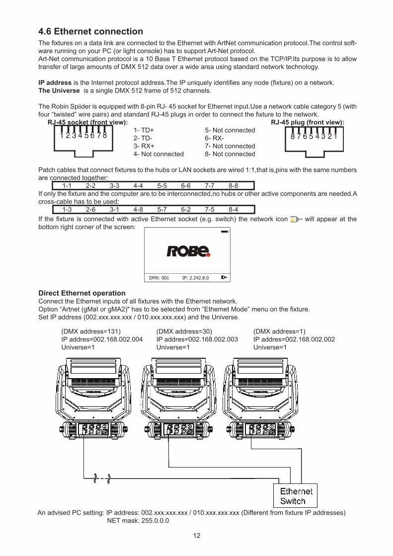
The Robin Spiider is equipped with 8-pin RJ- 45 socket for Ethernet input.Use a network cable category 5 (with four “twisted” wire pairs) and standard RJ-45 plugs in order to connect the fixture to the network. RJ-45 socket (front view): RJ-45 plug (front view): 1- TD+ 5- Not connected 2- TD- 6- RX- 3- RX+ 7- Not connected 4- Not connected 8- Not connected
Patch cables that connect fixtures to the hubs or LAN sockets are wired 1:1,that is,pins with the same numbers are connected together: 1-1 2-2 3-3 4-4 5-5 6-6 7-7 8-8 If only the fixture and the computer are to be interconnected,no hubs or other active components are needed.A cross-cable has to be used: 1-3 2-6 3-1 4-8 5-7 6-2 7-5 8-4If the fixture is connected with active Ethernet socket (e.g. switch) the network icon will appear at the bottom right corner of the screen:
Direct Ethernet operationConnect the Ethernet inputs of all fixtures with the Ethernet network.Option “Artnet (gMaI or gMA2)" has to be selected from “Ethernet Mode” menu on the fixture.Set IP address (002.xxx.xxx.xxx / 010.xxx.xxx.xxx) and the Universe.
(DMX address=131) (DMX address=30) (DMX address=1) IP addres=002.168.002.004 IP addres=002.168.002.003 IP addres=002.168.002.002 Universe=1 Universe=1 Universe=1
An advised PC setting: IP address: 002.xxx.xxx.xxx / 010.xxx.xxx.xxx (Different from fixture IP addresses) NET mask: 255.0.0.0
13
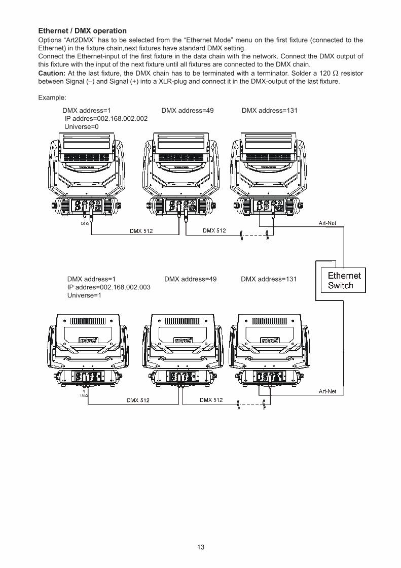
Ethernet / DMX operationOptions “Art2DMX” has to be selected from the “Ethernet Mode” menu on the first fixture (connected to the Ethernet) in the fixture chain,next fixtures have standard DMX setting.Connect the Ethernet-input of the first fixture in the data chain with the network. Connect the DMX output of this fixture with the input of the next fixture until all fixtures are connected to the DMX chain.Caution: At the last fixture, the DMX chain has to be terminated with a terminator. Solder a 120 Ω resistor between Signal (–) and Signal (+) into a XLR-plug and connect it in the DMX-output of the last fixture.
Example:
DMX address=1 DMX address=49 DMX address=131 IP addres=002.168.002.002 Universe=0
DMX address=1 DMX address=49 DMX address=131 IP addres=002.168.002.003 Universe=1
14
4.7 Wireless DMX operationThe wireless version of the Robin Spiider is equipped with the Lumen Radio CRMX module and antenna for receiving DMX signal. CRMX module operates on the 2.4 GHz band.
The item " Wireless " from the menu "DMX Input" allows you to activate receiving of wireless DMX (Person-ality--> DMX Input -->Wireless.). First two options from the "DMX Input" menu are stated in DMX chart as well (channel Power/Special functions , range of 10-19 DMX). If DMX input option is changed by DMX command, the change is permanently written into fixture´s memory.
DMX range of 10-19 switching fixture to the wired/wireless operation is active only during first 10 sec-onds after switching the fixture on.
After switching the fixture on, the fixture checks both modes of receiving DMX in the following order:
1. For the first five seconds, the fixture receives DMX signal from the wired input. If the Power/Special functions channel is set at some DMX input option, the fixture will receive DMX value according to this option. If DMX input option is set to the wired input , this option is saved and checking procedure is finished. If DMX input option is not set, the fixture continues next 5 seconds in scanning wireless DMX signal-see point 2.
2. For the next 5 seconds the fixture receives wireless DMX signal and again detects if the Power/Special functions channel is set at some DMX input option, if not, the fixture will take option which is set in the fixture menu "DMX Input".
To link the fixture with DMX transmitter.The fixture can be only linked with the transmitter by running the link procedure at DMX transmitter .After linking , the level of DMX signal ( 0-100 %) is displayed in the menu item “Wireless State“ (Information -->Wireless State).
To unlink the fixture from DMX transmitter.The fixture can be unlinked from receiver via the menu item “ Unlink Wireless Adapter“ (Information--> Wireless State --> Unlink Wireless Adapter).
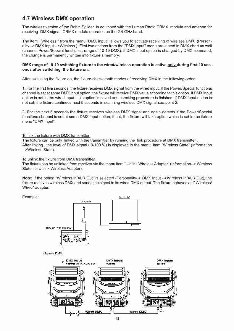
Note: If the option "Wireless In/XLR Out" is selected (Personality--> DMX Input -->Wireless In/XLR Out), the fixture receives wireless DMX and sends the signal to its wired DMX output. The fixture behaves as " Wireless/Wired" adapter.
Example:
15
5. Remotely controllable functionsVirtual colour wheel This wheel contains 66 preset colours, rainbow effect in both directions is available.
Colour temperarature correction (CTC) This channel allows to set calibrated white colour from range of 8000K-2700K.
RGBW or CMY colour mixing systemThe RGBW colour mixing system is based on red, green, blue and white high power LEDs. Option for switching the fixture to the CMY colour mixing system is available.
Colour Mix controlThe Colour Mix control channel defines relation between global colours (RGBW, CTO, Virtual colour wheel) and individual RGB pixels or Kling-Net. Global = Global Colours (RGBW, CTO, Virtual Color Wheel) Pixel = Pixel Colors (RGB individual pixels or Kling-Net)
DMX value Function 0-9 Global colours (Global has priority) 10-19 Maximum mode (highest values have priority) 20-29 Minimum mode (lowest values have priority) 30-39 Multiply mode (multiply Global and Pixel) 40-49 Addition mode (Global + Pixel) - default 50-59 Subtraction mode (Global – Pixel) 60-69 Inverted Subtraction mode (Pixel – Global) 70-79 Coloured background 80-127 Reserved 128 Global colours (Global has priority) 129-254 Crossfade (crossfade between Global and Pixel) 255 Pixel colours (Pixel has priority) E.g. If you wish to control RGBW channels, set the Colour Mix Control channel to 0 DMX, if you need to use pixel effects, set the Colour Mix Control channel to 255 DMX.
Flower Effect The flower effect rotating in both directions allows to create many dynamic effects.
Zoom Motorized zoom offers beam range of 4° to 50°.
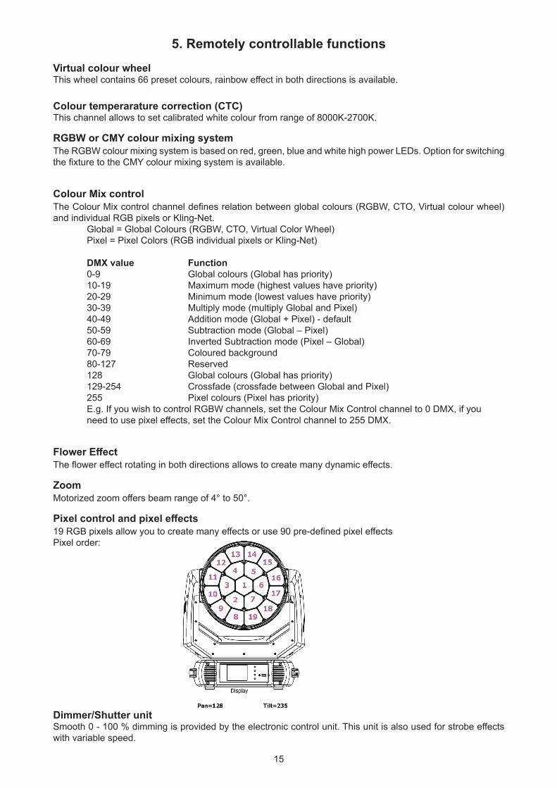
Pixel control and pixel effects 19 RGB pixels allow you to create many effects or use 90 pre-defined pixel effectsPixel order:
Dimmer/Shutter unitSmooth 0 - 100 % dimming is provided by the electronic control unit. This unit is also used for strobe effects with variable speed.
16
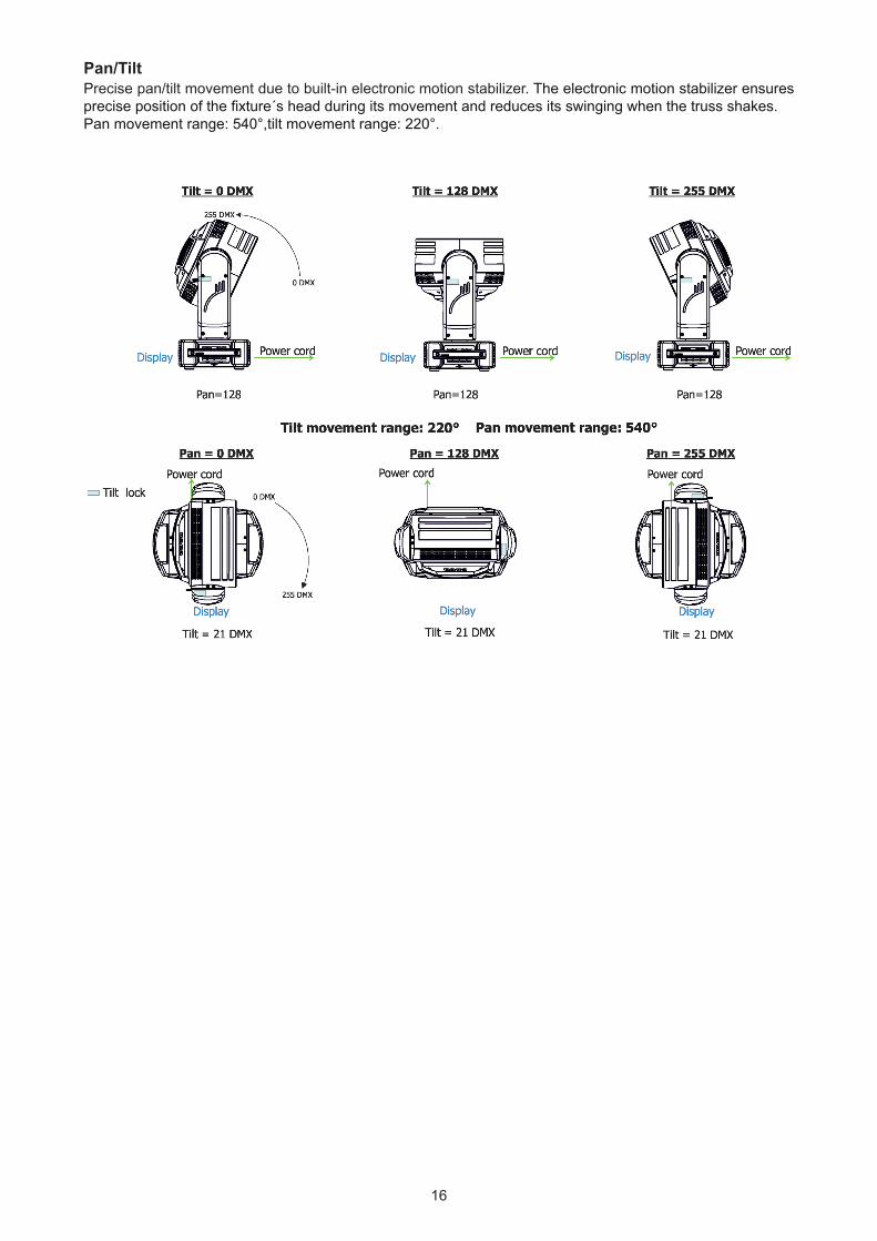
Pan/Tilt Precise pan/tilt movement due to built-in electronic motion stabilizer. The electronic motion stabilizer ensures precise position of the fixture´s head during its movement and reduces its swinging when the truss shakes.Pan movement range: 540°,tilt movement range: 220°.
17
6. Control menu map
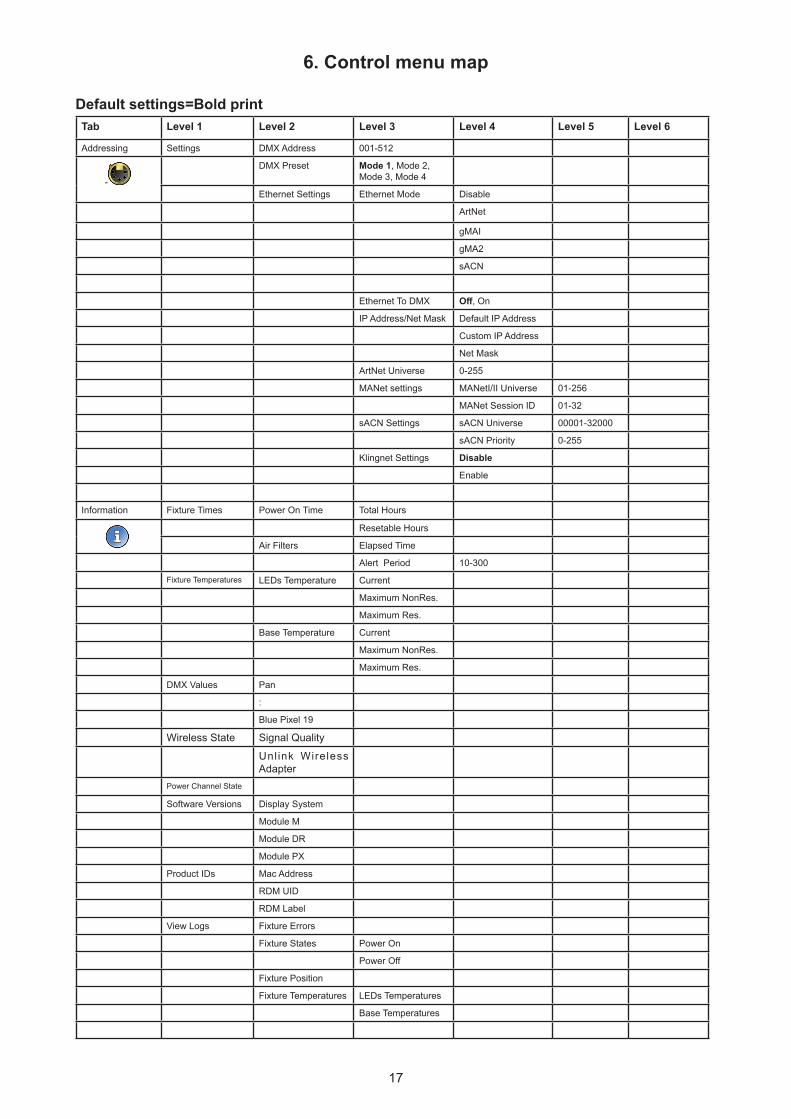
Default settings=Bold printTab Level 1 Level 2 Level 3 Level 4 Level 5 Level 6
Addressing Settings DMX Address 001-512
-
DMX Preset Mode 1, Mode 2, Mode 3, Mode 4
Ethernet Settings Ethernet Mode Disable
ArtNet
gMAI
gMA2
sACN
Ethernet To DMX Off, On
IP Address/Net Mask Default IP Address
Custom IP Address
Net Mask
ArtNet Universe 0-255
MANet settings MANetI/II Universe 01-256
MANet Session ID 01-32
sACN Settings sACN Universe 00001-32000
sACN Priority 0-255
Klingnet Settings Disable
Enable
Information Fixture Times Power On Time Total Hours
Resetable Hours
Air Filters Elapsed Time
Alert Period 10-300
Fixture Temperatures LEDs Temperature Current
Maximum NonRes.
Maximum Res.
Base Temperature Current
Maximum NonRes.
Maximum Res.
DMX Values Pan
:
Blue Pixel 19
Wireless State Signal Quality
Unlink Wireless Adapter
Power Channel State
Software Versions Display System
Module M
Module DR
Module PX
Product IDs Mac Address
RDM UID
RDM Label
View Logs Fixture Errors
Fixture States Power On
Power Off
Fixture Position
Fixture Temperatures LEDs Temperatures
Base Temperatures
18
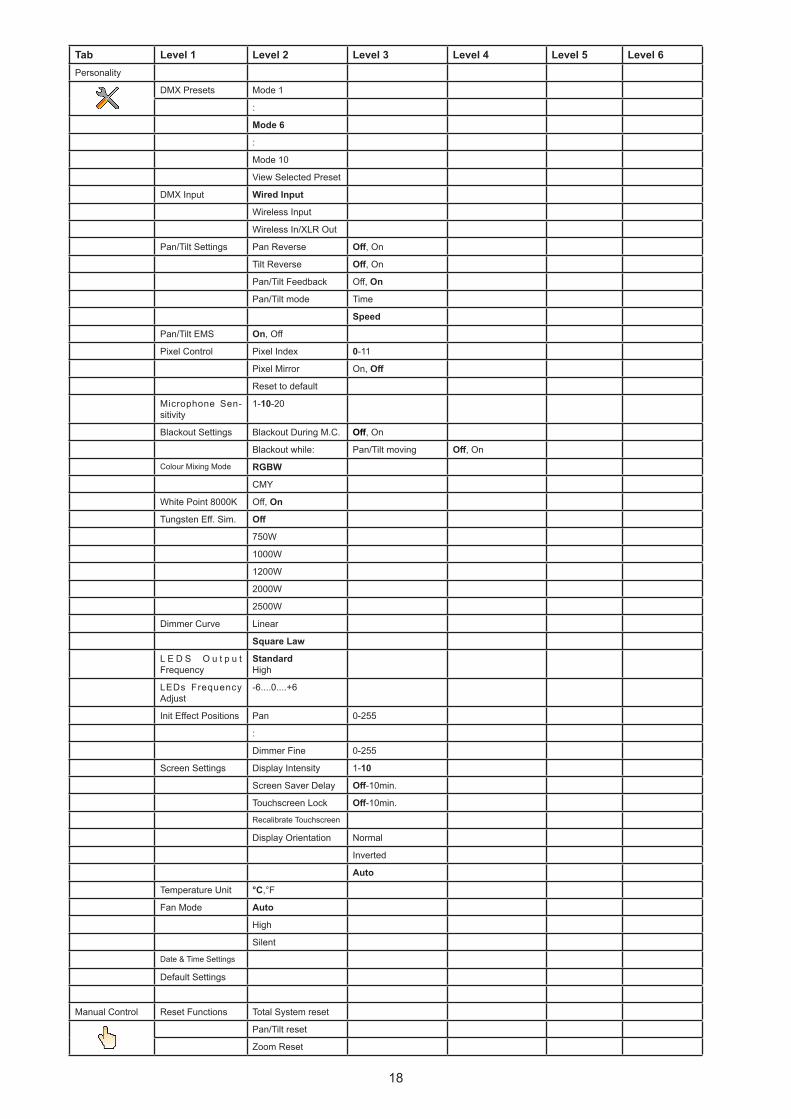
Tab Level 1 Level 2 Level 3 Level 4 Level 5 Level 6Personality
DMX Presets Mode 1
:
Mode 6
:
Mode 10
View Selected Preset
DMX Input Wired Input
Wireless Input
Wireless In/XLR Out
Pan/Tilt Settings Pan Reverse Off, On
Tilt Reverse Off, On
Pan/Tilt Feedback Off, On
Pan/Tilt mode Time
Speed
Pan/Tilt EMS On, Off
Pixel Control Pixel Index 0-11
Pixel Mirror On, Off
Reset to default
Microphone Sen-sitivity
1-10-20
Blackout Settings Blackout During M.C. Off, On
Blackout while: Pan/Tilt moving Off, On
Colour Mixing Mode RGBW
CMY
White Point 8000K Off, On
Tungsten Eff. Sim. Off
750W
1000W
1200W
2000W
2500W
Dimmer Curve Linear
Square Law
L E D S O u t p u t Frequency
StandardHigh
LEDs Frequency Adjust
-6....0....+6
Init Effect Positions Pan 0-255
:
Dimmer Fine 0-255
Screen Settings Display Intensity 1-10
Screen Saver Delay Off-10min.
Touchscreen Lock Off-10min.
Recalibrate Touchscreen
Display Orientation Normal
Inverted
Auto
Temperature Unit °C,°F
Fan Mode Auto
High
Silent
Date & Time Settings
Default Settings
Manual Control Reset Functions Total System reset
Pan/Tilt reset
Zoom Reset
19
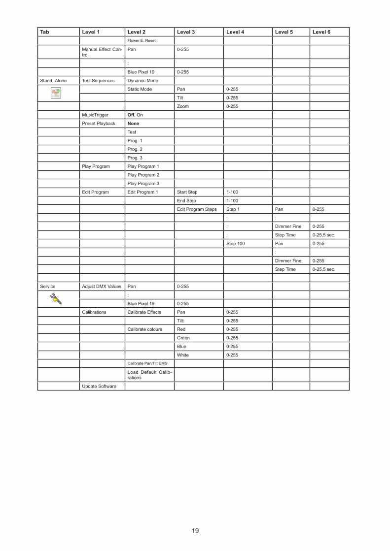
Tab Level 1 Level 2 Level 3 Level 4 Level 5 Level 6Flower E. Reset
Manual Effect Con-trol
Pan 0-255
:
Blue Pixel 19 0-255
Stand -Alone Test Sequences Dynamic Mode
Static Mode Pan 0-255
Tilt 0-255
Zoom 0-255
MusicTrigger Off, On
Preset Playback None
Test
Prog. 1
Prog. 2
Prog. 3
Play Program Play Program 1
Play Program 2
Play Program 3
Edit Program Edit Program 1 Start Step 1-100
End Step 1-100
Edit Program Steps Step 1 Pan 0-255
: :
: Dimmer Fine 0-255
: Step Time 0-25,5 sec.
Step 100 Pan 0-255
:
Dimmer Fine 0-255
Step Time 0-25,5 sec.
Service Adjust DMX Values Pan 0-255
:
Blue Pixel 19 0-255
Calibrations Calibrate Effects Pan 0-255
Tilt: 0-255
Calibrate colours Red 0-255
Green 0-255
Blue 0-255
White 0-255
Calibrate Pan/Tilt EMS
Load Default Calib-rations
Update Software
20
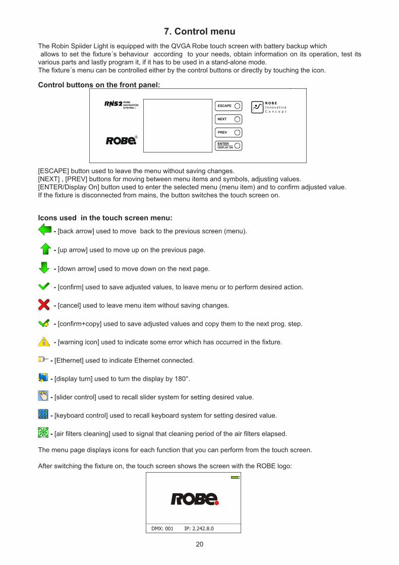
7. Control menu The Robin Spiider Light is equipped with the QVGA Robe touch screen with battery backup which allows to set the fixture´s behaviour according to your needs, obtain information on its operation, test its various parts and lastly program it, if it has to be used in a stand-alone mode. The fixture´s menu can be controlled either by the control buttons or directly by touching the icon.
Control buttons on the front panel:
[ESCAPE] button used to leave the menu without saving changes.[NEXT] , [PREV] buttons for moving between menu items and symbols, adjusting values.[ENTER/Display On] button used to enter the selected menu (menu item) and to confirm adjusted value. If the fixture is disconnected from mains, the button switches the touch screen on.
Icons used in the touch screen menu: - [back arrow] used to move back to the previous screen (menu).
- [up arrow] used to move up on the previous page.
- [down arrow] used to move down on the next page.
- [confirm] used to save adjusted values, to leave menu or to perform desired action.
- [cancel] used to leave menu item without saving changes.
- [confirm+copy] used to save adjusted values and copy them to the next prog. step.
- [warning icon] used to indicate some error which has occurred in the fixture.
- [Ethernet] used to indicate Ethernet connected.
- [display turn] used to turn the display by 180°.
- [slider control] used to recall slider system for setting desired value.
- [keyboard control] used to recall keyboard system for setting desired value.
- [air filters cleaning] used to signal that cleaning period of the air filters elapsed.
The menu page displays icons for each function that you can perform from the touch screen.
After switching the fixture on, the touch screen shows the screen with the ROBE logo:
21
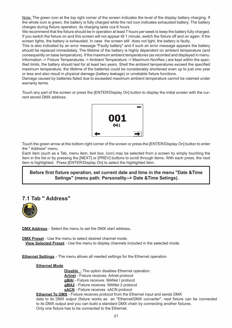
Note: The green icon at the top right corner of the screen indicates the level of the display battery charging. If the whole icon is green, the battery is fully charged while the red icon indicates exhausted battery. The battery charges during fixture operation, its charging lasts cca 6 hours.We recommend that the fixture should be in operation at least 7 hours per week to keep the battery fully charged. If you switch the fixture on and this screen will not appear till 1 minute, switch the fixture off and on again. If the screen lights, the battery is exhausted. In case the screen still does not light, the battery is faulty. This is also indicated by an error message "Faulty battery" and if such an error message appears the battery should be replaced immediately. The lifetime of the battery is highly dependent on ambient temperature (and consequently on base temperature). If the maximum ambient temperatures (as recorded and displayed in menu: Information -> Fixture Temperatures -> Ambient Temperature -> Maximum NonRes.) are kept within the spec-ified limits, the battery should last for at least two years. Shell the ambient temperatures exceed the specified maximum temperature, the lifetime of the batteries could be considerably shortened even up to just one year or less and also result in physical damage (battery leakage) or unreliable fixture functions.Damage caused by batteries failed due to exceeded maximum ambient temperature cannot be claimed under warranty terms.
Touch any part of the screen or press the [ENTER/Display On] button to display the initial screen with the cur-rent stored DMX address:
Touch the green arrow at the bottom right corner of the screen or press the [ENTER/Display On] button to enter the " Address" menu.Each item (such as a Tab, menu item, text box, icon) may be selected from a screen by simply touching the item in the list or by pressing the [NEXT] or [PREV] buttons to scroll through items. With each press, the next item is highlighted. Press [ENTER/Display On] to select the highlighted item.
Before first fixture operation, set current date and time in the menu "Date &Time Setings" (menu path: Personality--> Date &Time Setings).
7.1 Tab " Address"
DMX Address - Select the menu to set the DMX start address.
DMX Preset - Use the menu to select desired channel mode. View Selected Preset - Use the menu to display channels included in the selected mode.
Ethernet Settings - The menu allows all needed settings for the Ethernet operation
Ethernet Mode Disable - The option disables Ethernet operation. Artnet - Fixture receives Artnet protocol gMAI - Fixture receives MANet I protocol gMA2 - Fixture receives MANet 2 protocol sACN - Fixture receives sACN protocol Ethernet To DMX - Fixture receives protocol from the Ethernet input and sends DMX data to its DMX output (fixture works as an "Ethernet/DMX converter", next fixture can be connected to its DMX output and you can build a standard DMX chain by connecting another fixtures. Only one fixture has to be connected to the Ethernet.
22
IP Address/Net Mask - Select this menu to set IP address. IP address is the Internet protocol address.The IP uniquely identifies any node (fixture) on a network. There cannot be 2 fixtures with the same IP address on the network! Default IP Address -Preset IP address, you can set up only first byte of IP address (2 or 10) e.g. 002.019.052.086. Custom IP Address - The option enables to set up all bytes of IP address. Net Mask - The option enables to set up all bytes of Net Mask. ArtNet Universe - Use this item to set a Universe (0-255). The Universe is a single DMX 512 frame of 512 channels.
MANet Settings - Use this menu to set parameters for MANet operation. MANet Universe I/II - The value of this item can be set in range 1-256. MANet Session ID - The value of this item can be set in range 1-32.
sACN Settings - Use this menu to set parameters for sACN operation. sACN Universe - The value of this item can be set in range 1-32000. sACN Priority - The value of this item can be set in range 0-255.
Klingnet Settings - Use this menu to enable or disable Klingnet protocol.
7.2 Tab "Information"
Fixture Times - The menu provides readouts of fixture operation hours and air filters using hours. Power On Time Hours - Select this menu to read the number of fixture operation hours. Total Hours - The item shows the total number of the operation hours since the Robin Spiider has been fabricated. Resetable Hours - The item shows the number of the operation hours that the Robin Spiider has been powered on since the counter was last reset. In order to reset this counter to 0, touch the text box next to the item "Resetable Hours:" Air Filters - Regular cleaning of the air filters is very important for the fixture´s life and performance. Bild-up of dust, dirt and fog fluid residues reduces the fixture´s light output and cooling ability. The two items of this menu help you to keep cleaning period of the air filters. Alert period - Cleaning schedule for the fixture depends on the operating environment. It is therefore impossible to specify accurate cleaning interval. This item allows you to change the cleaning interval of the air filters. This "alert" value is 300 hours and it is set as default. Inspect the fixture within its 300 hours of operation to see whether cleaning is necessary. If cleaning is required, clean all air filters and change the value in this menu on acceptable level. Min. level of alert period is 10 hours, max. is 300 hours. Elapsed Time - The item allows you to read the time which remains to cleaning air filters. The time period is set in the menu mentioned above. Expired time period is signalled by a negative mark (-) at the time value and a warning icon on the display. Clean the filters and reset this menu item (by touching the text box next to the item "Elapsed Time"). Fixture Temperatures - The menu is used to view temperatures of the fixture´s inside. LEDs temperatures - The menu shows temperature on the LEDs PCB . Cur. - A current temperature of the LEDs PCB. Max. - A maximum temperature of the LEDs PCB since the fixture has been fabricated. Max. Res. - A maximum temperature of the LEDs PCB since the counter was last reset. In order to reset some counter to 0, touch desired text box under item "Max.Res." Base Temperature - The menu shows temperature in the fixture base (on the display PCB). Current - A current temperature in the fixture base. Maximum NonRes. - A maximum temperature in the fixture base since the fixture has been fabricated.
23
Maximum Res. - A maximum temperature in the fixture base since the counter was last reset. In order to reset this counter to 0, touch the text box next to the item "Maximum Res." DMX Values - The menu is used to read DMX values of each channel received by the fixture.
Wireless State - The menu serves for reading of the wireless operation status. Unlink Wireless Adapter - The item serves for unlinking the fixture from DMX transmitter.
Power Channel State - The menu item shows state of the Power/Special functions switches.
Software Version - Select this item to read the software version of the fixture modules: Display System - A display processor on the display board in the fixture base Module M - A pan/Tilt processors Module DR - A LEDs driver Module PX - Pixels + zooms control
Product IDs - The menu is used to read the MAC Address ,RDM UID and RDM Label.
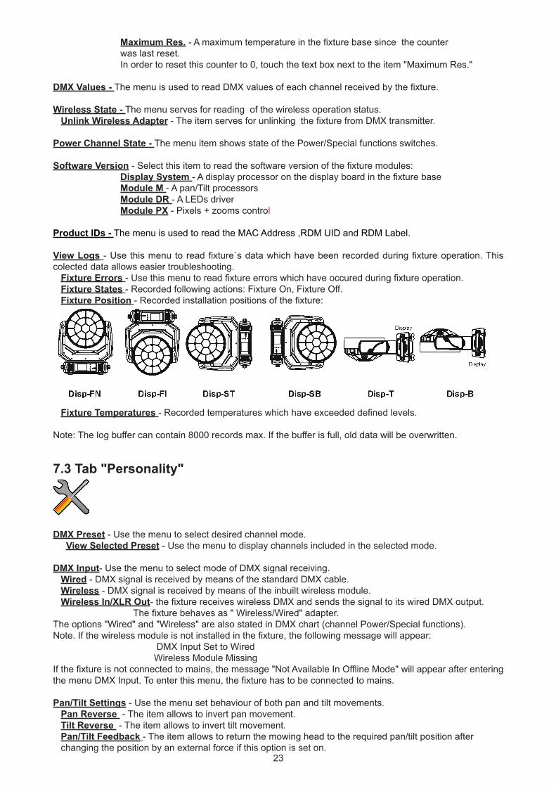
View Logs - Use this menu to read fixture´s data which have been recorded during fixture operation. This colected data allows easier troubleshooting. Fixture Errors - Use this menu to read fixture errors which have occured during fixture operation. Fixture States - Recorded following actions: Fixture On, Fixture Off. Fixture Position - Recorded installation positions of the fixture:
Fixture Temperatures - Recorded temperatures which have exceeded defined levels.
Note: The log buffer can contain 8000 records max. If the buffer is full, old data will be overwritten.
7.3 Tab "Personality"
DMX Preset - Use the menu to select desired channel mode. View Selected Preset - Use the menu to display channels included in the selected mode.
DMX Input- Use the menu to select mode of DMX signal receiving. Wired - DMX signal is received by means of the standard DMX cable. Wireless - DMX signal is received by means of the inbuilt wireless module. Wireless In/XLR Out- the fixture receives wireless DMX and sends the signal to its wired DMX output. The fixture behaves as " Wireless/Wired" adapter. The options "Wired" and "Wireless" are also stated in DMX chart (channel Power/Special functions).Note. If the wireless module is not installed in the fixture, the following message will appear: DMX Input Set to Wired Wireless Module Missing If the fixture is not connected to mains, the message "Not Available In Offline Mode" will appear after entering the menu DMX Input. To enter this menu, the fixture has to be connected to mains.
Pan/Tilt Settings - Use the menu set behaviour of both pan and tilt movements. Pan Reverse - The item allows to invert pan movement. Tilt Reverse - The item allows to invert tilt movement. Pan/Tilt Feedback - The item allows to return the mowing head to the required pan/tilt position after changing the position by an external force if this option is set on.
24
Note. Be careful, the Pan/Tilt Feedback should be permanent On, the option Off is not suitable for standard operation and the head of the fixture can be damaged! Pan/Tilt mode - Use this menu to set the mode of the pan/tilt movement Time mode – The pan and tilt will move with different speeds and they will come at the same time to the end point of their tracks (pan and tilt use their optimal speeds). Time of the pan/tilt movement (25.5 sec. max.) is set by the channel "Pan/Tilt speed, Pan/Tilt time". Speed Mode - Both Pan and tilt will move with the same speed as adjusted at the channel "Pan/Tilt speed, Pan/Tilt time".
Pan/Tilt EMS - Built-in electronic motion stabilizer ensures precise position of the fixture´s head during its movement and also reducing its swinging when the truss shakes.
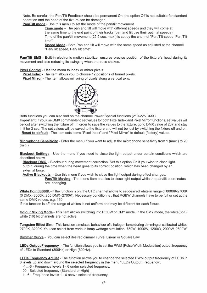
Pixel Control - Use the menu to index or mirror pixels. Pixel Index - The item allows you to choose 12 positions of turned pixels. Pixel Mirror - The item allows mirroring of pixels along a vertical axis.
Both functions you can also find on the channel Power/Special functions (210-225 DMX).Important: If you use DMX commands to set values for both Pixel Index and Pixel Mirror functions, set values will be lost after switching the fixture off. In order to save the values to the fixture, go to DMX value of 237 and stay in it for 3 sec. The set values will be saved to the fixture and will not be lost by switching the fixture off and on. Reset to default - The item sets items "Pixel Index" and "Pixel Mirror" to default (factory) values.
Microphone Sensitivity - Enter the menu if you want to adjust the microphone sensitivity from 1 (max.) to 20 (min.).
Blackout Settings - Use the menu if you need to close the light output under certain conditions which are described below Blackout DMC - Blackout during movement correction. Set this option On if you wish to close light output during the time when the head goes to its correct position, which has been changed by an external force. Active Blackouts - Use this menu if you wish to close the light output during effect changes. Pan/Tilt Moving - The menu item enables to close light output while the pan/tilt coordinates are changing.
White Point 8000K - If the function is on, the CTC channel allows to set desired white in range of 8000K-2700K(0 DMX=8000K, 255 DMX=2700K). Necessary condition is , that RGBW channels have to be full or set at the same DMX values, e.g. 150.If this function is off, the range of whites is not uniform and may be different for each fixture.
Colour Mixing Mode - This item allows switching into RGBW or CMY mode. In the CMY mode, the white(8bit)/white (16) bit channels are not active.
Tungsten Effect Sim. - This function simulates behaviour of a halogen lamp during dimming at calibrated whites 2700K, 3200K. You can select from various lamp wattage simulation: 750W, 1000W, 1200W, 2000W, 2500W.
Dimmer Curve - You can select desired dimmer curve: Linear or Square Law.
LEDs Output Frequency - The function allows you to set the PWM (Pulse Width Modulation) output frequency of LEDs to Standard (300Hz) or High (600Hz).
LEDs Frequency Adjust - The function allows you to change the selected PWM output frequency of LEDs in 6 levels up and down around the selected frequency in the menu “LEDs Output Frequency”. -1...-6 - Frequence levels 1 - 6 under selected frequency. 00 - Selected frequency (Standard or High) 1...6 - Frequence levels 1 - 6 above selected frequency.
25
Init Effect Positions - Use the menu to set all effects to the desired positions at which they will stay after switching the fixture on without DMX signal connected.
Screen Settings - Use this menu to change the touch screen settings. Display Intensity - The item allows to control the intensity of the screen (1-min., 10-max.). Screen saver Delay - The item allows you to keep the screen on or to turn it off automatically after 1-10 minutes after last touch (or pressing any button on the control panel). Touchscreen Lock - The item allows you to lock the screen after last touch (or pressing any button on the control panel). The time delay can be set in range of 1-10 minutes.To unlock the screen, press the [ENTER/Display On] button. Recalibrate Touchscreen - The item starts calibration of the touchscreen. Follow the instructions on the screen. Display Orientation - The menu allows to change display orientation. Normal - Standard display orientation if the fixture is placed horizontally (e.g. on the ground). Inverted - This function rotates menu 180 degrees from current orientation. Auto - The option activates a gravitation sensor for automatic screen orientation.Note: Auto option is set as default. You change the display orientation by touching the icon on the display, an the option set in the "Display Orientation" menu is temporarily overriden. Temperature unit - Use the menu item to change temperature unit from °C to °F.
Fan Mode - Use the menu to set the fixture fans to max. power mode ("High") or to auto-control mode ("Auto").The option "Silent" allows you to set desired fan noise. The light output of the fixture is reduced at low speeds of fans. Date & Time Settings - Use this menu to set current date and time for the fixture log system (menu "View Logs"). Set this menu item before first fixture operation.
Default Settings - The menu item allows to set all fixture parameters to the default (factory) values.
7.4 Tab "Manual Control"
Reset Functions - The menu allows to reset the fixture either per function modules or all modules together. Total System Reset - The item resets all function modules. Pan/Tilt Reset - The item resets the pan and tilt movement. Zoom Reset - The item resets the zoom module. Flower E. Reset - The item resets the Flower effect.Manual Effect control - Use the menu to control all fixture channels by means of the control panel.
7.5 Tab "Stand-alone"
Test Sequences -Use the menu to run a test/demo sequences without an external controller, which will show you some possibilities of using Robin Spiider. Dynamic Mode - This mode uses all Robin Spiider functions including pan/tilt movement and therefore is good for a complete introduction of the fixture. Static Mode - This mode is suitable for projections on the wall, ceiling or ground without any pan/tilt movement. Adjust the pan and tilt to desired positions and start test sequences by touching the green icon.
Music Trigger - Use the item to activate the sound control of the running program via the built-in microphone.Preset Playback - This menu allows you to select the program which will be played in a loop after switching the fixture on (the option is commonly used in a stand-alone operation without an external controller). None - The option disables “Presetting playback” function.
26
Test - The option starts the test sequences. Prog. 1 - The option starts user program No. 1. Prog. 2 - The option starts user program No. 2. Prog. 3 - The option starts user program No. 3.
Play program - Use the menu to run desired program in a loop. Play Program 1 - The option starts user program No.1. Play Program 2 - The option starts user program No. 2. Play Program 3 - The option starts user program No. 3.Edit Program - Use the menu to create or to edit desired program. The Robin Spiider offers 3 free programs, each up to 100 steps. Edit Program 1 - The option allows to edit user program No.1. Edit Program 2 - The option allows to edit user program No.2. Edit Program 3 - The option allows to edit user program No.3To edit program:1. Touch the item which you want to edit (“Edit Program 1” - “Edit Program 3”). 2. Touch the item "Edit Program Steps".3. Touch the item "Step 1".4 From the list of effects touch desired effect and set its value. Browse throw the list by touching the [up arrow] and [down arrow] and set all desired effects.An item "Step Time" (value of 0-25.5 sec.) is the time during which effects last in the current step 5. Save adjusted effects to the current step by touching the [confirm] or save and copy them to the following step by touching the [confirm+copy]. By touching the text box "Preview" next to the current program step you can view created scene.6. Repeat the steps 4 and 5 for next program steps.7. After editing desired program steps, adjust the length of the program by touching the text boxes "Start Step" and "End Step".Meaning of the icons used in the "Edit Program" menu:
- moves down on the next page - saves adjusted values and leaves menu - moves up on the previous page - saves values to the current step and copy them to the
following prog. step - leaves menu without saving values
7.6 Tab "Service"
Adjust DMX Values - The menu allows you to set all effects to desired positions before fine calibration of the effects .
Calibrations - This menu enables fine calibration of fixture effects and download default calibration values. Calibrate Effects - The menu allows the fine adjustment of effects. Pan- a pan position fine adjustment Tilt - a tilt position fine adjustment
Calibration of the effects via the control board1. Disconnect DMX controller from the fixture and enter the "Calibrate Effects" menu.2. Use the [up arrow] and [down arrow] to find "Pan" and touch it to enter the fine effect adjustment screen.3. Set desired value and save it by touching the [confirm].4. Repeat steps 2 and 3 for next item 5. After calibrating all effects, touch the [confirm] to save all adjusted values and reset the fixture.
Calibrate Colours - The menu serves for adjusting of LEDs saturation to achieve uniform white colours Red - a red LEDs saturation fine adjustment Green - a green LEDs saturation fine adjusment Blue - a blue LEDs saturation fine adjustment White - a white LEDs saturation fine adjustmentt
27
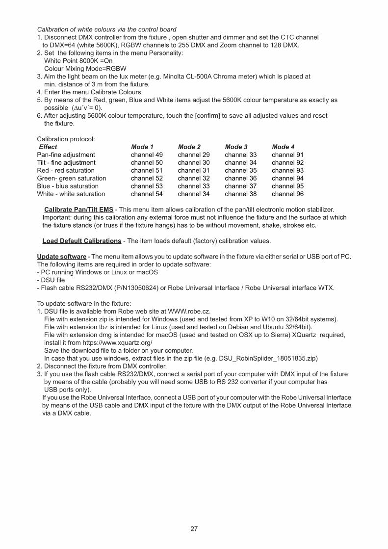
Calibration of white colours via the control board1. Disconnect DMX controller from the fixture , open shutter and dimmer and set the CTC channel to DMX=64 (white 5600K), RGBW channels to 255 DMX and Zoom channel to 128 DMX. 2. Set the following items in the menu Personality: White Point 8000K =On Colour Mixing Mode=RGBW3. Aim the light beam on the lux meter (e.g. Minolta CL-500A Chroma meter) which is placed at min. distance of 3 m from the fixture. 4. Enter the menu Calibrate Colours.5. By means of the Red, green, Blue and White items adjust the 5600K colour temperature as exactly as possible (∆u´v´= 0).6. After adjusting 5600K colour temperature, touch the [confirm] to save all adjusted values and reset the fixture.
Calibration protocol: Effect Mode 1 Mode 2 Mode 3 Mode 4Pan-fine adjustment channel 49 channel 29 channel 33 channel 91Tilt - fine adjustment channel 50 channel 30 channel 34 channel 92Red - red saturation channel 51 channel 31 channel 35 channel 93Green- green saturation channel 52 channel 32 channel 36 channel 94Blue - blue saturation channel 53 channel 33 channel 37 channel 95White - white saturation channel 54 channel 34 channel 38 channel 96
Calibrate Pan/Tilt EMS - This menu item allows calibration of the pan/tilt electronic motion stabilizer. Important: during this calibration any external force must not influence the fixture and the surface at which the fixture stands (or truss if the fixture hangs) has to be without movement, shake, strokes etc.
Load Default Calibrations - The item loads default (factory) calibration values.
Update software - The menu item allows you to update software in the fixture via either serial or USB port of PC.The following items are required in order to update software:- PC running Windows or Linux or macOS- DSU file - Flash cable RS232/DMX (P/N13050624) or Robe Universal Interface / Robe Universal interface WTX.
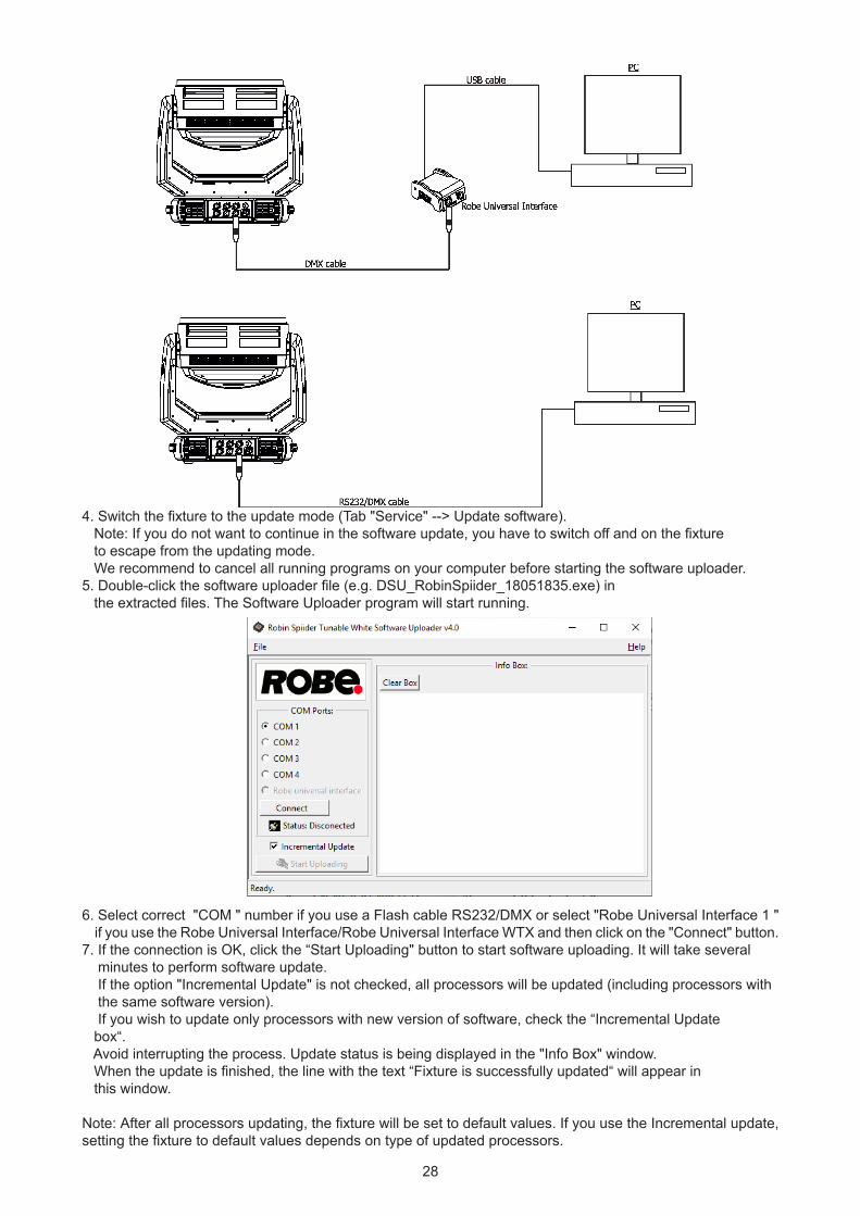
To update software in the fixture:1. DSU file is available from Robe web site at WWW.robe.cz. File with extension zip is intended for Windows (used and tested from XP to W10 on 32/64bit systems). File with extension tbz is intended for Linux (used and tested on Debian and Ubuntu 32/64bit). File with extension dmg is intended for macOS (used and tested on OSX up to Sierra) XQuartz required, install it from https://www.xquartz.org/ Save the download file to a folder on your computer. In case that you use windows, extract files in the zip file (e.g. DSU_RobinSpiider_18051835.zip) 2. Disconnect the fixture from DMX controller.3. If you use the flash cable RS232/DMX, connect a serial port of your computer with DMX input of the fixture by means of the cable (probably you will need some USB to RS 232 converter if your computer has USB ports only). If you use the Robe Universal Interface, connect a USB port of your computer with the Robe Universal Interface by means of the USB cable and DMX input of the fixture with the DMX output of the Robe Universal Interface via a DMX cable.
28
4. Switch the fixture to the update mode (Tab "Service" --> Update software). Note: If you do not want to continue in the software update, you have to switch off and on the fixture to escape from the updating mode. We recommend to cancel all running programs on your computer before starting the software uploader.5. Double-click the software uploader file (e.g. DSU_RobinSpiider_18051835.exe) in the extracted files. The Software Uploader program will start running.
6. Select correct "COM " number if you use a Flash cable RS232/DMX or select "Robe Universal Interface 1 " if you use the Robe Universal Interface/Robe Universal Interface WTX and then click on the "Connect" button.7. If the connection is OK, click the “Start Uploading" button to start software uploading. It will take several minutes to perform software update. If the option "Incremental Update" is not checked, all processors will be updated (including processors with the same software version). If you wish to update only processors with new version of software, check the “Incremental Update box“. Avoid interrupting the process. Update status is being displayed in the "Info Box" window. When the update is finished, the line with the text “Fixture is successfully updated“ will appear in this window.
Note: After all processors updating, the fixture will be set to default values. If you use the Incremental update, setting the fixture to default values depends on type of updated processors.
29
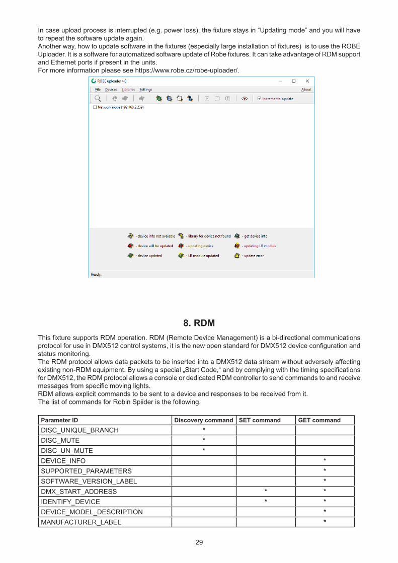
In case upload process is interrupted (e.g. power loss), the fixture stays in “Updating mode” and you will have to repeat the software update again.Another way, how to update software in the fixtures (especially large installation of fixtures) is to use the ROBE Uploader. It is a software for automatized software update of Robe fixtures. It can take advantage of RDM support and Ethernet ports if present in the units.For more information please see https://www.robe.cz/robe-uploader/.
8. RDMThis fixture supports RDM operation. RDM (Remote Device Management) is a bi-directional communications protocol for use in DMX512 control systems, it is the new open standard for DMX512 device configuration and status monitoring.The RDM protocol allows data packets to be inserted into a DMX512 data stream without adversely affecting existing non-RDM equipment. By using a special „Start Code,“ and by complying with the timing specifications for DMX512, the RDM protocol allows a console or dedicated RDM controller to send commands to and receive messages from specific moving lights.RDM allows explicit commands to be sent to a device and responses to be received from it. The list of commands for Robin Spiider is the following.
Parameter ID Discovery command SET command GET commandDISC_UNIQUE_BRANCH *DISC_MUTE *DISC_UN_MUTE *DEVICE_INFO *SUPPORTED_PARAMETERS *SOFTWARE_VERSION_LABEL *DMX_START_ADDRESS * *IDENTIFY_DEVICE * *DEVICE_MODEL_DESCRIPTION *MANUFACTURER_LABEL *
30
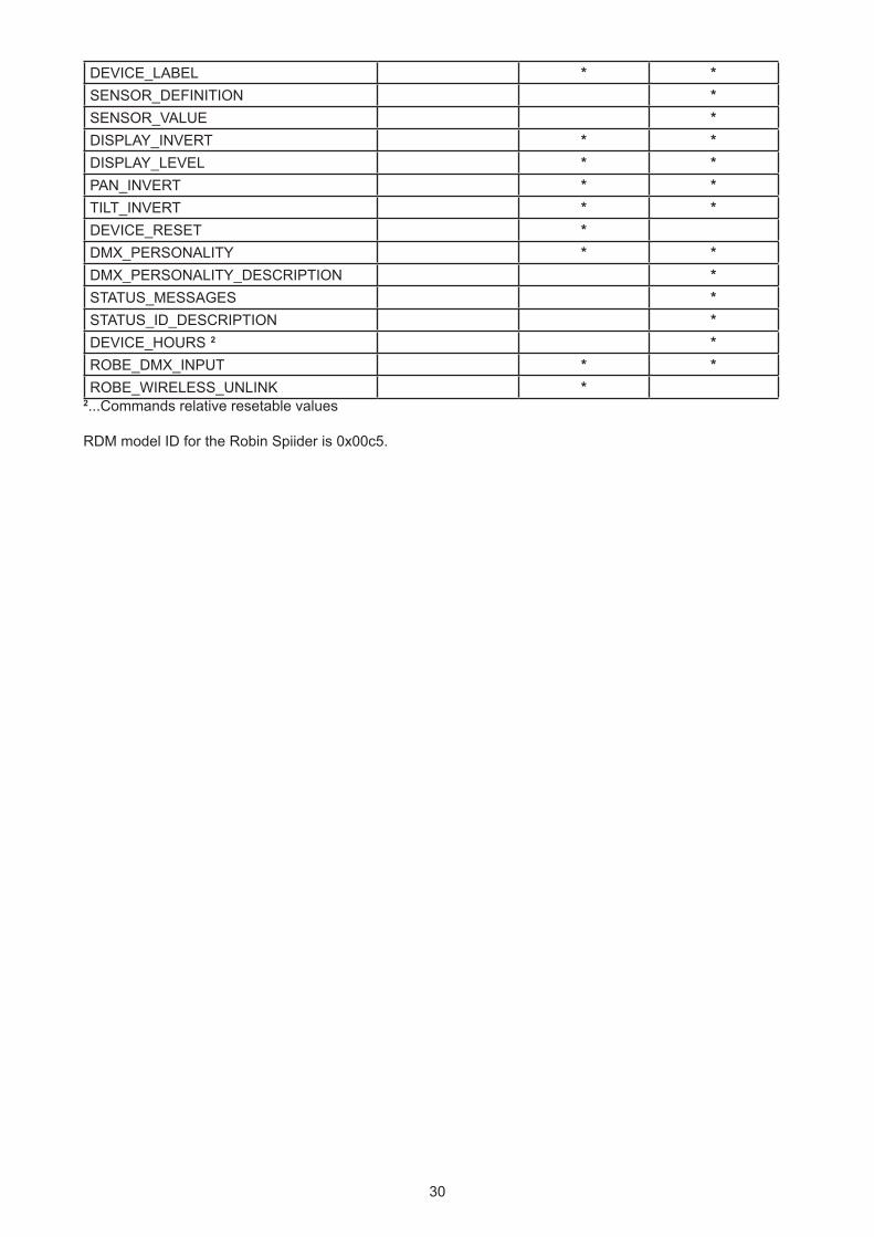
DEVICE_LABEL * *SENSOR_DEFINITION *SENSOR_VALUE *DISPLAY_INVERT * *DISPLAY_LEVEL * *PAN_INVERT * *TILT_INVERT * *DEVICE_RESET *DMX_PERSONALITY * *DMX_PERSONALITY_DESCRIPTION *STATUS_MESSAGES *STATUS_ID_DESCRIPTION *DEVICE_HOURS 2 *ROBE_DMX_INPUT * *ROBE_WIRELESS_UNLINK *
2...Commands relative resetable values
RDM model ID for the Robin Spiider is 0x00c5.
31
9. Error and information messagesInformation icon
- Air Filters Cleaning
This icon signalizes that cleaning period of the air filters has elapsedand you have to clear air filters and reset the menu item "Elapsed Time".
ErrorsError in the fixture is signalled by the yellow warning icon at the bottom line of the screen:
Touch the warning icon or press the [ESCAPE] button to display error messages.List of error and information messages:
Temper.Sensor ErrorThe message informs you that the communication betwen the head temperature sensor and the main processor failed.
Tilt Error 1 (Tilt Error 2)This message will appear after the reset of the fixture if the head´s magnetic-indexing circuit malfunctions (sensor failed or magnet is missing) or the stepping motor is defective or its driving IC on the PCB. The head is not located in the default position after the reset.
Pan Error 1 (Pan Error 2)This message will appear after the reset of the fixture if the yoke´s magnetic-indexing circuit malfunctions (sen-sor failed or magnet is missing) or the stepping motor is defective or its driving IC on the PCB. The yoke is not located in the default position after the reset of the fixture.
Zoom Error 1 (Zoom Error 2 )The messages will appear after the reset of the zoom module if the zoom module is not located in the default position.
Rod ErrorThe messages will appear after the reset of the flower effect if the rod is not in the default position.
EEprom ErrorHardware error of the EEprom.
Recharge The batteryThe battery on the display board needs to be charged. Let the fixture on for cca 6 hrs.
Battery faulty. Replace it.The battery on the display board is exhausted and should be replaced immediately.
Pan/Tilt EMS Cal. ErrorThe EMS system is not calibrated.
Pan/Tilt EMS ErrorControl electronics cannot communicate with the EMS system.
Clean Air FiltersThe message informs that the item "Elapsed Time" in the "Fixture Information" menu is at 0 value. Clean air filters and reset this counter.
32
10. Technical Specifications
Electrical Power supply:.........................electronic auto-ranging Input voltage range:............... supply 100-240V, 50-60Hz Fuse:.......................................T 8 A
Max. power consumption .......660W ( power factor= 0.99)
Optic Light source: 19 RGBW LED multichips RGBW or CMY colour mixing 19 controllable LED multichips (pixels) LED life expectancy: min. 50.000 hours
Virtual colour wheel 66 preset colours CTC in range of 2700K-8000K Halogen lamp effect at whites 2700K and 3200K Rainbow effect with in both directions with variable speedZoom Linear motorized zoom Min. beam angle: 4° (1/2 beam) Max. beam angle: 50°(1/10 beam)
Effect Flower effect rotating in both directions 10 Flower effect macros
Strobe Strobe effect with variable speed (0.3 - 20Hz)
Dimmer Smooth dimmer from 0 - 100 %
Control Graphic touch screen for fixture setting and addressing Gravitation sensor for auto screen positioning Battery backup of the touch screen Readout fixture and LED module usage, receiving DMX values, temperatures, etc Built-in analyzer for easy fault finding, error messages Built-in demo sequences Individual pixel control of each LED Stand-alone operation 3 user editable programs, each up to 100 steps Supported protocols: USITT DMX 512, RDM, ArtNet, MANet, MANet2, sACN, Kling-Net Support of RDM (Remote Device Management) 10 DMX modes (49, 27, 33, 90, 27,47, 91,110,104,123 control channels)
Wireless DMX/RDM module (only for Wireles DMX version) Compliance with USITT DMX-512 (1986 & 1990) and 512-A Full DMX fidelity and frame integrity Auto sensing of DMX frame rate and frame size <5ms DMX latency Operational frequency range of 2402-2480 MHz Producer: LumenRadio
33
Pan/Tilt Pan movement range 540° Tilt movement range 220° Continual pan/tilt rotation 16 bit movement resolution Pan/Tilt electronic motion stabilizer Automatic Pan/Tilt position correction Remotely controllable speed of pan/tilt movement for easy programming Pan/tilt-lock mechanism
Connection DMX data in/out: Locking 3-pin and 5-pin XLR AC power IN: Neutrik TrueOne NAC3MPX Ethernet IN/Out: RJ45
Max. number of fixtures in Ethernet IN/Out line 5
Rigging Mounting points: 2 pairs of 1/4-turn locks Mounting horizontally or vertically via two Omega brackets
Temperatures Maximum ambient temperature : 45° C Maximum housing temperature : 75° C
Minimum distances Min. distance from flammable surfaces: 0.5 m Min. distance to lighted object: 1 m
Total heat dissipation Max.1688 BTU/hr
Ingress protection IP2x
Accessories 1 x Omega adapter CL-regular 2 pcs in box (P/N 10980033) 1 x power cable
Weight (net) 13.25 kg

34
Dimensions (mm)
Optional accessories Upgrade kit CRMX Universal 260 (P/N 99030100) EggCrate for Robin Spiider (P/N10980317) Diffuser 2° for Robin Spiider (P/N 10980416) Doughty Trigger Clamp (P/N 17030386) Safety wire 35 kg (P/N 99011963) Clear lens cover Spiider (P/N 10980607)
35
11. Maintenance and cleaningIt is absolutely essential that the fixture is kept clean and that dust, dirt and smoke-fluid residues must not build up on or within the fixture. Otherwise, the fixture‘s light output will be significantly reduced. Regular cleaning will not only ensure the maximum light output, but will also allow the fixture to function reliably throughout its life.A soft lint-free cloth moistened with any weak detergent solution is recommended for cleaning fixture´s covers, under no circumstances should alcohol or solvents be used!
DANGER !Disconnect from the mains before starting any
maintenance and cleaning work
The interior of the fixture should be cleaned at least annually using a vacuum cleaner or compressed air.The cooling fans should be cleaned at least twice a year.
Important! Never use alcohols (ethanol, methanol, isopropyl alcohol), acetone and another aggressive solvents for cleaning the front lens array.
Recommended steps for cleaning the front lens array:1. Use low-pressure compressed air to remove coarse dust from lenses.2. Use distilled water with weak detergent solution and lint-free small cloth for further cleaning of lenses. 3. Use an antistatic, alcohol-free screen cleaner (we recommend the Lyreco Screen Cleaner) and polish lenses until they are dry.4. Check the lenses are dry before reapplying power.
Note: potential foggy front lens array does not influence function of the fixture and does not subject to complaint
Check the air filter periodically and clean before they become clogged!
Periodically clean air filter placed in the fixture´s base. The air filter cover is fastened by means of magnets. Use a vacuum cleaner, compressed air or you can wash them and put back dry.After replacing the air filters, reset the elapsed time counter in the menu "Information" (Information--->Air Fil-ters---> Elapsed Time).
Replacing the fuse.Before replacing the fuse, unplug mains lead. 1. Remove the fuse holder on the rear panel of the base with a fitting screwdriver from the housing (anti-clockwise). 2. Remove the old fuse from the fuse holder. 3. Install the new fuse in the fuse holder (only the same type and rating). 4. Replace the fuseholder in the housing and fix it.
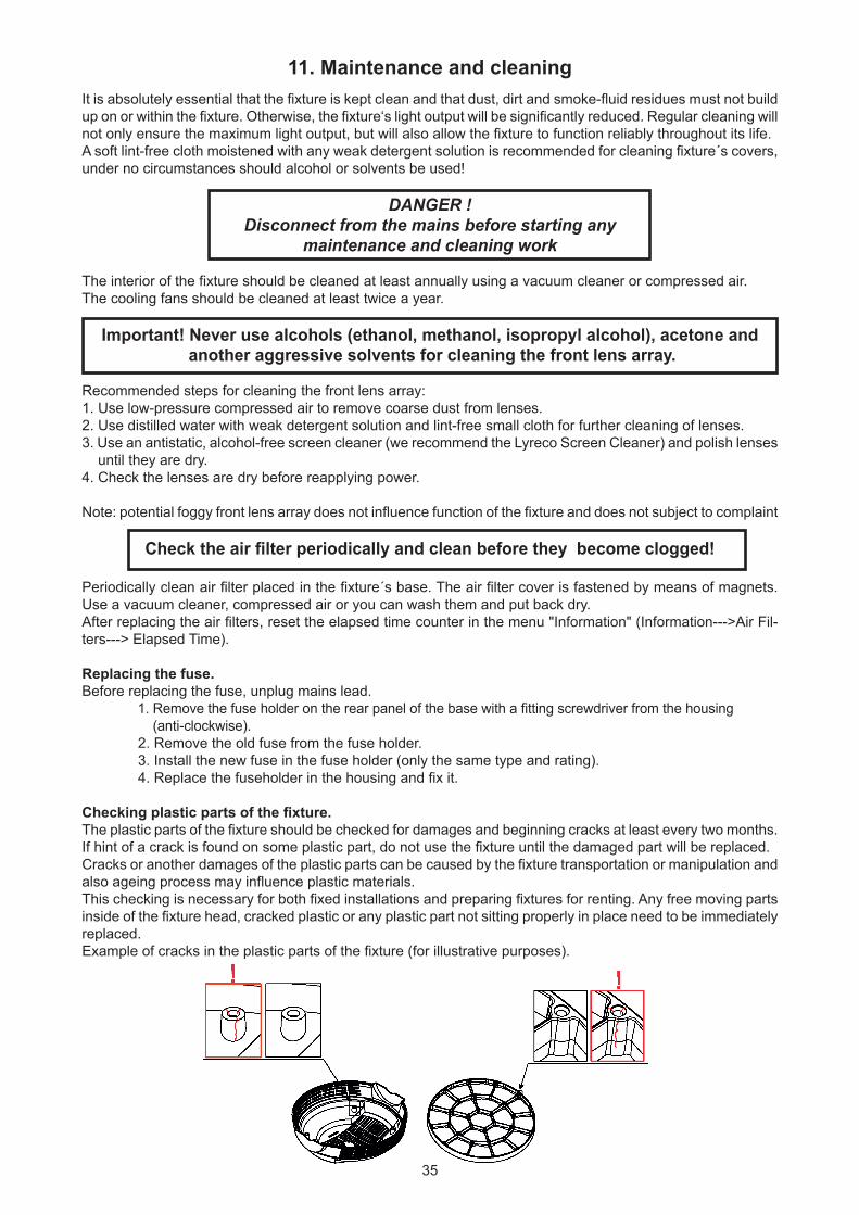
Checking plastic parts of the fixture.The plastic parts of the fixture should be checked for damages and beginning cracks at least every two months. If hint of a crack is found on some plastic part, do not use the fixture until the damaged part will be replaced.Cracks or another damages of the plastic parts can be caused by the fixture transportation or manipulation and also ageing process may influence plastic materials. This checking is necessary for both fixed installations and preparing fixtures for renting. Any free moving parts inside of the fixture head, cracked plastic or any plastic part not sitting properly in place need to be immediately replaced.Example of cracks in the plastic parts of the fixture (for illustrative purposes).
36
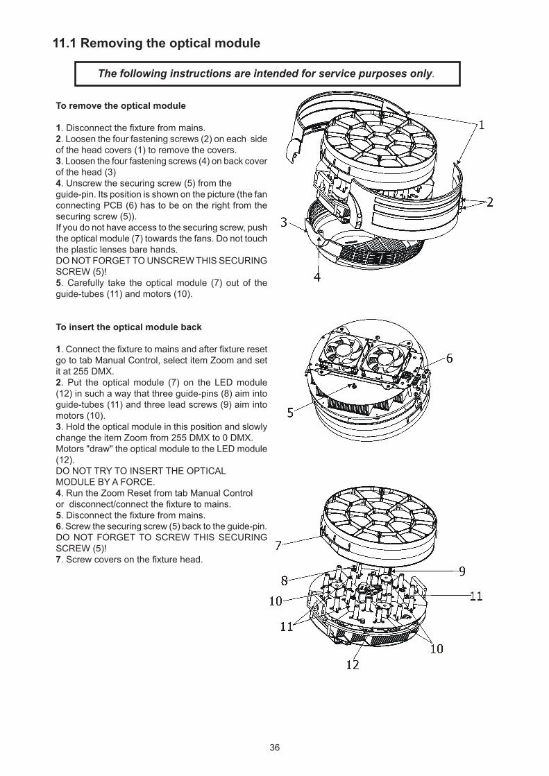
11.1 Removing the optical module
The following instructions are intended for service purposes only.
To remove the optical module
1. Disconnect the fixture from mains.2. Loosen the four fastening screws (2) on each side of the head covers (1) to remove the covers.3. Loosen the four fastening screws (4) on back cover of the head (3)4. Unscrew the securing screw (5) from the guide-pin. Its position is shown on the picture (the fan connecting PCB (6) has to be on the right from the securing screw (5)).If you do not have access to the securing screw, push the optical module (7) towards the fans. Do not touch the plastic lenses bare hands.DO NOT FORGET TO UNSCREW THIS SECURING SCREW (5)!5. Carefully take the optical module (7) out of the guide-tubes (11) and motors (10).
To insert the optical module back
1. Connect the fixture to mains and after fixture reset go to tab Manual Control, select item Zoom and set it at 255 DMX. 2. Put the optical module (7) on the LED module (12) in such a way that three guide-pins (8) aim into guide-tubes (11) and three lead screws (9) aim into motors (10). 3. Hold the optical module in this position and slowly change the item Zoom from 255 DMX to 0 DMX. Motors "draw" the optical module to the LED module (12).DO NOT TRY TO INSERT THE OPTICALMODULE BY A FORCE. 4. Run the Zoom Reset from tab Manual Control or disconnect/connect the fixture to mains.5. Disconnect the fixture from mains.6. Screw the securing screw (5) back to the guide-pin.DO NOT FORGET TO SCREW THIS SECURING SCREW (5)!7. Screw covers on the fixture head.
37
11.2 Disposing of the productTo preserve the environment please dispose or recycle this product at the end of its life according to the local regulations and codes.
12. ChangeLog This section summarizes all types of changes in the user manual.Version of the
manualDate of issue Description of changes
1.1 16/12/2016 DMX protocol ver. 1.3 (added 6 DMX modes)1.2 24/01/2017 Added Eggcrate installation 1.3 10/02/2017 DMX protocol ver. 1.4 (Pattern crossfade channel added)1.4 27/02/2017 DMX protocol ver.1.51.5 24/03/2017 DMX protocol ver.1.61.6 20/10/2017 DMX protocol 1.7 (Parking position, Pixel index, Pixel mirror on Power ch.)1.7 1/11/2017 Item Pixel control added to menu Personality 1.8 7/11/2017 DMX protocol 1.8 (Saving Pixel Index and pixel mirror to fixture)1.9 07/12/2017 2° Diffuser added to Optional Accessories2.0 15/01/2018 Optional accessories changed2.1 20/03/2018 Installation of the diffuser added2.2 26/04/2018 DMX protocol 1.92.3 03/06/2019 DMX protocol 2.0 (Leds PWM output frequency added on Power channel ) 2.4 03/07/2019 Check of plastic added (chapter Maintenance and cleaning)2.5 18/09/2019 DMX protocol 2.1 (RoboSpot support added)2.6 11/11/2019 Description of lenses cleaning added2.7 18/04/2020 DMX protocol v. 2.2 (pixel effects modified)2.8 28/07/2020 DMX protocol v. 2.3 (silent mode added) 2.9 15/10/2020 Added information about foggy lens array3.0 24/06/2021 BTU/h value changed
38
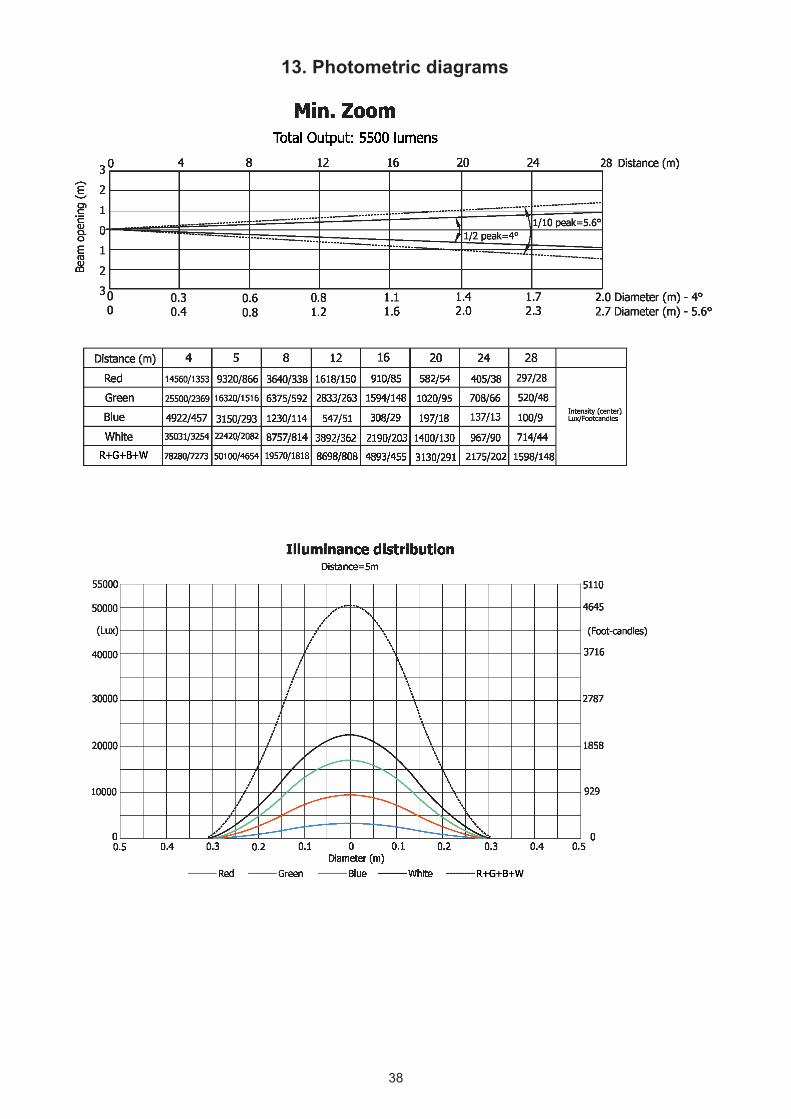
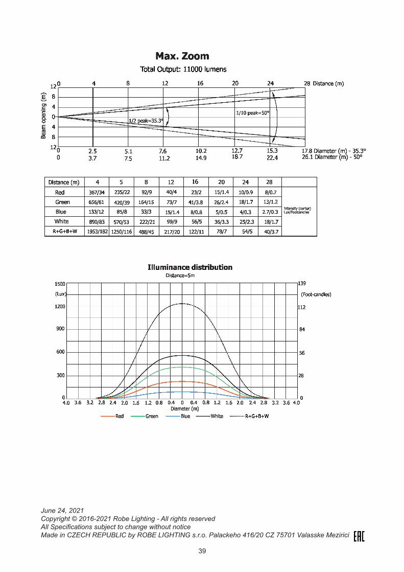
13. Photometric diagrams
39
June 24, 2021Copyright © 2016-2021 Robe Lighting - All rights reservedAll Specifications subject to change without noticeMade in CZECH REPUBLIC by ROBE LIGHTING s.r.o. Palackeho 416/20 CZ 75701 Valasske Mezirici
40
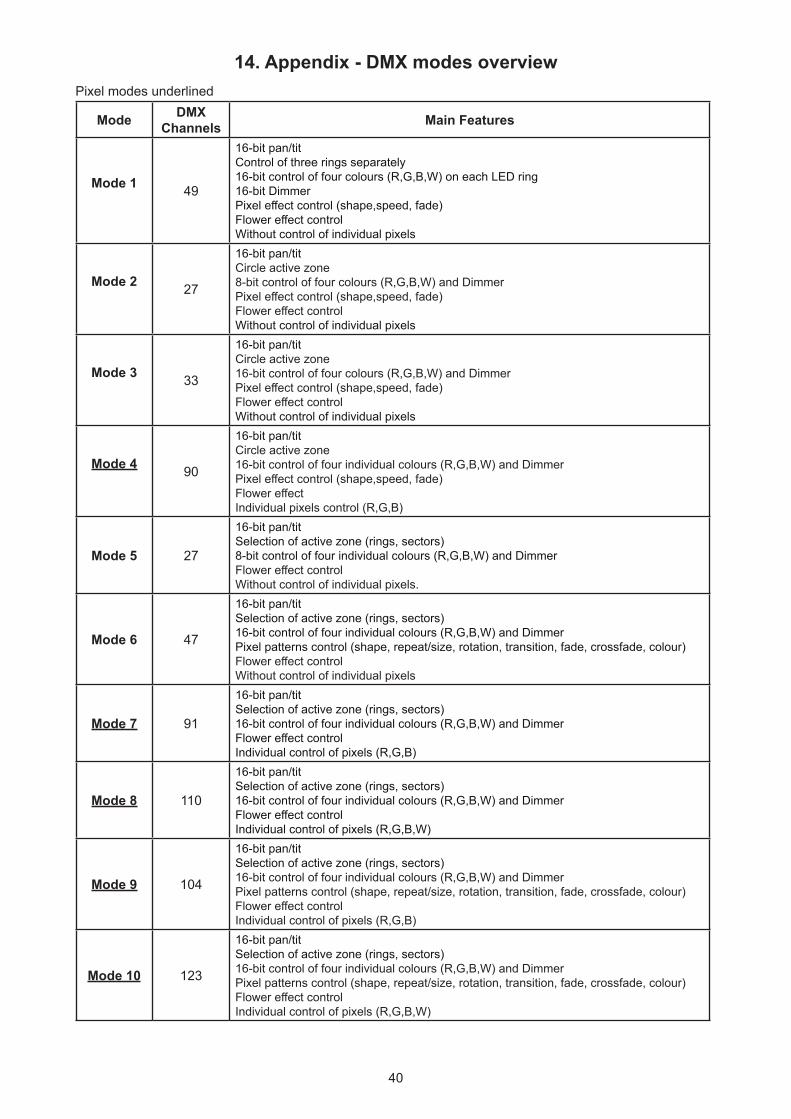
14. Appendix - DMX modes overviewPixel modes underlined
Mode DMX Channels Main Features
Mode 1 49
16-bit pan/titControl of three rings separately 16-bit control of four colours (R,G,B,W) on each LED ring16-bit DimmerPixel effect control (shape,speed, fade) Flower effect controlWithout control of individual pixels
Mode 2 27
16-bit pan/titCircle active zone8-bit control of four colours (R,G,B,W) and DimmerPixel effect control (shape,speed, fade)Flower effect controlWithout control of individual pixels
Mode 3 33
16-bit pan/titCircle active zone16-bit control of four colours (R,G,B,W) and Dimmer Pixel effect control (shape,speed, fade) Flower effect controlWithout control of individual pixels
Mode 4 90
16-bit pan/titCircle active zone16-bit control of four individual colours (R,G,B,W) and DimmerPixel effect control (shape,speed, fade)Flower effectIndividual pixels control (R,G,B)
Mode 5 27
16-bit pan/titSelection of active zone (rings, sectors)8-bit control of four individual colours (R,G,B,W) and DimmerFlower effect controlWithout control of individual pixels.
Mode 6 47
16-bit pan/titSelection of active zone (rings, sectors)16-bit control of four individual colours (R,G,B,W) and DimmerPixel patterns control (shape, repeat/size, rotation, transition, fade, crossfade, colour)Flower effect controlWithout control of individual pixels
Mode 7 91
16-bit pan/titSelection of active zone (rings, sectors)16-bit control of four individual colours (R,G,B,W) and DimmerFlower effect controlIndividual control of pixels (R,G,B)
Mode 8 110
16-bit pan/tit Selection of active zone (rings, sectors)16-bit control of four individual colours (R,G,B,W) and DimmerFlower effect controlIndividual control of pixels (R,G,B,W)
Mode 9 104
16-bit pan/titSelection of active zone (rings, sectors)16-bit control of four individual colours (R,G,B,W) and DimmerPixel patterns control (shape, repeat/size, rotation, transition, fade, crossfade, colour) Flower effect controlIndividual control of pixels (R,G,B)
Mode 10 123
16-bit pan/titSelection of active zone (rings, sectors)16-bit control of four individual colours (R,G,B,W) and DimmerPixel patterns control (shape, repeat/size, rotation, transition, fade, crossfade, colour)Flower effect controlIndividual control of pixels (R,G,B,W)
DMX protocol
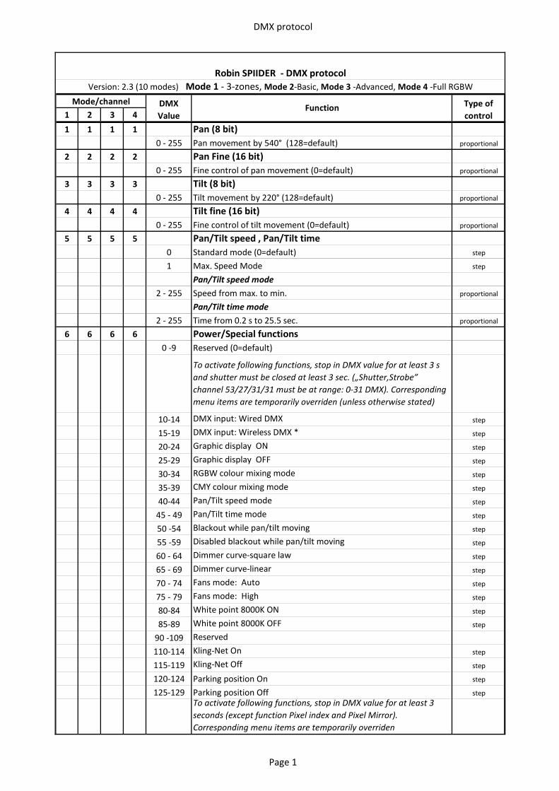
1 2 3 4
1 1 1 1 Pan (8 bit)0 - 255 Pan movement by 540° (128=default) proportional
2 2 2 2 Pan Fine (16 bit)0 - 255 Fine control of pan movement (0=default) proportional
3 3 3 3 Tilt (8 bit)0 - 255 Tilt movement by 220° (128=default) proportional
4 4 4 4 Tilt fine (16 bit)0 - 255 Fine control of tilt movement (0=default) proportional
5 5 5 5 Pan/Tilt speed , Pan/Tilt time0 Standard mode (0=default) step
1 Max. Speed Mode step
Pan/Tilt speed mode2 - 255 Speed from max. to min. proportional
Pan/Tilt time mode 2 - 255 Time from 0.2 s to 25.5 sec. proportional
6 6 6 6 Power/Special functions0 -9 Reserved (0=default)
To activate following functions, stop in DMX value for at least 3 s and shutter must be closed at least 3 sec. („Shutter,Strobe” channel 53/27/31/31 must be at range: 0-31 DMX). Corresponding menu items are temporarily overriden (unless otherwise stated)
10-14 DMX input: Wired DMX step
15-19 DMX input: Wireless DMX * step
20-24 Graphic display ON step
25-29 Graphic display OFF step
30-34 RGBW colour mixing mode step
35-39 CMY colour mixing mode step
40-44 Pan/Tilt speed mode step
45 - 49 Pan/Tilt time mode step
50 -54 Blackout while pan/tilt moving step
55 -59 Disabled blackout while pan/tilt moving step
60 - 64 Dimmer curve-square law step
65 - 69 Dimmer curve-linear step
70 - 74 Fans mode: Auto step
75 - 79 Fans mode: High step
80-84 White point 8000K ON step
85-89 White point 8000K OFF step
90 -109 Reserved
110-114 Kling-Net On step
115-119 Kling-Net Off step
120-124 Parking position On step
125-129 Parking position Off stepTo activate following functions, stop in DMX value for at least 3 seconds (except function Pixel index and Pixel Mirror). Corresponding menu items are temporarily overriden
Robin SPIIDER - DMX protocolVersion: 2.3 (10 modes) Mode 1 - 3-zones, Mode 2-Basic, Mode 3 -Advanced, Mode 4 -Full RGBW
Mode/channel DMX Value
Function Type of control
Page 1
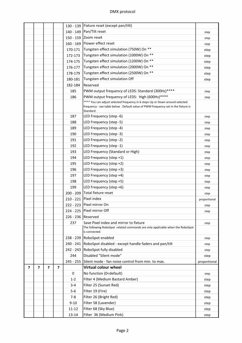
DMX protocol
130 - 139 Fixture reset (except pan/tilt)
140 - 149 Pan/Tilt reset step
150 - 159 Zoom reset step
160 - 169 Flower effect reset step
170-171 Tungsten effect simulation (750W) On ** step
172-173 Tungsten effect simulation (1000W) On ** step
174-175 Tungsten effect simulation (1200W) On ** step
176-177 Tungsten effect simulation (2000W) On ** step
178-179 Tungsten effect simulation (2500W) On ** step
180-181 Tungsten effect simulation Off step
182-184 Reserved185 PWM output frequency of LEDS: Standard (300Hz)**** step
186 PWM output frequency of LEDS: High (600Hz)**** step**** You can adjust selected frequency in 6 steps Up or Down around selected frequency - see table below . Default value of PWM frequency set in the fixture is Standard.
187 LED Frequency (step -6) step
188 LED Frequency (step -5) step
189 LED Frequency (step -4) step
190 LED Frequency (step -3) step
191 LED Frequency (step -2) step
192 LED Frequency (step -1) step
193 LED Frequency (Standard or High) step
194 LED Frequency (step +1) step
195 LED Frequency (step +2) step
196 LED Frequency (step +3) step
197 LED Frequency (step +4) step
198 LED Frequency (step +5) step
199 LED Frequency (step +6) step
200 - 209 Total fixture reset step
210 - 221 Pixel index proportional
222 - 223 Pixel mirror On step
224 - 225 Pixel mirror Off step
226 - 236 Reserved237 Save Pixel index and mirror to fixture step
The following RoboSpot related commands are only applicable when the RoboSpot is connected:
238 - 239 RoboSpot enabled step
240 - 241 RoboSpot disabled - except handle faders and pan/tilt step
242 - 243 RoboSpot fully disabled step
244 Disabled "Silent mode" step
245 - 255 Silent mode - fan noise control from min. to max. proportional
7 7 7 7 Virtual colour wheel0 No function (0=default) step
1-2 Filter 4 (Medium Bastard Amber) step
3-4 Filter 25 (Sunset Red) step
5-6 Filter 19 (Fire) step
7-8 Filter 26 (Bright Red) step
9-10 Filter 58 (Lavender) step
11-12 Filter 68 (Sky Blue) step
13-14 Filter 36 (Medium Pink) step
Page 2
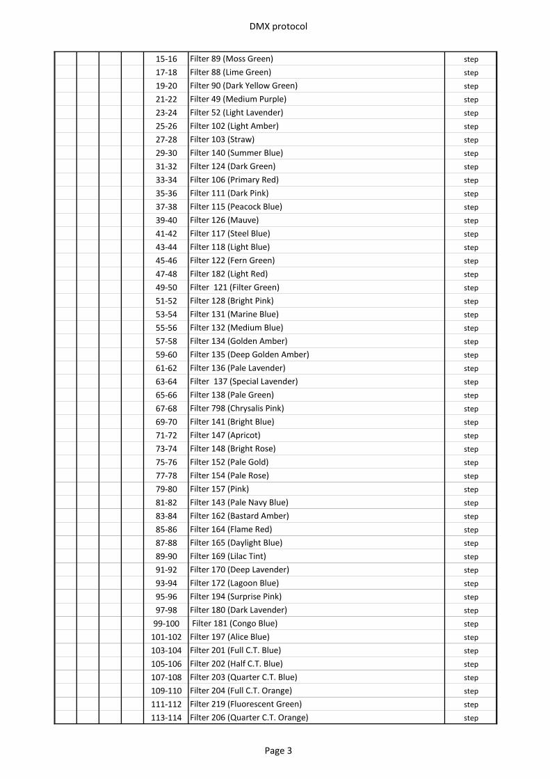
DMX protocol
15-16 Filter 89 (Moss Green) step
17-18 Filter 88 (Lime Green) step
19-20 Filter 90 (Dark Yellow Green) step
21-22 Filter 49 (Medium Purple) step
23-24 Filter 52 (Light Lavender) step
25-26 Filter 102 (Light Amber) step
27-28 Filter 103 (Straw) step
29-30 Filter 140 (Summer Blue) step
31-32 Filter 124 (Dark Green) step
33-34 Filter 106 (Primary Red) step
35-36 Filter 111 (Dark Pink) step
37-38 Filter 115 (Peacock Blue) step
39-40 Filter 126 (Mauve) step
41-42 Filter 117 (Steel Blue) step
43-44 Filter 118 (Light Blue) step
45-46 Filter 122 (Fern Green) step
47-48 Filter 182 (Light Red) step
49-50 Filter 121 (Filter Green) step
51-52 Filter 128 (Bright Pink) step
53-54 Filter 131 (Marine Blue) step
55-56 Filter 132 (Medium Blue) step
57-58 Filter 134 (Golden Amber) step
59-60 Filter 135 (Deep Golden Amber) step
61-62 Filter 136 (Pale Lavender) step
63-64 Filter 137 (Special Lavender) step
65-66 Filter 138 (Pale Green) step
67-68 Filter 798 (Chrysalis Pink) step
69-70 Filter 141 (Bright Blue) step
71-72 Filter 147 (Apricot) step
73-74 Filter 148 (Bright Rose) step
75-76 Filter 152 (Pale Gold) step
77-78 Filter 154 (Pale Rose) step
79-80 Filter 157 (Pink) step
81-82 Filter 143 (Pale Navy Blue) step
83-84 Filter 162 (Bastard Amber) step
85-86 Filter 164 (Flame Red) step
87-88 Filter 165 (Daylight Blue) step
89-90 Filter 169 (Lilac Tint) step
91-92 Filter 170 (Deep Lavender) step
93-94 Filter 172 (Lagoon Blue) step
95-96 Filter 194 (Surprise Pink) step
97-98 Filter 180 (Dark Lavender) step
99-100 Filter 181 (Congo Blue) step
101-102 Filter 197 (Alice Blue) step
103-104 Filter 201 (Full C.T. Blue) step
105-106 Filter 202 (Half C.T. Blue) step
107-108 Filter 203 (Quarter C.T. Blue) step
109-110 Filter 204 (Full C.T. Orange) step
111-112 Filter 219 (Fluorescent Green) step
113-114 Filter 206 (Quarter C.T. Orange) step
Page 3
DMX protocol
115-116 Filter 247 (Filter Minus Green) step
117-118 Filter 248 (Half Minus Green) step
119-120 Filter 281 (Three Quarter C.T. Blue) step
121-122 Filter 285 (Three Quarter C.T. Orange) step
123-124 Filter 352 (Glacier Blue) step
125-126 Filter 353 (Lighter Blue) step
127-128 Filter 507 (Madge) step
129-130 Filter 778 (Millennium Gold) step
131-132 Filter 793 (Vanity Fair) step
133-235 Raw DMX proportional
236-245 Rainbow effect (with fade time) from slow-> fast proportional
246-255 Rainbow effect (without fade time) from slow-> fast proportional
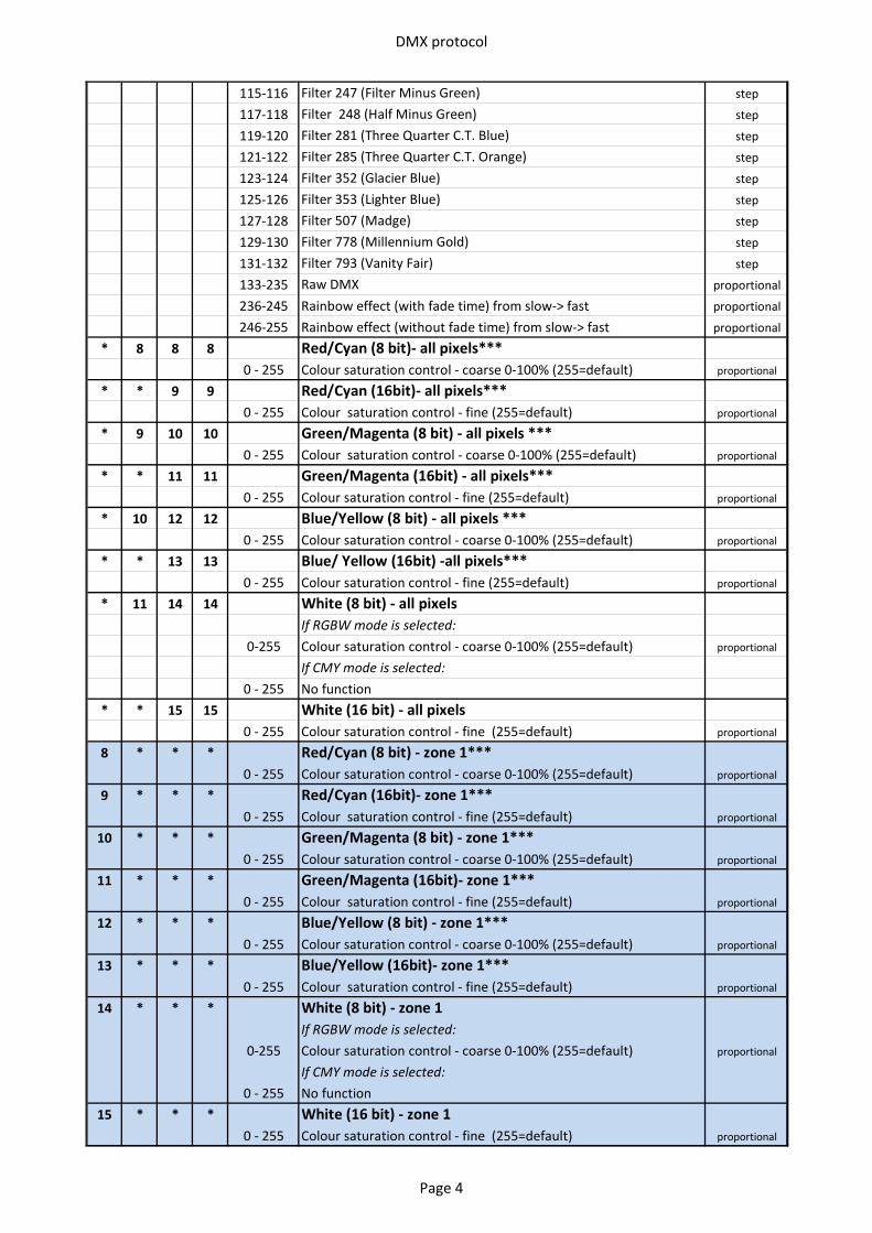
* 8 8 8 Red/Cyan (8 bit)- all pixels***0 - 255 Colour saturation control - coarse 0-100% (255=default) proportional
* * 9 9 Red/Cyan (16bit)- all pixels***0 - 255 Colour saturation control - fine (255=default) proportional
* 9 10 10 Green/Magenta (8 bit) - all pixels ***0 - 255 Colour saturation control - coarse 0-100% (255=default) proportional
* * 11 11 Green/Magenta (16bit) - all pixels***0 - 255 Colour saturation control - fine (255=default) proportional
* 10 12 12 Blue/Yellow (8 bit) - all pixels ***0 - 255 Colour saturation control - coarse 0-100% (255=default) proportional
* * 13 13 Blue/ Yellow (16bit) -all pixels***0 - 255 Colour saturation control - fine (255=default) proportional
* 11 14 14 White (8 bit) - all pixelsIf RGBW mode is selected:
0-255 Colour saturation control - coarse 0-100% (255=default) proportional
If CMY mode is selected:0 - 255 No function
* * 15 15 White (16 bit) - all pixels0 - 255 Colour saturation control - fine (255=default) proportional
8 * * * Red/Cyan (8 bit) - zone 1***0 - 255 Colour saturation control - coarse 0-100% (255=default) proportional
9 * * * Red/Cyan (16bit)- zone 1***0 - 255 Colour saturation control - fine (255=default) proportional
10 * * * Green/Magenta (8 bit) - zone 1***0 - 255 Colour saturation control - coarse 0-100% (255=default) proportional
11 * * * Green/Magenta (16bit)- zone 1***0 - 255 Colour saturation control - fine (255=default) proportional
12 * * * Blue/Yellow (8 bit) - zone 1***0 - 255 Colour saturation control - coarse 0-100% (255=default) proportional
13 * * * Blue/Yellow (16bit)- zone 1***0 - 255 Colour saturation control - fine (255=default) proportional
14 * * * White (8 bit) - zone 1If RGBW mode is selected:
0-255 Colour saturation control - coarse 0-100% (255=default) proportional
If CMY mode is selected:0 - 255 No function
15 * * * White (16 bit) - zone 10 - 255 Colour saturation control - fine (255=default) proportional
Page 4
DMX protocol
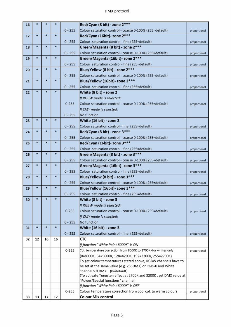
16 * * * Red/Cyan (8 bit) - zone 2***0 - 255 Colour saturation control - coarse 0-100% (255=default) proportional
17 * * * Red/Cyan (16bit)- zone 2***0 - 255 Colour saturation control - fine (255=default) proportional
18 * * * Green/Magenta (8 bit) - zone 2***0 - 255 Colour saturation control - coarse 0-100% (255=default) proportional
19 * * * Green/Magenta (16bit)- zone 2***0 - 255 Colour saturation control - fine (255=default) proportional
20 * * * Blue/Yellow (8 bit) - zone 2***0 - 255 Colour saturation control - coarse 0-100% (255=default) proportional
21 * * * Blue/Yellow (16bit)- zone 2***0 - 255 Colour saturation control - fine (255=default) proportional
22 * * * White (8 bit) - zone 2If RGBW mode is selected:
0-255 Colour saturation control - coarse 0-100% (255=default) proportional
If CMY mode is selected:0 - 255 No function
23 * * * White (16 bit) - zone 20 - 255 Colour saturation control - fine (255=default) proportional
24 * * * Red/Cyan (8 bit) - zone 3***0 - 255 Colour saturation control - coarse 0-100% (255=default) proportional
25 * * * Red/Cyan (16bit)- zone 3***0 - 255 Colour saturation control - fine (255=default) proportional
26 * * * Green/Magenta (8 bit) - zone 3***0 - 255 Colour saturation control - coarse 0-100% (255=default) proportional
27 * * * Green/Magenta (16bit)- zone 3***0 - 255 Colour saturation control - fine (255=default) proportional
28 * * * Blue/Yellow (8 bit) - zone 3***0 - 255 Colour saturation control - coarse 0-100% (255=default) proportional
29 * * * Blue/Yellow (16bit)- zone 3***0 - 255 Colour saturation control - fine (255=default) proportional
30 * * * White (8 bit) - zone 3If RGBW mode is selected:
0-255 Colour saturation control - coarse 0-100% (255=default) proportional
If CMY mode is selected:0 - 255 No function
31 * * * White (16 bit) - zone 30 - 255 Colour saturation control - fine (255=default) proportional
32 12 16 16 CTC If function "White Point 8000K" is ON
0-255 Col. temperature correction from 8000K to 2700K -for whites only proportional
(0=8000K, 64=5600K, 128=4200K, 192=3200K, 255=2700K) To get colour temperatures stated above, RGBW channels have to be set at the same value (e.g. 255DMX) or RGB=0 and White channel > 0 DMX (0=default)(To activate Tungsten effect at 2700K and 3200K , set DMX value at "Power/Special functions" channel)If function "White Point 8000K" is OFF
0-255 Colour temperature correction from cool col. to warm colours proportional
33 13 17 17 Colour Mix control
Page 5
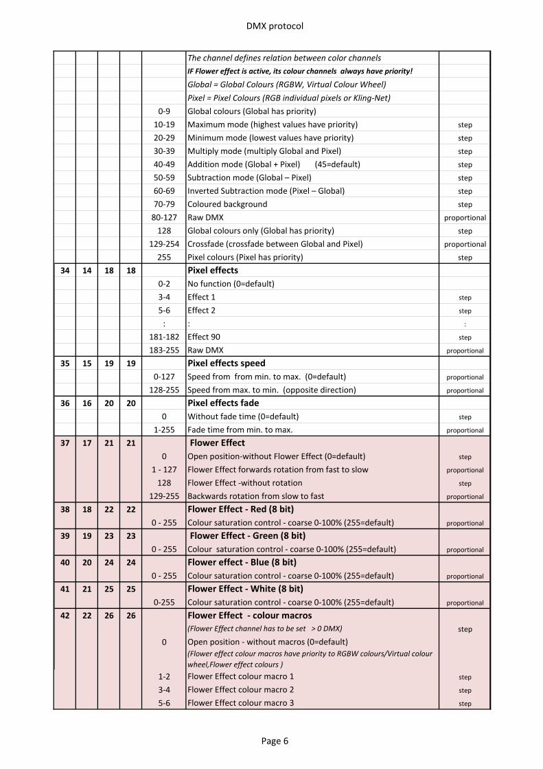
DMX protocol
The channel defines relation between color channelsIF Flower effect is active, its colour channels always have priority!
Global = Global Colours (RGBW, Virtual Colour Wheel)Pixel = Pixel Colours (RGB individual pixels or Kling-Net)
0-9 Global colours (Global has priority) 10-19 Maximum mode (highest values have priority) step
20-29 Minimum mode (lowest values have priority) step
30-39 Multiply mode (multiply Global and Pixel) step
40-49 Addition mode (Global + Pixel) (45=default) step
50-59 Subtraction mode (Global – Pixel) step
60-69 Inverted Subtraction mode (Pixel – Global) step
70-79 Coloured background step
80-127 Raw DMX proportional
128 Global colours only (Global has priority) step
129-254 Crossfade (crossfade between Global and Pixel) proportional
255 Pixel colours (Pixel has priority) step
34 14 18 18 Pixel effects0-2 No function (0=default)3-4 Effect 1 step
5-6 Effect 2 step
: : :
181-182 Effect 90 step
183-255 Raw DMX proportional
35 15 19 19 Pixel effects speed0-127 Speed from from min. to max. (0=default) proportional
128-255 Speed from max. to min. (opposite direction) proportional
36 16 20 20 Pixel effects fade0 Without fade time (0=default) step
1-255 Fade time from min. to max. proportional
37 17 21 21 Flower Effect0 Open position-without Flower Effect (0=default) step
1 - 127 Flower Effect forwards rotation from fast to slow proportional
128 Flower Effect -without rotation step
129-255 Backwards rotation from slow to fast proportional
38 18 22 22 Flower Effect - Red (8 bit)0 - 255 Colour saturation control - coarse 0-100% (255=default) proportional
39 19 23 23 Flower Effect - Green (8 bit) 0 - 255 Colour saturation control - coarse 0-100% (255=default) proportional
40 20 24 24 Flower effect - Blue (8 bit) 0 - 255 Colour saturation control - coarse 0-100% (255=default) proportional
41 21 25 25 Flower Effect - White (8 bit) 0-255 Colour saturation control - coarse 0-100% (255=default) proportional
42 22 26 26 Flower Effect - colour macros (Flower Effect channel has to be set > 0 DMX) step
0 Open position - without macros (0=default)(Flower effect colour macros have priority to RGBW colours/Virtual colour wheel,Flower effect colours )
1-2 Flower Effect colour macro 1 step
3-4 Flower Effect colour macro 2 step
5-6 Flower Effect colour macro 3 step
Page 6
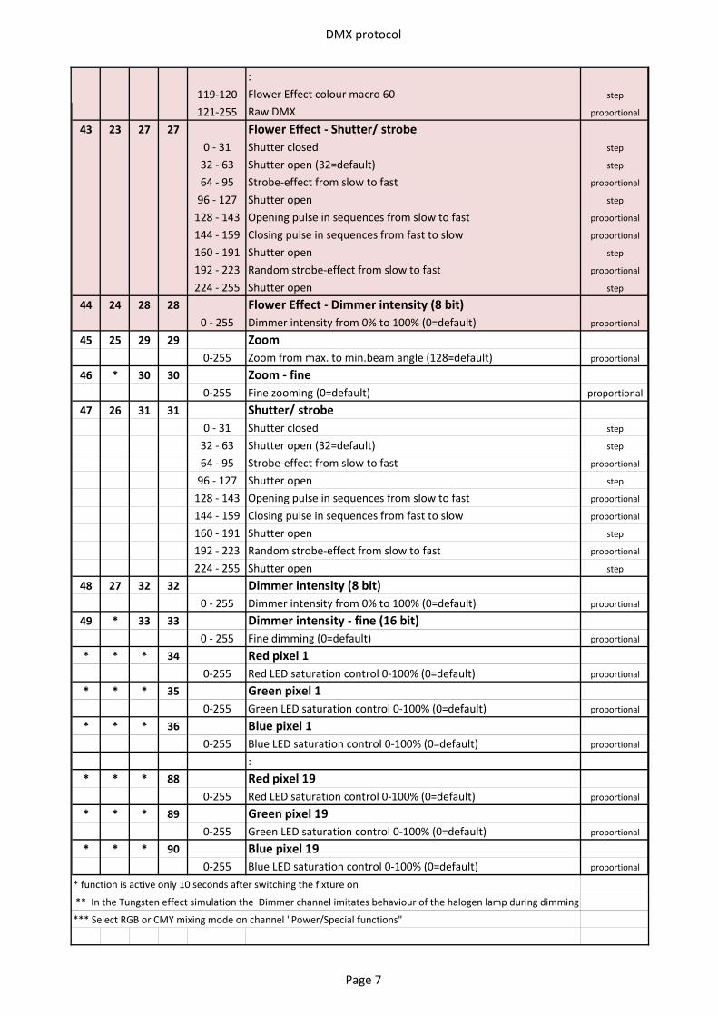
DMX protocol
:119-120 Flower Effect colour macro 60 step
121-255 Raw DMX proportional
43 23 27 27 Flower Effect - Shutter/ strobe 0 - 31 Shutter closed step
32 - 63 Shutter open (32=default) step
64 - 95 Strobe-effect from slow to fast proportional
96 - 127 Shutter open step
128 - 143 Opening pulse in sequences from slow to fast proportional
144 - 159 Closing pulse in sequences from fast to slow proportional
160 - 191 Shutter open step
192 - 223 Random strobe-effect from slow to fast proportional
224 - 255 Shutter open step
44 24 28 28 Flower Effect - Dimmer intensity (8 bit)0 - 255 Dimmer intensity from 0% to 100% (0=default) proportional
45 25 29 29 Zoom 0-255 Zoom from max. to min.beam angle (128=default) proportional
46 * 30 30 Zoom - fine0-255 Fine zooming (0=default) proportional
47 26 31 31 Shutter/ strobe0 - 31 Shutter closed step
32 - 63 Shutter open (32=default) step
64 - 95 Strobe-effect from slow to fast proportional
96 - 127 Shutter open step
128 - 143 Opening pulse in sequences from slow to fast proportional
144 - 159 Closing pulse in sequences from fast to slow proportional
160 - 191 Shutter open step
192 - 223 Random strobe-effect from slow to fast proportional
224 - 255 Shutter open step
48 27 32 32 Dimmer intensity (8 bit)0 - 255 Dimmer intensity from 0% to 100% (0=default) proportional
49 * 33 33 Dimmer intensity - fine (16 bit)0 - 255 Fine dimming (0=default) proportional
* * * 34 Red pixel 10-255 Red LED saturation control 0-100% (0=default) proportional
* * * 35 Green pixel 10-255 Green LED saturation control 0-100% (0=default) proportional
* * * 36 Blue pixel 10-255 Blue LED saturation control 0-100% (0=default) proportional
:* * * 88 Red pixel 19
0-255 Red LED saturation control 0-100% (0=default) proportional
* * * 89 Green pixel 190-255 Green LED saturation control 0-100% (0=default) proportional
* * * 90 Blue pixel 190-255 Blue LED saturation control 0-100% (0=default) proportional
* function is active only 10 seconds after switching the fixture on
** In the Tungsten effect simulation the Dimmer channel imitates behaviour of the halogen lamp during dimming
*** Select RGB or CMY mixing mode on channel "Power/Special functions"
Page 7

DMX protocol
Copyright © 2016-2020 Robe Lighting s.r.o. - All rights reservedAll Specifications subject to change without notice
Page 8
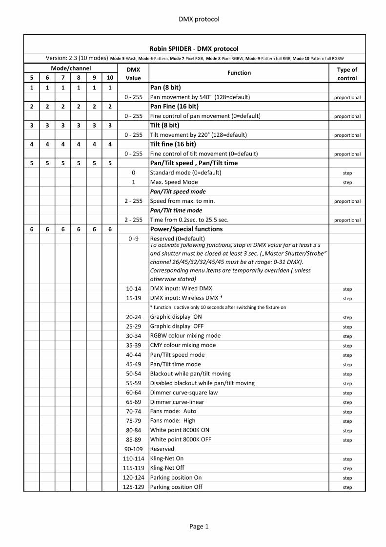
DMX protocol
5 6 7 8 9 10
1 1 1 1 1 1 Pan (8 bit)0 - 255 Pan movement by 540° (128=default) proportional
2 2 2 2 2 2 Pan Fine (16 bit)0 - 255 Fine control of pan movement (0=default) proportional
3 3 3 3 3 3 Tilt (8 bit)0 - 255 Tilt movement by 220° (128=default) proportional
4 4 4 4 4 4 Tilt fine (16 bit)0 - 255 Fine control of tilt movement (0=default) proportional
5 5 5 5 5 5 Pan/Tilt speed , Pan/Tilt time0 Standard mode (0=default) step
1 Max. Speed Mode step
Pan/Tilt speed mode2 - 255 Speed from max. to min. proportional
Pan/Tilt time mode 2 - 255 Time from 0.2sec. to 25.5 sec. proportional
6 6 6 6 6 6 Power/Special functions0 -9 Reserved (0=default)
To activate following functions, stop in DMX value for at least 3 s and shutter must be closed at least 3 sec. („Master Shutter/Strobe” channel 26/45/32/32/45/45 must be at range: 0-31 DMX). Corresponding menu items are temporarily overriden ( unless otherwise stated)
10-14 DMX input: Wired DMX step
15-19 DMX input: Wireless DMX * step
* function is active only 10 seconds after switching the fixture on
20-24 Graphic display ON step
25-29 Graphic display OFF step
30-34 RGBW colour mixing mode step
35-39 CMY colour mixing mode step
40-44 Pan/Tilt speed mode step
45-49 Pan/Tilt time mode step
50-54 Blackout while pan/tilt moving step
55-59 Disabled blackout while pan/tilt moving step
60-64 Dimmer curve-square law step
65-69 Dimmer curve-linear step
70-74 Fans mode: Auto step
75-79 Fans mode: High step
80-84 White point 8000K ON step
85-89 White point 8000K OFF step
90-109 Reserved110-114 Kling-Net On step
115-119 Kling-Net Off step
120-124 Parking position On step
125-129 Parking position Off step
Robin SPIIDER - DMX protocol Version: 2.3 (10 modes) Mode 5-Wash, Mode 6-Pattern, Mode 7-Pixel RGB, Mode 8-Pixel RGBW, Mode 9-Pattern full RGB, Mode 10-Pattern full RGBW
Mode/channel DMX Value
Function Type of control
Page 1
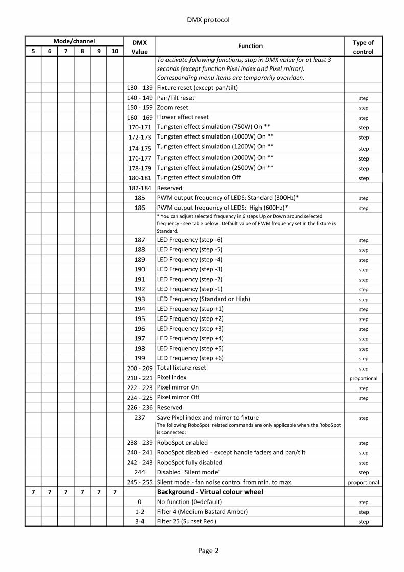
DMX protocol
5 6 7 8 9 10Mode/channel DMX
ValueFunction Type of
controlTo activate following functions, stop in DMX value for at least 3 seconds (except function Pixel index and Pixel mirror). Corresponding menu items are temporarily overriden.
130 - 139 Fixture reset (except pan/tilt)140 - 149 Pan/Tilt reset step
150 - 159 Zoom reset step
160 - 169 Flower effect reset step
170-171 Tungsten effect simulation (750W) On ** step
172-173 Tungsten effect simulation (1000W) On ** step
174-175 Tungsten effect simulation (1200W) On ** step
176-177 Tungsten effect simulation (2000W) On ** step
178-179 Tungsten effect simulation (2500W) On ** step
180-181 Tungsten effect simulation Off step
182-184 Reserved185 PWM output frequency of LEDS: Standard (300Hz)* step
186 PWM output frequency of LEDS: High (600Hz)* step* You can adjust selected frequency in 6 steps Up or Down around selected frequency - see table below . Default value of PWM frequency set in the fixture is Standard.
187 LED Frequency (step -6) step
188 LED Frequency (step -5) step
189 LED Frequency (step -4) step
190 LED Frequency (step -3) step
191 LED Frequency (step -2) step
192 LED Frequency (step -1) step
193 LED Frequency (Standard or High) step
194 LED Frequency (step +1) step
195 LED Frequency (step +2) step
196 LED Frequency (step +3) step
197 LED Frequency (step +4) step
198 LED Frequency (step +5) step
199 LED Frequency (step +6) step
200 - 209 Total fixture reset step
210 - 221 Pixel index proportional
222 - 223 Pixel mirror On step
224 - 225 Pixel mirror Off step
226 - 236 Reserved237 Save Pixel index and mirror to fixture step
The following RoboSpot related commands are only applicable when the RoboSpot is connected:
238 - 239 RoboSpot enabled step
240 - 241 RoboSpot disabled - except handle faders and pan/tilt step
242 - 243 RoboSpot fully disabled step
244 Disabled "Silent mode" step
245 - 255 Silent mode - fan noise control from min. to max. proportional
7 7 7 7 7 7 Background - Virtual colour wheel0 No function (0=default) step
1-2 Filter 4 (Medium Bastard Amber) step
3-4 Filter 25 (Sunset Red) step
Page 2
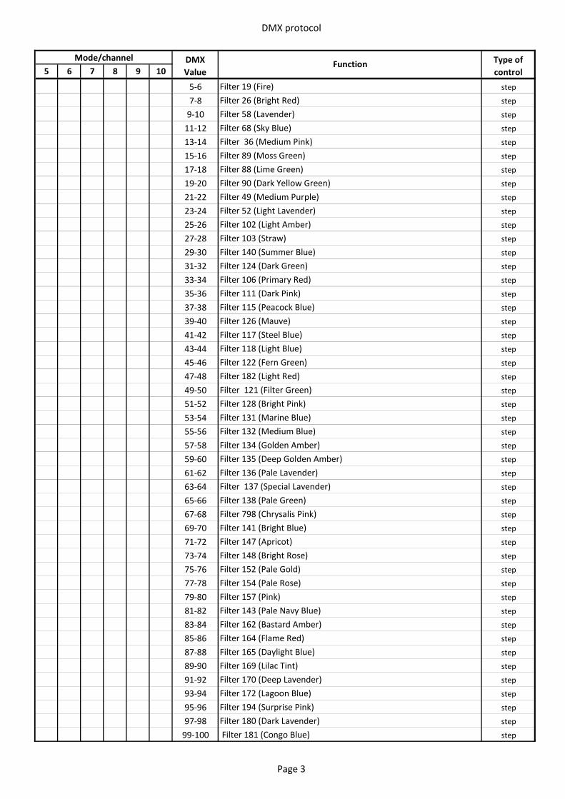
DMX protocol
5 6 7 8 9 10Mode/channel DMX
ValueFunction Type of
control
5-6 Filter 19 (Fire) step
7-8 Filter 26 (Bright Red) step
9-10 Filter 58 (Lavender) step
11-12 Filter 68 (Sky Blue) step
13-14 Filter 36 (Medium Pink) step
15-16 Filter 89 (Moss Green) step
17-18 Filter 88 (Lime Green) step
19-20 Filter 90 (Dark Yellow Green) step
21-22 Filter 49 (Medium Purple) step
23-24 Filter 52 (Light Lavender) step
25-26 Filter 102 (Light Amber) step
27-28 Filter 103 (Straw) step
29-30 Filter 140 (Summer Blue) step
31-32 Filter 124 (Dark Green) step
33-34 Filter 106 (Primary Red) step
35-36 Filter 111 (Dark Pink) step
37-38 Filter 115 (Peacock Blue) step
39-40 Filter 126 (Mauve) step
41-42 Filter 117 (Steel Blue) step
43-44 Filter 118 (Light Blue) step
45-46 Filter 122 (Fern Green) step
47-48 Filter 182 (Light Red) step
49-50 Filter 121 (Filter Green) step
51-52 Filter 128 (Bright Pink) step
53-54 Filter 131 (Marine Blue) step
55-56 Filter 132 (Medium Blue) step
57-58 Filter 134 (Golden Amber) step
59-60 Filter 135 (Deep Golden Amber) step
61-62 Filter 136 (Pale Lavender) step
63-64 Filter 137 (Special Lavender) step
65-66 Filter 138 (Pale Green) step
67-68 Filter 798 (Chrysalis Pink) step
69-70 Filter 141 (Bright Blue) step
71-72 Filter 147 (Apricot) step
73-74 Filter 148 (Bright Rose) step
75-76 Filter 152 (Pale Gold) step
77-78 Filter 154 (Pale Rose) step
79-80 Filter 157 (Pink) step
81-82 Filter 143 (Pale Navy Blue) step
83-84 Filter 162 (Bastard Amber) step
85-86 Filter 164 (Flame Red) step
87-88 Filter 165 (Daylight Blue) step
89-90 Filter 169 (Lilac Tint) step
91-92 Filter 170 (Deep Lavender) step
93-94 Filter 172 (Lagoon Blue) step
95-96 Filter 194 (Surprise Pink) step
97-98 Filter 180 (Dark Lavender) step
99-100 Filter 181 (Congo Blue) step
Page 3
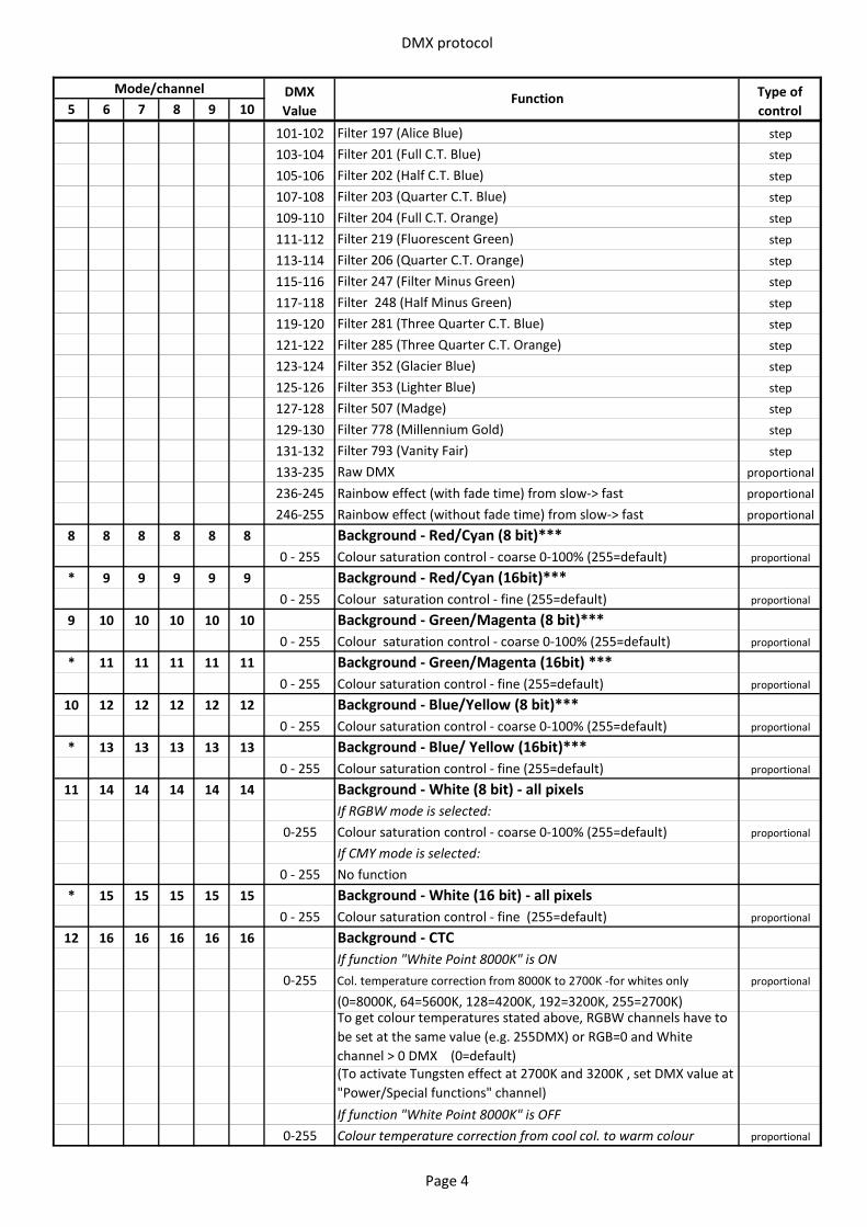
DMX protocol
5 6 7 8 9 10Mode/channel DMX
ValueFunction Type of
control
101-102 Filter 197 (Alice Blue) step
103-104 Filter 201 (Full C.T. Blue) step
105-106 Filter 202 (Half C.T. Blue) step
107-108 Filter 203 (Quarter C.T. Blue) step
109-110 Filter 204 (Full C.T. Orange) step
111-112 Filter 219 (Fluorescent Green) step
113-114 Filter 206 (Quarter C.T. Orange) step
115-116 Filter 247 (Filter Minus Green) step
117-118 Filter 248 (Half Minus Green) step
119-120 Filter 281 (Three Quarter C.T. Blue) step
121-122 Filter 285 (Three Quarter C.T. Orange) step
123-124 Filter 352 (Glacier Blue) step
125-126 Filter 353 (Lighter Blue) step
127-128 Filter 507 (Madge) step
129-130 Filter 778 (Millennium Gold) step
131-132 Filter 793 (Vanity Fair) step
133-235 Raw DMX proportional
236-245 Rainbow effect (with fade time) from slow-> fast proportional
246-255 Rainbow effect (without fade time) from slow-> fast proportional
8 8 8 8 8 8 Background - Red/Cyan (8 bit)***0 - 255 Colour saturation control - coarse 0-100% (255=default) proportional
* 9 9 9 9 9 Background - Red/Cyan (16bit)***0 - 255 Colour saturation control - fine (255=default) proportional
9 10 10 10 10 10 Background - Green/Magenta (8 bit)***0 - 255 Colour saturation control - coarse 0-100% (255=default) proportional
* 11 11 11 11 11 Background - Green/Magenta (16bit) ***0 - 255 Colour saturation control - fine (255=default) proportional
10 12 12 12 12 12 Background - Blue/Yellow (8 bit)***0 - 255 Colour saturation control - coarse 0-100% (255=default) proportional
* 13 13 13 13 13 Background - Blue/ Yellow (16bit)***0 - 255 Colour saturation control - fine (255=default) proportional
11 14 14 14 14 14 Background - White (8 bit) - all pixelsIf RGBW mode is selected:
0-255 Colour saturation control - coarse 0-100% (255=default) proportional
If CMY mode is selected:0 - 255 No function
* 15 15 15 15 15 Background - White (16 bit) - all pixels0 - 255 Colour saturation control - fine (255=default) proportional
12 16 16 16 16 16 Background - CTC If function "White Point 8000K" is ON
0-255 Col. temperature correction from 8000K to 2700K -for whites only proportional
(0=8000K, 64=5600K, 128=4200K, 192=3200K, 255=2700K) To get colour temperatures stated above, RGBW channels have to be set at the same value (e.g. 255DMX) or RGB=0 and White channel > 0 DMX (0=default)(To activate Tungsten effect at 2700K and 3200K , set DMX value at "Power/Special functions" channel)If function "White Point 8000K" is OFF
0-255 Colour temperature correction from cool col. to warm colour proportional
Page 4
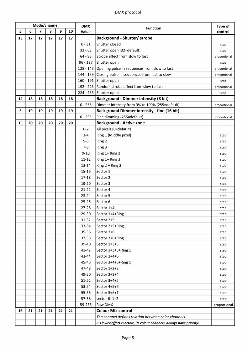
DMX protocol
5 6 7 8 9 10Mode/channel DMX
ValueFunction Type of
control
13 17 17 17 17 17 Background - Shutter/ strobe0 - 31 Shutter closed step
32 - 63 Shutter open (32=default) step
64 - 95 Strobe effect from slow to fast proportional
96 - 127 Shutter open step
128 - 143 Opening pulse in sequences from slow to fast proportional
144 - 159 Closing pulse in sequences from fast to slow proportional
160 - 191 Shutter open step
192 - 223 Random strobe effect from slow to fast proportional
224 - 255 Shutter open step
14 18 18 18 18 18 Background - Dimmer intensity (8 bit)0 - 255 Dimmer intensity from 0% to 100% (255=default) proportional
* 19 19 19 19 19 Background Dimmer intensity - fine (16 bit)0 - 255 Fine dimming (255=default) proportional
15 20 20 20 20 20 Background - Active zone0-2 All pixels (0=default)3-4 Ring 1 (Middle pixel) step
5-6 Ring 2 step
7-8 Ring 3 step
9-10 Ring 1+ Ring 2 step
11-12 Ring 1+ Ring 3 step
13-14 Ring 2 + Ring 3 step
15-16 Sector 1 step
17-18 Sector 2 step
19-20 Sector 3 step
21-22 Sector 4 step
23-24 Sector 5 step
25-26 Sector 6 step
27-28 Sector 1+4 step
29-30 Sector 1+4+Ring 1 step
31-32 Sector 2+5 step
33-34 Sector 2+5+Ring 1 step
35-36 Sector 3+6 step
37-38 Sector 3+6+Ring 1 step
39-40 Sector 1+3+5 step
41-42 Sector 1+3+5+Ring 1 step
43-44 Sector 2+4+6 step
45-46 Sector 2+4+6+Ring 1 step
47-48 Sector 1+2+3 step
49-50 Sector 2+3+4 step
51-52 Sector 3+4+5 step
53-54 Sector 4+5+6 step
55-56 Sector 5+6+1 step
57-58 sector 6+1+2 step
59-255 Raw DMX proportional
16 21 21 21 21 21 Colour Mix control The channel defines relation between color channelsIF Flower effect is active, its colour channels always have priority!
Page 5
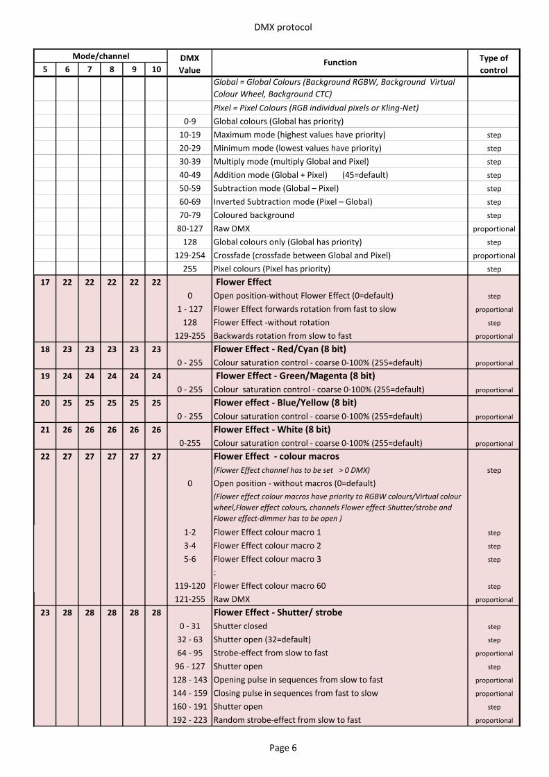
DMX protocol
5 6 7 8 9 10Mode/channel DMX
ValueFunction Type of
controlGlobal = Global Colours (Background RGBW, Background Virtual Colour Wheel, Background CTC)Pixel = Pixel Colours (RGB individual pixels or Kling-Net)
0-9 Global colours (Global has priority) 10-19 Maximum mode (highest values have priority) step
20-29 Minimum mode (lowest values have priority) step
30-39 Multiply mode (multiply Global and Pixel) step
40-49 Addition mode (Global + Pixel) (45=default) step
50-59 Subtraction mode (Global – Pixel) step
60-69 Inverted Subtraction mode (Pixel – Global) step
70-79 Coloured background step
80-127 Raw DMX proportional
128 Global colours only (Global has priority) step
129-254 Crossfade (crossfade between Global and Pixel) proportional
255 Pixel colours (Pixel has priority) step
17 22 22 22 22 22 Flower Effect0 Open position-without Flower Effect (0=default) step
1 - 127 Flower Effect forwards rotation from fast to slow proportional
128 Flower Effect -without rotation step
129-255 Backwards rotation from slow to fast proportional
18 23 23 23 23 23 Flower Effect - Red/Cyan (8 bit) 0 - 255 Colour saturation control - coarse 0-100% (255=default) proportional
19 24 24 24 24 24 Flower Effect - Green/Magenta (8 bit) 0 - 255 Colour saturation control - coarse 0-100% (255=default) proportional
20 25 25 25 25 25 Flower effect - Blue/Yellow (8 bit) 0 - 255 Colour saturation control - coarse 0-100% (255=default) proportional
21 26 26 26 26 26 Flower Effect - White (8 bit) 0-255 Colour saturation control - coarse 0-100% (255=default) proportional
22 27 27 27 27 27 Flower Effect - colour macros (Flower Effect channel has to be set > 0 DMX) step
0 Open position - without macros (0=default)(Flower effect colour macros have priority to RGBW colours/Virtual colour wheel,Flower effect colours, channels Flower effect-Shutter/strobe and Flower effect-dimmer has to be open )
1-2 Flower Effect colour macro 1 step
3-4 Flower Effect colour macro 2 step
5-6 Flower Effect colour macro 3 step
:119-120 Flower Effect colour macro 60 step
121-255 Raw DMX proportional
23 28 28 28 28 28 Flower Effect - Shutter/ strobe 0 - 31 Shutter closed step
32 - 63 Shutter open (32=default) step
64 - 95 Strobe-effect from slow to fast proportional
96 - 127 Shutter open step
128 - 143 Opening pulse in sequences from slow to fast proportional
144 - 159 Closing pulse in sequences from fast to slow proportional
160 - 191 Shutter open step
192 - 223 Random strobe-effect from slow to fast proportional
Page 6
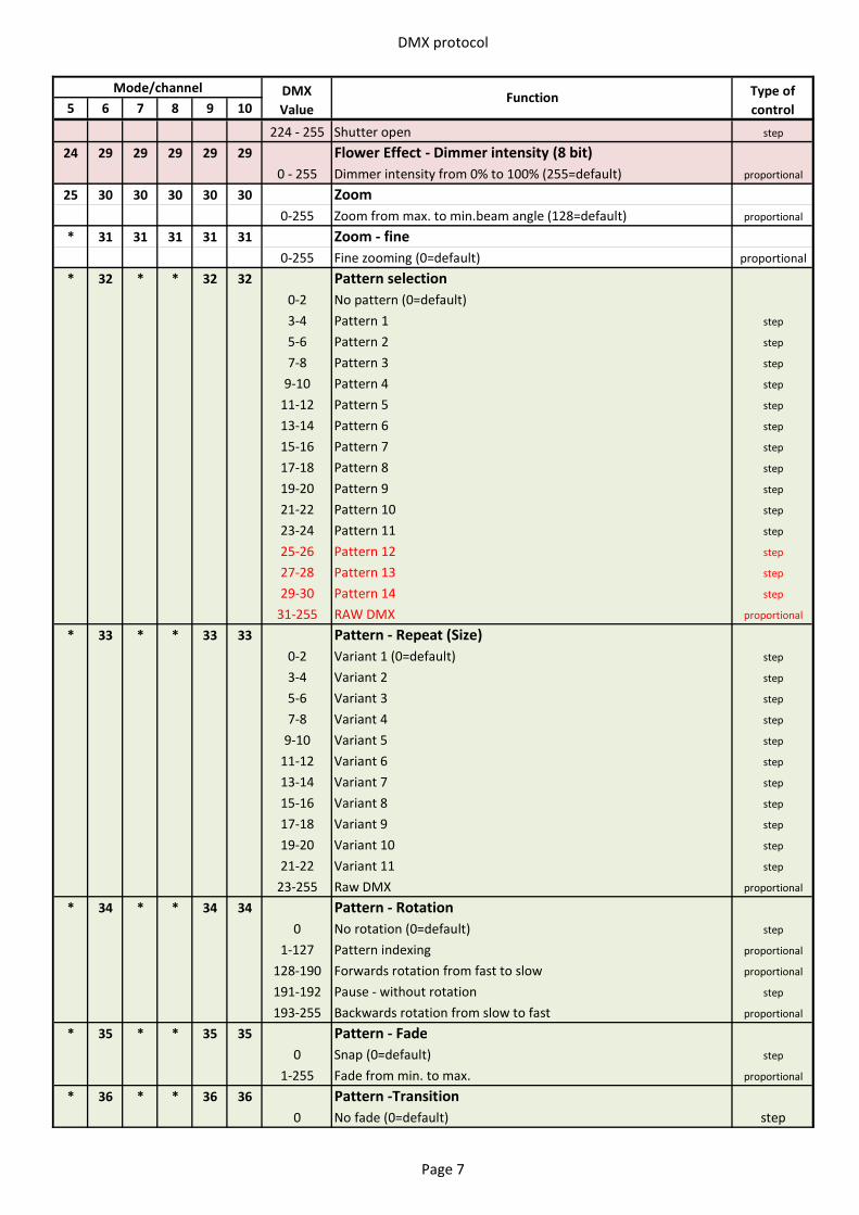
DMX protocol
5 6 7 8 9 10Mode/channel DMX
ValueFunction Type of
control
224 - 255 Shutter open step
24 29 29 29 29 29 Flower Effect - Dimmer intensity (8 bit)0 - 255 Dimmer intensity from 0% to 100% (255=default) proportional
25 30 30 30 30 30 Zoom 0-255 Zoom from max. to min.beam angle (128=default) proportional
* 31 31 31 31 31 Zoom - fine0-255 Fine zooming (0=default) proportional
* 32 * * 32 32 Pattern selection0-2 No pattern (0=default)3-4 Pattern 1 step
5-6 Pattern 2 step
7-8 Pattern 3 step
9-10 Pattern 4 step
11-12 Pattern 5 step
13-14 Pattern 6 step
15-16 Pattern 7 step
17-18 Pattern 8 step
19-20 Pattern 9 step
21-22 Pattern 10 step
23-24 Pattern 11 step
25-26 Pattern 12 step
27-28 Pattern 13 step
29-30 Pattern 14 step
31-255 RAW DMX proportional
* 33 * * 33 33 Pattern - Repeat (Size)0-2 Variant 1 (0=default) step
3-4 Variant 2 step
5-6 Variant 3 step
7-8 Variant 4 step
9-10 Variant 5 step
11-12 Variant 6 step
13-14 Variant 7 step
15-16 Variant 8 step
17-18 Variant 9 step
19-20 Variant 10 step
21-22 Variant 11 step
23-255 Raw DMX proportional
* 34 * * 34 34 Pattern - Rotation0 No rotation (0=default) step
1-127 Pattern indexing proportional
128-190 Forwards rotation from fast to slow proportional
191-192 Pause - without rotation step
193-255 Backwards rotation from slow to fast proportional
* 35 * * 35 35 Pattern - Fade0 Snap (0=default) step
1-255 Fade from min. to max. proportional
* 36 * * 36 36 Pattern -Transition0 No fade (0=default) step
Page 7
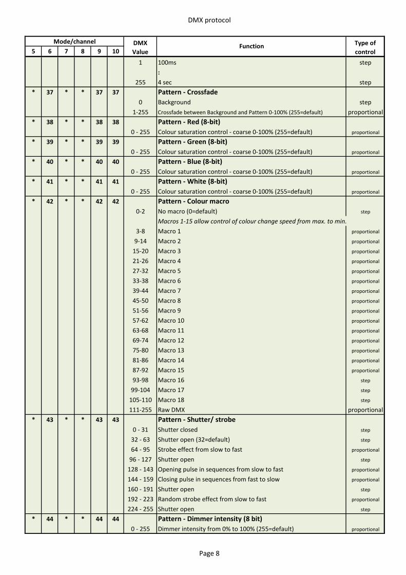
DMX protocol
5 6 7 8 9 10Mode/channel DMX
ValueFunction Type of
control
1 100ms step:
255 4 sec step* 37 * * 37 37 Pattern - Crossfade
0 Background step1-255 Crossfade between Background and Pattern 0-100% (255=default) proportional
* 38 * * 38 38 Pattern - Red (8-bit)0 - 255 Colour saturation control - coarse 0-100% (255=default) proportional
* 39 * * 39 39 Pattern - Green (8-bit)0 - 255 Colour saturation control - coarse 0-100% (255=default) proportional
* 40 * * 40 40 Pattern - Blue (8-bit)0 - 255 Colour saturation control - coarse 0-100% (255=default) proportional
* 41 * * 41 41 Pattern - White (8-bit)0 - 255 Colour saturation control - coarse 0-100% (255=default) proportional
* 42 * * 42 42 Pattern - Colour macro 0-2 No macro (0=default) step
Macros 1-15 allow control of colour change speed from max. to min.3-8 Macro 1 proportional
9-14 Macro 2 proportional
15-20 Macro 3 proportional
21-26 Macro 4 proportional
27-32 Macro 5 proportional
33-38 Macro 6 proportional
39-44 Macro 7 proportional
45-50 Macro 8 proportional
51-56 Macro 9 proportional
57-62 Macro 10 proportional
63-68 Macro 11 proportional
69-74 Macro 12 proportional
75-80 Macro 13 proportional
81-86 Macro 14 proportional
87-92 Macro 15 proportional
93-98 Macro 16 step
99-104 Macro 17 step
105-110 Macro 18 step
111-255 Raw DMX proportional* 43 * * 43 43 Pattern - Shutter/ strobe
0 - 31 Shutter closed step
32 - 63 Shutter open (32=default) step
64 - 95 Strobe effect from slow to fast proportional
96 - 127 Shutter open step
128 - 143 Opening pulse in sequences from slow to fast proportional
144 - 159 Closing pulse in sequences from fast to slow proportional
160 - 191 Shutter open step
192 - 223 Random strobe effect from slow to fast proportional
224 - 255 Shutter open step
* 44 * * 44 44 Pattern - Dimmer intensity (8 bit)0 - 255 Dimmer intensity from 0% to 100% (255=default) proportional
Page 8
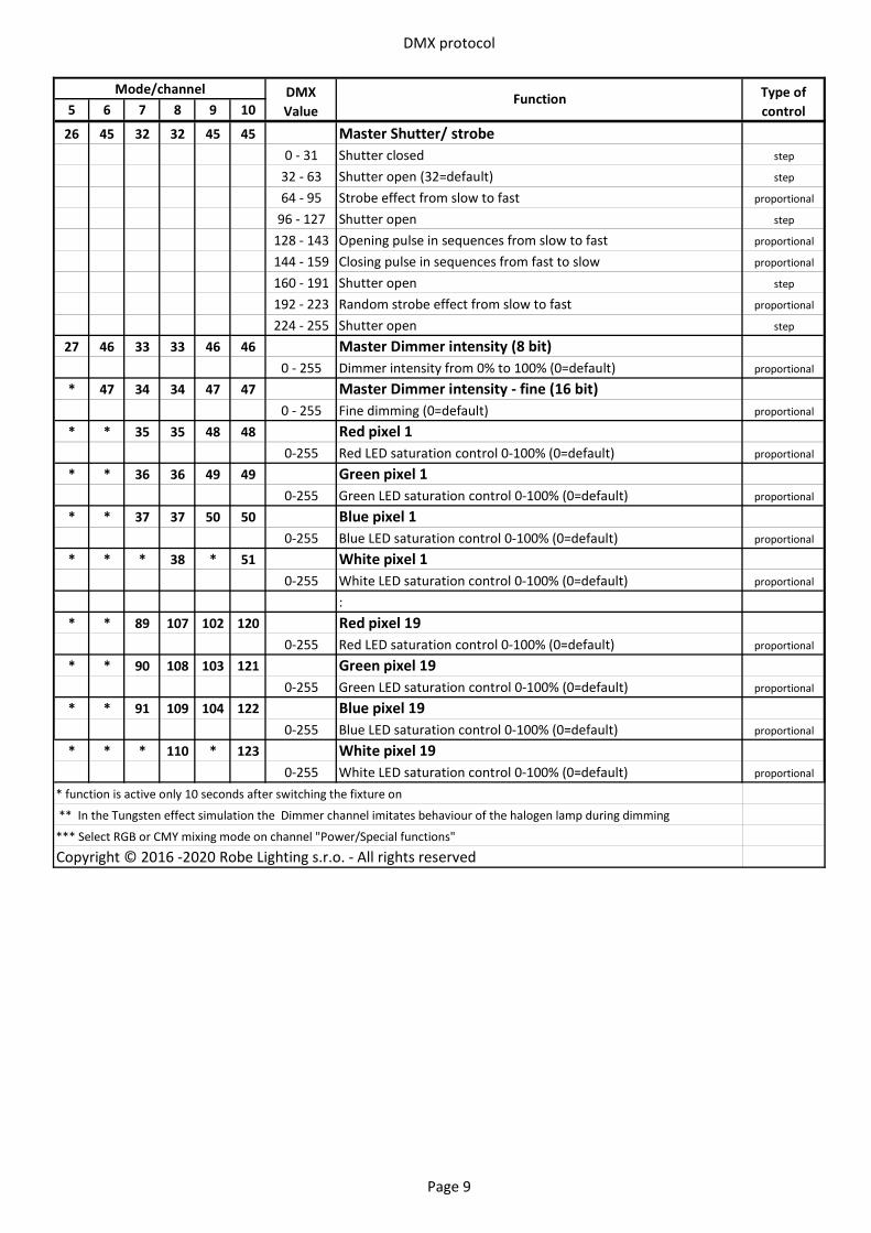
DMX protocol
5 6 7 8 9 10Mode/channel DMX
ValueFunction Type of
control
26 45 32 32 45 45 Master Shutter/ strobe0 - 31 Shutter closed step
32 - 63 Shutter open (32=default) step
64 - 95 Strobe effect from slow to fast proportional
96 - 127 Shutter open step
128 - 143 Opening pulse in sequences from slow to fast proportional
144 - 159 Closing pulse in sequences from fast to slow proportional
160 - 191 Shutter open step
192 - 223 Random strobe effect from slow to fast proportional
224 - 255 Shutter open step
27 46 33 33 46 46 Master Dimmer intensity (8 bit)0 - 255 Dimmer intensity from 0% to 100% (0=default) proportional
* 47 34 34 47 47 Master Dimmer intensity - fine (16 bit)0 - 255 Fine dimming (0=default) proportional
* * 35 35 48 48 Red pixel 10-255 Red LED saturation control 0-100% (0=default) proportional
* * 36 36 49 49 Green pixel 10-255 Green LED saturation control 0-100% (0=default) proportional
* * 37 37 50 50 Blue pixel 10-255 Blue LED saturation control 0-100% (0=default) proportional
* * * 38 * 51 White pixel 10-255 White LED saturation control 0-100% (0=default) proportional
:* * 89 107 102 120 Red pixel 19
0-255 Red LED saturation control 0-100% (0=default) proportional
* * 90 108 103 121 Green pixel 190-255 Green LED saturation control 0-100% (0=default) proportional
* * 91 109 104 122 Blue pixel 190-255 Blue LED saturation control 0-100% (0=default) proportional
* * * 110 * 123 White pixel 190-255 White LED saturation control 0-100% (0=default) proportional
* function is active only 10 seconds after switching the fixture on
** In the Tungsten effect simulation the Dimmer channel imitates behaviour of the halogen lamp during dimming
*** Select RGB or CMY mixing mode on channel "Power/Special functions"
Copyright © 2016 -2020 Robe Lighting s.r.o. - All rights reserved
Page 9
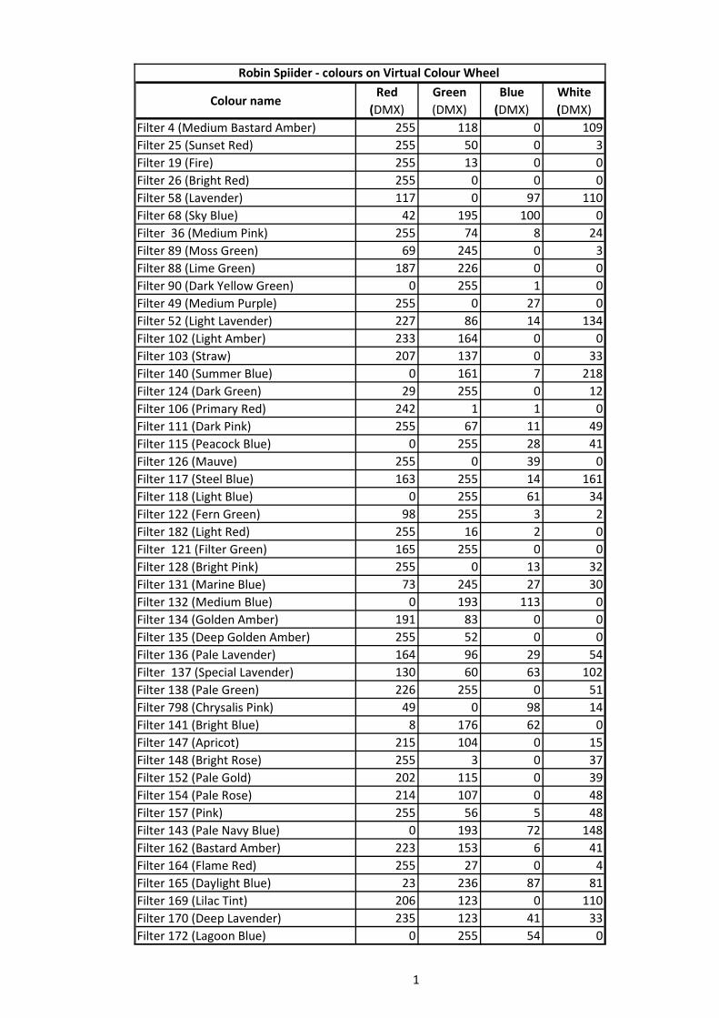
Colour nameRed
(DMX)Green (DMX)
Blue (DMX)
White (DMX)
Filter 4 (Medium Bastard Amber) 255 118 0 109Filter 25 (Sunset Red) 255 50 0 3Filter 19 (Fire) 255 13 0 0Filter 26 (Bright Red) 255 0 0 0Filter 58 (Lavender) 117 0 97 110Filter 68 (Sky Blue) 42 195 100 0Filter 36 (Medium Pink) 255 74 8 24Filter 89 (Moss Green) 69 245 0 3Filter 88 (Lime Green) 187 226 0 0Filter 90 (Dark Yellow Green) 0 255 1 0Filter 49 (Medium Purple) 255 0 27 0Filter 52 (Light Lavender) 227 86 14 134Filter 102 (Light Amber) 233 164 0 0Filter 103 (Straw) 207 137 0 33Filter 140 (Summer Blue) 0 161 7 218Filter 124 (Dark Green) 29 255 0 12Filter 106 (Primary Red) 242 1 1 0Filter 111 (Dark Pink) 255 67 11 49Filter 115 (Peacock Blue) 0 255 28 41Filter 126 (Mauve) 255 0 39 0Filter 117 (Steel Blue) 163 255 14 161Filter 118 (Light Blue) 0 255 61 34Filter 122 (Fern Green) 98 255 3 2Filter 182 (Light Red) 255 16 2 0Filter 121 (Filter Green) 165 255 0 0Filter 128 (Bright Pink) 255 0 13 32Filter 131 (Marine Blue) 73 245 27 30Filter 132 (Medium Blue) 0 193 113 0Filter 134 (Golden Amber) 191 83 0 0Filter 135 (Deep Golden Amber) 255 52 0 0Filter 136 (Pale Lavender) 164 96 29 54Filter 137 (Special Lavender) 130 60 63 102Filter 138 (Pale Green) 226 255 0 51Filter 798 (Chrysalis Pink) 49 0 98 14Filter 141 (Bright Blue) 8 176 62 0Filter 147 (Apricot) 215 104 0 15Filter 148 (Bright Rose) 255 3 0 37Filter 152 (Pale Gold) 202 115 0 39Filter 154 (Pale Rose) 214 107 0 48Filter 157 (Pink) 255 56 5 48Filter 143 (Pale Navy Blue) 0 193 72 148Filter 162 (Bastard Amber) 223 153 6 41Filter 164 (Flame Red) 255 27 0 4Filter 165 (Daylight Blue) 23 236 87 81Filter 169 (Lilac Tint) 206 123 0 110Filter 170 (Deep Lavender) 235 123 41 33Filter 172 (Lagoon Blue) 0 255 54 0
Robin Spiider - colours on Virtual Colour Wheel
1
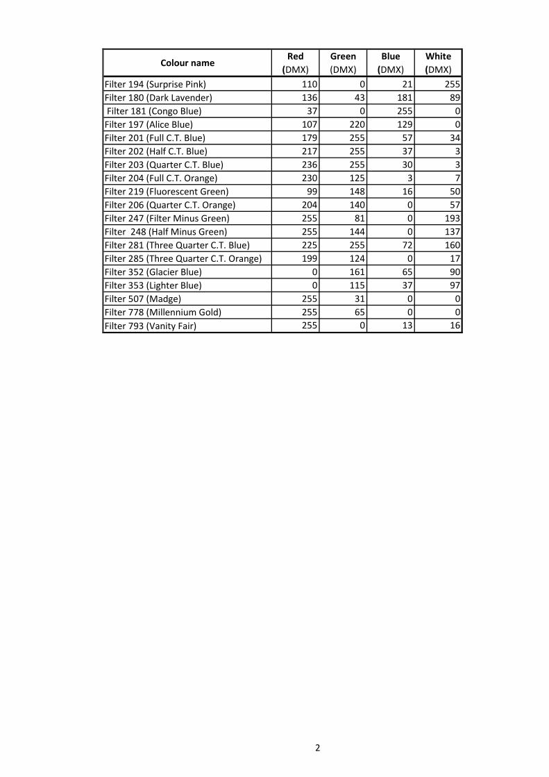
Colour nameRed
(DMX)Green (DMX)
Blue (DMX)
White (DMX)
Filter 194 (Surprise Pink) 110 0 21 255Filter 180 (Dark Lavender) 136 43 181 89 Filter 181 (Congo Blue) 37 0 255 0Filter 197 (Alice Blue) 107 220 129 0Filter 201 (Full C.T. Blue) 179 255 57 34Filter 202 (Half C.T. Blue) 217 255 37 3Filter 203 (Quarter C.T. Blue) 236 255 30 3Filter 204 (Full C.T. Orange) 230 125 3 7Filter 219 (Fluorescent Green) 99 148 16 50Filter 206 (Quarter C.T. Orange) 204 140 0 57Filter 247 (Filter Minus Green) 255 81 0 193Filter 248 (Half Minus Green) 255 144 0 137Filter 281 (Three Quarter C.T. Blue) 225 255 72 160Filter 285 (Three Quarter C.T. Orange) 199 124 0 17Filter 352 (Glacier Blue) 0 161 65 90Filter 353 (Lighter Blue) 0 115 37 97Filter 507 (Madge) 255 31 0 0Filter 778 (Millennium Gold) 255 65 0 0Filter 793 (Vanity Fair) 255 0 13 16
2