Embed Size (px)
Citation preview

Hand Vascular Pattern Recognition System
1
User’s Manual
VP-II X Hand Vascular Pattern Recognition System

2
Preface Thank you for choosing the VP-II X, Hand Vascular Pattern Recognition System.
This manual is to familiarize you with the features and functions of the VP-II X. It is recommended that you read through this manual before using the product for maximum performance.
VP-II X is a biometric scanner which verifies Users utilizing individually unique vascular patterns extracted from the hypoderm below the surface of the skin of the back of the hand using an infra-red based sensor device. The vascular pattern cannot be seen by the naked eye and is not easily affected by scars or contamination of hands. This results in no performance degradation in harsh environments, makes it 100% tamper-proof and eliminates privacy concerns with other biometric modalities. By utilizing HVPR technology, 99.98% of the entire population is able to use the system accurately and with the verification speed of 0.4 seconds, eliminating User bottlenecks and the requirement of a separate backdoor.
The VP-II X communicates with a server and/or other VP-II X devices through a TCP/IP network. An IP address can be obtained automatically by DHCP when connected to a local area network. Basic interface to a physical access control system (PACS) is Wiegand, and RS485 and/or RS232 can be also supported as an option.
VP-II X runs either as a stand-alone system or on a TCP/IP based network, and provides various interfaces to external systems through TCP/IP, Wiegand, RS232 and RS485. The application software running on a server is also provided.
Customer Service
To add or extend the configuration of installed products or required repairs and maintenance, please contact installer or product supplier for help from professional technician. For more information or technical support, or other service, please contact Techsphere customer service.
Techsphere Corporation (U.S & Canada)
U.S.A: 3435 Wilshire Blvd., Suite 1050, Los Angeles, CA 90010
Canada: 411 Confederation Pkwy, Unit 22, Vaughan, Ontario L4K 0A8
Tel: +1-877-833-4877(HVPR)
Techsphere Co., Ltd. (South Korea)
Wonil B/D 3F, 980-54 Bangbae, Seocho, Seoul 137-060 Korea
Tel: +82-2-523-4715
E-mail: [email protected] / [email protected]
Web: www.tech-sphere.com
Disclaimer
The information in this document is for informational purposes only. Techsphere Co., Ltd. assumes no liability for any inaccurate, or incomplete information, or for any actions taken in reliance thereon.
Note: The contents of this guide are subject to change in order to reflect improvements in product performance.
Copyright
This material is proprietary and shall not be used except for reference. Techsphere Co., Ltd. reserves the right to change or discontinue this product at any time.

3
Table of Contents Preface ........................................................................................................................................................ 2
Table of Contents ....................................................................................................................................... 3
Revision Information ................................................................................................................................. 5
Chapter 1 Overview ................................................................................................................................... 6
1. VP-II X Scanner ....................................................................................................................................... 6 2. Network Configuration ............................................................................................................................. 7
2.1 Master/Slave Operation .................................................................................................................... 7 2.2 Networking VP-II X ............................................................................................................................ 8
3. VP-II X Specification ................................................................................................................................ 9 4. Guideline to Place a Hand ...................................................................................................................... 11
Chapter 2 Enrollment, Deletion and Verification .................................................................................. 12
1. Manager Menu ...................................................................................................................................... 12 1.1 Manager .......................................................................................................................................... 12 1.2 Installer ............................................................................................................................................ 12 1.3 Test Mode ........................................................................................................................................ 12 1.4 Enrolling an Installer ........................................................................................................................ 12 1.5 Manager Menu Access ................................................................................................................... 13 1.6 Key Usage in the Manager Menu ................................................................................................... 13 1.7 Menu Tree ....................................................................................................................................... 13
2. Enrollment ............................................................................................................................................. 15 2.1 User Type ........................................................................................................................................ 15 2.2 User/Manager Enrolment ................................................................................................................ 16
2.2.1 Enrollment options ................................................................................................................. 16 3. Deletion ................................................................................................................................................. 18
3.1 Delete Installer ................................................................................................................................ 18 3.2 Delete Users ................................................................................................................................... 18
4. Verification ............................................................................................................................................. 19 4.1 Manager Verification ....................................................................................................................... 19 4.2 Password User Verification ............................................................................................................. 20 4.3 Job Code Input ................................................................................................................................ 20 4.4 Verification With a Card Number ..................................................................................................... 20 4.5 Verification With a Function Key ..................................................................................................... 20 4.6 Verification With Duress Code ........................................................................................................ 20 4.7 Installer Verification ......................................................................................................................... 21
5. Modifying User Information.................................................................................................................... 21 5.1 Edit User ......................................................................................................................................... 21 5.2 Template Management (Add/Update Vascular Data) ...................................................................... 22
5.2.1 Vascular Update .................................................................................................................... 22 5.2.2 Multiple Template Assignment ............................................................................................... 23 5.2.3 Smart Card Update ................................................................................................................ 23
Chapter 3 Environment Setup ................................................................................................................ 24
1. Network Setup ....................................................................................................................................... 24 1.1 Set Network Environment (TCP/IP Parameters) ............................................................................ 24 1.2 Master/Slave Setting ....................................................................................................................... 24

4
1.3 Server Setting ................................................................................................................................. 25 1.4 Slave List ......................................................................................................................................... 26
2. System Setup ........................................................................................................................................ 27 2.1 Date/Time Set ................................................................................................................................. 27 2.2 Firmware Information ...................................................................................................................... 27 2.3 VP Set (Security level, Liveness detection, Retry times) ................................................................ 27 2.4 Door Settings .................................................................................................................................. 28
2.4.1 VP-II XG (Door Controller) ..................................................................................................... 28 2.5 Daylight Saving Time ...................................................................................................................... 29 2.6 System initialization (Reset to Factory Settings) ............................................................................ 30 2.7 Door lock Setting ............................................................................................................................. 30 2.8 AUX Settings ................................................................................................................................... 31
3. Operation Settings ................................................................................................................................. 32 3.1 Mode Settings (Network / Serial) .................................................................................................... 32 3.2 Test Mode Release ......................................................................................................................... 32 3.3 Keypad Input Settings ..................................................................................................................... 32 3.4 Sleep Mode ..................................................................................................................................... 33 3.5 Tamper Switch Setting .................................................................................................................... 33 3.6 DB Search Option ........................................................................................................................... 33
4. UI Settings ............................................................................................................................................. 34 4.1 Language Settings .......................................................................................................................... 34 4.2 Sound Settings ................................................................................................................................ 34 4.3 PIN Display Option .......................................................................................................................... 34
5. Card Settings ......................................................................................................................................... 35 5.1 Wiegand Settings ............................................................................................................................ 35
5.1.1 Wiegand Output ..................................................................................................................... 35 5.1.2 Set Wiegand Format .............................................................................................................. 35 5.1.3 Wiegand Output Options ....................................................................................................... 36
5.2 Mifare / iClass Card ......................................................................................................................... 37 5.3 PACS System Settings .................................................................................................................... 39
6. Tools ...................................................................................................................................................... 40 6.1 Report ............................................................................................................................................. 40 6.2 Diagnostic Tools .............................................................................................................................. 40
6.2.1 Network Diagnostics .............................................................................................................. 40 6.2.2 Network Info. .......................................................................................................................... 40
6.3 Soft Reset ....................................................................................................................................... 41
Chapter 4 Appendix ................................................................................................................................. 42
1. Firmware Upgrade ................................................................................................................................. 42 2. Quick Installation Guide ......................................................................................................................... 44
2.1 VP-II X Location .............................................................................................................................. 44 2.2 Ports and Connections .................................................................................................................... 45
3. Event Report Viewer .............................................................................................................................. 47 4. Tray Icons .............................................................................................................................................. 48

5
Revision Information V1 May 26, 2009 Draft
V1.0 June 3, 2009 First release
V1.1 December 10, 2009
− U.S and Canada customer service contact (Techsphere Corporation) − Formatted to letter size
V1.2 April 01, 2010 (Internal management purpose)
V1.3 June 09, 2010
− Changed all related VP-II X images − Added new functions by the firmware – app-0.1.14.v56

6
Chapter 1 Overview
1. VP-II X Scanner
Display
Display
USB port
Keypad
RF Antenna Hand input indicator
Trigger switch
Speaker
Handle
Status indicator Date & Time

7
USB Port
A USB port is available to be used for firmware upgrade or database backup.
Keypad
VP-II X keypad consists of 10 digit keys (0~9), an enter key (ENT), an escape key (ESC) and four function keys (F1 ~ F4). Function keys are used for special purpose functions such as password input, punch in/out or job code transfer for time and attendance, or Manager menu access. Function keys are also used as arrow keys when accessing the Manager menu.
Hand Input Indicator
This is an LED indicating a User to place a hand.
Trigger Switch
VP-II X starts capturing the vascular data when this switch is triggered by a User. The trigger switch is operational only when the hand input indicator LED is on.
Speaker
VP-II X has an internal speaker being used for beep and voice messages.
Handle
The handle guides a User’s hand into a proper scanning position. It is required for a User to insert a middle finger between the two guide bars until contact is made with the webbing in between your fingers.
2. Network Configuration VP-II X can be configured as a stand-alone unit or a networked system through a TCP/IP network. It is required to set proper network parameters to run the VP-II X in a network environment. Refer to “Chapter 3 1 Network Setup” for details on network setup.
2.1 Master/Slave Operation When multiple VP-II X units are networked, one unit has to be configured to a master unit while other units are configured to slaves. A server on which the VP-II X application software (NetControl-X) runs can be also configured as a master, in this case all VP-II X units are set to slaves.
Master
A master unit manages the site’s entire network database. There must be only one master on each network, which can be either a VP-II X or server. When there are more than 64 units of the VP-II X running in the same network, a VP-II X cannot be a master and the server must be run as a master. A VP-II X, when it is configured to a master, can only handle up to 63 slave units.
The VP-II X has to be configured to a master when it runs as a stand-alone. Factory default is set to master.
Slave
The database of the slave units are synchronized with those of the master. Manager(s) can enrol/delete Users on a slave, but the master unit must be available when enrolling or deleting a User as the slave units are always referring to the database of the master. However, verification can be performed anytime on any slave units without regard to the status of master unit.
8
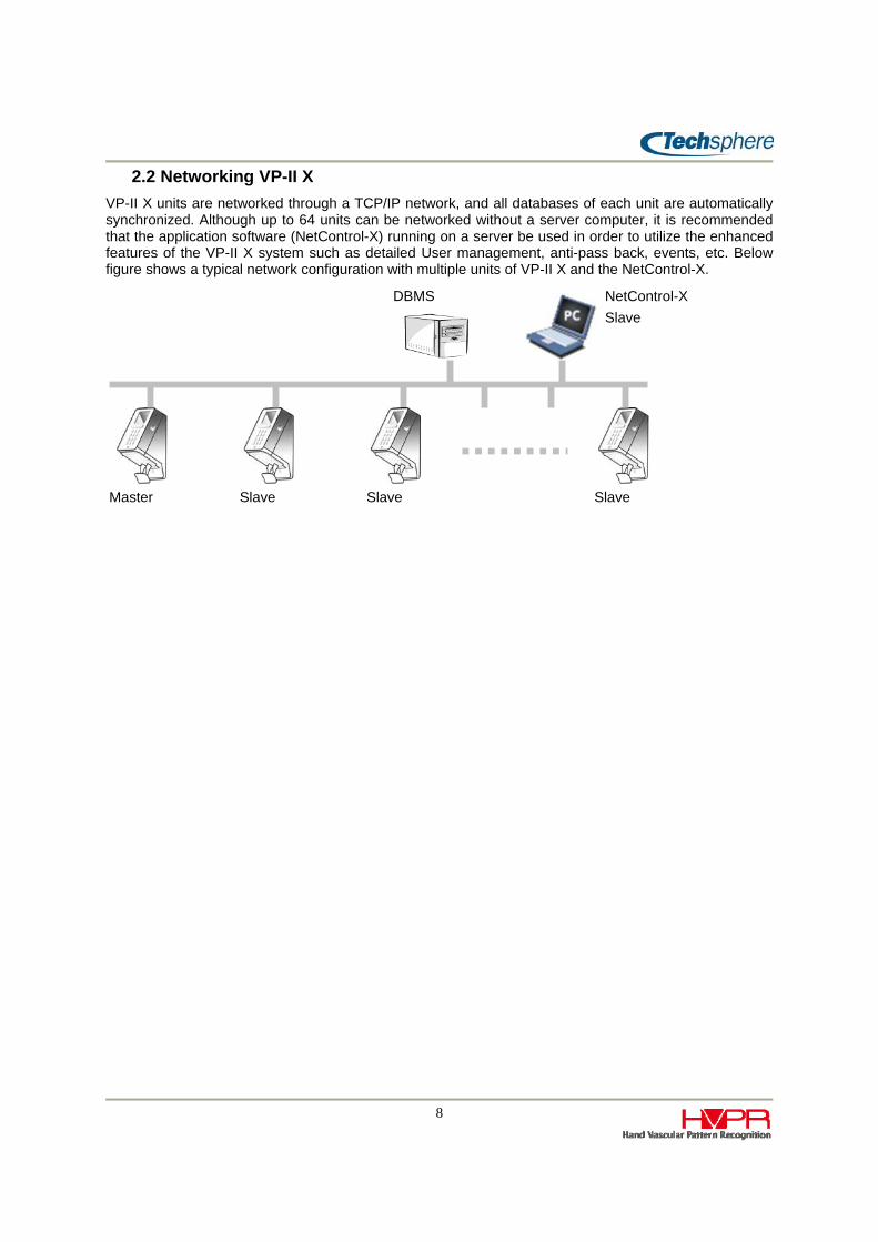
2.2 Networking VP-II X VP-II X units are networked through a TCP/IP network, and all databases of each unit are automatically synchronized. Although up to 64 units can be networked without a server computer, it is recommended that the application software (NetControl-X) running on a server be used in order to utilize the enhanced features of the VP-II X system such as detailed User management, anti-pass back, events, etc. Below figure shows a typical network configuration with multiple units of VP-II X and the NetControl-X.
Master Slave Slave Slave
DBMS NetControl-X Slave

9
3. VP-II X Specification
Environmental Specification Power Supply DC 12V / 1.5A (SMPS: AC 100~250V, 50Hz/60Hz)
Operating Temperature -5 ~ 50°C
Operating Humidity 10% ~ 90%
Physical Specification
Material Scanner: PC + ABS Rear plate & Bracket: Metal
Weight 820g (Without card reader module)
Dimension 110 * 200 * 130mm (See the drawings for details)
Biometric Features
Utilized Technology HVPR (Hand Vascular Pattern Recognition) on the back of the human hand
Accuracy
FAR(False Acceptance Rate): Up to 0.0001% FRR(False Rejection Rate): 0.1% Changeable 5 levels: 1(Highest accuracy) ~ 5; the level can be individually set to each Users or to the unit.
Usability 99.98% (Usability: Percentage of the entire population who is able to use the system accurately)
Speed 0.4sec/verification, 0.4sec * 2 times for enrollment
Liveness Detection HCD(Human Criteria Decision) algorithm: Non-human materials are not allowed to be enrolled Configurable level: 1(most strict) ~ 3, or disable
An infrared based sensor device No physical contact with sensor Biometric feature(vascular data) from below the skin Eliminate spoofing Harsh environmental robustness User privacy protected

10
Hardware Specifications
Core Processor Dual CPUs (400Mhz DSP, 180Mhz ARM Processor)
Display 65K Color 2.8” TFT LCD with backlight Lifetime: 10 years
Keypad 0~9, Enter, ESC, 4 Function keys
External Interface I/O Ports
RJ45 Ethernet TCP/IP (Between VP-II Xs and/or Server) Wiegand (Input: 1, Output: 1) Serial port: 2 channel RS232 only: 1 RS232/RS485 shared: 1 (Optional RS485 module required) Digital I/O (Input: 2, Output: 2)
Memory
512Mbytes NAND Flash memory built-in Up to 50,000 Users database Up to 500,000 logs(User transactions and/or system events) Firmware, GUI, Font, etc storage
USB 2.0 USB Memory device (Firmware upgrade, DB transfer) Can be activated only when authorized by an administrator Optional use: Wireless LAN, External key board
Card Module
Card reader module installed inside (Optional) 125Khz Prox. reader 13.5Mhz Mifare / DESFire / TWIC / PIV 13.5Mhz HID iClass Only one type out of above three can be installed Built-in antenna for 125KHz and 13.5Mhz
RTC (Real Time Clock) Automatic adjustment function for time accuracy
Speaker Sound/Voice supported
IR Sensor User detection, Awake from sleep mode
Tamper Switch Installed on the rear cover
11
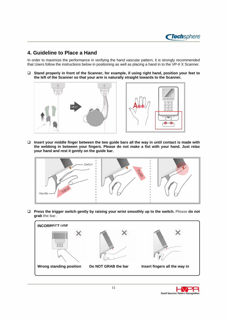
4. Guideline to Place a Hand In order to maximize the performance in verifying the hand vascular pattern, it is strongly recommended that Users follow the instructions below in positioning as well as placing a hand in to the VP-II X Scanner.
Stand properly in front of the Scanner, for example, if using right hand, position your feet to the left of the Scanner so that your arm is naturally straight towards to the Scanner.
Insert your middle finger between the two guide bars all the way in until contact is made with the webbing in between your fingers. Please do not make a fist with your hand. Just relax your hand and rest it gently on the guide bar.
Press the trigger switch gently by raising your wrist smoothly up to the switch. Please do not grab the bar.
INCORRECT USE
Wrong standing position Do NOT GRAB the bar Insert fingers all the way in

12
Chapter 2 Enrollment, Deletion and Verification
1. Manager Menu It is required to access the Manager Menu in order to enrol/delete Users or change system setup. The Manager menu can only be accessed by a Manager or an Installer. The VP-II X is set to the Test Mode when delivered, which enables an Installer to be enrolled as a Manager.
1.1 Manager Manager(s) is an administrator who has the right to enrol/delete Users as well as to setup or change system settings. When a Manager is verified, the Manager Menu automatically appears on the LCD.
1.2 Installer Installer is a temporary Manager who can be enrolled when the VP-II X is under Test Mode. An Installer has the same right as Managers, and can access the Manager menu to setup/change system settings as well as enrol/delete Users. Typically an Installer is temporary enrolled as a Manager for system setup for installation, and it is recommended that the Installer be deleted once the installation is completed. Only a PIN is allowed to be used for Installer, and no cards are allowed to be used for enrolling an Installer while both cards and PIN are allowed to enrol Manager(s).
1.3 Test Mode Test Mode is a factory default set when the VP-II X is delivered. Under Test Mode, the VP-II X brings a menu allowing an installer to be enrolled as a Manager each time the VP-II X starts up. As this means that anyone can be enrolled as a Manager as long as the unit is under Test Mode by recycling the power, it is strongly recommended that the system Manager release the Test Mode once the installation is completed.
1.4 Enrolling an Installer When the VP-II X is under Test Mode, the below menu appears every time it starts up. Press ENT to enrol an Installer (system Manager), and then enter a PIN and hand twice in accordance with the displayed instructions. Press ESC to skip enrolling an Installer and directly go to the main screen.
Only one Installer is allowed to be enrolled on each unit. It will overwrite an existing Installer if you enrol a new Installer to the same unit. However, each unit in the same network can have different Installer with different PINs.

13
1.5 Manager Menu Access In order to perform any User management (enrolment, deletion, and modification) as well as any system setup, you need to access the Manager Menu by verifying a Manager or an Installer. Please refer to “0 Verification” to learn about Manager/Installer verification.
1.6 Key Usage in the Manager Menu In the Manager Menu, functions keys are used as arrow keys to move the cursor to select an item. The ENT key is used as an enter key to select a menu item or save the settings while the ESC key is used to escape from the menu or cancel the settings. You can also directly enter a number key to select a menu if indexed with a number.
1.7 Menu Tree
VP-II X Manager Menu
1. User Management 1. Enroll User 2. Delete User 3. Edit User 4. Template Management 5. Delete Installer 6. Smart Card Update
2. Operational Settings 1. Mode Setting 2. Test Mode 3. Keypad Input Settings 4. Sleep Mode 5. Tamper Switch Setting 6. DB Search Option
3. System Settings
1. Network Settings
1. Network Environment 2. Master/Slave Setting 3. Server Settings 4. Slave List
2. Date/Time Settings 3. Firmware Information 4. VP Settings 5. Door Settings 6. Daylight Saving Time 7. Initialize Settings 8. Door lock Setting 9. AUX Settings

14
4. UI Settings 1. Language Settings 2. Sound Settings 3. PIN Display Option
5. Card Settings 1. Wiegand Settings 2. Mifare Card 3. HID iClass Card 4. PACS Settings
6. Tools 1. Report
2. Diagnostic Tools 1. Network Diagnostics 2. Network Info.
3. Soft Reset

15
2. Enrollment Users or Managers can be enrolled using the Manager Menu or through NetControl-X application software. Access to the Manager Menu is required to perform the following instructions to enrol Users and/or Managers. Please refer to the User’s guide of the NetControl-X for the details on how to enrol using the application software.
2.1 User Type There are different User types according to the identification number used for enrollment and verification. Users/Managers can be enrolled with a PIN, Proximity card, smart card or password.
PIN User
Users enrolled with a PIN (Personal Identification Number) from 2 to 24 digits.
Prox. Card User
Users enrolled with a proximity card. Wiegand code of a card is used as the PIN.
Smart Card User
Users enrolled with a smart card (HID, Mifare, DESFire, PIV/TWIC, etc). In this case the vascular data is stored on a card and/or a server.
Password User
Users enrolled with a password do not use the vascular data from their hand during verification to gain an access. A specific instruction is required to enter a password using the keypad. See “Chapter 2 4.2 Password User Verification” for details.

16
2.2 User/Manager Enrolment When a User is enrolled on a slave unit, the master unit must be in operation. The enrolment function is not permitted if the slave cannot reach the master on the network. A User once enrolled on any unit will be automatically distributed to all the units in the network.
To enrol a User or Manager, access the Manager Menu and go to the menu as follows:
After setting User Class and Level (or keep the default settings which are User and System Level), execute Enroll to start enrollment process. And then follow the steps shown on the display. It will first ask you to enter a PIN (from 2 to 24 digits) or present a card (Proximity or smart card), and then place a hand. This process is required to take place twice in order to make sure that the entered ID and vascular data are accurate.
2.2.1 Enrollment options
User Class
Select User or Manager to enroll. Multiple Managers can be enrolled.
Level (Security level)
Select a level from 1 to 5 to assign a Personal Security Level to the User being enrolled, or select System Level for the User to use the level set to the unit. It is recommended that you use the default which is System Level for the Users who are initially enrolled to the VP-II X. You can later assign a
Manager Menu > 1. User Management > 1. Enroll User

17
Personal Security Level using the NetControl-X or in the Manager menu on the VP-II X, see “Chapter 2 5.1Edit User”.
The Level indicates an adjustable Security Level for matching vascular biometric data for verification. Five adjustable levels are provided; level 1 is the strictest in matching the vascular data. Higher level (1) provides a higher accuracy in matching, but may cause a higher false rejection ratio depending on individual vascular characteristic and/or environment.
The default factory setting is level 4 which is the recommendation for use during initial implementation to allow training of Users in the correct positioning and/or placing his/her hand to the scanner. It is recommended that after successful implementation and training that the System level for the VP-II X be set at Level 3 or higher. The Personal Security Level can be adjusted for individual Users based on their specific requirements.
Each VP-II X unit has a security level (System Level), and it can be individually assigned to each User’s (Personal Security Level). When verifying a User, the VP-II X uses either Personal Security Level if assigned or System Level if the Personal Security Level is not assigned to the User.
TEST
This function gives the User an opportunity to check if the enrollment has been properly made. If you execute TEST, it will start a verification process so that the User can perform test verification. In case a User cannot properly verify, you may re-enrol.
More
This will bring up additional options for enrollment as shown below. This allows the activation of a User start time and/or expiry time. Select Enable and set the Start Time and/or Expire Time. The User will not be able to gain access until the Start Time if set. This option also can be set by using NetControl-X software.
Password
This is an option to enroll a User with only a password, from 4 to 10 digits, without enrolling the vascular data. If assigned, the User can gain access by only entering the password followed by a PIN or card. See “Chapter 2 4.2 Password User Verification” for details on how the password Users can gain access.

18
3. Deletion A Manager can delete User(s) from the Manager Menu. When deleting Users from a slave unit, the master unit has to be in operation so that the slave unit can access the database of the master unit. Deleting a User from any unit will automatically remove the User from the database of all units in the network.
3.1 Delete Installer It is strongly recommended that a system Manager delete the Installer, who has the same right as a Manager, once installation is complete. Go to the menu as indicated below to delete the Installer.
If you delete the Installer from the VP-II X, it will delete only the Installer enrolled on that unit which means Installer’s PIN enrolled in other units in the network will remain. In order to delete all Installer PINs of every unit in the network at the same time, you should use NetControl-X software.
3.2 Delete Users
Delete User
This function is to delete a single User. Enter the Users PIN or present the Users card to be deleted. Follow the steps as displayed to complete deletion.
Only Users can be deleted, Managers cannot be directly deleted from this menu. In order to delete a Manager, its User class has to be changed to a User. Please refer to “Chapter 2 5.1 Edit User” to learn how to change the User class of a Manager to a User.
Using Card Number
For card Users, normally a card User is deleted by its Wiegand PIN when it is enabled; The VP-II X will delete a card User by using its card number. To match the card number exactly, VP-II X has to be set to the proper Wiegand format in the system. Please refer to “Chapter 3 5.1 Wiegand Settings” to learn how to set a Wiegand format for a card User.
Manager Menu > 1. User Management > 2. Delete User
Manager Menu > 1. User Management > 5. Delete Installer

19
4. Verification Verification is typically made by (1) entering a PIN or presenting a card, and (2) place a hand.
When a PIN is entered or a card is presented, a sub-menu appears at the bottom of the screen as shown in the above figure. This provides the User or Manager the option to choose: F1 Manager; F2 Password Verification; F3 Job Code for Time and Attendance; or F4 to allow User to enter their card number instead of presenting their card. Select the appropriate “F” Key for the desired operation, please refer to the following instructions:
4.1 Manager Verification To verify a Manager, (1) enter a Manager PIN or present a Manager card, (2) press F1 key to proceed with Manager verification, and (3) place a hand. Below figure shows an example of Manager verification with a PIN input.
F1
C d
PIN

20
When a Manager is verified, VP-II X brings up the Manager Menu automatically; Note: When a Manager is verified the VP-II X does not provide a Wiegand output or door open signal.
4.2 Password User Verification It is not required for password Users to verify utilizing their hand vascular pattern. Password Users can gain access with only a password assigned at enrolment in combination with a PIN or card.
To verify a password User, (1) enter a PIN or present a card, (2) press F2 to proceed with a password input, and (3) Place a hand and push the trigger switch (VP-II X does not verify a hand but the User is required to trigger the switch).
4.3 Job Code Input When the VP-II X is used for time and attendance applications and a job code is required to be input, a User can input a job code prior to verifying a hand. Only numerals can be used for jog codes; e.g., 1234, 20000, or 6666666.
To enter a job code, (1) enter a PIN or present a card, (2) press F3 to proceed with a job code input, and (3) place a hand.
4.4 Verification With a Card Number This function allows a proximity card User to enter the card number directly instead of presenting a card. To use this function, a proper Wiegand format (parity bits, facility code, and bit length of the card serial number) should be set in advance. Please refer to “Chapter 3 5.1 Wiegand Setting” for details on how to set Wiegand format.
To verify with a card number, (1) enter the card number using the keypad, (2) press F4 to proceed with card number verification, and (3) place a hand.
4.5 Verification With a Function Key Function keys are typically used for time and attendance purposes. If used, Users are required to press a function prior to entering a PIN or presenting a card.
VP-II X sends the function key information (none, F1, F2, F3 or F4) to the NetControl-X software along with a User transaction event. The usage of each function key, F1 for punch-in and F2 for punch-out as an example, shall be assigned by the NetControl-X.
As for more advanced time and attendance applications, the function keys may be customized in order to be used for multi-level job code transfers, viewing of individual punches, etc.
4.6 Verification With Duress Code VP-II X provides a function that can generate an alert alarm when a User is forced to gain access. There are two ways to generate a duress code.
First method is to press ENT key prior to entering a PIN or presenting a card. To generate an alert alarm, (1) Press ENT key, (2) Enter a PIN or present a card, (3) Place a hand.
The second method is to enrol both hands for the User and to use one of enrolled hands as duress verification/notification. VP-II X allows a User to enrol two hands. Please refer to “Chapter 2 5.2.2 “Multiple Template Assignment” for details on how to enrol two hands for one User, and “Chapter 2 5.1 Edit User“ to learn how to assign a hand for duress verification.
(1) Press a function key (F1 ~ F4), (2) Enter a PIN or present a card, and (3) Place a hand

21
When the duress verification is made, the VP-II X can send an alarm event in three ways 1) it sends to NetControl-X software in real time and NetControl-X will generate an alarm message and/or send an e-mail to the pre-assigned accounts; 2) VP-II X also can output a digital signal through its AUX port by modifying its firmware upon request; and 3) by sending a pre-defined Wiegand Site Code to the access control system, please refer to Chapter 3 5.1.3 “Wiegand Output Options” for details on setting Wiegand options. Please contact a sales representative or technical specialist for this function.
4.7 Installer Verification To verify the Installer, (1) Press ENT key twice, (2) Enter an Installer PIN, and (3) Place a hand. When the ENT key is entered twice, a message indicating Installer verification appears above the PIN input screen as shown below. Note: There is no Wiegand output or door open signal sent when an Installer verifies.
5. Modifying User Information
5.1 Edit User User information of enrolled Users can be modified using this function. Go to the menu as follows to edit a User.
When the following window appears, enter a PIN or present a card of the User for VP-II X to retrieve the User data to edit. To perform this function, the master unit must be in operation in order to update the modified User information to all the units in the network.
This function is not applicable for smart card Users. Smart card Users must be deleted and re-enrolled.
Manager Menu > 1. User Management > 3. Edit User
22
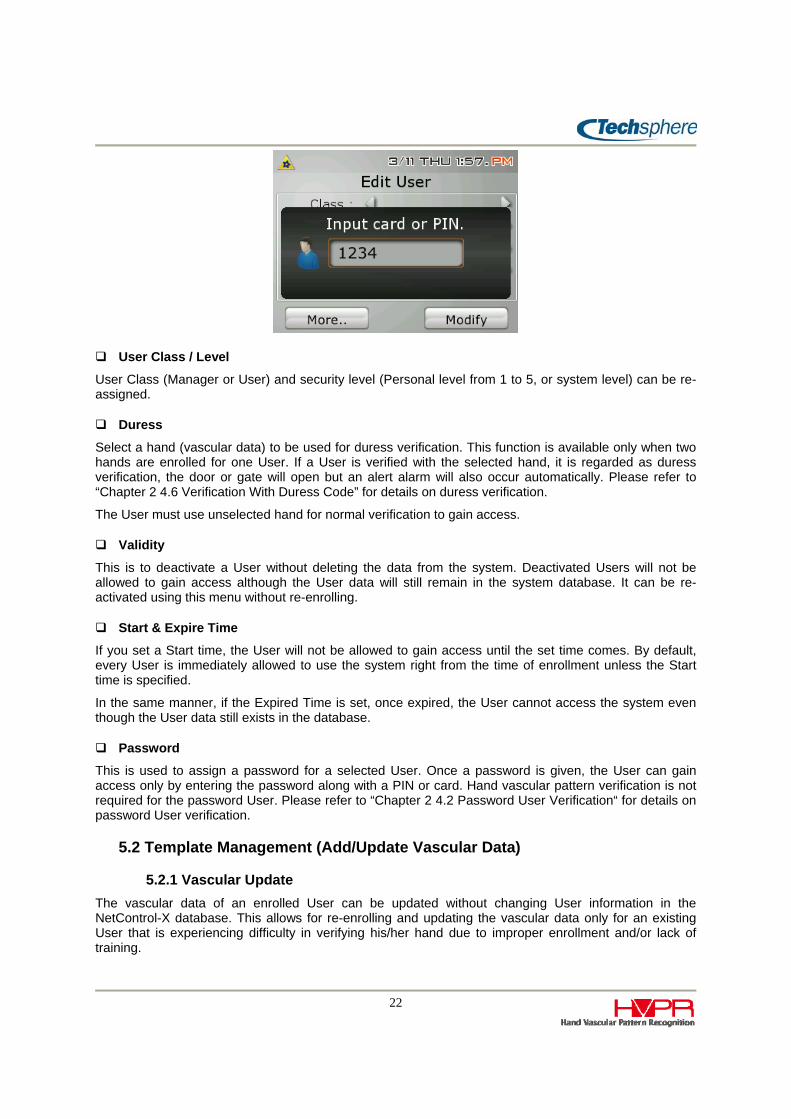
User Class / Level
User Class (Manager or User) and security level (Personal level from 1 to 5, or system level) can be re-assigned.
Duress
Select a hand (vascular data) to be used for duress verification. This function is available only when two hands are enrolled for one User. If a User is verified with the selected hand, it is regarded as duress verification, the door or gate will open but an alert alarm will also occur automatically. Please refer to “Chapter 2 4.6 Verification With Duress Code” for details on duress verification.
The User must use unselected hand for normal verification to gain access.
Validity
This is to deactivate a User without deleting the data from the system. Deactivated Users will not be allowed to gain access although the User data will still remain in the system database. It can be re-activated using this menu without re-enrolling.
Start & Expire Time
If you set a Start time, the User will not be allowed to gain access until the set time comes. By default, every User is immediately allowed to use the system right from the time of enrollment unless the Start time is specified.
In the same manner, if the Expired Time is set, once expired, the User cannot access the system even though the User data still exists in the database.
Password
This is used to assign a password for a selected User. Once a password is given, the User can gain access only by entering the password along with a PIN or card. Hand vascular pattern verification is not required for the password User. Please refer to “Chapter 2 4.2 Password User Verification“ for details on password User verification.
5.2 Template Management (Add/Update Vascular Data)
5.2.1 Vascular Update The vascular data of an enrolled User can be updated without changing User information in the NetControl-X database. This allows for re-enrolling and updating the vascular data only for an existing User that is experiencing difficulty in verifying his/her hand due to improper enrollment and/or lack of training.

23
This eliminates the need to re-enter existing information such as User name (in the NetControl-X database), expiration time, etc, this information will all be maintained in the database.
This function is not applicable for smart card Users. For a smart card User please see “Chapter 2 5.2.3 Smart Card Update” to update its vascular data.
5.2.2 Multiple Template Assignment A User can have up to two templates. This function enables a User to enrol both right and left hands or enrol one hand twice.
This function may be used to enrol the same hand twice at different time, e.g. one in winter season and another one in summer season, in order to minimize false rejections that could be caused by minor changes of the extracted vascular pattern features due to cold and hot weather conditions. The second template can be also used for duress verification. See “Chapter 2 4.6 Verification With Duress Code” for details on duress verification.
Go to the menu as shown below:
After selecting the menu, enter a PIN or present a card of the User to proceed with. Please make sure that the master unit is in operation if this function is being performed on a slave unit. If the master unit is not able to be connected to on the network, this function will not work as the slave cannot update the User data to the database in the master.
The Template number shows the number of enrolled vascular data (templates). It means only one template is enrolled if only “1” is marked, and both “1” and “2” will be marked if there are two templates enrolled.
To enroll the second template when there is only one template enrolled (only “1” of the template number is marked), select “2” from Select Number menu and execute Add/Re-enroll. It will automatically allow you to enrol the second template.
To update the vascular data, just select template number 1 or 2 (if enrolled) and execute Add/Re-enroll.
To delete the second template, select template number 2 and execute Delete. (Template 1 cannot be deleted in this menu. Use “Delete User” menu to delete Users).
5.2.3 Smart Card Update This menu allows for smart card Users vascular data to be updated. From the Manager menu select 1. “User Management” and then 6 “Smart Card Update”.
Manager Menu > 1. User Management > 6. Smart Card Update
Manager Menu > 1. User Management > 4. Template Management

24
Chapter 3 Environment Setup
1. Network Setup It is required that a proper network environment is set in order to run the VP-II X in the TCP/IP network. An IP address (including subnet mask and gateway), master IP address, server IP address (if used), and slave information (only for master unit) must be set. See the following sections for details.
1.1 Set Network Environment (TCP/IP Parameters) Every VP-II X should have an IP address for network operation and the TCP/IP network parameters must be properly set.
A VP-II X can obtain an IP address automatically from a DHCP server or you can assign an IP address manually, depending on the network environment at the site. To manually set an IP address, make sure that all network parameters are properly set and there are no IP conflicts in the network. It is also strongly recommended that you test TCP/IP communication status using the “ping” command from a server.
Status
This shows the network parameters currently set (IP address, Subnet mask and Gateway). An IP address “128.0.0.1 (factory default)” will be shown if the IP address is not properly set.
1.2 Master/Slave Setting One VP-II X must be set to master while other(s) in the network are set to slave(s). Please see “Chapter 1 2 Network Configuration” for details on network operation.
Go to the menu shown below to set master/slave and appropriate parameters required for master/slave operation.
Manager Menu > 3. System Settings > 1. Network Settings > 2. Master/Slave Setting
Manager Menu > 3. System Settings > 1. Network Settings > 1. Network Environment
25
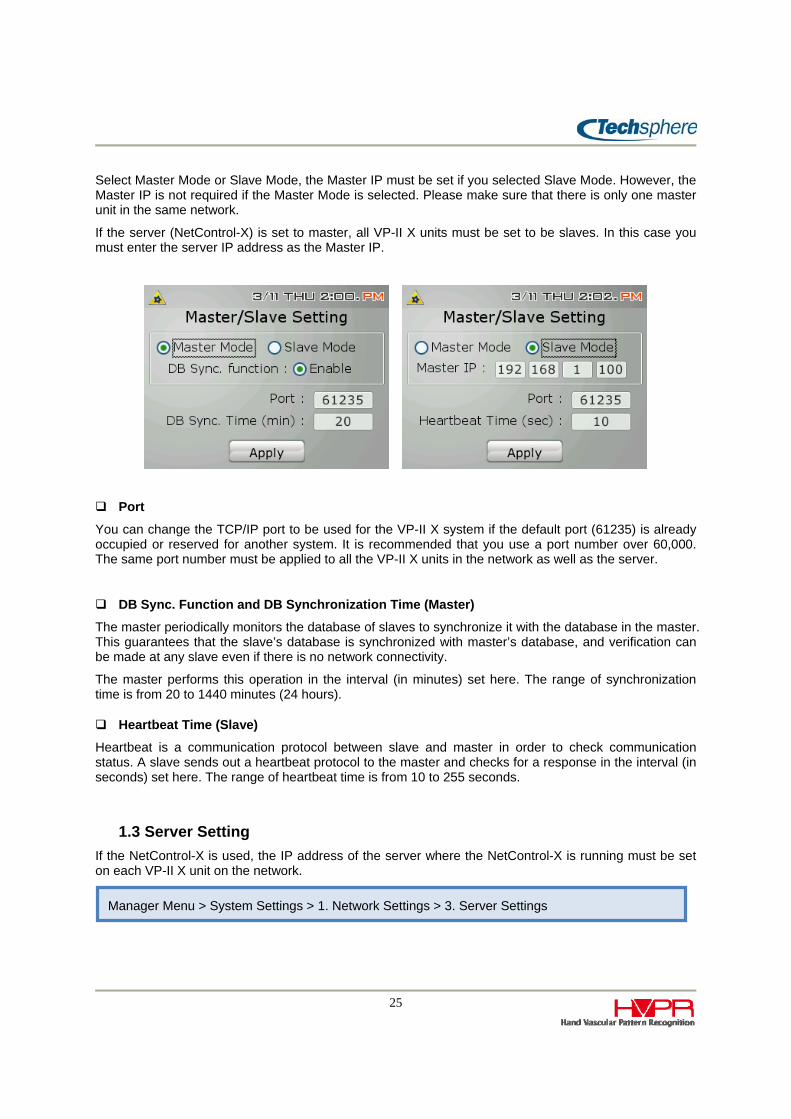
Select Master Mode or Slave Mode, the Master IP must be set if you selected Slave Mode. However, the Master IP is not required if the Master Mode is selected. Please make sure that there is only one master unit in the same network.
If the server (NetControl-X) is set to master, all VP-II X units must be set to be slaves. In this case you must enter the server IP address as the Master IP.
Port
You can change the TCP/IP port to be used for the VP-II X system if the default port (61235) is already occupied or reserved for another system. It is recommended that you use a port number over 60,000. The same port number must be applied to all the VP-II X units in the network as well as the server.
DB Sync. Function and DB Synchronization Time (Master)
The master periodically monitors the database of slaves to synchronize it with the database in the master. This guarantees that the slave’s database is synchronized with master’s database, and verification can be made at any slave even if there is no network connectivity.
The master performs this operation in the interval (in minutes) set here. The range of synchronization time is from 20 to 1440 minutes (24 hours).
Heartbeat Time (Slave)
Heartbeat is a communication protocol between slave and master in order to check communication status. A slave sends out a heartbeat protocol to the master and checks for a response in the interval (in seconds) set here. The range of heartbeat time is from 10 to 255 seconds.
1.3 Server Setting If the NetControl-X is used, the IP address of the server where the NetControl-X is running must be set on each VP-II X unit on the network.
Manager Menu > System Settings > 1. Network Settings > 3. Server Settings

26
Set the server IP, Port and Heartbeat time in the same manner as Master/Slave set in the above section.
Backup Master Function
For applications that customers do not want user information and template storage on the slave devices, the “DB Sync. Function” needs to be disabled; the slave devices will not store any user information in devices. Please refer “Chapter 3 1.2 Master/Slave Setting” for “DB Sync. Function” settings. To verify users’ vascular patterns, the user’s present their hand to a slave device, the slave will communicate to a master VP-II X or server where the enrolled template is stored to verify their hand. Please refer to “Chapter 3 3.6” for instructions to set the verification location to “Only Network”.
1.4 Slave List This function is only available for master units. You can check, add or delete the list of slaves being managed by the master. The MAC address is used for the list. The slave list is automatically created when configuring using the XConfig software, or it can be manually set by this menu.
Manager Menu > 3. System Settings > 1. Network Settings > 4. Slave List

27
2. System Setup 2.1 Date/Time Set
The date and time of the unit can be set in the following menu. You can set date and time for both master and slave. However, the date and time of slaves are automatically synchronized with those of master periodically.
2.2 Firmware Information This shows the VP-II X firmware information. There are five firmware files used: Boot, Kernel, Ramdisk, Application and Media.
Search USB (Firmware Upgrade)
You can also upgrade the firmware using a USB memory stick. In the USB drive, create a folder as shown below and locate the firmware(s) in this folder. And then execute Search USB after plugging the USB device in the VP-II X USB port (Refer to “Chapter 1 1 VP-II X Scanner”). It will automatically search the firmware and perform upgrade if available.
USB Driver:\Techsphere\VP-IIX\Firmware\
The firmware(s) must be in the folder indicated above. Otherwise the VP-II X will not locate it to perform the upgrade.
2.3 VP Set (Security level, Liveness detection, Retry times) To set or change the system security level, HCD (Human Criterion Decision – Liveness Detection), and number of retries, go to the menu as follows:
System Level
Manager Menu > 3. System Settings > 4. VP settings
Manager Menu > 3. System Settings > 3. Firmware Information
Manager Menu > 3. System Settings > 2. Date/Time setting

28
Set the system security level (1 ~ 5) to be used for User verification. Please see the section “Level (Security Level) in “Chapter 2 2.2.1 Enrollment options” to learn about security level. This menu is to set the “system security level”, and the “personal security level” can be individually set when enrolled or by the menu “Edit User” (Refer to “Chapter 2 5.1 Edit User”).
HCD Level
The Hand Vascular Pattern Recognition technology applied to the VP-II X can recognize human or non-human materials. The decision level can be adjusted using this menu. The range is from 1 (most strict) to 3, or off (disabled).
Level 1: HCD applied for both enrolment and verification and is the most strict level. At this level only a human hand can be enrolled and verified.
Level 2 and 3: HCD applied for enrolment only, not for verification. Off: HCD function disabled.
Retry Number
This sets the number of times the system retries if a hand verification fails, the default is 2, it can be adjusted from 2 to 5 times.
2.4 Door Settings The VP-II X system is capable of controlling doors with its controller without using a PACS (Physical Access Control System). The following menu is to set or change the parameters required to control a door.
Controller
This is to select a controller being used for door control. The VP-II XG is selected as the controller, additional controller options will be added in future upon availability. Select “None” if no controller is used.
2.4.1 VP-II XG (Door Controller) The VP-II X can control an electric door-lock through the VP-II XG door controller. The VP-II XG is separately provided and is connected to the VP-II X via RS232 (or RS485; an optional RS485 driver board needs to be installed at both VP-II X and XG to use RS485 interface). The VP-II XG has a relay output to connect an electrical lock and digital input ports for door status monitoring and exit button interface.
Open Time
Manager Menu > 3. System Settings > 5. Door settings

29
This is to set activation time of the door open signal. It can be set from 1 to 255 seconds. The VP-II XG outputs a door-open signal on the relay upon successful verification of a User, and holds the signal for the period of time set here.
Allowed Time
Allowed time means the maximum allowed time that the door can be kept open from the moment that the VP-II XG releases the door-open signal. The range is from 1 to 255 seconds.
To use this function a door detection sensor has to be available and connected to the door monitoring input port of the VP-II X. The VP-II X monitors the door status through the door monitoring input port whether it is open or closed, and will generate an event alarm if the door is not closed prior to the allowed time elapsing.
Function Key (Open)
This is to decide whether the VP-II X generates a door open signal when a User is verified with a function key input. Select or unselect for each function key accordingly.
As an example, if F1 is unselected in this menu, the VP-II X will not open the door for a successful verification of a User who pressed F1 prior to entering a PIN.
This option is to satisfy the requirement for time and attendance applications where customers do not want a door to be open when verifying for punch in/out using function keys.
Pairing
For security reasons it is necessary to control which XG device is allowed to connect to a given VP-II X device. If an installer replaces one of the paired devices, it must be paired again otherwise the VP-II X and the XG device will not communicate with each other.
2.5 Daylight Saving Time If you are in daylight saving time zone, you can set VP-II X time to be adjusted by setting the start time and expire time of daylight saving time. Once set, the VP-II X’s time will be adjusted automatically based on the timeframe set. He figure below shows menu to set a start and expired time.
Manager Menu > 3. System Settings > 6. Daylight Saving Time
Open Door status
Close
Open detected
Open time
Allowed time
Alarm event
On Door open signal
Off

30
2.6 System initialization (Reset to Factory Settings) You can reset all system settings back to factory settings. Note: Special caution is required when executing this function.
Init. Configuration
This will initialize all settings back to factory set.
Init. Database
This will delete all User data in the database. Users’ vascular data, control information and time zone tables will be deleted.
Init. Events
All User transaction records and system logs will be deleted.
2.7 Door lock Setting When the VP-II XG is used as the door controller, the door lock is used for closing or opening the door. In this case, the door lock system has a built in sensor to control the door, but in some cases the door lock may not have this sensor.
If this is the case, the VP-II XG can provide the signal to the door lock for opening or closing the door. This is done by selecting “Use the external sensor of the door lock” option.
Manager Menu > 3. System Settings > 8. Door lock Setting
Manager Menu > 3. System Settings > 7. Initialization Settings

31
2.8 AUX Settings To allow for two Wiegand Input ports, the VP-II X AUX port can be configured to also accept Wiegand Input. This allows for a second Wiegand reader to be used as an exit reader. When VP-II X AUX port is set to Wiegand Input, the VP-II X will work in bypass mode and will check only the following user verification options: 1) User Expiration Date, 2) User Activation and 3) Gate Time zone. Please refer to “Chapter 4 2.2 Ports and Connection” to get more details on the differences Wiegand and AUX.
Manager Menu > 3. System Settings > 9. AUX Settings

32
3. Operation Settings
3.1 Mode Settings (Network / Serial)
Currently only the Network Mode is supported. Serial Mode is reserved for future use. Keep the default setting.
3.2 Test Mode Release Test Mode should be released after successful implementation once the system Managers are trained to use the system and can verify themselves as Managers without any difficulties. Please refer to “Chapter 2 1.3 Test Mode” for details on what the Test Mode is and how it functions.
Test Mode can be released by the menu shown below:
If the Test Mode is released, the VP-II X does not show the Test Mode menu to enroll an Installer anymore. There are two options in releasing the Test Mode.
If you select “Enable recovery function”, before releasing the Test Mode, it can be recovered in this menu. If you re-access this menu after releasing the Test Mode with “Enable recovery function” selected, it will ask “Do you want to recover test mode?” to re-establish the Test Mode.
However, if you un-select “Enable recovery function” when releasing the Test Mode, the unit must be sent back to the factory or to a Techsphere sales representative to recover the Test Mode. This function is provided as a security feature, it must be sent back to manufacturer to recover the Test Mode.
3.3 Keypad Input Settings If necessary, the keypad input can be disabled. If disabled, all keys will not respond. To re-enable, a Manager must be verified with a card to access this menu or use the NetControl-X software to re-activate the keypad. The beep sound of key input can also be disabled for silent operation.
Manager Menu > 2. Operational Settings > 2. Test Mode
Manager Menu > 2. Operational Settings > 1. Mode Settings

33
3.4 Sleep Mode VP-II X enters into a sleep mode when there is no User activity for the set period if enabled (factory default). It is not only to minimize power consumption but also to maximize the life time of the system. Keypad LEDs and LCD backlight will be minimized in sleep mode, and return to normal when a User is detected by the IR sensor of VP-II X.
3.5 Tamper Switch Setting A tamper switch is installed on the rear cover. VP-II X detects the switch when it is detached from the wall bracket without authorization. If enabled, VP-II X generates a warning sound and sends an event to the server when it detects the tamper switch has opened. It is recommended that you disable this function when taking the VP-II X off the wall for maintenance purpose.
3.6 DB Search Option A Manager can set the sequence of database searches – local, network or both. The default is to firstly search the User data from the local database, and secondly from the network (Master’s database) if it failed to retrieve the data form the local database for any reason. If necessary according to the network environment, it may be changed accordingly.
This option is available for only slave units. The master unit always refers to its own database.
Manager Menu > 2. Operational Settings > 6. DB Search Option
Manager Menu > 2. Operational Settings > 5. Tamper Switch Setting
Manager Menu > 2. Operational Settings > 4. Sleep Mode
Manager Menu > 2. Operational Settings > 3. Keypad Input Settings

34
4. UI Settings
4.1 Language Settings VP-II X supports multiple languages. More languages will be added.
4.2 Sound Settings
Volume
Set speaker volume from 0(silent) to 10(loudest).
Keypad Sound
Select a beep sound for key input. Seven different sounds are available.
Voice
Voice messages are supported for some operations such as “Verification success”. It can be enabled or disabled.
4.3 PIN Display Option Factory default is not to display the PIN being entered by a User. It can be changed to show the number being entered.
Manager Menu > 4. UI Settings > 1. PIN Display Option
Manager Menu > 4. UI Settings > 1. Sound Settings
Manager Menu > 4. UI Settings > 1. Language Settings
35
5. Card Settings
5.1 Wiegand Settings
5.1.1 Wiegand Output VP-II X outputs a Wiegand code for interface with an external access control system when a User is successfully verified;
(1) For card Users (proximity or smart card), the VP-II X outputs the Wiegand code as it is read from the card; and
(2) For PIN Users, VP-II X outputs a Wiegand code created in accordance with the preset format. A Wiegand format is required to be set for PIN Users accordingly. Also a site code value has to be set with the option “PIN success” as described in the following section “Chapter 3 5.1.3 Wiegand Output Options”.
VP-II X is also capable of outputting a Wiegand code for verification failure and/or an emergency case with a duress code.
5.1.2 Set Wiegand Format
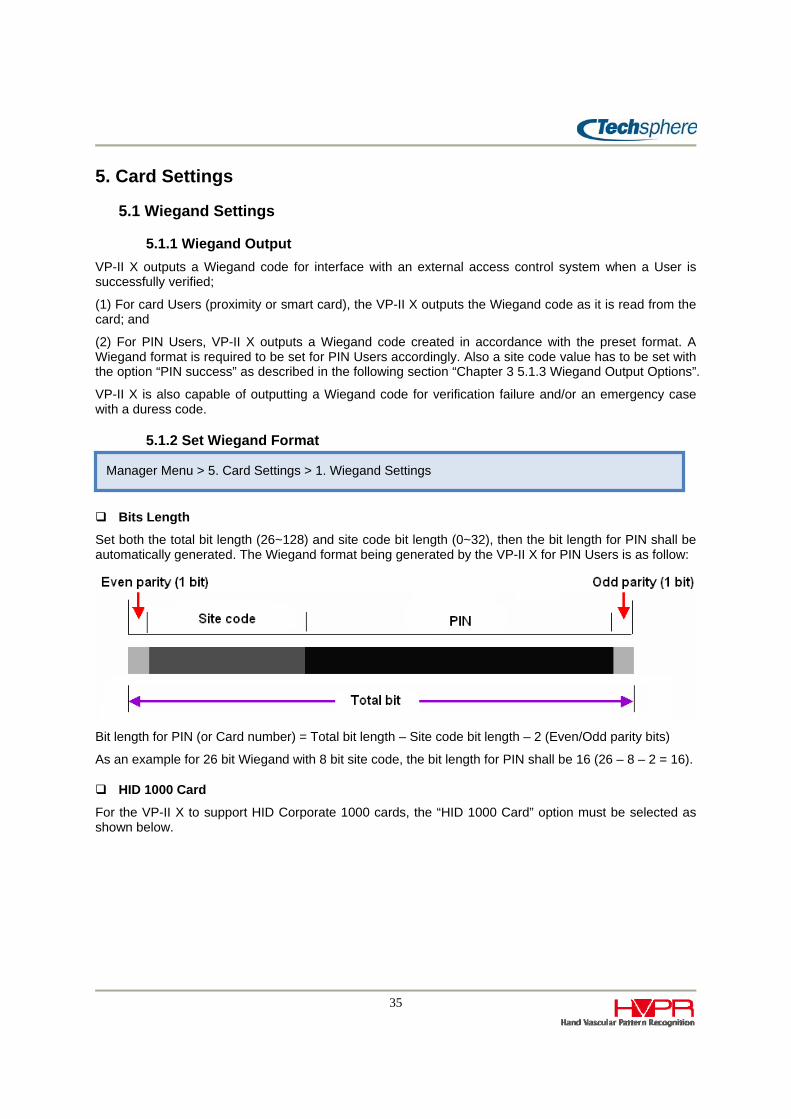
Bits Length
Set both the total bit length (26~128) and site code bit length (0~32), then the bit length for PIN shall be automatically generated. The Wiegand format being generated by the VP-II X for PIN Users is as follow:
Bit length for PIN (or Card number) = Total bit length – Site code bit length – 2 (Even/Odd parity bits)
As an example for 26 bit Wiegand with 8 bit site code, the bit length for PIN shall be 16 (26 – 8 – 2 = 16).
HID 1000 Card
For the VP-II X to support HID Corporate 1000 cards, the “HID 1000 Card” option must be selected as shown below.
Manager Menu > 5. Card Settings > 1. Wiegand Settings

36
As HID Corporate 1000 card’s format is not the same as a standard Wiegand format, to configure this card format properly, please contact your card vendor or installer.
Parity Bits
Even and odd parity consists of 1 bit each. Even parity is calculated with the first half bits of total bits and the odd parity is calculated with the remaining half bits. If the total bit length is odd, the bit in the middle is used for both even and odd parity calculation. As an example:
For 26 bit (Bit 0 to 25): Bits used for even parity calculation are from bit 0 to 12, and bits 13 to 25 are used for odd parity calculation.
For 37 bit (Bit 0 to 36): Bits used for even parity calculation are from bit 0 to 13, and bits 13 to 36 are used for odd parity calculation. The bit 13 is used for both odd and even parity calculation.
5.1.3 Wiegand Output Options VP-II X can also output a Wiegand code for verification failure and emergency notification (duress code). In order for PACS (Physical Access Control System) to recognize the difference for these codes, a separate site code needs to be assigned for each.
Output Enable Site Code Value Description
PIN Success 0 ~ 65535
A site code to be used for verification success for PIN Users. This option must be enabled with a site code value to output a Wiegand code when a User is verified with a PIN. The site code value set here doesn’t affect card Users as the Wiegand code read from the card is directly passed to the PACS for card Users.
Failure 0 ~ 65535
Set a site code to be used for instances of verification failures. If this option is enabled, VP-II X will replace the site code of original Wiegand code with this value for both PIN and card Users. The receiving device (PACS) must be also properly set to be able to recognize the different site code.

37
Duress 0 ~ 65535
When a User performs a duress verification to notify an emergency situation (See “Chapter 2 4.6 Verification With Duress Code” for details on duress verification), VP-II X will use this site code value in the same manner as the failure case described above.
5.2 Mifare / iClass Card To use smart cards (Mifare or HID iClass), a proper reader module according to the card type must be installed inside the VP-II X.
For smart card Users, User’s data including the vascular template and personal information is stored in the card, but can be also stored in the system memory if desired.
Supported Card Types
Mifare 1K, 4K, DESFire
HID iClass 16K/16, 16K/2, 32K(16K/2+16K/1), 32K(16K/16+16K/1)
Set the parameters required to access the card accordingly using the following menu:
Reader Status
This shows the status of a reader module. In the above example, there is not reader module installed as it says “Not installed”.
Start Sector/Page
Set the sectors (Mifare) or pages (HID) to be used for VP-II X template. Required space to store one User data is 7 sectors for Mifare and 2 pages for HID.
Blank Card Type (Mifare)
Manager Menu > 5. Card Settings > 2. Mifare Card Manager Menu > 5. Card Settings > 3. HID iClass Card

38
There are two different types of Mifare cards, the VP-II X automatically detects the card type based on the different types of keys used to access the card. Card type can be recognized by checking the blank values, which are FF or AB. If you are unsure, use the Check function to get the information. The Check function is available only when a reader module is installed.
Cache Mode (HID)
If the Cache Mode is enabled, VP-II X shall cache the User data once read from a card into its internal memory for a quicker reading operation for future use.
DB Dependence
When a smart card User is enrolled, the UID (Unique Identifier) number of a card is stored in the VP-II X database for management purpose. UID numbers of the enrolled Users are replicated to all VP-II X units in the network.
If this option is selected, a smart card that the UID number is not registered in the VP-II X database will not be accepted even though the card contains the vascular data issued by another VP-II X system.
If not selected, VP-II X will accept cards without checking a UID from the database.
Customer Key Setting
The VP-II X uses a key to encrypt the data stored in a smart card. For security reasons, customers should assign a unique key to be utilized for their VP-II X devices. The key is stored in both VP-II X and the card, and the key in the card must be matched to that in the VP-II X to be accepted. This prevents unauthorized cards such as one issued by another customer from being accepted at the site.
UID Order (Mifare)
The VP-II X generates the Wiegand data of Mifare cards with its UID. There are two types: MSB (Most Significant Bit) and LSB (Least Significant Bit). The VP-II X is set to MSB by default. The example below shows how to generate Wiegand data when MSB is selected.
The following table shows how VP-II X sends a Wiegand data by using different Mifare cards types and how VP-II X generates Wiegand data with MSB option.
Mifare Card UID Maximum Bit(include parity bit)
1K/4K 4 byte (32bits) 34 bits
DESFire 7 byte (56 bit) 58 bits
UID Hex: [12H][34H][56H][78H]
Even Parity 12H 34H 56H 78H Odd Parity
1 0001 0010 0011 0100 0101 0110 0111 1000 1
If a Manager wants to change the UID order after enrolling with a different order, the cards previously enrolled must be re-enrolled to get the correct format of Wiegand data.

39
5.3 PACS System Settings Enable the PACS Feedback to verify the signal communication between PACS (Physical Access Control System) system and VP-II X.
When VP-II X gets feedback from PACS system, VP-II X will display the message that follows:
Input Port
The input port being utilized for the signal is selected here. Two auxiliary ports are provided, for more details on auxiliary port, please refer to “Chapter 4 2.2 Ports and Connections”.
Detection Level / Detection Time
A detection level signal will be sent from PACS system to VP-II X. The detection ime is the expected time when the PACS system will respond to the VP-II X. VP-II X can be configured to detect a signal of 0V or 5V.
Timeout
The timeout setting sets the time the VP-II X will wait for the signal from the PACS, A minimum required time of 50ms is required, if VP-II X does not get a signal within this timeout period, a message(“Access is granted” or “Access is denied”) will be displayed on the VP-II X.
5V
0V
Timeout
PACS SystemDetection TimeVP-II X sends signal to
PACS as a User verified

40
6. Tools
6.1 Report Please see “Chapter 4 3 Event Report Viewer” to learn how to be used this function.
6.2 Diagnostic Tools
6.2.1 Network Diagnostics This setting is used for testing the current network status, and to determine whether a host is reachable across an Internet Protocol network. When a manager selects the “Test” menu, the VP-II X will send test packets to the device that’s IP address is specified. After about 10 seconds, the VP-II X will display the result. By using this tool, a manager can determine whether there is problem with their network configuration.
6.2.2 Network Info. This shows the current network information settings, such as IP address, Subnet mask, Gateway, Server IP, Master IP and port. A manager can view this information to determine the VP-II X network configuration.
Manager Menu > 6. Tools > 2. Diagnostic tools > 2. Network Info.
Manager Menu > 6. Tools > 2. Diagnostic tools > 1. Network Diagnostics

41
6.3 Soft Reset This allows the manager to reboot the VP-II X when required without the need to unplug power cord in the back.
Socket Restart
The VP-II X will reset and restart all related network protocols with the scanner.
Soft Reset
When a manager wants to reboot the system, this function can be used. It will reboot the system.
Manager Menu > 6. Tools > 3. Soft Reset

42
Chapter 4 Appendix
1. Firmware Upgrade There are five firmware files applied to a VP-II X, these firmware files can be easily upgraded upon availability. The firmware files are Boot, Kernel, Ramdisk, Application and Media. The file extension of a firmware file is “vpx", as shown in below examples:
kernel-0.1.2.v1.vpx or app-0.1.12.v60.vpx
Firmware can be downloaded to a VP-II X using a USB memory device or using the XConfig application software on the network.
By a USB Memory Device
Please see “Chapter 3 2.2 Firmware Information” to learn how to download the firmware using a USB memory device.
By Application Software (XConfig)
Firmware files can be downloaded to the VP-II X using the Download function of the VP-II XConfig software. It is useful for upgrading firmware to multiple VP-II X units at the same time without needing to physically go to the VP-II X units.
The XConfig software is included in the NetControl-X application software package, or it can be separately provided upon request. Please refer to the NetControl-X User’s Guide for details on how to install as well as for detailed instructions to use the XConfig.
When you click the Search (F5) button, it will show all VP-II Xs available on the network. Select a VP-II X or multiple VP-II X units to download the firmware. In the following example, two VP-II Xs are selected.
Click Download (F7) to load a firmware file, and then enter a password when the following window appears. Default password is “admin”.

43
After selecting a firmware file from a Windows file search window, click Start button to start downloading.
Wait until it shows the complete message. The VP-II X will also show the progress status while downloading, and will reboot automatically after writing the firmware to the flash memory. The power of VP-II X must be kept on in order to write complete firmware to its memory. Removing power while upgrading firmware may hang up the system due to incomplete firmware installation.

44
2. Quick Installation Guide
2.1 VP-II X Location
Installation Environment
It is strongly recommended that the VP-II X be installed in a place where it is not exposed to direct rain, excessive dust or excessive direct sunlight over 20,000 LUX. Excessive dust and sunlight may degrade verification performance, and exposure to rain may cause damage to the system. An enclosure shall be used for outdoor installations.
Also, do not install the VP-II X where the floor is inclined. Inclined floors may cause an unstable standing position for Users when placing hands which can degrade verification performance.
Locating Bracket and Scanner
Install the VP-II X at a height of 1,010 ~ 1,045mm from the floor and 100mm from the doorframe. If there is a nearby wall perpendicular to the door, the VP-II X should be at least 200mm away from the wall in order for Users to be able to stand properly to place hands.
Put the bracket in place for installing the VP-II X and make a hole after checking the hole-location for cabling. Fix the bracket on the wall using the bracket screws.
Fix VP-II X on the Bracket
Put the VP-II X on the bracket and push all the way down. And then fix the VP-II X on the bracket using the bracket screw located in the sensor module hosing.
Bracket screw
Cabling hole
Door
100mm
200mm
Floor
Wall
Screws(4Φ×30mm)
1010~1045mm

45
2.2 Ports and Connection
``
DC JACK / EXT PWR
DC JACK is used to plug in a power supply provided along the VP-II X. The input range of the power supply included in the package is AC100~250 / 50~60Hz, and output is DC 12V / 1.5A. If you need to supply the power to an external device connected to the VP-II X, such as an external card reader, you can use EXT PWR port. In this case, the power consumption of an external device must not exceed 200mA. If exceeded, it may cause performance degradation of the VP-II X.
If using an external power source supply the power to the EXT PWR port. The input power must be DC 12V (+/- 5%) with 1.5A or more current source.
Improper use of power supply may cause irreparable damage to the system or may degrade performance.
USB
This USB port is used for only production purpose for test and/or initial factory set. It cannot be used by a customer.
LAN
An Ethernet cable with an RJ45 connector is plugged in here for network connection.
WIEGAND
These are Wiegand interface ports for an input from a card reader and/or output to an access control system (PACS). IN0 means Wiegand D0 signal for input, and OUT0 means Wiegand D0 signal for output.
Rear view

46
VP-II X generates a standard Wiegand interface signal, the maximum distance to connect a Wiegand device is 150m (500ft) when using 22AWG which is perfectly shielded or is composed of 5 twisted pairs. The communication distance may be shortened depending on the cable specification.
AUX
These are TTL level (+5V) digital input/output ports to interface with external systems. Two input and output ports are provided. These ports can be used for access grant signal input from a PACS, fire alarm input, verification failure/success output to use as an external indicator such as large LED or lamps, etc. However, these functions are not included in the standard product, and will be provided with a customized firmware upon request.
SERIAL A / B
Serial port A is used for connecting the VP-II XG door controller. Connections are as follows:
Serial port B is reserved for future uses.
RS-485
In case that the distance between VP-II X and VP-II XG is over 15 meters, the RS485 interface can be used. However, an RS485 driver which is not installed by default has to be additionally installed inside both the VP-II X and VP-II XG. The RS485 driver is separately provided. Consult with the product provider.

47
3. Event Report Viewer
An application (“VP Report”) is provided by Techsphere for implementations where the VP-II X unit(s) are not using a server. In this case, the Manager can export stored events to a USB memory device to see and diagnose user management events.
The exported file name is “event_bak.db” that can be opened by the “VP Report” application. The figure below shows an example of a report. Using this application, Managers can view transaction details including user management events such as “User Enrolment”, “User Deletion” and “User Verification” For a complete audit trail of all system events and diagnosis tools, Techsphere strongly recommend s that customer to install a server with NetControl-X software.
Manager Menu > 6. Tools > 1. Report
48
4. Tray Icons
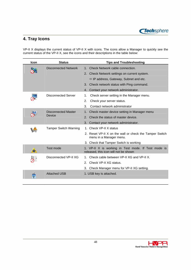
VP-II X displays the current status of VP-II X with icons. The icons allow a Manager to quickly see the current status of the VP-II X, see the icons and their descriptions in the table below:
Icon Status Tips and Troubleshooting
Disconnected Network
1. Check Network cable connection.
2. Check Network settings on current system.
IP address, Gateway, Subnet and etc.
3. Check network status with Ping command.
4. Contact your network administrator.
Disconnected Server
1. Check server setting in the Manager menu.
2. Check your server status.
3. Contact network administrator
Disconnected Master Device
1. Check master device setting in Manager menu
2. Check the status of master device.
3. Contact your network administrator.
Tamper Switch Warning
1. Check VP-II X status
2. Reset VP-II X on the wall or check the Tamper Switch menu in a Manager menu.
3. Check that Tamper Switch is working
Test mode 1. VP-II X is working in Test mode. If Test mode is
released, this icon will not be shown
Disconnected VP-II XG 1. Check cable between VP-II XG and VP-II X.
2. Check VP-II XG status.
3. Check Manager menu for VP-II XG setting.
Attached USB 1. USB key is attached.


