Embed Size (px)
Citation preview
Using Rheology to Achieve Co-Extrusion ofCement-Based Materials with Graded Cellular Structures
Yunbo Chen, Leslie J. Struble*,w and Glaucio H. Paulino
Department of Civil and Environmental Engineering, University of Illinois at Urbana-Champaign,Urbana 61801, Illinois
Co-extrusion involves simultaneous extrusion of multiple layers and can be used to produce functionally graded materialswhose layers have different properties. Rheological control is vital for successful co-extrusion. During extrusion, flow in thebarrel and die land in a ram extruder should be plug-like, while the paste should be sheared and uniformly elongated in the dieentry region. In the barrel of the extruder, the paste flow velocity field was inferred by direct observation of the paste left in thebarrel, and evidence for plug flow in the barrel was seen only at low-extrudate velocities. In the die land, the Benbow nonlinearmodel was employed to assess the paste flow behavior, and plug flow was achieved only when the shear stress applied to thepaste by the die land wall was smaller than its yield stress. For co-extrusion, a simple method using thin-walled tubes was foundto be effective to prepare layered feedrods. Functionally graded cellular structures of cement-based materials were successfullyco-extruded by using a low-extrudate velocity when the paste had decreasing shear viscosity from inner to outer layers.
Introduction
Concrete offers potential advantages in residentialconstruction—it is economical, durable, and fire resis-tant—but a key disadvantage of concrete is its highdensity, typically 2300 kg/m3. To overcome this disad-vantage, light-weight concrete has been producedthrough either aeration or light-weight fillers, but suchconcrete is usually associated with high permeability andlow strength.1–3 This investigation utilizes an advanced
co-extrusion process to engineer a functionally gradedcellular microstructure, highly porous in the center anddense on the outer surface, to produce light-weightcement-based material without the disadvantage ofhigh permeability and low strength.
Extrusion is a process in which a stiff plastic paste isforced to pass through a rigid die generating high shearwhich produces a fluid behavior. A very high volume frac-tion of cement is utilized in extruding cement-based ma-terials, which is beneficial to the ultimate strength of theextrudates. Co-extrusion involves simultaneous extrusionof multiple layers. High shear applied to the paste duringco-extrusion can improve the interfacial bonding betweenparticles and layers. Extrusion has been successfully appliedin production of many cement-based products, for exam-ple, pressure pipe,4 plate,5 and fiberboard.6 Extrusion canalso be used to manufacture complicated shapes.7 Extru-
Int. J. Appl. Ceram. Technol., 5 [5] 513–521 (2008)DOI:10.1111/j.1744-7402.2008.02216.x
Ceramic Product Development and Commercialization
This work was supported by NSF under Grant No. CMMI-0333576.
This work was partially presented at the Conference of Materials Science and Technology
2006, Cincinnati, OH, October, 2006 and partially at the Conference of Multiscale &
Functionally Graded Materials, Honolulu, HI, October, 2006.
*[email protected], The American Ceramic Society.
r 2008 The American Ceramic Society
sion has been shown to enhance properties such as tough-ness, tensile strength, and flexural strength.8,9
Extrusion is generally believed to require control ofrheology to obtain good-quality products, and researchershave gained some knowledge of the rheological propertiesof cementitious pastes required for successful extrusion.Peled et al.10 measured the pressure applied to pastesduring extrusion to compare the effects of fiber typeand fly ash addition on the rheological properties.Srinivasan et al.,11 Shen,12 and Kuder13 applied thephysically based paste flow linear model developed byBenbow and his colleagues14,15 to describe the rheology offiber-reinforced cementitious pastes. Zhou and Li16 char-acterized the rheology of similar pastes using the nonlinearmodel developed by Benbow and his colleagues14,15 andexplored the influence of such parameters as the watercontent, fiber content, and fiber category, on the extrusionbehavior. Li and colleagues17,18 studied the rheologicalbehavior of cementitious pastes based on a nonlinear vis-coelastic constitutive relationship.
Rheology control is especially important for suc-cessful co-extrusion. If rheology does not matchbetween layers, successful co-extrusion cannot beachieved. There is relatively little literature on rheologyand co-extrusion. When doing microfabrication of ce-ramics, Hoy et al.19 and Crumm and Halloran20 re-ported that all the materials in the green body shouldhave similar rheological behavior. On the other hand,Schrenk et al.21 and Kim and Kriven22 reported thatinner layers should be stiffer than outer layers for co-extrusion of certain ceramic materials. No literature wasfound describing co-extrusion of cement-based materials.
This paper focuses on using rheology to improvethe fabrication of functionally graded cementitiouspaste. Co-extrusion of multiple layers with different cel-lular contents was performed to fabricate functionallygraded cellular rods. The flow velocity field in the barrelof the extruder was inferred by direct observation ofpaste remaining in the barrel after extrusion was termi-nated. The paste-flow behavior in the die was studied byram extrusion tests and the experimental data were an-alyzed using the nonlinear Benbow model.14,15 Thestructure of extrudates was examined by both opticaland scanning electronic microscope.
Experimental Procedure
This section addresses the experimental methodsused to fabricate the extrudates. It includes a discussion
of materials, mix proportions, mixing procedure, theram extruder, and the actual co-extrusion process.
Materials
A commercial Portland cement (Essroc Cement,Nazareth, PA) was used in all cementitious mixtures,which meets the Type I specification of ASTMStandard Specification for Portland Cement (C 150-05). The cement was mixed with water to forma paste. Methyl hydroxyethyl cellulose (MHEC,WALOCEL M-20678, Wolff Cellulosics, Willow-brook, IL) was employed to make the paste dough-like and extrudable. Cenospheres, which are hollowspherical particles of fly ash (XL-150, Sphere Services,Clinton, TN, mean size 63 mm and specific density0.57 g/cm3), were blended into the mixture to producecellular pores.
Mixture Proportions
Extrudates with three and five layers were fabricat-ed. The water content in the outer layer was fixed, andthe extrudates with good quality were made by adjustingthe water content of inner layers to the final valuesshown in Table I. The MHEC content was adjusted ineach layer so that the MHEC concentration in the waterwas constant.
Mixing Procedure
For pastes used in extrusion (including the test forthe application of the Benbow model), solid powders(cement, MHEC, and cenospheres if used) were firstmixed dry for 3 min at a low speed of 136 rpm using aplanetary mixer (Model N-50, Hobart Corporation,Troy, OH). Water was then added and mixing contin-ued at the low speed until a dough-like paste wasformed. The dough-like paste was further mixed at ahigher speed of 281 rpm for 1 min.
Ram Extruder
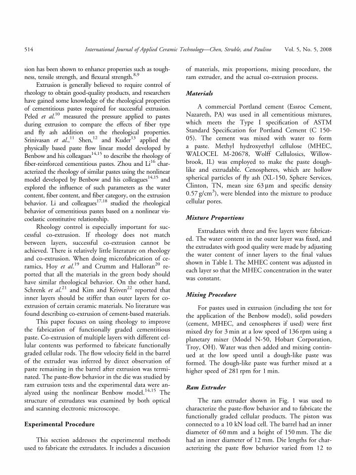
The ram extruder shown in Fig. 1 was used tocharacterize the paste-flow behavior and to fabricate thefunctionally graded cellular products. The piston wasconnected to a 10 kN load cell. The barrel had an innerdiameter of 60 mm and a height of 150 mm. The diehad an inner diameter of 12 mm. Die lengths for char-acterizing the paste flow behavior varied from 12 to
514 International Journal of Applied Ceramic Technology—Chen, Struble, and Paulino Vol. 5, No. 5, 2008
192 mm, such that the ratios of die length/die diameterwere 1, 4, 8, 12, and 16. For co-extrusion, a single dielength was used, such that the ratio of die length/diediameter was.8
As the piston moves downward, the feed paste in-side the barrel is forced into the die and the extrudatecomes out the die exit. A static zone in which the paste isnot squeezed out forms a natural cone at the die entryregion. For co-extrusion, extrudate with good qualitywas obtained only after the static zone was formed andthe flow became steady.
Co-extrusion
A simple and cost-effective method was employedto make a layered feedrod for co-extrusion. Using the
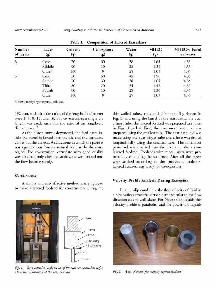
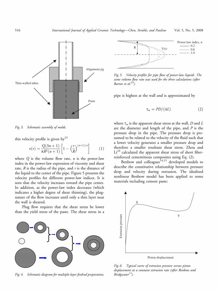
thin-walled tubes, rods and alignment jigs shown inFig. 2, and using the barrel of the extruder as the out-ermost tube, the layered feedrod was prepared as shownin Figs. 3 and 4. First, the innermost paste rod wasprepared using the smallest tube. The next paste rod wasmade using the next bigger tube and a hole was drilledlongitudinally using the smallest tube. The innermostpaste rod was inserted into the hole to make a two-layered feedrod. Feedrods with more layers were pre-pared by extending the sequence. After all the layerswere stacked according to this process, a multiple-layered feedrod was ready for co-extrusion.
Velocity Profile Analysis During Extrusion
In a nonslip condition, the flow velocity of fluid ina pipe varies across the section perpendicular to the flowdirection due to wall shear. For Newtonian liquids thisvelocity profile is parabolic, and for power-law liquids
Piston
Barrel
Feed
Die
Die entry
Static zone
Die exit
Fig. 1. Ram extruder. Left, set-up of the real ram extruder; right,schematic illustration of the ram extruder. Fig. 2. A set of molds for making layered feedrod.
Table I. Composition of Layered Extrudates
Numberof layers
Layer(g)
Cement(g)
Cenosphere(g)
Water(g)
MHEC(g)
MHEC% basedon water
3 Core 70 30 38 1.65 4.35Middle 90 10 28 1.30 4.35Outer 100 0 25 1.09 4.35
5 Core 50 50 45 1.96 4.35Second 70 30 38 1.65 4.35Third 80 20 34 1.48 4.35Fourth 90 10 28 1.30 4.35Outer 100 0 25 1.09 4.35
MHEC, methyl hydroxyethyl cellulose.
www.ceramics.org/ACT Using Rheology to Achieve Co-Extrusion of Cement-Based Materials 515
this velocity profile is given by23
vðrÞ ¼ Qð3nþ 1ÞpR2ðnþ 1Þ 1� r
R
� �ðnþ1Þ=n� �
ð1Þ
where Q is the volume flow rate, n is the power-lawindex in the power-law expression of viscosity and shearrate, R is the radius of the pipe, and r is the distance ofthe liquid to the center of the pipe. Figure 5 presents thevelocity profiles for different power-law indices. It isseen that the velocity increases toward the pipe center.In addition, as the power-law index decreases (whichindicates a higher degree of shear thinning), the plug-nature of the flow increases until only a thin layer nearthe wall is sheared.
Plug flow requires that the shear stress be lowerthan the yield stress of the paste. The shear stress in a
pipe is highest at the wall and is approximated by
tw ¼ PD=ð4LÞ ð2Þ
where tw is the apparent shear stress at the wall, D and Lare the diameter and length of the pipe, and P is thepressure drop in the pipe. The pressure drop is pre-sumed to be related to the velocity of the fluid such thata lower velocity generates a smaller pressure drop andtherefore a smaller resultant shear stress. Zhou andLi24 calculated the apparent shear stress of short fiber-reinforced cementitious composites using Eq. (2).
Benbow and colleagues14,15 developed models todescribe the constitutive relationship between pressuredrop and velocity during extrusion. The idealizednonlinear Benbow model has been applied to somematerials including cement paste:
Thin-walled tubes
Paste
Alignment jig
Fig. 3. Schematic assembly of molds.
Fig. 4. Schematic diagram for multiple-layer feedrod preparation.
Power law index, n0.20.61.0
R V(r)
Fig. 5. Velocity profiles for pipe flow of power-law liquids. Thesame volume flow rate was used for the three calculations (afterBarnes et al.23).
X
Y
Ext
rusi
on p
ress
ure
Piston displacement
Fig. 6. Typical curve of extrusion pressure versus pistondisplacement at a constant extrusion rate (after Benbow andBridgwater15).
516 International Journal of Applied Ceramic Technology—Chen, Struble, and Paulino Vol. 5, No. 5, 2008
Ptot ¼ P1 þ P¼ 2ðs0 þ aV mÞ lnðD0=DÞ þ 4ðt0 þ bV nÞ� ðL=DÞ ð3Þ
where the first term P1 is the pressure drop in the dieentry region, the second term P (the same as that inEq. (2)) is the pressure drop in the die land. The geo-metrical parameters D0 and D are the diameters of thebarrel and the die, respectively, L is the length of the dieland, V is the extrudate velocity, s0 is the yield stress ofbulk material, a is a parameter characterizing the veloc-ity effect in the die entry region, t0 is the wall yieldstress, and b is a parameter characterizing the velocity
effect in the die land region. The power indices m and naccount for the nonlinear features of the paste. All sixparameters, s0, a, t0, b, m, and n, were regarded asmaterial.
The Benbow model ignores any pressure drop in thebarrel. Indeed, the pressure drop in the barrel during ex-trusion is small and can be neglected when compared withthe total pressure drop. As the piston moves downward,the extrusion pressure increases rapidly to X (Fig. 6),where the piston fully contacts the paste and the paste isextruded out. As displacement increases from X, the con-dition is steady state, but the pressure decreases slightlybecause the friction in the barrel decreases as less and lesspaste remains in the barrel. When the piston reaches thestatic zone, the pressure increases rapidly again.
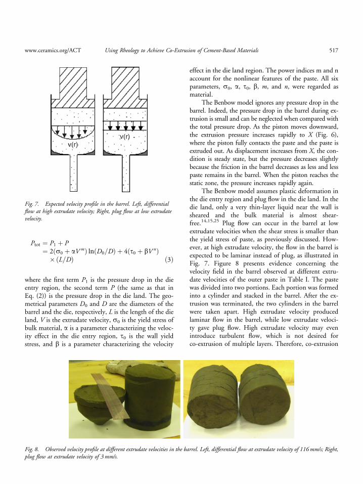
The Benbow model assumes plastic deformation inthe die entry region and plug flow in the die land. In thedie land, only a very thin-layer liquid near the wall issheared and the bulk material is almost shear-free.14,15,25 Plug flow can occur in the barrel at lowextrudate velocities when the shear stress is smaller thanthe yield stress of paste, as previously discussed. How-ever, at high extrudate velocity, the flow in the barrel isexpected to be laminar instead of plug, as illustrated inFig. 7. Figure 8 presents evidence concerning thevelocity field in the barrel observed at different extru-date velocities of the outer paste in Table I. The pastewas divided into two portions. Each portion was formedinto a cylinder and stacked in the barrel. After the ex-trusion was terminated, the two cylinders in the barrelwere taken apart. High extrudate velocity producedlaminar flow in the barrel, while low extrudate veloci-ty gave plug flow. High extrudate velocity may evenintroduce turbulent flow, which is not desired forco-extrusion of multiple layers. Therefore, co-extrusion
v(r) v(r)
Fig. 7. Expected velocity profile in the barrel. Left, differentialflow at high extrudate velocity; Right, plug flow at low extrudatevelocity.
Fig. 8. Observed velocity profile at different extrudate velocities in the barrel. Left, differential flow at extrudate velocity of 116 mm/s; Right,plug flow at extrudate velocity of 3 mm/s.
www.ceramics.org/ACT Using Rheology to Achieve Co-Extrusion of Cement-Based Materials 517
should be performed at a relatively low extrusion rate tomaintain plug flow in the barrel.
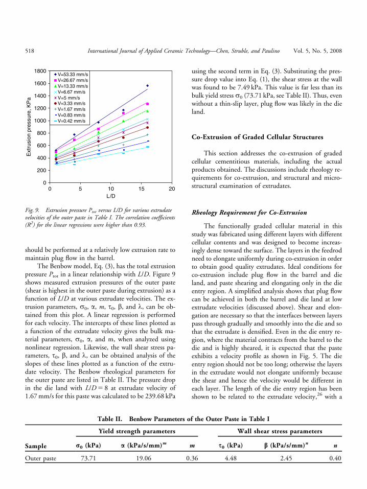
The Benbow model, Eq. (3), has the total extrusionpressure Ptot in a linear relationship with L/D. Figure 9shows measured extrusion pressures of the outer paste(shear is highest in the outer paste during extrusion) as afunction of L/D at various extrudate velocities. The ex-trusion parameters, s0, a, m, t0, b, and l, can be ob-tained from this plot. A linear regression is performedfor each velocity. The intercepts of these lines plotted asa function of the extrudate velocity gives the bulk ma-terial parameters, s0, a, and m, when analyzed usingnonlinear regression. Likewise, the wall shear stress pa-rameters, t0, b, and l, can be obtained analysis of theslopes of these lines plotted as a function of the extru-date velocity. The Benbow rheological parameters forthe outer paste are listed in Table II. The pressure dropin the die land with L/D 5 8 at extrudate velocity of1.67 mm/s for this paste was calculated to be 239.68 kPa
using the second term in Eq. (3). Substituting the pres-sure drop value into Eq. (1), the shear stress at the wallwas found to be 7.49 kPa. This value is far less than itsbulk yield stress s0 (73.71 kPa, see Table II). Thus, evenwithout a thin-slip layer, plug flow was likely in the dieland.
Co-Extrusion of Graded Cellular Structures
This section addresses the co-extrusion of gradedcellular cementitious materials, including the actualproducts obtained. The discussions include rheology re-quirements for co-extrusion, and structural and micro-structural examination of extrudates.
Rheology Requirement for Co-Extrusion
The functionally graded cellular material in thisstudy was fabricated using different layers with differentcellular contents and was designed to become increas-ingly dense toward the surface. The layers in the feedrodneed to elongate uniformly during co-extrusion in orderto obtain good quality extrudates. Ideal conditions forco-extrusion include plug flow in the barrel and dieland, and paste shearing and elongating only in the dieentry region. A simplified analysis shows that plug flowcan be achieved in both the barrel and die land at lowextrudate velocities (discussed above). Shear and elon-gation are necessary so that the interfaces between layerspass through gradually and smoothly into the die and sothat the extrudate is densified. Even in the die entry re-gion, where the material contracts from the barrel to thedie and is highly sheared, it is expected that the pasteexhibits a velocity profile as shown in Fig. 5. The dieentry region should not be too long; otherwise the layersin the extrudate would not elongate uniformly becausethe shear and hence the velocity would be different ineach layer. The length of the die entry region has beenshown to be related to the extrudate velocity,26 with a
0
200
400
600
800
1000
1200
1400
1600
1800
0 5 10 15 20L/D
Ext
rusi
on p
ress
ure,
KP
a
V=53.33 mm/sV=26.67 mm/sV=13.33 mm/sV=6.67 mm/sV=5 mm/sV=3.33 mm/sV=1.67 mm/sV=0.83 mm/sV=0.42 mm/s
Fig. 9. Extrusion pressure Ptot versus L/D for various extrudatevelocities of the outer paste in Table I. The correlation coefficients(R2) for the linear regressions were higher than 0.93.
Table II. Benbow Parameters of the Outer Paste in Table I
Sample
Yield strength parameters Wall shear stress parameters
r0 (kPa) a (kPa/s/mm)m m s0 (kPa) b (kPa/s/mm)n n
Outer paste 73.71 19.06 0.36 4.48 2.45 0.40
518 International Journal of Applied Ceramic Technology—Chen, Struble, and Paulino Vol. 5, No. 5, 2008
lower extrudate velocity generating a shorter die entryregion.
At low extrusion speed, the rheology of the pastesin different layers still needs to be matched to avoidturbulence between layers in the die entry region wherethe paste is highly sheared. It has been recommendedfor some ceramic materials that to minimize thevelocity difference between layers, the inner layer shouldhave higher viscosity.21,22 Our experience for thecementitious materials in this study was quite different.Figure 10 shows an example of tangling of two layersin which the inner layer had a higher shear viscosity.For successful co-extrusion of cementitious pastes, wefind that the inner layers must have a lower shear vis-cosity than the outer layer. The rheology of a paste de-pends on several factors, including the solid particleshape and size distribution, plasticizer type and amount,and water content. The water content was the mostconvenient parameter to change to adjust the rheology.The water content for each layer in Table I was adjusted
by trial and error to match rheology, thereby givingadequate co-extrusion behavior. Using this approach,we have successfully co-extruded mixtures with threeand five layers at extrudate velocity of 1.67 mm/s andL/D 5 8.
Structure and Micro-Structure Examination of theExtrudates
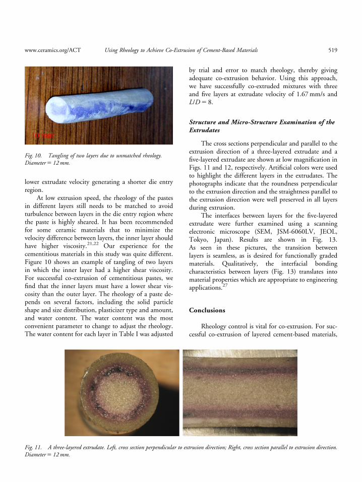
The cross sections perpendicular and parallel to theextrusion direction of a three-layered extrudate and afive-layered extrudate are shown at low magnification inFigs. 11 and 12, respectively. Artificial colors were usedto highlight the different layers in the extrudates. Thephotographs indicate that the roundness perpendicularto the extrusion direction and the straightness parallel tothe extrusion direction were well preserved in all layersduring extrusion.
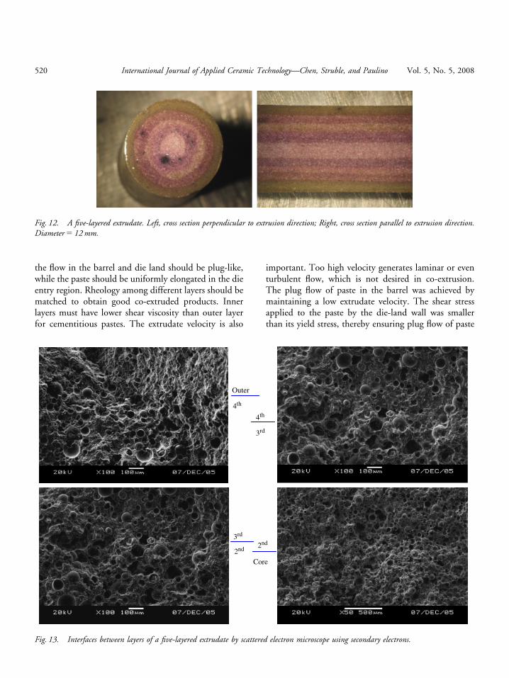
The interfaces between layers for the five-layeredextrudate were further examined using a scanningelectronic microscope (SEM, JSM-6060LV, JEOL,Tokyo, Japan). Results are shown in Fig. 13.As seen in these pictures, the transition betweenlayers is seamless, as is desired for functionally gradedmaterials. Qualitatively, the interfacial bondingcharacteristics between layers (Fig. 13) translates intomaterial properties which are appropriate to engineeringapplications.27
Conclusions
Rheology control is vital for co-extrusion. For suc-cessful co-extrusion of layered cement-based materials,
10 mm
Fig. 10. Tangling of two layers due to unmatched rheology.Diameter 5 12 mm.
Fig. 11. A three-layered extrudate. Left, cross section perpendicular to extrusion direction; Right, cross section parallel to extrusion direction.Diameter 5 12 mm.
www.ceramics.org/ACT Using Rheology to Achieve Co-Extrusion of Cement-Based Materials 519
the flow in the barrel and die land should be plug-like,while the paste should be uniformly elongated in the dieentry region. Rheology among different layers should bematched to obtain good co-extruded products. Innerlayers must have lower shear viscosity than outer layerfor cementitious pastes. The extrudate velocity is also
important. Too high velocity generates laminar or eventurbulent flow, which is not desired in co-extrusion.The plug flow of paste in the barrel was achieved bymaintaining a low extrudate velocity. The shear stressapplied to the paste by the die-land wall was smallerthan its yield stress, thereby ensuring plug flow of paste
Fig. 12. A five-layered extrudate. Left, cross section perpendicular to extrusion direction; Right, cross section parallel to extrusion direction.Diameter 5 12 mm.
4th
Outer
4th
3rd
2nd 2nd
Core
3rd
Fig. 13. Interfaces between layers of a five-layered extrudate by scattered electron microscope using secondary electrons.
520 International Journal of Applied Ceramic Technology—Chen, Struble, and Paulino Vol. 5, No. 5, 2008
in the die land. A simple experimental method usingthin-walled tubes was effective to prepare a layered feed-rod of cementitious paste. Functionally cellular-gradedcement-based extrudates were successfully fabricated byco-extrusion at a low extrudate velocity. Inspectionshowed that the roundness perpendicular to the extru-sion direction and the straightness parallel to the extru-sion direction between layers were well preserved afterextrusion and that the transition between layers wasgradual.
Acknowledgement
The authors thank the Wolff Cellulosics, NorthAmerica for generously supplying the MHEC. Theauthors also thank Bin Shen, a Ph.D. candidate atUniversity of Illinois at Urbana-Champaign, for his de-sign of the ram extruder. The authors also acknowledgethe Center for Microanalysis of Materials, University ofIllinois for use of SEM.
References
1. S. Mindess, J. F. Young, and D. Darwin, Concrete, 2nd edition, Prentice Hall,Upper Saddle River, NJ, 2003.
2. M. Kikuchi and T. Mukai, ‘‘Properties of Structural Light-Weight ConcreteContaining Sintered Fly Ash Aggregate and Clinker Ash,’’ Trans. Jpn.Concrete Inst., 8 45–50 (1986).
3. G. Bave, ‘‘Aerated Light Weight Concrete—Current Technology,’’ Proceed-ings of the 2nd International Congress on Lightweight Concrete, ConcreteInternational, London, 28–35, 1980.
4. C. Aldea, S. Markunte, and S. P. Shah, ‘‘Extruded Fiber Reinforced CementPressure Pipe,’’ Adv. Cement Based Mater., 8 [2] 47–55 (1998).
5. Z. Li, C. Liu, and T. Yu, ‘‘Laminate of Reformed Bamboo and ExtrudedFiber-Reinforced Cementitious Plate,’’ J. Mater. Civil Eng., 14 [4] 165–259(2002).
6. Y. Shao, J. Qiu, and S. P. Shah, ‘‘Microstructure of Extruded Cement-Bond-ed Fiberboard,’’ Cement Concrete Res., 31 [8] 1153–1161 (2001).
7. H. D. Deford, ‘‘Extruded Cellular Fly Ash Construction Materials,’’ Ph.D.Dissertation, University of Illinois at Urbana-Champaign, 1997.
8. X. Qian, X. Zhou, B. Mu, and Z. Li, ‘‘Fiber Alignment and PropertyDirection Dependency of FRC Extrudate,’’ Cement Concrete Res., 33 [12]1575–1581 (2003).
9. A. Peled and S. P. Shah, ‘‘Processing Effects in Cementitious Composites:Extrusion and Casting,’’ J. Mater. Civil Eng., 15 [1] 189–192 (2003).
10. A. Peled, M. F. Cyr, and S. P. Shah, ‘‘High Content of Fly Ash (Class F)in Extruded Cementitious Composites,’’ ACI Mater. J., 97 [5] 509–517(2000).
11. R. S. Srinivasan, D. Deford, and S. P. Shah, ‘‘The Use of Extrusion Rheome-try in the Development of Extruded Fiber-Reinforced Cement Composites,’’Concrete Sci. Eng., 1 [3] 26–36 (1999).
12. B. Shen ‘‘Experimental Approaches for Determining Rheological Propertiesof Cement-Based Extrudates,’’ M.S. Thesis, Hongkong University of Scienceand Technology, 2003.
13. K. G. Kuder ‘‘Extruded Fiber-Reinforced Cementitious Composites for Usein Residential Construction,’’ Ph.D. Thesis, Northwestern University, 2005.
14. J. J. Benbow, E. W. Oxley, and J. Bridgwater, ‘‘The Extrusion Mechanics ofPastes-the Influence of Paste Formulation on Extrusion Parameters,’’ Chem.Eng. Sci., 42 [9] 2151–2162 (1987).
15. J. J. Benbow and J. Bridgwater, Paste Flow and Extrusion, Oxford UniversityPress Inc, New York, NY, USA, 1993.
16. X. Zhou and Z. Li, ‘‘Characterization of Rheology of Fresh Fiber ReinforcedCementitious Composites through Ram Extrusion,’’ Mater. Struct., 38 [275]17–24 (2005).
17. Z. Li, B. Mu, and S. N. C. Chui, ‘‘Rheological Behavior of Short Fiber-Reinforced Cement-Based Extrudate,’’ J. Eng. Mech., 125 [5] 530–536(1999).
18. Z. Li and B. Mu, ‘‘Rheological Properties of Cement-Based Extrudates withFibers,’’ J. Am. Ceram. Soc., 84 [10] 2343–2350 (2001).
19. C. V. Hoy, A. Barda, M. Griffith, and J. W. Halloran, ‘‘Microfabrication ofCeramics by Co-Extrusion,’’ J. Am. Ceram. Soc., 81 [2] 152–158 (1998).
20. A. T. Crumm and J. W. Halloran, ‘‘Fabrication of Microconfigured Multi-component Ceramics,’’ J. Am. Ceram. Soc., 81 [4] 1053–1057 (1998).
21. W. J. Schrenk, N. L. Bradley, and T. Jr. Alfrey, ‘‘Interfacial Flow Instability inMultilayer Coextrusion,’’ Polym. Eng. Sci., 18 [8] 620–623 (1978).
22. D. K. Kim and W. M. Kriven, ‘‘Fibrous Monoliths of Mullite-AlPO4 andAlumina/YAG–Alumina Platelets,’’ Mater. Sci. Eng. A, 380 [1–2] 51–58(2004).
23. H. A. Barnes, J. F. Hutton, and K. Walters, An Introduction to Rheology,Elsevier Science Publishers, Amsterdam, The Netherlands, 1989.
24. X. Zhou and Z. Li, ‘‘Characterizing Rheology of Fresh Short Fiber Rein-forced Cementitious Composites through Capillary Extrusion,’’ J. Mater.Civil Eng., 17 [1] 28–35 (2005).
25. J. F. Jr. Wight, ‘‘The Extrusion of Ceramics,’’ Ph.D. Dissertation, AlfredUniversity, 1995.
26. D. M. Binding, ‘‘An Approximate Analysis for Contraction and ConvergingFlows,’’ J. Non-Newtonian Fluid Mech., 27 [2] 173–189 (1988).
27. G. H. Paulino, Z. -H. Jin, and R. H. Jr. Dodds, ‘‘Failure of FunctionallyGraded Materials,’’ Comprehensive Structure Integrity, Vol. 2 ‘‘FundamentalTheories and Mechanisms of Failure.’’ eds., B. Karihaloo and W. G. Knauss.Elsevier, San Diego, CA, 607–644, 2003.
www.ceramics.org/ACT Using Rheology to Achieve Co-Extrusion of Cement-Based Materials 521


