Embed Size (px)
Citation preview


V-RAY MY WAY

This page intentionally left blank
V-RAY MY WAYA Practical Designer’s
Guide to Creating Realistic Imagery Using V-Ray
& 3ds Max
LEE WYLDE
Focal Press Taylor & Francis Croup
NEW YORK AND LONDON
f

First published 2014by Focal Press70 Blanchard Road, Suite 402, Burlington, MA 01803
and by Focal Press2 Park Square, Milton Park, Abingdon, Oxon OX14 4RN
Focal Press is an imprint of the Taylor & Francis Group, an informa business
© 2014 Taylor & Francis
The right of Lee Wylde to be identified as the author of this work has been asserted by him in accordance with sections 77 and 78 of the Copyright, Designs and Patents Act 1988.
All rights reserved. No part of this book may be reprinted or reproduced or utilized in any form or by any electronic, mechanical, or other means, now known or hereafter invented, including photocopying and recording, or in any information storage or retrieval system, without permission in writing from the publishers.
NoticesKnowledge and best practice in this field are constantly changing. As new research and experience broaden our understanding, changes in research methods, professional practices, or medical treatment may become necessary.
Practitioners and researchers must always rely on their own experience and knowledge in evaluating and using any information, methods, compounds, or experiments described herein. In using such information or methods they should be mindful of their own safety and the safety of others, including parties for whom they have a professional responsibility.
Product or corporate names may be trademarks or registered trademarks, and are used only for identification and explanation without intent to infringe.
Library of Congress Cataloging in Publication DataWylde, Lee. V-Ray my way : a practical designer’s guide to creating realistic imagery using V-Ray & 3ds Max / Lee Wylde. pages cm 1. V-R ay. 2. 3ds max (Computer file) 3. Architectural rendering— Computer-aided design. I. Title. NA2728.W98 2014 776�.7—dc23 2013038376
ISBN: 978-0-415-70963-7 (pbk)ISBN: 978-1-315-88544-5 (ebk)
Typeset in AGaramond and Avenir By Keystroke, Station Road, Codsall, Wolverhampton
For Jovan, and what could have been …

Bound to Create
You are a creator.
Whatever your form of expression — photography, filmmaking, animation, games, audio, media communication, web design, or theatre — you simply want to create without limitation. Bound by nothing except your own creativity and determination.
Focal Press can help.
For over 75 years Focal has published books that support your creative goals. Our founder, Andor Kraszna-Krausz, established Focal in 1938 so you could have access to leading-edge expert knowledge, techniques, and tools that allow you to create without constraint. We strive to create exceptional, engaging, and practical content that helps you master your passion.
Focal Press and you.
Bound to create.
We'd love to hear how we've helped
you create. Share your experience:
www.focalpress.com/boundtocreate
Focal Press Taylor & Francis Group f

| vii
6 Interior Mockup Scenes 91
Design Process 92Lighting 94Cameras 98V-Ray Settings 99Rendering 103
7 Exterior Daytime Scenes 107
Design Process 108Lighting 110Cameras 118V-Ray Settings 120Rendering 125
8 Exterior Evening Scenes 129
Design Process 130Lighting 132Cameras 138V-Ray Settings 140Rendering 144
Acknowledgments 1
1 My Experience and Background Story 3
2 Methodology (How to Use this Book) 15
3 Introduction to My Workflow 19
4 Interior Daytime Scenes 29
Design Process 30Lighting 34Cameras 44V-Ray Settings 48Rendering 54
5 Interior Evening Scenes 63
Design Process 64Lighting 67Cameras 73V-Ray Settings 77Rendering 83
CONTENTS

viii |
C O N T E N T S
10 Shooting HDRIS 161
Introduction 162Methodology 163Choosing a Location 166Equipment 168Preparation 170Compiling HDRIS 175Setting up V-Ray HDRIS in 3D Studio Max 185
Index 205
9 Automotive Scenes 147
Design Process 148Lighting 149Cameras 153V-Ray Settings 155Rendering 158

| 1
exercises. Thank you to Markus Huber from openfootage.net for generously allowing me to use his HDRI files within some of the scenes.
And finally to my wife for her support and for keeping my energetic children entertained for the duration of my writing.
Thank you to the following individuals for their careful review of the text during its various stages of development:
Clark Cory, Alex Huguet Paredes, Jeremy Sahlman, and Matthew Valero.
Thanks also to Christian Bloch from HDRlabs.com for allow ing me to use some of their HDR lighting files for the
ACKNOWLEDGMENTS


CHAPTER 1
MY EXPERIENCE AND BACKGROUND STORY

M Y E X P E R I E N C E A N D B A C K G R O U N D S T O R Y
4 |
learn the very basics at my own pace. I spent the next six months glued to my rather slow, rather inefficient Acer lap-top following the steps to create meshes, render flowers and model spaceships.
My dedication and inquisitiveness had led me part of the way into a new career; however I was not prepared for the next stage of my life.
In the year 2000 I was accepted onto the British Government’s Modern Apprenticeship Scheme. I joined a bustling archi-tectural practice called Hadfield Cawkwell Davison. This was a new world to me; there were roughly 70 people in the company. Each studio was filled with architectural models, building materials, fabric samples, drawings and lots of cof-fee. My position was as an architectural apprentice.
With my pen in my shirt pocket I arrived on my first day ready to design the next building worthy of the architect of the year award. My ambition was strong but the likelihood of winning architect of the year was fairly low.
I soon came across the graphics department, a group of long-haired designers who listened to 1980s’ music with Starbucks cups on their desks. I was in awe and wanted to move in as soon as possible. At this time the production of artwork for architectural projects consisted of hand-drawn scanned images, digitally finished in Photoshop. Nostalgically mounted on the walls were the most beautiful hand-drawn and water-colored architectural illustrations.
‘To infinity and beyond’, the instantly recognizable phrase that shaped the public’s perception of computer visualization forever.
It was at the time of the release of the first Toy Story movie that I was sat in rural England in a small town called Sheffield, wondering what I wanted to do with my life. At 15 years old who actually knows what they want to do in life? However, Woody, Buzz and the rest of the gang had me mesmorized and keen to discover more about this phenomenal art.
At 15 I was the youngest in my year at high school. I had always been creative and teachers would often hurl abuse at me for doodling during history or religious education classes.
I had a computer at home and was taking computer classes at school, but these were nothing compared to the industry that was out there in the real world.
Luckily one day I was in a high street retail store and came across a magazine called 3D World. It was packed to the brim with industry information and glossy renderings of characters, creatures and vehicles, and I knew that this was my starting point.
The publication contained tutorials, albeit a little advanced for me but nevertheless incredibly useful. The most useful aspect was the CD-ROM with 30 day trial software that I yearned for every month. This was perfect, an ideal way to

C H A P T E R O N E
| 5
Having presented my boss with the output he was genu-inely surprised that I had created the images. I showed him the files and explained how I had achieved the end result. I soon started to work on interior schemes and moved to the interior design department. From that day I was sent on my way to learn parts of professionally accredited 3D courses for intermediate and advanced 3D Studio Max users. Happy days.
During 2002 the incredibly annoying user-friendly 3D pro-gram was released called SketchUp. Architects at the time were praising the software and thought it was the best thing since sliced bread. I hated it. (I do not now, I find it a key part of my workflow). Having learned the technical aspects of 3D Studio Max I felt threatened that suddenly everyone could produce 3D with relative ease. Versatile, unique, with customizable outputs, no render times, SketchUp was indus-try-changing.
Once the management had figured out the time to create visuals using 3D Studio Max versus the time taken using SketchUp, well let’s say I was less than pleased when I was told to use SketchUp instead.
Reluctantly I found myself using SketchUp almost every day for the remainder of my four years with the practice. I developed my own way of working, from taking briefs to photographing textures, making briefing sheets and eventu-ally by default, setting up the company 3D department. It
I was desperate to join this department but it was not to be, well not for a year and a half anyhow.
For those agonizing 18 months I was responsible for archiv-ing, photocopying and tea-making. How fruitful life seemed. On the other hand the social aspect was amazing, I moved to different departments to help the interior designers. During the 18 months I managed to teach myself 3D Studio Max and AutoCAD.
The department had a copy of 3D Studio Max which at this time was version 3. I was granted access to the dongle during the studio’s downtime (which was after 5:30 p.m.).
The practice did send me on training days for AutoCAD, but this was only 2D, and as ambitious as I was back then, I wanted 3D training.
I was in a position where I had to prove myself, yet not look as though I was above my station. One of the partners at the practice was very hands on, constantly mixing with the design team and providing creative direction. I knew this was the person I had to impress.
I had secretly modeled a whole building in 3D of a current project and had managed to render the facade and add trees and pavements etc. Looking back now they were dismal, but just what I needed to progress in my career. The practice, like others all over the UK at that time used an external consul-tant for high-end visualizations.

M Y E X P E R I E N C E A N D B A C K G R O U N D S T O R Y
6 |
enough to be able to create large scenes for leading retailers in the UK.
Finding Nemo was released in the UK during this year which quantified my admiration for Pixar, and how I longed to be the tea boy at their studios if given the chance. In fact I think I would be their tea boy now if I could wander in and out of each department looking at their stunning artwork.
‘3D is a fad, there is no future in it, you are wasting your time.’ The parting words from a member of staff as I left my first job to join another leading design practice in the UK.
I decided to depart from my first job for a number of reasons. I thoroughly enjoyed my creative days there; however I was young and had not grasped the corporate side of the work-ing environment. With suits on one side of the office and Hawaiian shirts on the other, it was not exactly a recipe for a balanced workplace. At 19 years old I wanted to broaden my horizons and decided the best thing to do was to take my capabilities elsewhere.
In 2005 I started my own company called Foothill Studios. I was 20 and full of energy ready to make my company work. I had seen the invoices from 3D consultants in my first job and thought to myself that I could provide a similar service much cheaper.
I had no idea what I was getting myself into, but it felt great at the time, a real sense of adventure. With my glossy
was fun, and that was the most important thing. I did not want to be an architect or an interior designer at that time, I had forgotten about climbing the career ladder. I simply enjoyed my creative time working with others to deliver stunning graphics for client meetings.
Come 5:30 p.m. we would be hooking everyone’s machines up to try and figure out how to network render using 3D Studio Max. It certainly gave the IT department something new to experiment with. We were using 3D Studio Max more and more as production software after SketchUp had been pushed as far as it possibly could.
Back then we thought that the light tracer function was a gigantic breakthrough for us to use. When I look back now it makes me laugh, there were studios in the US and London using all sorts of wizardry and we had not a clue, we were in a bubble, but at least it was fun for us to explore and develop our skills.
We spent hours, days and weekends reading through online tutorials, reading through training manuals purchased from high street book stores and just generally experimenting. Books were virtually useless to us. They were too scientific, academic if you will. We needed fresh, industry-related direction.
That is the first lesson in life that I had learned, nothing is easy, or otherwise everyone would be doing it. I had developed my skills in texturing, lighting and modeling

C H A P T E R O N E
| 7
based in London. They had seen my work through a third party who had specified their furniture in a concept pitch.
After making inquiries the company had managed to track me down, where at the time I was fast asleep in bed after a whole night of rendering. Watching scan-lines come down my screen, just waiting for errors I had made, forcing me to re-render was tiresome work back then.
It was my mother who had come running up three flights of stairs yielding the wireless phone in her hand. ‘There is a lovely man on the phone from London, he wants to talk to you about your work.’
I was half asleep and wearing The Matrix pajamas at the time. I do not think my professionalism was in question from what I was wearing, rather perhaps from my mother’s interrogation of my potential client.
I was asked to travel to London the following week to meet the company in their very posh and rather swanky showroom in Clerkenwell. I lived three hours north of London and had only been there on vacation a few times. There was something about the place that electrified my aspirations.
My meeting was with the global account manager and a few other members of the design team. I had not realized at this point in my life just how significant the commercial furni-ture industry was.
business cards ready, functioning website ready and price list ready it was time to market myself.
The great thing about the UK is that you can cold call and with a little tenacity can actually speak to the people you need to in order to pitch yourself. The decision makers if you will. This worked remarkably well for me and literally within the first week I had three projects to deliver.
My main aim at that time was to target architects, private property developers and interior designers throughout the UK. I created endless spreadsheets of business hit lists and allocated myself a time per week to speak to each one.
At the time I was mainly funded by the Bank of Mum and Dad; my father and I had built a new loft-space on my parents’ house and I used it to operate my small studio from.
I had a unique style that I could pitch to clients; this com-bined with value for money certainly made me relevant to small and medium enterprises (SMEs). For the first year my clients mainly consisted of interior designers, architects and developers. This was a fantastic market at the time; developments were springing up all over the UK and all required artwork for planning authority approvals, market-ing, public information etc.
One of the pivotal moments at this time came when I was contacted by a reputable furniture designer and manufacturer

M Y E X P E R I E N C E A N D B A C K G R O U N D S T O R Y
8 |
It took three months to contact all companies and to pitch to them. I had immediate success and found myself cre-ating new material for retail projects, commercial projects and high-end branded interiors. This is where I learned my second big lesson in life.
I had more work than I could cope with. My machine at the time had been kindly donated by my first employer. I had upgraded the RAM but that was all I could do for it. Inevitably it needed replacing to handle the amount of ren-dering work I had to carry out. I was also receiving requests for animations.
I needed new kit. Lesson number two; do not rush into any-thing, research thoroughly.
Given the need for speed at this time and not wanting to have delays with other clients I ordered shiny new machines from BOXXTECH in the US. The kit cost an arm and a leg. It arrived on Christmas Eve, how fitting. My father had signed for the boxes and was less than pleased that stacks of boxes were taking up his living space. ‘What the bloody hell is all this?’.
He thought that one computer should last forever and that my old machine should still be able to do the job. ‘New ma-chines, Dad, make more money.’ Enough said, he was fine with the justification.
Onwards and upwards, I had unpacked all the elements. Brushed aluminum render servers lay glittering on my
My mother must have made a good impression as the first question was ‘How is your Mother?’. I spent hours discuss-ing their current range of office furniture, their visualization requirements and how knowledgeable I was with their catalogues.
Luckily I was very knowledgeable, for I had modeled their furniture from 2D drawings for other clients to produce 3D mock-up images. It was far more cost effective for me to provide clients with renderings of furniture systems rather than have the system transported, erected, photographed, dismantled and delivered back to their showroom.
The meeting was incredibly successful. Armed with numer-ous brochures, samples and their supplier contacts directory I returned to the train for a three-hour journey north.
Within a few days, much to the dismay of my father, fur-niture items started arriving at my parents’ house, for my reference.
It seemed I was going to need a bigger boat. Along with the furniture were requisitions for 3D furniture mock-ups for projects throughout the country. I had more work than I had estimated for in my business plan. In fact I had exceeded my targets by more than 300 percent.
The contact list of suppliers, distributors and other com-panies was a fantastic opportunity for me to grow. The list comprised of over 50 companies throughout the UK all potentially requiring my services.

C H A P T E R O N E
| 9
incredibly good at planning and setting key stage delivera-bles and timelines for design projects.
With an overwhelming sense of commitment to the client, I made two lists. One list had elements of the projects I could do without using Uncle Google to fill me in on the bits I lacked the knowledge to complete. The other list, which at this point was demoralizingly larger than the other and often referred to as the how on earth list, contained things like ocean water, high dynamic range imaging (HDRI) lighting, pool water, moving people and most importantly how I was going to render the final image sequence.
During 2006 I went on a date (not just one I might add) and we found ourselves at the movies. Poseidon was the movie, which was about an ocean liner that was caught up in a catastrophic event, overturned and unfortunately for its inhabitants it sank, the usual boating accident film, but the visual effects were amazing.
There is a sequence at the beginning of the film where the camera pans around the periphery of the ship and zooms into the deck and finishes in a luxury cabin.
This was it; my inspiration had been burned into my mem-ory. I think I must have viewed the trailer more than 100 times. With the vision in mind I set about creating the environment containing the water and main light source, so I could prepare the main vessel in another 3D Studio Max file, texture it and simply merge it into the lighting rig.
bedroom floor. The modeling machine was an impressive 16 GB RAM dual quad core beast. I kept my old machine in the corner for post-production work.
Now I had the necessary tools, I needed to really progress and deliver higher quality work. I wanted to pitch for anima-tion projects, architectural, vehicle and product design etc. I had little experience in animation, but being young and tenacious I proceeded to punch above my weight.
‘Lee, someone is on the phone from America!’, the words my father was shouting from three floors down. Unlike my mother who would have dashed up three flights of stairs, my father took a more practical approach to announcing client calls.
It seems my decision to pitch above my comfort level had paid off; my first international client from the US. They required a 15-minute animation of a cruise liner with dol-phins jumping out of the water, retracting marina, jet skis and all sorts of crazy elements. I didn’t have a clue how on earth I was going to do it, so naturally I said yes.
I do not have many regrets in life, but looking back this had a firm place on the regret pile. This project should have been undertaken by a London-based studio with 10 latte-drinking animators packing state-of-the-art machinery and a monster render farm at their disposal.
Nope, it was to be undertaken by myself. With my dog at my side, who was often my strongest critic I must say, I began to come up with strategies to complete the project. I was

M Y E X P E R I E N C E A N D B A C K G R O U N D S T O R Y
10 |
It suddenly dawned on me just how long this project would take to render, at 24 frames per second and each frame tak-ing 15 minutes, which was something like 21,600 frames to render in total. I had calculated that it would take 5400 hours or rather 225 days to render.
Doomed I was, but still resourceful I toyed with the idea of using an external consultant to render my scenes. I did find a render farm in the UK who could render my animation over a 395-hour period. The only issue was that it would cost me $13,000.
This was one of the most important lessons of my career, managing client expectations and managing your own expectations. Being young and resilient I managed to scrape a deal with the client.
I forwarded all of the final files with test renders that were pre-approved for production. I also included a list of suitable render farms that I had contacted beforehand and briefed about the design account. Luckily I had a very understanding client, not many are like this, especially in the current market. It was probably one of the most impor-tant lessons learned, if you want to do Hollywood effects, go to Hollywood, otherwise keep it grounded and achievable.
The closest I ever got to Hollywood was Kansas City. In 2007 I was contacted by Winntech through Coroflot.com, which is a free online portfolio website. I highly rec-ommend it.
I often worked like this; it made sure that I had control over the lighting individually without affecting the main model. The main headache in the project so far was the ocean.
Plug-ins were available such as Real-Flow, which was way out of my price range, coupled with the fact that I would have to learn the software from scratch in time to deliver the project.
I trawled the web for resources, and spent hours and hours posting questions on forums. One day I came across a simu-lation software called Reactor. After using Uncle Google to find where I could buy the software, I found out I already had it, built into 3D Studio Max, doughnut.
After a week I was able to take the ship’s hull and animate it cutting through an ocean plane to create what is known as wake. I also had to animate the ocean plane with noise and current. It was a fantastic learning process. I finally had the ocean liner textured, the manufacturers forwarded me a huge 200 MB zipped file containing the ship’s 3D engi-neering model, it required significant cleaning and partial remodeling. I do like to make work hard for myself and chose to animate the ship during the early evening so I could insert artificial lights into the cabins and ship’s hull for max-imum contrast.
I must have thought I was in Hollywood. The test renders were actually rather good, the client was extremely happy. At 1920 � 1080 HD in 3D Studio Max’s output preset, the render time was 15 minutes a frame.

C H A P T E R O N E
| 11
in the US was the availability of a design team member for each part of the design process.
On a typical design account for a blue chip company, there would be one design account manager, one graphic designer, one interior designer and relative supporting staff. In order for the work we were producing to remain relevant, the account manager could pick and choose the designers that worked best together, which was ultimately highly beneficial to the client, thus reducing the amount of fric-tion between the team. Producing visuals under this design regime was simple, because I knew exactly what was required and furthermore I could track and request information as I needed it. This was the same for the rest of the team; they would simply go away and do what was needed.
Out of all the design companies and agencies that I have worked for, Winntech has to be my favorite in terms of team effort and collaboration style. It’s an ethos I try to utilize throughout my career even to this day.
Unfortunately my time in the US was cut short due to the government’s visa system and as such I had to relocate and find work elsewhere.
In 2008 I landed in Dubai, which was an architect’s paradise at that time. I was flown out to Dubai by one of Canada’s largest, if not the largest, branding agency called Watt International, for the position of Mid Weight Retail Interior Designer.
The position the company offered me was as an industrial designer of which I knew nothing about. Yet again being young and resilient, and knowing it had something to do with 3D, I went for it.
During the first couple of weeks at Winntech, I started to notice what makes America America. Coming from a back-ground where design is so segregated and follows a hierarchy, I soon learned that I would have to adapt to the more socially inclusive design process, as practiced by the Americans.
Having come from a self-employed background and more familiar with spectrum of operational aspects of a design business, I admit that I found it difficult to just focus on one element of design in my position.
All designers are judged by the work that they produce, and having operated my own studio for so long, I was used to taking the credit for my work directly from clients. Suddenly I was in an environment where all of my and my coworkers’ ideas were on the table, so you could say I felt protective about my concepts. I soon learned that designers to tend to gain bruised egos from being open to such scrutiny in all aspects of their work.
Over a three-month period, I understood just how strong and efficient their approach to design was, compared to the one I was used to. In other areas of the world, companies hire two or three designers to cope with a whole range of support-ing design services. What I particularly liked about working

M Y E X P E R I E N C E A N D B A C K G R O U N D S T O R Y
12 |
This is why computer generated imagery is incredibly impor-tant within such markets and reflects why your attention to details truly makes a difference.
In order to see true investable value, those developers were investing millions of dollars in the production of 3D visuals, animations and walk-throughs in order to secure sales deals and raise general awareness of key developments in the city.
Clearly, it worked. Without a doubt, there is not a billboard in the UAE that doesn’t have a 3D visual displayed on it. So the next time you are wondering what will be your future career pathway in 3D, just believe there is more to do out there other than visualizing your neighbor’s house.
Since I have been residing in the UAE, I have worked for and consulted with some of the largest architectural and in-terior design companies in the Middle East. It’s one of the most challenging places I have worked in terms of taking a brief, developing a concept and physically building a project. To work in this country you need to forget everything you know, adapt and realign your skills to suit. Why am I still here? I truly believe that in this current climate, considering the financial crisis the world is facing, the UAE is the only place that can offer stability, potential and career fulfillment as well as a jolly good salary.
Currently, I am the Head of Design at a Dubai based interior design agency and I am working on a multitude of commer-cial, retail, leisure and hospitality projects. I now face the
I expected a grand arrival and an office fit for a CEO; however as this was a new satellite office I was sat in what can only be described as a luxurious prison cell with 15 other people. It turns out that most of the competitors were working like this, also due to the astronomical operating expenses.
Not only had I just gotten use to the streamlined work pro-cess in the US, I had to now forget that and work to a more custom Middle Eastern way of working.
When you think of 3D visuals, you think of one house, perhaps a villa, maybe even a hotel interior that you would simply complete, print out and hand over to your client. You cannot comprehend how important 3D visuals are until you have visited Dubai.
Dubai’s whole property industry has been fuelled by 3D visuals. I often hear the statement that people don’t read plans in Dubai. In my experience, this could not be further from the truth.
In such a bustling market, property developers rely heavily on visualizations in order to market their properties off-plan (before the structures are built). Many people, including consumers, do not read architectural plans with such a keen eye as a designer, so if this trend is happening in the UAE, then it certainly will be happening in other regions of the world. A picture, however, can sell a product or property within seconds, with no scope for error from the readers side.

challenge of developing my junior staff into process-driven and not product-orientated design individuals.
Hopefully this book will help you in developing your career further by showing you the quickest, practical way to visu-alize, which will enable you to travel the world and fulfill your potential.


CHAPTER 2
METHODOLOGY (HOW TO USE THIS BOOK)

M E T H O D O L O G Y ( H O W T O U S E T H I S B O O K )
16 |
highlighting preparation work, modeling, lighting, render-ing and where necessary post-production work. It has been written in a way that supports my workflow, so if you fall asleep after working 18 hours on your project, you can wake up as fresh as a daisy and continue with the next section without forgetting where you were!
My particular way and method of working ensures that I cover all aspects of the design process so that the overall design intent does not suffer from last minute workloads, or mad rushes to simply get something out of the studio.
If you have a design account to visualize an architect’s mas-terpiece, then you have to take into consideration that this piece of work represents a person’s career, so you are going to want to do a thorough job.
Capturing and building a detailed scale model can take too long in 3D Studio Max alone. I highly suggest using SketchUp.
Within SketchUp there are numerous easy to use toolsets enabling you to work rapidly and to constantly be thinking of detail. Not only does SketchUp have its own workflow simplicities but it is also a great platform to show your clients progress. For the interior designers out there, my experience with SketchUp has proven to be incredibly successful.
The software enables designers to engage with clients on a new level allowing real-time walkthroughs and progressive changes to be made with relative ease.
In the design industry it is essential to possess the suitable equipment in order to complete the task in hand. When I sat down to write this book I believed that the book’s exercises should be able to be accessed, reconfigured and rendered using everyday technology. I wanted to take a laptop from a generic high street retailer and use it to create the scenes and renders to prove that you do not need to spend thousands of dollars to create high-end visuals.
In the end I settled for a Dell and I must say I certainly have put the poor notebook through its paces and it has evidently performed. Here are the specifications:
Dell N5510 8 GB RAM, 64-BIT OPERATING SYSTEM.WINDOWS 7INTEL (®) CORE i7-2670QM CPU @ 2.20GHz
Now provided you set up your scenes to handle the amount of power available to you at hand, then you should be able to deliver realistic renders on time in line with this book’s exercises. On the other hand if you are using a machine with a single processor and 2 GB of RAM, then I wouldn’t promise your design manager visuals within two hours if I were you.
I have written this book to accommodate and cater for a wide range of design industry professionals and other user groups. Each exercise has been split into relevant sections

C H A P T E R T W O
| 17
SketchUp seamlessly integrates into 3D Studio Max, making Max the perfect production tool for lighting and rendering.
You may already have your own workflow, which is fine; you can simply follow the exercises in this book to achieve your desired result.
More importantly clients feel that they are part of a process and that you are good value for money. I use this method all the time; it works and once the SketchUp is signed off you can then drop it straight into 3D Studio Max.


CHAPTER 3
INTRODUCTION TO MY WORKFLOW
I N T R O D U C T I O N T O M Y W O R K F L O W
20 |
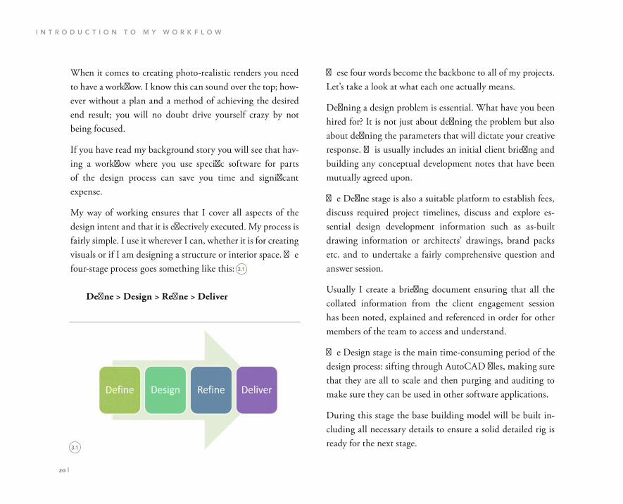
These four words become the backbone to all of my projects. Let’s take a look at what each one actually means.
Defining a design problem is essential. What have you been hired for? It is not just about defining the problem but also about defining the parameters that will dictate your creative response. This usually includes an initial client briefing and building any conceptual development notes that have been mutually agreed upon.
The Define stage is also a suitable platform to establish fees, discuss required project timelines, discuss and explore es-sential design development information such as as-built drawing information or architects’ drawings, brand packs etc. and to undertake a fairly comprehensive question and answer session.
Usually I create a briefing document ensuring that all the collated information from the client engagement session has been noted, explained and referenced in order for other members of the team to access and understand.
The Design stage is the main time-consuming period of the design process: sifting through AutoCAD files, making sure that they are all to scale and then purging and auditing to make sure they can be used in other software applications.
During this stage the base building model will be built in-cluding all necessary details to ensure a solid detailed rig is ready for the next stage.
When it comes to creating photo-realistic renders you need to have a workflow. I know this can sound over the top; how-ever without a plan and a method of achieving the desired end result; you will no doubt drive yourself crazy by not being focused.
If you have read my background story you will see that hav-ing a workflow where you use specific software for parts of the design process can save you time and significant expense.
My way of working ensures that I cover all aspects of the design intent and that it is effectively executed. My process is fairly simple. I use it wherever I can, whether it is for creating visuals or if I am designing a structure or interior space. The four-stage process goes something like this:
Define > Design > Refine > Deliver
3.1
3.1
Define Design Refine Deliver
C H A P T E R T H R E E
| 21
Camera work I usually leave until the last stage so that I can see not only how the forms and surfaces interact but also to aid in the correct placement of peripheral items for general composition purposes.
Initial renders will be sent to the client at the end of this stage for final approval. Shots that are 1920 � 1080 are usu-ally large enough to capture details for the client to discuss and mark up. Once all comments have been received then I progress to the next stage.
When I talk about the Refine stage people usually ask me why this stage is needed. My answer is multifaceted. One reason is that it helps in the pricing structure of a project.
Another is that clients need to be educated in design process. Refinements can take just as long as a design dependent on the client’s comments. Usually I have minimal comments and can proceed with ease to the Deliver stage.
Deliver means exactly that. Materials collected and developed at the define stage should be close by for reference purposes.
The client may require large format renders or an animation. This will need to be created, formatted, post-produced and delivered on time. Usually I use online methods of electronic delivery.
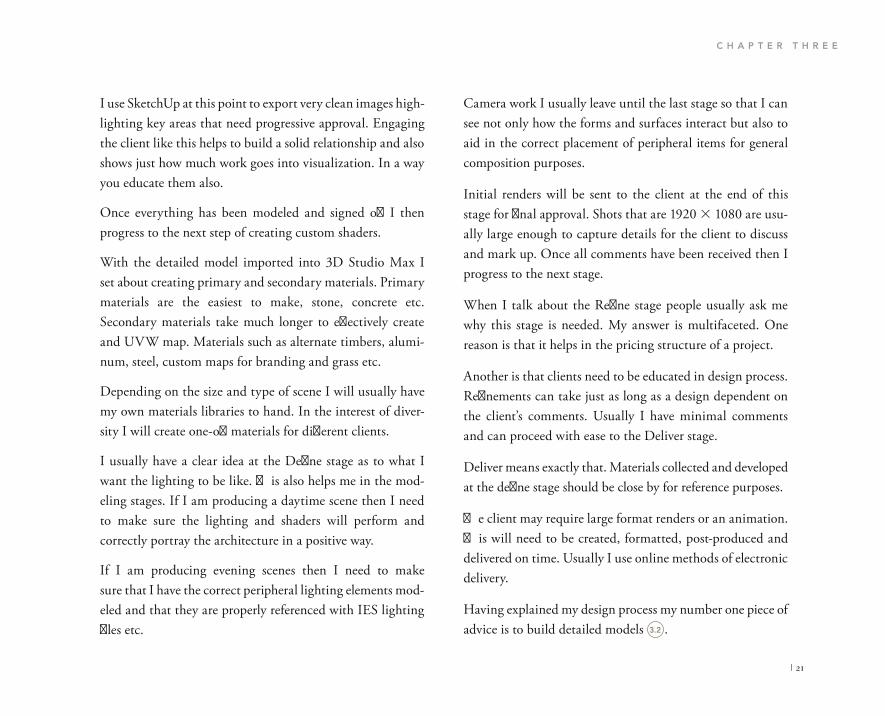
Having explained my design process my number one piece of advice is to build detailed models .
I use SketchUp at this point to export very clean images high-lighting key areas that need progressive approval. Engaging the client like this helps to build a solid relationship and also shows just how much work goes into visualization. In a way you educate them also.
Once everything has been modeled and signed off I then progress to the next step of creating custom shaders.
With the detailed model imported into 3D Studio Max I set about creating primary and secondary materials. Primary materials are the easiest to make, stone, concrete etc. Secondary materials take much longer to effectively create and UVW map. Materials such as alternate timbers, alumi-num, steel, custom maps for branding and grass etc.
Depending on the size and type of scene I will usually have my own materials libraries to hand. In the interest of diver-sity I will create one-off materials for different clients.
I usually have a clear idea at the Define stage as to what I want the lighting to be like. This also helps me in the mod-eling stages. If I am producing a daytime scene then I need to make sure the lighting and shaders will perform and correctly portray the architecture in a positive way.
If I am producing evening scenes then I need to make sure that I have the correct peripheral lighting elements mod-eled and that they are properly referenced with IES lighting files etc. 3.2

I N T R O D U C T I O N T O M Y W O R K F L O W
22 |
The second common mistake I see is a window with sin-gular reflections. There really isn’t much single glazing still around; double glazing gives you a slight double reflection adding to the realism of the project, so put two planes in your model .
The reference on page 24 to external metal cladding is an incred ibly important detail to bear in mind. Simply applying a cladding texture image to a surface will not produce the correct results .
The more effort you put into detailing a scene the better the render results will be. The types of details I am referring to are things such as window frames, walls, skirting, lighting, switches etc.
If you simply apply a material to a plane and expect it to look like a realistic window, then you are in for a surprise.
The most common mistake and misconception I have wit-nessed to this day is that glazing is blue. Windows actually appear dark during the daytime. This is because they are transparent and allow light to pass through.
3.2
3.3 3.4
3.5 3.6

C H A P T E R T H R E E
| 23
3.3 3.4

I N T R O D U C T I O N T O M Y W O R K F L O W
24 |
If you use the internet to search for cladding manufacturers such as Corus for example, their sites are full of specification sheets and technical drawings indicating how cladding systems are fixed to walls. If you make one standard block you should be able to populate your structure and add an incredibly increased depth to your scene.
Peripheral items are also important when you are intending to add an increased level of realism to your scenes. Items such as office furniture, lounge furniture, blinds, televisions and other accessories should be considered.
Modeling furniture and other items can be time consuming. If you perform a search on the internet you should find numerous furni-ture websites that have an architect’s lounge or a supplier log-in area. These areas are full of 3D models, AutoCAD drawings and materials readily available for download. Simply insert them into your models and apply the required V-Ray materials.
3.5
3.6
For more information on this topic, please visit WWW.FOCALPRESS.COM/CW/WYLDE!

C H A P T E R T H R E E
| 25
Where a ceiling connects with a wall why not show a shadow gap? If you model a ceiling with a perimeter shadow gap of 8 mm, then you will certainly emphasize the interior archi-tecture and the clean details that make a space contemporary .
Another pet hate of mine is looking at visuals that have little or no attention to detail when it comes to shapes and forms that intersect and connect. Standard details in the real world show us that where a floor connects with a wall there should be some level of finish in the form of skirting. So why not model the skirting details? .
3.7
3.8
3.9
3.10
3.7 3.8
3.9 3.10
I N T R O D U C T I O N T O M Y W O R K F L O W
26 |
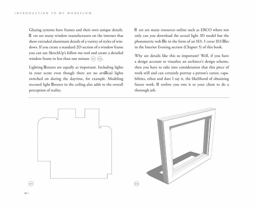
There are many resources online such as ERCO where not only can you download the actual light 3D model but the photometric web file in the form of an IES. I cover IES files in the Interior Evening section (Chapter 5) of this book.
Why are details like this so important? Well, if you have a design account to visualize an architect’s design scheme, then you have to take into consideration that this piece of work will and can certainly portray a person’s career, capa-bilities, ethos and dare I say it, the likelihood of obtaining future work. Therefore you owe it to your client to do a thorough job.
Glazing systems have frames and their own unique details. There are many window manufacturers on the internet that show extruded aluminum details of a variety of styles of win-dows. If you create a standard 2D section of a window frame you can use SketchUp’s follow me tool and create a detailed window frame in less than one minute .
Lighting fixtures are equally as important. Including lights in your scene even though there are no artificial lights switched on during the daytime, for example. Modeling recessed light fixtures in the ceiling also adds to the overall perception of reality.
3.11 3.12
3.11 3.12

C H A P T E R T H R E E
| 27
will also have the same properties within 3D Studio Max. Furthermore each material that you applied in SketchUp will also be brought into 3D Studio Max perfectly mapped and ready for lighting, texturing and rendering.
Let’s go ahead and see the outcome of using SketchUp by carrying out this book’s exercises.
Planning and building a detailed scale model can take far too long in 3D Studio Max alone. I highly suggest using SketchUp wherever you can – as discussed on pages 16–17.
Once you are ready to insert your finalized model into 3D Studio Max you will be surprised to see that any compo-nents that you have created and any items that are instanced


C H A P T E R O N E
| 29
CHAPTER 4
INTERIOR DAYTIME SCENES

I N T E R I O R D A Y T I M E S C E N E S
30 |
IBL is an advanced method of lighting that is photograph-ically captured to provide the artist with realistic accurate lighting levels from correctly exposed high resolution pho-tographic images. These images are applied to a single light source created in 3D Studio Max and as such cast the high resolution photograph in a 360 degree direction throughout the entire scene.
This, however, is only a third of the work flow (lucky for you in this case its 50% as I have provided you with the scenes in 3D) as every scene requires a detailed 3D model and cor-rectly calibrated set of cameras.
We will be using V-Ray Physical Cameras to give us the added control we require for our final renders.
V-Ray Physical Cameras are packed with real-world photog-raphy settings that enable us to manipulate the whole scene’s look and feel.
Settings such as film speed (ISO), F-stop and shutter speed that are traditionally found within an SLR camera, make the features available in 3D Studio Max and V-Ray truly powerful.
It is a good idea to visit your local camera store and pick up a handful of digital camera brochures. These brochures
DESIGN PROCESS
Interior designers face a tough challenge when creating visuals. Well, the fact that you are reading this book means that you want to pursue another avenue and create photore-alistic renders.
The most important thing to bear in mind before you start any 3D assignment is that you must have a plan. When I say plan, I mean a key work stage plan. Make a cartoon set of what it is that you want to render. If you have been com-missioned to create a set of visualizations, then creating a cartoon set will be one of the most valuable things you can produce. This will also help you break the process down into stages.
These stages require you to have the correct information to hand such as a set of as built drawings from an architect, or a set of concept sketches from an interior designer with indica-tive design direction contained within such as mood boards, reference materials etc.
As a designer I need to adhere to the most streamline work flow possible. I detest post-processing images. To me it is a waste of time, and time is money. I try and focus all my energy on creating a sterling scene that can be rendered from any camera position and produce great results. For this I use a method of lighting called IBL (image-based lighting).

C H A P T E R F O U R
| 31
Although well composed and glossy as they are, unfortu-nately these images have undergone hours of post-production work. It is my ethos to work smart and not hard. I am not a fan of post-production and I try to reduce the amount in all of my work.
Using Photoshop to adjust every visual you create not only breaks the continuity and feel of a set of renders, but totally undermines and extends the overall design process.
I tend to find that designers and artists who have to spend hours post-processing images do not follow a design process from start to finish. With this is mind it is usually the case that most design processes are not followed due to fiscal and time restraints.
Going back to my design process; define, design, refine and deliver, key information is required at each stage in order to successfully complete the task at hand.
It goes without saying that defining the needs of the client is essential, otherwise how are you going to deliver and most importantly get paid?
In this particular case, for this exercise, there is not a brief; however I knew what theme and style I wanted to aim for and set about collecting information in the form of reference photographs of furniture and similar environments, materi-als and most importantly 2D and 3D resources.
usually contain example photographs and show the cameras’ capabilities together with their respective picture settings. These can then be put into your scene as functional useable data.
It is essential to make sure that your scene is set up to uti-lize the extremely powerful tools available within 3D Studio Max and V-Ray. For example, if you are rendering a small room during the day with only one window, then you are going to find it difficult to capture any dramatic lighting. Alter the window structurally and the lighting will change immensely. This is the mindset you have to foster in order to push the boundaries of your capabilities.
In an effort to avoid creating the stereotypical, contemporary interior design visuals, I have reworked my original scene to encompass additional items that not only require technical ability to execute, but also require an eye for composition, color, material and photographic theory.
It would be incredibly easy to provide you with a scene com-plete with a polished concrete floor, a stylish sofa together with an exceedingly expensive lounge chair; however there are far more elements to understand and to consider when designing and visualizing interior spaces.
Interior daytime scenes can be tricky. If you take it upon yourself to Google image search ‘interior visuals’, you will be presented with a whole host of post-produced visual nightmares.

I N T E R I O R D A Y T I M E S C E N E S
32 |
modeling it when you can download the actual manufactur-ers’ models from their websites together with the textures and specifications? This comes back to the design process and being prepared. I always try and build myself a solid models library with textures that are available and once more procurable.
The same applies to things such as wooden flooring, textiles, carpets and artwork etc. Having these in place and ready to use will help to save you time during production, increases your professionalism and makes your work significantly noticeable and meaningful.
All materials and products have specifications that divulge a host of useful information for designers. Take white paint for example; you would assume that a V-Ray shader applied to an object would simply be given an RGB value of 255,255,255. This is fine; however why not actually reference the paint sample properly from a definitive source? There are hundreds of shades of white out there.
Take Ralph Lauren for example, although expensive and perhaps not what your client is looking for, they do have an incredible swatch of paints available for viewing on their website. The paint in this scene was taken from the site as a readily available swatch .jpeg for reference download. For me this is the equivalent to walking into a hardware store and leaving with a paint sample card.
Reference imagery is an ideal resource. If you have an image from the internet or a magazine that is a close match for the scene you want to create, then make sure it is always in front of you.
The minute you lose track of your creative direction utiliz-ing these materials, and the minute you start reinventing the wheel, adjusting cameras, tweaking lighting etc, before you know it you will need to start your scene from the beginning in order to follow the strategic process that you developed! I have done this many times, it is an occupational hazard I’m afraid.
I find it imperative, whether you are a designer, digital art-ist or an enthusiast, to familiarize yourself with furniture brands, paint suppliers, materials suppliers and other interior design-related industry material manufacturers. Increasing your knowledge of real-world brands and products will strengthen your skills tenfold; it also helps you to remain relevant in an industry that is forever changing and undeni-ably competitive.
Why are my scenes different? Well, it is because what you see within them can actually be sourced in the real world. Why would I place a chair in a scene that cannot be sourced? If a client signs off on a set of visuals that you have created with that particular piece of furniture contained within it, then you have a problem and will have to find a similar piece later to specify and procure. In addition to this, why waste time

C H A P T E R F O U R
| 33
Ultimately the design of the space is down to the architect or interior designer. If you are rendering a room which has a glazed area of only 10 percent of the total surface area, then I guarantee your visuals are going to be pretty dark. This is the moment when some visualizers like to cheat. If you are replicating reality with physically based lighting, then what you see on your screen is an accurate representation of what will happen once the scheme is built in the real world, so don’t cheat!
Depending on what stage in the design process this scheme is at, I would certainly suggest increasing the glazing ratio to accommodate as much natural light as possible. Often the architecture is fixed and change is impossible, so you have to be extremely creative in how you market the space visually.
Luckily we are going to be doing things properly and by doing so you will learn how to succeed with the most diffi-cult of spaces to light without having to take shortcuts. Let’s begin this exercise.
In doing this I have lifted the scene and given it purpose and an increased level of realism. The paint also has a specifica-tion sheet, allowing you to see the properties of items such as light reflectance levels. This is key information that can be inputted into your materials palette which further empha-sizes your skills and increases the quality of the final image.
The fundamental intent of this section is to open your minds to the alternative ways to use natural daylight and in turn realistically light your scenes. We will comprehensively cover real-world camera settings and how the combination of these settings and your scene can be manipulated to produce ren-ders with depth and character.
This scene is extremely simple in terms of its form and composition. It is essentially a modern piece of micro-archi-tecture in the form of a prefabricated living space. It has two walls and is predominantly glazed. Glazing is an extremely important aspect for interior renderings. It can be your best friend or it can be your arch enemy.

I N T E R I O R D A Y T I M E S C E N E S
34 |
want my scenes to be organic and have an increased depth to them. I do however cover alternative lighting methods other than HDRI in this book to balance out the argument.
For me HDRI files have multifaceted benefits. Like conven-tional photography you can shoot scenes anywhere in the world and they are yours. You can also purchase them online if you do not have the time or equipment to go out and create the perfect lighting files.
The way in which these lighting files operate in this particu-lar scene is not only to act as a backdrop to the scene, but also as an emitter casting beautiful pre-captured color and tones onto the scene’s geometry.
The variable intensity of the light source enables surface materials to perform in a way that would be comparable to reality, absorbing warm and cold temperatures, displaying correct reflections and casting atmospheric shadows and bouncing color between multiple surfaces.
In our scene we are going to be using a V-Ray Dome Light. That is all. This sounds rather simple; however there is a con-siderable amount of work involved.
LIGHTING
The main method of lighting we are going to use in this exercise is known as HDR lighting. It is without doubt one of the most effective lighting methods to use when creating architectural and interior visuals.
HDR is an acronym for high dynamic range. What does this mean and why is it so relevant to what we are aiming to achieve? It is a term commonly associated with photogra-phy. It is a method of capturing an image and storing all the lighting information from the darkest points to the lightest points of the photograph, or exposures for those of you who are knowledgeable photographers.
The method of capturing these files is also referred to as bracketing. HDRI files have the file extension .hdr and are typically large files taking up storage space of up to and often beyond 200 MB. I cover all of the detailed topics about HDRI in the Photography section of this book (Chapter 10).
Utilizing these files means we can manipulate the stored lighting information and apply it to our scene. We can then adjust the intensity of the HDRI file to create a number of different moods dependent on the choice of camera settings.
There are other methods of lighting interior scenes. These alternative methods utilize the built-in V-Ray lights to rep-licate lighting levels artificially. I try not to do this because I
For more information on this topic, please visit WWW.FOCALPRESS.COM/CW/WYLDE!

C H A P T E R F O U R
| 35
The V-Ray Dome Light will act as a 360 degree reposi-tionable backdrop to our scene casting all the pre-captured lighting information in a realistic way.
Let’s begin by opening the file 04_Interior_Day_Start.max from the project directory .
As you can see this is a pretty simple scene. The first thing we need to do is to let 3D Studio Max know that we do not want to use the standard scanline renderer but instead to use V-Ray’s.
Open your render settings dialog by pressing F10. This menu can also be found by going to the Rendering menu and selecting Render Setup .
4.1
4.24.2
4.1
Render Setup: Default Scanline Renderer
Render Elements Raytracer Advanced
Common Renderer
Common Parameters Time Output
Every Nth Frame: Single
Active Time Segment: 0 To 100
Range: 0 To 100
File Number Base:
Frames 1,3,5-12
Area to Render Auto Region Selected View
Lighting

I N T E R I O R D A Y T I M E S C E N E S
36 |
In the F10 dialog box (floating menu) scroll down to the Assign Renderer rollout. In the Production optional rollout press the … button .
Choose V-Ray Adv from the pop up window and press OK .
If you are always going to be using V-Ray as your primary render engine you can go ahead and press the Save as Defaults button. This will enable V-Ray as your renderer every time you open 3D Studio Max.
Now we need to set up our V-Ray lighting system. Navigate your way over to the right-hand side tools palette. This is where the brains of the operation are located. In the Create panel, select Lights from the icons, it should be the third from the left .
4.3
4.4
4.5
4.3
4.4
4.5
Render Setup: Default Scanline [tenderer
Render Elements Raytracer Advanced Lighting
Renderer Common
Common Parameters
Email Notifications Scripts
Assign Renderer
Production: Default Scanline Renderer
Material Editior: Default Scanline Renderer
ActiveShade: Default Scanline Renderer
Save as Defaults
Render Elements Raytracer Advanced Lighting
Common Renderer
Common Parameters
Email Notification Scripts
Assign Rendrer
pefault Scanline Renderer Production:
Material Editor: Default Setup:Render
ActiveShade: Default Setup:Render
Choose Renderer
NVIDIA iray NVIDIA mental ray
Quicksilver Hardware Renderer V-Ray Adv 2.30.01 V-Ray RT 2.30.02 VUE File Renderer
Photometric

C H A P T E R F O U R
| 37
When you have selected this, you should be presented with another series of rollouts. Sorry but Max is full of rollouts so you will have to get used to it! Photometric should be first on the drop down list. Click this to re-veal the rest of the options from the drop down menu. Choose VRay at the bottom .
A new and rather intense-looking lighting panel should have loaded with four options for creating V-Ray lights. We want to create a VRayLight .
Click VRayLight and then click anywhere in your scene within the top viewport. It does not matter where you place the light; it has no relevance with regard to the final rendered image. Simply think of it as an icon.
Now with the light selected we need to adjust the prop-erties of the light. From the standard 3D Studio Max menu on the right click on the Modify icon .
In the Parameters section under General, switch the Type to Dome from the drop down list .
In doing this we are instructing the light to act differ-ently in terms of its method of distribution.
Further down you should see the Intensity section. In here keep the Units set to Default (image). Also keep the Multiplier set to a value of 1.0 .
4.6
4.7
4.8
4.9
4.10
4.6
4.7
4.8
4.9
4.10
Photometri c
Photometri c Standar d VRa y
vRayLight001
Modifier List
VRayLight
VRa y
Objec t Typ e
AutoGri d
VRayLigh VRayIE S
VRaySu n ayAmdientLig
Parameters Genera l
Exclude On
Parameters
Genera l
Exclud e On
Type : Plan e
Plan e
Sphere Mesh
Ena
Inten s
Units :
Intensit y
Defaul t (image ) Units :
Multiplier :
Mode : Colo r
Color :
Temperature 6500.0
1.0

I N T E R I O R D A Y T I M E S C E N E S
38 |
the Texture settings not being set up correctly. Some people leave these settings low to try and achieve a lower render time, but unfortunately produce images with a vast amount of noise within them.
In the Texture options settings enable the Use Texture func-tion. With this selected we are instructing the light to emit not just a color but to emit a texture. In this case it will be our HDRI file. Insert a value of 50 in the Subdivs section. This value can go up to a limit of 1000. I suggest not going more than 100. It can significantly affect the render time of the final image.
Set the Resolution to 2048, which is the highest value you can go to. Some people may say this is insane, it will take forever to render. Well, those people may only be using one HDRI file in their scene to emit light which is 200 MB. In this case I would agree and lower the value, but we are actu-ally going to be utilizing two HDRI files. We return to this in a short while. For now make sure your settings resemble this .
Just underneath the Texture Options is another small group of settings labeled Dome Light Options. This is often overlooked and makes a world of difference when the settings are adjusted. If this is not enabled when we come to render we will see a large horizontal line below which all will appear black. More importantly we will have zero light emission from below the horizon line. Enabling this
Scroll down to the Options section. In here are all the attrib-utes that dictate the behavior of the light. We want the light to cast shadows so enable Cast Shadows. Leave Double-sided unchecked.
Make sure that the Invisible box is enabled. I will explain this later when we import our light source HDRI file. Here is an overview of what should and should not be enabled .
Navigate your way down to the next group of settings called Sampling. These are incredibly important. I receive a lot of inquiries through my website from artists asking why their scenes look so patchy when rendering with HDRI files. The usual rationale is that the light source’s subdivision’s value is not set high enough. If not this then it is a combination of the Subdivs and source resolution value of the HDRI in
4.11
4.12
4.11 4.12
Options
Cast shadows
Double-sided
Invisible
Ignore light normals
No decay
Skylight portal Simple
Store with irradiance map
Affect diffuse
Affect specular
Affect reflections
Sampling
Subdivs:
Shadow dias: 0.02mm
Cutoff: 0.001
Texture:
Use texture
Map #l VRayHDRI
Resolution: 2048
Adaptiveness: 1.0
50

C H A P T E R F O U R
| 39
Open your materials browser by pressing M on your key-board. If your Materials Editor appears as the annoying new Slate mode, and in fact you are rather partial to being old school, then you can change back to the standard stacked Materials Editor by going to the menu at the top and nav-igating to Rendering, then choosing Materials Editor and choosing Compact Materials Editor.
means we are able to use the whole HDRI lighting file instead of just 50 percent of it. Here is an example of not utilizing this option .
So with this make sure Spherical (full dome) is enabled.
The most important part of this process comes now. The lighting files I have provided you with have been prepared to expedite the rendering process.
4.13
4.13

I N T E R I O R D A Y T I M E S C E N E S
40 |
from the subsection. Scroll down to the VRayHDRI slot and double click it. It will load a small black box into your Materials Editor slot .
In the Materials Editor you will see a V-Ray Power Shader has loaded. This shader is wonderful; it enables us to alter the HDRI files from one location.
Where it reads bitmap: click the Browse button and go to the 04_Interior_Daytime project folder and within here select the Maps folder .
Your Materials Editor may also be only showing 6 materi-als to play with. Keep pressing X on your keyboard and it will cycle through 18 materials and finally 24 materials. This helps with scenes that have the requirement for vast amounts of materials and shaders.
Now we need to import our HDRI files into the Materials Editor. Choose a blank material and select the Get Material icon .
The Materials/Map browser should pop up. Within here scroll down to the Maps section and select the Standard
4.14
4.15 4.16
4.14
4.15
4.16
Get Material Map #1
Parameters AR1 VRayMt
Basic parameters
V•fay V-Ra y PowerShade r optimized for V-Ray
Diffuse
Diffuse M Roughness 0.0
Reflection
Reflect
Fresnel reflections Hilight glossiness 1.0 VRayHDRI
VRayEdges Tex
VRayGLSL Tex
VRay HDDRI
VRayMultiSub Tex
VRaySoftbox

C H A P T E R F O U R
| 41
In the Mapping options select the drop down menu which will say Angular. Choose Spherical from the list. Now your preview looks better. Leave everything else as it is for now .
We now need to instruct our VRayDome light to emit our HDRI file. Select the VRayDome light and navigate to the Lights properties. In here scroll down to the Texture options section .
Very simply we are going to drag the HDRI material from the Materials Editor and drop it into the Texture Slot within the Lights properties. Like this :
In the Maps folder is a HDRI folder. Contained within this folder are two HDRI files. I mentioned above that some peo-ple use only one HDRI file and apply it to their scene. We will be utilizing two files for two reasons.
First, one HDRI is for the background which will be rendered in the final scene, and as such the quality of the image needs to be rather high, otherwise there will be a large contrasting quality issue between our rendered geometry and the background image. The quality of reflec -tions in objects can be seen also, so we need to make sure that the reflections are accurate and proportional to the scene’s scale.
Second, using this high-quality HDRI file as the light emit-ter will significantly increase the render time. So instead we will use a slightly blurred version of the file at a reduced res-olution. This also gives us incredibly soft shadows which will add an increasing level of realism to the scene.
Once the HDRI has been loaded, you will see a small pre-view in your Materials Editor. It will also look distorted. Don’t panic as we will be dictating the mapping method in order for it to function properly.
A HDRI file is a spherical image that has been captured through dozens of bracketed photographs, and compiled into one large file. We need to tell the Materials Editor that this is a spherical image so that it casts light and shadows accurately.
4.17
4.18
4.17
4.18
4.19
Mapping
Mapping type: Spherical
Horiz. rotation: Angular Cubic Spherical Mirrored ball 3ds Max standard
Vert. rotation:
Processing
Texture:
Use texture
None
Resolution: 2043
Adaptiveness: 1.0

I N T E R I O R D A Y T I M E S C E N E S
42 |
A final important part in this step is instructing Max to use this HDRI as a visible backdrop. Press 8 on your keyboard to open the Environment and Effects dialog.
Under the Common Parameters section you will see Background. Check the Use Map to enable the texture roll-out slot. Now simply drag and drop the high-quality HDRI file from the Materials Editor to that of the Environment Map slot .
Again when the Instance (Copy) Map pop up menu appears, be sure to select Instance.
When the Instance (Copy) Map pop up menu appears you need to select Instance and press OK. This is important because any changes you make to the HDRI in the Materials Editor will automatically be updated rather than having to drag and drop the HDRI into the Lights properties again and again .
Now we need to load the large HDRI file into our scene to act as the visible background image.
As before select a blank material and import the large HDRI file from the same location. Make sure the Mapping Type is set to Spherical.
4.19
4.20
4.20
4.21
M o d es Material Navigation Opt ions Utilities
Material Editor - Map #1 Shadow bias: 02mm
Cutoff: 0.001
Texture: Use texture
Map #1 (VRayHDRI)
Resolution: 2048
Adaptiveness: 1.0
Rectangle light opations
Directional: 0.0
Dome light optons
Spherical (full done)
None Ray dist:
Distance: 100.0mm Photon emission:
Taret radius 200.0mm
Emit radius: 223.3mm
Mesh light options
Flip normals
Pick mesh
Replace mesh with light
Map #l VRyHDRI
V.Fay V-Ray PowerShader optimized for V-Ray
Instanc e (Copy).. .
Metho d
Instance
Cop y
OK Cancel Parameters
223.3mm

C H A P T E R F O U R
| 43
We have now created what is known as the environment light, the HDRI background and the HDRI mapped VRayDome light.
Remember this chapter means nothing unless we create a camera that can balance all of the lighting information we have created. Let’s take a look at what steps we need to take in order to finalize this exercise.
4.21
Environment and Effects
Environmen t Effect s
Commo n Parameter s Background : Color Environment Map:
None Use Map
Global Lighting Tint : Leavel:
1.0 Ambient:
Instanc e (Copy).. .
Metho d Instanc e Cop y
OK Cance l
Exposur e Contro l
<no exposur e control > Active Process Background and Environmen t Map s
Render Preview
Atmospher e Effects :
Add. . Delet e
Active
Map #2
Parameter s
VRayHDR I
v - r a y V-Ra y PowerShade r optimize d for V-Ra y
Bitmap : C:\lee.w\Desktop\HDRIs\w Browse Reload
Mappin g
evigatio n Option s Utilitie s

I N T E R I O R D A Y T I M E S C E N E S
44 |
In the resources section of this book I have added ideal cam-era settings for a whole range of environments. I have also added a full explanation of each camera setting contained within a VRay Physical Camera. So as not to go off track we will keep this section relevant to the exercise.
Now within Max there are a set of standard Cameras, a Target Camera and a Free Camera. Some people do use these when rendering with V-Ray. Most commonly they are used with alternative methods to HDRI lighting. As I mentioned before, some people use standard V-Ray lights in an artifi-cial way to mimic an environment and they will be forever changing light settings. The more lights that there are in their scenes the more work they have changing the values to achieve a thorough look and feel.
Here we want to be able to control a range of lighting ele ments though the camera only. We do not want to be adjusting the VRay Dome Light. In reality we cannot adjust the sun so why do it here? We have to master the SLR Camera and its capabilities in order to deliver.
For Interior Daytime scenes there are whole spectrums of camera settings to use depending on what type of look and feel you want to achieve.
CAMERAS
We now have our lighting rig set up. This will be useless to us unless we combine the scene with real-world camera values .
As daunting as digital SLR cameras are, they are actually incredible machines. They certainly contributed to my under standing of how light works. The same understand-ing once mastered can be put to use within 3D Studio Max using V-Ray.
4.22
4.22

C H A P T E R F O U R
| 45
Some common errors I see in most visuals are the views through glazed elements in interior scenes. Where some art-ists show the outside world perfectly in focus and a different contrast to the interior space, in reality the windows would actually produce a rather holy-looking glow due to a high exposure setting being used on the camera .
If you have ever flicked through the pages of the Architectural Digest or any interiors magazine you will see beautifully lit interior scenes. Well, this is due to the photographer bringing top-notch lighting equipment and spending hours setting up the scene and obtaining the correct light levels. We however require a less involved approach.
4.23
4.23

I N T E R I O R D A Y T I M E S C E N E S
46 |
Open your scene from the previous stage.
Press T on your keyboard to go to the plan view of the model.
Within the create panel on the right-hand side go to Create and select Cameras. It should be the fourth icon from the left .
In the Object Type choose the VRayPhysicalCam button. In your top viewport go ahead and click the first point where you want your view to be taken from and second click where you want your view to point towards.
In the camera’s Modification rollout you will yet again see an overwhelming list of modifiers. Fear not for we only want to alter a fraction of these. It is this group of settings that allows us to use real-world parameters to set up a virtual digital SLR Camera .
Under the Basic Parameters settings, maintain the selection of Still Cam as the type. Swiftly change the f-number to a value of 0.01. Next make sure that the White balance is set to Daylight. Finally set the Shutter speed to a value of 10 and the Film speed (ISO) to 600.0.
While there are numerous sunny places in the world, there are equally parts that are overcast and the climatic condi-tions can severely affect the lighting conditions in a room. Direct sunlight also affects the lighting conditions in an in-terior space.
I highly suggest researching digital SLR camera brands. Often on certain manufacturers’ websites there are example photographs shot with the cameras, together with the cam-era settings that contributed to the final image. These are ideal for setting up your scenes. All of the scenes in this book have been based on my Cannon 450D .
For now let’s run through the settings for this scene.
4.24
4.25
4.24
4.25
4.26
Standard

C H A P T E R F O U R
| 47
Now we are ready to set up the main V-Ray render settings.
I have also included a detailed guide to all V-Ray settings on this book’s companion website.
4.26
For more information on this topic, please visit WWW.FOCALPRESS.COM/CW/WYLDE!
VRayPhysicalCamera
Basic parameters
type Still cam
targeted film ga te (mm)
focal length (mm)
fov
zoom factor
horizontal offset
vertical offset f-number
target distance
vertical shift
horizontal shift
Guess vert Guess horiz
35.0
50.0
35.666
1.0
0.0
0.0 0.01
618.33
0.0 0.0 0.0

I N T E R I O R D A Y T I M E S C E N E S
48 |
Press F10 on your keyboard to open up the Render Setup dialog.
From the tabs at the top navigate yourself to the V-Ray tab .
Scroll down to the V-Ray:: Frame buffer selection area. In here we want to check that the Enable built-in Frame Buffer is enabled. Here is how this section should look .
Next scroll down to the next selection of settings labeled V-Ray:: Global switches. Under the subheading Lighting, make sure that Default lights are set to Off from the drop down menu. Also uncheck Hidden lights .
V-RAY SETTINGS
Are there universal render settings that are applicable to all types of renderings? The answer is no. All rendering settings require a fundamental knowledge of how they operate and will ultimately affect the scene’s final output in terms of quality and time to render.
There are literally hundreds of combinations of render set-tings for V-Ray. I have included a cheat sheet paper for the closest render settings I find applicable for all the scenes on this book’s companion website and for other scenes you may need to create in the future. I have also included an explana-tion of what each setting actually does.
The main emphasis in this scene is quality. There are many materials in this scene where their properties require a cer-tain selection of filtering in order to render properly.
Ultimately my intent is to have your scenes rendering as fast as possible without compromising the quality of the final image.
With your lighting and camera set up let us finalize the scene by inputting the sufficient settings.
For more information on this topic, please visit WWW.FOCALPRESS.COM/CW/WYLDE!
4.27
4.27
4.28
4.29
Render Setup: V-Ray Adv 2.30.01
Common V-Ray Indirect illumination Settings Render Elements
V-Ray::Authorization
V-Ray::About V-Ray
V-Ray:: Frame buffer
V-Ray:: Global switches
V-Ray:: Image sampler (Antialiasing)
V-Ray::Adaptive DMC image sampler
V-Ray:: Environment
V-Ray:: Color mapping
V-Ray:: Camera

C H A P T E R F O U R
| 49
V-Ray:: Image sampler (Antialiasing) can be found, right, as our next collection of adjustable settings. This is incredibly important and value entered in here will determine the qual-ity of the final image. In the Image sampler subsection, in the Type, select Adaptive DMC from the drop down menu.
In the Antialiasing filter subsection select Catmull-Rom from the drop down menu. Make sure that the checkbox is enabled .
4.28
4.29
4.304.30
Render Setup: V-Ray Adv 2 3 0 .0
Common V-Ray Indirect illumination Settings Render Elements
V-Ray:: Authorization
V-Ray:: About V-Ray
V-Ray:: Frame buffer
Enable built-in Frame Buffer Show last VFB
Render to memory frame buffer
Output resolution Get resolution from MAX
L
V-Ray raw image file
Render to V-Ray raw image file
Split render channels
Save separate render channels
Render Setup: V-Ray Adv 2 3 0 .0
Common V-Ray Indirect illumination Settings Render Elements
V-Ray:: Authorization
V-Ray:: About V-Ray
V-Ray:: Frame buffer
V-Ray:: Global switches Materials
Reflection/refraction
Max depth
Maps
Geometry
Displacement
Force Back face culling
Lighting Filter maps Filter maps for Gl Lights
Default lights Off Max transp.levels 50 Transp.cutoff 0.001
Override mtl:
Glossy effects
Hidden lights
Shadows
Show GI only
Indirect illumination
Don't render final image
Raytracing Secondary rays bias 0.0
Compatibility
Legacy sun/sky/camera models Use 3ds Max photometric scale
Render Setup V-Ray Adv2.30.0
Common V-Ray Indirect illumination Settings Render Elements
V-Ray:: Authorization
V-Ray:: About V-Ray
V-Ray:: Frame buffer
V-Ray:: Global switches
V-Ray:: Image sampler (Antialiasing) Image sampler
Type: Adaptive DMC
A 25 pixel filter with pronounced edge enhancement effects.
Antialising filter
Catmull -Rom On
Size:
Swap width
Height
Image aspect
640
480
1.333
640x480
800x600
102x768
1280x960
1600x1200
2048x1536
Pixel aspect 1.0
Generate preview Browse
Save RGB save alpha Browse
2
Note Override Exdude
4.0

I N T E R I O R D A Y T I M E S C E N E S
50 |
Now that you have finalized the Image sampler settings, you should find the V-Ray:: Adaptive DMC image sampler roll-out, left. Make sure your settings match these .
Perhaps one of the most frustrating parts of physically based lighting and rendering is when an image is rendered and dis-plays burnt areas. This is because the HDRI files can hold a higher range of colors than can be displayed on screen .
We can avoid burning like this in the V-Ray:: Color map-ping rollout. In here we want to set the type to Reinhard from the drop down menu.
I tend to find that the higher quality HDRI file I use, espe-cially outdoor HDRIS that contain exceeding amounts of color information, require a very small burn value. In the Burn value input area, type in 0.015.
Over to the right, select Sub-pixel mapping and Affect background. I also like to clamp the output at level 1.0 .
Back to the top of the F10 render dialog box, the next tab along is the Indirect Illumination one .
These settings are also incredibly pivotal. We need to tell V-Ray how we want our scene’s lighting to be calculated. From the V-Ray:: Indirect illumination (GI) rollout you will see that there are dozens more selectable options. The good news is we only have to change a few.
4.31
4.32
4.31
4.32
4.33
4.34
Common V-Ray Indirect illumination Settings Render Elements
V-Ray:: Authorization
V-Ray:: About V-Ray
V-Ray:: Frame buffer
V-Ray:: Global switches
V-Ray:: Image sampler (Antialiasing)
V-Ray:: Adaptive DMC image sampler
Min subdivs: 1
Max subdivs: 4 Use DMC sampler thresh.
Show samples
Render Setup: V-Ray Adv 230.01
Clr thresh: 0.01

C H A P T E R F O U R
| 51
select Irradiance map. Now from the Secondary bounces GI engine drop down menu, select Light cache .
The following changes you are about to make will have a sig-nificant impact on how long your render takes to complete.
First, let’s set up the V-Ray:: Irradiance map. A great tool that Chaos Group has built into V-Ray is the ability to choose a preset for the quality of the irradiance map. You can go ahead and select Medium from the drop down menu.
Just below you will see another group of settings under the heading Basic parameters, of which most have been locked. In here you should set the HSph.subdivs to 50 and the Interp.samples to 20.
Make sure that the On checkbox is enabled. Below you should see a subsection named Primary bounces and Secondary bounces. Keep both multiplier values set to 1.0. In the Primary bounces GI engine drop down menu,
4.33
4.34
4.35
4.35
Render Setup: V-Ray Adv 2.30.01
Common V-Ray Indirect illumination Settings Render Elements
V-Ray:: Authorization V-Ray:: About V-Ray V-Ray:: Frame buffer
V-Ray:: Global switches V-Ray:: Image sampler (Antialiasing) V-Ray:: Adaptive DMC image sampler
V-Ray:: Environment V-Ray:: Color mapping
Sub-pixel mapping Clamp output Clamp level: 1.0
Multiplier: 1.0 Burn value: 0.015
Gamma: 1.0
Affect background Don't affect colors (adaptation only) Linear workflow
Type: Reinhard
Render Setup: V-Rav Adv 2.30.01
Common V-Ray Indirect illumination Settings Render Elements
V-Ray:: Indirect illumination (GI) V-Ray:: Irradiance map
V-Ray:: Light cache V-Ray:: Caustics
Common V-Ray Indirect illumination Settings Render Elements
V-Ray:: Indirect illumination (GI)
On GI caustics Post-processing
Reflective Refractive
Saturation Contrast 1.0
Contrast base 0.5
Ambient ocdusion
On 0.8 Radius 10.Omr
Subdivs 8
Primary bounces Multiplier 1.0 GI engine Irradiance map
Secondary bounces
Multiplier 1.0 GI engine Light cache
Render Setup: V-Rav Adv 2.30.01

I N T E R I O R D A Y T I M E S C E N E S
52 |
Just below in the Options area, simply enable the Show calc. phase. Here is how your settings should look at this point .
Almost there!
Go down to the V-Ray:: Light cache rollout. In here we need to make some small adjustments so that the quality of this task is executed within our scene.
In the calculation parameters area, enter a value of 1000 in the Subdivs. Make sure the Show calc. phase is checked as on. Here is what you should have at this point .
Now that you have the main render settings ready to go, all that is remaining is to set what size image you want to render. I usually like to render a high-quality image so that good details are visibly enhanced.
Press F10 on your keyboard to bring up the Render Setup di-alog. In the Common tab scroll down to Output size. From the drop down menu choose HDTV. This will give you a canvas size of 1920 � 1080. I have personally printed A3 and even A2 presentations from this size output and they have been perfect for presentations.
Now you can go ahead and render your scene by pressing F9 on your keyboard.
The settings we went through and adjusted above (Irradiance map and Light cache) have now enabled you to view the
4.36
4.36
4.37
Render Setup: V-Ray Adv 2.30.0
Common V-Ray Indirect illumination Settings Render Elements
V-Ray:: Indirect illumination (GI)
V-Ray:: Irradiance map Built-in presets
Current preset: Medium
Basic Parameters
HSph. subdivs: 50
Interp. samples: 20
Options
Show calc. phase Full preview Show directight
Detail enhancement
On
A d v a n c e d
Use camera path Show samples
Interpolation
Sample lookup:
Least squares fit (good/smoott
Density-based (best)
Mode
Mode: Single frame
Multipass
Randomize samples
Check sample visibility
Save Reset
A new irradiance map is created for each frame. This mode is suitable for still images and animations with moving objects.
0 samples 0 bytes (0.0 MB)
On render end
Don't delete
Auto save: Browse
Min rate: -
Max rate: -1Interp, frames: 2
Clr thresh: 0.4
Nrn thresh: 02Dist thresh: 0.1
Scale: Scraen Radus: 60.0 Subdivs mult. 0.3
Calc. pass interpolation samplees: 15
3
File Browse
Switch to save map
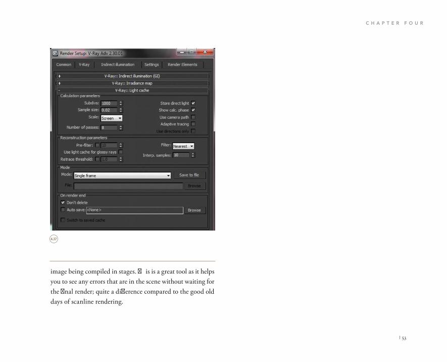
C H A P T E R F O U R
| 53
image being compiled in stages. This is a great tool as it helps you to see any errors that are in the scene without waiting for the final render; quite a difference compared to the good old days of scanline rendering.
4.37
Rende r Setup : V-Ri y Adv 2.30.0
Common V-Ray Indirect illumination Settings Render Elements
V-Ray:: Indirect illumination (GI)
V-Ray:: Irradiance map
V-Ray:: Light cache Calculation parameters
Subdivs: 1000
Sample size: 0.02
Scale: Scree n
Number of passes: 8
Reconstruction paranmeters
Pre-filter:
Use light cache for glossy rays
Retrace threshold:
Mode
Mode: Single frame
On render end
Don't delete
Auto save: <None>
Store direct light
Show calc. phase
Use camera path
Adaptive tracing
Filter: Nearest
Interp. samples: 10
Save to file
Browse
Use directions only
10
1.0
File Browse
Switch to saved cache

I N T E R I O R D A Y T I M E S C E N E S
54 |
What you are seeing is an image that has depth and tone but is a little dark and could perhaps benefit further from an alternate alignment of background image and some minor adjustments to the camera’s properties .
RENDERING
Once you have completed a test render which should have taken around 20 minutes to render, depending on what type of machine you are using of course, you will notice that there is some room for improvement.
4.38
4.38

C H A P T E R F O U R
| 55
There are two workflow options we have available. We can either adjust the camera settings or we can adjust the HDRI settings to give us a more realistic feel to the scene. I am going to highlight both.
Let’s start by changing the background HDRI settings. We can simply adjust the brightness of the VRay Dome Light source HDRI by increas-ing the render multiplier value to 2.0 .
Make sure that you have also changed the background HDRI setting to match. This should resemble your scene. Remember that you have two HDRIS inside your scene .
4.39
4.40
4.40
4.39
Parameters
V-Ray PowerShader optimized for V-Ray
Bitmap: C:\Users\lee.w\Desktop\HDRIs\W Browse Reload
Mapping
Mapping type: Spherical
Horiz. rotation: 75.0 Filip horizontally
Vert. rotation: 0.0 Flip vertically
Processing
Overall mult: 1.0 Gamma: 1.0
Render mult: Interpolation Default
V.ray

I N T E R I O R D A Y T I M E S C E N E S
56 |
One important factor to keep in mind is that in 3D Studio Max the environment is a 360 degree world, if you will, just like ours in reality. HDRI files can span 360 degrees mak-ing them ideal for numeric adjustment to achieve alternate moods with the scene.
In the Horiz. rotation enter a value of 180. Do not forget to do the same in the background HDRI file also. Go ahead and produce a test render, F9 on your keyboard. Here is the result . Notice in this image we are presented with some
As mentioned previously in the lighting section, HDRI files are incredibly useful for changing the mood of a scene utiliz-ing the same HDRI file. In this particular case we can see if the image would appear more realistic if it were in a shaded spot in the woods. With one simple numeric adjustment to the horizontal rotation value, we can change the dynamics of the whole scene.
In the HDRI material palette, you will see a group of prop-erties under the subheading Mapping.
4.41
4.41

C H A P T E R F O U R
| 57
In the Horiz. rotation, change the value to 75. Once more do not forget to do the same in the background HDRI file. Press F9 to produce a render. Here is the result .
This is a more suitable backdrop, providing us with an ade-quate amount of light to make the image look realistic. At a pixel size of 1000 � 563 this image should render in around 20 minutes .
slight patchy elements on the floor in the form of noise. This can be due to dark areas in the HDRI file being cast onto the geometry in our scene that do not perform as well as other light areas of the HDRI. This is tolerable but I want to make sure that we have the best possible result. Also notice some scaling of trees and plants that seem too large in comparison to the objects in our scene. We can rotate the image out of sight to counter this.
4.42
4.42
4.43

I N T E R I O R D A Y T I M E S C E N E S
58 |
In the Camera section I touched on the topic of realistic representation of views through windows in interior scenes and the realistic result that should be displayed .
We can achieve this in our scene by adjusting a number of settings. Select the VRay Physical Camera and open the set-tings menu on the right-hand side .
The f-number should be set to 3.5.
Further down set the shutter speed to 4.0.
Now that we have achieved a suitable image by adjusting all but the camera, we will now take a look at refining camera values instead.
In the real world if a photographer takes a picture and the image appears too dark or in fact too light, then a whole range of settings can be adjusted.
This alternative workflow is based on all the settings of the original file, where the HDRI Material values for both back-ground and light source are set to a multiplier of 1.0.
4.43
4.44
4.45
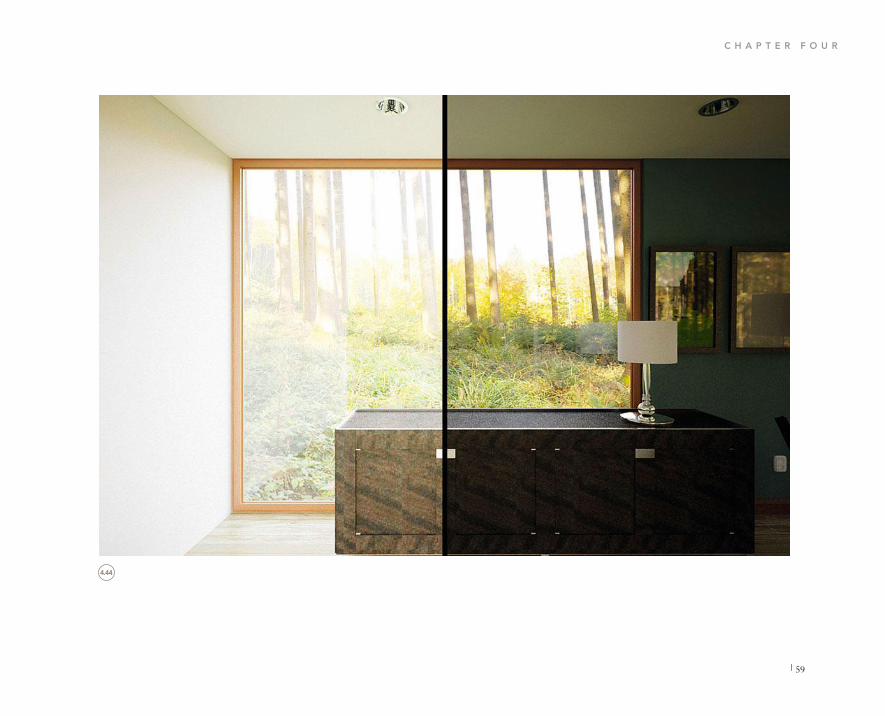
C H A P T E R F O U R
| 59
4.44

I N T E R I O R D A Y T I M E S C E N E S
60 |
Just below this is the shutter speed (ISO) setting. Change this to 3200 and produce a test render .
In this render you can see significant noise around the peri meter of the room and a halo effect around the glazing areas. This is due to the camera settings, especially the ISO being set too high. Usually the higher this is the more grain you will see in the scene. We need to make some adjustments to maintain the lighting levels but increase the noise impact significantly.
Go ahead and adjust the camera settings to match the following .
This makes the render just about right for the setting that it is in. The lack of direct sunlight due to the scene being located in the woods would certainly bounce shades of green around 4.45
4.46
4.46
4.45
Basic parameters
type Still cam
targeted
film gate (mm) 100.0 focal length (mm) 50.0
fov
zoom factor 1.0
horizontal offset 0.0
vertical offset 0.0
f-number 3.5 terget distance
vertical 0.0
horizontal shift 0.0
Guess vert. Guess horiz
specify focus
focus distance
exposure vignetting, 1.0
White balance Daylight
custom balance
temperature
shutter speed ( s -l 4.0
shutter angle (deg)
shutter offset ( d e g)
latency (s)
film speed (ISO) 3200.0
shif
89.454
5273.63
200.0m
3500.0
180.0
0.00.0

C H A P T E R F O U R
| 61
the room. The quality of the materials is much more prominent in this final render due to a higher f-number combined with a lower shutter speed .
It is entirely your choice whichever method you choose to adopt. There is no right way or wrong way in art. All that matters is the final result.
Finally, one more benefit in setting up your scenes utilizing the extreme versatility of HDRIS is that you can use these scenes for a range of other activities.
Take the image on the left for example .
Using the same scene I have made a copy of the original camera with the same settings. I have focused specifically on the table lamp and enabled depth of field. This gives addi-tional realism to the scene and gives you more flexibility when focusing on key details without having to set up alternative files or having to Photoshop everything.
4.47
4.48
4.48
4.46
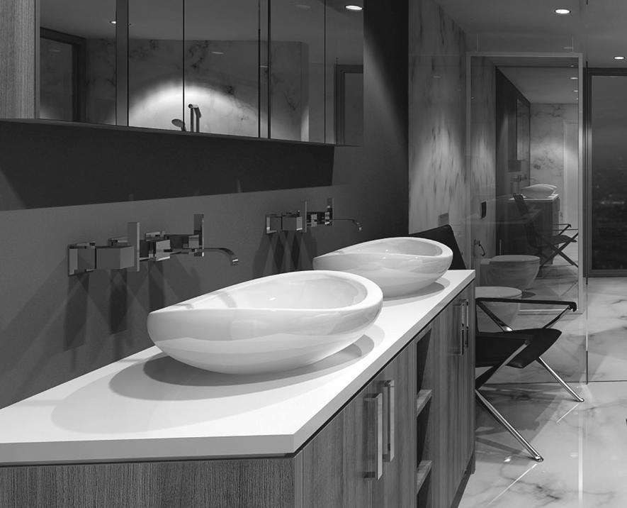

CHAPTER 5
INTERIOR EVENING SCENES

I N T E R I O R E V E N I N G S C E N E S
64 |
V-Ray has a wonderful set of tools to utilize so that you can enter real-world values in the form of downloadable files from lighting manufacturers’ websites. These files are known as IES files.
These IES lighting files are a standard lighting format con taining what is known as photometric data. IES or Illuminating Engineering Society is the file extension we will be using for our exercise scene. We use these files to make sure the artificial lights in our scene are physically accurate.
I usually have IES files stored in my library which are split by manufacturer and performance type. You can find the specification for these lights contained within the manufac-turer’s website.
Attention to detail in surface materials is paramount in in-terior scenes. How do these materials absorb artificial light and not natural light? I do collect as many reference material images as I can and tend to show the client what type of look can be achieved upfront. This constitutes to positive working direction and once more defines your design direction.
There are two types of interior evening scenes. One is a scene that only contains artificial lighting and has no environ-mental light. The latter is a mixture of artificial light and natural light.
DESIGN PROCESS
Nighttime scenes and sunset scenes are without doubt my favorite to produce. They provide a platform to deliver dra-matic lighting effects and can really transform a space into something quite unique.
The key focus when producing visuals for evening shots is to incorporate artificial lights to increase the level of reality through features such as highlights, reflections, and shadows.
IES lights are preset lights in 3D Studio Max that allow a profile to be loaded in to each light. These profiles or pho-tometric data files, as they are commonly known, contain all the properties of real-world lights. We will cover IES lights in this section. These lights will be combined with the IBL method of lighting.
Not only do interior evening scenes require a significant amount of work to set up architecturally in terms of the 3D model, but they also demand the application of artifi-cial lighting in great detail. Interior evening scenes also need rigorous planning in terms of materials in order to adhere to the design process.
Whenever I am asked to produce these types of scenes, one of my foremost thoughts is light. What type of light is required and where am I going to get it from?
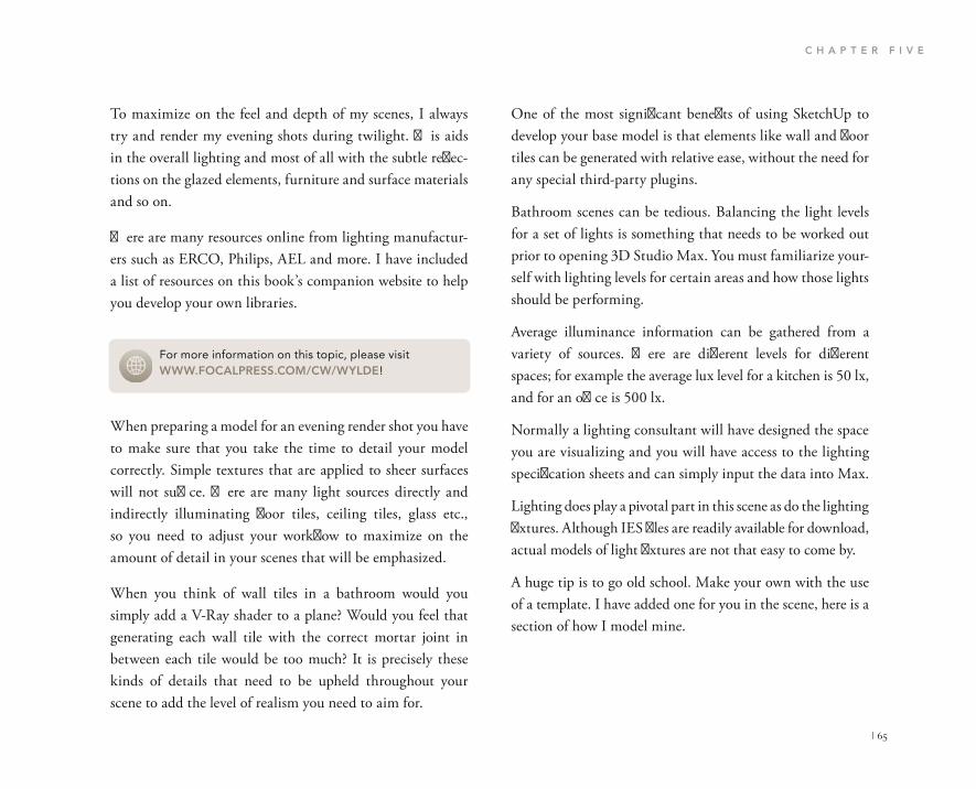
C H A P T E R F I V E
| 65
One of the most significant benefits of using SketchUp to develop your base model is that elements like wall and floor tiles can be generated with relative ease, without the need for any special third-party plugins.
Bathroom scenes can be tedious. Balancing the light levels for a set of lights is something that needs to be worked out prior to opening 3D Studio Max. You must familiarize your-self with lighting levels for certain areas and how those lights should be performing.
Average illuminance information can be gathered from a variety of sources. There are different levels for different spaces; for example the average lux level for a kitchen is 50 lx, and for an office is 500 lx.
Normally a lighting consultant will have designed the space you are visualizing and you will have access to the lighting specification sheets and can simply input the data into Max.
Lighting does play a pivotal part in this scene as do the lighting fixtures. Although IES files are readily available for download, actual models of light fixtures are not that easy to come by.
A huge tip is to go old school. Make your own with the use of a template. I have added one for you in the scene, here is a section of how I model mine.
To maximize on the feel and depth of my scenes, I always try and render my evening shots during twilight. This aids in the overall lighting and most of all with the subtle reflec-tions on the glazed elements, furniture and surface materials and so on.
There are many resources online from lighting manufactur-ers such as ERCO, Philips, AEL and more. I have included a list of resources on this book’s companion website to help you develop your own libraries.
When preparing a model for an evening render shot you have to make sure that you take the time to detail your model correctly. Simple textures that are applied to sheer surfaces will not suffice. There are many light sources directly and indirectly illuminating floor tiles, ceiling tiles, glass etc., so you need to adjust your workflow to maximize on the amount of detail in your scenes that will be emphasized.
When you think of wall tiles in a bathroom would you simply add a V-Ray shader to a plane? Would you feel that generating each wall tile with the correct mortar joint in between each tile would be too much? It is precisely these kinds of details that need to be upheld throughout your scene to add the level of realism you need to aim for.
For more information on this topic, please visit WWW.FOCALPRESS.COM/CW/WYLDE!

I N T E R I O R E V E N I N G S C E N E S
66 |
library of sanitary fixtures. Why model a toilet? I have seen the worst visuals in the world with toilets and urinals that are not the right size, scale or even in the correct positions. There are literally thousands of suppliers on the web with products readily available for download. Start now and build your own library.
Finally this is a lifestyle shot, so the correct placement of the camera, its focal depth and settings will need to be planned. Build your scene around your view. I have witnessed this literally thousands of times, and in part have been guilty of it myself: getting carried away with your model. If you are not going to render it, then do not model it.
I have seen full buildings modeled with brickwork and stone work and beautiful details all for a partial interior shot! Hours and hours wasted that no one will ever see. If you can use your time wisely you can achieve truly professional results.
OK, enough life coaching, let’s push on with the exercise.
Applying the correct materials for the reflections in this light fixture will give you the creative edge you need for your images to stand out and be unique.
Putting the shape and form of the bathroom scene to one side, there are a number of peripheral elements that we require to complete the scene in a realistic way.
Bathroom furniture, sinks, taps and shower heads etc will all need sourcing. Sticking firmly with the ethos ‘work smart, not hard’, it is of high importance that you build yourself a

C H A P T E R F I V E
| 67
One of the main performance benefits of using IES lights can be seen in the material reflections on solid surfaces such as aluminum, timber and porcelain. Overlapping reflections of IES lights and HDRI backdrops really does create unri-valed realism.
Let’s start the exercise by loading in our HDRI backdrop image and primary environment lighting source.
Open up 05_Interior_Evening_Start.max
You have a completely textured scene complete with all nec-essary models and V-Ray shaders loaded.
LIGHTING
We are going to be using the two types of lighting as men-tioned in the design process: a mixture of natural light and artificial light.
I prefer to use a HDRI file that has a mixture of blue mid tones combined with a warm setting sun. This acts as a sub-tle light source to our scene, highlighting glossy reflective surfaces and enabling a small amount of natural light to bounce around the room.
IES lights will be our detailed light source perfectly aligned with our ceiling-mounted light fixtures. These lights will directly illuminate the surfaces below creating accurate shadow projections enhancing detail throughout the scene.

I N T E R I O R E V E N I N G S C E N E S
68 |
In the top viewport, T on your keyboard, go over to the Create panel and navigate your way to the lighting section .
From the drop down menu choose VRay.
You will now see that a new group of lights has loaded. From this selection you need to choose the VRayLight.
With this selected just underneath I would like you to change the Type to Dome and set the Multiplier to a value of 1.0.
Just a little further below, in the control panel, you will see the options section. Make sure your settings mimic these .
Finally we want to enable the Texture selection option ready to receive the evening HDRI file. Go ahead and enable the check box labeled Use texture. We want to also enable the light to cast 360 degree light so from the Dome light op-tions, enable the Spherical (full dome) option. The settings should resemble the following .
You can now go ahead and click anywhere in your top view-port to place the Light source. Again it does not really matter where you place the light as it is environmental and as such will not affect shadow casting etc.
In this particular scene we are using an evening HDRI file as our subtle background light source. Here is a preview of the file :
Open your Materials Editor by pressing M on your key-board.
5.1
5.2
5.3
5.1
5.2
5.3
5.4
VRa y
Photometric
Standard VRa y
VRayLigh t VRayIE S
ayAmbientLi g VRaySu n
Texture :
Use texture
Non e
Resolution : 102 4
Adaptiveness : 1. 0
Done light options
Spherica l (ful l dome )
Ra y dist : Non e
Photo n emission :
Targe t radius : 100.0m m
Emi t radius : 150.0m m
VRayLight001
Modifier List
VRayLight
Parameters General
Exdude On
Type: Dome
Enable viwport shading Intensity
Units: Default (image) Multiplier: 1.0
Mode: Color Color:
Temperature:
Size
Optons
Cast shadows Double-sided Invisible Ignore light normals No decay Skylight portal Store with irradiance map Affect diffuse Affect specular Affect reflections
Sampling
Subdivs; 24 Shadow bias: 0.02mm
Rectagle light option
Directioal: 0.0
Distance: 100.0mm
U size: 0.0mm
V size: 0.0mmw size: 10.0mm
Simple

C H A P T E R F I V E
| 69
We are going to load the first of two HDRI files which will act as the light casting source ap-plied to the VRay dome light. Import a VRay HDRI shader into an active slot. Here’s how .
With your VRay dome light selected, navigate your way to the Modify panel on the right-hand side of your screen. We want to apply this HDRI file to the Texture slot in the Lights en-vironment settings. Drag and drop the HDRI preview image to the empty slot as per the fol-low image .
5.5
5.4
5.5
5.6
5.6
Material/Map Browser
Search by Mame ...
Perlin Marble Raytrace Reflect/Refract RGB Multiply RGB Tint
Speckle Splat Stucco Substance
Thin Wall Refraction Tiles Vector Displacement Vertex Color VRayColor VRayCompTex VRayEdgesTex VRayGLSLTex VRayHDRI VRayMultiSubTex VRaySoftbox Waves Wood
V-Ray Adv 230.01
material Editor-Map #2 Modes: Matinal Navigaticn Option;- Utilities
Get Material Map #2 VRayHDRI
Parameters
V.ray V-Ray PowerShader optimized for V-Ray
Bitmap: C:\Program File\Autodes\3ds M: Browse Reload
Mapping Mapping type: Spherical
Horiz. rotation: 0.0 Vert. rotation: 0.0
Flip horizontally Flip vertically
Processing
Material Editor - p #2
Mcde:- Material Na.igaticn Option: Instance (Copy)
Methoc
I n s t a n ce
Copy
OK Cancel
Pecular flections
Map #2. (VRayHDRI )
Resolution: 1024 Adapt iveness: l.0
Dome light opbons
Spherical (full dome)
Ray.dist: Note
Photon emission: Target radius: 100.0mm
Emit radius: 150.0mm
Map #2 VRayHDRI
Pa rame te rs
V-ra y V-Ray P o w e r S h a d e r
o p t i m i z ed for V-Ray
Bitmap: C:\Program File\Autodes\3ds M: Browse Reload
24 0.02mm
0.001

I N T E R I O R E V E N I N G S C E N E S
70 |
At this point it is certainly a good time to save. We have the secondary lighting set up. I say secondary because the primary focus is on the artificial IES lights.
In the top viewport expand the view so that you can see the floor plan as large as possible. In this floor plan you will also see the ceiling detail and the main downlight positions .
We need to create a photometric light that will cast realistic light and shadows onto our scene’s geometry.
The photometric light creation tools can be found in the Create panel. Choose VRay from the drop down menu and in the Object Type select the VRayIES button .
Now this is set up we can go ahead and load the remaining high-quality HDRI to act as the viewable evening back-ground.
In an empty material slot go ahead and create another V-Ray HDRI shader and load the backdrop HDRI file into the empty slot. Make sure the Mapping type is set to Spherical as before. Your settings should resemble this .
Bring up the Environment and Effects dialog box by press-ing 8 on your keyboard. We want to place the high-quality HDRI evening backdrop into the environment map slot .
5.7 5.8
5.7
5.8
5.9
5.10
Paramtters
V-r V-Ray PowerShade r
o p t i m i z ed for V-Ray
Bitmap: C:\Program Files\Autodesk\3ds a Browse Reload
Mapping
Mapping type: Spherical
Horiz. rotation Angular Cubic
Sphericl Mirrored ball 3ds Max standaer
Processing
Vert. rotation:V-Ra y PowerShade r
o p t i m i z e d for
V.ray
V.ray

C H A P T E R F I V E
| 71
inside the light fixture, I know it seems logical because that is where the point of illumination is in reality, but in our scene it will simply cause dark circular shadows on the floor. Instead keep the source point around 10–15 mm from the ceiling in the Z direction.
Now we need to adjust the properties to match real-world values. Luckily the majority of these settings will come from the manufacturers’ IES file.
Creating a light source is simple, drag and point. The first click is where you want to place the light source and the second click is the light target point.
Try to align your lights correctly as per the ceiling layout. In the front and right viewport align the light vertically so that it points straight down. You will find a sample of my align-ment overleaf .
The light source should be positioned and aligned correctly in the top and left viewports. Do not place the light source
5.9 5.10
5.11
VRay
Object Type
VRayLight VRayIES
LayAmbientLig VRaySun
Name and Color
VRayIES Parameters
enabled
enable viewport shading
show distribution

I N T E R I O R E V E N I N G S C E N E S
72 |
In the modify panel you will see a group of settings that allow us to significantly adjust the light. There is an empty slot with the name None. Go ahead and click this slot so we can load an IES file .
From the project folder load the IES file named 2782724. As soon as the file is loaded notice the emitter icon of your light change to match the settings of the loaded IES. This is reflecting the real-world light fixture attributes .
Now we have a master IES light source we need to copy this around the room and correctly align it to the remaining light fixtures. Be sure to instance copy the light otherwise you will
5.11
5.12
5.12
5.13

C H A P T E R F I V E
| 73
CAMERAS
Calculating the correct settings for evening shots can be tedi ous. You must take into consideration the balance between natural light (what remains) and artificial light.
Having photography experience or understanding the basic functions of a digital SLR camera is certainly beneficial when using V-Ray Cameras.
Taking dramatic nighttime interior photographs can open your scene up to all sorts of alternative lifestyle shots for you to create.
In reality if you take a photograph in a dark room it is a dead cert that your camera will pop up the flash and flood the space with direct light, creating strong shadows and thus an overall dull image. This is far from what we want to achieve. As we do not have a flash we will manipulate the settings to increase and decrease the amount of light let in to the cam-era. The ISO value plays a particularly leading role in this. As mentioned before, the higher the ISO numeric value the higher the chances are of a resulting grainy picture, so we counter this by adding IES lights to our scene and adjusting the f-number and shutter speed .
In this case we will be creating a camera set up for long expo-sures. For us this means the balance between shutter speed and f-number is an essential combination that we need to adequately gain control of.
have to manually adjust every single light individually when making changes to brightness etc.
So that we are achieving a light level worthy of rendering go ahead and change the power value of the light to a value of 20,000.
Still in the IES light’s properties menu, change the color mode to temperature. Finally set the color temperature value to a value of 5000.
Now we have the lights set up we can go ahead and set up the cameras.
5.13
5.14

I N T E R I O R E V E N I N G S C E N E S
74 |
Cinematography is something I research and keep up to date with as much as I can. It helps me to see alternative ways to shoot scenes and helps me to apply old and new techniques to my scenes. I highly recommend reading Cinematography, Theory and Practice by Blain Brown (Focal Press, 2011), as well as Painting with Light by John Alton (University of California Press, 2013).
Typically for nighttime shots we should be using an f-num-ber setting of f11 and if needs be f16. However this may produce a darker image, but this can be balanced out by alternating the shutter speed value.
The main objective here is to achieve a realistic light level that highlights the detail within our scene and one that the client will ultimately be happy with.
5.14

C H A P T E R F I V E
| 75
Now you have positioned your camera, let’s input some basic settings so that we can go ahead and progress to the next step.
Select your camera and navigate your way to the Modify panel on the right-hand side of your screen.
In the Basic parameters section set the f-number value to 11.0 .
Just below this group of options there is a button with the name Guess vertical shift. If you have the camera view set to your active viewport, keep watching while you press this button. Notice how all of the vertical lines in your scene are unified in the Z direction.
Another incredibly important feature to V-Ray Physical Cameras is the ability to set the white balance. White balance
These two fantastic books are filled with knowledge and years of practical experience shooting movies and lighting scenes. They have helped me to frame my scenes and use traditional physical toolsets in a virtual way.
One final element to this scene with regard to camera cre-ation is depth of field. DOF is a byproduct of focusing the camera on one particular area of the scene. V-Ray Physical Cameras will act like real-world cameras and put a slight blur on the background while maintaining a sharp focus on the foreground and vice versa.
Let’s go ahead and create the evening scene camera so that we can put all the above to practice.
From the Create panel on the right-hand side of the screen click the camera icon to reveal the creation choices.
From the drop down menu choose VRay.
Choose VRay physical camera from the creation options and place the camera in your scene.
Due to the nature of this space, its shape and form being inherently nondynamic, I suggest placing the camera at a slightly lower height and focusing the foreground on a fur-niture piece. Simply placing the camera in the middle of the room does nothing for the depth of the scene. We want to emphasize the beautiful outdoor twilight scene, so we need to place the camera over to the left. This also helps us to maxi-mize the natural reflections combined with artificial shadows. 5.15
5.15
Basic parameters
type Still cam
targeted
film gate (mm)
focal length (mm)
fov
zoom factor
horizontal ffset
vertica offset f-number
36.0
40.0
1.0
0.0
0.0
11.0
11.23

I N T E R I O R E V E N I N G S C E N E S
76 |
the main light source for the environment, the white balance should be set to match. This is what I try and do for all my scenes; it significantly reduces the amount of post- production work that is required .
In the white balance customization area you are presented with numerous options from the drop down menu, or you can enter a custom value. For this exercise select Daylight .
is the process of removing unrealistic color casts so that ob-jects which appear white in reality are rendered white in your image output.
Realistic camera white balance should take into account the type of scene you are rendering and the temperature of the background HDRI being cast onto the scene’s geometry.
In this case we have a HDRI file of a dusk scene that con-tains mainly deep blues and some shades of white. As this is
5.16
5.16
5.17

C H A P T E R F I V E
| 77
V-RAY SETTINGS
Interior evening render settings are similar to the interior daytime settings. There are however a few subtle changes we need to make to fully achieve our desired result.
In an effort to maintain the render times to complete within one hour, the V-Ray render settings will reflect this as will the quality of the final image.
Press F10 on your keyboard to open up the Render Setup dialog.
From the tabs at the top navigate yourself to the V-Ray tab .
Scroll down to the V-Ray:: Frame buffer selection area. In here we need to check that the Enable built-in Frame Buffer is enabled. Over the page is how this section should look .
Now scroll down to the next selection of settings labeled V-Ray:: Global switches. Under the subheading Lighting, make sure that Default Lights option is selected as being Off from the drop down menu. Also uncheck Hidden Lights .
V-Ray:: Image sampler (Antialiasing) can be found below as our next collection of adjustable settings. These are incredibly important and values entered within here will determine the quality of the final image. In the Image
Underneath this option is the shutter speed. Change this value to 16.0 .
The ISO setting should be set to a value of 200.0. We can adjust this later when producing test renders.
Now we need to focus on the V-Ray system settings.
5.17 5.18
5.18
5.19
5.20
5.21
exposure
vignetting
white balance Daylight
custom balance
temperature
white balance Daylight
custom balance
temprature
shutter speed ( s ^ - 1 1 6 . 0
s h u t t e angle (deg)

I N T E R I O R E V E N I N G S C E N E S
78 |
sampler subsection, in the Type, select Adaptive DMC from the drop down menu.
In the Antialiasing filter subsection select Catmull-rom from the drop down menu. Make sure that the checkbox is enabled as On .
Now you have finalized the Image sampler settings you should find the V-Ray:: Adaptive DMC image sampler roll-out just below. Make sure your settings match those shown .
5.20
5.21
5.19
5.22
5.23
Render Setup: V-Ray Adv 230.0
Common V-Ray Indirect illumination Settings Render Elements
V-Ray:: Authorization
V-Ray:: About V-Ray
V-Ray:: Frame buffer
V-Ray:: Global switches
V-Ray:: Image sampler (Antialiasing)
V-Ray:: Adaptive DMC image sampler
V-Ray:: Environment
V-Ray:: Color mapping
V-Ray:: Camera
Preset:
View: Quad 4 - Top Render
Geometry V-Ray:: Global switches
Materials
Displacement Reflection /refraction Max depth Force black face culling
Lighting Maps Lights Default lights off
Filter maps Filter map For GI
Hidden lights of on of with GI
Shadows Show Gl only
Indirect illumination
Don't render final image
Compatibility
Legacy sun/sky/camera models
Max trnsp levels 50 Transp. cutoff 0.001 Override mtl Glossy effects
Raytracing
Secondary rays bias 0.0
Use 3ds Max photometric scale
Render Setup: V-Rav Adv 2.30.0:
Common V-Ray Indirect illumination Settings Render Elements
V-Ray:: Authorization V-Ray:: About V-Ray V-Ray:: Frame buffer
Enable built-in Frame Buffer Render to memory frame buffer
Output resolution Get resolution from MAX
Show last VFB
V-Ray raw image file Render to V-Ray raw image file
Split render channes Save separate render channels

C H A P T E R F I V E
| 79
Perhaps one of the most frustrating parts of physically based lighting and rendering is when an image is finally rendered but displays burnt areas. This is because the HDRI files can hold a higher range of colors than can be displayed on screen and as such need controlling in order to become visible. These settings will also affect the performance of the IES file .
5.22
5.23
5.24
5.24
V-Ray:: Image sampler (Antialiasing) Image sampler
Type: Adaptive DMC
Antialiasing filer
On Catmull-Rom
Size: Area Sharp Quadratic Catrmull-Rom Plate MatchyMAX R2 Quadratic Cubic Video Soften Cook Variable Blend Bladtman Mitchell-Netra vali VRayLanczosFilter
A 25 pixel filter with pronounced edge enhancement effects.
I image sampler
ronment
mapping
amera
V-Ray:: Adaptive DMC image sampler
Min subdivs: 1
Maxsubdivs: 4 Use DMC sampler thresh.
Coo VariablCoo VariablCoo VariablCoo Variabl
Maxsubdivs

I N T E R I O R E V E N I N G S C E N E S
80 |
Over to the right, select Sub-pixel mapping and Affect background. I once more like to clamp the output at level 1.0 .
Back to the top of the F10 Render dialog box, the next folder along is the Indirect Illumination tab .
These settings are also incredibly pivotal. We need to inform V-Ray how we want our scene to be calculated.
From the V-Ray:: Indirect illumination (GI) rollout you will see there are dozens of selectable options. The good news is we only have to change a few of these.
Make sure the On checkbox is enabled. Below you should see a subsection named Primary bounces and Secondary bounces.
Keep both multiplier values set to 1.0. In the Primary bounces GI engine drop down menu, select Irradiance map. Now from the Secondary bounces GI Engine drop down menu, select Light cache .
The following changes you are about to make will also have a significant impact on how long your render takes to com-plete, bearing in mind you have multiple light sources.
First, let’s set up the V-Ray:: Irradiance map. A great tool that Chaos Group has built into V-Ray is the ability to choose a preset for the quality of the irradiance map. You can go ahead and select Medium from the drop down menu.
We can avoid burning in the V-Ray:: Color mapping rollout. In here we want to set the type to Reinhard from the drop down menu.
I tend to find that the higher quality HDRI file I use, espe-cially outdoor HDRIS that contain tremendous amounts of color information, require a very small burn value. In the Burn value input area, type in 0.015. We can alter this to suit the IES performance later.
5.26
5.25
5.25
5.26
5.27
V-Ray:: Color mapping
Type: Reinhard Sub-pixel mapping
Clamp output Clamp level: 1.0
Affect background
Don't affect colors (adaptation only)
Linear workflow
Multiplier: 1,0
Burn value: 0.15
Gamma: 1.0
Render Setup: V-Ray Adv 2.30.011
Common V-Ray Indirect illumination Settings Render Elements
V-Ray:: Indirect illumination (GI)
V-Ray:: Irradiance map
V-Ray:: Light cache
V-Ray:: Caustics
Preset:
View: Quad 4 - Top Render
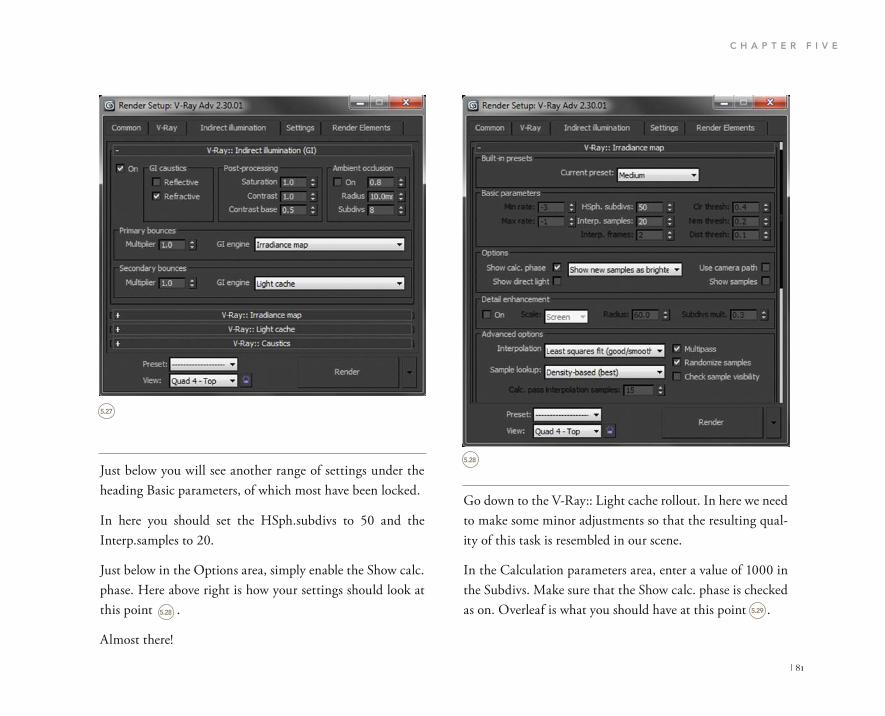
C H A P T E R F I V E
| 81
Go down to the V-Ray:: Light cache rollout. In here we need to make some minor adjustments so that the resulting qual-ity of this task is resembled in our scene.
In the Calculation parameters area, enter a value of 1000 in the Subdivs. Make sure that the Show calc. phase is checked as on. Overleaf is what you should have at this point .
Just below you will see another range of settings under the heading Basic parameters, of which most have been locked.
In here you should set the HSph.subdivs to 50 and the Interp.samples to 20.
Just below in the Options area, simply enable the Show calc. phase. Here above right is how your settings should look at this point .
Almost there!
5.27
5.28 5.29
5.28
Render Setup: V-Ray Adv 2.30.09
Common V-Ray Indirect illumination Settings Render Elements
V-Ray:: Indirect illumination (GI)
On GI caustics Post-processing Reflective
Refractive
Saturation 1.0
Ambient occlusion
Contrast l.0
Contrast base 0.5
On 0.8
Radius l0.0mr
Subdivs 8
Primary bounces
Multiplier l.0 GI engine Irradiance map
Secondary bounces
Multiplier l.0 GI engine Light cache
V-Ray:: Irradiance map
V-Ray:: Light cache
V-Ray:: Caustics
Preset:
View: Quad 4 - Top Render
Render Setup: V-Ray Adv 2.30.01
Common V-Ray Indirect illumination Settings Render Elements
V-Ray:: Irradiance map Built-in presets
Current preset: Medium
Basic parameters
HSph. subdivs: 50
Interp. samples: 20
Options
Show calc. phase
Show direct light
Detail enhancement
Show new samples as brighte Use camera path
Show samples
On
Advanced options Screen
Interpolation Least squares fit (good/smoott Multipass
Randomize samples
Check sample visibility Sample lookup: Density-based (best)
Preset:
View: Quad 4-Top Render

I N T E R I O R E V E N I N G S C E N E S
82 |
Now you have the main render settings ready to go, all that is remaining is to set the size of render output for your scene.
I usually like to render a decent quality image so that archi-tectural details are enhanced.
Press F10 on your keyboard to bring up the Render Setup dialog.
In the Common tab scroll down to Output size settings.
From the drop down menu choose HDTV. This will give you a canvas size of 1920 � 1080. I have personally printed A3 and even A2 presentations from this size output and they have been perfect for presentations.
5.29
Render Seturp: V-Rat Adv 2.30.01
Common V-Ray Indirect illumination Settings Render Elements
V-Ray:: Light cache Calculation parameters
Subdivs: 1000
Sample size: 0.02
Scale:
Store direct light
Show calc. phase
Use camera path
Adaptive tracing Nunder of passes: 8
Recostruction parameters
Pre-filter:
Use light cachefor glossy rats
Filter: Nearest
Interp. samples: 10 Retrace threshold:
Mode
Mode: Single frame Save to file
On render end
Auto save:
Don't delete
None: Browse
Preset:
View: Quad 4 - Top Rende
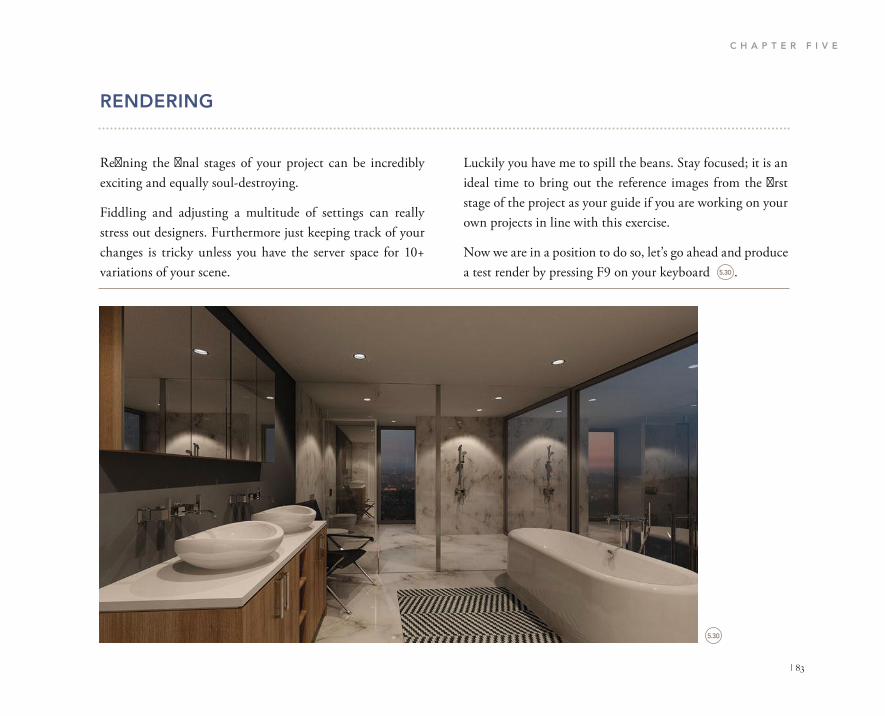
C H A P T E R F I V E
| 83
Luckily you have me to spill the beans. Stay focused; it is an ideal time to bring out the reference images from the first stage of the project as your guide if you are working on your own projects in line with this exercise.
Now we are in a position to do so, let’s go ahead and produce a test render by pressing F9 on your keyboard .
RENDERING
Refining the final stages of your project can be incredibly exciting and equally soul-destroying.
Fiddling and adjusting a multitude of settings can really stress out designers. Furthermore just keeping track of your changes is tricky unless you have the server space for 10+ variations of your scene.
5.30
5.30

I N T E R I O R E V E N I N G S C E N E S
84 |
Change the value in the white balance section of the camera settings to custom, and enter a value of 6500.
Execute another test render; it should only take 25 minutes assuming you have the DOF function temporarily switched off. Here is the result .
We can further improve the tone of the image through the lighting controls.
The IES files can also be adjusted to suit the scene. We want to emphasize the warmth of the artificial illumination so we need a value of around 2000–4000 K. Select one of the IES lights and change the color temperature to 2000. Execute a test render, F9 .
See how there is such a dramatic difference between the interior and exterior lighting? The result is nicely balanced but the realistic highlights from the artificial lights are not quite there yet.
There may be an occasion that justifies the adjustment of the IES power value. Sometimes directly importing an IES file without adjusting the power value can result in very dark scenes. In our scene I suggest increasing the power of the IES light to 30,000. You can view the result on page 86 .
The result remains nicely balanced but I am not content with it yet. Go ahead and ramp up the power value of your IES lights to 45,000.
It is an average result; we do not want average so we have to make some minor adjustments in order to increase the color depth and feel of the scene.
In the VRay Physical Camera properties you can adjust the color temperature to a custom value to further match the back ground HDRI as previously mentioned.
We need to establish a neutral reference point to match the camera as naturally as possible. In this case it is the bluish twilight tones.
Color temperatures vary. Candlelight for example has a color temperature of 1000–2000 K. Clear sky on a sunny day has a color temperature of 3000–4000 K.
In our scene we want to aim for a temperature of around 6500–8000 K. This seems pretty broad; however we can adjust the value in integers of 100 to fine tune the camera to obtain the desired effect.
In scenes containing multiple illuminants with varied color temperatures, such as our IES lights for example, normally photographers can leave an automatic white balance on their camera and it will calculate an average white balance based on all lighting information in the scene.
We require additional control, because we want to empha-size the warm lights against the cool exterior HDRI light. For this we must enter our own values based on the neutral reference point.
5.31
5.32
5.33

C H A P T E R F I V E
| 85
5.31
5.32

I N T E R I O R E V E N I N G S C E N E S
86 |
5.33
5.34

C H A P T E R F I V E
| 87
Now I am happy with the level of lighting contained. You may not be so happy so keep trying out the settings to see what results you get.
Finally we need to enable the depth of field camera function. Select your camera and open up the properties through the modify panel. Be warned, this will take longer to render.
Scroll down to the sampling settings. Once DOF is enabled change the Subdivs numeric value to 10.0.
The depth of field option is not essential but nonetheless adds realistic depth to the scene. The ethos of this book is to stray away from scientific jargon and remain practical, so with that in mind I will explain a simple way to work out how you should set your camera up to utilize DOF.
The depth of field is the distance in front and beyond an object that is in focus or you want to focus on. There are three main elements that affect DOF, the first being the size of the aperture, the second being the distance to the object and finally the lens you are using.
In terms of photography DOF can take a while to figure out given the above variables. In V-Ray we can keep this relatively simple in order to create rather interesting results.
The first thing is to figure out why you are using the DOF function. It should be to highlight a specific architectural, interior detail or product.
Adjusting the IES power of an instanced light means we are uniformly adjusting the light levels throughout the whole scene. There may be an occasion when you only want the foreground lights to be a high power and the rest a lower power. This is an incredibly effective way of highlighting ar-chitectural details.
I am often asked the question, why is my scene so dark? I have seen IES lighting power values of up to 350,000 used.
This can be due to improper world scaling. Always make sure you work to a scale. Even if the SketchUp model is metric, you have to make sure that 3D Studio Max is set to metric also, otherwise your lighting scale will be ruined. I also try to make sure that the IES files I am collecting for use within my scenes are from professional, reputable lighting companies.
Again produce a test render by pressing F10 .
For me this still looks a little flat. The reason is perhaps that we have a too low level of color burn in our color mapping settings. We need to change this low amount and slightly decrease the effect.
Press F10 to open the Render settings dialog. Go to V-Ray in the tabs at the top of the pop up window.
Scroll down to the Color mapping section. In here change the Burn value from 0.15 to 0.3. Save your file. Press F9 to render your scene .
5.34
5.35

I N T E R I O R E V E N I N G S C E N E S
88 |
5.35
5.36

C H A P T E R F I V E
| 89
In your scene if you right click and select Unhide all from the quad menu you will see that a camera and a piece of geometry have appeared. Yes we are using Mr. Turtle again. He will be your primary focus object in the scene. The cam-era has the DOF function already enabled.
Now you can reposition the turtle in your scene and practice alternating the focal depth of your camera in order to see the results.
Here is the render output from the initial position. Remember that enabling the DOF function can increase render times significantly .5.36
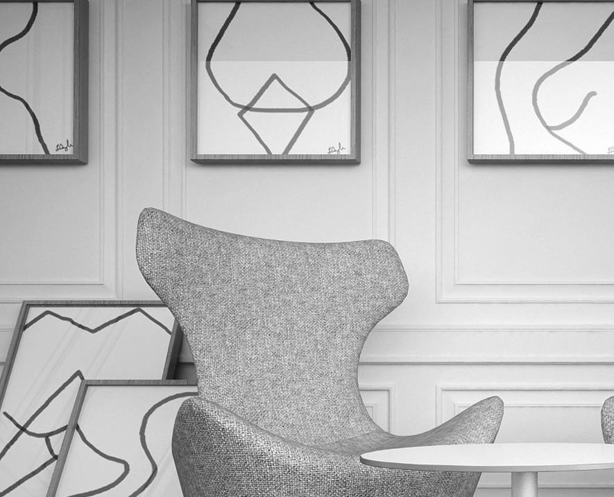

CHAPTER 6
INTERIOR MOCKUP
SCENES

I N T E R I O R M O C K U P S C E N E S
92 |
These photographs have been shot in a preconfigured studio lighting environment. Most of these shoots involve artificial light and some perhaps a small percentage of natural light.
Mockup scenes significantly reduce the need for any auxil-iary modeling for the environment that they are in, what you see is what you get and you can create very impressive results dependent on your subject.
DESIGN PROCESS
Mockup scenes are an incredibly effective way of visualizing items such as furniture, products and partial scenes of a design in a simple and fast way.
I usually use these scenes for commercial furniture mock-ups. If you pick up a magazine such as Harper’s Bazaar, Wallpaper* or World of Interiors for example, you will see many adverts for furniture.
6.1

C H A P T E R S I X
| 93
I use has been acquired from the actual manufacturer. They normally make available 3D models in .3DS format or if you are lucky in .max on their websites.
Work smart not hard! Your scene then becomes a matter of suitable placement of furniture and artwork in order to make it look real.
I tend to find that the more interesting HDRI files you have of interior and exterior spaces, the more diversity you can offer utilizing just a single .max lighting rig. Here is the HDRI file I used for this scene .
HDRI lighting plays a vital role in the lighting as its simpli-fied workflow makes it easy to create realistic renders in short amounts of time.
For this scene I modeled the timber paneling in SketchUp which took around five minutes. There is nothing truly com-plicated about this scene.
Here is a snapshot of the model so that you can see the amount of minimal geometry involved .
Coming back to workflow, you will notice that there is no furniture in the SketchUp file. This is because the furniture
6.2
6.2
6.1

I N T E R I O R M O C K U P S C E N E S
94 |
LIGHTING
The lighting for this scene is similar to the other scenes in this book in terms of workflow. We are going to use the V-Ray Dome Light again and load it with a HDRI map.
The main emphasis is on saving time. We can have an incred-ibly fast turnaround with scenes like this if we are strategic in the way we set them up.
There are other methods such as using V-Ray lights to artifi-cially illuminate the scene. For me this takes too long to set up and takes too long to render. The best designers are fast on their feet and using long-winded rendering methods is just not practical.
Open the exercise file named 06_Furniture_Mockup_Start.max from the project directory.
In this scene are two beautiful B&B Italia chairs with a table from Tom Dixon and a stunning lamp from Moooi. There are only 75,775 polygons in the scene so it will render pretty fast.
Now let’s go ahead and set up V-Ray to begin with so that we can create the main light source.
In your Renderer dialog box, F10, set V-Ray as your produc-tion render engine .
What I particularly like about these types of scenes is that with a few small changes to the materials and the HDRI file, you can have what looks like a total different scene, so the flexibility is immense.
If you use this workflow you should be able to create and render these scenes from scratch within 30 minutes.
6.3

C H A P T E R S I X
| 95
We now need to create the main V-Ray light that will cast our HDRI image onto our simple scene’s geometry.
In the Create panel on the right-hand side of your screen select the light icon .
From the drop down menu choose V-Ray. In the object type select VRayLight.
In your top viewport click to place the light. I do try to place it in front of where my camera will be pointing so that I can easily select it when needed.
Now we need to adjust the light properties.
With the light still selected click on Modify in the panel to the right.
In the Parameters section, set the type to Dome in the drop down menu.
In the Intensity modifier make sure that the multiplier is set to 1.0.
Scroll down to the Options area. In here make sure that your settings reflect those shown (see over) .
In the Sampling settings set the Subdivs to 50.
Next in the Texture options enable Use texture. Set the Resolution to 2048.
6.3
6.4
6.4
6.5
Render Setup: Default Scanline Renderer
Render Elements Raytracer Advanced Lighting
Renderer Common
Common Parameters
Assing Renderer
Production: Default Scanline Renderer
Matt
Acti
Choose Renderer
NVIDIA ray NVIDIA mental ray Quicksilver Hardware Renderer V-Ray Adv 2.30.01 V-RayRT 2.30.02 VUE Fie Renderer
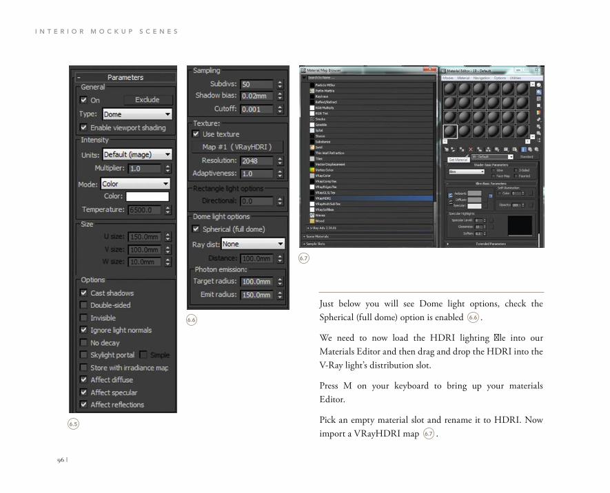
I N T E R I O R M O C K U P S C E N E S
96 |
Just below you will see Dome light options, check the Spherical (full dome) option is enabled .
We need to now load the HDRI lighting file into our Materials Editor and then drag and drop the HDRI into the V-Ray light’s distribution slot.
Press M on your keyboard to bring up your materials Editor.
Pick an empty material slot and rename it to HDRI. Now import a VRayHDRI map .
6.5
6.6
6.7
6.6
6.7
Parameters General
On Exdude
Type: Dome
Enable viewport shading
Intensity
Units: Default (image)
Multiplier: 1.0
Mode Color
Color:
Temperature: 6500.0
Size
U size:
W size:
150.0mm
100.0mm
10.0mm
Options
Cast shadows
Double-sided
Invisible
Ignore light normals
No decay
Skylight portal
Store with irradiance map
Affect diffuse
Affect specular
Affect reflections
Sampling
Subdivs: 50 Shadow bias: 0.02mm
Cutoff: 0.001 Texture:
Use texture Map #l (VRayHDRI)
Resolution: 2048 Adaptiveness: 1.0 Resctangle light options
Directoral: 0.0
Dome light options
Spherical (full dome)
Ray dist: None
Distance: 100.0mm
Photon emission: Target radius: 100.0mm
Emit radius: 150.0mm

C H A P T E R S I X
| 97
Make sure that the Mapping type is set to Spherical .
Next, select the V-Ray Dome Light and open up the mod-ify tab. Scroll down to the Texture settings of the light and what you need to do now is to drag and drop the HDRI file from the Materials Editor into the empty slot with the name None .
When the Instance (Copy) Map box pops up, be sure to select the Instance method and press OK.
Because we are only using one HDRI file there is no need to add the HDRI to the background slot in the environment settings.
With this in mind make sure that the Invisible option in your V-Ray Dome Light is unchecked so that the textures in the scene will pick up the reflections of the light source .
That is it for this stage. This is a brief chapter so onwards and upwards we go and create the camera.
6.8
6.9
6.8
6.9
6.10
6.10
V-Ray PowerShader optimized for V-Ray
Bitmap: C:\Program File\Autodesk\3ds map Browse Reload
Mapping
Mapping type: Spherical
Horiz. rotation: Angular Cubic Spherical Mirrored ball 3ds Max standard
Vert. rotation:
Processing
Options
Cast shadows
D
ouble-sided
Invisible
Ignore light normals
V.ray

I N T E R I O R M O C K U P S C E N E S
98 |
Just below you will find the Guess vert. button; click this while in your camera view to align your verticals.
We can select a Neutral white balance for now.
Set the shutter speed to 5.0 and the film speed (ISO) to 200.0. Here is what you should have .
Now we have the initial camera set up, let’s adjust the V-Ray Render settings so we can create some output renders.
CAMERAS
Maintaining the theme of swiftness in this chapter we will keep the camera work fairly simple. One of the main benefits of working with a scene like this is that it acts as a platform for you to really experiment and develop your own camera and lighting styles.
The more you experiment with custom HDRI files com-bined with physically accurate camera settings the faster and more efficient you will become in creating any type of scenes for your clients in future.
This is the type of scene where you can really maximize on using added camera features such as depth of field given the shorter render times.
Continuing with our scene let’s create a primary VRay Physical Camera from the Create panel .
Place the camera anywhere in your scene. I have taken the usual eye-level height of around 1500 mm in the Z direction.
In the camera’s settings enter the following values as a rough starting point.
Let’s input a fairly low value in the f-number option. Enter a value of 3.5.
6.11 6.12
6.11
6.12
VRay
Object Type
AutoGrid
ayDomeCame yPhysicalCan
Name and Color
specify focus.
focus distance.
exposure
vignetting
white balance
custom balance
temperature
shutter speed
Neutral
shutter -angle
shutter offset (deg)
latentcy)
file speed(ISO) 200.0
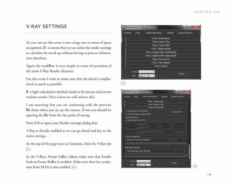
C H A P T E R S I X
| 99
V-RAY SETTINGS
As you can see this scene is not a large one in terms of space occupation. This means that we can tailor the render settings to calculate the mock up without having to process informa-tion elsewhere.
Again the workflow is very simple in terms of activation of the main V-Ray Render elements.
For this scene I want to make sure that the detail is empha-sized as much as possible.
The light calculation method needs to be precise and return realistic results. Here is how we will achieve this.
I am assuming that you are continuing with the previous file from where you set up the camera. If not you should be opening the file from the last point of saving.
Press F10 to open your Render settings dialog box.
V-Ray is already enabled so we can go ahead and key in the main settings.
At the top of the page next to Common, click the V-Ray tab .
In the V-Ray:: Frame buffer rollout make sure that Enable built-in Frame Buffer is enabled. Make sure that Get resolu-tion from MAX is also enabled .
6.13
6.14
6.13
6.14
R e n d er S e t u p: V-Ray Adv 2 .30 .01
Common V-Ray Indirect lumination Settings Render Elements
V-Ray:: Authorization
V-Ray:: About V-Ray
V-Ray:: Frame buffer
V-Ray:: Global switches
V-Ray:: Image sampler (Antialiasing)
V-Ray:: Adaptive DMC image sampler
V-Ray:: Environment
V-Ray:: Color mapping
V-Ray:: Camera
Preset:
View: Quad 4 - Top Reder
Render Setup: V-Ray Adv 2.30.01
Common V-Ray Indirect illumination Settings Render Bements
V-Ray:: Authorization
V-Ray:: About V-Ray
V-Ray: : Frame buffer
Enable bult-in Frame Buffer
Render to memory frame buffer
Output resolution
Show last VFB
Get resolution from MAX
V-Ray raw image file
Render to V-Ray raw image file
Split render channels Save separate render channels
Preset:
View: Render

I N T E R I O R M O C K U P S C E N E S
100 |
Head down to the V-Ray:: Color mapping rollout. In the Type dropdown menu select Reinhard. Set the Burn value to 0.30 and make sure that the Sub-pixel mapping and the Clamp output options are enabled .
Back at the top of the Render scene dialog box click the Indirect Illumination tab .
The next rollout we require is V-Ray:: Global switches. In the Lighting section, make sure that Hidden lights is checked and from the drop down menu Default lights are set to Off .
Just underneath you will find V-Ray Image sampler. In the Type section, select Adaptive DMC from the dropdown menu. Turn On the antialiasing filter and select Catmull Rom from the drop down menu .
6.15
6.16
6.15
6.16
6.17
6.18
Render Setup: V-Ray Adv 2.30.01
Common V-Ray Indirect illumination Settings Render Elements
V-Ray:: Authorization
V-Ray:: About V-Ray
V-Ray:: Frame buffer
V-Ray:: Global switches
V-Ray:: Image sampler (Antialiasing)
V-Ray:: Adaptive DMC image sampler
V-Ray:: Environment
V-Ray:: Color mapping
Type: Reinhard Sub-pixel mapping
Champ output Clamp level:
Affect background
Don't affect colors (adaptation only)
Linear workflow
1.0
Multiplier:
Bum value:
1.0
0.3
1.0
V-Ray:: Camera
Preset:
View: Quad 4 -Top Render
Render Setup: V-Ray Adv 2.30.01
Common V-Ray Indrect illumination Settings Render Elements
V-Ray:: Authorization
V-Ray:: About V-Ray
V-Ray:: Frame buffer
V-Ray:: Global switches
V-Ray: : Image sampler (Antialiasing)
Image sampler
Type: Adaptive DMC
Antialiasing filter
On Catmull-Rom A 25 pixel filter with pronounced edge Enhancement effects.
V-Ray:: Adaptive DMC image sampler
V-Ray:: Color mapping
V-Ray:: Camera
Preset:
Yiev:: Quad 4 -Top Render
V-Ray:: Camera
Rende

C H A P T E R S I X
| 101
Usually I use the other settings in here for animation pur-poses .
In the V-Ray:: Irradiance map rollout in the Built-in presets choose Medium from the drop down menu. Chaos Group did a fantastic job in creating presets that are built into V-Ray. The facility makes working with V-Ray a lot simpler for designers .
In the very first rollout named V-Ray:: Indirect illumination (GI), make sure that the On option is checked.
In the Primary bounces selection area choose Irradiance map.
Now in the Secondary bounces area choose Light cache from the drop down menu. While it seems that we are using these two methods a lot I do explain the other methods on the companion website.
6.17
6.18
6.19
For more information on this topic, please visit WWW.FOCALPRESS.COM/CW/WYLDE!
6.19
6.20
V-Ray:: Color maping
Type: Reinhard
Multiplier:
Burn value:
Gamma:
LG
0.30
1.0
Sub pixel maping
Clamp output Clamp level 1.0
Affect background
Don't affect colors (adaptation only)
Linear workflow
Render Setup: V-Ray Adv 2.30.01
Common V-Ray Indirect illumination Settings Render Elements
V-Ray:: Indirectlumination (GI)
V-Ray:: Irradiance map
V-Ray:: Light cache
V-Ray:: Caustics
Preset:
View: Quad 4 - Top Render
Render Setup: V-Ray Adv 2.30.01
Common V-Ray Indirect illumination Settings Render Elements
V-Ray:: Indirect illumination (GI)
On GI caustics
Reflective
Refractive
Post-processing Ambient ocdusion
Saturation
Contrast
Contrast base
1.0
1.0
0.5
On 0.3
Radius l 0 . 0 mm
Subdivs 8
Primaty bounces Multiplier 1.0 GI engine Irradiance map
Secondary bounces
Multiplier 1.0 GI engine Light cache
V-Ray:: Irradiance map
V-Ray:: Light cache
V-Ray:: Caustics
Preset:
view Quad 4 - Top Render

I N T E R I O R M O C K U P S C E N E S
102 |
This is pretty much it for now. The main aim of this section is to emphasize quality and speed. With that in mind let’s go and render this scene.
In the Options area to the right, make sure that Show calc. phase is enabled.
In the V-Ray:: Light cache rollout enter a value of 1000 in the Subdivs area. Finally make sure that the Show calc. phase is enabled .
6.20 6.21
6.21
V-Ray:: Indirect illumination (Gl)
V-Ray:: Irradiance map
Built-in Pressts
Current preset: Medium
Basic parameters
HSph. subdivs: 50
Interp. samples 20
Options
Show calc. phase Show direct light
show new samples as brighte Use camera path
Show samples
Detail enhancement
On
Advanced options
Interpolation Least squares fit (good/smootr Multipass
Randomize samples
Check sample visibility Sample lookup: Density-based (best)
Mode
Mode: Single frame Save Reset
Preset:
View: Render
V-Ray:: Indirect illumination (Gl)
V-Ray:: Irradance map
V-Ray:: Light cache
Calculation Parameters
Subdivs: 1000
Sample size: 0.02
Scale: Screen
Number of passes:
Store direct light
Show cale, phase
Use camera path
Adaptive tracing
Reconstruction parameters
Pre-filter:
Use light cachre for glossy rays
Retrace threshold:
Mode
Mode Single frame
Filter
Interp. samples:
Nearest
On render end
Don't delete
Auto save: None Browse
V-Ray:: Caustics
Preset:
View: Quad 4 - Top Render
Render Setup: V-Ray Adv 2.30.01
Commo V-Ra Indirec illuminatio Setting Rende Element
Render Setup: V-Ray Adv 2.30.01
Commo V-Ra Indirec illuminatio Setting Rende Element

C H A P T E R S I X
| 103
The scene has a nice tone, provides us with realistic depth and is all in all rather well balanced. The image could benefit from a small amount of post-production work such as minor color and contrast filters.
RENDERING
Now you have the final elements of the scene all set up, you can now proceed and produce a test render by pressing F9 on your keyboard. The result should look like this .
6.22
6.22

I N T E R I O R M O C K U P S C E N E S
104 |
Press C on your keyboard to choose which camera to render. Choose the DOF camera.
This particular camera has been set up to show you the alternative life style shots you can produce in this scene. If you render the DOF camera you will see that the floor lamp is out of focus and the primary focus is on the pictures on the wall. Of course rendering with DOF does take lon-ger to com plete compared to a camera without the function enabled .
Having said that, the image is good enough to be used straight from 3D Studio Max.
We can also go one step further in this scene by adding depth of field to the camera. Due to the space being rela-tively small, depth of field requires sufficient focal depth in order to achieve realistic results.
If you right-click your mouse button anywhere in the scene you will be presented with a pop up menu, in here select Unhide All .
6.23
6.24
6.236.24
Viewport Lighting and Shadows
Isolate Selection Unfreeze All
Freeze Selection
Unhide by Name Unhide All Hide Unselected
Hide Selection Save Scene State...
Manage Scene States... disp l

This page intentionally left blank


CHAPTER 7
EXTERIOR DAYTIME
SCENES

E X T E R I O R D A Y T I M E S C E N E S
108 |
concrete structure together with large open glazed areas. There is a peripheral timber cladding element that acts as an exoskeleton fusing the house together and connects it with its surroundings.
The selection of the background lighting source is incredibly important in a daytime scene. It must be high quality, sharp and relevant to your scene.
If I use a low dynamic range HDRI then the shadows will be simply awful, the materials will look cheap and patchy and this is certainly not what the client will be expecting.
Collecting the resources for architectural scenes is incredi-bly important. Wherever I can create my own textures and model my own elements I do. There are times when you will need to rely on other resources that are available commercially.
One of the main elements for any designer, architect or enthusiast to strategize when creating exterior renders is location, location, location.
It is one task to model a piece of architecture, it is quite another to create accurate landscaping that does not high-light or bring into question the authenticity of your render. Couple this with the fact that trees take forever to render,
DESIGN PROCESS
Having an architectural background certainly helps me focus when creating architectural exterior scenes.
My usual workflow would be to start by obtaining the archi-tect’s design scheme, depending on what stage the design is at. If you have designed the scheme, then that is a bonus as you will have a clear vision of what look and feel you require.
A fundamental understanding of how light works is essential if you want to achieve realistic results. Light is everywhere, sounds simple enough, but light also bounces. This has an effect on how a surface or material performs when hit by direct light or indeed artificial light. Light also affects the way that colored surfaces and materials bounce color around a scene. What is truly nice about exterior scenes is the mix of rugged materials with slick, polished, almost conformative materials. Understanding how light works will enable you to seamlessly mix the two.
The proper use of materials is essential if you are seeking to achieve a realistic result. Created materials such as aluminum, glass, wood, grass, soil, chrome and related industrial materials require the correct properties in order to function realisti-cally.
For this particular exercise I have created a mockup of a con-temporary residential scheme that consists of a rather simple

C H A P T E R S E V E N
| 109
Scene props and peripherals are essential. If you are creating a scene for a contemporary piece of architecture with large glazed areas, then you will achieve an even better result if you place furniture in the interior space.
Glass is opaque; if you can make the spaces look occupied, then you have won half of the battle convincing someone that the image is real.
The same can be said for garden furniture. With the care-ful placement of external furniture combined with depth of field, truly realistic results can be achieved.
SketchUp is an essential tool for exterior scenes. Simplified modeling techniques enable you to think about detail with-out being overwhelmed with the sheer amount of work that needs to be done.
Architectural visualization for exterior scenes is really about selling a product, someone’s dream; you should have fun doing it, you should strive to be different and you should certainly read the remainder of this chapter if you want to boost your skills!
Let’s crack on and tackle the exercise.
you are stuck with a balance of time versus quality versus getting paid!
Luckily there are resources online to ease the burden. Items such as foliage, trees, vehicles and other models exist in the form of purchasable libraries. I have listed many of these on the companion website.
Another concept is to photo match your building into a pho-tograph. Using camera tracking methods can be tricky, but if mastered can be a very effective medium. On the other hand I know that often designers do not have the time for luxuries and as such I will show you my practical way.
The method that we will be undertaking is a sort of blend between a photomontage and traditional visualization meth-ods. HDRI lends itself particularly well to scenes that require a seamless integration of subject matter and a photographic environment.
For more information on this topic, please visit WWW.FOCALPRESS.COM/CW/WYLDE!

E X T E R I O R D A Y T I M E S C E N E S
110 |
Understandably you are going to find it difficult if you want to mimic the lighting in Turkey and you live in Kansas City, you cannot go and shoot a custom HDRI file for your proj-ect or coursework.
Professionals with wonderful budgets on the other hand may have the chance to visit a site that they have been contracted to design. It would be incredibly beneficial to take their cam-eras and shoot an onsite HDRI.
What time of day are we rendering? Why is this even impor-tant? As the sun rises on a clear day it casts beautiful fuzzy shadows complemented with warm sunlight onto objects. On the other hand the sun can barely cast directional shad-ows at 16:00 p.m. while it is raining in London. So we have to make a decision so that we can match the direct sunlight to the HDRI file to cast accurate shadows.
All of the above needs to be pondered before you begin to even open 3D Studio Max.
For this scene we are going to use the HDRI method of lighting of course and utilize the V-Ray sunlight source.
Now navigate yourself to the project folders and open the 07_Exterior_Day_Start.max file.
LIGHTING
Are we aiming to imbue sadness or happiness? I ask this because another of my pet hates is seeing architectural renders spoilt by what can only be described as miserable lighting. One would assume that the very notion of creat-ing something that resembles another’s dream means that it should be in fact happily portrayed.
Deciding on your lighting methods upfront before you even begin to render, apply materials and fiddle with cameras, is essential. We want beautifully brightly lit scenes with the correct physically balanced lighting.
The geography of the site in question plays a crucial part in the fabric of the scene. If for example the site is on a level plane and has no foliage surrounding it, then you are going to be stuck for additional realistic elements such as reflec-tions in your glass. I always find it useful to take a look at Google Earth, see what surrounds your site. If your project is theoretical then choose a site, factor in some real-world scenarios; this will not only give your project additional depth, but it will also aid the development of your research skills as well as your analytical skills.
Making positive use of HDRI files stops us from trying to guess nature’s way. We are in fact on nature’s side, using geographic referenced atmospheric lighting in a way that requires little guesswork.

C H A P T E R S E V E N
| 111
Further down you should see the Intensity section. In here keep the Units as Default (image). Also keep the Multiplier set to a value of 1.0 .
Scroll down to the Options section. In here are all the attrib-utes that dictate the behavior of the light. We want the light to cast shadows so enable Cast shadows. Leave Double-sided unchecked.
In this file you will find a simple, fully textured scene with peripheral items such as trees, foliage, garden furniture and vehicles contained within.
Sometimes when using trees in your scene you can experience slow graphic user interface feedback, or slow regenerating viewports.
To counter this I adjust the properties of the tree so that I only see boxes instead of the final mesh. Do not worry, the trees still render, just make sure that your landscaping layout is pretty much fixed otherwise you’ll be switching back and forth between viewing options. Alternatively you can utilize the import overlay method of merging files. I do the same for items such as vehicles and furniture if I know they are in fixed positions.
In the top viewport, T on your keyboard, go ahead and create a V-Ray Dome Light. This can be found on the right-hand side of your screen under the lighting creation panel .
Place the lighting anywhere in the scene, preferably so that it is easy to select in your future camera view.
In the Parameters section under General, switch the Type to Dome from the drop down list .
In doing this we are instructing the light to act differently in terms of its distribution.
7.2
7.1
7.3
7.1
7.2
7.3
VRay
Object Type
AutoGrid
VRayLight VRayIES
ayAmbientLig VRaySun
Parameters General
Exdude On
Type: Dome
Ena
Intens
Plane
Sphere Mesh
Units:
Intensity
Units: Default (image)
Multiplier: 1.0
Mode: Color
Color:
Temperature: 6500.0
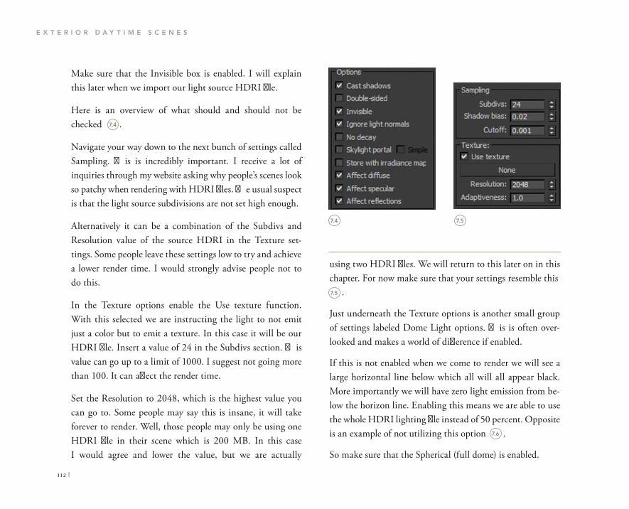
E X T E R I O R D A Y T I M E S C E N E S
112 |
using two HDRI files. We will return to this later on in this chapter. For now make sure that your settings resemble this .
Just underneath the Texture options is another small group of settings labeled Dome Light options. This is often over-looked and makes a world of difference if enabled.
If this is not enabled when we come to render we will see a large horizontal line below which all will all appear black. More importantly we will have zero light emission from be-low the horizon line. Enabling this means we are able to use the whole HDRI lighting file instead of 50 percent. Opposite is an example of not utilizing this option .
So make sure that the Spherical (full dome) is enabled.
Make sure that the Invisible box is enabled. I will explain this later when we import our light source HDRI file.
Here is an overview of what should and should not be checked .
Navigate your way down to the next bunch of settings called Sampling. This is incredibly important. I receive a lot of inquiries through my website asking why people’s scenes look so patchy when rendering with HDRI files. The usual suspect is that the light source subdivisions are not set high enough.
Alternatively it can be a combination of the Subdivs and Resolution value of the source HDRI in the Texture set-tings. Some people leave these settings low to try and achieve a lower render time. I would strongly advise people not to do this.
In the Texture options enable the Use texture function. With this selected we are instructing the light to not emit just a color but to emit a texture. In this case it will be our HDRI file. Insert a value of 24 in the Subdivs section. This value can go up to a limit of 1000. I suggest not going more than 100. It can affect the render time.
Set the Resolution to 2048, which is the highest value you can go to. Some people may say this is insane, it will take forever to render. Well, those people may only be using one HDRI file in their scene which is 200 MB. In this case I would agree and lower the value, but we are actually
7.4 7.5
7.4
7.5
7.6
Optons
Cast shadows
Double-sided
Invisible
Ignore light normals
No decay Skylight portal
Store with irradiance map
Affect diffuse
Affect specular Affect reflections
Sampling
Subdivs:
Shadow bias:
Cutoff:
24 0.02
0.001
Texture: Use texture
None
Resolution: 2048
Adaptiveness: 1.0

C H A P T E R S E V E N
| 113
Materials Editor by going to the menu at the top and nav-igating to Rendering, then choosing Materials Editor and choosing Compact Materials Editor.
Open your Materials browser by pressing M on your key-board. If your Materials Editor appears as the annoying new Slate mode, and in fact you are rather partial to being old school, then you can change back to the standard stacked
7.6

E X T E R I O R D A Y T I M E S C E N E S
114 |
Where it says bitmap: click the Browse button and go to the 07_Exterior_Daytime project folder and within here select the maps folder .
Now we need to import our HDRI files into the Materials Editor. Choose a blank material and select the Get Material icon .
The Materials/Map Browser should pop up. Within here scroll down to the Maps section and select the Standard from the subsection. Scroll down to the VRayHDRI slot and double click it. It will load a small black box into your Materials Editor slot .
In the Materials Editor you will see that a V-Ray Power Shader has loaded. This shader is wonderful; it enables us to alter the HDRI files from one location.
7.7
7.8
7.9
7.7
7.8
7.9
Get Material 19- Default Shader Basic Param
Parameters
v.ray V-Ray PowerShader optimized for V-Ray
Bitmap: Browse Reload

C H A P T E R S E V E N
| 115
Very simply we are going to drag the HDRI material from the Materials Editor and drop it into the Texture slot within the Light’s properties. Like this :
In the maps folder is an HDRI folder. Contained within this folder are two HDRI files. I mentioned above that some peo-ple use only one HDRI file and apply it to their scene. We will be using two for two reasons.
First, one HDRI is for the outdoor background which will be rendered in the final scene, so in this case the quality of the image needs to be rather high, otherwise there will be a large contrasting quality issue between our rendered geome-try and the background image. The quality of reflections in objects can be seen also, so we need to make sure that the reflections are accurate and proportional to the scene’s scale.
Second, using this high-quality HDRI file as the light emit-ter will significantly increase the render time. So instead we will use a slightly blurred version of the file. This also gives us incredibly soft shadows which will add an increasing level of realism to the scene.
Once the HDRI has been loaded, you will see a small pre-view in your Materials Editor. It will also look distorted. Don’t panic, we will be dictating the mapping method.
In the Mapping options select the drop down menu which will say Angular. Choose Spherical from the list. Now your preview looks better. Leave everything else as is .
Let’s now instruct our V-Ray Dome Light to emit our HDRI file. Select the light and navigate to the light’s properties. In here scroll down to the Texture options section .
7.10
7.11
7.12
7.10
7.11
v.raV-Ra PowerShade
optimize fo V-Ra

E X T E R I O R D A Y T I M E S C E N E S
116 |
Almost there, stick with me! Now we need to load the large HDRI file into our scene to act as the background image.
As before, select a blank material and import the large HDRI file from the same location. Make sure the Mapping Type is set to Spherical.
A final important part is telling Max to use this high-quality HDRI as the visible backdrop. Press 8 on your keyboard to open the Environment and Effects dialog.
Under the Common Parameters Section you will see Background. Check the Use Map to enable the texture roll out slot. Simply drag and drop the high-quality HDRI file from the Materials Editor to the empty slot in the Environment Map slot. Here is the backdrop HDR file we are using .
When the Instance (Copy) Map pop up appears, be sure to select Instance.
We now need to create a light source to act as the sun. This light will create beautiful soft shadows and cast warm light onto our geometry.
In the Create panel, go to the Light section and choose VRay from the drop down menu.
Let’s go ahead and create a V-Ray Sun. In your top viewport choose a location in the bottom right-hand corner of your viewport and drag the target to the center of the house .
When the Instance (Copy) Map pop up appears you need to select Instance and press OK. This is important because any changes you make to the HDRI will automatically be updated rather than having to drag and drop the HDRI into the light’s properties again .
7.12
7.13
7.13
7.14
7.15
v.ra V-Ra PowerShadeoptimize fo V-Ra

C H A P T E R S E V E N
| 117
In the Modify panel on the right we will now change the properties of the sun so that the lighting levels are correct and balanced.
Under the VRaySun Parameters, drop the Intensity multiplier to 0.01. This does seem low; however if you do a test render later on with the multiplier set to 0.5 then you will see why.
You can also change the Shadow subdivs to a value of 5.
Finally reposition the VRay Sun in the Z direction so that you are achieving a nice angle in order to cast shadows.
Remember lighting is just one part of this process; none of the above will even matter unless we can place cameras in the scene with the cor-rect settings to give us the desired output.
7.14
7.15

E X T E R I O R D A Y T I M E S C E N E S
118 |
great if you live in San Francisco, but not everyone does. If you live in the UK then you will be sitting around for a long time waiting for a sunny day. So we have to adapt and configure the camera settings to deal with a whole range of environments.
This is particularly poignant in the case of creating 3D vi-sualizations. You may have a client who requires a rainy day scene, or overcast scene, so you have to be prepared. Luckily for this scene we are using a nice bright sky so we will adapt the camera settings to best suit the environment.
Create a V-Ray Physical Camera from the Creation panel on the right-hand side of your screen .
CAMERAS
To best accentuate architectural scenes I usually place my camera at eye level which is 1590 mm (I do suppose it depends on how tall you are!).
The other relevant choice you must make is what size of image you are rendering and how it correlates to the cam-er’s aperture. For example if you are rendering in the preset size of HDTV 1920 � 1080, but have your camera set to 35 mm, then we will have render issues with the final render output in terms of composition.
In my opinion you should check www.archdaily.com for the best examples of architectural and interior photography.
The V-Ray Physical Camera settings for daytime scenes are critical. Again we must be process-orientated and match our camera settings to the HDRI file as much as possible.
There are also other factors that can increase the realism of architectural exterior scenes such as depth of field. Enabling this feature will increase the render time significantly; how-ever it does produce phenomenal results.
When it comes to creating cameras for external scenes, there are literally hundreds of combinations to achieve a well-balanced image. When people think of outdoor pho-tography they think sunny day with a bright blue sky. That’s 7.16
7.16
VRay
Object Type
ay Dome Came

C H A P T E R S E V E N
| 119
cannot use an auto function here. Ultimately a little tenacity on your part is needed.
As with the interior scene earlier in this book, we have to adjust a significant portion of the camera’s settings to achieve a realistic result.
With the camera selected bring up the camera’s properties in the Modify section on the right.
In the Basic parameters section adjust the f-number to 16.0.
Don’t forget to click the Guess vert. button to align your verticals.
Set the White balance to Neutral.
Just beneath you will see the shutter speed (s^-1), set the value to 0.05.
Finally adjust the film speed ISO to a value of 100.0.
Setting up our cameras for external scenes with the workflow we are using enables you to place a camera any-where and render with the same look and feel, so go ahead and place as many cameras as you like and experiment with the scene.
Now we are ready to finalize the render settings.
Place the camera in your scene where you deem fit. Try to capture foreground details that can be emphasized while maintaining focus on the main structure.
With the camera selected make the Z value 1590 to place it at eye level. Do the same for the camera pointer.
When photographing sunny scenes there is what’s known as the sunny 16 rule where you should keep the f-number set to 16, keep the ISO value as low as possible and simply adjust the shutter speed to suit.
So with this in mind let’s put the theory into a virtual reality .
As this is a daytime scene the camera values will obviously differ from the interior scenes in the previous chapters.
The process of refining the setting is the same however. Manual photography during the day can be tedious. There are a lot of factors to bear in mind, and unfortunately we
7.17
7.17
Add Time Tag
Grid =0.0

E X T E R I O R D A Y T I M E S C E N E S
120 |
V-Ray is already enabled as the production renderer.
From the tabs at the top click on the V-Ray tab .
From the V-Ray:: Frame buffer rollout enable the built-in Frame Buffer. Make sure the Get resolution from MAX is enabled .
Next open the V-Ray:: Global Switches rollout. In here un-check Hidden lights. Select Off from the Default lights drop down menu .
V-RAY SETTINGS
Since exterior scenes have a significant amount of light bouncing around, we need to make sure that the method of rendering complements and highlights the main details in surface textures etc.
To achieve this we will make a modification to the V-Ray render settings. At this point you may be thinking that the settings are virtually the same for all scenes. Well, this is far from the truth. As I am showing you my way of creating scenes, these are the settings that best perform for me and my requirements in order to successfully deliver a quality product to my clients.
While interior scenes may share similar settings with the mockup scenes for example, exterior scenes require refine-ments through specific data entry.
We will be effectively following the previous methods of ren-dering that have utilized the Irradiance map and Light cache for the Global illumination calculations.
Changing the Global illumination calculation methods will affect the overall render time so be warned when you are experimenting.
With the project exercise still open go ahead and press F10 on your keyboard to bring up the Render setup window.
7.18
7.18
7.19
7.20
Render Setup: V-Ray Adv 2.33 01
Common V-Ray Indirect illumination Settings Render Elements
V-Ray:: Authorization
V-Ray:: About V-Ray
V-Ray:: Frame buffer
V-Ray:: Global switches
V-Ray:: Image sandier (Antialiasing)
V-Ray:: Adaptive DMC image sampler
V-Ray:: Environment
V-Ray:: Color mapping
V-Ray:: Camera
Preset:
View: Quad 4-TopRender

C H A P T E R S E V E N
| 121
For this scene I want my rendered geometry to seem sharp and accentuated, so I want an emphasized filter. To do this we will be using the Catmull-Rom Antialiasing Filter. You can choose this from the drop down menu (see over) .
You should find the V-Ray:: Image sampler (Antialiasing) rollout just below the Global switches rollout.
In here change the Image sampler to Adaptive DMC from the drop down menu.
7.19 7.20
7.21
Render Setup: V-Ray Adv 2.30.01
Common V-Ray Indirect illumination Settings Render Elements
V-Ray:: Authorization
V-Ray:: About V-Ray
V-Ray:: Frame buffer
Enable built-in Frame Buffer
Render to memory frame buffer
Output resolution
Get resolution from MAX
Show last VFB
Preset:
View: 3uad4-Top
V-Ray:: Global switchesGeometry
Displacement
Force back face culling
Materials
Reflection/refraction
Max depth
Maps
Filter maps OffMax transp. levels
Transp. cutoff
Off with GI
Raytracing
Use 3ds Max photometric scaleLegacy sun/sky/camera models

E X T E R I O R D A Y T I M E S C E N E S
122 |
mix between exponential color mapping and linear color mapping. Why is this so important? Well, if we use another singular method of color mapping we will not be able to achieve realistic toning using the method of HDRI lighting.
Reinhard is easy to control from a value of 0.0 to 1.0 mean-ing that the closer to the value 1.0 the more burnt out the final render will be. I cover each of the settings and what they do on the companion website. For now go ahead and adjust the Burn value to 0.12 .
Back to the top of the F10 Render setup dialog box, open up the Indirect Illumination tab .
In the V-Ray:: Indirect illumination rollout make sure that the On is enabled.
Scroll down to the V-Ray:: Color mapping rollout. Now because we are using a particularly large HDRI file contain-ing so many temperature depths, combined with a VRay Sun, we need to make sure that the scene is not returned overbright and remains realistically balanced.
In the Type selection area choose Reinhard from the drop down menu. The reason why I use Reinhard a lot is because it is a mixture of two color mapping types. It is a dynamic
7.21
7.22
For more information on this topic, please visit WWW.FOCALPRESS.COM/CW/WYLDE!
7.22
7.23
Render Setup: V-Ray Adv 2.30.01
Common V-Ray Indrect iumination Settings Render Elements
V-Ray:: Authorization
V-Ray:: About V-Ray
V-Ray:: Frame buffer
V-Ray:: Global switches
V-Ray: : Image sampler (Antialiasing)Image sampler
Type: Adaptive DMC
Antialiasing filter
On Catmull-Rom A 25 pixel filter with pronounced edgeenhancement effects.
Size: 4.0
V-Ray:: Adaptive DMC image sampler
V-Ray:: Color mapping
V-Ray:: Camera
Preset:Render
V-Ray: : Color mapping
Type: Reinhard Sub-pixel mapping
Clamp output Clamp level: 1.0
Affect background
Don't affect colors (adaptation only)
Linear workflow
Multiplier:
Burn value:
Gamma:

C H A P T E R S E V E N
| 123
In the Primary bounces section set the GI engine to Irradiance map. Now set the Secondary bounces GI engine to Light cache .
In the V-Ray:: Irradiance map rollout there is a section named Built-in presets. From the drop down menu choose Medium. In the options area just below make sure that Show calc. phase is enabled .
7.23
7.24 7.25
7.24
7.25
Render Setup: V-Ray Adv 2.30.01
Common V-Ray Indirect illumination Settings Render Elements
V-Ray:: Indirect illumination (GI)
V-Ray:: I i radiance map
V-Ray:: Light cache
V-Ray:: Caustics
Preset:
View: Ouad 4 - TOPRender
Render Setup: V-Ray Adv 2.30.01
Common V-Ray Indirect illumination Settings Render Elements
V-Ray:: Indirect illumination (GI)
GI caustics
Reflective
Refractive
Post-processing
Contrast base
Ambient ocduskxi
OnRadiusSubdivs
Primary bounces
Multiplier GI engine Irradiante map
Secondary bouncesMultiplier GI engine Light cache
V-Ray:: Irradiance map
V-Ray:: Light cache
V-Ray:: Caustics
Preset:
viêïAT Quad 4 - TopRender
Render Setup: V-Ray Adv 2.30.01
Common V-Ray Indirect illumination Settings Render Elements
V-Ray:: Indirect illumination (GI)
V-Ray:: Irradiance mapBuilt-in presets
Current preset: Medium
Basic parametersHSph. subdivs:
Interp. samples:
Clr thresh;
Nrm thresh:
Dist thresh:
Options
Show calc. phase
Show direct light
Show new samples as bnghte
Detail enhancement
Advanced options
Sample lookup: ^ ^ ^ W ^ ^ C T ^ f f i ^ BRandomize samples
Check sample visibility
Mode
Mode: Single frame Save Reset
Preset
View: Quad 4 -Top

E X T E R I O R D A Y T I M E S C E N E S
124 |
Just underneath open the V-Ray:: Irradiance map rollout. In here we need to input sufficient settings in order to render a quality scene. As a general rule, keeping in mind we need to stick to fast render times, in the calculation parameters I set the Subdivs to equal 50 percent of my output render size. So for example the width of the render we will produce is 1920. Fifty percent of this is 960, so we can enter a value of 960–1000. In this case you can input 1000. Keep the sample size set to 0.02.
We want to instantly see the results as the render screen builds so enable Show calc. phase on the right .
Now we have the majority of the base settings set up.
You can now start rendering your scene to see what kind of finish you are presented with. Like everything in design, when you are replicating reality in a digital format there are always tweaks to be made.
7.26
7.26
Render Setup: V-Ray Adv 2.30.01
Common V-Ray Indirect illumination Settings Render Elements
V-Ray:: Indirect illumination (GI)
V-Ray:: Irradance map
Calculation parameters
ubdivs: 1000
Sample size: 0.02
Number of passes: 8Use directions only
Reconstruction parameters
Pre-filter:
Use light cache for glossy rays
Retrace threshold:Interp. samples: 10 ;
Mode
Mode Single frame
On render end
Don't delete
Auto save : <None> BrowseSwitch to saved cache
V-Ray:: Caustics
RenderPreset:
View: Quad 4 - Top

C H A P T E R S E V E N
| 125
I am relatively happy with the output for this scene. I do believe however that we can achieve a richer image by adjust-ing the camera settings. Go ahead and change your camera settings. Keep the f-number set to 16.0. Change the shutter
RENDERING
Press F9 to create a test render. This should take 40 minutes or so. Your scene should produce an image that resembles the following, depending on your chosen camera position of course .
7.27
7.27

E X T E R I O R D A Y T I M E S C E N E S
126 |
time try alternate camera settings, render them, print them out and pin them up. Involve the team so that you can unify a decision for finals.
Again adding additional elements to the scene increases the render time. Try and keep your foliage numbers down as well as trees and vehicles.
speed to a value of 0.24. Finally change the film speed ISO to a value of 200.0 .Now press F9 and render the scene again .
This is much better, the shadows are deeper and the overall color and depth of the scene are well balanced. As with every-thing in design, it is opinion that counts, so if you have the
7.28
7.28

C H A P T E R S E V E N
| 127
These trees were rendered in 00:35:00 at HDTV 1920 �
1080 .
So if you are looking to work with smoother files and have less lag in your viewports then V-Ray proxies are the way to go. You will find out how to create and use these files effec-tively on this book’s companion website.
If you want to take your scene further, try enabling the DOF function on the camera and experimenting with the position of the camera to achieve realistic results.
If you do have the requirement for copious amounts of trees to be placed in your scene then I highly suggest using V-Ray proxies. These proxies are essential for scenes that sometimes 3D Studio Max cannot cope with when rendering. These are external files loaded into 3D Studio Max at render time. They do not take up any resources in your scene while you are modeling so you can freely move around.
Whenever I try to convince someone that HDRI lighting is an essential skill that they should discover and explore, the usual response I get is negative, solely based on items like trees not being able to render in short amounts of time, or simply Max crashes when rendering.
For more information on this topic, please visit WWW.FOCALPRESS.COM/CW/WYLDE!
7.29
7.29


CHAPTER 8
EXTERIOR EVENING
SCENES

E X T E R I O R E V E N I N G S C E N E S
130 |
If you are modeling from architect’s drawings then try and obtain the AutoCAD versions so that you can build the model in SketchUp in tremendous detail.
You should always model to a scale. I create all of my scenes in metric, specifically millimeters.
SketchUp lends itself very well to rescaling objects and full scenes even if you have started in inches and want to use the metric scale instead.
Use layers where possible. When you import the SketchUp into 3D Studio Max the same layer-naming conventions are used. This is the same for any instanced objects or groups. You need not export a 3ds from SketchUp. 3D Studio Max has a function to directly import Skp files.
I cannot emphasize enough how important it is to have detail in your scene. In this particular exercise you will see that the apartment has an external aluminum cladding system. The amount of times I have seen just a picture or texture of aluminum applied as a material to a plane surface is incredible. Instead try and model the sections of cladding with the correct nominal offsets etc. so that the depth is increased in the scene.
DESIGN PROCESS
Truth be told, exterior evening scenes are my favorite. If you can master the balance between twilight and artificial light while emphasizing materials, then you have the poten-tial to create striking renders.
In this chapter we cover the essential elements to be able to adequately set up evening exterior environments combined with complementing camera settings. It is a very straightfor-ward workflow.
In order to successfully create detailed renders you must start from the beginning.
What do I mean by this?
Model in detail and try to not cut corners. There is nothing worse than a third party saying ‘What about the drainpipes?’.
Utilizing all the information available regarding a specific design scheme including specifications and yet again refer-ence imagery is pivotal.
I often come across images with such potential that are unfortunately ruined by poor attention to details—details such as repetitive textures visible on brick or concrete sur-faces, glass that does not reflect properly, poor foreground textures etc. These critical elements can be planned upfront with the right workflow.

C H A P T E R E I G H T
| 131
Most exterior scenes will show at least a glimpse of the inte-rior space. Using this to your advantage rather than treating it as an element to cover up will certainly strengthen your visuals.
In this scene you will see plenty of furniture and artwork. There are subtle features such as the air conditioning linear slot diffusers in the ceiling that just balance the space out and increase the realism.
So with this in mind let’s go ahead and open the scene and see what we have to play with.
Open the file 08_Exterior_Evening_Start.max from the project exercise folder. Here is a preview of the scene .
This also means that accurate performing V-Ray power shaders can be applied to the mesh without having to cheat with photographic textures.
In this exercise scene there is a vast amount of glazing. Contributing factors to the level of realism come from items modeled such as glazing channels, shadow gaps, interior loose elements and the choice of materials.
Again if you can obtain a drawing package that includes a lighting layout, then this is an additional bonus to your workflow. You can configure the lighting to calculate the lighting levels and achieve a physically balanced render. Adding the actual light fixture as a 3D model will also add to the overall depth and realism of the scene.
8.1
8.1

E X T E R I O R E V E N I N G S C E N E S
132 |
Zip down to the Options section. In here collectively are the controllable attributes that dictate the behavior and per-formance of the light. We want the light to cast shadows so enable Cast shadows. Leave Double-sided unchecked.
LIGHTING
In this section we need to set up the main indoor artificial lighting and the evening environment light source.
The interior space once lit will create some very interesting results given that this is a dual aspect piece of architecture. Dual aspect means significant glazed areas on both sides of the building.
Let’s proceed and set up the HDRI lighting first. As you will have noticed by now, the workflow in terms of setting up V-Ray environment lighting is starting to become second nature. You will soon be able to do this within minutes.
In the top viewport, T on your keyboard, go ahead and create a VRay Dome Light. This can be found on the right-hand side of your screen under the lighting creation panel .
Place the lighting anywhere in the scene, preferably so that it is easy to select in your future camera view.
In the Parameters section under General, switch the Type to Dome from the drop down list .
In doing this we are instructing the light to act differently in terms of its distribution method.
Just below you should see the Intensity section. Keep the Units set as Default (image). Also set the Multiplier to a value of 1.0 .
8.2
8.3 8.4
8.4
8.3
8.2
VRay
Object Type
AutoGrid
ayAmbientLig
VRaylES
VRaySun
Parameters
General
Exdude
PlanePlane
Done
Mesh
Intensity
Units: Default(jmage)Multiplier: 1.0
Mode : Colo
Temperature

C H A P T E R E I G H T
| 133
Navigate your way down to the next group of settings named Sampling.
In the Texture options enable the Use texture function. With this selected we are instructing the light to not emit just a color but also a texture.
In this case it will be our evening HDRI file. Insert a value of 50 in the Subdivs section.
Set the Resolution to 2048, which is the highest value you can input .
Make sure that the Spherical (full dome) is enabled.
Open your Materials browser by pressing M on your key-board. We now need to import our HDRI files into the Materials Editor. Choose a blank material and select the Get Material icon .
The Materials/Map browser should pop up. Within here scroll down to the Maps section and select the Standard from the subsection. Scroll down to the VRayHDRI slot and double click it .
Make sure that the Invisible checkbox is reading as active. Here is a preview of what should and should not be enabled .
8.5 8.6
8.7
8.5
8.8
8.6
8.7
8.8
Options
Cast shadows
Double-sided
Invisible
Ignore light normals
No decay
Skylight portal
Store with irradiance map
Affect diffuse
Affect specular
Affect reflections
Sampling
Subdivs: 50
Shadow bias: 0.02
Cutoff: 0.001
Texture:
Use texture
None
Resolution: 2048
Adaptiveness: 1.0
Rectangle light options
Directional: 0.0
Get Material 19 - Default Standard
Shader Basic Parameters
Blinn Wire
Face Map
2-Sided
Faceted
VRayEdgesTex
VRayGLSLTex
VRayHDRI
VRayMultiSubTex
VRaySoftbox
Waves
VRayHDRI

E X T E R I O R E V E N I N G S C E N E S
134 |
Once the HDRI has been loaded, you will see a small pre-view in your Materials Editor. It will also look distorted. Don’t panic, we will be dictating the mapping method.
In the Mapping options select the drop down menu which will say Angular. Choose Spherical from the list. Now your preview looks better. Leave everything else as is .
Let’s now instruct our VRay Dome Light to emit our HDRI file. Select the light and navigate to the light’s properties. In here scroll down to the Texture options section .
Very simply we are going to drag the HDRI material from the Materials Editor and drop it into the Texture slot within the light’s properties (see opposite) :
It will load a small black box into your Materials Editor slot .
In the Materials Editor you will see a V-Ray PowerShader has loaded. This shader is wonderful; it enables us to alter the HDRI files from one location.
Where it says Bitmap, click the Browse button and go to the 08_Exterior_Evening project folder and within here select the Maps folder.
In the Maps folder is a HDRI folder. Contained within this folder are two HDRI files. Go ahead and import the HDRI_EVE_LOW.hdr
8.9
8.11
8.10
8.9
8.10
8.11
8.12
Map #2
Parameters
VRayHDRI
v-Jay V-Ray PowerShaderoptimized for V-Ray
Bitmap: C:\Users\lee.w\Desktop\HDRIs\Sa Browse Reload
Mapping
Mapping type: Angular
Horiz. rotation:
Vert, rotation
Flip horizontally
Flip vertically
Mapping
Mapping type:
Horiz. rotation:
Spherical
Flip horizontally
Texture:
Use texture
None
Resolution:
Adapt veness:

C H A P T E R E I G H T
| 135
When the Instance (Copy) map pop up appears you need to select Instance and press OK. This is important because any changes you make to the HDRI will automatically be updated rather than having to drag and drop the HDRI into the light’s properties again and again .
Almost there, stick with me it will be worth it!
Now we need to load the remaining large HDRI file into our scene to act as the background image.
As before select a blank material and import the HDRI_EVE_HIGH.hdr file from the same location. Make sure the Mapping Type is set to Spherical.
A final important part is telling Max to use this HDRI as a backdrop. Press 8 on your keyboard to open the Environment and Effects dialog.
Under the Common Parameters section you will see Background. Check the Use map to enable the texture roll out slot. Simply drag and drop the high-quality HDRI file from the Materials Editor to the empty slot in the Environment Map slot.
When the Instance (Copy) Map pop up appears, be sure to select Instance .
Now we can start to concentrate on the artificial lighting in the form of V-Ray IES lights.
8.12
8.13
8.13
8.14
Material Editor - Map #2
Modes Material Navigation Options Utilities
V-RayPowerShaderoptimized for V-Rayv-ray
Affect specular
Affect reflections
Sampling
Subdivs:Shadow bias:
Cutoff:Use texture
Map #2 (VRayHDRI)
Resolution:Adaptiveness:
Dome light options
Spherical (full dome)
Ray dist: None
Photon emission:
Target radius:
Emit radius:Bitmap: C:\Users\lee.w\Desktop\HDRIs\Sa Browse Reload
Instance (Copy)...
Method
Instance
Copy
OK Cancel

E X T E R I O R E V E N I N G S C E N E S
136 |
We need to create a photometric light that will cast realistic light and shadows onto our scene’s geometry.
The photometric light creation tools can be found in the Create panel. Choose VRay from the drop down menu and in the object type select the VRayIES button .
Creating a light source is simple; drag and point. The first click is where you want to place the light source and the second click is the direction.
Try to align your lights correctly as per the ceiling layout. In the front and right viewport align the light vertically so that it points straight down. Here is my alignment .
The light source is in place and correctly aligned; now we need to adjust the properties to match real-world values.
8.14
8.15
8.16
8.15
8.16
Environment and effects
Environment Effects
Common Parameters
Background:
Environment Map:
Instance (Copy)...
Method
Instance
Copy
OK Cancel
Exposure Control
<no exposure c o n t r o l
Render Preview
Atmosphere
HighQualityHDRI
Parameters
V-Ray PowerShader
VRay
Object Type
AutoGrid
VRayLight
ayAmbientLig
VRayIES
VRaySun

C H A P T E R E I G H T
| 137
Now that we have a master IES light source, we need to copy this around the room and correctly align it to the remaining light fixtures. Be sure to instance copy the light otherwise you will have to manually adjust every single light individu-ally when making changes.
Now we have the lights set up we can go ahead and set up the camera.
Luckily the majority of these settings will come from the manufacturer’s IES file.
In the Modify panel you will see a group of settings that allow us to adjust the light. There is an empty slot with the name None. Go ahead and click this slot so thar we can load an IES file .
From the project folder load the IES file named 2782724. As soon as the file is loaded notice the emitter icon of your light change to match the settings of the IES. This is reflecting the real-world lighting fixtures attributes .
8.17
8.18
8.17
8.18
VRaylES Parameters
enabled
enable viewport shading..
show distribution
targeted
None
rotation X 0.0

E X T E R I O R E V E N I N G S C E N E S
138 |
In our case we have many warm IES lights in the interior space which we want to emphasize with the camera.
As the human eye is light sensitive, it sees the warmest part of a picture first, so our emphasis on the interior space in an evening shot will be rather straightforward and produce seamless lighting conditions from cold to warm.
Create a V-Ray Physical Camera and place it in your scene. Try to place the camera so that you can pick up a portion of the environment around the building as well as capturing detail within the space .
I am going to share with you some fairly straightforward camera settings typical for nighttime photography. We can adjust them later if we do not like them.
With your camera selected go to the Modify panel and open up the camera’s properties.
Go ahead and set the f-number to a value of 8.0.
Be sure to click the Guess vert.
Set the white balance to Daylight.
The shutter speed should be set to a value of around 4.3. You can play with this later in the render section.
CAMERAS
You are probably wondering if this amount of camera work is really necessary. My answer is absolutely. Following this workflow will boost your understanding of how cameras work both indoors and outdoors. Your renders will be accurate and physically balanced, requiring minimal post-production.
When we use the HDRI method to light daytime exterior scenes, we can take advantage of the captured data and ma-nipulate the cameras to achieve different moods.
Evening and nighttime HDRI lighting files however are much more delicate. They lack color temperature depth some what compared to daytime ones. What does this mean?
Well, it means as the HDRI environment is pretty much set, we have to be creative with the camera values to achieve a realistic shot. There may just be artificial captured lighting data from a light post or from a building embedded into the HDRI file. When the camera ISO is adjusted from a value of 100 to a value of 1600, these light emitters will affect the geometry in the scene, especially reflections, adding beauti-ful detail.
The downside to using a high ISO value in nighttime shots is that the image can be grainy or return overbright, so we have to adjust the other critical camera settings to even this out.
8.19

C H A P T E R E I G H T
| 139
Finally adjust the film speed (ISO) to a value of 100.0.
Here is how the camera settings should look :
Now these are my settings that I have calculated and previ-ously used on commercial projects. There are other ways and combinations for you to explore.
Now that we have the camera data inputted, we can set up the V-Ray settings.
8.19
8.20
8.20
targeted
film gate (mm)
focal length (mm).
fov
zoom factor
horizontal offset..
vertical offset
f-number
torget distance,...
vertical shift
horizontal shift....
Guess vert. Guess horiz.
specify focus..
focus distance,
exposure
vignetting
white balance
custom balance
temperature
shutter speed (s^-1
shutter angle (deg).
shuttar off set (dag)
latency (s)
film speed OSO)
Daylight

E X T E R I O R E V E N I N G S C E N E S
140 |
From the tabs at the top click on the V-Ray tab .
From the V-Ray:: Frame buffer rollout enable the built-in Frame Buffer. Make sure that the Get resolution from MAX is enabled .
V-RAY SETTINGS
The benefit of producing night renders is that the majority of the hard work comes from everything else other than the V-Ray settings.
In fact we do not need to deviate from the previous work-flows for rendering the other scenes in this book with the exception of product rendering. With this is mind let’s swiftly set up the V-Ray render parameters.
With the project exercise still open go ahead and press F10 on your keyboard to bring up the Render Setup window.
V-Ray is already enabled as the production renderer.
8.21 8.22
8.21
8.22
Render Setup: V-Ray Adv 2.30.01
Common V-Ray Indirectillumination Settings Render Elements
V-Ray:: Authorization
V-Ray:: About V-Ray
V-Ray:: Frame buffer
V-Ray:: Global switches
V-Ray:: Image sampler (Antialiasing)
V-Ray:: Adaptive DMC image sampler
V-Ray:: Environment
V-Ray:: Color mapping
V-Ray:: Camera
Quad 4-TopRender
V-Ray:: Authorization
V-Ray:: About V-Ray
V-Ray:: Frame buffer
Enable built-in Frame Buffer
Render to memory frame buffer
Output resolution
Get resolution from MAX
Show last VFB
V-Ray raw image file
Render to V-Ray raw image file
Split render channels
Save separate render channels
Quad 4-Top
Render Setup: V-Ray Adv 2.30.01

C H A P T E R E I G H T
| 141
In the Type selection area choose Reinhard from the drop down menu. The evening HDRI does not contain as much color or temperature as the daytime HDRIS, so we do not need to use a low value to adjust the burn amount.
Furthermore the more you reduce the value of the Bright Multiplier the more you reduce the performance of the arti-ficial IES lights. So as you can imagine balancing the image out within Max is not so easy.
Next open the V-Ray:: Global switches rollout. In here un-check Hidden lights. Select Off from the Default lights drop down menu .
You should find the V-Ray:: Image sampler (Antialiasing) rollout just below the Global switches rollout.
In here change the Image sampler to Adaptive DMC from the drop down menu.
Due to the amount of detail in the geometry contained within this scene, I want V-Ray to emphasize all the hard work put into the model when rendering. To do this we will be using the Catmull-Rom filter. You can choose this from the drop down menu .
Scroll down to the V-Ray:: Color mapping rollout.
8.23
8.24
8.23
8.24
V-Ray:: Global switchesGeometry
Displacement
Force back face culling
Default lights
Hidden lights
Shadows
Show GI only
Off
Indirect illumination
Don't render final image
Compatibility
Legacy sun/sky/camera models
Materials
Reflection/refractorMax depth
Filter maps
Max transp. levels
Transp. cutoffOverride mtl:
Glossy effects
RaytracingSecondary rays bias
Use 3ds Max photometric scale
Render Setup: V-Ray Adv 2.30.01
Common V-Ray Indrect üumination Settings Render Bernent
V-Ray:: Authorization
V-Ray:: About V-Ray
V-Ray:: Frame buffer
V-Ray:: Global switches
V-Ray: : Image sampler (Antialiasing)
Adaptive DMC
Catmull-Rom A 25 pixel filter with pronounced edgefinancement effects.
V-Ray:: Adaptive DMC image sampler
V-Ray:: Color mapping
V-Ray:: Camera
Quad 4-TopRender
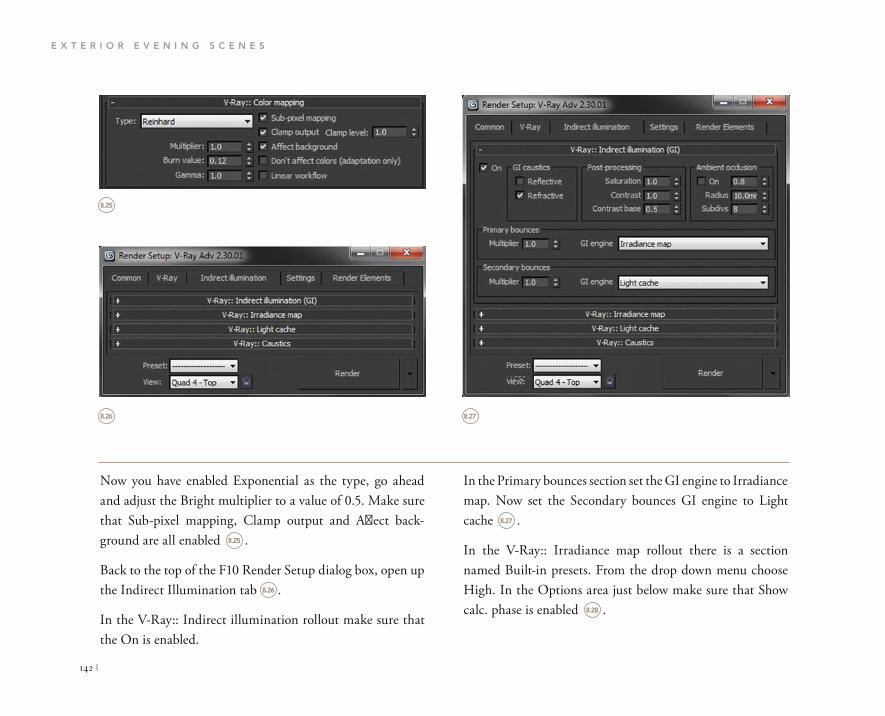
E X T E R I O R E V E N I N G S C E N E S
142 |
In the Primary bounces section set the GI engine to Irradiance map. Now set the Secondary bounces GI engine to Light cache .
In the V-Ray:: Irradiance map rollout there is a section named Built-in presets. From the drop down menu choose High. In the Options area just below make sure that Show calc. phase is enabled .
Now you have enabled Exponential as the type, go ahead and adjust the Bright multiplier to a value of 0.5. Make sure that Sub-pixel mapping, Clamp output and Affect back-ground are all enabled .
Back to the top of the F10 Render Setup dialog box, open up the Indirect Illumination tab .
In the V-Ray:: Indirect illumination rollout make sure that the On is enabled.
8.25
8.26 8.27
8.25
8.26
8.27
8.28
V-Ray: : Color mapping
keinhard
Multiplier:
Burn value:
Gamma:
Sub-pixel mapping
Clamp output Clamp level: 1.0
Affect background
Don't affect colors (adaptation only)
Linear workflow
Render Setup: V-Ray Adv 2.30.01
Common V-Ray Indirect illumination Settings Render Elements
V-Ray:: Indirect illumination (GI)
V-Ray:: Irradiance map
V-Ray:: Light cache
V-Ray:: Caustics
Quad 4-TopRender
Common V-Ray Indirect lumination Settings Render Elements
V-Ray:: Indirect illumination (GI)
Reflective
Refractive
Post-processing
Saturation
Contrast
Contrast base
Ambient occlusion
RadiusSubdivs
Irradiance map
Light cache
V-Ray:: Irradiance maf
V-Ray:: Light cache
V-Ray:: Caustics
Quad4-TopRender

C H A P T E R E I G H T
| 143
As a general rule, bearing in mind that we need to stick to fast render times, in the Calculation parameters I set the Subdivs to equal 50 percent of my output render size. So for exam ple the width of the render we will produce is 1920.
Just underneath open the V-Ray:: Light cache rollout. In here we need to input sufficient settings in order to render a quality scene.
8.28 8.29
Render SetuD: V-Rav Adv 2.30.01
V-Ray:: Indirect illumination (GI)
V-Ray:: Irradiance map
Current preset: Medium
Show new samples as brighte
Screen
Least squares fit (good/smootr
Density-based (best)
Single frame
Quad 4-Top
V-Ray:: Indirect illumination (GI)
V-Ray:: Irradiance map
V-Ray:: Light cache
Screer
Nearest
Single frame
Quad 4 -TOD
Render SetuD V-Rav Adv 2.30.01

E X T E R I O R E V E N I N G S C E N E S
144 |
RENDERING
I always like to render an exterior evening shot with and without artificial lights. Let’s take a look at how the scene would look without IES lights .
It is a nice effect. You can see that the HDRI is really effec tive, casting moonlight tones on the aluminum cladding. More importantly the glazing is really performing as it should.
Fifty percent of this is 960, so we can enter a value of 960–1000. In this case you can input 1000. Keep the sample size set to 0.02. We want to instantly see the results as the render screen builds so enable Show calc. phase on the right .
Now we have the majority of the base settings set up.
Like everything in design, when you are replicating reality in a digital format, there are always tweaks to be made.
Now you can proceed to the rendering stage.
8.29
8.30
8.30

C H A P T E R E I G H T
| 145
I am happy with this scene. There may be some slight room for post-production work; however I would use this as is for client approval.
Now you can adjust the camera ISO to see what alternat-ing the values gives you in visual feedback. Try the same for the f-stop and shutter speed. You can also use the guide in the photography section in Chapter 10 for alternate camera settings.
Let’s now take a look at the final rendered output with all lights enabled and active .
The IES lights are performing as they should without any significant unrealistic burning effects. The warm light is certainly prominent in the reflections of the aluminum clad-ding that wraps around the external envelope of the space, acting as a buffer between natural and artificial light.
The reflections in the glazing elements are still performing and correctly showing slight double reflections due to the double glazing.
8.31
8.31

CHAPTER 9
AUTOMOTIVE SCENES

A U T O M O T I V E S C E N E S
148 |
For this chapter’s supporting exercise you will be creating a photoshoot scene similar to those that appear in the glossy motorsport magazines.
In this scene I have provided you with one Pontiac Solstice. Let’s go ahead and take a look at the scene.
DESIGN PROCESS
Transportation design is a field that I have always been inter-ested in. I can remember when I first watched the Citroën C4 advert on television. I was blown away with the realistic lighting and materials applied to the transforming car.
When the movie Transformers was released it blew my mind. It remains to this day the best movie for visual effects in my opinion.
As my career has progressed I have become increasingly aware of how important 3D skills are and the potential mar-kets that one can go into with such skills.
In this section of the book I want to open your minds. I want you to see the potential you can achieve using V-Ray and the built-in materials and lighting tools available to you.
There are many talented digital artists out there who can build the 3D meshes of any vehicle from a simple front, side and top blueprint of a vehicle .
On the other hand there are those of us out there who can-not dedicate the time to build such realistic and accurate 3D models, so we look elsewhere. There are numerous online outlets where you can purchase a fully scaled and already textured 3D mesh of a vehicle. Check the companion web-site for links to these resources.
For more information on this topic, please visit WWW.FOCALPRESS.COM/CW/WYLDE!
9.1
9.1

C H A P T E R N I N E
| 149
We will be creating a backdrop like you would get in a com-mercial photoshoot as well as the key lights .
LIGHTING
As we are creating a shoot similar to what you would see in a product brochure or magazine, we can set up the lighting to best suit the chosen format.
9.2
9.2

A U T O M O T I V E S C E N E S
150 |
the client will not be happy either if you have been commis-sioned to produce such visuals.
We will now go ahead and create three V-Ray plane lights.
In the lighting creation panel drag and drop a VRay Plane Light into the top viewport .
Open the scene file 09_Transportation_Start.max from the project folder.
Here is a quick snapshot of the scene .
This is an incredibly simple scene. I have created a backdrop to simulate a canvas if you will. The vehicle is positioned accordingly so as to not show the edges of the backdrop.
The lighting method we will use will simulate studio lights as illustrated in Figure 9.2
To do this we will need to use the V-Ray light toolsets. Mimicking realistic light levels is essential otherwise the prod-uct will not be correctly displayed in all its glory. Chances are
9.3 9.4
9.3
9.4
VRay
Object Type
AutoGrid
Name and Color
ParametersGeneral
On Exclude
Type: Plane
Enable viewport shading

C H A P T E R N I N E
| 151
Make sure that the light covers a significant portion of the vehicle in order to illuminate it properly; here is where I placed mine .
We now need to rotate the light so that we can maximize the recti-linear reflections on the vehicle’s curved surfaces .
Once you have done this you can go ahead and set the light’s prop-erties to match the following .
I would like you now to make two more lights such as you have pre-viously created. Place each light as shown .
This scene would look pretty flat if we simply made all the light emit a white color of 255,255,255. Instead we can add a gradient type light effect by adjusting the color com-ing in from the left and right by adjusting the color settings.
The light emitting from the left-hand side of the screen should be less powerful than the rest.
9.5
9.6
9.5
9.6
9.7
9.7
9.8
ParametersGeneral
On Exdude
Type: PlaneEnable viewport shading
Intensity
Units: Default (image)
Multiplier:
Mode: Color
Color:
Temperature:
SizeHalf-length:
Half-width:
Options
Cast shadows
Double-sided
Invisible
Ignore light normals
No decay
Skylight portal
Store with irradiance map
Affect diffuse
Affect specular
Affect reflections

A U T O M O T I V E S C E N E S
152 |
Go ahead and change the settings of this light to match .
Now let’s go ahead and change the light coming from the right-hand side of the scene to be a daylight type tempera-ture with a higher value so that the shadow-casting changes to add increased depth to the scene. Change the light’s set-tings to match .
Now you have the lights set up you can proceed to create the cameras and finalize the scene’s settings.
9.8
9.9 9.10
9.9
9.10
ParametersGeneral
On
Type:
Exdude
PlaneEnable viewport shading
Intensity
[Default (image)Units:
Multiplier: 6.0
Mode: Color
Color
Temperature:
Size
Half-length:
Half-width:
Options
Cast shadows
Double-sided
Invisible
Ignore light normals
No decay
Skylight portal
Store with irradiance map
Affect diffuse
Affect specular
Affect reflections
ParametersGeneral
On Exclude
Type: Plane
Enable viewport shading
Intensity
Default (image)
Multiplier:
Temperature
Color
Temperature:
Size
Half-length
Options
Cast shadows
Double-sided
Invisible
Ignore light normals
No decay
Skylight portal
Store with irradiance map
Affect diffuse
Affect specular
Affect reflections

C H A P T E R N I N E
| 153
and you are instantly updated in the viewport with the result. Unlike V-Ray Physical Cameras there are no exposure settings etc. to fiddle with; this is a straight point-and-shoot method.
CAMERAS
For this scene I want you to use the normal standard 3D Studio Max Camera. We have already used V-Ray Physical Cameras throughout this book.
In the interests of diversity I believe you should see what type of results can be achieved utilizing alternative cameras.
With your scene open go to the top viewport. I want you to create a camera from the Standard camera panel and place it looking directly at the backdrop and the side elevation of the vehicle .
shows where I placed my camera.
One of the great features of the built-in 3D Studio Max Standard Camera is that you can simply select a stock lens
9.11 9.12
9.11
9.12
Standard
Object Type
AutoGridTarget Free

A U T O M O T I V E S C E N E S
154 |
From the drop down menu select Depth of Field. Also make sure the Enable is checked .
Now you have completed the majority of the hard work, we can now proceed and finalize the render settings and see what type of output we are presented with.
Press C on your keyboard and go to your camera view. You will need to raise the camera in the Z direction to achieve a suit-able result. The image below shows how my camera is placed .
Finally with your camera selected, go to the properties tool-set and scroll down to the section called Multi-Pass Effect.
9.13
9.14
9.13
9.14
Multj-Pass Effect
Enable Preview
Depth of Field
Render Effects Per Pass

C H A P T E R N I N E
| 155
From the V-Ray tab at the top direct your way to the V-Ray :: Frame buffer tab. Make sure the settings are as shown in .
Next scroll down to the V-Ray:: Global switches tab. In here you need to match the settings as shown (over) .
Just below you will see V-Ray:: Image sampler. Enter the values as shown .
V-RAY SETTINGS
As with the rest of the scenes you should be used to the generic setup by now.
As this is essentially a product scene, we will need the main V-Ray settings to be primarily focused on outlining the sur-face detail of the vehicle and correctly calculating color and tone etc.
Open up your file from the point of last saving.
Press F10 on your keyboard. The usual Render dialog should appear .
9.15
9.16
9.15
9.16
9.17
9.18
V-Ray:: Authorization
V-Ray:: About V-Ray
V-Ray:: Frame buffer
Enable built-in Frame Buffer
Render to memory frame buffer
Output resolution
Get resolubon from MAX
Scripts
Email Notifications
Quad 4 - TopRender

A U T O M O T I V E S C E N E S
156 |
Next we need to enable the Global illumination methods. At the top of the F10 pop up window, select the next tab called Indirect Illumination. In the first rollout in this section set the Primary and Secondary bounces to match .
Below adjust the V-Ray:: Irradiance map settings to mimic those shown .
Next we need to adjust the color mapping so that we avoid any undue burning. Even though we are not utilizing the HDRI lighting method, artificial lights can still return over-bright areas and damage the scene’s realistic output. Scroll down to the V-Ray:: Color mapping rollout. Make sure that the settings are as shown .
9.17
9.18
9.19
9.20
9.19
9.20
9.21
V-Ray:: Global switches
Off
Adaptive DMC
Catmull-Rom
Reinhard
Irradiance map
Light cache

C H A P T E R N I N E
| 157
Finally in the V-Ray:: Light cache rollout, copy the settings in to complete the final stages of the render settings.
Now we can render the scene.
9.21
9.22
9.22
High
Full preview
Screen
Screen
Nearest

A U T O M O T I V E S C E N E S
158 |
The final result is rather nice .
You can now explore even further with your own creative methods of lighting.
RENDERING
This is a fairly basic scene yet has incredibly realistic results. Go ahead and press F9 on your keyboard to product a final render.
You will notice that the scene keeps rendering. This is be-cause we have the Multi-Pass Effect switched on which is the Depth of Field.
9.23
9.23

This page intentionally left blank


CHAPTER 10
SHOOTING HDRIS

S H O O T I N G H D R I S
162 |
I know that there is a lot to learn in V-Ray and 3D Studio Max alone without having to educate yourself further with in-depth photography terms and workflows, but I promise you that if you pick this up and can effectively use this work-flow from start to finish, then your work will be recognized and you will increase your employment potential.
The main ethos of this section of the book is to open your minds to experimental photography merged with 3D visual-ization. This section is meant to be fun so that you are not sat at a computer; to get you out on the ground, on site if you will, to become increasingly aware of the surroundings that the building or space you are visualizing will one day inhabit. Ultimately, it gets you out of the office!
INTRODUCTION
Throughout this book I refer to HDRI or HDR files; in fact they make up most of the workflow when lighting the scenes in each of the exercises .
This chapter adopts a more practical approach to creating your own photographic back plates for your 3D scenes to enable them to function as lighting and environment subject matter.
It is incredibly beneficial for you to have alternative custom HDRI files for your library. Many designers search the far corners of the internet to try and download free ones but nothing really compares with utilizing your own skills to complete the full workflow and deliver quality.
10.1
10.1

C H A P T E R T E N
| 163
METHODOLOGY
We are going to create one 3D Studio Max scene set up with V-Ray lighting to utilize the back plates we have pho-tographed and the HDRI file we have created. The exercise should yield the following result .
10.2
10.2

S H O O T I N G H D R I S
164 |
Usually when shooting panoramic images one would take perhaps five or six photographs in total while turning 360 degrees making sure that there is a sufficient overlap. The next stage would be to merge the photographs in Photoshop to create one final panoramic image.
While this would be an OK method, the final image file would be useless to use because it will not perform in the way we want it to as per this book’s exercises.
We need a HDRI instead which contains the juicy lighting data that will realistically illuminate your scene’s geometry.
To do this instead of shooting one image and then spinning the camera around, we will be taking three photographs in the same position and will then proceed to rotate the camera and do the same. This is bracketing.
To make your workflow easy to follow and to see the design process involved, here is a broad illustration outlining the process that we will follow .
In this exercise we are going to be shooting a series of photo-graphs using a technique referred to as bracketing.
Bracketing is the general technique of taking several shots of the same subject using different camera settings.
Fundamentally we are going to photograph a series of images that will be shot in a rotational turn and then we will merge them together in stitching software called PTGui to create one large HDRI lighting file .
10.3
10.410.4
10.3
SHOOTPHOTOGRAPHS
FORHDRI &BACKPLATES
CREATE V-RAY
LIGHTING RIG IN3D STUDIO MAX
COMPILEPROJECT
PHOTOGRAPHS
USING PTGui
EDIT FINAL HDRI
USINGPHOTOSHOP
SHOT 2
SHOT 3
SHOT 1
SHOT 4

C H A P T E R T E N
| 165
It is the lighting information contained within these three images that once merged with each other can be used within V-Ray to achieve realistic lighting through the use of a V-Ray HDRI Power Shader.
We will need to use a mixture of Photoshop and a program called PTGui to compile the bracketed photographs we will be shooting, but it is minimal and actually straightforward.
Each of the three photographs will be shot in the same posi-tion at alternate exposures. To put this simply, one image will be shot as per normal conditions, one will be over exposed and one will be underexposed.
Here is one sample of a bracketed image from the panorama in this exercise highlighting the three captured exposures .
10.5
10.5

S H O O T I N G H D R I S
166 |
CHOOSING A LOCATION
First of all you should be able to get there! If you have to watch Mission Impossible the night before to help you venture out for your shoot, then it is not worth it!
There is no point risking your safety to capture a HDRI. You may as well spend $30 purchasing one that looks similar.
Depending on which type of mood you want to achieve in your V-Ray scene, you should plan a trip that takes advan-tage of the best possible natural lighting conditions.
I am in Dubai and now it is almost summertime I am slowly seeing the beautiful bright blue sky turn yellow and hazy due to the humidity. This will significantly affect my HDRI and ultimately the feel of my scene .
I often try to shoot at midday if I am producing daytime renders. This means I can easily make use of the almost ver-tical shadows cast by the sun which emits directly over the camera.
This also helps with regard to adding and positioning a V-Ray Sun to cast proper shadows to match the chosen back plate.
I try to avoid anything in my HDRIS that will cause prob-lems in the stitching software later on when compiling the final photographed panorama.
Photoshop has some great tools to aid us with this workflow such as HDR toning and the ability to make refinements. PTGui is an incredible piece of software that super stream-lines the HDR merging process. It does take some time to process, usually around 20 minutes, but it is well worth the wait!
This sounds rather in-depth and to some a little too much, however once you complete your first shoot you’ll be up and running in no time and wanting to create more.
The greater and more varied collection of HDRIS you pos-sess, the more flexible you can be with the final quality of the renders you produce.
10.6

C H A P T E R T E N
| 167
3D Studio Max scene, so you can rotate the HDRI to avoid seeing those captured issues that you do not want visible.
All in all, the HDR file is simply for light casting and reflec-tions; your back plate will be the main image that you want to perfect as it will be visible to the camera.
People and vehicles are a nuisance; you have to wait for them to move.
The ocean is another problem due to the waves never staying still in time for you to do a full 180 or 360 degree shoot.
If you are producing interior visuals then some of these issues are not really relevant as your primary focus is within the
10.6

S H O O T I N G H D R I S
168 |
One note on tripods: if you are going to purchase a new one, make sure you test it first in the store. Sometimes the legs can be rather flimsy and the rotation not very smooth. Some tripods do not come with spirit levels built in so you have to be sure that this will work for you.
It is important to try and purchase a tripod with a tiltable head so that you can place your camera at 90 degrees (por-trait) as well as 180 degrees (landscape). Again this depends on what type of scene you want to capture.
EQUIPMENT
In order to successfully capture the projects HDR, you are going to require some basic equipment. I used my wife’s Canon 550D for this exercise .
Usually I use my 450D but the quality of the image is far superior using the 550D. It is a great camera and is not too complicated to operate. You can easily adjust the settings and it lends itself well to this kind of practical work.
I use a basic tripod so there is no need to go out and purchase an expensive solution.
10.7
10.7
10.8

C H A P T E R T E N
| 169
This enables me to simply turn the camera to certain angles and then move out of the way so I am not casting shadows on the floor within the camera’s view and so I am not visible in any reflections once in Max.
Not touching the camera is important; any change in the position other than on its rotational axis could affect the final merged panorama and how it is generated.
You can get around this by purchasing some mounting plates instead; a simple 90 degree mount can do the job .
For our purposes in this book, it would not be practical to spend significant amounts on mounts etc, so for this exercise we will stick to a good old tripod and mount the camera as normal.
Try to have plenty of storage available on your memory cards. I use a 4 GB card for every project; it makes it easy to track the files down and not delete my wife’s pictures!
Take two batteries. Shooting HDRIS can put stress on your camera processing multiple photographs so you need to make sure that you are not stuck in the middle of a field shouting and swearing because your battery went after only the first set of bracketed shots. I have done this before.
Finally we want to be nowhere near the camera while it is capturing the scene. To get around this I use a $10 remote for the Canon camera .
10.8
10.9
10.9

S H O O T I N G H D R I S
170 |
If you shoot the scene using your camera in a normal posi-tion (landscape) then you may need to take many more photographs to make up the shortfall for sky etc.
If on the other hand you use your camera rotated 90 degrees (portrait) then you will capture much more detail with a vertical emphasis. You will however have to shoot more photographs to make up the 360 degree panorama.
PREPARATION
Should you mount your camera horizontally or vertically? The answer is how much work do you want to do and what type of result are you looking for?
Ideally you need to capture as much of the sky as possible to-gether with foreground. If you do not do this correctly then your panorama will look squashed in your reflections as below .
10.10
10.10

C H A P T E R T E N
| 171
If you are shooting a panoramic scene with multiple shots and your camera is not set to manual then the final merged panoramic HDRI will vary in focus and in white balance in certain parts and produce unrealistic results in V-Ray.
So with that in mind we will now set up the camera to eliminate any fluctuations between photographs.
Looking through your viewfinder, zoom out as much as you can to capture items such as the top of trees, buildings, lights etc. I am using a Cannon 10–22mm lens.
Here is what I can see through my viewfinder .
I will highlight the differences between the two orientation methods of shooting later. For now we need to work out the camera settings so that we can proceed with the shoot.
The easiest way to figure out what the best settings are for your scene wherever in the world you are is to take a photograph with your camera set to full auto mode. Then you can simply input those values into your camera in manual mode. Here are the settings for my chosen destination .
So now I will go ahead and program the ISO, shut-ter speed and f-number into my camera.
In order to shoot this correctly we need to close off or lock some of the other settings so that the cam-era does not automatically calculate things such as focus, white balance etc.
10.11
10.11
10.12
10.12
1/180 F11 ISO100- 2 . 1 . 1.+2
M
ONE SHOT

S H O O T I N G H D R I S
172 |
I now need to tell the camera that I want to take multiple exposures. To do this I must access the camera’s menu .
The image is well proportioned to obtain sufficient fore-ground coverage as well as background depth and to display enough sky.
Perhaps most importantly the horizon is in the center of the image as it should be, always try and position the horizon line in the middle of your photographs. This is because when you put your final HDRI into 3D Studio Max, if the ho-rizon line is offset in any way in the captured photographs then it will be off in 3D Studio Max also, so your lighting will return incorrectly balanced and positioned, negatively affecting reflections etc.
Now I can proceed to finalize my settings. I am firstly go-ing to lock off my white balance by setting it to daylight in manual mode .
Next I am going to switch from Auto focus to Manual focus, making sure I do not alter the focus from now until I am finished with the shoot .
10.13
10.14
10.15
10.13
10.14
10.15
Expo.comp./AEBAuto Lighting OptimizerMetering modeCustom White BalanceWB Shift/BKTColor spacePicture Style
0,0/±0sRGBStandardWhite balance
Daylight
(Approx. 5200K)
SET OK
EB

C H A P T E R T E N
| 173
better to shoot fast as it avoids any unwanted visitors in your HDR files.
The shooting method is fairly simple, the general rule is to try and get a 30 percent overlap between camera rotations. Remember if you are shooting with your camera rotated at 90 degrees (portrait) then you will be taking a lot more pho-tographs than in landscape orientation .
With my bracketed photographs complete I then decide on what type of backplate shot I will require.
If for instance I am rendering a product or vehicle, then I will try and take some shots that emphasize the product’s curves or details so that they can be viewed in proportion with the backplate.
I navigate my way to the Expo.comp./AEB menu option. With this selected I simply scroll the function wheel to the right so that the settings look like this .
Finally I need to instruct the camera to use continuous shoot ing mode as the method of capture. This means when I press the remote a series of three images will be shot one after the other .
Now that the camera is set up, I then make sure that the coast is clear and start shooting. Like I said previously it is
10.16
10.17
10.18
10.16
10.17
10.18
Exposure comp./AEB setting
Darker Brighter
B O O K
Drive mode
Continuous shooting
SET OK

S H O O T I N G H D R I S
174 |
JPEGs then this is fine also, it totally depends on timeframe and ultimately the project in hand and what you are com-fortable with .
So now with the shoot complete we can focus on the colla-tion, processing and compiling of the HDRI files.
Normally designers will shoot a high resolution photograph in JPEG format for their backplates. I like to use the brack-eting method. Why? Simply because I want more control when matching my HDRI lighting to my backplate.
You can really push the boundaries of HDR photography utilizing V-Ray. Having said this if you want straightforward
10.19
10.19
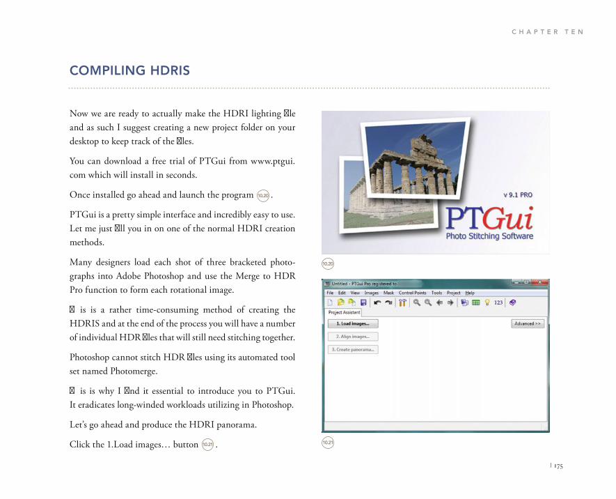
C H A P T E R T E N
| 175
COMPILING HDRIS
Now we are ready to actually make the HDRI lighting file and as such I suggest creating a new project folder on your desktop to keep track of the files.
You can download a free trial of PTGui from www.ptgui.com which will install in seconds.
Once installed go ahead and launch the program .
PTGui is a pretty simple interface and incredibly easy to use. Let me just fill you in on one of the normal HDRI creation methods.
Many designers load each shot of three bracketed photo-graphs into Adobe Photoshop and use the Merge to HDR Pro function to form each rotational image.
This is a rather time-consuming method of creating the HDRIS and at the end of the process you will have a number of individual HDR files that will still need stitching together.
Photoshop cannot stitch HDR files using its automated tool set named Photomerge.
This is why I find it essential to introduce you to PTGui. It eradicates long-winded workloads utilizing in Photoshop.
Let’s go ahead and produce the HDRI panorama.
Click the 1.Load images… button .
10.20
10.21
10.20
10.21
v 9.1 PRO
PTGuiPhoto Stitching Software
File Edit View Images Mask Control Points Tools Project Help
Project Assistant
1. Load images.. Advanced
2. Align mages...
3. Create panorama...

S H O O T I N G H D R I S
176 |
Select all the bracketed images and then click Open .
Once loaded you will see all of your bracketed photographs have loaded in a linear display .
Browse to the folder you have created on your desktop that contains the photographed bracketed images.
Try not to mix your backplates with the panorama ones! Create a different folder so that you can keep a track on them.
10.22
10.22
10.23
IMG_2723 IMG_2724 IMG_2725 IMG_2726
IMG_2727 IMG_2728 IMG_2729 IMG_2730
IMG_2731 IMG_2732 IMG_2733 IMG_2734
IMG_716" "IMG_2717" "IMG_2718" "IMG_2719" "IMG_2720" "IMG_2721" "IMG_2722" "IMG_2723" "IMG_2724" "IMG_2725" "IMG_2726" "IMG_2727" "IMG_2728" "IMC Supported formats
Open Cancel

C H A P T E R T E N
| 177
Next we need to tell the program to process all the images, merge them into HDR files and then show us the overlapped HDR panorama. Go ahead and click the 2. Align Images… button.
Now you will notice a Bracketed Exposures menu appear, fear not as our selection process is very straightforward .
We need to instruct PTGui to Enable HDR mode and to link the HDR files as we shot them using the tripod.
This great piece of software informs you of the actions of selecting each option.
Finally we need to make sure the HDR method is set to true HDR .
10.23
10.24
10.24
10.25
10.25
File Edit View Images Mask Control Points Tools Project Help
Project Assistant Source lmages Mask
Advanced :1. Load images..
Camera I lens parameters
Automatic (use EXIF data from camera, if available)
2. Align images...
Bracketed Exposures
The project appears to contain 10 sets of 3 bracketed exposures. Whatwould you like to do?
Enable HDR mode and link the bracketed images
Choose this option if the images were taken from a tripod, andthey are already aligned with pixel accuracy.
Enable HDR mode but do not link images
Choose this option if the images were taken handheld. PTGui willattempt to alignthebracketed images.
This is not an HDR exposure set. Do not enable HDR mode.
HDR Method: Exposure Fusion True HDR
OK Cancel
Bracketed Exposures
The project appears to contain 10 sets of 3 bracketed exposures. Whatwouldyou like to do?
Enable HDR mode and link the bracketed images
Choose this option if the images were taken from a tripod, andthey are already aligned with pixel accuracy.
Enable HDR mode but do not link images
Choose this option if the images were taken handheld. PTGui willattemptto align the bracketed images.
This is not an HDR exposure set. Do not enable HDR mode.
HDR Method: Exposure Fusion Tue HDR
OK Cancel

S H O O T I N G H D R I S
178 |
Once you have done this press the OK button and let the software do its thing .
If all has gone to plan then you should be presented with a large format panorama in a new window.
This interface enables you to view the merged bracketed pho-tographs and how they have been stitched. You can change the method of mapping from spherical to cylindrical etc. For now just leave the settings as they are. You can experiment later .
The final stage in this process is to direct PTGui to finalize the images and create the HDR file.
Flick back to the main PTGui window. In here you will need to click on the 3. Create panorama… button .
The software will automatically give you the width and height based on the pre-captured and merged photographic data.
10.26 10.28
10.27
10.26
10.27
10.28

C H A P T E R T E N
| 179
PTGui will give you two files, an LDR and a HDR. You already know what a HDR is, an LDR is a low dynamic range image and is often used as backplates. For us it is sim-ply a preview image.
You can leave the settings as they are. Make sure that your output file path is set up to navigate to your desktop project folder.
Finally in the Output section make sure that your settings resemble the following .
You can now click the Create Panorama button.
Now may be a good time to make a cup of tea as the process will take around 10–20 minutes dependent on your hardware.
Once the process is complete you can view the files in the project folder. No need to open the HDR as there will be a JPEG file showing you the final result .
10.29
10.30
10.30
10.29

S H O O T I N G H D R I S
180 |
Notice the dark parts at the top and bottom of the image. This is due to the stitching method and the way the images have been overlapped. It is perfectly normal. All we have to do is crop the image to omit these defects. Alternatively you can use the stamp tool to fill the black parts with sky and any ground coverage .
Photoshop has some great tools for adjusting the quality and ultimately the performance of the HDR file. If you nav-igate your way to the menu header Image, you will see a sub selection option named Adjustments. In here select the HDR Toning option .
Now before we jump into 3D Studio Max and set up the V-Ray lighting, we need to adjust the HDR file so that the color, tone and exposure are looking sufficient to return a realistic result.
Using Photoshop we will now open up and edit the HDR file. Bear in mind that these files can be up to 200 MB in size and can take quite some time to save dependent on your system.
10.31 10.32
10.31
10.32
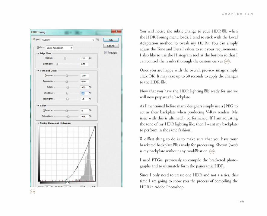
C H A P T E R T E N
| 181
You will notice the subtle change to your HDR file when the HDR Toning menu loads. I tend to stick with the Local Adaptation method to tweak my HDRs. You can simply adjust the Tone and Detail values to suit your requirements. I also like to use the Histogram tool at the bottom so that I can control the results thorough the custom curves .
Once you are happy with the overall preview image simply click OK. It may take up to 30 seconds to apply the changes to the HDR file.
Now that you have the HDR lighting file ready for use we will now prepare the backplate.
As I mentioned before many designers simply use a JPEG to act as their backplate when producing V-Ray renders. My issue with this is ultimately performance. If I am adjusting the tone of my HDR lighting file, then I want my backplate to perform in the same fashion.
The first thing to do is to make sure that you have your bracketed backplate files ready for processing. Shown (over) is my backplate without any modification .
I used PTGui previously to compile the bracketed photo-graphs and to ultimately form the panoramic HDR.
Since I only need to create one HDR and not a series, this time I am going to show you the process of compiling the HDR in Adobe Photoshop.
10.33
10.33
10.34

S H O O T I N G H D R I S
182 |
A pop up menu will appear and from this you can simply press the Browse button.
Now select the three bracketed photographs and press Open .
Open up Adobe Photoshop.
We will use the simple process of a built-in feature in Photoshop to merge the files. Navigate your way to File, then go to Automate, and then select the Merge to HDR Pro… option .
10.34
10.35
10.36

C H A P T E R T E N
| 183
All you have to do now is to make sure that the Attempt to Automatically Align Source Images is checked. Next press OK.
Let Photoshop do its thing; it should take around 20 seconds. All that is happening is the blending and overlapping of each image.
Once ready you should see the following screen .
10.35
10.36
10.37
10.37

S H O O T I N G H D R I S
184 |
Over to the right you will see the Mode drop down menu, it is currently set to 16 Bit. We need to change this to 32 Bit. You will see that a histogram has loaded with a slider that can be adjusted .
This histogram is a function that will let you set the white point of the HDR file. You can drag the slider from left to right to see the effect it has on the preview image.
You can drag the slider to a position that best suits the image, we can make further changes after the file has been compiled using the HDR Toning option.
Press OK to finalize the process.
The final HDR image is now ready for you to edit and make refinements.
Go to the main menu and select Image, Adjustments, HDR Toning.
Try to make the same adjustments that you made to the bracketed panorama so that the images are as similar in tone as possible. I try to only adjust the sharpness, Color Vibrance, and the Saturation levels .
Finally save your file as a Radiance file .HDR. It may take 30 seconds or so to write the Radiance format.
Now we have both methods covered of shooting, processing and compiling custom photographs to act as lighting files, we can now progress to the final stage which is actually set-ting up a 3D Studio Max scene.
Take note of the three bracketed exposures at the bottom of the screen. Notice the naming of the images with the prefix EV .
EV 0.00 is the normal photograph with the custom settings we entered into the digital camera’s Manual Settings.
EV -1.47 is the underexposed photograph and the EV+1.49 is the overexposed photograph.
10.39
10.38
10.38
10.39
10.40

C H A P T E R T E N
| 185
SETTING UP V-RAY HDRIS IN 3D STUDIO MAX
When I set up working project files in 3D Studio Max I become rather particular about what information is used and where it is stored.
There is no doubt that I like clean, workable files. I use one Max file for lighting and one file for all the modeling and texturing. This means that designers in my studio can access and work on the files individually and in a collaborative way.
Once my production model is ready I simply X-ref it into the lighting file or Light Rig as I call it and begin to render from there.
Let us progress now and set up the Light Rig.
Open up a fresh 3D Studio Max file.
Press F10 on your keyboard to bring up the Render Setup dialog box.
In here you we will need to make sure that the Output Size of the render matches the image size of our backplate. Simply enter the width and height values of your backplate which are 5184 � 3456 .
Once you enter the values make sure that you lock off the Image Aspect ratio and the Pixel Aspect ratio. One you have
10.40
10.41

S H O O T I N G H D R I S
186 |
done this you can go ahead and enter a more reasonable out-put size for test renders. Set the width to 1000; you will see the Height will automatically adjust.
Scroll down to the Assign Renderer rollout. In here you need to set the Production renderer to V-Ray .
From the tabs at the top of the F10 dialog select the V-Ray tab .
From the rollouts select V-Ray:: Frame buffer. In here you need to enable the built-in Frame Buffer .
10.41
10.42
10.42
10.43
10.43
10.44
10.44

C H A P T E R T E N
| 187
Next on the list is V-Ray:: Global switches. In the lighting section make sure the Default lights are set to Off. Also make sure Hidden lights is checked .
Just below the next rollout should be V-Ray:: Image Sampler. In here set the Image sampler Type to Adaptive DMC and the Antialiasing filter set to Catmull-Rom .
In the V-Ray:: Color mapping rollout, set the Type to Reinhard. Make sure the Sub-pixel mapping is checked as well as Clamp output and Affect background. Set the Burn value to 0.24 .
In the next tab of the F10 dialog box is Indirect Illumination .
10.45
10.46
10.47
10.45
10.46
10.47
10.48

S H O O T I N G H D R I S
188 |
In the first rollout named V-Ray:: Indirect Illumination (GI) select the On.
Set the Primary bounces engine to Irradiance map.
Set the Secondary bounces engine to Light cache .
In the V-Ray:: Irradiance map rollout where Current preset is written, go ahead and select Medium from the drop down menu.
In the Options area make sure that Show calc. phase is enabled .
10.48
10.49
10.50
10.50
10.49

C H A P T E R T E N
| 189
Set the Multiplier to a value of 2.4.
Scroll down to the light’s options and make sure Invisible is checked as being active.
Just below you will find the Sampling options of the light. Enter a value of 30.0 in the Subdivs area.
In the Texture options area, enable the Use texture and set the Resolution to 2048.0.
Finally you need to scroll down to the Dome light options and select the Spherical (full dome).
We now need to import the panorama HDR file you created and apply it to the V-Ray Dome light.
Press M on your keyboard to bring up the Materials Editor. Import a new VRayHDRI file from the Material/Map Browser .
Finally scroll down to the V-Ray:: Light cache tab and adjust the Calculation parameters. In the Subdivs option set the value to 1000. The sample size is sufficient set to a value of 0.02. Make sure Show calc. phase is enabled .
Now the main settings have been applied we can set up the lighting elements. Bear in mind that HDR files are in a large format and bear a hefty weight which may affect your com-puter’s response time.
Go ahead and create a V-Ray Dome Light. Place it anywhere in the scene.
10.51
10.51
10.52
10.52

S H O O T I N G H D R I S
190 |
You will now need to drag and drop the HDRI preview image from the Material Editor dialog to the empty slot in the V-Ray Dome lights Texture options slot .
When the Instance Copy Method pop up appears be sure to select Instance and not Copy.
Now you have the Environment lighting ready and set, you will need to load a secondary HDRI file and instruct it to act as your backplate.
To do this we will be using another method of loading a HDR file. In a new Material slot import a Bitmap file from the Material/Map Browser .
Once loaded, you will need to set the Mapping type to Spherical in the Mapping section of the shader’s Parameters .
10.53
10.54 10.55
10.53 10.54
10.55
V-Ray PowerShaderoptimized for V-Ray
Bitmap: C:\Users\lawylde\Desktop\CUSTO Brows Reload
Mapping
Mapping type:
Horiz. rotation:
Vert, rotation:
AngularCubic
Mirrored ball3ds Max standard
V-Jay

C H A P T E R T E N
| 191
When it loads you will be prompted with an Explorer win-dow, navigate to where the HDR files are stored and load in the BackPlate.hdr file that you created.
Once the HDR has loaded scroll down to the Coordinates rollout and switch the type from Texture to Environ. From the Mapping drop down menu choose Screen .
Now you have loaded the backplate you need to instruct V-Ray to use it as the visible background.
Press 8 on your keyboard to bring up the Environment and Effects dialog box.
In the Common Parameters section drag and drop the BackPlate.hdr into the empty Environment Map slot. Choose instance as the method of copying .
Now we have the main lighting rig set up we need to create a camera and some test geometry to make absolutely sure that the scene works properly and yields realistic results.
Let’s go ahead and create a normal 3D Studio Max Camera.
Place the camera at the following coordinates 0,0,0. Make sure that the camera target is pointing straight ahead.
Select both the camera and its target and set the Z value to 1450 mm .
10.56
10.57
10.56
10.57
10.58
BactcPlate Bitmap
Coordinates
Texture Environ Mapping: Screen
Offsetu
v
U:
V:
Mf:
Blur: Blur offset: Rotate
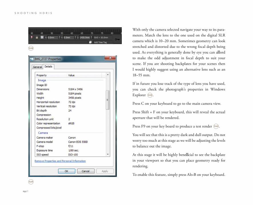
S H O O T I N G H D R I S
192 |
With only the camera selected navigate your way to its para-meters. Match the lens to the one used on the digital SLR camera which is 10–20 mm. Sometimes geometry can look stretched and distorted due to the wrong focal depth being used. As everything is generally done by eye you can afford to make the odd adjustment in focal depth to suit your scene. If you are shooting backplates for your scenes then I would highly suggest using an alternative lens such as an 18–55 mm.
If in future you lose track of the type of lens you have used, you can check the photograph’s properties in Windows Explorer .
Press C on your keyboard to go to the main camera view.
Press Shift + F on your keyboard, this will reveal the actual aperture that will be rendered.
Press F9 on your key board to produce a test render .
You will see that this is a pretty dark and dull output. Do not worry too much at this stage as we will be adjusting the levels to balance out the image.
At this stage it will be highly beneficial to see the backplate in your viewport so that you can place geometry ready for rendering.
To enable this feature, simply press Alt+B on your keyboard.
10.58
10.59
10.59
10.60
IMG_2727 Properties
General Details
Property Value
Image
Image ID
Dimensions
WidthHeight
Horizontal resolution
Vertical resolution
Bit depth
Compression
Resolution unit
Color representation
Compressed bits/pixel
5184x3456
5184 pixels
3456 pixels
72 dpi
72 dpi
24
2
sRGB
Camera
Camera maker
Camera model
F-stop
Exposure time
ISO speed
Canon
Canon EOS 55OD
f/111/60 sec.ISO-100
Remove Properties and Personal Information
OK Cancel Apply

C H A P T E R T E N
| 193
Now that you can see the backplate, you can go ahead and create a piece of geometry. I use the built-in teapot as it can show accurate reflections on the curved surfaces. Insert as many teapots as you like.
When the Viewport Configuration panel appears you need to select the Use Environment Background option. Press the Apply to Active View and then press OK .
10.60
10.61

S H O O T I N G H D R I S
194 |
This is the geometry in my scene .
In order to produce a realistic render we need to apply real-istic shaders to the geometry in the scene. We need to apply shaders that have reflective properties to make full use of the HDR lighting method.
Let’s go ahead and apply a car paint material to the tea-pots. You can find this built in shader in the V-Ray material library. Once loaded in to the Materials palette you can ap-ply the shader to the teapots .
We also need to make sure that the background HDR file looks a lot brighter than in the previous test render.
10.61
10.62
10.62
10.63
Viewport Configuration
Display Performance Regions Statistics ViewCube SteeringWheete
Visual Style & Appearance Background Layout Safe Frames
Use Customize User Interface Gradient Colors
Use Customize User Interface Solid Color
Use Environment Background
Use Files:
Animation Synchronization
Use Frame
Start at Sync Start to Frame
End Processing
Apply to All Views in Active Layout Tab Apply to Active View OK Cancel

C H A P T E R T E N
| 195
In here set the Output Amount to a value of 1.0. You should instantly see your viewport background change and become brighter.
We also need to make sure that the brightness of the reflec-tions in the Panorama HDR file match the backplate so under Processing, adjust the Panorama’s Overall mult. to a value of 4.0 .
Now would be a good time to see what results are being returned from the scene. Press F9 and produce a test render .
To do this open up the Materials Editor and scroll down to the Output rollout in the BackPlate Bitmap Material .
10.63
10.64
10.65
10.64
10.65
10.66
Material/Map Browser
Search by Name
Simple Glass Clear by Amleto.mat
Materials
Standard
V-RayAdv 2.30.01
VRay2SidedMtl
VRayBlendMtl
VRayCarPaintMtlVRayFastSSS
VRayFastSSS2
VRayFlakesMtl
VRayHairMtl
VRayLightMtlVRayMtl
BackPlate
Time
Output
Output
Invert
Clamp
Alpha from RGB Intensity
Enable Color Map
Output Amount:
RGB Offset:
RGB Level:
Bump Amount:
1.00.0
1.0
1.0
Pano VRavHDRI
v-ray V-Ray PowerShaderoptimized for V-Ray
Bitmap: C:\Users\lawylde\Desktop\CUSTOBrowseReload
MappingMapping type: SDherical
Horiz. rotation: 0.0 Flip horizontally
Vert, rotation: 0.0 Flip vertically
ProcessingOverall mult:4.0 Gamma:1.0Render mult:1.0 Interpolation: Default
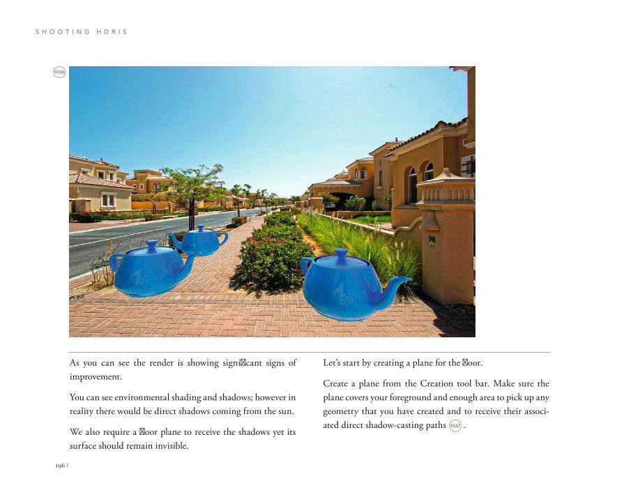
S H O O T I N G H D R I S
196 |
Let’s start by creating a plane for the floor.
Create a plane from the Creation tool bar. Make sure the plane covers your foreground and enough area to pick up any geometry that you have created and to receive their associ-ated direct shadow-casting paths .
As you can see the render is showing significant signs of improvement.
You can see environmental shading and shadows; however in reality there would be direct shadows coming from the sun.
We also require a floor plane to receive the shadows yet its surface should remain invisible.
10.66
10.67

C H A P T E R T E N
| 197
Apply the material to the plane object.
We also need to make sure that the ground plane is not visi-ble in any reflections of the scene’s geometry.
To do this we need to select the plane and right click on it. When the menu pops up choose Object Properties… .
In order for the floor to remain invisible during render time yet display proper shadow casting, we must apply a Matte/Shadow material to it.
Press M on your keyboard.
Import a new Matte/Shadow shader from the Standard library .
10.67
10.68
10.69
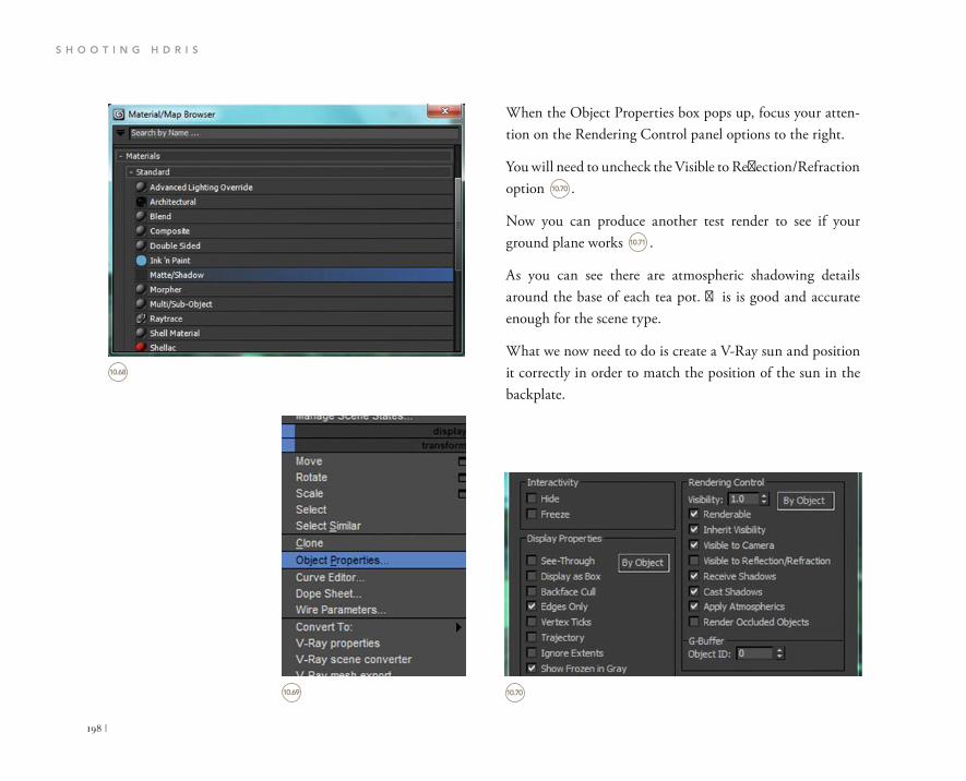
S H O O T I N G H D R I S
198 |
When the Object Properties box pops up, focus your atten-tion on the Rendering Control panel options to the right.
You will need to uncheck the Visible to Reflection/Refraction option .
Now you can produce another test render to see if your ground plane works .
As you can see there are atmospheric shadowing details around the base of each tea pot. This is good and accurate enough for the scene type.
What we now need to do is create a V-Ray sun and position it correctly in order to match the position of the sun in the backplate.
10.69
10.68
10.70
10.70
10.71
Material/Map Browser
Seach by Name
Materials
StandardAdvanced Lighting Override
ArchitecturalBlend
CompositeDouble SidedInk n Paint
Matte/ShadowMorpher
Multi/Sub-ObiectRaytrace
Shell Material
Shellac
MoveRotateScaleSelectSelect Similar
CloneObject Properties
Curve Editor.Dope Sheet.Wire Parameters.
Convert To:V-Ray propertiesV-Ray scene converter
Interactivity
Hide
Freeze
Display Properties
See-Through
Display as Box
Backface Cull
Edges Only
Vertex Ticks
Trajectory
Ignore Extents
Show Frozen in Gray
By Object
Rendering Control
Visibility: 1.0 By Object
RenderableInherit Visibility
Visible to Camera
Visible to Reflection/Refraction
Receive Shadows
Cast Shadows
Apply Atmospherics
Render Ocduded Objects
G-BufferObject ID:0
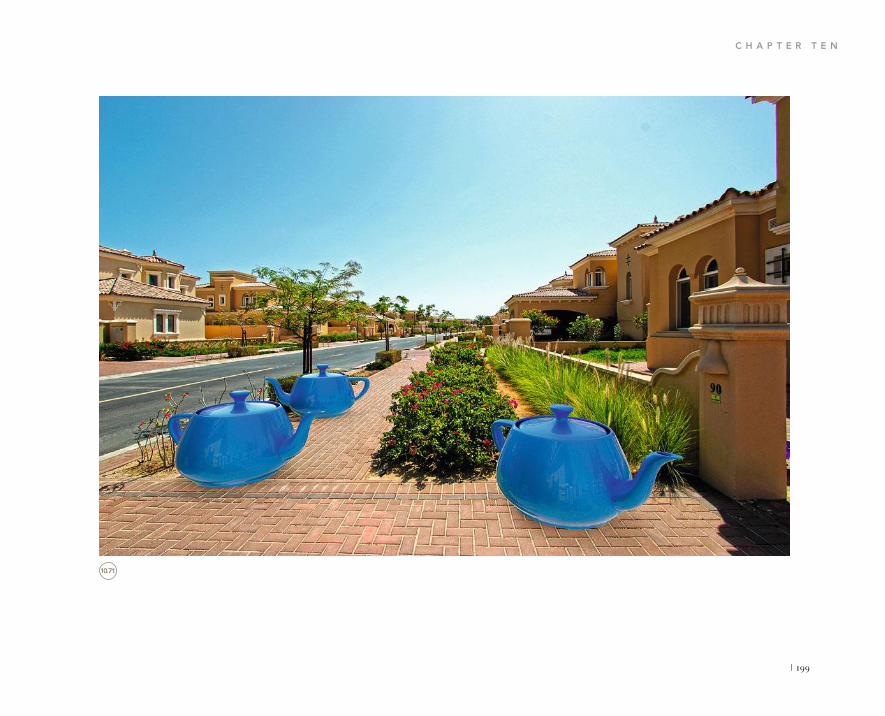
C H A P T E R T E N
| 199
10.71

S H O O T I N G H D R I S
200 |
First change the Intensity multiplier to a value of 0.15.
Change the Photon emit radius to 20,000.
Once you are happy with the final position of the V-Ray Sun go ahead and produce a test render .
Create a V-Ray sun and position it as best you can to match the backplate. Pay attention to the way the shadows fall from the architecture of the scene. You can refine the placement of the sun in your camera view .
You now need to change a few settings to the V-Ray Sun in the Modification panel.
10.72
10.72
10.73
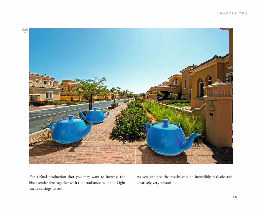
C H A P T E R T E N
| 201
As you can see the results can be incredibly realistic and creatively very rewarding.
For a final production shot you may want to increase the final render size together with the Irradiance map and Light cache settings to suit.
10.73

S H O O T I N G H D R I S
202 |
Here is an example of what can be achieved with this method of capturing bracketed photographs, manipulating them and putting them to functional use in 3D Studio Max and V-Ray .
This type of workflow is ideal for vehicle rendering and prod-uct rendering etc.
10.74
10.74

C H A P T E R T E N
| 203
intend writing a book containing advanced 3D Studio Max and V-Ray tools such as automation in rendering and advanced lighting effects. For now, keep practicing and I look forward to any technical inquiries or tutorial requests, Lee Wylde
FINAL THOUGHTS
Using Autodesk 3D Max with V-Ray as the rendering engine can provide you with a very powerful set of tools to aid you in your career. I hope this book has refined and improved your understanding of how these software pack-ages intertwine to provide realistic results. It is now your turn to create visuals and improve your portfolio. I do

This page intentionally left blank

| 205
Page umbers in bold refer to illustrations.
3D Studio Max 5, 6, 9, 10, 16, 17, 21, 27, 30; backplate configuration 190–3, 190, 191, 192; Dome Light settings 34–9, 36, 37, 38, 39; environment 57; IES lights 64; inserting objects 193–202, 193, 194, 195, 196, 197, 198, 199, 200, 201, 202; layer-naming conventions 130; Light Rig setup 185–9, 186, 187, 188, 189; lighting element setup 189–90, 189, 190; lighting settings 36–7, 36, 37; Object Properties box 197–8, 198; Viewport Configuration panel 193; working project file setup 185–202, 186, 187, 188, 189, 190, 191, 192, 193, 194, 195, 196, 197, 198, 199, 200, 201, 202
3D Studio Max Camera 44, 153–4, 153; settings 191–2, 191, 1923D visuals, importance of 123D World (magazine) 4
Adaptive DMC image sampler 50, 50Alton, John, Painting with Light 74–5animation 101, 101; importance of 12Antialiasing filter 49, 49architect’s design scheme 108architect’s lounge 24architectural visualization 109artificial lighting 64, 135–7, 136, 137AutoCAD 5, 130
automotive scenes: camera settings 153–4, 153, 154; design process 148, 148; lighting 149–52, 149, 150, 151, 152; reflections 151, 151; render settings 155–7, 155, 156, 157; rendering 158, 158
background light source 68, 69, 108BackPlate Bitmap Material 195, 195backplate configuration 190–3, 190, 191, 192backplate creation 181–4, 182, 183, 184base building model 20bathroom furniture 66batteries 169BOXXTECH 8bracketing 34, 164–5, 164, 165, 184, 184briefing document 20Brown, Blain, Cinematography, Theory and Practice 74–5Burn value 87, 88burning 50, 50, 79–80, 79, 156
camera placement 75, 118, 119, 153, 153, 154, 154camera settings: automotive scenes 153–4, 153, 154;
Exterior daytime scenes 118–19, 118, 119, 125–6; Exterior evening scenes 138–9, 139; HDRI photography 171–3, 171, 172, 173; Interior daytime scenes 44–7, 45, 46, 47, 58–61, 58, 59, 60, 61; Interior evening scenes 73–7, 74, 75, 76,
INDEX

I N D E X
206 |
Define stage 20, 21Deliver stage 21depth of field 75, 84, 85, 87, 88, 89, 104, 104, 118, 127, 158design account manager 11design accounts, design team 11design process: automotive scenes 148, 148; Exterior daytime
scenes 108–9; Exterior evening scenes 130–1, 130, 131; Interior daytime scenes 30–3; Interior evening scenes 64–6, 66; Interior mockup scenes 92–4, 92, 93
design teams 11Design stage 20–1detailing 21–7, 22, 23, 24, 25details, importance of 130Digital SLR Cameras 44, 44, 46, 46Dome Light 34–9, 36, 37, 38, 39, 41, 56, 56, 68, 68, 69, 95, 97,
97, 111, 111, 115, 115, 116, 132–4, 132, 133, 134, 189Dome Light Options 38–9, 39, 112, 189Dome Light settings 94, 96, 96double glazing 145, 22, 23Dubai 11–12
environment 57Environment and Effects dialog 70, 70, 116–17, 117environment light 43, 132–5, 132, 133, 134, 135, 136Environment Map 135, 136equipment 16, 168–9, 168, 169ERCO 26expectations, managing 10Exterior daytime scenes: camera settings 118–19, 118, 119,
125–6; design process 108–9; lighting 110–17, 111, 112, 113, 114, 115, 116, 117; render settings 120–4, 120, 121, 122, 123, 124; rendering 125–7, 125, 126, 127; site 110
Exterior evening scenes: artificial lighting 135–7, 136, 137; camera settings 138–9, 138, 139; design process 130–1, 130,
77; Interior mockup scenes 98, 98; nighttime photography 138–9, 139
camera tracking 109cameras 44–7, 44, 45, 46, 47, 168, 168, 169.camera work 21Cast Shadows 38, 132Catmull Rom Antialiasing Filter 121, 122, 141, 141ceilings 25, 25changes, tracking 83cinematography 74Citroën C4 advert 148clients, relations with 16, 17, 21collaboration 11color 31color, tone and exposure adjustments, HDRI files 180–4, 180,
181, 182, 183, 184color Burn 87, 88color mapping 87, 156, 156Color mapping rollout 50, 100, 101, 122, 141, 156, 156, 187,
187color settings 151–2, 152color temperature 84, 138commitment 9Common Parameters 135Compact Materials Editor 113, 39composition 31contact list 8control 10corners, not cutting 130Coroflot.com 10creative direction 32credit 11cropping 180, 180custom shaders 21

I N D E X
| 207
and exposure adjustments 180–4, 180, 181, 182, 183, 184; compiling 175–84, 175, 176, 177, 178, 179, 180, 181, 182, 183, 184; cropping 180, 180; environment 57; importing 40, 133–5, 134, 135; inserting objects 193–202, 193, 194, 195, 196, 197, 198, 199, 200, 201, 202; Light Rig setup 185–9, 186, 187, 188, 189; lighting data 164, 165; lighting element setup 189–90, 189, 190; merging 182–4, 183, 184; saving 184; using two 41; versatility 61; working project file setup 185–202, 186, 187, 188, 189, 190, 191, 192, 193, 194, 195, 196, 197, 198, 199, 200, 201, 202
HDRI lighting 34, 93, 93, 127, 132HDRI map, importing 96, 96HDRI material palette 57HDRI photography: camera settings 171–3, 171, 172, 173;
equipment 168–9, 168, 169; exposure adjustment 184, 184; focus 172, 173; location choice 166–7, 167; merging images 182–4, 183, 184; orientation 170–1, 170, 173; preparation 170–4, 170, 171, 172, 173, 174; process 163–6, 163, 164, 165; shadows 166; shoot timing 166; shooting 173–4, 173; viewfinder image 171–2, 171
HDRI shader 69, 69Hidden lights 120Hollywood 10horizon line 172
IBL (image-based lighting) 30IES lighting files 64; 72, 73, 137, 137; power value 84, 85, 87IES lights 64, 67, 73, 135–7, 136, 137, 144–5, 144, 145illuminance information 65Image sampler 100, 100, 155, 156, 187, 187Image sampler (Antialiasing) 49, 49, 121, 141, 141Indirect illumination rollout 50–1, 51, 122, 123, 142, 142Indirect Illumination tab 50, 51, 122, 122, 123initial renders 21
131; environment light 132–5, 132, 133, 134, 135, 136; render settings 140–4, 140, 141, 142, 143; rendering 144–5, 144, 145
film speed (ISO) 60, 73, 77, 98, 98, 119, 126, 138, 139, 30Finding Nemo (film) 6flooring, manufacturers’ models 32Foothill Studios 6–8Frame buffer 155, 155, 186, 186Frame buffer rollout 120, 121, 140, 140Free Camera 44F-stops 30, 58, 61, 73–4, 75, 75, 98, 119, 125furniture 24, 32, 109furniture industry 7–8
glazing 22, 23, 109, 131, 144, 144; ratios 33; window frames 26, 26
Global illumination calculations 120Global illumination methods 156, 156Global switches 100, 100, 155, 156, 187, 187Global Switches rollout 120, 121, 141, 141Google 31graphic designer 11ground plane 196–8, 196, 197, 198Guess vert. button 119Guess vertical shift 75
Hadfield Cawkwell Davison 4–6halo effects 60Harper’s Bazaar 92HDRI 109HDRI files 34, 96, 96, 162, 162; backdrop 42; backplate
configuration 190–3, 190, 191, 192; backplate creation 181–4, 182, 183, 184; burning 50, 79–80, 79; color, tone

I N D E X
208 |
landscaping, online resources 108–9layer-naming conventions 130library 162light 108Light cache 201Light cache rollout 52, 81, 124, 143, 157, 157Light Cache tab 189, 189light fixtures 65–6, 66, 131light properties, adjusting 95Light Rig setup 185–9, 186, 187, 188, 189light sources 68; background 68, 69, 108; creating 71;
positioning 71–2, 72light tracer function 6lighting: artificial 64, 135–7, 136, 137; atmospheric 110;
automotive scenes 149–52, 149, 150, 151, 152; bounce 120; control 10; environment light 132–5, 132, 133, 134, 135, 136; Exterior daytime scenes 110–17, 111, 112, 113, 114, 115, 116, 117; Exterior evening scenes 132–7, 132, 133, 134, 135, 136, 137; HDR 34; IBL (image-based lighting) 30; instance copy 72–3; intensity 132, 132; Interior evening scenes 67–73, 67, 68, 69, 70, 71, 72, 73; Interior daytime scenes 34–43; materials browser 39–42, 40, 41, 42, 43; photometric data 64; placement 132, 136–7, 136, 151, 151; preconfigured 92; render settings 50–1, 51; secondary 70; studio lights 149–52, 149, 150, 151, 152
lighting creation panel 132, 132lighting element setup 189–90, 189, 190lighting elements 21lighting files 21lighting fixtures 26lighting levels 65lighting manufacturers 64, 65lighting scale 87lighting system 36–7, 36, 37
inserting objects, 3D Studio Max 193–202, 193, 194, 195, 196, 197, 198, 199, 200, 201, 202
inspiration 9Instance (Copy) Map box 97, 116Instance (Copy) Map pop up menu 42, 42, 135, 135instance copy, lighting 72–3Instance Copy Method pop up 190interior architecture, detailing 25, 25Interior daytime scenes: background HDRI settings 55–7,
55, 56; camera values 58–61, 58, 59, 60, 61; Dome Light settings 34–9, 36, 37, 38, 39; lighting settings 36–7, 36, 37; rendering 54–61, 54, 55, 56, 57, 58, 59, 60, 61; test render 54, 54, 57, 57
interior designer 11Interior evening scenes: camera settings 73–7, 74, 75, 76, 77;
design process 64–6, 66; lighting 67–73, 67, 68, 69, 70, 71, 72, 73; reflections 67; render settings 77–82, 78, 79, 80, 81, 82; rendering 83–9, 83, 85, 86, 88
Interior mockup scenes: camera settings 98, 98; design process 92–4, 92, 93; furniture 93; HDRI lighting file 93; lighting 94–7, 95, 96, 97; render settings 99–102, 99, 100, 101, 102; rendering 103–4, 103, 104; SketchUp file 92, 93
Interior daytime scenes: camera settings 44–7, 45, 46, 47; design process 30–3; Google image search 31; lighting 34–43; render settings 48–53, 48, 49, 50, 51, 52, 53
Invisible box 38Irradiance map 51, 51, 80–1, 101, 102, 123, 123, 156, 157, 201Irradiance map rollout 142, 143, 188, 188
JPEG format 174, 174, 179, 179, 181
key details, focusing on 61, 61key work stage plan 30

I N D E X
| 209
PhysicalCam button 46Pixar 6plane lights 150–2, 150, 151, 152planning 30Poseidon (film) 9Power Shader 40, 114, 131, 134Primary bounces GI engine 51, 51, 101, 123, 123, 142, 142, 188,
188primary materials 21proxies 127PTGui 165, 166, 175–9, 175, 176, 177, 178, 179, 181
real-flow 10realism, increasing 32–3real-world brands 32reference imagery 32Refine stage 21reflections 22, 23, 67, 97, 115, 145, 145, 151, 151, 194, 194Reinhard 122remote controls 169, 169Render dialog box 94–5, 95, 100, 101render settings: automotive scenes 155–7, 155, 156, 157; Exterior
daytime scenes 120–4, 120, 121, 122, 123, 124; Exterior evening scenes 140–4, 140, 141, 142, 143; Interior daytime scenes 48–53, 48, 49, 50, 51, 52, 53; Interior evening scenes 77–82, 78, 79, 80, 81, 82; Interior mockup scenes 99–102, 99, 100, 101, 102
Render Setup 35, 35–6, 36Render Setup dialog 36, 36, 48, 48, 49, 52, 82, 87, 120, 155,
155rendering: automotive scenes 158, 158; background HDRI
settings 55–7, 55, 56; camera values 58–61, 58, 59, 60, 61; Exterior daytime scenes 125–7, 125, 126, 127; Exterior evening scenes 144–5, 144, 145; initial 21; Interior daytime
lights 94–5light sources 30; variable intensity 34
manufacturers’ models, downloading 32Mapping Options 41, 41, 114, 115, 134, 134, 190, 190Mapping Type 42, 116materials 31, 108materials browser 39–42, 40, 41, 42, 43, 113Materials Editor 39, 68, 96, 97, 113–14, 115, 133–4, 133, 134,
189, 189, 195, 195materials libraries 21Materials/Map browser 40, 40, 114, 114memory cards 169metal cladding 22, 24, 24mounting plates 168, 169Multi-Pass Effect 154, 154, 158, 158Multiplier 37
nighttime photography, camera settings 138–9, 139noise 60notebook 16
paint samples 32–3peripheral items 24photographic environment, integration with 109photographic theory 31photography: bracketing 164–5, 164; panoramic images 164, 164photometric data 64photometric light creation tools 70, 71, 136, 136Photoshop 4, 31, 165, 166; color, tone and exposure adjustments
180–4, 180, 181, 182, 183, 184; HDR Toning menu 181, 181; HDR Toning option 184; Merge to HDR Pro option 182–4, 183, 184; Photomerge 175
Physical Cameras 30–1, 44, 58, 75, 98, 98, 118, 118, 138, 139

I N D E X
210 |
top viewport 70, 71Toy Story movie 4Transformers (film) 148trees 111, 126–7, 127tripods 168, 168
Use Texture function 112, 133, 189, 38
verticals., aligning 119VRayLight 68
walk-throughs, importance of 12wall tiles 65Wallpaper 92Watt International 11–12white balance 75–6, 76, 98window frames 26, 26windows 22, 45, 45Winntech 10–11workflow 16–17, 20–7; camera work 21; Define stage 20, 21;
Deliver stage 21; Design stage 20–1; importance of 20; process 20–1, 20; Refine stage 21; streamlining 30
working project file setup: backplate configuration 190–3, 190, 191, 192; backplate creation 181–4, 182, 183, 184; inserting objects 193–202, 193, 194, 195, 196, 197, 198, 199, 200, 201, 202; Light Rig 185–9, 186, 187, 188, 189; lighting element setup 189–90, 189, 190
World of Interiors 92Wylde, Lee, background 4–12
scenes 54–61, 54, 55, 56, 57, 58, 59, 60, 61; Interior evening scenes 83–9, 83, 85, 86, 88
rescaling 130research 8resolution 38, 95, 99, 112, 133
Sampling 38, 112, 133sanitary fixtures 66scale 130Secondary bounces GI engine 51, 51, 101, 123, 123, 142, 142,
188, 188secondary lighting set up 70secondary materials 21shadows 110, 111–12, 112, 126, 126, 132, 166; creating 196–8,
196, 197, 198, 199, 200Show calc. 52, 52, 53, 81, 81, 82, 102, 102, 123, 123, 124, 124,
142–4, 143, 188, 188shutter speed 30, 58, 60, 60, 61, 73–4, 77, 77, 98, 119, 125–6SketchUp 5–6, 16–17, 21, 109, 130; benefits 65; follow me tool
26, 26; layer-naming conventions 130skirting details 25, 25sky 118studio lights 149–52, 149, 150, 151, 152Sub-pixel mapping 50, 51sun creation 198, 200–1, 200, 201Sun Parameters 116–17sunlight 46, 110–17, 111, 112, 113, 114, 115, 116, 117supplier logs 24surface materials 64
Target Camera 44Texture options settings 95, 112, 38